JP7337276B2 - Rotating shaft structure and electronic device - Google Patents
Rotating shaft structure and electronic device Download PDFInfo
- Publication number
- JP7337276B2 JP7337276B2 JP2022535886A JP2022535886A JP7337276B2 JP 7337276 B2 JP7337276 B2 JP 7337276B2 JP 2022535886 A JP2022535886 A JP 2022535886A JP 2022535886 A JP2022535886 A JP 2022535886A JP 7337276 B2 JP7337276 B2 JP 7337276B2
- Authority
- JP
- Japan
- Prior art keywords
- assembly
- support plate
- disposed
- shaft
- housing
- Prior art date
- Legal status (The legal status is an assumption and is not a legal conclusion. Google has not performed a legal analysis and makes no representation as to the accuracy of the status listed.)
- Active
Links
- 238000013016 damping Methods 0.000 claims description 199
- 230000008878 coupling Effects 0.000 claims description 194
- 238000010168 coupling process Methods 0.000 claims description 194
- 238000005859 coupling reaction Methods 0.000 claims description 194
- 238000000034 method Methods 0.000 claims description 96
- 230000000712 assembly Effects 0.000 claims description 37
- 238000000429 assembly Methods 0.000 claims description 37
- 230000001360 synchronised effect Effects 0.000 claims description 17
- 238000005304 joining Methods 0.000 claims description 6
- 238000003825 pressing Methods 0.000 claims description 6
- 238000004904 shortening Methods 0.000 claims description 3
- 238000010586 diagram Methods 0.000 description 83
- 230000008569 process Effects 0.000 description 82
- 230000033001 locomotion Effects 0.000 description 57
- 230000002093 peripheral effect Effects 0.000 description 57
- 230000007246 mechanism Effects 0.000 description 39
- 238000013461 design Methods 0.000 description 35
- 230000006835 compression Effects 0.000 description 26
- 238000007906 compression Methods 0.000 description 26
- 238000005452 bending Methods 0.000 description 19
- 230000000694 effects Effects 0.000 description 19
- 238000010276 construction Methods 0.000 description 15
- 230000013011 mating Effects 0.000 description 14
- 230000006870 function Effects 0.000 description 13
- 230000009471 action Effects 0.000 description 9
- 238000001125 extrusion Methods 0.000 description 8
- 230000004308 accommodation Effects 0.000 description 7
- 238000004026 adhesive bonding Methods 0.000 description 7
- 238000005096 rolling process Methods 0.000 description 7
- 230000007935 neutral effect Effects 0.000 description 6
- XLYOFNOQVPJJNP-UHFFFAOYSA-N water Substances O XLYOFNOQVPJJNP-UHFFFAOYSA-N 0.000 description 6
- 238000003466 welding Methods 0.000 description 6
- 239000000853 adhesive Substances 0.000 description 5
- 230000001070 adhesive effect Effects 0.000 description 5
- 230000008030 elimination Effects 0.000 description 5
- 238000003379 elimination reaction Methods 0.000 description 5
- 229910000831 Steel Inorganic materials 0.000 description 3
- 239000011230 binding agent Substances 0.000 description 3
- 230000005540 biological transmission Effects 0.000 description 3
- 230000008859 change Effects 0.000 description 3
- 238000005516 engineering process Methods 0.000 description 3
- 239000003292 glue Substances 0.000 description 3
- 230000001788 irregular Effects 0.000 description 3
- 239000002184 metal Substances 0.000 description 3
- 239000007787 solid Substances 0.000 description 3
- 239000010959 steel Substances 0.000 description 3
- 238000003860 storage Methods 0.000 description 3
- 230000007704 transition Effects 0.000 description 3
- 229920001621 AMOLED Polymers 0.000 description 2
- VJYFKVYYMZPMAB-UHFFFAOYSA-N ethoprophos Chemical compound CCCSP(=O)(OCC)SCCC VJYFKVYYMZPMAB-UHFFFAOYSA-N 0.000 description 2
- 238000007689 inspection Methods 0.000 description 2
- 230000010354 integration Effects 0.000 description 2
- 238000003754 machining Methods 0.000 description 2
- 238000007514 turning Methods 0.000 description 2
- 241000473391 Archosargus rhomboidalis Species 0.000 description 1
- 230000003044 adaptive effect Effects 0.000 description 1
- 238000013459 approach Methods 0.000 description 1
- 235000013405 beer Nutrition 0.000 description 1
- 230000000903 blocking effect Effects 0.000 description 1
- 238000004891 communication Methods 0.000 description 1
- 230000036461 convulsion Effects 0.000 description 1
- 238000011161 development Methods 0.000 description 1
- 238000011982 device technology Methods 0.000 description 1
- 238000006073 displacement reaction Methods 0.000 description 1
- 239000000428 dust Substances 0.000 description 1
- 230000005489 elastic deformation Effects 0.000 description 1
- 239000000945 filler Substances 0.000 description 1
- 230000003993 interaction Effects 0.000 description 1
- 238000012423 maintenance Methods 0.000 description 1
- 238000004519 manufacturing process Methods 0.000 description 1
- 239000000463 material Substances 0.000 description 1
- 230000000149 penetrating effect Effects 0.000 description 1
- 239000002096 quantum dot Substances 0.000 description 1
- 230000000717 retained effect Effects 0.000 description 1
- 239000011435 rock Substances 0.000 description 1
- 230000000087 stabilizing effect Effects 0.000 description 1
- 230000037303 wrinkles Effects 0.000 description 1
Images


Classifications
-
- F—MECHANICAL ENGINEERING; LIGHTING; HEATING; WEAPONS; BLASTING
- F16—ENGINEERING ELEMENTS AND UNITS; GENERAL MEASURES FOR PRODUCING AND MAINTAINING EFFECTIVE FUNCTIONING OF MACHINES OR INSTALLATIONS; THERMAL INSULATION IN GENERAL
- F16C—SHAFTS; FLEXIBLE SHAFTS; ELEMENTS OR CRANKSHAFT MECHANISMS; ROTARY BODIES OTHER THAN GEARING ELEMENTS; BEARINGS
- F16C11/00—Pivots; Pivotal connections
- F16C11/04—Pivotal connections
- F16C11/045—Pivotal connections with at least a pair of arms pivoting relatively to at least one other arm, all arms being mounted on one pin
-
- H—ELECTRICITY
- H04—ELECTRIC COMMUNICATION TECHNIQUE
- H04M—TELEPHONIC COMMUNICATION
- H04M1/00—Substation equipment, e.g. for use by subscribers
- H04M1/02—Constructional features of telephone sets
- H04M1/0202—Portable telephone sets, e.g. cordless phones, mobile phones or bar type handsets
- H04M1/0206—Portable telephones comprising a plurality of mechanically joined movable body parts, e.g. hinged housings
- H04M1/0208—Portable telephones comprising a plurality of mechanically joined movable body parts, e.g. hinged housings characterized by the relative motions of the body parts
- H04M1/0214—Foldable telephones, i.e. with body parts pivoting to an open position around an axis parallel to the plane they define in closed position
- H04M1/0216—Foldable in one direction, i.e. using a one degree of freedom hinge
- H04M1/022—The hinge comprising two parallel pivoting axes
-
- F—MECHANICAL ENGINEERING; LIGHTING; HEATING; WEAPONS; BLASTING
- F16—ENGINEERING ELEMENTS AND UNITS; GENERAL MEASURES FOR PRODUCING AND MAINTAINING EFFECTIVE FUNCTIONING OF MACHINES OR INSTALLATIONS; THERMAL INSULATION IN GENERAL
- F16C—SHAFTS; FLEXIBLE SHAFTS; ELEMENTS OR CRANKSHAFT MECHANISMS; ROTARY BODIES OTHER THAN GEARING ELEMENTS; BEARINGS
- F16C11/00—Pivots; Pivotal connections
- F16C11/04—Pivotal connections
- F16C11/10—Arrangements for locking
-
- F—MECHANICAL ENGINEERING; LIGHTING; HEATING; WEAPONS; BLASTING
- F16—ENGINEERING ELEMENTS AND UNITS; GENERAL MEASURES FOR PRODUCING AND MAINTAINING EFFECTIVE FUNCTIONING OF MACHINES OR INSTALLATIONS; THERMAL INSULATION IN GENERAL
- F16C—SHAFTS; FLEXIBLE SHAFTS; ELEMENTS OR CRANKSHAFT MECHANISMS; ROTARY BODIES OTHER THAN GEARING ELEMENTS; BEARINGS
- F16C11/00—Pivots; Pivotal connections
- F16C11/04—Pivotal connections
- F16C11/12—Pivotal connections incorporating flexible connections, e.g. leaf springs
-
- G—PHYSICS
- G06—COMPUTING; CALCULATING OR COUNTING
- G06F—ELECTRIC DIGITAL DATA PROCESSING
- G06F1/00—Details not covered by groups G06F3/00 - G06F13/00 and G06F21/00
- G06F1/16—Constructional details or arrangements
- G06F1/1613—Constructional details or arrangements for portable computers
- G06F1/1615—Constructional details or arrangements for portable computers with several enclosures having relative motions, each enclosure supporting at least one I/O or computing function
- G06F1/1616—Constructional details or arrangements for portable computers with several enclosures having relative motions, each enclosure supporting at least one I/O or computing function with folding flat displays, e.g. laptop computers or notebooks having a clamshell configuration, with body parts pivoting to an open position around an axis parallel to the plane they define in closed position
-
- G—PHYSICS
- G06—COMPUTING; CALCULATING OR COUNTING
- G06F—ELECTRIC DIGITAL DATA PROCESSING
- G06F1/00—Details not covered by groups G06F3/00 - G06F13/00 and G06F21/00
- G06F1/16—Constructional details or arrangements
- G06F1/1613—Constructional details or arrangements for portable computers
- G06F1/1633—Constructional details or arrangements of portable computers not specific to the type of enclosures covered by groups G06F1/1615 - G06F1/1626
- G06F1/1675—Miscellaneous details related to the relative movement between the different enclosures or enclosure parts
- G06F1/1681—Details related solely to hinges
-
- H—ELECTRICITY
- H04—ELECTRIC COMMUNICATION TECHNIQUE
- H04M—TELEPHONIC COMMUNICATION
- H04M1/00—Substation equipment, e.g. for use by subscribers
- H04M1/02—Constructional features of telephone sets
- H04M1/0202—Portable telephone sets, e.g. cordless phones, mobile phones or bar type handsets
- H04M1/0206—Portable telephones comprising a plurality of mechanically joined movable body parts, e.g. hinged housings
- H04M1/0208—Portable telephones comprising a plurality of mechanically joined movable body parts, e.g. hinged housings characterized by the relative motions of the body parts
-
- H—ELECTRICITY
- H05—ELECTRIC TECHNIQUES NOT OTHERWISE PROVIDED FOR
- H05K—PRINTED CIRCUITS; CASINGS OR CONSTRUCTIONAL DETAILS OF ELECTRIC APPARATUS; MANUFACTURE OF ASSEMBLAGES OF ELECTRICAL COMPONENTS
- H05K5/00—Casings, cabinets or drawers for electric apparatus
- H05K5/02—Details
- H05K5/0217—Mechanical details of casings
- H05K5/0226—Hinges
-
- G—PHYSICS
- G06—COMPUTING; CALCULATING OR COUNTING
- G06F—ELECTRIC DIGITAL DATA PROCESSING
- G06F1/00—Details not covered by groups G06F3/00 - G06F13/00 and G06F21/00
- G06F1/16—Constructional details or arrangements
- G06F1/1613—Constructional details or arrangements for portable computers
- G06F1/1633—Constructional details or arrangements of portable computers not specific to the type of enclosures covered by groups G06F1/1615 - G06F1/1626
- G06F1/1637—Details related to the display arrangement, including those related to the mounting of the display in the housing
- G06F1/1652—Details related to the display arrangement, including those related to the mounting of the display in the housing the display being flexible, e.g. mimicking a sheet of paper, or rollable
-
- H—ELECTRICITY
- H04—ELECTRIC COMMUNICATION TECHNIQUE
- H04M—TELEPHONIC COMMUNICATION
- H04M1/00—Substation equipment, e.g. for use by subscribers
- H04M1/02—Constructional features of telephone sets
- H04M1/0202—Portable telephone sets, e.g. cordless phones, mobile phones or bar type handsets
- H04M1/026—Details of the structure or mounting of specific components
- H04M1/0266—Details of the structure or mounting of specific components for a display module assembly
- H04M1/0268—Details of the structure or mounting of specific components for a display module assembly including a flexible display panel
-
- H—ELECTRICITY
- H04—ELECTRIC COMMUNICATION TECHNIQUE
- H04M—TELEPHONIC COMMUNICATION
- H04M2201/00—Electronic components, circuits, software, systems or apparatus used in telephone systems
- H04M2201/38—Displays
Description
[関連出願の相互参照]
本出願は、全体が参照により本明細書に組み込まれている、2019年12月13日に中国国家知識産権局に出願した中国特許出願第201911286336.8号、名称「HINGE AND MOBILE TERMINAL」の優先権を主張するものである。本出願は、全体が参照により本明細書に組み込まれている、2020年1月19日に中国国家知識産権局に出願した中国特許出願第202010059260.1号、名称「FOLDABLE MOBILE TERMINAL」の優先権を主張するものである。本出願は、全体が参照により本明細書に組み込まれている、2020年7月1日に中国国家知識産権局に出願した中国特許出願第202010619631.7号、名称「FOLDING MODULE AND FOLDING ELECTRONIC DEVICE」の優先権を主張するものである。本出願は、全体が参照により本明細書に組み込まれている、2020年7月8日に中国国家知識産権局に出願した中国特許出願第202010651834.4号、名称「ROTATING SHAFT STRUCTURE AND ELECTRONIC DEVICE」の優先権を主張するものである。本出願は、全体が参照により本明細書に組み込まれている、2020年7月29日に中国国家知識産権局に出願した中国特許出願第202010741295.3号、名称「ROTATING SHAFT STRUCTURE AND ELECTRONIC DEVICE」の優先権を主張するものである。本出願は、全体が参照により本明細書に組み込まれている、2020年7月29日に中国国家知識産権局に出願した中国特許出願第202010741274.1号、名称「DAMPING MECHANISM, FOLDING HINGE, AND FOLDING ELECTRONIC DEVICE」の優先権を主張するものである。本出願は、全体が参照により本明細書に組み込まれている、2020年9月30日に中国国家知識産権局に出願した中国特許出願第202011062457.7号、名称「FOLDING APPARATUS AND ELECTRONIC DEVICE」の優先権を主張するものである。本出願は、全体が参照により本明細書に組み込まれている、2020年10月31日に中国国家知識産権局に出願した中国特許出願第202011198925.3号、名称「HINGE MECHANISM AND FOLDABLE ELECTRONIC DEVICE」の優先権を主張するものである。
[Cross reference to related applications]
This application is the priority of Chinese Patent Application No. 201911286336.8 entitled "HINGE AND MOBILE TERMINAL" filed with State Intellectual Property Office of China on December 13, 2019, which is incorporated herein by reference in its entirety. is claimed. This application takes priority from Chinese Patent Application No. 202010059260.1, entitled "FOLDABLE MOBILE TERMINAL", filed with the State Intellectual Property Office of China on January 19, 2020, which is incorporated herein by reference in its entirety. It is claimed. This application is based on Chinese Patent Application No. 202010619631.7 entitled "FOLDING MODULE AND FOLDING ELECTRONIC DEVICE" filed with the State Intellectual Property Office of China on July 1, 2020, which is incorporated herein by reference in its entirety. Priority is claimed. This application is based on Chinese Patent Application No. 202010651834.4 entitled "ROTATING SHAFT STRUCTURE AND ELECTRONIC DEVICE" filed with the State Intellectual Property Office of China on July 8, 2020, which is incorporated herein by reference in its entirety. Priority is claimed. This application is based on Chinese Patent Application No. 202010741295.3 entitled "ROTATING SHAFT STRUCTURE AND ELECTRONIC DEVICE" filed with the State Intellectual Property Office of China on July 29, 2020, which is incorporated herein by reference in its entirety. Priority is claimed. This application is based on Chinese Patent Application No. 202010741274.1, entitled "DAMPING MECHANISM, FOLDING HINGE, AND FOLDING ELECTRONIC DEVICE" priority. This application is the priority of Chinese Patent Application No. 202011062457.7, titled "FOLDING APPARATUS AND ELECTRONIC DEVICE", filed with State Intellectual Property Office of China on September 30, 2020, which is incorporated herein by reference in its entirety. Claims rights. This application is based on Chinese Patent Application No. 202011198925.3 entitled "HINGE MECHANISM AND FOLDABLE ELECTRONIC DEVICE" filed with the State Intellectual Property Office of China on October 31, 2020, which is incorporated herein by reference in its entirety. Priority is claimed.
本出願は、電子デバイス技術の分野に関するものであり、具体的には、回転シャフト構造(rotation shaft structure)および電子デバイスに関するものである。 TECHNICAL FIELD This application relates to the field of electronic device technology, and in particular to rotation shaft structures and electronic devices.
通信技術および電子技術の急速な発展に伴い、携帯電話などの電子デバイスは、人々の毎日の生活に欠かせないツールとなっている。現在、電子デバイスは、ますます多様な機能を提供し、ユーザは、より大きくより広いディスプレイを使用することによって、前述の機能をより良く使用することも期待している。しかしながら、ディスプレイが大きくなると、電子デバイスの構造全体も大きくなる。その結果、電子デバイスは、十分にポータブルでコンパクトなものでなくなる。 With the rapid development of communication technology and electronic technology, electronic devices such as mobile phones have become indispensable tools in people's daily lives. Electronic devices now offer more and more diverse functions, and users also expect to make better use of the aforementioned functions by using larger and wider displays. However, as the display becomes larger, so does the overall structure of the electronic device. As a result, electronic devices are not sufficiently portable and compact.
現段階では、フレキシブルディスプレイ技術がますます成熟してきており、折り畳み式電子デバイスが実装され得る。折り畳み式電子デバイスは、大きなディスプレイを有し、持ち運びが容易であるので、消費者の間で人気が高まってきている。折り畳み式電子デバイスが使用されるときに、ディスプレイは、電子デバイスと一緒に頻繁に折り畳まれる必要がある。その結果、ディスプレイの耐用年数は短い。 At this stage, flexible display technology is becoming more and more mature and foldable electronic devices can be implemented. Foldable electronic devices are becoming more popular among consumers because they have large displays and are easy to carry. When a foldable electronic device is used, the display often needs to be folded together with the electronic device. As a result, the useful life of the display is short.
フレキシブルディスプレイの耐用年数を延ばし、折り畳み式電子デバイスの信頼性を改善するために、フレキシブルディスプレイの折り畳まれた部分は特定の曲率変形を有する必要がある。また、フレキシブルディスプレイの折り畳まれた部分の曲率一様性も、フレキシブルディスプレイの耐用年数を延ばすことに対して重要な影響を及ぼす。フレキシブルディスプレイの曲率変形および折り畳まれた部分の曲率一様性を実装する鍵は、電子デバイスの回転シャフト構造にある。したがって、フレキシブルディスプレイの信頼性を改善するために、回転シャフト構造をどのように設計するかは、現在解決すべき緊急の課題である。 In order to prolong the service life of flexible displays and improve the reliability of foldable electronic devices, the folded portion of flexible displays should have a certain curvature deformation. The curvature uniformity of the folded portion of the flexible display also has a significant impact on extending the service life of the flexible display. The key to implementing curvature deformation and folded portion curvature uniformity of flexible displays lies in the rotating shaft structure of the electronic device. Therefore, how to design the rotating shaft structure to improve the reliability of flexible displays is an urgent issue to be solved at present.
本出願は、フレキシブルディスプレイの耐用年数を延ばし、電子デバイスの信頼性を改善するための回転シャフト構造および電子デバイスを提供する。 The present application provides rotating shaft structures and electronic devices for extending the useful life of flexible displays and improving the reliability of electronic devices.
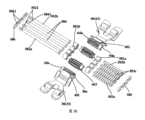
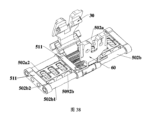
第1の態様によれば、本出願は、回転シャフト構造を提供する。回転シャフト構造は、主シャフトアセンブリと、主シャフトアセンブリに対して対称的に配設されている第1の折り畳みアセンブリおよび第2の折り畳みアセンブリとを備える。第1の折り畳みアセンブリおよび第2の折り畳みアセンブリは、主シャフトアセンブリに関して互いの方へ回転するか、または互いに対向して回転し得る。第1の折り畳みアセンブリが、特に配設されるときに、第1の折り畳みアセンブリは、第1の回転アセンブリと、第1の支持プレートと、第1のハウジング装着ブラケットとを備える。第1の回転アセンブリは、主シャフトアセンブリに回転可能に接続される。第1の支持プレートは、第1のハウジング装着ブラケットに回転可能に接続され、第1の回転アセンブリに摺動可能に接続される。第2の折り畳みアセンブリが、特に配設されるときに、第2の折り畳みアセンブリは、第2の回転アセンブリと、第2の支持プレートと、第2のハウジング装着ブラケットとを備える。第2の回転アセンブリは、主シャフトアセンブリに回転可能に接続される。第2の支持プレートは、第2のハウジング装着ブラケットに回転可能に接続され、第2の回転アセンブリに摺動可能に接続される。第1の支持プレートが第1の回転アセンブリに関して摺動する方向は、第1の回転アセンブリの回転軸に対して垂直であり得る。同様に、第2の支持プレートが第2の回転アセンブリに関して摺動する方向は、第2の回転アセンブリの回転軸に対して垂直であり得る。 According to a first aspect, the present application provides a rotating shaft structure. The rotating shaft structure comprises a main shaft assembly and first and second folding assemblies symmetrically disposed with respect to the main shaft assembly. The first folding assembly and the second folding assembly can rotate toward each other or rotate against each other about the main shaft assembly. When the first folding assembly is specifically arranged, the first folding assembly comprises a first rotating assembly, a first support plate and a first housing mounting bracket. A first rotating assembly is rotatably connected to the main shaft assembly. A first support plate is rotatably connected to the first housing mounting bracket and slidably connected to the first rotating assembly. When the second folding assembly is specifically arranged, the second folding assembly comprises a second rotating assembly, a second support plate and a second housing mounting bracket. A second rotating assembly is rotatably connected to the main shaft assembly. A second support plate is rotatably connected to the second housing mounting bracket and slidably connected to the second rotating assembly. A direction in which the first support plate slides relative to the first rotating assembly may be perpendicular to the axis of rotation of the first rotating assembly. Similarly, the direction in which the second support plate slides relative to the second rotating assembly can be perpendicular to the axis of rotation of the second rotating assembly.
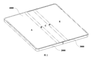
このようにして、第1のハウジング装着ブラケットおよび第2のハウジング装着ブラケットが互いの方へ回転するときに、第1のハウジング装着ブラケットは、第1の回転アセンブリを駆動して主シャフトアセンブリの周りに回転させる。この場合、第1の回転アセンブリは、第1の支持プレートを駆動して第1のハウジング装着ブラケットに関して回転させ、主シャフトアセンブリに近い、第1の支持プレートの一方の端部を駆動して主シャフトアセンブリから離れる方向に移動させる。これに対応して、第2のハウジング装着ブラケットは、第2の回転アセンブリを駆動して主シャフトアセンブリの周りに回転させる。第2の回転アセンブリは、第2の支持プレートを駆動して第2のハウジング装着ブラケットに関して回転させ、主シャフトアセンブリに近い、第2の支持プレートの一方の端部を駆動して主シャフトアセンブリから離れる方向に移動させ、それにより第1の支持プレートおよび第2の支持プレートは、第1の位置まで回転したときにプリセットされた含まれる角度を形成し、主シャフトアセンブリと一緒にディスプレイ収容空間を囲む。 In this manner, as the first housing mounting bracket and the second housing mounting bracket rotate toward each other, the first housing mounting bracket drives the first rotating assembly to rotate about the main shaft assembly. rotate to In this case, the first rotating assembly drives the first support plate to rotate with respect to the first housing mounting bracket and drives one end of the first support plate near the main shaft assembly to rotate the main shaft assembly. Move it away from the shaft assembly. Correspondingly, the second housing mounting bracket drives the second rotating assembly to rotate about the main shaft assembly. A second rotating assembly drives the second support plate to rotate with respect to the second housing mounting bracket and drives one end of the second support plate proximate the main shaft assembly to rotate from the main shaft assembly. moving apart such that the first support plate and the second support plate form a preset included angle when rotated to the first position to move the display receiving space together with the main shaft assembly; surround.
本出願における回転シャフト構造によれば、第1のハウジング装着ブラケットおよび第2のハウジング装着ブラケットが互いの方へ回転したときに、第1の支持プレートは、第1のハウジング装着ブラケットに関して同じ方向に回転し、第2の支持プレートは、第2のハウジング装着ブラケットに関して同じ方向に回転するので、第1の支持プレート、第2の支持プレート、および主シャフトアセンブリは、三角形のディスプレイ収容空間を形成することができる。電子デバイスが閉じた状態にあるときに、ディスプレイ収容空間は、フレキシブルディスプレイの曲がった部分を収容するために使用することができ、したがってフレキシブルディスプレイが押し出しによって損傷することはない。これは、フレキシブルディスプレイの耐用年数を延ばす。 According to the rotating shaft construction in the present application, when the first housing mounting bracket and the second housing mounting bracket are rotated toward each other, the first support plate rotates in the same direction with respect to the first housing mounting bracket. As it rotates and the second support plate rotates in the same direction with respect to the second housing mounting bracket, the first support plate, the second support plate and the main shaft assembly form a triangular display receiving space. be able to. When the electronic device is in the closed state, the display receiving space can be used to receive the bent portion of the flexible display, so the flexible display will not be damaged by extrusion. This extends the useful life of the flexible display.
それに加えて、第1のハウジング装着ブラケットおよび第2のハウジング装着ブラケットが互いに対向して回転するときに、第1のハウジング装着ブラケットは、第1の回転アセンブリを駆動して主シャフトアセンブリの周りに回転させ、第2のハウジング装着ブラケットは、第2の回転アセンブリを駆動して主シャフトアセンブリの周りに回転させる。それに加えて、第1の回転アセンブリは、第1の支持プレートを駆動して第1のハウジング装着ブラケットに関して同じ方向に回転させ、主シャフトアセンブリに近い、第1の支持プレートの一方の端部を駆動して主シャフトアセンブリに接近する方向に移動させる。第2の回転アセンブリは、第2の支持プレートを駆動して第2のハウジング装着ブラケットに関して同じ方向に回転させ、主シャフトアセンブリに近い、第2の支持プレートの一方の端部を駆動して主シャフトアセンブリに接近する方向に移動させ、それにより第1の支持プレートおよび第2の支持プレートが第2の位置まで回転したときに、第1の支持プレート、第2の支持プレート、および主シャフトアセンブリは平らに展開されて支持表面を形成する。したがって、平らな支持表面が、フレキシブルディスプレイに設けられ、フレキシブルディスプレイの部分的につぶれる問題を回避し、フレキシブルディスプレイの平坦性を改善することができる。 In addition, the first housing mounting bracket drives the first rotating assembly around the main shaft assembly when the first housing mounting bracket and the second housing mounting bracket rotate against each other. Rotating, the second housing mounting bracket drives the second rotating assembly to rotate about the main shaft assembly. In addition, the first rotating assembly drives the first support plate to rotate in the same direction with respect to the first housing mounting bracket and rotates one end of the first support plate near the main shaft assembly. It is driven to move toward the main shaft assembly. A second rotating assembly drives the second support plate to rotate in the same direction with respect to the second housing mounting bracket and drives one end of the second support plate near the main shaft assembly to rotate the main shaft assembly. The first support plate, the second support plate and the main shaft assembly when moved toward the shaft assembly thereby rotating the first support plate and the second support plate to the second position. is laid out flat to form a support surface. Therefore, a flat support surface can be provided on the flexible display to avoid the problem of partial collapse of the flexible display and to improve the flatness of the flexible display.
本出願の可能な実装形態において、第1の支持プレートと第1のハウジング装着ブラケットとの間の回転接続を実装するために、第1の円弧溝は、第1のハウジング装着ブラケット内に配設され、第1の円弧シャフトは、第1の支持プレート上に配設され、それにより第1の支持プレートと第1のハウジング装着ブラケットとの間の回転接続は、第1の円弧シャフトと第1の円弧溝との間の摺動嵌合によって形成される仮想軸を使用することによって実装される。同様に、第2の円弧溝は、第2のハウジング装着ブラケット内に配設され、第2の円弧シャフトは、第2の支持プレート上に配設される。このようにして、第2の支持プレートと第2のハウジング装着ブラケットとの間の回転接続は、第2の円弧シャフトと第2の円弧溝との摺動嵌合によって形成される仮想軸を使用することによって実装される。円弧シャフトおよび円弧溝の相対移動を通じて、第1の支持プレートと第1のハウジング装着ブラケットとの間の回転接続および第2の支持プレートと第2のハウジング装着ブラケットとの間の回転接続は、仮想軸を使用することによって実装される。回転接続構造が単純であり、回転軸によって占有される空間は小さい。これは、回転シャフト構造の厚さを薄くするのに役立ち、電子デバイスのより軽くより薄い設計を実装することがより容易になる。 In a possible implementation of the present application, the first arcuate groove is disposed in the first housing mounting bracket to implement the rotational connection between the first support plate and the first housing mounting bracket. and the first arcuate shaft is disposed on the first support plate such that the rotational connection between the first support plate and the first housing mounting bracket is the first arcuate shaft and the first arcuate shaft. implemented by using a virtual axis formed by a sliding fit between the arcuate grooves of the Similarly, a second arcuate groove is disposed in the second housing mounting bracket and a second arcuate shaft is disposed on the second support plate. In this way, the rotational connection between the second support plate and the second housing mounting bracket uses a virtual axis formed by the sliding fit of the second arcuate shaft and the second arcuate groove. It is implemented by Through the relative movement of the arc shaft and the arc groove, the rotational connection between the first support plate and the first housing mounting bracket and the rotational connection between the second support plate and the second housing mounting bracket are virtual Implemented by using axes. The rotary connection structure is simple and the space occupied by the rotary shaft is small. This helps reduce the thickness of the rotating shaft structure, making it easier to implement lighter and thinner designs of electronic devices.
本出願の可能な実装形態において、第1の回転アセンブリが特に配設されるときに、第1の回転アセンブリは、第1のスイングアームと第1の従動アームとを備えている。第1のスイングアームの一方の端部は、主シャフトアセンブリに回転可能に接続され、他方の端部は、第1のハウジング装着ブラケットに回転可能に接続される。第1の従動アームの一方の端部は、主シャフトアセンブリに回転可能に接続され、他方の端部は、第1のハウジング装着ブラケットに摺動可能に接続される。主シャフトアセンブリ上の第1の従動アームおよび第1のスイングアームの回転軸中心は、互いに平行であり、互いに一致しない。同様に、第2の回転アセンブリは、第2のスイングアームおよび第2の従動アームを備える。第2のスイングアームの一方の端部は、主シャフトアセンブリに回転可能に接続され、他方の端部は、第2のハウジング装着ブラケットに回転可能に接続される。第2の従動アームの一方の端部は、主シャフトアセンブリに回転可能に接続され、他方の端部は、第2のハウジング装着ブラケットに摺動可能に接続される。主シャフトアセンブリ上の第2の従動アームおよび第2のスイングアームの回転軸中心は、互いに平行であり、互いに一致しない。第1の従動アームおよび第1のスイングアームの回転軸は、一致しないので、第2の従動アームおよび第2のスイングアームの回転軸中心は一致しない。第1の回転アセンブリと第2の回転アセンブリとが互いの方へ回転したときに、第1のハウジング装着ブラケットは、第1の従動アームの回転軸中心から離れる方向に第1の従動アームに関して摺動し、第2のハウジング装着ブラケットは、第2の従動アームの回転軸中心から離れる方向に第2の従動アームに関して摺動し、それにより、第1のハウジング装着ブラケットおよび第1のスイングアームは、第1の従動アームに関して伸び、第2のハウジング装着ブラケットおよび第2のスイングアームは、第2の従動アームに関して伸びて、主シャフトアセンブリに関する第1の折り畳みアセンブリおよび第2の折り畳みアセンブリの伸展長さを大きくし、回転シャフト構造の長さを長くする。それに加えて、第1の回転アセンブリと第2の回転アセンブリとが互いに対向して回転したときに、第1のハウジング装着ブラケットは、第1の従動アームの回転軸中心に接近する方向に第1の従動アームに関して摺動し、第2のハウジング装着ブラケットは、第2の従動アームの回転軸中心に接近する方向に第2の従動アームに関して摺動し、それにより、第1のハウジング装着ブラケットおよび第1のスイングアームは、第1の従動アームに関して収縮して、主シャフトアセンブリに関する第1の折り畳みアセンブリおよび第2の折り畳みアセンブリの伸展長を短くし、回転シャフト構造の長さを短くする。このようにして、回転シャフト構造が閉じた状態であるか、展開状態であるか、または折り畳みプロセスに入っているときに、主シャフトアセンブリに関する第1の折り畳みアセンブリおよび第2の折り畳みアセンブリの伸展長さは、フレキシブルディスプレイの長さに合わせることができるので、フレキシブルディスプレイは、引き伸ばされるかまたは押し出されるということはない。 In a possible implementation of the present application, when the first rotating assembly is specifically arranged, the first rotating assembly comprises a first swing arm and a first driven arm. One end of the first swing arm is rotatably connected to the main shaft assembly and the other end is rotatably connected to the first housing mounting bracket. One end of the first driven arm is rotatably connected to the main shaft assembly and the other end is slidably connected to the first housing mounting bracket. The rotational axis centers of the first driven arm and the first swing arm on the main shaft assembly are parallel to each other and do not coincide with each other. Similarly, the second rotating assembly comprises a second swing arm and a second driven arm. One end of the second swing arm is rotatably connected to the main shaft assembly and the other end is rotatably connected to the second housing mounting bracket. One end of the second driven arm is rotatably connected to the main shaft assembly and the other end is slidably connected to the second housing mounting bracket. The rotational axis centers of the second driven arm and the second swing arm on the main shaft assembly are parallel to each other and do not coincide with each other. Since the rotation axes of the first driven arm and the first swing arm do not match, the rotation axis centers of the second driven arm and the second swing arm do not match. The first housing mounting bracket slides relative to the first driven arm in a direction away from the center of rotation of the first driven arm when the first rotating assembly and the second rotating assembly are rotated toward each other. and the second housing mounting bracket slides relative to the second driven arm in a direction away from the center of rotation of the second driven arm, whereby the first housing mounting bracket and the first swing arm , extends relative to the first driven arm, and the second housing mounting bracket and the second swing arm extend relative to the second driven arm to extend the extended length of the first folding assembly and the second folding assembly relative to the main shaft assembly. increase the length of the rotating shaft structure. In addition, when the first rotating assembly and the second rotating assembly are rotated against each other, the first housing mounting bracket rotates the first housing mounting bracket in a direction toward the center of rotation of the first driven arm. and the second housing mounting bracket slides relative to the second driven arm in a direction closer to the center of rotation of the second driven arm, whereby the first housing mounting bracket and the The first swing arm contracts with respect to the first driven arm to shorten the extended length of the first folding assembly and the second folding assembly relative to the main shaft assembly and shorten the length of the rotating shaft structure. In this manner, the extended length of the first and second folding assemblies relative to the main shaft assembly when the rotating shaft structure is in the closed state, in the deployed state, or in the folding process. The height can be matched to the length of the flexible display, so the flexible display will not be stretched or pushed out.
本出願の可能な実装形態において、第1の支持プレートと第1の回転アセンブリとの間の摺動可能な接続は、第1の支持プレートと第1のスイングアームとの間の摺動可能な接続として反映され得る。この場合、第1のガイドシャフトが第1のスイングアーム上に配設されてもよく、第1のトラックスロットが第1の支持プレート内に配設されてもよい。このようにして、第1のスイングアームと第1のハウジング装着ブラケットとの間の含まれる角度が変化した後に、第1のスイングアームは、第1のガイドシャフトと第1の支持プレートの第1のトラックスロットとの間の摺動嵌合を通じて、第1の支持プレートを駆動して第1のハウジング装着ブラケットに関して回転させ得る。 In a possible implementation of the present application, the slidable connection between the first support plate and the first rotating assembly is a slidable connection between the first support plate and the first swing arm. It can be reflected as a connection. In this case, the first guide shaft may be arranged on the first swing arm and the first track slot may be arranged in the first support plate. In this way, after the included angle between the first swing arm and the first housing mounting bracket is changed, the first swing arm moves between the first guide shaft and the first support plate of the first support plate. The first support plate may be driven to rotate with respect to the first housing mounting bracket through a sliding fit between the track slots of.
同様に、第2の支持プレートと第2の回転アセンブリとの間の摺動可能な接続は、第2の支持プレートと第2のスイングアームとの間の摺動可能な接続として反映され得る。この場合、第2のガイドシャフトが第2のスイングアーム上に配設されてもよく、第2のトラックスロットが第2の支持プレート内に配設されてもよい。このようにして、第2のスイングアームと第2のハウジング装着ブラケットとの間の含まれる角度が変化した後に、第2のスイングアームは、第2のガイドシャフトと第2の支持プレートの第2のトラックスロットとの間の摺動嵌合を通じて、第2の支持プレートを駆動して第2のハウジング装着ブラケットに関して回転させ得る。2つの支持プレートは、対応する側のスイングアームによって駆動され得るので、2つの支持プレートは、常に十分な駆動力を有し、移動プロセスにおいて良好な移動円滑性を有することができ、それにより、第1のハウジング装着ブラケットおよび第2のハウジング装着ブラケットが互いに関して折り畳まれるか、または展開されるときに、2つの支持プレートが適所に移動できる。これは、フレキシブルディスプレイを保護するのに役立つ。 Similarly, the slidable connection between the second support plate and the second rotating assembly can be mirrored as the slidable connection between the second support plate and the second swing arm. In this case, a second guide shaft may be arranged on the second swing arm and a second track slot may be arranged in the second support plate. In this way, after the included angle between the second swing arm and the second housing mounting bracket is changed, the second swing arm is positioned between the second guide shaft and the second support plate of the second support plate. The second support plate may be driven to rotate with respect to the second housing mounting bracket through a sliding fit between the track slots of the second support plate. The two support plates can be driven by the corresponding side swing arms, so that the two support plates can always have sufficient driving force and have good movement smoothness in the movement process, thereby The two support plates can move into position when the first housing mounting bracket and the second housing mounting bracket are folded or unfolded with respect to each other. This helps protect the flexible display.
それに加えて、第1の支持プレートと第1の回転アセンブリとの間の摺動可能な接続は、第1の支持プレートと第1の従動アームとの間の摺動可能な接続として反映される。この場合、第1のガイドシャフトが第1の従動アーム上に配設されてもよく、第1のトラックスロットが第1の支持プレート内に配設されてもよい。このようにして、第1の従動アームと第1のハウジング装着ブラケットとの間の含まれる角度が変化した後に、第1の従動アームは、第1のガイドシャフトと第1の支持プレートの第1のトラックスロットとの間の摺動嵌合を通じて、第1の支持プレートを駆動して第1のハウジング装着ブラケットに関して回転させ得る。 Additionally, the slidable connection between the first support plate and the first rotating assembly is reflected as a slidable connection between the first support plate and the first driven arm. . In this case, the first guide shaft may be arranged on the first driven arm and the first track slot may be arranged in the first support plate. In this way, after the included angle between the first driven arm and the first housing mounting bracket is changed, the first driven arm moves between the first guide shaft and the first support plate. The first support plate may be driven to rotate with respect to the first housing mounting bracket through a sliding fit between the track slots of.
同様に、第2の支持プレートと第2の回転アセンブリとの間の摺動可能な接続は、第2の支持プレートと第2の従動アームとの間の摺動可能な接続として反映される。この場合、第2のガイドシャフトが第2の従動アーム上に配設されてもよく、第2のトラックスロットが第2の支持プレート内に配設されてもよい。このようにして、第2の従動アームと第2のハウジング装着ブラケットとの間の含まれる角度が変化した後に、第2の従動アームは、第2のガイドシャフトと第2の支持プレートの第2のトラックスロットとの間の摺動嵌合を通じて、第2の支持プレートを駆動して第2のハウジング装着ブラケットに関して回転させ得る。2つの支持プレートは、対応する側の従動アームによって駆動され得るので、2つの支持プレートは、常に十分な駆動力を有し、移動プロセスにおいて良好な移動円滑性を有することができ、それにより、第1のハウジング装着ブラケットおよび第2のハウジング装着ブラケットが互いに関して折り畳まれるか、または展開されるときに、2つの支持プレートが適所に移動できる。これは、フレキシブルディスプレイを保護するのに役立つ。 Similarly, the slidable connection between the second support plate and the second rotating assembly is mirrored as the slidable connection between the second support plate and the second driven arm. In this case, a second guide shaft may be arranged on the second driven arm and a second track slot may be arranged in the second support plate. In this way, after the included angle between the second driven arm and the second housing mounting bracket is changed, the second driven arm moves between the second guide shaft and the second support plate of the second support plate. The second support plate may be driven to rotate with respect to the second housing mounting bracket through a sliding fit between the track slots of the second support plate. The two support plates can be driven by the driven arm on the corresponding side, so that the two support plates can always have sufficient driving force and have good movement smoothness in the movement process, so that The two support plates can move into position when the first housing mounting bracket and the second housing mounting bracket are folded or unfolded with respect to each other. This helps protect the flexible display.
第1の支持プレートが第1の従動アームに摺動可能に接続されたときに、第1の支持プレートに摺動可能に接続される、第1の従動アームの、一方の端部は陥凹し、それにより第1の凹領域を形成し、第1のガイドシャフトの一方の端部は第1の凹領域の一方の側に接続され、他方の端部は第1の凹領域の他方の側に接続されてよく、それによって第1のガイドシャフトは第1の凹領域内に収容される。同様に、第2の支持プレートが第2の従動アームに摺動可能に接続されたときに、第2の支持プレートに摺動可能に接続される、第2の従動アームの、一方の端部は陥凹し、それにより第2の凹領域を形成し、第2のガイドシャフトの一方の端部は第2の凹領域の一方の側に接続され、他方の側は第2の凹領域の他方の側に接続されてよく、それによって第2のガイドシャフトは第2の凹領域に収容される。このようにして、回転シャフト構造によって占有される空間が縮小されるものとしてよく、回転シャフト構造および回転シャフト構造を備える電子デバイスのより軽くより薄い設計を実装することがより容易になる。 One end of the first driven arm slidably connected to the first support plate is recessed when the first support plate is slidably connected to the first driven arm and thereby forming a first recessed area, one end of the first guide shaft is connected to one side of the first recessed area and the other end is connected to the other side of the first recessed area. side, whereby the first guide shaft is accommodated within the first recessed area. Similarly, one end of the second driven arm slidably connected to the second support plate when the second support plate is slidably connected to the second driven arm. is recessed thereby forming a second recessed area, one end of the second guide shaft is connected to one side of the second recessed area and the other side of the second recessed area It may be connected to the other side, whereby the second guide shaft is accommodated in the second recessed area. In this way, the space occupied by the rotating shaft structure may be reduced, making it easier to implement lighter and thinner designs of the rotating shaft structure and electronic devices comprising the rotating shaft structure.
本出願の可能な実装形態において、第1の支持プレートの第1のトラックスロットおよび第2の支持プレートの第2のトラックスロットは、円弧状スロットまたは直線状スロットであってよく、2つの支持プレートの移動トラック要件に基づき調整され、それにより支持プレートは角度要件を満たす回転位置まで回転することができる。 In a possible implementation of the present application, the first track slot of the first support plate and the second track slot of the second support plate may be arcuate slots or linear slots, and the two support plates , so that the support plate can be rotated to a rotational position that meets the angular requirements.
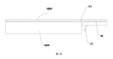
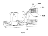
本出願の可能な実装形態において、第1の支持プレートと第1の回転アセンブリとの間の相対的摺動の安定性を改善するために、第1の重ね継ぎ部が第1のスイングアームまたは第1の従動アーム上に配設されてよく、第1の重ね継ぎ部は主シャフトアセンブリから第1のハウジング装着ブラケットへの方向に延在する。第1の支持プレートは、互いに対向して配設されている第1の表面および第2の表面を有する。第1の表面は、フレキシブルディスプレイを支持する。第2の重ね継ぎ部は、主シャフトアセンブリに近い、第1の支持プレートの、側に配設される。第2の重ね継ぎ部は、第1の支持プレートの第2の表面上に配設される。第1の支持プレートが第1の回転アセンブリに関して摺動するときに、第2の重ね継ぎ部は、第1の重ね継ぎ部の表面に沿って摺動可能である。したがって、第1の支持プレートと第1の回転アセンブリとの間の組み立てクリアランスが補償され、それにより第1の支持プレートの移動安定性を改善することができる。 In a possible implementation of the present application, the first lap joint is connected to the first swing arm or A first splice may be disposed on the first driven arm and extends in a direction from the main shaft assembly to the first housing mounting bracket. The first support plate has a first surface and a second surface disposed opposite each other. A first surface supports a flexible display. A second splice is disposed on the side of the first support plate that is closer to the main shaft assembly. A second splice is disposed on the second surface of the first support plate. The second splice is slidable along the surface of the first splice as the first support plate slides relative to the first rotating assembly. Therefore, the assembly clearance between the first support plate and the first rotating assembly is compensated, thereby improving the movement stability of the first support plate.
同様に、第3の重ね継ぎ部は、第2のスイングアームまたは第2の従動アーム上に配設され、第3の重ね継ぎ部は、主シャフトアセンブリから第2のハウジング装着ブラケットに向かう方向に延在する。第2の支持プレートは、互いに対向して配設されている第3の表面および第4の表面を有する。第3の表面は、フレキシブルディスプレイを支持する。第4の重ね継ぎ部は、主シャフトアセンブリに近い、第2の支持プレートの、側に配設される。第4の重ね継ぎ部は、第2の支持プレートの第4の表面上に配設される。第2の支持プレートが第2の回転アセンブリに関して摺動するときに、第4の重ね継ぎ部は、第3の重ね継ぎ部の表面に沿って摺動可能である。したがって、第2の支持プレートと第2の回転アセンブリとの間の組み立てクリアランスが補償され、それにより第2の支持プレートの移動安定性を改善することができる。 Similarly, a third lap joint is disposed on the second swing arm or the second driven arm, the third lap joint extending in a direction from the main shaft assembly to the second housing mounting bracket. Extend. The second support plate has third and fourth surfaces disposed opposite each other. A third surface supports a flexible display. A fourth lap joint is disposed on the side of the second support plate that is closer to the main shaft assembly. A fourth splice is disposed on the fourth surface of the second support plate. The fourth splice is slidable along the surface of the third splice as the second support plate slides relative to the second rotating assembly. Therefore, the assembly clearance between the second support plate and the second rotating assembly is compensated, thereby improving the movement stability of the second support plate.
第1の重ね継ぎ部および第2の重ね継ぎ部が特に配設されているときに、第2の重ね継ぎ部と接触する、第1の重ね継ぎ部の、表面は、キャンバ表面であり得るか、または第1の重ね継ぎ部と接触する、第2の重ね継ぎ部の、表面は、キャンバ表面であり得るか、または第2の重ね継ぎ部と接触する、第1の重ね継ぎ部の、表面と、第1の重ね継ぎ部と接触する、第2の重ね継ぎ部の、表面との両方が、キャンバ表面であり得る。同様に、第4の重ね継ぎ部と接触する、第3の重ね継ぎ部の、表面は、キャンバ表面であり得るか、または第3の重ね継ぎ部と接触する、第4の重ね継ぎ部の、表面は、キャンバ表面であり得るか、または第4の重ね継ぎ部と接触する、第3の重ね継ぎ部の、表面と、第3の重ね継ぎ部と接触する、第4の重ね継ぎ部の、表面との両方が、キャンバ表面であり得る。このようにして、第1の回転アセンブリ上の第1の重ね継ぎ部および第1の支持プレート上の第2の重ね継ぎ部は、接触および相対的摺動のプロセスにおいてより滑らかに移動することができる。それに加えて、第2の回転アセンブリ上の第3の重ね継ぎ部および第2の支持プレート上の第4の重ね継ぎ部は、接触および相対的摺動のプロセスにおいてより滑らかに移動することができる。 Can the surface of the first splice contacting the second splice, especially when the first and second splices are arranged, be a camber surface? or the surface of the second splice that contacts the first splice may be a camber surface, or the surface of the first splice that contacts the second splice and the surface of the second splice that contacts the first splice may be camber surfaces. Similarly, the surface of the third splice that contacts the fourth splice may be a camber surface or the surface of the fourth splice that contacts the third splice. The surface can be a camber surface or a surface of the third lap joint that contacts the fourth lap joint and a surface of the fourth lap joint that contacts the third lap joint. and both can be camber surfaces. In this way, the first lap joint on the first rotating assembly and the second lap joint on the first support plate can move more smoothly in the process of contact and relative sliding. can. In addition, the third lap joint on the second rotating assembly and the fourth lap joint on the second support plate can move more smoothly in the process of contact and relative sliding. .
それに加えて、互いに接触する、2つの重ね継ぎ部の、表面がキャンバ表面であるときに、キャンバ表面は少なくとも2つの湾曲表面を継ぐことによって形成され、プリセットされた含まれる角度が、2つの隣接する湾曲表面の間に形成され得るので、キャンバ表面は、第2の重ね継ぎ部が第1の重ね継ぎ部に関してそれに沿って摺動する移動トラックによりよく合わされ、第1の支持プレートおよび第2の支持プレートの摺動トラックをより正確に制御することができる。 In addition, when the surfaces of the two lap joints in contact with each other are camber surfaces, the camber surfaces are formed by joining at least two curved surfaces, and the preset included angle is between the two adjacent so that the camber surface is better aligned with the moving track along which the second splice slides with respect to the first splice and the first support plate and the second splice. The sliding track of the support plate can be controlled more precisely.
本出願の可能な一実装形態において、第5の重ね継ぎ部は、第1の支持プレートに近い、主シャフトアセンブリの、側に配設される。第5の重ね継ぎ部および第1の重ね継ぎ部は、第2の重ね継ぎ部と同じ側に配置される。第2の重ね継ぎ部は、第5の重ね継ぎ部の表面上に重ね継ぎされる。同様に、第6の重ね継ぎ部は、第2の支持プレートに近い、主シャフトアセンブリの、側に配設される。第6の重ね継ぎ部および第3の重ね継ぎ部は、第4の重ね継ぎ部と同じ側に配置される。第4の重ね継ぎ部は、第6の重ね継ぎ部の表面上に重ね継ぎされる。第5の重ね継ぎ部および第6の重ね継ぎ部は、主シャフトアセンブリ上に配設される。これは、第1の支持プレートおよび第2の支持プレートの移動トラックの制御精度を効果的に改善し、主シャフトアセンブリと第1の支持プレートおよび第2の支持プレートの両方との間の回避クリアランスを効果的に小さくすることができ、それにより、第1の支持プレートおよび第2の支持プレートは、フレキシブルディスプレイを効果的に支持し、フレキシブルディスプレイのつぶれ領域を縮小することができる。それに加えて、フレキシブルディスプレイを支持するための回転シャフト構造の有効面積が大幅に増大するので、フレキシブルディスプレイは、垂直方向の押し出し力に耐えることができる。これは、フレキシブルディスプレイの使用プロセスにおける圧迫故障などの問題が発生する危険性を低減する。 In one possible implementation of the present application, the fifth splice is located on the side of the main shaft assembly that is closer to the first support plate. The fifth lap joint and the first lap joint are located on the same side as the second lap joint. The second splice is spliced onto the surface of the fifth splice. Similarly, a sixth splice is disposed on the side of the main shaft assembly that is closest to the second support plate. The sixth lap joint and the third lap joint are located on the same side as the fourth lap joint. A fourth splice is spliced onto the surface of the sixth splice. A fifth lap joint and a sixth lap joint are disposed on the main shaft assembly. This effectively improves the control accuracy of the moving tracks of the first support plate and the second support plate, and avoids clearance between the main shaft assembly and both the first support plate and the second support plate. can be effectively reduced, so that the first support plate and the second support plate can effectively support the flexible display and reduce the collapse area of the flexible display. In addition, the effective area of the rotating shaft structure for supporting the flexible display is greatly increased, so that the flexible display can withstand vertical pushing force. This reduces the risk of problems such as compression failure occurring in the process of using the flexible display.
本出願の可能な一実装形態において、移動プロセスにおける第1の支持プレートおよび第2の支持プレートの揺れを低減するために、回転シャフト構造は、第1の回転補助アセンブリおよび第2の回転補助アセンブリをさらに備え得る。第1の回転補助アセンブリは、第1の弾性部材を備える。第1の弾性部材の一方の端部は、第1のハウジング装着ブラケットに固定され、他方の端部は第1の支持プレートの表面に沿って摺動可能である。同様に、第2の回転補助アセンブリは、第2の弾性部材を備える。第2の弾性部材の一方の端部は、第2のハウジング装着ブラケットに固定され、他方の端部は第2の支持プレートの表面に沿って摺動可能である。第1の回転補助アセンブリおよび第2の回転補助アセンブリが配設されており、それにより、第1の支持プレートと第2の支持プレートとの間の含まれる角度が、部品間の移動クリアランスのせいで設計上要求される角度に達し得ない可能性が最小化され、第1の支持プレートと第2の支持プレートとの間の含まれる角度は、設計上要求される最適な角度に達することができる。 In one possible implementation of the present application, the rotary shaft structure includes a first rotary auxiliary assembly and a second rotary auxiliary assembly to reduce swaying of the first support plate and the second support plate in the moving process. can be further provided. The first rotation assist assembly comprises a first elastic member. One end of the first elastic member is fixed to the first housing mounting bracket and the other end is slidable along the surface of the first support plate. Similarly, the second rotational assist assembly comprises a second elastic member. One end of the second elastic member is fixed to the second housing mounting bracket and the other end is slidable along the surface of the second support plate. A first rotary assist assembly and a second rotary assist assembly are provided whereby the included angle between the first support plate and the second support plate is due to the movement clearance between the parts. is minimized, and the included angle between the first support plate and the second support plate can reach the optimum angle required by the design. can.
第1の弾性部材および第2の弾性部材が、特に配設されるときに、第1の弾性部材は、トーションバネであってもよく、第1の弾性部材および第1のスイングアームは同軸上に配設される。それに加えて、第2の弾性部材は、トーションバネであり、第2の弾性部材および第1のスイングアームは同軸上に配設される。このようにして、回転シャフト構造の部品は、効果的に削減され得る。これは、回転シャフト構造によって占有される空間を縮小し、回転シャフト構造のより薄い設計を実装することを助ける。 When the first elastic member and the second elastic member are particularly arranged, the first elastic member may be a torsion spring, and the first elastic member and the first swing arm are coaxially is placed in In addition, the second elastic member is a torsion spring, and the second elastic member and the first swing arm are coaxially arranged. In this way the parts of the rotating shaft structure can be effectively reduced. This reduces the space occupied by the rotating shaft structure and helps implement thinner designs of the rotating shaft structure.
第1の支持プレート上の第1の弾性部材の摺動トラックを制御するために、第1のストッパー構造が、第1の支持プレート上に配設され得る。第1の合わせ穴が、第1のストッパー構造内に配設される。第1の弾性部材の他方の端部は、第1の合わせ穴を貫通し、第1の合わせ穴の誘導機能の下で、第1の支持プレートの表面に沿って摺動する。同様に、第2のストッパー構造が、第2の支持プレート上に配設される。第2の合わせ穴が、第2のストッパー構造内に配設される。第2の弾性構造部材の他方の端部は、第2の合わせ穴を貫通し、第2の合わせ穴の誘導機能の下で、第2の支持プレートの表面に沿って摺動する。対応する支持プレート上の第1の弾性部材および第2の弾性部材の摺動トラックが制御され、それにより、対応する側の第1の支持プレートと第2の支持プレートとハウジング装着ブラケットとの間の引っ張り力が制御され得る。この引っ張り力は、第1の支持プレートおよび第2の支持プレートを指定された位置に移動することができる。 A first stopper structure may be disposed on the first support plate to control the sliding track of the first elastic member on the first support plate. A first mating hole is disposed in the first stopper structure. The other end of the first elastic member passes through the first mating hole and slides along the surface of the first support plate under the guidance function of the first mating hole. Similarly, a second stopper structure is disposed on the second support plate. A second mating hole is disposed in the second stopper structure. The other end of the second resilient structural member passes through the second mating hole and slides along the surface of the second support plate under the guidance function of the second mating hole. The sliding tracks of the first elastic member and the second elastic member on the corresponding support plate are controlled so that the first support plate and the second support plate on the corresponding side and the housing mounting bracket. can be controlled. This pulling force can move the first support plate and the second support plate to a designated position.
本出願の可能な一実施形態において、第1のスイングアームと第2のスイングアームと主シャフトアセンブリとの間の回転接続が、特に実装されるときに、第3の円弧溝および第4の円弧溝が、主シャフトアセンブリ内に配設される。第3の円弧シャフトは、第1のスイングアームの一方の端部に配設され、第4の円弧シャフトは、第2のスイングアームの一方の端部に配設される。このようにして、第3の円弧シャフトは、第3の円弧シャフト内に配設され、第4の円弧シャフトは、第4の円弧シャフト内に配設されるものとしてよく、それにより、第1のスイングアームと第2のスイングアームと主シャフトアセンブリとの間の回転接続は、仮想軸を使用することによって実装される。したがって、第1のスイングアームと第2のスイングアームと主シャフトアセンブリとの間の接続構造が、主シャフトアセンブリ内にうまく隠され得る。これは、回転シャフト構造の統合およびユーザエクスペリエンスを改善するのに役立つ。それに加えて、仮想軸の接続方式は、機械全体のより薄い設計を実装するのにさらに役立つ。 In one possible embodiment of the present application, when the rotational connection between the first swing arm and the second swing arm and the main shaft assembly is specifically implemented, the third arc groove and the fourth arc A groove is disposed in the main shaft assembly. A third arcuate shaft is arranged at one end of the first swing arm, and a fourth arcuate shaft is arranged at one end of the second swing arm. Thus, the third arc shaft may be disposed within the third arc shaft, and the fourth arc shaft may be disposed within the fourth arc shaft, thereby providing the first The rotational connection between the swing arm of the second swing arm and the main shaft assembly is implemented by using a virtual axis. Therefore, the connecting structure between the first swing arm, the second swing arm and the main shaft assembly can be well hidden within the main shaft assembly. This helps improve the integration and user experience of rotating shaft structures. In addition, the virtual axis connection scheme is more helpful in implementing a thinner overall machine design.
主シャフトアセンブリは、スナップ式に嵌められる内側ハウジングおよび外側ハウジングを備え得る。主シャフトアセンブリの第3の円弧溝および第4の円弧溝は、内側ハウジングおよび外側ハウジングの協働を通じて実装され得る。特に、2つの突起部が、主シャフトアセンブリの内側ハウジング内に配設される。2つの陥凹部が、外側ハウジングに配設される。外側ハウジングおよび内側ハウジングは、スナップ式に嵌められる。2つの突起部と2つの陥凹部は、一対一対応方式で配設され、それにより、第3の円弧溝と第4の円弧溝とを形成する。したがって、主シャフトアセンブリの第3の円弧溝および第4の円弧溝の配設方式は、効果的に簡素化され得る。 The main shaft assembly may comprise inner and outer housings that snap together. The third and fourth arcuate grooves of the main shaft assembly may be implemented through cooperation of the inner and outer housings. Specifically, two projections are disposed within the inner housing of the main shaft assembly. Two recesses are disposed in the outer housing. The outer housing and inner housing are snap fit. The two protrusions and the two recesses are arranged in a one-to-one correspondence, thereby forming a third arcuate groove and a fourth arcuate groove. Therefore, the arrangement scheme of the third arcuate groove and the fourth arcuate groove of the main shaft assembly can be effectively simplified.
本出願の可能な一実装形態において、第1のスイングアームと第1のハウジング装着ブラケットとの間の回転接続および第2のスイングアームと第2のハウジング装着ブラケットとの間の回転接続が、特に実装されるときに、第1のシャフト穴が、第1のスイングアーム内に配設され、第2のシャフト穴が第1のハウジング装着ブラケット内に配設され、第1のシャフト穴および第2のシャフト穴は、ピンシャフトを通じて接続され得る。同様に、第3のシャフト穴が第2のスイングアーム内に配設され、第4のシャフト穴が第2のハウジング装着ブラケット内に配置され、第3のシャフト穴および第4のシャフト穴は、ピンシャフトを通じて接続される。したがって、第1のスイングアームおよび第2のスイングアームは、対応する側のハウジング装着ブラケットに確実に接続される。 In one possible implementation of the present application, the rotational connection between the first swing arm and the first housing mounting bracket and the rotational connection between the second swing arm and the second housing mounting bracket are particularly When mounted, a first shaft hole is disposed in the first swing arm, a second shaft hole is disposed in the first housing mounting bracket, and the first shaft hole and the second shaft hole are disposed in the first housing mounting bracket. can be connected through pin shafts. Similarly, a third shaft hole is disposed in the second swing arm, a fourth shaft hole is disposed in the second housing mounting bracket, the third shaft hole and the fourth shaft hole are Connected through a pin shaft. Thus, the first swing arm and the second swing arm are securely connected to the corresponding side housing mounting brackets.
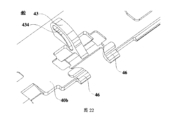
本出願の可能な実装形態において、第1の従動アームと第1のハウジング装着ブラケットとの間の摺動可能な接続、および第2の従動アームと第2のハウジング装着ブラケットとの間の摺動可能な接続を実装するために、第1の摺動スロットが第1のハウジング装着ブラケット内に配設され、第1の摺動レールが第1の従動アーム上に配設され、第1の摺動レールが第1の摺動スロット内で摺動可能に配置される。第2の摺動スロットが第2のハウジング装着ブラケット内に配設され、第2の摺動レールが第2の従動アーム上に配設され、第2の摺動レールが第2の摺動スロット内に摺動可能に配設される。このようにして、2つの従動アームと対応する側のハウジング装着ブラケットとの間の相対的摺動運動を実装することがより容易であり、制御精度も高くなる。 In a possible implementation of the present application, a slidable connection between the first driven arm and the first housing mounting bracket and sliding between the second driven arm and the second housing mounting bracket To implement the possible connection, a first sliding slot is disposed in the first housing mounting bracket, a first sliding rail is disposed on the first driven arm, and a first sliding rail is disposed on the first driven arm. A motion rail is slidably disposed within the first sliding slot. A second sliding slot is disposed in the second housing mounting bracket, a second sliding rail is disposed on the second driven arm, and the second sliding rail is disposed in the second sliding slot. slidably disposed within. In this way, it is easier to implement the relative sliding motion between the two driven arms and the corresponding side housing mounting brackets, and the control accuracy is higher.
回転シャフト構造を折り畳み、展開するプロセスにおける第1の折り畳みアセンブリおよび第2の折り畳みアセンブリの同期運動を実装するために、回転シャフト構造は、同期アセンブリをさらに備え得る。同期アセンブリは、第1の従動アームおよび第2の従動アームに駆動可能に接続されてよく、それにより第1の折り畳みアセンブリと第2の折り畳みアセンブリとの間の同期的な反対回転を実装する。 The rotatable shaft structure may further comprise a synchronizing assembly to implement synchronized movement of the first folding assembly and the second folding assembly in the process of folding and unfolding the rotatable shaft structure. A synchronizing assembly may be drivingly connected to the first driven arm and the second driven arm, thereby implementing synchronous counter-rotation between the first folding assembly and the second folding assembly.
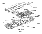
同期アセンブリが特に配設されるときには、同期アセンブリは、互いに係合する第1の歯車および第2の歯車を備えるものとしてよい。第1の歯車は、第1の従動アームの一方の端部に固定される。第2の歯車は、第2の従動アームの一方の端部に固定される。第1の歯車および第1の従動アームは、同軸上で回転する。第2の歯車および第2の従動アームは、同軸上で回転する。したがって、回転シャフト構造の構造は、効果的に簡素化され得る。 When the synchronizing assembly is specifically provided, the synchronizing assembly may comprise a first gear and a second gear that engage with each other. A first gear is fixed to one end of the first driven arm. A second gear is fixed to one end of the second driven arm. The first gear and the first driven arm rotate coaxially. The second gear and the second driven arm rotate coaxially. Therefore, the structure of the rotating shaft structure can be effectively simplified.
それに加えて、同期アセンブリは、偶数個の従動歯車をさらに備え得る。第1の歯車および第2の歯車は、偶数個の従動歯車を通じて駆動可能に接続される。これは、第1の回転アセンブリおよび第2の回転アセンブリの同期回転の安定性を効果的に改善することができる。 Additionally, the synchronizing assembly may further comprise an even number of driven gears. The first gear and the second gear are drivingly connected through an even number of driven gears. This can effectively improve the stability of the synchronous rotation of the first rotating assembly and the second rotating assembly.
本出願の可能な一実装形態において、回転シャフト構造は、減衰アセンブリをさらに備え得る。減衰アセンブリは、主シャフトアセンブリ内に配設され得るか、または回転シャフト構造の構造に配設され得る。 In one possible implementation of the present application, the rotating shaft structure may further comprise a dampening assembly. The damping assembly may be disposed within the main shaft assembly or may be disposed in the structure of the rotating shaft structure.
減衰アセンブリが主シャフトアセンブリ内に配設されるときに、減衰アセンブリの一方の端部は、第1の従動アームおよび第2の従動アームを弾性的に押圧する。減衰アセンブリは、第1の従動アームおよび第2の従動アームが互いに関して回転するときに減衰力をもたらすように構成され得る。この場合、次の配設方式が使用され得る。 One end of the damping assembly resiliently presses against the first driven arm and the second driven arm when the damping assembly is disposed within the main shaft assembly. The damping assembly may be configured to provide a damping force when the first driven arm and the second driven arm rotate with respect to each other. In this case, the following arrangement scheme may be used.
第1の配設方式では、減衰アセンブリの一方の端部が第1の従動アームおよび第2の従動アームを押圧し、他方の端部が主シャフトアセンブリを押圧して、第1の従動アームおよび第2の従動アームが互いに関して回転するときに減衰力をもたらす。減衰力は、第1の従動アームおよび第2の従動アームを介して対応する側のハウジングに伝達されてよく、それにより、ユーザは、電子デバイスの折り畳みまたは展開プロセスについて明確な感覚を有する。これは、ユーザエクスペリエンスを改善する。 In a first arrangement, one end of the damping assembly presses against the first driven arm and the second driven arm, and the other end presses against the main shaft assembly to push the first driven arm and the second driven arm. A damping force is provided when the second driven arms rotate with respect to each other. The damping force may be transmitted to the housing on the corresponding side via the first driven arm and the second driven arm, so that the user has a distinct feeling of the folding or unfolding process of the electronic device. This improves user experience.
本出願において、第1の従動アームおよび第2の従動アームが主シャフトアセンブリに回転可能に接続されるときに、第1の従動アームは第1の回転シャフトを通じて主シャフトアセンブリに回転可能に接続され、第2の従動アームは第2の回転シャフトを通じて主シャフトアセンブリに回転可能に接続され得る。 In this application, the first driven arm is rotatably connected to the main shaft assembly through the first rotatable shaft when the first driven arm and the second driven arm are rotatably connected to the main shaft assembly. , the second driven arm may be rotatably connected to the main shaft assembly through a second rotatable shaft.
本出願の可能な一実装形態では、主シャフトアセンブリの長さ方向において、第1のカム構造が、第1の歯車の2つの端部に配設され、第2のカム構造は、第2の歯車の2つの端部に配設される。 In one possible implementation of the present application, in the lengthwise direction of the main shaft assembly, a first cam structure is arranged at the two ends of the first gear and a second cam structure is located at the second gear. Located at the two ends of the gear.
この実装形態において、減衰アセンブリが特に配設されるときに、減衰アセンブリは、第1の結合カム、第2の結合カム、第1の弾性構造部材、および第2の弾性構造部材をさらに備える。主シャフトアセンブリの長さ方向において、第1の結合カムおよび第2の結合カムは、同期アセンブリの2つの側に配設され、第1の結合カムは、同じ側に配設されている第1のカム構造および第2のカム構造と係合し、第2の結合カムは、同じ側に配設されている第1のカム構造および第2のカム構造と係合する。第1のビアホールおよび第2のビアホールが第1の結合カムに配設され、第3のビアホールおよび第4のビアホールが第2の結合カムに配設され、第1の回転シャフトは第1のビアホールおよび第3のビアホールを貫通し、第2の回転シャフトは第2のビアホールおよび第4のビアホールを貫通する。 In this implementation, when the damping assembly is specifically arranged, the damping assembly further comprises a first coupling cam, a second coupling cam, a first resilient structural member, and a second resilient structural member. In the length direction of the main shaft assembly, the first coupling cam and the second coupling cam are arranged on two sides of the synchronizing assembly, and the first coupling cam is arranged on the same side. The second coupling cam engages the first cam structure and the second cam structure disposed on the same side. A first via hole and a second via hole are arranged in the first coupling cam, a third via hole and a fourth via hole are arranged in the second coupling cam, the first rotating shaft is arranged in the first via hole and the third via hole, and the second rotary shaft passes through the second via hole and the fourth via hole.
それに加えて、主シャフトアセンブリの長さ方向で、第1の弾性構造部材および第2の弾性構造部材は、第2の結合カムから離れる、第1の結合カムの、側に配設され、第1の弾性構造部材は、第1の回転シャフトにスリーブ付けされ、第2の弾性構造部材は、第2の回転シャフトにスリーブ付けされる。第1の弾性構造部材および第2の弾性構造部材は、第1の結合カムを弾性的に押圧し、第1の結合カムを同期アセンブリに押し付ける。回転シャフト構造が扁平状態、閉じた状態、または中間状態にあるときに、減衰力が、第1の結合カムおよび第2の結合カムと第1のカム構造および第2のカム構造との係合により発生し、それにより、回転シャフト構造は、対応する安定状態に保持され得る。それに加えて、第1のカム構造および第2のカム構造の凸部分が摺動して第1の結合カムおよび第2の結合カムの凹部分内に入り込む傾向があるときに、減衰力の効果の下で、第1のカム構造および第2のカム構造の凸部分は、第1のカム構造および第2のカム構造の凹部分内に摺動して入り込む方向に、安定した扁平状態または閉じた状態になるまで摺動し続け、回転シャフト構造の自動展開または閉じる動作を実装し、電子デバイスの自動展開または閉じる動作をさらに実装する。これは、電子デバイスの構造安定性および使用安全性を改善するのに役立つ。 In addition, along the length of the main shaft assembly, the first resilient structural member and the second resilient structural member are disposed on the side of the first coupling cam away from the second coupling cam; One resilient structural member is sleeved to the first rotatable shaft and the second resilient structural member is sleeved to the second rotatable shaft. The first resilient structural member and the second resilient structural member resiliently bias the first coupling cam and press the first coupling cam against the synchronization assembly. A damping force is applied to the engagement of the first and second coupling cams with the first and second cam structures when the rotary shaft structure is in a flat, closed or intermediate state. , whereby the rotating shaft structure can be held in a corresponding stable state. In addition, the damping force effect when the convex portions of the first and second cam structures tend to slide into the concave portions of the first and second coupling cams. Below, the convex portions of the first cam structure and the second cam structure are in a stable flattened or closed state in a direction of sliding into the concave portions of the first cam structure and the second cam structure. It continues to slide until it reaches a closed state, implements the automatic deployment or closing action of the rotating shaft structure, and further implements the automatic deployment or closing action of the electronic device. This helps improve the structural stability and safety of use of the electronic device.
可能な一実装形態において、第1の弾性構造部材および第2の弾性構造部材が対応する回転シャフトから外れることを防止するために、減衰アセンブリは、第1のアレスタ構造および第2のアレスタ構造をさらに備える。第1のアレスタ構造は、第1の結合カムから離れる、第1の回転シャフトの、一方の端部、および第1の結合カムから離れる、第2の回転シャフトの、一方の端部に制限される。第1の弾性構造部材および第2の弾性構造部材は、第1のアレスタ構造を押圧する。それに加えて、第2のアレスタ構造は、第2の結合カムから離れる、第1の回転シャフトの、一方の端部、および第2の結合カムから離れる、第2の回転シャフトの、一方の端部に制限され、それにより、第2の結合カムは、第1の回転シャフトおよび第2の回転シャフトから外れず、第2の結合カムは、第1のカム構造および第2のカム構造と係合する。 In one possible implementation, the damping assembly comprises a first arrestor structure and a second arrestor structure to prevent disengagement of the first and second resilient structural members from their respective rotating shafts. Prepare more. The first arrestor structure is restricted to one end of the first rotatable shaft remote from the first coupling cam and one end of the second rotatable shaft remote from the first coupling cam. be. The first elastic structural member and the second elastic structural member press against the first arrestor structure. In addition, the second arrestor structure includes one end of the first rotating shaft remote from the second coupling cam and one end of the second rotating shaft remote from the second coupling cam. , so that the second coupling cam does not disengage from the first rotatable shaft and the second rotatable shaft, and the second coupling cam engages the first cam structure and the second cam structure. match.
同期アセンブリが従動歯車を備えるときに、従動歯車は、中間シャフトの周りを回転する。主シャフトアセンブリの長さ方向において、第3のカム構造も、従動歯車の2つの端部のところに配設され得る。第1の結合カムは、同じ側に配設されている第3のカム構造とさらに係合し、第2の結合カムは、同じ側に配設されている第3のカム構造とさらに係合する。第5のビアホールは、第1の結合カム内に配設される。第6のビアホールは、第2の結合カム内にさらに配設される。中間シャフトは、第5のビアホールおよび第6のビアホールを貫通する。 When the synchronizing assembly includes the driven gear, the driven gear rotates about the intermediate shaft. A third cam structure may also be disposed at the two ends of the driven gear along the length of the main shaft assembly. The first coupling cam further engages a third cam structure disposed on the same side, and the second coupling cam further engages a third cam structure disposed on the same side. do. A fifth via hole is disposed in the first coupling cam. A sixth via hole is further disposed within the second coupling cam. The intermediate shaft passes through the fifth via hole and the sixth via hole.
それに加えて、減衰アセンブリは、第3の弾性構造部材をさらに備える。第3の弾性構造部材は、第2の結合カムから離れる、第1の結合カムの、側に配設される。第3の弾性構造部材は、中間シャフト上にスリーブ付けされ、第1の結合カムを弾性的に押圧する。このようにして、第1の結合カムは、第1のカム構造および第2のカム構造に対して押し付けられるものとしてよく、それにより、第1の結合カムは、第1のカム構造および第2のカム構造と係合する。これは、第1の従動アームと第2の従動アームとの間の減衰力を増大させ、第1の回転アセンブリと第2の回転アセンブリとの間の減衰力をさらに増大させ、回転シャフト構造の回転信頼性を改善する。 Additionally, the damping assembly further comprises a third resilient structural member. A third resilient structural member is disposed on a side of the first coupling cam remote from the second coupling cam. A third resilient structural member is sleeved onto the intermediate shaft and resiliently presses against the first coupling cam. In this manner, the first coupling cam may be pressed against the first cam structure and the second cam structure, whereby the first coupling cam is pressed against the first cam structure and the second cam structure. cam structure. This increases the damping force between the first driven arm and the second driven arm, further increases the damping force between the first rotating assembly and the second rotating assembly, and increases the damping force between the rotating shaft structure. Improves rolling reliability.
この場合、第1のアレスタ構造は、第1の結合カムから離れる、第1の回転シャフトの、一方の端部、第1の結合カムから離れる、第2の回転シャフトの、一方の端部、および第1の結合カムから離れる、中間シャフトの、一方の端部に制限される。第1の弾性構造部材、第2の弾性構造部材、および第3の弾性構造部材は、第1のアレスタ構造を押圧する。それに加えて、第2のアレスタ構造は、第2の結合カムから離れる、第1の回転シャフトの、一方の端部、第2の結合カムから離れる、第2の回転シャフトの、一方の端部、および第2の結合カムから離れる、中間シャフトの、一方の端部に制限され、第2の結合カムは、第2のアレスタ構造を押圧し、それにより、第2の結合カムは、第1の回転シャフトおよび第2の回転シャフトから外れず、第2の結合カムは、第1のカム構造および第2のカム構造と係合する。 In this case, the first arrestor structure is one end of the first rotating shaft away from the first coupling cam, one end of the second rotating shaft away from the first coupling cam, and at one end of the intermediate shaft, remote from the first coupling cam. The first elastic structural member, the second elastic structural member and the third elastic structural member press against the first arrestor structure. In addition, the second arrestor structure is provided on one end of the first rotating shaft away from the second coupling cam and on one end of the second rotating shaft away from the second coupling cam. , and a second coupling cam, confined to one end of the intermediate shaft, away from the second coupling cam, the second coupling cam presses against the second arrestor structure, whereby the second coupling cam moves from the first and the second rotatable shaft, the second coupling cam engages the first cam structure and the second cam structure.
前述の実装形態において、第1のアレスタ構造が特に配設されるときに、第1のアレスタ構造は、複数のアレスタ部品を設けられる。複数のアレスタ部品は、第1の回転シャフト、第2の回転シャフト、および中間シャフトに一対一で対応する。複数のアレスタ部品は、第1のアレスタ構造の一体化を改善し、第1のアレスタ構造の構造安定性を改善するように、互いに接続され得る。代替的に、複数のアレスタ部品は、第1のアレスタ構造の配設柔軟性を改善するために、互いに独立しているものとしてよい。 In the aforementioned implementations, when the first arrestor structure is specifically arranged, the first arrestor structure is provided with a plurality of arrestor components. The plurality of arrestor parts corresponds one-to-one with the first rotary shaft, the second rotary shaft and the intermediate shaft. A plurality of arrestor parts may be connected together to improve the integrity of the first arrestor structure and improve the structural stability of the first arrestor structure. Alternatively, the multiple arrestor components may be independent of each other in order to improve the layout flexibility of the first arrestor structure.
本出願の別の可能な実装形態において、従動歯車は、中間シャフトの周りで回転する。主シャフトアセンブリの長さ方向において、第3のカム構造は、従動歯車の2つの端部のところに配設される。減衰アセンブリは、第1の結合カムと、第2の結合カムと、第3の弾性構造部材とをさらに備える。主シャフトアセンブリの長さ方向において、第1の結合カムおよび第2の結合カムは、同期アセンブリの2つの側に配設される。第1の結合カムは、同じ側に配設されている第3のカム構造と係合し、第2の結合カムは、同じ側に配設されている第3のカム構造と係合する。第5のビアホールは、第1の結合カム内に配設される。第6のビアホールは、第2の結合カム内にさらに配設される。中間シャフトは、第5のビアホールおよび第6のビアホールを貫通する。第3の弾性構造部材は、第2の結合カムから離れる、第1の結合カムの、側に配設される。第3の弾性構造部材は、中間シャフト上にスリーブ付けされ、第1の結合カムを弾性的に押圧する。したがって、第1の結合カムは、第1のカム構造および第2のカム構造に対して押し付けられ、それにより、第1の結合カムは、第1のカム構造および第2のカム構造と係合する。これは、第1の回転アセンブリと第2の回転アセンブリとの間の減衰力を増大させ、回転シャフト構造の回転信頼性を改善する。 In another possible implementation of the present application, the driven gear rotates around the intermediate shaft. A third cam structure is disposed at the two ends of the driven gear along the length of the main shaft assembly. The dampening assembly further comprises a first coupling cam, a second coupling cam and a third resilient structural member. In the lengthwise direction of the main shaft assembly, the first coupling cam and the second coupling cam are arranged on two sides of the synchronizing assembly. The first coupling cam engages a third cam structure located on the same side and the second coupling cam engages a third cam structure located on the same side. A fifth via hole is disposed in the first coupling cam. A sixth via hole is further disposed within the second coupling cam. The intermediate shaft passes through the fifth via hole and the sixth via hole. A third resilient structural member is disposed on a side of the first coupling cam remote from the second coupling cam. A third resilient structural member is sleeved onto the intermediate shaft and resiliently presses against the first coupling cam. Accordingly, the first coupling cam is pressed against the first cam structure and the second cam structure, whereby the first coupling cam engages the first cam structure and the second cam structure. do. This increases the damping force between the first rotating assembly and the second rotating assembly and improves the rotational reliability of the rotating shaft structure.
この実装形態では、減衰アセンブリは、第1のアレスタ構造および第2のアレスタ構造をさらに備え得ることが理解されてよい。第1のアレスタ構造および第2のアレスタ構造は、前述の実装形態を参照しつつ特に配設され得る。このようにして、第1のアレスタ構造は、第1の結合カムから離れる、中間軸の、一方の端部に制限され、第3の弾性構造部材は、第1のアレスタ構造体を押圧し、それにより、第3の弾性構造部材は、中間軸から外れない。それに加えて、第2のアレスタ構造は、第2の結合カムから離れる、中間シャフトの、一方の端部に制限され、第2の結合カムは、第2のアレスタ構造を押圧し、それにより、第2の結合カムが中間シャフトから外れず、第2の結合カムは、第1のカム構造および第2のカム構造に係合する。 It may be appreciated that in this implementation, the damping assembly may further comprise a first arrestor structure and a second arrestor structure. The first arrestor structure and the second arrestor structure may be specifically arranged with reference to the implementations described above. Thus, the first arrestor structure is restricted to one end of the intermediate shaft remote from the first coupling cam, the third resilient structural member pressing against the first arrestor structure, Thereby, the third elastic structural member does not deviate from the intermediate shaft. In addition, the second arrestor structure is restricted to one end of the intermediate shaft remote from the second coupling cam, the second coupling cam pressing against the second arrestor structure, thereby The second coupling cam does not disengage from the intermediate shaft, and the second coupling cam engages the first cam structure and the second cam structure.
第2の配設方式において、主シャフトアセンブリの長さ方向で、同じ側にある、第1の歯車、従動歯車、および第2の歯車の、端部周辺側は、各々少なくとも2つのボールスロットを備えている。互いに隣接する第1の歯車および従動歯車のボールスロット、2つの隣接する従動歯車のボールスロット、ならびに互いに隣接する従動歯車および第2の歯車のボールスロットは、対にされて、収容スロットを形成する。 In a second arrangement, the end peripheral sides of the first gear, the driven gear, and the second gear on the same side in the lengthwise direction of the main shaft assembly each have at least two ball slots. I have. The ball slots of the first and driven gears adjacent to each other, the ball slots of two adjacent driven gears, and the ball slots of the driven and second gears adjacent to each other are paired to form receiving slots. .
減衰アセンブリが特に配設されるときに、減衰アセンブリは、ガイド部を備える。ガイド部は、収容スロットが形成されることを可能にする、同期アセンブリの、側に配置される。収容スロットと一対一対応する位置決めスロットは、同期アセンブリの方を向く、ガイド部の、側に配設される。位置決めスロットの開口部は、収容スロットの方を向いている。ボールが、位置決めスロットの各々の中に配設されている。位置決めスロットが対応する収容スロットの開口部の反対側にあるときに、ボールの一部は、収容スロット内に配置され、ボールの一部は、位置決めスロット内に配置される。 When the damping assembly is specifically arranged, the damping assembly comprises the guide portion. The guide part is located on the side of the synchronization assembly that allows the receiving slot to be formed. A locating slot in one-to-one correspondence with the receiving slot is arranged on that side of the guide part facing towards the synchronizing assembly. The opening of the positioning slot faces the receiving slot. A ball is disposed within each of the positioning slots. A portion of the ball is positioned within the receiving slot and a portion of the ball is positioned within the positioning slot when the positioning slot is opposite the opening of the corresponding receiving slot.
それに加えて、減衰アセンブリは、第一の弾性構造部材および第2の弾性構造部材をさらに備える。第1のビアホールおよび第2のビアホールは、ガイド部内に配設される。第1の回転シャフトは、第1のビアホールを貫通する。第2の回転シャフトは、第2のビアホールを貫通する。 Additionally, the damping assembly further comprises a first elastic structural member and a second elastic structural member. The first via hole and the second via hole are arranged within the guide portion. A first rotating shaft passes through the first via hole. A second rotating shaft passes through the second via hole.
主シャフトアセンブリの長さ方向で、第1の弾性構造部材および第2の弾性構造部材は、同期アセンブリから離れる、ガイド部の、側に配設される。第1の弾性構造部材は、第1の回転シャフトにスリーブ付けされる。第2の弾性構造部材は、第2の回転シャフトにスリーブ付けされる。第1の弾性構造部材および第2の弾性構造部材は、ガイド部を弾性的に押圧する。第1の弾性構造部材および第2の弾性構造部材は、ガイド部を押して、ボールを同期アセンブリの端面上に押し付けるように構成される。この実装形態において、第1の折り畳みアセンブリおよび第2の折り畳みアセンブリが、扁平状態、閉じた状態、または中間状態にあるときに、減衰アセンブリは、位置決め作業台にある。この場合、第1の弾性構造部材および第2の弾性構造部材は、圧迫を受けた状態にあり、それにより、ボールは、収容スロットと位置決めスロットとの間に配置され、第1の折り畳みアセンブリおよび第2の折り畳みアセンブリは、安定状態に保たれる。ボールがボールスロットの外側の位置にあるときに、ボールは不安定な状態にある。この場合、第1の弾性構造部材および第2の弾性構造部材の作用力の下で、ボールは、ボールスロットに入るまでボールスロットに向かって押され、それにより、回転シャフト構造は安定状態に入り、回転シャフト構造の自動展開または閉じる動作を実装し、電子デバイスの自動展開または閉じる動作をさらに実装する。これは、電子デバイスの構造安定性および使用安全性を改善するのに役立つ。 In the lengthwise direction of the main shaft assembly, the first elastic structural member and the second elastic structural member are arranged on the side of the guide portion remote from the synchronizing assembly. A first resilient structural member is sleeved to the first rotatable shaft. A second resilient structural member is sleeved to the second rotating shaft. The first elastic structural member and the second elastic structural member elastically press the guide section. The first resilient structural member and the second resilient structural member are configured to push against the guide portion to force the ball onto the end face of the synchronization assembly. In this implementation, the damping assembly resides on the positioning workbench when the first folding assembly and the second folding assembly are in the flattened, closed, or intermediate states. In this case, the first elastic structural member and the second elastic structural member are in a state of compression such that the ball is positioned between the receiving slot and the positioning slot and the first folding assembly and the The second folding assembly remains stable. The ball is in an unstable state when the ball is in a position outside the ball slot. In this case, under the acting forces of the first elastic structural member and the second elastic structural member, the ball is pushed toward the ball slot until it enters the ball slot, thereby causing the rotary shaft structure to enter a stable state. , implementing the automatic deployment or closing action of the rotating shaft structure, and further implementing the automatic deployment or closing action of the electronic device. This helps improve the structural stability and safety of use of the electronic device.
同期アセンブリが従動歯車を備えるときに、従動歯車は、中間シャフトの周りを回転する。減衰アセンブリは、第3の弾性構造部材をさらに備える。第3の弾性構造部材は、同期アセンブリから離れる、ガイド部の、側に配設される。第3の弾性構造部材は、中間シャフトにスリーブ付けされる。第3の弾性構造部材は、ガイド部を弾性的に押圧するものであり、ガイド部を押してボールを同期アセンブリの端面上に押し付けるように構成される。この場合、第1の弾性構造部材、第2の弾性構造部材、および第3の弾性構造部材は、連携して弾性力をガイド部に印加する。したがって、第1の回転アセンブリおよび第2の回転アセンブリの相対的回転に対してより大きな減衰力が加えられ得るので、第1の回転アセンブリおよび第2の回転アセンブリは、より高い移動安定性を有し、適所での安定性を保つ。 When the synchronizing assembly includes the driven gear, the driven gear rotates about the intermediate shaft. The dampening assembly further comprises a third resilient structural member. A third resilient structural member is disposed on the side of the guide portion remote from the synchronizing assembly. A third resilient structural member is sleeved to the intermediate shaft. A third resilient structural member resiliently presses against the guide portion and is configured to press against the guide portion to force the ball onto the end face of the synchronizing assembly. In this case, the first elastic structural member, the second elastic structural member, and the third elastic structural member cooperate to apply the elastic force to the guide section. Accordingly, the first rotating assembly and the second rotating assembly have higher movement stability because a greater damping force can be applied to the relative rotation of the first rotating assembly and the second rotating assembly. and keep stability in place.
可能な一実装形態において、ガイド部の位置決めスロットが、特に配設されるときに、位置決めスロットの内径は、ボールの直径より小さく、ボールの球面は、歯車の方を向いている、位置決めスロットの、開口部を押圧する。したがって、ボールは、各弾性構造部材によってガイド部に印加される力の下で位置決めスロットの開口部の縁を常に押圧する。 In one possible implementation, the inner diameter of the positioning slot is smaller than the diameter of the ball, the spherical surface of the ball pointing towards the gear wheel, especially when the positioning slot of the guide part is arranged. , pressing the opening. Therefore, the ball always presses against the edge of the opening of the positioning slot under the force applied to the guide by each resilient structural member.
それに加えて、ガイド部は、ガイドスリーブ、ならびにガイドスリーブと第1の弾性構造部材および第2の弾性構造部材の両方との間に配設される圧迫ブロックとを備え得る。この場合、位置決めスロットは、ガイドスリーブ内に配設され得る。 Additionally, the guide portion may comprise a guide sleeve and a compression block disposed between the guide sleeve and both the first elastic structural member and the second elastic structural member. In this case, the positioning slots can be arranged in the guide sleeve.
位置決めスロットは貫通スロットであってよく、円柱状突起部は、ガイドスリーブの方を向いている、圧迫ブロックの、側に配設され、円柱状突起部は貫通スロット内に挿入される。この構造では、円柱状突起部は、ボールに作用力を印加するのに使用することができる。 The positioning slot may be a through slot, the cylindrical projection being arranged on that side of the compression block facing the guide sleeve, the cylindrical projection being inserted into the through slot. In this construction, the cylindrical projection can be used to apply a force to the ball.
それに加えて、貫通スロットの内径がボールの直径よりも小さく、ボールの球面は、歯車の方を向いている、貫通スロットの、開口部の縁を押圧する。この構造では、ボールの球面は、また、円柱状突起部を押圧して、ボールとガイド部との間の接触点を広くし得る。これは、構造の安定性を改善する。代替的に、貫通スロットの内径がボールの直径よりも大きいものとしてよく、円柱状突起部は、同期アセンブリから離れている、ボールの、球面を押圧する。この構造では、ボールは、摺動プロセスにおいて貫通スロット内に完全に入り、円柱状突起部は、ボールを押圧し得る。このようにして、転動プロセスにおいてボールがより安定し、係合が外れるのを効果的に防止することができる。 In addition, the inner diameter of the through-slot is smaller than the diameter of the ball, and the spherical surface of the ball presses against the edge of the opening of the through-slot facing the gear. In this construction, the spherical surface of the ball can also press against the cylindrical projection to widen the contact point between the ball and the guide. This improves structural stability. Alternatively, the inner diameter of the through slot may be larger than the diameter of the ball, and the cylindrical projection presses against the spherical surface of the ball, away from the synchronization assembly. With this structure, the ball can fully enter the through slot in the sliding process and the cylindrical projection can press against the ball. In this way, the balls are more stable in the rolling process and can be effectively prevented from disengaging.
可能な一実装形態において、第1の弾性構造部材および第2の弾性構造部材が対応する回転シャフトから外れることを防止するために、減衰アセンブリは、第1のアレスタ構造および第2のアレスタ構造をさらに備える。第1のアレスタ構造は、ガイド部から離れる、第1の回転シャフトの、一方の端部、およびガイド部から離れる、第2の回転シャフトの、一方の端部に制限される。第1の弾性構造部材および第2の弾性構造部材は、第1のアレスタ構造を押圧する。それに加えて、第2のアレスタ構造は、同期アセンブリから離れる、第1の回転シャフトの、一方の端部、および同期アセンブリから離れる、第2の回転シャフトの、一方の端部に制限される。 In one possible implementation, the damping assembly comprises a first arrestor structure and a second arrestor structure to prevent disengagement of the first and second resilient structural members from their respective rotating shafts. Prepare more. The first arrestor structure is limited to one end of the first rotatable shaft away from the guide and one end of the second rotatable shaft away from the guide. The first elastic structural member and the second elastic structural member press against the first arrestor structure. Additionally, the second arrestor structure is limited to one end of the first rotatable shaft away from the synchronizing assembly and one end of the second rotatable shaft away from the synchronizing assembly.
第3の配設方式では、減衰アセンブリは、第1の回転シャフトと第2の回転シャフトとの間に配置されている1つまたは複数の減衰グループを備え得る。第1の回転シャフトは、第1の歯車に固定されている。第2の回転シャフトは、第2の歯車に固定されている。第1のストッパースロットが、第1の回転シャフトの周辺表面に配設されている。第2のストッパースロットが、第2の回転シャフトの周辺表面に配設されている。各減衰グループは、弾性構造部材と、第1のボールと、第2のボールとを備える。第1のボールは、弾性構造部材の第1の端部に配置される。弾性構造部材は、第1のボールを第1の回転シャフトの周辺表面に押し当てる。第2のボールは、弾性構造部材の第2の端部に配置される。弾性構造部材は、第2のボールを第2の回転シャフトの周辺表面に押し当てる。 In a third arrangement, the damping assembly may comprise one or more damping groups positioned between the first rotatable shaft and the second rotatable shaft. A first rotating shaft is fixed to the first gear. A second rotating shaft is fixed to the second gear. A first stopper slot is disposed in the peripheral surface of the first rotating shaft. A second stopper slot is disposed in the peripheral surface of the second rotating shaft. Each damping group comprises a resilient structural member, a first ball and a second ball. A first ball is positioned at the first end of the resilient structural member. A resilient structural member presses the first ball against the peripheral surface of the first rotating shaft. A second ball is positioned at the second end of the resilient structural member. A resilient structural member presses the second ball against the peripheral surface of the second rotating shaft.
この実装形態において、第1の回転シャフトおよび第1の歯車も、第2の回転シャフトおよび第2の歯車も、互いに関して回転することはない。第1の歯車および第2の歯車が互いに関して回転するときに、第1の回転シャフトおよび第2の回転シャフトは、互いに関して回転するように駆動される。この場合、第1のボールは、第1の回転シャフトの周辺表面に関して転動可能であり、第1のストッパースロット内に位置決めすることができる。第2のボールは、第2の回転シャフトの周辺表面に関して転動可能であり、第2のストッパースロット内に位置決めすることができる。第1のボールが第1のストッパースロット内に位置決めされ、第2のボールが第2のストッパースロット内に位置決めされたときに、第1の回転アセンブリおよび第2の回転アセンブリは、安定した扁平状態であり得る。 In this implementation, neither the first rotating shaft and first gear nor the second rotating shaft and second gear rotate with respect to each other. The first rotatable shaft and the second rotatable shaft are driven to rotate with respect to each other when the first gear and the second gear rotate with respect to each other. In this case, the first ball is rollable with respect to the peripheral surface of the first rotating shaft and can be positioned within the first stopper slot. A second ball is rollable about the peripheral surface of the second rotatable shaft and positionable in the second stopper slot. When the first ball is positioned in the first stopper slot and the second ball is positioned in the second stopper slot, the first rotating assembly and the second rotating assembly are in a stable flattened state. can be
それに加えて、第3のストッパースロットが第1の回転シャフトにさらに配設されてもよい。第3のストッパースロットは、第1の回転シャフトの回転方向に配設され、第1のストッパースロットから離間される。それに加えて、第4のストッパースロットが第2の回転シャフトに配設される。第4のストッパースロットは、第2の回転シャフトの回転方向に配設され、第2のストッパースロットから離間される。第1のボールが第3のストッパースロット内に位置決めされ、第2のボールが第4のストッパースロット内に位置決めされたときに、第1の回転アセンブリおよび第2の回転アセンブリは、安定した閉じた状態であり得る。 Additionally, a third stopper slot may be further disposed in the first rotating shaft. The third stopper slot is disposed in the direction of rotation of the first rotating shaft and spaced from the first stopper slot. Additionally, a fourth stopper slot is disposed in the second rotating shaft. A fourth stopper slot is disposed in the direction of rotation of the second rotating shaft and spaced from the second stopper slot. When the first ball is positioned in the third stopper slot and the second ball is positioned in the fourth stopper slot, the first rotating assembly and the second rotating assembly form a stable closed can be a state.
このように、第1のボールの一部が第1のストッパースロットに位置合わせされ、第2のボールの一部が第2のストッパースロットに位置合わせされたときに、第1のボールおよび第2のボールは不安定な状態になる。この場合、第1のボールおよび第2のボールは、弾性構造部材の押す力の下で第1のストッパースロットおよび第2のストッパースロットにそれぞれ自動的に進入するので、第1の回転アセンブリおよび第2の回転アセンブリは、互いに関して平らに展開され、回転シャフト構造は、ある程度まで自動的に平らに展開される。同様に、第1のボールの一部が第3のストッパースロットに位置合わせされ、第2のボールの一部が第4のストッパースロットに位置合わせされたときに、第1のボールおよび第2のボールは不安定な状態になる。この場合、第1のボールおよび第2のボールは、弾性構造部材の押す力の下で第3のストッパースロットおよび第4のストッパースロットにそれぞれ自動的に進入するので、第1の回転アセンブリおよび第2の回転アセンブリは、互いに関して閉じられ、回転シャフト構造は、ある程度まで自動的に閉じられる。別のストッパースロットが、第1のストッパースロットと第3のストッパースロットとの間、および第2のストッパースロットと第4のストッパースロットとの間に、さらに配設され、それにより、第1の回転アセンブリおよび第2の回転アセンブリは、中間状態に安定して留まることができることは理解され得る。 Thus, when a portion of the first ball is aligned with the first stopper slot and a portion of the second ball is aligned with the second stopper slot, the first ball and the second ball are aligned. ball is in an unstable state. In this case, the first ball and the second ball automatically enter the first stopper slot and the second stopper slot, respectively, under the pushing force of the resilient structural member, so that the first rotating assembly and the second ball The two rotating assemblies are laid out flat with respect to each other, and the rotating shaft structure is, to some extent, automatically laid out flat. Similarly, when a portion of the first ball is aligned with the third stopper slot and a portion of the second ball is aligned with the fourth stopper slot, the first ball and the second The ball becomes unstable. In this case, the first ball and the second ball automatically enter the third stopper slot and the fourth stopper slot, respectively, under the pushing force of the resilient structural member, so that the first rotating assembly and the second ball The two rotating assemblies are closed with respect to each other and the rotating shaft structure is to some extent automatically closed. Another stopper slot is further disposed between the first stopper slot and the third stopper slot and between the second stopper slot and the fourth stopper slot, whereby the first rotation It can be appreciated that the assembly and the second rotating assembly can remain stable in the intermediate state.
可能な一実装形態において、減衰アセンブリは、第1の位置決め部材と第2の位置決め部材とをさらに備え得る。第1の位置決め部材は、第1のボールと弾性構造部材との間に配設される。第1の位置決め部材は、第1の位置決めスロットを備える。第1のボールの一部は、第1の位置決めスロット内に収容される。弾性構造部材の第1の端部は、第1の位置決めスロットの反対側にある、第1の位置決め部材の、表面に接続される。第2の位置決め部材は、第2のボールと弾性構造部材との間に配設される。第2の位置決め部材は、第2の位置決めスロットを備える。第2のボールの一部は、第2の位置決めスロット内に収容される。弾性構造部材の第2の端部は、第2の位置決めスロットの反対側にある、第2の位置決め部材の、表面に接続される。このようにして、弾性構造部材の弾性力は、第1の位置決め部材および第2の位置決め部材を通じて第1のボールおよび第2のボールにそれぞれ伝達され、それにより、第1のボールおよび第2のボールは、対応する側の回転シャフトに強く押し付けられる。 In one possible implementation, the attenuation assembly may further comprise a first positioning member and a second positioning member. A first positioning member is disposed between the first ball and the resilient structural member. The first locating member comprises a first locating slot. A portion of the first ball is received within the first positioning slot. A first end of the resilient structural member is connected to a surface of the first positioning member opposite the first positioning slot. A second positioning member is disposed between the second ball and the resilient structural member. The second locating member comprises a second locating slot. A portion of the second ball is received within the second positioning slot. A second end of the resilient structural member is connected to a surface of the second positioning member opposite the second positioning slot. In this way, the elastic force of the elastic structural member is transmitted to the first ball and the second ball through the first positioning member and the second positioning member respectively, thereby causing the first ball and the second ball to move. The ball is pressed hard against the rotating shaft on the corresponding side.
それに加えて、第1の位置決め部材は、位置決めクレードルをさらに備える。位置決めクレードルは、第1の位置決めスロットの反対側にある、第1の位置決め部材の、表面上に配設される。位置決めクレードルは、弾性構造部材内に貫入する。第2の位置決め部材は、位置決めクレードルをさらに備え得る。位置決めクレードルは、第2の位置決めスロットの反対側にある、第2の位置決め部材の、表面上に配設される。位置決めクレードルは、弾性構造部材内に貫入する。弾性構造部材内に貫入することができる位置決めクレードルは、第1の位置決め部材および第2の位置決め部材上にそれぞれ配設され、弾性構造部材の移動安定性を効果的に改善する。 Additionally, the first positioning member further comprises a positioning cradle. A positioning cradle is disposed on a surface of the first positioning member opposite the first positioning slot. The positioning cradle penetrates within the resilient structural member. The second positioning member may further comprise a positioning cradle. A positioning cradle is disposed on a surface of the second positioning member opposite the second positioning slot. The positioning cradle penetrates within the resilient structural member. Positioning cradles that can penetrate into the elastic structural member are respectively disposed on the first positioning member and the second positioning member, effectively improving the movement stability of the elastic structural member.
第1の位置決め部材は、第3の位置決めスロットをさらに備える。第3の位置決めスロットおよび第1の位置決めスロットは、それぞれ、互いに対向する、第1の位置決め部材の、2つの表面上に配置される。弾性構造部材の一部は、第3の位置決めスロット内に収容される。第2の位置決め部材は、第4の位置決めスロットをさらに備える。第4の位置決めスロットおよび第2の位置決めスロットは、それぞれ、互いに対向する、第2の位置決め部材の、2つの表面上に配置される。弾性構造部材の一部は、第4の位置決めスロット内に配置される。この実装形態において、第1の位置決め部材の位置決めクレードルは、第3の位置決めスロット内に配設され、第2の位置決め部材の位置決めクレードルは、第3の位置決めスロット内に配設されるものとしてよく、それにより弾性構造部材の移動安定性をさらに改善する。 The first positioning member further comprises a third positioning slot. The third positioning slot and the first positioning slot are respectively arranged on two surfaces of the first positioning member that face each other. A portion of the resilient structural member is received within the third positioning slot. The second positioning member further comprises a fourth positioning slot. The fourth positioning slot and the second positioning slot are respectively arranged on two surfaces of the second positioning member that face each other. A portion of the resilient structural member is positioned within the fourth positioning slot. In this implementation, the positioning cradle of the first positioning member may be disposed within the third positioning slot and the positioning cradle of the second positioning member may be disposed within the third positioning slot. , thereby further improving the movement stability of the elastic structural member.
別の可能な実装形態において、第1の位置決め部材は、第3の位置決めスロットをさらに備える。第3の位置決めスロットおよび第1の位置決めスロットは、それぞれ、互いに対向する、第1の位置決め部材の、2つの表面上に配置される。第3の位置決めスロットは、第1の位置決めスロットに接続される。弾性構造部材は、第3の位置決めスロット内に配置され、第1のボールを押圧する。第2の位置決め部材は、第4の位置決めスロットをさらに備える。第4の位置決めスロットおよび第2の位置決めスロットは、それぞれ、互いに対向する、第2の位置決め部材の、2つの表面上に配置される。第4の位置決めスロットは、第2の位置決めスロットに接続される。弾性構造部材は、第4の位置決めスロット内に配置され、第2のボールを押圧する。この実装形態において、弾性構造部材の弾性力は、第1のボールおよび第2のボールに直接作用し、それにより、第1のボールおよび第2のボールは、対応する側の回転シャフト上に強く押し付けられる。弾性構造部材が弾性変形すると、弾性構造部材および第1のボールは、第1の位置決め部材に関して相対的に移動し、弾性構造部材および第2のボールは、第2の位置決め部材に関して移動する。 In another possible implementation, the first positioning member further comprises a third positioning slot. The third positioning slot and the first positioning slot are respectively arranged on two surfaces of the first positioning member that face each other. The third positioning slot is connected to the first positioning slot. A resilient structural member is disposed within the third positioning slot and presses against the first ball. The second positioning member further comprises a fourth positioning slot. The fourth positioning slot and the second positioning slot are respectively arranged on two surfaces of the second positioning member that face each other. A fourth positioning slot is connected to the second positioning slot. A resilient structural member is disposed within the fourth positioning slot and presses against the second ball. In this implementation, the elastic force of the elastic structural member acts directly on the first ball and the second ball, so that the first ball and the second ball are strongly pushed onto the corresponding side of the rotating shaft. be pushed. When the elastic structural member is elastically deformed, the elastic structural member and the first ball move relative to the first positioning member and the elastic structural member and the second ball move relative to the second positioning member.
減衰アセンブリは、クランプ部材の対をさらに備え得る。主シャフトアセンブリの長さ方向において、クランプ部材の対は、減衰グループの2つの側に配設される。クランプ部材は、第3の摺動スロットを備える。第1のスライダは、第1の位置決め部材の2つの側に配設される。第2のスライダは、第2の位置決め部材の2つの側に配設される。第1のスライダおよび第2のスライダは、第3の摺動スロット内に配置される。弾性構造部材が弾性変形したときに、第1のスライダおよび第2のスライダは、第3の摺動スロット内を摺動する。クランプ部材は、第1の位置決め部材および第2の位置決め部材の2つの側に配設され、2つの位置決め部材の安定性を効果的に改善する。これは、減衰アセンブリが安定した減衰力を提供することを可能にし、回転シャフト構造の動きを安定させる。 The attenuation assembly may further comprise a pair of clamp members. In the longitudinal direction of the main shaft assembly, pairs of clamping members are arranged on two sides of the damping group. The clamping member comprises a third sliding slot. A first slider is disposed on two sides of the first positioning member. A second slider is disposed on two sides of the second positioning member. The first slider and the second slider are positioned within the third sliding slot. The first slider and the second slider slide within the third slide slot when the elastic structural member is elastically deformed. The clamping members are arranged on two sides of the first positioning member and the second positioning member, effectively improving the stability of the two positioning members. This allows the damping assembly to provide a stable damping force, stabilizing the motion of the rotating shaft structure.
それに加えて、第1の折り畳みアセンブリから第2の折り畳みアセンブリへの方向において、クランプ部材の2つの端部は、第1の回転シャフトおよび第2の回転シャフトにそれぞれ回転可能に接続される。したがって、回転シャフト構造は、コンパクトな構造である。これは、回転シャフト構造の小型化設計を円滑にする。 Additionally, in the direction from the first folding assembly to the second folding assembly, the two ends of the clamp member are rotatably connected to the first rotating shaft and the second rotating shaft, respectively. The rotating shaft structure is therefore a compact structure. This facilitates a compact design of the rotating shaft structure.
本出願の前述の実装形態では、第1のボールは、第1の位置決めスロット内に固定されてよく、それにより第1のボールは第1の回転シャフトに安定して接触する。代替的に、第1のボールは、第1の位置決めスロット内で転動可能である。これは、第1のボールと第1の回転シャフトとの間の摩擦力を低減するのに役立つ。同様に、第2のボールは、第2の位置決めスロット内に固定されてもよく、それにより第2のボールは第2の回転シャフトと安定して接触する。代替的に、第2のボールは、第2の位置決めスロット内で転動可能である。これは、第2のボールと第2の回転シャフトとの間の摩擦力を低減するのに役立つ。 In the aforementioned implementations of the present application, the first ball may be fixed within the first positioning slot, such that the first ball stably contacts the first rotating shaft. Alternatively, the first ball is rollable within the first positioning slot. This helps reduce frictional forces between the first ball and the first rotating shaft. Similarly, a second ball may be secured within the second positioning slot such that the second ball is in stable contact with the second rotating shaft. Alternatively, the second ball is rollable within the second positioning slot. This helps reduce frictional forces between the second ball and the second rotating shaft.
別の可能な実装形態では、減衰アセンブリは、第1の位置決め部材を備える。第1の位置決め部材は、前述の実装形態のものとは異なる。特に、収容スロットは、第1の位置決め部材内に配設される。収容スロットの2つの対向するスロット壁は、各々貫通孔を設けられている。弾性構造部材は、収容スロット内に配置される。第1のボールの一部が、一方の貫通孔内に収容される。第2のボールの一部が、他方の貫通孔内に収容される。弾性構造部材の第1の端部は、第1のボールを押圧する。弾性構造部材の第2の端部は、第2のボールを押圧する。位置決め部材は、簡単な構造を有する。位置決め部材は、第1のボール、第2のボール、および弾性構造部材を位置決めするように構成され得る。位置決め部材は、第1のボールおよび第2のボールが弾性構造部材と位置合わせされ、弾性構造部材が第1のボールおよび第2のボールに対して十分な弾性力を提供することを確実にする。 In another possible implementation, the dampening assembly comprises a first positioning member. The first positioning member differs from the previous implementation. In particular, the receiving slot is arranged in the first positioning member. Two opposing slot walls of the receiving slot are each provided with a through hole. A resilient structural member is disposed within the receiving slot. A portion of the first ball is accommodated in one of the through holes. A portion of the second ball is accommodated in the other through hole. A first end of the resilient structural member presses against the first ball. A second end of the resilient structural member presses against the second ball. The positioning member has a simple structure. A positioning member may be configured to position the first ball, the second ball, and the resilient structural member. The positioning member ensures that the first ball and the second ball are aligned with the elastic structural member and that the elastic structural member provides sufficient elastic force to the first ball and the second ball. .
減衰アセンブリは、回転シャフト構造の別の構造内に配設され得る。たとえば、減衰アセンブリは、ハウジング装着ブラケット上に配設され得る。この場合、回転シャフト構造は、第1の減衰アセンブリおよび第2の減衰アセンブリを備え得る。第1の減衰アセンブリは、第1のハウジング装着ブラケット内に配置される。第1の減衰アセンブリの一方の端部は、第1の従動アームを弾性的に押圧する。第2の減衰アセンブリは、第2のハウジング装着ブラケット内に配置される。第2の減衰アセンブリの一方の端部は、第2の従動アームを弾性的に押圧する。第1の減衰アセンブリおよび第2の減衰アセンブリは、第1の従動アームおよび第2の従動アームが互いに関して回転するときに減衰力を提供するように構成される。 The dampening assembly may be disposed within another structure of the rotating shaft structure. For example, the damping assembly may be disposed on the housing mounting bracket. In this case, the rotating shaft structure may comprise a first damping assembly and a second damping assembly. A first damping assembly is disposed within the first housing mounting bracket. One end of the first damping assembly resiliently presses against the first driven arm. A second damping assembly is disposed within the second housing mounting bracket. One end of the second damping assembly resiliently presses against the second driven arm. The first damping assembly and the second damping assembly are configured to provide a damping force when the first driven arm and the second driven arm rotate relative to each other.
特定の実装形態において、第4の摺動スロットは、第1のハウジング装着ブラケット内にさらに配設される。主シャフトアセンブリの長さ方向において、第4の摺動スロットは、第1の摺動スロットの一方の側に配設される。第1の摺動スロットは、第1の開口部を通して第4の摺動スロットに接続される。第1の突起部は、第4の摺動スロットの方を向いている、第1の従動アームの、第1の摺動スロットに装着されている部分の、表面に配設される。第1の減衰アセンブリは、第1のスライダおよび第1の弾性構造部材を備える。第1のスライダは、第1の開口部内に挿入される。第1の弾性構造部材は、第4の摺動スロット内に収容される。第1の弾性構造部材の一方の端部は第1のスライダの表面を押圧し、他方の端部は第4の摺動スロットのスロット壁を押圧する。第1の弾性構造部材の弾性力の効果の下で、第1のスライダは第1の開口部に沿って摺動可能であり、第1の摺動スロット内に貫入し、第1のスライダは第1の突起部にクランプされる。 In certain implementations, a fourth sliding slot is further disposed within the first housing mounting bracket. The fourth sliding slot is disposed on one side of the first sliding slot in the lengthwise direction of the main shaft assembly. The first sliding slot is connected to the fourth sliding slot through the first opening. The first projection is disposed on the surface of the portion of the first driven arm mounted in the first sliding slot facing the fourth sliding slot. The first damping assembly comprises a first slider and a first resilient structural member. A first slider is inserted into the first opening. A first resilient structural member is received within the fourth sliding slot. One end of the first resilient structural member presses against the surface of the first slider and the other end presses against the slot wall of the fourth sliding slot. Under the effect of the elastic force of the first elastic structural member, the first slider is slidable along the first opening and penetrates into the first sliding slot, the first slider It is clamped to the first protrusion.
同様に、第5の摺動スロットは、第2のハウジング装着ブラケット内にさらに配設される。主シャフトアセンブリの伸展方向において、第5の摺動スロットは、第2の摺動スロットの一方の側に配設される。第2の摺動スロットは、第2の開口部を通して第5の摺動スロットに接続される。第2の突起部は、第5の摺動スロットの方を向いている、第2の従動アームの、第2の摺動スロットに装着されている部分の、表面に配設される。第2の減衰アセンブリは、第2のスライダおよび第2の弾性構造部材を備える。第2のスライダは、第2の開口部内に挿入される。第2の弾性構造部材は、第5の摺動スロット内に収容される。第2の弾性構造部材の一方の端部は第2のスライダの表面を押圧し、他方の端部は第5の摺動スロットのスロット壁を押圧する。第2の弾性構造部材の弾性力の効果の下で、第2のスライダは第2の開口部に沿って摺動可能であり、第2の摺動スロット内に貫入し、第2のスライダは第2の突起部にクランプされる。 Similarly, a fifth sliding slot is further disposed within the second housing mounting bracket. In the direction of extension of the main shaft assembly, the fifth sliding slot is arranged on one side of the second sliding slot. The second sliding slot is connected to the fifth sliding slot through the second opening. The second projection is disposed on the surface of the portion of the second driven arm mounted in the second sliding slot facing the fifth sliding slot. A second damping assembly includes a second slider and a second resilient structural member. A second slider is inserted into the second opening. A second resilient structural member is received within the fifth sliding slot. One end of the second resilient structural member presses against the surface of the second slider and the other end presses against the slot wall of the fifth sliding slot. Under the effect of the elastic force of the second elastic structural member, the second slider is slidable along the second opening and penetrates into the second sliding slot, the second slider It is clamped to the second protrusion.
この配設方式における減衰アセンブリについて、ハウジング装着ブラケットが回転位置にあるときに、減衰アセンブリのスライダは、弾性構造部材の効果の下でスライドスロット内に貫入し、従動アームの突起部にクランプされ、それによりハウジング装着ブラケットは回転位置に保たれる。作用力がハウジング装着ブラケットに印加されハウジング装着ブラケットを主シャフトアセンブリの周りに回転させたときに、突起部はスライダを押し出し、弾性構造部材が圧縮される。この状態で、スライダは、突起部にクランプされるまで突起部の表面に沿って自由に摺動するものとしてよく、それにより、ハウジング装着ブラケットは再び安定した状態になる。これは、回転シャフト構造の構造安定性を効果的に改善することができる。 For the damping assembly in this arrangement, when the housing mounting bracket is in the rotated position, the slider of the damping assembly penetrates into the slide slot under the effect of the resilient structural member and is clamped to the projection of the driven arm; The housing mounting bracket is thereby kept in a rotated position. When a force is applied to the housing mounting bracket to rotate the housing mounting bracket about the main shaft assembly , the projection pushes the slider and compresses the resilient structural member. In this state, the slider may be free to slide along the surface of the projection until it is clamped to the projection, thereby restoring the housing mounting bracket to a stable condition. This can effectively improve the structural stability of the rotating shaft structure.
それに加えて、減衰アセンブリは、ハウジング装着ブラケット上に配設され、それにより減衰アセンブリとハウジング装着ブラケットとの間の減衰力の腕が長くなる。したがって、減衰アセンブリは、狭い空間内で大きなトルク力を出力することができ、回転シャフト構造のハウジング装着ブラケットは扁平状態、閉じた状態、または中間状態に安定して保持することができる。それに加えて、本出願におけるこの配設方式の回転シャフト構造は、大きなトルク力が要求される応用シナリオの条件をさらに満たすことができる。 In addition, the damping assembly is disposed on the housing mounting bracket, thereby lengthening the damping force arm between the damping assembly and the housing mounting bracket. Therefore, the damping assembly can output a large torque force in a narrow space, and the housing mounting bracket of the rotary shaft structure can be stably held in a flat, closed or intermediate state. In addition, the rotary shaft structure of this arrangement in the present application can further meet the requirements of application scenarios requiring large torque forces.
可能な一実装形態において、少なくとも2つの第1の突起部がある。少なくとも2つの第1の突起部は、間隔をあけて配置される。第1のスライダは、2つの第1の突起部にクランプされる。少なくとも2つの第2の突起部がある。少なくとも2つの第2の突起部は、間隔をあけて配置される。第2のスライダは、2つの第2の突起部にクランプされる。少なくとも2つの第1の突起部および少なくとも2つの第2の突起部があるので、2つのハウジング装着ブラケットは、複数の回転位置で安定した状態に保たれ、ユーザの使用条件を満たすことができる。それに加えて、第1のスライダおよび第2のスライダは、2つの突起部にクランプされ、それにより、スライダおよび突起部のクランプ信頼性を改善する。 In one possible implementation, there are at least two first projections. The at least two first protrusions are spaced apart. A first slider is clamped to the two first protrusions. There are at least two secondary projections. The at least two second projections are spaced apart. A second slider is clamped to the two second protrusions. Since there are at least two first protrusions and at least two second protrusions, the two housing mounting brackets can remain stable in multiple rotational positions to meet the user's usage conditions. Additionally, the first slider and the second slider are clamped to the two protrusions, thereby improving the clamping reliability of the slider and the protrusion.
第1の弾性構造部材と第2の弾性構造部材が特に配設されるときに、第1の弾性構造部材はバネであってもよい。第1のストッパークレードルは、第1の弾性構造部材の方を向いている、第1のスライダの、表面上に配設される。第1の弾性構造部材は、第1のストッパークレードル上にスリーブ付けされる。同様に、第2の弾性構造部材は、バネである。第2のストッパークレードルは、第2の弾性構造部材の方を向いている、第2のスライダの、表面上に配設される。第2の弾性構造部材は、第2のストッパークレードルにスリーブ付けされる。第1の弾性構造部材および第2の弾性構造部材は、対応するストッパークレードル上にスリーブ付けされているので、移動プロセスにおいて弾性構造部材が曲がるのを防止され得る。これは、減衰アセンブリの構造的安定性を改善するのに役立ち、回転シャフト構造に対して安定した減衰力を提供する。 The first elastic structural member may be a spring, especially when the first elastic structural member and the second elastic structural member are arranged. A first stopper cradle is disposed on the surface of the first slider facing the first resilient structural member. A first resilient structural member is sleeved over the first stopper cradle. Similarly, the second elastic structural member is a spring. A second stopper cradle is disposed on the surface of the second slider facing the second resilient structural member. A second resilient structural member is sleeved to the second stopper cradle. The first elastic structural member and the second elastic structural member are sleeved on corresponding stopper cradles so that bending of the elastic structural member can be prevented in the movement process. This helps improve the structural stability of the damping assembly and provides a stable damping force to the rotating shaft structure.
本出願の可能な一実装形態において、第1の回転アセンブリおよび第2の回転アセンブリは、前述の実装形態における構造に加えて、別の可能な構造を使用してもよい。配設方式にかかわらず、第1の回転アセンブリおよび第2の回転アセンブリは、2つのハウジングが扁平状態にあるときにフレキシブルディスプレイを安定して支持するとともに、2つのハウジングが互いに向かって回転するか、または互いに対向して回転するときに第1の支持プレートおよび第2の支持プレートを駆動して対応する側のハウジングの周りで回転させることができる。それに加えて、第1の回転アセンブリおよび第2の回転アセンブリは任意の形態のものが使用される。第1の回転アセンブリと第1の支持プレートとの間、および第2の回転アセンブリと第2の支持プレートとの間に相対的摺動が生じることを条件として、ガイドシャフトは、対応する側の回転アセンブリ上に配設され、トラックスロットは、支持プレート内に配設され得る。特に、第1のガイド構造が、第1の支持プレート上に配設される。第1のトラックスロットが、第1のガイド構造内に配設される。第1のガイドシャフトが、第1の回転アセンブリ内に配設される。第1のガイドシャフトは、第1のトラックスロットに摺動可能に接続される。第2のガイド構造が、第2の支持プレート上に配設される。第2のトラックスロットが、第2のガイド構造内に配設される。第2のガイドシャフトが、第2の回転アセンブリ内に配設される。第2のガイドシャフトは、第2のトラックスロットに摺動可能に接続される。したがって、ガイドシャフトは、トラックスロット内で摺動し、支持プレートと回転アセンブリとの間の摺動可能な接続を実装する。 In one possible implementation of the present application, the first rotating assembly and the second rotating assembly may use other possible structures in addition to those in the previous implementations. Regardless of the arrangement method, the first rotating assembly and the second rotating assembly stably support the flexible display when the two housings are in a flat state and the two housings rotate toward each other. , or the first support plate and the second support plate can be driven to rotate about the corresponding side of the housing when rotated against each other. In addition, any form of first rotating assembly and second rotating assembly may be used. Provided that there is relative sliding between the first rotating assembly and the first support plate and between the second rotating assembly and the second support plate, the guide shafts are positioned on the corresponding side Disposed on the rotating assembly, the track slot may be disposed in the support plate. In particular, a first guide structure is arranged on the first support plate. A first track slot is disposed within the first guide structure. A first guide shaft is disposed within the first rotating assembly. A first guide shaft is slidably connected to the first track slot. A second guide structure is disposed on the second support plate. A second track slot is disposed in the second guide structure. A second guide shaft is disposed within the second rotating assembly. A second guide shaft is slidably connected to the second track slot. The guide shaft thus slides within the track slot and implements a slidable connection between the support plate and the rotating assembly.
それに加えて、第1の重ね継ぎ部が、第1の回転アセンブリ上にさらに配設され得る。第1の重ね継ぎ部は、主シャフトアセンブリから第1のハウジング装着ブラケットへの方向に延在する。第1の支持プレートは、互いに対向して配設されている第1の表面および第2の表面を有する。第1の表面は、フレキシブルディスプレイを支持する。第2の重ね継ぎ部は、主シャフトアセンブリに近い、第1の支持プレートの、側に配設される。第2の重ね継ぎ部は、第1の支持プレートの第2の表面上に配設される。第2の重ね継ぎ部は、第1の重ね継ぎ部の表面に沿って摺動可能である。第3の重ね継ぎ部は、第2の回転アセンブリ上に配設される。第3の重ね継ぎ部は、主シャフトアセンブリから第2のハウジング装着ブラケットへの方向に延在する。第2の支持プレートは、互いに対向して配設されている第3の表面および第4の表面を有する。第3の表面は、フレキシブルディスプレイを支持する。第4の重ね継ぎ部は、主シャフトアセンブリに近い、第2の支持プレートの、側に配設される。第4の重ね継ぎ部は、第2の支持プレートの第4の表面上に配設される。第4の重ね継ぎ部は、第3の重ね継ぎ部の表面に沿って摺動可能である。このようにして、第1の支持プレートが第1の回転アセンブリに関して摺動するときに、第2の重ね継ぎ部は、第1の重ね継ぎ部の表面に沿って摺動可能である。第2の支持プレートが第2の回転アセンブリに関して摺動するときに、第4の重ね継ぎ部は、第3の重ね継ぎ部の表面に沿って摺動可能である。したがって、第1の支持プレートと第1の回転アセンブリとの間の組み立てクリアランス、および第2の支持プレートと第2の回転アセンブリとの間の組み立てクリアランスが補償され、それにより第1の支持プレートおよび第2の支持プレートの移動安定性を改善することができる。 Additionally, a first lap joint may be further disposed on the first rotating assembly. A first lap joint extends in a direction from the main shaft assembly to the first housing mounting bracket. The first support plate has a first surface and a second surface disposed opposite each other. A first surface supports a flexible display. A second splice is disposed on the side of the first support plate that is closer to the main shaft assembly. A second splice is disposed on the second surface of the first support plate. The second splice is slidable along the surface of the first splice. A third lap joint is disposed on the second rotating assembly. A third lap joint extends in a direction from the main shaft assembly to the second housing mounting bracket. The second support plate has third and fourth surfaces disposed opposite each other. A third surface supports a flexible display. A fourth lap joint is disposed on the side of the second support plate that is closer to the main shaft assembly. A fourth splice is disposed on the fourth surface of the second support plate. The fourth splice is slidable along the surface of the third splice. In this manner, the second splice is slidable along the surface of the first splice as the first support plate slides relative to the first rotating assembly. The fourth splice is slidable along the surface of the third splice as the second support plate slides relative to the second rotating assembly. Accordingly, the assembly clearance between the first support plate and the first rotating assembly and the assembly clearance between the second support plate and the second rotating assembly are compensated, thereby compensating the first support plate and the second rotating assembly. The movement stability of the second support plate can be improved.
第1の重ね継ぎ部および第2の重ね継ぎ部が特に配設されているときに、第2の重ね継ぎ部と接触する、第1の重ね継ぎ部の、表面は、キャンバ表面であり得るか、または第1の重ね継ぎ部と接触する、第2の重ね継ぎ部の、表面は、キャンバ表面であり得るか、または第2の重ね継ぎ部と接触する、第1の重ね継ぎ部の、表面と、第1の重ね継ぎ部と接触する、第2の重ね継ぎ部の、表面との両方が、キャンバ表面であり得る。同様に、第4の重ね継ぎ部と接触する、第3の重ね継ぎ部の、表面は、キャンバ表面であり得るか、または第3の重ね継ぎ部と接触する、第4の重ね継ぎ部の、表面は、キャンバ表面であり得るか、または第4の重ね継ぎ部と接触する、第3の重ね継ぎ部の、表面と、第3の重ね継ぎ部と接触する、第4の重ね継ぎ部の、表面との両方が、キャンバ表面であり得る。このようにして、第1の回転アセンブリ上の第1の重ね継ぎ部および第1の支持プレート上の第2の重ね継ぎ部は、接触および相対的摺動のプロセスにおいてより滑らかに移動することができる。それに加えて、第2の回転アセンブリ上の第3の重ね継ぎ部および第2の支持プレート上の第4の重ね継ぎ部は、接触および相対的摺動のプロセスにおいてより滑らかに移動することができる。 Can the surface of the first splice contacting the second splice, especially when the first and second splices are arranged, be a camber surface? or the surface of the second splice that contacts the first splice may be a camber surface, or the surface of the first splice that contacts the second splice and the surface of the second splice that contacts the first splice may be camber surfaces. Similarly, the surface of the third splice that contacts the fourth splice may be a camber surface or the surface of the fourth splice that contacts the third splice. The surface can be a camber surface or a surface of the third lap joint that contacts the fourth lap joint and a surface of the fourth lap joint that contacts the third lap joint. and both can be camber surfaces. In this way, the first lap joint on the first rotating assembly and the second lap joint on the first support plate can move more smoothly in the process of contact and relative sliding. can. In addition, the third lap joint on the second rotating assembly and the fourth lap joint on the second support plate can move more smoothly in the process of contact and relative sliding. .
それに加えて、互いに接触する、2つの重ね継ぎ部の、表面がキャンバ表面であるときに、キャンバ表面は、少なくとも2つの湾曲表面を継ぐことによって形成されてよく、プリセットされた含まれる角度が、隣接する2つの湾曲表面の間に形成されてよく、それにより、キャンバ表面は、第2の重ね継ぎ部が第1の重ね継ぎ部に関して摺動する移動トラックにより良く合わせられ、第1の支持プレートおよび第2の支持プレートの摺動トラックをより正確に制御することができる。 In addition, when the surfaces of the two lap joints in contact with each other are camber surfaces, the camber surface may be formed by joining at least two curved surfaces, and the preset included angle is may be formed between two adjacent curved surfaces so that the camber surface is better aligned with the moving track along which the second splice slides relative to the first splice and the first support plate and the sliding track of the second support plate can be controlled more precisely.
本出願の可能な一実装形態において、第5の重ね継ぎ部は、第1の支持プレートに近い、主シャフトアセンブリの、側に配設される。第5の重ね継ぎ部および第1の重ね継ぎ部は、第2の重ね継ぎ部と同じ側に配置される。第2の重ね継ぎ部は、第5の重ね継ぎ部の表面上に重ね継ぎされる。同様に、第6の重ね継ぎ部は、第2の支持プレートに近い、主シャフトアセンブリの、側に配設される。第6の重ね継ぎ部および第3の重ね継ぎ部は、第4の重ね継ぎ部と同じ側に配置される。第4の重ね継ぎ部は、第6の重ね継ぎ部の表面上に重ね継ぎされる。第5の重ね継ぎ部および第6の重ね継ぎ部は、主シャフトアセンブリ上に配設される。これは、第1の支持プレートおよび第2の支持プレートの移動トラックの制御精度を効果的に改善し、主シャフトアセンブリと第1の支持プレートおよび第2の支持プレートの両方との間の回避クリアランスを効果的に小さくすることができ、それにより、第1の支持プレートおよび第2の支持プレートは、フレキシブルディスプレイを効果的に支持し、フレキシブルディスプレイのつぶれ領域を縮小することができる。それに加えて、フレキシブルディスプレイを支持するための回転シャフト構造の有効面積が大幅に増大するので、フレキシブルディスプレイは、垂直方向の押し出し力に耐えることができる。これは、フレキシブルディスプレイの使用プロセスにおける圧迫故障などの問題が発生する危険性を低減する。 In one possible implementation of the present application, the fifth splice is located on the side of the main shaft assembly that is closer to the first support plate. The fifth lap joint and the first lap joint are located on the same side as the second lap joint. The second splice is spliced onto the surface of the fifth splice. Similarly, a sixth splice is disposed on the side of the main shaft assembly that is closest to the second support plate. The sixth lap joint and the third lap joint are located on the same side as the fourth lap joint. A fourth splice is spliced onto the surface of the sixth splice. A fifth lap joint and a sixth lap joint are disposed on the main shaft assembly. This effectively improves the control accuracy of the moving tracks of the first support plate and the second support plate, and avoids clearance between the main shaft assembly and both the first support plate and the second support plate. can be effectively reduced, so that the first support plate and the second support plate can effectively support the flexible display and reduce the collapse area of the flexible display. In addition, the effective area of the rotating shaft structure for supporting the flexible display is greatly increased, so that the flexible display can withstand vertical pushing force. This reduces the risk of problems such as compression failure occurring in the process of using the flexible display.
第2の態様によれば、本出願は、電子デバイスをさらに提供する。電子デバイスは、第1のハウジングと、第2のハウジングと、フレキシブルディスプレイと、第1の態様における回転シャフト構造とを備える。第1のハウジング装着ブラケットは、第1のハウジングに固定される。第2のハウジング装着ブラケットは、第2のハウジングに固定される。第1のハウジングは、第1の表面を備える。第2のハウジングは、第2の表面を備える。フレキシブルディスプレイは、第1のハウジングの第1の表面、回転シャフト構造、および第2のハウジングの第2の表面を切れ目無く覆う。フレキシブルディスプレイは、第1のハウジングの第1の表面および第2のハウジングの第2の表面にそれぞれ固定される。 According to a second aspect, the present application further provides an electronic device. An electronic device comprises a first housing, a second housing, a flexible display, and a rotating shaft structure in the first aspect. A first housing mounting bracket is secured to the first housing. A second housing mounting bracket is secured to the second housing. The first housing has a first surface. The second housing has a second surface. A flexible display seamlessly covers the first surface of the first housing, the rotating shaft structure, and the second surface of the second housing. A flexible display is secured to the first surface of the first housing and the second surface of the second housing, respectively.
本出願における電子デバイスによれば、第1のハウジングおよび第2のハウジングが扁平状態にあるとき、主シャフトアセンブリ、第1のハウジング、第1の支持プレート、第2の支持プレート、および第2のハウジングは、フレキシブルディスプレイに対する平坦な支持面を連携して提供し、フレキシブルディスプレイの部分的つぶれ問題を回避し、フレキシブルディスプレイの平坦性を改善し得る。第1のハウジングおよび第2のハウジングが閉じた状態にあるときに、特定の角度が、第1の支持プレートと第2の支持プレートとの間に形成される。この場合、三角形状のディスプレイ収容空間が、第1の支持プレート、第2の支持プレート、および主シャフトアセンブリの間に形成される。それに加えて、フレキシブルディスプレイは、第1のハウジングの第1の表面および第2のハウジングの第2の表面にそれぞれ固定されるので、第1のハウジングおよび第2のハウジングが閉じた状態にあるときに、フレキシブルディスプレイの曲げられた部分が、第1の支持プレート、第2の支持プレート、および主シャフトアセンブリの間に形成されたディスプレイ収容空間内に収容され、水滴の形状を取り得る。この場合、フレキシブルディスプレイの曲げられた部分の曲率半径が大きくなり、フレキシブルディスプレイの曲げられた部分の曲率は一様になる。これは、フレキシブルディスプレイにできる折り目を減らし、フレキシブルディスプレイの曲げ破損のリスクを低減することができる。 According to the electronic device of the present application, when the first housing and the second housing are in a flat state, the main shaft assembly, the first housing, the first support plate, the second support plate, and the second The housing can jointly provide a flat support surface for the flexible display, avoid the problem of partial collapse of the flexible display, and improve the flatness of the flexible display. A specific angle is formed between the first support plate and the second support plate when the first housing and the second housing are in a closed state. In this case, a triangular display receiving space is formed between the first support plate, the second support plate and the main shaft assembly. In addition, the flexible display is fixed to the first surface of the first housing and the second surface of the second housing respectively, so that when the first housing and the second housing are in the closed state Additionally, the bent portion of the flexible display may be received within the display receiving space formed between the first support plate, the second support plate and the main shaft assembly and take the shape of a water drop. In this case, the curved portion of the flexible display has a large radius of curvature, and the curved portion of the flexible display has a uniform curvature. This can reduce creases in the flexible display and reduce the risk of bending breakage of the flexible display.
本出願の可能な実装形態では、フレキシブルディスプレイは、次々に配設される第1の領域、第2の領域、第3の領域、第4の領域、および第5の領域を備える。第1の領域は、第1のハウジングの第1の表面に固定される。第2の領域は、フレキシブルディスプレイの方を向いている、第1の支持プレートの、表面に固定される。第3の領域は、主シャフトアセンブリに対向して配設される。第3の領域は、主シャフトアセンブリに関して移動可能である。第4の領域は、フレキシブルディスプレイの方を向いている、第2の支持プレートの、表面に固定される。第5の領域は、第2のハウジングの第2の表面に固定される。このようにして、第1のハウジングおよび第2のハウジングが閉じた状態にあるときに、フレキシブルディスプレイの曲げられた部分が、第1の支持プレート、第2の支持プレート、および主シャフトアセンブリの間に形成されたディスプレイ収容空間内に収容され、水滴のような形状を取り得る。この場合、フレキシブルディスプレイの曲げられた部分の曲率半径が大きくなり、フレキシブルディスプレイの曲げられた部分の曲率はより一様になる。これは、フレキシブルディスプレイにできる折り目を減らし、フレキシブルディスプレイの曲げ破損のリスクを低減することができる。 In a possible implementation of the present application, the flexible display comprises first, second, third, fourth and fifth regions arranged one after the other. The first region is secured to the first surface of the first housing. A second region is secured to the surface of the first support plate facing the flexible display. A third region is disposed opposite the main shaft assembly. A third region is movable with respect to the main shaft assembly. A fourth region is secured to the surface of the second support plate facing the flexible display. A fifth region is secured to the second surface of the second housing. In this way, the bent portion of the flexible display is positioned between the first support plate, the second support plate and the main shaft assembly when the first housing and the second housing are in the closed state. It is housed in a display housing space formed in the , and can take a shape like a water drop. In this case, the curved portion of the flexible display has a larger radius of curvature, and the curved portion of the flexible display has a more uniform curvature. This can reduce creases in the flexible display and reduce the risk of bending breakage of the flexible display.
本出願の可能な一実装形態において、フレキシブルディスプレイの第2の領域が第1の支持プレートに固定され、第4の領域が第2の支持プレートに固定されるときに、第2の領域の一部は、フレキシブルディスプレイの方を向いている、第1の支持プレートの、表面に固定され、第4の領域の一部は、フレキシブルディスプレイの方を向いている、第2の支持プレートの、表面に固定され得る。 In one possible implementation of the present application, when the second region of the flexible display is fixed to the first support plate and the fourth region is fixed to the second support plate, one of the second regions A portion is fixed to the surface of the first support plate facing the flexible display and a portion of the fourth region is the surface of the second support plate facing the flexible display can be fixed to
第1の支持プレートに固定されていない、第2の領域の、一部は、媒体で充填され、媒体は、フレキシブルディスプレイまたは第1の支持プレートに固定される。第2の支持プレートに固定されていない、第4の領域の、一部は、媒体で充填され、媒体は、フレキシブルディスプレイまたは第2の支持プレートに固定される。したがって、第1の支持プレートおよび第2の支持プレートは、フレキシブルディスプレイの第2の領域および第4の領域を平らに支持することができる。 A portion of the second region not fixed to the first support plate is filled with a medium, and the medium is fixed to the flexible display or the first support plate. A portion of the fourth region not fixed to the second support plate is filled with a medium, and the medium is fixed to the flexible display or the second support plate. Therefore, the first support plate and the second support plate can flatly support the second region and the fourth region of the flexible display.
本出願の可能な一実装形態において、第1のハウジング装着ブラケットに関する第1の支持プレートの回転軸中心は、フレキシブルディスプレイから特定の高さの距離にあり、第2のハウジング装着ブラケットに関する第2の支持プレートの回転軸中心は、フレキシブルディスプレイから特定の高さの距離にある。したがって、フレキシブルディスプレイは、曲げるプロセスで引き伸ばされる、または押し出される、ということがなく、曲げるプロセスにおいてフレキシブルディスプレイに引き起こされる損傷を最小限に抑えることができ、信頼性が高い。 In one possible implementation of the present application, the rotation axis center of the first support plate for the first housing mounting bracket is at a certain height distance from the flexible display, and the second housing mounting bracket for the second housing mounting bracket. The rotation axis center of the support plate is at a certain height distance from the flexible display. Therefore, the flexible display will not be stretched or pushed out during the bending process, and the damage caused to the flexible display during the bending process can be minimized and is highly reliable.
次に、本出願の以下の実施形態における添付図面を参照しつつ本出願の実施形態について説明する。 Embodiments of the present application will now be described with reference to the accompanying drawings in the following embodiments of the present application.
本出願の一実施形態は、折り畳み式電子デバイスを提供する。折り畳み式電子デバイスは、フレキシブルディスプレイを有する、フレキシブルディスプレイおよび折り畳み式電子デバイスの展開された形態または折り畳まれた形態を変更できる、様々な電子デバイスを含み得る。異なる使用要件の下で、折り畳み式電子デバイスは、扁平状態に展開されるか、または閉じた状態に折り畳まれるか、または扁平状態と閉じた状態との間の中間状態であってもよい。言い換えると、折り畳み式電子デバイスは、少なくとも2つの状態、すなわち、扁平状態と閉じた状態とを有する。いくつかの場合において、折り畳み式電子デバイスは、第3の状態、すなわち、扁平状態と閉じた状態との間の中間状態をさらに有し得る。中間状態は、固有の状態ではなく、電子デバイスの扁平状態と閉じた状態との間の任意の1つまたは複数の状態であり得ることは理解され得る。 One embodiment of the present application provides a foldable electronic device. Foldable electronic devices can include a variety of electronic devices having flexible displays and capable of changing the expanded or folded configuration of the flexible displays and foldable electronic devices. Under different usage requirements, the foldable electronic device may be deployed to a flat state or folded to a closed state, or an intermediate state between the flat state and the closed state. In other words, the foldable electronic device has at least two states, a flat state and a closed state. In some cases, the foldable electronic device may further have a third state, an intermediate state between the flat state and the closed state. It can be appreciated that the intermediate state is not a unique state, but can be any one or more states between the flattened and closed states of the electronic device.
たとえば、折り畳み式電子デバイスは、限定はしないが、携帯電話、タブレットコンピュータ、ノートブックコンピュータ、電子ブックリーダー、カメラ、ウェアラブルデバイス、家庭用電子デバイス、または同様のものであってよい。理解を容易にするために、本出願の実施形態では、たとえば、折り畳み式電子デバイスは携帯電話である。 For example, foldable electronic devices may be, but are not limited to, mobile phones, tablet computers, notebook computers, e-book readers, cameras, wearable devices, consumer electronic devices, or the like. For ease of understanding, in embodiments of the present application, for example, the foldable electronic device is a mobile phone.
図1aは、本出願の一実施形態による折り畳み式電子デバイスの分解図である。折り畳み式電子デバイスは、回転シャフト構造1000と、第1のハウジング2000と、第2のハウジング3000と、フレキシブルディスプレイ4000とを備え得る。
FIG. 1a is an exploded view of a foldable electronic device according to one embodiment of the present application. A foldable electronic device may comprise a
第1のハウジング2000および第2のハウジング3000は、回転シャフト構造1000の2つの側に配置され、それぞれ回転シャフト構造1000に接続される。回転シャフト構造1000は移動することができるので、第1のハウジング2000および第2のハウジング3000は、互いに関して折り畳まれるか、または展開される。
A
第1のハウジング2000および/または第2のハウジング3000は、それぞれ、電子デバイスの回路基板、電池、受信機、スピーカー、およびカメラなどの電子コンポーネントを装着するための装着空間を形成し得る。回路基板は、電子デバイスの主コントローラ、記憶ユニット、アンテナモジュール、およびパワーマネジメントモジュールなどの電子コンポーネントを一体化するものであってよい。バッテリーは、フレキシブルディスプレイ4000、回路基板、受信機、スピーカー、およびカメラなどの電子コンポーネントに電力を供給し得る。第1のハウジング2000および第2のハウジング3000は、厚さが等しいか、または厚さが等しくなくてもよい。これは、本出願のこの実施形態において限定されない。可能な一設計において、装着空間は、第1のハウジング2000と第2のハウジング3000の両方に配設され、電子デバイスのコンポーネントを2つの側のハウジング内に分配する。別の可能な設計において、装着空間は、第1のハウジング2000のみに配設され、電子デバイスのコンポーネントを第1のハウジング2000内に集めるものとしてよいか、または装着空間は、第1のハウジング2000と第2のハウジング3000の両方に配置され得るが、電子デバイスのコンポーネントの大部分は、第1のハウジング2000内に配設され、小さな部分は、第2のハウジング3000内に配設されて、それにより第2のハウジング3000は軽くなり、折り畳みおよび展開を円滑にする。
The
図1aおよび図1bを参照する。図1bは、本出願の一実施形態による折り畳み式電子デバイスの後部構造を示す概略図である。本出願のこの実施形態において、第1のハウジング2000は、第1の表面2001と、第1の表面2001に対向して配設される第2の表面2002とを有する。第2のハウジング3000は、第3の表面3001と、第3の表面3001に対向して配設される第4の表面3002とを有する。第1のハウジング2000の第1の表面2001および第2のハウジング3000の第3の表面3001は、連携してフレキシブルディスプレイ4000を支持し得る。第1のハウジング2000の第2の表面2002および第2のハウジング3000の第4の表面3002は、電子デバイスの外観表面として使用され得る。それに加えて、いくつかの応用シナリオにおいて、ディスプレイが、代替的に第1のハウジング2000の第2の表面2002および/または第2のハウジング3000の第4の表面3002上に配設されてもよいことは理解され得る。ディスプレイは、フレキシブルディスプレイまたは非フレキシブルディスプレイであり得る。これは、本明細書において特には限定されない。
See FIGS. 1a and 1b. FIG. 1b is a schematic diagram showing the rear structure of a foldable electronic device according to one embodiment of the present application. In this embodiment of the present application,
図2は、第1のハウジング2000および第2のハウジング3000が互いから離れて扁平状態に展開される電子デバイスの構造を示す概略図である。本出願のこの実施形態において、図1aおよび図2に示されているように、第1のハウジング2000および第2のハウジング3000が扁平状態にあるときに、第1のハウジング2000の第1の表面2001および第2のハウジング3000の第3の表面3001は、同一平面内にある。この場合、第1の表面2001と第3の表面3001との間の含まれる角度は、約180°であり得る(特定の角度の公差も許容され、第1の表面2001と第3の表面3001との間の含まれる角度は、たとえば、165°、177°、または185°である)。
FIG. 2 is a schematic diagram showing the structure of an electronic device in which a
図3aおよび図3bを参照する。図3aは、第1のハウジング2000および第2のハウジング3000が互いに関して回転して(展開されるか、または折り畳まれて)中間状態になる電子デバイスの構造を示す概略図である。図3bは、第1のハウジング2000および第2のハウジング3000が互いに関して回転して(展開されるか、または折り畳まれて)中間状態になる電子デバイスの側面図である。図3aでは、中間状態にある2つのハウジングの形態を表示するために、フレキシブルディスプレイ4000は省かれている。この場合、電子デバイスは、扁平状態と閉じた状態との間の任意の状態にあってよい。たとえば、第1のハウジング2000の第1の表面2001と第2のハウジング3000の第3の表面3001との間の含まれる角度は、たとえば、130°から150°の範囲内であってよい。
See Figures 3a and 3b. FIG. 3a is a schematic diagram showing the structure of an electronic device in which a
図4は、第1のハウジング2000および第2のハウジング3000が互いに向かって折り畳まれて閉じた状態になっている電子デバイスの構造を示す概略図である。図1aおよび図4に示されているように、第1のハウジング2000および第2のハウジング3000が閉じた状態にあるときに、第1のハウジング2000の第1の表面2001および第2のハウジング3000の第3の表面3001は、互いの方を向くか、または離れる方向を向く(特に、折り畳みタイプに関係する)。この場合、第1のハウジング2000の第1の表面2001と第2のハウジング3000の第3の表面3001は、小さな含まれる角度を形成するか、または互いに平行であって、それにより2つのハウジングは完全に折り畳まれ得る(特定の角度の公差も許容される)。
FIG. 4 is a schematic diagram showing the structure of the electronic device with the
フレキシブルディスプレイ4000は、情報を表示し、ユーザに対してインタラクションインターフェースを提供するように構成され得る。本出願の実施形態において、フレキシブルディスプレイ4000は、限定はしないが、有機発光ダイオード(organic light-emitting diode、OLED)ディスプレイ、アクティブマトリクス有機発光ダイオード(active-matrix organic light-emitting diode、AMOLED)ディスプレイ、ミニ発光ダイオード(mini organic light-emitting diode)ディスプレイ、マイクロ発光ダイオード(micro organic light-emitting diode)ディスプレイ、マイクロ有機発光ダイオード(micro organic light-emitting diode)ディスプレイ、量子ドット発光ダイオード(quantum dot light-emitting diode、QLED)ディスプレイ、または同様のものであってよい。
さらに図1aおよび図2に示されているように、フレキシブルディスプレイ4000は、折り畳み式電子デバイスの第1のハウジング2000の第1の表面2001、回転シャフト構造1000、および第2のハウジング3000の第3の表面3001を継ぎ目なく覆う。フレキシブルディスプレイ4000は、連続領域A、B、C、D、およびEに分割され得る。領域B、C、およびDは、折り畳まれるときに曲げられる部分を含む。領域Aは、第1のハウジング2000の第1の表面2001に対応し、第1のハウジング2000の第1の表面2001に固定され得る。領域Eは、第2のハウジング3000の第3の表面3001に対応し、第2のハウジング3000の第3の表面3001に固定され得る。図に示されている領域B、C、およびDの境界は、単なる例であり、領域B、C、およびDの境界は、回転シャフト構造1000の特定の設計に基づき調整され得ることに留意されたい。
1a and 2, the
上で説明されているように、電子デバイスは、回転シャフト構造1000の動作を通じて扁平状態と閉じた状態との間で切り替えられ、フレキシブルディスプレイ4000は、第1のハウジング2000および第2のハウジング3000とともに折り畳まれるか、または展開され得る。一般的に、折り畳み式電子デバイスの折り畳みタイプは、外向き折り畳みタイプと内向き折り畳みタイプとを含む。外向き折り畳みタイプは、電子デバイスが扁平状態から閉じた状態に切り替えられ、電子デバイスが閉じた状態にあるときに、フレキシブルディスプレイ4000は、電子デバイスの外側に配置されることを意味する。言い換えると、フレキシブルディスプレイ4000は、折り畳みプロセスおよび閉じた状態においてもユーザから依然として視認可能であり、ユーザは、閉じた状態においてフレキシブルディスプレイ4000に対してさらにいくつかの操作を実行し得る。上で説明されているように、第1のハウジング2000の第1の表面2001と第2のハウジング3000の第3の表面3001は、互いに離れる方向に移動し得る。第1のハウジング2000および第2のハウジング3000が閉じた状態にあるときに、第1のハウジング2000の第1の表面2001および第2のハウジング3000の第3の表面3001は、互いに対向している。図5aおよび図5bを参照する。図5aは、扁平状態にある外向き折り畳みタイプの電子デバイスの構造の概略図である。図5bは、閉じた状態にある外向き折り畳みタイプの電子デバイスの構造の概略図である。電子デバイスが閉じた状態にあるときに、フレキシブルディスプレイ4000は、電子デバイスの外側に配置される。調整が実行されない場合、外向き折り畳みタイプの電子デバイスの折り畳みプロセス(すなわち、図5aから図5bへのプロセス)において、フレキシブルディスプレイ4000の回転半径が、回転シャフト構造1000の回転半径より大きくなり、その結果フレキシブルディスプレイ4000は伸びすぎてしまうことが理解され得る。したがって、外向き折り畳みタイプの回転シャフト構造1000の設計では、このような伸びが回避されるか、または最小限度に抑えられる必要がある。
As described above, the electronic device is switched between a flattened state and a closed state through operation of the
それに対応して、内向き折り畳みタイプは、電子デバイスが扁平状態から閉じた状態に切り替えられ、電子デバイスが閉じた状態にあるときに、フレキシブルディスプレイ4000は、電子デバイスの内側に配置されることを意味する。言い換えると、フレキシブルディスプレイ4000は、フレキシブルディスプレイ4000が2つのハウジングの間に収容されて閉じた状態で完全に隠されるまで折り畳みプロセスにおいてユーザに対して徐々に見えなくなる。上で説明されているように、第1のハウジング2000の第1の表面2001と第2のハウジング3000の第3の表面3001は、互いの方へ移動し得る。第1のハウジング2000および第2のハウジング3000が閉じた状態にあるときに、第1のハウジング2000の第1の表面2001および第2のハウジング3000の第3の表面3001は、互いの方を向いている。図6aおよび図6bを参照する。図6aは、扁平状態にある内向き折り畳みタイプの電子デバイスの構造の概略図である。図6bは、閉じた状態にある内向き折り畳みタイプの電子デバイスの構造の概略図である。電子デバイスが閉じた状態にあるときに、フレキシブルディスプレイ4000は、電子デバイスの内側に配置される。内向き折り畳みタイプの電子デバイスの折り畳みプロセス(すなわち、図6aから図6bへのプロセス)において、フレキシブルディスプレイ4000は2つに折り畳まれることが理解され得る。しかしながら、フレキシブルディスプレイ4000が耐え得る最大曲げ度は制限されている。したがって、対応する臨界曲率半径R(または臨界曲率半径範囲)がある。フレキシブルディスプレイ4000の曲げられた位置の曲率半径が臨界曲率半径Rより小さくなると、フレキシブルディスプレイ4000は、非常に破損しやすくなり、もはや使用できなくなり得る。それに加えて、曲げられた位置の曲率半径が臨界曲率半径より大きい場合であっても、電子デバイスの回転シャフト構造1000の曲率半径が過度に小さければ、フレキシブルディスプレイのシワ、折り目、および内層ずれなどの問題が引き起こされる。したがって、内向き折り畳みタイプの電子デバイスの回転シャフト構造1000の設計では、フレキシブルディスプレイ4000上の押し出しを低減するために、フレキシブルディスプレイ4000の曲げられた位置の曲率半径が最大にされる必要がある。
Correspondingly, the inward folding type means that the electronic device is switched from the flat state to the closed state, and the
折り畳まれた状態での2つのハウジングの間隔を大きくすることで曲率半径を大きくすることができ、それによりフレキシブルディスプレイ4000は直接2つに折り畳まれないことは容易に理解される。2つのハウジングの間の間隔が大きければ大きいほど、フレキシブルディスプレイ4000の曲げられた位置の曲率半径が大きく、フレキシブルディスプレイ4000上の押し出しが小さいことを示す。2つのハウジングの間の間隔が小さければ小さいほど、フレキシブルディスプレイ4000の曲げられた位置の曲率半径が小さく、フレキシブルディスプレイ4000上の押し出しが大きく、折り目がより目立つことを示す。それに加えて、2つのハウジングの間の間隔が大きければ大きいほど、折り畳まれた状態の電子デバイスの厚さが大きくなり、電子デバイスの携帯性に影響を及ぼす。それに加えて、この間隔のあいた場所には埃、異物、および同様のものが入り込み、フレキシブルディスプレイを損傷し、磨耗させる可能性があり、フレキシブルディスプレイの耐用年数に影響を与え、さらに、回転シャフト構造の耐用年数にも影響を与える。
It is easy to understand that the radius of curvature can be increased by increasing the distance between the two housings in the folded state, so that the
本出願の実施形態は、内向き折り畳みタイプの折り畳み式電子デバイスの前述の問題点に基づき、折り畳み式電子デバイスおよび電子デバイスに適用可能な回転シャフト構造を提供し、それにより、電子デバイスの携帯性を改善し、また折り畳みプロセスおよび折り畳まれた状態でのフレキシブルディスプレイ4000の大きな収容空間を提供する。これは、フレキシブルディスプレイ4000の曲げられた位置の曲率半径を大きくし、フレキシブルディスプレイ4000への押し出し損傷が発生する危険性を低減する。
The embodiments of the present application provide a foldable electronic device and a rotating shaft structure applicable to the electronic device based on the aforementioned problems of the inward folding type foldable electronic device, thereby improving the portability of the electronic device. and also provide a folding process and a large accommodation space for the
以下では、最初に、本出願において提供される回転シャフト構造1000に関連付けられ得る主コンポーネントおよび関係するメカニズムについて簡単に説明し、以下では、さらに、各部の具体的構造および実装原理について詳細に説明する。
The following first briefly describes the main components and related mechanisms that may be associated with the
図7に示されているように、本出願で提供される回転シャフト構造1000(いくつかのシナリオでは、回転シャフト構造はヒンジとも称される)は、主シャフトアセンブリ100(いくつかのシナリオでは、主シャフトアセンブリは主シャフト、本体部、または同様のものとも称される)と、第1の折り畳みアセンブリ200と、第2の折り畳みアセンブリ300とを備え得る。第1の折り畳みアセンブリ200および第2の折り畳みアセンブリ300は、主シャフトアセンブリ100に関して対称的に配設され、第1の折り畳みアセンブリ200および第2の折り畳みアセンブリ300は、主シャフトアセンブリ100の方へ、または対向して回転し、回転シャフト構造1000の折り畳み機能および展開機能を実装することができる。それに加えて、図1aおよび図7に示されているように、第1のハウジング2000は、第1の折り畳みアセンブリ200を通して主シャフトアセンブリ100に回転可能に接続され、第2のハウジング3000は、第2の折り畳みアセンブリ300を通して主シャフトアセンブリ100に回転可能に接続され得る。第1のハウジング2000および第2のハウジング3000が互いの方へ、または互いに対向して回転するときに、第1のハウジング2000は、第1の折り畳みアセンブリ200を駆動して主シャフトアセンブリ100の周りで同じ方向に回転させ、第2のハウジング3000は、第2の折り畳みアセンブリ300を駆動して主シャフトアセンブリ100の周りで同じ方向に回転させて、電子デバイスの折り畳みまたは解体を実装することができる。
As shown in FIG. 7, a rotating shaft structure 1000 (in some scenarios the rotating shaft structure is also referred to as a hinge) provided in this application includes a main shaft assembly 100 (in some scenarios a The main shaft assembly may also be referred to as a main shaft, body portion, or the like), a
本出願では、なおも図7に示されているように、主シャフトアセンブリ100、第1の折り畳みアセンブリ200、第2の折り畳みアセンブリ300は、電子デバイスの折り畳み機能を実装するためのコアアセンブリであり、主に、2つのハウジングと協働して次の機能を実装するように構成される。図1aおよび図2に示されている扁平状態において、フレキシブルディスプレイ4000を平らに支持されるものとしてよく、中間状態ならびに図3aおよび図3bに示されている展開または折り畳みプロセスにおいて、フレキシブルディスプレイ4000の曲げられた部分は、一様な力に耐えることができ、図4に示されている折り畳まれた状態において、フレキシブルディスプレイ4000に対する収容空間が提供され、収容空間は、フレキシブルディスプレイ4000の曲げられた部分が押し出されない範囲の曲率を有することができる。さらに、フレキシブルディスプレイ4000の長さは、折り畳みおよび展開プロセス全体において実質的に変化せず、フレキシブルディスプレイ4000の信頼性を確保することができる。
In the present application, as still shown in FIG. 7,
それに加えて、回転シャフト構造1000の展開および折り畳みをより良く実装するために、本出願のいくつかの実施形態は、より多くの補助メカニズムまたはモジュール、たとえば、トラック制御メカニズム、移動クリアランス除去メカニズム、同期メカニズム、および減衰メカニズムをさらに提供する。
Additionally, to better implement the deployment and folding of the
トラック制御メカニズムは、折り畳みおよび展開プロセスにおいて第1の折り畳みアセンブリ200および第2の折り畳みアセンブリ300内のいくつかのまたはすべての部分の移動トラックを制御するように構成され得る。したがって、それらの部分は、対応する状態において効果を実装するために、前述の状態の1つまたは複数において指定された位置に移動することができる。フレキシブルディスプレイ4000の曲げられた部分は、移動プロセスにおいて一様な力に耐え、フレキシブルディスプレイ4000の押し出しをうまく防ぐことができる。
The track control mechanism may be configured to control movement tracks of some or all portions within the
アンチブロッキングメカニズムは、第1の折り畳みアセンブリ200および第2の折り畳みアセンブリ300のいくつかまたはすべての部分が折り畳みおよび展開プロセスで主シャフトアセンブリに引っ掛かるのを防ぐように構成され得る、すなわちこれは部分が折り畳み経路上で他のコンポーネントによる干渉を受けるか、またはブロックされること、また折り畳みまたは展開が滑らかでなくなるのを防ぐメカニズムである。これは、第1の折り畳みアセンブリ200および第2の折り畳みアセンブリ300の移動が円滑であることを確実にし、ユーザエクスペリエンスを改善する。
The anti-blocking mechanism may be configured to prevent some or all portions of the
移動クリアランス除去メカニズムは、第1の折り畳みアセンブリ200の各部と第1のハウジング2000との間の移動クリアランス、および第2の折り畳みアセンブリ300と第2のハウジング3000との間の移動クリアランスを除去するように構成される。たとえば、移動クリアランス除去メカニズムは、対応する側のハウジングと、フレキシブルディスプレイ4000の収容空間を提供する、第1の折り畳みアセンブリ200および第2の折り畳みアセンブリ300の、部分との間の移動クリアランスを除去し得る。このようにして、折り畳みプロセスまたは展開プロセスにおける第1の折り畳みアセンブリ200および第2の折り畳みアセンブリ300の移動トラックは、より正確になる。第1の折り畳みアセンブリ200および第2の折り畳みアセンブリ300の部分は、閉じた状態でそれぞれの対応する特定の位置に到達するように制御され、主シャフトアセンブリ100とともにフレキシブルディスプレイ4000に対する、要件を満たす、収容空間を提供する。これは、移動逸脱によってフレキシブルディスプレイ4000に引き起こされる押し出しなどの問題を回避する。
The travel clearance elimination mechanism is designed to eliminate travel clearance between portions of the
同期メカニズムは、第1の折り畳みアセンブリ200と第2の折り畳みアセンブリ300の同期回転を実装するように構成され、それにより第1の折り畳みアセンブリ200または第2の折り畳みアセンブリ300のいずれかが移動し、他方の側の折り畳みアセンブリは、接近する方向または対向する方向に移動するように駆動される。これは、一方の側のみでの折り畳みアセンブリの移動によってフレキシブルディスプレイが引き伸ばされるのを防ぐことができる。それに加えて、これは、2つの折り畳みアセンブリの折り畳みまたは展開効率をさらに改善し、ユーザエクスペリエンスを改善することができる。
The synchronization mechanism is configured to implement synchronized rotation of the
減衰メカニズムは、折り畳みアセンブリが主シャフトアセンブリ100に関して回転するときに第1の折り畳みアセンブリ200および第2の折り畳みアセンブリ300に対して特定の抵抗を与えるように構成される。特に、抵抗は、回転中の第1の折り畳みアセンブリ200および第2の折り畳みアセンブリ300のグイッという動きとして手で感じられ得るので、ユーザは、電子デバイスの折り畳みまたは展開プロセスについて明白な感覚を有する。それに加えて、減衰メカニズムは、2つの折り畳みアセンブリに対する減衰力を提供し、2つの折り畳みアセンブリが誤って展開されるかまたは折り畳まれることをさらに防ぎ、それにより、2つの折り畳みアセンブリは、指定された位置でサスペンドすることができる。たとえば、減衰アセンブリは、主シャフトアセンブリ内に配設され得るか、または2つの折り畳みアセンブリ内に配設され得る。これは、本出願において特には限定されない。
The dampening mechanism is configured to provide a certain resistance to the
本出願のいくつかの実施形態において、減衰メカニズムおよび同期メカニズムは、代替的に、協働動作するように設計され、回転シャフト構造のサイズを縮小し、電子デバイスによって占有される空間を縮小し得る。 In some embodiments of the present application, the damping mechanism and the synchronization mechanism may alternatively be designed to operate cooperatively to reduce the size of the rotating shaft structure and reduce the space occupied by the electronic device. .
次に、添付図面および具体的な実施形態を参照しつつ、回転シャフト構造の主シャフトアセンブリ、第1の折り返しアセンブリ、および第2の折り返しアセンブリの機能モジュールの特定の構造、接続関係、および同様のことを詳細に説明する。 Next, with reference to the accompanying drawings and specific embodiments, the specific structures, connection relationships, and similarities of the functional modules of the main shaft assembly, the first turn assembly, and the second turn assembly of the rotating shaft structure. will be explained in detail.
次の実施形態において使用される用語は、単に特定の実施形態を説明することを意図しており、本出願を限定することを意図していない。本明細書および本出願の付属の請求項において使用されている英語原文中の単数形の「one」(一、1つの)、「a」(1つの)、「the foregoing」(前述の)、「this」(この)、および「the one」(その1つ)という言い回しは、文脈において明確にそうでないことが指定されていない限り、「one or more」(1つまたは複数)のような形を含むことも意図されている。本出願の次の実施形態において、「少なくとも1つ」および「1つまたは複数」は、1つ、2つ、またはそれ以上を指すことがさらに理解されるべきである。「および/または」という言い回しは、関連付けられているオブジェクト間の関連付け関係を説明するために使用され、3つの関係があり得ることを示す。たとえば、Aおよび/またはBは、次の場合を表し得る。Aのみが存在する、AとBが両方とも存在する、およびBのみが存在する。ただし、AおよびBは単数形または複数形であってよい。文字「/」は、一般的に、関連付けられている対象の間の「または」の関係を表す。 The terminology used in the following embodiments is intended merely to describe specific embodiments and is not intended to limit the present application. The singular forms "one", "a", "the foregoing" (above), as used in the specification and the appended claims of this application, in the original English language, The phrases "this" and "the one" are used in the form of "one or more" unless the context clearly dictates otherwise. It is also intended to include It should be further understood that in the following embodiments of this application, "at least one" and "one or more" refer to one, two, or more. The phrase "and/or" is used to describe an association relationship between associated objects, indicating that there are three possible relationships. For example, A and/or B may represent the following cases: Only A is present, both A and B are present, and only B is present. However, A and B may be singular or plural. The character "/" generally represents an "or" relationship between the objects it is associated with.
本明細書において説明されている「一実施形態」、「いくつかの実施形態」、または同様のものへの言及は、本出願の1つまたは複数の実施形態が、実施形態を参照しつつ説明されている特定の特徴、構造、または特性を含むことを示す。したがって、本明細書の異なる場所に出現する「一実施形態において」、「いくつかの実施形態において」、「いくつかの他の実施形態において」、および「他の実施形態において」などの記述は、必ずしも同じ実施形態を指すことを意味せず、代わりに、特に強調されない限り、「一つまたは複数の実施形態であってすべての実施形態ではない」ことを意味する。「備える」、「含む」、「有する」、およびそれらの変形はすべて、特に強調されていない限り、「限定はしないが、...を含む」を意味する。 References to "one embodiment," "some embodiments," or the like described herein means that one or more embodiments of the present application are described with reference to the embodiments. indicates that it contains a particular feature, structure, or property that is Thus, statements such as "in one embodiment," "in some embodiments," "in some other embodiments," and "in other embodiments," appearing in different places in this specification are do not necessarily refer to the same embodiment, but instead mean "one or more but not all embodiments," unless specifically emphasized. "Comprising," "including," "having," and variations thereof all mean "including, but not limited to," unless otherwise emphasized.
図7は、本出願の別の実施形態による回転シャフト構造1000の構造の概略図である。本出願の可能な一実施形態において、第1の折り畳みアセンブリ200は、第1の支持プレート40(いくつかのシナリオでは、支持プレートはドアプレートとも称される)を備え得る。第2の折り畳みアセンブリ300は、第2の支持プレート70を備え得る。図1aおよび図7に示されているように、第1のハウジング2000および第2のハウジング3000が互いに向かって折り畳まれて閉じた状態になったときに、第1のハウジング2000は、主シャフトアセンブリ100に関して回転し、第1の支持プレート40を駆動して第1のハウジング2000の周りを回転させる。このプロセスでは、主シャフトアセンブリ100に近い、第1の支持プレート40の、一方の端部は、主シャフトアセンブリ100から離れる方向に移動する。特に、なおも図7に示されているように、第1のハウジング2000および第2のハウジング3000が互いに向かって折り畳まれて閉状態になったときに、主シャフトアセンブリ100に近い、第1の支持プレート40の、一方の端部は、主シャフトアセンブリ100から離れるY方向に移動し、主シャフトアセンブリ100から離れるZ方向(XY平面に垂直な方向)へも移動し得る。それに加えて、第1のハウジング2000の周りの第1の支持プレート40の回転方向は、第1のハウジング2000の回転方向と同じであってよい。たとえば、第1のハウジング2000が時計回りに回転するときに、第1の支持プレート40は、第1のハウジング2000の周りに時計回りに回転するか、または第1のハウジング2000が反時計回りに回転するときに、第1の支持プレート40は、第1のハウジング2000の周りに反時計回りに回転する。
FIG. 7 is a schematic diagram of the structure of a
同様に、第2のハウジング3000は、主シャフトアセンブリ100に関して回転し、第2の支持プレート70を駆動して第2のハウジング3000の周りを回転させる。このプロセスでは、主シャフトアセンブリ100に近い、第2の支持プレート70の、一方の端部は、主シャフトアセンブリ100から離れる方向に移動する。特に、なおも図7に示されているように、主シャフトアセンブリ100に近い、第2の支持プレート70の、一方の端部は、主シャフトアセンブリ100から離れるY方向に移動し、主シャフトアセンブリ100から離れるZ方向(図7のXY平面に垂直な方向)へも移動し得る。それに加えて、第2のハウジング3000の周りの第2の支持プレート70の回転方向は、第2のハウジング3000の回転方向と同じであってよい。たとえば、第2のハウジング3000が時計回りに回転するときに、第2の支持プレート70は、第2のハウジング3000の周りに時計回りに回転するか、または第2のハウジング3000が反時計回りに回転するときに、第2の支持プレート70は、第2のハウジング3000の周りに反時計回りに回転する。第1の支持プレート40および第2の支持プレート70が駆動されて回転するときに、主シャフトアセンブリ100と別の構造との間にリンケージ関係がないことは理解され得る。
Similarly, the
それに対応して、第1のハウジング2000および第2のハウジング3000が互いから離れる方向に展開されて扁平状態になったときに、第1のハウジング2000は、主シャフトアセンブリ100に関して回転し、第1の支持プレート40を駆動して第1のハウジング2000の周りを回転させる。このプロセスでは、主シャフトアセンブリ100に近い、第1の支持プレート40の、一方の端部は、主シャフトアセンブリ100に接近する方向に移動する。特に、なおも図7に示されているように、このプロセスにおいて、主シャフトアセンブリ100に近い、第1の支持プレート40の、一方の端部は、主シャフトアセンブリ100に接近するY方向に移動し、主シャフトアセンブリ100に接近するZ方向(図7のXY平面に垂直な方向)へも移動し得る。同様に、主シャフトアセンブリ100に近い、第2の支持プレート70の、一方の端部は、主シャフトアセンブリ100に接近するY方向に移動し、主シャフトアセンブリ100に接近するZ方向(図7のXY平面に垂直な方向)へも移動し得る。
Correspondingly, when the
図1aに示されているように、第1のハウジング2000および第2のハウジング3000が扁平状態にあるとき、フレキシブルディスプレイ4000は扁平状態にある。図7に示されているように、第1の支持プレート40は、フレキシブルディスプレイ4000に向かって配設されている第1の表面40aと、第1の表面40aに対向して配設されている第2の表面(図示せず)とを有している。同様に、第2の支持プレート70は、フレキシブルディスプレイ4000に向かって配設されている第3の表面70aと、第3の表面70aに対向して配設されている第4の表面(図示せず)とを有している。この場合、図1Aおよび図7に示されているように、第1の支持プレート40および第2の支持プレート70は、第2の位置まで回転し、フレキシブルディスプレイ4000の方を向いている、主シャフトアセンブリ100の、支持表面100aは、第1のハウジング2000の第1の表面2001、第1の支持プレート40の第1の表面40a、第2の支持プレート70の第3の表面70a、および第2のハウジング3000の第3の表面3001と同一平面であってよい。代替的に、フレキシブルディスプレイ4000の方を向いている、主シャフトアセンブリ100の、支持表面100aは、第1のハウジング2000の第1の表面2001、第1の支持プレート40の第1の表面40a、第2の支持プレート70の第3の表面70a、および第2のハウジング3000の第3の表面3001と完全には同一平面になっていない。この場合、凸凹の領域は、接着剤または鋼板などの充填材で埋められてよく、平坦な支持表面がフレキシブルディスプレイ4000に対して設けられ、フレキシブルディスプレイ4000の部分的につぶれる問題を回避し、フレキシブルディスプレイ4000の平坦性を改善する。
The
図4、図8a、および図8bを参照する。図8aおよび図8bは、本出願の一実施形態による閉じた状態にある回転シャフト構造の断面図である。本出願のこの実施形態では、第1のハウジング2000および第2のハウジング3000が閉じた状態にあるときに、第1の支持プレート40および第2の支持プレート70は、第1の位置まで回転してその間にプリセットされた角度を形成する。この場合、ディスプレイ収容空間が、第1の支持プレート40、第2の支持プレート70、および主シャフトアセンブリ100の間に形成される。本明細書におけるディスプレイ収容空間は、フレキシブルディスプレイ4000が押し出され得ないように、閉じた状態でフレキシブルディスプレイ4000を収容するための空間である。特に、第1の支持プレート40、第2の支持プレート70、および主シャフトアセンブリ100の間に形成されるディスプレイ収容空間は、三角形に似た形態であり得るが、ディスプレイ収容空間は、封止された空間ではない。閉じた状態では、主シャフトアセンブリ100に近い、第1の支持プレート40の、一方の端部、および主シャフトアセンブリ100に近い、第2の支持プレート70の、一方の端部は、主シャフトアセンブリ100に接触していない。さらに、第1の支持プレート40および第2の支持プレート70の伸展線は、主シャフトアセンブリ100の端部と交差しても、交差しなくてもよい。
See Figures 4, 8a and 8b. Figures 8a and 8b are cross-sectional views of a rotating shaft structure in a closed state according to one embodiment of the present application. In this embodiment of the present application, the
さらに、フレキシブルディスプレイ4000と回転シャフト構造1000との間の接続方式は、閉じた状態におけるフレキシブルディスプレイ4000の形態、フレキシブルディスプレイ4000に印加される力、ならびに折り畳みおよび展開プロセスにおける安定性に影響を及ぼし得る。
Furthermore, the connection scheme between the
可能な一実施形態において、なおも図8aに示されているように、フレキシブルディスプレイ4000は、第1のハウジング2000および第2のハウジング3000にのみ接着され、第1の支持プレート40、第2の支持プレート70、および主シャフトアセンブリ100には接着されない。第1のハウジング2000および第2のハウジング3000が閉じた状態にあるときに、フレキシブルディスプレイ4000の曲げられた部分が、第1の支持プレート40、第2の支持プレート70、および主シャフトアセンブリ100の間に形成されたディスプレイ収容空間内に収容され、水滴の形状を取り得る。図8aからわかるように、本出願のこの実施形態の回転シャフト構造によれば、第1のハウジング2000および第2のハウジング3000が閉じた状態にあるときに、フレキシブルディスプレイ4000の曲げられた部分の曲率半径は大きく、フレキシブルディスプレイ4000の曲げられた部分の曲率は一様である。これは、フレキシブルディスプレイ4000にできる折り目を減らし、フレキシブルディスプレイ4000の曲げ破損のリスクを低減することができる。
In one possible embodiment, still shown in FIG. 8a, the
本出願の他のいくつかの実施形態において、図8bを参照する。図8bは、本出願の別の実施形態による閉じた状態にある回転シャフト構造の概略断面図である。本出願のこの実施形態において、図2、図7、および図8bに示されているように、フレキシブルディスプレイ4000が回転シャフト構造1000に固定されたときに、フレキシブルディスプレイの領域Bの全部または一部が第1の支持プレート40の第1の表面40aに固定されてよく、領域Dの全部または一部が第2の支持プレート70の第3の表面70aに固定されてよく、フレキシブルディスプレイ4000の領域Cは主シャフトアセンブリ100の支持表面100aに固定されない。フレキシブルディスプレイ4000の領域Bの一部および領域Dの一部が、第1の支持プレート40および第2の支持プレート70に固定されているときに、領域Aに近い、領域Bの、部分は、第1の支持プレート40の第1の表面40aに固定され、領域Eに近い、領域Dの、部分は、第2の支持プレート70の第3の表面70aに固定され得る。
In some other embodiments of the present application, refer to FIG. 8b. Figure 8b is a schematic cross-sectional view of a rotating shaft structure in a closed state according to another embodiment of the present application; In this embodiment of the present application, when the
フレキシブルディスプレイ4000の領域Aは、第1のハウジング2000に固定され、領域Bの一部または全部は、第1の支持プレート40に固定され、領域Dの一部または全部は、第2の支持プレート70に固定され、領域Eは、第2のハウジング3000に固定され、領域Cは、主シャフトアセンブリ100に固定されない。このようにして、第1のハウジング2000および第2のハウジング3000が扁平状態から互いの方へ回転して折り畳まれるときに、フレキシブルディスプレイ4000は、第1のハウジング2000、第1の支持プレート40、第2の支持プレート70、および第2のハウジング3000に関して摺動しない。第1の支持プレート40に固定されている、領域Bの、一部または全部は、第1の支持プレート40によって駆動されて第1のハウジング2000の周りを回転し得る。第2の支持プレート70に固定されている、領域Dの、一部または全部は、第2の支持プレート70によって駆動されて第2のハウジング3000の周りを回転し得る。このプロセスにおいて、フレキシブルディスプレイ4000の領域Cは、第1のハウジング2000および第2のハウジング3000が折り畳まれるときに曲げられる。部分が固定されているときに、第1の支持プレート40に固定されていない、領域Bの、部分および第2の支持プレート70に固定されていない、領域Dの、部分は、第1のハウジング2000および第2のハウジング3000が折り畳まれるときに曲げられ得る。
A region A of the
第1のハウジング2000および第2のハウジング3000が閉じた状態にあるときに、フレキシブルディスプレイ4000の曲げられた部分は、第1の支持プレート40、第2の支持プレート70、および主シャフトアセンブリ100の間に形成されたディスプレイ収容空間内に収容され、水滴のような形状を取り得る。図8bから、フレキシブルディスプレイ4000の曲げられた部分は、特定の含まれる角度を形成する2つの真っ直ぐな側、および2つの真っ直ぐな側に接続され、主シャフトアセンブリ100に近い、円弧の形状の側を備えることがわかる。円弧の形状の側は異なる半径を有するが、曲率は一様に変化し、水滴のような形状を形成する。本出願における回転シャフト構造1000によれば、第1のハウジング2000および第2のハウジング3000が閉じた状態にあるときに、フレキシブルディスプレイ4000の曲げられた部分の曲率半径は大きく、フレキシブルディスプレイ4000の曲げられた部分の曲率はより一様である。これは、フレキシブルディスプレイ4000にできる折り目を減らし、フレキシブルディスプレイ4000の曲げ破損のリスクを低減することができる。
When the
前述の実施形態で述べたフレキシブルディスプレイ4000の領域が、第1のハウジング2000の第1の表面2001、第2のハウジング3000の第3の表面3001、第1の支持プレート40の第1の表面40a、および第2の支持プレート70の第3の表面70aにそれぞれ固定されるときに、フレキシブルディスプレイ4000は、直接的にまたは間接的に固定され得る(たとえば、金属板を通して固定され得る)ことに留意されたい。特に、フレキシブルディスプレイ4000は、対応する表面に直接的に固定され得るか、または金属シートなどの構造に最初に固定されてよく、次いで、金属シートは、対応する表面に固定される。言い換えると、金属シートは、フレキシブルディスプレイ4000と、第1のハウジング2000、第2のハウジング3000、および回転シャフト構造1000のすべてとの間の中間層として配設され、それにより、フレキシブルディスプレイ4000は、対応する表面に締結される。
The area of the
直接的または間接的な方式に関係なく、フレキシブルディスプレイ4000は、バインダー(たとえば、分注される接着剤またはバックグルー)を通して固定され得るか、または溶接などの別の方式を通して固定され得る。これは、本出願において特には限定されない。可能な一実装形態において、領域Bおよび第1の支持プレート40の固定ならびに領域Dおよび第2の支持プレート70の固定がバインダーを通して実装されるときには、図8cを参照されたい。図8cは、フレキシブルディスプレイ4000と第1の支持プレート40との間の固定する関係を示しており、確かにフレキシブルディスプレイ4000と第2の支持プレート70との間の固定する関係も示し得る。主シャフトアセンブリ100の長さ方向および幅方向(すなわち、図7におけるX方向およびY方向)において、領域Bおよび領域Dは、対応する第1の支持プレート40および対応する第2の支持プレート70にそれぞれ連続して、または不連続に、接着され得る。不連続に接着する場合、領域Bの一部および領域Dの一部は、フレキシブルディスプレイ4000の方を向いている、対応する第1の支持プレート40の、表面およびフレキシブルディスプレイ4000の方を向いている、対応する第2の支持プレート70の、表面に固定される。言い換えると、対応する第1の支持プレート40および対応する第2の支持プレート70に固定されるいくつかの領域(以下、接着領域401と称され、図8cにおいて複数のブロックによって示される領域は、接着領域401を表し得る)ならびに対応する第1の支持プレート40および対応する第2の支持プレート70に固定されていないいくつかの領域(以下、非接着領域402と称される)が、領域Bおよび領域D内に存在している。バインダーが接着領域401上に配設され、それにより、フレキシブルディスプレイ4000を対応する第1の支持プレート40または対応する第2の支持プレート70に固定するものとしてよい。フレキシブルディスプレイ4000の領域Bと第1の支持プレート40との間、および領域Dと第2の支持プレート70との間で、非接着領域402は、媒体(図示せず)で充填され得る。媒体および対応する支持プレートは、固定されるか、または一体成形されるが、媒体はフレキシブルディスプレイ4000に接着されない。代替的に、媒体は、フレキシブルディスプレイ4000の領域Bまたは領域Dに接着されているが、支持プレートには接着されていない。したがって、第1の支持プレート40および第2の支持プレート70は、フレキシブルディスプレイ4000の領域Bおよび領域Dを滑らかに支持することができる。本出願の図8cに示されている接着領域401および非接着領域402は、単なる例に過ぎないことは理解され得る。特定の実装を行う際に、接着領域401および非接着領域402は、代替的に、複数の方式で分配されてよい。詳細については、この出願において説明されない。
Regardless of the direct or indirect method,
次に、回転シャフト構造1000の各アセンブリを詳細に説明する。
Each assembly of
本出願のいくつかの実施形態において、主シャフトアセンブリ100は、固体一体構造であってよく、第1の折り畳みアセンブリ200および第2の折り畳みアセンブリ300の回転を支持するための基盤として使用され得る。本出願の他のいくつかの実施形態では、図7および図9を参照されたい。図9は、本出願の一実施形態による回転シャフト構造1000の分解図である。主シャフトアセンブリ100は、外側ハウジング10および内側ハウジング11を備え得る。レセプタクルが、外側ハウジング10と内側ハウジング11との間に形成され得る。内側ハウジング11は、フレキシブルディスプレイ4000を支持するものとしてよく、主シャフトアセンブリ100の支持表面100aは、フレキシブルディスプレイ4000の方を向いている、内側ハウジング11の、表面である。主シャフトアセンブリ100の外側ハウジング10は、レセプタクル内の部分を保護するものとしてよい。内側ハウジングから離れている、外側ハウジング10の、表面が、外観表面として使用されてよく、それにより、電子デバイス全体の外観を美しく、すっきりしたものに見せる。それに加えて、本出願の実施形態において、外側ハウジング10および内側ハウジング11は、ネジにより固定され得るか、またはクランプ締め、溶接、または接着などの別の方式を通じて接続され得る。説明を簡単にするために、主シャフトアセンブリ100の長さ方向は、本出願において定義され得る。図7および図9に示されているように、主シャフトアセンブリ100の長さ方向は、第1の折り畳みアセンブリ200および第2の折り畳みアセンブリ300の回転軸方向であってよい。
In some embodiments of the present application,
なおも図9に示されているように、本出願のいくつかの実施形態では、第1の折り畳みアセンブリ200は、第1のハウジング装着ブラケット20(いくつかのシナリオでは、ハウジング装着ブラケットは、スイングリンク、装着ブラケット、または同様のものとも称される)および第1の回転アセンブリ30をさらに備え得る。本出願の可能な一実施形態において、図1aおよび図9に示されているように、第1のハウジング装着ブラケット20は独立した構造であり、複数の固定穴が第1のハウジング装着ブラケット20内に配設され得る。このようにして、第1のハウジング装着ブラケット20は、複数の固定穴に一対一で対応する複数の固定具を通して第1のハウジング2000に固定され得る。本出願のいくつかの他の実施形態において、第1のハウジング装着ブラケット20および第1のハウジング2000は、代替的に、一体成形され得る。言い換えると、第1のハウジング装着ブラケット20は、第1のハウジング2000の一部として使用される。したがって、回転シャフト構造1000の構造が簡素化される。
Still shown in FIG. 9, in some embodiments of the present application, the
第1の回転アセンブリ30は、主シャフトアセンブリ100に回転可能に接続され、それにより、第1のハウジング2000は、上で説明されているように主シャフトアセンブリ100に関して回転する。それに加えて、第1の支持プレート40は、第1のハウジング装着ブラケット20に回転可能に接続され、第1の回転アセンブリ30に摺動可能に接続され、それにより、第1の支持プレート40は、第1のハウジング2000の周りを回転し、折り畳まれた状態で指定位置に到達し、収容空間を形成する。
First rotating
同様に、図9に示されているように、第2の折り畳みアセンブリ300は、第2のハウジング装着ブラケット50および第2の回転アセンブリ60を備え得る。図1aおよび図9に示されているように、第2のハウジング装着ブラケット50は独立した構造であり、複数の固定穴が第2のハウジング装着ブラケット50内に配設され得る。それに加えて、第2のハウジング装着ブラケット50は、複数の固定穴に一対一で対応する複数の固定具を通して第2のハウジング3000に固定され得る。本出願のいくつかの他の実施形態において、第2のハウジング装着ブラケット50および第2のハウジング3000は、代替的に、一体成形され得る。言い換えると、第2のハウジング装着ブラケット50は、第2のハウジング3000の一部として使用される。したがって、回転シャフト構造の構造が簡素化される。
Similarly, the
第2の回転アセンブリ60は、主シャフトアセンブリ100に回転可能に接続され、それにより、第2のハウジング3000は、上で説明されているように主シャフトアセンブリ100に関して回転する。それに加えて、第2の支持プレート70は、第2のハウジング装着ブラケット50に回転可能に接続され、第2の回転アセンブリ60に摺動可能に接続され、それにより、第2の支持プレート70は、第2のハウジング3000の周りを回転し、折り畳まれた状態で指定位置に到達し、収容空間を形成する。
A second
第1の回転アセンブリ30および第2の回転アセンブリ60は、主シャフトアセンブリ100に関して対称的に配設され得るか、または非対称的に配設され得ることに留意されたい。これは、本出願において限定されない。
Note that first
図1a、図7、および図9に示されているように、第1のハウジング装着ブラケット20が第1のハウジング2000に固定され、第2のハウジング装着ブラケット50が第2のハウジング3000に固定されているので、第1のハウジング2000および第2のハウジング3000が互いに関して回転するときに、第1のハウジング装着ブラケット20および第2のハウジング装着ブラケット50は、互いに関して回転し、第1のハウジング装着ブラケット20は、第1の回転アセンブリ30を駆動して主シャフトアセンブリ100の周りに回転させ、第2のハウジング装着ブラケット50は、第2の回転アセンブリ60を駆動して主シャフトアセンブリ100の周りに回転させる。それに加えて、第1の回転アセンブリ30は、第1の支持プレート40を駆動して第1のハウジング装着ブラケット20に関して回転させ、それにより、第1の支持プレート40は第1の回転アセンブリ30の回転軸に垂直な方向に第1の回転アセンブリ30に関して摺動し、主シャフトアセンブリ100に近い、第1の支持プレート40の、一方の端部を駆動して主シャフトアセンブリ100から離れる方向に移動させる。第2の回転アセンブリ60は、第2の支持プレート70を駆動して第2のハウジング装着ブラケット50に関して回転させ、それにより、第2の支持プレート70は、第2の回転アセンブリ60の回転軸に垂直な方向に第2の回転アセンブリ60に関して摺動し、主シャフトアセンブリ100に近い、第2の支持プレート70の、一方の端部を駆動して主シャフトアセンブリ100から離れる方向に移動させ、それにより、第1の支持プレート40および第2の支持プレート70は、第1の位置まで回転したときに、プリセットされた含まれる角度を形成し、主シャフトアセンブリとともにディスプレイ収容空間を取り囲む。
First
本出願のこの実施形態において、第1のハウジング装着ブラケット20に関する第1の支持プレート40の回転方向は、主シャフトアセンブリ100の周りの第1の回転アセンブリ30の回転方向と同じであってよい。たとえば、第1の回転アセンブリ30が、主シャフトアセンブリ100の周りを時計回りに回転するときに、第1の支持プレート40は、第1のハウジング装着ブラケット20に関して時計回りに回転する。第1の回転アセンブリ30が、主シャフトアセンブリ100の周りを反時計回りに回転するときに、第1の支持プレート40は、第1のハウジング装着ブラケット20に関して反時計回りに回転する。同様に、第2のハウジング装着ブラケット50に関する第2の支持プレート70の回転方向は、主シャフトアセンブリ100の周りの第2の回転アセンブリ60の回転方向と同じであってよい。たとえば、第2の回転アセンブリ60が、主シャフトアセンブリ100の周りを時計回りに回転するときに、第2の支持プレート70は、第2のハウジング装着ブラケット50に関して時計回りに回転する。第2の回転アセンブリ60が、主シャフトアセンブリ100の周りを反時計回りに回転するときに、第2の支持プレート70は、第2のハウジング装着ブラケット50に関して反時計回りに回転する。
In this embodiment of the present application, the direction of rotation of
第1のハウジング2000および第2のハウジング3000が互いに対向して回転するときに、第1のハウジング装着ブラケット20および第2のハウジング装着ブラケット50は、互いに対向して回転し、第1のハウジング装着ブラケット20は、第1の回転アセンブリ30を駆動して主シャフトアセンブリ100の周りに回転させ、第2のハウジング装着ブラケット50は、第2の回転アセンブリ60を駆動して主シャフトアセンブリ100の周りに回転させる。それに加えて、第1の回転アセンブリ30は、第1の支持プレート40を駆動して第1のハウジング装着ブラケット20に関して同じ方向に回転させ、それにより、第1の支持プレート40は、第1の回転アセンブリ30の回転軸に垂直な方向に第1の回転アセンブリ30に関して摺動し、主シャフトアセンブリ100に近い、第1の支持プレート40の、一方の端部を駆動して主シャフトアセンブリ100に接近する方向に移動させる。第2の回転アセンブリ60は、第2の支持プレート70を駆動して第2のハウジング装着ブラケット50に関して同じ方向に回転させ、それにより、第1の支持プレート40は、第1の回転アセンブリの回転軸に垂直な方向に第1の回転アセンブリに関して摺動し、主シャフトアセンブリ100に近い、第2の支持プレート70の、一方の端部を駆動して主シャフトアセンブリ100に接近する方向に移動させ、それにより、第1の支持プレート40および第2の支持プレート70が第2の位置まで回転したときに、第1の支持プレート40、第2の支持プレート70、および主シャフトアセンブリ100は、平らに展開されて支持表面を形成する。それに加えて、本出願では、複数の第1の回転アセンブリ30および複数の第2の回転アセンブリ60が対になっており、複数の第1の回転アセンブリ30および複数の第2の回転アセンブリ60は、主シャフトアセンブリ100の長さ方向に間隔を置いて配設され得る。これは、回転シャフト構造1000の回転安定性を効果的に改善することができる。
When the
フレキシブルディスプレイ4000の曲げられた位置の曲率半径が大きければ大きいほど、フレキシブルディスプレイ4000の曲げ損傷の危険性を低減し、フレキシブルディスプレイ4000の折り目を効果的に低減することができることが前述の説明からわかる。図8aおよび図8bから、第1の支持プレート40と第2の支持プレート70との間の含まれる角度は、フレキシブルディスプレイ4000の曲げられた位置の曲率半径に決定的な役割を果たすことがわかる。しかしながら、本出願では、第1の支持プレート40が第1の回転アセンブリ30によって駆動されて第1のハウジング装着ブラケット20の周りを回転し、第2の支持プレート70が第2の回転アセンブリ60によって駆動されて第2のハウジング装着ブラケット50の周りを回転してもよい。したがって、以下では、第1の回転アセンブリ30および第2の回転アセンブリ60の構造および関係する接続関係を説明する。第1の回転アセンブリ30および第2の回転アセンブリ60は、構造および接続関係に関して実質的に同じであるので、以下では主に第1の回転アセンブリ30を例として詳細に説明する。
It can be seen from the above description that the greater the curvature radius of the bent position of the
まず、本出願のいくつかの実施形態における第1の回転アセンブリ30および第2の回転アセンブリ60の特定の構造設計が説明される。
First, the specific structural design of the first
図10は、本出願の一実施形態による閉じた状態にある回転シャフト構造の構造の概略図である。本出願において、第1の回転アセンブリ30は、第1の従動アーム33および第1の旋回アーム32を含み得る(いくつかのシナリオにおいて、従動アームは伝達アームとも称され、スイングアームは回転アーム、摺動アーム、または同様のものとも称される)。第1の従動アーム33の一方の端部は、第1のハウジング装着ブラケット20に摺動可能に接続され、他方の端部は、主シャフトアセンブリ100に回転可能に接続される。第1のスイングアーム32の一方の端部は、第1のハウジング装着ブラケット20に回転可能に接続され、他方の端部は、主シャフトアセンブリ100に回転可能に接続される。
FIG. 10 is a structural schematic diagram of a rotating shaft structure in a closed state according to an embodiment of the present application. In this application, the first
本出願のいくつかの実施形態において、図11に示されているように、第1の従動アーム33と主シャフトアセンブリ100との間の回転接続を実装するために、第1の従動アーム33および主シャフトアセンブリ100は、ピンシャフトを通じて回転接続され得る。特に、第1のシャフト穴333が、主シャフトアセンブリ100に接続されている、第1の従動アーム33の、一方の端部に配設され、主シャフトアセンブリ100に固定されているピンシャフト13などの構造が、第1の従動アーム33の第1のシャフト穴333を貫通し、第1の従動アーム33と主シャフトアセンブリ100との間の回転接続を実装する。本出願のいくつかの他の実施形態において、円弧の形状のアームが、代替的に、主シャフトアセンブリ100に近い、第1の従動アーム33の、一方の端部に配設されてよく、円弧の形状の溝が、主シャフトアセンブリ100内に配設され、円弧の形状のアームは、円弧の形状の溝内に装着される。したがって、第1の従動アーム33と主シャフトアセンブリ100との間の回転接続は、円弧の形状のアームおよび円弧の形状の溝の相対的移動(たとえば、摺動)を通じて実装される。この場合、第1の従動アーム33と主シャフトアセンブリ100との間の回転接続は、仮想軸を使用することによって実装される。
In some embodiments of the present application, to implement a rotational connection between the first driven
第1の従動アーム33と主シャフトアセンブリ100との間の回転接続は、本出願で提供されるいくつかの例示的な説明に過ぎないことは理解され得る。本出願のいくつかの可能な実施形態では、第1の従動アーム33および主シャフトアセンブリ100は、代替的に、別の可能な方法で互いに関して回転し得る。
It can be appreciated that the rotational connection between the first driven
本出願で提供される実施形態において、第1の従動アーム33と第1のハウジング装着ブラケット20との間の摺動可能な接続を実装するために、図11および図12を参照する。図12は、本出願の一実施形態による第1のハウジング装着ブラケット20の構造の概略図である。第1の摺動スロット22が、第1のハウジング装着ブラケット20内に配設され得る。たとえば、第1の摺動スロット22は、2つの対向して配設された側壁を有するものとしてよく、2つの対向して配設された側壁は、それぞれ陥凹し、第1の摺動スロット22の第1のガイド空間221を形成する。第1の摺動レール(図示せず)が、第1の従動アーム33内に配設されてもよく、第1の摺動レールは、第1のガイド空間221内に摺動可能に配設される。このようにして、第1の摺動スロット22の側壁の第1のガイド空間221は、第1の従動アーム33上の第1の摺動レールの摺動方向をガイドして、第1の従動アーム33と第1のハウジング装着ブラケット20との間の摺動可能な接続を実装するように構成され得る。このようにして、第1のハウジング装着ブラケット20と第1の従動アーム33との間の相対的摺動運動を実装するのがより容易であり、制御精度がより高い。本出願のいくつかの他の実施形態において、第1の摺動スロット22は、代替的に、第1の従動アーム33内に配設されてもよく、第1の摺動レールは、代替的に、第1のハウジング装着ブラケット20上に配設されてもよいことは理解され得る。
11 and 12 for implementing the slidable connection between the first driven
本出願で提供される実施形態において、たとえば、第1のスイングアーム32と主シャフトアセンブリ100との間の回転接続を実装するために、第1のスイングアーム32と主シャフトアセンブリ100との間の回転接続は、仮想軸を使用することによって特に実装され得る。
In the embodiments provided in this application, for example, to implement a rotational connection between the
特に図13aおよび図13bを参照する。図13aおよび図13bは、一実施形態による、第1のスイングアーム32と主シャフトアセンブリ100との間の接続構造および第2のスイングアーム62と主シャフトアセンブリ100との間の接続構造の概略図である。陥凹部101は、主シャフトアセンブリ100の外側ハウジング10内に配設されてよく、突起部111は、内側ハウジング11上に配設されてもよい。陥凹部101は、円弧の形状の陥凹部であってよく、突起部111は、円弧の形状の突起部であってよい。このようにして、図13a、図13b、および図13cを参照する。図13cは、本出願の実施形態による第1のスイングアーム32、第2のスイングアーム62、および主シャフトアセンブリ100のアセンブリ構造を示す断面図である。外側ハウジング10および内側ハウジング11が、スナップ式に嵌められ、固定された後、陥凹部101および突起部111は、スナップ式に嵌められ、円弧の形状の円弧溝12を形成する。言い換えると、円弧の形状のギャップが、陥凹部101と突起部111との間に形成される。本出願のいくつかの実施形態において、主シャフトアセンブリ100が固体一体構造であるときに、円弧溝12は、代替的に、主シャフトアセンブリ100内に直接的に形成された溝であり、前述の実施形態におけるものと類似する特定の構造形態を有し得る。
Refer in particular to Figures 13a and 13b. 13a and 13b are schematic diagrams of the connection structure between the
それに加えて、円弧シャフト321が、第1のスイングアーム32の一方の端部に配設され、円弧シャフト321は、円弧溝12内に組み付けられ、第1のスイングアーム32と主シャフトアセンブリ100との間の回転接続を実装する。仮想軸の接続方式を通じて、第1のスイングアーム32と主シャフトアセンブリ100との間の接続構造は、主シャフトアセンブリ100内にうまく隠され得る。これは、回転シャフト構造1000の統合およびユーザエクスペリエンスを改善するのに役立つ。それに加えて、仮想軸の接続方式は、機械全体のより薄い設計を実装するのにさらに役立つ。本出願のいくつかの実施形態において、円弧シャフト321は、代替的に、主シャフトアセンブリ100上に配設されてもよく、円弧溝12は、代替的に、第1のスイングアーム32内に配設されてもよいことは理解され得る。特定の配設方式は、円弧溝12が主シャフトアセンブリ100内に配設され、円弧シャフト321が第1のスイングアーム32上に配設される前述の実施形態の方式に類似している。詳細については、ここで再び説明しない。
In addition, an
特定の実装において、円弧溝12は、1/4円弧溝、1/3円弧溝、または同様のものであり得るか、または円弧シャフト321は、1/4円弧シャフト、1/3円弧シャフト、または同様のものであり得る。当業者であれば、実際の要件に基づき、円弧溝12および円弧シャフト321の特定のパラメータを適応的に調整し得る。これは、本出願において特には限定されない。
In certain implementations,
いくつかの他の実施形態において、第1のスイングアーム32と主シャフトアセンブリ100との間の回転接続は、代替的に、ピンシャフトまたは他の方式を通じて実装され得る。たとえば、本出願で提供される一実施形態において、第1のスイングアーム32と主シャフトアセンブリ100との間の回転接続は、代替的に、ピンシャフトを通じて特に実装され得る。
In some other embodiments, the rotational connection between
第1のスイングアーム32が第1のハウジング装着ブラケット20に回転可能に接続されるときに、図11および図13cを参照する。シャフト穴322が、第1のスイングアーム32の一方の端部に配設されてもよく、シャフト穴20aが、主シャフトアセンブリ100に近い、第1のハウジング装着ブラケット20の、一方の端部にも配設されてもよい。ピンシャフト34は、シャフト穴322およびシャフト穴20aを貫通し、第1のスイングアーム32と第1のハウジング装着ブラケット20との間の回転接続を実装する。ピンシャフト34は、第1のハウジング装着ブラケット20に固定され得るか、またはピンシャフト34は、第1のスイングアーム32に固定され得る。これは、本出願において特には限定されない。
When the
いくつかの実装形態において、第1のスイングアーム32と第1のハウジング装着ブラケット20との間の回転接続は、代替的に、仮想軸を使用することによって、または他の方式を通じて実装され得る。これは、本出願において特には限定されない。
In some implementations, the rotational connection between the
本出願のいくつかの実施形態において、主シャフトアセンブリ100上の第1の従動アーム33および第1のスイングアーム32の回転軸中心は、互いに平行であり、互いに一致しないので、第1の折り畳みアセンブリが主シャフトアセンブリ100に関して回転するときに長さ変化が発生し得る。
In some embodiments of the present application, the rotational axis centers of the first driven
特に、なおも図14を参照する。図14は、第1の折り畳みアセンブリの構造図である。本出願のこの実施形態において、第1のハウジング装着ブラケット20(図中、実線で表されている)は、第1のスイングアーム32(図中、鎖線で表されている)に回転可能に接続され、第1のハウジング装着ブラケット20は、第1の従動アーム33(図中、破線で表されている)に摺動可能に接続されており、それにより、第1のハウジング装着ブラケット20、第1のスイングアーム32、および第1の従動アーム33は、クランクおよびスライダメカニズムを形成することができる。図1bおよび図11に示されているように、外力が第1のハウジング2000に作用して第1のハウジング2000を回転させたときに、第1のハウジング装着ブラケット20がしかるべく回転する。第1のハウジング装着ブラケット20と第1の従動アーム33との間の摺動可能な接続を通じて、第1のハウジング装着ブラケット20は、第1の従動アーム33を駆動して同期回転させる。それに加えて、第1のハウジング装着ブラケット20は、第1のスイングアーム32に回転可能に接続されているので、第1のハウジング装着ブラケット20は、また、回転プロセスで第1のスイングアーム32を駆動して回転させる。それに加えて、主シャフトアセンブリ100上の第1の従動アーム33の回転軸中心R1と主シャフトアセンブリ100に設けられた第1のスイングアーム32の回転軸中心R2とは一致しないので、第1の従動アーム33および第1のスイングアーム32の回転プロセスにおいて、第1の従動アーム33および第1のハウジング装着ブラケット20は、互いに関して摺動することができる。特定の実装において、第1のハウジング2000および第2のハウジング3000が互いに向かって回転して折り畳まれるときに、第1のハウジング装着ブラケット20は第1の従動アーム33の回転軸中心から離れる方向に第1の従動アーム33に関して摺動し、それにより、第1のハウジング装着ブラケット20と第1のスイングアーム32との間の含まれる角度は小さくなり、最後に第1のハウジング装着ブラケット20および第1のスイングアーム32によって形成されるリンクメカニズムは、第1の従動アーム33に関して伸び、主シャフトアセンブリ100に関する第1の折り畳みアセンブリ200の伸展長さを長くし、回転シャフト構造の長さを長くする。しかしながら、第1のハウジング2000および第2のハウジング3000が互いに対向して回転して展開されるときに、第1のハウジング装着ブラケット20は第1の従動アーム33の回転軸中心に接近する方向に第1の従動アーム33に関して摺動し、それにより、第1のハウジング装着ブラケット20と第1のスイングアーム32との間の含まれる角度は大きくなり、最後に第1のハウジング装着ブラケット20および第1のスイングアーム32によって形成されるリンクメカニズムは、第1の従動アーム33に関して収縮し、主シャフトアセンブリ100に関する第1の折り畳みアセンブリ200の伸展長さを短くし、回転シャフト構造の長さを短くする。
In particular, still refer to FIG. FIG. 14 is a structural diagram of the first folding assembly. In this embodiment of the present application, the first housing mounting bracket 20 (represented in solid lines) is rotatably connected to the first swing arm 32 (represented in dashed lines). and the first
なおも図9に示されているように、本出願で提供される一実施形態において、第2の回転アセンブリ60は、第2のスイングアーム62および第2の従動アーム63を備え得る。第2のスイングアーム62の一方の端部は、第2のハウジング装着ブラケット50に回転可能に接続され、他方の端部は、主シャフトアセンブリ100に回転可能に接続される。第2の従動アーム63の一方の端部は、第2のハウジング装着ブラケット50に摺動可能に接続され、他方の端部は、主シャフトアセンブリ100に回転可能に接続される。本出願のいくつかの実施形態において、主シャフトアセンブリ100上の第2のスイングアーム62および第2の従動アーム63の回転軸中心は、互いに平行であり、互いに一致しないので、第2の折り畳みアセンブリが主シャフトアセンブリ100に関して回転するときに長さ変化が発生し得る。
As still shown in FIG. 9, in one embodiment provided herein, the second
第1の折り畳みアセンブリ200および第2の折り畳みアセンブリ300は、主シャフトアセンブリ100に関して対称的に配設され得るので、第2の従動アーム63と主シャフトアセンブリ100との間の接続および第2の従動アーム63と第2のハウジング装着ブラケット50との間の接続については、第1の従動アーム33と主シャフトアセンブリ100との間の、および第1の従動アーム33と第1のハウジング装着ブラケット20との間の、接続方式の前述の説明を参照すると理解されてよい。詳細については、ここで再び説明しない。同様に、第2のスイングアーム62と主シャフトアセンブリ100との間の接続、および第2のスイングアーム62と第2のハウジング装着ブラケット50との間の接続については、第1のスイングアーム32と主シャフトアセンブリ100との間の、および第1のスイングアーム32と第1のハウジング装着ブラケット20との間の、接続方式の前述の説明を参照されたい。詳細については、ここで再び説明しない。それに加えて、本出願では、第1のハウジング2000、第1のハウジング装着ブラケット20、第1の従動アーム33、第1のスイングアーム32、第2の従動アーム63、第2のスイングアーム62、第2のハウジング装着ブラケット50、第2のハウジング3000、第1の支持プレート40、および第2の支持プレート70の回転軸は、すべて平行である。
The
本出願のいくつかの実施形態では、第1の従動アーム33と主シャフトアセンブリ100との間、および第2の従動アーム63と主シャフトアセンブリ100との間の、信頼できる回転接続を実装するために、主シャフトアセンブリ100に接続されている、第1の従動アーム33および第2の従動アーム63の、部分は、主シャフトアセンブリ100内に貫入し得る。特定の実装において、図13Aに示されているように、第1の回避スロット102および第2の回避スロット103は、内側ハウジング11の方を向いている、主シャフトアセンブリ100の外側ハウジング10の、側に配設され得る。第1の回避スロット102は2つある。主シャフトアセンブリ100の長さ方向に垂直な方向で、第2の回避スロット103は、2つの第1の回避スロット102の間に配置される。
In some embodiments of the present application, to implement a reliable rotational connection between the first driven
それに加えて、第1のクランピングスロット104および第2のクランピングスロット105が、外側ハウジング10内に配設されている。第1のクランピングスロット104および第2のクランピングスロット105は、外側ハウジング10の2つの側に対向して配設される。それに加えて、第1の回避スロット102および第2の回避スロット103は、第1のクランピングスロット104と第2のクランピングスロット105との間に配設される。2つの第1の回避スロット102は、それぞれ、第1のクランピングスロット104および第2のクランピングスロット105に近い。
Additionally, a
このようにして、主シャフトアセンブリ100に接続される、第1の従動アーム33の、部分は、第1のクランピングスロット104内に配置され、1つの第1の回避スロット102内に貫入するものとしてよく、主シャフトアセンブリ100に接続される、第2の従動アーム63の、部分は、第2のクランピングスロット105内に配置され、他の第1の回避スロット102内に貫入するものとしてよく、それにより内側ハウジング11および外側ハウジング10は、スナップ式に嵌められて固定され、外側ハウジング10と内側ハウジング11との間に第1の従動アーム33および第2の従動アーム63を圧迫して制限するものとしてよい。言い換えると、第1の回避スロット102は、第1の従動アーム33の一部および第2の従動アーム63の一部を回避するように構成され、それにより、第1の従動アーム33および第2の従動アーム63は、互いに関して柔軟に回転することができる。それに加えて、第2の回避スロット103は、他の回転コンポーネントを回避するように構成され得る。
Thus, the portion of the first driven
なおも図13aに示されているように、第1のスイングアーム32および第2のスイングアーム62が主シャフトアセンブリ100に接続されるときに、第3の回避スロット106が、2つの円弧溝12に対応する、外側ハウジング10の、位置の各々においてさらに配設され得る。このようにして、主シャフトアセンブリ100に接続される、第1のスイングアーム32および第2のスイングアーム62の、部分は、各々、1つの第3の回避スロット106を通して外側ハウジング10内に貫入することができ、円弧シャフトが対応する側の円弧溝に嵌合する。したがって、内側ハウジング11および外側ハウジング10は、スナップ式で嵌められて、固定され、それにより、外側ハウジング10と内側ハウジング11との間に第1のスイングアーム32および第2のスイングアーム62を圧迫して制限し得る。
As still shown in FIG. 13a, when the
次に、第1の支持プレート40と第1の回転アセンブリ30との間、および第2の支持プレート70と第2の回転アセンブリ60との間の、摺動可能な接続がどのように実施されているかについて、前述の実施形態における第1の回転アセンブリおよび第2の回転アセンブリの特定の配設方式を参照しつつさらに説明される。
Next, how is the slidable connection between the
図15aは、本出願の一実施形態による第1の支持プレート40の構造の概略図である。本出願のいくつかの実施形態において、第1の支持プレート40は、第1のプレート本体部41と、第1のプレート本体部41上に配設されている第1のガイド構造43とを備える。図15aおよび図15bを参照する。図15bは、本出願の別の実施形態による第1の支持プレート40の構造の概略図である。第1のガイド構造43は、特に、第1のプレート本体部41の第2の表面40bに配設されてもよい。第1のプレート本体部41は、第1の支持プレート40の支持本体部として使用され、第1のプレート本体部41の第2の表面40bは、第1の支持プレート40の第2の表面40bであると理解され得る。第1のガイド構造43が、特に配設されているときに、第1のガイド構造43は、第1の面431と、第2の面432と、周辺側面433とを備える。主シャフトアセンブリ100の長さ方向において、第1の面431および第2の面432は、互いに対向して配設される。周辺側面433は、第1の面431および第2の面432を接続するように構成される。第1のガイド構造43の第2の表面40bおよび周辺側面433は、互いに接続され、第1のガイド構造43の外側表面を形成する。たとえば、図15bに示されているように、第1のガイド構造43は三日月形である。
FIG. 15a is a schematic diagram of the structure of the
図15aおよび図15bに示されているように、第1のトラックスロット43が第1のガイド構造43内に配設され、第1のトラックスロット434は、第1のガイド構造43の第1の面431および第2の面432を通り、第1のトラックスロット434は第1のガイド構造43の周辺側面433を通らない。このようにして、第1のトラックスロット434は、閉じた構造を形成することができる。
As shown in FIGS. 15a and 15b, a
本出願のいくつかの実施形態において、第1のトラックスロット434が、特に配設されるときに、第1のトラックスロット434の伸展経路の形状が、フレキシブルディスプレイ4000の応力および曲率半径の均一性の要件、ならびに/または第1の支持プレート40の実際の移動要件に基づき、調整されてよく、それにより、フレキシブルディスプレイ4000の応力を低減し、曲率半径の一様性を維持し得る。言い換えると、第1のトラックスロット434の伸展経路は、調整可能である。言い換えると、第1のトラックスロット434のトラックは、調整可能であり得る。本出願の可能な一実施形態において、図15bに示されているように、第1のトラックスロット434の伸展経路は、円弧の形状であり、それにより、第1のトラックスロット434は円弧の形状である。
In some embodiments of the present application, the shape of the extension path of the
いくつかの他の可能な実施形態において、第1のトラックスロット434の伸展経路は、代替的に、限定はしないが、直線形状、不規則な曲線形状、または同様の形状であってよく、それにより第1のトラックスロット434は、直線形状、不規則な曲線形状、または同様の形状を取る。
In some other possible embodiments, the extension path of the
同様に、第2の支持プレート70は、第1の支持プレート40を参照しつつ、特に配設され得る。単に、図16を参照する。図16は、本出願の一実施形態による回転シャフト構造の部分的構造の概略図である。第2の支持プレート70は、第2のガイド構造72を含む。第2のトラックスロット721が、第2のガイド構造72内に配設される。第2のトラックスロット721は、直線形状、不規則曲線形状、または同様のものである。
Similarly, the
本出願の実施形態では、第1のトラックスロット434および第2のトラックスロット721の伸展経路は、第1のハウジング装着ブラケット20および第2のハウジング装着ブラケット50が互いに関して折り畳まれ、展開されるときに第1の支持プレート40および第2の支持プレート70の移動トラックを調整するように設計されてよく、このプロセスにおけるフレキシブルディスプレイの移動トラックは制御できる。これは、フレキシブルディスプレイの局部応力が過大になるという問題を回避し、フレキシブルディスプレイの曲げ応力を効果的に低減する。第1のトラックスロット434および第2のトラックスロット721の伸展経路は、前述の円弧形状または直線形状に限定され得ないが、代替的に、曲線形状、直線形状、および破線形状のうちの1つまたは複数の組合せであってもよいことは理解されるべきである。これは、本出願のこの実施形態において厳密に限定されない。
In an embodiment of the present application, the extension path of
本出願のいくつかの実装形態において、第1の支持プレート40と第1の回転アセンブリ30との間の摺動可能な接続が第1の支持プレート40と第1の従動アーム33との間の摺動可能な接続として反映されるときには、図16を参照する。この場合、第1のガイドシャフト31は、第1の従動アーム33上に配設される。第1のハウジング2000および第2のハウジング3000が閉じた状態にあるときに、図4および図16に示されているように、第1のガイドシャフト31は、第1のトラックスロット434の第1の端部に配置される。この場合、第1のガイドシャフト31は、第1のハウジング装着ブラケット20の周りの第1の支持プレート40の回転軸中心から最も離れている。第1のハウジング2000および第2のハウジング3000が閉じた状態から扁平状態に展開されるときに、第1の従動アーム33および第1のハウジング装着ブラケット20が互いに関して摺動した後、第1の従動アーム33の第1のガイドシャフト31は、第1のトラックスロット434の第1の端部から第2の端部への方向に摺動し、第1の支持プレート40を駆動して第1のハウジング装着ブラケット20に関して回転させる。第1のハウジング2000および第2のハウジング3000が扁平状態にあるときに、第1のガイドシャフト31は、第1のトラックスロット434の第2の端部に配置される。この場合、第1のガイドシャフト31は、第1のハウジング装着ブラケット20の周りの第1の支持プレート40の回転軸中心に最も近い。
In some implementations of the present application, the slidable connection between
第1の従動アーム33と第1の支持プレート40との間の摺動可能な接続を実装するためには、図16および図17を参照する。図17は、図10における位置Fの部分的構造の拡大図である。第1の支持プレート40に摺動可能に接続される、第1の従動アーム33の、一方の端部が陥凹し、第1の凹領域332を形成し、それにより、第1の支持プレート40に摺動可能に接続される、第1の従動アーム33の、端部は、「U」字型となる。この実施形態において、第1の従動アーム33が第1の支持プレート40に関して摺動し、第1の支持プレート40を駆動して第1のハウジング装着ブラケット20の周りに回転させる場合、第1のガイドシャフト31の一方の端部は、第1の凹領域332の一方の側に接続され、第1のガイドシャフト31の他方の端部は、第1の凹領域332の他方の側に接続され得る。
To implement the slidable connection between the first driven
それに加えて、なおも図16および図17に示されているように、第1の従動アーム33は、第1のガイドシャフト31を通して第1の支持プレート40に摺動可能に接続され得る。したがって、第1の凹領域332は、第1のガイドシャフト31と第1の支持プレート40の第1のガイド構造43との両方を収容し、第1のガイドシャフト31と第1の従動アーム33との間の接続、および第1のガイドシャフト31と第1の支持プレート40との間の接続を、円滑にすることができる。これは、回転シャフト構造1000によって占有される空間を縮小し、回転シャフト構造1000および回転シャフト構造1000を備える電子デバイスのより軽くより薄い設計を実装するのに役立つ。
Additionally, as still shown in FIGS. 16 and 17, the first driven
本出願のいくつかの他の実装形態において、第1の支持プレート40と第1の回転アセンブリ30との間の摺動可能な接続が第1の支持プレート40と第1のスイングアーム32との間の摺動可能な接続として反映されるときに、第1のガイドシャフト(図示せず)は、第1のスイングアーム32上に配設され得る(図17に示されているように)。第1のスイングアーム32と第1のハウジング装着ブラケット20との間の含まれる角度が変化した後に、第1のスイングアーム32は、第1のガイドシャフトと第1の支持プレート40の第1のガイド構造43の第1のトラックスロット434との間の摺動嵌合を通じて、第1の支持プレート40を駆動して第1のハウジング装着ブラケット20に関して回転させ得る。特定の回転プロセスについては、第1の従動アーム33が第1の支持プレート40を駆動して回転させることに関する前述の説明を参照されたい。詳細については、ここで再び説明しない。
In some other implementations of the present application, the slidable connection between
本出願のこの実施形態において、第1のトラックスロット434の円弧のラジアンが調整され、第1の支持プレート40の移動トラックを直接的に制御することができ、それにより第1の支持プレート40の移動プロセスの制御精度が高くなる。これは、第1の支持プレート40がある角度に沿って移動するときにフレキシブルディスプレイが引き伸ばされるか、または押し出される問題を回避し、フレキシブルディスプレイの曲げ応力を効果的に減少させる。それに加えて、フレキシブルディスプレイの移動トラックは、間接的に調整され、それにより、第1のトラックスロット434の円弧のラジアンは、フレキシブルディスプレイの移動トラックによく適応し、フレキシブルディスプレイの移動トラックの調整可能な機能を実施することができる。
In this embodiment of the present application, the radian of the arc of the
それに加えて、本出願の前述の実施形態において、第1のトラックスロット434は閉じた特徴を有するので、第1のガイドシャフト31は、第1のトラックスロット434によって制限された移動空間内でのみ前後に摺動することができ、それにより、第1のガイドシャフト31は制限され、第1のガイドシャフト31が、第1のトラックスロット434から誤って外れることを効果的に防止され得る。本出願のこの実施形態において、第1のガイド構造43および第1のガイドシャフト31は、互いに関して摺動することができる。言い換えると、第1の支持プレート40および第1の回転アセンブリ30は、互いに関して摺動することができる。このようにして、主シャフトアセンブリ100の周りを回転するときに、第1のスイングアーム32または第1の従動アーム33は、第1の支持プレート40を駆動して移動させることができ、それにより、第1の支持プレート40は、第1のハウジング装着ブラケット20に関して回転することができる。このプロセスにおいて、第1の支持プレート40は、第1のスイングアーム32または第1の従動アーム33によって駆動され、常に十分な駆動力を有し、移動プロセスにおいて良好な移動円滑性を有することができ、それにより、第1の支持プレート40は、第1のハウジング装着ブラケット20および第2のハウジング装着ブラケット50が互いに関して折り畳まれるか、または展開されるときに適所に移動することができる。これは、フレキシブルディスプレイを保護するのに役立つ。
In addition, in the above-described embodiment of the present application, the
本出願において、第1の折り畳みアセンブリ200および第2の折り畳みアセンブリ300は、主シャフトアセンブリに関して対称的に配設され得るので、第2の支持プレート70と第2のスイングアーム62または第2の従動アーム63との間の摺動可能な接続については、第1の支持プレート40と第1のスイングアーム32または第1の従動アーム33との間の摺動可能な接続方式の前述の説明を参照すると理解され得る。詳細については、ここで再び説明しない。簡単に言えば、第2の支持プレート70は、第2のハウジング装着ブラケット50に回転可能に接続され、第2のスイングアーム62または第2の従動アーム63に摺動可能に接続される。第2の折り畳みアセンブリが主シャフトアセンブリ100に関して回転するときに、第2の支持プレート70は、第2のスイングアーム62または第2の従動アーム63によって駆動されて第2のハウジング装着ブラケット50に関して回転させられ、フレキシブルディスプレイを支持するか、または主シャフトアセンブリ100とともに、フレキシブルディスプレイを収容するための収容空間を囲むことができる。
In the present application, the
前述の実施形態において、第1のガイド構造43は第1の支持プレート40上に配設され、第1のガイドシャフト31は第1のスイングアーム32または第1の従動アーム33上に配設され、第1のガイドシャフト31は第1のガイド構造43の第1のトラックスロット434内で摺動し、第1の支持プレート40と第1の回転アセンブリ30との間の摺動可能な接続を実装することは理解され得る。これは、本出願において、第1の支持プレート40と第1の回転アセンブリ30との間の摺動嵌合がどのように実装されるかを説明するための単なる一例に過ぎない。本出願の別の可能な実施形態において、たとえば、第1のガイドシャフト31は、代替的に、第1の回転アセンブリ30の別の可能な構造上に配設され、第1の支持プレート40と第1の回転アセンブリ30との間の摺動可能な接続を実装し得る。同様に、第2の支持プレート70と第2の回転アセンブリ60との間の摺動可能な接続を実装するために、第2のガイドシャフト61は、代替的に、第2のスイングアーム62および第2の従動アーム63を除く第2の回転アセンブリの別の可能な構造上に配設され得る。
In the aforementioned embodiments, the
本出願のいくつかの実装形態において、第1の回転アセンブリ30および第2の回転アセンブリ60は、前述の実施形態における構造に加えて、別の可能な構造を使用してもよい。配設方式にかかわらず、第1の回転アセンブリ30および第2の回転アセンブリ60は、2つのハウジングが扁平状態にあるときにフレキシブルディスプレイ4000を安定して支持するとともに、2つのハウジングが互いに向かって回転するか、または互いに対向して回転するときに第1の支持プレート40および第2の支持プレート70を駆動して対応する側のハウジングの周りで回転させることができる。それに加えて、2つのハウジングの折り畳み角度が制御され得る。
In some implementations of the present application, the first
それに加えて、第1の回転アセンブリ30および第2の回転アセンブリ60は、任意の形態のものが使用される。第1の回転アセンブリ30と第1の支持プレート40との間、および第2の回転アセンブリ60と第2の支持プレート70との間に相対的摺動が生じることを条件として、ガイドシャフトは、対応する側の回転アセンブリ上に配設され、トラックスロットは、支持プレート内に配設され得る。したがって、ガイドシャフトは、トラックスロット434内で摺動し、支持プレートと回転アセンブリとの間の摺動可能な接続を実装する。
In addition, any form of first
第1の支持プレート40と第1の回転アセンブリ30との間および第2の支持プレート70と第2の回転アセンブリとの間の摺動可能な接続の配設方式がわかった後、第1の支持プレート40と第1のハウジング装着ブラケット20との間の回転接続関係および第2の支持プレート70と第2のハウジング装着ブラケット50との間の回転接続関係が、以下で説明される。
After knowing the arrangement of the slidable connections between the
なおも図17を参照する。図17から、第1の支持プレート40が、主シャフトアセンブリ100に近い、第1のハウジング装着ブラケット20の、縁に接続され得ることがわかる。図17および図18を参照する。図18は、本出願の一実施形態による主シャフトアセンブリの部分的構造を示す概略図であり、支持プレートとハウジング装着ブラケットとの間の接続関係を示している。第1のハウジング装着ブラケット20の周りの第1の支持プレート40の回転を実装するために、円弧溝21が、主シャフトアセンブリ100に近い、第1のハウジング装着ブラケット20の、縁に配設され得る。それに加えて、第1の支持プレートの構造概略図である図15aおよび図15bを参照されたい。第1の支持プレート40が、特に配設されるときに、第1の支持プレート40は、第1の回転構造42をさらに含む。第1の回転構造42および第1のガイド構造43は、第1のプレート本体部41の同じ側に配設される。第1の回転構造42は、第1のプレート本体部41から突起する円弧シャフト422を備える。第1の円弧シャフト422の形状は、限定されない。本出願の可能な一実施形態において、円弧シャフト422は、三日月形であってよい。
Still referring to FIG. From FIG. 17 it can be seen that the
第1の支持プレート40の円弧シャフト422は、図18に示されている第1のハウジング装着ブラケット20の円弧溝21内に摺動可能に配設されることは理解され得る。
It can be seen that the
本出願のこの実施形態では、円弧シャフト422は、円弧溝21の中で回転することができる。円弧シャフト422が円弧溝21内で回転できることは、円弧シャフト422が円弧溝21内を前後に摺動することと理解してもよい。たとえば、第1のハウジング2000および第2のハウジング3000が扁平状態にあるときに、第1の支持プレート40の円弧シャフト422は、第1のハウジング装着ブラケット20の円弧溝21の第1の端部に配置される。この場合、第1のハウジング装着ブラケット20から離れている、第1の支持プレート40の、縁が、主シャフトアセンブリ100に最も近い。第1のハウジング2000および第2のハウジング3000が、扁平状態から閉じた状態に展開されるときに、第1の支持プレート40は、第1の回転アセンブリ30によって駆動されて第1のハウジング装着ブラケット20の周りを回転させられ、第1の支持プレート40の円弧シャフト422は、円弧溝21の第1の端部から第2の端部まで摺動する。第1のハウジング2000および第2のハウジング3000が閉じた状態にあるときに、第1の支持プレート40の円弧シャフト422は、第1のハウジング装着ブラケット20の円弧溝21の第2の端部に配置される。この場合、第1のハウジング装着ブラケット20から離れている、第1の支持プレート40の、縁は、主シャフトアセンブリ100に最も遠い。このようにして、円弧シャフト422は、円弧溝21に回転可能に接続され、それにより、第1のハウジング装着ブラケット20と第1の支持プレート40との間の回転接続は、仮想軸を使用することによって実装される。本出願のいくつかの可能な実施形態において、第1の支持プレート40と第1のハウジング装着ブラケット20との間の回転接続は、仮想軸を使用することによって実装され得るか、または第1の支持プレート40と第1のハウジング装着ブラケット20との間の回転接続は、ソリッドシャフトを使用することによって実装され得る。たとえば、第1の支持プレート40と第1のハウジング装着ブラケット20との間の回転接続は、ピンシャフトを使用することによって実装される。
In this embodiment of the present application,
本出願のいくつかの実施形態において、複数の円弧溝21が、代替的に、第1のハウジング装着ブラケット20内に配設されてもよく、複数の円弧溝21は、第1のハウジング装着ブラケット20の軸方向に間隔を置いて配設されることは理解され得る。それに加えて、複数の円弧シャフト422が、第1の支持プレート40上に配設され、複数の円弧シャフト422は、複数の円弧溝21に一対一対応方式で回転可能に接続される。
In some embodiments of the present application, a plurality of
本出願の可能な一実施形態において、図15aおよび図15bに示されているように、第1の回転構造42は、バッフルプレート421をさらに備え得る。円弧シャフト422の軸方向で、円弧シャフト422は、バッフルプレート421の一方の側に接続される。バッフルプレート421は、円弧シャフト422を制限するものとしてよく、それにより、円弧シャフト422の軸方向に円弧溝21に関して移動するときに円弧シャフト422の係合が外れることがない。それに加えて、バッフルプレート421は、円弧シャフト422をさらに支持して、第1の回転構造42の強度を高め、回転プロセスにおいて円弧シャフト422が折れるか、または損傷することで回転シャフト構造が故障するという問題を回避し得る。可能な一実装形態において、バッフルプレート421および円弧シャフト422は、一体成形され得る。一体成形された第1の回転構造42は、組み立て工程を簡素化している。これは、製造時間の短縮およびコストの削減に役立つ。
In one possible embodiment of the present application, the first
第1の折り畳みアセンブリ200および第2の折り畳みアセンブリ300は、主シャフトアセンブリ100に関して対称的に配設されているので、第2のハウジング装着ブラケット50および第2の支持プレート70が、特に配設されているときに、第1のハウジング装着ブラケット20および第1の支持プレート40を参照する。詳細は、ここでは説明されない。単に、図18を参照する。第2の支持プレート70の第2の回転構造71は、円弧の形状の円弧シャフト711も備え得る。円弧シャフト711は、第2のハウジング装着ブラケット50の円弧溝51内に装着され得る。第2の支持プレート70と第2のハウジング装着ブラケット50との間の回動接続が、円弧シャフト711と円弧溝51との間の嵌合を通じて実装される。
Since the
このようにして、第2の支持プレート70と第2のハウジング装着ブラケット50との間の回転接続は、円弧シャフト711および円弧溝51の相対的移動を通じて仮想軸を使用することによって実装される。このアーキテクチャでは、回転接続構造は単純であり、回転シャフト構造によって占有される空間は小さい。これは、回転シャフト構造の厚さを薄くするのに役立ち、電子デバイスのより軽くより薄い設計を実装することがより容易になる。
In this way, the rotational connection between the
なおも図18に示されているように、本出願の可能な一実施形態において、円弧溝21に関する円弧シャフト422の回転中心(すなわち、第1の円弧シャフト422の軸中心)は、(図8bに示されているように)フレキシブルディスプレイ4000の近くに配設され得る。この場合、回転中心は、フレキシブルディスプレイ4000から特定の高さの距離のところにあり得る。特定の高さは、回転中心から第1の支持プレート40に接着されている、フレキシブルディスプレイ4000の、表面までの距離、回転中心から第1の支持プレート40から最も遠い、フレキシブルディスプレイ4000の、表面までの距離、または回転中心からフレキシブルディスプレイ4000の中間の任意の層構造の表面までの距離であってよい。たとえば、図19は、フレキシブルディスプレイ4000と円弧溝21に関する円弧シャフト422の回転中心との間の相対的位置関係を示している。フレキシブルディスプレイ4000が、第1の支持プレート40に接着されるときに、第1の回転構造42の回転中心E1は、フレキシブルディスプレイ4000上に配置され得る。回転中心は、第1の回転構造42が回転する直線または軸として理解されてよい。
As still shown in FIG. 18, in one possible embodiment of the present application, the center of rotation of the
第1の支持プレート40の回転中心(すなわち、第1の回転構造42の回転中心)は、フレキシブルディスプレイ4000上に配設される。このようにして、フレキシブルディスプレイ4000は、第1の支持プレート40の回転プロセスにおいて一定の長さを維持することができる。したがって、フレキシブルディスプレイ4000は、曲げるプロセスで引き伸ばされる、または押し出される、ということがなく、曲げるプロセスにおいてフレキシブルディスプレイ4000に引き起こされる損傷が最小限に抑えることができ、信頼性が高い。
The center of rotation of the first support plate 40 (that is, the center of rotation of the first rotating structure 42) is disposed on the
たとえば、第1の回転構造42の回転中心E1は、フレキシブルディスプレイ4000の中性層(neutral layer)に配置され、それにより、フレキシブルディスプレイ4000は一定の長さを維持することができる。フレキシブルディスプレイ4000の曲げプロセスにおいて、フレキシブルディスプレイ4000の外層は伸縮力に耐え、フレキシブルディスプレイ4000の内層は押出力に耐えることは理解されるべきである。しかしながら、フレキシブルディスプレイ4000の断面は、伸縮力にも押出力にも耐えない遷移層を含む。遷移層での応力はほぼゼロである。遷移層は、フレキシブルディスプレイ4000の中性層である。はっきり言うと、フレキシブルディスプレイ4000の中性層は、フレキシブルディスプレイ4000が曲げられるか、または変形されたときに、内部接線応力がゼロになるすべての位置によって形成される層である。フレキシブルディスプレイ4000の中性層は、曲げプロセスにおいて、曲げる前に存在する長さと実質的に同じ長さを維持し、不変の長さを維持する。
For example, the center of rotation E1 of the first
図19は、第1の回転構造42の回転中心E1の位置を単に示すだけであり、接続位置、特定の構造、またはコンポーネントの個数を特に限定するものではないことに留意されたい。
Note that FIG. 19 merely shows the position of the center of rotation E1 of the first
同様に、円弧溝51に関する円弧シャフト711の回転中心は、代替的に、フレキシブルディスプレイ4000の近くに配設されてもよい。たとえば、円弧溝51に関する円弧シャフト711の回転中心は、フレキシブルディスプレイ4000の中性層のところに配設されてもよい。したがって、回転シャフト構造1000は、フレキシブルディスプレイ4000を中性表面として使用することによって回転させることができ、フレキシブルディスプレイ4000の伸びまたは押し出しの危険性を低減し、フレキシブルディスプレイを保護し、フレキシブルディスプレイ4000の信頼性を改善し、それにより、フレキシブルディスプレイ4000および電子デバイスの耐用年数を長くすることができる。
Similarly, the center of rotation of
構造の部分の間の可能な組み立てクリアランスがあることは理解され得る。移動中に手ぶれが発生する。手ぶれは、移動クリアランスとして理解され得る。図18に示されているように、移動の際に互いに協働する、回転シャフト構造1000の、部分の結合部に、移動クリアランス、たとえば、第1の支持プレート40と第1のハウジング装着ブラケット20との間の移動クリアランス、および第2の支持プレート70と第2のハウジング装着ブラケット50との間の移動クリアランスが存在し得る。移動クリアランスにより、第1の支持プレート40および第2の支持プレート70は、主シャフトアセンブリ100に関して回転するときに角度ずれを生じる。その結果、電子デバイスが閉じた状態にあるときに、第1の支持プレート40と第2の支持プレート70との間の含まれる角度は、設計要件を満たすことができない。たとえば、第1の支持プレート40と第2の支持プレート70との間の含まれる角度は、設計上要求される角度より小さいことがあり得る。その結果、フレキシブルディスプレイ4000が押し出され、フレキシブルディスプレイ4000の局部応力が高まり、フレキシブルディスプレイが損傷しやすくなる。
It can be appreciated that there are possible assembly clearances between parts of the structure. Camera shake occurs while moving. Camera shake can be understood as moving clearance. As shown in FIG. 18, the joints of the parts of the
そこで、図20aおよび図20bを参照する。図20aおよび図20bは、第1のハウジング装着ブラケット20と第1の回転アセンブリ30との間の接続位置の部分的構造の概略図である。本出願の可能な一実施形態において、第1の折り畳みアセンブリ200は、第1の回転補助アセンブリ80をさらに備え得る。第1の回転補助アセンブリ80は、弾性部材81を備え得る。弾性部材81の一方の端部は、第1のハウジング装着ブラケット20に固定される。弾性部材81と第1のハウジング装着ブラケット20の固定方式は、限定はしないが、溶接、クランプ締め、リベット留め、または同様の方式であってよい。弾性部材81の他方の端部は、第1の支持プレート40に摺動可能に接続される。特定の実装形態において、ストッパー構造44が、第1の支持プレート40上に配設され得る。ストッパー構造44は、特に、第1の支持プレート40の第2の表面40b上に配設され得る。合わせ穴441が、ストッパー構造44内に配設される。弾性部材81の他方の端部は、合わせ穴441を貫通し得る。第1の支持プレート40が第1のハウジング装着ブラケット20に関して回転するときに、弾性部材81の他方の端部は、合わせ穴441のガイド機能の下で第1の支持プレート40の第2の表面40bに沿って摺動し得る。第1のハウジング2000および第2のハウジング3000が扁平状態にあるときに、弾性部材81は、圧縮状態にあり、第1の支持プレート40に対して、主シャフトアセンブリ100に向かう方向の弾性力を印加し、第1の支持プレート40を主シャフトアセンブリ100に押し付け、それにより、第1の支持プレート40の位置は、平坦化状態で制御される。第1のハウジング2000および第2のハウジング3000が閉じた状態にあるときに、弾性部材81は、引き伸ばされた状態にあり、第1の支持プレート40に対して、第1のハウジング装着ブラケット20に向かう方向の弾性力を印加し、第1の支持プレート40を第1のハウジング装着ブラケット20の一方の側に引っ張り、それにより、第1の支持プレート40の位置は、閉じた状態で制御される。
Reference is therefore made to Figures 20a and 20b. 20a and 20b are partial structural schematic diagrams of the connection location between the first
本出願の他のいくつかの実施形態において、第1の回転補助アセンブリ80は、シャフト本体部82をさらに含み得る。シャフト本体部82は、第1のハウジング装着ブラケット20に固定され得る。本出願において、弾性部材81は、限定はしないが、トーションバネであってよい。また、弾性部材81は、シャフト本体部82にスリーブ付けされ得る。このようにして、第1の支持プレート40が第1のハウジング装着ブラケット20の周りを回転するときに、弾性部材81は、シャフト本体部82の周りを回転して、圧縮されるか、または引き伸ばされ得る。
In some other embodiments of the present application, first rotary assist
本出願の可能な一実施形態において、なおも図20aおよび図20bに示されているように、第1の回転アセンブリ30の第1のスイングアーム32は第1のハウジング装着ブラケット20に回転可能に接続され得るので、図11において第1のスイングアーム32および第1のハウジング装着ブラケット20が回転可能に接続される際に用いられるピンシャフト34は、シャフト本体部82と同軸上に配設され得る。言い換えると、ピンシャフト34およびシャフト本体部82は同軸上にある。シャフト本体部82は、第1のハウジング装着ブラケット20に回転可能に接続される。このようにして、回転シャフト構造の部品は、効果的に削減され得る。これは、回転シャフト構造によって占有される空間を縮小し、回転シャフト構造のより薄い設計を実装することを助ける。
In one possible embodiment of the present application, as still shown in Figures 20a and 20b, the
本出願のこの実施形態において、図20aおよび図20bに示され、上で説明されているように、第1の回転補助アセンブリ80が配設されており、それにより、第1の支持プレート40と第2の支持プレート70との間の含まれる角度が、部分間の移動クリアランスのせいで設計上要求される角度に達し得ない可能性が最小化され、第1の支持プレート40と第2の支持プレート70との間の含まれる角度は、設計上要求される最適な角度に達することができる。
In this embodiment of the present application, as shown in FIGS. 20a and 20b and described above, a first rotation assist
たとえば、弾性部材81は、トーションバネであってよい。トーションバネは、2つの自由端部を有する。トーションバネの一方の自由端部は、第1のハウジング装着ブラケット20に固定され、第1のハウジング装着ブラケット20に関して静止状態を保つ。トーションバネの他方の自由端部は、第1の支持プレート40に接続され、第1の支持プレート40の表面上を摺動することができる。たとえば、トーションバネの一方の自由端部は、接着、クランプ締め、溶接、または同様の方法を通じて第1のハウジング装着ブラケット20に固定され得る。トーションバネの他方の自由端部は、第1の支持プレート40上のストッパー構造44の合わせ穴441内に貫通することによって第1の支持プレート40に摺動可能に接続され得る。しかしながら、トーションバネが第1のハウジング装着ブラケット20および第1の支持プレート40に固定される方式は、実際の要件に基づき設計され得ることは理解されるべきである。これは、本出願のこの実施形態において厳密に限定されない。
For example,
本出願のいくつかの実施形態において、トーションバネは、第2のハウジング装着ブラケット50と第2の支持プレート70との間にも配設され得ることが理解され得る。トーションバネの特定の配設方式については、第1のハウジング装着ブラケット20、第1の支持プレート40、およびトーションバネの接続方式に関する前述の説明を参照されたい。詳細については、ここで再び説明しない。
It can be appreciated that a torsion spring may also be disposed between the second
本出願のこの実施形態において、トーションバネのねじり力は、第1の支持プレート40に作用することができ、それにより、第1のハウジング装着ブラケット20に向かう方向の引っ張り力が、第1の支持プレート40に印加される。同様に、トーションバネのねじり力は、第2の支持プレート70に作用することができ、それにより、第2のハウジング装着ブラケット50に向かう方向の引っ張り力が、第2の支持プレート70に印加される。回転シャフト構造が扁平状態または閉じた状態にあるときに、引っ張り力が、部分の間の組み立てクリアランスによって引き起こされる角度ずれを補償することができ、それにより、第1の支持プレート40および第2の支持プレート70は、指定された位置まで移動する。たとえば、扁平状態では、第1の支持プレート40および第2の支持プレート70は、指定された位置まで展開されておおよそ平坦になるが、それらの間に特定の小さな含まれる角度があり得る。閉じた状態では、第1の支持プレート40および第2の支持プレート70は、三角形のような形状を形成するものとしてよく、それにより、第1の支持プレート40と第2の支持プレート70との間の含まれる角度は、設計要件を満たし、構造は単純であり、性能は優れている。それに加えて、本出願のこの実施形態における回転補助アセンブリは、上述の移動クリアランス除去メカニズムであり、これにより、第1の支持プレート40と第1のハウジング2000との間の移動クリアランスおよび第2の支持プレート70と第2のハウジング3000との間の移動クリアランスを除去することは理解され得る。
In this embodiment of the present application, the torsion force of the torsion spring can act on the
前述の実施形態で説明されているような第1の支持プレート40と第1のハウジング装着ブラケット20との間、および第2の支持プレート70と第2のハウジング装着ブラケット50との間の組み立てクリアランスに加えて、組み立てクリアランスは、第1の支持プレート40と第1の回転アセンブリ30との間、および第2の支持プレート70と第2の回転アセンブリ60との間にもあり得る。これは、回転アセンブリとともに回転するプロセスにおいて2つの支持プレートを揺らし得る。その結果、支持プレートの移動トラックの安定性が確実にされ得ず、回転シャフト構造1000が閉じた状態にあるときに第1の支持プレート40と第2の支持プレート70との間の含まれる角度が影響を受ける。
Assembly clearances between
この点を鑑みて、図21を参照する。図21は、本出願の一実施形態による回転シャフト構造の構造の概略図である。重ね継ぎ部35が第1の回転アセンブリ30上に配設され、重ね継ぎ部46が第1の支持プレート40上に配設されてよく、重ね継ぎ部35および重ね継ぎ部46は、第1のハウジング2000が主シャフトアセンブリ100に関して回転するときにプロセス全体または一部のプロセスにおいて互いに接触する。したがって、第1の支持プレート40と第1の回転アセンブリ30との間の組み立てクリアランスが補償され、それにより第1の支持プレート40の移動安定性を改善することができる。
In view of this point, refer to FIG. FIG. 21 is a structural schematic diagram of a rotating shaft structure according to one embodiment of the present application. A lap joint 35 may be disposed on the first
重ね継ぎ部35が、特に配設されるときに、重ね継ぎ部35は、主シャフトアセンブリ100から離れる方向に延在し得る(特定の伸展長さは、第1の支持プレート40の移動トラックおよび第1のトラックスロット434の移動トラックに基づき調整され得る)。それに加えて、重ね継ぎ部35は、代替的に、主シャフトアセンブリ100の長さ方向において第1の従動アーム33の両側に配設され得る。本出願の別の実施形態では、重ね継ぎ部35は、代替的に、第1のスイングアーム32上に配設され得るか、または重ね継ぎ部35は、第1の従動アーム33および第1のスイングアーム32の両方に配設され得ることが理解され得る。本出願の次の実施形態において、たとえば、重ね継ぎ部35は、第1の従動アーム33上に配設される。
When the lap joint 35 is specifically arranged, the lap joint 35 may extend away from the main shaft assembly 100 (the particular extension length depends on the movement track of the
本出願のいくつかの実施形態において、重ね継ぎ部46が、特に配設されるときに、図21および図22を参照する。図22は、本出願の一実施形態による回転シャフト構造の構造の概略図である。重ね継ぎ部46は、主シャフトアセンブリ100に近い、第1の支持プレート40の、縁に配設される。本出願のこの実施形態において、第1の従動アーム33の重ね継ぎ部35が第1の支持プレート40を支持することを可能にするために、重ね継ぎ部46は、第1の支持プレート40の第2の表面40b上に配設され得ることは理解され得る。
21 and 22 when the lap joint 46 is specifically arranged in some embodiments of the present application. FIG. 22 is a structural schematic diagram of a rotating shaft structure according to one embodiment of the present application. A lap joint 46 is disposed at the edge of the
回転シャフト構造1000が折り畳まれたときに(すなわち、2つのハウジング装着ブラケットが互いに関して折り畳まれるか、または展開されたときに)、図23を参照されたい。図23は、本出願の一実施形態による回転シャフト構造の部分的構造の概略図である。重ね継ぎ部35および重ね継ぎ部46は、重なり合い、表面で接触し得る。このようにして、重ね継ぎ部46は、重ね継ぎ部35の表面に沿って摺動し得る。折り畳みプロセスにおいて、重ね継ぎ部35と重ね継ぎ部46との接触表面が配設され、それにより、第1の支持プレート40の移動トラックは正確に制御され、移動プロセスにおける第1の支持プレート40の揺れを低減することができる。それに加えて、従来技術では、展開プロセスにおいて第1の支持プレート40が引っ掛かるのを防ぐために、第1の支持プレート40と主シャフトアセンブリ100との間の回避クリアランスが、通常は、十分に大きい値に設定される。しかしながら、本出願における回転シャフト構造1000の展開プロセスにおいて、第1の支持プレート40は、第1の従動アーム33の重ね継ぎ部35によって駆動されて所定のトラックに沿って持ち上げられ、主シャフトアセンブリ100の表面と同一平面となるものとしてよい。このようにして、第1の支持プレート40が他のコンポーネントの組み立てクリアランスまたは同様のものの影響を受けて移動トラックを変化させて、引っ掛かってしまい、扁平状態になるまで持ち上げることができなくなることが回避され得る。
See FIG. 23 when the
従来技術では、重ね継ぎ部35および重ね継ぎ部46が配設されないときに、第1の支持プレート40の一方の側がサスペンドされ、組み立てクリアランスが、第1のガイドシャフト31と第1の支持プレート40の第1のトラックスロット434との間に存在することは容易に理解されるであろう。したがって、第1の支持プレート40は、3方向に制約され得ない。たとえば、垂直方向の圧力が第1の支持プレート40に印加されたときに、第1の支持プレート40は特定の角度の移動空間を有する。本出願の実施形態において提供される回転シャフト構造1000では、第1の支持プレート40が圧迫されたときに、第1の支持プレート40上の重ね継ぎ部46は、第1の従動アーム33上の重ね継ぎ部35に接触する。第1の支持プレート40が回転すると、第1の支持プレート40のトラックは、正確に制御することができ、第1の支持プレート40は、折り畳みプロセスでつぶれることはない。
In the prior art, one side of the
本出願のいくつかの実施形態では、重ね継ぎ部35および重ね継ぎ部46は常に接触し、折り畳みまたは展開のプロセス全体において第1の支持プレート40の移動安定性を改善し得る。それに加えて、重ね継ぎ部35および重ね継ぎ部46は、代替的に、折り畳みまたは展開の一部のプロセスでのみ重ね継ぎされ得る。たとえば、重ね継ぎ部35および重ね継ぎ部46は、回転シャフト構造の折り畳みプロセスの初期段階、または展開プロセスの終了段階で接触していてもよい。言い換えると、重ね継ぎ部35および重ね継ぎ部46は、扁平状態から閉じた瞬間に摺動接触し、これに対応して、重ね継ぎ部35および重ね継ぎ部46は、閉じた状態から展開する終わりに摺動接触してよく、それにより、回転シャフト構造1000の設計難度を軽減し得る。これは、異なる構造特徴に基づき特に設定されてよく、本出願において特に限定されるものではない。
In some embodiments of the present application, the lap joint 35 and the lap joint 46 are always in contact, which may improve the movement stability of the
重ね継ぎ部35および重ね継ぎ部46の前述の説明から、本出願のこの実施形態では、重ね継ぎ部35上の重ね継ぎ部46の摺動トラックが、第1の支持プレート40の移動トラックを制御するように設計され得ることがわかる。重ね継ぎ部46上の重ね継ぎ部35の摺動トラックは、主に、重ね継ぎ部35と重ね継ぎ部46との間の接触表面の設計形態に反映される。たとえば、本出願のいくつかの実施形態において、図21および図22に示されているように、重ね継ぎ部46と接触している、重ね継ぎ部35の、表面は、キャンバ表面であってもよい。2つの重ね継ぎ部の重ね継ぎ長さは、重ね継ぎ部46の長さと一致する。重ね継ぎ部46の長さは、重ね継ぎ部35の長さよりもわずかに大きくてもよい。重ね継ぎ部46の表面トラック線は、重ね継ぎ部35の移動トラックと一致し、2つの部分の間の確実な接触を実装する。
From the above description of the lap joint 35 and the lap joint 46, in this embodiment of the present application, the sliding track of the lap joint 46 on the lap joint 35 controls the movement track of the
それに加えて、本出願のこの実施形態において、重ね継ぎ部46と接触している、重ね継ぎ部35の、表面がキャンバ表面であり得ることは、重ね継ぎ部46と接触している、重ね継ぎ部35の、表面がキャンバ表面であること、または重ね継ぎ部35と接触している、重ね継ぎ部46の、表面がキャンバ表面であること、または重ね継ぎ部46と接触している、重ね継ぎ部35の、表面および重ね継ぎ部35と接触している、重ね継ぎ部46の、表面の両方がキャンバ表面であることと理解される。重ね継ぎ部46と接触している、重ね継ぎ部35の、表面は、キャンバ表面として設定され、それにより、第1の回転アセンブリ30上の重ね継ぎ部35および第1の支持プレート40上の重ね継ぎ部46は、接触および相対的摺動のプロセスにおいてより滑らかに移動することができる。
Additionally, in this embodiment of the present application, the surface of the lap joint 35 in contact with the lap joint 46 may be a camber surface. The surface of the
別の可能な実施形態において、重ね継ぎ部46と接触している、重ね継ぎ部35の、表面がキャンバ表面であるときに、キャンバ表面は、少なくとも2つの曲面を継ぐことによって形成され、プリセットされた含まれる角度が、2つの隣接する曲面の間に形成され得る。たとえば、図23に示されているように、重ね継ぎ部46と接触している、重ね継ぎ部35の、表面は、少なくとも4つの曲面を継ぐことによって形成されるキャンバ表面である。2つの隣接する曲面は、互いに平行でない。言い換えると、含まれる角度が、2つの隣接する曲面の間に形成される。重ね継ぎ部46と接触している、重ね継ぎ部35の、表面は、少なくとも2つの曲面を継ぐことによって形成されるキャンバ表面として設定され、プリセットされた含まれる角度は、2つの隣接する曲面の間に形成され、それにより、キャンバ表面は、重ね継ぎ部46が重ね継ぎ部35に関して摺動する移動トラックによりよく合わされ、第1の支持プレート40の摺動トラックをより正確に制御することができる。
In another possible embodiment, when the surface of the lap joint 35 in contact with the lap joint 46 is a camber surface, the camber surface is formed by joining at least two curved surfaces and is preset. An included angle may be formed between two adjacent curved surfaces. For example, as shown in FIG. 23, the surface of
本出願のこの実施形態において、2つの隣接する曲面の間に形成される含まれる角度の値は、限定されず、実際の応用シナリオにおける要求、たとえば、実際の移動トラックに基づき柔軟に設定され得ることに留意されたい。 In this embodiment of the present application, the value of the included angle formed between two adjacent curved surfaces is not limited, and can be flexibly set according to the requirements in actual application scenarios, such as the actual moving track. Please note that
それに加えて、本出願のこの実施形態では、図21から図23に示されているように、第1のガイド構造43および重ね継ぎ部46の両方が、第1の支持プレート40上に配設され、第1のガイドシャフト31および重ね継ぎ部35は、第1の従動アーム33上に配設されてよく、それにより、第1のガイドシャフト31は、第1のガイド構造43の第1のトラックスロット434と摺動嵌合し、重ね継ぎ部35は、重ね継ぎ部46と摺動嵌合する。このようにして、第1の支持プレート40と第1の回転アセンブリ30との間の安定した相対的移動は、摺動する対の2つのグループの効果の下で実装される。
Additionally, in this embodiment of the present application, both the
第1の折り畳みアセンブリ200および第2の折り畳みアセンブリ300は、主シャフトアセンブリ100に関して対称的に配設されてよく、それにより、第2の支持プレート40と第2の従動アーム63との間の重ね継ぎ関係については、第1の支持プレート40と第1の従動アーム33との間の重ね継ぎ関係の前述の記述を参照されたい。詳細については、ここで再び説明しない。
The
前述の実施形態では、重ね継ぎ部35は、第1の従動アーム33上に配設され、重ね継ぎ部46は、第1の支持プレート40上に配設され、重ね継ぎ部35は、重ね継ぎ部46を支持して、第1の支持プレート40の移動トラックを制御することは理解され得る。これは、本出願における第1の支持プレート40の移動トラックを制御する方法を説明するための一例に過ぎない。本出願の別の可能な実施形態において、たとえば、重ね継ぎ部35は、代替的に、第1の回転アセンブリ30の別の可能な構造上に配設され、第1の支持プレート40の移動トラックを制御し得る。同様に、第2の支持プレート70の移動トラックを制御するために、第2のスイングアーム62および第2の従動アーム63を除く第2の回転アセンブリ60の別の可能な構造がさらに使用され得る。詳細は、本明細書では1つ1つ説明しない。
In the previous embodiment, the lap joint 35 is disposed on the first driven
図24は、本出願の一実施形態による回転シャフト構造1000の部分的構造の概略図である。本出願のこの実装形態において、重ね継ぎ部14は、第1の支持プレート40に近い、主シャフトアセンブリ100の、側にさらに配設され得る。重ね継ぎ部14は、主シャフトアセンブリ100から第1の支持プレート40まで延在し得る。重ね継ぎ部14および重ね継ぎ部35は、重ね継ぎ部46と同じ側に配置される。回転シャフト構造体1000が扁平状態にあるときに、重ね継ぎ部46は、重ね継ぎ部14上に重ね継ぎされている。重ね継ぎ部14は、重ね継ぎ部46を垂直方向に支持し得る。重ね継ぎ部14は、主シャフトアセンブリ100上に配設される。これは、第1の支持プレート40の移動トラックの制御精度を効果的に改善し、第1の支持プレート40と主シャフトアセンブリ100との間の回避クリアランスをさらに効果的に小さくすることができ、それにより、第1の支持プレート40は、フレキシブルディスプレイ4000を効果的に支持し、フレキシブルディスプレイ4000のつぶれ領域を縮小することができる。それに加えて、フレキシブルディスプレイ4000を支持するための回転シャフト構造1000の有効面積が大幅に増大するので、フレキシブルディスプレイ4000は、垂直方向の押し出し力に耐えることができる。これは、フレキシブルディスプレイ4000の使用プロセスにおける圧迫故障などの問題が発生する危険性を低減する。
FIG. 24 is a partial structural schematic diagram of a
第1のハウジング2000および第2のハウジング3000が扁平状態にあるとき、主シャフトアセンブリ100の重ね継ぎ部14の高さは、第1の支持プレート40の重ね継ぎ部46の高さよりも小さいことは理解され得る。言い換えると、第1のプレート本体部41と対向する、第1の支持プレート40の重ね継ぎ部46の、表面が、重ね継ぎ部14の表面上に重ね継ぎされる。本出願において、重ね継ぎ部46と重ね継ぎ部14との間の重ね継ぎ長さは、特には限定されず、重ね継ぎ部46および重ね継ぎ部14が確実に接触することができるならば、実際のシナリオにおける応用要件に基づき柔軟に設定され得る。
The height of the
第1のハウジング2000および第2のハウジング3000を扁平状態から折り畳まれるときに、重ね継ぎ部35の設計により、重ね継ぎ部46は重ね継ぎ部35の表面に沿って主シャフトアセンブリ100から離れる方向に摺動し、重ね継ぎ部14に引っ掛からない。それに加えて、第1のハウジング2000および第2のハウジング3000を閉じた状態から展開するときに、重ね継ぎ部46は重ね継ぎ部35によって駆動されてプリセット済みトラックに基づき重ね継ぎ部14よりも高い位置まで持ち上げられ、それにより、第1の支持プレート40は、主シャフトアセンブリ100に引っ掛かることにはならない。
When the
したがって、本出願では、重ね継ぎ部35、重ね継ぎ部46、および重ね継ぎ部14のリンケージ設計を通じて、第1の支持プレート40および第2の支持プレート70は、より滑らかに、安定して、折り畳まれ、展開されてよく、それにより、回転シャフト構造1000全体は、より安定して、滑らかに移動し、使用効果が改善される。
Therefore, in the present application, through the linkage design of lap joint 35, lap joint 46, and lap joint 14,
それに加えて、本出願のこの実施形態では、重ね継ぎ部35、重ね継ぎ部46、および重ね継ぎ部14によって協働して形成されるリンケージメカニズムは、上で説明されているアンチブロッキングメカニズムであり、第1の支持プレート40および第2の支持プレート70が折り畳みおよび展開のプロセスにおいて主シャフトアセンブリ100に引っ掛かることを防止すると理解され得る。これは、第1の折り畳みアセンブリ200および第2の折り畳みアセンブリ300の移動が円滑であることを改善し、ユーザエクスペリエンスを改善する。
Additionally, in this embodiment of the present application, the linkage mechanism cooperatively formed by lap joint 35, lap joint 46, and lap joint 14 is the anti-blocking mechanism described above. , prevents the
本出願で提供される実施形態において、回転シャフト構造を折り畳み、展開するプロセスにおいて、第1の折り畳みアセンブリ200および第2の折り畳みアセンブリ300が同期して動作することを可能にすることについては、図9を参照されたい。回転シャフト構造1000は、同期アセンブリ400をさらに備えるものとしてよく、第1の折り畳みアセンブリ200と第2の折り畳みアセンブリ300との間の同期的な反対回転(互いに向かう同期的な回転および互いに対向する同期的な回転)を実装する。特に、たとえば、ユーザは、第1のハウジング2000に、主シャフトアセンブリ100に関して時計回りの回転力のみを印加する。回転力は、第1の折り畳みアセンブリ200、同期アセンブリ400、および第2の折り畳みアセンブリ300を通して、第2のハウジング3000に順次伝達され得る。この場合、第2のハウジング3000は、主シャフトアセンブリ100の周りを反時計回りに同期回転する。本出願では、同期アセンブリ400は、主シャフトアセンブリ100上に配設され、それにより、第1のハウジング2000および第2のハウジング3000は、互いに向かって、または互いに対向して回転するときに、フレキシブルディスプレイ4000に一様な力を印加してフレキシブルディスプレイ4000の伸縮力を減少させることができる。言い換えると、本出願のこの実施形態において説明されている同期アセンブリ400は、上で述べた同期メカニズムであり、回転シャフト構造において同じ機能を有する。
For enabling the
特定の実装形態では、図25aを参照する。図25aは、本出願の一実施形態による回転シャフトアセンブリの部分的構造の概略図である。上で説明されているように、主シャフトアセンブリ100の外側ハウジング10内の第2の回避スロット103は、別の構造を収容し得る。したがって、本出願では、同期アセンブリ400は、主シャフトアセンブリ100の第2の回避スロット103内に配設されてもよい。確かに、同期アセンブリ400は、第1の折り畳みアセンブリ200と第2の折り畳みアセンブリ300との間の駆動接続が実装され得るならば、代替的に主シャフトアセンブリ100の別の位置に配設されてもよい。それに加えて、同期アセンブリ400は、第1の折り畳みアセンブリ200および第2の折り畳みアセンブリ300との多様な構造および多様な接続関係を有し得る。たとえば、図25aおよび図25bを参照されたい。図25bは、本出願の一実施形態による閉じた状態にある電子デバイスの断面図である。本出願において提供される一実施形態において、同期アセンブリ400は、歯車構造を備えてもよい。同期アセンブリ400は、第1の回転アセンブリ30および第2の回転アセンブリ60に駆動するように接続され得る。
In a specific implementation, refer to FIG. 25a. Figure 25a is a partial structural schematic view of a rotating shaft assembly according to an embodiment of the present application. As explained above, the
特に、同期アセンブリは、互いに係合する第1の歯車および第2の歯車を備えるものとしてよい。第1の歯車401は、第1の回転アセンブリ30の一方の端部に固定される(いくつかの実装形態において、歯車構造は、代替的に、第1の回転アセンブリ30の端部に直接形成され得る)。第2の歯車402は、第2の回転アセンブリ60の一方の端部に固定される(いくつかの実装形態において、歯車構造は、代替的に、第2の回転アセンブリ60の端部に直接形成され得る)。本出願の可能な一実施形態において、第1の歯車401の軸中心は、主シャフトアセンブリ100上の第1の回転アセンブリ30の回転軸と一致し得る。第2の歯車402の軸中心は、主シャフトアセンブリ100上の第2の回転アセンブリ60の回転軸中心と一致し得る。第1の歯車401および第2の歯車402は互いに係合するので、第1の回転アセンブリ30は、主シャフトアセンブリ100の周りを回転するときに、第1の歯車401を駆動して第1の回転アセンブリ30に向かって、または第1の回転アセンブリ30に対向して回転させる。同様に、第2の回転アセンブリ60は、また、回転するときに第2の歯車402を駆動して第2の回転アセンブリ60に向かってまたは第2の回転アセンブリ60に対向して回転させる。
In particular, the synchronizing assembly may comprise a first gear and a second gear that engage with each other.
本出願で提供される別の実施形態では、さらに多くの歯車が、第1の歯車401と第2の歯車402との間にさらに追加されてもよい。たとえば、なおも図25aおよび図25bに示されているように、互いに係合する従動歯車403は、第1の歯車401と第2の歯車402との間にさらに配設され得る。従動歯車403の数は偶数個である。従動歯車403の特定の個数は、主シャフトアセンブリ100のレセプタクルの容積に基づき適切に設計され得る。それに加えて、互いに係合する偶数個の従動歯車403は、第1の歯車401および第2の歯車402とそれぞれ係合し、それにより、第1の回転アセンブリ30および第2の回転アセンブリ60は、第1の歯車401、第2の歯車402、および従動歯車403を使用することによって同期回転する。これは、第1の回転アセンブリ30および第2の回転アセンブリ60の同期回転の安定性を効果的に改善することができる。
More gears may be added between the
本出願のいくつかの実施形態において、図25bに示されているように、第1の回転アセンブリ30が前述の実施形態における第1のスイングアーム32および第1の従動アーム33を含み、第2の回転アセンブリ60が、第2のスイングアーム62および第2の従動アーム63を含むときに、第1の歯車401は、第1の従動アーム33に固定され、第2の歯車402は、第2の従動アーム63に固定され得る。この場合、第1の歯車401の軸中心は、主シャフトアセンブリ100上の第1の従動アーム33の回転軸中心と一致する。第2の歯車402の軸中心は、主シャフトアセンブリ100上の第2の従動アーム63の回転軸中心と一致する。いくつかの他の可能な実施形態では、第1の歯車401は、第1のスイングアーム32に固定され、第2の歯車402は、第2のスイングアーム62に固定され得る。この場合、第1の歯車401の軸中心は、主シャフトアセンブリ100上の第1のスイングアーム32の回転軸中心と一致し、第2の歯車402の軸中心は、主シャフトアセンブリ100上の第2のスイングアーム62の回転軸中心と一致する。したがって、回転シャフト構造1000の構造は、効果的に簡素化され得る。それに加えて、第1の回転アセンブリ30および第2の回転アセンブリ60は、ベルトホイールメカニズムまたは他の伝達メカニズムを使用することによって、代替的に、同期回転し得る。本出願のこの実施形態において、1つまたは複数の同期アセンブリ400があり得ることは理解され得る。同期アセンブリ400は、第1の回転アセンブリ30および第2の回転アセンブリ60の個数に基づき選択され得る。
In some embodiments of the present application, as shown in FIG. 25b, the first
本出願の他のいくつかの実施形態において、図26aを参照する。図26aは、本出願の一実施形態による回転シャフト構造の部分的構造の概略図である。回転シャフト構造1000は、減衰アセンブリ500をさらに含み得る。減衰アセンブリ500は、回転プロセスにおいて、第1の折り畳みアセンブリ200および第2の折り畳みアセンブリ300に特定の減衰力をもたらし、それにより、ユーザが電子デバイスの折り畳みまたは展開プロセスに対して明確な感触を有するように構成され得る。言い換えると、本出願のこの実施形態において述べられている減衰アセンブリ500は、上で述べた減衰メカニズムであり、回転シャフト構造において同じ機能を有する。
In some other embodiments of the present application, refer to FIG. 26a. FIG. 26a is a partial structural schematic diagram of a rotating shaft structure according to an embodiment of the present application. Rotating
それに加えて、第1の折り畳みアセンブリ200および第2の折り畳みアセンブリ300に対する減衰アセンブリの抵抗は、次のように反映され得る。第1の折り畳みアセンブリ200および第2の折り畳みアセンブリ300が扁平状態および閉じた状態にあるときに、減衰アセンブリ500の減衰力の効果の下で、第1の折り畳みアセンブリ200および第2の折り畳みアセンブリ300は、外力のない状態で互いに関して回転しないので、第1の折り畳みアセンブリ200および第2の折り畳みアセンブリ300は、対応する折り畳まれた状態で安定に保たれる。第1のハウジング2000は、第1の折り畳みアセンブリ200を通して主シャフトアセンブリ100に回転可能に接続され、第2のハウジング3000は、第2の折り畳みアセンブリ300を通して主シャフトアセンブリ100に回転可能に接続されており、それにより、第1の折り畳みアセンブリ200および第2の折り畳みアセンブリ300は、対応する折り畳まれた状態に保たれ、第1のハウジング2000および第2のハウジング3000は、対応する折り畳まれた状態に間接的に保たれ得る。このようにして、特定の含まれる角度が、第1のハウジング2000の第1の表面2001と第2のハウジング3000の第2の表面3001との間で保たれ、ユーザの使用要件を満たす。
Additionally, the damping assembly's resistance to the
それに加えて、第1の折り畳みアセンブリ200および第2の折り畳みアセンブリ300が中間状態まで回転したときに、減衰アセンブリ500の抵抗の効果により、第1の折り畳みアセンブリ200および第2の折り畳みアセンブリ300は外力がない状態で自動的に中間状態でサスペンドし得る。第1の折り畳みアセンブリ200および第2の折り畳みアセンブリ300は自動サスペンド機能を有するので、第1のハウジング2000および第2のハウジング3000は、閉じた状態と扁平状態との間の中間状態に留まり、使用者の使用要件を満たし得る。
In addition, when the
別の応用シナリオでは、第1の折り畳みアセンブリ200および第2の折り畳みアセンブリ300が扁平状態または閉じた状態までほとんど回転するときに、外力が除去された場合、第1の折り畳みアセンブリ200および第2の折り畳みアセンブリ300は、安定した扁平状態または閉じた状態に達するまで減衰アセンブリ500の減衰力の下で移動し続けて、第1の折り畳みアセンブリ200および第2の折り畳みアセンブリ300の自動展開および閉じる動作を実装し得る。第1の折り畳みアセンブリ200および第2の折り畳みアセンブリ300は、自動的に展開し、閉じる機能を有するので、電子デバイスは、外力がない状態で安定した構造状態になることができる。これは、電子デバイスの安全性を改善するのに役立ち得る。
In another application scenario, when the
なおも図25aに示されているように、また上で説明されているように、主シャフトアセンブリ100の外側ハウジング10内の第2の回避スロット103は、別の構造を収容し得る。したがって、本出願では、減衰アセンブリ500は、主シャフトアセンブリ100の第2の回避スロット103内に配設されてもよい。確かに、減衰アセンブリ500は、第1の折り畳みアセンブリ200および第2の折り畳みアセンブリ300に対して減衰力が提供されるならば、代替的に主シャフトアセンブリ100の別の位置に配設されてもよい。
As still shown in FIG. 25a, and as described above, the
特定の実装において、たとえば図26aに示されているように、第1の回転アセンブリ30および第2の回転アセンブリ60は、同期アセンブリ400を通して駆動可能に接続され得ることが、前述の説明からわかる。本出願の可能な一実施形態において、主シャフトアセンブリ100の長さ方向において、カム構造36aが、同期アセンブリ400の第1の歯車401の一方の端部に配設され、カム構造36bが他方の端部に配設される。同様に、カム構造64aが、第2の歯車402の一方の端部に配設され、カム構造64bが他方の端部に配設される。
It will be appreciated from the foregoing discussion that in certain implementations, the first
なおも図26aに示されているように、減衰アセンブリ500は、結合カム501a、結合カム501b、弾性構造部材503a、および弾性構造部材503bを備える。結合カム501aは、カム構造36aおよびカム構造64aの凸側に配設される。2つのカム構造は、カム構造36aおよびカム構造64aの方を向いている、結合カム501aの、端部に配設される。2つのカム構造は、カム構造36aおよびカム構造64aに一対一対応で係合している。結合カム501bは、カム構造36bおよびカム構造64bの凸側に配設される。2つのカム構造は、カム構造36bおよびカム構造64bの方を向いている、結合カム501bの、端部に配設される。2つのカム構造は、カム構造36bおよびカム構造64bに一対一対応で係合している。凸部分および凹部分は、カム構造36aおよびカム構造36bの方を向いている、結合カム501aの、端部面に配設される。凸部分および凹部分は、カム構造64aおよびカム構造654bの方を向いている、結合カム501bの、端部面に配設される。
As still shown in FIG. 26a, damping
第1の回転アセンブリ30および第2の回転アセンブリ60が同期アセンブリ400を通して駆動するように接続されたときに、第1の回転アセンブリ30の第1の従動アーム33は、同期アセンブリ400の第1の歯車401に固定され、第2の回転アセンブリ60の第2の従動アーム63は、同期アセンブリ400の第2の歯車402に固定され得ることが前述の説明からわかる。確かに、第1の回転アセンブリ30および第2の回転アセンブリ60の他の構造は、代替的に、同期アセンブリ400の2つの歯車にそれぞれ固定され得る。それに加えて、第1の歯車401に固定されている、第1の回転アセンブリ30の、部分の、主シャフトアセンブリ100上の、回転軸中心は、第1の歯車401の回転シャフトの軸中心と一致する。第2の歯車402に固定されている、第2の回転アセンブリ60の、部分の、主シャフトアセンブリ100上の、回転軸中心は、第2の歯車402の回転シャフトの軸中心と一致する。したがって、説明を容易にするために、次の実施形態において、第1の歯車401の回転シャフトは、回転シャフト502aと表記され、第1の歯車401の回転シャフトは、回転シャフト502bと表記されている。回転シャフト502aは、第1の歯車401に固定される、第1の回転アセンブリ30の、部分の、主シャフトアセンブリ100上の、回転軸として、同時に使用され得ることは理解され得る。回転シャフト502bは、第2の歯車402に固定される、第2の回転アセンブリ60の、部分の、主シャフトアセンブリ100上の、回転軸として、同時に使用され得る。
When the first
本出願のこの実施形態において、図26aに示されているように、それに対応して、第1のビアホールおよび第2のビアホールが、結合カム501a内に配設され、第3のビアホールおよび第4のビアホールが、結合カム501b内に配設される。第1のビアホールおよび第3のビアホールは、同軸上に配設されており、回転シャフト502aは第1のビアホールおよび第3のビアホールを貫通する。第2のビアホールおよび第4のビアホールは、同軸上に配設されており、回転シャフト502bは第2のビアホールおよび第4のビアホールを貫通する。
In this embodiment of the present application, correspondingly, a first via hole and a second via hole are disposed in the
本出願のこの実施形態では、結合カム501aは、カム構造36aおよびカム構造64aに接近する、またはカム構造36aおよびカム構造64aから遠ざかる方向に、回転シャフト502aおよび回転シャフト502bに沿って摺動することができる。結合カム501bは、カム構造36bおよびカム構造64bに接近する、またはカム構造36bおよびカム構造64bから遠ざかる方向に、回転シャフト502aおよび回転シャフト502bに沿って摺動することができる。
In this embodiment of the present application,
なおも図26aに示されているように、本出願のこの実施形態では、主シャフトアセンブリの長さ方向で、弾性構造部材503aおよび弾性構造部材503bは、結合カム501bから離れる、結合カム501aの、側に配設される。結合カム501aから離れる、弾性構造部材503aの、一方の端部は、アレスタ構造505を使用することによって回転シャフト502aに制限され、他方の端部は、結合カム501aを押圧し、結合カム501aをカム構造36aおよびカム構造64aに押し付け、それにより、結合カム501aは、カム構造36aおよびカム構造64aと係合するか、または結合カム501aのカム構造の凸部が、カム構造36aおよびカム構造64aの凸部を押圧する。弾性構造部材503bの一方の端部は、アレスタ構造505を使用することによって回転シャフト502bに制限され、他方の端部は、結合カム501bを押圧し、結合カム501bをカム構造36bおよびカム構造64bに押し付け、それにより、結合カム501bは、カム構造36aおよびカム構造64bと係合するか、または結合カム501aのカム構造の凸部が、カム構造36aおよびカム構造64aの凸部を押圧する。本出願のこの実施形態では、アレスタ構造505は、結合カム501aから離れる、回転シャフト502aの、一方の端部、および結合カム501aから離れる、回転シャフト502bの、一方の端部に制限される。言い換えると、アレスタ構造505は、結合カム501aから離れる、回転シャフト502aの、端部、および結合カム501aから離れる、回転シャフト502bの、端部から外されない。
As still shown in FIG. 26a, in this embodiment of the present application, along the length of the main shaft assembly, the resilient
アレスタ構造505は、いくつかの方式で配設され得る。可能な一実装形態において、アレスタ構造505は、結合カム501aに向かって、または結合カム501aから離れるように回転シャフト502aおよび回転シャフト502bに沿って移動し得る。言い換えると、アレスタ構造505は、弾性構造部材503bに固定されてよく、弾性構造部材503bの弾性変形が生じると結合カム501aに近づくか、または結合カム501aから離れる。別の可能な実施形態では、アレスタ構造505は、結合カム501aから離れる、回転シャフト502aの、一方の端部、および結合カム501aから離れる、回転シャフト502bの、一方の端部に固定され得る。アレスタ構造505は、代替的に、主シャフトアセンブリ100のハウジングに固定されてもよい。いくつかの実施形態において、アレスタ構造505は、代替的に、弾性構造部材503aおよび弾性構造部材503bを制限するために主シャフトアセンブリ100のハウジングの内壁に直接形成されてもよい。
それに加えて、たとえば、弾性構造部材503aはバネであってよく、弾性構造部材503bもバネであってよい。このようにして、弾性構造部材503aは、回転軸502a上にスリーブ付けされてもよく、弾性構造部材503bは、回転軸502b上にスリーブ付けされてもよい。弾性構造部材503aおよび弾性構造部材503bは、アレスタ構造505を使用することによって、対応する回転シャフトに制限され、それにより、弾性構造部材503aおよび弾性構造部材503bが対応する回転シャフトから外れることを効果的に防止し得る。図26Aに示されている実施形態では、弾性構造部材503aおよび弾性構造部材503bは、同じアレスタ構造505を使用することによって、対応する回転シャフトに制限されることは理解され得る。アレスタ構造505は、2つのアレスタ部品を設けられている。2つのアレスタ部品は、回転シャフト502aおよび回転シャフト502bに一対一で対応する。2つのアレスタ部品は、互いに接続されている。本出願のいくつかの他の実施形態では、2つのアレスタ部品は、代替的に、互いに独立していてもよい。
Additionally, for example, resilient
なおも図26aに示されているように、本出願のいくつかの実施形態において、結合カム501aのカム構造の凸部および凹部の個数は、カム構造36aおよびカム構造64aの凸部および凹部の個数と同じである。結合カム501bのカム構造の凸部および凹部の個数は、カム構造36bおよびカム構造64bの凸部および凹部の個数と同じである。回転力が電子デバイスの第1のハウジング2000および第2のハウジング3000に印加されたときに、第1の回転アセンブリ30および第2の回転アセンブリ60は、しかるべく回転する。この場合、カム構造36aおよびカム構造64aは、結合カム501aに関して回転し、カム構造36bおよびカム構造64bは、結合カム501bに関して回転する。カム構造36aおよびカム構造64aの凸部が結合カム501aの凹部から摺動して出る傾向があり、カム構造36bおよびカム構造64bの凸部が結合カム501bの凹部から摺動して出る傾向があるときに、弾性構造部材503aおよび弾性構造部材503bは圧縮され、それにより、特定の減衰力をもたらし、カム構造36aおよびカム構造64aの凸部を結合カム501aの凹部内に、ならびにカム構造36bおよびカム構造64bの凸部を結合カム501bの凹部内に、ある程度保ち、それにより、回転シャフト構造1000は、安定した折り畳まれた状態に保たれる。
As still shown in FIG. 26a, in some embodiments of the present application, the number of protrusions and recesses in the cam structure of
たとえば、第1のハウジング2000および第2のハウジング3000が扁平状態または閉じた状態にあるときに、カム構造36aおよびカム構造64aの凸部は、結合カム501aの凹部内に正確に配置され、カム構造36bおよびカム構造64bの凸部は、結合カム501bの凹部内に正確に配置されてよく、それにより、回転シャフト構造1000は、扁平状態または閉じた状態に保たれ得る。ユーザが電子デバイスを操作する(たとえば、フレキシブルディスプレイを触るか、または圧迫する)と、電子デバイスは、簡単に折り畳まれる傾向はない。これは、ユーザエクスペリエンスを改善する。それに加えて、いくつかの実施形態において、回転シャフト構造1000が扁平状態または閉じた状態にあるときに、カム構造36aおよびカム構造64aの凸部は、結合カム501aの凹部内に完全には配置されておらず、カム構造36bおよびカム構造64bの凸部も結合カム501bの凹部内に完全には配置されていない。この場合、凸部および凹部が斜面接触して減衰力を発生させ、回転シャフト構造1000を扁平状態または閉じた状態に保つものとしてよい。
For example, when the
別の例として、第1のハウジング2000および第2のハウジング3000が中間状態から扁平状態または閉じた状態に折り畳まれるときに(すなわち、凸部が頂面接触から斜面接触に摺動するときに)、カム構造36aおよびカム構造64aの凸部は、結合カム501aの凹部内に摺動する傾向があり、カム構造36bおよびカム構造64bの凸部は、結合カム501bの凹部内に摺動する傾向がある。この場合、外力の下では、凸部および凹部は、斜面接触して小さな減衰力を発生させる。カム構造36aおよびカム構造64aの凸部は、安定した扁平状態または閉じた状態に達するまで、結合カム501aの凹部内に摺動し続け、カム構造36bおよびカム構造64bの凸部は、結合カム501b内の凹部に摺動し続け、回転シャフト構造1000の自動展開または閉じる動作を実装し、さらに電子デバイスの自動展開または閉じる動作も実装する。
As another example, when the
別の例として、第1のハウジング2000および第2のハウジング3000が中間状態へ折り畳まれたときに、回転シャフト構造1000は中間状態へ折り畳まれる。この場合、カム構造36aおよびカム構造64aの凸部の頂面は、結合カム501aの凸部の頂面を正確に押圧し、カム構造36bおよびカム構造64bの凸部の頂面は、結合カム501bの凸部の頂面を正確に押圧し得る。この場合、弾性構造部材503aおよび弾性構造部材503bは、最も大きい程度まで圧縮され、最も大きな減衰力を発生し、それにより、回転シャフトアセンブリは、特定角度の中間状態にサスペンドして、回転シャフト構造を有する電子デバイスが外力の下でランダムに展開されることが防がれる。これは、電子デバイスの安全性を改善することができる。それに加えて、各カム構造の凸部の個数は、サスペンド角度の要件および中間状態の位置に基づき調整され得る。たとえば、結合カム501a、カム構造36a、およびカム構造64aのカム構造の各々には、2つ、3つ、または4つの凸部があってよく、結合カム501b、カム構造36b、およびカム構造64bのカム構造の各々には、2つ、3つ、または4つの凸部があってよい。
As another example, the
本出願のいくつかの他の実施形態において、結合カム501aのカム構造の凸部および凹部の個数が、カム構造36aおよびカム構造64aの凸部および凹部の個数と異なり、結合カム501bのカム構造の凸部および凹部の個数が、カム構造36bおよびカム構造64bの凸部および凹部の個数と異なるときに、回転シャフト構造1000は、中間状態にあり、カム構造36aとカム構造64aとの間の結合カム501aとの嵌合関係、およびカム構造36bとカム構造64bとの間の結合カム501bとの嵌合関係は、前述の実施形態におけるものと同じであっても異なっていてもよい。その違いは、主に、カム構造36aおよびカム構造64aの凸部が、また結合カム501aの凹部内に正確に配置され、カム構造36bおよびカム構造64bの凸部が、また結合カム501bの凹部内に正確に配置され得るという点にある。それに加えて、この実施形態において、回転シャフト構造1000が別の状態にあるときに、カム構造36aとカム構造64aとの間の、結合カム501aとの嵌合関係は、カム構造36bとカム構造64bとの間の、結合カム501bとの嵌合関係に類似している。詳細については、ここで再び説明しない。
In some other embodiments of the present application, the number of protrusions and recesses in the cam structure of
本出願の他のいくつかの実施形態において、図26bを参照する。図26bは、本出願の一実施形態による回転シャフト構造の部分的構造の概略図である。同期アセンブリ400が、第1の歯車401と第2の歯車402との間に配設されている従動歯車403を備えるときに、従動歯車403は、中間シャフト504の周りを回転し得る。第5のビアホールは、結合カム501a内にさらに配設され得る。第6のビアホールは、結合カム501b内にさらに配設され得る。第5のビアホールおよび第6のビアホールは、同軸上に配設される。中間シャフト504は、第5のビアホールおよび第6のビアホールの両方を貫通する。中間シャフト504は、回転シャフト502aおよび回転シャフト502bと平行に配置されている。中間シャフト504は、回転シャフト502aおよび回転シャフト502bと平行に配設される。それに加えて、第1の回転アセンブリ30および第2の回転アセンブリ60を反対方向に回転させ、第1の回転アセンブリ30および第2の回転アセンブリ60を迅速に折り畳むか、または展開するために、偶数個の従動歯車403、および偶数個の中間シャフト504、偶数個の第5のビアホール、および偶数個の第6のビアホールがあり、従動歯車403、中間シャフト504、第5のビアホール、および第6のビアホールは、一対一対応方式で配設されると理解され得る。
In some other embodiments of the present application, refer to FIG. 26b. Figure 26b is a partial structural schematic diagram of a rotating shaft structure according to an embodiment of the present application. When
図26bに示されている実施形態において、従動歯車403は2つある。主シャフトアセンブリ100の長さ方向において、カム構造36aは、第1の歯車401と係合する、従動歯車403の、一方の端部に配設され、カム構造36bは、他方の端部に配設される。同様に、カム構造64aは、第2の歯車402と係合する、従動歯車403の、一方の端部に配設され、カム構造64bは、他方の端部に配設される。それに加えて、この実施形態において、第1の歯車401および第2の歯車402の端部面には、カム構造は配設されていない。結合カム501aは、カム構造36aおよびカム構造64aの凸側に配設される。2つのカム構造は、カム構造36aおよびカム構造64aの方を向いている、結合カム501aの、端部に配設される。2つのカム構造は、カム構造36aおよびカム構造64aに一対一対応で係合している。結合カム501bは、カム構造36bおよびカム構造64bの凸側に配設される。2つのカム構造は、カム構造36bおよびカム構造64bの方を向いている、結合カム501bの、端部に配設される。2つのカム構造は、カム構造36bおよびカム構造64bに一対一対応で係合している。
In the embodiment shown in Figure 26b, there are two driven
なおも図26bに示されているように、弾性構造部材503cが、中間シャフト504上にさらにスリーブ付けされている。弾性構造部材503cは、結合カム501bから離れる、結合カム501aの、側に配設される。結合カム501aから離れる、弾性構造部材503cの、一方の端部は、アレスタ構造505を使用することによって中間シャフト504に制限され、他方の端部は、結合カム501aを押圧し、結合カム501aをカム構造36aおよびカム構造64aに押し付け、それにより、結合カム501aは、カム構造36aおよびカム構造64aと係合する。これは、第1の回転アセンブリ30と第2の回転アセンブリ60との間の減衰力を増大させ、回転シャフト構造の回転信頼性を改善する。
A resilient
本出願のいくつかの他の実施形態において、図27に示されているように、同期アセンブリ400が、第1の歯車401と第2の歯車402との間に配設されている従動歯車403を備えるときに、従動歯車403は、中間シャフト504の周りを回転し得る。第5のビアホールは、結合カム501a内にさらに配設され得る。第6のビアホールは、結合カム501b内にさらに配設され得る。第5のビアホールおよび第6のビアホールは、同軸上に配設される。中間シャフト504は、第5のビアホールおよび第6のビアホールの両方を貫通する。中間シャフト504は、回転シャフト502aおよび回転シャフト502bと平行に配置されている。中間シャフト504は、回転シャフト502aおよび回転シャフト502bと平行に配設される。それに加えて、第1の回転アセンブリ30および第2の回転アセンブリ60を反対方向に回転させ、第1の回転アセンブリ30および第2の回転グループ60を迅速に折り畳むか、または展開するために、偶数個の従動歯車403、および偶数個の中間シャフト504、偶数個の第5のビアホール、および偶数個の第6のビアホールがあり、従動歯車403、中間シャフト504、第5のビアホール、および第6のビアホールは、一対一対応方式で配設されると理解され得る。
In some other embodiments of the present application, as shown in FIG. 27, a synchronizing
図27に示されている実施形態では、主シャフトアセンブリ100の長さ方向において、従動歯車403の2つの端部面には、カム構造が配設されない。これに対応して、従動歯車403の方を向いている、結合カム501aおよび結合カム501bの、端部面には、カム構造が配設されない。この場合、結合カム501aおよび結合カム501bは、従動歯車403と係合しない。それに加えて、この実施形態において、中間シャフト504、回転シャフト502a、および回転シャフト502bは、等しい長さを有し得ることに留意されたい。弾性構造部材503cは、中間シャフト504にスリーブ付けされる。弾性構造部材503cは、結合カム501bから離れる、結合カム501aの、側に配設される。結合カム501aから離れる、弾性構造部材503cの、一方の端部は、アレスタ構造505を使用することによって回転シャフト502aに制限され、他方の端部は、結合カム501aを押圧し、結合カム501aをカム構造36aおよびカム構造64aに押し付け、それにより、結合カム501aは、カム構造36aおよびカム構造64aと係合する。これは、第1の回転アセンブリ30と第2の回転アセンブリ60との間の減衰力を増大させ、回転シャフト構造の回転信頼性を改善する。
In the embodiment shown in FIG. 27, the two end faces of driven
本出願の他のいくつかの実施形態において、図28を参照する。図28は、本出願の一実施形態による回転シャフト構造の部分的構造の概略図を示している。この実施形態では、主シャフトアセンブリ100の長さ方向において、カム構造は、代替的に、従動歯車403の2つの端部面に配設されるものとしてよく、カム構造は、結合カム501aおよび結合カム501bの対応する位置に配設され、結合カム501aおよび結合カム501bのカム構造は、従動歯車403のカム構造と係合する。言い換えると、結合カム501aおよび結合カム501bは、カム構造を通して、第1の歯車401、第2の歯車402、および従動歯車403と係合する。これは、第1の回転アセンブリ30と第2の回転アセンブリ60との間の減衰力を効果的に改善することができる。
In some other embodiments of the present application, reference is made to FIG. FIG. 28 shows a partial structural schematic view of a rotating shaft structure according to one embodiment of the present application. In this embodiment, along the length of
それに加えて、この実施形態では、中間シャフト504の長さは、回転シャフト502aおよび回転シャフト502bの長さよりも短いものとしてよく、それにより、結合カム501bから離れている、結合カム501aの、側の回転シャフト502aおよび回転シャフト502bは、装着空間Bを囲む。特定の実装において、結合カム501aから離れている、中間シャフト504の、一方の端部は、結合カム501aから離れている、回転シャフト502aの、一方の端部および回転シャフト502bの、結合カム501aから離れた側の一方の端部と同一平面上にあってよい。この設定を通じて、装着空間Bは、ネジおよび他のデバイスなどの固定部材を装着するための空間をもたらし、空間利用を改善し得る。
Additionally, in this embodiment, the length of
いくつかの他の実施形態において、図29を参照する。図29は、本出願の別の実施形態による回転シャフト構造の部分的構造の概略図を示している。この実施形態では、結合カム501aおよび結合カム501bは、従動歯車403と係合するカム構造を有する。特定の設定方式は、図28に示されている実施形態のものと同じである。詳細については、ここで再び説明しない。それに加えて、この実施形態では、中間シャフト504の長さは、回転シャフト502aおよび回転シャフト502bの長さと同じであってよい。この場合、弾性構造部材503cが、中間シャフト504上にさらに配設され得る。たとえば、弾性構造部材503cは、バネであってよく、中間シャフト504上にスリーブ付けされる。結合カム501aから離れている、弾性構造部材503cの、一方の端部は、アレスタ構造505を押圧し、他方の端部は、結合カム501aを押圧して、結合カム501aをカム構造36aおよびカム構造64aに押し付ける。この実施形態では、弾性構造部材503a、弾性構造部材503b、および弾性構造部材503cは、同じアレスタ構造505を押圧する。アレスタ構造505は、複数のアレスタ部品を設けられている。複数のアレスタ部品は、回転シャフト502a、回転シャフト502b、および中間シャフト504に一対一で対応する。複数のアレスタ部品は、互いに接続される。本出願のいくつかの他の実施形態では、複数のアレスタ部品は、代替的に、互いに独立していてもよい。弾性構造部材503cが、弾性構造部材503aと弾性構造部材503bとの間に追加され、それにより、第1の歯車401、第2の歯車402、および従動歯車403のカム構造の凸部を結合カム501aの対応するカム構造の凹部内に摺動させるための駆動力、第1の歯車401、第2の歯車402、および従動歯車403の凸部を結合カム501bの凹部内に摺動させるための駆動力は、効果的に高められ、第1の回転アセンブリ30および第2の回転アセンブリ60の回転を駆動するための駆動力を改善することができる。
In some other embodiments, refer to FIG. FIG. 29 shows a partial structural schematic view of a rotating shaft structure according to another embodiment of the present application. In this embodiment,
図29および図30を参照する。図30は、実施形態による減衰アセンブリ、同期アセンブリ、第1の回転アセンブリ、および第2の回転アセンブリの分解図を示している。本出願のいくつかの実施形態において、結合カム501bが回転シャフト502a、回転シャフト502b、および中間シャフト504から外れるのを防ぐために、減衰アセンブリは、結合カム501aから離れている、結合カム501bの、側に配設されているアレスタ構造506をさらに備え得る。たとえば、アレスタ構造506は、クランプバネであってよい。特定の実装において、図30に示されているように、アレスタ構造506は、クランピングスロット5061を備え得る。環状溝5021は、回転シャフト502aの端部および回転シャフト502bの端部に配設される。環状溝5041は、中間シャフト504の端部に配設されてもよい。回転シャフト502aおよび回転シャフト502bの環状溝5021、ならびに中間シャフト504の環状溝5041は、一対一対応方式で、アレスタ構造506のクランピングスロット5061にクランプされる。この実施形態において、減衰アセンブリの別の構造の特定の配設方式については、前述の実施形態を参照されたい。詳細については、ここで再び説明しない。
See FIGS. 29 and 30. FIG. FIG. 30 shows an exploded view of a damping assembly, synchronization assembly, first rotation assembly, and second rotation assembly according to an embodiment. In some embodiments of the present application, the damping assembly is spaced apart from
アレスタ構造505と同様に、アレスタ構造506もまた、いくつかの方式で配設され得ることが理解され得る。可能な一実装形態において、アレスタ構造506は、結合カム501bに向かって、または結合カム501bから離れるように回転シャフト502aおよび回転シャフト502bに沿って移動し得る。言い換えると、アレスタ構造506は、結合カム501bに固定されてよく、結合カム501bが移動すると結合カム501bに近づくか、または結合カム501bから離れる。別の可能な実装形態では、アレスタ構造506は、結合カム501bから離れる、回転シャフト502aの、一方の端部、および結合カム501bから離れる、回転シャフト502bの、一方の端部に固定され得る。アレスタ構造506は、代替的に、主シャフトアセンブリ100のハウジングに固定されてもよい。いくつかの実施形態において、アレスタ構造506は、代替的に、結合カム501bを制限するために主シャフトアセンブリ100のハウジングの内壁に直接形成されてもよい。
It can be appreciated that similar to
いくつかの実施形態において、図30に示されているように、第1の回転アセンブリ30が第1のスイングアーム32および第1の従動アーム33を含むときに、図29および図30に示されているように、カム構造36a、カム構造36b、第1の歯車401、および第1の従動アーム33は、一体構造であるか、または確かに互いに独立している構造部材であってもよい。同様に、図30に示されているように、第2の回転アセンブリ60が第2のスイングアーム62および第2の従動アーム63を備えるときに、カム構造64a、カム構造64b、第2の歯車402、および第2の従動アーム63は、一体構造であるか、または互いに独立した構造部材であってもよい。
29 and 30 when the first
本出願のいくつかの他の実施形態において、主シャフトアセンブリ100の長さ方向において、第1の回転アセンブリ30と第2の回転アセンブリ60との間に同期アセンブリ400が配設されていないときに、カム構造36aは、第1の回転アセンブリ30の一方の端部に配設され、カム構造36bは、他方の端部に配設され得る。同様に、カム構造64aは、第2の回転アセンブリ60の一方の端部に配設され、カム構造64bは、他方の端部に配設される。この実施形態において、結合カム501aとカム構造36aおよびカム構造64aの両方との間の接続方式、および結合カム501aとカム構造36aおよびカム構造64aの両方との間の接続方式については、前述の実施形態を参照されたい。詳細については、ここで再び説明しない。
In some other embodiments of the present application, when the synchronizing
本出願のこの実施形態における減衰アセンブリ500は、両側の回転アセンブリが本出願のこの実施形態における主シャフトアセンブリ100にそれぞれ回転可能に接続されているときの同期アセンブリ400の端部面に対して使用されてもよく、本出願のこの実施形態における中間構造(たとえば、主シャフトアセンブリ、装着ブラケット、またはベース)に関して2つの側の回転アセンブリ(たとえば、ハウジングおよび回転構造部材)が回転することを条件として、他の回転シャフト構造にも使用され得ることは理解され得る。さらに、折り畳み式電子デバイスに加えて、本出願のこの実施形態における減衰アセンブリ500は、代替的に、回転プロセスにおける減衰力に対する2つの回転シャフトに接続されている回転アセンブリの要件を満たすように、互いに関して回転する、平行に配設されている、2つの回転シャフトを含む任意の他のシナリオにおいて使用され得る。
The damping
いくつかの実装形態において、減衰アセンブリ500は、前述の実装形態で開示されている構造形態に単に限定されるものではない。たとえば、図31を参照されたい。図31は、別の実施形態による減衰アセンブリの配設方式を示している。この実施形態において、減衰アセンブリ500は、ガイド部507と、前述の実施形態における弾性構造部材503aおよび弾性構造部材503bとを備え得る。図32は、本出願の一実施形態による減衰アセンブリ500の構造の分解図である。
In some implementations, damping
なおも図31に示されているように、この実施形態において、減衰アセンブリ500の特定の構造、および減衰アセンブリ500と第1の回転アセンブリ30と第2の回転アセンブリ60との間の伝達関係が、第1の回転アセンブリ30および第2の回転アセンブリ60が同期アセンブリ400を通して駆動可能に接続される一例を使用することによって、説明されている。図31および図32に示されているように、同期アセンブリ400の特定の配設方式については、前述の実施形態を参照されたい。詳細については、ここで再び説明しない。簡単に言うと、この実施形態において、同期アセンブリ400は、第1の歯車401および第2の歯車402を備える。第1の歯車401は、第1の回転アセンブリ30に固定されている。第2の歯車402は、第2の回転アセンブリ60に固定されている。第1の歯車401が特に配設されるときに、第1の歯車401は、第1の歯車401の軸に垂直である第1の端部面4011および第2の端部面4012を備え得る。同期アセンブリ400において、異なる歯車の第1の端部面4011はすべて同じ側に配置され、異なる歯車の第2の端部面4012もすべて同じ側に配置される。
As still shown in FIG. 31, in this embodiment, the particular structure of damping
図32に示されているように、本出願の可能な一実施形態において、減衰アセンブリ500は、ボール508をさらに備え得る。これに対応して、ボールスロット404は、同期アセンブリ400の第1の歯車401および第2の歯車402内に配設されてもよい。
In one possible embodiment of the present application, the damping
ボールスロット404が、特に配設されるときに、第1の歯車401の一例において、第1の歯車401に少なくとも2つのボールスロット404があり得る。たとえば、図33を参照されたい。図33は、本出願の一実施形態による第1の回転アセンブリ30および第1の歯車401を固定することによって形成される構造概略図である。2つのボールスロット404が、第1の端部面4011に近い、第1の歯車401の、周辺側に配設される。
When
いくつかの他の実施形態において、なおも図32に示されているように、同期アセンブリ400は、第1の歯車401と第2の歯車402との間に配設されている従動歯車403をさらに備え得る。従動歯車403の数は偶数個である。従動歯車403の構造については、図34を参照されたい。図34は、本出願の一実施形態による従動歯車403の構造の概略図である。4つのボールスロット404が、第1の端部面4011に近い、従動歯車403の、周辺側に配設され得る。4つのボールスロット404は、従動歯車403の第1の端部面4011の周方向に均等に配設される。この配設方式は、第1の回転アセンブリ30と従動歯車403との間の位置合わせおよび接続を円滑にし得る。それに加えて、本出願のいくつかの実施形態において、従動歯車403のボールスロット404は、代替的に、対称的に配設されてよく、それにより、方向選択性が低減され、同期アセンブリ400が装着されるときに迅速な位置合わせが実施され得る。
In some other embodiments, still shown in FIG. 32,
前述の配設方式に加えて、代替的に、第1の歯車401、第2の歯車402、および従動歯車403に同じ数のボールスロット404があり得る。任意選択の実施形態において、第1の歯車401、第2の歯車402、および従動歯車403に3つ、4つ、5つ、または6つのボールスロット404があり得る。ボールスロット404の個数は、異なる角度で減衰アセンブリ500の位置維持を実装するように選択され得ることは理解され得る。
In addition to the arrangement described above, there may alternatively be the same number of
たとえば、図32に示されているように、第1の歯車401、第2の歯車402、および従動歯車403の各々に3つのボールスロット404があり、それら3つのボールスロット404がすべて第1の端部面4011に近い周辺側に沿って均一に分布しているときに、図1aおよび図32に示されているように、第1のハウジング2000の第1の表面2001および第2のハウジング3000の第3の表面3001は、0°(閉じた状態)、120°(中間状態)、または180°(扁平状態)の含まれる角度のところで止まるものとしてよい。別の例では、第1の歯車401、第2の歯車402、および従動歯車403の各々に4つのボールスロット404があり、それら4つのボールスロット404がすべて第1の端部面4011に近い周辺側に沿って均一に分布しているときに、第1のハウジング2000の第1の表面2001および第2のハウジング3000の第3の表面3001は、0°、90°、または180°の含まれる角度のところで止まるものとしてよい。別の例では、第1の歯車401、第2の歯車402、および従動歯車403の各々に6つのボールスロット404があり、それら6つのボールスロット404がすべて第1の端部面4011に近い周辺側に沿って均一に分布しているときに、第1のハウジング2000の第1の表面2001および第2のハウジング3000の第3の表面3001は、0°、60°、120°、または180°の含まれる角度のところで止まるものとしてよい。
For example, as shown in FIG. 32,
図35および図36を参照する。図35は、第1のハウジング2000および第2のハウジング3000が閉じた状態にあるときの第1の回転アセンブリ30および第2の回転アセンブリ60の状態を示す概略図である。図36は、第1のハウジング2000および第2のハウジング3000が扁平状態にあるときの第1の回転アセンブリ30および第2の回転アセンブリ60の状態を示す概略図である。この技術的解決手段における減衰アセンブリ500は、第1の回転アセンブリ30および第2の回転アセンブリ60の回転プロセスにおいて多角度停止を実装し得ることがわかる。
See FIGS. 35 and 36. FIG. FIG. 35 is a schematic diagram showing the state of first
本出願の任意選択の実施形態において、同期アセンブリ400における第1の歯車401、第2の歯車402、および従動歯車403について、ボールスロット404の球中心が、対応する歯車の第1の端部面4011の円周線上に配置され得る。ボールスロット404が、特に配設されるときに、たとえば、ボールスロット404は、1/4ボールスロットであってもよい。この場合、ボールスロット404の球面は、1/4球面であってもよい。
In an optional embodiment of the present application, for
なおも図32に示されているように、同期アセンブリ400が位置決め作業台にあるとき、第1の回転アセンブリ30と第2の回転アセンブリ60との間の含まれる角度は、外力がない状態で、変化しないままであり得る。位置決め作業台において、任意の2つの隣接する歯車のボールスロット404は、収容スロット404aを形成するために対になっている。ボール508は、収容スロット404a内に配置される。収容スロット404aの開口部は、各歯車の第1の端部面4011に対して垂直である。
As still shown in FIG. 32, when the
本出願の一実施形態において、図31および図32に示されているように、ガイド部507は、収容スロット404aの近くに配設され、位置決めスロット5071aは、同期アセンブリ400の方を向いている、ガイド部507の、側に配設される。同期アセンブリ400が位置決め作業台にあるときに、位置決めスロット5071aは、収容スロット404aに対して一対一対応し、1つのボール508が、位置決めスロット5071aと収容スロット404aの各対の間に配設される。本出願のこの実施形態において、位置決めスロット5071aの開口直径は、ボール508の直径より小さくてもよく、ボール508の球面は、同期アセンブリ400の方を向いている、位置決めスロット5071aの、開口部を押圧し、それにより、ボール508は、同期アセンブリ400とガイド部507との間に保たれることは理解され得る。
In one embodiment of the present application,
同期アセンブリ400が位置決め作業台にあるときに、ボール508の一部は、収容スロット404a内に配置され、ボールの一部は、位置決めスロット5071a内に配置される。同期アセンブリ400が回転作業台にあるときに、収容スロット404aは、2つのボールスロット404に分離され、ボール508は、回転同期アセンブリ400によってボールスロット404から押し出される。しかしながら、ボール508の一部は、位置決めスロット5071a内に常に配置され、それにより、ボール508は、減衰アセンブリ500から外れることがない。
When the
本出願の任意選択の実施形態において、少なくとも2つのボール508があり得る。同期アセンブリ400の回転プロセスにおいて、少なくとも2つのボール508は、ガイド部507に対する支持点を提供し、ボール508の回転プロセスにおけるガイド部507の移動安定性を改善し得る。
There may be at least two
たとえば、図31および図32に示されているように、同期アセンブリ400は、第1の歯車401と、第2の歯車402と、第1の歯車401と第2の歯車402との間に配設されている2つの従動歯車403とを備える。この場合、3つのボール508があってもよい。このようにして、1つのボール508が、互いに隣接する第1の歯車401と従動歯車403との間、互いに隣接する2つの従動歯車403の間、および互いに隣接する従動歯車403と第2の歯車402との間にそれぞれ配設され、ガイド部507の移動安定性および力平衡を効果的に改善し得る。
For example, as shown in FIGS. 31 and 32, synchronizing
本出願の一実施形態において、ガイド部507が、特に配設されるときに、ガイド部507は、ガイドスリーブ5071を備え得る。位置決めスロット5071aは、同期アセンブリ400の方を向いている、ガイドスリーブ5071の、側に配設される。
In one embodiment of the present application, the
なおも図31および図32に示されているように、本出願の別の実施形態において、ガイド部507は、圧迫ブロック5072をさらに備える。圧迫ブロック5072は、同期アセンブリ400から離れている、ガイドスリーブ5071の、側に配設される。
As still shown in FIGS. 31 and 32, in another embodiment of the present application the
本出願の一実施形態において、図32に示されているように、ガイドスリーブ5071内に配設されている位置決めスロット5071aは、貫通スロットである。これに対応して、柱状突起部5072aが、各位置決めスロット5071aに対応する、圧迫ブロック5072の、位置に配設される。柱状突起部5072aの外形寸法は、位置決めスロット5071aの内径より小さい。柱状突起5072aは、位置決めスロット5071a内に挿入することができる。本実施形態において、位置決めスロット5071aの内径は、ボール508の直径より大きい。この場合、柱状突起部5072aの端部は、圧迫ブロック202の方を向いている、ボール508の、球面を押圧する。このようにして、減衰アセンブリ500が位置決め作業台にあるか、摺動作業台にあるかにかかわらず、ボール508は、常に、安定的に位置決めスロット5071a内に配置され、ボール508は、圧迫ブロック5072の効果下で同期アセンブリの第1の端部面4011に常に接触していてもよい。
In one embodiment of the present application, as shown in Figure 32, the
たとえば、柱状突起部5072aは、たとえば、円筒形の突起部または四角形の突起部であってよい。ボール508と接触している、柱状突起部5072aの、端部表面は、たとえば、球面であってもよい。球面は、ボール508の半径と同じ曲率半径を有し、それにより、ボール508との接触面積を増やし、安定性を改善し得る。
For example, the
本出願の一実施形態において、ガイドスリーブ5071は、じっとしているものとしてよく、圧迫ブロック5072は、ガイドスリーブ201を圧迫する方向に移動することができ、ボール508の押し出し力の効果の下で同期アセンブリ400から離れる方向に移動することができる。
In one embodiment of the present application, the
本出願の一実施形態において、第1の装着穴5071bは、ガイドスリーブ5071内にさらに配設される。第2の装着穴5072bは、圧迫ブロック5072内に配設される。なおも図32に示されているように、本出願のこの実施形態では、上で説明されているように、同期アセンブリの第1の歯車401は、回転シャフト502aの周りを回転し得る。第2の歯車402は、回転シャフト502bの周りを回転し得る。従動歯車403は、中間シャフト504の周りを回転する。回転シャフト502aの一方の端部は、第1の歯車401の軸方向に第1の歯車401を貫通し、他方の端部は、ガイドスリーブ5071の第1の装着穴5071bおよび圧迫ブロック5072の第2の装着穴5072bを順次貫通する。回転シャフト502bの一方の端部は、第2の歯車402の軸方向に第2の歯車402を貫通し、他方の端部は、ガイドスリーブ5071の第1の装着穴5071bおよび圧迫ブロック5072の第2の装着穴5072bを順次貫通する。中間シャフト504の一方の端部は、従動歯車403の軸方向に従動歯車403を貫通し、他方の端部は、ガイドスリーブ5071の第1の装着穴5071bおよび圧迫ブロック5072の第2の装着穴5072bを順次貫通する。したがって、ガイドスリーブ5071は、第1の装着穴5071bを通して回転シャフト502a、回転シャフト502b、および中間シャフト504に装着される。それに加えて、圧迫ブロック5072は、第2の装着穴5072bを通して回転シャフト502a、回転シャフト502b、および中間シャフト504に装着される。
In one embodiment of the present application, the first mounting
それに加えて、なおも図32に示されているように、アレスタ構造506は、歯車の第2の端部表面4012上にさらに配設される。回転シャフト502a、回転シャフト502b、および中間シャフト504は、対応する歯車を貫通した後に、アレスタ構造506に固定される。本出願の実施形態において、回転シャフト502aおよび第1の歯車401は、互いに固定または回転可能に接続され得る。回転シャフト502bおよび第2の歯車402は、互いに固定または回転可能に接続され得る。中間シャフト504および従動歯車403は、固定されるか、または互いに回転可能に接続され得る。これは、本明細書において特には限定されない。それに加えて、たとえば、第1の歯車401、第2の歯車402、および従動歯車403が回転軸方向位置でじっとさせることを条件として、回転シャフト502a、回転シャフト502b、および中間シャフト504は、アレスタ構造506に固定または回転可能に接続され得る。本出願の可能な一実施形態において、回転シャフト502a、回転シャフト502b、および中間シャフト504は、アレスタ構造506に固定される。回転シャフト502aは、第1の歯車401に回転可能に接続され、回転シャフト502bは、第2の歯車402に回転可能に接続され、中間シャフト504は、従動歯車403に回転可能に接続される。
Additionally, as still shown in FIG. 32, the
本出願のこの実施形態において、なおも図32に示されているように、同期アセンブリから離れている、回転シャフト502aの、一方の端部、同期アセンブリから離れている、回転シャフト502bの、一方の端部および同期アセンブリから離れている、中間シャフト504の、一方の端部は、各々、環状突起部5022およびアレスタ構造505を設けられ、アレスタ部品505は、回転シャフト502a、回転シャフト502b、および中間シャフト504にスリーブ付けされ、環状突起部5022の近くに配設される。本出願のこの実施形態において、アレスタ構造505は、分割構造であってもよいことは理解され得る。この場合、回転シャフト502a、回転シャフト502b、および中間シャフト504は、各々、1つのアレスタ構造505を設けられ得る。本出願のいくつかの他の実施形態では、アレスタ構造505は、代替的に、一体構造であってもよい。この場合、アレスタ構造505が回転軸502a、回転軸502b、および中間軸504上にスリーブされるように、回転シャフト502a、回転シャフト502b、および中間シャフト504に対応する、アレスタ構造505の、位置にドリルで穴を開ける必要がある。図32に示されている本出願の実施形態では、一体構造のアレスタ構造505が使用され、それにより、減衰アセンブリの全体的リンケージを改善する。
In this embodiment of the present application, as still shown in FIG. 32, one end of
図32に示されているように、この出願の実施形態では、弾性構造部材503aおよび弾性構造部材503bは、ガイド部507とアレスタ構造505との間に配設される。弾性構造部材503aおよび弾性構造部材503bは、圧迫ブロック5072に弾性力を印加し、圧迫ブロック5072をガイドスリーブ5071に押し付ける。
As shown in FIG. 32, in the embodiment of this application, elastic
弾性構造部材503aおよび弾性構造部材503bが特に配設されるときに、弾性構造部材503aは、回転シャフト502a上に配設され、弾性構造部材503bは、回転シャフト502b上に配設され得る。それに加えて、弾性構造部材503aおよび弾性構造部材503bは、限定はしないが、バネであってもよい。このようにして、減衰アセンブリ500が位置決め作業台にあるときに、バネは、圧縮状態にあり、そのため、ボール508は収容スロット404aと位置決めスロット5071aとの間に配置される。本出願の任意選択の実施形態において、バネは、ドームに置き換えられ得る。たとえば、ドームは、V字形ドームまたはW字形ドームであってもよい。減衰アセンブリ500が位置決め作業台にあるときに、ドームはまた、圧縮状態にあり、そのため、ボール508は収容スロット404aと位置決めスロット5071aとの間に配置される。
When resilient
なおも図32に示されているように、同期アセンブリが従動歯車403を備え、減衰アセンブリが中間シャフト504を備えるときに、減衰アセンブリは、中間シャフト504上に配設された弾性構造部材503cをさらに含み得る。弾性構造部材503cは、ガイド部507とアレスタ構造505との間に配設され、圧迫ブロック5072を弾性的に押圧し、圧迫ブロック5072をガイドスリーブ5071に押し付ける。したがって、第1の回転アセンブリ30および第2の回転アセンブリ60の相対的回転に対してより大きな減衰力が加えられ得るので、第1の回転アセンブリ30および第2の回転アセンブリ60は、より高い移動安定性を有し、適所での安定性を保つ。
As still shown in FIG. 32, when the synchronizing assembly comprises the driven
次に、図31および図32を参照しつつ、本出願の実施形態における減衰メカニズムの移動プロセスについて詳細に説明する。 Next, referring to FIGS. 31 and 32, the moving process of the damping mechanism in the embodiments of the present application will be described in detail.
同期アセンブリ400が位置決め作業台にあるときに、第1のハウジング2000および第2のハウジング3000は、扁平状態、閉じた状態、または中間状態に保たれる。この場合、同期アセンブリ400の隣接する歯車の1/4ボールスロットは、収容スロット404aを形成する。ボールスロット404の半径は、ボール508の半径と同じである。形成された収容スロット404aは、ガイドスリーブ5071に配設されている位置決めスロット5071aに一対一対応している。位置決めスロット5071aの内径は、ボール508の直径より大きい。この場合、収容スロット404aおよび位置決めスロット5071aの各対の間のボール508の半分が、収容スロット404a内に配置され、残りの半分が位置決めスロット5071aに配置される。弾性構造部材503a、弾性構造部材503b、および弾性構造部材503cの作用力の下で、位置決めスロット5071a内に貫入する、圧迫ブロック5072の、柱状突起部5072aは、ボール508が収容スロット404a内にぴったり嵌合することを可能にする。第1のハウジング2000と第2のハウジング3000との間の相対的折り畳み位置が、変更される必要があるときに、第1のハウジング2000および第2のハウジング3000に特定のねじり力が印加される必要がある。印加されるねじり力が過度に小さい場合、同期アセンブリ400は、安定した停止状態にある。
The
第1のハウジング2000および第2のハウジング3000にねじり力が印加されたときに、第1の回転アセンブリ30および第2の回転アセンブリ60は、回転し、それにより、同期アセンブリ400は回転し始める。第1の歯車401、第2の歯車402、および従動歯車403は、回転し、収容スロット404aを形成する2つのボールスロット404を分離し、ボール508を押して収容スロット404aから徐々に移動し、ボール508が位置決めスロット5071aに徐々に進入することを可能にする。この場合、ボール508は、柱状突起部5072aに作用力を印加し、圧迫ブロック5072を押して、弾性構造部材503a、弾性構造部材503b、および弾性構造部材503cを圧縮する。隣接する歯車の2つのボールスロット404が再び収容スロット404aを形成するまで同期アセンブリ400が回転したときに、ボール508は、弾性構造部材503a、弾性構造部材503b、および弾性構造部材503cの復元力の効果の下で再び収容スロット404aに進入するが、これは柱状突起5072aを使用することによって収容スロット404aに制限される。この場合、第1のハウジング2000および第2のハウジング3000は、再び折り畳まれた状態に保たれる。
When a torsional force is applied to the
ボール508が、ボールスロット404の外側にある、同期アセンブリ400の第1の端部面4011上の、位置に配置されているときに、ボール508は、不安定な状態にあることは理解され得る。この場合、弾性構造部材503a、弾性構造部材503b、および弾性構造部材503cの作用力の下で、ボール508は、押されてボールスロット404の方へ移動し、同期アセンブリ400を駆動して回転させ、第1の回転アセンブリ30および第2の回転アセンブリ60の自動展開および閉じる動作の機能を実装し、第1のハウジング2000および第2のハウジング3000の自動展開および閉じる動作の機能をさらに実装する。
It can be appreciated that
本出願のこの実施形態において提供される減衰メカニズムによれば、ボール508およびボール508を嵌めるボールスロット404は、両方とも正則球面を有している、すなわち、摩擦力が小さく、ボール508とボールスロット404への摩耗が少ない。これは、減衰アセンブリの耐用年数を効果的に延ばすことができる。それに加えて、ボール508およびボールスロット404の両方が正則曲面を有しているので、加工および検査が容易である。
According to the damping mechanism provided in this embodiment of the present application, the
それに加えて、前述の実施形態において、第1の回転アセンブリ30が、第1のスイングアーム32および第1の従動アーム33を含み、第2の回転アセンブリ60が、第2のスイングアーム62および第2の従動アーム63を含むときに、第1のスイングアーム32は、第1の歯車401に固定され、第2のスイングアーム62は、第2の歯車402に固定され得る。代替的に、第1の従動アーム33は第1の歯車401に固定され、第2の従動アーム63は第2の歯車402に固定される。確かに、第1の歯車401は、代替的に、第1の回転アセンブリ30の他の可能な構造に固定されてよく、第2の歯車402は、代替的に、第2の回転アセンブリ60の他の可能な構造に固定されてもよい。これは、本明細書において特には限定されない。
Additionally, in the previously described embodiment, the first
本出願のこの実施形態における減衰アセンブリ500は、両側の回転アセンブリが本出願のこの実施形態における主シャフトアセンブリ100にそれぞれ回転可能に接続されているときの同期アセンブリ400の端部面に対して使用されてもよく、本出願のこの実施形態における中間構造(たとえば、主シャフトアセンブリ、装着ブラケット、またはベース)に関して2つの側の回転アセンブリ(たとえば、ハウジングおよび回転構造部材)が回転することを条件として、他の回転シャフト構造にも使用され得ることは理解され得る。さらに、折り畳み式電子デバイスに加えて、本出願のこの実施形態における減衰アセンブリ500は、代替的に、回転プロセスにおける減衰力に対する2つの回転アセンブリの要件を満たすように、互いに関して回転する2つの回転アセンブリを含む任意の他のシナリオにおいて使用され得る。
The damping
図37は、別の実施形態による減衰アセンブリの構造の概略図を示している。減衰アセンブリの構造に関する前述の説明で述べたように、第1の回転アセンブリ30は、回転シャフト502aの周りを回転し、第2の回転アセンブリ60は回転シャフト502bの周りを回転し得る。本出願のいくつかの実施形態において、回転シャフト502aは、周辺表面を含む。回転シャフト502aの周辺表面は、回転シャフト502aの軸aを取り囲む、回転シャフト502aの、表面である。回転シャフト502bは、周辺表面を含む。回転シャフト502bの周辺表面は、回転シャフト502bの軸bを取り囲む、回転シャフト502bの、表面である。図36に示されている実施形態では、回転シャフト502aの周辺表面および回転シャフト502bの周辺表面は、円弧表面である。他の実施形態では、回転シャフト502aの周辺表面および回転シャフト502bの周辺表面は、代替的に、非円弧表面である。
FIG. 37 shows a schematic diagram of the construction of a damping assembly according to another embodiment. As noted in the previous discussion of damping assembly construction, first rotating
それに加えて、この実施形態では、回転シャフト502aは、第1の回転アセンブリ30に固定され得る。回転シャフト502bは、第2の回転アセンブリ60に固定され得る。回転シャフト502aおよび回転シャフト502bは、互いに対向して離間し、それぞれ第1の回転アセンブリ30および第2の回転アセンブリ60とともに回転し得る。第1のストッパースロット502a1が、回転シャフト502aの周辺表面に配設されている。第1のストッパースロット502b1が、回転シャフト502bの周辺表面に配設されている。第1の回転アセンブリ30が第1の従動アーム33および第1のスイングアーム32を備え、第2の回転アセンブリ60が第2の従動アーム63および第2のスイングアーム62を備え、第1の歯車401が第1の従動アーム33の一方の端部に固定され、第2の歯車402が第2の従動アーム63の一方の端部に固定されているときに、回転シャフト502aは、第1の歯車401に固定されてもよく、回転シャフト502aは、第2の歯車402に固定されてもよい。
Additionally, in this embodiment,
この実施形態において、減衰アセンブリ500の配設方式は、前述の実施形態と異なる。特に、図36に示されているように、減衰アセンブリ500は、回転シャフト502aと回転シャフト502bとの間に配設される。減衰アセンブリ500は、少なくとも1つの減衰グループ509を含み得る。可能な一実施形態において、図37に示されているように、各減衰グループ509は、弾性構造部材5091、ボール5092a、およびボール5092bを備え得る。ボール5092aは、弾性構造部材5091の第1の端部2111に配置される。ボール5092aは、弾性構造部材5091の弾性力の下で回転シャフト502aの周辺表面を押圧する。それに加えて、第1の端部2111に対向する、弾性構造部材5091の、第2の端部2112が、ボール5092bを通して回転シャフト502bの周面に弾性的に接続される。言い換えると、ボール5092bは、弾性構造部材5091の第1の端部2112に配置される。ボール5092bは、弾性構造部材5091の弾性力の下で回転シャフト502bの周辺表面を押圧する。
In this embodiment, the manner in which damping
図37は、回転シャフト構造が扁平状態にあるときの減衰グループ509と回転シャフト502aおよび回転シャフト502bの両方の間の位置関係を示している。回転シャフト502aおよび回転シャフト502bの回転プロセスにおいて、ボール5092aは、回転シャフト502aの周辺表面に関して転動し、第1のストッパースロット502a1に位置決めすることができ、ボール5092bは、回転シャフト502bの周辺表面に関して転動し、第2のストッパースロット502b1に位置決めすることができ、それにより、第1の回転アセンブリ30および第2の回転アセンブリ60は、扁平状態にある。
FIG. 37 shows the positional relationship between damping
別の可能な実施形態において、減衰グループ509は、弾性構造部材5091およびボール5092aを含み得る。この実施形態において、回転シャフト502bは、第2の回転アセンブリ60とともに回転し得る。この実装形態における原理は、減衰グループ509が弾性構造部材5091、ボール5092a、およびボール5092bを含む原理と同じである。特に、ボール5092aは、弾性構造部材5091の第1の端部2111に配置される。ボール5092aは、弾性構造部材5091の弾性力の下で回転シャフト502aの周辺表面を押圧する。弾性構造部材5091の第2の端部2112は、回転シャフト502bを直接的に押圧する。回転シャフト502aおよび回転シャフト502bが回転したときに、ボール5092aは、回転シャフト502aの周辺表面に関して転動し、第1のストッパースロット502a1に位置決めされてよく、第2の端部2112は、回転シャフト502bの周辺表面に関して摺動し得る。
In another possible embodiment, damping
別の可能な実施形態において、回転シャフト502bは、第2の回転アセンブリ60とともに回転し得ない。この実装形態における原理は、減衰グループ509が弾性構造部材5091、ボール5092a、およびボール5092bを含む、実装シナリオにおける原理と異なる。特に、弾性構造部材5091の第2の端部2112は、回転シャフト502bに直接的に固定され得る。回転シャフト502aが回転したときに、回転シャフト502bは回転せず、ボール5092aは回転シャフト502aの周辺表面に関して転動し、第1のストッパー溝502a1に位置決めされ得る。なお、回転シャフト502bが回転しないときには、回転シャフト502bは、ハウジングの一部として理解されてよく、ボール5092aに対向する、弾性構造部材5091の、端部は、回転シャフト構造のハウジングに固定される。
In another possible embodiment, the
減衰グループ509が2つのボールを含む実施形態、および減衰グループ509が1つのボールを含む実施形態において、ボールは、回転シャフト502aまたは回転シャフト502bに関して類似の移動原理および接続関係を有することは理解され得る。たとえば、減衰グループ509は、弾性構造部材5091、ボール5092a、およびボール5092bを備える。
It is understood that in embodiments in which
本出願のこの実施形態において、ボール5092aは、第1のストッパースロット502a1内で停止し、ボール5092bは、第1のストッパースロット502b1内で停止し、第1の回転アセンブリ30および第2の回転アセンブリ60は、第1の回転アセンブリ30および第2の回転アセンブリ60が展開されて扁平になったときに停止し、それにより、第1の回転アセンブリ30および第2の回転アセンブリ60は、扁平状態になる。これは、ユーザエクスペリエンスを改善する。
In this embodiment of the present application,
図37および図38を参照する。図38は、図37に閉じた状態で示されている回転シャフト構造1000の構造の概略図である。本出願のこの実施形態において、回転シャフト502aは、第3のストッパースロット502a2をさらに含み得る。第3のストッパースロット502a2は、回転シャフト502aの回転方向に配設され、第1のストッパースロット502a1から離間する。それに加えて、回転シャフト502bは、第4のストッパースロット502b2を含む。第4のストッパースロット502b2は、回転シャフト502bの回転方向に配設され、第2のストッパースロット502b1から離間する。
See FIGS. 37 and 38. FIG. 38 is a schematic diagram of the construction of the
第1の回転アセンブリ30および第2の回転アセンブリ60が、折り畳まれたときに、ボール5092aは、第3のストッパースロット502a2に配置され、ボール5092bは第4のストッパースロット502b2に配置される。ボール5092aは、第3のストッパースロット502a2内で停止し、ボール5092bは、第4のストッパースロット502b2内で停止し、第1の回転アセンブリ30および第2の回転アセンブリ60は、第1の回転アセンブリ30および第2の回転アセンブリ60が展開されたときに停止し、それにより、第1の回転アセンブリ30および第2の回転アセンブリ60は、閉じた状態になる。これは、可搬性を改善し、ユーザエクスペリエンスを改善する。
本出願のこの実施形態の可能な一実装形態において、第1のストッパースロット502a1、第2のストッパースロット502b1、第3のストッパースロット502a2、および第4のストッパースロット502b2は、ボール5092aおよびボール5092bにそれぞれ適合するように、すべて球状スロット、特に1/2球状スロットである。このようにして、ボールは、うまくストッパースロット内に転がり込み、ストッパースロットから転がり出るので、回転シャフト構造は、より滑らかに停止する。これは、ユーザエクスペリエンスを改善する。
In one possible implementation of this embodiment of the present application, first stopper slot 502a1, second stopper slot 502b1, third stopper slot 502a2, and fourth stopper slot 502b2 are connected to
本出願のこの実施形態の別の可能な実装形態において、第1のストッパースロット502a1、第2のストッパースロット502b1、第3のストッパースロット502a2、および第4のストッパースロット502b2は、代替的に、3/4もしくは1/4球状スロット、または同様のものであってよい。第1のストッパースロット502a1、第2のストッパースロット502b1、第3のストッパースロット502a2、および第4のストッパースロット502b2は、円筒形または別の形状であってもよい。第1のストッパースロット502a1、第2のストッパースロット502b1、第3のストッパースロット502a2、および第4のストッパースロット502b2は、同じ形状または異なる形状を有してもよい。 In another possible implementation of this embodiment of the present application, the first stopper slot 502a1, the second stopper slot 502b1, the third stopper slot 502a2, and the fourth stopper slot 502b2 are alternatively 3 It may be a /4 or 1/4 spherical slot, or the like. The first stopper slot 502a1, second stopper slot 502b1, third stopper slot 502a2, and fourth stopper slot 502b2 may be cylindrical or another shape. The first stopper slot 502a1, second stopper slot 502b1, third stopper slot 502a2, and fourth stopper slot 502b2 may have the same shape or different shapes.
本出願のこの実施形態において、弾性構造部材5091は、バネまたはバネ以外の別の弾性コンポーネントである。ボール5092aおよびボール5092bは、両方とも、スチールボールまたはスチール以外の材料で作られたボールである。ボール5092a、ボール5092b、および弾性構造部材5091は、単純な構造を有し、加工が容易である。
In this embodiment of the application, the elastic
図37および図38に示されているように、回転シャフト502aは、第1のストッパースロット502a1および第3のストッパースロット502a2の両方を含み、回転シャフト502bは、第2のストッパースロット502b1および第4のストッパースロット502b2の両方を含んでいる。第1のハウジング2000および第2のハウジング3000が閉じた状態から扁平状態に切り替えられたときに、第1の回転アセンブリ30および第2の回転アセンブリ60は、互いに対向して回転する。第1の回転アセンブリ30は、回転シャフト502aを駆動して同期回転させ得る。第2の回転アセンブリ60は、回転シャフト502bを駆動して同期回転させ得る。それに加えて、第3のストッパースロット502a2は、ボール5092aが第3のストッパースロット502a2から転がり出て第1のストッパースロット502a1の方を向くまで、ボール5092aから離れる位置に向かって回転シャフト502aとともに回転する。ボール5092aは、弾性構造部材5091によって第1のストッパースロット502a1内に押し込まれ、停止される。第4のストッパースロット502b2は、ボール5092bが第4のストッパースロット502b2から転がり出て第2のストッパースロット502b1の方を向くまで、ボール5092bから離れる位置に対向して回転シャフト502bとともに回転する。ボール5092bは、弾性構造部材5091によって第2のストッパースロット502b1内に押し込まれ、停止される。第1のハウジング2000および第2のハウジング3000は、扁平状態にある。言い換えると、第1の回転アセンブリ30および第2の回転アセンブリ60が扁平状態にあるときに、弾性構造部材5091の2つの対向する端部は、ボールを通して回転シャフト502aおよび回転シャフト502bを押圧する。第1の回転アセンブリ30および第2の回転アセンブリ60は、回転シャフト502aおよび回転シャフト502bを使用することによってそれぞれ停止させられ、第1の回転アセンブリ30と第2の回転アセンブリ60との間の力平衡を確実にし、それにより、第1のハウジング2000および第2のハウジング3000は、安定した扁平状態に保たれる。これは、ユーザエクスペリエンスを改善する。それに加えて、第1のハウジング2000および第2のハウジング3000がほとんど扁平状態であるときに、ボール5092aの一部が、第1のストッパースロット502a1に位置合わせされ、ボール5092bの一部は、第2のストッパースロット502b1に位置合わせされ、ボール5092aおよびボール5092bは、不安定な状態となる。この場合、ボール5092aおよびボール5092bは、弾性構造部材5091によって押されて、第1のストッパースロット502a1および第2のストッパースロット502b1にそれぞれ自動的に進入し、それにより、第1の回転アセンブリおよび第2の回転アセンブリ60は、平らに展開され、ある程度までの回転シャフト構造の自動展開を実装する。
As shown in FIGS. 37 and 38,
それに加えて、第1のハウジング2000および第2のハウジング3000が扁平状態から閉状態に切り替えられたときに、第1の回転アセンブリ30は、第2の回転アセンブリ60に関して回転し、第1の回転アセンブリ30は、回転シャフト502aを駆動して同期回転させ、第2の回転アセンブリ60は、回転シャフト502bを駆動して同期回転させる。それに加えて、第1のストッパースロット502a1は、ボール5092aが第1のストッパースロット502a1から転がり出て第3のストッパースロット502a2の方を向くまで、ボール5092aから離れる位置に向かって回転シャフト502aとともに回転する。ボール5092aは、弾性構造部材5091によって第3のストッパースロット502a2内に押し込まれ、停止される。第2のストッパースロット502b1は、ボール5092bが第2のストッパースロット502b1から転がり出て第4のストッパースロット502b2の方を向くまで、ボール5092bから離れる位置に対向して回転シャフト502bとともに回転する。ボール5092bは、弾性構造部材5091によって第4のストッパースロット502b2内に押し込まれ、停止される。回転シャフト構造は、閉じた状態に切り替えられる。言い換えると、第1のハウジング2000および第2のハウジング3000が閉じた状態にあるときに、第1の回転アセンブリ30および第2の回転アセンブリ60は、回転シャフト502aおよび回転シャフト502bを使用することによってそれぞれ停止させられ、第1の回転アセンブリ30と第2の回転アセンブリ60との間の力平衡を確実にし、それにより第1のハウジング2000および第2のハウジング3000は、安定な閉じた状態に保たれる。これは、ユーザエクスペリエンスを改善する。それに加えて、第1のハウジング2000および第2のハウジング3000がほとんど閉じた状態であるときに、ボール5092aの一部が、第3のストッパースロット502a2に位置合わせされ、ボール5092bの一部は、第4のストッパースロット502b2に位置合わせされる。この場合、ボール5092aおよびボール5092bは、弾性構造部材5091によって押されて、第3のストッパースロット502a2および第4のストッパースロット502b2にそれぞれ自動的に進入し、それにより、第1の回転アセンブリ30および第2の回転アセンブリ60は、互いに向かって折り畳まれ、ある程度までの回転シャフト構造の自動的に閉じる動作を実装する。
In addition, when the
確かに、別の実施形態では、回転シャフト502aおよび回転シャフト502bは、回転シャフト502aおよび回転シャフト502bの回転方向に複数のストッパースロットをさらに設けられてよく、それにより、回転シャフト構造1000は、折り畳まれた状態または閉じた状態と扁平状態との間の中間状態でも停止され得る。たとえば、第1の回転アセンブリ30および第2の回転アセンブリ60は、15°、45°、75°、または135°の含まれる角度で停止され得る。
Indeed, in another embodiment,
本出願のこの実施形態の可能な一実装形態において、回転シャフト502aは、第1のストッパースロット502a1しか含み得ず、および/または回転シャフト502bは、第2のストッパースロット502b1しか含み得ない。回転シャフト構造1000は、他の構造を使用することによって閉じた状態で停止される。
In one possible implementation of this embodiment of the present application,
本出願のこの実施形態において、ボール5092aおよびボール5092bが球体であるので、回転シャフト502aおよび回転シャフト502bの回転プロセスにおいて、ボール5092aは、回転シャフト502a、第1のストッパースロット502a1、および第3のストッパースロット502a2の周辺表面と小面積で接触し、ボール5092bは、回転シャフト502a、第2のストッパースロット502b1、および第4のストッパースロット502b2の周辺表面と小面積で接しており、これは摩擦力が小さいことを意味する。このようにして、ボール5092aは、回転シャフト502a、第1のストッパースロット502a1、および第3のストッパースロット502a2の周辺表面の間でより滑らかに転動し、ボール5092bは、回転シャフト502b、第2のストッパースロット502b1、および第4のストッパースロット502b2の周辺表面の間でより滑らかに転動する。これは、回転シャフト構造の折り畳みおよび展開エクスペリエンスを改善する。
In this embodiment of the present application,
それに加えて、第1の回転アセンブリ30および第2の回転アセンブリ60の回転プロセスにおいて、ボール5092aは、回転シャフト502aの周辺表面、第1のストッパースロット502a1、および第3のストッパースロット502a2の間で転動するときに摩耗が少なく、ボール5092bは、回転シャフト502bの周面、第2のストッパースロット502b1、および第4のストッパースロット502b2の間で転動するときに少ししか摩耗しない。これは、減衰アセンブリ500の耐用年数を効果的に延ばす。それに加えて、ボール5092aが第1のストッパースロット502a1または第3のストッパースロット502a2に進入し、ボール5092bが第2のストッパースロット502b1または第4のストッパースロット502b2に進入するときに、弾性構造部材5091は、ボール5092aおよびボール5092bに対して押す力をもたらして、ボール5092aを第1のストッパースロット502a1または第3のストッパースロット502a2に押し込み、ボール5092bを第2のストッパースロット502b1または第4のストッパースロット502b2に押し込む。このプロセスにおいて、ユーザは、力の変化を感知して、回転シャフト構造が扁平状態または閉じた状態にあること、すなわち、第1の回転アセンブリ30および第2の回転アセンブリ60が扁平状態または閉じた状態にあることを知ることができる。これは、ユーザエクスペリエンスを改善する。
In addition, in the rotating process of the first
本出願のこの実施形態において、図37に示されているように、減衰アセンブリ500は、位置決め部材510をさらに備え得る。位置決め部材510は、ボール5092aと弾性構造部材5091との間、およびボール5092bと弾性構造部材5091との間に配設され、それにより、弾性構造部材5091とボール5092aおよびボール5092bの両方との間の相対位置合わせを確実にするものとしてよい。本出願のこの実施形態における位置決め部材510は、特に以下のような複数の実装形態を有している。
In this embodiment of the present application, damping
可能な一実施形態において、図38および図39を参照する。図39は、図38に示されている回転シャフト構造の減衰アセンブリの構造の概略図である。位置決め部材510は、ボール5092aと弾性構造部材5091との間、およびボール5092bと弾性構造部材5091との間に配設され得る。位置決めスロット510a1および位置決めスロット510a2は、位置決め部材510の2つの対向する面にそれぞれ配設されてもよい。区別を容易にするために、ボール5092aと弾性構造部材5091との間に配設されている位置決め部材510は、位置決め部材510aと表記され、ボール5092bと弾性構造部材5091との間に配設されている位置決め部材510は、位置決め部材510bと表記される。ボール5092aの一部は、位置決め部材510aの位置決めスロット510a1内に収容される。弾性構造部材5091の第1の端部5091aの一部は、位置決め部材510aの位置決めスロット510a2内に収容される。ボール5092bの一部は、位置決め部材510bの位置決めスロット510a1内に収容される。弾性構造部材5091の第2の端部5091bの一部は、位置決め部材510bの位置決めスロット510a2内に配置される。言い換えると、位置決め部材510aは、ボール5092aおよび弾性構造部材5091を位置決めするように構成される。位置決め部材510bは、ボール5092bおよび弾性構造部材5091を位置決めするように構成される。特に、位置決め部材510は、弾性構造部材5091とボール5092aおよびボール5092bの両方との間の相対的位置合わせを確実にし、また弾性構造部材5091がボール5092aおよびボール5092bに対して十分な弾性力をもたらすことができることを確実にし、それにより、ボール5092aは、回転シャフト502aの周辺表面から第1のストッパー溝502a1内に転がり込んで停止され、ボール5092bは、回転シャフト502bの周辺表面から第2のストッパースロット502b1内に転がり込んで停止されるか、またはボール5092aおよびボール5092bは、それぞれ第1のストッパースロット502a1および第2のストッパースロット502b1から転がり出て第1の回転アセンブリ30および第2の回転アセンブリ60の相対回転を実装する。
In one possible embodiment, refer to FIGS. 38 and 39. FIG. 39 is a schematic diagram of the construction of the damping assembly of the rotary shaft construction shown in FIG. 38; FIG. The positioning
この実施形態の別の可能な実装形態では、位置決め部材510aは、代替的に、位置決めスロット510a1のみを含み得る。ボール5092aの一部は、位置決めスロット510a内に収容される。弾性構造部材5091の第1の端部5091aは、位置決めスロット510a1の反対側にある、位置決め部材510aの、側に接続される。弾性構造部材5091の第1の端部5091aは、接着またはクランピングなどの接続方式で、位置決めスロット510a1の反対側にある、位置決め部材510の、側に接続され得る。同様に、位置決め部材510bは、代替的に、位置決めスロット510a1のみを含み得る。ボール5092bの一部は、位置決めスロット510a内に収容される。弾性構造部材5091の第2の端部5091bは、位置決めスロット510a1の反対側にある、位置決め部材510bの、側に接続される。弾性構造部材5091の第2の端部5091bは、接着またはクランピングなどの接続方式で、位置決めスロット510a1の反対側にある、位置決め部材510bの、側に接続され得る。
In another possible implementation of this embodiment,
なおも図37および図38に示されているように、位置決め部材510は、位置決めクレードル5102をさらに備え得る。位置決めクレードル5102は、位置決めスロット510a1の反対側にある、位置決め部材510の、面上に配設される。特に、位置決めクレードル5102は、位置決めスロット510a2に配設され得、弾性構造部材5091の第1の端5091aおよび/または第2の端5092b内に貫入する。言い換えると、位置決めスロット510a2のスロット壁が、位置決めクレードル5102の周りに配設され、位置決めクレードル5102は、位置決めスロット510a2を嵌め込んで弾性構造部材5091の第1の端部5091aおよび/または第2の端部5092bを位置決めし、弾性構造部材5091の逸脱を回避するように構成され、弾性構造部材5091は、ボール5092aおよびボール5092bに対して十分な弾性力をもたらすことができることを確実にし、それにより、ボール5092aは回転シャフト502aの周辺表面から第1のストッパースロット502a1内に転がり込んで停止され、ボール5092bは回転シャフト502bの周辺表面から第2のストッパースロット502b1内に転がり込んで停止される。確かに、別の実施形態では、位置決め部材510は、代替的に、位置決めクレードル5102を備えなくてもよい。
As still shown in FIGS. 37 and 38, the positioning
図39に示されているように、本出願のこの実施形態において、位置決め部材510は、スライダ5101をさらに備え得る。主シャフト構造の長さ方向で、スライダ5101は、位置決め部材510の2つの対向する側に配設される。
As shown in FIG. 39, the positioning
本出願のいくつかの実施形態において、図37および図40に示されているように、減衰アセンブリ500は、クランプ部材511をさらに備え得る。図40は、図37に示されている回転シャフト構造のクランプ部材511の構造の概略図である。クランプ部材511は、2つあってよい。2つのクランプ部材511は、主シャフトアセンブリの長さ方向にある、減衰グループ509の、2つの側にそれぞれ配設される。図38に示されているように、クランプ部材511の2つの端部は、回転シャフト502aおよび回転シャフト502bにそれぞれ接続され、回転シャフト502aおよび回転シャフト502bは、クランプ部材511に関して回転することができる。言い換えると、回転シャフト502aと回転シャフト502bとの間には、互いに対向する2つのクランプ部材511がある。図40に示されているように、本出願のこの実施形態では、クランプ部材511は、摺動スロット5111と、摺動スロット5111の2つの側に配置されている2つのビアホール5112とを備える。
In some embodiments of the present application, damping
図37に示されているように、回転シャフト502aは、本体部502a3を備える。第1の縁部502a4が、本体部502a3の2つの端部の各々にさらに配設され得る。第1のストッパースロット502a1は、本体部502a3内に配置される。同様に、回転シャフト502bは、本体部502b3を備える。第2の縁部502b4が、本体部502b3の2つの端部の各々にさらに配設され得る。第2のストッパースロット502b1は、本体部502b3内に配置される。回転シャフト502aの第1の縁部502a4および回転シャフト502bの第2の縁部502b4は、それぞれ、対応するクランプ部材511のビアホール5112内に配置され、クランプ部材511により制限される。
As shown in FIG. 37,
それに加えて、クランプ部材511の摺動スロット5111は、対応するスライダ5101を収容し得る。言い換えると、スライダ5101は、摺動スロット5111内に貫入し、クランプ部材511の摺動スロット5111に嵌合する。したがって、位置決め部材510は、弾性構造部材5091の変形中に平衡を維持し、それにより、第1の回転アセンブリ30および第2の回転アセンブリ60は、適切に停止される。本出願の別の可能な実装形態では、代替的に、1つまたは複数のスライダ5101があり得る。代替的に、位置決め部材510の一方の側に配設されている1つのクランプ部材511があり得る。クランプ部材511は、代替的に、回転シャフト502aと回転シャフト502bとの間に、接着などの別の方式で固定され得る。代替的に、クランプ部材511は、制限を実装するために回転シャフト構造1000の別のコンポーネントに接続されてもよい。
Additionally, the sliding
それに加えて、なおも図37に示されているように、本出願のいくつかの実施形態では、第1の回転アセンブリ30および第2の回転アセンブリ60は、同期アセンブリ400を通して駆動接続され、回転シャフト構造の同期回転を実装し得る。この実施形態において、同期アセンブリ400の特定の配設方式については、前述の実施形態を参照されたい。詳細については、ここで再び説明しない。
Additionally, as still shown in FIG. 37, in some embodiments of the present application, first rotating
図37および図41を参照する。図41は、別の角度からの図40に示されているクランプ部材の構造の概略図である。本出願のこの実施形態では、同期アセンブリ400の従動歯車403の両方の軸受は、軸受に近いクランプ部材511と転動嵌合していてもよい。特定の配設において、固定穴5113が、従動歯車403の方を向いている、クランプ部材511の、表面に配設され、従動歯車403の軸受は、対応する固定穴5113内にそれぞれ配置される。本出願において、位置決め部材510をクランプしながら、クランプ部材511は、従動歯車403をさらに固定するものとしてよく、それにより、従動歯車403は、第1の回転アセンブリ30と第2の回転アセンブリ60との間により確実に接続され、第1の回転アセンブリ30および第2の回転アセンブリ60が適切に回転するのを助ける。確かに、別の実装形態では、従動歯車403は、代替的に、別の構造、たとえば、主シャフトアセンブリの構造を通して主シャフトアセンブリに直接的に固定されてもよい。
See FIGS. 37 and 41. FIG. Figure 41 is a schematic view of the structure of the clamp member shown in Figure 40 from another angle; In this embodiment of the present application, both bearings of driven
本出願のいくつかの実施形態において、前述の実施形態における配設方式に加えて、位置決め部材510については、図42を参照されたい。図42は、本出願の一実施形態による回転シャフト構造の部分的構造の概略図である。この実装形態において、位置決め部材510は、ボール5092aと弾性構造部材5091との間、およびボール5092bと弾性構造部材5091との間に配設される。位置決め部材510は、位置決めスロット510a1および位置決めクレードル5102を含み得る。位置決めクレードル5102は、位置決めスロット510a1の反対側にある、位置決め部材510の、面上に配設される。区別を容易にするために、ボール5092aと弾性構造部材5091との間に配置されている位置決め部材510は、位置決め部材510aと表記されてよく、ボール5092bと弾性構造部材5091との間に配設されている位置決め部材510は、位置決め部材510bと表記されてよい。弾性構造部材5091の第1の端部5091aは、位置決め部材510aの位置決めクレードル5102上にスリーブ付けされる。ボール5092aの一部は、位置決め部材510aの位置決めスロット510a1内に収容される。弾性構造部材5091の第2の端部5091bは、位置決め部材510bの位置決めクレードル5102上にスリーブ付けされる。ボール5092bの一部は、位置決め部材510bの位置決めスロット510a1内に収容される。言い換えると、位置決め部材510は、ボール5092a、ボール5092b、および弾性構造部材5091を位置決めするように構成される。特に、位置決め部材510は、弾性構造部材5091とボール5092aおよびボール5092bの両方との間の相対的位置合わせを確実にし、また弾性構造部材5091がボール5092aおよびボール5092bに対して十分な弾性力をもたらすことができることを確実にし、それにより、ボール5092aは、回転シャフト502aの周辺表面から第1のストッパースロット502a1内に転がり込んで停止され、ボール5092bは、回転シャフト502bの周辺表面から第2のストッパースロット502b1内に転がり込んで停止されるか、またはボール5092aおよびボール5092bは、それぞれ第1のストッパースロット502a1および第2のストッパースロット502b1から転がり出て第1の回転アセンブリ30および第2の回転アセンブリ60の相対回転を実装する。
See FIG. 42 for positioning
この実装形態の別の実装形態において、位置決め部材510は、ボール5092aと弾性構造部材5091との間にのみ配設されるか、または位置決め部材510は、ボール5092bと弾性構造部材5091との間にのみ配設されることは理解され得る。この実施形態のなおも別の実装形態において、位置決め部材510を固定するためのクランプ部材が配設され得、それにより、位置決め部材510は、ボール5092aと弾性構造部材5091との間、および/またはボール5092bと弾性構造部材5091との間でより安定してクランプできる。
In another implementation of this implementation, the positioning
位置決め部材510を説明する前述のいくつかの実装形態において、ボール5092aおよびボール5092bは、位置決め部材510aおよび位置決め部材510bの位置決めスロット510a1内でそれぞれ転動することができる。したがって、ボール5092aおよびボール5092bがそれぞれ回転シャフト502aおよび回転シャフト502bの周辺表面に関して転動するときに、ボール5092aおよびボール5092bは回転もし、それにより、ボール5092aが回転シャフト502aの周辺表面に関して転動するときに、ボール5092aは、回転シャフト502aの周辺表面上の異なる位置で回転シャフト502aの周辺表面に接触し、ボール5092bが回転シャフト502bの周辺表面に関して転動するときに、ボール5092bは、回転シャフト502bの周辺表面上の異なる位置で回転シャフト502bの周辺表面に接触する。したがって、ボール5092aおよびボール5092bは、それぞれ、回転シャフト502aおよび回転シャフト502bの周辺表面の間でより滑らかに転動する。それに加えて、転動プロセスの際にボール5092aおよびボール5092bの一箇所のみの摩耗によって引き起こされるボール5092aおよびボール5092bの変形が回避される。これは、減衰アセンブリ500の耐用年数を効果的に延ばす。
In some implementations described above that describe
本出願のいくつかの可能な実施形態において、位置決めスロットが、位置決めスロットに接続されていないか、または図42に示されている位置決め部材510が、位置決めスロット510a1および位置決めクレードル5102を含むときに、ボール5092aおよびボール5092bは、代替的に、それぞれ、位置決め部材510aおよび位置決め部材510bの位置決めスロット510a1にそれぞれ固定され得る。言い換えると、ボール5092aおよびボール5092bは、位置決め部材510aおよび位置決め部材510bの位置決めスロット510a1内でそれぞれ転動することができない。これは、ボール5092aおよびボール5092bが対応する位置決め部材510の位置決めスロット510a1から外れること防ぎ得る。
In some possible embodiments of the present application, the positioning slots are not connected to the positioning slots, or when the
なおも別の実施形態において、図43を参照する。図43は、本出願の一実施形態による別の回転シャフト構造の部分的構造の概略図である。この実装形態において、減衰アセンブリ500の位置決め部材510は、ガイドスリーブの形態をとり得る。収容スロット5103は、位置決め部材510内に配設される。収容スロット5103の2つの対向するスロット壁は、各々貫通孔5104を設けられている。弾性構造部材は、収容スロット5103内に収容される。弾性構造部材5091の第1の端部5091aは、ボール5092aを押圧するが、その一部分は貫通孔5104内に配置されている。弾性構造部材5091の第2の端部5091bは、ボール5092bを押圧するが、その一部分は貫通孔5104内に配置されている。
In yet another embodiment, refer to FIG. FIG. 43 is a partial structural schematic diagram of another rotating shaft structure according to an embodiment of the present application. In this implementation, the positioning
この実施形態において、位置決め部材510は、ボール5092a、ボール5092b、および弾性構造部材5091を位置決めするように構成され得る。位置決め部材510は、弾性構造部材5091とボール5092aおよびボール5092bの両方との間の相対的位置合わせを確実にし、また弾性構造部材5091がボール5092aおよびボール5092bに対して十分な弾性力をもたらすことができることを確実にし、それにより、ボール5092aは、回転シャフト502aの周辺表面から第1のストッパー溝502a1内に転がり込んで停止され、ボール5092bは、回転シャフト502bの周辺表面から第2のストッパースロット502b1内に転がり込んで停止されるか、またはボール5092aおよびボール5092bは、それぞれ第1のストッパースロット502a1および第2のストッパースロット502b1から転がり出て第1の回転アセンブリ30および第2の回転アセンブリ60の相対回転を実装する。
In this embodiment,
さらに、本出願のこの実施形態では、なおも図43に示されているように、代替的に、減衰アセンブリ500内に複数の減衰グループ509があり得る。それに対応して、減衰グループ509の個数に適応するために、代替的に、複数の第1のストッパースロット502a1および複数の第2のストッパースロット502b1があり得る。複数の第1のストッパースロット502a1は、回転シャフト502aの伸展方向に間隔をあけて配設され、複数の第2のストッパースロット502b1は、回転シャフト502bの伸展方向に間隔をあけて配設され、複数の減衰グループ509は、複数の第1のストッパースロット502a1および複数の第2のストッパースロット502b1に対応する間隔をあけて配設される。
Further, in this embodiment of the present application, as still shown in FIG. 43, there may alternatively be multiple damping
回転シャフト502aおよび回転シャフト502bの回転プロセスにおいて、複数のボール5092aは、回転シャフト502aの周辺表面に関して転動し、対応する第1のストッパースロット502a1に位置決めすることができ、複数のボール5092bは、回転シャフト502bの周辺表面に関して転動し、対応する第2のストッパースロット502b1に位置決めすることができる。これに対応して、複数の減衰グループ509に一対一で対応する複数の第3のストッパースロット502a2および複数の第4のストッパースロット502b2がある。本出願のこの実施形態では、複数の減衰グループ509が配設されている。したがって、より大きい力が、第1の回転アセンブリ30および第2の回転アセンブリ60の効果的な停止を行わせるためにもたらされ得る。
In the rotating process of the
なおも図40に示されているように、本出願の可能な一実装形態において、回転シャフト構造は、2つの減衰アセンブリ500を備え得る。主シャフトアセンブリの長さ方向において、2つの減衰アセンブリ500は、同期アセンブリ400の2つの側にそれぞれ配設され、同期アセンブリ400に関して対称的に配設され得る。それに加えて、本出願のこの実施形態では、2つの回転シャフト502aは、代替的に、第1の歯車401の2つの対向して配設されている軸方向端部にそれぞれ接続され得る。第1の歯車401の2つの対向して配設された軸方向端部は、軸方向の第1の歯車401の2つの端部である。同様に、2つの回転シャフト502bは、第2の歯車402の2つの対向して配設されている軸方向端部にそれぞれ接続されている。第2の歯車402の2つの対向して配設された軸方向端部は、軸方向の第2の歯車402の2つの端部である。
As still shown in FIG. 40, in one possible implementation of the present application, the rotating shaft structure may comprise two damping
それに加えて、本出願のこの実施形態では、回転シャフト502aおよび第1の歯車401の回転方向、および回転シャフト502bおよび第2の歯車402の回転方向が制限されるものとしてよく、それにより、回転シャフト502aおよび回転シャフト502bは、それぞれ第1の回転アセンブリ30および第2の回転アセンブリ60とともに回転する。なお、本出願では、回転シャフト502aおよび第1の歯車401の回転方向を制限するために、回転シャフト502aの端部の周辺表面が、非円弧表面として配設されてよく、非円弧表面に嵌合する装着穴が、第1の歯車401に配設され、それにより、回転方向は、非円弧表面と装着穴との嵌合を通して制限されることは理解され得る。同様に、回転シャフト502bおよび第2の歯車402の回転方向も、非円弧表面と装着穴との間の嵌合を通して制限され得る。
Additionally, in this embodiment of the present application, the rotational direction of the
前述の実施形態では、回転シャフト502aは、第1の歯車401に着脱可能に接続され、回転シャフト502bは、第2の歯車402に着脱可能に接続されることは理解され得る。これは、構造の間の分解および組み立てを円滑にする。本出願のいくつかの応用シナリオにおいて、回転シャフト502aは、第1の歯車401の端部に固定され、回転シャフト502bは、第2の歯車402の端部に固定され得るが、これは限定はしないが代替的に溶接、接着、または同様のものを通して行われ得る。これは、構造の接続信頼性を改善する。
It can be appreciated that in the foregoing embodiment, the
本出願のこの実施形態において、回転シャフト502aおよび回転シャフト502bは、それぞれ、第1の歯車401の2つの側および第2の歯車402の2つの側に配設され、それにより、回転シャフト502aと反対側の回転シャフト502bとの間に配設されている減衰アセンブリ500は、第1の歯車401および第2の歯車402の2つの側で均衡した力を保つ。
In this embodiment of the present application,
本出願のこの実施形態における減衰アセンブリ500は、本出願のこの実施形態における主シャフトアセンブリ100に2つの側の回転アセンブリがそれぞれ回転可能に接続されるときに回転シャフトの間に使用され、また本出願のこの実施形態における中間構造(たとえば、主シャフトアセンブリ、装着ブラケット、またはベース)に関して2つの側の回転アセンブリ(たとえば、ハウジングおよび回転構造部材)が回転することを条件として、別の回転シャフト構造にも使用され得ることは理解され得る。さらに、折り畳み式電子デバイスに加えて、本出願のこの実施形態における減衰アセンブリ500は、代替的に、回転プロセスにおける減衰力に対する2つの回転シャフトに接続されている回転アセンブリの要件を満たすように、互いに関して回転する、平行に配設されている、2つの回転シャフトを含む任意の他のシナリオにおいて使用され得る。
The damping
それに加えて、前述の実施形態において、第1の回転アセンブリ30が、第1のスイングアーム32および第1の従動アーム33を含み、第2の回転アセンブリ60が、第2のスイングアーム62および第2の従動アーム63を含むときに、第1のスイングアーム32は、第1の歯車401に固定され、第2のスイングアーム62は、第2の歯車402に固定され得る。代替的に、第1の従動アーム33は第1の歯車401に固定され、第2の従動アーム63は第2の歯車402に固定される。確かに、第1の歯車401は、代替的に、第1の回転アセンブリ30の他の可能な構造に固定されてよく、第2の歯車402は、代替的に、第2の回転アセンブリ60の他の可能な構造に締結されてもよい。これは、本明細書において特には限定されない。
Additionally, in the previously described embodiment, the first
本出願のいくつかの実施形態において、減衰アセンブリ500は、主シャフトアセンブリ100上に配設されるか、または回転シャフト構造1000の別の部分上に配設されてもよい。本出願の可能な一実施形態において、図44に示されているように、回転シャフト構造1000の第1の回転アセンブリ30が第1のスイングアーム32および第1の従動アーム33を備えるときに、第1の従動アーム33が第1のハウジング装着ブラケット20に関して摺動し得ることを考慮して、減衰力は、第1の従動アーム33の摺動に対してもたらされ、減衰効果または回転シャフト構造1000全体の自動的なサスペンド、展開、および閉じる機能を実装することができる。
In some embodiments of the present application, damping
特定の実装の際に、図45および図46に示されているように、第2の摺動スロット23が、第1のハウジング装着ブラケット20にさらに配設され、減衰アセンブリ500は、第2の摺動スロット23内に配設される。図46に示されているように、主シャフトアセンブリ100の伸展方向において、第2の摺動スロット23は、第1の摺動スロット22の一方の側に配設され、第1の摺動スロット22は、開口部24を通して第2の摺動スロット23に接続される。
In a particular implementation, as shown in FIGS. 45 and 46, a second sliding
減衰アセンブリ500が特に配設されるときに、図46および図47に示されるように、減衰アセンブリ500は、スライダ512および弾性構造部材513を含み得る。スライダ512は、開口部24内に挿入される。弾性構造部材513は、第2の摺動スロット23内に収容される。弾性構造部材513の一方の端部はスライダ512の表面を押圧し、他方の端部は第2の摺動スロット23のスロット壁を押圧する。弾性構造部材513の弾性力の効果の下で、スライダ512は、開口部24に沿って摺動し、第1の摺動スロット22内に貫入し得る。
When damping
それに加えて、なおも図47に示されているように、第1の従動アーム33が第1の摺動スロット22に沿って摺動し得ることが、前述の説明からわかる。したがって、突起部334が、第2の摺動スロット23の方を向いている、第1の従動アーム33の、側の表面に配設され得る。スライダ512が第1の摺動スロット22内に貫入したときに、スライダ512は、突起部334にクランプされるものとしてよく、それにより、スライダ512は、第1の従動アーム33が第2の摺動スロット23に沿って移動し続けることを防ぐ。したがって、第1のハウジング装着ブラケット20は、対応する回転位置に保たれ得る。
In addition, it can be seen from the foregoing description that the first driven
本出願のいくつかの実施形態において、図47に示されているように、第1の従動アーム33上に少なくとも2つの突起部334があってもよく、少なくとも2つの突起部334は、間隔をあけて配設され、それにより、第1の摺動スロット22内に貫入したときにスライダ512は少なくとも1つの突起部334にクランプされ得る。これは、第1のハウジング2000を対応する回転位置に効果的に保ち、回転シャフト構造の構造安定性を改善することができる。
In some embodiments of the present application, as shown in FIG. 47, there may be at least two
特定の実装の際に、第1のハウジング2000および第2のハウジング3000が扁平状態または閉じた状態にあるときに、スライダ512は、2つの突起部334の間にクランプされてよく、それにより、回転シャフト構造1000は、扁平状態または閉じた状態に保つことができる。ユーザが電子デバイスを操作する(たとえば、フレキシブルディスプレイを触るか、または圧迫する)と、電子デバイスは、簡単に折り畳まれる傾向はない。これは、ユーザエクスペリエンスを改善する。それに加えて、いくつかの実施形態では、回転シャフト構造1000が扁平状態または閉じた状態にあるときに、スライダ512は、2つの突起部334の間に完全には配置されていない。この場合、スライダ512および突起部334は、斜面接触して減衰力を発生させ(上で説明されているようにクランプされてもよい)、それにより、回転シャフト構造1000は、扁平状態または閉じた状態に保たれる。
In certain implementations, the
他の例について、第1のハウジング2000および第2のハウジング3000が中間状態から扁平状態または閉じた状態に折り畳まれるときに(すなわち、スライダ512が頂部表面接触から突起部334との斜面接触に摺動するとき)、スライダ512は、突起部334の一方の側にある凹部に摺動する傾向がある。この場合、外力の下で、スライダ512および突起部334は、斜面接触して小さな減衰力を発生させる。スライダ512は、安定した扁平状態または閉じた状態に達するまで、突起部334の一方の側の凹部内に摺動し続け、それにより、回転シャフト構造1000の自動展開または閉じる動作を実装し、さらに電子デバイスの自動展開または閉じる動作を実装する。
For another example, when
第1のハウジング2000および第2のハウジング3000が中間状態へ折り畳まれるときに、回転シャフト構造1000は中間状態へ折り畳まれる。この場合、スライダ512の頂部表面は、突起部334の頂部表面を正確に押圧し得る。この場合、弾性構造部材513は、最も大きい程度まで圧縮され、最も大きな減衰力を発生し、それにより、回転シャフト構造は、特定角度の中間状態にサスペンドして、回転シャフト構造を有する電子デバイスが外力の下でランダムに展開されることを防ぐ。これは、電子デバイスの安全性を改善することができる。それに加えて、突起部334の個数は、サスペンド角度の要件および中間状態の位置に基づき調整され得る。たとえば、適切な設計を通じて、突起部334は、第1のハウジング2000の第1の表面2001と主シャフトアセンブリ100の支持表面との間の0°、20°、30°、45°、50°、60°、75°、および90°の含まれる角度に対応する回転位置で第1のハウジング装着ブラケット20上に配設され、それにより、第1のハウジング装着ブラケット20は、主シャフトアセンブリ100の周りに回転するときに対応する回転位置に保たれ得る。これは、ユーザエクスペリエンスを改善するのに役立つ。
Rotating
いくつかの他の実施形態において、第1のハウジング2000および第2のハウジング3000が中間状態に折り畳まれるときに、スライダ512は2つの突起部334の間に正確にクランプされるか、またはスライダ512および突起部334は傾斜接触して減衰力を発生し、それにより、回転シャフト構造1000は中間状態に保たれる。
In some other embodiments, when the
スライダ512が突起部334にクランプされるときに、作用力が第1のハウジング装着ブラケット20に印加され、それにより、第1のハウジング装着ブラケット20が主シャフトアセンブリ100の周りに回転し続けるときに、第1の従動アーム33は、第1の摺動スロット22に沿って摺動し続け、スライダ512は、突起部334の押し出し効果の下で開口部24に沿って第2の摺動スロット23に向かって移動すると理解され得る。この場合、弾性構造部材513は、圧縮状態にある。
When the
本出願の他のいくつかの実施形態において、図48に示されているように、突起部334は、代替的に、滑らかな表面を有し得る。このようにして、突起部334およびスライダ512が押し出されるときに、第1のハウジング装着ブラケット20に力がさらに印加されなければ、スライダ512は、第1のハウジング装着ブラケット20が回転位置に保たれるまで、突起部334の表面に沿ってスライドするものとしてよく、それにより、スライダ512は、2つの突起部334の間に正確にクランプされるか、またはスライダ512および突起部334は、斜面接触して減衰力を発生し、それにより、回転シャフト構造1000は、安定した展開状態、閉じた状態、または中間状態に保たれ得る。この実施形態において、代替的に、面取りがスライダ512の表面上に配設されてよく、スライダ512および突起部334の相対的摺動のためのガイド機能を提供し得る。これは、スライダ512と突起部334との間の摩擦を低減するのに役立つ。確かに、面取りは、代替的に、突起部334の表面上に配設されてもよい。それに加えて、スライダ512は、代替的に、滑らかな表面を有していてもよく、それにより、スライダ512と突起部334との間の摩擦をさらに低減する。これは、スライダ512および突起部334に対する摩耗を低減し、スライダ512および突起部334の耐用年数を延ばすのに役立つ。
In some other embodiments of the present application,
本出願の可能な一実施形態において、突起部334の表面は、代替的に、球面として配設されてもよく、突起部334と接触する、スライダ512の、表面も、球面として配設され得る。それに加えて、突起334が特に形成されるときに、たとえば、溝が、第1の従動アーム33の表面に配設され、2つの隣接する溝の間の部分が、突起部334を形成するために使用され得るか、または突起部334は独立した構造であり、接着、溶接、または同様の手段を通して第1の従動アーム33の特定の位置に固定される。
In one possible embodiment of the present application, the surface of the
図48に示されているように、本出願のいくつかの実施形態において、弾性構造部材513が特に配設されるときに、弾性構造部材513は、限定はしないが、バネ、ドーム、または同様のものであってもよい。弾性構造部材513がバネであるときに、ストッパークレードル5121が、代替的に、弾性構造部材513の方を向いている、スライダ512の、側の表面上に配設され、それにより、バネは、ストッパークレードル5121上にスリーブ付けされ、バネが第2の摺動スロット23から外れるのを防ぎ得る(図45に示されているように)。それに加えて、なおも図47に示されているように、本出願のこの実施形態では、バネの個数は制限されず、バネの弾性係数に基づき選択され得る。たとえば、少なくとも2つのバネがあってよく、移動弾性力に対するスライダ512の要件を満たし、減衰アセンブリ500の構造的安定性を改善し得る。
As shown in FIG. 48, in some embodiments of the present application, when resilient
なおも図46に示されているように、減衰アセンブリ500は、ストッパー514をさらに備え得る。ストッパースロット25が、第1のハウジング装着ブラケット20内にさらに配設され得る。このようにして、ストッパー514は、ストッパースロット25にクランプされて、スライダ512および弾性構造部材513を第2の摺動スロット23内に制限し、それにより、減衰アセンブリ500は第1のハウジング装着ブラケット20から外れることがない。
As still shown in FIG. 46, damping
本出願の特定の実施形態において、なおも図46および図47に示されているように、ストッパークレードル5121がスライダ512上に配設され、弾性構造部材513がバネであり、バネがストッパークレードル5121上にスリーブ付けされているときに、ストッパークレードル5121は、スライダ512およびバネの組み立て後にストッパー514とストッパースロット25との間に配置されてよく、バネは第2の摺動スロット23内に装着される。それに加えて、ストッパー514は、ストッパースロット25にクランプされて、ストッパークレードル5121を制限し、それにより、減衰アセンブリ500は、第1のハウジング装着ブラケット20に固定される。
In certain embodiments of the present application, still shown in FIGS. 46 and 47, a
本出願のこの実施形態において、第1の従動アーム33および減衰アセンブリ500は一対一対応方式で配設され、第1の従動アーム33は1つまたは少なくとも2つあり、減衰アセンブリ500は1つまたは少なくとも2つあり得ることは理解され得る。図43に示されているように、第1の従動アーム33が少なくとも2つあり、減衰アセンブリ500が少なくとも2つあるときに、少なくとも2つの第1の従動アーム33および少なくとも2つの減衰アセンブリ500は、主シャフトアセンブリ100の長さ方向に間隔をあけて配設され得る。これは、主シャフトアセンブリの周りの第1のハウジング装着ブラケット20の回転信頼性を改善するのに役立つ。
In this embodiment of the present application, the first driven
本出願のこの実施形態では、第1の折り畳みアセンブリ200および第2の折り畳みアセンブリ300は、主シャフトアセンブリ100に関して対称的に配設され、第1のハウジング装着ブラケット20および第2のハウジング装着ブラケット50は類似の構造を有し、第1のハウジング装着ブラケット20および第2のハウジング装着ブラケット50は類似の方式で主シャフトアセンブリ100に接続されており、それにより、第2のハウジング装着ブラケット50は、前述の実施形態における第1のハウジング装着ブラケット20の配設方式を参照しつつ配設され得る。第2のハウジング装着ブラケット50の構造、および第2のハウジング装着ブラケット50と主シャフトアセンブリ100との接続方式に関する詳細は、本明細書において再び説明されない。それに加えて、いくつかの実施形態において、第1のハウジング装着ブラケット20および第1のハウジング2000は、一体構造であってもよく、第2のハウジング装着ブラケット50および第2のハウジング3000は、一体構造であってもよいことは、前述の説明からわかる。したがって、本出願のこの実施形態における減衰アセンブリ500は、代替的に、第1のハウジング2000および第2のハウジング3000に直接的に配設され得る。特定の配設方式は、第1のハウジング装着ブラケット20および第2のハウジング装着ブラケット50上に減衰アセンブリ500を配設する方式と同じである。詳細については、ここで再び説明しない。
In this embodiment of the present application, the
本出願のこの実施形態の回転シャフト構造1000によれば、第1のハウジング装着ブラケット20および第2のハウジング装着ブラケット50が回転位置にあるときに(図44に示されているように)、図48に示されているように、減衰アセンブリ500のスライダ512は、弾性構造部材513の効果の下で第1の摺動スロット22まで延在し(図48には示されていない。図46に示されているように)、第1の従動アーム33の突起部334にクランプされ、それにより、第1のハウジング装着ブラケット20および第2のハウジング装着ブラケット50は、回転位置に保たれる。図49に示されているように、作用力が第1のハウジング装着ブラケット20(または第2のハウジング装着ブラケット50)に印加され、第1のハウジング装着ブラケット20(または第2のハウジング装着ブラケット50)を主シャフトアセンブリ100の周りに回転させるときに、突起部334は、スライダ512を押し出し、弾性構造部材513は圧縮される。この状態で、スライダ512は、突起部334にクランプされるまで突起部334の表面に沿って自由に摺動してよく、それにより、第1のハウジング装着ブラケット20(または第2のハウジング装着ブラケット50)は、再び安定状態に入る。これは、回転シャフト構造1000の構造安定性を効果的に改善することができる。
According to the
図49に示されているように、本出願の実施形態における回転シャフト構造1000において、減衰アセンブリ500は、第1のハウジング装着ブラケット20および第2のハウジング装着ブラケット50に配設される。減衰アセンブリ500が主シャフトアセンブリ100上に配設される解決策と比較して、本出願のこの実施形態における減衰アセンブリ500と第1のハウジング装着ブラケット20との間の減衰力の腕は長い。したがって、減衰アセンブリ500は、狭い空間内で大きなトルク力を出力することができ、回転シャフト構造1000の第1のハウジング装着ブラケット20および第2のハウジング装着ブラケット50は、特定の回転位置に安定して保持することができる。それに加えて、本出願におけるこの実施形態における回転シャフト構造1000は、大きなトルク力が要求される応用シナリオの条件をさらに満たすことができる。それに加えて、本出願のこの実施形態における減衰アセンブリ500は、主シャフトアセンブリ100の空間を占有せず、より大きな空間が、主シャフトアセンブリ100に他の機能モジュールまたは部品を配設するために確保され得る。これは、回転シャフト構造1000の多様な機能設計を実装するのに役立つ。
As shown in FIG. 49, in the
本出願のこの実施形態における減衰アセンブリ500は、第1の従動アーム33を含み、第1のハウジング装着ブラケット20に関して摺動できる回転シャフト構造1000に使用され得る。回転シャフト構造1000が別の形態で実装されるときに、互いに関して摺動できる2つの構造があることを条件として、本出願のこの実施形態における減衰アセンブリ500も、同じまたは類似の効果をもたらすために適応的であり得ることは理解され得る。さらに、本出願のこの実施形態における減衰アセンブリ500は、電子デバイスの回転シャフト構造に使用されてもよく、また相対的摺動可能接続関係を有する2つの構造を含む任意の他のシナリオに使用され、これにより、2つの摺動可能に接続されている構造の相対的位置をロックし得る。
The damping
本出願における電子デバイスによれば、第1のハウジング2000および第2のハウジング3000が扁平状態にあるときに、主シャフトアセンブリ100、第1のハウジング2000、第1の支持プレート40、第2の支持プレート70、および第2のハウジング3000は、フレキシブルディスプレイ4000に対する平坦な支持表面を連携して提供し、フレキシブルディスプレイ4000の部分的つぶれ問題を回避し、フレキシブルディスプレイ4000の平坦性を改善し得る。第1のハウジング2000および第2のハウジング3000が閉じた状態にあるときに、特定の角度が、第1の支持プレート40と第2の支持プレート70との間に形成される。この場合、三角形のような形状のディスプレイ収容空間が、第1の支持プレート40、第2の支持プレート70、および主シャフトアセンブリ100の間に形成される。それに加えて、フレキシブルディスプレイ4000の領域Aは、第1のハウジング2000に固定され、領域Bの一部または全部は、第1の支持プレート40に固定され、領域Dの一部または全部は、第2の支持プレート70に固定され、領域Eは、第2のハウジング3000に固定され、領域Cは、主シャフトアセンブリ100に固定されない。このようにして、第1のハウジング2000および第2のハウジング3000が閉じた状態にあるときに、フレキシブルディスプレイ4000の曲げられた部分は、第1の支持プレート40、第2の支持プレート70、および主シャフトアセンブリ100の間に形成されたディスプレイ収容空間内に収容され、水滴のような形状を取り得る。この場合、フレキシブルディスプレイ4000の曲げられた部分の曲率半径が大きくなり、フレキシブルディスプレイ4000の曲げられた部分の曲率はより一様になる。これは、フレキシブルディスプレイ4000にできる折り目を減らし、フレキシブルディスプレイ4000の曲げ破損のリスクを低減することができる。
According to the electronic device of the present application, when the
それに加えて、本出願では、トラックスロットは、第1の支持プレート40および第2の支持プレート70内に配設され、ガイドシャフトは、対応する回転アセンブリ上に配設されて、上で述べたトラック制御メカニズムを形成する。したがって、トラックスロットのトラック形状が、第1の支持プレート40および第2の支持プレート70の移動トラックを制御するように調整することができ、それにより、第1の支持プレート40および第2の支持プレート70の移動プロセスの制御精度は高い。これは、第1の支持プレート40および第2の支持プレート70がある角度に沿って移動するときにフレキシブルディスプレイ4000が引き伸ばされるか、または押し出されるという問題を回避し、フレキシブルディスプレイ4000の曲げ応力を効果的に減少させる。
In addition, in the present application the track slots are disposed in the
重ね継ぎ部は、第1の支持プレート40、第2の支持プレート70、主シャフトアセンブリ100、第1の回転アセンブリ30、および第2の回転アセンブリ60上にそれぞれ配設される。対応する重ね継ぎ部のリンケージ設計を通じて、上で述べたアンチブロッキングメカニズムが形成され、第1の支持プレート40および第2の支持プレート70が他の構造物に引っ掛かるのを防止し、第1の支持プレート40および第2の支持プレート70は、より滑らかに安定的に折り畳まれ、展開され得、それにより、回転シャフト構造1000全体がより安定的に滑らかに移動し、使用効果が改善される。
The lap joints are disposed on
回転補助アセンブリは、上で述べた移動クリアランス除去メカニズムであり、第1の支持プレート40および第2の支持プレート70に、それぞれ、対応する側のハウジングに向かう方向の引っ張る力を印加し得る。このようにして、回転シャフト構造1000が扁平状態または閉じた状態にあるときに、引っ張り力が、部分の間の組み立てクリアランスによって引き起こされる角度ずれを補償することができ、それにより、第1の支持プレート40および第2の支持プレート70は、指定された位置まで移動する。したがって、第1の支持プレート40と第2の支持プレート70との間の含まれる角度が設計要件を満たすことができ、構造は単純であり、性能が優れている。
The rotary assist assembly, which is the moving clearance elimination mechanism described above, can apply a pulling force to the
本出願において、電子デバイスのユーザエクスペリエンスを改善するために、回転シャフト構造1000は、同期アセンブリ400をさらに備え得る。第1の折り畳みアセンブリ200および第2の折り畳みアセンブリ300は、同期アセンブリ400を通して回転可能に接続され得る。このようにして、たとえば、ユーザが一方の側のハウジングに、主シャフトアセンブリ100に関する回転力を印加したときに、他方の側のハウジングは、反対方向に同期して回転する。これは、電子デバイスの折り畳みおよび展開のユーザエクスペリエンスを改善することができる。それに加えて、同期アセンブリ400は、主シャフトアセンブリ100上に配設され、それにより、第1のハウジング2000および第2のハウジング3000は、互いに向かって、または互いに対向して回転するときに、フレキシブルディスプレイ4000に一様な力を印加してフレキシブルディスプレイ4000の伸縮力を減少させることができる。
In the present application,
減衰アセンブリ500が配設され、それにより、ユーザは電子デバイスの折り畳みまたは展開プロセスについて明白な感触を持つ。本明細書における減衰アセンブリ500は、上で述べた減衰メカニズムである。本出願では、減衰アセンブリ500は、主シャフトアセンブリ100内に配設され得る。たとえば、第1の回転アセンブリ30および第2の回転アセンブリ60がカム構造を通して2つの結合カムと係合する減衰設計の解決策によれば、十分な減衰力が、扁平状態、閉じた状態、および中間状態にある第1の回転アセンブリ30および第2の回転アセンブリ60に対してもたらされ、それにより、第1のハウジング2000および第2のハウジング3000は安定状態に保たれ、ユーザの使用要件を満たすことができる。それに加えて、第1のハウジング2000および第2のハウジング3000の相対的回転プロセスにおいて、減衰アセンブリ500によって第1の回転アセンブリ30および第2の回転アセンブリ60に印加される減衰力は、ユーザによってグイッという動きとして感じられ得る。これは、ユーザエクスペリエンスを改善する。
A damping
それに加えて、ボールが第1の回転アセンブリ30および第2の回転アセンブリ60の端面のボールスロットに嵌合する減衰設計の解決策によれば、十分な減衰力が、扁平状態、閉じた状態、および中間状態にある第1の回転アセンブリ30および第2の回転アセンブリ60に対してもたらされてよく、それにより、第1のハウジング2000の第1の表面2001と第2のハウジング3000の第2の表面3001との間で特定の含まれる角度が保たれる。さらに、ボール508およびボール508を嵌めるボールスロット404は、両方とも正則球面を有している、すなわち、減衰アセンブリと同期アセンブリ400との間の摩擦力が小さく、ボール508とボールスロット404への摩耗が少ない。これは、減衰アセンブリ500の耐用年数を効果的に延ばすことができる。それに加えて、ボール508およびボールスロット404の両方が正則曲面を有しているので、加工および検査が容易である。
In addition, according to the damping design solution in which the balls fit into the ball slots in the end faces of the first
減衰グループが第1の回転アセンブリ30および第2の回転アセンブリ60の回転シャフトと転動嵌合している減衰アセンブリの設計の解決策によれば、第1の回転アセンブリ30および第2の回転アセンブリ60が互いに関して回転するときに、減衰力が、減衰グループを使用することによって2つの回転シャフトに印加され、十分な減衰力が扁平状態、閉じた状態、および中間状態にある第1の回転アセンブリ30および第2の回転アセンブリ60に対してもたらされてよく、それにより、特定の含まれる角度は、第1のハウジング2000の第1の表面2001と第2のハウジング3000の第2の表面3001との間に保たれ、ユーザの使用要件を満たし得る。それに加えて、減衰力は、第1の回転アセンブリ30および第2の回転アセンブリ60の回転シャフトに直接的に作用し、回転シャフトに作用する力は等しい。このようにして、2つの側の力が平衡し、それにより、第1の回転アセンブリ30および第2の回転アセンブリ60は、安定して移動することができる。
According to a damping assembly design solution in which the damping groups are in rolling fit with the rotating shafts of the first
それに加えて、減衰アセンブリ500がハウジング装着ブラケット上に配設される設計の解決策では、減衰アセンブリ500とハウジング装着ブラケットとの間の減衰力の腕が長くなる。したがって、減衰アセンブリ500は、狭い空間内で大きなトルク力を出力することができ、それにより、回転シャフト構造1000の第1のハウジング装着ブラケット20および第2のハウジング装着ブラケット50は、特定の回転位置に安定して保持することができる。それに加えて、減衰アセンブリ500は、主シャフトアセンブリ100の空間を占有せず、より大きな空間が、主シャフトアセンブリ100に他の機能モジュールまたは部品を配設するために確保され得る。これは、回転シャフト構造1000の多様な機能設計を実装するのに役立つ。
In addition, design solutions in which the damping
以上で、本出願における折り畳み式電子デバイスおよび折り畳み式電子デバイスの回転シャフト構造の様々な実装解決策を説明し、内向き折り畳み式電子デバイスのコアアセンブリおよび内向き折り畳み式電子デバイスの回転シャフト構造、トラック制御メカニズム、アンチブロッキングメカニズム、移動クリアランス除去メカニズム、同期メカニズム、および減衰メカニズムなどの様々な態様から本出願の特定の実装形態を説明した。しかしながら、これは、本出願の保護範囲を限定するものではない。本出願において開示されている技術の範囲内で当業者が容易に考え付く変更形態または代替的形態は、本出願の保護範囲内にあるものとする。したがって、本出願の保護範囲は、請求項の保護範囲に従うものとする。 The above describes various implementation solutions of the folding electronic device and the rotating shaft structure of the folding electronic device in the present application, including the core assembly of the inward folding electronic device and the rotating shaft structure of the inward folding electronic device; Particular implementations of the present application have been described in terms of various aspects such as track control mechanisms, anti-blocking mechanisms, moving clearance elimination mechanisms, synchronization mechanisms, and damping mechanisms. However, this does not limit the scope of protection of this application. Any variation or alternative readily figured out by a person skilled in the art within the technical scope disclosed in this application shall fall within the protection scope of this application. Therefore, the protection scope of this application shall be subject to the protection scope of the claims.
1000 回転シャフト構造
100 主シャフトアセンブリ
10 外側ハウジング
101 陥凹部
102 中間部分
103 側部
104 第1のクランピングスロット
105 第2のクランピングスロット
106 第1の回避スロット
107 第2の回避スロット
11 内側ハウジング
111 突起部
12 円弧溝
13 ピン
14 重ね継ぎ部
200 第1の折り畳みアセンブリ
20 第1のハウジング装着ブラケット
21 円弧溝
22 第1の摺動スロット
221 第1のガイド空間
23 第2の摺動スロット
24 開口部
25 ストッパースロット
30 第1の回転アセンブリ
31 第1のガイドシャフト
32 第1のスイングアーム
321 円弧シャフト
33 第1の従動アーム
331 第1の摺動レール
332 第1の凹領域
333 第1のシャフト穴
334 突起部
34 第2のピン
35 重ね継ぎ部
36a カム構造
36b カム構造
40 第1の支持プレート
40a 第1の表面
40b 第2の表面
401 接着領域
402 非接着領域
41 第1のプレート本体部
42 第1の回転構造
421 第1のバッフルプレート
422 円弧シャフト
43 第1のガイド構造
431 第1の面
432 第2の面
433 周辺側面
434 第1のトラックスロット
46 重ね継ぎ部
80 第1の回転補助アセンブリ
81 シャフト本体部
82 弾性部材
300 第2の折り畳みアセンブリ
50 第2のハウジング装着ブラケット
51 円弧溝
60 第2の回転アセンブリ
61 第2のガイドシャフト
62 第2のスイングアーム
63 第2の従動アーム
64a カム構造
64b カム構造
70 第2の支持プレート
70a 第3の表面
70b 第4の表面
71 第2の回転構造
711 円弧シャフト
72 第2のガイド構造
721 第2のトラックスロット
400 同期アセンブリ
401 第1の歯車
4011 第1の端面
4012 第2の端面
402 第2の歯車
403 従動歯車
404 ボールスロット
404 収容スロット
500 減衰アセンブリ
501a 結合カム
501b 結合カム
502a 回転シャフト
502b 回転シャフト
502a1 第1のストッパースロット
502a2 第3のストッパースロット
502a3 本体部
502a4 第1の縁部
502b1 第2のストッパースロット
502b2 第4のストッパースロット
502b3 本体部
502b4 第2の縁部
5021 環状溝
5022 環状突起部
503a 弾性構造部材
503b 弾性構造部材
503c 弾性構造部材
504 中間シャフト
5041 環状溝
505 アレスタ構造
506 アレスタ構造
5061 クランピングスロット
507 ガイド部
5071 ガイドスリーブ
5071a 位置決めスロット
5071b 第1の装着穴
5072 圧迫ブロック
5072a 柱状突起部
5072b 第2の装着穴
508 ボール
509 減衰グループ
5091 弾性構造部材
5091a 第1の端部
5091b 第2の端部
5092a ボール
5092b ボール
510 位置決め部材
510a 位置決め部材
51b 位置決め部材
510a1 位置決めスロット
510a2 位置決めスロット
5101 スライダ
5102 位置決めクレードル
5103 収容スロット
5104 貫通孔
511 クランプ部材
5111 摺動スロット
5112 ビアホール
5113 固定穴
512 スライダ
5121 ストッパークレードル
513 弾性構造部材
514 ストッパー
2000 第1のハウジング
2001 第1の表面
2002 第2の表面
3000 第2のハウジング
3001 第3の表面
3002 第4の表面
4000 フレキシブルディスプレイ
1000 rotation shaft structure
100 Main shaft assembly
10 outer housing
101 recess
102 intermediate part
103 side
104 1st clamping slot
105 Second clamping slot
106 First Evasion Slot
107 Second Evasion Slot
11 inner housing
111 Projection
12 Arc groove
13 pins
14 Lap joint
200 first folding assembly
20 First housing mounting bracket
21 Arc groove
22 First sliding slot
221 first guide space
23 Second sliding slot
24 openings
25 stopper slot
30 first rotating assembly
31 first guide shaft
32 1st swing arm
321 arc shaft
33 First driven arm
331 1st sliding rail
332 first recessed area
333 1st Shaft Hole
334 Projection
34 second pin
35 Lap joint
36a cam structure
36b cam structure
40 first support plate
40a first surface
40b second surface
401 glue area
402 non-adhesive area
41 First plate body
42 First rotating structure
421 First Baffle Plate
422 arc shaft
43 First guide structure
431 first side
432 Second side
433 Peripheral side
434 First Track Slot
46 Lap joint
80 1st Rotating Auxiliary Assembly
81 Shaft body
82 elastic member
300 second folding assembly
50 Second housing mounting bracket
51 arc groove
60 second rotating assembly
61 2nd guide shaft
62 second swing arm
63 Second driven arm
64a cam structure
64b cam structure
70 Second support plate
70a third surface
70b Fourth surface
71 Second rotating structure
711 arc shaft
72 Second guide structure
721 second track slot
400 synchronous assembly
401 first gear
4011 first end face
4012 second end face
402 second gear
403 driven gear
404 ball slot
404 accommodation slots
500 damping assembly
501a Combined cam
501b Combined cam
502a rotating shaft
502b rotating shaft
502a1 1st stopper slot
502a2 3rd stopper slot
502a3 Main unit
502a4 first edge
502b1 Second stopper slot
502b2 4th stopper slot
502b3 Body
502b4 second edge
5021 annular groove
5022 Annular protrusion
503a Elastic structural members
503b Elastic structural members
503c Resilient structural members
504 intermediate shaft
5041 annular groove
505 arrestor structure
506 arrestor structure
5061 clamping slot
507 Guide part
5071 Guide sleeve
5071a Locating Slot
5071b First mounting hole
5072 compression block
5072a columnar protrusion
5072b Second mounting hole
508 balls
509 attenuation group
5091 Elastic structural members
5091a first end
5091b second end
5092a ball
5092b ball
510 Positioning member
510a Positioning member
51b Positioning member
510a1 Locating slot
510a2 Locating slot
5101 Slider
5102 Positioning Cradle
5103 containment slot
5104 through hole
511 clamp member
5111 sliding slot
5112 Beer Hall
5113 Fixing hole
512 Slider
5121 Stopper Cradle
513 Elastic Structural Members
514 Stopper
2000 First housing
2001 First Surface
2002 Second Surface
3000 second housing
3001 Third surface
3002 Fourth surface
4000 flexible display
Claims (35)
前記第1の折り畳みアセンブリは、第1の回転アセンブリ、第1の支持プレート、および第1のハウジング装着ブラケットを備え、
前記第1の回転アセンブリは、第1のスイングアームと第1の従動アームとを備え、前記主シャフトアセンブリ上の前記第1の従動アームおよび前記第1のスイングアームの回転軸中心は、互いに平行であり、互いに一致せず、前記第1のスイングアームの一方の端部は、前記主シャフトアセンブリに回転可能に接続され、前記第1のスイングアームの他方の端部は、前記第1のハウジング装着ブラケットに回転可能に接続され、前記第1の従動アームの一方の端部は、前記主シャフトアセンブリに回転可能に接続され、前記第1の従動アームの他方の端部は、前記第1のハウジング装着ブラケットに摺動可能に接続され、
前記第1の支持プレートは、前記第1のハウジング装着ブラケットに回転可能に接続され、前記第1のスイングアームまたは前記第1の従動アームに摺動可能に接続され、
前記第2の折り畳みアセンブリは、第2の回転アセンブリ、第2の支持プレート、および第2のハウジング装着ブラケットを備え、
前記第2の回転アセンブリは、第2のスイングアームと第2の従動アームとを備え、前記主シャフトアセンブリ上の前記第2の従動アームおよび前記第2のスイングアームの回転軸中心は、互いに平行であり、互いに一致せず、前記第2のスイングアームの一方の端部は、前記主シャフトアセンブリに回転可能に接続され、前記第2のスイングアームの他方の端部は、前記第2のハウジング装着ブラケットに回転可能に接続され、前記第2の従動アームの一方の端部は、前記主シャフトアセンブリに回転可能に接続され、前記第2の従動アームの他方の端部は、前記第2のハウジング装着ブラケットに摺動可能に接続され、
前記第2の支持プレートは、前記第2のハウジング装着ブラケットに回転可能に接続され、前記第2のスイングアームおよび第2の従動アームに摺動可能に接続され、
前記第1のハウジング装着ブラケットおよび前記第2のハウジング装着ブラケットが互いの方へ回転したときに、前記第1のハウジング装着ブラケットは、前記第1の回転アセンブリを駆動して前記主シャフトアセンブリの周りに回転させ、前記第2のハウジング装着ブラケットは、前記第2の回転アセンブリを駆動して前記主シャフトアセンブリの周りに回転させ、前記第1のハウジング装着ブラケットおよび前記第1のスイングアームは、前記第1の従動アームに関して伸び、前記第2のハウジング装着ブラケットおよび前記第2のスイングアームは、前記第2の従動アームに関して伸びて、前記回転シャフト構造の長さを長くし、前記第1の回転アセンブリは、前記第1の支持プレートを駆動して前記第1のハウジング装着ブラケットに関して同じ方向に回転させ、前記第2の回転アセンブリは、前記第2の支持プレートを駆動して前記第2のハウジング装着ブラケットに関して同じ方向に回転させ、それにより、前記第1の支持プレートおよび前記第2の支持プレートが第1の位置まで回転したときに、前記第1の支持プレートおよび前記第2の支持プレートは、前記主シャフトアセンブリと一緒にディスプレイ収容空間を取り囲む回転シャフト構造。 A rotating shaft structure comprising a main shaft assembly and first and second folding assemblies disposed on two sides of the main shaft assembly,
the first folding assembly comprises a first rotating assembly, a first support plate, and a first housing mounting bracket;
The first rotating assembly comprises a first swing arm and a first driven arm, and rotational axis centers of the first driven arm and the first swing arm on the main shaft assembly are parallel to each other. and are not coincident with each other, one end of the first swing arm being rotatably connected to the main shaft assembly and the other end of the first swing arm being connected to the first housing Rotatically connected to a mounting bracket, one end of the first driven arm is rotatably connected to the main shaft assembly, and the other end of the first driven arm is rotatably connected to the first shaft assembly. slidably connected to the housing mounting bracket;
the first support plate is rotatably connected to the first housing mounting bracket and slidably connected to the first swing arm or the first driven arm;
the second folding assembly comprises a second rotating assembly, a second support plate, and a second housing mounting bracket;
The second rotating assembly comprises a second swing arm and a second driven arm, wherein rotational axis centers of the second driven arm and the second swing arm on the main shaft assembly are parallel to each other. and are not coincident with each other, one end of the second swing arm being rotatably connected to the main shaft assembly and the other end of the second swing arm being connected to the second housing One end of the second driven arm is rotatably connected to the mounting bracket, one end of the second driven arm is rotatably connected to the main shaft assembly, and the other end of the second driven arm is connected to the second driven arm. slidably connected to the housing mounting bracket;
said second support plate is rotatably connected to said second housing mounting bracket and slidably connected to said second swing arm and a second driven arm;
The first housing mounting bracket drives the first rotating assembly around the main shaft assembly when the first housing mounting bracket and the second housing mounting bracket are rotated toward each other. and the second housing mounting bracket drives the second rotating assembly to rotate about the main shaft assembly, and the first housing mounting bracket and the first swing arm are coupled to the Extending with respect to the first driven arm, the second housing mounting bracket and the second swing arm extend with respect to the second driven arm to increase the length of the rotating shaft structure and the first rotating arm. An assembly drives the first support plate to rotate in the same direction with respect to the first housing mounting bracket, and the second rotating assembly drives the second support plate to rotate the second housing. The first support plate and the second support plate rotate in the same direction with respect to the mounting bracket, thereby rotating the first support plate and the second support plate to a first position. , a rotating shaft structure enclosing a display receiving space together with said main shaft assembly;
第2の円弧溝は、前記第2のハウジング装着ブラケット内に配設され、第2の円弧シャフトは、前記第2の支持プレート上に配設され、前記第2の円弧シャフトは、前記第2の円弧溝内に摺動可能に配設され、前記第2のハウジング装着ブラケットと前記第2の支持プレートとの間の回転接続を実装する請求項1または2に記載の回転シャフト構造。 A first arcuate groove is disposed in the first housing mounting bracket, a first arcuate shaft is disposed on the first support plate, and the first arcuate shaft is disposed on the first housing mounting bracket. slidably disposed within an arcuate groove of the first housing mounting bracket and implementing a rotational connection between the first support plate;
A second arcuate groove is disposed in the second housing mounting bracket, a second arcuate shaft is disposed on the second support plate, and the second arcuate shaft is disposed on the second housing mounting bracket. 3. A rotating shaft structure according to claim 1 or 2 , slidably disposed within an arcuate groove of a to implement a rotational connection between said second housing mounting bracket and said second support plate.
第2のガイド構造は、前記第2の支持プレート上に配設され、第2のトラックスロットは、前記第2のガイド構造内に配設され、第2のガイドシャフトは、前記第2のスイングアーム上に配設され、前記第2のガイドシャフトは、前記第2のトラックスロットに摺動可能に接続される請求項1から3のいずれか一項に記載の回転シャフト構造。 A first guide structure is disposed on the first support plate, a first track slot is disposed in the first guide structure, and a first guide shaft is disposed on the first swing shaft. disposed on an arm, the first guide shaft slidably connected to the first track slot;
A second guide structure is disposed on the second support plate, a second track slot is disposed in the second guide structure, and a second guide shaft is disposed on the second swing. 4. A rotating shaft structure according to any one of claims 1 to 3 , arranged on an arm, wherein said second guide shaft is slidably connected to said second track slot.
第2のガイド構造は、前記第2の支持プレート上に配設され、第2のトラックスロットは、前記第2のガイド構造内に配設され、第2のガイドシャフトは、前記第2の従動アーム上に配設され、前記第2のガイドシャフトは、前記第2のトラックスロットに摺動可能に接続される請求項1から3のいずれか一項に記載の回転シャフト構造。 A first guide structure is disposed on the first support plate, a first track slot is disposed in the first guide structure, and a first guide shaft is disposed on the first driven shaft. disposed on an arm, the first guide shaft slidably connected to the first track slot;
A second guide structure is disposed on the second support plate, a second track slot is disposed in the second guide structure, and a second guide shaft is disposed on the second driven shaft. 4. A rotating shaft structure according to any one of claims 1 to 3 , arranged on an arm, wherein said second guide shaft is slidably connected to said second track slot.
前記第2の支持プレートに摺動可能に接続される、前記第2の従動アームの、一方の端部は、陥凹しており、第2の凹領域を形成し、前記第2のガイドシャフトの一方の端部は、前記第2の凹領域の一方の側に接続され、他方の端部は、前記第2の凹領域の他方の側に接続される請求項5に記載の回転シャフト構造。 One end of the first driven arm, which is slidably connected to the first support plate 40, is recessed to form a first recessed area and the first guide arm is recessed. one end of the shaft is connected to one side of the first recessed area and the other end is connected to the other side of the first recessed area;
One end of the second driven arm slidably connected to the second support plate is recessed to form a second recessed area and the second guide shaft 6. The rotating shaft structure according to claim 5 , wherein one end of is connected to one side of the second recessed area, and the other end is connected to the other side of the second recessed area. .
第3の円弧シャフトは、第1のスイングアームの一方の端部に配設され、第4の円弧シャフトは、第2のスイングアームの一方の端部に配設され、前記第3の円弧シャフトは、前記第3の円弧溝内に配設されて、前記第1のスイングアームと前記主シャフトアセンブリとの間に回転接続を実装し、前記第4の円弧シャフトは、前記第4の円弧溝内に配設されて、前記第2のスイングアームと前記主シャフトアセンブリとの間に回転接続を実装する請求項1から8のいずれか一項に記載の回転シャフト構造。 a third arcuate groove and a fourth arcuate groove disposed within the main shaft assembly;
A third arc shaft is provided at one end of the first swing arm, a fourth arc shaft is provided at one end of the second swing arm, and the third arc shaft is provided at one end of the second swing arm. is disposed within the third arcuate groove to implement a rotational connection between the first swing arm and the main shaft assembly, and the fourth arcuate shaft is disposed within the fourth arcuate groove. 9. A rotary shaft structure according to any one of claims 1 to 8 , disposed within to implement a rotary connection between the second swing arm and the main shaft assembly.
第3の重ね継ぎ部は、前記第2のスイングアームまたは前記第2の従動アーム上に配設され、前記第3の重ね継ぎ部は、前記主シャフトアセンブリから前記第2のハウジング装着ブラケットへの方向に延在し、前記第2の支持プレートは、互いに対向して配設されている第3の表面および第4の表面を有し、前記第3の表面は、前記フレキシブルディスプレイを支持し、第4の重ね継ぎ部は、前記主シャフトアセンブリに近い、前記第2の支持プレートの、側に配設され、前記第4の重ね継ぎ部は、前記第2の支持プレートの前記第4の表面上に配設され、前記第4の重ね継ぎ部は、前記第3の重ね継ぎ部の表面に沿って摺動可能である請求項6から12のいずれか一項に記載の回転シャフト構造。 A first splice is disposed on the first swing arm or the first driven arm, the first splice extending from the main shaft assembly to the first housing mounting bracket. extending in a direction, the first support plate has a first surface and a second surface disposed opposite each other, the first surface supporting a flexible display; Two splices are disposed on the side of the first support plate proximate the main shaft assembly, and the second splice is on the second surface of the first support plate. wherein the second splice is slidable along the surface of the first splice;
A third splice is disposed on the second swing arm or the second driven arm, the third splice extending from the main shaft assembly to the second housing mounting bracket. extending in a direction, the second support plate has a third surface and a fourth surface disposed opposite each other, the third surface supporting the flexible display; A fourth splice is disposed on a side of the second support plate proximate the main shaft assembly, the fourth splice connecting to the fourth surface of the second support plate. 13. A rotary shaft structure according to any one of claims 6 to 12, wherein the fourth lap joint disposed thereon is slidable along the surface of the third lap joint.
前記第1の重ね継ぎ部と接触する、前記第2の重ね継ぎ部の、表面は、キャンバ表面であるか、または
前記第2の重ね継ぎ部と接触する、前記第1の重ね継ぎ部の、表面、および前記第1の重ね継ぎ部と接触する、前記第2の重ね継ぎ部の、表面の両方が、キャンバ表面である請求項13に記載の回転シャフト構造。 a surface of the first splice that contacts the second splice is a cambered surface; or a surface of the second splice that contacts the first splice; The surface is a camber surface, or a surface of said first lap joint in contact with said second lap joint and said second lap joint in contact with said first lap joint. 14. The rotary shaft structure according to claim 13, wherein both surfaces of the part are camber surfaces.
第6の重ね継ぎ部は、前記第2の支持プレートに近い、前記主シャフトアセンブリの、側に配設され、前記第6の重ね継ぎ部および前記第3の重ね継ぎ部は、前記第4の重ね継ぎ部と同じ側に配置され、前記第4の重ね継ぎ部は、前記第6の重ね継ぎ部の表面上に重ね継ぎされる請求項13から15のいずれか一項に記載の回転シャフト構造。 A fifth splice is disposed on a side of the main shaft assembly proximate the first support plate, the fifth splice and the first splice joining the second splice. located on the same side as the lap joint, the second lap joint being lap spliced onto the surface of the fifth lap joint;
A sixth lap joint is disposed on a side of the main shaft assembly near the second support plate, and the sixth lap joint and the third lap joint overlap the fourth lap joint. 16. A rotary shaft structure according to any one of claims 13 to 15, wherein the fourth lap joint is located on the same side as the lap joint and the fourth lap joint is lap spliced onto the surface of the sixth lap joint. .
前記減衰アセンブリは、第1の結合カムと、第2の結合カムと、第1の弾性構造部材と、第2の弾性構造部材とを備え、前記主シャフトアセンブリの前記長さ方向において、前記第1の結合カムおよび前記第2の結合カムは、前記同期アセンブリの2つの側に配設され、前記第1の結合カムは、同じ側に配設されている前記第1のカム構造および前記第2のカム構造と係合し、前記第2の結合カムは、前記同じ側に配設されている前記第1のカム構造および前記第2のカム構造と係合し、第1のビアホールおよび第2のビアホールは、前記第1の結合カム内に配設され、第3のビアホールおよび第4のビアホールは、前記第2の結合カム内に配設され、前記第1の回転シャフトは、前記第1のビアホールおよび前記第3のビアホールを貫通し、前記第2の回転シャフトは、前記第2のビアホールおよび前記第4のビアホールを貫通し、
前記主シャフトアセンブリの前記長さ方向で、前記第1の弾性構造部材および前記第2の弾性構造部材は、前記第2の結合カムから離れる、前記第1の結合カムの、側に配設され、前記第1の弾性構造部材は、前記第1の回転シャフト上にスリーブ付けされ、前記第2の弾性構造部材は、前記第2の回転シャフト上にスリーブ付けされ、前記第1の弾性構造部材および前記第2の弾性構造部材は、前記第1の結合カムを弾性的に押圧し、前記第1の結合カムを前記同期アセンブリに押し付ける請求項21に記載の回転シャフト構造。 A first cam structure is disposed at two ends of the first gear and a second cam structure is disposed at two ends of the second gear in the longitudinal direction of the main shaft assembly. is arranged,
The damping assembly includes a first coupling cam, a second coupling cam, a first resilient structural member, and a second resilient structural member, and extends along the length of the main shaft assembly. The one coupling cam and the second coupling cam are disposed on two sides of the synchronizing assembly, and the first coupling cam comprises the first cam structure and the first cam structure disposed on the same side. two cam structures, wherein the second coupling cam engages the first cam structure and the second cam structure disposed on the same side, the first via hole and the second cam structure; A second via hole is arranged in the first coupling cam, a third via hole and a fourth via hole are arranged in the second coupling cam, and the first rotating shaft is arranged in the first coupling cam. The first via hole and the third via hole are penetrated, the second rotating shaft penetrates the second via hole and the fourth via hole,
In the longitudinal direction of the main shaft assembly, the first resilient structural member and the second resilient structural member are disposed on a side of the first coupling cam away from the second coupling cam. , the first elastic structural member sleeved on the first rotatable shaft, the second elastic structural member sleeved on the second rotatable shaft, the first elastic structural member 22. The rotating shaft structure of claim 21 , wherein and said second resilient structural member resiliently biases said first coupling cam to force said first coupling cam against said synchronizing assembly.
第5のビアホールは、前記第1の結合カム内に配設され、第6のビアホールは、前記第2の結合カム内にさらに配設され、前記中間シャフトは、前記第5のビアホールおよび前記第6のビアホールを貫通する請求項22に記載の回転シャフト構造。 The driven gear rotates about an intermediate shaft, and in the lengthwise direction of the main shaft assembly, third cam structures are disposed at two ends of the driven gear, The coupling cam further engages the third cam structure located on the same side, and the second coupling cam further engages the third cam structure located on the same side. death,
A fifth via hole is disposed within the first coupling cam, a sixth via hole is further disposed within the second coupling cam, and the intermediate shaft extends through the fifth via hole and the third coupling cam. 23. The rotary shaft structure according to claim 22 , passing through six via holes.
前記第2のアレスタ構造は、前記第2の結合カムから離れる、前記第1の回転シャフトの、一方の端部、および前記第2の結合カムから離れる、前記第2の回転シャフトの、一方の端部に制限され、前記第2の結合カムは、前記第2のアレスタ構造を押圧する請求項23または24に記載の回転シャフト構造。 The damping assembly further comprises a first arrestor structure and a second arrestor structure, the first arrestor structure being positioned at one end of the first rotatable shaft remote from the first coupling cam, and Confined to one end of the second rotary shaft remote from the first coupling cam, the first elastic structural member and the second elastic structural member press against the first arrestor structure. ,
The second arrestor structure comprises one end of the first rotating shaft remote from the second coupling cam and one end of the second rotating shaft remote from the second coupling cam. 25. A rotating shaft structure according to claim 23 or 24 , wherein said second coupling cam, limited to an end, presses against said second arrestor structure.
前記第2のアレスタ構造は、前記第2の結合カムから離れる、前記第1の回転シャフトの、一方の端部、前記第2の結合カムから離れる、前記第2の回転シャフトの、一方の端部、および前記第2の結合カムから離れる、前記中間シャフトの、一方の端部に制限され、前記第2の結合カムは、前記第2のアレスタ構造を押圧する請求項24に記載の回転シャフト構造。 The damping assembly further comprises a first arrestor structure and a second arrestor structure, the first arrestor structure being positioned at one end of the first rotating shaft remote from the first coupling cam, the said first resilient structural member confined to one end of said second rotating shaft remote from said first coupling cam and one end of said intermediate shaft remote from said first coupling cam; , the second elastic structural member, and the third elastic structural member press against the first arrestor structure;
The second arrestor structure comprises one end of the first rotating shaft away from the second coupling cam and one end of the second rotating shaft away from the second coupling cam. 25. The rotating shaft of claim 24 , wherein the intermediate shaft is restricted to one end of the intermediate shaft remote from a portion and the second coupling cam, the second coupling cam pressing against the second arrestor structure. structure.
前記複数のアレスタ部品は互いに接続されるか、または前記複数のアレスタ部品は互いに独立している請求項26に記載の回転シャフト構造。 the first arrester structure is provided with a plurality of arrester parts, the plurality of arrester parts corresponding to the first rotating shaft, the second rotating shaft, and the intermediate shaft one-to-one;
27. The rotary shaft structure according to claim 26 , wherein said plurality of arrestor components are connected to each other or said plurality of arrestor components are independent of each other.
前記第2の支持プレートに固定されていない、前記第4の領域の、一部は、媒体で充填され、前記媒体は、前記フレキシブルディスプレイまたは前記第2の支持プレートに固定される請求項30に記載の電子デバイス。 A portion of the second region that is not fixed to the first support plate is filled with a medium, and the medium is fixed to the flexible display or the first support plate;
31. A portion of the fourth region not fixed to the second support plate is filled with a medium, and the medium is fixed to the flexible display or the second support plate. Electronic device as described.
Applications Claiming Priority (17)
| Application Number | Priority Date | Filing Date | Title |
|---|---|---|---|
| CN201911286336.8A CN112995368B (en) | 2019-12-13 | 2019-12-13 | Hinge and mobile terminal |
| CN201911286336.8 | 2019-12-13 | ||
| CN202010059260.1 | 2020-01-19 | ||
| CN202010059260.1A CN113141422B (en) | 2020-01-19 | 2020-01-19 | Foldable mobile terminal |
| CN202010619631.7A CN113883156A (en) | 2020-07-01 | 2020-07-01 | Folding module and folding electronic equipment |
| CN202010619631.7 | 2020-07-01 | ||
| CN202010651834.4A CN113915227A (en) | 2020-07-08 | 2020-07-08 | Rotating shaft mechanism and electronic equipment |
| CN202010651834.4 | 2020-07-08 | ||
| CN202010741295.3 | 2020-07-29 | ||
| CN202010741274.1 | 2020-07-29 | ||
| CN202010741295.3A CN111997991B (en) | 2020-07-29 | 2020-07-29 | Rotating shaft mechanism and electronic equipment |
| CN202010741274.1A CN114063706A (en) | 2020-07-29 | 2020-07-29 | Damping mechanism, folding hinge and foldable electronic equipment |
| CN202011062457.7A CN114338864A (en) | 2020-09-30 | 2020-09-30 | Folding device and electronic equipment |
| CN202011062457.7 | 2020-09-30 | ||
| CN202011198925.3 | 2020-10-31 | ||
| CN202011198925.3A CN114449068A (en) | 2020-10-31 | 2020-10-31 | Hinge mechanism and foldable electronic equipment |
| PCT/CN2020/135961 WO2021115462A1 (en) | 2019-12-13 | 2020-12-11 | Rotary shaft mechanism and electronic device |
Publications (2)
| Publication Number | Publication Date |
|---|---|
| JP2023506798A JP2023506798A (en) | 2023-02-20 |
| JP7337276B2 true JP7337276B2 (en) | 2023-09-01 |
Family
ID=76329648
Family Applications (1)
| Application Number | Title | Priority Date | Filing Date |
|---|---|---|---|
| JP2022535886A Active JP7337276B2 (en) | 2019-12-13 | 2020-12-11 | Rotating shaft structure and electronic device |
Country Status (6)
| Country | Link |
|---|---|
| US (1) | US20220303371A1 (en) |
| EP (1) | EP4063674B1 (en) |
| JP (1) | JP7337276B2 (en) |
| KR (1) | KR20220106219A (en) |
| CN (3) | CN117006149A (en) |
| WO (1) | WO2021115462A1 (en) |
Families Citing this family (37)
| Publication number | Priority date | Publication date | Assignee | Title |
|---|---|---|---|---|
| CN111615277B (en) * | 2019-02-25 | 2021-11-05 | Oppo广东移动通信有限公司 | Rotating device, shell and electronic device |
| CN112153178A (en) * | 2019-06-27 | 2020-12-29 | 华为技术有限公司 | Rotating shaft mechanism and foldable mobile terminal |
| CN114449068A (en) * | 2020-10-31 | 2022-05-06 | 华为技术有限公司 | Hinge mechanism and foldable electronic equipment |
| CN114338864A (en) | 2020-09-30 | 2022-04-12 | 华为技术有限公司 | Folding device and electronic equipment |
| CN113883156A (en) * | 2020-07-01 | 2022-01-04 | 华为技术有限公司 | Folding module and folding electronic equipment |
| CN112995368B (en) * | 2019-12-13 | 2021-12-21 | 华为技术有限公司 | Hinge and mobile terminal |
| WO2021195579A1 (en) * | 2020-03-27 | 2021-09-30 | Lepton Computing Llc | Peripheral enclosure mechanism for a flexible display device |
| KR20210137286A (en) * | 2020-05-07 | 2021-11-17 | 삼성디스플레이 주식회사 | Display device |
| CN115705074A (en) * | 2021-08-12 | 2023-02-17 | 北京小米移动软件有限公司 | Hinge assembly and electronic device |
| CN113790211B (en) * | 2021-08-26 | 2023-11-21 | 联想(北京)有限公司 | Rotating shaft mechanism and electronic equipment |
| TWI764822B (en) * | 2021-09-02 | 2022-05-11 | 仁寶電腦工業股份有限公司 | Electronic device |
| CN115842883B (en) * | 2021-09-18 | 2023-10-24 | 荣耀终端有限公司 | Folding assembly of electronic equipment and electronic equipment |
| CN113931923B (en) * | 2021-09-30 | 2023-11-21 | 联想(北京)有限公司 | Connecting device and electronic equipment |
| CN115995181A (en) * | 2021-10-19 | 2023-04-21 | 华为技术有限公司 | Foldable electronic equipment, rotating shaft assembly and shell device |
| CN116030709A (en) * | 2021-10-26 | 2023-04-28 | 华为技术有限公司 | Rotating shaft mechanism and electronic equipment |
| CN115022429B (en) * | 2021-11-12 | 2023-04-18 | 荣耀终端有限公司 | Hinge assembly and foldable electronic device |
| CN116123207A (en) * | 2021-11-12 | 2023-05-16 | 北京小米移动软件有限公司 | Folding hinge and electronic device |
| CN114244926B (en) * | 2021-11-30 | 2022-08-26 | 荣耀终端有限公司 | Foldable electronic equipment |
| CN115013422B (en) * | 2021-12-07 | 2023-03-10 | 荣耀终端有限公司 | Electronic device |
| CN116412203A (en) * | 2021-12-30 | 2023-07-11 | Oppo广东移动通信有限公司 | Torque module, rotating shaft assembly and electronic equipment |
| CN116517949A (en) * | 2022-01-30 | 2023-08-01 | 华为技术有限公司 | Rotating shaft mechanism and electronic equipment |
| CN116928202A (en) * | 2022-03-31 | 2023-10-24 | 北京小米移动软件有限公司 | Rotating shaft device and folding electronic equipment |
| CN116939070A (en) * | 2022-03-31 | 2023-10-24 | 荣耀终端有限公司 | Foldable mechanism and foldable terminal |
| CN115539498B (en) * | 2022-04-19 | 2023-07-21 | 荣耀终端有限公司 | Rotating mechanism and electronic equipment |
| CN117119083A (en) * | 2022-05-16 | 2023-11-24 | 华为技术有限公司 | Rotating shaft mechanism and foldable equipment |
| KR20230174115A (en) * | 2022-06-20 | 2023-12-27 | 삼성전자주식회사 | Electronic device including hinge structure for folding display |
| CN116044889B (en) * | 2022-07-06 | 2023-10-24 | 荣耀终端有限公司 | Synchronous mechanism, rotating shaft mechanism and electronic equipment |
| WO2024009807A1 (en) * | 2022-07-07 | 2024-01-11 | スガツネ工業株式会社 | Hinge device |
| WO2024019263A1 (en) * | 2022-07-20 | 2024-01-25 | 삼성전자 주식회사 | Electronic apparatus including hinge structure |
| CN115394190A (en) * | 2022-08-16 | 2022-11-25 | 武汉华星光电半导体显示技术有限公司 | Display device |
| CN116696928B (en) * | 2022-12-29 | 2024-04-12 | 荣耀终端有限公司 | Damping mechanism, folding hinge and electronic equipment |
| CN117128231A (en) * | 2023-02-20 | 2023-11-28 | 荣耀终端有限公司 | Swing arm, rotating mechanism and electronic equipment |
| CN116517950A (en) * | 2023-04-10 | 2023-08-01 | 荣耀终端有限公司 | Rotating shaft mechanism, supporting device and folding screen equipment |
| KR102644316B1 (en) * | 2023-05-23 | 2024-03-07 | 주식회사 파츠텍 | Waterdrop type hinge module for foldable mobile terminal and foldable mobile terminal using the same |
| CN116816804B (en) * | 2023-08-25 | 2023-11-21 | 荣耀终端有限公司 | Rotating shaft assembly and electronic equipment |
| CN116877566B (en) * | 2023-09-01 | 2023-11-17 | 荣耀终端有限公司 | Synchronous mechanism and foldable electronic equipment |
| CN117075687A (en) * | 2023-10-10 | 2023-11-17 | 荣耀终端有限公司 | Hinge mechanism and foldable electronic equipment |
Citations (4)
| Publication number | Priority date | Publication date | Assignee | Title |
|---|---|---|---|---|
| US9348450B1 (en) | 2014-12-31 | 2016-05-24 | Lg Display Co., Ltd. | Foldable display apparatus |
| CN109654112A (en) | 2018-12-29 | 2019-04-19 | 兆利科技工业股份有限公司 | The shaft mould group of folding type device |
| WO2019149238A1 (en) | 2018-02-01 | 2019-08-08 | 杭州安费诺飞凤通信部品有限公司 | Hinge of mobile terminal having inward foldable flexible screen, and mobile terminal having inward foldable flexible screen |
| CN209724948U (en) | 2018-12-12 | 2019-12-03 | 杭州安费诺飞凤通信部品有限公司 | The hinge and flexible screen mobile terminal of flexible screen mobile terminal |
Family Cites Families (21)
| Publication number | Priority date | Publication date | Assignee | Title |
|---|---|---|---|---|
| KR101487189B1 (en) * | 2014-11-19 | 2015-01-29 | 주식회사 에스코넥 | Hinge for flexible display device |
| CN104836865B (en) * | 2015-04-01 | 2017-05-17 | 京东方科技集团股份有限公司 | Foldable display device |
| CN105491193B (en) * | 2015-12-29 | 2018-03-27 | 广东欧珀移动通信有限公司 | A kind of collapsible terminal with flexible screen |
| CN206112430U (en) * | 2016-11-01 | 2017-04-19 | 京东方科技集团股份有限公司 | Foldable flexible screen's strutting arrangement and display device |
| US9848502B1 (en) * | 2017-03-24 | 2017-12-19 | Shin Zu Shing Co., Ltd. | Hinge assembly and foldable display device using the same |
| CN208421694U (en) * | 2018-07-13 | 2019-01-22 | Oppo广东移动通信有限公司 | Electronic equipment |
| CN110007715B (en) * | 2018-12-10 | 2023-03-31 | 兆利科技工业股份有限公司 | Rotating shaft module of folding device |
| CN209731301U (en) * | 2019-01-15 | 2019-12-03 | 杭州安费诺飞凤通信部品有限公司 | A kind of hinge and infolding flexible screen mobile terminal of infolding flexible screen mobile terminal |
| CN209430596U (en) * | 2019-01-15 | 2019-09-24 | 龚登明 | A kind of more hinge multi-angle Damping rotation shaft mechanisms |
| CN111615277B (en) * | 2019-02-25 | 2021-11-05 | Oppo广东移动通信有限公司 | Rotating device, shell and electronic device |
| CN111698355B (en) * | 2019-03-15 | 2021-07-09 | 华为技术有限公司 | Rotating shaft mechanism and mobile terminal |
| CN111692196B (en) * | 2019-03-15 | 2021-10-22 | 华为技术有限公司 | Rotating shaft mechanism and mobile terminal |
| CN109979328A (en) * | 2019-04-26 | 2019-07-05 | 拓米(成都)应用技术研究院有限公司 | A kind of interior folding linkage with excellent support effect |
| CN110010008A (en) * | 2019-04-26 | 2019-07-12 | 拓米(成都)应用技术研究院有限公司 | A kind of interior folding linkage suitable for showing equipment |
| CN110552953A (en) * | 2019-09-04 | 2019-12-10 | 东莞市劲丰电子有限公司 | Lever type inward-folding synchronous rotating mechanism |
| CN112995368B (en) * | 2019-12-13 | 2021-12-21 | 华为技术有限公司 | Hinge and mobile terminal |
| CN114449068A (en) * | 2020-10-31 | 2022-05-06 | 华为技术有限公司 | Hinge mechanism and foldable electronic equipment |
| CN114338864A (en) * | 2020-09-30 | 2022-04-12 | 华为技术有限公司 | Folding device and electronic equipment |
| CN113225412B (en) * | 2020-04-15 | 2022-10-25 | 华为技术有限公司 | Folding device and electronic equipment |
| CN113542457B (en) * | 2020-04-15 | 2022-10-11 | 华为技术有限公司 | Folding device and electronic equipment |
| CN114006962B (en) * | 2020-10-29 | 2022-09-23 | 华为技术有限公司 | Folding mechanism and electronic equipment |
-
2020
- 2020-12-11 CN CN202211739511.6A patent/CN117006149A/en active Pending
- 2020-12-11 JP JP2022535886A patent/JP7337276B2/en active Active
- 2020-12-11 CN CN202211731544.6A patent/CN116517948A/en active Pending
- 2020-12-11 KR KR1020227023586A patent/KR20220106219A/en not_active Application Discontinuation
- 2020-12-11 WO PCT/CN2020/135961 patent/WO2021115462A1/en unknown
- 2020-12-11 CN CN202080033591.6A patent/CN113795683B/en active Active
- 2020-12-11 EP EP20899413.7A patent/EP4063674B1/en active Active
-
2022
- 2022-06-10 US US17/837,965 patent/US20220303371A1/en active Pending
Patent Citations (5)
| Publication number | Priority date | Publication date | Assignee | Title |
|---|---|---|---|---|
| US9348450B1 (en) | 2014-12-31 | 2016-05-24 | Lg Display Co., Ltd. | Foldable display apparatus |
| WO2019149238A1 (en) | 2018-02-01 | 2019-08-08 | 杭州安费诺飞凤通信部品有限公司 | Hinge of mobile terminal having inward foldable flexible screen, and mobile terminal having inward foldable flexible screen |
| JP2021513237A (en) | 2018-02-01 | 2021-05-20 | 杭州安費諾飛鳳通信部品有限公司 | Back-folding flexible screen mobile device hinges and back-folding flexible screen mobile device |
| CN209724948U (en) | 2018-12-12 | 2019-12-03 | 杭州安费诺飞凤通信部品有限公司 | The hinge and flexible screen mobile terminal of flexible screen mobile terminal |
| CN109654112A (en) | 2018-12-29 | 2019-04-19 | 兆利科技工业股份有限公司 | The shaft mould group of folding type device |
Also Published As
| Publication number | Publication date |
|---|---|
| CN117006149A (en) | 2023-11-07 |
| CN113795683A (en) | 2021-12-14 |
| EP4063674B1 (en) | 2024-04-10 |
| EP4063674A4 (en) | 2023-01-25 |
| CN116517948A (en) | 2023-08-01 |
| KR20220106219A (en) | 2022-07-28 |
| WO2021115462A1 (en) | 2021-06-17 |
| US20220303371A1 (en) | 2022-09-22 |
| EP4063674A1 (en) | 2022-09-28 |
| JP2023506798A (en) | 2023-02-20 |
| CN113795683B (en) | 2022-12-30 |
Similar Documents
| Publication | Publication Date | Title |
|---|---|---|
| JP7337276B2 (en) | Rotating shaft structure and electronic device | |
| CN113542456B (en) | Folding device and electronic equipment | |
| US11467633B2 (en) | Hinge and mobile terminal | |
| US11336759B2 (en) | Rotating shaft mechanism and mobile terminal | |
| US11630491B2 (en) | Rotating shaft connection mechanism and foldable device | |
| EP3955555A1 (en) | Rotating shaft mechanism and foldable mobile terminal | |
| CN114697416A (en) | Folding mechanism and electronic equipment | |
| US20230171334A1 (en) | Folding Apparatus and Electronic Device | |
| CN113202857A (en) | Hinge, flexible display panel and electronic device | |
| CN116671093A (en) | Folding mechanism, housing device and electronic equipment | |
| WO2021036677A1 (en) | Rotating shaft mechanism and electronic device | |
| US11762431B2 (en) | Rotating shaft structure and electronic device | |
| EP4138371A1 (en) | Rotating mechanism, support device, and folding screen terminal | |
| CN217849479U (en) | Rotating shaft mechanism and foldable equipment | |
| CN115076218B (en) | Electronic device and folding device | |
| CN113643609B (en) | Display device | |
| CN211741963U (en) | Rotating shaft mechanism and electronic equipment | |
| CN113643610B (en) | Display device | |
| CN113870707A (en) | Folding mechanism and display device | |
| US20240019909A1 (en) | Hinge, flexible display panel and electronic device | |
| CN218760886U (en) | Folding assembly, folding device and electronic equipment | |
| WO2024083078A1 (en) | Folding assembly, folding apparatus and electronic device | |
| CN117419098B (en) | Rotating mechanism and foldable electronic device | |
| CN116838702A (en) | Rotating mechanism and foldable electronic device | |
| WO2024027489A1 (en) | Folding assembly and electronic device |
Legal Events
| Date | Code | Title | Description |
|---|---|---|---|
| A521 | Request for written amendment filed |
Free format text: JAPANESE INTERMEDIATE CODE: A523 Effective date: 20220809 |
|
| A621 | Written request for application examination |
Free format text: JAPANESE INTERMEDIATE CODE: A621 Effective date: 20220809 |
|
| TRDD | Decision of grant or rejection written | ||
| A977 | Report on retrieval |
Free format text: JAPANESE INTERMEDIATE CODE: A971007 Effective date: 20230804 |
|
| A01 | Written decision to grant a patent or to grant a registration (utility model) |
Free format text: JAPANESE INTERMEDIATE CODE: A01 Effective date: 20230807 |
|
| A61 | First payment of annual fees (during grant procedure) |
Free format text: JAPANESE INTERMEDIATE CODE: A61 Effective date: 20230822 |
|
| R150 | Certificate of patent or registration of utility model |
Ref document number: 7337276 Country of ref document: JP Free format text: JAPANESE INTERMEDIATE CODE: R150 |