JP7337070B2 - articulating surgical instrument - Google Patents
articulating surgical instrument Download PDFInfo
- Publication number
- JP7337070B2 JP7337070B2 JP2020535605A JP2020535605A JP7337070B2 JP 7337070 B2 JP7337070 B2 JP 7337070B2 JP 2020535605 A JP2020535605 A JP 2020535605A JP 2020535605 A JP2020535605 A JP 2020535605A JP 7337070 B2 JP7337070 B2 JP 7337070B2
- Authority
- JP
- Japan
- Prior art keywords
- articulation
- articulating
- shaft
- shaft assembly
- locking
- Prior art date
- Legal status (The legal status is an assumption and is not a legal conclusion. Google has not performed a legal analysis and makes no representation as to the accuracy of the status listed.)
- Active
Links
Images


Classifications
-
- A—HUMAN NECESSITIES
- A61—MEDICAL OR VETERINARY SCIENCE; HYGIENE
- A61B—DIAGNOSIS; SURGERY; IDENTIFICATION
- A61B17/00—Surgical instruments, devices or methods, e.g. tourniquets
- A61B17/00234—Surgical instruments, devices or methods, e.g. tourniquets for minimally invasive surgery
-
- A—HUMAN NECESSITIES
- A61—MEDICAL OR VETERINARY SCIENCE; HYGIENE
- A61B—DIAGNOSIS; SURGERY; IDENTIFICATION
- A61B17/00—Surgical instruments, devices or methods, e.g. tourniquets
- A61B17/28—Surgical forceps
- A61B17/29—Forceps for use in minimally invasive surgery
-
- A—HUMAN NECESSITIES
- A61—MEDICAL OR VETERINARY SCIENCE; HYGIENE
- A61B—DIAGNOSIS; SURGERY; IDENTIFICATION
- A61B17/00—Surgical instruments, devices or methods, e.g. tourniquets
- A61B17/04—Surgical instruments, devices or methods, e.g. tourniquets for suturing wounds; Holders or packages for needles or suture materials
- A61B17/0401—Suture anchors, buttons or pledgets, i.e. means for attaching sutures to bone, cartilage or soft tissue; Instruments for applying or removing suture anchors
-
- A—HUMAN NECESSITIES
- A61—MEDICAL OR VETERINARY SCIENCE; HYGIENE
- A61B—DIAGNOSIS; SURGERY; IDENTIFICATION
- A61B17/00—Surgical instruments, devices or methods, e.g. tourniquets
- A61B17/068—Surgical staplers, e.g. containing multiple staples or clamps
-
- A—HUMAN NECESSITIES
- A61—MEDICAL OR VETERINARY SCIENCE; HYGIENE
- A61B—DIAGNOSIS; SURGERY; IDENTIFICATION
- A61B17/00—Surgical instruments, devices or methods, e.g. tourniquets
- A61B17/10—Surgical instruments, devices or methods, e.g. tourniquets for applying or removing wound clamps, e.g. containing only one clamp or staple; Wound clamp magazines
-
- A—HUMAN NECESSITIES
- A61—MEDICAL OR VETERINARY SCIENCE; HYGIENE
- A61B—DIAGNOSIS; SURGERY; IDENTIFICATION
- A61B17/00—Surgical instruments, devices or methods, e.g. tourniquets
- A61B17/12—Surgical instruments, devices or methods, e.g. tourniquets for ligaturing or otherwise compressing tubular parts of the body, e.g. blood vessels, umbilical cord
- A61B17/128—Surgical instruments, devices or methods, e.g. tourniquets for ligaturing or otherwise compressing tubular parts of the body, e.g. blood vessels, umbilical cord for applying or removing clamps or clips
- A61B17/1285—Surgical instruments, devices or methods, e.g. tourniquets for ligaturing or otherwise compressing tubular parts of the body, e.g. blood vessels, umbilical cord for applying or removing clamps or clips for minimally invasive surgery
-
- A—HUMAN NECESSITIES
- A61—MEDICAL OR VETERINARY SCIENCE; HYGIENE
- A61B—DIAGNOSIS; SURGERY; IDENTIFICATION
- A61B17/00—Surgical instruments, devices or methods, e.g. tourniquets
- A61B17/00234—Surgical instruments, devices or methods, e.g. tourniquets for minimally invasive surgery
- A61B2017/00292—Surgical instruments, devices or methods, e.g. tourniquets for minimally invasive surgery mounted on or guided by flexible, e.g. catheter-like, means
- A61B2017/003—Steerable
- A61B2017/00305—Constructional details of the flexible means
- A61B2017/00309—Cut-outs or slits
-
- A—HUMAN NECESSITIES
- A61—MEDICAL OR VETERINARY SCIENCE; HYGIENE
- A61B—DIAGNOSIS; SURGERY; IDENTIFICATION
- A61B17/00—Surgical instruments, devices or methods, e.g. tourniquets
- A61B2017/00367—Details of actuation of instruments, e.g. relations between pushing buttons, or the like, and activation of the tool, working tip, or the like
- A61B2017/00407—Ratchet means
-
- A—HUMAN NECESSITIES
- A61—MEDICAL OR VETERINARY SCIENCE; HYGIENE
- A61B—DIAGNOSIS; SURGERY; IDENTIFICATION
- A61B17/00—Surgical instruments, devices or methods, e.g. tourniquets
- A61B17/04—Surgical instruments, devices or methods, e.g. tourniquets for suturing wounds; Holders or packages for needles or suture materials
- A61B17/0401—Suture anchors, buttons or pledgets, i.e. means for attaching sutures to bone, cartilage or soft tissue; Instruments for applying or removing suture anchors
- A61B2017/0409—Instruments for applying suture anchors
-
- A—HUMAN NECESSITIES
- A61—MEDICAL OR VETERINARY SCIENCE; HYGIENE
- A61B—DIAGNOSIS; SURGERY; IDENTIFICATION
- A61B17/00—Surgical instruments, devices or methods, e.g. tourniquets
- A61B17/28—Surgical forceps
- A61B17/29—Forceps for use in minimally invasive surgery
- A61B17/2909—Handles
- A61B2017/2912—Handles transmission of forces to actuating rod or piston
- A61B2017/2913—Handles transmission of forces to actuating rod or piston cams or guiding means
-
- A—HUMAN NECESSITIES
- A61—MEDICAL OR VETERINARY SCIENCE; HYGIENE
- A61B—DIAGNOSIS; SURGERY; IDENTIFICATION
- A61B90/00—Instruments, implements or accessories specially adapted for surgery or diagnosis and not covered by any of the groups A61B1/00 - A61B50/00, e.g. for luxation treatment or for protecting wound edges
- A61B90/08—Accessories or related features not otherwise provided for
- A61B2090/0803—Counting the number of times an instrument is used
-
- A—HUMAN NECESSITIES
- A61—MEDICAL OR VETERINARY SCIENCE; HYGIENE
- A61B—DIAGNOSIS; SURGERY; IDENTIFICATION
- A61B90/00—Instruments, implements or accessories specially adapted for surgery or diagnosis and not covered by any of the groups A61B1/00 - A61B50/00, e.g. for luxation treatment or for protecting wound edges
- A61B90/08—Accessories or related features not otherwise provided for
- A61B2090/0807—Indication means
Description
[0001] 開示の実施形態は、関節動作する外科用器具に関する。 [0001] Embodiments of the disclosure relate to articulating surgical instruments.
[0002] ヘルニアを外科的に修復するために、外科用メッシュ生地又は他のプロテーゼ修復ファブリックが使用され得る。プロテーゼ修復ファブリックは、一般に開放術式で又は腹腔鏡によって配置される。しばしば、外科用器具は、外科用器具の遠位端部からプロテーゼ修復ファブリックを通って下層組織内へと1つ以上のファスナーを展開することによって、修復ファブリックを適所に固定するために使用される。しかしながら、ファスナーを展開するための剛直な長尺状シャフトアセンブリを含む外科用器具は、術野内での動きの範囲が限定され得る。従って、多くの外科用器具は、長尺状シャフトアセンブリに沿って少なくとも1つの関節動作可能部分すなわち関節式部分を含み、術野内でのファスナーの向き付け及び配置を容易にする。 [0002] Surgical mesh fabrics or other prosthetic repair fabrics may be used to surgically repair hernias. Prosthetic repair fabrics are generally deployed either openly or laparoscopically. Surgical instruments are often used to secure the repair fabric in place by deploying one or more fasteners from the distal end of the surgical instrument through the prosthetic repair fabric and into the underlying tissue. . However, surgical instruments that include rigid elongated shaft assemblies for deploying fasteners can have a limited range of motion within the surgical field. Accordingly, many surgical instruments include at least one articulatable or articulating portion along the elongate shaft assembly to facilitate orientation and placement of fasteners within the surgical field.
[0003] 一実施形態では、外科用器具が、ハンドルと、ハンドルから遠位に延在する長尺状シャフトアセンブリとを含む。長尺状シャフトアセンブリは、関節が不動作にされているすなわち関節不動作形態と関節が動作されているすなわち関節動作形態との間で可動である関節式部分を含む。長尺状シャフトアセンブリは、第1関節動作するシャフトすなわち関節動作シャフトと、長尺状シャフトアセンブリの関節式部分から遠位に位置する箇所で、第1関節動作シャフトに対して同軸方向に配置され且つ第1関節動作シャフトに対して軸方向に固定される第2関節動作シャフトとを含む。第1関節動作シャフトの近位部分は遠位方向に変位可能であり、及び第2関節動作シャフトの近位部分は近位方向に変位可能であって、長尺状シャフトアセンブリの関節式部分を関節不動作形態から関節動作形態へ動かす。 [0003] In one embodiment, a surgical instrument includes a handle and an elongate shaft assembly extending distally from the handle. The elongate shaft assembly includes an articulated portion that is movable between an articulated or non-articulated configuration and an articulated or articulated configuration. The elongate shaft assembly is coaxially disposed with respect to the first articulating or articulating shaft and at a point distal from the articulating portion of the elongate shaft assembly. and a second articulation shaft axially fixed relative to the first articulation shaft. A proximal portion of the first articulation shaft is distally displaceable and a proximal portion of the second articulation shaft is proximally displaceable to move the articulating portion of the elongate shaft assembly. Move from non-articulated configuration to articulated configuration.
[0004] 別の実施形態では、外科用器具の動作方法が、外科用器具の長尺状シャフトアセンブリの第1関節動作シャフトの近位部分を近位方向に変位させることを含む。長尺状シャフトアセンブリは、関節不動作形態と関節動作形態との間で可動である関節式部分を含む。方法はまた、長尺状シャフトアセンブリの第2関節動作シャフトの近位部分を遠位方向に変位させることを含む。第2関節動作シャフトは、長尺状シャフトアセンブリの関節式部分から遠位に位置する箇所で、第1関節動作シャフトに対して同軸方向に配置され、且つ第1関節動作シャフトに対して軸方向に固定される。方法は、さらに、少なくとも一部には、第1関節動作シャフトの近位部分及び第2関節動作シャフトの近位部分の変位に起因して、長尺状シャフトアセンブリを関節不動作形態から関節動作形態へ関節動作させることを含む。 [0004] In another embodiment, a method of operating a surgical instrument includes proximally displacing a proximal portion of a first articulation shaft of an elongate shaft assembly of the surgical instrument. The elongate shaft assembly includes an articulated portion movable between a non-articulated configuration and an articulated configuration. The method also includes distally displacing the proximal portion of the second articulation shaft of the elongate shaft assembly. A second articulation shaft is coaxially disposed relative to the first articulation shaft and axially relative to the first articulation shaft at a point distal from the articulating portion of the elongate shaft assembly. fixed to The method further articulates the elongate shaft assembly from a non-articulated configuration due, at least in part, to the displacement of the proximal portion of the first articulating shaft and the proximal portion of the second articulating shaft. Including articulating into form.
[0005] さらなる実施形態では、外科用器具は、ハンドルと、ハンドルに対して少なくとも第1位置と第2位置との間で可動である関節動作カムとを含む。関節動作カムは、第1カムプロファイル及び第2カムプロファイルを含む。外科用器具は、さらに、ハンドルから遠位に延在する長尺状シャフトアセンブリを含み、及び長尺状シャフトアセンブリは、第1カムプロファイルに結合された近位部分を含む第1シャフトと、第2カムプロファイルに結合された近位部分を含む第2シャフトとを含み、第2シャフトは、第1シャフトに対して同軸方向に配置されている。関節動作カムを第1位置から第2位置へ動かすことによって、第1シャフトの近位部分を第1方向に、及び第2シャフトの近位部分を第2方向に変位させる。 [0005] In a further embodiment, a surgical instrument includes a handle and an articulating cam movable relative to the handle between at least a first position and a second position. The articulating cam includes a first cam profile and a second cam profile. The surgical instrument further includes an elongate shaft assembly extending distally from the handle, the elongate shaft assembly including a first shaft including a proximal portion coupled to the first cam profile; a second shaft including a proximal portion coupled to the two cam profiles, the second shaft being coaxially disposed relative to the first shaft. Moving the articulation cam from the first position to the second position displaces the proximal portion of the first shaft in a first direction and the proximal portion of the second shaft in a second direction.
[0006] さらに別の実施形態では、外科用器具の動作方法は、外科用器具のハンドルに対して、関節動作カムを第1位置から第2位置へ動かすことを含む。外科用器具は、ハンドルから遠位に延在する長尺状シャフトアセンブリを含む。長尺状シャフトアセンブリは、第1シャフトと、第1シャフトに対して同軸方向に配置された第2シャフトとを含む。関節動作カムは、第1シャフトの近位部分に結合された第1カムプロファイルと、第2シャフトの近位部分に結合された第2カムプロファイルとを含む。方法は、さらに、少なくとも一部には、関節動作カムの第1位置から第2位置への動きに起因して、第1シャフトの近位部分を第1方向に変位させること、及び少なくとも一部には、関節動作カムの第1位置から第2位置への動きに起因して、第2シャフトの近位部分を、第1方向とは反対の第2方向に変位させることを含む。 [0006] In yet another embodiment, a method of operating a surgical instrument includes moving an articulation cam from a first position to a second position relative to a handle of the surgical instrument. The surgical instrument includes an elongated shaft assembly extending distally from a handle. The elongated shaft assembly includes a first shaft and a second shaft coaxially arranged relative to the first shaft. The articulating cam includes a first cam profile coupled to the proximal portion of the first shaft and a second cam profile coupled to the proximal portion of the second shaft. The method further comprises displacing a proximal portion of the first shaft in a first direction, at least in part due, at least in part, to movement of the articulating cam from the first position to the second position; includes displacing a proximal portion of the second shaft in a second direction opposite the first direction due to movement of the articulation cam from the first position to the second position.
[0007] 別の実施形態では、外科用器具は、ハンドルと、ハンドルから遠位に延在する長尺状シャフトアセンブリとを含む。長尺状シャフトアセンブリは、関節不動作位置と関節動作位置との間で可動である関節式部分を含む。外科用器具は、さらに、関節動作ロックを含み、関節動作ロックは、関節動作ロックが第1ロック形態にあるとき、長尺状シャフトアセンブリの関節式部分の関節動作を選択的に防止し、及び関節動作ロックが第2ロック解除形態にあるとき、長尺状シャフトアセンブリの関節式部分の関節動作を許容する。外科用器具はまた、長尺状シャフトアセンブリの関節式部分の関節動作を制御する関節制御部を含む。関節制御部を第1位置から第2位置へ動かすことによって、関節動作ロックを第1ロック形態から第2ロック解除形態へ動かして、長尺状シャフトアセンブリの関節式部分の関節動作を許容し、及び関節制御部を第2位置から第3位置へ動かすことによって、長尺状シャフトアセンブリの関節式部分を関節不動作位置から関節動作位置へ関節動作させる。 [0007] In another embodiment, a surgical instrument includes a handle and an elongate shaft assembly extending distally from the handle. The elongated shaft assembly includes an articulated portion movable between a non-articulating position and an articulating position. The surgical instrument further includes an articulation lock that selectively prevents articulation of the articulating portion of the elongate shaft assembly when the articulation lock is in the first locked configuration; and When the articulation lock is in the second unlocked configuration, it permits articulation of the articulating portion of the elongate shaft assembly. The surgical instrument also includes an articulation control that controls articulation of the articulating portion of the elongate shaft assembly. moving the articulation lock from the first locked configuration to the second unlocked configuration to permit articulation of the articulating portion of the elongate shaft assembly by moving the articulation control from the first position to the second position; and moving the articulation control from the second position to the third position to articulate the articulating portion of the elongate shaft assembly from the non-articulating position to the articulating position.
[0008] さらに別の実施形態では、外科用器具の動作方法は、外科用器具の関節制御部を第1位置から第2位置へ動かすことを含む。外科用器具は、ハンドルから遠位に延在する長尺状シャフトアセンブリを含み、及び長尺状シャフトアセンブリは、関節不動作位置と関節動作位置との間で可動である関節式部分を含む。方法は、さらに、関節制御部が第1位置から第2位置へ動く間、外科用器具の関節動作ロックを第1ロック形態から第2ロック解除形態へ動かすことを含む。関節動作ロックは、関節動作ロックが第1ロック形態にあるとき、関節式部分の関節動作を選択的に防止し、及び関節動作ロックは、関節動作ロックが第2ロック解除形態にあるとき、関節式部分の関節動作を許容する。方法はまた、関節制御部を第2位置から第3位置へ動かすこと、及び関節制御部が第2位置から第3位置へ動く間、長尺状シャフトアセンブリの関節式部分を関節不動作位置から関節動作位置へ関節動作させることを含む。 [0008] In yet another embodiment, a method of operating a surgical instrument includes moving an articulation control of the surgical instrument from a first position to a second position. The surgical instrument includes an elongate shaft assembly extending distally from a handle, and the elongate shaft assembly includes an articulating portion movable between a non-articulating position and an articulating position. The method further includes moving the articulation lock of the surgical instrument from the first locked configuration to the second unlocked configuration while the articulation control moves from the first position to the second position. The articulation lock selectively prevents articulation of the articulating portion when the articulation lock is in the first locked configuration, and the articulation lock prevents articulation when the articulation lock is in the second unlocked configuration. Allows articulation of the expression part. The method also includes moving the articulation control from the second position to the third position, and moving the articulating portion of the elongate shaft assembly from the non-articulating position while moving the articulation control from the second position to the third position. Including articulating to an articulated position.
[0009] 別の実施形態では、外科用器具は、ハンドルと、ハンドルから遠位に延在する長尺状シャフトアセンブリとを含む。長尺状シャフトアセンブリは、関節不動作形態と関節動作形態との間で可動である関節式部分を含む。長尺状シャフトアセンブリは、第1シャフトの少なくとも遠位部分の第1長さに沿って離間された第1複数の切れ目を有する関節式部分を含む、第1シャフトを含む。第1複数の切れ目の各切れ目は、第1シャフトの円周に部分的に延在して、第1シャフトの第1長さに沿って延在する第1背骨状部分を画成し、及び第1背骨状部分は、第1背骨状部分の遠位端部に第1幅、及び第1背骨状部分の近位端部に、第1幅を上回る第2幅を有する。長尺状シャフトアセンブリは、さらに、第1シャフトに対して同軸方向に配置された第2シャフトを含み、及び第2シャフトは、第2シャフトの少なくとも遠位部分の第2長さに沿って離間された第2複数の切れ目を有する関節式部分を含む。第2複数の切れ目の各切れ目は、第2シャフトの円周に部分的に延在して、第2シャフトの第2長さに沿って延在する第2背骨状部分を画成し、及び第2背骨状部分は、第2背骨状部分の遠位端部に第3幅、及び第4背骨状部分の近位端部に、第3幅を上回る第4幅を有する。第1背骨状部分は、長尺状シャフトアセンブリの第1側に位置し、及び第2背骨状部分は、長尺状シャフトアセンブリの第2対向する側に位置する。 [0009] In another embodiment, a surgical instrument includes a handle and an elongate shaft assembly extending distally from the handle. The elongate shaft assembly includes an articulated portion movable between a non-articulated configuration and an articulated configuration. The elongate shaft assembly includes a first shaft including an articulating portion having a first plurality of discontinuities spaced along a first length of at least a distal portion of the first shaft. each cut of the first plurality of cuts extends partially around the circumference of the first shaft to define a first spine extending along the first length of the first shaft; and The first spine portion has a first width at the distal end of the first spine portion and a second width greater than the first width at the proximal end of the first spine portion. The elongated shaft assembly further includes a second shaft coaxially disposed relative to the first shaft and spaced apart along a second length of at least a distal portion of the second shaft. an articulating portion having a second plurality of cuts formed therein. each cut of the second plurality of cuts extends partially around the circumference of the second shaft to define a second spine extending along the second length of the second shaft; and The second spine portion has a third width at the distal end of the second spine portion and a fourth width greater than the third width at the proximal end of the fourth spine portion. A first spine portion is located on a first side of the elongate shaft assembly and a second spine portion is located on a second opposing side of the elongate shaft assembly.
[0010] 当然のことながら、本開示はこの点に関して限定されないため、上記の概念、及び下記で説明する追加的な概念は、任意の好適な組み合わせで構成され得る。さらに、本開示の他の利点及び新規の特徴は、添付図面と併せて考慮するときに、様々な非限定的な実施形態の以下の詳細な説明から明らかになる。 [0010] It should be appreciated that the above concepts, and the additional concepts described below, may be configured in any suitable combination, as the disclosure is not limited in this respect. Furthermore, other advantages and novel features of the present disclosure will become apparent from the following detailed description of various non-limiting embodiments when considered in conjunction with the accompanying drawings.
[0011] 本明細書及び参照により援用される文献が、相反する及び/又は矛盾する開示を含む場合、本明細書が支配する。参照により援用される2つ以上の文献が、互いに相反する及び/又は矛盾する開示を含む場合、後の発効日を有する文献が支配する。 [0011] In the event that this specification and any documents incorporated by reference contain conflicting and/or inconsistent disclosures, the present specification will control. Where two or more documents incorporated by reference contain conflicting and/or inconsistent disclosures, the document with the later effective date controls.
[0012] 添付図面は、縮尺通りであることを意図しない。図面では、様々な図面に示される各同一又はほぼ同一の構成要素は、同様の符号で表され得る。明瞭にするために、全ての図面において全ての構成要素に符号が付されているわけではない。 [0012] The accompanying drawings are not intended to be to scale. In the drawings, each identical or nearly identical component that is illustrated in various drawings may be represented by a like numeral. For clarity, not all components are labeled in all drawings.
[0036] 本発明者らは、外科用器具の少なくとも一部分を1つ以上の所望の形態及び/又は向きに配置できるようにするために関節式部分を有する長尺状シャフトアセンブリを含む外科用器具に関連する多数の利点を理解している。例えば、関節式部分の関節動作は、外科用ファスナーを組織内に展開するなどの外科的処置を行うために、長尺状シャフトアセンブリの遠位先端を1つ又は複数の所望の位置及び/又は向きに簡単に置けるようにし得る。場合によっては、関節動作ロックによって長尺状シャフトアセンブリの関節動作を選択的に許容したり、又は防止したりすることが望ましいかもしれない。例えば、腹腔鏡手術の間に発生し得るような、外科用器具を術野内へ挿入及び抜き出しする間、及び/又は関節が動作解除されているすなわち関節動作解除形態でファスナーを展開することが望ましいときに、関節動作を防止することが望ましいかもしれない。それゆえ、いくつかの実施形態では、本発明者らは、単一の統合関節制御部を提供して、使用者が、関節動作ロックを選択的にロック及びロック解除でき、且つ関節式部分の関節動作を制御できるようにすることが望ましいかもしれないと認識した。そのような統合関節制御部は、関節動作ロックに対する個別の制御部の使用を排除し得、これにより、そのような外科装置の典型的な操作に追加的なステップが加わったり及び操作が複雑化したりするのを回避し得る。 [0036] The inventors have discovered a surgical instrument that includes an elongated shaft assembly having an articulating portion to allow at least a portion of the surgical instrument to be positioned in one or more desired configurations and/or orientations. understand the many benefits associated with For example, articulation of the articulating portion may move the distal tip of the elongate shaft assembly to one or more desired locations and/or positions to perform a surgical procedure, such as deploying a surgical fastener into tissue. Orientation can be easily placed. In some cases, it may be desirable to selectively allow or prevent articulation of the elongate shaft assembly by an articulation lock. For example, it may be desirable to deploy fasteners during insertion and withdrawal of surgical instruments into and from the surgical field, such as may occur during laparoscopic surgery, and/or in a disarmed or disarmed configuration. At times, it may be desirable to prevent articulation. Therefore, in some embodiments, we provide a single integrated articulation control that allows a user to selectively lock and unlock the articulation lock and the We have recognized that it may be desirable to be able to control joint motion. Such integrated articulation controls may eliminate the use of separate controls for articulation locks, which adds additional steps and complicates the typical operation of such surgical devices. can be avoided.
[0037] いくつかの実施形態では、本発明者らはまた、関節動作可能なシャフトアセンブリすなわち関節式シャフトアセンブリの関節式部分が関節不動作形態と関節動作形態との間で動かされるときに、関節式シャフトアセンブリの遠位先端の軸方向の動きが最小限にされるという、関節動作可能な外科用器具すなわち関節式外科用器具に関連する利点を理解している。例えば、関節動作する間、遠位先端の軸方向位置を維持することによって、ファスナーを展開する又は別の好適な外科的処置を行うときに、先端の正確な配置を支援し得る。 [0037] In some embodiments, the inventors also provide that when an articulatable shaft assembly or an articulating portion of an articulating shaft assembly is moved between a non-articulating configuration and an articulating configuration: An advantage associated with an articulatable or articulating surgical instrument is that axial movement of the distal tip of the articulating shaft assembly is minimized. For example, maintaining the axial position of the distal tip during articulation may aid in accurate placement of the tip when deploying fasteners or performing another suitable surgical procedure.
[0038] 加えて、さらに他の実施形態では、本発明者らは、装置の作動期間中、長尺状シャフトアセンブリが関節動作形態にあるときに、長尺状シャフトアセンブリの過度の撓みを回避するために、十分な剛直性のある関節動作可能な長尺状シャフトアセンブリすなわち関節式長尺状シャフトアセンブリを提供することが望ましいかもしれないことを認識している。そのような剛直性は、外科的処置中に長尺状シャフトアセンブリの遠位先端を所望の位置及び/又は向きに維持する及び/又は力が遠位先端に加えられるときにシャフトアセンブリの過度の撓みを回避するのに役立ち得る。例えば、遠位先端は、ファスナーを組織に展開するとき、表面に圧接され得、及び長尺状シャフトアセンブリの剛直性は、先端の撓みを、遠位先端に加えられる予め決められた力に対する所望の閾値撓み未満に制限し得る。 [0038] Additionally, in still other embodiments, the inventors avoid excessive deflection of the elongate shaft assembly when the elongate shaft assembly is in the articulated configuration during actuation of the device. Recognizes that it may be desirable to provide an articulatable elongate shaft assembly or articulating elongate shaft assembly that is sufficiently rigid to do so. Such stiffness maintains the distal tip of the elongate shaft assembly in a desired position and/or orientation during a surgical procedure and/or prevents excessive stiffness of the shaft assembly when force is applied to the distal tip. It can help avoid deflection. For example, the distal tip may be pressed against a surface when deploying the fastener into tissue, and the stiffness of the elongated shaft assembly may provide the desired deflection of the tip for a predetermined force applied to the distal tip. can be limited to less than a threshold deflection of
[0039] 本明細書では、外科装置内での「遠位方向」という用語は、外科装置の長手方向中心軸に沿って、所望の動作が行われる外科装置の遠位端部へ向かって延びる方向を指し得る。対応して、「近位方向」は、遠位方向に対して反対方向に向けられて、外科装置の長手方向中心軸に沿って、所望の動作が行われる外科装置の遠位端部から離れるように向けられ得る方向を指し得る。 [0039] As used herein, the term "distal" within a surgical device extends along the central longitudinal axis of the surgical device toward the distal end of the surgical device where the desired action is performed. can point in the direction. Correspondingly, the "proximal direction" is directed in the opposite direction to the distal direction, along the central longitudinal axis of the surgical device and away from the distal end of the surgical device where the desired action is performed. It can point to a direction that can be directed to.
[0040] いくつかの実施形態によれば、長尺状シャフトアセンブリは、外科用器具のハンドルから遠位に延在する。長尺状シャフトアセンブリは、第1位置と第2位置との間の少なくとも1つの方向において、関節動作し得る関節式部分を含み、第1位置は、関節不動作形態に対応し得、第2位置は、関節式部分の近位に位置する長尺状シャフトアセンブリの部分に対して遠位先端がある角度(例えば、関節動作角度)の向きにされる、十分に関節動作した形態すなわち十分な関節動作形態に対応し得る。関節不動作、すなわち真っ直ぐな形態にあるとき、関節式部分を通過する長手方向軸は、長尺状シャフトアセンブリの近位部分の長手方向軸と位置合わせされ得る。対応して、十分な関節動作形態にあるとき、長尺状シャフトアセンブリの遠位先端、及び関節式部分の長手方向軸は、近位部分の長手方向軸に対して、ある関節動作角度の向きにされている。一実施形態では、十分な関節動作形態の関節動作角度は、-30度~30度、-45度~45度、-90度~90度、-180度~180度、15度~90度、又は45度~90度とし得るが、本開示は、関節動作角度の任意の特定の範囲に限定されないことを理解すべきである。さらに、いくつかの実施形態では、関節式部分は、関節不動作(すなわち、真っ直ぐな)形態と十分な関節動作形態との間の1つ以上の追加的な関節動作位置へ可動としてもよい。 [0040] According to some embodiments, an elongate shaft assembly extends distally from a handle of the surgical instrument. The elongate shaft assembly includes an articulating portion articulatable in at least one direction between a first position and a second position, wherein the first position can correspond to a non-articulated configuration and a second position. The position is a fully articulated configuration or full shaft assembly in which the distal tip is oriented at an angle (e.g., an articulation angle) with respect to a portion of the elongate shaft assembly located proximal to the articulating portion. It can correspond to articulated motion forms. When in the non-articulated or straight configuration, the longitudinal axis passing through the articulating portion can be aligned with the longitudinal axis of the proximal portion of the elongate shaft assembly. Correspondingly, when in the fully articulated configuration, the distal tip of the elongate shaft assembly and the longitudinal axis of the articulating portion are oriented at an articulation angle with respect to the longitudinal axis of the proximal portion. has been In one embodiment, the articulation angles of the full articulation configurations are -30 degrees to 30 degrees, -45 degrees to 45 degrees, -90 degrees to 90 degrees, -180 degrees to 180 degrees, 15 degrees to 90 degrees, or 45 degrees to 90 degrees, but it should be understood that the present disclosure is not limited to any particular range of articulation angles. Additionally, in some embodiments, the articulating portion may be movable to one or more additional articulating positions between the non-articulating (ie, straight) configuration and the fully articulating configuration.
[0041] 本明細書で説明する外科装置は、任意の所望の材料又は材料の組み合わせから作製され得る。場合によっては、本明細書で説明する外科装置は、限定されるものではないが、熱、放射線、及び/又は圧力を含む、任意の適切な方法を使用して、滅菌された及び/又は滅菌可能な材料から作製され得る。さらに、材料は、無菌性を維持するために、組み立て及び梱包の前、その最中、又はその後のいずれかに、滅菌されることができてもよい。 [0041] The surgical devices described herein may be made from any desired material or combination of materials. In some cases, the surgical devices described herein are sterilized and/or sterilized using any suitable method including, but not limited to, heat, radiation, and/or pressure. It can be made from available materials. Additionally, the materials may be capable of being sterilized either before, during, or after assembly and packaging to maintain sterility.
[0042] 一実施形態では、外科用器具は、第1関節動作シャフトと、第1関節動作シャフトに対して同軸方向に配置された第2関節動作シャフトとを含む長尺状シャフトアセンブリを含み得る。第1及び第2関節動作シャフトは、長尺状シャフトアセンブリの関節式部分を形成する可撓性部分を含み得、並びに第1及び第2関節動作シャフトは、関節式部分に対して遠位に位置する箇所で、互いに軸方向に固定されている。第1及び第2関節動作シャフトの近位部分は互いに対して変位可能であり、長尺状シャフトアセンブリの関節式部分を第1位置と第2位置との間で動かし得る。例えば、第1及び第2関節動作シャフトの近位部分は互いに対して変位されて、第1及び第2関節動作シャフトを、互いに反対の緊張状態及び/又は圧縮状態に選択的に置き得る。下記でより詳細に説明するように、そのような引張力及び/又は圧縮力は、関節式部分内の好適な構造を通して伝達されて、第1及び第2関節動作シャフトに曲げモーメントを加え及び/又は解放し、それにより、関節式部分を関節不動作形態と関節動作形態との間で動かす。いくつかの実施形態では、曲げモーメントによって、関節式部分を、長尺状シャフトアセンブリの弛緩形態に対応し得る関節不動作形態から、関節動作形態へ動かす。しかしながら、本開示は、曲げモーメントによって関節動作形態の方への動きを引き起こす実施形態に限定されないことを理解すべきである。例えば、いくつかの実施形態では、十分な関節動作形態は、長尺状シャフトアセンブリの弛緩した(すなわち、応力のない)状態に対応し得、及び曲げモーメント(又は他の好適な応力)を加えることによって、長尺状シャフトアセンブリを関節不動作(すなわち、真っ直ぐな)形態へ動かし得る。 [0042] In one embodiment, a surgical instrument may include an elongated shaft assembly including a first articulation shaft and a second articulation shaft coaxially disposed relative to the first articulation shaft. . The first and second articulating shafts may include a flexible portion forming an articulating portion of the elongate shaft assembly, and the first and second articulating shafts distal to the articulating portion. They are axially fixed to each other at a location. The proximal portions of the first and second articulation shafts are displaceable relative to each other to move the articulating portion of the elongate shaft assembly between first and second positions. For example, the proximal portions of the first and second articulation shafts may be displaced relative to each other to selectively place the first and second articulation shafts in opposite tension and/or compression. As described in more detail below, such tensile and/or compressive forces are transmitted through suitable structures within the articulating portion to apply bending moments and/or to the first and second articulating shafts. or released, thereby moving the articulated portion between the non-articulated configuration and the articulated configuration. In some embodiments, the bending moment moves the articulating portion from a non-articulated configuration, which may correspond to a relaxed configuration of the elongate shaft assembly, to an articulated configuration. However, it should be understood that the present disclosure is not limited to embodiments in which a bending moment causes movement toward the articulated configuration. For example, in some embodiments, a sufficient articulation configuration may correspond to a relaxed (i.e., stress-free) state of the elongate shaft assembly and apply a bending moment (or other suitable stress). This may move the elongate shaft assembly to a non-articulating (ie, straight) configuration.
[0043] 本開示のいくつかの態様によれば、長尺状シャフトアセンブリの遠位先端の望ましくない動きは、長尺状シャフトアセンブリの第1及び第2関節動作シャフトを互いに反対方向に変位させて、長尺状シャフトアセンブリの関節式部分を関節不動作形態と関節動作形態との間で動かすことによって、減少させ得る。上述の通り、第1及び第2関節動作シャフトは、関節式部分に対して遠位に位置する箇所で軸方向に固定され得、並びに第1及び第2関節動作シャフトの近位部分のそのような互いに反対方向の変位は、関節式部分を関節不動作形態と関節動作形態との間で動かすときに、関節動作シャフトに、反対方向の引張力及び圧縮力を生じ得る。理論に束縛されるものではないが、シャフトのこれらの反対方向の変位は、単に長尺状シャフトアセンブリを関節動作させることから予期されるものよりも多い遠位先端の軸方向変位を減少させるのに役立ち得る。 [0043] According to some aspects of the present disclosure, undesired movement of the distal tip of the elongate shaft assembly displaces the first and second articulation shafts of the elongate shaft assembly in opposite directions. can be reduced by moving the articulating portion of the elongate shaft assembly between a non-articulated configuration and an articulated configuration. As described above, the first and second articulation shafts may be axially fixed at a point located distally with respect to the articulating portion, and such a proximal portion of the first and second articulation shafts may be axially fixed. Such opposing displacements can produce opposing tensile and compressive forces on the articulating shaft when moving the articulating portion between the non-articulating configuration and the articulating configuration. Without wishing to be bound by theory, it is believed that these opposite displacements of the shaft reduce axial displacement of the distal tip by more than would be expected from simply articulating the elongate shaft assembly. can help.
[0044] 一実施形態では、外科用器具は、装置の長尺状シャフトアセンブリの関節式部分を関節不動作形態と十分な関節動作形態との間で選択的に動かすために、使用者によって動作可能な関節制御部を含み得る。さらに、外科用器具は、関節動作ロックが関節式部分の関節動作を防止する第1ロック形態と、関節動作ロックが関節動作を許容する第2ロック解除形態との間で可動である、関節動作ロックを含み得る。いくつかの実施形態では、関節制御部はまた、関節動作ロックと関連付けられ得、関節制御部の動きによって、関節動作ロックをロック位置とロック解除位置との間で動かすようにする。例えば、一実施形態では、関節制御部は、関節式部分が関節不動作形態にあり且つ関節動作ロックがロック形態にある状態に対応し得る第1位置から、関節動作ロックがロック解除位置へ動かされ且つ関節式部分が関節不動作形態に留まっている状態に対応する第2位置へ可動としてもよい。関節制御部は、さらに、第2位置から、関節式部分が十分に関節動作された状態に対応する第3位置へ可動としてもよい。このようにして、単一の関節制御部を使用して、関節式部分の関節動作のロック解除並びに関節動作の制御の双方を行い得る。 [0044] In one embodiment, the surgical instrument is operated by a user to selectively move an articulating portion of an elongate shaft assembly of the device between a non-articulated configuration and a fully articulated configuration. Possible articulation controls may be included. Further, the surgical instrument articulates, wherein the articulation lock is movable between a first locked configuration in which the articulation lock prevents articulation of the articulating portion and a second unlocked configuration in which the articulation lock permits articulation. May contain locks. In some embodiments, the articulation control may also be associated with the articulation lock such that movement of the articulation control moves the articulation lock between the locked and unlocked positions. For example, in one embodiment, the articulation control moves the articulation lock to an unlocked position from a first position, which may correspond to the articulating portion being in the non-articulating configuration and the articulation lock being in the locking configuration. and the articulated portion may be movable to a second position corresponding to remaining in the non-articulated configuration. The articulation control may also be movable from a second position to a third position corresponding to a fully articulated state of the articulating portion. In this manner, a single articulation control may be used to both unlock the articulation of the articulating portion as well as control the articulation.
[0045] 本明細書で説明する実施形態は、長尺状シャフトアセンブリの関節式部分の関節動作及び関節動作ロックの動きの双方を制御する単一の関節制御部を含み得るが、他の構成配置が好適としてもよいことを理解すべきである。例えば、いくつかの実施形態では、外科用器具は、関節動作ロックをロック位置とロック解除位置との間で動かす個別のロック制御部を含み得る。それゆえ、本開示は、長尺状シャフトアセンブリの関節式部分及び/又は関節動作ロックを動かすために、関節動作及び/又はロック制御部のいずれの特定の構成配置にも限定されないことを理解すべきである。 [0045] Although the embodiments described herein may include a single articulation control that controls both the articulation of the articulating portion of the elongate shaft assembly and the movement of the articulation lock, other configurations may be used. It should be understood that placement may be preferred. For example, in some embodiments, a surgical instrument may include a separate lock control that moves an articulation lock between locked and unlocked positions. Therefore, it should be understood that the present disclosure is not limited to any particular configuration and arrangement of articulation and/or lock controls for moving the articulation portion and/or articulation lock of the elongate shaft assembly. should.
[0046] 実施形態に依存して、長尺状シャフトアセンブリの関節式部分は、関節動作を許容する関連のシャフトの1つ以上の可撓性部分によって形成され得る。例えば、シャフトの可撓性部分は、所望の可撓性をもたらすために、シャフトの幅を横切って横断方向に延在し且つ長尺状シャフトアセンブリを含む様々なシャフトの長さの少なくとも一部分に沿って配置された複数の切れ目を含み得る。いくつかの実施形態では、切れ目は、関節式部分の優先的な曲げ方向を規定し得、且つ関節式部分の関節動作は、優先的な曲げ方向に沿って関節式部分を曲げることを含み得る。切れ目を含む関節式部分を本明細書で説明するが、関節動作を許容する他の構造も考えられる。例えば、本開示はこの点に関して限定されないため、関節式部分は、所望の可撓性及び/又は好ましい曲げ方向を生じるように配置された1つ以上の弱体化セクション、相互接続された可撓性セグメント、ヒンジで接続された相互接続されたセグメント、1つ以上の可撓性シャフト、又は任意の他の好適な構造を含み得る。 [0046] Depending on the embodiment, the articulating portion of the elongate shaft assembly may be formed by one or more flexible portions of the associated shaft that permit articulation. For example, the flexible portion of the shaft extends transversely across the width of the shaft and over at least a portion of the length of various shafts, including elongate shaft assemblies, to provide desired flexibility. It may include a plurality of cuts arranged along it. In some embodiments, the cut may define a preferred bending direction of the articulating portion, and articulating the articulating portion may include bending the articulating portion along the preferred bending direction. . Although articulated portions including cuts are described herein, other structures that allow articulation are also contemplated. For example, since the disclosure is not limited in this regard, an articulated portion may comprise one or more weakened sections, interconnected flexible sections arranged to produce a desired flexibility and/or preferred bending direction. It may include segments, hinged interconnected segments, one or more flexible shafts, or any other suitable structure.
[0047] 上述の通り、長尺状シャフトアセンブリの所望の剛直性を提供するが、依然として長尺状シャフトアセンブリの関節式部分の関節動作を許容することが有益とし得る。それゆえ、いくつかの実施形態では、長尺状シャフトアセンブリの少なくとも第1及び第2関節動作シャフトの切れ目、背骨状部分、及び/又は他の好適な特徴の具体的な寸法及び構成配置は、所望の剛性を提供するように選択され得る。一実施形態では、第1及び第2背骨状部分は、第1及び第2背骨状部分の遠位部分がそれらの近位部分よりも狭くされた、テーパ付き形態を有し得る。これは、背骨状部分の近位端部において長尺状シャフトアセンブリの曲げ剛性を高め、且つ遠位端部においてアセンブリの可撓性を高め得る。そのような形態は、関節動作シャフトアセンブリの遠位端部が、所望の関節動作位置へ関節動作するのに十分な可撓性を有するだけでなく、関節式部分の近位端部において徐々に剛性となるようにすることを許容し得る。理論に束縛されるものではないが、そのような形態は、使用中、例えば、使用者がシャフトアセンブリの遠位端部を表面に押し付けてファスナーを組織へ展開するとき、長尺状シャフトアセンブリの望まれていない撓みを回避するのに役立ち得る。 [0047] As discussed above, it may be beneficial to provide the desired stiffness of the elongate shaft assembly while still allowing articulation of the articulating portion of the elongate shaft assembly. Therefore, in some embodiments, the specific dimensions and configuration of the cuts, spines, and/or other suitable features of at least the first and second articulation shafts of the elongate shaft assembly are: It can be selected to provide the desired stiffness. In one embodiment, the first and second spine portions may have a tapered configuration with distal portions of the first and second spine portions being narrower than their proximal portions. This can increase the bending stiffness of the elongate shaft assembly at the proximal end of the spine and increase the flexibility of the assembly at the distal end. Such a configuration not only allows the distal end of the articulation shaft assembly to be sufficiently flexible to articulate to the desired articulation position, but also provides a gradual increase in the proximal end of the articulating portion. It is permissible to make it rigid. While not wishing to be bound by theory, such a configuration is such that during use, e.g., when a user presses the distal end of the shaft assembly against a surface to deploy the fastener into tissue, the elongated shaft assembly is It can help avoid unwanted deflection.
[0048] 上記に加えて、本発明者らは、長尺状シャフトアセンブリの関節式部分のシャフトにある切れ目の数、サイズ、及び/又は間隔は、関節不動作形態及び/又は関節動作形態において、結果として生じる長尺状シャフトアセンブリの剛性に影響を及ぼし得ることを認識している。例えば、本発明者らは、関節式部分において切れ目の数が多く且つ切れ目のサイズが小さい、関節動作シャフトは、剛性を高めるが、依然として、所望量の関節式部分の関節動作を許容し得ることを見出した。それゆえ、いくつかの実施形態では、切れ目の数、切れ目のサイズ、及び/又は切れ目の間隔は、長尺状シャフトアセンブリに所望の剛性をもたらすように選択され得る。切れ目の具体的なサイジング及び間隔について、具体的な実施形態に関して下記でより詳細に説明する。さらに、いくつかの実施形態では、切れ目の少なくとも一部分は、各切れ目の対向する端部に応力除去部を含んで、切れ目に沿った応力集中を減少させるのに役立ち得る。応力除去部は、例えば、楕円形、円形、又は任意の他の適切な形状を含む、任意の好適な形状を有し得る。 [0048] In addition to the above, the inventors have found that the number, size, and/or spacing of discontinuities in the shaft of the articulating portion of the elongate shaft assembly is , can affect the stiffness of the resulting elongated shaft assembly. For example, the inventors have found that an articulation shaft with a high number of cuts and a small cut size in the articulating portion may increase stiffness while still allowing a desired amount of articulation of the articulating portion. I found Therefore, in some embodiments, the number of cuts, cut size, and/or cut spacing may be selected to provide the desired stiffness to the elongate shaft assembly. Specific sizing and spacing of cuts are described in more detail below with respect to specific embodiments. Additionally, in some embodiments, at least a portion of the cuts may include stress reliefs at opposing ends of each cut to help reduce stress concentrations along the cuts. The stress relief may have any suitable shape including, for example, oval, circular, or any other suitable shape.
[0049] 上述の通り、長尺状シャフトアセンブリは、長尺状シャフトアセンブリの関節式部分が関節動作形態にあるとき、互いに反対の緊張状態及び圧縮状態に置かれる第1及び第2関節動作シャフトを含み得る。いくつかの実施形態では、圧縮状態に置かれる関節動作シャフトは、関節式部分が十分に関節動作されているとき、それぞれの切れ目の対向する側が互いに接触するようなサイズ及び形状にされる複数の切れ目を含み得る。例えば、本発明者らは、そのような形態は、関節動作形態にあるとき、長尺状シャフトアセンブリの遠位部分に追加的な安定性及び/又は剛直性を与え得ることを理解した。 [0049] As described above, the elongate shaft assembly includes first and second articulating shafts that are placed in opposite tension and compression when the articulating portion of the elongate shaft assembly is in the articulated configuration. can include In some embodiments, the articulation shaft placed in compression has a plurality of sized and shaped such that opposing sides of respective cuts contact each other when the articulating portion is fully articulated. May contain cuts. For example, the inventors have realized that such configurations can provide additional stability and/or stiffness to the distal portion of the elongate shaft assembly when in the articulated configuration.
[0050] 明瞭にするために、図面に関して下記で説明する本開示の実施形態は、1つ以上のファスナーを展開するための腹腔鏡装置に関する。しかしながら、本開示は、1つ以上のファスナーを展開するための腹腔鏡装置に限定されない。それどころか、開示の関節動作システム、ロッキング機構、制御部、及び外科用ファスナーは、関節式部分を含む任意の適切な外科用器具において使用され得る。例えば、適切な外科用器具は、内視鏡装置、ボアスコープ装置、カテーテル、「開放」術式で使用される外科用器具、又は任意の他の適切な外科用器具を含み得る。さらに、開示の外科用器具は、任意の適切なエンドエフェクタを含んでもよく、及びファスナーの展開に限定されない。しかしながら、ファスナーを含む実施形態では、関節動作ロッキング機構を含む器具は、1つ以上のファスナーが装填されてもいても、又は使用者が器具に1つ以上のファスナーを装填できるように構成されていてもよい。さらに、ファスナーを含む開示の実施形態は、一般的なファスナーに関して説明される。従って、任意の適切なファスナーは、タック、クリップ、ステープル、ピン、組織アンカー、骨アンカー、又は任意の他の適切なタイプのファスナーを含む、本開示の関節動作ロッキング機構と一緒に使用され得ることも理解すべきである。 [0050] For clarity, the embodiments of the disclosure described below with respect to the drawings relate to laparoscopic devices for deploying one or more fasteners. However, the present disclosure is not limited to laparoscopic devices for deploying one or more fasteners. Rather, the disclosed articulation systems, locking mechanisms, controls, and surgical fasteners may be used in any suitable surgical instrument that includes an articulating portion. For example, suitable surgical instruments may include endoscopic devices, borescope devices, catheters, surgical instruments used in "open" procedures, or any other suitable surgical instrument. Additionally, the disclosed surgical instruments may include any suitable end effector and are not limited to deploying fasteners. However, in embodiments that include fasteners, the instrument including the articulating locking mechanism may be loaded with one or more fasteners or configured to allow the user to load the instrument with one or more fasteners. may Further, embodiments of the disclosure that include fasteners are described with respect to fasteners in general. Accordingly, any suitable fastener may be used with the articulating locking mechanisms of the present disclosure, including tacks, clips, staples, pins, tissue anchors, bone anchors, or any other suitable type of fastener. should also be understood.
[0051] 図面を参照して、具体的な非限定的な実施形態をさらに詳細に説明する。本開示は、本明細書で説明する具体的な実施形態にのみ限定されるわけではないため、これらの実施形態に関して説明する様々なシステム、構成要素、特徴、及び方法は、個別に及び/又は任意の所望の組み合わせのいずれかで使用され得ることを理解すべきである。 [0051] Specific non-limiting embodiments will now be described in further detail with reference to the drawings. As the present disclosure is not limited to only the specific embodiments described herein, the various systems, components, features, and methods described with respect to those embodiments may individually and/or It should be understood that any desired combination may be used.
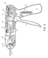
[0052] 図1は、外科用器具2の一実施形態を示す。外科用器具は、ハンドル4と、ハンドルから遠位端部20の方へ向かって遠位に延在する長尺状シャフトアセンブリ6とを含み、その遠位端部からファスナーが展開され得る。長尺状シャフトアセンブリ6は、関節不動作(すなわち、真っ直ぐな)位置と、1つ以上の関節動作(すなわち、湾曲した又は曲げられた)位置との間で可動な関節式部分8を含む。関節式部分8の関節動作は、関節制御部10によって制御され得、この制御部は、例えば、ハンドル4に対して1つ以上の位置間で動かされて、関節式部分8を関節不動作形態と1つ以上の関節動作形態との間で動かし得る、回転自在及び/又は軸方向に変位自在なノブ、ハンドル、レバー、又は他の特徴である。外科用器具2はまたファスナーを展開するためにファスナー展開システムを作動させるためのトリガ12を含むが、他のタイプの動作を行うための他の適切なタイプの作動システムも考えられる。
[0052] FIG. 1 shows an embodiment of a surgical instrument 2. As shown in FIG. The surgical instrument includes a handle 4 and an elongated shaft assembly 6 extending distally from the handle toward a
[0053] 長尺状シャフトアセンブリの関節式部分8は、関節制御部10を使用して、少なくとも関節動作解除(すなわち真っ直ぐな)位置などの第1位置と、十分な関節動作位置などの第2位置との間で動かされ得る。実施形態に依存して、関節式部分8は、1つ以上の事前選択した関節動作角度へ動かされ得るか、又は関節式部分8は、1つ以上の任意の(すなわち事前選択されていない)関節動作角度へ調整され得る。関節式部分8は、少なくとも第1方向に関節動作され得るが、関節式部分が少なくとも第2方向に関節動作する実施形態も想定される。例えば、関節式部分8は、約0°を上回る関節動作角度に対応する第1方向、及び約0°未満の関節動作角度に対応する、対向する第2方向に関節動作され得る。上記の代わりに、又はそれに加えて、関節式部分8は、2つの異なる軸の周りで関節動作され(例えば水平方向及び垂直方向における関節動作)、少なくとも2つの方向で関節動作するようにし得る。
[0053] The articulating portion 8 of the elongate shaft assembly is positioned using the
[0054] いくつかの実施形態では、長尺状シャフトアセンブリ6を回転させて、遠位先端の位置決めを容易にすることが望ましいかもしれない。例えば、長尺状シャフトアセンブリ6は、単に、ハンドル4の少なくとも一部分に対して回転自在となるように適合され得る。或いは、長尺状シャフトアセンブリ6を含むハンドル4の一部分は、グリップを含む部分など、ハンドル4の別の部分に対して回転自在とし得る。1つのそのような実施形態を図1に示す。図示の実施形態では、外科用器具2は、第1ハンドル部分14及び第2ハンドル部分16を含み、第2ハンドル部分から長尺状シャフトアセンブリ6が延在する。第1及び第2ハンドル部分14及び16は、任意の適切な方法で、互いに対して回転自在であるように構成及び配置され得る。外科用器具は、第1ハンドル部分14に対する第2ハンドル部分16の回転を選択的に許容し且つ防止するように可動である回転ロック18を含み得る。回転自在な長尺状シャフトアセンブリ6又はハンドル4を含む外科用器具を図面に示しているが、本開示はこの方法に限定されないため、ユニタリーのハンドル及び/又はハンドルに対して静止している長尺状シャフトアセンブリ6を含む外科用器具も可能であることを理解すべきである。
[0054] In some embodiments, it may be desirable to rotate the elongate shaft assembly 6 to facilitate distal tip positioning. For example, elongate shaft assembly 6 may simply be adapted to be rotatable relative to at least a portion of handle 4 . Alternatively, the portion of handle 4 that includes elongated shaft assembly 6 may be rotatable relative to another portion of handle 4, such as the portion that includes the grip. One such embodiment is shown in FIG. In the illustrated embodiment, the surgical instrument 2 includes a
[0055] いくつかの適用例では、長尺状シャフトアセンブリの関節式部分8から遠位に位置する遠位の剛直な直線部分20を含むことが好都合とし得る。剛直な直線部分20は、長尺状シャフトアセンブリ6の遠位端部からのファスナーの展開を支援するためのいくつもの特徴を含み得る。例えば、遠位の剛直な直線部分20は、外科用器具の作動前、最遠位のファスナーをファスナー展開位置に保持するために、タブなどのファスナー保持要素を含み得る。さらに、理論に束縛されるものではないが、ファスナー展開システムのドライブシャフトがファスナーに力を加えると、力は長尺状シャフトアセンブリの関節動作部分の周囲を通るために、ファスナーのヘッドにドライブシャフトによって加えられる力は、関連のファスナーの展開方向と完全に位置合わせされてはいない可能性がある。例えば、最遠位のファスナーは、ドライブシャフトの遠位端部に対して遠位に位置してもよく、及びそれに応じて、ファスナーは、ドライブシャフトの遠位端部を含む長尺状シャフトアセンブリの部分よりも大きい角度の向きにされている長尺状シャフトアセンブリの部分内に位置してもよい。従って、ドライブシャフトがファスナーに力を加えるとき(例えば、ドライブシャフトの往復運動によって)、ファスナーに加えられた力は、ファスナーの長手方向軸とミスアライメントされ得る。
[0055] In some applications, it may be advantageous to include a distal rigid
[0056] 上記を考慮して、ファスナーに適応する十分な長さの長尺状シャフトアセンブリの直線部分を提供し且つファスナー展開方向と同じ方向にファスナー展開システムからそのファスナーへ作動力を加えることを許容するために、遠位の剛直な直線部分20を含むことが望ましいとし得る。理論に束縛されるものではないが、これは、外科用器具からファスナーを展開するために必要とされる作動力の低減を生じ得る。いくつかの実施形態では、遠位の剛直な直線部分の長さは、ドライブシャフトの遠位端部が展開方向において位置合わせされ得るように、ファスナーの長さ以上とし得る。例えば、図3に示すように、遠位の剛直な直線部分20は、ファスナー202の長さよりも長い。このようにして、最遠位のファスナー及びドライブシャフトの遠位端部の双方が、遠位の剛直な直線部分に収容されて、ドライブシャフトからの展開力とファスナーの向きの位置合わせを支援し得る。遠位の剛直な直線部分20を含む外科用器具2を本明細書で説明し且つ図面に示したが、関節式部分8が長尺状シャフトアセンブリ6の遠位端部までずっと延在して、外科用器具が遠位の剛直な直線部分を含まないようにする実施形態が想定されることも理解すべきである。
[0056] In view of the above, it is desirable to provide a straight portion of the elongated shaft assembly of sufficient length to accommodate the fastener and to apply an actuation force from the fastener deployment system to the fastener in the same direction as the fastener deployment direction. It may be desirable to include a distal rigid
[0057] 図2は、ハンドル4内に設けられ得る様々な構成要素及びシステムを示す、図1の外科用器具の概略的な側面図を示す。図示の通り、トリガ12は、ファスナーを展開するためのトリガの作動に続いて、トリガを作動解除位置の方へ戻るように駆り立てる復元力を提供し得る戻しばね22に結合され得る。トリガは、ファスナーを長尺状シャフトアセンブリ6の遠位端部から展開するためにトリガ12を作動すると、ファスナーに展開力を加えるように構成及び配置された駆動システム24に結合され得る。さらに、いくつかの実施形態では、外科用器具は、トリガに加えられる力が閾値力を超えるまで、駆動システム24の起動を選択的に防止し得る作動ロックアウトシステム26を含み得る。具体的な駆動システム及び作動ロックアウトシステムを図面に示すが、本開示は、任意の特定の駆動システム及び/又は作動ロックアウトシステムを含む外科用器具に限定されないことを理解すべきである。例えば、カム、リンク機構、ギヤ、クラッチ、及び他の適切な構成要素の任意の適切な構成配置が、駆動システムの一部として任意の適切な組み合わせで使用され得る。
[0057] FIG. 2 depicts a schematic side view of the surgical instrument of FIG. As shown, the
[0058] いくつかの実施形態では、外科用器具は、長尺状シャフトアセンブリ6内に複数のファスナーを含み得、及びファスナーは、トリガ12が続けて作動されると、連続的に展開され得る。いくつかのそのような実施形態では、まだ展開されていない長尺状シャフトアセンブリ内に残っているファスナーの数を監視することが望ましいかもしれない。それゆえ、外科用器具2は、展開に利用可能なファスナーの数を表示するように構成及び配置されるファスナーレベルインジケータシステム28を含み得る。例えば、ファスナーレベルインジケータシステム28は、トリガ12に結合され得、トリガが作動すると(及びファスナーが展開すると)、ファスナーレベルインジケータシステムが、対応するインジケータを動かして、残っているファスナーの数が1だけ減少されたことを表示し得る(例えば、以下でさらに詳述する図21~23参照)。しかしながら、本開示はこの点に関して限定されないため、残りのファスナーの数を監視するための他のシステムも使用され得ること、及びいくつかの実施形態では、外科用器具は、ファスナーレベル監視システム含まなくてもよいことを理解すべきである。
[0058] In some embodiments, the surgical instrument may include multiple fasteners within the elongate shaft assembly 6, and the fasteners may be deployed sequentially as the
[0059] 上記に加えて、図2は、いくつかの実施形態による関節制御システム100を示す。下記でより詳細に説明するように、関節制御システムは、関節制御部10及び長尺状シャフトアセンブリ6の1つ以上のシャフトに結合されて、関節制御部10の動きによって、1つ以上のシャフト、又は長尺状シャフトアセンブリの他の構成要素に好適な関節動作力を加えて、少なくとも関節動作解除位置と関節動作位置との間で長尺状シャフトアセンブリの関節式部分8を選択的に動かす。
[0059] In addition to the above, Figure 2 illustrates a
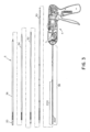
[0060] 図3は、ハンドル4から遠位に延在する外科用器具2の長尺状シャフトアセンブリ6の分解図を示す。長尺状シャフトアセンブリはドライブシャフト30を含み、ドライブシャフトは、好適な駆動システム(上述の駆動システム24など)によって駆動されて、遠位に向ける力をファスナーに加えて、長尺状シャフトアセンブリの遠位端部からファスナーを展開させ得る。長尺状シャフトアセンブリは、さらに、内側の、関節動作するシャフトとし得る第1関節動作シャフト32、外側の、関節動作するシャフトとし得る第2関節動作シャフト34、及びロッキングシャフト36の形態の関節動作ロックを含む。下記でより詳細に説明するように、第1及び第2関節動作シャフトは、長尺状シャフトアセンブリに関節動作力を加えて、関節式部分8を関節不動作位置と1つ以上の関節動作位置との間で動かすように構成及び配置される。
[0060] FIG. 3 shows an exploded view of elongate shaft assembly 6 of surgical instrument 2 extending distally from handle 4. As shown in FIG. The elongated shaft assembly includes a
[0061] 図3に示すように、長尺状シャフトアセンブリの様々なシャフトが、互いに対して同軸方向に配置され得る。例えば、図示の実施形態では、ファスナーキャリア及びフォロアアセンブリ38がドライブシャフトに収容され、ドライブシャフトは、第1及び第2関節動作シャフト32、34及びロッキングシャフト36に収容されている。シャフトの特定の構成配置を図面に示すが、他の構成配置も好適とし得ることを理解すべきである。例えば、一実施形態では、ロッキングシャフト36は、第1及び第2関節動作シャフト32、34内に位置し得る。それゆえ、本開示は、長尺状シャフトアセンブリを含むシャフトのいずれの具体的な構成配置にも限定されない。
[0061] As shown in FIG. 3, the various shafts of the elongated shaft assembly may be coaxially arranged with respect to each other. For example, in the illustrated embodiment, the fastener carrier and
[0062] いくつかの実施形態では、ファスナーキャリア及びフォロアアセンブリ38は、長尺状シャフトアセンブリ内に設けられる。例えば、ファスナーのスタック200は、ファスナーキャリア上に摺動自在に配置され得る。フォロアは、ファスナースタック200に対して近位に位置してもよく、及びスタックの1つ以上の外科用ファスナーに、遠位方向の力を加えて、ファスナーのスタックを遠位方向に駆り立て得る。適切なタイプのフォロアは、限定されるものではないが、圧縮バネ、ラチェット・ポール機構、ウォーキングビームアセンブリ、及び/又はファスナーのスタックを装置の遠位端部の方へ向かって遠位方向に動かすことができる任意の他の適切なタイプの機構を含む。
[0062] In some embodiments, the fastener carrier and
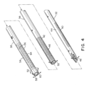
[0063] 図4は、第1関節動作シャフト32、第2関節動作シャフト34、及びロッキングシャフト36の分解斜視図を示す。これらのシャフトのそれぞれは、長尺状シャフトアセンブリの関節式部分8に位置する可撓性部分を含み得る。図示の通り、可撓性部分は、関節式部分にあるシャフトの長さに沿って延在する1つ以上の背骨状部分を画成する複数の切れ目を含む。特に、第1関節動作シャフト32は、第1複数の切れ目40を含み、第1複数の切れ目は、第1関節動作シャフトの円周を部分的に横断方向に延在し、且つシャフトの長さに沿って互いに離間して、第1関節動作シャフトの可撓性部分の長さに沿って延在する第1背骨状部分44を画成する。同様に、第2関節動作シャフト34は、第2複数の切れ目42を含み、第2複数の切れ目は、第2関節動作シャフトの円周を部分的に横断方向に延在し、且つシャフトの長さに沿って互いに離間して、第2背骨状部分46を画成する。切れ目40、42及び背骨状部分44、46は、背骨状部分が延在する方向に対して垂直な方向に向けられた第1及び第2関節動作シャフト32及び34に対して、それぞれの優先的な曲げ方向を規定し得る。例えば、第1関節動作シャフト32は、好ましい曲げ方向48を有し、及び第2関節動作シャフト34は、好ましい曲げ方向50を有する。図示の実施形態では、曲げ方向48及び50は平行であるが、第1及び第2背骨状部分44、46は、長尺状シャフトアセンブリの互いに対向する側に位置する。下記でより詳細に説明するように、そのような形態は、第1及び第2関節動作シャフトが、互いに反対の緊張状態及び圧縮状態に置かれるときに、第1及び第2関節動作シャフトを同じ方向に曲げさせ得る。
[0063] FIG. 4 shows an exploded perspective view of the
[0064] 特定の実施形態に依存して、第1及び第2関節動作シャフトは、任意の好適な構造を含んで、所望の優先的な曲げ方向を提供し得る。例えば、上述の通り、第1及び第2関節動作シャフトは、互いに対向して位置決めされた背骨状部分を含み、第1及び第2関節動作シャフトに対して、平行な優先的な曲げ方向を規定し得る。いくつかの実施形態では、第1及び第2背骨状部分は、長尺状シャフトアセンブリの長手方向軸に対して平行とし得るが、他の形態も考えられる。例えば、第1及び第2背骨状部分は、第1及び第2関節動作シャフトの対向する側の周りをそれぞれらせん状に延在し得る。それゆえ、第1及び第2背骨状部分は、任意の好適な方法で配置され得ることを理解すべきである。 [0064] Depending on the particular embodiment, the first and second articulation shafts may include any suitable structure to provide the desired preferential bending directions. For example, as described above, the first and second articulation shafts include spines positioned opposite each other to define parallel preferred bending directions for the first and second articulation shafts. can. In some embodiments, the first and second spine-like portions may be parallel to the longitudinal axis of the elongate shaft assembly, although other configurations are contemplated. For example, the first and second spine-like portions may extend spirally around opposite sides of the first and second articulation shafts, respectively. It should therefore be appreciated that the first and second spine-like portions may be arranged in any suitable manner.
[0065] 関節動作シャフトの切れ目及び背骨状部分に加えて、ロッキングシャフト36は、2組の切れ目54を含み、それらは、ロッキングシャフトの長さの少なくとも一部分に沿って及び可撓性部分の長さに沿って延在する、対向する背骨状部分56を画成し得る。このようにして、切れ目54及び背骨状部分56は、対向する背骨状部分間を通過する平面に対して垂直な優先的な曲げ方向58並びに対向する背骨状部分間に延在する方向における曲げ抵抗方向60を規定する。いくつかの実施形態では、ロッキングシャフト36は、長尺状シャフトアセンブリの長手方向軸の周りの方向52において、並びに第1及び第2関節動作シャフト32、34に対して、回転自在である。例えば、ロッキングシャフトは、ロッキングシャフトの優先的な曲げ方向58が第1及び第2関節動作シャフトの優先的な曲げ方向48、50と位置合わせされるロック解除位置へと回転され、長尺状シャフトアセンブリ6の関節式部分8の関節動作を許容し得る。同様に、ロッキングシャフトは、ロック位置へと回転されて、そこでは、曲げ抵抗方向60が、関節動作シャフトの優先的な曲げ方向と位置合わせされて、関節動作を抑制又は防止し得る。さらに、第1及び第2関節動作シャフトの背骨状部分と同様に、背骨状部分56は、ロッキングシャフトに任意の好適な方法で、例えば、長尺状シャフトアセンブリの長手方向軸に対して平行に、長手方向軸に対して角度をなして、ロッキングシャフトの対向する側の周りをらせん状に、などで配置され得る。
[0065] In addition to the cuts and spine of the articulation shaft, the locking
[0066] 第1及び第2関節動作シャフトに対して回転自在であるロッキングシャフトの形態の関節動作ロックを含む、いくつかの考えられる実施形態を本明細書で説明するが、関節動作ロックに関する他の構成配置が考えられる。例えば、関節動作ロックはロッキングシャフトを含み得、関節動作ロックは、関節動作シャフトに対して軸方向に可動であり、ロッキングシャフトをロック形態とロック解除形態との間で動かすようにする。ロッキングシャフトは可撓性部分を含み得、及び軸方向の動きは、ロッキングシャフトの可撓性部分を長尺状シャフトアセンブリの関節式部分と選択的に位置合わせするか又は重ねて、関節動作を許容し得る。可撓性部分が関節式部分と位置合わせされていないとき、ロッキングシャフトは、関節式部分の関節動作を抑制し得る。それゆえ、本開示は、関節動作ロックに関する任意の特定の構造に限定されず、長尺状シャフトアセンブリの関節動作を選択的に許容し且つ防止することを理解すべきである。 [0066] Although several possible embodiments are described herein, including an articulation lock in the form of a locking shaft that is rotatable relative to the first and second articulation shafts, other can be considered. For example, the articulation lock may include a locking shaft, the articulation lock axially movable relative to the articulation shaft to move the locking shaft between a locked configuration and an unlocked configuration. The locking shaft may include a flexible portion, and axial movement selectively aligns or overlaps the flexible portion of the locking shaft with the articulating portion of the elongate shaft assembly to effect articulation. acceptable. The locking shaft may inhibit articulation of the articulating portion when the flexible portion is out of alignment with the articulating portion. Therefore, it should be understood that the present disclosure is not limited to any particular construction for the articulation lock, which selectively allows and prevents articulation of the elongate shaft assembly.
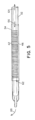
[0067] 図5に示すように、第1及び第2関節動作シャフト32及び34は、長尺状シャフトアセンブリの関節式部分から遠位に位置する取付点62において、互いに取り付けられ得る。この取り付けによって、取付点において第1及び第2関節動作シャフトを互いに軸方向に固定し得る。図示の実施形態では、取付点は、第2関節動作シャフト34の遠位端部に位置するが、他の形態も好適とし得る。例えば、第2関節動作シャフトは取付点を越えて延在して、取付点が、第2関節動作シャフトの遠位端部から離間されるようにし得る。さらに、第1及び第2関節動作シャフトは、任意の好適な方法で、接着剤、1つ以上のファスナー、1つ以上のピン、1つ以上の溶接、及び/又は任意の他の適切な接続形態などで取り付けられ得ることを理解すべきである。
[0067] As shown in Figure 5, the first and second articulating
[0068] 遠位に位置する取付点62での第1及び第2関節動作シャフト32、34の取り付けに起因して、第1及び第2シャフトの対応する近位部分に対して軸方向力及び/又は変位を加えることによって、第1及び第2シャフトを緊張及び/又は圧縮状態に置き得る。例えば、第1関節動作シャフト32の近位部分に加えられた、近位方向の力及び変位64は、第1関節動作シャフトに引張応力を生じ得る。同様に、対応する遠位方向の力及び変位を、第2関節動作シャフト34の近位部分に加えることによって、第2関節動作シャフトに圧縮応力を生じ得る。これらの反対方向の引張応力及び圧縮応力は、双方とも長尺状シャフトアセンブリ全体の中立曲げ軸からオフセットされている第1及び第2関節動作シャフトの対向する背骨状部分44及び46を通して伝えられる。これにより、関節動作シャフトに曲げモーメントを生じ、これにより、関節動作シャフトを方向68に沿って曲げて、長尺状シャフトアセンブリを関節動作位置の方へ動かす。下記でより詳細に説明するように、近位及び遠位方向の力及び変位は、任意の好適な関節制御システムを介して、第1及び第2シャフトにそれぞれ加えられ得ることを理解すべきである。
[0068] Due to the attachment of the first and
[0069] 長尺状シャフトアセンブリを関節動作位置の方へ動かすために、第1及び第2関節動作シャフトに力及び/又は変位を加える特定の構成配置を図面に示し且つ上述したが、他の構成配置も好適とし得る。例えば、いくつかの実施形態では、長尺状シャフトアセンブリを関節動作させることは、遠位方向の力及び/又は変位を、第1関節動作シャフト32の近位部分に加えること、及び近位方向の力及び/又は変位を、第2関節動作シャフト34の近位部分に加えることを含み得、これにより、長尺状シャフトアセンブリを、図5に示すものとは反対方向に関節動作させる。或いは、ある実施形態では、第1及び第2関節動作シャフトは、湾曲した(例えば、関節動作形態に対応する方向に沿って)静止形状(すなわち、応力が加えられていないとき)を備える長尺状シャフトアセンブリを形成し得、並びに第1及び第2関節動作シャフトは、互いに反対の緊張状態及び圧縮状態に置かれて、長尺状シャフトアセンブリを関節不動作(すなわち、真っ直ぐな)形態へ動かし得る。それゆえ、本開示の関節動作シャフトアセンブリは、それらの関節動作方向、及び/又は圧縮及び/又は緊張状態に置かれるときの最終的な形態に関して、限定されないことを理解すべきである。
[0069] While certain arrangements for applying force and/or displacement to the first and second articulating shafts to move the elongate shaft assembly toward the articulated position have been shown in the drawings and described above, other Arrangements may also be preferred. For example, in some embodiments, articulating the elongate shaft assembly applies a force and/or displacement in the distal direction to the proximal portion of the
[0070] 関節式長尺状シャフトアセンブリの構成に関するいくつかの考えられる実施形態を本明細書で説明するが、本開示は、説明の実施形態にのみ限定されるわけではないことを理解すべきである。例えば、長尺状シャフトアセンブリの関節式部分は、任意の適切な方法で、所望の方向に関節動作をもたらすように構成及び配置され得る。さらに、対向する背骨状部分を備える、関節動作シャフトを使用する具体的なタイプの関節動作機構を説明するが、長尺状シャフトアセンブリを関節動作させる他の機構が好適としてもよい。例えば、長尺状シャフトアセンブリの関節式部分は:関節式部分に関連付けられる、1つ以上の制御ワイヤー、リボン、又はスラット;車軸関節に関連付けられる、プレストレス部材及び伸縮自在なシース、剛直リンク機構;又は関節式部分を関節動作させることができる任意の他の適切な構造を使用して関節動作され得る。 [0070] Although several possible embodiments of articulating elongate shaft assembly configurations are described herein, it should be understood that the present disclosure is not limited to only the illustrated embodiments. is. For example, the articulating portion of the elongate shaft assembly may be constructed and arranged to provide articulation in a desired direction in any suitable manner. Furthermore, although a specific type of articulation mechanism using an articulation shaft with opposing spines is described, other mechanisms for articulating an elongate shaft assembly may be suitable. For example, the articulating portion of the elongated shaft assembly may include: one or more control wires, ribbons, or slats associated with the articulating portion; prestressing members and telescoping sheaths associated with the axle joints; rigid linkages; or articulated using any other suitable structure capable of articulating an articulating portion.
[0071] 上述の通り、外科用器具は、長尺状シャフトアセンブリの関節式部分を関節不動作位置と関節動作位置との間で選択的に動かすために関節制御部を含み得る。特定の実施形態に依存して、関節制御部は、任意の好適な構造を介して、長尺状シャフトアセンブリの関節動作シャフトに結合されて、関節動作を制御し得る。図6~14を参照して、関節制御システム100の実施形態をより詳細に説明する。
[0071] As described above, the surgical instrument may include an articulation control for selectively moving the articulating portion of the elongate shaft assembly between the non-articulating position and the articulating position. Depending on the particular embodiment, the articulation control may be coupled via any suitable structure to the articulation shaft of the elongate shaft assembly to control articulation. An embodiment of the
[0072] 図6は、関節不動作(真っ直ぐな)形態にある長尺状シャフトアセンブリに対応し得る第1位置にある関節動作システム100の概略的な側面図である。関節動作システムは、関節制御部10に結合される関節動作カム102を含み、関節制御部10の動きによって、関節動作カム102の関連の動きを引き起こすようにする。図示の実施形態では、関節制御部の回転運動によって、例えば、外科用器具の回転自在なハンドル部分16を含むハンドルの関連部分に対して関節動作カムを回転させる。回転を示したが、本開示は回転自在な関節動作カムに限定されないため、例えば、関節制御部と関節動作カムの並進運動を含む他のタイプの動きも想定されることを理解すべきである。
[0072] Figure 6 is a schematic side view of the
[0073] 図示の実施形態では、関節動作カム102は、カムの回転軸の対向する側に位置し得る第1及び第2カムプロファイル104及び106を含む。カムプロファイルは、第1及び第2関節動作ピン108及び110をそれぞれ収容するように構成及び配置され得る。第1及び第2関節動作ピンは、第1及び第2関節動作シャフトのそれぞれの近位部分に結合され得、カムプロファイル内での関節動作ピンの動きによって、関節動作シャフトの近位部分を変位させる。例えば、下記でより詳細に説明するように、カムプロファイル104及び106のそれぞれは、関節動作カム102の回転軸から異なる半径方向距離に位置する1つ以上のプロファイル部分を含み得る。従って、関節動作カムの回転は、ピンを、異なる半径方向距離に位置するプロファイル部分間で動かして、関節動作シャフトの関連の近位部分を変位させ得る。カムプロファイルに結合された関節動作ピンを含む実施形態を本明細書で説明するが、本開示はこの点に関して限定されないため、関節動作シャフトを関節動作カムに結合する他の構造も好適とし得ることを理解すべきである。
[0073] In the illustrated embodiment, the articulating
[0074] 関節動作シャフトアセンブリの関節動作の制御に加えて、関節制御システム100はまた、関連のロッキングシャフト36をロック位置とロック解除位置との間で動かして、長尺状シャフトアセンブリの関節動作を選択的に抑制するか又は許容するために使用され得る。図示の実施形態では、関節動作カム102は、ロッキングカム112に結合され、これは、同様に、ギヤ114を介してロッキングシャフト36に結合される。下記でより詳細に説明するように、関節動作カムの動き(例えば、回転運動)は、対応して、ロッキングカムを変位させ得、これにより、ギヤ114を回転させ得る。その後、ギヤ114の回転によってロッキングシャフト36を回転させて、上述の通り、ロッキングシャフトをロック形態とロック解除形態との間で動かし得る。
[0074] In addition to controlling the articulation of the articulating shaft assemblies, the
[0075] いくつかの実施形態では、関節制御システムが、長尺状シャフトアセンブリを関節不動作位置又は1つ以上の関節動作位置に維持するのを支援するために1つ以上の特徴を含むことが望ましいかもしれない。例えば、1つ以上のディテント機構又は他の適切なロック形態が、関節制御システムの望まれていない動きを及び/又は関節動作位置の方へ向かう又はそこから離れる長尺状シャフトアセンブリの望まれていない動きを回避するのに役立ち得る。図示の実施形態では、関節制御システムは、関節動作カム102から延出する弾性アームに対応する第1及び第2カムロック116及び118を含み得る。対応する特徴、例えば凹部120及び122が、回転自在なハンドル部分16の内表面に設けられており、且つカムロック116、118の凹部120、122との係合が、ディテント機構の機能を果たして、関節動作カム102を所望の向きに維持し得る。例えば、図6に示すように、第1カムロック116と凹部120との係合によって、関節制御システムを第1位置に維持して、長尺状シャフトアセンブリを関節不動作位置に維持する。同様に、図12に示すように、第2カムロック118と第2凹部122との係合が、長尺状シャフトアセンブリを十分な関節動作位置に維持するのを支援し得る。関節制御部の動きが望まれるとき、弾性アームは変形して、カムロックを対応する凹部から係合解除し得る。
[0075] In some embodiments, the articulation control system includes one or more features to assist in maintaining the elongate shaft assembly in a non-articulating position or one or more articulating positions. may be desirable. For example, one or more detent mechanisms or other suitable locking features may prevent unwanted movement of the articulation control system and/or desired movement of the elongate shaft assembly toward or away from the articulating position. It can help avoid no movement. In the illustrated embodiment, the articulation control system may include first and second cam locks 116 and 118 corresponding to resilient arms extending from
[0076] 長尺状シャフトアセンブリに関する関節不動作位置及び十分な関節動作位置に対応する、2つのカムロック及び2つの関連の凹部を含む実施形態を説明したが、関節制御システムは、任意の好適な数及び/又はタイプのカムロックを含み得ることを理解すべきである。例えば、いくつかの実施形態では、1つ以上の追加的なカムロック及び凹部を設けて、関節制御システムを、1つ以上の中間位置に、すなわち長尺状シャフトアセンブリが部分的に関節動作された位置に対応し得る位置に、維持し得る。他の実施形態では、関節制御システムは、カムロックを全く含まなくてもよい。例えば、関節制御システムの様々な構成要素間の摩擦係合は、関節制御部を所望の位置に維持するのに十分とし得るか、又は関節制御システムは、関節制御部10へのユーザ入力によって所望の位置に保持され得る。
[0076] Although embodiments have been described that include two cam locks and two associated recesses corresponding to the non-articulation position and the full articulation position for the elongate shaft assembly, the articulation control system can be any suitable It should be understood that the number and/or types of cam locks may be included. For example, in some embodiments, one or more additional cam locks and recesses are provided to move the articulation control system to one or more intermediate positions, i.e., when the elongate shaft assembly is partially articulated. It can be maintained in a position that can correspond to the position. In other embodiments, the joint control system may not include cam locks at all. For example, frictional engagement between the various components of the joint control system may be sufficient to maintain the joint control in a desired position, or the joint control system may be controlled by user input to the
[0077] 上述の通り、いくつかの実施形態では、関節制御システムが、第1及び第2関節動作シャフトの近位部分に、互いに反対方向の変位を適用することが望ましいかもしれない。例えば、そのような反対方向の変位は、第1及び第2関節動作シャフトを互いに反対の緊張状態及び/又は圧縮状態に置き(例えば、遠位に位置する取付点において軸方向に固定されているシャフトに起因して)、これにより、外科用器具の関節式部分が関節動作する間の、長尺状シャフトアセンブリの遠位先端の動きを減少させ得る。それゆえ、関節動作カムの様々なカムプロファイルが、下記で説明するように、関節動作シャフトの近位部分にこの所望の動きをもたらすような形状にされ得る。 [0077] As noted above, in some embodiments it may be desirable for the articulation control system to apply displacements to the proximal portions of the first and second articulation shafts in opposite directions. For example, such opposing displacement places the first and second articulation shafts in opposing tension and/or compression (e.g., axially fixed at a distally located attachment point). shaft), this may reduce movement of the distal tip of the elongate shaft assembly during articulation of the articulating portion of the surgical instrument. Therefore, various cam profiles of the articulation cam can be shaped to provide this desired motion for the proximal portion of the articulation shaft, as described below.
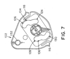
[0078] 例えば、図7は、関節制御システム100の関節動作カム102の概略的な側面図を示す。図示の通り、第1カムプロファイル104は、第1プロファイル部分124及び第2プロファイル部分126を含む。同様に、第2カムプロファイル106は、第3プロファイル部分128及び第4プロファイル部分130を含む。第1及び第3プロファイル部分は、湾曲した経路を辿り、この経路は、関節動作カムの回転軸から一定の半径方向距離にあるとし得る。いくつかの実施形態では、第1及び第3プロファイル部分は、回転軸から一定の第1半径方向距離に位置し得る。対応して、第2及び第4プロファイル部分は、対応する第1及び第3プロファイル部分の半径方向距離とは異なる半径方向距離に位置する湾曲した経路を辿る。例えば、第2及び第4プロファイル部分は、回転軸からより長い第2半径方向距離まで延在し得る。このようにして、第1及び第2関節動作シャフトの近位部分に関連する第1及び第2関節動作ピン108及び110(図7には示さず)が、第1及び第2カムプロファイル104及び106内でそれぞれ動かされるとき、関節動作ピンは、関節動作カムの回転軸に対して変位される。関節動作ピン及び関節動作シャフトは、軸方向に動くように制約されているため、これは、回転の方向に依存して、関節動作カムの回転軸の方へ向かう及び/又はそこから離れるピン及びシャフトの軸方向変位を生じる。
[0078] For example, FIG. 7 shows a schematic side view of the
[0079] 関節動作カムが、複数のプロファイル部分を備えるカムプロファイルを含む実施形態が、本明細書で説明されるが、本開示はこのように限定されないこと、及びカムプロファイルは、任意の好適な形態を有して、カムプロファイルが、反対方向における、関節動作シャフトの近位部分の所望の動きを生じるようにし得ることを理解すべきである。 [0079] Although embodiments are described herein in which the articulating cam includes a cam profile comprising multiple profile portions, the disclosure is not so limited, and the cam profile can be any suitable It should be appreciated that the cam profile may be configured to produce desired movement of the proximal portion of the articulation shaft in opposite directions.
[0080] 図示の実施形態では、第1及び第2カムプロファイル104及び106は、関節動作カム102の回転軸の周りで対称的に配置される。それゆえ、関節動作カムが回転すると、第1及び第2関節動作ピン108及び110、及び関連の関節動作シャフト32及び34は、反対方向に変位される(図11~14を参照)。さらに、第1及び第2カムプロファイル104及び106の様々な部分は、関節動作カム102の回転軸から同じ半径方向距離に位置し得、これにより、第1及び第2関節動作ピン108及び110、並びに関連の関節動作シャフト32及び34を、反対方向に等しい大きさだけ変位させる。
[0080] In the illustrated embodiment, the first and second cam profiles 104 and 106 are arranged symmetrically about the axis of rotation of the articulating
[0081] カムプロファイルの特定の構成配置を示したが、他の形態が好適とし得ることを理解すべきである。例えば、カムプロファイルは、カムの回転軸の周りに対称的に配置されていなくてもよい。そのような実施形態では、第1プロファイル部分124、第2プロファイル部分126、第3プロファイル部分128、及び第4プロファイル部分130は、それぞれ、関節動作カム102の回転軸から異なる半径方向距離に離間され得る。他の実施形態では、カムプロファイルの一方又は双方は、単一のプロファイル部分のみを有し、そこでは、回転軸からのプロファイル部分の間隔は、プロファイルの長さに沿って変化し得るか、又は本開示はそのように限定されないため、カムプロファイルは3つ以上のプロファイル部分を有してもよい。さらに、特定の実施形態に依存して、第1及び第2カムプロファイルの第1、第2、第3、及び/又は第4経路部分は、関節動作カムの回転軸からそれぞれ一定の半径方向距離に位置しても、又は半径方向距離は、一定でなく、及びそれぞれの経路部分内で変化してもよい。
[0081] While a particular arrangement of cam profiles has been shown, it should be understood that other forms may be suitable. For example, the cam profile may not be arranged symmetrically around the axis of rotation of the cam. In such embodiments,
[0082] 図8に最もよく示すように、関節動作カムは、外科用器具の様々な他の構成要素に適応するように構成及び配置され得る。例えば、関節動作カムは、伝動システム又はファスナー展開システムの構成要素へ収納させるために、装置の近位部分から長尺状シャフトアセンブリの遠位端部の方へ延在する1つ以上のチャンネル、開口部、又は他の特徴を含み得る。図示の実施形態では、関節動作カム102は、交差片136で互いに取り付けられる一対の端部片134を含み、これらは、関節動作カムを通って延在するチャンネル138を画成する。端部片のそれぞれは、同一のカムプロファイル104及び106を含み得る。さらに、関節動作カムは、端部片から延在する回転シャフト140を含み得、この回転シャフトは、関節制御部10、例えばハンドルを関節動作カムに取り付けるキー状結合部142を含み得る。しかしながら、本開示はそのように限定されないため、限定するものではないが、溶接、ファスナー、スナップフィット、接着剤、及び/又は他の適切な取付方法を含む、関節制御部をカムに取り付ける他の形態も考えられる。
[0082] As best shown in FIG. 8, the articulating cam may be constructed and arranged to accommodate various other components of the surgical instrument. For example, the articulation cam may include one or more channels extending from the proximal portion of the device toward the distal end of the elongated shaft assembly for inclusion in a component of a transmission system or fastener deployment system; It may include openings or other features. In the illustrated embodiment, the articulating
[0083] いくつかの実施形態では、関節動作カムは、例えば、好適な成形法又はキャスティング法によって、単一のモノリシック構成要素として形成され得る。しかしながら、関節動作カムが別々の要素から形成される実施形態も考えられる。例えば、本開示はそのように限定されないため、様々な構成要素、例えば端部片及び交差片は、別々に形成され、且つ溶接、ファスナー、スナップフィット、接着剤、及び/又は他の適切な取付方法によって互いに取りけられてもよい。 [0083] In some embodiments, the articulating cam may be formed as a single monolithic component, for example, by suitable molding or casting methods. However, embodiments are also conceivable in which the articulating cam is formed from separate elements. For example, the various components, such as end pieces and cross-pieces, may be separately formed and welded, fasteners, snap-fits, adhesives, and/or other suitable attachments may be used, as the present disclosure is not so limited. They may be attached to each other by methods.
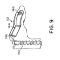
[0084] 図9は、図6に示すように、関節動作カム102及びロッキングシャフト36に結合され得るロッキングカム112の概略的な側面図を示す。ロッキングカムは、対応する関節動作カム102の貫通孔132(図7~8参照)に受け入れられるロッキングピン152(図10参照)を受け入れるように構成及び配置されたロッキングカムプロファイル144を含む。それゆえ、ロッキングピン152は、関節動作カム102が回転されるとき、関節動作カムの回転軸から一定の半径方向距離で回転する。ロッキングカム112は、所望の方向、例えば長尺状シャフトアセンブリの長手方向軸を横断する方向に動くように制約されて、関節動作ロックをロック解除形態に動かし得る。さらに、ロッキングカムプロファイル144は第5プロファイル部分146を含み得、第5プロファイル部分は、第5プロファイル部分内でのロッキングピンの回転運動によって、ロッキングカムが所望の方向に動いて、ロッキングカムを、ロック形態にあるロッキングシャフト36に対応し得る第1位置から、ロック解除形態にあるロッキングシャフトに対応する第2位置へ変位させるように、構成及び配置されている(図6及び図12参照)。例えば、図示の実施形態では、第5プロファイル部分は線形であるが、他の形態が好適としてもよい。
[0084] FIG. 9 depicts a schematic side view of a
[0085] ロッキングカム112のロッキングカムプロファイル144は、さらに、第6プロファイル部分内でのロッキングピン152の動きによって、ロッキングカムの変位を全く引き起こさないように構成及び配置され得る第6プロファイル部分148を含み得る。例えば、第6プロファイル部分は湾曲形態を有して、ロッキングカム112が第2位置へ動かされると、第6プロファイル部分148が、関節動作カム102の回転軸から、回転軸からのロッキングピンの距離に対応する一定の半径方向距離に位置するようにし得る。このようにして、関節動作カムの動きの第1部分は、ロッキングカムの動きを引き起こし得るが、ロッキングカムは、関節動作カムの動きの第2部分の間、静止したままとし得る。
[0085] The
[0086] ロッキングカムプロファイル144に加えて、ロッキングカム112は、長尺状シャフトアセンブリのロッキングシャフト36に結合され得るギヤ114に係合するように構成及び配置されるラック150を含み得る。ラックは、ロッキングカムの動きの方向に平行な方向に延在し得る。このようにして、第1位置と第2位置との間でのロッキングカムの変位は、ギヤ及びロッキングシャフトの対応する回転を引き起こして、前述の通り、ロッキングシャフトをロック形態とロック解除形態との間で動かし得る。
[0086] In addition to the
[0087] 図10は、関節制御システム100の概略的な分解図であり、及びどのように関節制御システムの様々な構成要素が互いに結合され得るかを示す。図面に示すように、第1関節動作ピン108は、第1関節動作シャフト32の近位部分及び/又は端部及び第1ピンに接続される第1シャトル154を介して、第1関節動作シャフトの近位部分及び/又は端部に結合され、並びに第2関節動作ピン110は、第2関節動作シャフト34の近位部分及び/又は端部及び第2ピンに接続される第2シャトル156を介して、第2関節動作シャフトの近位部分及び/又は端部に結合される。第1及び第2シャトルは、関節動作カム102のチャンネル138内に収容されて、関節動作ピンの対向する端部が、シャトルから、関節動作カムの両側に位置する第1及び第2カムプロファイル104及び106内へと延出する。さらに、関節動作カムのロッキングピン152の端部は、関節動作カムから、及びいくつかの実施形態ではそこを通って、延出して、ロッキングピンがロッキングカム112のロッキングカムプロファイル144に収容されて、関節動作カムをロッキングカムに結合するようにし得る。
[0087] Figure 10 is a schematic exploded view of the
[0088] 図6及び図11~図14は、関節制御システム100の動作の様々な態様を示す。上述の通り、図6は、関節不動作位置にある長尺状シャフトアセンブリ、及びロック形態にあるロッキングシャフトに対応する第1位置にある関節制御システム100を示す。図11は、第1位置にある関節制御システムの斜視図を示すが、明瞭にするために、関節動作カム102は図11には示していない。図示の通り、関節制御部が第1位置にあるとき、第1及び第2シャトル154及び156は互いに隣接した位置にあってもよく、及びロッキングピン152は、ロッキングカムプロファイル144の第1端部に収容される。さらに、ロッキングカムが第1位置にあるとき、ロッキングカムラック150の上部が、ギヤ114と係合され得る。
[0088] FIGS. 6 and 11-14 illustrate various aspects of the operation of the
[0089] 図12~図13は、第2位置及び第3位置にそれぞれある関節制御システムの概略的な側面図を示す。例えば、第2位置は、ロック解除形態へと回転されているが、長尺状シャフトアセンブリの関節動作前であるため、長尺状シャフトアセンブリは依然として関節不動作位置にあるロッキングシャフト36に対応する中間形態とし得る。図面に示すように、関節動作カムは、図6に示す形態と比べて回転されており、第5経路部分146の最後部分への(及び第6経路部分148の最初部分への)ロッキングカムプロファイル144内でのロッキングピン152の動きを生じる。上述の通り、第5経路部分内でのロッキングピンの動きは、ロッキングカム112を第1位置(図6に示す)から、図12に示す第2位置へ変位させ得る。ロッキングカムのこの動きにより、ロッキングカムラック150を変位させ、これにより、ギヤ114及び関連のロッキングシャフト36を方向160(図14)に回転させる。図示の実施形態では、ロッキングカムの変位は、長尺状シャフトアセンブリの長手方向軸を横断する方向158(図14)であるが、本開示はこの点に関して限定されないため、他の動きの方向及び/又は動きのタイプ(例えば回転運動)も好適とし得る。
[0089] Figures 12-13 show schematic side views of the joint control system in the second and third positions, respectively. For example, the second position corresponds to the locking
[0090] 図12にも示すように、関節制御システム100が第2形態にあるとき、第1及び第2関節動作ピン108及び112は、第1及び第2カムプロファイル104及び106の第1及び第3経路部分124及び128内でそれぞれ動かされる。しかしながら、いくつかの実施形態では、第1及び第3経路部分は、関節動作カムの回転軸から一定の半径方向距離に位置する。それゆえ、関節動作ピン、及び対応して、長尺状シャフトアセンブリ6は、関節制御システムが図6に示す第1位置から図12に示す第2位置まで動く間、ハンドルに対して静止したままである。このようにして、関節制御システムが第1位置から第2位置まで動くことによって、ロッキングシャフト36をロック形態からロック解除形態へ動かし得るが、関節動作シャフトに全く力を加えない及び/又はそれを変位させず、関節不動作形態に留まらせる。
[0090] As also shown in FIG. 12, when the
[0091] 図13及び図14は、ロッキングシャフト36がロック解除形態にあり、及び長尺状シャフトアセンブリが十分に関節動作されている第3位置にある関節制御システム100を示す。図13に示すように、関節動作カム102は、さらに、図12に示す第2位置に対して回転されている。この回転によって、第1及び第2関節動作ピン108及び110を第1及び第2カムプロファイル104及び106内で第2及び第4プロファイル部分126及び130へとそれぞれ動かす。第2及び第4プロファイル部分は、第1及び第3プロファイル部分と比べて関節動作カム102の回転軸から異なる半径方向距離に位置するため、第1及び第2関節動作ピン108及び110は、関節動作カムの回転軸から離れるか又はそこへ向かうかのいずれかの反対方向に変位される。特に、図14に示すように、第2及び第4プロファイル部分は、第1及び第3プロファイル部分と比べて関節動作カムの回転軸からより長い半径方向距離に位置する。それゆえ、下記で説明するように軸方向にのみ動くように制約され得る第1及び第2関節動作ピン108及び110は、対向する軸方向に変位される。具体的には、第1関節動作ピン108は近位方向162に変位され、及び第2関節動作ピンは遠位方向164に変位される。いくつかの実施形態では、第1及び第2カムプロファイル104及び106は、第1及び第2関節動作ピン108及び110の変位を引き起こすように配置され得、この変位は、大きさが等しく、上述の通り、長尺状シャフトアセンブリの遠位先端の動きの回避を支援し得る。しかしながら、他の実施形態では、本開示はこの点に関して限定されないため、変位は、大きさが等しくなくてもよい。
[0091] Figures 13 and 14 show the
[0092] 第1及び第2関節動作ピン108及び110は、それぞれ第1及び第2シャトル154及び156を介して、第1及び第2関節動作シャフト32及び34の近位部分及び/又は端部に結合されるため、関節動作ピンの変位は、関節動作シャフトの近位端部の関連の変位を引き起こす。特に、第1関節動作シャフト32の近位端部は、方向162に沿って近位に変位され、及び第2関節動作シャフト34の近位端部は、方向164に沿って遠位に変位される(図14参照)。さらに、遠位に位置する取付点62(図5参照)での第1及び第2シャフトの取り付けに起因して、第1及び第2関節動作シャフトの互いに反対方向の変位によって、シャフトを、それぞれ反対の緊張状態及び圧縮状態に置く。上述の通り、これらの引張状態及び圧縮状態によって、関節動作シャフトに曲げモーメントを生じ、これにより、長尺状シャフトアセンブリを関節動作位置の方へ関節動作させる。
[0092] First and second articulation pins 108 and 110 are coupled to proximal portions and/or ends of first and
[0093] 第2及び第4経路部分126及び130内での関節動作ピン108及び110の動きに加えて、関節制御部100が第2位置(図12)から第3位置へ動かされるとき、ロッキングピン152は第6経路部分148内で動かされる(図13参照)。しかしながら、図9に関連して上述した通り、ロック解除形態にあるロッキングシャフトに対応し得る、ロッキングカムが第2位置にあるとき、ロッキングカムの第6プロファイル部分148は、関節動作カム102の回転軸から一定の半径方向距離に位置し得る。それゆえ、第6経路部分内でのロッキングピンの動きは、ロッキングカムのさらなる動きを全く、又はロッキングシャフトの関連の動き(例えば、回転)を全く引き起こさないかもしれない。このようにして、ロッキングシャフトはロック解除位置に留まる一方で、関節制御部は、第2位置と第3位置との間で動かされて、長尺状シャフトアセンブリを関節動作させる。
[0093] In addition to the movement of the articulation pins 108 and 110 within the second and
[0094] 対応するカムプロファイルに受け入れられる様々なピンを含む関節制御システムを、上記で説明し、且つ図面に示したが、他の形態も考えられる。例えば、関節動作カムは、関節動作シャフト及び/又はロッキングシャフトの対応する面と係合する、好適な形状にされた係合面を含み得、1つ又は複数のシャフトの所望の動きを生じる。さらに、回転自在な関節動作カムを上記で説明したが、本開示は、関節動作を制御するために関節動作カムが回転される外科用器具に限定されないため、関節動作カムの他のタイプの動きが好適としてもよい。例えば、いくつかの実施形態では、関節制御部の動きによって、外科用器具のハンドルに対して関節動作カムを変位させ得、及び関節動作は、関節動作シャフトの近位部分の所望の変位を引き起こすために、好適な形状にされたカミング構造を含み得る。 [0094] While articulation control systems including various pins received in corresponding cam profiles have been described above and shown in the drawings, other configurations are also possible. For example, an articulation cam may include suitably shaped engagement surfaces that engage corresponding surfaces of an articulation shaft and/or a locking shaft to produce a desired movement of one or more shafts. Additionally, although a rotatable articulation cam has been described above, other types of motion of the articulation cam are not limited to surgical instruments in which the articulation cam is rotated to control articulation. may be preferred. For example, in some embodiments, movement of the articulation control may displace the articulation cam relative to the handle of the surgical instrument, and the articulation causes the desired displacement of the proximal portion of the articulation shaft. To that end, it may include a suitably shaped camming structure.
[0095] さらに、関節制御システムは、本明細書で説明する具体的な関節動作及びロッキングシステムに限定されないため、長尺状シャフトアセンブリの関節動作及び関節動作ロックの動きの双方を制御する、本明細書で説明する関節制御システムは、任意の好適な関節動作システム及び/又はロッキングシステムと一緒に使用され得ることを理解すべきである。例えば、関節動作及び関節動作ロック複合制御システムは、弾性的に付勢されたシステム、可撓管及び/又はシャフト、1つ以上の可撓性部材によって1つ以上の方向に付勢された連結セグメント、又は緊張状態に置かれたケーブルなどを含む関節動作システムと一緒に使用され得る。 [0095] Further, the articulation control system is not limited to the specific articulation and locking systems described herein, and thus the present invention controls both the articulation of the elongate shaft assembly and the movement of the articulation lock. It should be understood that the articulation control system described herein may be used with any suitable articulation and/or locking system. For example, articulation and articulation locking combined control systems include elastically biased systems, flexible tubes and/or shafts, couplings biased in one or more directions by one or more flexible members. It can be used with articulation systems that include segments, or cables placed in tension, or the like.
[0096] ここで図15を参照して、図6~図14に関連して上記で説明した関節制御システム100及び関節動作ロックの一実施形態の動作をより詳細に説明する。特に、図15は、関節制御部10の位置に応じた、長尺状シャフトアセンブリの近位直線部分に対する、ロッキングシャフト36の角度位置並びに長尺状シャフトアセンブリ6の関節式部分の関節動作角度の概略的なプロットである。例えば、位置Aは、図6に示すように、関節制御システムの第1位置、すなわち、ロッキングシャフトがロック形態にあり、及び長尺状シャフトアセンブリが関節不動作形態にある関節動作解除位置に対応し得る。対応して、位置Bは、長尺状シャフトアセンブリがロック解除されており、長尺状シャフトアセンブリが関節動作する直前の、図12に示す関節制御システムの第2位置に対応し得る。位置Cは、ひとたび装置が十分に関節動作された、図13に示す関節制御システムの第3位置に対応し得る。
[0096] Referring now to Figure 15, the operation of one embodiment of the
[0097] 図15に示すように、関節制御部が位置Aから位置Bへ動かされるとき、ロッキングシャフトは、ロック形態からロック解除形態へ動く。例えば、図6~14に関連して上記で説明した実施形態では、ロッキングシャフトの動きは回転運動とし得る。特に、位置Aにおけるロック形態は0°の回転に対応し得、ロッキングシャフトの曲げ抵抗方向が、関節動作シャフトの優先的な曲げ方向と位置合わせされて、長尺状シャフトアセンブリの関節動作を防止するようにする。関節制御部を位置Aから位置Bの方へ動かすことによって、上述の通り、ロッキングシャフトを、関節動作シャフトに対して回転させる。この回転は、ロッキングシャフトの優先的な曲げ方向の1つ以上と関節動作シャフトを位置合わせして、ロッキングシャフト及び長尺状シャフトアセンブリをロック解除形態に置き得る。この回転は、任意の適切な角度に対応し得るが、いくつかの実施形態では、位置Bにおけるロック解除形態は、位置Aのロック形態に対して90°回転されているロッキングシャフトに対応し得る。 [0097] As shown in Figure 15, when the articulation control is moved from position A to position B, the locking shaft moves from the locked configuration to the unlocked configuration. For example, in the embodiments described above with respect to Figures 6-14, the movement of the locking shaft may be rotational. In particular, the locked configuration at position A may correspond to 0° rotation, with the bending resistance direction of the locking shaft aligned with the preferred bending direction of the articulation shaft to prevent articulation of the elongate shaft assembly. make sure to Moving the articulation control from position A toward position B rotates the locking shaft relative to the articulation shaft, as described above. This rotation may align the articulation shaft with one or more of the locking shaft's preferred bending directions to place the locking shaft and elongate shaft assembly in an unlocked configuration. This rotation may correspond to any suitable angle, but in some embodiments the unlocked configuration in position B may correspond to the locking shaft being rotated 90° relative to the locked configuration in position A. .
[0098] 関節制御部が位置Aから位置Bへ動く間、ロッキングシャフトはロック位置からロック解除位置へ動かされるが、長尺状シャフトアセンブリは関節動作せず、関節不動作位置に留まる。具体的には、関節動作角度は、0°の関節動作角度に対応し得る角度θ関節不動作に留まる。実施形態に依存して、これは、カムの動きのタイプに依存して、上述したもののような関節動作シャフトに関連付けられる1つ以上の好適な形状にされたカムプロファイルを介して達成され得、これらカムプロファイルは、回転軸から一定の半径方向距離、すなわち関節動作カムの並進軸に対して一定の直線距離に位置する少なくとも1つの経路部分を含む。それゆえ、関節制御部が位置Aから位置Bへ動かされるとき、ピン、それゆえ関連の関節動作シャフトは、動かされない。 [0098] While the articulation control moves from position A to position B, the locking shaft is moved from the locked position to the unlocked position, but the elongate shaft assembly does not articulate and remains in the non-articulated position. Specifically, the articulation angle remains at the angle θ joint inaction, which may correspond to an articulation angle of 0°. Depending on the embodiment, this may be accomplished through one or more suitably shaped cam profiles associated with an articulating shaft such as those described above, depending on the type of cam motion, These cam profiles include at least one path portion located at a constant radial distance from the axis of rotation, ie, a constant linear distance with respect to the translation axis of the articulating cam. Therefore, when the articulation control is moved from position A to position B, the pin, and hence the associated articulation shaft, is not moved.
[0099] 関節制御部が位置Bから位置Cへ動かされるとき、ロッキングシャフトは、ロック解除形態で静止したままとし得る。例えば、図6~図14に関連して上記で説明した実施形態では、関節制御ハンドルを位置Bから位置Cへ動かすことは、ロッキングカムの第6経路部分内でのロッキングピンの動きに対応し得る。上述の通り、ロッキングカムのこの部分は、ロッキングカムが第2位置にあるとき、関節動作カムの回転軸から一定の半径方向距離に位置し得る。その結果、この経路部分内でロッキングピンを動かすことは、ロッキングカムの関連の動きを全く引き起こさないかもしれず、及びロッキングシャフトをロック位置に留めることができるとし得る。 [0099] When the articulation control is moved from position B to position C, the locking shaft may remain stationary in the unlocked configuration. For example, in the embodiments described above with respect to FIGS. 6-14, moving the articulation control handle from position B to position C corresponds to movement of the locking pin within the sixth path portion of the locking cam. obtain. As mentioned above, this portion of the locking cam may be located at a constant radial distance from the axis of rotation of the articulation cam when the locking cam is in the second position. As a result, moving the locking pin within this path portion may cause no associated movement of the locking cam and may allow the locking shaft to remain in the locked position.
[00100] 上記に加えて、関節制御部を位置Bから位置Cへ動かすことによって、長尺状シャフトアセンブリをθ関節不動作から、いくつかの実施形態では、十分な関節動作位置へ動かされている長尺状シャフトアセンブリに対応し得る角度θ関節動作へ関節動作させ得る。具体的な関節動作角度は、上述のような任意の適切な角度に対応し得る。いくつかの実施形態では、図6~14に関連して上記で説明したもののように、長尺状シャフトアセンブリのこの関節動作は、第1及び第3経路部分と比較して関節動作カムの回転軸からより長い半径方向距離で離間される関節動作カムのそれぞれの第2及び第4経路部分内での関節動作ピンの動きによって、引き起こされ得る。従って、関節動作ピン、並びに第1及び第2関節動作シャフトの関連の近位部分は、互いに反対方向に変位されて、関節動作シャフトを互いに反対の緊張状態及び圧縮状態に置き、それにより曲げモーメントを生じて、長尺状シャフトアセンブリを関節動作位置へ動かす。しかしながら、上述の通り、他の関節動作機構が好適としてもよく、及び対応して、関節制御部を位置Bから位置Cへ動かすことによって、長尺状シャフトアセンブリに任意の好適な方法を引き起こし得る。 [00100] In addition to the above, moving the articulation control from position B to position C moves the elongate shaft assembly from theta non-articulation to, in some embodiments, a full articulation position. articulation to an angle .theta. articulation that may correspond to the elongated shaft assembly. A specific articulation angle may correspond to any suitable angle as described above. In some embodiments, this articulation of the elongate shaft assembly, such as those described above with respect to FIGS. It may be caused by movement of the articulation pin within respective second and fourth path portions of the articulation cam spaced a greater radial distance from the axis. Accordingly, the articulation pins and associated proximal portions of the first and second articulation shafts are displaced in opposite directions to place the articulation shafts in opposite tension and compression, thereby creating a bending moment. to move the elongate shaft assembly to the articulated position. However, as noted above, other articulation mechanisms may be suitable, and correspondingly moving the articulation control from position B to position C may cause the elongate shaft assembly to move in any suitable manner. .
[00101] 関節動作角度θ関節動作を、ロック解除位置にあるロッキングシャフトに対応する角度(例えば、90°)よりも大きさが小さいとして図15に示すが、他の構成配置も想定される。例えば、いくつかの実施形態では、長尺状シャフトアセンブリの関節動作角度は、ロッキングシャフトをロック形態からロック解除形態へ動かすために必要な回転角度よりも大きいとし得る。さらに、ロッキングシャフトの回転及び長尺状シャフトアセンブリの関節動作を、関節制御部の動きによって線形に変化するとして示すが、いくつかの実施形態では、応答は、任意の好適な機能形態を有してもよく、線形でなくてもよい。上記に加えて、図15では、ロッキングシャフトの動きと長尺状シャフトアセンブリの関節動作は重なり合わないが、他の構成配置が好適としてもよい。例えば、いくつかの実施形態では、本開示はそのように限定されないため、長尺状シャフトアセンブリは、ロッキングシャフトが十分にロック解除された形態になる前に、関節動作を開始してもよい。 [00101] Although the articulation angle θ articulation is shown in FIG. 15 as being less in magnitude than the angle corresponding to the locking shaft in the unlocked position (eg, 90°), other configurations are envisioned. For example, in some embodiments, the articulation angle of the elongate shaft assembly may be greater than the angle of rotation required to move the locking shaft from the locked configuration to the unlocked configuration. Further, although the rotation of the locking shaft and the articulation of the elongated shaft assembly are shown as varying linearly with movement of the articulation control, in some embodiments the response may have any suitable functional form. may be linear, and may not be linear. In addition to the above, although in FIG. 15 the locking shaft motion and the articulation motion of the elongate shaft assembly are not superimposed, other configurations may be suitable. For example, in some embodiments, the elongated shaft assembly may initiate articulation before the locking shaft is fully in the unlocked configuration, as the present disclosure is not so limited.
[00102] ここで図16~図18を参照して、ロッキングシャフト36並びに第1及び第2関節動作シャフト32及び34の様々な態様がより詳細に説明されている。
[00102] Referring now to Figures 16-18, various aspects of the locking
[00103] 図16は、ロッキングシャフト36の遠位部分の概略的な側面図を示す。ロッキングシャフトは、ロッキングシャフトの対向する側に位置する一対の背骨状部分56を含み(図16では1つの背骨状部分のみを示す)、及び背骨状部分は、ロッキングシャフトの可撓性部分70の長さに沿って延在する。背骨状部分56は、ロッキングシャフト36の連続部分に対応し、及び軸方向力をそれらの長さに沿って、ロッキングシャフトの隣接する部分へ伝えることができるとし得る。上述の通り、背骨状部分は、可撓性部分70内でロッキングシャフトの対向する側に形成された複数の切れ目54によって画成され得る。例えば、切れ目は、ロッキングシャフト36の円周に部分的に延在し得、及び背骨状部分を切り目の対向する両組間に位置させた状態で、可撓性部分70の長さに沿って軸方向に離間され得る。背骨状部分56及び切れ目54は相互作用して、複数の一体丁番74によって一緒に接合された複数の可撓性セグメント72を形成し得る。隣接する可撓性セグメント72は、介在する一体丁番74の周りで互いに旋回し得る。可撓性セグメントのこの相対的な旋回は、可撓性部分70内のロッキングシャフトに可撓性を与え得る。さらに、一体丁番74の回転軸の周りでの優先的な曲げ方向58を規定するのは、背骨状部分56及び切れ目54の向きである。理論に束縛されるものではないが、一体丁番74は、一体丁番の回転軸の周りでの一体丁番74の旋回に対応する以外の方向における曲げ抵抗を高くし得る。それゆえ、一体丁番74が剛性を高める方向は、曲げ抵抗方向(図4参照)に対応するとみなされ得る。図示の実施形態では、曲げ抵抗方向60(図4)は、優先的な曲げ方向58に対して垂直及びロッキングシャフト36の一体丁番74の回転軸に対して平行である方向に対応し得る。
[00103] FIG. 16 shows a schematic side view of the distal portion of locking
[00104] 図17は、図18に示す第2関節動作シャフト34と同軸方向に配置されるときに内側の関節動作シャフトとし得る、第1関節動作シャフト32の遠位端部の概略的な側面図を示す。上述の通り、第1関節動作シャフトは、第1関節動作シャフトの可撓性部分80の長さに沿って延在する背骨状部分44を含む。上記と同様に、背骨状部分44は、第1関節動作シャフト32の連続部分に対応し、及び軸方向力をその長さに沿って、第1関節動作シャフトの隣接する部分へ伝達できるとし得るが、ロッキングシャフト36とは異なり、第1関節動作シャフトは、単一の背骨状部分44しか有さない。さらに、背骨状部分は、可撓性部分80内の第1関節動作シャフトの円周の一部分に形成された複数の切れ目40によって画成され得、及び切れ目は、可撓性部分80の長さに沿って軸方向に離間され得る。上記と同様に、背骨状部分44及び切れ目40は相互作用して、複数の一体丁番84によって接合された複数の可撓性セグメント82を形成し得る。隣接する可撓性セグメント82は、介在する一体丁番84の周りで互いに対して旋回し得る。理論に束縛されるものではないが、一体丁番84は、一体丁番の回転軸の周りでの一体丁番74の旋回に対応する以外の方向における曲げ抵抗を高める。可撓性セグメントのこの相対的な旋回は、可撓性部分80内の第1関節動作シャフト32に可撓性を与える。さらに、背骨状部分44及び切れ目40の向きが、第1関節動作シャフト32の一体丁番84の回転軸に対して平行な優先的な曲げ方向48を規定する。
[00104] FIG. 17 is a schematic side view of the distal end of the
[00105] さらに、第1関節動作シャフト32は、第1関節動作シャフトの遠位端部に、タブ76などの1つ以上のファスナー保持特徴を含み得る。理論に束縛されるものではないが、そのようなタブは、外科用器具からファスナーを展開する前又は展開する間、1つ以上のファスナーを所望の位置に維持するのを支援し得る。
[00105] Additionally, the
[00106] 図17と同様に、図18は、第1関節動作シャフト32と同軸方向に配置されたときに外側の関節動作シャフトとし得る、第2関節動作シャフト34の遠位端部の概略的な側面図を示す。上記と同様に、第2関節動作シャフトは、第2関節動作シャフトの可撓性部分90の長さに沿って背骨状部分46を含み、及び背骨状部分44は、軸方向力をその長さに沿って、第2関節動作シャフトの隣接する部分に伝達できるとし得る第2関節動作シャフト34の連続部分に対応する。背骨状部分は、可撓性部分90内の第2関節動作シャフトの円周の一部分に形成された複数の切れ目42によって画成され得、及び切れ目は、可撓性部分90の長さに沿って軸方向に離間され得る。上記と同様に、背骨状部分46及び切れ目42は相互作用して、複数の一体丁番94によって一緒に接合された複数の可撓性セグメント92を形成し得る。隣接する可撓性セグメント92は、介在する一体丁番94の周りで互いに対して旋回し得る。可撓性セグメントのこの相対的な旋回は、可撓性部分90内で第2関節動作シャフト34に可撓性を与える。さらに、背骨状部分46及び切れ目42の向きは、一体丁番94の回転軸に対して平行な優先的な曲げ方向50を規定する。
[00106] Similar to FIG. 17, FIG. shows a side view. Similar to above, the second articulation shaft includes a
[00107] 第1関節動作シャフト32及び第2関節動作シャフト34が組み立てられると(例えば、図4~図5に示すように互いに対して同軸方向に配置される)、第2関節動作シャフトは、図18に示す構成配置に対して180度回転されて、第2関節動作シャフトの背骨状部分46が、長尺状シャフトアセンブリの、第1関節動作シャフト32の背骨状部分44に対向する側に位置するようにし得る。本発明者らは、長尺状シャフトアセンブリの対向する側に背骨状部分を位置させることによって、長尺状シャフトアセンブリの剛性を高め得ることを認識した。前述の通り、そのように剛性を高めることは、例えば、ファスナーを組織内へ展開するための外科用器具の作動中の、長尺状シャフトアセンブリの望まれていない撓み又は動きを回避するために、好都合とし得る。
[00107] When the
[00108] 図17及び図18に示すように、第1及び第2関節動作シャフト32及び34の背骨状部分44及び46はそれぞれ、テーパ付き形態を有し得る。例えば、第1関節動作シャフトの背骨状部分44では、背骨状部分の遠位端部は、背骨状部分44の近位端部の第2幅d2よりも狭い第1幅d1を有し得る。いくつかの実施形態では、第1幅d1は約1.5mm~約2.2mmとし得、及び第2幅d2は約3.5mm~約4.0mmとし得る。同様に、第2関節動作シャフトの第2背骨状部分46では、背骨状部分の遠位端部は、背骨状部分46の近位端部の第4幅d4よりも狭い第3幅d3を有し得る。いくつかの実施形態では、第3幅d3は約2.6mm~約3.0mmとし得、及び第4幅d4は約4.3mm~約4.8mmとし得る。特定の実施形態に依存して、第1及び第2関節動作シャフトの様々な切れ目は、関節動作シャフトの円周に約240度~約300度で延在して、テーパ付き背骨状部分の形態を画成し得る。しかしながら、切れ目、背骨状部分、及び他の特徴に関して、具体的な寸法の範囲を本明細書で与えるが、本開示はそのように限定されないため、本明細書で開示したよりも大きい及び小さいの双方の他の範囲が使用され得ることに留意すべきである。
[00108] As shown in Figures 17 and 18, the
[00109] 理論に束縛されるものではないが、背骨状部分に関するそのようなテーパ付き形態は、その遠位端部における可撓性部分80及び90の可撓性を高め得るが、近位端部の方へ向かって剛直性を徐々に高める。このようにして、テーパ付き背骨状部分は、関節動作シャフトの全体的な剛直性を高め得る一方、依然として、長尺状シャフトアセンブリの関節動作を許容するように十分に可撓性である。さらに、いくつかの実施形態では、テーパ付き背骨状部分は、一定幅の背骨状部分の形態と比較して、背骨状部分の長さに沿って、より均一な剛直性を提供し得る。特に、テーパ付き背骨状部分の、その近位部分における幅の増加は、遠位先端に近い箇所と比べてより大きな曲げモーメントを受ける長尺状シャフトアセンブリに沿った箇所に対応し得る(例えば、遠位先端からより離れた箇所における、より大きなモーメントアームに起因して)。対応して、これらの近位の箇所においてテーパ付き背骨状部分の剛直性を高めることは、より大きな曲げモーメントを少なくとも部分的にオフセットさせ得るため、長尺状シャフトアセンブリの長さに沿って、より均一な曲げ剛直性をもたらし得る。
[00109] While not wishing to be bound by theory, such a tapered configuration for the spine may increase the flexibility of
[00110] 特定の実施形態に依存して、関節動作シャフト及び/又はロッキングシャフトの様々な切れ目、背骨状部分、及び可撓性セグメントは、長尺状シャフトアセンブリに所望の剛直性及び/又は可撓性をもたらすように選択された寸法を有し得る。例えば、第1及び/又は第2関節動作シャフトは、約3.5mm~約5.5mmの直径、及び約0.13mm~約0.30mmの肉厚を有し得、及びロッキングシャフトは、約5.5mm~6.4mmの直径、及び約0.07mm~約0.15mmの肉厚を有し得る。例示的な一実施形態では、第1関節動作シャフトは、約4.8mmの直径、及び約.025mmの肉厚を有し、第2関節動作シャフトは、約5mmの直径、及び約.18mmの肉厚を有し、及びロッキングシャフトは、約5.6mmの直径、及び約0.13mmの肉厚を有する。この実施形態では、第1及び第2関節動作シャフト及びロッキングシャフトは、異なる肉厚を有するが、本開示はそのように限定されないことを理解すべきである。例えば、他の実施形態では、第1関節動作シャフトの肉厚は、第2関節動作シャフト及び/又はロッキングシャフトよりも薄くてもよく、又は関節動作シャフト及びロッキングシャフトは、ほぼ同じ肉厚を有し得る。 [00110] Depending on the particular embodiment, the various cuts, spines, and flexible segments of the articulating and/or locking shafts provide the desired stiffness and/or flexibility for the elongated shaft assembly. It may have dimensions selected to provide flexibility. For example, the first and/or second articulating shaft can have a diameter of about 3.5 mm to about 5.5 mm and a wall thickness of about 0.13 mm to about 0.30 mm, and the locking shaft can have a thickness of about It can have a diameter of 5.5 mm to 6.4 mm and a wall thickness of about 0.07 mm to about 0.15 mm. In one exemplary embodiment, the first articulation shaft has a diameter of about 4.8 mm and a diameter of about. 025 mm, the second articulation shaft has a diameter of about 5 mm and a diameter of about. It has a wall thickness of 18 mm and the locking shaft has a diameter of approximately 5.6 mm and a wall thickness of approximately 0.13 mm. In this embodiment, the first and second articulation shafts and the locking shaft have different wall thicknesses, but it should be understood that the present disclosure is not so limited. For example, in other embodiments, the wall thickness of the first articulation shaft may be thinner than the second articulation shaft and/or the locking shaft, or the articulation shaft and the locking shaft have approximately the same wall thickness. can.
[00111] さらに、いくつかの実施形態では、関節動作シャフト及びロッキングシャフト上の隣接する切れ目間の間隔は、約0.6mm~約2.2mmとし得る。例示的な一実施形態では、隣接する切れ目間の間隔は、第1及び第2関節動作シャフトでは約1mm、及びロッキングシャフトでは約1.5mmとし得る。さらに、第1関節動作シャフト、第2関節動作シャフト、及びロッキングシャフトのそれぞれは、異なる幅を有する切れ目を含み得る。例えば、例示的な一実施形態では、第1関節動作シャフトは、幅が約0.007mm~0.03mm(例えば、約0.02mm)の切れ目を有し、第2関節動作シャフトは、幅が約0.07mm~約0.18mm(例えば、約0.09mm)の切れ目を有し、及びロッキングシャフトは、幅が約0.10mm~約0.18mm(例えば、約0.14mm)の切れ目を有する。いくつかの実施形態では、ロッキングシャフト上での切れ目の幅は、長尺状シャフトアセンブリが十分な関節動作形態にあるとき、切れ目の対向する側が接触しないように、選択され得る。例えば、本発明者らは、そのような形態は、長尺状シャフトアセンブリが関節動作されるときに、ドライブシャフトの動きを許容するのを支援し得る(例えば、ファスナーを展開する間)ことを見出した。しかしながら、いくつかの実施形態では、長尺状シャフトアセンブリの所望の剛直性及び/又は可撓性をもたらすために、上述のものよりも小さい及び大きいの双方の範囲を含む切れ目の間隔及び幅の他の寸法が好適としてもよいことを理解すべきである。 [00111] Further, in some embodiments, the spacing between adjacent discontinuities on the articulation and locking shafts may be from about 0.6 mm to about 2.2 mm. In one exemplary embodiment, the spacing between adjacent cuts may be approximately 1 mm for the first and second articulation shafts and approximately 1.5 mm for the locking shaft. Additionally, each of the first articulation shaft, the second articulation shaft, and the locking shaft may include discontinuities having different widths. For example, in one exemplary embodiment, the first articulation shaft has a cut that is approximately 0.007 mm to 0.03 mm (eg, approximately 0.02 mm) wide and the second articulation shaft has a width of The locking shaft has a cut of about 0.07 mm to about 0.18 mm (eg, about 0.09 mm), and the locking shaft has a cut of about 0.10 mm to about 0.18 mm (eg, about 0.14 mm). have. In some embodiments, the width of the cut on the locking shaft may be selected such that opposing sides of the cut do not meet when the elongate shaft assembly is in a fully articulated configuration. For example, the inventors have discovered that such a configuration can help allow movement of the drive shaft when the elongate shaft assembly is articulated (eg, during fastener deployment). Found it. However, in some embodiments, the spacing and width of the cuts, including ranges both smaller and larger than those described above, may be varied to provide the desired stiffness and/or flexibility of the elongate shaft assembly. It should be understood that other dimensions may be suitable.
[00112] 実施形態に依存して、関節動作シャフト及び/又はロッキングシャフトに形成された切れ目は、長尺状シャフトアセンブリの関節式部分にあるそれぞれの各シャフトの可撓性部分の長さに沿って延在し得る。例えば、いくつかの実施形態では、各シャフトの可撓性部分の長さは、約26mm~約42mmとし得る。いくつかの実施形態では、第1及び第2関節動作シャフトは、同じ長さ又は異なる長さを有する可撓性部分を有し得る。例えば、第1関節動作シャフトは、長さが約26mm~約42mmの可撓性部分を有し得、及び第2関節動作シャフトは、長さが約26mm~約38mmの可撓性部分を有し得る。いくつかの実施形態では、第1及び第2関節動作シャフトの可撓性部分の長さは、第1シャフトの可撓性部分の長さが、第2シャフトの可撓性部分の長さ以上であるように、選択され得る。 [00112] Depending on the embodiment, the discontinuities formed in the articulation shaft and/or the locking shaft are along the length of the flexible portion of each respective shaft in the articulating portion of the elongate shaft assembly. can extend over For example, in some embodiments, the length of the flexible portion of each shaft can be from about 26mm to about 42mm. In some embodiments, the first and second articulation shafts can have flexible portions with the same length or different lengths. For example, the first articulation shaft may have a flexible portion with a length of about 26mm to about 42mm, and the second articulation shaft has a flexible portion with a length of about 26mm to about 38mm. can. In some embodiments, the length of the flexible portion of the first and second articulation shafts is such that the length of the flexible portion of the first shaft is greater than or equal to the length of the flexible portion of the second shaft. can be selected such that
[00113] 上記に加えて、いくつかの実施形態では、及び図16~18に示すように、様々なシャフトに形成された切れ目は、一体丁番と一まとめにされた応力除去部において終端し得る。応力除去部は、可撓性部分の繰り返しの曲げによる、例えば、長尺状シャフトアセンブリが関節不動作位置と関節動作位置との間で前後に動かされるときの、一体丁番の疲労及び/又は故障を回避するのを支援するような形状にされ得る。いくつかの実施形態では、応力除去部は楕円形状を有し得るが、円形などの他の形状も好適とし得る。 [00113] In addition to the above, in some embodiments, and as shown in FIGS. obtain. The stress relief may prevent living hinge fatigue and/or due to repeated bending of the flexible portion, e.g., when the elongate shaft assembly is moved back and forth between non-articulated and articulated positions. It can be shaped to help avoid failure. In some embodiments, the stress relief may have an elliptical shape, although other shapes such as circular may also be suitable.
[00114] 上記に加えて、切れ目及び背骨状部分のいくつかのパターンが、ロッキングシャフト及び関節動作シャフトの可撓性部分に関して開示されているが、切れ目及び背骨状部分の他のパターンも可能であることを理解すべきである。例えば、長尺状シャフトアセンブリの関節式部分に対応するシャフトの可撓性部分は、可撓性部分が少なくとも一方向において優先的に曲がるように、任意の適切な方法で構成及び配置され得る。さらに、線形テーパ付き背骨状部分が図示されたが、背骨状部分が非線形テーパの実施形態も考えられる。 [00114] In addition to the above, although several patterns of cuts and spines have been disclosed for the flexible portions of the locking and articulating shafts, other patterns of cuts and spines are possible. It should be understood that there is For example, the flexible portion of the shaft corresponding to the articulating portion of the elongate shaft assembly may be constructed and arranged in any suitable manner such that the flexible portion preferentially bends in at least one direction. Further, although a linearly tapered spine is illustrated, embodiments in which the spine has a non-linear taper are also contemplated.
[00115] 図19~図20は、例えば、ドライブシャフトの往復式軸方向変位によって、遠位方向の力を加えて外科用器具からファスナーを展開させるために、外科用器具において用いられ得るドライブシャフト30の一実施形態を示す。図3に示すように、ドライブシャフトは、関節動作シャフト及びロッキングシャフト内で同軸方向に配置され得るが、他の構成配置も好適とし得る。図示の実施形態では、下記でより詳細に説明するように、ドライブシャフトは、ファスナーのヘッドの対応する平面に係合するように構成及び配置され得る平坦面302を含む。平面の係合によって、長尺状シャフトアセンブリが関節動作されるときを含め、ファスナーをドライブシャフト内で所望の向きに維持し得る。さらに、ドライブシャフトは、可撓性部分310を含み得、そこでは、ドライブシャフトの円周に部分的に延在し且つドライブシャフトの互いに対向する側に位置する2つの複数の切れ目306によって、一対の背骨状部分304が画成される。切れ目は、上述のロッキングシャフトと同様に、可撓性部分の長さに沿って離間され得る。ロッキングシャフトと同様に、背骨状部分304及び切れ目306は相互作用して、複数の一体丁番312によって接合された複数の可撓性セグメント308を形成し得、及び隣接する可撓性セグメント308は、介在する一体丁番312の周りで互いに対して旋回され得る。
[00115] FIGS. 19-20 illustrate a drive shaft that may be used in a surgical instrument to apply a distal force to deploy a fastener from the surgical instrument, for example, by reciprocating axial displacement of the drive shaft. 30 shows an embodiment. As shown in FIG. 3, the drive shafts may be coaxially arranged within the articulation and locking shafts, although other configurations may be suitable. In the illustrated embodiment, the drive shaft includes a
[00116] 図19~図20に示すように、切れ目は、ドライブシャフトの長手方向軸に対して非直角の角度に配置され得る。いくつかの実施形態では、切れ目は、ドライブシャフトの周りでらせん状経路を辿るように配置され得る。理論に束縛されるものではないが、この構成配置は、ドライブシャフト30の切れ目を、関節動作シャフト32及び34にある切れ目に対してある角度に置き得、それにより、ドライブシャフト上の切れ目を関節動作シャフト上の切れ目と一緒にされる(binding)のを回避するのを支援し得る。例えば、ドライブシャフトの任意の単一の角度にされた切れ目306は、一点においてのみ、第1ロッキングシャフト32上の隣接する切れ目とのみ接触し、それにより、ファスナーが展開する間、関節動作シャフトに対してドライブシャフトが変位されるときに、切れ目が互いに一緒にされる可能性を低減する。
[00116] As shown in Figures 19-20, the discontinuities may be arranged at a non-perpendicular angle to the longitudinal axis of the drive shaft. In some embodiments, the discontinuities may be arranged to follow a helical path around the drive shaft. While not wishing to be bound by theory, this configuration may place the cuts in the
[00117] 特定の実施形態に依存して、ドライブシャフト上の切れ目の幅は約0.07mm~約0.13mmとし得、及び隣接する切れ目間の間隔は約0.8mm~約1.4mmとし得る。いくつかの実施形態では、切れ目は、ドライブシャフトの長さに沿って背骨状部分を画成し得、及び背骨状部分の幅は、約0.5mm~約1.3mmに及び得る。さらに、切れ目は、ドライブシャフトの可撓性部分に沿って延在し得、及び可撓性部分の長さは約38mm~約54mmとし得る。いくつかの実施形態では、ドライブシャフトの可撓性部分の長さは、外側の関節動作シャフトの可撓性部分の長さプラスドライブシャフトの移動距離以上とし得る。そのような形態は、長尺状シャフトアセンブリが関節動作形態にある間のドライブシャフトの摺動を許容するのを支援し得る(例えば、ファスナーを展開する間)。 [00117] Depending on the particular embodiment, the width of the cuts on the drive shaft may be from about 0.07 mm to about 0.13 mm, and the spacing between adjacent cuts may be from about 0.8 mm to about 1.4 mm. obtain. In some embodiments, the cut may define a spine along the length of the drive shaft, and the width of the spine may range from about 0.5 mm to about 1.3 mm. Additionally, the cut may extend along the flexible portion of the drive shaft, and the length of the flexible portion may be from about 38 mm to about 54 mm. In some embodiments, the length of the flexible portion of the drive shaft may be equal to or greater than the length of the flexible portion of the outer articulation shaft plus the travel distance of the drive shaft. Such a configuration can help allow the drive shaft to slide while the elongate shaft assembly is in the articulated configuration (eg, during fastener deployment).
[00118] 上記に加えて、ドライブシャフト30は、ドライブシャフトの遠位端部に、遠位方向に延在し且つ半径方向内側に向けられたタブ314などのファスナー係合特徴を含み得る。それゆえ、外科用ファスナーのトリガが作動されると、タブは、最遠位のファスナーと係合して、遠位方向の力をファスナーに加えて、ファスナーを長尺状シャフトアセンブリの遠位端部から展開する。しかしながら、本開示はそのように限定されないため、最遠位のファスナーに力を加えるための他の形態も想定される。
[00118] In addition to the above, the
[00119] ここで図21~図23を参照して、ファスナーレベルインジケータシステム28の一実施形態をより詳細に説明する。上述の通り、ファスナーレベルインジケータシステムは、外科用器具からの展開に利用可能なファスナーの数を表示するように構成及び配置され得る。例えば、図21は、窓502を含み、そこを通してインジケータを可視し得る、外科用器具の斜視的な後面図を示す。図22に示すように、ファスナーレベルインジケータシステム28は、ギヤシリンダーの形態のインジケータ504を含み得る。例えば、インジケータの上面は、窓502を通して見ることができるとし得る。インジケータは、往復動アーム506に結合され、往復動アームは、任意の好適な方法で外科用器具のトリガ12に結合され得、トリガが作動すると(及びファスナーが展開すると)、往復動アームが動かされ、インジケータを新しい位置へ回転させるようにする。例えば、新しい位置は、1つ少ないファスナーが外科用器具からの展開用に残っていることを示す。
[00119] Referring now to Figures 21-23, one embodiment of the fastener
[00120] 図22~図23に示すように、往復動アームは、インジケータ504のギヤシリンダー内に位置決めされるアクチュエータ508によってインジケータに結合され得る。ファスナーレベルインジケータシステム28の斜視的な底面図を示す図23に示すように、アクチュエータ508は、アームの端部に歯512を備える弾性アーム508を含む。歯512は、インジケータギヤシリンダー504の内部に位置する対応するギヤ歯514に係合するように構成及び配置される。このようにして、弾性アーム及び歯512及び514は、アクチュエータ508とインジケータ504との間にクラッチ型のインターフェースを形成して、アクチュエータの第1方向の回転によって、インジケータの関連の回転を生じるようにする(例えば、インジケータを新しい位置へ動かすために)一方、アクチュエータの反対方向の回転によって、弾性アーム510を内側へ撓ませて、インジケータが回転されないようにする。それゆえ、アクチュエータの第1及び第2方向の関連の回転を引き起こし得る往復式アーム506の往復運動は、インジケータの後方への動きを引き起こさない。さらに、いくつかの実施形態では、ファスナーレベルインジケータシステムは、インジケータギヤシリンダーの外側に形成された、対応する歯520に係合するように構成及び配置された歯518を含む固定アーム516を含む。歯516及び520の係合は、インジケータの後方への回転を阻止するように配置され得る。
[00120] As shown in FIGS. As shown in FIG. 23, which shows a perspective bottom view of fastener
[00121] 本教示を、様々な実施形態及び例と併せて説明したが、本教示をそのような実施形態又は例に限定することは意図していない。それどころか、当業者によって理解されるように、本教示は、様々な代替例、修正例、及び等価物を含む。それゆえ、上記の説明及び図面は、例示にすぎない。 [00121] While the present teachings have been described in conjunction with various embodiments and examples, it is not intended that the present teachings be limited to such embodiments or examples. On the contrary, the present teachings include various alternatives, modifications, and equivalents, as will be appreciated by those skilled in the art. Accordingly, the above description and drawings are exemplary only.
Claims (12)
前記ハンドルから遠位に延在する長尺状シャフトアセンブリであって、関節不動作位置と関節動作位置との間で可動である関節式部分を含む、長尺状シャフトアセンブリと、
第1ロック形態と第2ロック解除形態との間で回転するように構成された関節動作ロッキングシャフトであって、前記第1ロック形態にあるとき、前記長尺状シャフトアセンブリの前記関節式部分の関節動作を選択的に防止し、及び前記第2ロック解除形態にあるとき、前記長尺状シャフトアセンブリの前記関節式部分の関節動作を許容する、関節動作ロッキングシャフトと、
前記関節動作ロッキングシャフトに動作可能に結合された関節制御部であって、前記関節制御部は、前記長尺状シャフトアセンブリの前記関節式部分の関節動作を制御し、前記関節制御部を第1位置から第2位置へ動かすことによって、前記関節動作ロッキングシャフトを前記第1ロック形態から前記第2ロック解除形態へ動かして、前記長尺状シャフトアセンブリの前記関節式部分の関節動作を許容し、及び前記関節制御部を前記第2位置から第3位置へ動かすことによって、前記長尺状シャフトアセンブリの前記関節式部分を前記関節不動作位置から前記関節動作位置へ関節動作させる、関節制御部と、
を備える外科用器具。 a handle;
an elongate shaft assembly extending distally from the handle, the elongate shaft assembly including an articulating portion movable between a non-articulating position and an articulating position;
an articulating locking shaft configured to rotate between a first locked configuration and a second unlocked configuration, wherein when in the first locked configuration, the articulated portion of the elongate shaft assembly; an articulation locking shaft that selectively prevents articulation and permits articulation of the articulating portion of the elongate shaft assembly when in the second unlocked configuration;
An articulation control operably coupled to the articulation locking shaft , the articulation control controlling articulation of the articulating portion of the elongate shaft assembly, the articulation control Movement from a first position to a second position moves the articulating locking shaft from the first locked configuration to the second unlocked configuration to permit articulation of the articulating portion of the elongate shaft assembly. and moving the articulation control from the second position to the third position to articulate the articulating portion of the elongate shaft assembly from the non-articulating position to the articulating position. Department and
A surgical instrument comprising:
Applications Claiming Priority (3)
| Application Number | Priority Date | Filing Date | Title |
|---|---|---|---|
| US15/867,130 US11134928B2 (en) | 2018-01-10 | 2018-01-10 | Articulating surgical instruments |
| US15/867,130 | 2018-01-10 | ||
| PCT/US2019/012145 WO2019139811A1 (en) | 2018-01-10 | 2019-01-03 | Articulating surgical instruments |
Publications (3)
| Publication Number | Publication Date |
|---|---|
| JP2021510099A JP2021510099A (en) | 2021-04-15 |
| JP2021510099A5 JP2021510099A5 (en) | 2022-01-04 |
| JP7337070B2 true JP7337070B2 (en) | 2023-09-01 |
Family
ID=65411911
Family Applications (1)
| Application Number | Title | Priority Date | Filing Date |
|---|---|---|---|
| JP2020535605A Active JP7337070B2 (en) | 2018-01-10 | 2019-01-03 | articulating surgical instrument |
Country Status (8)
| Country | Link |
|---|---|
| US (1) | US11134928B2 (en) |
| EP (1) | EP3737309B1 (en) |
| JP (1) | JP7337070B2 (en) |
| CN (1) | CN111601561B (en) |
| AU (1) | AU2019206351B2 (en) |
| CA (1) | CA3087074A1 (en) |
| ES (1) | ES2927351T3 (en) |
| WO (1) | WO2019139811A1 (en) |
Families Citing this family (4)
| Publication number | Priority date | Publication date | Assignee | Title |
|---|---|---|---|---|
| NL2019175B1 (en) | 2017-07-04 | 2019-01-14 | Fortimedix Surgical B V | Steerable instrument comprising a radial spacers between coaxial cylindrical elements |
| US11103234B2 (en) | 2018-01-10 | 2021-08-31 | C.R. Bard, Inc. | Articulating surgical instruments |
| CN111214267B (en) * | 2020-01-20 | 2021-01-12 | 盈甲医疗科技(北京)有限公司 | Electric bending failure remedying device and electric anastomat thereof |
| CN113440184B (en) * | 2021-08-12 | 2022-07-26 | 吉林大学 | Manual-control flexible minimally invasive surgical instrument |
Citations (6)
| Publication number | Priority date | Publication date | Assignee | Title |
|---|---|---|---|---|
| JP2005046272A (en) | 2003-07-31 | 2005-02-24 | Olympus Corp | Treatment appliance for endoscope |
| JP2009082705A (en) | 2007-10-02 | 2009-04-23 | Tyco Healthcare Group Lp | Articulating surgical instrument |
| US20100030239A1 (en) | 2006-10-05 | 2010-02-04 | Viola Frank J | Axial Stitching Device |
| US20140276966A1 (en) | 2013-03-14 | 2014-09-18 | C.R. Bard, Inc. | Articulating surgical instruments |
| JP2016510649A (en) | 2013-03-14 | 2016-04-11 | シー・アール・バード・インコーポレーテッドC R Bard Incorporated | Surgical instrument with actuated lockout |
| US20160174976A1 (en) | 2014-12-18 | 2016-06-23 | Ethicon Endo-Surgery, Inc. | Locking arrangements for detachable shaft assemblies with articulatable surgical end effectors |
Family Cites Families (27)
| Publication number | Priority date | Publication date | Assignee | Title |
|---|---|---|---|---|
| US3802440A (en) | 1972-12-19 | 1974-04-09 | M Salem | Intubation guide |
| US5851212A (en) | 1997-06-11 | 1998-12-22 | Endius Incorporated | Surgical instrument |
| US6746422B1 (en) | 2000-08-23 | 2004-06-08 | Norborn Medical, Inc. | Steerable support system with external ribs/slots that taper |
| US6146338A (en) | 1999-04-23 | 2000-11-14 | Medtronic, Inc. | Apparatus for deflecting a catheter or lead |
| US7637903B2 (en) | 2004-02-09 | 2009-12-29 | Cryocor, Inc. | Catheter articulation segment with alternating cuts |
| US7785252B2 (en) | 2004-11-23 | 2010-08-31 | Novare Surgical Systems, Inc. | Articulating sheath for flexible instruments |
| ATE452676T1 (en) | 2005-04-07 | 2010-01-15 | Creganna Technologies Ltd | DIRECTORABLE CATHETER ASSEMBLY |
| DE602006007712D1 (en) * | 2006-10-06 | 2009-08-20 | Ethicon Endo Surgery Inc | Improvements in an applicator for attaching anastomotic rings |
| AU2007231733B2 (en) | 2006-11-28 | 2014-03-13 | Cathrx Ltd | A catheter steering system |
| ES2541117T3 (en) | 2008-03-10 | 2015-07-16 | Fortimedix Surgical B.V. | Instrument for endoscopic applications |
| GB2466180B (en) * | 2008-12-05 | 2013-07-10 | Surgical Innovations Ltd | Surgical instrument, handle for a surgical instrument and surgical instrument system |
| DE202009012796U1 (en) * | 2009-05-29 | 2009-11-26 | Aesculap Ag | Surgical instrument |
| US8132706B2 (en) | 2009-06-05 | 2012-03-13 | Tyco Healthcare Group Lp | Surgical stapling apparatus having articulation mechanism |
| EP2445568B1 (en) | 2009-06-24 | 2020-09-23 | Kalila Medical, Inc. | Steerable medical delivery devices |
| IN2012DN02987A (en) * | 2009-10-09 | 2015-07-31 | Ethicon Endo Surgery Inc | |
| US9393007B2 (en) * | 2010-06-09 | 2016-07-19 | C.R. Bard, Inc. | Instruments for delivering transfascial sutures, transfascial assemblies, and methods of transfascial suturing |
| US20120078244A1 (en) * | 2010-09-24 | 2012-03-29 | Worrell Barry C | Control features for articulating surgical device |
| US8940005B2 (en) * | 2011-08-08 | 2015-01-27 | Gyrus Ent L.L.C. | Locking flexible surgical instruments |
| US8684953B2 (en) | 2012-05-13 | 2014-04-01 | Ozca Engineering Solutions Ltd. | Steering tool |
| US9629629B2 (en) * | 2013-03-14 | 2017-04-25 | Ethicon Endo-Surgey, LLC | Control systems for surgical instruments |
| US9883860B2 (en) * | 2013-03-14 | 2018-02-06 | Ethicon Llc | Interchangeable shaft assemblies for use with a surgical instrument |
| US20150099997A1 (en) | 2013-10-03 | 2015-04-09 | Oz Cabiri | Steering tool |
| US9693774B2 (en) * | 2014-06-25 | 2017-07-04 | Ethicon Llc | Pivotable articulation joint unlocking feature for surgical stapler |
| US10178992B2 (en) * | 2015-06-18 | 2019-01-15 | Ethicon Llc | Push/pull articulation drive systems for articulatable surgical instruments |
| US11696759B2 (en) * | 2017-06-28 | 2023-07-11 | Cilag Gmbh International | Surgical stapling instruments comprising shortened staple cartridge noses |
| US10779813B2 (en) * | 2018-01-10 | 2020-09-22 | C.R. Bard, Inc. | Articulating surgical instruments |
| US11103234B2 (en) * | 2018-01-10 | 2021-08-31 | C.R. Bard, Inc. | Articulating surgical instruments |
-
2018
- 2018-01-10 US US15/867,130 patent/US11134928B2/en active Active
-
2019
- 2019-01-03 EP EP19705233.5A patent/EP3737309B1/en active Active
- 2019-01-03 CA CA3087074A patent/CA3087074A1/en active Pending
- 2019-01-03 AU AU2019206351A patent/AU2019206351B2/en active Active
- 2019-01-03 CN CN201980007677.9A patent/CN111601561B/en active Active
- 2019-01-03 WO PCT/US2019/012145 patent/WO2019139811A1/en unknown
- 2019-01-03 JP JP2020535605A patent/JP7337070B2/en active Active
- 2019-01-03 ES ES19705233T patent/ES2927351T3/en active Active
Patent Citations (6)
| Publication number | Priority date | Publication date | Assignee | Title |
|---|---|---|---|---|
| JP2005046272A (en) | 2003-07-31 | 2005-02-24 | Olympus Corp | Treatment appliance for endoscope |
| US20100030239A1 (en) | 2006-10-05 | 2010-02-04 | Viola Frank J | Axial Stitching Device |
| JP2009082705A (en) | 2007-10-02 | 2009-04-23 | Tyco Healthcare Group Lp | Articulating surgical instrument |
| US20140276966A1 (en) | 2013-03-14 | 2014-09-18 | C.R. Bard, Inc. | Articulating surgical instruments |
| JP2016510649A (en) | 2013-03-14 | 2016-04-11 | シー・アール・バード・インコーポレーテッドC R Bard Incorporated | Surgical instrument with actuated lockout |
| US20160174976A1 (en) | 2014-12-18 | 2016-06-23 | Ethicon Endo-Surgery, Inc. | Locking arrangements for detachable shaft assemblies with articulatable surgical end effectors |
Also Published As
| Publication number | Publication date |
|---|---|
| WO2019139811A1 (en) | 2019-07-18 |
| US11134928B2 (en) | 2021-10-05 |
| JP2021510099A (en) | 2021-04-15 |
| CN111601561B (en) | 2024-02-02 |
| EP3737309B1 (en) | 2022-06-29 |
| CN111601561A (en) | 2020-08-28 |
| ES2927351T3 (en) | 2022-11-04 |
| EP3737309A1 (en) | 2020-11-18 |
| US20190209147A1 (en) | 2019-07-11 |
| WO2019139811A8 (en) | 2019-08-15 |
| AU2019206351A1 (en) | 2020-07-23 |
| AU2019206351B2 (en) | 2024-04-04 |
| CA3087074A1 (en) | 2019-07-18 |
Similar Documents
| Publication | Publication Date | Title |
|---|---|---|
| JP7337070B2 (en) | articulating surgical instrument | |
| US20220338864A1 (en) | Articulating surgical instruments | |
| US11944289B2 (en) | Articulating surgical instruments | |
| AU2019206371B2 (en) | Surgical fasteners for articulating surgical instruments |
Legal Events
| Date | Code | Title | Description |
|---|---|---|---|
| A521 | Request for written amendment filed |
Free format text: JAPANESE INTERMEDIATE CODE: A523 Effective date: 20211118 |
|
| A621 | Written request for application examination |
Free format text: JAPANESE INTERMEDIATE CODE: A621 Effective date: 20211118 |
|
| A977 | Report on retrieval |
Free format text: JAPANESE INTERMEDIATE CODE: A971007 Effective date: 20221125 |
|
| A131 | Notification of reasons for refusal |
Free format text: JAPANESE INTERMEDIATE CODE: A131 Effective date: 20221128 |
|
| A521 | Request for written amendment filed |
Free format text: JAPANESE INTERMEDIATE CODE: A523 Effective date: 20230227 |
|
| A131 | Notification of reasons for refusal |
Free format text: JAPANESE INTERMEDIATE CODE: A131 Effective date: 20230412 |
|
| A521 | Request for written amendment filed |
Free format text: JAPANESE INTERMEDIATE CODE: A523 Effective date: 20230712 |
|
| TRDD | Decision of grant or rejection written | ||
| A01 | Written decision to grant a patent or to grant a registration (utility model) |
Free format text: JAPANESE INTERMEDIATE CODE: A01 Effective date: 20230725 |
|
| A61 | First payment of annual fees (during grant procedure) |
Free format text: JAPANESE INTERMEDIATE CODE: A61 Effective date: 20230822 |
|
| R150 | Certificate of patent or registration of utility model |
Ref document number: 7337070 Country of ref document: JP Free format text: JAPANESE INTERMEDIATE CODE: R150 |