JP7336384B2 - Applied Computational Techniques for Parameter Management, Synthesis, Visualization, and Exploration in Large Multiparameter Datasets - Google Patents
Applied Computational Techniques for Parameter Management, Synthesis, Visualization, and Exploration in Large Multiparameter Datasets Download PDFInfo
- Publication number
- JP7336384B2 JP7336384B2 JP2019531469A JP2019531469A JP7336384B2 JP 7336384 B2 JP7336384 B2 JP 7336384B2 JP 2019531469 A JP2019531469 A JP 2019531469A JP 2019531469 A JP2019531469 A JP 2019531469A JP 7336384 B2 JP7336384 B2 JP 7336384B2
- Authority
- JP
- Japan
- Prior art keywords
- cell
- gene
- scatterplot
- processor
- data
- Prior art date
- Legal status (The legal status is an assumption and is not a legal conclusion. Google has not performed a legal analysis and makes no representation as to the accuracy of the status listed.)
- Active
Links
Images


Classifications
-
- G—PHYSICS
- G16—INFORMATION AND COMMUNICATION TECHNOLOGY [ICT] SPECIALLY ADAPTED FOR SPECIFIC APPLICATION FIELDS
- G16B—BIOINFORMATICS, i.e. INFORMATION AND COMMUNICATION TECHNOLOGY [ICT] SPECIALLY ADAPTED FOR GENETIC OR PROTEIN-RELATED DATA PROCESSING IN COMPUTATIONAL MOLECULAR BIOLOGY
- G16B45/00—ICT specially adapted for bioinformatics-related data visualisation, e.g. displaying of maps or networks
-
- C—CHEMISTRY; METALLURGY
- C12—BIOCHEMISTRY; BEER; SPIRITS; WINE; VINEGAR; MICROBIOLOGY; ENZYMOLOGY; MUTATION OR GENETIC ENGINEERING
- C12N—MICROORGANISMS OR ENZYMES; COMPOSITIONS THEREOF; PROPAGATING, PRESERVING, OR MAINTAINING MICROORGANISMS; MUTATION OR GENETIC ENGINEERING; CULTURE MEDIA
- C12N15/00—Mutation or genetic engineering; DNA or RNA concerning genetic engineering, vectors, e.g. plasmids, or their isolation, preparation or purification; Use of hosts therefor
- C12N15/09—Recombinant DNA-technology
- C12N15/10—Processes for the isolation, preparation or purification of DNA or RNA
- C12N15/1034—Isolating an individual clone by screening libraries
- C12N15/1089—Design, preparation, screening or analysis of libraries using computer algorithms
-
- G—PHYSICS
- G01—MEASURING; TESTING
- G01N—INVESTIGATING OR ANALYSING MATERIALS BY DETERMINING THEIR CHEMICAL OR PHYSICAL PROPERTIES
- G01N15/00—Investigating characteristics of particles; Investigating permeability, pore-volume, or surface-area of porous materials
- G01N15/10—Investigating individual particles
-
- G—PHYSICS
- G01—MEASURING; TESTING
- G01N—INVESTIGATING OR ANALYSING MATERIALS BY DETERMINING THEIR CHEMICAL OR PHYSICAL PROPERTIES
- G01N33/00—Investigating or analysing materials by specific methods not covered by groups G01N1/00 - G01N31/00
- G01N33/48—Biological material, e.g. blood, urine; Haemocytometers
-
- G—PHYSICS
- G16—INFORMATION AND COMMUNICATION TECHNOLOGY [ICT] SPECIALLY ADAPTED FOR SPECIFIC APPLICATION FIELDS
- G16B—BIOINFORMATICS, i.e. INFORMATION AND COMMUNICATION TECHNOLOGY [ICT] SPECIALLY ADAPTED FOR GENETIC OR PROTEIN-RELATED DATA PROCESSING IN COMPUTATIONAL MOLECULAR BIOLOGY
- G16B25/00—ICT specially adapted for hybridisation; ICT specially adapted for gene or protein expression
-
- G—PHYSICS
- G16—INFORMATION AND COMMUNICATION TECHNOLOGY [ICT] SPECIALLY ADAPTED FOR SPECIFIC APPLICATION FIELDS
- G16B—BIOINFORMATICS, i.e. INFORMATION AND COMMUNICATION TECHNOLOGY [ICT] SPECIALLY ADAPTED FOR GENETIC OR PROTEIN-RELATED DATA PROCESSING IN COMPUTATIONAL MOLECULAR BIOLOGY
- G16B50/00—ICT programming tools or database systems specially adapted for bioinformatics
- G16B50/10—Ontologies; Annotations
-
- G—PHYSICS
- G16—INFORMATION AND COMMUNICATION TECHNOLOGY [ICT] SPECIALLY ADAPTED FOR SPECIFIC APPLICATION FIELDS
- G16B—BIOINFORMATICS, i.e. INFORMATION AND COMMUNICATION TECHNOLOGY [ICT] SPECIALLY ADAPTED FOR GENETIC OR PROTEIN-RELATED DATA PROCESSING IN COMPUTATIONAL MOLECULAR BIOLOGY
- G16B50/00—ICT programming tools or database systems specially adapted for bioinformatics
- G16B50/30—Data warehousing; Computing architectures
-
- G—PHYSICS
- G01—MEASURING; TESTING
- G01N—INVESTIGATING OR ANALYSING MATERIALS BY DETERMINING THEIR CHEMICAL OR PHYSICAL PROPERTIES
- G01N15/00—Investigating characteristics of particles; Investigating permeability, pore-volume, or surface-area of porous materials
- G01N15/10—Investigating individual particles
- G01N2015/1006—Investigating individual particles for cytology
-
- G—PHYSICS
- G01—MEASURING; TESTING
- G01N—INVESTIGATING OR ANALYSING MATERIALS BY DETERMINING THEIR CHEMICAL OR PHYSICAL PROPERTIES
- G01N15/00—Investigating characteristics of particles; Investigating permeability, pore-volume, or surface-area of porous materials
- G01N15/10—Investigating individual particles
- G01N15/14—Electro-optical investigation, e.g. flow cytometers
- G01N2015/1402—Data analysis by thresholding or gating operations performed on the acquired signals or stored data
Description
関連特許出願の相互参照及び優先権主張
本出願は、引用によりその開示全体が組み入れられる2016年12月14日出願の「Applied Computer Technology for Management, Synthesis, Visualization, and Exploration of Parameters in Large Multi-Parameter Data Sets」と題する米国仮特許出願第62/433,930号に対する優先権を主張する。
CROSS-REFERENCES AND CLAIMED PRIORITY TO RELATED PATENT APPLICATIONS This application is the subject of Applied Computer Technology for Management, Synthesis, Visualization, and Exploration of Parameters in Large Mult i-Parameter No. 62/433,930, entitled "Data Sets".
緒言
バルク集団及び個々の細胞の両方に対して利用可能な遺伝及び遺伝子発現情報の量は、もはや研究者の手に余るところまで増大してきている。例えば、細胞遺伝子発現データは、今や個々の細胞について測定することができる、数千もの遺伝子(例えば、10,000-30,000又はそれより多くの遺伝子)を含むことがあり、1サンプルあたり千個もの細胞が測定され得る。このことは、細胞遺伝子発現データの可視化、分析、探索、及び理解の分野において、甚だしい技術的課題を提示している。
INTRODUCTION The amount of genetic and gene expression information available for both bulk populations and individual cells has grown beyond the reach of researchers. For example, cellular gene expression data can now include thousands of genes (eg, 10,000-30,000 or more genes) that can now be measured for individual cells, with thousands of genes per sample. As many as individual cells can be measured. This presents significant technical challenges in the area of visualization, analysis, exploration and understanding of cellular gene expression data.
例えば、細胞遺伝子発現データの可視化を促進するのにコンピュータを使用する従来の手法では、可視化が最終的な終点であり、可視化は、ユーザがRプログラミング言語を用いて手動でスクリプトを記述した結果として達成され、それはそのユーザがデータ入力を行うための異なるライブラリ、再フォーマット、操作、計算及びグラフ化の知識を有することを要する。これらのスクリプトは、通常、特定のデータセットに合わせてカスタマイズしなければならず、その作成には、プログラミング言語、既存のライブラリ、及び結果を生成するための要求される入力の専門的な知識を要する。そのうえ、このような従来の手法は、異種細胞集団の深い探索を妨げる。 For example, in conventional approaches that use computers to facilitate visualization of cellular gene expression data, visualization is the final endpoint, where visualization is the result of manual scripting by the user using the R programming language. Accomplished, it requires the user to have knowledge of different libraries for data entry, reformatting, manipulation, calculation and graphing. These scripts usually have to be customized for a particular data set, and their creation requires expert knowledge of programming languages, existing libraries, and the inputs required to produce the results. need. Moreover, such conventional approaches hinder the deep exploration of heterogeneous cell populations.
この技術的課題に対する解決策として、本発明者らは、細胞が個々のデータポイントとして可視化される細胞(又は細胞集団)ビュー散布図(例えば、細胞の、遺伝子 対 遺伝子散布図)と、遺伝子が個々のデータポイントとして可視化される遺伝子ビュー散布図(例えば、遺伝子の、細胞集団 対 細胞集団散布図)とを含む、細胞発現データの種々の次元にわたる革新的な散布図表示を用いたコンピュータ技術の適用を開示する。これらの散布図内でゲーティング(gating)を行って細胞集団及び遺伝子セットをそれぞれ作成することができ、それは、細胞遺伝子発現データを増補し、有意味な研究のための新たな道を拓く際に使用するためにワークスペース内に新規データオブジェクトとして追加される生物学的に妥当な次元(biologically-relevant dimension)として役立つことができる。対比のために、このような分析を孤立化し、サイロ化(siloed)した方式で個々の遺伝子ベースで速やかに行うと手に余るものとなるのに対し、細胞ビュー散布図と遺伝子ビュー散布図との間でピボットする能力は、遺伝子の生物学的に妥当なグループ分けを、ユーザが見いだすことを可能にし、次いでこれを細胞ビュー散布図の合成パラメータとしてさらに調査することができる。 As a solution to this technical problem, the inventors proposed a cell (or cell population) view scatterplot (e.g., a cell, gene-by-gene scatterplot), where cells are visualized as individual data points, and a gene-by-gene scatterplot, where genes are Computer technology using innovative scatterplot displays across various dimensions of cell expression data, including gene view scatterplots visualized as individual data points (e.g., gene population versus cell population scatterplots). Disclose application. Gating can be performed within these scatterplots to create cell populations and gene sets, respectively, which are useful in augmenting cellular gene expression data and opening new avenues for meaningful research. can serve as a biologically-relevant dimension added as a new data object in the workspace for use in . For contrast, cell-view scatterplots and gene-view scatterplots are shown, whereas doing such analyzes rapidly on an individual gene basis in an isolated and siled fashion would be cumbersome. The ability to pivot between allows the user to find biologically relevant groupings of genes, which can then be further explored as synthetic parameters in cell view scatterplots.
上記のように、当該分野の従来の可視化システムでは、可視化は、プロセスの終点としての役割を果たすものであり、さらなる調査のためのさらなる可視化の洗練をさらに創出するための開始点としての役割を果たすことはできない。一例として、転移性黒色腫の患者由来の免疫細胞のサンプルはT細胞を含有し得るが、当該分野の従来の可視化システムでは、このサブセットを免疫細胞内で単に同定することができるに過ぎない。しかしながら、本明細書で説明する革新的なコンピュータシステムは、例示的な実施形態を参照してより詳しく後述するように、T細胞サブセットの深い探索及び分析を可能にして、T細胞内の複数のサブセット、例えば「消耗した」T細胞を同定し、この状態を個々の遺伝子まで追跡し、次いでそれを標的として、この消耗を逆転させ、T細胞を活性化し、かくして可能であれば免疫応答を刺激して転移を根絶する。 As noted above, in conventional visualization systems in the field, visualization serves as the endpoint of the process and as the starting point for further creating further visualization refinements for further investigation. cannot be fulfilled. As an example, a sample of immune cells from a patient with metastatic melanoma may contain T cells, but conventional visualization systems in the field can only identify this subset within the immune cells. However, the innovative computer system described herein enables deep probing and analysis of T cell subsets, allowing multiple Identify subsets, e.g., "exhausted" T cells, trace this condition to individual genes, and then target it to reverse this exhaustion, activate T cells, and thus possibly stimulate an immune response. to eradicate metastases.
したがって、本明細書に記載された革新的な可視化技術を通じて、コンピュータ技術を細胞遺伝子発現データに適用して、細胞と遺伝子との間の新たな関係を見いだし、これらの関係を表す新たな結合的データ構造(associative data structure)を細胞遺伝子発現データ内に作り出すことができる。 Thus, through the innovative visualization techniques described herein, computational techniques are applied to cellular gene expression data to find new relationships between cells and genes, and new combinatorial data representing these relationships. An associative data structure can be created within the cellular gene expression data.
これら及び他の特徴を通じて、本発明の例示的な実施形態は、応用バイオインフォマティクス技術における著しい技術的前進をもたらす。 Through these and other features, exemplary embodiments of the present invention provide significant technological advances in applied bioinformatics technology.
図1は、本明細書で説明する革新的なデータ処理及び可視化技術をサポートするために用いることができる例示的なコンピュータシステム100を開示する。例示的なコンピュータシステム100は、バス110などの相互接続技術を介して互いに通信することができる、プロセッサ102と、メモリ104と、データベース106と、ディスプレイ108とを含む。
FIG. 1 discloses an
プロセッサ102は、本明細書で説明する動作を行うのに適した任意のプロセッサの形態をとることができる。例えば、ラップトップ又はワークステーションのCPUはプロセッサ102としての使用に適するであろう。プロセッサ102は、ネットワーク上で互いに通信して本明細書で説明するタスクを実行する分散型プロセッサを含む、複数のプロセッサを含むことができることを理解されたい(例えば、クラウドコンピューティング処理リソース)。メモリ104は、本明細書で説明するタスクの実行の際にプロセッサ102と協働するのに適した任意のコンピュータメモリの形態をとることができる。メモリ104は、ネットワーク全体にわたって分散されたメモリを含む、複数のメモリデバイスの形態をとることができることを理解されたい。同様に、データベース106は、プロセッサ102にアクセス可能な任意のデータリポジトリの形態をとることができ(例えば、コンピュータ上のファイルシステム、リレーショナルデータベース等)、また、データベース106は、複数の分散したデータベース(例えば、クラウドストレージ)の形態をとることができることを理解されたい。ディスプレイ108は、本明細書で説明する可視化を生成することが可能なコンピュータモニタ又はスクリーンの形態をとることができる。
本明細書で説明する革新的なデータ分析及び可視化技術は、細胞遺伝子発現データ112に対して行うことができる。細胞遺伝子発現データ112は、次世代シーケンシング(例えば、他のシーケンシング手法の中でもとりわけRNAシーケンシング(RNASeq)及びシングルセル(単一細胞)RNAシーケンシング(scRNA-Seq)の測定用)によって生成することができる。しかしながら、これは単なる一例であり、細胞遺伝子発現データ112を生成するための他の技術を使用することができる。追加例として、デジタルドロップレット及び逆転写酵素を含む、ポリメラーゼ連鎖反応手法が挙げられる。さらなる例として、とりわけフローサイトメトリによるRNA測定、及びマイクロアレイが挙げられ、これはDNA及び/又はRNAの定量を含むデータファイルを生成し、又は生リードデータを処理するソフトウェアプログラム(一次及び二次分析)を通じて遺伝子発現データファイルを生成する。さらに別の例は、サンプルの確率的標識化(stochastic labeling)から誘導された遺伝子発現データである。確立的標識化された遺伝子発現データの例は、特許文献1及び特許文献2並びに2017年9月25日出願の「Measurement of Protein Expression Using Reagents with Barcoded Oligonucleotide Sequences」と題する米国特許出願第15/715,028号に見いだすことができ、これらの各々の全開示は引用により組み入れられる。
Innovative data analysis and visualization techniques described herein can be performed on cellular
さらに、本明細書で説明する革新的なデータ分析及び可視化技術は、様々な手段で単一細胞から生成されるデータに適用することができる。単一細胞分析は、核酸若しくはタンパク質又はタンパク質と核酸との任意の組合せの確率的標識化を含むことができる。一例として、本明細書で説明する革新的なデータ分析及び可視化技術は、タンパク質密度若しくは遺伝子発現又はそれらの任意の組合せの定量的特徴を分析するために用いることができる。本明細書で説明する革新的なデータ分析及び可視化技術はまた、単一細胞における様々なタンパク質又は核酸の確率的標識化によって生成される定量的データの改善された可視化を提供することもできる。個々の細胞内の生物学的集団(核酸、タンパク質等)の定量的値を、他の個々の細胞と比較することができ、又は細胞型の間で比較することがで、又はデータを生成する方法間で比較することさえ可能である。例えば遺伝子発現値を、データセットを生成するために用いた方法の関数として可視化することができる。本明細書で説明する革新的なデータ分析及び可視化技術はまた、本明細書で説明する種々の手段によって生成された定量的データを、そうしたデータの生成方法とは独立に定量的生物学的集団データの可視化を提供する方式で比較するために用いることもできる。 Moreover, the innovative data analysis and visualization techniques described herein can be applied to data generated from single cells in a variety of ways. Single-cell analysis can include stochastic labeling of nucleic acids or proteins or any combination of proteins and nucleic acids. As an example, the innovative data analysis and visualization techniques described herein can be used to analyze quantitative characteristics of protein density or gene expression or any combination thereof. The innovative data analysis and visualization techniques described herein can also provide improved visualization of quantitative data generated by stochastic labeling of various proteins or nucleic acids in single cells. Quantitative values of biological populations (nucleic acids, proteins, etc.) within individual cells can be compared to other individual cells, or can be compared between cell types, or generate data. It is even possible to compare between methods. For example, gene expression values can be visualized as a function of the method used to generate the dataset. The innovative data analysis and visualization techniques described herein also allow the quantitative data generated by the various means described herein to be analyzed by quantitative biological populations independently of how such data is generated. It can also be used for comparison in a manner that provides visualization of the data.
このデータ112は、大きいマルチパラメータ・データセットとして特徴づけることができ、これは、特に生物学的に妥当な情報が視覚的方式でユーザに有意味に提示されるように根底にある生物学に関して考えたときに、有意味な可視化の作成において特別な技術的課題を提起する。例えば、細胞遺伝子発現データは、多数の個々の細胞及び細胞集団に対するデータを含むことがあり、各細胞又は細胞集団に対するパラメータは10,000~30,000パラメータ以上に及ぶことがある。細胞遺伝子発現データ112をデータベース106内のファイルから読出し、複数のデータ構造116としてメモリ104内にロードすることができ、このデータ構造が分析及び可視化プログラム114の実行中にプロセッサ102によって操作されることになる。プログラム114は、メモリ104のような非一時的コンピュータ可読ストレージ媒体上に常駐する複数のプロセッサ実行可能命令の形態の、プロセッサ実行可能コンピュータコードを含むことができる。
This
図2Aは、細胞遺伝子発現データセットの例を示し、ここで各細胞(又は細胞集団)は、細胞IDで識別され、複数のパラメータに関連付けられ、各パラメータは、細胞IDに関連してID及び値を有する。上で示したように、細胞の遺伝子発現データは高次元であり、各細胞に対するパラメータの数は、1細胞当たり又は1細胞集団当たり10,000~30,000パラメータ以上に達し得る。細胞データにおけるパラメータの例は、多数の遺伝子についての対象細胞内の遺伝子発現のカウントを含む。それゆえ細胞1(Cell 1)のパラメータ1(Parameter 1)は遺伝子1(Gene 1)に対応するものとすることができ、その値は、細胞1内の遺伝子1についての発現のカウントとすることができる。同様に、細胞1のパラメータ2(Parameter 2)は、遺伝子2(Gene 2)に対応するものとすることができ、その値は、細胞1内の遺伝子2についての発現のカウントとすることができる。図2Bは、例示的な細胞遺伝子発現データ112の表ビューを示す。表200内の各行は、異なる細胞に対応し(「細胞」列参照)、遺伝子1、遺伝子2等と表示された種々の列は、異なる遺伝子に対応し、表のセルは、各対象細胞における対応遺伝子についての遺伝子発現のカウントを特定する。この表は、遺伝子以外のパラメータを含むこともできる。例えば、細胞遺伝子発現データ112は、t分布型確率的近傍埋め込み(t-distributed stochastic neighbor embedding (tSNE))、主成分分析(PCA)、線形判別分析(LDA)等のようなパラメータに対するデータ値を各表セル中に含むことができ、これらのデータ値は、その値がnパラメータにわたって個々のセルに対する差異を捕捉する、分析計算を表す。細胞遺伝子発現データ112は、任意の幾つかの形式(例えば、CSVファイル、データベース表(例えば、リレーショナルデータベースにおけるリレーショナルデータ)、スペアデータ表現、バイナリ形式、及びその他)で格納することができる。
FIG. 2A shows an example of a cell gene expression data set, where each cell (or cell population) is identified by a cell ID and associated with multiple parameters, each parameter associated with the cell ID and has a value. As indicated above, cellular gene expression data is highly dimensional and the number of parameters for each cell can reach 10,000-30,000 or more parameters per cell or cell population. Examples of parameters in cell data include gene expression counts within a cell of interest for a large number of genes. Therefore
図3は、ディスプレイ108を介してユーザに提示するための、プログラム114の実行を通じて生成することができる例示的なグラフウインドウ(GW)を示し、ここではグラフウインドウは、細胞集団に関して遺伝子1対遺伝子2を可視化している。この可視化を、細胞遺伝子発現データ112の細胞ビューと称することができる。後述するように、細胞ビューにおける個々の細胞の選択に対するゲーティングが、細胞集団を作成する。このグラフウインドウは、ユーザ選択ファイル306内の細胞集団に関して、ユーザが選択した2つの遺伝子302及び304(この例ではそれぞれTMEM216及びMMP2)についての遺伝子発現の散布図300を提示する。各ファイルは、細胞集団の単一サンプル、単一細胞集団(例えば、フローサイトメトリ活性細胞ソートによってソートされ、分析された1つの集団)、又は場合によっては連結された複数のサンプル(異なる患者由来、又は異なる時点での1人の患者由来)に対応し得る。散布図内の各ドット308は、対象ファイル306の細胞集団内の細胞を表す。この例のX軸及びY軸のスケールは、対応する遺伝子に対するカウントを特定する。したがって、水平のX軸上のドット308は、対象ドット308に対応する細胞内に遺伝子MMP2がどれだけ存在するかのカウントを特定し、垂直のY軸上のドット308の位置は、対象ドット308に対応する細胞内に遺伝子TMEM216がどれだけ存在するかのカウントを特定する。したがって、散布図300の右上の象限内のドット308は、TMEM216及びMMP2の両方が高度に発現した細胞に対応するのに対し、散布図300の左下の象限内のドットは、TMEM216及びMMP2の両方が低レベルで発現した細胞に対応する。同様に、左上の象限は、TMEM216は高度に発現しているがMMP2がそうではない細胞に対応するのに対し、右下の象限は、MMP2は高度に発現しているがTMEM216がそうではない細胞に対応する。y=xの対角線上は、細胞308が選択された遺伝子の両方を等しく発現する場合にそれら細胞が配置される場所である。したがってこの対角線からいずれかの方向に細胞308が遠ざかった距離は、所与の細胞における選択された遺伝子の示差的な発現の程度を示す。多くの細胞集団について、選択された遺伝子の発現がそれらの細胞についてはゼロレベルである多数の細胞が存在することが予期される。このことは、ドット308がそれぞれX軸及びY軸上のゼロレベル310及び312において大きいクラスタを形成することにつながる。310及び312においてカラーコード化を用いて、このようなゼロレベルの遺伝子発現の細胞の密度を示すことができる。
FIG. 3 shows an exemplary graph window (GW) that can be generated through execution of
図4は、散布図300をどのようにして生成することができるかを説明する、プログラム114の一部として実行するための例示的なプロセスフローを示す。ステップ400において、プロセッサは、メモリワークスペース内でデータ構造を作成する(図1の116参照)。このデータ構造は、細胞ビューデータを保持するために用いることができる。
FIG. 4 shows an exemplary process flow for execution as part of
第1の軸に対して、プロセッサは、ユーザ入力に基づいて細胞遺伝子発現データ112内の遺伝子を選択する(ステップ402)。例えば、プロセッサは、ユーザ入力に応答して表200の中の遺伝子列を選択することができる。図5は、ユーザインタフェースがユーザに対してどのように各軸のための遺伝子のリスト提示することができるかを示す。選択メニューにアクセスするために、ユーザは、それぞれY軸及びX軸用の遺伝子セレクタ302又は304を選択することができる。この例における第1の軸がY軸であるとすると、302を選択したとき、Y軸に関する選択のために利用可能なパラメータのリストを提示するパラメータ選択メニュー500が示される。このリストに、細胞遺伝子発現データ112からのパラメータをポピュレートすることができる。図5に示すように、Y軸に対するユーザ選択502はTMEM216である。ステップ404において、プロセッサは、データ構造に、細胞遺伝子発現データ112からの細胞のリスト(例えば、表200の細胞列内の細胞)をポピュレートする。リストに挙げられた各細胞は、選択された第1の軸の遺伝子に対するそのカウント値に関連付けられる。
For the first axis, the processor selects genes within the cellular
第2の軸に対して、プロセッサは、ユーザ入力に基づいて細胞遺伝子発現データ112内の別の遺伝子を選択する(ステップ406)。例えば、プロセッサは、ユーザ入力に応答して表200の中の遺伝子列を選択することができる。図5は、X軸パラメータ選択メニュー506にアクセスするために304が選択された(その結果、MMP2である選択508が得られる)ユーザインタフェースの例を示す。ステップ408において、プロセッサは、細胞リストを増補して、各細胞に、選択された第2の軸の遺伝子に対するその関連付けられたカウント値を付加する。したがって、この時点で、データ構造は、第1及び第2の軸の選択された遺伝子についてのカウント対に関連付けられた細胞のリストを含む。例えば、リストは、細胞遺伝子発現データ112内の各細胞に対するベクトル{細胞ID 1,遺伝子1カウント,遺伝子2カウント}の組を含むことができる。
For the second axis, the processor selects another gene within the cellular
ステップ410において、プロセッサは、リストを構文解析して、各選択遺伝子に対して最大値(最高カウント)を見いだす。次いでプロセッサがこれら最大値を用いて、散布図におけるX軸及びY軸に対する適切なスケールを定める(ステップ412)。例えば、X軸遺伝子に対する最大値が10であるならば、X軸スケールは、0-10までとすることができる。ステップ414において、プロセッサは、細胞リスト及び定められたスケールに基づいて、細胞の関連付けられたカウント値を散布図におけるX,Y座標として用いて、散布図を描画する。結果は、図3に示されるような散布図300である。
At step 410, the processor parses the list to find the maximum value (highest count) for each selected gene. These maximum values are then used by the processor to determine the appropriate scales for the X and Y axes in the scatter plot (step 412). For example, if the maximum value for the X-axis gene is 10, the X-axis scale can go from 0-10. At step 414, the processor draws a scatter plot using the cell's associated count values as the X, Y coordinates in the scatter plot based on the cell list and the defined scale. The result is a
図3に戻ると、ユーザは、ユーザインタフェース内のゲート作成ツール320にアクセスすることができ、これを通じて子細胞集団が作成される。例えば、ユーザは、ツール320にアクセスして、細胞308のサブセットを取り囲む形状を散布図300内に描画することができる。図6は、2つの選択遺伝子の非ゼロ発現を有する細胞を捕捉するために描画されたゲート600を示す。描画された形状600の内側に入る細胞308は、ゲーティングされたそれ自身の子細胞集団になり、この細胞集団を明確に区別されたオブジェクト602としてワークスペースに追加することができる。細胞集団を作成するために、プロセッサは、ゲート600を、ゲーティングされる細胞集団に対する複数の境界条件に翻訳することができる。例えば、ゲート600によって示されるような矩形に関して、境界条件は、(1)X軸の値が1と10との間、かつ(2)Y軸の値が1と8との間のすべての細胞とすることができる。細胞リストデータ構造(例えば、ベクトル{細胞ID 1,遺伝子1カウント,遺伝子2カウント}の組)をトラバースして、これらの基準を満たすすべての細胞IDを見いだすことができ、これらの細胞IDに対するデータをワークピース内の新たな子細胞集団データ構造にポピュレートすることができる。また、子細胞集団に対する遺伝子発現の対応する散布図300を次いで提示することができる(ここで細胞集団は1つ以上の細胞308を含む)。このゲーティングは、ユーザが散布図300内の細胞308の生物学的に興味深いクラスタに焦点を合わせることを可能にすることができる。
Returning to FIG. 3, the user has access to a
また、図3の細胞ビューモードは、ユーザがナビゲーションツール322を使用して、子細胞集団及び親細胞集団を含む異なるサンプルを視覚的に比較することを可能にする。例えば、ツール322の「戻る」(back)ボタン及び「次へ」(next)ボタンにより、ユーザは、ワークスペース内の次のサンプル及び以前のサンプルの散布図300に進むことができる。ツール322におけるダウンボタンにより、ユーザは、分析階層内の子細胞集団に(例えば、図6のゲート600により作成された子細胞集団に)進むことができる。また、アップボタン(図示せず)により、ユーザは、分析階層内の親細胞集団に進むことができる。
The cell view mode of FIG. 3 also allows the user to use
さらに、細胞ビューモードの場合、多くの細胞集団について、選択された遺伝子の発現がそれらの細胞についてはゼロレベルである多数の細胞が存在することが予期される。このことは、ドット308が図3に示される散布図300のそれぞれX軸及びY軸上のゼロレベル310及び312において大きいクラスタを形成することにつながる。310及び312においてカラーコード化を用いて、このようなゼロレベルの遺伝子発現の細胞の密度を示すことができる。しかしながら、本発明者らは、2つの選択遺伝子(又は後述するような遺伝子セット)についてゼロレベルの可視化を拡張することによって、特定の状況においてユーザに生物学的に妥当な情報を提供するために表示を強化することができると信じる。これを達成するために、ユーザインタフェースは、図7に示すように「展開ゼロ(spread zero)」ユーザ制御部700(例えばチェックボックス、ボタン等)を含むことができる。この制御部700は、軸パラメータを選択するためのメニュー上に設けることができるが、実務者(practitioner)が所望するならば、制御部700は、どこか別のところ、例えば図3によって示されるユーザインタフェース上のどこかに配置することができる。図7の上半分は、ゼロが展開されていない散布図を示す。図7の下半分は、入力機構700を介して展開ゼロ・オプションが選択されたときの散布図を示す。
Furthermore, for cell view mode, for many cell populations, it is expected that there will be a large number of cells for which the expression of the selected gene is at zero level for those cells. This leads to the
図7の下の散布図によって示されるように、ボックス702は、X軸遺伝子(この例ではMMP2)の発現に関してゼロ値を示す細胞の拡張されたビューを提供する。ボックス704は、Y軸遺伝子(この例ではTMEM216)の発現に関してゼロ値を示す細胞の拡張されたビューを提供する。X軸及びY軸に沿ったゼロスペースの深さは、各遺伝子に対してゼロレベルにあるドット/細胞が幾つあるかの関数として定めることができ、ドット/細胞は、ボックス702及び704によって定められるゼロスペースにわたって各ゼロ位置における細胞の密度の関数として展開することができるが、他の分布技術を用いることもできる。理解されるように、図7の下の散布図の左下象限(ボックス702と704との重なりによって定められる)は、X軸遺伝子及びY軸遺伝子の両方に対してゼロ発現を有する細胞を含む。この散布図の右下象限は、Y軸遺伝子のゼロ発現を有するがX軸遺伝子の正の発現を有する細胞を含み、この散布図の左上象限は、X軸遺伝子のゼロ発現を有するがY軸遺伝子の正の発現を有する細胞を含む。この散布図の右上象限は、両方の遺伝子の正の発現を有する細胞を含む(事実上、図7の上部に示す散布図である)。図7の下の散布図から分かるように、右上象限の細胞集団は、他の象限よりも疎である。本発明者らは、この展開方式でゼロレベルを可視化する能力は、ユーザに対して、生物学的に妥当な情報(例えば、予期せぬ分布が生じた場合、例えば右上象限が一般に予期されるように疎ではない場合に、遺伝子の組合せを評価する能力)を提供することができると信じる。
細胞ビュー散布図はまた、遺伝子以外の、細胞遺伝子発現データ112内の選択されたパラメータに対する細胞情報を表示することもできる。上記で示したように、細胞遺伝子発現データ112は、tSNE、LDA、PCA等の結果得られるような次元の低減(dimensionality reduction)からのパラメータ、及び品質制御パラメータ(閾値を上回る(above threshold)、リボソームRNA(rRNA)存在量に関連したパラメータ、等)を含むことができる。これらのパラメータは、パラメータ選択メニュー500及び506のオプションとして提示することができる。図8は、Y軸のための選択800がパラメータtSNE軸2、X軸のための選択506がパラメータtSNE軸1である例を示す。結果として得られる図8の散布図は、図4のプロセスフローによって作成することができる。ユーザは、図6に関して上で説明したように、図8の散布図内の所望の細胞集団をゲーティングすることもできる(図9のゲート900参照)。
Cellular view scatterplots can also display cellular information for selected parameters within cellular
図3の細胞ビュー・ユーザインタフェースはまた、ユーザがそれを通じて散布図300内の情報の表示を変更することができる、ユーザ制御部330(例えば、図3の「T」ボタン)を含むこともできる。Tボタン330を選択すると、図10のユーザインタフェースを提示することができる。このインタフェースを通じて、ユーザは、散布図データのビニング/表示を対話方式で、ライブで変更することができる。図10の右側のリストは、散布図のX軸に対して利用可能な選択パラメータを示す。ヒストグラム1000は、対象細胞集団に関して、選択パラメータに対する値のビニング(binning)を示す。ゼロの率が高いと仮定すると、ヒストグラム1000は、ゼロレベルにおいて大きなスパイクを示し、この例のスケールは、ヒストグラムにおける非ゼロレベルを不明瞭にする。図10の上部近くに示された左/右矢印により、ユーザは、異なるサンプルに対する表示をすばやくプレビューすることができる。図10の中ほどの+/-制御部により、ユーザは、ヒストグラムのズームレベルを容易に変更することができる。
The cell view user interface of FIG. 3 may also include a user control 330 (eg, the “T” button of FIG. 3) through which the user can change the display of information within the
スケール制御部1002により、ユーザは、散布図のX軸を様々な方式で調整することができる。例えば、X軸スケールを、線形スケール又は他の何らかのスケール(例えば、log2スケール)を示すように定めることができる(制御部1004参照)。また、最小(min)/最大(max)制御部1006により、ユーザは、X軸の最小境界及び最大境界を定めることができる。例えば、これらの制御部をより、最小値をゼロより大きい値に定めることができ、これによりゼロスパイクがヒストグラムから除去されて新たなスケールのヒストグラムが再提示され、そこではX軸にわたる非ゼロ値の分布をより明確に見ることができる。スライダ1008は、ユーザに変換変数の容易な制御を与えることができる。また、ユーザ入力によってその変数を調整することができるユーザ提供の変換を含む、付加的な変換のオプションを提供することができることを理解されたい(例えば、引用によりその全開示が本明細書に組み入れられる「Plugin Interface and Framework for Integrating External Algorithms with Sample Data Analysis Software」と題する特許文献3参照)。
本明細書で開示される特に革新かつ強力な本発明のシステムの態様は、散布図表示を細胞ビューモードから遺伝子ビューモードにピボットする能力である。図11は、遺伝子ビューモードの散布図1100の例を示す。本明細書で用いる場合、「遺伝子ビュー」可視化は、遺伝子が、軸次元に対して測定される個々のデータ点であるような可視化を意味する(例えば、2つの細胞集団に対して測定された散布図におけるドットとしての遺伝子)。散布図1100では、軸パラメータは細胞集団である(B細胞の集団を特定するX軸パラメータ1102及び「非B」細胞の集団を特定するY軸パラメータ1104を参照のこと)。散布図1100内のドット1106は、(図3の散布図300の場合の個々の細胞ではなく)特定の遺伝子を表す。集団選択メニュー1110は、X軸上で用いられる選択のために利用可能な細胞集団のリストを提供し、集団選択メニュー1112は、Y軸上で用いられる選択のために利用可能な細胞集団のリストを提供する。上記のように、この例において、選択1114及び1116は、B細胞の集団及び「非B」細胞の集団にそれぞれ対応する。
A particularly innovative and powerful aspect of the inventive system disclosed herein is the ability to pivot the scatterplot display from cell view mode to gene view mode. FIG. 11 shows an example of a
このピボットにより、図2の表200のような細胞遺伝子発現データ112を参照すると、遺伝子が表の行になり、細胞のサブセットが2つの細胞集団にグループ化され、それが表の列になるように、表200をピボットすることができる。さらに、2つの細胞集団の細胞について表2における遺伝子カウントに対する計算を行って、ピボット表のセルにポピュレートする値を決定することができる。図11の制御部1120により、ユーザは、ピボット表のセルについての値を計算するために遺伝子データに対して行う計算を定義することができる。図11の例においては、正規化平均計算が選択されている。しかしながら、正規化メジアン、正規化モード、直接(straight)平均、直接メジアン、直接モード等のようなその他の計算オプションを利用することができることを理解されたい。したがって、ピボット表データに対して行われる計算は、ユーザにとって生物学的に妥当と考えられる任意のユーザ定義関数とすることができることを理解されたい。発明者らは、計算は、2つの細胞集団の細胞カウントにおける潜在的な不一致を考慮したある種の平均化に基づくこと、及び/又はサンプル間の変動を考慮した正規化(例えば、測定すべき既知量のRNAを含むExternal RNA Controls Consortium(ERCC)コントロールのスパイクイン(spike-in)に対する正規化)に基づくことが望ましい場合があることに注目する。例えば、ピボット表の値が2つの細胞集団における各遺伝子の直接カウントである場合であって、2つの細胞集団の細胞のカウントに有意味な差がある場合、2つの細胞集団にわたって集約した遺伝子カウントの合計は、比較の意味ではそれほど有益(informative)であるとは言えないであろう。しかしながら、細胞集団がおおまかに同じようなサイズである場合、2つの細胞集団内の各遺伝子の直接遺伝子カウントは、やはり有益であるだろう。
With this pivoting, when looking at cellular
図12は、細胞ビューから遺伝子ビューへの例示的なピボットを示す。図12の表200は、サンプル内の多数の細胞に対して、細胞毎の遺伝子発現を示す。各行は異なる細胞に対応し、列は、関連付けられた細胞における異なる遺伝子についての発現カウントに対応する。これらの細胞のサブセットが、図12に示すように(例えば、細胞ビュー散布図300におけるゲーティングにより)2つの細胞集団1210及び1212にグループ化される場合、これら2つの細胞集団を図示したようにピボットして、ピボット表1200を作成することができる。ピボット表1200において、行は、表200では列であった遺伝子である。表1200における列は、2つの細胞集団1210及び1212である。各表セルに、各細胞集団の細胞における関連付けられた遺伝子の遺伝子カウントの連接(concatenation)がポピュレートされる。図12の例において、これらの値に対して行われる計算は、ピボット表1200aに示されるような平均を計算するための直接平均である。やはりまた、実務者によって所望される場合、他の計算を行うことができることを理解されたい。次に、図11の散布図1100によって示されるタイプの遺伝子ビュー散布図をピボット表1200aから(表200ではなくピボット表1200aを用いる以外は)図4で説明される幾つかの基本技術を用いて作成することができる。
FIG. 12 shows an exemplary pivot from cell view to gene view. Table 200 in FIG. 12 shows gene expression per cell for a number of cells within the sample. Each row corresponds to a different cell and the columns correspond to expression counts for different genes in the associated cell. If these subsets of cells are grouped into two cell populations 1210 and 1212 (e.g., by gating in cell view scatterplot 300) as shown in FIG. It can be pivoted to create pivot table 1200 . In pivot table 1200 , rows are genes that were columns in table 200 . The columns in table 1200 are two cell populations 1210 and 1212 . Each table cell is populated with a concatenation of gene counts of associated genes in cells of each cell population. In the example of FIG. 12, the calculations performed on these values are direct averages to calculate the averages as shown in pivot table 1200a. Again, it should be understood that other calculations can be performed if desired by the practitioner. Gene view scatterplots of the type illustrated by
図11に戻ると、遺伝子ビュー散布図1100は、このようにして、極めて大きいサイズであり得る遺伝子のリストにわたって2つの細胞集団間の示差的な遺伝子発現を可視化する強力な方法をユーザに提供する。本発明者らは、散布図1100が、細胞遺伝子発現データを、実務者に数多くの広範な新しい研究オプションを開放するように可視化する、先駆的な新たな方式を表すものと信じる。図11の例示的な遺伝子ビュー散布図1100は、x/y軸集団の指定におけるフレキシビリティ及び集団が変化したときの遺伝子発現グラフの動的な更新におけるフレキシビリティをユーザに与える。例示的な遺伝子ビュー散布図1100はまた、有り余るほどのグラフ・オプション及び解像度をユーザに与える。重要なことに、分析はこのグラフで終わらない。後述するように、それは新たな遺伝子セットを作成し、データをより深く掘り下げる能力を伴って続く。特に新しいシングルセル法によって明らかにされる細胞の不均一性及びサンプル/患者間の差異の検査は、この手法なくしては不可能である。
Returning to FIG. 11, the
y=Xの対角線は、遺伝子1106が、1120を介して定義されたメトリックに従って両方の細胞集団内で等しく発現される場合に配置される場所である。したがって、この対角線からいずれかの方向に遺伝子1106が遠ざかった距離は、2つの選択された細胞集団間での対象遺伝子1106の示差的な発現の程度を示す。大部分の遺伝子1106は多くの細胞集団において発現されない(又はごくわずか発現する)ことが予期されると仮定すると、典型的には散布図1100の左下象限内に遺伝子1106の大きいクラスタが存在することが予期される。
The y=X diagonal is where the
さらに、ユーザは、図6に関連して説明したワークスペース内のデータオブジェクトとして存在する複数の階層的に関連した細胞集団を作成することができるので、ユーザは、遺伝子ビューモードにある間にこれらの細胞集団のいずれかを選択することができる。さらに、ワークスペースを用いて、遺伝子ビューモードにおける探索のための細胞集団のブール演算式を作成する(例えば「非B細胞」であるすべての細胞集団のOR結合は相補的な細胞集団を作成する)ことができることを理解されたい。図13A及び図13Bは、ワークスペース内のこのような相補的ブール細胞集団の例を示す。したがって、ユーザは、B細胞の集団と「非B」細胞の集団との間で示差的な遺伝子発現を示す散布図1100を作成することができる。
Additionally, the user can create multiple hierarchically related cell populations that exist as data objects within the workspace described in connection with FIG. of cell populations can be selected. Additionally, the workspace is used to create a Boolean expression of cell populations for exploration in gene view mode (e.g. ORing all cell populations that are "non-B cells" creates a complementary cell population ) can be understood. Figures 13A and 13B show examples of such complementary Boolean cell populations within a workspace. Thus, the user can create a
本明細書で説明する遺伝子ビューの別の強力かつ革新的な態様は、ユーザが、遺伝子ビューモードにある間に遺伝子をゲーティングすることにより遺伝子セットを作成する能力である。図14は、遺伝子ビュー散布図内にゲート1400が作成され、ユーザがさらなる検査に値すると考える遺伝子のセットをキャプチャする例を示す。ゲート1400は、図6に関連して上述した技術を用いて散布図上に描くことができる。このゲーティングは、ゲート1400によって定められた遺伝子セットに対応するデータ構造をワークスペース内に作成する(遺伝子セットは、ユーザが定義したゲート1400によって幾つの遺伝子1106が取り囲まれるかに応じて1以上の遺伝子を含む)。次いでこのような遺伝子セットは、細胞ビューモードにある間に可視化のために選択することができる細胞遺伝子発現データ112に関連した合成パラメータとして役立つことができる。図14の例において、ゲート1400は、台形であり、B細胞対非B細胞において正の示差的発現を有する遺伝子1106をキャプチャする。正の示差的発現の範囲は、ユーザによって、散布図のy=x対角線からの台形の対角線の距離により制御される。
Another powerful and innovative aspect of the gene view described herein is the ability for users to create gene sets by gating genes while in gene view mode. FIG. 14 shows an example where a
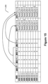
図15は、細胞遺伝子発現データ112を合成パラメータとしての遺伝子セットでどのように増補することができるかの例を(例示的な増補された表200の形で)示す。この表200は、パラメータとしての2つの遺伝子セットで増補されている(遺伝子セット1及び遺伝子セット2の列を参照)。この例において、遺伝子セット1は、{遺伝子2,遺伝子3}から成り、遺伝子セット2は{遺伝子2,遺伝子4}から成る。次いでこれらの遺伝子セットのための表セル(各々が表の行内の異なるセルに対応する)を、対象の遺伝子セットを構成する遺伝子に対する遺伝子カウントの合計でポピュレートすることができる。したがって、ユーザは、細胞ビューモードに戻って、X軸及びY軸のパラメータの一方又は両方が遺伝子セットである細胞ビュー散布図を作成することができる。この例を図16によって示す。図16の各軸に対するパラメータ選択メニューは、利用可能な遺伝子セットオプションを一覧にしたセクションを含む。図16の細胞ビュー散布図は、このようにして、X軸パラメータが「B_GeneTable」と表示された遺伝子セットであり、Y軸パラメータが「B_GeneTable」と表示された遺伝子セットである細胞308の散布図を示す。このように、遺伝子セットを作成するための遺伝子ビュー散布図におけるゲーティング能力を、生成された遺伝子セットを細胞ビュー散布図において合成パラメータとして使用する能力と組み合わせて、ユーザに、細胞遺伝子発現データのマルチパラメータ・データスペースをインテリジェントに削減する予期せぬ能力を与えることを理解されたい。この組合せは、ユーザが、集団内の共通遺伝子の同定及び集団内の示差的遺伝子の同定という極めて困難な課題を克服することを可能にする。換言すれば、ユーザがどの遺伝子が共通であるのかを探索している場合又はどの遺伝子が異なるかを探索している場合のどちらであっても、新たな遺伝子セットを作成する能力及びそれらを単一パラメータとして見る/分析することは、ユーザが細胞集団と遺伝子セットとの間の重要な関係に焦点を合わせることを可能にする。さらに、ユーザが細胞集団の種々の比較に基づいて生物学的に興味深い遺伝子セットを作成すると、これらの遺伝子セットを(含まれる遺伝子の定義されたリストとして)他のユーザに渡すことによって、これらの遺伝子セットを他のユーザと共有することができるので、それら他のユーザは、その遺伝子セットを自身の細胞データのサンプルで評価することができる。異なる細胞データセットにわたるこのような共有される研究及び独立した研究に基づいて、細胞に関して遺伝子挙動へのより深い洞察を得ることができることが期待される。
FIG. 15 shows an example (in the form of exemplary augmented table 200) of how cellular
図17Aは、ワークスペースの例示的なビューを示し、これはワークスペースを、ワークスペース内に存在する種々の遺伝子セット1700、サンプル1702、及び細胞集団1704に分割する。図示したように、遺伝子セットを一覧にしたセクション1700は、各対象遺伝子セットに関するメタデータ(例えば、名称、遺伝子セット内の遺伝子のカウント、及び遺伝子セットの説明)を提供する種々の表示フィールドを含むことができる。名称及び説明は、ユーザによって編集可能なものとすることができ、その遺伝子セットの関連の特性に関してユーザに知らせるのに有用である。また、遺伝子セットは、遺伝子セット内に存在する何らかの階層関係を示すような方式で一覧にすることができる。
FIG. 17A shows an exemplary view of the workspace, which divides the workspace into the
遺伝子セット制御部1710(図17Bでより詳細に示す)は、遺伝子セットをブール演算によって他の遺伝子セットから作成する能力をユーザに与える。例えば、論理和(union)ボタンにより、ユーザは、リスト1700内の2つ以上の選択された遺伝子セットの和集合である新たな遺伝子セットを作成することができる。論理積(intersection)ボタンにより、ユーザは、リスト1700内の2つ以上の選択された遺伝子セットの両方/すべてに存在する遺伝子から成る新たな遺伝子セットを作成することができる。相補(complement)ボタンにより、ユーザは、リスト1700内の2つの遺伝子セット(遺伝子セット1及び遺伝子セット2)から相補的な遺伝子セットを作成することができ、ここで第1の相補的な新たな遺伝子セットは、遺伝子セット1にあるが遺伝子セット2の中にないすべての遺伝子から成るが、第2の相補的な新たな遺伝子セットは、遺伝子セット2の中にあるが遺伝子セット1の中にないすべての遺伝子から成る。「全比較(All Comparisons)」ボタンにより、ユーザは、上記の技術の各々により、同時に幾つかの新たな遺伝子セット(論理和演算、論理積演算、及び相補演算による新たな遺伝子セット)を作成することができる。既存の遺伝子セットから新たな遺伝子セットを作成するこのフレキシブルな能力は、処置条件、患者、実験等の間での遺伝子セットの比較を可能にする。したがって、制御部1710を使用することによって、ユーザは、遺伝子セットの組合せを含む遺伝子コレクションを作成することができる。
The geneset control 1710 (shown in more detail in FIG. 17B) gives the user the ability to create genesets from other genesets via Boolean operations. For example, a union button allows the user to create a new geneset that is the union of two or more selected genesets in
プログラム116によって提供される可視化の別の強力かつ革新的な態様は、細胞ビュー及び/又は遺伝子ビュー散布図上に第3の次元を重ね合わせる能力を含む。例えば、カラーコード化(例えば、ヒートマップ)を散布図内の細胞308又は遺伝子1106に適用して、データの提示に別の次元を提供することができる。この例を図18A~図18Dによって示す。図18Aは、例示的な細胞ビュー散布図表示において第3の次元をどのように提示するかを定めるために第3の次元の制御部1800をどのように用いることができるかを示す。制御部1804を通じて、ユーザは、ヒートマップに用いる統計量を定めることができる。図18Bは、例示的な実施形態においてこの統計量1804のために利用可能なオプションを示す(例えば、メジアン、平均、幾何平均、変動係数(CV)、ロバストCV、標準偏差(SD)、ロバストSD、等)。ヒートマップ統計量は、以下のように計算することができる。グラフ内の各ドットは、1つ以上の細胞を表す(通常、複数の細胞)。ドット毎に、選択された統計量(例えば、平均、メジアン等)を細胞(1つ又は複数)に対して計算する。したがってグラフ内に400ドットがある場合、400個の統計量が計算されることになる。400個の統計値に対して、最小及び最大が決定され、これがカラーマップ(勾配が1つの色から別の色へ変化するカラー値のアレイ)にインデックス付けするための下限及び上限として用いられ、すなわち最小値はカラーアレイ内のインデックス0にマッピングされ、最大値はカラーマップ内の最後のインデックスにマッピングされる。次いでカラーマップ内の色をなんらかの方式(値に対する色の線形分布など)で最小値と最大値との間の値に適用することができる。
Another powerful and innovative aspect of visualization provided by
図18Cは、ユーザが、第3の次元として使用するために細胞遺伝子発現データからどのようにパラメータ1808を選択することができるかを示す。パラメータリスト1810に、細胞遺伝子発現データに対するパラメータのリスト(例えば表200の列)をポピュレートすることができる。この例において、ユーザは、図18Dに示す通り、カラーコードによって細胞ビュー散布図の上にオーバーレイする第3の次元として、パラメータHighTHighBを選択している。この第3の次元のオーバーレイは、散布図を有意味に解釈するさらなる能力をユーザに与える。例えば、ユーザは、カラーコード化を用いて、注目する細胞集団を同定し、そのような細胞集団をゲーティングする(図19のゲート1900を参照のこと)ことにより、さらなる調査のためにワークスペース内で別の新たなオブジェクトを作成することができ。
FIG. 18C shows how the user can select
さらに、開示されるシステムの別の態様によれば、細胞集団をワークスペースからレポートエディタ内にドラッグすることによって、レポートエディタ内でレポートを作成することができる(図20A参照)。別の例として、1つの細胞集団を別の細胞集団の上にドラッグして細胞集団をオーバーレイして、遺伝子セットによる2Dの重ね合わせ及びヒートマップを作成することができる。細胞集団のオーバーレイを図20A~図20Dに2つの方式で示す。散布図において、異なる集団は、同じグラフ内で異なる色のドットプロットとして示される(どちらの集団を他方の上に置くかを選ぶことができる)。ヒートマップにおいて、異なる集団は、編成されて、ヒートマップ内の追加列として水平方向に付加される。すなわち集団1のすべての細胞が一緒に描画されて標識され、集団2のすべての細胞がそれに続く、等々。図20Bは、遺伝子セット及び細胞集団による例示的なヒートマップを示す。図20Cは、図20Bの左側部分の拡大図を示し、図20Dは、図20Cの右側部分の拡大図を示す。
Further, according to another aspect of the disclosed system, reports can be created within the report editor by dragging cell populations from the workspace into the report editor (see FIG. 20A). As another example, one can overlay cell populations by dragging one cell population on top of another to create a 2D overlay and heatmap by gene set. Cell population overlays are shown in two formats in FIGS. 20A-20D. In a scatterplot, different populations are shown as different colored dot plots within the same graph (you can choose which population to put on top of the other). In the heatmap, different populations are organized and added horizontally as additional columns in the heatmap. That is, all cells of
例示的な使用事例
上記のように、開示されるシステムは、細胞ビューモードと遺伝子ビューモードとの間で(又はその逆に)切り替えるとともにこれら2つのビューモードにおいてゲーティングを行って注目するデータに焦点を合わせることによって、細胞遺伝子発現データ112を研究するための強力な機構を提供する。
Exemplary Use Cases As described above, the disclosed system switches between cell view mode and gene view mode (or vice versa) and performs gating in these two view modes to focus on data of interest. Focusing provides a powerful mechanism for studying cellular
図21は、プログラム114の一部として実行するための例示的なプロセスフローを示し、これは、ユーザが細胞遺伝子発現データの深い研究をサポートするために細胞ビューと遺伝子ビューとの間をどのように切り替えることができるかを説明する。ステップ2100において、プロセッサはユーザ入力に応答してワークスペースからサンプルを選択する。ステップ2102において、細胞ビューモード又は遺伝子ビューモードのどちらを作動させるかに関する決定がなされる。この決定は、ユーザ入力応答して行うことができる。細胞ビューモードが選択された場合、プロセスフローはステップ2104に進む。遺伝子ビューモードが選択された場合、プロセスフローはステップ2122に進む。ステップ2104-2120は細胞ビューの動作に対応し、ステップ2122-2140は遺伝子ビューモードの動作に対応する。
FIG. 21 shows an exemplary process flow for execution as part of
ステップ2104において、プロセッサは、ユーザ入力に応答して細胞ビューの軸パラメータを選択する(例えば、遺伝子又は遺伝子セットといったパラメータの選択)。ステップ2106において、プロセッサは、ステップ2104で選択された軸パラメータに基づいて細胞遺伝子発現データ112から細胞ビュー散布図データ構造を生成する。このステップは、表200において、選択されたパラメータに対応する列を選択して、細胞のリストと、各々選択されたパラメータに対するそれらの関連付けられた値とを得ることを伴い得る。ステップ2108において、プロセッサは、ユーザに提示するために、ステップ2106において作成した細胞ビュー散布図データ構造から細胞ビュー散布図300を生成する。
At step 2104, the processor selects axis parameters for the cell view in response to user input (eg, selecting parameters such as genes or gene sets). At step 2106 , the processor generates a cell view scatterplot data structure from the cell
ステップ2110において、プロセッサは、ユーザからの入力に応答して細胞ビュー散布図に関するゲートの規格を受け取る。このゲーティングは、細胞集団を作成し(ステップ2112)、作成された細胞集団は、新たなデータ構造としてワークスペース内に保存される。この時点で、ユーザは、(1)新たなサンプルを扱う(ステップ2114でステップ2100に戻る進行を参照)、(2)細胞ビューモードにある間に現在のサンプルに関して1つ以上の新たな軸パラメータを定義する(ステップ2116でステップ2104に戻る進行を参照)、(3)細胞ビューモードにある間に現在のサンプルに関して新たなゲートを定める(ステップ2118でステップ2110に戻る進行を参照)、又は(4)遺伝子ビューモードに切り替える(ステップ2120でステップ2122に進む進行を参照)のいずれかを選択することができる。
At step 2110, the processor receives gate specifications for the cell view scatterplot in response to input from the user. This gating creates a cell population (step 2112), which is saved in the workspace as a new data structure. At this point, the user can (1) work with a new sample (see
ステップ2122において、プロセッサは、上で論じたように細胞遺伝子発現データ112をピボットする。次いで、ステップ2124において、プロセッサは、ユーザ入力に応答してワークスペースから細胞集団を選択する。ステップ2126において、プロセッサは、ステップ2124で選択された細胞集団に基づいて、ピボットされた細胞遺伝子発現データから遺伝子ビュー散布図データ構造を生成する。このステップは、ピボットバージョンの表200において、選択された細胞集団に対応するピボット列を選択して、遺伝子のリストと、各々選択された細胞集団に対するそれらの関連付けられたメトリックとを得ることを伴い得る。ステップ2128において、プロセッサは、ユーザに提示するために、ステップ2126において作成した遺伝子ビュー散布図データ構造から遺伝子ビュー散布図1100を生成する。
At step 2122, the processor pivots the cellular
ステップ2130において、プロセッサは、ユーザからの入力に応答して遺伝子ビュー散布図に関するゲートの規格を受け取る。このゲーティングは、遺伝子セットを作成し(ステップ2132)、作成された遺伝子セットは、細胞遺伝子発現データとの連係のために新たな合成パラメータとしてワークスペース内に保存される。このようにして、細胞遺伝子発現データを、ステップ2132において生成された遺伝子セットに対応する新たなデータ値で増補することができる。この時点で、ユーザは、(1)新たなサンプルを扱う(ステップ2134でステップ2100に戻る進行を参照)、(2)遺伝子ビューモードにある間に現在のサンプルに関して1つ以上の新たな細胞集団を定義する(ステップ2136でステップ2124に戻る進行を参照)、(3)遺伝子ビューモードにある間に現在のサンプルに関して新たなゲートを定める(ステップ2138でステップ2130に戻る進行を参照)、又は(4)細胞ビューモードに切り替える(ステップ2140でステップ2104に進む進行を参照)のいずれかを選択することができる。
At step 2130, the processor receives gate specifications for the gene view scatterplot in response to input from the user. This gating creates a gene set (step 2132), which is saved in the workspace as a new synthesis parameter for linkage with cellular gene expression data. In this manner, the cellular gene expression data can be augmented with new data values corresponding to the gene set generated in step 2132. At this point, the user can (1) work with a new sample (see
このように、図21は、どのようにして、ユーザがこのシステムを用いて、細胞ビューモードと遺伝子ビューモードとの間ですばやく移行する一方で、モード間の切替後の可視化を補助するのに使用することができる細胞集団及び遺伝子セットをそれぞれゲーティングによって作成することができるかを示す。 Thus, FIG. 21 illustrates how a user can use this system to quickly transition between cell view mode and gene view mode while assisting visualization after switching between modes. It shows which cell populations and gene sets that can be used can be generated by gating, respectively.
一例として、強力かつ革新的な動作モードが図22の例示的なプロセスフローによって示され、ここでユーザは、図21のプロセスフローによってプログラム114と対話し、(1)表示の細胞ビューモードにおいて1つ以上の細胞集団を作成し(ステップ2200)、(2)複数の細胞集団にわたって遺伝子発現を比較して表示する遺伝子ビューモードにピボットし(ステップ2202)、(3)表示の遺伝子ビューモードにおいて1つ以上の遺伝子セットを作成し(ステップ2204)、これは細胞遺伝子発現データを合成パラメータとしての新たな遺伝子セットで増補し(ステップ2206)、(4)これら遺伝子セットの1つ以上を細胞ビュー散布図のための軸パラメータとして用いて、細胞ビュー散布図にピボットして戻り(ステップ2208)、(5)これらの動作を所望により反復的に繰り返して、細胞遺伝子発現データ112内に存在し得る生物学的に妥当な関係を掘り下げる(ここで動作(1)及び(3)をユーザが定義した第3の次元を細胞ビュー又は遺伝子ビューデータ表示上にオーバーレイすることによって補助することができる)。例えば、開示されたシステムは、精密な/個別化された医学を研究するための強力なツールとしての役立つことができ、多数の患者由来の細胞データを評価して、種々のがん若しくは他の疾病/病理に対する生存及び治療応答との相関が高い遺伝子を有する患者を見いだすような作業を行うことができる。
As an example, a powerful and innovative mode of operation is illustrated by the exemplary process flow of FIG. 22, where the user interacts with
例えば、本明細書で提供されるツールを通じて、ユーザは、細胞集団を分析して、特定のがんX(Cancer X)に関してより高い生存率(chances for survival)と相関する示差的に発現された遺伝子セット(これを「生存遺伝子セット(Survival Gene Set)として標識することができる)を同定することが可能であり得る。同時に、ユーザは、細胞集団を分析して、がんXに関してより低い生存率と相関する示差的に発現された遺伝子セット(これを「非生存遺伝子セット(Not Survival Gene Set)」として標識することができる)を同定することが可能であり得る。さらにまた、ユーザは、細胞集団を分析して、がんXのための治療Y(Therapy Y)に対して良好に応答することと相関する示差的に発現された遺伝子セット(これを「治療応答遺伝子セット(Therapy Responsive Gene Set)として標識することができる)を同定することが可能であり得る。次いでこれらの遺伝子セットをシステムの細胞ビューモードにおける合成パラメータとして用いて、がんXを生き延びるための治療Yによる処置に対して良好に応答する遺伝的な素因のある患者内の細胞集団を見いだすことができる。例えば、細胞ビュー散布図は、生存遺伝子セットを一方の軸パラメータ(例えばX軸パラメータ)として用い、非生存遺伝子セットを他方の軸パラメータ(例えばY軸パラメータ)として用いることができる一方で、治療応答遺伝子セットを第3の次元のオーバーレイとして用いることができる。得られた散布図は、生存及び治療応答の両方との相関が高い細胞集団(並びに生存又は治療応答との相関が高くない細胞集団)を示すことができる。 For example, through the tools provided herein, users can analyze cell populations to identify differentially expressed cancers that correlate with greater chances for survival for a particular cancer X. It may be possible to identify a gene set, which can be labeled as the "Survival Gene Set", at the same time the user can analyze the cell population to determine the lower survival rate for Cancer X. It may be possible to identify a differentially expressed gene set (which can be labeled as the "Not Survival Gene Set") that correlates with rate. Furthermore, the user analyzes the cell population to identify differentially expressed gene sets that correlate with good response to therapy Y for cancer X (referred to as "treatment response"). Gene Sets (which can be labeled as Therapy Responsive Gene Set) can then be used as synthetic parameters in the system's cell view mode to determine the number of genes for surviving cancer X. Cell populations within genetically predisposed patients that respond well to treatment with therapy Y can be found.For example, a cell view scatterplot plots the survival gene set as one axis parameter (e.g., the X-axis parameter). and the non-survival gene set can be used as the other axis parameter (e.g., the Y-axis parameter), while the treatment response gene set can be used as a third dimension overlay. Cell populations that are highly correlated with both survival and therapeutic response (as well as cell populations that are not highly correlated with survival or therapeutic response) can be shown.
本発明をその例示的な実施形態に関連して説明してきたが、本発明の範囲内に入る種々の変更をこれに対して行うことができる。例えば、本明細書において示される例示的な散布図は、X軸を水平軸、Y軸を垂直軸として提示されているが、実務家によっては散布図を傾けることが望ましいと気付く場合もある。一例は、対角線y=xが生物学的に重要だと思われるシナリオの場合である。このような場合、散布図を、y=xの対角線が45度の線ではなく水平線又は垂直線として提示されるように傾けることができ、それによりデータがy=xの線からどれだけ離れているかということにユーザが集中することを助ける。したがって、本発明に対するこれら及び他の変更は、本明細書における教示を検討すると認識可能である。 Although the invention has been described in relation to exemplary embodiments thereof, various modifications can be made thereto while remaining within the scope of the invention. For example, although the exemplary scatterplots shown herein are presented with the X axis as the horizontal axis and the Y axis as the vertical axis, some practitioners may find it desirable to tilt the scatterplot. One example is for scenarios where the diagonal y=x is likely to be biologically significant. In such cases, the scatterplot can be tilted so that the y=x diagonal is presented as a horizontal or vertical line rather than a 45 degree line, so that how far the data are from the y=x line. Helps users focus on whether Accordingly, these and other modifications to the invention are recognizable upon reviewing the teachings herein.
100:コンピュータシステム
200:細胞遺伝子発現データの表
300:細胞ビュー散布図
300:ユーザ制御部
302、304:遺伝子セレクタ
306:ユーザ選択ファイル
308:ドット
310、312:ゼロレベル
320:ゲート作成ツール
322:ナビゲーションツール
500、506:パラメータ選択メニュー
600、900、1400:ゲート
700:「展開ゼロ」ユーザ制御部
1000:ヒストグラム
1100:遺伝子ビューモードの散布図
1110、1112:集団選択メニュー
1200:ピボット表
1700:遺伝子セット
1702:サンプル
1704:細胞集団
1710:遺伝子セット制御部
1800:第3の次元の制御部
100: Computer System 200: Table of Cellular Gene Expression Data 300: Cell View Scatterplot 300:
Claims (20)
プロセッサが、前記マルチパラメータ・データセットの散布図を第1及び第2の軸にわたって生成するステップを含み、前記データセットが複数のデータ項目を含み、各データ項目が、複数のパラメータに関連付けられ、関連付けられた前記パラメータの各々に対するデータ値を呈示し、前記第1及び第2の軸が前記データセット内のユーザ選択パラメータであり、前記散布図が複数のドットを含み、各ドットが、前記データセットからのデータ項目に対応し、第1及び第2の軸に沿って該軸に対応する前記パラメータに対する前記データ値に対応する場所にある位置において前記散布図上に配置され、
前記散布図が細胞ビュー散布図を含み、
プロセッサが、前記細胞ビュー散布図から、複数の異なる遺伝子を複数の細胞集団にわたってプロットする遺伝子ビュー散布図にピボットするステップをさらに含み、
前記複数の細胞集団のサブセットが、前記細胞ビュー散布図におけるゲーティングにより2つの細胞集団にグループ化される場合、これら2つの細胞集団をピボットして、ピボット表を作成し、前記ピボット表における行は、サンプル内の複数の細胞に対して、細胞毎の遺伝子発現を示す表では列であった遺伝子であり、前記ピボット表における列は、前記2つの細胞集団であり、各表セルに、各細胞集団の細胞における関連付けられた遺伝子の発現に対する遺伝子カウントの値に対する平均の値がポピュレートされ、前記2つの細胞集団が前記遺伝子ビュー散布図にピボットされることを特徴とする方法。 A method of visualizing a multiparameter dataset, comprising:
a processor generating a scatter plot of the multi-parameter dataset across first and second axes, the dataset comprising a plurality of data items, each data item associated with a plurality of parameters; presenting data values for each of said associated parameters, said first and second axes being user-selected parameters within said data set, said scatter plot comprising a plurality of dots, each dot representing said data positioned on the scatter plot at positions corresponding to data items from a set and at locations along first and second axes corresponding to the data values for the parameters corresponding to the axes;
the scatterplot comprises a cell view scatterplot;
further comprising the processor pivoting from said cell view scatterplot to a gene view scatterplot plotting a plurality of different genes across a plurality of cell populations;
If subsets of the plurality of cell populations are grouped into two cell populations by gating in the cell view scatterplot, pivot the two cell populations to create a pivot table, and The rows are the genes that were the columns in the table showing gene expression per cell for multiple cells in the sample, the columns in the pivot table are the two cell populations, and in each table cell: A method , wherein an average value for gene count values for expression of associated genes in cells of each cell population is populated, and the two cell populations are pivoted into the gene view scatterplot.
プロセッサが、定義された前記細胞集団を代表するデータオブジェクトをワークスペース内で作成するステップと
をさらに含むことを特徴とする請求項3に記載の方法。 a processor gating groups of dots in the cell view scatterplot to define cell populations;
4. The method of claim 3, further comprising a processor creating data objects within a workspace that are representative of the defined cell population.
プロセッサが、定義された前記遺伝子セットを代表する合成パラメータ・データオブジェクトをワークスペース内で作成するステップと
をさらに含むことを特徴とする請求項2~請求項7のいずれかに記載の方法。 a processor gating groups of dots in the gene view scatterplot to define gene sets;
A method according to any of claims 2-7, further comprising the step of a processor creating synthetic parameter data objects in a workspace representative of said defined gene set.
プロセッサが、前記定義された別の細胞集団の代表であるデータオブジェクトを前記ワークスペース内で作成するステップと
をさらに含むことを特徴とする請求項8に記載の方法。 a processor gating groups of dots in the cell view scatterplot based on the defined gene set to define another cell population;
9. The method of claim 8 , further comprising a processor creating data objects within the workspace that are representative of the defined distinct cell populations.
プロセッサが、前記細胞遺伝子発現データの遺伝子ビュー散布図にピボットするステップであって、前記遺伝子ビュー散布図が、作成された前記細胞集団に対応する少なくとも1つの軸を含む、ステップと、
プロセッサが、遺伝子セットを作成するために、前記細胞遺伝子発現データの前記遺伝子ビュー散布図の領域をゲーティングするステップと
を含み、
プロセッサが、作成された前記遺伝子セットが前記細胞遺伝子発現データの合成パラメータとして利用可能となるように、作成された前記遺伝子セットで前記細胞遺伝子発現データを増補するステップをさらに含み、
前記細胞集団のサブセットが、前記細胞ビュー散布図におけるゲーティングにより2つの細胞集団にグループ化される場合、これら2つの細胞集団をピボットして、ピボット表を作成し、前記ピボット表における行は、サンプル内の複数の細胞に対して、細胞毎の遺伝子発現を示す表では列であった遺伝子であり、前記ピボット表における列は、前記2つの細胞集団であり、各表セルに、各細胞集団の細胞における関連付けられた遺伝子の発現に対する遺伝子カウントの値に対する平均の値がポピュレートされ、前記2つの細胞集団が前記遺伝子ビュー散布図にピボットされることを特徴とする方法。 a processor gating an area of a cell view scatterplot of cellular gene expression data to create a cell population, wherein the cellular gene expression data comprises a plurality of data values for a plurality of parameters; a scatter plot comprising first and second axes corresponding to first and second parameters of said cellular gene expression data;
a processor pivoting to a gene view scatter plot of said cellular gene expression data, said gene view scatter plot including at least one axis corresponding to said generated cell population;
a processor gating regions of the gene view scatterplot of the cellular gene expression data to create a gene set;
further comprising a processor augmenting the cellular gene expression data with the generated gene set such that the generated gene set is available as a synthesis parameter for the cellular gene expression data;
If the subsets of cell populations are grouped into two cell populations by gating in the cell view scatterplot, then pivot these two cell populations to create a pivot table, where rows in the pivot table are , the genes that were columns in a table showing gene expression per cell, for multiple cells in a sample, the columns in the pivot table being the two cell populations, and each cell in each table cell A method, wherein mean values for gene count values for expression of associated genes in cells of a population are populated, and the two cell populations are pivoted onto the gene view scatterplot.
請求項1~請求項16のいずれかに記載の方法を行うように構成された、前記メモリと協働するためのプロセッサと、
を含むことを特徴とする装置。 a memory configured to store a multi-parameter dataset;
a processor for cooperating with said memory, configured to perform the method of any of claims 1-16;
An apparatus comprising:
Priority Applications (1)
| Application Number | Priority Date | Filing Date | Title |
|---|---|---|---|
| JP2023018931A JP2023065439A (en) | 2016-12-14 | 2023-02-10 | Applied computer technology for management of parameter, synthesis, visualization, and searching in large multi-parameter data set |
Applications Claiming Priority (3)
| Application Number | Priority Date | Filing Date | Title |
|---|---|---|---|
| US201662433930P | 2016-12-14 | 2016-12-14 | |
| US62/433,930 | 2016-12-14 | ||
| PCT/US2017/065987 WO2018111982A1 (en) | 2016-12-14 | 2017-12-13 | Applied computer technology for management, synthesis, visualization, and exploration of parameters in large multi-parameter data sets |
Related Child Applications (1)
| Application Number | Title | Priority Date | Filing Date |
|---|---|---|---|
| JP2023018931A Division JP2023065439A (en) | 2016-12-14 | 2023-02-10 | Applied computer technology for management of parameter, synthesis, visualization, and searching in large multi-parameter data set |
Publications (3)
| Publication Number | Publication Date |
|---|---|
| JP2020513630A JP2020513630A (en) | 2020-05-14 |
| JP2020513630A5 JP2020513630A5 (en) | 2021-01-28 |
| JP7336384B2 true JP7336384B2 (en) | 2023-08-31 |
Family
ID=62489507
Family Applications (2)
| Application Number | Title | Priority Date | Filing Date |
|---|---|---|---|
| JP2019531469A Active JP7336384B2 (en) | 2016-12-14 | 2017-12-13 | Applied Computational Techniques for Parameter Management, Synthesis, Visualization, and Exploration in Large Multiparameter Datasets |
| JP2023018931A Abandoned JP2023065439A (en) | 2016-12-14 | 2023-02-10 | Applied computer technology for management of parameter, synthesis, visualization, and searching in large multi-parameter data set |
Family Applications After (1)
| Application Number | Title | Priority Date | Filing Date |
|---|---|---|---|
| JP2023018931A Abandoned JP2023065439A (en) | 2016-12-14 | 2023-02-10 | Applied computer technology for management of parameter, synthesis, visualization, and searching in large multi-parameter data set |
Country Status (5)
| Country | Link |
|---|---|
| US (1) | US20180165414A1 (en) |
| EP (1) | EP3555590A4 (en) |
| JP (2) | JP7336384B2 (en) |
| CN (1) | CN109937358B (en) |
| WO (1) | WO2018111982A1 (en) |
Families Citing this family (4)
| Publication number | Priority date | Publication date | Assignee | Title |
|---|---|---|---|---|
| US10616219B2 (en) | 2014-12-11 | 2020-04-07 | FlowJo, LLC | Single cell data management and analysis systems and methods |
| US11573182B2 (en) | 2017-05-25 | 2023-02-07 | FlowJo, LLC | Visualization, comparative analysis, and automated difference detection for large multi-parameter data sets |
| CN110706750B (en) * | 2019-10-28 | 2022-04-19 | 广州基迪奥生物科技有限公司 | Dynamic interactive microbiology online analysis cloud platform and generation method thereof |
| CN117116356B (en) * | 2023-10-25 | 2024-01-30 | 智泽童康(广州)生物科技有限公司 | Generation method of cell subgroup association network diagram, storage medium and server |
Citations (6)
| Publication number | Priority date | Publication date | Assignee | Title |
|---|---|---|---|---|
| JP2001511546A (en) | 1997-07-25 | 2001-08-14 | アフィメトリックス インコーポレイテッド | Gene expression and evaluation system |
| US20020067358A1 (en) | 2000-01-21 | 2002-06-06 | Georg Casari | Data analysis software |
| WO2004072866A1 (en) | 2003-02-14 | 2004-08-26 | Fujitsu Limited | Data analyzer |
| JP2005352771A (en) | 2004-06-10 | 2005-12-22 | Hitachi Software Eng Co Ltd | Pattern recognition system by expression profile |
| US20100070904A1 (en) | 2008-09-16 | 2010-03-18 | Beckman Coulter, Inc. | Interactive Tree Plot for Flow Cytometry Data |
| US20160130574A1 (en) | 2009-12-23 | 2016-05-12 | Merck Sharp & Dohme Corp. | Methods of measuring gene expression in facs-sorted cells |
Family Cites Families (4)
| Publication number | Priority date | Publication date | Assignee | Title |
|---|---|---|---|---|
| US8835358B2 (en) | 2009-12-15 | 2014-09-16 | Cellular Research, Inc. | Digital counting of individual molecules by stochastic attachment of diverse labels |
| US9589099B2 (en) * | 2011-07-21 | 2017-03-07 | The Chinese University Of Hong Kong | Determination of gene expression levels of a cell type |
| KR102536833B1 (en) | 2013-08-28 | 2023-05-26 | 벡톤 디킨슨 앤드 컴퍼니 | Massively parallel single cell analysis |
| WO2016183026A2 (en) | 2015-05-08 | 2016-11-17 | FlowJo, LLC | Data discovery nodes |
-
2017
- 2017-12-12 US US15/838,724 patent/US20180165414A1/en active Pending
- 2017-12-13 EP EP17881922.3A patent/EP3555590A4/en active Pending
- 2017-12-13 WO PCT/US2017/065987 patent/WO2018111982A1/en unknown
- 2017-12-13 CN CN201780069990.6A patent/CN109937358B/en active Active
- 2017-12-13 JP JP2019531469A patent/JP7336384B2/en active Active
-
2023
- 2023-02-10 JP JP2023018931A patent/JP2023065439A/en not_active Abandoned
Patent Citations (6)
| Publication number | Priority date | Publication date | Assignee | Title |
|---|---|---|---|---|
| JP2001511546A (en) | 1997-07-25 | 2001-08-14 | アフィメトリックス インコーポレイテッド | Gene expression and evaluation system |
| US20020067358A1 (en) | 2000-01-21 | 2002-06-06 | Georg Casari | Data analysis software |
| WO2004072866A1 (en) | 2003-02-14 | 2004-08-26 | Fujitsu Limited | Data analyzer |
| JP2005352771A (en) | 2004-06-10 | 2005-12-22 | Hitachi Software Eng Co Ltd | Pattern recognition system by expression profile |
| US20100070904A1 (en) | 2008-09-16 | 2010-03-18 | Beckman Coulter, Inc. | Interactive Tree Plot for Flow Cytometry Data |
| US20160130574A1 (en) | 2009-12-23 | 2016-05-12 | Merck Sharp & Dohme Corp. | Methods of measuring gene expression in facs-sorted cells |
Also Published As
| Publication number | Publication date |
|---|---|
| US20180165414A1 (en) | 2018-06-14 |
| CN109937358A (en) | 2019-06-25 |
| EP3555590A4 (en) | 2020-08-12 |
| JP2023065439A (en) | 2023-05-12 |
| EP3555590A1 (en) | 2019-10-23 |
| JP2020513630A (en) | 2020-05-14 |
| CN109937358B (en) | 2024-03-12 |
| WO2018111982A1 (en) | 2018-06-21 |
Similar Documents
| Publication | Publication Date | Title |
|---|---|---|
| JP2023065439A (en) | Applied computer technology for management of parameter, synthesis, visualization, and searching in large multi-parameter data set | |
| Pretorius et al. | Visualization of parameter space for image analysis | |
| Lex et al. | Comparative analysis of multidimensional, quantitative data | |
| Gratzl et al. | Domino: Extracting, comparing, and manipulating subsets across multiple tabular datasets | |
| US10289802B2 (en) | Spanning-tree progression analysis of density-normalized events (SPADE) | |
| US20020067358A1 (en) | Data analysis software | |
| US20040061702A1 (en) | Methods and system for simultaneous visualization and manipulation of multiple data types | |
| JP7194119B2 (en) | Visualization, comparative analysis, and automatic difference detection for large multiparameter datasets | |
| Höllt et al. | CyteGuide: Visual guidance for hierarchical single-cell analysis | |
| Rubel et al. | Integrating data clustering and visualization for the analysis of 3d gene expression data | |
| Cruz et al. | Interactive and coordinated visualization approaches for biological data analysis | |
| Díaz et al. | Morphing projections: a new visual technique for fast and interactive large-scale analysis of biomedical datasets | |
| Kaushal et al. | Analyzing and visualizing expression data with Spotfire | |
| Kennedy et al. | The graph landscape: using visual analytics for graph set analysis | |
| US20190369001A1 (en) | Biexponential transformation for graphics display | |
| Rutter et al. | bigPint: A Bioconductor visualization package that makes big data pint-sized | |
| US11886513B2 (en) | Data analysis system, data analysis method, and computer program product | |
| Seo et al. | A knowledge integration framework for information visualization | |
| US20030208322A1 (en) | Apparatus, method, and computer program product for plotting proteomic and genomic data | |
| New et al. | Dynamic visualization of coexpression in systems genetics data | |
| Díaz et al. | Exploratory analysis of the gene expression matrix based on dual conditional dimensionality reduction | |
| Aouabed et al. | Visualizing biclustering results on gene expression data: A survey | |
| Jeong et al. | Interactive visual analysis of time-series microarray data | |
| Nguyen et al. | Unlocking the complexity of genomic data of RMS patients through visual analytics | |
| Marasigan et al. | Microarray data clustering and visualization tool using self-organizing maps |
Legal Events
| Date | Code | Title | Description |
|---|---|---|---|
| A521 | Request for written amendment filed |
Free format text: JAPANESE INTERMEDIATE CODE: A523 Effective date: 20201211 |
|
| A621 | Written request for application examination |
Free format text: JAPANESE INTERMEDIATE CODE: A621 Effective date: 20201211 |
|
| A131 | Notification of reasons for refusal |
Free format text: JAPANESE INTERMEDIATE CODE: A131 Effective date: 20220302 |
|
| A521 | Request for written amendment filed |
Free format text: JAPANESE INTERMEDIATE CODE: A523 Effective date: 20220531 |
|
| A02 | Decision of refusal |
Free format text: JAPANESE INTERMEDIATE CODE: A02 Effective date: 20221011 |
|
| A521 | Request for written amendment filed |
Free format text: JAPANESE INTERMEDIATE CODE: A523 Effective date: 20230210 |
|
| C60 | Trial request (containing other claim documents, opposition documents) |
Free format text: JAPANESE INTERMEDIATE CODE: C60 Effective date: 20230210 |
|
| A911 | Transfer to examiner for re-examination before appeal (zenchi) |
Free format text: JAPANESE INTERMEDIATE CODE: A911 Effective date: 20230217 |
|
| C21 | Notice of transfer of a case for reconsideration by examiners before appeal proceedings |
Free format text: JAPANESE INTERMEDIATE CODE: C21 Effective date: 20230220 |
|
| A131 | Notification of reasons for refusal |
Free format text: JAPANESE INTERMEDIATE CODE: A131 Effective date: 20230424 |
|
| A521 | Request for written amendment filed |
Free format text: JAPANESE INTERMEDIATE CODE: A523 Effective date: 20230721 |
|
| TRDD | Decision of grant or rejection written | ||
| A01 | Written decision to grant a patent or to grant a registration (utility model) |
Free format text: JAPANESE INTERMEDIATE CODE: A01 Effective date: 20230803 |
|
| A61 | First payment of annual fees (during grant procedure) |
Free format text: JAPANESE INTERMEDIATE CODE: A61 Effective date: 20230821 |
|
| R150 | Certificate of patent or registration of utility model |
Ref document number: 7336384 Country of ref document: JP Free format text: JAPANESE INTERMEDIATE CODE: R150 |