JP7335251B2 - Prosthetic heart valve with cover - Google Patents

Prosthetic heart valve with cover Download PDF

Info

Publication number
JP7335251B2
JP7335251B2 JP2020539704A JP2020539704A JP7335251B2 JP 7335251 B2 JP7335251 B2 JP 7335251B2 JP 2020539704 A JP2020539704 A JP 2020539704A JP 2020539704 A JP2020539704 A JP 2020539704A JP 7335251 B2 JP7335251 B2 JP 7335251B2
Authority
JP
Japan
Prior art keywords
frame
weave
heart valve
covering
strands
Prior art date
Legal status (The legal status is an assumption and is not a legal conclusion. Google has not performed a legal analysis and makes no representation as to the accuracy of the status listed.)
Active
Application number
JP2020539704A
Other languages
Japanese (ja)
Other versions
JP2021511139A (en
Inventor
エヴァン・ティー・シュワルツ
ショーン・チョウ
サンディップ・ヴァサント・パワル
ダーシン・エス・パテル
シャンボリー・チー
アルピト・ラダー
ゴック・ホアン・ティ・グエン
ワイナ・ミシェル・チュウ
ユァンロン・ドゥ
マイケル・ブキン
ボアズ・マナッシュ
サラ・ハイヴァトヴ
タミール・エス・リーヴァイ
Current Assignee (The listed assignees may be inaccurate. Google has not performed a legal analysis and makes no representation or warranty as to the accuracy of the list.)
Edwards Lifesciences Corp
Original Assignee
Edwards Lifesciences Corp
Priority date (The priority date is an assumption and is not a legal conclusion. Google has not performed a legal analysis and makes no representation as to the accuracy of the date listed.)
Filing date
Publication date
Priority claimed from US15/876,053 external-priority patent/US11185406B2/en
Application filed by Edwards Lifesciences Corp filed Critical Edwards Lifesciences Corp
Publication of JP2021511139A publication Critical patent/JP2021511139A/en
Application granted granted Critical
Publication of JP7335251B2 publication Critical patent/JP7335251B2/en
Active legal-status Critical Current
Anticipated expiration legal-status Critical

Links

Images

Classifications

    • AHUMAN NECESSITIES
    • A61MEDICAL OR VETERINARY SCIENCE; HYGIENE
    • A61FFILTERS IMPLANTABLE INTO BLOOD VESSELS; PROSTHESES; DEVICES PROVIDING PATENCY TO, OR PREVENTING COLLAPSING OF, TUBULAR STRUCTURES OF THE BODY, e.g. STENTS; ORTHOPAEDIC, NURSING OR CONTRACEPTIVE DEVICES; FOMENTATION; TREATMENT OR PROTECTION OF EYES OR EARS; BANDAGES, DRESSINGS OR ABSORBENT PADS; FIRST-AID KITS
    • A61F2/00Filters implantable into blood vessels; Prostheses, i.e. artificial substitutes or replacements for parts of the body; Appliances for connecting them with the body; Devices providing patency to, or preventing collapsing of, tubular structures of the body, e.g. stents
    • A61F2/02Prostheses implantable into the body
    • A61F2/24Heart valves ; Vascular valves, e.g. venous valves; Heart implants, e.g. passive devices for improving the function of the native valve or the heart muscle; Transmyocardial revascularisation [TMR] devices; Valves implantable in the body
    • A61F2/2412Heart valves ; Vascular valves, e.g. venous valves; Heart implants, e.g. passive devices for improving the function of the native valve or the heart muscle; Transmyocardial revascularisation [TMR] devices; Valves implantable in the body with soft flexible valve members, e.g. tissue valves shaped like natural valves
    • AHUMAN NECESSITIES
    • A61MEDICAL OR VETERINARY SCIENCE; HYGIENE
    • A61FFILTERS IMPLANTABLE INTO BLOOD VESSELS; PROSTHESES; DEVICES PROVIDING PATENCY TO, OR PREVENTING COLLAPSING OF, TUBULAR STRUCTURES OF THE BODY, e.g. STENTS; ORTHOPAEDIC, NURSING OR CONTRACEPTIVE DEVICES; FOMENTATION; TREATMENT OR PROTECTION OF EYES OR EARS; BANDAGES, DRESSINGS OR ABSORBENT PADS; FIRST-AID KITS
    • A61F2/00Filters implantable into blood vessels; Prostheses, i.e. artificial substitutes or replacements for parts of the body; Appliances for connecting them with the body; Devices providing patency to, or preventing collapsing of, tubular structures of the body, e.g. stents
    • A61F2/0077Special surfaces of prostheses, e.g. for improving ingrowth
    • AHUMAN NECESSITIES
    • A61MEDICAL OR VETERINARY SCIENCE; HYGIENE
    • A61FFILTERS IMPLANTABLE INTO BLOOD VESSELS; PROSTHESES; DEVICES PROVIDING PATENCY TO, OR PREVENTING COLLAPSING OF, TUBULAR STRUCTURES OF THE BODY, e.g. STENTS; ORTHOPAEDIC, NURSING OR CONTRACEPTIVE DEVICES; FOMENTATION; TREATMENT OR PROTECTION OF EYES OR EARS; BANDAGES, DRESSINGS OR ABSORBENT PADS; FIRST-AID KITS
    • A61F2/00Filters implantable into blood vessels; Prostheses, i.e. artificial substitutes or replacements for parts of the body; Appliances for connecting them with the body; Devices providing patency to, or preventing collapsing of, tubular structures of the body, e.g. stents
    • A61F2/02Prostheses implantable into the body
    • A61F2/24Heart valves ; Vascular valves, e.g. venous valves; Heart implants, e.g. passive devices for improving the function of the native valve or the heart muscle; Transmyocardial revascularisation [TMR] devices; Valves implantable in the body
    • A61F2/2412Heart valves ; Vascular valves, e.g. venous valves; Heart implants, e.g. passive devices for improving the function of the native valve or the heart muscle; Transmyocardial revascularisation [TMR] devices; Valves implantable in the body with soft flexible valve members, e.g. tissue valves shaped like natural valves
    • A61F2/2418Scaffolds therefor, e.g. support stents
    • AHUMAN NECESSITIES
    • A61MEDICAL OR VETERINARY SCIENCE; HYGIENE
    • A61LMETHODS OR APPARATUS FOR STERILISING MATERIALS OR OBJECTS IN GENERAL; DISINFECTION, STERILISATION OR DEODORISATION OF AIR; CHEMICAL ASPECTS OF BANDAGES, DRESSINGS, ABSORBENT PADS OR SURGICAL ARTICLES; MATERIALS FOR BANDAGES, DRESSINGS, ABSORBENT PADS OR SURGICAL ARTICLES
    • A61L27/00Materials for grafts or prostheses or for coating grafts or prostheses
    • A61L27/14Macromolecular materials
    • AHUMAN NECESSITIES
    • A61MEDICAL OR VETERINARY SCIENCE; HYGIENE
    • A61FFILTERS IMPLANTABLE INTO BLOOD VESSELS; PROSTHESES; DEVICES PROVIDING PATENCY TO, OR PREVENTING COLLAPSING OF, TUBULAR STRUCTURES OF THE BODY, e.g. STENTS; ORTHOPAEDIC, NURSING OR CONTRACEPTIVE DEVICES; FOMENTATION; TREATMENT OR PROTECTION OF EYES OR EARS; BANDAGES, DRESSINGS OR ABSORBENT PADS; FIRST-AID KITS
    • A61F2/00Filters implantable into blood vessels; Prostheses, i.e. artificial substitutes or replacements for parts of the body; Appliances for connecting them with the body; Devices providing patency to, or preventing collapsing of, tubular structures of the body, e.g. stents
    • A61F2/02Prostheses implantable into the body
    • A61F2/24Heart valves ; Vascular valves, e.g. venous valves; Heart implants, e.g. passive devices for improving the function of the native valve or the heart muscle; Transmyocardial revascularisation [TMR] devices; Valves implantable in the body
    • A61F2/2409Support rings therefor, e.g. for connecting valves to tissue
    • AHUMAN NECESSITIES
    • A61MEDICAL OR VETERINARY SCIENCE; HYGIENE
    • A61FFILTERS IMPLANTABLE INTO BLOOD VESSELS; PROSTHESES; DEVICES PROVIDING PATENCY TO, OR PREVENTING COLLAPSING OF, TUBULAR STRUCTURES OF THE BODY, e.g. STENTS; ORTHOPAEDIC, NURSING OR CONTRACEPTIVE DEVICES; FOMENTATION; TREATMENT OR PROTECTION OF EYES OR EARS; BANDAGES, DRESSINGS OR ABSORBENT PADS; FIRST-AID KITS
    • A61F2210/00Particular material properties of prostheses classified in groups A61F2/00 - A61F2/26 or A61F2/82 or A61F9/00 or A61F11/00 or subgroups thereof
    • A61F2210/0076Particular material properties of prostheses classified in groups A61F2/00 - A61F2/26 or A61F2/82 or A61F9/00 or A61F11/00 or subgroups thereof multilayered, e.g. laminated structures
    • AHUMAN NECESSITIES
    • A61MEDICAL OR VETERINARY SCIENCE; HYGIENE
    • A61FFILTERS IMPLANTABLE INTO BLOOD VESSELS; PROSTHESES; DEVICES PROVIDING PATENCY TO, OR PREVENTING COLLAPSING OF, TUBULAR STRUCTURES OF THE BODY, e.g. STENTS; ORTHOPAEDIC, NURSING OR CONTRACEPTIVE DEVICES; FOMENTATION; TREATMENT OR PROTECTION OF EYES OR EARS; BANDAGES, DRESSINGS OR ABSORBENT PADS; FIRST-AID KITS
    • A61F2220/00Fixations or connections for prostheses classified in groups A61F2/00 - A61F2/26 or A61F2/82 or A61F9/00 or A61F11/00 or subgroups thereof
    • A61F2220/0025Connections or couplings between prosthetic parts, e.g. between modular parts; Connecting elements
    • A61F2220/0075Connections or couplings between prosthetic parts, e.g. between modular parts; Connecting elements sutured, ligatured or stitched, retained or tied with a rope, string, thread, wire or cable
    • AHUMAN NECESSITIES
    • A61MEDICAL OR VETERINARY SCIENCE; HYGIENE
    • A61FFILTERS IMPLANTABLE INTO BLOOD VESSELS; PROSTHESES; DEVICES PROVIDING PATENCY TO, OR PREVENTING COLLAPSING OF, TUBULAR STRUCTURES OF THE BODY, e.g. STENTS; ORTHOPAEDIC, NURSING OR CONTRACEPTIVE DEVICES; FOMENTATION; TREATMENT OR PROTECTION OF EYES OR EARS; BANDAGES, DRESSINGS OR ABSORBENT PADS; FIRST-AID KITS
    • A61F2230/00Geometry of prostheses classified in groups A61F2/00 - A61F2/26 or A61F2/82 or A61F9/00 or A61F11/00 or subgroups thereof
    • A61F2230/0002Two-dimensional shapes, e.g. cross-sections
    • A61F2230/0028Shapes in the form of latin or greek characters
    • A61F2230/0054V-shaped
    • AHUMAN NECESSITIES
    • A61MEDICAL OR VETERINARY SCIENCE; HYGIENE
    • A61FFILTERS IMPLANTABLE INTO BLOOD VESSELS; PROSTHESES; DEVICES PROVIDING PATENCY TO, OR PREVENTING COLLAPSING OF, TUBULAR STRUCTURES OF THE BODY, e.g. STENTS; ORTHOPAEDIC, NURSING OR CONTRACEPTIVE DEVICES; FOMENTATION; TREATMENT OR PROTECTION OF EYES OR EARS; BANDAGES, DRESSINGS OR ABSORBENT PADS; FIRST-AID KITS
    • A61F2230/00Geometry of prostheses classified in groups A61F2/00 - A61F2/26 or A61F2/82 or A61F9/00 or A61F11/00 or subgroups thereof
    • A61F2230/0063Three-dimensional shapes
    • A61F2230/0091Three-dimensional shapes helically-coiled or spirally-coiled, i.e. having a 2-D spiral cross-section
    • AHUMAN NECESSITIES
    • A61MEDICAL OR VETERINARY SCIENCE; HYGIENE
    • A61FFILTERS IMPLANTABLE INTO BLOOD VESSELS; PROSTHESES; DEVICES PROVIDING PATENCY TO, OR PREVENTING COLLAPSING OF, TUBULAR STRUCTURES OF THE BODY, e.g. STENTS; ORTHOPAEDIC, NURSING OR CONTRACEPTIVE DEVICES; FOMENTATION; TREATMENT OR PROTECTION OF EYES OR EARS; BANDAGES, DRESSINGS OR ABSORBENT PADS; FIRST-AID KITS
    • A61F2250/00Special features of prostheses classified in groups A61F2/00 - A61F2/26 or A61F2/82 or A61F9/00 or A61F11/00 or subgroups thereof
    • A61F2250/0058Additional features; Implant or prostheses properties not otherwise provided for
    • A61F2250/0069Sealing means
    • AHUMAN NECESSITIES
    • A61MEDICAL OR VETERINARY SCIENCE; HYGIENE
    • A61LMETHODS OR APPARATUS FOR STERILISING MATERIALS OR OBJECTS IN GENERAL; DISINFECTION, STERILISATION OR DEODORISATION OF AIR; CHEMICAL ASPECTS OF BANDAGES, DRESSINGS, ABSORBENT PADS OR SURGICAL ARTICLES; MATERIALS FOR BANDAGES, DRESSINGS, ABSORBENT PADS OR SURGICAL ARTICLES
    • A61L2430/00Materials or treatment for tissue regeneration
    • A61L2430/20Materials or treatment for tissue regeneration for reconstruction of the heart, e.g. heart valves

Description

[関連出願の相互参照]
本出願は、2018年1月19日に出願した米国出願第15/876,053号の一部継続出願である。本出願は、2018年7月25日に出願した米国仮出願第62/703,363号の利益も主張する。前述の出願の各々は、参照により全体が本明細書に組み込まれる。
[Cross reference to related applications]
This application is a continuation-in-part of US Application No. 15/876,053, filed January 19, 2018. This application also claims the benefit of US Provisional Application No. 62/703,363, filed July 25, 2018. Each of the aforementioned applications is incorporated herein by reference in its entirety.

本開示は、人工心臓弁に関し、特に、カバリング(covering)を備える人工心臓弁に関するものである。 TECHNICAL FIELD The present disclosure relates to prosthetic heart valves, and more particularly to prosthetic heart valves with coverings.

経カテーテル人工心臓弁を埋め込む手技では、人工心臓弁は、自然心臓弁の弁輪内に位置決めされ、機能するサイズになるまで拡張させられるか、または拡張することを可能にされ得る。人工心臓弁を所望の配置に保持するために、人工心臓弁は、周辺組織に力を加えて人工心臓弁が外れるのを防止するように自然弁輪の直径より大きいものとしてよい。他の構成において、人工心臓弁は、自然弁輪内に配置され、弁輪に関する選択された位置に人工心臓弁を保持するように構成されている支持構造体内で拡張させられ得る。時間の経過とともに、人工心臓弁および人工心臓弁と接触している自然心臓弁(たとえば、自然弁尖、腱索など)の組織の相対的運動は、組織への損傷を引き起こし得る。したがって、人工心臓弁の改善が必要である。 In the procedure of implanting a transcatheter heart valve prosthesis, the prosthesis may be positioned within the annulus of the native heart valve and expanded or allowed to expand to a functional size. To hold the prosthetic heart valve in the desired position, the prosthetic heart valve may be larger than the diameter of the native annulus to apply force to the surrounding tissue to prevent the prosthetic heart valve from dislodging. In other configurations, a prosthetic heart valve may be positioned within the native annulus and expanded within a support structure configured to hold the prosthetic heart valve in a selected position relative to the annulus. Over time, the relative motion of the tissue of the prosthetic heart valve and the native heart valve (eg, native valve leaflets, chordae tendineae, etc.) in contact with the prosthetic heart valve can cause damage to the tissue. Therefore, there is a need for improved prosthetic heart valves.

米国出願第15/682,287号U.S. Application No. 15/682,287 米国公開第2018/0055628号US Publication No. 2018/0055628 米国出願第15/684,836号U.S. Application No. 15/684,836 米国公開第2018/0055630号US Publication No. 2018/0055630 米国出願第15/984,661号U.S. Application No. 15/984,661 米国公開第2018/0318079号US Publication No. 2018/0318079 米国特許第9,393,110号U.S. Patent No. 9,393,110 米国公開第2017/0065415号US Publication No. 2017/0065415 米国特許第9,339,384号U.S. Patent No. 9,339,384 米国公開第2018/0153689号US Publication No. 2018/0153689 米国公開第2018/0325665号US Publication No. 2018/0325665

いくつかの開示されている実施形態は、人工心臓弁用のカバリングおよびそれを製作し、それを使用する方法に関するものである。この発明の概要では、いくつかの例を提示することになっており、本発明の範囲をいかなる形でも制限することを意図しない。たとえば、この発明の概要の例に含まれる特徴は、請求項において明示的に特徴を述べていない限り、請求項では要求されない。また、説明されている特徴は、様々な仕方で組み合わされ得る。本開示の別のところで説明されているような様々な特徴およびステップは、ここで要約としてまとめられている例に含まれ得る。 Several disclosed embodiments relate to coverings for prosthetic heart valves and methods of making and using the same. This summary of the invention is intended to present some examples and is not intended to limit the scope of the invention in any way. For example, features contained in this Summary Example are not required by a claim unless explicitly recited in the claim. Also, the described features may be combined in various ways. Various features and steps as described elsewhere in this disclosure may be included in the examples summarized herein.

代表的な一実施形態において、人工心臓弁は、複数の支柱部材を備えるフレームを具備し、フレームは、折り畳まれた(collapsed)構成と拡張された構成との間で半径方向に折り畳み可能(collapsible)および拡張可能であり、フレームは流入端と流出端とを有し、縦軸を画定する。人工心臓弁は、少なくとも部分的にフレーム内に置かれている弁尖構造体と、フレームの周り(たとえば、フレームの一部、部分、または全部の周り)に配設されているカバリングとをさらに備える。カバリングは、フレームの一部または全部の周りに配設され、カバリングの一部または全部を形成することができる、封止部材またはカバー部材を備えるか、またはそれから形成され得る。いくつかの実施形態において、カバリングおよび/または封止部材/カバー部材は、フレームの周りの周方向に延在し、フレームの縦軸に沿って延在する複数のテクスチャード加工されたストランド(texturized strands)(たとえば、ヤーン、糸、縫合糸、または本明細書で説明されているのと似た仕方で使用可能な他の細長材料)を含む第1の織り部分を含む。いくつかの実施形態において、カバリングおよび/または封止部材/カバー部材は、フレームの周りの周方向に延在し、フレームの縦軸に沿って第1の織り部分から離間される第2の織り部分をさらに含む。テクスチャード加工されたストランド(たとえば、ヤーンなど)は、第1の織り部分から第2の織り部分へフレームの縦軸に沿って延在し、第1の織り部分と第2の織り部分との間に、浮遊するヤーン部分などの、浮遊部分を形成する。 In one exemplary embodiment, a prosthetic heart valve comprises a frame comprising a plurality of strut members, the frame being radially collapsible between a collapsed configuration and an expanded configuration. ) and expandable, the frame has an inflow end and an outflow end and defines a longitudinal axis. The prosthetic heart valve further includes a leaflet structure located at least partially within the frame and a covering disposed around the frame (e.g., around part, part, or all of the frame). Prepare. The covering may comprise or be formed from a sealing or cover member that may be disposed about part or all of the frame and form part or all of the covering. In some embodiments, the covering and/or sealing member/cover member extends circumferentially around the frame and comprises a plurality of textured strands extending along the longitudinal axis of the frame. strands (eg, yarns, threads, sutures, or other elongated materials that can be used in a manner similar to that described herein). In some embodiments, the covering and/or sealing member/cover member extends circumferentially around the frame in a second weave spaced apart from the first weave along the longitudinal axis of the frame. Further includes parts. Textured strands (e.g., yarns, etc.) extend along the longitudinal axis of the frame from the first weave to the second weave and extend between the first weave and the second weave. In between, a floating portion is formed, such as a floating yarn portion.

いくつかの実施形態において、カバリングおよび/または封止部材/カバー部材は、フレームの半径方向に拡張された構成に対応する第1の状態と、フレームの半径方向に折り畳まれた構成に対応する第2の状態との間で弾性的に伸長可能である。 In some embodiments, the covering and/or sealing member/cover member has a first state corresponding to a radially expanded configuration of the frame and a second state corresponding to a radially collapsed configuration of the frame. It is elastically extensible between two states.

いくつかの実施形態において、浮遊部分/浮遊ヤーン部分は、カバリングおよび/または封止部材/カバー部材の第1の状態と第2の状態との間で弾性的に伸長可能である。 In some embodiments, the floating portion/floating yarn portion is elastically extensible between a first state and a second state of the covering and/or sealing member/cover member.

いくつかの実施形態において、テクスチャード加工されたヤーンなどの、テクスチャード加工されたストランドは、圧縮可能な体積を、フレームが拡張された構成になっているときにカバリングおよび/または封止部材/カバー部材の浮遊部分、または浮遊ヤーン部分に付与するように構成される。 In some embodiments, textured strands, such as textured yarns, provide compressible volume to covering and/or sealing members/ It is configured to be applied to the floating portion, or floating yarn portion, of the cover member.

いくつかの実施形態において、テクスチャード加工されたストランド(たとえば、ヤーンなど)は、第1の織り部分および第2の織り部分において絡み織りパターンに織られる。 In some embodiments, textured strands (eg, yarns, etc.) are woven in a leno weave pattern in a first weave portion and a second weave portion.

いくつかの実施形態において、カバリングおよび/または封止部材/カバー部材は、複数の周方向に離間する開口部を画定する。 In some embodiments, the covering and/or sealing member/cover member defines a plurality of circumferentially spaced openings.

いくつかの実施形態において、カバリングおよび/または封止部材/カバー部材内の開口部は、フレームの支柱部材によって画定される開口部の上に載る。 In some embodiments, openings in the covering and/or sealing member/cover member overlie openings defined by strut members of the frame.

いくつかの実施形態において、開口部は、開口部の周りの擦り切れを阻止するためにバイアス布またはバイアス繊維から作られた封止部材の一部分を切って作られている。 In some embodiments, the opening is made by cutting a portion of a sealing member made of bias cloth or bias fabric to prevent fraying around the opening.

いくつかの実施形態において、カバリングおよび/または封止部材/カバー部材は、第1の織り部分の、浮遊部分/浮遊ヤーン部分とは反対の側に第3の織り部分をさらに含み、第3の織り部分は第1の織り部分のテクスチャード加工されたストランド/テクスチャード加工されたヤーンを含む。 In some embodiments, the covering and/or sealing member/cover member further comprises a third weave portion on the opposite side of the first weave portion from the floating portion/floating yarn portion, the third The weave portion includes the textured strands/textured yarns of the first weave portion.

いくつかの実施形態において、テクスチャード加工されたストランド/テクスチャード加工されたヤーンは、第3の織り部分内で平織パターンに織られる。 In some embodiments, the textured strands/textured yarns are woven in a plain weave pattern in the third weave portion.

いくつかの実施形態において、第3の織り部分は、フレームの流入端における支柱部材の先端の上に折り重ねられる(folded)。 In some embodiments, the third weave is folded over the tips of the strut members at the inflow end of the frame.

いくつかの実施形態において、カバリングおよび/または封止部材/カバー部材は、第2の織り部分の、浮遊部分/浮遊ヤーン部分とは反対の側に第4の織り部分をさらに含む。第4の織り部分は、テクスチャード加工されたストランド/テクスチャード加工されたヤーンを含み、テクスチャード加工されたストランド/テクスチャード加工されたヤーンは、第4の織り部分内で平織パターンに織られる。 In some embodiments, the covering and/or sealing member/cover member further comprises a fourth weave portion on the opposite side of the second weave portion from the floating portion/floating yarn portion. The fourth weave section includes textured strands/textured yarns, and the textured strands/textured yarns are woven into a plain weave pattern within the fourth weave section .

いくつかの実施形態において、第4の織り部分は、フレームが拡張された構成であるときにフレームの支柱部材によって画定される開口部の上に載る複数の伸長部分を含む。 In some embodiments, the fourth weave includes a plurality of extensions that overlie openings defined by strut members of the frame when the frame is in the expanded configuration.

いくつかの実施形態において、伸長部分は、フレームの流出端に向かう方向に先細りである。 In some embodiments, the elongated portion tapers in a direction toward the outflow end of the frame.

いくつかの実施形態において、カバリングおよび/または封止部材/カバー部材は、フレームの流入端における支柱部材の先端の上に折り重ねられている第1の保護部分を含み、カバリングおよび/または封止部材/カバー部材は、フレームの流出端における支柱部材の先端の上に折り重ねられている第2の保護部分を含む。 In some embodiments, the covering and/or sealing member/cover member includes a first protective portion folded over the tips of the strut members at the inflow end of the frame to provide the covering and/or sealing. The member/cover member includes a second protective portion folded over the tip of the strut member at the outflow end of the frame.

いくつかの実施形態において、フレームは、機械的拡張可能フレームである。 In some embodiments the frame is a mechanically expandable frame.

いくつかの実施形態において、フレームは、可塑的拡張可能フレームである。 In some embodiments, the frame is a plastically expandable frame.

いくつかの実施形態において、カバリングおよび/または封止部材/カバー部材は、フレームの縦軸に沿って互いにから離間している複数の浮遊部分(たとえば、浮遊ヤーン部分など)を含む。 In some embodiments, the covering and/or sealing member/cover member includes a plurality of floating portions (eg, floating yarn portions, etc.) spaced apart from each other along the longitudinal axis of the frame.

浮遊部分または浮遊ヤーン部分は、所望のサイズおよび織り目(texture)になるように、たとえば、より柔らかくテクスチャード加工がさらになされる(more texturized)ようにヒートセットされ得る。 The floating portion or floating yarn portion may be heat set to a desired size and texture, eg, to be softer and more textured.

人工心臓弁は、縦糸方向では撚られたPETヤーン(twisted PET yarns)、および横糸方向ではテクスチャード加工されたPETヤーンを使用することができる。縦糸方向の撚られたPETヤーンは、絡み織りパターンに織るように配置されるものとしてよく、横糸方向のテクスチャード加工されたPETヤーンは、いかなる織り構造もなく浮遊ヤーン部分を形成することができる。封止部材は、80~160%の伸長性が得られるように熱収縮させられ得る。フレームは、上記のカバリングまたは封止部材を載せた機械的拡張可能フレームであるものとしてよい。 Prosthetic heart valves can use twisted PET yarns in the warp direction and textured PET yarns in the weft direction. The warp direction twisted PET yarns may be arranged to weave in a leno weave pattern and the weft direction textured PET yarns may form the floating yarn portion without any weave structure. . The sealing member can be heat shrunk to obtain an elongation of 80-160%. The frame may be a mechanically expandable frame on which the covering or sealing members described above are mounted.

カバリングおよび/または封止部材は、その少なくとも一部分の上に低摩擦層または低摩擦コーティングのうちの少なくとも一方を含む。これは、材料の別の層の上に低摩擦層および/または別の層の一部分の上に低摩擦細長片もしくは層を含むことができる。低摩擦層または低摩擦コーティングは、低摩擦材料をカバリングおよび/または封止部材のフレームまたは別の層上に電界紡糸することによって形成され得る。 The covering and/or sealing member includes at least one of a low friction layer or coating on at least a portion thereof. This can include a low friction layer over another layer of material and/or a low friction strip or layer over a portion of another layer. A low friction layer or coating may be formed by electrospinning a low friction material onto the frame or another layer of the covering and/or sealing member.

人工心臓弁は、フレームの一方の端部または両方の端部において支柱および/または先端の周りに螺旋状に巻き付けられた材料の細長片も含むことができる。 The prosthetic heart valve can also include strips of material helically wrapped around the struts and/or tips at one or both ends of the frame.

別の代表的な実施形態において、人工心臓弁は、複数の支柱部材を備えるフレームを具備し、フレームは流入端と流出端とを有し、支柱部材はフレームの流出端において複数の開口部をフレーム内に画定する。人工心臓弁は、少なくとも部分的にフレーム内に置かれている弁尖構造体と、フレームの周り(たとえば、フレームの一部、部分、または全部の周り)に配設されているカバリングとをさらに備える。カバリングは、フレームの一部または全部の周りに配設され、カバリングの一部または全部を形成することができる、封止部材またはカバー部材を備え、またそれから形成され得る。カバリングおよび/または封止部材/カバー部材は、フレーム内の開口部と整列する複数の開口部を画定する。 In another exemplary embodiment, a prosthetic heart valve includes a frame having a plurality of strut members, the frame having an inflow end and an outflow end, the strut members defining a plurality of openings at the outflow end of the frame. Define within a frame. The prosthetic heart valve further includes a leaflet structure located at least partially within the frame and a covering disposed around the frame (e.g., around part, part, or all of the frame). Prepare. The covering may comprise and be formed from a sealing or cover member disposed about part or all of the frame and which may form part or all of the covering. The covering and/or sealing member/cover member defines a plurality of openings aligned with the openings in the frame.

いくつかの実施形態において、フレームは外面を備え、カバリングまたは封止部材/カバー部材は、フレームの外面全体を覆う。 In some embodiments, the frame comprises an outer surface and the covering or sealing member/cover member covers the entire outer surface of the frame.

いくつかの実施形態において、カバリングおよび/または封止部材/カバー部材は、プラッシュパイル層を含むフレームの流入端に隣接する第1の部分を含む。カバリングおよび/または封止部材/カバー部材は、フレームの流出端に隣接するパイル層のない第2の部分をさらに含み、カバリングおよび/または封止部材/カバー部材の第2の部分は、カバリングおよび/または封止部材/カバー部材の開口部を画定する。 In some embodiments, the covering and/or sealing member/cover member includes a first portion adjacent the inflow end of the frame including the plush pile layer. The covering and/or sealing member/cover member further includes a second pile layer-free portion adjacent the outflow end of the frame, the second portion of the covering and/or sealing member/cover member comprising the covering and/or sealing member/cover member. /or define an opening in the sealing member/cover member.

開示されている技術の前述のおよび他の目的、特徴、および利点は、添付図面を参照しつつ進む次の詳細な説明からより明らかになるであろう。 The foregoing and other objects, features, and advantages of the disclosed technology will become more apparent from the following detailed description, which proceeds with reference to the accompanying drawings.

ヒトの心臓の概略断面図である。1 is a schematic cross-sectional view of a human heart; FIG. 心臓の僧帽弁輪の概略上面図である。1 is a schematic top view of the mitral annulus of the heart; FIG. 人工心臓弁の一実施形態の斜視図である。1 is a perspective view of one embodiment of a prosthetic heart valve; FIG. 一実施形態による、埋め込まれた人工弁を備える、心臓の僧帽弁位置に配備されているリングアンカーまたはドッキングデバイスの側断面図である。FIG. 10 is a side cross-sectional view of a ring anchor or docking device deployed at the mitral valve location of the heart with an implanted prosthetic valve, according to one embodiment. 埋め込まれた人工弁を備える、心臓の僧帽弁位置に配備されているコイルアンカーまたはドッキングデバイスの一例を示す側断面図である。FIG. 3 is a side cross-sectional view showing an example of a coil anchor or docking device deployed at the mitral valve location of the heart with an implanted prosthetic valve. アンカーまたはドッキングデバイスの代表的実施形態の斜視図である。1A-1D are perspective views of representative embodiments of anchoring or docking devices; カバリングの代表的一実施形態を含む人工心臓弁の斜視図である。1 is a perspective view of a prosthetic heart valve including one representative embodiment of a covering; FIG. 図5の人工心臓弁の側面図である。FIG. 6 is a side view of the prosthetic heart valve of FIG. 5; 図5の人工心臓弁の上面図である。FIG. 6 is a top view of the prosthetic heart valve of FIG. 5; 図5の人工心臓弁の側面断面図である。FIG. 6 is a side cross-sectional view of the artificial heart valve of FIG. 5; プラッシュパイルを含む緩衝層の代表的一実施形態の斜視図である。FIG. 11 is a perspective view of a representative embodiment of a cushioning layer comprising plush pile. 心臓の僧帽弁位置に配備されている図5の人工心臓弁の側断面図である。6 is a side cross-sectional view of the prosthetic heart valve of FIG. 5 deployed in the mitral valve position of the heart; FIG. カバリングの一例を含む人工心臓弁の側面図である。1 is a side view of a prosthetic heart valve including an example covering; FIG. バッキング層、バッキング層を形成するためのステンシル、および緩衝層の、バッキング層および緩衝層が一緒に固定される前の、斜視図である。1 is a perspective view of a backing layer, a stencil for forming the backing layer, and a cushioning layer, before the backing layer and cushioning layer are secured together; FIG. カバリングの一例を含む人工心臓弁の側面断面図である。1 is a side cross-sectional view of a heart valve prosthesis including one example of a covering; FIG. 図13のカバリングの流入保護部分の詳細図である。14 is a detailed view of the inflow protection portion of the covering of FIG. 13; FIG. スペーサー織物を含むカバリングの一例を含む人工心臓弁の側面図である。1 is a side view of a prosthetic heart valve that includes an example of a covering that includes a spacer fabric; FIG. 輪になったパイル糸を含むスペーサー布の代表的一実施形態の斜視図である。1 is a perspective view of a representative embodiment of a spacer fabric comprising looped pile yarns; FIG. 図16のスペーサー織物の側面図である。17 is a side view of the spacer fabric of FIG. 16; FIG. 平行四辺形ステンシルを使用して切った後のバッキング層の一実施形態の上面図である。FIG. 4B is a top view of one embodiment of a backing layer after being cut using a parallelogram stencil; カバリングの一例を含む人工心臓弁の斜視図である。1 is a perspective view of a prosthetic heart valve including an example covering; FIG. 図19の人工心臓弁の側面図である。FIG. 20 is a side view of the prosthetic heart valve of FIG. 19; 図19の人工心臓弁の流出端の平面図である。FIG. 20 is a plan view of the outflow end of the prosthetic heart valve of FIG. 19; 図19の人工心臓弁の側面断面図である。FIG. 20 is a side cross-sectional view of the prosthetic heart valve of FIG. 19; 折り重ねられていない構成の図19のカバリングの上面図である。Figure 20 is a top view of the covering of Figure 19 in an unfolded configuration; カバリングが円筒形の形状に形成された後のカバリングへの図19の人工心臓弁の留置を例示する斜視図である。20 is a perspective view illustrating placement of the heart valve prosthesis of FIG. 19 into the covering after the covering has been formed into a cylindrical shape; FIG. 弁フレームの支柱部材へのカバリングの取り付けを例示している図19の人工心臓弁の流入端の斜視図である。20 is a perspective view of the inflow end of the heart valve prosthesis of FIG. 19 illustrating the attachment of the covering to the strut members of the valve frame; FIG. 流入保護部分を形成するために弁フレームの支柱部材の上に折り重ねられたカバリングの細長片部材を例示している図19の人工心臓弁の流入端の斜視図である。20 is a perspective view of the inflow end of the heart valve prosthesis of FIG. 19 illustrating the strip members of the covering folded over the strut members of the valve frame to form the inflow protection portion; FIG. カバリングの一例を含む人工心臓弁用のフレームの斜視図である。1 is a perspective view of a frame for a heart valve prosthesis including an example covering; FIG. 図27のフレームおよびカバリングの側面断面図である。FIG. 28 is a side cross-sectional view of the frame and covering of FIG. 27; 図27のカバリングを製作する代表的方法を例示する斜視図である。28 is a perspective view illustrating an exemplary method of fabricating the covering of FIG. 27; FIG. 図27のカバリングを製作する代表的方法を例示する斜視図である。28 is a perspective view illustrating an exemplary method of fabricating the covering of FIG. 27; FIG. 図27のカバリングを製作する代表的方法を例示する斜視図である。28 is a perspective view illustrating an exemplary method of fabricating the covering of FIG. 27; FIG. 図31Aのカバリングの流入端部分の電界紡糸層の詳細図である。31B is a detailed view of the electrospun layer at the inflow end portion of the covering of FIG. 31A. FIG. 主カバリングとフレームの先端に被さるように延在する第2のカバリングとを備える人工心臓弁の斜視図である。1 is a perspective view of a prosthetic heart valve comprising a primary covering and a secondary covering extending over the distal end of a frame; FIG. 図32の人工心臓弁の側面図である。FIG. 33 is a side view of the prosthetic heart valve of FIG. 32; 平置き構成の図32の人工弁のフレームの一部分の平面図である。33 is a plan view of a portion of the frame of the prosthetic valve of FIG. 32 in a flat configuration; FIG. 主外側カバリングなしの図32の人工心臓弁の斜視図である。33 is a perspective view of the prosthetic heart valve of FIG. 32 without the main outer covering; FIG. フレームの先端の周りに第2のカバリングがどのように巻き付けられるかを例示する図32の人工心臓弁の斜視図である。33 is a perspective view of the prosthetic heart valve of FIG. 32 illustrating how the second covering is wrapped around the tip of the frame; FIG. 送達装置のシャフト上にクリンプされた第2のカバリングを含む図32の人工弁のフレームを例示する斜視図である。33 is a perspective view illustrating the frame of the prosthetic valve of FIG. 32 including a second covering crimped onto the shaft of the delivery device; FIG. 外側カバリングの一例を含む図19の人工弁の側面図である。20 is a side view of the prosthetic valve of FIG. 19 including an example outer covering; FIG. 図38Aの外側カバリングの織物の詳細図である。FIG. 38B is a detail view of the fabric of the outer covering of FIG. 38A; 送達デバイスのシャフト上にクリンプされた図38Aの人工心臓弁を例示する平面図である。38B is a plan view illustrating the prosthetic heart valve of FIG. 38A crimped onto the shaft of a delivery device; FIG. 図39Aの人工心臓弁の外側カバリングの詳細図である。FIG. 39B is a detailed view of the outer covering of the heart valve prosthesis of FIG. 39A. 弛緩状態の図38Aの外側カバリングの織物の側面断面図である。38B is a side cross-sectional view of the fabric of the outer covering of FIG. 38A in a relaxed state; FIG. 緊張状態の図38Aの外側カバリングの織物の側面断面図である。38B is a side cross-sectional view of the fabric of the outer covering of FIG. 38A in tension; FIG. 平置き構成の人工弁に対する織物外側カバリングの一例である、パイル層によって画定される外面を含む平面図である。1 is a plan view including an outer surface defined by a pile layer, an example of a textile outer covering for a prosthetic valve in a flat configuration. FIG. 図41Aの外側カバリングの拡大図である。41B is an enlarged view of the outer covering of FIG. 41A. FIG. 図41Aの外側カバリングの基層の平面図である。41B is a plan view of the base layer of the outer covering of FIG. 41A; FIG. 図42Aの基層の拡大図である。42B is an enlarged view of the base layer of FIG. 42A. FIG. 開口部を含む外側カバリングの様々な実施形態を含む人工心臓弁の側面図である。1A-1D are side views of prosthetic heart valves including various embodiments of outer coverings including openings. 開口部を含む外側カバリングの様々な実施形態を含む人工心臓弁の側面図である。1A-1D are side views of prosthetic heart valves including various embodiments of outer coverings including openings. 開口部を含む外側カバリングの様々な実施形態を含む人工心臓弁の側面図である。1A-1D are side views of prosthetic heart valves including various embodiments of outer coverings including openings. 織り部分と浮遊ヤーン部分として構成されている浮遊部分とを含む人工心臓弁用の封止部材またはカバー部材の一例の平面図である。1 is a plan view of an example of a sealing or covering member for a heart valve prosthesis including a woven portion and a floating portion configured as a floating yarn portion; FIG. 図46の封止部材またはカバー部材の第1の織り部分の拡大図である。47 is an enlarged view of the first weave portion of the sealing member or cover member of FIG. 46; FIG. 図46の封止部材またはカバー部材の第2の織り部分の拡大図である。47 is an enlarged view of a second weave portion of the sealing member or cover member of FIG. 46; FIG. 弛緩状態の図46の封止部材またはカバー部材の浮遊ヤーン部分の拡大図である。Figure 47 is an enlarged view of the floating yarn portion of the sealing member or cover member of Figure 46 in a relaxed state; 伸長状態の図49の浮遊ヤーン部分を例示する図である。Figure 50 illustrates the floating yarn portion of Figure 49 in a stretched state; 伸長状態の図46の封止部材またはカバー部材の平面図である。Figure 47 is a plan view of the sealing or cover member of Figure 46 in an extended state; 図46の封止部材またはカバー部材の縁部分を例示する斜視図である。47 is a perspective view illustrating an edge portion of the sealing member or cover member of FIG. 46; FIG. 一実施形態による、図46の封止部材またはカバー部材を含む外側カバリングを有する人工心臓弁の側面図である。47 is a side view of a prosthetic heart valve having an outer covering that includes the sealing or covering member of FIG. 46, according to one embodiment. FIG. 送達装置の遠位端においてバルーン上にクリンプされている図53の人工心臓弁を例示する図である。54 illustrates the heart valve prosthesis of FIG. 53 crimped onto a balloon at the distal end of the delivery device. FIG. 絡み織りパターンおよび絡み織り技術の例を示す図である。FIG. 2 illustrates examples of leno weaving patterns and leno weaving techniques; 絡み織りパターンおよび絡み織り技術の例を示す図である。FIG. 2 illustrates examples of leno weaving patterns and leno weaving techniques; 絡み織りパターンおよび絡み織り技術の例を示す図である。FIG. 2 illustrates examples of leno weaving patterns and leno weaving techniques; 絡み織りパターンおよび絡み織り技術の例を示す図である。FIG. 2 illustrates examples of leno weaving patterns and leno weaving techniques; 絡み織りパターンおよび絡み織り技術の例を示す図である。FIG. 2 illustrates examples of leno weaving patterns and leno weaving techniques; 絡み織りパターンおよび絡み織り技術の例を示す図である。FIG. 2 illustrates examples of leno weaving patterns and leno weaving techniques; 絡み織りパターンおよび絡み織り技術の例を示す図である。FIG. 2 illustrates examples of leno weaving patterns and leno weaving techniques; 絡み織りパターンおよび絡み織り技術の例を示す図である。FIG. 2 illustrates examples of leno weaving patterns and leno weaving techniques; 絡み織りパターンおよび絡み織り技術の例を示す図である。FIG. 2 illustrates examples of leno weaving patterns and leno weaving techniques; 絡み織りパターンおよび絡み織り技術の例を示す図である。FIG. 2 illustrates examples of leno weaving patterns and leno weaving techniques; 一実施形態による、機械的拡張可能人工心臓弁の斜視図である。1 is a perspective view of a mechanically expandable prosthetic heart valve, according to one embodiment; FIG. 人工心臓弁用の機械的拡張可能フレームの一例の側面図である。1 is a side view of one example of a mechanically expandable frame for a prosthetic heart valve; FIG. 人工心臓弁用の封止部材またはカバー部材の一例の平面図である。1 is a plan view of an example of a sealing or covering member for a prosthetic heart valve; FIG. 図58の封止部材またはカバー部材の一部分の拡大図である。FIG. 59 is an enlarged view of a portion of the sealing member or cover member of FIG. 58; 半径方向に拡張された構成の図57のフレームに取り付けられている図58の封止部材またはカバー部材から形成されたカバリングの一例を示す側面図である。59 is a side view of an example covering formed from the sealing or cover member of FIG. 58 attached to the frame of FIG. 57 in a radially expanded configuration; FIG. 図60のフレームおよびカバリングアセンブリの流入端部分の斜視図である。61 is a perspective view of the inlet end portion of the frame and covering assembly of FIG. 60; FIG. 半径方向に折り畳まれた構成の図60のフレームおよびカバリングの側面図である。61 is a side view of the frame and covering of FIG. 60 in a radially collapsed configuration; FIG.

本開示は、埋め込み可能な人工心臓弁の実施形態およびそのようなデバイスを製作し、それを使用する方法に関するものである。一態様において、人工心臓弁は、バッキング層と、バッキング層上に配設されている主緩衝層とを有し、緩衝層は弁の周上で半径方向外向きに配向されるカバリングまたは外側カバリングを備える。緩衝層は、軟質で順応性があり、たとえば、心臓が拡張、収縮を行うときの人工弁と組織との間に相対的移動または摩擦により埋め込み部位で心臓弁および/または周辺解剖学的構造の自然組織に対して生じる損傷を低減することができる。カバリングは、周辺解剖学的構造に緩衝作用をもたらす流入保護部分と流出保護部分とをさらに備え、心臓弁の自然組織がフレームの支柱部材の先端に接触するのを防ぎ、それによって周辺組織を保護することができる。一実施形態において、カバリングは、緩衝層に固定され、支柱部材の先端の上に折り重ねられて流入および流出保護部分を形成する流入細長片部材と流出細長片部材とを含み得る。 The present disclosure relates to embodiments of implantable prosthetic heart valves and methods of making and using such devices. In one aspect, a prosthetic heart valve has a backing layer and a main cushioning layer disposed on the backing layer, the cushioning layer being oriented radially outward on the circumference of the valve or an outer covering. Prepare. The cushioning layer may be soft and compliant, e.g., allow relative movement or friction between the prosthetic valve and the tissue as the heart undergoes expansion and contraction, thereby reducing the impact of the heart valve and/or surrounding anatomy at the implantation site. Damage caused to natural tissue can be reduced. The covering further comprises an inflow protection portion and an outflow protection portion that provide cushioning to the surrounding anatomy to prevent natural tissue of the heart valve from contacting the tips of the strut members of the frame, thereby protecting the surrounding tissue. can do. In one embodiment, the covering may include inflow strip members and outflow strip members secured to the cushioning layer and folded over the tips of the strut members to form inflow and outflow protection portions.

開示されている技術の実施形態は、心臓内の様々な配置に埋め込むように構成されている様々な人工心臓弁と組み合わせて使用することができる。代表的な、非限定的例は、自然僧帽弁の機能を置き換えるための人工心臓弁である。図1および図2は、ヒトの心臓の僧帽弁を例示している。僧帽弁は、左心房と左心室との間の血液の流れを制御する。左心房が肺静脈を介して肺から酸素を豊富に含んだ血液を受け取った後、僧帽弁は、左心房から左心室への酸素を豊富に含んだ血液の流れを許す。左心室が収縮すると、左心室内に保持されていた酸素を豊富に含んだ血液は、大動脈弁および大動脈を通して身体の他の部分に送達される。その一方で、僧帽弁は、心室収縮のときに閉じて、血液が左心房内に逆流するのを防ぐ。 Embodiments of the disclosed technology can be used in combination with various prosthetic heart valves configured to be implanted in various locations within the heart. A representative, non-limiting example is a prosthetic heart valve to replace the function of the natural mitral valve. Figures 1 and 2 illustrate the mitral valve of the human heart. The mitral valve controls blood flow between the left atrium and left ventricle. After the left atrium receives oxygenated blood from the lungs via the pulmonary veins, the mitral valve allows the flow of oxygenated blood from the left atrium to the left ventricle. As the left ventricle contracts, the oxygen-rich blood that has been retained within the left ventricle is delivered through the aortic valve and the aorta to the rest of the body. The mitral valve, on the other hand, closes during ventricular contraction, preventing blood from flowing back into the left atrium.

左心室が収縮すると、左心室内の血圧は実質的に増大し、僧帽弁を閉じさせる。このときに左心室と左心房との間の差圧が大きいため、僧帽弁の弁尖の脱出、すなわち僧帽弁の弁尖が心房内に戻る翻転の可能性が生じる。したがって、一連の腱索が僧帽弁の弁尖を左心室の壁に配置されている乳頭筋に接続し、腱索および乳頭筋は両方とも心室収縮において張力がかけられ、弁尖を閉位置に保持し、それらが左心房の方へ戻るのを防ぐ。これは、一般的に、酸素を豊富に含んだ血液が左心房内に逆流するのを防ぐ。腱索は、図1の心臓断面図と図2の僧帽弁の上面図の両方に概略として例示されている。 When the left ventricle contracts, blood pressure within the left ventricle increases substantially, causing the mitral valve to close. Due to the large differential pressure between the left ventricle and the left atrium at this time, there is the possibility of prolapse of the mitral valve leaflets, ie, eversion of the mitral valve leaflets back into the atrium. Thus, a series of chordae tendineae connect the mitral valve leaflets to the papillary muscles located in the wall of the left ventricle, and both the chordae tendineae and the papillary muscles are tensioned in ventricular contraction, pushing the leaflets into the closed position. to prevent them from moving back towards the left atrium. This generally prevents backflow of oxygen-rich blood into the left atrium. The chordae tendineae are illustrated schematically in both the cross-sectional view of the heart in FIG. 1 and the top view of the mitral valve in FIG.

左心房から見たときの僧帽弁およびその弁尖の一般的形状は図2に示されている。僧帽弁の様々な合併症は、潜在的に、致命的な心不全の原因となり得る。心臓弁膜症の一形態は僧帽弁漏れまたは僧帽弁逆流であり、これは左心室から僧帽弁を通って左心房内に逆流する血液の異常な漏れによって特徴付けられる。これは、たとえば、左心室の拡張によって引き起こされることがあり、これは自然僧帽弁尖の不完全な接合を引き起こし、結果として弁を通る漏れを引き起こし得る。僧帽弁逆流は、また、自然弁尖への損傷によっても引き起こされ得る。これらの状況において、僧帽弁を修復すること、または僧帽弁の機能を経カテーテル心臓弁などの、人工心臓弁の機能と置き換えることが望ましい場合がある。 The general shape of the mitral valve and its leaflets as viewed from the left atrium is shown in FIG. Various complications of the mitral valve can potentially lead to fatal heart failure. One form of valvular heart disease is mitral valve leak or regurgitation, which is characterized by abnormal leakage of blood from the left ventricle through the mitral valve and back into the left atrium. This can be caused, for example, by dilation of the left ventricle, which can cause imperfect coaptation of the native mitral valve leaflets, resulting in leakage through the valve. Mitral regurgitation can also be caused by damage to the native valve leaflets. In these situations, it may be desirable to repair the mitral valve or replace the function of the mitral valve with that of a prosthetic heart valve, such as a transcatheter heart valve.

いくつかの経カテーテル心臓弁は、半径方向にクリンプされるか、または圧縮され患者の心臓における埋め込み部位への血管内送達を円滑にするように設計される。自然弁輪に位置決めされた後、交換弁は、たとえば、拡張バルーンによって、動作可能状態にまで拡張され、人工心臓弁の弁尖構造体は、自然弁輪を通る血流を調節する。他の場合には、人工弁は、送達シースから解放されたときに自らの弾力性の下で圧縮された送達状態から動作可能状態へ機械的に拡張されるか、または半径方向に自己拡張し得る。人工心臓弁の一実施形態は、図3に例示されている。図3に示されている心臓弁に類似する弁外径を有する経カテーテル心臓弁は、エドワーズライフサイエンス社製サピエン(Edwards Lifesciences SAPIEN)XT(商標)弁である。図3の人工弁1は、流入端2および流出端3を有し、フレームまたはステント10と、フレーム10の内側に支持されている弁尖構造体20とを備える。いくつかの実施形態において、スカート30がフレーム10の内面に取り付けられ、弁尖構造体20の弁尖に対するより適している取付表面を形成する。 Some transcatheter heart valves are designed to be radially crimped or compressed to facilitate intravascular delivery to an implantation site in a patient's heart. After being positioned in the native annulus, the replacement valve is expanded to an operational state, eg, by a dilatation balloon, and the leaflet structure of the prosthetic heart valve regulates blood flow through the native annulus. In other cases, the prosthetic valve mechanically expands under its own elasticity from a compressed delivery state to an operative state or radially self-expands when released from the delivery sheath. obtain. One embodiment of a prosthetic heart valve is illustrated in FIG. A transcatheter heart valve with a valve outer diameter similar to the heart valve shown in FIG. 3 is the Edwards Lifesciences SAPIEN XT™ valve. The prosthetic valve 1 of FIG. 3 has an inflow end 2 and an outflow end 3 and comprises a frame or stent 10 and a leaflet structure 20 supported inside the frame 10 . In some embodiments, skirt 30 is attached to the inner surface of frame 10 to provide a more suitable mounting surface for the leaflets of leaflet structure 20 .

フレーム10は、クリンプを半径方向に折り畳まれた状態にし、拡張を図3に例示されている拡張機能状態に戻すことの両方を許す身体と親和性を有する任意の拡張可能な材料から作られるものとしてよい。たとえば、自らの弾力性の下で人工弁が機能的サイズに拡張する自己拡張可能人工弁である実施形態では、フレーム10は、ニチノールまたは別の自己拡張材料から作ることができる。いくつかの実施形態において、人工弁は、バルーンまたは別の拡張デバイスによって機能的サイズに拡張される可塑的拡張可能弁とすることができ、その場合、フレームは、ステンレス鋼またはコバルトクロム合金などの、可塑的拡張可能材料から作られてよい。他の好適な材料または材料の組合せも使用することができる。 The frame 10 is made of any body compatible expandable material that allows both the crimps to be radially collapsed and the expansion to be returned to the dilated functional state illustrated in FIG. may be For example, in embodiments in which the prosthetic valve is a self-expanding prosthetic valve that expands to a functional size under its own elasticity, the frame 10 can be made from Nitinol or another self-expanding material. In some embodiments, the prosthetic valve can be a plastically expandable valve that is expanded to its functional size by a balloon or another expansion device, where the frame is made of a material such as stainless steel or cobalt-chromium alloy. , may be made from a plastically expandable material. Other suitable materials or combinations of materials can also be used.

フレーム10は、中に弁尖構造体20を取り付け、整形するのを助ける、複数の垂直に伸長する交連取付ポスト11を有する環状構造体を備えることができる。追加の垂直ポストまたは支柱部材12は、周方向に延在する支柱部材13とともに、フレーム10の残り部分を形成するのを助ける。フレーム10の支柱部材13はジグザグになっており、弁1の流入端2および流出端3において縁付き王冠部分または先端14を形成する。さらに、取付ポスト11は、また、フレーム10の一方の端部または両方の端部において縁を形成することもできる。 The frame 10 may comprise an annular structure having a plurality of vertically extending commissural attachment posts 11 that assist in mounting and shaping the leaflet structure 20 therein. Additional vertical posts or strut members 12 help form the remainder of frame 10 along with circumferentially extending strut members 13 . The strut members 13 of the frame 10 are zig-zag and form fringed crown portions or tips 14 at the inflow end 2 and outflow end 3 of the valve 1 . Additionally, the mounting posts 11 can also form a rim at one end or both ends of the frame 10 .

人工弁1では、スカート30は、一般的に必要に応じてフレーム10の様々な支柱11、12、13の外側に巻き付く、1つまたは複数のネジ山40を介して弁フレーム10の内面に取り付けることができる。スカート30は、弁1の流入端2により近い位置に置かれる弁尖構造体20の一部分に対するより実質的な取付表面を設ける。 In the prosthetic valve 1, the skirt 30 is generally attached to the inner surface of the valve frame 10 via one or more threads 40 that wrap around the various struts 11, 12, 13 of the frame 10 as needed. can be installed. The skirt 30 provides a more substantial mounting surface for the portion of the leaflet structure 20 located closer to the inflow end 2 of the valve 1 .

図4Aおよび図4Bは、動物または患者の僧帽弁位置または三尖弁位置などの、自然弁において、弁1の埋め込みを円滑にするために使用することができる異なるアンカーの実施形態の側断面図を示している。図示されているように、たとえば、図4Aおよび図4Bでは、心臓80の左側は左心房82、左心室84、および左心房82と左心室84とを接続する僧帽弁86を含む。僧帽弁86は、腱索90および乳頭筋92を介して左心室84の内壁に接続される前尖および後尖88を備える。 Figures 4A and 4B are side cross-sections of different anchor embodiments that can be used to facilitate implantation of a valve 1 in a native valve, such as the mitral or tricuspid position of an animal or patient. Figure shows. As shown, for example in FIGS. 4A and 4B, the left side of heart 80 includes left atrium 82, left ventricle 84, and mitral valve 86 connecting left atrium 82 and left ventricle 84. FIG. Mitral valve 86 includes anterior and posterior leaflets 88 that are connected to the inner wall of left ventricle 84 via chordae tendineae 90 and papillary muscles 92 .

図4Aにおいて、第1の固定用デバイスは、自然弁86および/または腱索90の自然弁尖88を囲む可撓性リングまたはハロ60を備える。リング60は、人工弁1のより効果的な埋め込みのために、弁尖の一部分を挟むか、または内側へ付勢して、自然弁において円形に近い開口部を形成する。人工弁1は、リングアンカー60(ドッキングデバイスとして働く)によって自然弁86において保持され、たとえば、図4Aに示されているように位置決めされた後に人工弁1が送達され、拡張されている間に自然弁86において弁1を位置決めすることによって、図示されている位置に送達され得る。拡張された後、人工弁1はリングアンカー60を外向きに押して、弁1およびリングアンカー60の両方の位置を固定する。いくつかの実施形態において、拡張状態にある人工弁1の直径よりわずかに小さい内径を有するアンダーサイズのリングアンカー60を使用して部品同士の間の摩擦を強くし、それにより取付強度を高めることができる。図4Aを見るとわかるように、少なくとも自然弁尖88の一部および/または腱索90の一部は、弁1とリングアンカー60との間で挟まれるか、または挟装され、それによりコンポーネントを自然解剖学的構造に固定する。 In FIG. 4A, the first fixation device comprises a flexible ring or halo 60 surrounding the native valve 86 and/or leaflet 88 of the chordae tendineae 90 . The ring 60 pinches or biases a portion of the leaflets inward to form a near-circular opening in the native valve for more effective implantation of the prosthetic valve 1 . Prosthetic valve 1 is held in native valve 86 by ring anchor 60 (which acts as a docking device), for example, while prosthetic valve 1 is delivered and expanded after being positioned as shown in FIG. 4A. By positioning valve 1 in native valve 86, the position shown can be delivered. After being expanded, prosthetic valve 1 pushes ring anchors 60 outward to fix the position of both valve 1 and ring anchors 60 . In some embodiments, an undersized ring anchor 60 with an inner diameter slightly smaller than the diameter of the valve prosthesis 1 in its expanded state is used to increase friction between the components and thereby increase attachment strength. can be done. As can be seen in FIG. 4A, at least a portion of the native valve leaflets 88 and/or a portion of the chordae tendineae 90 are pinched or pinched between the valve 1 and the ring anchor 60, thereby separating the components. to the natural anatomy.

図4Bは、リングアンカー60、螺旋状もしくはコイル状アンカーまたはドッキングデバイス70が代わりに利用されることを除き、図4Aに類似している。螺旋状アンカー70が含むコイル数または巻き数はリングアンカー60より多くてよく、螺旋状アンカー70は自然弁86の上流および下流の両方に延在することができる。螺旋状アンカー70は、いくつかの状況において、人工弁1が当接できる取付領域の固定強度を高めることができる。図4Aのリングアンカー60と同様に、自然弁尖88および/または腱索90の少なくとも一部は、弁1と螺旋状アンカー70との間に挟まれる。本開示における発明で使用することができる、アンカー/ドッキングデバイスおよび人工弁を埋め込むための方法およびデバイスは、各々参照により本明細書に組み込まれている、2017年8月21日に出願され、米国公開第2018/0055628号として公開されている、米国出願第15/682,287号、2017年8月23日に出願され、米国公開第2018/0055630号として公開されている、米国出願第15/684,836号、および2018年5月21日に出願され、米国公開第2018/0318079号として公開されている、米国出願第15/984,661号において説明されている。 Figure 4B is similar to Figure 4A except that a ring anchor 60, helical or coiled anchor or docking device 70 is utilized instead. Helical anchor 70 may include more coils or turns than ring anchor 60 and helical anchor 70 may extend both upstream and downstream of native valve 86 . The helical anchor 70 can increase the fixation strength of the attachment area against which the prosthetic valve 1 can abut in some circumstances. At least a portion of the native leaflet 88 and/or chordae tendineae 90 are sandwiched between the valve 1 and the helical anchor 70, similar to the ring anchor 60 of FIG. 4A. Anchoring/docking devices and methods and devices for implanting prosthetic valves that can be used with the inventions in the present disclosure were filed on Aug. 21, 2017, US U.S. Application No. 15/682,287, published as Publication No. 2018/0055628, U.S. Application No. 15/684,836, filed August 23, 2017, published as U.S. Publication No. 2018/0055630 , and in U.S. Application No. 15/984,661, filed May 21, 2018 and published as U.S. Publication No. 2018/0318079.

図4Cは、本明細書において説明されている人工弁のうちのいずれかと組み合わせて使用することができるアンカーまたはドッキングデバイス300の別の代表的な実施形態を例示している。アンカー300は、機能的なコイル/巻き領域または中心領域302および取り囲む巻きまたは下側領域304を有する。アンカー300は、任意選択で、上側領域306も有し得る。下側領域304は、腱索および/または僧帽弁または三尖弁などの自然弁の弁尖を取り囲むか、または捕らえるように構成され得る1つまたは複数の巻きを含む。中心領域302は、自然弁において人工弁を保持するように構成されている複数の巻きを含む。上側領域306は1つまたは複数の巻きを含むことができ、人工弁を埋め込む前にアンカーが弁輪から外れるのを阻止するように構成され得る。いくつかの実施形態において、上側領域306は心房の床の上に位置決めされるものとしてよく、中心領域302の巻きを自然弁装置内に高く位置決めされたままにするように構成され得る。 FIG. 4C illustrates another representative embodiment of an anchoring or docking device 300 that can be used in conjunction with any of the prosthetic valves described herein. Anchor 300 has a functional coil/turn region or central region 302 and a surrounding turns or lower region 304 . Anchor 300 may optionally also have an upper region 306 . The lower region 304 includes one or more turns that may be configured to surround or capture the chordae and/or leaflets of a native valve such as the mitral or tricuspid valve. The central region 302 includes multiple turns configured to retain the prosthetic valve in the native valve. The upper region 306 can include one or more turns and can be configured to prevent the anchor from dislodging from the valve annulus prior to implanting the prosthetic valve. In some embodiments, the upper region 306 may be positioned above the floor of the atrium and may be configured to keep the turns of the central region 302 positioned high within the native valve device.

アンカー300は、任意選択で、中心領域302と上側領域306との間に位置決めされる伸長部分308も含み得る。いくつかの実施形態において、伸長部分308は、その代わりに、たとえば、中心領域302内に全体的に(たとえば、中心領域の上側部分に)、または上側領域306内に全体的に位置決めされ得る。伸長部分308は、アンカーの中心軸に実質的に平行に延在するコイルの一部を含む。いくつかの実施形態において、伸長部分308は、アンカーの中心軸に相対的に角度を付けられ得る。いくつかの実施形態において、伸長部分308は図示されているものよりも長いか、または短くてもよく、領域302および/または領域306に相対的により大きい、または小さい角度を有することができる。伸長部分308は、中心領域302および上側領域306を、アンカーの心房側と心室側との間に間隙が形成されるように中心軸に沿った方向で互いから離間させる働きをし得る。 Anchor 300 may optionally also include an extension portion 308 positioned between central region 302 and upper region 306 . In some embodiments, the elongate portion 308 may instead be positioned entirely within the central region 302 (eg, in an upper portion of the central region) or entirely within the upper region 306, for example. Extension portion 308 includes a portion of the coil that extends substantially parallel to the central axis of the anchor. In some embodiments, the extension portion 308 can be angled relative to the central axis of the anchor. In some embodiments, elongated portion 308 may be longer or shorter than shown and may have a relatively greater or lesser angle to region 302 and/or region 306 . Extensions 308 may serve to space central region 302 and upper region 306 from each other in a direction along the central axis such that a gap is formed between the atrial and ventricular sides of the anchor.

アンカーの伸長部分308は、自然弁輪を通して、近くに、および/または周りに位置決めされ、アンカーが埋め込まれたときに自然弁輪および/または自然弁尖を通過するか、押すか、または寄り掛かるアンカーの量を減らすように構成され得る。これは、アンカーによって自然弁に加えられる力を減らし、自然弁尖の摩耗を減らすことができる。一配置において、伸長部分308は、自然弁の交連のうちの1つに位置決めされ、そこを通過する。この方式で、伸長部分308は、上側領域306を自然弁の自然弁尖から離間させ、上側領域306が心房側から自然弁尖と相互作用するのを防ぐことができる。伸長部分308は、上側領域306を、上側領域が自然弁より上にある心房壁と接触するように持ち上げ、それにより、自然弁にかかる応力およびその周りの応力を低減し、さらにはアンカーの保持力を高めることができる。 The anchor extension portion 308 is positioned through, near and/or around the native valve annulus to pass, push or rest against the native valve annulus and/or leaflets when the anchor is implanted. It can be configured to reduce the amount of anchors. This can reduce the force exerted by the anchor on the native valve and reduce wear on the native valve leaflets. In one arrangement, extension portion 308 is positioned in and passes through one of the commissures of the native valve. In this manner, the extension portion 308 can space the upper region 306 from the native leaflets of the native valve and prevent the upper region 306 from interacting with the native leaflets from the atrial side. The extension portion 308 lifts the upper region 306 so that it contacts the atrial wall above the native valve, thereby reducing stress on and around the native valve, as well as anchor retention. can increase power.

図4Cに示されているように、アンカー300は、アンカーの近位端および遠位端のうちの一方または両方に、もしくはその近くにスルーホール310として構成されている1つまたは複数の開口部をさらに備えることができる。スルーホール310は、たとえば、アンカーのコイルの上にカバー層を取り付けるための縫合穴として、および/またはプルワイヤ、保持部材、保持縫合糸などの送達具のための取付部位もしくは繋留穴として働き得る。いくつかの実施形態において、アンカー300のコイルの幅または太さも、アンカーの長さに沿って異なり得る。たとえば、アンカーおよび/または伸長部308の中心部分は、アンカーの端部分より細くすることができる。これにより、中心部分および/または伸長部308に高い柔軟性を持たせることができ、その一方で、端部分はより強く、または頑丈にできる。いくつかの例では、コイルの端部分を比較的太くすることで、カバー層をアンカーのコイルに縫合するか、または他の何らかの方法で取り付けるための表面積を広げることもできる。 As shown in FIG. 4C, anchor 300 has one or more openings configured as through holes 310 at or near one or both of the anchor's proximal and distal ends. can be further provided. Through holes 310 may serve, for example, as suture holes for attaching a cover layer over the coil of the anchor and/or as attachment sites or anchor holes for delivery devices such as pull wires, retaining members, retaining sutures, and the like. In some embodiments, the width or thickness of the coils of anchor 300 can also vary along the length of the anchor. For example, the central portion of the anchor and/or extension 308 can be thinner than the end portions of the anchor. This allows the central portion and/or extensions 308 to be highly flexible, while the end portions can be stronger or stiffer. In some instances, the relatively thick end portions of the coil may also provide more surface area for suturing or otherwise attaching the cover layer to the coil of the anchor.

いくつかの実施形態において、アンカーまたはドッキングデバイス300は、反時計回りの方向で自然弁輪に挿通するように構成され得る。たとえば、アンカーは、交連A3P3、交連A1P1を通して、または自然僧帽弁の別の部分を通して前進させられ得る。アンカー300のコイルが反時計回りの方向であることにより、類似の反時計回りの方向に送達カテーテルの遠位端が曲がるようにすることができ、これは送達カテーテルを時計回りの方向に曲げることよりも行いやすい。しかしながら、アンカーは、必要ならば、時計回りまたは反時計回りのいずれかで弁に挿通するように構成され得る。 In some embodiments, the anchor or docking device 300 can be configured to pass through the native valve annulus in a counterclockwise direction. For example, the anchor may be advanced through commissure A3P3, commissure A1P1, or through another portion of the native mitral valve. The counterclockwise direction of the coil of anchor 300 can cause the distal end of the delivery catheter to bend in a similar counterclockwise direction, which causes the delivery catheter to bend in a clockwise direction. easier to do than However, the anchor can be configured to pass through the valve either clockwise or counterclockwise, if desired.

図3の人工弁の例を再び参照すると、人工弁1は、一般的に、多数の縁を形成する金属フレーム10を備える。それに加えて、多くのフレーム10が、縁付き王冠部または先端14、および突き出ている交連取付ポスト11、さらにはフレーム10の外面に沿って露出し得るネジ山40を備えるように製作される。これらの特徴は、たとえば、自然組織と人工弁1の様々な摩耗面との間の移動もしくは摩擦によって、人工弁1とアンカー60、70との間に留まっている組織などの自然組織に損傷を引き起こす可能性がある。それに加えて、腱索などの、人工弁1に近接近している他の自然組織も、潜在的に損傷を受ける可能性がある。 Referring again to the prosthetic valve example of FIG. 3, the prosthetic valve 1 generally comprises a metal frame 10 forming a number of limbs. In addition, many frames 10 are manufactured with a fringed crown or tip 14 and protruding commissure attachment posts 11 as well as threads 40 that may be exposed along the outer surface of the frame 10 . These features may cause damage to natural tissue, such as tissue retained between the prosthetic valve 1 and the anchors 60, 70, for example, due to movement or friction between the natural tissue and various wear surfaces of the prosthetic valve 1. can cause. In addition, other natural tissues in close proximity to the prosthetic valve 1, such as chordae tendineae, may also potentially be damaged.

図5~図7は、参照により本明細書に組み込まれている、米国特許第9,393,110号において詳しく説明されている、エドワーズライフサイエンス社製サピエン(Edwards Lifesciences SAPIEN)(商標)3弁に類似する人工心臓弁100の代表的な一実施形態を例示している。人工弁100は、複数の角度付き支柱部材104によって形成され、流入端106と流出端108とを有するフレーム102を備える。人工弁100は、フレーム102内に少なくとも部分的に置かれ、大動脈弁に類似する三尖弁配置で折り畳むように構成されている3つの弁尖110を備える弁尖構造体も具備するが、人工弁は、僧帽弁の方式で二尖弁配置で折り畳むように構成されている2つの弁尖、または必要ならば、3つより多い弁尖も備え得る。支柱部材104は、フレームの流入端および流出端の周りに配置される複数の先端124を形成することができる。 FIGS. 5-7 show an artificial valve similar to the Edwards Lifesciences SAPIEN™ 3 valve, described in detail in US Pat. No. 9,393,110, which is incorporated herein by reference. A representative embodiment of heart valve 100 is illustrated. Prosthetic valve 100 comprises a frame 102 formed by a plurality of angled strut members 104 and having an inflow end 106 and an outflow end 108 . Prosthetic valve 100 also comprises a leaflet structure comprising three leaflets 110 positioned at least partially within frame 102 and configured to fold in a tricuspid configuration similar to the aortic valve, but with a prosthetic valve. The valve may also comprise two leaflets configured to fold in a bicuspid configuration in the manner of a mitral valve, or even more than three leaflets if desired. The strut members 104 can form a plurality of tips 124 arranged around the inflow and outflow ends of the frame.

人工心臓弁は、埋め込み後に人工弁と接触している自然組織に緩衝作用をもたらし(保護し)、弁の組織と表面との間の移動もしくは摩擦による組織への損傷を低減するように構成されているカバリングまたは外側カバリング112を備えることができる。カバリング112は、弁傍漏れも低減し得る。図5の実施形態において、カバリング112は、バッキング層114として構成されている第1の層(たとえば、図8を参照)と、緩衝層116として構成されている第2の層とを備える。緩衝層116はバッキング層114上に配設されてよく、緩衝層と接触している組織または物体を保護するように半径方向外向きに配向されている軟質プラッシュ表面118を備えることができる。例示されている構成において、カバリング112は、また、フレームの流入端106の周りの周方向に延在する無傷流入保護部分120と、フレームの流出端108の周りの周方向に延在する無傷流出保護部分122とを備える。流入保護部分120と流出保護部分122との間の緩衝層116の部分は、主緩衝部分136を画定することができる。第1の層114および第2の層116は、一緒になって、フレームの周りに置くことができる封止部材またはカバー部材を形成し、カバリング112を形成することができる。封止部材/カバー部材は、保護部分120、122も含み得る。 Prosthetic heart valves are designed to provide cushioning (protection) to natural tissue in contact with the prosthetic valve after implantation to reduce tissue damage due to movement or friction between tissue and surfaces of the valve. A covering or outer covering 112 may be provided. The covering 112 may also reduce paravalvular leak. In the embodiment of FIG. 5, covering 112 comprises a first layer configured as backing layer 114 (see, eg, FIG. 8) and a second layer configured as cushioning layer . A cushioning layer 116 may be disposed over the backing layer 114 and may include a soft plush surface 118 oriented radially outward to protect tissue or objects in contact with the cushioning layer. In the illustrated configuration, the covering 112 also includes a circumferentially extending intact inflow protection portion 120 around the frame inflow end 106 and a circumferentially extending intact outflow protection portion 120 around the frame outflow end 108 . and a protective portion 122 . The portion of cushioning layer 116 between inflow protection portion 120 and outflow protection portion 122 may define main cushioning portion 136 . The first layer 114 and the second layer 116 together form a sealing member or cover member that can be placed around the frame to form the covering 112 . The sealing member/cover member may also include protective portions 120,122.

図8は、例示することを目的として弁尖構造体が取り除かれている人工弁100の概略を例示する断面図である。カバリング112はフレーム102の外部の周りに延在し、バッキング層114の内面は支柱部材104の外面に隣接するか、または当接する。図8に例示されているように、緩衝層116は、フレームの縦軸126に沿って測定されたときにフレームの長さより大きい長さを有することができる。したがって、カバリング112は、緩衝層116がフレームの流入端106における支柱部材の先端124を超えて遠位に(たとえば、上流方向に)延在するように置くことができ、先端を超えて延在する緩衝層の部分は本明細書において遠位端部分128と称される。弁の対向端では、緩衝層116は支柱部材の先端124を超えて近位に(たとえば、下流方向に)延在することができ、先端を超えて配置される部分は近位端部分130と称される。緩衝層116の近位端部分128および遠位端部分130が弁のそれぞれの端部における先端を超えて延在できる距離は、たとえば、弁の寸法、特定の用途などに応じて、同じまたは異なる距離であってよい。 FIG. 8 is a cross-sectional view schematically illustrating the prosthetic valve 100 with the leaflet structure removed for purposes of illustration. The covering 112 extends around the exterior of the frame 102 and the inner surface of the backing layer 114 abuts or abuts the outer surface of the strut members 104 . As illustrated in FIG. 8, the cushioning layer 116 can have a length that is greater than the length of the frame as measured along the longitudinal axis 126 of the frame. Thus, the covering 112 can be positioned such that the cushioning layer 116 extends distally (eg, upstream) beyond the tips 124 of the strut members at the inflow end 106 of the frame and extends beyond the tips. The portion of the cushioning layer that does so is referred to herein as distal end portion 128 . At the opposite end of the valve, the cushioning layer 116 can extend proximally (e.g., downstream) beyond the tips 124 of the strut members, the portion disposed beyond the tips being a proximal end portion 130 . is called The distance that the proximal end portion 128 and the distal end portion 130 of the cushioning layer 116 can extend beyond the tip at each end of the valve may be the same or different, depending, for example, on the size of the valve, the particular application, and the like. It can be distance.

バッキング層114は、バッキング層114の近位端部分またはフラップ132が流出保護部分122をカフで形成する方式で緩衝層116の近位端部分130の上に折り重ねることができるように軸方向に十分な強度を有することができる。その一方で、バッキング層114の遠位端部分またはフラップ134は、緩衝層116の遠位端部分128の上に折り重ねて、流入保護部分120を形成することができる。バッキング層116の近位フラップ132および遠位フラップ134は、取付手段、たとえば、縫合糸136、接着剤、クリップなどによってバッキング層の下にあるセクションに固定され得る。この方式で、流入保護部分120および流出保護部分122は、緩衝層116の近位端部分130および遠位端部分128が少なくとも部分的にバッキング層116のフラップ132、134によって囲まれるように製作される。この製作では、流入保護部分120および流出保護部分122に、それらが弁の内径に曲がるかまたは他の何らかの形で突き出る(たとえば、自重による曲がり、血流、または血圧によって)ことなく弁の縦軸126に沿って伸長するように曲げに対する十分な強度および抵抗を付与する。この方式で、流入保護部分120および流出保護部分122は、人工弁を通る流れへの影響を最小限度に抑え、人工弁弁尖への干渉を回避し、流れへの妨害を低減し、潜在的に血栓のリスクを下げる。 The backing layer 114 is axially folded over the proximal end portion 130 of the cushioning layer 116 in such a manner that the proximal end portion or flap 132 of the backing layer 114 cuffs the spill protection portion 122 . It can have sufficient strength. Meanwhile, the distal end portion or flap 134 of the backing layer 114 can be folded over the distal end portion 128 of the cushioning layer 116 to form the inflow protection portion 120 . Proximal flaps 132 and distal flaps 134 of backing layer 116 may be secured to underlying sections of the backing layer by attachment means such as sutures 136, adhesives, clips, and the like. In this manner, inflow protection portion 120 and outflow protection portion 122 are fabricated such that proximal end portion 130 and distal end portion 128 of cushioning layer 116 are at least partially surrounded by flaps 132 , 134 of backing layer 116 . be. This fabrication allows the inflow protection portion 120 and the outflow protection portion 122 to extend along the longitudinal axis of the valve without them bending into the inner diameter of the valve or otherwise protruding (e.g., due to self-weight bending, blood flow, or blood pressure). It provides sufficient strength and resistance to bending as it stretches along 126. In this manner, inflow protection portion 120 and outflow protection portion 122 minimize impact on flow through the prosthetic valve, avoid interfering with the prosthetic valve leaflets, reduce obstruction to flow, and potentially to lower the risk of blood clots.

例示されている構成において、流入保護部分120はフレームの流入端における支柱部材の先端124を超えて距離d1だけ延在することができ、流出保護部分122はフレームの流出端における支柱部材の先端124を超えて距離d2だけ延在することができる。距離d1およびd2は、人工弁のタイプ、治療位置などに応じて、同じであるか、または異なるものであってよい。たとえば、29mmの人工弁では、距離d1およびd2は、約0.5mmから約3mmの範囲とすることができる。代表的な一実施形態において、距離d1およびd2は、約1mmから約2mmの範囲とすることができる。流入保護部分120および流出保護部分122は、フレームのそれぞれの端部の先端124を超えて延在するので、流入保護部分および流出保護部分は、隣接する組織および/または人工弁に隣接する別のインプラントをフレームの先端124と接触しないように遮蔽することができる。 In the illustrated configuration, the inflow protection portion 120 can extend a distance d 1 beyond the strut member tips 124 at the inflow end of the frame, and the outflow protection portion 122 extends beyond the strut member tips 124 at the outflow end of the frame. It can extend beyond 124 by a distance d2 . Distances d1 and d2 may be the same or different depending on the type of prosthetic valve, treatment location, and the like. For example, for a 29mm prosthetic valve, the distances d1 and d2 can range from about 0.5mm to about 3mm. In one exemplary embodiment, distances d1 and d2 can range from about 1 mm to about 2 mm. The inflow and outflow protection portions 120 and 122 extend beyond the tips 124 of the respective ends of the frame so that the inflow and outflow protection portions are in contact with adjacent tissue and/or separate areas adjacent to the prosthetic valve. The implant can be shielded from contact with the tip 124 of the frame.

たとえば、図10は、上の図4Aおよび図4Bと同様に、自然弁86内のアンカーまたはドッキングデバイス70内に埋め込まれている人工弁100を例示している。図示されている例では、人工弁の流入端部分は、自然弁輪の上面より上に位置決めされ、周辺組織から離間されているように図示されている。しかしながら、他の実装形態では、異なり得る、人工弁の軸方向位置決めに応じて、流入保護部分120は自然弁尖88と接触し、それらがフレームの流入端において先端124と直接接触するのを防ぐことができる。流入端における人工弁の直径に応じて、流入保護部分120は、心房壁がフレームの流入端において先端124と直接接触することを防ぐ働きをし得る。 For example, FIG. 10, similar to FIGS. 4A and 4B above, illustrates a prosthetic valve 100 implanted within an anchor or docking device 70 within a native valve 86. FIG. In the illustrated example, the inflow end portion of the prosthetic valve is shown positioned above the top surface of the native annulus and spaced from the surrounding tissue. However, in other implementations, depending on the axial positioning of the prosthetic valve, which may vary, the inflow protection portion 120 contacts the native valve leaflets 88 and prevents them from directly contacting the tip 124 at the inflow end of the frame. be able to. Depending on the diameter of the prosthetic valve at the inflow end, the inflow protection portion 120 may serve to prevent the atrial wall from directly contacting the tip 124 at the inflow end of the frame.

図10に示されているように、アンカー70は、順応性のある流入保護部分120に寄り掛かることもできる。その一方で、アンカー70と人工弁100との間に捕らえられた自然弁尖88の部分は、主緩衝部分136のプラッシュ表面118による緩衝作用を受けることができる。いくつかの実施形態において、緩衝層116が軟質で順応性があり織り目を有することで、自然弁尖と人工弁との間の摩擦を増大させ得る。これは、左心室が拡張、収縮するときに自然弁尖および人工弁の相対運動を減らすことができ、これにより、自然弁尖および周辺組織に損傷が生じる可能性を低減できる。緩衝層116は、また、アンカー70と人工弁100との間の保持力を高めることもできる。緩衝層116のプラッシュの圧縮性も、カバリングの圧力を印加することによって引き起こされる、フレーム102内の開口部へのカバリング112の貫通を低減し、それによって、弁の血行動態への干渉を低減できる。それに加えて、流出緩衝部分122は、腱索90をフレームの支柱部材に、特にフレームの流出端における先端124に接触しないように保護し、それによって、腱索の損傷または破断のリスクを低減することができる。 As shown in FIG. 10, the anchor 70 can also rest against a conformable inflow protection portion 120. FIG. On the other hand, the portion of native valve leaflet 88 trapped between anchor 70 and prosthetic valve 100 can be cushioned by plush surface 118 of main cushioning portion 136 . In some embodiments, the cushioning layer 116 can be soft, compliant, and textured to increase friction between the native valve leaflets and the prosthetic valve. This can reduce the relative motion of the native leaflets and the prosthetic valve as the left ventricle expands and contracts, thereby reducing the potential for damage to the native leaflets and surrounding tissue. Cushioning layer 116 may also enhance retention between anchor 70 and prosthetic valve 100 . The compressibility of the plush of the cushioning layer 116 can also reduce penetration of the covering 112 into openings in the frame 102 caused by applying pressure on the covering, thereby reducing interference with valve hemodynamics. . In addition, the outflow buffer portion 122 protects the chordae tendineae 90 from contacting the strut members of the frame, particularly the tips 124 at the outflow end of the frame, thereby reducing the risk of injury or rupture of the chordae tendineae. be able to.

バッキング層114は、たとえば、ガーゼ、ポリエチレンテレフタレート(PET)織物(たとえば、ダクロン)、ポリエステル織物、ポリアミド織物などの様々な織物のうちのいずれか、またはフェルトなどの、様々な不織織物のうちのいずれかを含み得る。いくつかの実施形態において、バッキング層114は、ポリテトラフルオロエチレン(PTFE)、PET、ポリプロピレン、ポリアミド、ポリエーテルエーテルケトン(PEEK)などの、様々な結晶または半結晶ポリマー材料のうちのいずれかを含むフィルムも含み得る。この方式で、バッキング層114は、比較的薄く、それでいて、カバリング112をフレームに縫合することができ、引き裂くことなく人工弁をクリンプすることができる十分な強度を有するものとしてよい。 The backing layer 114 may be, for example, any of a variety of fabrics such as gauze, polyethylene terephthalate (PET) fabric (eg, Dacron), polyester fabric, polyamide fabric, or a variety of non-woven fabrics such as felt. can include either In some embodiments, the backing layer 114 comprises any of a variety of crystalline or semi-crystalline polymeric materials such as polytetrafluoroethylene (PTFE), PET, polypropylene, polyamide, polyetheretherketone (PEEK). It can also include a film containing. In this manner, the backing layer 114 may be relatively thin, yet strong enough to allow the covering 112 to be sutured to the frame and crimped onto the prosthetic valve without tearing.

上で述べたように、緩衝層116は少なくとも1つの軟質プラッシュ表面118を備えることができる。いくつかの例において、緩衝層116は、様々な織物または編物のうちのいずれかから作ることができ、表面116は織物のプラッシュナップまたはパイルの表面である。パイルを有する例示的な織物は、ベロア、ベルベット、ビロード、コーデュロイ、テリー織り、フリースなどを含む。図9は、緩衝層116の代表的な一実施形態をより詳しく例示している。図9の実施形態において、緩衝層116は基層162(第1の層)を有することができ、ここからパイル158(第2の層)が延在する。基層162は、メッシュ状構造体に織られるか、または編まれる縦糸および横糸(たとえば、ヤーンなど)を含むことができる。たとえば、代表的な構成では、基層162のストランド/ヤーンは、約7dtexから約100dtexのデニール範囲の平ストランド/ヤーンであってよく、1インチ当たり約20から約100ウェールおよび1インチ当たり約30から約110コースの密度で編まれるものとしてよい。ストランド/ヤーンは、たとえば、PET、ナイロン、ePTFEなどの生体適合性熱可塑性ポリマー、他の好適な天然もしくは合成繊維、または軟質モノリシック材料から作ることができる。 As mentioned above, the cushioning layer 116 can comprise at least one soft plush surface 118. As shown in FIG. In some examples, the cushioning layer 116 can be made from any of a variety of woven or knitted fabrics, and the surface 116 is a woven plush nap or pile surface. Exemplary fabrics having pile include velor, velvet, velvet, corduroy, terry, fleece, and the like. FIG. 9 illustrates one representative embodiment of buffer layer 116 in more detail. In the embodiment of FIG. 9, the buffer layer 116 can have a base layer 162 (first layer) from which the piles 158 (second layer) extend. Base layer 162 can include warp and weft threads (eg, yarns, etc.) that are woven or knitted into a mesh-like structure. For example, in a typical configuration, the strands/yarns of the base layer 162 may be flat strands/yarns in a denier range of about 7 dtex to about 100 dtex with about 20 to about 100 wales per inch and about 30 to about 30 wales per inch. May be knitted at a density of about 110 courses. The strands/yarns can be made from, for example, biocompatible thermoplastic polymers such as PET, nylon, ePTFE, other suitable natural or synthetic fibers, or soft monolithic materials.

パイル158は、織られるか、または編まれて輪にされたパイルストランドまたはパイルヤーン164を含むことができる。いくつかの構成において、パイルストランドまたはパイルヤーン164は、織られるか、または編まれて輪にされた基層162の縦ストランド/ヤーンまたは横ストランド/ヤーンであってよい。パイルストランドまたはパイルヤーン164は、望む特定の特性に応じて、基層内に組み込まれた別個のストランド/ヤーンであってもよい。いくつかの実施形態において、輪は、パイル158が、たとえば、ベロア織物の方式のカットパイルであるように切断できる。図5~図8は、ベロア織物として構成される緩衝層116の代表的な一実施形態を例示している。いくつかの実施形態において、輪は、たとえば、テリー織りの方式でループパイルを形成するようにそのまま残されてもよい。図9は、パイルストランドまたはパイルヤーン164が輪166を形成するように編まれた緩衝層116の代表的な一実施形態を例示している。図11は、図9の緩衝層116を組み込んだカバリング112の一実施形態を例示している。 Pile 158 may include pile strands or yarns 164 that are woven or knitted into loops. In some configurations, the pile strands or yarns 164 may be warp strands/yarns or weft strands/yarns of the base layer 162 that are woven or knitted into a loop. The pile strands or pile yarns 164 may be separate strands/yarns incorporated within the base layer, depending on the particular properties desired. In some embodiments, the loops can be cut such that the pile 158 is cut pile, for example, in the style of velor fabric. Figures 5-8 illustrate one representative embodiment of the cushioning layer 116 constructed as a velor fabric. In some embodiments, the loops may be left intact to form a loop pile, for example in a terry weave fashion. FIG. 9 illustrates one representative embodiment of a cushioning layer 116 in which pile strands or yarns 164 are woven to form loops 166 . FIG. 11 illustrates one embodiment of covering 112 incorporating cushioning layer 116 of FIG.

いくつかの構成において、パイルストランドまたはパイルヤーン164は、織り目加工されたストランド/ヤーンで、たとえば、波状のまたは起伏のある構造により表面積を増やしている。図11のループパイルの実施形態などの構成では、輪構造および輪166の織り目加工されたストランドまたは織り目加工されたヤーンによってもたらされる表面積の増大により、輪はパイルの輪の中へおよびその周りに組織が増殖するための足場として働き得る。パイル158内への組織増殖を促進することは、インプラント部位での弁の保持力を高め、弁の長期安定性に寄与することができる。 In some configurations, the pile strands or yarns 164 are textured strands/yarns, eg, having a wavy or undulating structure to increase surface area. In configurations such as the looped pile embodiment of FIG. 11, the loop structure and the increased surface area provided by the textured strands or yarns of the loops 166 allow the loops to extend into and around the loops of the pile. It can serve as a scaffold for tissue growth. Encouraging tissue growth into the pile 158 can increase retention of the valve at the implant site and contribute to long-term stability of the valve.

本明細書で説明されている緩衝層の実施形態も、知られている弁カバリングおよびスカートの上へのカバリング112の圧縮性および形状記憶特性の改善に寄与し得る。たとえば、パイル158は、荷重の下で圧縮し(たとえば、組織、インプラント、または同様のものと接触したときに)、荷重が取り除かれたときに元のサイズおよび形状に戻るように順応性を有するものとしてよい。これは、緩衝層116と、たとえば、人工弁が展開される螺旋状アンカー70などの支持構造体もしくは他のデバイスとの間、または緩衝層と自然弁輪の壁との間の封止を改善するのを助けることができる。緩衝層116のパイル158によってもたらされる圧縮性は、人工弁のクリンプ外形を縮小するのに有益でもある。それに加えて、カバリング112は、人工弁がクリンプされるときに弁尖110またはその一部が支柱部材104の間の空間を貫通するのを防ぎ、それによって、弁尖が支柱の間に挟まれることで生じる人工弁尖への損傷を減らすことができる。 The cushioning layer embodiments described herein may also contribute to improved compressibility and shape memory properties of the covering 112 over known valve coverings and skirts. For example, the pile 158 is compliant such that it compresses under load (eg, when in contact with tissue, implants, or the like) and returns to its original size and shape when the load is removed. Good as a thing. This improves the seal between the cushioning layer 116 and a support structure or other device, such as the helical anchor 70 on which the prosthetic valve is deployed, or between the cushioning layer and the walls of the native annulus. can help you do The compressibility provided by the pile 158 of the cushioning layer 116 is also beneficial in reducing the crimp profile of the prosthetic valve. Additionally, the covering 112 prevents the leaflets 110, or portions thereof, from penetrating the spaces between the strut members 104 when the prosthetic valve is crimped, thereby pinching the leaflets between the struts. can reduce the damage to the artificial valve leaflets caused by

いくつかの実施形態において、緩衝層116は、フェルトなどの不織織物、または不織綿繊維などの繊維から作られる。緩衝層116は、また、たとえば、様々な順応性のあるポリマー発泡体材料などの多孔質もしくはスポンジ状材料、または織られた、もしくは編まれたPETなどの織布もしくは編物から作ることができる。いくつかの実施形態において、図11の実施形態の緩衝層116の近位端部分および遠位端部分には輪166がなく、流入保護部分120および流出保護部分122は、基層162を折り重ねて弁の流入端および流出端においてカフを形成することによって形成される。 In some embodiments, the cushioning layer 116 is made from nonwoven fabrics such as felt or fibers such as nonwoven cotton fabrics. The cushioning layer 116 can also be made from, for example, porous or spongy materials such as various conformable polymeric foam materials, or woven or knitted fabrics such as woven or knitted PET. In some embodiments, the proximal and distal end portions of the cushioning layer 116 of the embodiment of FIG. It is formed by forming cuffs at the inflow and outflow ends of the valve.

図12に例示されている代表的な例では、図5~図8のカバリング112は、少なくとも一部は、ステンシル138で織物材料(たとえば、PET織物)をカットしてバッキング層114を形成することによって作られる。例示されている実施形態において、ステンシル138は平行四辺形のような形状をとるが、他の構成および形状も可能である。ステンシル138の隅の角度は、織物材料が織物の繊維の方向に関して約45度の角度で切断されるような形状にすることができる。これは、たとえば、バッキング層が縦および横ストランド/ヤーンに対して対角線を成す方向に沿って伸長できるようにすることによって、結果として得られるバッキング層114のクリンプ性を改善することができる。図18は、平行四辺形のステンシル138を使用して切断された後のバッキング層114の代表的な例の平面図を示している。 In the representative example illustrated in FIG. 12, the covering 112 of FIGS. made by In the illustrated embodiment, the stencil 138 is shaped like a parallelogram, although other configurations and shapes are possible. The corner angles of the stencil 138 can be shaped such that the fabric material is cut at an angle of approximately 45 degrees with respect to the direction of the fibers of the fabric. This can improve the crimpability of the resulting backing layer 114, for example, by allowing the backing layer to stretch along directions that are diagonal to the warp and weft strands/yarns. FIG. 18 shows a plan view of a representative example of backing layer 114 after being cut using parallelogram stencil 138. FIG.

緩衝層116は、バッキング層114に(たとえば、縫合糸、接着剤などによって)取り付けられ得る。図12では、カバリングがフレームに取り付けられたときのフレーム102の近位端および遠位端の配置は、バッキング層114上で破線140、141として表されている。その一方で、破線142、144は、緩衝層がバッキング層に固定された後の緩衝層116の近位縁および遠位縁の配置を表す。たとえば、緩衝層116は、直線142、144において、またはその近くの近位縁および遠位縁に沿ってバッキング層114に縫合され得る。図12に示されているように、緩衝層116の近位縁を表す直線142は、バッキング層114の近位縁146から距離d3だけオフセットされ、近位フラップ132を形成することができる。その一方で、緩衝層116の遠位縁を表す直線144は、バッキング層114の遠位縁148から距離d4だけオフセットされ、遠位フラップ134を形成することができる。距離d3およびd4は、必要に応じて同じであるか、または異なっていてもよい。たとえば、弁のサイズならびに流入緩衝部分および流出緩衝部分のサイズに応じて、距離d3およびd4は、たとえば、約3~5mmであってよい。いくつかの実施形態において、距離d3およびd4は約3.5mmであってよい。 The cushioning layer 116 may be attached (eg, by sutures, adhesives, etc.) to the backing layer 114 . In FIG. 12, the placement of the proximal and distal ends of frame 102 when the covering is attached to the frame is represented as dashed lines 140, 141 on backing layer 114. FIG. Dashed lines 142, 144, on the other hand, represent the placement of the proximal and distal edges of the cushioning layer 116 after the cushioning layer is secured to the backing layer. For example, the cushioning layer 116 can be sutured to the backing layer 114 along the proximal and distal edges at or near straight lines 142,144. As shown in FIG. 12, the straight line 142 representing the proximal edge of the cushioning layer 116 can be offset from the proximal edge 146 of the backing layer 114 by a distance d 3 to form the proximal flap 132 . Meanwhile, straight line 144 representing the distal edge of cushioning layer 116 can be offset from distal edge 148 of backing layer 114 by a distance d 4 to form distal flap 134 . Distances d3 and d4 may be the same or different as desired. For example, depending on the size of the valve and the size of the inflow and outflow cushioning portions, distances d3 and d4 may be, for example, about 3-5 mm. In some embodiments, distances d3 and d4 may be about 3.5mm.

緩衝層116がバッキング層114に固定された後、結果として得られるスワッチは折り重ねられ、円筒形の形状に縫合され得る。バッキング層114のフラップ132、134は、緩衝層116の縁の上に折り重ねられ、縫合されて流入保護部分120および流出保護部分122を形成することができる。その結果得られるカバリング112は、次いで、取付手段、たとえば、それを支柱部材104に縫合する、クリップする、接着することなどによってフレーム102に固定され得る。 After the cushioning layer 116 is secured to the backing layer 114, the resulting swatch can be folded over and stitched into a cylindrical shape. The flaps 132 , 134 of the backing layer 114 can be folded over the edges of the cushioning layer 116 and stitched to form an inflow protection portion 120 and an outflow protection portion 122 . The resulting covering 112 may then be secured to the frame 102 by attachment means such as suturing, clipping, gluing, etc. it to the strut members 104 .

図13および図14は、流入保護部分120および流出保護部分122が弁の流入端および流出端において緩衝層116の端部の周りに巻き付く分離している材料片により形成されるカバリング112の一例を示している。たとえば、緩衝層116の近位端部分130は、緩衝層116の内面170(たとえば、フレームに隣接する表面)から、近位端部分130の周縁の上に、緩衝層の外面118上へ、緩衝層の周りに巻き付く材料の細長片150として構成されている部材によって覆われ流出保護部分122を形成することができる。同様に、材料の細長片部材152は、緩衝層の内面170から、遠位端部分128の周縁の上に、緩衝層の外面上へ延在し、流入保護部分120を形成することができる。細長片部材150、152は、それぞれ、縫合線154、156において緩衝層の近位端部分130および遠位端部分128に沿って緩衝層116に縫合され得る。 Figures 13 and 14 show an example of a covering 112 in which an inflow protection portion 120 and an outflow protection portion 122 are formed by separate pieces of material that wrap around the ends of a cushioning layer 116 at the inflow and outflow ends of the valve. is shown. For example, the proximal end portion 130 of the cushioning layer 116 extends from the inner surface 170 of the cushioning layer 116 (eg, the surface adjacent to the frame) over the periphery of the proximal end portion 130 to the outer surface 118 of the cushioning layer. The spill protection portion 122 can be covered by a member configured as a strip of material 150 that wraps around the layer. Similarly, a strip member 152 of material may extend from the inner surface 170 of the cushioning layer over the periphery of the distal end portion 128 and onto the outer surface of the cushioning layer to form the inflow protection portion 120 . Strip members 150, 152 may be sutured to cushioning layer 116 along cushioning layer proximal end portion 130 and distal end portion 128 at suture lines 154, 156, respectively.

いくつかの構成において、細長片部材150、152は、心膜組織(たとえば、ウシ心膜組織)などの、様々な天然材料および/または組織のうちのいずれかから作ることができる。細長片部材150、152は、また、PETおよび/または延伸ポリテトラフルオロエチレン(ePTFE)などの、様々な合成材料のうちのいずれかから作ることもできる。いくつかの構成では、心膜組織などの自然組織から細長片部材150、152を作ることで、インプラントを囲む材料または組織に、強度、耐久性、疲労抵抗、および順応性などの望ましい特性、ならびに緩衝および低摩擦を付与することができる。 In some configurations, the strip members 150, 152 can be made from any of a variety of natural materials and/or tissues, such as pericardial tissue (eg, bovine pericardial tissue). The strip members 150, 152 can also be made from any of a variety of synthetic materials such as PET and/or expanded polytetrafluoroethylene (ePTFE). In some configurations, fabricating the strip members 150, 152 from natural tissue, such as pericardial tissue, imparts desirable properties, such as strength, durability, fatigue resistance, and compliance, to the material or tissue surrounding the implant. It can provide cushioning and low friction.

図15は、スペーサー織物から作られた緩衝層204を含む外側カバーまたはカバリング202の一例を含む人工弁200を例示している。例示されている実施形態において、外側カバリング202は、流入保護部分および流出保護部分なしで、また緩衝層204がフレームの全長に沿って弁の流入端から流出端へ延在する状態で図示されている。しかしながら、外側カバリング202は、本明細書の別のところで説明されているように、流入および/または流出保護部分も含み得る。緩衝層204は、フレームに取り付けられてカバリング202を形成することができる、封止部材またはカバー部材であるか、またはそれを形成するものとしてよい。 FIG. 15 illustrates a prosthetic valve 200 that includes an example outer cover or covering 202 that includes a cushioning layer 204 made from spacer fabric. In the illustrated embodiment, the outer covering 202 is shown without inflow and outflow protection portions and with the cushioning layer 204 extending along the entire length of the frame from the inflow end to the outflow end of the valve. there is However, the outer covering 202 may also include inflow and/or outflow protection portions, as described elsewhere herein. The cushioning layer 204 may be or form a sealing or covering member that may be attached to the frame to form the covering 202 .

図16および図17を参照すると、スペーサー織物の緩衝層または封止部材/カバー部材は、第1の層206と、第2の層208と、第1の層と第2の層との間に延在し三次元織物を形成するスペーサー層210とを備えることができる。第1の層206および第2の層208は、織物またはメッシュ層であってよい。いくつかの構成では、第1の層206および第2の層208のうちの1つまたは複数は、複数の開口部212を画定するように織ることができる。いくつかの例では、開口部212などの開口部は、カバリング202内への組織増殖を促進することができる。いくつかの実施形態において、層206、208は開口部を画定する必要はないが、必要に応じて、多孔質であってよい。 Referring to FIGS. 16 and 17, the spacer fabric cushioning layer or sealing member/cover member is first layer 206, second layer 208, and between the first and second layers. and a spacer layer 210 that extends to form a three-dimensional fabric. The first layer 206 and the second layer 208 may be woven or mesh layers. In some configurations, one or more of first layer 206 and second layer 208 can be woven to define multiple openings 212 . In some examples, openings such as openings 212 can facilitate tissue growth into covering 202 . In some embodiments, layers 206, 208 need not define openings, but may be porous if desired.

スペーサー層210は、複数のパイルストランドまたはパイルヤーン214を含み得る。パイルストランドまたはパイルヤーン214は、たとえば、第1の層206と第2の層208との間に足場に類似する構造体を形成するように配置されている単繊維のストランド/ヤーンであってよい。たとえば、図16および図17は、パイルストランドまたはパイルヤーン214が正弦波またはループパターンで第1の層206と第2の層208との間に延在する一実施形態を例示している。 Spacer layer 210 may include a plurality of pile strands or pile yarns 214 . The pile strands or yarns 214 may be, for example, monofilament strands/yarns arranged to form a scaffold-like structure between the first layer 206 and the second layer 208 . For example, FIGS. 16 and 17 illustrate one embodiment in which pile strands or yarns 214 extend between first layer 206 and second layer 208 in a sinusoidal or loop pattern.

いくつかの例では、パイルストランドまたはパイルヤーン214は、パイルストランドまたはパイルヤーン214が第2の層208の重量で折り畳むことなく第1の層206と第2の層208との間に延在できるように第1の層206および第2の層208の織物の剛性より高い剛性を有することができる。パイルストランドまたはパイルヤーン214は、また、パイルストランドまたはパイルヤーンが荷重に曝されたときに曲がるか、またはたわむことができ、織物が圧縮し、荷重が取り除かれたときに非湾曲状態に戻ることを許すように十分な弾力性を有するものとしてよい。 In some examples, the pile strands or pile yarns 214 are arranged such that the pile strands or pile yarns 214 can extend between the first layer 206 and the second layer 208 without folding under the weight of the second layer 208. The first layer 206 and the second layer 208 can have a stiffness higher than that of the fabric. The pile strands or pile yarns 214 can also bend or flex when the pile strands or pile yarns are subjected to a load, allowing the fabric to compress and return to an uncurved state when the load is removed. It may have sufficient elasticity as shown in FIG.

スペーサー織物は、必要に応じて、縦編みまたは横編みであってよい。スペーサー布のいくつかの構成は、ダブルバー編機で作ることができる。代表的な例では、第1の層206および第2の層208のストランド/ヤーンは、約10dtexから約70dtexのデニール範囲を有することができ、単繊維パイルストランド/ヤーン214のストランド/ヤーンは、約2ミルから約10ミルのデニール範囲を有することができる。パイルストランドまたはパイルヤーン214は、1インチ当たり約20から約100ウェール、および1インチ当たり約30から約110コースの編み密度を有することができる。それに加えて、いくつかの構成(たとえば、ワープニットスペーサー織物)では、異なる可撓性特性を有する材料がスペーサー布に組み込まれてよく、スペーサー布の全体的可撓性を改善する。 The spacer fabric may be warp or weft knit as desired. Some constructions of spacer fabric can be made on a double bar knitting machine. In a representative example, the strands/yarns of first layer 206 and second layer 208 can have a denier range of about 10 dtex to about 70 dtex, and the strands/yarns of monofilament pile strands/yarns 214 are: It can have a denier range of about 2 mils to about 10 mils. The pile strands or pile yarns 214 can have a knit density of about 20 to about 100 wales per inch and about 30 to about 110 courses per inch. Additionally, in some configurations (eg, warp-knit spacer fabric), materials with different flexibility properties may be incorporated into the spacer fabric to improve the overall flexibility of the spacer fabric.

図19~図21は、支柱部材の先端をカプセル封入する流入および流出保護部分を使用する外側カバリングを備える人工心臓弁400の一例を示している。たとえば、人工弁は、先端420(図22および図24)を画定する複数の支柱部材404によって形成されるフレーム402を備えることができ、流入端406と流出端408とを有することができる。複数の弁尖410が、少なくとも部分的にフレーム402内に置かれるものとしてよい。 Figures 19-21 show an example of a heart valve prosthesis 400 with an outer covering using inflow and outflow protection portions that encapsulate the tips of the strut members. For example, a prosthetic valve can comprise a frame 402 formed by a plurality of strut members 404 defining a tip 420 (FIGS. 22 and 24) and can have an inflow end 406 and an outflow end 408 . A plurality of leaflets 410 may be positioned at least partially within the frame 402 .

人工弁は、フレーム402の周りに置かれたカバリングまたは外側カバリング412を備えることができる。外側カバリング412は、上記の図13の緩衝層116に類似する、プラッシュ外面432(たとえば、第1の表面)を含む主層または主緩衝層414を備えることができる。カバリング412は、また、弁の流入端406の周りの周方向に延在する流入保護部分416と、弁の流出端408の周りの周方向に延在する流出保護部分418とを備えることができる。流入保護部分416および流出保護部分418は、保護部分が支柱部材の先端420をカプセル封入するように弁の流入端および流出端において緩衝層414の周端部の周りに折り重ねられている別々の材料片により形成することができる。層414は単独で、または保護部分416、418と一緒に、フレームの周りに置くことができる封止部材またはカバー部材を形成し、カバリング412を形成することができる。 The prosthetic valve can include a covering or outer covering 412 placed around the frame 402 . The outer covering 412 may comprise a main layer or primary cushioning layer 414 including a plush outer surface 432 (eg, first surface), similar to the cushioning layer 116 of FIG. 13 above. The covering 412 may also include an inflow protection portion 416 extending circumferentially around the inflow end 406 of the valve and an outflow protection portion 418 extending circumferentially around the outflow end 408 of the valve. . The inflow protection portion 416 and the outflow protection portion 418 are separate, folded around the perimeter of the cushioning layer 414 at the inflow and outflow ends of the valve such that the protection portions encapsulate the tips 420 of the strut members. It can be formed by a piece of material. Layer 414 alone or together with protective portions 416 , 418 can form a sealing or covering member that can be placed around the frame to form covering 412 .

たとえば、図22を参照すると、流入保護部分416は、第1の周縁部分426と第2の周縁部分428とを備える材料の細長片424として構成されている部材を備えることができる。材料の細長片部材424は、第1の周縁部分426がフレーム402内に配設されている内側スカート430に隣接する(たとえば、接触する)ように折り重ねられ得る。第1の周縁部分426は、それにより、流入保護部分416の第1の、または内側層を形成する。細長片部材424は、支柱部材の先端420の上に、および緩衝層414の流入端部分422の上に、第2の周縁部分428が緩衝層414の外面432上に配設されるように延在することができる。この方式で、緩衝層414の流入端部422は流入保護部分414の第2の層を形成することができ、第2の周縁部分428は流入保護部分の第3の、または外側層を形成することができる。細長片部材424の第1の周縁部分426および第2の周縁部分428は、縫合糸434、435、接着剤などの取付手段により支柱部材404(流入端406に最も近い支柱の横木)に固定され得る。したがって、細長片部材424は、第1の周縁部分426と第2の周縁部分428との間に、緩衝層414の流入端部分422とともに、先端420をカプセル封入することができる。 For example, referring to FIG. 22, the inflow protection portion 416 can comprise a member configured as a strip 424 of material comprising a first peripheral edge portion 426 and a second peripheral edge portion 428 . The strip member 424 of material may be folded such that the first perimeter portion 426 is adjacent (eg, contacts) the inner skirt 430 disposed within the frame 402 . The first perimeter portion 426 thereby forms the first or inner layer of the inflow protection portion 416 . Strip member 424 extends over strut member tip 420 and over inflow end portion 422 of cushioning layer 414 such that second peripheral edge portion 428 is disposed on outer surface 432 of cushioning layer 414 . can exist. In this manner, the inflow end 422 of the buffer layer 414 can form the second layer of the inflow protection portion 414, and the second peripheral edge portion 428 forms the third or outer layer of the inflow protection portion. be able to. First peripheral portion 426 and second peripheral portion 428 of strip member 424 are secured to strut member 404 (the crosspiece of the strut closest to inflow end 406) by attachment means such as sutures 434, 435, adhesive, or the like. obtain. Thus, the strip member 424 can encapsulate the tip 420 with the inflow end portion 422 of the cushioning layer 414 between the first peripheral edge portion 426 and the second peripheral edge portion 428 .

例示されている構成において、流入保護部分416は、上記の実施形態と同様に、フレームの先端420を超えて延在する。特に、緩衝層414の流入端部分422は、フレームの先端420を超えて、折り重ねられた細長片424内の流入保護部分416内に貫入することができる。この方式で、緩衝層414の流入端部422は、細長片部材424と一緒に、流入保護部分416に弾力的な緩衝品質を付与することができる。これは、また、流入保護部分416が、流入保護部分と接触することになる、たとえば、自然組織、他のインプラントなどを収容し、保護するように弾力的に変形することを可能にし得る。 In the illustrated configuration, the inflow protection portion 416 extends beyond the tip 420 of the frame, similar to the previous embodiments. In particular, the inflow end portion 422 of the cushioning layer 414 can extend beyond the tip 420 of the frame and into the inflow protection portion 416 within the folded strip 424 . In this manner, the inflow end 422 of the cushioning layer 414 together with the strip member 424 can impart resilient cushioning qualities to the inflow protection portion 416 . This may also allow the inflow protection portion 416 to elastically deform to accommodate and protect, eg, natural tissue, other implants, etc., that come into contact with the inflow protection portion.

任意選択で、1つまたは複数の追加の材料もしくは層は、フレームの先端で追加の緩衝作用および/または保護作用をもたらすように保護部分のいずれか(たとえば、120、122、416、418、518、520など)の下に備えられ、および/または形成することができる。 Optionally, one or more additional materials or layers are added to any of the protective portions (e.g., 120, 122, 416, 418, 518) to provide additional cushioning and/or protection at the extremities of the frame. , 520, etc.).

例示されている実施形態において、流入端部分422は先端420を距離d1だけ超えて延在することができる。距離d1は、流入保護部分416がたとえば治療部位における自然組織と接触したときに流入端部分422が先端420の上に延在するか、または覆うことができるように構成され得る。細長片部材424は、流入端部分422の縁が細長片部材424のドーム型部分から離間されるように流入端部分422の縁の上にドームを形成することもできる。いくつかの実施形態において、細長片部材424は、図13の実施形態と同様に、流入縁部分422の縁と接触するように折り重ねられる。 In the illustrated embodiment, the inflow end portion 422 can extend beyond the tip 420 by a distance d1 . Distance d1 may be configured to allow inflow end portion 422 to extend over or cover tip 420 when inflow protective portion 416 contacts, for example, natural tissue at the treatment site. Strip member 424 may also form a dome over the edge of inflow end portion 422 such that the edge of inflow end portion 422 is spaced from the domed portion of strip member 424 . In some embodiments, strip member 424 is folded over to contact an edge of inflow edge portion 422, similar to the embodiment of FIG.

流出保護部分418は、流入保護部分416と同様に、第1の周縁部分438が支柱部材の内側表面440に隣接し(たとえば、接触し)、第2の周縁部分442が緩衝層414の外面432上に配設されるように折り重ねられた材料の細長片436として構成されている部材を備えることができる。緩衝層414の流出端部分444は、先端420を距離d2だけ超えて延在することができ、第1の周縁部分438と第2の周縁部分442との間で先端420と一緒に細長片部材436によってカプセル封入され得る。距離d2は、必要に応じて、距離d1と同じであるか、または異なり得る。細長片部材436は、縫合糸446、447、接着剤などの取付手段で支柱部材404に固定することができる。細長片部材436は、細長片部材424に類似するドーム型形状を形成することもできる。 Outflow protection portion 418, similar to inflow protection portion 416, has a first peripheral portion 438 adjacent (eg, in contact with) the inner surface 440 of the strut member and a second peripheral portion 442 extending from the outer surface 432 of the cushioning layer 414. There may be a member configured as a strip 436 of material folded over to be disposed thereon. The outflow end portion 444 of the cushioning layer 414 can extend beyond the tip 420 by a distance d 2 and strip together with the tip 420 between the first peripheral portion 438 and the second peripheral portion 442 . It can be encapsulated by member 436 . Distance d2 can be the same as or different from distance d1 , as desired. Strip members 436 may be secured to strut members 404 with attachment means such as sutures 446, 447, adhesives, or the like. Strip member 436 can also form a domed shape similar to strip member 424 .

いくつかの構成において、緩衝層414は、上で説明されているように、ベロア織物などのプラッシュパイル、または他のタイプのプラッシュ編み、織り、または不織布材料を含む織物であってよい。いくつかの実施形態において、緩衝層414は、また、プラッシュパイルなしの比較的薄い織物も含み得る。いくつかの構成では、細長片部材424、436は、心膜などの弾力的自然組織材料から作ることができる。任意選択で、細長片部材は、PTFEまたはePTFEなどの織物またはポリマー材料から作ることもできる。 In some configurations, the cushioning layer 414 may be a fabric including plush pile, such as a velor fabric, or other types of plush knitted, woven, or nonwoven materials, as described above. In some embodiments, the cushioning layer 414 can also include a relatively thin fabric without plush pile. In some configurations, strip members 424, 436 can be made from a resilient natural tissue material such as pericardium. Optionally, the strip member can also be made from a woven or polymeric material such as PTFE or ePTFE.

図23~図26は、カバリングまたは外側カバリング412を作り、カバリングを人工弁400に取り付けて流入保護部分416および流出保護部分418を形成する代表的な方法を例示している。図23は、カバリングをフレーム402に固定する前の折り重ねられていない構成の外側カバリング412を例示している。図23に例示されているように、細長片部材424の第2の周縁部分428は、緩衝層の流入端部分422における緩衝層414のプラッシュ表面432(たとえば、第1の表面)に縫合され得る。細長片部材436の第2の周縁部分442は、緩衝層の流出端部分444における緩衝層414のプラッシュ表面432に縫合され得る。 23-26 illustrate an exemplary method of making a covering or outer covering 412 and attaching the covering to prosthetic valve 400 to form inflow protection portion 416 and outflow protection portion 418. FIG. FIG. 23 illustrates outer covering 412 in an unfolded configuration prior to securing the covering to frame 402 . As illustrated in FIG. 23, the second peripheral portion 428 of the strip member 424 may be stitched to the plush surface 432 (eg, the first surface) of the cushioning layer 414 at the inflow end portion 422 of the cushioning layer. . A second peripheral edge portion 442 of the strip member 436 may be stitched to the plush surface 432 of the cushioning layer 414 at an outflow end portion 444 of the cushioning layer.

例示されている構成において、緩衝層414および細長片部材424、436は、フレーム402の周に対応する長さ寸法Lを有することができる。代表的な例では、長さ寸法Lは約93mmであってよい。細長片部材424、436は、また、それぞれの幅寸法W1、W2も有することができる。例示を目的として幅寸法W1を参照すると、幅寸法W1は、図22に示されているように、細長片部材424が支柱部材の先端420と接触することなく弁の内側から弁の外側に延在するように構成され得る。たとえば、幅寸法W1は、細長片部材424がフレームの流入端406における支柱部材404の横木に隣接する位置から支柱部材の同じ横木に隣接する弁の外側まで延在し、先端420の上にドーム型形状を形成するように構成され得る。いくつかの構成において、幅寸法W1は約6mmとすることができる。幅寸法W2は、必要に応じて、W1と同じであるか、または異なり得る。 In the illustrated configuration, the cushioning layer 414 and strip members 424 , 436 can have a length dimension L corresponding to the perimeter of the frame 402 . In a representative example, length dimension L may be about 93 mm. The strip members 424, 436 can also have respective width dimensions W1 , W2 . Referring to width dimension W1 for illustrative purposes, width dimension W1 extends from the inside of the valve to the outside of the valve without strip members 424 contacting strut member tips 420, as shown in FIG. can be configured to extend to the For example, the width dimension W 1 extends from the location where the strip member 424 is adjacent the rung of the strut member 404 at the inflow end 406 of the frame to the outside of the valve adjacent the same rung of the strut member and over the tip 420 . It may be configured to form a domed shape. In some configurations, the width dimension W1 can be about 6mm. Width dimension W2 can be the same as or different from W1 , as desired.

図24を参照すると、外側カバリング412は折り重ねられ、円筒形形状に縫合され得る。次いで、外側カバリング412は、緩衝層414の第2の、または内面454がフレームの方へ配向されるようにフレーム402の周りに置かれるものとしてよい。いくつかの構成において、フレーム402は、図24に示されているように、内側スカート430と弁尖構造体410とをすでに備えているものとしてよい。 Referring to FIG. 24, the outer covering 412 can be folded over and stitched into a cylindrical shape. The outer covering 412 may then be placed around the frame 402 such that the second or inner surface 454 of the cushioning layer 414 is oriented toward the frame. In some configurations, frame 402 may already include inner skirt 430 and leaflet structure 410, as shown in FIG.

次いで、図25および図26を参照すると、外側カバリング412はフレームに縫合され得る。たとえば、図25に例示されているように、細長片部材424は、支柱部材404の隣接する横木(たとえば、フレームの流入端に最も近い支柱部材の横木)に揃えられ得る。次いで、緩衝層414および/または細長片部材424は、縫合線434において支柱部材404に縫合され得る。次いで、細長片部材424はフレームの流入端において先端420の上に折り重ねられるものとしてよく、第2の周縁部分426、428は、縫合線435において互いに縫合され流入保護部分416を形成することができる。いくつかの実施形態において、細長片部材424は、外側カバリング412がフレームに縫合される前に流入保護部分416を形成するように折り重ねられ縫合される。 25 and 26, the outer covering 412 can then be sutured to the frame. For example, as illustrated in FIG. 25, strip member 424 can be aligned with an adjacent rung of strut member 404 (eg, the rung of the strut member closest to the inflow end of the frame). Cushioning layer 414 and/or strip member 424 may then be sutured to strut member 404 at suture line 434 . Strip member 424 may then be folded over tip 420 at the inflow end of the frame and second peripheral portions 426 , 428 may be sutured together at suture line 435 to form inflow protection portion 416 . can. In some embodiments, strip members 424 are folded and stitched to form inflow protection portion 416 before outer covering 412 is stitched to the frame.

流出保護部分418は、類似の方式で形成され得る。たとえば、細長片部材426は、フレームの流出端408に隣接する支柱部材404の横木に揃えられるものとしてよく、細長片部材426および/または緩衝層414は、支柱部材に縫合され得る。次いで、細長片部材436は、フレームの流出端において先端420および緩衝層414の上に折り重ねられるものとしてよく、第1の周縁部分438および第2の周縁部分442は一緒に、フレームの流出端に隣接する支柱部材404の横木に縫合されて、流出保護部分418を形成することができる。カバリング412は、また、図22に示されているように、縫合線448および450など、1つまたは複数の追加の配置でフレームに縫合され得る。 Spill protection portion 418 may be formed in a similar fashion. For example, the strip members 426 may be aligned with the rungs of the strut members 404 adjacent the outflow end 408 of the frame, and the strip members 426 and/or the cushioning layer 414 may be sutured to the strut members. The strip member 436 may then be folded over the tip 420 and the cushioning layer 414 at the outflow end of the frame, with the first peripheral portion 438 and the second peripheral portion 442 together forming the outflow end of the frame. A spillage protection portion 418 may be sutured to the strut member 404 adjacent the strut member 404 . The covering 412 may also be sutured to the frame at one or more additional arrangements, such as suture lines 448 and 450, as shown in FIG.

図27および図28は、上で説明され、また米国特許第9,393,110号でも説明されているフレーム102と同様に、先端506(図28)を画定する複数の支柱部材504によって形成されるフレーム502を含む人工心臓弁500の一例を示している。人工弁500は、流入端508と流出端510とを有することができ、少なくとも部分的にフレーム内に置かれている弁尖構造体(図示せず)を備えることができる。 Figures 27 and 28 show a frame 502 formed by a plurality of strut members 504 defining tips 506 (Figure 28), similar to the frame 102 described above and also described in U.S. Patent No. 9,393,110. An example of an included prosthetic heart valve 500 is shown. Prosthetic valve 500 can have an inflow end 508 and an outflow end 510 and can comprise a leaflet structure (not shown) that is at least partially positioned within a frame.

人工弁は、フレーム502の周りに置かれた外側カバリング514を備えることができる。カバリングまたは外側カバリング514は、円筒形の形状を有し、織物、編物、または編組織物(たとえば、PET織物、超高分子量ポリエチレン(UHMWPE)織物、PTFE織物など)から作られた主緩衝層516(主層とも称される)を備えることができる。いくつかの実施形態において、主緩衝層516の織物はプラッシュパイルを含むことができる。いくつかの実施形態において、主緩衝層516の織物は、ストランド/ヤーンの構成繊維が、たとえば、繊維が変形され、撚られた形状を保持し、嵩張った織物を形成するように撚られ、ヒートセットされ、撚りを解かれることによって嵩を増やしたテクスチャード加工されたストランド(たとえば、テクスチャード加工されたヤーンなど)を含むことができる。テクスチャード加工されたストランド/ヤーンが寄与する体積は、カバリングの緩衝特性を改善し、さらには織物と周辺解剖学的構造および/または弁が配備される固定デバイスとの間の摩擦を高めることができる。層516は単独で、または保護部分518、520および/または層530、534と一緒に、フレームの周りに置くことができる封止部材またはカバー部材を形成し、カバリング514を形成することができる。 The prosthetic valve can comprise an outer covering 514 placed around the frame 502 . The covering or outer covering 514 has a cylindrical shape and a main cushioning layer 516 made from a woven, knitted, or knitted fabric (eg, PET fabric, ultra-high molecular weight polyethylene (UHMWPE) fabric, PTFE fabric, etc.). (also referred to as the main layer). In some embodiments, the fabric of the primary cushioning layer 516 can include plush pile. In some embodiments, the fabric of the primary cushioning layer 516 is twisted such that the constituent fibers of the strands/yarns are, for example, deformed and retain their twisted shape, forming a bulky fabric, It can include textured strands (eg, textured yarns, etc.) that have been heat set and untwisted to gain bulk. The volume contributed by the textured strands/yarns can improve the cushioning properties of the covering and even increase the friction between the fabric and the surrounding anatomy and/or fixation device in which the valve is deployed. can. Layer 516 alone or together with protective portions 518 , 520 and/or layers 530 , 534 can form a sealing or covering member that can be placed around the frame to form covering 514 .

外側カバリング514は、フレームの流入端508の周りの周方向に延在する流入保護部分518と、フレームの流出端510の周りの周方向に延在する流出保護部分520とを備えることができる。いくつかの実施形態において、流入保護部分518および流出保護部分520は、以下でさらに説明されるように、外側カバリング514が一体型単一構造であるように主緩衝層516の織物上に形成され得る。 The outer covering 514 may comprise an inflow protection portion 518 extending circumferentially around the inflow end 508 of the frame and an outflow protection portion 520 extending circumferentially around the outflow end 510 of the frame. In some embodiments, the inflow protection portion 518 and the outflow protection portion 520 are formed on the fabric of the main cushioning layer 516 such that the outer covering 514 is a one-piece unitary structure, as further described below. obtain.

図28を参照すると、主緩衝層516は、流入保護部分518の一部を形成することができる、弁の流入端508に隣接する位置に配置される第1の周縁部分522(流入縁部分とも称される)を備えることができる。緩衝層516は、弁の流出端510に隣接する位置に配置され、流出保護部分520の一部を形成することができる、第2の周縁部分524(流出縁部分とも称される)をさらに備えることができる。なおも図28を参照すると、第1の周縁部分522は縁526を備えるものとしてよく、第2の周縁部分524は縁528を備えるものとしてよい。第1の周縁部分522は、縁526がフレーム502の内側に配設されるように支柱部材504の先端506の上に折り重ねられるか、または巻き付けられ得る。第2の周縁部分524は、縁528が縁522と反対の側のフレームの内側にも配設されるのと同様の仕方でフレームの流出端510において先端506の周りに折り重ねられ得る。 Referring to FIG. 28, the main cushioning layer 516 includes a first peripheral edge portion 522 (also referred to as the inflow edge portion) positioned adjacent the inflow end 508 of the valve, which may form part of the inflow protection portion 518 . ) can be provided. The cushioning layer 516 further comprises a second peripheral edge portion 524 (also referred to as an outflow edge portion) that is positioned adjacent the outflow end 510 of the valve and can form part of the outflow protection portion 520 . be able to. Still referring to FIG. 28, the first perimeter portion 522 may comprise an edge 526 and the second perimeter portion 524 may comprise an edge 528 . First perimeter portion 522 may be folded or wrapped over tip 506 of strut member 504 such that edge 526 is disposed inside frame 502 . A second peripheral edge portion 524 may be folded around tip 506 at outflow end 510 of the frame in a similar manner as edge 528 is also disposed inside the frame on the side opposite edge 522 .

例示されている構成において、流入保護部分518は、主緩衝層516の外面532上に配設されている材料の潤滑層530として構成されている第2の、または外層を含むことができる。流出保護部分520は、主緩衝層516の外面532上に配設されている材料の第2の、または外側潤滑層534も備えることができる。いくつかの実施形態において、層530および534は、低摩擦または潤滑材料を含む滑らかな薄いコーティングであってよい。たとえば、いくつかの構成では、層530、534のうちの一方または両方は、PTFEもしくはePTFEを含むことができる。 In the illustrated configuration, the inflow protection portion 518 can include a second or outer layer configured as a lubricious layer 530 of material disposed on the outer surface 532 of the primary cushioning layer 516 . Spill protection portion 520 may also include a second or outer lubricious layer 534 of material disposed on outer surface 532 of main cushioning layer 516 . In some embodiments, layers 530 and 534 may be smooth thin coatings comprising low friction or lubricating materials. For example, in some configurations one or both of layers 530, 534 can comprise PTFE or ePTFE.

例示されている構成において、潤滑層530は、第1の周縁536(図27)と第2の周縁538(図28)とを有することができる。潤滑層530は、第1の周縁536がフレームの外側に配設され、第2の周縁538がフレームの内側に配設されるように、主緩衝層516の外面532から、先端506の上に延在することができる。潤滑層534も、同様に、第1の周縁540(図27)がフレームの外側に配設され、層534がフレームの流出端510の先端506の上に延在し、第2の周縁542(図28)がフレームの内側に配設されるように構成され得る。自然心臓弁内に埋め込まれた後、保護部分518および520は、先端506と周辺解剖学的構造との間の直接的接触を防ぐことができる。層530および534の潤滑材料は、人工弁の流入端および流出端と接触している自然弁(たとえば、腱索)の組織との摩擦も低減し、それによって組織への損傷を防ぐことができる。いくつかの実施形態において、主緩衝層516の外面532全体、またはその一部は、流入保護部分518および流出保護部分520に加えて、ePTFEなどの潤滑コーティングで覆われ、潤滑コーティングは流入端から軸方向にカバリングの流出端へ延在する。いくつかの実施形態において、緩衝層516は、PTFE、ePTFEなどの潤滑材料の織られた、編まれた、編組された、または電界紡糸された繊維から形成され、流入保護部分および流出保護部分を形成することができる。 In the illustrated configuration, the lubricating layer 530 can have a first perimeter 536 (Fig. 27) and a second perimeter 538 (Fig. 28). A lubricating layer 530 extends from the outer surface 532 of the main cushioning layer 516 over the tip 506 such that a first perimeter 536 is disposed on the outside of the frame and a second perimeter 538 is disposed on the inside of the frame. can be extended. The lubricating layer 534 similarly has a first peripheral edge 540 (FIG. 27) disposed on the outside of the frame, the layer 534 extending over the tip 506 of the outflow end 510 of the frame, and a second peripheral edge 542 (FIG. 27). 28) can be configured to be disposed inside the frame. After being implanted within a native heart valve, protective portions 518 and 520 can prevent direct contact between tip 506 and surrounding anatomy. The lubricious material of layers 530 and 534 can also reduce friction with tissue of the native valve (eg, chordae tendineae) in contact with the inflow and outflow ends of the prosthetic valve, thereby preventing damage to the tissue. . In some embodiments, the entire outer surface 532 of the main buffer layer 516, or a portion thereof, in addition to the inflow protection portion 518 and the outflow protection portion 520, is covered with a lubricious coating such as ePTFE, the lubricious coating extending from the inflow end. It extends axially to the outflow end of the covering. In some embodiments, the cushioning layer 516 is formed from woven, knitted, braided, or electrospun fibers of a lubricious material such as PTFE, ePTFE, and provides inflow and outflow protection portions. can be formed.

図29~図31Bは、カバリング514を作る代表的な方法を例示している。図29は、円筒形のチューブ状本体部に形成された主緩衝層516を例示している。次いで、図30を参照すると、緩衝層516の第1の周縁部分522は、下側縁526がチューブ状本体部の内側にありチューブ状本体部の内面に当てて配設されるように矢印544の方向に折り重ねられ得る(たとえば、チューブ状本体部の内面に向かって内向きに)。縁部分524は、頂部縁528がチューブ状本体部の内側にあり、内面に当てて配設されるように矢印546によって示される類似の方式で折り重ねられ得る。 29-31B illustrate exemplary methods of making covering 514. FIG. FIG. 29 illustrates the main cushioning layer 516 formed on a cylindrical tubular body. Referring now to FIG. 30, the first peripheral portion 522 of the cushioning layer 516 is positioned by arrow 544 such that the lower edge 526 is inside the tubular body and disposed against the inner surface of the tubular body. (eg, inward toward the inner surface of the tubular body). Edge portion 524 can be folded in a similar manner indicated by arrow 546 so that top edge 528 is inside the tubular body and disposed against the inner surface.

次いで、図31Aおよび図31Bを参照すると、潤滑層530、534は主層516に施され、流入保護部分518および流出保護部分520を形成することができる。いくつかの実施形態において、潤滑層530、534は、低摩擦材料(たとえば、PTFE、ePTFEなど)を第1の周縁部分522および第2の周縁部分524上に電界紡糸することによって形成され得る。いくつかの実施形態において、電界紡糸によって層530および534を形成することで、滑らかで均一な表面にし、層の厚さを厳密に定められた仕様の範囲内に保つことができる。 31A and 31B, lubricating layers 530, 534 can be applied to the main layer 516 to form an inflow protection portion 518 and an outflow protection portion 520. FIG. In some embodiments, the lubricating layers 530 , 534 may be formed by electrospinning a low friction material (eg, PTFE, ePTFE, etc.) onto the first peripheral portion 522 and the second peripheral portion 524 . In some embodiments, layers 530 and 534 are formed by electrospinning to provide smooth, uniform surfaces and to keep layer thicknesses within tight specifications.

たとえば、層530および534は比較的薄くすることができ、これにより弁の全体的なクリンプ外形を縮小することができる。いくつかの実施形態において、層530および534の厚さは、約10μmから約500μm、約100μmから約500μm、約200μmから約300μm、約200μm、または約300μmであってよい。これらの層530および534は、様々な方法で作られ、および/または修正され得る。いくつかの実施形態において、層530および/または534は、浸漬コーティング、吹き付けコーティング、または他の任意の好適な方法で、潤滑材料の薄層を主緩衝層516に施すことによって作られる。次いで、完成したカバリングまたは外側カバリング514は、取付手段、たとえば、縫合糸、接着剤、超音波溶接、または他の任意の好適な取付方法もしくは手段を使用して、フレーム502の周りに置かれ、フレーム502に固定され得る。いくつかの実施形態において、主緩衝層516は、縁が折り重ねられる前に、および/または潤滑層530および534が施される前にフレーム502の周りに置かれる。いくつかの実施形態において、潤滑槽530および/または534のうちの一方または両方は、第1の周縁部分522および第2の周縁部分524から省くことができる。いくつかの実施形態において、第1の周縁部分522および第2の周縁部分524のうちの一方または両方は、フレームの内側に折り重ねられる必要はないが、必要に応じて、フレームのそれぞれの流入または流出端へ、またはフレームの外側のフレームの端部を超えて延在するものとしてよい。 For example, layers 530 and 534 can be relatively thin, thereby reducing the overall crimp profile of the valve. In some embodiments, layers 530 and 534 can have a thickness of about 10 μm to about 500 μm, about 100 μm to about 500 μm, about 200 μm to about 300 μm, about 200 μm, or about 300 μm. These layers 530 and 534 can be made and/or modified in various ways. In some embodiments, layers 530 and/or 534 are made by applying a thin layer of lubricious material to main buffer layer 516 by dip coating, spray coating, or any other suitable method. The completed covering or outer covering 514 is then placed around the frame 502 using attachment means such as sutures, adhesives, ultrasonic welding, or any other suitable attachment method or means, It can be fixed to frame 502 . In some embodiments, the primary cushioning layer 516 is placed around the frame 502 before the edges are folded over and/or before the lubricating layers 530 and 534 are applied. In some embodiments, one or both of lubrication sump 530 and/or 534 may be omitted from first peripheral portion 522 and second peripheral portion 524 . In some embodiments, one or both of the first peripheral portion 522 and the second peripheral portion 524 need not be folded inside the frame, but if desired, the respective inflow of the frame. or to the outflow end or beyond the edge of the frame on the outside of the frame.

フレーム502および先端506を覆うことに加えて、外側カバリング514は、多数の他の著しい利点をもたらし得る。たとえば、カバリング514は比較的薄くてよく、人工弁のクリンプ外形を低くすることができる(たとえば、23Frまたはそれ以下)。外側カバリング514ならびに保護部分518および520の一体型単一構造は、また、カバリングを生産し、それをフレームに固定するのに要する時間を著しく短縮することができ、生産収率を高めることができる。 In addition to covering frame 502 and tip 506, outer covering 514 can provide a number of other significant benefits. For example, the covering 514 can be relatively thin, allowing the prosthetic valve to have a low crimp profile (eg, 23 Fr or less). The one-piece unitary construction of the outer covering 514 and protective portions 518 and 520 can also significantly reduce the time required to produce the covering and secure it to the frame, increasing production yield. .

いくつかの実施形態において、流入保護部分および流出保護部分の一方または両方は、主層または主緩衝層から離間している別々のカバリングまたはカバーとして構成することができ、主層または主緩衝層に結合されても結合されなくてもよい。たとえば、図32~図36は、上で説明され、また米国特許第9,393,110号でも説明されているフレーム102と同様に、先端606を画定する複数の支柱部材604によって形成されるフレーム602を含む人工心臓弁600の一例を示している。人工弁600は、流入端608と流出端610とを有することができ、少なくとも部分的にフレーム内に置かれている複数の弁尖612を備えることができる。 In some embodiments, one or both of the inflow protection portion and the outflow protection portion can be configured as separate coverings or covers that are spaced apart from the main layer or the main cushioning layer, and that are attached to the main layer or the main cushioning layer. May or may not be coupled. For example, FIGS. 32-36 show a prosthetic frame 602 formed by a plurality of strut members 604 defining tips 606, similar to the frame 102 described above and also described in US Pat. No. 9,393,110. An example heart valve 600 is shown. The prosthetic valve 600 can have an inflow end 608 and an outflow end 610 and can comprise a plurality of leaflets 612 at least partially resting within a frame.

図34は、例示を目的として平置き構成のフレーム602の一部を例示している。支柱部材604は、フレーム602の周りの周方向に延在する支柱部材の複数の列または横木を形成するように端と端とを接して配置され得る。たとえば、図34を参照すると、フレーム602は、フレームの流入端608を形成する角度を付けられた支柱部材の第1の、または下側列Iと、第1の列より上の支柱部材の第2の列IIと、第2の列より上の支柱部材の第3の列IIIと、第3の列より上の支柱部材の第4の列IVと、第4の列より上の支柱部材の第5の列Vとを備えることができ、フレームの流出端610を形成することができる。フレームの流出端610において、第5の列Vの支柱部材604は、ジグザグパターンで交互する角度で配置され得る。第5の列Vの支柱部材604は、その遠位端において結合され(たとえば、僧帽弁内の埋め込みの方向に関して)先端606を形成し、接合点630における近位端で結合され、これは交連窓638の一部を形成し得る。支柱部材604の列I~Vの追加の構造および特徴は、上記の参照により組み込まれている米国特許第9,393,110号において説明されている。 FIG. 34 illustrates a portion of frame 602 in a flat configuration for illustrative purposes. The strut members 604 may be arranged end-to-end to form a plurality of rows or rungs of strut members extending circumferentially around the frame 602 . For example, referring to FIG. 34, a frame 602 includes a first or lower row I of angled strut members forming an inflow end 608 of the frame and a first row I of strut members above the first row. a third row III of strut members above the second row; a fourth row IV of strut members above the third row; and a fourth row of strut members above the fourth row. A fifth column V may be provided and may form the outflow end 610 of the frame. At the outflow end 610 of the frame, the strut members 604 of the fifth row V may be arranged at alternating angles in a zigzag pattern. Fifth row V strut members 604 are joined at their distal ends (e.g., with respect to the direction of implantation within the mitral valve) to form tips 606 and are joined at proximal ends at juncture 630, which It may form part of the commissural window 638 . Additional structures and features of columns IV of strut members 604 are described in US Pat. No. 9,393,110, incorporated by reference above.

図32および図33を再び参照すると、人工弁は、フレーム602の周りに置かれている第1のカバリングまたは第1の層614(主カバリングまたは主層とも称される)を備えることができる。弁は、支柱部材604およびフレームの流出端610における支柱部材の第5の列Vの先端606の周りに配設されている第2のカバリングまたはカバー616として構成されている流出保護部分も備えることができる。第1のカバリングまたは層614は、たとえば、PET、UHMWPE、PTFEなどから作られた織物または編物を含むことができる。図33を参照すると、第1のカバリングまたは層614は、弁の流入端608において配置されている流入端部分618と、弁の流出端610において配置されている流出端部分620とを備えることができる。例示されている実施形態において、第1のカバリングまたは層614の流出端部分620は、支柱部材604の第5の列Vからフレームの流入端の方へ(たとえば、上流方向に)オフセットされ得る。言い換えると、第5の列Vの支柱部材604は、第1のカバリングまたは層614の一番上の周縁622を超えて延在し得る(たとえば、人工弁が自然弁内に埋め込まれたときに縁622を超えて遠位に)。主カバリングまたは層614の一番下の周縁624は、弁の流入端608における支柱部材604の第1の列Iに隣接する位置に配設され得る。いくつかの実施形態において、第1のカバリングまたは層614は、フレームの流入端608において先端606の上に延在し、先端606を覆うことができる。 Referring again to FIGS. 32 and 33, the prosthetic valve can comprise a first covering or first layer 614 (also referred to as a primary covering or primary layer) that is placed around the frame 602 . The valve also includes an outflow protection portion configured as a second covering or cover 616 disposed around the strut members 604 and the tips 606 of the fifth row V of strut members at the outflow end 610 of the frame. can be done. A first covering or layer 614 can comprise, for example, a woven or knitted fabric made from PET, UHMWPE, PTFE, and the like. Referring to FIG. 33, a first covering or layer 614 can comprise an inflow end portion 618 located at the inflow end 608 of the valve and an outflow end portion 620 located at the outflow end 610 of the valve. can. In the illustrated embodiment, the outflow end portion 620 of the first covering or layer 614 can be offset from the fifth row V of the strut members 604 toward the inflow end of the frame (eg, upstream). In other words, the strut members 604 of the fifth row V may extend beyond the top peripheral edge 622 of the first covering or layer 614 (e.g., when a prosthetic valve is implanted in a native valve). distal beyond the rim 622). A bottom peripheral edge 624 of the main covering or layer 614 may be disposed adjacent the first row I of strut members 604 at the inflow end 608 of the valve. In some embodiments, a first covering or layer 614 can extend over and cover the tip 606 at the inflow end 608 of the frame.

図35は、第2のカバリングまたはカバー616および内側スカート640を含むフレーム602を例示しており、例示のために第1のカバリングまたは層614を除いてある。いくつかの実施形態において、第2のカバリングまたはカバー616は、フレーム602の周上に延在し、支柱部材604の第5の列Vを囲むラッピングとして構成され得る。たとえば、図36を参照すると、カバリングまたはカバー616は、矢印632によって示されているような方向で支柱604とフレームの流出端610における支柱部材の第5の列Vの先端606との周りに螺旋状に巻き付く材料の1つまたは複数のストラップもしくは細長片626として構成され得る。いくつかの構成では、第2のカバリングまたはカバー616は、PTFE、ePTFE、UHMWPE、ポリウレタンなどの潤滑または低摩擦ポリマー材料から作られる。この方式で、第2のカバリングまたはカバー616は、第2のカバリングまたはカバーと、弁の流出端610と接触する自然組織との間の摩擦を低減することができる。カバリングまたはカバー616は、また、先端606と直接接触するのを防ぐことによって自然組織への損傷を防ぐことができる。 FIG. 35 illustrates frame 602 including second covering or cover 616 and inner skirt 640, with first covering or layer 614 removed for purposes of illustration. In some embodiments, a second covering or cover 616 may be configured as a wrap that extends around the circumference of frame 602 and surrounds fifth row V of strut members 604 . For example, referring to FIG. 36, a covering or cover 616 spirals around the struts 604 and the tips 606 of the fifth row V of strut members at the outflow end 610 of the frame in a direction as indicated by arrows 632. It may be configured as one or more straps or strips 626 of material that wraps around. In some configurations, the second covering or cover 616 is made from a lubricious or low friction polymeric material such as PTFE, ePTFE, UHMWPE, polyurethane. In this manner, the second covering or cover 616 can reduce friction between the second covering or cover and natural tissue in contact with the outflow end 610 of the valve. The covering or cover 616 can also prevent damage to natural tissue by preventing direct contact with the tip 606 .

いくつかの実施形態において、細長片626は比較的厚く、第2のカバリングまたはカバー616の緩衝特性を改善し得る。たとえば、いくつかの実施形態において、細長片626は、約0.1mmから約0.5mmの厚さ、および約3mmから約10mmの幅を有するPTFE細長片であってよい。代表的な一実施形態において、細長片626は、約0.25mmの厚さ、および約6mmの幅を有することができる。第2のカバリングまたはカバー616も、1つまたは複数の層を備え得る。たとえば、第2のカバリングまたはカバー616は、フレームの支柱の列の周りに巻き付けられた単一層(たとえば、単一細長片626)を備えることができる。第2のカバリングまたはカバーは、2つの層、3つの層、またはフレームの支柱の列の周りに巻き付けられた細長片のさらに多くも備え得る。いくつかの実施形態において、第2のカバリングまたはカバー616は、異なる材料から作られた複数の層を備えることができる。いくつかの構成において、第2のカバリングまたはカバー616は多孔質であってもよく、第2のカバリング/カバーの材料内への組織成長侵入を促進するように構成されている細孔サイズおよび細孔密度を有することができる。 In some embodiments, strip 626 may be relatively thick to improve the cushioning properties of second covering or cover 616 . For example, in some embodiments, strip 626 may be a PTFE strip having a thickness of about 0.1 mm to about 0.5 mm and a width of about 3 mm to about 10 mm. In one exemplary embodiment, strip 626 can have a thickness of approximately 0.25 mm and a width of approximately 6 mm. A second covering or cover 616 may also comprise one or more layers. For example, the second covering or cover 616 can comprise a single layer (eg, a single strip 626) wrapped around the row of columns of the frame. The second covering or cover may comprise two layers, three layers, or even more strips wrapped around the rows of columns of the frame. In some embodiments, the second covering or cover 616 can comprise multiple layers made from different materials. In some configurations, the second covering or cover 616 may be porous, with a pore size and fineness configured to promote tissue growth penetration into the material of the second covering/cover. It can have a pore density.

いくつかの実施形態において、第1のカバリングもしくは層614および/または第2のカバリングもしくはカバー616は、取付手段、たとえば、縫合、接着剤などによってフレームに固定され得る。いくつかの実施形態において、第1のカバリング614および第2のカバリング616は、取付手段で互いに固定されてもよい。たとえば、図32および図33を参照すると、第1のカバリングまたは層614は、たとえば、ランニングステッチで第1のカバリングの流出端部分620の周りの周方向に延在する1つまたは複数本の縫合糸628を含み得る。支柱部材604の第5の列Vの接合点630(図34)において、またはその近くで、縫合糸628はステッチ線から外へ延在し(たとえば、カバリング614の半径方向外向きの表面から)、第2のカバリング/カバー616の上で輪を作るものとしてよい。次いで、縫合糸628は、カバリング614内に再入し(たとえば、カバリング/層614の半径方向内向きの表面上で)、ランニングステッチを再開することができる。例示されている実施形態において、縫合糸628は、接合点630において第2のカバリング/カバー616の上に輪を作ることができる。縫合糸628の輪は、それにより、先端606の間の「谷」内に留まり、第2のカバリング/カバー616を支柱部材602の適所に保持する働きをすることができる。縫合糸628は、弁がクリンプされている間に第1のカバリング614を適所に保持することもできる。 In some embodiments, the first covering or layer 614 and/or the second covering or cover 616 can be secured to the frame by attachment means such as sutures, adhesives, and the like. In some embodiments, the first covering 614 and the second covering 616 may be secured together with attachment means. For example, referring to FIGS. 32 and 33, the first covering or layer 614 is formed by one or more sutures extending circumferentially around the outflow end portion 620 of the first covering, for example, in running stitches. Threads 628 may be included. At or near the juncture 630 (FIG. 34) of the fifth row V of the strut member 604, the suture 628 extends out from the stitch line (eg, from the radially outward facing surface of the covering 614). , may loop over the second covering/cover 616 . The suture 628 can then re-enter the covering 614 (eg, on the radially inward facing surface of the covering/layer 614) and resume the running stitch. In the illustrated embodiment, suture 628 can be looped over second covering/cover 616 at junction 630 . The loops of suture 628 can thereby remain within the “valleys” between the tips 606 and serve to hold the second covering/cover 616 in place on the strut members 602 . Sutures 628 may also hold the first covering 614 in place while the valve is crimped.

なおも図32および図33を参照すると、第1のカバリング/層614の周縁622は比較的直線的であるものとしてよく、第2のカバリング/カバー616は支柱部材604の第5の列Vの角度を付けたパターンまたはジグザグパターンに形状適合し得る。この方式で、第1のカバリング614および第2のカバリング616は、第1のカバリングと第2のカバリングとの間のフレーム602を通る複数の間隙または開口部634を画定することができる。例示されている実施形態において、開口部634は三角形の形状を有し、三角形の底辺は第1のカバリング614の縁622によって画定され、辺は第2のカバリング/カバー616によって画定される。開口部634は、弁600が埋め込まれた後、血液が開口部を通してフレーム602内に流れ込み、および/またはフレーム602から流れ出るように構成され得る。この方式で、フレーム602の内側と弁尖612の心室表面638との間の空間は、人工弁の動作時に開口部634内に流れ込み、開口部634から流れ出る血液によってフラッシングされるか、または洗われ得る。これは、潜在的に、血栓形成および左室流出路閉塞のリスクを低減し得る。 Still referring to FIGS. 32 and 33, the perimeter 622 of the first covering/layer 614 may be relatively straight, and the second covering/cover 616 may extend from the fifth row V of the strut members 604. It can conform to an angled pattern or a zigzag pattern. In this manner, the first covering 614 and the second covering 616 can define a plurality of gaps or openings 634 through the frame 602 between the first covering and the second covering. In the illustrated embodiment, the opening 634 has a triangular shape with the base of the triangle defined by the edge 622 of the first covering 614 and the sides defined by the second covering/cover 616 . Openings 634 may be configured to allow blood to flow into and/or out of frame 602 through the openings after valve 600 is implanted. In this manner, the space between the interior of frame 602 and ventricular surface 638 of leaflet 612 is flushed or washed by blood flowing into and out of opening 634 during operation of the prosthetic valve. obtain. This could potentially reduce the risk of thrombus formation and left ventricular outflow tract obstruction.

図37は、送達装置のシャフト636上の半径方向に折り畳まれた、またはクリンプされた送達構成の第2のカバリング/カバー616を含むフレーム602を例示している。図37に示されているように、第2のカバリング/カバー616は、半径方向に折り畳まれた構成に移動するときに支柱部材604の密充填蛇行形状に形状適合し得る。いくつかの構成において、第2のカバリング/カバー616は、低クリンプ外形を維持するために膨れたり、襞を作ったり、皺になったり、または団子状態になったりすることなく支柱部材604の形状および方向をそっくりまねることができる。いくつかの実施形態において、フレームの流入端は、カバリング/カバー616に類似する別個のカバリングを備える。 FIG. 37 illustrates the frame 602 including the second covering/cover 616 in a radially folded or crimped delivery configuration over the shaft 636 of the delivery device. As shown in FIG. 37, the second covering/cover 616 may conform to the close-packed serpentine shape of the strut members 604 as they move to the radially collapsed configuration. In some configurations, the second covering/cover 616 conforms to the shape of the strut member 604 without blistering, pleating, wrinkling, or bunching to maintain a low crimp profile. and can mimic the direction. In some embodiments, the inflow end of the frame is provided with a separate covering similar to covering/cover 616 .

図38A、図38B、図39A、および図39Bは、例示的なカバリングまたは外側カバリング700を含む図19~図26の人工弁400を例示している。外側カバリング700は、プラッシュ外面704を有する主層または主緩衝層702を備えることができる。カバリング700は、また、弁の流入端406の周りの周方向に延在する流入保護部分706と、弁の流出端408の周りの周方向に延在する流出保護部分708とを備えることができる。図19~図26の実施形態の場合のように、流入保護部分706および流出保護部分708は、緩衝部分が弁の流入端および流出端における支柱部材の先端420をカプセル封入するように主層702の周端部の周りに折り重ねられている別々の材料片により形成することができる。たとえば、流入保護部分706および流出保護部分708は、材料(たとえば、PTFE、ePTFEなどのポリマー材料、または心膜などの自然組織など)の細長片から作製することができ、この細長片は、細長片の一方の周縁がフレーム402の内側(またはフレーム内の内側スカート)に当てて配設され、;他方の周縁が主層702の外面に当てて配設されるように折り重ねられる。外側カバリング700は、取付手段、たとえば、縫合糸、超音波溶接、または他の任意の好適な取付方法もしくは手段を使用して、フレーム402に固定され得る。層702は単独で、または保護部分706、708と一緒に、フレームの周りに置くことができる封止部材またはカバー部材を形成し、カバリング700を形成することができる。 38A, 38B, 39A, and 39B illustrate the prosthetic valve 400 of FIGS. 19-26 including an exemplary covering or outer covering 700. FIG. The outer covering 700 may comprise a main or main cushioning layer 702 having a plush outer surface 704 . The covering 700 may also include a circumferentially extending inflow protection portion 706 around the valve inflow end 406 and a circumferentially extending outflow protection portion 708 around the valve outflow end 408 . . As in the embodiment of FIGS. 19-26, the inflow protection portion 706 and the outflow protection portion 708 are formed on the main layer 702 such that the cushioning portions encapsulate the tips 420 of the strut members at the inflow and outflow ends of the valve. It may be formed by separate pieces of material that are folded around the peripheral edge of the. For example, inflow protection portion 706 and outflow protection portion 708 can be made from a strip of material (eg, a polymeric material such as PTFE, ePTFE, or natural tissue such as pericardium, etc.), the strip comprising an elongated One peripheral edge of the strip is placed against the inside of the frame 402 (or an inner skirt within the frame); Outer covering 700 may be secured to frame 402 using attachment means such as sutures, ultrasonic welding, or any other suitable attachment method or means. Layer 702 alone or together with protective portions 706 , 708 can form a sealing or covering member that can be placed around the frame to form covering 700 .

外側カバリング700の主層702は、織物または編物を含み得る。主層702の織物は、第1の自然または弛緩構成(図38Aおよび図38B)と第2の細長または緊張構成(図39Aおよび図39B)との間で弾性的に伸長可能であるものとしてよい。フレーム402上に配設されたときに、弛緩構成は、人工弁の半径方向に拡張した機能的構成に対応するものとしてよく、細長構成は、弁の半径方向に折り畳まれた送達構成に対応し得る。したがって、図38Aを参照すると、外側カバリング700は、以下でより詳しく説明されているように、人工弁が拡張された構成にあるときに第1の長さL1を、弁が送達構成にクリンプされたときにL1より長い長さL2(図39A)を有するものとしてよい。 The main layer 702 of the outer covering 700 may comprise a woven or knitted fabric. The fabric of main layer 702 may be elastically stretchable between a first natural or relaxed configuration (FIGS. 38A and 38B) and a second elongated or taut configuration (FIGS. 39A and 39B). . When disposed on the frame 402, the relaxed configuration may correspond to the radially expanded functional configuration of the prosthetic valve and the elongated configuration may correspond to the radially collapsed delivery configuration of the valve. obtain. Thus, referring to FIG. 38A, the outer covering 700 has a first length L1 when the prosthetic valve is in the expanded configuration and the valve is crimped to the delivery configuration, as described in more detail below. It may have a length L 2 (FIG. 39A) that is longer than L 1 when folded.

織物は、複数の周方向に延在する縦ストランド/ヤーン712および複数の軸方向に延在する横ストランド/ヤーン714を含み得る。いくつかの実施形態において、縦ストランド/ヤーン712は、約1Dから約300D、約10Dから約200D、または約10Dから約100Dのデニールを有することができる。いくつかの実施形態において、縦ストランド/ヤーン712は、約0.01mmから約0.5mm、約.02mmから約0.3mm、または約0.03mmから約0.1mmの太さt1(図40A)を有するものとしてよい。いくつかの実施形態において、縦ストランド/ヤーン712は、約0.03mm、約0.04mm、約0.05mm、約0.06mm、約0.07mm、約0.08mm、約0.09mm、または約0.1mmの太さt1を有するものとしてよい。代表的な一実施形態において、縦ストランド/ヤーン712は、約0.06mmの太さを有し得る。 The fabric may include a plurality of circumferentially extending warp strands/yarns 712 and a plurality of axially extending weft strands/yarns 714 . In some embodiments, the warp strands/yarns 712 can have a denier of about 1D to about 300D, about 10D to about 200D, or about 10D to about 100D. In some embodiments, the warp strands/yarns 712 have a thickness t 1 (FIG. 40A) of about 0.01 mm to about 0.5 mm, about 0.02 mm to about 0.3 mm, or about 0.03 mm to about 0.1 mm. may be In some embodiments, warp strands/yarns 712 have a thickness t of about 0.03 mm, about 0.04 mm, about 0.05 mm, about 0.06 mm, about 0.07 mm, about 0.08 mm, about 0.09 mm, or about 0.1 mm. 1 . In one exemplary embodiment, warp strands/yarns 712 may have a thickness of about 0.06 mm.

横ストランド/ヤーン714は、複数のテクスチャード加工された長繊維716を含むテクスチャード加工されたストランド/ヤーンであってよい。たとえば、横ストランド/ヤーン714の長繊維716は嵩があるものとしてよく、たとえば、長繊維716は、長繊維が弛緩非伸長構成で変形され、撚られた形状を保持するように撚られ、ヒートセットされ、撚りを解かれる。長繊維716は、クリンプ形成、コイル形成などによってもテクスチャード加工され得る。横ストランド/ヤーン714が弛緩した非緊張状態にあるときに、長繊維716は緩く充填され、圧縮可能な体積または嵩を織物に、さらにはプラッシュ表面にもたらすことができる。いくつかの実施形態において、横ストランド/ヤーン714は、約1Dから約500D、約10Dから約400D、約20Dから約350D、約20Dから約300D、または約40Dから約200Dのデニールを有することができる。いくつかの実施形態において、横ストランド/ヤーン714は約150Dのデニールを有することができる。いくつかの実施形態において、横ストランド/ヤーン714の長繊維本数は、ストランド/ヤーン1本当たり長繊維2本からストランド/ヤーン1本当たり長繊維200本、ストランド/ヤーン1本当たり長繊維10本からストランド/ヤーン1本当たり長繊維100本、ストランド/ヤーン1本当たり長繊維20本からストランド/ヤーン1本当たり長繊維80本、またはストランド/ヤーン1本当たり長繊維約30本からストランド/ヤーン1本当たり長繊維60本とすることができる。それに加えて、軸方向に延在するテクスチャード加工されたストランド/ヤーン714は例示されている構成において横ストランド/ヤーンと称されるが、織物は、また、軸方向に延在するテクスチャード加工されたストランド/ヤーンが縦ストランド/ヤーンとなり、周方向に延在するストランド/ヤーンが横ストランド/ヤーンとなるように製造され得る。 Weft strands/yarns 714 may be textured strands/yarns that include a plurality of textured filaments 716 . For example, the filaments 716 of the weft strands/yarns 714 may be bulky, e.g., the filaments 716 may be twisted and heat stretched such that the filaments retain their twisted shape when deformed in a relaxed, non-stretched configuration. Set and untwisted. Long fibers 716 may also be textured by crimping, coiling, and the like. When the weft strands/yarns 714 are in a relaxed, untensioned state, the filaments 716 can be loosely packed to provide compressible volume or bulk to the fabric and even to the plush surface. In some embodiments, the transverse strands/yarns 714 can have a denier of about 1D to about 500D, about 10D to about 400D, about 20D to about 350D, about 20D to about 300D, or about 40D to about 200D. can. In some embodiments, the weft strands/yarns 714 can have a denier of about 150D. In some embodiments, the number of filaments in the weft strands/yarn 714 ranges from 2 filaments per strand/yarn to 200 filaments per strand/yarn to 10 filaments per strand/yarn. 100 filaments per strand/yarn, 20 filaments per strand/yarn to 80 filaments per strand/yarn, or about 30 filaments per strand/yarn to strand/yarn 60 long fibers can be used per one fiber. In addition, although the axially-extending textured strands/yarns 714 are referred to as weft strands/yarns in the illustrated configuration, the fabric may also be referred to as the axially-extending textured strands/yarns. The strands/yarns that extend in the circumferential direction can be made to be the weft strands/yarns.

図40Aおよび図40Bは、横ストランド/ヤーン712がページの平面内に入る主層702の断面図を例示している。図40Aを参照すると、主層702の織物は、弛緩状態にあり、フレームに固定されたときに、約0.1mmから約10mm、約1mmから約8mm、約1mmから約5mm、約1mmから約3mm、約0.5mm、約1mm、約1.5mm、約2mm、約2.5mm、または約3mmの太さt2を有することができる。いくつかの実施形態において、主層702は、押さえ金を有する加重ドロップゲージを使用して弛緩状態で測定したときに約0.1mm、約0.2mm、約0.3mm、約0.4mm、または約0.5mmの太さを有することができる。代表的な例では、主層702は、弛緩状態で人工弁フレームに固定されたときに約1.5mmの太さを有することができる。これは、主層702の織物が弁本体部と弁が埋め込まれるアンカーまたはリングとの間の弁尖の緩衝材となり、さらには解剖学的構造内の空隙または空間を埋めることを可能にし得る。弛緩状態にある横ストランド/ヤーン714のテクスチャード加工され緩く充填された長繊維716は、主層702内への組織増殖を促進することもできる。 Figures 40A and 40B illustrate cross-sectional views of the main layer 702 with the transverse strands/yarns 712 in the plane of the page. Referring to FIG. 40A, the fabric of the main layer 702 is in a relaxed state and when secured to the frame is about 0.1 mm to about 10 mm, about 1 mm to about 8 mm, about 1 mm to about 5 mm, about 1 mm to about 3 mm. , about 0.5 mm, about 1 mm, about 1.5 mm, about 2 mm, about 2.5 mm, or about 3 mm . In some embodiments, the main layer 702 is about 0.1 mm, about 0.2 mm, about 0.3 mm, about 0.4 mm, or about 0.5 mm when measured in a relaxed state using a weighted drop gauge with a presser foot. can have a thickness of In a representative example, main layer 702 can have a thickness of about 1.5 mm when secured to the prosthetic valve frame in a relaxed state. This may allow the fabric of the main layer 702 to cushion the leaflets between the valve body and the anchors or rings in which the valve is implanted, as well as fill voids or spaces within the anatomy. The textured loosely packed filaments 716 of the weft strands/yarns 714 in a relaxed state can also promote tissue growth into the main layer 702 .

織物が弛緩状態にあるときに、横ストランド/ヤーン714のテクスチャード加工された長繊維716は、個別の横ストランド/ヤーンが図38Aおよび図38Bのように容易に見分けられないように広く分散され得る。ピンと張られたときに、横ストランド/ヤーン714の長繊維716は横ストランド/ヤーンが延びるとともに引かれるものとしてよく、長繊維のもつれ、撚りなどは、織物が伸長され、太さが減るように真っ直ぐに引っ張られる。いくつかの実施形態において、人工弁が送達シャフト上にクリンプされたときなど、十分な張力が織物に軸(たとえば、横)方向で加えられたときに、テクスチャード加工された繊維716は、図39Bおよび図40Bに最もよく示されているように、個別の横ストランド/ヤーン714が識別できるように一緒に引っ張られ得る。 When the fabric is in its relaxed state, the textured filaments 716 of the transverse strands/yarns 714 are widely distributed such that the individual transverse strands/yarns are not readily distinguishable as in Figures 38A and 38B. obtain. When tensioned, the filaments 716 of the weft strands/yarns 714 may be drawn as the weft strands/yarns extend, and any entanglement, twisting, etc. of the filaments may cause the fabric to elongate and reduce in thickness. pulled straight up. In some embodiments, when sufficient tension is applied to the fabric in the axial (e.g., transverse) direction, such as when a prosthetic valve is crimped onto the delivery shaft, the textured fibers 716 are oriented as shown in FIG. As best shown in 39B and FIG. 40B, individual transverse strands/yarns 714 can be identifiably pulled together.

したがって、たとえば、完全に伸長したときに、主層702は、太さt2より小さい図40Bに示されているような第2の太さt3を有することができる。いくつかの実施形態において、張力をかけられている横ストランド/ヤーン714の太さは、縦ストランド/ヤーン712の太さt1と同じであるか、またはほぼ同じであるものとしてよい。したがって、いくつかの例では、伸長したときに、織物は、たとえば、横ストランド/ヤーン714の平たくなる量に応じて、縦ストランド/ヤーン712の太さt1の3倍に等しいか、またはほぼ等しい太さt3を有することができる。したがって、縦ストランド/ヤーン712が約0.06mmの太さを有する上記の例では、主層702の厚さは、織物が伸長し弛緩するときに織物が約0.2mmと約1.5mmとの間で変化し得る。言い換えると、織物の厚さは、織物が伸長し弛緩するときに750%以上変化する可能性があるということである。 Thus, for example, when fully stretched, main layer 702 can have a second thickness t3 as shown in FIG. 40B that is less than thickness t2 . In some embodiments, the thickness of the tensioned weft strands/yarns 714 may be the same or about the same as the thickness t 1 of the warp strands/yarns 712 . Thus, in some examples, the fabric, when stretched, is, for example, equal to or approximately 3 times the thickness t 1 of the warp strands/yarns 712, depending on the amount of flattening of the weft strands/yarns 714. Can have equal thickness t 3 . Thus, in the example above where the warp strands/yarns 712 have a thickness of about 0.06 mm, the thickness of the main layer 702 is between about 0.2 mm and about 1.5 mm when the fabric is stretched and relaxed. can change. In other words, the thickness of the fabric can change by 750% or more as the fabric stretches and relaxes.

それに加えて、図40Aに示されているように、縦ストランド/ヤーン712は、外側カバリングが弛緩状態にあるときに織物内で互いから距離y1だけ離間され得る。図39Bおよび図40Bに示されているように、張力が縦ストランド/ヤーン712に垂直で、横ストランド/ヤーン714に平行な方向で織物に加えられたときに、縦ストランド/ヤーン712の間の距離は、横ストランド/ヤーン712が長くなるほど大きくなり得る。織物が横ストランド/ヤーン714が長くなり細くなって縦ストランド/ヤーン712の直径におおよそ等しくなるように伸長されている図40Bに図示されている例では、縦ストランド/ヤーン712の間の距離は、距離y1より大きい新しい距離y2まで増大し得る。 Additionally, as shown in FIG. 40A, the warp strands/yarns 712 may be spaced apart from each other by a distance y 1 within the fabric when the outer covering is in a relaxed state. 39B and 40B, when tension is applied to the fabric in a direction perpendicular to the warp strands/yarns 712 and parallel to the weft strands/yarns 714, the tension between the warp strands/yarns 712 increases. The distance can be greater as the transverse strands/yarns 712 are longer. In the example illustrated in FIG. 40B, in which the fabric is stretched such that the weft strands/yarns 714 are lengthened and narrowed to approximately equal the diameter of the warp strands/yarns 712, the distance between the warp strands/yarns 712 is , can be increased to a new distance y2 greater than the distance y1 .

いくつかの実施形態において、距離y1は、たとえば、約1mmから約10mm、約2mmから約8mm、または約3mmから約5mmであってよい。代表的な例では、距離y1は約3mmであってよい。いくつかの実施形態において、織物が図39Bおよび図40Bのように伸長されたときに、距離y2は約6mmから約10mmであってよい。したがって、いくつかの実施形態において、外側カバリング700の長さは、弛緩した長さL1と完全に伸長した長さ(たとえば、L2)との間で100%以上変化し得る。織物をこの方式で長くすることができるので、外側カバリングが伸長できることによる制限を受けることなく人工弁はたとえば23Frの直径までクリンプされ得るようにできる。したがって、外側カバリング700は、人工弁がその機能的サイズまで拡張されたときに軟質で嵩高であり、人工弁が人工弁の全体的クリンプ外形を最小にするようにクリンプされたときに比較的薄くできる。 In some embodiments, distance y 1 can be, for example, from about 1 mm to about 10 mm, from about 2 mm to about 8 mm, or from about 3 mm to about 5 mm. In a typical example, distance y1 may be about 3 mm. In some embodiments, the distance y2 can be from about 6 mm to about 10 mm when the fabric is stretched as in Figures 39B and 40B. Thus, in some embodiments, the length of outer covering 700 can vary by 100% or more between a relaxed length L 1 and a fully extended length (eg, L 2 ). Because the fabric can be lengthened in this manner, the prosthetic valve can be crimped to a diameter of, for example, 23 Fr without being restricted by the stretchability of the outer covering. Thus, the outer covering 700 is soft and bulky when the prosthetic valve is expanded to its functional size, and relatively thin when the prosthetic valve is crimped to minimize the overall crimp profile of the prosthetic valve. can.

図41A、図41B、図42A、および図42Bは、人工心臓弁(たとえば、人工心臓弁400など)のための封止部材またはカバー部材800の一例を示している。封止部材800は、基層802とパイル層804とを含む二重層織物であってよい。図41Aは、パイル層804によって画定される封止部材800の外面を示している。図42Aは、基層802によって画定される封止部材800の内面を示している。例示されている構成の基層802は、低密度のメッシュ部分の列またはストライプ808と散在しているより高密度のメッシュ部分の周方向に延在する列またはストライプ806を有するメッシュ織りを含む。封止部材/カバー部材800は、ステントフレーム(たとえば、ステントフレームの一部、部分、または全部)を覆うか、またはその上にカバリングを形成するために使用することができる。 Figures 41A, 41B, 42A, and 42B show an example of a sealing or covering member 800 for a prosthetic heart valve (eg, prosthetic heart valve 400, etc.). Sealing member 800 may be a double layer fabric comprising a base layer 802 and a pile layer 804 . 41A shows the outer surface of sealing member 800 defined by pile layer 804. FIG. 42A shows the inner surface of sealing member 800 defined by base layer 802. FIG. The base layer 802 of the illustrated configuration comprises a mesh weave having circumferentially extending rows or stripes 806 of a higher density mesh portion interspersed with rows or stripes 808 of a lower density mesh portion. A sealing member/cover member 800 can be used to cover or form a covering over a stent frame (eg, a portion, portion, or all of a stent frame).

いくつかの実施形態において、周方向に(図42Aおよび図42Bにおいて横ならびに、または水平に)延在するストランド/ヤーンのストランド/ヤーン本数は、より低密度の列808よりも、より高密度の列806の方が多い。いくつかの実施形態において、周方向に延在するストランド/ヤーンのストランド/ヤーン本数および軸方向に(図42Aおよび図42Bにおいて垂直に)は延在するストランド/ヤーンのストランド/ヤーン本数は、より低密度の列808よりも、より高密度の列806の方が多い。 In some embodiments, the number of strands/yarns in the circumferentially extending strands/yarns (horizontally and/or horizontally in FIGS. 42A and 42B) is higher than the lower density rows 808 Column 806 has more. In some embodiments, the number of strands/yarns in the circumferentially extending strands/yarns and the number of strands/yarns in the axially (perpendicular in FIGS. 42A and 42B) extending strands/yarns is greater than There are more high density columns 806 than low density columns 808 .

パイル層804は、基層802に織られたストランド/ヤーンから形成され得る。たとえば、パイル層804は、基層802に組み込まれているストランド/ヤーンから形成されたベロア織りを含むことができる。図41Bを参照すると、パイル層804は、隣接する列810の間に軸方向に延在する間隙があるように封止部材800の高さに沿って軸方向に離間する配置に形成されるパイルの周方向に延在する列またはストライプ810を備え得る。この方式で、パイル層の密度は封止部材の高さに沿って変化する。いくつかの実施形態において、パイル層804は、パイルの隣接する列の間に間隙を置くことなく形成され得るが、パイル層は、より低密度のパイルの列またはストライプと散在されているより高密度のパイルの周方向に延在する列またはストライプを備えることができる。 Pile layer 804 may be formed from strands/yarns woven into base layer 802 . For example, pile layer 804 can include a velor weave formed from strands/yarns that are incorporated into base layer 802 . 41B, the pile layers 804 are formed in an axially spaced arrangement along the height of the sealing member 800 such that there is an axially extending gap between adjacent rows 810. may comprise circumferentially extending columns or stripes 810 of the . In this way the density of the pile layer varies along the height of the sealing member. In some embodiments, the pile layers 804 may be formed with no gaps between adjacent rows of pile, but the pile layers may be interspersed with rows or stripes of lower density piles of higher density. Circumferentially extending rows or stripes of dense pile may be provided.

いくつかの実施形態において、基層802は、均一なメッシュ織り(織りパターンの密度が均一である)を含むものとしてよく、パイル層804は、変化する密度を有する。 In some embodiments, the base layer 802 may comprise a uniform mesh weave (where the density of the weave pattern is uniform) and the pile layer 804 has varying densities.

いくつかの実施形態において、封止部材800の密度は、封止部材の周に沿って変化し得る。たとえば、パイル層804は、パイルヤーンの複数の軸方向に延在する、周方向に離間する列を含み得るか、またはより低密度のパイルの軸方向に延在する列と散在するより高密度のパイルの交互に軸方向に延在する列を含み得る。同様に、基層802は、より低密度のメッシュの列と散在するより高密度のメッシュの複数の軸方向に延在する列を含み得る。 In some embodiments, the density of sealing member 800 can vary along the circumference of the sealing member. For example, the pile layer 804 may include multiple axially-extending, circumferentially-spaced rows of pile yarns, or axially-extending rows of lower density pile interspersed with higher density yarns. It may comprise alternating axially extending rows of piles. Similarly, the base layer 802 may include multiple axially extending rows of higher density mesh interspersed with rows of lower density mesh.

いくつかの実施形態において、封止部材800は、封止部材の周に沿って、および封止部材の高さに沿って密度が変化する基層802および/またはパイル層804を備える。 In some embodiments, the sealing member 800 comprises a base layer 802 and/or pile layer 804 that vary in density along the perimeter of the sealing member and along the height of the sealing member.

封止部材800の高さおよび/または周に沿ってパイル層804および/または基層802の密度を変化させることは、半径方向に折り畳まれた状態の封止部材の嵩を減らし、したがって人工心臓弁の全体的なクリンプ外形を縮小するという点で有利である。 Varying the density of the pile layer 804 and/or the base layer 802 along the height and/or circumference of the sealing member 800 reduces the bulk of the sealing member in its radially collapsed state, thus reducing the prosthetic heart valve. This is advantageous in that it reduces the overall crimp profile of the

いくつかの実施形態において、外側カバリング800は、上記の保護部分416および418に類似する流入保護部分および/または流出保護部分を備えることができる。しかしながら、いくつかの実施形態において、外側カバリング800は、保護部分を含む必要はなく、具体的用途に応じて、フレームの支柱部材の頂部列と底部列との間に、または支柱部材の中間列の間に延在することができる。 In some embodiments, the outer covering 800 can include inflow and/or outflow protection portions similar to the protection portions 416 and 418 described above. However, in some embodiments, the outer covering 800 need not include a protective portion, but rather be between the top and bottom rows of strut members of the frame, or between the middle rows of strut members, depending on the specific application. can extend between

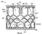
図43および図44は、フレーム904の周りに置かれたカバリングまたは外側カバリング902の一例を含む、また少なくとも部分的にフレーム904内に置かれている複数の弁尖922(図44)を備える人工心臓弁900を例示している。フレーム904は、複数の支柱920を備えることができ、図19のフレーム402に類似する、エドワーズライフサイエンス社製サピエン(Edwards Lifesciences SAPIEN)(登録商標)3人工心臓弁のフレームとして構成され得る。外側カバリング902は、円筒形の形状を有し、織物、編物、または編組織物(たとえば、PET織物、超高分子量ポリエチレン(UHMWPE)織物、PTFE織物など)、フェルトなどの不織布、または押し出しポリマーフィルム(たとえば、ePTFEもしくはUHMWPE膜)から作られた主緩衝層または封止部材/カバー部材906(主層とも称される)を備えることができる。外側カバリング902は、また、フレームの流入端910の周りの周方向に延在する流入保護部分908と、フレームの流出端914の周りの周方向に延在する流出保護部分912とを備えることができる。図43および図44の実施形態において、流入保護部分908および流出保護部分912は、図19~図26の実施形態に類似する主層906の周端部の周りに折り重ねられた材料の別々の細長片として構成されるが、図31Aの実施形態のように、電界紡糸などの、他の手段によって主層906の周縁部分上に形成された潤滑層も含み得る。 43 and 44 include an example of a covering or outer covering 902 positioned around a frame 904, and a prosthesis comprising a plurality of leaflets 922 (FIG. 44) positioned at least partially within the frame 904. A heart valve 900 is illustrated. Frame 904 may comprise a plurality of struts 920 and may be configured as the frame of an Edwards Lifesciences SAPIEN® 3 prosthetic heart valve similar to frame 402 of FIG. The outer covering 902 has a cylindrical shape and is made of a woven, knitted, or knitted fabric (eg, PET fabric, ultra-high molecular weight polyethylene (UHMWPE) fabric, PTFE fabric, etc.), non-woven fabric such as felt, or an extruded polymer film. A primary cushioning layer or sealing member/cover member 906 (also referred to as the primary layer) made from (eg, ePTFE or UHMWPE membrane) can be provided. The outer covering 902 may also include a circumferentially extending inlet protection portion 908 around the frame inlet end 910 and a circumferentially extending outlet protection portion 912 around the frame outlet end 914 . can. 43 and 44, inflow protection portion 908 and outflow protection portion 912 are separate pieces of material folded around the peripheral edge of main layer 906 similar to the embodiment of FIGS. 19-26. Although configured as strips, it may also include a lubricious layer formed on the peripheral portion of the main layer 906 by other means, such as electrospinning, as in the embodiment of Figure 31A.

図43を参照すると、外側カバリング902の層906は、織物または編物を含み得る。層906は、フレーム904の周りで互いから周方向に離間され、フレーム支柱と揃えられるか、またはフレーム支柱の間に画定された開口部の上に重なる複数の穴または開口部916を備え得る。たとえば、例示されている実施形態において、開口部916は、第4の列IVのフレーム支柱とフレームの流出端914の近くの支柱(図34も参照)の第5の列Vとの間に画定される開口部918のレベルに配置され得る。開口部916は、望んでいる特定の特性に応じて、図43の実施形態のように比較的小さいか、またはより大きいものとしてよい。 Referring to FIG. 43, layer 906 of outer covering 902 may comprise a woven or knitted fabric. Layer 906 may include a plurality of holes or openings 916 circumferentially spaced from one another around frame 904 and aligned with frame struts or overlying openings defined between frame struts. For example, in the illustrated embodiment, an opening 916 is defined between the frame struts of the fourth row IV and the fifth row V of struts near the outflow end 914 of the frame (see also FIG. 34). can be positioned at the level of the opening 918 where the Openings 916 may be relatively small, as in the embodiment of FIG. 43, or larger, depending on the particular properties desired.

たとえば、図44を参照すると、いくつかの実施形態において、開口部916はフレーム開口部918と同じサイズおよび形状であるか、またはほぼ同じサイズおよび形状であってよい。したがって、図44の実施形態において、開口部916は、フレーム開口部918の多角形(たとえば、六角形)の形状を備えていてよく、フレーム開口部918と同じサイズまたは面積であってよい。この構成では、主層906の比較的狭い細長片930は、支柱の第4列IVと第5列Vとの間の軸方向に配向された支柱920Aに沿って、弁尖922の交連窓および交連タブ932の上に延在し得る。したがって、いくつかの構成において、カバリング902の開口部916はフレーム開口部918に揃えられるものとしてよく、それなのにカバリング902はフレーム904の外面全体を覆うことができる。言い換えると、カバリング902は、支柱部材920のすべての外面を覆うことができる。 For example, referring to FIG. 44, in some embodiments opening 916 can be the same size and shape as frame opening 918, or about the same size and shape. Thus, in the embodiment of FIG. 44, opening 916 may have the polygonal (eg, hexagonal) shape of frame opening 918 and may be the same size or area as frame opening 918 . In this configuration, the relatively narrow strips 930 of the main layer 906 extend along the axially oriented struts 920A between the fourth and fifth rows IV and V of struts, along the commissural windows and the commissural windows of the leaflets 922. It may extend over the commissural tabs 932 . Thus, in some configurations, the opening 916 of the covering 902 can be aligned with the frame opening 918, yet the covering 902 can cover the entire outer surface of the frame 904. In other words, covering 902 can cover all outer surfaces of strut member 920 .

開口部916は、様々な仕方で形成され得る。いくつかの実施形態において、開口部916は、カバリングがフレーム904上に組み立てられる前に主層906の織物を切って作られる(たとえば、レーザーを使用して)。いくつかの実施形態において、カバリング902は、フレーム904上で互いから軸方向に離間している2つの別々の外側または主層を備え、一方の層は、たとえば、支柱920の第1の列Iと支柱の第4の列IVとの間に延在し、他方の層はフレーム開口部918がカバーを外されるように第5の列Vに沿って延在する。主層906の開口部916は、任意のサイズもしくは形状を有することができ、人工弁の軸に沿った任意の配置に配置されてよく、および/または異なる軸方向配置に配置されてよい。開口部916は、任意の好適な周方向の間隔を有することもできる。 Apertures 916 can be formed in a variety of ways. In some embodiments, openings 916 are cut through the fabric of main layer 906 (eg, using a laser) before the covering is assembled onto frame 904 . In some embodiments, the covering 902 comprises two separate outer or main layers axially spaced apart from each other on the frame 904, one layer being, for example, the first row I of the struts 920. and the fourth row IV of struts and the other layer extends along the fifth row V such that the frame opening 918 is uncovered. The openings 916 in the main layer 906 can have any size or shape, can be arranged in any arrangement along the axis of the prosthetic valve, and/or can be arranged in different axial arrangements. Openings 916 can also have any suitable circumferential spacing.

図45は、外側カバリング902の主層906(封止部材またはカバー部材の一部または全部を形成することができる)は図19のカバリング414に類似するプラッシュ(たとえば、編まれた)パイル層928を含む第1の部分924と、パイルのない第2の部分926とを備える人工弁900の一例を示している。追加の部分も可能である。第1の部分924のプラッシュパイル層928は、フレーム904の周りの周方向に、およびフレーム904に沿って軸方向に流入端部分910から支柱920の第4の列IVのレベルに延在することができる。第2の部分926は、フレーム開口部918の上に位置決めされ、フレーム開口部918より小さい面積を有する、複数の丸い開口部916を画定することができるが、開口部916は、任意のサイズ、形状、配置、および/または間隔を有することができる。パイル層928は、人工弁の軸の任意の部分に沿って延在するように構成され得る。 45 shows that the main layer 906 of the outer covering 902 (which can form part or all of the sealing member or cover member) is a plush (eg, woven) pile layer 928 similar to the covering 414 of FIG. 9 shows an example of a prosthetic valve 900 comprising a first portion 924 with a pile and a second portion 926 without pile. Additional parts are also possible. The plush pile layer 928 of the first portion 924 extends circumferentially around the frame 904 and axially along the frame 904 from the inflow end portion 910 to the level of the fourth row IV of the struts 920. can be done. The second portion 926 is positioned over the frame openings 918 and can define a plurality of rounded openings 916 having areas smaller than the frame openings 918, although the openings 916 can be of any size, It can have shape, placement, and/or spacing. Pile layer 928 may be configured to extend along any portion of the shaft of the prosthetic valve.

いくつかの実施形態において、第1の部分924および第2の部分926は異なる材料片を含む。たとえば、いくつかの実施形態において、第1の部分924は上で説明されているプラッシュパイル層928を備える編物であり、第2の部分926はパイル層のない編物である。第1の部分924および第2の部分926は、互いに重なり合うように構成され得る(たとえば、第1の部分924の一部は、2つの織物片が交わる第2の部分926の上に延在し得る)。第2の部分926は、また、第1の部分924と異なる編みパターンも有することができ、また第1の部分924のストランド/ヤーンと異なる特性(たとえば、デニール、材質、織り目などの表面特性、長繊維の本数、パイルの個数、撚りの個数など)を有するストランド(たとえば、ヤーンなど)を含み得る。いくつかの実施形態において、第1の部分924および/または第2の部分926は、2バーシステム、3バーシステム、4バーシステムなど、または8バーシステム程度のものを使用して形成された編みパターンを含む。第1の部分924および/または第2の部分926は、様々な仕方で、たとえば、円編み技法、かぎ針編み技法、トリコット編み技法、ラッシェル編み技法、その他の技法、またはこれらの組合せを使用して編むことができる。第2の部分926の特性は、開口部916がより容易に(たとえば、レーザー切断によって)形成されることが可能になるように、織物がその構造的完全性を保持することを確実にするように最適化され得る。たとえば、特定のタイプの織られたストランドまたは織られたヤーンから作られた布または織物は、切って中に開口部が作られた場合にバラバラになり、および/または擦り切れる可能性が高い場合があり、したがって第2の部分926は、切って中に開口部が作られたときにバラバラになったり擦り切れたりする可能性が低いバイアス布またはバイアス織物から作ることも可能である。任意選択で、第1の部分924および第2の部分926は、単一の織物片を含むことができる。いくつかの実施形態において、第1の部分924および/または第2の部分926は、不織布材料(たとえば、発泡体、フェルトなど)を含む。 In some embodiments, first portion 924 and second portion 926 comprise different pieces of material. For example, in some embodiments, the first portion 924 is a knitted fabric with the plush pile layer 928 described above and the second portion 926 is a knitted fabric without the pile layer. The first portion 924 and the second portion 926 can be configured to overlap each other (eg, a portion of the first portion 924 extends over the second portion 926 where the two fabric pieces meet). obtain). The second portion 926 can also have a different knitting pattern than the first portion 924, and different properties than the strands/yarns of the first portion 924 (e.g., surface properties such as denier, material, texture, It may include strands (eg, yarns, etc.) having a number of filaments, a number of piles, a number of twists, etc.). In some embodiments, the first portion 924 and/or the second portion 926 are knitted using a 2-bar system, a 3-bar system, a 4-bar system, etc., or as much as an 8-bar system. Contains patterns. The first portion 924 and/or the second portion 926 may be knitted in various ways, such as using circular knitting techniques, crochet knitting techniques, tricot knitting techniques, raschel knitting techniques, other techniques, or combinations thereof. can knit. The properties of the second portion 926 are such as to ensure that the fabric retains its structural integrity so that the openings 916 can be formed more easily (eg, by laser cutting). can be optimized for For example, fabrics or fabrics made from certain types of woven strands or woven yarns may be more likely to break apart and/or fray if cut to create an opening therein. Yes, so the second portion 926 can also be made from a bias cloth or fabric that is less likely to come apart or fray when cut to create an opening therein. Optionally, first portion 924 and second portion 926 can comprise a single piece of fabric. In some embodiments, first portion 924 and/or second portion 926 comprise a nonwoven material (eg, foam, felt, etc.).

開口部916などの開口部を外側カバリング902に含めることで、支柱920および弁尖922の半径方向外向きの表面が弁動作時に人工弁を通って流れる血液に浸かるか、または血液によって洗われるようにカバリングを通り人工弁の内側から外側へ流れる血流を促進するものとしてよい。これは、支柱部材920の周り、および支柱920と弁尖922との間に生じる鬱血を低減するのを助け、潜在的に血栓症のリスクを下げ得る。 The inclusion of openings, such as openings 916, in the outer covering 902 allows the radially outwardly facing surfaces of the struts 920 and leaflets 922 to be bathed or washed by blood flowing through the prosthetic valve during valve actuation. It may also promote blood flow through the covering from the inside to the outside of the prosthetic valve. This can help reduce congestion that occurs around the strut member 920 and between the strut 920 and the leaflets 922, potentially reducing the risk of thrombosis.

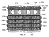
図46~図51は、主緩衝層または封止部材/カバー部材1000の一例を示している。封止部材1000は、本明細書で説明されている人工弁外側カバリングのうちのいずれかに組み込むことができる、複数の第1の部分(たとえば、織られた部分、織られた部分の複数の集まり、など)および複数の第2の部分(たとえば、浮遊ヤーン部分などの浮遊部分として構成される弾性的で伸長可能な部分)などの、一緒になって働く複数の異なる部分を有する織物本体部を含み得る。図46は、平置き構成の封止部材/カバー部材1000を例示しており、x軸は周方向に対応し、y軸は封止部材が人工弁のフレームに取り付けられたときの軸方向に対応する。封止部材1000は、複数の第1の部分(x軸に沿って延在する織られた細長片もしくはストライプとして構成される第1の織り部分1002など)、複数の第2の部分(x軸に沿って延在する織られた細長片もしくはストライプとして構成される第2の織り部分1004など)、複数の第3の部分(x軸に沿って延在する浮遊部分もしくは浮遊ヤーン部分、細長片、もしくはストライプ1006など)、および/または任意選択で追加の部分を含むことができる。様々な織りおよび浮遊部分/浮遊ヤーン部分は、y軸に沿って互いから離間されるものとしてよい。例示されている構成において、第1の織り部分1002は、以下でより詳しく説明されているように、第2の織り部分1004の織りパターンと異なる織りパターンを含む。 46-51 show an example of a primary cushioning layer or sealing member/cover member 1000. FIG. The sealing member 1000 includes a plurality of first portions (eg, a woven portion, a plurality of portions of the woven portion) that can be incorporated into any of the prosthetic valve outer coverings described herein. gathering, etc.) and a plurality of second portions (e.g. elastic stretchable portions configured as floating portions such as floating yarn portions) working together. can include FIG. 46 illustrates the sealing member/cover member 1000 in a flat configuration, with the x-axis corresponding to the circumferential direction and the y-axis being axial when the sealing member is attached to the frame of the prosthetic valve. handle. Sealing member 1000 includes a plurality of first portions (such as first woven portion 1002 configured as woven strips or stripes extending along the x-axis), a plurality of second portions (x-axis , such as a second weave portion 1004 configured as a woven strip or stripe extending along the x-axis, a plurality of third portions (floating or floating yarn portions extending along the x-axis, strip , or stripes 1006), and/or optionally additional portions. The various weaves and floating portions/floating yarn portions may be spaced apart from each other along the y-axis. In the illustrated configuration, the first weave portion 1002 includes a weave pattern that differs from the weave pattern of the second weave portion 1004, as described in more detail below.

例示的な一構成において、例示されているように、封止部材/カバー部材1000は、封止部材/カバー部材の下側または流入縁であり得る、第1の織り部分1002Aを含む。正のy軸に沿った方向に移動することで、封止部材/カバー部材1000は、第2の織り部分1004A、浮遊部分/浮遊ヤーン部分1006A、第2の織り部分1004B、浮遊部分/浮遊ヤーン部分1006B、第2の織り部分1004C、浮遊部分/浮遊ヤーン部分1006C、第2の織り部分1004D、浮遊部分/浮遊ヤーン部分1006D、第2の織り部分1004E、第1の織り部分1002B、第2の織り部分1004F、浮遊部分/浮遊ヤーン部分1006E、第2の織り部分1004G、および第1の織り部分1002Cを第1の織り部分1002Aとは反対の、封止部材/カバー部材の端部においてさらに備え得る。言い換えると、第1の織り部分1002Bおよび浮遊部分/浮遊ヤーン部分1006A~1006Eの各々は、第1の織り部分1002Bおよび浮遊部分/浮遊ヤーン部分1006A~1006Eの各々がそれぞれの第2の織り部分1004によってx軸に沿った方向に境界または縁を付けられるように2つの第2の織り部分1004の間に配置され得る。 In one exemplary configuration, as illustrated, the sealing member/cover member 1000 includes a first weave portion 1002A, which can be the underside or inflow edge of the sealing member/cover member. By moving in a direction along the positive y-axis, the sealing member/cover member 1000 moves between the second weave portion 1004A, the floating portion/floating yarn portion 1006A, the second weaving portion 1004B, the floating portion/floating yarn portion. portion 1006B, second weave portion 1004C, floating portion/floating yarn portion 1006C, second weaving portion 1004D, floating portion/floating yarn portion 1006D, second weaving portion 1004E, first weaving portion 1002B, second A woven portion 1004F, a floating portion/floating yarn portion 1006E, a second woven portion 1004G, and a first woven portion 1002C are further provided at an end of the sealing member/cover member opposite the first woven portion 1002A. obtain. In other words, each of the first weave portion 1002B and the floating portions/floating yarn portions 1006A-1006E is connected to the respective second weave portion 1004. can be positioned between the two second weave portions 1004 so as to be bordered or edged in the direction along the x-axis by the .

図47および図48を参照すると、主層または封止部材/カバー部材1000は、一般的にx軸に沿って配向された複数の第1のストランド1008(たとえば、ヤーンなど)および一般的にy軸に沿って配向された複数の第2のヤーン1010を含み得る。いくつかの構成において、第1のストランド/ヤーン1008は縦ストランド/ヤーンである、すなわち、製織プロセスにおいて、ストランド/ヤーン1008は機によって保持され、第2のストランド/ヤーン1010は横ストランド/ヤーンであり、これらは製織プロセスにおいて移動する杼または横糸支持機構によって縦ストランド/ヤーンと織り合わされる、横ストランド/ヤーンである。しかしながら、いくつかの実施形態において、第1のストランド/ヤーン1008は横ストランド/ヤーンであってよく、第2のストランド/ヤーン1010は縦ストランド/ヤーンであってよい。 47 and 48, a main layer or sealing member/cover member 1000 comprises a plurality of first strands 1008 (eg, yarns, etc.) oriented generally along the x-axis and y It may include a plurality of second yarns 1010 oriented along the axis. In some configurations, the first strand/yarn 1008 is the warp strand/yarn, i.e., the strand/yarn 1008 is held by the loom and the second strand/yarn 1010 is the weft strand/yarn in the weaving process. Yes, these are the weft strands/yarns that are interwoven with the warp strands/yarns by a moving shuttle or weft support mechanism in the weaving process. However, in some embodiments, the first strand/yarn 1008 may be a cross strand/yarn and the second strand/yarn 1010 may be a warp strand/yarn.

第1のストランド/ヤーン1008および第2のストランド/ヤーン1010の各々は、一緒に紡がれる、巻き付けられる、撚られる、混ぜられる、織り混ぜられるなどされてそれぞれのストランド/ヤーンを形成する複数の構成長繊維1012を含み得る。第2のストランド/ヤーン1010の例示的な個別の長繊維1012は図48~図50を見るとわかる。いくつかの実施形態において、第1のストランド/ヤーン1008は、約1Dから約200D、約10Dから約100D、約10Dから約80D、約10Dから約60D、または約10Dから約50Dのデニールを有する。いくつかの実施形態において、第1のストランド/ヤーン1008は、ストランド/ヤーン1本当たり長繊維1本から約600本、ストランド/ヤーン1本当たり長繊維約10本から約300本、ストランド/ヤーン1本当たり長繊維約10本から約100本、ストランド/ヤーン1本当たり長繊維約10本から約60本、ストランド/ヤーン1本当たり長繊維約10本から約50本、またはヤーン1本当たり長繊維約10本から約30本の長繊維本数を有する。いくつかの実施形態において、第1のストランド/ヤーン1008は、約40Dのデニールおよびヤーン1本当たり長繊維24本の長繊維本数を有する。第1のストランド/ヤーン1008は、撚られたストランド/ヤーンまたは撚られていないストランド/ヤーンであってもよい。例示されている実施形態において、第1のストランド/ヤーン1008の長繊維1012はテクスチャード加工されていない。しかしながら、いくつかの実施形態において、第1のストランド/ヤーン1008はテクスチャード加工された長繊維を含み得る。 Each of the first strands/yarns 1008 and the second strands/yarns 1010 may be spun, wrapped, twisted, blended, interwoven, etc. together in multiple configurations to form the respective strands/yarns. Long fibers 1012 may be included. Exemplary individual filaments 1012 of second strand/yarn 1010 can be seen in FIGS. 48-50. In some embodiments, the first strand/yarn 1008 has a denier of about 1D to about 200D, about 10D to about 100D, about 10D to about 80D, about 10D to about 60D, or about 10D to about 50D. . In some embodiments, the first strand/yarn 1008 has 1 to about 600 filaments per strand/yarn, about 10 to about 300 filaments per strand/yarn, About 10 to about 100 long fibers per strand, about 10 to about 60 long fibers per strand/yarn, about 10 to about 50 long fibers per strand/yarn, or per yarn It has a long fiber count of about 10 to about 30 long fibers. In some embodiments, the first strand/yarn 1008 has a denier of about 40D and a filament count of 24 filaments per yarn. The first strand/yarn 1008 may be a twisted strand/yarn or an untwisted strand/yarn. In the illustrated embodiment, the filaments 1012 of the first strand/yarn 1008 are non-textured. However, in some embodiments, the first strand/yarn 1008 may comprise textured filaments.

第2のストランド/ヤーン1010は、複数のテクスチャード加工された長繊維1012を含むテクスチャード加工されたストランド/ヤーンであってよい。たとえば、第2のストランド/ヤーン1010の長繊維1012は、たとえば、上で説明されているように長繊維を撚り、ヒートセットさせ、長繊維の撚りを解くことによってテクスチャード加工され得る。いくつかの実施形態において、第2のストランド/ヤーン1010は、約1Dから約200D、約10Dから約100D、約10Dから約80D、または約10Dから約70Dのデニールを有する。いくつかの実施形態において、第2のストランド/ヤーン1010の長繊維本数は、ストランド/ヤーン1本当たり長繊維1本からストランド/ヤーン1本当たり長繊維約100本、ストランド/ヤーン1本当たり長繊維約10本から長繊維約80本、ストランド/ヤーン1本当たり長繊維約10本から長繊維約60本、またはヤーン1本当たり長繊維約10本から長繊維約50本の間である。いくつかの実施形態において、第2のストランド/ヤーン1010は、約68Dのデニールおよびヤーン1本当たり長繊維約36本の長繊維本数を有する。 Second strand/yarn 1010 may be a textured strand/yarn that includes a plurality of textured filaments 1012 . For example, the filaments 1012 of the second strand/yarn 1010 may be textured by, for example, twisting the filaments, heat setting the filaments, and untwisting the filaments as described above. In some embodiments, the second strand/yarn 1010 has a denier of about 1D to about 200D, about 10D to about 100D, about 10D to about 80D, or about 10D to about 70D. In some embodiments, the number of filaments in the second strand/yarn 1010 ranges from 1 filament per strand/yarn to about 100 filaments per strand/yarn to about 100 filaments per strand/yarn. Between about 10 filaments to about 80 filaments, between about 10 filaments to about 60 filaments per strand/yarn, or between about 10 filaments to about 50 filaments per yarn. In some embodiments, the second strand/yarn 1010 has a denier of about 68D and a filament count of about 36 filaments per yarn.

上で指摘されているように、第1のストランド/ヤーン1008および第2のストランド/ヤーン1010は一緒に織られて、封止部材/カバー部材の織り部分を形成することができる。たとえば、第1の織り部分1002A~1002Cでは、第1のストランド/ヤーン1008および第2のストランド/ヤーン1010は、平織パターンで一緒に織られるものとしてよく、第2のストランド/ヤーン1010(たとえば、横ストランド/ヤーン)は、繰り返しパターンで第1のストランド/ヤーン1008(たとえば、縦糸)の上を通り、次いで、次の第1のストランド/ヤーンの下を通る。この織りパターンは図47に詳しく例示されている。いくつかの実施形態において、第1のストランド/ヤーン1008の密度は、1インチ当たりストランド/ヤーン約10本から1インチ当たりストランド/ヤーン約200本、1インチ当たりストランド/ヤーン約50本から1インチ当たりストランド/ヤーン約200本、または1インチ当たりストランド/ヤーン約100本から1インチ当たりストランド/ヤーン約200本である。いくつかの実施形態において、第1の織り部分1002Aおよび第1の織り部分1002Cは、セルビッジ部分として構成されてよく、第1の織り部分1002Bよりストランド/ヤーン密度が低く、弁フレームへの組み立てが円滑にされ得る。2本上2本下、2本上1本下などの他の織りパターンも使用され得る。第1の織り部分は、綾織、繻子、またはこれらのうちのいずれかの組合せなどの平織派生パターンで織ることもできる。 As noted above, the first strand/yarn 1008 and the second strand/yarn 1010 can be woven together to form the weave of the sealing member/cover member. For example, in first weave portions 1002A-1002C, first strand/yarn 1008 and second strand/yarn 1010 may be woven together in a plain weave pattern, second strand/yarn 1010 (eg, Weft strands/yarns) pass over a first strand/yarn 1008 (eg, warp) and then under the next first strand/yarn in a repeating pattern. This weave pattern is illustrated in detail in FIG. In some embodiments, the density of the first strands/yarns 1008 is from about 10 strands/yarns per inch to about 200 strands/yarns per inch, from about 50 strands/yarns per inch to 1 inch. about 200 strands/yarn per inch, or about 100 strands/yarn per inch to about 200 strands/yarn per inch. In some embodiments, the first weave portion 1002A and the first weave portion 1002C may be configured as selvedge portions and have a lower strand/yarn density than the first weave portion 1002B to facilitate assembly into the valve frame. can be smoothed out. Other weave patterns such as 2 over 2 under, 2 over 1 under, etc. may also be used. The first weave portion may also be woven in a plain derived pattern such as twill, satin, or a combination of any of these.

第2の織り部分1004A~1004Gでは、第1のストランド/ヤーン1008および第2のストランド/ヤーン1010は、第1の織り部分1002A~1002Cの織りパターンと異なる別のパターンで織り合わされ得る。たとえば、例示されている実施形態において、第1のストランド/ヤーン1008および第2のストランド/ヤーン1010は第2の織り部分1004A~1004Gにおいて絡み織りパターンで一緒に織られる。図48は、第2の織り部分1004Bの絡み織りをより詳しく例示している。図48を参照すると、絡み織りは、1本または複数の絡み織りストランド/ヤーンまたは「絡み織り端部」1014、および「縦糸端部」とも称される、4本の第1のストランド/ヤーン1008A、1008B、1008C、および1008Dを含むことができる。図48に例示されているパターンは、半絡み織りの方式の単一絡み織りストランド/ヤーン1014を含む。しかしながら、いくつかの実施形態において、絡み織りパターンは、2本の絡み合う絡み織りストランド/ヤーン1014を含む完全絡み織りパターンまたは他の絡み織り派生織りであってよい。半絡み織り、完全絡み織り、および関連する製織技法の例は、図55A~図55Jに例示されている。 In the second weave portions 1004A-1004G, the first strands/yarns 1008 and the second strands/yarns 1010 may be interwoven in another pattern different from the weave pattern of the first weave portions 1002A-1002C. For example, in the illustrated embodiment, first strand/yarn 1008 and second strand/yarn 1010 are woven together in a leno weave pattern in second weave portions 1004A-1004G. FIG. 48 illustrates in more detail the leno weave of the second weave portion 1004B. Referring to Figure 48, the leno weave consists of one or more leno strands/yarns or "leno weave ends" 1014, and four first strands/yarns 1008A, also referred to as "warp ends". , 1008B, 1008C, and 1008D. The pattern illustrated in FIG. 48 includes single leno strands/yarns 1014 in a semi-leno style. However, in some embodiments, the leno weave pattern may be a full leno weave pattern comprising two intertwined leno strands/yarns 1014 or other leno derived weaves. Examples of semi-leno weaves, full leno weaves, and related weaving techniques are illustrated in Figures 55A-55J.

図48に例示されている半絡み織りでは、第1のストランド/ヤーン1008A~1008Dはx軸に平行に延在するものとしてよく、第2のストランド/ヤーン1010は、たとえば、平織において第1のストランド/ヤーン1008A~1008Dと織り合わされ得る。絡み織りストランド/ヤーン1014は、絡み織りストランド/ヤーン1014が正のy方向の各パスにより第1のストランド/ヤーン1008A~1008Dを越えて、またはその上で交差し、x方向で次の第2のヤーン1010の下にまたは背後に交差し、負のy方向で第1のストランド/ヤーン1008A~1008Dを越えて戻るように第1のストランド/ヤーン1008A~1008Dの周りに織ることができる。このパターンは、第2の織り部分1004Bの長さに沿って繰り返すことができる。この方式では、第2の織り部分1004は、封止要素がフレームに装着されたときにフレームに沿って互いから軸方向に離間する比較的狭く強い織り部分であるものとしてよい。絡み織りストランド/ヤーン1014は、人工弁がクリンプされ拡張されるときに第1のストランド/ヤーン1008A~1008Dおよび第2のストランド/ヤーン1010を互いに関して適所に保つ働きをするものとしてよく、幅を最小にしながら第2の織り部分1004に強度を付与することができる。 In the semi-leno weave illustrated in FIG. 48, the first strands/yarns 1008A-1008D may extend parallel to the x-axis, and the second strands/yarns 1010 are, for example, the first strands/yarns in a plain weave. May be interwoven with strands/yarns 1008A-1008D. The lenostrands/yarns 1014 cross over or over the first strand/yarn 1008A-1008D with each pass in the positive y-direction and the next second strand/yarn 1014 in the x-direction. can be woven around the first strands/yarns 1008A-1008D to cross under or behind the first strands/yarns 1010 and return over the first strands/yarns 1008A-1008D in the negative y direction. This pattern can be repeated along the length of the second weave portion 1004B. In this manner, the second weave 1004 may be a relatively narrow, strong weave that is axially spaced apart from each other along the frame when the sealing element is attached to the frame. The lenostrands/yarns 1014 may serve to hold the first strands/yarns 1008A-1008D and the second strands/yarns 1010 in place with respect to each other when the prosthetic valve is crimped and expanded, and have a width of Strength can be imparted to the second woven portion 1004 while minimizing it.

いくつかの実施形態において、第2の織り部分1004A~1004Gの各々は、上で説明されている絡み織りパターンを含む。いくつかの実施形態において、第2の織り部分1004A~1004Gのうちの1つまたは複数は、絡み織りに組み込む第1のストランド/ヤーン1008を加減する、複数の絡み織り端部をストランド/ヤーン1008の複数のグループの周りに織らせるなどによって異なる形で構成される。いくつかの実施形態において、絡み織りおよび/または平織が芯鞘構造長繊維を有する縦ストランド/ヤーンを含む化学的係止方法が使用される。個別の長繊維の鞘は生体適合性ポリプロピレンなどの低溶融温度ポリマーから作ることができ、長繊維の芯はポリエステルなどの別の生体適合性ポリマーから作ることができる。製織プロセスの後に、以下で説明されるヒートセットプロセスが、鞘の軟化および/または溶融を可能にし得る。冷却した後、軟化された鞘ポリマーは芯ポリエステル長繊維を接着して結合し得る。これは、織り構造の係止を可能にする接着本体部を形成し得る。 In some embodiments, each of the second weave portions 1004A-1004G includes the leno weave pattern described above. In some embodiments, one or more of the second weave portions 1004A-1004G form a plurality of lenoweave ends that moderate the first strands/yarns 1008 incorporated into the lenostrands/yarns 1008. configured in different ways, such as by being woven around multiple groups of In some embodiments, a chemical locking method is used in which the leno weave and/or plain weave comprises warp strands/yarns having sheath-core filaments. The sheath of the individual long fibers can be made from a low melting temperature polymer such as biocompatible polypropylene, and the core of the long fibers can be made from another biocompatible polymer such as polyester. After the weaving process, the heat-setting process described below may allow softening and/or melting of the sheath. After cooling, the softened sheath polymer can adhere and bond the core polyester filaments. This may form an adhesive body that allows locking of the woven structure.

図46を再び参照すると、浮遊部分または浮遊ヤーン部分1006は、y軸に沿って互いから離間するそれぞれの第2の織り部分1004の間でただ1つの軸において延在するストランド/ヤーンを含むことができる。たとえば、浮遊部分/浮遊ヤーン部分1006Aを代表的な一例として取りあげると、浮遊部分/浮遊ヤーン部分1006Aは、第2の織り部分1004Aの絡み織りを出て、浮遊部分/浮遊ヤーン部分1006Aを横切り、浮遊部分/浮遊ヤーン部分内の他の任意のストランド/ヤーンと織り合わされることなく第2の織り部分1004Bの絡み織り内に組み込まれる複数の第2のストランド/ヤーン1010を含むことができる。いくつかの実施形態において、浮遊部分/浮遊ヤーン部分1006内の第2のストランド/ヤーンの密度は、1インチ当たりストランド/ヤーン約10本から約200本、1インチ当たりストランド/ヤーン約50本から約200本、または1インチ当たりストランド/ヤーン約100本から約200本である。いくつかの実施形態において、第2のストランド/ヤーン1010の密度は、1インチ当たりストランド/ヤーン約60~80本である。いくつかの実施形態において、浮遊部分/浮遊ヤーン部分は、第2のストランド/ヤーンが第1のストランド/ヤーンの上に浮遊するか、またはその逆に浮遊するように第2のストランド/ヤーン1010の下にまたは上に配設されるが、織り合わされることがない第1のストランド/ヤーン1008を含む。浮遊部分または浮遊ヤーン部分は、少なくとも人工弁の軸方向に弾力的に伸長可能である、2、3例をあげると、弾力的に伸長可能な織物、編物、編組織物、もしくは不織布織物、またはポリマー膜などの他の任意の弾力的に伸長可能な構造体として構成されてもよい。 Referring again to FIG. 46, the floating portion or floating yarn portion 1006 includes strands/yarns that extend in only one axis between respective second weave portions 1004 spaced apart from each other along the y-axis. can be done. For example, taking floating portion/floating yarn portion 1006A as a representative example, floating portion/floating yarn portion 1006A exits the lenoweave of second weave portion 1004A, traverses floating portion/floating yarn portion 1006A, A plurality of second strands/yarns 1010 can be included that are incorporated within the lenoweave of the second weave portion 1004B without being interwoven with any other strands/yarns within the floating portion/floating yarn portion. In some embodiments, the density of the second strands/yarns in the floating portion/floating yarn portion 1006 is from about 10 to about 200 strands/yarns per inch, from about 50 strands/yarns per inch. about 200, or about 100 to about 200 strands/yarns per inch. In some embodiments, the density of the second strands/yarns 1010 is about 60-80 strands/yarns per inch. In some embodiments, the floating portion/floating yarn portion is positioned above the second strand/yarn 1010 such that the second strand/yarn floats above the first strand/yarn or vice versa. It includes a first strand/yarn 1008 that is disposed below or above the but is not interwoven. The floating portion or floating yarn portion is resiliently stretchable at least in the axial direction of the prosthetic valve, to name a few, a resiliently stretchable woven, knitted, knitted or non-woven fabric, or It may be configured as any other elastically extensible structure such as a polymer membrane.

例示されている実施形態において、織り部分1002A~1002Cおよび1004A~1004Gの各々、ならびに浮遊部分1006A~1006Eの各々は、y軸方向に幅寸法を有する。構成部分の幅は、封止部材/カバー部材1000の全長L1(図46)が拡張構成にある人工心臓弁の軸方向長さに一般的に対応するように構成され得る。たとえば、例示されている実施形態において、第1の織り部分1002Aおよび1002Cは、各々、幅W1を有する。いくつかの実施形態において、幅W1は、第1の織り部分1002Aおよび1002Cの一部分が人工弁のフレームのそれぞれの流入端および/または流出端上に折り重ねられ得るように構成される。 In the illustrated embodiment, each of the woven portions 1002A-1002C and 1004A-1004G and each of the floating portions 1006A-1006E have a width dimension in the y-axis direction. The width of the components can be configured such that the total length L 1 (FIG. 46) of the sealing member/cover member 1000 generally corresponds to the axial length of the prosthetic heart valve in the expanded configuration. For example, in the illustrated embodiment, first weave portions 1002A and 1002C each have a width W1 . In some embodiments, width W1 is configured such that a portion of first woven portions 1002A and 1002C can be folded over respective inflow and/or outflow ends of a prosthetic valve frame.

第1の織り部分1002Bは幅W2を有することができる。図52を参照すると、封止部材/カバー部材1000がエドワーズライフサイエンス社製サピエン(Edwards Lifesciences SAPIEN)(登録商標)3人工心臓弁のフレームと組み合わせて使用されるときに、幅W2は、以下でより詳しく説明されているように、支柱の第4の列IVと第5の列Vとの間の支柱部材によって画定されるフレーム開口部の軸方向寸法に対応するように構成され得る。いくつかの実施形態において、第1の織り部分1002Bの幅W2は、約2mmから約20mm、約2mmから約12mm、または約3mmから約10mmである。いくつかの実施形態において、幅W2は約7mmである。 The first woven portion 1002B can have a width W2 . Referring to FIG. 52, when the sealing/covering member 1000 is used in combination with the frame of the Edwards Lifesciences SAPIEN® 3 heart valve prosthesis, the width W2 is: , can be configured to correspond to the axial dimension of the frame opening defined by the strut members between the fourth row IV and the fifth row V of struts, as described in more detail in . In some embodiments, the width W2 of the first woven portion 1002B is about 2mm to about 20mm, about 2mm to about 12mm, or about 3mm to about 10mm. In some embodiments, width W2 is about 7mm.

第2の織り部分1004A~1004Gは、幅W3(図48)を有することができる。例示されている実施形態において、第2の織り部分1004A~1004Gのすべてが幅W3を有するが、第2の織り部分のうちの1つまたは複数も異なる幅を有し得る。いくつかの実施形態において、幅W3は、約0.1mmから約3mm、約0.1mmから約2mm、または約0.1mmから約1mmなど、比較的短くてよい。いくつかの実施形態において、幅W3は約1mmである。 The second weave portions 1004A-1004G can have a width W 3 (Fig. 48). In the illustrated embodiment, all of the second weave portions 1004A-1004G have a width W3 , although one or more of the second weave portions may also have different widths. In some embodiments, width W3 can be relatively short, such as about 0.1 mm to about 3 mm, about 0.1 mm to about 2 mm, or about 0.1 mm to about 1 mm. In some embodiments, width W3 is about 1 mm.

図46および図49~図52を参照すると、いくつかの実施形態において、封止部材/カバー部材1000、および特に浮遊部分/浮遊ヤーン部分1006A~1006Eは、人工弁の半径方向拡張状態に対応する第1の、自然な、または弛緩した構成(図46および図49)と、人工弁の半径方向圧縮状態に対応する第2の、細長い、または張力をかけられた構成(図50および図51)との間で弾性的に伸長可能である。したがって、浮遊部分1006A~1006Eは、封止部材1000が弛緩した非伸長状態にあるときに初期幅W4を有することができる。図49は、自然な弛緩状態にある浮遊部分1006Bの一部を例示している。織物が弛緩状態にあるときに、第2のストランド/ヤーン1010のテクスチャード加工された長繊維1012は、浮遊部分1006Bが嵩のある、大きく波打つ、または枕に似た品質を有し、圧縮可能な体積または嵩をもたらすように多方向によじれ(kinked)、撚られる(twisted)ことができる。張力がかけられたときに、長繊維1012のよじれ(kinks)、撚れ(twists)などは、y軸に沿って少なくとも部分的に真っ直ぐ引っ張られ、第2のストランド/ヤーン1010を細長くすることができる。したがって、図50を参照すると、浮遊部分1006の幅は、初期幅W4より大きい第2の幅W5まで増大し得る。 46 and 49-52, in some embodiments, the sealing member/cover member 1000, and in particular the floating portion/floating yarn portions 1006A-1006E, correspond to the radially expanded state of the prosthetic valve. A first, native or relaxed configuration (FIGS. 46 and 49) and a second, elongated or tensioned configuration (FIGS. 50 and 51) corresponding to the radially compressed state of the prosthetic valve. is elastically extensible between Thus, floating portions 1006A-1006E can have an initial width W4 when sealing member 1000 is in a relaxed, unstretched state. FIG. 49 illustrates a portion of floating portion 1006B in its natural relaxed state. When the fabric is in a relaxed state, the textured filaments 1012 of the second strand/yarn 1010 are compressible, with the floating portion 1006B having a bulky, wavy, or pillow-like quality. It can be kinked and twisted in multiple directions to provide significant volume or bulk. When tension is applied, the kinks, twists, etc. of the filaments 1012 can be pulled at least partially straight along the y-axis to elongate the second strand/yarn 1010. can. Thus, referring to FIG. 50, the width of the floating portion 1006 may increase to a second width W5 greater than the initial width W4 .

初期幅W4から第2の幅W5に幅が増大する浮遊部分/浮遊ヤーン部分1006A~1006Eの累積効果は、封止部材/カバー部材1000の全体的軸方向寸法が初期長さL1(図46)から第1の長さL1より長い第2の全長L2(図51)に増大し得るという効果である。図51は、浮遊ヤーン部分1006A~1006Eの第2のストランド/ヤーン1010が封止部材の全長が第2の長さL2まで増大するように張力がかかっている状態で真っ直ぐにされた伸長構成をとる封止部材1000を例示している。いくつかの実施形態において、浮遊ヤーン部分1006のサイズ、数、間隔など、および構成要素の第2のストランド/ヤーン1010のテクスチャード加工の程度は、図53および図54を参照しつつ以下で説明されているように、封止部材1000の第2の長さL2が、人工弁が送達装置上で送達できるようにクリンプされたときに人工弁のフレームの長さに対応するように選択され得る。いくつかの実施形態において、浮遊ヤーン部分1006の弛緩状態の初期幅W4は、約1mmから約10mm、約1mmから約8mm、または約1mmから約5mmである。いくつかの実施形態において、初期幅W4は約4mmである。 The cumulative effect of the floating portions/floating yarn portions 1006A-1006E increasing in width from the initial width W4 to the second width W5 is that the overall axial dimension of the sealing member/cover member 1000 is reduced to the initial length L1 ( 46) to a second total length L 2 (FIG. 51) longer than the first length L 1 . FIG. 51 shows a stretched configuration in which the second strands/yarns 1010 of floating yarn portions 1006A-1006E are straightened under tension such that the overall length of the sealing member increases to a second length L2 . 10 illustrates a sealing member 1000 that takes In some embodiments, the size, number, spacing, etc. of the floating yarn portions 1006 and the degree of texturing of the constituent second strands/yarns 1010 are described below with reference to FIGS. As described above, the second length L2 of the sealing member 1000 is selected to correspond to the length of the prosthetic valve frame when the prosthetic valve is crimped for delivery on the delivery device. obtain. In some embodiments, the initial relaxed width W4 of the floating yarn portion 1006 is from about 1 mm to about 10 mm, from about 1 mm to about 8 mm, or from about 1 mm to about 5 mm. In some embodiments, initial width W4 is about 4 mm.

図52は、一対の把持器1050の間に把持される封止部材/カバー部材1000の縁部分を例示している。いくつかの実施形態において、浮遊部分/浮遊ヤーン部分1006内のテクスチャード加工されたストランド/ヤーン1010の嵩のある、波を打つ性質の結果、浮遊部分/浮遊ヤーン部分1006は織り部分1002および1004の厚さt2より大きい厚さt1を有する。たとえば、いくつかの実施形態において、浮遊部分1006の厚さt1は、封止部材が弛緩状態にあるときに、織り部分1002および1004の厚さt2より2倍、3倍、4倍、5倍、6倍、さらには10倍、またはそれ以上大きい。これは、浮遊部分1006が弁本体部の間および/または人工弁が埋め込まれるアンカーもしくはリングに対して自然弁尖の緩衝材となることを可能にし得る。浮遊部分1006は、上で説明されている実施形態のように、解剖学的構造内の空隙または空間を占有し、および/または浮遊部分への組織増殖を促進することもできる。浮遊部分1006を伸長するため張力がかけられると、厚さt1は、テクスチャード加工された第2のストランド/ヤーン1010が真っ直ぐになるときに減少し得る。いくつかの実施形態において、厚さt1は、封止部材が緊張状態にあるときに織り部分1002および1004の厚さt2に等しいか、またはほぼ等しい。人工弁の拡張時など、封止部材1000にかかっている張力が解放されると、ストランド/ヤーン1012はそのテクスチャード加工された形状を取り戻し、浮遊部分1006の厚さは初期厚さt1に戻り得る。 FIG. 52 illustrates edge portions of the sealing member/cover member 1000 gripped between a pair of grippers 1050. FIG. In some embodiments, the bulky, undulating nature of the textured strands/yarns 1010 within the floating portion/floating yarn portion 1006 results in the floating portion/floating yarn portion 1006 interlacing with the woven portions 1002 and 1004. has a thickness t 1 greater than the thickness t 2 of . For example , in some embodiments, the thickness t 1 of the floating portion 1006 is two, three, four times, 5x, 6x, or even 10x or more. This may allow the floating portion 1006 to cushion the native valve leaflets between the valve bodies and/or against anchors or rings in which the prosthetic valve is implanted. The floating portion 1006 can also occupy voids or spaces within the anatomy and/or encourage tissue growth into the floating portion, as in the embodiments described above. When tension is applied to elongate the floating portion 1006, the thickness t 1 may decrease as the textured second strand/yarn 1010 straightens. In some embodiments, thickness t 1 is equal or approximately equal to thickness t 2 of woven portions 1002 and 1004 when the sealing member is in tension. When the tension on the sealing member 1000 is released, such as during expansion of the prosthetic valve, the strands/yarns 1012 resume their textured shape and the thickness of the floating portion 1006 is reduced to the initial thickness t 1 . can return.

図53は、封止部材1000が外側カバリング1018内に形成され、人工弁1022のフレーム1020上に組み立てられていることを例示している。例示されている実施形態において、フレーム1020は、上で説明されているフレームに類似するエドワーズライフサイエンス社製サピエン(Edwards Lifesciences SAPIEN)(登録商標)3人工心臓弁のフレームであるが、封止部材1000は、図56のフレームを含む、他の人工弁でも同様に使用するように構成され得る。外側カバリング1018は、上で説明されている外側カバリングに類似する流入保護部分1024および流出保護部分1026も備えることができ、僧帽弁、三尖弁、大動脈弁、肺動脈弁、下大静脈弁などの自然弁内に埋め込むように構成されるものとしてよいが、いくつかの実施形態において、外側カバリングは、流入保護部分および/または流出保護部分を備える必要はなく、他の心臓弁または体腔にも埋め込むように構成され得る。封止部材1000は、第2の織り部分1004A~1004Gおよび浮遊部分/浮遊ヤーン部分1006A~1006Eがフレーム1020の周りで周方向に延在するように、また浮遊部分/浮遊ヤーン部分1006Aが人工弁の流入端において流入保護部分1024に隣接するように配向され得る。この構成では、テクスチャード加工された第2のストランド/ヤーン1010は、人工弁の縦軸1034に沿った方向に延在する。例示されている実施形態において、第1の織り部分1002Aおよび第2の織り部分1004Aは、少なくとも部分的に流入保護部分1024の下に配設されるものとしてよいが、図には見えてない。同様に、第1の織り部分1002Cおよび第2の織り部分1004Gは、少なくとも部分的に流出保護部分1026の下に配設されるものとしてよいが、これも図には見えてない。 FIG. 53 illustrates sealing member 1000 formed within outer covering 1018 and assembled onto frame 1020 of prosthetic valve 1022 . In the illustrated embodiment, the frame 1020 is that of an Edwards Lifesciences SAPIEN® 3 prosthetic heart valve similar to the frame described above, but with a sealing member. 1000 may be configured for use with other prosthetic valves as well, including the frame of FIG. The outer covering 1018 can also include an inflow protection portion 1024 and an outflow protection portion 1026 similar to the outer coverings described above, such as mitral, tricuspid, aortic, pulmonary, inferior vena cava valves. Although the outer covering need not include inflow and/or outflow protection portions, in some embodiments, other heart valves or body cavities, the outer covering need not include inflow and/or outflow protection portions. It can be configured to be embedded. The sealing member 1000 is configured such that the second weave portions 1004A-1004G and the floating portions/floating yarn portions 1006A-1006E extend circumferentially around the frame 1020, and the floating portion/floating yarn portions 1006A extend around the prosthetic valve. may be oriented so as to be adjacent to the inflow protection portion 1024 at the inflow end of the . In this configuration, the textured second strands/yarns 1010 extend in a direction along the longitudinal axis 1034 of the prosthetic valve. In the illustrated embodiment, the first woven portion 1002A and the second woven portion 1004A may be disposed at least partially below the inflow protection portion 1024, but are not visible in the figures. Similarly, the first weave portion 1002C and the second weave portion 1004G may be disposed at least partially under the spill protection portion 1026, which is also not visible.

なおも図53を参照すると、外側カバリング1018は、取付手段、たとえば、第2の織り部分1004A~1004Gのうちの1つまたは複数に沿って封止部材1000をフレーム1020に縫合する、接着するなどによってフレームに固定され得る。第1の織り部分1002Bは、複数の周方向に離間する開口部1016も含み得る。開口部1016は、上記の図43の実施形態と同様に、支柱の第4の列IVと支柱の第5の列Vとの間のフレーム支柱によって画定される対応する開口部の上に載るようなサイズおよび位置を設定され得る。いくつかの実施形態において、封止部材1000は、第1の織り部分1002B内の開口部なしで図46に例示されている状態の外側カバリング内に組み込まれる。 Still referring to FIG. 53, the outer covering 1018 is attached by means of attachment, such as suturing, gluing, etc. the sealing member 1000 to the frame 1020 along one or more of the second weave portions 1004A-1004G. can be secured to the frame by The first woven portion 1002B may also include a plurality of circumferentially-spaced openings 1016. As shown in FIG. The openings 1016 overlie corresponding openings defined by the frame struts between the fourth row IV of struts and the fifth row V of struts, similar to the embodiment of FIG. 43 above. can be sized and positioned. In some embodiments, the sealing member 1000 is incorporated within the outer covering as illustrated in FIG. 46 without openings in the first woven portion 1002B.

図54は、送達装置1032のバルーンカテーテル1030の遠位端におけるバルーン1028で送達するための人工弁1022を例示している。本明細書で説明されている人工弁とともに使用することができる代表的な送達システムのさらなる詳細は、参照により本明細書に組み込まれている、米国公開第2017/0065415号および米国特許第9,339,384号に記載されている。図53に図示されている例において示されているように、浮遊部分/浮遊ヤーン部分1006A~1006Eは細長く、テクスチャード加工された第2のストランド/ヤーン1010は少なくとも部分的に真っ直ぐにされており、これにより、封止部材1000をクリンプされたフレーム1020の長さ増大を受け入れる長さにすることができる。いくつかの実施形態において、浮遊部分/浮遊ヤーン部分1006A~1006Eは、封止部材1000が約10%から約500%、約10%から約300%、約10%から約200%、約10%から約100%、約10%から約80%、または約10%から約50%、長くできるように構成される。いくつかの実施形態において、浮遊部分/浮遊ヤーン部分1006A~1006Eは、拡張された構成とクリンプされた構成との間でフレーム1022の延びに対応して、封止部材1000を約30%だけ長くすることを可能にするように構成される。上で指摘されているように、浮遊部分/浮遊ヤーン部分1006A~1006Eの幅の増大は、結果として、浮遊部分/浮遊ヤーン部分の厚さの対応する減少を引き起こし、送達時に人工弁のクリンプ外形を縮小することもできる。 FIG. 54 illustrates a prosthetic valve 1022 for delivery with a balloon 1028 at the distal end of balloon catheter 1030 of delivery device 1032. FIG. Further details of exemplary delivery systems that can be used with the prosthetic valves described herein are described in U.S. Publication No. 2017/0065415 and U.S. Patent No. 9,339,384, which are incorporated herein by reference. It is described in. As shown in the example illustrated in FIG. 53, the floating portions/floating yarn portions 1006A-1006E are elongated and the textured second strands/yarns 1010 are at least partially straightened. This allows the sealing member 1000 to be sized to accommodate an increase in length of the crimped frame 1020 . In some embodiments, the floating portion/floating yarn portions 1006A-1006E are about 10% to about 500%, about 10% to about 300%, about 10% to about 200%, about 10% of the sealing member 1000. from about 100%, from about 10% to about 80%, or from about 10% to about 50%. In some embodiments, floating portions/floating yarn portions 1006A-1006E lengthen sealing member 1000 by about 30% in response to elongation of frame 1022 between the expanded and crimped configurations. configured to allow As pointed out above, an increase in the width of the floating portion/floating yarn portions 1006A-1006E results in a corresponding decrease in the thickness of the floating portion/floating yarn portions, reducing the crimp profile of the prosthetic valve during delivery. can also be reduced.

いくつかの実施形態において、第1のストランド/ヤーン1008および第2のストランド/ヤーン1010は、PET、ナイロン、ePTFE、UHMWPEなど、または他の好適な天然もしくは合成繊維などの、様々な生体適合性熱可塑性ポリマーのうちのいずれかを含むことができる。いくつかの実施形態において、封止部材1000は、機で織られるものとしてよく、次いで、熱処理またはヒートセットされて、所望のサイズおよび構成にされ得る。たとえば、選択された材料に応じて、ヒートセットは、封止部材1000の収縮を引き起こし得る。ヒートセットは、第2のストランド/ヤーン1010の、テクスチャード加工効果も引き起こすか、またはテクスチャード加工の量を増やし得る。熱処理後に、開口部1016は、第1の織り部分1002B内に(たとえば、レーザー切断によって)形成されてよく、封止部材は、人工弁上に組み立てるためにカバリング1018などの外側カバリング内に組み込まれ、および/または形成し得る。いくつかの実施形態において、開口部1016は、熱処理前に形成することもできる。 In some embodiments, first strand/yarn 1008 and second strand/yarn 1010 are made of various biocompatible materials such as PET, nylon, ePTFE, UHMWPE, etc., or other suitable natural or synthetic fibers. Any of the thermoplastic polymers can be included. In some embodiments, the sealing member 1000 may be machine woven and then heat treated or heat set to the desired size and configuration. For example, depending on the materials selected, heat setting may cause the sealing member 1000 to shrink. Heat setting may also cause a texturing effect or increase the amount of texturing of the second strand/yarn 1010 . After heat treatment, opening 1016 may be formed (eg, by laser cutting) in first woven portion 1002B, and sealing member incorporated into an outer covering, such as covering 1018, for assembly onto a prosthetic valve. , and/or may form. In some embodiments, openings 1016 can also be formed prior to heat treatment.

いくつかの実施形態において、本明細書で説明されている人工弁封止部材の輪、長繊維、浮遊部分、浮遊ヤーン部分などは、人工弁と周辺解剖学的構造との間にシールを形成するために生物学的反応を促進するように構成され得る。いくつかの構成において、本明細書において説明されている封止部材は、選択された期間にわたってシールを形成するように構成され得る。たとえば、いくつかの実施形態において、輪、長繊維、ストランド/ヤーンなどの開いている、多孔質の性質は、埋め込みの後の時間期間において人工弁の周りの選択された量の弁傍漏れを許すことができる。シール構造を越える弁傍漏れの量は、輪、長繊維、ストランド/ヤーンなどへの生物学的反応が血液凝固、組織成長侵入などを引き起こすので、選択された期間にわたって徐々に減らされるものとしてよい。いくつかの実施形態において、封止部材および特に弁傍封止構造体の輪、長繊維、ストランド/ヤーンなどは、封止構造体への生物学的反応を抑制する1つまたは複数の薬剤で処理される。たとえば、いくつかの実施形態において、輪、長繊維、ストランド/ヤーンなどは、ヘパリンで処理される。いくつかの実施形態において、薬剤の量または濃度は、弁を埋め込んだ後の選択された期間(たとえば、日、週、または月)後に薬剤が消耗するように選択される。薬剤が消耗した後、封止構造体の輪、長繊維、ストランド、ヤーンなどへの生物学的反応は、弁傍シールが選択された期間にわたって徐々に形成するように増大し得る。これは、人工弁を通り過ぎる逆流が徐々に減少するときにリモデリングが反転する機会を用意することにより、左心房または左心室リモデリング(たとえば、僧帽弁逆流などによる)などの心臓リモデリングに苦しんでいる患者にとって有益であり得る。 In some embodiments, the loops, filaments, floating portions, floating yarn portions, etc. of the prosthetic valve sealing members described herein form a seal between the prosthetic valve and the surrounding anatomy. It can be configured to promote a biological response to do so. In some configurations, the sealing members described herein can be configured to form a seal for a selected period of time. For example, in some embodiments, the open, porous nature of the annulus, filaments, strands/yarns, etc., allows a selected amount of paravalvular leakage around the prosthetic valve for a period of time after implantation. can forgive. The amount of paravalvular leakage across the seal structure may be gradually reduced over a selected period of time as biological reactions to annulus, filaments, strands/yarns, etc. cause blood clotting, tissue growth invasion, etc. . In some embodiments, the sealing members, and particularly the rings, filaments, strands/yarns, etc. of the paravalvular sealing structure are coated with one or more agents that inhibit the biological response to the sealing structure. It is processed. For example, in some embodiments, loops, filaments, strands/yarns, etc. are treated with heparin. In some embodiments, the amount or concentration of drug is selected such that the drug is exhausted after a selected period of time (eg, days, weeks, or months) after implanting the valve. After depletion of the agent, the biological response to the loops, filaments, strands, yarns, etc. of the sealing structure may increase such that a paravalvular seal gradually forms over a selected period of time. This is useful for cardiac remodeling, such as left atrial or left ventricular remodeling (e.g., due to mitral regurgitation), by providing an opportunity for remodeling to reverse when regurgitation past the prosthetic valve is gradually reduced. It can be beneficial to the suffering patient.

図55A~図55Jは、封止部材/カバー部材1000、または本明細書で説明されている他の封止部材/カバー部材のうちのいずれかを生産するために使用することができる様々な絡み織りおよび絡み織り技法を例示している。図55Aは、絡み織りヤーン、「絡み織り端部」、または「交差端」1060が横ストランド/ヤーン1064より上の図の左に頂部シェッドを形成し、標準縦ストランド/ヤーン1062が底部シェッドを形成するシェッド(たとえば、上側および下側縦ストランド/ヤーンを形成するための縦ストランド/ヤーンの一時的分離)を例示する断面図である。図55Bは、絡み織りストランド/ヤーン1060が標準縦ストランド/ヤーン1062の右に頂部シェッドを形成する連続シェッドを例示している。図55Aおよび図55Bにおいて、絡み織りストランド/ヤーン1060は、底部搦みとして知られているパターンの標準ストランド/ヤーン1062の下で交差することができる。代替的に、絡み織りストランド/ヤーン1060は、図55Hおよび図55Iのように、頂部搦みとして知られている、標準ストランド/ヤーン1062の上で交差することができる。 55A-55J illustrate various entanglements that can be used to produce the sealing member/cover member 1000, or any of the other sealing member/cover members described herein. It illustrates weaving and leno weaving techniques. FIG. 55A shows leno yarns, "leno ends" or "cross ends" 1060 forming the top shed to the left of the figure above the weft strands/yarns 1064 and the standard warp strands/yarns 1062 forming the bottom shed. FIG. 5 is a cross-sectional view illustrating the forming shed (eg, temporary separation of warp strands/yarns to form upper and lower warp strands/yarns). FIG. 55B illustrates a continuous shed in which the leno strand/yarn 1060 forms the top shed to the right of the standard warp strand/yarn 1062. FIG. In Figures 55A and 55B, the leno weave strands/yarns 1060 can cross under the standard strands/yarns 1062 in a pattern known as the bottom braid. Alternatively, the leno weave strands/yarns 1060 can cross over the standard strands/yarns 1062, known as the top braid, as in Figures 55H and 55I.

図55Cは、縦糸巻きが一方の機で使用されるときに形成される絡み織り交ぜパターンを例示しており、絡み織りストランド/ヤーン1060および標準ストランド/ヤーン1062の歪みまたは張力はストランド/ヤーン1060およびストランド/ヤーン1062が両方とも横ストランド/ヤーン1064の周りに湾曲するように等しい。図55Dは、複数の縦糸巻きが使用されるときに形成される絡み織りレーシングパターンを例示しており、絡み織りストランド/ヤーン1060は、絡み織りストランド/ヤーン1060が標準ストランド/ヤーン1062の周りに湾曲している間に、標準ストランド/ヤーン1062が織りにおいて比較的真っ直ぐなままであり、横ストランド/ヤーン1064に垂直であるように標準ストランド/ヤーン1062より弱い張力をかけられている。 FIG. 55C illustrates the entanglement interlace pattern formed when the warp winding is used on one loom, where the strain or tension of the lenostrands/yarns 1060 and the standard strands/yarns 1062 is reduced to the strands/yarns 1060. and strands/yarns 1062 are both curved around the transverse strands/yarns 1064. FIG. 55D illustrates a leno lacing pattern formed when multiple warp windings are used, with leno strands/yarns 1060 wrapped around standard strands/yarns 1062. FIG. While curved, the standard strands/yarns 1062 remain relatively straight in the weave and are less tensioned than the standard strands/yarns 1062 to be perpendicular to the weft strands/yarns 1064 .

図55Eは、図55Cに対応しているが、隣接する絡み織りストランド/ヤーン1060が対向するレーシング方向を有するように交互絡み織りストランド/ヤーン1060がポイントドラフトされる(point-drafted)(絡み織りストランド/ヤーンが綜絖に引き通される技法)織り混ぜパターンを例示している。図55Fは、図55Dに対応しているが、隣接する絡み織りストランド/ヤーンが対向するレーシング方向を有するように絡み織りストランド/ヤーン1060がポイントドラフトされる、織り交ぜパターンを例示している。 FIG. 55E corresponds to FIG. 55C, but alternating leno strands/yarns 1060 are point-drafted (leno weave) so that adjacent leno strands/yarns 1060 have opposite lacing directions. A technique in which the strands/yarns are pulled through the heddles) exemplifies the interwoven pattern. FIG. 55F corresponds to FIG. 55D but illustrates an interlace pattern in which the leno strands/yarns 1060 are point drafted such that adjacent leno strands/yarns have opposite lacing directions.

図55Gは、横ストランド/ヤーン1064を通してとられた平絡み織り構造の断面図である。 55G is a cross-sectional view of the plain leno weave structure taken through the transverse strands/yarns 1064. FIG.

図55Jは、織物の裏側から見たときの代表的な絡み織りを例示している。 Figure 55J illustrates a typical leno weave when viewed from the back side of the fabric.

本明細書で説明されている人工弁実施形態は、様々な異なるタイプの人工心臓弁で使用することもできる。たとえば、カバリングは、図56に例示されている弁1100などの、機械的拡張可能人工心臓弁で使用するように、適合されるものとしてよく、いくつかの実施形態において、適合される。人工弁1100は環状ステントまたはフレーム1102、およびフレーム1102内に置かれフレーム1102に結合されている弁尖構造体1104を備え得る。フレーム1102は、流入端1106および流出端1108を備えることができる。弁尖構造体は、弁尖が弁尖のそれぞれの流出縁部分1134が互いに接触する交連1132を形成するように大動脈弁に類似する三尖弁配置で折り畳むように配置されている3つの弁尖などの複数の弁尖1110を備えることができる。任意選択で、人工弁は、具体的用途に応じて、僧帽弁に類似する二尖弁配置で折り畳むように構成されている2つの弁尖1110、または3つより多い弁尖を備えることができる。 The prosthetic valve embodiments described herein can also be used with a variety of different types of prosthetic heart valves. For example, the covering may, and in some embodiments, is adapted for use with a mechanically expandable prosthetic heart valve, such as the valve 1100 illustrated in FIG. Prosthetic valve 1100 may comprise an annular stent or frame 1102 and a leaflet structure 1104 positioned within and coupled to frame 1102 . Frame 1102 can include an inflow end 1106 and an outflow end 1108 . The leaflet structure is arranged so that the three leaflets fold in a tricuspid configuration similar to the aortic valve such that the leaflets form commissures 1132 where the respective outflow edge portions 1134 of the leaflets contact each other. A plurality of leaflets 1110 such as can be provided. Optionally, the prosthetic valve may comprise two leaflets 1110 configured to fold in a bicuspid configuration similar to the mitral valve, or more than three leaflets, depending on the specific application. can.

図56を参照すると、フレーム1102は、格子型パターンで配置され、人工弁の流出端1108において複数の先端1114を形成する複数の相互接続された格子支柱1112を備えることができる。支柱1112は、人工弁の流入端1106において類似の先端1114を形成することもできる。格子支柱1112は、支柱が互いに重なり合う場所に配置されたヒンジ1116によって互いに、また先端1114にも、枢動可能に結合され得る。ヒンジ1116は、フレーム1102が人工弁1100の組み立て、準備、または埋め込みなどの際に支柱1112が拡張または収縮するときに互いに関して枢動することを可能にし得る。ヒンジ1116は、支柱が互いに重なり合う配置で支柱1112内に形成された開口を貫通するリベットまたはピンを備えることができる。図56の実施形態において、支柱1112は5個のヒンジ1116に対する開口を備える。しかしながら、支柱は、フレームの特定のサイズなどに応じて任意の数のヒンジを備え得る。たとえば、いくつかの実施形態において、支柱は図57に示されている構成と同様に、7個のヒンジを備える。フレーム1102ならびにフレームを半径方向に拡張および折り畳むためのデバイスおよび技術に関する追加の詳細は、参照により本明細書に組み込まれている、米国公開第2018/0153689号に記載されている。 Referring to FIG. 56, the frame 1102 can comprise a plurality of interconnected grid struts 1112 arranged in a grid pattern and forming a plurality of tips 1114 at the outflow end 1108 of the prosthetic valve. The struts 1112 can also form similar tips 1114 at the inflow end 1106 of the prosthetic valve. Grid struts 1112 may be pivotally coupled to each other and also to tips 1114 by hinges 1116 located where the struts overlap each other. Hinge 1116 may allow frame 1102 to pivot relative to each other as struts 1112 expand or contract, such as during assembly, preparation, or implantation of prosthetic valve 1100 . The hinges 1116 may comprise rivets or pins that pass through openings formed in the posts 1112 in an overlapping arrangement of the posts. In the embodiment of FIG. 56, the post 1112 has openings for five hinges 1116. In the embodiment of FIG. However, the struts may have any number of hinges, depending on the particular size of the frame, etc. For example, in some embodiments the strut comprises seven hinges, similar to the configuration shown in FIG. Additional details regarding the frame 1102 and devices and techniques for radially expanding and collapsing the frame are described in US Publication No. 2018/0153689, which is incorporated herein by reference.

図56に例示されているように、フレーム1102は、フレームを半径方向に拡張し、収縮させるように構成されている解放および係止ユニット(係止アセンブリとも称される)として機能することもできる複数のアクチュエータコンポーネント1118を備えることができる。例示されている構成において、フレーム1102は、ポストとして構成され、周方向に離間する配置でフレーム1102に結合されている3つのアクチュエータコンポーネント1118を備えるが、フレームが備えることができるアクチュエータコンポートの数は、具体的用途に応じて多い場合も少ない場合もある。アクチュエータコンポーネント1118の各々は、一般的に、内側チューブ状部材などの内側部材1120と、内側部材1120の周りに同心円状に配設されている外側チューブ状部材などの外側部材1122とを備えることができる。内側部材1120および外側部材1122は、米国公開第2018/0153689号においてさらに説明されているように、フレーム1102を径方向に拡張し、収縮させる伸縮方式で互いに関して縦方向に移動可能であるものとしてよい。 As illustrated in FIG. 56, the frame 1102 can also function as a release and locking unit (also referred to as locking assembly) configured to radially expand and contract the frame. Multiple actuator components 1118 can be provided. In the illustrated configuration, the frame 1102 comprises three actuator components 1118 configured as posts and coupled to the frame 1102 in circumferentially spaced arrangements, although the number of actuator components a frame can comprise is , which may be more or less depending on the specific application. Each of the actuator components 1118 can generally comprise an inner member 1120, such as an inner tubular member, and an outer member 1122, such as an outer tubular member, disposed concentrically around the inner member 1120. can. Inner member 1120 and outer member 1122 are assumed to be longitudinally moveable relative to each other in a telescoping fashion to radially expand and contract frame 1102, as further described in US Publication No. 2018/0153689. good.

例示されている構成において、内側部材1120は、フレーム1102の流入端1106に(たとえば、ピン部材などの結合要素により)結合されている遠位端部分1124を有する。例示されている実施形態において、内側部材1120の各々は、フレームの流入端1106のそれぞれの先端1114においてフレームに結合される。外側部材1122は、たとえば、図56に示されているような、外側部材の中間部分の、または必要ならば、外側部材の近位端部分の、フレーム1102の流出端1108において先端1114に結合され得る。 In the illustrated configuration, inner member 1120 has a distal end portion 1124 that is coupled (eg, by a coupling element such as a pin member) to inflow end 1106 of frame 1102 . In the illustrated embodiment, each inner member 1120 is coupled to the frame at a respective tip 1114 at the inflow end 1106 of the frame. Outer member 1122 is coupled to tip 1114 at outflow end 1108 of frame 1102, eg, at the middle portion of the outer member, or at the proximal end portion of the outer member, if desired, as shown in FIG. obtain.

内側部材1120および外側部材1122は、完全に収縮した状態(人工弁の完全に半径方向に拡張した状態に対応する)と、完全に伸長した状態(人工弁の完全に半径方向に圧縮された状態に対応する)との間で互いに関して伸縮し得る。完全に伸長した状態では、内側部材1120は、外側部材1122から完全に伸長している。この方式で、アクチュエータコンポーネント1118は、人工弁が完全に拡張されるか、または異なる直径に部分的に拡張されることを可能にし、人工弁を部分的にまたは完全に拡張された状態に保持する。 The inner member 1120 and the outer member 1122 can be in a fully contracted state (corresponding to the fully radially expanded state of the prosthetic valve) and a fully extended state (the fully radially compressed state of the prosthetic valve). ) can be stretched with respect to each other. In the fully extended state, inner member 1120 is fully extended from outer member 1122 . In this manner, the actuator component 1118 allows the prosthetic valve to be fully expanded or partially expanded to different diameters and holds the prosthetic valve in a partially or fully expanded state. .

いくつかの実施形態において、アクチュエータコンポーネント1118は、アクチュエータのコンポーネントのうちの1つを回転させることによってフレーム1102を半径方向に拡張し、圧縮するように構成されているネジアクチュエータである。たとえば、内側部材1120は、対応する外側コンポーネントの雌ネジと係合する雄ネジを有するネジとして構成され得る。ネジアクチュエータに関するさらなる詳細は、米国公開第2018/0153689号において開示されている。 In some embodiments, actuator component 1118 is a screw actuator configured to radially expand and compress frame 1102 by rotating one of the actuator's components. For example, inner member 1120 may be configured as a screw with external threads that mate with internal threads on a corresponding outer component. Further details regarding screw actuators are disclosed in US Publication No. 2018/0153689.

人工弁1100は、交連留め金または締め具1136として構成されている複数の交連支持要素も備え得る。例示されている構成において、人工弁は、各交連1132において位置決めされ、フレーム1102の半径方向内向きに離間されている配置において交連の弁尖1110を把持するように構成されている交連締め具1136を備える。交連締め具に関するさらなる詳細は、参照により本明細書に組み込まれている、米国公開第2018/0325665号において開示されている。 Prosthetic valve 1100 may also include multiple commissural support elements configured as commissural clasps or fasteners 1136 . In the illustrated configuration, a prosthetic valve is positioned at each commissure 1132 with commissure clamps 1136 configured to grip the leaflets 1110 of the commissure in a radially inwardly spaced configuration of the frame 1102. Prepare. Further details regarding commissural fasteners are disclosed in US Publication No. 2018/0325665, which is incorporated herein by reference.

図57は、弁尖、弁尖締め具、およびアクチュエータコンポーネントなどのコンポーネントが図解のために取り除かれている機械的拡張可能フレーム1202の一例を例示している。フレーム1202は、支柱1204がヒンジ1116に類似するヒンジを形成するために各支柱の長さに沿って離間する7個の開口1206を備えることを除き、フレーム1102に類似しているものとしてよい。たとえば、各支柱1204は、真っ直ぐな部分またはセグメント1214によって接続される複数の丸い、湾曲した、または円形の部分1212を備えることができる。各連続するセグメント1214は、米国公開第2018/0153689号で説明されているように、先行するセグメント1214に平行であるが、先行するセグメント1214から周方向にオフセットされ得る。各丸い部分1212は、開口1206を画定することができる。したがって、例として支柱部材1204Aを取りあげると、フレーム1202の流入端1208における丸い部分1212Aは開口1206Aを画定することができる。流入端1210の方向で支柱1204Aに沿って移動することで、部分1212Bは開口1206Bを画定することができ、部分1212Cは開口1206Cを画定することができ、部分1212Dは開口1206Dを画定することができ、部分1212Eは開口1206Eを画定することができ、部分1212Fは開口1206Fを画定することができ、部分1212Gは流出端1210において開口1206Gを画定することができる。開口、およびそれとともに形成されるヒンジは、実質的に上で説明されているとおりに機能し、フレームが送達の場合には半径方向に折り畳まれ、治療部位にあるときに半径方向に拡張されることを可能にすることができる。 FIG. 57 illustrates an example of a mechanical expandable frame 1202 with components such as leaflets, leaflet clamps, and actuator components removed for illustration. Frame 1202 may be similar to frame 1102 except that struts 1204 include seven openings 1206 spaced along the length of each strut to form a hinge similar to hinge 1116 . For example, each strut 1204 can comprise multiple rounded, curved, or circular portions 1212 connected by straight portions or segments 1214 . Each successive segment 1214 may be parallel to, but circumferentially offset from, the preceding segment 1214 as described in US Publication No. 2018/0153689. Each rounded portion 1212 can define an opening 1206 . Thus, taking strut member 1204A as an example, rounded portion 1212A at inlet end 1208 of frame 1202 can define opening 1206A. By moving along post 1204A in the direction of inflow end 1210, portion 1212B can define opening 1206B, portion 1212C can define opening 1206C, and portion 1212D can define opening 1206D. The portion 1212E can define an opening 1206E, the portion 1212F can define an opening 1206F, and the portion 1212G can define an opening 1206G at the outflow end 1210. The apertures, and hinges formed therewith, function substantially as described above, with the frame radially collapsed for delivery and radially expanded when at the treatment site. can make it possible.

例示されている構成において、支柱1204は2つのセットで配置され、第1のセットはフレーム1202の内側にあり、互いに周方向にオフセットされ、支柱がフレームの中心軸1216の周りに螺旋状に延在するように角度を付けられる。図57の実施形態では、支柱1204Bおよび1204Cは支柱の第1の、または内側セットの一部である。支柱1204の第2のセットは、支柱の第1のセットの半径方向外向きに配設され得る。支柱の第2のセットは、開口1206は支柱の内側セットの開口1206に揃うように角度を付けることができ、支柱の第1のセットと反対の向きの螺旋で配向され得る。図57に例示されている実施形態において、支柱1204Aおよび1204Dは支柱の第2の、または外側セットの一部である。支柱1204の内側および外側セットは、それぞれの丸い部分1212が揃えられるフレームの流入先端1218を形成することができ、支柱の対向端におけるそれぞれの丸い部分が揃えられる流出先端1220を形成することができる。拡張された構成において、支柱の内側および外側セットの支柱1204は、複数のダイアモンド形状のセルまたは開口部1222を画定することもできる。 In the illustrated configuration, the struts 1204 are arranged in two sets, the first set inside the frame 1202 and circumferentially offset from each other such that the struts extend spirally around the central axis 1216 of the frame. angled to be present. In the embodiment of Figure 57, struts 1204B and 1204C are part of a first or inner set of struts. A second set of struts 1204 may be disposed radially outward of the first set of struts. The second set of struts can be angled such that the openings 1206 align with the openings 1206 of the inner set of struts and can be oriented with an opposite helix as the first set of struts. In the embodiment illustrated in FIG. 57, struts 1204A and 1204D are part of a second or outer set of struts. The inner and outer sets of struts 1204 can form inflow tips 1218 of the frame with their respective rounded portions 1212 aligned, and can form outflow tips 1220 with their respective rounded portions aligned at opposite ends of the struts. . In the expanded configuration, the struts 1204 of the inner and outer sets of struts can also define a plurality of diamond-shaped cells or openings 1222 .

図58および図59は、主緩衝層、カバー部材、または封止部材1300の一例を示している。封止部材1300は、図46の実施形態に類似する、複数の織り部分および1つまたは複数の浮遊部分(たとえば、浮遊ヤーン部分、など)を有する織物本体部を備えることができる。図58は、平置き構成の封止部材1300を例示しており、x軸は周方向に対応し、y軸は封止部材1300が人工弁のフレームに取り付けられたときの軸方向に対応する。図59は、封止部材1300の一部分の拡大図である。封止部材1300の流入端部分1310から始めて、封止部材は第1の織り部分1302Aを含み得る。正のy軸に沿った方向に移動することで、封止部材1300は、第2の織り部分1304Aと、浮遊部分/浮遊ヤーン部分1306と、第2の織り部分1304Bと、第1の織り部分1302Bとをさらに備え得る。第1の織り部分1302Bは、浮遊部分/浮遊ヤーン部分の、第1の織り部分1302Aとは反対の側の流出端部分1312において配置される。 58 and 59 show an example of a primary cushioning layer, cover member, or sealing member 1300. FIG. The sealing member 1300 can comprise a woven body having a plurality of woven portions and one or more floating portions (eg, floating yarn portions, etc.) similar to the embodiment of FIG. FIG. 58 illustrates the sealing member 1300 in a flat configuration, with the x-axis corresponding to the circumferential direction and the y-axis corresponding to the axial direction when the sealing member 1300 is attached to the frame of the prosthetic valve. . FIG. 59 is an enlarged view of a portion of sealing member 1300. FIG. Beginning at the inflow end portion 1310 of the sealing member 1300, the sealing member can include a first weave portion 1302A. By moving in a direction along the positive y-axis, sealing member 1300 moves between second weave portion 1304A, floating portion/floating yarn portion 1306, second weave portion 1304B, and first weave portion 1304B. 1302B. The first weave portion 1302B is positioned at the outflow end portion 1312 of the floating portion/floating yarn portion on the side opposite the first weave portion 1302A.

なおも図59を参照すると、封止部材1300は、上記の例のように、x方向に延在するストランド/ヤーン1308(たとえば、縦ストランド/ヤーン)と、y方向に延在するストランド/ヤーン1314(たとえば、横ストランド/ヤーン)とを備えることができる。いくつかの実施形態において、少なくともストランド/ヤーン1314はテクスチャード加工され得る。テクスチャード加工されたストランド/ヤーン1314は、第1の織り部分1302A、および第2の織り部分1304Aにおいてストランド/ヤーン1308と織り合わされるものとしてよい。テクスチャード加工されたストランド/ヤーン1314は、第2の織り部分1304Bへ延在するか、または「浮遊」して渡り、浮遊部分/浮遊ヤーン部分1306を形成することができる。ストランド/ヤーン1314は第2の織り部分1304Bにおいて織りに再入することができる。 Still referring to FIG. 59, the sealing member 1300 includes strands/yarns 1308 extending in the x-direction (e.g., warp strands/yarns) and strands/yarns 1308 extending in the y-direction, as in the examples above. 1314 (eg, weft strands/yarns). In some embodiments, at least strands/yarns 1314 may be textured. Textured strands/yarns 1314 may be interwoven with strands/yarns 1308 in first weave portion 1302A and second weave portion 1304A. The textured strands/yarns 1314 may extend or “float” across the second woven portion 1304B to form the floating portion/floating yarn portion 1306. FIG. Strand/yarn 1314 can reenter the weave in second weave portion 1304B.

図46の実施形態のように、第1の織り部分1302Aおよび1302Bは、平織を含み得る。いくつかの実施形態において、第1の織り部分1302Aおよび/または第1の織り部分1302Bは、1インチ当たりストランド/ヤーン40本から1インチ当たりストランド/ヤーン120本などの、1インチ当たりストランド/ヤーン(または端)20本から1インチ当たりストランド/ヤーン150本のストランド/ヤーン密度を有することができる。いくつかの実施形態において、第1の織り部分1302Aおよび1302Bは、セルビッジとして構成されるものとしてよく、織物がほどけるのを防ぐことができる。 As with the embodiment of Figure 46, the first weave portions 1302A and 1302B may comprise a plain weave. In some embodiments, the first weave portion 1302A and/or the first weave portion 1302B has a strands/yarn per inch, such as 40 strands/yarns per inch to 120 strands/yarns per inch. (or ends) can have a strand/yarn density of 20 to 150 strands/yarn per inch. In some embodiments, the first woven portions 1302A and 1302B can be configured as selvedges to prevent unraveling of the fabric.

第2の織り部分1304Aは、浮遊部分/浮遊ヤーン部分1306の下側縁に沿って延在することができ、第2の織り部分1304Bは、浮遊部分/浮遊ヤーン部分1306の上側縁に沿って延在することができる。この方式で、浮遊部分/浮遊ヤーン部分1306は、第2の織り部分1304Aおよび1304Bによってx軸に沿った方向に境界または縁を付けられるものとしてよい。いくつかの構成において、第2の織り部分1304Aおよび1304Bの幅は、図46の実施形態と同様に、第1の織り部分1302Aおよび1302Bと比べて比較的小さいものとしてよい。いくつかの実施形態において、第2の織り部分1304Aおよび1304Bは、上で説明されている絡み織りパターンのうちのいずれかなどの、絡み織りパターンを含む。たとえば、図59の例を参照すると、第2の織り部分1304Aおよび1304Bの各々は、ストランド/ヤーン1314およびストランド/ヤーン1308の周りに絡み合う2つの絡み織り端1316を含む。いくつかの実施形態において、第2の織り部分1304Aおよび1304Bは、1つの絡み織り端、または2つより多い絡み織り端を含む。 The second weave portion 1304A can extend along the lower edge of the floating portion/floating yarn portion 1306 and the second weaving portion 1304B can extend along the upper edge of the floating portion/floating yarn portion 1306. can be extended. In this manner, the floating portion/floating yarn portion 1306 may be bounded or edged in the direction along the x-axis by the second weave portions 1304A and 1304B. In some configurations, the width of the second weave portions 1304A and 1304B may be relatively small compared to the first weave portions 1302A and 1302B, similar to the embodiment of FIG. In some embodiments, second weave portions 1304A and 1304B comprise a leno weave pattern, such as any of the leno weave patterns described above. For example, referring to the example of FIG. 59, second weave portions 1304A and 1304B each include two entwined ends 1316 that intertwine around strand/yarn 1314 and strand/yarn 1308 . In some embodiments, the second weave portions 1304A and 1304B include one leno selvedge, or more than two leno selvedges.

封止部材1300は、図46の実施形態と同様に、非緊張状態に対応する第1の、自然な幅と、封止部材がy方向に伸長されるときの第2の幅との間で弾性的に伸長可能であるものとしてよい。前に説明されている実施形態のように、浮遊部分/浮遊ヤーン部分1306のテクスチャード加工されたストランド/ヤーン1314は、弛緩状態にあるときに嵩のある、圧縮可能な体積をもたらすように構成され得る。封止部材1300がy方向に張力をかけられたときに、テクスチャード加工されたストランド/ヤーン1314は真っ直ぐ引っ張られ、封止部材をy方向に長くすることができる。 The sealing member 1300, like the embodiment of FIG. 46, has a width between a first, natural width corresponding to an untensioned state, and a second width when the sealing member is stretched in the y-direction. It may be elastically extensible. As with previously described embodiments, the textured strands/yarns 1314 of the floating portion/floating yarn portion 1306 are configured to provide a bulky, compressible volume when in a relaxed state. can be When the sealing member 1300 is tensioned in the y-direction, the textured strands/yarns 1314 are pulled straight, allowing the sealing member to lengthen in the y-direction.

図60は、フレーム上にカバリングを形成するために図57のフレーム1202に固定されている封止部材またはカバー部材1300を例示している。図60では、フレームは拡張された構成をとり、カバリングおよび封止部材は第1の、比較的張力がかかっていない状態にある。例示されている実施形態において、第1の織り部分1302Aは、支柱1204の流入端部分に(たとえば、縫合、接着剤などの取付手段によって)固定され得る。たとえば、図61を参照すると、第1の織り部分1302Aは、織物の自由縁1318がフレーム1202の内側に配置され、第1の織り部分1302Aが先端1218を覆うように流入先端1218の上に折り重ねられるものとしてよい。 Figure 60 illustrates a sealing or cover member 1300 secured to the frame 1202 of Figure 57 to form a covering over the frame. In FIG. 60, the frame is in its expanded configuration and the covering and sealing members are in a first, relatively untensioned condition. In the illustrated embodiment, the first woven portion 1302A can be secured (eg, by attachment means such as stitching, adhesive, etc.) to the inflow end portion of the strut 1204. FIG. For example, referring to FIG. 61, the first weave portion 1302A is folded over the inflow tip 1218 such that the free edge 1318 of the fabric is positioned inside the frame 1202 and the first weave portion 1302A covers the tip 1218. It may be superimposed.

図60の外側支柱1204Aおよび1204Dを参照すると、第1の織り部分1302Bは、丸い部分1212Cのレベルにおおよそ近いレベルから丸い部分1212Dまで延在するようにサイズを決められるものとしてよい。いくつかの実施形態において、第1の織り部分1302Bは、フレーム1202が拡張された構成にあるときに支柱1204によって形成されるセル1222(図57)の形状にマッチするように整形され得る。たとえば、第1の織り部分1302Bは、複数の伸長部分1320を備えるように切断されるか、または整形され得る。伸長部分1320は、第2の織り部分1304Bより上に延在するセル1222の部分に対応するサイズを有するものとしてよい。例示されている実施形態において、伸長部分1320は、2等辺台形形状などの、台形形状を有するように弁を通る流れの方向に先細りになっている。しかしながら、伸長部分1320は、三角形形状、矩形形状などの他の任意の形状を有することができる。伸長部分1320は、フレームの外径上の支柱の丸い部分1212Cと1212Dとの間を通り、フレームの内側の支柱1204の対応するセグメントまで延在する支柱セグメント1214(図57)に沿ってフレーム1202に縫合され得る。 Referring to outer struts 1204A and 1204D in FIG. 60, first woven portion 1302B may be sized to extend from a level approximately near the level of rounded portion 1212C to rounded portion 1212D. In some embodiments, first woven portion 1302B can be shaped to match the shape of cells 1222 (FIG. 57) formed by struts 1204 when frame 1202 is in the expanded configuration. For example, the first weave portion 1302B can be cut or shaped to include a plurality of elongated portions 1320. FIG. The elongated portion 1320 may have a size corresponding to the portion of the cells 1222 that extends above the second woven portion 1304B. In the illustrated embodiment, elongated portion 1320 tapers in the direction of flow through the valve to have a trapezoidal shape, such as an isosceles trapezoidal shape. However, the elongated portion 1320 can have any other shape, such as a triangular shape, a rectangular shape, or the like. The extension portion 1320 passes between the round portions 1212C and 1212D of the strut on the outer diameter of the frame and extends along the strut segment 1214 (FIG. 57) to the corresponding segment of the strut 1204 on the inner side of the frame. can be sutured to

支柱1204の外側セットを参照すると、浮遊部分/浮遊ヤーン部分1306は、丸い部分1212Bのおおよそのレベルから丸い部分1212Cまでの間に延在し得る。フレーム1202が拡張された構成にあるときに、浮遊部分/浮遊ヤーン部分1306はフレームから半径方向外向きに延在するか、出っ張って、嵩張る圧縮可能な枕に似た構造体または緩衝材を形成し、周辺解剖学的構造を封止することを補助することができる。浮遊部分/浮遊ヤーン部分1306のテクスチャード加工されたストランド/ヤーンは、組織成長侵入のための多孔質環境を提供することもできる。 Referring to the outer set of struts 1204, the floating portion/floating yarn portion 1306 can extend between approximately the level of rounded portion 1212B to rounded portion 1212C. When the frame 1202 is in the expanded configuration, the floating portion/floating yarn portion 1306 extends or bulges radially outwardly from the frame to form a bulky compressible pillow-like structure or cushion. and can help seal the surrounding anatomy. The textured strands/yarns of the floating portion/floating yarn portion 1306 can also provide a porous environment for tissue growth penetration.

なおも図60を参照すると、フレーム1202が拡張された構成にあるときに、フレームは長さL1を有することができる。カバリングおよび封止部材1300は対応する長さH1を有することができ、これは流入先端1218から伸長部分1320の上側または流出端の最も外側の縁1322までの間で測定され得る。図62に例示されているように、フレーム1202が送達のため半径方向に折り畳まれたときに、フレームの長さは第2の長さL2まで増大し得る。フレームが長くなると、カバリングおよび封止部材1300、ならびに浮遊部分/浮遊ヤーン部分1306は、特に、カバリングおよび封止部材が長くなって第2の長さH2(たとえば、第2の緊張状態に対応する)になりフレーム1202の増大した長さを受け入れるように延びることができる。いくつかの実施形態において、フレーム1202は、拡張された構成と折り畳まれた構成との間で10%から160%またはそれ以上に長くなるように構成される。したがって、カバリングおよび封止部材1300は、また、フレームの長さの変化に対応するために、10%から200%、10%から180%、10%から160%などの類似の量だけ伸長するように構成され得る。 Still referring to FIG. 60, when the frame 1202 is in the expanded configuration, the frame can have a length L1 . The covering and sealing member 1300 can have a corresponding length H 1 , which can be measured from the inflow tip 1218 to the upper or outflow end outermost edge 1322 of the elongated portion 1320 . As illustrated in FIG. 62, the length of the frame can increase to a second length L2 when the frame 1202 is radially collapsed for delivery. As the frame lengthens, the covering and sealing member 1300 and the floating portion/floating yarn portion 1306 may, among other things, lengthen the covering and sealing member to a second length H2 (e.g., to accommodate a second tension state). ) and can extend to accommodate the increased length of frame 1202 . In some embodiments, the frame 1202 is configured to lengthen from 10% to 160% or more between the expanded and collapsed configurations. Accordingly, the covering and sealing member 1300 may also be elongated by similar amounts, such as 10% to 200%, 10% to 180%, 10% to 160%, etc., to accommodate changes in frame length. can be configured to

本明細書で説明されている人工弁カバリングの実施形態は、ときには、僧帽弁修復の状況に関して提示されるが、開示されているカバリングは、心臓内の、または心臓の周りの自然弁のいずれかにおける埋め込みのために様々な人工心臓弁のうちのいずれかと組み合わせて使用することができることは理解されるべきである。たとえば、本明細書で説明されている人工弁カバリングは、経カテーテル心臓弁、外科的心臓弁、低侵襲心臓弁などと組み合わせて使用され得る。本明細書のカバリングの実施形態は、動物または患者の自然弁(たとえば、大動脈弁、肺動脈弁、僧帽弁、三尖弁、および下大静脈弁など)のうちのいずれかにおいて埋め込むことを意図されている人工弁において使用することができ、既存の人工弁内に埋め込むことを意図されている弁(いわゆる、「バルブインバルブ」術)を含む。カバリングの実施形態は、心臓の外側の他の体腔内に埋め込み可能な他のタイプのデバイス、または経心房または経心室隔壁弁などの、自然弁以外の位置で心臓内に埋め込み可能な心臓弁と組み合わせて使用することもできる。 Although the embodiments of the prosthetic valve coverings described herein are sometimes presented in the context of mitral valve repair, the disclosed coverings are suitable for natural valves either in or around the heart. It should be understood that it can be used in combination with any of a variety of prosthetic heart valves for implantation in either. For example, the prosthetic valve coverings described herein can be used in combination with transcatheter heart valves, surgical heart valves, minimally invasive heart valves, and the like. Embodiments of the coverings herein are intended for implantation in any of the animal's or patient's native valves, such as the aortic, pulmonary, mitral, tricuspid, and inferior vena cava valves. This includes valves that are intended to be implanted within existing prosthetic valves (the so-called “valve-in-valve” technique). Embodiments of the covering may be used with other types of devices implantable in other body cavities outside the heart, or heart valves implantable in the heart at locations other than the native valve, such as transatrial or transventricular septal valves. They can also be used in combination.

一般的考慮事項
本発明を説明することを目的として、本開示の実施形態のいくつかの態様、利点、および新規性のある特徴が説明されている。開示されている方法、装置、およびシステムは、いかなる形でも制限するものとして解釈されるべきでない。その代わりに、本開示は、単独のまた互いとの様々な組合せおよび部分的組合せの様々な開示されている実施形態のすべての新規性のある非自明の特徴および態様を対象とする。方法、装置、およびシステムは、特定の態様または特徴またはこれらの組合せに限定されず、また開示されている実施形態が1つまたは複数の特定の利点が存在すること、または問題が解決されることを要求するものではない。
General Considerations For the purpose of illustrating the invention, some aspects, advantages and novel features of the disclosed embodiments have been described. The disclosed methods, devices, and systems should not be construed as limiting in any way. Instead, this disclosure is directed to all novel and non-obvious features and aspects of the various disclosed embodiments alone and in various combinations and subcombinations with each other. The methods, apparatus, and systems are not limited to any particular aspect or feature or combination thereof, and that the disclosed embodiments possess one or more specific advantages or solve problems does not require

開示されている実施形態のうちのいくつかの方法の運用は、発表の便宜のため特定の順次的順序で説明されているが、この説明の仕方は、特定の順序が以下に規定される特定の言語で要求されていない限り、再配置を包含することは理解されるであろう。たとえば、順次的に説明されている運用は、場合によっては、再配置されるか、または同時に実行され得る。さらに、簡単にするため、添付図面は、開示されている方法が他の方法と併せて使用され得る様々な仕方を示し得ない。それに加えて、説明では、開示されている方法を説明するために「提供する」または「達成する」のような言い回しを使用することもある。これらの言い回しは、実行される実際の動作の高水準の抽象化である。これらの言い回しに対応する実際の動作は特定の実装形態に応じて変わり得るものであり、当業者によって容易に認識可能である。 Although the operation of the methods of some of the disclosed embodiments are described in a specific sequential order for presentation convenience, this manner of description is consistent with the specific order in which the specific order is defined below. It will be understood to include rearrangements unless required by the language of For example, operations described sequentially may in some cases be rearranged or performed concurrently. Furthermore, for the sake of simplicity, the accompanying drawings may not illustrate the various ways in which the disclosed methods can be used in conjunction with other methods. Additionally, the description sometimes uses phrases like "provide" or "achieve" to describe the disclosed methods. These phrases are high-level abstractions of the actual actions that are performed. The actual actions corresponding to these phrases may vary depending on the particular implementation and are readily recognizable by those skilled in the art.

本出願および請求項で使用されているように、「1つの(または使わない場合もある)」および「その(使わない場合もある)」(英語原文の冠詞「a」、「an」、および「the」に対応する)で示される単数形は、文脈上明らかにそうでないことを示していない限り、複数形を含む。それに加えて、「含む、備える(include)」という言い回しは「備える、含む(comprise)」を意味する。さらに、「結合される」および「関連付けられる」という言い回しは、電気的に、電磁気的に、および/または物理的に(たとえば、機械的にもしくは化学的に)結合されるか、もしくは連結されることを一般的に意味し、特定の反対語がない限り結合されるか、または関連付けられている項目の間の中間要素の存在を除外しない。 As used in this application and claims, "a (or which may not)" and "the (which may or may not)" (the original English articles "a", "an", and The singular forms referring to "the" include the plural unless the context clearly dictates otherwise. In addition, the phrase "include" means "comprise." Further, the phrases "coupled" and "associated with" are used to electrically, electromagnetically, and/or physically (e.g., mechanically or chemically) couple or couple generally means, and does not exclude the presence of intermediate elements between items that are combined or related unless the specific opposite is specified.

本出願の文脈において、「下側」および「上側」という言い回しは、それぞれ、「流入」および「流出」という言い回しと交換可能に使用される。したがって、たとえば、弁の下側端は流入端であり、弁の上側端は流出端である。 In the context of this application, the phrases "lower" and "upper" are used interchangeably with the phrases "inflow" and "outflow" respectively. Thus, for example, the lower end of the valve is the inflow end and the upper end of the valve is the outflow end.

本明細書で使用されているように、「近位」という語は、ユーザにより近く、埋め込み部位からより遠いデバイスの位置、方向、または部分を指す。本明細書で使用されているように、「遠位」という語は、ユーザからより遠く、埋め込み部位により近いデバイスの位置、方向、または部分を指す。したがって、たとえば、デバイスの近位運動は、ユーザに向かうデバイスの運動であり、デバイスの遠位運動は、ユーザから遠ざかるデバイスの運動である。「長手方向」および「軸方向」という語は、他の形で明示的に定義されていない限り、近位および遠位方向に延在する軸を指す。 As used herein, the term "proximal" refers to a location, orientation, or portion of the device that is closer to the user and further from the implantation site. As used herein, the term "distal" refers to a location, orientation, or portion of the device that is farther from the user and closer to the site of implantation. Thus, for example, proximal movement of the device is movement of the device toward the user, and distal movement of the device is movement of the device away from the user. The terms "longitudinal" and "axial" refer to axes extending in proximal and distal directions, unless expressly defined otherwise.

開示されている技術の原理が応用され得る多くの可能な実施形態に照らして、例示されている実施形態は、好ましい例にすぎず、本開示の範囲を制限するものとして解釈されるべきでないことは理解されるであろう。むしろ、本開示の範囲は、次の請求項と少なくとも同じ程度に広い。 In light of the many possible embodiments in which the principles of the disclosed technology may be applied, the illustrated embodiments are preferred examples only and should not be construed as limiting the scope of the present disclosure will be understood. Rather, the scope of the disclosure is at least as broad as the following claims.

1 人工弁
2 流入端
3 流出端
10 フレーム、ステント
11 交連取付ポスト
12 垂直ポスト、支柱部材
13 支柱部材
14 縁付き王冠部分、先端
20 弁尖構造体
30 スカート
40 ネジ山
60 可撓性リング、ハロ
70 ドッキングデバイス
80 心臓
82 左心房
84 左心室
86 僧帽弁
88 自然弁尖
90 腱索
92 乳頭筋
100 人工心臓弁
102 フレーム
104 角度付き支柱部材
106 流入端
108 流出端
110 弁尖
112 カバリング
114 バッキング層
116 緩衝層
118 軟質プラッシュ表面
120 無傷流入保護部分
122 無傷流出保護部分
124 先端
126 縦軸
128 遠位端部分
130 近位端部分
132 近位端部分またはフラップ
134 遠位フラップ
136 主緩衝部分
138 ステンシル
146 近位縁
148 遠位縁
150 細長片
152 材料の細長片部材
154、156 縫合線
158 パイル
162 基層
164 パイルストランド、パイルヤーン
166 輪
170 内面
200 人工弁
202 外側カバー、カバリング
204 緩衝層
206 第1の層
208 第2の層
210 スペーサー層
212 開口部
214 パイルストランド、パイルヤーン
300 アンカー、ドッキングデバイス
302 機能的なコイル/巻き領域、中心領域
304 取り囲む巻き、下側領域
306 上側領域
308 伸長部分
400 人工心臓弁
402 フレーム
404 支柱部材
406 流入端
408 流出端
410 弁尖
412 カバリング、外側カバリング
414 主層、主緩衝層
416 流入保護部分
418 流出保護部分
420 先端
422 流入端部分
424 細長片
426 第1の周縁部分
428 第2の周縁部分
430 内側スカート
432 プラッシュ外面
434、435 縫合糸
436 細長片
438 第1の周縁部分
440 内側表面
442 第2の周縁部分
444 流出端部分
446、447 縫合糸
448、450 縫合線
454 第2のまたは内側面
500 人工心臓弁
502 フレーム
504 支柱部材
506 先端
508 流入端
510 流出端
514 外側カバリング
516 主緩衝層
518、520 保護部分
522 第1の周縁部分
524 第2の周縁部分
526 縁
528 縁
530 潤滑層
532 外面
534 第2の、または外側潤滑層
530、540 層
536 第1の周縁
538 第2の周縁
540 第1の周縁
542 第2の周縁
600 人工心臓弁
602 フレーム
604 支柱部材
606 先端
608 流入端
610 流出端
612 弁尖
614 第1のカバリング、層
616 第2のカバリング、カバー
618 流入端部分
620 流出端部分
622 一番上の周縁
624 一番下の周縁
626 ストラップ、細長片
628 縫合糸
630 接合点
634 開口部
638 交連窓
638 心室表面
640 内側スカート
700 カバリング、外側カバリング
702 主層、主緩衝層
704 プラッシュ外面
706 流入保護部分
708 流出保護部分
712 縦ストランド、ヤーン
714 横ストランド、ヤーン
716 テクスチャード加工された長繊維
730 接合点
800 封止部材、カバー部材
802 基層
804 パイル層
806 列、ストライプ
808 列、ストライプ
810 列、ストライプ
900 人工心臓弁
902 カバリング、外側カバリング
904 フレーム
906 主緩衝層、封止部材、カバー部材
908 流入保護部分
910 流入端
912 流出保護部分
914 流出端
916 穴、開口部
918 開口部
920 支柱
920A 支柱
922 弁尖
924 第1の部分
926 第2の部分
928 プラッシュパイル層
930 比較的狭い細長片
932 交連タブ
1000 封止部材
1002 第1の織り部分
1002A 第1の織り部分
1002B 第1の織り部分
1002C 第1の織り部分
1004 第2の織り部分
1004A 第2の織り部分
1004B 第2の織り部分
1004C 第2の織り部分
1004D 第2の織り部分
1004E 第2の織り部分
1004F 第2の織り部分
1004G 第2の織り部分
1006 浮遊部分、浮遊ヤーン部分、細長片、ストライプ
1006A 浮遊部分、浮遊ヤーン部分
1006B 浮遊部分、浮遊ヤーン部分
1006C 浮遊部分、浮遊ヤーン部分
1006D 浮遊部分、浮遊ヤーン部分
1006E 浮遊部分、浮遊ヤーン部分
1008 第1のストランド
1008A、1008B、1008C、1008D 第1のストランド/ヤーン
1010 第2のストランド/ヤーン
1012 長繊維、ストランド/ヤーン
1014 単一絡み織りストランド/ヤーン
1018 外側カバリング
1020 フレーム
1022 人工弁
1024 流入保護部分
1026 流出保護部分
1028 バルーン
1030 バルーンカテーテル
1032 送達装置
1034 人工弁の縦軸
1050 把持器
1060 絡み織り端部、または交差端
1062 標準縦ストランド/ヤーン
1064 横ストランド/ヤーン
1100 人工弁
1102 環状ステント、フレーム
1104 弁尖構造体
1106 流入端
1108 流出端
1110 弁尖
1112 格子状支柱
1114 先端
1116 ヒンジ
1118 アクチュエータコンポーネント
1120 内側部材
1122 外側部材
1124 遠位端部分
1132 交連
1134 流出縁部分
1136 交連留め金、締め具
1202 機械的拡張可能フレーム
1204 支柱
1204A 支柱部材
1204B 支柱
1204C 支柱
1204D 支柱
1206 開口
1206A 開口
1206B 開口
1206C 開口
1206D 開口
1206E 開口
1206F 開口
1206G 開口
1208 流入端
1212 丸い、湾曲した、または円形の部分
1212A 丸い部分
1212B 部分
1212C 部分
1212D 部分
1212E 部分
1212F 部分
1212G 部分
1214 真っ直ぐな部分またはセグメント
1216 中心軸
1218 流入先端
1220 流出先端
1222 開口部
1222 セル
1300 封止部材
1302A 第1の織り部分
1302B 第1の織り部分
1304A 第2の織り部分
1304B 第2の織り部分
1306 浮遊部分、浮遊ヤーン部分
1308 ストランド、ヤーン
1310 流入端部分
1312 流出端部分
1314 ストランド、ヤーン
1316 絡み織り端
1318 自由縁
1320 伸長部分
1322 上側または流出端の最も外側の縁
1 artificial valve
2 Inflow end
3 outflow end
10 frames, stents
11 Commissure mounting post
12 vertical post, strut member
13 Strut member
14 rimmed crown, tip
20 Leaflet structure
30 Skirt
40 screw threads
60 flexible ring, halo
70 docking device
80 Heart
82 Left Atrium
84 Left Ventricle
86 Mitral Valve
88 Natural Valve Leaflets
90 Chordae
92 Papillary muscles
100 artificial heart valve
102 frames
104 Angled strut member
106 Inflow end
108 outflow end
110 leaflets
112 Covering
114 backing layer
116 buffer layer
118 Soft Plush Surface
120 intact inflow protection part
122 Intact Spill Protection Part
124 tip
126 vertical axis
128 Distal Portion
130 proximal portion
132 Proximal Portion or Flap
134 Distal Flap
136 Main buffer
138 Stencil
146 proximal limb
148 distal rim
150 strips
152 Material Strips
154, 156 suture line
158 Pile
162 Substratum
164 Pile Strand, Pile Yarn
166 wheels
170 inside
200 artificial valve
202 outer cover, covering
204 buffer layer
206 first layer
208 Second layer
210 spacer layer
212 opening
214 Pile Strand, Pile Yarn
300 anchor, docking device
302 functional coil/winding area, central area
304 encircling windings, lower region
306 upper area
308 extension
400 Artificial Heart Valve
402 frames
404 Strut member
406 Inflow end
408 outflow end
410 Leaflets
412 Covering, Outer Covering
414 Main Layer, Main Buffer Layer
416 Inflow protection part
418 spill protection part
420 tip
422 inflow end
424 Strip
426 first peripheral portion
428 second peripheral portion
430 inner skirt
432 Plush Exterior
434, 435 Suture
436 Strip
438 first peripheral portion
440 inner surface
442 second peripheral portion
444 outflow end
446, 447 Suture
448, 450 suture line
454 second or medial surface
500 prosthetic heart valve
502 frames
504 Strut member
506 tip
508 inflow end
510 outflow end
514 Outer Covering
516 Main buffer layer
518, 520 protective part
522 first peripheral portion
524 second peripheral portion
526 Rim
528 Rim
530 lubricating layer
532 Exterior
534 Second or outer lubricating layer
530, 540 layers
536 first rim
538 second rim
540 first rim
542 Second Perimeter
600 prosthetic heart valve
602 frames
604 Strut member
606 tip
608 inflow end
610 outflow end
612 Leaflets
614 1st covering, layer
616 Second Covering, Cover
618 inflow end
620 outflow end
622 top rim
624 bottom rim
626 strap, strip
628 Suture
630 junction
634 opening
638 Commissural Window
638 ventricular surface
640 inner skirt
700 covering, outer covering
702 main layer, main buffer layer
704 plush exterior
706 Inflow protection part
708 spill protection part
712 warp strand, yarn
714 Weft Strand, Yarn
716 textured filament
730 junction
800 sealing member, cover member
802 Substratum
804 pile layer
806 columns, stripes
808 columns, stripes
810 columns, stripes
900 prosthetic heart valve
902 Covering, Outer Covering
904 frames
906 Main buffer layer, sealing member, cover member
908 Inflow protection part
910 Inflow end
912 spill protection part
914 outflow end
916 holes, openings
918 opening
920 Stanchions
920A Prop
922 Leaflets
924 first part
926 second part
928 plush pile layer
930 relatively narrow strip
932 Commissure tab
1000 sealing material
1002 First weaving part
1002A First weave part
1002B First weave part
1002C First weave part
1004 Second weave
1004A Second weave part
1004B Second weave part
1004C Second weave part
1004D second weave
1004E Second weave part
1004F Second weave part
1004G second weave
1006 Floating parts, floating yarn parts, strips, stripes
1006A floating part, floating yarn part
1006B Floating part, Floating yarn part
1006C floating part, floating yarn part
1006D floating part, floating yarn part
1006E Floating part, floating yarn part
1008 first strand
1008A, 1008B, 1008C, 1008D first strand/yarn
1010 Second Strand/Yarn
1012 long fiber, strand/yarn
1014 single lenostrand/yarn
1018 outer covering
1020 frames
1022 Artificial valve
1024 Inflow protection part
1026 spill protection part
1028 Balloon
1030 Balloon Catheter
1032 delivery device
1034 Longitudinal axis of artificial valve
1050 Gripper
1060 leno end or cross end
1062 standard warp strand/yarn
1064 Weft Strand/Yarn
1100 artificial valve
1102 Annular Stent, Frame
1104 Leaflet structure
1106 Inflow end
1108 outflow end
1110 Leaflets
1112 Lattice Support
1114 tip
1116 Hinge
1118 Actuator Components
1120 inner member
1122 outer member
1124 distal end portion
1132 Commissary
1134 outflow edge
1136 Commissure clasps, fasteners
1202 mechanical expandable frame
1204 Post
1204A strut member
1204B Post
1204C Post
1204D Prop
1206 aperture
1206A Aperture
1206B Aperture
1206C Aperture
1206D Aperture
1206E Aperture
1206F Aperture
1206G aperture
1208 Inflow end
1212 round, curved or circular parts
1212A round part
1212B part
1212C part
1212D part
1212E part
1212F part
1212G part
1214 straight part or segment
1216 central axis
1218 inflow tip
1220 outflow tip
1222 opening
1222 cells
1300 Sealing material
1302A First weaving part
1302B First weaving part
1304A Second weave
1304B Second weave part
1306 floating part, floating yarn part
1308 strand, yarn
1310 inflow end
1312 outflow end
1314 strands, yarns
1316 Tangle Edge
1318 free edge
1320 extension
1322 outermost edge of upper or outflow end

Claims (42)

複数の支柱部材を備えるフレームであって、前記フレームは折り畳まれた構成と拡張された構成との間で半径方向に折り畳み可能および拡張可能であり、前記フレームは流入端と流出端とを有するとともに縦軸を画定する、フレームと、
少なくとも部分的に前記フレーム内に置かれる弁尖構造体と、
前記フレームの周りに配設される封止部材であって、
前記フレームの周りの周方向に延在する第1の織り部分であって、前記第1の織り部分は前記フレームの前記縦軸に沿って延在する複数のテクスチャード加工されたヤーンを含む、第1の織り部分と、
前記フレームの周りの周方向に延在し、前記フレームの前記縦軸に沿って前記第1の織り部分から離間する第2の織り部分とを備え、
前記テクスチャード加工されたヤーンは、前記第1の織り部分から前記第2の織り部分へ前記フレームの前記縦軸に沿って延在し、前記第1の織り部分と前記第2の織り部分との間に浮遊ヤーン部分を形成する、封止部材と、
を備える人工心臓弁。
A frame comprising a plurality of strut members, said frame being radially collapsible and expandable between a collapsed configuration and an expanded configuration, said frame having an inflow end and an outflow end and a frame defining a longitudinal axis;
a leaflet structure positioned at least partially within the frame;
A sealing member disposed around the frame, comprising:
a first weave extending circumferentially about the frame, the first weave including a plurality of textured yarns extending along the longitudinal axis of the frame; a first woven portion;
a second weave extending circumferentially around the frame and spaced apart from the first weave along the longitudinal axis of the frame;
The textured yarn extends from the first weave section to the second weave section along the longitudinal axis of the frame, and the first weave section and the second weave section extend along the longitudinal axis of the frame. a sealing member forming a floating yarn portion between;
A prosthetic heart valve comprising:
前記封止部材は、前記フレームの前記半径方向に拡張された構成に対応する第1の状態と、前記フレームの前記半径方向に折り畳まれた構成に対応する第2の状態との間で弾性的に伸長可能である請求項1に記載の人工心臓弁。 The sealing member is resilient between a first state corresponding to the radially expanded configuration of the frame and a second state corresponding to the radially collapsed configuration of the frame. 2. The heart valve prosthesis of claim 1, wherein the prosthetic heart valve is expandable to . 前記浮遊ヤーン部分は、前記封止部材の前記第1の状態と前記第2の状態との間で弾性的に伸長可能である請求項2に記載の人工心臓弁。 3. The heart valve prosthesis of claim 2, wherein the floating yarn portion is elastically extensible between the first and second states of the sealing member. 前記テクスチャード加工されたヤーンは、前記フレームが前記拡張された構成をとったときに前記封止部材の前記浮遊ヤーン部分に圧縮可能な体積をもたらすように構成される請求項1から3のいずれか一項に記載の人工心臓弁。 4. Any of claims 1-3, wherein the textured yarns are configured to provide a compressible volume to the floating yarn portion of the sealing member when the frame is in the expanded configuration. 1. The artificial heart valve according to claim 1. 前記テクスチャード加工されたヤーンは、前記第1の織り部分および前記第2の織り部分において絡み織りパターンに織られる請求項1から4のいずれか一項に記載の人工心臓弁。 5. The heart valve prosthesis of any one of claims 1-4, wherein the textured yarns are woven in a leno weave pattern in the first weave portion and the second weave portion. 前記封止部材は、複数の周方向に離間する開口部を画定する請求項1から5のいずれか一項に記載の人工心臓弁。 6. The prosthetic heart valve of any one of claims 1-5, wherein the sealing member defines a plurality of circumferentially spaced openings. 前記封止部材内の開口部は、前記フレームの支柱部材によって画定された開口部の上に載る請求項6に記載の人工心臓弁。 7. The prosthetic heart valve of claim 6, wherein openings in the sealing member overlie openings defined by strut members of the frame. 前記封止部材は、前記第1の織り部分の、前記浮遊ヤーン部分とは反対の側に第3の織り部分をさらに含み、前記第3の織り部分は前記第1の織り部分の前記テクスチャード加工されたヤーンを含む請求項1から7のいずれか一項に記載の人工心臓弁。 The sealing member further includes a third weave on a side of the first weave opposite the floating yarn portion, the third weave being the textured portion of the first weave. 8. The heart valve prosthesis of any one of claims 1-7, comprising engineered yarns. 前記テクスチャード加工されたヤーンは、前記第3の織り部分において平織パターンに織られる請求項8に記載の人工心臓弁。 9. The heart valve prosthesis of claim 8, wherein the textured yarns are woven in a plain weave pattern in the third weave. 前記第3の織り部分は、前記フレームの流入端において支柱部材の先端の上に折り重ねられる請求項8または請求項9に記載の人工心臓弁。 10. The prosthetic heart valve of claim 8 or claim 9, wherein the third weave is folded over the tips of the strut members at the inflow end of the frame. 前記封止部材は、前記第2の織り部分の、前記浮遊ヤーン部分とは反対の側に第4の織り部分をさらに備え、
前記第4の織り部分は前記テクスチャード加工されたヤーンを含み、前記テクスチャー
ド加工されたヤーンは前記第4の織り部分において平織パターンに織られる請求項8から10のいずれか一項に記載の人工心臓弁。
said sealing member further comprising a fourth weave portion on a side of said second weave portion opposite said floating yarn portion;
11. The method of any one of claims 8 to 10, wherein said fourth weave portion comprises said textured yarns, said textured yarns being woven in a plain weave pattern in said fourth weave portion. artificial heart valve.
前記第4の織り部分は、前記フレームが前記拡張された構成をとったときに前記フレームの支柱部材によって画定される開口部の上に載る複数の伸長部分を含む請求項11に記載の人工心臓弁。 12. The artificial heart of claim 11, wherein the fourth weave includes a plurality of extensions that overlie openings defined by strut members of the frame when the frame is in the expanded configuration. valve. 前記伸長部分は、前記フレームの流出端に向かう方向に先細りである請求項12に記載の人工心臓弁。 13. The prosthetic heart valve of claim 12, wherein the elongated portion tapers in a direction toward the outflow end of the frame. 前記封止部材は、前記フレームの流入端において前記支柱部材の先端の上に折り重ねられた第1の保護部分を含み、
前記封止部材は、前記フレームの流出端において前記支柱部材の先端の上に折り重ねられた第2の保護部分をさらに含む請求項1から10のいずれか一項に記載の人工心臓弁。
the sealing member includes a first protective portion folded over the tips of the strut members at the inflow end of the frame;
11. The prosthetic heart valve of any one of claims 1-10, wherein the sealing member further comprises a second protective portion folded over the tips of the strut members at the outflow end of the frame.
前記フレームは、機械的拡張可能フレームである請求項1から14のいずれか一項に記載の人工心臓弁。 15. The prosthetic heart valve of any one of claims 1-14, wherein the frame is a mechanically expandable frame. 前記フレームは、可塑的拡張可能フレームである請求項1から14のいずれか一項に記載の人工心臓弁。 15. The prosthetic heart valve of any one of claims 1-14, wherein the frame is a plastically expandable frame. 前記封止部材は、前記フレームの縦軸に沿って互いから離間する複数の浮遊ヤーン部分を含む請求項1から14のいずれか一項に記載の人工心臓弁。 15. The heart valve prosthesis of any one of claims 1-14, wherein the sealing member comprises a plurality of floating yarn portions spaced apart from one another along the longitudinal axis of the frame. 複数の支柱部材を備えるフレームであって、前記フレームは折り畳まれた構成と拡張された構成との間で半径方向に折り畳み可能および拡張可能であり、前記フレームは流入端と流出端とを有し、縦軸を画定する、フレームと、
少なくとも部分的に前記フレーム内に置かれる弁尖構造体と、
前記フレームの周りに配設されるカバリングであって、
前記フレームの周りの周方向に延在する第1の織り部分であって、前記第1の織り部分は前記フレームの前記縦軸に沿って延在する複数のテクスチャード加工されたストランドを含む、第1の織り部分と、
前記フレームの周りの周方向に延在し、前記フレームの前記縦軸に沿って前記第1の織り部分から離間する第2の織り部分と、を備え、
前記テクスチャード加工されたストランドは、前記第1の織り部分から前記第2の織り部分へ前記フレームの縦軸に沿って延在するとともに、前記第1の織り部分と前記第2の織り部分との間に浮遊部分を形成する、カバリングと、
を備える人工心臓弁。
A frame comprising a plurality of strut members, said frame being radially collapsible and expandable between a collapsed configuration and an expanded configuration, said frame having an inflow end and an outflow end. , a frame defining a vertical axis, and
a leaflet structure positioned at least partially within the frame;
A covering disposed around the frame, comprising:
a first weave extending circumferentially about the frame, the first weave including a plurality of textured strands extending along the longitudinal axis of the frame; a first woven portion;
a second weave extending circumferentially around the frame and spaced apart from the first weave along the longitudinal axis of the frame;
The textured strands extend from the first weave portion to the second weave portion along the longitudinal axis of the frame and extend between the first weave portion and the second weave portion. a covering that forms a floating portion between
A prosthetic heart valve comprising:
前記カバリングは、前記フレームの半径方向に拡張された構成に対応する第1の状態と、前記フレームの半径方向に折り畳まれた構成に対応する第2の状態との間で弾性的に伸長可能である請求項18に記載の人工心臓弁。 The covering is elastically extensible between a first state corresponding to a radially expanded configuration of the frame and a second state corresponding to a radially collapsed configuration of the frame. 19. The prosthetic heart valve of claim 18. 前記浮遊部分は、前記カバリングの前記第1の状態と前記第2の状態との間で弾性的に伸長可能である請求項19に記載の人工心臓弁。 20. The heart valve prosthesis of claim 19, wherein said floating portion is elastically extensible between said first and second states of said covering. 前記テクスチャード加工されたストランドは、前記フレームが前記拡張された構成をとったときに前記カバリングの浮遊部分に圧縮可能な体積をもたらすように構成される請求項18から20のいずれか一項に記載の人工心臓弁。 21. The method of any one of claims 18-20, wherein the textured strands are configured to provide a compressible volume to floating portions of the covering when the frame is in the expanded configuration. A prosthetic heart valve as described. 前記テクスチャード加工されたストランドは、前記第1の織り部分および前記第2の織り部分において絡み織りパターンに織られる請求項18から21のいずれか一項に記載の人工心臓弁。 22. The heart valve prosthesis of any one of claims 18-21, wherein the textured strands are woven in a leno weave pattern in the first weave portion and the second weave portion. 前記カバリングは、複数の周方向に離間する開口部を画定する請求項18から22のいずれか一項に記載の人工心臓弁。 23. The prosthetic heart valve of any one of claims 18-22, wherein the covering defines a plurality of circumferentially spaced openings. 前記カバリング内の開口部は、前記フレームの支柱部材によって画定された開口部の上に載る請求項23に記載の人工心臓弁。 24. The prosthetic heart valve of claim 23, wherein openings in the covering overlie openings defined by strut members of the frame. 前記開口部は、前記開口部の周りの擦り切れを抑制するために、バイアス布から作られた前記カバリングの一部の中に切り込まれる請求項23に記載の人工心臓弁。 24. The prosthetic heart valve of claim 23, wherein the opening is cut into a portion of the covering made from bias fabric to inhibit fraying around the opening. 前記カバリングは、前記第1の織り部分の、前記浮遊部分とは反対の側に第3の織り部分をさらに含み、前記第3の織り部分は前記第1の織り部分の前記テクスチャード加工されたストランドを含む請求項18から24のいずれか一項に記載の人工心臓弁。 The covering further includes a third weave on a side of the first weave opposite the floating portion, the third weave having the textured texture of the first weave. 25. The heart valve prosthesis of any one of claims 18-24, comprising strands. 前記テクスチャード加工されたストランドは、前記第3の織り部分において平織パターンに織られる請求項26に記載の人工心臓弁。 27. The heart valve prosthesis of claim 26, wherein the textured strands are woven in a plain weave pattern in the third weave. 前記第3の織り部分は、前記フレームの流入端において支柱部材の先端の上に折り重ねられる請求項26または請求項27に記載の人工心臓弁。 28. The prosthetic heart valve of claim 26 or claim 27, wherein the third weave is folded over the tips of the strut members at the inflow end of the frame. 前記カバリングは、前記第2の織り部分の、前記浮遊部分とは反対の側に第4の織り部分をさらに備え、
前記第4の織り部分は前記テクスチャード加工されたストランドを含み、前記テクスチャード加工されたストランドは前記第4の織り部分において平織パターンに織られる請求項26から28のいずれか一項に記載の人工心臓弁。
the covering further comprises a fourth weave on a side of the second weave opposite the floating portion;
29. Claims 26 to 28, wherein said fourth weave portion comprises said textured strands, said textured strands being woven in a plain weave pattern in said fourth weave portion. artificial heart valve.
前記第4の織り部分は、前記フレームが前記拡張された構成をとったときに前記フレームの支柱部材によって画定される開口部の上に載る複数の伸長部分を含む請求項29に記載の人工心臓弁。 30. The artificial heart of claim 29, wherein the fourth weave includes a plurality of extensions that overlie openings defined by strut members of the frame when the frame is in the expanded configuration. valve. 前記伸長部分は、前記フレームの流出端に向かう方向に先細りである請求項30に記載の人工心臓弁。 31. The prosthetic heart valve of claim 30, wherein the elongated portion tapers in a direction toward the outflow end of the frame. 前記カバリングは、前記フレームの流入端において前記支柱部材の先端の上に折り重ねられた第1の保護部分を含み、
前記カバリングは、前記フレームの流出端において前記支柱部材の先端の上に折り重ねられた第2の保護部分を備える請求項18から28のいずれか一項に記載の人工心臓弁。
the covering includes a first protective portion folded over the tips of the strut members at the inflow end of the frame;
29. The heart valve prosthesis of any one of claims 18-28, wherein the covering comprises a second protective portion folded over the tips of the strut members at the outflow end of the frame.
前記フレームは、機械的拡張可能フレームである請求項18から32のいずれか一項に記載の人工心臓弁。 33. The prosthetic heart valve of any one of claims 18-32, wherein the frame is a mechanically expandable frame. 前記フレームは、可塑的拡張可能フレームである請求項18から32のいずれか一項に記載の人工心臓弁。 33. The prosthetic heart valve of any one of claims 18-32, wherein the frame is a plastically expandable frame. 前記カバリングは、前記フレームの縦軸に沿って互いから離間する複数の浮遊部分を含む請求項18から32のいずれか一項に記載の人工心臓弁。 33. The heart valve prosthesis of any one of claims 18-32, wherein the covering includes a plurality of floating portions spaced apart from each other along the longitudinal axis of the frame. 前記浮遊部分は、より柔らかくし、および/またはよりテクスチャード加工がなされるようにするためにヒートセットされる請求項18から35のいずれか一項に記載の人工心臓弁。 36. The heart valve prosthesis of any one of claims 18-35, wherein the floating portion is heat set to make it softer and/or more textured. 撚られたPETストランドは縦糸方向で使用され、テクスチャード加工されたPETストランドは横糸方向で使用される請求項18から20のいずれか一項に記載の人工心臓弁。 21. The heart valve prosthesis of any one of claims 18-20, wherein twisted PET strands are used in the warp direction and textured PET strands are used in the weft direction. 前記縦糸方向の撚られたPETストランドは、絡み織りパターンで織るように配置され、前記横糸方向のテクスチャード加工されたPETストランドは、いかなる織り構造もなく前記浮遊部分を形成する請求項37に記載の人工心臓弁。 38. The claim 37, wherein the warp direction twisted PET strands are arranged to weave in a leno weave pattern and the weft direction textured PET strands form the floating portions without any weave structure. prosthetic heart valve. 前記カバリングは、伸長されていない状態に対して80~160%の間の伸長性を達成するように熱収縮される請求項38に記載の人工心臓弁。 39. The heart valve prosthesis of claim 38, wherein the covering is heat-shrunk to achieve an extensibility of between 80-160% relative to an unstretched state . 前記フレームは、機械的拡張可能フレームである請求項37から39のいずれか一項に記載の人工心臓弁。 40. The prosthetic heart valve of any one of claims 37-39, wherein the frame is a mechanically expandable frame. 前記カバリングは、その少なくとも一部分の上に低摩擦層または低摩擦コーティングのうちの少なくとも一方を含む請求項18から40のいずれか一項に記載の人工心臓弁。 41. The heart valve prosthesis of any one of claims 18-40, wherein the covering includes at least one of a low friction layer or a low friction coating on at least a portion thereof. 前記フレームの端部において支柱および先端の周りに螺旋状に巻き付けられる材料片をさらに含む請求項18から41のいずれか一項に記載の人工心臓弁。 42. The heart valve prosthesis of any one of claims 18-41, further comprising strips of material helically wrapped around struts and tips at the ends of the frame.
JP2020539704A 2018-01-19 2019-01-18 Prosthetic heart valve with cover Active JP7335251B2 (en)

Applications Claiming Priority (5)

Application Number Priority Date Filing Date Title
US15/876,053 US11185406B2 (en) 2017-01-23 2018-01-19 Covered prosthetic heart valve
US15/876,053 2018-01-19
US201862703363P 2018-07-25 2018-07-25
US62/703,363 2018-07-25
PCT/US2019/014338 WO2019144036A1 (en) 2018-01-19 2019-01-18 Covered prosthetic heart valve

Publications (2)

Publication Number Publication Date
JP2021511139A JP2021511139A (en) 2021-05-06
JP7335251B2 true JP7335251B2 (en) 2023-08-29

Family

ID=67302500

Family Applications (1)

Application Number Title Priority Date Filing Date
JP2020539704A Active JP7335251B2 (en) 2018-01-19 2019-01-18 Prosthetic heart valve with cover

Country Status (16)

Country Link
EP (2) EP4082479B1 (en)
JP (1) JP7335251B2 (en)
KR (1) KR20200112887A (en)
CN (1) CN111836602A (en)
AU (3) AU2019208326B2 (en)
BR (1) BR112020014367A2 (en)
CA (1) CA3088320A1 (en)
DK (1) DK3740162T3 (en)
ES (1) ES2911445T3 (en)
HU (1) HUE058254T2 (en)
IL (1) IL276116A (en)
MX (1) MX2020007486A (en)
PL (1) PL3740162T3 (en)
PT (1) PT3740162T (en)
SG (1) SG11202006501PA (en)
WO (1) WO2019144036A1 (en)

Families Citing this family (40)

* Cited by examiner, † Cited by third party
Publication number Priority date Publication date Assignee Title
US8579964B2 (en) 2010-05-05 2013-11-12 Neovasc Inc. Transcatheter mitral valve prosthesis
US9554897B2 (en) 2011-04-28 2017-01-31 Neovasc Tiara Inc. Methods and apparatus for engaging a valve prosthesis with tissue
US9308087B2 (en) 2011-04-28 2016-04-12 Neovasc Tiara Inc. Sequentially deployed transcatheter mitral valve prosthesis
US9345573B2 (en) 2012-05-30 2016-05-24 Neovasc Tiara Inc. Methods and apparatus for loading a prosthesis onto a delivery system
US9572665B2 (en) 2013-04-04 2017-02-21 Neovasc Tiara Inc. Methods and apparatus for delivering a prosthetic valve to a beating heart
US11833034B2 (en) 2016-01-13 2023-12-05 Shifamed Holdings, Llc Prosthetic cardiac valve devices, systems, and methods
WO2017127939A1 (en) 2016-01-29 2017-08-03 Neovasc Tiara Inc. Prosthetic valve for avoiding obstruction of outflow
CN113893064A (en) 2016-11-21 2022-01-07 内奥瓦斯克迪亚拉公司 Methods and systems for rapid retrieval of transcatheter heart valve delivery systems
EP3672530A4 (en) 2017-08-25 2021-04-14 Neovasc Tiara Inc. Sequentially deployed transcatheter mitral valve prosthesis
EP3697343A1 (en) 2017-10-19 2020-08-26 Admedus Corporation Replacement heart valve with reduced suturing
WO2019195860A2 (en) 2018-04-04 2019-10-10 Vdyne, Llc Devices and methods for anchoring transcatheter heart valve
US11071627B2 (en) 2018-10-18 2021-07-27 Vdyne, Inc. Orthogonally delivered transcatheter heart valve frame for valve in valve prosthesis
US11344413B2 (en) 2018-09-20 2022-05-31 Vdyne, Inc. Transcatheter deliverable prosthetic heart valves and methods of delivery
US10321995B1 (en) 2018-09-20 2019-06-18 Vdyne, Llc Orthogonally delivered transcatheter heart valve replacement
US11278437B2 (en) 2018-12-08 2022-03-22 Vdyne, Inc. Compression capable annular frames for side delivery of transcatheter heart valve replacement
US10595994B1 (en) 2018-09-20 2020-03-24 Vdyne, Llc Side-delivered transcatheter heart valve replacement
CA3115270A1 (en) 2018-10-05 2020-04-09 Shifamed Holdings, Llc Prosthetic cardiac valve devices, systems, and methods
US11109969B2 (en) 2018-10-22 2021-09-07 Vdyne, Inc. Guidewire delivery of transcatheter heart valve
US11737872B2 (en) 2018-11-08 2023-08-29 Neovasc Tiara Inc. Ventricular deployment of a transcatheter mitral valve prosthesis
US11253359B2 (en) 2018-12-20 2022-02-22 Vdyne, Inc. Proximal tab for side-delivered transcatheter heart valves and methods of delivery
US11185409B2 (en) 2019-01-26 2021-11-30 Vdyne, Inc. Collapsible inner flow control component for side-delivered transcatheter heart valve prosthesis
US11273032B2 (en) 2019-01-26 2022-03-15 Vdyne, Inc. Collapsible inner flow control component for side-deliverable transcatheter heart valve prosthesis
CA3132162A1 (en) 2019-03-05 2020-09-10 Vdyne, Inc. Tricuspid regurgitation control devices for orthogonal transcatheter heart valve prosthesis
US11173027B2 (en) 2019-03-14 2021-11-16 Vdyne, Inc. Side-deliverable transcatheter prosthetic valves and methods for delivering and anchoring the same
US11076956B2 (en) 2019-03-14 2021-08-03 Vdyne, Inc. Proximal, distal, and anterior anchoring tabs for side-delivered transcatheter mitral valve prosthesis
US11471282B2 (en) 2019-03-19 2022-10-18 Shifamed Holdings, Llc Prosthetic cardiac valve devices, systems, and methods
JP7438236B2 (en) 2019-04-01 2024-02-26 ニオバスク ティアラ インコーポレイテッド Controllably deployable prosthetic valve
EP3952792A4 (en) 2019-04-10 2023-01-04 Neovasc Tiara Inc. Prosthetic valve with natural blood flow
JP2022530764A (en) 2019-05-04 2022-07-01 ブイダイン,インコーポレイテッド Tightening device and method for deploying a laterally delivered artificial heart valve with a native annulus.
US11779742B2 (en) 2019-05-20 2023-10-10 Neovasc Tiara Inc. Introducer with hemostasis mechanism
AU2020295566B2 (en) 2019-06-20 2023-07-20 Neovasc Tiara Inc. Low profile prosthetic mitral valve
JP2022544707A (en) 2019-08-20 2022-10-20 ブイダイン,インコーポレイテッド Devices and methods for delivery and retrieval of laterally deliverable transcatheter valve prostheses
CN114630665A (en) 2019-08-26 2022-06-14 维迪内股份有限公司 Laterally deliverable transcatheter prosthetic valve and methods of delivery and anchoring thereof
US11234813B2 (en) 2020-01-17 2022-02-01 Vdyne, Inc. Ventricular stability elements for side-deliverable prosthetic heart valves and methods of delivery
JP2023520087A (en) * 2020-04-03 2023-05-16 エドワーズ ライフサイエンシーズ コーポレイション Multi-layer covering for artificial heart valve
US20230248513A1 (en) 2020-07-07 2023-08-10 Anteris Technologies Corporation Expandable frame for improved hemodynamic performance of transcatheter replacement heart valve
WO2022120279A1 (en) * 2020-12-04 2022-06-09 Shifamed Holdings, Llc Flared prosthetic cardiac valve delivery devices and systems
EP4304530A1 (en) * 2021-03-11 2024-01-17 Edwards Lifesciences Corporation Systems, devices, and methods for implantable valve skirts
CN113181432B (en) * 2021-04-15 2022-07-05 复旦大学附属中山医院 Artificial silk valve and preparation method thereof
US11622853B1 (en) 2022-09-30 2023-04-11 Anteris Technologies Corporation Prosthetic heart valves

Citations (5)

* Cited by examiner, † Cited by third party
Publication number Priority date Publication date Assignee Title
JP2010517638A (en) 2007-02-02 2010-05-27 トアニエ, インコーポレイテッド Systems and methods for repairing tendons and ligaments
JP2010521226A (en) 2007-03-12 2010-06-24 クック・インコーポレイテッド Woven fabric with shape memory element yarn
JP2014509210A (en) 2010-12-23 2014-04-17 マッケ カーディオバスキュラー エルエルシー Woven prosthesis and method of manufacturing the same
WO2014164832A8 (en) 2013-03-12 2015-09-11 Edwards Lifesciences Corporation Rapidly deployable surgical heart valves
JP2017515643A (en) 2014-05-12 2017-06-15 エドワーズ ライフサイエンシーズ コーポレイションEdwards Lifesciences Corporation Prosthetic heart valve

Family Cites Families (14)

* Cited by examiner, † Cited by third party
Publication number Priority date Publication date Assignee Title
US6349749B1 (en) * 1999-07-09 2002-02-26 Geschmay Corp. Woven fabric
WO2011143238A2 (en) * 2010-05-10 2011-11-17 Edwards Lifesciences Corporation Prosthetic heart valve
CN114209472A (en) 2010-10-05 2022-03-22 爱德华兹生命科学公司 Artificial heart valve
WO2012142189A1 (en) * 2011-04-11 2012-10-18 Skardia, Llc Prostheses, systems and methods for percutaneous heart valve replacement
US8945209B2 (en) * 2011-05-20 2015-02-03 Edwards Lifesciences Corporation Encapsulated heart valve
US9339384B2 (en) 2011-07-27 2016-05-17 Edwards Lifesciences Corporation Delivery systems for prosthetic heart valve
US10588744B2 (en) 2015-09-04 2020-03-17 Edwards Lifesciences Corporation Delivery system for prosthetic heart valve
CR20190069A (en) 2016-08-26 2019-05-14 Edwards Lifesciences Corp Heart valve docking coils and systems
US10603165B2 (en) 2016-12-06 2020-03-31 Edwards Lifesciences Corporation Mechanically expanding heart valve and delivery apparatus therefor
JP7440263B2 (en) 2016-12-16 2024-02-28 エドワーズ ライフサイエンシーズ コーポレイション Deployment systems, tools, and methods for delivering anchoring devices for prosthetic valves
US11185406B2 (en) * 2017-01-23 2021-11-30 Edwards Lifesciences Corporation Covered prosthetic heart valve
US11135056B2 (en) 2017-05-15 2021-10-05 Edwards Lifesciences Corporation Devices and methods of commissure formation for prosthetic heart valve
KR20200003424A (en) * 2017-05-31 2020-01-09 에드워즈 라이프사이언시스 코포레이션 Sealing member for artificial heart valve
EP3664749B1 (en) * 2017-08-11 2023-07-26 Edwards Lifesciences Corporation Sealing element for prosthetic heart valve

Patent Citations (5)

* Cited by examiner, † Cited by third party
Publication number Priority date Publication date Assignee Title
JP2010517638A (en) 2007-02-02 2010-05-27 トアニエ, インコーポレイテッド Systems and methods for repairing tendons and ligaments
JP2010521226A (en) 2007-03-12 2010-06-24 クック・インコーポレイテッド Woven fabric with shape memory element yarn
JP2014509210A (en) 2010-12-23 2014-04-17 マッケ カーディオバスキュラー エルエルシー Woven prosthesis and method of manufacturing the same
WO2014164832A8 (en) 2013-03-12 2015-09-11 Edwards Lifesciences Corporation Rapidly deployable surgical heart valves
JP2017515643A (en) 2014-05-12 2017-06-15 エドワーズ ライフサイエンシーズ コーポレイションEdwards Lifesciences Corporation Prosthetic heart valve

Also Published As

Publication number Publication date
MX2020007486A (en) 2020-09-14
EP4082479B1 (en) 2024-03-13
ES2911445T3 (en) 2022-05-19
CA3088320A1 (en) 2019-07-25
IL276116A (en) 2020-08-31
EP4082479A1 (en) 2022-11-02
PL3740162T3 (en) 2022-05-23
EP3740162A1 (en) 2020-11-25
DK3740162T3 (en) 2022-03-28
AU2022202244B2 (en) 2023-07-06
JP2021511139A (en) 2021-05-06
WO2019144036A1 (en) 2019-07-25
AU2022202244A1 (en) 2022-04-21
BR112020014367A2 (en) 2020-12-01
AU2023241374A1 (en) 2023-10-26
SG11202006501PA (en) 2020-08-28
AU2019208326A1 (en) 2020-07-23
PT3740162T (en) 2022-04-05
CN111836602A (en) 2020-10-27
HUE058254T2 (en) 2022-07-28
EP3740162B1 (en) 2022-01-26
AU2019208326B2 (en) 2022-05-19
KR20200112887A (en) 2020-10-05

Similar Documents

Publication Publication Date Title
JP7335251B2 (en) Prosthetic heart valve with cover
US11013600B2 (en) Covered prosthetic heart valve
US11654023B2 (en) Covered prosthetic heart valve
JP7391158B2 (en) covered artificial heart valve
US11883281B2 (en) Sealing member for prosthetic heart valve
EP4035628B1 (en) Sealing member for prosthetic heart valve

Legal Events

Date Code Title Description
A621 Written request for application examination

Free format text: JAPANESE INTERMEDIATE CODE: A621

Effective date: 20220105

A977 Report on retrieval

Free format text: JAPANESE INTERMEDIATE CODE: A971007

Effective date: 20230125

A131 Notification of reasons for refusal

Free format text: JAPANESE INTERMEDIATE CODE: A131

Effective date: 20230206

A521 Request for written amendment filed

Free format text: JAPANESE INTERMEDIATE CODE: A523

Effective date: 20230414

TRDD Decision of grant or rejection written
A01 Written decision to grant a patent or to grant a registration (utility model)

Free format text: JAPANESE INTERMEDIATE CODE: A01

Effective date: 20230718

A61 First payment of annual fees (during grant procedure)

Free format text: JAPANESE INTERMEDIATE CODE: A61

Effective date: 20230817

R150 Certificate of patent or registration of utility model

Ref document number: 7335251

Country of ref document: JP

Free format text: JAPANESE INTERMEDIATE CODE: R150