JP7330817B2 - Power distribution system and method - Google Patents
Power distribution system and method Download PDFInfo
- Publication number
- JP7330817B2 JP7330817B2 JP2019153703A JP2019153703A JP7330817B2 JP 7330817 B2 JP7330817 B2 JP 7330817B2 JP 2019153703 A JP2019153703 A JP 2019153703A JP 2019153703 A JP2019153703 A JP 2019153703A JP 7330817 B2 JP7330817 B2 JP 7330817B2
- Authority
- JP
- Japan
- Prior art keywords
- power
- electric
- power supply
- bus
- regenerative
- Prior art date
- Legal status (The legal status is an assumption and is not a legal conclusion. Google has not performed a legal analysis and makes no representation as to the accuracy of the status listed.)
- Active
Links
Images


Classifications
-
- H—ELECTRICITY
- H02—GENERATION; CONVERSION OR DISTRIBUTION OF ELECTRIC POWER
- H02J—CIRCUIT ARRANGEMENTS OR SYSTEMS FOR SUPPLYING OR DISTRIBUTING ELECTRIC POWER; SYSTEMS FOR STORING ELECTRIC ENERGY
- H02J7/00—Circuit arrangements for charging or depolarising batteries or for supplying loads from batteries
- H02J7/0068—Battery or charger load switching, e.g. concurrent charging and load supply
-
- B—PERFORMING OPERATIONS; TRANSPORTING
- B64—AIRCRAFT; AVIATION; COSMONAUTICS
- B64D—EQUIPMENT FOR FITTING IN OR TO AIRCRAFT; FLIGHT SUITS; PARACHUTES; ARRANGEMENTS OR MOUNTING OF POWER PLANTS OR PROPULSION TRANSMISSIONS IN AIRCRAFT
- B64D31/00—Power plant control; Arrangement thereof
- B64D31/14—Transmitting means between initiating means and power plants
-
- B—PERFORMING OPERATIONS; TRANSPORTING
- B64—AIRCRAFT; AVIATION; COSMONAUTICS
- B64D—EQUIPMENT FOR FITTING IN OR TO AIRCRAFT; FLIGHT SUITS; PARACHUTES; ARRANGEMENTS OR MOUNTING OF POWER PLANTS OR PROPULSION TRANSMISSIONS IN AIRCRAFT
- B64D27/00—Arrangement or mounting of power plant in aircraft; Aircraft characterised thereby
- B64D27/02—Aircraft characterised by the type or position of power plant
- B64D27/24—Aircraft characterised by the type or position of power plant using steam, electricity, or spring force
-
- B—PERFORMING OPERATIONS; TRANSPORTING
- B64—AIRCRAFT; AVIATION; COSMONAUTICS
- B64D—EQUIPMENT FOR FITTING IN OR TO AIRCRAFT; FLIGHT SUITS; PARACHUTES; ARRANGEMENTS OR MOUNTING OF POWER PLANTS OR PROPULSION TRANSMISSIONS IN AIRCRAFT
- B64D41/00—Power installations for auxiliary purposes
-
- B—PERFORMING OPERATIONS; TRANSPORTING
- B64—AIRCRAFT; AVIATION; COSMONAUTICS
- B64D—EQUIPMENT FOR FITTING IN OR TO AIRCRAFT; FLIGHT SUITS; PARACHUTES; ARRANGEMENTS OR MOUNTING OF POWER PLANTS OR PROPULSION TRANSMISSIONS IN AIRCRAFT
- B64D47/00—Equipment not otherwise provided for
-
- H—ELECTRICITY
- H02—GENERATION; CONVERSION OR DISTRIBUTION OF ELECTRIC POWER
- H02J—CIRCUIT ARRANGEMENTS OR SYSTEMS FOR SUPPLYING OR DISTRIBUTING ELECTRIC POWER; SYSTEMS FOR STORING ELECTRIC ENERGY
- H02J1/00—Circuit arrangements for dc mains or dc distribution networks
- H02J1/08—Three-wire systems; Systems having more than three wires
-
- H—ELECTRICITY
- H02—GENERATION; CONVERSION OR DISTRIBUTION OF ELECTRIC POWER
- H02J—CIRCUIT ARRANGEMENTS OR SYSTEMS FOR SUPPLYING OR DISTRIBUTING ELECTRIC POWER; SYSTEMS FOR STORING ELECTRIC ENERGY
- H02J7/00—Circuit arrangements for charging or depolarising batteries or for supplying loads from batteries
- H02J7/0029—Circuit arrangements for charging or depolarising batteries or for supplying loads from batteries with safety or protection devices or circuits
- H02J7/00304—Overcurrent protection
-
- H—ELECTRICITY
- H02—GENERATION; CONVERSION OR DISTRIBUTION OF ELECTRIC POWER
- H02J—CIRCUIT ARRANGEMENTS OR SYSTEMS FOR SUPPLYING OR DISTRIBUTING ELECTRIC POWER; SYSTEMS FOR STORING ELECTRIC ENERGY
- H02J7/00—Circuit arrangements for charging or depolarising batteries or for supplying loads from batteries
- H02J7/14—Circuit arrangements for charging or depolarising batteries or for supplying loads from batteries for charging batteries from dynamo-electric generators driven at varying speed, e.g. on vehicle
- H02J7/1415—Circuit arrangements for charging or depolarising batteries or for supplying loads from batteries for charging batteries from dynamo-electric generators driven at varying speed, e.g. on vehicle with a generator driven by a prime mover other than the motor of a vehicle
-
- H—ELECTRICITY
- H02—GENERATION; CONVERSION OR DISTRIBUTION OF ELECTRIC POWER
- H02J—CIRCUIT ARRANGEMENTS OR SYSTEMS FOR SUPPLYING OR DISTRIBUTING ELECTRIC POWER; SYSTEMS FOR STORING ELECTRIC ENERGY
- H02J7/00—Circuit arrangements for charging or depolarising batteries or for supplying loads from batteries
- H02J7/14—Circuit arrangements for charging or depolarising batteries or for supplying loads from batteries for charging batteries from dynamo-electric generators driven at varying speed, e.g. on vehicle
- H02J7/1438—Circuit arrangements for charging or depolarising batteries or for supplying loads from batteries for charging batteries from dynamo-electric generators driven at varying speed, e.g. on vehicle in combination with power supplies for loads other than batteries
-
- H—ELECTRICITY
- H02—GENERATION; CONVERSION OR DISTRIBUTION OF ELECTRIC POWER
- H02J—CIRCUIT ARRANGEMENTS OR SYSTEMS FOR SUPPLYING OR DISTRIBUTING ELECTRIC POWER; SYSTEMS FOR STORING ELECTRIC ENERGY
- H02J7/00—Circuit arrangements for charging or depolarising batteries or for supplying loads from batteries
- H02J7/14—Circuit arrangements for charging or depolarising batteries or for supplying loads from batteries for charging batteries from dynamo-electric generators driven at varying speed, e.g. on vehicle
- H02J7/1469—Regulation of the charging current or voltage otherwise than by variation of field
- H02J7/1492—Regulation of the charging current or voltage otherwise than by variation of field by means of controlling devices between the generator output and the battery
-
- B—PERFORMING OPERATIONS; TRANSPORTING
- B64—AIRCRAFT; AVIATION; COSMONAUTICS
- B64D—EQUIPMENT FOR FITTING IN OR TO AIRCRAFT; FLIGHT SUITS; PARACHUTES; ARRANGEMENTS OR MOUNTING OF POWER PLANTS OR PROPULSION TRANSMISSIONS IN AIRCRAFT
- B64D2221/00—Electric power distribution systems onboard aircraft
-
- H—ELECTRICITY
- H02—GENERATION; CONVERSION OR DISTRIBUTION OF ELECTRIC POWER
- H02H—EMERGENCY PROTECTIVE CIRCUIT ARRANGEMENTS
- H02H3/00—Emergency protective circuit arrangements for automatic disconnection directly responsive to an undesired change from normal electric working condition with or without subsequent reconnection ; integrated protection
- H02H3/08—Emergency protective circuit arrangements for automatic disconnection directly responsive to an undesired change from normal electric working condition with or without subsequent reconnection ; integrated protection responsive to excess current
- H02H3/087—Emergency protective circuit arrangements for automatic disconnection directly responsive to an undesired change from normal electric working condition with or without subsequent reconnection ; integrated protection responsive to excess current for dc applications
-
- H—ELECTRICITY
- H02—GENERATION; CONVERSION OR DISTRIBUTION OF ELECTRIC POWER
- H02J—CIRCUIT ARRANGEMENTS OR SYSTEMS FOR SUPPLYING OR DISTRIBUTING ELECTRIC POWER; SYSTEMS FOR STORING ELECTRIC ENERGY
- H02J1/00—Circuit arrangements for dc mains or dc distribution networks
- H02J1/10—Parallel operation of dc sources
- H02J1/102—Parallel operation of dc sources being switching converters
-
- H—ELECTRICITY
- H02—GENERATION; CONVERSION OR DISTRIBUTION OF ELECTRIC POWER
- H02J—CIRCUIT ARRANGEMENTS OR SYSTEMS FOR SUPPLYING OR DISTRIBUTING ELECTRIC POWER; SYSTEMS FOR STORING ELECTRIC ENERGY
- H02J2310/00—The network for supplying or distributing electric power characterised by its spatial reach or by the load
- H02J2310/40—The network being an on-board power network, i.e. within a vehicle
- H02J2310/44—The network being an on-board power network, i.e. within a vehicle for aircrafts
-
- H—ELECTRICITY
- H02—GENERATION; CONVERSION OR DISTRIBUTION OF ELECTRIC POWER
- H02M—APPARATUS FOR CONVERSION BETWEEN AC AND AC, BETWEEN AC AND DC, OR BETWEEN DC AND DC, AND FOR USE WITH MAINS OR SIMILAR POWER SUPPLY SYSTEMS; CONVERSION OF DC OR AC INPUT POWER INTO SURGE OUTPUT POWER; CONTROL OR REGULATION THEREOF
- H02M3/00—Conversion of dc power input into dc power output
- H02M3/02—Conversion of dc power input into dc power output without intermediate conversion into ac
- H02M3/04—Conversion of dc power input into dc power output without intermediate conversion into ac by static converters
- H02M3/10—Conversion of dc power input into dc power output without intermediate conversion into ac by static converters using discharge tubes with control electrode or semiconductor devices with control electrode
- H02M3/145—Conversion of dc power input into dc power output without intermediate conversion into ac by static converters using discharge tubes with control electrode or semiconductor devices with control electrode using devices of a triode or transistor type requiring continuous application of a control signal
- H02M3/155—Conversion of dc power input into dc power output without intermediate conversion into ac by static converters using discharge tubes with control electrode or semiconductor devices with control electrode using devices of a triode or transistor type requiring continuous application of a control signal using semiconductor devices only
- H02M3/156—Conversion of dc power input into dc power output without intermediate conversion into ac by static converters using discharge tubes with control electrode or semiconductor devices with control electrode using devices of a triode or transistor type requiring continuous application of a control signal using semiconductor devices only with automatic control of output voltage or current, e.g. switching regulators
- H02M3/158—Conversion of dc power input into dc power output without intermediate conversion into ac by static converters using discharge tubes with control electrode or semiconductor devices with control electrode using devices of a triode or transistor type requiring continuous application of a control signal using semiconductor devices only with automatic control of output voltage or current, e.g. switching regulators including plural semiconductor devices as final control devices for a single load
- H02M3/1582—Buck-boost converters
Description
本発明は、配電システムおよび配電方法に関する。 The present invention relates to power distribution systems and power distribution methods.
従来、動力系統の多くを電気系統とした電動化航空機の配電システムに関する技術が知られている。例えば、特許文献1には、発電機およびPWMコンバータを含む第一直流電源部と、バッテリおよび昇圧コンバータを含む第二直流電源部とを備え、直流バスを介して第一直流電源部および第二直流電源部とアクチュエータとの間で電力のやり取りを行う電動化航空機の電源システムが開示されている。この電源システムでは、第一直流電源部と第二直流電源部とのそれぞれで、電力供給安定化動作の分担量を調整している。
2. Description of the Related Art Conventionally, there is known a technology related to a power distribution system for an electric aircraft in which most of the power system is an electric system. For example,
また、特許文献2には、発電機に接続された中央配電盤と、中央配電盤および電気式アクチュエータに接続された遠隔配電盤とを備えた電動化航空機の配電装置が開示されている。この配電装置は、蓄電器が設けられており、遠隔配電盤によって、電気式アクチュエータで発生した回生電力を蓄電器に出力可能とされている。なお、電気式アクチュエータと遠隔配電盤との間には、所定値以上の電流を遮断するスイッチ(継電器)が設けられている。 Patent Document 2 also discloses a power distribution system for an electric aircraft comprising a central switchboard connected to a generator and a remote switchboard connected to the central switchboard and the electric actuators. This power distribution device is provided with a power storage device, and a remote switchboard can output regenerated electric power generated by the electric actuator to the power storage device. A switch (relay) is provided between the electric actuator and the remote switchboard to cut off current exceeding a predetermined value.
上記特許文献1に記載の電源システムでは、アクチュエータで回生電力が発生した場合、第一直流電源部と第二直流電源部とで回生電力を分担して処理することになる。しかしながら、例えば、信頼性を高めるために第一直流電源部が複数の発電機を備える場合、第一直流電源部における回生電力の処理が複雑になってしまう。また、急峻な回生電力が発生した場合、第一直流電源部での応答性が問題となる。さらに、回生電力が直流バスを経由して第一直流電源部および第二直流電源部で処理されるため、処理に際して直流バスに電圧変動が生じることになり、直流バスに接続された他の電気機器に電圧変動の影響が生じる可能性がある。
In the power supply system described in
また、上記特許文献2に記載の配電装置では、アクチュエータで発生した回生電力を蓄電器に充電可能であるものの、蓄電器の蓄電率を考慮していない。そのため、蓄電器の蓄電率が高くなりすぎた場合、回生電力を蓄電器で処理することができない可能性がある。また、蓄電器が過充電されてしまうと、蓄電器の劣化につながってしまう。 Further, in the power distribution device described in Patent Literature 2, although the regenerative electric power generated by the actuator can be charged in the storage battery, the storage rate of the storage battery is not taken into consideration. Therefore, if the storage rate of the battery becomes too high, the battery may not be able to process the regenerated electric power. Moreover, if the battery is overcharged, it will lead to deterioration of the battery.
本発明は、上記に鑑みてなされたものであって、航空機の電動アクチュエータで発生した回生電力を応答性良く、かつ、安定的に処理可能であり、回生電力の処理に際して直流バスの電圧変動を防止可能な配電システムの提供を目的とする。 The present invention has been made in view of the above, and is capable of stably processing regenerative power generated by an electric actuator of an aircraft with good responsiveness, and suppresses voltage fluctuations in the DC bus when processing regenerative power. The purpose is to provide a preventable power distribution system.
上述した課題を解決し、目的を達成するために、本発明は、航空機に搭載され、前記航空機が有する電動アクチュエータへと配電を行う配電システムであって、発電機を有し、直流バスに接続された第一直流電源部と、前記直流バスおよび前記電動アクチュエータに接続された電力ライン、前記電力ラインに接続された蓄電器、前記蓄電器の充放電を制御する充放電制御回路、前記電動アクチュエータから前記電力ラインへと供給される回生電力の有無を検出する検出センサ、並びに、前記充放電制御回路を制御する制御部を有する第二直流電源部と、前記第二直流電源部から前記直流バスへと流れる電流を遮断するダイオードと、を備え、前記制御部は、前記検出センサが前記回生電力を検出していないとき、前記充放電制御回路により前記蓄電器の蓄電率が所定範囲内に維持されるように前記蓄電器を充放電させながら、前記第一直流電源部で発電された発電電力を前記直流バスおよび前記電力ラインを介して前記電動アクチュエータに供給する力行電力処理モードを実行し、前記検出センサが前記回生電力を検出したとき、前記充放電制御回路により前記回生電力を前記蓄電器に充電する回生電力処理モードを実行する、ことを特徴とする。 In order to solve the above-described problems and achieve the object, the present invention provides a power distribution system mounted on an aircraft for distributing power to electric actuators of the aircraft, the system comprising a generator and connected to a DC bus. a power line connected to the DC bus and the electric actuator; a capacitor connected to the power line; a charge/discharge control circuit for controlling charging and discharging of the capacitor; A second DC power supply unit having a detection sensor that detects the presence or absence of regenerative power supplied to the power line, and a control unit that controls the charge/discharge control circuit, and from the second DC power supply unit to the DC bus and a diode that cuts off the flowing current, and the control unit maintains the charging rate of the battery within a predetermined range by the charge/discharge control circuit when the detection sensor does not detect the regenerated power. while charging and discharging the electric storage device, a power running power processing mode is executed in which power generated by the first DC power supply unit is supplied to the electric actuator via the DC bus and the power line, and the detection When the sensor detects the regenerated power, the charge/discharge control circuit executes a regenerated power processing mode in which the regenerated power is charged to the capacitor.
この構成により、発電機を電力源とする第一直流電源部を用いることなく、電動アクチュエータで生じた回生電力を蓄電器に充電することで処理するため、回生電力の処理応答性を高め、急峻な回生電力の発生にも対応することが可能となる。また、第二直流電源部から直流バスへと流れる電流をダイオードで遮断することで、回生電力の処理に際して、直流バスの電圧が変動しない。さらに、電動アクチュエータで回生電力が生じていない場合、すなわち電動アクチュエータに電力を供給している場合には、蓄電率が所定範囲内に維持されるように蓄電器を充放電させておく。その結果、電動アクチュエータで回生電力が生じたときに、蓄電器の蓄電率が高すぎることで回生電力を処理できなくなったり、蓄電器の過充電が生じたりすることを抑制することができる。したがって、本発明にかかる配電システムによれば、航空機の電動アクチュエータで発生した回生電力を応答性良く、かつ、安定的に処理可能であり、回生電力の処理に際して直流バスの電圧変動を防止することができる。 With this configuration, the regenerative power generated by the electric actuator is processed by charging the storage device without using the first DC power supply section that uses the generator as the power source. It is also possible to deal with the generation of regenerative electric power. In addition, by blocking the current flowing from the second DC power supply to the DC bus with the diode, the voltage of the DC bus does not fluctuate when regenerative power is processed. Further, when regenerative electric power is not generated by the electric actuator, that is, when electric power is being supplied to the electric actuator, the battery is charged and discharged so that the charge rate is maintained within a predetermined range. As a result, when regenerative power is generated by the electric actuator, it is possible to prevent the regenerative power from being processed due to the storage rate of the capacitor being too high, or overcharging of the capacitor. Therefore, according to the power distribution system of the present invention, it is possible to stably process the regenerated power generated by the electric actuator of the aircraft with good responsiveness, and to prevent the voltage fluctuation of the DC bus when processing the regenerated power. can be done.
また、前記制御部は、前記力行電力処理モードにおいて、前記蓄電率が第一蓄電率以上となると、前記第一蓄電率よりも低い第二蓄電率未満となるまで前記発電電力に加えて前記蓄電器からの電力を前記電動アクチュエータに供給する力行アシストモードを継続し、前記蓄電率が前記第二蓄電率未満となると、前記第一蓄電率以上となるまで前記発電電力の一部を前記蓄電器に充電させる充電モードを継続することが好ましい。 Further, in the power running power processing mode, when the power storage rate becomes equal to or higher than the first power storage rate, the control unit adds the generated power to the power storage until the power storage rate becomes less than a second power storage rate which is lower than the first power storage rate. to the electric actuator, and when the power storage rate becomes less than the second power storage rate, a part of the generated power is charged into the power storage device until the power storage rate becomes equal to or higher than the first power storage rate. It is preferable to continue the charging mode that allows
この構成により、電動アクチュエータに電力を供給している間に、蓄電器の蓄電率を第一蓄電率と第二蓄電率との間の所定範囲内に維持することができる。その結果、電動アクチュエータで回生電力が生じたときに、蓄電器の蓄電率が高すぎることで回生電力を処理できなくなったり、蓄電器の過充電が生じたりすることを抑制することができる。さらに、蓄電器の蓄電率を十分に維持し、余裕をもって蓄電器から電動アクチュエータへと電力を供給することが可能となる。また、第一蓄電率以上になると第二蓄電率未満となるまで力行アシストモードを継続し、第一蓄電率未満になると第二蓄電率以上となるまで充電モードを継続することで、力行アシストモードと充電モードとが頻繁に切り替わることを抑制することができる。 With this configuration, it is possible to maintain the charge rate of the battery within a predetermined range between the first charge rate and the second charge rate while power is being supplied to the electric actuator. As a result, when regenerative power is generated by the electric actuator, it is possible to prevent the regenerative power from being processed due to the storage rate of the capacitor being too high, or overcharging of the capacitor. Furthermore, it is possible to sufficiently maintain the storage rate of the battery and supply electric power from the battery to the electric actuator with a margin. Further, when the power storage rate becomes equal to or higher than the first power storage rate, the power running assist mode is continued until the power storage rate becomes lower than the second power storage rate, and when the power storage rate becomes lower than the first power storage rate, the power running assist mode is continued until the power storage rate becomes equal to or higher than the second power storage rate. and the charging mode can be prevented from being frequently switched.
また、前記制御部は、前記第一直流電源部が正常に使用できないとき、前記充放電制御回路により前記蓄電器を充放電させながら、前記蓄電器と前記電動アクチュエータとの間で電力のやり取りを行う非常用電力処理モードを実行することが好ましい。 Further, when the first DC power supply unit cannot be used normally, the control unit exchanges electric power between the electric storage device and the electric actuator while charging and discharging the storage device by the charge/discharge control circuit. An emergency power handling mode is preferably implemented.
この構成により、第一直流電源部と電動アクチュエータとの電力のやり取りができない場合にも、第二直流電源部から電動アクチュエータに電力を供給し、電動アクチュエータからの回生電力を第二直流電源部で処理することができる。また、上述したように、第一直流電源部から電動アクチュエータに電力を供給している間に、蓄電器の蓄電率を所定範囲内に維持させるため、非常用電力処理モードの際に蓄電器からの電力が不足することを抑制することができる。 With this configuration, even when power cannot be exchanged between the first DC power supply unit and the electric actuator, power is supplied from the second DC power supply unit to the electric actuator, and regenerated power from the electric actuator is supplied to the second DC power supply unit. can be processed with In addition, as described above, in order to maintain the charge rate of the battery within a predetermined range while supplying electric power from the first DC power supply to the electric actuator, Power shortage can be suppressed.
また、前記制御部は、前記回生電力処理モードの実行中に前記検出センサが前記回生電力を検出しない状態となったとき、所定待機時間が経過するまで前記回生電力処理モードを継続し、前記検出センサが前記回生電力を検出しない状態が所定待機時間にわたって継続されると、前記力行電力処理モードへと移行することが好ましい。 Further, when the detection sensor does not detect the regenerative power during execution of the regenerative power processing mode, the control unit continues the regenerative power processing mode until a predetermined waiting time elapses, and the detection is performed. It is preferable that when a state in which the sensor does not detect the regenerative power continues for a predetermined standby time, the mode is shifted to the power running power processing mode.
この構成により、回生電力処理モードと力行電力処理モードとが頻繁に切り替わることを抑制することができる。 With this configuration, frequent switching between the regenerative power processing mode and the power running power processing mode can be suppressed.
また、前記第二直流電源部は、所定値以上の電流が所定時間以上流れたときに、前記電動アクチュエータとの接続を遮断する過電流遮断回路を有することが好ましい。 Moreover, it is preferable that the second DC power supply section has an overcurrent cutoff circuit that cuts off connection with the electric actuator when a current of a predetermined value or more flows for a predetermined time or longer.
この構成により、例えば電動アクチュエータ側で短絡が生じたとき等に、配電システムに過電流が流れこむことを抑制し、直流バスの電圧低下を抑制することができる。 With this configuration, for example, when a short circuit occurs on the electric actuator side, it is possible to suppress overcurrent from flowing into the power distribution system, and suppress voltage drop in the DC bus.
また、前記第二直流電源部は、前記電力ラインに複数の電動アクチュエータが並列に接続されており、前記過電流遮断回路は、前記電動アクチュエータの一つずつに対応して設けられることが好ましい。 Moreover, it is preferable that the second DC power supply unit has a plurality of electric actuators connected in parallel to the power line, and the overcurrent cutoff circuit is provided corresponding to each of the electric actuators.
この構成により、一つの電動アクチュエータで発生した回生電力の一部を、他の電動アクチュエータへと供給することができる。その結果、回生電力のすべてを蓄電器に充電させる場合に比べて、充放電制御回路および蓄電器への充電において発生し得る電力損失を低減させることができ、電力効率を向上させることが可能となる。また、特に非常用電力処理モードにおいて、駆動する必要がない電動アクチュエータがある場合には、当該電動アクチュエータに対応する過電流遮断回路をオフすれば、バッテリから当該電動アクチュエータへの電力の持ち出しを抑制することができる。したがって、バッテリの蓄電率の低下を抑制することが可能となる。 With this configuration, part of the regenerated electric power generated by one electric actuator can be supplied to another electric actuator. As a result, power loss that can occur in the charge/discharge control circuit and the charging of the battery can be reduced, and power efficiency can be improved, compared to the case where the battery is charged with all of the regenerated power. In addition, especially in the emergency power processing mode, if there is an electric actuator that does not need to be driven, turning off the overcurrent cutoff circuit corresponding to the electric actuator suppresses power taken from the battery to the electric actuator. can do. Therefore, it is possible to suppress a decrease in the charge rate of the battery.
上述した課題を解決し、目的を達成するために、本発明は、発電機を有し、直流バスに接続された第一直流電源部と、前記直流バスおよび電動アクチュエータに接続された電力ライン、前記電力ラインに接続された蓄電器、前記蓄電器の充放電を制御する充放電制御回路、並びに、前記電動アクチュエータから前記電力ラインへと供給される回生電力の有無を検出する検出センサを有する第二直流電源部と、前記第二直流電源部から前記直流バスへと流れる電流を遮断するダイオードと、を備え、航空機に搭載された配電システムから、前記航空機が有する前記電動アクチュエータへと配電を行う配電方法であって、前記検出センサが前記回生電力を検出していないとき、前記充放電制御回路により前記蓄電器の蓄電率が所定範囲内に維持されるように前記蓄電器を充放電させながら、前記第一直流電源部で発電された発電電力を前記直流バスおよび前記電力ラインを介して前記電動アクチュエータに供給する力行電力処理モードステップと、前記検出センサが前記回生電力を検出したとき、前記充放電制御回路により前記回生電力を前記蓄電器に充電する回生電力処理モードステップと、を備えることを特徴とする。 In order to solve the above-described problems and achieve the object, the present invention provides a first DC power supply section having a generator and connected to a DC bus, and a power line connected to the DC bus and an electric actuator. , a battery connected to the power line, a charge/discharge control circuit that controls charging and discharging of the battery, and a detection sensor that detects the presence or absence of regenerated power supplied from the electric actuator to the power line. A power distribution system comprising a DC power supply unit and a diode that cuts off current flowing from the second DC power supply unit to the DC bus, and that distributes power from a power distribution system mounted on an aircraft to the electric actuators of the aircraft. In the method, when the detection sensor does not detect the regenerated electric power, the charge/discharge control circuit charges and discharges the electric storage device so that the charging rate of the electric storage device is maintained within a predetermined range. a power running power processing mode step of supplying power generated by a DC power supply unit to the electric actuator via the DC bus and the power line; and a regenerative electric power processing mode step of charging the electric storage device with the regenerative electric power by means of a control circuit.
この構成により、発電機を電力源とする第一直流電源部を用いることなく、電動アクチュエータで生じた回生電力を蓄電器に充電することで処理するため、回生電力の処理応答性を高め、急峻な回生電力の発生にも対応することが可能となる。また、第二直流電源部から直流バスへと流れる電流をダイオードで遮断することで、回生電力の処理に際して、直流バスの電圧が変動しない。さらに、電動アクチュエータで回生電力が生じていない場合、すなわち電動アクチュエータに電力を供給している場合には、蓄電率が所定範囲内に維持されるように蓄電器を充放電させておく。その結果、電動アクチュエータで回生電力が生じたときに、蓄電器の蓄電率が高すぎることで回生電力を処理できなくなったり、蓄電器の過充電が生じたりすることを抑制することができる。したがって、本発明にかかる配電方法によれば、航空機の電動アクチュエータで発生した回生電力を応答性良く、かつ、安定的に処理可能であり、回生電力の処理に際して直流バスの電圧変動を防止することができる。 With this configuration, the regenerative power generated by the electric actuator is processed by charging the storage device without using the first DC power supply section that uses the generator as the power source. It is also possible to deal with the generation of regenerative electric power. In addition, by blocking the current flowing from the second DC power supply to the DC bus with the diode, the voltage of the DC bus does not fluctuate when regenerative power is processed. Further, when regenerative electric power is not generated by the electric actuator, that is, when electric power is being supplied to the electric actuator, the battery is charged and discharged so that the charge rate is maintained within a predetermined range. As a result, when regenerative power is generated by the electric actuator, it is possible to prevent the regenerative power from being processed due to the storage rate of the capacitor being too high, or overcharging of the capacitor. Therefore, according to the power distribution method of the present invention, the regenerative power generated by the electric actuators of the aircraft can be stably processed with good responsiveness, and voltage fluctuations in the DC bus can be prevented when processing the regenerated power. can be done.
以下に、本発明にかかる配電システムおよび配電方法の実施形態を図面に基づいて詳細に説明する。なお、この実施形態によりこの発明が限定されるものではない。 EMBODIMENT OF THE INVENTION Below, embodiment of the power distribution system and power distribution method concerning this invention is described in detail based on drawing. In addition, this invention is not limited by this embodiment.
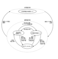
図1は、実施形態にかかる配電システムの構成の一例を示す説明図である。実施形態にかかる配電システム100は、動力系統(油圧系統、電気系統、抽気系統など)の多くを電気系統とした図示しない航空機(電動化航空機)に搭載され、航空機が有する複数の電動アクチュエータ80に配電を行うためのシステムである。また、航空機は、図1に示すように、電動アクチュエータ80以外にも、複数の電力機器90を備えている。複数の電力機器90は、配電システム100の直流バスL1に接続されている。配電システム100は、直流バスL1を介して複数の電力機器90に対しても電力を供給する。
FIG. 1 is an explanatory diagram illustrating an example of a configuration of a power distribution system according to an embodiment; The
本実施形態において、電動アクチュエータ80は、航空機の翼に設けられた舵面制御用のアクチュエータである。舵面制御用のアクチュエータは、航空機の飛行中において舵面が空気抵抗の外力を受けることにより、回生電力を発生することがある。なお、電動アクチュエータ80は、舵面制御用に限られず、回生電力を発生しうるものであれば、いかなる装置を駆動させるためのアクチュエータであってもよい。例えば、電動アクチュエータ80は、車輪を駆動させる駆動機構に用いられるもの等であってもよい。
In this embodiment, the
本実施形態において、配電システム100は、複数の配電部1を有する。すなわち、配電システム100は、図1に示すように、配電部1Lと、配電部1Rとを含む。配電部1L、1Rは、基本的に同じ構成であるため、配電部1L、1Rを区別する必要がない場合、単に配電部1と称して説明する。
In this embodiment, the
配電部1は、図1に示すように、第一直流電源部10と、第二直流電源部20と、ダイオード50とを備えている。なお、配電部1は、第一直流電源部10が正常に機能しないときに、電動アクチュエータ80との間で電力のやり取りを行う非常用の直流電源部をさらに備えてもよい。非常用の直流電源部は、直流バスL1に接続され、第二直流電源部20を介して電動アクチュエータ80に電力を供給するものであればよい。
The
第一直流電源部10は、発電機11と、PWMコンバータ12とを有する。発電機11は、航空機の図示しないエンジンからの動力によって発電する交流電源として機能する。PWMコンバータ12は、発電機11に接続され、発電機11で発電された交流の発電電力を直流の発電電力へと変換する。PWMコンバータ12は、直流バスL1に接続され、一定電圧(本実施形態では270V)の直流電力を直流バスL1へと供給する。直流バスL1の電圧VL1は、電圧センサ13(図2参照)により検出することができる。PWMコンバータ12で一定電圧とされた発電電力は、図1に示すように、一次配電制御器15により、直流バスL1を介して、第二直流電源部20や複数の電力機器90に接続された図示しない配電制御器といった、配電システム100内の各構成要素へと分配される。図1に示すように、配電部1L、1Rとは、PWMコンバータ12の下流側および一次配電制御器15の下流側などにおいて、直流バスL1を介して接続されている。それにより、配電部1L、1Rは、第一直流電源部10での発電電力を互いに利用し合うことができる。
The first DC
第二直流電源部20は、バッテリ(蓄電器)30と、二次配電制御器40とを備えている。バッテリ30は、例えばリチウムイオン蓄電池といった電力を蓄電可能な周知の蓄電池である。なお、第二直流電源部20は、バッテリ30に限らず、例えばキャパシタといった電力を蓄電可能な蓄電器を備えるものであればよい。また、蓄電器は、複数設けられてもよいし、異なる蓄電器を複数組み合わせて構成してもよい。本実施形態において、配電システム100は、バッテリ30の端子間電圧を検出する電圧センサ14と、バッテリ30の充放電電流を検出する電流センサ16とを備えている。
The second DC
二次配電制御器40は、電力ラインL2を介して直流バスL1に接続されている。ただし、図1に示すように、電力ラインL2と直流バスL1との間には、ダイオード50が設けられている。ダイオード50は、アノード側が直流バスL1に接続され、カソード側が電力ラインL2に接続されている。そのため、ダイオード50は、第二直流電源部20から直流バスL1へと流れる電流を遮断する。また、二次配電制御器40は、複数の電力ラインL3を介して各電動アクチュエータ80に並列に接続されている。さらに、二次配電制御器40は、電力ラインL4を介してバッテリ30に接続されている。なお、本実施形態では、例示として、2つの電動アクチュエータ80が第二直流電源部20に並列に接続された例を示しているが、電動アクチュエータ80は、3つ以上が並列に接続されてもよいし、少なくとも1つ接続されていればよい。
二次配電制御器40は、第一直流電源部10で発電されて一次配電制御器15で分配された発電電力が直流バスL1を介して供給される。二次配電制御器40は、第一直流電源部10からの発電電力およびバッテリ30に蓄電された電力を各電動アクチュエータ80へと供給する。また、二次配電制御器40は、各電動アクチュエータ80で発生した回生電力をバッテリ30に充電させる。
The secondary
二次配電制御器40の構成について、より詳細に説明する。図2は、二次配電制御器の構成の一例を説明図である。二次配電制御器40は、図2に示すように、昇降圧コンバータ41と、複数の過電流遮断回路42と、電圧センサ43と、制御部44とを有する。
The configuration of
昇降圧コンバータ41は、電力ラインL2と電力ラインL4との間に設けられ、電力ラインL2とバッテリ30との間でやり取りされる直流電力の電圧を調整するPWMコンバータである。昇降圧コンバータ41は、バッテリ30の充放電を制御する充放電制御回路として機能する。
Buck-
図3は、昇降圧コンバータを示す説明図である。昇降圧コンバータ41は、複数のスイッチング素子411(411A、411B、411C、411D、411E、411F)を備えた3相式のDC/DCコンバータである。スイッチング素子411は、例えばMOSFETといった周知のスイッチング素子である。なお、スイッチング素子411は、IGBT等であってもよい。スイッチング素子411A、411B、スイッチング素子411C、411D、およびスイッチング素子411E、411Fは、3相式の昇降圧コンバータ41の各相に流れる電流をオンオフする。昇降圧コンバータ41には、各相の電流値を検出する電流センサ46が設けられている。本実施形態では、昇降圧コンバータ41は、各相の電圧の位相を120(°)ずつ、ずらしてスイッチングを行った後、各相の電流の位相を結合する。それにより、出力電圧の波形のリプルを抑制することができる。なお、昇降圧コンバータ41は、3相式に限らず、単相式、2相式または4相以上の多相式であってもよい。
FIG. 3 is an explanatory diagram showing a buck-boost converter. The buck-
昇降圧コンバータ41は、各スイッチング素子411を所定のスイッチング周期(例えば1/40(kHz))でオンオフすることで、電力ラインL2の電力を降圧させてバッテリ30に供給することができる。また、昇降圧コンバータ41は、各スイッチング素子411を所定のスイッチング周期でオンオフすることで、バッテリ30からの電力を昇圧させて電力ラインL2へと供給することができる。昇降圧コンバータ41の各スイッチング素子411は、制御部44により制御される。
The step-up/step-
過電流遮断回路42は、各電動アクチュエータ80に対応して、電力ラインL2と電力ラインL3との間に1つずつ設けられている。過電流遮断回路42は、電力ラインL3に所定値以上の電流が所定時間以上流れたときに電流を遮断可能なスイッチ回路である。図2に示すように、電力ラインL3には、電流値を検出する電流センサ48が設けられている。電流センサ48で検出された電流値は、過電流遮断回路42に入力される。過電流遮断回路42は、電流センサ48で検出された電流値が所定時間以上にわたって所定値以上である場合に、各電動アクチュエータ80と第二直流電源部20との接続を遮断する。なお、電流センサ48で検出された電流値によるオンオフとは別に、過電流遮断回路42を任意のタイミングでオンオフする場合には、制御部44により制御される。
One
電圧センサ43は、電力ラインL2の電圧VL2を検出するセンサである。電圧センサ43で検出された電力ラインL2の電圧VL2は、制御部44へと出力される。本実施形態において、電圧センサ43は、電動アクチュエータ80から電力ラインL2へと供給される回生電力の有無を検出する検出センサとして機能する。
制御部44は、例えば、CPU(Central Processing Unit)などで構成された演算処理装置である。制御部44には、図2に示すように、電圧センサ13で検出された直流バスL1の電圧VL1が入力される。制御部44は、入力した電圧VL1の値に基づいて、電圧VL1が正常であるか否か、すなわち第一直流電源部10が正常に使用できるか否かを判定する。第一直流電源部10が正常に使用できるか否かの判定処理の詳細については、後述する。
The control unit 44 is an arithmetic processing device including, for example, a CPU (Central Processing Unit). As shown in FIG. 2, the voltage VL1 of the DC bus L1 detected by the
また、制御部44には、図2に示すように、電圧センサ43で検出された電力ラインL2の電圧VL2が入力される。制御部44は、入力された電圧VL2の値に基づいて、電動アクチュエータ80から電力ラインL2に回生電力が供給されているか否かを判定する。電動アクチュエータ80から電力ラインL2に回生電力が供給されているか否かの判定処理の詳細については、後述する。
In addition, the voltage VL2 of the power line L2 detected by the
また、制御部44は、図2に示すように、バッテリ30の端子間電圧を検出する電圧センサ14と、バッテリ30の充放電電流を検出する電流センサ16とに接続されている。制御部44は、電圧センサ14から入力されたバッテリ30の端子間電圧と、電流センサ16から入力されたバッテリ30の充放電電流とに基づいて、バッテリ30の蓄電率Aを算出する。
The control unit 44 is also connected to the
なお、制御部44には、昇降圧コンバータ41、過電流遮断回路42、バッテリ30において、図示しない温度検出センサで検出された温度の情報が入力される。また、制御部44は、図示しない通信部を有しており、通信部を介して一次配電制御器15と通信可能とされている。
Note that temperature information detected by a temperature detection sensor (not shown) in the step-up/step-
また、制御部44は、昇降圧コンバータ41に接続されている。制御部44は、昇降圧コンバータ41の各スイッチング素子411を所定のスイッチング周期でオンオフさせるゲート信号を生成し、各スイッチング素子411へと出力する。それにより、バッテリ30の充放電状態が制御される。その結果、配電部1は、電動アクチュエータ80と第一直流電源部10および第二直流電源部20との間で電力をやり取りする複数の電力処理モードを切り替えることができる。以下、図4を参照しながら、各電力処理モードについて説明する。図4は、実施形態にかかる配電システムにおける各電力処理モードの別を示す説明図である。
Also, the control unit 44 is connected to the step-up/step-
配電部1は、図4に示すように、第一直流電源部10が正常に使用できる通常動作時、すなわち直流バスL1の電圧VL1が正常であるときに、力行アシストモード、定電流充電モード(充電モード)および回生電力処理モードを実行する。力行アシストモードおよび定電流充電モードは、通常動作時において、第一直流電源部10で発電された発電電力を直流バスL1および電力ラインL2を介して複数の電動アクチュエータ80に供給する力行電力処理モードの一部である。通常動作時において、直流バスL1の電圧VL1は、第一直流電源部10からの電力によって一定電圧(本実施形態では、270(V))に維持されている。
As shown in FIG. 4, the
力行アシストモードは、第一直流電源部10からの発電電力に加えて、バッテリ30に蓄電された電力を複数の電動アクチュエータ80に供給するモードである。制御部44は、昇降圧コンバータ41を制御して、要求される電力に応じて設定される電流値で、バッテリ30からの電力を電力ラインL2へと供給する。
The power running assist mode is a mode in which electric power stored in the
定電流充電モードは、第一直流電源部10からの発電電力の一部をバッテリ30に充電させつつ、残りの発電電力を複数の電動アクチュエータ80へと供給するモードである。制御部44は、昇降圧コンバータ41を制御して電力ラインL2から発電電力の一部を、所定の一定電流値(本実施形態では、12(A))でバッテリ30へと充電させる。なお、充電モードは、電流値を変化させながらバッテリ30を充電するモードであってもよい。
The constant-current charging mode is a mode in which the
回生電力処理モードは、通常動作時において、複数の電動アクチュエータ80で回生電力が発生したときに、発生した回生電力をバッテリ30に充電させるモードである。制御部44は、昇降圧コンバータ41を制御して、電力ラインL2から回生電力をバッテリ30へと充電させる。上述したように、第二直流電源部20と直流バスL1との間には、ダイオード50が設けられている。そのため、複数の電動アクチュエータ80で回生電力が発生した場合、回生電力が直流バスL1に流れることはなく、昇降圧コンバータ41の制御によりバッテリ30に充電させることができる。
The regenerative power processing mode is a mode for charging the
また、配電部1は、電力処理モードとして、第一直流電源部10が正常に使用できない非常動作時、すなわち直流バスL1の電圧VL1が異常であるときに、非常用電力処理モードを実行する。非常用電力処理モードは、第一直流電源部10を用いることなく、バッテリ30と複数の電動アクチュエータ80との間で電力のやり取りを行うモードである。第一直流電源部10が正常に使用できない場合、直流バスL1に一定電圧(270(V))が印加されないことになる。このとき、制御部44は、昇降圧コンバータ41を制御して、バッテリ30の電力を電動アクチュエータ80へと供給し、また、電動アクチュエータ80からの回生電力をバッテリ30へと充電させる。
Further, the
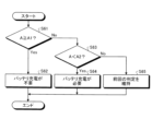
次に、実施形態にかかる配電方法としての各電力処理モードの切替手順について、図5を参照しながら説明する。図5は、各電力処理モードの切替手順の一例を示すフローチャートである。図5に示すフローチャートは、制御部44により予め定められた時間で繰り返し実行される。 Next, a switching procedure of each power processing mode as the power distribution method according to the embodiment will be described with reference to FIG. FIG. 5 is a flow chart showing an example of a switching procedure for each power processing mode. The flowchart shown in FIG. 5 is repeatedly executed by the control unit 44 at predetermined times.
制御部44は、ステップS10として、直流バスL1の電圧VL1が正常であるか否かを判定する。制御部44は、電圧センサ13から直流バスL1の電圧VL1を入力しており、入力した電圧VL1の値に基づいて正常性を判定する。図6は、直流バスの電圧が正常であるか否かを判定するための手順の一例を示すフローチャートである。図6に示すフローチャートは、制御部44により実行される。また、図7は、直流バスの電圧が正常であるか否かを判定するための判定値の一例を示す説明図である。図7において、縦軸は、直流バスL1の電圧VL1値であり、横軸は、言い換えると、各電圧における許容時間である。
In step S10, control unit 44 determines whether or not voltage VL1 of DC bus L1 is normal. The control unit 44 receives the voltage VL1 of the DC bus L1 from the
制御部44は、図6に示すように、まずステップS11として、電圧VL1が第一判定値V1以上であるか否かを判定する。本実施形態において、第一判定値V1は、直流バスL1の電圧範囲として予め定められる上限値Vlimit1と下限値Vlimit2との間の値であり、通常動作時の直流バスL1の電圧VL1(例えば270(V))よりも低い値とされる。第一判定値V1は、例えば255(V)である。制御部44は、電圧VL1が第一判定値V1以上であると判定した場合(ステップS11でYes)、ステップS12に進み、電圧VL1が正常であると判定する。 As shown in FIG. 6, the control unit 44 first determines whether or not the voltage VL1 is greater than or equal to the first determination value V1 in step S11. In this embodiment, the first determination value V1 is a value between an upper limit value Vlimit1 and a lower limit value Vlimit2 predetermined as the voltage range of the DC bus L1, and is the voltage VL1 of the DC bus L1 during normal operation (for example, 270 (V)). The first judgment value V1 is, for example, 255 (V). When the control unit 44 determines that the voltage VL1 is equal to or higher than the first determination value V1 (Yes in step S11), the control unit 44 proceeds to step S12 and determines that the voltage VL1 is normal.
一方、制御部44は、電圧VL1が第一判定値V1未満であると判定した場合(ステップS11でNo)、ステップS13に進み、電圧VL1が第二判定値V2未満であるか否かを判定する。第二判定値V2は、第一判定値V1よりも低い値である。なお、図7では、第二判定値V2が下限値Vlimit2よりも低い値である例を示しているが、第二判定値V2は、下限値Vlimit2以上の値であってもよい。第二判定値V2は、例えば195(V)~245(V)である。制御部44は、電圧VL1が第二判定値V2未満であると判定した場合(ステップS13でYes)、ステップS14に進み、電圧VL1が異常であると判定する。 On the other hand, when the control unit 44 determines that the voltage VL1 is less than the first determination value V1 (No in step S11), the process proceeds to step S13 to determine whether the voltage VL1 is less than the second determination value V2. do. The second determination value V2 is a value lower than the first determination value V1. Although FIG. 7 shows an example in which the second determination value V2 is a value lower than the lower limit value Vlimit2, the second determination value V2 may be a value equal to or higher than the lower limit value Vlimit2. The second judgment value V2 is, for example, 195 (V) to 245 (V). When the control unit 44 determines that the voltage VL1 is less than the second determination value V2 (Yes in step S13), the control unit 44 proceeds to step S14 and determines that the voltage VL1 is abnormal.
また、制御部44は、電圧VL1が第二判定値V2以上であると判定した場合(ステップS13でNo)、ステップS15に進み、前回の判定を維持する。つまり、電圧VL1が第一判定値V1未満の状態(ステップS11でNo)となると、電圧VL1が第二判定値V2未満の状態(ステップS13でYes)となるまで、電圧VL1は正常であると判定される。したがって、いったん電圧VL1が正常であると判定された場合、電圧VL1が第二判定値V2未満まで減少しない限りは、電圧VL1は正常であるという判定が継続される。また、電圧VL1が第二判定値V2未満の状態(ステップS13でYes)となると、電圧VL1が第一判定値V1以上の状態(ステップS11でYes)となるまでは、電圧VL1は異常であると判定される。したがって、いったん電圧VL1が異常と判定された場合、電圧VL1が第一判定値V1以上まで回復しない限りは、電圧VL1が異常であるという判定が継続される。 When the control unit 44 determines that the voltage VL1 is equal to or higher than the second determination value V2 (No in step S13), the control unit 44 proceeds to step S15 and maintains the previous determination. That is, when the voltage VL1 becomes less than the first determination value V1 (No in step S11), the voltage VL1 is normal until the voltage VL1 becomes less than the second determination value V2 (Yes in step S13). be judged. Therefore, once it is determined that the voltage VL1 is normal, the determination that the voltage VL1 is normal continues unless the voltage VL1 decreases below the second determination value V2. Further, when the voltage VL1 becomes less than the second determination value V2 (Yes in step S13), the voltage VL1 is abnormal until the voltage VL1 becomes greater than or equal to the first determination value V1 (Yes in step S11). is determined. Therefore, once the voltage VL1 is determined to be abnormal, the determination that the voltage VL1 is abnormal continues until the voltage VL1 recovers to the first determination value V1 or higher.
図5の説明に戻る。制御部44は、直流バスL1の電圧VL1が正常であると判定した場合(ステップS10でYes)、ステップS20に進み、電動アクチュエータ80からの回生電力があるか否かを判定する。より詳細には、制御部44は、電圧センサ43で検出された電力ラインL2の電圧VL2が、予め設定される閾値Vr未満であるとき、回生電力なしと判定し、電圧VL2が予め設定される閾値Vr以上であるとき、回生電力ありと判定する。予め設定される閾値Vrは、通常動作時の電圧VL2(直流バスL1の電圧VL1と一致。例えば270(V))よりも高い値とされる。閾値Vrは、例えば275(V)である。通常動作時の電圧VL2(通常動作時の電圧VL1)よりも高い閾値Vr以上の電圧が電力ラインL2に生じたときには、電動アクチュエータ80から電力ラインL2に電流が供給されていることになるため、回生電力が発生していると判定することができる。
Returning to the description of FIG. When the control unit 44 determines that the voltage VL1 of the DC bus L1 is normal (Yes in step S10), the control unit 44 proceeds to step S20 and determines whether or not regenerated power from the
制御部44は、電動アクチュエータ80からの回生電力があると判定した場合(ステップS20でYes)、ステップS30に進み、回生電力処理モードを実行する(回生電力処理モードステップ)。制御部44は、昇降圧コンバータ41を制御して電力ラインL4から回生電力をバッテリ30へと充電させる。このとき、上述したように、電動アクチュエータ80からの回生電力は、ダイオード50によって直流バスL1側に流れることが防止される。なお、一つの電動アクチュエータ80で発生した回生電力のすべてをバッテリ30に充電させる必要はない。つまり、一つの電動アクチュエータ80で発生した回生電力の一部をバッテリ30に充電させ、回生電力の残りを他の電動アクチュエータ80へと供給してもよい。
When the control unit 44 determines that there is regenerative power from the electric actuator 80 (Yes in step S20), the control unit 44 proceeds to step S30 and executes the regenerative power processing mode (regenerative power processing mode step). Control unit 44 controls step-up/step-
一方、制御部44は、電動アクチュエータ80からの回生電力がないと判定した場合(ステップS20でNo)、ステップS40に進み、回生電力処理モードの実行中であるか否かを判定する。制御部44は、回生電力処理モードの実行中でないと判定した場合(ステップS40でNo)、ステップS60に進む。一方、制御部44は、回生電力処理モードの実行中あると判定した場合(ステップS40でYes)、ステップS50に進み、所定待機時間が経過したか否かを判定する。所定待機時間は、回生電力処理モードの実行中に、ステップS20で回生電力がないと最初に判定されたタイミングから計時が開始される。また、所定待機時間は、いったん計時が開始されてからステップS20で回生電力があると判定された場合、および、ステップS60以降の処理に進んだ場合にリセットされる。所定待機時間は、例えば、150(msec)である。 On the other hand, when the control unit 44 determines that there is no regenerative power from the electric actuator 80 (No in step S20), the control unit 44 proceeds to step S40 and determines whether or not the regenerative power processing mode is being executed. When the control unit 44 determines that the regenerative power processing mode is not being executed (No in step S40), the process proceeds to step S60. On the other hand, when determining that the regenerative power processing mode is being executed (Yes in step S40), the control unit 44 proceeds to step S50 and determines whether or not the predetermined waiting time has elapsed. The predetermined standby time starts from the timing when it is first determined in step S20 that there is no regenerative power during execution of the regenerative power processing mode. Further, the predetermined standby time is reset when it is determined in step S20 that there is regenerative power after the time measurement is started, and when the process proceeds to step S60 and subsequent steps. The predetermined waiting time is, for example, 150 (msec).
制御部44は、所定待機時間が経過していないと判定した場合(ステップS50でNo)、ステップS30に進み、回生電力処理モードを実行する。したがって、回生電力処理モードの実行中に、電圧VL2が閾値Vr未満となったと判定されても、所定待機時間が経過するまでは回生電力処理モードが継続される。また、所定待機時間が経過するまでの間に、電圧VL2が閾値Vr以上の状態に戻った場合(ステップS20でYes)には、電動アクチュエータ80で回生電力が発生している状態であるため、回生電力処理モードの実行が継続される(ステップS30)。このとき、所定待機時間は、上述したようにリセットされ、改めてステップS20で回生電力がないと最初に判定されたタイミングから、計時が開始される。そして、制御部44は、所定待機時間が経過したと判定した場合(ステップS50でYes)、ステップS60に進む。つまり、制御部44は、回生電力処理モードの実行中に、電圧VL2が閾値Vr未満となった状態が所定待機時間にわたって継続すると、ステップS60に進む。
If the control unit 44 determines that the predetermined standby time has not passed (No in step S50), the process proceeds to step S30, and the regenerative power processing mode is executed. Therefore, even if it is determined that the voltage VL2 has become less than the threshold value Vr during execution of the regenerative power processing mode, the regenerative power processing mode is continued until the predetermined waiting time elapses. If the voltage VL2 returns to the threshold value Vr or higher before the predetermined standby time elapses (Yes in step S20), the
制御部44は、ステップS60として、バッテリ30の充電が必要であるか否かを判定する。図8は、バッテリの充電が必要であるか否かを判定するための手順の一例を示すフローチャートである。図8に示すフローチャートは、制御部44により実行される。制御部44は、図8に示すように、まずステップS61として、バッテリ30の蓄電率Aが第一蓄電率A1以上であるか否かを判定する。バッテリ30の蓄電率Aは、上述したように、バッテリ30の端子間電圧と充放電電流とに基づいて算出される。第一蓄電率A1は、バッテリ30が過充電状態となることを抑制可能な値であり、例えば80(%)とされる。制御部44は、蓄電率Aが第一蓄電率A1以上であると判定した場合(ステップS61でYes)、ステップS62に進み、バッテリ30の充電が不要であると判定する。
The control unit 44 determines whether or not the
一方、制御部44は、蓄電率Aが第一蓄電率A1未満であると判定した場合(ステップS61でNo)、ステップS63に進み、蓄電率Aが第二蓄電率A2未満であるか否かを判定する。第二蓄電率A2は、第一蓄電率A1よりも低い値である。第二蓄電率A2は、非常用電力処理モードとなった場合にも、バッテリ30から余裕をもって電動アクチュエータ80に電力を供給可能な値であり、例えば60(%)とされる。制御部44は、蓄電率Aが第二蓄電率A2未満であると判定した場合(ステップS63でYes)、ステップS64に進み、バッテリ30の充電が必要であると判定する。
On the other hand, when the control unit 44 determines that the power storage rate A is less than the first power storage rate A1 (No in step S61), the process proceeds to step S63 to determine whether the power storage rate A is less than the second power storage rate A2. judge. The second charge rate A2 is a value lower than the first charge rate A1. The second charge rate A2 is a value that allows power to be supplied from the
また、制御部44は、蓄電率Aが第二蓄電率A2以上であると判定した場合(ステップS63でNo)、ステップS65に進み、前回の判定を維持する。つまり、蓄電率Aが第一蓄電率A1未満の状態(ステップS61でNo)となると、蓄電率Aが第二蓄電率A2未満の状態(ステップS63でYes)となるまで、バッテリ30の充電が不要であると判定される。したがって、いったんバッテリ30の充電が不要と判定された場合、蓄電率Aが第二蓄電率A2未満まで減少しない限りは、バッテリ30の充電が不要であるという判定が継続される。また、蓄電率Aが第二蓄電率A2未満の状態(ステップS63でYes)となると、蓄電率Aが第一蓄電率A1以上の状態(ステップS61でYes)となるまで、バッテリ30の充電が必要であると判定される。したがって、いったんバッテリ30の充電が必要と判定された場合、蓄電率Aが第一蓄電率A1以上まで回復しない限りは、バッテリ30の充電が必要であるという判定が継続される。
When the control unit 44 determines that the power storage rate A is equal to or higher than the second power storage rate A2 (No in step S63), the control unit 44 proceeds to step S65 and maintains the previous determination. That is, when the state of charge A becomes less than the first state of charge A1 (No in step S61), charging of the
再び図5の説明に戻る。制御部44は、バッテリ30の充電が必要であると判定した場合(ステップS60でYes)、ステップS70に進み、定電流充電モードを実行する(力行電力処理モードステップ、定電流充電モードステップ)。制御部44は、昇降圧コンバータ41を制御して、第一直流電源部10からの発電電力の一部を電力ラインL4からバッテリ30へと充電させる。なお、残りの発電電力は、電動アクチュエータ80へと供給される。一方、制御部44は、バッテリ30の充電が不要であると判定した場合(ステップS60でNo)、ステップS80に進み、力行アシストモードを実行する(力行電力処理モードステップ、力行アシストモードステップ)。制御部44は、昇降圧コンバータ41を制御して、第一直流電源部10からの発電電力に加えて、バッテリ30に蓄電された電力を電動アクチュエータ80に供給する。
Returning to the description of FIG. 5 again. When the control unit 44 determines that the
上述したように、いったんバッテリ30の充電が不要と判定された場合、蓄電率Aが第二蓄電率A2未満まで減少しない限りは、バッテリ30の充電が不要であるという判定が継続される。つまり、バッテリ30の蓄電率Aが第一蓄電率A1以上となると(図8のステップS61でYes)、蓄電率Aが第二蓄電率A2未満となるまで(図8のステップS63でYes)、力行アシストモードが継続される。また、上述したように、いったんバッテリ30の充電が必要と判定された場合、蓄電率Aが第一蓄電率A1以上まで回復しない限りは、バッテリ30の充電が必要であるという判定が継続される。つまり、バッテリ30の蓄電率Aが第二蓄電率A2未満となると(図8のステップS63でYes)、蓄電率Aが第一蓄電率A1以上となるまで(図8のステップS61でYes)、定電流充電モードが継続される。
As described above, once it is determined that the
制御部44は、直流バスL1の電圧VL1が異常であると判定した場合(ステップS10でNo)には、ステップS90に進み、非常用電力処理モードを実行する。制御部44は、昇降圧コンバータ41の制御によって、バッテリ30から電動アクチュエータ80へと電力を供給し、また、電動アクチュエータ80からの回生電力をバッテリ30へと充電する。なお、非常用電力処理モードにおいて、バッテリ30から電動アクチュエータ80へと電力を供給するか、電動アクチュエータ80からの回生電力をバッテリ30へと充電するかは、ステップS20と同様の判定処理を行うことによって切り替えることができる。
When the control unit 44 determines that the voltage VL1 of the DC bus L1 is abnormal (No in step S10), the control unit 44 proceeds to step S90 and executes the emergency power processing mode. Control unit 44 supplies electric power from
また、非常用電力処理モードの実行中において、バッテリ30から電力を放電している場合、電力ラインL2の電圧は、基本的に直流バスL1の電圧VL1の正常値(270(V))より高くならない。そのため、直流バスL1の電圧VL1が正常値(270(V))に復帰した場合には、直流バスL1からの電流がダイオード50を介して第二直流電源部20へと供給されるため、速やかに通常動作時の電力処理モードへと移行することができる。
Also, during execution of the emergency power processing mode, when power is being discharged from the
次に、昇降圧コンバータ41の具体的な制御手順の一例について、図9および図10を参照しながら説明する。図9は、第一直流電源部が正常に使用できる通常動作時における昇降圧コンバータの制御ブロックの一例を示す説明図であり、図10は、第一直流電源部が正常に使用できない非常用動作時における昇降圧コンバータの制御ブロックの一例を示す説明図である。図9および図10に示す一連の処理は、昇降圧コンバータ41の所定のスイッチング周期(例えば1/40(kHz))ごとに繰り返し実施される。
Next, an example of a specific control procedure for the buck-
図9を参照しながら、通常動作時、つまり直流バスL1の電圧VL1が正常であると判定した場合(図5のステップS10でYes)の昇降圧コンバータ41の制御手順について説明する。制御部44は、電圧フィードバック部451において電力ラインL2の電圧指令V*を予め設定される閾値Vr(本実施形態では275V)に設定する。次に、制御部44は、設定した電圧指令V*と、実際の電力ラインL2の電圧VL2(直流バスL1の電圧VL1と一致)との差分(VL2-V*)を算出する。さらに、制御部44は、差分(VL2-V*)をPIDブロック451Aに入力する。PIDブロック451Aは、予め設定される比例ゲイン、積分時間および微分時間を用いて、電流指令値I1*を生成する。そして、制御部44は、生成した電流指令値I1*をLimitブロック451Bに入力して制限をかける。それにより、制限された電流指令値I2*が生成される。
A control procedure of the buck-
次に、制御部44は、電流指令加算部452において、定電流充電モード時、力行アシストモード時に必要となるバッテリ30の充放電電流の値である電流指令値I3*を、電流指令値I2*に加算する。制御部44は、定電流充電モードを実行するとき(図5のステップS70)、図中の切替回路452Aに1:充電の切替信号を出力する。そして、制御部44は、電流指令値I3*を所定の一定電流値(本実施形態では、12A)に設定し、この値を電流指令値I2*に加算して電流指令値I4*を生成する。一方、制御部44は、力行アシストモードを実行するとき(図5のステップS80)、図中の切替回路452Aに2:放電の切替信号を出力する。そして、制御部44は、電流指令値I3*を力行アシストモード時の電流指令値に設定し、この値を電流指令値I2*に加算して電流指令値I4*を生成する。なお、力行アシストモード時の電流指令値I3*は、電動アクチュエータ80で要求される電力に応じて設定されればよい。これにより、定電流充電モード、力行アシストモードを実行する場合のバッテリ30の充放電電流を設定することができる。また、制御部44は、定電流充電モード時、力行アシストモード時のいずれも実行しない場合、すなわち回生電力処理モードを実行する場合(図5のステップS30)には、本ブロックにおいて電流指令値I3*を加算することなく、もとの電流指令値I2*を電流指令値I4*として生成する。それにより、回生電力処理モードを実行する場合のバッテリ30の充電電流を設定することができる。
Next, the control unit 44 causes the current
次に、制御部44は、電流フィードバック部454において、電流指令値I4*を1/3倍とした電流指令値I5*を生成する。この電流指令値I5*が、昇降圧コンバータ41の各相の電流指令値となる。制御部44は、電流指令値I5*と、電流センサ46(図3参照)で検出された昇降圧コンバータ41の各相の電流値I1、I2、I3との差分(I5*-I1)、(I5*-I2)、(I5*-I3)を算出する。そして、算出した差分(I5*-I1)、(I5*-I2)、(I5*-I3)をPIDブロック454A、454B、454Cに入力する。PIDブロック454A、454B、454Cは、予め設定される比例ゲイン、積分時間および微分時間を用いて、各相の電圧指令値V1*,V2*、V3*を生成する。
Next, the control unit 44 generates a current command value I5* that is ⅓ times the current command value I4* in the
そして、制御部44は、PWM指令変換部455において、各相の電圧指令値V1*,V2*、V3*をPWM変換指令ブロック455A、455B、455Cに入力し、各相のゲート信号P(PA、PB、PC、PD、PE、PF)を生成する。すなわち、電圧指令の振幅である電圧指令値V1*,V2*、V3*を、昇降圧コンバータ41の各スイッチング素子411をオンオフする時間としてのパルス信号であるゲート信号Pに変換する。生成されたゲート信号PAは、スイッチング素子411Aに入力される。ゲート信号PBは、スイッチング素子411Bに入力される。ゲート信号PCは、スイッチング素子411Cに入力される。ゲート信号PDは、スイッチング素子411Dに入力される。ゲート信号PEは、スイッチング素子411Eに入力される。ゲート信号PFは、スイッチング素子411Fに入力される。
Then, the control unit 44 inputs the voltage command values V1*, V2*, V3* of each phase to the PWM
以上の処理を所定のスイッチング周期ごとに繰り返し実行することで、各ゲート信号Pに基づいて昇降圧コンバータ41の各スイッチング素子411が所定のスイッチング周期でオンオフ制御される。その結果、通常動作時において、力行アシストモード、定電流充電モードおよび回生電力処理モードに対応して、バッテリ30の充放電を制御することができる。
By repeatedly executing the above process every predetermined switching cycle, each switching
図10を参照しながら、非常用動作時、つまり直流バスL1の電圧VL1が異常であると判定した場合(図5のステップS10でNo)に、バッテリ30の電力を電動アクチュエータ80に供給するための昇降圧コンバータ41の制御手順について説明する。制御部44は、図10に示すように、電圧フィードバック部451において電力ラインL2の電圧指令V*を、通常動作時の電圧VL2(直流バスL1の電圧VL1と一致。本実施形態では270(V))に設定する。次に、制御部44は、設定した電圧指令V*と実際の電圧VL2(直流バスL1の電圧VL1と一致)との差分(VL2-V*)を算出する。さらに、制御部44は、差分(VL2-V*)をPIDブロック451Aに入力する。PIDブロック451Aは、予め設定される比例ゲイン、積分時間および微分時間を用いて、電流指令値I1*を生成する。そして、制御部44は、生成した電流指令値I1*をLimitブロック451Bに入力して制限をかける。それにより、制限された電流指令値I2*が生成される。
Referring to FIG. 10, during emergency operation, that is, when it is determined that the voltage VL1 of the DC bus L1 is abnormal (No in step S10 of FIG. 5), the electric power of the
次に、制御部44は、電流フィードバック部454において、電流指令値I2*を1/3倍とした電流指令値I3*を生成する。この電流指令値I3*が、昇降圧コンバータ41の各相の電流指令値となる。制御部44は、電流指令値I3*と、電流センサ46(図3参照)で検出された昇降圧コンバータ41の各相の電流値I1、I2、I3との差分(I3*-I1)、(I3*-I2)、(I3*-I3)を算出する。そして、算出した差分(I3*-I1)、(I3*-I2)、(I3*-I3)をPIDブロック454A、454B、454Cに入力する。PIDブロック454A、454B、454Cは、予め設定される比例ゲイン、積分時間および微分時間を用いて、各相の電圧指令値V1*,V2*、V3*を生成する。
Next, the control unit 44 generates a current command value I3* that is ⅓ times the current command value I2* in the
そして、制御部44は、PWM指令変換部455において、各相の電圧指令値V1*,V2*、V3*をPWM変換指令ブロック455A、455B、455Cに入力し、各相のゲート信号P(PA、PB、PC、PD、PE、PF)を生成する。すなわち、電圧指令の振幅である電圧指令値V1*,V2*、V3*を、昇降圧コンバータ41の各スイッチング素子411をオンオフする時間としてのパルス信号であるゲート信号Pに変換する。生成されたゲート信号PAは、スイッチング素子411Aに入力される。ゲート信号PBは、スイッチング素子411Bに入力される。ゲート信号PCは、スイッチング素子411Cに入力される。ゲート信号PDは、スイッチング素子411Dに入力される。ゲート信号PEは、スイッチング素子411Eに入力される。ゲート信号PDは、スイッチング素子411Fに入力される。
Then, the control unit 44 inputs the voltage command values V1*, V2*, V3* of each phase to the PWM
以上の処理を所定のスイッチング周期ごとに繰り返し実行することで、各ゲート信号Pに基づいて昇降圧コンバータ41の各スイッチング素子411が所定のスイッチング周期でオンオフ制御される。その結果、非常動作時において、バッテリ30の放電を制御することができ、また、電動アクチュエータ80で回生電力が生じた場合にも、回生電力をバッテリ30に充電することができる。
By repeatedly executing the above process every predetermined switching cycle, each switching
以上説明したように、実施形態にかかる配電システム100は、発電機11を有し、直流バスL1に接続された第一直流電源部10と、直流バスL1および電動アクチュエータ80に接続された電力ラインL2、L3と、電力ラインL2に接続されたバッテリ30と、バッテリ30の充放電を制御する昇降圧コンバータ41と、電動アクチュエータ80から電力ラインL2へと供給される回生電力の有無を検出する電圧センサ43と、昇降圧コンバータ41を制御する制御部44とを有する第二直流電源部20と、第二直流電源部20から直流バスL1へと流れる電流を遮断するダイオード50とを備える。制御部44は、電圧センサ43が回生電力を検出していないとき、昇降圧コンバータ41によりバッテリ30の蓄電率Aが所定範囲内に維持されるようにバッテリ30を充放電させながら、第一直流電源部10で発電された発電電力を直流バスL1および電力ラインL2、3を介して電動アクチュエータ80に供給する力行電力処理モードを実行する。制御部44は、電圧センサ43が回生電力を検出したとき、昇降圧コンバータ41により回生電力をバッテリ30に充電する回生電力処理モードを実行する。
As described above, the
この構成により、実施形態にかかる配電システム100および配電方法では、発電機11を電力源とする第一直流電源部10を用いることなく、電動アクチュエータ80で生じた回生電力をバッテリ30に充電することで処理するため、回生電力の処理応答性を高め、急峻な回生電力の発生にも対応することが可能となる。また、第二直流電源部20から直流バスL1へと流れる電流をダイオード50で遮断することで、回生電力の処理に際して、直流バスL1の電圧が変動しない。さらに、電動アクチュエータ80で回生電力が生じていない場合、すなわち電動アクチュエータ80に電力を供給している場合には、蓄電率Aが所定範囲内に維持されるようにバッテリ30を充放電させておく。その結果、電動アクチュエータ80で回生電力が生じたときに、バッテリ30の蓄電率Aが高すぎることで回生電力を処理できなくなったり、バッテリ30の過充電が生じたりすることを抑制することができる。したがって、実施形態にかかる配電システム100および配電方法によれば、電動アクチュエータ80で発生した回生電力を応答性良く、かつ、安定的に処理可能であり、回生電力の処理に際して直流バスL1の電圧変動を防止することができる。
With this configuration, in the
また、制御部44は、力行電力処理モードにおいて、蓄電率Aが第一蓄電率A1以上となると、第一蓄電率A1よりも低い第二蓄電率A2未満となるまで発電電力に加えてバッテリ30からの電力を電動アクチュエータ80に供給する力行アシストモードを継続し、蓄電率Aが第二蓄電率A2未満となると、第一蓄電率A1以上となるまで発電電力の一部をバッテリ30に充電させる定電流充電モード(充電モード)を継続する。
Further, in the power running power processing mode, when the power storage rate A becomes equal to or greater than the first power storage rate A1, the control unit 44 adds the generated power to the
この構成により、電動アクチュエータ80に電力を供給している間に、バッテリ30の蓄電率Aを第一蓄電率A1と第二蓄電率A2との間の所定範囲内に維持することができる。その結果、電動アクチュエータ80で回生電力が生じたときに、バッテリ30の蓄電率Aが高すぎることで回生電力を処理できなくなったり、バッテリ30の過充電が生じたりすることを抑制することができる。さらに、バッテリ30の蓄電率Aを十分に維持し、余裕をもってバッテリ30から電動アクチュエータ80へと電力を供給することが可能となる。また、第一蓄電率A1以上になると第二蓄電率A2未満となるまで力行アシストモードを継続し、第一蓄電率A1未満になると第二蓄電率A2以上となるまで定電流充電モードを継続することで、力行アシストモードと定電流充電モードとが頻繁に切り替わることを抑制することができる。
With this configuration, while electric power is being supplied to the
また、制御部44は、第一直流電源部10が正常に使用できないとき、すなわち直流バスL1の電圧VL1が予め定められた閾値Vr未満のとき、昇降圧コンバータ41によりバッテリ30を充放電させながら、バッテリ30と電動アクチュエータ80との間で電力のやり取りを行う非常用電力処理モードを実行する。
Further, when the first DC
この構成により、第一直流電源部10と電動アクチュエータ80との間で電力のやり取りができない場合にも、第二直流電源部20から電動アクチュエータ80に電力を供給し、電動アクチュエータ80からの回生電力を第二直流電源部20で処理することができる。また、上述したように、第一直流電源部10から電動アクチュエータ80に電力を供給している間に、バッテリ30の蓄電率Aを所定範囲内に維持させるため、非常用電力処理モードの際にバッテリ30からの電力が不足することを抑制することができる。
With this configuration, even when power cannot be exchanged between the first DC
また、制御部44は、回生電力処理モードの実行中に、電圧センサ43が回生電力を検出しない状態となったとき、所定待機時間が経過するまで回生電力処理モードを継続し、電圧センサ43が回生電力を検出しない状態が所定待機時間にわたって継続されると、力行電力処理モード(力行アシストモードまたは定電流充電モード)へと移行する。
Further, when the
回生電力処理モードの実行により、電力ラインL2の電圧がいったん低下して電圧センサ43が回生電力を検出しない状態となった場合にも、電動アクチュエータ80から回生電力が継続している場合には、再び電力ラインL2の電圧が上昇することがある。このとき、電力ラインL2の電圧がいったん低下するごとに力行電力処理モード(力行アシストモードまたは定電流充電モード)に移行すると、回生電力処理モードと力行電力処理モードとが頻繁に切り替わってしまう可能性がある。本実施形態の構成によれば、所定待機時間が経過するまで力行電力処理モードへの切替を行わないため、回生電力処理モードと力行電力処理モード(力行アシストモードまたは定電流充電モード)とが頻繁に切り替わることを抑制することができる。なお、本実施形態では、回生電力処理モードから力行アシストモードまたは定電流充電モードに切り替えるときに所定待機時間の経過を待つものとしたが、回生電力処理モードから力行アシストモードに切り替えるときにのみ、所定待機時間の経過を待つものとしてもよい。
When the regenerative power processing mode is executed and the voltage of the power line L2 drops temporarily and the
また、第二直流電源部20は、所定値以上の電流が所定時間以上流れたときに、電動アクチュエータ80との接続を遮断する過電流遮断回路42を有する。
The second DC
この構成により、例えば電動アクチュエータ80側で短絡が生じたとき等に、配電システム100に過電流が流れこむことを抑制し、直流バスL1の電圧低下を抑制することができる。
With this configuration, for example, when a short circuit occurs on the
また、第二直流電源部20は、電力ラインL2に複数の電動アクチュエータ80が並列に接続されており、過電流遮断回路42は、電動アクチュエータ80の一つずつに対応して設けられる。
In addition, the second DC
この構成により、一つの電動アクチュエータ80で発生した回生電力の一部を、他の電動アクチュエータ80へと供給することができる。その結果、回生電力のすべてをバッテリ30に充電させる場合に比べて、昇降圧コンバータ41およびバッテリ30への充電において発生し得る電力損失を低減させることができ、電力効率を向上させることが可能となる。また、特に非常用電力処理モードにおいて、駆動する必要がない電動アクチュエータ80がある場合には、対応する過電流遮断回路42をオフすれば、バッテリ30から当該電動アクチュエータ80への電力の持ち出しを抑制することができる。したがって、バッテリ30の蓄電率Aの低下を抑制することが可能となる。
With this configuration, part of the regenerated electric power generated by one
本実施形態では、直流バスL1の電圧VL1が予め定められた閾値Vr未満のとき、第一直流電源部10が正常に使用できないと判定するものとした。このように、ダイオード50のアノード側である直流バスL1の電圧VL1をモニタすることで、第一直流電源部10の正常性および非常用電力処理モードへの移行を容易に判定することができる。ただし、第一直流電源部10が正常に使用できるか否かは、ダイオード50のカソード側、すなわち電力ラインL2を流れる電流値に基づいて判定してもよい。それにより、直流バスL1から第二直流電源部20までの間で電圧をモニタする必要がなくなり、配電システム100の簡易化を図ることが可能となる。
In this embodiment, when the voltage VL1 of the DC bus L1 is less than the predetermined threshold value Vr, it is determined that the first DC
本実施形態では、配電部1ごとに、第一直流電源部10および第二直流電源部20をひとつずつ備えるものとしたが、冗長性を確保するため、予備となる第一直流電源部10および第二直流電源部20を別に備えてもよい。
In the present embodiment, one first DC
本実施形態では、電動アクチュエータ80から電力ラインL2へと供給される回生電力の有無を、電力ラインL2の電圧VL2を検出する電圧センサ43で検出するものとした。ただし、回生電力の有無は、例えば電力ラインL2を流れる電流値を検出する電流センサとしてもよい。
In this embodiment, the presence or absence of regenerative power supplied from the
1、1L、1R 配電部
10 第一直流電源部
11 発電機
12 PWMコンバータ
13、14、43 電圧センサ
15 一次配電制御器
20 第二直流電源部
30 バッテリ
40 二次配電制御器
41 昇降圧コンバータ
411 スイッチング素子
42 過電流遮断回路
44 制御部
16、46、48 電流センサ
50 ダイオード
80 電動アクチュエータ
90 電力機器
100 配電システム
L1 直流バス
L2、L3、L4 電力ライン
1, 1L, 1R
Claims (6)
発電機を有し、直流バスに接続された第一直流電源部と、
前記直流バスおよび前記電動アクチュエータに接続された電力ライン、前記電力ラインに接続された蓄電器、前記蓄電器の充放電を制御する充放電制御回路、前記電動アクチュエータから前記電力ラインへと供給される回生電力の有無を検出する検出センサ、並びに、前記充放電制御回路を制御する制御部を有する第二直流電源部と、
前記第二直流電源部から前記直流バスへと流れる電流を遮断するダイオードと、
を備え、
前記直流バスには、前記第一直流電源部と、前記電力機器と、前記第二直流電源部とが接続され、
前記電力機器には、前記直流バスを介して電力が供給され、
前記電動アクチュエータには、前記第二直流電源部を介して電力が供給され、
前記制御部は、
前記検出センサが前記回生電力を検出していないとき、前記充放電制御回路により前記蓄電器の蓄電率が所定範囲内に維持されるように前記蓄電器を充放電させながら、前記第一直流電源部で発電された発電電力を前記直流バスから前記電力ラインを介して前記電動アクチュエータに供給する力行電力処理モードを実行し、
前記検出センサが前記回生電力を検出したとき、前記充放電制御回路により前記回生電力を前記第二直流電源部を介して前記蓄電器に充電する回生電力処理モードを実行し、
前記回生電力処理モードの実行中に前記検出センサが前記回生電力を検出しない状態となったとき、所定待機時間が経過するまで前記回生電力処理モードを継続し、前記検出センサが前記回生電力を検出しない状態が所定待機時間にわたって継続されると、前記力行電力処理モードへと移行する、
ことを特徴とする配電システム。 A power distribution system mounted on an aircraft for distributing power to electric actuators and power equipment of the aircraft,
a first DC power supply section having a generator and connected to a DC bus;
A power line connected to the DC bus and the electric actuator, a capacitor connected to the power line, a charge/discharge control circuit for controlling charging and discharging of the capacitor, and regenerated power supplied from the electric actuator to the power line. A second DC power supply unit having a detection sensor that detects the presence or absence of, and a control unit that controls the charge and discharge control circuit,
a diode that cuts off current flowing from the second DC power supply to the DC bus;
with
The DC bus is connected to the first DC power supply unit, the power equipment, and the second DC power supply unit,
Power is supplied to the power equipment via the DC bus,
Electric power is supplied to the electric actuator via the second DC power supply,
The control unit
When the detection sensor does not detect the regenerated electric power, the charge/discharge control circuit charges and discharges the capacitor so that the charging rate of the capacitor is maintained within a predetermined range, while the first DC power supply unit executing a power running power processing mode in which the generated power generated in is supplied from the DC bus to the electric actuator through the power line,
When the detection sensor detects the regenerative power, the charge/discharge control circuit executes a regenerative power processing mode in which the regenerative power is charged to the capacitor through the second DC power supply unit,
When the detection sensor does not detect the regenerative power during execution of the regenerative power processing mode, the regenerative power processing mode is continued until a predetermined standby time elapses, and the detection sensor detects the regenerative power. When the non-powered state continues for a predetermined standby time, the power running power processing mode is entered;
A power distribution system characterized by:
前記過電流遮断回路は、前記電動アクチュエータの一つずつに対応して設けられることを特徴とする請求項4に記載の配電システム。 The second DC power supply unit has a plurality of electric actuators connected in parallel to the power line,
5. The power distribution system according to claim 4 , wherein the overcurrent cutoff circuit is provided for each of the electric actuators.
前記直流バスおよび電動アクチュエータに接続された電力ライン、前記電力ラインに接続された蓄電器、前記蓄電器の充放電を制御する充放電制御回路、並びに、前記電動アクチュエータから前記電力ラインへと供給される回生電力の有無を検出する検出センサを有する第二直流電源部と、
前記第二直流電源部から前記直流バスへと流れる電流を遮断するダイオードと、
を備え、航空機に搭載された配電システムから、前記航空機が有する前記電動アクチュエータおよび電力機器へと配電を行う配電方法であって、
前記直流バスには、前記第一直流電源部と、前記電力機器と、前記第二直流電源部とが接続され、
前記電力機器には、前記直流バスを介して電力が供給され、
前記電動アクチュエータには、前記第二直流電源部を介して電力が供給され、
前記検出センサが前記回生電力を検出していないとき、前記充放電制御回路により前記蓄電器の蓄電率が所定範囲内に維持されるように前記蓄電器を充放電させながら、前記第一直流電源部で発電された発電電力を前記直流バスから前記電力ラインを介して前記電動アクチュエータに供給する力行電力処理モードを実行するステップと、
前記検出センサが前記回生電力を検出したとき、前記充放電制御回路により前記回生電力を前記第二直流電源部を介して前記蓄電器に充電する回生電力処理モードを実行するステップと、
を備え、
前記回生電力処理モードの実行中に前記検出センサが前記回生電力を検出しない状態となったとき、所定待機時間が経過するまで前記回生電力処理モードを継続し、前記検出センサが前記回生電力を検出しない状態が所定待機時間にわたって継続されると、前記力行電力処理モードへと移行することを特徴とする配電方法。 a first DC power supply section having a generator and connected to a DC bus;
A power line connected to the DC bus and the electric actuator, a capacitor connected to the power line, a charge/discharge control circuit for controlling charging and discharging of the capacitor, and regeneration supplied from the electric actuator to the power line. a second DC power supply unit having a detection sensor that detects the presence or absence of power;
a diode that cuts off current flowing from the second DC power supply to the DC bus;
A power distribution method for distributing power from a power distribution system mounted on an aircraft to the electric actuator and power equipment of the aircraft,
The DC bus is connected to the first DC power supply unit, the power equipment, and the second DC power supply unit,
Power is supplied to the power equipment via the DC bus,
Electric power is supplied to the electric actuator via the second DC power supply,
When the detection sensor does not detect the regenerated electric power, the charge/discharge control circuit charges and discharges the capacitor so that the charging rate of the capacitor is maintained within a predetermined range, while the first DC power supply unit a step of executing a power running power processing mode in which the generated power generated in is supplied from the DC bus to the electric actuator through the power line;
a step of executing a regenerative power processing mode in which, when the detection sensor detects the regenerative power, the charging/discharging control circuit charges the battery with the regenerative power via the second DC power supply;
with
When the detection sensor does not detect the regenerative power during execution of the regenerative power processing mode, the regenerative power processing mode is continued until a predetermined waiting time elapses, and the detection sensor detects the regenerative power. A method for distributing power, characterized in that, when the non-powered state continues for a predetermined standby time, the mode is shifted to the power running power processing mode .
Priority Applications (4)
| Application Number | Priority Date | Filing Date | Title |
|---|---|---|---|
| JP2019153703A JP7330817B2 (en) | 2019-08-26 | 2019-08-26 | Power distribution system and method |
| PCT/JP2020/031024 WO2021039475A1 (en) | 2019-08-26 | 2020-08-17 | Power distribution system and power distribution method |
| US17/632,704 US11708171B2 (en) | 2019-08-26 | 2020-08-17 | Power distribution system and power distribution method |
| EP20859118.0A EP4001122A4 (en) | 2019-08-26 | 2020-08-17 | Power distribution system and power distribution method |
Applications Claiming Priority (1)
| Application Number | Priority Date | Filing Date | Title |
|---|---|---|---|
| JP2019153703A JP7330817B2 (en) | 2019-08-26 | 2019-08-26 | Power distribution system and method |
Publications (2)
| Publication Number | Publication Date |
|---|---|
| JP2021035177A JP2021035177A (en) | 2021-03-01 |
| JP7330817B2 true JP7330817B2 (en) | 2023-08-22 |
Family
ID=74676229
Family Applications (1)
| Application Number | Title | Priority Date | Filing Date |
|---|---|---|---|
| JP2019153703A Active JP7330817B2 (en) | 2019-08-26 | 2019-08-26 | Power distribution system and method |
Country Status (4)
| Country | Link |
|---|---|
| US (1) | US11708171B2 (en) |
| EP (1) | EP4001122A4 (en) |
| JP (1) | JP7330817B2 (en) |
| WO (1) | WO2021039475A1 (en) |
Families Citing this family (2)
| Publication number | Priority date | Publication date | Assignee | Title |
|---|---|---|---|---|
| CN112888531B (en) * | 2018-12-11 | 2023-04-14 | 本田技研工业株式会社 | Workpiece inspection device and workpiece inspection method |
| US20230378796A1 (en) * | 2022-05-17 | 2023-11-23 | Hamilton Sundstrand Corporation | Hybrid electric secondary power and battery charging architecture and control system |
Citations (4)
| Publication number | Priority date | Publication date | Assignee | Title |
|---|---|---|---|---|
| JP2015112002A (en) | 2013-11-05 | 2015-06-18 | ナブテスコ株式会社 | Distribution device |
| JP2017005944A (en) | 2015-06-15 | 2017-01-05 | 川崎重工業株式会社 | Dc stabilizing power source system |
| WO2018047224A1 (en) | 2016-09-06 | 2018-03-15 | 日産自動車株式会社 | Hybrid vehicle control method and control device |
| JP2019122122A (en) | 2017-12-28 | 2019-07-22 | 株式会社日立製作所 | Control device and control method for controlling charge and discharge of power storage device provided in railway vehicle |
Family Cites Families (5)
| Publication number | Priority date | Publication date | Assignee | Title |
|---|---|---|---|---|
| JPS6181132A (en) * | 1984-09-25 | 1986-04-24 | 三菱重工業株式会社 | Multiple power supply system for aircraft |
| CA2842825C (en) * | 2011-07-26 | 2017-01-24 | Moog Inc. | Electric motor clamping system |
| JP5474898B2 (en) | 2011-09-14 | 2014-04-16 | 本田技研工業株式会社 | Fuel cell vehicle |
| US20140197681A1 (en) * | 2012-07-30 | 2014-07-17 | The Boeing Company | Electric system stabilizing system for aircraft |
| WO2018175349A1 (en) * | 2017-03-19 | 2018-09-27 | Zunum Aero, Inc. | Hybrid-electric aircraft, and methods, apparatus and systems for facilitating same |
-
2019
- 2019-08-26 JP JP2019153703A patent/JP7330817B2/en active Active
-
2020
- 2020-08-17 US US17/632,704 patent/US11708171B2/en active Active
- 2020-08-17 WO PCT/JP2020/031024 patent/WO2021039475A1/en unknown
- 2020-08-17 EP EP20859118.0A patent/EP4001122A4/en active Pending
Patent Citations (4)
| Publication number | Priority date | Publication date | Assignee | Title |
|---|---|---|---|---|
| JP2015112002A (en) | 2013-11-05 | 2015-06-18 | ナブテスコ株式会社 | Distribution device |
| JP2017005944A (en) | 2015-06-15 | 2017-01-05 | 川崎重工業株式会社 | Dc stabilizing power source system |
| WO2018047224A1 (en) | 2016-09-06 | 2018-03-15 | 日産自動車株式会社 | Hybrid vehicle control method and control device |
| JP2019122122A (en) | 2017-12-28 | 2019-07-22 | 株式会社日立製作所 | Control device and control method for controlling charge and discharge of power storage device provided in railway vehicle |
Also Published As
| Publication number | Publication date |
|---|---|
| EP4001122A4 (en) | 2022-11-30 |
| JP2021035177A (en) | 2021-03-01 |
| US11708171B2 (en) | 2023-07-25 |
| US20220281612A1 (en) | 2022-09-08 |
| EP4001122A1 (en) | 2022-05-25 |
| WO2021039475A1 (en) | 2021-03-04 |
Similar Documents
| Publication | Publication Date | Title |
|---|---|---|
| JP6732837B2 (en) | Power redundancy system | |
| EP3190682B1 (en) | Power supply system and method | |
| US10992169B2 (en) | Vehicle-mounted backup device | |
| CN109038772B (en) | Charging control device | |
| EP3444922B1 (en) | Uninterruptible power source device | |
| JP6731607B2 (en) | Power conversion system | |
| WO2018087876A1 (en) | Uninterruptible power source apparatus | |
| US20150203060A1 (en) | Power supply management system and power supply management method | |
| US10840729B2 (en) | Method and system for operating a DC-DC converter of an electrical system to distribute a load | |
| CN105406580A (en) | Power supply system and method | |
| JP7330817B2 (en) | Power distribution system and method | |
| US11159031B2 (en) | Electrical machinery and apparatus | |
| JP2019193493A (en) | In-vehicle backup circuit and in-vehicle backup device | |
| KR101861889B1 (en) | Method for voltage dip compensation of inverter | |
| JP5790313B2 (en) | Electric power leveling device | |
| US20230170713A1 (en) | Control apparatus and control method | |
| JP2009071922A (en) | Dc backup power supply device and method of controlling the same | |
| JP2007215378A (en) | Uninterruptible power unit | |
| EP3846314B1 (en) | Inverter control strategy for a transient heavy load | |
| EP3640175B1 (en) | Decentralized power management in an elevator system | |
| CN114944694A (en) | Power supply apparatus and control method | |
| KR20180099277A (en) | Uninterruptible power supply system including energy storage device | |
| JP6095894B2 (en) | Voltage drop protection device for DC power supply | |
| EP3275720B1 (en) | Auxiliary power supply device | |
| JP2009018388A (en) | Robot controller |
Legal Events
| Date | Code | Title | Description |
|---|---|---|---|
| A621 | Written request for application examination |
Free format text: JAPANESE INTERMEDIATE CODE: A621 Effective date: 20220519 |
|
| A131 | Notification of reasons for refusal |
Free format text: JAPANESE INTERMEDIATE CODE: A131 Effective date: 20230110 |
|
| A521 | Request for written amendment filed |
Free format text: JAPANESE INTERMEDIATE CODE: A523 Effective date: 20230310 |
|
| A131 | Notification of reasons for refusal |
Free format text: JAPANESE INTERMEDIATE CODE: A131 Effective date: 20230418 |
|
| A521 | Request for written amendment filed |
Free format text: JAPANESE INTERMEDIATE CODE: A523 Effective date: 20230616 |
|
| TRDD | Decision of grant or rejection written | ||
| A01 | Written decision to grant a patent or to grant a registration (utility model) |
Free format text: JAPANESE INTERMEDIATE CODE: A01 Effective date: 20230711 |
|
| A61 | First payment of annual fees (during grant procedure) |
Free format text: JAPANESE INTERMEDIATE CODE: A61 Effective date: 20230809 |
|
| R150 | Certificate of patent or registration of utility model |
Ref document number: 7330817 Country of ref document: JP Free format text: JAPANESE INTERMEDIATE CODE: R150 |