JP7330787B2 - Light source device and image projection device provided with the same - Google Patents
Light source device and image projection device provided with the same Download PDFInfo
- Publication number
- JP7330787B2 JP7330787B2 JP2019131061A JP2019131061A JP7330787B2 JP 7330787 B2 JP7330787 B2 JP 7330787B2 JP 2019131061 A JP2019131061 A JP 2019131061A JP 2019131061 A JP2019131061 A JP 2019131061A JP 7330787 B2 JP7330787 B2 JP 7330787B2
- Authority
- JP
- Japan
- Prior art keywords
- light
- light source
- source device
- blue
- blue light
- Prior art date
- Legal status (The legal status is an assumption and is not a legal conclusion. Google has not performed a legal analysis and makes no representation as to the accuracy of the status listed.)
- Active
Links
Images


Classifications
-
- H—ELECTRICITY
- H04—ELECTRIC COMMUNICATION TECHNIQUE
- H04N—PICTORIAL COMMUNICATION, e.g. TELEVISION
- H04N9/00—Details of colour television systems
- H04N9/12—Picture reproducers
- H04N9/31—Projection devices for colour picture display, e.g. using electronic spatial light modulators [ESLM]
- H04N9/3141—Constructional details thereof
- H04N9/315—Modulator illumination systems
- H04N9/3161—Modulator illumination systems using laser light sources
-
- G—PHYSICS
- G03—PHOTOGRAPHY; CINEMATOGRAPHY; ANALOGOUS TECHNIQUES USING WAVES OTHER THAN OPTICAL WAVES; ELECTROGRAPHY; HOLOGRAPHY
- G03B—APPARATUS OR ARRANGEMENTS FOR TAKING PHOTOGRAPHS OR FOR PROJECTING OR VIEWING THEM; APPARATUS OR ARRANGEMENTS EMPLOYING ANALOGOUS TECHNIQUES USING WAVES OTHER THAN OPTICAL WAVES; ACCESSORIES THEREFOR
- G03B21/00—Projectors or projection-type viewers; Accessories therefor
- G03B21/14—Details
- G03B21/20—Lamp housings
- G03B21/2006—Lamp housings characterised by the light source
- G03B21/2033—LED or laser light sources
- G03B21/204—LED or laser light sources using secondary light emission, e.g. luminescence or fluorescence
-
- G—PHYSICS
- G02—OPTICS
- G02B—OPTICAL ELEMENTS, SYSTEMS OR APPARATUS
- G02B26/00—Optical devices or arrangements for the control of light using movable or deformable optical elements
- G02B26/007—Optical devices or arrangements for the control of light using movable or deformable optical elements the movable or deformable optical element controlling the colour, i.e. a spectral characteristic, of the light
- G02B26/008—Optical devices or arrangements for the control of light using movable or deformable optical elements the movable or deformable optical element controlling the colour, i.e. a spectral characteristic, of the light in the form of devices for effecting sequential colour changes, e.g. colour wheels
-
- G—PHYSICS
- G02—OPTICS
- G02B—OPTICAL ELEMENTS, SYSTEMS OR APPARATUS
- G02B27/00—Optical systems or apparatus not provided for by any of the groups G02B1/00 - G02B26/00, G02B30/00
- G02B27/10—Beam splitting or combining systems
- G02B27/1006—Beam splitting or combining systems for splitting or combining different wavelengths
- G02B27/102—Beam splitting or combining systems for splitting or combining different wavelengths for generating a colour image from monochromatic image signal sources
- G02B27/1046—Beam splitting or combining systems for splitting or combining different wavelengths for generating a colour image from monochromatic image signal sources for use with transmissive spatial light modulators
-
- G—PHYSICS
- G02—OPTICS
- G02B—OPTICAL ELEMENTS, SYSTEMS OR APPARATUS
- G02B27/00—Optical systems or apparatus not provided for by any of the groups G02B1/00 - G02B26/00, G02B30/00
- G02B27/10—Beam splitting or combining systems
- G02B27/14—Beam splitting or combining systems operating by reflection only
- G02B27/141—Beam splitting or combining systems operating by reflection only using dichroic mirrors
-
- G—PHYSICS
- G03—PHOTOGRAPHY; CINEMATOGRAPHY; ANALOGOUS TECHNIQUES USING WAVES OTHER THAN OPTICAL WAVES; ELECTROGRAPHY; HOLOGRAPHY
- G03B—APPARATUS OR ARRANGEMENTS FOR TAKING PHOTOGRAPHS OR FOR PROJECTING OR VIEWING THEM; APPARATUS OR ARRANGEMENTS EMPLOYING ANALOGOUS TECHNIQUES USING WAVES OTHER THAN OPTICAL WAVES; ACCESSORIES THEREFOR
- G03B21/00—Projectors or projection-type viewers; Accessories therefor
- G03B21/14—Details
- G03B21/20—Lamp housings
- G03B21/2006—Lamp housings characterised by the light source
- G03B21/2013—Plural light sources
-
- G—PHYSICS
- G03—PHOTOGRAPHY; CINEMATOGRAPHY; ANALOGOUS TECHNIQUES USING WAVES OTHER THAN OPTICAL WAVES; ELECTROGRAPHY; HOLOGRAPHY
- G03B—APPARATUS OR ARRANGEMENTS FOR TAKING PHOTOGRAPHS OR FOR PROJECTING OR VIEWING THEM; APPARATUS OR ARRANGEMENTS EMPLOYING ANALOGOUS TECHNIQUES USING WAVES OTHER THAN OPTICAL WAVES; ACCESSORIES THEREFOR
- G03B21/00—Projectors or projection-type viewers; Accessories therefor
- G03B21/14—Details
- G03B21/20—Lamp housings
- G03B21/2066—Reflectors in illumination beam
-
- G—PHYSICS
- G03—PHOTOGRAPHY; CINEMATOGRAPHY; ANALOGOUS TECHNIQUES USING WAVES OTHER THAN OPTICAL WAVES; ELECTROGRAPHY; HOLOGRAPHY
- G03B—APPARATUS OR ARRANGEMENTS FOR TAKING PHOTOGRAPHS OR FOR PROJECTING OR VIEWING THEM; APPARATUS OR ARRANGEMENTS EMPLOYING ANALOGOUS TECHNIQUES USING WAVES OTHER THAN OPTICAL WAVES; ACCESSORIES THEREFOR
- G03B21/00—Projectors or projection-type viewers; Accessories therefor
- G03B21/14—Details
- G03B21/20—Lamp housings
- G03B21/2073—Polarisers in the lamp house
-
- G—PHYSICS
- G03—PHOTOGRAPHY; CINEMATOGRAPHY; ANALOGOUS TECHNIQUES USING WAVES OTHER THAN OPTICAL WAVES; ELECTROGRAPHY; HOLOGRAPHY
- G03B—APPARATUS OR ARRANGEMENTS FOR TAKING PHOTOGRAPHS OR FOR PROJECTING OR VIEWING THEM; APPARATUS OR ARRANGEMENTS EMPLOYING ANALOGOUS TECHNIQUES USING WAVES OTHER THAN OPTICAL WAVES; ACCESSORIES THEREFOR
- G03B21/00—Projectors or projection-type viewers; Accessories therefor
- G03B21/14—Details
- G03B21/20—Lamp housings
- G03B21/208—Homogenising, shaping of the illumination light
-
- G—PHYSICS
- G03—PHOTOGRAPHY; CINEMATOGRAPHY; ANALOGOUS TECHNIQUES USING WAVES OTHER THAN OPTICAL WAVES; ELECTROGRAPHY; HOLOGRAPHY
- G03B—APPARATUS OR ARRANGEMENTS FOR TAKING PHOTOGRAPHS OR FOR PROJECTING OR VIEWING THEM; APPARATUS OR ARRANGEMENTS EMPLOYING ANALOGOUS TECHNIQUES USING WAVES OTHER THAN OPTICAL WAVES; ACCESSORIES THEREFOR
- G03B33/00—Colour photography, other than mere exposure or projection of a colour film
- G03B33/10—Simultaneous recording or projection
- G03B33/12—Simultaneous recording or projection using beam-splitting or beam-combining systems, e.g. dichroic mirrors
-
- H—ELECTRICITY
- H01—ELECTRIC ELEMENTS
- H01L—SEMICONDUCTOR DEVICES NOT COVERED BY CLASS H10
- H01L33/00—Semiconductor devices with at least one potential-jump barrier or surface barrier specially adapted for light emission; Processes or apparatus specially adapted for the manufacture or treatment thereof or of parts thereof; Details thereof
- H01L33/48—Semiconductor devices with at least one potential-jump barrier or surface barrier specially adapted for light emission; Processes or apparatus specially adapted for the manufacture or treatment thereof or of parts thereof; Details thereof characterised by the semiconductor body packages
- H01L33/50—Wavelength conversion elements
-
- H—ELECTRICITY
- H04—ELECTRIC COMMUNICATION TECHNIQUE
- H04N—PICTORIAL COMMUNICATION, e.g. TELEVISION
- H04N9/00—Details of colour television systems
- H04N9/12—Picture reproducers
- H04N9/31—Projection devices for colour picture display, e.g. using electronic spatial light modulators [ESLM]
- H04N9/3141—Constructional details thereof
- H04N9/315—Modulator illumination systems
- H04N9/3158—Modulator illumination systems for controlling the spectrum
-
- H—ELECTRICITY
- H04—ELECTRIC COMMUNICATION TECHNIQUE
- H04N—PICTORIAL COMMUNICATION, e.g. TELEVISION
- H04N9/00—Details of colour television systems
- H04N9/12—Picture reproducers
- H04N9/31—Projection devices for colour picture display, e.g. using electronic spatial light modulators [ESLM]
- H04N9/3141—Constructional details thereof
- H04N9/315—Modulator illumination systems
- H04N9/3164—Modulator illumination systems using multiple light sources
-
- H—ELECTRICITY
- H04—ELECTRIC COMMUNICATION TECHNIQUE
- H04N—PICTORIAL COMMUNICATION, e.g. TELEVISION
- H04N9/00—Details of colour television systems
- H04N9/12—Picture reproducers
- H04N9/31—Projection devices for colour picture display, e.g. using electronic spatial light modulators [ESLM]
- H04N9/3141—Constructional details thereof
- H04N9/315—Modulator illumination systems
- H04N9/3167—Modulator illumination systems for polarizing the light beam
Description
本発明は、光源装置およびこれを備える画像投射装置に関する。 The present invention relates to a light source device and an image projection device having the same.
プロジェクタ(画像投射装置)用の光源装置として、特許文献1に記載の光源装置が知られている。特許文献1に記載の光源装置は、波長変換素子を有する第1の回転ホイールと、拡散素子を有する第2の回転ホイールを備えている。この光源装置は、第1の回転ホイールへ入射する青色光を射出する第1の青色レーザーダイオード(以下、青色LD)と、第2の回転ホイールへ入射する青色光を射出する第2の青色LDも備えている。 2. Description of the Related Art As a light source device for a projector (image projection device), the light source device disclosed in Japanese Patent Application Laid-Open No. 2002-200001 is known. The light source device described in Patent Document 1 includes a first rotating wheel having a wavelength converting element and a second rotating wheel having a diffusing element. This light source device includes a first blue laser diode (hereinafter referred to as a blue LD) that emits blue light incident on the first rotating wheel, and a second blue LD that emits blue light incident on the second rotating wheel. is also provided.
特許文献1に記載の光源装置において、第1の青色LDからの青色光は第1の回転ホイールによって拡散反射され、かつ波長変換されて黄色光となって後段の液晶パネルを介してスクリーンへ投射される。第2の青色LDからの青色光は第2の回転ホイールを拡散透過し、青色光のまま後段の液晶パネルを介してスクリーンへ投射される。 In the light source device described in Patent Document 1, the blue light emitted from the first blue LD is diffusely reflected by the first rotating wheel, converted into yellow light by wavelength conversion, and projected onto the screen via the subsequent liquid crystal panel. be done. The blue light from the second blue LD is diffused and transmitted through the second rotating wheel, and the blue light is projected onto the screen via the subsequent liquid crystal panel.
特許文献1に記載の光源装置では、第1の回転ホイールと第2の回転ホイールという回転する部材が2つ存在するために、回転ホイールを回転させるためのモータも2つ存在する。したがって、特許文献1に記載の光源装置は2つの回転ホイールと2つのモータが存在するために大型化している。光源装置が大型化するとプロジェクタも大型化してしまうために好ましくない。 In the light source device described in Patent Literature 1, there are two rotating members, the first rotating wheel and the second rotating wheel, so there are also two motors for rotating the rotating wheels. Therefore, the light source device described in Patent Document 1 is large due to the presence of two rotating wheels and two motors. If the size of the light source device is increased, the size of the projector is also increased, which is not preferable.
そこで本発明は、従来よりも小型な光源装置およびこれを備える画像投射装置を提供することを目的とする。 SUMMARY OF THE INVENTION Accordingly, it is an object of the present invention to provide a light source device that is smaller than the conventional one and an image projection device having the light source device.
上記の目的を達成するために、本発明の光源装置は、
光変調素子を照明するための照明光学系に光を導く光源装置であって、
第1の青色光を射出するための第1の光源部と、
第2の青色光を射出するための第2の光源部と、
前記第1の青色光を拡散させる拡散素子および前記第2の青色光の少なくとも一部を黄色光に変換する波長変換素子が同心円状に設けられた回転ホイールを備え、前記拡散素子により拡散された前記第1の青色光は前記回転ホイールを透過し、前記波長変換素子により黄色光に変換された前記第2の青色光は前記回転ホイールを反射することを特徴とする。
In order to achieve the above object, the light source device of the present invention includes:
A light source device for guiding light to an illumination optical system for illuminating a light modulation element,
a first light source unit for emitting first blue light;
a second light source unit for emitting a second blue light;
A rotating wheel on which a diffusing element for diffusing the first blue light and a wavelength converting element for converting at least a part of the second blue light into yellow light are provided concentrically , the diffusing element diffusing the The first blue light thus obtained is transmitted through the rotating wheel, and the second blue light converted into yellow light by the wavelength conversion element is reflected by the rotating wheel.
本発明によれば、従来よりも小型な光源装置およびこれを備える画像投射装置を提供することができる。 According to the present invention, it is possible to provide a light source device that is smaller than the conventional one and an image projection device having the same.
(プロジェクタの構成)
図1を用いて後述の各実施例の光源装置を搭載可能なプロジェクタについて説明する。
(Projector configuration)
A projector that can be equipped with a light source device of each embodiment described later will be described with reference to FIG.
図1に示すプロジェクタは光源装置100、照明光学系110、色分離合成部120、投射レンズ42、投射レンズ42を保持可能なレンズ保持部420を備えている。光源装置100の代わりに、後述の第2実施例の光源装置200、第3実施例の光源装置300、第4実施例の光源装置400のいずれかを用いてもよい。
The projector shown in FIG. 1 includes a
光源装置100から射出された白色光は照明光学系110、色分離合成部120、投射レンズ42を介してスクリーンSへ投射される。
White light emitted from the
また、各実施例の光源装置はスクリーン(被投射面)Sへ画像を投射可能なプロジェクタであれば、スクリーンの表側から画像を投射するフロントプロジェクタだけではなく、スクリーンの裏側から画像を投射するリアプロジェクタにも搭載可能である。 Further, if the light source device of each embodiment is a projector capable of projecting an image onto the screen (projection surface) S, the light source device is not only a front projector that projects an image from the front side of the screen, but also a rear projector that projects an image from the back side of the screen. It can also be mounted on a projector.
また、投射レンズ42はレンズ保持部420から取り外し可能な交換レンズでもよいし、取り外し不能な固定式レンズでもよい。
Also, the
(照明光学系110の構成)
照明光学系110は、光源装置100の側から順に配置された、第1のレンズアレイ14、第2のレンズアレイ15、偏光変換素子17、コンデンサーレンズ16を備えている。
(Configuration of Illumination Optical System 110)
The illumination
第1のレンズアレイ14は、照明光学系110の光軸に直交する面内にマトリクス状に配列され、光源装置100からの光を複数の光束に分割する複数のレンズセルを有する。
The
第2のレンズアレイ15は、第1のレンズアレイ14の複数のレンズセルのそれぞれに対応するように照明光学系110の光軸に直交する面内にマトリクス状に配列された複数のレンズセルを有する。第2のレンズアレイ15は、後述のコンデンサーレンズ16とともに、第1のレンズアレイ14の複数のレンズセルの像を後述の光変調素子40R、40G、40Bの近傍に形成する。
The second lens array 15 has a plurality of lens cells arranged in a matrix in a plane perpendicular to the optical axis of the illumination
第2のレンズアレイ15とコンデンサーレンズ16との間には偏光変換素子17が配置されている。偏光変換素子17は光源装置100からの光の偏光方向を所定の方向に揃えるように構成されている。
A polarization conversion element 17 is arranged between the second lens array 15 and the condenser lens 16 . The polarization conversion element 17 is configured to align the polarization direction of the light from the
コンデンサーレンズ16は、第2のレンズアレイ15からの複数の分割光束を集光して各光変調素子上に重ね合わせる。つまり、第1のレンズアレイ14、第2のレンズアレイ15およびコンデンサーレンズ16は、光源装置100からの光の強度分布を均一にするインテグレータ光学系を構成する。なお、インテグレータ光学系はロッドインテグレータを用いた光学系であってもよい。
The condenser lens 16 converges the plurality of split beams from the second lens array 15 and superimposes them on each light modulation element. That is, the
(色分離合成部120の構成)
色分離合成部120は、色分離合成系と光変調素子40R、40G、40Bからなる。色分離合成系は後述の各光学素子からなる。図1において光変調素子40R、40G、40Bは透過型液晶パネルであるが、透過型液晶パネルの代わりに反射型液晶パネルやマイクロミラーアレイを用いることもでき、光変調素子の種類によって色分離合成系の構成を適宜変更すればよい。また、図1において光変調素子は合計3つ存在するが、各実施例の光源装置は光変調素子が1つまたは2つのプロジェクタにも搭載可能である。光変調素子が1つの場合には色分離合成系は不要である。
(Configuration of color separation/synthesis unit 120)
The color separation/
照明光学系110からの白色光はダイクロイックミラー21によって色分離される。ダイクロイックミラー21は赤色光を反射し、青色光および緑色光を透過させる特性を有する。
White light from the illumination
(赤色光の光路)
ダイクロイックミラー21からの赤色光はミラー23で反射され、コンデンサーレンズ30Rおよび入射側偏光板31Rを介して赤色光用の光変調素子40Rへ入射する。プロジェクタに接続されたコンピュータなどの入力装置からの情報を基に、赤色光用の光変調素子40Rは入射した赤色光を変調する。赤色光用の光変調素子40Rによって変調された赤色光は出射側偏光板32Rとクロスダイクロイックプリズム41、投射レンズ42を介してスクリーンSへ投影される。クロスダイクロイックプリズム41は、4つの直角プリズムを貼り合わせた立方体または直方体形状を有し、プリズムの貼り合わせ面には誘電体多層膜であるダイクロイック膜が形成されている。
(optical path of red light)
The red light from the
(緑色光の光路)
ダイクロイックミラー21からの緑色光はダイクロイックミラー22に入射する。ダイクロイックミラー22は緑色光を反射し、青色光を透過させる特性を有する。ダイクロイックミラー22からの緑色光はコンデンサーレンズ30Gおよび入射側偏光板31Gを介して緑色光用の光変調素子40Gへ入射する。緑色光用の光変調素子40Gも赤色光用の光変調素子40Rと同様に入力装置からの情報を基に、入射した緑色光を変調する。緑色光用の光変調素子40Gによって変調された緑色光は出射側偏光板32Gとクロスダイクロイックプリズム41、投射レンズ42を介してスクリーンSへ投影される。
(optical path of green light)
Green light from the
(青色光の光路)
ダイクロイックミラー21からの青色光はダイクロイックミラー22に入射する。前述のようにダイクロイックミラー22は緑色光を反射し、青色光を透過させる特性を有する。したがって、ダイクロイックミラー21からの青色光はダイクロイックミラー22を透過し、リレー光学系、コンデンサーレンズ30Bおよび入射側偏光板31Bを介して青色光用の光変調素子40Bへ入射する。ここでいうリレー光学系とは、リレーレンズ26、ミラー24、リレーレンズ27、ミラー25のことである。
(optical path of blue light)
Blue light from
青色光用の光変調素子40Bも赤色光用の光変調素子40Rと同様に入力装置からの情報を基に、入射した青色光を変調する。青色光用の光変調素子40Bによって変調された青色光は出射側偏光板32Bとクロスダイクロイックプリズム41、投射レンズ42を介してスクリーンSへ投影される。
Similar to the red
以上説明した光路で赤色光、緑色光、青色光がスクリーンSへ投影され、カラー画像が表示される。 Red light, green light, and blue light are projected onto the screen S through the optical paths described above, and a color image is displayed.
(第1実施例)
図2から図4を用いて第1実施例の光源装置100について説明する。
(First embodiment)
A
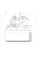
図2は光源装置100の構成を示す図である。図2において1は青色光を射出する第1の光源部、2は青色光を射出する第2の光源部である。第1の光源部1からの青色光(第1の青色光)は後述の拡散体層(拡散素子)90Cに導かれ、第2の光源部2からの青色光(第2の青色光)は後述の蛍光体層(波長変換素子)9Bに導かれる。
FIG. 2 is a diagram showing the configuration of the
第1の光源部1および第2の光源部2は同一の部材に保持された青色LDの集合(青色LDバンク)であるが、1つの青色LD(発光素子)であってもよい。より詳細には、本実施例および後述の第2、第3実施例では第1の光源部1は1つの青色LDバンクのことであり、第2の光源部2は互いに近接して(接触して)配置された2つの青色LDバンクのことである。1つの青色LDバンクは、合計8個の青色LDと、各青色LDからの発散光を平行光にするための8個コリメータレンズと、これら複数の青色LDと複数のコリメータレンズを保持する保持部材を有している。そして、ベース部材B上において、第1の光源部1である青色LDバンクは、第2の光源部2である2つの青色LDバンクの集合から離れた位置に設けられている。ベース部材Bはヒートシンクやヒートパイプ等の冷却部材(放熱部材)であり、各光源部を冷却する機能を有する。
The first light source section 1 and the second
第1の光源部1の青色LDの個数と第2の光源部2の青色LDの個数および波長は同じでも互いに異なっていてもよい。各光源部の青色LDからの青色光の波長は465nmであるが、445nmあるいは455nmの青色光を射出する青色LDを用いてもよい。本実施例では第1の光源部1が備える青色LDの個数は第2の光源部2が備える青色LDの個数よりも少ないが、青色LDの個数の関係は逆あるいは同数であってもよい。
The number of blue LDs in the first light source section 1 and the number and wavelength of the blue LDs in the second
第1の光源部1および第2の光源部2はともにベース部材B上に設けられている。ベース部材Bは第1の光源部1および第2の光源部2が発する熱を放熱するための複数のフィンなどの放熱部を有する。本実施例では複数の光源部が1つの冷却部材を共用している。
Both the first light source section 1 and the second
第1の光源部1と第2の光源部2は次のように区別してもよい。ベース部材B上に複数の青色LDバンクが設けられている場合、この複数の青色LDバンクのうち、後述のコンデンサーレンズ(第1のコンデンサーレンズユニット)81に入射する光を射出する青色LDバンクを第1の光源部1とする。コンデンサーレンズ81に入射する光を射出する青色LDバンクが複数ある場合には、それら複数の青色LDバンクを第1の光源部1とする。同様に、ベース部材B上に設けられている複数の青色LDバンクのうち、後述のコンデンサーレンズユニット6(第2のコンデンサーレンズユニット)に入射する光を射出する青色LDバンクを第2の光源部2とする。コンデンサーレンズユニット6に入射する光を射出する青色LDバンクが複数ある場合には、それら複数の青色LDバンクを第2の光源部2とする。
The first light source section 1 and the second
(第1の光源部1からの青色光の光路)
第1の光源部1からの青色光(青色の平行光)L3はミラー7で反射され、コンデンサーレンズ81によって回転ホイール9の拡散体層(拡散素子)90Cに集光される。本実施例ではコンデンサーレンズ81は1枚の正レンズで構成したが、全体として正のパワーを有する構成であれば、複数のレンズの集合で構成してもよい。
(Optical path of blue light from first light source unit 1)
Blue light (parallel blue light) L3 from the first light source unit 1 is reflected by the mirror 7 and condensed by the
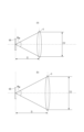
回転ホイール9は図3に示すように円板状の回転板90A、円環状の蛍光体層9B、円環状の拡散体層90Cを備え、図2に示すモータMによって回転可能である。回転板90Aの表面には、円環状の蛍光体層(波長変換素子)9Bおよび円環状の拡散体層90Cが同心円状に形成されている。回転板90Aには円環状の貫通部(穴部)が設けられており、この貫通部に拡散ガラスである拡散体層90Cが埋め込まれている。つまり、回転板90Aは拡散体層90Cよりも内側の部分と外側の部分を有しており、この内側の部分と拡散体層90Cが接着剤で連結されており、拡散体層90Cと上記外側の部分が接着剤で連結されている。
As shown in FIG. 3, the rotary wheel 9 includes a disk-shaped
蛍光体層9Bは透明な樹脂バインダに細かな蛍光体粒子を均一に混合させたものを回転板90A上に塗布する等して形成した。しかしながら、入射光を使用上問題がない程度に拡散させることができ、かつ青色光を充分に黄色光へ変換することができる構成であれば蛍光体層9Bの構成は上記の構成に限定されない。例えば、蛍光体層9Bの代わりに量子ドットあるいは量子ロッドを用いてもよい。本実施例では蛍光体粒子の主材料はYAG(イットリウム・アルミニウム・ガーネット)系であり、第2の光源部2からの青色光の少なくとも一部を黄色光に変換する。量子ロッドの主材料はカドミウムセレン等を用いればよい。
The
本実施例では拡散体層と蛍光体層を同一の回転ホイール上に形成しているため、回転ホイール、その回転支持機構およびモータMも1つでよい。このため、従来のように波長変換素子と拡散素子をそれぞれ別個の回転ホイールに形成した構成に対し、大幅な小型化が可能となる。 In this embodiment, since the diffuser layer and the phosphor layer are formed on the same rotating wheel, only one rotating wheel, its rotation support mechanism and motor M are required. Therefore, it is possible to significantly reduce the size as compared with the conventional structure in which the wavelength conversion element and the diffusion element are formed on separate rotating wheels.
なお、回転板90Aはアルミなどの金属製であるが、蛍光体層9Bに入射した光を使用上充分に反射させることができれば、この構成に限定されない。また、蛍光体層9Bは拡散体層90Cよりも外側に設けられているが、逆に蛍光体層9Bを拡散体層90Cよりも内側に設けてもよい。
Although the
また、拡散体層90Cは拡散ガラスであるが、入射光を使用上問題がない程度に拡散させることができれば、上記の構成に限定されない。例えば透明な樹脂バインダに細かな拡散粒子を均一に混合させたものを回転板90Aの貫通部に流し込み、硬化させて形成してもよい。
Further, although the
また、回転板90Aは金属製ではなく樹脂製やガラス製であってもよい。回転板90Aが樹脂製やガラス製で透明である場合には、拡散体層90Cは透明な樹脂バインダに細かな拡散粒子を均一に混合させたものを回転板90Aに塗布して形成すればよい。回転板90Aの表面に円環状の金属コーティング(反射部)を施し、この金属コーティングの上に蛍光体層9Bを設ければよい。この金属コーティングによって蛍光体9Bからの光は反射されて照明光学系110へ導かれる。
Further, the
コンデンサーレンズ81から拡散体層90Cに入射した青色光は拡散体層90Cによって拡散されつつ拡散体層90Cを透過し、コリメータレンズユニット8によって平行光となってミラー10へ向かう。本実施例ではコリメータレンズユニット8は2枚の正レンズで構成したが、全体として正のパワーを有する構成であれば、1枚の正レンズあるいは3枚以上のレンズの集合であってもよい。
The blue light incident on the
コリメータレンズユニット8からの拡散光L4はミラー10で反射され、ダイクロイックミラー(第1のダイクロイックミラー、第1の合成素子)5に入射する。ダイクロイックミラー5の特性を図4に示す。図4に示すように、ダイクロイックミラー5は第1の光源部1および第2の光源部2からの青色光の波長である465nm付近で高い透過率を有するともに、500nm以上の帯域、つまり緑色光および赤色光に対しては高い反射率を有する。したがって、ミラー10で反射された拡散光L4はダイクロイックミラー5を透過して照明光学系110へ向かう。
The diffused light L4 from the collimator lens unit 8 is reflected by the
(第2の光源部2からの青色光の光路)
第2の光源部2からの青色光(青色の平行光)L1は正レンズ50および負レンズ51によって圧縮されて径が小さくなった平行光に変換される。つまり、正レンズ50と負レンズ51はアフォーカル光学系(第1のアフォーカルレンズユニット)である。青色光L1を径が小さい平行光に圧縮することで負レンズ51以降の光学素子の径を小さくすることができる。アフォーカル光学系の構成は正レンズ50と負レンズ51の組み合わせに限定されるものではなく、青色光L1をより径が小さい平行光に圧縮することができれば、例えば3枚以上のレンズの集合であってもよい。正レンズ50と負レンズ51の間にはミラー3が設けられており、光路が90度折り曲げられる。
(Optical path of blue light from second light source unit 2)
The blue light (parallel blue light) L1 from the second
負レンズ51からの青色光L1はマイクロレンズアレイ52に入射する。マイクロレンズアレイ52は入射側と出射側に複数のレンズセルがマトリックス状に配置されている光学素子である。負レンズ51からの青色光L1はマイクロレンズアレイ52によって複数の部分光束に分割され、コンデンサーレンズユニット(第2のコンデンサーレンズユニット)6によって蛍光体層9Bに重畳される。この結果、蛍光体層9B上にマイクロレンズアレイ52の入射側のレンズセルと相似形状のスポットが形成される。
Blue light L1 from the
前述のようにダイクロイックミラー5は青色光を透過させる特性を有するため、マイクロレンズアレイ52からの青色光はダイクロイックミラー5を透過してコンデンサーレンズユニット6を介して蛍光体層9Bへ入射する。なお、マイクロレンズアレイ52の代わりにロッドインテグレータや例えば凹凸構造を有する光拡散素子等を用いてもよい。
Since the
また、本実施例ではコンデンサーレンズユニット6は2枚の正レンズからなるが、全体として正のパワーを有する構成であれば、コンデンサーレンズユニット6の代わりに1枚の正レンズ、あるいは複数のレンズの集合を用いてもよい。 In this embodiment, the condenser lens unit 6 consists of two positive lenses. Sets may also be used.
コンデンサーレンズユニット6から蛍光体層9Bに入射した青色光は前述の蛍光体粒子によって黄色光L2に変換され、回転板90Aによって反射されてコンデンサーレンズユニット6に入射する。蛍光体層9Bからの黄色光L2は方向を定めずにランダムな方向に出射するが、コンデンサーレンズユニット6によって平行光となり、ダイクロイックミラー5で反射されて照明光学系110に導かれる。これによって光源装置100は青色光および黄色光、つまり白色光を射出することができる。そして、拡散体層90Cと蛍光体層9Bの両方を共通の回転板90A上に形成したので、光源装置を従来よりも大幅に小型化することが可能である。
Blue light incident on
(光学系の設定)
光学系の具体例について説明する。
(Optical system setting)
A specific example of the optical system will be described.
コリメータレンズユニット8の焦点距離をf1とし、コンデンサーレンズユニット6の焦点距離をf2とする。このとき、光源装置100は、
1.2≦f1/f2≦10・・・(1)
および、
2.0≦f1/f2≦6.0・・・(1a)
を満足している。本実施例ではf1/f2=4.0である。ただし、条件式(1)と(1a)の双方を満足することは必須ではなく、例えば、プロジェクタ内部に余裕があれば、f1/f2=1.5である光源装置をプロジェクタに搭載してもよい。
Let the focal length of the collimator lens unit 8 be f1, and the focal length of the condenser lens unit 6 be f2. At this time, the
1.2≤f1/f2≤10 (1)
and,
2.0≤f1/f2≤6.0 (1a)
are satisfied. In this embodiment, f1/f2=4.0. However, it is not essential to satisfy both conditional expressions (1) and (1a). good.
条件式(1)および(1a)は焦点距離f1の方が焦点距離f2よりも大きい、すなわち、コリメータレンズユニット8のパワーの方がコンデンサーレンズユニット6のパワーよりも弱いことを意味する。光源装置100が条件式(1)あるいは(1a)を満足することによって得られる効果について図5および図6を用いて説明する。
Conditional expressions (1) and (1a) mean that the focal length f1 is greater than the focal length f2, that is, the power of the collimator lens unit 8 is weaker than the power of the condenser lens unit 6. Effects obtained by the
図5は拡散体層90Cとコリメータレンズユニット8を模式的に示した図である。図5(b)は図5(a)よりも焦点距離f1が短い場合を示している。拡散体層90Cから出射する光の発散角度θ90Cが一定であるとした場合、焦点距離f1が小さいとコリメータレンズユニット8から出射する平行光の径D1が小さくなる。逆に焦点距離f1が大きいと径D1は大きくなる。
FIG. 5 is a diagram schematically showing the
図6は蛍光体層9Bとコンデンサーレンズユニット6を模式的に示した図であり、図6(b)は図6(a)よりも焦点距離f2が大きい場合を示している。
FIG. 6 is a diagram schematically showing the
図5と図6を比較すれば分かるように、拡散体層90Cから出射する光の発散角度θ90Cは蛍光体層9Bから出射する光の発散角度θ9Bよりも小さくなりやすい。これは、拡散体層90Cによる拡散はコヒーレンス(可干渉性)を有するレーザー光である青色LDからの青色光を使用上問題がない程度に拡散させれば済むためである。つまり、蛍光体層9Bによる拡散度合いと、拡散体層90Cによる拡散度合いを比較すると、蛍光体層9Bによる拡散度合いの方が大きい。このため、コンデンサーレンズユニット6から出射する平行光(青色光)の径D2は、コリメータレンズユニット8から出射する平行光(黄色光)の径D1よりも大きくなりやすい。径が互いに異なる青色光と黄色光を、照明光学系110を介して光変調素子40R、40G、40Bに導いてしまうと、投射画像に色むらが生じてしまう。
As can be seen by comparing FIGS. 5 and 6, the divergence angle θ 90C of light emitted from the
そこで、本実施例では焦点距離f1を大きくして径D1を大きくし、径D1と径D2の差を埋めることで前述の色むらの発生を抑制している。焦点距離f2が大きすぎると図6(b)に示すようにコンデンサーレンズユニット6が大型化してしまうため、焦点距離f2は大きすぎない値としている。その結果、光源装置100は条件式(1)および(1a)を満足する。
Therefore, in this embodiment, the focal length f1 is increased to increase the diameter D1, thereby filling the difference between the diameter D1 and the diameter D2, thereby suppressing the above-described color unevenness. If the focal length f2 is too large, the condenser lens unit 6 becomes large as shown in FIG. 6B, so the focal length f2 is set to a value that is not too large. As a result, the
拡散体層90Cにおける拡散度をΦとする。このとき、光源装置100は、
1°≦Φ≦30°・・・(2)
および
1°≦Φ≦15°・・・(2a)
を満足している。本実施例ではΦ=10°である。ただし、条件式(2)と(2a)の双方を満足することは必須ではなく、例えば、プロジェクタ内部に余裕があれば、Φ=20°である光源装置をプロジェクタに搭載してもよい。拡散度Φは次に説明するように計測すればよい。拡散体層90Cの表面(あるいは回転板90Aの表面)とコリメータレンズユニット8の最も回転ホイール9側の面の面頂点間のコリメータレンズユニット8の光軸方向における距離が半分になる位置を計測位置とする。この計測位置における拡散体層90Cからの出射光の照度分布を計測し、この照度分布における半値全幅を計算する。そして、半値全幅の端部に相当する2点と、拡散体層90Cの径方向における中心点の合計3点からなる角度を拡散度Φとすればよい。
Let Φ be the degree of diffusion in the
1°≦Φ≦30° (2)
and
1°≦Φ≦15° (2a)
are satisfied. In this embodiment, Φ=10°. However, it is not essential to satisfy both conditional expressions (2) and (2a). For example, if there is room in the projector, a light source device with Φ=20° may be installed in the projector. The degree of diffusion Φ can be measured as described below. The position where the distance in the optical axis direction of the collimator lens unit 8 between the surface of the
条件式(2)および(2a)は拡散体層90Cにおける拡散度Φが小さすぎず、かつ大きすぎないことを意味している。光源装置100が条件式(2)あるいは(2a)を満足することによって得られる効果は以下の通りである。
Conditional expressions (2) and (2a) mean that the degree of diffusion Φ in the diffuser layer 9 0 C is neither too small nor too large. The effects obtained by the
拡散度Φが条件式(2)の下限を逸脱するほどに小さい場合、第1の光源部1が備える青色LDからの光が拡散体層90Cで充分に拡散されないことを意味する。コヒーレンスを有するレーザー光である青色LDからの光が充分に拡散されないと、スクリーンS上にスペックルノイズ(明暗の斑点模様等の不要な模様)が視認しやすくなる。逆に拡散度Φが条件式(2)の上限を逸脱するほどに大きい場合、第1の光源部1が備える青色LDからの光が拡散体層90Cで拡散されすぎることを意味する。青色LDからの光が拡散体層90Cで拡散されすぎると、前述のスペックルノイズは低減されるが、拡散体層90Cからの光が本実施例よりも広がることになる。その結果、拡散体層90Cからの青色光の一部がコリメータレンズユニット8へ入射しないことによって損失が生じたり、コリメータレンズユニット8の径を大きくせざるを得なくなったりする。
If the degree of diffusion Φ is so small as to deviate from the lower limit of conditional expression (2), it means that the light from the blue LD included in the first light source section 1 is not sufficiently diffused by the
以上説明したように、光源装置100が条件式(2)および(2a)を満足するように拡散度Φを設定することで、スペックルノイズを低減し、コリメータレンズユニット8および光源装置100の大型化を抑制しつつ、光の損失を減らすこともできる。
As described above, speckle noise is reduced by setting the degree of diffusion Φ so that the
図3に示したように、本実施例では蛍光体層9Bは拡散体層90Cよりも内側に位置している。その理由について説明する。図5および図6に示したように蛍光体層9Bから出射する光の発散角度θ9Bと拡散体層90Cから出射する光の発散角度θ90Cを比較すると、発散角度θ9Bの方向が大きくなりやすい。つまり、コリメータレンズユニット8の径よりもコンデンサーレンズユニット6の径の方が大きくなりやすい。そこで本実施例では、蛍光体層9Bを拡散体層90Cよりも内側に設け、コンデンサーレンズユニット6を回転ホイール9の回転軸の近くに配置している。その結果、光源装置100を小型にすることができる。
As shown in FIG. 3, in this embodiment, the
図2に示したように、回転ホイール9のモータM側にはコンデンサーレンズ81が設けられている。本実施例とは逆に拡散体層90Cが蛍光体層9Bよりも内側に位置している場合、コンデンサーレンズ81が本実施例よりもモータMに近づき、両者が干渉する可能性がある。そこで本実施例では、コンデンサーレンズ81とモータMの干渉を回避するために、拡散体層90Cを蛍光体層9Bよりも外側に設けている。本実施例では蛍光体層9Bのコストを削減することも目的として蛍光体層9Bを拡散体層90Cよりも内側に設けている。
As shown in FIG. 2 , a
(変形例)
図2に示したように第1の光源部1が有する青色LDバンクの数よりも第2の光源部2が有する青色LDバンクの数の方が多い。つまり、蛍光体層9Bに入射する光の光量は拡散体層90Cに入射する光の光量よりも多い。そこで本実施例とは逆に拡散体層90Cよりも熱くなりやすい蛍光体層9Bを拡散体層90Cよりも外側に設けて、蛍光体層9Bを冷却しやすい構成を採用してもよい。
(Modification)
As shown in FIG. 2, the number of blue LD banks included in the second
回転ホイール9の代わりに図7に示す回転ホイール90を用いてもよい。回転ホイール90は円板状の拡散ガラス900Cと、拡散ガラス900C上に設けた金属コーティングの上に塗布された蛍光体層9Bを備える。このような構成の回転ホイール90でも回転ホイール9と同様の機能を発揮することができる。
A
コンデンサーレンズ81の代わりに図8に示すコンデンサーレンズ82を用いてもよい。コンデンサーレンズ82はいわゆるDカット形状を有しており、モータM側が平坦になっている。このため、コンデンサーレンズ82をコンデンサーレンズ81よりもモータMに近い位置に配置することができる。図8に示す光源装置101においては、コンデンサーレンズ82からの光は拡散体層90Cに対して回転ホイール9の回転軸に近づくように角度をなして入射する。
A
(第2実施例)
図9を用いて第2実施例の光源装置200について説明する。光源装置100と光源装置200の主な違いは第3の光源部55を新たに設けた点である。
(Second embodiment)
A
(第1の光源部1からの青色光の光路)
本実施例における第1の光源部1からの青色光の光路について説明する。第1の光源部1からの青色光(平行光)L3がコンデンサーレンズ81を介して拡散体層90Cに入射する。拡散体層90Cからの拡散光L4はコリメータレンズ83によって平行光となり、ダイクロイックミラー(第2のダイクロイックミラー、第2の合成素子)54に入射する。ダイクロイックミラー54は青色光を反射してIR光を透過させる特性を有する。したがって、コリメータレンズ83からの拡散光L4はダイクロイックミラー54で反射され、アフォーカル光学系(第2のアフォーカルレンズユニット84)に入射する。アフォーカル光学系84は入射した平行光の径を拡大するように構成されており、少なくとも1枚の負レンズと、少なくとも1枚の正レンズを有する。したがって、ダイクロイックミラー54からの拡散光L4はアフォーカル光学系84で拡大されてダイクロイックミラー(第1のダイクロイックミラー、第1の合成素子)53に入射する。
(Optical path of blue light from first light source unit 1)
An optical path of blue light from the first light source unit 1 in this embodiment will be described. Blue light (parallel light) L3 from the first light source section 1 enters the
ダイクロイックミラー53の特性を図10に示す。図10に示すように、ダイクロイックミラー53は第1の光源部1および第2の光源部2からの青色光の波長である465nm付近で高い透過率を有する。そして、500nm以上700nm以下の帯域、つまり緑色光および赤色光に対しては高い反射率を有し、750nm以上の帯域に対して高い透過率を有する。したがって、アフォーカル光学系84からの拡散光L4はダイクロイックミラー53を透過して照明光学系110に導かれる。
Characteristics of the
(第2の光源部2からの青色光の光路)
第2の光源部2からの青色光の光路については、ダイクロイックミラー5の代わりにダイクロイックミラー53を通る点以外は前述の第1実施例と同様であるため、説明は割愛する。
(Optical path of blue light from second light source unit 2)
The optical path of the blue light from the second
(第3の光源部55からのIR光の光路)
第3の光源部55は波長が750nm以上のIR光(近赤外光)を射出するLD等の発光素子と、この発光素子からの発散光を平行光化するためのコリメータレンズを備える。第3の光源部55からのIR光L5はダイクロイックミラー54を透過し、アフォーカル光学系84で拡大される。そして、アフォーカル光学系84からのIR光L5はダイクロイックミラー53を透過して照明光学系110に導かれる。
(Optical path of IR light from third light source unit 55)
The third
このように、光源装置200は白色光に加えてIR光も射出することができる。
Thus, the
図1に示したプロジェクタに光源装置101を搭載する場合には、照明光学系110と色分離合成部120との間にカラーホイールを設ける。あるいは、第1の光源部1および第2の光源部2を消灯している間に第3の光源部55を点灯できるようにする。そして、IR光を前述の光変調素子40R、40G、40Bのいずれかで変調して投射レンズ42を介してスクリーンSへ投射する。これにより、カラー画像だけではなくIR画像もスクリーンSへ投射できる。
When the
(第3実施例)
図11を用いて第3実施例の光源装置300について説明する。光源装置100と光源装置300の主な違いは第4の光源部60を新たに設けた点である。
(Third embodiment)
A
(第1の光源部1からの青色光の光路)
第1の光源部1からの青色光の光路については前述の第1実施例と同様であるため、説明は割愛する。
(Optical path of blue light from first light source unit 1)
Since the optical path of the blue light from the first light source unit 1 is the same as that of the first embodiment, the explanation is omitted.
(第2の光源部2および第4の光源部60からの青色光の光路)
前述の第1および第2実施例において第2の光源部2からの青色光L1はS偏光であったが、本実施例においてはP偏光である。したがって、第2の光源部2からの青色光L1はPBS(偏光分離素子、第3の合成素子)61を透過する。PBS61の特性は図12に示すようにP偏光に対して高い透過率を有し、S偏光に対しては高い反射率を有する。
(Optical paths of blue light from second
Although the blue light L1 from the second
第4の光源部60は第2の光源部2と同様に複数の青色LDバンクを有するが、第4の光源部60からの青色光(第3の青色光)L6はS偏光である。したがって、ミラー10で反射された青色光L6はPBS61で反射されて青色光L1と合流し、以後、前述の第1実施例における青色光L1と同様の光路を進む。
The fourth
このように、本実施例は前述の第1実施例よりも多くの青色光を蛍光体層9Bに入射させることができるため、より明るい画像を投射することができるようになる。
As described above, in this embodiment, more blue light can be incident on the
なお、第4の光源部60からの青色光の偏光方向を第2の光源部2からの青色光の偏光方向と同じにし、第4の光源部60からPBS61までの光路上に2分の1波長板を設けてもよい。
The polarization direction of the blue light from the fourth
(変形例)
前述の各実施例における第1の光源部1と第2の光源部2は一体的に構成されていてもよい。例えば、1つの光源部からの青色光をハーフミラー(分離素子)で青色光(第1の青色光)L3と青色光(第2の青色光)L1とに分離させてもよい。
(Modification)
The first light source section 1 and the second
また、前述の各光源部から回転ホイール9に至るまでの光路上には各図に示されている光学素子とは異なる光学素子を設けてもよい。例えば、図13に示すプリズムミラーPMを光源部の直後に設けることで、光源部からの光の幅W1を幅W2へ小さくしてもよい。プリズムミラーPMの代わりに各光源部からの各青色LDからの光を取り込める大きさを有するレンズを用いてもよい。 Also, optical elements different from those shown in the respective drawings may be provided on the optical paths from the light sources described above to the rotating wheel 9 . For example, the width W1 of the light from the light source may be reduced to the width W2 by providing the prism mirror PM shown in FIG. 13 immediately after the light source. A lens having a size capable of taking in the light from each blue LD from each light source may be used instead of the prism mirror PM.
1 第1の光源部(光源部の一部)
2 第2の光源部(光源部の一部)
9 回転ホイール
9B 蛍光体層(波長変換素子)
90C 拡散体層(拡散素子)
100 光源装置
1 first light source unit (part of light source unit)
2 Second light source unit (part of light source unit)
9 rotating
90C diffuser layer (diffusing element)
100 light source device
Claims (19)
第1の青色光を射出するための第1の光源部と、
第2の青色光を射出するための第2の光源部と、
前記第1の青色光を拡散させる拡散素子および前記第2の青色光の少なくとも一部を黄色光に変換する波長変換素子が同心円状に設けられた回転ホイールを備え、
前記拡散素子により拡散された前記第1の青色光は前記回転ホイールを透過し、前記波長変換素子により黄色光に変換された前記第2の青色光は前記回転ホイールを反射することを特徴とする光源装置。 A light source device for guiding light to an illumination optical system for illuminating a light modulation element,
a first light source unit for emitting first blue light;
a second light source unit for emitting a second blue light;
A rotating wheel on which a diffusing element for diffusing the first blue light and a wavelength converting element for converting at least part of the second blue light into yellow light are provided concentrically ,
The first blue light diffused by the diffusion element is transmitted through the rotating wheel, and the second blue light converted into yellow light by the wavelength conversion element is reflected by the rotating wheel. light source device.
前記第1の合成素子は前記拡散素子からの光を透過させるとともに、前記波長変換素子からの光を反射する特性を有することを特徴とする請求項1乃至3のいずれか一項に記載の光源装置。 further comprising a first synthesizing element for synthesizing the light from the diffusion element and the light from the wavelength conversion element;
4. The light source according to any one of claims 1 to 3, wherein the first synthesizing element has characteristics of transmitting light from the diffusion element and reflecting light from the wavelength conversion element. Device.
近赤外光を射出するための第3の光源部と、
前記拡散素子からの光と前記第3の光源部からの光を合成するための第2の合成素子と、をさらに備え、
前記第1の合成素子は前記拡散素子からの光と前記第3の光源部からの光を透過させるとともに、前記波長変換素子からの光を反射する特性を有することを特徴とする請求項1乃至3のいずれか一項に記載の光源装置。 a first synthesizing element for synthesizing the light from the diffusion element and the light from the wavelength conversion element;
a third light source unit for emitting near-infrared light;
a second synthesizing element for synthesizing the light from the diffusion element and the light from the third light source unit,
3. The first synthesizing element has characteristics of transmitting the light from the diffusing element and the light from the third light source section, and reflecting the light from the wavelength converting element. 4. The light source device according to any one of 3.
前記第2の光源部からの光と前記第4の光源部からの光を合成するための第3の合成素子と、をさらに備えることを特徴とする請求項1乃至3のいずれか一項に記載の光源装置。 a fourth light source unit for emitting third blue light;
4. The light source according to any one of claims 1 to 3, further comprising a third synthesizing element for synthesizing the light from the second light source section and the light from the fourth light source section. A light source device as described.
前記第3の青色光の偏光方向は前記第2の青色光の偏光方向と異なることを特徴とする請求項6に記載の光源装置。 The third synthesis element is a polarization separation element,
7. The light source device according to claim 6, wherein the polarization direction of said third blue light is different from the polarization direction of said second blue light.
前記第3の青色光の偏光方向は前記第2の青色光の偏光方向と同じであって、
前記第4の光源部から前記偏光分離素子までの光路上には2分の1波長板が設けられていることを特徴とする請求項6に記載の光源装置。 The third synthesis element is a polarization separation element,
The polarization direction of the third blue light is the same as the polarization direction of the second blue light,
7. A light source device according to claim 6, wherein a half-wave plate is provided on an optical path from said fourth light source section to said polarization separating element.
前記拡散素子および前記波長変換素子は円環状であって、
前記拡散素子および前記波長変換素子は前記回転板に設けられていることを特徴とする請求項1乃至8のいずれか一項に記載の光源装置。 The rotating wheel has a disk-shaped rotating plate,
The diffusing element and the wavelength converting element are annular,
9. The light source device according to claim 1, wherein said diffusion element and said wavelength conversion element are provided on said rotating plate.
前記波長変換素子は円環状であって、
前記波長変換素子は前記拡散素子に設けられていることを特徴とする請求項1乃至8のいずれか一項に記載の光源装置。 the diffusing element is disc-shaped,
The wavelength conversion element is annular,
9. The light source device according to any one of claims 1 to 8, wherein the wavelength conversion element is provided on the diffusion element.
前記拡散素子からの光を平行光化するためのコリメータレンズユニットと、
前記第2の青色光を前記波長変換素子に導くための第2のコンデンサーレンズユニットと、をさらに備えることを特徴とする請求項1乃至13のいずれか一項に記載の光源装置。 a first condenser lens unit for directing the first blue light to the diffusing element;
a collimator lens unit for collimating the light from the diffusion element;
14. The light source device according to any one of claims 1 to 13, further comprising a second condenser lens unit for guiding the second blue light to the wavelength conversion element.
1.2≦f1/f2≦10
を満足することを特徴とする請求項14に記載の光源装置。 When the focal length of the collimator lens unit is f1 and the focal length of the second condenser lens unit is f2,
1.2≤f1/f2≤10
15. The light source device according to claim 14, wherein:
をさらに満足することを特徴とする請求項15に記載の光源装置。 2.0≤f1/f2≤6.0
16. The light source device according to claim 15, further satisfying:
1°≦Φ≦30°
を満足することを特徴とする請求項1乃至16のいずれか一項に記載の光源装置。 When the diffusivity in the diffusion element is Φ,
1°≤Φ≤30°
17. The light source device according to any one of claims 1 to 16, wherein:
をさらに満足することを特徴とする請求項17に記載の光源装置。 1°≤Φ≤15°
18. The light source device according to claim 17, further satisfying:
光変調素子と、
前記光変調素子からの光を被投射面へ導く投射レンズを保持可能なレンズ保持部と、を備えることを特徴とする画像投射装置。 A light source device according to any one of claims 1 to 18;
an optical modulation element;
and a lens holder capable of holding a projection lens for guiding light from the light modulation element to a projection surface.
Priority Applications (2)
| Application Number | Priority Date | Filing Date | Title |
|---|---|---|---|
| JP2019131061A JP7330787B2 (en) | 2019-07-16 | 2019-07-16 | Light source device and image projection device provided with the same |
| US16/926,354 US11442347B2 (en) | 2019-07-16 | 2020-07-10 | Light source device having rotating wheel and image projection apparatus including the same |
Applications Claiming Priority (1)
| Application Number | Priority Date | Filing Date | Title |
|---|---|---|---|
| JP2019131061A JP7330787B2 (en) | 2019-07-16 | 2019-07-16 | Light source device and image projection device provided with the same |
Publications (3)
| Publication Number | Publication Date |
|---|---|
| JP2021015247A JP2021015247A (en) | 2021-02-12 |
| JP2021015247A5 JP2021015247A5 (en) | 2022-07-12 |
| JP7330787B2 true JP7330787B2 (en) | 2023-08-22 |
Family
ID=74343700
Family Applications (1)
| Application Number | Title | Priority Date | Filing Date |
|---|---|---|---|
| JP2019131061A Active JP7330787B2 (en) | 2019-07-16 | 2019-07-16 | Light source device and image projection device provided with the same |
Country Status (2)
| Country | Link |
|---|---|
| US (1) | US11442347B2 (en) |
| JP (1) | JP7330787B2 (en) |
Families Citing this family (2)
| Publication number | Priority date | Publication date | Assignee | Title |
|---|---|---|---|---|
| KR20210112525A (en) * | 2020-03-05 | 2021-09-15 | 에스케이하이닉스 주식회사 | Camera Module Having an Image Sensor and a Three-Dimensional Sensor |
| EP4318125A1 (en) * | 2021-04-27 | 2024-02-07 | Panasonic Intellectual Property Management Co., Ltd. | Projection system |
Citations (8)
| Publication number | Priority date | Publication date | Assignee | Title |
|---|---|---|---|---|
| JP2010237443A (en) | 2009-03-31 | 2010-10-21 | Casio Computer Co Ltd | Light source device and projector |
| US20150267880A1 (en) | 2014-02-05 | 2015-09-24 | Osram Gmbh | Lighting Device Comprising A Wavelength Conversion Arrangement |
| WO2016067822A1 (en) | 2014-10-28 | 2016-05-06 | ソニー株式会社 | Light source device and projector |
| WO2016158297A1 (en) | 2015-03-30 | 2016-10-06 | Necディスプレイソリューションズ株式会社 | Projector and image optical projection method |
| JP2016186566A (en) | 2015-03-27 | 2016-10-27 | セイコーエプソン株式会社 | Illumination device and projector |
| JP2018054780A (en) | 2016-09-28 | 2018-04-05 | セイコーエプソン株式会社 | Light source device and projector |
| JP2018146806A (en) | 2017-03-06 | 2018-09-20 | セイコーエプソン株式会社 | Illumination device and projector |
| JP2019008018A (en) | 2017-06-21 | 2019-01-17 | セイコーエプソン株式会社 | Illumination device and projector |
Family Cites Families (5)
| Publication number | Priority date | Publication date | Assignee | Title |
|---|---|---|---|---|
| JP5664222B2 (en) | 2010-12-27 | 2015-02-04 | セイコーエプソン株式会社 | Light source device and projector |
| JP6283932B2 (en) * | 2013-01-28 | 2018-02-28 | パナソニックIpマネジメント株式会社 | Lighting device and video display device |
| JP6844220B2 (en) | 2016-11-28 | 2021-03-17 | セイコーエプソン株式会社 | Light source device and projector |
| CN108267913B (en) * | 2016-12-30 | 2021-06-08 | 中强光电股份有限公司 | Light source module and projection device |
| JP6946651B2 (en) | 2017-02-01 | 2021-10-06 | セイコーエプソン株式会社 | Light source device and projector |
-
2019
- 2019-07-16 JP JP2019131061A patent/JP7330787B2/en active Active
-
2020
- 2020-07-10 US US16/926,354 patent/US11442347B2/en active Active
Patent Citations (8)
| Publication number | Priority date | Publication date | Assignee | Title |
|---|---|---|---|---|
| JP2010237443A (en) | 2009-03-31 | 2010-10-21 | Casio Computer Co Ltd | Light source device and projector |
| US20150267880A1 (en) | 2014-02-05 | 2015-09-24 | Osram Gmbh | Lighting Device Comprising A Wavelength Conversion Arrangement |
| WO2016067822A1 (en) | 2014-10-28 | 2016-05-06 | ソニー株式会社 | Light source device and projector |
| JP2016186566A (en) | 2015-03-27 | 2016-10-27 | セイコーエプソン株式会社 | Illumination device and projector |
| WO2016158297A1 (en) | 2015-03-30 | 2016-10-06 | Necディスプレイソリューションズ株式会社 | Projector and image optical projection method |
| JP2018054780A (en) | 2016-09-28 | 2018-04-05 | セイコーエプソン株式会社 | Light source device and projector |
| JP2018146806A (en) | 2017-03-06 | 2018-09-20 | セイコーエプソン株式会社 | Illumination device and projector |
| JP2019008018A (en) | 2017-06-21 | 2019-01-17 | セイコーエプソン株式会社 | Illumination device and projector |
Also Published As
| Publication number | Publication date |
|---|---|
| JP2021015247A (en) | 2021-02-12 |
| US11442347B2 (en) | 2022-09-13 |
| US20210018822A1 (en) | 2021-01-21 |
Similar Documents
| Publication | Publication Date | Title |
|---|---|---|
| JP6085025B2 (en) | Light source device and projection display device | |
| JP5910554B2 (en) | Light source device and display device | |
| US10372027B2 (en) | Illuminator and projector | |
| JP6627364B2 (en) | Light source device, light source unit and projector | |
| WO2015111145A1 (en) | Light source device and image display device using same | |
| US10564531B2 (en) | Light source device and projector | |
| JP2019040177A (en) | Light source device and projection type display device | |
| JP6604110B2 (en) | Optical device and projection device | |
| JPWO2020137749A1 (en) | Light source device and projection type image display device | |
| US20200319541A1 (en) | Light source device and projection display apparatus | |
| JP7330787B2 (en) | Light source device and image projection device provided with the same | |
| JP2020024318A (en) | Light source device and projector | |
| JP2017015966A (en) | Light source device and projector | |
| JP2011215531A (en) | Projector | |
| JP2018021990A (en) | Light source device and projector | |
| TW201833655A (en) | Light source apparatus | |
| US20210191243A1 (en) | Light source apparatus and projection-type image display apparatus | |
| JP2020177070A (en) | Light source device and projection type display unit | |
| US20170242266A1 (en) | Illumination device and projector | |
| JP7106349B2 (en) | Light source device and image projection device | |
| WO2016147580A1 (en) | Projector | |
| WO2014171135A1 (en) | Projection type image display device | |
| US9860497B2 (en) | Illumination device and projector | |
| JP2019008018A (en) | Illumination device and projector | |
| JP2023024245A (en) | Wave conversion plate, light source device, and image projector |
Legal Events
| Date | Code | Title | Description |
|---|---|---|---|
| A521 | Request for written amendment filed |
Free format text: JAPANESE INTERMEDIATE CODE: A523 Effective date: 20220701 |
|
| A621 | Written request for application examination |
Free format text: JAPANESE INTERMEDIATE CODE: A621 Effective date: 20220701 |
|
| A977 | Report on retrieval |
Free format text: JAPANESE INTERMEDIATE CODE: A971007 Effective date: 20230308 |
|
| A131 | Notification of reasons for refusal |
Free format text: JAPANESE INTERMEDIATE CODE: A131 Effective date: 20230314 |
|
| A521 | Request for written amendment filed |
Free format text: JAPANESE INTERMEDIATE CODE: A523 Effective date: 20230509 |
|
| TRDD | Decision of grant or rejection written | ||
| A01 | Written decision to grant a patent or to grant a registration (utility model) |
Free format text: JAPANESE INTERMEDIATE CODE: A01 Effective date: 20230711 |
|
| A61 | First payment of annual fees (during grant procedure) |
Free format text: JAPANESE INTERMEDIATE CODE: A61 Effective date: 20230809 |
|
| R151 | Written notification of patent or utility model registration |
Ref document number: 7330787 Country of ref document: JP Free format text: JAPANESE INTERMEDIATE CODE: R151 |