JP7328452B2 - Method for handling capabilities in a wireless network - Google Patents
Method for handling capabilities in a wireless network Download PDFInfo
- Publication number
- JP7328452B2 JP7328452B2 JP2022528179A JP2022528179A JP7328452B2 JP 7328452 B2 JP7328452 B2 JP 7328452B2 JP 2022528179 A JP2022528179 A JP 2022528179A JP 2022528179 A JP2022528179 A JP 2022528179A JP 7328452 B2 JP7328452 B2 JP 7328452B2
- Authority
- JP
- Japan
- Prior art keywords
- capability
- capabilities
- network
- assigned
- radio
- Prior art date
- Legal status (The legal status is an assumption and is not a legal conclusion. Google has not performed a legal analysis and makes no representation as to the accuracy of the status listed.)
- Active
Links
Images


Classifications
-
- H—ELECTRICITY
- H04—ELECTRIC COMMUNICATION TECHNIQUE
- H04W—WIRELESS COMMUNICATION NETWORKS
- H04W72/00—Local resource management
- H04W72/20—Control channels or signalling for resource management
- H04W72/23—Control channels or signalling for resource management in the downlink direction of a wireless link, i.e. towards a terminal
-
- H—ELECTRICITY
- H04—ELECTRIC COMMUNICATION TECHNIQUE
- H04W—WIRELESS COMMUNICATION NETWORKS
- H04W8/00—Network data management
- H04W8/22—Processing or transfer of terminal data, e.g. status or physical capabilities
-
- H—ELECTRICITY
- H04—ELECTRIC COMMUNICATION TECHNIQUE
- H04W—WIRELESS COMMUNICATION NETWORKS
- H04W48/00—Access restriction; Network selection; Access point selection
- H04W48/08—Access restriction or access information delivery, e.g. discovery data delivery
-
- H—ELECTRICITY
- H04—ELECTRIC COMMUNICATION TECHNIQUE
- H04W—WIRELESS COMMUNICATION NETWORKS
- H04W48/00—Access restriction; Network selection; Access point selection
- H04W48/20—Selecting an access point
-
- H—ELECTRICITY
- H04—ELECTRIC COMMUNICATION TECHNIQUE
- H04W—WIRELESS COMMUNICATION NETWORKS
- H04W72/00—Local resource management
- H04W72/04—Wireless resource allocation
-
- H—ELECTRICITY
- H04—ELECTRIC COMMUNICATION TECHNIQUE
- H04W—WIRELESS COMMUNICATION NETWORKS
- H04W8/00—Network data management
- H04W8/22—Processing or transfer of terminal data, e.g. status or physical capabilities
- H04W8/24—Transfer of terminal data
-
- H—ELECTRICITY
- H04—ELECTRIC COMMUNICATION TECHNIQUE
- H04W—WIRELESS COMMUNICATION NETWORKS
- H04W88/00—Devices specially adapted for wireless communication networks, e.g. terminals, base stations or access point devices
- H04W88/02—Terminal devices
Description
本開示は、無線ネットワークにおいて無線端末の能力を処理するための方法及びデバイスに関する。より具体的には、端末ベンダ又は製造業者IDによって提供される能力ID間の移行を管理するための解決策が提供され、ネットワークのオペレータによって提供される。 The present disclosure relates to methods and devices for handling wireless terminal capabilities in wireless networks. More specifically, solutions are provided for managing transitions between Capability IDs provided by terminal vendor or manufacturer IDs, provided by network operators.
第3世代パートナーシッププロジェクト(3GPP(登録商標))によって提供される様々な世代などの無線通信システムでは、無線端末と基地局との間のワイヤレス無線インターフェース、及び無線ネットワークの様々な動作レベルの両方をセットアップして動作させるための共通ルールをセットアップするための様々な世代の仕様が提供されている。3GPPのドキュメントでは、無線端末、又は無線通信デバイスは、一般に、ユーザ機器(UE)と呼ばれる。UEという用語は、本開示において今後使用されるが、提案された解決策は、3GPPシステム以外の他のシステムにも適用され得ることに留意されたい。基地局は、セルを定義し、セル内のUEに無線アクセスを提供することによって、UEのための無線アクセスを周囲のエリアに提供するように動作する。基地局は、本明細書ではアクセスノードとも呼ばれ、様々なタイプのシステム又は仕様のために3GPPで様々な用語が使用される。アクセスネットワーク、すなわち無線アクセスネットワーク(RAN)は、通常、複数のアクセスノードを含み、とりわけ他の通信ネットワークへのアクセスを提供するコアネットワーク(CN)に接続される。ユニバーサルモバイルテレコミュニケーションシステム(UMTS)とも呼ばれるいわゆる3G仕様では、アクセスノードを示すためにノードBという用語が使用されるのに対して、ロングタームエボリューション(LTE)とも呼ばれるいわゆる4G仕様では、eノードB(eNB)という用語が使用される。無線通信のためにさらに開発された仕様のセットは、ニューラジオ(NR)技術を含む5Gタイプの無線通信システム(5GS)と呼ばれ、gNBという用語は、アクセスノードを示すために使用される。 In wireless communication systems, such as the various generations provided by the 3rd Generation Partnership Project (3GPP®), both the wireless air interface between wireless terminals and base stations, and the various operational levels of the wireless network. Various generations of specifications have been provided for setting up common rules to set up and operate. In 3GPP documents, a wireless terminal, or wireless communication device, is commonly referred to as user equipment (UE). Note that the term UE will be used henceforth in this disclosure, but the proposed solution can also be applied to other systems besides 3GPP systems. A base station operates to provide radio access for a UE to a surrounding area by defining a cell and providing radio access to the UE within the cell. A base station is also referred to herein as an access node, and different terms are used in 3GPP for different types of systems or specifications. The access network, ie the radio access network (RAN), usually comprises a plurality of access nodes and is connected to a core network (CN) which provides access to, among other things, other communication networks. In the so-called 3G specifications, also called Universal Mobile Telecommunications System (UMTS), the term Node B is used to denote access nodes, whereas in the so-called 4G specifications, also called Long Term Evolution (LTE), the eNodeB (eNB) is used. A further developed set of specifications for wireless communication is called 5G-type wireless communication system (5GS), which includes New Radio (NR) technology, and the term gNB is used to denote an access node.
UEは、例えば、UEにおけるモデムプロパティ又はサポートされる機能に関連付けられたUE無線機能など、多くの異なるUE能力を有することができる。無線ネットワークの様々なエンティティに、特定のUEによってサポートされているUE能力を認識させるために、UEは、そのUE能力を無線ネットワークに示す。これは、通常、UEが無線通信ネットワークに登録するときに達成される。UE能力は、例えば、1つ又は複数のメッセージの1つ又は複数の情報要素に列挙されたパラメータ又はインジケータに関して、異なるフォーマットで示すことができる。 A UE may have many different UE capabilities, eg, UE radio capabilities associated with modem properties or supported capabilities in the UE. A UE indicates its UE capabilities to the wireless network in order to make various entities of the wireless network aware of the UE capabilities supported by a particular UE. This is typically achieved when the UE registers with the wireless communication network. UE capabilities may be indicated in different formats, eg in terms of parameters or indicators listed in one or more information elements of one or more messages.
一般に、UEは、例えば、無線通信システムの周波数帯域、サポートされる周波数帯域の組み合わせ、異なる変調及び復調フォーマットのサポート、最大データ復調速度、3GPPリリースバージョン、又は中継又はデバイス間通信のサポートなどの特定の機能に関する場合のある複数の異なるUE能力を示すことができる。既存の技術では、UE能力は、ネットワークに対してかなり静的な方法で示される。UE能力は、ネットワークがUE能力問合せを送信することに応答して、初期ネットワーク登録時及びいくつかのハンドオーバシナリオで示され得る。UE側から能力情報の更新を開始するために、UEはネットワークに再登録する必要があり得る。 Generally, a UE specifies, for example, the frequency bands of a wireless communication system, the combinations of frequency bands supported, support for different modulation and demodulation formats, maximum data demodulation rate, 3GPP release version, or support for relaying or inter-device communication. A number of different UE capabilities may be indicated that may relate to the function of In existing technology, UE capabilities are indicated to the network in a fairly static way. UE capabilities may be indicated during initial network registration and in some handover scenarios in response to the network sending a UE capability query. The UE may need to re-register with the network to initiate the update of the capability information from the UE side.
無線ネットワークで動作するUEの数が増加し、同時にサポート可能なサービス、機能、無線周波数帯域などの数が増加するにつれて、UE能力のデータサイズは増加し続ける。現在の3GPPリリースは、UE能力のサイズに関して既に問題を有している。改善方法を調査するために3GPP内で承認された研究は、UE能力のセットにUE能力IDを割り当てることを提案している。この概念は、RACS ID(無線アクセス能力シグナリングのためのID)という用語で提案されている。UE能力ID(又はUE無線能力ID)は、製造業者によって割り当てられても、製造業者固有であってもよく、UE製造業者によって決定されてもよく、又は特定のPLMN(公衆地上移動体通信ネットワーク)若しくはその一部について、例えばネットワークのオペレータによって決定されてもよい。 As the number of UEs operating in wireless networks increases and the number of services, functions, radio frequency bands, etc. that can be supported simultaneously increases, the data size of UE capabilities continues to increase. Current 3GPP releases already have problems with UE capability size. A study approved within 3GPP to investigate how to improve proposes assigning a UE capability ID to a set of UE capabilities. This concept has been proposed under the term RACS ID (ID for Radio Access Capability Signaling). The UE Capability ID (or UE Radio Capability ID) may be manufacturer-assigned, manufacturer-specific, determined by the UE manufacturer, or specified by a specific PLMN (Public Land Mobile Network). ) or part thereof may be determined, for example, by the operator of the network.
製造業者によって割り当てられたUE能力IDは、UEタイプ又はモデルのためのUE無線能力の完全なセットを定義し得る。PLMNによって割り当てられたUE能力IDはまた、完全なセットを定義することができるが、代替として、UE無線能力の完全なセットのサブセットのみを定義することができ、このサブセットでは、無線ネットワークに関連しないUE能力、例えば、無線ネットワークで使用されない周波数帯域に関連するUE能力が除外される。 A manufacturer-assigned UE Capability ID may define the complete set of UE radio capabilities for a UE type or model. The UE Capability ID assigned by the PLMN may also define the complete set, but alternatively only a subset of the complete set of UE radio capabilities, in which subset the radio network related UE capabilities that are not used by the wireless network, eg, UE capabilities associated with frequency bands that are not used in the wireless network, are excluded.
RACS IDに関するSA2研究はTR 23.743に記載されており、規範的研究は23.501及び23.502並びにEPCの対応する仕様に規定されている。RACSが使用される場合、UEは、登録時にそのUE能力IDを無線ネットワークへ送信するものとする。 SA2 studies on RACS IDs are described in TR 23.743, normative studies are defined in 23.501 and 23.502 and the corresponding EPC specifications. If RACS is used, the UE shall send its UE Capability ID to the radio network upon registration.
UE無線能力管理機能(UCMF)として知られるデータベースマネージャエンティティは、ネットワークにおけるUE無線能力管理を処理する。ネットワークがRACS動作のためにPLMNによって割り当てられたUE能力IDを使用し、UEがそれ自体をPLMNによって割り当てられた能力IDに登録する場合、UCMFは、コアネットワーク及び無線アクセスネットワーク(RAN)が無線インターフェースを介してUE無線能力を送信する必要なしにUE無線能力を採用できるように、このIDによって定義されたUE無線能力のセットを用いてネットワークを構成することができる。しかしながら、ネットワークがPLMNによって割り当てられた能力IDに基づいているが、UEがPLMNによって割り当てられた無線能力IDで構成されていない場合、UEは、UE無線能力の完全なセット(おそらくフィルタリングされた)を無線ネットワークにシグナリングしなければならない。一方、UEは、無線ネットワークが使用しない、UE無線能力IDの完全なセットを定義する、製造業者によって割り当てられたUE能力IDを有し得る。 A database manager entity known as the UE Radio Capability Management Function (UCMF) handles UE radio capability management in the network. If the network uses a PLMN-assigned UE capability ID for RACS operation and the UE registers itself with the PLMN-assigned capability ID, the UCMF will ensure that the core network and radio access network (RAN) The set of UE radio capabilities defined by this ID can be used to configure the network so that the UE radio capabilities can be employed without having to send them over the interface. However, if the network is based on PLMN-assigned capability IDs, but the UE is not configured with PLMN-assigned radio capability IDs, the UE will receive the full (possibly filtered) set of UE radio capabilities. must be signaled to the wireless network. On the other hand, the UE may have a manufacturer-assigned UE Capability ID that defines the complete set of UE radio capability IDs that the radio network does not use.
したがって、特にUE及び無線ネットワークが、異なるRACSタイプなどの異なる能力IDを利用する場合に、UEのサポートされているUE能力を無線通信ネットワークに効率的に示すことを可能にする技術が必要とされている。 Therefore, what is needed is a technique that enables efficient indication of a UE's supported UE capabilities to a wireless communication network, especially when the UE and the wireless network utilize different capability IDs, such as different RACS types. ing.
一般的な目的は、無線ネットワークにおいてUE能力情報を処理するための改善された解決策を提供することである。この問題を対象とする解決策は、独立請求項に記載されている。さらなる利点となる実施形態は、従属請求項に記載されている。 A general objective is to provide an improved solution for handling UE capability information in wireless networks. Solutions directed to this problem are described in the independent claims. Further advantageous embodiments are described in the dependent claims.
第1の態様によれば、UEの能力情報を処理するために無線ネットワークにおいてデータベースマネージャエンティティを動作させるための方法が提供され、本方法は、
ネットワークノードから、サポートされているUE能力を識別する第1の能力IDを受信するステップと、
UE及び無線ネットワークによってサポートされるUE能力のセットであって、UEによってサポートされるUE能力のフルセットのサブセットを形成するセット、及び
第1の能力IDに基づいて、UE能力の前記セットに関連付けられた第2の能力IDであって、無線ネットワークのオペレータによって割り当てられる第2の能力IDを決定するステップと、
無線ネットワークによってサポートされるUE能力のセット、及び、第1の能力IDに基づいて、UE能力の前記セットに関連付けられた第2の能力IDであって、無線ネットワークのオペレータによって割り当てられる第2の能力IDと、
第2の能力ID及びUE能力のセットをネットワークノードに送信するステップとを含む。
According to a first aspect, there is provided a method for operating a database manager entity in a wireless network for processing UE capability information, the method comprising:
receiving from a network node a first capability ID identifying supported UE capabilities;
a set of UE capabilities supported by a UE and a radio network, the set forming a subset of the full set of UE capabilities supported by the UE; and, based on a first capability ID, associating with said set of UE capabilities. determining a second capability ID assigned by an operator of the wireless network;
a set of UE capabilities supported by the wireless network and, based on the first capability ID, a second capability ID associated with the set of UE capabilities, the second capability ID being assigned by an operator of the wireless network; ability ID;
and sending the second capability ID and the set of UE capabilities to the network node.
第2の態様によれば、UEの能力情報を処理するように構成された、無線ネットワークのデータベースマネージャエンティティが提供され、データベースマネージャエンティティは、
ネットワークノードから、サポートされているUE能力を識別する第1の能力IDを受信し、
UE及び無線ネットワークによってサポートされるUE能力のセットであって、UEによってサポートされるUE能力のフルセットのサブセットを形成するセット、及び
第1の能力IDに基づいて、UE能力の前記セットに関連付けられた第2の能力IDであって、無線ネットワークのオペレータによって割り当てられる第2の能力IDを決定し、
第2の能力ID及びUE能力のセットをネットワークノードに送信するように構成されたロジックを備える。
According to a second aspect, there is provided a database manager entity of a radio network configured to process UE capability information, the database manager entity comprising:
receiving from a network node a first capability ID identifying supported UE capabilities;
a set of UE capabilities supported by a UE and a radio network, the set forming a subset of the full set of UE capabilities supported by the UE; and, based on a first capability ID, associating with said set of UE capabilities. determining a second capability ID assigned by an operator of the wireless network;
Logic configured to send the second capability ID and the set of UE capabilities to the network node.
このようにして、無線ネットワークが、UEが保持してネットワークに送信する能力IDを採用しない場合でも、UE能力の適切なセットを取得するために使用可能なアルゴリズムが提供される。 In this way, an algorithm is provided that can be used to obtain the appropriate set of UE capabilities even if the wireless network does not employ the capability IDs that the UE maintains and transmits to the network.
図面を参照して様々な実施形態を説明する。 Various embodiments are described with reference to the drawings.
本発明の実施形態が示されている添付の図面を参照して、本発明を以下で全面的に説明する。しかしながら、本発明は、多くの異なる形態で具体化されてもよく、本明細書に記載の実施形態に限定されると解釈されるべきではなく、むしろ、これらの実施形態は、本開示が徹底的且つ全面的であり、本発明の範囲を当業者に十分に伝えるように提供される。 DETAILED DESCRIPTION OF THE INVENTION The present invention is now fully described with reference to the accompanying drawings, in which embodiments of the invention are shown. This invention may, however, be embodied in many different forms and should not be construed as limited to the embodiments set forth herein; rather, these embodiments are intended to fully satisfy this disclosure. It is provided to be thorough and complete, and to fully convey the scope of the invention to those skilled in the art.
ある要素が別の要素に「接続」されていると言及される場合、それは他の要素に直接接続することができ、又は介在要素が存在してもよいことが理解されよう。対照的に、ある要素が別の要素に「直接接続」されていると言及される場合、介在する要素は存在しない。同様の番号は、全体を通して同様の要素を指す。さらに、本明細書では様々な要素を説明するために第1、第2などの用語が使用され得るが、これらの要素はこれらの用語によって限定されるべきではないことが理解されよう。これらの用語は、ある要素を別の要素と区別するためにのみ使用される。例えば、本発明の範囲から逸脱することなく、第1の要素を第2の要素と呼ぶことができ、同様に、第2の要素を第1の要素と呼ぶことができる。本明細書で使用される場合、「及び/又は」という用語は、関連する列挙された項目のうちの1つ又は複数のありとあらゆる組み合わせを含む。 When an element is referred to as being "connected" to another element, it will be understood that it may be directly connected to the other element or there may be intervening elements. In contrast, when an element is referred to as being "directly connected" to another element, there are no intervening elements present. Like numbers refer to like elements throughout. Furthermore, it will be understood that although the terms first, second, etc. may be used herein to describe various elements, these elements should not be limited by these terms. These terms are only used to distinguish one element from another. For example, a first element could be termed a second element, and, similarly, a second element could be termed a first element, without departing from the scope of the present invention. As used herein, the term "and/or" includes any and all combinations of one or more of the associated listed items.
周知の機能又は構成は、簡潔さ及び/又は明瞭さのために詳細に説明されない場合がある。他に定義されない限り、本明細書で使用されるすべての用語(技術用語及び科学用語を含む)は、本発明が属する技術分野の当業者によって一般的に理解されるのと同じ意味を有する。一般的に使用される辞書で定義されているような用語は、本明細書及び関連技術の文脈におけるそれらの意味と一致する意味を有すると解釈されるべきであり、本明細書で明示的にそのように定義された理想化された又は過度に形式的な意味で解釈されないことがさらに理解されよう。 Well-known functions or constructions may not be described in detail for brevity and/or clarity. Unless defined otherwise, all terms (including technical and scientific terms) used herein have the same meaning as commonly understood by one of ordinary skill in the art to which this invention belongs. Terms as defined in commonly used dictionaries are to be construed to have a meaning consistent with their meaning in the context of this specification and the related art, and expressly herein It will further be understood that the terms so defined are not to be construed in an idealized or overly formal sense.
本発明の実施形態は、本発明の理想化された実施形態の概略図を参照して本明細書で説明される。したがって、例えば製造技術及び/又は公差の結果として、図の形状及び相対的なサイズからの変形が予想される。したがって、本発明の実施形態は、本明細書に示される領域の特定の形状及び相対サイズに限定されると解釈されるべきではなく、例えば、異なる動作上の制約及び/又は製造上の制約から生じる形状及び/又は相対サイズの偏差を含むものとする。したがって、図に示される要素は、本質的に概略的であり、それらの形状は、デバイスの領域の実際の形状を示すことを意図しておらず、本発明の範囲を限定することを意図していない。 Embodiments of the present invention are described herein with reference to schematic illustrations of idealized embodiments of the present invention. Accordingly, variations from the shapes and relative sizes of the figures are to be expected, for example as a result of manufacturing techniques and/or tolerances. Accordingly, embodiments of the present invention should not be construed as limited to the specific shapes and relative sizes of the regions illustrated herein, for example due to differing operational and/or manufacturing constraints. shall include deviations in shape and/or relative size that occur. Accordingly, the elements shown in the figures are schematic in nature and their shapes are not intended to represent the actual shape of the regions of the device, but are intended to limit the scope of the invention. not
図1は、無線通信システムの無線ネットワーク10を概略的に示している。無線ネットワークは、インターネット140などの他の通信ネットワークへのアクセスを提供するコアネットワーク(CN)100と、無線端末との通信のためのアクセスネットワーク120とを備え、そのうちの1つのUEが示されている。アクセスネットワーク120は、様々なセルにサービスを提供するように構成された複数のアクセスノード121、122を含むことができる。アクセスネットワーク120は、例えば、無線アクセスネットワーク(RAN)であってもよい。UEは、例えば無線によって、アクセスネットワーク120のアクセスノードと無線で通信するように構成された無線端末である。UEは、固定式又は移動式であり得る。
FIG. 1 schematically shows a
CN100は、特定の3GPPリリースにより、又は別のセットの無線通信規格により定義された、様々なコアネットワークノードを含んでもよい。そのようなCNエンティティは、アクセス&モビリティ管理機能(AMF)などのUEのモビリティを処理するための少なくとも1つのノードを含むことができる。他のCNエンティティは、セッション管理機能(SMF)、ユーザプレーン機能(UPF)、並びにサービングゲートウェイ及びPDNゲートウェイなどの1つ又は複数のゲートウェイなどの、図示されていない様々な機能を実現するさらなるノードを含んでもよい。
各アクセスノード121、122は、様々な実施形態において、各々が1つのセルにサービス提供する基地局と呼ばれ得る。アクセスネットワーク120は、いくつかのアクセスネットワークグループを含むことができ、そのような各アクセスネットワークグループは、少なくともUEモビリティ管理のために、1つ又は複数のAMF110によってサポート及びサービス提供され得る。各アクセスネットワークグループは、複数のアクセスノードを備え得る。様々な実施形態では、アクセスネットワークグループは、1つのAMF又は1つのAMFセットによってサービス提供される、アクセスネットワーク120全体の一部として定義され、AMFセットはいくつかのAMFを含むことができる。AMFセットは3GPPで定義され、例えばUEへの不要なシグナリングなしに互いに置換することができるAMFのグループを含む。
Each
ネットワーク10内のUE能力を管理する目的で、中央又はグローバルCNノード130は、中央又はグローバルデータベース135を備えるか、又はそれに接続されるデータベースマネージャエンティティ130として含まれてもよい。データベース135は、本明細書では能力情報とも呼ばれる、ネットワーク10のためのUE能力を記憶するように構成され得る。データベース135は、そのような能力情報の様々な組み合わせ、部分、又はサブセットに関連付けられた能力IDをさらに記憶することができる。様々な実施形態において、場合によってはデータベース135を含むノード130は、UE無線能力管理機能(UCMF)を実現することができる。したがって、データベースマネージャエンティティ130は、UE能力情報、すなわち、例えば、UEのための無線ベアラ、周波数帯域などのサポート、並びに能力IDを定義する実際のデータを記憶するように構成することができる。能力IDは、この文脈において、UEの能力情報のセット又はUEの特定のバージョンを一意に識別するいくつかのビットである。前述のように、そのような能力IDは、無線ネットワーク10によって、オペレータによる制御下で、又は、UEの製造業者によって割り当てられ得る。これらのIDがどのように提供又は計算されるかは異なり得る。様々な実施形態において、能力IDは、UE能力情報の関連するセットのハッシュであり得るか、又はそれを含み得る。通常、無線ネットワーク10は、PLMNによって割り当てられたIDである、PLMN_IDを取得するために、共通のアルゴリズムを使用して、それ自体の能力IDを定義又は作成し得る。さらに、例えば、無線ネットワークのアクセスネットワーク120に登録する場所及び時間に依存して、UE能力の観点から、異なるが同一のUEのために、異なるPLMN_IDが無線ネットワーク10においてローカルに割り当てられ得る。製造業者固有の解決策の場合、能力ID、MANU_IDがUE製造業者によって割り当てられてもよく、その場合、能力ID、MANU_IDは、MANU_IDの一部として、又はMANU_IDによって表される能力セットの一部として、又はMANU_IDと共に追加識別情報として、UE製造業者情報(例えば、PEIのTACフィールド)を伴う。この場合、能力IDは、この製造業者のUE無線機能のセットを一意に識別し、このUE製造業者情報と共に、任意のPLMNのUE無線機能のこのセットを一意に識別する。
For the purpose of managing UE capabilities within the
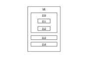
図2は、図1のUEなどのUEを概略的に示す。UEは、アクセスネットワーク120と通信するように構成することができ、少なくともエアインターフェースを介してアクセスネットワーク120と通信するための無線受信機及び送信機などのトランシーバ213を備えることができる。UEはロジック210をさらに備える。ロジック210は、例えばコントローラ又はマイクロプロセッサ211を備えることができる。ロジックはまた、コンピュータ可読記憶媒体を含むように構成されたデータ記憶デバイス212を備えるか、又はそれに接続されてもよい。データ記憶デバイス212は、メモリを含んでもよく、例えば、バッファ、フラッシュメモリ、ハードドライブ、リムーバブルメディア、揮発性メモリ、不揮発性メモリ、ランダムアクセスメモリ(RAM)、又は他の適切なデバイスのうちの1つ又は複数であってもよい。標準的な構成では、データ記憶デバイス212は、長期データ記憶用の不揮発性メモリと、コントローラ211用のシステムメモリとして機能する揮発性メモリとを含むことができる。データ記憶デバイス212は、データバスを介してロジック210のコントローラ211、例えばプロセッサとデータを交換することができる。データ記憶デバイス212は、非一時的なコンピュータ可読媒体と見なされる。本明細書で概説するように、ロジック210のコントローラ211の1つ又は複数のプロセッサは、UEの動作を実行するために、データ記憶デバイス212又は別個のメモリに記憶された命令を実行することができる。UEは、UE能力情報及び能力IDなどの関連データを記憶するためのデータメモリ214をさらに備えることができる。データメモリ214は、データ記憶デバイス212の一部であってもよく、又はデータ記憶デバイスの一部を形成してもよく、又は別個のエンティティであってもよいが、ネットワーク10の他のノードにアクセスして送信することができる能力データから、UEを制御及び動作するために使用されるデータ記憶デバイス212にコンピュータプログラム又はオペレーティングシステムに関連付けられたコードを記憶することの間の意図された違いを識別するために図に具体的に示されている。UEは、例えば、1つ又は複数のアンテナ、ユーザインターフェース、電源などのような、識別されたもの以外のその他の特徴及び機能を明確に含み得るが、これらの構成要素は、明確にするために図2には示されていないことに留意され得る。
FIG. 2 schematically shows a UE such as the UE of FIG. A UE may be configured to communicate with the
図3は、コアネットワーク100のデータベースマネージャエンティティ130として機能する、ネットワークノード130を概略的に示す。ネットワークノード130は、ネットワーク10のUEモビリティを処理するための機能であるか、又はそれを備える。したがって、コアネットワークノード130は、UCMFを実現する制御機能131として動作することができる。制御機能131は、CNノードロジック310を備える。CNノードロジック310は、例えば、コントローラ又はマイクロプロセッサ311を備えることができる。ロジック310はまた、コンピュータ可読記憶媒体を含むように構成されたデータ記憶デバイス312を備えるか、又はそれに接続されてもよい。データ記憶デバイス312は、メモリを含んでもよく、例えば、バッファ、フラッシュメモリ、ハードドライブ、リムーバブルメディア、揮発性メモリ、不揮発性メモリ、ランダムアクセスメモリ(RAM)、又は他の適切なデバイスのうちの1つ又は複数であってもよい。標準的な構成では、データ記憶デバイス312は、長期データ記憶用の不揮発性メモリと、制御ユニット用のシステムメモリとして機能する揮発性メモリとを含むことができる。データ記憶デバイス312は、データバスを介してロジック310のプロセッサ311とデータを交換することができる。データ記憶デバイス312は、非一時的なコンピュータ可読媒体と見なされる。本明細書で概説するように、ロジック310の1つ又は複数のプロセッサ311は、CNノード130の動作を実行するために、データ記憶デバイス又は別個のメモリに記憶された命令を実行することができる。CNノード130は、AMF110を含む、他のエンティティと通信するための1つ又は複数のトランシーバ又はインターフェース313をさらに備えることができる。UCMFを実現する制御機能131は、好ましくは複数のUEのための、UE能力情報及び能力IDなどの関連データを記憶するためのグローバルデータベース135に接続される。データベース135は、UEモビリティを処理する制御機能131に接続された別個のメモリユニットに物理的に記憶されてもよい。他の実施形態では、データベース135は、UEモビリティを処理する制御機能131として共通エンティティ110で実現される。例示のために、図面は、ネットワークノード130がエンティティ131とデータベース135の両方を含むことを示している。
FIG. 3 schematically shows a
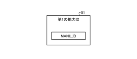
図4は、UE能力の様々なセットと関連付けられた能力IDとの間の関係を概略的に示す。本明細書では、UEのためのUE能力の完全なセットは、UEのための、サポートされるUE能力の第1のセット41と呼ばれ得る。これは、いくつかの要素を含むものとして概略的に示されており、それぞれが無線通信における特定の機能のサポートを示し得る。第1のセット41は、製造業者によって定義されるように、UEによってサポートされるUE能力の全面的又は完全なセットを提供する。通常、この完全なセットは、特定のタイプ、モデル、又はソフトウェアバージョンのすべてのUEに対して有効であり得る。さらに、製造業者OEMによって提供されるMANU_IDは、UE能力の第1の完全なセットを識別するためにリンクされてもよい。
FIG. 4 schematically shows the relationship between different sets of UE capabilities and associated capability IDs. The complete set of UE capabilities for the UE may be referred to herein as the first set of supported
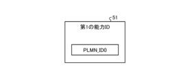
特定の無線ネットワーク10、特に無線ネットワーク10のアクセスネットワーク120は、UE能力のフルセットのサブセットのみを利用するように構成され得る。このサブセットは、アクセスネットワークに関連するUE能力のセット42を報告するようにUEを構成する、アクセスネットワークによってUEに提供される、1つ又は複数のフィルタによって識別され得る。したがって、これは、サポートされるUE能力の第2のセット42と呼ばれる場合があり、これは、第1のフルセット41と同じである場合があるが、通常、UE能力の第1のセット41のサブセットである。さらに、PLMN_IDは、UE能力の第2のセットを識別するためにリンクされ得る。様々な実施形態において、PLMN_IDは、UE能力の第2のセットのハッシュとして構成され得る。
A
無線ネットワークでは、例えば、動作特性、機器、設定、又は規制の変更は、サポートされるUE能力の変更につながる可能性がある。これは、サポートされるUE能力の定義をUE能力のあるセット42から別のセット43に変更する必要性をもたらし得る。さらに、様々な実施形態において、ネットワークの2つ以上の異なるPLMNによって割り当てられた能力IDが、例えばAMFレベルで定義されており、サポートされるUE能力の同じセットをカバー又は含む状況が発生し得る。これらの理由のいずれかのために、あるネットワークによって割り当てられたIDが別のネットワークによって割り当てられたIDに変更されることが起こり得る。図では、そのような異なるIDをPLMN_ID及びPLMN_ID0として示している。対応するUE能力42及び43は異なるものとして示されているが、それらは様々な実施形態において、UE能力41の完全なセットの同じサブセットをカバーすることができる。
In wireless networks, for example, changes in operating characteristics, equipment, settings, or regulations can lead to changes in supported UE capabilities. This may lead to the need to change the definition of supported UE capabilities from one set 42 of UE capabilities to another 43 . Further, in various embodiments, situations may arise where two or more different PLMN-assigned Capability IDs in a network are defined, e.g., at the AMF level, and cover or include the same set of supported UE capabilities. . For any of these reasons, it may happen that an ID assigned by one network is changed to an ID assigned by another network. In the figure, such different IDs are shown as PLMN_ID and PLMN_ID0. Although the
本明細書で提供される様々な実施形態の背後にある全体的な目的は、無線インターフェースを介した、すなわちUEとRAN120との間のシグナリングを最小限に抑えることである。具体的には、UEがサポートされているUE能力を識別する第1の能力IDを有するが、無線ネットワーク10が異なる第2の能力IDを使用して動作する場合に、そのようなシグナリングを最小限に抑えることが目的である。
The overall goal behind the various embodiments provided herein is to minimize signaling over the radio interface, ie between the UE and the
一実施形態が図5Aを参照して概説される一般的な態様によれば、UEの能力情報を処理するために無線ネットワーク10においてデータベースマネージャエンティティ130を動作させるための方法が提供され、本方法は、
ネットワークノード110から、サポートされるUE能力を識別する第1の能力ID51を受信するステップ510と、
無線ネットワークによってサポートされるUE能力のセット52と、UE能力の前記セット52に関連付けられた第2の能力ID53とを、第1の能力IDに基づいて決定するステップ515と、第2の能力ID53は、無線ネットワークのオペレータによって割り当てられたPLMN_IDであり、
第2の能力ID及びUE能力のセット52をネットワークノードに送信するステップ520とを含む。
According to general aspects, one embodiment of which is outlined with reference to FIG. 5A, a method is provided for operating a
receiving 510 a
Determining 515 a
and sending 520 the second capability ID and the set of
さらに、第2の一般的な態様によれば、UEの能力情報を処理するように構成された、無線ネットワーク10のデータベースマネージャエンティティ130が提供され、データベースマネージャエンティティは、
ネットワークノード110から、サポートされるUE能力を識別する第1の能力ID51を受信し(510)、
無線ネットワークによってサポートされるUE能力のセット52と、UE能力の前記セット52に関連付けられた第2の能力ID53とを、第1の能力IDに基づいて決定し(515)、第2の能力ID53は、無線ネットワークのオペレータによって割り当てられ、
第2の能力IDとUE能力のセット52とをネットワークノードへ送信する(520)ように構成されたロジック310を備える。
Further, according to a second general aspect, there is provided a
receiving (510) a
determining 515 a
このようにして、無線ネットワークが、UEが保持してネットワークに送信する能力IDを採用しない場合でも、UE能力の適切なセットを取得するためのアルゴリズムが提供される。 In this way, an algorithm is provided for obtaining the appropriate set of UE capabilities even if the radio network does not adopt the capability IDs that the UE maintains and sends to the network.
さらに、ネットワーク10は、ネットワーク10内で将来使用するため、及び場合によっては第1の能力IDを置き換えるためにUEに送信するための適切な第2の能力IDを送信することによって構成される。
Additionally, the
ここで、主に図5Aを参照して、一例示的な実施形態を説明する。ネットワークがPLMNによって割り当てられた能力IDを使用している場合、PLMN10に初めてアクセスする各UEは、無線インターフェースを介してネットワークにUE能力の完全なセット41を送信する必要がある。これは、UEが製造業者によって割り当てられたUE能力IDを有し、これをネットワーク10に送信する場合には必要ではない。むしろ、UCMF130は、この情報が中央データベース135で利用可能であり、UEベンダ又は製造業者によって公開されているという条件下で、製造業者によって割り当てられたIDに基づいてUE能力の関連するセットを取得するように構成されることが提案される。したがって、ネットワーク10がPLMNによって割り当てられたIDを使用している場合であっても、UEが(UCMF130における受信のために)製造業者によって割り当てられた能力ID MANU_IDをネットワークに送信することができることが提案される。例えばUCMFとして動作するデータベースマネージャエンティティは、データベース135からUE無線能力のセットを取得するように構成される。これにより、UE無線機能は、UEが無線インターフェースを介して無線能力を送信する必要なしに、UCMFにおいて利用可能である。次いで、UCMF130は、あたかもPLMN_IDがUEから受信されたかのように、対応する方法でUE能力52をPLMNによって割り当てられたID PLMN_IDと照合することができる。UCMF130は、PLMNによって割り当てられたID PLMN_IDと共にUE無線機能52のセットをAMFに送信するようにさらに構成され、次にAMFは、PLMN割り当て能力ID PLMN_IDによりUEを構成するように動作し、ネットワークの残りの部分は、対応する機能を用いて構成することができる。
An exemplary embodiment will now be described primarily with reference to FIG. 5A. If the network uses PLMN-assigned capability IDs, each UE accessing the
図5Aは、3GPP実施形態におけるUE、RAN、AMF、及びUCMFを示し、これらのエンティティ間のシグナリングを含む。 FIG. 5A shows the UE, RAN, AMF and UCMF in a 3GPP embodiment and includes signaling between these entities.
ステップ501は、UEとRAN120との間のRRCシグナリングを含む、ネットワーク10へのUEの登録の開始を示す。これは、とりわけ、UEがネットワーク10に登録するためにRRCメッセージを送信することを含み得る。
Step 501 indicates initiation of UE registration with
このプロセスでは、ネットワーク10が製造業者によって割り当てられた能力IDの代わりにPLMNによって割り当てられた能力IDを使用する場合であっても、UE及びRAN120ノードはUE無線能力をネゴシエートし、その間にUEはMANU_ID51を送信する(502)。
In this process, the UE and
RANのアクセスノード121などのRANは、MANU_ID51を含む、登録要求をAMF110に送信する(503)。
A RAN, such as
AMF110は、UE無線能力を取得するためにMANU_ID51をUCMF130に送信する(504)。
PLMNによって割り当てられたIDを使用する、UCMF130は、AMFからMANU_ID51を受信する(510)。製造業者又はベンダによって提供されるサポートされるUE能力を識別するMANU_ID51。
これにより、UCMFは、受信した能力ID MANU_ID51に基づいて、無線ネットワーク10によってサポートされるUE能力のセット52、及びUE能力の前記セット52に関連付けられた第2の能力ID53を決定する(515)。第2の能力ID53は、無線ネットワークのオペレータによってPLMN_IDとして割り当てられ、本明細書では、オペレータによって決定又は制御されるプロセス又はルールのセットによって割り当てられることを意味する。ステップ515は、例えばTS23.502のセクション5.2.18.3で提供されるように、Nucmf_UECapabilityManagement Resolveサービスオペレーションに関連付けることができる。このステップの例を、図6を参照してさらに概説する。
Thereby, the UCMF determines (515) a
これにより、UCMFは、PLMN_ID53及びUE能力のセット52でAMFに応答する(520)。
The UCMF then responds 520 to the AMF with the
AMFは、UEとの接続の構成のために、PLMN_ID53及びUE能力のセット52をRAN120にさらに送信する(521)。
The AMF further sends (521) the
RAN120は、UEの登録525をさらに完了し得、UEによる将来の使用のためにPLMN_ID53を用いてUEを構成し得る(522)。
図6は、一般的な方法の様々なステップをフローチャートとして示す。具体的には、受信した第1の能力ID51に基づいて、無線ネットワークによってサポートされるUE能力のセット52、及びUE能力の前記セット52に関連付けられた第2の能力ID53を決定するステップ515に含まれ得る様々なステップ。
FIG. 6 shows various steps of the general method as a flow chart. Specifically, determining 515 a
図6によってカバーされる一実施形態では、図5A、図5B、及び図5Dを参照して説明した実施形態に対応して、第1の能力ID51はMANU_IDである。
In one embodiment covered by FIG. 6, corresponding to the embodiment described with reference to FIGS. 5A, 5B and 5D,
したがって、例えばUCMFとして動作する、データベースマネージャエンティティ130によって実行されたと決定するステップ515は、受信したMANU_IDに基づいて、データベース135から能力情報52を取得することを試みる論理ステップ516を含むことができる。UE能力のそのようなセット52がある場合、このセット52は、AMF110への送信520のためにデータベース記憶装置から取得される。UE能力のセット52は、とりわけ、UEによってサポートされる、周波数帯域を含む、無線能力に関する情報を含む。一実施形態では、UE能力のセット52は、UEによってサポートされるUE能力の完全なセットであり得る。別の実施形態では、機能のセット52は、完全なセットのサブセットであり得る。したがって、サブセットは、完全なセットのフィルタリングされたバージョンを形成し、無線ネットワーク10又はRAN120においてサポート又は使用される能力のみを含み得る。例えば、無線ネットワーク10は、能力のサブセットにおいて定義された、ベアラの特定のセットを利用するように構成され得る一方、UEは、それ自体、能力の完全なセットによって定義されたようなさらなるベアラをさらにサポートする。
Thus, determining 515 performed by
UCMFがデータを取得するデータベース135がMANU_ID51によって識別される能力の完全なセットを記憶する一実施形態では、UCMFは、一実施形態では、その能力のセット52のAMF110への送信520の前に、能力の関連するサブセット52を取得するための記憶されたフィルタを適用することができる。別の実施形態では、UCMFは、無線ネットワーク10の関連サブセットを取得するために、MAF110又はRAN120における後続のフィルタリングのための能力の完全なセット52を送信するように構成され得る。
In one embodiment where the
MANU_IDを入力として使用して見つけられ得るUE能力のセット52がない場合、プロセスは、ヌル回答の指示をAMF110に送信する520か、又はまったく回答しないことによって終了することができる。
If there is no UE capability set 52 that can be found using the MANU_ID as input, the process may end by sending 520 a null reply indication to the
さらに、決定するステップ515は、データベース135から、第2の能力ID、PLMN_ID、53を取得することを試みる論理ステップ517を含むことができる。ここでの目的は、UE構成で使用される能力を識別するために無線ネットワーク10で使用される、ネットワークによって割り当てられた能力ID、PLMN_IDを取得することである。第2の能力ID53、PLMN_IDは、取得された能力のセット52に関連付けられ、完全なUE能力の前記サブセットを識別し、この能力のサブセットは、無線ネットワーク10又はRAN120においてサポート又は使用される。
Additionally, determining 515 may include a logical step 517 of attempting to obtain the second capability ID, PLMN_ID, 53 from
UE能力のセット52に関連付けられた事前に記録されたネットワークによって割り当てられた第2の能力ID53、PLMN_IDがデータベース135から取得され得る場合、プロセスは、取得された第2の能力53ID及び取得された能力情報52をAMF110に送信するステップ520に進むことができる。
If the pre-recorded network assigned
一方、第1の能力ID51に対応するPLMN_IDが存在しない場合、データベースマネージャエンティティ130は、第2の能力IDを作成する(518)ように構成され得る。したがって、プロセスは、作成された第2の能力53ID及び取得された能力情報52をAMF110に送信するステップ520に進むことができる。
On the other hand, if a PLMN_ID corresponding to the
上記の実施形態は、以下の論理ステップとして提示される。
MANU_ID51→UE能力52→PLMN_ID53。
The above embodiment is presented as the following logical steps.
しかしながら、他の実施形態では、必要な情報、すなわち能力のセット52及びステップ520で送信されるべき第2のネットワークによって割り当てられたPLMN_ID53は、代替として、以下の順序で取得されてもよいことに留意されたい。
MANU_ID51→PLMN_ID53→UE能力52。
However, in other embodiments, the required information, namely the set of
そのような実施形態では、データベース135は、MANU_IDからPLMN_IDへのマッピングを含むことができる。したがって、MANU_ID51の入力に基づいて、UCMFは事前記憶されたPLMN_ID53を取得することができ、これはデータベース135の能力のセット52を識別又は指し示す。
In such embodiments,
次に、図6も参照して、代替的な実施形態及びユースケースについて説明する。この実施形態は、第1の能力ID51がネットワークによって割り当てられる、図5A、図5C、及び図5Dに示される実施形態に対応する。
Alternative embodiments and use cases will now be described, also with reference to FIG. This embodiment corresponds to the embodiment shown in Figures 5A, 5C and 5D in which the
上記で概説した方法及びデータベースマネージャエンティティ130の一般的な態様は、ネットワークによって割り当てられたIDを更新するためにさらに使用されてもよい。そのような実施形態は、無線ネットワークのオペレータによって以前に割り当てられたID PLMN_ID0である第1の能力ID51に関する。これは、UEに以前に通信され記憶されていてもよく、又はAMF110に接続されたローカルメモリ又はデータベースにのみ記憶されてもよい。様々な実施形態では、ネットワークによって割り当てられたIDは、例えば接続されたUEのモビリティ管理で使用するために、例えばAMF110で、一時的に作成することができる。そのような一時IDは、その後、例えばUCMFにおいて、より永続的なIDに更新され得る。
The methods outlined above and general aspects of the
さらに、UCMFは、例えば、市場におけるUE及びUEタイプの数の増加を考慮して、能力IDの使用を最適化するように構成され得る。したがって、例えばUCMFにおいて、いくつかの異なるタイプのUEが、無線ネットワーク10への接続の適切な設定に十分なUE能力の共通セットを有すると決定され得る。したがって、能力IDの数を制限するために、UCMFは、たとえそれらの異なるタイプのUEのためのUE能力の完全なセットが異なり得るとしても、同じネットワークによって割り当てられたIDを異なるタイプのUEに割り当てることによってIDの数を制限するように構成され得る。
Additionally, UCMF may be configured to optimize the use of Capability IDs, eg, given the increasing number of UEs and UE types in the market. Thus, for example in UCMF, it may be determined that several different types of UEs have a common set of UE capabilities sufficient to properly set up a connection to the
したがって、図6及び図4を参照すると、例えばUCMFとして動作する、データベースマネージャエンティティ130によって実行されたと決定するステップ515は、受信したPLMN_ID0に基づいて、データベース135から能力情報52を取得することを試みる論理ステップ516を含むことができる。上述したように、AMF110から受信されたこのID PLMN_ID0は、UEから又はAFM110からのものであり得る。そのようなPLMN_ID0を入力として使用して見つけられ得るUE能力のセット52がない場合、プロセスは、ヌル回答の指示をAMF110に送信する520か、又はまったく回答しないことによって終了することができる。
Thus, referring to FIGS. 6 and 4, step 515 of determining performed by the
次に、決定するステップ515は、データベース135の第2の能力ID、PLMN_ID、53を検索する論理ステップ517を含むことができる。そのような第2の能力ID53 ID、PLMN_IDがデータベース135で利用可能である場合、プロセスは、取得された第2の能力53ID及び取得された能力情報52をAMF110に送信するステップ520に進むことができる。
Determining 515 may then include a logical step 517 of retrieving the second capability ID, PLMN_ID, 53 in
様々な実施形態が本明細書に記載されているが、本発明は特許請求の範囲の条件によって定義される。
While various embodiments are described herein, the invention is defined by the terms of the claims.
Claims (15)
ネットワークノード(110)から、サポートされるUE能力を識別する第1の能力ID(51)であって、前記UEの製造業者によって割り当てられる(MANU_ID)第1の能力ID(51)を受信するステップ(510)と、
前記第1の能力IDに基づいて、
-前記UE及び前記無線ネットワークによってサポートされるUE能力のセット(52)であって、前記UEによってサポートされるUE能力(41)のフルセットのサブセット(42、43)を形成するセット、及び
-前記第1の能力IDに基づいて、UE能力の前記セット(52)に関連付けられた第2の能力ID(53)であって、前記無線ネットワークのオペレータによって割り当てられる(PLMN_ID)前記第2の能力ID(53)を決定するステップ(515)と、
前記第2の能力ID及びUE能力の前記セット(52)を前記ネットワークノードに送信するステップ(520)とを含む方法。 A method for operating a database manager entity (130) in a wireless network (10) for processing user equipment UE capability information, comprising:
receiving from a network node (110) a first capability ID (51) identifying supported UE capabilities , the first capability ID (51) assigned by the manufacturer of said UE (MANU_ID); (510) and
Based on the first capability ID,
- a set (52) of UE capabilities supported by said UE and said radio network, forming a subset (42, 43) of the full set of UE capabilities (41) supported by said UE; a second capability ID (53) associated with said set (52) of UE capabilities based on said first capability ID, said second capability being assigned (PLMN_ID) by an operator of said radio network; determining (515) an ID (53);
and sending (520) said second capability ID and said set (52) of UE capabilities to said network node.
ネットワークノード(110)から、サポートされるUE能力を識別する第1の能力ID(51)であって、前記UEの製造業者によって割り当てられる(MANU_ID)第1の能力ID(51)を受信し(510)、
-前記UE及び前記無線ネットワークによってサポートされるUE能力のセット(52)であって、前記UEによってサポートされるUE能力(41)のフルセットのサブセット(42、43)を形成するセット、及び
-前記第1の能力IDに基づいて、UE能力の前記セット(52)に関連付けられた第2の能力ID(53)であって、前記無線ネットワークのオペレータによって割り当てられる(PLMN_ID)第2の能力ID(53)を決定し(515)、
前記第2の能力ID及びUE能力の前記セット(52)を前記ネットワークノードに送信する(520)ように構成されたロジック(310)を備えるデータベースマネージャエンティティ。 A database manager entity (130) in a wireless network (10) configured to process user equipment UE capability information, comprising:
Receive from a network node (110) a first capability ID (51) identifying supported UE capabilities , the first capability ID (51) assigned by the manufacturer of said UE (MANU_ID) ( 510),
- a set (52) of UE capabilities supported by said UE and said radio network, forming a subset (42, 43) of the full set of UE capabilities (41) supported by said UE; a second capability ID (53) associated with said set (52) of UE capabilities based on said first capability ID, said second capability ID being assigned (PLMN_ID) by an operator of said radio network; (53) is determined (515),
A database manager entity comprising logic (310) configured to send (520) said second capability ID and said set (52) of UE capabilities to said network node.
サポートされるUE能力を識別する第1の能力ID(51)であって、前記UEの製造業者によって割り当てられる(MANU_ID)第1の能力ID(51)を含む前記UEの登録要求を、前記無線ネットワークのアクセスネットワーク(120)から受信するステップ(503)と、Sending the UE registration request to the radio, including a first capability ID (51) identifying supported UE capabilities, the first capability ID (51) assigned by the manufacturer of the UE (MANU_ID). receiving (503) from the access network (120) of the network;
前記UEの無線能力情報を取得するため、前記第1の能力ID(51)をデータベースマネージャエンティティ(130)に送信するステップ(504)と、sending (504) said first capability ID (51) to a database manager entity (130) to obtain radio capability information of said UE;
前記データベースマネージャエンティティから、From said database manager entity:
-前記UE及び前記無線ネットワークによってサポートされるUE能力のセット(52)、及び- a set of UE capabilities (52) supported by the UE and the radio network; and
-前記第1の能力IDに基づいて、UE能力の前記セット(52)に関連付けられた第2の能力ID(53)であって、前記無線ネットワークのオペレータによって割り当てられる(PLMN_ID)第2の能力ID(53)を受信するステップ(520)と、- a second capability ID (53) associated with said set of UE capabilities (52), based on said first capability ID, assigned (PLMN_ID) by an operator of said radio network; receiving (520) an ID (53);
前記第2の能力ID及びUE能力の前記セット(52)を前記アクセスネットワークに送信するステップ(521)とを含む方法。and sending (521) said second capability ID and said set (52) of UE capabilities to said access network.
サポートされるUE能力を識別する第1の能力ID(51)であって、前記UEの製造業者によって割り当てられる(MANU_ID)第1の能力ID(51)を含む前記UEの登録要求を、前記無線ネットワークのアクセスネットワーク(120)から受信し(503)、Sending the UE registration request to the radio, including a first capability ID (51) identifying supported UE capabilities, the first capability ID (51) assigned by the manufacturer of the UE (MANU_ID). receive (503) from the access network (120) of the network;
前記UEの無線能力情報を取得するため、前記第1の能力ID(51)をデータベースマネージャエンティティ(130)に送信し(504)、sending (504) said first capability ID (51) to a database manager entity (130) to obtain radio capability information of said UE;
前記データベースマネージャエンティティから、From said database manager entity:
-前記UE及び前記無線ネットワークによってサポートされるUE能力のセット(52)、及び- a set of UE capabilities (52) supported by the UE and the radio network; and
-前記第1の能力IDに基づいて、UE能力の前記セット(52)に関連付けられた第2の能力ID(53)であって、前記無線ネットワークのオペレータによって割り当てられる(PLMN_ID)第2の能力ID(53)を受信し(520)、- a second capability ID (53) associated with said set of UE capabilities (52), based on said first capability ID, assigned (PLMN_ID) by an operator of said radio network; receive (520) the ID (53);
前記第2の能力ID及びUE能力の前記セット(52)を前記アクセスネットワークに送信する(521)ように構成された、configured to send (521) the second capability ID and the set (52) of UE capabilities to the access network;
コアネットワークノード。core network node.
Applications Claiming Priority (3)
| Application Number | Priority Date | Filing Date | Title |
|---|---|---|---|
| SE1951322 | 2019-11-15 | ||
| SE1951322-5 | 2019-11-15 | ||
| PCT/EP2020/079776 WO2021094070A1 (en) | 2019-11-15 | 2020-10-22 | Method and apparatus for handling user equipment capabilities in a wireless network |
Publications (2)
| Publication Number | Publication Date |
|---|---|
| JP2023501698A JP2023501698A (en) | 2023-01-18 |
| JP7328452B2 true JP7328452B2 (en) | 2023-08-16 |
Family
ID=73037942
Family Applications (1)
| Application Number | Title | Priority Date | Filing Date |
|---|---|---|---|
| JP2022528179A Active JP7328452B2 (en) | 2019-11-15 | 2020-10-22 | Method for handling capabilities in a wireless network |
Country Status (5)
| Country | Link |
|---|---|
| US (1) | US20220394683A1 (en) |
| EP (1) | EP4059245A1 (en) |
| JP (1) | JP7328452B2 (en) |
| CN (1) | CN114667749A (en) |
| WO (1) | WO2021094070A1 (en) |
Citations (2)
| Publication number | Priority date | Publication date | Assignee | Title |
|---|---|---|---|---|
| WO2020244911A1 (en) | 2019-06-04 | 2020-12-10 | Sony Corporation | Method for handling of terminal capabilities in a wireless network |
| JP2022549250A (en) | 2019-09-19 | 2022-11-24 | 維沃移動通信有限公司 | Wireless capability identifier transmission method, terminal equipment and network node |
Family Cites Families (8)
| Publication number | Priority date | Publication date | Assignee | Title |
|---|---|---|---|---|
| EP2364051B1 (en) * | 2010-03-03 | 2017-05-03 | BlackBerry Limited | Method and apparatus to indicate space requirements for communicating capabilities of a device |
| US10588130B2 (en) * | 2017-02-03 | 2020-03-10 | Qualcomm Incorporated | Methods and apparatus for user equipment capability exchange |
| WO2018230983A1 (en) * | 2017-06-15 | 2018-12-20 | Lg Electronics Inc. | Method for reporting ue capability and device supporting the same |
| US11647381B2 (en) * | 2017-08-10 | 2023-05-09 | Ntt Docomo, Inc. | Radio communication system, network device, user device, radio base station and radio communication method |
| US10939280B2 (en) * | 2018-04-05 | 2021-03-02 | Qualcomm Incorporated | Optimization of user equipment radio capability signaling |
| US11671822B2 (en) * | 2018-04-10 | 2023-06-06 | Apple Inc. | UE capabilities provisioning and retrieval in cellular networks |
| WO2020032491A1 (en) * | 2018-08-10 | 2020-02-13 | Samsung Electronics Co., Ltd. | Device and method for providing ue radio capability to core network of mobile communication system |
| CN110430564B (en) * | 2019-07-31 | 2022-04-29 | 展讯通信(上海)有限公司 | Method and device for reporting terminal capability information, terminal equipment and storage medium |
-
2020
- 2020-10-22 US US17/775,277 patent/US20220394683A1/en active Pending
- 2020-10-22 EP EP20799643.0A patent/EP4059245A1/en active Pending
- 2020-10-22 JP JP2022528179A patent/JP7328452B2/en active Active
- 2020-10-22 WO PCT/EP2020/079776 patent/WO2021094070A1/en unknown
- 2020-10-22 CN CN202080078537.3A patent/CN114667749A/en active Pending
Patent Citations (2)
| Publication number | Priority date | Publication date | Assignee | Title |
|---|---|---|---|---|
| WO2020244911A1 (en) | 2019-06-04 | 2020-12-10 | Sony Corporation | Method for handling of terminal capabilities in a wireless network |
| JP2022549250A (en) | 2019-09-19 | 2022-11-24 | 維沃移動通信有限公司 | Wireless capability identifier transmission method, terminal equipment and network node |
Non-Patent Citations (2)
| Title |
|---|
| Apple,Provisioning of Manufacturer-assigned UE Radio Capability ID[online],3GPP TSG SA WG2 #136 S2-1911901,Internet<URL:https://www.3gpp.org/ftp/tsg_sa/WG2_Arch/TSGS2_136_Reno/Docs/S2-1911901.zip> |
| Sony, Deutsche Telekom,Corrections and improvements of PLMN assigned Capability signaling[online],3GPP TSG SA WG2 #134 S2-1907016,Internet<URL:https://www.3gpp.org/ftp/tsg_sa/WG2_Arch/TSGS2_134_Sapporo/Docs/S2-1907016.zip>,2019年06月28日 |
Also Published As
| Publication number | Publication date |
|---|---|
| EP4059245A1 (en) | 2022-09-21 |
| US20220394683A1 (en) | 2022-12-08 |
| WO2021094070A1 (en) | 2021-05-20 |
| CN114667749A (en) | 2022-06-24 |
| JP2023501698A (en) | 2023-01-18 |
Similar Documents
| Publication | Publication Date | Title |
|---|---|---|
| EP3669591B1 (en) | Network entity, user equipment and method for the control and use of network slices | |
| US11388661B2 (en) | Network slice configuration update | |
| US9730056B2 (en) | System, method, and apparatus for facilitating selection of a serving node | |
| TWI769309B (en) | A method, a terminal device, and a base station for configuring anr | |
| KR102514834B1 (en) | A method for handling terminal capabilities in a wireless communication network | |
| EP1968333B1 (en) | Method and apparatus for handling roaming lists in a wireless communication system | |
| CN109906628B (en) | Automatic configuration method, device and base station | |
| CN114051745A (en) | System and method for dual SIM UE operation in 5G networks | |
| US20220256329A1 (en) | Method for handling of terminal capabilities in a wireless network | |
| US20210067951A1 (en) | Terminal capability acquisition method and apparatus, and computer storage medium | |
| EP3834444B1 (en) | Method for identifying terminal capabilities in a wireless communication system | |
| JP7328452B2 (en) | Method for handling capabilities in a wireless network | |
| US11284296B2 (en) | Method of supporting data replication, transmitting terminal device and receiving terminal device | |
| CN115589624A (en) | Communication method and device | |
| CN116057980A (en) | Adaptive UE capability message compaction | |
| WO2020162802A1 (en) | Handling user equipment capability information by a core network node and an access network node of a wireless communication network | |
| WO2016163937A1 (en) | Handover rejection of incompatible user equipment categories | |
| US20220394566A1 (en) | Registration with accessibility and mobility management function re-allocation | |
| WO2020253948A1 (en) | Session management function selection policy with limited assistance information provided by a user equipment |
Legal Events
| Date | Code | Title | Description |
|---|---|---|---|
| A621 | Written request for application examination |
Free format text: JAPANESE INTERMEDIATE CODE: A621 Effective date: 20220623 |
|
| A977 | Report on retrieval |
Free format text: JAPANESE INTERMEDIATE CODE: A971007 Effective date: 20230420 |
|
| A131 | Notification of reasons for refusal |
Free format text: JAPANESE INTERMEDIATE CODE: A131 Effective date: 20230425 |
|
| A521 | Request for written amendment filed |
Free format text: JAPANESE INTERMEDIATE CODE: A523 Effective date: 20230623 |
|
| TRDD | Decision of grant or rejection written | ||
| A01 | Written decision to grant a patent or to grant a registration (utility model) |
Free format text: JAPANESE INTERMEDIATE CODE: A01 Effective date: 20230704 |
|
| A61 | First payment of annual fees (during grant procedure) |
Free format text: JAPANESE INTERMEDIATE CODE: A61 Effective date: 20230803 |
|
| R150 | Certificate of patent or registration of utility model |
Ref document number: 7328452 Country of ref document: JP Free format text: JAPANESE INTERMEDIATE CODE: R150 |