JP7328362B2 - Cell encapsulation device with controlled oxygen diffusion distance - Google Patents
Cell encapsulation device with controlled oxygen diffusion distance Download PDFInfo
- Publication number
- JP7328362B2 JP7328362B2 JP2021571529A JP2021571529A JP7328362B2 JP 7328362 B2 JP7328362 B2 JP 7328362B2 JP 2021571529 A JP2021571529 A JP 2021571529A JP 2021571529 A JP2021571529 A JP 2021571529A JP 7328362 B2 JP7328362 B2 JP 7328362B2
- Authority
- JP
- Japan
- Prior art keywords
- layer
- cell
- microns
- cells
- lumen
- Prior art date
- Legal status (The legal status is an assumption and is not a legal conclusion. Google has not performed a legal analysis and makes no representation as to the accuracy of the status listed.)
- Active
Links
Images


Classifications
-
- A—HUMAN NECESSITIES
- A61—MEDICAL OR VETERINARY SCIENCE; HYGIENE
- A61F—FILTERS IMPLANTABLE INTO BLOOD VESSELS; PROSTHESES; DEVICES PROVIDING PATENCY TO, OR PREVENTING COLLAPSING OF, TUBULAR STRUCTURES OF THE BODY, e.g. STENTS; ORTHOPAEDIC, NURSING OR CONTRACEPTIVE DEVICES; FOMENTATION; TREATMENT OR PROTECTION OF EYES OR EARS; BANDAGES, DRESSINGS OR ABSORBENT PADS; FIRST-AID KITS
- A61F2/00—Filters implantable into blood vessels; Prostheses, i.e. artificial substitutes or replacements for parts of the body; Appliances for connecting them with the body; Devices providing patency to, or preventing collapsing of, tubular structures of the body, e.g. stents
- A61F2/02—Prostheses implantable into the body
- A61F2/022—Artificial gland structures using bioreactors
-
- B—PERFORMING OPERATIONS; TRANSPORTING
- B01—PHYSICAL OR CHEMICAL PROCESSES OR APPARATUS IN GENERAL
- B01D—SEPARATION
- B01D69/00—Semi-permeable membranes for separation processes or apparatus characterised by their form, structure or properties; Manufacturing processes specially adapted therefor
- B01D69/02—Semi-permeable membranes for separation processes or apparatus characterised by their form, structure or properties; Manufacturing processes specially adapted therefor characterised by their properties
-
- A—HUMAN NECESSITIES
- A61—MEDICAL OR VETERINARY SCIENCE; HYGIENE
- A61L—METHODS OR APPARATUS FOR STERILISING MATERIALS OR OBJECTS IN GENERAL; DISINFECTION, STERILISATION OR DEODORISATION OF AIR; CHEMICAL ASPECTS OF BANDAGES, DRESSINGS, ABSORBENT PADS OR SURGICAL ARTICLES; MATERIALS FOR BANDAGES, DRESSINGS, ABSORBENT PADS OR SURGICAL ARTICLES
- A61L27/00—Materials for grafts or prostheses or for coating grafts or prostheses
- A61L27/14—Macromolecular materials
- A61L27/16—Macromolecular materials obtained by reactions only involving carbon-to-carbon unsaturated bonds
-
- A—HUMAN NECESSITIES
- A61—MEDICAL OR VETERINARY SCIENCE; HYGIENE
- A61L—METHODS OR APPARATUS FOR STERILISING MATERIALS OR OBJECTS IN GENERAL; DISINFECTION, STERILISATION OR DEODORISATION OF AIR; CHEMICAL ASPECTS OF BANDAGES, DRESSINGS, ABSORBENT PADS OR SURGICAL ARTICLES; MATERIALS FOR BANDAGES, DRESSINGS, ABSORBENT PADS OR SURGICAL ARTICLES
- A61L27/00—Materials for grafts or prostheses or for coating grafts or prostheses
- A61L27/14—Macromolecular materials
- A61L27/18—Macromolecular materials obtained otherwise than by reactions only involving carbon-to-carbon unsaturated bonds
-
- A—HUMAN NECESSITIES
- A61—MEDICAL OR VETERINARY SCIENCE; HYGIENE
- A61L—METHODS OR APPARATUS FOR STERILISING MATERIALS OR OBJECTS IN GENERAL; DISINFECTION, STERILISATION OR DEODORISATION OF AIR; CHEMICAL ASPECTS OF BANDAGES, DRESSINGS, ABSORBENT PADS OR SURGICAL ARTICLES; MATERIALS FOR BANDAGES, DRESSINGS, ABSORBENT PADS OR SURGICAL ARTICLES
- A61L27/00—Materials for grafts or prostheses or for coating grafts or prostheses
- A61L27/28—Materials for coating prostheses
- A61L27/34—Macromolecular materials
-
- A—HUMAN NECESSITIES
- A61—MEDICAL OR VETERINARY SCIENCE; HYGIENE
- A61L—METHODS OR APPARATUS FOR STERILISING MATERIALS OR OBJECTS IN GENERAL; DISINFECTION, STERILISATION OR DEODORISATION OF AIR; CHEMICAL ASPECTS OF BANDAGES, DRESSINGS, ABSORBENT PADS OR SURGICAL ARTICLES; MATERIALS FOR BANDAGES, DRESSINGS, ABSORBENT PADS OR SURGICAL ARTICLES
- A61L27/00—Materials for grafts or prostheses or for coating grafts or prostheses
- A61L27/50—Materials characterised by their function or physical properties, e.g. injectable or lubricating compositions, shape-memory materials, surface modified materials
- A61L27/54—Biologically active materials, e.g. therapeutic substances
-
- A—HUMAN NECESSITIES
- A61—MEDICAL OR VETERINARY SCIENCE; HYGIENE
- A61P—SPECIFIC THERAPEUTIC ACTIVITY OF CHEMICAL COMPOUNDS OR MEDICINAL PREPARATIONS
- A61P3/00—Drugs for disorders of the metabolism
- A61P3/08—Drugs for disorders of the metabolism for glucose homeostasis
- A61P3/10—Drugs for disorders of the metabolism for glucose homeostasis for hyperglycaemia, e.g. antidiabetics
-
- A—HUMAN NECESSITIES
- A61—MEDICAL OR VETERINARY SCIENCE; HYGIENE
- A61P—SPECIFIC THERAPEUTIC ACTIVITY OF CHEMICAL COMPOUNDS OR MEDICINAL PREPARATIONS
- A61P37/00—Drugs for immunological or allergic disorders
-
- B—PERFORMING OPERATIONS; TRANSPORTING
- B01—PHYSICAL OR CHEMICAL PROCESSES OR APPARATUS IN GENERAL
- B01D—SEPARATION
- B01D69/00—Semi-permeable membranes for separation processes or apparatus characterised by their form, structure or properties; Manufacturing processes specially adapted therefor
- B01D69/12—Composite membranes; Ultra-thin membranes
- B01D69/1214—Chemically bonded layers, e.g. cross-linking
-
- B—PERFORMING OPERATIONS; TRANSPORTING
- B01—PHYSICAL OR CHEMICAL PROCESSES OR APPARATUS IN GENERAL
- B01D—SEPARATION
- B01D69/00—Semi-permeable membranes for separation processes or apparatus characterised by their form, structure or properties; Manufacturing processes specially adapted therefor
- B01D69/12—Composite membranes; Ultra-thin membranes
- B01D69/1216—Three or more layers
-
- B—PERFORMING OPERATIONS; TRANSPORTING
- B01—PHYSICAL OR CHEMICAL PROCESSES OR APPARATUS IN GENERAL
- B01D—SEPARATION
- B01D71/00—Semi-permeable membranes for separation processes or apparatus characterised by the material; Manufacturing processes specially adapted therefor
- B01D71/06—Organic material
- B01D71/30—Polyalkenyl halides
- B01D71/32—Polyalkenyl halides containing fluorine atoms
- B01D71/36—Polytetrafluoroethylene
-
- C—CHEMISTRY; METALLURGY
- C08—ORGANIC MACROMOLECULAR COMPOUNDS; THEIR PREPARATION OR CHEMICAL WORKING-UP; COMPOSITIONS BASED THEREON
- C08L—COMPOSITIONS OF MACROMOLECULAR COMPOUNDS
- C08L27/00—Compositions of homopolymers or copolymers of compounds having one or more unsaturated aliphatic radicals, each having only one carbon-to-carbon double bond, and at least one being terminated by a halogen; Compositions of derivatives of such polymers
- C08L27/02—Compositions of homopolymers or copolymers of compounds having one or more unsaturated aliphatic radicals, each having only one carbon-to-carbon double bond, and at least one being terminated by a halogen; Compositions of derivatives of such polymers not modified by chemical after-treatment
- C08L27/12—Compositions of homopolymers or copolymers of compounds having one or more unsaturated aliphatic radicals, each having only one carbon-to-carbon double bond, and at least one being terminated by a halogen; Compositions of derivatives of such polymers not modified by chemical after-treatment containing fluorine atoms
- C08L27/18—Homopolymers or copolymers or tetrafluoroethene
-
- A—HUMAN NECESSITIES
- A61—MEDICAL OR VETERINARY SCIENCE; HYGIENE
- A61F—FILTERS IMPLANTABLE INTO BLOOD VESSELS; PROSTHESES; DEVICES PROVIDING PATENCY TO, OR PREVENTING COLLAPSING OF, TUBULAR STRUCTURES OF THE BODY, e.g. STENTS; ORTHOPAEDIC, NURSING OR CONTRACEPTIVE DEVICES; FOMENTATION; TREATMENT OR PROTECTION OF EYES OR EARS; BANDAGES, DRESSINGS OR ABSORBENT PADS; FIRST-AID KITS
- A61F2210/00—Particular material properties of prostheses classified in groups A61F2/00 - A61F2/26 or A61F2/82 or A61F9/00 or A61F11/00 or subgroups thereof
- A61F2210/0076—Particular material properties of prostheses classified in groups A61F2/00 - A61F2/26 or A61F2/82 or A61F9/00 or A61F11/00 or subgroups thereof multilayered, e.g. laminated structures
-
- A—HUMAN NECESSITIES
- A61—MEDICAL OR VETERINARY SCIENCE; HYGIENE
- A61F—FILTERS IMPLANTABLE INTO BLOOD VESSELS; PROSTHESES; DEVICES PROVIDING PATENCY TO, OR PREVENTING COLLAPSING OF, TUBULAR STRUCTURES OF THE BODY, e.g. STENTS; ORTHOPAEDIC, NURSING OR CONTRACEPTIVE DEVICES; FOMENTATION; TREATMENT OR PROTECTION OF EYES OR EARS; BANDAGES, DRESSINGS OR ABSORBENT PADS; FIRST-AID KITS
- A61F2220/00—Fixations or connections for prostheses classified in groups A61F2/00 - A61F2/26 or A61F2/82 or A61F9/00 or A61F11/00 or subgroups thereof
- A61F2220/0025—Connections or couplings between prosthetic parts, e.g. between modular parts; Connecting elements
- A61F2220/0058—Connections or couplings between prosthetic parts, e.g. between modular parts; Connecting elements soldered or brazed or welded
-
- A—HUMAN NECESSITIES
- A61—MEDICAL OR VETERINARY SCIENCE; HYGIENE
- A61F—FILTERS IMPLANTABLE INTO BLOOD VESSELS; PROSTHESES; DEVICES PROVIDING PATENCY TO, OR PREVENTING COLLAPSING OF, TUBULAR STRUCTURES OF THE BODY, e.g. STENTS; ORTHOPAEDIC, NURSING OR CONTRACEPTIVE DEVICES; FOMENTATION; TREATMENT OR PROTECTION OF EYES OR EARS; BANDAGES, DRESSINGS OR ABSORBENT PADS; FIRST-AID KITS
- A61F2250/00—Special features of prostheses classified in groups A61F2/00 - A61F2/26 or A61F2/82 or A61F9/00 or A61F11/00 or subgroups thereof
- A61F2250/0014—Special features of prostheses classified in groups A61F2/00 - A61F2/26 or A61F2/82 or A61F9/00 or A61F11/00 or subgroups thereof having different values of a given property or geometrical feature, e.g. mechanical property or material property, at different locations within the same prosthesis
- A61F2250/0023—Special features of prostheses classified in groups A61F2/00 - A61F2/26 or A61F2/82 or A61F9/00 or A61F11/00 or subgroups thereof having different values of a given property or geometrical feature, e.g. mechanical property or material property, at different locations within the same prosthesis differing in porosity
-
- A—HUMAN NECESSITIES
- A61—MEDICAL OR VETERINARY SCIENCE; HYGIENE
- A61F—FILTERS IMPLANTABLE INTO BLOOD VESSELS; PROSTHESES; DEVICES PROVIDING PATENCY TO, OR PREVENTING COLLAPSING OF, TUBULAR STRUCTURES OF THE BODY, e.g. STENTS; ORTHOPAEDIC, NURSING OR CONTRACEPTIVE DEVICES; FOMENTATION; TREATMENT OR PROTECTION OF EYES OR EARS; BANDAGES, DRESSINGS OR ABSORBENT PADS; FIRST-AID KITS
- A61F2250/00—Special features of prostheses classified in groups A61F2/00 - A61F2/26 or A61F2/82 or A61F9/00 or A61F11/00 or subgroups thereof
- A61F2250/0014—Special features of prostheses classified in groups A61F2/00 - A61F2/26 or A61F2/82 or A61F9/00 or A61F11/00 or subgroups thereof having different values of a given property or geometrical feature, e.g. mechanical property or material property, at different locations within the same prosthesis
- A61F2250/0036—Special features of prostheses classified in groups A61F2/00 - A61F2/26 or A61F2/82 or A61F9/00 or A61F11/00 or subgroups thereof having different values of a given property or geometrical feature, e.g. mechanical property or material property, at different locations within the same prosthesis differing in thickness
-
- A—HUMAN NECESSITIES
- A61—MEDICAL OR VETERINARY SCIENCE; HYGIENE
- A61F—FILTERS IMPLANTABLE INTO BLOOD VESSELS; PROSTHESES; DEVICES PROVIDING PATENCY TO, OR PREVENTING COLLAPSING OF, TUBULAR STRUCTURES OF THE BODY, e.g. STENTS; ORTHOPAEDIC, NURSING OR CONTRACEPTIVE DEVICES; FOMENTATION; TREATMENT OR PROTECTION OF EYES OR EARS; BANDAGES, DRESSINGS OR ABSORBENT PADS; FIRST-AID KITS
- A61F2250/00—Special features of prostheses classified in groups A61F2/00 - A61F2/26 or A61F2/82 or A61F9/00 or A61F11/00 or subgroups thereof
- A61F2250/0014—Special features of prostheses classified in groups A61F2/00 - A61F2/26 or A61F2/82 or A61F9/00 or A61F11/00 or subgroups thereof having different values of a given property or geometrical feature, e.g. mechanical property or material property, at different locations within the same prosthesis
- A61F2250/0041—Special features of prostheses classified in groups A61F2/00 - A61F2/26 or A61F2/82 or A61F9/00 or A61F11/00 or subgroups thereof having different values of a given property or geometrical feature, e.g. mechanical property or material property, at different locations within the same prosthesis differing in wear resistance
-
- A—HUMAN NECESSITIES
- A61—MEDICAL OR VETERINARY SCIENCE; HYGIENE
- A61L—METHODS OR APPARATUS FOR STERILISING MATERIALS OR OBJECTS IN GENERAL; DISINFECTION, STERILISATION OR DEODORISATION OF AIR; CHEMICAL ASPECTS OF BANDAGES, DRESSINGS, ABSORBENT PADS OR SURGICAL ARTICLES; MATERIALS FOR BANDAGES, DRESSINGS, ABSORBENT PADS OR SURGICAL ARTICLES
- A61L2300/00—Biologically active materials used in bandages, wound dressings, absorbent pads or medical devices
- A61L2300/20—Biologically active materials used in bandages, wound dressings, absorbent pads or medical devices containing or releasing organic materials
- A61L2300/252—Polypeptides, proteins, e.g. glycoproteins, lipoproteins, cytokines
- A61L2300/256—Antibodies, e.g. immunoglobulins, vaccines
-
- A—HUMAN NECESSITIES
- A61—MEDICAL OR VETERINARY SCIENCE; HYGIENE
- A61L—METHODS OR APPARATUS FOR STERILISING MATERIALS OR OBJECTS IN GENERAL; DISINFECTION, STERILISATION OR DEODORISATION OF AIR; CHEMICAL ASPECTS OF BANDAGES, DRESSINGS, ABSORBENT PADS OR SURGICAL ARTICLES; MATERIALS FOR BANDAGES, DRESSINGS, ABSORBENT PADS OR SURGICAL ARTICLES
- A61L2300/00—Biologically active materials used in bandages, wound dressings, absorbent pads or medical devices
- A61L2300/40—Biologically active materials used in bandages, wound dressings, absorbent pads or medical devices characterised by a specific therapeutic activity or mode of action
- A61L2300/404—Biocides, antimicrobial agents, antiseptic agents
-
- A—HUMAN NECESSITIES
- A61—MEDICAL OR VETERINARY SCIENCE; HYGIENE
- A61L—METHODS OR APPARATUS FOR STERILISING MATERIALS OR OBJECTS IN GENERAL; DISINFECTION, STERILISATION OR DEODORISATION OF AIR; CHEMICAL ASPECTS OF BANDAGES, DRESSINGS, ABSORBENT PADS OR SURGICAL ARTICLES; MATERIALS FOR BANDAGES, DRESSINGS, ABSORBENT PADS OR SURGICAL ARTICLES
- A61L2300/00—Biologically active materials used in bandages, wound dressings, absorbent pads or medical devices
- A61L2300/60—Biologically active materials used in bandages, wound dressings, absorbent pads or medical devices characterised by a special physical form
- A61L2300/606—Coatings
-
- A—HUMAN NECESSITIES
- A61—MEDICAL OR VETERINARY SCIENCE; HYGIENE
- A61L—METHODS OR APPARATUS FOR STERILISING MATERIALS OR OBJECTS IN GENERAL; DISINFECTION, STERILISATION OR DEODORISATION OF AIR; CHEMICAL ASPECTS OF BANDAGES, DRESSINGS, ABSORBENT PADS OR SURGICAL ARTICLES; MATERIALS FOR BANDAGES, DRESSINGS, ABSORBENT PADS OR SURGICAL ARTICLES
- A61L2420/00—Materials or methods for coatings medical devices
- A61L2420/02—Methods for coating medical devices
-
- B—PERFORMING OPERATIONS; TRANSPORTING
- B01—PHYSICAL OR CHEMICAL PROCESSES OR APPARATUS IN GENERAL
- B01D—SEPARATION
- B01D2325/00—Details relating to properties of membranes
- B01D2325/20—Specific permeability or cut-off range
Landscapes
- Health & Medical Sciences (AREA)
- Chemical & Material Sciences (AREA)
- Chemical Kinetics & Catalysis (AREA)
- Transplantation (AREA)
- Life Sciences & Earth Sciences (AREA)
- Veterinary Medicine (AREA)
- Public Health (AREA)
- General Health & Medical Sciences (AREA)
- Animal Behavior & Ethology (AREA)
- Medicinal Chemistry (AREA)
- Oral & Maxillofacial Surgery (AREA)
- Dermatology (AREA)
- Epidemiology (AREA)
- Engineering & Computer Science (AREA)
- Biomedical Technology (AREA)
- Cardiology (AREA)
- Organic Chemistry (AREA)
- Vascular Medicine (AREA)
- Heart & Thoracic Surgery (AREA)
- Diabetes (AREA)
- Bioinformatics & Cheminformatics (AREA)
- General Chemical & Material Sciences (AREA)
- Pharmacology & Pharmacy (AREA)
- Nuclear Medicine, Radiotherapy & Molecular Imaging (AREA)
- Polymers & Plastics (AREA)
- Hematology (AREA)
- Obesity (AREA)
- Endocrinology (AREA)
- Emergency Medicine (AREA)
- Immunology (AREA)
- Molecular Biology (AREA)
- Materials For Medical Uses (AREA)
- Laminated Bodies (AREA)
- Separation Using Semi-Permeable Membranes (AREA)
- Prostheses (AREA)
- Medicinal Preparation (AREA)
- Medicines That Contain Protein Lipid Enzymes And Other Medicines (AREA)
- Medical Preparation Storing Or Oral Administration Devices (AREA)
Description
本発明は、移植可能な医療デバイスの分野に関し、詳細には、制御された酸素拡散距離を有する細胞カプセル化デバイスおよびその使用に関する。 FIELD OF THE INVENTION The present invention relates to the field of implantable medical devices, and in particular to cell-encapsulated devices with controlled oxygen diffusion distance and uses thereof.
生物学的療法は、末梢動脈疾患、動脈瘤、心臓疾患、アルツハイマおよびパーキンソン病、自閉症、失明、糖尿病および他の病理を治療するための増々有望な方法である。 Biologic therapy is an increasingly promising method for treating peripheral arterial disease, aneurysms, heart disease, Alzheimer's and Parkinson's disease, autism, blindness, diabetes and other pathologies.
生物学的療法全般に関しては、細胞、ウイルス、ウイルスベクタ、細菌、タンパク質、抗体および他の生物活性実体が、患者の組織層内に生物活性部分を入れる外科的または他の介入的方法によって、患者の体内に導入され得る。生物活性実体は、最初にデバイス内に置かれ、その後このデバイスが患者の体内に挿入され得る。代替的には、デバイスを最初に患者の体内に挿入し、生物活性実体をその後に添加することができる。 With regard to biological therapy in general, cells, viruses, viral vectors, bacteria, proteins, antibodies, and other bioactive entities are administered to patients by surgical or other interventional methods that entrap bioactive moieties within the patient's tissue layers. can be introduced into the body of The bioactive entity may first be placed within the device, after which the device is inserted into the patient's body. Alternatively, the device can be inserted into the patient's body first and the bioactive entity added afterwards.
生物活性実体(例えば細胞)の生存能力および生産性の高い集団を維持するためには、生物活性実体は、宿主の血管を通して送達される酸素などの栄養素に対するアクセスを維持しなければならない。移植されたカプセル化細胞の生存能力および生産性を最大化するためには、移植されたカプセル化細胞に対する酸素および栄養素の輸送に必要とされる拡散距離および時間が最小限に抑えられるように、可能なかぎり細胞の近くで血管の形成が行なわれるように保証することによって、酸素および栄養素の供給源に対するアクセスを最大化することが必要である。 In order to maintain a viable and productive population of bioactive entities (eg, cells), the bioactive entities must maintain access to nutrients such as oxygen delivered through the host's blood vessels. To maximize the viability and productivity of the implanted encapsulated cells, the diffusion distance and time required for transport of oxygen and nutrients to the implanted encapsulated cells is minimized. It is necessary to maximize access to sources of oxygen and nutrients by ensuring that blood vessel formation occurs as close to the cells as possible.
例えば細胞カプセル化デバイスなどの外部デバイスの体内への移植は、異物巨細胞が形成し少なくとも部分的に移植済みデバイスをカプセル化する免疫応答をひき起こす。移植された細胞カプセル化デバイスの表面またはその近くに異物巨細胞が存在すると、血管がカプセル化細胞の至近に血管を形成させることは、不可能ではないにせよ困難になり、これにより、カプセル化細胞の生存能力および健康を維持するのに必要とされる酸素および栄養素に対するアクセスは制限される。 Implantation of an external device, eg, a cell-encapsulated device, into the body provokes an immune response in which foreign body giant cells form and at least partially encapsulate the implanted device. The presence of foreign giant cells on or near the surface of an implanted cell-encapsulated device makes it difficult, if not impossible, for blood vessels to form in close proximity to the encapsulated cells, thereby precluding encapsulation. Access to the oxygen and nutrients needed to maintain cell viability and health is limited.
当該技術分野においては、細胞不浸透性表面で充分な血管が形成できるように異物応答を緩和または調整しながら、宿主の免疫細胞からの充分な免疫隔離を移植された細胞に提供する細胞カプセル化デバイスに対するニーズがなおも存在する。同様に、移植された細胞が存続して治療上有用な物質を分泌する能力を、界面にある血管が最大化するように最適な酸素拡散距離を提供するデバイスに対するニーズも存在している。 Cell encapsulation that provides transplanted cells with sufficient immunoisolation from the host's immune cells while attenuating or modulating the foreign body response to allow sufficient blood vessel formation on cell-impermeable surfaces. A need still exists for devices. Similarly, there is a need for a device that provides an optimal oxygen diffusion distance such that the interfacing blood vessels maximize the ability of the implanted cells to survive and secrete therapeutically useful substances.
一態様(「態様1」)において、カプセル化デバイスは、(1)少なくとも1つの管腔を内部に画定するために周囲の一部分に沿って第2の生体適合膜複合材料に対して周囲の一部に沿って封止された第1の生体適合膜複合材料であって、第1の生体適合膜複合材料と第2の生体適合膜複合材料が相対する表面を有している第1の生体適合膜複合材料と、(2)管腔と流体連通状態にある少なくとも1つの充填用管と、を含み、ここで第1の生体適合膜複合材料と第2の生体適合膜複合材料の少なくとも1つは、第1の層、および中実特徴部を有し、中実特徴部の離隔距離の大部分が約50ミクロン未満である第2の層、を含んでおり、ここでこのカプセル化デバイスは、300ミクロンの主要酸素拡散距離を有している。
In one aspect (“
態様1に加えて別の態様(「態様2」)によると、第1の層は、約5g/m2未満の面積当たり質量(MpA)を有する。
According to another aspect (“Aspect 2”) in addition to
態様1または態様2に加えて別の態様(「態様3」)によると、第1の層は、約1ミクロン未満のMPS(最大細孔サイズ)を有する。
According to
態様1ないし3のいずれか1つに加えて別の態様(「態様4」)によると、第1の生体適合膜複合材料および第2の生体適合膜複合材料のうちの少なくとも1つは、40N/m超の最脆弱軸内の最大引張荷重を有する。 According to another aspect (“Aspect 4”) in addition to any one of Aspects 1-3, at least one of the first biocompatible membrane composite and the second biocompatible membrane composite is 40N /m with a maximum tensile load in the weakest axis.
態様1ないし4のいずれか1つに加えて別の態様(「態様5」)によると、第1の層は約50%超の第1の多孔性を有する。 According to another aspect (“Aspect 5”) in addition to any one of Aspects 1-4, the first layer has a first porosity of greater than about 50%.
態様1ないし5のいずれか1つに加えて別の態様(「態様6」)によると、第2の層は約60%超の第2の多孔性を有する。 According to another aspect (“Aspect 6”) in addition to any one of Aspects 1-5, the second layer has a second porosity greater than about 60%.
態様1ないし6のいずれか1つに加えて別の態様(「態様7」)によると、第2の層は約200ミクロン未満の厚みを有する。 According to another aspect (“Aspect 7”) in addition to any one of Aspects 1-6, the second layer has a thickness of less than about 200 microns.
態様1ないし7のいずれか1つに加えて別の態様(「態様8」)によると、第2の層の中実特徴部は各々、代表的短軸、代表的長軸および中実特徴部深さを含み、ここで第2の層の代表的短軸、代表的長軸および中実特徴部深さのうちの少なくとも2つの大部分は約5ミクロン超である。 According to another aspect ("Aspect 8") in addition to any one of Aspects 1-7, the solid features of the second layer each comprise a representative minor axis, a representative major axis and a solid feature Including depth, wherein a majority of at least two of the representative short axis, the representative long axis and the solid feature depth of the second layer is greater than about 5 microns.
態様1ないし8のいずれか1つに加えて別の態様(「態様9」)によると、第2の層は、有効直径で約1ミクロン~約9ミクロンの細孔サイズを有する。
According to another aspect (“Aspect 9”) in addition to any one of
態様1ないし9のいずれか1つに加えて別の態様(「態様10」)によると、中実特徴部はフィブリルによって連結されており、フィブリルは変形可能である。 According to another aspect ("Aspect 10") in addition to any one of Aspects 1-9, the solid features are connected by fibrils, and the fibrils are deformable.
態様1ないし10のいずれか1つに加えて別の態様(「態様11」)によると、第1の層と接触状態にある第1の中実特徴部の少なくとも一部分は、結合された中実特徴部である。 According to any one of aspects 1-10, in addition to another aspect (“Aspect 11”), at least a portion of the first solid feature in contact with the first layer is a bonded solid It is a characteristic part.
態様1ないし11のいずれか1つに加えて別の態様(「態様12」)によると、結合された特徴部の大部分は、約3ミクロン~約20ミクロンの中実特徴部サイズを有する。 According to any one of aspects 1-11 plus another aspect (“Aspect 12”), the majority of the bonded features have a solid feature size of about 3 microns to about 20 microns.
態様1ないし12のいずれか1つに加えて別の態様(「態様13」)によると、第1の層および第2の層は密に結合されている。 According to any one of aspects 1-12 plus another aspect ("aspect 13"), the first layer and the second layer are intimately bonded.
態様1ないし13のいずれか1つに加えて別の態様(「態様14」)によると、第1の層および第2の層のうちの少なくとも1つは、ポリマ、フルオロポリマ膜、非フルオロポリマ膜、織布、不織布、繊維またはヤーンの製織または不織収集物、繊維性マトリックス、スパンボンド不織材料およびそれらの組合せを含む。 According to another aspect (“Aspect 14”) in addition to any one of Aspects 1-13, at least one of the first layer and the second layer is a polymer, a fluoropolymer film, a non-fluoropolymer Includes membranes, wovens, nonwovens, woven or nonwoven collections of fibers or yarns, fibrous matrices, spunbond nonwoven materials and combinations thereof.
態様1ないし14のいずれか1つに加えて別の態様(「態様15」)によると、第1の層および第2の層のうちの少なくとも1つは、延伸ポリテトラフルオロエチレン(ePTFE)膜、フッ素化エチレンプロピレン(FEP)膜および変性ePTFE膜の中から選択されたポリマである。 According to another aspect (“Aspect 15”) in addition to any one of Aspects 1-14, at least one of the first layer and the second layer is an expanded polytetrafluoroethylene (ePTFE) membrane. , fluorinated ethylene propylene (FEP) membranes and modified ePTFE membranes.
態様1ないし15のいずれか1つに加えて別の態様(「態様16」)によると、第1の層および第2の層のうちの少なくとも1つは延伸ポリテトラフルオロエチレン膜である。 According to another aspect ("Aspect 16") in addition to any one of Aspects 1-15, at least one of the first layer and the second layer is an expanded polytetrafluoroethylene membrane.
態様1ないし16のいずれか1つに加えて別の態様(「態様17」)によると、第2の層は、布地および非フルオロポリマ膜のうちの少なくとも1つを含む。 According to another aspect (“Aspect 17”) in addition to any one of Aspects 1-16, the second layer comprises at least one of a fabric and a non-fluoropolymer film.
態様17に加えて別の態様(「態様18」)によると、布地は、織布、不織布、スパンボンド材料、メルトブローン繊維性材料および静電紡糸ナノファイバの中から選択されている。 According to another aspect (“Aspect 18”) in addition to aspect 17, the fabric is selected among woven fabrics, non-woven fabrics, spunbond materials, meltblown fibrous materials and electrospun nanofibers.
態様17に加えて別の態様(「態様19」)によると、非フルオロポリマ膜は、ポリビニリデンジフルオリド、ナノファイバ、ポリスルホン、ポリエーテルスルホン、ポリアリールスルホン、ポリエーテルエーテルケトン、ポリエチレン、ポリプロピレン、ポリイミドおよびそれらの組合せの中から選択される。 According to another aspect (“Aspect 19”) in addition to aspect 17, the non-fluoropolymer membrane is polyvinylidene difluoride, nanofibers, polysulfones, polyethersulfones, polyarylsulfones, polyetheretherketones, polyethylene, polypropylene, selected from polyimides and combinations thereof;
態様1ないし19のいずれか1つに加えて別の態様(「態様20」)によると、第2の層は延伸ポリテトラフルオロエチレンを含む。 According to another aspect (“Aspect 20”) in addition to any one of Aspects 1-19, the second layer comprises expanded polytetrafluoroethylene.
態様1ないし20のいずれか1つに加えて別の態様(「態様21」)によると、第2の層はノードを含み、ここでノードは中実特徴部である。 According to another aspect ("Aspect 21") in addition to any one of Aspects 1-20, the second layer includes nodes, wherein the nodes are solid features.
態様1ないし21のいずれか1つに加えて別の態様(「態様22」)によると、カプセル化デバイスは、補強用構成要素を含む。 According to another aspect (“Aspect 22”) in addition to any one of Aspects 1-21, the encapsulation device includes a reinforcing component.
態様22に加えて別の態様(「態様23」)によると、補強用構成要素は外部補強用構成要素である。 According to another aspect (“Aspect 23”) in addition to aspect 22, the reinforcing component is an external reinforcing component.
態様23に加えて別の態様(「態様24」)によると、外部補強用構成要素は約0.01N/cm~約3N/cmの剛性を有する。 According to another aspect (“Aspect 24”) in addition to aspect 23, the external reinforcing component has a stiffness of from about 0.01 N/cm to about 3 N/cm.
態様23または態様24に加えて別の態様(「態様25」)によると、外部補強用構成要素はスパンボンドポリエステル不織材料を含む。 In addition to Aspect 23 or Aspect 24, according to another aspect (“Aspect 25”), the external reinforcing component comprises a spunbond polyester nonwoven material.
態様23ないし25のいずれか1つに加えて別の態様(「態様26」)によると、外部補強用構成要素はポリエステル製織メッシュである。 According to another aspect ("Aspect 26") in addition to any one of Aspects 23-25, the external reinforcing component is a woven polyester mesh.
態様22に加えて別の態様(「態様27」)によると、補強用構成要素は内部補強用構成要素である。 According to another aspect (“Aspect 27”) in addition to aspect 22, the reinforcing component is an internal reinforcing component.
態様27に加えて別の態様(「態様28」)によると、カプセル化デバイスは補強用構成要素が内部補強用構成要素を含む。 According to another aspect (“Aspect 28”) in addition to aspect 27, the encapsulation device wherein the reinforcing component comprises an internal reinforcing component.
態様27または態様28に加えて別の態様(「態様29」)によると、内部補強用構成要素は細胞および栄養素不浸透性層である。 According to another aspect ("Aspect 29") in addition to Aspect 27 or Aspect 28, the internal reinforcing component is a cell and nutrient impermeable layer.
態様27ないし29のいずれか1つに加えて別の態様(「態様30」)によると、内部補強用構成要素は、カプセル化デバイスの内部で実質的に中心に位置設定されており、管腔を実質的に半分に分割している。 According to another aspect (“Aspect 30”) in addition to any one of Aspects 27-29, the internal stiffening component is substantially centered within the encapsulation device and the lumen is effectively divided in half.
態様27ないし30のいずれか1つに加えて別の態様(「態様31」)によると、内部補強用構成要素は上に構造的支柱を有する。 According to another aspect ("Aspect 31") in addition to any one of Aspects 27-30, the internal reinforcing component has structural struts thereon.
態様1ないし31のいずれか1つに加えて別の態様(「態様32」)によると、カプセル化デバイスは、第1の生体適合膜複合材料と第2の生体適合膜複合材料との間にボンド点を含む。 According to another aspect (“Aspect 32”) in addition to any one of Aspects 1-31, the encapsulation device comprises: between the first biocompatible membrane composite and the second biocompatible membrane composite: Includes bond points.
態様1ないし32のいずれか1つに加えて別の態様(「態様33」)によると、カプセル化デバイスは、第1の生体適合膜複合材料および第2の生体適合膜複合材料のうちの少なくとも1つと補強用構成要素との間にボンド点を含む。 According to another aspect (“Aspect 33”) in addition to any one of Aspects 1-32, the encapsulated device comprises at least one of the first biocompatible membrane composite and the second biocompatible membrane composite. Including bond points between one and the reinforcing component.
態様1ないし33のいずれか1つに加えて別の態様(「態様34」)によると、カプセル化デバイスは、直径およそ1mmで、互いに約0.5mm~約9mm離隔されているボンド点を含む。 According to another aspect ("Aspect 34") in addition to any one of Aspects 1-33, the encapsulation device includes bond points approximately 1 mm in diameter and spaced from about 0.5 mm to about 9 mm from each other. .
態様1ないし34のいずれか1つに加えて別の態様(「態様35」)によると、カプセル化デバイスは、管腔内に配置された細胞押し退け用コアを含む。 According to another aspect (“Aspect 35”) in addition to any one of aspects 1-34, the encapsulation device includes a cell displacing core disposed within the lumen.
態様1ないし35のいずれか1つに加えて別の態様(「態様36」)によると、カプセル化デバイスは、第2の生体適合膜複合材料に対し第1の生体適合膜複合材料を相互連結するポリマ製構造的スペーサを含む。 According to another aspect ("Aspect 36") in addition to any one of Aspects 1-35, the encapsulation device interconnects a first biocompatible membrane composite to a second biocompatible membrane composite. includes a polymeric structural spacer that
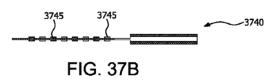
態様1ないし36のいずれか1つに加えて別の態様(「態様37」)によると、カプセル化デバイスは、ラップシーム、バットシームまたはフィンシームの1つ以上を伴って形成されている。
According to another aspect (“
態様1ないし37のいずれか1つに加えて別の態様(「態様38」)によると、カプセル化デバイスは、管腔の所望される厚みを維持するために管腔の内部に位置設定された構造的スペーサを含む。 According to another aspect ("Aspect 38") in addition to any one of Aspects 1-37, the encapsulating device is positioned within the lumen to maintain a desired thickness of the lumen. Contains structural spacers.
態様1ないし38のいずれか1つに加えて別の態様(「態様39」)によると、カプセル化デバイスは、互いに9mm未満離れた溶接離隔距離を有する。 According to another aspect (“Aspect 39”) in addition to any one of Aspects 1-38, the encapsulated devices have a weld separation of less than 9 mm from each other.
態様1ないし39のいずれか1つに加えて別の態様(「態様40」)によると、第2の層の中実特徴部の少なくとも一部分は、第1の層の結合された中実特徴部と接触している。 According to any one of aspects 1-39, in addition to another aspect (“Aspect 40”), at least a portion of the solid features of the second layer comprise bonded solid features of the first layer are in contact with
態様1ないし40のいずれか1つに加えて別の態様(「態様41」)によると、第2の層は有効直径で約1ミクロン~約9ミクロンの細孔サイズを有する。
According to another embodiment ("Embodiment 41") in addition to any one of
態様1ないし41のいずれか1つに加えて別の態様(「態様42」)によると、カプセル化デバイスは、表面コーティングを有し、この表面コーティングは、抗菌剤、抗体、医薬品および生物活性分子の中から選択された1つ以上の部材である。
According to another aspect (“Aspect 42”) in addition to any one of
態様1ないし41のいずれか1つに加えて別の態様(「態様43」)によると、カプセル化デバイスは、親水性コーティングを上に有する。 According to another aspect (“Aspect 43”) in addition to any one of aspects 1-41, the encapsulated device has a hydrophilic coating thereon.
一態様(「態様44」)によると、カプセル化デバイスは、(1)少なくとも1つの管腔を内部に画定するために周囲の一部分に沿って封止された少なくとも1つの生体適合膜複合材料であって、管腔が相対する表面を有している、生体適合膜複合材料と、(2)管腔と流体連通状態にある少なくとも1つの充填用管と、を含み、ここで少なくとも1つの生体適合膜複合材料は、中実特徴部離隔距離の大部分が約50ミクロン未満である中実特徴部の大部分を有する第1の層および第2の層を含み、ここで最大酸素拡散距離は約25ミクロン~約500ミクロンである。 According to one aspect (“aspect 44”), the encapsulated device comprises: (1) at least one biocompatible membrane composite sealed along a portion of the periphery to define at least one lumen therein; a biocompatible membrane composite material having a lumen having opposing surfaces; and (2) at least one filling tube in fluid communication with the lumen, wherein at least one biological The compliant membrane composite includes a first layer and a second layer having a majority of solid features with a majority of solid feature separation less than about 50 microns, wherein the maximum oxygen diffusion distance is From about 25 microns to about 500 microns.
態様44に加えて別の態様(「態様45」)によると、第1の層は、約5g/m2未満の面積当たり質量(MpA)を有する。 According to another aspect (“Aspect 45”) in addition to aspect 44, the first layer has a weight per area (MpA) of less than about 5 g/m 2 .
態様44または態様45に加えて別の態様(「態様46」)によると、第1の層は、約1ミクロン未満のMPS(最大細孔サイズ)を有する。 According to aspect 44 or aspect 45, plus another aspect ("aspect 46"), the first layer has an MPS (maximum pore size) of less than about 1 micron.
態様44ないし46のいずれか1つに加えて別の態様(「態様47」)によると、少なくとも1つの生体適合膜複合材料は、40N/m超の最脆弱軸内の最大引張荷重を有する。 According to another aspect (“Aspect 47”) in addition to any one of Aspects 44-46, the at least one biocompatible membrane composite has an ultimate tensile load in the weakest axis of greater than 40 N/m.
態様44ないし47のいずれか1つに加えて別の態様(「態様48」)によると、第1の層は約50%超の第1の多孔性を有する。 According to another aspect (“Aspect 48”) in addition to any one of Aspects 44-47, the first layer has a first porosity of greater than about 50%.
態様44ないし48のいずれか1つに加えて別の態様(「態様49」)によると、第2の層は約60%超の第2の多孔性を有する。 According to another aspect (“Aspect 49”) in addition to any one of Aspects 44-48, the second layer has a second porosity of greater than about 60%.
態様44ないし49のいずれか1つに加えて別の態様(「態様50」)によると、第2の層は約200ミクロン未満の厚みを有する。 According to another aspect ("Aspect 50") in addition to any one of Aspects 44-49, the second layer has a thickness of less than about 200 microns.
態様44ないし50のいずれか1つに加えて別の態様(「態様51」)によると、第2の層の中実特徴部は各々、代表的短軸、代表的長軸および中実特徴部深さを含み、ここで第2の層の代表的短軸、代表的長軸および中実特徴部深さのうちの少なくとも2つの大部分は約5ミクロン超である。 According to another aspect ("Aspect 51") in addition to any one of Aspects 44-50, the solid features of the second layer each comprise a representative minor axis, a representative major axis and a solid feature Including depth, wherein a majority of at least two of the representative short axis, the representative long axis and the solid feature depth of the second layer is greater than about 5 microns.
態様44ないし51のいずれか1つに加えて別の態様(「態様52」)によると、第2の層は、有効直径で約1ミクロン~約9ミクロンの細孔サイズを有する。 According to another aspect (“Aspect 52”) in addition to any one of Aspects 44-51, the second layer has a pore size of about 1 micron to about 9 microns in effective diameter.
態様44ないし52のいずれか1つに加えて別の態様(「態様53」)によると、中実特徴部はフィブリルによって連結されており、フィブリルは変形可能である。 According to any one of aspects 44-52 plus another aspect ("aspect 53"), the solid features are connected by fibrils, and the fibrils are deformable.
態様44ないし53のいずれか1つに加えて別の態様(「態様54」)によると、第1の層と接触状態にある第1の中実特徴部の少なくとも一部分は、結合された中実特徴部である。 According to another aspect (“Aspect 54”) in addition to any one of Aspects 44-53, at least a portion of the first solid feature in contact with the first layer is a bonded solid It is a characteristic part.
態様54に加えて別の態様(「態様55」)によると、結合された特徴部の大部分は、約3ミクロン~約20ミクロンの代表的短軸を有する。 According to another aspect (“Aspect 55”) in addition to aspect 54, the majority of the bonded features have a typical minor axis of about 3 microns to about 20 microns.
態様44ないし55のいずれか1つに加えて別の態様(「態様56」)によると、第1の層および第2の層は密に結合されている。 According to any one of aspects 44-55 plus another aspect ("aspect 56"), the first layer and the second layer are intimately bonded.
態様44ないし56のいずれか1つに加えて別の態様(「態様57」)によると、第1の層および第2の層のうちの少なくとも1つは、ポリマ、フルオロポリマ膜、非フルオロポリマ膜、織布、不織布、繊維またはヤーンの製織または不織収集物、繊維性マトリックス、スパンボンド不織材料およびそれらの組合せを含む。 According to another aspect (“Aspect 57”) in addition to any one of Aspects 44-56, at least one of the first layer and the second layer is a polymer, a fluoropolymer film, a non-fluoropolymer Includes membranes, wovens, nonwovens, woven or nonwoven collections of fibers or yarns, fibrous matrices, spunbond nonwoven materials and combinations thereof.
態様44ないし57のいずれか1つに加えて別の態様(「態様58」)によると、第1の層および第2の層のうちの少なくとも1つは、延伸ポリテトラフルオロエチレン(ePTFE)膜、フッ素化エチレンプロピレン(FEP)膜および変性ePTFE膜の中から選択されたポリマである。 According to another aspect ("Aspect 58") in addition to any one of Aspects 44-57, at least one of the first layer and the second layer is an expanded polytetrafluoroethylene (ePTFE) membrane. , fluorinated ethylene propylene (FEP) membranes and modified ePTFE membranes.
態様44ないし58のいずれか1つに加えて別の態様(「態様59」)によると、第1の層および第2の層のうちの少なくとも1つは延伸ポリテトラフルオロエチレン膜である。 According to another aspect ("Aspect 59") in addition to any one of Aspects 44-58, at least one of the first layer and the second layer is an expanded polytetrafluoroethylene membrane.
態様44ないし59のいずれか1つに加えて別の態様(「態様60」)によると、第2の層は、布地および非フルオロポリマ膜のうちの少なくとも1つを含む。 According to another aspect (“Aspect 60”) in addition to any one of Aspects 44-59, the second layer comprises at least one of a fabric and a non-fluoropolymer film.
態様60に加えて別の態様(「態様61」)によると、布地は、織布、不織布、スパンボンド材料、メルトブローン繊維性材料および静電紡糸ナノファイバの中から選択されている。 According to another aspect ("Aspect 61") in addition to aspect 60, the fabric is selected from among woven fabrics, non-woven fabrics, spunbond materials, meltblown fibrous materials and electrospun nanofibers.
態様60に加えて別の態様(「態様62」)によると、非フルオロポリマ膜は、ポリビニリデンジフルオリド、ナノファイバ、ポリスルホン、ポリエーテルスルホン、ポリアリールスルホン、ポリエーテルエーテルケトン、ポリエチレン、ポリプロピレン、ポリイミドおよびそれらの組合せの中から選択される。 In addition to aspect 60, according to another aspect (“Aspect 62”), the non-fluoropolymer membrane comprises polyvinylidene difluoride, nanofibers, polysulfones, polyethersulfones, polyarylsulfones, polyetheretherketones, polyethylene, polypropylene, selected from polyimides and combinations thereof;
態様44ないし62のいずれか1つに加えて別の態様(「態様63」)によると、第2の層は延伸ポリテトラフルオロエチレンを含む。 According to another aspect ("Aspect 63") in addition to any one of Aspects 44-62, the second layer comprises expanded polytetrafluoroethylene.
態様44ないし63のいずれか1つに加えて別の態様(「態様64」)によると、第2の層はノードを含み、ノードは中実特徴部である。 According to another aspect ("aspect 64") in addition to any one of aspects 44-63, the second layer includes nodes, and the nodes are solid features.
態様44ないし64のいずれか1つに加えて別の態様(「態様65」)によると、カプセル化デバイスは、補強用構成要素を含む。 According to another aspect ("aspect 65") in addition to any one of aspects 44-64, the encapsulation device includes a reinforcing component.
態様65に加えて別の態様(「態様66」)によると、補強用構成要素は第2の層上の外部補強用構成要素である。 According to another aspect ("aspect 66") in addition to aspect 65, the reinforcing component is an external reinforcing component on the second layer.
態様65または態様66に加えて別の態様(「態様67」)によると、外部補強用構成要素は約0.01N/cm~約3N/cmの剛性を有する。 According to another aspect ("Aspect 67") in addition to Aspect 65 or Aspect 66, the external reinforcing component has a stiffness of from about 0.01 N/cm to about 3 N/cm.
態様65ないし67のいずれか1つに加えて別の態様(「態様68」)によると、外部補強用構成要素はスパンボンドポリエステル不織材料を含む。 According to another aspect ("Aspect 68") in addition to any one of Aspects 65-67, the external reinforcing component comprises a spunbond polyester nonwoven material.
態様65ないし68のいずれか1つに加えて別の態様(「態様69」)によると、外部補強用構成要素はポリエステル製織メッシュである。 According to another aspect ("Aspect 69") in addition to any one of Aspects 65-68, the external reinforcing component is a woven polyester mesh.
態様65に加えて別の態様(「態様70」)によると、カプセル化デバイスは、内部補強用構成要素を含む。 According to another aspect ("aspect 70") in addition to aspect 65, the encapsulation device includes an internal reinforcing component.
態様70に加えて別の態様(「態様71」)によると、内部補強用構成要素は約0.05N/cm~約5N/cmの剛性を有する。 In addition to aspect 70, according to another aspect (“Aspect 71”), the internal reinforcing component has a stiffness of from about 0.05 N/cm to about 5 N/cm.
態様70または態様71に加えて別の態様(「態様72」)によると、内部補強用構成要素は細胞および栄養素不浸透性補強用構成要素である。 According to another aspect ("Aspect 72") in addition to aspect 70 or aspect 71, the internal reinforcing component is a cell and nutrient impermeable reinforcing component.
態様70ないし72のいずれか1つに加えて別の態様(「態様73」)によると、内部補強用構成要素は、カプセル化デバイスの内部で実質的に中心に位置設定されており、管腔を実質的に半分に分割している。 According to another aspect ("aspect 73") in addition to any one of aspects 70-72, the internal stiffening component is substantially centered within the encapsulation device and the lumen is effectively divided in half.
態様70ないし73のいずれか1つに加えて別の態様(「態様74」)によると、内部補強用構成要素は上に構造的支柱を有する。 According to another aspect (“Aspect 74”) in addition to any one of aspects 70-73, the internal reinforcing component has structural struts thereon.
態様70ないし74のいずれか1つに加えて別の態様(「態様75」)によると、カプセル化デバイスは、内部補強用構成要素と少なくとも1つの生体適合膜複合材料との間にボンド点を含む。 According to another aspect ("aspect 75") in addition to any one of aspects 70-74, the encapsulation device provides bond points between the internal reinforcing component and the at least one biocompatible membrane composite. include.
態様44ないし75のいずれか1つに加えて別の態様(「態様76」)によると、カプセル化デバイスは、(1)第1の生体適合膜複合材料および第2の生体適合膜複合材料を含み、かつ(2)第1および第2の生体適合膜複合材料の間にボンド点を含む。 According to another aspect (“Aspect 76”) in addition to any one of Aspects 44-75, the encapsulated device comprises: (1) a first biocompatible membrane composite and a second biocompatible membrane composite; and (2) a bond point between the first and second biocompatible membrane composites.
態様44ないし76のいずれか1つに加えて別の態様(「態様77」)によると、カプセル化デバイスは、約1mmの直径を有するボンド点を含み、ここでボンド点は互いに約0.5mm~約9mm離隔されている。 According to another aspect ("Aspect 77") in addition to any one of Aspects 44-76, the encapsulated device includes bond points having a diameter of about 1 mm, wherein the bond points are about 0.5 mm from each other. ~9 mm apart.
態様44ないし77のいずれか1つに加えて別の態様(「態様78」)によると、カプセル化デバイスは、管腔内に配置された細胞押し退け用コアを含む。 According to another aspect (“aspect 78”) in addition to any one of aspects 44-77, the encapsulation device includes a cell displacing core disposed within the lumen.
態様44ないし78のいずれか1つに加えて別の態様(「態様79」)によると、カプセル化デバイスは、管腔の相対する層を相互連結するポリマ製構造的スペーサを含む。 According to another aspect (“Aspect 79”) in addition to any one of Aspects 44-78, the encapsulation device includes polymeric structural spacers interconnecting the opposing layers of the lumen.
態様44ないし79のいずれか1つに加えて別の態様(「態様80」)によると、カプセル化デバイスは、ラップシーム、バットシームまたはフィンシームの1つ以上を伴って形成されている。 According to another aspect (“Aspect 80”) in addition to any one of Aspects 44-79, the encapsulated device is formed with one or more of a lap seam, a butt seam or a fin seam.
態様44ないし80のいずれか1つに加えて別の態様(「態様81」)によると、カプセル化デバイスは、管腔の所望される厚みを維持するために管腔の内部に位置設定された構造的スペーサを含む。 According to another aspect ("Aspect 81") in addition to any one of aspects 44-80, the encapsulation device is positioned within the lumen to maintain a desired thickness of the lumen. Contains structural spacers.
態様44ないし81のいずれか1つに加えて別の態様(「態様82」)によると、カプセル化デバイスは、互いに9mm未満の溶接離隔距離を有する。 According to another aspect (“Aspect 82”) in addition to any one of Aspects 44-81, the encapsulated devices have a weld separation of less than 9 mm from each other.
態様44ないし82のいずれか1つに加えて別の態様(「態様83」)によると、カプセル化デバイスは、表面コーティングを有し、この表面コーティングは、抗菌剤、抗体、医薬品および生物活性分子の中から選択された1つ以上の部材である。 According to another aspect (“Aspect 83”) in addition to any one of Aspects 44 to 82, the encapsulating device has a surface coating, the surface coating comprising antimicrobial agents, antibodies, pharmaceutical agents and bioactive molecules. is one or more members selected from
態様44ないし83のいずれか1つに加えて別の態様(「態様84」)によると、カプセル化デバイスは、親水性コーティングを上に有する。 According to another aspect (“Aspect 84”) in addition to any one of Aspects 44 to 83, the encapsulated device has a hydrophilic coating thereon.
一態様(「態様85」)において、カプセル化デバイスは、(1)互いに9mm未満の溶接離隔距離を伴う第1の内部表面と第2の内部表面を有する少なくとも1つの管腔を画定するために外周に沿って第2の生体適合膜複合材料に対して封止された第1の生体適合膜複合材料と、(2)約0.01N/cm超の剛性を有する外部補強用構成要素と、(3)管腔と流体連通状態にある少なくとも1つの充填用管と、を含み、ここで第1および第2の生体適合膜複合材料の少なくとも1つは、第1の層、および中実特徴部を有し、中実特徴部の離隔距離の大部分が約50ミクロン未満である第2の層、を含んでおり、ここで第1の内部表面は管腔内で第2の内部表面から離隔されている。 In one aspect (“aspect 85”), the encapsulation device (1) defines at least one lumen having a first interior surface and a second interior surface with a weld separation of less than 9 mm from each other; (2) an external reinforcing component having a stiffness greater than about 0.01 N/cm; (3) at least one filling tube in fluid communication with the lumen, wherein at least one of the first and second biocompatible membrane composites comprises the first layer and the solid feature; and wherein a majority of the solid features are less than about 50 microns apart, wherein the first interior surface is within the lumen from the second interior surface. isolated.
態様85に加えて別の態様(「態様86」)によると、第1の層は、約5g/m2未満の面積当たり質量(MpA)を有する。 According to another aspect (“Aspect 86”) in addition to aspect 85, the first layer has a mass per area (MpA) of less than about 5 g/m 2 .
態様85または態様860に加えて別の態様(「態様87」)によると、第1の層は、約1ミクロン未満のMPS(最大細孔サイズ)を有する。 According to another aspect (“Aspect 87”) in addition to aspect 85 or aspect 860, the first layer has an MPS (maximum pore size) of less than about 1 micron.
態様85ないし87のいずれか1つに加えて別の態様(「態様88」)によると、第1の生体適合膜複合材料および第2の生体適合膜複合材料のうちの少なくとも1つは、40N/m超の最脆弱軸内の最大引張荷重を有する。 According to another aspect (“Aspect 88”) in addition to any one of Aspects 85-87, at least one of the first biocompatible membrane composite and the second biocompatible membrane composite is 40N /m with a maximum tensile load in the weakest axis.
態様85ないし88のいずれか1つに加えて別の態様(「態様89」)によると、第1の層は約50%超の第1の多孔性を有する。 According to another aspect (“Aspect 89”) in addition to any one of Aspects 85-88, the first layer has a first porosity of greater than about 50%.
態様85ないし89のいずれか1つに加えて別の態様(「態様90」)によると、第2の層は約60%超の第2の多孔性を有する。 In accordance with any one of aspects 85-89 in addition to another aspect (“Aspect 90”), the second layer has a second porosity greater than about 60%.
態様85ないし90のいずれか1つに加えて別の態様(「態様91」)によると、第2の層は約200ミクロン未満の厚みを有する。 According to any one of aspects 85-90 in addition to another aspect (“Aspect 91”), the second layer has a thickness of less than about 200 microns.
態様85ないし91のいずれか1つに加えて別の態様(「態様92」)によると、第2の層の中実特徴部は各々、代表的短軸、代表的長軸および中実特徴部深さを含み、第2の層の代表的短軸、代表的長軸および中実特徴部深さのうちの少なくとも2つの大部分は約5ミクロン超である。 According to another aspect ("Aspect 92") in addition to any one of Aspects 85-91, the solid features of the second layer each comprise a representative minor axis, a representative major axis and a solid feature At least a majority of at least two of the representative minor axis, the representative major axis and the solid feature depth of the second layer, including depth, is greater than about 5 microns.
態様85ないし92のいずれか1つに加えて別の態様(「態様93」)によると、第2の層は、有効直径で約1ミクロン~約9ミクロンの細孔サイズを有する。 In accordance with any one of aspects 85-92 in addition to another aspect (“Aspect 93”), the second layer has a pore size of from about 1 micron to about 9 microns in effective diameter.
態様85ないし93のいずれか1つに加えて別の態様(「態様94」)によると、中実特徴部はフィブリルによって連結されており、フィブリルは変形可能である。 According to any one of aspects 85-93 in addition to another aspect (“aspect 94”), the solid features are connected by fibrils, and the fibrils are deformable.
態様85ないし94のいずれか1つに加えて別の態様(「態様95」)によると、第1の層と接触状態にある第1の中実特徴部の少なくとも一部分は、結合された中実特徴部である。 According to another aspect (“Aspect 95”) in addition to any one of Aspects 85-94, at least a portion of the first solid feature in contact with the first layer is a bonded solid It is a characteristic part.
態様95に加えて別の態様(「態様96」)によると、結合された特徴部の大部分は、約3ミクロン~約20ミクロンの代表的短軸を有する。 According to another aspect (“Aspect 96”) in addition to aspect 95, a majority of the bonded features have a typical minor axis of about 3 microns to about 20 microns.
態様85ないし96のいずれか1つに加えて別の態様(「態様97」)によると、第1の層および第2の層は密に結合されている。 According to any one of aspects 85-96 plus another aspect (“aspect 97”), the first layer and the second layer are intimately bonded.
態様85ないし97のいずれか1つに加えて別の態様(「態様98」)によると、第1の層および第2の層のうちの少なくとも1つは、ポリマ、フルオロポリマ膜、非フルオロポリマ膜、織布、不織布、繊維またはヤーンの製織または不織収集物、繊維性マトリックス、スパンボンド不織材料およびそれらの組合せを含む。 According to another aspect (“Aspect 98”) in addition to any one of Aspects 85-97, at least one of the first layer and the second layer is a polymer, a fluoropolymer film, a non-fluoropolymer Includes membranes, wovens, nonwovens, woven or nonwoven collections of fibers or yarns, fibrous matrices, spunbond nonwoven materials and combinations thereof.
態様85ないし98のいずれか1つに加えて別の態様(「態様99」)によると、第1の層および第2の層のうちの少なくとも1つは、延伸ポリテトラフルオロエチレン(ePTFE)膜、フッ素化エチレンプロピレン(FEP)膜および変性ePTFE膜の中から選択されたポリマである。 According to another aspect (“Aspect 99”) in addition to any one of Aspects 85-98, at least one of the first layer and the second layer is an expanded polytetrafluoroethylene (ePTFE) membrane. , fluorinated ethylene propylene (FEP) membranes and modified ePTFE membranes.
態様85ないし99のいずれか1つに加えて別の態様(「態様100」)によると、第1の層および第2の層のうちの少なくとも1つは延伸ポリテトラフルオロエチレン膜である。
According to another embodiment ("
態様85ないし100のいずれか1つに加えて別の態様(「態様101」)によると、第2の層は、布地および非フルオロポリマ膜のうちの少なくとも1つを含む。 According to another aspect (“Aspect 101”) in addition to any one of aspects 85-100, the second layer comprises at least one of a fabric and a non-fluoropolymer film.
態様101に加えて別の態様(「態様102」)によると、布地は、織布、不織布、スパンボンド材料、メルトブローン繊維性材料および静電紡糸ナノファイバの中から選択されている。 According to another aspect (“Aspect 102”) in addition to aspect 101, the fabric is selected from among woven fabrics, non-woven fabrics, spunbond materials, meltblown fibrous materials and electrospun nanofibers.
態様85ないし102のいずれか1つに加えて別の態様(「態様103」)によると、非フルオロポリマ材料は、ポリビニリデンジフルオリド、ナノファイバ、ポリスルホン、ポリエーテルスルホン、ポリアリールスルホン、ポリエーテルエーテルケトン、ポリエチレン、ポリプロピレン、ポリイミドおよびそれらの組合せの中から選択される。態様85ないし103のいずれか1つに加えて別の態様(「態様104」)によると、第2の層は延伸ポリテトラフルオロエチレン膜を含む。 According to another aspect (“Aspect 103”) in addition to any one of aspects 85-102, the non-fluoropolymer material is polyvinylidene difluoride, nanofibers, polysulfones, polyethersulfones, polyarylsulfones, polyethersulfones selected from among ether ketones, polyethylenes, polypropylenes, polyimides and combinations thereof. According to another aspect (“Aspect 104”) in addition to any one of aspects 85-103, the second layer comprises an expanded polytetrafluoroethylene membrane.
態様85ないし1046のいずれか1つに加えて別の態様(「態様105」)によると、中実特徴部がノードを含み、ノードは中実特徴部である。 According to another aspect (“aspect 105”) in addition to any one of aspects 85-1046, the solid feature comprises a node, and the node is a solid feature.
態様87ないし105のいずれか1つに加えて別の態様(「態様106」)によると、カプセル化デバイスは、補強用構成要素を含む。 According to another aspect (“aspect 106”) in addition to any one of aspects 87-105, the encapsulation device includes a reinforcing component.
態様106に加えて別の態様(「態様107」)によると、補強用構成要素は外部補強用構成要素である。 In addition to aspect 106, according to another aspect (“aspect 107”), the reinforcing component is an external reinforcing component.
態様106または態様107に加えて別の態様(「態様108」)によると、外部補強用構成要素は約0.01N/cm~約3N/cmの剛性を有する。 According to aspect 106 or aspect 107 plus another aspect (“aspect 108”), the external reinforcing component has a stiffness of from about 0.01 N/cm to about 3 N/cm.
態様106ないし108のいずれか1つに加えて別の態様(「態様109」)によると、外部補強用構成要素はスパンボンドポリエステル不織材料を含む。 According to another aspect ("Aspect 109") in addition to any one of Aspects 106-108, the external reinforcing component comprises a spunbond polyester nonwoven material.
態様106ないし109のいずれか1つに加えて別の態様(「態様110」)によると、外部補強用構成要素はポリエステル製織メッシュである。
According to another aspect (“
態様106に加えて別の態様(「態様111」)によると、補強用構成要素は内部補強用構成要素である。 In addition to aspect 106, according to another aspect (“Aspect 111”), the reinforcing component is an internal reinforcing component.
態様111に加えて別の態様(「態様112」)によると、内部補強用構成要素は0.05N/cm~約5N/cmの剛性を有する。 According to another aspect (“Aspect 112”) in addition to aspect 111, the internal reinforcing component has a stiffness of from 0.05 N/cm to about 5 N/cm.
態様111または態様112に加えて別の態様(「態様113」)によると、内部補強用構成要素は細胞および栄養素不浸透性補強用構成要素である。 According to aspect 111 or aspect 112 plus another aspect ("aspect 113"), the internal reinforcing component is a cell and nutrient impermeable reinforcing component.
態様111ないし113のいずれか1つに加えて別の態様(「態様114」)によると、内部補強用構成要素は、カプセル化デバイスの内部で実質的に中心に位置設定されており、管腔を実質的に半分に分割している。 According to another aspect (“Aspect 114”) in addition to any one of Aspects 111-113, the internal stiffening component is substantially centered within the encapsulation device and the lumen is effectively divided in half.
態様111ないし114のいずれか1つに加えて別の態様(「態様115」)によると、内部補強用構成要素は上に構造的支柱を有する。 According to another aspect (“Aspect 115”) in addition to any one of aspects 111-114, the internal reinforcing component has structural struts thereon.
態様111ないし115のいずれか1つに加えて別の態様(「態様116」)によると、カプセル化デバイスは、第1および第2の生体適合膜複合材料のうちの少なくとも1つと内部補強用構成要素との間にボンド点を含む。 According to another aspect (“Aspect 116”) in addition to any one of Aspects 111-115, the encapsulated device comprises at least one of the first and second biocompatible membrane composites and an internal reinforcement configuration. Contains bond points between elements.
態様85ないし116のいずれか1つに加えて別の態様(「態様117」)によると、カプセル化デバイスは、第1の生体適合膜複合材料と第2の生体適合膜複合材料との間にボンド点を含む。 According to another aspect (“Aspect 117”) in addition to any one of aspects 85-116, the encapsulation device comprises: between the first biocompatible membrane composite and the second biocompatible membrane composite: Includes bond points.
態様85ないし117のいずれか1つに加えて別の態様(「態様118」)によると、カプセル化デバイスは、ラップシーム、バットシームまたはフィンシームの1つ以上を伴って形成されている。 According to another aspect (“Aspect 118”) in addition to any one of aspects 85-117, the encapsulating device is formed with one or more of a lap seam, a butt seam or a fin seam.
態様85ないし118のいずれか1つに加えて別の態様(「態様119」)によると、第1および第2の生体適合膜複合材料のうちの少なくとも1つの第2の層は内部に、第1の層の表面に密に結合された中実特徴部を有する。 According to another aspect (“Aspect 119”) in addition to any one of aspects 85-118, the second layer of at least one of the first and second biocompatible membrane composites internally comprises a second It has solid features that are tightly bonded to the surface of one layer.
態様85ないし119のいずれか1つに加えて別の態様(「態様120」)によると、カプセル化デバイスは、表面コーティングを有し、この表面コーティングは、抗菌剤、抗体、医薬品および生物活性分子の中から選択された1つ以上の部材である。 According to another aspect (“Aspect 120”) in addition to any one of aspects 85 to 119, the encapsulating device has a surface coating, the surface coating comprising antimicrobial agents, antibodies, pharmaceutical agents and bioactive molecules. is one or more members selected from
態様85ないし120のいずれか1つに加えて別の態様(「態様121」)によると、カプセル化デバイスは、親水性コーティングを上に有する。 According to any one of aspects 85-120 plus another aspect (“aspect 121”), the encapsulated device has a hydrophilic coating thereon.
一態様(「態様122」)において、カプセル化デバイスは、(1)第1の生体適合膜複合材料と、(1)第2の生体適合膜複合材料と、(3)約0.01N/cm~約5N/cmの剛性を有する補強用構成要素と、(4)外周シールと、(5)互いに9mm未満の外周シールの溶接離隔距離と、を含み、ここで第1および第2の生体適合膜複合材料のうちの少なくとも1つの大部分は、第1の層および中実特徴部を有し、中実特徴部の離隔距離の大部分が約50ミクロン未満である第2の層、を含んでいる。 In one aspect (“Aspect 122”), the encapsulated device comprises: (1) a first biocompatible membrane composite; (1) a second biocompatible membrane composite; (4) a perimeter seal; and (5) a weld separation of the perimeter seals less than 9 mm from each other, wherein the first and second biocompatible A majority of at least one of the membrane composites includes a first layer and a second layer having solid features, wherein a majority of the solid features are separated by less than about 50 microns. I'm in.
態様122に加えて別の態様(「態様123」)によると、第1の層は、約5g/m2未満の面積当たり質量(MpA)を有する。 According to another aspect (“Aspect 123”) in addition to aspect 122, the first layer has a mass per area (MpA) of less than about 5 g/m 2 .
態様122または態様123に加えて別の態様(「態様124」)によると、第1の層は、約1ミクロン未満のMPS(最大細孔サイズ)を有する。 According to aspect 122 or aspect 123, plus another aspect ("aspect 124"), the first layer has an MPS (maximum pore size) of less than about 1 micron.
態様123ないし124のいずれか1つに加えて別の態様(「態様125」)によると、第1の生体適合膜複合材料および第2の生体適合膜複合材料のうちの少なくとも1つは、40N/m超の最脆弱軸内の最大引張荷重を有する。 According to another aspect (“Aspect 125”) in addition to any one of aspects 123-124, at least one of the first biocompatible membrane composite and the second biocompatible membrane composite is 40N /m with a maximum tensile load in the weakest axis.
態様123ないし125のいずれか1つに加えて別の態様(「態様126」)によると、第1の層は約50%超の第1の多孔性を有する。 According to any one of aspects 123-125 in addition to another aspect (“Aspect 126”), the first layer has a first porosity of greater than about 50%.
態様123ないし126のいずれか1つに加えて別の態様(「態様127」)によると、第2の層は約60%超の第2の多孔性を有する。 According to another aspect (“Aspect 127”) in addition to any one of aspects 123-126, the second layer has a second porosity greater than about 60%.
態様123ないし127のいずれか1つに加えて別の態様(「態様128」)によると、第2の層は約200ミクロン未満の厚みを有する。 According to any one of aspects 123-127, in addition to another aspect (“Aspect 128”), the second layer has a thickness of less than about 200 microns.
態様123ないし128のいずれか1つに加えて別の態様(「態様129」)によると、第2の層の中実特徴部は各々、代表的短軸、代表的長軸および中実特徴部深さを含み、ここで第2の層の代表的短軸、代表的長軸および中実特徴部深さのうちの少なくとも2つの大部分は約5ミクロン超である。 According to another aspect ("Aspect 129") in addition to any one of Aspects 123-128, the solid features of the second layer each have a representative minor axis, a representative major axis and a solid feature Including depth, wherein a majority of at least two of the representative short axis, the representative long axis and the solid feature depth of the second layer is greater than about 5 microns.
態様123ないし129のいずれか1つに加えて別の態様(「態様130」)によると、第2の層は、有効直径で約1ミクロン~約9ミクロンの細孔サイズを有する。
According to another aspect (“
態様123ないし130のいずれか1つに加えて別の態様(「態様131」)によると、中実特徴部はフィブリルによって連結されており、フィブリルは変形可能である。 According to any one of aspects 123-130 plus another aspect ("aspect 131"), the solid features are connected by fibrils, and the fibrils are deformable.
態様123ないし131のいずれか1つに加えて別の態様(「態様132」)によると、第1の層と接触状態にある第1の中実特徴部の少なくとも一部分は、結合された中実特徴部である。 According to another aspect (“Aspect 132”) in addition to any one of aspects 123-131, at least a portion of the first solid feature in contact with the first layer is a bonded solid It is a characteristic part.
態様132に加えて別の態様(「態様133」)によると、結合された中実特徴部の大部分は、約3ミクロン~約20ミクロンの代表的短軸を有する。 According to another aspect (“Aspect 133”) in addition to aspect 132, a majority of the bonded solid features have a typical minor axis of about 3 microns to about 20 microns.
態様123ないし133のいずれか1つに加えて別の態様(「態様134」)によると、第1の層および第2の層は密に結合されている。 According to any one of aspects 123-133 plus another aspect (“Aspect 134”), the first layer and the second layer are intimately bonded.
態様123ないし134のいずれか1つに加えて別の態様(「態様135」)によると、第1の層および第2の層のうちの少なくとも1つは、ポリマ、フルオロポリマ膜、非フルオロポリマ膜、織布、不織布、繊維またはヤーンの製織または不織収集物、繊維性マトリックス、スパンボンド不織材料およびそれらの組合せを含む。 According to another aspect (“Aspect 135”) in addition to any one of Aspects 123-134, at least one of the first layer and the second layer is a polymer, a fluoropolymer film, a non-fluoropolymer Includes membranes, wovens, nonwovens, woven or nonwoven collections of fibers or yarns, fibrous matrices, spunbond nonwoven materials and combinations thereof.
態様123ないし135のいずれか1つに加えて別の態様(「態様136」)によると、第1の層および第2の層のうちの少なくとも1つは、延伸ポリテトラフルオロエチレン(ePTFE)膜、フッ素化エチレンプロピレン(FEP)膜および変性ePTFE膜の中から選択されたポリマである。 According to another aspect ("Aspect 136") in addition to any one of Aspects 123-135, at least one of the first layer and the second layer is an expanded polytetrafluoroethylene (ePTFE) membrane. , fluorinated ethylene propylene (FEP) membranes and modified ePTFE membranes.
態様123ないし136のいずれか1つに加えて別の態様(「態様137」)によると、第1の層および第2の層のうちの少なくとも1つは延伸ポリテトラフルオロエチレン膜である。 According to another aspect ("Aspect 137") in addition to any one of Aspects 123-136, at least one of the first layer and the second layer is an expanded polytetrafluoroethylene membrane.
態様123ないし137のいずれか1つに加えて別の態様(「態様138」)によると、第2の層は、布地および非フルオロポリマ膜のうちの少なくとも1つを含む。 According to another aspect (“Aspect 138”) in addition to any one of aspects 123-137, the second layer comprises at least one of a fabric and a non-fluoropolymer film.
態様138に加えて別の態様(「態様139」)によると、布地は、織布、不織布、スパンボンド材料、メルトブローン繊維性材料および静電紡糸ナノファイバの中から選択されている。 According to another aspect (“Aspect 139”) in addition to aspect 138, the fabric is selected from among woven fabrics, non-woven fabrics, spunbond materials, meltblown fibrous materials and electrospun nanofibers.
態様138に加えて別の態様(「態様140」)によると、非フルオロポリマ膜は、ポリビニリデンジフルオリド、ナノファイバ、ポリスルホン、ポリエーテルスルホン、ポリアリールスルホン、ポリエーテルエーテルケトン、ポリエチレン、ポリプロピレン、ポリイミドおよびそれらの組合せの中から選択される。 In addition to aspect 138, according to another aspect (“Aspect 140”), the non-fluoropolymer membrane comprises polyvinylidene difluoride, nanofibers, polysulfones, polyethersulfones, polyarylsulfones, polyetheretherketones, polyethylene, polypropylene, selected from polyimides and combinations thereof;
態様123ないし140のいずれか1つに加えて別の態様(「態様141」)によると、第2の層は延伸ポリテトラフルオロエチレン膜を含む。 According to another aspect ("Aspect 141") in addition to any one of Aspects 123-140, the second layer comprises an expanded polytetrafluoroethylene membrane.
態様123ないし141のいずれか1つに加えて別の態様(「態様142」)によると、第2の層はノードを含み、ノードは中実特徴部である。 According to another aspect (“aspect 142”) in addition to any one of aspects 123-141, the second layer includes nodes, and the nodes are solid features.
態様123ないし142のいずれか1つに加えて別の態様(「態様143」)によると、補強用構成要素は細胞および栄養素不浸透性補強用構成要素である。 According to another aspect (“Aspect 143”) in addition to any one of aspects 123-142, the reinforcing component is a cell and nutrient impermeable reinforcing component.
態様123ないし143のいずれか1つに加えて別の態様(「態様144」)によると、補強用構成要素は、カプセル化デバイスの内部で実質的に中心に位置設定されており、管腔を実質的に半分に分割している。 According to another aspect (“aspect 144”) in addition to any one of aspects 123-143, the stiffening component is substantially centered within the encapsulation device and extends through the lumen. essentially split in half.
態様123ないし144のいずれか1つに加えて別の態様(「態様145」)によると、補強用構成要素は上に構造的支柱を有する。 According to another aspect (“Aspect 145”) in addition to any one of aspects 123-144, the reinforcing component has structural struts thereon.
態様123ないし145のいずれか1つに加えて別の態様(「態様146」)によると、カプセル化デバイスは、第1の生体適合膜複合材料と第2の生体適合膜複合材料との間にボンド点を含む。 According to another aspect (“Aspect 146”) in addition to any one of aspects 123-145, the encapsulation device comprises: between the first biocompatible membrane composite and the second biocompatible membrane composite: Includes bond points.
態様146に加えて別の態様(「態様147」)によると、ボンド点は、約1mmの直径を有し、互いに約0.5mm~約9mm離隔されている。 According to another aspect (“Aspect 147”) in addition to aspect 146, the bond points have a diameter of about 1 mm and are separated from each other by about 0.5 mm to about 9 mm.
態様123ないし147のいずれか1つに加えて別の態様(「態様148」)によると、カプセル化デバイスは、ラップシーム、バットシームまたはフィンシームの1つ以上を伴って形成されている。 According to another aspect (“Aspect 148”) in addition to any one of aspects 123-147, the encapsulating device is formed with one or more of a lap seam, a butt seam or a fin seam.
態様123ないし152のいずれか1つに加えて別の態様(「態様149」)によると、カプセル化デバイスは、表面コーティングを有し、この表面コーティングは、抗菌剤、抗体、医薬品および生物活性分子の中から選択された1つ以上の部材である。
According to another aspect (“
態様123ないし149のいずれか1つに加えて別の態様(「態様150」)によると、カプセル化デバイスは、親水性コーティングを上に有する。
According to another aspect (“
一態様(「態様151」)において、カプセル化デバイスは、(1)第1の相対する縁部に沿って自らに封止されかつ第2の相対する縁部上でその周囲に沿って封止されて管腔を形成する生体適合膜複合材料と、(2)管腔と流体連通状態にある少なくとも1つの充填用管と、を含み、ここで生体適合膜複合材料は、第1の層、および中実特徴部の大部分を有し、中実特徴部の離隔距離の大部分が約50ミクロン未満である第2の層、を含んでいる。 In one aspect (“Aspect 151”), the encapsulated device is (1) sealed to itself along a first opposed edge and sealed along its perimeter on a second opposed edge; and (2) at least one filling tube in fluid communication with the lumen, wherein the biocompatible membrane composite comprises a first layer; and a second layer having a majority of solid features and a majority of the solid features separated by less than about 50 microns.
態様151に加えて別の態様(「態様152」)によると、第1の層は、約5g/m2未満の面積当たり質量(MpA)を有する。 According to another aspect (“Aspect 152”) in addition to aspect 151, the first layer has a mass per area (MpA) of less than about 5 g/m 2 .
態様151または態様152に加えて別の態様(「態様153」)によると、第1の層は、約1ミクロン未満のMPS(最大細孔サイズ)を有する。 According to embodiment 151 or embodiment 152, plus another embodiment ("embodiment 153"), the first layer has an MPS (maximum pore size) of less than about 1 micron.
態様151ないし153のいずれか1つに加えて別の態様(「態様154」)によると、生体適合膜複合材料は、40N/m超の最脆弱軸内の最大引張荷重を有する。 According to another aspect (“Aspect 154”) in addition to any one of aspects 151-153, the biocompatible membrane composite has an ultimate tensile load in the weakest axis of greater than 40 N/m.
態様151ないし158154のいずれか1つに加えて別の態様(「態様155」)によると、第1の層は約50%超の第1の多孔性を有する。 In accordance with any one of aspects 151-158154 in addition to another aspect (“Aspect 155”), the first layer has a first porosity of greater than about 50%.
態様151ないし155のいずれか1つに加えて別の態様(「態様156」)によると、第2の層は約60%超の第2の多孔性を有する。 According to any one of aspects 151-155 in addition to another aspect (“Aspect 156”), the second layer has a second porosity greater than about 60%.
態様151ないし156のいずれか1つに加えて別の態様(「態様157」)によると、第2の層は約200ミクロン未満の厚みを有する。 According to any one of aspects 151-156 in addition to another aspect (“Aspect 157”), the second layer has a thickness of less than about 200 microns.
態様151ないし157のいずれか1つに加えて別の態様(「態様158」)によると、第2の層の中実特徴部は各々、代表的短軸、代表的長軸および中実特徴部深さを含み、ここで第2の層の代表的短軸、代表的長軸および中実特徴部深さのうちの少なくとも2つの大部分は約5ミクロン超である。 According to another aspect ("Aspect 158") in addition to any one of Aspects 151-157, the solid features of the second layer each have a representative minor axis, a representative major axis and a solid feature Including depth, wherein a majority of at least two of the representative short axis, the representative long axis and the solid feature depth of the second layer is greater than about 5 microns.
態様151ないし158のいずれか1つに加えて別の態様(「態様159」)によると、第2の層は、有効直径で約1ミクロン~約9ミクロンの細孔サイズを有する。 According to another aspect (“Aspect 159”) in addition to any one of aspects 151-158, the second layer has a pore size of about 1 micron to about 9 microns in effective diameter.
態様151ないし159のいずれか1つに加えて別の態様(「態様160」)によると、中実特徴部はフィブリルによって連結されており、フィブリルは変形可能である。
According to any one of aspects 151-159 in addition to another aspect (“
態様151ないし160のいずれか1つに加えて別の態様(「態様161」)によると、第1の層と接触状態にある第1の中実特徴部の少なくとも一部分は、結合された中実特徴部である。 According to another aspect (“Aspect 161”) in addition to any one of aspects 151-160, at least a portion of the first solid feature in contact with the first layer is a bonded solid It is a characteristic part.
態様161に加えて別の態様(「態様162」)によると、結合された特徴部は、約3ミクロン~約20ミクロンの代表的短軸を有する。 According to another aspect (“Aspect 162”) in addition to aspect 161, the bonded features have a typical minor axis of about 3 microns to about 20 microns.
態様151ないし162のいずれか1つに加えて別の態様(「態様163」)によると、第1の層および第2の層は密に結合されている。 According to any one of aspects 151-162 plus another aspect (“Aspect 163”), the first layer and the second layer are intimately bonded.
態様151ないし163のいずれか1つに加えて別の態様(「態様164」)によると、第1の層および第2の層のうちの少なくとも1つは、ポリマ、フルオロポリマ膜、非フルオロポリマ膜、織布、不織布、繊維またはヤーンの製織または不織収集物、繊維性マトリックス、スパンボンド不織材料およびそれらの組合せを含む。 According to another aspect (“Aspect 164”) in addition to any one of aspects 151-163, at least one of the first layer and the second layer is a polymer, a fluoropolymer film, a non-fluoropolymer Includes membranes, wovens, nonwovens, woven or nonwoven collections of fibers or yarns, fibrous matrices, spunbond nonwoven materials and combinations thereof.
態様151ないし164のいずれか1つに加えて別の態様(「態様165」)によると、第1の層および第2の層のうちの少なくとも1つは、延伸ポリテトラフルオロエチレン(ePTFE)膜、フッ素化エチレンプロピレン(FEP)膜および変性ePTFE膜の中から選択されたポリマである。 According to another aspect ("Aspect 165") in addition to any one of Aspects 151-164, at least one of the first layer and the second layer is an expanded polytetrafluoroethylene (ePTFE) membrane. , fluorinated ethylene propylene (FEP) membranes and modified ePTFE membranes.
態様151ないし165のいずれか1つに加えて別の態様(「態様166」)によると、第1の層および第2の層のうちの少なくとも1つは延伸ポリテトラフルオロエチレン膜である。 According to another aspect (“Aspect 166”) in addition to any one of aspects 151-165, at least one of the first layer and the second layer is an expanded polytetrafluoroethylene membrane.
態様151ないし166のいずれか1つに加えて別の態様(「態様167」)によると、第2の層は、布地および非フルオロポリマ膜のうちの少なくとも1つを含む。 According to another aspect (“Aspect 167”) in addition to any one of aspects 151-166, the second layer comprises at least one of a fabric and a non-fluoropolymer film.
態様167に加えて別の態様(「態様168」)によると、布地は、織布、不織布、スパンボンド材料、メルトブローン繊維性材料および静電紡糸ナノファイバの中から選択されている。 According to another aspect (“Aspect 168”) in addition to aspect 167, the fabric is selected from among woven fabrics, non-woven fabrics, spunbond materials, meltblown fibrous materials and electrospun nanofibers.
態様167に加えて別の態様(「態様169」)によると、非フルオロポリマ膜は、ポリビニリデンジフルオリド、ナノファイバ、ポリスルホン、ポリエーテルスルホン、ポリアリールスルホン、ポリエーテルエーテルケトン、ポリエチレン、ポリプロピレン、ポリイミドおよびそれらの組合せの中から選択される。 In addition to aspect 167, according to another aspect (“Aspect 169”), the non-fluoropolymer membrane comprises polyvinylidene difluoride, nanofibers, polysulfones, polyethersulfones, polyarylsulfones, polyetheretherketones, polyethylene, polypropylene, selected from polyimides and combinations thereof;
態様151ないし167のいずれか1つに加えて別の態様(「態様170」)によると、第1の層および第2の層のうちの少なくとも1つは、ポリマ、フルオロポリマ膜、非フルオロポリマ膜、織布、不織布、繊維またはヤーンの製織または不織収集物、繊維性マトリックス、スパンボンド不織材料およびそれらの組合せを含む。 According to another aspect (“Aspect 170”) in addition to any one of aspects 151-167, at least one of the first layer and the second layer is a polymer, a fluoropolymer film, a non-fluoropolymer Includes membranes, wovens, nonwovens, woven or nonwoven collections of fibers or yarns, fibrous matrices, spunbond nonwoven materials and combinations thereof.
態様151ないし170のいずれか1つに加えて別の態様(「態様171」)によると、第1の層および第2の層のうちの少なくとも1つは、延伸ポリテトラフルオロエチレン(ePTFE)膜、フッ素化エチレンプロピレン(FEP)膜および変性ePTFE膜の中から選択されたポリマである。 According to another aspect ("Aspect 171") in addition to any one of Aspects 151-170, at least one of the first layer and the second layer is an expanded polytetrafluoroethylene (ePTFE) membrane. , fluorinated ethylene propylene (FEP) membranes and modified ePTFE membranes.
態様151ないし171のいずれか1つに加えて別の態様(「態様172」)によると、第2の層は延伸ポリテトラフルオロエチレンを含む。 According to another aspect (“Aspect 172”) in addition to any one of aspects 151-171, the second layer comprises expanded polytetrafluoroethylene.
態様151ないし172のいずれか1つに加えて別の態様(「態様173」)によると、第2の層はノードを含み、ノードは中実特徴部である。 According to any one of aspects 151-172 plus another aspect (“aspect 173”), the second layer includes nodes, and the nodes are solid features.
態様151ないし174のいずれか1つに加えて別の態様(「態様174」)によると、カプセル化デバイスは、内部補強用構成要素を含む。 According to another aspect (“aspect 174”) in addition to any one of aspects 151-174, the encapsulation device includes an internal stiffening component.
態様174に加えて別の態様(「態様175」)によると、内部補強用構成要素は約0.05N/cm~約5N/cmの剛性を有する。 In addition to aspect 174, according to another aspect (“Aspect 175”), the internal reinforcing component has a stiffness of from about 0.05 N/cm to about 5 N/cm.
態様174または態様175に加えて別の態様(「態様176」)によると、内部補強用構成要素は細胞および栄養素不浸透性補強用構成要素層である。 According to aspect 174 or aspect 175, as well as another aspect ("aspect 176"), the internal reinforcing component is a cell and nutrient impermeable reinforcing component layer.
態様174ないし176のいずれか1つに加えて別の態様(「態様177」)によると、内部補強用構成要素は管腔内に配置された細胞押し退け用コアである。 According to another aspect (“Aspect 177”) in addition to any one of aspects 174-176, the internal reinforcing component is a cell displacing core disposed within the lumen.
態様151ないし177のいずれか1つに加えて別の態様(「態様178」)によると、カプセル化デバイスは、ラップシーム、バットシームまたはフィンシームの1つ以上を伴って形成されている。 According to another aspect (“Aspect 178”) in addition to any one of aspects 151-177, the encapsulating device is formed with one or more of a lap seam, a butt seam or a fin seam.
態様151ないし178のいずれか1つに加えて別の態様(「態様179」)によると、カプセル化デバイスは、互いに9mm未満である溶接離隔距離を有する。 According to another aspect (“Aspect 179”) in addition to any one of aspects 151-178, the encapsulated devices have a weld separation that is less than 9 mm from each other.
態様151ないし179のいずれか1つに加えて別の態様(「態様180」)によると、カプセル化デバイスは、表面コーティングを有し、この表面コーティングは、抗菌剤、抗体、医薬品および生物活性分子の中から選択された1つ以上の部材である。 According to another aspect (“Aspect 180”) in addition to any one of aspects 151-179, the encapsulation device has a surface coating, the surface coating comprising antimicrobial agents, antibodies, pharmaceutical agents and bioactive molecules. is one or more members selected from
態様151ないし180のいずれか1つに加えて別の態様(「態様181」)によると、カプセル化デバイスは、親水性コーティングを上に有する。 According to any one of aspects 151-180 plus another aspect (“Aspect 181”), the encapsulation device has a hydrophilic coating thereon.
態様1ないし181のいずれか1つに加えて別の態様(「態様182」)によると、哺乳動物の体内の血糖値を低下させる方法は、請求項1ないし181のいずれか1項に記載の生体適合膜複合材料を含む細胞カプセル化デバイスを移植するステップを含み、ここで内部にカプセル化された細胞はPDX1陽性膵臓内胚葉細胞の集団を含み、膵臓内胚葉細胞は、インシュリン分泌細胞へと成長して、これにより血糖を低下させる。 According to another aspect (“Aspect 182”) in addition to any one of aspects 1-181, a method of lowering blood sugar levels in a mammal comprises: implanting a cell encapsulation device comprising a biocompatible membrane composite, wherein the cells encapsulated therein comprise a population of PDX1-positive pancreatic endoderm cells, the pancreatic endoderm cells transforming into insulin-secreting cells; grow, thereby lowering blood sugar.
態様1ないし182のいずれか1つに加えて別の態様(「態様183」)によると、PDX1-陽性膵臓内胚葉細胞は、内分泌および/または内分泌前駆体細胞をさらに含む細胞混合物を含み、内分泌および/または内分泌前駆体細胞はクロモグラニンA(CHGA)を発現する。 According to another aspect (“Aspect 183”) in addition to any one of aspects 1-182, the PDX1-positive pancreatic endoderm cells comprise a cell mixture further comprising endocrine and/or endocrine progenitor cells; and/or endocrine progenitor cells express chromogranin A (CHGA).
態様1ないし183のいずれか1つに加えて別の態様(「態様184」)によると、哺乳動物の体内の血糖値を低下させる方法は、請求項1に記載の細胞カプセル化デバイスを移植するステップを含み、ここで内部にカプセル化された細胞はPDX1陽性膵臓内胚葉細胞の集団を含み、膵臓内胚葉細胞は、インシュリン分泌細胞へと成長して、これにより血糖を低下させる。
According to another aspect ("Aspect 184") in addition to any one of aspects 1-183, a method of lowering blood glucose levels in a mammal comprises implanting a cell-encapsulated device of
態様1ないし態様184のいずれか1つに加えて別の態様(「態様185」)によると、PDX1-陽性膵臓内胚葉細胞は、内分泌および/または内分泌前駆体細胞をさらに含む細胞混合物を含み、ここで内分泌および/または内分泌前駆体細胞はクロモグラニンA(CHGA)を発現する。 According to another aspect (“Aspect 185”) in addition to any one of aspects 1-184, the PDX1-positive pancreatic endoderm cells comprise a cell mixture further comprising endocrine and/or endocrine progenitor cells, Here the endocrine and/or endocrine progenitor cells express chromogranin A (CHGA).
態様1ないし185のいずれか1つに加えて別の態様(「態様186」)によると、哺乳動物の体内の血糖値を低下させる方法は、第1の層および約50ミクロン未満の中実特徴部離隔距離を伴う中実特徴部を有する第2の層を含む生体適合膜複合材料を含む細胞カプセル化デバイスを移植するステップを含み、細胞集団は、PDX1陽性膵臓内胚葉細胞の集団を含み、膵臓内胚葉細胞はインシュリン分泌細胞へと成長して、これにより血糖を低下させ、ここでカプセル化デバイスは、300ミクロン未満、詳細には約150ミクロン未満の主要酸素拡散距離を有している。 According to another aspect ("Aspect 186") in addition to any one of Aspects 1-185, a method of lowering blood glucose levels in a mammal comprises: a first layer and a solid feature of less than about 50 microns; implanting a cell encapsulation device comprising a biocompatible membrane composite comprising a second layer having solid features with partial separation, wherein the cell population comprises a population of PDX1-positive pancreatic endoderm cells; Pancreatic endoderm cells develop into insulin-secreting cells, thereby lowering blood sugar, wherein the encapsulated device has a primary oxygen diffusion distance of less than 300 microns, particularly less than about 150 microns.
態様1ないし186のいずれか1つに加えて別の態様(「態様187」)によると、PDX1-陽性膵臓内胚葉細胞は、内分泌および/または内分泌前駆体細胞をさらに含む細胞混合物を含み、ここで内分泌および/または内分泌前駆体細胞はクロモグラニンA(CHGA)を発現する。 According to another aspect (“Aspect 187”) in addition to any one of aspects 1-186, the PDX1-positive pancreatic endoderm cells comprise a cell mixture further comprising endocrine and/or endocrine progenitor cells, wherein In humans, endocrine and/or endocrine progenitor cells express chromogranin A (CHGA).
態様1ないし187のいずれか1つに加えて別の態様(「態様188」)によると、哺乳動物の体内の血糖値を低下させる方法は、第1の層および、約50ミクロン未満の中実特徴部離隔距離を伴う中実特徴部を有する第2の層を含む生体適合膜複合材料およびPDX1陽性膵臓内胚葉細胞を含む細胞集団を移植するステップを含み、ここで膵臓内胚葉細胞は、インシュリン分泌細胞へと成長して、これにより血糖を低下させ、ここでカプセル化デバイスは、300ミクロン未満の主要酸素拡散距離を有している。 According to another aspect ("Aspect 188") in addition to any one of Aspects 1-187, a method of lowering blood glucose levels in a mammal comprises: a first layer and a solid layer of less than about 50 microns; implanting a biocompatible membrane composite comprising a second layer having solid features with feature separations and a cell population comprising PDX1-positive pancreatic endoderm cells, wherein the pancreatic endoderm cells are treated with insulin; It develops into secretory cells, thereby lowering blood sugar, where the encapsulated device has a major oxygen diffusion length of less than 300 microns.
態様1ないし188のいずれか1つに加えて別の態様(「態様189」)によると、PDX1-陽性膵臓内胚葉細胞は、内分泌および/または内分泌前駆体細胞をさらに含む細胞混合物を含み、ここで内分泌および/または内分泌前駆体細胞はクロモグラニンA(CHGA)を発現する。 According to another aspect (“Aspect 189”) in addition to any one of aspects 1-188, the PDX1-positive pancreatic endoderm cells comprise a cell mixture further comprising endocrine and/or endocrine progenitor cells, wherein In humans, endocrine and/or endocrine progenitor cells express chromogranin A (CHGA).
態様1ないし189のいずれか1つに加えて別の態様(「態様190」)によると、カプセル化されたインビトロPDX1-陽性膵臓内胚葉細胞は、少なくともPDX-1/NKX6.1を同時発現する膵臓始原体集団を含む細胞亜集団の混合物を含む。 According to another aspect (“Aspect 190”) in addition to any one of aspects 1-189, the encapsulated in vitro PDX1-positive pancreatic endoderm cells co-express at least PDX-1/NKX6.1 It contains a mixture of cell subpopulations, including the pancreatic progenitor population.
態様1ないし190のいずれか1つに加えて別の態様(「態様191」)によると、カプセル化されたインビトロPDX1-陽性膵臓内胚葉細胞は、少なくともPDX-1/NKX6.1を同時発現する膵臓始原体集団およびPDX-1/NKX6.1およびCHGAを発現する内分泌および/または内分泌前駆体集団を含む、細胞亜集団の混合物を含む。 According to another aspect (“Aspect 191”) in addition to any one of aspects 1-190, the encapsulated in vitro PDX1-positive pancreatic endoderm cells co-express at least PDX-1/NKX6.1 Includes a mixture of cell subpopulations, including pancreatic progenitor populations and endocrine and/or endocrine progenitor populations expressing PDX-1/NKX6.1 and CHGA.
態様1ないし191のいずれか1つに加えて別の態様(「態様192」)によると、集団の少なくとも30%はPDX-1/NKX6.1を同時発現する膵臓始原体集団を含む。 According to another embodiment ("embodiment 192") in addition to any one of embodiments 1-191, at least 30% of the population comprises a pancreatic progenitor population that co-expresses PDX-1/NKX6.1.
態様1ないし192のいずれか1つに加えて別の態様(「態様193」)によると、集団の少なくとも40%はPDX-1/NKX6.1を同時発現する膵臓始原体集団を含む。 According to another embodiment ("embodiment 193") in addition to any one of embodiments 1-192, at least 40% of the population comprises a pancreatic progenitor population that co-expresses PDX-1/NKX6.1.
態様1ないし193のいずれか1つに加えて別の態様(「態様194」)によると、集団の少なくとも50%はPDX-1/NKX6.1を同時発現する膵臓始原体集団を含む。 According to another embodiment ("embodiment 194") in addition to any one of embodiments 1-193, at least 50% of the population comprises a pancreatic progenitor population that co-expresses PDX-1/NKX6.1.
態様1ないし194のいずれか1つに加えて別の態様(「態様195」)によると、内分泌および/または内分泌前駆体集団の少なくとも20%は、PDX-1/NKX6.1/CHGAを発現する。 According to another embodiment ("embodiment 195") in addition to any one of embodiments 1-194, at least 20% of the endocrine and/or endocrine progenitor population express PDX-1/NKX6.1/CHGA .
態様1ないし195のいずれか1つに加えて別の態様(「態様196」)によると、内分泌および/または内分泌前駆体集団の少なくとも30%は、PDX-1/NKX6.1/CHGAを発現する。 According to another aspect (“Aspect 196”) in addition to any one of aspects 1-195, at least 30% of the endocrine and/or endocrine progenitor population express PDX-1/NKX6.1/CHGA .
態様1ないし196のいずれか1つに加えて別の態様(「態様197」)によると、内分泌および/または内分泌前駆体集団の少なくとも40%は、PDX-1/NKX6.1/CHGAを発現する。 According to another aspect (“Aspect 197”) in addition to any one of aspects 1-196, at least 40% of the endocrine and/or endocrine progenitor population express PDX-1/NKX6.1/CHGA .
態様1ないし197のいずれか1つに加えて別の態様(「態様198」)によると、膵臓始原体細胞および/または内分泌または内分泌前駆体細胞は、インビボでインシュリン分泌細胞へと成長する能力を有する。 According to another aspect (“Aspect 198”) in addition to any one of aspects 1-197, the pancreatic progenitor cells and/or endocrine or endocrine progenitor cells have the ability to develop into insulin-secreting cells in vivo. have.
態様1ないし198のいずれか1つに加えて別の態様(「態様199」)によると、インビボでインシュリンを産生する方法は、請求項1ないし198のいずれか1項に記載の生体適合膜複合材料を含む細胞カプセル化デバイスを移植するステップを含み、PDX-1膵臓内胚葉細胞の集団はインシュリン分泌細胞へと成長し、ここでインシュリン分泌細胞はグルコース刺激に応答してインシュリンを分泌する。 According to another aspect (“Aspect 199”) in addition to any one of aspects 1-198, a method for producing insulin in vivo comprises: Implanting a cell encapsulation device containing the material, wherein the population of PDX-1 pancreatic endoderm cells develops into insulin-secreting cells, where the insulin-secreting cells secrete insulin in response to glucose stimulation.
態様1ないし199のいずれか1つに加えて別の態様(「態様200」)によると、PDX1-陽性膵臓内胚葉細胞は、内分泌および/または内分泌前駆体細胞をさらに含む細胞の混合物を含み、ここで内分泌および/または内分泌前駆体細胞はクロモグラニンA(CHGA)を発現する。
According to another aspect (“
態様1ないし200のいずれか1つに加えて別の態様(「態様201」)によると、集団の少なくとも約30%は、PDX-1/NKX6.1/CHGAを発現する内分泌および/または内分泌前駆体集団である。 According to another aspect (“Aspect 201”) in addition to any one of Aspects 1-200, at least about 30% of the population is endocrine and/or endocrine progenitor expressing PDX-1/NKX6.1/CHGA body group.
態様1ないし201のいずれか1つに加えて別の態様(「態様202」)によると、インビトロヒトPDX1-陽性膵臓内胚葉細胞培養には、PDX1-陽性膵臓内胚葉細胞の混合物および、少なくとも1つの形質転換成長因子ベータ(TGF-beta)受容体キナーゼ阻害剤が含まれる。 According to another aspect (“Aspect 202”) in addition to any one of aspects 1-201, the in vitro human PDX1-positive pancreatic endoderm cell culture comprises a mixture of PDX1-positive pancreatic endoderm cells and at least one and two transforming growth factor-beta (TGF-beta) receptor kinase inhibitors.
態様1ないし202のいずれか1つに加えて別の態様(「態様203」)によると、培養にはさらに骨形成タンパク質(BMP)阻害剤が含まれる。 According to another aspect (“Aspect 203”) in addition to any one of aspects 1-202, the culture further comprises a bone morphogenetic protein (BMP) inhibitor.
態様1ないし203のいずれか1つに加えて別の態様(「態様204」)によると、TGF-ベータ受容体キナーゼ阻害剤は、TGF-ベータ1型受容体キナーゼ阻害剤である。
According to another aspect (“Aspect 204”) in addition to any one of aspects 1-203, the TGF-beta receptor kinase inhibitor is a TGF-
態様1ないし204のいずれか1つに加えて別の態様(「態様205」)によると、TGF-ベータ受容体キナーゼ阻害剤はALK5iである。 According to another aspect (“Aspect 205”) in addition to any one of aspects 1-204, the TGF-beta receptor kinase inhibitor is ALK5i.
態様1ないし205のいずれか1つに加えて別の態様(「態様206」)によると、BMP阻害剤はノギンである。 According to another aspect (“Aspect 206”) in addition to any one of aspects 1-205, the BMP inhibitor is Noggin.
添付図面は、本開示をさらに良く理解できるようにするために含められており、本明細書に組込まれその一部を構成し、実施形態を例示し、かつ記述部と共に本開示の原理を説明するのに役立つものである。 The accompanying drawings are included to provide a further understanding of the disclosure, and are incorporated in and constitute a part of this specification, illustrate embodiments, and together with the description, explain the principles of the disclosure. It helps to do
当業者であれば、本開示のさまざまな態様を、意図された機能を行なうように構成された任意の数の方法および装置によって実現できるということを容易に認識するものである。同様に、本明細書中で参照指示されている添付図面が、必ずしも原寸に比例して描かれておらず、本開示のさまざまな態様を例示するために誇張されている可能性があり、この点において、図は限定的なものとみなされるべきではない、ということも指摘しておかなければならない。なかでも、「上」、「下」、「頂部」、「左」、「右」、「前方」、「後方」などの方向的言及は、構成要素および方向が基準としている図(単数または複数)中で例示され描写されている配向を意味するように意図されている。 Those skilled in the art will readily recognize that the various aspects of the disclosure can be implemented by any number of methods and devices configured to perform their intended functions. Similarly, the accompanying drawings referenced herein are not necessarily drawn to scale and may be exaggerated to illustrate various aspects of the present disclosure; It should also be pointed out that the figures should not be considered limiting in that respect. Among other things, directional references such as "top", "bottom", "top", "left", "right", "forward", "backward" refer to the figure (singular or plural) to which the component and direction refer. ) are intended to mean the orientations illustrated and depicted in .
本明細書中では「生体適合膜複合材料」および「膜複合材料」なる用語が互換的に使用されているということを認識すべきである。さらに、「細胞カプセル化デバイス」、「カプセル化デバイス」および「デバイス」なる用語は、本明細書中で互換的に使用され得る。本明細書中に記載の全ての範囲は事実上例示的なものであり、範囲の間のありとあらゆる値を含むということに留意すべきである。さらに、本明細書中で引用される全ての参照文献はその全体が参照により組込まれている。 It should be recognized that the terms "biocompatible membrane composite" and "membrane composite" are used interchangeably herein. Furthermore, the terms "cell encapsulation device", "encapsulation device" and "device" can be used interchangeably herein. It should be noted that all ranges given herein are exemplary in nature and include every and every value between the ranges. Additionally, all references cited herein are incorporated by reference in their entirety.
本開示は、少なくとも1つの生体適合膜複合材料を含有する生物学的実体および/または細胞集団のための細胞カプセル化デバイスに向けられている。細胞カプセル化デバイスは、充分な血管が細胞不浸透性表面において形成できるように宿主からの異物応答を緩和または調整することができる。さらに、カプセル化デバイスは、細胞が治療上有用な物質を分泌できるようにカプセル化細胞の存続にとって充分である酸素拡散距離を有する。 The present disclosure is directed to cell encapsulation devices for biological entities and/or cell populations containing at least one biocompatible membrane composite. A cell-encapsulated device can mitigate or modulate the foreign body response from the host so that sufficient blood vessels can form on the cell-impermeable surface. Additionally, the encapsulation device has an oxygen diffusion distance that is sufficient for the survival of the encapsulated cells so that the cells can secrete therapeutically useful substances.
生体適合膜複合材料は、第1の層と第2の層を含む。各々の層は、明確に異なるものであり、カプセル化細胞の存続のために必要な機能に役立つ。いくつかの実施形態において、第1の層は、細胞不浸透性層として機能し、第2の層は、緩和層として機能する。一部の実施形態では、緩和層は同様に、血管新生層としても作用する。本明細書中、便宜上、「第1の層」なる用語は、「細胞不浸透性層」と互換的に使用され、「第2の層」なる用語は、「緩和層」と互換的に使用される。緩和層は、細胞不浸透性層の表面上での異物巨細胞の形成を削減する。生体適合膜複合材料上またはその内部の血管新生層、メッシュ層、ファブリック層、補強用構成要素などの他の層も同様に、細胞カプセル化デバイスの一部として内含され得る。本明細書中、「補強用構成要素」は、外部または内部のものとしてさらに記載されている場合があり、栄養素浸透性または不浸透性であり得る。例えば補強用構成要素は、任意には、カプセル化デバイスに対し支持体を提供しカプセル化デバイスの歪みを防止するために、生体適合膜複合材料の側(すなわちその外部)かまたは生体適合膜複合材料内(すなわちその内部)のいずれかに位置付けされ得る。本明細書中で使用される「約」なる用語は、指定された測定単位の+/-10%を意味する。 A biocompatible membrane composite includes a first layer and a second layer. Each layer is distinct and serves a function necessary for the survival of the encapsulated cell. In some embodiments, the first layer functions as a cell impermeable layer and the second layer functions as a relief layer. In some embodiments, the relief layer also acts as a neovascularization layer. For convenience herein, the term "first layer" is used interchangeably with "cell-impermeable layer" and the term "second layer" is used interchangeably with "relief layer." be done. The relief layer reduces the formation of foreign body giant cells on the surface of the cell-impermeable layer. Other layers such as vascularization layers, mesh layers, fabric layers, reinforcing components, etc. on or within the biocompatible membrane composite may also be included as part of the cell encapsulation device. A "reinforcing component" herein may be further described as external or internal, and may be nutrient permeable or impermeable. For example, the reinforcing component can optionally be on the side of (i.e., outside of) the biocompatible membrane composite or on the biocompatible membrane composite to provide support for the encapsulated device and prevent distortion of the encapsulated device. It can be located anywhere within (ie within) the material. As used herein, the term "about" means +/−10% of the specified unit of measure.
生体適合膜複合材料およびそれを用いて作られる細胞カプセル化デバイスと共に使用するのに好転である生物学的実体としては、非限定的に、細胞、ウイルス、ウイルスベクタ、遺伝子療法、細菌、タンパク質、多糖、抗体および他の生物活性実体が含まれる。細胞以外の生物学的実体が本明細書中での使用に選択される場合には、生物学的実体の生物活性構成要素または産物は、細胞不浸透性層を通過できるものの実体自体を通過できないことが必要である。単純化するために、本明細書では、生物学的実体は細胞として言及されているが、本明細書中で生物学的実体を細胞または任意の特定のタイプの細胞に限定するものは一切無く、以下の説明は細胞以外の生物学的実体にも適用される。 Biological entities that are amenable for use with biocompatible membrane composites and cell-encapsulated devices made therewith include, but are not limited to, cells, viruses, viral vectors, gene therapy, bacteria, proteins, Polysaccharides, antibodies and other bioactive entities are included. When biological entities other than cells are selected for use herein, the bioactive components or products of the biological entity can pass through the cell-impermeable layer but not through the entity itself. It is necessary. For simplicity, the biological entity is referred to herein as a cell, but nothing herein limits the biological entity to a cell or any particular type of cell. , the following discussion also applies to biological entities other than cells.
本明細書中に記載の生体適合膜複合材料と共に、さまざまなタイプの原核細胞、真核細胞、哺乳動物細胞、非哺乳動物細胞、および/または幹細胞を使用することができる。一部の実施形態において、細胞は、治療上有利な物質を分泌する。このような治療上有用な物質には、ホルモン、成長因子、栄養因子、神経伝達物質、リンホカイン、抗体、またはデバイスのレシピエントに対して治療的メリットを提供する他の細胞産物が含まれる。このような治療用細胞産物としては、非限定的に、ホルモン、成長因子、栄養因子、神経伝達物質、リンホカイン、抗体、またはデバイスのレシピエントに対して治療的メリットを提供する他の細胞産物が含まれる。このような治療的細胞産物の例としては、非限定的に、インシュリンおよび他の膵臓ホルモン、成長因子、インタロイキン、副甲状腺ホルモン、エリトロポエチン、トランスフェリン、コラーゲン、エラスチン、トロポエラスチン、エクソソーム、小胞、遺伝子片および第VIII因子が含まれる。好適な成長因子の非限定的な例としては、血管内皮成長因子、血小板由来成長因子、血小板活性化因子、形質転換成長因子、骨形成タンパク質、アクチビン、インヒビン、線維芽細胞成長因子、顆粒球コロニー刺激因子、顆粒球マクロファージコロニー刺激因子、グリア細胞株由来神経栄養因子、成長分化因子-9、上皮細胞成長因子およびこれらの組合せが含まれる。 Various types of prokaryotic, eukaryotic, mammalian, non-mammalian, and/or stem cells can be used with the biocompatible membrane composites described herein. In some embodiments, the cells secrete therapeutically beneficial substances. Such therapeutically useful substances include hormones, growth factors, trophic factors, neurotransmitters, lymphokines, antibodies, or other cellular products that provide a therapeutic benefit to the recipient of the device. Such therapeutic cell products include, without limitation, hormones, growth factors, trophic factors, neurotransmitters, lymphokines, antibodies, or other cell products that provide a therapeutic benefit to the recipient of the device. included. Examples of such therapeutic cell products include, without limitation, insulin and other pancreatic hormones, growth factors, interleukins, parathyroid hormone, erythropoietin, transferrin, collagen, elastin, tropoelastin, exosomes, vesicles. , gene segments and factor VIII. Non-limiting examples of suitable growth factors include vascular endothelial growth factor, platelet-derived growth factor, platelet-activating factor, transforming growth factor, bone morphogenetic protein, activin, inhibin, fibroblast growth factor, granulocyte colony. Included are stimulatory factors, granulocyte-macrophage colony-stimulating factor, glial cell line-derived neurotrophic factor, growth differentiation factor-9, epidermal growth factor and combinations thereof.
上述のように、生体適合膜複合材料は、第1の層(すなわち細胞不浸透性層)を含む。細胞不浸透性層は、微小孔性免疫隔離障壁として役立ち、血管内殖に影響されず、宿主からの細胞接触を防止する。本明細書中、血管内殖を制限または防止する層は、「緊密」層と呼ばれる場合がある。本明細書中、細胞内殖を可能にするのに充分な程度に大きい開口部は有していない層を「緊密」層と呼ぶことができる。細胞不浸透性層の細孔は、いかなる細胞の通過も可能にしない一方で、細胞栄養素、酸素、老廃物および治療用物質の通過を可能にするように充分小さいものである。一部の実施形態において、細胞不浸透性層は、ポロメータによって測定した場合に、約1ミクロン未満、約0.50ミクロン未満、約0.30ミクロン未満または約0.10ミクロン未満である最大細孔サイズ(以下MPS)を有する。MPSは、ポロメータによって測定した場合に、約0.05ミクロン~約1ミクロン、約0.1ミクロン~約0.80ミクロン、約0.1ミクロン~約0.6ミクロン、約0.1ミクロン~約0.5ミクロン、または約0.2ミクロン~約0.5ミクロンであり得る。 As noted above, the biocompatible membrane composite includes a first layer (ie, a cell-impermeable layer). The cell-impermeable layer serves as a microporous immunoisolation barrier, is impervious to vascular ingrowth, and prevents cell contact from the host. Layers that limit or prevent vascular ingrowth are sometimes referred to herein as "tight" layers. A layer that does not have openings large enough to allow cell ingrowth can be referred to herein as a "compact" layer. The pores of the cell-impermeable layer are small enough to allow the passage of cellular nutrients, oxygen, waste products and therapeutic substances while not allowing the passage of any cells. In some embodiments, the cell-impermeable layer has a maximum thickness of less than about 1 micron, less than about 0.50 microns, less than about 0.30 microns, or less than about 0.10 microns as measured by a porometer. It has a pore size (hereinafter MPS). MPS ranges from about 0.05 micron to about 1 micron, about 0.1 micron to about 0.80 micron, about 0.1 micron to about 0.6 micron, about 0.1 micron to It can be about 0.5 microns, or about 0.2 microns to about 0.5 microns.
細胞不浸透性層は、血管内殖を防止するのに充分な程度に小さいMPSを有することから、細胞不浸透性層の大量輸送および拡散特性に対する負の影響を及ぼし得る細胞不浸透性層のパラメータをバランスさせることが必要である。例えば、MPSは、細胞の進入または血管内殖を防止するのに充分小さいものの、細胞不浸透性層は、分子(すなわち栄養素および治療用分子)が中を通過できるように充分な程度に開放している。さらに、細胞不浸透性層を薄く多孔性かつ低質量に保つことによって、拡散抵抗はさらに最小化される。この緊密層の無欠性を保証することによって意図された使用全体を通してインビボで免疫隔離を提供できるように、細胞不浸透性層の充分な耐久性および強度が維持されることを認識すべきである。したがって、強度と拡散抵抗という競合する特性のトレードオフをバランスさせることが必要である。 Since the cell-impermeable layer has a sufficiently small MPS to prevent vascular ingrowth, the cell-impermeable layer can have a negative impact on the mass transport and diffusion properties of the cell-impermeable layer. It is necessary to balance the parameters. For example, the MPS is small enough to prevent cell invasion or vascular ingrowth, but the cell-impermeable layer is open enough to allow molecules (i.e., nutrients and therapeutic molecules) to pass through. ing. Furthermore, by keeping the cell impermeable layer thin, porous and low mass, diffusional resistance is further minimized. It should be recognized that sufficient durability and strength of the cell-impermeable layer is maintained so that it can provide immunoisolation in vivo throughout its intended use by ensuring the integrity of this compact layer. . Therefore, it is necessary to balance the trade-offs of competing properties of strength and diffusion resistance.
一部の実施形態において、細胞不浸透性層は、約10ミクロン未満、約8ミクロン未満、約6ミクロン未満、または約4ミクロン未満の厚みを有する。細胞不浸透性層の厚みは、約1ミクロン~約10ミクロン、約1ミクロン~約8ミクロン、約1ミクロン~約6ミクロン、約5ミクロン~約10ミクロン、または約1ミクロン~約5ミクロンの範囲内にあり得る。さらに、分子の通過を可能にするために細胞不浸透性層に充分な多孔性が維持されることを認識すべきである。いくつかの実施形態において、細胞不浸透性膜の多孔性は、約50%超、約60%超、約70%超、または約80%超である。さらに、多孔性は、約50%~約98%、約50%~約90%、約50%~約80%、または約60%~約90%の範囲内であり得る。 In some embodiments, the cell impermeable layer has a thickness of less than about 10 microns, less than about 8 microns, less than about 6 microns, or less than about 4 microns. The thickness of the cell impermeable layer is from about 1 micron to about 10 microns, from about 1 micron to about 8 microns, from about 1 micron to about 6 microns, from about 5 microns to about 10 microns, or from about 1 micron to about 5 microns. can be in range. Additionally, it should be recognized that sufficient porosity is maintained in the cell-impermeable layer to allow the passage of molecules. In some embodiments, the porosity of the cell impermeable membrane is greater than about 50%, greater than about 60%, greater than about 70%, or greater than about 80%. Additionally, porosity can be in the range of about 50% to about 98%, about 50% to about 90%, about 50% to about 80%, or about 60% to about 90%.
この緊密層の無欠性を保証することによって意図された使用全体を通してインビボで免疫隔離を提供できるように、細胞不浸透性層の充分な耐久性および強度が維持されることを認識すべきである。拡散抵抗に影響を及ぼす特性が最小化されるにつれて、細胞不浸透性層の無欠性のために必要な強度特性を維持する上でのトレードオフが創出される。いくつかの実施形態において、細胞不浸透性膜の最脆弱軸の最大引張荷重は、約40N/m超、約130N/m超、約260N/m超、約600N/m超、または約1000N/m超である。さらに、最脆弱軸の最大引張荷重は、約40N/m~約2000N/m、約40N/m~約780N/m、約40N/m~約350N/m、約130N/m~約2000N/m、約130N/m~約450N/m、または約260N/m~約2000N/mの範囲内であり得る。 It should be recognized that sufficient durability and strength of the cell-impermeable layer is maintained so that it can provide immunoisolation in vivo throughout its intended use by ensuring the integrity of this compact layer. . Tradeoffs are created in maintaining the strength properties necessary for the integrity of the cell-impermeable layer as properties that affect diffusion resistance are minimized. In some embodiments, the maximum tensile load of the weakest axis of the cell-impermeable membrane is greater than about 40 N/m, greater than about 130 N/m, greater than about 260 N/m, greater than about 600 N/m, or greater than about 1000 N/m. more than m. Furthermore, the maximum tensile load of the weakest shaft is about 40 N/m to about 2000 N/m, about 40 N/m to about 780 N/m, about 40 N/m to about 350 N/m, about 130 N/m to about 2000 N/m. , from about 130 N/m to about 450 N/m, or from about 260 N/m to about 2000 N/m.
いくつかの実施形態において、細胞不浸透性膜は、幾何平均引張り強度が以下の等式によって定義される場合に、約20MPa超、約50MPa超、約100MPa超、または約150MPa超である幾何平均引張り強度を結果としてもたらす直交方向(D1、D2)における引張り強度の組合せを有する:
さらに、幾何平均引張り強度は、約20MPa~約180MPa、約30MPa~約150MPa、約50MPa~約150MPa、または約100MPa~約150MPaの範囲内であり得る。 Additionally, the geometric mean tensile strength can be in the range of about 20 MPa to about 180 MPa, about 30 MPa to about 150 MPa, about 50 MPa to about 150 MPa, or about 100 MPa to about 150 MPa.
細胞不浸透性層の高い固有強度によって、細胞不浸透性層は、栄養素の輸送のために充分な多孔性でその厚みを最小限に抑えながら、利用中保持率およびロバスト性を保ち続けるのに必要なバルク強度を達成することができる。これにより、これまで得ることのできなかった厚み、多孔性およびバルク強度の組合せを有する細胞不浸透性層を可能にし、こうして、厚みの削減を通してより高い拡散率を有するロバストな構成体が可能となる。 Due to the high inherent strength of the cell-impermeable layer, the cell-impermeable layer is sufficiently porous for nutrient transport and minimizes its thickness, while maintaining retention and robustness during use. The required bulk strength can be achieved. This allows for cell-impermeable layers with hitherto unobtainable combinations of thickness, porosity and bulk strength, thus enabling robust constructs with higher diffusion rates through reduced thickness. Become.
先に論述した通り、生体適合膜複合材料は第2の層(すなわち緩和層)を含む。緩和層は、緩和層内への血管組織の成長を可能にするのに充分な多孔性を有し、したがって、血管新生層としても作用する。緩和層は、細胞不浸透性層において直接血管にアクセスできるようにする一方で、異物巨細胞の形成を最小化、削減、阻害、さらには防止するのに好適な環境を創出する。緩和層内への血管組織の内殖は、細胞不浸透性層を通した栄養素移送を容易にする。本明細書中、血管内殖を可能にするのに充分な程度に大きい開口部を有する層は、「開放」層と呼ぶことができる。移植された細胞のための酸素および栄養素の供給源である血管は、細胞不浸透性層に充分近いものとなるように緩和層内で形成する必要があり、こうしていずれのカプセル化細胞に対する栄養素拡散のための距離も最小限に抑えられる。細胞不浸透性層の薄さは、拡散が発生すべき距離を削減する一助となる。 As discussed above, the biocompatible membrane composite includes a second layer (ie, the relaxation layer). The relief layer has sufficient porosity to allow the growth of vascular tissue into the relief layer, thus also acting as an angiogenic layer. The palliative layer allows direct blood vessel access in the cell impermeable layer while creating a favorable environment to minimize, reduce, inhibit or even prevent the formation of foreign body giant cells. In-growth of vascular tissue into the relief layer facilitates nutrient transport through the cell-impermeable layer. A layer having openings large enough to allow vascular ingrowth can be referred to herein as an "open" layer. Blood vessels, the source of oxygen and nutrients for the implanted cells, must form within the relaxation layer to be sufficiently close to the cell-impermeable layer, thus allowing nutrient diffusion to any encapsulated cells. The distance for is also minimized. The thinness of the cell-impermeable layer helps reduce the distance over which diffusion must occur.
緩和層を通って細胞不浸透性層に至るまでの血管組織の内殖は、細胞不浸透性層を横断した栄養素移送を容易にする。緩和層は、異物巨細胞の形成に代って細胞不浸透性層に隣接して位置付けされた緩和層内への血管の充分な形成を可能にする環境を創出する。結果として、実施例中で示されているように、異物巨細胞が細胞不浸透性層と緩和層の界面において形成して異物巨細胞が細胞の存続のための充分な血管新生を妨げることはない。異物巨細胞は個別に細胞不浸透性層と緩和層の界面で形成するものの、カプセル化細胞の成長に必要とされる血管形成を妨害または防止することはないということが指摘される。 In-growth of vascular tissue through the relief layer to the cell-impermeable layer facilitates nutrient transport across the cell-impermeable layer. The palliative layer creates an environment that allows sufficient formation of blood vessels within the palliative layer positioned adjacent to the cell-impermeable layer to replace the formation of foreign body giant cells. As a result, as shown in the Examples, foreign body giant cells cannot form at the interface of the cell-impermeable layer and the relaxed layer to prevent the foreign body giant cells from forming sufficient angiogenesis for cell survival. do not have. It is pointed out that although foreign body giant cells form individually at the interface of the cell-impermeable layer and the relaxed layer, they do not interfere or prevent the angiogenesis required for the growth of the encapsulated cells.
緩和層は、少なくとも部分的に、以下で詳述されている中実特徴部離隔距離を有する複数の中実特徴部の内含をその特徴としている。本明細書中で使用される「中実特徴部」は、例えば非限定的に細胞運動(例えば細胞遊走および内殖、宿主血管新生/内皮血管形成)といった環境的力に曝露されたときに概して不動で耐変形性を有する緩和層内部の3次元構成要素として定義され得る。細胞不浸透性層における異物巨細胞の障壁の形成の削減または緩和を容易にするため、緩和層に隣接する細胞不浸透性層の表面に当接する中実特徴部は、この界面における多核異物巨細胞内への多数のマクロファージの融合を防止する一助となる。一部の実施形態において、細胞不浸透性層に当接する緩和層内の中実特徴部は、細胞不浸透性層に対し密に結合されており、本明細書中では、「結合された中実特徴部」と呼ばれている。「結合されていない中実特徴部」は、細胞不浸透性層に結合されていない(密に結合されているかまたは他の形のいずれであれ)緩和層内部の中実特徴部である。「密な結合」または「密に結合された」なる用語は、それらの表面上の任意の点において容易に分離可能または離脱可能でない生体適合膜複合材料の層または生体適合膜複合材料内部の中実特徴部を意味する。 The relief layer is characterized, at least in part, by the inclusion of a plurality of solid features having solid feature separations as detailed below. As used herein, "solid features" are generally It can be defined as a three-dimensional component within the relaxation layer that is immobile and resistant to deformation. To facilitate reducing or mitigating the formation of a foreign body giant cell barrier in the cell-impermeable layer, the solid feature abutting the surface of the cell-impermeable layer adjacent to the easing layer may contain multinucleated foreign body giant cells at this interface. Helps prevent fusion of large numbers of macrophages into the cell. In some embodiments, the solid features in the relief layer that abut the cell-impermeable layer are tightly bonded to the cell-impermeable layer, herein referred to as "bonded medium It is called "real feature part". An "unbonded solid feature" is a solid feature within the relaxation layer that is not bonded (whether tightly bonded or otherwise) to the cell impermeable layer. The terms "tightly bonded" or "tightly bonded" refer to layers of a biocompatible membrane composite that are not readily separable or detachable at any point on their surface or within a biocompatible membrane composite. means real feature.
一部の実施形態において、緩和層の中実特徴部は、細胞不浸透性層によって画定された平面から外向きに突出する。このような実施形態においては、緩和層の中実特徴部は、細胞不浸透性層と密に結合され、この緊密な細胞不透過性界面における異物巨細胞の形成に対する障害物または障壁を提供するような形で離隔されていてよい。一部の実施形態において、中実特徴部は、緩和層の1つの特徴部(例えばノード)であり得、例えばフィブリルまたは繊維によって互いに連結され得る。別の実施形態においては、中実特徴部は、中実特徴部が細胞不浸透性層によって画定された平面によって画定された平面から外向きに突出するような形で細胞不浸透性層の表面上に提供されかつ/または他の形で形成され得る。 In some embodiments, the solid features of the relief layer project outwardly from the plane defined by the cell impermeable layer. In such embodiments, the solid features of the easing layer are tightly bound to the cell-impermeable layer and provide an obstacle or barrier to the formation of foreign body giant cells at this tight cell-impermeable interface. may be separated in such a way that In some embodiments, a solid feature may be one feature (eg, a node) of the relief layer and may be connected to each other by, eg, fibrils or fibers. In another embodiment, the solid feature is formed on the surface of the cell-impermeable layer in such a way that the solid feature projects outwardly from the plane defined by the plane defined by the cell-impermeable layer. provided above and/or may be formed in other ways.
緩和層がノードおよびフィブリル微細構造(例えばフィブリル化されたポリマで形成されたもの)を有する実施形態においては、ノードは中実特徴部であり、フィブリルは中実特徴部ではない。実際、一部の実施形態において、フィブリルを除去して、緩和層内にノードのみを残すことができる。緩和層内部のノードが中実特徴部である実施形態においては、細胞不浸透性層に結合されたノードは、結合された中実特徴部である。少なくとも1つの実施形態において、緩和層は、ノードとフィブリルの微細構造を有する延伸ポリテトラフルオロエチレン(ePTFE)膜で形成されている。 In embodiments in which the relaxation layer has a node and fibril microstructure (eg, formed of fibrillated polymer), the nodes are solid features and the fibrils are not solid features. Indeed, in some embodiments the fibrils can be removed leaving only the nodes in the relaxed layer. In embodiments in which the nodes within the relief layer are solid features, the nodes bonded to the cell-impermeable layer are solid bonded features. In at least one embodiment, the relief layer is formed of an expanded polytetrafluoroethylene (ePTFE) membrane having a microstructure of nodes and fibrils.
緩和層の中実特徴部は、急速な拡散経時変化を必要とする利用分野のための生体適合膜複合材料の全体的拡散抵抗に対し負の影響を及ぼさない。緩和層の中実特徴部は、それらが細胞不浸透性層を横断した拡散に必要とされる多孔性部域の量と干渉しないように充分小さいサイズを有する。同様に、緩和層の厚みは、移植後の急性期の間の、間質からカプセル化細胞への酸素および栄養素の大量輸送を最大化するため充分に薄いものである。中実特徴部間の空間は、急性期の持続時間を低減させるべく細胞不浸透性層(すなわち緊密層)までの宿主組織の容易かつ急速な貫入/統合を可能にするため、充分に開放している。「急性期」は、本明細書中では、宿主細胞/血管浸潤に先立つ期間として定義される。 The solid features of the relaxation layer do not negatively impact the overall diffusional resistance of the biocompatible membrane composite for applications requiring rapid diffusional aging. The solid features of the relaxed layer have a size small enough so that they do not interfere with the amount of porous area required for diffusion across the cell impermeable layer. Similarly, the thickness of the relief layer is sufficiently thin to maximize oxygen and nutrient mass transport from the stroma to the encapsulated cells during the acute phase after implantation. Spaces between solid features are sufficiently open to allow easy and rapid penetration/integration of host tissue up to the cell-impermeable layer (i.e., compact layer) to reduce the duration of the acute phase. ing. "Acute phase" is defined herein as the period preceding host cell/vascular invasion.
細胞不浸透性層に隣接する大部分の中実特徴部の中実特徴部離隔距離は、約50ミクロン未満、約40ミクロン未満、約30ミクロン未満、約20ミクロン未満または約10ミクロン未満である。本明細書中で使用される「大部分」なる用語は、測定対象のパラメータについての測定値の半分を超える(すなわち50%超)量を説明するように意図される。一部の実施形態において、中実特徴部離隔距離の大部分は、約5ミクロン~約50ミクロン、約5ミクロン~約45ミクロン、約10ミクロン~約40ミクロン、約10ミクロン~約35ミクロン、または約15ミクロン~約35ミクロンの範囲内であり得る。「中実特徴部離隔距離」なる言い回しは、本明細書において、2つの隣接する中実特徴部の間の直線距離として定義される。本開示において、中実特徴部は、それらの質量中心が、空の内部を有する外接円をもつ三角形の隅を表わしている場合に、隣接するものとみなされる。図1Aに絵を用いて示されているように、指定された中実特徴部(P)は、隣接する中実特徴部(N)に連結されて三角形100を形成し、ここで外接円110は内部にいかなる中実特徴部も格納していない。中実特徴部(X)は、隣接する中実特徴部でない中実特徴部を指定している。こうして、図1Aで描かれた事例においては、中実特徴部離隔距離130は、指定された中実特徴部(P)、(N)の間の直線距離である。対照的に、三角形160から描画された図1B中に示された外接円150は、内部に中実特徴部(N)を含み、したがって、緩和層(または血管新生層)内の中実特徴部離隔距離を決定するために利用できない。図2は、測定された距離、例えば延伸ポリテトラフルオロエチレン(ePTFE)膜で形成された緩和層内の中実特徴部210(白色形状)の間の白線200、を描いた走査型電子顕微鏡写真である。
Most of the solid features adjacent to the cell-impermeable layer have a solid feature separation distance of less than about 50 microns, less than about 40 microns, less than about 30 microns, less than about 20 microns, or less than about 10 microns . The term "majority" as used herein is intended to describe an amount greater than half (ie greater than 50%) of the measured value for the parameter being measured. In some embodiments, the majority of the solid feature separation is from about 5 microns to about 50 microns, from about 5 microns to about 45 microns, from about 10 microns to about 40 microns, from about 10 microns to about 35 microns, or within the range of about 15 microns to about 35 microns. The phrase "solid feature separation" is defined herein as the linear distance between two adjacent solid features. In this disclosure, solid features are considered adjacent if their centers of mass represent the corners of a triangle with a circumscribed circle having an empty interior. As shown pictorially in FIG. 1A, a designated solid feature (P) is connected to an adjacent solid feature (N) to form a
中実特徴部は同様に、代表的短軸、代表的長軸および中実特徴部深さも含んでいる。中実特徴部の代表的短軸は、本明細書中では、中実特徴部に適合した楕円の短軸の長さとして定義されており、ここでこの楕円は中実特徴部と同じ面積、配向、および質量中心を有する。中実特徴部の代表的長軸は、本明細書中では、中実特徴部に適合した楕円の長軸の長さとして定義されており、ここでこの楕円は中実特徴部と同じ面積、配向および質量中心を有する。長軸は短軸以上の長さを有する。中実特徴部310に適合すべき楕円320の短軸および長軸は、図3Aに絵を用いて示されている。中実特徴部310の代表的短軸は矢印300によって描かれ、中実特徴部310の代表的長軸は、矢印330によって描かれている。層の代表的短軸および代表的長軸は、層内の特徴部の全ての測定された代表的短軸および代表的長軸のそれぞれの中央値である。中実特徴部の大部分は、約3ミクロン~約20ミクロン、約3ミクロン~約15ミクロン、または約3ミクロン~約10ミクロンの範囲内のサイズの短軸を有する。中実特徴部深さは、層(例えば緩和層または血管新生層)の表面に垂直な軸内の中実特徴部の突出部の長さである。中実特徴部310の中実特徴部深さは、図3Bに図形的に示されている。中実特徴部310の深さは、ライン340によって描かれている。少なくとも1つの実施形態において、中実特徴部の深さは、緩和層の厚み以下である。層の中実特徴部深さは、層内の全ての測定された中実特徴部深さの中央値である。少なくとも1つの実施形態において、緩和層の代表的短軸、平均的代表的長軸および平均的中実特徴部深さのうちの少なくとも2つの大部分は、5ミクロン超である。
A solid feature also includes a representative minor axis, a representative major axis and a solid feature depth. A representative minor axis of a solid feature is defined herein as the length of the minor axis of an ellipse fitted to the solid feature, where the ellipse has the same area as the solid feature, Orientation, and center of mass. A representative major axis of a solid feature is defined herein as the length of the major axis of an ellipse fitted to the solid feature, where the ellipse has the same area as the solid feature, It has orientation and center of mass. The major axis has a length greater than or equal to the minor axis. The minor and major axes of
中実特徴部がフィブリルまたは繊維によって相互連結されている実施形態において、中実特徴部を連結する境界は細孔を創出する。これらの細孔は、急速な細胞内殖および血管新生を可能にしかつ酸素および栄養素の大量輸送に対する抵抗を創出しないように充分開放していることが必要である。細孔有効直径は、走査型電子顕微鏡写真(SEM)画像上で行なわれる定量的画像解析(QIA)によって測定される。細孔の「有効直径」は、表面細孔の測定された面積に等しい面積を有する円の直径として定義される。この関係は、以下の等式によって定義される:
図4に目を向けると、有効直径は、図4に描かれている円400の直径であり、表面細孔は参照番号420によって呼称されている。表面の総細孔面積は、その表面における全ての細孔の面積の合計である。層の細孔サイズは、総細孔面積のおおよそ半分がこの細孔サイズより小さい直径を有する細孔から成り、総細孔面積の半分がこの細孔サイズ以上の直径を有する細孔から成っている点を定義する、細孔の有効直径である。図5は、細孔サイズ500(白色)、より小さいサイズの細孔510(薄灰色で示されている)、およびより大きいサイズの細孔520(濃灰色で示されている)を例示している。画像530の縁部と交差する細孔は、解析から排除されており、黒色で示されている。
Turning to FIG. 4, the effective diameter is the diameter of the
緩和層の細孔サイズは、SEM画像上で行なわれた定量的画像解析(QIA)によって測定された場合に、有効直径で約1ミクロン~約9ミクロン、有効直径で約3ミクロン~有効直径で約9ミクロン、または有効直径で約4ミクロン~有効直径で約9ミクロンの範囲内であり得る。同様に、緩和層は、約200ミクロン未満、約290ミクロン未満、約280ミクロン未満、約270ミクロン未満、約260ミクロン未満、約200ミクロン未満、約190ミクロン未満、約180ミクロン未満、約170ミクロン未満、約160ミクロン未満、約150ミクロン未満、約140ミクロン未満、約130ミクロン未満、約120ミクロン未満、約110ミクロン未満、約100ミクロン未満、約90ミクロン未満、約80ミクロン未満、約70ミクロン未満、または約60ミクロン未満、約50ミクロン未満、約40ミクロン未満、約30ミクロン未満、約20ミクロン未満、または約10ミクロン未満の厚みを有する。緩和層の厚みは、約60ミクロン~約200ミクロン、約60ミクロン~約170ミクロン、約60~約150ミクロン、約60ミクロン~約125ミクロン、約60ミクロン~約100ミクロン、約3ミクロン~約60ミクロン、約10ミクロン~約50ミクロン、約10ミクロン~約40ミクロンまたは約15ミクロン~約35ミクロンの範囲内であり得る。一部の実施形態において緩和層は、約60%超の多孔性を有する。他の実施形態において、緩和層は、約70%超、約75%超、約80%超または約85%超の多孔性を有する。さらに、緩和層の多孔性は、約60%~約90%、約70%~約90%、約75%~約90%、約80%~約90%、または約80%~約90%の範囲内であり得る。少なくとも1つの実施形態において、多孔性は、約80%であり得る。 The pore size of the relaxed layer ranges from about 1 micron to about 9 microns in effective diameter, from about 3 microns to about 3 microns in effective diameter, as determined by quantitative image analysis (QIA) performed on SEM images. It can be about 9 microns, or within the range of about 4 microns in effective diameter to about 9 microns in effective diameter. Similarly, the relief layer is less than about 200 microns, less than about 290 microns, less than about 280 microns, less than about 270 microns, less than about 260 microns, less than about 200 microns, less than about 190 microns, less than about 180 microns, about 170 microns Less than about 160 microns, less than about 150 microns, less than about 140 microns, less than about 130 microns, less than about 120 microns, less than about 110 microns, less than about 100 microns, less than about 90 microns, less than about 80 microns, about 70 microns or less than about 60 microns, less than about 50 microns, less than about 40 microns, less than about 30 microns, less than about 20 microns, or less than about 10 microns. The thickness of the relief layer is from about 60 microns to about 200 microns, from about 60 microns to about 170 microns, from about 60 microns to about 150 microns, from about 60 microns to about 125 microns, from about 60 microns to about 100 microns, from about 3 microns to about It can range from 60 microns, from about 10 microns to about 50 microns, from about 10 microns to about 40 microns, or from about 15 microns to about 35 microns. In some embodiments, the relief layer has a porosity greater than about 60%. In other embodiments, the relief layer has a porosity greater than about 70%, greater than about 75%, greater than about 80%, or greater than about 85%. Further, the porosity of the relaxation layer is from about 60% to about 90%, from about 70% to about 90%, from about 75% to about 90%, from about 80% to about 90%, or from about 80% to about 90%. can be within the range. In at least one embodiment, the porosity can be about 80%.
一部の実施形態において、細胞不浸透性層を含む生体適合膜複合材料には、離散的に配置された穴が穿孔されている。穿孔のサイズ、数および場所は、細胞機能を最適化するように選択され得る。1つといった少ない穿孔穴が存在していてよい。穿孔は、宿主血管組織(例えば毛細血管)が生体適合膜複合材料の中を通過して例えばカプセル化膵臓細胞タイプを支持できるよう充分なサイズを有する。細胞不浸透性層は、いかなる穿孔も存在しない場所において微小孔性の免疫隔離障壁としてのその機能を維持する一方で、細胞不浸透性層の一部が除去された離散的穿孔に起因して、離散的穿孔は血管内殖および宿主からの細胞接触が生体適合膜複合材料を通過できるようにするために、細胞不浸透性層は全体としてもはや細胞不浸透性ではない。穿孔された細胞不浸透性層を含む細胞カプセル化デバイスの実施形態は、細胞との宿主免疫細胞接触を可能にすることから、宿主が免疫障害をもつかまたは免疫抑制剤治療を受けているのでないかぎり、細胞はもはや免疫拒絶から防御されていない。 In some embodiments, a biocompatible membrane composite comprising a cell impermeable layer is perforated with discretely arranged holes. The size, number and location of perforations can be selected to optimize cell function. There may be as few as one perforated hole. The perforations are of sufficient size to allow host vascular tissue (eg, capillaries) to pass through the biocompatible membrane composite to support, for example, encapsulated pancreatic cell types. The cell-impermeable layer maintains its function as a microporous immunoisolation barrier where no perforations are present, while due to discrete perforations where portions of the cell-impermeable layer have been removed. The cell-impermeable layer as a whole is no longer cell-impermeable because discrete perforations allow vascular ingrowth and cell contact from the host to pass through the biocompatible membrane composite. Embodiments of the cell encapsulation device comprising a perforated cell-impermeable layer allow host immune cell contact with the cells, thus allowing the host to be immunocompromised or undergoing immunosuppressive drug therapy. Cells are no longer protected from immune rejection unless
(例えばカプセル化されたデバイス内において)細胞床の厚みが維持されるようにインビボでの歪みを最小限に抑えるために、生体適合膜複合材料に対して任意の補強用構成要素を提供することができる。この追加の任意の補強用構成要素は、機械的支持を提供するべく生体適合膜複合材料自体よりも高い剛性を生体適合膜複合材料に提供する。この任意の補強用構成要素は、本来連続的であり得ると考えられ、あるいは、例えば生体適合膜複合材料の表面全体にわたってパターン化されるかまたは生体適合膜複合材料の外周などの特定の場所に位置設定されるなどして、生体適合膜複合材料上の離散的領域内に存在していてよい。膜複合材料の表面上の補強用構成要素に好適な非限定的パターンとしては、ドット、直線、傾斜線、曲線、点線、格子などが含まれる。補強用構成要素を形成するパターンを、単独でまたは組合せた形で使用することができる。さらに、補強用構成要素は、本来一時的なもの(例えば生体吸収性材料で形成されている)、または本来永続的なもの(例えばポリエチレンテレフタレート(PET)メッシュまたはニチノール)であり得る。当業者であれば理解するように、構成要素の剛性の影響は、単一の構成要素の剛性だけではなく、最終的なデバイス形態内の補強用構成要素の場所および制約によっても左右される。例えば、補強用構成要素の剛性は、インビボでの細胞カプセル化デバイスの歪みを最小限に抑えるかまたは防止するのに充分なものでなければならない。さらに、補強用構成要素に起因する剛性は、周囲の組織とのコンプライアンス不整合による組織応答を最小限に抑えるためさほど大きくてはならない。カプセル化デバイスの設計の具体的詳細に応じて、デバイスの剛性は、約0.01N/cm~約5N/cm、約0.05N/cm~約4N/cm、約0.1N/cm~約3N/cm、または約0.3N/cm~約2N/cmの範囲内であり得る。一部の実施形態において、所望されるデバイス剛性を達成するために生体適合膜複合材料の片側または両側に外部補強用構成要素を使用することができる。 Providing an optional reinforcing component to the biocompatible membrane composite to minimize strain in vivo so that cell bed thickness is maintained (e.g., within an encapsulated device) can be done. This additional optional reinforcing component provides the biocompatible membrane composite with greater stiffness than the biocompatible membrane composite itself to provide mechanical support. It is believed that this optional reinforcing component may be continuous in nature, or it may be patterned across the surface of the biocompatible membrane composite or at specific locations such as the perimeter of the biocompatible membrane composite. It may be located or otherwise present in discrete areas on the biocompatible membrane composite. Non-limiting patterns suitable for reinforcing components on the surface of the membrane composite include dots, straight lines, slanted lines, curves, dotted lines, grids, and the like. Patterns forming reinforcing components can be used singly or in combination. Further, the reinforcing component may be temporary in nature (eg formed of bioabsorbable material) or permanent in nature (eg polyethylene terephthalate (PET) mesh or nitinol). As those skilled in the art will appreciate, the effect of component stiffness is dependent not only on the stiffness of a single component, but also on the location and constraints of the stiffening component within the final device configuration. For example, the stiffness of the reinforcing component should be sufficient to minimize or prevent distortion of the cell encapsulation device in vivo. Additionally, the stiffness due to the reinforcing component should not be too great to minimize tissue response due to compliance mismatch with the surrounding tissue. Depending on the specific details of the design of the encapsulated device, the stiffness of the device can range from about 0.01 N/cm to about 5 N/cm, from about 0.05 N/cm to about 4 N/cm, from about 0.1 N/cm to about 3 N/cm, or within the range of about 0.3 N/cm to about 2 N/cm. In some embodiments, external reinforcing components can be used on one or both sides of the biocompatible membrane composite to achieve desired device stiffness.
外部補強用構成要素は、細胞カプセル化デバイスとは別個に測定された場合、0.01N/cm超の剛性を有し得る。外部補強用構成要素の剛性は、約0.01N/cm~約3N/cm、約0.05N/cm~約2N/cm、約0.09~約1N/cmの範囲内にあり得る。一部の実施形態においては、細胞カプセル化デバイスの所望の剛性を達成するために、内部補強用構成要素を使用することができる。内部補強用構成要素は、細胞カプセル化デバイスとは別個に測定された場合に、約0.05N/cm超の剛性を有することができる。内部補強用構成要素の剛性は、約0.05N/cm~約5N/cm、約0.1N/cm~約3N/cm、または約0.3N/cm~約2N/cmの範囲内であり得る。 The external reinforcing component can have a stiffness greater than 0.01 N/cm when measured separately from the cell encapsulation device. The stiffness of the external reinforcing component can range from about 0.01 N/cm to about 3 N/cm, from about 0.05 N/cm to about 2 N/cm, from about 0.09 to about 1 N/cm. In some embodiments, internal stiffening components can be used to achieve the desired stiffness of the cell encapsulation device. The internal stiffening component can have a stiffness greater than about 0.05 N/cm when measured separately from the cell encapsulation device. The stiffness of the internal reinforcing component is in the range of about 0.05 N/cm to about 5 N/cm, about 0.1 N/cm to about 3 N/cm, or about 0.3 N/cm to about 2 N/cm. obtain.
少なくとも1つの実施形態において、補強用構成要素は、生体適合膜複合材料を環境的影響力に対し強化する目的で、緩和層の外側表面(例えば細胞カプセル化デバイスの管腔から最も遠い表面)上に提供されてよい。これは、外部補強用構成要素の一例である。この配向において、補強用構成要素は、血管内殖を可能にするのに充分な細孔サイズを有し、したがって、同様に「開放」層としてもみなされる。補強用構成要素として有用な材料としては、生体適合膜複合材料よりも著しく剛性の高い材料が含まれる。このような材料としては、非限定的に、目の荒いメッシュの生体材料布地、織布、不織布(例えば繊維またはヤーンの収集物)および繊維性マトリックスが、単独または組合せの形で含まれる。別の実施形態では、パターン化された格子、スクリーン、ストランドおよび/またはロッドを補強用構成要素として使用することができる。補強用構成要素は、生体適合膜複合材料の外側表面上で細胞不浸透性層に隣接して位置付けされ得る(例えば図9Bを参照のこと)。これは、内部補強用構成要素の一例である。この配向において補強用構成要素は、細胞が栄養素不浸透性の高密度層(すなわち補強用構成要素)と細胞不浸透性層との間に存在するのに充分な離隔距離があるかぎりにおいて、細胞不浸透性で栄養素不浸透性の高密度層であってよい。さらに、補強用構成要素は、緩和層内部で離散的領域において配向され得る(例えば図9Aを参照のこと)。一部の実施形態において、補強用構成要素は、細胞不浸透性層と緩和層の間に位置付けされ得る(例えば図9Cを参照のこと)。2つ以上の補強用構成要素が存在し得、補強用構成要素が、生体適合膜複合材料の外部、生体適合膜複合材料の内部、生体適合膜複合材料の外部と内部の両方に位置設定され得ることを認識すべきである。本明細書中では詳述されていないものの、生体適合膜複合材料の上または内部の他の層(例えば血管新生層、メッシュ層、ファブリック層、補強用構成要素など)が、その中への包含から除外されておらず、本開示の範囲内にあるものとみなされることを認識すべきである。 In at least one embodiment, the reinforcing component is placed on the outer surface of the relaxation layer (e.g., the surface furthest from the lumen of the cell encapsulation device) for the purpose of toughening the biocompatible membrane composite against environmental impacts. may be provided to This is an example of an external reinforcing component. In this orientation, the reinforcing component has sufficient pore size to allow vascular in-growth and is therefore also considered an "open" layer. Materials useful as reinforcing components include materials that are significantly stiffer than biocompatible membrane composites. Such materials include, but are not limited to, open mesh biomaterial fabrics, woven fabrics, non-woven fabrics (eg, collections of fibers or yarns) and fibrous matrices, alone or in combination. In another embodiment, patterned grids, screens, strands and/or rods can be used as reinforcing components. A reinforcing component can be positioned adjacent the cell-impermeable layer on the outer surface of the biocompatible membrane composite (see, eg, FIG. 9B). This is an example of an internal stiffening component. In this orientation, the reinforcing component can be placed between the cells as long as there is sufficient separation for the cells to reside between the nutrient-impermeable dense layer (i.e., the reinforcing component) and the cell-impermeable layer. It may be a dense layer that is impermeable and nutrient impermeable. Additionally, the reinforcing components can be oriented in discrete regions within the relief layer (see, eg, FIG. 9A). In some embodiments, a reinforcing component can be positioned between the cell-impermeable layer and the relief layer (see, eg, FIG. 9C). There may be more than one reinforcing component, with reinforcing components positioned on the exterior of the biocompatible membrane composite, the interior of the biocompatible membrane composite, and both exterior and interior of the biocompatible membrane composite. You should recognize that you get Although not detailed herein, other layers on or within the biocompatible membrane composite (e.g., neovascular layers, mesh layers, fabric layers, reinforcing components, etc.) may be included therein. are not excluded from and are considered within the scope of this disclosure.
少なくとも1つの実施形態において、細胞不浸透性層および緩和層は、1つ以上の生体適合性接着剤により共に結合されて、生体適合膜複合材料を形成する。接着剤は、層間に離散的なまたは密なボンドを創出するような形で細胞不浸透性層と緩和層のうちの一方または両方の表面に対して塗布され得る。好適な生体適合性接着剤の非限定的な例としては、フッ素化エチレンプロピレン(FEP)、ポリカーボネートウレタン、TFEおよびPAVEで構成される熱可塑性フルオロポリマ、EFEP(エチレンフッ素化エチレンプロピレン)、PEBAX(ポリエーテルアミド)、PVDF(ポリビニリデンフルオリド)、CarbOSil(登録商標)(シリコーンポリカーボネートウレタン)、エラスタン(商標)(ポリエーテルウレタン)、PurSil(登録商標)(シリコーンポリエーテルウレタン)、ポリエチレン、高密度ポリエチレン(HDPE)、エチレンクロロテトラフルオロエチレン(ECTFE)、ペルフルオロアルコキシ(PFA)、ポリプロピレン、ポリエチレンテレフタレート(PET)およびそれらの組合せが含まれる。1つ以上の実施形態において、緩和層は、細胞不浸透性層に対し密に結合されている。他の実施形態において、細胞不浸透性層および緩和層は、互いに離散的に結合され得る。本明細書中で使用される「離散的結合」または「離散的に結合された」なる言い回しは、点または線の意図的なパターンでの、または定義された領域の連続的外周の周りでの結合またはボンドを含むように意図されている。一部の実施形態において、細胞不浸透性層および緩和層は、複合材料として同時延伸される。さらに別の実施形態では、細胞不浸透性層は、少なくとも部分的に、結合された中実特徴部により緩和層に結合され得、こうして細胞不浸透性層と緩和層の間に離散的ボンドを創出する。いくつかの密に結合された実施形態においては、測定された複合材料Z強度は、100kPa超である。測定された複合材料Z強度は、約100kPa~約1300kPa、約100kPa~約1100kPa、約100kPa~約900kPa、約100kPa~約700kPa、約100kPa~約500kPa、約100kPa~約300kPa、または約100kPa~約200kPaの範囲内であり得る。 In at least one embodiment, the cell impermeable layer and the relief layer are bonded together by one or more biocompatible adhesives to form a biocompatible membrane composite. The adhesive may be applied to the surface of one or both of the cell impermeable layer and the relief layer in a manner that creates a discrete or dense bond between the layers. Non-limiting examples of suitable biocompatible adhesives include fluorinated ethylene propylene (FEP), polycarbonate urethane, thermoplastic fluoropolymers composed of TFE and PAVE, EFEP (ethylene fluorinated ethylene propylene), PEBAX ( polyether amide), PVDF (polyvinylidene fluoride), CarbOSil® (silicone polycarbonate urethane), Elastane® (polyether urethane), PurSil® (silicone polyether urethane), polyethylene, high density Included are polyethylene (HDPE), ethylene chlorotetrafluoroethylene (ECTFE), perfluoroalkoxy (PFA), polypropylene, polyethylene terephthalate (PET) and combinations thereof. In one or more embodiments, the relief layer is tightly bound to the cell-impermeable layer. In other embodiments, the cell impermeable layer and the relief layer may be discretely bonded to each other. As used herein, the phrases "discretely bonded" or "discretely bonded" refer to points or lines in an intentional pattern or around a continuous perimeter of a defined area. intended to include a bond or bond. In some embodiments, the cell impermeable layer and the relaxation layer are co-stretched as a composite. In yet another embodiment, the cell-impermeable layer can be at least partially bonded to the relief layer by connecting solid features, thus creating discrete bonds between the cell-impermeable layer and the relief layer. create. In some closely bonded embodiments, the measured composite Z-strength is greater than 100 kPa. The measured composite Z-strength is from about 100 kPa to about 1300 kPa, from about 100 kPa to about 1100 kPa, from about 100 kPa to about 900 kPa, from about 100 kPa to about 700 kPa, from about 100 kPa to about 500 kPa, from about 100 kPa to about 300 kPa, or from about 100 kPa to about It can be in the range of 200 kPa.
細胞不浸透性層および緩和層のうちの少なくとも1つは、単独または組合せの形で、ポリマ膜または繊維またはヤーンの製織または不織収集物で形成されてよい。細胞不浸透性層および緩和層のうちの一方または両方において使用され得るポリマの非限定的な例としては、アルギネート;セルロースアセテート;ポリアルキレングリコール、例えばポリエチレングリコールおよびポリプロピレングリコール;パンビニルポリマ、例えばポリビニルアルコール;キトサン;ポリアクリレート、例えばポリヒドロキシエチルメタクリレート;アガロース;加水分解ポリアクリロニトリル;ポリアクリロニトリルコポリマ;ポリビニルアクリレート、例えばポリエチレンコアクリル酸、ポリアルキレン、例えばポリプロピレン、ポリエチレン;ポリビニリデンフルオリド;フッ素化エチレンプロピレン(FEP);ペルフルオロアルコキシアルカン(PFA);ポリエステルスルホン(PES);ポリウレタン;ポリエステル;およびそれらのコポリマおよび組合せが含まれるが、これらに限定されるわけではない。緩和層を形成するために使用可能な材料の例としては、製織および不織ファブリック(例えばスパンボンド不織、メルトブローン繊維性材料、静電紡糸ナノファイバなど)を含めた生体適合性布地、非フルオロポリマ膜、例えばポリビニリデンジフルオリド(PVDF)、ナノファイバ、ポリスルホン、ポリエーテルスルホン、ポリアリールスルホン、ポリエーテルエーテルケトン(PEEK)、ポリエチレン、ポリプロピレンおよびポリイミドが、非限定的に含まれる。例示的実施形態において、血管新生層は、スパンボンドポリエステルまたは延伸ポリテトラフルオロエチレン(ePTFE)膜である。 At least one of the cell impermeable layer and the relief layer, alone or in combination, may be formed of a polymeric membrane or a woven or non-woven collection of fibers or yarns. Non-limiting examples of polymers that may be used in one or both of the cell impermeable layer and the relief layer include alginate; cellulose acetate; polyalkylene glycols such as polyethylene glycol and polypropylene glycol; Polyacrylates such as polyhydroxyethyl methacrylate; Agarose; Hydrolyzed polyacrylonitrile; Polyacrylonitrile copolymers; Polyvinyl acrylates such as polyethylene coacrylic acid, Polyalkylenes such as polypropylene, polyethylene; polyestersulfones (PES); polyurethanes; polyesters; and copolymers and combinations thereof. Examples of materials that can be used to form the relief layer include biocompatible fabrics, including woven and nonwoven fabrics (e.g., spunbond nonwovens, meltblown fibrous materials, electrospun nanofibers, etc.), non-fluorinated Non-limiting examples include polymeric membranes such as polyvinylidene difluoride (PVDF), nanofibers, polysulfones, polyethersulfones, polyarylsulfones, polyetheretherketones (PEEK), polyethylene, polypropylene and polyimides. In an exemplary embodiment, the neovascular layer is a spunbond polyester or expanded polytetrafluoroethylene (ePTFE) membrane.
一部の実施形態においては、緩和層または補強用構成要素のうちの少なくとも一方が不織ファブリックで形成されている。不織ファブリックには数多くのタイプが存在し、その各々は、織り方の緊密性およびシートの厚みが変動し得る。一実施形態において、フィラメント横断面は三葉状である。不織ファブリックは、製織または編組以外のプロセスによって製造されたボンデッドファブリック、フォームドファブリック、またはエンジニアードファブリックであり得る。一部の実施形態において、不織ファブリックは、ウェブシートまたはバットの形に組立てられたステープルファイバなどの、主としてまたは完全に繊維で構成された、通常は平担なシート形態の多孔性布地様材料である。不織ファブリックの構造は、例えば典型的には無作為に配設されたステープルファイバの配設に基づいている。さらに、不織ファブリックは、繊維業界で公知のさまざまな技術によって創出され得る。さまざまな方法で、カーデッド、ウェットレイド、メルトブローン、スパンボンデッドまたはエアレイド不織布を創出することができる。方法および基材は、例えばColterら、に対する米国特許出願公開第2010/0151575号中で記載されている。一実施形態において、不織ファブリックはポリテトラフルオロエチレン(PTFE)である。一実施形態において、不織ファブリックはスパンボンドポリエステルである。不織ファブリックの密度は、加工条件に応じて変動し得る。一実施形態において、不織ファブリックは、約0.40~約1.00(oz/yd2)の坪量、約127ミクロン~約228ミクロンの公称厚みおよび約0.5ミクロン~約26ミクロンの繊維直径を有するスパンボンドポリエステルである。一実施形態において、フィラメント横断面は三葉状である。一部の実施形態において、不織ファブリックは生体吸収性である。 In some embodiments, at least one of the relief layer or reinforcing component is formed from a nonwoven fabric. There are numerous types of nonwoven fabrics, each of which can vary in weave tightness and sheet thickness. In one embodiment, the filament cross-section is trilobal. Nonwoven fabrics can be bonded, formed, or engineered fabrics made by processes other than weaving or braiding. In some embodiments, nonwoven fabrics are porous fabric-like materials, usually in flat sheet form, composed primarily or entirely of fibers, such as staple fibers assembled into web sheets or batts. is. The construction of nonwoven fabrics, for example, is typically based on an arrangement of randomly arranged staple fibers. Additionally, nonwoven fabrics can be created by various techniques known in the textile industry. Carded, wet-laid, meltblown, spunbonded or air-laid nonwovens can be created in a variety of ways. Methods and substrates are described, for example, in US Patent Application Publication No. 2010/0151575 to Colter et al. In one embodiment, the nonwoven fabric is polytetrafluoroethylene (PTFE). In one embodiment, the nonwoven fabric is spunbond polyester. The density of nonwoven fabrics can vary depending on processing conditions. In one embodiment, the nonwoven fabric has a basis weight of about 0.40 to about 1.00 (oz/yd 2 ), a nominal thickness of about 127 microns to about 228 microns and a thickness of about 0.5 microns to about 26 microns. Spunbond polyester with fiber diameter. In one embodiment, the filament cross-section is trilobal. In some embodiments, the nonwoven fabric is bioabsorbable.
一部の実施形態において、細胞不浸透性層および/または緩和層のポリマ膜を形成するポリマは、フィブリル化可能である。本明細書中で使用するフィブリル化可能とは、非限定的に中実特徴部の一部分をフィブリルに転換することなどの、フィブリルをポリマ膜に導入する能力を意味する。例えば、フィブリルは、中実特徴部間の間隙に跨る中実要素である。フィブリルは概して、環境的影響力への曝露時点での変形に対して抵抗せずしたがって変形可能である。生体適合膜複合材料の層の1つの中に存在する変形可能なフィブリルの大部分は、約2ミクロン未満、約1ミクロン未満、約0.75ミクロン未満、約0.50ミクロン未満、または約0.25ミクロン未満の直径を有し得る。一部の実施形態において、変形可能なフィブリルの大部分は、約0.25ミクロン~約2.0ミクロン、約0.5ミクロン~約2ミクロン、または約0.75ミクロン~約2ミクロンの直径を有し得る。 In some embodiments, the polymer forming the polymer membrane of the cell impermeable layer and/or the relaxation layer is fibrillatable. As used herein, fibrillatable means the ability to introduce fibrils into a polymer film, including without limitation converting a portion of a solid feature into fibrils. For example, fibrils are solid elements that span the gaps between solid features. Fibrils generally do not resist deformation upon exposure to environmental forces and are therefore deformable. A majority of the deformable fibrils present in one of the layers of the biocompatible membrane composite are less than about 2 microns, less than about 1 micron, less than about 0.75 microns, less than about 0.50 microns, or about 0 microns. It can have a diameter of less than 0.25 microns. In some embodiments, the majority of deformable fibrils are about 0.25 microns to about 2.0 microns, about 0.5 microns to about 2 microns, or about 0.75 microns to about 2 microns in diameter can have
細胞不浸透性層および緩和層のうちの1つ以上を形成するために使用可能なフィブリル化可能なポリマの非限定的例としては、Sbrigliaに対する米国特許出願公開第2016/0032069号中で教示されている通りのテトラフルオロエチレン(TFE)ポリマ、例えばポリテトラフルオロエチレン(PTFE)、延伸PTFE(ePTFE)、変性PTFE、TFEコポリマ、ポリビニリデンフルオリド(PVDF)、ポリ(p-キシリレン)(ePPX)、Sbrigliaに対する米国特許第9,926,416号中で教示されている通りの多孔性超高分子量ポリエチレン(eUHMWPE)、Sbrigliaに対する米国特許第9,932,429号中で教示されている通りの多孔性エチレンテトラフルオロエチレン(eETFE)、およびSbrigliaに対する米国特許第9,441,088号中で教示されている通りの多孔性ビニリデンフルオリド-コ-テトラフルオロエチレンまたはトリフルオロエチレン[VDF-co-(TFEまたはTrFE)]ポリマ、およびそれらの組合せが含まれるが、これらに限定されるわけではない。 Non-limiting examples of fibrillatable polymers that can be used to form one or more of the cell impermeable layer and the relaxation layer are taught in US Patent Application Publication No. 2016/0032069 to Sbriglia. tetrafluoroethylene (TFE) polymers such as polytetrafluoroethylene (PTFE), expanded PTFE (ePTFE), modified PTFE, TFE copolymer, polyvinylidene fluoride (PVDF), poly(p-xylylene) (ePPX) , porous ultra high molecular weight polyethylene (eUHMWPE) as taught in US Pat. No. 9,926,416 to Sbriglia, porous as taught in US Pat. No. 9,932,429 to Sbriglia ethylene tetrafluoroethylene (eETFE), and porous vinylidene fluoride-co-tetrafluoroethylene or trifluoroethylene [VDF-co-( TFE or TrFE)] polymers, and combinations thereof.
一部の実施形態において、フィブリル化可能なポリマは、延伸ポリテトラフルオロエチレン(ePTFE)膜などのフルオロポリマ膜である。延伸ポリテトラフルオロエチレン(ePTFE)膜は、ノードがフィブリルによって相互連結され細孔が膜全体を通してノードとフィブリルの間に位置設定された空間である、ノードとフィブリルの微細構造を有する。本明細書中で使用される「ノード」なる用語は、大部分がポリマ材料で構成されている中実特徴部を意味するように意図されている。変形可能なフィブリルが存在する場合、これらのノードは多数のフィブリルの接合部に存在する。一部の実施形態において、フィブリルは、例えばプラズマエッチングなどによって、膜から除去され得る。 In some embodiments, the fibrillatable polymer is a fluoropolymer membrane, such as expanded polytetrafluoroethylene (ePTFE) membrane. Expanded polytetrafluoroethylene (ePTFE) membranes have a microstructure of nodes and fibrils, where the nodes are interconnected by fibrils and the pores are spaces located between the nodes and fibrils throughout the membrane. As used herein, the term "node" is intended to mean a solid feature composed mostly of polymeric material. When deformable fibrils are present, these nodes are at the junctions of many fibrils. In some embodiments, fibrils can be removed from the membrane, such as by plasma etching.
少なくとも1つの実施形態においては、細胞不浸透性膜層および緩和層のうちの一方または両方の中で延伸ポリテトラフルオロエチレン膜が使用される。本明細書中では、非限定的に、Goreに対する米国特許第3,953,566号、Bacinoら、に対する米国特許第7,306,729号、Bacinoに対する米国特許第5,476,589号、Bacinoに対する国際公開第94/13469号、Brancaら、に対する米国特許第5,814,405号またはBrancaら、に対する米国特許第5,183,545号中に記載の方法にしたがって調製されたものなどの延伸ポリテトラフルオロエチレン膜が使用可能である。一部の実施形態において、細胞不浸透性層および緩和層のうちの一方または両方が、非限定的に、延伸ポリテトラフルオロエチレン(ePTFE)膜、変性延伸ポリテトラフルオロエチレン膜、テトラフルオロエチレン(TFE)コポリマ膜、ポリビニリデンフルオリド(PVDF)膜、またはフッ素化エチレンプロピレン(FEP)膜などのフルオロポリマ膜で形成されている。 In at least one embodiment, an expanded polytetrafluoroethylene membrane is used in one or both of the cell impermeable membrane layer and the relief layer. US Patent No. 3,953,566 to Gore, US Patent No. 7,306,729 to Bacino et al., US Patent No. 5,476,589 to Bacino, Bacino et al. WO 94/13469 to Branca et al., U.S. Patent No. 5,814,405 to Branca et al. or U.S. Patent No. 5,183,545 to Branca et al. A polytetrafluoroethylene membrane can be used. In some embodiments, one or both of the cell-impermeable layer and the relieving layer include, but are not limited to, expanded polytetrafluoroethylene (ePTFE) membrane, modified expanded polytetrafluoroethylene membrane, tetrafluoroethylene ( TFE) copolymer membranes, polyvinylidene fluoride (PVDF) membranes, or fluoropolymer membranes such as fluorinated ethylene propylene (FEP) membranes.
一部の実施形態においては、補強用構成要素および/または追加の層(例えば血管新生層、補強用構成要素、メッシュ層、ファブリック層など)が非浸透性(例えば生分解性)であることが望ましい場合がある。このような事例においては、補強用構成要素を形成するために生分解性材料が使用されてよい。生分解性材料の好適な例としては、非限定的に、Sbrigliaに対する米国特許出願公開第2016/0032069号中で教示されているようなポリグリコリド:トリメチレンカーボネート(PGA:TMC)、ポリアルファヒドロキシ酸、例えばポリ乳酸、ポリグリコール酸、ポリ(グリコーリド)、およびポリ(ラクチド-コ-カプロラクトン)、ポリ(カプロラクトン)、ポリ(カーボネート)、ポリ(ジオキサノン)、ポリ(ヒドロキシブチレート)、ポリ(ヒドロキシバレレート)、ポリ(ヒドロキシブチレート-コ-バレレート)、延伸ポリパラキシリレン(ePLLA)、およびそれらのコポリマおよびブレンドが含まれる。代替的には、緩和層を生体吸収性材料でコーティングすることができ、あるいは、生体吸収性材料を粉末の形で緩和層内またはその上に組込むこともできる。コーティングされた材料は、感染部位の削減、血管新生、および有利な1型コラーゲンの被着を促進し得る。
In some embodiments, the reinforcing component and/or additional layers (e.g., angiogenic layer, reinforcing component, mesh layer, fabric layer, etc.) are non-permeable (e.g., biodegradable). may be desirable. In such instances, biodegradable materials may be used to form the reinforcing component. Suitable examples of biodegradable materials include, but are not limited to, polyglycolide:trimethylene carbonate (PGA:TMC), polyalphahydroxy Acids such as polylactic acid, polyglycolic acid, poly(glycolide), and poly(lactide-co-caprolactone), poly(caprolactone), poly(carbonate), poly(dioxanone), poly(hydroxybutyrate), poly(hydroxy valerate), poly(hydroxybutyrate-co-valerate), expanded polyparaxylylene (ePLLA), and copolymers and blends thereof. Alternatively, the relief layer can be coated with a bioabsorbable material, or the bioabsorbable material can be incorporated in or on the relief layer in powder form. Coated materials may promote reduction of infected sites, angiogenesis, and deposition of
生体適合膜複合材料は、その上に少なくとも部分的に、表面コーティング、例えば両性イオン汚染防止コーティング、親水性コーティングまたはCBAS(登録商標)/ヘパリンコーティング(W.L.Gore&Associates社より市販)を有することができる。表面コーティングは同様に、または代替的に、抗菌剤;抗体(例えば抗-CD47抗体(抗線維化剤));薬剤;生物活性分子(例えば、FGF、VEGF、エンドグリン、PDGF、アンジオポエチンおよびインテグリンなどの血管新生刺激物質;抗線維化剤、例えばTGFb阻害物質;シロリムス、CSF1R阻害物質;抗炎症/免疫調整剤、例えばCXCL12およびコルチコステロイド)抗CD47抗体(抗線維化剤)、およびそれらの組合せを含有する。 The biocompatible membrane composite has, at least in part, a surface coating thereon, such as a zwitterionic antifouling coating, a hydrophilic coating or a CBAS®/heparin coating (commercially available from WL Gore & Associates, Inc.). can be done. The surface coating may also or alternatively include antimicrobial agents; antibodies such as anti-CD47 antibodies (antifibrotic agents); drugs; bioactive molecules such as FGF, VEGF, endoglin, PDGF, angiopoietins and integrins, etc. anti-fibrotic agents such as TGFb inhibitors; sirolimus, CSF1R inhibitors; anti-inflammatory/immunomodulators such as CXCL12 and corticosteroids) anti-CD47 antibodies (anti-fibrotic agents), and combinations thereof contains
一部の実施形態において、緩和層の中実特徴部は、中実特徴部の少なくとも一部を形成するための細胞不浸透性層へのポリマ(例えば熱可塑性)のマイクロリソグラフィ、微小成形、機械加工、選択的被着、または印刷(または他の形での敷設)によって、形成され得る。細胞不浸透性層上に熱可塑性ポリマを置くために、トランスファコーティング、スクリーン印刷、グラビア印刷、インクジェット印刷、パターンドインビビングおよびナイフコーティングなどの任意の従来の印刷技術を利用することができる。図6Aは、中実特徴部620が特徴部離隔距離630を有する、(印刷の完了後の)細胞不浸透性層610上に位置付けされた中実特徴部620の形をした熱可塑性ポリマを例示する。中実特徴部を形成するための幾何形状の非限定的例としては、非限定的に、破線(図6B参照)、点および/または点線(図6C、6G参照)、幾何学的形状(図6H参照)、直線(図6D参照)、傾斜線(図6F参照)、曲線(図6I参照)、格子(図6E参照)およびそれらの組合せが含まれる。
In some embodiments, the solid features of the relief layer are formed by microlithography, micromolding, machining of polymers (e.g., thermoplastics) into the cell-impermeable layer to form at least a portion of the solid features. It may be formed by processing, selective deposition, or printing (or laying down in other ways). Any conventional printing technique such as transfer coating, screen printing, gravure printing, inkjet printing, patterned in-viving and knife coating can be utilized to place the thermoplastic polymer onto the cell impermeable layer. FIG. 6A illustrates a thermoplastic polymer in the form of
緩和層の中実特徴部を形成するために使用される材料としては、非限定的に、熱可塑性物質、ポリウレタン、ポリプロピレン、シリコーン、ゴム、エポキシ、ポリエチレン、ポリエーテルアミド、ポリエーテルエーテルケトン、ポリフェニルスルホン、ポリスルホン、シリコーンポリカーボネートウレタン、ポリエーテルウレタン、ポリカーボネートウレタン、シリコーンポリエーテルウレタン、ポリエステル、ポリエステルテレフタレート、溶融加工可能なフルオロポリマ、例えば、フッ素化エチレンプロピレン(FEP)、テトラフルオロエチレン(ペルフルオロアルキル)ビニルエーテル(PFA)、エチレンとテトラフルオロエチレンの交互コポリマ(ETFE)、テトラフルオロエチレン(TFE)、ヘキサフルオロプロピレン(HFP)およびビニリデンフルオリド(THV)のターポリマ、ポリビニリデンフルオリド(PVDF)およびそれらの組合せが含まれる。一部の実施形態において、パターン特徴部を形成するためにポリテトラフルオロエチレンを使用することができる。さらなる実施形態において、中実特徴部は、別個に形成され得、細胞不浸透性層(図示せず)の表面に接着され得る。 Materials used to form the solid features of the relief layer include, but are not limited to, thermoplastics, polyurethanes, polypropylenes, silicones, rubbers, epoxies, polyethylenes, polyetheramides, polyetheretherketones, polyetheretherketones. Phenylsulfone, polysulfone, silicone polycarbonate urethane, polyether urethane, polycarbonate urethane, silicone polyether urethane, polyester, polyester terephthalate, melt processable fluoropolymers such as fluorinated ethylene propylene (FEP), tetrafluoroethylene (perfluoroalkyl) vinyl ethers (PFA), alternating copolymers of ethylene and tetrafluoroethylene (ETFE), terpolymers of tetrafluoroethylene (TFE), hexafluoropropylene (HFP) and vinylidene fluoride (THV), polyvinylidene fluoride (PVDF) and their Combinations are included. In some embodiments, polytetrafluoroethylene can be used to form the pattern features. In further embodiments, the solid feature may be separately formed and adhered to the surface of a cell impermeable layer (not shown).
図7Aで描かれている生体適合膜複合材料700は、細胞不浸透性層710、緩和層720および任意の補強用構成要素730を含む。描かれた実施形態において、中実特徴部750は、細胞不浸透性層710の表面に結合されて、緩和層720を形成する。中実特徴部750は、図7A中では、本質的に同じ高さおよび幅であり細胞不浸透性層710と任意の補強層730との間に延在しているものとして描かれているが、これは一例であって、中実特徴部750の高さおよび/または幅は変動し得る、ということを認識すべきである。中実特徴部750間の距離は、中実特徴部離隔距離760であり、一部の事例において、さまざまな中実特徴部750間で変動し得る。
The
図7Bは、細胞不浸透性層710、緩和層720および任意の補強用構成要素730を含む別の生体適合複合材料700である。描かれている実施形態において、中実特徴部750、780は、高さおよび幅が異なるノードであり、細胞不浸透性層710と任意の補強層730との間の距離だけ延在していてもいなくてもよい。中実特徴部750、780は、フィブリル770によって連結されている。図7Bにおいて、中実特徴部深さの大部分は、緩和層720の厚みよりも小さい。中実特徴部780は、結合された中実特徴部である。
FIG. 7B is another biocompatible
図8に目を向けると、細胞不浸透性層810、緩和層820および任意の補強層830を含む生体適合膜複合材料が描かれている。この実施形態において、緩和層820内部の中実特徴部850、880は、延伸ポリテトラフルオロエチレン膜の内部に形成されている緩和層820のノードである。ノード850、880は、フィブリル870によって相互連結されている。ノード850は、緩和層820の内部に位置付けされる。ノード880は、緩和層820の内部に位置付けされているだけでなく、細胞不浸透性層810と接触しており、この細胞不浸透性層に密に結合されている。
Turning to FIG. 8, a biocompatible membrane composite comprising a cell-
上述のように、補強用構成要素は、離散的領域において、生体適合膜複合材料の内部にまたは生体適合膜複合材料の層の間に配向され得る。図9Aに示されている1つの非限定的な実施形態においては、補強用構成要素920は、細胞不浸透性層900の内側表面上で離散的領域として形成され、生体適合膜複合材料950内の緩和層910の内部に位置付けされている。図9Bに描かれた実施形態においては、補強用構成要素920は、緩和層910と反対の側で細胞不浸透性層900上に位置付けされ、生体適合膜複合材料950の外部にある。図9Cで描かれているさらに別の非限定的な実施形態においては、補強用構成要素920は、生体適合膜複合材料950内で細胞不浸透性層900と緩和層910の間に位置付けされている。
As noted above, the reinforcing components may be oriented within the biocompatible membrane composite or between layers of the biocompatible membrane composite at discrete regions. In one non-limiting embodiment shown in FIG. 9A, reinforcing
図10に目を向けると、緩和層1000は、図10に全体的に描かれているように、中実特徴部サイズ(すなわち短軸)1010、中実特徴部離隔距離1020、厚み1030、フィブリルの不在、および/またはSEM画像上で行なわれる定量的画像解析(QIA)によって測定される細孔サイズのうちの1つ以上によって特徴付けられるパターン(上述の通り)でポリマを置くことによって形成され得る。細胞不浸透性層1050は、参考までに示されているにすぎない。
Turning to FIG. 10, the
図11は、中実特徴部サイズ(すなわち短軸)1110、中実特徴部離隔距離1120、中実特徴部深さ1170、厚み1130、フィブリル1160の存在、および/または(SEM画像上で行なわれる定量的画像解析(QIA)によって測定される)細孔サイズ1140のうちの1つ以上によって特徴付けられるノードとフィブリルの微細構造を有するポリマで形成されている緩和層1100を描いている。細胞不浸透性層1150は、参考までに示されているにすぎない。
FIG. 11 illustrates solid feature size (ie, minor axis) 1110,
生体適合膜複合材料は、非限定的に細胞カプセル化デバイス、ハウジング、チャンバ、ポーチ、管またはカバーを含めたさまざまな形態に製造可能である。一実施形態において、生体適合膜複合材料は、図12Aに例示されている通りの細胞カプセル化デバイスを形成する。図12Aは、周囲1210の一部分に沿って封止されている生体適合膜複合材料の2層で形成された例示的細胞カプセル化デバイス1200の上面図である。図12Aでは、生体適合膜複合材料1220の外部層(例えば、移植された時点で宿主組織と接触している生体適合膜複合材料の側)だけが示されている。細胞カプセル化デバイス1200は、対象の細胞を格納するための管腔(図示せず)としても公知の内部チャンバ、および内部チャンバ内に延在し管腔内部に対象の細胞を設置するべく内部チャンバと流体連通状態にある充填用管1230を含む。
Biocompatible membrane composites can be manufactured into a variety of forms including, but not limited to, cell encapsulation devices, housings, chambers, pouches, tubes or covers. In one embodiment, the biocompatible membrane composite forms a cell encapsulation device as illustrated in Figure 12A. 12A is a top view of an exemplary
本明細書中に記載の細胞カプセル化デバイスは各々、インビボに移植された時点でカプセル化細胞の存続にとって充分である酸素拡散距離を有する。「酸素拡散距離(ODD)」なる用語は、管腔の最も内部の部分の中に位置設定された仮想上の細胞から、最も近い細胞不浸透性層の外側に位置設定された仮想上の最も近い血管新生源までの距離を定義するように意図されている。この測定単位は、カプセル化デバイスがインビボに移植され、緩和層が細胞不浸透性界面における血管の形成を可能にする場合に最も該当することから、酸素拡散距離は、管腔内でのカプセル化細胞の成長から内部圧力が発生する現実的な状態を表わすため、デバイスが加圧された時点でインビトロで測定される。酸素拡散距離を測定するために使用すべきインビトロ圧力の範囲は、0.5~5psiの内部圧力の範囲内であり得る。酸素拡散距離は、細胞カプセル化デバイスの活性表面部域を横断してさまざまな場所で測定可能である。本明細書中で使用される「活性表面部域」なる用語は、栄養素の大量輸送を容易にすることができ(すなわち微小孔性)かつ生物学的実体または細胞で充填され得る開放した管腔空間を縁どる部域を意味する。最大拡散距離は、最も近い潜在的血管新生源までの管腔内部の考えられる全ての仮想上の細胞の最大酸素拡散距離を表わす。最大酸素拡散距離(ODD)は、本明細書中では、加圧時の膜複合材料の最大たわみ点として定義される。酸素拡散距離は同様に、細胞カプセル化デバイスの全活性表面部域の割合との関係において査定され得る。本明細書中で使用される主要酸素拡散距離は、デバイスの活性表面部域の大部分(>50%)を横断する管腔内の仮想上の最も内部の細胞の酸素拡散距離を表わす。カプセル化細胞の生存能力および生産性を最大化するためには、最大拡散距離を最小距離に保つ必要があるか、または活性表面部域の主要酸素拡散距離を最小距離に保つ必要があるかのいずれかである。一実施形態において、酸素拡散距離は、最大酸素拡散距離と主要酸素拡散距離の間の差異が最小となるようにデバイスの活性表面部域全体を横断して一貫したものであり続ける。 Each of the cell encapsulation devices described herein has an oxygen diffusion distance that is sufficient for the survival of encapsulated cells when implanted in vivo. The term "oxygen diffusion distance (ODD)" refers to the distance from a hypothetical cell located within the innermost portion of the lumen to a hypothetical cell located outside the nearest cell-impermeable layer. It is intended to define the distance to the nearest angiogenic source. Since this unit of measure is most relevant when the encapsulated device is implanted in vivo and the palliative layer allows the formation of blood vessels at the cell-impermeable interface, the oxygen diffusion distance is the length of the encapsulation within the lumen. It is measured in vitro when the device is pressurized to represent a realistic situation where internal pressure is generated from cell growth. The range of in vitro pressures to be used for measuring oxygen diffusion distance can be within the range of 0.5-5 psi internal pressure. The oxygen diffusion distance can be measured at various locations across the active surface area of the cell encapsulation device. As used herein, the term "active surface area" refers to open lumens that can facilitate mass transport of nutrients (i.e. microporous) and can be filled with biological entities or cells. Means the area that borders the space. Maximum diffusion distance represents the maximum oxygen diffusion distance of all possible hypothetical cells inside the lumen to the nearest potential source of angiogenesis. Maximum Oxygen Diffusion Distance (ODD) is defined herein as the maximum deflection point of a membrane composite under pressure. Oxygen diffusion distance can also be assessed in relation to the percentage of total active surface area of the cell encapsulation device. The major oxygen diffusion length, as used herein, represents the oxygen diffusion length of a hypothetical innermost cell within the lumen that traverses the majority (>50%) of the active surface area of the device. Whether the maximum diffusion distance should be kept to a minimum distance or the major oxygen diffusion distance of the active surface area should be kept to a minimum distance to maximize the viability and productivity of the encapsulated cells. Either. In one embodiment, the oxygen diffusion length remains consistent across the active surface area of the device such that the difference between the maximum oxygen diffusion length and the major oxygen diffusion length is minimized.
一例として、図12Bは、図12Aに示されたものに類似する細胞カプセル化デバイスの横断面を描いている。細胞カプセル化デバイス1205は、生体適合膜複合材料1240および生体適合膜複合材料1245を、それらの間の管腔1265と共に含む。各生体適合膜複合材料1240、1245は、細胞不浸透性層(第1の層)1250および緩和層(第2の層)1260で形成され、その周囲1280で封止されている。デバイス1205を形成する生体適合膜複合材料1240、1245が同じまたは異なる細胞不浸透性層および/または緩和層を含み得るということを認識すべきである。補強用構成要素(第3の層)(図示せず)などの任意の層は、緩和層1260の外部に内含され得、カプセル化デバイスを少なくとも部分的に取り囲む、または取り囲むことができる。同様に、描かれてはいないものの、カプセル化デバイス1205が、対象の細胞を注入または他の形で挿入するための充填用管を有することも認識すべきである。図12B中に概略的に示されている最大酸素拡散距離(ODD)は、それが膜複合材料の最大のたわみひいては細胞不浸透性層1250の外側に形成され得ると考えられる最も近い血管までの考えられる全てのカプセル化細胞1275の最大距離を描いていることから、表示されている。内部補強用構成要素または外周シールにおいて接合された相対する膜複合材料の2つの層を分離する管腔内部の他のこのようなデバイスが全く存在しないデバイスにおいては、ODDは、2(二)つに分割する矢印1270の距離内で示されている加圧時の管腔の総延伸を測定し、細胞不浸透性層の厚みを加えることによって計算され得る。一部の実施形態において、最大酸素拡散距離(ODD)は、約7ミクロン~約500ミクロン、約10ミクロン~約400ミクロン、約25ミクロン~約350ミクロン、約50ミクロン~約300ミクロン、約50ミクロン~約250ミクロン、約75ミクロン~約250ミクロン、約50ミクロン~約200ミクロン、約75ミクロン~約200ミクロン、約25ミクロン~約200ミクロン、約10ミクロン~約200ミクロンまたは約7ミクロン~約100ミクロンである。好ましい実施形態において、ODDは、細胞不浸透性膜(第1の層)が本明細書中に記載されているような厚み(または無視できる厚み)および寸法を有するものと仮定して、約300ミクロン(600ミクロンの総管腔厚み)、約200ミクロン(400ミクロンの総管腔厚み)、約150ミクロン(300ミクロンの総管腔厚み)、または約100ミクロン(200ミクロンの総厚み)である。
As an example, Figure 12B depicts a cross-section of a cell encapsulation device similar to that shown in Figure 12A.
さらに、最大たわみ点においてのみ測定する代りに、活性表面部域の大部分を横断した酸素拡散距離(本明細書中では「主要酸素拡散距離」)を査定するために、細胞カプセル化デバイスの活性表面部域を横断した多数の場所で酸素拡散距離を測定することもできる。一部の実施形態において、主要酸素拡散距離は、300ミクロン未満であり得る。一部の実施形態において、主要酸素拡散距離は、約7ミクロン~約300ミクロン、約7ミクロン~約250ミクロン、約7ミクロン~約200ミクロン、約7ミクロン~約150ミクロン、約7ミクロン~約100ミクロン、約7ミクロン~約75ミクロン、約7ミクロン~約50ミクロン、または約25ミクロン~約250ミクロン、約25ミクロン~約200ミクロン、または約25ミクロン~約150ミクロンである。 Furthermore, instead of measuring only at the point of maximum deflection, the activity of the cell-encapsulated device was measured in order to assess the oxygen diffusion distance across most of the active surface area (herein the "main oxygen diffusion distance"). The oxygen diffusion length can also be measured at multiple locations across the surface area. In some embodiments, the primary oxygen diffusion length can be less than 300 microns. In some embodiments, the primary oxygen diffusion length is from about 7 microns to about 300 microns, from about 7 microns to about 250 microns, from about 7 microns to about 200 microns, from about 7 microns to about 150 microns, from about 7 microns to about 100 microns, about 7 microns to about 75 microns, about 7 microns to about 50 microns, or about 25 microns to about 250 microns, about 25 microns to about 200 microns, or about 25 microns to about 150 microns.
生体適合膜複合材料によって形成され得る別の細胞カプセル化デバイスは、平面的であるかまたは実質的に平面的である内部補強用構成要素を含み、栄養素不浸透性であり、かつ厚み方向で外周シールを横断して細胞カプセル化デバイスを各々単一の生体適合膜複合材料によって縁取りされた2つ(またはそれ以上)の個別の管腔空間(例えば多数の管腔空間)へと二分する平面デバイスである。内部補強用構成要素は、管腔を2つの部分に分割する。少なくとも1つの実施形態において、内部平面インサートは、中心に位置設定されるかまたは実質的に中心に位置設定され、管腔を実質的に半分に分割する。本明細書中で使用される「実質的に半分に」とは、管腔が両方の側に等しい部分を伴う半分に分割されること、または一方の半分が他方の半分よりもわずかに大きいほぼ半分に分割されることを意味するように意図されている。平面デバイス4100の一部分が、図41に横断面で概略的に例示されている。図示されているように、生体適合膜複合材料4120は、細胞不浸透性層4130および緩和層4140を含む。内部補強用構成要素4150は、管腔4135を2つの部分に分割する(管腔の1つの部分だけが図41に4135として描かれている)。
Another cell-encapsulated device that may be formed by a biocompatible membrane composite includes an internal reinforcing component that is planar or substantially planar, is nutrient impermeable, and has a perimeter through its thickness. A planar device that bisects the cell encapsulation device across the seal into two (or more) separate luminal spaces (e.g., multiple luminal spaces) each bordered by a single biocompatible membrane composite. is. An internal stiffening component divides the lumen into two parts. In at least one embodiment, the internal planar insert is centrally located or substantially centrally located and divides the lumen substantially in half. As used herein, "substantially in half" means that the lumen is divided in half with equal portions on both sides, or approximately half with one half slightly larger than the other half. intended to mean divided in half. A portion of
本明細書中に記載の他の細胞カプセル化デバイスの場合と同様に、この細胞カプセル化デバイスは、細胞の存続にとって充分である酸素拡散距離を有する。このような実施形態において、最大酸素拡散距離(ODD)は、仮想上の最も内部の細胞の場所を表わす内部補強用構成要素4150(例えば平面インサート)から、カッコ付き部域ODDにより描かれ矢印4160によって例示されている管腔の最大たわみの場所における細胞不浸透性層4130の外部側までの距離である。
As with other cell encapsulation devices described herein, this cell encapsulation device has an oxygen diffusion distance that is sufficient for cell survival. In such embodiments, the maximum oxygen diffusion distance (ODD) is delineated by the bracketed area ODD and
細胞カプセル化デバイスは、固有のデバイス構造、補強用構成要素の使用または他の管腔制御メカニズムの使用(図42~46および48に示されている通り)のいずれかを通して最適な酸素拡散距離を維持する。管腔の厚みは、数多くの方法で制御され得る。一実施形態において、細胞カプセル化デバイスは、図12Bおよび図41に示されているカプセル化デバイスに類似して、内部で細胞不浸透性層が互いに対面し膜複合材料が共に封止(例えば溶接)または結合されている2つの生体適合膜複合材料で形成され得る。しかしながら、図12Bおよび図41に示されている実施形態とは異なり、ポリマ支柱または印刷構造などの構造的スペーサが、管腔内部に位置設定され、管腔の所望の厚みを維持し得る。図42に目を向けると、このようなカプセル化デバイスの管腔の略図が見られる。図示されているように、細胞カプセル化デバイス4200は、第1の生体適合膜複合材料4210、第2の生体適合膜複合材料4220、生体適合膜複合材料4210、4220の細胞不浸透性層4224の間に位置付けされた管腔4230、および生体適合膜複合材料4210、4220を分離するために管腔4230の内部に配置された構造的スペーサ4240を含む。構造的スペーサ4240は、生体適合膜複合材料4210、4220間の距離を維持し、したがって、酸素拡散距離(ODD)は、最大ODDが主要ODDに類似するような形で細胞カプセル化デバイス4200の活性部域を通して一貫したものである。緩和層4222は、細胞カプセル化デバイス4200の外部表面として位置付けされるが、これは、外部補強(例えばメッシュ)の使用を除外するものではなく、このような実施形態は、本開示の範囲内に入るものとみなされる。構造的スペーサを格納する細胞カプセル化デバイスのさらなる説明は、Cullyらに対する米国特許出願公開第2018/0125632号に見い出すことができる。
Cell encapsulation devices achieve optimal oxygen diffusion distances either through unique device construction, use of stiffening components or use of other lumen control mechanisms (as shown in FIGS. 42-46 and 48). maintain. Lumen thickness can be controlled in a number of ways. In one embodiment, the cell encapsulation device is similar to the encapsulation device shown in FIGS. 12B and 41, wherein the cell impermeable layers face each other and the membrane composite is sealed together (e.g., welded). ) or two biocompatible membrane composites that are bonded together. However, unlike the embodiments shown in FIGS. 12B and 41, structural spacers such as polymer struts or printed structures can be positioned inside the lumen to maintain the desired thickness of the lumen. Turning to Figure 42, a schematic representation of the lumen of such an encapsulation device is seen. As shown, the
酸素拡散距離を最適化するための管腔制御の別の形態は、管腔から離れて相対する側方力を及ぼす1つの張力部材または複数の張力部材の使用によるものである。図43に示されている一実施形態において、細胞カプセル化デバイス4300は、管形状のカプセル化用ポーチ4302として形成されており、第1の生体適合膜複合材料4306、第2の生体適合膜複合材料4308および管腔4312を含む。充填用管(図示せず)が、細胞カプセル化用ポーチ4302を通って延在することができ、管腔4312と流体連通状態にあり得る。第1および第2の生体適合膜複合材料4306、4308は、それらの周囲において封止されている。張力部材4304が管腔4312内部に配置され、細胞カプセル化用ポーチ4302の少なくとも2つの相対する部分と接触し、第1および第2の生体適合膜複合材料4306、4308上に張力を加える。管腔4312は、第1および第2の生体適合膜複合材料4306、4308の間で、かつ張力部材4304から内向きに存在する。管腔4312は、第1の生体適合膜4306の最内側部分から第2の生体適合膜4308の最内側部分までの距離であり張力部材4304の厚み4338によって定義される厚み4328を有する。この実施形態において、張力部材4304により提供される細胞カプセル化用ポーチ4302上の張力が、管腔4312の圧壊または膨張を妨げ、こうして張力部材4304により定義される厚み4328を維持する。その結果として、最大および主要酸素拡散距離(ODD)は、細胞カプセル化デバイス4300を横断して実質的に同じである。図43は、ボンド点、構造的スペーサ、細胞押し退け用コアまたは内容積の内部に配置され得る別の構造的要素などのいかなる任意の構成要素も例示していないが、このような実施形態は、本開示の範囲内に入るものとみなされる、ということを認識すべきである。
Another form of lumen control for optimizing oxygen diffusion distance is through the use of a tension member or tension members that exert opposing lateral forces away from the lumen. In one embodiment, shown in FIG. 43,
張力部材の使用を通して管腔の厚みひいては酸素拡散距離を制御する別の細胞カプセル化デバイスが、図44に示されている。図44は、細胞カプセル化デバイス4400が、周囲4410に沿って封止された第1の生体適合膜複合材料4406と第2の生体適合膜複合材料4408を含むことを示している。張力部材4404は、管腔4420内部に配置され、細胞カプセル化デバイス4400の少なくとも2つの相対する部分と接触し、第1および第2の生体適合膜複合材料4406、4408上に張力を加える。管腔4420は、第1および第2の膜複合材料4406、4408の間で、溶接スペーサ4426から内向きに存在している。この実施形態において、管腔厚み4428は、溶接スペーサ4426の厚みによって定義され、溶接スペーサ4426は第1および第2の生体適合膜複合材料4406、4408を張力部材4404から内向きに一緒に挟みかつ管腔4420の厚み4428は溶接スペーサ4426の厚みであることから張力部材4404の厚み4438とは無関係である。したがって、図44に例示されている実施形態において、管腔の厚み4428は張力部材4404の厚み4438よりも小さい。代替的には、溶接スペーサ4426は、張力部材4404の厚み4438以上の厚みを有し得ると考えられ、これらの実施形態において、管腔4420の厚み4428は、張力部材4404の厚み4438以上になると思われる。張力部材4404によって提供される細胞カプセル化デバイス4400上の張力は、管腔4420の圧壊または膨張を妨げ、こうして、溶接スペーサ4426によって定義される厚みを維持し、こうして、管腔制御を通して所望の距離に酸素拡散距離を維持する。
Another cell encapsulation device that controls lumen thickness and thus oxygen diffusion distance through the use of tension members is shown in FIG. FIG. 44 shows that
図42に関して説明されたものと類似したさらに別の細胞カプセル化デバイスにおいては、図45中に示された細胞カプセル化デバイス4500は、同様に、周囲4510の少なくとも一部分に沿って封止されている2つの別個の膜複合材料4506、4508から形成されている。張力部材4504が、第1および第2の膜複合材料4506、4508間に配置され、細胞カプセル化デバイス4500の少なくとも2つの相対する部分と接触し、第1および第2の生体適合膜複合材料4506、4508上に張力を加える。しかしながら、上述のような溶接スペーサの代りに、細胞カプセル化デバイス4500は、第1および第2の生体適合膜複合材料4506、4508を互いに張力部材4504から内向きに結合するシール4521を含む。シール4521から内方に向かって、構造的スペーサ4526が位置付けされて、第1および第2の膜複合材料4506、4508を分離し、張力部材4504または構造的スペーサ4526によって占有されない内容積の部分内に管腔4520を形成する。図45に描かれている実施形態においては、管腔4520の厚み4528は、構造的スペーサ4526の高さによって決定される。張力部材4504の厚み4538は、管腔4520の厚み4528よりも大きい。張力部材4504によって提供される細胞カプセル化デバイス4500上の張力は、管腔4520の圧壊または膨張を妨げ、こうして、構造的スペーサ4526により定義される厚みならびに酸素拡散距離を維持する。
In yet another cell encapsulation device similar to that described with respect to FIG. 42, the
さらに別のカプセル化デバイスにおいては、酸素拡散距離(ODD)は、カプセル化デバイスの外周シール間の離隔距離と外部補強用構成要素の剛性の組合せ効果を制御することによって最適化される。2つの生体適合膜複合材料層間の構造的スペーサまたは内部補強用構成要素のいずれかと管腔内部の離散的溶接点または外周溶接間の間の距離がさらに短くなると、これらの溶接された場所の間に考えられるたわみの量は減少し、これによりODDがより良く制御される。溶接スペーサが管腔の長さを増減させるように調整されるにつれて、同等の管腔容積容量に対応するべく管腔の幅を増減させるようにデバイス設計を調整する必要もあり得る。生体適合膜複合材料のたわみ量およびその結果としての酸素拡散距離は、カプセル化デバイスの外部側の補強用構成要素の存在および剛性によって左右される。より剛性の高い補強用構成要素は、溶接場所の間の離隔距離が等しい場合に、膜複合材料のたわみをより少なくする。外部補強用構成要素の非限定的な例としては、布地、例えばポリマまたは金属ストランドで形成された製織メッシュおよび不織布、ポリマまたは金属スパーまたはリブ、クランプ、ケージ、繊維、ストランドなどが含まれる。例示的実施形態においては、外部補強用構成要素の剛性は、0.01N/cm超である。一実施形態において、外部補強用構成要素の剛性は、0.097N/cmであるものと決定された(実施例1参照)。この実施形態においては、ODDを制御するために、管腔の外周溶接点間の溶接離隔距離は9mm未満であった。類似した剛性(すなわち約0.097N/cm)の補強用構成要素では、溶接離隔距離を9mm未満まで減少させて、酸素拡散距離の減少を結果としてもたらすことが可能である。さらに、剛性が増大した(すなわち0.097N/cm超の)補強用構成要素では、同等の溶接離隔距離(約9mm)で酸素拡散距離をさらに削減するかまたは、溶接離隔距離を増大させて(>9mm)、一貫した酸素拡散距離を維持することが可能である。 In yet another encapsulation device, the oxygen diffusion distance (ODD) is optimized by controlling the combined effect of the separation distance between the perimeter seals of the encapsulation device and the stiffness of the external stiffening component. As the distance between either the structural spacer or the internal reinforcing component between the two biocompatible membrane composite layers and the discrete weld points or perimeter welds inside the lumen is further reduced, the distance between these welded locations is reduced. The amount of possible deflection is reduced, which gives better control of ODD. As the weld spacer is adjusted to increase or decrease lumen length, it may be necessary to adjust the device design to increase or decrease lumen width to accommodate equivalent lumen volumetric capacity. The amount of biocompatible membrane composite deflection and resulting oxygen diffusion distance is dependent on the presence and stiffness of reinforcing components on the exterior side of the encapsulated device. Stiffer stiffening components result in less deflection of the membrane composite when the separation between weld locations is equal. Non-limiting examples of external reinforcing components include fabrics such as woven meshes and nonwovens formed from polymeric or metallic strands, polymeric or metallic spars or ribs, clamps, cages, fibers, strands, and the like. In an exemplary embodiment, the stiffness of the external reinforcing component is greater than 0.01 N/cm. In one embodiment, the stiffness of the external reinforcing component was determined to be 0.097 N/cm (see Example 1). In this embodiment, the weld separation between the lumen perimeter weld points was less than 9 mm to control ODD. For reinforcing components of similar stiffness (ie, about 0.097 N/cm), the weld separation can be reduced to less than 9 mm, resulting in reduced oxygen diffusion distances. In addition, for reinforcing components with increased stiffness (i.e. greater than 0.097 N/cm), the oxygen diffusion distance can be further reduced at equivalent weld separation (about 9 mm) or the weld separation can be increased ( >9 mm), it is possible to maintain a consistent oxygen diffusion distance.
別の実施形態においては、酸素拡散距離(ODD)は、移植技術および細胞カプセル化デバイスをインビボで所定の場所に保持するメカニズム、例えば体内の所望の場所に細胞カプセル化デバイスを固定するための縫合糸または細胞カプセル化デバイスの管腔の延伸を制限するためのキルティングなどを通して制御可能である。 In another embodiment, the oxygen diffusion distance (ODD) is an implant technique and a mechanism to hold the cell-encapsulated device in place in vivo, such as sutures to secure the cell-encapsulated device at a desired location in the body. Controllable, such as through thread or quilting to limit the stretch of the lumen of the cell encapsulation device.
一部の実施形態においては、細胞カプセル化デバイスは、酸素拡散距離(ODD)を細胞押し退け用コアによって制御するような形で構造化される。図49Aおよび49Bで示されているように、細胞カプセル化デバイス4900は、生体適合膜複合材料4910によって取り囲まれている細胞押し退け用コア4905(例えばスプライン)を含む。細胞押し退け用コア4905の外側表面と生体適合膜複合材料4910の内側表面の間の空間は、細胞4915を内部に格納できる境界ゾーンを画定している。仮想上の最も内部の細胞を表わすコア4905の外側表面と浸透性膜4910の内側表面との間の最大距離(ODD)は、格納された細胞4915の存続および機能にとって好適な条件を提供するため充分に狭いものであり、これにより、格納された細胞4915の大きな割合の生存能力を維持することが可能である。詳細には、細胞カプセル化デバイス4900の内部に格納された細胞4915は、浸透性膜4910を通して細胞カプセル化デバイス4900の外側の環境から栄養素および他の生体分子を得、細胞カプセル化デバイス4900の外側に老廃物および治療用物質を放出することができる。
In some embodiments, the cell encapsulation device is structured in such a way that the oxygen diffusion distance (ODD) is controlled by the cell displacing core. As shown in FIGS. 49A and 49B,
図50は、図49Aおよび49Bに描かれた細胞カプセル化デバイスを斜視図で示す。細胞カプセル化デバイス5000は、第1のアクセスポート5015、第2のアクセスポート5025、カプセル化デバイス5000の外部を形成する生体適合膜複合材料5005、およびカプセル化デバイス5000を通って延在する管腔5010を含む。細胞押し退け用コア(図示せず)は、管腔5010の内部に(そして図49Aおよび49B中で示されているように)位置付けされ得る。一部の実施形態において、細胞カプセル化デバイス5000の横断面は、円形、卵形または楕円形であり得る。
Figure 50 shows in perspective view the cell encapsulation device depicted in Figures 49A and 49B. The
細胞カプセル化デバイスは多数の格納管を含み得る。図51に示されているように、移植可能なデバイス5100は、細胞カプセル化デバイス5100の長さに沿って互いに実質的に平行である複数の相互連結された細胞カプセル化デバイス5105を含み得る。図51に描かれた実施形態において、細胞カプセル化デバイス5105は、互いに独立して可動であり、こうして細胞カプセル化デバイス5100は、組織および/または組織の運動と迎合しかつ/またはそれに対して柔軟性のあるものになっている。細胞カプセル化デバイス5105は、細胞に沿って細胞押し退け用コア(図示せず)を収納するように構成されていてよい。各々の細胞カプセル化デバイス5105は、近位端部5110に第1のアクセスポート5170を、そして遠位端部5115に第2のアクセスポート5180を有している。第2のアクセスポート5180は上に、細胞カプセル化デバイス5105の遠位端部を封止するための解除式キャップ5150を有することができる。描かれていないものの、解除式キャップは、同様に、細胞カプセル化デバイス5105の近位端部を封止するために第1のアクセスポート5170にも固定され得る。細胞カプセル化デバイス5105は、連結部材5160において、例えばそれらの近位端部において、相互連結され得る。類似の管状細胞カプセル化デバイスが、Cullyらに対する米国特許出願公開第2018/0126134号中に記載されている。
A cell encapsulation device can include multiple containment tubes. As shown in FIG. 51, an
本明細書中に記載のデバイスのシームが、代替的または任意に、それぞれ図47A~Cに描かれているような「ラップ」シーム、「バット」シーム、または「フィン」シームのうちの1つ以上で形成され得るということを認識すべきである。図47Aに示されているように、「ラップ」シーム構成においては、生体適合膜複合材料4710の2つの縁部の間に熱可塑性溶接フィルム4720が挟まれている。カプセル化デバイスの製造において、同じまたは異なる生体適合膜複合材料4710の外側表面に対し生体適合膜複合材料4710の一方の縁部の内側表面に結合した結果として「ラップ」シームが得られる(単一の生体適合膜複合材料の場合、結果としてのカプセル化デバイスはシームの無い縁部を有し得る(同じことが図47B~Cにあてはまる))。図47Bは、同じまたは異なる生体適合膜複合材料4710の2つの端部の側が相対していて2つの熱可塑性溶接フィルム4720間に挟まれながら、細胞カプセル化デバイスを形成する「バット」シーム構成を示している。図47Cは、生体適合膜複合材料4710の2つの縁部間に熱可塑性溶接フィルム4720が挟まれている例示的「フィン」シーム構成を示している。フィンシーム構成は、生体適合膜複合材料4710の2つの縁部の2つの内側表面が熱可塑性溶接フィルム4720を介して結合されているという点において、「ラップ」シームと異なっている。結果としての細胞カプセル化デバイスは、例えば非限定的に図47A~Cで描かれているもののような1つのシーム構成またはシーム構成の組合せから形成され得る。さらに、本明細書中に記載の細胞カプセル化デバイスのいずれかの構築においては、1つのまたは複数の異なる生体適合膜複合材料4710を使用することができると思われる。
The seams of the devices described herein alternatively or optionally are one of a "wrap" seam, a "butt" seam, or a "fin" seam as depicted in FIGS. 47A-C, respectively. It should be recognized that the above can be formed. As shown in FIG. 47A, a
本開示を一般的に説明してきたが、単なる例示を目的として提供されかつ別段の規定の無いかぎり包括的または限定的であるように意図されていない以下に示されたいくつかの具体的実施例を参照することによって、さらに理解を深めることが可能である。 Having generally described the present disclosure, some specific examples set forth below are provided for purposes of illustration only and are not intended to be exhaustive or limiting unless otherwise specified. Further understanding can be obtained by referring to
試験方法
多孔性
層の多孔性は、本明細書中では、細孔空間からなる層体積の層の総体積と比べた割合として定義される。多孔性は、以下の等式を用いて中実分率および空隙分率で構成される多孔性構成体の嵩密度を中実分率の密度と比較することによって計算される:
厚み
生体適合膜複合材料中の層の厚みを、横断面SEM画像の定量的画像解析(QIA)によって測定した。接着剤に膜を固定し、液体窒素で冷却したかみそりの刃を用いて手でフィルムを切断し、その後、横断面が垂直になるように裏面接着剤付きフィルムを立てることにより、横断面SEM画像を生成した。その後、Emitech K550X スパッタコータ(Quorum Technologies Ltd.UKより市販)および白金標的を用いて、試料をスパッタコーティングした。その後、Thermo Scientific社のFEI Quanta 400走査型電子顕微鏡を用いて、試料を画像化した。
Thickness The thickness of the layers in the biocompatible membrane composite was measured by quantitative image analysis (QIA) of cross-sectional SEM images. Cross-sectional SEM images were obtained by fixing the film in adhesive, manually cutting the film using a liquid nitrogen-cooled razor blade, and then standing the adhesive-backed film so that the cross-section was vertical. generated. The samples were then sputter coated using an Emitech K550X sputter coater (commercially available from Quorum Technologies Ltd. UK) and a platinum target. Samples were then imaged using a Thermo
その後、横断面SEM画像内部の層の厚みを、National Institutes of Health(NIH)製のImage J1.51hを用いて測定した。SEMが提供するスケールによって、画像スケールを設定した。フリーハンドツールを用いて、対象の層を単離し収穫した。次に、層厚み方向に、少なくとも10本という数の等間隔の線を引いた。全ての線の長さを測定し、平均して層の厚みを定義した。 The thickness of the layers within the cross-sectional SEM images was then measured using Image J1.51h from the National Institutes of Health (NIH). The image scale was set by the scale provided by the SEM. Layers of interest were isolated and harvested using freehand tools. At least 10 equally spaced lines were then drawn through the thickness of the layer. All line lengths were measured and averaged to define the layer thickness.
剛性
非強化および強化プラスチックおよび電気絶縁材料の曲げ特性についてのASTM D790-17規格の試験方法に基づいて、剛性試験を行なった。この方法は、生体適合膜複合材料層および/または最終的デバイスの剛性を決定するために使用した。
Stiffness Stiffness testing was performed based on the ASTM D790-17 Standard Test Method for Flexural Properties of Unreinforced and Reinforced Plastics and Electrically Insulating Materials. This method was used to determine the stiffness of the biocompatible membrane composite layer and/or the final device.
ASTM方法の手順Bに従った。これには、5%のひずみおよびひずみの1型クロスヘッド位置が含まれる。16mmのスパンおよび1.6mmの支持体およびノズル半径を得るように、固定具の寸法を調整した。使用した試験パラメータは、3.14mmのたわみ、96.8mm/minの試験速度であった。試料の幅が標準の1cmと異なっていた場合には、線形比により力を1cmの試料幅に正規化した。
ASTM method procedure B was followed. This includes a 5% strain and a
最大たわみでのN/cm単位で、荷重を報告した。 Loads were reported in N/cm at maximum deflection.
引張り強度
5500 Series Instron(登録商標)Electromechanical Testing Systemを用いて、材料の引張り強度を試験した。別段の指摘の無いかぎり、何らかのコーティングを適用する前に材料を試験した。D412FまたはD638-V型ドッグボーンダイを用いて、試料を切断した。その後、試料をInstron(登録商標)テスターグリップ内に装填し、破損に至るまで20in/min(D412F試料について)または3in/min(D683-V試料について)の恒常な速度で試験した。試験面積(ゲージ幅×材料厚みとして定義される)により、最大荷重を正規化して、引張り強度を定義した。材料を、直交する方向(D1およびD2)で試験し、各方向における最大応力を用いて、以下の等式により材料の幾何平均引張り強度を計算した:
最大引張荷重
5500 Series Instron(登録商標) Electromechanical Testing Systemを用いて、最大引張荷重について材料を試験した。D412FまたはD638-V型ドッグボーンダイを用いて、対象の軸に配向した状態で試料を切断した。その後、試料をInstron(登録商標)テスターグリップ内に装填し、破損に至るまで20in/min(D412F試料について)または3in/min(D683-V試料について)の恒常な速度で試験した。試料中持続した最大荷重を、供試体ゲージ幅(D412F試料については6.35mm、D638-V試料については3.175mm)により正規化して、最大引張荷重を定義した。
Maximum Tensile Load Materials were tested for maximum tensile load using a 5500 Series Instron® Electromechanical Testing System. Samples were cut with a D412F or D638-V dogbone die oriented with the axis of interest. The samples were then loaded into Instron® tester grips and tested at a constant speed of 20 in/min (for D412F samples) or 3 in/min (for D683-V samples) until failure. The maximum sustained load in the specimen was normalized by the specimen gauge width (6.35 mm for D412F specimens and 3.175 mm for D638-V specimens) to define the maximum tensile load.
複合材料結合強度(Z-強度)
5500 Series Instron(登録商標)Electromechanical Testing Systemを用いて、複合材料結合強度について材料を試験した。別段の指摘の無いかぎり、何らかのコーティングを適用する前に材料を試験した。3M9500PC両面テープを用いて、1’’×1’’(2.54cm×2.54cm)の鋼製プラテンに試料を固定し、表面上に3M9500PC両面テープを伴う相対する1’’×1’’の鋼製プラテンを有するInstron(登録商標)内に装填した。接着剤が部分的に構造に貫入できるように60秒間、1001Nの特徴的圧縮荷重を適用した。この結合の後、プラテンを、破損するまで20in/sの恒常な速度で分離した。最大荷重を、試験面積(1’’×1’’の試験面積として定義される)によって正規化して、複合材料の結合を定義した。
Composite bond strength (Z-strength)
The materials were tested for composite bond strength using a 5500 Series Instron® Electromechanical Testing System. Materials were tested before any coating was applied unless otherwise indicated. Using 3M9500PC double-sided tape, the sample was fixed to a 1″×1″ (2.54 cm×2.54 cm) steel platen, and an opposing 1″×1″ with 3M9500PC double-sided tape on the surface. was loaded into an Instron® with a steel platen of . A characteristic compressive load of 1001 N was applied for 60 seconds to allow the adhesive to partially penetrate the structure. After this bond, the platens were separated at a constant speed of 20 in/s until failure. The maximum load was normalized by the test area (defined as a 1″×1″ test area) to define the composite bond.
質量/面積
試料を公知の幾何形状に(手作業、レーザーまたはダイのいずれかによって)切断した。別段の指摘の無いかぎり、何らかのコーティングを適用する前に材料を試験した。試料の寸法を測定または確認し、面積をm2単位で計算した。その後、試料の重量を較正済みスケール上でグラム単位により測定した。グラム単位の質量をm2単位の面積で除して、g/m2の面積あたり質量を計算した。
Mass/Area Samples were cut (either by hand, laser or die) into known geometries. Materials were tested before any coating was applied unless otherwise indicated. The dimensions of the sample were measured or verified and the area was calculated in m2 . The weight of the sample was then measured in grams on a calibrated scale. The mass in grams was divided by the area in m 2 to calculate the mass per area in g/m 2 .
SEM試料の調製
画像化用に意図された側とは反対の側が接着剤に面している状態で、取扱いのために接着剤上に膜複合材料または膜複合材料層をまず固定することによって、SEM試料を調製した。その後、フィルムを切断して、画像化のためにおおよそ3mm×3mmの面積を提供する。その後Emitech K550Xスパッタコータおよび白金標的を用いて、試料をスパッタコーティングした。次に、各々の特徴部の最小寸法が少なくとも長さ5画素となるように保証しながら、ロバストな解析のために充分な数の特徴部の視覚化を可能にする倍率および解像度でThermo Scientific社のFEI Quanta400走査型電子顕微鏡を用いて、画像を撮った。
SEM Sample Preparation By first fixing the membrane composite or membrane composite layer onto an adhesive for handling, with the side opposite the side intended for imaging facing the adhesive, SEM samples were prepared. The film is then cut to provide an area of approximately 3 mm x 3 mm for imaging. Samples were then sputter coated using an Emitech K550X sputter coater and platinum target. Thermo Scientific at a magnification and resolution that allowed visualization of a sufficient number of features for robust analysis while ensuring that the minimum dimension of each feature was at least 5 pixels in length. Images were taken using a
中実特徴部離隔距離
National Institute of Health(NIH)製のImage J1.51h内でSEM画像を解析することによって、中実特徴部を決定した。SEM画像が提供するスケールに基づいて、画像スケールを設定した。サイズに基づく閾値化/シェーディングおよび/または手作業での識別の組合せを通して、特徴部を識別し、単離した。離散的な中実特徴部を伴う構造とは対照的に、構造が不織またはエッチングされた表面などの連続的構造で構成される事例では、中実特徴部は、空隙を取り囲む構造の部分として定義され、それらの対応する離隔距離は空隙の一方の側から反対の側まで延在する。特徴部を単離した後、隣接する特徴部を識別するために、ドロネー三角形分割を行なった。画像の縁部を超えて外接円が延在する三角形分割は、解析では無視した。隣接する特徴部の最も近い縁部の間に線を引き、長さを測定して、隣接する特徴部間の離隔距離を定義した(例えば図1Aを参照)。
Solid Feature Separation Solid features were determined by analyzing SEM images in Image J1.51h from the National Institute of Health (NIH). The image scale was set based on the scale provided by the SEM image. Features were identified and isolated through a combination of size-based thresholding/shading and/or manual identification. In contrast to structures with discrete solid features, in cases where the structure consists of a continuous structure such as a non-woven or etched surface, the solid features are part of the structure surrounding voids. defined and their corresponding separation extends from one side of the air gap to the opposite side. After isolating the features, a Delaunay triangulation was performed to identify adjacent features. Triangulations with circumscribed circles extending beyond the edge of the image were ignored in the analysis. A line was drawn between the nearest edges of adjacent features and the length was measured to define the separation distance between adjacent features (see, eg, FIG. 1A).
全ての測定された中実特徴部離隔距離の中央値は、測定された中実特徴部離隔距離の半分以下でかつ測定された中実特徴部離隔距離の半分以上である値を示す。したがって、測定された中央値が、或る値より上または下である場合、測定値の大部分は、同様にその値より上または下である。したがって、中央値は、中実特徴部離隔距離の大部分を代表するための要約統計量として使用される。 The median value of all measured solid feature separations represents a value that is less than or equal to half the measured solid feature separations and greater than or equal to half the measured solid feature separations. Thus, if the median measured value is above or below a certain value, the majority of the measured values are above or below that value as well. Therefore, the median value is used as a summary statistic to represent the majority of solid feature separations.
代表的短軸および代表的長軸の測定
NIH製のImage J1.51h内で膜表面のSEM画像を解析することによって、代表的短軸を測定した。SEM画像が提供するスケールに基づいて、画像スケールを設定した。サイズに基づく閾値化/シェーディングおよび/または手作業での識別の組合せを介して、特徴部を識別し単離した。特徴部を単離した後、内蔵された粒子解析能力を活用して、代表的な楕円の長軸および短軸を決定した。この楕円の短軸は、測定された特徴部の代表的短軸である。この楕円の長軸は、測定された特徴部の代表的長軸である。全ての測定された短軸の中央値は、測定された短軸の半分以下でかつ測定された短軸の半分以上である値を示す。同様にして、全ての測定された長軸の中央値は、測定された長軸の半分以下でかつ測定された長軸の半分以上である値を示す。両方の場合において、測定された中央値が、或る値より上または下である場合、測定値の大部分は同様にこの値より上または下である。したがって、中央値は、中実特徴部の代表的短軸および代表的長軸の大部分を代表するための要約統計量として使用される。
Representative Short Axis and Representative Long Axis Measurements The representative short axis was measured by analyzing SEM images of the film surface in Image J1.51h from NIH. The image scale was set based on the scale provided by the SEM image. Features were identified and isolated through a combination of size-based thresholding/shading and/or manual identification. After isolating the features, built-in particle analysis capabilities were utilized to determine the major and minor axes of representative ellipses. The minor axis of this ellipse is the representative minor axis of the measured feature. The major axis of this ellipse is the representative major axis of the feature being measured. The median value of all measured minor axes represents the value that is less than or equal to half the measured minor axis and greater than or equal to half the measured minor axis. Similarly, the median value of all measured long axes represents the value that is less than or equal to half the measured long axis and greater than or equal to half the measured long axis. In both cases, if the measured median value is above or below a certain value, the majority of the measured values are above or below this value as well. Therefore, the median value is used as a summary statistic to represent the majority of representative minor and major axes of solid features.
中実特徴部深さ
膜横断面のSEM画像の定量的画像解析(QIA)を使用することによって、中実特徴部深さを決定した。接着剤にフィルムを固定し、液体窒素で冷却したかみそりの刃を用いて手でフィルムを切断し、その後、横断面が垂直になるように裏面接着剤付きフィルムを立てることにより、横断面SEM画像を生成した。その後、Emitech K550X スパッタコーター(Quorum Technologies Ltd. UKより市販)および白金標的を用いて、試料をスパッタコーティングした。その後、Thermo Scientific社のFEI Quanta 400走査型電子顕微鏡を用いて、試料を画像化した。
Solid Feature Depth Solid feature depth was determined by using quantitative image analysis (QIA) of SEM images of membrane cross-sections. Cross-sectional SEM images were obtained by fixing the film to the adhesive, manually cutting the film using a liquid nitrogen cooled razor blade, and then standing the adhesive-backed film so that the cross section was vertical. generated. The samples were then sputter coated using an Emitech K550X sputter coater (commercially available from Quorum Technologies Ltd. UK) and a platinum target. Samples were then imaged using a Thermo
National Institutes of health(NIH)製のImage J1.51hを用いて、次に横断面のSEM画像内部の特徴部の深さを測定した。SEMが提供するスケールによって、画像スケールを設定した。サイズに基づく閾値化/シェーディングおよび/または手作業での識別の組合せを介して、特徴部を識別し単離した。特徴部を単離した後、内蔵された粒子解析能力を活用して、フェレット直径およびフェレット直径軸により定義される軸と水平平面によって形成される角度を各々中実特徴部について計算する。フェレット直径は、SEM画像の平面内の特徴部の境界上の任意の2つの点の間の最も遠い距離である。フェレット直径軸は、これら2つの点により定義された線である。層の厚みの方向における各々の中実特徴部のフェレット直径の投影を、以下の等式によって計算した:
層厚みの方向での最長軸の投影は、測定された特徴部の中実特徴部深さである。全ての測定された特徴部中実特徴部深さの中央値は、測定された中実特徴部深さの半分以下でかつ測定された中実特徴部深さの半分以上である値を示す。したがって、測定された中央値が或る値より上または下である場合、測定値の大部分は同様にこの値より上または下である。したがって、中央値は、中実特徴部深さの大部分を代表するための要約統計量として使用される。 The projection of the longest axis in the layer thickness direction is the solid feature depth of the measured feature. The median value of all measured feature solid feature depths represents a value that is less than or equal to half the measured solid feature depth and greater than or equal to half the measured solid feature depth. Thus, if the measured median value is above or below a certain value, the majority of the measured values are above or below this value as well. Therefore, the median value is used as a summary statistic to represent the majority of solid feature depths.
細孔サイズ
NIH製のImage J1.51h内で膜表面のSEM画像を解析することによって、細孔サイズを測定した。SEM画像が提供するスケールに基づいて、画像スケールを設定した。サイズに基づく閾値化/シェーディングおよび/または手作業での識別の組合せを介して、細孔を識別し単離した。細孔を単離した後、内蔵された粒子解析能力を活用して各細孔の面積を決定した。測定された細孔面積を、以下の等式によって、「有効直径」へと転換した:
細孔面積を合計して、細孔によって画定される表面の総面積を定義した。これは、この表面の総細孔面積である。1つの層の細孔サイズは、総細孔面積のほぼ半分が細孔サイズよりも小さい直径を有する細孔で構成されかつ総細孔面積のほぼ半分が細孔サイズ以上の直径を有する細孔で構成されている点を定義する細孔の有効直径である。 The pore areas were summed to define the total surface area defined by the pores. This is the total pore area of this surface. The pore size of one layer is such that approximately half of the total pore area is composed of pores having a diameter smaller than the pore size and approximately half of the total pore area is composed of pores having a diameter equal to or greater than the pore size. is the effective diameter of the pore defining the point consisting of
MPS(最大細孔サイズ)
Anton Paar社製のQuantachrome 3Gzhポロメータおよび湿潤溶液としてのシリコーン油(20.1dyne/cm)を用いて、ASTM F316により、MPS(最大細孔サイズ)を測定した。
MPS (maximum pore size)
MPS (maximum pore size) was measured by ASTM F316 using an Anton Paar Quantachrome 3Gzh porometer and silicone oil (20.1 dyne/cm) as wetting solution.
酸素拡散距離(ODD)
インビトロで酸素拡散距離(ODD)を査定するために、内部に細胞が無い細胞カプセル化デバイスを1.0PSIまで加圧して、カプセル化細胞のインビボ効果をシミュレートする。カプセル化細胞は、周囲の組織よりおよそ1.0PSI高い圧力を及ぼすものと仮定されるという点に留意すべきである。
oxygen diffusion distance (ODD)
To assess oxygen diffusion distance (ODD) in vitro, a cell-encapsulated device without cells inside is pressurized to 1.0 PSI to simulate the in vivo effect of encapsulated cells. It should be noted that the encapsulated cells are assumed to exert approximately 1.0 PSI higher pressure than the surrounding tissue.
ODDの測定を行なうためには、細胞カプセル化デバイスをまず所望の圧力(例えば1.0PSI)まで加圧する。さらに、この方法を異なる圧力(例えば0.5~5psi)の範囲で行ない、内部圧力に伴うODDの変化をプロットすることが可能である。細胞カプセル化デバイスを加圧するために使用される流体は、所望される内部圧力を正確に制御できるかぎりにおいて、特に限定的ではない。インビボで血管が貫入すると予測される追加の層(例えば補強用構成要素)が細胞不浸透性膜の外部表面上に存在する場合、これらの層は、ODDを正確に測定するために、最終的測定の中に含められない。 To perform ODD measurements, the cell encapsulation device is first pressurized to the desired pressure (eg, 1.0 PSI). Additionally, it is possible to run the method over a range of different pressures (eg, 0.5-5 psi) and plot the variation of ODD with internal pressure. The fluid used to pressurize the cell encapsulation device is not critical as long as the desired internal pressure can be precisely controlled. If additional layers (e.g., reinforcing components) that are expected to be penetrated by blood vessels in vivo are present on the outer surface of the cell-impermeable membrane, these layers are ultimately required to accurately measure ODD. not included in the measurement.
相対する膜複合材料層の間に内部補強用構成要素または追加の層または構造を全く有していない開放した管腔を含むデバイスのODDを計算するためには、内部加圧後の厚みの変化を査定することによって、加圧時点の管腔の延伸を測定する。まず、細胞カプセル化デバイスが周囲環境との平衡圧状態にある間に、総デバイス厚みの測定を行なう。この測定は、測定ゲージが記録済み寸法を明らかに変えないかぎりにおいて、非接触ゲージまたは接触力学ゲージなどの任意の正確な厚み測定方法によって行なわれる。使用可能な測定ゲージの非限定的な1つの例は、ドロップゲージ(Mitutoy、Absolute)である。使用可能である測定技術の追加の非限定的例は、光学測定顕微鏡または光学比較器(Keyence)である。本明細書中、この測定値は、非加圧寸法と呼ばれる。非加圧寸法の測定に先立ち、細胞カプセル化デバイスのあらゆる予備的条件付けを考慮に入れなければならない。例えば、細胞カプセル化デバイスは、細胞装填により誘発されたシミュレーション圧力(例えば5psi)までデバイスを加圧し、その後、ODD方法とより一貫性ある最終的圧力(例えば1psi)まで圧力を段階的に低減させることにより、シミュレートされた細胞装填予備条件付けステップを受けることができる。 To calculate the ODD of a device containing an open lumen with no internal reinforcing components or additional layers or structures between opposing membrane composite layers, the change in thickness after internal pressurization The stretch of the lumen at the time of pressurization is measured by assessing the . First, the total device thickness is measured while the cell-encapsulated device is at equilibrium pressure with the surrounding environment. This measurement is made by any accurate thickness measurement method, such as a non-contact gauge or a contact dynamics gauge, so long as the measuring gauge does not appreciably alter the recorded dimensions. One non-limiting example of a measurement gauge that can be used is a drop gauge (Mitutoy, Absolute). Additional non-limiting examples of measurement techniques that can be used are optical measuring microscopes or optical comparators (Keyence). This measurement is referred to herein as the unpressurized dimension. Any preconditioning of the cell-encapsulated device must be taken into account prior to measuring the unpressurized dimensions. For example, a cell encapsulation device pressurizes the device to a simulated pressure induced by cell loading (e.g. 5 psi), then stepwise reduces the pressure to a final pressure (e.g. 1 psi) more consistent with the ODD method. This allows them to undergo a simulated cell loading preconditioning step.
管腔を加圧するための1つの方法は、細胞不浸透性膜を一時的に空気不浸透性にするために細胞カプセル化デバイスを湿らせることである。イソプロピルアルコールが、好適な湿潤流体の1つの非限定的な例である。次に、カプセル化デバイスを、圧力調整器を用いて例えば周囲雰囲気よりも1.0PSI高い空気で加圧する。非加圧寸法のために使用されたものと同じ場所で細胞カプセル化デバイスが所望の圧力にある間に、第2の厚み測定を行なう。次に、加圧寸法から非加圧寸法を減算して、管腔の延伸を得る。このとき、管腔の延伸を二(2)で除して、管腔の最も内部の部分から、細胞不浸透性層の内部側までの距離を得る(図12B参照)。その後、細胞不浸透性膜の厚みを限定的な細胞の場所からCIMの内部までの距離に加算することによって、最大ODDを計算する。最大ODDは、デバイスの最大たわみ点であり、最大ODDは細胞カプセル化デバイス上のどこででも得られる。主要ODDを計算するためには、デバイスの活性表面部域を横断して、多数の測定(5回超)を行なう必要がある。デバイスの横断面全体を横断した一定範囲の距離を査定することを保証するように、注意を払うべきである。 One method for pressurizing the lumen is to wet the cell encapsulation device to render the cell impermeable membrane temporarily air impermeable. Isopropyl alcohol is one non-limiting example of a suitable wetting fluid. The encapsulated device is then pressurized with air using a pressure regulator, for example, 1.0 PSI above the ambient atmosphere. A second thickness measurement is taken while the cell encapsulation device is at the desired pressure at the same location used for the unpressurized dimension. The unpressurized dimension is then subtracted from the pressurized dimension to obtain the lumen stretch. The lumen extension is then divided by two (2) to obtain the distance from the innermost portion of the lumen to the inner side of the cell-impermeable layer (see Figure 12B). The maximum ODD is then calculated by adding the thickness of the cell-impermeable membrane to the distance from the limiting cell location to the interior of the CIM. The maximum ODD is the maximum deflection point of the device, and the maximum ODD is obtained anywhere on the cell encapsulation device. A large number of measurements (more than 5) must be made across the active surface area of the device to calculate the main ODD. Care should be taken to ensure that a range of distances is assessed across the entire cross-section of the device.
管腔内部のまたは相対する膜複合材料層の間に位置付けされた内部補強構造(例えば補強用構成要素または構造的支柱)が存在する代替的試験方法が必要とされる。この場合、内部補強構造の厚みおよび場所を仮定する必要があると思われ、かつ任意の内部補強構造が細胞カプセル化デバイスの内部を2つの等しい部分に同等に分割することを保証できないことを理由として、内部補強構造の存在は、非加圧状態において正確な測定値を得る能力を制限する。内部補強構造を伴う細胞カプセル化デバイスのための代替的試験方法を行なうためには、例えば2成分シラスティックゴム(例えばFlexbar Machine Corporation、Islandia、NY社から入手可能なReprorubber thin pour型 16301)または2成分エポキシ(例えばMaster Bond Inc.、Hackensack、NJ社製のMaster Bond EP30LV)などの凝固可能な液体を用いて、デバイスの管腔を加圧する。液体凝固時点での寸法変化があった場合にこれを考慮に入れることを条件として、細胞カプセル化デバイスの横断面切断の直後に、最終的ODD測定を行なうことができる。最大ODDを決定するために最大たわみ点での凝固した横断面を用いて、ODDを測定することができる。さらに、主要ODDを決定するために、横断面の幅全体を横断して多数の測定(5回超)を行なうことによって、デバイスの活性表面部域全体にわたる多数の場所で凝固した横断面を用いてODDを測定することが可能である。 Alternative test methods are needed in which there are internal reinforcing structures (eg, reinforcing components or structural struts) positioned within the lumen or between opposing membrane composite layers. In this case, it would be necessary to make assumptions about the thickness and location of the internal reinforcement structure, and because it cannot be guaranteed that any internal reinforcement structure will equally divide the interior of the cell encapsulation device into two equal parts. As such, the presence of internal stiffening structures limits the ability to obtain accurate measurements in non-pressurized conditions. To perform an alternative test method for cell encapsulation devices with internal stiffening structures, e.g., two-component silastic rubber (e.g., Reprorubber thin pour type 16301 available from Flexbar Machine Corporation, Islandia, NY) or 2 A solidifiable liquid such as a component epoxy (eg, Master Bond EP30LV from Master Bond Inc., Hackensack, NJ) is used to pressurize the lumen of the device. Final ODD measurements can be taken immediately after cross-sectioning the cell-encapsulated device, provided that any dimensional changes at the point of liquid solidification are taken into account. ODD can be measured using the solidified cross section at the point of maximum deflection to determine maximum ODD. In addition, to determine the major ODD, we used coagulated cross-sections at multiple locations across the active surface area of the device by making multiple measurements (>5) across the width of the cross-section. It is possible to measure ODD with
ヒトPDX1陽性膵臓内胚葉および内分泌細胞のインビトロ産生
例えばhESおよびiPS細胞などの万能性幹細胞のための本明細書中の指向性分化方法は、所望される最終段階の細胞培養または細胞集団(例えば、PDX陽性膵臓内胚葉細胞集団(またはPEC)、または内分泌前駆体細胞集団、または内分泌細胞集団、または未成熟ベータ細胞集団、または成熟内分泌細胞集団)に応じて、少なくとも4つまたは5つまたは6つまたは7つの段階で説明することができる。
In Vitro Production of Human PDX1-Positive Pancreatic Endoderm and Endocrine Cells The directed differentiation methods herein for pluripotent stem cells, e.g. at least 4 or 5 or 6, depending on the PDX-positive pancreatic endoderm cell population (or PEC), or endocrine progenitor cell population, or endocrine cell population, or immature beta cell population, or mature endocrine cell population) Or it can be explained in seven stages.
ステージ1は、万能性幹細胞からの最終的内胚葉の産生であり、約2~5日、好ましくは2日ないし3日かかる。万能性幹細胞を、成長および/または存続および/または増殖および/または細胞間接着を増強する目的で、RPMI、TGFβスーパファミリ成員成長因子、例えばアクチビンA、アクチビンB、GDF-8またはGDF-11(100ng/mL)、Wntファミリ成員またはWnt活性化因子、例えばWnt3a(25ng/mL)および代替的には、ローキナーゼまたはROCK阻害物質、例えばY-27632(10μM)を含む培地中に懸濁させる。約24時間後に、培地をさらに24時間(第1日目)~48時間(第2日目)の間、血清を伴うRPMI、例えば0.2%のFBSおよびTGFβスーパファミリ成員成長因子、例えばアクチビンA、アクチビンB、GDF-8またはGDF-11(100ng/mL)および代替的にはローキナーゼまたはROCK阻害物質を含む培地と交換する。代替的には、アクチビン/Wnt3aを含む培地中で24時間の後、アクチビンを単独で含む培地(すなわち培地はWnt3aを含まない)中で、ひき続き24時間、細胞を培養する。重要なことに、最終的内胚葉の産生には、血清含有量が低くしたがってインシュリンまたはインシュリン様成長因子含有量が低い細胞培養条件が必要とされる。McLeanら、(2007)Stem Cells 25:29~38を参照のこと。McLeanら、は同様に、ステージ1で0.2μg/mLといった低い濃度でインシュリンとhES細胞を接触させることが、最終的内胚葉の産生にとって有害であり得る、ということも示している。それでもなお、他の当業者は、実質的に本明細書中および、D’Amourら(2005)、例えば少なくともAgarwalら、Efficient Differentiation of Functional Hepatocytes from Human Embryonic Stem Cells、Stem Cells(2008)26:1117~1127;Borowiakら、Small Molecules Efficiently Direct Endodermal Differentiation of Mouse and Human Embryonic Stem Cells、(2009)Cell Stem Cell 4:348~358;Brunnerら、Distinct DNA methylation patterns characterize differentiated human embryonic stem cells and developing human fetal liver、(2009)Genome Res.19:1044~1056、Rezaniaら、Reversal of Diabetes with Insulin-producing Cells Derived In Vitro from Human Pluripotent Stem Cells(2014)Nat Biotech32(11):1121~1133(GDF8 & GSK3beta inhibitor、e.g.CHIR99021);およびPagliucaら、(2014)Generation of Function Human Pancreatic B-cell In Vitro、Cell 159:428~439(Activin A & CHIR)Proper differentiation、specification、characterization and identification of definitive are necessary in order to derive other endoderm-lineage cells中に記載されているように、最終的内胚葉への多能性細胞のステージ1の分化を修正している。この段階において最終的内胚葉は、SOX17およびHNF3β(FOXA2)を同時発現し、少なくともHNF4アルファ、HNF6、PDX1、SOX6、PROX1、PTF1A、CPA、cMYC、NKX6.1、NGN3、PAX3、ARX、NKX2.2、INS、GSC、GHRL、SSTまたはPPを明らか発現しない。最終的内胚葉中のHNF4アルファ発現の不在は、少なくともDuncanら、(1994)、「Expression of transcription factor HNF-4 in the extraembryonic endoderm、gut、and nephrogenic tissue of the developing mouse embryo:HNF-4 is a marker for primary endoderm in the implanting blastocyst」Proc.Natl.Acad.Sci、91:7598~7602 and Si-Tayebら、(2010)、Highly Efficient Generation of Human Hepatocyte-Like cells from Induced Pluripotent Stem Cells,」Hepatology51:297~305の中で裏づけされ詳述されている。
ステージ2では、ステージ1由来の最終的内胚葉細胞培養を取り、低い血清レベルのRPMI、例えばITSの1:1000希釈液中の0.2%のFBS、25ngのKGF(またはFGF7)、そして代替的にはROCK阻害物質と共に懸濁培養を24時間(第2日目から第3日目)インキュベートすることによって、前腸内胚葉またはPDX-1陰性前腸内胚葉を産生する。24時間(第3日目から第4日目)後、細胞の成長、存続および増殖を増強する目的で同じ培地からTGFβ阻害物質が欠落しているものの代替的にはROCK阻害物質がさらに欠落している同じ培地と、さらに24時間(第4日目から第5日目)ないし48時間(第6日目)の間、培地を交換した。前腸内胚葉の適正仕様にとって極めて重要なステップは、TGFβファミリ成長因子の除去である。したがって、例えば、TGFβI型受容体であるアクチビン受容体様キナーゼ(ALK)の特異的阻害物質である5μMのSB431542または2.5μmのTGFβ阻害物質No.4などのTGFβ阻害物質を、ステージ2の細胞培養に添加することができる。ステージ2から産生された前腸内胚葉またはPDX1陰性前腸内胚葉細胞は、SOX17、HNF1βおよびHNF4アルファを同時発現し、最終的な内胚葉、PDX-1陽性膵臓内胚葉または膵臓始原体細胞または内分泌始原体/前駆体ならびに典型的には多ホルモン型細胞の特質である少なくともHNF3β(FOXA2)も、HNF6、PDX1、SOX6、PROX1、PTF1A、CPA、cMYC、NKX6.1、NGN3、PAX3、ARX、NKX2.2、INS、GSC、GHRL、SSTまたはPPも明らか発現しない。
In stage 2, the final endoderm cell culture from
PEC産生のステージ3(第5~8日目)では、ステージ2由来の前腸内胚葉細胞培養を取り、約24時間(第7日目)ないし48時間(第8日目)の間、1%のB27中のDMEMまたはRPMI、0.25μMのKAADシクロパミン、レチノイド、例えば0.2μMのレチノイン酸(RA)またはレチノイン酸類似体、例えば3nMのTTNPB(またはKAADシクロパミンとTTNPBの組合せであるCTT3)、および50ng/mLのノギンにより、PDX1陽性前腸内胚葉細胞を産生する。具体的には、およそ2003年以降出願人らはDMEM-高グルコースを使用しており、その時点における全ての特許および非特許開示は、たとえ「DMEM-高グルコース」などとして言及されていなくても、DMEM-高グルコースを使用していた。これは、一部には、Gibcoなどのメーカーが、例えばDMEM(Cat.No 11960)および Knockout DMEM(Cat.No 10829)などと、自社のDMEMをそのように命名しなかったからである。本出願の出願日現在で、Gibcoがさらに多くのDMEM製品を提供しているが、それでもなお、例えばKnockout DMEM(Cat.No.10829-018)などの高グルコースを含有する自社のDMEM製品のいくつかにおいて「高グルコース」を付けていない、という点は指摘に値する。したがって、DMEMが記載されている各々の事例において、高グルコースのDMEMが意図されており、このことはこの分野で研究開発を行なっている他の人々によって明らかであった、ということが仮定される。ここでもまた、成長、存続、増殖を増強し、細胞間接着を促進する目的で、ROCK阻害物質またはローキナーゼ阻害物質、例えばY-27632を使用することができる。追加の作用物質および因子としては、非限定的に、アスコルビン酸(例えばビタミンC)、BMP阻害物質(例えばノギン、LDN、コーディン)、SHH阻害物質(例えばSANT、シクロパミン、HIP1);および/またはPKC活性化因子(例えばPdBu、TBP、ILV)またはそれらの任意の組合せが含まれる。代替的には、ステージ3は、ステージ3におけるシクロパミンなどのSHH阻害物質無しで行なわれた。ステージ3から産生されたPDX1陽性前腸細胞は、PDX1およびHNF6ならびにSOX9およびPROXを同時発現し、ステージ1および2において前述した最終的内胚葉または前腸内胚葉(PDX1陰性前腸内胚葉)細胞またはPDX1陽性前腸内胚葉細胞を標示するマーカーを明らか同時発現しない。
For stage 3 (days 5-8) of PEC production, stage 2-derived foregut endoderm cell cultures were taken and incubated for approximately 24 hours (day 7) to 48 hours (day 8). % DMEM or RPMI in B27, 0.25 μM KAAD cyclopamine, a retinoid such as 0.2 μM retinoic acid (RA) or a retinoic acid analog such as 3 nM TTNPB (or CTT3, a combination of KAAD cyclopamine and TTNPB) , and 50 ng/mL Noggin produce PDX1-positive foregut endoderm cells. Specifically, Applicants have been using DMEM-high glucose since approximately 2003, and all patent and non-patent disclosures at that time, even if not referred to as "DMEM-high glucose," etc. , DMEM-high glucose was used. This is in part because manufacturers such as Gibco did not name their DMEMs as such, eg DMEM (Cat. No. 11960) and Knockout DMEM (Cat. No. 10829). As of the filing date of this application, Gibco offers many more DMEM products, but still some of their own DMEM products containing high glucose, such as Knockout DMEM (Cat. No. 10829-018). It's worth pointing out that we didn't label "high glucose" in either case. Thus, in each instance where DMEM is mentioned, it is assumed that high-glucose DMEM is intended, and that this has been evident by others doing research and development in this area. . Again, ROCK inhibitors or rhokinase inhibitors such as Y-27632 can be used to enhance growth, persistence, proliferation and promote cell-to-cell adhesion. Additional agents and factors include, without limitation, ascorbic acid (e.g. vitamin C), BMP inhibitors (e.g. Noggin, LDN, Chordin), SHH inhibitors (e.g. SANT, cyclopamine, HIP1); and/or PKC Included are activators (eg PdBu, TBP, ILV) or any combination thereof. Alternatively, stage 3 was performed without an SHH inhibitor such as cyclopamine in stage 3. PDX1-positive foregut cells generated from stage 3 co-express PDX1 and HNF6 as well as SOX9 and PROX, definitive endoderm or foregut endoderm (PDX1-negative foregut endoderm) cells as previously described in
上述のステージ3の方法は、PEC集団の産生のための4段階のうちの1つである。以下で詳述する内分泌始原体/前駆体および内分泌細胞の産生のためには、ノギン、KAAD-シクロパミンおよびレチノイドに加えて;早期発現NGN3および増大するCHGA陰性型の細胞を抑制する目的で、アクチビン、Wntおよびヘレグリン、甲状腺ホルモン、TGFb-受容体阻害物質、タンパク質キナーゼC活性化因子、ビタミンCおよびROCK阻害物質が、単独でおよび/または組合わせた形で使用される。 The Stage 3 method described above is one of four steps for the production of PEC populations. For the production of endocrine progenitors/progenitors and endocrine cells detailed below, in addition to Noggin, KAAD-cyclopamine and retinoids; , Wnt and heregulin, thyroid hormone, TGFb-receptor inhibitors, protein kinase C activator, vitamin C and ROCK inhibitors are used alone and/or in combination.
ステージ4(およそ第8~14日目)PEC培養産生では、ステージ3由来の培地を取り、この培地を、1%vol/volのB27サプリメント中のDMEM、プラス50ng/mLのKGFおよび50ng/mLのEGFおよび時には同様に50ng/mLのノギンおよびROCK阻害物質を含有しさらに単独のまたはヘレグリンと組合せた形のアクチビンを含む培地と交換する。代替的には、KGF、RA、SANT、PKC活性化因子および/またはビタミンCまたはそれらの任意の組合せを用いて、ステージ3の細胞をさらに分化することができる。これらの方法は、少なくともPDX1およびNKX6.1ならびにPTF1Aを同時発現する膵臓始原体細胞を発生させる。これらの細胞は、ステージ1、2および3において前述した最終的内胚葉または前腸内胚葉(PDX1陰性前腸内胚葉)細胞を標示するマーカを明らか発現しない。
For stage 4 (approximately days 8-14) PEC culture production, medium from stage 3 was taken and added to DMEM in 1% vol/vol B27 supplement plus 50 ng/ml KGF and 50 ng/ml of EGF and sometimes also 50 ng/mL of Noggin and ROCK inhibitors and activin either alone or in combination with heregulin. Alternatively, KGF, RA, SANT, PKC activator and/or vitamin C or any combination thereof can be used to further differentiate stage 3 cells. These methods generate pancreatic progenitor cells that co-express at least PDX1 and NKX6.1 and PTF1A. These cells apparently do not express markers that indicate definitive endoderm or foregut endoderm (PDX1-negative foregut endoderm) cells previously described in
ステージ5の産生では、上述のステージ4のPEC細胞集団を取り、約1日~6日(好ましくは約2日、すなわち第13~15日目)の間、これらの細胞集団をさらに分化させて、1%vol/volのB27サプリメントを伴うDMEM、ノギン、KGF、EGF、RO(ガンマセクレターゼ阻害物質)、ニコチンアミドおよび/またはALK5阻害物質、またはそれらの任意の組合せ、例えばノギンおよびALK5阻害物質を含有する培地中で内分泌始原体/前駆体または始原体タイプの細胞および/または単一および多ホルモン膵臓内分泌タイプの細胞を産生する。代替的には、レチノイン酸(例えばRAまたはその類似体)、甲状腺ホルモン(例えば、T3、T4またはその類似体)、TGFb受容体阻害物質(ALK5阻害物質)、BMP阻害物質(例えばノギン、コーディン、LDN)またはガンマセクレターゼ阻害物質(例えばXXI、XX、DAPT、XVI、L685458)、および/またはベータセルリンまたはそれらの任意の組合せを用いて、ステージ4の細胞をさらに分化させることができる。ステージ5から産生された内分泌始原体/前駆体は、少なくともPDX1/NKX6.1を同時発現し、同様にCHGA、NGN3およびNkx2.2も発現し、PEC産生についてステージ1、2、3および4において前述した通りの最終的内胚葉または前腸内胚葉(PDX1陰性前腸内胚葉)を標示するマーカを明らか発現しない。
Stage 5 production involves taking the above-described Stage 4 PEC cell populations and further differentiating these cell populations for about days 1-6 (preferably about days 2, i.e. days 13-15). , DMEM with 1% vol/vol B27 supplement, Noggin, KGF, EGF, RO (gamma secretase inhibitor), nicotinamide and/or ALK5 inhibitor, or any combination thereof, such as Noggin and ALK5 inhibitor. Produce endocrine progenitor/progenitor or progenitor type cells and/or single and multihormonal pancreatic endocrine type cells in the containing medium. Alternatively, retinoic acid (e.g. RA or analogues thereof), thyroid hormones (e.g. T3, T4 or analogues thereof), TGFb receptor inhibitors (ALK5 inhibitors), BMP inhibitors (e.g. Noggin, Chordin, LDN) or gamma secretase inhibitors (eg, XXI, XX, DAPT, XVI, L685458), and/or betacellulin or any combination thereof can be used to further differentiate stage 4 cells. Endocrine progenitors/progenitors produced from stage 5 co-expressed at least PDX1/NKX6.1, as well as CHGA, NGN3 and Nkx2.2, and were isolated in
内分泌細胞、内分泌前駆体および未成熟ベータ細胞の適切な比率および細胞培養集団を達成する目的で、非限定的にPDGF+SSH阻害物質(例えばSANT、シクロパミン、HIP1)、BMP阻害物質(例えばノギン、コーディン、LDN)、ニコチンアミド、インシュリン様成長因子(例えばIGF1、IGF2)、TTNBP、ROCK阻害物質(例えばY27632)、TGFb受容体阻害物質(例えばALK5i)、甲状腺ホルモン(例えばT3、T4およびその類似体)、および/またはガンマセクレターゼ阻害物質(XXI、XX、DAPT、XVI、L685458)またはそれらの任意の組合せを含む作用物質または因子の組合わせのうちのいずれかを添加することによって、ステージ5の細胞集団からステージ6および7をさらに分化させることができる。 PDGF + SSH inhibitors (e.g. SANT, Cyclopamine, HIP1), BMP inhibitors (e.g. Noggin, Chordin, LDN), nicotinamide, insulin-like growth factors (e.g. IGF1, IGF2), TTNBP, ROCK inhibitors (e.g. Y27632), TGFb receptor inhibitors (e.g. ALK5i), thyroid hormones (e.g. T3, T4 and analogues thereof), and/or from a stage 5 cell population by adding any of the agents or combinations of factors including gamma secretase inhibitors (XXI, XX, DAPT, XVI, L685458) or any combination thereof. Stages 6 and 7 can be further differentiated.
ステージ7または未成熟ベータ細胞は、内分泌細胞とみなされるものの、生理学的にグルコースに応答するほど充分に成熟している場合もあればそうでない場合もある。ステージ7の未成熟細胞はMAFBを発現し得るが、一方MAFAおよびMAFB発現細胞は、生理学的にグルコースに応答する能力を有する完全に成熟した細胞である。 Stage 7 or immature beta cells are considered endocrine cells, but may or may not be mature enough to physiologically respond to glucose. Stage 7 immature cells can express MAFB, whereas MAFA- and MAFB-expressing cells are fully mature cells with the ability to physiologically respond to glucose.
ステージ1から7の細胞集団は、ヒト万能性幹細胞(例えば現在利用可能であるかまたは後日開発される遺伝子編集ツールおよびアプリケーションのいずれかを用いた、例えばヒト胚性幹細胞、人工万能性幹細胞、遺伝子組換えされた幹細胞)から誘導され、それらはインビボの内細胞塊ではなく(すなわちインビボでのヒトの発達にはヒトES細胞等価物が無い)インビトロで(すなわち人工組織培養内で)生成された不死のヒト万能性幹細胞から誘導されたために、その正確な自然に発生する対応する細胞型を有していない可能性がある。
本明細書中で意図されている膵臓細胞療法の代替物を、ステージ4、5、6または7のいずれかを用いて本明細書中に記載の膜からなる本明細書中に記載のデバイスの中にカプセル化することができ、これらは、マクロカプセル化デバイス内に装填され、完全に格納され、患者の体内に移植され、膵臓内胚葉系統細胞は、インビボで膵臓ホルモン分泌細胞、または膵島、例えばインシュリン分泌ベータ細胞へと成熟し(「インビボ機能」とも呼ばれる)、血糖に対して正常に応答する能力を有する。 The pancreatic cell therapy alternatives contemplated herein are the devices described herein consisting of the membranes described herein using either Stage 4, 5, 6 or 7. These can be encapsulated in, loaded within a macroencapsulation device, fully contained, and implanted within a patient's body, and pancreatic endoderm lineage cells are transformed in vivo into pancreatic hormone-secreting cells, or pancreatic islets, For example, they have the ability to mature into insulin-secreting beta cells (also called "in vivo function") and respond normally to blood glucose.
膵臓内胚葉系統細胞のカプセル化およびインビボでのインシュリン産生は、2009年11月13日出願の「ヒト万能性幹細胞から誘導された膵臓系統細胞のカプセル化」という題の米国特許出願第12/618,659号)(’659出願)中で詳述されている。’659出願は、2008年11月14日出願の「HES細胞から誘導された膵臓始原体のカプセル化」という題の仮特許出願第61/114,857号;および、2008年12月9日出願の「膵臓内胚葉細胞のカプセル化」という題の米国仮特許出願第61/121,084号;および現米国特許第8,278,106号および8,424,928号に対する優先権の利益を主張するものである。本明細書中に記載の方法、組成物およびデバイスは、現在、好ましい実施形態を代表するものであり、例示的であって、本発明の範囲に対する制限として意図されていない。当業者であれば、本発明の精神の範囲内に包含され開示の範囲によって定義される変更および他の用途を思い付くものである。したがって、本発明の範囲および精神から逸脱することなく本明細書中で開示されている発明に対し、多様な置換および修正を加えることが可能であるということが、当業者には明白になるものである。 Encapsulation of pancreatic endoderm lineage cells and in vivo insulin production is described in U.S. patent application Ser. , 659) (the '659 application). The '659 application is entitled "Encapsulation of Pancreatic Progenitors Derived from HES Cells," provisional patent application Ser. U.S. Provisional Patent Application No. 61/121,084, entitled "Encapsulation of Pancreatic Endoderm Cells," and claims the benefit of priority to current U.S. Patent Nos. 8,278,106 and 8,424,928. It is something to do. The methods, compositions, and devices described herein are presently representative of preferred embodiments, are exemplary, and are not intended as limitations on the scope of the invention. Those skilled in the art will envision modifications and other uses encompassed within the spirit of the invention and defined by the scope of the disclosure. Accordingly, it will be apparent to those skilled in the art that various substitutions and modifications can be made to the invention disclosed herein without departing from the scope and spirit of the invention. is.
さらに、本明細書中に記載の実施形態は、いずれか1つのタイプの万能性幹細胞またはヒト万能性幹細胞に限定されず、非限定的に、ヒト胚性幹(hES)細胞および人工万能性幹(iPS)細胞または後日開発される他の万能性幹細胞を含む。同様に当該技術分野においては、この出願の出願時点で、ヒト万能性幹を作製する方法は、ヒト胚を破壊することなく行なうことができ、このような方法は、ヒト多能性幹細胞の産生用に見込まれている、ということも周知である。 Furthermore, the embodiments described herein are not limited to any one type of pluripotent stem cells or human pluripotent stem cells, but are not limited to human embryonic stem (hES) cells and induced pluripotent stem cells. (iPS) cells or other pluripotent stem cells developed at a later date. Similarly, in the art at the time of filing this application, methods of making human pluripotent stems can be performed without destroying the human embryo, and such methods are known to produce human pluripotent stem cells. It is also known that it is expected to be used for
ヒト万能性細胞から膵臓細胞系統を産生する方法は、実質的に、少なくとも非限定的に以下のものを含めたViaCyte、Incに対し譲渡された列挙された刊行物中に記載されている通りに実施された:
米国特許出願公開第2007/62755号(国際公開第2007101130号)、米国特許出願公開第2008/80516号(国際公開第2009052505号)、米国特許出願公開第2008/82356号(国際公開第2010053472号)、米国特許出願公開第2005/28829号(国際公開第2006020919号)、米国特許出願公開第2014/34425号(国際公開第2015160348号)、米国特許出願公開第2014/60306号(国際公開第2016080943号)、米国特許出願公開第2016/61442号(国際公開第2018089011号)、米国特許出願公開第2014/15156号(国際公開第2014124172号)、米国特許出願公開第2014/22109号(国際公開第2014138691号)、米国特許出願公開第2014/22065号(国際公開第2014138671号)、米国特許出願公開第2005/14239号(国際公開第2005116073号)、米国特許出願公開第2004/43696号(国際公開第2005063971号)、米国特許出願公開第2005/24161号(国際公開第2006017134号)、米国特許出願公開第2006/42413号(国際公開第2007051038号)、米国特許出願公開第2007/15536号(国際公開第2008013664号)、米国特許出願公開第2007/05541号(国際公開第2007103282号)、米国特許出願公開第2008/61053号(国際公開第2009131568号)、米国特許出願公開第2008/65686号(国際公開第2009154606号)、米国特許出願公開第2014/15156号(国際公開第2014124172号)、米国特許出願公開第2018/41648号(国際公開第2019014351号)、米国特許出願公開第2014/26529号(国際公開第2014160413号)、米国特許出願公開第2009/64459号(国際公開第2010057039号);およびd’Amourら、2005 Nature Biotechnology23:1534~41;D’Amourら、2006 Nature Biotechnology24(11):1392~401;McLeanら、2007 Stem Cells25:29~38、Kroonら、2008 Nature Biotechnology26(4):443~452、Kellyら、2011 Nature Biotechnology29(8):750~756、Schulzら、2012 PLos One 7(5):e37004;および/またはAgulnickら、2015 Stem Cells Transl.Med.4(10):1214~22。
Methods for producing pancreatic cell lines from human pluripotent cells are substantially as described in listed publications assigned to ViaCyte, Inc., including, but not limited to: It was implemented:
US2007/62755 (WO2007101130), US2008/80516 (WO2009052505), US2008/82356 (WO2010053472) , US2005/28829 (WO2006020919), US2014/34425 (WO2015160348), US2014/60306 (WO2016080943) ), US2016/61442 (WO2018089011), US2014/15156 (WO2014124172), US2014/22109 (WO2014138691) No.), U.S. Patent Application Publication No. 2014/22065 (International Publication No. 2014138671), U.S. Patent Application Publication No. 2005/14239 (International Publication No. 2005116073), U.S. Patent Application Publication No. 2004/43696 (International Publication No. 2005063971), U.S. Patent Application Publication No. 2005/24161 (International Publication No. 2006017134), U.S. Patent Application Publication No. 2006/42413 (International Publication No. 2007051038), U.S. Patent Application Publication No. 2007/15536 (International Publication No. No. 2008013664), U.S. Patent Application Publication No. 2007/05541 (International Publication No. 2007103282), U.S. Patent Application Publication No. 2008/61053 (International Publication No. Publication No. 2009154606), U.S. Patent Application Publication No. 2014/15156 (International Publication No. 2014124172), U.S. Patent Application Publication No. 2018/41648 (International Publication No. 2019014351), U.S. Patent Application Publication No. 2014/26529 ( WO2014160413), U.S. Patent Application Publication No. 2009/64459 (WO2010057039); and d'Amour et al., 2005 Nature Biotechnology 23:1534-41; D'Amour et al., 2006 Nature Biotechnology 24 ( 11): 1392-401; McLean et al., 2007 Stem Cells 25:29-38, Kroon et al., 2008 Nature Biotechnology 26(4):443-452, Kelly et al., 2011 Nature Biotechnology 29(8):750-756, Schul z et al., 2012 PLos One 7 (5): e37004; and/or Agulnick et al., 2015 Stem Cells Transl. Med. 4(10):1214-22.
ヒト万能性細胞から膵臓細胞系統を産生する方法は、実質的に少なくとも非限定的に以下のものを含めたJanssenに対し譲渡された以下に列挙する刊行物中で記載されている通りに実施された:
米国特許出願公開第2008/68782号(国際公開第200906399号)、米国特許出願公開第2008/71775号(国際公開第200948675号)、米国特許出願公開第2008/71782号(国際公開第200918453号)、米国特許出願公開第2008/84705号(国際公開第200970592号)、米国特許出願公開第2009/41348号(国際公開第2009132063号)、米国特許出願公開第2009/41356号(国際公開第2009132068号)、米国特許出願公開第2009/49183号(国際公開第2010002846号)、米国特許出願公開第2009/61635号(国際公開第2010051213号)、米国特許出願公開第2009/61774号(国際公開第2010051223号)、米国特許出願公開第2010/42390号(国際公開第2011011300号)、米国特許出願公開第2010/42504号(国際公開第2011011349号)、米国特許出願公開第2010/42393号(国際公開第2011011302号)、米国特許出願公開第2010/60756号(国際公開第2011079017号)、米国特許出願公開第2011/26443号(国際公開第2011109279号)、米国特許出願公開第2011/36043号(国際公開第2011143299号)、米国特許出願公開第2011/48127号(国際公開第2012030538号)、米国特許出願公開第2011/48129号(国際公開第2012030539号)、米国特許出願公開第2011/48131号(国際公開第2012030540号)、米国特許出願公開第2011/47410号(国際公開第2012021698号)、米国特許出願公開第2012/68439号(国際公開第2013095953号)、米国特許出願公開第2013/29360号(国際公開第2013134378号)、米国特許出願公開第2013/39940号(国際公開第2013169769号)、米国特許出願公開第2013/44472号(国際公開第2013184888号)、米国特許出願公開第2013/78191号(国際公開第2014106141号)、PCTU/S2014/38993号(国際公開第2015065524号)、米国特許出願公開第2013/75939号(国際公開第2014105543号)、米国特許出願公開第2013/75959号(国際公開第2014105546号)、米国特許出願公開第2015/29636号(国際公開第2015175307号)、米国特許出願公開第2015/64713号(国際公開第2016100035号)、米国特許出願公開第2014/41988号(国際公開第2015002724号)、米国特許出願公開第2017/25847号(国際公開第2017180361号)、米国特許出願公開第2017/37373号(国際公開第2017222879号)、米国特許出願公開第2017/37373号(国際公開第2017222879号);米国特許出願公開第2009/049049号(国際公開第2010/002785号)、米国特許出願公開第2010/060770号(国際公開第2011/079018号)、米国特許出願公開第2014/042796号(国際公開第2015/065537号)、米国特許出願公開第2008/070418号(国際公開第2009/012428号);Bruinら、2013 Diabetologia.56(9):1987~98、Fryerら、2013 Curr.Opin.Endocrinol.Diabetes Obes.20(2):112~7、Chettyら、2013 Nature Methods.10(6):553~6、Rezaniaら、2014 Nature Biotechnologyy 32(11):1121~33、Bruinら、2014 Stem Cell Res.12(1):194~208、Hrvatin 2014 Proc.Natl.Acad.Sci.USA.111(8):3038~43、Bruinら、2015 Stem Cell Reports.5、1081~1096、Bruinら、2015 Science Transl.Med.、2015、7、316ps23、および/またはBruinら、2015 Stem Cell Reports.14;4(4):605~20
Methods of producing pancreatic cell lines from human pluripotent cells are performed substantially as described in the following listed publications assigned to Janssen, including, but not limited to: Ta:
US2008/68782 (WO200906399), US2008/71775 (WO200948675), US2008/71782 (WO200918453) , US2008/84705 (WO200970592), US2009/41348 (WO2009132063), US2009/41356 (WO2009132068) ), US2009/49183 (WO2010002846), US2009/61635 (WO2010051213), US2009/61774 (WO2010051223) No.), U.S. Patent Application Publication No. 2010/42390 (International Publication No. 2011011300), U.S. Patent Application Publication No. 2010/42504 (International Publication No. 2011011349), U.S. Patent Application Publication No. 2010/42393 (International Publication No. 2011011302), U.S. Patent Application Publication No. 2010/60756 (International Publication No. 2011079017), U.S. Patent Application Publication No. 2011/26443 (International Publication No. 2011109279), U.S. Patent Application Publication No. 2011/36043 (International Publication No. 2011143299), U.S. Patent Application Publication No. 2011/48127 (International Publication No. 2012030538), U.S. Patent Application Publication No. 2011/48129 (International Publication No. Publication No. 2012030540), U.S. Patent Application Publication No. 2011/47410 (International Publication No. 2012021698), U.S. Patent Application Publication No. 2012/68439 (International Publication No. 2013095953), U.S. Patent Application Publication No. 2013/29360 ( International Publication No. 2013134378), U.S. Patent Application Publication No. 2013/39940 (International Publication No. 2013169769), U.S. Patent Application Publication No. 2013/44472 (International Publication No. 2013184888), U.S. Patent Application Publication No. 2013/78191 (International Publication No. 2014106141), PCTU/S2014/38993 (International Publication No. 2015065524), US Patent Application Publication No. 2013/75939 (International Publication No. 2014105543), US Patent Application Publication No. 2013/75959 (International Pub. International Publication No. 2015002724), U.S. Patent Application Publication No. 2017/25847 (International Publication No. 2017180361), U.S. Patent Application Publication No. 2017/37373 (International Publication No. 2017222879), U.S. Patent Application Publication No. 2017/37373 (WO2017222879); US2009/049049 (WO2010/002785), US2010/060770 (WO2011/079018), US2011/079018 2014/042796 (WO2015/065537), U.S. Patent Application Publication No. 2008/070418 (WO2009/012428); Bruin et al., 2013 Diabetologia. 56(9):1987-98, Fryer et al., 2013 Curr. Opin. Endocrinol. Diabetes Obes. 20(2):112-7, Chetty et al., 2013 Nature Methods. 10(6):553-6, Rezania et al., 2014 Nature Biotechnologyy 32(11):1121-33, Bruin et al., 2014 Stem Cell Res. 12(1):194-208, Hrvatin 2014 Proc. Natl. Acad. Sci. USA. 111(8):3038-43; Bruin et al., 2015 Stem Cell Reports. 5, 1081-1096, Bruin et al., 2015 Science Transl. Med. , 2015, 7, 316ps23, and/or Bruin et al., 2015 Stem Cell Reports. 14;4(4):605-20
一実施形態においては、ヒト万能性細胞を、以下の好ましい条件Aおよび/またはBのうちの一方にしたがって、膵臓始原体および内分泌前駆体を含むPDX1陽性膵臓内胚葉細胞へと分化させた。
表1凡例:r0.2 FBS:RPMI 1640(Mediatech);0.2%のFBS(HyClone)、1×GlutaMAX-1(Life Technologies)、1%v/vのペニシリン/ストレプトマイシン;dB:0.5×B-27サプリメント(Life Technologies)で補足されたDMEM Hi Glucose(HyClone);A100、A50、A5:100ng/mLの組換え型ヒトアクチビンA(R&D Systems);A5i:1μM、5μM、10μMのALK5阻害物質;TT3:3nMのTTNPB(Sigma-Aldrich);E50:50ng/mLの組換え型ヒトEGF(R&D Systems);ITS:1:5000または1:1000希釈のインシュリン-トランスフェリン-セレン(Life Technologies);IV:2.5mMのTGF-bRIキナーゼ阻害物質IV(EMD Bioscience);K50、K25:50ng/mL、25ng/mLの組換え型ヒトKGF(R&D Systems、またはPeprotech);N50、N100:50ng/mLまたは100ng/mLの組換え型ヒトノギン(R&D Systems);W50:50ng/mLの組換え型マウスWnt3A(R&D Systems)。 Table 1 Legend: r0.2 FBS: RPMI 1640 (Mediatech); 0.2% FBS (HyClone), 1x GlutaMAX-1 (Life Technologies), 1% v/v penicillin/streptomycin; dB: 0.5 DMEM Hi Glucose (HyClone) supplemented with xB-27 supplement (Life Technologies); A100, A50, A5: 100 ng/mL recombinant human activin A (R&D Systems); A5i: 1 μM, 5 μM, 10 μM ALK5 Inhibitors; TT3: 3 nM TTNPB (Sigma-Aldrich); E50: 50 ng/mL recombinant human EGF (R&D Systems); ITS: 1:5000 or 1:1000 dilution insulin-transferrin-selenium (Life Technologies) IV: 2.5 mM TGF-bRI Kinase Inhibitor IV (EMD Bioscience); K50, K25: 50 ng/mL, 25 ng/mL recombinant human KGF (R&D Systems, or Peprotech); N50, N100: 50 ng/mL mL or 100 ng/mL recombinant human Noggin (R&D Systems); W50: 50 ng/mL recombinant mouse Wnt3A (R&D Systems).
当業者であれば、PDX1陽性膵臓内胚葉細胞または膵臓始原体さらには内分泌および内分泌前駆体細胞を含むPDX1陽性膵臓内胚葉系統細胞;および少なくともKroonら、2008、Rezaniaら、2014上掲、およびPagliucaら、2014 Cell 159(2):428~439上掲中に記載のPDX1陽性膵臓内胚葉細胞の産生のための他の方法が存在し得るということを認識するものである。 PDX1-positive pancreatic endoderm cells or PDX1-positive pancreatic endoderm lineage cells, including pancreatic progenitor and even endocrine and endocrine progenitor cells; and at least Kroon et al., 2008, Rezania et al., 2014 supra, and Pagliuca. et al., 2014 Cell 159(2):428-439 supra, that there may be other methods for the production of PDX1-positive pancreatic endoderm cells.
当業者であれば同様に、PDX1陽性膵臓内胚葉細胞の産生のための、本明細書中に記載の実施形態が、混合型集団または亜集団混合物で構成されることも認識するものである。また、前後軸に沿って発生する哺乳動物インビボ発達とは異なり、かつ細胞および組織はこのように相応して命名されることから、いずれの培養容器内の細胞培養にもこのような方向的パターン化が欠如しており、したがって特にそれらのマーカーの発現によって特徴付けされてきた。したがって、任意の分化段階における細胞の混合型亜集団はインビボでは発生しない。したがって、PDX1陽性膵臓内胚葉細胞培養には、非限定的に、以下のものを含む:i)内分泌前駆体(例えば早期内分泌マーカー、クロモグラニンAまたはCHGAによって標示されるもの);ii)インシュリン(INS)、ソマトスタチン(SST)、膵臓ポリペプチド(PP)、グルカゴン(GCG)、さらにはガストリン、インクレチン、セクレチンまたはコレシストキニンなどの典型的膵臓ホルモンのいずれかを発現する単一ホルモン多ホルモン細胞;iii)前膵臓細胞、例えばPDX-1を発現するもののNKX6.1またはCHGAは発現しない細胞;iv)PDX-1/NKX6.1およびCHGAを同時発現する内分泌細胞、または例えばPDX-1/NKX6.1を同時発現するもののCHGAは発現しない非内泌細胞(PDX-1+/NKX6.1+/CHA-);およびv)さらに、PDX-1、NKX6.1またはCHGAを発現しない細胞がなおも存在する(例えば三重陰性細胞)。 Those skilled in the art will also recognize that the embodiments described herein for the production of PDX1-positive pancreatic endoderm cells are composed of mixed populations or mixtures of subpopulations. Also, unlike mammalian in vivo development, which occurs along an anterior-posterior axis, and because cells and tissues are so named accordingly, cell culture within any culture vessel has such a directional pattern. Lack of replication and thus have been characterized specifically by the expression of those markers. Therefore, mixed subpopulations of cells at any stage of differentiation do not occur in vivo. Thus, PDX1-positive pancreatic endoderm cell cultures include, but are not limited to: i) endocrine precursors (e.g., those marked by early endocrine markers, chromogranin A or CHGA); ii) insulin (INS ), somatostatin (SST), pancreatic polypeptide (PP), glucagon (GCG), as well as any of the typical pancreatic hormones such as gastrin, incretin, secretin or cholecystokinin; iii) pre-pancreatic cells, such as cells expressing PDX-1 but not NKX6.1 or CHGA; iv) endocrine cells co-expressing PDX-1/NKX6.1 and CHGA, or such as PDX-1/NKX6. 1 but not CHGA (PDX-1+/NKX6.1+/CHA-); and v) In addition, there are still cells that do not express PDX-1, NKX6.1 or CHGA. (e.g. triple negative cells).
このPDX1陽性膵臓内胚葉細胞集団はその混合型細胞亜集団と共に、ほとんどは、少なくともPDX-1、詳細にはPDX-1/NKX6.1を発現する亜集団を発現する。PDX1/NKX6.1亜集団は、「膵臓始原体」、「膵臓上皮」または「PEC」またはPECの各バージョン、例えばPEC-01とも呼ばれてきた。表1は、ステージ4の細胞集団を記載しているが、これらのさまざまな亜集団は、単にステージ4に限定されない。これらの亜集団のいくつかは、例えばステージ3といった早期に、そしてステージ5、6および7を含めたその後のステージにおいて見い出され得る(未成熟ベータ細胞)。各亜集団の比率は、利用される細胞培養培地条件に応じて変動する。例えば、Agulnickら、2015上掲、においては、74~89%の内分泌細胞を一般に含有しこれらのうち40~50%がインシュリン(INS)を発現していた膵島様細胞(ICs)をさらに分化させるために、73~80%のPDX-1/NKX6.1細胞が使用された。したがって、異なる細胞培養条件が異なる細胞亜集団比率を生成することができ、このようなことは、インビボ機能ひいては血清c-ペプチドレベルに影響を及ぼし得る。そして、PDX1陽性膵臓内胚葉系統細胞培養集団を作るための方法の修正がインビボ機能に影響を及ぼすか否かは、以下でより詳細に説明する通りインビボ研究を用いてのみ決定され得る。さらに、或る1つの細胞型が作られ充分に特徴付けされてきたという理由だけで、このような方法が同じ細胞中間体を産生するとの仮定は、この中間体も同様に充分特徴付けされているのでないかぎり、行なうことができずかつ行なうべきではない。 This PDX1-positive pancreatic endoderm cell population, along with its mixed cell subpopulation, mostly expresses at least PDX-1, particularly PDX-1/NKX6.1. The PDX1/NKX6.1 subpopulation has also been called "pancreatic progenitor", "pancreatic epithelium" or "PEC" or versions of PEC, eg PEC-01. Although Table 1 lists stage 4 cell populations, these various subpopulations are not limited to just stage 4. Some of these subpopulations can be found early, eg at stage 3, and in later stages including stages 5, 6 and 7 (immature beta cells). The proportions of each subpopulation will vary depending on the cell culture medium conditions utilized. For example, Agulnick et al., 2015 supra, further differentiated islet-like cells (ICs), which generally contained 74-89% endocrine cells, 40-50% of which expressed insulin (INS). For this purpose, 73-80% PDX-1/NKX6.1 cells were used. Thus, different cell culture conditions can produce different cell subpopulation ratios, and such can affect in vivo function and thus serum c-peptide levels. And whether modification of the method for generating PDX1-positive pancreatic endoderm lineage cell culture populations affects in vivo function can only be determined using in vivo studies, as described in more detail below. Moreover, the assumption that such a method produces the same cellular intermediate simply because one cell type has been made and well-characterized does not suggest that this intermediate is likewise well-characterized. You cannot and should not do it unless you are.
一態様においては、インビボで成熟ベータ細胞を産生するための方法が提供されている。この方法は、少なくともTGFβスーパファミリ成員および/または少なくともTGFβスーパファミリ成員およびWntファミリ成員、好ましくはTGFβスーパファミリ成員およびWntファミリ成員、好ましくはTGFβスーパファミリ成員およびWntファミリ成員、好ましくはアクチビンA、BまたはGDF-8、GDF-11またはGDF-15およびWnt3a、好ましくはアクチビンAおよびWnt3a、好ましくはGDF-8およびWnt3aを用いてインビトロでヒト万能性幹細胞から誘導されたヒト最終的内胚葉系統細胞を作製することからなる。少なくともKGF、BMP阻害物質およびレチノイン酸(RA)またはRA類似体を用いて、そして好ましくはKGF、ノギンおよびRAを用いて、最終的内胚葉細胞からPDX1陽性膵臓内胚葉細胞を作製するための方法が提供される。該方法はさらに、甲状腺ホルモンおよび/またはTGFb-RI阻害物質、BMP阻害物質、KGF、EGF、甲状腺ホルモンおよび/またはタンパク質キナーゼC活性化因子を用いて;好ましくはノギン、KGFおよびEGFを用いて、好ましくはさらにT3またはT4およびALK5阻害物質またはT3またはT4単独またはALK5阻害物質単独、またはT3またはT4、ALK5阻害物質およびPKC活性化因子、例えばILV、TPBおよびPdBuを用いて、PDX1陽性膵臓内胚葉細胞を未成熟ベータ細胞またはMAFA発現細胞へと分化させることができる。あるいは、好ましくはノギンおよびALK5iを用いて、PDX1陽性膵臓内胚葉細胞またはMAFA未成熟ベータ細胞集団を哺乳動物宿主の体内にインビボで移植し成熟させることにより、血糖に応答する能力を有するインシュリン分泌細胞を含む細胞集団を産生することができる。 In one aspect, methods are provided for producing mature beta cells in vivo. The method includes at least TGFβ superfamily members and/or at least TGFβ superfamily members and Wnt family members, preferably TGFβ superfamily members and Wnt family members, preferably TGFβ superfamily members and Wnt family members, preferably activin A, B. or human definitive endoderm lineage cells derived from human pluripotent stem cells in vitro using GDF-8, GDF-11 or GDF-15 and Wnt3a, preferably activin A and Wnt3a, preferably GDF-8 and Wnt3a. It consists of making. Methods for generating PDX1-positive pancreatic endoderm cells from definitive endoderm cells using at least KGF, a BMP inhibitor and retinoic acid (RA) or an RA analogue, and preferably using KGF, Noggin and RA is provided. The method further comprises using thyroid hormone and/or TGFb-RI inhibitor, BMP inhibitor, KGF, EGF, thyroid hormone and/or protein kinase C activator; preferably using Noggin, KGF and EGF; PDX1 positive pancreatic endoderm, preferably further using T3 or T4 and ALK5 inhibitors or T3 or T4 alone or ALK5 inhibitors alone, or T3 or T4, ALK5 inhibitors and PKC activators such as ILV, TPB and PdBu Cells can be differentiated into immature beta cells or MAFA-expressing cells. Alternatively, insulin-secreting cells with the ability to respond to blood glucose by transplanting and maturing PDX1-positive pancreatic endoderm cells or MAFA immature beta cell populations in vivo in a mammalian host, preferably using Noggin and ALK5i A cell population comprising
一態様においては、INSおよびNKX6.1を発現するもののNGN3を実質的に発現しない単能性ヒト未成熟ベータ細胞またはPDX1陽性膵臓内胚葉細胞が提供される。一実施形態において、単能性ヒト未成熟ベータ細胞は、成熟ベータ細胞へと成熟する能力を有する。一実施形態において、単能性ヒト未成熟ベータ細胞はさらに、インビトロおよびインビボでMAFBを発現する。一実施形態において、未成熟ベータ細胞は、INS、NKX6.1およびMAFAを発現し、実質的にNGN3を発現しない。 In one aspect, unipotent human immature beta cells or PDX1-positive pancreatic endoderm cells are provided that express INS and NKX6.1 but do not substantially express NGN3. In one embodiment, a unipotent human immature beta cell has the ability to mature into a mature beta cell. In one embodiment, the unipotent human immature beta cells further express MAFB in vitro and in vivo. In one embodiment, the immature beta cells express INS, NKX6.1 and MAFA and do not substantially express NGN3.
一態様において、少なくともCHGAを発現する膵臓内胚葉系統細胞(またはCHGA+)は、内分泌細胞を意味し;CHGAを発現しない膵臓内胚葉細胞(またはCHGA-)は非内分泌細胞を意味する。別の態様では、これらの内分泌および非内分泌亜集団は、多能性始原体/前駆体亜集団、例えば非内分泌多能性膵臓始原体亜集団または内分泌多能性膵臓始原体亜集団であり得;あるいは、これらは単能性亜集団、例えば未成熟内分泌細胞、好ましくは未成熟ベータ細胞、未成熟グルカゴン細胞などであり得る。 In one aspect, a pancreatic endoderm lineage cell that expresses at least CHGA (or CHGA+) refers to an endocrine cell; a pancreatic endoderm cell that does not express CHGA (or CHGA−) refers to a non-endocrine cell. In another aspect, these endocrine and non-endocrine subpopulations can be multipotent progenitor/progenitor subpopulations, such as non-endocrine multipotent pancreatic progenitor subpopulations or endocrine multipotent pancreatic progenitor subpopulations. or they may be unipotent subpopulations, such as immature endocrine cells, preferably immature beta cells, immature glucagon cells, and the like.
一態様において、膵臓内胚葉またはPDX1陽性膵臓内胚葉細胞集団内の細胞(ステージ4)の10%超、好ましくは20%、30%、40%超、そしてより好ましくは50%、60%、70%、80%、90%、95%、98%または100%超が、成熟インシュリン分泌細胞を発生させ哺乳動物宿主の体内に移植されたときインビボでグルコースに対し応答する非内分泌(CHGA-)多能性始原体亜集団である。 In one aspect, more than 10%, preferably more than 20%, 30%, 40%, and more preferably 50%, 60%, 70% of the cells (stage 4) within the pancreatic endoderm or PDX1-positive pancreatic endoderm cell population %, 80%, 90%, 95%, 98% or more than 100% of the non-endocrine (CHGA-) cells that develop mature insulin secreting cells and respond to glucose in vivo when implanted in a mammalian host. Potent progenitor subpopulation.
一実施形態は、インビトロで多能性幹細胞を実質的に膵臓内胚葉の培養に分化させ、さらに膵臓内胚葉培養をインビトロで内分泌または内分泌前駆体細胞へと分化させるための組成物および方法を提供する。一態様において、内分泌前駆体または内分泌細胞はCHGAを発現する。一態様において、内分泌細胞は、インビトロでインシュリンを産生することができる。一態様において、インビトロ内分泌インシュリン分泌細胞は、グルコース刺激に応答してインシュリンを産生し得る。一態様においては、細胞集団中の細胞の10%超、好ましくは20%、30%、40%超、そしてより好ましくは50%、60%、70%、80%、90%、95%、98%または100%超が内分泌細胞である。 One embodiment provides compositions and methods for differentiating pluripotent stem cells in vitro into substantially pancreatic endoderm cultures and further differentiating pancreatic endoderm cultures in vitro into endocrine or endocrine progenitor cells. do. In one aspect, the endocrine progenitor or endocrine cell expresses CHGA. In one aspect, the endocrine cells are capable of producing insulin in vitro. In one aspect, in vitro endocrine insulin-secreting cells can produce insulin in response to glucose stimulation. In one aspect, more than 10%, preferably more than 20%, 30%, 40%, and more preferably 50%, 60%, 70%, 80%, 90%, 95%, 98% of the cells in the cell population % or more than 100% are endocrine cells.
本明細書中に記載の実施形態は、インビトロで多能性ヒト幹細胞を内分泌細胞に分化させる組成物および方法を提供する。一態様において、内分泌細胞は、CHGAを発現する。一態様において、内分泌細胞は、インビトロでインシュリンを産生できる。一態様において、内分泌細胞は、未成熟ベータ細胞などの未成熟内分泌細胞である。一態様において、インビトロインシュリン産生細胞は、グルコース刺激に応答してインシュリンを産生し得る。 Embodiments described herein provide compositions and methods for differentiating pluripotent human stem cells into endocrine cells in vitro. In one aspect, the endocrine cell expresses CHGA. In one aspect, the endocrine cell can produce insulin in vitro. In one aspect, the endocrine cell is an immature endocrine cell, such as an immature beta cell. In one aspect, an in vitro insulin-producing cell can produce insulin in response to glucose stimulation.
一実施形態は、哺乳動物の体内でインビボでインシュリンを産生するための方法において、(a)膵臓内胚葉細胞または内分泌細胞または内分泌前駆体細胞集団を移植可能な半浸透性デバイス内に装填するステップと;(b)哺乳動物宿主の体内に細胞集団を伴うデバイスを移植するステップと;(c)インビボでデバイス内の細胞集団を成熟させるステップとを含み、内分泌細胞の少なくとも一部が、インビボでグルコース刺激に応答してインシュリンを産生するインシュリン分泌細胞であり、これにより哺乳動物に対してインビボでインシュリンが産生される方法、を提供している。一態様において、内分泌細胞は、より高い非内分泌多能性膵臓始原体亜集団(CHGA-)を伴うPECを含む細胞組成物から誘導される。別の態様では、内分泌細胞は、削減された内分泌亜集団(CHGA+)を伴うPECを含む細胞組成物から誘導される。別の態様では、内分泌細胞は未成熟内分泌細胞、好ましくは未成熟ベータ細胞である。 One embodiment is a method for producing insulin in vivo in a mammalian body comprising the steps of: (a) loading pancreatic endoderm or endocrine or endocrine progenitor cell populations into an implantable semi-permeable device; (b) implanting the device with the cell population within the body of a mammalian host; and (c) maturing the cell population within the device in vivo, wherein at least a portion of the endocrine cells are An insulin-secreting cell that produces insulin in response to glucose stimulation, thereby providing a method for producing insulin in vivo in a mammal. In one aspect, the endocrine cells are derived from a cell composition comprising PECs with a higher non-endocrine multipotent pancreatic progenitor subpopulation (CHGA-). In another aspect, the endocrine cells are derived from a cell composition comprising PECs with a reduced endocrine subpopulation (CHGA+). In another aspect, the endocrine cell is an immature endocrine cell, preferably an immature beta cell.
一態様において、万能性幹細胞からインビトロで作られた内分泌細胞は、PDX-1陽性膵臓内胚葉集団またはPDX1/NKX6.1陽性である非内分泌(CHGA-)亜集団に比べてより多くPDX1およびNKX6.1を発現する。一態様において、万能性幹細胞からインビトロで作られた内分泌細胞は、PEC非内分泌多能性膵臓始原体亜集団(CHGA-)よりも相対的に多くPDX-1およびNKX6.1を発現する。一態様においては、骨形態形成タンパク質(BMP)およびレチノイン酸(RA)類似体を単独でまたは組合せた形で細胞培養に添加して、PEC非内分泌多能性始原体亜集団(CHGA-)に比べて増大したPDX1およびNKX6.1発現を伴う内分泌細胞を得る。一態様においては、BMPは、BMP2、BMP5、BMP6、BMP7、BMP8およびBMP4そしてより好ましくはBMP4を含む群の中から選択される。一態様においては、オールトランス型レチノイン酸およびTTNPB(4-[(E)-2-(5,6,7,8-テトラヒドロ-5,5,8,8-テトラメチル-2-ナフタレニル)-l-プロぺニル]安息香酸アロチノイド酸)、または0.1~10μMのAM-580(4-[(5,6,7,8-テトラヒドロ-5,5,8,8-テトラメチル-2-ナフタレニル)カルボキサミド]安息香酸)そしてより好ましくはTTNPBを含む群の中から選択される。 In one aspect, endocrine cells generated in vitro from pluripotent stem cells have more PDX1 and NKX6 compared to the PDX-1 positive pancreatic endoderm population or the non-endocrine (CHGA-) subpopulation that is PDX1/NKX6.1 positive. .1. In one aspect, endocrine cells generated in vitro from pluripotent stem cells express relatively more PDX-1 and NKX6.1 than the PEC non-endocrine multipotent pancreatic progenitor subpopulation (CHGA-). In one aspect, bone morphogenetic proteins (BMPs) and retinoic acid (RA) analogs, alone or in combination, are added to cell cultures to induce PEC non-endocrine pluripotent progenitor subpopulations (CHGA-). Endocrine cells with increased PDX1 and NKX6.1 expression are obtained. In one aspect the BMP is selected from the group comprising BMP2, BMP5, BMP6, BMP7, BMP8 and BMP4 and more preferably BMP4. In one embodiment, all-trans retinoic acid and TTNPB (4-[(E)-2-(5,6,7,8-tetrahydro-5,5,8,8-tetramethyl-2-naphthalenyl)-l -propenyl]benzoic arotinoid acid), or 0.1-10 μM AM-580 (4-[(5,6,7,8-tetrahydro-5,5,8,8-tetramethyl-2-naphthalenyl ) carboxamido] benzoic acid) and more preferably TTNPB.
一実施形態は、インビトロで万能性幹細胞を、内分泌および未成熟内分泌細胞、好ましくは未成熟ベータ細胞へと分化させるための方法において、凝集体を解離させ再会合させるステップを含む方法を提供している。一態様において、解離および再会合は、ステージ1、ステージ2、ステージ3、ステージ4、ステージ5、ステージ6またはステージ7またはそれらの組合せにおいて発生する。一態様において、最終的内胚葉、PDX-1陰性前腸内胚葉、PDX1陽性前腸内胚葉、PECおよび/または内分泌および内分泌始原体/前駆体細胞は解離され、再会合される。一態様において、解離され再凝集されたステージ7の細胞凝集体は、内分泌(CHGA+)亜集団と比べて少数の非内分泌(CHGA-)亜集団からなる。一態様において、細胞集団中の細胞の10%超、好ましくは20%、30%、40%超、そしてより好ましくは50%、60%、70%、80%、90%、95%、98%または100%超が内分泌(CHGA+)細胞である。
One embodiment provides a method for differentiating pluripotent stem cells in vitro into endocrine and immature endocrine cells, preferably immature beta cells, comprising dissociating and reassociating aggregates. there is In one aspect, dissociation and reassociation occurs at
一実施形態は、ステージ4のPEC産生中に作られた内分泌細胞を除去しこうしてPDX1+かつNKX6.1+である非内分泌多能性膵臓始原体(CHGA-)について富化することによって、インビトロで万能性幹細胞を内分泌細胞へと分化させるための方法を提供する。 One embodiment is universal in vitro by removing endocrine cells created during stage 4 PEC production and thus enriching for non-endocrine pluripotent pancreatic progenitors (CHGA-) that are PDX1+ and NKX6.1+. Methods are provided for differentiating sex stem cells into endocrine cells.
一実施形態においては、非内分泌多能性始原体亜集団(CHGA-)について富化されたPEC培養が、ステージ3および/またはステージ4でノギンファミリ成員を添加しないことによって作られる。一実施形態においては、内分泌系統(CHGA+)一辺倒である細胞が比較的満ちているPEC培養が、ステージ3および/またはステージ4でノギンファミリ成員を添加しないことによって作られる。一態様において、ノギンファミリ成員は、ノギン、コーディン、フォリスタチン、フォリスタチン様タンパク質、ケルべロス、ココ、ダン、グレムリン、スクレロスチン、PRDC(ダンおよびケルベロスに関連するタンパク質)を含む群の中から選択された化合物である。 In one embodiment, PEC cultures enriched for the non-endocrine pluripotent progenitor subpopulation (CHGA-) are made by not adding Noggin family members at stage 3 and/or stage 4. In one embodiment, PEC cultures that are relatively confluent of cells that are endocrine lineage (CHGA+)-reliant are made by not adding Noggin family members at Stage 3 and/or Stage 4. In one aspect, the noggin family member is selected from the group comprising noggin, chordin, follistatin, follistatin-like protein, cerberus, coco, dan, gremlin, sclerostin, PRDC (dan and cerberus related proteins) It is a compound that has been
一実施形態は、外因性の高レベルのグルコースを含む培地中で培養することによって内分泌細胞を培養状態に維持するための方法において、添加される外因性グルコースが約1mM~25mM、約1mM~20mM、約5mM~15mM、約5mM~10mM、約5mM~8mMである方法を提供する。一態様において、培地はDMEM、CMRLまたはRPMIベースの培地である。 In one embodiment, a method for maintaining endocrine cells in culture by culturing in a medium containing exogenous high levels of glucose, wherein the added exogenous glucose is about 1 mM to 25 mM, about 1 mM to 20 mM , about 5 mM to 15 mM, about 5 mM to 10 mM, about 5 mM to 8 mM. In one aspect, the medium is a DMEM, CMRL or RPMI based medium.
一実施形態は、細胞凝集体を解離および再会合させてまたはさせずにインビトロで万能性幹細胞を内分泌細胞へと分化するための方法を提供する。一態様において非解離または解離され再会合された細胞凝集体は、内分泌細胞のインビボ機能に影響を及ぼすことなく、ステージ6および/またはステージ7において冷凍保存または凍結させられる。一態様においては、冷凍保存内分泌細胞培養は、解凍され、培養され、かつ移植時には、インビボで機能する。 One embodiment provides a method for differentiating pluripotent stem cells into endocrine cells in vitro, with or without dissociation and reassociation of cell aggregates. In one aspect, undissociated or dissociated and reassociated cell aggregates are cryopreserved or frozen at stage 6 and/or stage 7 without affecting the in vivo function of the endocrine cells. In one aspect, the cryopreserved endocrine cell culture is thawed, cultured, and functions in vivo upon transplantation.
別の実施形態は、万能性幹細胞を内分泌細胞に分化させるための培養系において、分化の初期段階中に内分泌遺伝子発現を抑制または阻害する能力を有する作用物質および分化の後期段階中に内分泌遺伝子発現を誘発する能力を有する作用物質で構成されている培養系を提供する。一態様においては、内分泌遺伝子発現を抑制または阻害する能力を有する作用物質が、膵臓PDX1陰性前腸細胞からなる培養系に添加される。一態様においては、内分泌遺伝子発現を誘発する能力を有する作用物質が、PDX1陽性膵臓内胚葉始原体またはPECからなる培養系に対して添加される。一態様においては、内分泌遺伝子発現を抑制または阻害する能力を有する作用物質が、TGFベータ受容体ファミリを活性化する作用物質、好ましくは、アクチビン、好ましくは高レベルのアクチビンとそれに続く低レベルのアクチビンである。一態様において、内分泌遺伝子発現を誘発する能力を有する作用物質は、N-[N-(3,5-ジフルロフェナセチル-L-アラニル)]-S-フェニルグリシンt-ブチルエステル(DAPT)、RO44929097、DAPT(N--[N-(3,5-ジフルオロフェナセチル-L-アラニル)]-S-フェニルグリシンt-ブチルエステル)、1-(S)-エンド-N-(1,3,3)-トリメチルビシクロ[2.2.1]ヘプト-2-イル)-4-フルオロフェニルスルホンアミド、WPE-III31C、S-3-[N’-(3,5-ジフルオロフェニル-アルファ-ヒドロキシアセチル)-L-アラニリル]アミノ-2,3-ジヒドロ-1-メチル-5-フェニル-1H-1,4-ベンゾジアゼピン-2-オン、(N)-[(S)-2-ヒドロキシ-3-メチル-ブチリル]-1-(L-アラニル)-(S)-1-アミノ-3-メチル--4,5,6,7-テトラヒドロ-2H-3-ベンズアゼピン-2-オン、BMS-708163(アバガセスタット)、BMS-708163、セマガセスタット(LY450139)、セマガセスタット(LY450139)、MK-0752、MK-0752、YO-01027、YO-01027(ジベンズアゼピン、DBZ)、LY-411575、LY-411575、またはLY2811376からなる群の中から選択されたガンマセクレターゼ阻害物質である。一態様において、高レベルアクチビンは、40ng/mL超、50ng/mL超および75ng/mL超のレベルを意味する。一態様においては、高レベルのアクチビンが、ステージ3中に、あるいは膵臓前腸内胚葉細胞の産生に先立って使用される。一態様において、低レベルアクチビンは、30ng/mL、20ng/mL、10ng/mLおよび5ng/mL未満を意味する。一態様においては、低レベルのアクチビンがステージ4中、またはPECの産生のために使用される。一態様においては、阻害されるかまたは誘発される内分泌遺伝子は、NGN3である。別の態様において、アクチビンAおよびWnt3Aは、膵臓前腸内胚葉細胞の産生に先立ってかまたは好ましくはステージ3中に、内分泌発現を阻害するため、好ましくはNGN3を阻害するために、単独でまたは組合せた形で使用される。一態様においては、PECの産生後または好ましくはステージ5、6および/または7中に、内分泌遺伝子発現を誘発するために、培養系中でガンマセクレターゼ阻害物質、好ましくはRO44929097またはDAPTが使用される。 Another embodiment is an agent capable of suppressing or inhibiting endocrine gene expression during early stages of differentiation and endocrine gene expression during later stages of differentiation in a culture system for differentiating pluripotent stem cells into endocrine cells. A culture system is provided that is comprised of an agent that has the ability to induce In one aspect, an agent capable of suppressing or inhibiting endocrine gene expression is added to a culture system consisting of pancreatic PDX1-negative foregut cells. In one aspect, an agent capable of inducing endocrine gene expression is added to a culture system consisting of PDX1-positive pancreatic endoderm progenitors or PECs. In one aspect, the agent capable of suppressing or inhibiting endocrine gene expression is an agent that activates the TGFbeta receptor family, preferably activin, preferably high levels of activin followed by low levels of activin. is. In one aspect, the agent capable of inducing endocrine gene expression is N-[N-(3,5-diflurophenacetyl-L-alanyl)]-S-phenylglycine t-butyl ester (DAPT), RO44929097, DAPT (N--[N-(3,5-difluorophenacetyl-L-alanyl)]-S-phenylglycine t-butyl ester), 1-(S)-endo-N-(1,3, 3)-trimethylbicyclo[2.2.1]hept-2-yl)-4-fluorophenylsulfonamide, WPE-III31C, S-3-[N'-(3,5-difluorophenyl-alpha-hydroxyacetyl )-L-alanylyl]amino-2,3-dihydro-1-methyl-5-phenyl-1H-1,4-benzodiazepin-2-one, (N)-[(S)-2-hydroxy-3-methyl -butyryl]-1-(L-alanyl)-(S)-1-amino-3-methyl-4,5,6,7-tetrahydro-2H-3-benzazepin-2-one, BMS-708163 (Ava Gacestat), BMS-708163, Semagacestat (LY450139), Semagacestat (LY450139), MK-0752, MK-0752, YO-01027, YO-01027 (Dibenzazepine, DBZ), LY-411575, LY-411575, or LY281 from 1376 A gamma secretase inhibitor selected from the group consisting of In one aspect, high activin levels refer to levels greater than 40 ng/mL, greater than 50 ng/mL and greater than 75 ng/mL. In one aspect, high levels of activin are used during stage 3 or prior to production of pancreatic foregut endoderm cells. In one aspect, low level activin means less than 30 ng/mL, 20 ng/mL, 10 ng/mL and 5 ng/mL. In one aspect, low levels of activin are used during stage 4 or for the production of PEC. In one aspect, the endocrine gene that is inhibited or induced is NGN3. In another aspect, activin A and Wnt3A are used alone or to inhibit endocrine expression, preferably NGN3, prior to or preferably during stage 3 production of pancreatic foregut endoderm cells. Used in combination. In one aspect, a gamma secretase inhibitor, preferably RO44929097 or DAPT, is used in the culture system to induce endocrine gene expression after production of PECs or preferably during stages 5, 6 and/or 7. .
ヒト細胞の少なくとも5%が、インシュリン(INS)、NK6ホメオボックス1(NKX6.1)、膵臓および十二指腸ホメオボックス1(PDX1)、転写因子関連遺伝子座2(NKX.2)、ペアードボックス4(PAX4)、神経発生分化1(NEUROD)、フォークヘッドボックスA1(FOXA1)、フォークヘッドボックスA2(FOXA2)、カタツムリファミリージンクフィンガ2(SNAIL2)、および筋腱膜性線維肉腫癌遺伝子ファミリAおよびB(MAFAおよびMAFB)からなる群の中から選択された内分泌マーカーを発現し、かつ、ニューロゲニン3(NGN3)、膵島1(ISL1)、肝細胞核因子6(HNF6)、GATA結合タンパク質4(GATA4)、GATA結合タンパク質6(GATA6)、膵臓特異的転写因子1a(PTF1A)およびSRY(性決定領域Y)-9(SOX9)からなる群の中から選択されたマーカを実質的に発現せず、内分泌細胞が単能性であり、膵臓ベータ細胞へと成熟し得る、内分泌細胞を含むインビトロ細胞培養が提供されている。 At least 5% of human cells contain insulin (INS), NK6 homeobox 1 (NKX6.1), pancreatic and duodenal homeobox 1 (PDX1), transcription factor-associated locus 2 (NKX.2), paired box 4 ( PAX4), neurodevelopmental differentiation 1 (NEUROD), forkhead box A1 (FOXA1), forkhead box A2 (FOXA2), snail family zinc finger 2 (SNAIL2), and musculoaponeurotic fibrosarcoma cancer gene families A and B ( MAFA and MAFB), and neurogenin 3 (NGN3), islet 1 (ISL1), hepatocyte nuclear factor 6 (HNF6), GATA binding protein 4 (GATA4), Endocrine cells that do not substantially express a marker selected from the group consisting of GATA binding protein 6 (GATA6), pancreatic specific transcription factor 1a (PTF1A) and SRY (sex determining region Y)-9 (SOX9) Provided is an in vitro cell culture comprising endocrine cells that are unipotent and capable of maturing into pancreatic beta cells.
機能的応答を評価するためのインビボヌードラット研究
少なくともMartinsonら、に対する米国特許第8,278,106号の教示中に記載されている通り、膵臓始原体細胞約6~7×10⁶個(または約20μL)をエクスビボでカプセル化デバイスに装填した。24~96時間未満の間培地中に保持した後、2つのデバイスを、各々の雄の免疫不全無胸腺ヌードラットの体内で皮下に移植した。膵臓始原体細胞をインビボで発達させ成熟させ、移植後は、12、16、20および23~24週目にグルコース刺激性インシュリン分泌(GSIS)アッセイを行なうことによって、移植片の機能的性能を測定した。
In Vivo Nude Rat Studies to Assess Functional Response Approximately 6-7×10 6 pancreatic progenitor cells (or Approximately 20 μL) was loaded into the encapsulation device ex vivo. After being kept in culture for less than 24-96 hours, the two devices were implanted subcutaneously in each male immunodeficient athymic nude rat. Pancreatic progenitor cells are developed and matured in vivo and graft functional performance is measured by glucose-stimulated insulin secretion (GSIS) assays at 12, 16, 20 and 23-24 weeks after transplantation. did.
GSISアッセイおよびCペプチド分泌の測定
カプセル化された膵臓始原体細胞の移植を受けた動物は、移植片の機能を監視するため、デバイス移植後12、16、20および23~24週間後に、グルコース刺激性インシュリン分泌アッセイを受けた。動物を4~16時間絶食させ、頸静脈穿刺により血液試料を採取し、その後、無菌の30%のグルコース溶液の腹腔内注射を介して体重1kgあたり3gの用量でグルコースを投与した。グルコース投与の90分後、または60分および90分後、または30分および60分後に、再度血液試料を抜き取った。全血から血清を分離し、その後、市販のELISAキット(Mercodia、カタログ#10-1141-01、Uppsala Sweden)を用いて、ヒトCペプチドについてアッセイを行なった。ベータ細胞は、等モル比でプロインシュリンからのインシュリンと共にCペプチドを同時放出し、Cペプチドは、血中の半減期が比較的長いことから、インシュリン分泌についてのサロゲートとして測定される。
GSIS Assay and Measurement of C-Peptide Secretion Animals receiving engrafted pancreatic progenitor cells were treated with glucose stimulation at 12, 16, 20 and 23-24 weeks after device implantation to monitor graft function. underwent a sexual insulin secretion assay. Animals were fasted for 4-16 hours, blood samples were taken by jugular puncture, and then glucose was administered at a dose of 3 g/kg body weight via intraperitoneal injection of a sterile 30% glucose solution. Blood samples were drawn again at 90 minutes, or 60 and 90 minutes, or 30 and 60 minutes after glucose administration. Serum was separated from whole blood and then assayed for human C-peptide using a commercial ELISA kit (Mercodia, catalog #10-1141-01, Uppsala Sweden). Beta cells co-release C-peptide with insulin from proinsulin in an equimolar ratio, and C-peptide is measured as a surrogate for insulin secretion due to its relatively long half-life in blood.
ヌードラット外植片組織構造
移植後の標示された時点において、ヌードラットを安楽死させ、デバイスを外植した。余剰の組織をトリミングし、デバイスを少なくとも約6~30時間、中性緩衝10%ホルマリン中に置いた。固定したデバイスを、Leica Biosystems ASP300S 組織処理装置内でパラフィン包埋用に処理した。処理したデバイスを、各々およそ5mmの4~6個の部片に切断し、パラフィンブロック内に共に包埋した。各ブロックから、3~10ミクロンの多数の横断面を切断し、スライド上に置き、ヘマトキシリンとエオジン(H&E)で染色した。Hamamatsu Nanozoomer 2.0-HT Digital Slide Scannerを用いて、スライドの画像を捕捉した。
Nude rat explant histology At the indicated time points after implantation, nude rats were euthanized and devices were explanted. Excess tissue was trimmed and the device placed in neutral buffered 10% formalin for at least about 6-30 hours. Fixed devices were processed for paraffin embedding in a Leica Biosystems ASP300S tissue processor. The treated devices were cut into 4-6 pieces of approximately 5 mm each and embedded together in a paraffin block. From each block, multiple cross-sections of 3-10 microns were cut, placed on slides and stained with hematoxylin and eosin (H&E). Images of the slides were captured using a Hamamatsu Nanozoomer 2.0-HT Digital Slide Scanner.
実施例1
各デバイス内で使用された生体適合膜複合材料を除いて、同一の細胞カプセル化デバイスを作成した。1つのデバイス(デバイスA)は、細胞不浸透性層としてePTFE膜そして血管新生層として不織ポリエステルを伴う2層生体適合膜複合材料からなり、一方、第2のデバイス(デバイスB)は、細胞不浸透性層としてePTFE膜をそして血管新生層として不織ポリエステルを伴うものの、細胞不浸透性層と血管新生層の間に位置付けされた緩和層として別のePTFE膜が付加された3層生体適合膜複合材料からなっていた。
Example 1
Identical cell encapsulation devices were made except for the biocompatible membrane composite material used within each device. One device (Device A) consisted of a two-layer biocompatible membrane composite with an ePTFE membrane as the cell-impermeable layer and a non-woven polyester as the angiogenic layer, while the second device (Device B) consisted of cells A 3-layer biocompatible with an ePTFE membrane as an impermeable layer and a non-woven polyester as an angiogenic layer, but with the addition of another ePTFE membrane as a relief layer positioned between the cell impermeable layer and the angiogenic layer. The membrane was made of composite material.
第1のデバイス(デバイスA)の細胞不浸透性層は、Millipore(Cork、Ireland)からBiopore(登録商標)の商品名で販売されている市販の微小孔性親水性ePTFE膜であるePTFE膜で構成されていた。このePTFE膜は、緊密な細胞不浸透性界面を提供し、さらになお、それを通した酸素および栄養素の大量輸送を可能にした。デバイスAの細胞不浸透性層を形成するePTFE膜1400の表面の代表的走査型電子顕微鏡写真(SEM)が、図14に示されている。MPSは、0.43ミクロンであるものと決定された。
The cell-impermeable layer of the first device (Device A) was an ePTFE membrane, a commercially available microporous hydrophilic ePTFE membrane sold under the trade name Biopore® by Millipore (Cork, Ireland). was configured. This ePTFE membrane provided a tight cell-impermeable interface and still allowed mass transport of oxygen and nutrients therethrough. A representative scanning electron micrograph (SEM) of the surface of the
デバイスAの血管新生層は、市販のスパンボンドポリエステル不織材料で構成されていた。この血管新生層は、組織の固着を提供し生体適合膜複合材料の充分な血管新生を可能にする開放層であった。この血管新生層の代表的表面微細構造が、図22中にSEM画像で示されている。デバイスAのために使用される膜複合材料の層の関連する特性は、表2に記されている。
デバイスAの2層(すなわち細胞不浸透性層および血管新生層)を、加熱積層プロセスを用いて複合材料へと組立てた。不織材料の繊維をその溶融温度より高い温度まで加熱して、スパンボンド不織布の繊維がePTFE膜の表面と接触するePTFE膜の表面部域全面にわたりこれらの繊維がePTEFに接着するようにした。使用したラミネータの2つの例は、Galaxy Flatbed LaminatorおよびHPL Flatbed Laminatorである。充分な圧力と温度が、所与の走行速度でポリエステル繊維をePTFE膜へと加熱すると同時に溶融させるような形で、条件を調整した。好適な温度範囲を150~170℃、ニップ圧を35kPA~355kPA、そして走行速度を毎分1~3メートルと識別した。 The two layers of Device A (ie, the cell impermeable layer and the neovascular layer) were assembled into a composite using a heat lamination process. The fibers of the nonwoven material were heated to a temperature above their melting temperature so that they adhered to the ePTFE over the entire surface area of the ePTFE membrane where the fibers of the spunbond nonwoven contacted the surface of the ePTFE membrane. Two examples of laminators used are the Galaxy Flatbed Laminator and the HPL Flatbed Laminator. Conditions were adjusted such that sufficient pressure and temperature heated and simultaneously melted the polyester fibers into the ePTFE membrane at a given running speed. A suitable temperature range was identified as 150-170° C., a nip pressure of 35 kPA-355 kPA, and a running speed of 1-3 meters per minute.
第2のデバイス(デバイスB)は、3層生体適合膜複合材料で構成されている。Goreに対する米国特許第3,953,566号の教示にしたがって、デバイスBの第1のePTFE膜(細胞不浸透性層)を形成した。この細胞不浸透性緊密層のMPSは、0.18ミクロンであるものと決定された。 The second device (Device B) is constructed from a three-layer biocompatible membrane composite. The first ePTFE membrane (cell impermeable layer) of Device B was formed according to the teachings of US Pat. No. 3,953,566 to Gore. The MPS of this cell-impermeable compact layer was determined to be 0.18 microns.
デバイスBの第2のePTFE膜(緩和層)を、Brancaら、に対する米国特許第5,814,405号にしたがって調製した。流れ方向(MD)の延伸中、第2のePTFE膜に対してフッ素化エチレンプロピレン(FEP)フィルムを適用した。流れ方向(MD)延伸および横断方向(TD)延伸を通した第2のePTFE膜およびFEPの後続する同時処理を通して、FEPは、Bacinoに対する国際公開第94/13469号の教示の通り、第2のePTFE膜上で不連続になった。図15に示されたSEM画像は、上にFEP1510の不連続層を伴う、第2のePTFE膜表面1500の代表的画像である。
A second ePTFE membrane (relaxed layer) for Device B was prepared according to US Pat. No. 5,814,405 to Branca et al. A fluorinated ethylene propylene (FEP) film was applied to the second ePTFE membrane during machine direction (MD) stretching. Through subsequent co-processing of a second ePTFE membrane and FEP through machine direction (MD) stretching and transverse direction (TD) stretching, the FEP undergoes a second It became discontinuous on the ePTFE membrane. The SEM image shown in Figure 15 is a representative image of a second
(2つのePTFE膜間にFEPが位置付けされている状態で)FEPの融点より高い温度で材料を接触させることによって、上にFEPの不連続層を含む第2のePTFE層を第1のePTFE層に対し積層した。2つのePTFE膜を、積層中横断方向で拘束の無い状態に置いた。その後、積層品をポリテトラフルオロエチレン(PTFE)の融点より高温で横断方向に延伸して、各々のePTFE層を、積層を通してネッキングを受ける前のその幅に戻した。その後、Butlerら、に対する米国特許第5,902,745号の教示により複合材料を親水性にした。図16に示されたSEM画像は、第1のePTFE膜1600(細胞不浸透性層)のノードとフィブリルの微細構造の代表的画像である。図17に示されているSEM画像は、第2のePTFE膜1700(緩和層)のノードとフィブリルの微細構造の代表的画像である。図18に示されたSEM画像は、2層複合材料1800(すなわち第1のePTFE膜1810(細胞不浸透性層)と第2のePTFE膜1820(緩和層))の横断面の代表的画像である。第2層のePTFE膜内部のノードは、生体適合膜複合材料内部の緩和層の中実特徴部として役立った。中実特徴部離隔距離は、25.7ミクロンであるものと決定された。 A second ePTFE layer comprising a discontinuous layer of FEP thereon is laminated to the first ePTFE layer by contacting the materials at a temperature above the melting point of the FEP (with the FEP positioned between the two ePTFE membranes). laminated against. The two ePTFE membranes were left unconstrained in the transverse direction during lamination. The laminate was then transversely stretched above the melting point of polytetrafluoroethylene (PTFE) to return each ePTFE layer to its width prior to necking through the laminate. The composite was then made hydrophilic according to the teachings of US Pat. No. 5,902,745 to Butler et al. The SEM image shown in FIG. 16 is a representative image of the node and fibril microstructure of the first ePTFE membrane 1600 (the cell-impermeable layer). The SEM image shown in FIG. 17 is a representative image of the node and fibril microstructure of the second ePTFE membrane 1700 (relaxed layer). The SEM image shown in FIG. 18 is a representative image of a cross-section of a two-layer composite 1800 (ie, a first ePTFE membrane 1810 (cell-impermeable layer) and a second ePTFE membrane 1820 (relaxing layer)). be. The nodes inside the second layer ePTFE membrane served as solid features of the relaxed layer inside the biocompatible membrane composite. The solid feature separation was determined to be 25.7 microns.
デバイスB内の血管新生層は、デバイスAと同じであり、市販のスパンボンドポリエステル不織材料で構成されていた。この血管新生層の代表的な表面微細構造が図22にSEM画像で示されている。この複合材料のデバイスB内の血管新生層を、緩和層の表面上に設置し、最終的デバイス形態の製造ステップが、生体適合膜複合材料の3つの層全てを合わせて溶接するまでは、恒久的にまたは他の形で接着しなかった。 The vascularization layer in Device B was the same as in Device A and was composed of a commercially available spunbond polyester nonwoven material. A representative surface microstructure of this neovascular layer is shown in the SEM image in FIG. The vascularization layer in this composite device B is placed on top of the relief layer and is permanently removed until the fabrication step of the final device form is to weld all three layers of biocompatible membrane composite material together. not glued together or in any other way.
デバイスBのために使用される生体適合膜複合材料の各々の個別層を、各層の機能に必要な関連パラメータについて評価し特徴付けした。関連パラメータの特徴付けに使用される方法を、以上で記載した方法にしたがって行なった。層についてのパラメータは、その層の特定の機能にとって関連性がない場合、「N/A」とマーキングされている。層のパラメータは、複合材料層の処理方法の結果として実際上それらを得ることができない場合には、「-」とマーキングされている。結果は、表3に要約されている。 Each individual layer of the biocompatible membrane composite used for Device B was evaluated and characterized for relevant parameters required for each layer's function. The methods used to characterize relevant parameters were performed according to the methods described above. Parameters for a layer are marked "N/A" if they are not relevant for the specific function of that layer. Layer parameters are marked with "-" if they cannot be obtained in practice as a result of the method of processing the composite layer. Results are summarized in Table 3.
次に、これらの複合材料膜をデバイス形態に成形するために、溶接中にデバイスの構成要素の周りに外周シールを創出する目的でポリカーボネートウレタンフィルム(すなわち熱可塑性フィルム)を獲得した。その後、1.60mmの外径と0.889mmの内径を有する熱可塑性フィルム(すなわちポリカーボネートウレタン)と同じ材料の充填用管を得た。さらに、補強用機械的支持体(すなわち補強用構成要素)を獲得した。詳細には、補強用機械的支持体は、互いにおよそ300ミクロン離隔された120ミクロンの繊維を伴うポリエステルモノフィラメント製織メッシュであった。補強用機械的支持体層の剛性は、0.097N/cmであるものと決定された。この外部補強用構成要素5200の代表的表面SEMが、図52に見られる。
To mold these composite membranes into a device form, a polycarbonate urethane film (ie, a thermoplastic film) was then obtained for the purpose of creating a perimeter seal around the device components during welding. A filling tube of the same material as the thermoplastic film (ie polycarbonate urethane) was then obtained with an outer diameter of 1.60 mm and an inner diameter of 0.889 mm. In addition, a reinforcing mechanical support (ie, reinforcing component) was obtained. Specifically, the reinforcing mechanical support was a polyester monofilament woven mesh with 120 micron fibers spaced approximately 300 microns from each other. The stiffness of the reinforcing mechanical support layer was determined to be 0.097 N/cm. A representative surface SEM of this external reinforcing
その後、デバイスAとデバイスBの生体適合膜複合材料を各々、図12Aに全体的に示された構成を有する同一の細胞カプセル化デバイスへと形成した。デバイスAおよびデバイスBの生体適合膜複合材料をまず、レーザ切断テーブルを用いて、およそ22mm×11mmの卵形の外側寸法サイズに切断した。熱可塑性溶接フィルム(すなわちポリカーボネートウレタンフィルム)を、幅2mmの卵形のリングの断面形状へと切断した。生体適合膜複合材料、ポリカーボネートウレタンフィルム、およびポリエステルメッシュ(補強用構成要素)を図13中に描かれている挿入式積重ねパターンで配置した。構成要素のこの挿入式積重ねパターンにより、2つの相対する膜複合材料および外側ポリエステルメッシュ(補強材料)を外周の周りで結合するために熱可塑性溶接フィルム(すなわちポリカーボネートウレタンフィルム)を溶融させることによって外周シールを形成することが可能になった。デバイスAおよびデバイスBを形成する層を、充填用管と対称的に相対した状態で積重ね、こうして生体適合膜複合材料の細胞不浸透性緊密層がデバイスBについて内側管腔に向かって内部に面しているようにした。 The biocompatible membrane composites of Device A and Device B were then each formed into identical cell encapsulation devices having the configuration generally shown in FIG. 12A. The biocompatible membrane composites of Device A and Device B were first cut to an oval outer dimension size of approximately 22 mm x 11 mm using a laser cutting table. A thermoplastic welding film (ie polycarbonate urethane film) was cut into the cross-sectional shape of an oval ring with a width of 2 mm. The biocompatible membrane composite, polycarbonate urethane film, and polyester mesh (reinforcing component) were arranged in the interleaved stacking pattern depicted in FIG. This interleaved stacking pattern of components allows two opposing membrane composites and an outer polyester mesh (reinforcing material) to be bonded around the perimeter by melting a thermoplastic welding film (i.e. polycarbonate urethane film). It became possible to form a seal. The layers forming device A and device B are stacked symmetrically opposite the filling tube such that the cell-impermeable compact layer of biocompatible membrane composite faces inwardly toward the inner lumen of device B. I made it look like
カプセル化デバイスの分解組立図が、図13に示されている。図13に示されているように、細胞カプセル化デバイスは、2つの溶接フィルム1340を用いて2つの生体適合膜複合材料1300、1310を接着することによりその周囲の一部分に沿って第2の生体適合膜複合材料1310に対してその周囲の一部分に沿って封止された第1の生体適合膜複合材料1300から形成される。生体適合膜複合材料1300、1310の間に内側チャンバを形成し、充填用管1330を通してアクセスできる状態にした。生体適合膜複合材料1300、1310および補強用構成要素1350の各々の側に、追加の溶接フィルム1340を位置付けした。
An exploded view of the encapsulation device is shown in FIG. As shown in FIG. 13, the cell encapsulation device is attached to the second biomembrane along a portion of its perimeter by adhering two
デバイスAのためには超音波溶接機(Herrmann Ultrasonics)そしてデバイスBのためには熱ステーキング溶接機を使用することによって、カプセル化デバイスの周りの一体型外周シールを形成した。両方のプロセスで、全ての層を一緒に溶接する目的で、挿入された積重ねに対して熱または振動エネルギおよび力を適用し、熱可塑性フィルム(ポリカーボネートウレタンフィルム)をその軟化温度より高い温度で溶融させ流動させた。生体適合性カプセル化デバイスは、カプセル化デバイスの一方の側に第1の生体適合膜複合材料を統合させ、その後第2の生体適合膜複合材料をデバイスの反対側に統合させるような形でエネルギまたは熱が一方の側から適用される2ステップ溶接プロセスにおいて構築された。5psiの試験圧力で、USON Sprint iQ Leak Testerを用いた圧力減衰試験を使用してデバイスの無欠性を試験することによって、溶接の最終的好適性を査定した。 An integral perimeter seal around the encapsulated device was formed by using an ultrasonic welder (Herrmann Ultrasonics) for device A and a heat staking welder for device B. In both processes, heat or vibrational energy and force are applied to the inserted stack to melt the thermoplastic film (polycarbonate urethane film) above its softening temperature with the aim of welding all the layers together. Let it flow. The biocompatible encapsulation device is energized in such a manner as to integrate a first biocompatible membrane composite on one side of the encapsulation device and then integrate a second biocompatible membrane composite on the opposite side of the device. Or constructed in a two-step welding process where heat is applied from one side. Final suitability of the weld was assessed by testing the integrity of the device using a pressure decay test with a USON Sprint iQ Leak Tester at a test pressure of 5 psi.
細胞カプセル化デバイス4800の管腔4810の周りの外周シール間の溶接離隔距離(W)は、両方のデバイスについて図48に例示されているように、7.2mmであった。デバイスAおよびデバイスBは、同じ設置面積を有しており、両方共全体的に参照番号4800で表わされている。
The weld separation (W) between the perimeter seals around
上述の試験方法の節で記したインビボヌードラット研究にしたがって、機能的応答について両方のデバイスを評価した。細胞が装填されたデバイスの機能的応答は、表4に示されている。結果は、デバイスA(緩和層無し)のものに比べたデバイスB(緩和層を含んでいた)についての機能的応答における段階的変化を実証した。デバイスAの代表的組織構造画像5300が、図53に示されており、細胞不浸透性層界面においては異物巨細胞5310および極少数の血管が存在しており、これにより結果として生存可能なカプセル化細胞は非常に少なくなっている、ということを例示している。これに比較して、デバイスBの組織構造画像5400は図54に示されており、細胞不浸透性層における異物巨細胞の存在は示しておらず、代って、この場所に多数の血管があり、その結果として生存細胞が管腔全体を消費していることを示している。これらの組織構造画像の評価から、デバイスBの緩和層内の中実特徴部の存在が細胞不浸透性層上の異物巨細胞の形成を首尾よく緩和し、その結果として、機能的応答における段階的変化がもたらされ、こうして、細胞カプセル化デバイス内の緩和層の存在の重要性が実証されたという結論を下すことができる。
実施例2
実施例1で説明した細胞カプセル化デバイスの形態を構築するために、三(3)つの層を含む代替的膜複合材料を使用した。唯一の差異は、デバイス管腔の外周シール間の溶接離隔距離を意図的に変動させるためにデバイスの幾何形状が修正されたという点にあった。
Example 2
To construct the cell encapsulation device configuration described in Example 1, an alternative membrane composite material comprising three (3) layers was used. The only difference was that the geometry of the device was modified to intentionally vary the weld separation between the peripheral seals of the device lumen.
3つの明確に異なる層を有する生体適合膜複合材料を構築した。第1に、Goreに対する米国特許第3,953,566号の教示にしたがって調製された乾燥2軸延伸膜(細胞不浸透性層)からなる第1のePTFE層と、Goreに対する米国特許第3,953,566号の教示にしたがって調製されたペースト押出しカレンダ加工テープ(緩和層)を層状化し次に同時延伸することにより、2層ePTFE複合材料を調製した。2層ePTFE複合材料を2軸延伸し、その後Butlerら、に対する米国特許第5,902,745号の教示にしたがって親水性にした。第1のePTFE層は、酸素および栄養素の大量輸送をなおも可能にしながら緊密な細胞不浸透性界面を提供した。第1のePTFE層1900(細胞不浸透性層)の代表的表面微細構造が、図19のSEM画像中に示されている。この細胞不浸透性緊密層の細孔サイズは、0.35ミクロンであるものと決定された。第2のePTFE膜2000(緩和層)の代表的表面微細構造が図20に示されている。第1のePTFE膜2510(細胞不浸透性層)および第2のePTFE膜2520(緩和層)を含む複合材料2500の微細構造を示す代表的横断面が、図21のSEM画像中に示されている。 A biocompatible membrane composite with three distinct layers was constructed. First, a first ePTFE layer consisting of a dry biaxially stretched membrane (cell impermeable layer) prepared according to the teachings of US Pat. No. 3,953,566 to Gore and US Pat. A two-layer ePTFE composite was prepared by layering and then co-stretching a paste-extruded calendered tape (relief layer) prepared according to the teachings of US Pat. No. 953,566. A two-layer ePTFE composite was biaxially stretched and then made hydrophilic according to the teachings of US Pat. No. 5,902,745 to Butler et al. The first ePTFE layer provided a tight cell-impermeable interface while still allowing mass transport of oxygen and nutrients. A representative surface microstructure of the first ePTFE layer 1900 (the cell-impermeable layer) is shown in the SEM image of FIG. The pore size of this cell-impermeable compact layer was determined to be 0.35 microns. A representative surface microstructure of the second ePTFE membrane 2000 (relaxed layer) is shown in FIG. A representative cross-section showing the microstructure of a composite 2500 comprising a first ePTFE membrane 2510 (cell-impermeable layer) and a second ePTFE membrane 2520 (relieving layer) is shown in the SEM image of FIG. there is
この生体適合膜複合材料中には補足的血管新生層として、追加の第3の層が含められた。この第3の層は、市販のスパンボンドポリエステル不織材料であった。図22中にSEM画像で、この第3のスパンボンドポリエステル不織材料2200(血管新生層)の代表的表面微細構造が示されている。この第3の層を、デバイス製造中に2層ePTFE膜複合材料の第2のePTFE膜2120(緩和層)の上にスパンボンドポリエステル不織布を置くことによって、第1および第2のePTFE膜との生体適合膜複合材料(すなわち2層ePTFE膜複合材料)の形に組立て、実施例1で説明された通りデバイス組立て中に熱可塑性溶接リングを用いて外周において溶接した。 An additional third layer was included in this biocompatible membrane composite as a supplemental neovascular layer. This third layer was a commercially available spunbond polyester nonwoven material. The SEM image in FIG. 22 shows the representative surface microstructure of this third spunbond polyester nonwoven material 2200 (neovascular layer). This third layer was combined with the first and second ePTFE membranes by placing the spunbond polyester nonwoven on top of the second ePTFE membrane 2120 (relief layer) of the two-layer ePTFE membrane composite during device fabrication. It was assembled into a biocompatible membrane composite (ie, a two-layer ePTFE membrane composite) and welded at its periphery using a thermoplastic weld ring during device assembly as described in Example 1.
生体適合膜複合材料の各々の個別層を、各層の機能に必要な関連パラメータについて評価し特徴付けした。関連パラメータのこの特徴付けに使用される方法を、以上で記載した試験方法にしたがって行なった。層についてのパラメータは、その層の特定の機能にとって関連性がない場合、「N/A」とマーキングされている。層のパラメータは、複合材料層の処理方法の結果として実際上それらを得ることができない場合には、「-」とマーキングされている。結果は、表5に要約されている。
この生体適合膜複合材料を実施例1で説明された通りの細胞カプセル化デバイス内に統合した場合、それは、0.097N/cmの剛性を有するモノフィラメントポリエステル製織メッシュである同じ外部補強用構成要素を含んでいた。3つの異なるデバイス幾何形状を横断した外周シール間の溶接離隔距離を意図的に変動させるために、デバイスの幾何形状を修正した。図23Aに示されたデバイスAは、9mmの最大溶接離隔距離(W)を有し、図23Bに示されたデバイスBは、7.2mmの実施例1と一貫した溶接離隔距離(W)を有し、図23Cに示されたデバイスCは、5.4mmの最も狭い溶接離隔距離(W)を有していた。図23A~Cは、全体として、これらの細胞カプセル化デバイスの各々の幾何形状を示している。 When this biocompatible membrane composite is integrated into a cell encapsulation device as described in Example 1, it incorporates the same external reinforcing component, which is a monofilament polyester woven mesh with a stiffness of 0.097 N/cm. contained. Device geometry was modified to intentionally vary the weld separation between perimeter seals across three different device geometries. Device A, shown in FIG. 23A, has a maximum weld separation (W) of 9 mm, and Device B, shown in FIG. 23B, has a weld separation (W) consistent with Example 1 of 7.2 mm. Device C, shown in FIG. 23C, had the narrowest weld separation (W) of 5.4 mm. Figures 23A-C generally show the geometry of each of these cell encapsulation devices.
各カプセル化デバイスを、1PSIの内側圧力での最大酸素拡散距離(ODD)について評価し、以上で記載した試験方法の節中に記されたインビボヌードラット研究にしたがって移植した。結果を要約する表が表8に示されている。結果は、一貫した外部補強用構成要素を用いると、デバイスの外周シール間の溶接離隔距離を制御することによって酸素拡散距離を制限することができるということを実証した。酸素拡散距離は、図24A~Cに示されているように管腔内の移植片厚みの組織学的観察と辻褄が合っていることも同様に示された。図24A~Cに示されているように、より狭い溶接離隔距離およびより小さい酸素拡散距離を有するデバイスは、デバイスの横断面を横断する最大移植片厚みを標示する矢印2420のサイズによって証明されるように20週目においてインビボでより薄い移植片厚みを実証した。さらに、GSISペプチド応答によって測定されるデバイスの機能的応答は、表6に示されている通り酸素拡散距離の減少に伴う機能の有意な増大の傾向を示した。
実施例3
3つの明確に異なる層を有する生体適合膜複合材料を構築した。Goreに対する米国特許第3,953,566号の教示にしたがって、ePTFE膜(細胞不浸透性層)で形成された第1の層を形成した。
Example 3
A biocompatible membrane composite with three distinct layers was constructed. A first layer formed of an ePTFE membrane (cell impermeable layer) was formed according to the teachings of US Pat. No. 3,953,566 to Gore.
第2のePTFE膜(緩和層)と第3のePTFE膜(血管新生層)からなる2層複合材料を形成した。Brancaら、に対する米国特許第5,814,405号の教示にしたがって、第2のePTFE膜を調製した。溶融未満のMD延伸ステップを通してBrancaらに対する米国特許第5,814,405号の教示により、第2のePTFE層のePTFEテープ前駆体を処理した。第2のePTFEテープ前駆体の溶融未満のMD延伸ステップ中、Bacinoに対する国際公開第94/13469号の教示によって、FEPフィルムを適用した。その後、非晶質係止ステップおよび溶融超のMD延伸を通して、Brancaらに対する米国特許第5,814,405号の教示によって、第3のePTFE層のePTFEテープ前駆体を処理した。ePTFEテープ前駆体の第1の溶融未満のMD延伸ステップ中、Bacinoに対する国際公開第94/13469の教示により、FEPフィルムを適用した。第3のePTFE膜の延伸ePTFEテープ前駆体を、第3のePTFEテープのFEP側が第2のePTFE膜のePTFEテープ前駆体のPTFE側と接触するような形で、第2のePTFE膜の延伸ePTFEテープ前駆体に積層した。その後、2層複合材料を、PTFEの融点より高温で流れ方向および横断方向で同時延伸した。上にFEP2510を有する第2のePTFE膜2500の代表的表面微細構造が、図25のSEM画像で示されている。
A two-layer composite was formed consisting of a second ePTFE membrane (relaxation layer) and a third ePTFE membrane (neovascular layer). A second ePTFE membrane was prepared according to the teachings of US Pat. No. 5,814,405 to Branca et al. The ePTFE tape precursor for the second ePTFE layer was processed according to the teachings of US Pat. No. 5,814,405 to Branca et al. through a submelt MD drawing step. The FEP film was applied according to the teachings of WO 94/13469 to Bacino during the MD draw step below the melt of the second ePTFE tape precursor. The ePTFE tape precursor for the third ePTFE layer was then processed according to the teachings of US Pat. No. 5,814,405 to Branca et al., through an amorphous locking step and super melt MD stretching. During the first sub-melt MD draw step of the ePTFE tape precursor, an FEP film was applied according to the teachings of WO 94/13469 to Bacino. The expanded ePTFE tape precursor of the third ePTFE membrane was contacted with the expanded ePTFE tape precursor of the second ePTFE membrane such that the FEP side of the third ePTFE tape was in contact with the PTFE side of the ePTFE tape precursor of the second ePTFE membrane. Laminated to tape precursor. The two-layer composite was then simultaneously stretched in the machine and transverse directions above the melting point of PTFE. A representative surface microstructure of a
第2のePTFE膜(緩和層)と第3のePTFE膜(血管新生層)からなる2層複合材料を、第1のePTFE膜(細胞不浸透性層)に積層した。上にFEPの不連続層を含む第2のePTFE膜の側を、まずは、ePTFE膜が横断方向で拘束されていない状態で2層ePTFE複合材料をFEPの融点より高い温度で第3のePTFE層(FEPが2つの層の間に位置付けされた状態で)と接触させることによって、第1のePTFE層に対し積層した。その後、PTFEの融点より高温で積層品を横断方向に延伸させ、こうして、各層を、積層を通したネッキングを受ける前のその幅に戻した。結果としての生体適合膜複合材料をその後、Butlerらに対する米国特許第5,902,745号の教示によって、親水性にした。図16に示されたSEM画像は、第1のePTFE膜(細胞不浸透性層)のノードとフィブリルの微細構造の代表的画像である。図26に示されたSEM画像は、第3のePTFE膜2600(血管新生層)のノードとフィブリルの微細構造の代表的画像である。図27に示されたSEM画像は、第1のePTFE膜3710(細胞不浸透性層)、第2のePTFE膜3720(緩和層)、および第3のePTFE膜3730(血管新生層)を含む3層生体適合膜複合材料の横断面2700の代表的画像である。
A two-layer composite consisting of a second ePTFE membrane (relieving layer) and a third ePTFE membrane (neovascular layer) was laminated to the first ePTFE membrane (cell-impermeable layer). The side of the second ePTFE membrane comprising a discontinuous layer of FEP on top was first subjected to a two-layer ePTFE composite while the ePTFE membrane was transversely unconstrained and then subjected to a third ePTFE layer at a temperature above the melting point of the FEP. (with the FEP positioned between the two layers) to the first ePTFE layer. The laminate was then stretched in the transverse direction above the melting point of the PTFE, thus returning each ply to its width prior to being necked through the laminate. The resulting biocompatible membrane composite was then rendered hydrophilic according to the teachings of US Pat. No. 5,902,745 to Butler et al. The SEM image shown in FIG. 16 is a representative image of the node and fibril microstructure of the first ePTFE membrane (the cell-impermeable layer). The SEM image shown in FIG. 26 is a representative image of the node and fibril microstructure of the third ePTFE membrane 2600 (neovascular layer). The SEM image shown in FIG. 27 is a three-dimensional image comprising a first ePTFE membrane 3710 (cell-impermeable layer), a second ePTFE membrane 3720 (relaxation layer), and a third ePTFE membrane 3730 (neovascularization layer). 2700 is a representative image of a
生体適合膜複合材料の各々の個別層を、各層の機能に必要な関連パラメータについて評価し特徴付けした。関連パラメータの特徴付けに使用される方法を、以上で記載した試験方法にしたがって行なった。層についてのパラメータは、その層の特定の機能にとって関連性がない場合、「N/A」とマーキングされている。層のパラメータは、複合材料層の処理方法の結果として実際上それらを得ることができない場合には、「-」とマーキングされている。結果として得られた生体適合膜複合材料の特性は、表7に示されている。
2つの同一の生体適合膜複合材料を、図28に全体的に示されている内部補強用構成要素2830を含む平面デバイス2800へと統合した。この実施例において説明される平面細胞カプセル化デバイスは、平面デバイスが2つの生体適合膜複合材料の細胞不浸透性層に隣接して位置設定された内部補強用構成要素である補強用構成要素2820(図28に描かれている)に基づいているという点で、先に説明したデバイス(すなわち実施例1~2のデバイス)とは異なっている。補強用構成要素2820は、先の実施例において製織ポリエステルメッシュによって提供された外部補強用構成要素とは対照的に、デバイスの管腔の内部に(例えば内骨格として)位置設定される。補強用構成要素2900は、補強用インサート2910および、補強用構成要素2900の両側にアクセスするための流入孔2930を伴う統合型充填用管2920を含んでいた。
Two identical biocompatible membrane composites were integrated into a
TFE、HFPおよびVDFのフルオロ熱可塑性ターポリマのシートを金型キャビティ内に置き、最終寸法および形状に適用するようにポリマの軟化温度よりも高い温度に設定した加熱したプレス(Wabash C30H-15-CPX)内でターポリマをプレス加工することによって、補強用構成要素を構築した。結果として得られた補強用構成要素は、およそ270ミクロンの厚みと0.6N/cmの剛性を有していた。 A sheet of TFE, HFP and VDF fluorothermoplastic terpolymers is placed in the mold cavity and a heated press (Wabash C30H-15-CPX) set above the softening temperature of the polymer to accommodate the final dimensions and shape. ) was constructed by pressing the terpolymer in the . The resulting reinforcing component had a thickness of approximately 270 microns and a stiffness of 0.6 N/cm.
2つの生体適合膜複合材料をおよそ1’’×2’’(2.54cm×5.08cm)に切断し、各膜複合材料の細胞不浸透性層が管腔および補強用構成要素に向かって内向きに面している状態で、補強用構成要素の両側に配設した。平面デバイスの個別の構成要素の分解組立図が、図28に示されている。 Cut two biocompatible membrane composites approximately 1″×2″ (2.54 cm×5.08 cm) with the cell-impermeable layer of each membrane composite facing toward the lumen and reinforcing component. They were placed on both sides of the reinforcing component, facing inward. An exploded view of the individual components of the planar device is shown in FIG.
平面デバイスは、図30中に示されている。平面デバイス3000を創出するために、外周に沿ってインパルス溶接機を用いて図28に示された材料スタック2800を圧縮し、熱可塑性物質が各複合材料膜へとボンドを形成するのに充分な程に軟化するような温度および圧力を適用することによって、溶接を形成した。溶接中、充填用管3030が加熱中に溶接により閉鎖されるのを防ぐため、充填用管3030内に鋼製マンドレル(図示せず)を置いた。各々の側の12か所の場所で少なくとも1.45mm離隔されたおよそ直径1mmの内部ボンド点3020を創出するために感熱ヘッドを用いて軽く手で圧力を加えることによって、補強用平面構成要素3000の内部点を、各々の膜複合材料表面に対して結合した。5psiの内部圧力でイソプロピルアルコール中に沈めた場合に気泡流として目で検出される漏れの存在について試験することによって、溶接の無欠性を適合性評価した。
A planar device is shown in FIG. To create the
図30に目を向けると、平面デバイス3000の補強用構成要素3010および内部管腔3030の内部幾何形状が横断面で示されている。補強用構成要素3010および内部管腔3030の内部幾何形状は、図31および32に示されている。図31は、単一のボンド点3120および管腔3130を示す、ラインA-Aに沿って切り取った平面デバイス3000の横断面を描いている。図32は、2つのボンド点3220と管腔3230を示すラインB-Bに沿って切り取った平面デバイス3000の横断面画像である。図30に示された仕上った平面デバイスに低粘度のシラスティックを充填して、図31に示されている補強用構成要素3110および図32に示されている補強用構成要素3210をより良く視覚化および画像化でできるようにした。
Turning to FIG. 30, the internal geometry of reinforcing
1PSIでの酸素拡散距離(ODD)について平面デバイス3000を評価し、その後、前述の試験方法の節に記されたヌードラット外植片組織構造にしたがって移植して組織学的応答を評価した。平面デバイス3000が1PSIで194ミクロンの最大酸素拡散距離を有することが決定された。結果は同様に、平面デバイスの管腔内に位置付けされた補強用構成要素3040の内含を通して、酸素拡散距離を制御し制限することができるということも実証した。酸素拡散距離の制御は、図30Bに示された平面デバイス3000の代表的横断面に示されている通りの代表的組織学的横断面において観察することができる。図30B中の生存カプセル化細胞3050によって証明されるように、平面デバイス3000の酸素拡散距離が、24週目におけるインビボでの細胞生存能力を首尾よく可能にする、という結論が組織学的評価から下された。
The
比較例1
補強用構成要素を生体適合膜複合材料の表面に結合する内部点が全く存在しないという点を除いて、実施例3において説明された生体適合膜複合材料およびデバイスを使用した。このデバイス実施形態の目的は、適切な酸素拡散距離を維持する上での内部ボンド点の影響を実証するための比較例を提供することにある。
Comparative example 1
The biocompatible membrane composite and device described in Example 3 were used, except that there were no internal points to attach the reinforcing component to the surface of the biocompatible membrane composite. The purpose of this device embodiment is to provide a comparative example to demonstrate the effect of internal bond points on maintaining adequate oxygen diffusion distance.
以上の試験方法の節に記された酸素拡散距離方法にしたがって1PSIでの酸素拡散距離(ODD)についてデバイスを評価した。ボンド点の無いこの比較例用に作られたデバイスは、1159ミクロンの最大酸素拡散距離を結果としてもたらした。この最大酸素拡散距離は、内部ボンド点が存在する場合の実施例3における194ミクロンの最大拡散距離に比較される。これらの結果は、平面デバイスの管腔内に位置付けされ生体適合複合材料膜に結合された内部補強用構成要素の内含を通して、酸素拡散距離を制御し制限することができるということを実証した。 The devices were evaluated for oxygen diffusion distance (ODD) at 1 PSI according to the oxygen diffusion distance method described in the Test Methods section above. A device made for this comparative example without bond points resulted in a maximum oxygen diffusion length of 1159 microns. This maximum oxygen diffusion length is compared to the maximum diffusion length of 194 microns in Example 3 when internal bond points are present. These results demonstrated that oxygen diffusion distance can be controlled and limited through the inclusion of an internal reinforcing component positioned within the lumen of the planar device and bonded to the biocompatible composite membrane.
実施例4
使用される膜複合材料および使用される内部補強用構成要素の幾何形状を除いて、実施例3で説明されている通りにデバイスを構築した。
Example 4
The device was constructed as described in Example 3, with the exception of the membrane composite used and the geometry of the internal reinforcing components used.
3つの明確に異なる層を有する生体適合膜複合材料を構築した。第1に、Goreに対する米国特許第3,953,566号の教示にしたがって調製された乾燥2軸延伸膜(細胞不浸透性層)からなる第1のePTFE層と、Goreに対する米国特許第3,953,566号の教示にしたがって調製されたペースト押出ししたカレンダ加工テープ(緩和層)を層状化し次に同時延伸することにより、2層ePTFE複合材料を調製した。2層ePTFE複合材料(細胞不浸透性層/緩和層)を2軸延伸して最終複合材料構造を形成した。 A biocompatible membrane composite with three distinct layers was constructed. First, a first ePTFE layer consisting of a dry biaxially stretched membrane (cell impermeable layer) prepared according to the teachings of US Pat. No. 3,953,566 to Gore and US Pat. A two-layer ePTFE composite was prepared by layering and then co-stretching a paste extruded calendered tape (relaxation layer) prepared according to the teachings of US Pat. No. 953,566. The two-layer ePTFE composite (cell impermeable layer/relaxation layer) was biaxially stretched to form the final composite structure.
Brancaら、に対する米国特許第5,814,405号の教示にしたがって、第3の層(血管新生層)を調製した。初期流れ方向(MD)延伸ステップ中、フッ素化エチレンプロピレン(FEP)フィルムを、第3のePTFE膜に適用した。流れ方向(MD)延伸および横断方向(TD)延伸を通した第3のePTFE膜およびFEPの後続する同時処理を通して、FEPは、Bacinoに対する国際公開第94/13469号の教示によって第3のePTFE膜の表面上で不連続になった。図33は、上にFEP3310の不連続層を伴う第3のePTFE層の表面3300の代表的画像である。
A third layer (neovascular layer) was prepared according to the teachings of US Pat. No. 5,814,405 to Branca et al. A fluorinated ethylene propylene (FEP) film was applied to the third ePTFE membrane during the initial machine direction (MD) stretching step. Through subsequent co-processing of the third ePTFE membrane and FEP through machine direction (MD) stretching and transverse direction (TD) stretching, the FEP is transformed into a third ePTFE membrane according to the teachings of WO 94/13469 to Bacino. became discontinuous on the surface of FIG. 33 is a representative image of a third
第3のePTFE膜を2層ePTFE複合材料に対し積層した。上にFEPの不連続層を有する第3のePTFE層の側を、まずは、FEPの融点より高い温度で第3のePTFE膜を(FEPが第2および第3のePTFE膜の間に位置付けされた状態で)2層ePTFE複合材料の第2のePTFE膜と接触させることによって、(2層ePTFE複合材料の)第2のePTFE膜に対し積層した。積層中、ePTFE膜は横断方向で拘束されていなかった。その後、PTFEの融点より高温で積層品を横断方向に延伸させ、こうして各層を、積層を通したネッキングを受ける前のその原初の幅に戻した。結果としての生体適合膜複合材料をその後、Butlerらに対する米国特許第5,902,745号の教示によって親水性にした。図34に示されたSEM画像は、2層ePTFE複合材料の一方の側(すなわち細胞不浸透性層)のノードとフィブリルの微細構造3400の代表的画像である。図35に示されたSEM画像は、第3の膜3500(血管新生層)のノードとフィブリルの微細構造の代表的画像である。図36に示されたSEM画像は、第1のePTFE膜3610(細胞不浸透性層)、第2のePTFE膜3620(緩和層)、および第3のePTFE膜3630(血管新生層)を含む3層生体適合膜複合材料3600の横断面の代表的画像である。結果としての生体適合膜複合材料の特性は、表8に示されている。
この生体適合膜複合材料を実施例3で説明されている通りのデバイス内に統合させる場合には、補強用構成要素(すなわち支柱)の内部点の高さを意図的に変動させるために、内部補強用構成要素の幾何形状を修正した。図37Aは、支柱3720を伴う補強用構成要素3700の上面図である。図37Bに見られるデバイスA3740において、平面デバイス3740は、250ミクロンの支柱3745を伴う幾何形状を有していた。図37Cに見られるデバイスB3760においては、平面デバイス3760は、150ミクロンの支柱3765を伴う内部幾何形状を有していた。図37Dに見られるデバイスC3780においては、平面デバイス3780は、75ミクロンの支柱3785を伴う内部幾何形状を有していた。支柱に対する膜の結合は、圧縮および膜構造内へのポリマの流入および/または意図された結合済み領域の外側での余剰のポリマフラッシュに起因して、最終的な支柱の高さを変更することになる、ということを指摘しておかなければならない。
When integrating this biocompatible membrane composite into a device as described in Example 3, internal Modified the geometry of the reinforcing components. 37A is a top view of reinforcing
以上の試験方法の節に記されている酸素拡散距離(ODD)試験にしたがって1psiでの酸素拡散距離(ODD)について各デバイスを評価した。ODDの結果の要約が表9に示されている。結果は、細胞カプセル化デバイスの管腔内部への補強用構成要素の内含を通して最大酸素拡散距離を制御し制限することができること、そして所望の酸素拡散距離を目標にして補強用構成要素の幾何形状を調整できることを実証した。 Each device was evaluated for Oxygen Diffusion Distance (ODD) at 1 psi according to the Oxygen Diffusion Distance (ODD) Test described in the Test Methods section above. A summary of the ODD results is shown in Table 9. The results show that the maximum oxygen diffusion distance can be controlled and limited through the inclusion of a reinforcing component within the lumen of the cell encapsulation device, and that the geometric configuration of the reinforcing component can be adjusted to target the desired oxygen diffusion distance. It was demonstrated that the shape can be adjusted.
以上の試験方法の節に記されているヌードラット外植片組織構造にしたがって、細胞が装填されたデバイスA3740およびデバイスB3760の機能的性能を評価した。支柱高さの減少と共に観察された、結果としての酸素拡散距離の減少も同様に、図37B中のデバイスA3740および図37C中のデバイスB3760の代表的横断面に示されているように、管腔内の移植片厚みの組織学的観察と辻褄が合うものであることが示された。さらに、組織学的評価から、緩和層の存在およびデバイスA3740およびデバイスB3760の酸素拡散距離が、それぞれ図37Eおよび37F中の生存細胞3750、3770によって証明されるように、インビボの細胞生存能力を可能にしたという結論を下すことができる。
The functional performance of the cell-loaded Device A3740 and Device B3760 was evaluated according to the nude rat explant histology described in the Test Methods section above. The resulting decrease in oxygen diffusion distance observed with decreasing strut height is also similar to the lumen, as shown in representative cross-sections of device A3740 in FIG. 37B and device B3760 in FIG. 37C. shown to be consistent with histological observations of intragraft thickness. Furthermore, from histological evaluation, the presence of a relaxed layer and the oxygen diffusion distance of device A3740 and device B3760 enabled in vivo cell viability as evidenced by
実施例5
異なる膜複合材料が使用されているという点を除いて、実施例4のデバイスCにおいて説明された通りに、3つの異なるデバイスを構築した。この実施例のために構築されたこれらのデバイスは、内部補強用構成要素を伴うデバイス内で使用されたさまざまな血管新生層を実証するように意図されている。
Example 5
Three different devices were constructed as described in Device C of Example 4, except that different membrane composites were used. These devices constructed for this example are intended to demonstrate various neovascular layers used within devices with internal reinforcing components.
各々3つの明確に異なる層を有する3つの生体適合膜複合材料を同様の方法で構築した。これらの膜複合材料を以下、構成体A、構成体B、および構成体Cと呼ぶ。3つの構成体は、類似の第1の層(細胞不浸透性層)および第2の層(緩和層)を共有するものの、異なる第3の層(血管新生層)を有していた。 Three biocompatible membrane composites, each with three distinct layers, were constructed in a similar manner. These membrane composites are hereinafter referred to as Construct A, Construct B, and Construct C. The three constructs shared similar first (cell-impermeable) and second (relaxing) layers, but had different third (neovascular) layers.
Goreに対する米国特許第3,953,566号の教示にしたがって、ePTFE膜(細胞不浸透性層)で形成された第1の層を形成した。 A first layer formed of an ePTFE membrane (cell impermeable layer) was formed according to the teachings of US Pat. No. 3,953,566 to Gore.
第2のePTFE層(緩和層)および第3のePTFE層(血管新生層)で構成された3つの特有の2層複合材料を形成した。Brancaらに対する米国特許第5,814,405号の教示にしたがって、第2のePTFE膜を調製した。溶融未満のMD延伸ステップを通してBrancaらに対する米国特許第5,814,405号の教示により、第2のePTFE層のePTFEテープ前駆体を処理した。第2のePTFEテープ前駆体の溶融未満のMD延伸ステップ中、Bacinoに対する国際公開第94/13469号の教示によって、FEPフィルムを適用した。非晶質係止ステップおよび溶融超のMD延伸を通して、Brancaらに対する米国特許第5,814,405号の教示によって、第3のePTFE層のePTFEテープ前駆体を処理した。テープ前駆体の特性および第3の層上で行われた延伸の度合いは、3つの構成体の間で変動した。第3のePTFEテープ前駆体の第1の溶融未満のMD延伸ステップ中、Bacinoに対する国際公開第94/13469の教示により、FEPフィルムを適用した。第3のePTFE膜の延伸ePTFEテープ前駆体を、第3のePTFEテープのFEP側が第2のePTFE膜のePTFEテープ前駆体のPTFE側と接触するような形で、第2のePTFE膜の延伸ePTFEテープ前駆体に積層した。その後、2層複合材料を、PTFEの融点より高温で流れ方向および横断方向で同時延伸した。 Three unique two-layer composites were formed consisting of a second ePTFE layer (relaxation layer) and a third ePTFE layer (neovascular layer). A second ePTFE membrane was prepared according to the teachings of US Pat. No. 5,814,405 to Branca et al. The ePTFE tape precursor for the second ePTFE layer was processed according to the teachings of US Pat. No. 5,814,405 to Branca et al. through a submelt MD drawing step. The FEP film was applied according to the teachings of WO 94/13469 to Bacino during the MD draw step below the melt of the second ePTFE tape precursor. The ePTFE tape precursor for the third ePTFE layer was processed according to the teachings of US Pat. No. 5,814,405 to Branca et al., through an amorphous locking step and super melt MD stretching. The properties of the tape precursor and the degree of stretching performed on the third layer varied among the three constructions. During the first submelt MD draw step of the third ePTFE tape precursor, an FEP film was applied according to the teachings of WO 94/13469 to Bacino. The expanded ePTFE tape precursor of the third ePTFE membrane was contacted with the expanded ePTFE tape precursor of the second ePTFE membrane such that the FEP side of the third ePTFE tape was in contact with the PTFE side of the ePTFE tape precursor of the second ePTFE membrane. Laminated to tape precursor. The two-layer composite was then simultaneously stretched in the machine and transverse directions above the melting point of PTFE.
第2のePTFE膜(緩和層)と第3のePTFE膜(血管新生層)からなる2層複合材料を、第1のePTFE膜(細胞不浸透性層)に積層した。上にFEPの不連続層を含む第2のePTFE膜の側を、まずは、ePTFE膜が横断方向で拘束されていない状態で2層ePTFE複合材料をFEPの融点より高い温度で第1のePTFE層(FEPが2つの層の間に位置付けされた状態で)と接触させることによって、第1のePTFE層に対し積層した。その後、PTFEの融点より高温で積層品を横断方向に延伸させ、こうして各層を、積層を通したネッキングを受ける前のその幅に戻した。複合材料をその後、Butlerらに対する米国特許第5,902,745号の教示によって親水性にした。図16に示されたSEM画像は、第1のePTFE膜(細胞不浸透性層)のノードとフィブリルの構造の代表的画像である。図61、図62および図63に示されたSEM画像は各々、それぞれ構成体A、BおよびCの各々の中の第3のePTFE膜6100、6200および6300(血管新生層)のノードとフィブリルの構造の代表的画像である。図64、図65および図66に示されたSEM画像は、それぞれ第1のePTFE膜6420、6520および6620(細胞不浸透性層)、それぞれ第2のePTFE膜6440、6540および6640(緩和層)、およびそれぞれ第3のePTFE膜6460、6560および6660(血管新生層)を含むそれぞれ3層生体適合膜複合材料の横断面構造6400、6500および6600の代表的画像である。上にFEP6020を有する構成体A、構成体Bおよび構成体Cの第2のePTFE層6000の代表的表面微細構造が、図60の走査型電子顕微鏡写真(SEM)画像内に示されている。生体適合膜複合材料の各々の個別層を、各層の機能に必要な関連パラメータについて評価し特徴付けした。関連パラメータの特徴付けに使用される方法を、以上で記載した試験方法にしたがって行なった。
A two-layer composite consisting of a second ePTFE membrane (relieving layer) and a third ePTFE membrane (neovascular layer) was laminated to the first ePTFE membrane (cell-impermeable layer). The side of the second ePTFE membrane comprising a discontinuous layer of FEP on top was first placed on the first ePTFE layer at a temperature above the melting point of the FEP with the ePTFE membrane being transversely unconstrained. (with the FEP positioned between the two layers) to the first ePTFE layer. The laminate was then stretched transversely above the melting point of the PTFE, thus returning each ply to its width prior to necking through the lamination. The composite was then made hydrophilic according to the teachings of US Pat. No. 5,902,745 to Butler et al. The SEM image shown in FIG. 16 is a representative image of the node and fibril structure of the first ePTFE membrane (cell-impermeable layer). SEM images shown in FIGS. 61, 62 and 63 respectively show the nodes and fibrils of the
2層複合材料の各層を、各層の機能に必要な関連パラメータについて評価し特徴付けした。層についてのパラメータは、その層の特定の機能にとって関連性がない場合、「N/A」とマーキングされている。層のパラメータは、複合材料層の処理方法の結果として実際上それらを得ることができない場合には、「-」とマーキングされている。関連パラメータの特徴付けに使用される方法を、以上で記された「試験方法」の節で説明した方法にしたがって行なった。結果は、表10に要約されている。
実施例4のデバイスCにより説明されている通りの細胞カプセル化デバイス中に、生体適合膜複合材料を統合した。 The biocompatible membrane composite was integrated into a cell encapsulation device as described by Device C in Example 4.
以上に記載された試験方法の節の中で説明されているインビボヌードラット研究にしたがって記述された通り、細胞カプセル化デバイスに細胞を充填した。移植の7週間後、以上に記載された試験方法の節の中で説明されている通りに組織学的評価によって、細胞カプセル化デバイスを検査した。図55および図56に示されているように、細胞カプセル化デバイス5500、5600は、管腔の内部で生存細胞5520、5620を維持する能力を実証しており、これは、細胞不浸透性表面における異物巨細胞の形成を緩和する能力、および適切な酸素拡散距離を維持する能力を標示するものである。
Cell encapsulation devices were loaded with cells as described according to the in vivo nude rat study described in the Test Methods section above. Seven weeks after implantation, the cell-encapsulated devices were examined by histological evaluation as described in the Test Methods section above. As shown in Figures 55 and 56, the
実施例6
実施例3で説明されている通りの生体適合膜複合材料を作製し、図40Aで示されている細胞カプセル化デバイス4000へと形成した。この実施例中に記載の細胞カプセル化デバイスは、細胞カプセル化デバイスが生体適合膜複合材料の円筒形管の形成に基づいているという点において、先に説明したカプセル化デバイス(すなわち実施例1~6中の細胞カプセル化デバイス)とは異なっている。
Example 6
A biocompatible membrane composite as described in Example 3 was fabricated and formed into a
管状細胞カプセル化デバイス4000は、図40Aおよび40Bに示されている(図40Bは、分解組立図で細胞カプセル化デバイスを描いている)。図40Bに示されているように、管状デバイス4000は、生体適合膜複合材料4070、成形内部補強用構成要素4050、エンドプラグ4080および充填用管4030(各々の細胞カプセル化デバイスについて)を含む。この実施例においては、内部補強用構成要素4050として、カスタム設計の横断面を有する押出しシリコーン(すなわちスプライン)を使用した。
A tubular
図38に目を向けると、スプライン3800は、図38中に横断面で描かれているカスタム幾何形状で形成されている。図示された通り、スプライン3800は、内側径3810および外側径3820を有していた。内側径と外側径の間の領域は、細胞が存在する管腔領域で構成されていた。
Turning to FIG. 38,
図40Aおよび40Bに戻ると、市販のポリカーボネートウレタン製の押出しチューブを取得し、管腔を査定するための充填用管4030として利用している。円筒形キャビティ内でマンドレルの周りにポリカーボネートウレタンを圧縮成形することによって、生体適合膜複合材料の充填用管4030の外径と充填用管4030の内径を整合させるためのアダプタ4040を製造した。アダプタ4040を2mmの所望の長さに切断した。
Returning to Figures 40A and 40B, a commercially available polycarbonate urethane extruded tube was obtained and utilized as a filling
円筒形キャビティ内でポリカーボネートウレタンを圧縮成形することによって、エンドプラグ4080を形成した。エンドプラグ4080を、2mmの所望の長さに切断した。
An
図39に目を向けると、最終的細胞カプセル化デバイスの形状の2つの同一の半金型3930(一方の半分のみが図39に示されている)を有する鋼製金型3910が、二(2)つの平行なキャビティ3920を伴って機械加工されている。各々のキャビティ3920は、多様な長さおよび直径を有する三(3)つの区分A、BおよびCで構成されていた。
Turning to FIG. 39, a
単一の生体適合膜複合材料を、およそ2.54cm×3.0cmに切断し、生体適合膜複合材料の細胞不浸透性層が両方の平行なキャビティ3920全体にわたって上を向いている(すなわち細胞不浸透性膜または細胞に面した側が上方を向いている)ような形で、鋼製金型3910の下半分の上に配設した。複合材料の他方の側(すなわち緩和層または身体に面した側)は、鋼製金型3910の金型キャビティ3920の区分Bの一部分および区分Aと接触していた。
A single biocompatible membrane composite is cut to approximately 2.54 cm by 3.0 cm with the cell-impermeable layer of biocompatible membrane composite facing up (i.e., cell-impermeable) across both
図40Aおよび40Bに戻ると、各々の充填用管4030の中に鋼製マンドレル4020が挿入され、充填用管4030の一方の端部全体にわたってアダプタ4040が設置されて、マンドレルアセンブリを形成していた。アダプタ4040を伴うマンドレルアセンブリの端部を、細胞不浸透性膜が上向のままの状態で、生体適合膜複合材料の上で区分A(図39に描かれている)において金型キャビティ3920の端部内に装填した。充填用管4030を区分Bに位置付けし、マンドレル4020を区分Cまで伸長させた。
40A and 40B, a
膜複合材料(図示せず)の細胞不浸透性層と直接接触して区分A(図39に示されている)において各々のキャビティ3920内に、シリコーンの予め切断した部片4050(例えば細胞押し退け用コア)(図38中のスプライン3800と同じ寸法および形状)を、細胞押し退け用コア4050の近位端部がマンドレル4020の遠位端部に触れている状態で設置した。次に、生体適合膜複合材料の上で区分A(図39に示されている)において各キャビティ3920の遠位端部内に、ポリカーボネートウレタンプラグ4080を設置した。
A pre-cut piece of silicone 4050 (e.g., cell-displaced core) (same size and shape as
ポリカーボネートウレタン溶接フィルム4060を得、溶接フィルム4060の近位端部をキャビティ3920の区分Aの近位端部と整列させて、2つのキャビティ3920の間で生体適合膜複合材料の上に置いた。溶接フィルムは、生体適合膜複合材料の長さにわたり中心線4005を覆うように設置した。その後、生体適合膜複合材料が実質的に半金型3910の中心線4005と整列するような形でキャビティ3920内に位置付けされた細胞押し退け用コア3800全体にわたり、かつ溶接フィルム4060が生体適合膜複合材料4070を共に結合するような形で(以下で詳述)2つのキャビティ3920の間に位置付けされた溶接フィルム4060の上で、生体適合膜複合材料を折り畳んだ。
A polycarbonate
金型の上半分(図示せず)を金型3910の下半分上に組立て、結果として得た金型アセンブリをポリカーボネートウレタンの溶融温度より高く予熱したホットプレス内に置き、金型を閉鎖し、ポリカーボネートウレタン溶接フィルム4060、エンドプラグ4080およびアダプタ4040が生体適合膜複合材料4070へと一体化させ、その時点でプレスを開放し、金型アセンブリを取り出し、金属テーブル上に置いて冷却した。
Assemble the top half of the mold (not shown) onto the bottom half of
ひとたび金型アセンブリが取扱いに充分な程度に冷却された時点で、これを開放し、カプセル化デバイスを取り出した。マンドレル4020を充填用管4030から取出し、余剰の生体適合膜複合材料があればそれを除去した。デバイス4000の中心で2つの管4070の間に2つの孔4035を穿孔し、プラグ4080およびアダプタ4040と整列させた。厚み0.5mmのポリカーボネートウレタン半分を、孔4035を通して局所的に溶融させることによって、各々厚み0.5mmのポリカーボネートウレタン製の二(2)つの部片で形成された2つの補剛部材4025を取付けた。補剛部材4025は、カプセル化デバイス4000に対して支持と剛性を提供した。最後に、Butlerら、に対する米国特許第5,902,745号の教示によって、細胞カプセル化デバイス4000全体を親水性にした。
Once the mold assembly was cool enough to handle, it was opened and the encapsulated device was removed.
細胞カプセル化デバイス4000は、図40Aに示されている中心線に沿った生体適合膜複合材料と溶接フィルム4060の結合から管4070の間に形成されたヒートシールを伴う2つの管4070(図40Aおよび40B中で図示)を含んでいた。
The
5psiの内部圧力でイソプロピルアルコール中に沈められた場合に気泡流として視覚的に検出される漏れの存在について試験することにより、溶接の無欠性を適合性評価した。 Weld integrity was conformed by testing for the presence of leaks visually detected as bubble flow when submerged in isopropyl alcohol at an internal pressure of 5 psi.
試験方法の節に記されている酸素拡散距離(ODD)方法にしたがって、インビトロ管腔延伸について細胞カプセル化デバイス4000を評価した。デバイス4000は、結果として56μmのインビトロ管腔延伸および1PSIで206μmの酸素拡散距離をもたらした。結果は、平面またはポーチ構成ではない代替的デバイス形態でデバイスの管腔の内部に補強用構成要素を内含させることを通して、酸素拡散距離を制御し制限することができる、ということを実証した。
Cell-encapsulated
実施例7
各デバイス中で使用される補強用構成要素を除いて、同一の細胞カプセル化デバイスを創出した。
Example 7
Identical cell encapsulation devices were created, except for the reinforcing components used in each device.
実施例1で説明されている通りに、3つのデバイス(デバイス7A、7B、7C)を構築した。使用した生体適合膜複合材料は、実施例1のデバイスBにおいて前述したものである。この実施例においては、実施例1で説明された追加の第3の不織血管新生層を、膜複合材料の一部として含めなかった。生体適合膜複合材料は、実施例1のデバイスBにおいて説明した第1の細胞不浸透性ePTFE層および第2の開放ePTFE緩和層で構成されていた。 Three devices (Devices 7A, 7B, 7C) were constructed as described in Example 1. The biocompatible membrane composites used are those previously described in Example 1, Device B. In this example, the additional third non-woven neovascular layer described in Example 1 was not included as part of the membrane composite. The biocompatible membrane composite was composed of a first cell-impermeable ePTFE layer and a second open ePTFE relaxation layer as described in Example 1, Device B.
これらのデバイスは、外部補強用構成要素の変形形態を伴って構築された。 These devices were constructed with variations of the external reinforcing components.
各デバイスのために使用されたさまざまな外部補強用構成要素は表11に示されている。
全ての細胞カプセル化デバイス(デバイス7A、デバイス7Bおよびデバイス7C)を、最大酸素拡散距離について評価した。1PSIの内部圧力における表集計結果は、表12に示されている。これらの結果は、外部補強用構成要素の特性を変動させることによって、酸素拡散距離を適切に制御できるということを実証している。
実施例8
実施例7により説明されている通りに、2つのカプセル化デバイス(8Bおよび8C)を構築した。これらのデバイスの各々において、追加の外部補強用構成要素を追加し、この追加の補強用構成要素の影響を、対照としての実施例7で説明されたデバイス7Aと比較した。
Example 8
Two encapsulation devices (8B and 8C) were constructed as described by Example 7. In each of these devices an additional external reinforcing component was added and the effect of this additional reinforcing component was compared with Device 7A described in Example 7 as a control.
デバイス8B5700について、追加の外部補強用構成要素は、デバイスとは別個に曲げられヒートセットされた直径254ミクロン(10mil)のニチノールワイヤであった。このワイヤは、デバイスの短軸を横断して2つの平行な支持体を構築するように形成されたものである。形成されヒートセットされたニチノールクリップ5720を次に組立てて、図57に示されたデバイス8Bを得た。デバイス8B5700の裏面は、ニチノールクリップ5820が参照指示された状態で、図58に示されている。
For Device 8B5700, the additional external reinforcing component was a 254 micron (10 mil) diameter Nitinol wire that was bent and heat set separately from the device. This wire was shaped to build two parallel supports across the short axis of the device. The formed and heat-set
デバイス8C5900については、図59に示されている追加の外部補強用構成要素は、実施例7のデバイス7Aにおいて構築されたカプセル化デバイス上に適合し得る平担なスリーブ内へステントを形成するべくデバイスとは別個に平担化されヒートセットされた0.152mm×0.2032mmのストラットで構成された直径8mm、長さ20mmのニチノールステントから製造されたスリーブ5920であった。ニチノールスリーブは、デバイスの長軸に沿って接合された支持体の2つの平行な層を有していた。形成されヒートセットされたニチノールスリーブ5920をその後、実施例7のデバイス7Aにより説明したデバイス上に組み立てて、図59に示された通りのデバイス8C5900を達成した。2つのデバイスを最大酸素拡散距離について評価し、基準対照としての実施例7のデバイス7Aに比較した。1psiの内部圧力における結果は表13に示され、ODDがデバイスの外部に追加の補強用構成要素を付加することによってさらに制御可能であることを実証している。
For Device 8C5900, additional external reinforcing components, shown in FIG. The device was a
以上の試験方法の節に記されているヌードラット外植片組織構造にしたがって、細胞が装填されたデバイスA3740およびデバイスB3760の機能的性能を評価した。支柱高さの減少と共に観察された、結果としての酸素拡散距離の減少は、同様に、図37B中のデバイスA3740および図37C中のデバイスB3760の代表的横断面に示されているように、管腔内の移植片厚みの組織学的観察と辻褄が合うものであることが示された。さらに、組織学的評価から、結果として得られたデバイスA3740およびデバイスB3760の酸素拡散距離が、それぞれ図37Eおよび37F中の生存細胞3750、3770によって証明されるように、インビボの細胞生存能力を可能にしたという結論を下すことができる。
The functional performance of the cell-loaded Device A3740 and Device B3760 was evaluated according to the nude rat explant histology described in the Test Methods section above. The resulting decrease in oxygen diffusion distance observed with decrease in strut height is similar to that of the tube, as shown in representative cross-sections of device A3740 in FIG. 37B and device B3760 in FIG. 37C. It was shown to be consistent with histological observations of intraluminal graft thickness. Furthermore, from histological evaluation, the resulting oxygen diffusion distances of Device A3740 and Device B3760 enabled in vivo cell viability, as evidenced by
実施例9
管腔内部に追加の内部補強用構成要素を付加する点を除いて、実施例7で説明されている通りにカプセル化デバイス(9B)を構築した。この追加の内部補強用構成要素の影響を、対照としての実施例7で説明されたデバイス7Aと比較した。
Example 9
An encapsulation device (9B) was constructed as described in Example 7, except that an additional internal reinforcing component was added inside the lumen. The effect of this additional internal reinforcing component was compared with Device 7A described in Example 7 as a control.
デバイス9Bに付加された追加の内部補強用構成要素は、およそ6.2mmの内側開口部と幅およそ1mmのデバイスの中心にある横材を伴う、溶接の内側に適合するようにレーザカットされたニチノール製の0.1mm(4mil)シートであった。レーザカットされたニチノール製の内部フレームを、内部補強用構成要素が膜の層の間の最も内側の溶接リングと当接するような形で溶接の間、管1330(図13)の端部においてデバイス管腔内に置いた。 An additional internal reinforcing component added to device 9B was laser cut to fit inside the weld, with an inner opening of approximately 6.2 mm and a cross member in the center of the device approximately 1 mm wide. It was a 0.1 mm (4 mil) sheet made of Nitinol. A laser-cut nitinol inner frame is placed on the device at the end of tube 1330 (FIG. 13) during welding such that the inner reinforcing component abuts the innermost weld ring between the membrane layers. placed intraluminally.
デバイス9Bを、最大酸素拡散距離について評価し、基準対照としての実施例7のデバイス7Aと比較した。1psiの内部圧力における結果は表14に示され、ODDがデバイスの管腔内部への追加の補強用構成要素の付加によってさらに改善可能であることを実証している。
本出願の発明について、一般的にと同時に具体的実施形態に関しても、以上で説明してきた。当業者にとっては、本開示の範囲から逸脱することなく、実施形態にさまざまな修正および変形形態を加えることができるということは明白である。したがって、実施形態は、添付のクレームおよびその等価物の範囲内に入ることを条件として、本発明の修正および変形形態を網羅する、ということが意図されている。 The invention of the present application has been described above both generically as well as with regard to specific embodiments. It will be apparent to those skilled in the art that various modifications and variations can be made to the embodiments without departing from the scope of this disclosure. Thus, the embodiments are intended to cover the modifications and variations of this invention provided they come within the scope of the appended claims and their equivalents.
Claims (32)
前記少なくとも1つの管腔と流体連通状態にある少なくとも1つの充填用管と;
を含むカプセル化デバイスであって、
前記少なくとも1つの生体適合膜複合材料は、1ミクロン未満の最大細孔サイズ(MPS)を有する細胞不浸透性の第1の層と、中実特徴部離隔距離の大部分が約50ミクロン未満である中実特徴部を有する、細胞内殖を可能にする第2の層とを含み、かつ
最大酸素拡散距離が約25ミクロン~約500ミクロンであり、さらに
前記中実特徴部は、環境的力に曝露されたときに耐変形性を有する前記第2の層の内部に配置された3次元構成要素である、カプセル化デバイス。 at least one biocompatible membrane composite sealed along a portion of its circumference to define at least one lumen therein, said at least one lumen having opposing surfaces; a biocompatible membrane composite;
at least one filling tube in fluid communication with said at least one lumen;
An encapsulation device comprising:
The at least one biocompatible membrane composite comprises: a cell-impermeable first layer having a maximum pore size (MPS) of less than 1 micron; and a majority of solid feature separations less than about 50 microns. a second layer that allows for cell ingrowth, having a solid feature, and having a maximum oxygen diffusion distance of about 25 microns to about 500 microns, and
The encapsulated device, wherein the solid feature is a three-dimensional component disposed within the second layer that is resistant to deformation when exposed to environmental forces.
前記代表的短軸、前記代表的長軸および前記中実特徴部深さのうちの少なくとも2つの50%超が、約5ミクロン超である、請求項1に記載のカプセル化デバイス。 each of said second layer solid features includes a representative minor axis, a representative major axis and a solid feature depth; and
2. The encapsulated device of claim 1 , wherein greater than 50% of at least two of said representative minor axis, said representative major axis and said solid feature depth is greater than about 5 microns.
Applications Claiming Priority (3)
| Application Number | Priority Date | Filing Date | Title |
|---|---|---|---|
| US201962855676P | 2019-05-31 | 2019-05-31 | |
| US62/855,676 | 2019-05-31 | ||
| PCT/US2020/035452 WO2020243668A1 (en) | 2019-05-31 | 2020-05-30 | Cell encapsulation devices with controlled oxygen diffusion distances |
Publications (2)
| Publication Number | Publication Date |
|---|---|
| JP2022534540A JP2022534540A (en) | 2022-08-01 |
| JP7328362B2 true JP7328362B2 (en) | 2023-08-16 |
Family
ID=71787129
Family Applications (1)
| Application Number | Title | Priority Date | Filing Date |
|---|---|---|---|
| JP2021571529A Active JP7328362B2 (en) | 2019-05-31 | 2020-05-30 | Cell encapsulation device with controlled oxygen diffusion distance |
Country Status (7)
| Country | Link |
|---|---|
| US (1) | US20220233299A1 (en) |
| EP (1) | EP3976237A1 (en) |
| JP (1) | JP7328362B2 (en) |
| CN (1) | CN114401752B (en) |
| AU (1) | AU2020283150B2 (en) |
| CA (2) | CA3139292C (en) |
| WO (1) | WO2020243668A1 (en) |
Families Citing this family (7)
| Publication number | Priority date | Publication date | Assignee | Title |
|---|---|---|---|---|
| US11883275B2 (en) | 2014-06-11 | 2024-01-30 | Bard Shannon Limited | In vivo tissue engineering devices, methods and regenerative and cellular medicine employing scaffolds made of absorbable material |
| US11638640B2 (en) | 2014-06-11 | 2023-05-02 | Bard Shannon Limited | In vivo tissue engineering devices, methods and regenerative and cellular medicine employing scaffolds made of absorbable material |
| US11844682B2 (en) | 2018-03-12 | 2023-12-19 | Bard Shannon Limited | In vivo tissue engineering devices, methods and regenerative and cellular medicine employing scaffolds made of absorbable material |
| BR122023021841A2 (en) | 2020-03-23 | 2024-02-20 | Bard Shannon Limited | IMPLANTABLE PROSTHESIS COMPRISING BIOCOMPATIBLE MATERIAL STRUCTURE |
| EP4388081A1 (en) * | 2021-08-16 | 2024-06-26 | Vertex Pharmaceuticals Incorporated | Macroencapsulation devices |
| WO2024039773A1 (en) | 2022-08-19 | 2024-02-22 | Dimension Inx Corp | Biointegrative implantable cell encapsulation device and system |
| EP4593761A2 (en) | 2022-09-30 | 2025-08-06 | W. L. Gore & Associates, Inc. | Anchor regions for implantable medical device |
Citations (3)
| Publication number | Priority date | Publication date | Assignee | Title |
|---|---|---|---|---|
| JP2016516827A (en) | 2013-04-24 | 2016-06-09 | ネステク ソシエテ アノニム | Encapsulation device |
| US20160250262A1 (en) | 2013-03-08 | 2016-09-01 | Viacyte, Inc. | Cryopreservation, hibernation and room temperature storage of encapulated pancreatic endoderm cell aggregates |
| WO2018089399A1 (en) | 2016-11-08 | 2018-05-17 | W. L. Gore & Associates, Inc. | Cell encapsulation devices containing structural spacers |
Family Cites Families (73)
| Publication number | Priority date | Publication date | Assignee | Title |
|---|---|---|---|---|
| CA962021A (en) | 1970-05-21 | 1975-02-04 | Robert W. Gore | Porous products and process therefor |
| US5183545A (en) | 1989-04-28 | 1993-02-02 | Branca Phillip A | Electrolytic cell with composite, porous diaphragm |
| AU4408693A (en) | 1992-12-10 | 1994-07-04 | W.L. Gore & Associates, Inc. | Composite article |
| US5476589A (en) | 1995-03-10 | 1995-12-19 | W. L. Gore & Associates, Inc. | Porpous PTFE film and a manufacturing method therefor |
| EP0747046A3 (en) * | 1995-05-19 | 1997-12-03 | Baxter International Inc. | Permeable immunoisolation membrane structures for implantation of cells in host tissue |
| US5814405A (en) | 1995-08-04 | 1998-09-29 | W. L. Gore & Associates, Inc. | Strong, air permeable membranes of polytetrafluoroethylene |
| WO1997010807A1 (en) | 1995-09-22 | 1997-03-27 | Gore Hybrid Technologies, Inc. | Improved cell encapsulation device |
| CN103898047B (en) | 2003-12-23 | 2020-03-03 | 维亚希特公司 | Definitive endoderm |
| CN103103158B (en) | 2004-04-27 | 2016-08-03 | 韦尔赛特公司 | Cell culture medium |
| CN102586170B (en) | 2004-07-09 | 2019-11-29 | 维亚希特公司 | Preceding original item and mesendodermal cell |
| US8187878B2 (en) | 2004-08-13 | 2012-05-29 | University Of Georgia Research Foundation, Inc. | Methods for increasing definitive endoderm differentiation of pluripotent human embryonic stem cells with PI-3 kinase inhibitors |
| US7306729B2 (en) | 2005-07-18 | 2007-12-11 | Gore Enterprise Holdings, Inc. | Porous PTFE materials and articles produced therefrom |
| WO2007051038A2 (en) | 2005-10-27 | 2007-05-03 | Cythera, Inc. | Pdx1-expressing dorsal and ventral foregut endoderm |
| SG170021A1 (en) | 2006-02-23 | 2011-04-29 | Novocell Inc | Compositions and methods useful for culturing differentiable cells |
| JP6110048B2 (en) | 2006-03-02 | 2017-04-05 | ヴィアサイト,インコーポレイテッド | Endocrine precursor cells, pancreatic hormone-expressing cells and methods for producing them |
| AU2007277364B2 (en) | 2006-07-26 | 2010-08-12 | Viacyte, Inc. | Methods of producing pancreatic hormones |
| EP2559756B1 (en) | 2007-07-01 | 2019-12-18 | Janssen Biotech, Inc. | Single pluripotent stem cell culture |
| EP3957716A1 (en) | 2007-07-18 | 2022-02-23 | Janssen Biotech, Inc. | Differentiation of human embryonic stem cells |
| DK2185693T3 (en) | 2007-07-31 | 2019-09-23 | Lifescan Inc | DIFFERENTIZING HUMAN EMBRYONIC STEM CELLS |
| EP2584034B8 (en) | 2007-07-31 | 2017-12-06 | Lifescan, Inc. | Pluripotent stem cell differentiation by using human feeder cells |
| US8623650B2 (en) | 2007-10-19 | 2014-01-07 | Viacyte, Inc. | Methods and compositions for feeder-free pluripotent stem cell media containing human serum |
| CA2954431C (en) | 2007-11-27 | 2021-08-24 | Lifescan, Inc. | Differentiation of human embryonic stem cells to pancreatic cells |
| AU2008355123B2 (en) | 2008-04-21 | 2014-12-04 | Viacyte, Inc. | Methods for purifying endoderm and pancreatic endoderm cells derived from human embryonic stem cells |
| US7939322B2 (en) | 2008-04-24 | 2011-05-10 | Centocor Ortho Biotech Inc. | Cells expressing pluripotency markers and expressing markers characteristic of the definitive endoderm |
| US8623648B2 (en) | 2008-04-24 | 2014-01-07 | Janssen Biotech, Inc. | Treatment of pluripotent cells |
| EP2297319B1 (en) | 2008-06-03 | 2015-10-07 | Viacyte, Inc. | Growth factors for production of definitive endoderm |
| AU2009267167A1 (en) | 2008-06-30 | 2010-01-07 | Centocor Ortho Biotech Inc. | Differentiation of pluripotent stem cells |
| EP2942392B1 (en) | 2008-06-30 | 2018-10-03 | Janssen Biotech, Inc. | Differentiation of pluripotent stem cells |
| US9234178B2 (en) | 2008-10-31 | 2016-01-12 | Janssen Biotech, Inc. | Differentiation of human pluripotent stem cells |
| EP2350265B1 (en) | 2008-10-31 | 2019-04-17 | Janssen Biotech, Inc. | Differentiation of human embryonic stem cells to the pancreatic endocrine lineage |
| JP5390624B2 (en) | 2008-11-04 | 2014-01-15 | バイアサイト インク | Stem cell assembly suspension composition and differentiation method thereof |
| JP2012508584A (en) | 2008-11-14 | 2012-04-12 | ヴィアサイト,インコーポレイテッド | Encapsulation of human pluripotent stem cell-derived pancreatic cells |
| US20100151575A1 (en) | 2008-12-15 | 2010-06-17 | Colter David C | Method of Making Conditioned Media from Kidney Derived Cells |
| WO2010085337A1 (en) * | 2009-01-21 | 2010-07-29 | Creatv Microtech, Inc. | Method of fabrication of micro and nanofilters |
| CN102482643B (en) | 2009-07-20 | 2016-06-29 | 詹森生物科技公司 | The differentiation of human embryo stem cell |
| CN103952372B (en) | 2009-07-20 | 2016-10-05 | 詹森生物科技公司 | The differentiation of human embryo stem cell |
| US8785184B2 (en) | 2009-07-20 | 2014-07-22 | Janssen Biotech, Inc. | Differentiation of human embryonic stem cells |
| SG10201408552YA (en) | 2009-12-23 | 2015-02-27 | Janssen Biotech Inc | Differentiation of human embryonic stem cells |
| CN102712902B (en) | 2009-12-23 | 2019-01-08 | 詹森生物科技公司 | Differentiation of Human Embryonic Stem Cells |
| PH12012501686A1 (en) | 2010-03-01 | 2020-10-19 | Janssen Biotech Inc | Methods for purifying cells derived from pluripotent stem cells |
| RU2587634C2 (en) | 2010-05-12 | 2016-06-20 | Янссен Байотек, Инк. | Differentiation of human embryo stem cells |
| KR20190027969A (en) | 2010-08-12 | 2019-03-15 | 얀센 바이오테크 인코포레이티드 | Treatment of diabetes with pancreatic endocrine precursor cells |
| PL2853589T3 (en) | 2010-08-31 | 2018-05-30 | Janssen Biotech, Inc | Differentiation of human embryonic stem cells |
| EP3372672A1 (en) | 2010-08-31 | 2018-09-12 | Janssen Biotech, Inc. | Differentiation of human embryonic stem cells |
| CN103154237B (en) | 2010-08-31 | 2016-03-16 | 詹森生物科技公司 | The differentiation of multipotential stem cell |
| US8424928B2 (en) | 2010-09-24 | 2013-04-23 | Thase Enterprise Co., Ltd. | Door handle having a handgrip changeable indoor and outdoor |
| FI2794857T3 (en) | 2011-12-22 | 2026-03-25 | Janssen Biotech Inc | Differentiation of human embryonic stem cells into single hormonal insulin positive cells |
| CA2866590A1 (en) | 2012-03-07 | 2013-09-12 | Janssen Biotech, Inc. | Defined media for expansion and maintenance of pluripotent stem cells |
| BR112014027783A2 (en) | 2012-05-07 | 2017-06-27 | Janssen Biotech Inc | differentiation of human embryonic stem cells into pancreatic endoderm |
| EP3450544A1 (en) | 2012-06-08 | 2019-03-06 | Janssen Biotech, Inc. | Differentiation of human embryonic stem cells into pancreatic endodrine cells |
| BR112015015714A2 (en) | 2012-12-31 | 2017-07-11 | Janssen Biotech Inc | suspension and agglomeration of human pluripotent cells for differentiation into pancreatic endocrine cells |
| DK2938723T3 (en) | 2012-12-31 | 2023-02-20 | Janssen Biotech Inc | DIFFERENTIATION OF HUMAN EMBRYONIC STEM CELLS TO PANCREATIC ENDOCRINE CELLS USING HB9 REGULATORS |
| ES2837763T3 (en) | 2012-12-31 | 2021-07-01 | Janssen Biotech Inc | Culture of human embryonic stem cells in the air-liquid interface for differentiation into pancreatic endocrine cells |
| EP3263637B1 (en) | 2013-01-30 | 2020-08-12 | W. L. Gore & Associates, Inc. | Method for producing porous articles from ultra high molecular weight polyethylene |
| IL311689B2 (en) | 2013-02-06 | 2025-12-01 | Viacyte Inc | Cell preparations derived from dedifferentiated and reprogrammed cells |
| AU2014225352B2 (en) | 2013-03-07 | 2017-02-09 | Viacyte, Inc. | 3-dimensional large capacity cell encapsulation device assembly |
| US8859286B2 (en) | 2013-03-14 | 2014-10-14 | Viacyte, Inc. | In vitro differentiation of pluripotent stem cells to pancreatic endoderm cells (PEC) and endocrine cells |
| CN120796168A (en) | 2013-06-11 | 2025-10-17 | 哈佛学院校长同事会 | SC-beta cells, compositions and methods for producing the same |
| WO2015065524A2 (en) | 2013-11-01 | 2015-05-07 | Janssen Biotech, Inc. | Suspension and clustering of human pluripotent stem cells for differentiation into pancreatic endocrine cells |
| FR3014316B1 (en) * | 2013-12-10 | 2017-01-20 | Defymed | BIOARTIFICIAL ORGAN |
| WO2015160348A1 (en) | 2014-04-16 | 2015-10-22 | Viacyte, Inc. | Tools and instruments for use with implantable encsapsulation devices |
| WO2015175307A1 (en) | 2014-05-16 | 2015-11-19 | Janssen Biotech, Inc. | Use of small molecules to enhance mafa expression in pancreatic endocrine cells |
| US9441088B2 (en) | 2014-07-29 | 2016-09-13 | W. L. Gore & Associates, Inc. | Articles produced from VDF-co-(TFE or TrFE) polymers |
| US12280525B2 (en) | 2014-07-29 | 2025-04-22 | W. L. Gore & Associates, Inc. | Porous articles formed from polyparaxylylene and processes for forming the same |
| US9932429B2 (en) | 2014-07-29 | 2018-04-03 | W. L. Gore & Associates, Inc. | Method for producing porous articles from alternating poly(ethylene tetrafluoroethylene) and articles produced therefrom |
| JP6701192B2 (en) | 2014-11-20 | 2020-05-27 | ヴィアサイト インコーポレイテッド | Device and method for loading cells into implantable devices |
| EP3234109A4 (en) | 2014-12-19 | 2018-06-27 | Janssen Biotech, Inc. | Suspension culturing of pluripotent stem cells |
| US10420803B2 (en) | 2016-04-14 | 2019-09-24 | Janssen Biotech, Inc. | Differentiation of pluripotent stem cells to intestinal midgut endoderm cells |
| MD4194548T2 (en) | 2016-06-21 | 2026-02-28 | Janssen Biotech Inc | Generation of functional beta cells derived from human pluripotent stem cells possessing glucose-dependent mitochondrial respiration and a two-phase insulin secretion response |
| US11052230B2 (en) | 2016-11-08 | 2021-07-06 | W. L. Gore & Associates, Inc. | Implantable encapsulation devices |
| CA3042495A1 (en) | 2016-11-10 | 2018-05-17 | Viacyte, Inc. | Pdx1 pancreatic endoderm cells in cell delivery devices and methods thereof |
| US20180319943A1 (en) * | 2017-05-08 | 2018-11-08 | Lockheed Martin Corporation | Porous membrane and membrane support with integrated high permeability barrier |
| US10391156B2 (en) | 2017-07-12 | 2019-08-27 | Viacyte, Inc. | University donor cells and related methods |
-
2020
- 2020-05-30 CA CA3139292A patent/CA3139292C/en active Active
- 2020-05-30 JP JP2021571529A patent/JP7328362B2/en active Active
- 2020-05-30 WO PCT/US2020/035452 patent/WO2020243668A1/en not_active Ceased
- 2020-05-30 EP EP20746431.4A patent/EP3976237A1/en active Pending
- 2020-05-30 CN CN202080056090.XA patent/CN114401752B/en active Active
- 2020-05-30 CA CA3257300A patent/CA3257300A1/en active Pending
- 2020-05-30 AU AU2020283150A patent/AU2020283150B2/en active Active
- 2020-05-30 US US17/595,915 patent/US20220233299A1/en active Pending
Patent Citations (3)
| Publication number | Priority date | Publication date | Assignee | Title |
|---|---|---|---|---|
| US20160250262A1 (en) | 2013-03-08 | 2016-09-01 | Viacyte, Inc. | Cryopreservation, hibernation and room temperature storage of encapulated pancreatic endoderm cell aggregates |
| JP2016516827A (en) | 2013-04-24 | 2016-06-09 | ネステク ソシエテ アノニム | Encapsulation device |
| WO2018089399A1 (en) | 2016-11-08 | 2018-05-17 | W. L. Gore & Associates, Inc. | Cell encapsulation devices containing structural spacers |
Also Published As
| Publication number | Publication date |
|---|---|
| JP2022534540A (en) | 2022-08-01 |
| WO2020243668A1 (en) | 2020-12-03 |
| US20220233299A1 (en) | 2022-07-28 |
| CA3139292C (en) | 2025-06-10 |
| AU2020283150B2 (en) | 2023-08-17 |
| CA3139292A1 (en) | 2020-12-03 |
| AU2020283150A1 (en) | 2022-01-06 |
| CA3257300A1 (en) | 2025-06-12 |
| EP3976237A1 (en) | 2022-04-06 |
| CN114401752A (en) | 2022-04-26 |
| CN114401752B (en) | 2023-04-04 |
Similar Documents
| Publication | Publication Date | Title |
|---|---|---|
| JP7328362B2 (en) | Cell encapsulation device with controlled oxygen diffusion distance | |
| US20250325360A1 (en) | Biocompatible membrane composite | |
| JP7555975B2 (en) | Biocompatible Membrane Composites | |
| JP2026034578A (en) | Biocompatible Membrane Composites | |
| US20250152324A1 (en) | Multilayer implantable cell encapsulation devices and methods thereof |
Legal Events
| Date | Code | Title | Description |
|---|---|---|---|
| A521 | Request for written amendment filed |
Free format text: JAPANESE INTERMEDIATE CODE: A523 Effective date: 20220131 |
|
| A621 | Written request for application examination |
Free format text: JAPANESE INTERMEDIATE CODE: A621 Effective date: 20220131 |
|
| A131 | Notification of reasons for refusal |
Free format text: JAPANESE INTERMEDIATE CODE: A131 Effective date: 20230228 |
|
| A521 | Request for written amendment filed |
Free format text: JAPANESE INTERMEDIATE CODE: A523 Effective date: 20230526 |
|
| TRDD | Decision of grant or rejection written | ||
| A01 | Written decision to grant a patent or to grant a registration (utility model) |
Free format text: JAPANESE INTERMEDIATE CODE: A01 Effective date: 20230704 |
|
| A61 | First payment of annual fees (during grant procedure) |
Free format text: JAPANESE INTERMEDIATE CODE: A61 Effective date: 20230803 |
|
| R150 | Certificate of patent or registration of utility model |
Ref document number: 7328362 Country of ref document: JP Free format text: JAPANESE INTERMEDIATE CODE: R150 |