JP7328096B2 - Image processing device, image processing method, and program - Google Patents
Image processing device, image processing method, and program Download PDFInfo
- Publication number
- JP7328096B2 JP7328096B2 JP2019167259A JP2019167259A JP7328096B2 JP 7328096 B2 JP7328096 B2 JP 7328096B2 JP 2019167259 A JP2019167259 A JP 2019167259A JP 2019167259 A JP2019167259 A JP 2019167259A JP 7328096 B2 JP7328096 B2 JP 7328096B2
- Authority
- JP
- Japan
- Prior art keywords
- patch
- image processing
- patches
- noise
- interest
- Prior art date
- Legal status (The legal status is an assumption and is not a legal conclusion. Google has not performed a legal analysis and makes no representation as to the accuracy of the status listed.)
- Active
Links
- 238000003672 processing method Methods 0.000 title claims 3
- 238000000034 method Methods 0.000 claims description 22
- 230000035945 sensitivity Effects 0.000 claims description 4
- 230000002194 synthesizing effect Effects 0.000 claims description 4
- 230000007423 decrease Effects 0.000 claims description 3
- 238000011946 reduction process Methods 0.000 claims description 2
- 238000001228 spectrum Methods 0.000 claims description 2
- 238000004364 calculation method Methods 0.000 description 29
- 238000010586 diagram Methods 0.000 description 16
- 239000011159 matrix material Substances 0.000 description 12
- 230000006870 function Effects 0.000 description 9
- 238000003384 imaging method Methods 0.000 description 7
- 230000000694 effects Effects 0.000 description 6
- 238000005516 engineering process Methods 0.000 description 3
- 230000002411 adverse Effects 0.000 description 2
- 238000004458 analytical method Methods 0.000 description 2
- 230000015572 biosynthetic process Effects 0.000 description 2
- 238000000926 separation method Methods 0.000 description 2
- 238000003786 synthesis reaction Methods 0.000 description 2
- 239000013598 vector Substances 0.000 description 2
- 238000012935 Averaging Methods 0.000 description 1
- 238000004422 calculation algorithm Methods 0.000 description 1
- 238000004040 coloring Methods 0.000 description 1
- 238000004590 computer program Methods 0.000 description 1
- 238000000354 decomposition reaction Methods 0.000 description 1
- 239000000284 extract Substances 0.000 description 1
- 230000010365 information processing Effects 0.000 description 1
- 230000003287 optical effect Effects 0.000 description 1
- 230000017105 transposition Effects 0.000 description 1
Images


Classifications
-
- G06T5/70—
-
- G—PHYSICS
- G06—COMPUTING; CALCULATING OR COUNTING
- G06T—IMAGE DATA PROCESSING OR GENERATION, IN GENERAL
- G06T7/00—Image analysis
- G06T7/10—Segmentation; Edge detection
- G06T7/13—Edge detection
-
- G—PHYSICS
- G06—COMPUTING; CALCULATING OR COUNTING
- G06T—IMAGE DATA PROCESSING OR GENERATION, IN GENERAL
- G06T2207/00—Indexing scheme for image analysis or image enhancement
- G06T2207/10—Image acquisition modality
- G06T2207/10024—Color image
-
- G—PHYSICS
- G06—COMPUTING; CALCULATING OR COUNTING
- G06T—IMAGE DATA PROCESSING OR GENERATION, IN GENERAL
- G06T2207/00—Indexing scheme for image analysis or image enhancement
- G06T2207/20—Special algorithmic details
- G06T2207/20021—Dividing image into blocks, subimages or windows
-
- G—PHYSICS
- G06—COMPUTING; CALCULATING OR COUNTING
- G06T—IMAGE DATA PROCESSING OR GENERATION, IN GENERAL
- G06T2207/00—Indexing scheme for image analysis or image enhancement
- G06T2207/20—Special algorithmic details
- G06T2207/20172—Image enhancement details
- G06T2207/20182—Noise reduction or smoothing in the temporal domain; Spatio-temporal filtering
Description
本発明は、撮像された画像を処理する画像処理技術に関する。 The present invention relates to image processing technology for processing captured images.
近年、デジタルカメラ等の撮像装置に対して、暗所や夜間などの環境下でも高画質な画像を得られる要求が高まりつつある。このような環境下では高感度撮影を行う必要があり、十分なSN比が得られないためにノイズによって画質が低下してしまう。このため、ノイズ低減技術の重要性が認識されてきている。
これに対し、近年、特許文献1や非特許文献1に開示されているように、パッチベースのノイズ低減手法(以降では、「パッチベース手法」と呼ぶ。)が有効であることが広く知られている。パッチベース手法は、画像を局所領域(以降では「パッチ」と呼ぶ。)に分解し、任意の着目パッチに類似したパッチ(以降では「類似パッチ」と呼ぶ。)の集合を用いてノイズ低減処理を行うことで、従来よりも高いノイズ低減性能を得る技術である。
2. Description of the Related Art In recent years, there has been an increasing demand for imaging apparatuses such as digital cameras to obtain high-quality images even in environments such as dark places and nighttime. In such an environment, it is necessary to perform high-sensitivity photography, and since a sufficient SN ratio cannot be obtained, image quality deteriorates due to noise. Therefore, the importance of noise reduction technology has been recognized.
On the other hand, in recent years, as disclosed in
前述のパッチベース手法は、類似パッチを十分な数だけ集めなければ良好なノイズ低減効果が得られない。しかしながら、画質向上のために類似パッチの数を過剰に増やすと、平坦部の色つきやエッジのぼけといった画質弊害が発生する場合があった。 The aforementioned patch-based method cannot obtain a good noise reduction effect unless a sufficient number of similar patches are collected. However, if the number of similar patches is excessively increased to improve image quality, image quality problems such as coloring of flat portions and blurring of edges may occur.
そこで本発明は、良好なノイズ低減効果を得つつ画質弊害の発生を抑制可能にすることを目的とする。 SUMMARY OF THE INVENTION Accordingly, it is an object of the present invention to suppress the occurrence of adverse effects on image quality while obtaining a good noise reduction effect.
本発明は、画像処理装置であって、入力画像において着目パッチと該着目パッチの近傍の領域とを設定する設定手段と、前記設定された領域のノイズ量に基づいて、前記着目パッチへのノイズ低減処理に用いられる参照パッチとして検出するパッチ数を決定する決定手段と、前記入力画像から前記参照パッチを前記決定されたパッチ数分、探索する探索手段と、前記探索された参照パッチを用いて、前記着目パッチにノイズ低減処理を行うノイズ低減手段と、前記ノイズ低減処理された複数のパッチ群を合成した画像を生成する生成手段と、を有することを特徴とする。 The present invention is an image processing apparatus comprising: setting means for setting a patch of interest and an area in the vicinity of the patch of interest in an input image ; determining means for determining the number of patches to be detected as reference patches used for noise reduction processing to the image ; searching means for searching the determined number of patches from the input image for the reference patches; and the searched reference patches and generating means for generating an image obtained by synthesizing a plurality of patch groups subjected to the noise reduction processing.
本発明によれば、良好なノイズ低減効果を得つつ画質弊害の発生を抑制可能となる。 According to the present invention, it is possible to suppress the occurrence of adverse effects on image quality while obtaining a good noise reduction effect.
以下、実施形態を、添付の図面に基づいて詳細に説明する。なお、以下の実施形態は本発明を必ずしも限定するものではない。
図1は、本実施形態の画像処理装置100の概略構成例を示す図である。
本実施形態の画像処理装置100は、CPU(中央処理ユニット)101、RAM(ランダムアクセスメモリ)102、HDD(ハードディスクドライブ)103、汎用I/Fインターフェース)104、モニタ108、およびメインバス109等を備えている。汎用I/F104は、カメラなどの撮像装置105や、マウス、キーボードなどの入力装置106、およびメモリカードなどの外部メモリ107を、メインバス109に接続する。なお、HDD103の他に、光ディスクドライブやフラッシュメモリなど、様々な記憶デバイスが用いられてもよい。また画像処理装置100の構成要素は、これら各構成要素以外にも存在するが、ここでは説明を省略する。
Hereinafter, embodiments will be described in detail based on the attached drawings. In addition, the following embodiments do not necessarily limit the present invention.
FIG. 1 is a diagram showing a schematic configuration example of an
The
CPU101は、HDD103に格納された各種ソフトウェア(OSやアプリケーションプログラムなどのコンピュータプログラム)を実行することで、メインバス109を介して各構成要素を統括的に制御し、また各種情報処理を行う。以下の説明では、CPU101が、HDD103に格納されている各種ソフトウェアのうち、本実施形態に係る画像処理アプリケーションプログラム(以下、画像処理プログラムとする。)を実行することで実現する画像処理について述べる。
The
CPU101は、まずHDD103に格納されている画像処理プログラムをRAM102に展開して起動し、モニタ108にユーザインターフェース(UI)画面を表示する。続いて、HDD103や外部メモリ107に格納されている各種データ、撮像装置105で撮影された画像データ、入力装置106からの指示などがRAM102に転送される。さらに、CPU101は、画像処理プログラムの処理に従って、RAM102に格納されているデータに対して各種演算を実行する。そして、CPU101は、その演算結果をモニタ108に表示したり、HDD103または外部メモリ107に格納したりする。なお、HDD103や外部メモリ107に格納されている画像データはRAM102に転送されてもよい。また、不図示のネットワークを介してサーバ等から送信された画像データがRAM102に転送されてもよい。
以下、図1の構成において、CPU101が画像処理プログラムを実行することで、画像のノイズを低減し、そのノイズ低減後の画像データを出力する処理の詳細について説明する。
The
In the configuration shown in FIG. 1, the
<実施形態1>
以下、実施形態1に係る画像処理として、画像処理装置100が、入力画像における局所領域をパッチとして用いてノイズ低減処理を行う例を挙げる。本実施形態の画像処理装置100は、着目パッチとその周辺の小領域のノイズ量とに基づいて、適応的に類似パッチ数を決定することで、好適な画質を得ることが可能なノイズ低減処理を実現する。
<
Hereinafter, as image processing according to the first embodiment, an example in which the
図2は、図1に示した実施形態の画像処理装置100における論理構成を示したブロック図である。図2に示すように、本実施形態の画像処理装置100は、入力部201、記憶部202、処理部203、出力部204により構成されている。また、処理部203は、着目パッチ設定部205、小領域設定部206、パッチ数決定部207、探索部208、ノイズ低減部209、及び合成部210の各機能を有する。これら論理構成の各構成要素は、CPU101が本実施形態に係る画像処理プログラムを実行することにより形成される。
FIG. 2 is a block diagram showing the logical configuration of the
図2において、入力部201は、画像データおよび画像処理パラメータを、画像処理装置100に入力する。入力されるデータは、撮像装置105或いはHDD103や外部メモリ107から取得されたデータである。勿論、入力データは、撮像装置105で撮影した画像データをHDD103などの記憶装置に一旦記憶した後に取得されたものでもよい。
In FIG. 2, an
記憶部202は、入力部201により取得された画像データ、画像処理パラメータ、及び画像処理した結果の画像データなどを、図1のRAM102、HDD103、または外部メモリ107などに記憶する。勿論、記憶部202は、それら記憶されたデータを読み出すことも可能である。
The
処理部203は、入力部201或いは記憶部202から画像データと画像処理パラメータを読み込んで画像処理を行う。処理部203は、その画像処理結果を記憶部202や出力部204に出力する。処理部203における画像処理の詳細は後述する。
The
出力部204は、処理部203による画像処理の結果の画像データや、記憶部202に記憶された画像データなどを、モニタ108やHDD103などに出力する。なお、出力先はこれに限られるものではなく、例えば汎用I/F104に接続した外部メモリ107や不図示の外部サーバに出力してもよいし、プリンタなどを接続して出力しても構わない。
The
また、処理部203のパッチ数決定部207は、図3に示すようにノイズ量算出部301、及びパッチ数算出部302の機能を有する。これらの詳細は後述する。
さらに、探索部208は、図4に示すように参照パッチ設定部401、類似度算出部402、パッチ選択部403としての機能を有する。これらの詳細は後述する。
Also, the patch
Furthermore, the
以下、本実施形態におけるノイズ低減処理について、図2~図4および図5のフローチャートを参照して説明する。図5に示されるフローチャートの処理は、CPU101が本実施形態に係る画像処理プログラムを実行することで実現される。
ステップS501において、入力部201は、入力画像データと画像処理パラメータを入力して、記憶部202に記憶する。画像処理パラメータには、着目パッチのサイズや小領域のサイズなどが含まれる。
Noise reduction processing according to the present embodiment will be described below with reference to the flow charts of FIGS. 2 to 4 and 5. FIG. The processing of the flowchart shown in FIG. 5 is realized by the
In step S<b>501 , the
次にステップS502において、着目パッチ設定部205は、処理対象である入力画像データからステップS501で取得したサイズの着目パッチを設定する。着目パッチ設定部205は、入力画像データの中からノイズ低減処理を行うべき全ての画素が包含されるように、順に、着目パッチを設定する。例えば、着目パッチ設定部205は、入力画像の全画素に対し、その位置を基準とする既定のサイズおよび形状のパッチを、ラスタ走査で順に着目パッチとして設定していく。なお、処理時間を短縮するために、着目パッチを適切に間引くことも有効である。
Next, in step S502, the target
次にステップS503において、小領域設定部206は、入力画像データから着目パッチ近傍の小領域を設定する。本実施形態の場合、小領域設定部206は、着目パッチを中心とする矩形領域を小領域として設定する。
次にステップS504において、パッチ数決定部207は、小領域のノイズ量に基づいて類似パッチ数を決定する。類似パッチ数の決定手順について、図3に示したパッチ数決定部207の構成と図6のフローチャートとを参照して説明する。
Next, in step S503, the small
Next, in step S504, the patch
ステップS601において、パッチ数決定部207のノイズ量算出部301は、小領域内の画素値の分散をノイズ量として算出する。このとき、ノイズ量算出部301は、ラプラシアンフィルタのような微分フィルタを用いて小領域内のエッジ画素を検出し、エッジ画素を除いた画素から分散を算出する。ノイズ量の算出方法はこれに限定されず、小領域内のノイズ量を示すことができる指標であれば何でもよい。
In step S601, the noise
次にステップS602において、パッチ数算出部302は、小領域内のノイズ量、着目パッチのサイズ、及び類似パッチを探索するための探索領域のサイズに基づいて、類似パッチ数を算出する。探索領域のサイズは、着目パッチのサイズを基に決定され、例えば着目パッチのn倍+1(本実施形態ではn=5)のサイズとする。探索領域のサイズの算出方法はこれに限定されず、画像処理パラメータとして入力した値を用いてもよい。そして、パッチ数算出部302は、3つの要素を算出した後、下記の式(1)により類似パッチ数を算出する。
Next, in step S602, the patch
N=β・p・σ2 式(1) N=β・p・σ 2 Formula (1)
ここで、式(1)中のNは類似パッチ数、pは着目パッチのサイズ、σ2は小領域内のノイズ量、βは図7に示すように予め用意したLUT(ルックアップテーブル)から探索領域のサイズZに対応する係数を参照することで求まる。ノイズ量σ2が多いほどノイズを低減するために類似パッチ数Nは多くなり、例えば、p=6、σ2=4、Z=31の場合、N=72となり、p=6、σ2=6、Z=31の場合、N=108となる。ただし、後段のノイズ低減処理において、共分散行列を算出するために最低限必要な類似パッチ数を設定する必要があり、この数はp2+1で算出される。なお、計算コストを削減するため、小領域内のノイズ量を動的に算出するのではなく、事前にISO感度別に測定したノイズ量を用いてもよい。 Here, N in equation (1) is the number of similar patches, p is the size of the patch of interest, σ 2 is the amount of noise in the small region, and β is from a prepared LUT (lookup table) as shown in FIG. It is obtained by referring to the coefficient corresponding to the size Z of the search area. As the amount of noise σ 2 increases, the number of similar patches N increases in order to reduce noise . 6, if Z=31, then N=108. However, in the subsequent noise reduction processing, it is necessary to set the minimum number of similar patches necessary for calculating the covariance matrix, and this number is calculated by p 2 +1. In order to reduce the calculation cost, the noise amount measured in advance for each ISO sensitivity may be used instead of dynamically calculating the noise amount in the small area.
図5のフローチャートに説明を戻し、ステップS505において、探索部208は、入力画像から類似パッチを類似パッチ数分、探索する。このため、探索部208では、まず図4の参照パッチ設定部401が、入力画像データから複数の参照パッチを抽出する。参照パッチは、着目パッチを基準に定められる一定の座標範囲に含まれるパッチであり、着目パッチと同じサイズ、形状である。参照パッチは互いに重複していてもよい。例えば、参照パッチ設定部401は、着目パッチを水平方向および垂直方向にW画素以内の距離だけずらした位置のパッチを全て参照パッチとする。
Returning to the flowchart of FIG. 5, in step S505, the
次に、類似度算出部402は、着目パッチと各参照パッチとの間の類似度を算出する。類似度としては、パッチ内各画素の差分二乗和(SSD)や絶対値和(SAD)など一般に知られている類似度距離を用いることができる。
Next, the
そして、パッチ選択部403は、類似度に基づき参照パッチの中からN個の参照パッチを類似パッチとして選択する。類似パッチを選択する方法としては、例えば類似度距離をソートし、上位N個のパッチだけを類似パッチとして選択する。
Then, the
次にステップS506において、ノイズ低減部209は、入力されたパッチ群に対しノイズ低減処理を行う。ノイズ低減処理としては任意のパッチベース手法を用いることができる。本実施形態では、非特許文献1に開示された手法を用いる場合を例にとり説明する。ノイズ低減部209は、まず式(2)で表されるように、着目および類似パッチの集合であるパッチ群を表す行列Pを生成する。ここで、式(2)中のx0は着目パッチ、x1~xNは類似パッチの画素値を並べた列ベクトルをそれぞれ表す。また、ノイズ低減部209は、式(3)で表されるように、行列Pの行(水平)方向に平均をとって得られる平均パッチをN+1列繰り返し、行列Pmを生成する。さらに、式(4)で表されるように、共分散行列Cを算出する。そして、ノイズ低減部209は、共分散行列Cを用いてノイズが低減されたパッチの集合Pdを式(5)に従い算出する。このような演算処理により、入力されたパッチ群の各パッチに対しノイズが低減されたノイズ低減済みパッチ群が生成される。
Next, in step S506, the
P=[x0 x1 … xN] 式(2) P=[ x0x1 ... xN ] Equation (2)

C=(1/N)(P-Pm)(P-Pm)T 式(4)
なお、式(4)中のTは行列の転置を表す。
C=(1/N)(P- Pm )(P- Pm ) T Formula (4)
Note that T in Equation (4) represents transposition of the matrix.
Pd=P-vC-1(P-Pm) 式(5)
ここで、式(5)中のvはノイズの分散値を表し、Pdの各列はPの各列に対応するパッチに対しノイズが低減されたパッチとなっている。
P d =P−vC −1 (P−P m ) Equation (5)
Here, v in equation (5) represents the variance of noise, and each column of P d is a noise-reduced patch with respect to the patch corresponding to each column of P.
非特許文献1の手法においては、さらなるノイズ低減効果を得るために、2段階の処理が行われている。このためノイズ低減部209は、1段階目の処理として、各着目パッチに対し式(2)~式(5)までの演算処理を行うことによりノイズが低減されたパッチ群を生成し、パッチ統合処理によりノイズが低減された第1の画像を生成する。そしてノイズ低減部209は、2段階目の処理として、1段階目で生成された第1のノイズ低減済み画像を入力画像として同様の処理を行うことで、第2のノイズ低減済み画像を生成する。
In the technique of
前述した手法では、式(6)で表されるように、共分散行列の対角成分からvを差し引いて得られる行列が、ノイズが除去されたパッチ群に対して同様に算出される共分散行列C0の良い近似であることが前提となっている。 In the above-described method, the matrix obtained by subtracting v from the diagonal component of the covariance matrix is the covariance A good approximation of the matrix C 0 is assumed.

ここで、式(6)中のIは単位行列を表す。また、式(5)の近似精度は、類似パッチ数Nが増えるほど向上する。より詳細には、式(5)の右辺の各要素のC0に対する誤差は、大数の法則に従い、N+1の平方根に逆比例する。このため、Nを増やすことは式(4)によるPdの推定精度を高め、結果としてノイズ低減性能の向上につながる。 Here, I in Formula (6) represents a unit matrix. Also, the approximation accuracy of equation (5) improves as the number of similar patches N increases. More specifically, the error for C 0 of each element on the right side of equation (5) is inversely proportional to the square root of N+1 according to the law of large numbers. Therefore, increasing N increases the estimation accuracy of Pd by Equation (4), which leads to an improvement in noise reduction performance.
次にステップS507において、着目パッチ設定部205は、未処理の着目パッチがあるか否かを判定する。着目パッチ設定部205は、未処理の着目パッチがあると判定した場合にはステップS502に処理を戻し、そうでない場合はステップS508へ進む。なお、処理時間を短縮するために、一度類似パッチとして選択されたパッチは以後着目パッチとして選択しない、などの方法を採ってもよい。
Next, in step S507, the target
ステップS508に進むと、合成部210は、ノイズ低減済みパッチ群を用いてノイズ低減済み画像を生成する。ノイズ低減済みパッチ群は互いに重複しうる。そのため、各画素に対して複数の出力パッチからの画素値を統合した1つの値を決定する必要がある。非特許文献1の手法では、各画素に対して複数の出力パッチからの画素値の平均値を出力しているが、この方法に限定されることはない。
Proceeding to step S508, the synthesizing
<実施形態2>
次に実施形態2について説明する。前述した実施形態1では、着目パッチを含む小領域から算出したノイズ量に基づいて類似パッチ数が決定される。実施形態2では、予めISO感度別に測定したノイズ量と小領域のノイズ量とを用いて類似パッチ数を決定する例について説明する。なお、装置構成や処理フローにおいて、前述の実施形態1と同じ部分については図示および説明を省略する。
<
Next,
以下、実施形態2のパッチ数決定部207で行われる処理について、図8に示すブロック図と図9に示すフローチャートとを参照して説明する。図8は実施形態2のパッチ数決定部207の論理構成を示したブロック図であり、図9は実施形態2の類似パッチ数決定処理の流れを示したフローチャートである。
Processing performed by the patch
図8に示すように、実施形態2のパッチ数決定部207は、ノイズ量算出部801、比率算出部802、パッチ数算出部803としての機能を有する。なお、ノイズ量算出部801は、実施形態1のノイズ量算出部301と同じである。
As shown in FIG. 8 , the patch
まずステップS901において、ノイズ量算出部801は、小領域内における画素値の分散σ2を算出する。
次にステップS902において、比率算出部802は、分散σ2を、ISO感度別に測定したノイズ分散σ0
2で割ることにより分散の比率Rを算出する。
First, in step S901, the noise
Next, in step S902, the
次にステップS903において、パッチ数算出部803は、小領域内の分散の比率R、着目パッチのサイズ、及び類似パッチを探索するための探索領域のサイズに基づいて、式(7)により類似パッチ数Nを算出する。
Next, in step S903, the patch
N=(β・p2)/R 式(7) N=(β·p 2 )/R Formula (7)
この式(7)は、分散の比率Rが小さいほど、類似パッチ数を多くすることを表している。この理由として、分散値の比率Rが小さいほど小領域内のテクスチャが乏しい(平坦部)であることを示しており、平坦部ほど類似パッチ数を多くする必要があるからである。 This formula (7) expresses that the number of similar patches increases as the variance ratio R decreases. The reason for this is that the smaller the ratio R of the variance values, the poorer the texture in the small area (flat area), and the flatter the area, the more similar patches it is necessary to have.
<実施形態3>
次に実施形態3について説明する。前述した実施形態1および実施形態2では、着目パッチを含む小領域のノイズ量に基づいて類似パッチ数が決定される。実施形態3では、小領域のノイズ量だけでなく、小領域に含まれる情報を補助情報として用いることで、類似パッチ数を決定する例について説明する。なお、装置構成や処理フローにおいて実施形態1と同じ部分については図示と説明を省略する。
<
Next,
以下、実施形態3のパッチ数決定部207で行われる処理について、図10に示したブロック図と図11に示すフローチャートを参照して説明する。図10は実施形態3のパッチ数決定部207の論理構成を示したブロック図であり、図11は実施形態3の類似パッチ数決定処理の流れを示したフローチャートである。
Processing performed by the patch
図10に示すように、実施形態3のパッチ数決定部207は、ノイズ量算出部1001、解析部1002、およびパッチ数算出部1003としての機能を有する。なお、ノイズ量算出部1001は、実施形態1のノイズ量算出部301と同じである。
As shown in FIG. 10 , the patch
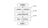
まずステップS1101において、ノイズ量算出部1001は、小領域のノイズ量を算出する。算出方法は実施形態1と同じである。
次にステップS1102において、解析部1002は、小領域内のエッジ強度を算出する。
次にステップS1103において、パッチ数算出部1003は、式(1)にエッジ強度を付加した式(8)よりモデル生成用のパッチ数を算出する。
First, in step S1101, the noise
Next, in step S1102, the
Next, in step S1103, the patch
N=(β・p・σ2)/(w・E) 式(8) N=(β·p·σ 2 )/(w·E) Equation (8)
ここで、式(8)中のEはエッジ強度、wは重みを示している。この式(8)により、エッジ強度Eが小さいほど類似パッチ数Nは多くなる。この理由として、エッジ強度Eが小さいほど小領域内のテクスチャが乏しい(平坦部)であることを示しており、平坦部ほど類似パッチ数を多くする必要があるからである。 Here, E in Equation (8) indicates edge strength, and w indicates weight. According to Equation (8), the number of similar patches N increases as the edge strength E decreases. The reason for this is that the smaller the edge strength E, the poorer the texture in the small area (flat area), and the flatter the area, the more similar patches it is necessary to have.
本実施形態では、エッジ強度を補助情報として用いたが、これに限定されず、エッジの方向、微分値の解析値、フーリエスペクトルの高周波成分の代表値を用いることができる。なお、微分値とは、水平方向ないしは垂直方向の隣接画素との差分値である。また、その解析値として、微分値を並べたベクトルに対するノルムや、水平方向および垂直方向の微分値を並べた行列の特異値分解から得られる特異値を用いることができる。 In the present embodiment, the edge intensity is used as the auxiliary information, but it is not limited to this, and the direction of the edge, the analytical value of the differential value, and the representative value of the high frequency component of the Fourier spectrum can be used. Note that the differential value is a difference value between adjacent pixels in the horizontal or vertical direction. Further, as the analytical value, a norm for a vector in which differential values are arranged, or a singular value obtained from singular value decomposition of a matrix in which horizontal and vertical differential values are arranged can be used.
<実施形態4>
次に実施形態4について説明する。実施形態1と実施形態2では小領域のノイズ量に基づいてモデル生成用のパッチ数を決定し、実施形態3では小領域のノイズ量だけでなく補助情報として用いることでモデル生成用のパッチ数を決定する例について説明した。実施形態4では、小領域のノイズ量だけでなく、彩度を補助情報として用いることで類似パッチ数を決定する例について説明する。なお、装置構成や処理フローにおいて実施形態1と同じ部分については図および説明を省略する。
<Embodiment 4>
Next, Embodiment 4 will be described. In the first and second embodiments, the number of patches for model generation is determined based on the amount of noise in the small area. An example of determining is described. In the fourth embodiment, an example will be described in which the number of similar patches is determined by using not only the amount of noise in a small area but also saturation as auxiliary information. It should be noted that the diagrams and explanations of the parts that are the same as those of the first embodiment in the device configuration and processing flow are omitted.
以下、実施形態4の画像処理装置で行われる処理について、図12に示すブロック図と、図13に示すフローチャートを参照して説明する。図12は実施形態4のパッチ数決定部207の論理構成を示したブロック図であり、図13は実施形態4の類似パッチ数決定処理の流れを示したフローチャートである。
Processing performed by the image processing apparatus of the fourth embodiment will be described below with reference to the block diagram shown in FIG. 12 and the flowchart shown in FIG. FIG. 12 is a block diagram showing the logical configuration of the patch
図12に示すように、実施形態4のパッチ数決定部207は、ノイズ量算出部1201、分離部1202、彩度算出部1203、パッチ数算出部1204としての機能を有する。なお、ノイズ量算出部1201は、実施形態1のノイズ量算出部301と同じである。
As shown in FIG. 12, the patch
まずステップS1301において、ノイズ量算出部1201は、小領域のノイズ量を算出する。算出方法は実施形態1と同じである。
次にステップS1302において、分離部1202は、小領域における画素毎のR(赤)G(緑)B(青)信号を輝度信号Yと色差信号U,Vに分離する。
First, in step S1301, the noise
Next, in step S1302, the
次にステップS1303において、彩度算出部1203は、輝度信号Yと色差信号U,Vから彩度を画素毎に算出する。
そしてステップS1304において、パッチ数算出部1204は、式(1)に小領域の平均彩度を付加した式(9)により類似パッチ数を算出する。
Next, in step S1303, the
Then, in step S1304, the patch
N=k・C・β・p・σ2 式(9) N=k・C・β・p・σ 2 Formula (9)
ここで、式(9)中のkは重み、Cは小領域の平均彩度を示している。式(9)によれば、彩度が大きいほど類似パッチ数Nが多くなる。なお、平均彩度は小領域における全画素の彩度の平均値である。 Here, k in equation (9) indicates the weight, and C indicates the average saturation of the small area. According to equation (9), the number of similar patches N increases as the saturation increases. Note that the average saturation is the average value of the saturation of all pixels in the small area.
本実施形態では、小領域の彩度を補助情報として用いたが、着目パッチの彩度を用いてもよい。また、事前に入力画像データのRGB信号を輝度信号Yと色差信号U,Vに分解し、各信号に対して算出した類似パッチ数に基づいてノイズ低減処理を行い、RGB信号に戻してもよい。このとき、彩度がある判定値以上(th以上)である場合は色差信号U,V用の類似パッチ数を輝度信号Y用の類似パッチ数よりも多くする。これは、彩度が高いほど色差信号のノイズ量が多くなり、これを低減するには多くの類似パッチが必要だからである。 Although the saturation of the small area is used as auxiliary information in this embodiment, the saturation of the patch of interest may be used. Alternatively, the RGB signals of the input image data may be decomposed in advance into a luminance signal Y and color difference signals U and V, noise reduction processing may be performed on each signal based on the number of similar patches calculated, and the RGB signals may be restored. . At this time, when the saturation is equal to or higher than a certain judgment value (th or higher), the number of similar patches for the color difference signals U and V is made larger than the number of similar patches for the luminance signal Y. This is because the higher the saturation, the greater the amount of noise in the color difference signal, and the more similar patches are required to reduce this.
以上説明したように、本発明の各実施形態によれば、パッチベース手法によるノイズ低減処理において、類似パッチの数を適切に決定することで好適な画質を得ることが可能となる。 As described above, according to each embodiment of the present invention, it is possible to obtain a suitable image quality by appropriately determining the number of similar patches in noise reduction processing using a patch-based method.
以上、本発明の各実施形態について説明したが、本発明はこれら特定の実施形態に限られるものではなく、この発明の要旨を逸脱しない範囲の様々な形態も本発明に含まれる。上述の各実施形態の一部を適宜組み合わせることも可能である。 Although each embodiment of the present invention has been described above, the present invention is not limited to these specific embodiments, and various forms without departing from the gist of the present invention are also included in the present invention. It is also possible to appropriately combine part of each of the above-described embodiments.
前述した実施形態では、デジタルカメラ等の撮像装置で撮像された入力画像を処理する例を挙げたが、入力画像はデジタルカメラで撮像されたものに限定されない。入力画像は、例えば監視カメラ、カメラ機能を備えたパーソナルコンピュータやタブレット端末、スマートフォン、携帯ゲーム機などの各種情報端末、カムコーダ、車載カメラ、あるいは工業用カメラ等で取得された画像であってもよい。 In the above-described embodiment, an example of processing an input image captured by an imaging device such as a digital camera was given, but the input image is not limited to one captured by a digital camera. The input image may be an image acquired by, for example, a surveillance camera, a personal computer or tablet terminal equipped with a camera function, a smartphone, various information terminals such as a portable game machine, a camcorder, an in-vehicle camera, an industrial camera, or the like. .
前述した実施形態に係る構成または各フローチャートの処理は、ハードウェア構成により実現されてもよいし、例えばCPUが本実施形態に係るプログラムを実行することによりソフトウェア構成により実現されてもよい。また、一部がハードウェア構成で残りがソフトウェア構成により実現されてもよい。ソフトウェア構成のためのプログラムは、予め用意されている場合だけでなく、不図示の外部メモリ等の記録媒体から取得されたり、不図示のネットワーク等を介して取得されたりしてもよい。 The configuration according to the above-described embodiment or the processing of each flowchart may be implemented by a hardware configuration, or may be implemented by a software configuration, for example, when a CPU executes a program according to the present embodiment. Alternatively, a part may be implemented by hardware and the rest by software. The program for software configuration may not only be prepared in advance, but may also be acquired from a recording medium such as an external memory (not shown) or through a network (not shown).
本発明は、上述の実施形態の1以上の機能を実現するプログラムを、ネットワーク又は記憶媒体を介してシステム又は装置に供給し、そのシステム又は装置のコンピュータにおける一つ以上のプロセッサがプログラムを読出し実行する処理でも実現可能である。また、1以上の機能を実現する回路(例えば、ASIC)によっても実現可能である。
上述の実施形態は、何れも本発明を実施するにあたっての具体化の例を示したものに過ぎず、これらによって本発明の技術的範囲が限定的に解釈されてはならないものである。即ち、本発明は、その技術思想、又はその主要な特徴から逸脱することなく、様々な形で実施することができる。
The present invention supplies a program that implements one or more functions of the above-described embodiments to a system or device via a network or a storage medium, and one or more processors in the computer of the system or device reads and executes the program. It can also be realized by processing to It can also be implemented by a circuit (for example, ASIC) that implements one or more functions.
All of the above-described embodiments merely show specific examples for carrying out the present invention, and the technical scope of the present invention should not be construed to be limited by these. That is, the present invention can be embodied in various forms without departing from its technical spirit or main features.
100:画像処理装置、203:処理部、205:着目パッチ設定部、206:小領域設定部、207:パッチ数決定部、208:探索部、209:ノイズ低減部、210:合成部 100: image processing apparatus, 203: processing unit, 205: target patch setting unit, 206: small area setting unit, 207: patch number determination unit, 208: search unit, 209: noise reduction unit, 210: synthesis unit
Claims (11)
入力画像において着目パッチと該着目パッチの近傍の領域とを設定する設定手段と、
前記設定された領域のノイズ量に基づいて、前記着目パッチへのノイズ低減処理に用いられる参照パッチとして検出するパッチ数を決定する決定手段と、
前記入力画像から前記参照パッチを前記決定されたパッチ数分、探索する探索手段と、
前記探索された参照パッチを用いて、前記着目パッチにノイズ低減処理を行うノイズ低減手段と、
前記ノイズ低減処理された複数のパッチ群を合成した画像を生成する生成手段と、
を有することを特徴とする画像処理装置。 An image processing device,
setting means for setting a patch of interest and an area in the vicinity of the patch of interest in an input image;
determining means for determining the number of patches to be detected as reference patches used in noise reduction processing for the patch of interest based on the amount of noise in the set area;
search means for searching the reference patches from the input image for the determined number of patches;
noise reduction means for performing noise reduction processing on the patch of interest using the searched reference patch;
generating means for generating an image obtained by synthesizing the plurality of noise- reduced patch groups;
An image processing device comprising:
前記決定手段は、前記比率が小さいほど前記参照パッチ数を多く決定することを特徴とする請求項3に記載の画像処理装置。 The auxiliary information is the ratio of the noise amount of the set area and the noise amount measured in advance for each sensitivity,
4. The image processing apparatus according to claim 3, wherein said determining means determines a larger number of said reference patches as said ratio is smaller.
前記決定手段は、前記エッジ強度の値が小さいほど前記参照パッチ数を多く決定することを特徴とする請求項3に記載の画像処理装置。 The auxiliary information is a value indicating edge strength in the set area,
4. The image processing apparatus according to claim 3, wherein said determining means determines a greater number of said reference patches as said edge strength value decreases.
前記決定手段は、前記代表値が小さいほど前記参照パッチ数を多く決定することを特徴とする請求項3に記載の画像処理装置。 The auxiliary information is a representative value of high frequency components of the Fourier spectrum in the set region,
4. The image processing apparatus according to claim 3, wherein said determining means determines a larger number of said reference patches as said representative value is smaller.
前記決定手段は、前記微分値が小さいほど前記参照パッチ数を多く決定することを特徴とする請求項3に記載の画像処理装置。 The auxiliary information is a differential value in the set area,
4. The image processing apparatus according to claim 3, wherein said determination means determines a larger number of said reference patches as said differential value is smaller.
前記決定手段は、前記彩度が大きいほど前記参照パッチ数を多く決定することを特徴とする請求項3に記載の画像処理装置。 the auxiliary information is the saturation of the patch of interest or the set area;
4. The image processing apparatus according to claim 3, wherein said determining means determines a larger number of said reference patches as said saturation increases.
入力画像において着目パッチと該着目パッチの近傍の領域とを設定する設定工程と、
前記設定された領域のノイズ量に基づいて、前記着目パッチへのノイズ低減処理に用いられる参照パッチとして検出するパッチ数を決定する決定工程と、
前記入力画像から前記参照パッチを前記決定されたパッチ数分、探索する探索工程と、
前記探索された参照パッチを用いて、前記着目パッチにノイズ低減処理を行うノイズ低減工程と、
前記ノイズ低減処理された複数のパッチ群を合成した画像を生成する生成工程と、
を有することを特徴とする画像処理方法。 An image processing method executed by an image processing device,
a setting step of setting a patch of interest and an area in the vicinity of the patch of interest in an input image;
a determination step of determining the number of patches to be detected as reference patches used in noise reduction processing for the patch of interest based on the amount of noise in the set area;
a searching step of searching the reference patches from the input image for the determined number of patches;
a noise reduction step of performing noise reduction processing on the patch of interest using the searched reference patch;
a generating step of generating an image obtained by synthesizing the plurality of patch groups subjected to the noise reduction process;
An image processing method characterized by comprising:
Priority Applications (3)
| Application Number | Priority Date | Filing Date | Title |
|---|---|---|---|
| JP2019167259A JP7328096B2 (en) | 2019-09-13 | 2019-09-13 | Image processing device, image processing method, and program |
| US17/018,645 US11410279B2 (en) | 2019-09-13 | 2020-09-11 | Image processing apparatus, image processing method, and storage medium |
| US17/859,985 US11734802B2 (en) | 2019-09-13 | 2022-07-07 | Image processing apparatus, method, and storage medium for patch-based noise reduction |
Applications Claiming Priority (1)
| Application Number | Priority Date | Filing Date | Title |
|---|---|---|---|
| JP2019167259A JP7328096B2 (en) | 2019-09-13 | 2019-09-13 | Image processing device, image processing method, and program |
Publications (3)
| Publication Number | Publication Date |
|---|---|
| JP2021043874A JP2021043874A (en) | 2021-03-18 |
| JP2021043874A5 JP2021043874A5 (en) | 2022-09-16 |
| JP7328096B2 true JP7328096B2 (en) | 2023-08-16 |
Family
ID=74862382
Family Applications (1)
| Application Number | Title | Priority Date | Filing Date |
|---|---|---|---|
| JP2019167259A Active JP7328096B2 (en) | 2019-09-13 | 2019-09-13 | Image processing device, image processing method, and program |
Country Status (2)
| Country | Link |
|---|---|
| US (2) | US11410279B2 (en) |
| JP (1) | JP7328096B2 (en) |
Families Citing this family (3)
| Publication number | Priority date | Publication date | Assignee | Title |
|---|---|---|---|---|
| WO2019116975A1 (en) | 2017-12-13 | 2019-06-20 | キヤノン株式会社 | Image processing method, image processing device, and program |
| JP7409606B2 (en) * | 2020-02-13 | 2024-01-09 | キヤノン株式会社 | Image processing device, image processing method and program |
| US20230022057A1 (en) * | 2021-07-16 | 2023-01-26 | Taiwan Semiconductor Manufacturing Company, Ltd. | Method for retrieving images from database |
Citations (1)
| Publication number | Priority date | Publication date | Assignee | Title |
|---|---|---|---|---|
| JP2019101686A (en) | 2017-11-30 | 2019-06-24 | キヤノン株式会社 | Image processor, method for processing image, and program |
Family Cites Families (8)
| Publication number | Priority date | Publication date | Assignee | Title |
|---|---|---|---|---|
| US20120281923A1 (en) * | 2011-05-02 | 2012-11-08 | Yeda Research And Development Co., Ltd. | Device, system, and method of image processing utilizing non-uniform image patch recurrence |
| JP5822157B2 (en) | 2011-07-15 | 2015-11-24 | 国立大学法人東京工業大学 | Noise reduction apparatus, noise reduction method, and program |
| US9754389B2 (en) * | 2012-08-06 | 2017-09-05 | Koninklijke Philips N.V. | Image noise reduction and/or image resolution improvement |
| US9122960B2 (en) * | 2012-11-30 | 2015-09-01 | Adobe Systems Incorporated | Patch size adaptation for image enhancement |
| WO2017133660A1 (en) * | 2016-02-04 | 2017-08-10 | Mediatek Inc. | Method and apparatus of non-local adaptive in-loop filters in video coding |
| US10192525B2 (en) * | 2016-03-11 | 2019-01-29 | Nvidia Corporation | System, method and computer program product for generating one or more values for a signal patch using neighboring patches collected based on a distance dynamically computed from a noise distribution of the signal patch |
| US10419758B2 (en) * | 2017-03-16 | 2019-09-17 | Mediatek Inc. | Non-local adaptive loop filter processing |
| JP7114431B2 (en) * | 2017-12-13 | 2022-08-08 | キヤノン株式会社 | Image processing method, image processing device and program |
-
2019
- 2019-09-13 JP JP2019167259A patent/JP7328096B2/en active Active
-
2020
- 2020-09-11 US US17/018,645 patent/US11410279B2/en active Active
-
2022
- 2022-07-07 US US17/859,985 patent/US11734802B2/en active Active
Patent Citations (1)
| Publication number | Priority date | Publication date | Assignee | Title |
|---|---|---|---|---|
| JP2019101686A (en) | 2017-11-30 | 2019-06-24 | キヤノン株式会社 | Image processor, method for processing image, and program |
Also Published As
| Publication number | Publication date |
|---|---|
| US11410279B2 (en) | 2022-08-09 |
| US20220351338A1 (en) | 2022-11-03 |
| JP2021043874A (en) | 2021-03-18 |
| US20210082089A1 (en) | 2021-03-18 |
| US11734802B2 (en) | 2023-08-22 |
Similar Documents
| Publication | Publication Date | Title |
|---|---|---|
| JP7328096B2 (en) | Image processing device, image processing method, and program | |
| US11145032B2 (en) | Image processing apparatus, method and storage medium for reducing color noise and false color | |
| WO2014070273A1 (en) | Recursive conditional means image denoising | |
| JP5653104B2 (en) | Image processing apparatus, image processing method, and program | |
| JP7032913B2 (en) | Image processing device, image processing method, computer program | |
| US20160260199A1 (en) | Image processing apparatus, image processing method, and storage medium | |
| US9451165B2 (en) | Image processing apparatus | |
| JP6645442B2 (en) | Information processing apparatus, information processing method, and program | |
| JP6221333B2 (en) | Image processing apparatus, image processing circuit, and image processing method | |
| JP6938282B2 (en) | Image processing equipment, image processing methods and programs | |
| JP6826277B2 (en) | Image processing system, image processing method, and image processing program | |
| JP2020181402A (en) | Image processing system, image processing method and program | |
| TWI721288B (en) | Image processing device, image processing method and program recording medium | |
| JP5810593B2 (en) | Image processing apparatus, imaging apparatus, and program | |
| JP6661491B2 (en) | Image processing apparatus and image processing method | |
| JP2019016865A (en) | Image processing device and image processing method | |
| JP2021071906A (en) | Image processing apparatus and image processing method, and program | |
| US20230074889A1 (en) | Depth estimation method and depth estimation device | |
| JP2021026311A (en) | Image processing apparatus, image processing method and program | |
| JP2017108243A (en) | Image processing device and image processing method | |
| JP2021077037A (en) | Image processing apparatus, image processing method, and program | |
| JP2021077038A (en) | Image processing apparatus, image processing method, and program | |
| JP2021071816A (en) | Image processing apparatus and image processing method, and program | |
| Perry et al. | Natural scene statistics for image denoising | |
| JP2021182239A (en) | Image processing device, image processing method and program |
Legal Events
| Date | Code | Title | Description |
|---|---|---|---|
| A521 | Request for written amendment filed |
Free format text: JAPANESE INTERMEDIATE CODE: A523 Effective date: 20220908 |
|
| A621 | Written request for application examination |
Free format text: JAPANESE INTERMEDIATE CODE: A621 Effective date: 20220908 |
|
| A977 | Report on retrieval |
Free format text: JAPANESE INTERMEDIATE CODE: A971007 Effective date: 20230623 |
|
| TRDD | Decision of grant or rejection written | ||
| A01 | Written decision to grant a patent or to grant a registration (utility model) |
Free format text: JAPANESE INTERMEDIATE CODE: A01 Effective date: 20230704 |
|
| A61 | First payment of annual fees (during grant procedure) |
Free format text: JAPANESE INTERMEDIATE CODE: A61 Effective date: 20230803 |
|
| R151 | Written notification of patent or utility model registration |
Ref document number: 7328096 Country of ref document: JP Free format text: JAPANESE INTERMEDIATE CODE: R151 |