JP7328022B2 - Radiation imaging device and radiation imaging system - Google Patents
Radiation imaging device and radiation imaging system Download PDFInfo
- Publication number
- JP7328022B2 JP7328022B2 JP2019118381A JP2019118381A JP7328022B2 JP 7328022 B2 JP7328022 B2 JP 7328022B2 JP 2019118381 A JP2019118381 A JP 2019118381A JP 2019118381 A JP2019118381 A JP 2019118381A JP 7328022 B2 JP7328022 B2 JP 7328022B2
- Authority
- JP
- Japan
- Prior art keywords
- radiation
- irradiation
- integrated value
- imaging
- signal output
- Prior art date
- Legal status (The legal status is an assumption and is not a legal conclusion. Google has not performed a legal analysis and makes no representation as to the accuracy of the status listed.)
- Active
Links
- 230000005855 radiation Effects 0.000 title claims description 296
- 238000003384 imaging method Methods 0.000 title claims description 171
- 238000000034 method Methods 0.000 claims description 54
- 230000007423 decrease Effects 0.000 claims description 14
- 238000006243 chemical reaction Methods 0.000 description 20
- 238000001514 detection method Methods 0.000 description 16
- 238000010586 diagram Methods 0.000 description 6
- 230000005856 abnormality Effects 0.000 description 5
- 238000002601 radiography Methods 0.000 description 5
- 239000000758 substrate Substances 0.000 description 4
- 239000003990 capacitor Substances 0.000 description 3
- 230000000694 effects Effects 0.000 description 3
- 230000001186 cumulative effect Effects 0.000 description 2
- 230000010354 integration Effects 0.000 description 2
- 239000000463 material Substances 0.000 description 2
- 239000002245 particle Substances 0.000 description 2
- 238000005070 sampling Methods 0.000 description 2
- 230000035939 shock Effects 0.000 description 2
- BUGBHKTXTAQXES-UHFFFAOYSA-N Selenium Chemical compound [Se] BUGBHKTXTAQXES-UHFFFAOYSA-N 0.000 description 1
- 238000009825 accumulation Methods 0.000 description 1
- 229910021417 amorphous silicon Inorganic materials 0.000 description 1
- 230000003321 amplification Effects 0.000 description 1
- 210000000988 bone and bone Anatomy 0.000 description 1
- JJWKPURADFRFRB-UHFFFAOYSA-N carbonyl sulfide Chemical compound O=C=S JJWKPURADFRFRB-UHFFFAOYSA-N 0.000 description 1
- 230000002950 deficient Effects 0.000 description 1
- 230000006866 deterioration Effects 0.000 description 1
- 239000011521 glass Substances 0.000 description 1
- 238000003702 image correction Methods 0.000 description 1
- 210000004072 lung Anatomy 0.000 description 1
- 230000007257 malfunction Effects 0.000 description 1
- 239000011159 matrix material Substances 0.000 description 1
- 238000012544 monitoring process Methods 0.000 description 1
- 238000003199 nucleic acid amplification method Methods 0.000 description 1
- 210000000056 organ Anatomy 0.000 description 1
- 230000005258 radioactive decay Effects 0.000 description 1
- 229910052711 selenium Inorganic materials 0.000 description 1
- 239000011669 selenium Substances 0.000 description 1
- 239000004065 semiconductor Substances 0.000 description 1
- 230000035945 sensitivity Effects 0.000 description 1
- 229910052710 silicon Inorganic materials 0.000 description 1
- 239000010703 silicon Substances 0.000 description 1
- 239000000126 substance Substances 0.000 description 1
- 239000010409 thin film Substances 0.000 description 1
Images


Classifications
-
- A—HUMAN NECESSITIES
- A61—MEDICAL OR VETERINARY SCIENCE; HYGIENE
- A61B—DIAGNOSIS; SURGERY; IDENTIFICATION
- A61B6/00—Apparatus for radiation diagnosis, e.g. combined with radiation therapy equipment
- A61B6/54—Control of apparatus or devices for radiation diagnosis
- A61B6/542—Control of apparatus or devices for radiation diagnosis involving control of exposure
-
- A—HUMAN NECESSITIES
- A61—MEDICAL OR VETERINARY SCIENCE; HYGIENE
- A61B—DIAGNOSIS; SURGERY; IDENTIFICATION
- A61B6/00—Apparatus for radiation diagnosis, e.g. combined with radiation therapy equipment
- A61B6/42—Apparatus for radiation diagnosis, e.g. combined with radiation therapy equipment with arrangements for detecting radiation specially adapted for radiation diagnosis
- A61B6/4208—Apparatus for radiation diagnosis, e.g. combined with radiation therapy equipment with arrangements for detecting radiation specially adapted for radiation diagnosis characterised by using a particular type of detector
- A61B6/4233—Apparatus for radiation diagnosis, e.g. combined with radiation therapy equipment with arrangements for detecting radiation specially adapted for radiation diagnosis characterised by using a particular type of detector using matrix detectors
Description
本発明は、放射線を用いた撮像を行う放射線撮像装置、及び、当該放射線撮像装置を含み構成された放射線撮像システムに関するものである。 The present invention relates to a radiation imaging apparatus that performs imaging using radiation , and a radiation imaging system including the radiation imaging apparatus.
X線などの放射線を検出するセンサパネル等の撮像部を備えた放射線撮像装置は、産業や医療などの分野で広く用いられている。近年、静止画撮影や動画撮影など、目的に応じた複数の撮影モードでの撮影が可能な可搬型の放射線撮像装置が検討されている。また、被検体を透過した放射線の積算照射量を検知し、検知した積算照射量が適正量に達した時点で放射線源による放射線の照射を停止することで、自動露出制御(Automatic Exposure Control:AEC)を行うことが可能な放射線撮像装置も検討されている。 2. Description of the Related Art Radiation imaging apparatuses having imaging units such as sensor panels that detect radiation such as X-rays are widely used in industrial and medical fields. 2. Description of the Related Art In recent years, portable radiation imaging apparatuses capable of imaging in a plurality of imaging modes according to purposes, such as still image imaging and moving image imaging, have been considered. In addition, automatic exposure control (AEC) is performed by detecting the cumulative dose of radiation transmitted through the subject and stopping the irradiation of radiation from the radiation source when the detected cumulative dose reaches an appropriate amount. ) is also under consideration.
特許文献1には、放射線検出用のセンサ部に発生した電荷に応じた電気信号であって第1配線を流れる電気信号と第1配線と略同一の配線パターンの第2配線を流れる電気信号との差に基づいて放射線の検出を行うことにより、外乱要因などに起因してノイズが発生する場合でも、ノイズの影響を抑えて精度良く放射線を検出できる放射線画像撮影装置の例が開示されている。そして、特許文献2には、検出手段によって放射線の線量を表す信号に外乱ノイズの発生が検出された場合に、当該信号を当該信号が表す放射線の線量より少ない線量を表す信号に変換することにより、ノイズが発生しても放射線停止制御を精度良く行って線量不足による再撮影を防止する放射線撮像システムの例が開示されている。
In
しかしながら、特許文献2を含む従来の技術においては、例えば、放射線の線量を検出するデバイスの経年劣化や衝撃などによる故障等によって、不適切な放射線停止制御がなされる場合がありうる。
However, in the conventional technology including
本発明は、このような問題点に鑑みてなされたものであり、不適切な放射線停止制御が行われることを回避することができる仕組みを提供することを目的とする。 SUMMARY OF THE INVENTION The present invention has been made in view of such problems, and an object of the present invention is to provide a mechanism capable of avoiding inappropriate radiation stop control.
本発明の放射線撮像装置は、放射線を用いた撮像を行う放射線撮像装置であって、入射した前記放射線の線量に基づく電気信号を出力する線量信号出力画素を含み構成された撮像部と、前記撮像部に対して前記放射線が照射されていない期間において、前記線量信号出力画素から出力された電気信号の積算値と、閾値とを比較する処理を行う処理部と、を有し、前記処理部は、前記放射線の照射の許可を指示した後であって、前記放射線の最小照射時間の経過後に、前記積算値が前記閾値を超えず、かつ、前記積算値が一定の期間で所定以上の増減が無かった場合には、前記撮像部に対する前記放射線の照射を停止する停止指示を行う。
本発明の放射線撮像装置における他の態様は、放射線を用いた撮像を行う放射線撮像装置であって、入射した前記放射線の線量に基づく電気信号を出力する線量信号出力画素を含み構成された撮像部と、前記線量信号出力画素から出力された電気信号の積算値と、閾値とを比較する処理を行う処理部と、を有し、前記処理部は、前記放射線の照射の許可を指示した後であって、前記放射線の最小照射時間の経過後に、前記積算値が前記閾値を超えず、かつ、前記積算値が一定の期間で所定以上の増減が無かった場合には、前記撮像部に対する前記放射線の照射を停止する停止指示を行う。
また、本発明は、上述した放射線撮像装置を含み構成された放射線撮像システムを含む。
A radiation imaging apparatus according to the present invention is a radiation imaging apparatus that performs imaging using radiation, and includes an imaging unit that includes dose signal output pixels that output electrical signals based on the dose of the incident radiation; a processing unit that compares an integrated value of the electrical signal output from the dose signal output pixel with a threshold during a period in which the radiation is not irradiated to the part, wherein the processing unit , after the permission to irradiate the radiation is instructed, the integrated value does not exceed the threshold value, and the integrated value does not increase or decrease by a predetermined amount or more in a certain period of time after the minimum irradiation time of the radiation has elapsed; If not, a stop instruction is issued to stop irradiation of the radiation to the imaging unit .
Another aspect of the radiation imaging apparatus of the present invention is a radiation imaging apparatus that performs imaging using radiation, the imaging unit including dose signal output pixels that output electrical signals based on the dose of the incident radiation. and a processing unit that compares the integrated value of the electrical signal output from the dose signal output pixel with a threshold value, and the processing unit, after instructing permission to irradiate the radiation , and if the integrated value does not exceed the threshold value after the minimum irradiation time of the radiation has passed and the integrated value does not increase or decrease by a predetermined amount or more in a certain period, the radiation to the imaging unit A stop instruction is given to stop the irradiation of .
The present invention also includes a radiation imaging system including the radiation imaging apparatus described above .
本発明によれば、不適切な放射線停止制御が行われることを回避することができる。 According to the present invention, inappropriate radiation stop control can be avoided.
以下に、図面を参照しながら、本発明を実施するための形態(実施形態)について説明する。なお、以下に記載する本発明の実施形態において、放射線には、放射線崩壊によって放出される粒子(光子を含む)の作るビームであるα線やβ線、γ線、更には、同程度以上のエネルギーを有するビームである、例えばX線や粒子線、宇宙線なども含む。 EMBODIMENT OF THE INVENTION Below, the form (embodiment) for implementing this invention is demonstrated, referring drawings. In the embodiments of the present invention described below, radiation includes α-rays, β-rays, and γ-rays, which are beams produced by particles (including photons) emitted by radioactive decay. It also includes energetic beams such as X-rays, particle beams, and cosmic rays.
(第1の実施形態)
まず、本発明の第1の実施形態について説明する。
(First embodiment)
First, a first embodiment of the present invention will be described.
図1は、本発明の第1の実施形態に係る放射線撮像装置100を含む放射線撮像システム10の概略構成の一例を示す図である。放射線撮像システム10は、図1に示すように、放射線撮像装置100、照射制御装置200、及び、放射線源300を有して構成されている。この放射線撮像システム10は、放射線301によって形成される被検体Hの像を電気的に撮像し、電気的な放射線画像を得るように構成されている。
FIG. 1 is a diagram showing an example of a schematic configuration of a
放射線源300は、照射制御装置200からの照射許可指令に従って放射線301の照射を行う。放射線源300から放射された放射線301は、被検体Hを通って放射線撮像装置100に入射する。また、放射線源300は、照射制御装置200からの照射停止指令に従って放射線301の照射を停止する。
The
照射制御装置200は、放射線源300による放射線301の照射を制御する。この照射制御装置200は、照射スイッチ201を備えていてもよい。例えば、照射制御装置200は、照射スイッチ201の操作状態や放射線撮像装置100からの各種の指示情報に基づいて、放射線源300による放射線301の照射を制御する。
The
放射線撮像装置100は、放射線301を用いた被検体Hの撮像を行う装置である。この放射線撮像装置100は、放射線301の照射停止を制御する自動露出制御機能(AEC機能)を有している。この放射線撮像装置100は、図1に示すように、コンピュータ110、撮像部120、処理部130、入力部140、及び、表示部150を有して構成されている。
The radiation imaging apparatus 100 is an apparatus for imaging a subject
撮像部120には、放射線源300から放射された放射線301(被検体Hを透過した放射線301も含む)が入射する。この撮像部120は、放射線画像に係る画像信号を出力する複数の画像信号出力画素、及び、入射した放射線301の照射線量に基づく電気信号である線量信号を出力する複数の線量信号出力画素を含み構成されている。なお、本実施形態では、線量信号を出力する構成として、画素を適用した例について説明するが、専用のセンサ等を適用するようにしてもよい。
処理部130は、放射線停止制御に係る各種の処理を行う。本実施形態においては、処理部130は、撮像部120に対して放射線源300から放射線301が照射されていない期間において、撮像部120の線量信号出力画素から出力された電気信号(線量信号)の積算値と、閾値とを比較する処理を行う。その後、本実施形態においては、処理部130は、上述した積算値が閾値を超えている場合には、撮像部120に対する放射線源300からの放射線301の照射を不許可とする不許可指示情報を照射制御装置200に送信する。そして、照射制御装置200は、処理部130から不許可指示情報を受信した場合には、放射線源300に対して照射不許可指令を送信し、放射線源300から放射線301が照射されないように制御する。他方、本実施形態においては、処理部130は、上述した積算値が閾値を超えていない場合には、撮像部120に対する放射線源300からの放射線301の照射を許可する許可指示情報を照射制御装置200に送信する。そして、照射制御装置200は、処理部130から許可指示情報を受信した場合には、放射線源300に対して照射許可指令を送信し、放射線源300から放射線301を照射するように制御する。
The
この処理部130は、例えば、FPGA(Field Programmable Gate Array)やASIC(Application Specific Integrated Circuit)、或いは、プログラムが組み込まれた汎用コンピュータによって構成してもよい。また、処理部130は、これらの全部または一部の組み合わせによって構成してもよい。
The
コンピュータ110は、放射線撮像装置100の動作を統括的に制御するとともに、各種の処理を行う。また、コンピュータ110は、照射制御装置200との間で通信を行う。また、コンピュータ110は、撮像部120の画像信号出力画素から出力される画像信号を処理して、放射線画像データを生成する処理等も行う。
The
入力部140は、コンピュータ110に対して、各種の情報を入力する。
The
表示部150は、コンピュータ110の制御に基づいて、各種の情報や各種の画像を表示する。例えば、表示部150は、処理部130において照射制御装置200に対して不許可指示情報を送信した場合に、その旨を示す警告表示を行う。また、例えば、表示部150は、コンピュータ110で生成された放射線画像データに基づく放射線画像を表示する。
The
次に、図1に示す撮像部120の内部構成について説明する。
図2は、本発明の第1の実施形態を示し、図1に示す撮像部120の内部構成の一例を示す図である。以下、この図2に示す第1の実施形態における撮像部120を「撮像部120-1」と記載する。
Next, the internal configuration of the
FIG. 2 shows the first embodiment of the present invention and is a diagram showing an example of the internal configuration of the
撮像部120-1は、図2に示すように、画素領域121、バイアス電源122、駆動回路であるシフトレジスタ123、読出回路124、バッファ増幅器125、及び、A/D変換器126を有して構成されている。
The imaging unit 120-1 has a
画素領域121は、例えば絶縁基板上に複数の画素210が行列状に配置されて構成されている。ここで、図2に示す例では、説明の簡便化のために、5行×5列の画素210(具体的には、図2に示す画素210-11~画素210-55)が配置された画素領域121が示されているが、実際の画素領域121には、より多くの画素210が配置されている。例えば、17インチのFPDでは、約2800行×約2800列の画素210を有しうる。
The
1つの画素210は、入射した放射線301を電荷に変換する変換素子S、及び、変換素子Sで発生した電荷に応じた電気信号を出力するためのスイッチ素子Tを含み構成されている。図2に示す例では、1行1列目の画素210-11に含まれる変換素子Sを「変換素子S11」として記載し、1行1列目の画素210-11に含まれるスイッチ素子Tを「スイッチ素子T11」として記載している。ここで、任意の自然数m及びnを用いて一般化して図2に示す例を説明すると、m行n列目の画素210-mnに含まれる変換素子Sを「変換素子Smn」として記載し、m行n列目の画素210-mnに含まれるスイッチ素子Tを「スイッチ素子Tmn」として記載している。
One pixel 210 includes a conversion element S that converts
本実施形態においては、変換素子Sは、例えば、放射線301を光電変換素子で検知可能な光に変換する波長変換体(例えば、シンチレータ)と、波長変換体で変換された光を電荷に変換する光電変換素子を含む、間接型の変換素子が用いられうる。この場合、光電変換素子は、ガラス基板などの絶縁基板上に配置され、例えばアモルファスシリコンを主材料とするMIS型のフォトダイオードが用いられてもよい。また、光電変換素子は、シリコンなどの半導体基板上に配置されたPIN型のフォトダイオードを用いてもよい。また、変換素子Sは、上述した間接型の変換素子に限定されるものではなく、放射線301を直接、電荷に変換する直接型の変換素子が用いられてもよい。この場合、変換素子の主材料としては、例えばアモルファスセレンなどが用いられうる。図2に示された複数の変換素子Sは、撮像部120-1に到達した放射線301の二次元分布を検出する。
In the present embodiment, the conversion element S includes, for example, a wavelength converter (for example, a scintillator) that converts the
スイッチ素子Tには、例えば、制御端子と2つの主端子とを有するトランジスタが用いられうる。本実施形態においては、スイッチ素子Tは、薄膜トランジスタ(TFT)が用いられうる。 For the switch element T, for example, a transistor having a control terminal and two main terminals can be used. In this embodiment, the switch element T may be a thin film transistor (TFT).
変換素子Sの一方の電極は、スイッチ素子Tの2つの主端子の一方に電気的に接続され、変換素子Sの他方の電極は、共通のバイアス配線を介してバイアス電源122に電気的に接続される。行方向(図2において横方向)に配置されているスイッチ素子T、例えば1行目のスイッチ素子T11~T15は、制御端子が駆動配線Vg(1)に共通に電気的に接続されている。このスイッチ素子T11~T15には、シフトレジスタ123から駆動配線Vg(1)を介して、スイッチ素子T11~T15の導通状態を制御する駆動信号が与えられる。また、列方向(図2において縦方向)に配置されているスイッチ素子T、例えば1列目のスイッチ素子T11~T51は、他方の主端子が信号配線Sig1に電気的に接続されている。スイッチ素子T11~T51が導通状態である間、変換素子Sに蓄積された電荷に応じた信号が、信号配線Sig1を介して読出回路124に出力される。列方向に配置されている信号配線Sig1~Sig5は、同じ駆動配線Vgに接続された画素210から出力される信号を、並列に読出回路124に伝送する。
One electrode of the conversion element S is electrically connected to one of the two main terminals of the switch element T, and the other electrode of the conversion element S is electrically connected to the
ここで、図2に示す本実施形態では、撮像部120に含まれる、上述した線量信号出力画素と画像信号出力画素とは、撮像部120-1の画素領域121において、同一の画素210として構成されている態様を採りうる。この場合、図1のコンピュータ110は、シフトレジスタ123を制御して、画素210を駆動させるタイミングを相互に異ならせることによって当該画素を上述した線量信号出力画素または画像信号出力画素として機能させるものとする。例えば、図1のコンピュータ110は、入力部140からの情報に基づいて、画素210を線量信号出力画素として機能させる第1の駆動モードと、画素210を画像信号出力画素として機能させる第2の駆動モードのいずれかの駆動モードを選択しうる。なお、ここでは、撮像部120の内部構成に対する各種の制御を、図1のコンピュータ110が行う態様について説明を行うが、本実施形態においてはこの態様に限定されるものではなく、図1の処理部130が行う態様も、本実施形態に適用可能である。
Here, in the present embodiment shown in FIG. 2, the above-described dose signal output pixels and image signal output pixels included in the
シフトレジスタ123は、図1のコンピュータ110から供給される制御信号D-CLK、DIO及びOEに応じて、スイッチ素子Tを導通状態にする導通電圧Vcomと非導通状態にする非導通電圧Vssとを含む駆動信号を、それぞれの駆動配線Vgに出力する。これによって、シフトレジスタ123は、スイッチ素子Tの導通状態及び非導通状態を制御し、画素領域121のそれぞれの画素210を駆動する。具体的に、制御信号D-CLKは、駆動回路として用いられるシフトレジスタ123のシフトクロック信号である。また、制御信号DIOは、シフトレジスタ123が転送するパルス信号である。また、制御信号OEは、シフトレジスタ123の出力端を制御する信号である。以上によって、駆動の所要時間と走査方向が設定される。
The
読出回路124には、画素領域121に配置された画素210から並列に出力された信号を増幅する増幅回路242が、信号配線Sigごとに設けられている。増幅回路242は、積分増幅器2421、可変増幅器2422、及び、サンプルホールド回路2423を含み構成されている。積分増幅器2421は、画素210から出力された信号を増幅する。より具体的には、積分増幅器2421は、画素210から読み出された電気信号を増幅して出力する演算増幅器、積分容量、及び、リセットスイッチを含む。積分増幅器2421は、積分容量の値を変化させることによって、増幅率を変更することが可能である。また、積分増幅器2421の演算増幅器における反転入力端子には、画素210から出力された信号が入力され、演算増幅器における正転入力端子には、基準電源241から基準電圧Vrefが入力される。また、積分増幅器2421の演算増幅器における出力端子から、増幅された信号が出力される。また、積分増幅器2421において、積分容量が、演算増幅器の反転入力端子と出力端子との間に配置される。可変増幅器2422は、積分増幅器2421から出力された信号を増幅する。サンプルホールド回路2423は、積分増幅器2421及び可変増幅器2422で増幅された信号をサンプリングし保持する。このサンプルホールド回路2423は、サンプリングスイッチ、及び、サンプリング容量を含む。また、読出回路124は、増幅回路242から並列に読み出された信号を順次出力して直列の電気信号として出力するマルチプレクサ243を含み構成されている。
The
この読出回路124は、図1のコンピュータ110から供給される制御信号RC、SH及びCLKに応じて、各構成要素の動作が制御される。具体的に、制御信号RCは、積分増幅器2421のリセットスイッチの動作を制御するための信号である。また、制御信号SHは、サンプルホールド回路2423の動作を制御するための信号である。また、制御信号CLKは、マルチプレクサ243の動作を制御するための信号である。
The
バッファ増幅器125は、マルチプレクサ243から出力された電気信号をインピーダンス変換してA/D変換器126に出力する。
The
A/D変換器126は、バッファ増幅器125から出力されたアナログの電気信号を、デジタルの電気信号に変換する。例えば、画素領域121の或る1行または或る複数行の画素210を線量信号出力画素として機能させる駆動モードの場合、放射線301の照射前または照射中、当該画素210(線量信号出力画素)からA/D変換器126を介して出力されるデジタルの電気信号(線量信号)は、例えば図1の処理部130に供給される。また、例えば、画素領域121の画素210を画像信号出力画素として機能させる駆動モードの場合、放射線301の照射後、当該画素210(画像信号出力画素)からA/D変換器126を介して出力されるデジタルの電気信号(画像信号)は、例えば図1のコンピュータ110に供給される。
The A/D converter 126 converts the analog electrical signal output from the
次に、例えば、ユーザによって照射スイッチ201が操作(オン)されて、照射制御装置200から放射線撮像装置100に対して放射線301の照射要求があった場合の動作を、図3及び図4を用いて説明する。
Next, for example, the operation when the irradiation switch 201 is operated (turned on) by the user and the
図3は、本発明の第1の実施形態に係る放射線撮像装置100を含む放射線撮像システム10の制御方法における処理手順の一例を示すタイミングチャートである。具体的に、図3では、上から順に、放射線源300の放射線301の照射タイミング、撮像部120の露光(蓄積)タイミング、撮像部120の本画像(放射線画像)の読み出しタイミング、撮像部120の線量検出ラインの読み出しタイミング、閾値Th及び線量検出ラインの積算値の変動タイミングが示されている。ここで、撮像部120の本画像(放射線画像)の読み出しタイミングは、例えば、画素領域121の画素210を画像信号出力画素として機能させる駆動モードの場合に、当該画素210(画像信号出力画素)から電気信号(画像信号)を読み出すタイミングである。また、撮像部120の線量検出ラインの読み出しタイミングは、例えば、画素領域121の或る1行または或る複数行の画素210を線量信号出力画素として機能させる駆動モードの場合に、当該線量信号出力画素ラインから電気信号(線量信号)を読み出すタイミングである。
FIG. 3 is a timing chart showing an example of a processing procedure in a control method for the
ここで、図3では、撮像部120に対して放射線源300から放射線301が照射されていない期間における、第1の実施形態に係る放射線撮像装置100の動作の一例を示している。具体的に、図3では、例えば画素領域121の或る1行または或る複数行の画素210を線量信号出力画素として機能させる駆動モードの場合に、当該線量信号出力画素ライン(線量検出ライン)から電気信号(線量信号)を読み出す動作を示している。そして、図3では、処理部130は、当該読み出された電気信号(線量信号)を積算した積算値と、閾値Thとを比較する処理を行う。図3の場合、線量検出ライン(線量信号出力画素ライン)の電気信号の積算値が閾値Thを超えているため、処理部130は、撮像部120に対する放射線源300からの放射線301の照射を不許可とする不許可指示情報を、照射制御装置に送信することになる。なお、図3に示す例のように、線量検出ライン(線量信号出力画素ライン)の電気信号の積算値が閾値Thを超える場合には、例えば線量検出ライン(線量信号出力画素ライン)が経年劣化や衝撃などによる故障等によって、出力異常が生じていることが考えられる。
Here, FIG. 3 shows an example of the operation of the radiation imaging apparatus 100 according to the first embodiment during a period in which the
図4は、本発明の第1の実施形態に係る放射線撮像装置100の制御方法における処理手順の一例を示すフローチャートである。この図4に示すフローチャートは、撮像部120に対して放射線源300から放射線301が照射されていない状態(放射線301の照射前の状態)で開始される。
FIG. 4 is a flow chart showing an example of a processing procedure in the control method of the radiation imaging apparatus 100 according to the first embodiment of the present invention. The flowchart shown in FIG. 4 is started in a state where the
まず、ステップS101において、処理部130は、例えば画素領域121の或る1行または或る複数行の画素210を線量信号出力画素として機能させる駆動モードの場合に、当該線量信号出力画素ライン(線量検出ライン)から電気信号(線量信号)を読み出す。
First, in step S101, the
続いて、ステップS102において、処理部130は、ステップS101において線量信号出力画素ラインから読み出した電気信号(線量信号)を積算して積算値を算出する。
Subsequently, in step S102, the
続いて、ステップS103において、処理部130は、ステップS102で算出された積算値と閾値Thとを比較し、ステップS102で算出された積算値が閾値Thを超えたか否かを判断する。
Subsequently, in step S103, the
ステップS103の判断の結果、ステップS102で算出された積算値が閾値Thを超えていない場合には(S103/NO)、ステップS104に進む。
ステップS104に進むと、処理部130は、例えば線量信号出力画素ラインの出力異常が生じていないと判断し、撮像部120に対する放射線源300からの放射線301の照射を許可する許可指示情報を照射制御装置200に送信する。そして、照射制御装置200は、処理部130から許可指示情報を受信した場合には、放射線源300に対して照射許可指令を送信し、放射線源300から放射線301を照射するように制御する。その後、ステップS104の処理が終了すると、図4のフローチャートの処理を終了しても、或いは、ステップS101に戻ってステップS101以降の処理を再度行うようにしてもよい。
As a result of the determination in step S103, when the integrated value calculated in step S102 does not exceed the threshold value Th (S103/NO), the process proceeds to step S104.
When proceeding to step S104, the
一方、ステップS103の判断の結果、ステップS102で算出された積算値が閾値Thを超えている場合には(S103/YES)、ステップS105に進む。
ステップS105に進むと、処理部130は、例えば線量信号出力画素ラインの出力異常が生じていると判断し、撮像部120に対する放射線源300からの放射線301の照射を不許可とする不許可指示情報を照射制御装置200に送信する。そして、照射制御装置200は、処理部130から不許可指示情報を受信した場合には、放射線源300に対して照射不許可指令を送信し、放射線源300から放射線301が照射されないように制御する。また、例えば、線量信号出力画素ラインの出力異常が生じていることから適切な放射線停止制御が行えない可能性があるため、ステップS105では、表示部150に、例えば、適切な線量検出が行えない等を示す警告表示を行う。これにより、ユーザは、適切な線量検出が行えないため、適切な放射線停止制御が実施できないことを把握することができる。
On the other hand, as a result of the determination in step S103, when the integrated value calculated in step S102 exceeds the threshold value Th (S103/YES), the process proceeds to step S105.
Proceeding to step S105, the
第1の実施形態に係る放射線撮像装置100では、処理部130は、撮像部120に対して放射線301が照射されていない期間において、線量信号出力画素ライン(線量検出ライン)から出力された電気信号の積算値と閾値Thとを比較するようにしている。
かかる構成によれば、処理部130は、線量信号出力画素ラインから出力された電気信号の積算値が閾値Thを超えている場合には、例えば線量信号出力画素ラインの出力異常が生じていると判断し、撮像部120に対する放射線源300からの放射線301の照射を不許可とする不許可指示情報を照射制御装置200に送信することができる。これにより、不適切な放射線停止制御が行われることを回避することができる。さらに、不要な放射線撮影を防止することができる。
In the radiation imaging apparatus 100 according to the first embodiment, the
According to such a configuration, when the integrated value of the electric signal output from the dose signal output pixel line exceeds the threshold value Th, the
(第2の実施形態)
次に、本発明の第2の実施形態について説明する。なお、以下に記載する第2の実施形態の説明では、上述した第1の実施形態と共通する事項については説明を省略し、上述した第1の実施形態と異なる事項について説明を行う。
(Second embodiment)
Next, a second embodiment of the invention will be described. In the description of the second embodiment described below, the description of matters common to the first embodiment is omitted, and the matters different from the first embodiment are described.
第2の実施形態に係る放射線撮像装置を含む放射線撮像システムの概略構成は、図1に示す第1の実施形態に係る放射線撮像装置100を含む放射線撮像システム10の概略構成と同様である。また、第2の実施形態に係る放射線撮像装置100の撮像部120の内部構成は、図2に示す第1の実施形態における撮像部120-1の内部構成と同様である。
A schematic configuration of a radiation imaging system including the radiation imaging apparatus according to the second embodiment is similar to the schematic configuration of the
具体的に、第2の実施形態は、図4のステップS104における放射線301の照射許可がなされた後の各種の態様に係る形態である。この第2の実施形態に係る放射線撮像装置100は、放射線301の照射停止を制御する自動露出制御機能(AEC機能)を有している。
Specifically, the second embodiment is a form relating to various aspects after the irradiation permission of the
図5は、本発明の第2の実施形態に係る放射線撮像装置100を含む放射線撮像システム10の制御方法における第1処理手順の一例を示すタイミングチャートである。この図5において、図3に示す要素と同様の要素については同じ名称を付しており、その詳細な説明は省略する。
FIG. 5 is a timing chart showing an example of the first processing procedure in the method of controlling the
この図5に示すタイミングチャートでは、図5に示すように、図4のステップS104における放射線301の「照射許可」がなされた後の処理手順の一例を示している。具体的に、処理部130から、放射線源300からの放射線301の照射を許可する許可指示情報が照射制御装置200に対して送信されると、照射制御装置200は、放射線源300から放射線301の照射を開始する。ここで、本実施形態では、照射制御装置200は、放射線源300からの放射線301の照射時間として、被検体Hの放射線撮影に係る最小照射時間501及び設定照射時間502を設定しているものとする。
The timing chart shown in FIG. 5 shows an example of a processing procedure after "permitting irradiation" of the
放射線源300からの放射線301の照射開始に際して、撮像部120の画素領域121のそれぞれの画素210では、電荷を蓄積する露光を開始する。そして、処理部130は、例えば画素領域121の或る1行または或る複数行の画素210から構成される線量検出ライン(線量信号出力画素ライン)から、一定の時間間隔で電気信号(線量信号)を読み出す。この際、線量検出ライン(線量信号出力画素ライン)から電気信号(線量信号)が読み出される度に露光し電荷をリセットしているため、処理部130は、読み出した線量検出ライン(線量信号出力画素ライン)の電気信号(線量信号)を積算して積算値を算出する。以下、線量検出ライン(線量信号出力画素ライン)の電気信号(線量信号)を積算して算出した積算値を「ライン積算値」と記載する。
At the start of
そして、処理部130は、送信した許可指示情報に基づき撮像部120に対して放射線301が照射されている期間において、一定の時間間隔で、ライン積算値と閾値Thとを比較する処理を行う。そして、図5に示す例では、処理部130は、ライン積算値が閾値Thを超えた場合には、撮像部120に対する放射線301の照射を停止する停止指示情報を、例えば照射制御装置200及びコンピュータ110に送信する。照射制御装置200は、処理部130から停止指示情報を受信すると、放射線源300に対して照射停止指令を送信し、放射線源300からの放射線301の照射を停止させる。さらに、コンピュータ110は、処理部130から停止指示情報を受信すると、撮像部120の画素領域121のそれぞれの画素210における露光動作を停止させる。続いて、コンピュータ110は、それまでに蓄積した各画素210(線量検出ラインの画素(線量信号出力画素)として機能させた画素を含めてもよい)の電気信号(画像信号)を読み出す動作を行う。
Then, the
この図5に示すように、ライン積算値が閾値Thを超えた場合に、撮像部120に対する放射線301の照射を停止することで、適切な放射線停止制御を行うことができる。これにより、適切な自動露出制御(AEC)を行うことができる。
As shown in FIG. 5, by stopping irradiation of the
ここで、処理部130に設定される閾値Thについて説明する。
閾値Thは、検査する被検体Hの部位によって異なる値を設定できる。例えば、撮影する領域が被検体Hの肺領域のような空気量が多い部位では、放射線301を透過しやすい傾向にあるため、画素領域121への放射線301の到達線量が多くなることから、設定する閾値Thは、高い値となる。逆に、撮影する領域が被検体Hの骨や臓器などのような放射線301を透過しにくい部位では、設定する閾値Thは、低い値となる。
Here, the threshold Th set in the
Different values can be set for the threshold Th depending on the part of the subject H to be inspected. For example, if the region to be imaged is a region with a large amount of air, such as the lung region of the subject H, the
そして、図5に示す例では、最小照射時間501以上で、かつ、例えば放射線技師が撮影手技に応じて選択する設定照射時間502以内において、上述した閾値Thを用いた適切な放射線停止制御が実施される。 Then, in the example shown in FIG. 5, appropriate radiation stop control using the threshold value Th described above is performed within the minimum irradiation time 501 or longer and within the set irradiation time 502 selected by, for example, the radiological technologist according to the imaging technique. be done.
図6は、本発明の第2の実施形態に係る放射線撮像装置100を含む放射線撮像システム10の制御方法における第2処理手順の一例を示すタイミングチャートである。この図6において、図3及び図5に示す要素と同様の要素については同じ名称を付しており、その詳細な説明は省略する。
FIG. 6 is a timing chart showing an example of the second processing procedure in the method of controlling the
この図6に示すタイミングチャートでは、上述した図5と同様に、図4のステップS104における放射線301の「照射許可」がなされた後の処理手順の一例を示している。
Similar to FIG. 5 described above, the timing chart shown in FIG. 6 shows an example of a processing procedure after "permission of irradiation" of the
この図6では、処理部130は、放射線301の最小照射時間501の期間内においてライン積算値が閾値Thを超えた場合には、最小照射時間501が経過した際に、撮像部120に対する放射線301の照射を停止する停止指示情報を、例えば照射制御装置200及びコンピュータ110に送信する。この図6では、設定された最小照射時間501よりも短い時間に、上述したライン積算値が閾値Thを超えているが、照射制御装置200によって放射線源300が制御されているため、放射線源300から照射されている放射線301を停止できないからである。そのため、図6では、最小照射時間501が経過した際に、放射線停止制御を行い、さらに、撮像部120の画素領域121の各画素210における露光動作を停止させた上で各画素210から電気信号(画像信号)を読み出す動作を行う。この際、コンピュータ110では、読み出した画像信号に基づき生成した放射線画像データについて、上述したライン積算値が閾値Thを超えた時点から照射停止の時点までの時間から、ゲインダウンするような画像補正を行ってもよい。
In FIG. 6, if the line integrated value exceeds the threshold value Th within the period of the minimum irradiation time 501 of the
また、放射線301の線量は、放射線源300の管電流と照射時間との積で表される。このため、例えば、最小照射時間501内における停止指示情報の発生の有無や、上述したライン積算値が閾値Thを超えた時間と現在設定されている管電流から、最小照射時間501以上になるように管電流の適正な設定値を算出して表示部150に表示してもよい。ただし、この他に、放射線源300の管電圧や、放射線源300と被検体Hとの距離、グリッドの有無によって、設定すべき管電流の値は変わるため、特にここでは、具体的な数値を示さない。
Also, the dose of the
図7は、本発明の第2の実施形態に係る放射線撮像装置100を含む放射線撮像システム10の制御方法における第3処理手順の一例を示すタイミングチャートである。この図7において、図3及び図5~図6に示す要素と同様の要素については同じ名称を付しており、その詳細な説明は省略する。
FIG. 7 is a timing chart showing an example of the third processing procedure in the method of controlling the
この図7に示すタイミングチャートでは、上述した図5と同様に、図4のステップS104における放射線301の「照射許可」がなされた後の処理手順の一例を示している。
Similar to FIG. 5 described above, the timing chart shown in FIG. 7 shows an example of a processing procedure after "permission of irradiation" of the
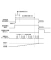
この図7では、処理部130は、放射線301の最小照射時間501の経過後に、ライン積算値が閾値Thを超えず、かつ、ライン積算値が一定の期間701で所定以上の増減が無かった場合には、一定の期間701が経過した際に、撮像部120に対する放射線301の照射を停止する停止指示情報を、例えば照射制御装置200及びコンピュータ110に送信する。具体的に、図7では、上述したライン積算値が閾値Thを超えるか否かの判断に加えて、上述したライン積算値の増減(変動)も監視する。
In FIG. 7, when the line integrated value does not exceed the threshold value Th after the minimum irradiation time 501 of the
この図7に示す例では、処理部130は、ライン積算値が一定の期間701で所定以上の増減が無かった場合、設定した閾値Thを超えていなくても、放射線301の照射を停止する停止指示情報を、照射制御装置200及びコンピュータ110に送信する。これにより、一定の期間701が経過した際に、放射線源300からの放射線301の照射が停止され、さらに、撮像部120の画素領域121の各画素210における露光動作を停止させた上で各画素210から電気信号(画像信号)を読み出す動作がなされる。
In the example shown in FIG. 7, the
この図7に示す、一定の期間701にライン積算値の増減がなく、設定した閾値Th以下のライン積算値の時点で放射線301の照射を停止する処理は、例えば、検査する被検体Hの部位に放射線301を透過しにくい物質などを含んでいる場合等、予想される閾値よりも低いレベルの放射線画像データとなっていることがある。しかしながら、ライン積算値も監視することで放射線301の照射を続けることなく、被検体Hに対する不用意な放射線301の被爆を避けることができる。
The process of stopping irradiation of the
図8は、本発明の第2の実施形態に係る放射線撮像装置100を含む放射線撮像システム10の制御方法における第4処理手順の一例を示すタイミングチャートである。この図8において、図3及び図5~図7に示す要素と同様の要素については同じ名称を付しており、その詳細な説明は省略する。
FIG. 8 is a timing chart showing an example of a fourth processing procedure in the method of controlling the
この図8に示すタイミングチャートでは、上述した図5と同様に、図4のステップS104における放射線301の「照射許可」がなされた後の処理手順の一例を示している。
Similar to FIG. 5 described above, the timing chart shown in FIG. 8 shows an example of the processing procedure after the "permission of irradiation" of the
この図8では、処理部130は、放射線301の最小照射時間501の経過後に、ライン積算値が一定の期間801で所定以上の増減(急激な変化)800があった場合には、一定の期間801が経過した際に、撮像部120に対する放射線301の照射を停止する停止指示情報を、例えば照射制御装置200及びコンピュータ110に送信する。具体的に、図8では、上述したライン積算値が閾値Thを超えるか否かの判断に加えて、ライン積算値の増減(変動)800も監視する。
In FIG. 8, when the line integrated value increases or decreases (rapidly changes) 800 by a predetermined amount or more in a
この図8に示す例では、処理部130は、ライン積算値が一定の期間801で所定以上の増減(急激な変化)800があった場合、放射線301の照射を停止する停止指示情報を、照射制御装置200及びコンピュータ110に送信する。これにより、一定の期間801が経過した際に、放射線源300からの放射線301の照射が停止され、さらに、撮像部120の画素領域121の各画素210における露光動作を停止させた上で各画素210から電気信号(画像信号)を読み出す動作がなされる。
In the example shown in FIG. 8, the
この図8に示すように、ライン積算値が一定の期間801で所定以上の増減(急激な変化)800があった場合、放射線301の照射停止制御を行うのは、線量信号出力画素に不具合が生じていることや放射線301の照射制御の不具合等が予想されるためである。即ち、そのまま、放射線撮影を続行することが望ましくない可能性があるためである。このため、例えば、この図8に示すように、ライン積算値が一定の期間801で所定以上の増減(急激な変化)800があった場合には、表示部150にその旨の警告表示を行って、ユーザに警告してもよい。
As shown in FIG. 8, when there is a predetermined increase or decrease (rapid change) 800 in the line integrated value during a
図9は、本発明の第2の実施形態に係る放射線撮像装置100を含む放射線撮像システム10の制御方法における第5処理手順の一例を示すタイミングチャートである。この図9において、図3及び図5~図8に示す要素と同様の要素については同じ名称を付しており、その詳細な説明は省略する。
FIG. 9 is a timing chart showing an example of the fifth processing procedure in the method of controlling the
この図9に示すタイミングチャートでは、上述した図5と同様に、図4のステップS104における放射線301の「照射許可」がなされた後の処理手順の一例を示している。
Similar to FIG. 5 described above, the timing chart shown in FIG. 9 shows an example of the processing procedure after the "permission of irradiation" of the
この図9では、処理部130は、放射線301の設定照射時間502が経過するまでにライン積算値が閾値Thを超えず、かつ、ライン積算値が所定範囲で増加し続けている場合には、ライン積算値が閾値Thを超えるまで撮像部120に対する放射線301の照射を継続する継続指示情報を、例えば照射制御装置200及びコンピュータ110に送信する。具体的に、図9では、上述したライン積算値が閾値Thを超えるか否かの判断に加えて、ライン積算値の増減(変動)も監視する。
In FIG. 9, when the line integrated value does not exceed the threshold value Th by the time the set irradiation time 502 of the
この図9に示す例では、ライン積算値が、単位時間当たりの照射線量に相当する増加を示しているが、設定照射時間502を経過しても閾値Thに達しない場合、設定照射時間502を経過しても放射線301の照射を続行している。そして、図9に示す例では、設定照射時間502を経過した後、ライン積算値が閾値Thに達した場合、処理部130は、その時点で、放射線301の照射を停止する停止指示情報を、照射制御装置200及びコンピュータ110に送信する。これにより、ライン積算値が閾値Thに達した際に、放射線源300からの放射線301の照射が停止され、さらに撮像部120の画素領域121の各画素210における露光動作を停止させた上で各画素210から電気信号(画像信号)を読み出す動作がなされる。
In the example shown in FIG. 9, the line integrated value indicates an increase corresponding to the irradiation dose per unit time. Irradiation with the
この図9に示す例では、設定照射時間502を経過した後であっても、放射線301の照射を続行して画素領域121の各画素210における適正な露光動作を行う。また、図9に示す例の場合、放射線撮影後に設定照射時間502と実際に放射線301を照射した時間との差異を、表示部150に表示するようにしてもよい。実際に放射線301を照射した時間が長い、つまり撮影時間が長くなると、被検体Hの振動や揺れによって取得される放射線画像データが不鮮明になることがある。このため、例えば次の放射線撮影に活かせるように、放射線源300の適正な管電流設定値を、表示部150に表示するようにしてもよい。
In the example shown in FIG. 9, even after the set irradiation time 502 has passed, the irradiation of the
図10は、本発明の第2の実施形態に係る放射線撮像装置100を含む放射線撮像システム10の制御方法における第6処理手順の一例を示すタイミングチャートである。この図10において、図3及び図5~図9に示す要素と同様の要素については同じ名称を付しており、その詳細な説明は省略する。
FIG. 10 is a timing chart showing an example of the sixth processing procedure in the method of controlling the
この図10に示すタイミングチャートでは、上述した図5と同様に、図4のステップS104における放射線301の「照射許可」がなされた後の処理手順の一例を示している。
Similar to FIG. 5 described above, the timing chart shown in FIG. 10 shows an example of a processing procedure after "permission of irradiation" of the
この図10では、処理部130は、放射線301の設定照射時間502が経過するまでにライン積算値が閾値Thを超えていない場合には、設定照射時間502が経過した際に、撮像部120に対する放射線301の照射を停止する停止指示情報を、例えば照射制御装置200及びコンピュータ110に送信する。これにより、設定照射時間502が経過した際に、放射線源300からの放射線301の照射が停止され、さらに、撮像部120の画素領域121の各画素210における露光動作を停止させた上で各画素210から電気信号(画像信号)を読み出す動作がなされる。そして、この図10に示す例では、放射線301の設定照射時間502が経過するまでにライン積算値が閾値Thを超えなかったため、コンピュータ110は、取得した放射線画像データに対してゲイン補正を行う。また、放射線撮影後に当該ゲイン補正を行った場合には、表示部150に補正した感度やdBを表示するようにしてもよい。
In FIG. 10 , if the line integrated value does not exceed the threshold value Th by the time the set irradiation time 502 of the
この図10に示すように、設定照射時間502で放射線301の照射の制限をかけるのは、例えば、被検体Hに対する放射線301の被爆量を制限したいとき等に行われるものである。
As shown in FIG. 10, limiting the irradiation of the
また、図5~図10を用いて説明した第2の実施形態においては、表示部150に、例えば、放射線301の照射に係る実照射時間から算出される、放射線源300の所定の管電流設定値を表示するようにしてもよい。
Further, in the second embodiment described with reference to FIGS. 5 to 10, the
以上説明した第2の実施形態によれば、上述した第1の実施形態における効果に加えて、適切な放射線停止制御を行うことができる。 According to the second embodiment described above, in addition to the effects of the first embodiment described above, appropriate radiation stop control can be performed.
(第3の実施形態)
次に、本発明の第3の実施形態について説明する。なお、以下に記載する第3の実施形態の説明では、上述した第1及び第2の実施形態と共通する事項については説明を省略し、上述した第1及び第2の実施形態と異なる事項について説明を行う。
(Third Embodiment)
Next, a third embodiment of the invention will be described. In addition, in the description of the third embodiment described below, the description of matters common to the first and second embodiments described above is omitted, and the matters different from those of the first and second embodiments described above are omitted. Give an explanation.
第3の実施形態に係る放射線撮像装置を含む放射線撮像システムの概略構成は、図1に示す第1の実施形態に係る放射線撮像装置100を含む放射線撮像システム10の概略構成と同様である。
A schematic configuration of a radiation imaging system including the radiation imaging apparatus according to the third embodiment is similar to the schematic configuration of the
図11は、本発明の第3の実施形態を示し、図1に示す撮像部120の内部構成の一例を示す図である。以下、この図11に示す第3の実施形態における撮像部120を「撮像部120-3」と記載する。また、この図11において、図2に示す構成と同様の構成については同じ符号を付しており、その詳細な説明は省略する。
FIG. 11 shows a third embodiment of the present invention and is a diagram showing an example of the internal configuration of the
撮像部120-3は、図11に示すように、画素領域621、バイアス電源122、駆動回路であるシフトレジスタ623、読出回路124、バッファ増幅器125、及び、A/D変換器126を有して構成されている。
The imaging unit 120-3 has a
上述した第1及び第2の実施形態は、図2に示すように、同一の画素210を、駆動させるタイミングを相互に異ならせることによって、線量信号出力画素及び画像信号出力画素として機能させる形態であった。これに対して、第3の実施形態は、線量信号出力画素と画像信号出力画素とを、図11に示す画素領域621において異なる画素として構成する形態である。
In the above-described first and second embodiments, as shown in FIG. 2, the same pixel 210 functions as a dose signal output pixel and an image signal output pixel by mutually different driving timings. there were. On the other hand, in the third embodiment, the dose signal output pixels and the image signal output pixels are configured as different pixels in the
図11において、画素領域621に配置されている複数の画素210のうち、駆動配線Vg(d1)に接続されている画素210-23、及び、駆動配線Vg(d2)に接続されている画素210-43が、線量信号出力画素である。また、画素領域621に配置されている複数の画素210のうち、駆動配線Vg(1)~Vg(5)に接続されている画素210が、画像信号出力画素である。
In FIG. 11, among the plurality of pixels 210 arranged in the
この第3の実施形態を第1の実施形態に適用する場合、処理部130は、撮像部120-3に対して放射線源300から放射線301が照射されていない期間において、例えば撮像部120-3の線量信号出力画素210-23及び210-43から出力された電気信号(線量信号)の積算値と、閾値Thとを比較する処理を行う。その後、第3の実施形態においては、処理部130は、上述した積算値が閾値Thを超えている場合には、撮像部120-3に対する放射線源300からの放射線301の照射を不許可とする不許可指示情報を照射制御装置200に送信する。そして、照射制御装置200は、処理部130から不許可指示情報を受信した場合には、放射線源300に対して照射不許可指令を送信し、放射線源300から放射線301が照射されないように制御する。他方、第3の実施形態においては、処理部130は、上述した積算値が閾値Thを超えていない場合には、撮像部120-3に対する放射線源300からの放射線301の照射を許可する許可指示情報を照射制御装置200に送信する。そして、照射制御装置200は、処理部130から許可指示情報を受信した場合には、放射線源300に対して照射許可指令を送信し、放射線源300から放射線301を照射するように制御する。
When the third embodiment is applied to the first embodiment, the
さらに、この第3の実施形態を第2の実施形態に適用する場合、処理部130は、送信した許可指示情報に基づき撮像部120-3に対して放射線301が照射されている期間において、一定の時間間隔で、例えば撮像部120-3の線量信号出力画素210-23及び210-43から出力された電気信号(線量信号)の積算値と、閾値Thとを比較する処理を行う。また、この第3の実施形態を、図5~図10を用いて説明した第2の実施形態に適用する場合、第2の実施形態におけるライン積算値に換えて、線量信号出力画素210-23及び210-43から出力された電気信号(線量信号)の積算値を適用しうる。
Furthermore, when the third embodiment is applied to the second embodiment, the
また、図11に示す例では、駆動配線Vg(d1)及び駆動配線Vg(d2)には、それぞれに1つの線量信号出力画素210が接続されているが、それぞれに複数の線量信号出力画素210が接続されていてもよい。 Further, in the example shown in FIG. 11, one dose signal output pixel 210 is connected to each of the drive wiring Vg(d1) and the drive wiring Vg(d2). may be connected.
また、図11に示す例では、シフトレジスタ623は、駆動配線Vg(1)~Vg(5)と駆動配線Vg(d1)~Vg(d2)とを、それぞれ異なる駆動タイミングで当該駆動配線に接続された画素210を駆動させるように構成されている。
Further, in the example shown in FIG. 11, the
第3の実施形態においても、上述した第1の実施形態と同様に、不適切な放射線停止制御が行われることを回避することができる。さらに、第3の実施形態においても、上述した第2の実施形態と同様に、適切な放射線停止制御を行うことができる。 Also in the third embodiment, as in the first embodiment described above, inappropriate radiation stop control can be avoided. Furthermore, in the third embodiment, as in the second embodiment described above, appropriate radiation stop control can be performed.
(その他の実施形態)
本発明は、上述の実施形態の1以上の機能を実現するプログラムを、ネットワーク又は記憶媒体を介してシステム又は装置に供給し、そのシステム又は装置のコンピュータにおける1つ以上のプロセッサーがプログラムを読出し実行する処理でも実現可能である。また、1以上の機能を実現する回路(例えば、ASIC)によっても実現可能である。
このプログラム及び当該プログラムを記憶したコンピュータ読み取り可能な記憶媒体は、本発明に含まれる。
(Other embodiments)
The present invention supplies a program that implements one or more functions of the above-described embodiments to a system or device via a network or a storage medium, and one or more processors in the computer of the system or device reads and executes the program. It can also be realized by processing to It can also be implemented by a circuit (for example, ASIC) that implements one or more functions.
This program and a computer-readable storage medium storing the program are included in the present invention.
なお、上述した本発明の実施形態は、いずれも本発明を実施するにあたっての具体化の例を示したものに過ぎず、これらによって本発明の技術的範囲が限定的に解釈されてはならないものである。即ち、本発明はその技術思想、又はその主要な特徴から逸脱することなく、様々な形で実施することができる。 It should be noted that the above-described embodiments of the present invention are merely examples of specific implementations of the present invention, and the technical scope of the present invention should not be construed to be limited by these. is. That is, the present invention can be embodied in various forms without departing from its technical concept or main features.
10:放射線撮像システム、100:放射線撮像装置、110:コンピュータ、120:撮像部、130:処理部、140:入力部、150:表示部、200:照射制御装置、201:照射スイッチ、300:放射線源、301:放射線、H:被検体 10: radiation imaging system, 100: radiation imaging apparatus, 110: computer, 120: imaging unit, 130: processing unit, 140: input unit, 150: display unit, 200: irradiation control device, 201: irradiation switch, 300: radiation source, 301: radiation, H: subject
Claims (11)
入射した前記放射線の線量に基づく電気信号を出力する線量信号出力画素を含み構成された撮像部と、
前記撮像部に対して前記放射線が照射されていない期間において、前記線量信号出力画素から出力された電気信号の積算値と、閾値とを比較する処理を行う処理部と、を有し、
前記処理部は、前記放射線の照射の許可を指示した後であって、前記放射線の最小照射時間の経過後に、前記積算値が前記閾値を超えず、かつ、前記積算値が一定の期間で所定以上の増減が無かった場合には、前記撮像部に対する前記放射線の照射を停止する停止指示を行う
ことを特徴とする放射線撮像装置。 A radiation imaging device that performs imaging using radiation,
an imaging unit configured to include dose signal output pixels that output electrical signals based on the dose of the incident radiation;
a processing unit that performs a process of comparing an integrated value of electrical signals output from the dose signal output pixels with a threshold value during a period in which the imaging unit is not irradiated with the radiation ;
The processing unit, after instructing permission to irradiate the radiation, after the minimum irradiation time of the radiation has passed, the integrated value does not exceed the threshold value, and the integrated value remains within a predetermined period of time If there is no increase or decrease above, a stop instruction is issued to stop irradiation of the radiation to the imaging unit.
A radiation imaging apparatus characterized by:
ことを特徴とする請求項1に記載の放射線撮像装置。 2. The radiation imaging apparatus according to claim 1 , further comprising a display unit that displays a warning when the stop instruction is issued in the processing unit.
前記処理部は、前記積算値として、前記複数の線量信号出力画素から出力された電気信号の積算値を用いる
ことを特徴とする請求項1または2に記載の放射線撮像装置。 The imaging unit is configured to include a plurality of the dose signal output pixels,
3. The radiation imaging apparatus according to claim 1, wherein the processing unit uses an integrated value of the electrical signals output from the plurality of dose signal output pixels as the integrated value.
前記放射線の照射を制御する照射制御装置と、を有する
ことを特徴とする放射線撮像システム。 a radiation imaging apparatus according to any one of claims 1 to 3 ;
and an irradiation control device that controls irradiation of the radiation .
ことを特徴とする請求項4に記載の放射線撮像システム。5. The radiation imaging system according to claim 4, characterized in that:
ことを特徴とする請求項5に記載の放射線撮像システム。 2. The radiation imaging apparatus according to claim 1, further comprising a display section for displaying a predetermined tube current setting value of the radiation source, which is calculated from an actual irradiation time of the irradiation of the radiation. 6. The radiation imaging system according to 5 .
入射した前記放射線の線量に基づく電気信号を出力する線量信号出力画素を含み構成された撮像部と、
前記線量信号出力画素から出力された電気信号の積算値と、閾値とを比較する処理を行う処理部と、を有し、
前記処理部は、前記放射線の照射の許可を指示した後であって、前記放射線の最小照射時間の経過後に、前記積算値が前記閾値を超えず、かつ、前記積算値が一定の期間で所定以上の増減が無かった場合には、前記撮像部に対する前記放射線の照射を停止する停止指示を行う
ことを特徴とする放射線撮像装置。 A radiation imaging device that performs imaging using radiation,
an imaging unit configured to include dose signal output pixels that output electrical signals based on the dose of the incident radiation;
A processing unit that performs a process of comparing the integrated value of the electrical signal output from the dose signal output pixel and a threshold value,
The processing unit, after instructing permission to irradiate the radiation, after the minimum irradiation time of the radiation has passed, the integrated value does not exceed the threshold value, and the integrated value remains within a predetermined period of time A radiation imaging apparatus, comprising: issuing a stop instruction to stop irradiation of the radiation to the imaging unit when there is no increase or decrease as described above.
前記処理部は、前記積算値として、前記複数の線量信号出力画素から出力された電気信号の積算値を用いる
ことを特徴とする請求項7に記載の放射線撮像装置。 The imaging unit is configured to include a plurality of the dose signal output pixels,
The radiation imaging apparatus according to claim 7 , wherein the processing unit uses an integrated value of the electrical signals output from the plurality of dose signal output pixels as the integrated value.
前記放射線の照射を制御する照射制御装置と、を有する
ことを特徴とする放射線撮像システム。 a radiation imaging apparatus according to claim 7 or 8 ;
and an irradiation control device that controls irradiation of the radiation.
ことを特徴とする請求項9に記載の放射線撮像システム。10. The radiation imaging system according to claim 9, characterized by:
ことを特徴とする請求項10に記載の放射線撮像システム。 2. The radiation imaging apparatus according to claim 1, further comprising a display section for displaying a predetermined tube current setting value of the radiation source, which is calculated from an actual irradiation time of the irradiation of the radiation. 11. The radiation imaging system according to 10 .
Priority Applications (3)
| Application Number | Priority Date | Filing Date | Title |
|---|---|---|---|
| JP2019118381A JP7328022B2 (en) | 2019-06-26 | 2019-06-26 | Radiation imaging device and radiation imaging system |
| US16/909,728 US11369332B2 (en) | 2019-06-26 | 2020-06-23 | Radiation imaging apparatus and method of controlling the same, and radiation imaging system |
| JP2023126919A JP2023156392A (en) | 2019-06-26 | 2023-08-03 | Radiation imaging device, control method thereof, and radiation imaging system |
Applications Claiming Priority (1)
| Application Number | Priority Date | Filing Date | Title |
|---|---|---|---|
| JP2019118381A JP7328022B2 (en) | 2019-06-26 | 2019-06-26 | Radiation imaging device and radiation imaging system |
Related Child Applications (1)
| Application Number | Title | Priority Date | Filing Date |
|---|---|---|---|
| JP2023126919A Division JP2023156392A (en) | 2019-06-26 | 2023-08-03 | Radiation imaging device, control method thereof, and radiation imaging system |
Publications (3)
| Publication Number | Publication Date |
|---|---|
| JP2021004790A JP2021004790A (en) | 2021-01-14 |
| JP2021004790A5 JP2021004790A5 (en) | 2022-06-28 |
| JP7328022B2 true JP7328022B2 (en) | 2023-08-16 |
Family
ID=74042697
Family Applications (2)
| Application Number | Title | Priority Date | Filing Date |
|---|---|---|---|
| JP2019118381A Active JP7328022B2 (en) | 2019-06-26 | 2019-06-26 | Radiation imaging device and radiation imaging system |
| JP2023126919A Pending JP2023156392A (en) | 2019-06-26 | 2023-08-03 | Radiation imaging device, control method thereof, and radiation imaging system |
Family Applications After (1)
| Application Number | Title | Priority Date | Filing Date |
|---|---|---|---|
| JP2023126919A Pending JP2023156392A (en) | 2019-06-26 | 2023-08-03 | Radiation imaging device, control method thereof, and radiation imaging system |
Country Status (2)
| Country | Link |
|---|---|
| US (1) | US11369332B2 (en) |
| JP (2) | JP7328022B2 (en) |
Citations (7)
| Publication number | Priority date | Publication date | Assignee | Title |
|---|---|---|---|---|
| JP2004024683A (en) | 2002-06-27 | 2004-01-29 | Canon Inc | Apparatus and system for radiation detection |
| JP2012110565A (en) | 2010-11-26 | 2012-06-14 | Fujifilm Corp | Radiation image detecting device and drive control method thereof |
| JP2013052147A (en) | 2011-09-05 | 2013-03-21 | Fujifilm Corp | Radiographic system, automatic exposure control method of radiographic system, and radiological image detector |
| JP2013215518A (en) | 2012-04-12 | 2013-10-24 | Fujifilm Corp | Radiographic system and driving control method for the same |
| JP2014138654A (en) | 2013-01-21 | 2014-07-31 | Hitachi Medical Corp | X-ray image diagnostic apparatus |
| JP2016152970A (en) | 2016-04-19 | 2016-08-25 | 富士フイルム株式会社 | Radiation irradiation start determination device, operation method thereof, and radiation irradiation start determination system |
| JP2017184946A (en) | 2016-04-04 | 2017-10-12 | 東芝電子管デバイス株式会社 | Radiation detector |
Family Cites Families (23)
| Publication number | Priority date | Publication date | Assignee | Title |
|---|---|---|---|---|
| US2985761A (en) * | 1954-04-09 | 1961-05-23 | Ohmart Corp | Method and apparatus for regulating X-ray exposures |
| US3546461A (en) * | 1968-09-13 | 1970-12-08 | Litton Medical Products | Automatic control of a nonsynchronous cine fluororadiographic apparatus |
| DE2062633C3 (en) * | 1970-12-18 | 1981-06-11 | Philips Patentverwaltung Gmbh, 2000 Hamburg | X-ray exposure machine |
| DE2321448A1 (en) * | 1973-04-27 | 1974-11-14 | Siemens Ag | X-RAY DIAGNOSTIC APPARATUS FOR THE PRODUCTION OF X-RAY PHOTOS WITH AN EXPOSURE AUTOMATIC AND AUTOMATIC ADJUSTMENT OF THE RECORDING VOLTAGE |
| DE2825323C2 (en) * | 1978-06-09 | 1986-03-06 | Philips Patentverwaltung Gmbh, 2000 Hamburg | Automatic exposure device for an X-ray generator |
| DE60110206T2 (en) * | 2000-02-02 | 2006-03-09 | Gendex Corp. | AUTOMATIC DETECTION OF X-RAY RADIATION FOR INTERORAL DENTAL X-RAY RECORDING DEVICE |
| JP4850730B2 (en) * | 2006-03-16 | 2012-01-11 | キヤノン株式会社 | Imaging apparatus, processing method thereof, and program |
| JP5599681B2 (en) * | 2010-08-31 | 2014-10-01 | 富士フイルム株式会社 | Radiation imaging equipment |
| JP6008430B2 (en) * | 2011-07-26 | 2016-10-19 | 富士フイルム株式会社 | Radiation image detection apparatus and control method thereof |
| JP5460666B2 (en) * | 2011-09-27 | 2014-04-02 | 富士フイルム株式会社 | Radiation imaging system and long imaging method of radiation imaging system |
| JP5897020B2 (en) * | 2011-09-27 | 2016-03-30 | 富士フイルム株式会社 | Radiation imaging system, operating method thereof, and radiation image detection apparatus |
| JP5460674B2 (en) * | 2011-11-15 | 2014-04-02 | 富士フイルム株式会社 | Radiation imaging apparatus, control method therefor, and radiation imaging system |
| JP5602198B2 (en) * | 2011-12-08 | 2014-10-08 | 富士フイルム株式会社 | Radiation imaging apparatus, radiographic image detection apparatus used therefor, and operating method thereof |
| JP5592962B2 (en) * | 2012-02-03 | 2014-09-17 | 富士フイルム株式会社 | Radiation imaging apparatus, control method therefor, and radiation imaging system |
| JP5587926B2 (en) * | 2012-02-10 | 2014-09-10 | 富士フイルム株式会社 | Radiation imaging system and control method thereof |
| JP5587356B2 (en) * | 2012-02-24 | 2014-09-10 | 富士フイルム株式会社 | Radiation imaging system, radiation imaging system drive control method, drive control program, and radiation image detection apparatus |
| JP5904681B2 (en) * | 2012-04-13 | 2016-04-20 | 富士フイルム株式会社 | Radiation imaging system and operating method thereof |
| JP5784567B2 (en) * | 2012-09-28 | 2015-09-24 | 富士フイルム株式会社 | Radiation imaging apparatus, radiation dose detection method and program |
| JP2014090869A (en) | 2012-11-02 | 2014-05-19 | Fujifilm Corp | Radiation signal processor, radiographic image photographing system, radiation signal processing method, and radiation signal processing program |
| JP6016673B2 (en) * | 2013-02-28 | 2016-10-26 | キヤノン株式会社 | Radiation imaging apparatus and radiation imaging system |
| JP6238604B2 (en) * | 2013-07-09 | 2017-11-29 | キヤノン株式会社 | Radiation imaging system |
| JP2015230197A (en) * | 2014-06-04 | 2015-12-21 | コニカミノルタ株式会社 | X-ray image imaging device |
| US10634799B2 (en) * | 2016-07-29 | 2020-04-28 | Fujifilm Corporation | Radiography system, radiography method, and radiography program storage medium |
-
2019
- 2019-06-26 JP JP2019118381A patent/JP7328022B2/en active Active
-
2020
- 2020-06-23 US US16/909,728 patent/US11369332B2/en active Active
-
2023
- 2023-08-03 JP JP2023126919A patent/JP2023156392A/en active Pending
Patent Citations (7)
| Publication number | Priority date | Publication date | Assignee | Title |
|---|---|---|---|---|
| JP2004024683A (en) | 2002-06-27 | 2004-01-29 | Canon Inc | Apparatus and system for radiation detection |
| JP2012110565A (en) | 2010-11-26 | 2012-06-14 | Fujifilm Corp | Radiation image detecting device and drive control method thereof |
| JP2013052147A (en) | 2011-09-05 | 2013-03-21 | Fujifilm Corp | Radiographic system, automatic exposure control method of radiographic system, and radiological image detector |
| JP2013215518A (en) | 2012-04-12 | 2013-10-24 | Fujifilm Corp | Radiographic system and driving control method for the same |
| JP2014138654A (en) | 2013-01-21 | 2014-07-31 | Hitachi Medical Corp | X-ray image diagnostic apparatus |
| JP2017184946A (en) | 2016-04-04 | 2017-10-12 | 東芝電子管デバイス株式会社 | Radiation detector |
| JP2016152970A (en) | 2016-04-19 | 2016-08-25 | 富士フイルム株式会社 | Radiation irradiation start determination device, operation method thereof, and radiation irradiation start determination system |
Also Published As
| Publication number | Publication date |
|---|---|
| JP2021004790A (en) | 2021-01-14 |
| US11369332B2 (en) | 2022-06-28 |
| US20200405254A1 (en) | 2020-12-31 |
| JP2023156392A (en) | 2023-10-24 |
Similar Documents
| Publication | Publication Date | Title |
|---|---|---|
| US10473801B2 (en) | Radiation imaging apparatus, radiation imaging system, method of controlling radiation imaging apparatus, and non-transitory computer-readable storage medium | |
| JP6573377B2 (en) | Radiation imaging apparatus, control method thereof, and program | |
| US8809795B2 (en) | Imaging apparatus, radiation imaging system, controlling method of imaging apparatus, and recording medium recording control program of imaging apparatus | |
| JP6663210B2 (en) | Radiation imaging apparatus and control method thereof | |
| US9417333B2 (en) | Radiation imaging apparatus and radiation imaging system | |
| US8792022B2 (en) | Image pickup apparatus, image pickup system, and method of controlling them | |
| US9360562B2 (en) | Radiation imaging apparatus and radiation imaging system | |
| US8436314B2 (en) | Imaging apparatus, imaging system, method of controlling the apparatus and the system, and program | |
| JP2016065781A (en) | Radiation imaging apparatus | |
| WO2007037121A1 (en) | Radiographic imaging apparatus and imaging method for radiographic imaging apparatus | |
| JP6587517B2 (en) | Radiation imaging system | |
| US20070158572A1 (en) | Method, a system for generating a spatial roadmap for an interventional device and a quality control system for guarding the spatial accuracy thereof | |
| US9910172B2 (en) | Temperature compensation for thin film transistors in digital X-ray detectors | |
| US9239390B2 (en) | Radiation imaging apparatus and radiation imaging system | |
| CN108968992B (en) | Radiation imaging apparatus, radiation imaging method, and computer-readable storage medium | |
| JP7328022B2 (en) | Radiation imaging device and radiation imaging system | |
| JP2016201665A (en) | Radiographic apparatus and radiographic system | |
| JP7330748B2 (en) | RADIATION IMAGING DEVICE, CONTROL DEVICE, CONTROL METHOD AND PROGRAM | |
| WO2020149098A1 (en) | Radiographic imaging device and radiographic imaging system | |
| US20230417934A1 (en) | Radiation imaging apparatus, radiation imaging system, control method for radiation imaging apparatus, non-transitory computer-readable storage medium, and signal processing apparatus | |
| JP2021108910A (en) | Radiation imaging apparatus and control method thereof | |
| JP6555893B2 (en) | Radiation imaging apparatus and radiation imaging system | |
| JP2020089656A (en) | Radiation imaging apparatus and control method therefor | |
| JP2019136403A (en) | Radiographic apparatus and radiographic system | |
| JP2013190365A (en) | Radiation detection device |
Legal Events
| Date | Code | Title | Description |
|---|---|---|---|
| A521 | Request for written amendment filed |
Free format text: JAPANESE INTERMEDIATE CODE: A523 Effective date: 20220620 |
|
| A621 | Written request for application examination |
Free format text: JAPANESE INTERMEDIATE CODE: A621 Effective date: 20220620 |
|
| A977 | Report on retrieval |
Free format text: JAPANESE INTERMEDIATE CODE: A971007 Effective date: 20230228 |
|
| A131 | Notification of reasons for refusal |
Free format text: JAPANESE INTERMEDIATE CODE: A131 Effective date: 20230404 |
|
| A521 | Request for written amendment filed |
Free format text: JAPANESE INTERMEDIATE CODE: A523 Effective date: 20230602 |
|
| TRDD | Decision of grant or rejection written | ||
| A01 | Written decision to grant a patent or to grant a registration (utility model) |
Free format text: JAPANESE INTERMEDIATE CODE: A01 Effective date: 20230704 |
|
| A61 | First payment of annual fees (during grant procedure) |
Free format text: JAPANESE INTERMEDIATE CODE: A61 Effective date: 20230803 |
|
| R151 | Written notification of patent or utility model registration |
Ref document number: 7328022 Country of ref document: JP Free format text: JAPANESE INTERMEDIATE CODE: R151 |