JP7326311B2 - Intervertebral cage with deployable anchors - Google Patents
Intervertebral cage with deployable anchors Download PDFInfo
- Publication number
- JP7326311B2 JP7326311B2 JP2020546376A JP2020546376A JP7326311B2 JP 7326311 B2 JP7326311 B2 JP 7326311B2 JP 2020546376 A JP2020546376 A JP 2020546376A JP 2020546376 A JP2020546376 A JP 2020546376A JP 7326311 B2 JP7326311 B2 JP 7326311B2
- Authority
- JP
- Japan
- Prior art keywords
- cage
- anchor
- actuator
- anchors
- intervertebral
- Prior art date
- Legal status (The legal status is an assumption and is not a legal conclusion. Google has not performed a legal analysis and makes no representation as to the accuracy of the status listed.)
- Active
Links
Images


Classifications
-
- A—HUMAN NECESSITIES
- A61—MEDICAL OR VETERINARY SCIENCE; HYGIENE
- A61F—FILTERS IMPLANTABLE INTO BLOOD VESSELS; PROSTHESES; DEVICES PROVIDING PATENCY TO, OR PREVENTING COLLAPSING OF, TUBULAR STRUCTURES OF THE BODY, e.g. STENTS; ORTHOPAEDIC, NURSING OR CONTRACEPTIVE DEVICES; FOMENTATION; TREATMENT OR PROTECTION OF EYES OR EARS; BANDAGES, DRESSINGS OR ABSORBENT PADS; FIRST-AID KITS
- A61F2/00—Filters implantable into blood vessels; Prostheses, i.e. artificial substitutes or replacements for parts of the body; Appliances for connecting them with the body; Devices providing patency to, or preventing collapsing of, tubular structures of the body, e.g. stents
- A61F2/02—Prostheses implantable into the body
- A61F2/30—Joints
- A61F2/44—Joints for the spine, e.g. vertebrae, spinal discs
- A61F2/4455—Joints for the spine, e.g. vertebrae, spinal discs for the fusion of spinal bodies, e.g. intervertebral fusion of adjacent spinal bodies, e.g. fusion cages
- A61F2/447—Joints for the spine, e.g. vertebrae, spinal discs for the fusion of spinal bodies, e.g. intervertebral fusion of adjacent spinal bodies, e.g. fusion cages substantially parallelepipedal, e.g. having a rectangular or trapezoidal cross-section
-
- A—HUMAN NECESSITIES
- A61—MEDICAL OR VETERINARY SCIENCE; HYGIENE
- A61F—FILTERS IMPLANTABLE INTO BLOOD VESSELS; PROSTHESES; DEVICES PROVIDING PATENCY TO, OR PREVENTING COLLAPSING OF, TUBULAR STRUCTURES OF THE BODY, e.g. STENTS; ORTHOPAEDIC, NURSING OR CONTRACEPTIVE DEVICES; FOMENTATION; TREATMENT OR PROTECTION OF EYES OR EARS; BANDAGES, DRESSINGS OR ABSORBENT PADS; FIRST-AID KITS
- A61F2/00—Filters implantable into blood vessels; Prostheses, i.e. artificial substitutes or replacements for parts of the body; Appliances for connecting them with the body; Devices providing patency to, or preventing collapsing of, tubular structures of the body, e.g. stents
- A61F2/02—Prostheses implantable into the body
- A61F2/30—Joints
- A61F2/46—Special tools or methods for implanting or extracting artificial joints, accessories, bone grafts or substitutes, or particular adaptations therefor
- A61F2/4603—Special tools or methods for implanting or extracting artificial joints, accessories, bone grafts or substitutes, or particular adaptations therefor for insertion or extraction of endoprosthetic joints or of accessories thereof
- A61F2/4611—Special tools or methods for implanting or extracting artificial joints, accessories, bone grafts or substitutes, or particular adaptations therefor for insertion or extraction of endoprosthetic joints or of accessories thereof of spinal prostheses
-
- A—HUMAN NECESSITIES
- A61—MEDICAL OR VETERINARY SCIENCE; HYGIENE
- A61F—FILTERS IMPLANTABLE INTO BLOOD VESSELS; PROSTHESES; DEVICES PROVIDING PATENCY TO, OR PREVENTING COLLAPSING OF, TUBULAR STRUCTURES OF THE BODY, e.g. STENTS; ORTHOPAEDIC, NURSING OR CONTRACEPTIVE DEVICES; FOMENTATION; TREATMENT OR PROTECTION OF EYES OR EARS; BANDAGES, DRESSINGS OR ABSORBENT PADS; FIRST-AID KITS
- A61F2/00—Filters implantable into blood vessels; Prostheses, i.e. artificial substitutes or replacements for parts of the body; Appliances for connecting them with the body; Devices providing patency to, or preventing collapsing of, tubular structures of the body, e.g. stents
- A61F2/02—Prostheses implantable into the body
- A61F2/30—Joints
- A61F2/30767—Special external or bone-contacting surface, e.g. coating for improving bone ingrowth
- A61F2/30771—Special external or bone-contacting surface, e.g. coating for improving bone ingrowth applied in original prostheses, e.g. holes or grooves
-
- A—HUMAN NECESSITIES
- A61—MEDICAL OR VETERINARY SCIENCE; HYGIENE
- A61F—FILTERS IMPLANTABLE INTO BLOOD VESSELS; PROSTHESES; DEVICES PROVIDING PATENCY TO, OR PREVENTING COLLAPSING OF, TUBULAR STRUCTURES OF THE BODY, e.g. STENTS; ORTHOPAEDIC, NURSING OR CONTRACEPTIVE DEVICES; FOMENTATION; TREATMENT OR PROTECTION OF EYES OR EARS; BANDAGES, DRESSINGS OR ABSORBENT PADS; FIRST-AID KITS
- A61F2/00—Filters implantable into blood vessels; Prostheses, i.e. artificial substitutes or replacements for parts of the body; Appliances for connecting them with the body; Devices providing patency to, or preventing collapsing of, tubular structures of the body, e.g. stents
- A61F2/02—Prostheses implantable into the body
- A61F2/30—Joints
- A61F2/44—Joints for the spine, e.g. vertebrae, spinal discs
- A61F2/442—Intervertebral or spinal discs, e.g. resilient
-
- A—HUMAN NECESSITIES
- A61—MEDICAL OR VETERINARY SCIENCE; HYGIENE
- A61F—FILTERS IMPLANTABLE INTO BLOOD VESSELS; PROSTHESES; DEVICES PROVIDING PATENCY TO, OR PREVENTING COLLAPSING OF, TUBULAR STRUCTURES OF THE BODY, e.g. STENTS; ORTHOPAEDIC, NURSING OR CONTRACEPTIVE DEVICES; FOMENTATION; TREATMENT OR PROTECTION OF EYES OR EARS; BANDAGES, DRESSINGS OR ABSORBENT PADS; FIRST-AID KITS
- A61F2/00—Filters implantable into blood vessels; Prostheses, i.e. artificial substitutes or replacements for parts of the body; Appliances for connecting them with the body; Devices providing patency to, or preventing collapsing of, tubular structures of the body, e.g. stents
- A61F2/02—Prostheses implantable into the body
- A61F2/30—Joints
- A61F2002/30001—Additional features of subject-matter classified in A61F2/28, A61F2/30 and subgroups thereof
- A61F2002/30316—The prosthesis having different structural features at different locations within the same prosthesis; Connections between prosthetic parts; Special structural features of bone or joint prostheses not otherwise provided for
- A61F2002/30535—Special structural features of bone or joint prostheses not otherwise provided for
- A61F2002/30579—Special structural features of bone or joint prostheses not otherwise provided for with mechanically expandable devices, e.g. fixation devices
-
- A—HUMAN NECESSITIES
- A61—MEDICAL OR VETERINARY SCIENCE; HYGIENE
- A61F—FILTERS IMPLANTABLE INTO BLOOD VESSELS; PROSTHESES; DEVICES PROVIDING PATENCY TO, OR PREVENTING COLLAPSING OF, TUBULAR STRUCTURES OF THE BODY, e.g. STENTS; ORTHOPAEDIC, NURSING OR CONTRACEPTIVE DEVICES; FOMENTATION; TREATMENT OR PROTECTION OF EYES OR EARS; BANDAGES, DRESSINGS OR ABSORBENT PADS; FIRST-AID KITS
- A61F2/00—Filters implantable into blood vessels; Prostheses, i.e. artificial substitutes or replacements for parts of the body; Appliances for connecting them with the body; Devices providing patency to, or preventing collapsing of, tubular structures of the body, e.g. stents
- A61F2/02—Prostheses implantable into the body
- A61F2/30—Joints
- A61F2002/30001—Additional features of subject-matter classified in A61F2/28, A61F2/30 and subgroups thereof
- A61F2002/30316—The prosthesis having different structural features at different locations within the same prosthesis; Connections between prosthetic parts; Special structural features of bone or joint prostheses not otherwise provided for
- A61F2002/30535—Special structural features of bone or joint prostheses not otherwise provided for
- A61F2002/30604—Special structural features of bone or joint prostheses not otherwise provided for modular
Description
(関連出願の相互参照)
本願は、2018年3月6日に出願された米国特許出願第62/639,237号の利益を主張し、その開示内容は、その全体があたかも本明細書に陳述されているかのように、参照により本明細書に組み込まれる。
(Cross reference to related applications)
This application claims the benefit of U.S. Patent Application No. 62/639,237, filed March 6, 2018, the disclosure of which, as if fully set forth herein, incorporated herein by reference.
(発明の分野)
本開示は、インプラント可能な整形外科用デバイスに関し、より具体的には、脊椎を安定させるためのインプラント可能なデバイスに関する。更により具体的には、本開示は、展開可能なアンカーを有する椎間ケージに関する。
(Field of Invention)
TECHNICAL FIELD The present disclosure relates to implantable orthopedic devices and, more particularly, to implantable devices for stabilizing the spine. Even more particularly, the present disclosure relates to intervertebral cages having deployable anchors.
ケージ又はスペーサと呼ばれることが多い、癒合を促進する椎体間インプラント可能なデバイスの使用は、特定の脊椎障害又は疾患の治療のための治療の標準として周知である。例えば、ある種の脊椎障害では、椎間板は、急性損傷若しくは外傷、椎間板疾患、又は単純に自然な老化過程に起因して、劣化又は損傷する。健康な椎間板は、脊椎の安定化、椎骨間の力の分散、及び椎体のクッションとなる役割を果たす。したがって、弱化又は損傷した椎間板は、力の不均衡及び脊椎の不安定性をもたらし、これにより不快感及び痛みが生じる。今日の標準的な治療は、それぞれ、部分的又は全椎間板切除術として公知のプロセスにて病変又は損傷した椎間板の一部又は全部を外科的に取り除くことを伴い得る。椎間板切除術後、多くの場合、ケージ又はスペーサを挿入して、この弱化又は損傷した脊椎領域を安定化させる。このケージ又はスペーサは、損傷の更なる進行を回避するために、及び/又は損傷若しくは負傷によって引き起こされる痛みを軽減若しくは緩和するために、処置領域における移動性を低減又は抑制する働きをする。更に、これらの種類のケージ又はスペーサは、正常な椎間板高さを回復及び維持するための機械的又は構造的スキャフォールドとして機能し、場合によっては、隣接する椎骨間の骨癒合も促進させることができる。 The use of interbody implantable devices to promote fusion, often referred to as cages or spacers, is well known as a standard of care for the treatment of certain spinal disorders or diseases. For example, in certain spinal disorders, intervertebral discs deteriorate or become damaged due to acute injury or trauma, disc disease, or simply the natural aging process. Healthy intervertebral discs serve to stabilize the spine, distribute forces between vertebrae, and cushion the vertebral bodies. A weakened or damaged intervertebral disc thus results in a force imbalance and spinal instability that causes discomfort and pain. Today's standard treatment may involve surgical removal of part or all of the diseased or damaged disc in a process known as a partial or total discectomy, respectively. After a discectomy, cages or spacers are often inserted to stabilize this weakened or damaged spinal region. This cage or spacer serves to reduce or inhibit mobility in the treatment area to avoid further progression of the injury and/or to reduce or alleviate pain caused by the injury or injury. In addition, these types of cages or spacers can act as mechanical or structural scaffolds to restore and maintain normal disc height, and in some cases also promote bony fusion between adjacent vertebrae. can.
しかしながら、これらの種類の処置の現在の課題のうちの1つは、外科医が、治療される椎間領域内にケージを操作及び挿入可能であるような作業空間が非常に限定されている点である。椎間腔へのアクセスは、血管、大静脈、硬膜、及び神経根などの、格納された隣接する血管及び組織の周囲のナビゲーションを必要としており、アクセスのための経路は非常に狭いままである。椎間板腔自体への開口部もまた、比較的小さい。したがって、周囲の組織又は椎体自体を著しく破壊することなく挿入され得るケージの実際のサイズには、物理的制限が存在する。 However, one of the current challenges of these types of procedures is that the working space in which the surgeon can manipulate and insert the cage into the intervertebral region to be treated is very limited. be. Access to the intervertebral space requires navigation around the retracted adjacent vessels and tissues, such as vessels, vena cava, dura mater, and nerve roots, leaving the pathway for access very narrow. be. The opening to the intervertebral disc space itself is also relatively small. Therefore, there is a physical limit to the practical size of a cage that can be inserted without significantly disrupting the surrounding tissue or the vertebral body itself.
問題を更に複雑にすることは、椎体が正常な脊椎内で互いに平行に配置されていないという事実である。椎体の互いに対する角度関係により、脊椎に対して自然な湾曲が存在する。理想的なケージは、椎体のこの角度関係に適応することができなければならず、そうでない場合にはケージは椎間腔の内側に適切に位置しない。不適切に適合されたケージは、位置から外れるか又は移動し、時間の経過と共に有効性を失い、更に悪いことに既に弱化した領域を損傷する。 Further complicating the problem is the fact that the vertebral bodies are not arranged parallel to each other in the normal spine. There is a natural curvature for the spine due to the angular relationship of the vertebral bodies to each other. An ideal cage must be able to accommodate this angular relationship of the vertebral bodies, otherwise the cage will not sit properly inside the intervertebral space. An improperly fitted cage will move out of position or move, lose effectiveness over time, and worse, damage already weakened areas.
したがって、治療される脊椎セグメントへの椎間板の高さ又は椎骨の整列を回復するための機械的強度又は構造的一体性を有するだけでなく、また、骨への強力な固定を実現しながら、椎間腔内へと狭いアクセス通路を容易に通過させるように構成されることも望ましい。 Thus, the vertebral joints not only have mechanical strength or structural integrity to restore disc height or vertebral alignment to the spinal segment being treated, but also provide strong fixation to the bone. It is also desirable to be configured to facilitate passage of narrow access passages into the interspace.
本開示の一態様によれば、前述の課題のうちの1つ以上に対処し、所望の目的を満たす脊椎インプラント可能なデバイスが開示される。これらの脊椎インプラント可能なデバイス、又はより具体的には椎間ケージ若しくはスペーサは、展開可能なアンカーで構成され得る。ケージは、椎体のそれぞれの終板に当接するように構成された上部プレート及び下部プレートを含むことができる。ケージは、ケージが狭いアクセス通路を通して椎間腔内への挿入を容易にするために、第1縮小サイズによって特徴付けられる第1構成又は挿入構成を有することを可能にする、一体型のアンカーを更に含むことができる。ケージは、第1構成又は挿入構成で椎体によって画定される椎間板腔内に挿入されてもよい。アンカーはその後、椎体に対するより強い固定を提供するように展開され得る。したがって、これらのケージは、隣接する椎体を互いに対して固定することによって脊椎安定性を更に向上させるために癒合を促進するように構成され得る。 According to one aspect of the present disclosure, a spinal implantable device is disclosed that addresses one or more of the aforementioned problems and meets desired objectives. These spinal implantable devices, or more specifically intervertebral cages or spacers, can be configured with deployable anchors. The cage can include upper and lower plates configured to abut respective endplates of the vertebral bodies. The cage has an integral anchor that allows the cage to have a first or insertion configuration characterized by a first reduced size to facilitate insertion into the intervertebral space through a narrow access passageway. can further include: The cage may be inserted into the intervertebral disc space defined by the vertebral bodies in a first or insertion configuration. The anchor can then be deployed to provide stronger fixation to the vertebral body. Accordingly, these cages may be configured to promote fusion to further improve spinal stability by immobilizing adjacent vertebral bodies relative to each other.
本開示の一態様によれば、ケージは、選択的レーザ溶融(SLM)技術、付加製造の形態を使用して製造することができる。ケージはまた、例えば、3D印刷、電子ビーム溶融(EBM)、層堆積、及び高速製造などの他の同等の技術によって製造することもできる。これらの製造技術により、構成要素を一緒に維持するために外部固定要素又は取り付け要素を更に必要とせずに、相互接続部品及び可動部品を有することができる、一体型多成分デバイスを作製することが可能である。したがって、本開示の椎間ケージは、相互接続された構成要素を一緒に維持するために追加の外部固定要素を必要としない、複数の相互接続された構成要素で形成することができる。 According to one aspect of the present disclosure, the cage can be manufactured using selective laser melting (SLM) technology, a form of additive manufacturing. Cages can also be manufactured by other comparable techniques such as, for example, 3D printing, electron beam melting (EBM), layer deposition, and rapid manufacturing. These manufacturing techniques make it possible to create integrated multi-component devices that can have interconnecting and moving parts without the additional need for external fixation or attachment elements to hold the components together. It is possible. Accordingly, the intervertebral cage of the present disclosure can be formed with multiple interconnected components that do not require additional external fixation elements to maintain the interconnected components together.
更に、このようにして製造されたケージは、接続シームを欠いていてもよいが、従来製造されているデバイスは、典型的には、1つの構成要素を別の構成要素に接続する接合シームを含む。これらの接続シームは、特に、これらのシームの結合が、繰り返し使用又は応力下で経時的に摩耗又は破断したときに、インプラント可能なデバイスの弱化領域を表すことがある。付加製造を使用して開示されたインプラント可能なデバイスを製造することによる利点の1つは、接続シームを完全に回避することができる点である。 Moreover, while cages manufactured in this manner may lack connecting seams, conventionally manufactured devices typically include bonding seams connecting one component to another. include. These connecting seams can represent weakened areas of the implantable device, especially when the bonds of these seams wear or break over time under repeated use or stress. One of the advantages of manufacturing the disclosed implantable devices using additive manufacturing is that connecting seams can be avoided entirely.
更に、付加製造プロセスを使用してこれらのインプラント可能なデバイスを製造することにより、デバイスの内部構成要素の全ては、挿入プロセス及び拡張プロセスの両方の間に完全な構造体を維持する。すなわち、複数の構成要素が集合的な単一ユニットとして一緒に提供され、その結果、集合的単一ユニットが患者に埋め込まれ、作動され拡張を可能にし、次いでその場で集合的な単一ユニットとして留まることができる。拡張のための外部ねじ又はウェッジの挿入を必要とする他のケージとは対照的に、本実施形態では、拡張及び遮断構成要素は、プロセス中の任意の段階でケージに挿入される必要はなく、ケージから取り外される必要はない。これは、これらの構成要素がケージ内で内部に捕捉されるように製造され、ケージ内で自由に移動可能でありながら追加の挿入又は取り外しが必要ではないように、ケージ内に既に収容されているからである。 Furthermore, by manufacturing these implantable devices using an additive manufacturing process, all of the internal components of the device maintain structural integrity during both the insertion and expansion processes. That is, multiple components are provided together as a collective single unit, such that the collective single unit is implanted in the patient, actuated to allow expansion, and then the collective single unit in situ. can remain as In contrast to other cages that require the insertion of external screws or wedges for expansion, in this embodiment the expansion and blocking components need not be inserted into the cage at any stage during the process. , need not be removed from the cage. It is manufactured such that these components are internally captured within the cage and are already housed within the cage so that they are free to move within the cage yet do not require additional insertion or removal. because there is
いくつかの実施形態では、椎間ケージは、ケージの一部又は全体にわたって、遺伝子操作された細胞性多孔質構造を有することができる。この細胞構造は、骨形成を促進する細孔、マイクロ構造及びナノ構造の網状組織を含むことができる。例えば、遺伝子操作された細胞構造は、細孔並びにメッシュ様の外観をとる他のマイクロ及びナノサイズ構造の相互接続網状組織を含むことができる。これらの遺伝子操作された細胞構造は、ナノレベルでデバイスの表面を変化させるために、エッチング又はブラスト処理によって提供することができる。1つの種類のエッチングプロセスは、例えば、HF酸処理を利用してもよい。 In some embodiments, the intervertebral cage can have a genetically engineered cellular porous structure throughout part or all of the cage. This cellular structure can include a network of pores, microstructures and nanostructures that promote bone formation. For example, genetically engineered cellular structures can include interconnected networks of pores and other micro- and nano-sized structures that take on a mesh-like appearance. These genetically engineered cell structures can be provided by etching or blasting to alter the surface of the device at the nano level. One type of etching process may utilize, for example, an HF acid treatment.
本開示の他の態様によれば、椎間ケージはまた、ユーザがデバイスを適切に整列することができ、ナビゲーション中に可視化を通じて挿入を一般的に容易にすることができる内部撮像マーカを含むことができる。撮像マーカは、例えば、X線、蛍光透視、又はCTスキャンの下では、メッシュ中で固形の物体として示される。 According to other aspects of the present disclosure, the intervertebral cage also includes internal imaging markers that allow the user to properly align the device and generally facilitate insertion through visualization during navigation. can be done. Imaging markers are shown as solid objects in the mesh, for example, under X-ray, fluoroscopy, or CT scan.
本開示のインプラント可能なデバイスによって提供される別の利益は、それらが患者のニーズに対して具体的にカスタマイズされ得ることである。インプラント可能なデバイスのカスタマイズは、インプラント可能なデバイスと、例えば、皮質対海綿、アポフィシス対中央、及び硬化性の骨対骨減少性の骨などの、治療される骨の様々な性質及び種類との間に好ましい弾性率整合を提供することに関連し、それぞれに構造障害データに対する独自の異なる圧縮がある。同様に、同様のデータは、例えば、多孔性対固体、小柱対非小柱のような様々なインプラント設計のために生成することもできる。そのようなデータは、死体、又は生成されたコンピュータ有限要素であってもよい。例えば、Dual-Energy X線吸収測定(DEXA)データとの臨床的相関もまた、インプラント可能なデバイスを硬化性の骨、正常骨、又は骨減少性の骨と共に使用するため、具体的に設計することを可能にすることができる。したがって、本明細書で提供されるものなどのカスタマイズされたインプラント可能なデバイスを提供する能力は、複合構造体(EMOCS)の弾性率の整合を可能にし、これにより、インプラント可能なデバイスを設計して不整合を最小限に抑え、沈下を軽減し、治癒を最適化し、それによってより良好な臨床成績を提供することを可能にする。 Another benefit provided by the implantable devices of the present disclosure is that they can be specifically customized to the patient's needs. Customization of the implantable device is based on compatibility between the implantable device and different properties and types of bone to be treated, e.g., cortical vs. cancellous, apophysis vs. central, and sclerotic vs. osteopenic bone. Each has its own different compression for the structural failure data associated with providing a favorable modulus match between. Similarly, similar data can also be generated for various implant designs, eg, porous vs. solid, trabecular vs. non-trabecular. Such data may be cadavers or computer generated finite elements. For example, clinical correlation with Dual-Energy X-ray absorptiometry (DEXA) data also specifically designs implantable devices for use with sclerotic, normal, or osteopenic bone. can make it possible. Thus, the ability to provide customized implantable devices such as those provided herein enables elastic modulus matching of composite structures (EMOCS), thereby designing implantable devices. minimizing inconsistency, reducing subsidence and optimizing healing, thereby providing better clinical outcomes.
例示的な一実施形態では、脊椎インプラントが提供される。脊椎インプラントは、第1椎体の終板に接して配置されるように構成された上部プレートと、第2の隣接する椎体の終板に接して配置されるように構成された下部プレートと、上部プレートと下部プレートとを接続する側壁と、を含む、本体を備え得る。プレートのそれぞれは、埋め込まれた骨アンカーを収容することができる。例えば、プレートは、埋め込まれた骨アンカーを含むスロットを有することができる。脊椎インプラントは、本体内に存在するアクチュエータを更に含むことができる。アクチュエータは、アクチュエータが係合されると、埋め込まれたアンカーをスロットから展開するように構成された1つ以上の傾斜面を有することができる。本体は、更に、アクチュエータと係合するように構成されたドライバ器具と係合し、埋め込まれたアンカーを展開するようにアクチュエータを作動させるよう構成され得る。 In one exemplary embodiment, a spinal implant is provided. The spinal implant has an upper plate configured to be placed against the endplate of the first vertebral body and a lower plate configured to be placed against the endplate of the second adjacent vertebral body. , and sidewalls connecting the upper and lower plates. Each of the plates can accommodate an implanted bone anchor. For example, the plate can have slots containing embedded bone anchors. The spinal implant can further include an actuator residing within the body. The actuator can have one or more ramps configured to deploy the implanted anchor from the slot when the actuator is engaged. The body may further be configured to engage a driver instrument configured to engage the actuator and actuate the actuator to deploy the implanted anchor.
一例によれば、傾斜面は、アクチュエータから延在するアーム上に存在する。埋め込まれたアンカーのそれぞれは、ばね及びそこから延在する突出部を含むことができる。突出部は、アクチュエータのアーム上のノッチと係合するための隆起部を有してもよい。 According to one example, the ramp is present on an arm extending from the actuator. Each implanted anchor can include a spring and a protrusion extending therefrom. The protrusion may have a ridge for engaging a notch on the arm of the actuator.
いくつかの例では、脊椎インプラントの本体は、多孔質表面を含み得る。多孔質表面は、上部若しくは下部プレート上にあってもよく、又は多孔質表面は側壁上にあってもよい。いくつかの実施形態では、突出部は、鋭利な骨穿孔縁部を有する。いくつかの実施形態では、本体はテーパ状端を有することができる。いくつかの実施形態では、本体は、4つの埋め込まれたアンカーを含み得る。いくつかの実施形態では、下部プレートの下方に延在するのと同じ数のアンカーが上部プレートの上方に延在する。 In some examples, the body of the spinal implant can include a porous surface. The porous surface may be on the top or bottom plate, or the porous surface may be on the sidewalls. In some embodiments, the projection has sharp bone-piercing edges. In some embodiments, the body can have a tapered end. In some embodiments, the body can include four embedded anchors. In some embodiments, the same number of anchors extend above the upper plate as they extend below the lower plate.
以下の考察は脊椎インプラントに焦点を当てているが、膝関節、肩関節、足関節、又は指関節などの他の関節を含む、ヒト又は動物の体内の骨修復又は骨癒合を必要とする他の構造体部分にも同様に適用され得ることが理解されるであろう。 Although the following discussion focuses on spinal implants, other implants requiring bone repair or fusion within the human or animal body, including other joints such as knee, shoulder, ankle, or finger joints. It will be appreciated that the same applies to the structural portion of the .
前述の一般的な説明及び以下の詳細な説明はどちらも具体例であって、例示だけを目的としており、本発明を限定するものではないことを理解されたい。本発明の追加の特徴は、後に続く説明に一部が記載されており、また本発明の実践を通じて知ることができる。 It is to be understood that both the foregoing general description and the following detailed description are exemplary and are for purposes of illustration only, and are not limiting of the invention. Additional features of the invention will be set forth in part in the description that follows, or may be learned through practice of the invention.
本明細書に組み込まれかつ本明細書の一部を構成する添付の図面は、本発明の実施形態を例示し、説明と共に本発明の原理を説明するのに役立つ。 The accompanying drawings, which are incorporated in and constitute a part of this specification, illustrate embodiments of the invention and, together with the description, serve to explain the principles of the invention.
本開示は、隣接する椎骨間に挿入するための椎体間固定術スペーサ又はケージなどの様々な脊椎インプラントデバイスを提供する。デバイスは、脊椎の頸部又は腰椎領域のいずれかで使用するように構成され得る。いくつかの実施形態では、これらのデバイスは、前方経路腰椎椎体間固定術(ALIF)ケージ、又は側方経路腰椎椎体間固定術(LLIF)ケージ、頸部椎体間固定術(CIF)デバイス、腰椎後方椎体間固定術(TLIF)ケージ、後方椎体間固定術(PLIF)ケージ、及び腰椎前外側椎体間固定術(OLIF)ケージとして構成され得る。 The present disclosure provides various spinal implant devices such as interbody fusion spacers or cages for insertion between adjacent vertebrae. The device can be configured for use in either the cervical or lumbar region of the spine. In some embodiments, these devices are anterior pathway lumbar interbody fusion (ALIF) cages, or lateral pathway lumbar interbody fusion (LLIF) cages, cervical interbody fusion (CIF) cages. The device can be configured as a lumbar posterior interbody fusion (TLIF) cage, a posterior lumbar interbody fusion (PLIF) cage, and a lumbar anterolateral interbody fusion (OLIF) cage.
椎間ケージは、処置される脊椎セグメントの椎間高さを回復及び維持し、矢状バランス及び整列を回復させることによって脊椎を安定化させるように構成され得る。いくつかの例では、椎間ケージは、ケージが、狭いアクセス通路を通して椎間板腔内への挿入を容易にするために、縮小されたサイズによって特徴付けられる第1構成又は挿入構成を有することを可能にする、一体型かつ展開可能なアンカーを有することができる。ケージが第1構成又は挿入構成の椎間腔内に挿入された後、一体型のアンカーは、椎間板腔を画定する椎骨の椎体への椎間ケージの固定を更に強化するために展開され得る。いくつかの例では、アンカーを椎体に固定することにより相対運動に対して隣接する椎体を固定することができ、それによって脊椎安定性を更に向上させることができる。 The intervertebral cage may be configured to stabilize the spine by restoring and maintaining intervertebral height of the spinal segment being treated and restoring sagittal balance and alignment. In some examples, the intervertebral cage can have a first or insertion configuration characterized by a reduced size to facilitate insertion of the cage into the intervertebral disc space through a narrow access passageway. It can have an integral and deployable anchor that allows After the cage has been inserted into the intervertebral space in the first or insertion configuration, the integral anchors can be deployed to further strengthen the fixation of the intervertebral cage to the vertebral bodies of the vertebrae that define the intervertebral disc space. . In some instances, securing the anchors to the vertebral bodies can immobilize the adjacent vertebral bodies against relative motion, thereby further improving spinal stability.
インプラント可能なデバイスは、選択的レーザ溶融(SLM)技術、付加製造の形態を使用して製造することができる。デバイスはまた、例えば、3D印刷、電子ビーム溶融(EBM)、層堆積、及び高速製造などの他の同等の技術によって製造されてもよい。これらの製造技術により、構成要素を一緒に維持するために外部固定要素又は取り付け要素を更に必要とせずに、相互接続部品及び可動部品を有することができる、一体型多成分デバイスを作製することが可能である。したがって、本開示の椎間ケージは、一緒に維持するために追加の外部固定要素を必要としない、複数の相互接続された部品から形成される。 Implantable devices can be manufactured using selective laser melting (SLM) technology, a form of additive manufacturing. Devices may also be manufactured by other equivalent techniques such as, for example, 3D printing, electron beam melting (EBM), layer deposition, and rapid manufacturing. These manufacturing techniques make it possible to create integrated multi-component devices that can have interconnecting and moving parts without the additional need for external fixation or attachment elements to hold the components together. It is possible. Thus, the intervertebral cage of the present disclosure is formed from multiple interconnected pieces that do not require additional external fixation elements to maintain them together.
このようにして製造されたデバイスは、接続シームなしに構成することができるが、従来製造されているデバイスは、椎間ケージの構成要素を互いに接続する接合接続シームを含む。これらの接続シームは、特に、これらのシームの結合が、繰り返し使用又は応力下で経時的に摩耗又は破断したときに、しばしばインプラント可能なデバイスの弱化領域を表すことができる。付加製造を使用して開示されたインプラント可能なデバイスを製造することにより、接続シームを完全に回避することができる。 Devices manufactured in this manner can be constructed without connecting seams, whereas conventionally manufactured devices include juncture connecting seams that connect the components of the intervertebral cage to one another. These connecting seams can often represent weakened areas of implantable devices, especially when the bonds of these seams wear or break over time under repeated use or stress. By manufacturing the disclosed implantable devices using additive manufacturing, connection seams can be avoided entirely.
加えて、付加製造プロセスを使用してこれらのデバイスを製造することによって、デバイスの内部構成要素の全ては、挿入プロセス及び拡張プロセスの両方の間に完全な構造体を画定することができる。すなわち、椎間ケージの複数の構成要素は、集合的単一ユニットが患者に挿入され、拡張を可能にするように作動され、その後その場で集合的な単一ユニットとして留まることができるように、集合的な単一ユニットとして一緒に提供され得る。拡張のための外部ねじ又はウェッジの挿入を必要とする他のケージとは対照的に、特定の例では、拡張及び遮断構成要素は、プロセスのどの段階でもケージに挿入される必要はなく、ケージから取り外される必要はない。これは、これらの構成要素がケージ内で内部に捕捉されるように製造され、ケージ内で自由に移動可能でありながら追加の挿入又は取り外しが必要ではないように、ケージ内に既に収容されているからである。 Additionally, by manufacturing these devices using an additive manufacturing process, all of the internal components of the device are able to define a complete structure during both the insertion and expansion processes. That is, the multiple components of the intervertebral cage are such that the collective single unit can be inserted into the patient, actuated to allow expansion, and then remain in place as a collective single unit. , may be provided together as a collective single unit. In certain instances, the expansion and blocking components need not be inserted into the cage at any stage in the process, as opposed to other cages that require the insertion of external screws or wedges for expansion. does not need to be removed from the It is manufactured such that these components are internally captured within the cage and are already housed within the cage so that they are free to move within the cage yet do not require additional insertion or removal. because there is
いくつかの実施形態では、ケージは、ケージの一部又は全体にわたって、遺伝子操作された細胞性多孔質構造を有することができる。この細胞構造は、骨形成を促進する細孔、マイクロ構造及びナノ構造の網状組織を含むことができる。例えば、遺伝子操作された細胞構造は、細孔並びにメッシュ様の外観をとる他のマイクロ及びナノサイズ構造の相互接続網状組織を含むことができる。これらの遺伝子操作された細胞構造は、ナノレベルでデバイスの表面を変化させるために、エッチング又はブラスト処理によって提供することができる。1つの種類のエッチングプロセスは、例えば、HF酸処理を利用してもよい。 In some embodiments, the cage can have genetically engineered cellular porous structures throughout part or all of the cage. This cellular structure can include a network of pores, microstructures and nanostructures that promote bone formation. For example, genetically engineered cellular structures can include interconnected networks of pores and other micro- and nano-sized structures that take on a mesh-like appearance. These genetically engineered cell structures can be provided by etching or blasting to alter the surface of the device at the nano level. One type of etching process may utilize, for example, an HF acid treatment.
加えて、これらのケージはまた、ユーザがデバイスを適切に整列することができ、ナビゲーション中に可視化を通じて挿入を一般的に容易にすることができる内部撮像マーカを含むことができる。撮像マーカは、例えば、X線、蛍光透視、又はCTスキャンの下では、メッシュ中で固形の物体として示される。 In addition, these cages can also include internal imaging markers that allow the user to properly align the device and generally facilitate insertion through visualization during navigation. Imaging markers are shown as solid objects in the mesh, for example, under X-ray, fluoroscopy, or CT scan.
本開示のインプラント可能なデバイスによって提供される別の利益は、それらが患者のニーズに対して具体的にカスタマイズされ得ることである。インプラント可能なデバイスのカスタマイズは、インプラント可能なデバイスと、例えば、皮質対海綿、アポフィシス対中央、及び硬化性の骨対骨減少性の骨などの、治療される骨の様々な品質及び種類との間に好ましい弾性率整合を提供することに関連し、それぞれに構造障害データに対する独自の異なる圧縮がある。同様に、同様のデータは、例えば、多孔性対固体、小柱対非小柱のような様々なインプラント設計のために生成することもできる。そのようなデータは、死体、又は生成されたコンピュータ有限要素であってもよい。例えば、Dual-Energy X線吸収測定(DEXA)データとの臨床的相関もまた、本明細書に記載されるインプラント可能なデバイスを硬化性の骨、正常骨、又は骨減少性の骨と共に使用するため、特別に設計することができる。したがって、本明細書で提供されるものなどのカスタマイズされたインプラント可能なデバイスを提供する能力は、複合構造体(EMOCS)の弾性率の整合を可能にし、これにより、インプラント可能なデバイスを設計して不整合を最小限に抑え、沈下を軽減し、治癒を最適化し、それによってより良好な臨床転帰を提供することを可能にする。 Another benefit provided by the implantable devices of the present disclosure is that they can be specifically customized to the patient's needs. Customization of the implantable device can be done with implantable devices and different qualities and types of bone to be treated, e.g., cortical vs. cancellous, apophysis vs. central, and sclerotic vs. osteopenic bone. Each has its own different compression for the structural failure data associated with providing a favorable modulus match between. Similarly, similar data can also be generated for various implant designs, eg, porous vs. solid, trabecular vs. non-trabecular. Such data may be cadavers or computer generated finite elements. For example, clinical correlation with Dual-Energy X-ray absorptiometry (DEXA) data also indicates use of the implantable devices described herein with sclerotic, normal, or osteopenic bone. Therefore, it can be specially designed. Thus, the ability to provide customized implantable devices such as those provided herein enables elastic modulus matching of composite structures (EMOCS), thereby designing implantable devices. minimizing inconsistency, reducing subsidence and optimizing healing, thereby providing a better clinical outcome.
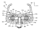
ここで図1A及び1Bを参照すると、椎間インプラント又はケージ110の例は、椎間板腔に挿入するように構成されている。椎間ケージ110は、インプラント又はケージ本体120を有することができ、このインプラント又はケージ本体120は、次に、椎間板腔を画定する一対の隣接する椎体の終板に接して配置されるように構成された上部プレート130と、下部プレート140と、を含む。上部プレート130及び下部プレート140は、それぞれ、横方向Tに沿って互いに対向することができる。上部プレート130は、上方方向に下部プレート140から離間されると言うことができる。同様に、下部プレート140は、上部プレート130から下方方向に離間されると言うことができる。したがって、上方方向及び下方方向は、横方向Tに沿って配向される選択方向を画定することができる。用語「上」、「上方」、及び同様の意味の語は、本明細書で使用するとき、上方方向を指すことができる。用語「下」、「下方」、及び同様の意味の語は、本明細書で使用するとき、下方方向を指すことができる。上部プレート130は、椎間ケージ110が椎間板腔内に配置されたときに、上位椎体の終板に当接するように構成された上部軸受面131を画定することができる。下部プレート140は、椎間ケージ110が椎間板腔内に配置されたときに、下位椎体の終板に当接するように構成された下部軸受面141を画定することができる。
1A and 1B, an exemplary intervertebral implant or
椎間ケージ110は、上位椎骨と下位椎骨との間に画定された椎間板腔への挿入に関する第1前端114を画定することができる。椎間ケージ110は、長手方向Lに沿って前端114と反対側の第2後端116を更に画定することができる。前端114は、椎間板腔への挿入を容易にするためにテーパ状にすることができる。長手方向Lは、横方向に対して垂直に配向することができる。したがって、椎間ケージ110は、後端116から前端114に向かって延在する前方向を画定することができる。したがって、椎間ケージ110の前構成要素は、椎間ケージの後構成要素から前方向に離間され得る。椎間ケージ110は同様に、前端114から後端116に向かって延在する後方向を画定することができる。
本体120は、上部プレート130と下部プレートとの間に接続される側壁150を更に含むことができる。図示されるように、上部プレート130及び下部プレート140は、多孔質構造体132を含むことができる。多孔質構造体132は、上部軸受面131及び下部軸受面141の一方又は両方の全体までの少なくとも一部分を画定することができる。同様に、側壁150は多孔質構造体152を含むことができる。多孔質構造体132及び152は、隣接する椎体からの細胞活性及び骨の内部成長を促進するように構成することができる。
The
椎間ケージ110は、上位椎体を貫通して延在するように構成された、1つ以上の展開可能な第1アンカー又は上部アンカー160を更に含むことができる。一例では、椎間ケージ110は、一対の上部アンカー160を含むことができる。一対の上部アンカー160の上部アンカー160は、横方向T及び長手方向Lのそれぞれに垂直な横方向Aに沿って互いに離間されることができる。更に、上部アンカー160は、横方向Aに沿って互いに整列させることができる。上部アンカー160は、図1Aに示される第1位置又は挿入位置を画定することができ、それにより、アンカー160は、上部プレート130などのケージ本体120に埋め込まれる。アンカー160は、図1Bに示される第2位置又は展開位置に作動又は展開され得、それによってアンカー160は、上部プレート130を通って、上部軸受面131から外に突出する。
上部プレート130は、上部アンカー160のそれぞれ1つ以上を保持するように構成された、1つ以上の第1スロット又は上部保持スロット122を画定することができる。上部アンカー160は、第1位置又は挿入位置と第2位置又は展開位置との間を移動する際に、保持スロット122内に乗ることができる。椎間ケージ110が椎間腔内に配置され、アンカー160が展開位置にあるとき、アンカー160は、上位椎体に埋め込まれ得る。上部アンカー160は、アンカー160が第2係合位置にあるときに上部軸受面131から外に延在する、突き合わせた上部突出部又は歯166をそれぞれの遠位端に有することができる。上部歯166は、上位椎体内にアンカー160を埋め込むように、上位椎体を穿孔するのを補助するように構成された、鋭い骨穿孔上縁部又は先端161を有することができる。
The
椎間ケージ110は、アンカー160が第1位置又は挿入位置にあるとき、アンカー160の一部が、横方向Tに沿って上部軸受面131を越えて延在しないように構成され得る。あるいは、アンカー160が第1位置又は挿入位置にあるとき、例えば、椎間ケージの挿入中に上位椎体の終板表面を粗面化することが望ましい場合、先端161は、上部軸受面131をわずかに越えて延在し得る。以下の説明から理解されるように、上部アンカー160は、一例で同時に展開されるように構成され得る。
椎間ケージ110は、上位椎体に貫通して延在するように構成された1つ以上の展開可能な第2アンカー又は下部アンカー170を更に含むことができる。一例では、ケージ110は、下部アンカー170と等しい数の上部アンカー160を含むことができる。例えば、椎間ケージ110は、一対の下部アンカー170を含むことができる。一対の下部アンカー170の下部アンカー170は、横方向Aに沿って互いに離間されることができる。下部アンカー170は、横方向Aに沿って互いに整列させることができる。更に、下部アンカー170は、横方向Tに沿って上部アンカー160のそれぞれの上部アンカーと整列させることができる。下部アンカー170は、図1Aに示される第1位置又は挿入位置を画定することができ、それにより、下部アンカー170は、下部プレート140などのケージ本体120に埋め込まれる。下部アンカー170は、図1Bに示される第2位置又は展開位置に作動又は展開され得、それにより、下部アンカー170は下部プレート140を通って、下部軸受面141から外に突出する。
下部プレート140は、下部アンカー170のうちのそれぞれの1つ以上を保持するように構成された、1つ以上の第2保持スロット又は下部保持スロット142を画定することができる。下部アンカー170は、第1位置又は挿入位置と第2位置又は展開位置との間を移動する際に、保持スロット142内に乗ることができる。椎間ケージ110が椎間腔内に配置され、下部アンカー170が展開位置にあるとき、下部アンカー170は、上位椎体に埋め込まれ得る。下部アンカー170は、下部アンカー170が第2係合位置にあるときに、下部軸受面141から外に延在する、突き合わせた下部突出部又は歯176をそれらのそれぞれの遠位端に有することができる。歯176は、下位椎体にアンカー170を埋め込むように、下位椎体を穿孔するのを補助するように構成された鋭利な骨穿孔縁部又は先端171を有することができる。
The
歯166及び176の形状は、所望に応じて変化し得ることが理解されるべきである。一例では、歯166及び176の側面は、一例では滑らかであり得る。別の例では、歯166及び176の側面は、椎体の固定を支援するためにかかり付きであってもよい。更に、それぞれの先端161及び171は、所望に応じて鈍くても又は鋭くてもよい。
It should be appreciated that the shape of
椎間ケージ110は、下部アンカー170が第1位置又は挿入位置にあるとき、下部アンカー170の一部が、下部軸受面141を越えて横方向Tに沿って延在しないように構成され得る。あるいは、下部アンカー170が第1位置又は挿入位置にあるとき、例えば、椎間ケージの挿入中に上位椎体の終板表面を粗面化することが望ましい場合、先端171は、下部軸受面141をわずかに越えて延在し得る。以下の説明から理解されるように、下部アンカー170は、一例で同時に展開されるように構成され得る。
上部アンカー160及び下部アンカー170がそれらの第1位置又は挿入位置にあるとき、ケージ110は、第1構成又は挿入構成にあると言うことができる。ケージ110は、上部アンカー160及び下部アンカー170を同時に展開するように構成され得る。
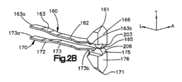
ここで図2A~図3を参照すると、上部アンカー160のそれぞれは、上部歯166がばね部材162から外に延在するように、上部ばね部材162を更に含み得る。上部歯166は、いくつかの例では、上部歯166がばね部材162に対して移動できないように、ばね部材162から固定的に外に延在することができる。ばね部材162は、上部歯166を挿入位置に向かって付勢するばね力を提供することができる。一例では、上部ばね部材162は、上部カンチレバーばね163として構成され得る。上部カンチレバーばね163の第1端163aは、固定位置で本体120に固定することができる。上部歯166は、カンチレバーばね163から、第1端から離間した位置で延在することができる。例えば、上部歯166は、カンチレバーばね163の第1端と反対側の第2端163bから延在することができる。一例では、カンチレバーばね163は、長手方向に沿って配向され得る。したがって、第1端163aはカンチレバーばね163の前端であってもよく、第2端163bはカンチレバーばね163の後端であってよい。したがって、カンチレバーばね163は、固定位置から上部歯166まで後方に延在し得る。あるいは、第1端163aは、上部カンチレバーばね163の後端であってもよく、第2端163bは、上部カンチレバーばね163の前端であってもよい。あるいは、依然として、片持ち梁状に突出したばね163は、所望に応じて任意の代替的な方向に配向することができる。当然ながら、ばね部材162は、所望に応じて任意の好適な方法で代替的に構築され得ることを更に理解されたい。例えば、ばね部材162は、コイルばね、板ばね、又は所望に応じて任意の好適な代替的ばねとして構成することができる。
2A-3, each of the
上部アンカー160は、ばね部材162から外に延在し、挿入位置と展開位置との間を一緒に移動する1つ以上の歯166を含むことができることを更に理解されたい。あるいは、ケージ110は、所望に応じて配置された複数の上部アンカー160を含むことができる。例えば、ケージ110は、上部アンカー160の複数列を含むことができる。この列は、片持ち梁状に突出したばね部材の中心軸に沿って配向され、横方向Aに沿って互いに離間されてもよい。
It should further be appreciated that
引き続き図2A~図3を参照すると、下部アンカー170のそれぞれは、下部歯176がばね部材172から外に延在するように、下部ばね部材172を更に含むことができる。下部歯176は、いくつかの例では、下部歯176がばね部材172に対して移動できないように、ばね部材172から固定的に外に延在することができる。ばね部材172は、下部歯176を挿入位置に向かって付勢するばね力を提供することができる。一例では、下部ばね部材172は、下部カンチレバーばね173として構成され得る。下部カンチレバーばね173の第1端173aは、固定位置で本体120に固定され得る。下部歯176は、カンチレバーばね173から、第1端から離間した位置で延在することができる。例えば、下部歯176は、第1端と反対側のカンチレバーばね173の第2端173bから延在することができる。一例では、カンチレバーばね173は、長手方向に沿って配向され得る。したがって、第1端173aはカンチレバーばね173の前端であってもよく、第2端173bはカンチレバーばね173の後端とすることができる。したがって、カンチレバーばね173は、固定位置から下部歯176まで後方に延在し得る。あるいは、第1端173aは、下部カンチレバーばね173の後端であってもよく、第2端173bは、下部カンチレバーばね173の前端であってもよい。あるいは、依然として、片持ち梁状に突出したばね173は、所望に応じて任意の代替的な方向に配向することができる。当然ながら、ばね部材172は、所望に応じて任意の好適な方法で代替的に構築され得ることを更に理解されたい。例えば、ばね部材172は、コイルばね、板ばね、又は所望に応じて任意の好適な代替的ばねとして構成することができる。
With continued reference to FIGS. 2A-3, each of the
下部アンカー170は、ばね部材172から外に延在し、挿入位置と展開位置との間を一緒に移動する1つ以上の歯176を含むことができることを更に理解されたい。あるいは、ケージ110は、所望に応じて配置された複数の下部アンカー170を含むことができる。例えば、ケージ110は、下部アンカー170の複数の列を含むことができる。列は、片持ち梁状に突出したばね部材の中心軸に沿って配向され、横方向Aに沿って互いに離間されてもよい。一例では、上部アンカー160及び下部アンカー170は、長手方向L及び横方向Aに沿って配向される平面の周りで互いに鏡像であってもよい。
It should be further appreciated that the
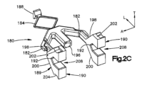
ここで図2Cを参照すると、ケージ110は、本体120内に支持され、アンカー160及び170を展開するために作動方向に移動可能なアクチュエータ180を更に含むことができる。アクチュエータ180は、作動方向の第1位置又は初期位置から第2位置又は作動位置へと移動可能である。作動方向におけるアクチュエータ180の移動は、直線方向に沿った並進運動であり得る。アクチュエータ180が初期位置にあるとき、アンカー160及び170は、それらの挿入位置にあることができる。アクチュエータ180が初期位置から作動位置へと移動すると、アクチュエータ180はアンカー160及び170をそれらの展開位置へと付勢する。ケージ本体120、アクチュエータ180、並びにアンカー160及び170は、上述のように、単一の完全な構造体を形成するように共に製造することができる。
Referring now to FIG. 2C,
アクチュエータ180は、停止部材188を含むことができる第1端と、停止部材188と反対側のプランジャ機構189を含む第2端と、停止部材188とプランジャ機構189との間に接続されたアクチュエータばね184と、を含むことができる。アクチュエータばね184は、対向付勢力を適用するように、長手方向に沿って圧縮可能な圧縮ばねを画定することができる。アクチュエータ180の少なくとも一部分は、ケージ本体120の内部空隙193内に配置されるように構成されている(図6A~図6Bを参照)。停止部材188は、ケージ本体120の座面に当接するように構成され、したがって、動作中にケージ本体120に対して静止して保持され得る。ケージ本体120の座面は、内部空隙193を部分的に画定し得る。あるいは、停止部材188は、ケージ本体120と一体であってもよい。アクチュエータばね184は、プランジャ機構189が停止部材188に向かって移動する際にばね力を適用するように構成されている。具体的には、ばね力は、プランジャ機構189が作動方向に停止部材188に向かって移動する際に、プランジャ機構189を停止部材188から離れさせるように付勢する。
The
アクチュエータ180は、第1端がプランジャから前方方向に離間されるように、ケージ本体120内に配向され得る。第1端は前端を画定することができ、第2端は後端を画定することができる。したがって、プランジャ機構189は、前方方向の第1端に対して移動可能である。具体的には、プランジャ機構189は、プランジャ機構189を付勢し、アクチュエータばね184の力に逆らって前方方向に移動させる作動力を受容することができる。作動力は、一例ではプッシュ力であり得る。
プランジャ機構189は、作動力を受容するように構成されたアクチュエータシャフト196を含むことができる。例えば、図2Aに示すように、ケージ本体120は、アクチュエータシャフト196の中心軸に整列されたガイドスリーブ124を含むことができる。したがって、ガイドスリーブ124は、ドライバ器具のドライバシャフトを受容し、ドライバシャフトをアクチュエータシャフト196の軸受面197に向かってガイドするように構成される。ドライバシャフトが前方方向に更に駆動されると、ドライバシャフトは、アクチュエータシャフト196に、したがってプランジャ機構189に駆動力を適用し、プランジャ機構189を、アクチュエータばね184のばね力に逆らって、ケージ本体120に対して前方方向に移動させる。したがって、椎間ケージ120を椎間板腔内に挿入した後、アクチュエータ180に係合するように構成されたドライバ器具を最初に挿入し、アクチュエータ180を駆動してケージ本体120内で作動方向に移動させるよう駆動力をアクチュエータ180に適用することによって、アンカー160を展開することができる。ケージ本体120のガイドスリーブ124は、バヨネット式器具インターフェースとして構成することができ、それにより、ガイドスリーブ124によって画定される開口部が複数の機能を果たすことができ、ガイド本体120を他の器具及びデバイスと共に使用するように適合させることができる。一例では、駆動力を前方方向に適用することができる。したがって、作動方向は、前方方向によって画定され得る。
あるいは、アクチュエータ180は、第1端がプランジャから後方方向に離間されるように、ケージ本体内に配向され得る。したがって、第1端は後端を画定することができ、第2端は前端を画定することができる。したがって、プランジャ機構189は、後方方向の第1端に対して移動可能である。具体的には、プランジャ機構189は、プランジャ機構189を付勢し、アクチュエータばね184の力に逆らって後方方向に移動させる作動力を受容することができる。この代替例では、作動力は引張力であり得る。したがって、駆動力は、後方方向にプランジャ機構189に適用され得る。したがって、作動方向は、後方方向によって画定され得る。
Alternatively, the
プランジャ機構189は、少なくとも1つのアンカーをプランジャ機構として挿入位置から展開位置へと付勢するように、アンカー160及び170のうちのそれぞれの少なくとも1つと係合するように構成された少なくとも1つの傾斜190を含むことができる。したがって、少なくとも1つの傾斜は、作動方向に作動位置へと移動する。一例では、プランジャ機構189は、アンカー160及び170のそれぞれ異なるものと係合するように構成された第1傾斜及び第2傾斜190を含むことができる。第1傾斜及び第2傾斜190は、作動方向に沿って互いに平行に移動することができる。一例では、アクチュエータシャフト196は、傾斜190間で横方向Aに対して配置されてもよい。例えば、アクチュエータシャフト196は、横方向Aに沿って傾斜190と整列されてもよい。更に、第1傾斜及び第2傾斜190のそれぞれは、第1傾斜面又は上部傾斜面198及び第2傾斜面又は下部傾斜面200の一方又は両方を含むことができる。上部傾斜面198及び下部傾斜面200は、したがって、互いに一体であり得る。上部傾斜面198及び下部傾斜面200は、横方向に沿って互いに整列され得る。上部傾斜面198は、駆動力の方向と反対側に後方に延在するにつれて、上方に傾斜し得る。下部傾斜面200は、駆動力の方向と反対側に後方に延在するにつれて、下方に傾斜し得る。
傾斜190は、傾斜190がアクチュエータシャフト196と共に移動するように、アクチュエータシャフト196に対して支持され得る。したがって、駆動力に応答してアクチュエータシャフト196が前方方向に駆動されると、傾斜190も同様に前方方向に移動する。一例では、プランジャ機構189は、アクチュエータシャフト196から横方向外側に、かつ後方に広がることができ、傾斜190を支持することができる第1アーム及び第2アーム182を含むことができる。第1アーム及び第2アーム182は、一例では、アクチュエータシャフト196から片持ち梁状に突出し得る。傾斜190は、横方向に沿って互いに整列させることができ、又は所望に応じて代替的に配置することができる。
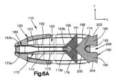
ここで図2B~図2C及び図4~図6Bを参照すると、アクチュエータ180が初期位置にあるとき、上部及び下部傾斜面198及び200は、作動方向に上部アンカー160及び下部アンカー170のそれぞれの軸受面165及び175と整列される。例えば、傾斜190は、作動方向において軸受面165と175との間の間隙と整列されている、テーパ状先端を画定することができる。傾斜面198及び200は、テーパ状先端から後方に延在し得る。上部軸受面165は、上部歯166の表面によって画定され得る。上部軸受面165はまた、傾斜面を画定することができる。例えば、上部軸受面165は、後方に延在するにつれて上方に傾斜していてもよい。したがって、上部軸受面165は、上部傾斜面198と平行であり得る。同様に、下部軸受面175は、下部歯176の表面によって画定され得る。下部軸受面175はまた、傾斜面を画定することができる。例えば、下部軸受面175は、後方に延在するにつれて下方に傾斜していてもよい。したがって、下部軸受面175は、下部傾斜面200に平行であり得る。
2B-2C and 4-6B, when the
動作中、アクチュエータ180、具体的にはプランジャ機構189、より具体的には少なくとも1つの傾斜190は、未だに作動方向に駆動され、上部軸受面165は上部傾斜面198に沿って進む。上部傾斜面198の傾斜は、上部ばね部材162の力に逆らって、横方向Tに沿って、対応する上部歯166を展開位置へと外向きに付勢する。この点に関して、上部ばね部材162は、上部歯166を付勢して上部傾斜面198と接触させることを理解されたい。同様に、下部軸受面175は、下部傾斜面200に沿って進む。下部傾斜面200の傾斜は、下部ばね部材172の力に逆らって、横方向Tに沿って、対応する下部歯176を展開位置へと外向きに付勢する。この点に関して、下部ばね部材172は下部歯176を付勢して下部傾斜面200と接触させることを理解されたい。
In operation, the
したがって、上部及び下部軸受面165及び175は、等しくかつ互いに反対側に傾斜することができることを理解されたい。更に、上部及び下部傾斜面198及び200は、互いに等しく傾斜し、互いに反対側に傾斜することができる。あるいは、上部及び下部傾斜面198及び200は、上部アンカー160及び下部アンカー170を、異なる深さでそれぞれの上位及び下位椎骨に挿入することが所望される場合、互いに反対側に、異なる傾斜で傾斜していてもよい。
Accordingly, it should be appreciated that the upper and lower bearing surfaces 165 and 175 can be equally and oppositely sloped. Further, the upper and lower
引き続き図4~図6Bを参照すると、傾斜190のそれぞれは、アンカー160及び170がそれらの展開位置にあるとき、上部アンカー160及び下部アンカー170のそれぞれ1つ又は両方と噛み合うか、又は解放可能に連動するように構成され得る。具体的には、傾斜190のうちの少なくとも1つから傾斜190の全てまでは、上部保持ポケット202を画定でき、上部アンカー160の一部分を受容するように構成されている。上部保持ポケット202は、上部傾斜面198から後方方向に離間され得る。一例では、上部保持ポケット202は、上部傾斜面から後方に延在する平坦な表面内へと下方に延在することができる。平坦な表面は、横方向L及び長手方向Lに沿って実質的に平面とすることができる。上部歯166の横方向内側又は下方端は、保持ポケット202内に受容されるようにサイズ決めされた突起203を画定することができる。突起203は、上部軸受面165を更に画定することができる。同様に、傾斜190のうちの少なくとも1つが傾斜190の全てまで下部保持ポケット204を画定でき、下部アンカー170の一部分を受容するように構成されている。下部保持ポケット204は、下部傾斜面200から後方方向に離間され得る。一例では、下部保持ポケット204は、上部傾斜面から後方に延在する平坦な表面内に上方に延在することができる。平坦な表面は、横方向L及び長手方向Lに沿って実質的に平面であってもよい。下部歯176の横方向内側又は上部端は、保持ポケット204内に受容されるようにサイズ決めされた突起206を画定することができる。突起206は、下部軸受面175を更に画定することができる。
With continued reference to FIGS. 4-6B, each of the
動作中、上部歯166は、完全に展開されるまで上部傾斜面198に沿って進む。前方方向への傾斜190の継続的な移動、例えば、プランジャ機構189が前方方向に移動するにつれて、上部歯は、突起203が対応する上部保持ポケット202内に受容されるまで、傾斜190に継続して沿って進む。同様に、動作中、下部歯176は、それが完全に展開されるまで下部傾斜面200に沿って進む。前方方向への傾斜190の継続的な移動、例えば、プランジャ機構189が前方方向に移動するにつれて、下部歯176は、突起206が対応する下部保持ポケット204内に受容されるまで傾斜190に継続して沿って進む。
In operation,
上部ばね部材162のばね力は、上部歯166、特に上部保持ポケット202内の突起203を保持する保持力を、上部歯166に適用することができる。同様に、下部ばね部材172のばね力は、下部歯176、特に下部保持ポケット204内の突起206を保持する保持力を、下部歯176に適用することができる。ばね部材162及び172によって適用される保持力は、更に、アクチュエータばね184のばね力がプランジャ機構189を駆動し、したがってこれは傾斜190が後方方向に移動するのを防止するのに十分であり、これにより、アンカー160及び170を挿入位置に戻すことになる。別の言い方をすれば、ばね部材162及び172によって単独で又は組み合わせて適用される保持力は、アクチュエータ180を作動位置に保持するのに十分であり得る。傾斜190は、アクチュエータ180が作動位置にあるとき、ケージ本体120内に配置され得る。いくつかの例では、傾斜190の一部分は、アクチュエータが初期位置にあるとき、ケージ本体120から外に延在することができる。
The spring force of the
したがって、上部及び下部歯160及び170は、傾斜190にしっかりとロックされ、これにより、歯160及び170がそれぞれの椎体を穿孔して延在することを可能にし、それにより、アンカー160及び170がそれらの挿入位置にあるときには、埋め込みアンカー160及び170が挿入プロセスと干渉することを防止しながら、椎間ケージ110を骨へより良好に固定することができる。傾斜190はポケット及びアンカー160及び170を画定することができ、特に歯166及び176はポケット内に受容され得るが、アンカー160及び170、並びに特に歯166及び176はポケットを画定することができ、傾斜190はポケット内に受容される突出部を有することができることを理解されたい。したがって、傾斜190及び上部アンカー160の一方はポケットを画定することができ、上部アンカー160がその展開位置に移動された後に、傾斜190及び上部アンカー160の他方はポケット内に受容されるように構成され得る。更に、傾斜190及び下部アンカー170のうちの1つはポケットを画定することができ、下部アンカー170がその展開位置に移動された後に、傾斜190及び下部アンカー170の他方はポケット内に受容されるように構成され得る。
Accordingly, upper and
ここで図1A及び図3を参照すると、アクチュエータ180は、初期位置から作動位置へと移動する際にハウジング内に捕捉され得る。具体的には、停止部材188は、アクチュエータ180の第1端でケージ本体120に当接するか、又は、ケージ本体120と一体であってもよい(本明細書では集合的にケージ本体120を「係合している」と呼ぶ)。アクチュエータ180の第2端はまた、ケージ本体120に当接し得る。例えば、プランジャ機構189は、ケージ本体120の少なくとも1つのブレース部材174に当接するように構成されたブレース部材192を含むことができる。具体的には、ブレース部材192は、ケージ本体120のブレース部材174の前方に配置することができる。更に、停止部材188がケージ本体120と係合され、ブレース部材174及び192が互いに当接すると、アクチュエータばね184を圧縮することができるようにアクチュエータ180を離間し得る。したがって、アクチュエータ180は、ケージ本体120の座面とケージ本体のブレース部材174との間のケージ内に捕捉され得る。アクチュエータばね184は、係止部材188をケージ本体120の座面に対して付勢することができる付勢力を与えることができ、更に、アクチュエータ180のブレース部材192をケージ本体120のブレース部材174に対して付勢する付勢力を更に与える。
1A and 3, the
一例では、アクチュエータ180は、ケージ本体120のブレース部材174を受容するガイドスロット208を画定することができる。ガイドスロット208は、アクチュエータ180のブレース部材192にて長手方向に終端することができる。したがって、ブレース部材174は、アクチュエータが初期位置にあるとき、スロット内へと延在し、ブレース部材192に当接することができる。アクチュエータ180が作動位置に移動されると、アクチュエータ180のブレース部材192は、ケージ本体120のブレース部材174に対して前方又は作動方向に移動する。用語「前方」、「前」、及びその派生語は、作動方向に等しく言及することができることを理解されたい。しかしながら、上述のような代替的な実施形態では、作動方向は、代替的に、後方方向に配向され得る。
In one example,
しかしながら、アクチュエータ180が作動位置にあるとき、ブレース部材174はガイドスロット208内に留まることができる。あるいは、アクチュエータ180が作動位置にあるとき、ブレース部材174は、ガイドスロット208から取り外され、ガイドスロット208の開放後端から後方に離間されてもよい。一例では、アクチュエータ180は、傾斜190のうちの少なくとも1つの後端へと前方に延在する少なくとも1つのガイドスロット208を含むことができる。したがって、アクチュエータ180のブレース部材192は、ガイドスロット208の前端を画定する傾斜190の表面によって画定され得る。ガイドスロット208は、上部傾斜面198と下部傾斜面200との間に配置することができる。一例では、アクチュエータ180は、傾斜190のそれぞれへと延在するガイドスロット208を含むことができる。同様に、ケージ本体120は、ガイドスロット208のそれぞれに配置されるそれぞれのブレース部材174を含むことができる。アクチュエータ180は少なくとも1つのガイドスロット208を画定することができ、ケージ本体120は、少なくとも1つのガイドスロット208内に配置された少なくとも1つのブレース部材174を画定することができる一方で、ケージ本体120は、代替的に少なくとも1つのガイドスロット208を画定することができ、アクチュエータ180は、少なくとも1つのガイドスロット208内に配置された少なくとも1つのブレース部材174を代替的に画定することができることを理解されたい。
However,
ここで再び図1Aを参照すると、椎間ケージ110は、横方向Tに沿って少なくともケージ本体120の中に又はケージ本体120を通って延在する1つ以上の骨移植片挿入穴127を含むことができる。例えば、1つ以上の骨移植片挿入穴127は、横方向に沿って、上部プレート130、下部プレート140、又は上部プレート130及び下部プレート140の両方を通って延在することができる。骨移植片は、骨移植片挿入穴127を通してケージ本体120に挿入されて、それぞれの椎体への骨の内方成長及び癒合を促進することができる。あるいは、図7A~図7Bに示すように、図1A~図1Bの椎間ケージは、骨移植片挿入穴127なしに示されている。具体的には、骨移植片挿入穴は、上述の多孔質構造体132によって置き換えられている。一例では、軸受面131及び141の全体に匹敵する部分は、多孔質構造体132によって画定され得る。
Referring again to FIG. 1A, the
ここで図1A~図1B及び図8A~図8Cを参照すると、上記のように、ドライバ器具210は、アクチュエータを作動方向に駆動するように構成することができ、それによって、傾斜190は、上部アンカー160及び下部アンカー170などの少なくとも1つのアンカーを展開させるように構成され得る。具体的には、ドライバ器具210は、作動方向へのドライバシャフト212の移動がプランジャ機構189を駆動し、したがって作動方向に少なくとも1つの傾斜190を駆動するように、アクチュエータシャフト196に当接するように構成されたドライバシャフト212を含むことができる。したがって、インプラントアセンブリ214は、ケージ110及びドライバ器具210を含み得ることが理解されるべきである。
1A-1B and 8A-8C, as described above,
場合によっては、アンカー160及び170が展開された後、椎間板腔から椎間ケージ110を取り外すことが望ましい場合がある。したがって、椎間ケージ110の取り外しを可能にするために、展開位置から挿入位置にアンカー160及び170を戻すことが望ましい場合がある。ドライバ器具210は、プランジャ機構189を駆動するように構成することができ、したがって、少なくとも1つの傾斜190を、作動方向とは反対の逆方向に駆動するように構成され得る。作動方向が前方方向によって画定されるとき、逆方向は、後方方向によって画定され得る。具体的には、ドライバ器具210は、作動方向にケージ110内に挿入されて、アクチュエータ180と係合することができる。次いで、ドライバ器具210を逆方向に移動させて、それに対応して、プランジャ機構189、ひいては少なくとも1つの傾斜190を逆方向に移動させることができる。図6A~図6Bに示されるように、傾斜190が逆方向に移動すると、アクチュエータ、歯166及び176が対応するポケット202及び204から取り外される。傾斜190の逆方向への継続的な移動により、歯166及び176はそれぞれ傾斜面198及び200に沿って進み、これによって歯166及び176は、ばね部材162及び172のばね力の下でケージ本体120内へとそれぞれ後退させる。歯166及び176が挿入位置に戻されると、ケージ110を椎間腔から取り外すことができる。
In some cases, it may be desirable to remove
アクチュエータシャフト196は、内側シャフト部分216と、内側シャフト部分に隣接する外側シャフト部分218とを含むことができる。例えば、外側シャフト部分は、内側シャフト部分216から前方に配置され得る。内側シャフト部分216は、ドライバシャフト212が第1回転位置にあるときにドライバシャフト212を受容するようにサイズ決めされた内腔217を画定することができる。外側シャフト部分218は、内側シャフト部分216の内腔に開口する空隙219を画定することができる。内側シャフト部分216の内腔217は、外側シャフト部分218の空隙219の内側断面よりも小さい内側断面を画定することができる。一例では、内腔217及び空隙219は、断面が円形であってもよい。空隙219は、内側シャフト部分216と、外側シャフト部分218から前方に延在する第2シャフト部分221との間に画定され得る。
一例では、内側シャフト部分216はスロット付きであってもよい。すなわち、アクチュエータシャフト196は、内側シャフト部分216の壁を通って内腔217内へと延在する少なくとも1つのスロット220を画定することができる。内側シャフト部分216は、所望に応じて多くのスロット220を画定することができる。一例では、内側シャフト部分216は、一対の対向するスロット220を画定する。例えば、スロット220は、横方向Tに沿って互いに反対であってもよい。当然のことながら、1つ以上のスロット220を所望のように配置することができることを理解されたい。ドライバ210は、ドライバシャフト212から径方向に外に突出する1つ以上のフランジ213を含むことができる。1つ以上のフランジ213は、ドライバシャフト212が第1回転位置にあるときに、1つ以上のスロット220のそれぞれ1つに受容されるようなサイズである。したがって、ドライバシャフト212が第1回転位置にあるとき、少なくとも1つのフランジ213は、長手方向に沿って少なくとも1つのスロット220の対応する1つと整列されている。したがって、ドライバシャフト212は、作動方向に内側シャフト部分216の内腔217内へと駆動され得る。少なくとも1つのフランジ213は、ドライバシャフト212が作動方向に内腔217内へと駆動される際に、対応する整列された少なくとも1つのスロット220内を移動することができる。
In one example,
ドライバシャフト212は、少なくとも1つのフランジ213が外側シャフト部分218の空隙219に入るまで、作動方向に内腔内へと駆動され得る。すなわち、少なくとも1つのフランジ213は、作動方向に内側シャフト部分216を通って駆動され得る。ドライバシャフト212が作動方向に更に移動すると、ドライバシャフト212が第2シャフト部分221に当接し、ドライバシャフト212によって適用された駆動力を受容することができる。したがって、駆動力は、プランジャ機構189、ひいては傾斜190を作動方向に作動位置まで移動させ、それによって、上述のようにアンカーを展開させることができる。
アンカーを展開位置から挿入位置に戻すことが望ましい場合、ドライバシャフト212は、第1回転位置とは異なる第2回転位置に回転され得る。ドライバシャフト212の第2回転位置への回転は、少なくとも1つのフランジ213を、対応する少なくとも1つのスロット220との整列から取り外される。少なくとも1つのフランジ213は、代わりにアクチュエータシャフト196の壁と整列され得る。アクチュエータシャフト196の整列された壁は、ドライバシャフト212が第2回転位置にあるときに、内側シャフト部分216の壁によって画定され得る。具体的には、内側シャフト部分216の壁は、後方方向に少なくとも1つのフランジ213と隣接することができ、上記の逆方向を画定することができる。したがって、ドライバシャフト212の逆方向へのその後の移動は、少なくとも1つのフランジ213を内側シャフト部分216の壁に当接させ、したがって、ドライバシャフト212に、プランジャ189、したがって少なくとも1つの傾斜190に逆力を適用させる。逆力は、作動力とは反対の方向である。したがって、ドライバシャフト212は、プランジャ189、したがって、少なくとも1つの傾斜190を駆動することができ、アクチュエータ180が初期位置となるまで逆方向に移動し、アンカーは挿入位置となる。プランジャ189、ひいては少なくとも1つの傾斜190の逆方向への移動は、ドライバシャフト212に適用される引張力によって達成することができる。ドライバシャフト212は、第1回転位置に回転することができ、それによって、少なくとも1つのフランジを、対応する少なくとも1つのスロット220と長手方向に沿って整列させ、アクチュエータシャフト196から取り外すことができる。あるいは、ドライバ器具210は、ケージ本体120内に捕捉され、したがって、回転位置のいずれにおいてもケージ本体から取り外し可能ではないことが企図される。例えば、ドライバ器具210、ケージ本体120、アクチュエータ180、並びにアンカー160及び170は、単一の完全な構造体を形成するように一緒に製造され得る。
If it is desired to move the anchor from the deployed position back to the inserted position, the
図8B~図8Cに示されるように、外側シャフト部分218は、第1回転位置から第2回転位置へのドライバシャフト212の回転を制限する1つ以上の停止部材222を含むことができる。具体的には、ドライバシャフト212が第1回転位置で外側シャフト部分の空隙219に入ると、停止部材222は、ドライバシャフト212が第1回転位置から第2回転位置へと第1回転方向に回転させることが可能となる。停止部材222と少なくとも1つのフランジ213との間の干渉は、ドライバシャフト212が第1回転方向とは反対の第2回転方向に回転することを防止することができる。一例では、第1回転方向は、時計回りの方向によって画定され得る。停止部材222はまた、ドライバシャフト212が第2回転位置に到達する前に、ドライバシャフト212が第1回転方向に回転する角度距離を制限することができる。具体的には、停止部材222は、ドライバシャフト212が第2回転位置に回転されたときに、少なくとも1つのフランジ213に当接することができ、それによって、ドライバシャフト212が第1回転方向に更に回転することを防止する。一例では、ドライバシャフト212は、第1回転位置から第2回転位置へと90度回転することができる。当然ながら、少なくとも1つのフランジ213が長手方向に沿ってスロット220のいずれとも整列されないように、ドライバシャフト212は、第1回転位置から第2回転位置まで所望の任意の量を回転させることが可能であることを理解されたい。ドライバシャフト212はまた、ドライバシャフト212が第2回転位置にあるときに、駆動方向に駆動力を適用することができることを更に理解されたい。
As shown in FIGS. 8B-8C, the
ここで図9A~図9Bを参照すると、椎間インプラント又はケージ310の別の例は、スペーサ321を受容するように構成されたインプラント又はケージ本体320を含むことができる(図9Eを参照)。具体的には、ケージ本体は、支持部材323と、支持部材323の横方向に対向する端から外に延在する、一対のアーム325とを含むことができる。アーム325は、横方向Aに沿って互いに離間され得る。アーム325は、スペーサ321を把持するように構成することができ、その後、ケージ310を椎間板腔内に挿入することができる。スペーサ321は、ポリエーテルエーテルケトン(PEEK)といった、任意の好適な材料から作製され得る。あるいは、スペーサ321は、皮質骨、海綿骨、又はこれら2つの組み合わせなどの同種移植片から作製することができる。アーム325は、アーム325間にスペーサを確実に固定するのに好適な、所望の任意の方法で構築することができる。スペーサ321は、上位及び下位椎骨との癒合を容易にすることができる。スペーサ321は放射線透過性であることができるため、術後CT画像は、上部椎骨と下部椎骨と椎間ケージ310との間の癒合の良好な視認性を提供することができる。一例では、アーム325及びスペーサ321は、米国特許出願公開第9,241,809号で説明されるように構築することができ、その開示は、その全体が本明細書に記載されているかのように、参照により本明細書に組み込まれる。したがって、アーム325は可撓性であってもよく、又は剛性であってもよいことを理解されたい。
9A-9B, another example of an intervertebral implant or
ケージ本体320は、上部軸受面331と、横方向Tに沿って上部軸受面331と反対側の下部軸受面341を画定することができる。上部軸受面は、椎間ケージ310が椎間板腔内に配置されたときに、第1椎体又は上位椎体の終板に当接するように構成される。下部軸受面341は、椎間ケージ310が椎間板腔内に配置されたときに、第2椎体又は下位椎体の終板に当接するように構成されている。支持部材323は、前面323aと、長手方向Lに沿って前面323aと反対側の後面323bとを含むことができる。後面323bは、スペーサ321に面するように構成されている。
The
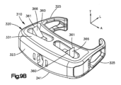
椎間ケージ310は、上位椎体を貫通して延在するように構成された1つ以上の展開可能な第1アンカー又は上部アンカー360を更に含むことができる。一例では、椎間ケージ310は、一対の上部アンカー360を含むことができる。一対の上部アンカーの上部アンカー360は、横方向Aに沿って互いに離間され得る。更に、上部アンカー360は、横方向Aに沿って互いに整列させることができる。上部アンカー360は、図9Aに示される第1位置又は挿入位置を画定することができ、それによってアンカー360はケージ本体320内に埋め込まれる。例えば、アンカー360は、椎間ケージ310の椎間板腔内への挿入を容易にするために、上部軸受面331に対して凹設することができる。あるいは、アンカーは、ケージ310が椎間板腔内に挿入される際に、上位椎体終板を粗面化するように、上部軸受面331からわずかに外に突出することができる。上部アンカー360は、図9Bに示される第2位置又は展開位置に作動又は展開され得、それによってアンカー360は上部軸受面331を通って突出する。
ケージ本体320は、上部アンカー360のそれぞれ1つ以上を保持するように構成された1つ以上の上部保持スロット322を画定することができる。例えば、保持スロット322は、支持部材322によって画定され得る。上部アンカー360は、第1位置又は挿入位置と第2位置又は展開位置との間を移動する際に、保持スロット322内に乗ることができる。椎間ケージ310が椎間腔内に配置され、アンカー360が展開位置にあるとき、アンカー360は上位椎体に埋め込まれ得る。上部アンカー360は、アンカー360が第2係合位置にあるとき、上部軸受面331から外に延在する歯366として構成され得る。上部歯366は、上位椎体内にアンカー360を埋め込むよう、上位椎体を穿孔するのを補助するように構成された、鋭い骨穿孔上縁部又は先端361を有することができる。以下の説明から理解されるように、上部アンカー360は、一例では同時に展開されるように構成され得る。
ここで図9A及び図9Dを参照すると、椎間ケージ310は、下位椎体を貫通して延在するように構成された1つ以上の展開可能な第2アンカー又は下部アンカー370を更に含むことができる。一例では、椎間ケージ310は、一対の下部アンカー370を含むことができる。一対の下部アンカーの下部アンカー370は、横方向Aに沿って互いに離間され得る。更に、下部アンカー370は、横方向Aに沿って互いに整列させることができる。下部アンカー370は、図9Aに示される第1位置又は挿入位置を画定することができ、それによってアンカー370はケージ本体320に埋め込まれる。例えば、アンカー370は、椎間ケージ310の椎間板腔への挿入を容易にするために、下部軸受面341に対して凹設することができる。あるいは、下部アンカー370は、ケージ310が椎間板腔内に挿入される際に、上位椎体終板を粗面化するように、下部軸受面341からわずかに外に突出することができる。下部アンカー370は、第2位置又は展開位置(図9Dを参照)に作動又は展開され得、それにより下部アンカー370は下部軸受面341から外に突出する。
9A and 9D, the
ケージ本体320は、下部アンカー370のそれぞれ1つ以上を保持するように構成された、1つ以上の下部保持スロット342を画定することができる。例えば、下部保持スロット342は、支持部材322によって画定され得る。下部アンカー370は、第1位置又は挿入位置と第2位置又は展開位置との間を移動する際に、保持スロット342内に乗ることができる。椎間ケージ310が椎間腔内に配置され、アンカー370が展開位置にあるとき、アンカー370は、下位椎体に埋め込まれ得る。下部アンカー370は、アンカー370が第2係合位置にあるとき、下部軸受面341から外に延在する歯376として構成され得る。下部歯376は、下位椎体にアンカー370を埋め込むように、上位椎体を穿孔するのを補助するように構成された、鋭い骨穿孔上縁部又は先端371を有することができる。以下の説明から理解されるように、下部アンカー370は、一例では同時に展開されるように構成され得る。
歯366及び376の形状は、所望に応じて変化し得ることが理解されるべきである。一例では、歯366及び376の側面は、一例では滑らかであり得る。別の例では、歯366及び376の側面は、椎体の固定を支援するためにかかり付きであってもよい。更に、それぞれの先端361及び371は、所望に応じて鈍くても又は鋭くてもよい。
It should be appreciated that the shape of
上部アンカー360及び下部アンカー370がそれらの第1位置又は挿入位置にあるとき、ケージ310は、第1位置又は挿入構成にあると言うことができる。ケージ310は、上部アンカー360及び下部アンカー370を同時に展開するように構成され得る。
ここで図9C~図9Dを参照すると、ケージ310は、ケージ本体320内に支持及び捕捉され、アンカー360及び370を展開するために作動方向に移動可能である、少なくとも1つのアクチュエータ380を更に含むことができる。作動方向は、一例では、横方向Aに沿って配向することができる。アクチュエータ380は、作動方向の第1位置又は初期位置から第2位置又は作動位置へと移動可能である。アクチュエータ380が初期位置にあるとき、アンカー360及び370は、それらの挿入位置にあることができる。アクチュエータ380が初期位置から作動位置へと移動すると、アクチュエータ380はアンカー360及び370をそれらの展開位置へと付勢する。ケージ本体320、アクチュエータ380、並びにアンカー360及び370は、上述のように、単一の完全な構造体を形成するように共に製造することができる。
9C-9D,
アクチュエータ380は、アクチュエータ380を作動方向に移動させるように付勢するドライバ器具410から作動力を受容するように構成された力伝達面388を含むことができる、第1端を画定することができる。アクチュエータ380は、第1端と反対側の第2端を更に画定することができ、傾斜390を含むことができる。一例では、アクチュエータ380の第1端及び第2端は、横方向Aに沿って互いに対向することができる。アクチュエータ380は、作動方向で駆動され得る。これにより、傾斜390はアンカー360及び370をそれらの展開位置に付勢させる。具体的には、傾斜390は、上部傾斜面398と、横方向に沿って上部傾斜面398と反対側の下部傾斜面400と、を画定することができる。上部傾斜面398は、アクチュエータ380の第1端から離れる方向に上部アンカー360に向かって横方向外側に延在するにつれて、横方向Tに沿って下方に延在することができる。これにより、駆動力の方向を画定することができる。下部傾斜面400はアクチュエータ380の第1端から離れる方向に、下部アンカー360に向かって横方向外側に延在するにつれて、横方向Tに沿って上方に延在し得る。これにより、駆動力の方向を画定することができる。上部及び下部傾斜面398及び400は、所望に応じて、等しくかつ反対側に傾斜することができる。
The
アクチュエータ380が初期位置にあるとき、上部傾斜面及び下部傾斜面398及び400は、作動方向において上部アンカー360及び下部アンカー370のそれぞれの軸受面365及び375と整列される。例えば、傾斜390は、作動方向において軸受面365と375との間の間隙と整列される、テーパ状先端を画定することができる。傾斜面398及び400は、テーパ状先端から後方に延在し得る。上部軸受面365はまた、傾斜面を画定することができる。例えば、上部軸受面365は、作動方向とは反対の方向に延在するにつれて上方に傾斜していてもよい。したがって、上部軸受面365は、上部傾斜面398と平行であり得る。同様に、下部軸受面375は、傾斜面を画定することができる。例えば、下部軸受面375は、作動方向とは反対の方向に延在するにつれて、下方に傾斜していてもよい。したがって、下部軸受面375は、下部傾斜面400に平行であり得る。
When the
作動中、アクチュエータ380は、作動方向に駆動されて、上部アンカー360及び下部アンカー370を展開する。一例では、ケージ310は、それぞれ作動方向に移動するにつれて、それぞれの第1対の及び第2対の上部アンカー360及び下部アンカー370を配置するように構成された、第1アクチュエータ及び第2アクチュエータ380を含むことができる。具体的には、第1アクチュエータ及び第2アクチュエータ380は、それらのそれぞれの作動方向に移動するにつれて、横方向Aに沿って互いに離れて移動することができる。すなわち、第1アクチュエータ380の作動方向は、横方向Aに沿って第2アクチュエータ380から離れることができる。同様に、第2アクチュエータ380の作動方向は、横方向Aに沿って第1アクチュエータ380から離れることができる。アクチュエータ380が作動方向に移動するにつれて、上部軸受面365は上部傾斜面398に沿って進む。上部傾斜面398の傾斜は、対応する上部歯366を横方向Tに沿って展開位置へと外向きに付勢する。同様に、下部軸受面375は、下部傾斜面400に沿って進む。下部傾斜面400の傾斜は、対応する下部歯376を横方向Tに沿って展開位置へと外向きに付勢する。
During actuation,
したがって、上部及び下部軸受面365及び375は、等しくかつ互いに反対側に傾斜することができることを理解されたい。更に、上部及び下部傾斜面398及び400は、互いに等しく傾斜し、反対側に傾斜することができる。あるいは、上部及び下部傾斜面398及び400は、上部アンカー360及び下部アンカー370を、異なる深さでそれぞれの上位及び下位椎骨に挿入することが所望される場合、互いに反対側に、異なる傾斜で傾斜していてもよい。
Accordingly, it should be appreciated that the upper and lower bearing surfaces 365 and 375 can be equally and oppositely sloped. Further, the upper and lower
ここで図9E~図9Fを参照すると、アクチュエータ380は、それらの作動位置に保持されるように構成されており、これに対応して、上部アンカー360及び下部アンカー370をそれらの展開位置に保持する。例えば、アクチュエータ380は、アクチュエータ380を作動位置に保持するために、ケージ本体320と連動するように構成された、少なくとも1つの保持部材を各々画定することができる。例えば、アクチュエータ380のそれぞれは、一対の保持部材を含むことができる。保持部材は、外向きに突出する保持指部377として構成され得る。例えば、保持指部377は、長手方向に外向きに突出し得る。保持指部377は、弾性及びかかり付きであってよく、ケージ本体320の保持ポケット内に受容されるように構成され得る。具体的には、ケージ本体320は、アクチュエータ380がそれらの第1位置又は初期位置にあるときに、保持指部377を受容するように構成された第1保持ポケット379aを画定することができる。保持指部377のかかり343は、作動方向と反対の方向に延在するとき、それぞれのアクチュエータ380から外向きに角度付けされた傾斜面381を画定することができる。したがって、作動力がアクチュエータ380に適用されると、かかり343は第1保持ポケット379aから外に移動することができる。保持指部377は、かかり343が第1保持ポケット379aから外に移動する際に弾性的に内側に屈曲することができる。かかり343は、アクチュエータ380がそれぞれの作動位置にあるとき、それぞれの第2保持ポケット379b内に受容される。かかり343は、作動方向と反対の逆方向へのアクチュエータの移動を防止することができる保持ポケット379a及び379b内に停止面を提供する、角度付けされた傾斜面381の反対側の第2停止面383を有する。
9E-9F, actuators 380 are configured to be held in their actuated positions, correspondingly holding upper and
再び図9C~図9Dを参照すると、上記のように、ケージ310は、アクチュエータ380の一方又は両方を付勢して作動方向に移動させるように構成された、ドライバ器具410を更に含むことができる。具体的には、ドライバ器具410は、ドライバシャフト412と、ドライバシャフト412から外に延在する少なくとも1つの駆動部材414と、を含むことができる。駆動部材414は、アクチュエータ380のそれぞれ1つ又は両方の力伝達面388に駆動力を適用するように構成され得る。一例では、少なくとも1つの駆動部材414は、ドライバシャフト412から外に突出する少なくとも1つのカム部材415として構成され得る。この点に関して、ドライバシャフトは、いくつかの例では、カムシャフトと呼ばれることがある。したがって、ドライバシャフト412の回転により、カム部材415をアクチュエータ380の力伝達面388に当接させて、アクチュエータ380を初期位置から作動位置へと駆動させることができる。ドライバ器具410は、第1カム部材及び第2カム部材415として構成され得る第1駆動部材及び第2駆動部材414を含むことができ、それぞれがそれぞれの第1アクチュエータ及び第2アクチュエータを、それらのそれぞれの初期位置からそれらのそれぞれの作動位置に駆動するように構成されている。ドライバ器具410は、ケージ本体320内に捕捉することができ、上述のタイプの単一の完全な構造体を形成するように、ケージ本体320、アクチュエータ380、並びにアンカー360及び370と共に製造されることができる。ケージ本体320は、ドライバ器具に連結するツールを受容するように構成された開口部323aを含むことができ、ドライバ器具を回転させてアクチュエータ380を作動位置に駆動することができる。
Referring again to FIGS. 9C-9D, as noted above,
動作中、各上部歯366は、完全に展開されるまで上部傾斜面198に沿って進み、その時点で、指部377は、対応する保持ポケット379b内に受容される。同様に、動作中、それぞれの下部歯376は、完全に展開されるまで下部傾斜表面400に沿って進み、その時点で、指部377は、対応する保持ポケット379b内に受容される。
In operation, each
癒合を促進する拡張可能ケージの能力に関して、骨治癒及び癒合に対する多くのin vitro及びin vivo研究は、多孔性が血管新生を促進することができ、新しい骨成長を促進するための所望の基盤は、細胞付着、遊走、増殖、及び分化のために最適化された表面特性を有する多孔質相互接続孔網状組織を有するべきであることを示している。同時に、新たな細胞活性に対する十分な構造的支持又は機械的一体性を提供するインプラントの能力が、臨床的成功を達成する主要な要因であると考えている人々は存在するが、他方は主要な要因としての多孔性の役割を強調する。他と比較して一態様の相対的重要性に関係なく、明確なものは、安定化のための構造的一体性、及び細胞成長を支持するための多孔質構造の両方が、適切かつ持続可能な骨再成長の主要な構成要素であることである。 Regarding the ability of expandable cages to promote fusion, many in vitro and in vivo studies on bone healing and fusion indicate that porosity can promote angiogenesis and that the desired basis for promoting new bone growth is , that it should have a porous interconnected pore network with optimized surface properties for cell attachment, migration, proliferation, and differentiation. At the same time, some believe that the implant's ability to provide sufficient structural support or mechanical integrity for new cellular activity is a major factor in achieving clinical success, while others believe that it is a major factor. Emphasize the role of porosity as a factor. Regardless of the relative importance of one aspect over the other, what is clear is that both the structural integrity for stabilization and the porous structure to support cell growth are adequate and sustainable. is a major component of successful bone regrowth.
したがって、これらのケージは、固体及び多孔質の特徴の両方を1つに有し得る一体型本体を作製することによって、デバイスのより大きなカスタマイズを可能にする、現行の付加製造技術の利点を取り得る。示されるようないくつかの実施形態では、ケージは、多孔質構造を有することができ、骨形成を促進するための細孔、マイクロ構造、及びナノ構造の網状組織を含む遺伝子操作された細胞構造で作製され得る。例えば、遺伝子操作された細胞構造は、細孔並びにメッシュ様の外観をとる他のマイクロ及びナノサイズ構造の相互接続網状組織を含むことができる。これらの遺伝子操作された細胞構造は、ナノレベルでデバイスの表面を変化させるために、エッチング又はブラスト処理によって提供することができる。1つの種類のエッチングプロセスは、例えば、HF酸処理を利用してもよい。これらの同じ製造技術を用いて、これらのケージに内部撮像マーカを提供することができる。例えば、これらのケージはまた、ユーザがケージを適切に整列することができ、ナビゲーション中に可視化を通じて挿入を容易にすることができる内部撮像マーカも含み得る。撮像マーカは、例えば、X線、蛍光透視、又はCTスキャンの下では、メッシュ中で固形の物体として示される。ケージは、単一のマーカ、又は複数のマーカを含んでもよい。これらの内部撮像マーカは、ナビゲーション及びインプラント中の改善された可視化のために、1つ以上の内部埋め込みマーカを用いてケージを製造することが可能であるため、ケージのインプラントの容易さ及び精度を大幅に促進する。 Thus, these cages take advantage of current additive manufacturing techniques that allow greater customization of the device by creating a unitary body that can have both solid and porous features in one. obtain. In some embodiments as shown, the cage can have a porous structure, a genetically engineered cellular structure comprising a network of pores, microstructures, and nanostructures to promote bone formation. can be made with For example, genetically engineered cellular structures can include interconnected networks of pores and other micro- and nano-sized structures that take on a mesh-like appearance. These genetically engineered cell structures can be provided by etching or blasting to alter the surface of the device at the nano level. One type of etching process may utilize, for example, an HF acid treatment. These same manufacturing techniques can be used to provide these cages with internal imaging markers. For example, these cages may also include internal imaging markers that allow the user to properly align the cage and facilitate insertion through visualization during navigation. Imaging markers are shown as solid objects in the mesh, for example, under X-ray, fluoroscopy, or CT scan. A cage may include a single marker or multiple markers. These internal imaging markers enhance the ease and accuracy of cage implantation, as cages can be manufactured with one or more internal implanted markers for navigation and improved visualization during implantation. greatly facilitate.
本開示のインプラント可能なデバイスによって提供される別の利益は、患者のニーズに対して具体的にカスタマイズすることができることである。インプラント可能なデバイスのカスタマイズは、インプラント可能なデバイスと、例えば、皮質対海綿、アポフィシス対中央、及び硬化性の骨対骨減少性の骨などの、治療される骨の様々な品質及び種類との間に好ましい弾性率整合を提供することに関連し、それぞれに構造障害データに対する独自の異なる圧縮がある。同様に、同様のデータは、例えば、多孔性対固体、小柱対非小柱のような様々なインプラント設計のために生成することもできる。そのようなデータは、死体、又は生成されたコンピュータ有限要素であってもよい。例えば、DEXAデータとの臨床的相関はまた、インプラント可能なデバイスを、硬化性の骨、正常骨、又は骨減少性の骨と共に使用するために具体的に設計することを可能にすることができる。したがって、本明細書で提供されるものなどのカスタマイズされたインプラント可能なデバイスを提供する能力は、複合構造体(EMOCS)の弾性率の整合を可能にし、これにより、インプラント可能なデバイスを設計して不整合を最小限に抑え、沈下を軽減し、治癒を最適化し、それによってより良好な臨床転帰を提供することを可能にする。 Another benefit provided by the implantable device of the present disclosure is that it can be specifically customized to the patient's needs. Customization of the implantable device can be done with implantable devices and different qualities and types of bone to be treated, e.g., cortical vs. cancellous, apophysis vs. central, and sclerotic vs. osteopenic bone. Each has its own different compression for the structural failure data associated with providing a favorable modulus match between. Similarly, similar data can also be generated for various implant designs, eg, porous vs. solid, trabecular vs. non-trabecular. Such data may be cadavers or computer generated finite elements. For example, clinical correlation with DEXA data can also allow implantable devices to be specifically designed for use with sclerotic, normal, or osteopenic bone. . Thus, the ability to provide customized implantable devices such as those provided herein enables elastic modulus matching of composite structures (EMOCS), thereby designing implantable devices. minimizing inconsistency, reducing subsidence and optimizing healing, thereby providing a better clinical outcome.
脊椎の頸部又は腰椎領域のいずれかで使用するための椎体間固定術ケージを含む、様々な脊椎インプラントが本開示によって提供され得る。前方経路腰椎椎体間固定術(ALIF)デバイスのみが示されているが、同じ原理は、頸部椎体間固定術(CIF)デバイス、腰椎後方椎体間固定術(TLIF)デバイス、後方椎体間固定術(PLIF)ケージ、側方経路腰椎椎体間固定術(LLIF)ケージ、及び腰椎前外側椎体間固定術(OLIF)ケージで使用され得ることが企図される。 Various spinal implants may be provided by the present disclosure, including interbody fusion cages for use in either the cervical or lumbar regions of the spine. Although only an anterior pathway lumbar interbody fusion (ALIF) device is shown, the same principle applies to cervical interbody fusion (CIF) devices, lumbar posterior interbody fusion (TLIF) devices, posterior spinal interbody fusion (TLIF) devices, It is contemplated that it may be used in interbody fusion (PLIF) cages, lateral path lumbar interbody fusion (LLIF) cages, and lumbar anterolateral interbody fusion (OLIF) cages.
本発明の他の実施形態は、本明細書に開示される発明の明細書又は実施を考慮すれば当業者には自明であろう。本明細書及び実施例は、単なる例示として見なされることが意図される。 Other embodiments of the invention will be apparent to those skilled in the art from consideration of the specification or practice of the invention disclosed herein. It is intended that the specification and examples be considered as exemplary only.
〔実施の態様〕
(1) 第1椎体と第2椎体との間に画定された椎間板腔内に挿入されるように構成された椎間ケージであって、前記椎間ケージが、
ケージ本体であって、前記第1椎体の終板に接して配置されるように構成された上部プレートと、前記第2椎体の終板に接して配置されるように構成された下部プレートと、を含み、前記ケージ本体が第1スロットを画定する、ケージ本体と、
前記第1スロット内に配置され、かつ挿入位置において前記ケージ本体内に埋め込まれている第1アンカーであって、前記第1アンカーが、前記挿入位置から展開位置へと移動するように構成され、それによって、前記第1及び第2椎体のうちの1つを穿孔するように、前記第1アンカーが前記ケージ本体から外に延在する、第1アンカーと、
前記ケージ本体によって捕捉されたアクチュエータであって、前記アクチュエータが第1傾斜面を有し、前記アクチュエータが、作動方向に駆動されるように構成され、これにより、前記第1アンカーを前記第1傾斜面に沿って進ませ、それによって前記第1アンカーを前記展開位置に駆動させる、アクチュエータと、を備える、椎間ケージ。
(2) 前記アクチュエータが、前記ケージ本体と係合するように構成された停止部材と、前記ケージ本体によって前記アクチュエータを捕捉するように前記ケージ本体に係合するように構成されたプランジャ機構と、を備え、前記アクチュエータが、前記停止部材と前記プランジャ機構との間に接続されたアクチュエータばねを更に備える、実施態様1に記載の椎間ケージ。
(3) 前記本体がテーパ状の前端を有し、前記作動方向が前記前端に向かっている、実施態様1に記載の椎間ケージ。
(4) 前記上部プレート、前記下部プレート及び前記側壁のいずれか1つから全てが、多孔質表面を含む、実施態様1に記載の椎間ケージ。
(5) 前記ケージ本体が、前記作動方向に前記アクチュエータを駆動するように構成されたドライバ器具を受容するように構成された開口部を画定する、実施態様1に記載の椎間ケージ。
[Mode of implementation]
(1) an intervertebral cage configured to be inserted into an intervertebral disc space defined between a first vertebral body and a second vertebral body, the intervertebral cage comprising:
A cage body, an upper plate configured to be positioned against an endplate of the first vertebral body and a lower plate configured to be positioned against an endplate of the second vertebral body. a cage body, said cage body defining a first slot;
a first anchor disposed within the first slot and embedded within the cage body at an insertion position, the first anchor being configured to move from the insertion position to a deployed position; a first anchor thereby extending out of the cage body to pierce one of the first and second vertebral bodies;
An actuator captured by the cage body, the actuator having a first angled surface, the actuator configured to be driven in an actuation direction to thereby move the first anchor to the first angled surface. an actuator for advancing along a plane, thereby driving the first anchor to the deployed position.
(2) the actuator is configured to engage a stop member configured to engage the cage body; a plunger mechanism configured to engage the cage body to capture the actuator by the cage body; and wherein said actuator further comprises an actuator spring connected between said stop member and said plunger mechanism.
(3) The intervertebral cage of claim 1, wherein said body has a tapered front end and said working direction is toward said front end.
Aspect 4. The intervertebral cage of aspect 1, wherein any one to all of the upper plate, the lower plate and the sidewalls include a porous surface.
Clause 5. The intervertebral cage of clause 1, wherein the cage body defines an opening configured to receive a driver instrument configured to drive the actuator in the actuation direction.
(6) 前記第1スロットが、前記上部プレートによって画定された上部スロットであり、前記第1アンカーは、前記上部スロット内に配置された上部アンカーであり、前記第1傾斜面が上部傾斜面であり、前記椎間ケージが、
前記下部プレートによって画定される下部スロット内に配置された下部アンカーを更に備え、前記上部アンカー及び前記下部アンカーは両方とも、前記挿入位置において前記ケージ本体内に埋め込まれ、前記展開位置に移動するように構成され、それにより、前記上部及び下部椎体をそれぞれ穿孔するように、前記アンカーが前記ケージ本体から外に延在し、
前記アクチュエータが、下部傾斜面を有し、前記作動方向に前記アクチュエータを駆動することにより、前記上部アンカー及び前記下部アンカーがそれぞれ、前記上部及び下部傾斜面に沿って進み、それによって前記上部アンカー及び前記下部アンカーを前記展開位置に駆動させる、実施態様1に記載の椎間ケージ。
(7) 前記上部アンカー及び前記下部アンカーが、上部ばね部材及び下部ばね部材それぞれと、前記ばね部材のそれぞれから外に延在する歯と、を備え、前記上部アンカーの前記歯が、前記第1椎体を穿孔するように構成され、前記下部アンカーの前記歯が、前記第2椎体を穿孔するように構成されている、実施態様6に記載の椎間ケージ。
(8) 前記プランジャ機構が、前記上部傾斜面及び前記下部傾斜面のそれぞれを画定する傾斜を備え、前記上部及び下部歯は、前記アクチュエータが前記作動方向に駆動される際に、前記上部及び下部傾斜面それぞれに沿って進むように構成されている、実施態様7に記載の椎間ケージ。
(9) 前記傾斜は、前記上部アンカーが前記展開位置にあるときに前記上部歯を受容するように構成された上部ポケットを画定し、前記傾斜は、前記下部アンカーが前記展開位置にあるときに、前記下部歯を受容するように構成された下部ポケットを更に画定する、実施態様8に記載の椎間ケージ。
(10) 前記ばね部材が、前記上部及び下部ポケットそれぞれの中へと、前記上部及び下部歯それぞれに、保持力を適用する、実施態様9に記載の椎間ケージ。
(6) said first slot is a top slot defined by said top plate, said first anchor is a top anchor disposed within said top slot, and said first ramp is a top ramp; wherein the intervertebral cage is
Further comprising a lower anchor positioned within a lower slot defined by the lower plate, wherein both the upper and lower anchors are embedded within the cage body in the inserted position and move to the deployed position. wherein the anchors extend out from the cage body to respectively perforate the upper and lower vertebral bodies;
The actuator has a lower slanted surface, and driving the actuator in the actuation direction causes the upper and lower anchors to advance along the upper and lower slanted surfaces, respectively, thereby causing the upper and lower anchors to 2. The intervertebral cage of claim 1, wherein the inferior anchor is driven to the deployed position.
(7) said upper anchor and said lower anchor comprise respective upper and lower spring members and teeth extending out from each of said spring members, said teeth of said upper anchor being aligned with said first spring member; 7. The intervertebral cage of embodiment 6, configured to penetrate a vertebral body, wherein the teeth of the lower anchor are configured to penetrate the second vertebral body.
(8) said plunger mechanism comprises ramps defining said upper ramp surface and said lower ramp surface, respectively, and said upper and lower teeth are adapted to move said upper and lower teeth when said actuator is driven in said actuation direction; 8. The intervertebral cage of embodiment 7, configured to travel along each angled surface.
(9) said slope defines an upper pocket configured to receive said upper tooth when said upper anchor is in said deployed position; said slope defines an upper pocket when said lower anchor is in said deployed position; 9. The intervertebral cage of claim 8, further defining a lower pocket configured to receive the lower tooth.
Clause 10. The intervertebral cage of clause 9, wherein the spring members apply a retaining force into each of the upper and lower pockets and to each of the upper and lower teeth.
(11) 前記保持力は、前記停止部材と前記プランジャ機構との間に接続されるアクチュエータばねの力に逆らって、前記アクチュエータを作動位置に維持する、実施態様10に記載の椎間ケージ。
(12) 2対のアンカーを更に備え、前記アクチュエータが2つの傾斜を備え、各傾斜が、前記2対のアンカーのそれぞれの上部アンカー及び下部アンカーを前記展開位置に付勢するように構成されている、実施態様8に記載の椎間ケージ。
(13) 前記2つの傾斜が、前記作動方向において共に互いに平行に移動する、実施態様12に記載の椎間ケージ。
(14) 下部アンカーと等しい数の上部アンカーを備える、実施態様6に記載の椎間ケージ。
(15) 前記ケージ本体、前記上部アンカー及び前記下部アンカー、並びに前記アクチュエータが、単一の動作で3D印刷されている、実施態様6に記載の椎間ケージ。
Clause 11. The intervertebral cage of clause 10, wherein the retaining force maintains the actuator in the actuated position against the force of an actuator spring connected between the stop member and the plunger mechanism.
(12) further comprising two pairs of anchors, wherein the actuator comprises two ramps, each ramp configured to bias a respective upper and lower anchor of the two pairs of anchors to the deployed position; 9. The intervertebral cage of embodiment 8, wherein the intervertebral cage is
13. The intervertebral cage of claim 12, wherein the two ramps move together parallel to each other in the working direction.
(14) The intervertebral cage of embodiment 6, comprising an equal number of upper anchors to lower anchors.
Aspect 15. The intervertebral cage of aspect 6, wherein the cage body, the upper and lower anchors, and the actuator are 3D printed in a single motion.
(16) 2対の上部アンカー及び下部アンカー、並びに第1及び第2アクチュエータを更に備え、前記第1及び第2アクチュエータが、それぞれの作動方向において互いから離れる方向に移動して、前記2対の前記上部アンカー及び前記下部アンカーのそれぞれを、前記展開位置に移動させる、実施態様6に記載の椎間インプラント。
(17) 前記作動方向に前記アクチュエータのそれぞれを駆動するように回転可能なカムシャフトを更に備える、実施態様16に記載の椎間インプラント。
(18) 椎間インプラントアセンブリであって、
実施態様17に記載の椎間ケージと、
ドライバ器具であって、前記ドライバ器具は、第1回転位置で前記ケージ内に挿入され、第2回転位置に回転されるように構成され、それによって、前記第2回転位置で前記ドライバ器具に適用された引張力が、前記アンカーを前記作動方向とは反対の方向に駆動するように構成されている、ドライバ器具と、を備える、椎間インプラントアセンブリ。
(19) 前記ドライバ器具が前記第1回転位置にあるとき及び前記ドライバ器具が前記第2回転位置にあるときの両方で、前記ドライバ器具が前記アクチュエータを駆動して前記作動方向に移動させるように構成されている、実施態様18に記載の椎間インプラントアセンブリ。
(16) further comprising two pairs of upper and lower anchors and first and second actuators, wherein said first and second actuators move away from each other in their respective actuation directions to move said two pairs of 7. The intervertebral implant of claim 6, wherein each of the upper and lower anchors is moved to the deployed position.
Clause 17. The intervertebral implant of clause 16, further comprising a camshaft rotatable to drive each of said actuators in said actuation direction.
(18) An intervertebral implant assembly comprising:
an intervertebral cage according to embodiment 17;
A driver instrument configured to be inserted into the cage in a first rotational position and rotated to a second rotational position, thereby applying the driver instrument to the driver instrument in the second rotational position. a driver instrument configured such that applied tensile forces drive the anchor in a direction opposite the actuation direction.
(19) such that the driver implement drives the actuator to move in the actuation direction both when the driver implement is in the first rotational position and when the driver implement is in the second rotational position; 19. The intervertebral implant assembly of embodiment 18, wherein the intervertebral implant assembly is configured.
Claims (14)
ケージ本体であって、前記第1椎体の終板に接して配置されるように構成された上部プレートと、前記第2椎体の終板に接して配置されるように構成された下部プレートと、を含み、前記ケージ本体が第1スロットを画定する、ケージ本体と、
前記第1スロット内に配置され、かつ挿入位置において前記ケージ本体内に埋め込まれている第1アンカーであって、前記第1アンカーが、前記挿入位置から展開位置へと移動するように構成され、それによって、前記第1及び第2椎体のうちの1つを穿孔するように、前記第1アンカーが前記ケージ本体から外に延在する、第1アンカーと、
前記ケージ本体によって捕捉されたアクチュエータであって、前記アクチュエータが第1傾斜面を有し、前記アクチュエータが、作動方向に駆動されるように構成され、これにより、前記第1アンカーを前記第1傾斜面に沿って進ませ、それによって前記第1アンカーを前記展開位置に駆動させる、アクチュエータと、を備え、
前記アクチュエータが、前記ケージ本体と係合するように構成された停止部材と、前記ケージ本体によって前記アクチュエータを捕捉するように前記ケージ本体に係合するように構成されたプランジャ機構と、を備え、前記アクチュエータが、前記停止部材と前記プランジャ機構との間に接続されたアクチュエータばねを更に備える、椎間ケージ。 An intervertebral cage configured to be inserted into an intervertebral disc space defined between a first vertebral body and a second vertebral body, the intervertebral cage comprising:
A cage body, an upper plate configured to be positioned against an endplate of the first vertebral body and a lower plate configured to be positioned against an endplate of the second vertebral body. a cage body, said cage body defining a first slot;
a first anchor disposed within the first slot and embedded within the cage body at an insertion position, the first anchor being configured to move from the insertion position to a deployed position; a first anchor thereby extending out of the cage body to pierce one of the first and second vertebral bodies;
An actuator captured by the cage body, the actuator having a first angled surface, the actuator configured to be driven in an actuation direction to thereby move the first anchor to the first angled surface. an actuator for advancing along a plane, thereby driving the first anchor to the deployed position;
the actuator comprises a stop member configured to engage the cage body and a plunger mechanism configured to engage the cage body to capture the actuator by the cage body; The intervertebral cage, wherein the actuator further comprises an actuator spring connected between the stop member and the plunger mechanism .
前記下部プレートによって画定される下部スロット内に配置された下部アンカーを更に備え、前記上部アンカー及び前記下部アンカーは両方とも、前記挿入位置において前記ケージ本体内に埋め込まれ、前記展開位置に移動するように構成され、それにより、前記第1及び第2椎体をそれぞれ穿孔するように、前記上部アンカー及び前記下部アンカーが前記ケージ本体から外に延在し、
前記アクチュエータが、下部傾斜面を有し、前記作動方向に前記アクチュエータを駆動することにより、前記上部アンカー及び前記下部アンカーがそれぞれ、前記上部及び下部傾斜面に沿って進み、それによって前記上部アンカー及び前記下部アンカーを前記展開位置に駆動させる、請求項1に記載の椎間ケージ。 said first slot being an upper slot defined by said upper plate, said first anchor being an upper anchor disposed within said upper slot, said first angled surface being an upper angled surface, said The intervertebral cage
Further comprising a lower anchor positioned within a lower slot defined by the lower plate, wherein both the upper and lower anchors are embedded within the cage body in the inserted position and move to the deployed position. so that the upper anchor and the lower anchor extend out from the cage body to respectively pierce the first and second vertebral bodies;
The actuator has a lower inclined surface, and driving the actuator in the actuation direction causes the upper and lower anchors to advance along the upper and lower inclined surfaces, respectively, thereby causing the upper anchor and the lower anchor to move along the upper and lower inclined surfaces. The intervertebral cage of claim 1, wherein the inferior anchor is driven to the deployed position.
Applications Claiming Priority (5)
| Application Number | Priority Date | Filing Date | Title |
|---|---|---|---|
| US201862639237P | 2018-03-06 | 2018-03-06 | |
| US62/639,237 | 2018-03-06 | ||
| US16/292,568 US11135069B2 (en) | 2018-03-06 | 2019-03-05 | Intervertebral cages with deployable anchors |
| US16/292,568 | 2019-03-05 | ||
| PCT/EP2019/055574 WO2019170748A1 (en) | 2018-03-06 | 2019-03-06 | Intervertebral cages with deployable anchors |
Publications (2)
| Publication Number | Publication Date |
|---|---|
| JP2021517013A JP2021517013A (en) | 2021-07-15 |
| JP7326311B2 true JP7326311B2 (en) | 2023-08-15 |
Family
ID=67843094
Family Applications (1)
| Application Number | Title | Priority Date | Filing Date |
|---|---|---|---|
| JP2020546376A Active JP7326311B2 (en) | 2018-03-06 | 2019-03-06 | Intervertebral cage with deployable anchors |
Country Status (6)
| Country | Link |
|---|---|
| US (2) | US11135069B2 (en) |
| EP (1) | EP3761913A1 (en) |
| JP (1) | JP7326311B2 (en) |
| CN (1) | CN112423713A (en) |
| AU (1) | AU2019229581A1 (en) |
| WO (1) | WO2019170748A1 (en) |
Families Citing this family (5)
| Publication number | Priority date | Publication date | Assignee | Title |
|---|---|---|---|---|
| US11883300B2 (en) | 2020-06-15 | 2024-01-30 | Nofusco Corporation | Orthopedic implant system and methods of use |
| WO2021257484A1 (en) | 2020-06-15 | 2021-12-23 | Nofusco Corporation | Intravertebral implant system and methods of use |
| US20220096850A1 (en) * | 2020-09-30 | 2022-03-31 | Medtronic, Inc. | Deployable structures to anchor implanted devices |
| US11723778B1 (en) | 2021-09-23 | 2023-08-15 | Nofusco Corporation | Vertebral implant system and methods of use |
| KR102511113B1 (en) * | 2022-04-08 | 2023-03-15 | 김현성 | Bidirectional expandable intervertebral fusion cage device |
Citations (2)
| Publication number | Priority date | Publication date | Assignee | Title |
|---|---|---|---|---|
| US20050049590A1 (en) | 2003-03-07 | 2005-03-03 | Neville Alleyne | Spinal implant with securement spikes |
| US20170056179A1 (en) | 2011-09-29 | 2017-03-02 | Morgan Packard Lorio | Expandable intervertebral cage with living hinges apparatus, systems and methods of manufacture thereof |
Family Cites Families (16)
| Publication number | Priority date | Publication date | Assignee | Title |
|---|---|---|---|---|
| DE19529605C2 (en) * | 1995-08-11 | 1997-10-09 | Bernhard Zientek | Intervertebral implant |
| CA2336176C (en) | 1998-06-23 | 2008-10-07 | Dimso (Distribution Medicale Du Sud-Ouest) | Backbone intersomatic implant with anchoring elements |
| US6102950A (en) | 1999-01-19 | 2000-08-15 | Vaccaro; Alex | Intervertebral body fusion device |
| US6113638A (en) * | 1999-02-26 | 2000-09-05 | Williams; Lytton A. | Method and apparatus for intervertebral implant anchorage |
| US8267997B2 (en) * | 2007-11-12 | 2012-09-18 | Theken Spine, Llc | Vertebral interbody compression implant |
| US9700431B2 (en) * | 2008-08-13 | 2017-07-11 | Smed-Ta/Td, Llc | Orthopaedic implant with porous structural member |
| US10441433B2 (en) * | 2009-08-06 | 2019-10-15 | Alphatec Spine, Inc. | Stand-alone interbody fixation system |
| US8778025B2 (en) * | 2010-08-02 | 2014-07-15 | Ashraf A. Ragab | Rotatable cam lift for an expandable bone cage |
| US10085849B2 (en) * | 2010-09-03 | 2018-10-02 | Globus Medical, Inc. | Expandable fusion device and method of installation thereof |
| US9241809B2 (en) | 2010-12-21 | 2016-01-26 | DePuy Synthes Products, Inc. | Intervertebral implants, systems, and methods of use |
| JP6188722B2 (en) * | 2012-01-09 | 2017-08-30 | アピフィックス・リミテッド | Spine cage |
| US9707100B2 (en) * | 2015-06-25 | 2017-07-18 | Institute for Musculoskeletal Science and Education, Ltd. | Interbody fusion device and system for implantation |
| US10219914B2 (en) * | 2015-11-10 | 2019-03-05 | Globus Medical, Inc. | Stabilized expandable intervertebral spacer |
| US20170165082A1 (en) | 2015-12-15 | 2017-06-15 | Globus Medical, Inc. | Stabilized expandable intervertebral spacer |
| US10307265B2 (en) * | 2016-10-18 | 2019-06-04 | Institute for Musculoskeletal Science and Education, Ltd. | Implant with deployable blades |
| US10238503B2 (en) * | 2016-11-01 | 2019-03-26 | Warsaw Orthopedic, Inc. | Expandable spinal implant system with a biased tip and method of using same |
-
2019
- 2019-03-05 US US16/292,568 patent/US11135069B2/en active Active
- 2019-03-06 WO PCT/EP2019/055574 patent/WO2019170748A1/en unknown
- 2019-03-06 EP EP19709692.8A patent/EP3761913A1/en active Pending
- 2019-03-06 AU AU2019229581A patent/AU2019229581A1/en active Pending
- 2019-03-06 JP JP2020546376A patent/JP7326311B2/en active Active
- 2019-03-06 CN CN201980030541.XA patent/CN112423713A/en active Pending
-
2021
- 2021-08-26 US US17/412,573 patent/US20210378839A1/en active Pending
Patent Citations (2)
| Publication number | Priority date | Publication date | Assignee | Title |
|---|---|---|---|---|
| US20050049590A1 (en) | 2003-03-07 | 2005-03-03 | Neville Alleyne | Spinal implant with securement spikes |
| US20170056179A1 (en) | 2011-09-29 | 2017-03-02 | Morgan Packard Lorio | Expandable intervertebral cage with living hinges apparatus, systems and methods of manufacture thereof |
Also Published As
| Publication number | Publication date |
|---|---|
| US11135069B2 (en) | 2021-10-05 |
| WO2019170748A1 (en) | 2019-09-12 |
| AU2019229581A1 (en) | 2020-09-24 |
| JP2021517013A (en) | 2021-07-15 |
| US20190274840A1 (en) | 2019-09-12 |
| EP3761913A1 (en) | 2021-01-13 |
| US20210378839A1 (en) | 2021-12-09 |
| CN112423713A (en) | 2021-02-26 |
Similar Documents
| Publication | Publication Date | Title |
|---|---|---|
| JP7326311B2 (en) | Intervertebral cage with deployable anchors | |
| US11696838B2 (en) | Systems and methods for inserting an expandable intervertebral device | |
| US20230181332A1 (en) | Expandable and angularly adjustable intervertebral cages with articulating joint | |
| JP7451411B2 (en) | Intervertebral cage with integrated expansion and angle adjustment mechanism | |
| US20210259850A1 (en) | Expandable, Angularly Adjustable Intervertebral Cages | |
| US11752006B2 (en) | Angularly adjustable intervertebral cages with integrated ratchet assembly | |
| US11806245B2 (en) | Expandable intervertebral implant | |
| US7270681B2 (en) | Articulating spinal implant | |
| AU777480B2 (en) | Articulating spinal implant | |
| JP2007509677A (en) | Intervertebral disc prosthesis | |
| CA1337842C (en) | Artificial spinal fusion implants |
Legal Events
| Date | Code | Title | Description |
|---|---|---|---|
| A621 | Written request for application examination |
Free format text: JAPANESE INTERMEDIATE CODE: A621 Effective date: 20220210 |
|
| A977 | Report on retrieval |
Free format text: JAPANESE INTERMEDIATE CODE: A971007 Effective date: 20230222 |
|
| A131 | Notification of reasons for refusal |
Free format text: JAPANESE INTERMEDIATE CODE: A131 Effective date: 20230228 |
|
| A521 | Request for written amendment filed |
Free format text: JAPANESE INTERMEDIATE CODE: A523 Effective date: 20230530 |
|
| TRDD | Decision of grant or rejection written | ||
| A01 | Written decision to grant a patent or to grant a registration (utility model) |
Free format text: JAPANESE INTERMEDIATE CODE: A01 Effective date: 20230704 |
|
| A61 | First payment of annual fees (during grant procedure) |
Free format text: JAPANESE INTERMEDIATE CODE: A61 Effective date: 20230802 |
|
| R150 | Certificate of patent or registration of utility model |
Ref document number: 7326311 Country of ref document: JP Free format text: JAPANESE INTERMEDIATE CODE: R150 |