JP7324552B1 - golf bags and frames - Google Patents
golf bags and frames Download PDFInfo
- Publication number
- JP7324552B1 JP7324552B1 JP2023021128A JP2023021128A JP7324552B1 JP 7324552 B1 JP7324552 B1 JP 7324552B1 JP 2023021128 A JP2023021128 A JP 2023021128A JP 2023021128 A JP2023021128 A JP 2023021128A JP 7324552 B1 JP7324552 B1 JP 7324552B1
- Authority
- JP
- Japan
- Prior art keywords
- frame
- golf bag
- leg
- legs
- standby position
- Prior art date
- Legal status (The legal status is an assumption and is not a legal conclusion. Google has not performed a legal analysis and makes no representation as to the accuracy of the status listed.)
- Active
Links
Images


Classifications
-
- A—HUMAN NECESSITIES
- A63—SPORTS; GAMES; AMUSEMENTS
- A63B—APPARATUS FOR PHYSICAL TRAINING, GYMNASTICS, SWIMMING, CLIMBING, OR FENCING; BALL GAMES; TRAINING EQUIPMENT
- A63B55/00—Bags for golf clubs; Stands for golf clubs for use on the course; Wheeled carriers specially adapted for golf bags
- A63B55/40—Bags with partitions or club holders
-
- A—HUMAN NECESSITIES
- A63—SPORTS; GAMES; AMUSEMENTS
- A63B—APPARATUS FOR PHYSICAL TRAINING, GYMNASTICS, SWIMMING, CLIMBING, OR FENCING; BALL GAMES; TRAINING EQUIPMENT
- A63B55/00—Bags for golf clubs; Stands for golf clubs for use on the course; Wheeled carriers specially adapted for golf bags
- A63B55/50—Supports, e.g. with devices for anchoring to the ground
- A63B55/53—Supports, e.g. with devices for anchoring to the ground with legs opening automatically upon putting the bag on the ground
-
- A—HUMAN NECESSITIES
- A63—SPORTS; GAMES; AMUSEMENTS
- A63B—APPARATUS FOR PHYSICAL TRAINING, GYMNASTICS, SWIMMING, CLIMBING, OR FENCING; BALL GAMES; TRAINING EQUIPMENT
- A63B55/00—Bags for golf clubs; Stands for golf clubs for use on the course; Wheeled carriers specially adapted for golf bags
- A63B55/408—Releasably mounted accessories fitted outside the bag, e.g. straps or holders
-
- A—HUMAN NECESSITIES
- A63—SPORTS; GAMES; AMUSEMENTS
- A63B—APPARATUS FOR PHYSICAL TRAINING, GYMNASTICS, SWIMMING, CLIMBING, OR FENCING; BALL GAMES; TRAINING EQUIPMENT
- A63B55/00—Bags for golf clubs; Stands for golf clubs for use on the course; Wheeled carriers specially adapted for golf bags
- A63B55/50—Supports, e.g. with devices for anchoring to the ground
- A63B55/57—Bags with tripod or like set-up stands
-
- A—HUMAN NECESSITIES
- A63—SPORTS; GAMES; AMUSEMENTS
- A63B—APPARATUS FOR PHYSICAL TRAINING, GYMNASTICS, SWIMMING, CLIMBING, OR FENCING; BALL GAMES; TRAINING EQUIPMENT
- A63B2102/00—Application of clubs, bats, rackets or the like to the sporting activity ; particular sports involving the use of balls and clubs, bats, rackets, or the like
- A63B2102/32—Golf
Landscapes
- Health & Medical Sciences (AREA)
- General Health & Medical Sciences (AREA)
- Physical Education & Sports Medicine (AREA)
- Purses, Travelling Bags, Baskets, Or Suitcases (AREA)
Abstract
【課題】ゴルフバッグ本体を支持する展開位置に変位可能な脚を備え、脚を容易に展開位置に変位させることができるゴルフバッグ及びゴルフバッグ用のフレームを提供する。【解決手段】ゴルフバッグ1であって、ゴルフクラブが挿入されるゴルフバッグ本体3と、ゴルフバッグ本体を上側に開口7が位置するように支持するフレーム本体15と、待機位置及びフレーム本体を支持可能な展開位置の間で変位可能に、フレーム本体の一方の側にて枢支された一対の脚17、17A,17Bと、フレーム本体の他方の側の上部にて、所定方向に変位可能に設けられた操作部材19と、操作部材の変位によって、脚を待機位置から展開位置に変位させるべく、少なくとも一部において開口の側縁に沿って延在する伝達部材49と、を有する。【選択図】図5The object of the present invention is to provide a golf bag and a frame for the golf bag, which have legs that support a golf bag body and can be displaced to a deployed position, the legs being easily displaceable to the deployed position. A golf bag 1 includes a golf bag main body 3 into which golf clubs are inserted, a frame main body 15 supporting the golf bag main body so that an opening 7 is positioned on the upper side, a standby position, and a frame main body. A pair of legs 17, 17A, 17B pivotally supported on one side of the frame body, displaceable between possible deployed positions, and displaceable in a predetermined direction at the top of the other side of the frame body. An operating member 19 provided and a transmission member 49 extending at least partially along the side edge of the opening for displacing the leg from the standby position to the deployed position by displacement of the operating member. [Selection drawing] Fig. 5
Description
本開示は、ゴルフバッグ及びゴルフバッグ用のフレームに関する。 The present disclosure relates to golf bags and frames for golf bags.
ゴルフクラブを収納するゴルフバッグであって、格納可能な支持部材を備えたものが公知である(例えば、特許文献1)。特許文献1のゴルフバッグは、ゴルフクラブが収容される本体と、該本体を受け入れるフレームとを備えている。
2. Description of the Related Art A golf bag for storing golf clubs, which is provided with a retractable support member, is known (for example, Patent Document 1). The golf bag of
フレームには底部に回動可能に設けられた押圧部材と、フレームに回動可能に接続された支持部材(スタンド)とが設けられている。 The frame is provided with a pressing member rotatably provided at the bottom, and a support member (stand) rotatably connected to the frame.
ゴルフバッグを傾斜させると、底部に設けられた押圧部材が地面によって押圧される。これにより、弾性部材を介して支持部材が押圧され、支持部材が回転してフレームから突出して開いた状態となる。ユーザが支持部材を開いたまま、その先端を地面に当接させると、支持部材によってゴルフバッグは地面に対して傾斜した状態で支持される。 When the golf bag is tilted, the pressing member provided at the bottom is pressed by the ground. As a result, the support member is pressed via the elastic member, and the support member rotates and protrudes from the frame into an open state. When the user brings the tip of the support member into contact with the ground while the support member is open, the support member supports the golf bag in an inclined state with respect to the ground.
しかしながら、ゴルフバッグが載置される地面は平坦であるとは限らない。そのため、特許文献1のゴルフバッグでは、地面の状態によっては、ゴルフバッグを傾斜させても、押圧部材が十分に押圧されず、支持部材(脚)が開かれない虞がある。
However, the ground on which the golf bag is placed is not always flat. Therefore, in the golf bag of
本発明は、以上の背景に鑑み、ゴルフバッグ本体を支持する展開位置に変位可能な脚を備え、脚を容易に展開位置に変位させることができるゴルフバッグ及びゴルフバッグ用のフレームを提供することを課題とする。 SUMMARY OF THE INVENTION In view of the above background, the present invention provides a golf bag and a frame for the golf bag, which are provided with legs capable of being displaced to the unfolded position for supporting the body of the golf bag, and capable of easily displacing the legs to the unfolded position. is the subject.
上記課題を解決するために本発明のある態様は、ゴルフバッグ(1)であって、ゴルフクラブが挿入されるゴルフバッグ本体(3)と、前記ゴルフバッグ本体を上側に開口(7)が位置するように支持するフレーム本体(15)と、待機位置及び前記フレーム本体を支持可能な展開位置の間で変位可能に、前記フレーム本体の一方の側にて枢支された一対の脚(17、17A,17B)と、前記フレーム本体の他方の側の上部にて、所定方向に変位可能に設けられた操作部材(19)と、前記操作部材の変位によって、前記脚を前記待機位置から前記展開位置に変位させるべく、少なくとも一部において前記開口の側縁に沿って延在する伝達部材(49)と、を有する。 In order to solve the above problems, one aspect of the present invention is a golf bag (1) comprising a golf bag main body (3) into which golf clubs are inserted, and an opening (7) positioned above the golf bag main body. and a pair of legs (17, 17A, 17B), an operating member (19) provided at the upper portion of the other side of the frame body so as to be displaceable in a predetermined direction, and the leg being deployed from the standby position by displacement of the operating member. a transmission member (49) extending at least partially along a side edge of said opening for displacing it into position.
この態様によれば、脚を展開位置に変位させるための操作部材がフレーム本体の上部に設けられるため、脚を容易に展開位置に変位させることができるゴルフバッグを提供できる。更に、伝達部材が開口の側縁に沿って延在するため、伝達部材によって開口が狭められることが防止できる。 According to this aspect, since the operation member for displacing the legs to the deployed position is provided on the upper portion of the frame body, it is possible to provide a golf bag in which the legs can be easily displaced to the deployed position. Furthermore, since the transmission member extends along the side edge of the opening, it is possible to prevent the opening from being narrowed by the transmission member.
上記の態様において、好ましくは、前記フレーム本体は前記ゴルフバッグ本体の前記開口の側縁に沿って前記延在する上枠(25)を含み、前記伝達部材は前記上枠に沿って延在するワイヤ状をなす。 In the above aspect, the frame body preferably includes the upper frame (25) extending along the side edges of the opening of the golf bag body, and the transmission member extends along the upper frame. form a wire.
この態様によれば、伝達部材が開口に沿って延在する上枠に沿うため、伝達部材によって開口が狭められることが防止できる。 According to this aspect, since the transmission member follows the upper frame extending along the opening, it is possible to prevent the opening from being narrowed by the transmission member.
上記の態様において、好ましくは、前記上枠は中空のパイプ材によって構成され、前記伝達部材は前記上枠の内部に挿通されている。 In the above aspect, preferably, the upper frame is made of a hollow pipe material, and the transmission member is inserted through the inside of the upper frame.
この態様によれば、伝達部材によってゴルフバッグ本体の開口が狭められることが防止できる。 According to this aspect, it is possible to prevent the opening of the golf bag body from being narrowed by the transmission member.
上記の態様において、好ましくは、前記上枠は左右に配置された一対の左右枠(25A、25B)を有し、前記操作部材は前記左右枠の間にて、2つの前記左右枠に、前記脚が前記待機位置となる前位置と、前記脚が前記展開位置となる後位置とに変位可能に支持されている。 In the above aspect, preferably, the upper frame has a pair of left and right frames (25A, 25B) arranged on the left and right sides, and the operation member is provided between the left and right frames, on the two left and right frames, and on the two left and right frames. The leg is supported so as to be displaceable between a front position where the leg is at the standby position and a rear position where the leg is at the deployed position.
この態様によれば、操作部材の操作が容易であり、且つ、意匠性の高いゴルフバッグを提供できる。 According to this aspect, it is possible to provide a golf bag in which the operation member is easy to operate and which has a good design.
上記の態様において、好ましくは、前記伝達部材は両端において前記脚に接続され、前記操作部材に掛け止めされている。 In the above aspect, preferably, both ends of the transmission member are connected to the legs and hooked to the operation member.
この態様によれば、1つの操作部材の変位によって、2つの脚を展開位置に変位させることができる。 According to this aspect, the two legs can be displaced to the deployed position by displacing one operating member.
上記の態様において、好ましくは、前記上枠の前記他方の側の端部には下方に延びる支柱(31)が設けられ、前記操作部材と前記支柱とはグリップ部材(201)によって接続されている。 In the above aspect, preferably, the other end of the upper frame is provided with a support (31) extending downward, and the operating member and the support are connected by a grip member (201). .
この態様によれば、グリップ部材を把持することで、脚を容易に操作することができる。 According to this aspect, the leg can be easily operated by gripping the grip member.
上記の態様において、好ましくは、前記操作部材には前記他方の側の端部にて下方に延出するグリップ部が設けられている。 In the above aspect, preferably, the operating member is provided with a grip portion extending downward at the other end portion.
この態様によれば、グリップ部(19D)を把持することで、脚を容易に操作することができる。 According to this aspect, the leg can be easily operated by gripping the grip portion (19D).
上記の態様において、好ましくは、前記フレーム本体には、前記脚を前記待機位置に向けて付勢する付勢部材(53)を更に備える。 In the above aspect, preferably, the frame main body further includes a biasing member (53) that biases the leg toward the standby position.
この態様によれば、ゴルフバッグが若干傾いたときにも、付勢部材の付勢力によって脚が待機位置に維持される。そのため、例えば、ゴルフバッグの運搬時に意図せず脚が待機位置に変位することが防止できる。 According to this aspect, even when the golf bag is slightly tilted, the legs are maintained at the standby position by the biasing force of the biasing member. Therefore, for example, it is possible to prevent the legs from being unintentionally displaced to the standby position during transportation of the golf bag.
上記課題を解決するために本発明のある態様は、ゴルフバッグ(1)用のフレーム(5)であって、ゴルフクラブが挿入されるゴルフバッグ本体(3)を上側に開口(7)が位置するように支持するフレーム本体(15)と、待機位置及び前記フレーム本体を支持可能な展開位置の間で変位可能に、前記フレーム本体の一方の側にて枢支された一対の脚(17、17A,17B)と、前記フレーム本体の他方の側の上部にて、所定方向に変位可能に設けられた操作部材(19)と、前記操作部材の変位によって、前記脚を前記待機位置から前記展開位置に変位させるべく、少なくとも一部において前記開口の側縁に沿って延在する伝達部材と、を有する。 In order to solve the above problems, one aspect of the present invention is a frame (5) for a golf bag (1), in which an opening (7) is positioned above a golf bag body (3) into which golf clubs are inserted. and a pair of legs (17, 17A, 17B), an operating member (19) provided at the upper portion of the other side of the frame body so as to be displaceable in a predetermined direction, and the leg being deployed from the standby position by displacement of the operating member. a transmission member extending at least partially along a side edge of the opening for displacing it into position.
この態様によれば、脚を展開位置に変位させるための操作部材がフレーム本体の上部に設けられるため、脚を容易に展開位置に変位させることができるゴルフバッグ用のフレームを提供できる。更に、伝達部材が開口の側縁に沿って延在するため、伝達部材によって開口が狭められることが防止できる。 According to this aspect, since the operation member for displacing the legs to the deployed position is provided on the upper portion of the frame body, it is possible to provide a golf bag frame that allows the legs to be easily displaced to the deployed position. Furthermore, since the transmission member extends along the side edge of the opening, it is possible to prevent the opening from being narrowed by the transmission member.
以上の態様によれば、ゴルフバッグ本体を支持する展開位置に変位可能な脚を備え、脚を容易に展開位置に変位させることができるゴルフバッグ及びゴルフバッグ用のフレームを提供することができる。 According to the above aspect, it is possible to provide a golf bag and a frame for the golf bag, which have legs that can be displaced to the deployed position for supporting the golf bag body, and whose legs can be easily displaced to the deployed position.
以下、図面を参照して、本発明に係るゴルフバッグ及びゴルフバッグ用フレームの実施形態について説明する。 Hereinafter, embodiments of a golf bag and a golf bag frame according to the present invention will be described with reference to the drawings.
ゴルフバッグ1は主として、ユーザがゴルフクラブを運搬するために使用される。以下、ゴルフバッグ1がいわゆるキャディバッグを構成する場合を例示して説明する。
The
<<第1実施形態>>
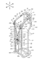
図1に示すように、ゴルフバッグ1は、ゴルフバッグ本体3と、フレーム5とを有している。
<<First Embodiment>>
As shown in FIG. 1, the
ゴルフバッグ本体3は開口7を備えた袋状をなしている。ゴルフバッグ本体3は可撓性を有する布部材によって構成されているとよい。ゴルフバッグ本体3は適所にてフレーム5に固定されることにより、有底な筒状をなす。ゴルフクラブはユーザによって開口7からゴルフバッグ本体3の内部に挿入されて、ゴルフバッグ本体3に収納される。ゴルフバッグ本体3の外周面には図示しない肩掛け用のベルトや、ボールやティ・マーカ等を収納するための収納部が設けられていてもよい。
The
以下、説明の便宜上、図1に示すように、ゴルフバッグ本体3の開口7が上側に位置する状態を基準として上下の各方向を定めて説明を行う。但し、これらの方向は説明の便宜上定めたものであって、本発明はこの方向の記載には限定されない。
For convenience of explanation, the following description will be made with reference to the state in which the opening 7 of the
ゴルフバッグ本体3の開口7には環状の口枠9が設けられているとよい。口枠9は布部材により覆われているとよい。その他、ゴルフバッグ本体3には、その内部を仕切る板状の仕切壁11が設けられているとよい。仕切壁11はゴルフバッグ本体3の内部を区切る態様であれば、いかなる態様であってもよい。
The opening 7 of the
図2に示すように、フレーム5は、フレーム本体15と、フレーム本体15に設けられた脚17及び操作部材19とを備える。
As shown in FIG. 2 , the
以下、図1及び図2に示すように、フレーム5の脚17が設けられている側を前方とし、それを基準として、前後左右の各方向を定めて説明を行う。但し、これらの方向は説明の便宜上定めたものであって、本発明はこの方向の記載には限定されない。
Hereinafter, as shown in FIGS. 1 and 2, the side of the
フレーム本体15はゴルフバッグ1の骨格を形成する。図1に示すように、フレーム本体15にはゴルフバッグ本体3の適所が固定され、フレーム本体15はゴルフバッグ本体3を上側に開口7が位置するように支持する。
The frame
図2に示すように、フレーム本体15は、パイプ材によって構成された主部21と、主部21に結合された副部23とを備えている。
As shown in FIG. 2 , the
主部21は、その上部を構成する上枠25と、その下部を構成する下枠27と、下枠27に設けられた連接部29と、上枠25及び下枠27を接続する複数の支柱31とを備えている。上枠25はゴルフバッグ本体3の上部、すなわち、口枠9の径外側にて開口7の側縁に沿って延在し、所定方向に向けて開く略U字状をなしている。下枠27はゴルフバッグ本体3の下部の外側にて、ゴルフバッグ本体3の下縁に沿って延在し、上枠25と同じ方向に向けて開く略U字状をなしている。
The
上枠25は左枠25A、右枠25B及び後枠25Cを有している。左枠25A及び右枠25Bはそれぞれ略前後方向に延び、左右に間隔をおいて配置されている。後枠25Cは左枠25Aの後端及び右枠25Bの後端を接続している。
The
下枠27もまた左枠27A、右枠27B及び後枠27Cを有している。左枠27A及び右枠27Bはそれぞれ略前後方向に延び、左右に間隔をおいて配置されている。後枠27Cは左枠27Aの後端及び右枠27Bの後端を接続している。本実施形態では、下枠27の左枠27A及び右枠27Bの間の距離は、上枠25の左枠25A及び右枠27Bの間の距離よりも大きく、下枠27の左右方向の幅は、上枠25の左右方向の幅よりも大きい。
The
連接部29は左右に延び、左端において下枠27の左枠27Aに、右端において下枠27の右枠27Bにそれぞれ接続されている。本実施形態では、主部21は前連接部29A及び後連接部29Bの2つの連接部29を含み、前連接部29Aと後連接部29Bはそれぞれ前後に並んで配置されている。前連接部29A及び後連接部29Bは下枠27の左枠27A及び下枠27の右枠27Bをそれぞれ接続している。
The connecting
主部21は支柱31として、第1支柱31A、第2支柱31B、第3支柱31C及び第4支柱31Dの4つの支柱31を有する。但し、本発明は、主部21の有する支柱31の数には限定されない。第1支柱31A及び第2支柱31Bは左右に並んで配置され、第3支柱31C及び第4支柱31Dはそれぞれ第1支柱31A及び第2支柱31Bの前方にて左右に並んで配置されている。
The
第1支柱31A及び第2支柱31Bはそれぞれ下方に延び、略中央部において屈曲して、斜め前下方に延びた後、更に屈曲して下方に延びている。換言すれば、第1支柱31A及び第2支柱31Bは下端から上方に延び、略中央部にて後上方に延びた後、更に屈曲して上方に延びている。これにより、第1支柱31A及び第2支柱31Bはそれぞれ上部に後方に膨出した膨出部31Eを備えている。第1支柱31A及び第2支柱31Bは上端にて上枠25にそれぞれ結合され、下端にて後連接部29Bの左右端にそれぞれ結合されている。
The
第3支柱31C及び第4支柱31Dはそれぞれ上下方向に略直線状に延びている。第3支柱31C及び第4支柱31Dはそれぞれ、上枠25の左右前端と、下枠27の左右前端とを接続している。但し、これらの支柱31の形状はゴルフバッグ本体3の形状や大きさに応じて設定されてもよい。
The
上枠25、下枠27、第1支柱31A、第2支柱31B、第3支柱31C及び第4支柱31Dによってゴルフバッグ本体3を収容する収容空間32が画定されている。
A
本実施形態では、上枠25、下枠27、第3支柱31C及び第4支柱31Dは、曲げ加工された中空のパイプ材が連続した態様をなすように接続されることによって構成されている。前連接部29A及び後連接部29Bはそれぞれ1つのパイプ材によって構成され、左右端部において下枠27に接続されている。第3支柱31C及び第4支柱31Dもまたそれぞれ1つのパイプ材によって構成され、上端において上枠25に、下端において後連接部29Bにそれぞれ接続されている。上枠25、下枠27、第3支柱31C及び第4支柱31Dを構成するパイプ材は、ねじによる締結や溶接等のいかなる方法によって接続されていてもよい。また前連接部29A、後連接部29B、第3支柱31C及び第4支柱31Dを構成するパイプ材もまた、上枠25や下枠27に、ねじによる締結や溶接等のいかなる方法によって接続されていてもよい。
In this embodiment, the
本実施形態では、主部21はアルミニウム製のパイプ材に、アルミニウム製又は樹脂製のパーツを嵌め合わせて連結させることによって構成されている。これにより、ゴルフバッグ1の強度を保ちつつ、軽量化を図ることができる。
In this embodiment, the
副部23は主部21を補強することや、また、機能部をフレーム本体15に構成することを目的として、主部21に設けられる。本実施形態では、フレーム本体15は、副部23として、フレーム本体15の前部に設けられる第1副部33及び第2副部35と、フレーム本体15の後部に設けられる第3副部37とを備えている。
The
第1副部33は主部21の前側上部に設けられる。第1副部33は左右に延在して第3支柱31Cの上部と第4支柱31Dの上部とを接続する。本実施形態では、第1副部33は、前方を向く主面を有する中央部33Aと、中央部33Aの左端に設けられ第3支柱31Cに結合された左端部33Bと、中央部33Aの右端に設けられ第4支柱31Dに結合された右端部33Cとを備えている。第1副部33は樹脂製の部材によって構成されていてもよく、また、金属製の部材によって構成されていてもよい。本実施形態では、第1副部33は樹脂製の部材によって構成されている。
The
第2副部35は主部21の前側中央部分に設けられる。第2副部35は左右に延在して第3支柱31Cの上下方向中央部分と第4支柱31Dの上下方向中央部分とを接続する。本実施形態では、第2副部35は、前方を向く主面を有する板状の中央部35Aと、中央部35Aの左端に設けられ第3支柱31Cに結合された左端部35Bと、中央部35Aの右端に設けられ第4支柱31Dに結合された右端部35Cとを備えている。第2副部35は樹脂製の部材によって構成されていてもよく、また、金属製の部材によって構成されていてもよい。本実施形態では、第2副部35は金属製のパイプ材によって構成されている。
The
第3副部37は主部21の後部に設けられる。第3副部37は左右方向に延在し上下に対をなすように配置され一対の横部37Aと、上下に延在して上下端においてそれぞれ横部37Aの左右方向略中央部に接続された縦部37Bと、を備えている。上側の横部37Aは上枠25の後枠25Cに結合されている。上側の横部37Aは後枠25Cの外周面を覆うように配置されて、後枠25Cに結合されている。下側の横部37Aは左端において第1支柱31Aに結合され、右端において第2支柱31Bに結合されている。第3副部37はユーザがゴルフバッグ1を持ち上げるための把持部を構成する。本実施形態では、第3副部37は樹脂製の部材によって構成されている。
A
フレーム5には左右一対の脚17が設けられている。図3及び図4に示すように、脚17はそれぞれフレーム本体15の前側に枢支されている。これにより、脚17はそれぞれ上端において回転軸41においてフレーム本体15の前部に回転可能に支持されている。本実施形態では、左側に位置する脚17(以下、左脚17A)の回転軸41Aは左斜め前方向に延びるように設定され、右側に位置する脚17(以下、右脚17B)の回転軸41Bは右斜め前方向に延びるように設定されている。左脚17Aはフレーム本体15の前部の左側部に、右脚17Bはフレーム本体15の前部の右側部にてそれぞれ、回転可能に支持されている。本実施形態では、左脚17A及び右脚17Bは左右対称をなすように構成されている。
The
本実施形態では、図2に示すように、左脚17A及び右脚17Bはそれぞれ、第1副部33の前側左右側部にそれぞれ回動可能に連結された接続部43と、直管状に形成され、一端(上端)において接続部43に連結された脚本体45と、を備えている。図4に示すように、接続部43と、第1副部33とは、回転軸41に沿って延在する支持体47によって接続されている。支持体47の一端は第1副部33によって回動可能に支持され、支持体47の他端は接続部43に固定されているとよい。これにより、接続部43と第1副部33とは互いに回転軸41の回りに回動可能に連結されている。
In this embodiment, as shown in FIG. 2, the
本実施形態では、図2に示すように、左脚17A及び右脚17Bはそれぞれ、脚本体45の他端(下端)に設けられ、脚本体45の開口部分を封止する封止部材45A(キャップ)を備えている。脚本体45は金属製(例えば、アルミニウム製)のパイプ材によって構成され、封止部材45Aは樹脂製の部材によって構成されているとよい。
In this embodiment, as shown in FIG. 2, the
脚17はそれぞれ回転によって、図2に示す待機位置(閉位置ともいう)と、図5に示す展開位置(開位置や拡開位置ともいう)との間で変位可能となっている。待機位置にあるときには、脚17はそれぞれ垂下してその下端がゴルフバッグ本体3に近接した位置にある。一方、展開位置にあるとき、脚17はそれぞれ待機位置よりもその下端が前方に位置し、下端がゴルフバッグ本体3から離れた位置にある。脚17がそれぞれ展開位置にあるときに、ゴルフバッグ1を傾けて、脚17それぞれの下端を地面に当接させると、フレーム5及びゴルフバッグ本体3はともに脚17によって支持される。
Each
左脚17Aの下端は展開位置にあるとき、待機位置にあるときに比べて左前方に位置し、右脚17Bの下端は展開位置にあるとき、待機位置にあるときに比べて右前方に位置している。これにより、左脚17A及び右脚17Bがともに展開位置にあるときには、右脚17B及び左脚17Aがともに待機位置にあるときに比べて、左脚17Aの下端と右脚17Bの下端との距離が長くなっている。
The lower end of the
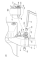
操作部材19(レバーやハンドルともいう)は脚17を待機位置から展開位置に変位させるためのユーザの操作入力を受け付ける。操作部材19は、フレーム本体15の後側上部にて、前後方向に変位可能に支持されている(図2及び図5も参照)。
An operation member 19 (also referred to as a lever or handle) receives a user's operation input for displacing the
本実施形態では、図3に示すように、操作部材19は上枠25の左枠25A及び右枠25Bの間に位置している。操作部材19は左右両端において左枠25A及び右枠25Bにそれぞれ前後方向に摺動可能に支持されている。本実施形態では、操作部材19は左右方向に延在する中央部19Aと、中央部19A左端において左枠25Aの右側面に摺接する左端部19Bと、中央部19A右端において右枠25Bの左側面に摺接する右端部19Cとを含む。
In this embodiment, as shown in FIG. 3, the operating
このように、操作部材19は左枠25A及び右枠25Bの間(すなわち、左右枠の間)において左右方向に延在するように設けられている。そのため、操作部材19が比較的大きくすることができ、ユーザが操作部材19を把持し易くすることができるため、操作部材19の操作性が向上する。また、操作部材19がフレーム本体15の外部に突出せず、ゴルフバッグ1の意匠性の高めることができる。
Thus, the
図6に示すように、左端部19Bは左枠25Aの右側面に整合する管状をなし、右端部19Cは右枠25Bの左側面に整合する管状をなしている。図3に示すように、左端部19Bと右端部19Cとはそれぞれ左枠25A及び右枠25Bに摺動可能に構成されている。中央部19Aの前面中央部分には、ユーザが指を引っ掛けて握るためのグリップ19D(グリップ部)が設けられているとよい。グリップ19Dが設けられることによって、操作部材19を容易に後方に引くことができるため、脚17の操作が容易になる。
As shown in FIG. 6, the
図3及び図6に示すように、フレーム5には操作部材19の操作力を左右の脚17それぞれに伝える伝達部材49が設けられている。詳細には、伝達部材49は、操作部材19の後方への変位によって、左右の脚17をそれぞれ回転させて、待機位置から展開位置に変位させる。
As shown in FIGS. 3 and 6, the
以下、脚17が待機位置にあるときの操作部材19の位置を前位置と記載し、脚17が展開位置となるときの操作部材19の位置をそれぞれ後位置と記載する。操作部材19は左枠25A及び右枠25Bの間にて、前位置と後位置との間で変位可能に支持されている。
Hereinafter, the position of the operating
図6に示すように、伝達部材49は、操作部材19及び左脚17Aと、操作部材19及び右脚17Bとをそれぞれ連結する連結部材51を含む。連結部材51は一つ又は複数のワイヤ(索状部材、ケーブルともいう)によって構成されているとよい。
As shown in FIG. 6, the
本実施形態では、伝達部材49は、筒状のアウタケーシングと、アウタケーシングの内部に収容された内部ケーブルとを含むフレキシブルケーブル(いわゆるボーデンケーブル)によって構成され、その内部ケーブルが連結部材51に相当する。
In this embodiment, the
図3に示すように、連結部材51は両端において脚17に接続されている。本実施形態では、連結部材51の端部は、回転軸41の上方向から回転軸41の前方を通過して下方に延び、回転軸41よりも下側にて脚17(詳細には、接続部43)に接続されている。これにより、連結部材51の引張力によって、脚17はそれぞれ待機位置から展開位置に変位するように回転する。
As shown in FIG. 3, the connecting
図4に示すように、連結部材51は中央部分において操作部材19の後側面に掛け止めされて、操作部材19に結合されている。
As shown in FIG. 4 , the connecting
図3に示すように、連結部材51は端部と中央部分との間において上枠25(詳細には、左枠25A及び右枠25B)に沿うように配置されている。これにより、伝達部材49(詳細には、伝達部材49の一部)は上枠25に沿って配置され、ゴルフバッグ本体3の開口7の側縁に沿って延在している。
As shown in FIG. 3, the connecting
上枠25の左枠25A及び右枠25Bには、連結部材51を内部に導入するための貫通孔55が適所に設けられている。連結部材51のうち上枠25の左枠25Aに沿う部分はその貫通孔55を介して、左枠25Aの内部に侵入している。これにより、連結部材51のうち上枠25の左枠25Aに沿う部分の少なくとも一部は、上枠25の左枠25Aの内部に挿通されている。連結部材51のうち上枠25の右枠25Bに沿う部分はその貫通孔55を介して、右枠25Bの内部に侵入している。連結部材51のうち上枠25の右枠25Bに沿う部分の少なくとも一部もまた、上枠25の右枠25Bの内部に挿通されている。
The
操作部材19が前位置(図2参照)にあるときから、後位置(図5参照)に移動すると、連結部材51の中央部分が後方に引っ張られる。これにより、連結部材51の両端が後方に引っ張られて、左右の脚17がそれぞれ回転軸41を中心として回転して待機位置から展開位置に変位する。
When the operating
図2に示すように、フレーム5には、更に、付勢部材53が設けられている。付勢部材53は、脚17を待機位置に向けて付勢する。付勢部材53は、左右の脚17の回転軸41それぞれに設けられたねじりコイルばねや各種の弾性部材によって構成されていてもよい。
As shown in FIG. 2, the
付勢部材53は、左右の脚17の下端(外端)を互いに近接する方向に付勢するように構成されていてもよい。展開位置にあるときには、右脚17Bの下端と左脚17Aの下端との距離が待機位置にあるときに比べて長いため、左右の脚17の下端(外端)を互いに近接する方向に付勢することで、右脚17B及び左脚17Aはそれぞれ付勢部材53によって待機位置に向けて付勢されることになる。
The biasing
本実施形態では、付勢部材53は、折曲加工された中実の金属製の棒状部材によって構成されている。棒状部材は、左右の脚17の下端(外端)を互いに近接する方向に付勢する弾性部材として機能する。
In the present embodiment, the biasing
詳細には、付勢部材53は左端において左脚17Aに接続され、右下方に延びた左半部53Aと、右端において右脚17Bに接続され、左下方に延びた右半部53Bと、左右に延びて左半部53Aの下端及び右半部53Bの下端を接続する中央部53Cとを備えている。付勢部材53(詳細には、左半部53Aの上端)は左端において、左脚17Aの回転軸41よりも下方(下端側)に連結され、付勢部材53(詳細には、右半部53Bの上端)は右端において、右脚17Bの回転軸41よりも下方(下端側)に連結されている。
Specifically, the biasing
左脚17Aと右脚17Bとがそれぞれ待機位置から展開位置に変位すると、左半部53Aの上端と、右半部53Bの上端とがそれぞれ離れる方向に引っ張られる。そのため、付勢部材53は左半部53Aの上端と、右半部53Bの上端とを近づけるように付勢力を発揮する。これにより、左脚17Aと右脚17Bとがそれぞれ待機位置になるように付勢される。
When the
本実施形態では、付勢部材53の両端部がそれぞれ、接続部43に設けられた貫通孔に挿入されることで、付勢部材53が接続部43に結合している。付勢部材53の端部に連結部材51が結合されることによって、連結部材51は接続部43に結合している。
In this embodiment, the biasing
図7(A)は、別実施例に係る、付勢部材53及び接続部43の結合部分101の分解斜視図を示し、図7(B)は結合部分101の側面図(二点鎖線内参照)を示している。
FIG. 7A shows an exploded perspective view of a connecting
図7(A)及び図7(B)に示す別実施例では、結合部分101には、筒状のカラー103が設けられている。付勢部材73は端部において、カラー103の内孔103Aと、接続部43に設けられた貫通孔43Aとを順に通過している。付勢部材73の挿入端には封止部材105が設けられている。これにより、付勢部材73が接続部43の貫通孔43Aから抜け落ちることが防止できる。
In another embodiment shown in FIGS. 7A and 7B, the connecting
図7(A)に示すように、カラー103は貫通孔107Aを有する円筒状のカラー本体107と、カラー本体107の貫通孔107Aに挿入される筒状の筒部材109とを含む。カラー本体107はゴム製の部材によって構成されているとよい。筒部材109は金属製の部材によって構成されている。筒部材109の内孔109Aは付勢部材73の外径よりも若干大きい。筒部材109の内孔109Aには付勢部材73が挿入され、その挿入端に封止部材105が設けられることによって、カラー103は付勢部材73の端部に回動可能に支持されている。
As shown in FIG. 7A, the
カラー本体107の外周には溝107Bが形成されている。連結部材51の端部には円環状の掛止部51Aが結合されている。掛止部51Aがカラー本体107の溝107Bに収容されることによって、連結部材51はカラー103に掛け止めされている。これにより、連結部材51が付勢部材53の端部に結合されている。
A
第2副部35には付勢部材53を収容するための収容部57が設けられている。収容部57は第2副部35と協働して、付勢部材53の下部の一部(詳細には、左半部53Aの下部及び右半部53Bの下部)を収容するポケット59を構成する。ポケット59に付勢部材53の下部の一部が収容されることによって、付勢部材53の下部が前方に突出することが防止される。
A
その他、付勢部材53には、左半部53A及び右半部53Bを近づけた状態で保持する保持部材61が設けられている。保持部材61は左半部53A及び右半部53Bに対して上下方向に摺動可能に構成されている。保持部材61は左半部53A及び右半部53Bの前側に設けられた前部材61Aと、左半部53A及び右半部53Bの後側に設けられた後部材61Bとをねじ止めすることによって構成されているとよい。保持部材61の位置を上下方向に変更することによって、ユーザは付勢部材53が発揮する付勢力を適切な大きさに設定することができる。
In addition, the biasing
次に、このように構成したゴルフバッグ1及びフレーム5の動作について説明する。
Next, operations of the
ゴルフバッグ1が起立し、上方に向けて開口7が位置しているときには、図1に示すように、左脚17A及び右脚17Bはともに、待機位置となっている。
When the
ユーザが操作部材19を把持して後方に引くと、操作部材19の後面に掛け止めされた連結部材51が後方に引っ張られる。これにより、連結部材51の左右両端が引っ張られ、左脚17A及び右脚17Bがそれぞれ対応する回転軸41を中心に回転する。操作部材19が後位置まで引っ張られると、左脚17A及び右脚17Bがそれぞれ展開位置となる。
When the user grips the
ユーザが操作部材19を把持して後位置に維持したまま、ゴルフバッグ1の上部を前方に向けて傾けて、左脚17A及び右脚17Bの下端をそれぞれ地面に当接させる。これにより、図5に示すように、左脚17A及び右脚17Bが開かれ、それぞれの下端が地面に当接したまま、フレーム5及びゴルフバッグ本体3は左脚17A及び右脚17Bによって支持される。
While the user grips the
次に、ユーザが、ゴルフバッグ1の前端を後方に傾けて、ゴルフバッグ1を起立させると、付勢部材53による付勢力によって、左脚17A及び右脚17Bはそれぞれ展開位置から回転して、下方に垂下し、展開を待機する待機位置となる。
Next, when the user tilts the front end of the
起立したゴルフバッグ1が若干前方に傾いたときには、付勢部材53の付勢力によって左脚17A及び右脚17Bはそれぞれ互いに近接した待機位置に維持される。これにより、ゴルフバッグ1の運搬時に意図せず脚17が開かれることが防止できる。
When the
次に、このように構成したゴルフバッグ1及びフレーム5の効果について説明する。
Next, the effects of the
このように、操作部材19を操作することによって、左脚17A及び右脚17Bを同時に待機位置から展開位置に変位(移動)させることができる。
By operating the operating
操作部材19は上枠25に設けられているため、フレーム本体15の上部に位置している。そのため、脚17を開くために操作するべき部材がフレーム本体15の下部に設けられている場合に比べて、脚17を開くための操作が容易である。また、脚17はフレーム本体15の前側(一方の側)に位置し、操作部材19はフレーム本体15上部の後側(他方の側)に位置している。そのため、操作部材19がフレーム本体15上部の前側に位置している場合に比べて、脚17の展開位置への移動を妨げることなく、操作部材19を操作することができる。
Since the operating
連結部材51は一部において、フレーム本体15(詳細には上枠25)に沿って延在しているため、連結部材51が上面視で本体の開口7に横切るように配置されず、ゴルフバッグ本体3の開口7が連結部材51によって狭められることが防止できる。よって、ゴルフバッグ1へのゴルフクラブの収納が容易になる。
Since the connecting
上枠25は中空のパイプ材によって構成され、連結部材51は上枠25の左枠25A及び右枠25Bの内部にそれぞれ挿通されている。これにより、連結部材51が露出せず、ゴルフバッグ(及びフレーム5)の意匠性が高められるとともに、連結部材51によってゴルフバッグ本体3の開口7が狭められることがより確実に防止できる。
The
連結部材51は両端において左右の脚17にそれぞれ接続され、中央部分において操作部材19の後側面に掛け止めされている。そのため、ユーザは1つの操作部材19を後方に引くことによって、左脚17A及び右脚17Bの2つの脚17を同時に展開位置に変位させることができる。
The connecting
本実施形態では、連結部材51が1本のワイヤによって構成されているため、伝達部材49を操作部材19及び左脚17Aを接続するワイヤと、操作部材19及び右脚17Bを接続するワイヤとの2つのワイヤで構成する場合に比べて、ワイヤを固定するための固定部の数を低減することができ、フレーム5の構成が簡素になる。
In this embodiment, since the connecting
<<第2実施形態>>
第2実施形態に係るゴルフバッグ1及びゴルフバッグ1用のフレーム5は、図8に示すように、第1実施形態とは異なり、操作部材19が第3副部37に設けられている点と、連結部材51の配設構造とが異なり、他の構成は第1実施形態と同様である。よって、第1実施形態と同様の構成については、説明を省略する。
<<Second Embodiment>>
As shown in FIG. 8, the
操作部材19は第3副部37に上下方向に変位可能に支持されている。操作部材19は第3副部37の横部37Aの背面から後方に突出する突出部63を備えているとよい。
The operating
連結部材51は第1実施形態と同様にワイヤ状の部材であり、両端において左脚17A及び右脚17Bにそれぞれ結合されている。連結部材51と左脚17Aとの結合位置と、連結部材51と右脚17Bとの結合位置とは、第1実施形態と同様であってよい。連結部材51は上枠25の左枠25A、右枠25B及び後枠25Cの内部を通過するように構成されている。
The connecting
連結部材51は中央部分において、操作部材19に掛け止めされている。左右の脚17がそれぞれ待機位置にあるときに、ユーザによって操作部材19が押し下げられると、連結部材51の中央部分が下方に引っ張られる。これにより、連結部材51の左右両端が後方に引っ張られて、左右の脚17はそれぞれ回転し、展開位置に変位する。
The connecting
次に、このように構成したゴルフバッグ1及びゴルフバッグ1用のフレーム5の効果について説明する。
Next, the effects of the
脚17を開くための操作部材19がフレーム本体15の上部に配置されている。そのため、ユーザは容易に脚17を開くことができる。更に、連結部材51は上枠25の内部を通過するように構成されているため、伝達部材49によってゴルフバッグ本体3の開口7が狭められることが防止できる。
An
<<第3実施形態>>
第3実施形態に係るゴルフバッグ1及びゴルフバッグ1用のフレーム5は、図9に示すように、支柱31及び第3副部37それぞれの構成と、グリップ19Dの代わりに操作部材19及び支柱31を接続するグリップ部材201が設けられている点とが異なり、他の構成については同様である。よって、他の構成については説明を省略する。
<<Third Embodiment>>
The
フレーム本体15は、パイプ材によって構成された主部21と、主部21に結合された第1副部33及び第2副部35(不図示)とを備えている。第1副部33及び第2副部35は第1実施形態と同様である。
The frame
主部21は第1実施形態と同様に、上枠25、下枠27(不図示)、及び複数の支柱31を備える。上枠25は、第1実施形態と同様に、ゴルフバッグ本体3の開口7の側縁に沿って延在している。上枠25は中空のパイプ材によって構成され、第1実施形態と同様、伝達部材49は貫通孔55を介して上枠25の内部に挿通されている。
The
本実施形態では、主部21はフレーム本体15の前部に位置する左右一対の前側支柱31Fと、フレーム本体15の後部に位置する1つの後側支柱31Gとを備えている。前側支柱31Fはそれぞれ第1実施形態の第3支柱31C及び第4支柱31Dと同様の機能を奏する。後側支柱31Gは上枠25の後端部、詳細には、後枠25Cの左右中央部分に結合されている。後側支柱31Gは上枠25から後方に延びた後、更に、下方に延び、下枠27に接続されている。
In this embodiment, the
第3副部37は後側支柱31Gの上部に設けられている。第3副部37は後側支柱31Gの上部にて、外面を覆う筒状をなしている。
The
上枠25は、第1実施形態と同様に、左右一対の左枠25A及び右枠25B(合わせて左右枠)と、後枠25Cとを備え、上面視でU字状をなしている。左枠25A及び右枠25Bはそれぞれ前後方向に延在し、後枠25Cは左枠25Aの後端及び右枠25Bの後端を接続している。
As in the first embodiment, the
操作部材19は左枠25A及び右枠25Bの間にて、左枠25A及び右枠25Bそれぞれに、前後に摺動可能に支持されている。第1実施形態と同様に、操作部材19が前位置にあるときには、2つの脚17がそれぞれ閉じられた待機位置となる。操作部材19が前位置より後方の後位置にあるときには、2つの脚17が開かれた展開位置となる。
The
本実施形態では、操作部材19は左右一対の結合部19Eと、左右の結合部19Eを接続する接続部19Fとを備えている。結合部19Eは左枠25A及び右枠25Bそれぞれに沿って延在し、左枠25A及び右枠25Bのそれぞれに摺動可能に結合されている。
In this embodiment, the operating
図10には、結合部19Eの分解斜視図が示されている。図10に示すように、結合部19Eはそれぞれ2つの半割の筒状部材19Gが螺子19Hによって結合されることによって構成されている。筒状部材19Gの下部には伝達部材49を収容するための溝19Jが設けられている。2つの筒状部材19Gが結合されることによって、伝達部材49を収容するための貫通孔19Kが形成される。結合部19E材が上枠25に結合されたときには、貫通孔19Kは左枠25A及び右枠25Bに沿ってそれぞれ延在している。
FIG. 10 shows an exploded perspective view of the
接続部19Fは上面視で前方に向けて開口するU字状をなす線状部材によって構成されている。接続部19Fは両端においてそれぞれ結合部19Eに結合されている。接続部19Fはその後端部に加わる荷重に応じて弾性変形可能に構成されているとよい。
The connecting
接続部19Fは左側の結合部19Eの貫通孔19Kと右側の結合部19Eの貫通孔19Kとに連通する1つの貫通孔(不図示)が設けられたパイプ状をなしている。伝達部材49は左側の結合部19Eの貫通孔19K、結合部19Eの貫通孔、及び、右側の結合部19Eの貫通孔19Kにそれぞれ挿通されている。これにより、図9に示すように、伝達部材49は、操作部材19の結合部19Eの内部にて、左枠25A及び右枠25Bに沿うように配置されている。
The connecting
グリップ部材201は操作部材19と後側支柱31Gとを接続している。グリップ部材201は後側支柱31Gに回転可能に結合されている。本実施形態では、グリップ部材201は上端において操作部材19の後縁に結合され、下端において後側支柱31Gに左右方向に延びる軸線203を中心として回転可能に結合されている。
The
グリップ部材201は、操作部材19の前位置及び後位置との変位を妨げないように、操作部材19に結合されていればよく、操作部材19との結合態様はいかなるものであってもよい。例えば、接続部19Fが操作部材19の前位置及び後位置の間の変位によって弾性変形可能である場合には、操作部材19とグリップ部材201は互いに固定されていてもよい。また、グリップ部材201の上端に接続部19Fを挿通させるための貫通孔が左右方向の延在するように設けられ、接続部19Fはその貫通孔に挿通されていてもよい。これにより、接続部19Fは操作部材19に対して左右方向にスライド移動可能に結合されていてもよい。
The
次に、このように構成したゴルフバッグ1及びゴルフバッグ1用のフレーム5の効果について説明する。
Next, the effects of the
ユーザがグリップ部材201と後側支柱31Gを把持すると、グリップ部材201が下端を中心として上端が後方に移動するように回転し(図9の矢印を参照)、操作部材19が後方に移動する。これにより、操作部材19が前位置から後位置に移動し、脚17はそれぞれ待機位置から展開位置に移動する。ユーザがグリップ部材201と後側支柱31Gとの把持を止めると、第1実施形態と同様に、付勢部材の付勢力や重力などによって、脚17はそれぞれ展開位置から待機位置に移動する。
When the user grips the
このように、グリップ部材201と後側支柱31Gとを把持することで、操作部材19を後方に移動させることができるため、ユーザが容易に脚17を操作することができる。
By gripping the
以上で具体的な実施形態の説明を終えるが、本発明は上記実施形態や変形例に限定されることなく、幅広く変形実施することができる。各部材や部位の具体的構成や配置、数量、具体的制御態様などは、本発明の趣旨を逸脱しない範囲であれば適宜変更可能である。 Although the specific embodiments have been described above, the present invention is not limited to the above-described embodiments and modifications, and can be widely modified. The specific configuration, arrangement, quantity, specific control mode, etc. of each member and part can be changed as appropriate without departing from the gist of the present invention.
上記実施形態では、フレーム本体15に車輪が設けられていなかったが、フレーム本体15の下部に左右一対の車輪が設けられていてもよい。左脚17A及び右脚17Bがともに展開位置にあるときには、左右の車輪がともに回転不能となるように構成されていてもよい。これにより、フレーム5及びゴルフバッグ本体3が左脚17A及び右脚17Bによって支持されているときに、車輪の回転を防止することができる。
In the above embodiment, the frame
上記第3実施形態において、後側支柱31Gは上端にて後方に延出した後、下方に延びるように構成されていたが、この態様には限定されない。図11に示すように、後側支柱31Gは上枠25から直接下方に延びるように構成されていてもよい。
In the above-described third embodiment, the
上記第3実施形態において、主部21に3つの支柱が設けられていたが、本発明は支柱の数には限定されない。例えば、第1実施形態と同様に、図12に示すように、主部21には4つの支柱31が設けられていてもよい。その場合には、第1実施形態と同様の第3副部37がフレーム本体15の後部に配置された支柱31に設けられていてもよい。
In the third embodiment, the
また上記第1実施形態において、第1支柱31A及び第2支柱31Bがそれぞれ上端において上枠25に結合されるように構成されていたがこの態様には限定されない。例えば、図13の第3実施形態の変形例に示すように、第1支柱31A及び第2支柱31Bはそれぞれ、上端において、上枠25の下縁に沿って延在するように屈曲されて、上枠25(詳細には、左枠25A及び右枠25Bそれぞれ)の下縁に結合されていてもよい。
In addition, in the above-described first embodiment, the
また図13に示すように、第1支柱31A及び第2支柱31Bはそれぞれ上枠25のとの結合部分において屈曲し、下方に向かって後方に傾斜する方向に延びた後、下方に向かって前方に傾斜する方向に延びて、下枠27(不図示)に結合されていてもよい。
Also, as shown in FIG. 13, the
上記実施形態において、伝達部材49の少なくとも一部において、開口7の縁部に沿って延在する場合を例示して説明したが、本願発明はこの態様には限定されない。伝達部材49の全長に渡って、開口7の縁部に沿って延在していてもよく、また、伝達部材49が開口7の中央を横切らない態様であればいかなる態様であってもよい。具体的には、例えば、伝達部材49が開口7を画定する縁部から下側にオフセットした位置に沿って延在するように構成されていてもよい。伝達部材49は少なくとも一部において、ゴルフバッグ本体3を構成する部材(シート状部材や樹脂部材等)の外縁に沿って延在していてもよい。また、伝達部材49は少なくとも一部において、ゴルフバッグ本体3を構成する部材の内縁に沿って延在していてもよい。その他、伝達部材49は少なくとも一部において、ゴルフバッグ本体3を構成する部材の内部に収容されていてもよい。
In the above embodiment, at least part of the
また、本発明はゴルフバッグ本体3の上下方向の長さや、開口7の大きさ、形状等には限定されない。その他、本発明はゴルフバッグ1に収容されるクラブの本数には限定されない。上記実施形態では、キャディバッグを構成するゴルフバッグ1に本発明を適用した例について記載したが、本発明はゴルフクラブを収容するためのあらゆるバッグに適用可能である。ゴルフバッグ1は、いわゆるキャディバッグの他、例えば、ユーザがゴルフクラブを1本から数本選んで持ち運ぶために使用されるケース(いわゆるゴルフクラブケース)を構成してもよい。
Further, the present invention is not limited to the length of the
1 :ゴルフバッグ
3 :ゴルフバッグ本体
5 :フレーム
7 :開口
15 :フレーム本体
17 :脚
17A :左脚
17B :右脚
19 :操作部材
19D :グリップ(グリップ部)
25 :上枠
25A :左枠
25B :右枠
49 :伝達部材
53 :付勢部材
201 :グリップ部材
Reference Signs List 1: golf bag 3: golf bag main body 5: frame 7: opening 15: frame main body 17:
25:
Claims (10)
前記ゴルフバッグ本体を上側に開口が位置するように支持するフレーム本体と、
待機位置及び前記フレーム本体を支持可能な展開位置の間で変位可能に、前記フレーム本体の一方の側にて枢支された一対の脚と、
前記フレーム本体の他方の側の上部にて、所定方向に変位可能に設けられた操作部材と、
前記操作部材の変位によって、前記脚を前記待機位置から前記展開位置に変位させる伝達部材とを備え、
前記伝達部材は、前記脚と前記操作部材とを接続し、且つ、少なくとも一部において前記開口の側縁に沿って延在するワイヤを含むゴルフバッグ。 a golf bag body into which golf clubs are inserted;
a frame body that supports the golf bag body so that the opening is positioned on the upper side;
a pair of legs pivotally supported on one side of the frame body so as to be displaceable between a standby position and a deployed position capable of supporting the frame body;
an operation member provided displaceably in a predetermined direction at the upper portion of the other side of the frame main body;
a transmission member that displaces the leg from the standby position to the deployed position by displacement of the operating member;
The golf bag, wherein the transmission member includes a wire connecting the leg and the operation member and extending at least partially along the side edge of the opening.
前記操作部材の前記所定方向の変位によって、前記脚は前記ワイヤに引っ張られて回転し、前記待機位置から前記展開位置に変位する請求項1に記載のゴルフバッグ。 The legs are rotatably supported by the frame body,
2. The golf bag according to claim 1, wherein the leg is rotated by being pulled by the wire and displaced from the standby position to the deployed position by displacement of the operating member in the predetermined direction.
前記ワイヤは前記上枠に沿って延在する部分を含む請求項1に記載のゴルフバッグ。 the frame body includes the upper frame extending along a side edge of the opening of the golf bag body;
2. The golf bag of claim 1, wherein said wire includes a portion extending along said upper frame.
前記ワイヤは前記上枠の内部に挿通されている請求項3に記載のゴルフバッグ。 The upper frame is composed of a hollow pipe material,
4. The golf bag according to claim 3, wherein said wire is passed through said upper frame.
前記操作部材は前記左右枠の間にて、2つの前記左右枠に、前記脚が前記待機位置となる前位置と、前記脚が前記展開位置となる後位置とに変位可能に支持され、
前記脚は対応する回転軸を中心に前記フレーム本体に回転可能に支持され、
前記操作部材は、前記後位置にあるときに、前記前位置にあるときよりも、前記回転軸から離れた位置にある請求項3に記載のゴルフバッグ。 The upper frame has a pair of left and right frames arranged on the left and right,
The operation member is supported by the two left and right frames between the left and right frames so as to be displaceable between a front position where the legs are at the standby position and a rear position where the legs are at the deployed position ,
the legs are rotatably supported by the frame body about corresponding rotation axes;
4. The golf bag according to claim 3, wherein the operating member is positioned farther from the axis of rotation when at the rear position than when at the front position.
前記操作部材と前記支柱とはグリップ部材によって接続されている請求項5に記載のゴルフバッグ。 A post extending downward is provided at the end of the upper frame on the other side,
6. The golf bag according to claim 5, wherein said operating member and said strut are connected by a grip member.
ゴルフクラブが挿入されるゴルフバッグ本体を上側に開口が位置するように支持するフレーム本体と、
待機位置及び前記フレーム本体を支持可能な展開位置の間で変位可能に、前記フレーム本体の一方の側にて枢支された一対の脚と、
前記フレーム本体の他方の側の上部にて、所定方向に変位可能に設けられた操作部材と、
前記操作部材の変位によって、前記脚を前記待機位置から前記展開位置に変位させる伝達部材とを備え、
前記伝達部材は、前記脚と前記操作部材とを接続し、且つ、少なくとも一部において前記開口の側縁に沿って延在するワイヤを含むフレーム。 A frame for a golf bag,
a frame body supporting a golf bag body into which the golf clubs are inserted so that the opening is located on the upper side;
a pair of legs pivotally supported on one side of the frame body so as to be displaceable between a standby position and a deployed position capable of supporting the frame body;
an operation member provided displaceably in a predetermined direction at the upper portion of the other side of the frame main body;
a transmission member that displaces the leg from the standby position to the deployed position by displacement of the operating member;
A frame in which the transmission member includes a wire connecting the leg and the operation member and extending at least partially along the side edge of the opening.
Priority Applications (5)
| Application Number | Priority Date | Filing Date | Title |
|---|---|---|---|
| JP2023021128A JP7324552B1 (en) | 2023-02-14 | 2023-02-14 | golf bags and frames |
| KR1020230045168A KR102672325B1 (en) | 2023-02-14 | 2023-04-06 | Golf bags and frames |
| JP2023118962A JP2024115501A (en) | 2023-02-14 | 2023-07-21 | Golf bags and frames |
| US18/366,716 US12303754B2 (en) | 2023-02-14 | 2023-08-08 | Golf bag and frame for golf bag |
| CN202311088285.4A CN116899195A (en) | 2023-02-14 | 2023-08-28 | Golf bag and frame |
Applications Claiming Priority (1)
| Application Number | Priority Date | Filing Date | Title |
|---|---|---|---|
| JP2023021128A JP7324552B1 (en) | 2023-02-14 | 2023-02-14 | golf bags and frames |
Related Child Applications (1)
| Application Number | Title | Priority Date | Filing Date |
|---|---|---|---|
| JP2023118962A Division JP2024115501A (en) | 2023-02-14 | 2023-07-21 | Golf bags and frames |
Publications (2)
| Publication Number | Publication Date |
|---|---|
| JP7324552B1 true JP7324552B1 (en) | 2023-08-10 |
| JP2024115432A JP2024115432A (en) | 2024-08-26 |
Family
ID=87519537
Family Applications (2)
| Application Number | Title | Priority Date | Filing Date |
|---|---|---|---|
| JP2023021128A Active JP7324552B1 (en) | 2023-02-14 | 2023-02-14 | golf bags and frames |
| JP2023118962A Pending JP2024115501A (en) | 2023-02-14 | 2023-07-21 | Golf bags and frames |
Family Applications After (1)
| Application Number | Title | Priority Date | Filing Date |
|---|---|---|---|
| JP2023118962A Pending JP2024115501A (en) | 2023-02-14 | 2023-07-21 | Golf bags and frames |
Country Status (4)
| Country | Link |
|---|---|
| US (1) | US12303754B2 (en) |
| JP (2) | JP7324552B1 (en) |
| KR (1) | KR102672325B1 (en) |
| CN (1) | CN116899195A (en) |
Cited By (1)
| Publication number | Priority date | Publication date | Assignee | Title |
|---|---|---|---|---|
| US12303754B2 (en) | 2023-02-14 | 2025-05-20 | Shanlong Co., Ltd. | Golf bag and frame for golf bag |
Families Citing this family (2)
| Publication number | Priority date | Publication date | Assignee | Title |
|---|---|---|---|---|
| US12564772B2 (en) * | 2023-04-20 | 2026-03-03 | Acushnet Company | Recyclable article |
| KR102885388B1 (en) | 2024-09-13 | 2025-11-14 | 강영민 | a golf bag with improved legs |
Citations (8)
| Publication number | Priority date | Publication date | Assignee | Title |
|---|---|---|---|---|
| US1693889A (en) * | 1927-06-27 | 1928-12-04 | Talbert M Dick | Golf-bag support |
| US1954413A (en) * | 1933-06-16 | 1934-04-10 | Andrew M Hunter | Golf bag stanchion |
| US2661174A (en) * | 1950-09-18 | 1953-12-01 | Sands Walter | Golf bag and stand |
| US4778136A (en) * | 1987-02-12 | 1988-10-18 | Reimers Eric W | Golf bag with integral stand |
| US5605310A (en) * | 1993-08-13 | 1997-02-25 | Ms-Trade Handels-Gmbh | Supporting device for a golfbag |
| US6296116B1 (en) * | 1999-08-26 | 2001-10-02 | Karsten Manufacturing Corporation | Golf bag with cam actuated support stand and detachable body |
| US6652045B1 (en) * | 2000-03-05 | 2003-11-25 | Ms-Trade Gmbh & Co. | Support device for a golf bag |
| US20040178094A1 (en) * | 2003-03-14 | 2004-09-16 | Reimers Eric W. | Golf bag with integral V block |
Family Cites Families (13)
| Publication number | Priority date | Publication date | Assignee | Title |
|---|---|---|---|---|
| GB211693A (en) * | 1923-02-14 | 1924-02-28 | David Turner Mairs | Improvements relating to golf club bags |
| JP2703499B2 (en) * | 1993-03-30 | 1998-01-26 | 中部総業株式会社 | Golf bag |
| JPH0759885A (en) * | 1993-08-31 | 1995-03-07 | Nippon Berubon Seiki Kogyo Kk | Golf bag stand equipment |
| US5474175A (en) * | 1994-05-10 | 1995-12-12 | Gattis; Doyle E. | Golf bag |
| US5718401A (en) * | 1995-11-15 | 1998-02-17 | Worldwide Billiards Concepts, Inc. | Support stand assembly for carrying case |
| KR100560383B1 (en) | 1999-06-11 | 2006-03-13 | 주식회사 케이티프리텔 | Kidphone and its service system and method |
| JP3897693B2 (en) | 2002-03-06 | 2007-03-28 | 美津濃株式会社 | Golf bag and golf bag frame |
| EP2618896A1 (en) * | 2010-09-20 | 2013-07-31 | Dual Bag Ltd. | Golf bag with integrated accessory bag |
| DE102012213209B3 (en) * | 2012-07-26 | 2013-12-05 | Ms-Trade Gmbh | Device for spreading and attaching supporting leg from or at golf bag, has lever mechanism connected with actuating element, fork, and upper region of golf bag, and self-lockingly designed, where leg at bag is pivoted in position of fork |
| US9704189B2 (en) * | 2012-09-05 | 2017-07-11 | Rakuten Kobo, Inc. | System and method for a graphical user interface having recommendations |
| US11673031B2 (en) * | 2019-11-20 | 2023-06-13 | Acushnet Company | Golf bag having lightweight top frame with club dividers made of cord material |
| JP2022021128A (en) | 2020-07-21 | 2022-02-02 | 株式会社Jvcケンウッド・ビクターエンタテインメント | Video game processor and program |
| JP7324552B1 (en) | 2023-02-14 | 2023-08-10 | 株式会社シャンロン | golf bags and frames |
-
2023
- 2023-02-14 JP JP2023021128A patent/JP7324552B1/en active Active
- 2023-04-06 KR KR1020230045168A patent/KR102672325B1/en active Active
- 2023-07-21 JP JP2023118962A patent/JP2024115501A/en active Pending
- 2023-08-08 US US18/366,716 patent/US12303754B2/en active Active
- 2023-08-28 CN CN202311088285.4A patent/CN116899195A/en active Pending
Patent Citations (8)
| Publication number | Priority date | Publication date | Assignee | Title |
|---|---|---|---|---|
| US1693889A (en) * | 1927-06-27 | 1928-12-04 | Talbert M Dick | Golf-bag support |
| US1954413A (en) * | 1933-06-16 | 1934-04-10 | Andrew M Hunter | Golf bag stanchion |
| US2661174A (en) * | 1950-09-18 | 1953-12-01 | Sands Walter | Golf bag and stand |
| US4778136A (en) * | 1987-02-12 | 1988-10-18 | Reimers Eric W | Golf bag with integral stand |
| US5605310A (en) * | 1993-08-13 | 1997-02-25 | Ms-Trade Handels-Gmbh | Supporting device for a golfbag |
| US6296116B1 (en) * | 1999-08-26 | 2001-10-02 | Karsten Manufacturing Corporation | Golf bag with cam actuated support stand and detachable body |
| US6652045B1 (en) * | 2000-03-05 | 2003-11-25 | Ms-Trade Gmbh & Co. | Support device for a golf bag |
| US20040178094A1 (en) * | 2003-03-14 | 2004-09-16 | Reimers Eric W. | Golf bag with integral V block |
Cited By (1)
| Publication number | Priority date | Publication date | Assignee | Title |
|---|---|---|---|---|
| US12303754B2 (en) | 2023-02-14 | 2025-05-20 | Shanlong Co., Ltd. | Golf bag and frame for golf bag |
Also Published As
| Publication number | Publication date |
|---|---|
| CN116899195A (en) | 2023-10-20 |
| KR102672325B1 (en) | 2024-06-04 |
| JP2024115501A (en) | 2024-08-26 |
| JP2024115432A (en) | 2024-08-26 |
| US12303754B2 (en) | 2025-05-20 |
| US20240335714A1 (en) | 2024-10-10 |
Similar Documents
| Publication | Publication Date | Title |
|---|---|---|
| JP7324552B1 (en) | golf bags and frames | |
| CN101888882B (en) | Golf bag | |
| US7637850B2 (en) | Treadmill having adjustable control panel | |
| US6179101B1 (en) | Foldable suitcase having foldable handle device | |
| JP5629339B2 (en) | Double strap transport system and base stand for golf bags and other shoulder goods | |
| US8191920B2 (en) | Single action collapsing/expanding three-wheeled golf cart | |
| US20110316258A1 (en) | Golf club cart | |
| JPH0632665B2 (en) | Golf bag assembly | |
| US6196366B1 (en) | Foldable suitcase having retractable handle device | |
| KR20230083232A (en) | Lightweight golf bag with a top cuff actuator mechanism | |
| US6047798A (en) | Foldable suitcase having retractable handle device | |
| JP6777353B1 (en) | Golf club case | |
| KR20140136364A (en) | Golf bag accommodating convenience for player | |
| EP0317673A1 (en) | Golf cart or trolley | |
| US6139047A (en) | Golf bag equipped with detachable carrier | |
| JP3191244U (en) | Golf bag with stand legs | |
| JP7526534B1 (en) | Golf Club Case | |
| JP2703499B2 (en) | Golf bag | |
| JP4790146B2 (en) | Folding cart | |
| JP2016096939A (en) | Caddie bag | |
| US20190248399A1 (en) | Foldable walker | |
| JP6635520B2 (en) | Caddy bag | |
| KR101633885B1 (en) | Adjustable handle and luggage include the same | |
| JP7318484B2 (en) | Transport aids and transport containers | |
| JP2004081561A (en) | Golf bag |
Legal Events
| Date | Code | Title | Description |
|---|---|---|---|
| A621 | Written request for application examination |
Free format text: JAPANESE INTERMEDIATE CODE: A621 Effective date: 20230321 |
|
| A871 | Explanation of circumstances concerning accelerated examination |
Free format text: JAPANESE INTERMEDIATE CODE: A871 Effective date: 20230321 |
|
| A131 | Notification of reasons for refusal |
Free format text: JAPANESE INTERMEDIATE CODE: A131 Effective date: 20230530 |
|
| A521 | Request for written amendment filed |
Free format text: JAPANESE INTERMEDIATE CODE: A523 Effective date: 20230705 |
|
| TRDD | Decision of grant or rejection written | ||
| A01 | Written decision to grant a patent or to grant a registration (utility model) |
Free format text: JAPANESE INTERMEDIATE CODE: A01 Effective date: 20230711 |
|
| A61 | First payment of annual fees (during grant procedure) |
Free format text: JAPANESE INTERMEDIATE CODE: A61 Effective date: 20230724 |
|
| R150 | Certificate of patent or registration of utility model |
Ref document number: 7324552 Country of ref document: JP Free format text: JAPANESE INTERMEDIATE CODE: R150 |
|
| S631 | Written request for registration of reclamation of domicile |
Free format text: JAPANESE INTERMEDIATE CODE: R313631 |
|
| R350 | Written notification of registration of transfer |
Free format text: JAPANESE INTERMEDIATE CODE: R350 |