JP7322015B2 - System and method for spherical vehicle - Google Patents
System and method for spherical vehicle Download PDFInfo
- Publication number
- JP7322015B2 JP7322015B2 JP2020524831A JP2020524831A JP7322015B2 JP 7322015 B2 JP7322015 B2 JP 7322015B2 JP 2020524831 A JP2020524831 A JP 2020524831A JP 2020524831 A JP2020524831 A JP 2020524831A JP 7322015 B2 JP7322015 B2 JP 7322015B2
- Authority
- JP
- Japan
- Prior art keywords
- sphere
- vehicle
- ride
- ride vehicle
- platform
- Prior art date
- Legal status (The legal status is an assumption and is not a legal conclusion. Google has not performed a legal analysis and makes no representation as to the accuracy of the status listed.)
- Active
Links
Images


Classifications
-
- A—HUMAN NECESSITIES
- A63—SPORTS; GAMES; AMUSEMENTS
- A63G—MERRY-GO-ROUNDS; SWINGS; ROCKING-HORSES; CHUTES; SWITCHBACKS; SIMILAR DEVICES FOR PUBLIC AMUSEMENT
- A63G29/00—Rolling drums turning somersaults with or without rolling seats
- A63G29/02—Rolling drums turning somersaults with or without rolling seats with seats staying at the bottom of the drum
-
- A—HUMAN NECESSITIES
- A63—SPORTS; GAMES; AMUSEMENTS
- A63G—MERRY-GO-ROUNDS; SWINGS; ROCKING-HORSES; CHUTES; SWITCHBACKS; SIMILAR DEVICES FOR PUBLIC AMUSEMENT
- A63G31/00—Amusement arrangements
- A63G31/16—Amusement arrangements creating illusions of travel
-
- G—PHYSICS
- G02—OPTICS
- G02B—OPTICAL ELEMENTS, SYSTEMS OR APPARATUS
- G02B27/00—Optical systems or apparatus not provided for by any of the groups G02B1/00 - G02B26/00, G02B30/00
- G02B27/01—Head-up displays
- G02B27/0101—Head-up displays characterised by optical features
-
- G—PHYSICS
- G02—OPTICS
- G02B—OPTICAL ELEMENTS, SYSTEMS OR APPARATUS
- G02B27/00—Optical systems or apparatus not provided for by any of the groups G02B1/00 - G02B26/00, G02B30/00
- G02B27/01—Head-up displays
- G02B27/0101—Head-up displays characterised by optical features
- G02B2027/014—Head-up displays characterised by optical features comprising information/image processing systems
-
- G—PHYSICS
- G06—COMPUTING; CALCULATING OR COUNTING
- G06F—ELECTRIC DIGITAL DATA PROCESSING
- G06F3/00—Input arrangements for transferring data to be processed into a form capable of being handled by the computer; Output arrangements for transferring data from processing unit to output unit, e.g. interface arrangements
- G06F3/14—Digital output to display device ; Cooperation and interconnection of the display device with other functional units
- G06F3/147—Digital output to display device ; Cooperation and interconnection of the display device with other functional units using display panels
Landscapes
- Physics & Mathematics (AREA)
- General Physics & Mathematics (AREA)
- Optics & Photonics (AREA)
- Motorcycle And Bicycle Frame (AREA)
- Toys (AREA)
- Seats For Vehicles (AREA)
Description
本開示は、一般に遊園地の分野に関する。より詳細には、本開示の実施形態は、遊園地用具又は乗物と併せて使用される方法及び設備に関する。 The present disclosure relates generally to the field of amusement parks. More particularly, embodiments of the present disclosure relate to methods and equipment used in conjunction with amusement park equipment or rides.
20世紀初頭から、遊園地(又は、テーマパーク)は人気がかなり高まっている。1つの形式の遊園地アトラクションは、軌道に沿って走行する複数の乗物車両(ride vehicle)から成ることができる。特定のアトラクションにおいて、乗物車両は、ユーザーにまるで代替的車両内で遊園地アトラクションの中を移動しているかのように感じさせるために様々な装飾又は疑似特徴部を有することができる。例えば、乗物車両は、ユーザーの体験を高めてユーザーを遊園地アトラクションのテーマの中に没頭させるために、宇宙船、電車、動物、自動車などに似るように装飾的特徴部で装飾することができる。 Since the early 20th century, amusement parks (or theme parks) have grown considerably in popularity. One type of amusement park attraction may consist of multiple ride vehicles that travel along tracks. At certain attractions, the ride vehicles may have various decorations or pseudo-features to make the user feel as if they were traveling through the amusement park attraction in an alternate vehicle. For example, ride vehicles can be decorated with decorative features to resemble space ships, trains, animals, automobiles, etc., to enhance the user's experience and immerse the user in the theme of the amusement park attraction. .
当初クレームに記載された主題に相当する特定の実施形態は以下に要約される。これらの実施形態は、本開示の範囲を限定することが意図されておらす、むしろこれらの実施形態は、特定の開示された実施形態の概要を提示することのみが意図されている。実際には、本開示は、以下に記載の実施形態に類似する又はそれとは異なる場合がある種々の形態を包含することができる。 Certain embodiments commensurate in originally claimed subject matter are summarized below. These embodiments are not intended to limit the scope of the present disclosure; rather, these embodiments are intended only to provide a summary of certain disclosed embodiments. Indeed, this disclosure can encompass various forms that may be similar to or different from the embodiments set forth below.
1つの実施形態によれば、乗物車両は、アトラクション環境(attraction environment)の中を移動するように構成された基部(base)と、基部に係合する(engaging)球体とを含み、さらに球体の中に配置された1又は2以上の乗物座席を含む。1又は2以上の乗物座席は、球体の中に配置されたプラットフォーム(platform)の上面に結合される。また、乗物車両は、球体を基部に対して回転させるために球体の外面と係合するように構成された基部の球体駆動システムを含む。プラットフォームの上面は、球体駆動システムが球体を回転させる間に実質的に水平にとどまるように構成される。 According to one embodiment, a ride vehicle includes a base configured to move in an attraction environment and a sphere engaging the base; Includes one or more vehicle seats located therein. One or more vehicle seats are coupled to the upper surface of a platform positioned within the sphere. The ride vehicle also includes a sphere drive system at the base configured to engage an outer surface of the sphere to rotate the sphere with respect to the base. The top surface of the platform is configured to remain substantially horizontal while the sphere drive system rotates the sphere.
別の実施形態によれば、方法は、乗車構成信号を受け取るステップと、受け取った乗車構成信号に基づいて乗物車両の球形キャビン(spherical cabin)のドアを開位置(open position)に作動させるステップ(actuating)と、受け取った乗車構成信号に基づいてプラットフォームの外側回転台(outer turntable)をプラットフォームの内側回転台(inner turntable)に対して回転させるステップとを含む。プラットフォームは、球形キャビンの中に配置される。本方法は、乗車構成信号を受け取った後に1又は2以上の乗客を乗物車両の球形キャビンの中に受け入れるステップと、乗物構成信号を受け取るステップと、受け取った乗物構成信号に基づいて外側回転台を内側回転台に対して回転させるステップと、受け取った乗物構成信号に基づいて乗物車両のドアを閉位置(closed position)に作動させるステップとを含む。 According to another embodiment, a method comprises the steps of: receiving a ride configuration signal; and actuating a door of a spherical cabin of a ride vehicle to an open position based on the received ride configuration signal. and rotating an outer turntable of the platform relative to an inner turntable of the platform based on the received ride configuration signals. A platform is positioned within the spherical cabin. The method comprises the steps of receiving one or more passengers into a spherical cabin of a ride vehicle after receiving a ride configuration signal; receiving the ride configuration signal; and controlling an outer carousel based on the received ride configuration signal. Rotating with respect to the inner carousel; and actuating a door of the ride vehicle to a closed position based on the received vehicle configuration signal.
別の実施形態において、乗物車両は、球体駆動システムによって回転されるように構成された球体キャビンを含む。球体駆動システムは、球体キャビンをその中心の周りで全ての方向に回転させることができるように回転運動を球体キャビンに伝える(transfer)ように構成された複数の駆動装置(driver)を含む。乗物車両は、球体キャビンの中の1又は2以上のユーザーを支持するように構成された1又は2以上のプラットフォームを含む。さらに、球体キャビンは、1又は2以上のプラットフォームに対して回転するように構成される。 In another embodiment, a ride vehicle includes a spherical cabin configured to be rotated by a spherical drive system. The spherical drive system includes multiple drivers configured to transfer rotational motion to the spherical cabin such that the spherical cabin can be rotated about its center in all directions. The ride vehicle includes one or more platforms configured to support one or more users within a spherical cabin. Additionally, the spherical cabin is configured to rotate relative to one or more platforms.
本本開示の上記及び他の特徴、態様、利点は、同じ符号が同じ要素を表す添付図面を参照して以下の詳細な説明を読むことでより良く理解できることになる。 The above and other features, aspects and advantages of the present disclosure will become better understood upon reading the following detailed description with reference to the accompanying drawings, in which like numerals represent like elements.
本開示は、作動時、車両の一部が回転する場合でもユーザーの位置を維持する回転及び平行移動する球体として構成された乗物キャビンの中の乗物車両のユーザーを取り囲むシステム及び方法を提供する。すなわち、特定の実施形態において、車両の球体がユーザーの周りを回転する間、ユーザーは、回転しないがそれでも地面に沿って移動する。このようにして、ユーザーは、ボールが地面に沿って回転する際に、あたかもボール内で進んでいるかのように感じることができる。 The present disclosure provides systems and methods that, when activated, enclose a ride vehicle user in a ride cabin configured as a rotating and translating sphere that maintains the user's position even if a portion of the vehicle rotates. That is, in certain embodiments, the user does not rotate but still moves along the ground while the sphere of the vehicle rotates around the user. In this way, the user can feel as if he is traveling inside the ball as it rolls along the ground.
特定の形式のテーマライドについては、乗物車両は、ユーザーの没入体験を高めるための様々な特徴部を含むことができる。例えば、乗物車両は、ユーザーにまるで従来の追跡システムに沿った通常の乗物車両以外の手段によって推進されているかのように又は乗物システムの制御下で他の方法で駆動されるかのように感じさせるために、操向車輪、翼、ボタン、ブースタ、ロケットなどの様々な非機能的要素を含むことができる。しかしながら、一般的なユーザーは、非機能的要素が車両の作動を強化するように思えない場合、これらの要素に気を取られる場合があり、結果的にユーザーには不十分な体験となる。 For certain types of themed rides, the ride vehicle may include various features to enhance the user's immersive experience. For example, the ride vehicle may appear to the user as if it were being propelled by means other than the normal ride vehicle along a conventional tracking system or otherwise driven under the control of the ride system. Various non-functional elements such as steerable wheels, wings, buttons, boosters, rockets, etc. However, the typical user may be distracted by non-functional elements when they do not appear to enhance the operation of the vehicle, resulting in a poor experience for the user.
特定の実施形態において、軌道型乗物、自律走行車乗物、又はオープン地形乗物などの遊園地乗物が提供され、これは内部ユーザー空間つまりキャビンを画定する球形シェルとして構成された球体の中にユーザーを取り囲むことになる。詳細には、乗物車両は、少なくとも部分的に半透明であり、ユーザーの周りで回転する球体を含むことができ、これによりユーザーは、まるで球体が遊園地乗物の中を通って回転するかのように感じる。球体の中に位置するユーザーには見えないが、乗物車両は、球体を遊園地乗物の中を通って輸送する基部を含むことができる。特定の実施形態において、基部は、所定の経路に沿って(例えば、軌道によって)移動するように構成すること、及び/又は乗物車両が様々な高さで様々な地形を通過することを可能にする車輪セットを含むことができる。従って、乗物車両は、ユーザーの座席及び/又は背もたれを収容するプラットフォーム又は回転台の周りで回転するように構成されている球形シェルなどの球体を含むことができる。プラットフォーム及び球体の両方は、球形シェルの外側に配置された基部によって平行移動することができる。球体は、基部とプラットフォームとの間に配置され、作動時にこれらに対して回転するように構成されている。従って、乗物車両は、このような回転を可能にするために、球体と基部との間及び/又は球体とプラットフォームとの間に1又は2以上の構成要素(例えば、1又は2以上のローラー又はローラー軸受システム)を含むことができる。回転は、任意の方向とすること及び/又は乗物車両の移動速度に一致する回転速度とすることができ、球体の中のユーザーは、球体が遊園地乗物の中を通って床面に沿って回転していると感じる。プラットフォームは、球体の中のユーザーが球体と一緒に回転しないように、球体とは独立して動作するように構成することができる。特定の実施形態において、プラットフォームは、別個の平面に沿って独立してユーザーを回転させるように構成されている。例えば、ユーザーは、左方向又は右方向に回転することができる。 In certain embodiments, an amusement park ride, such as a track ride, an autonomous vehicle ride, or an open terrain ride, is provided that places a user within a sphere configured as a spherical shell that defines an interior user space or cabin. will be surrounded. In particular, the ride vehicle is at least partially translucent and can include a sphere that rotates around the user so that the user can see as if the sphere were rotating through the amusement park ride. I feel like Invisible to the user located within the sphere, the ride vehicle may include a base that transports the sphere through the amusement park ride. In certain embodiments, the base can be configured to travel along a predetermined path (e.g., by a track) and/or allow the ride vehicle to traverse different terrains at different heights. can include a set of wheels that Accordingly, a ride vehicle may include a sphere, such as a spherical shell, configured to rotate about a platform or swivel that accommodates a user's seat and/or backrest. Both the platform and the sphere can be translated by a base located outside the spherical shell. A sphere is positioned between the base and the platform and is configured to rotate relative thereto during actuation. Accordingly, the ride vehicle may include one or more components (e.g., one or more rollers or rollers) between the sphere and the base and/or between the sphere and the platform to enable such rotation. roller bearing system). The rotation can be in any direction and/or at a rotational speed that matches the speed of travel of the ride vehicle, allowing the user inside the sphere to see if the sphere passes through the amusement park ride and along the floor. I feel it spinning. The platform can be configured to operate independently of the sphere such that a user within the sphere does not rotate with the sphere. In certain embodiments, the platform is configured to independently rotate the user along separate planes. For example, the user can rotate left or right.
以上を考慮して、図1は、テーマパーク乗物13のアトラクション環境12内の乗物車両10の実施形態を示す。乗物車両10は、球体14、基部16、1又は2以上のプラットフォーム18(例えば、回転台)、1又は2以上のユーザー座席20(又は、ユーザー背もたれ)、及び1又は2以上のテーマ要素22を含むことができる。本明細書で使用する場合、用語「球体(sphere)」又は「球形の(spherical)」は、技術的又は正確な幾何学的用語ではない可能性がある。例えば、球体として記述された物体又は形状が球形の物体は、実質的に直線状の部分を含む場合がある。
In view of the foregoing, FIG. 1 illustrates an embodiment of a
球体14は、内部空間23に1又は2以上のユーザー(例えば、乗物乗客)を収容する球形シェル又は中空球形形状として構成することができる。特定の実施形態において、閉鎖時又は作動時、球体14は、連続的な球体形状である。他の実施形態において、球体14は、外部空間25に対する間隙又は窓領域を含むことができる。1つの実施形態において、球体14は、フレーム26によって共に結合された複数のパネル24で構成することができる。図示の実施形態において、パネル24及びフレーム26は、球体14を作り出すためにハニカムパターンを形成する。例えば、各パネル24は、球体14の全体的な曲率に適合する六角形の形状とすることができる。しかしながら、一部の実施形態において、パネル24及びフレーム26は、三角形、正方形部、五角形などなどの様々な形状とすることができる。例えば、パネル24及びフレーム26は、五角形と三角形、又は五角形と六角形などの複数の形状の組み合わせとすることができる。さらに、各パネル24は、交換パネル24との互換性を可能にするために同じ大きさ及び形状とすることができる。他の実施形態において、各球体14は、複数のパネル形状及び/又は複数のパネル寸法を混ぜ合わせたものを含むことができる。いずれにしも、各パネル24は、乗物車両10への支持を可能にするために剛体でありかつ適当な厚さとすることができる。さらに、一部の実施形態において、フレーム26は、予め形成された構造体とすることができ、パネル24は、圧入、エポキシ、樹脂、ロック機構、ラッチ、又はこれらの何らかの組み合わせを利用してフレーム26にぴったり収まるようになっている。特定の実施形態において、パネル24は、球体14から簡単に取り外すことができる。例えば、パネル24は、摩耗(例えば、擦り傷、かき傷など)を受ける場合があるので、個々のパネル24は、磨耗していないパネル24が所定位置のままで、交換及び/又は修復のために取り外すことができ、修復経費が軽減される。一部の実施形態において、各パネル24は、別個のフレームなしで接着すること及び/又は結合することができる。実際には、このような実施形態において、フレーム26は、隣接したパネル24との間の結合(例えば、エポキシ)から形成することができる。また、各パネル24は、球体14が滑らで面一な表面を有しかつ実質的に半透明であるようにフレーム26に結合することもできる。特に、各パネル24は、剛体であり、ガラス又はプラスチックなどの透明材料又は半透明材料で構成することができる。しかしながら、特定の実施形態において、パネル24は、透明度を変更することができる材料(例えば、電圧、光、又は熱を加えることで透明度が変化する切替え可能ガラス)で形成することができる。さらに、特定の実施形態において、複数のパネル24の一部のみを透明/半透明とすることができる。一部の実施形態において、フレーム26は、剛体であり、透明材料又は半透明材料で構成することもできる。付加的に又は代替的に、フレーム26は、金属などの剛体でありかつ実質的に不透明な材料で構成することができる。
Sphere 14 may be configured as a spherical shell or hollow spherical shape that accommodates one or more users (eg, vehicle passengers) in
また、球体14は、ドア28を含むことができ、ドア28はユーザーが入口29(例えば、出入口)を通って乗物車両10に出入りすることを可能にするために開く。ドア28は、パネル24と同様に、球体14の曲率に適合するように曲線を成すことができる。実際には、ドア28は、閉じられると球体14と実質的に面一の表面を形成することができる。さらに、ドア28は何らかの適切な形状とすることができることを理解されたい。例えば、本実施形態に示すように、ドア28は、実質的に矩形の形状とすることができ、航空機の胴体のドアと同様に、面取りされたコーナー部を有することができる。一部の実施形態において、28aによって示すように、ドア28の外周部は、フレーム26のパターンに実質的に適合することができ、ドア28の外周部は、パネル24のうちの1つを横切らない。
The
さらに、上述したように、ドア28は、ユーザーが入口29を通って乗物車両10に出入りすることを可能にするために開閉する。開くためには、ドア28は、全体的に矢印30で示すように、最初に球体14の中心に対して半径方向に移動することができ、ドアは、半径方向に所定距離だけ球体14の他の表面を超えることができる。ドア28は、半径方向に球体14の他の表面を超えると、全体的に矢印34で示すように、球体14の中心に対して円周方向に及び/又は正接方向に移動するために1又は2以上のレールシステム32を利用することができる。ドア28は、閉まる場合、最初に矢印34の反対側に移動し、その後矢印30の反対側に移動することができる。1又は2以上のレールシステム32は、ドア28が開くか又は閉まり1又は2以上のレールシステム32に沿って円周方向/接線方向(例えば、矢印34)に移動する際にドア28を支持することができる。一部の実施形態において、1又は2以上のレールシステム32は、開く又は閉まる間にドア28を支持するために伸長する伸縮部分を含むことができる。一部の実施形態において、レールシステム32は、球体14と一体にする(例えば、剛結合する)ことができる。付加的に又は代替的に、ドア28は、ヒンジを利用して開閉することができる。
Additionally, as discussed above,
また、乗物車両10は、1又は2以上のテーマ要素22を含むことができ、これは、内部構造体及び/又は外部構造体として実装することができ、乗物車両10のユーザーのスリル要因を強化する役割を果たすことができる。従って、テーマ要素22は、アトラクション環境12のテーマに従って形作ることができる。例えば、テーマ要素22は、概して円形、三角、矩形、五角形、六角形などの形状とすることができる。形状に対して付加的又は代替的に、テーマ要素22は、遮蔽体、タレット、追加の座席20、電子システム(例えば、レーダーシステム、目標設定システム、メディアディスプレイなど)、又はユーザーの体験を強化することができる他の物体などの様々な物体の形とすることができる。いずれにしても、本実施形態に示すように、テーマ要素22は、図示するように座席20の概して両側(右側及び左側)に配置することができる。実際には、テーマ要素22ののうちの1又は2以上は、ユーザーが乗物車両10に出入りすることができる入口29に隣接して配置することができる。特に、ユーザーが乗物車両10に入る/そこから出るときに、ユーザーは、座席20が対面する方向に概して直交する方向で入口29を通って出入りすることができる。従って、現在位置では、テーマ要素22は、ユーザーが乗物車両10を出入りする際に、入口29を通るユーザーの経路を遮る可能性がある。例えば、図示の実施形態において、テーマ要素22は支柱であり、これは入口29を遮るよう配置されている。
The
テーマ要素22は、球体14の中心の周りでドア28、入口29、及び座席20に対して回転することができ、テーマ要素22は、ユーザーが乗物車両10を出入りする際にユーザーの経路の範囲外に回転するようになっている。このために、乗物車両10は、入口29ならびに座席20に対するテーマ要素22の回転を可能にする1又は2以上の回転台を含むことができる。詳細には、乗物車両10の横断面図である図2を同時に参照すると、乗物車両10は、内側プラットフォーム又は回転台36及び外側回転台38を含むことができる。座席20は、内側回転台36に結合すること、テーマ要素22は、外側回転台38に結合ことができる。特に、テーマ要素22は、結合部39を介して外側回転台38に結合(例えば、ボルト留め及び/又は溶接)することができる。乗物車両10は、内側回転台36と外側回転台38との間に配置された内側ころ軸受(inner roller bearing)40をさらに含むことができ、これは、外側回転台38に対する内側回転台36の実質的に自由な移動に可能にすることができる。乗物車両10は、外側ころ軸受48、又は外側回転台38と球体14の内面50との間に配置された何らかの他の適切な摩擦減少機構を含むこともできる。実際には、外側回転台38は、内面50の輪郭に実質的に適合するように輪郭をつける(contour)ことができる。特に、内側回転台36は、外側回転台38の中で、実質的に水平面内で回転することができる。このために、内側回転台36は、外側回転台38のはめ込み部(inset)43の中に配置されたリップ41を含むことができる。内側回転台36のリップ41の外側回転台38のはめ込み部43との係合は、内側回転台36の内側上面45と外側回転台38の外側上面47とが実質的に同一平面(例えば、水平面)にある状態を保証することができる。このようにして、内側回転台36は、外側回転台38に対して回転することができ、テーマ要素22は、ユーザーが車両10に入る/そこから出る際にユーザー53の経路(例えば、入口29と座席20との間の)の範囲外に回転する。一部の実施形態において、テーマパーク乗物13の乗物オペレータは、手動でテーマ要素22及び/又は外側回転台38を回転させて、テーマ要素22を乗物車両10に入る又はそこから出るユーザー53の経路から移動させることができる。一部の実施形態において、以下に詳細に説明するように、乗物車両10は、回転台モータ49を利用してテーマ要素22及び外側回転台38を回転させることができる。さらに、一部の実施形態において、内側回転台36は、外側回転台38から取り外すことができ、外側回転台38は、乗物車両10から取り外すこともできる。実際には、一部の実施形態において、回転台36又は回転台38は、複数のセクションで形成することができ、これにより簡単な取り外しが可能になる。さらに、回転台36又は回転台38が取り外し可能であることは、オペレータが回転台36又は回転台38、ころ軸受40、48、及び/又は球体14の保守(例えば、清浄)を行うのを可能にする。
The
乗物車両10は、駆動システム(drive system)42(例えば、球形駆動システム、球形誘導システム、タイヤ駆動システム)を含むこともでき、これは、3又は4以上の駆動装置44で示す複数の駆動装置44(例えば、タイヤ、球形誘導モーター、球体)で球体14を回転させることができる。特に、一部の実施形態において、駆動装置44は、タイヤ(実質的にドーナツ形状)とすることができ、これは、回転すると球体14の外面55に接触することができる。このような実施形態において、駆動装置44の各々は、別個に異なる回転平面で回転することができ、結果的に球体14は任意の方向に回転し、これは、駆動装置44の異なる回転平面の組み合わせの結果である。さらに、各駆動装置44は、単一のそれぞれの回転平面で回転することができるが、各駆動装置44は、各駆動装置44のそれぞれの回転平面に実質的に垂直な方向の球体14の回転をもたらす、各駆動装置44の表面の周りに配置された追加の回転要素を含むこともできる。詳細には、回転要素は、各駆動装置44の環状軸線の周りに配置することができ、環状軸線の周りで回転するように構成されている。例えば、球体14は、各駆動装置44の回転平面を組み合わせた方向に回転するが、球体14の回転方向は、駆動装置44のうちの1又は2以上の回転平面と合致することはできない。従って、特定の駆動装置44の追加の回転要素は、球体14が特定の駆動装置44の回転平面と合致しない方向に回転する場合に球体14上の特定の駆動装置44の摩擦抵抗(つまり抗力)を低減することができる。一部の実施形態において、各駆動装置44は、1又は2以上のモータによって駆動することができる。
The
さらに、一部の実施形態において、駆動装置44の各々は、球形誘導モータによって駆動されるボール(例えば、球体)を含むことができる。特に、各駆動装置44は、誘導を用いて3又は4以上の固定子で駆動される回転子(例えば、ボール)とすることができる。例えば、各駆動装置44は、ボールを任意の方向に回転させることができる3自由度の誘導モータを含むことができる。このような実施形態において、駆動装置44は、球体14の外面55と接触するボール部分を含むことができる。従って、個々の駆動装置44が回転すると、球体14は、個々の駆動装置44の回転を組み合わせた方向に回転することができ、それによって、球体14は、その中心周りの任意の方向に回転することができる。駆動装置44の形態又は駆動装置44の回転動力に関係なく、駆動装置44は、平面52内で球体14の外面55に接触することができる。特に、平面52は、球体14の下部の周りに配置することができる。しかしながら、球体14上の平面52の正確な場所は、球体14の重量の関数とすることができる。例えば、球体14の重量が大きいほど、球体14上での駆動装置44の接触点(例えば、平面52)は低くなるであろう。実際には、一部の実施形態において、球体14は、追加の重りを含むことができる。追加の重りは、球体14の重量を増大させる役割を果たし、重量を球体14の周りに均一に分散するのを助けることができる。一部の実施形態において、球体14は、補助支持体37で支持することもでき、補助支持体37は、球体14の重量の少なくとも一部を支持することができる。実際には、補助支持体37は、球体14の外面55に接触することができる摩擦低減要素(例えば、ころ軸受)を含むことができ、これにより、補助支持体37に対する球体14の実質的に自由な回転が可能になる。
Additionally, in some embodiments, each of the
球体14が(例えば、駆動システム42との接触によって)回転する際に、外側回転台38及び外側ころ軸受48は、内側回転台36及び外側回転台38の内側上面45及び外側上面47が実質的に水平位置のままとすることができる。このようにして、乗物車両10の座席20に配置されたユーザー53は、球体14がユーザー53に対して回転する間に実質的に直立した位置のままとすることができる。例えば、外側ころ軸受48は、球体14の内面50に接触することができ、それによって、外側回転台38に対する、ひいては内側回転台36及び座席20に対する球体14の回転が可能である。実際には、プラットフォーム18、座席20、ユーザー53及びテーマ要素22の重量は、プラットフォーム18が球体14の下部(例えば、下半球)の位置に向かって付勢されることを保証することができる。一部の実施形態において、球体14がプラットフォーム18及びユーザー53に対して回転する間に、プラットフォーム18及びユーザー53は、(例えば、球体14内の可変抵抗によって)水平の方位に回転(例えば、移行)する傾向にあるであろう。従って、このような実施形態において、乗物車両10は、ユーザー53及びプラットフォーム18が特定の方向(例えば、前方方向)に向かう状態にしておくように構成された1又は2以上の操向機構61を含むことができる。プラットフォーム18及び/又はユーザー53を適切に配向するために、操向機構61は、1又は2以上の摩擦要素及び/又は回転要素を利用して球体14の内面50及び外側回転台38と相互作用することができる。
As the
一部の実施形態において、プラットフォーム18、座席20、ひいてはユーザー53は、球体14の回転と連動して回転することができる。例えば、一部の実施形態において、乗物車両10は、1又は2以上のプラットフォーム18に対する球体14の移動を防止するように構成されたロッキングシステム(locking system)57を含むことができる。すなわち、ロッキングシステム57は、内側回転台36を外側回転台38とロックするか、外側回転台38を球体14とロックするか、内側回転台36を球体14とロックするか、又は、その何らかの組み合わせをロックするように構成された1又は2以上のロッキング特徴部59を含むことができる。一部の実施形態において、ロッキング特徴部59は、プラットフォーム18の上面45、47を一緒にロックするように構成されたラッチ又は他の装置とすることができる。付加的に又は代替的に、ロッキング特徴部59は、外側回転台38に対する内側回転台36の回転を防止するように構成された、プラットフォーム18内に配置されたボルト及び1又は2以上のボルト受けを含むことができる。さらに、一部の実施形態において、ロッキング特徴部59は、プラットフォーム18を球体14の内面50と係合するように構成された圧迫装置とすることができる。このような実施形態において、ロッキング特徴部59は、プラットフォーム18と球体14の内面50との間に延びてこれらに係合することができ、それによって、プラットフォーム18に対する球体14の回転を防止するために、圧迫力がロッキング特徴部59に伝達される。
In some embodiments,
上述のように、基部16は、乗物車両10がアトラクション環境12を横断する際に球体14を支持することができ、球体14より下方に及び/又は球体14とアトラクション床面51との間に位置することができる。従って、基部16は、アトラクション環境12の床面51に接触してこれに沿って回転する車輪60を含むことができる。一部の実施形態において、乗物車両10は、3、4、又は任意の他の適切な数の車輪60を含むことができる。付加的に又は代替的に、乗物車両10は、アトラクション環境12の軌道に沿って移動することができる。従って、一部の実施形態において、基部16は、軌道に沿った乗物車両10の移動を可能にするために1又は2以上の軌道適合システム(例えば、1又は2以上の軌道ガイド、台車システムなど)を含むことができる。基部16は、ユーザー53が乗物車両10内でアトラクション環境12を通って進む際にユーザー53に滑らかな乗り心地をもたらすためのサスペンションシステム62をさらに含むことができる。このために、サスペンションシステム62は、ばね/コイル及び/又は液圧サスペンションシステム、他の減衰装置、又はその何らかの組み合わせなどの、何らかの適切な衝撃吸収機構(shock absorption mechanism)を利用することができる。一部の実施形態において、サスペンションシステム62は、リーフスプリング式サスペンション、トーションビーム式サスペンション、又はコイルばね式サスペンションなどの自動車サスペンションシステムと類似することができる。特に、一部の実施形態において、サスペンションシステム62は、車輪60を球体駆動システム42に結合することができる。このように、乗物車両10がアトラクション環境12の高さの急変部(例えば、窪み、ステップ、物体など)を移動する場合、球体14に伝達される反力の大きさが最小になる。実際には、球体14は少なくとも部分的に球体駆動システム42によって支持することができるので、サスペンションシステム62は、球体14が受ける反力を低減することができ、それによって、球体14が球体駆動システム42と実質的に接触したままとすることを保証する。さらに、一部の実施形態において、乗物車両10は、乗物車両モータ68の入力によってアトラクション環境12を通過することができる。例えば、乗物車両モータ68は、車輪60の回転を引き起こして乗物車両10をアトラクション環境12の床面51に沿って動かすことができる。
As discussed above,
乗物車両10は、内側回転台36の中に乗物車両10の様々なシステムを収容することができるハウジング(housing)70つまり区画を含むこともできる。例えば、ハウジング70は、音響システム(sound system)72、特殊効果システム(special effects system)74、球体制御装置(sphere controller)76、照明システム77、電源78、及び回転台モータ49を含むことができる。ハウジング70は、内側上面45内に配置されたハッチ80を通じてアクセス可能とすることができる。一部の実施形態において、座席20は、ハッチ80への簡単なアクセスを可能にするために及び/又は乗物車両10のメンテナンスのために取り外し可能とすることができる。音響システム72は、アトラクション環境12のテーマ又は物語に従って音声をもたらすことができる。例えば、音響システム72は、動物の声及び/又は環境騒音を出すことができる。同様に、特殊効果システム74は、アトラクション環境12のテーマ又は物語に従って様々な特殊効果をもたらすことができる。例えば、特殊効果システム74は、乗物車両10内のユーザー53の周り漂うことができるスモッグ/煙/蒸気を放出することができる。特殊効果システム74は、ユーザー53の体験を強化することもできる様々な振動効果、空気効果、流体影響などを含むこともできる。照明システム77は、テーマに従って様々な照明効果を球体14に提供することができ、それによって、ユーザー53の体験がさらに強化される。さらに、電源78は、バッテリ又は発電機などの何らかの適切な電源とすることができる。電源78は、例えば、音響システム72、特殊効果システム74、球体制御装置76、照明システム77、乗物車両10の他のシステム、又はその何らかの組み合わせを含む乗物車両の様々な構成要素に電力を供給することができる。一部の実施形態において、乗物車両10は、空調ユニット79を含むことができ、空調ユニット79は、乗物車両10の球体14内の空気を循環及び調節する(例えば、冷却、暖房、除湿など)ことができる。
The
球体制御装置76は、乗物車両10の特定の特徴部を制御することができる。球体制御装置76は、特定用途向けプロセッサなど、プロセッサ81(1又は2以上のプロセッサを表すことができる)を使用する何らかの装置とすることができる。球体制御装置76は、乗物車両10に関係する本明細書で説明する方法及び制御措置を実行するためにプロセッサ81によって実行可能な命令を記憶する記憶装置82を含むこともできる。プロセッサ81は、1又は2以上の処理装置を含むことができ、記憶装置82は、1又は2以上の有形の非一時的な機械可読媒体を含むことができる。一例として、このような機械可読媒体として、RAM、ROM、EPROM、EEPROM、CD-ROM又は他の光ディスク記憶装置、磁気ディスク記憶装置又は他の磁気記憶装置、又は機械実行可能命令又はデータ構造の形の所望のプログラムコードを保持又は記憶するために使用することができ、プロセッサ81によって又はプロセッサを有する任意の汎用又は専用コンピュータ又は他の機械によってアクセスすることができる何らかの他の媒体を挙げることができる。
The
球体制御装置76は、乗物制御装置84に通信可能に接続することができる。乗物制御装置84は、それぞれ球体制御装置76のプロセッサ81及び記憶装置82と類似することができる、プロセッサ86及び記憶装置88を利用することができる。詳細には、乗物オペレータは、乗物車両10の様々な機能/要素を乗物制御装置84の1又は2以上の入力装置91(例えば、ボタン、ノブ、タッチスクリーン、ユーザーインターフェースなど)を介して制御することができる。例えば、乗物オペレータは、乗物制御装置84の入力装置91を介して、乗物車両10の操作を可能にする操作信号を球体制御装置76に送ることができる。一部の実施形態において、乗物車両10は、球体制御装置76及び/又は乗物制御装置84からの入力によって、アトラクション環境12の中を自律的に移動することができる(例えば、ユーザー53入力なしで)。しかしながら、一部の実施形態において、ユーザー53は、入力装置(例えば、操向車輪)を利用して乗物車両10をアトラクション環境12の中で移動させることができる。
The
乗物車両10がアトラクション環境12の中を進む際に、球体14は、これに対応してユーザー53の周りで回転することができ、これによって、球体14はアトラクション環境12の床面51に接触している(例えば、床面51に沿って回転している)という印象を与えることができる。詳細には、球体14の外面55の接線速度(tangential speed)は、アトラクション環境12の床面51を横切る乗物車両10の速度に実質的に一致する(match)ことができる。このために、乗物車両10は、1又は2以上の様々なセンサ87(例えば、移動速度センサ、回転速度センサ、ホール効果センサ、渦電流センサ、加速度計、ジャイロスコープ、全地球測位システムセンサ、速度計など)を含むことができる。例えば、センサ87の1つは、球体14の回転速度及び/又は球体14の外面55の接線速度を測定/検出することができ、センサ87のうちの1つは、乗物車両10の速度(例えば、移動速度/線速度)を測定/検出することができる。球体制御装置76及び/又は乗物制御装置84は、球体14の回転速度を示すデータ及び乗物車両10の移動速度を示すデータを受信することができる。受信データに基づいて、球体制御装置76及び/又は乗物制御装置84は、車両10の移動速度、球体14の回転速度及び/又は球体14の外面55の接線方向の速度を判定することができる。この判定に基づいて、球体制御装置76及び/又は乗物制御装置84は、1又は2以上の駆動信号を球体駆動システム42及び/又は乗物車両モータ68に送ることができる。受信した駆動信号に基づいて、球体駆動システム42及び/又は乗物車両モータ68は、球体の外面55の接線速度がアトラクション環境12の床面51を横切る乗物車両10の速度に実質的に一致する(match)ことができるように、それぞれ球体14の回転及び/又は乗物車両10の速度を調整することができる。
As the
一部の実施形態において、1又は2以上の連結器89(例えば、歯車セット)は、車輪60の回転運動を伝達して駆動システム42を駆動することができる。実際には、1又は2以上の連結器89の歯数比は、球体14の外面55の接線速度(駆動システム42が球体14の回転を駆動する結果とすることができる)が、乗物車両10の速度(アトラクション環境12の中を通って、乗物車両モータ68が車輪60を駆動する結果とすることができる)に実質的に一致するようなものとすることができる。
In some embodiments, one or more couplers 89 (eg, gear sets) can transmit rotational motion of
さらに、ユーザー53の視野角69は、ユーザー53が基部16を見ることができないように制限することができる。すなわち、ユーザー53は、基部16を見ることが阻止された状態で、球体14の回転を見ることができる。従って、ユーザー53には、アトラクション環境12の床面51に沿った乗物車両10の移動の原動力が球体14の回転であると思われる。詳細には、一部の実施形態において、外側回転台38の外側上面47は、ユーザー53の視野角69が基部16の何らかの部分と重なるのを妨げることができる。さらに、一部の実施形態において、ヘッドアップディスプレイ(HUD)90は、同様にユーザー53の視野角69を妨げることができる。
Additionally, the
乗物車両10の垂直断面図である図3でわかるように、HUD90は、概してユーザー53の前方に配置することができる。HUD90は、テーマパーク乗物13のテーマに従って様々な画像を表示することによってユーザー53の体験を強化することができる。例えば、HUD90は、乗物車両10がアトラクション環境12の特定のテーマ要素に接近していることを示す警告メッセージなどの様々なメッセージをユーザー53に伝達することができる。特定の実施形態において、HUD90は、アトラクション環境12のマップなどの静止画像を示すこともできる。特定の実施形態において、HUD90は、アトラクション環境12内の乗物車両10の進行/場所に基づいて更新することができる球体14の健全性(例えば、ステータス)を示すこともできる。特に、HUD90によって示されるものに基づいて、ユーザー53には、テーマパーク乗物13のテーマ/物語に従って、球体14が良好な状態にあること、及び/又は、擬似脅威(pseudo-threat)を与えうる1又は2以上の不具合要素(failing elements)を有する可能性があることを示す物語情報(narrative)を提示することができる。一部の実施形態において、HUD90は、球体制御装置76及び/又は乗物制御装置84から受信した1又は2以上の信号に基づいて画像を表示することができる。
As seen in FIG. 3 , which is a vertical cross-sectional view of
さらに、乗物車両10は、適切な数の座席20(及び、ユーザー53)を無理なく収容することができるような大きさとすることができる。例えば、本実施形態において、球体14は、直径約10~12フィートで座席20の数は6~8とすることができる。実際には、球体14は、6~8人のユーザー53を対応する数の座席20と共に無理なく収容するような大きさとすることができる。しかしながら、乗物車両10は、何らかの適切な数の座席20及びユーザー53を収容するような適切な大きさとすることができることを理解されたい。
Additionally, the
乗物車両10は、レール92(例えば、手すり、ガードレールなど)を含むこともできる。レール92は、座席20と球体14の内面50との間に配置することができる。詳細には、ユーザー53は、乗物車両10に入る及び/又はそこから出る間にレール92を掴むことができる。一部の実施形態において、ユーザー53は、ユーザー53がそれぞれの座席20にしっかり固定されて乗物車両10がアトラクション環境12の中を通っている間にレール92を掴むこともできる。一部の実施形態において、レール92は、球体14の回転中にユーザー53が球体14の内面50に接触するのを阻止する役割を果たすことができる。さらに、球体14が回転している間に、より詳細には、乗物車両10がアトラクション環境12を移動している間に、ユーザー53は、拘束具94によって座席20にしっかり固定することができる。一部の実施形態において、座席20の各横列95に1つの拘束具94aを設けることができる。このような実施形態において、拘束具94は、ユーザー53を座席20に着座した状態に維持し、ユーザー53がつかむ握り部を提供する役割を果たすことができる。一部の実施形態において、各座席20が拘束具94bを含むことができる。このような実施形態において、各拘束具94bは、座席20の配向に関係なく各ユーザー53をそれぞれの座席20にしっかり固定することができる。例えば、このような実施形態において、ユーザー53は、上記のように球体14とともに回転することができ、このため、逆さになるか又は様々な角度に配置することができる。従って、各ユーザー53は、拘束具94bによって向きに関係なくそれぞれの座席20の各々に無理なくしっかり固定することができる。
The
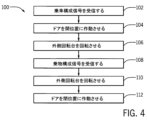
図4は、図1~図3に開示された特定の要素に関連して説明した、乗物車両10の構成操作100のフロー図である。ブロック102において、制御装置(例えば、球体制御装置76及び/又は乗物制御装置84)は、乗車構成信号を受信することができ、乗車構成信号は、乗物車両10が乗車構成に移行するよう合図し、それによって、ユーザー53は、乗物車両10に乗り込むことができる。例えば、乗物オペレータは、ボタンを押して(例えば、入力装置91によって)、乗車構成信号を制御装置に送ることができる。制御装置は、乗車構成信号を受信すると、乗物車両10のドア28を開位置に作動させるための対応する信号を送ることができる(ブロック104)。詳細には、ドア28は、最初に乗物車両10の球体14の中心に対して半径方向外向きに移動することができる。ドア28は、乗物車両10の球体14の表面を半径方向に超えると、ドア28は、乗物車両10の球体14の中心に対して円周方向に移動して開位置になることができる。ドア28が開位置になると、ユーザー53が乗物車両10に乗り込むことができる入口29つまり出入口が露出する。
FIG. 4 is a flow diagram of
また、制御装置は、乗車構成信号を受信すると、乗物車両10の外側回転台38を作動させるための対応する信号をモーター(例えば、回転台モーター49)に送ることができる(ブロック106)。例えば、外側回転台38は、1又は2以上のテーマ要素22を含むことができ、これは外側回転台38に結合され、外側回転台38とともに回転することができる。乗車構成信号の受信前、テーマ要素22の1又は2以上は、球体14の入口29と座席20との間に配置することができる。乗車構成信号の受信後、外側回転台38は、テーマ要素22が球体14の入口29と座席20との間の経路から除かれるように回転させることができる。例えば、一部の実施形態において、外側回転台38及びテーマ要素22は、球体14の入口29と座席20との間の経路から除かれるように約90°だけ回転させることができる。一部の実施形態において、上述したように、外側回転台38及びテーマ要素22の回転には、乗物車両10のモータから動力を供給することができる。付加的に又は代替的に、外側回転台38及びテーマ要素22の回転には、手動で動力を供給することができる(例えば、乗物オペレータによって)。実際には、一部の実施形態において、乗車構成信号は、第1のオペレータが外側回転台38及び/又はテーマ要素22を手動で回転させるように第2のオペレータに合図することを含むことができる。テーマ要素22が球体の入口29と座席20の間で経路の範囲外に回転した後、ユーザー53は、球体14に入ってそれぞれの座席20に着座することができる。さらに、ブロック104及び106で説明したような構成操作100の各部分は、同時に起こること、及び/又はブロック104又はブロック106の一方が他方よりも前に起こる逐次的とすることができることに留意されたい。
Also, upon receiving a ride configuration signal, the controller may send a corresponding signal to a motor (eg, carousel motor 49) to actuate the
ブロック108において、制御装置は、乗物車両10が乗物構成に移行するよう合図する乗物構成信号を受信することができ、それによって、乗物車両10は、乗物サイクル(例えば、アトラクション環境12の中を通る)を開始することができる。例えば、乗物オペレータは、ユーザー53の全員が拘束具を係合した状態でそれぞれの座席20に着座していることを確認した後にボタンを押して(例えば、入力装置91によって)、制御装置に乗物構成信号を送ることができる。制御装置は、乗物構成信号を受信すると、乗物車両10の外側回転台38を回転させるための対応する信号をモータに送ることができる。詳細には、外側ターンテーブル38は、対応する信号を制御装置から受信すると、テーマ要素22の1又は2以上が乗物車両10の座席20と乗物車両10の入口29との間に配置されるように回転(例えば、約90°)することができる(ブロック110)。実際には、一部の実施形態において、外側回転台38は、乗物オペレータによって手動で回転させることができる。詳細には、オペレータは、外側回転台38及び/又はテーマ要素22を手動で回転させることができる。
At
また、制御装置は、乗物構成信号を受信すると、乗物車両10のドア28を閉位置に作動させる信号を送ることができる(ブロック112)。詳細には、ドア28は、まず露出した入口29に向かって球体14の中心に対して円周方向に移動することができる。ドア28は、球体14の中心に対して半径方向で出入口よりも上方に配置されると、球体14の中心に対して半径方向で内向きに移動して入口29をカバーすることができる。詳細には、ドア28は、球体14の表面と面一の又は実質的に面一の位置に移動することができる。さらに、ブロック110及び112で説明したような構成操作100の各部分は、同時に起こること、及び/又はブロック110又はブロック112の一方が他方よりも前に起こる逐次的とすることができることに留意されたい。
Also, upon receiving the ride configuration signal, the controller may send a signal to actuate the
図5a及び図5bは、それぞれ乗物構成120及び乗車構成122での乗物車両10の球体14の斜視図である。実際には、一部の実施形態において、上述した図4の構成操作100は、乗物構成120と乗車構成122との間での乗物車両10の遷移を少なくとも部分的に説明することができる。例えば、乗物構成120において、テーマ要素22の1又は2以上は、入口29と座席20との間に配置されている。乗物構成120の間、乗物車両10は、テーマパーク乗物13のアトラクション環境12の中を通ることができる。しかしながら、乗車構成122において、テーマ要素22は、入口29と座席20との間に配置されず、ドア28は、入口29が露出するように移動している。乗車構成122の間、ユーザーは、入口29を通って球体14を出入りすることができる。一部の実施形態において、乗物車両10が乗車構成122である間、乗物車両10は、アトラクション環境12の中を通って移動するのを阻止することができる(例えば、ブレーキをかけることで)。
5a and 5b are perspective views of
図6は、実施形態による、乗物車両10の断面側面図である。この実施形態において、乗物車両10は、単一プラットフォーム又は回転台124を利用する。詳細には、図6の実施形態において、乗物車両10は、2つの別個の回転台(例えば、内側回転台36及び外側回転台38)、及び2つの別個の回転台を有することに関連した要素(例えば、内側ころ軸受40及び外側ころ軸受48)を有する代わりに、単一ころ軸受126のセットを有する単一回転台124を含むことができることを除いて、図1~図5に関して上述した実施形態と類似することができる。例えば、単一回転台124は、座席20及びユーザー53を支持するが、単一ころ軸受126は、球体14の内面50と相互作用することができる。実際には、上述した実施形態と同様に、単一ころ軸受126は、球体14の回転運動が単一回転台124に伝達しないように球体14の内面50に沿って摺動する(例えば、回転する)ことができる。このようにして、単一回転台124の上面128は、乗物車両10がアトラクション環境12の中を移動して球体14が回転している間に実質的に水平のままとすることができる。しかしながら、同様に上述したように、一部の実施形態において、乗物車両10は、ロッキングシステム57を含むことができ、これは、単一回転台124及び座席20が球体14の回転と連動して回転するのを可能にすることができる。さらに、単一回転台124は、静止プラットフォームとして所定の位置にロックすることができる。
FIG. 6 is a cross-sectional side view of
図7は、実施形態による、テーマパーク乗物13のブロック図である。上述したように、テーマパーク乗物13は、1又は2以上の乗物車両10、乗物車両10内に配置することができる球体制御装置76、及び乗物制御装置84を含むことができる。実際には、球体制御装置76、乗物制御装置84、及び乗物車両の要素(例えば、システム)は、互いに通信可能に接続することができる。例えば、一部の実施形態において、球体制御装置76、乗物制御装置84、及び乗物車両10は、ローカルエリアネットワーク(LAN)、無線ローカルエリアネットワーク(WLAN)、無線広域ネットワーク(WWAN)又は近距離無線通信(NFC)などのネットワークを介して通信可能に接続することができる。さらに、一部の実施形態において、球体制御装置76及び乗物制御装置84の機能は、単一の制御装置によって実行することができる。このような実施形態において、単一の制御装置は、乗物車両10の外部に位置することができ、乗物オペレータからの入力を受信するよう構成された1又は2以上の入力装置91を備える。
FIG. 7 is a block diagram of a
本発明の開示のある特定の特徴のみを本明細書に図示して説明したが、当業者には多くの修正及び変更が想起されるであろう。従って、添付の特許請求の範囲は、全てのそのような修正及び変更を本発明の開示の真の精神に該当するとして網羅するように意図していることを理解されたい。 While only certain specific features of the invention disclosure have been illustrated and described herein, many modifications and changes will occur to those skilled in the art. It is therefore to be understood that the appended claims are intended to cover all such modifications and alterations as fall within the true spirit of this disclosure.
本明細書に示して特許請求する技術は、本技術分野を確実に改善する、従って抽象的なもの、無形のもの又は純粋に理論的なものではない実際的性質の有形物及び具体例を参照し、これらに適用される。さらに、本明細書の最後に添付するいずれかの請求項が、「...[機能]を[実行]する手段」又は「...[機能]を[実行]するステップ」として指定されている1又は2以上の要素を含む場合、このような要素は米国特許法112条(f)に従って解釈すべきである。一方で、他のいずれかの形で指定された要素を含むあらゆる請求項については、このような要素を米国特許法112条(f)に従って解釈すべきではない。 The technology shown and claimed herein certainly improves the technical field, so reference is made to tangibles and examples of a practical nature that are not abstract, intangible, or purely theoretical. and apply to these. Furthermore, if any claim appended at the end of this specification is designated as "...means for [performing] [function]" or as "a step for [performing] [function]" 112(f), such elements are to be construed pursuant to 35 U.S.C. §112(f). However, for any claim containing any element otherwise specified, such element is not to be construed under 35 USC 112(f).
Claims (22)
アトラクション環境の中を移動するように構成された基部と、
前記基部に係合する球体であって、前記球体は前記球体内に配置された1又は2以上の乗物座席を含み、前記1又は2以上の乗物座席は前記球体内に配置されたプラットフォームの上面に結合される、球体と、
前記球体を前記基部に対して回転させるために前記球体の外面と係合するように構成された前記基部の球体駆動システムであって、前記プラットフォームの上面は、前記球体駆動システムが非垂直軸の周りで前記球体を回転させる間、前記基部の中心を通る垂直軸に対して直交方向を維持するように構成される、球体駆動システムと、
を含む、
乗物車両。 a vehicle,
a base configured to move through the attraction environment;
a sphere engaging said base, said sphere including one or more vehicle seats disposed within said sphere, said one or more vehicle seats being an upper surface of a platform disposed within said sphere; a sphere, coupled to
a sphere drive system of the base configured to engage an outer surface of the sphere to rotate the sphere with respect to the base, wherein the upper surface of the platform allows the sphere drive system to rotate along a non-vertical axis; a sphere drive system configured to maintain an orthogonal orientation to a vertical axis through the center of the base while rotating the sphere about;
including,
ride vehicle.
乗車構成信号を受け取るステップと、
前記受け取った乗車構成信号に基づいて乗物車両の球形キャビンのドアを開位置に作動させるステップと、
前記受け取った乗車構成信号に基づいて前記球形キャビン内に配置されるプラットフォームの外側回転台を前記プラットフォームの内側回転台に対して回転させるステップと、
前記乗車構成信号を受け取った後に1又は2以上の乗客を前記乗物車両の前記球形キャビンの中に受け入れるステップと、
乗物構成信号を受け取るステップと、
前記受け取った乗物構成信号に基づいて前記外側回転台を前記内側回転台に対して回転させるステップと、
前記受け取った乗物構成信号に基づいて前記乗物車両の前記ドアを閉位置に作動させるステップと、
を含み、
前記方法は、
前記球形キャビンを前記外側回転台に対して回転させる信号を受け取るステップと、
前記受け取った信号に基づいて前記球形キャビンを前記外側回転台に対して回転させるステップと、
を含み、
前記球形キャビンは、前記球形キャビン内に配置された1又は2以上の乗物座席を含み、前記1又は2以上の乗物座席は前記プラットフォームの上面に結合され、
前記球形キャビンを前記外側回転台に対して回転させるステップにおいて、前記プラットフォームの上面は、前記球形キャビンを支持するように構成された基部の中心を通る垂直軸に対して直交方向を維持するように構成される、
方法。 a method,
receiving a ride configuration signal;
actuating a spherical cabin door of the ride vehicle to an open position based on the received ride configuration signal;
rotating an outer carousel of a platform located within the spherical cabin relative to an inner carousel of the platform based on the received ride configuration signal;
receiving one or more passengers into the spherical cabin of the ride vehicle after receiving the ride configuration signal;
receiving a vehicle configuration signal;
rotating the outer carousel relative to the inner carousel based on the received vehicle configuration signal;
actuating the doors of the ride vehicle to a closed position based on the received ride configuration signal;
including
The method includes:
receiving a signal to rotate the spherical cabin relative to the outer rotating platform;
rotating the spherical cabin relative to the outer rotating platform based on the received signal;
including
the spherical cabin includes one or more vehicle seats disposed within the spherical cabin, the one or more vehicle seats coupled to an upper surface of the platform;
In the step of rotating the spherical cabin relative to the outer rotating platform, the upper surface of the platform is maintained orthogonal to a vertical axis through the center of a base configured to support the spherical cabin. composed of
Method.
前記ドアを前記球形キャビンの表面を半径方向に超えて移動させるステップと、
前記ドアを前記球形キャビンに対して円周方向に移動させるステップと、
を含む、請求項12に記載の方法。 The door is configured to form part of the spherical cabin of the ride vehicle, and actuating the door to the open position comprises:
moving the door radially over the surface of the spherical cabin ;
moving the door circumferentially relative to the spherical cabin ;
13. The method of claim 12, comprising:
球体駆動システムによって回転されるように構成された球形キャビンであって、前記球体駆動システムは、前記球形キャビンをその中心の周りで全ての方向に回転させることができるように回転運動を前記球形キャビンに伝えるように構成された複数の駆動装置を含む、球形キャビンと、
前記球形キャビンの中の1又は2以上のユーザーを支持するように構成された1又は2以上のプラットフォームであって、前記球形キャビンは、前記1又は2以上のプラットフォームに対して回転するように構成される、1又は2以上のプラットフォームと、
前記球体駆動システムを有する基部と、
前記1又は2以上のプラットフォームに結合され、前記1又は2以上のユーザーを支持するように構成された1又は2以上の座席であって、前記1又は2以上のプラットフォーム及び前記1又は2以上の座席は、非垂直軸周りの前記球形キャビンの回転の間、前記基部及び前記基部の中心を通る垂直軸に対して向きを維持するように構成される、1又は2以上の座席と、
を含む、乗物車両。 a vehicle,
A spherical cabin configured to be rotated by a spherical drive system, said spherical drive system imparting rotational motion to said spherical cabin so as to rotate said spherical cabin about its center in all directions. a spherical cabin including a plurality of drives configured to communicate with
One or more platforms configured to support one or more users in said spherical cabin, said spherical cabin configured to rotate relative to said one or more platforms one or more platforms, and
a base having said spherical drive system;
one or more seats coupled to said one or more platforms and configured to support said one or more users, wherein said one or more platforms and said one or more seats one or more seats configured to maintain orientation with respect to the base and a vertical axis through the center of the base during rotation of the spherical cabin about a non-vertical axis;
Vehicles, including
アトラクション環境の中を移動するように構成された基部と、
前記基部に係合する球体であって、前記球体は前記球体内に配置された1又は2以上の乗物座席を含み、前記1又は2以上の乗物座席は前記球体内に配置されたプラットフォームの上面に結合される、球体と、
前記球体を前記基部に対して回転させるために前記球体の外面と係合するように構成された前記基部の球体駆動システムであって、前記プラットフォームの上面は、前記球体駆動システムが前記球体を回転させる間、実質的に水平のままであるように構成され、前記球体はフレームに結合された複数のパネルを含む、球体駆動システムと、
を含む、乗物車両。 a vehicle,
a base configured to move through the attraction environment;
a sphere engaging said base, said sphere including one or more vehicle seats disposed within said sphere, said one or more vehicle seats being an upper surface of a platform disposed within said sphere; a sphere, coupled to
a sphere drive system of the base configured to engage an outer surface of the sphere to rotate the sphere with respect to the base , wherein the top surface of the platform is configured such that the sphere drive system rotates the sphere; a sphere drive system configured to remain substantially horizontal while driving, said sphere comprising a plurality of panels coupled to a frame;
Vehicles, including
Applications Claiming Priority (3)
| Application Number | Priority Date | Filing Date | Title |
|---|---|---|---|
| US15/806,053 US10293265B1 (en) | 2017-11-07 | 2017-11-07 | Systems and methods for a sphere ride |
| US15/806,053 | 2017-11-07 | ||
| PCT/US2018/059187 WO2019094325A1 (en) | 2017-11-07 | 2018-11-05 | Systems and methods for a sphere ride |
Publications (3)
| Publication Number | Publication Date |
|---|---|
| JP2021502160A JP2021502160A (en) | 2021-01-28 |
| JP2021502160A5 JP2021502160A5 (en) | 2021-12-16 |
| JP7322015B2 true JP7322015B2 (en) | 2023-08-07 |
Family
ID=64362760
Family Applications (1)
| Application Number | Title | Priority Date | Filing Date |
|---|---|---|---|
| JP2020524831A Active JP7322015B2 (en) | 2017-11-07 | 2018-11-05 | System and method for spherical vehicle |
Country Status (9)
| Country | Link |
|---|---|
| US (1) | US10293265B1 (en) |
| EP (1) | EP3706878B1 (en) |
| JP (1) | JP7322015B2 (en) |
| KR (1) | KR102644705B1 (en) |
| CN (1) | CN111295236B (en) |
| CA (1) | CA3079997A1 (en) |
| RU (1) | RU2769882C2 (en) |
| SG (1) | SG11202003444RA (en) |
| WO (1) | WO2019094325A1 (en) |
Families Citing this family (5)
| Publication number | Priority date | Publication date | Assignee | Title |
|---|---|---|---|---|
| US10832490B2 (en) * | 2016-03-11 | 2020-11-10 | Sangwha Co., Ltd. | Virtual reality experience apparatus capable of providing experiencing user with virtual reality image and physical motion |
| KR101885128B1 (en) * | 2016-03-11 | 2018-08-03 | 주식회사 상화 | Virtual reality experience apparatus |
| US10486558B1 (en) * | 2018-06-28 | 2019-11-26 | Ford Global Technologies, Llc | Turntable assembly for a vehicle |
| US11219311B1 (en) * | 2020-10-06 | 2022-01-11 | James Mark Kondziela | Ergonomic multi-positionable workstation |
| CN112790939B (en) * | 2021-04-12 | 2021-06-22 | 上海志听医疗科技有限公司 | Posture changing chair for vertigo diagnosis and treatment detection |
Citations (3)
| Publication number | Priority date | Publication date | Assignee | Title |
|---|---|---|---|---|
| US6017276A (en) | 1998-08-25 | 2000-01-25 | Elson; Matthew | Location based entertainment device |
| US20070089633A1 (en) | 2005-10-07 | 2007-04-26 | University Of South Florida | Interactive Amusement Park Attraction Vehicle |
| US20080300730A1 (en) | 2007-06-04 | 2008-12-04 | Cleary Joseph M | Roller-ball roller coaster |
Family Cites Families (26)
| Publication number | Priority date | Publication date | Assignee | Title |
|---|---|---|---|---|
| EP0159052A3 (en) * | 1984-04-20 | 1986-10-22 | Entreprises Robert Delbrassinne | Spherical transport vehicle, in particular for transporting persons in amusement parks |
| BE899473A (en) | 1984-04-20 | 1984-10-22 | Entpr S Robert Delbrassinne Sa | Spherical personnel transport for amusement parks - uses two concentric spherical shells, with inner one containing passengers and drive motors |
| US4856771A (en) * | 1987-10-22 | 1989-08-15 | Nelson, Berg Enterprises | Video simulation apparatus |
| US5060932A (en) | 1989-05-25 | 1991-10-29 | Nisshinbo Techno Vehicle Inc. | Amusement apparatus having rotary capsule |
| US5052932A (en) * | 1990-01-24 | 1991-10-01 | James Trani | Spherical simulator |
| US5489212A (en) * | 1990-07-02 | 1996-02-06 | Sega Enterprises Ltd. | Rotating simulator and body holding apparatus therefor |
| JPH04164479A (en) * | 1990-10-29 | 1992-06-10 | Kanematsu Kk | Riding device for playing |
| US5678889A (en) | 1996-04-09 | 1997-10-21 | Purcell, Jr.; Joseph William | Moveable theater seats |
| US5702307A (en) * | 1996-04-11 | 1997-12-30 | Moran; Kristen G. | Pivotal, spherically shaped, motion simulator-with shifting means for controlling its' center of gravity |
| CN2292588Y (en) * | 1997-03-14 | 1998-09-30 | 洪添富 | Space simulating machine for recreation |
| US6095926A (en) * | 1998-05-01 | 2000-08-01 | Universal Studios, Inc. | Amusement ride vehicle |
| US6024647A (en) | 1998-06-24 | 2000-02-15 | Universal Studios, Inc. | Amusement ride vehicle with motion controlled seating |
| US6220965B1 (en) * | 1998-07-08 | 2001-04-24 | Universal City Studios Inc. | Amusement system |
| US6053576A (en) | 1998-10-30 | 2000-04-25 | Jessee; Michael J | Bank of seats for amusement ride |
| US6354954B1 (en) | 2000-12-28 | 2002-03-12 | Disney Enterprises, Inc. | Amusement apparatus and method |
| US6796908B2 (en) * | 2001-06-14 | 2004-09-28 | Creative Kingdoms, Llc | Interactive dark ride |
| CN2699967Y (en) * | 2004-05-01 | 2005-05-18 | 袁丰久 | Human carrying balanced grounder |
| ITRE20060093A1 (en) | 2006-07-27 | 2008-01-28 | Acha S R L | EQUIPMENT FOR AMUSEMENT PARK |
| WO2009092452A1 (en) | 2008-01-25 | 2009-07-30 | Acha S.R.L. | Equipment for a funfair |
| CN101912689B (en) | 2010-08-04 | 2012-10-17 | 诺华特控股有限公司 | Dynamic emulation cinema analog system, method and equipment |
| AT511523B1 (en) | 2011-05-23 | 2013-06-15 | Amst Systemtechnik Gmbh | DEVICE FOR SPATIAL MOVEMENT OF PERSONS |
| US9011259B2 (en) * | 2013-03-15 | 2015-04-21 | Jordan Michael Schmidt | People mover |
| CN103711335B (en) | 2013-12-30 | 2016-05-04 | 深圳华侨城文化旅游科技股份有限公司 | A kind of comprehensive dynamic tracking viewing system |
| CN103691134B (en) | 2013-12-30 | 2015-09-09 | 深圳华侨城文化旅游科技股份有限公司 | A kind of Platform-type kinetic car |
| CN205759643U (en) * | 2016-06-03 | 2016-12-07 | 秦皇岛两只老虎科技有限公司 | Spherical vehicle |
| CN106428273A (en) * | 2016-08-31 | 2017-02-22 | 秦皇岛两只老虎科技有限公司 | Manned rolling two-wheeled vehicle |
-
2017
- 2017-11-07 US US15/806,053 patent/US10293265B1/en active Active
-
2018
- 2018-11-05 EP EP18804886.2A patent/EP3706878B1/en active Active
- 2018-11-05 SG SG11202003444RA patent/SG11202003444RA/en unknown
- 2018-11-05 KR KR1020207016011A patent/KR102644705B1/en active IP Right Grant
- 2018-11-05 CA CA3079997A patent/CA3079997A1/en active Pending
- 2018-11-05 RU RU2020117568A patent/RU2769882C2/en active
- 2018-11-05 WO PCT/US2018/059187 patent/WO2019094325A1/en unknown
- 2018-11-05 JP JP2020524831A patent/JP7322015B2/en active Active
- 2018-11-05 CN CN201880071703.XA patent/CN111295236B/en active Active
Patent Citations (3)
| Publication number | Priority date | Publication date | Assignee | Title |
|---|---|---|---|---|
| US6017276A (en) | 1998-08-25 | 2000-01-25 | Elson; Matthew | Location based entertainment device |
| US20070089633A1 (en) | 2005-10-07 | 2007-04-26 | University Of South Florida | Interactive Amusement Park Attraction Vehicle |
| US20080300730A1 (en) | 2007-06-04 | 2008-12-04 | Cleary Joseph M | Roller-ball roller coaster |
Non-Patent Citations (1)
| Title |
|---|
| moviecollectionjp,"映画『ジュラシック・ワールド』あの乗り物「ジャイロスフィア」制作の舞台裏/ボーナスDVD特典映像",YouTube [online] [video],2016年03月22日,<https://www.youtube.com/watch?v=_FUjZL-nQic>,特に0:00-0:35,2:06[2022年9月22日検索] |
Also Published As
| Publication number | Publication date |
|---|---|
| JP2021502160A (en) | 2021-01-28 |
| SG11202003444RA (en) | 2020-05-28 |
| CN111295236A (en) | 2020-06-16 |
| CN111295236B (en) | 2021-12-07 |
| US10293265B1 (en) | 2019-05-21 |
| WO2019094325A1 (en) | 2019-05-16 |
| KR20200083572A (en) | 2020-07-08 |
| EP3706878B1 (en) | 2024-02-07 |
| CA3079997A1 (en) | 2019-05-16 |
| RU2020117568A (en) | 2021-12-08 |
| US20190134515A1 (en) | 2019-05-09 |
| RU2769882C2 (en) | 2022-04-07 |
| KR102644705B1 (en) | 2024-03-06 |
| EP3706878A1 (en) | 2020-09-16 |
| RU2020117568A3 (en) | 2021-12-08 |
Similar Documents
| Publication | Publication Date | Title |
|---|---|---|
| JP7322015B2 (en) | System and method for spherical vehicle | |
| US8641540B2 (en) | Inverted simulation attraction | |
| EP2318106B1 (en) | Amusement park ride with vehicles pivoting about a common chassis to provide racing and other effects | |
| KR101319051B1 (en) | Amusement ride track with motion base | |
| US7770523B2 (en) | Interactive amusement park attraction vehicle | |
| CN107303434B (en) | Amusement park riding device | |
| US6402624B1 (en) | Amusement ride without hubs and spokes | |
| US8057317B2 (en) | Amusement park attraction | |
| JP2005520665A (en) | Recreational vehicle | |
| US7918740B2 (en) | Big wheel roundabout amusement ride | |
| JP2008540054A (en) | Wheel hub vehicle carrier | |
| WO2016201755A1 (en) | Entertainment-oriented multi-mode experience system | |
| JP2021502160A5 (en) | ||
| CN105169704B (en) | Sectional track live shell interaction gun post and its application method | |
| JP4820018B2 (en) | Ferris wheel and high-rise building equipped with the same | |
| CN203170025U (en) | Snatching-type dynamic rail cart | |
| JP2022518971A (en) | Vertical motion drive system for vehicle systems | |
| JP2022527492A (en) | Rotating platform coaster | |
| JP4486398B2 (en) | Ferris wheel, control device for ferris wheel, and computer program for controlling ferris wheel | |
| JP2828487B2 (en) | Gondola cabin body | |
| JP2020534983A (en) | Amusement park capsule type vehicle |
Legal Events
| Date | Code | Title | Description |
|---|---|---|---|
| A521 | Request for written amendment filed |
Free format text: JAPANESE INTERMEDIATE CODE: A523 Effective date: 20211105 |
|
| A621 | Written request for application examination |
Free format text: JAPANESE INTERMEDIATE CODE: A621 Effective date: 20211105 |
|
| A977 | Report on retrieval |
Free format text: JAPANESE INTERMEDIATE CODE: A971007 Effective date: 20220930 |
|
| A131 | Notification of reasons for refusal |
Free format text: JAPANESE INTERMEDIATE CODE: A131 Effective date: 20221003 |
|
| A601 | Written request for extension of time |
Free format text: JAPANESE INTERMEDIATE CODE: A601 Effective date: 20221228 |
|
| A601 | Written request for extension of time |
Free format text: JAPANESE INTERMEDIATE CODE: A601 Effective date: 20230303 |
|
| A521 | Request for written amendment filed |
Free format text: JAPANESE INTERMEDIATE CODE: A523 Effective date: 20230331 |
|
| TRDD | Decision of grant or rejection written | ||
| A01 | Written decision to grant a patent or to grant a registration (utility model) |
Free format text: JAPANESE INTERMEDIATE CODE: A01 Effective date: 20230626 |
|
| A61 | First payment of annual fees (during grant procedure) |
Free format text: JAPANESE INTERMEDIATE CODE: A61 Effective date: 20230726 |
|
| R150 | Certificate of patent or registration of utility model |
Ref document number: 7322015 Country of ref document: JP Free format text: JAPANESE INTERMEDIATE CODE: R150 |