JP7318809B2 - VIDEO ANALYSIS DEVICE, VIDEO ANALYSIS SYSTEM AND VIDEO ANALYSIS METHOD - Google Patents
VIDEO ANALYSIS DEVICE, VIDEO ANALYSIS SYSTEM AND VIDEO ANALYSIS METHOD Download PDFInfo
- Publication number
- JP7318809B2 JP7318809B2 JP2022515228A JP2022515228A JP7318809B2 JP 7318809 B2 JP7318809 B2 JP 7318809B2 JP 2022515228 A JP2022515228 A JP 2022515228A JP 2022515228 A JP2022515228 A JP 2022515228A JP 7318809 B2 JP7318809 B2 JP 7318809B2
- Authority
- JP
- Japan
- Prior art keywords
- video analysis
- unit
- video
- detection
- analysis means
- Prior art date
- Legal status (The legal status is an assumption and is not a legal conclusion. Google has not performed a legal analysis and makes no representation as to the accuracy of the status listed.)
- Active
Links
Images


Classifications
-
- G—PHYSICS
- G06—COMPUTING; CALCULATING OR COUNTING
- G06T—IMAGE DATA PROCESSING OR GENERATION, IN GENERAL
- G06T7/00—Image analysis
- G06T7/20—Analysis of motion
- G06T7/215—Motion-based segmentation
-
- G—PHYSICS
- G06—COMPUTING; CALCULATING OR COUNTING
- G06V—IMAGE OR VIDEO RECOGNITION OR UNDERSTANDING
- G06V20/00—Scenes; Scene-specific elements
- G06V20/50—Context or environment of the image
- G06V20/56—Context or environment of the image exterior to a vehicle by using sensors mounted on the vehicle
-
- G—PHYSICS
- G06—COMPUTING; CALCULATING OR COUNTING
- G06T—IMAGE DATA PROCESSING OR GENERATION, IN GENERAL
- G06T1/00—General purpose image data processing
- G06T1/20—Processor architectures; Processor configuration, e.g. pipelining
-
- G—PHYSICS
- G06—COMPUTING; CALCULATING OR COUNTING
- G06T—IMAGE DATA PROCESSING OR GENERATION, IN GENERAL
- G06T2210/00—Indexing scheme for image generation or computer graphics
- G06T2210/12—Bounding box
-
- H—ELECTRICITY
- H04—ELECTRIC COMMUNICATION TECHNIQUE
- H04N—PICTORIAL COMMUNICATION, e.g. TELEVISION
- H04N21/00—Selective content distribution, e.g. interactive television or video on demand [VOD]
- H04N21/20—Servers specifically adapted for the distribution of content, e.g. VOD servers; Operations thereof
- H04N21/23—Processing of content or additional data; Elementary server operations; Server middleware
- H04N21/234—Processing of video elementary streams, e.g. splicing of video streams, manipulating MPEG-4 scene graphs
- H04N21/2343—Processing of video elementary streams, e.g. splicing of video streams, manipulating MPEG-4 scene graphs involving reformatting operations of video signals for distribution or compliance with end-user requests or end-user device requirements
- H04N21/234381—Processing of video elementary streams, e.g. splicing of video streams, manipulating MPEG-4 scene graphs involving reformatting operations of video signals for distribution or compliance with end-user requests or end-user device requirements by altering the temporal resolution, e.g. decreasing the frame rate by frame skipping
-
- H—ELECTRICITY
- H04—ELECTRIC COMMUNICATION TECHNIQUE
- H04N—PICTORIAL COMMUNICATION, e.g. TELEVISION
- H04N21/00—Selective content distribution, e.g. interactive television or video on demand [VOD]
- H04N21/40—Client devices specifically adapted for the reception of or interaction with content, e.g. set-top-box [STB]; Operations thereof
- H04N21/43—Processing of content or additional data, e.g. demultiplexing additional data from a digital video stream; Elementary client operations, e.g. monitoring of home network or synchronising decoder's clock; Client middleware
- H04N21/44—Processing of video elementary streams, e.g. splicing a video clip retrieved from local storage with an incoming video stream, rendering scenes according to MPEG-4 scene graphs
- H04N21/44008—Processing of video elementary streams, e.g. splicing a video clip retrieved from local storage with an incoming video stream, rendering scenes according to MPEG-4 scene graphs involving operations for analysing video streams, e.g. detecting features or characteristics in the video stream
-
- H—ELECTRICITY
- H04—ELECTRIC COMMUNICATION TECHNIQUE
- H04N—PICTORIAL COMMUNICATION, e.g. TELEVISION
- H04N7/00—Television systems
- H04N7/18—Closed-circuit television [CCTV] systems, i.e. systems in which the video signal is not broadcast
Description
本発明は映像分析装置、映像分析システム及び映像分析方法に関する。 The present invention relates to a video analysis device, a video analysis system and a video analysis method.
非特許文献1には、一連の映像フレームについて、複数の映像分析部で分散して映像分析を行う技術が開示されている。
しかしながら、非特許文献1に記載の技術では、依然として映像分析の精度が十分ではないという問題がある。
本発明は、このような問題点を解決するためになされたものであり、映像分析精度を向上させた映像分析装置、映像分析システム及び映像分析方法を提供することを目的とする。However, the technique described in
SUMMARY OF THE INVENTION It is an object of the present invention to provide a video analysis apparatus, a video analysis system, and a video analysis method with improved video analysis accuracy.
本発明の第1の態様にかかる映像分析装置は、
第1映像分析部と第2映像分析部とを備えた映像分析装置であって、
前記第1映像分析部は、
少なくとも2つのフレームを前記第1映像分析部か、前記第2映像分析部に振り分ける振り分け部と、
前記第1映像分析部に振り分けられたフレーム内の対象物を検出する第1検出部と、
前記検出された対象物に関連付けられた移動に関する情報を取得し、前記移動に関する情報と前記第1検出部での検出結果を前記第2映像分析部に送信する取得部と、
を備え、
前記第2映像分析部は、
前記振り分け部から受信したフレーム内の対象物を検出する第2検出部と、
前記第2検出部での検出結果と前記移動に関する情報に基づいて、前記第1検出部での検出結果を調整する調整部と、
を備える。The video analysis device according to the first aspect of the present invention comprises
A video analysis device comprising a first video analysis unit and a second video analysis unit,
The first video analysis unit
a sorting unit that sorts at least two frames to the first video analysis unit or the second video analysis unit;
a first detection unit that detects an object in the frames sorted by the first image analysis unit;
an acquisition unit that acquires information on movement associated with the detected object and transmits the information on movement and the detection result of the first detection unit to the second video analysis unit;
with
The second video analysis unit
a second detection unit that detects an object in the frame received from the sorting unit;
an adjustment unit that adjusts the detection result of the first detection unit based on the detection result of the second detection unit and the information about the movement;
Prepare.
本発明の第2の態様にかかる映像分析システムは、
第1映像分析部と、第2映像分析部とを備えた映像分析システムであって、
前記第1映像分析部は、
少なくとも2つのフレームを前記第1映像分析部か、前記第2映像分析部に振り分ける振り分け部と、
前記第1映像分析部に振り分けられたフレーム内の対象物を検出する第1検出部と、
前記検出された対象物に関連付けられた移動に関する情報を取得し、前記移動に関する情報と前記第1検出部での検出結果を前記第2映像分析部に送信する取得部と、
を備え、
前記第2映像分析部は、
前記振り分け部から受信したフレーム内の対象物を検出する第2検出部と、
前記第2検出部での検出結果と前記移動に関する情報に基づいて、前記第1検出部での検出結果を調整する調整部と、
を備える。A video analysis system according to a second aspect of the present invention comprises:
A video analysis system comprising a first video analysis unit and a second video analysis unit,
The first video analysis unit
a sorting unit that sorts at least two frames to the first video analysis unit or the second video analysis unit;
a first detection unit that detects an object in the frames sorted by the first image analysis unit;
an acquisition unit that acquires information on movement associated with the detected object and transmits the information on movement and the detection result of the first detection unit to the second video analysis unit;
with
The second video analysis unit
a second detection unit that detects an object in the frame received from the sorting unit;
an adjustment unit that adjusts the detection result of the first detection unit based on the detection result of the second detection unit and the information about the movement;
Prepare.
本発明の第3の態様にかかる映像分析方法は、
一連のフレームに対して第1映像分析部と第2映像分析部で分散して映像分析を行う映像分析方法であって、
前記第1映像分析部において、
少なくとも2つのフレームを連続して受信し、前記第1映像分析部で分析するか、前記第2映像分析部で分析するかを振り分け、
前記第1映像分析部で分析すると振り分けられたフレーム内の対象物を検出し、
前記検出された対象物に関連付けられた移動に関する情報を取得し、前記移動に関する情報と前記第1映像分析部での検出結果を前記第2映像分析部に送信し、
前記第2映像分析部において、
前記第1映像分析部から受信したフレーム内の対象物を検出し、
前記第2映像分析部での検出結果と前記移動に関する情報に基づいて、前記第1映像分析部での検出結果を調整する。A video analysis method according to a third aspect of the present invention comprises:
A video analysis method in which a first video analysis unit and a second video analysis unit perform distributed video analysis on a series of frames,
In the first video analysis unit,
receiving at least two frames in succession and sorting whether to analyze by the first video analysis unit or by the second video analysis unit;
Detecting an object in the frame sorted by the analysis by the first video analysis unit;
acquiring information about movement associated with the detected object, transmitting the information about the movement and the detection result of the first image analysis unit to the second image analysis unit;
In the second video analysis unit,
detecting an object in the frame received from the first video analysis unit;
The detection result of the first image analysis unit is adjusted based on the detection result of the second image analysis unit and the information about the movement.
本発明によれば、映像分析精度を向上させた映像分析装置、映像分析システム及び映像分析方法を提供することができる。 According to the present invention, it is possible to provide a video analysis device, a video analysis system, and a video analysis method with improved video analysis accuracy.
実施の形態1
以下、図面を参照して本発明の実施の形態について説明する。
図1は、実施の形態1にかかる映像分析装置の構成を示すブロック図である。
映像分析装置1は、少なくとも2つのフレームを分散して処理するために、第1映像分析部100と第2映像分析部200とを備える。映像分析装置1は、1つ又はそれ以上のコンピュータにより実現され得る。少なくとも2つのフレームは、連続する2つのフレームでもよいし、別のフレームを挟んだ2つのフレームでもよい。
BEST MODE FOR CARRYING OUT THE INVENTION Hereinafter, embodiments of the present invention will be described with reference to the drawings.
FIG. 1 is a block diagram of a configuration of a video analysis apparatus according to a first embodiment; FIG.
The
第1映像分析部100は、少なくとも2つのフレームを、第1映像分析部100か、第2映像分析部200に振り分ける振り分け部103と、第1映像分析部100で分析すると振り分けられたフレーム内の対象物を検出する第1検出部105と、検出された対象物に関連付けられた移動に関する情報を取得し、当該移動に関する情報と第1検出部105での検出結果を第2映像分析部200に送信する取得部106と、を備える。第1検出部105は、所定の映像分析プログラムを用いて、フレームから、予め指定された対象物を検出する。振り分け部103は、予め設定された振り分け率で、フレームを第1映像分析部100か、第2映像分析部200に振り分けることができる。「検出された対象物に関連付けられた移動に関する情報」とは、例えば、対象物を囲うバウンディングボックス内の対象物の移動する方向の情報又は移動ベクトルを含んでもよい。
The first
第2映像分析部200は、振り分け部103からのフレーム内の対象物を検出する第2検出部205と、第2検出部205での検出結果と前記移動に関する情報に基づいて、第1検出部105での検出結果を調整する調整部207と、を備える。第2検出部205は、所定の映像分析プログラムを用いて、フレームの中から、予め指定された対象物を検出する。
The second
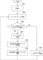
図2は、実施の形態1にかかる映像分析方法を示すフローチャートである。
実施の形態1にかかる映像分析方法は、少なくとも2つのフレームを第1映像分析部100と第2映像分析部200において分散して処理する。FIG. 2 is a flow chart showing the video analysis method according to the first embodiment.
The video analysis method according to the first embodiment distributes and processes at least two frames in the first
第1映像分析部100において、連続して受信した少なくとも2つのフレームを、前記第1映像分析部100か、第2映像分析部200に振り分ける(ステップS101)。第1映像分析部100に振り分けられたフレーム内の対象物を検出する(ステップS102)。検出された対象物に関連付けられた移動に関する情報を取得し、移動に関する情報と第1映像分析部100での検出結果を第2映像分析部200に送信する(ステップS103)。第2映像分析部200において、第1映像分析部100から受信したフレーム内の対象物を検出する(ステップS103)。第2映像分析部200において、第2映像分析部200での検出結果と移動に関する情報に基づいて、第1映像分析部100での検出結果を調整する(ステップS105)。
In the first
以上説明した実施の形態1にかかる映像分析装置および映像分析方法によれば、複数の映像分析部において、少なくとも2つのフレームを分散して処理しても、高精度な映像分析結果を得ることができる。 According to the video analysis apparatus and the video analysis method according to the first embodiment described above, highly accurate video analysis results can be obtained even if at least two frames are distributed and processed in a plurality of video analysis units. can.
実施の形態2
図3は、実施の形態2にかかる映像分析装置の構成を示すブロック図である。
映像分析装置1aは、一連のフレーム(少なくとも2つのフレームを含む)を分散して処理するために、第1映像分析部100aと第2映像分析部200aとを備える。
FIG. 3 is a block diagram of a configuration of a video analysis apparatus according to a second embodiment;
The video analysis device 1a includes a first
第1映像分析部100aは、カメラから受信した少なくとも2つの一連のフレームを第1映像分析部100aか、第2映像分析部200aに振り分ける振り分け部103aと、第1映像分析部100に振り分けられたフレーム内の対象物を検出する第1検出部105aと、検出された対象物内の移動に関する情報を取得する移動情報取得部106aと、移動に関する情報と第1検出部105aでの検出結果を第2映像分析部に送信する分析結果送信部107aと、第2映像分析部200aに振り分けられたフレームを第2映像分析部200aに送信するフレーム送信部109aと、を備える。
第1検出部105aは、所定の映像分析プログラムを用いて、フレームから、予め指定された対象物を検出する。検出された対象物は、バウンディングボックスにより囲われ得る。移動情報取得部106aは、2つのフレーム間において、対象物が動いていることを認識し、バウンディングボックス内の対象物に関する移動情報を取得する。移動情報取得部106aは、第1映像分析部100a内の記憶部に一時的に格納された映像フレームと、第1検出部105aからの検出結果フレームとを比較して、移動情報を取得することができる。取得される移動情報は、対象物の移動する方向の情報又は移動ベクトルを含んでもよい。振り分け部103は、予め設定された振り分け率で、フレームを第1映像分析部100か、第2映像分析部200に振り分けることができる。例えば、振り分け率が10%と設定されている場合、振り分け部103は、連続して受信するフレームを振り分けカウンタを用いてカウントし、最初のフレームを第2映像分析部200に送信した後、残りの9枚のフレームを第1映像分析部100に振り分けることができる。振り分け率は、閾値以上に設定されている。The first
The
「検出された対象物の検出領域内の移動に関する情報」とは、例えば、対象物を囲うバウンディングボックス内の対象物の移動する方向の情報又は移動ベクトルを含んでもよい。 "Information on the movement of the detected object within the detection area" may include, for example, information on the direction of movement of the object within the bounding box surrounding the object or a movement vector.
フレーム送信部109aは、映像フレームを所定の品質で符号化するエンコーダを備えてもよい。本実施の形態にかかる第1映像分析部100aは、分析結果送信部107aと、フレーム送信部109aと、を備える。分析結果送信部107aは、第1映像分析部100aに振り分けられたフレームについての移動ベクトルと、検出結果を分析結果として、第2映像分析部200aに送信する。そのため、分析結果送信部107aのフレーム当たりの送信データ容量は、比較的少ない。一方、フレーム送信部109aは、第2映像分析部200aに振り分けられたフレームを所定の品質で符号化して送信するため、フレーム送信部109aのフレーム当たりの送信データ容量は、分析結果送信部107aより大きくなる。なお、以上説明したように、分析結果送信部107aと、フレーム送信部109aとは、異なるフレーム、すなわち、振り分け部103aにおいて、第1映像分析部100aに振り分けられたフレームと、第2映像分析部200aに振り分けられたフレームに対処するものである。
The
第2映像分析部200aは、フレーム送信部109aから受信したフレーム内の対象物を検出する第2検出部205aと、第2検出部205aでの検出結果と移動に関する情報に基づいて、第1検出部105aでの検出結果を調整する調整部207aと、を備える。第2検出部205aは、第1検出部105aの映像分析プログラムとは異なる、又はより高精度な所定の映像分析プログラムを用いて、フレームから、予め指定された対象物を検出する。
The second
図4は、実施の形態2にかかる映像分析方法を示すフローチャートである。
実施の形態2にかかる映像分析方法は、少なくとも2つのフレームを第1映像分析部100と第2映像分析部200において分散して処理する。FIG. 4 is a flow chart showing a video analysis method according to the second embodiment.
The video analysis method according to the second embodiment distributes and processes at least two frames in the first
第1映像分析部100aは、カメラから受信した一連のフレームを第1映像分析部100aか、第2映像分析部200aに別々に振り分ける(ステップS201)。第1映像分析部100aは、第1映像分析部100aに振り分けられたフレーム内の対象物を検出する(ステップS202)。第1映像分析部100aは、検出された対象物の検出領域(例えば、バウンディングボックス)内の移動に関する情報を取得する(ステップS203)。第1映像分析部100aは、移動に関する情報と第1映像分析部100aでの検出結果を第2映像分析部200aに送信する(ステップS204)。第1映像分析部100aは第2映像分析部200aに振り分けられたフレームを第2映像分析部200aに送信する(ステップS205)。
The first
第2映像分析部200aは、第1映像分析部100aから受信したフレーム内の対象物を検出する(ステップS206)。第2映像分析部200aでの検出結果と、第1映像分析部100aから受信した移動に関する情報に基づいて、第1映像分析部100aでの検出結果を調整する(ステップS207)。
The second
以上説明した実施の形態2にかかる映像分析装置および映像分析方法によれば、複数の映像分析部において、一連のフレームを分散して処理しても、高精度な映像分析結果を得ることができる。 According to the video analysis apparatus and the video analysis method according to the second embodiment described above, highly accurate video analysis results can be obtained even if a series of frames are distributed and processed in a plurality of video analysis units. .
実施の形態3
図5は、実施の形態3にかかる映像分析システムの構造を示すブロック図である。
映像分析システム1bは、第1映像分析部100bと、第2映像分析部200bと、を備える。第1映像分析部100bは、エッジ側に配置され、カメラと有線又は無線で接続されている。第1映像分析部100bとカメラが、例えば、Wi-Fi(登録商標)などの無線通信で接続される場合、接続台数が少ないので、4G、5G等の携帯電話網と比べて、安定した通信が可能となる。第1映像分析部100bは電源や設置スペースの制約から、十分な計算リソースを用意できず、計算コストの低い低精度モデルとなる場合が多い。一方、第2映像分析部200は、第1映像分析部100とLTE(登録商標)や5G、Wi-fi(登録商標)などの無線ネットワークを介して接続され、第1映像分析部100bに比べて、計算リソースが潤沢であるので、高精度な映像分析を実現する。
FIG. 5 is a block diagram showing the structure of the video analysis system according to the third embodiment.
The
まず、第1映像分析部100bの構成を説明する。第1映像分析部100bは、例えば、コンピュータにより実現され得る車載用の映像分析装置である。第1映像分析部100bは、例えば、図17に示すように、演算処理等を行うCPU(Central Processing Unit)などのプロセッサ1202、プロセッサ1202によって実行される演算プログラム等が記憶されたROM(Read Only Memory)やRAM(Random Access Memory)からなるメモリ1203、外部と信号の入出力を行うインターフェイス部(I/F)1201、などからなるマイクロコンピュータ等により構成されている。プロセッサ1202、メモリ1203、及びインターフェイス部1201は、データバスなどを介して相互に接続されている。インターフェイス部(I/F)1201は、IEEE 802.11 seriesにおいて規定された無線LAN通信、もしくは3GPP(3rd Generation Partnership Project)において規定されたモバイル通信を行うために使用されてもよい。もしくは、インターフェイス部(I/F)1201は、例えば、IEEE 802.3 seriesに準拠したネットワークインターフェースカード(NIC)を含んでもよい。
First, the configuration of the first
第1映像分析部100bは、図5に示すように、映像フレーム受信部101b、フレーム振り分け部103b、変更部104b、第1検出部105b、移動ベクトル取得部106b、分析結果送信部107b、エンコーダ108b及び記憶部110bを含む。
As shown in FIG. 5, the first
映像フレーム受信部101bは、車載カメラ(不図示)から有線ネットワークを介して1つ以上の映像フレームを連続的に受信する。なお、本例では車載カメラを例に説明するが、固定カメラなどの他のカメラであってもよい。受信した各映像フレームは、記憶部110bに一時的に格納される。
The video
フレーム振り分け部103bは、映像フレーム受信部101bからの各映像フレームについて、第1映像分析部100bで分析するか、それとも第2映像分析部200bで分析するかを所定のフレーム送信割合(振り分け率とも呼ばれる場合がある)で振り分ける。例えば、所定のフレーム送信割合が10%と設定された場合、連続的に受信する10枚の映像フレームのうち、第2映像分析部200bに1枚のフレームを送信した後、9枚のフレームを第1映像分析部100bに振り分ける。フレーム振り分け部103bは、連続的に受信する映像フレームを所定のフレーム送信割合以上で、第2映像分析部200bで分析するように振り分ける。所定のフレーム送信割合は、第1映像分析部100bから第2映像分析部200bへの無線ネットワークの可用帯域に基づいて設定され得る。
The
またフレーム振り分け部103bは、無線ネットワークでデータを送信するために使用可能である帯域を示す可用帯域を推定する。例えば、フレーム振り分け部103bは、可用帯域をレベル分けした値(例えば、大、中、小)で評価し、評価した可用帯域に基づいて、段階的にフレーム送信割合を変更してもよい(詳細は後述する)。
Also, the
エンコーダ108bは、第2映像分析部200bで分析するように振り分けられた映像フレームをフレーム振り分け部103bから受信すると、映像フレームを所定の品質で符号化し、符号化された映像フレームを第2映像分析部200bに送信する。
When the
一方、フレーム振り分け部103bにおいて第1映像分析部100bで分析するように振り分けられた映像フレームは、第1検出部105bに送られる。
On the other hand, the video frames sorted by the
第1検出部105bは、振り分けられたフレーム内の対象物を検出する。具体的には、第1検出部105bは、映像分析ブログラムA(エッジモデル、軽量モデル又は低精度モデルとも呼ばれる場合がある)を用いて、フレーム振り分け部103bで振り分けられた映像フレームに対して画像分析を実行する。図6は、第1映像分析部で検出される例示的な対象物を含む映像フレームを示す図である。軽量モデルの例としては、認識精度が若干劣るが高速で動作可能なYOLOv3 Tinyが挙げられる。図6は、走行中の車両の車載カメラが前方を撮影した例示の映像フレームを示す。本例では、自動車、トラック、バス、オートバイ、自転車、歩行者、信号機など交通関連の対象物が検出される。図6に示すように、検出された各対象物は、バウンディングボックスで囲われている。また、バウンディングボックスの近傍に示された表記「Car:3%」は、検出対象物が自動車である確率(信頼度)が3%であることを示している。なお、交通に関する対象物の場合、1フレームあたり1~200個程度の対象物が検出され得る。
The
移動ベクトル取得部106bは、2つのフレーム間における、第1検出部105bで検出された対象物内の移動ベクトルを取得する。すなわち、移動ベクトル取得部106bは、第1検出部105bからの検出結果フレームと、記憶部110bに記憶されたフレームとの輝度勾配等を比較して、移動ベクトルを取得することができる。図7は、移動ベクトルを算出する例を説明する図である。図7(a)は時刻tに撮影された映像フレーム内の検出された自動車を示す。移動ベクトル取得部106bは、破線で示したバウンディングボックス内の移動ベクトルの平均値を取得する。この移動ベクトルは、2つのフレームがどれくらいずれているかを算出し、検出位置を調整するのに使用され得る。2つのフレームは、時系列に沿って連続する2つのフレーム(例えば、t-1,t)でもよいし、所定時間だけ離れている2つのフレーム(例えば、t-5,t)でもよい。ここでは、移動ベクトルは、Optical FlowをGunnar Farneback法を使って取得される。すなわち、まず、フレーム全体において、ピクセル当たりx方向及びy方向の移動ベクトルが生成される。その後、各エッジ対象物の検出領域(例えば、バウンディングボックス)内の平均ベクトルを算出する。これにより、フレーム間において、各検出対象物がどの方向に移動しているかを認識することができる。
The motion
図7(b)は、調整部207bにおいて、取得した移動ベクトルに基づき、シフトした自動車を示す(すなわち、図7(b)は、時刻t+1の映像フレームを推定したものである)。実線で示したバウンディングボックスは、シフト後のバウンディングボックスを示している。このように、移動ベクトルに基づき、対象物を所定時間分移動させることができる。本実施の形態では、このように2つのフレーム全体の移動ベクトルではなく、検出された対象物又はバウンディングボックスに関連付けられた移動ベクトルのみに絞ることで、データ容量を大幅に削減することができる。
FIG. 7(b) shows the shifted car based on the acquired motion vectors in the
分析結果送信部107bは、第1検出部105で検出された対象物と、移動ベクトル取得部106で取得された移動ベクトルを、分析結果として、無線ネットワークを介して第2映像分析部200bに送信する。分析結果は、例えば、バウンディングボックスの中心座標(x、y)、幅、高さ、検出された対象物の識別子、検出された対象物の数、移動ベクトル(x、y)を含み得る。つまり、分析結果送信部107bは、第1映像分析部100bで分析した映像フレーム自体ではなく、こうした分析結果を第2映像分析部200bに送信する。これにより、第1映像分析部100bで分析した映像フレーム自体を送信する場合よりも、送信データ容量を低減し、帯域不足に起因する問題(ブロックノイズやフレーム落ちなど)の発生を抑制する。
The analysis
続いて、第2映像分析部200bの構成を説明する。第2映像分析部200bは、例えば、コンピュータにより実現され得るクラウドサーバである。第2映像分析部200bは、例えば、図17に示すように、演算処理等を行うCPU(Central Processing Unit)などのプロセッサ1202、プロセッサ1202によって実行される演算プログラム等が記憶されたROM(Read Only Memory)やRAM(Random Access Memory)からなるメモリ1203、外部と信号の入出力を行うインターフェイス部(I/F)1201、などからなるマイクロコンピュータ等により構成されている。プロセッサ1202、メモリ1203、及びインターフェイス部1201は、データバスなどを介して相互に接続されている。インターフェイス部(I/F)は、IEEE 802.11 seriesにおいて規定された無線LAN通信、もしくは3GPP(3rd Generation Partnership Project)において規定されたモバイル通信を行うために使用されてもよい。もしくは、インターフェイス部(I/F)1201は、例えば、IEEE 802.3 seriesに準拠したネットワークインターフェースカード(NIC)を含んでもよい。
Next, the configuration of the second
第2映像分析部200bは、図5に示すように、デコーダ201b、分析結果受信部203b、第2検出部205b、分析結果調整部207b、及び帯域推定部212bを含む。
The second
デコーダ201bは、エンコーダ108bで符号化された映像フレームを復号し、映像フレームを第2検出部205bに送信する。デコーダ201bは、エンコーダ108からの映像フレームを受信し、一時的に格納するフレームバッファを備えてもよい。
The
第2検出部205bは、振り分けられたフレーム内の対象物を検出する。具体的には、第2検出部205bは、デコーダ201からの映像フレームに対して、映像分析ブログラムAより高精度な映像分析が可能な映像分析ブログラムB(クラウドモデル又は高精度モデルとも呼ばれる場合がある)で画像分析を実行する。高精度モデルの例としては、一般物体検出とセグメンテーションを行うMask RCNNが挙げられる。図8は、第2映像分析部で検出される例示的な対象物を含む映像フレームを示す図である。図8は、図6と同一の映像フレームを、高精度モデルで対象物を検出した結果を示す。本例では、図8に示すように、自動車、自転車、歩行者、信号機など交通関連の対象物が検出される。検出された各対象物は、バウンディングボックスで囲われている。図8は、バウンディングボックスの近傍に示された表記「Car:99%」は、検出対象物が自動車である確率(信頼度)が99%であることを示している。図8は、図6と比べると、高信頼度で対象物を検出していることを示している。
The
一方、分析結果受信部203bは、分析結果送信部107bからの分析結果を受信する。分析結果受信部203bは、分析結果データを一時的に格納する分析結果データ用バッファであってもよい。
On the other hand, the analysis
分析結果調整部207bは、第2検出部205bにより対象物が検出された映像フレーム(対象物はバウンディングボックスで囲まれている)と移動ベクトルとに基づいて、映像フレームを調整する。具体的には、分析結果調整部207bは、第2検出部205bにより対象物が検出された映像フレームと、移動ベクトルとに基づき、映像フレームの後に撮影された映像フレームを調整する。分析結果調整部207bは、例えば、第2検出部205bにより対象物が検出された映像フレーム(対象物はバウンディングボックスで囲まれている)と、移動ベクトルとに基づき、第1検出部105bによる検出結果から、対象物の位置を調整する。換言すると、分析結果調整部207bは、第2検出部205bの高精度モデルの検出結果を参照して、第1検出部105bによる低精度モデルの検出結果を調整する。分析結果調整部207bは、第2検出部205bの高精度モデルにより検出された映像フレームを参照して、当該映像フレームの後に撮影され、第1検出部105(低精度モデル)に振り分けられた映像フレームについて高精度で推定する。
The analysis
帯域推定部212bは、前述した分析結果データ用バッファおよびフレームバッファの使用量を参照し、第1映像分析部100bから第2映像分析部200bへの無線ネットワークでデータを送信するために使用可能である帯域を示す可用帯域を推定する。帯域推定部212bは、推定された可用帯域(例えば、大、中、小)を、第1映像分析部100bの変更部104に通知する。
The
変更部104bは、推定された可用帯域に基づき、フレーム振り分け部103bのフレーム送信割合を変更する。例えば、可用帯域が大きい場合、変更部104bは、フレーム送信割合を高く変更し、クラウドでの分析割合を増加させてもよい。あるいは、可用帯域が小さい場合、変更部104bは、フレーム送信割合を低く変更し、エッジでの分析割合を増加させてもよい。
The changing
図9は、一部の実施の形態にかかる調整処理の全体像を説明する概念図である。
図9の上部には、時系列に沿って撮影された一連の映像フレームが示されている。実線で示したフレームは、クラウドに送信されたフレームを示す。破線で示したフレームは、エッジに振り分けられたフレームを示す。本例では、フレーム振り分け部103bが25%のフレーム送信割合で、クラウド側の第2映像分析部200にフレームを送信する。すなわち、時刻tに撮影されたフレーム(実線で示す)は、クラウド側の第2映像分析部200bに送られる。そして、当該フレームは、クラウド側の第2検出部205bの高精度モデルにより、対象物の検出が行われる。クラウド側で対象物の検出が行われたフレームを参照フレームと称する。FIG. 9 is a conceptual diagram illustrating an overview of adjustment processing according to some embodiments.
The upper part of FIG. 9 shows a series of video frames shot in chronological order. Frames with solid lines indicate frames sent to the cloud. A frame indicated by a dashed line indicates a frame assigned to an edge. In this example, the
一方、時刻t+1,t+2,t+3に撮影された各フレーム(破線で示す)は、エッジ側の第1検出部105bの軽量モデルにより、対象物の検出が行われる。このエッジでの検出精度が悪いため、以下のように調整が行われる。
On the other hand, for each frame (indicated by the dashed line) captured at times t+1, t+2, and t+3, detection of the object is performed by the lightweight model of the
当該参照フレームの直後の時刻t+1に撮影されたフレームについては、エッジ側の第1映像分析部100bの第1検出部105で対象物の検出が行われる。さらに、時刻t+1に撮影されたフレームは、移動ベクトル取得部106bで検出対象物を囲んだバウンディングボックス内の移動ベクトルが取得される。これらの検出結果(本明細書ではエッジ検出結果とも呼ばれる)および移動ベクトルは、分析結果送信部107bによって、第2映像分析部200bの分析結果受信部203bに送られる。分析結果調整部207bは、時刻tにおけるフレームについてのクラウド側の第2検出部205bによる検出結果(本明細書ではクラウド検出結果とも呼ばれる)と、時刻t+1のフレームについての移動ベクトルに基づいて、時刻t+1のフレームについてのエッジ検出結果を調整する。
For the frame captured at time t+1 immediately after the reference frame, the
同様に、当該時刻t+1に撮影されたフレームの直後の時刻t+2に撮影されたフレームについても、エッジ側の第1映像分析部100bの第1検出部105bで対象物の検出が行われる。さらに、時刻t+2に撮影されたフレームについて、移動ベクトル取得部106bは、検出対象物を囲んだバウンディングボックス内の移動ベクトルを取得する。これらのエッジ検出結果および移動ベクトルは、分析結果送信部107bによって、第2映像分析部200bの分析結果受信部203bに送られる。分析結果調整部207bは、時刻t+1におけるフレームについての調整後の結果と、時刻t+2のフレームについての移動ベクトルに基づいて、時刻t+2のフレームについてのエッジ検出結果を調整する。
Similarly, for the frame shot at time t+2 immediately after the frame shot at
更に、同様に、当該時刻t+2に撮影されたフレームの直後の時刻t+3に撮影されたフレームについても、エッジ側の第1映像分析部100bの第1検出部105bで対象物の検出が行われる。さらに、時刻t+3に撮影されたフレームについて、移動ベクトル取得部106bは検出対象物を囲んだバウンディングボックス内の移動ベクトルを取得する。これらのエッジ検出結果および移動ベクトルは、分析結果送信部107bによって、第2映像分析部200bの分析結果受信部203bに送られる。分析結果調整部207bは、時刻t+2におけるフレームについての調整後の結果と、時刻t+3のフレームについての移動ベクトルに基づいて、時刻t+3のフレームについてのエッジ検出結果を調整する。
Furthermore, in the same manner, the
時刻t+4に撮影されたフレームは、フレーム振り分け部103により、再びクラウド側の第2映像分析部200bに送られる。そして、当該フレームは、クラウド側の第2検出部205bの高精度モデルにより、対象物の検出が行われる。つまり、時刻t+4に撮影されたフレームが参照フレームとなり、時刻t+5以降の調整処理が行われる。
The frame captured at time t+4 is sent again by the
なお、本実施の形態では、フレーム送信割合を25%としたが、本発明はこれに限定されない。また、フレーム間の撮影間隔も任意に設定することができる。 Although the frame transmission rate is 25% in this embodiment, the present invention is not limited to this. Also, the shooting interval between frames can be arbitrarily set.
また、上記した例では、t+2又はt+3のフレームについては、直前のt+1又はt+2のフレームの調整後の結果を基準としたが、参照フレームを基準としてもよい。すなわち、時刻tにおけるフレームについてのクラウド検出結果と、時刻tの参照フレームを基準とした時刻t+2のフレームについての移動ベクトルに基づいて、時刻t+2のフレームについてのエッジ検出結果を調整してもよい。同様に、時刻tにおけるフレームについてのクラウド検出結果と、時刻tの参照フレームを基準とした時刻t+3のフレームについての移動ベクトルに基づいて、時刻t+3のフレームについてのエッジ検出結果を調整してもよい。 Further, in the above example, for the t+2 or t+3 frame, the result after adjustment of the immediately preceding t+1 or t+2 frame was used as the reference, but the reference frame may be used as the reference. That is, the edge detection result for the frame at time t+2 may be adjusted based on the cloud detection result for the frame at time t and the motion vector for the frame at time t+2 relative to the reference frame at time t. Similarly, the edge detection result for the frame at time t+3 may be adjusted based on the cloud detection result for the frame at time t and the motion vector for the frame at time t+3 relative to the reference frame at time t. .
図10は、分析結果調整部207bの動作の具体例を説明する概念図である。
クラウド側の第2映像分析部200bの分析結果調整部207bは、時刻tに撮影されたフレームについてのクラウド検出結果と、時刻t+1に撮影されたフレームについてのエッジ検出結果および移動ベクトルから、時刻t+1における正確な結果を推定する。FIG. 10 is a conceptual diagram explaining a specific example of the operation of the analysis
The analysis
時刻tに撮影されたフレームは、クラウド側の第2映像分析部200bの第2検出部205bにより対象物の検出が行われる。当該フレームには、図10に示すように、検出された2つの対象物を囲う2つのバウンディングボックスB1、B2(クラウド検出物体とも呼ばれる)が示されている。
The frame captured at time t undergoes object detection by the
時刻tに撮影されたフレームの直後の時刻t+1に撮影されたフレームは、エッジ側の第1映像分析部100の第1検出部105bにより対象物の検出が行われる。当該フレームには、図10に示すように、検出された2つの対象物を囲う2つのバウンディングボックスB21、B22(エッジ検出物体とも呼ばれる)が示されている。前述した通り、当該フレーム自体は、クラウド側の第2映像分析部200bに送られず、対象物(バウンディングボックスB21、B22)の検出結果と、各バウンディングボックス内の移動ベクトルの平均値が第2映像分析部200bに送られる。
The
分析結果調整部207bは、時刻tに撮影された参照フレーム上に、時刻t+1に撮影されたバウンディングボックスB21、B22を配置する。ここで、バウンディングボックスB1とバウンディングボックスB21の重複部分が閾値以上である場合、バウンディングボックスB1内の対象物とバウンディングボックスB21の対象物は同一であるとみなすことができる。そのため、バウンディングボックスB1をこれらのフレーム間の撮影間隔分、バウンディングボックスB21内の平均移動ベクトルに基づいて、バウンディングボックスB12まで移動させる(図9では、移動後のクラウド対象物)。
The analysis
時刻tのフレーム内のバウンディングボックスB2については、時刻t+1のフレーム内に対象物が検出されていない(すなわち、時刻t+1のフレーム内にバウンディングボックスB2と重複するバウンディングボックスが存在しない)。つまり、時刻tのフレーム内のバウンディングボックスB2内の対象物は、時刻t+1のフレームにおいて、当該対象物の移動によりフレームアウトしたと考えられる。そのため、時刻t+1の推定結果には、バウンディングボックスB2を削除する。
For bounding box B2 in the frame at time t, no object is detected in the frame at time t+1 (that is, there is no bounding box overlapping bounding box B2 in the frame at time t+1). That is, it is considered that the object within the bounding box B2 in the frame at time t is out of the frame due to the movement of the object in the frame at
時刻t+1のフレーム内のバウンディングボックスB22については、時刻tのフレーム内に対象物が検出されていない(すなわち、時刻tのフレーム内に、バウンディングボックスB22と重複するバウンディングボックスが存在しない)。時刻t+1のフレーム内のバウンディングボックスB22内の対象物は、新たに出現したものと考えられる(図9では、エッジ新規検出対象物)。そのため、時刻t+1の推定結果には、バウンディングボックスB22を存続させる。
For bounding box B22 in the frame at
以上のように、クラウド側の分析結果調整部207bは、時刻t+1におけるエッジ検出結果を調整することで、図10に示すように、時刻t+1におけるより正確な分析結果(図9では調整後結果)を推定することができる。なお、この推定された時刻t+1における分析結果(図9ではt+1の調整後結果)は、時刻t+2のフレームの調整処理において、参照される(図9参照)。
As described above, the analysis
図11は、実施の形態3にかかるエッジ側に配置された第1映像分析部の動作を示すフローチャートである。
第1映像分析部100bはまず、初期化を行う(ステップS301)。ここでは、フレームの振り分けカウンタ等が初期化される。映像フレーム受信部101bは、車載カメラ(図示せず)から、映像フレームを受信する(ステップS302)。フレーム振り分け部103bは、映像フレームを、クラウド側の第2映像分析部200bで分析するか、それともエッジ側の第1検出部105bで分析するかを振り分ける(ステップS303)。映像フレームを、クラウド側の第2映像分析部200bで分析する場合(ステップS303でYES)、エンコーダ108bは、当該映像フレームを所定の品質で符号化し、第2映像分析部200に送信する(ステップS304)。FIG. 11 is a flow chart showing the operation of the first video analysis unit arranged on the edge side according to the third embodiment.
First, the first
一方、映像フレームを、エッジ側の第1映像分析部100bで分析する場合(ステップS303でNO)、第1検出部105bは、エッジモデル(軽量モデル)を用いて、当該映像フレーム内の対象物を検出する(ステップS305)。続いて、移動ベクトル取得部106は、検出された対象物を囲うバウンディングボックス内の平均移動ベクトルを取得する(ステップS306)。分析結果送信部107bは、各対象物の検出結果と、各対象物の移動ベクトルを第2映像分析部200bに送信する(ステップS307)。続いて、映像フレーム受信部101bは、時系列に沿って後続するフレームをカメラから受信すると(ステップS302に戻る)、上記した処理が繰り返される。
On the other hand, when the video frame is analyzed by the first
次に、クラウド側の第2映像分析部200bの動作を説明する。
図12は、実施の形態3にかかるクラウド側に配置された第2映像分析部の映像フレーム受信に関する動作を示すフローチャートである。
第2映像分析部200bは、映像フレームを受信する(ステップS401)。デコーダ201は、符号化された映像フレームを復号する。第2検出部205は、クラウドモデルを用いて、映像フレーム内の対象物を検出する(ステップS402)。クラウド検出物体を初期化する(ステップS403)。ここでは、後述するクラウド検出物体の未検出カウンタ値や位置が初期化される。最後に、第2映像分析部200の第2検出部205bは、クラウド検出結果を外部および分析結果調整部207bに出力する(ステップS404)。Next, the operation of the second
FIG. 12 is a flowchart illustrating operations related to video frame reception by the second video analysis unit arranged on the cloud side according to the third embodiment.
The second
図13は、実施の形態3にかかるクラウド側に配置された分析結果調整部による動作を示すフローチャートである。
分析結果調整部207bは、時刻tに撮影されたフレームについて、第2検出部205bからクラウド検出結果を受信し、参照フレームとして保持する(ステップS410)。分析結果調整部207bは、分析結果受信部203bから、時刻tに撮影された参照フレームの直後に撮影された時刻t+1のフレームについてのエッジ分析結果を受信する(ステップS411)。分析結果には、第1検出部105bでの検出結果と、移動ベクトル取得部106bで取得された、検出された各対象物の移動ベクトルを含む。この分析結果データの容量は、映像フレーム自体の容量に比べ、著しく小さい。分析結果調整部207bは、調整されていないクラウド検出対象物が参照フレーム内にある場合(ステップS412でYES)、クラウド検出対象物とエッジ検出対象物との重複が一番大きいものをそれぞれ取得する(ステップS414)。図10の例では、クラウド検出対象物を囲うバウンディングボックスB1とエッジ検出対象物を囲うバウンディングボックスB21との重複が一番大きいので、これらを取得する。FIG. 13 is a flowchart illustrating operations performed by an analysis result adjustment unit arranged on the cloud side according to the third embodiment.
The analysis
次に、重複度が閾値以上かを判定する(ステップS416)。ここでは、重複度は、IoU(Intersection over Union)で評価される。重複度が閾値以上の場合(ステップS416でYES)、取得したエッジ検出対象物を削除し(ステップS417)、取得したクラウド検出対象物をエッジ検出対象物の移動ベクトルに応じて、移動させる(ステップS419)。図10の例では、バウンディングボックスB1とバウンディングボックスB21との重複度が閾値以上であるので、エッジ検出結果は低精度である可能性があるので、エッジ検出対象物を囲うバウンディングボックスB21を削除する。さらに、クラウド検出対象物を囲うバウンディングボックスB1を、バウンディングボックスB21内の平均移動ベクトルに応じて、バウンディングボックスB12まで移動させる。こうして、t+1における高精度な推定結果が得られる。 Next, it is determined whether or not the redundancy is equal to or greater than a threshold (step S416). Here, the redundancy is evaluated by IoU (Intersection over Union). If the redundancy is greater than or equal to the threshold (YES in step S416), the acquired edge detection object is deleted (step S417), and the acquired cloud detection object is moved according to the movement vector of the edge detection object (step S419). In the example of FIG. 10, the degree of overlap between the bounding box B1 and the bounding box B21 is greater than or equal to the threshold, so the edge detection result may be inaccurate. Therefore, the bounding box B21 surrounding the edge detection object is deleted. . Further, the bounding box B1 surrounding the cloud detection object is moved to the bounding box B12 according to the average movement vector within the bounding box B21. Thus, a highly accurate estimation result at t+1 is obtained.
その後、処理はステップS412に戻り、参照フレーム内の他のクラウド検出対象物についても検討する。すなわち、調整されていないクラウド検出対象物が参照フレーム内にある場合(ステップS412でYES)、クラウド検出対象物とエッジ検出対象物との重複が一番大きいものをそれぞれ取得する(ステップS414)。図11の例では、(重複するエッジ検出対象物がないので)クラウド検出対象物を囲うバウンディングボックスB2のみを取得する。 The process then returns to step S412 to consider other cloud detection objects in the reference frame. That is, if there is an unadjusted cloud detection object in the reference frame (YES in step S412), each of the cloud detection objects and edge detection objects with the largest overlap is obtained (step S414). In the example of FIG. 11, only the bounding box B2 surrounding the cloud detection object is obtained (because there are no overlapping edge detection objects).
重複するエッジ検出対象物がない(すなわち、重複度はゼロである)ので、重複度が閾値未満となり(ステップS417でNO)、参照フレーム内のクラウド検出対象物が、直後に撮影された時刻t+1のフレーム内に検出されない場合は、クラウド検出対象物の未検出カウンタを加算する(ステップS421)。未検出カウンタが閾値回数より大きい(すなわち、所定数の連続するフレームにおいて、クラウド検出対象物が発見されない)場合、当該クラウド検出対象物は、その移動によりフレームアウトしたと考えられるので、削除する。図10の例では、クラウド検出対象物を囲うバウンディングボックスB2を削除する。
Since there is no overlapping edge detection object (that is, the degree of redundancy is zero), the degree of redundancy is less than the threshold (NO in step S417), and the cloud detection object in the reference frame was captured immediately after
参照フレーム内のすべてのクラウド検出対象物について調整処理が行われた場合(ステップS412でNO)、分析結果調整部207bは、クラウド検出対象物と新たに出現したエッジ検出対象物を、時刻t+1における推定結果として出力する(ステップS413)。図10の例では、新たに出現したエッジ検出対象物がバウンディングボックスB22である。推定結果の具体例は、図10に示す。
If adjustment processing has been performed for all cloud detection targets in the reference frame (NO in step S412), the analysis
図14は、固定カメラを用いた映像分析システムの検出精度を説明するグラフである。
縦軸は対象物の検出精度を示し、横軸は、エッジとクラウドとの振り分け率を示すフレーム送信割合を示す。例えば、横軸の10-1は、連続するフレームのうち、10回に1回の割合でフレームをクラウド側の第2映像分析部200bに送ること、言い換えると、1回フレームをクラウド側の第2映像分析部200bに送った後、9回連続してエッジ側の第1映像分析部100で処理することを意味する。
FIG. 14 is a graph illustrating the detection accuracy of the video analysis system using fixed cameras.
The vertical axis indicates the detection accuracy of the target object, and the horizontal axis indicates the frame transmission ratio indicating the distribution ratio between the edge and the cloud . For example, 10-1 on the horizontal axis indicates that one out of ten consecutive frames is sent to the second
図14では、固定カメラを交差点付近に配置した場合、本実施の形態にかかる映像分析システムの検出精度を評価した(図14の提案方式参照)。比較例として、関連方法1は、時刻tに撮影されたフレームについてのクラウド検出結果を、時刻t+1に撮影されたフレームついての検出結果とした場合の検出精度である。別の比較例として、関連方法2は、時刻t+1に撮影されたフレームついてのエッジの検出結果をそのまま使用した場合の検出精度である。
In FIG. 14, the detection accuracy of the video analysis system according to this embodiment is evaluated when a fixed camera is placed near an intersection (see the proposed method in FIG. 14). As a comparative example,
図14のグラフから、固定カメラを用いた場合、本提案方法は、関連方法1よりも若干精度が高く、関連方法2よりも著しく精度が高いことが分かる。
From the graph in FIG. 14, it can be seen that the proposed method is slightly more accurate than
図15は、車載カメラを用いた映像分析システムの検出精度を説明するグラフである。図15では、図14と基本的に同一であるので、適宜説明を省略する。
図15から、車載カメラを用いた場合、本提案方法は、関連方法1よりもかなり精度が高く、関連方法2よりも著しく精度が高いことが分かる。特に、車載カメラを用いた場合では、カメラ自体が移動するため、フレーム間での検出位置ずれが大幅に生じる。そのため、直前のフレームについてのクラウド検出結果をそのまま使用する関連方法2では、精度が著しく低下する。また、図15から、本提案方法も、フレーム送信割合が低くなるにつれて、関連方法3と同程度まで精度が悪化することが分かる。これより、本提案方法も、フレーム送信割合が閾値以上(例えば、図15では1%以上)であれば、関連方法よりも高精度な映像分析を実現できる。FIG. 15 is a graph for explaining detection accuracy of a video analysis system using an in-vehicle camera. Since FIG. 15 is basically the same as FIG. 14, description thereof will be omitted as appropriate.
From FIG. 15, it can be seen that the proposed method is significantly more accurate than
以上説明したように、本実施の形態にかかる映像分析システム1は、クラウド検出結果を参照して、エッジ検出結果を調整することで、無線ネットワークが低帯域であっても、高精度な映像分析を実現することができる。また、エッジモデルと、クラウドモデルとの間の映像検出の精度差が大きい場合でも、一連の映像フレームに対して高精度な映像分析を実現することができる。また、車載カメラなどカメラが移動する場合でも、高精度な映像分析を実現することができる。
As described above, the
実施の形態4
図16は、実施の形態4にかかる車両遠隔制御システムの構成を示すブロック図である。
車両遠隔制御システム3は、複数の自動運転車両10A、10Bと、これらの自動運転車両10A、10Bを監視し制御する遠隔監視装置50と、を備える。複数の自動運転車両10Aは、携帯電話網などのネットワーク30を介して遠隔監視装置50と接続されている。こうした携帯電話網では、可用帯域が変動し得るため、帯域不足により遠隔監視装置50における映像品質が悪化する場合がある。なお、図16では、2台の自動運転車両を図示しているが、車両の数はこれに限定されない。N台の自動運転車両(N以上の自然数)を備えてもよい。
FIG. 16 is a block diagram showing the configuration of the vehicle remote control system according to the fourth embodiment.
The vehicle
また、ここでいうネットワーク30の例としては、ローカルエリアネットワーク(local area network、LAN)、及びワイドエリアネットワーク(wide area network、WAN)、例えば、インターネットを挙げることができる。また、通信ネットワークは、例えば、イーサネット(登録商標)、ユニバーサルシリアルバス(Universal Serial Bus、USB)、FIREWIRE(登録商標)、移動通信用のグローバルシステム(Global System for Mobile Communications、GSM(登録商標))、拡張データGSM(登録商標)環境(Enhanced Data GSM(登録商標) Environment、EDGE)、符号分割多元接続(code division multiple access、CDMA)、時分割多元接続(time division multiple access、TDMA)、Bluetooth(登録商標)、Wi-Fi(登録商標)、ボイスオーバーインターネットプロトコル(voice over Internet Protocol、VoIP)、Wi-MAX(登録商標)、又は任意の他の好適な通信プロトコル等の、様々な有線又は無線プロトコルを含む、任意の周知のネットワークプロトコルを用いて実施することができる。
Examples of the
各自動運転車両は、図16に示すように、1台以上の車載カメラ130と第1映像分析部100と車体制御部150と、を備える。第1映像分析部100(100a、100b)の具体的な構成は、前記した構成と基本的に同一であるので、ここでは省略する。第1映像分析部100は、前述したように、車載カメラ130からの映像フレームを、第1映像分析部100か、第2映像分析部200に振り分ける。第1映像分析部100は、第2映像分析部200に振り分けられたフレームを符号化し、無線ネットワークを経由して、第2映像分析部200に送信する。また、第1映像分析部100は、第1映像分析部100に振り分けられたフレーム内の対象物をエッジモデルで検出する。さらに、第1映像分析部100は、対象物の検出領域内の移動ベクトルを取得する。第1映像分析部100は、各対象物(検出結果)と、それに関連付けた移動ベクトルを、無線ネットワークを経由して、遠隔監視装置50に送信する。
Each self-driving vehicle includes one or more vehicle-mounted
遠隔監視装置50は、各自動運転車両の車載カメラから受信した映像を用いて、各自動運転車両を遠隔で監視し制御する。例えば、遠隔運転者が、各車載カメラからの映像を表示した表示部260を見ながら、特定の自動運転車両を遠隔運転してもよい。あるいは、遠隔監視装置50が、高精度で映像分析した結果を元に、自動的に各自動運転車両を制御してもよい。
The
遠隔監視装置50は、表示部260と第2映像分析部200(200a、200b)と車両制御部250とを備える。第2映像分析部200(200a、200b)の具体的な構成は、前述した構成と基本的に同一であるので、ここでは省略する。第2映像分析部200は、各自動運転車両から送られた映像フレーム内の対象物を、クラウドモデルを用いて検出する。また、第2映像分析部200は、前述したように、各自動運転車両の第1映像分析部100から送られた分析結果を調整する。これにより、第2映像分析部200は、各自動運転車両から送られた映像フレームについての高精度な検出結果だけでなく、後続する映像フレームについての高精度な推定結果を得ることができる。
The
表示部260は、第2映像分析部200で分析された分析結果を表示する。例えば、図8で示したように、バウンディングボックスで囲われた複数の検出対象物が表示されてもよい。
The
車両制御部250は、第2映像分析部200による映像分析結果に基づいて、各自動運転車両の動きを推定することができ、各車両に対して、適切な自動運転の制御情報を決定し、送信することができる。例えば、車両制御部250は、第2映像分析部200の分析結果から、十字路付近で対向車(例えば、自動運転車両10B)が迫ってきていることを判定した場合、優先車両ではない自車(例えば、自動運転車両10A)を十字路に進入する前に停車させるように、自車の車体制御部150に指示する。
The
また、車両制御部250は、自動運転車両10A及び自動運転車両10Bについての第2映像分析部200の各分析結果から、異常又は特殊な運転をする車両(例えば、車両10B)を特定することができる。その後、車両制御部250は、特定された車両(例えば、車両10B)の第1映像分析部100内のフレーム振り分け部103における、第2映像分析部200に送信するフレームの割合を規定するフレーム送信割合(例えば、50%)を変更するように指示してもよい。こうすることで、異常又は特殊な運転をする車両の車載カメラからの映像フレームをより一層、高精度に分析でき、安全性の高い遠隔制御を実現できる。
In addition, the
本実施の形態によれば、帯域変動や帯域不足があっても、高精度な映像分析を実現することで、より安全性の高い車両遠隔制御システムを提供することができる。 According to the present embodiment, it is possible to provide a vehicle remote control system with higher safety by realizing highly accurate video analysis even if there is band fluctuation or band shortage.
図17は、映像分析部100、200(以下、映像分析部100等とする)の構成例を示すブロック図である。図17を参照すると、映像分析部100等は、ネットワーク・インターフェース1201、プロセッサ1202、及びメモリ1203を含む。ネットワーク・インターフェース1201は、通信システムを構成する他のネットワークノード装置と通信するために使用される。ネットワーク・インターフェース1201は、無線通信を行うために使用されてもよい。例えば、ネットワーク・インターフェース1201は、IEEE 802.11 seriesにおいて規定された無線LAN通信、もしくは3GPP(3rd Generation Partnership Project)において規定されたモバイル通信を行うために使用されてもよい。もしくは、ネットワーク・インターフェース1201は、例えば、IEEE 802.3 seriesに準拠したネットワークインターフェースカード(NIC)を含んでもよい。
FIG. 17 is a block diagram showing a configuration example of
プロセッサ1202は、メモリ1203からソフトウェア(コンピュータプログラム)を読み出して実行することで、上述の実施形態においてフローチャートもしくはシーケンスを用いて説明された監視装置10等の処理を行う。プロセッサ1202は、例えば、マイクロプロセッサ、MPU(Micro Processing Unit)、又はCPU(Central Processing Unit)であってもよい。プロセッサ1202は、複数のプロセッサを含んでもよい。
The
メモリ1203は、揮発性メモリ及び不揮発性メモリの組み合わせによって構成される。メモリ1203は、プロセッサ1202から離れて配置されたストレージを含んでもよい。この場合、プロセッサ1202は、図示されていないI/Oインタフェースを介してメモリ1203にアクセスしてもよい。
The
図17の例では、メモリ1203は、ソフトウェアモジュール群を格納するために使用される。プロセッサ1202は、これらのソフトウェアモジュール群をメモリ1203から読み出して実行することで、上述の実施形態において説明された映像分析部100等の処理を行うことができる。
In the example of FIG. 17,
図17を用いて説明したように、映像分析部100等が有するプロセッサの各々は、図面を用いて説明されたアルゴリズムをコンピュータに行わせるための命令群を含む1つ又は複数のプログラムを実行する。
As described with reference to FIG. 17, each of the processors of the
なお、図2,4,11,12及び13のフローチャートは、実行の具体的な順番を示しているが、実行の順番は描かれている形態と異なっていてもよい。例えば、2つ以上のステップの実行の順番は、示された順番に対して入れ替えられてもよい。また、図2,4,11,12及び13の中で連続して示された2つ以上のステップは、同時に、または部分的に同時に実行されてもよい。さらに、いくつかの実施形態では、図2,4,11,12及び13に示された1つまたは複数のステップがスキップまたは省略されてもよい。 Although the flowcharts of FIGS. 2, 4, 11, 12 and 13 show a specific order of execution, the order of execution may differ from the illustrated form. For example, the order of execution of two or more steps may be interchanged with respect to the order shown. Also, two or more steps shown in succession in FIGS. 2, 4, 11, 12 and 13 may be performed concurrently or with partial concurrence. Additionally, in some embodiments, one or more of the steps shown in FIGS. 2, 4, 11, 12 and 13 may be skipped or omitted.
上述の例において、プログラムは、様々なタイプの非一時的なコンピュータ可読媒体(non-transitory computer readable medium)を用いて格納され、コンピュータに供給することができる。非一時的なコンピュータ可読媒体は、様々なタイプの実体のある記録媒体(tangible storage medium)を含む。非一時的なコンピュータ可読媒体の例は、磁気記録媒体(例えばフレキシブルディスク、磁気テープ、ハードディスクドライブ)、光磁気記録媒体(例えば光磁気ディスク)、CD-ROM(Read Only Memory)、CD-R、CD-R/W、DVD(Digital Versatile Disc)、BD(Blu-ray(登録商標) Disc)、半導体メモリ(例えば、マスクROM、PROM(Programmable ROM)、EPROM(Erasable PROM)、フラッシュROM、RAM(Random Access Memory))を含む。また、プログラムは、様々なタイプの一時的なコンピュータ可読媒体(transitory computer readable medium)によってコンピュータに供給されてもよい。一時的なコンピュータ可読媒体の例は、電気信号、光信号、及び電磁波を含む。一時的なコンピュータ可読媒体は、電線及び光ファイバ等の有線通信路、又は無線通信路を介して、プログラムをコンピュータに供給できる。 In the above examples, the programs can be stored and delivered to computers using various types of non-transitory computer readable media. Non-transitory computer-readable media include various types of tangible storage media. Examples of non-transitory computer-readable media include magnetic recording media (eg, flexible discs, magnetic tapes, hard disk drives), magneto-optical recording media (eg, magneto-optical discs), CD-ROMs (Read Only Memory), CD-Rs, CD-R/W, DVD (Digital Versatile Disc), BD (Blu-ray (registered trademark) Disc), semiconductor memory (eg, mask ROM, PROM (Programmable ROM), EPROM (Erasable PROM), flash ROM, RAM ( Random Access Memory)). The program may also be delivered to the computer on various types of transitory computer readable medium. Examples of transitory computer-readable media include electrical signals, optical signals, and electromagnetic waves. Transitory computer-readable media can deliver the program to the computer via wired channels, such as wires and optical fibers, or wireless channels.
なお、本発明は上記実施の形態に限られたものではなく、趣旨を逸脱しない範囲で適宜変更することが可能である。例えば、映像分析装置1における第1映像分析部100と第2映像分析部200は、同一の装置内、同一のサーバ内、同一の敷地内に設けられてもよい。また、以上で説明した複数の例又は実施の形態は、適宜組み合わせて実施されることもできる。
It should be noted that the present invention is not limited to the above embodiments, and can be modified as appropriate without departing from the scope of the invention. For example, the first
上記の実施形態の一部又は全部は、以下の付記のようにも記載され得るが、以下には限られない。
(付記1)
第1映像分析部と第2映像分析部とを備えた映像分析装置であって、
前記第1映像分析部は、
少なくとも2つのフレームを前記第1映像分析部か、前記第2映像分析部に振り分ける振り分け部と、
前記第1映像分析部に振り分けられたフレーム内の対象物を検出する第1検出部と、
前記検出された対象物に関連付けられた移動に関する情報を取得し、前記移動に関する情報と前記第1検出部での検出結果を前記第2映像分析部に送信する取得部と、
を備え、
前記第2映像分析部は、
前記振り分け部から受信したフレーム内の対象物を検出する第2検出部と、
前記第2検出部での検出結果と前記移動に関する情報に基づいて、前記第1検出部での検出結果を調整する調整部と、
を備える、映像分析装置。
(付記2)
前記第1映像分析部は、
前記検出された対象物の検出領域内の移動に関する情報を取得する移動情報取得部と、
前記移動に関する情報と前記第1検出部での検出結果を、分析結果として前記第2映像分析部に送信する分析結果送信部と、
前記第2映像分析部で分析すると振り分けられたフレームを前記第2映像分析部に送信するフレーム送信部と、
を備える、付記1に記載の映像分析装置。
(付記3)
前記振り分け部は、連続的に受信する一連のフレームを所定のフレーム送信割合以上で、前記第2映像分析部で分析するように振り分ける、付記1又は2に記載の映像分析装置。
(付記4)
前記第1映像分析部から前記第2映像分析部へのネットワークが使用可能な帯域を推定する推定部と、
前記推定された前記使用可能な帯域に応じて前記所定のフレーム送信割合を変更する変更部と、を備える、付記3に記載の映像分析装置。
(付記5)
前記分析結果は、検出された対象物を囲むボックスの中心座標と、当該ボックスの幅及び高さと、前記検出された対象物を示す識別子と、を含む、付記2に記載の映像分析装置。
(付記6)
前記第1映像分析部に振り分けられたフレームは、前記第2映像分析部に振り分けられたフレームの後に撮影されたものである、付記1~5のいずれか一項に記載の映像分析装置。
(付記7)
前記移動に関する情報は、前記対象物の移動する方向の情報又は移動ベクトルを含む、付記1~6のいずれか一項に記載の映像分析装置。
(付記8)
第1映像分析部と、第2映像分析部とを備えた映像分析システムであって、
前記第1映像分析部は、
少なくとも2つのフレームを前記第1映像分析部か、前記第2映像分析部に振り分ける振り分け部と、
前記第1映像分析部に振り分けられたフレーム内の対象物を検出する第1検出部と、
前記検出された対象物に関連付けられた移動に関する情報を取得し、前記移動に関する情報と前記第1検出部での検出結果を前記第2映像分析部に送信する取得部と、
を備え、
前記第2映像分析部は、
前記振り分け部から受信したフレーム内の対象物を検出する第2検出部と、
前記第2検出部での検出結果と前記移動に関する情報に基づいて、前記第1検出部での検出結果を調整する調整部と、
を備える、映像分析システム。
(付記9)
前記第1映像分析部は、
前記検出された対象物の検出領域内の移動に関する情報を取得する移動情報取得部と、
前記移動に関する情報と前記第1検出部での検出結果を、分析結果として前記第2映像分析部に送信する分析結果送信部と、
前記第2映像分析部で分析すると振り分けられたフレームを前記第2映像分析部に送信するフレーム送信部と、
を備える、付記8に記載の映像分析システム。
(付記10)
前記振り分け部は、連続的に受信する一連のフレームを所定のフレーム送信割合以上で、前記第2映像分析部で分析するように振り分ける、付記8に記載の映像分析システム。
(付記11)
前記第1映像分析部から前記第2映像分析部へのネットワークが使用可能な帯域を推定する推定部と、
前記推定された前記使用可能な帯域に応じて前記所定のフレーム送信割合を変更する変更部と、を備える、付記10に記載の映像分析システム。
(付記12)
前記第1映像分析部に振り分けられたフレームは、前記第2映像分析部に振り分けられたフレームの後に撮影されたものである、付記8~11のいずれか一項に記載の映像分析システム。
(付記13)
前記第1映像分析部は、エッジ側に設けられ、前記第2映像分析部はクラウド側に設けられている、付記8~12のいずれか一項に記載の映像分析システム。
(付記14)
一連のフレームに対して第1映像分析部と第2映像分析部で分散して映像分析を行う映像分析方法であって、
前記第1映像分析部において、
受信した少なくとも2つのフレームを、前記第1映像分析部か、前記第2映像分析部に振り分け、
前記第1映像分析部で分析すると振り分けられたフレーム内の対象物を検出し、
前記検出された対象物に関連付けられた移動に関する情報を取得し、前記移動に関する情報と前記第1映像分析部での検出結果を前記第2映像分析部に送信し、
前記第2映像分析部において、
前記第1映像分析部から受信したフレーム内の対象物を検出し、
前記第2映像分析部での検出結果と前記移動に関する情報に基づいて、前記第1映像分析部での検出結果を調整する、映像分析方法。
(付記15)
前記第1映像分析部において、
連続的に受信する一連のフレームを所定のフレーム送信割合以上で、前記第2映像分析部で分析するように振り分ける、付記14に記載の映像分析方法。
(付記16)
前記第2映像分析部において、
前記第1映像分析部から前記第2映像分析部へのネットワークの使用可能な帯域を推定し、
前記第1映像分析部において、
前記推定された前記使用可能な帯域に応じてフレーム送信割合を変更する、付記14又は15に記載の映像分析方法。
(付記17)
検出された対象物を囲むボックスの中心座標と、当該ボックスの幅及び高さと、前記検出された対象物を示す識別子と、を含む分析結果を前記第2映像分析部に送信する、付記14に記載の映像分析方法。
(付記18)
前記第1映像分析部は、エッジ側に設けられ、前記第2映像分析部はクラウド側に設けられている、付記14~17のいずれか一項に記載の映像分析方法。
(付記19)
前記第1映像分析部に振り分けられたフレームは、前記第2映像分析部に振り分けられたフレームの後に撮影されたものである、付記14~18のいずれか一項に記載の映像分析方法。
(付記20)
前記移動に関する情報は、前記対象物の移動する方向の情報又は移動ベクトルを含む、付記14~19のいずれか一項に記載の映像分析方法。Some or all of the above embodiments may also be described in the following additional remarks, but are not limited to the following.
(Appendix 1)
A video analysis device comprising a first video analysis unit and a second video analysis unit,
The first video analysis unit
a sorting unit that sorts at least two frames to the first video analysis unit or the second video analysis unit;
a first detection unit that detects an object in the frames sorted by the first image analysis unit;
an acquisition unit that acquires information on movement associated with the detected object and transmits the information on movement and the detection result of the first detection unit to the second video analysis unit;
with
The second video analysis unit
a second detection unit that detects an object in the frame received from the sorting unit;
an adjustment unit that adjusts the detection result of the first detection unit based on the detection result of the second detection unit and the information about the movement;
A video analysis device.
(Appendix 2)
The first video analysis unit
a movement information acquisition unit that acquires information about the movement of the detected object within the detection area;
an analysis result transmission unit that transmits the information about the movement and the detection result of the first detection unit as an analysis result to the second video analysis unit;
a frame transmission unit configured to transmit the frames sorted by the second video analysis unit to the second video analysis unit;
The video analysis device according to
(Appendix 3)
3. The video analysis device according to
(Appendix 4)
an estimating unit for estimating a band that can be used by a network from the first video analysis unit to the second video analysis unit;
The video analysis device according to
(Appendix 5)
2. The video analysis device according to
(Appendix 6)
6. The video analysis device according to any one of
(Appendix 7)
7. The video analysis apparatus according to any one of
(Appendix 8)
A video analysis system comprising a first video analysis unit and a second video analysis unit,
The first video analysis unit
a sorting unit that sorts at least two frames to the first video analysis unit or the second video analysis unit;
a first detection unit that detects an object in the frames sorted by the first image analysis unit;
an acquisition unit that acquires information on movement associated with the detected object and transmits the information on movement and the detection result of the first detection unit to the second video analysis unit;
with
The second video analysis unit
a second detection unit that detects an object in the frame received from the sorting unit;
an adjustment unit that adjusts the detection result of the first detection unit based on the detection result of the second detection unit and the information about the movement;
A video analysis system.
(Appendix 9)
The first video analysis unit
a movement information acquisition unit that acquires information about the movement of the detected object within the detection area;
an analysis result transmission unit that transmits the information about the movement and the detection result of the first detection unit as an analysis result to the second video analysis unit;
a frame transmission unit configured to transmit the frames sorted by the second video analysis unit to the second video analysis unit;
The video analysis system of
(Appendix 10)
9. The video analysis system according to
(Appendix 11)
an estimating unit for estimating a band that can be used by a network from the first video analysis unit to the second video analysis unit;
11. The video analysis system according to
(Appendix 12)
12. The video analysis system according to any one of
(Appendix 13)
13. The video analysis system according to any one of
(Appendix 14)
A video analysis method in which a first video analysis unit and a second video analysis unit perform distributed video analysis on a series of frames,
In the first video analysis unit,
sorting the received at least two frames to the first video analysis unit or the second video analysis unit;
Detecting an object in the frame sorted by the analysis by the first video analysis unit;
acquiring information about movement associated with the detected object, transmitting the information about the movement and the detection result of the first image analysis unit to the second image analysis unit;
In the second video analysis unit,
detecting an object in the frame received from the first video analysis unit;
A video analysis method, wherein the detection result of the first video analysis unit is adjusted based on the detection result of the second video analysis unit and information about the movement.
(Appendix 15)
In the first video analysis unit,
15. The video analysis method according to appendix 14, wherein a series of consecutively received frames are sorted to be analyzed by the second video analysis unit at a predetermined frame transmission rate or more.
(Appendix 16)
In the second video analysis unit,
estimating a usable bandwidth of a network from the first video analysis unit to the second video analysis unit;
In the first video analysis unit,
16. The video analysis method according to appendix 14 or 15, wherein the frame transmission rate is changed according to the estimated usable band.
(Appendix 17)
Supplementary note 14, wherein an analysis result including center coordinates of a box surrounding the detected object, width and height of the box, and an identifier indicating the detected object is transmitted to the second video analysis unit The video analysis method described.
(Appendix 18)
18. The video analysis method according to any one of appendices 14 to 17, wherein the first video analysis unit is provided on the edge side, and the second video analysis unit is provided on the cloud side.
(Appendix 19)
19. The video analysis method according to any one of appendices 14 to 18, wherein the frames assigned to the first video analysis unit are shot after the frames assigned to the second video analysis unit.
(Appendix 20)
20. The video analysis method according to any one of Appendices 14 to 19, wherein the information on movement includes information on a direction in which the object moves or a movement vector.
以上、実施の形態を参照して本願発明を説明したが、本願発明は上記によって限定されるものではない。本願発明の構成や詳細には、発明のスコープ内で当業者が理解し得る様々な変更をすることができる。 Although the present invention has been described with reference to the embodiments, the present invention is not limited to the above. Various changes that can be understood by those skilled in the art can be made to the configuration and details of the present invention within the scope of the invention.
この出願は、2020年4月13日に出願された日本出願特願2020-071448を基礎とする優先権を主張し、その開示の全てをここに取り込む。 This application claims priority based on Japanese Patent Application No. 2020-071448 filed on April 13, 2020, and the entire disclosure thereof is incorporated herein.
1 映像分析システム
3 車両遠隔制御システム
10 自動運転車両
30 ネットワーク
50 遠隔監視装置
100 第1映像分析部
101b 映像フレーム受信部
103 振り分け部
103b フレーム振り分け部
104b 変更部
105 第1検出部
105a、105b 第1検出部
106 取得部
106a 移動情報取得部
106b 移動ベクトル取得部
107a 分析結果送信部
108b エンコーダ
109a フレーム送信部
110b 記憶部(バッファ)
150 車体制御部
200 第2映像分析部
201b デコーダ
203b 分析結果受信部
205 第2検出部
207、207a 調整部
207b 分析結果調整部
212b 帯域推定部
250 車両制御部
260 表示部1
150
Claims (20)
前記第1映像分析手段は、
少なくとも2つのフレームを前記第1映像分析手段か、前記第2映像分析手段に振り分ける振り分け手段と、
前記第1映像分析手段に振り分けられたフレーム内の対象物を検出する第1検出手段と、
前記検出された対象物に関連付けられた移動に関する情報を取得し、前記移動に関する情報と前記第1検出手段での検出結果を前記第2映像分析手段に送信する取得手段と、
を備え、
前記第2映像分析手段は、
前記振り分け部から受信したフレーム内の対象物を検出する第2検出手段と、
前記第2検出手段での検出結果と前記移動に関する情報に基づいて、前記第1検出手段での検出結果を調整する調整手段と、
を備える、映像分析装置。A video analysis device comprising first video analysis means and second video analysis means,
The first image analysis means is
distribution means for distributing at least two frames to the first video analysis means or the second video analysis means;
a first detection means for detecting an object in the frames sorted by the first image analysis means;
acquisition means for acquiring information on movement associated with the detected object, and transmitting the information on movement and the detection result of the first detection means to the second video analysis means;
with
The second video analysis means is
a second detection means for detecting an object in the frame received from the sorting unit;
adjustment means for adjusting the detection result of the first detection means based on the detection result of the second detection means and the information on the movement;
A video analysis device.
前記検出された対象物の検出領域内の移動に関する情報を取得する移動情報取得手段と、
前記移動に関する情報と前記第1検出手段での検出結果を、分析結果として前記第2映像分析手段に送信する分析結果送信手段と、
前記第2映像分析手段で分析すると振り分けられたフレームを前記第2映像分析手段に送信するフレーム送信手段と、
を備える、請求項1に記載の映像分析装置。The first image analysis means is
a movement information obtaining means for obtaining information about the movement of the detected object within the detection area;
analysis result transmission means for transmitting the information about the movement and the detection result of the first detection means as an analysis result to the second video analysis means;
frame transmission means for transmitting the frames sorted by the second video analysis means to the second video analysis means;
The video analysis device according to claim 1, comprising:
前記推定された前記使用可能な帯域に応じて前記所定のフレーム送信割合を変更する変更手段と、を備える、請求項3に記載の映像分析装置。estimating means for estimating a band available for a network from the first video analysis means to the second video analysis means;
4. The video analysis apparatus according to claim 3, further comprising changing means for changing said predetermined frame transmission rate according to said estimated usable band.
前記第1映像分析手段は、
少なくとも2つのフレームを前記第1映像分析手段か、前記第2映像分析手段に振り分ける振り分け手段と、
前記第1映像分析手段に振り分けられたフレーム内の対象物を検出する第1検出手段と、
前記検出された対象物に関連付けられた移動に関する情報を取得し、前記移動に関する情報と前記第1検出手段での検出結果を前記第2映像分析手段に送信する取得手段と、
を備え、
前記第2映像分析手段は、
前記振り分け手段から受信したフレーム内の対象物を検出する第2検出手段と、
前記第2検出手段での検出結果と前記移動に関する情報に基づいて、前記第1検出手段での検出結果を調整する調整手段と、
を備える、映像分析システム。A video analysis system comprising first video analysis means and second video analysis means,
The first image analysis means is
distribution means for distributing at least two frames to the first video analysis means or the second video analysis means;
a first detection means for detecting an object in the frames sorted by the first image analysis means;
acquisition means for acquiring information on movement associated with the detected object, and transmitting the information on movement and the detection result of the first detection means to the second video analysis means;
with
The second video analysis means is
a second detection means for detecting an object in the frame received from the sorting means;
adjustment means for adjusting the detection result of the first detection means based on the detection result of the second detection means and the information on the movement;
A video analysis system.
前記検出された対象物の検出領域内の移動に関する情報を取得する移動情報取得手段と、
前記移動に関する情報と前記第1検出手段での検出結果を、分析結果として前記第2映像分析手段に送信する分析結果送信手段と、
前記第2映像分析手段で分析すると振り分けられたフレームを前記第2映像分析手段に送信するフレーム送信手段と、
を備える、請求項8に記載の映像分析システム。The first image analysis means is
a movement information obtaining means for obtaining information about the movement of the detected object within the detection area;
analysis result transmission means for transmitting the information about the movement and the detection result of the first detection means as an analysis result to the second video analysis means;
frame transmission means for transmitting the frames sorted by the second video analysis means to the second video analysis means;
9. The video analysis system of claim 8, comprising:
前記推定された前記使用可能な帯域に応じて前記所定のフレーム送信割合を変更する変更手段と、を備える、請求項10に記載の映像分析システム。estimating means for estimating a band available for a network from the first video analysis means to the second video analysis means;
11. The video analysis system according to claim 10, further comprising changing means for changing said predetermined frame transmission rate according to said estimated usable band.
前記第1映像分析手段において、
受信した少なくとも2つのフレームを、前記第1映像分析手段か、前記第2映像分析手段に振り分け、
前記第1映像分析手段で分析すると振り分けられたフレーム内の対象物を検出し、
前記検出された対象物に関連付けられた移動に関する情報を取得し、前記移動に関する情報と前記第1映像分析手段での検出結果を前記第2映像分析手段に送信し、
前記第2映像分析手段において、
前記第1映像分析手段から受信したフレーム内の対象物を検出し、
前記第2映像分析手段での検出結果と前記移動に関する情報に基づいて、前記第1映像分析手段での検出結果を調整する、映像分析方法。A video analysis method for dispersively analyzing a series of frames by a first video analysis means and a second video analysis means, comprising:
In the first video analysis means,
sorting the received at least two frames to the first video analysis means or the second video analysis means;
Detecting an object in the frame sorted by the analysis by the first video analysis means;
Acquiring information about the movement associated with the detected object, transmitting the information about the movement and the detection result of the first image analysis means to the second image analysis means,
In the second video analysis means,
detecting an object in the frame received from the first video analysis means;
A video analysis method, wherein the detection result of the first video analysis means is adjusted based on the detection result of the second video analysis means and the information about the movement.
連続的に受信する一連のフレームを所定のフレーム送信割合以上で、前記第2映像分析手段で分析するように振り分ける、請求項14に記載の映像分析方法。In the first video analysis means,
15. The video analysis method according to claim 14, wherein a series of consecutively received frames are distributed to be analyzed by said second video analysis means at a predetermined frame transmission ratio or more.
前記第1映像分析手段から前記第2映像分析手段へのネットワークの使用可能な帯域を推定し、
前記第1映像分析手段において、
前記推定された前記使用可能な帯域に応じてフレーム送信割合を変更する、請求項14又は15に記載の映像分析方法。In the second video analysis means,
estimating a usable bandwidth of a network from the first video analysis means to the second video analysis means;
In the first video analysis means,
16. The video analysis method according to claim 14, wherein a frame transmission rate is changed according to said estimated available band.
Applications Claiming Priority (3)
| Application Number | Priority Date | Filing Date | Title |
|---|---|---|---|
| JP2020071448 | 2020-04-13 | ||
| JP2020071448 | 2020-04-13 | ||
| PCT/JP2021/006512 WO2021210269A1 (en) | 2020-04-13 | 2021-02-19 | Video analysis device, video analysis system, and video analysis method |
Publications (3)
| Publication Number | Publication Date |
|---|---|
| JPWO2021210269A1 JPWO2021210269A1 (en) | 2021-10-21 |
| JPWO2021210269A5 JPWO2021210269A5 (en) | 2022-12-22 |
| JP7318809B2 true JP7318809B2 (en) | 2023-08-01 |
Family
ID=78083871
Family Applications (1)
| Application Number | Title | Priority Date | Filing Date |
|---|---|---|---|
| JP2022515228A Active JP7318809B2 (en) | 2020-04-13 | 2021-02-19 | VIDEO ANALYSIS DEVICE, VIDEO ANALYSIS SYSTEM AND VIDEO ANALYSIS METHOD |
Country Status (3)
| Country | Link |
|---|---|
| US (1) | US20230177701A1 (en) |
| JP (1) | JP7318809B2 (en) |
| WO (1) | WO2021210269A1 (en) |
Families Citing this family (1)
| Publication number | Priority date | Publication date | Assignee | Title |
|---|---|---|---|---|
| WO2024013936A1 (en) * | 2022-07-14 | 2024-01-18 | 日本電気株式会社 | Video processing system, video processing device, and video processing method |
Citations (2)
| Publication number | Priority date | Publication date | Assignee | Title |
|---|---|---|---|---|
| JP2010136032A (en) | 2008-12-04 | 2010-06-17 | Hitachi Ltd | Video monitoring system |
| WO2018012084A1 (en) | 2016-07-15 | 2018-01-18 | パナソニックIpマネジメント株式会社 | Image recognition system |
-
2021
- 2021-02-19 US US17/917,616 patent/US20230177701A1/en active Pending
- 2021-02-19 JP JP2022515228A patent/JP7318809B2/en active Active
- 2021-02-19 WO PCT/JP2021/006512 patent/WO2021210269A1/en active Application Filing
Patent Citations (2)
| Publication number | Priority date | Publication date | Assignee | Title |
|---|---|---|---|---|
| JP2010136032A (en) | 2008-12-04 | 2010-06-17 | Hitachi Ltd | Video monitoring system |
| WO2018012084A1 (en) | 2016-07-15 | 2018-01-18 | パナソニックIpマネジメント株式会社 | Image recognition system |
Also Published As
| Publication number | Publication date |
|---|---|
| US20230177701A1 (en) | 2023-06-08 |
| WO2021210269A1 (en) | 2021-10-21 |
| JPWO2021210269A1 (en) | 2021-10-21 |
Similar Documents
| Publication | Publication Date | Title |
|---|---|---|
| US11748947B2 (en) | Display method and display device for providing surrounding information based on driving condition | |
| KR102618662B1 (en) | 3D feature prediction for autonomous driving | |
| KR102605807B1 (en) | Generating ground truth for machine learning from time series elements | |
| JP2021185548A (en) | Object detection device, object detection method and program | |
| JP6202367B2 (en) | Image processing device, distance measurement device, mobile device control system, mobile device, and image processing program | |
| US11164051B2 (en) | Image and LiDAR segmentation for LiDAR-camera calibration | |
| JP2019008460A (en) | Object detection device and object detection method and program | |
| JP6392572B2 (en) | Image receiving apparatus, image transmission system, and image receiving method | |
| US9123133B1 (en) | Method and apparatus for moving object detection based on cerebellar model articulation controller network | |
| JP2011071986A (en) | Method for producing high definition video from low definition video | |
| JP2012185540A (en) | Image processing device, image processing method, and image processing program | |
| US20210287387A1 (en) | Lidar point selection using image segmentation | |
| JP7318809B2 (en) | VIDEO ANALYSIS DEVICE, VIDEO ANALYSIS SYSTEM AND VIDEO ANALYSIS METHOD | |
| JP2022191249A (en) | Communication control method, communication device and program | |
| JP2016206801A (en) | Object detection device, mobile equipment control system and object detection program | |
| JP2017219427A (en) | Object distance detection device | |
| JPWO2017115732A1 (en) | Image processing apparatus, object recognition apparatus, device control system, image processing method, and image processing program | |
| JPWO2018016151A1 (en) | Image processing apparatus and image processing method | |
| JPWO2018016150A1 (en) | Image processing apparatus and image processing method | |
| US20220368860A1 (en) | Transmission method, transmission system, and system control device | |
| US9953235B2 (en) | Image pickup device, vehicle number image pickup device, and image pickup method | |
| JP6899673B2 (en) | Object distance detector | |
| WO2019049548A1 (en) | Image processing device | |
| CN111862226B (en) | Hardware design for camera calibration and image preprocessing in a vehicle | |
| US20230334672A1 (en) | Information processing device, information processing system, and information processing method |
Legal Events
| Date | Code | Title | Description |
|---|---|---|---|
| A521 | Request for written amendment filed |
Free format text: JAPANESE INTERMEDIATE CODE: A523 Effective date: 20221005 |
|
| A621 | Written request for application examination |
Free format text: JAPANESE INTERMEDIATE CODE: A621 Effective date: 20221005 |
|
| TRDD | Decision of grant or rejection written | ||
| A01 | Written decision to grant a patent or to grant a registration (utility model) |
Free format text: JAPANESE INTERMEDIATE CODE: A01 Effective date: 20230620 |
|
| A61 | First payment of annual fees (during grant procedure) |
Free format text: JAPANESE INTERMEDIATE CODE: A61 Effective date: 20230703 |
|
| R151 | Written notification of patent or utility model registration |
Ref document number: 7318809 Country of ref document: JP Free format text: JAPANESE INTERMEDIATE CODE: R151 |