JP7318655B2 - Information processing device, control method and program - Google Patents
Information processing device, control method and program Download PDFInfo
- Publication number
- JP7318655B2 JP7318655B2 JP2020550247A JP2020550247A JP7318655B2 JP 7318655 B2 JP7318655 B2 JP 7318655B2 JP 2020550247 A JP2020550247 A JP 2020550247A JP 2020550247 A JP2020550247 A JP 2020550247A JP 7318655 B2 JP7318655 B2 JP 7318655B2
- Authority
- JP
- Japan
- Prior art keywords
- manipulator
- giving
- receiving
- amount
- information processing
- Prior art date
- Legal status (The legal status is an assumption and is not a legal conclusion. Google has not performed a legal analysis and makes no representation as to the accuracy of the status listed.)
- Active
Links
Images


Classifications
-
- B—PERFORMING OPERATIONS; TRANSPORTING
- B25—HAND TOOLS; PORTABLE POWER-DRIVEN TOOLS; MANIPULATORS
- B25J—MANIPULATORS; CHAMBERS PROVIDED WITH MANIPULATION DEVICES
- B25J9/00—Programme-controlled manipulators
- B25J9/16—Programme controls
- B25J9/1612—Programme controls characterised by the hand, wrist, grip control
-
- B—PERFORMING OPERATIONS; TRANSPORTING
- B25—HAND TOOLS; PORTABLE POWER-DRIVEN TOOLS; MANIPULATORS
- B25J—MANIPULATORS; CHAMBERS PROVIDED WITH MANIPULATION DEVICES
- B25J13/00—Controls for manipulators
- B25J13/08—Controls for manipulators by means of sensing devices, e.g. viewing or touching devices
- B25J13/081—Touching devices, e.g. pressure-sensitive
- B25J13/082—Grasping-force detectors
-
- B—PERFORMING OPERATIONS; TRANSPORTING
- B25—HAND TOOLS; PORTABLE POWER-DRIVEN TOOLS; MANIPULATORS
- B25J—MANIPULATORS; CHAMBERS PROVIDED WITH MANIPULATION DEVICES
- B25J11/00—Manipulators not otherwise provided for
- B25J11/0005—Manipulators having means for high-level communication with users, e.g. speech generator, face recognition means
-
- B—PERFORMING OPERATIONS; TRANSPORTING
- B25—HAND TOOLS; PORTABLE POWER-DRIVEN TOOLS; MANIPULATORS
- B25J—MANIPULATORS; CHAMBERS PROVIDED WITH MANIPULATION DEVICES
- B25J13/00—Controls for manipulators
- B25J13/02—Hand grip control means
-
- B—PERFORMING OPERATIONS; TRANSPORTING
- B25—HAND TOOLS; PORTABLE POWER-DRIVEN TOOLS; MANIPULATORS
- B25J—MANIPULATORS; CHAMBERS PROVIDED WITH MANIPULATION DEVICES
- B25J13/00—Controls for manipulators
- B25J13/08—Controls for manipulators by means of sensing devices, e.g. viewing or touching devices
- B25J13/085—Force or torque sensors
-
- B—PERFORMING OPERATIONS; TRANSPORTING
- B25—HAND TOOLS; PORTABLE POWER-DRIVEN TOOLS; MANIPULATORS
- B25J—MANIPULATORS; CHAMBERS PROVIDED WITH MANIPULATION DEVICES
- B25J5/00—Manipulators mounted on wheels or on carriages
- B25J5/007—Manipulators mounted on wheels or on carriages mounted on wheels
-
- B—PERFORMING OPERATIONS; TRANSPORTING
- B25—HAND TOOLS; PORTABLE POWER-DRIVEN TOOLS; MANIPULATORS
- B25J—MANIPULATORS; CHAMBERS PROVIDED WITH MANIPULATION DEVICES
- B25J9/00—Programme-controlled manipulators
- B25J9/16—Programme controls
- B25J9/1628—Programme controls characterised by the control loop
- B25J9/163—Programme controls characterised by the control loop learning, adaptive, model based, rule based expert control
-
- B—PERFORMING OPERATIONS; TRANSPORTING
- B25—HAND TOOLS; PORTABLE POWER-DRIVEN TOOLS; MANIPULATORS
- B25J—MANIPULATORS; CHAMBERS PROVIDED WITH MANIPULATION DEVICES
- B25J9/00—Programme-controlled manipulators
- B25J9/16—Programme controls
- B25J9/1628—Programme controls characterised by the control loop
- B25J9/1633—Programme controls characterised by the control loop compliant, force, torque control, e.g. combined with position control
-
- B—PERFORMING OPERATIONS; TRANSPORTING
- B25—HAND TOOLS; PORTABLE POWER-DRIVEN TOOLS; MANIPULATORS
- B25J—MANIPULATORS; CHAMBERS PROVIDED WITH MANIPULATION DEVICES
- B25J9/00—Programme-controlled manipulators
- B25J9/16—Programme controls
- B25J9/1656—Programme controls characterised by programming, planning systems for manipulators
- B25J9/1661—Programme controls characterised by programming, planning systems for manipulators characterised by task planning, object-oriented languages
-
- B—PERFORMING OPERATIONS; TRANSPORTING
- B25—HAND TOOLS; PORTABLE POWER-DRIVEN TOOLS; MANIPULATORS
- B25J—MANIPULATORS; CHAMBERS PROVIDED WITH MANIPULATION DEVICES
- B25J9/00—Programme-controlled manipulators
- B25J9/16—Programme controls
- B25J9/1694—Programme controls characterised by use of sensors other than normal servo-feedback from position, speed or acceleration sensors, perception control, multi-sensor controlled systems, sensor fusion
- B25J9/1697—Vision controlled systems
-
- G—PHYSICS
- G05—CONTROLLING; REGULATING
- G05B—CONTROL OR REGULATING SYSTEMS IN GENERAL; FUNCTIONAL ELEMENTS OF SUCH SYSTEMS; MONITORING OR TESTING ARRANGEMENTS FOR SUCH SYSTEMS OR ELEMENTS
- G05B2219/00—Program-control systems
- G05B2219/30—Nc systems
- G05B2219/40—Robotics, robotics mapping to robotics vision
- G05B2219/40202—Human robot coexistence
Description
本開示は、情報処理装置、制御方法及びプログラムに関する。 The present disclosure relates to an information processing device, control method, and program.
近年、家庭や介護施設や店舗などにおいて人間とのインタラクションを実行することを目的としたロボットの開発が盛んに行なわれている。人間とロボットとが行なうインタラクションには、例えば、会話や物体の授受などが存在する。 2. Description of the Related Art In recent years, robots have been actively developed for the purpose of interacting with humans in homes, nursing care facilities, shops, and the like. Interactions between humans and robots include, for example, conversations and giving and receiving of objects.
ここで、物体の授受では、物体のスムーズな受け渡しを達成するために、受け渡しの対象となる物体や受け手となる人間の所作や状況等に応じた繊細な制御が要求される。 Here, in giving and receiving an object, in order to achieve a smooth transfer of the object, delicate control according to the behavior and circumstances of the object to be transferred and the person who is the recipient is required.
そこで本開示では、物体のスムーズな受け渡しを可能にする情報処理装置、制御方法及びプログラムを提案する。 Therefore, the present disclosure proposes an information processing device, a control method, and a program that enable smooth delivery of objects.
上記の課題を解決するために、本開示の一形態に係る情報処理装置は、マニピュレータに把持された物体を授受対象者へ受け渡す際、前記物体の移動速度が連続性を保つように、前記マニピュレータを制御する制御部を備える。 In order to solve the above-described problems, an information processing apparatus according to an aspect of the present disclosure performs the above-described A controller for controlling the manipulator is provided.
(作用)本開示の一形態に係る情報処理装置によれば、物体を授受対象者へ受け渡す際に、物体の授受方向への移動速度の連続性が保たれるように、マニピュレータが制御される。これにより、物体の授受方向への変位が急激に変化することを低減できるため、物体のスムーズな受け渡しが可能となる。 (Operation) According to the information processing apparatus according to one aspect of the present disclosure, when the object is transferred to the transfer target person, the manipulator is controlled such that the continuity of the moving speed of the object in the transfer direction is maintained. be. As a result, it is possible to reduce abrupt changes in the displacement of the object in the delivery/receipt direction, thereby enabling smooth delivery of the object.
以下に、本開示の実施形態について図面に基づいて詳細に説明する。なお、以下の各実施形態において、同一の部位には同一の符号を付することにより重複する説明を省略する。 Embodiments of the present disclosure will be described in detail below with reference to the drawings. In addition, in each of the following embodiments, the same parts are denoted by the same reference numerals, thereby omitting redundant explanations.
また、以下に示す項目順序に従って本開示を説明する。
1.一実施形態
1.1 自律ロボットの概要
1.2 物体の授受動作について
1.3 自律ロボットの概略構成
1.4 手部の構成
1.5 自律ロボットの機能構成
1.6 授受行動の機械学習について
1.7 動作例
1.8 授受動作の具体例
1.8.1 第1の例
1.8.2 第2の例
1.8.3 第3の例
1.8.4 第4の例
1.9 把持動作とリリース動作とのブレンドについて
1.9.1 変形例
1.10 初期滑りの計測について
1.10.1 ビジョンセンサ
1.10.2 圧力分布センサ
1.11 システム構成
1.12 作用・効果Also, the present disclosure will be described according to the order of items shown below.
1. One Embodiment 1.1 Overview of Autonomous Robot 1.2 Giving and Receiving Action of Object 1.3 Schematic Configuration of Autonomous Robot 1.4 Hand Configuration 1.5 Functional Configuration of Autonomous Robot 1.6 Machine Learning of Giving and Receiving Action 1.7 Examples of actions 1.8 Specific examples of giving and receiving actions 1.8.1 First example 1.8.2 Second example 1.8.3 Third example 1.8.4 Fourth example 1 9 Blending of grasping motion and releasing motion 1.9.1 Modification 1.10 Measurement of initial slippage 1.10.1 Vision sensor 1.10.2 Pressure distribution sensor 1.11 System configuration 1.12 Action ·effect
1.一実施形態
以下、本開示の一実施形態に係る情報処理装置、制御方法及びプログラムについて、図面を参照して詳細に説明する。本実施形態では、ロボットハンドや人型ロボットやペットロボットなどのアーム(マニピュレータともいう)を備えた自律ロボットと人との間で未知の物体を授受する物理インタラクションをスムーズに行なうことを可能にする情報処理装置、制御方法及びプログラムについて、例を挙げて説明する。1. One Embodiment Hereinafter, an information processing apparatus, a control method, and a program according to one embodiment of the present disclosure will be described in detail with reference to the drawings. In this embodiment, it is possible to smoothly perform physical interactions such as giving and receiving unknown objects between an autonomous robot equipped with an arm (also called a manipulator) such as a robot hand, a humanoid robot, or a pet robot, and a person. An information processing device, a control method, and a program will be described with examples.
1.1 自律ロボットの概要
図1は、本実施形態に係る自律ロボットから人(以下、授受対象者という)へ物体を渡す動作を説明するための模式図である。図1に示すように、自律ロボット1は、例えば、頭部41と、胴体部42と、台車部43と、マニピュレータ44L及び44Rとを備える人型ロボットである。胴体部42と台車部43とは、例えば、床P1などの上を移動可能な移動体を構成する。1.1 Outline of Autonomous Robot FIG. 1 is a schematic diagram for explaining the operation of handing an object from an autonomous robot to a person (hereinafter referred to as a person to be given/received) according to the present embodiment. As shown in FIG. 1, the
台車部43には、例えば、車輪やキャタピラなどの走行機構の他、走行用モータやバッテリやコントロール部などが収容されている。ただし、走行機構は、車輪やキャタピラなどに限定されず、2本以上の脚などで構成された歩行機構などであってもよい。また、自律ロボット1は人型ロボットに限定されず、マニピュレータ単体や、マニピュレータが搭載された自律移動体など、少なくとも1つのアーム部を備えた種々のロボットを自律ロボット1として適用するも可能である。
The
各マニピュレータ44L及び44R(以下、マニピュレータ44L及び44Rを区別しない場合、その符号を単に44とする)は、胴体部42の肩に相当する箇所に取り付けられた上腕部441と、マニピュレータ44の肘に相当する箇所で上腕部441に取り付けられた前腕部442と、マニピュレータ44の手首に相当する箇所で前腕部442に取り付けられた手部443とを備える。上腕部441と前腕部442とは、例えば、マニピュレータ44におけるアーム部を構成する。マニピュレータ44の肩と肘と手首に相当する各関節には、例えば、マニピュレータ44を人の腕のように可動するための駆動部や関節機構等が設けられている。駆動部としては、例えば、電磁モータ、油圧アクチュエータ、空圧アクチュエータなどを用いることができる。
Each of the
また、手部443には、物体を把持するための機構として、指部も設けられている。なお、以下の説明では、手部443が2指である場合を例示するが、これに限定されず、例えば、3指や4指や5指など、種々変形することが可能である。また、ジャミング転移を利用したハンドや、空気圧力制御による吸引を利用したハンドなどを手部443として使用することも可能である。
The
1.2 物体の授受動作について
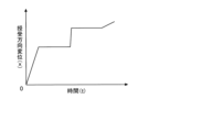
このような自律ロボット1では、手部443に把持した物体B1を授受対象者の手H1に手渡しする場合、図2に示すように、授受動作の実行期間中、物体B1の授受方向A1への変位が連続的、例えば直線的なものとなることが好ましい。一方、図3に示すように、授受動作の実行期間中の物体B1の授受方向A1への変位に急激な変化が含まれる場合、手部443から授受対象者の手H1へ物体B1をうまく授受することができず、物体B1が落下したり、物体B1の内容物がこぼれたりするなどの事象が発生してしまう可能性が高い。1.2 Giving and Receiving Actions of an Object In such an
人と自律ロボットとの間の物体の授受動作には、自律ロボットが物体を把持する把持動作と、自律ロボットが物体をリリースするリリース動作と、人が物体を受け取る受取動作とが含まれ、物体を人へ受け渡す際には、自律ロボット1は、把持動作で把持した物体をリリース動作でリリースする。すなわち、把持した物体を人へ受け渡す際、自律ロボット1は、把持動作とリリース動作とのブレンド率を変化させてリリース動作の占める割合を徐々に増加させ、最終的に物体をリリースする。
The object giving/receiving action between a human and an autonomous robot includes a grasping action in which the autonomous robot grasps the object, a releasing action in which the autonomous robot releases the object, and a receiving action in which the human receives the object. When handing over the object to a person, the
ここで、例えば、自律ロボットが実行するリリース動作には、予め決まったパターンが存在せず、物体や授受対象者毎に最適な動作が異なる。例えば、熱湯の入った湯呑を授受する場合と、テニスボールを授受する場合とでは、最適なリリース動作が異なる。 Here, for example, there is no predetermined pattern for the release action performed by the autonomous robot, and the optimum action differs depending on the object and the person to whom the transfer is to be performed. For example, the optimal release action differs between giving and receiving a teacup filled with boiling water and giving and receiving a tennis ball.
これは、物体B1の授受方向A1への単位時間あたりの移動量は、授受対象者が受取動作において物体B1に与える外力の大きさによって変化するが、この移動量の変化が、物体B1に固有の特性、例えば、静止摩擦係数、動摩擦係数、質量、形状寸法、剛性、強度、温度、湿度等の違いに依存して異なるためである。 This is because the amount of movement of the object B1 in the giving/receiving direction A1 per unit time varies depending on the magnitude of the external force applied to the object B1 in the receiving action by the person to whom the giving/receiving is performed. characteristics such as static friction coefficient, dynamic friction coefficient, mass, geometry, rigidity, strength, temperature, humidity, etc.
そのため、特性が異なる全ての物体について、自律ロボットの設計者が最適なリリース動作を予め計画しておくことは困難である。同様に、授受対象者の所作や状況等が異なる全てのケースについても、設計者が最適なリリース動作を予め計画しておくことは困難である。 Therefore, it is difficult for the designer of the autonomous robot to plan in advance the optimal release motion for all objects with different characteristics. Similarly, it is difficult for the designer to plan the optimum release operation in advance for all cases in which the gestures, situations, etc. of the recipients are different.
そこで本実施形態では、人と自律ロボットとが共存する家庭や介護施設や店舗など、受け渡しの対象となる物体が未知である環境や、授受対象者の所作や状況等が未知である環境、すなわち、最適なリリース動作のモデルを事前に作成できない環境において、人と自律ロボットとの間で品質の高い物理インタラクション、具体的には物体の授受を可能にする構成及び動作について、具体例を挙げて説明する。 Therefore, in this embodiment, an environment in which an object to be delivered is unknown, such as a home, a nursing facility, or a store where humans and autonomous robots coexist, or an environment in which the behavior or situation of a person to be delivered and received is unknown, that is, , in an environment where it is not possible to create a model of the optimal release motion in advance, give specific examples of configurations and motions that enable high-quality physical interaction between humans and autonomous robots, specifically the transfer of objects. explain.
例えば、本実施形態では、自律ロボット1に搭載した各種センサからの情報を活用することで、受け渡しの物体B1や授受対象者の所作や状況等に応じた最適な授受動作を可能にする。
For example, in this embodiment, by utilizing information from various sensors mounted on the
なお、本説明において、最適な授受動作とは、例えば、物体を授受する際の授受方向の滑り量の変化率が連続性を保っていることであってよい(例えば、図2参照)。ただし、これに限定されず、授受対象者が自律ロボット1からストレスなく物体を受け取ることができる種々の授受動作を最適な授受動作と定義することができる。
In this description, the optimum giving/receiving action may be, for example, that the change rate of the amount of slip in the giving/receiving direction when giving/receiving an object maintains continuity (for example, see FIG. 2). However, the present invention is not limited to this, and various giving/receiving motions in which the person to be given/received can receive an object from the
一方、適切でない授受動作とは、例えば、授受対象者が自律ロボット1から物体を受け取る際に必要以上の大きな力が発生したり、受け取った際に物体の変形や破損や内容物の飛び出しなどを引き起こす力が発生してしまったりなどの事象に繋がる動作であってよい。
On the other hand, inappropriate giving/receiving actions include, for example, when the object is received from the
また、適切でない授受動作には、リリース動作に必要以上に時間をかけることで、授受対象者が受け取りをやめてしまったり、その結果として物体の落下や内容物の飛び出しが発生してしまったりなどの動作も含まれ得る。 In addition, inappropriate giving/receiving actions may result in the subject giving/receiving giving up taking more time than necessary for the release action, and as a result, the object may drop or the contents may pop out. Actions can also be included.
これらのような適切でない授受動作が行なわれた場合、自律ロボット1において必要以上の外力や外乱が発生し、物体の授受方向の滑り量の変化率が不連続となる(例えば、図3参照)。また、適切でない授受動作が行なわれた場合には、物体の授受方向の滑り量の変化率が断続的となるが、このことも物体の授受方向の滑り量の変化率が不連続となる要因となる。
If inappropriate giving/receiving motions such as these are performed, excessive external force or disturbance occurs in the
そこで本実施形態では、例えば、手部443の把持力の変化率や手部443に搭載した各種センサで検出された情報等を入力とし、物体B1の授受方向A1への移動速度の連続性を出力とした機械学習を行う。これにより、物体B1の特性(静止摩擦係数、動摩擦係数、質量、形状寸法、剛性、強度、温度、湿度等)、及び、授受対象者の所作や状況等に応じたスムーズな物体B1の受け渡しを可能にすることができる。
Therefore, in this embodiment, for example, the rate of change in gripping force of the
また、本実施形態では、例えば、手部443が把持する物体B1の滑り量又は初期滑り量の変化を計測し、その変化が重力方向とは異なる方向の成分、例えば、重力と反対方向、重力による回転モーメントと反対方向、又は、授受方向A1(例えば、授受対象者の手H1の位置方向)の成分を含む際に、リリース動作を開始する。これにより、リリース動作を授受動作の初期段階に開始することが可能となるため、物体B1にかかる負荷や手部443の把持力の変動を最小限に抑えることが可能となり、それにより、よりスムーズな物体B1の受け渡しが可能となる。
Further, in the present embodiment, for example, a change in the amount of slippage or the amount of initial slippage of the object B1 gripped by the
さらに、本実施形態では、物理インタラクションの更なる高品質化のために、上記に加え、画像入力情報や音声入力情報等から得られる授受対象者の存在や感情の変化等を機械学習の入力や出力に加えてもよい。 Furthermore, in this embodiment, in order to further improve the quality of the physical interaction, in addition to the above, the existence of the person to be exchanged and the change in emotion obtained from the image input information and voice input information are input to machine learning. may be added to the output.
例えば、画像処理の結果や測距センサからの情報を用いて授受対象者の存在や手H1の存在を確認した上でリリース動作を開始してもよい。これにより、誤ってリリース動作を開始することを回避できるため、より安全且つ確実に物体B1の受け渡しを実行することが可能となる。なお、画像処理の結果や測距センサからの情報に限らず、例えば、音声入出力情報等を用いて授受対象者の存在を確認してもよい。また、音声入出力情報等を用いて授受対象者の把持の意思やリリース動作中の感情の変化を認識した上で、リリース動作の開始や動作継続の判断を実行するようにしてもよい。 For example, the release operation may be started after confirming the existence of the person to be handed over and the existence of the hand H1 using the result of image processing or information from the distance measuring sensor. As a result, erroneous initiation of the release operation can be avoided, so that the delivery of the object B1 can be performed more safely and reliably. It should be noted that the existence of the person to be exchanged may be confirmed using, for example, audio input/output information or the like, without being limited to the result of image processing or the information from the distance measuring sensor. In addition, it is also possible to determine whether to start the release motion or continue the motion after recognizing the intention of the person to be handed and received and the change in emotion during the release motion using voice input/output information or the like.
さらにまた、例えば、リリース動作の実行中に、物体B1の授受方向A1への滑り量の変化を計測し続けることで、物体B1の授受方向A1への移動速度の連続性が保たれるように、リリース動作を制御してもよい。これにより、物体B1の授受方向A1への変位が急激に変化することを低減できるため、よりスムーズな物体B1の受け渡しが可能となる。 Furthermore, for example, by continuing to measure the change in the amount of slippage of the object B1 in the giving and receiving direction A1 during execution of the release operation, the continuity of the moving speed of the object B1 in the giving and receiving direction A1 can be maintained. , may control the release action. As a result, it is possible to reduce abrupt changes in the displacement of the object B1 in the transfer direction A1, so that the object B1 can be transferred more smoothly.
さらにまた、例えば、リリース動作の実行中に、物体B1の重力方向への滑り量又は初期滑り量を計測し続けてもよい。これにより、物体B1を誤って落下せたり、物体B1が手部443内で不自然に上下に変位することを低減することが可能となる。
Furthermore, for example, the amount of slip in the direction of gravity or the amount of initial slip of object B1 may continue to be measured during execution of the release motion. This makes it possible to reduce the possibility that the object B1 is accidentally dropped or that the object B1 is unnaturally displaced vertically within the
なお、本説明において、授受方向A1は、例えば、授受対象者の手H1の位置、姿勢及び形状を認識した上で、第3指中手骨上端と手根骨を結んだ線上の手根骨方向であると定義する。また、授受方向A1を、授受対象者の手H1と体幹の位置と形状とを認識した上で、手根骨中心と胸骨中心とを結んだ線上の胸骨方向と定義することも可能である。若しくは、授受方向A1を、授受対象者の手H1と体幹の位置と形状とを認識した上で、手根骨中心と上腕骨頭中心を結んだ線上の上腕骨頭方向と定義することも可能である。ただし、授受方向A1の定義は、上記に限定されず、種々変更することが可能である。 In this description, the giving/receiving direction A1 is, for example, after recognizing the position, posture, and shape of the hand H1 of the person to be given/received, the carpal bone on the line connecting the upper end of the third finger metacarpal bone and the carpal bone. direction. It is also possible to define the giving/receiving direction A1 as the sternum direction on the line connecting the center of the carpal bone and the center of the sternum, after recognizing the positions and shapes of the hand H1 and trunk of the person to whom the giving/receiving is performed. . Alternatively, the giving/receiving direction A1 can be defined as the direction of the humeral head on the line connecting the center of the carpal bone and the center of the humeral head after recognizing the positions and shapes of the hand H1 and the trunk of the person to be given/received. be. However, the definition of the giving/receiving direction A1 is not limited to the above, and various changes are possible.
また、本実施形態に係るリリース動作には、手部443の把持力制御、マニピュレータ44におけるアーム部の動作制御(以下、アーム動作制御という)、自律ロボット1の全身動作制御等が含まれ得る。これら、手部443の把持力制御、マニピュレータ44におけるアーム部のアーム動作制御、自律ロボット1の全身動作制御等は、あるブレンド率でブレンドされるが、本実施形態では、このブレンド率を評価するための評価関数を定義し、この評価関数の最適解を求めるために、上記に示した、手部443に与えた把持力の変化率や手部443に搭載した各種センサで検出された情報等を入力とし、物体B1の授受方向A1への移動速度の連続性を出力とした機械学習を活用する。
Further, the release motion according to the present embodiment may include gripping force control of the
なお、本説明において、把持力制御とは、物体B1を把持するために手部443に発生している把持力をリリースに向けて減少させる際の単位時間における力の変化量を制御することであってよい。
In this description, gripping force control refers to controlling the amount of change in force per unit time when the gripping force generated in the
また、アーム動作制御とは、物体B1を把持して目標座標空間に物体B1を配置しているアーム部の姿勢を変化させて物体B1の位置を授受方向A1へ移動させることであってよく、その際の単位時間当たりの変化量を制御することであってよい。このようなアーム動作制御により、リリース動作の開始を検知した時点で手部443から物体B1を即時リリースした際に物体B1に発生する授受方向A1への慣性力を減少することが可能となる。
Further, the arm motion control may be to change the posture of the arm that holds the object B1 and arrange the object B1 in the target coordinate space to move the position of the object B1 in the giving/receiving direction A1. It may be to control the amount of change per unit time at that time. With such arm motion control, it is possible to reduce the inertial force in the delivery/receiving direction A1 generated in the object B1 when the
さらに、ロボット全身動作制御とは、物体B1を把持して目標座標空間に物体B1を配置している自律ロボット1の位置及び姿勢を変化させて物体B1の位置を授受方向A1へ移動させることであってよく、その際の単位時間当たりの位置変化量を制御することであってよい。
Furthermore, the robot whole-body motion control is to change the position and posture of the
1.3 自律ロボットの概略構成
次に、本実施形態に係る自律ロボット1の概略構成について、図面を参照して詳細に説明する。図4は、本実施形態に係る自律ロボットの概略構成例を示すブロック図である。図4に示すように、自律ロボット1は、例えば、CPU(Central Processing Unit)12、DRAM(Dynamic Random Access Memory)13、フラッシュROM(Read Only Memory)14、PC(Personal Computer)カードインタフェース(I/F)15、無線通信部16及び信号処理回路11が内部バス17を介して相互に接続されることにより形成されたコントロール部10と、この自律ロボット1の動力源としてのバッテリ18とを備える。1.3 Schematic Configuration of Autonomous Robot Next, the schematic configuration of the
また、自律ロボット1は、移動やジェスチャーなどの動作を実現するための可動機構として、マニピュレータ44の関節部分や胴体部42の関節部分((首関節や腰関節など)や車輪やキャタピラ等の可動部26と、この可動部26を駆動するためのアクチュエータ27とを備える。
In addition, the
さらに、自律ロボット1は、移動距離や移動速度や移動方向や姿勢などの情報を取得するためのセンサ(以下、内界センサという)として、自機の向きや動きの加速度を検出するための慣性計測装置(Inertial Measurement Unit:IMU)20と、アクチュエータ27の駆動量を検出するエンコーダ(又はポテンショメータ)28とを備える。なお、内界センサとしては、これらの他にも、加速度センサや角速度センサ等を用いることができる。
Furthermore, the
さらにまた、自律ロボット1は、自機の周囲の地形や自機の周囲に存在する物体までの距離や方向などの情報を取得するセンサ(以下、外界センサという)として、外部の状況を撮像するカメラ19と、自機に対して特定の方向に存在する物体までの距離を測定するToF(Time of Flight)センサ21とを備える。なお、外界センサとしては、これらの他にも、LIDAR(Light Detection and Ranging又はLaser Imaging Detection and Ranging)センサ、GPS(Global Positioning System)センサ、磁気センサ、Bluetooth(登録商標)やWi-Fi(登録商標)などの無線通信部16における電波強度の測定部(以下、電波強度センサという)等を用いることができる。
Furthermore, the
さらにまた、自律ロボット1には、外部から受けた物理的な圧力を検出するためのタッチセンサ22や、外部音を集音するためのマイク23や、周囲へ音声等を出力するためのスピーカ24や、ユーザ等へ各種情報を表示するための表示部25などが設けられてもよい。
Furthermore, the
さらにまた、自律ロボット1の可動部26には、物体B1の授受を制御するためのセンサとして、6軸力覚センサ501と、3軸力覚センサ502と、滑りセンサ503と、測距センサ504と、3軸センサ261と、1軸センサ262と、3軸センサ263と、1軸センサ264と、2軸センサ265と、3軸センサ266とを備える。
Furthermore, the
6軸力覚センサ501は、例えば、マニピュレータ44における手首部分に取り付けられ、手首部分に加わった力及びトルクの大きさと方向とを検出する。
The 6-
3軸力覚センサ502は、例えば、手部443における各指関節に取り付けられ、指関節に加わった力又はトルクの大きさと方向とを検出する。
The three-
滑りセンサ503は、例えば、手部443における手のひらや指の腹など、把持する物体B1と接触する部分に取り付けられ、物体B1とこれに接触する部分とのせん断滑りの大きさ(滑り量)及びその方向を検出する。また、滑りセンサ503は、物体B1とこれに接触する部分との間で発生する初期滑りの大きさ(初期滑り量)及びその方向を検出してもよい。この滑りセンサ503には、例えば、手部443における物体B1に接触する部分に取り付けられた所定形状の粘弾性体の変形を観測するビジョンセンサや、圧力の2次元分布を計測する圧力分布センサなどを用いることができる。
The
測距センサ504は、例えば、マニピュレータ44における手首や手のひらや手の甲や指先など、手部443が把持した物体B1を観測できる場所に取り付けられ、手部443と物体B1との間の距離を計測する。
The
3軸センサ261は、例えば、肩部分に取り付けられ、胴体部42に対する上腕部441のロール角、ピッチ角及びヨー角を検出する。
The 3-
1軸センサ262は、例えば、肘部分に取り付けられ、上腕部441に対する前腕部442のピッチ角を検出する。
The
3軸センサ263は、例えば、手首部分に取り付けられ、前腕部442に対する手部443のロール角、ピッチ角及びヨー角を検出する。
The 3-axis sensor 263 is attached to, for example, the wrist portion, and detects the roll angle, pitch angle, and yaw angle of the
1軸センサ264は、例えば、手部443の各指関節に取り付けられ、各関節のピッチ角を検出する。
The uniaxial sensor 264 is attached, for example, to each finger joint of the
2軸センサ265は、例えば、台車部43と胴体部42との関節部分に取り付けられ、台車部43に対する胴体部42のロール角及びピッチ角を検出する。
The two-
3軸センサ266は、例えば、首部分に取り付けられ、胴体部42に対する頭部41のロール角、ピッチ角及びヨー角を検出する。
The three-axis sensor 266 is attached to the neck, for example, and detects the roll angle, pitch angle, and yaw angle of the
以上の構成において、IMU20、タッチセンサ22、ToFセンサ21、マイク23、スピーカ24、エンコーダ(又はポテンショメータ)28などの各種センサ、表示部25、アクチュエータ27、カメラ19及びバッテリ18は、それぞれコントロール部10の信号処理回路11と接続されている。
In the above configuration, various sensors such as the
信号処理回路l4は、上述の各種センサから供給されるセンサデータや画像データ及び音声データを順次取り込み、これらをそれぞれ内部バス17を介してDRAM13内の所定位置に順次格納する。また、信号処理回路11は、これと共にバッテリ18から供給されるバッテリ残量を表すバッテリ残量データを順次取り込み、これをDRAM13内の所定位置に格納する。
The
このようにしてDRAM13に格納された各センサデータ、画像データ、音声データ及びバッテリ残量データは、CPU12が自律ロボット1の動作制御を行う際に利用されるとともに、必要に応じて、無線通信部16を介して外部のサーバ等へ送信される。なお、無線通信部16は、Bluetooth(登録商標)やWi-Fi(登録商標)などの他、無線LAN(Local Area Network)や移動体通信網等の所定のネットワークを介して外部のサーバ等と通信を行なうための通信部であってよい。
The sensor data, image data, audio data, and remaining battery level data stored in the
CPU12は、例えば、自律ロボット1の電源が投入された初期時、不図示のPCカードスロットに装填されたメモリカード30又はフラッシュROM14に格納された制御プログラムをPCカードI/F15を介して又は直接読み出し、これをDRAM13に格納する。
For example, when the power of the
また、CPU12は、上述のように信号処理回路11よりDRAM13に順次格納される各センサデータ、画像データ、音声データ及びバッテリ残量データに基づいて自機及び周囲の状況や、ユーザからの指示及び働きかけの有無などを判断する。
In addition, the
さらに、CPU12は、DRAM13等に格納されている地図データ又は無線通信部16を介して外部のサーバ等から取得した地図データと各種情報とを利用して、自己位置推定や種々の動作を実行してもよい。
Furthermore, the
そして、CPU12は、上述の判断結果や推定された自己位置やDRAM13に格納されている制御プログラム等に基づいて、その後の行動を決定すると共に、当該決定結果に基づいて必要なアクチュエータ27を駆動させることにより、物体B1の授受動作の他、移動やジェスチャーなどの各種行動を実行する。
Then, the
その際、CPU12は、必要に応じて音声データを生成し、これを信号処理回路11を介して音声信号としてスピーカ24に与えることにより当該音声信号に基づく音声を外部に出力させたり、表示部25に各種情報を表示させたりする。
At that time, the
このようにして、自律ロボット1は、自機及び周囲の状況や、ユーザからの指示及び働きかけに応じて自律的に行動し得るように構成されている。
In this way, the
1.4 手部の構成
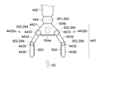
つづいて、本実施形態に係る自律ロボット1の手部443の構成について、図面を参照して詳細に説明する。なお、本説明では、簡略化のため、手部443が2指である場合を例示する。図5は、本実施形態に係る手部の構成例を示す外観図である。また、図6は、図5における方向A2から手部を見た場合の構成例を示す外観図である。1.4 Configuration of Hand Part Next, the configuration of the
図5及び図6に示すように、手部443は、例えば、手のひら及び手の甲に相当する基底部4431と、2本の指部4432a及び4432b(以下、指部4432a及び4432bを区別しない場合、その符号を4432とする)とを備える。基底部4431は、例えば、手首に相当する関節機構444を介して前腕部442に取り付けられている。
As shown in FIGS. 5 and 6, the
手首に相当する関節機構444には、上述したように、手首部分に加わった力及びトルクの大きさと方向とを検出する6軸力覚センサ501と、前腕部442に対する手部443のロール角、ピッチ角及びヨー角を検出する3軸センサ263とが設けられている。
The
各指部4432は、基底部4431に指関節(第3関節)に相当する関節機構4433を介して取り付けられた基節部4434と、基節部4434に指関節(第1関節)に相当する関節機構4435を介して取り付けられた末節部4436とを備える。これら2本の指部4432a及び4432は、例えば、指の腹に相当する面が互いに向き合うように、基底部4431に取り付けられている。
Each finger portion 4432 has a proximal
各指部4432の各指関節に相当する関節機構4433及び4435には、上述したように、各指関節に加わった力又はトルクの大きさと方向とを検出する3軸力覚センサ502と、各関節のピッチ角を検出する1軸センサ264とが設けられている。
The
また、物体B1を把持したときに指部4432における物体B1と接触する部分、例えば、末節部4436の指の腹に相当する部分には、滑りセンサ503が設けられている。さらに、基底部4431における手のひらに相当する面、すなわち、指部4432を折り畳んだときに末節部4436に取り付けられた滑りセンサ503と対向する面には、測距センサ504としてのToFセンサ504aが設けられている。さらにまた、基底部4431における手の甲に相当する部分には、測距センサ504としてのカメラ504bが、そのロール角、ピッチ角及びヨー角を調整可能に設けられている。
Further, a
1.5 自律ロボットの機能構成
次に、本実施形態に係る自律ロボット1の授受動作を実行するための機能構成について、図面を参照して詳細に説明する。図7は、本実施形態に係る自律ロボットの授受動作を実行するための機能構成の一例を示すブロック図である。なお、図7に示す機能構成のうち、物理インタラクション実行部55及び学習情報記憶部54以外の構成は、例えば、図4に示すCPU12がフラッシュROM14又はメモリカードに格納されている所定のプログラム、若しくは、無線通信部16を介してダウンロードされたプログラムを実行することで、実現され得る。また、物理インタラクション実行部55は、例えば、図4に示すCPU12、信号処理回路11、可動部26及びアクチュエータ27で実現され得る。さらに、学習情報記憶部54は、例えば、図4に示すフラッシュROM14又はメモリカード30によって実現され得る。1.5 Functional Configuration of Autonomous Robot Next, the functional configuration for executing the giving/receiving action of the
図7に示すように、自律ロボット1は、授受対象者との物体B1の授受動作を実行するための機能構成として、授受対象者認識部51と、物体認識部52と、授受行動計画部53と、学習情報記憶部54と、物理インタラクション実行部55と、把持情報取得部56と、レスポンス時間計測部57と、感情マップ生成部58と、授受行動評価部59とを備える。また、自律ロボット1が備えるセンサのうち、例えば、カメラ19と、マイク23と、6軸力覚センサ501と、3軸力覚センサ502と、滑りセンサ503と、測距センサ504とは、授受動作の実行において使用する各種情報を取得するためのセンサ群50を構成する。
As shown in FIG. 7, the
授受対象者認識部51は、例えば、カメラ19で取得された画像データやマイク23から入力された音声データを解析することで、授受対象者及び/又は授受対象者の手H1の存在や、授受対象者における物体B1を受け取る意思や、授受対象者の所作や状況等(以下、授受対象者の姿勢という)を認識し、その結果を授受行動計画部53に入力する。また、授受対象者認識部51は、後述する物理インタラクション実行部55が実行するリリース動作の過程で、カメラ19で取得された画像データやマイク23から入力された音声データを解析することで、リリース動作の過程における授受対象者に感情の変化、例えば、熱いや冷たいやタイミングが合わない等の理由で受取動作を中断又は放棄してしまうなどの感情の変化を検出し、その結果を感情マップ生成部58へ入力する。
The transfer target
物体認識部52は、例えば、カメラ19で取得された画像データの解析結果や、6軸力覚センサ501、3軸力覚センサ502及び滑りセンサ503から入力されたセンサデータ等に基づくことで、物体B1の位置や、物体B1の特性、例えば、静止摩擦係数、動摩擦係数、質量、形状寸法、剛性、強度、温度、湿度等を認識又は推定し、その結果を授受行動計画部53に入力する。
The
学習情報記憶部54は、例えば、過去に行なった授受動作を機械学習することで構築された学習済みモデルや、授受行動計画部53で計画された授受行動計画及びその評価結果等を記憶する。なお、過去に行なった授受動作に対して機械学習することで学習済みモデルを構築する構成は、例えば、自律ロボット1内に配置されてもよいし、自律ロボット1と所定のネットワークを介して接続されたサーバ上に配置されてもよい。
The learning
授受行動計画部53は、授受対象者認識部51から入力された授受対象者の認識結果と、物体認識部52から入力された物体B1の認識又は推定結果とから、学習情報記憶部54に記憶されている学習済みモデルや過去に計画した授受行動計画及びその評価結果等に基づいて、物体B1を授受対象者へ受け渡すための授受行動計画を作成する。作成された授受行動計画には、例えば、物体B1をテーブルや床等から持ち上げる又は人等から受け取る動作から授受対象者へ受け渡すまでの動作が含まれ得る。
The transfer
物理インタラクション実行部55は、授受行動計画部53で作成された授受行動計画を実行することで、物体B1を授受対象者へ受け渡す物理インタラクション(授受行動)を実行する。
The physical
把持情報取得部56は、物理インタラクション実行部55によるリリース動作の開始タイミングを決定するために、例えば、滑りセンサ503で検出された滑り量又は初期滑り量若しくは測距センサ504で検出された滑り量における重力と反対方向、重力による回転モーメントと反対方向、又は、授受対象者の手H1の位置方向の成分から、授受対象者が受取動作を開始したタイミングを検出し、検出したタイミングを物理インタラクション実行部55へ入力する。
For example, the grip
また、把持情報取得部56は、物理インタラクション実行部55がリリース動作を実行している期間中の物体B1の授受方向A1への移動速度の連続性を確保するために、例えば、物理インタラクション実行部55がリリース動作を実行している期間中、滑りセンサ503及び/又は測距センサ504で検出された物体B1の授受方向A1への滑り量を物理インタラクション実行部55へ継続して入力する。
In addition, the gripping
さらに、把持情報取得部56は、物理インタラクション実行部55がリリース動作を実行している期間中の物体B1の落下や不自然な上下動を低減するために、例えば、物理インタラクション実行部55がリリース動作を実行している期間中、滑りセンサ503及び/又は測距センサ504で検出された物体B1の重力方向への滑り量を物理インタラクション実行部55へ継続して入力する。
Furthermore, the grip
さらにまた、把持情報取得部56は、授受動作の機械学習における入力として、例えば、物理インタラクション実行部55がリリース動作を実行している期間中に手部443に設けられた各種センサで検出された情報、例えば、3軸力覚センサ502で検出された把持力や、滑りセンサ503で検出された滑り量及び/又は初期滑り量などの情報を、不図示の機械学習部に入力する。加えて、把持情報取得部56は、授受動作の機械学習における出力として、例えば、物理インタラクション実行部55がリリース動作を実行している期間中に測距センサ504で検出された物体B1までの距離を、不図示の機械学習部に入力する。
Furthermore, the grip
レスポンス時間計測部57は、例えば、自律ロボット1がリリース動作を開始して手部443の把持力を減少させてから物体B1の授受方向A1への移動速度が増加するまでの時間(レスポンス時間)を計測し、測定されたレスポンス時間を物理インタラクション実行部55へ入力する。
The response
感情マップ生成部58は、例えば、物理インタラクション実行部55がリリース動作を実行している期間中に、授受対象者認識部51から入力された授受対象者の感情の変化に関する情報に基づいて、リリース動作実行中の時間軸に沿った授受対象者の感情の変化をマッピングした感情マップを生成し、生成した感情マップを授受行動評価部59に入力する。なお、マッピングされる感情には、例えば、熱いや冷たいやタイミングが合わない等のネガティブな感情のみならず、快適に受け取ることができた等のポジティブな感情等も含まれ得る。
For example, the emotion
授受行動評価部59は、授受行動計画部53で計画された授受行動計画を、感情マップ生成部58から入力された感情マップに基づいて評価し、その評価結果を授受行動計画とともに学習情報記憶部54に入力する。
The giving/receiving
1.6 授受行動の機械学習について
ここで、授受行動の機械学習について説明する。図8は、機械学習プロセスにおける入出力情報の一例を示す模式図である。図8に示すように、本実施形態における授受行動の機械学習プロセスでは、入力層に手部443に設けられた各種センサで検出された情報又はこれらの情報から得られた情報、例えば、3軸力覚センサ502で検出された把持力又はその変化率や、滑りセンサ503で検出された滑り量及び/又は初期滑り量又はその変化率などの情報が与えられ、出力層に授受方向A1への物体B1の移動速度の連続性に関する情報が与えられて、入力層から隠れ層を介して出力層までの各層のノード(ニューロンともいう)60間を結ぶ各エッジ61の重みが求められる。これにより、授受動作に最適な学習済みモデルが作成される。なお、上述したように、授受対象者の感情を機械学習の入力や出力に使用することも可能である。1.6 Machine Learning of Giving and Receiving Behavior Here, machine learning of giving and receiving behavior will be explained. FIG. 8 is a schematic diagram showing an example of input/output information in the machine learning process. As shown in FIG. 8, in the machine learning process of giving and receiving behavior in the present embodiment, information detected by various sensors provided in the
なお、機械学習では、例えば、授受方向A1への物体B1の移動速度の連続性が高い程、プラスの報酬が設定されるものとする。一方、授受方向A1への物体B1の移動速度の連続性が低い、すなわち、物体B1の授受方向A1への単位時間あたりの移動量が不連続であるほど、マイナスの報酬が設定されるものとする。 Note that in machine learning, for example, the higher the continuity of the moving speed of the object B1 in the giving/receiving direction A1, the higher the reward set. On the other hand, the lower the continuity of the moving speed of the object B1 in the giving/receiving direction A1, that is, the more discontinuous the amount of movement of the object B1 in the giving/receiving direction A1 per unit time, the more a negative reward is set. do.
また、機械学習では、物理インタラクション実行部55がリリース動作を実行している期間中の授受対象者の感情及び/又はその変化に基づいて報酬が設定されてもよい。例えば、リリース動作を実行している期間中に授受対象者からネガティブな感情が認識されていた場合にはマイナスの報酬を設定し、ポジティブな感情が認識されていた場合にはプラスの報酬を設定するようにしてもよい。授受対象者がネガティブな感情であるかポジティブな感情であるかについては、例えば、感情マップ生成部58で生成された感情マップに基づいて判定することができる。
Further, in machine learning, the reward may be set based on the emotions of the recipient and/or changes thereof during the period when the physical
1.7 動作例
次に、本実施形態に係る自律ロボット1の動作例について、図面を参照して詳細に説明する。図9は、本実施形態に係る概略的な動作例を示すフローチャートである。図9に示すように、本動作では、まず、物体認識部52が、例えば、カメラ19で取得された画像データを解析することで、授受対象の物体B1の位置や形状寸法等を認識する(ステップS101)。つづいて、物体認識部52により認識された物体B1の位置や形状寸法等に基づき、物理インタラクション実行部55が物体B1を把持する(ステップS102)。1.7 Operation Example Next, an operation example of the
次に、物理インタラクション実行部55が物体B1を持ち上げた際にマニピュレータ44の各種センサ(6軸力覚センサ501、3軸力覚センサ502、滑りセンサ503等)で検出されたセンサデータに基づき、物体認識部52が、物体B1を持ち上げたことによる負荷を計算し(ステップS103)、計算された負荷に基づいて、物体B1の特性、例えば、静止摩擦係数、動摩擦係数、質量、剛性、強度、温度、湿度等を認識又は推定する(ステップS104)。
Next, based on the sensor data detected by various sensors (six-
次に、授受対象者認識部51が、例えば、カメラ19で取得された画像データやマイク23から入力された音声データを解析することで、授受対象者の位置を認識し(ステップS105)、つづいて、授受行動計画部53が、授受対象者認識部51により認識された授受対象者の位置から決定される物体B1の受渡し場所までの移動計画を作成する(ステップS106)。そして、物理インタラクション実行部55が、授受行動計画部53により作成された移動計画に従って、自律ロボット1を受渡し場所まで移動させる(ステップS107)。
Next, the transfer target
次に、授受対象者認識部51が、例えば、カメラ19で取得された画像データを解析することで、授受対象者の手H1の位置を認識し(ステップS108)、つづいて、授受行動計画部53が、授受対象者認識部51により認識された授受対象者の手H1の位置から決定される自律ロボット1の受渡しの姿勢までの姿勢制御計画を作成する(ステップS109)。そして、物理インタラクション実行部55が、授受行動計画部53により作成された姿勢制御計画に従って、自律ロボット1の姿勢を制御する(ステップS110)。なお、自律ロボット1の姿勢制御には、例えば、マニピュレータ44のならい制御や胴体部42及び頭部41の傾き制御等も含まれ得る。また、ステップS108では、授受対象者の手H1の位置に加え、授受対象者の手H1の所作や状況等も認識され得る。
Next, the transfer target
次に、授受行動計画部53が、物体認識部52で認識又は推定された物体B1の特性と、授受対象者認識部51で認識された授受対象者の手H1の位置や所作や状況等から、学習情報記憶部54に記憶されている学習済みモデルや過去に計画した授受行動計画及びその評価結果等に基づいて、物体B1を授受対象者へ受渡すための授受動作計画を作成し(ステップS111)、つづいて、物理インタラクション実行部55が、授受行動計画部53により作成された授受動作計画に従って、物体B1を授受対象者へ受け渡す授受行動を実行し(ステップS112)、その後、本動作を終了する。
Next, the giving/receiving
1.8 授受動作の具体例
つづいて、図9のステップS112に示す授受動作について、いくつか例を挙げて説明する。1.8 Specific Examples of Giving and Receiving Actions Next, several examples of giving and receiving actions shown in step S112 of FIG. 9 will be described.
1.8.1 第1の例
まず、第1の例に係る授受動作について説明する。図10は、本実施形態の第1の例に係る授受動作を示すフローチャートである。なお、第1の例では、物理インタラクション実行部55が把持力制御のみでリリース動作を実行する場合を例示する。1.8.1 First Example First, a giving/receiving action according to a first example will be described. FIG. 10 is a flow chart showing the giving/receiving operation according to the first example of the present embodiment. Note that the first example illustrates a case where the physical
図10に示すように、第1の例に係るリリース動作では、まず、把持情報取得部56が、例えば、滑りセンサ503で検出された滑り量U又は初期滑り量u若しくは測距センサ504で検出された滑り量Uにおける重力と反対方向、重力による回転モーメントと反対方向、又は、授受対象者の手H1の位置方向(以下、これらを特定方向という)の成分がゼロより大きくなったか否かを判定する(ステップS121)。すなわち、授受対象者による受取動作が開始されたか否かを判定する。特定方向の滑り量U又は初期滑り量uがゼロ以下である場合(ステップS121のNO)、すなわち、授受対象者による受取動作が未だ開始されていない場合、本動作がステップS121へリターンし、授受対象者による受取動作の開始を待機する。
As shown in FIG. 10 , in the release operation according to the first example, first, the grip
一方、特定方向の滑り量U又は初期滑り量uがゼロより大きくなった場合(ステップS121のYES)、すなわち、授受対象者による受取動作が開始された場合、把持情報取得部56は、例えば、測距センサ504におけるカメラ504bで取得された画像データを解析することで、授受方向A1を特定する(ステップS122)。特定された授受方向A1は、特定方向の滑り量U又は初期滑り量uがゼロより大きくなったことに基づくリリース動作の開始トリガとともに、把持情報取得部56から物理インタラクション実行部55に入力される。これに対し、物理インタラクション実行部55は、物体B1の授受方向A1へのリリース動作を開始する(ステップS123)。
On the other hand, when the amount U of slippage in the specific direction or the amount u of initial slippage becomes greater than zero (YES in step S121), that is, when the person to be handed and received starts the receiving motion, the gripping
このようにしてリリース動作を開始すると、物理インタラクション実行部55は、次に、手部443の把持力制御を実行する(ステップS124)。具体的には、物理インタラクション実行部55は、物体B1を把持するために手部443に発生させている把持力Fをリリースに向けて減少させる際の単位時間における力の変化量を制御する。
After starting the release motion in this manner, the physical
また、物理インタラクション実行部55がリリース動作を開始後、把持情報取得部56は、物体B1の授受方向A1への滑り量の変化を計測し続けることで、物体B1の授受方向A1への移動速度を計測する(ステップS125)。計測された物体B1の授受方向A1への移動速度は、物理インタラクション実行部55に入力されることで、物理インタラクション実行部55における把持力制御に用いられる。すなわち、物理インタラクション実行部55は、物体B1の授受方向A1への移動速度が連続性を保つように、手部443に発生させている把持力の単位時間あたりの減少量を制御する(フィードバック制御)。
Further, after the physical
その後、物理インタラクション実行部55は、手部443に発生させている把持力Fがゼロに達したか否かを判定し(ステップS126)、ゼロに達していた場合(ステップS126のYES)、リリース動作を完了し(ステップS127)、本授受動作を終了する。
After that, the physical
一方、把持力Fがゼロに達していない場合(ステップS126のNO)、本動作がステップS124へリターンし、以降の動作を把持力Fがゼロに達するまで繰返し実行する。 On the other hand, if the gripping force F has not reached zero (NO in step S126), the operation returns to step S124, and the subsequent operations are repeatedly executed until the gripping force F reaches zero.
このように、滑りセンサ503で検出された滑り量U又は初期滑り量u若しくは測距センサ504で検出された滑り量Uにおける特定方向の成分がゼロより大きくなったこと(ステップS121のYES)に基づいて、物理インタラクション実行部55がリリース動作を開始(ステップS123)する構成とすることで、リリース動作を授受動作の初期段階に開始することが可能となるため、物体B1にかかる負荷や手部443の把持力の変動を最小限に抑えることが可能となり、それにより、よりスムーズな物体B1の受け渡しが可能となる。
In this way, when the slip amount U detected by the
また、物理インタラクション実行部55がリリース動作を開始後、継続して物体B1の授受方向A1への滑り量の変化を計測(ステップS125)し、計測された物体B1の授受方向A1への滑り量の変化に基づいて、手部443に発生させている把持力Fの単位時間における減少量を制御することで、物体B1の授受方向A1への変位が急激に変化することを低減できるため、よりスムーズな物体B1の受け渡しが可能となるとともに、物体B1を誤って落下させたり、物体B1が手部443内で不自然に上下に変位したりすることを低減することが可能となる。
Further, after the physical
なお、物理インタラクション実行部55は、ステップS123においてリリース動作を開始後、例えば、レスポンス時間計測部57で計測されたレスポンス時間に基づき、一定時間以上、物体B1の授受方向A1への移動速度が増加しない場合には、リリース動作を停止又は終了するようにしてもよい。
After starting the release action in step S123, the physical
また、本実施形態では、手部443が2指である場合を例示したが、例えば、手部443が3指以上である場合、把持力制御では、物体B1を挟み込む2本の指部以外の指部からその把持力を徐々に減少させてもよい。これにより、物体B1が落下する危険性を低減し、より安定した授受動作を実行することが可能となる。
Further, in the present embodiment, the case where the
1.8.2 第2の例
次に、第2の例に係る授受動作について説明する。図11は、本実施形態の第2の例に係る授受動作を示すフローチャートである。第2の例では、物理インタラクション実行部55が、リリース動作として、学習済みモデルに基づいて特定されたブレンド率で把持力制御とアーム動作制御とをブレンドして実行する場合を例示する。1.8.2 Second Example Next, a giving/receiving action according to a second example will be described. FIG. 11 is a flow chart showing the giving/receiving operation according to the second example of the present embodiment. A second example illustrates a case where the physical
図11に示すように、第2の例に係る授受動作では、例えば、図9を用いて説明した第1の例に係る授受動作と同様の流れにおいて、図9のステップS124が、ステップS224に置き換えられている。 As shown in FIG. 11, in the giving/receiving action according to the second example, for example, in the same flow as the giving/receiving action according to the first example described using FIG. has been replaced.
ステップS224では、物理インタラクション実行部55が、学習済みモデルに基づいて特定されたブレンド率でブレンドされた手部443の把持力制御及びアーム部のアーム動作制御を実行する。具体的には、物理インタラクション実行部55は、物体B1を把持するために手部443に発生させている把持力Fをリリースに向けて減少させる際の単位時間における力の変化量を制御(把持力制御)するとともに、物体B1を把持して目標座標空間に物体B1を配置しているアーム部の姿勢を変化させて物体B1の位置を授受方向A1へ移動させる際の単位時間当たりの位置変化量を制御する。その際、授受方向A1への物体B1の移動速度が連続性を保つように、把持力Fの単位時間あたりの減少量と、アーム部の姿勢の変化量とが、上述したブレンド率でブレンドされる。
In step S224, the physical
1.8.3 第3の例
次に、第3の例に係る授受動作について説明する。図12は、本実施形態の第3の例に係る授受動作を示すフローチャートである。第3の例では、物理インタラクション実行部55が、リリース動作として、学習済みモデルに基づいて特定されたブレンド率で把持力制御とアーム動作制御と全身動作制御とをブレンドして実行する場合を例示する。1.8.3 Third Example Next, a giving/receiving action according to a third example will be described. FIG. 12 is a flow chart showing a giving/receiving operation according to the third example of the present embodiment. A third example illustrates a case where the physical
図12に示すように、第3の例に係る授受動作では、例えば、図9を用いて説明した第1の例に係る授受動作と同様の流れにおいて、図9のステップS124が、ステップS324に置き換えられている。 As shown in FIG. 12, in the giving/receiving action according to the third example, for example, in the same flow as the giving/receiving action according to the first example described using FIG. has been replaced.
ステップS324では、物理インタラクション実行部55が、学習済みモデルに基づいて特定されたブレンド率でブレンドされた手部443の把持力制御とアーム部のアーム動作制御と自律ロボット1の全身動作制御とを実行する。具体的には、物理インタラクション実行部55は、物体B1を把持するために手部443に発生させている把持力Fをリリースに向けて減少させる際の単位時間における力の変化量を制御(把持力制御)し、物体B1を把持して目標座標空間に物体B1を配置しているアーム部の姿勢を変化させて物体B1の位置を授受方向A1へ移動させる際の単位時間当たりの位置変化量を制御するとともに、物体B1を把持して目標座標空間に物体B1を配置している自律ロボット1の位置及び姿勢を変化させて物体B1の位置を授受方向A1へ移動させる。その際、授受方向A1への物体B1の移動速度が連続性を保つように、把持力Fの単位時間あたりの減少量と、アーム部の姿勢の変化量と、自律ロボット1の位置及び姿勢の変化量とが、上述したブレンド率でブレンドされる。
In step S324, the physics
1.8.4 第4の例
次に、第4の例に係る授受動作について説明する。図13は、本実施形態の第4の例に係る授受動作を示すフローチャートである。第4の例では、例えば、第3の例に示した授受動作に加え、物理インタラクション実行部55が、授受対象者の感情の変化に応じてリリース動作の停止や終了を実行する場合を例示する。なお、本説明では、第3の例をベースとするが、これに限らず、第1の例又は第2の例をベースとすることも可能である。1.8.4 Fourth Example Next, a giving/receiving action according to a fourth example will be described. FIG. 13 is a flow chart showing a giving/receiving operation according to the fourth example of the present embodiment. In the fourth example, for example, in addition to the giving/receiving action shown in the third example, the physical
図13に示すように、第4の例に係る授受動作では、例えば、図12を用いて説明した第3の例に係る授受動作と同様の流れにおいて、ステップS324とステップS125との間に、ステップS401~S403が追加されている。 As shown in FIG. 13, in the giving/receiving action according to the fourth example, for example, in the same flow as the giving/receiving action according to the third example described using FIG. 12, between step S324 and step S125, Steps S401 to S403 are added.
ステップS401では、授受対象者認識部51が、例えば、カメラ19で取得された画像データやマイク23から入力された音声データを解析することで、授受対象者の感情の変化を検出する。検出された授受対象者の感情の変化に関する情報は、例えば、機械学習の入力や出力として、感情マップ生成部58に入力されてもよい。
In step S401, the transfer target
次に、ステップS402では、授受対象者認識部51が、検出された変化後の感情が特定の感情であるか否かを判定する。特定の感情とは、例えば、授受対象者による授受動作の中断や放棄に繋がるようなネガティブな感情であってよい。特定の感情が検出されていない場合(ステップS402のNO)、本動作は、ステップS125へ進む。一方、特定の感情が検出されていた場合(ステップS402のYES)、物理インタラクション実行部55が、リリース動作を停止又は終了し(ステップS403)、その後、ステップS121へリターンする。なお、リリース動作の停止の指示は、授受対象者認識部51から物理インタラクション実行部55へ直接入力されてもよいし、感情マップ生成部58を介して入力されてもよい。
Next, in step S402, the transfer target
以上のように、物理インタラクション実行部55がステップS123においてリリース動作を開始後、授受対象者認識部51がカメラ19からの画像データやマイク23からの音声データを解析することで、授受対象者の感情の変化を検出し、検出された感情が授受動作の中断や放棄に繋がる特定の感情である場合には、物理インタラクション実行部55によるリリース動作が中断されるように構成してもよい。これにより、授受対象者が受取動作を中断又は放棄した際に物理インタラクション実行部55に迅速にリリース動作の停止又は終了を実行させることが可能となるため、物体B1の落下や内容物の飛び出し等を低減することが可能となる。
As described above, after the physical
1.9 把持動作とリリース動作とのブレンドについて
次に、把持動作とリリース動作とのブレンドについて、図面を用いて詳細に説明する。図14は、本実施形態に係る把持動作とリリース動作とのブレンドを説明するための図である。なお、図14では、物理インタラクション実行部55が、リリース動作として、学習済みモデルに基づいて特定されたブレンド率で把持力制御とアーム動作制御と全身動作制御とをブレンドして実行する場合(第3の例)を例示する。1.9 Blending of Grasping Action and Releasing Action Next, the blending of the grasping action and the releasing action will be described in detail with reference to the drawings. FIG. 14 is a diagram for explaining the blending of the grasping motion and the releasing motion according to this embodiment. In FIG. 14, the physical
図14に示すように、把持した物体を授受対象者へ受け渡す際、自律ロボット1は、把持動作71とリリース動作72とをブレンド率76でブレンド(加算)し、その結果(73)に基づいて把持力制御74を実行する。自律ロボット1が物体B1をリリースする過程において、ブレンド率76を減少させることで、最終的に、自律ロボット1が物体B1をリリースする。
As shown in FIG. 14, when handing over a gripped object to a person to be handed/received, the
ブレンド率76は、例えば、物理インタラクション実行部55がリリース動作を実行後にマニピュレータ44の各種センサ(6軸力覚センサ501、3軸力覚センサ502、滑りセンサ503等)で検出されたセンサデータ(把持力F、回転モーメントF等)から負荷を計算(75)し、その結果に基づいて求めることができる。
The
このようにして求められたブレンド率は、アーム動作制御77におけるパラメータとしても利用される。アーム動作制御77は、物理インタラクション実行部55がリリース動作を実行後にマニピュレータ44の各種センサ(6軸力覚センサ501、3軸力覚センサ502、滑りセンサ503等)で検出されたセンサデータ(把持力F、回転モーメントF等)と、ブレンド率76とに基づいてその制御量が決定され、そして、アーム動作制御77をサポートするように、全身動作制御78の制御量が決定される。
The blend ratio obtained in this manner is also used as a parameter in the
1.9.1 変形例
図15は、本実施形態の変形例に係る把持動作とリリース動作とのブレンドを説明するための図である。図15に示すように、ブレンド率76は、センサデータ(把持力F、回転モーメントF等)に加え、レスポンス時間計測部57で計測されたレスポンス時間Tや、授受対象者認識部51で検出された授受対象者の感情の変化に基づいて求められてもよい。これにより、例えば、授受対象者が不快を感じている場合には、より丁寧に若しくは迅速に物体B1をリリースするようにブレンド率76を調整することが可能となる。1.9.1 Modification FIG. 15 is a diagram for explaining blending of a grasping motion and a releasing motion according to a modification of the present embodiment. As shown in FIG. 15, the
1.10 初期滑りの計測について
次に、初期滑りの計測について、具体例を挙げて説明する。1.10 Measurement of initial slip Next, the measurement of initial slip will be described with a specific example.
1.10.1 ビジョンセンサ
まず、初期滑りを計測するためのセンサ(滑りセンサ503に相当)として、ビジョンセンサを用いた場合について説明する。図16は、ビジョンセンサを用いて構成された滑りセンサの一例を示す模式図である。1.10.1 Vision Sensor First, a case where a vision sensor is used as a sensor (corresponding to the slip sensor 503) for measuring initial slip will be described. FIG. 16 is a schematic diagram showing an example of a slip sensor configured using a vision sensor.
図16に示すように、ビジョンセンサ83を用いて構成された滑りセンサ503Aは、自律ロボット1の筐体81の一部に設けられた変形部82と、筐体81の内部から変形部82の変形を観測するビジョンセンサ83とを備える。
As shown in FIG. 16, a
図17に示すように、変形部82は、例えば、シリコーンゴムなどの粘弾性体821で構成される。粘弾性体821には、例えば、2次元格子状に配列する複数のマーカ822が設けられる。このような構造の変形部82に対し、図17に例示するように、領域R1に圧力を加えると、領域R1内のマーカ822が変形又は位置ずれを起こす。したがって、滑りセンサ503Aは、変形又は位置ずれを起こしたマーカ822の領域をビジョンセンサ83で観測することで、どの領域に圧力が加わっているか、すなわち、どの領域が物体B1と接触しているかを特定することができる。
As shown in FIG. 17, the
また、例えば、変形部82に接触している物体B1に外力が加わると、物体B1が変形部82に対して実際に滑り始める前の段階として、初期滑りが発生する。初期滑りとは、接触領域の中央部分は滑りが発生していない状態で周辺部分に滑りが発生する現象である。
Further, for example, when an external force is applied to the object B1 in contact with the
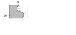
例えば、図18~図20に例示するように、変形部82の全体に接触している物体B1に図面中右方向の外力を与えると、変形部82の左側から初期滑り823が発生し(図18参照)、その領域が徐々に拡大し(図18~図20参照)、最終的には、変形部82の全体で滑りが検出される。
For example, as illustrated in FIGS. 18 to 20, when an external force in the right direction in the drawing is applied to the object B1 in contact with the
したがって、ビジョンセンサ83を用いて構成された滑りセンサ503Aを用いる場合には、手部443が物体B1を把持して持ち上げた状態を基準とし、この状態から重力と反対方向、重力による回転モーメントと反対方向、又は、授受対象者の手H1の位置方向の初期滑りを滑りセンサ503Aで検出し、初期滑りが検出されたタイミングを授受対象者が受取動作を開始したタイミングとすることが可能となる。
Therefore, when the
1.10.2 圧力分布センサ
また、初期滑りを計測するためのセンサ(滑りセンサ503に相当)には、圧力分布センサを用いることもできる。図21は、圧力分布センサを用いて構成された滑りセンサの一例を示す模式図である。1.10.2 Pressure distribution sensor A pressure distribution sensor can also be used as a sensor (corresponding to the slip sensor 503) for measuring initial slippage. FIG. 21 is a schematic diagram showing an example of a slip sensor configured using a pressure distribution sensor.
図21に示すように、圧力分布センサ91を用いて構成された滑りセンサ503Bは、物体B1と接触する面が歪曲している。したがって、滑りセンサ503Bに対して物体B1を接触させた場合、図22に示すように、接触領域R2における中央部分で検出される圧力が最も高くなる。なお、図22及び図23中、接触領域R2内の色の濃さは、圧力の高さを示しているものとする。
As shown in FIG. 21, the
この状態で図面中右方向の外力を与えると、図23に示すように、接触領域R2における最も圧力が高い領域は移動しないものの、その周辺領域は図面中右方向へシフトする。 In this state, when an external force is applied in the right direction in the drawing, as shown in FIG. 23, although the highest pressure region in the contact region R2 does not move, the surrounding region shifts in the right direction in the drawing.
したがって、圧力分布センサ91を用いて構成された滑りセンサ503Bを用いる場合には、手部443が物体B1を把持して持ち上げた状態を基準とし、この状態から重力と反対方向、重力による回転モーメントと反対方向、又は、授受対象者の手H1の位置方向の初期滑りを滑りセンサ503Bで検出し、初期滑りが検出されたタイミングを授受対象者が受取動作を開始したタイミングとすることが可能となる。
Therefore, when the
1.11 システム構成
本実施形態に係る自律ロボット1は、図24に例示するように、例えば、図24に例示するように、所定のネットワーク3を介してサーバ2に接続することが可能であってもよい。サーバ2は、例えばクラウドサーバなど、複数のサーバで構成されたサーバ群であってもよい。ネットワーク3は、例えば、インターネットやLANや移動体通信網等、種々のネットワークを適用することが可能である。1.11 System Configuration The
このようなシステム構成において、上述した機械学習部は、各自律ロボット1に配置されてもよいし、サーバ2に配置されてもよい。なお、機械学習部を各自律ロボット1に配置するかサーバ2に配置するかに関わらず、機械学習部による機械学習の結果(例えば、学習済みモデル)は、所定のネットワーク3を介して接続された複数の自律ロボット1で共有できるとよい。
In such a system configuration, the machine learning section described above may be arranged in each
機械学習部を実現する装置には、汎用の計算器又はプロセッサ(CPU)が用いられてもよいし、GPGPU(General-Purpose Computing on Graphics Processing Units)や大規模PC(Personal Computer)やFPGA(Field-Programmable Gate Array)などが用いられてもよい。 A general-purpose calculator or processor (CPU) may be used for the device that realizes the machine learning unit, and GPGPU (General-Purpose Computing on Graphics Processing Units), large-scale PC (Personal Computer), FPGA (Field -Programmable Gate Array) or the like may be used.
1.12 作用・効果
以上のように、本実施形態によれば、リリース動作の実行中に、物体B1の授受方向A1への滑り量の変化を計測し続け、物体B1の授受方向A1への移動速度の連続性が保たれるように、リリース動作が制御される。これにより、物体B1の授受方向A1への変位が急激に変化することを低減できるため、スムーズな物体B1の受け渡しが可能となる。1.12 Functions and Effects As described above, according to the present embodiment, the change in the amount of slippage of the object B1 in the delivery direction A1 is continuously measured during execution of the release operation, and the slippage of the object B1 in the delivery direction A1 is measured. The release action is controlled so that the continuity of the moving speed is maintained. As a result, it is possible to reduce abrupt changes in the displacement of the object B1 in the transfer direction A1, thereby enabling smooth transfer of the object B1.
また、本実施形態では、手部443の把持力の変化率や手部443に搭載した各種センサで検出された情報等を入力とし、物体B1の授受方向A1への移動速度の連続性を出力とした機械学習を行う。これにより、物体B1の特性(静止摩擦係数、動摩擦係数、質量、形状寸法、剛性、強度、温度、湿度等)、及び、授受対象者の所作や状況等に応じたよりスムーズな物体B1の受け渡しを可能にすることができる。
Further, in this embodiment, the rate of change in the gripping force of the
さらに、本実施形態では、例えば、手部443が把持する物体B1の滑り量又は初期滑り量の変化を計測し、その変化の向きが、重力と反対方向、重力による回転モーメントと反対方向、又は、授受対象者の手H1の位置方向の成分を有する際に、リリース動作を開始する。これにより、リリース動作を授受動作の初期段階に開始することが可能となるため、物体B1にかかる負荷や手部443の把持力の変動を最小限に抑えることが可能となり、それにより、よりスムーズな物体B1の受け渡しが可能となる。
Furthermore, in the present embodiment, for example, a change in the amount of slippage or the amount of initial slippage of the object B1 gripped by the
さらにまた、本実施形態では、リリース動作の実行中に、物体B1の重力方向への滑り量又は初期滑り量を計測し続ける。これにより、物体B1を誤って落下せたり、物体B1が手部443内で不自然に上下に変位することを低減することが可能となる。
Furthermore, in the present embodiment, the amount of slippage of object B1 in the direction of gravity or the amount of initial slippage is continuously measured during execution of the release operation. This makes it possible to reduce the possibility that the object B1 is accidentally dropped or that the object B1 is unnaturally displaced vertically within the
さらにまた、本実施形態では、画像入力情報や音声入力情報等から得られる授受対象者の存在や感情の変化等を機械学習の入力や出力に加える。これにより、物理インタラクションの更なる高品質化を達成することができる。 Furthermore, in the present embodiment, the existence of the person to be given and received, the change in emotion, etc. obtained from the image input information, the voice input information, etc., are added to the input and output of the machine learning. This makes it possible to achieve even higher quality physical interactions.
さらにまた、本実施形態では、画像処理の結果や測距センサからの情報を用いて授受対象者の存在や手H1の存在を確認した上でリリース動作を開始することができる。これにより、誤ってリリース動作を開始することを回避できるため、より安全且つ確実に物体B1の受け渡しを実行することが可能となる。なお、画像処理の結果や測距センサからの情報に限らず、例えば、音声入出力情報等を用いて授受対象者の存在を確認することもできる。また、音声入出力情報等を用いて授受対象者の把持の意思やリリース動作中の感情の変化を認識した上で、リリース動作の開始や動作継続の判断を実行することも可能となる。 Furthermore, in the present embodiment, the release operation can be started after confirming the presence of the hand H1 and the target person using the image processing result and the information from the distance measuring sensor. As a result, erroneous initiation of the release operation can be avoided, so that the delivery of the object B1 can be performed more safely and reliably. It should be noted that the existence of the person to be given/received can also be confirmed using, for example, voice input/output information or the like, without being limited to information from the result of image processing or the distance measuring sensor. It is also possible to determine whether to start the release motion or to continue the motion after recognizing the intention of the person to be handed and received and the change in emotion during the release motion using voice input/output information or the like.
なお、上記した実施形態では、物体B1を1つのマニピュレータ44で把持して授受対象者に受け渡す場合を例示したが、これに限定されるものではない。例えば、両方のマニピュレータ44R及び44Lを用いて物体B1を把持して授受対象者に受け渡す場合などにも、上述した実施形態を適用することが可能である。
In the above-described embodiment, the case where the object B1 is gripped by one manipulator 44 and transferred to the person to be handed over is illustrated, but the present invention is not limited to this. For example, it is possible to apply the above-described embodiment to a case where both
さらに、1台の自律ロボット1のみならず、複数台の自律ロボット1が連携して、物体B1を持ち上げて一人以上の授受対象者に受け渡す場合にも、上述した実施形態を適用することが可能である。
Furthermore, the above-described embodiment can be applied not only to one
また、上述した実施形態は、物体B1を対象者から受け取る場合にも応用することが可能である。 Also, the above-described embodiment can be applied to the case of receiving the object B1 from the subject.
以上、本開示の実施形態について説明したが、本開示の技術的範囲は、上述の各実施形態そのままに限定されるものではなく、本開示の要旨を逸脱しない範囲において種々の変更が可能である。また、異なる実施形態及び変形例にわたる構成要素を適宜組み合わせてもよい。 Although the embodiments of the present disclosure have been described above, the technical scope of the present disclosure is not limited to the embodiments described above, and various modifications are possible without departing from the gist of the present disclosure. . Moreover, you may combine the component over different embodiment and modifications suitably.
また、本明細書に記載された各実施形態における効果はあくまで例示であって限定されるものでは無く、他の効果があってもよい。 Further, the effects of each embodiment described in this specification are merely examples and are not limited, and other effects may be provided.
なお、本技術は以下のような構成も取ることができる。
(1)
マニピュレータに把持された物体を授受対象者へ受け渡す際、前記物体の移動速度が連続性を保つように、前記マニピュレータを制御する制御部を備える情報処理装置。
(2)
前記制御部は、前記物体の授受方向への前記移動速度が連続性を保つように、前記マニピュレータの把持力の単位時間あたりの変化量を制御する前記(1)に記載の情報処理装置。
(3)
前記マニピュレータは、前記物体を把持する手部と、一方の端に前記手部が取り付けられたアーム部とを備え、
前記制御部は、前記物体の授受方向への前記移動速度が連続性を保つように、前記手部の把持力の単位時間あたりの変化量を制御するとともに、前記アーム部の姿勢の単位時間あたりの変化量を制御する
前記(1)に記載の情報処理装置。
(4)
前記マニピュレータは、移動可能な移動体に取り付けられ、
前記制御部は、前記物体の移動速度が連続性を保つように、前記マニピュレータを制御するとともに、前記移動体の移動を制御する
前記(1)~(3)の何れか1項に記載の情報処理装置。
(5)
前記物体が前記マニピュレータと接する部分における前記物体の滑り量を検出する第1検出部をさらに備え、
前記制御部は、前記第1検出部で検出された滑り量に基づいて、前記物体の前記移動速度が連続性を保つように、前記マニピュレータを制御する
前記(1)~(4)の何れか1項に記載の情報処理装置。
(6)
前記物体が前記マニピュレータと接触する部分における前記物体の滑り量又は初期滑り量を検出する第2検出部をさらに備え、
前記制御部は、前記第2検出部で検出された前記滑り量又は前記初期滑り量の変化が重力方向とは異なる方向の成分を含む場合、前記物体を前記授受対象者へ受け渡す動作を前記マニピュレータに開始させる
前記(1)~(5)の何れか1項に記載の情報処理装置。
(7)
前記重力方向とは異なる方向は、重力と反対方向、重力による回転モーメントと反対方向、又は、前記授受対象者への授受方向である前記(6)に記載の情報処理装置。
(8)
前記物体が前記マニピュレータと接触する部分における前記物体の重力方向の滑り量又は初期滑り量を検出する第3検出部をさらに備え、
前記制御部は、前記第3検出部で検出された前記重力方向の前記滑り量又は前記初期滑り量に基づいて前記マニピュレータを制御する
前記(1)~(7)の何れか1項に記載の情報処理装置。
(9)
前記物体を前記授受対象者へ受け渡す動作中の前記授受対象者の感情を認識する対象者認識部をさらに備え、
前記制御部は、前記対象者認識部で検出された前記授受対象者の感情の変化に基づいて、前記物体を前記授受対象者へ受け渡す動作を停止又は終了する
前記(1)~(8)の何れか1項に記載の情報処理装置。
(10)
前記対象者認識部は、前記授受対象者を撮像した画像データ及び前記授受対象者が発した声を集音した音声データのうちの少なくとも1つに基づいて、前記授受対象者の感情を認識する前記(9)に記載の情報処理装置。
(11)
前記物体を前記授受対象者へ受け渡すために前記マニピュレータに実行させる授受動作を計画する計画部をさらに備え、
前記制御部は、前記計画部で計画された前記授受動作に従って、前記物体の前記移動速度が連続性を保つように、前記マニピュレータを制御する
前記(1)~(10)の何れか1項に記載の情報処理装置。
(12)
前記物体の特性を認識又は推定する物体認識部をさらに備え、
前記計画部は、前記物体認識部で認識又は推定された前記物体の特性に基づいて、前記授受動作を計画する
前記(11)に記載の情報処理装置。
(13)
前記物体の特性は、静止摩擦係数、動摩擦係数、質量、形状寸法、剛性、強度、温度及び湿度のうちの少なくとも1つを含む前記(12)に記載の情報処理装置。
(14)
前記計画部は、学習済みモデルに従って前記授受動作を計画する前記(11)~(13)の何れか1項に記載の情報処理装置。
(15)
前記学習済みモデルは、前記マニピュレータが前記物体を把持する把持力の変化率を入力とし、前記物体の授受方向への移動速度の連続性を出力とした機械学習にて作成されたモデルである前記(14)に記載の情報処理装置。
(16)
前記機械学習は、前記物体の授受方向への前記移動速度の連続性が高い程、プラスの報酬が設定され、前記授受方向への前記移動速度の連続性が低い程、マイナスの報酬が設定された機械学習である前記(15)に記載の情報処理装置。
(17)
前記第1検出部は、粘弾性体及びビジョンセンサ、圧力分布センサ及び測距センサのうちの少なくとも1つを含む前記(5)に記載の情報処理装置。
(18)
前記第2検出部は、粘弾性体及びビジョンセンサ、又は、圧力分布センサを含む前記(6)又は(7)に記載の情報処理装置。
(19)
マニピュレータに把持された物体を授受対象者へ受け渡す際、前記物体の移動速度が連続性を保つように、前記マニピュレータを制御する制御方法。
(20)
マニピュレータを制御するコンピュータを機能させるためのプログラムであって、
前記マニピュレータに把持された物体を授受対象者へ受け渡す際、前記物体の移動速度が連続性を保つように、前記マニピュレータを制御することを前記コンピュータに実行させるためのプログラム。Note that the present technology can also take the following configuration.
(1)
An information processing apparatus comprising a control unit that controls the manipulator so that the movement speed of the object maintains continuity when the object gripped by the manipulator is transferred to a person to be handed over.
(2)
The information processing apparatus according to (1), wherein the control unit controls the amount of change per unit time of the gripping force of the manipulator so that the moving speed of the object in the handing-over direction maintains continuity.
(3)
The manipulator comprises a hand for gripping the object and an arm having the hand attached to one end,
The control unit controls the amount of change per unit time in the gripping force of the hand so that the speed of movement of the object in the hand-giving direction maintains continuity, and controls the amount of change in the posture of the arm per unit time. The information processing apparatus according to (1) above, which controls the amount of change in .
(4)
The manipulator is attached to a movable body,
The information according to any one of (1) to (3) above, wherein the control unit controls the manipulator and controls the movement of the moving body so that the moving speed of the object maintains continuity. processing equipment.
(5)
further comprising a first detection unit that detects an amount of slippage of the object at a portion where the object contacts the manipulator;
Any one of (1) to (4) above, wherein the control unit controls the manipulator so that the moving speed of the object maintains continuity based on the amount of slippage detected by the first detection unit. The information processing device according to
(6)
Further comprising a second detection unit that detects a slip amount or an initial slip amount of the object at a portion where the object contacts the manipulator,
When the change in the amount of slip or the amount of initial slip detected by the second detection unit includes a component in a direction different from the direction of gravity, the control unit performs the operation of handing over the object to the person to be handed/received. The information processing apparatus according to any one of (1) to (5), wherein the manipulator is started.
(7)
The information processing apparatus according to (6), wherein the direction different from the direction of gravity is a direction opposite to gravity, a direction opposite to a rotational moment due to gravity, or a direction of giving/receiving to/from the person to be given/received.
(8)
further comprising a third detection unit that detects a slip amount or an initial slip amount of the object in the gravitational direction at a portion where the object contacts the manipulator;
The control unit according to any one of (1) to (7), wherein the control unit controls the manipulator based on the amount of slippage in the direction of gravity detected by the third detection unit or the amount of initial slippage. Information processing equipment.
(9)
further comprising a target person recognition unit that recognizes the emotion of the target person during the action of handing over the object to the target person;
The control unit stops or terminates the operation of handing over the object to the person to be handed over based on the change in the emotion of the person to be handed over detected by the person recognition unit. The information processing apparatus according to any one of 1.
(10)
The target person recognition unit recognizes the emotion of the target person based on at least one of image data obtained by imaging the target person and voice data obtained by collecting the voice uttered by the target person. The information processing device according to (9) above.
(11)
further comprising a planning unit that plans a transfer action to be executed by the manipulator to transfer the object to the transfer target person;
According to the giving/receiving action planned by the planning unit, the control unit controls the manipulator so that the moving speed of the object maintains continuity. The information processing device described.
(12)
further comprising an object recognition unit for recognizing or estimating characteristics of the object;
The information processing apparatus according to (11), wherein the planning unit plans the giving/receiving action based on the property of the object recognized or estimated by the object recognition unit.
(13)
The information processing apparatus according to (12), wherein the properties of the object include at least one of static friction coefficient, dynamic friction coefficient, mass, shape, rigidity, strength, temperature and humidity.
(14)
The information processing apparatus according to any one of (11) to (13), wherein the planning unit plans the giving/receiving action according to a learned model.
(15)
The learned model is a model created by machine learning in which the change rate of the gripping force with which the manipulator grips the object is input and the continuity of the moving speed of the object in the giving and receiving direction is output as the output. The information processing device according to (14).
(16)
In the machine learning, the higher the continuity of the speed of movement of the object in the giving/receiving direction, the more positive reward is set, and the lower the continuity of the speed of moving the object in the giving/receiving direction, the more negative reward is set. The information processing device according to (15) above, which is machine learning.
(17)
The information processing apparatus according to (5), wherein the first detection unit includes at least one of a viscoelastic body and a vision sensor, a pressure distribution sensor, and a range sensor.
(18)
The information processing apparatus according to (6) or (7), wherein the second detection unit includes a viscoelastic body and a vision sensor or a pressure distribution sensor.
(19)
A control method for controlling the manipulator so that the movement speed of the object maintains continuity when the object gripped by the manipulator is transferred to a person to be handed over.
(20)
A program for operating a computer that controls a manipulator,
A program for causing the computer to control the manipulator so that the movement speed of the object maintains continuity when the object gripped by the manipulator is transferred to a recipient.
1 自律ロボット
2 サーバ
3 ネットワーク
10 コントロール部
11 信号処理回路
12 CPU
13 DRAM
14 フラッシュROM
15 PCカードI/F
16 無線通信部
17 内部バス
18 バッテリ
19 カメラ
20 IMU
21 ToFセンサ
22 タッチセンサ
23 マイク
24 スピーカ
25 表示部
26 可動部
261 3軸センサ(肩)
262 1軸センサ(肘)
263 3軸センサ(手首)
264 1軸センサ(指関節)
265 2軸センサ(腰)
266 3軸センサ(首)
27 アクチュエータ
28 エンコーダ(ポテンショメータ)
30 メモリカード
41 頭部
42 胴体部
43 台車部
44、44L、44R マニピュレータ
441 上腕部
442 前腕部
443 手部
444 関節機構
4431 基底部
4432、4432a、4432b 指部
4433、4435 関節機構
4434 基節部
4436 末節部
50 センサ群
501 6軸力覚センサ
502 3軸力覚センサ
503、503A、503B 滑りセンサ
504 測距センサ
504a ToFセンサ
504b カメラ
51 授受対象者認識部
52 物体認識部
53 授受行動計画部
54 学習情報記憶部
55 物理インタラクション実行部
56 把持情報取得部
57 レスポンス時間計測部
58 感情マップ生成部
59 授受行動評価部
60 ノード(ニューロン)
61 エッジ
71 把持動作
72 リリース動作
73 α×把持動作+(1-α)×リリース動作
74 把持力制御
75 負荷計算
76 ブレンド率
77 アーム動作制御
78 全身動作制御
81 筐体
82 変形部
83 ビジョンセンサ
821 粘弾性体
822 マーカ
823 初期滑り
91 圧力分布センサ
A1 授受方向
B1 物体
H1 手
P1 床
R1 領域
R2 接触領域1
13 DRAM
14 Flash ROM
15 PC card I/F
16
21 ToF sensor 22
262 single-axis sensor (elbow)
263 3-axis sensor (wrist)
264 1-axis sensor (finger joint)
265 2-axis sensor (waist)
266 3-axis sensor (neck)
27
30
61
Claims (19)
前記制御部は、前記物体の授受方向への前記移動速度が連続性を保つように、前記マニピュレータの把持力の単位時間あたりの変化量を制御する、
情報処理装置。 a control unit that controls the manipulator so that the movement speed of the object maintains continuity when the object gripped by the manipulator is transferred to the person to be handed over ;
The control unit controls the amount of change per unit time of the gripping force of the manipulator so that the moving speed of the object in the handing-over direction maintains continuity.
Information processing equipment.
前記マニピュレータは、前記物体を把持する手部と、一方の端に前記手部が取り付けられたアーム部とを有し、
前記制御部は、前記物体の授受方向への前記移動速度が連続性を保つように、前記手部の把持力の単位時間あたりの変化量を制御するとともに、前記アーム部の姿勢の単位時間あたりの変化量を制御する
情報処理装置。 a control unit that controls the manipulator so that the movement speed of the object maintains continuity when the object gripped by the manipulator is transferred to the person to be handed over;
The manipulator has a hand portion for gripping the object and an arm portion to which the hand portion is attached at one end,
The control unit controls the amount of change per unit time in the gripping force of the hand so that the speed of movement of the object in the hand-giving direction maintains continuity, and controls the amount of change in the posture of the arm per unit time. controls the amount of change in
Information processing equipment.
前記制御部は、前記物体の移動速度が連続性を保つように、前記マニピュレータを制御するとともに、前記移動体の移動を制御する
請求項1又は2に記載の情報処理装置。 The manipulator is attached to a movable body,
The information processing apparatus according to claim 1 or 2 , wherein the control unit controls the manipulator and the movement of the moving body so that the moving speed of the object maintains continuity.
前記制御部は、前記第1検出部で検出された滑り量に基づいて、前記物体の前記移動速度が連続性を保つように、前記マニピュレータを制御する
請求項1~3のいずれか1項に記載の情報処理装置。 further comprising a first detection unit that detects an amount of slippage of the object at a portion where the object contacts the manipulator;
4. The control unit controls the manipulator so that the moving speed of the object maintains continuity based on the amount of slippage detected by the first detection unit. The information processing device described.
前記制御部は、前記第2検出部で検出された前記滑り量又は前記初期滑り量の変化が重力方向とは異なる方向の成分を含む場合、前記物体を前記授受対象者へ受け渡す動作を前記マニピュレータに開始させる
請求項1~4のいずれか1項に記載の情報処理装置。 Further comprising a second detection unit that detects a slip amount or an initial slip amount of the object at a portion where the object contacts the manipulator,
When the change in the amount of slip or the amount of initial slip detected by the second detection unit includes a component in a direction different from the direction of gravity, the control unit performs the operation of handing over the object to the person to be handed/received. The information processing apparatus according to any one of claims 1 to 4, wherein the manipulator is started.
前記制御部は、前記第3検出部で検出された前記重力方向の前記滑り量又は前記初期滑り量に基づいて前記マニピュレータを制御する
請求項1~6のいずれか1項に記載の情報処理装置。 further comprising a third detection unit that detects a slip amount or an initial slip amount of the object in the gravitational direction at a portion where the object contacts the manipulator;
The information processing apparatus according to any one of claims 1 to 6, wherein the control unit controls the manipulator based on the amount of slippage in the direction of gravity detected by the third detection unit or the amount of initial slippage. .
前記制御部は、前記対象者認識部で検出された前記授受対象者の感情の変化に基づいて、前記物体を前記授受対象者へ受け渡す動作を停止又は終了する
請求項1~7のいずれか1項に記載の情報処理装置。 further comprising a target person recognition unit that recognizes the emotion of the target person during the action of handing over the object to the target person;
8. The controller according to any one of claims 1 to 7, wherein the control unit stops or terminates the operation of handing over the object to the person to whom the object is to be exchanged, based on the change in the emotion of the person to whom the object is to be exchanged detected by the object recognition unit. The information processing device according to item 1 .
前記制御部は、前記計画部で計画された前記授受動作に従って、前記物体の前記移動速度が連続性を保つように、前記マニピュレータを制御する
請求項1~9のいずれか1項に記載の情報処理装置。 further comprising a planning unit that plans a transfer action to be executed by the manipulator to transfer the object to the transfer target person;
The information according to any one of claims 1 to 9, wherein the control unit controls the manipulator so that the moving speed of the object maintains continuity according to the giving/receiving action planned by the planning unit. processing equipment.
前記計画部は、前記物体認識部で認識又は推定された前記物体の特性に基づいて、前記授受動作を計画する
請求項10に記載の情報処理装置。 further comprising an object recognition unit for recognizing or estimating characteristics of the object;
The information processing apparatus according to claim 10 , wherein the planning section plans the giving/receiving action based on the property of the object recognized or estimated by the object recognition section.
前記物体の授受方向への前記移動速度が連続性を保つように、前記マニピュレータの把持力の単位時間あたりの変化量を制御する、
制御方法。 A control method for controlling the manipulator so that the moving speed of the object maintains continuity when the object gripped by the manipulator is transferred to a person to be handed over, comprising:
controlling the amount of change per unit time in the gripping force of the manipulator so that the speed of movement of the object in the direction of giving and receiving remains continuous;
control method.
前記マニピュレータに把持された物体を授受対象者へ受け渡す際、前記物体の授受方向への前記物体の移動速度が連続性を保つように、前記マニピュレータの把持力の単位時間あたりの変化量を制御することを前記コンピュータに実行させるためのプログラム。 A program for operating a computer that controls a manipulator,
Controlling the amount of change per unit time in the gripping force of the manipulator so that when the object gripped by the manipulator is transferred to the person to whom the object is to be transferred, the moving speed of the object in the direction of transfer of the object maintains continuity. A program for causing the computer to perform
Applications Claiming Priority (3)
| Application Number | Priority Date | Filing Date | Title |
|---|---|---|---|
| JP2018190285 | 2018-10-05 | ||
| JP2018190285 | 2018-10-05 | ||
| PCT/JP2019/035825 WO2020071080A1 (en) | 2018-10-05 | 2019-09-12 | Information processing device, control method, and program |
Publications (2)
| Publication Number | Publication Date |
|---|---|
| JPWO2020071080A1 JPWO2020071080A1 (en) | 2021-09-02 |
| JP7318655B2 true JP7318655B2 (en) | 2023-08-01 |
Family
ID=70055156
Family Applications (1)
| Application Number | Title | Priority Date | Filing Date |
|---|---|---|---|
| JP2020550247A Active JP7318655B2 (en) | 2018-10-05 | 2019-09-12 | Information processing device, control method and program |
Country Status (6)
| Country | Link |
|---|---|
| US (1) | US20210394362A1 (en) |
| EP (1) | EP3862148A4 (en) |
| JP (1) | JP7318655B2 (en) |
| KR (1) | KR20210069041A (en) |
| CN (1) | CN112770876A (en) |
| WO (1) | WO2020071080A1 (en) |
Families Citing this family (5)
| Publication number | Priority date | Publication date | Assignee | Title |
|---|---|---|---|---|
| JP2021049597A (en) * | 2019-09-24 | 2021-04-01 | ソニー株式会社 | Information processing device, information processing system, and information processing method |
| JP7458818B2 (en) * | 2020-02-21 | 2024-04-01 | キヤノン株式会社 | Robot device, interface device, control device, end effector, control method, method for manufacturing articles using robot device, program, and recording medium |
| DE102021108906A1 (en) * | 2021-04-09 | 2022-10-13 | Linde Material Handling Gmbh | Mobile picking robot |
| WO2024053204A1 (en) * | 2022-09-09 | 2024-03-14 | 東京ロボティクス株式会社 | Mobile manipulator, method for controlling same, and program |
| CN115635482B (en) * | 2022-10-18 | 2024-01-30 | 深圳市人工智能与机器人研究院 | Vision-based robot-to-person body transfer method, device, medium and terminal |
Citations (2)
| Publication number | Priority date | Publication date | Assignee | Title |
|---|---|---|---|---|
| JP2009012132A (en) | 2007-07-05 | 2009-01-22 | Denso Wave Inc | Polyarticular robot and method for handing over work |
| JP2013184273A (en) | 2012-03-09 | 2013-09-19 | Sony Corp | Robot apparatus, method of controlling robot apparatus, and computer program |
Family Cites Families (12)
| Publication number | Priority date | Publication date | Assignee | Title |
|---|---|---|---|---|
| CN101890720B (en) * | 2004-07-13 | 2012-01-11 | 松下电器产业株式会社 | Article holding system, robot, and method of controlling robot |
| JP4456561B2 (en) * | 2005-12-12 | 2010-04-28 | 本田技研工業株式会社 | Autonomous mobile robot |
| JP2008188722A (en) * | 2007-02-06 | 2008-08-21 | Fanuc Ltd | Robot controller |
| KR101687626B1 (en) * | 2010-01-06 | 2016-12-21 | 삼성전자주식회사 | Robot and Control Method Thereof |
| JP2013111737A (en) * | 2011-12-01 | 2013-06-10 | Sony Corp | Robot apparatus, control method thereof, and computer program |
| CN205058045U (en) * | 2015-10-26 | 2016-03-02 | 众德迪克科技(北京)有限公司 | Robot with vision servo |
| US20180021949A1 (en) * | 2016-07-20 | 2018-01-25 | Canon Kabushiki Kaisha | Robot apparatus, robot controlling method, program, and recording medium |
| US10682774B2 (en) * | 2017-12-12 | 2020-06-16 | X Development Llc | Sensorized robotic gripping device |
| CN108297068A (en) * | 2018-04-11 | 2018-07-20 | 南京理工大学 | A kind of hot line robot specific purpose tool replacing options based on force feedback master & slave control |
| US10967507B2 (en) * | 2018-05-02 | 2021-04-06 | X Development Llc | Positioning a robot sensor for object classification |
| US10471591B1 (en) * | 2018-06-01 | 2019-11-12 | X Development Llc | Object hand-over between robot and actor |
| JP6916157B2 (en) * | 2018-10-23 | 2021-08-11 | ファナック株式会社 | Robot systems that collaborate with people and robot control methods |
-
2019
- 2019-09-12 WO PCT/JP2019/035825 patent/WO2020071080A1/en active Application Filing
- 2019-09-12 EP EP19869651.0A patent/EP3862148A4/en active Pending
- 2019-09-12 US US17/279,990 patent/US20210394362A1/en active Pending
- 2019-09-12 CN CN201980064044.1A patent/CN112770876A/en active Pending
- 2019-09-12 KR KR1020217007107A patent/KR20210069041A/en unknown
- 2019-09-12 JP JP2020550247A patent/JP7318655B2/en active Active
Patent Citations (2)
| Publication number | Priority date | Publication date | Assignee | Title |
|---|---|---|---|---|
| JP2009012132A (en) | 2007-07-05 | 2009-01-22 | Denso Wave Inc | Polyarticular robot and method for handing over work |
| JP2013184273A (en) | 2012-03-09 | 2013-09-19 | Sony Corp | Robot apparatus, method of controlling robot apparatus, and computer program |
Non-Patent Citations (1)
| Title |
|---|
| 柴田 諭,協調と位置決め支援を有するロボットと人間の手渡し運動,日本感性工学会論文誌,日本,日本感性工学会,2010年02月,Vol.9 No.2,pp.227-234 |
Also Published As
| Publication number | Publication date |
|---|---|
| EP3862148A4 (en) | 2021-12-22 |
| CN112770876A (en) | 2021-05-07 |
| KR20210069041A (en) | 2021-06-10 |
| WO2020071080A1 (en) | 2020-04-09 |
| EP3862148A1 (en) | 2021-08-11 |
| US20210394362A1 (en) | 2021-12-23 |
| JPWO2020071080A1 (en) | 2021-09-02 |
Similar Documents
| Publication | Publication Date | Title |
|---|---|---|
| JP7318655B2 (en) | Information processing device, control method and program | |
| Asfour et al. | Armar-6: A collaborative humanoid robot for industrial environments | |
| Koenemann et al. | Real-time imitation of human whole-body motions by humanoids | |
| JP5180989B2 (en) | Method and apparatus for automatic control of a humanoid robot | |
| US9193072B2 (en) | Robot and control method thereof | |
| Nemlekar et al. | Object transfer point estimation for fluent human-robot handovers | |
| US8483877B2 (en) | Workspace safe operation of a force- or impedance-controlled robot | |
| US9014854B2 (en) | Robot and control method thereof | |
| Devine et al. | Real time robotic arm control using hand gestures with multiple end effectors | |
| JP7035309B2 (en) | Master-slave system | |
| Kaplish et al. | Motion retargeting and control for teleoperated physical human-robot interaction | |
| JP5633166B2 (en) | Robot and control method thereof | |
| Li et al. | Intelligent control strategy for robotic arm by using adaptive inertia weight and acceleration coefficients particle swarm optimization | |
| JP2006026875A (en) | Gripping control device for robot hand | |
| Falck et al. | DE VITO: A dual-arm, high degree-of-freedom, lightweight, inexpensive, passive upper-limb exoskeleton for robot teleoperation | |
| JPH05108108A (en) | Compliance control method and controller | |
| Jin et al. | Minimal grasper: A practical robotic grasper with robust performance for pick-and-place tasks | |
| CN116113523A (en) | Information processing device, information processing method, and program | |
| KR101211601B1 (en) | Motion Control System and Method for Grasping Object with Dual Arms of Robot | |
| US20220355490A1 (en) | Control device, control method, and program | |
| Balaji et al. | Smart phone accelerometer sensor based wireless robot for physically disabled people | |
| Schubö et al. | Movement coordination in applied human-human and human-robot interaction | |
| JP2005088175A (en) | Robot device and operation control method for the robot device | |
| CN110877335A (en) | Self-adaptive unmarked mechanical arm track tracking method based on hybrid filter | |
| Zubrycki et al. | Intuitive user interfaces for mobile manipulation tasks |
Legal Events
| Date | Code | Title | Description |
|---|---|---|---|
| A621 | Written request for application examination |
Free format text: JAPANESE INTERMEDIATE CODE: A621 Effective date: 20220726 |
|
| A131 | Notification of reasons for refusal |
Free format text: JAPANESE INTERMEDIATE CODE: A131 Effective date: 20230425 |
|
| A521 | Request for written amendment filed |
Free format text: JAPANESE INTERMEDIATE CODE: A523 Effective date: 20230602 |
|
| TRDD | Decision of grant or rejection written | ||
| A01 | Written decision to grant a patent or to grant a registration (utility model) |
Free format text: JAPANESE INTERMEDIATE CODE: A01 Effective date: 20230620 |
|
| A61 | First payment of annual fees (during grant procedure) |
Free format text: JAPANESE INTERMEDIATE CODE: A61 Effective date: 20230703 |
|
| R151 | Written notification of patent or utility model registration |
Ref document number: 7318655 Country of ref document: JP Free format text: JAPANESE INTERMEDIATE CODE: R151 |