JP7318552B2 - Cartridge, data recording device and data reproducing device - Google Patents
Cartridge, data recording device and data reproducing device Download PDFInfo
- Publication number
- JP7318552B2 JP7318552B2 JP2020019660A JP2020019660A JP7318552B2 JP 7318552 B2 JP7318552 B2 JP 7318552B2 JP 2020019660 A JP2020019660 A JP 2020019660A JP 2020019660 A JP2020019660 A JP 2020019660A JP 7318552 B2 JP7318552 B2 JP 7318552B2
- Authority
- JP
- Japan
- Prior art keywords
- magnetic
- magnetic tape
- width
- tape
- recording
- Prior art date
- Legal status (The legal status is an assumption and is not a legal conclusion. Google has not performed a legal analysis and makes no representation as to the accuracy of the status listed.)
- Active
Links
Images


Classifications
-
- G—PHYSICS
- G11—INFORMATION STORAGE
- G11B—INFORMATION STORAGE BASED ON RELATIVE MOVEMENT BETWEEN RECORD CARRIER AND TRANSDUCER
- G11B5/00—Recording by magnetisation or demagnetisation of a record carrier; Reproducing by magnetic means; Record carriers therefor
- G11B5/74—Record carriers characterised by the form, e.g. sheet shaped to wrap around a drum
- G11B5/78—Tape carriers
-
- G—PHYSICS
- G11—INFORMATION STORAGE
- G11B—INFORMATION STORAGE BASED ON RELATIVE MOVEMENT BETWEEN RECORD CARRIER AND TRANSDUCER
- G11B15/00—Driving, starting or stopping record carriers of filamentary or web form; Driving both such record carriers and heads; Guiding such record carriers or containers therefor; Control thereof; Control of operating function
- G11B15/18—Driving; Starting; Stopping; Arrangements for control or regulation thereof
- G11B15/43—Control or regulation of mechanical tension of record carrier, e.g. tape tension
-
- G—PHYSICS
- G11—INFORMATION STORAGE
- G11B—INFORMATION STORAGE BASED ON RELATIVE MOVEMENT BETWEEN RECORD CARRIER AND TRANSDUCER
- G11B23/00—Record carriers not specific to the method of recording or reproducing; Accessories, e.g. containers, specially adapted for co-operation with the recording or reproducing apparatus ; Intermediate mediums; Apparatus or processes specially adapted for their manufacture
- G11B23/02—Containers; Storing means both adapted to cooperate with the recording or reproducing means
- G11B23/027—Containers for single reels or spools
-
- G—PHYSICS
- G11—INFORMATION STORAGE
- G11B—INFORMATION STORAGE BASED ON RELATIVE MOVEMENT BETWEEN RECORD CARRIER AND TRANSDUCER
- G11B23/00—Record carriers not specific to the method of recording or reproducing; Accessories, e.g. containers, specially adapted for co-operation with the recording or reproducing apparatus ; Intermediate mediums; Apparatus or processes specially adapted for their manufacture
- G11B23/30—Record carriers not specific to the method of recording or reproducing; Accessories, e.g. containers, specially adapted for co-operation with the recording or reproducing apparatus ; Intermediate mediums; Apparatus or processes specially adapted for their manufacture with provision for auxiliary signals
Landscapes
- Digital Magnetic Recording (AREA)
- Adjustment Of The Magnetic Head Position Track Following On Tapes (AREA)
- Magnetic Record Carriers (AREA)
- Signal Processing For Digital Recording And Reproducing (AREA)
Description
本技術は、磁気テープを内部に収容するカートリッジ等の技術に関する。 The present technology relates to a technology such as a cartridge that accommodates a magnetic tape inside.
近年、電子データのバックアップなどの用途で磁気テープが広く普及している。磁気テープは、容量が多く長期保存が可能なことから、ビッグデータ等の蓄積媒体としてますます注目が集まっている。 In recent years, magnetic tapes have been widely used for applications such as backing up electronic data. Since magnetic tapes have a large capacity and can be stored for a long period of time, they are attracting more and more attention as a storage medium for big data and the like.
磁気テープには、複数の記録トラックを含むデータバンドが設けられており、この記録トラックに対してデータが記録される。また、幅方向でデータバンドを挟み込む位置にサーボバンドが設けられ、このサーボバンドにサーボ信号が記録される。磁気ヘッドは、サーボバンドに記録されたサーボ信号を読み取ることで、記録トラックに対して位置合わせを行う。 A magnetic tape is provided with a data band including a plurality of recording tracks, and data is recorded on the recording tracks. Further, servo bands are provided at positions sandwiching the data band in the width direction, and servo signals are recorded in these servo bands. The magnetic head is aligned with the recording track by reading the servo signal recorded in the servo band.
磁気テープの規格としては、LTO(Linear Tape Open)規格が広く知られている。LTO規格においては、巻回された磁気テープがカートリッジ内に収容され、また、カートリッジ内には、カートリッジメモリと呼ばれる非接触式で読み書き可能なメモリチップが組み込まれている(例えば、特許文献1参照)。このカートリッジメモリには、カートリッジや磁気テープの生産管理情報や使用履歴、記録内容の概要などが記録される。 As a magnetic tape standard, the LTO (Linear Tape Open) standard is widely known. According to the LTO standard, a wound magnetic tape is contained in a cartridge, and a contactless readable and writable memory chip called a cartridge memory is incorporated in the cartridge (see, for example, Patent Document 1). ). In this cartridge memory, production management information, usage history, outline of recorded contents, etc. of cartridges and magnetic tapes are recorded.
近年においては、磁気テープの大容量化の要請から、記録トラックの数が多くなり、記録トラックの幅が狭くなってきている。このため、磁気テープにデータが記憶された後、何らかの原因で、磁気テープの幅がわずかにでも変動してしまうと、磁気テープに記録されたデータが正確に再生できずにエラーが発生してしまう可能性がある。 In recent years, the number of recording tracks has increased and the width of the recording tracks has become narrower due to the demand for larger capacity magnetic tapes. Therefore, if for some reason the width of the magnetic tape changes even slightly after data is stored on the magnetic tape, the data recorded on the magnetic tape cannot be reproduced accurately and an error occurs. It may get lost.
以上のような事情に鑑み、本技術の目的は、磁気テープの幅が変動したような場合でも、磁気テープに記録されたデータを正確に再生することができる技術を提供することにある。 In view of the circumstances as described above, an object of the present technology is to provide a technology capable of accurately reproducing data recorded on a magnetic tape even when the width of the magnetic tape varies.
本技術に係るカートリッジは、カートリッジケースと、メモリとを具備する。
前記カートリッジケースは、磁気テープを収容する。
前記メモリは、前記カートリッジケースに設けられ、前記磁気テープのデータ記録時における情報であって、前記磁気テープのデータ再生時において前記磁気テープの幅を調整するための情報を記憶する。
A cartridge according to the present technology includes a cartridge case and a memory.
The cartridge case accommodates a magnetic tape.
The memory is provided in the cartridge case and stores information for recording data on the magnetic tape and for adjusting the width of the magnetic tape when reproducing data from the magnetic tape.
この技術では、磁気テープのデータ記録時における情報がメモリに記憶されているので、この情報をデータ再生時に利用することで、磁気テープの幅を適切に調整することができる。従って、磁気テープの幅が何らかの理由で変動したような場合でも、磁気テープに記録されたデータを正確に再生することができる。 In this technique, since the information during data recording on the magnetic tape is stored in the memory, the width of the magnetic tape can be appropriately adjusted by using this information during data reproduction. Therefore, even if the width of the magnetic tape varies for some reason, the data recorded on the magnetic tape can be reproduced accurately.
上記カートリッジにおいて、前記情報は、データ記録時における前記磁気テープの周囲の環境情報を含んでいてもよい。 In the cartridge described above, the information may include environmental information about the magnetic tape at the time of data recording.
上記カートリッジにおいて、前記環境情報は、データ記録時における前記磁気テープの周囲の温度の情報を含んでいてもよい。 In the cartridge described above, the environmental information may include information on the ambient temperature of the magnetic tape during data recording.
上記カートリッジにおいて、前記環境情報は、データ記録時における前記磁気テープの周囲の湿度の情報を含んでいてもよい。 In the cartridge described above, the environmental information may include information about humidity around the magnetic tape during data recording.
上記カートリッジにおいて、前記情報は、データ記録時における前記磁気テープのテンションの情報を含んでいてもよい。 In the cartridge described above, the information may include tension information of the magnetic tape during data recording.
上記カートリッジにおいて、前記情報は、データ記録時における前記磁気テープの幅の情報を含んでいてもよい。 In the cartridge described above, the information may include information on the width of the magnetic tape during data recording.
上記カートリッジにおいて、データ再生時において、前記磁気テープのテンションの調整により前記磁気テープの幅が調整されてもよい。 In the cartridge, the width of the magnetic tape may be adjusted by adjusting the tension of the magnetic tape during data reproduction.
上記カートリッジにおいて、データ再生時において、前記磁気テープの幅がデータ記録時における前記磁気テープの幅と同じとなるように、前記磁気テープの幅が調整されてもよい。 In the cartridge, the width of the magnetic tape may be adjusted so that the width of the magnetic tape is the same as the width of the magnetic tape during data recording during data reproduction.
上記カートリッジにおいて、前記情報が、データ記録時における前記磁気テープの周囲の環境情報を含む場合、前記メモリ内に記憶されたデータ記録時の前記環境情報と、データ再生時に測定された環境情報との差に基づいて、前記磁気テープの幅が調整されてもよい。 In the above cartridge, if the information includes environmental information about the magnetic tape during data recording, the environmental information stored in the memory during data recording and the environmental information measured during data reproduction. The width of the magnetic tape may be adjusted based on the difference.
上記カートリッジは、LTO(linear Tape Open)規格に基づいていてもよい。 The cartridge may be based on the LTO (linear Tape Open) standard.
本技術に係るメモリは、磁気テープを収容するカートリッジケースに設けられ、前記磁気テープのデータ記録時における情報であって、前記磁気テープのデータ再生時において前記磁気テープの幅を調整するための情報を記憶する。 The memory according to the present technology is provided in a cartridge case that accommodates a magnetic tape, and includes information when data is recorded on the magnetic tape, and information for adjusting the width of the magnetic tape when data is reproduced on the magnetic tape. memorize
本技術に係るデータ記録装置は、磁気テープにデータを記録するデータ記録装置であって、前記磁気テープを収容するカートリッジケースに設けられたメモリに対して、前記磁気テープのデータ記録時における情報であって、前記磁気テープのデータ再生時において前記磁気テープの幅を調整するための情報を記憶する。 A data recording device according to an embodiment of the present technology is a data recording device that records data on a magnetic tape. and stores information for adjusting the width of the magnetic tape when reproducing data from the magnetic tape.
本技術に係るデータ再生装置は、磁気テープに記録されたデータを再生するデータ再生装置であって、前記磁気テープを収容するカートリッジケースに設けられたメモリに記憶された前記磁気テープのデータ記録時における情報を読み出して、前記情報に基づいて、前記磁気テープのデータ再生時における前記磁気テープの幅を調整する。 A data reproducing device according to the present technology is a data reproducing device that reproduces data recorded on a magnetic tape, and when data is recorded on the magnetic tape stored in a memory provided in a cartridge case that houses the magnetic tape, and adjusts the width of the magnetic tape when reproducing data from the magnetic tape based on the information.
以下、本技術に係る実施形態を、図面を参照しながら説明する。 Hereinafter, embodiments according to the present technology will be described with reference to the drawings.
<システムの全体構成及び各部の構成>
[カートリッジ10]
図1は本技術の一実施形態に係るカートリッジ10を示す分解斜視図である。本実施形態の説明では、カートリッジ10として、LTO規格に準拠するカートリッジ10を例に挙げて説明する。
<Overall configuration of the system and configuration of each part>
[Cartridge 10]
FIG. 1 is an exploded perspective view showing a
図1に示すように、カートリッジ10は、カートリッジケース11と、カートリッジケース11の内部に回転可能に収容される磁気テープ1と、カートリッジケース11の内部に設けられるカートリッジメモリ9とを備えている。
As shown in FIG. 1, the
カートリッジケース11は、上シェル11aと下シェル11bとを複数本のネジ部材により結合することで構成されている。カートリッジケース11の内部には、磁気テープ1を巻装した単一のテープリール13が回転可能に収容されている。
The
テープリール13の底部中央には、データ記録/再生装置30のスピンドル31(図4参照)と係合するチャッキングギヤ(図示略)が環状に形成されている。このチャッキングギヤは、下シェル11bの中央に形成された開口部14を介して外部へ露出している。このチャッキングギヤの内周側には、スピンドル31と磁気的に吸着される環状の金属プレート15が固定されている。
A chucking gear (not shown) that engages with the spindle 31 (see FIG. 4) of the data recording/reproducing
上シェル11aの内面とテープリール13との間には、リールスプリング16、リールロック部材17及びスパイダ18が配置されている。これらにより、カートリッジ10の非使用時におけるテープリール13の回転を抑止するリールロック機構が構成される。
Between the inner surface of the
カートリッジケース11の一側壁部には、磁気テープ1の一端を外部へ引き出すためのテープ引出し口19が設けられている。この側壁部の内方には、テープ引出し口19を開閉するスライドドア20が配置されている。スライドドア20は、データ記録/再生装置30のテープローディング機構(不図示)との係合によりトーションバネ21の付勢力に抗してテープ引出し口19を開放する方向にスライドするように構成される。
One side wall of the
磁気テープ1の一端部には、リーダーピン22が固着されている。リーダーピン22は、テープ引出し口19の内方側に設けられたピン保持部23に対して着脱可能に構成される。ピン保持部23は、カートリッジケース11の上壁内面(上シェル11aの内面)及び底壁内面(下シェル11bの内面)において、リーダーピン22の上端部及び下端部をそれぞれ弾性的に保持する弾性保持具24を備えている。
A
そして、カートリッジケース11の他の側壁内方には、磁気テープ1に記録された情報の誤消去防止用のセイフティタブ25のほか、磁気テープ1に記録されたデータに関する内容を非接触で読み書き可能なカートリッジメモリ9が配置されている。
In addition to a
[磁気テープ1]
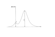
図2は、磁気テープ1を側方から見た模式図であり、図3は、磁気テープ1を上方からみた模式図である。
[Magnetic tape 1]
FIG. 2 is a schematic diagram of the
図2及び図3に示すように、磁気テープ1は、長手方向(X軸方向)に長く、幅方向(Y軸方向)に短く、厚さ方向(Z軸方向)に薄いテープ状に構成されている。
As shown in FIGS. 2 and 3, the
磁気テープ1は、長手方向(X軸方向)に長いテープ状の基材2と、基材2の一方の主面上に設けられた非磁性層3と、非磁性層3上に設けられた磁性層4と、基材2の他方の主面上に設けられたバック層5とを含む。なお、バック層5は、必要に応じて設けられればよく、このバック層5は省略されてもよい。
The
基材2は、非磁性層3および磁性層4を支持する非磁性支持体である。基材2は、例えば、ポリエステル類、ポリオレフィン類、セルロース誘導体、ビニル系樹脂、およびその他の高分子樹脂のうちの少なくとも1種を含む。
磁性層4は、データを記録するための記録層である。この磁性層4は、磁性粉、結着剤、導電性粒子等を含む。磁性層4は、必要に応じて、潤滑剤、研磨剤、防錆剤などの添加剤をさらに含んでいてもよい。
The
磁性層4は、垂直配向とされていてもよいし、長手配向とされていてもよい。磁性層4に含まれる磁性粉は、例えば、ε酸化鉄を含有するナノ粒子(ε酸化鉄粒子)、六方晶フェライトを含有するナノ粒子(六方晶フェライト粒子)、Co含有スピネルフェライトを含有するナノ粒子(コバルトフェライト)等により構成される。
The
非磁性層3は、非磁性粉及び結着剤を含む。非磁性層3は、必要に応じて、電動性粒子、潤滑剤、硬化剤、防錆材などの添加剤を含んでいてもよい。 The non-magnetic layer 3 contains non-magnetic powder and a binder. The non-magnetic layer 3 may contain additives such as electrically conductive particles, lubricants, curing agents, and rust preventives, if necessary.
バック層5は、非磁性粉及び結着剤を含む。バック層5は、必要に応じて潤滑剤、硬化剤及び帯電防止剤などの添加剤を含んでいてもよい。
The
磁気テープ1の平均厚み(平均全厚)の上限値は、例えば、5.6μm以下、5.0μm以下、4.4μm以下などとされる。磁気テープ1の平均厚みが5.6μm以下であると、カートリッジ1021内に記録できる記録容量を一般的な磁気テープ1よりも高めることができる。
The upper limit of the average thickness (average total thickness) of the
図3に示すように、磁性層4は、データが書き込まれる長手方向(X軸方向)に長い複数のデータバンドd(データバンドd0~d3)と、サーボ信号7が書き込まれる長手方向に長い複数のサーボバンドs(サーボバンドs0~s4)とを有している。サーボバンドsは、幅方向(Y軸方向)で各データバンドdを挟み込む位置に配置される。
As shown in FIG. 3, the
図3に示す例では、データバンドdの本数が4本とされ、サーボバンドsの本数が5本とされた場合の例が示されている。なお、データバンドdの本数、サーボバンドsの本数は、適宜変更することができる。 In the example shown in FIG. 3, the number of data bands d is four and the number of servo bands s is five. The number of data bands d and the number of servo bands s can be changed as appropriate.
データバンドdは、長手方向に長く、幅方向に整列された複数の記録トラック6を含む。データは、この記録トラック6に沿って、記録トラック6内に記録される。データバンドdに記録されるデータにおける長手方向の1ビット長は、例えば、48nm以下とされる。サーボバンドsは、サーボ信号記録装置(不図示)によって記録される所定パターンのサーボ信号7を含む。
The data band d includes a plurality of
ここで、LTO規格の磁気テープ1は、世代ごとに記録トラック6の数が増加して記録容量が飛躍的に向上している。一例を挙げると、初代のLTO-1が384であった記録トラック6の数が、LTO-2~LTO8ではそれぞれ、512、704、896、1280、2176、3584及び6656である。データの記録容量についても同様に、LTO-1では100GB(ギガバイト)であったのが、LTO-2~LTO-8ではそれぞれ、200GB、400GB、800GB、1.5TB(テラバイト)、2.5TB、6.0TB及び12TBである。
Here, in the LTO standard
本実施形態では、記録トラック6の本数や記録容量は、特に限定されず、適宜変更可能である。但し、例えば、記録トラック6の本数や記録容量が多く(例えば、6656本以上、12TB以上:LTO8以降)、磁気テープ1の幅の変動の影響をうけやすうような磁気テープ1に適用されると有利である。
In this embodiment, the number of
[カートリッジメモリ9]
カートリッジメモリ9は、例えば、基板上にアンテナコイル、ICチップ等が搭載された非接触通信媒体で構成される。ICチップは、アンテナコイルを介して受信したリーダライタ37(図4参照)からの信号磁界を基に起動電圧を生成する電圧発生部、カートリッジ10に関する所定の情報を記憶するメモリ部、メモリ部から情報を読み出す制御部などを内蔵する。
[Cartridge memory 9]
The
カートリッジメモリ9は、リーダライタ37から送信される信号磁界をアンテナコイルで受けて電力を生成するため、無電源で動作する。リーダライタ37からの給電・通信周波数はNFC(Near Field Communication)と同じ13.56MHzである。ICチップに内蔵されるメモリ部には、例えば不揮発性メモリ(NVM:Non-Volatile Memory)が使用される。
The
メモリ部には、管理情報が記憶される。管理情報としては、カートリッジ10及び磁気テープ1の製品情報、使用履歴情報、磁気テープ1に記録されている情報の概要などが挙げられる。製品情報には、製造情報、磁気テープ1の記録トラック6の数、ID等の固有情報が含まれる。使用履歴情報としては、アクセス日時、アドレス情報、リーダライタ37との通信履歴、データ記録/再生装置30に対するローディング/アンローディング時の異常の有無等が含まれる。
Management information is stored in the memory unit. The management information includes product information of the
ここで、特に、本実施形態では、メモリ部において、上記した管理情報等の他に、磁気テープ1のデータ記録時における情報であって、磁気テープ1のデータ再生時において磁気テープ1の幅を調整するための情報(以下、データ記録時情報)が記憶される。
Here, in particular, in the present embodiment, in addition to the above-described management information, etc., the memory unit includes information at the time of data recording on the
本実施形態では、データ記録時において、リーダライタ37によってカートリッジメモリ9のメモリ部に対してデータ記録時情報(例えば、温度の情報、湿度の情報、テンションの情報、磁気テープ1の幅の情報等)が記憶される。そして、データ再生時において、この情報がリーダライタ37によって読み取られ、この情報が用いられて磁気テープ1の幅の変動に対する対処が行われる。
In this embodiment, at the time of data recording, data recording time information (for example, temperature information, humidity information, tension information, width information of the
なお、データ記録時情報についての詳細については、後に詳述する。 The details of the data recording time information will be described later.
上述のように、LTO規格の磁気テープ1は、世代ごとに記録トラック6の数が増加して記録容量が飛躍的に向上している。磁気テープ1の記録トラック6の数の増加に伴い、カートリッジメモリ9に格納される管理情報も増加するため、カートリッジメモリ9の容量(メモリ容量)も大型化してきている。例えば、LTO-1及びLTO-2では4kB(キロバイト)であったのが、LTO-3~LTO-5では8kB、LTO-6~LTO-8では16kBである。
As described above, the number of
本実施形態では、カートリッジメモリ9の記憶容量は、特に限定されず、適宜変更可能である。但し、本実施形態では、カートリッジメモリ9に対しては、管理情報だけでなく、データ記録時情報が書き込まれる。従って、カートリッジメモリ9の記憶容量は、LTO規格で要請される容量以上の記録容量とされていてもよい。例えば、本技術が、LTO-6~LTO-8(あるいは、それ以降)の規格に適用される場合、典型的には、カートリッジメモリ9の記録容量は、16kB以上とされる。
In this embodiment, the storage capacity of the
[データ記録/再生装置30]
図4は、データ記録/再生装置30を示す図である。図4に示すように、データ記録/再生装置30は、カートリッジ10を装填可能に構成されている。データ記録/再生装置30は、1つのカートリッジ10を装填可能に構成されるが、複数のカートリッジ10を同時に装填可能に構成されてもよい。
[Data recording/reproducing device 30]
FIG. 4 is a diagram showing the data recording/reproducing
データ記録/再生装置30は、スピンドル31と、巻取りリール32と、スピンドル駆動装置33と、リール駆動装置34と、複数のガイドローラ35とを備えている。また、データ記録/再生装置30は、ヘッドユニット36と、リーダライタ37と、制御装置38と、温度計39と、湿度計40とを備えている。
The data recording/reproducing
スピンドル31は、カートリッジ10の下シェル11bに形成された開口部14を介してテープリール13のチャッキングギヤに係合するヘッド部を有する。スピンドル31は、リールスプリング16の付勢力に抗してテープリール13を所定距離上昇させ、リールロック部材17によるリールロック機能を解除する。これによりテープリール13は、スピンドル31によりカートリッジケース11の内部において回転可能に支持される。
The
スピンドル駆動装置33は、制御装置38からの指令に応じて、スピンドル31を回転させる。巻取りリール32は、テープローディング機構(不図示)を介してカートリッジ10から引き出された磁気テープ1の先端(リーダーピン22)を固定可能に構成される。
The
複数のガイドローラ35は、カートリッジ10と巻取りリール32との間に形成されるテープパスがヘッドユニット36に対して所定の相対位置関係となるように磁気テープ1の走行をガイドする。リール駆動装置34は、制御装置38からの指令に応じて、巻取りリール32を回転させる。
A plurality of
磁気テープ1に対してデータの記録/再生が行われるとき、スピンドル駆動装置33及びリール駆動装置34により、スピンドル31及び巻取りリール32が回転し、磁気テープ1が走行する。磁気テープ1の走行方向は、順方向(カートリッジ10側から装置30側に流れる方向)及び逆方向(装置30側からカートリッジ10側へ流れる方向)での往復が可能とされている。
When data is recorded/reproduced on the
なお、本実施形態では、スピンドル駆動装置33によるスピンドル31の回転、及びリール駆動装置34による巻取りリール32の回転の制御により、データ記録/再生時における磁気テープ1の長手方向(X軸方向)でのテンションが調整可能とされる。なお、磁気テープ1のテンションの調整は、スピンドル31、巻取りリール32の回転の制御に代えて(あるいは、この制御に加えて)、ガイドローラ35の移動の制御により行われてもよい。
In this embodiment, the rotation of the
リーダライタ37は、制御装置38からの指令に応じて、カートリッジメモリ9に対して管理情報、データ記録時情報を記録することが可能に構成されている。また、リーダライタ37は、制御装置38からの指令に応じて、カートリッジメモリ9から管理情報、データ記録時情報を読み出すことが可能に構成されている。リーダライタ37とカートリッジメモリ9との間の通信方式としては、例えば、ISO14443方式が採用される。
The reader/
制御装置38は、例えば、制御部、記憶部、通信部などを含む。制御部は、例えば、CPU(Central Processing Unit)等により構成されており、記憶部に記憶されたプログラムに従い、データ記録装置20の各部を統括的に制御する。
The control device 38 includes, for example, a control section, a storage section, a communication section, and the like. The control unit is composed of, for example, a CPU (Central Processing Unit) or the like, and comprehensively controls each unit of the
記憶部は、各種のデータや各種のプログラムが記録される不揮発性のメモリと、制御部の作業領域として用いられる揮発性のメモリとを含む。上記各種のプログラムは、光ディスク、半導体メモリ等の可搬性の記録媒体から読み取られてもよいし、ネットワーク上のサーバ装置からダウンロードされてもよい。通信部は、PC(Personal Computer)、サーバ装置等の他の装置との間で互いに通信可能に構成されている。 The storage unit includes a non-volatile memory in which various data and various programs are recorded, and a volatile memory used as a work area for the control unit. The various programs described above may be read from a portable recording medium such as an optical disk or a semiconductor memory, or may be downloaded from a server device on a network. The communication unit is configured to be able to communicate with other devices such as a PC (Personal Computer) and a server device.
ヘッドユニット36は、制御装置38からの指令に応じて、磁気テープ1に対してデータを記録することが可能に構成されている。また、ヘッドユニット36は、制御装置38からの指令に応じて、磁気テープ1に書き込まれたデータを再生することが可能に構成されている。
The
ヘッドユニット36は、例えば、2つのサーボリードヘッド、複数のデータライト/リードヘッド等を有している。
The
サーボリードヘッドは、磁気テープ1に記録されたサーボ信号7から発生する磁界をMR素子(MR:Magneto Resistive)などにより読み取ることで、サーボ信号7を再生可能に構成されている。2つのサーボリードヘッド32の幅方向での間隔は、隣接する2本のサーボバンドs間の距離と略同じとされている。
The servo read head is configured to be able to reproduce the
データライト/リードヘッド33は、2つのサーボリードヘッド32に挟み込まれる位置に、幅方向に沿って等間隔に配置されている。データライト/リードヘッド34は、磁気ギャップから発生する磁界によって、磁気テープ1に対してデータを記録することが可能に構成されている。また、データライト/リードヘッド35は、磁気テープ1に記録されたデータから発生する磁界をMR素子(MR:Magneto Resistive)などにより読み取ることで、データを再生可能に構成されている。
The data write/read heads 33 are arranged at equal intervals along the width direction at positions sandwiched between the two servo read heads 32 . The data write/
温度計39は、データ記録/再生時において、磁気テープ1(カートリッジ10)の周囲の温度を測定し、制御装置38へ出力する。また、湿度計40は、データ記録/再生時において、磁気テープ1(カートリッジ10)の周囲の湿度を測定し、制御装置38へ出力する。
The
<磁気テープ1の幅の変動>
上述のように、LTO規格では、記憶容量の増加に伴って、記録トラック6の数が増加している。このような場合、記録トラック6の幅が狭くなってしまい、磁気テープ1の幅(Y軸方向)のわずかな変動が問題となる場合がある。例えば、データ記録/再生装置30によって、磁気テープ1に所定のデータが記憶され、その後(例えば、一定期間保管後)、データ記録/再生装置30により、磁気テープ1に記録されたデータが再生されるとする。このような場合、データ再生時の磁気テープ1の幅が、磁気テープ1のデータ記録時の幅に比べてわずかにでも変動してしまうと、磁気テープ1に記録されたデータが正確に再生できずにエラーが発生してしまう可能性がある。
<Change in Width of
As described above, according to the LTO standard, the number of
磁気テープ1の幅の変動の原因としては、例えば、以下の(1)~(4)等が考えられる。
For example, the following (1) to (4) are conceivable as causes of the variation in the width of the
(1)温度の変動
磁気テープ1のデータ記録時における温度と、磁気テープ1のデータ再生時における温度とが異なる。
(A)例えば、磁気テープ1のデータ記録時における温度が高温であると、磁気テープ1の幅が膨張した状態でデータが記憶される。その後、磁気テープ1が低温で一定期間保管され、低温で、磁気テープ1のデータが再生されたとする。この場合、データ再生時における磁気テープ1の幅は、データ記録時における磁気テープ1の幅よりも狭まってしまっており、記録トラック6の幅が狭まってしまっている。この場合、ヘッドユニット36が記録トラック6に正確に位置合わせすることができず、エラーが発生する可能性がある。
(B)逆に、磁気テープ1のデータ記録時における温度が低温であると、磁気テープ1の幅が収縮した状態でデータが記憶される。その後、磁気テープ1が高温で一定期間保管され、高温で、磁気テープ1のデータが再生されたとする。この場合、データ再生時における磁気テープ1の幅は、データ記録時における磁気テープ1の幅よりも広がってしまっており、記録トラック6の幅も広がってしまっている。この場合、ヘッドユニット36が記録トラック6に正確に位置合わせすることができず、エラーが発生する可能性がある。
(1) Temperature Fluctuation The temperature during data recording on the
(A) For example, if the temperature of the
(B) Conversely, if the temperature of the
(2)湿度の変動
磁気テープ1のデータ記録時における湿度と、磁気テープ1のデータ再生時における湿度とが異なる。
(A)例えば、磁気テープ1のデータ記録時における湿度が高湿度であると、磁気テープ1の幅が膨張した状態でデータが記憶される。その後、磁気テープ1が低湿度で一定期間保管され、低湿度で、磁気テープ1のデータが再生されたとする。この場合、データ再生時における磁気テープ1の幅は、データ記録時における磁気テープ1の幅よりも狭まってしまっており、記録トラック6の幅も狭まってしまっている。この場合、ヘッドユニット36が記録トラック6に正確に位置合わせすることができず、エラーが発生する可能性がある。
(B)逆に、磁気テープ1のデータ記録時における湿度が低湿度であると、磁気テープ1の幅が収縮した状態でデータが記憶される。その後、磁気テープ1が高湿度で一定期間保管され、高湿度で、磁気テープ1のデータが再生されたとする。この場合、データ再生時における磁気テープ1の幅は、データ記録時における磁気テープ1の幅よりも広がってしまっており、記録トラック6の幅も広がってしまっている。この場合、ヘッドユニット36が記録トラック6に正確に位置合わせすることができず、エラーが発生する可能性がある。
(2) Fluctuations in Humidity The humidity during data recording on the
(A) For example, if the humidity during data recording on the
(B) Conversely, if the humidity during data recording on the
(3)テンションの変動
データ記録時において磁気テープ1の長手方向(X軸方向)に掛かるテンションと、データ再生時において磁気テープ1の長手方向に掛かるテンションとが異なる。
(A)例えば、磁気テープ1のデータ記録時におけるテンションが高いテンションであると、磁気テープ1の幅が収縮した状態でデータが記憶される。その後、例えば、データを記録した装置とは別の装置(同じ装置であってもよいが)で、磁気テープ1が再生されたところ、データ記録時よりも低いテンションで、磁気テープ1のデータが再生されたとする。この場合、データ再生時における磁気テープ1の幅は、データ記録時における磁気テープ1の幅よりも広がってしまっており、記録トラック6の幅も広がってしまっている。この場合、ヘッドユニット36が記録トラック6に正確に位置合わせすることができず、エラーが発生する可能性がある。
(B)逆に、磁気テープ1のデータ記録時におけるテンションが低いテンションであると、磁気テープ1の幅が膨張した状態でデータが記憶される。その後、例えば、データを記録した装置とは別の装置(同じ装置であってもよいが)で、磁気テープ1が再生されたところ、データ記録時よりも高いテンションで、磁気テープ1のデータが再生されたとする。この場合、データ再生時における磁気テープ1の幅は、データ記録時における磁気テープ1の幅よりも狭まってしまっており、記録トラック6の幅も狭まってしまっている。この場合、ヘッドユニット36が記録トラック6に正確に位置合わせすることができず、エラーが発生する可能性がある。
(3) Tension Variation The tension applied in the longitudinal direction (X-axis direction) of the
(A) For example, if the tension of the
(B) Conversely, if the tension of the
(4)その他
磁気テープ1のデータ記録時におけるテンションが必要以上に高いテンションであったため、必要以上に高いテンションで磁気テープ1が巻き取られてしまい、その状態で磁気テープ1が一定期間保管されたとする。この場合、巻き張力の影響で、カートリッジ10の内部で磁気テープ1の幅が広がってしまう。この場合、データ再生時における磁気テープ1の幅は、データ記録時における磁気テープ1の幅よりも広がってしまっており、記録トラック6の幅も広がってしまっている。この場合、ヘッドユニット36が記録トラック6に正確に位置合わせすることができず、エラーが発生する可能性がある。
(4) Others Since the tension of the
<データ記録時情報>
次に、カートリッジメモリ9のメモリ部に記録されるデータ記録時情報について説明する。データ記録時情報には、磁気テープ1のデータ記録時における磁気テープ1の周囲の環境情報が含まれる。環境情報には、磁気テープ1のデータ記録時における磁気テープ1の周囲の温度Tm1や、湿度H1の情報等が含まれる。
<Information when recording data>
Next, the data recording information recorded in the memory portion of the
例えば、温度Tm1の情報については、データ記録/再生装置30により磁気テープ1にデータが記録されているときに、そのときの温度Tm1が温度計39によって計測され、計測された値がリーダライタ37によってメモリ部に書き込まれる。また、湿度情報H1については、データ記録/再生装置30により磁気テープ1にデータが記録されているときに、そのときの湿度H1が湿度計40によって計測され、計測された値がリーダライタ37によってメモリ部に書き込まれる。
For example, with regard to information on the temperature Tm1, the temperature Tm1 at that time is measured by the
また、データ記録時情報には、磁気テープ1のデータ記録時において磁気テープ1に掛けられた長手方向(X軸方向)でのテンションT1の情報が含まれる。上述のように、データ記録/再生装置30により磁気テープ1に対してデータが記録されるとき、スピンドル31、巻取りリール32の駆動の制御により長手方向での磁気テープ1のテンションT1が調整される。このときのテンションT1の情報がリーダライタ37によってメモリ部に書き込まれる。
The data recording information includes information on the tension T1 in the longitudinal direction (X-axis direction) applied to the
また、データ記録時情報には、磁気テープ1のデータ記録時における磁気テープ1の幅W1の情報が含まれる。上述のように、データ記録/再生装置30により磁気テープ1に対してデータが記録されるとき、記録トラック6に対する位置合わせのために、ヘッドユニット36が、隣接する2本のサーボバンドsに記録されたサーボ信号7を読み取っている。このとき、2本のサーボバンドsから読み取られるサーボ信号7の再生波形から、隣接する2本のサーボバンドsの幅方向での距離が求められる。そして、求められた距離から磁気テープ1全体の幅W1が求められ、この情報がリーダライタ37によってメモリ部に書き込まれる。
The data recording information includes information on the width W1 of the
<動作説明>
次に、データ記録/再生装置30の制御装置38の処理について説明する。
<Description of operation>
Next, processing of the control device 38 of the data recording/reproducing
[データ記録時]
ここでの説明では、まず、データ記録時における制御装置38の処理について説明する。図5は、データ記録時における制御装置38の処理を示すフローチャートである。
[During data recording]
In the explanation here, first, the processing of the control device 38 at the time of data recording will be explained. FIG. 5 is a flow chart showing the processing of the control device 38 during data recording.
データ記録時においては、まず、制御装置38(制御部)は、データ記録/再生装置30へのカートリッジ10のローディングを行う(ステップ101)。その後、制御装置38は、スピンドル31及び巻取りリール32の回転の制御により、磁気テープ1に対して長手方向(X軸方向)で所定のテンションを掛けながら磁気テープ1を走行させる。そして、制御装置38は、ヘッドユニット36により磁気テープ1に対してデータを記録する(ステップ102)。
At the time of data recording, first, the control device 38 (control section) loads the
このとき、ヘッドユニット36は、ヘッドユニット36の2つのサーボリードヘッドにより隣接する2本のサーボバンドsをトレースしながら、ヘッドユニット36のデータライト/リードヘッドにより記録トラック6に対してデータを記録する。
At this time, the
次に、制御装置38は、温度計39及び湿度計40から、データ記録時における磁気テープ1の周囲の温度Tm1の情報及び湿度H1の情報(環境情報)を取得する(ステップ103)。
Next, the control device 38 acquires information (environmental information) on the temperature Tm1 and the humidity H1 around the
次に、制御装置38は、データ記録時におけるスピンドル31及び巻取りリール32の駆動データに基づいて、データ記録時において磁気テープ1の長手方向(X軸方向)に掛けられていたテンションTn1を算出する(ステップ104)。
Next, the controller 38 calculates the tension Tn1 applied in the longitudinal direction (X-axis direction) of the
次に、制御装置38は、ヘッドユニット36のサーボリードヘッドによって読み取られたサーボ信号7の再生波形から、隣接する2本のサーボバンドsの幅方向(Y軸方向)での距離を求める。そして、制御装置38は、この距離に基づいて、データ記録時の磁気テープ1の全体の幅W1を算出する(ステップ105)。
Next, the control device 38 obtains the distance in the width direction (Y-axis direction) between two adjacent servo bands s from the reproduced waveform of the
そして、制御装置38は、リーダライタ37により、温度Tm1の情報及び湿度H1の情報、テンションTn1の情報及び磁気テープ1の幅W1の情報を、データ記録時情報として、カートリッジメモリ9に書き込む(ステップ106)。
Then, the controller 38 writes the information on the temperature Tm1, the information on the humidity H1, the information on the tension Tn1, and the information on the width W1 of the
[データ再生時]
次に、データ再生時における制御装置38の処理について説明する。図6は、データ再生時における制御装置38の処理を示すフローチャートである。
[During data playback]
Next, the processing of the control device 38 during data reproduction will be described. FIG. 6 is a flow chart showing the processing of the control device 38 during data reproduction.
データ再生時においては、まず、制御装置38(制御部)は、データ記録/再生装置30へのカートリッジ10のローディングを行う(ステップ201)。次に、制御装置38は、カートリッジメモリ9に書き込まれたデータ記録時情報(温度Tm1の情報及び湿度H1の情報、テンションTn1の情報及び磁気テープ1の幅W1の情報)を、リーダライタ37により読み出してその情報を取得する(ステップ202)。
When reproducing data, the controller 38 (control section) first loads the
次に、制御装置38は、温度計39及び湿度計40から、データ再生時における現在の磁気テープ1の周囲の温度Tm2の情報及び湿度H2の情報を取得する(ステップ203)。
Next, the control device 38 acquires information on the current temperature Tm2 and humidity H2 around the
次に、制御装置38は、データ記録時における過去の温度Tm1と、データ再生時における現在の温度Tm2との温度差TmD(TmD=Tm2-Tm1)を算出する(ステップ204)。また、制御装置38は、データ記録時における過去の湿度H1と、データ再生時における現在の湿度H2との湿度差HD(HD=H2-H1)を算出する(ステップ205)。 Next, the controller 38 calculates a temperature difference TmD (TmD=Tm2-Tm1) between the past temperature Tm1 during data recording and the current temperature Tm2 during data reproduction (step 204). The controller 38 also calculates a humidity difference HD (HD=H2-H1) between the past humidity H1 during data recording and the current humidity H2 during data reproduction (step 205).
次に、制御装置38は、温度差TmDに係数αを乗算し(TmD×α)、湿度差HDに係数βを乗算する(HD×β)(ステップ206)。 Next, the controller 38 multiplies the temperature difference TmD by a coefficient α (TmD×α), and multiplies the humidity difference HD by a coefficient β (HD×β) (step 206).
係数αは、温度差1℃当たり、磁気テープ1のテンションをデータ記録時のテンションTn1と比べてどの程度変更すればよいかを示す値である。同様に、係数βは、湿度差1%あたり、磁気テープ1のテンションをデータ記録時のテンションTn1と比べてどの程度変更すればよいかを示す値である。
The coefficient α is a value that indicates how much the tension of the
次に、制御装置38は、データ記録時における過去のテンションTn1に対して、TmD×αの値と、HD×βの値とを加算することで、データ再生時(現在)において、長手方向(X軸方向)で磁気テープ1に掛けるべきテンションTn2を算出する(ステップ207)。
Tn2=Tn1+TmD×α+HD×β
Next, the control device 38 adds the value of TmD×α and the value of HD×β to the past tension Tn1 at the time of data recording, so that at the time of data reproduction (at present), the longitudinal direction ( X-axis direction) to calculate the tension Tn2 to be applied to the magnetic tape 1 (step 207).
Tn2=Tn1+TmD×α+HD×β
データ再生時における磁気テープ1のテンションTn2を決定した後、制御装置38は、スピンドル31及び巻取りリール32の駆動の制御により、そのテンションTnで磁気テープ1が走行するように磁気テープ1の走行を制御する。そして、制御装置38は、ヘッドユニット36のサーボリードヘッドによりサーボバンドsのサーボ信号7を読み取りながら、ヘッドユニット36のデータライト/リードヘッドにより、記録トラック6に記録されたデータの再生を行う。
After determining the tension Tn2 of the
このとき、磁気テープ1のテンションの調整により、磁気テープ1の幅がデータ記録時の幅に合わせられているので、ヘッドユニット36のデータライト/リードヘッドは、記録トラック6に対して正確に位置合わせすることができる。これにより、何らかの原因(例えば、温度、湿度の変動)で、磁気テープ1の幅が変動したような場合でも、磁気テープ1に記録されたデータを正確に再生することができる。
At this time, the tension of the
なお、データ再生時(現在)において、磁気テープ1に掛けるべきテンションTn2の値は、データ再生時の温度の方がデータ記録時の温度よりも高ければ高くなる。このため、温度が高くなり、データ記録時よりも磁気テープ1の幅が広くなってしまった場合には、磁気テープ1の幅を狭めてデータ再生時と同じ幅を再現することができる。
The value of the tension Tn2 to be applied to the
逆に、データ再生時(現在)において、磁気テープ1に掛けるべきテンションTn2の値は、データ再生時の温度の方がデータ記録時の温度よりも低ければ低くなる。このため、温度が低くなり、データ記録時よりも磁気テープ1の幅が狭くなってしまった場合には、磁気テープ1の幅を広げてデータ再生時と同じ幅を再現することができる。
Conversely, the value of the tension Tn2 to be applied to the
また、データ再生時(現在)において、磁気テープ1に掛けるべきテンションTn2の値は、データ再生時の湿度の方がデータ記録時の湿度よりも高ければ高くなる。このため、湿度が高くなり、データ記録時よりも磁気テープ1の幅が広くなってしまった場合には、磁気テープ1の幅を狭めてデータ再生時と同じ幅を再現することができる。
Also, the value of the tension Tn2 to be applied to the
逆に、データ再生時(現在)において、磁気テープ1に掛けるべきテンションTn2の値は、データ再生時の湿度の方がデータ記録時の湿度よりも低ければ低くなる。このため、湿度が低くなり、データ記録時よりも磁気テープ1の幅が狭くなってしまった場合には、磁気テープ1の幅を広げてデータ再生時と同じ幅を再現することができる。
Conversely, the value of the tension Tn2 to be applied to the
ここで、データ再生時において、磁気テープ1に掛けるべきテンションTn2を求めるために、データ記録時の温度Tm1、湿度H1、磁気テープ1のテンションTn1に加えて(あるいは、テンションTn1に代えて)、更に、データ記録時における磁気テープ1の幅W1の情報が用いられてもよい。
Here, in order to obtain the tension Tn2 to be applied to the
この場合も、同様に、制御装置38は、温度差TmD(TmD=Tm2-Tm1)と、湿度差HD(HD=H2-H1)とを算出する。そして、制御装置38は、温度差TmDに係数γを乗算し(TmD×γ)、湿度差HDに係数δを乗算する(HD×δ)(ステップ206)。 Also in this case, the controller 38 similarly calculates the temperature difference TmD (TmD=Tm2-Tm1) and the humidity difference HD (HD=H2-H1). Then, the controller 38 multiplies the temperature difference TmD by a coefficient γ (TmD×γ), and multiplies the humidity difference HD by a coefficient δ (HD×δ) (step 206).
ここで、係数γは、温度差1℃当たり磁気テープ1の幅がどの程度変動するかを示す値(温度に基づく単位長さ(幅方向)当たりの膨張率を示す値)である。また、係数δは、湿度差1%あたり、磁気テープ1の幅がどの程度変動するかを示す値(湿度に基づく単位長さ(幅方向)当たりの膨張率を示す値)である。
Here, the coefficient γ is a value indicating how much the width of the
次に、制御装置38は、以下の式により、データ記録時における過去の磁気テープ1の幅W1に基づいて、データ再生時における現在の磁気テープ1の幅w2を予測する。
W2=W1(1+TmD×γ+HD2×δ)
Next, the controller 38 predicts the current width w2 of the
W2=W1(1+TmD×γ+HD2×δ)
次に、制御装置38は、データ再生時における現在の磁気テープ1の幅w2と、データ記録時における過去の磁気テープ1の幅W1との差WDを算出する(WD=W2-W1=W1(TmD×γ+HD2×δ))。
Next, the controller 38 calculates the difference WD between the current width w2 of the
そして、制御装置38は、幅の差WDに係数εを乗算した値を、データ記録時における磁気テープ1のテンションTn1に加算して、データ再生時における磁気テープ1のテンションTn2を算出する
Tn2=Tn1+WD×ε
Then, the controller 38 calculates the tension Tn2 of the
ここで、係数εは、磁気テープ1の幅を単位距離分変化させるために必要な磁気テープ1の長手方向でのテンションを表す値である。
Here, the coefficient ε is a value representing the tension in the longitudinal direction of the
データ再生時における磁気テープ1のテンションTn2を決定した後、制御装置38は、スピンドル31及び巻取りリール32の駆動の制御により、そのテンションTn2で磁気テープ1が走行するように磁気テープ1の走行を制御する。そして、制御装置38は、ヘッドユニット36のサーボリードヘッドによりサーボバンドsのサーボ信号7を読み取りながら、ヘッドユニット36のデータライト/リードヘッドにより、記録トラック6に記録されたデータの再生を行う。
After determining the tension Tn2 of the
このような方法でテンションTn2が決定された場合においても、何らかの原因(例えば、温度、湿度の変動)で、磁気テープ1の幅が変動したような場合に、磁気テープ1に記録されたデータを正確に再生することができる。
Even when the tension Tn2 is determined by such a method, if the width of the
<作用等>
以上説明したように、本実施形態では、磁気テープ1のデータ記録時情報がカートリッジメモリ9に記憶されているので、この情報をデータ再生時に利用することで、磁気テープ1の幅を適切に調整することができる。従って、磁気テープ1の幅が何らかの理由で変動したような場合でも、磁気テープ1に記録されたデータを正確に再生することができる。
<Action, etc.>
As described above, in the present embodiment, the
また、本実施形態では、データ記録時情報として、データ記録時における磁気テープ1の周囲の温度Tm1の情報及び湿度H1の情報(環境情報)が書き込まれる。
In this embodiment, information on the temperature Tm1 and humidity H1 (environmental information) around the
従って、温度、湿度の変動による、磁気テープ1の幅、記録トラック6の幅の変動に適切に対応することができる。
Therefore, it is possible to appropriately cope with fluctuations in the width of the
データ記録時情報として、温度Tm1の情報、又は、湿度H1の情報が用いられる場合の作用について、比較例との比較により、具体的に説明する。図7は、比較例において温度、湿度が変動した場合において、磁気テープ1の幅が変動してしまった場合の図である。図8は、本実施形態において温度、湿度が変動した場合において、磁気テープ1の幅が変動してしまった場合の図である。
The effect of using the information on the temperature Tm1 or the information on the humidity H1 as the information at the time of data recording will be specifically described by comparison with a comparative example. FIG. 7 is a diagram showing the case where the width of the
図7を参照して比較例では、磁気テープ1にデータが記録された後、温度、湿度が変動し、その温度、湿度で、磁気テープ1(カートリッジ10)が一定期間保管されると、磁気テープ1の幅、記録トラック6の幅が変動してしまう。
Referring to FIG. 7, in the comparative example, after data is recorded on the
この場合、温度が低くなるように温度が変動した場合には、磁気テープ1の幅、記録トラック6の幅は狭くなり、温度が高くなるように温度が変動した場合には、磁気テープ1の幅、記録トラック6の幅は広くなる。また、湿度が低くなるように湿度が変動した場合には、磁気テープ1の幅、記録トラック6の幅は狭くなり、湿度が高くなるように湿度が変動した場合には、磁気テープ1の幅、記録トラック6の幅は広くなる。
In this case, when the temperature fluctuates so as to decrease the temperature, the width of the
磁気テープ1(カートリッジ10)が一定期間保管された後、比較例においては、データ記録時のテンションと同じテンションが掛けられて磁気テープ1が走行され、この状態で、磁気テープ1からデータの再生が行われる。この場合、磁気テープ1の幅、記録トラック6の幅が、データ記録時とは異なる状態で再生が行われるので、データライト/リードヘッドが、記録トラック6に対して正確に位置合わせすることができず、エラーが発生(再生不可)してしまう。
After the magnetic tape 1 (cartridge 10) has been stored for a certain period of time, in the comparative example, the
一方、図8を参照して本実施形態では、磁気テープ1にデータが記録されるときに、カートリッジメモリ9に対して、温度T1、湿度H1の情報が書き込まれる。その後、本実施形態においても、比較例と同様に、温度、湿度が変動し、その温度、湿度で、磁気テープ1(カートリッジ10)が一定期間保管されると、磁気テープ1の幅、記録トラック6の幅が変動してしまう。
On the other hand, referring to FIG. 8, in this embodiment, when data is recorded on the
しかしながら、本実施形態では、データ再生時において、温度Tm1、湿度H1の情報に基づいて、データ再生時における磁気テープ1のテンションTn2の調整が行われる。そして、テンションTn2の調整により、磁気テープ1の幅、記録トラック6の幅の調整が行われる。
However, in the present embodiment, the tension Tn2 of the
これにより、温度が低くなるように温度が変動して、磁気テープ1の幅、記録トラック6の幅が狭くなった場合には、磁気テープ1の幅、記録トラック6の幅を広げてデータ再生時と同じ幅を再現することができる。また、温度が高くなるように温度が変動して、磁気テープ1の幅、記録トラック6の幅が広がった場合には、磁気テープ1の幅、記録トラック6の幅を狭めてデータ再生時と同じ幅を再現することができる。
As a result, when the temperature fluctuates so as to lower the temperature and the width of the
同様に、湿度が低くなるように湿度が変動して、磁気テープ1の幅、記録トラック6の幅が狭くなった場合には、磁気テープ1の幅、記録トラック6の幅を広げてデータ再生時と同じ幅を再現することができる。また、湿度が高くなるように湿度が変動して、磁気テープ1の幅、記録トラック6の幅が広がった場合には、磁気テープ1の幅、記録トラック6の幅を狭めてデータ再生時と同じ幅を再現することができる。
Similarly, when the humidity fluctuates to lower the humidity and the width of the
このように、本実施形態では、データ再生時において、磁気テープ1の幅がデータ記録時における磁気テープ1の幅と同じとなるように、磁気テープ1の幅が調整される。従って、データ再生時において、ヘッドユニット36のデータライト/リードヘッドは、記録トラック6に対して正確に位置合わせすることができる。これにより、温度、湿度の変動で、磁気テープ1の幅が変動したような場合でも、磁気テープ1に記録されたデータを正確に再生することができる。
Thus, in this embodiment, the width of the
また、本実施形態では、データ再生時において、データ記録時の温度Tm1、湿度H1と、データ再生時の温度Tm2、湿度H2との差TmD、HDに基づいて、磁気テープ1の幅が調整される。これにより、データ再生時において、磁気テープ1の幅を更に適切に調整することができる。
Further, in the present embodiment, during data reproduction, the width of the
また、本実施形態では、データ記録時情報として、データ記録時における磁気テープ1のテンションの情報が書き込まれる。
In the present embodiment, information on the tension of the
従って、データ記録/再生装置30は、データ再生時において磁気テープ1にどのようなテンションが掛けられてデータが記録されたのかを認識することができる。これにより、データ再生時において、磁気テープ1の幅、記録トラック6の幅について、データ再生時と同じ幅を再現することができ、磁気テープ1に記録されたデータを正確に再生することができる。
Therefore, the data recording/reproducing
また、本実施形態では、データ記録時情報として、データ記録時における磁気テープ1の幅の情報が書き込まれる。
In this embodiment, information on the width of the
従って、データ記録/再生装置30は、データ再生時においてどのような幅で磁気テープ1にデータが記録されたのかを認識することができる。これにより、データ再生時において、磁気テープ1の幅、記録トラック6の幅について、データ再生時と同じ幅を再現することができ、磁気テープ1に記録されたデータを正確に再生することができる。
Therefore, the data recording/reproducing
データ記録時情報として、磁気テープ1のテンションTm1の情報、又は、幅W1の情報が用いられる場合の作用について、比較例との比較により、具体的に説明する。
The effect of using the information on the tension Tm1 of the
図9は、比較例において、カートリッジメモリ9に対して、データ記録時の磁気テープ1のテンションTm1、幅W1の情報を書き込まなかった場合の図である。図10は、本実施形態において、カートリッジメモリ9に対して、データ記録時の磁気テープ1のテンションTm1、又は幅W1の情報を書き込んだ場合の図である。なお、図9及び図10の説明では、便宜的に、温度、湿度は一定であるとする(本実施形態では、温度、湿度の変動にも対応できるので、異なっていても構わないが)。
FIG. 9 is a diagram showing a case in which information about the tension Tm1 and width W1 of the
図9を参照して比較例では、データ記録/再生装置30によって磁気テープ1にデータが記録される。その後、カートリッジ10がそのデータ記録/再生装置30から取り出され、カートリッジ10が別のデータ記録/再生装置30(同じ装置であってもよいが)にローディングされる。その後、その別のデータ記録/再生装置30によって、磁気テープ1が走行されたところ、データ記録時テンションとは異なる磁気テープ1が走行されたとする(データ記録時のテンションTm1、幅W1が分からないので)。
Referring to FIG. 9, in the comparative example, data is recorded on
この場合、磁気テープ1の幅、記録トラック6の幅が、データ記録時に比べて変動してしまう。例えば、テンションが高くなるようにテンションが変動した場合には、磁気テープ1の幅、記録トラック6の幅は狭くなり、テンションが低くなるようにテンションが変動した場合には、磁気テープ1の幅、記録トラック6の幅は広くなる。
In this case, the width of the
このように、比較例では、磁気テープ1の幅、記録トラック6の幅が、データ記録時とは異なる状態で再生が行われるので、データライト/リードヘッドが、記録トラック6に対して正確に位置合わせすることができず、エラーが発生(再生不可)してしまう。
As described above, in the comparative example, the width of the
一方、図10を参照して本実施形態では、磁気テープ1にデータが記録されるときに、カートリッジメモリ9に対して、磁気テープ1のテンションTn、又は幅W1の情報が書き込まれる。その後、比較例と同様に、カートリッジ10がそのデータ記録/再生装置30から取り出され、カートリッジ10が別のデータ記録/再生装置30(同じ装置であってもよいが)にローディングされる。
On the other hand, referring to FIG. 10, in this embodiment, when data is recorded on the
その後、その別のデータ記録/再生装置30によって、磁気テープ1が走行されるとき、本実施形態では、データ記録時の磁気テープ1のテンションTn1、又は幅W1が分かるので、データ記録時と同じテンションを再現することができる。従って、本実施形態では、データ再生時において、磁気テープ1の幅がデータ記録時における磁気テープ1の幅と同じとなるように、磁気テープ1の幅を調整することができる。従って、磁気テープ1に記録されたデータを正確に再生することができる。
After that, when the
<各種変形例>
ここで、温度、湿度による磁気テープ1の幅、記録トラック6の幅の変動は、磁気テープ1において幅方向(Y軸方向)で中央の位置よりも、幅方向で両端側の位置の方が、その変動が大きい可能性がある。従って、磁気テープ1に記録されたデータが再生されるとき、幅方向でのデータの読み出し位置に応じて、磁気テープ1のテンションTn2の大きさが異ならされてもよい。
<various modifications>
Here, fluctuations in the width of the
例えば、磁気テープ1において読み出すべきデータが記録された位置が、幅方向での中央付近である場合の磁気テープ1のテンションがTn2(a)であるとする。また、磁気テープ1において読み出すべきデータが記録された位置が幅方向で両端側である場合の磁気テープ1のテンションがTn2(b)であるとする。
For example, assume that the tension of the
この場合、データ再生時の温度、湿度がデータ記録時よりも高くなって、磁気テープ1の幅が広がっている場合には、Tn(a)<Tn2(b)となるように、データ再生時の磁気テープ1のテンションTnが調整される。
In this case, when the temperature and humidity during data reproduction are higher than those during data recording and the width of the
逆に、データ再生時の温度、湿度がデータ記録時よりも低くなって、磁気テープ1の幅が狭まっている場合には、Tn(a)>Tn2(b)となるように、データ再生時の磁気テープ1のテンションTnが調整される。
Conversely, when the temperature and humidity during data reproduction are lower than those during data recording and the width of the
以上の説明では、データ記録時情報として、温度Tm1の情報、湿度H1の情報、テンションT1の情報、幅W1の情報の全てが用いられる場合について説明した。一方、データ記録時情報は、温度Tm1の情報、湿度H1の情報、テンションT1の情報、及び幅W1の情報のうちいずれか1つであってもよいし、任意の2つ、3つの組合せであってもよい。 In the above description, the case where all of the information on the temperature Tm1, the information on the humidity H1, the information on the tension T1, and the information on the width W1 is used as the data recording time information has been described. On the other hand, the data recording information may be any one of the temperature Tm1 information, the humidity H1 information, the tension T1 information, and the width W1 information, or any combination of two or three. There may be.
カートリッジメモリ9に対して、データ記録時情報だけでなく、データ再生時の情報(温度Tm2、湿度H2、テンションTn2、幅W2)が記録されてもよい。このデータ再生時の情報は、データが再生された後、さらに別の機会に磁気テープ1内のデータが再生されるときに使用される。
In the
ここで、上述のように、磁気テープ1のデータ記録時におけるテンションが必要以上に高いテンションであると、巻き張力の影響で、カートリッジ10の内部で磁気テープ1の幅が広がってしまう場合がある。これに対処するために、データ記録時の磁気テープ1のテンションTn1が閾値よりも高い場合には、データ再生時において、このテンションn1に基づいて、カートリッジ10の内部で広がってしまった磁気テープ1の幅を予測してもよい。
Here, as described above, if the tension of the
以上の説明では、装置の一例として、データの記録/再生の両方の機能を備えたデータ記録/再生装置30を例に挙げて説明した。一方、データ記録/再生装置30は、少なくともデータの記録の機能を備えたデータ記録装置と、少なくともデータの再生の機能を備えたデータ再生装置とで別体であってもよい。
In the above description, the data recording/reproducing
<磁気記録媒体>
続いて、磁気テープ1に用いられる磁気記録媒体の詳細の一例について説明する。
<Magnetic recording medium>
Next, a detailed example of the magnetic recording medium used for the
本発明者らは、薄く、長手方向のテンションを調整する記録再生装置における使用に適している磁気記録媒体について検討した。その結果、本発明者らは特定の構成を有する磁気記録媒体がこれらの要件を満たすことを見出した。すなわち、本技術では、磁性層、非磁性層、及びベース層をこの順に有する層構造を有し、平均厚みtTが、tT≦5.5μmであり、長手方向のテンション変化に対する幅方向の寸法変化量Δwが、660ppm/N≦Δwであり、且つ、前記非磁性層の平均厚みtnが、tn≦1.0μmである、磁気記録媒体を用いることができる。 The present inventors have investigated a magnetic recording medium that is thin and suitable for use in a recording/reproducing device that adjusts the tension in the longitudinal direction. As a result, the inventors have found that a magnetic recording medium having a specific configuration satisfies these requirements. That is, the present technology has a layer structure having a magnetic layer, a non-magnetic layer, and a base layer in this order, the average thickness t T is t T ≤ 5.5 µm, and A magnetic recording medium having a dimensional change Δw of 660 ppm/N≦Δw and an average thickness t n of the non-magnetic layer of t n ≦1.0 μm can be used.
寸法変化量Δwが660ppm/N≦Δwであり且つ平均厚みtnがtn≦1.0μmであることが、薄い磁気記録媒体を、長手方向のテンションを調整する記録再生装置における使用に適しているものとする。
また、磁気記録媒体の長手方向のテンション変化による幅方向の寸法変化量Δwは、磁気記録媒体の各層のうちベース層の物理的特性に大きく依存するが、磁性層とベース層との間に配置される非磁性層の物理的特性にも依存し、特に非磁性層の厚みtnに依存すると考えられる。tn≦1.0μmであることが、Δwを大きくするために適していると考えられる。
When the dimensional change Δw is 660 ppm/N≦Δw and the average thickness t n is t n ≦1.0 μm, the thin magnetic recording medium is suitable for use in a recording/reproducing apparatus for adjusting tension in the longitudinal direction. It is assumed that there is
In addition, the amount of dimensional change Δw in the width direction due to the change in tension in the longitudinal direction of the magnetic recording medium greatly depends on the physical properties of the base layer among the layers of the magnetic recording medium. It is believed that it also depends on the physical properties of the non-magnetic layer to be applied, in particular on the thickness tn of the non-magnetic layer. It is considered that t n ≦1.0 μm is suitable for increasing Δw.
本技術に従う磁気記録媒体の平均厚みtTは、5.5μm以下であり、より好ましくは5.3μm以下であり、さらにより好ましくは5.2μm以下、5.0μm以下又は4.6μm以下でありうる。本技術に従う磁気記録媒体はこのように薄いものであるので、例えば1つの磁気記録カートリッジ中に巻き取られるテープ長をより長くすることができ、これにより1つの磁気記録カートリッジ当たりの記録容量を高めることができる。 The average thickness tT of the magnetic recording medium according to the present technology is 5.5 μm or less, more preferably 5.3 μm or less, still more preferably 5.2 μm or less, 5.0 μm or less, or 4.6 μm or less. sell. Because the magnetic recording media according to the present technology are so thin, a longer tape length can be wound into, for example, a single magnetic recording cartridge, thereby increasing the recording capacity per magnetic recording cartridge. be able to.
本技術に従う磁気記録媒体は、長手方向のテンション変化に対する幅方向の寸法変化量Δwが、660ppm/N以上であり、好ましくは670ppm/N以上であり、より好ましくは700ppm/N以上であり、さらにより好ましくは710ppm/N以上、730ppm/N以上、750ppm/N以上、780ppm/N以上、又は800ppm/N以上であってよい。磁気記録媒体が上記数値範囲内の寸法変化量ΔWを有することが、当該磁気記録媒体の長手方向のテンションを調整することで当該磁気記録媒体の幅を一定に保つことを可能とすることに貢献する。
また、前記寸法変化量ΔWの上限は、特に限定されるものではないが、例えば1700000ppm/N以下、好ましくは20000ppm/N以下、より好ましくは8000ppm/N以下、さらにより好ましくは5000ppm/N以下、4000ppm/N以下、3000ppm/N以下、又は2000ppm/N以下でありうる。寸法変化量ΔWが大きすぎる場合、製造工程内で安定して走行させることが困難になる場合がある
In the magnetic recording medium according to the present technology, the dimensional change Δw in the width direction with respect to the tension change in the longitudinal direction is 660 ppm/N or more, preferably 670 ppm/N or more, more preferably 700 ppm/N or more, and further More preferably, it may be 710 ppm/N or more, 730 ppm/N or more, 750 ppm/N or more, 780 ppm/N or more, or 800 ppm/N or more. The fact that the magnetic recording medium has a dimensional change amount ΔW within the above numerical range contributes to making it possible to keep the width of the magnetic recording medium constant by adjusting the tension in the longitudinal direction of the magnetic recording medium. do.
The upper limit of the dimensional change ΔW is not particularly limited, but is, for example, 1700000 ppm/N or less, preferably 20000 ppm/N or less, more preferably 8000 ppm/N or less, still more preferably 5000 ppm/N or less, It can be 4000 ppm/N or less, 3000 ppm/N or less, or 2000 ppm/N or less. If the dimensional change ΔW is too large, it may become difficult to run stably in the manufacturing process.
本技術に従う磁気記録媒体の非磁性層の平均厚みtnは、好ましくはtn≦1.0μmであり、より好ましくはtn≦0.9μmであり、さらにより好ましくはtn≦0.7μmである。非磁性層の平均厚みtnは、例えば0.01μm≦tnであり、好ましくは0.02μm≦tnである。 The average thickness tn of the non-magnetic layer of the magnetic recording medium according to the present technology is preferably tn ≦1.0 μm, more preferably tn ≦ 0.9 μm, and still more preferably tn ≦0.7 μm. is. The average thickness tn of the nonmagnetic layer is, for example, 0.01 μm≦ tn , preferably 0.02 μm≦ tn .
本技術に従う磁気記録媒体の前記バック層の表面粗度Rabは、好ましくは3.0nm≦Rab≦7.5nmであり、より好ましくは3.0nm≦Rab≦7.3nmである。表面粗度Rabが上記数値範囲内にあることが、磁気記録媒体のハンドリング性の向上に貢献する。
前記バック層の表面粗度Rabは、より好ましくは7.2nm以下であり、さらにより好ましくは7.0nm以下、6.5nm以下、6.3nm以下、又は6.0nm以下であってよい。また、前記表面粗度Rabは、より好ましくは3.2nm以上であり、さらにより好ましくは3.4nm以上であってよい。表面粗度Rabが上記数値範囲内にあることによって、特には上記上限値以下であることによって、ハンドリング性の向上に加えて、良好な電磁変換特性を達成することができる。
The surface roughness R ab of the back layer of the magnetic recording medium according to the present technology is preferably 3.0 nm≦R ab ≦7.5 nm, more preferably 3.0 nm≦R ab ≦7.3 nm. The fact that the surface roughness R ab is within the above numerical range contributes to the improvement of the handling properties of the magnetic recording medium.
The surface roughness R ab of the back layer is more preferably 7.2 nm or less, still more preferably 7.0 nm or less, 6.5 nm or less, 6.3 nm or less, or 6.0 nm or less. Further, the surface roughness R ab is more preferably 3.2 nm or more, and still more preferably 3.4 nm or more. When the surface roughness R ab is within the above numerical range, particularly when it is equal to or less than the above upper limit, it is possible to achieve good electromagnetic conversion characteristics in addition to improved handling properties.
本技術に従い磁気記録媒体は、好ましくは長尺状の磁気記録媒体であり、例えば磁気記録テープ(特には長尺状の磁気記録テープ)でありうる。 The magnetic recording medium according to the present technology is preferably an elongated magnetic recording medium, such as a magnetic recording tape (particularly an elongated magnetic recording tape).
本技術に従う磁気記録媒体は、磁性層、非磁性層、及びベース層に加えて、他の層を含んでいてよい。当該他の層は、磁気記録媒体の種類に応じて適宜選択されてよい。本技術に従う磁気記録媒体は、例えば塗布型の磁気記録媒体であってよく又は真空薄膜型の磁気記録媒体であってよい。 A magnetic recording medium according to the present technology may include other layers in addition to the magnetic layer, the non-magnetic layer, and the base layer. The other layer may be appropriately selected according to the type of magnetic recording medium. A magnetic recording medium according to the present technology may be, for example, a coating type magnetic recording medium or a vacuum thin film type magnetic recording medium.
本技術に従う磁気記録媒体は、例えば少なくとも一つのデータバンドと少なくとも二つのサーボバンドとを有してよく、好ましくは複数のデータバンドと複数のサーボバンドとを有しうる。データバンドの数は例えば2~10であり、特には3~6、より特には4又は5でありうる。サーボバンドの数は、例えば3~11であり、特には4~7であり、より特には5又は6でありうる。これらサーボバンド及びデータバンドは、例えば長尺状の磁気記録媒体(特には磁気記録テープ)の長手方向に延びるように、特には略平行となるように配置されていてよい。前記データバンド及び前記サーボバンドは、前記磁性層に設けられうる。このようにデータバンド及びサーボバンドを有する磁気記録媒体として、LTO(Linear Tape-Open)規格に従う磁気記録テープを挙げることができる。すなわち、本技術に従う磁気記録媒体は、LTO規格に従う磁気記録テープであってよい。例えば、本技術に従う磁気記録媒体は、LTO8又はそれ以降の規格(例えばLTO9、LTO10、LTO11、又はLTO12など)に従う磁気記録テープであってよい。
本技術に従う長尺状の磁気記録媒体(特には磁気記録テープ)の幅は、例えば5mm~30mmであり、特には7mm~25mmであり、より特には10mm~20mm、さらにより特には11mm~19mmでありうる。長尺状の磁気記録媒体(特には磁気記録テープ)の長さは、例えば500m~1500mでありうる。例えばLTO8規格に従うテープ幅は12.65mmであり、長さは960mである。
A magnetic recording medium consistent with the present technology may have, for example, at least one data band and at least two servo bands, and preferably may have multiple data bands and multiple servo bands. The number of data bands can be for example 2-10, especially 3-6, more especially 4 or 5. The number of servo bands can be for example 3-11, especially 4-7, more especially 5 or 6. These servo bands and data bands may be arranged, for example, so as to extend in the longitudinal direction of an elongated magnetic recording medium (particularly a magnetic recording tape), in particular substantially parallel. The data band and the servo band may be provided on the magnetic layer. As a magnetic recording medium having data bands and servo bands in this way, a magnetic recording tape conforming to the LTO (Linear Tape-Open) standard can be mentioned. That is, a magnetic recording medium according to the present technology may be a magnetic recording tape according to the LTO standard. For example, a magnetic recording medium consistent with the present technology may be a magnetic recording tape conforming to LTO8 or later standards (eg, LTO9, LTO10, LTO11, or LTO12, etc.).
The width of the elongated magnetic recording medium (especially magnetic recording tape) according to the present technology is for example 5 mm to 30 mm, particularly 7 mm to 25 mm, more particularly 10 mm to 20 mm, even more particularly 11 mm to 19 mm. can be The length of the elongated magnetic recording medium (especially magnetic recording tape) can be, for example, 500m to 1500m. For example, the tape width according to the LTO8 standard is 12.65 mm and the length is 960 m.
(1)磁気記録媒体の構成
図2を参照して説明したように、磁気記録媒体(磁気テープ1)は、例えば垂直配向処理を施した磁気記録媒体であって、長尺状のベース層(基材2)と、ベース層の一方の主面上に設けられた下地層(非磁性層3)と、下地層上に設けられた磁性層あるいは記録層(磁性層4)と、ベース層の他方の主面上に設けられたバック層(バック層5)とを備える。以下では、磁気記録媒体の両主面のうち、磁性層が設けられた側の面を磁性面といい、当該磁性面とは反対側の面(バック層が設けられた側の面)をバック面という。
(1) Configuration of Magnetic Recording Medium As described with reference to FIG. 2, the magnetic recording medium (magnetic tape 1) is, for example, a perpendicularly oriented magnetic recording medium, and has a long base layer ( Substrate 2), underlayer (nonmagnetic layer 3) provided on one main surface of the base layer, magnetic layer or recording layer (magnetic layer 4) provided on the underlayer, and base layer and a back layer (back layer 5) provided on the other main surface. Hereinafter, of the two main surfaces of the magnetic recording medium, the surface on which the magnetic layer is provided is referred to as the magnetic surface, and the surface opposite to the magnetic surface (the surface on which the back layer is provided) is the back surface. called a face.
磁気記録媒体は長尺状を有し、記録再生の際には長手方向に走行される。また、磁気記録媒体は、好ましくは100nm以下、より好ましくは75nm以下、更により好ましくは60nm以下、特に好ましくは50nm以下の最短記録波長で信号を記録可能に構成されていてよく、例えば最短記録波長が上記範囲内にある記録再生装置に用いられうる。この記録再生装置は、記録用ヘッドとしてリング型ヘッドを備えるものであってもよい。記録トラック幅は、例えば2μm以下である。 The magnetic recording medium has an elongated shape, and runs in the longitudinal direction during recording and reproduction. In addition, the magnetic recording medium may be configured to record signals at the shortest recording wavelength of preferably 100 nm or less, more preferably 75 nm or less, even more preferably 60 nm or less, and particularly preferably 50 nm or less. is within the above range. This recording/reproducing apparatus may have a ring-type head as a recording head. The recording track width is, for example, 2 μm or less.
(2)各層の説明
(ベース層)
ベース層は、磁気記録媒体の支持体として機能しうるものであり、例えば可撓性を有する長尺状の非磁性基体であり、特には非磁性のフィルムでありうる。ベース層の厚みは、例えば2μm以上8μm以下であり、好ましくは2.2μm以上7μm以下であり、より好ましくは2.5μm以上6μm以下であり、さらにより好ましくは2.6μm以上5μm以下でありうる。ベース層は、例えば、ポリエステル系樹脂、ポリオレフィン系樹脂、セルロース誘導体、ビニル系樹脂、芳香族ポリエーテルケトン樹脂、及びその他の高分子樹脂のうちの少なくとも1種を含みうる。ベース層が上記材料のうちの2種以上を含む場合、それらの2種以上の材料は混合されていてもよいし、共重合されていてもよいし、又は、積層されていてもよい。
(2) Description of each layer (base layer)
The base layer can function as a support for the magnetic recording medium, and can be, for example, a flexible elongated non-magnetic substrate, particularly a non-magnetic film. The thickness of the base layer is, for example, 2 μm or more and 8 μm or less, preferably 2.2 μm or more and 7 μm or less, more preferably 2.5 μm or more and 6 μm or less, and even more preferably 2.6 μm or more and 5 μm or less. . The base layer may include, for example, at least one of polyester-based resins, polyolefin-based resins, cellulose derivatives, vinyl-based resins, aromatic polyetherketone resins, and other polymeric resins. When the base layer comprises two or more of the above materials, the two or more materials may be mixed, copolymerized, or laminated.
前記ポリエステル系樹脂は、例えば、PET(ポリエチレンテレフタレート)、PEN(ポリエチレンナフタレート)、PBT(ポリブチレンテレフタレート)、PBN(ポリブチレンナフタレート)、PCT(ポリシクロヘキシレンジメチレンテレフタレート)、PEB(ポリエチレン-p-オキシベンゾエート)、及びポリエチレンビスフェノキシカルボキシレートのうちの1種又は2種以上の混合物であってよい。本技術の好ましい実施態様に従い、ベース層11は、PET又はPENから形成されてよい。
The polyester resin, for example, PET (polyethylene terephthalate), PEN (polyethylene naphthalate), PBT (polybutylene terephthalate), PBN (polybutylene naphthalate), PCT (polycyclohexylene dimethylene terephthalate), PEB (polyethylene- p-oxybenzoate), and polyethylene bisphenoxycarboxylate, or a mixture of two or more. According to preferred embodiments of the present technology, the
前記ポリオレフィン系樹脂は、例えば、PE(ポリエチレン)及びPP(ポリプロピレン)のうちの1種又は2種以上の混合物であってよい。 The polyolefin resin may be, for example, one or a mixture of two or more of PE (polyethylene) and PP (polypropylene).
前記セルロース誘導体は、例えば、セルロースジアセテート、セルローストリアセテート、CAB(セルロースアセテートブチレート)、及びCAP(セルロースアセテートプロピオネート)のうちの1種又は2種以上の混合物であってよい。 The cellulose derivative may be, for example, one or a mixture of two or more of cellulose diacetate, cellulose triacetate, CAB (cellulose acetate butyrate), and CAP (cellulose acetate propionate).
前記ビニル系樹脂は、例えば、PVC(ポリ塩化ビニル)及びPVDC(ポリ塩化ビニリデン)のうちの1種又は2種以上の混合物であってよい。 The vinyl resin may be, for example, one or a mixture of two or more of PVC (polyvinyl chloride) and PVDC (polyvinylidene chloride).
前記芳香族ポリエーテルケトン樹脂は、例えば、PEK(ポリエーテルケトン)、PEEK(ポリエーテルエーテルケトン)、PEKK(ポリエーテルケトンケトン)、及びPEEKK(ポリエーテルエーテルケトンケトン)のうちの1種又は2種以上の混合物であってよい。本技術の好ましい実施態様に従い、ベース層は、PEEKから形成されてよい。 The aromatic polyether ketone resin is, for example, one or two of PEK (polyether ketone), PEEK (polyether ether ketone), PEKK (polyether ketone ketone), and PEEKK (polyether ether ketone ketone) It may be a mixture of more than one species. In accordance with preferred embodiments of the present technology, the base layer may be formed from PEEK.
前記その他の高分子樹脂は、例えば、PA(ポリアミド、ナイロン)、芳香族PA(芳香族ポリアミド、アラミド)、PI(ポリイミド)、芳香族PI(芳香族ポリイミド)、PAI(ポリアミドイミド)、芳香族PAI(芳香族ポリアミドイミド)、PBO(ポリベンゾオキサゾール、例えばザイロン(登録商標))、ポリエーテル、ポリエーテルエステル、PES(ポリエーテルサルフォン)、PEI(ポリエーテルイミド)、PSF(ポリスルフォン)、PPS(ポリフェニレンスルフィド)、PC(ポリカーボネート)、PAR(ポリアリレート)、及びPU(ポリウレタン)のうちの1種又は2種以上の混合物であってよい。 Examples of the other polymer resins include PA (polyamide, nylon), aromatic PA (aromatic polyamide, aramid), PI (polyimide), aromatic PI (aromatic polyimide), PAI (polyamideimide), aromatic PAI (aromatic polyamideimide), PBO (polybenzoxazole, e.g. Zylon®), polyether, polyetherester, PES (polyethersulfone), PEI (polyetherimide), PSF (polysulfone), It may be one or a mixture of two or more of PPS (polyphenylene sulfide), PC (polycarbonate), PAR (polyarylate), and PU (polyurethane).
(磁性層)
磁性層は、例えば垂直記録層でありうる。磁性層は、磁性粉を含みうる。磁性層は、磁性粉に加えて、例えば結着剤及び導電性粒子をさらに含みうる。磁性層は、必要に応じて、例えば潤滑剤、研磨剤、及び防錆剤などの添加剤をさらに含んでいてもよい。
(magnetic layer)
The magnetic layer can be, for example, a perpendicular recording layer. The magnetic layer may contain magnetic powder. The magnetic layer may further contain, for example, a binder and conductive particles in addition to the magnetic powder. The magnetic layer may further contain additives such as lubricants, abrasives, and antirust agents, if necessary.
磁性層の平均厚みtmは、好ましくは35nm≦tm≦120nmであり、より好ましくは35nm≦tm≦100nmであり、特に好ましくは35nm≦tm≦90nmでありうる。磁性層の平均厚みtmが上記数値範囲内にあることが、電磁変換特性の向上に貢献する。 The average thickness t m of the magnetic layer is preferably 35 nm≦t m ≦120 nm, more preferably 35 nm≦t m ≦100 nm, and most preferably 35 nm≦t m ≦90 nm. The fact that the average thickness tm of the magnetic layer is within the above numerical range contributes to the improvement of the electromagnetic conversion characteristics.
磁性層の平均厚みtmは以下のようにして求められる。まず、磁気記録媒体を、その主面に対して垂直に薄く加工して試料片を作製し、その試験片の断面を透過型電子顕微鏡(Transmission Electron Microscope:TEM)により、下記の条件で観察を行う。
装置:TEM(日立製作所製H9000NAR)
加速電圧:300kV
倍率:100,000倍
次に、得られたTEM像を用い、磁気記録媒体の長手方向で少なくとも10点以上の位置で磁性層の厚みを測定した後、それらの測定値を単純平均(算術平均)して磁性層の平均厚みtm(nm)とする。
The average thickness tm of the magnetic layer is obtained as follows. First, a magnetic recording medium is thinned perpendicularly to its main surface to prepare a sample piece, and the cross section of the test piece is observed with a transmission electron microscope (TEM) under the following conditions. conduct.
Apparatus: TEM (H9000NAR manufactured by Hitachi, Ltd.)
Accelerating voltage: 300 kV
Magnification: 100,000 times Next, using the obtained TEM image, the thickness of the magnetic layer was measured at at least 10 positions in the longitudinal direction of the magnetic recording medium, and the measured values were simply averaged (arithmetic average). ) to obtain the average thickness t m (nm) of the magnetic layer.
磁性層は、好ましくは垂直配向している磁性層である。本明細書内において、垂直配向とは、磁気記録媒体の長手方向(走行方向)に測定した角形比S1が35%以下であることをいう。当該角形比S1の測定方法は、以下で別途説明する。
なお、磁性層は、面内配向(長手配向)している磁性層であってもよい。すなわち、磁気記録媒体が水平記録型の磁気記録媒体であってもよい。しかしながら、高記録密度化という点で、垂直配向がより好ましい。
The magnetic layer is preferably a vertically oriented magnetic layer. In this specification, perpendicular orientation means that the squareness ratio S1 measured in the longitudinal direction (running direction) of the magnetic recording medium is 35% or less. A method for measuring the squareness ratio S1 will be described separately below.
The magnetic layer may be an in-plane oriented (longitudinal oriented) magnetic layer. That is, the magnetic recording medium may be a horizontal recording type magnetic recording medium. However, vertical orientation is more preferable in terms of high recording density.
(磁性粉)
磁性層に含まれる磁性粉をなす磁性粒子として、例えばイプシロン型酸化鉄(ε酸化鉄)、ガンマヘマタイト、マグネタイト、二酸化クロム、コバルト被着酸化鉄、六方晶フェライト、バリウムフェライト(BaFe)、Coフェライト、ストロンチウムフェライト、及びメタル(金属)などを挙げることができるが、これらに限定されない。前記磁性粉は、これらのうちの1種であってよく、又は、2種以上の組合せであってもよい。特に好ましくは、前記磁性粉は、ε酸化鉄磁性粉、バリウムフェライト磁性粉、コバルトフェライト磁性粉、又はストロンチウムフェライト磁性粉を含みうる。なお、ε酸化鉄はGa及び/又はAlを含んでいてもよい。これらの磁性粒子については、例えば磁性層の製造方法、テープの規格、及びテープの機能などの要因に基づいて当業者により適宜選択されてよい。
(Magnetic powder)
Examples of magnetic particles forming the magnetic powder contained in the magnetic layer include epsilon-type iron oxide (ε-iron oxide), gamma hematite, magnetite, chromium dioxide, cobalt-coated iron oxide, hexagonal ferrite, barium ferrite (BaFe), and Co ferrite. , strontium ferrite, and metals, but are not limited to these. The magnetic powder may be one of these, or may be a combination of two or more. Particularly preferably, the magnetic powder may include ε-iron oxide magnetic powder, barium ferrite magnetic powder, cobalt ferrite magnetic powder, or strontium ferrite magnetic powder. Note that the ε-iron oxide may contain Ga and/or Al. These magnetic particles may be appropriately selected by those skilled in the art based on factors such as the manufacturing method of the magnetic layer, tape specifications, and tape functions.
磁性粉の平均粒子サイズ(平均最大粒子サイズ)Dは、好ましくは22nm以下、より好ましくは8nm以上22nm以下、更により好ましくは10nm以上20nm以下でありうる。 The average particle size (average maximum particle size) D of the magnetic powder is preferably 22 nm or less, more preferably 8 nm or more and 22 nm or less, and even more preferably 10 nm or more and 20 nm or less.
上記の磁性粉の平均粒子サイズDは、以下のようにして求められる。まず、測定対象となる磁気記録媒体をFIB(Focused Ion Beam)法などにより加工して薄片を作製し、TEMにより薄片の断面観察を行う。次に、撮影したTEM写真から500個のε酸化鉄粒子を無作為に選び出し、それぞれの粒子の最大粒子サイズdmaxを測定して、磁性粉の最大粒子サイズdmaxの粒度分布を求める。ここで、"最大粒子サイズdmax"とは、いわゆる最大フェレ径を意味し、具体的には、ε酸化鉄粒子の輪郭に接するように、あらゆる角度から引いた2本の平行線間の距離のうち最大のものをいう。その後、求めた最大粒子サイズdmaxの粒度分布から最大粒子サイズdmaxのメジアン径(50%径、D50)を求めて、これを磁性粉の平均粒子サイズ(平均最大粒子サイズ)Dとする。 The average particle size D of the magnetic powder is determined as follows. First, a magnetic recording medium to be measured is processed by an FIB (Focused Ion Beam) method or the like to prepare a thin piece, and a cross section of the thin piece is observed by a TEM. Next, 500 ε-iron oxide particles are randomly selected from the TEM photograph taken, and the maximum particle size d max of each particle is measured to determine the particle size distribution of the maximum particle size d max of the magnetic powder. Here, “maximum particle size d max ” means the so-called maximum Feret diameter, specifically the distance between two parallel lines drawn from all angles so as to touch the contour of the ε-iron oxide particle. means the largest of After that, the median diameter (50% diameter, D50) of the maximum particle size d max is determined from the particle size distribution of the maximum particle size d max , and this is defined as the average particle size (average maximum particle size) D of the magnetic powder.
磁性粒子の形状は、磁性粒子の結晶構造に依拠している。例えば、BaFe及びストロンチウムフェライトは六角板状でありうる。ε酸化鉄は球状でありうる。コバルトフェライトは立方状でありうる。メタルは紡錘状でありうる。磁気記録媒体の製造工程においてこれらの磁性粒子が配向される。 The shape of the magnetic particles depends on the crystal structure of the magnetic particles. For example, BaFe and strontium ferrite can be hexagonal tabular. ε-iron oxide can be spherical. Cobalt ferrite can be cubic. The metal can be spindle-shaped. These magnetic particles are oriented during the manufacturing process of the magnetic recording medium.
本技術の一つの好ましい実施態様に従い、前記磁性粉は、好ましくはε酸化鉄を含むナノ粒子(以下「ε酸化鉄粒子」という。)の粉末を含みうる。ε酸化鉄粒子は微粒子でも高保磁力を得ることができる。ε酸化鉄粒子に含まれるε酸化鉄は、磁気記録媒体の厚み方向(垂直方向)に優先的に結晶配向していることが好ましい。 According to one preferred embodiment of the present technology, the magnetic powder may preferably include a powder of nanoparticles containing ε-iron oxide (hereinafter referred to as “ε-iron oxide particles”). ε-iron oxide particles can obtain a high coercive force even when they are fine particles. The ε-iron oxide contained in the ε-iron oxide particles is preferably crystal-oriented preferentially in the thickness direction (perpendicular direction) of the magnetic recording medium.
ε酸化鉄粒子は、球状若しくはほぼ球状を有しているか、又は、立方体状若しくはほぼ立方体状を有している。ε酸化鉄粒子が上記のような形状を有しているため、磁性粒子としてε酸化鉄粒子を用いた場合、磁性粒子として六角板状のバリウムフェライト粒子を用いた場合に比べて、媒体の厚み方向における粒子同士の接触面積を低減し、粒子同士の凝集を抑制できる。したがって、磁性粉の分散性を高め、より良好なSNR(Signal-to-Noise Ratio)を得ることができる。 The ε-iron oxide particles have a spherical or nearly spherical shape, or have a cubic or nearly cubic shape. Since the ε-iron oxide particles have the above-described shape, the thickness of the medium using the ε-iron oxide particles as the magnetic particles is reduced compared to the case where the hexagonal plate-shaped barium ferrite particles are used as the magnetic particles. It is possible to reduce the contact area between the particles in the direction and suppress the aggregation of the particles. Therefore, it is possible to improve the dispersibility of the magnetic powder and obtain a better SNR (Signal-to-Noise Ratio).
ε酸化鉄粒子は、コアシェル型構造を有する。具体的には、ε酸化鉄粒子は、図11に示すように、コア部121と、このコア部121の周囲に設けられた2層構造のシェル部122とを備える。2層構造のシェル部122は、コア部121上に設けられた第1シェル部122aと、第1シェル部22a上に設けられた第2シェル部122bとを備える。
ε-iron oxide particles have a core-shell structure. Specifically, the ε-iron oxide particles, as shown in FIG. The
コア部121は、ε酸化鉄を含む。コア部121に含まれるε酸化鉄は、ε-Fe2O3結晶を主相とするものが好ましく、単相のε-Fe2O3からなるものがより好ましい。
The
第1シェル部122aは、コア部121の周囲のうちの少なくとも一部を覆っている。具体的には、第1シェル部122aは、コア部121の周囲を部分的に覆っていてもよいし、コア部121の周囲全体を覆っていてもよい。コア部121と第1シェル部122aの交換結合を十分なものとし、磁気特性を向上する観点からすると、コア部121の表面全体を覆っていることが好ましい。
The
第1シェル部122aは、いわゆる軟磁性層であり、例えば、α-Fe、Ni-Fe合金又はFe-Si-Al合金などの軟磁性体を含みうる。α-Feは、コア部21に含まれるε酸化鉄を還元することにより得られるものであってもよい。
The
第2シェル部122bは、酸化防止層としての酸化被膜である。第2シェル部122bは、α酸化鉄、酸化アルミニウム、又は酸化ケイ素を含みうる。α酸化鉄は、例えばFe3O4、Fe2O3、及びFeOのうちの少なくとも1種の酸化鉄を含みうる。第1シェル部122aがα-Fe(軟磁性体)を含む場合には、α酸化鉄は、第1シェル部122aに含まれるα-Feを酸化することにより得られるものであってもよい。
The
ε酸化鉄粒子が、上述のように第1シェル部122aを有することで、熱安定性を確保することができ、これによりコア部121単体の保磁力Hcを大きな値に保ちつつ且つ/又はε酸化鉄粒子(コアシェル粒子)全体としての保磁力Hcを記録に適した保磁力Hcに調整できる。また、ε酸化鉄粒子が、上述のように第2シェル部122bを有することで、磁気記録媒体の製造工程及びその工程前において、ε酸化鉄粒子が空気中に暴露されて、粒子表面に錆びなどが発生することにより、ε酸化鉄粒子の特性が低下することを抑制することができる。したがって、磁気記録媒体の特性劣化を抑制することができる。
Since the ε-iron oxide particles have the
ε酸化鉄粒子は、図12に示されるとおり、単層構造のシェル部123を有していてもよい。この場合、シェル部123は、第1シェル部122aと同様の構成を有する。但し、ε酸化鉄粒子の特性劣化を抑制する観点からすると、ε酸化鉄粒子が2層構造のシェル部122を有していることがより好ましい。
The ε-iron oxide particles may have a
ε酸化鉄粒子は、コアシェル構造に代えて添加剤を含んでいてもよく、又は、コアシェル構造を有すると共に添加剤を含んでいてもよい。これらの場合、ε酸化鉄粒子のFeの一部が添加剤で置換される。ε酸化鉄粒子が添加剤を含むことによっても、ε酸化鉄粒子全体の保磁力Hcを記録に適した保磁力Hcに調整できるため、記録容易性を向上することができる。添加剤は、鉄以外の金属元素、好ましくは3価の金属元素、より好ましくはアルミニウム(Al)、ガリウム(Ga)、及びインジウム(In)からなる群より選ばれる1種以上である。
具体的には、添加剤を含むε酸化鉄は、ε-Fe2-xMxO3結晶(ここで、Mは鉄以外の金属元素、好ましくは3価の金属元素、より好ましくは、Al、Ga、及びInからなる群より選ばれる1種以上である。xは、例えば0<x<1である。)である。
The ε-iron oxide particles may contain additives in place of the core-shell structure, or may have a core-shell structure and contain additives. In these cases, some of the Fe in the ε-iron oxide particles is replaced by the additive. By including the additive in the ε-iron oxide particles, the coercive force Hc of the entire ε-iron oxide particles can also be adjusted to a coercive force Hc suitable for recording, so that the ease of recording can be improved. The additive is a metal element other than iron, preferably a trivalent metal element, more preferably one or more selected from the group consisting of aluminum (Al), gallium (Ga), and indium (In).
Specifically, the ε-iron oxide containing the additive is an ε-Fe 2-x M x O 3 crystal (here, M is a metal element other than iron, preferably a trivalent metal element, more preferably Al , Ga, and In, where x satisfies, for example, 0<x<1.
本技術の他の好ましい実施態様に従い、前記磁性粉は、バリウムフェライト(BaFe)磁性粉であってもよい。バリウムフェライト磁性粉は、バリウムフェライトを主相とする鉄酸化物の磁性粒子(以下「バリウムフェライト粒子」という。)を含む。バリウムフェライト磁性粉は、例えば高温多湿環境でも抗磁力が落ちないなど、データ記録の信頼性が高い。このような観点から、バリウムフェライト磁性粉は、前記磁性粉として好ましい。 According to another preferred embodiment of the present technology, the magnetic powder may be barium ferrite (BaFe) magnetic powder. The barium ferrite magnetic powder contains iron oxide magnetic particles having barium ferrite as the main phase (hereinafter referred to as "barium ferrite particles"). Barium ferrite magnetic powder has high reliability in data recording, for example, its coercive force does not decrease even in a hot and humid environment. From this point of view, barium ferrite magnetic powder is preferable as the magnetic powder.
バリウムフェライト磁性粉の平均粒子サイズは、50nm以下、より好ましくは10nm以上40nm以下、さらにより好ましくは12nm以上25nm以下である。 The average particle size of the barium ferrite magnetic powder is 50 nm or less, more preferably 10 nm or more and 40 nm or less, still more preferably 12 nm or more and 25 nm or less.
磁性層が磁性粉としてバリウムフェライト磁性粉を含む場合、磁性層の平均厚みtm[nm]が、35nm≦tm≦100nmであることが好ましい。また、磁気記録媒体の厚み方向(垂直方向)に測定した保磁力Hcが、好ましくは160kA/m以上280kA/m以下、より好ましくは165kA/m以上275kA/m以下、更により好ましくは170kA/m以上270kA/m以下である。 When the magnetic layer contains barium ferrite magnetic powder as the magnetic powder, the average thickness t m [nm] of the magnetic layer is preferably 35 nm≦t m ≦100 nm. In addition, the coercive force Hc measured in the thickness direction (perpendicular direction) of the magnetic recording medium is preferably 160 kA/m or more and 280 kA/m or less, more preferably 165 kA/m or more and 275 kA/m or less, and even more preferably 170 kA/m. It is more than 270kA/m or less.
本技術のさらに他の好ましい実施態様に従い、磁性粉は、コバルトフェライト磁性粉でありうる。コバルトフェライト磁性粉は、コバルトフェライトを主相とする鉄酸化物の磁性粒子(以下「コバルトフェライト磁性粒子」という。)を含む。コバルトフェライト磁性粒子は、一軸異方性を有することが好ましい。コバルトフェライト磁性粒子は、例えば、立方体状又はほぼ立方体状を有している。コバルトフェライトは、Coを含むコバルトフェライトである。コバルトフェライトが、Co以外にNi、Mn、Al、Cu、及びZnからなる群より選ばれる1種以上をさらに含んでいてもよい。 According to yet another preferred embodiment of the present technology, the magnetic powder can be cobalt ferrite magnetic powder. Cobalt ferrite magnetic powder contains iron oxide magnetic particles having cobalt ferrite as a main phase (hereinafter referred to as "cobalt ferrite magnetic particles"). Cobalt ferrite magnetic particles preferably have uniaxial anisotropy. Cobalt ferrite magnetic particles, for example, have a cubic or nearly cubic shape. Cobalt ferrite is cobalt ferrite containing Co. Cobalt ferrite may further contain, in addition to Co, one or more selected from the group consisting of Ni, Mn, Al, Cu, and Zn.
コバルトフェライトは、例えば以下の式(1)で表される平均組成を有する。
CoxMyFe2Oz・・・(1)
(但し、式(1)中、Mは、例えば、Ni、Mn、Al、Cu、及びZnからなる群より選ばれる1種以上の金属である。xは、0.4≦x≦1.0の範囲内の値である。yは、0≦y≦0.3の範囲内の値である。但し、x及びyは(x+y)≦1.0の関係を満たす。zは3≦z≦4の範囲内の値である。Feの一部が他の金属元素で置換されていてもよい。)
Cobalt ferrite has, for example, an average composition represented by the following formula (1).
CoxMyFe2Oz ( 1 )
(In formula (1), M is, for example, one or more metals selected from the group consisting of Ni, Mn, Al, Cu, and Zn. x is 0.4 ≤ x ≤ 1.0 y is a value within the range of 0≤y≤0.3, provided that x and y satisfy the relationship (x+y)≤1.0, z is 3≤z≤ It is a value within the range of 4. A part of Fe may be substituted with other metal elements.)
コバルトフェライト磁性粉の平均粒子サイズは、好ましくは25nm以下、より好ましくは23nm以下である。コバルトフェライト磁性粉の保磁力Hcは、好ましくは2500Oe以上、より好ましくは2600Oe以上3500Oe以下である。 The average particle size of the cobalt ferrite magnetic powder is preferably 25 nm or less, more preferably 23 nm or less. The coercive force Hc of the cobalt ferrite magnetic powder is preferably 2500 Oe or more, more preferably 2600 Oe or more and 3500 Oe or less.
本技術のさらに他の好ましい実施態様に従い、磁性粉が、六方晶フェライトを含有するナノ粒子(以下「六方晶フェライト粒子」という。)の粉末を含みうる。六方晶フェライト粒子は、例えば、六角板状又はほぼ六角板状を有する。六方晶フェライトは、好ましくはBa、Sr、Pb、及びCaのうちの少なくとも1種、より好ましくはBa及びSrのうちの少なくとも1種を含みうる。六方晶フェライトは、具体的には例えばバリウムフェライト又はストロンチウムフェライトであってもよい。バリウムフェライトは、Ba以外に、Sr、Pb、及びCaのうちの少なくとも1種をさらに含んでいてもよい。ストロンチウムフェライトは、Sr以外に、Ba、Pb、及びCaのうちの少なくとも1種をさらに含んでいてもよい。
より具体的には、六方晶フェライトは、一般式MFe12O19で表される平均組成を有しうる。ここで、Mは、例えばBa、Sr、Pb、及びCaのうちの少なくとも1種の金属、好ましくはBa及びSrのうちの少なくとも1種の金属である。Mが、Baと、Sr、Pb、及びCaからなる群より選ばれる1種以上の金属との組み合わせであってもよい。また、Mが、Srと、Ba、Pb、及びCaからなる群より選ばれる1種以上の金属との組み合わせであってもよい。上記一般式においてFeの一部が他の金属元素で置換されていてもよい。
磁性粉が六方晶フェライト粒子の粉末を含む場合、磁性粉の平均粒子サイズは、好ましくは50nm以下、より好ましくは10nm以上40nm以下、さらにより好ましくは15nm以上30nm以下である。
According to yet another preferred embodiment of the present technology, the magnetic powder may include powder of nanoparticles containing hexagonal ferrite (hereinafter referred to as "hexagonal ferrite particles"). Hexagonal ferrite particles have, for example, a hexagonal plate shape or a substantially hexagonal plate shape. The hexagonal ferrite may preferably contain at least one of Ba, Sr, Pb, and Ca, more preferably at least one of Ba and Sr. The hexagonal ferrite may in particular be, for example, barium ferrite or strontium ferrite. Barium ferrite may further contain at least one of Sr, Pb, and Ca in addition to Ba. The strontium ferrite may further contain at least one of Ba, Pb, and Ca in addition to Sr.
More specifically, hexagonal ferrite can have an average composition represented by the general formula MFe 12 O 19 . Here, M is, for example, at least one of Ba, Sr, Pb and Ca, preferably at least one of Ba and Sr. M may be a combination of Ba and one or more metals selected from the group consisting of Sr, Pb and Ca. Also, M may be a combination of Sr and one or more metals selected from the group consisting of Ba, Pb and Ca. Part of Fe in the above general formula may be substituted with another metal element.
When the magnetic powder contains hexagonal ferrite particles, the average particle size of the magnetic powder is preferably 50 nm or less, more preferably 10 nm or more and 40 nm or less, and still more preferably 15 nm or more and 30 nm or less.
(結着剤)
結着剤としては、ポリウレタン系樹脂又は塩化ビニル系樹脂などに架橋反応を付与した構造の樹脂が好ましい。しかしながら結着剤はこれらに限定されるものではなく、磁気記録媒体に対して要求される物性などに応じて、その他の樹脂を適宜配合してもよい。配合する樹脂としては、通常、塗布型の磁気記録媒体において一般的に用いられる樹脂であれば、特に限定されない。
(Binder)
As the binder, a resin having a structure obtained by imparting a cross-linking reaction to a polyurethane-based resin, a vinyl chloride-based resin, or the like is preferable. However, the binder is not limited to these, and other resins may be blended as appropriate depending on the physical properties required for the magnetic recording medium. The resin to be blended is not particularly limited as long as it is a resin commonly used in coating type magnetic recording media.
前記結着剤として、例えば、ポリ塩化ビニル、ポリ酢酸ビニル、塩化ビニル-酢酸ビニル共重合体、塩化ビニル-塩化ビニリデン共重合体、塩化ビニル-アクリロニトリル共重合体、アクリル酸エステル-アクリロニトリル共重合体、アクリル酸エステル-塩化ビニル-塩化ビニリデン共重合体、塩化ビニル-アクリロニトリル共重合体、アクリル酸エステル-アクリロニトリル共重合体、アクリル酸エステル-塩化ビニリデン共重合体、メタクリル酸エステル-塩化ビニリデン共重合体、メタクリル酸エステル-塩化ビニル共重合体、メタクリル酸エステル-エチレン共重合体、ポリ弗化ビニル、塩化ビニリデン-アクリロニトリル共重合体、アクリロニトリル-ブタジエン共重合体、ポリアミド樹脂、ポリビニルブチラール、セルロース誘導体(セルロースアセテートブチレート、セルロースダイアセテート、セルローストリアセテート、セルロースプロピオネート、ニトロセルロース)、スチレンブタジエン共重合体、ポリエステル樹脂、アミノ樹脂、及び合成ゴムなどが挙げられる。 Examples of the binder include polyvinyl chloride, polyvinyl acetate, vinyl chloride-vinyl acetate copolymer, vinyl chloride-vinylidene chloride copolymer, vinyl chloride-acrylonitrile copolymer, acrylic acid ester-acrylonitrile copolymer. , Acrylate-Vinyl Chloride-Vinylidene Chloride Copolymer, Vinyl Chloride-Acrylonitrile Copolymer, Acrylate-Acrylonitrile Copolymer, Acrylate-Vinylidene Chloride Copolymer, Methacrylate-Vinylidene Chloride Copolymer , methacrylate-vinyl chloride copolymer, methacrylate-ethylene copolymer, polyvinyl fluoride, vinylidene chloride-acrylonitrile copolymer, acrylonitrile-butadiene copolymer, polyamide resin, polyvinyl butyral, cellulose derivative (cellulose Acetate butyrate, cellulose diacetate, cellulose triacetate, cellulose propionate, nitrocellulose), styrene-butadiene copolymer, polyester resin, amino resin, and synthetic rubber.
また、前記結着剤として、熱硬化性樹脂又は反応型樹脂が用いられてもよく、これらの例としては、フェノール樹脂、エポキシ樹脂、尿素樹脂、メラミン樹脂、アルキッド樹脂、シリコーン樹脂、ポリアミン樹脂、及び尿素ホルムアルデヒド樹脂などが挙げられる。 Thermosetting resins or reactive resins may be used as the binder, and examples thereof include phenol resins, epoxy resins, urea resins, melamine resins, alkyd resins, silicone resins, polyamine resins, and urea formaldehyde resin.
また、上述した各結着剤には、磁性粉の分散性を向上させる目的で、-SO3M、-OSO3M、-COOM、P=O(OM)2などの極性官能基が導入されていてもよい。ここで、式中Mは、水素原子、又は、リチウム、カリウム、及びナトリウムなどのアルカリ金属である。 In addition, polar functional groups such as —SO 3 M, —OSO 3 M, —COOM, and P═O(OM) 2 are introduced into each of the binders described above for the purpose of improving the dispersibility of the magnetic powder. may be Here, M is a hydrogen atom or an alkali metal such as lithium, potassium, and sodium.
更に、極性官能基としては、-NR1R2、-NR1R2R3+X-の末端基を有する側鎖型のもの、>NR1R2+X-の主鎖型のものが挙げられる。ここで、式中R1、R2、R3は、水素原子又は炭化水素基であり、X-は、弗素、塩素、臭素、若しくはヨウ素などのハロゲン元素イオン、又は、無機若しくは有機イオンである。また、極性官能基としては、-OH、-SH、-CN、及びエポキシ基なども挙げられる。 Further, the polar functional groups include side chain types having end groups of -NR1R2, -NR1R2R3 + X - , and main chain types of >NR1R2 + X - . In the formula, R1, R2 and R3 are hydrogen atoms or hydrocarbon groups, and X- is a halogen element ion such as fluorine, chlorine, bromine or iodine, or an inorganic or organic ion. Polar functional groups also include -OH, -SH, -CN, and epoxy groups.
(添加剤)
磁性層は、非磁性補強粒子として、酸化アルミニウム(α、β、又はγアルミナ)、酸化クロム、酸化珪素、ダイヤモンド、ガーネット、エメリー、窒化ホウ素、チタンカーバイト、炭化珪素、炭化チタン、酸化チタン(ルチル型またはアナターゼ型の酸化チタン)などをさらに含有していてもよい。
(Additive)
The magnetic layer contains nonmagnetic reinforcing particles such as aluminum oxide (α, β, or γ alumina), chromium oxide, silicon oxide, diamond, garnet, emery, boron nitride, titanium carbide, silicon carbide, titanium carbide, titanium oxide ( Rutile-type or anatase-type titanium oxide) and the like may be further contained.
(非磁性層)
非磁性層は、非磁性粉及び結着剤を主成分として含む。非磁性層は、下地層ともいう。上述の磁性層に含まれる結着剤に関する説明が、非磁性層に含まれる結着剤についても当てはまる。非磁性層は、必要に応じて、導電性粒子、潤滑剤、硬化剤、及び防錆剤などのうちの少なくとも1種の添加剤をさらに含んでいてもよい。
(non-magnetic layer)
The non-magnetic layer contains non-magnetic powder and a binder as main components. The non-magnetic layer is also called an underlayer. The above description of the binder contained in the magnetic layer also applies to the binder contained in the non-magnetic layer. The non-magnetic layer may further contain at least one additive selected from conductive particles, lubricants, hardeners, rust preventives, and the like, if necessary.
非磁性層の平均厚みtnは、1.0μm以下であり、より好ましくは0.9μm以下であり、さらにより好ましくはtn≦0.7μmである。非磁性層の平均厚みtnは、例えば0.01μm以上であり、好ましくは0.02μm以上であり、より好ましくは0.4μm以上であり、特に好ましくは0.5μm以上である。なお、非磁性層の平均厚みtnは、磁性層の平均厚みtmと同様にして求められる。但し、TEM像の倍率は、非磁性層の厚みに応じて適宜調整される。非磁性層の平均厚みtnが上記数値範囲内にあることが、Δwの上昇に貢献し、さらには磁気記録媒体を長手方向のテンションを調整する記録再生装置における使用に適しているものとする。 The average thickness t n of the non-magnetic layer is 1.0 μm or less, preferably 0.9 μm or less, and still more preferably t n ≦0.7 μm. The average thickness tn of the nonmagnetic layer is, for example, 0.01 μm or more, preferably 0.02 μm or more, more preferably 0.4 μm or more, and particularly preferably 0.5 μm or more. The average thickness tn of the non-magnetic layer is obtained in the same manner as the average thickness tm of the magnetic layer. However, the magnification of the TEM image is appropriately adjusted according to the thickness of the non-magnetic layer. The fact that the average thickness tn of the non-magnetic layer is within the above numerical range contributes to the increase in Δw, and makes the magnetic recording medium suitable for use in a recording/reproducing device that adjusts the tension in the longitudinal direction. .
(非磁性粉)
非磁性層に含まれる非磁性粉は、例えば、無機粒子及び有機粒子から選ばれる少なくとも1種を含みうる。1種の非磁性粉を単独で用いてもよいし、又は、2種以上の非磁性粉を組み合わせて用いてもよい。無機粒子は、例えば、金属、金属酸化物、金属炭酸塩、金属硫酸塩、金属窒化物、金属炭化物、及び金属硫化物から選ばれる1種又は2種以上の組み合わせを含む。より具体的には、無機粒子は、例えばオキシ水酸化鉄、ヘマタイト、酸化チタン、及びカーボンブラックから選ばれる1種又は2種以上でありうる。非磁性粉の形状としては、例えば、針状、球状、立方体状、及び板状などの各種形状が挙げられるが、これらに特に限定されるものではない。
非磁性層に含まれる非磁性粉は、好ましくはFe基含有非磁性粒子を含み、より好ましくはFe基含有非磁性無機粒子を含む。Fe基含有非磁性粒子の例として、例えばオキシ水酸化鉄(特にはゲーサイト)及びヘマタイトを挙げることができ、これらのうちの1つ又は2以上の組合せを、前記非磁性粉として用いることができる。
非磁性粉は、例えばヘマタイトとカーボンブラックとの組合せであってもよい。ヘマタイト及びカーボンブラックの質量比は、例えば2:1~20:1、好ましくは5:1~15:1、より好ましくは8:1~12:1でありうる。
非磁性層が含有するFe基非磁性粒子の粒子体積は、4.0×10⁻⁵μm3以下であることが好ましく、3.0×10⁻⁵μm3以下であることがより好ましく、2.0×10⁻⁵μm3以下であることがさらにより好ましく、1.0×10⁻⁵μm3以下であることがさらにより一層好ましい。非磁性層を薄くするほど、磁気記録媒体の磁性層側の表面性が悪化する傾向にあるが、非磁性層に含まれる非磁性粉の粒子体積を小さくするほど、該表面性の悪化を抑制でき、且つ、Δwをより大きくすることができる。
(non-magnetic powder)
The non-magnetic powder contained in the non-magnetic layer can contain, for example, at least one selected from inorganic particles and organic particles. One type of non-magnetic powder may be used alone, or two or more types of non-magnetic powder may be used in combination. The inorganic particles include, for example, one or a combination of two or more selected from metals, metal oxides, metal carbonates, metal sulfates, metal nitrides, metal carbides, and metal sulfides. More specifically, the inorganic particles may be one or more selected from, for example, iron oxyhydroxide, hematite, titanium oxide, and carbon black. Examples of the shape of the non-magnetic powder include various shapes such as acicular, spherical, cubic, and plate-like, but are not particularly limited to these.
The non-magnetic powder contained in the non-magnetic layer preferably contains Fe group-containing non-magnetic particles, and more preferably contains Fe group-containing non-magnetic inorganic particles. Examples of Fe group-containing non-magnetic particles include iron oxyhydroxide (especially goethite) and hematite, and one or a combination of two or more of these can be used as the non-magnetic powder. can.
The non-magnetic powder may be, for example, a combination of hematite and carbon black. The weight ratio of hematite and carbon black can be, for example, 2:1 to 20:1, preferably 5:1 to 15:1, more preferably 8:1 to 12:1.
The particle volume of the Fe-based nonmagnetic particles contained in the nonmagnetic layer is preferably 4.0×10 −5 μm 3 or less, more preferably 3.0×10 −5 μm 3 or less. 0×10 −5 μm 3 or less, and even more preferably 1.0×10 −5 μm 3 or less. The thinner the non-magnetic layer, the worse the surface properties of the magnetic layer of the magnetic recording medium. and Δw can be made larger.
以下、Fe基非磁性粒子の粒子体積の測定方法の一例について順を追って説明する。
1.試料前処理としてFIB法(μ-サンプリング法)による薄片化を磁気記録テープの長手方向に沿って行う。
2.得られた薄片サンプルのベース層、非磁性層及び磁性層が含まれる範囲の断面を観察する。この観察は、透過電子顕微鏡(日立ハイテクノロジーズ製H-9500)を用いて、加速電圧300kV、総合倍率250000倍の条件で行う。
3.得られた断面TEM像において、非磁性層中に含まれる粒子に対して極微電子回折法を用いて、Fe基非磁性粒子を50個特定する。この極微電子回折法は、透過電子顕微鏡(日本電子製JEM-ARM200F)を用いて、加速電圧200kV、カメラ長0.8m、ビーム径約1nmΦの条件で行う。
4.上記のように特定されたFe基非磁性粒子50個を用いて、該Fe基非磁性粒子の平均粒子体積を求める。Fe基非磁性粒子の平均粒子体積Vaveは、Vave=(π/6)×DSave
2×DLaveで算出できる。
そこで、先ず、各Fe基非磁性粒子の長軸長DLと短軸長DSを測定する。ここで、長軸長DLとは、粒子の輪郭に接するように、あらゆる角度から引いた2本の平行線間の距離のうち最大のもの(いわゆる最大フェレ径)を意味する。一方、短軸長DSとは、粒子の長軸と直交する方向における粒子の長さのうち最大のものを意味する。
次に、測定した50個のFe基非磁性粒子の長軸長DLを単純に平均(算術平均)して平均長軸長DLaveを求める。求めた平均長軸長DLaveは、Fe基非磁性粒子の平均粒子サイズとも呼ばれる。また、測定した50個のFe基非磁性粒子の短軸長DSを単純に平均(算術平均)して平均短軸長DSaveを求める。
最後に、上記求めた平均長軸長DLave及び平均短軸長DSaveを上記Vaveの計算式に代入して、Vaveを求める。
An example of a method for measuring the particle volume of Fe-based non-magnetic particles will be described in order below.
1. As sample pretreatment, thinning is performed along the longitudinal direction of the magnetic recording tape by the FIB method (μ-sampling method).
2. Observe the cross section of the obtained thin sample in the range including the base layer, the non-magnetic layer and the magnetic layer. This observation is performed using a transmission electron microscope (H-9500, manufactured by Hitachi High-Technologies Corporation) under the conditions of an acceleration voltage of 300 kV and a total magnification of 250,000 times.
3. In the obtained cross-sectional TEM image, 50 Fe-based non-magnetic particles are identified by using the microelectron diffraction method for the particles contained in the non-magnetic layer. This ultrafine electron diffraction method is performed using a transmission electron microscope (JEM-ARM200F manufactured by JEOL Ltd.) under the conditions of an acceleration voltage of 200 kV, a camera length of 0.8 m, and a beam diameter of about 1 nmΦ.
4. Using 50 Fe-based non-magnetic particles specified as described above, the average particle volume of the Fe-based non-magnetic particles is determined. The average particle volume V ave of the Fe-based non-magnetic particles can be calculated by V ave =(π/6)×DS ave 2 ×DL ave .
Therefore, first, the long axis length DL and the short axis length DS of each Fe-based non-magnetic particle are measured. Here, the major axis length DL means the maximum distance (so-called maximum Feret diameter) between two parallel lines drawn from all angles so as to touch the contour of the particle. On the other hand, the minor axis length DS means the maximum particle length in the direction perpendicular to the major axis of the particle.
Next, the average major axis length DL ave is obtained by simply averaging (arithmetic mean) the major axis lengths DL of the measured 50 Fe-based non-magnetic particles. The determined average major axis length DL ave is also called the average particle size of the Fe-based non-magnetic particles. Also, the average minor axis length DS ave is obtained by simply averaging (arithmetic mean) the minor axis length DS of the measured 50 Fe-based non-magnetic particles.
Finally, V ave is obtained by substituting the average long axis length DL ave and the average short axis length DS ave obtained above into the above V ave calculation formula.
(バック層)
バック層は、結着剤及び非磁性粉を含みうる。バック層は、必要に応じて潤滑剤、硬化剤、及び帯電防止剤などの各種添加剤を含んでいてもよい。上述の下地層に含まれる結着剤及び非磁性粉について述べた説明が、バック層に含まれる結着剤及び非磁性粉についても当てはまる。
(back layer)
The back layer may contain a binder and non-magnetic powder. The back layer may contain various additives such as lubricants, curing agents, and antistatic agents, if necessary. The above description of the binder and non-magnetic powder contained in the underlayer also applies to the binder and non-magnetic powder contained in the back layer.
バック層に含まれる無機粒子の平均粒子サイズは、好ましくは10nm以上150nm以下、より好ましくは15nm以上110nm以下である。無機粒子の平均粒子サイズは、上記の磁性粉の平均粒子サイズDと同様にして求められる。 The average particle size of the inorganic particles contained in the back layer is preferably 10 nm or more and 150 nm or less, more preferably 15 nm or more and 110 nm or less. The average particle size of the inorganic particles is determined in the same manner as the average particle size D of the magnetic powder.
バック層の平均厚みtbは、tb≦0.6μmであることが好ましい。バック層の平均厚みtbが上記範囲内にあることで、磁気記録媒体の平均厚みtTをtT≦5.5μmにした場合でも、下地層及びベース層の厚みを厚く保つことが出来、これにより磁気記録媒体の記録再生装置内での走行安定性を保つことが出来る。 The average thickness t b of the back layer is preferably t b ≦0.6 μm. When the average thickness tb of the back layer is within the above range, even when the average thickness tT of the magnetic recording medium is tT ≦5.5 μm, the thicknesses of the underlayer and the base layer can be kept large. As a result, the running stability of the magnetic recording medium in the recording/reproducing apparatus can be maintained.
バック層の平均厚みtbは以下のようにして求められる。まず、1/2インチ幅の磁気記録媒体を準備し、それを250mmの長さに切り出し、サンプルを作製する。次に、測定装置としてMitsutoyo社製レーザーホロゲージを用いて、サンプルの異なる場所の厚みを5点以上測定し、それらの測定値を単純平均(算術平均)して、平均値tT[μm]を算出する。続いて、サンプルのバック層をMEK(メチルエチルケトン)等の溶剤や希塩酸等で除去した後、再び上記のレーザーホロゲージを用いてサンプルの異なる場所の厚みを5点以上測定し、それらの測定値を単純に平均(算術平均)して平均値tB[μm]を算出する。その後、以下の式よりバック層の平均厚みtb(μm)を求める。
tb[μm]=tT[μm]-tB[μm]
The average thickness tb of the back layer is obtained as follows. First, a magnetic recording medium having a width of 1/2 inch is prepared and cut into a length of 250 mm to prepare a sample. Next, using a Mitsutoyo laser hologage as a measuring device, the thickness of the sample is measured at five or more different locations, and the measured values are simply averaged (arithmetic average) to obtain the average value t T [μm]. Calculate Subsequently, after removing the back layer of the sample with a solvent such as MEK (methyl ethyl ketone) or dilute hydrochloric acid, the thickness of the sample is measured at five or more different locations using the laser hologram again, and the measured values are calculated. An average value t B [μm] is calculated by simply averaging (arithmetic mean). After that, the average thickness t b (μm) of the back layer is obtained from the following formula.
t b [μm]=t T [μm]−t B [μm]
(3)物性及び構造
(磁気記録媒体の平均厚みtT)
磁気記録媒体の平均厚みtTは、tT≦5.5μmである。磁気記録媒体の平均厚みtTがtT≦5.5μmであると、1データカートリッジ内に記録できる記録容量を従来よりも高めることができる。磁気記録媒体の平均厚みtTの下限値は特に限定されるものではないが、例えば、3.5[μm]≦tTである。
(3) Physical properties and structure (average thickness t T of magnetic recording medium)
The average thickness t T of the magnetic recording medium is t T ≦5.5 μm. When the average thickness t T of the magnetic recording medium is t T ≦5.5 μm, the recording capacity that can be recorded in one data cartridge can be increased more than conventionally. Although the lower limit of the average thickness tT of the magnetic recording medium is not particularly limited, it is, for example, 3.5 [μm]≦ tT .
磁気記録媒体の平均厚みtTは、バック層の平均厚みtbの測定方法において説明した平均値tTの測定方法により求められる。 The average thickness tT of the magnetic recording medium is obtained by the method for measuring the average value tT described in the method for measuring the average thickness tb of the back layer.
(寸法変化量Δw)
磁気記録媒体の長手方向のテンション変化に対する磁気記録媒体の幅方向の寸法変化量Δw[ppm/N]は、660ppm/N≦Δwであり、好ましくは670ppm/N≦Δwであり、より好ましくは680ppm/N≦Δwであり、より好ましくは700ppm/N≦Δwであり、さらにより好ましくは750ppm/N≦Δwであり、特に好ましくは800ppm/N≦Δwである。寸法変化量ΔwがΔw<660ppm/Nであると、記録再生装置による長手方向のテンションの調整では、幅の変化を抑制することが困難となる虞がある。寸法変化量Δwの上限値は特に限定されるものではないが、例えばΔw≦1700000ppm/N、好ましくはΔw≦20000ppm/N、より好ましくはΔw≦8000ppm/N、さらにより好ましくはΔw≦5000ppm/N、Δw≦4000ppm/N、Δw≦3000ppm/N、又はΔw≦2000ppm/Nでありうる。
当業者は、寸法変化量Δwを適宜設定することができる。例えば、寸法変化量Δwは、ベース層の厚み及び/又はベース層の材料を選択することにより所望の値に設定されうる。また、寸法変化量Δwは、例えばベース層を構成するフィルムの縦横方向の延伸強度を調整することによって、所望の値に設定されてもよい。例えば、幅方向により強く延伸することによって、Δwはより低下し、反対に、縦方向における延伸を強めることによって、Δwは上昇する。
(Dimensional change amount Δw)
The dimensional change Δw [ppm/N] in the width direction of the magnetic recording medium with respect to the tension change in the longitudinal direction of the magnetic recording medium is 660 ppm/N≦Δw, preferably 670 ppm/N≦Δw, more preferably 680 ppm. /N≦Δw, more preferably 700 ppm/N≦Δw, even more preferably 750 ppm/N≦Δw, and particularly preferably 800 ppm/N≦Δw. If the dimensional change amount Δw is Δw<660 ppm/N, it may be difficult to suppress the width change by adjusting the tension in the longitudinal direction using the recording/reproducing device. Although the upper limit of the dimensional change amount Δw is not particularly limited, for example, Δw≦1700000 ppm/N, preferably Δw≦20000 ppm/N, more preferably Δw≦8000 ppm/N, still more preferably Δw≦5000 ppm/N. , Δw≦4000 ppm/N, Δw≦3000 ppm/N, or Δw≦2000 ppm/N.
A person skilled in the art can appropriately set the dimensional change amount Δw. For example, the dimensional change amount Δw can be set to a desired value by selecting the thickness of the base layer and/or the material of the base layer. Also, the dimensional change amount Δw may be set to a desired value, for example, by adjusting the stretching strength in the vertical and horizontal directions of the film constituting the base layer. For example, stronger stretching in the width direction lowers Δw, and conversely, stronger stretching in the machine direction raises Δw.
寸法変化量Δwは以下のようにして求められる。まず、1/2インチ幅の磁気記録媒体を準備し、それを250mmの長さに切り出し、サンプル10Sを作製する。次に、サンプル10Sの長手方向に0.2N、0.6N、1.0Nの順で荷重をかけ、0.2N、0.6N、及び1.0Nの荷重におけるサンプル10Sの幅を測定する。続いて、以下の式より寸法変化量Δwを求める。なお、0.6Nの荷重をかけた場合の測定は、測定において異常が生じていないかを確認するため(特にはこれら3つの測定結果が直線的になっていることを確認するため)に行われるものであり、その測定結果は以下の式において用いられない。

各荷重をかけたときのサンプル10Sの幅は以下のようにして測定される。まず、測定装置としてキーエンス社製のデジタル寸法測定器LS-7000を組み込んだ、図13に示す測定装置を準備し、この測定装置にサンプル10Sをセットする。具体的には、長尺状のサンプル(磁気記録媒体)10Sの一端を固定部231により固定する。次に、図13に示されるとおり、サンプル10Sを、5本の略円柱状且つ棒状の支持部材232に乗せる。サンプル10Sは、そのバック面が5本の支持部材232に接するように、これら支持部材に乗せられる。5本の支持部材232(特にその表面)はいずれもステンレス剛SUS304から形成されており、その表面粗さRz(最大高さ)は0.15μm~0.3μmである。
The width of the
5本の棒状の支持部材232の配置を、図14を参照しながら説明する。図14に示されるとおり、サンプル10Sは、5本の支持部材232に乗せられている。5本の支持部材232について、以下では、固定部231に最も近いほうから「第1支持部材」、「第2支持部材」、「第3支持部材」(スリット232Aを有する)、「第4支持部材」、及び「第5支持部材」(重り233に最も近い)という。これら5本の支持部材の直径は、7mmである。第1支持部材と第2支持部材との距離d1(特にはこれら支持部材の中心の間の距離)は20mmである。第2支持部材と第3支持部材との距離d2は30mmである。第3支持部材と第4支持部材との距離d3は30mmである。第4支持部材と第5支持部材との距離d4は20mmである。また、サンプル10Sのうち第2支持部材、第3支持部材、及び第4支持部材の間に乗っている部分が、重力方向に対して略垂直の平面を形成するように、これら3つの支持部材は配置されている。また、サンプル10Sが、第1支持部材と第2支持部材との間では、前記略垂直の平面に対してθ1=30°の角度を形成するように、第1支持部材及び第2支持部材は配置されている。さらに、サンプル10Sが、第4支持部材と第5支持部材との間では、前記略垂直の平面に対してθ2=30°の角度を形成するように、第4支持部材及び第5支持部材は配置されている。
また、5本の支持部材232のうち、第3支持部材は回転しないように固定されているが、その他の4本の支持部材は全て回転可能である。
The arrangement of five rod-shaped
Also, among the five
サンプル10Sは、支持部材232上でサンプル10Sの幅方向に移動しないように保持される。なお、支持部材232のうち、発光器234及び受光器235の間に位置し且つ固定部231と荷重をかける部分とのほぼ中心に位置する支持部材232にはスリット232Aが設けられている。スリット232Aを介して発光器234から受光器235に光Lが照射されるようになっている。スリット232Aのスリット幅は1mmであり、光Lは、スリット232Aの枠に遮られることなく、当該幅を通り抜けられる。
The
続いて、温度25℃相対湿度50%の一定環境下に制御されたチャンバー内に測定装置を収容した後、サンプル10Sの他端に、0.2Nの荷重をかけるための重り233を取り付け、サンプル10Sを上記環境内に2時間置く。2時間置いた後に、サンプル10Sの幅を測定する。次に、0.2Nの荷重をかけるための重りを、0.6Nの荷重をかけるための重りに変更し、当該変更の5分後にサンプル10Sの幅を測定する。最後に、1.0Nの荷重をかけるための重りに変更し、当該変更の5分後にサンプル10Sの幅を測定する。
以上のとおり、重り233の重さを調整することによりサンプル10Sの長手方向に加わる荷重を変化させることができる。各荷重が取り付けられた状態で、発光器234から受光器235に向けて光Lを照射し、長手方向に荷重が加えられたサンプル10Sの幅を測定する。当該幅の測定は、サンプル10Sがカールしていない状態で行われる。発光器234及び受光器235は、デジタル寸法測定器LS-7000に備えられているものである。
Subsequently, after the measuring device was housed in a chamber controlled under a constant environment with a temperature of 25° C. and a relative humidity of 50%, a
As described above, by adjusting the weight of the
(温度膨張係数α)
磁気記録媒体の温度膨張係数α[ppm/℃]は、好ましくは5.5ppm/℃≦α≦9ppm/℃であり、より好ましくは5.9ppm/℃≦α≦8ppm/℃でありうる。温度膨張係数αが上記範囲内にあると、記録再生装置による磁気記録媒体の長手方向のテンションの調整により、磁気記録媒体の幅の変化を更に抑制することができる。
(Temperature expansion coefficient α)
The temperature expansion coefficient α [ppm/°C] of the magnetic recording medium is preferably 5.5 ppm/°C ≤ α ≤ 9 ppm/°C, more preferably 5.9 ppm/°C ≤ α ≤ 8 ppm/°C. When the temperature expansion coefficient α is within the above range, the change in the width of the magnetic recording medium can be further suppressed by adjusting the tension in the longitudinal direction of the magnetic recording medium by the recording/reproducing apparatus.
温度膨張係数αは以下のようにして求められる。まず、寸法変化量Δwの測定方法と同様にしてサンプル10Sを作製し、寸法変化量Δwの測定方法と同様の測定装置にサンプル10Sをセットしたのち、測定装置を温度29℃相対湿度24%の一定環境に制御されたチャンバー内に収容する。次に、サンプル10Sの長手方向に0.2Nの荷重をかけ、上記環境にサンプル10Sを2時間置く。その後、相対湿度24%を保持したまま、45℃、29℃、及び10℃の順で温度を変え、45℃、29℃、及び10℃におけるサンプル10Sの幅を測定し、以下の式より温度膨張係数αを求める。これら温度での測定は、各温度への到達後2時間後に行われる。なお、29℃の温度における測定は、測定において異常が生じていないかを確認するため(特にはこれら3つの測定結果が直線的になっていることを確認するため)に行われるものであり、その測定結果は以下の式において用いられない。

(湿度膨張係数β)
磁気記録媒体の湿度膨張係数β[ppm/%RH]は、好ましくはβ≦5.5ppm/%RHであり、より好ましくはβ≦5.2ppm/%RHであり、さらにより好ましくはβ≦5.0ppm/%RHでありうる。湿度膨張係数βが上記範囲内にあると、記録再生装置による磁気記録媒体の長手方向のテンションの調整により、磁気記録媒体の幅の変化を更に抑制することができる。
(humidity expansion coefficient β)
The humidity expansion coefficient β [ppm/%RH] of the magnetic recording medium is preferably β≦5.5 ppm/%RH, more preferably β≦5.2 ppm/%RH, and even more preferably β≦5. 0 ppm/% RH. When the humidity expansion coefficient β is within the above range, the change in the width of the magnetic recording medium can be further suppressed by adjusting the tension in the longitudinal direction of the magnetic recording medium by the recording/reproducing apparatus.
湿度膨張係数βは以下のようにして求められる。まず、寸法変化量Δwの測定方法と同様にしてサンプル10Sを作製し、寸法変化量Δwの測定方法と同様の測定装置にサンプルを10Sセットしたのち、測定装置を温度29℃相対湿度24%の一定環境に制御されたチャンバー内に収容する。次に、サンプル10Sの長手方向に0.2Nの荷重をかけ、上記環境中にサンプルを2時間置く。その後、温度29℃を保持したまま、80%、24%、10%の順で相対湿度を変え、80%、24%、及び10%におけるサンプル10Sの幅を測定し、以下の式より湿度膨張係数βを求める。これら湿度での測定は、各湿度に到達した直後に行われる。なお、24%の湿度における測定は、測定において異常が生じていないかを確認するために行われるものであり、その測定結果は以下の式において用いられない。

(ポアソン比ρ)
磁気記録媒体のポアソン比ρは、好ましくは0.25≦ρであり、より好ましくは0.29≦ρであり、さらにより好ましくは0.3≦ρでありうる。ポアソン比ρが上記範囲内であると、記録再生装置による磁気記録媒体の長手方向のテンションの調整による磁気記録媒体の幅の変化をより行いやすくなる。
(Poisson's ratio ρ)
The Poisson's ratio ρ of the magnetic recording medium is preferably 0.25≦ρ, more preferably 0.29≦ρ, and even more preferably 0.3≦ρ. When the Poisson's ratio ρ is within the above range, it becomes easier to change the width of the magnetic recording medium by adjusting the tension in the longitudinal direction of the magnetic recording medium by the recording/reproducing apparatus.
ポアソン比ρは以下のようにして求められる。まず、1/2インチ幅の磁気記録媒体を準備し、それを150mmの長さに切り出しサンプルを作製したのち、そのサンプルの中央部に6mm×6mmのサイズのマークを付与する。次に、チャック間の距離が100mmとなるようにサンプルの長手方向の両端部をチャックし、初期荷重2Nをかけ、その際のサンプルの長手方向のマークの長さを初期長とし、サンプルの幅方向のマークの幅を初期幅とする。続いて、引張速度0.5mm/minで、インストロンタイプの万能引張試験装置にて引張り、キーエンス製イメージセンサーにて、サンプルの長手方向のマークの長さ及びサンプルの幅方向のマークの幅それぞれの寸法変化量を測定する。その後、以下の式よりポアソン比ρを求める。

(長手方向の弾性限界値σMD)
磁気記録媒体の長手方向の弾性限界値σMD[N]が、好ましくは0.7N≦σMDであり、より好ましくは0.75N≦σMDであり、さらにより好ましくは0.8N≦σMDでありうる。弾性限界値σMDが上記範囲であると、記録再生装置による磁気記録媒体の長手方向のテンションの調整により、磁気記録媒体の幅の変化を更に抑制することができる。また、ドライブ側の制御がし易くなる。磁気記録媒体の長手方向の弾性限界値σMDの上限値は特に限定されるものではないが、例えばσMD≦5.0Nである。弾性限界値σMDが、弾性限界測定を行う際の速度Vに依らないことが好ましい。弾性限界値σMDが上記速度Vに依らないことで、記録再生装置における磁気記録媒体の走行速度や、記録再生装置のテンション調整速度とその応答性に影響を受ける事無く、効果的に磁気記録媒体の幅の変化を抑制できるからである。弾性限界値σMDは、例えば、下地層、磁性層、及びバック層の硬化条件の選択、及び/又は、ベース層11の材質の選択により所望の値に設定される。例えば、下地層形成用塗料、磁性層形成用塗料、及びバック層形成用塗料の硬化時間を長くするほど又は硬化温度を上げるほど、これらの各塗料に含まれるバインダと硬化剤の反応が促進する。これにより、弾性的な特徴が向上し、弾性限界値σMDが向上する。
(longitudinal elastic limit value σ MD )
The elastic limit value σ MD [N] in the longitudinal direction of the magnetic recording medium is preferably 0.7N≦ σMD , more preferably 0.75N≦ σMD , and even more preferably 0.8N≦ σMD . can be When the elastic limit value σMD is within the above range, the change in the width of the magnetic recording medium can be further suppressed by adjusting the tension in the longitudinal direction of the magnetic recording medium by the recording/reproducing device. In addition, control on the drive side becomes easier. Although the upper limit of the elastic limit value σ MD in the longitudinal direction of the magnetic recording medium is not particularly limited, it is σ MD ≦5.0N, for example. It is preferred that the elastic limit value σ MD does not depend on the speed V at which the elastic limit measurement is performed. Since the elastic limit value σMD does not depend on the speed V, magnetic recording can be effectively performed without being affected by the traveling speed of the magnetic recording medium in the recording/reproducing device, the tension adjustment speed of the recording/reproducing device, and its responsiveness. This is because changes in the width of the medium can be suppressed. The elastic limit value σMD is set to a desired value by, for example, selecting curing conditions for the underlayer, magnetic layer, and back layer and/or selecting the material for the
弾性限界値σMDは以下のようにして求められる。まず、1/2インチ幅の磁気記録媒体を準備し、それを150mmの長さに切り出しサンプルを作製し、チャック間距離λ0がλ0=100mmとなるように、万能引張試験装置にサンプルの長手方向の両端をチャックする。次に、引張速度0.5mm/minでサンプルを引張り、チャック間距離λ(mm)に対する荷重σ(N)を連続的に計測する。続いて、得られたλ(mm)、σ(N)のデータを用い、Δλ(%)とσ(N)の関係をグラフ化する。但し、Δλ(%)は以下の式により与えられる。
Δλ(%)=((λ-λ0)/λ0)×100
次に、上記のグラフ中、σ≧0.2Nの領域で、グラフが直線となる領域を算出し、その最大荷重σを弾性限界値σMD(N)とする。
The elastic limit value σMD is obtained as follows. First, a magnetic recording medium with a width of 1/2 inch was prepared, a sample was prepared by cutting it into a length of 150 mm, and the sample was placed in a universal tensile tester so that the distance between chucks λ 0 was λ 0 = 100 mm. Chuck both ends in the longitudinal direction. Next, the sample is pulled at a pulling speed of 0.5 mm/min, and the load σ (N) with respect to the chuck-to-chuck distance λ (mm) is continuously measured. Subsequently, using the obtained data of λ (mm) and σ (N), the relationship between Δλ (%) and σ (N) is graphed. However, Δλ (%) is given by the following formula.
Δλ (%) = ((λ-λ 0 )/λ 0 ) x 100
Next, in the above graph, in the region where σ≧0.2N, the region where the graph becomes a straight line is calculated, and the maximum load σ is defined as the elastic limit value σ MD (N).
(磁性面とバック面との間の摩擦係数μ)
磁気記録媒体の前記磁性層側の表面と前記バック層側の表面との間の摩擦係数μ(以下「層間摩擦係数μ」ともいう)は、好ましくは0.20≦μ≦0.80であり、より好ましくは0.25≦μ≦0.75である。前記摩擦係数μが上記範囲内にあると、磁気記録媒体のハンドリング性が向上する。例えば、前記摩擦係数μが上記範囲内にあると、例えば磁気記録媒体をリール(例えば図1のテープリール13など)に巻いたときに巻ズレが発生することを抑制できる。より具体的には、摩擦係数μが小さすぎる場合(例えばμ<0.20である場合)と、カートリッジリールに既に巻かれている磁気記録媒体のうち最外周に位置する部分の磁性面と、その外側に新たに巻こうとしている磁気記録媒体のバック面との間の層間摩擦が極端に低い状態となり、新たに巻こうとしている磁気記録媒体が、既に巻かれている磁気記録媒体のうち最外周に位置する部分の磁性面からズレやすくなる。したがって、磁気記録媒体の巻ズレが発生する。一方、摩擦係数μが大きすぎる場合(例えば0.80<μである場合)、ドライブ側リールの最外周から正に巻き出されようとしている磁気記録媒体のバック面と、その直下に位置する、未だドライブリールに巻かれたままの磁気記録媒体の磁性面との間の層間摩擦が極端に高い状態となり、上記バック面と上記磁性面とが貼り付いた状態となる。したがって、カートリッジリールへと向かう磁気記録媒体の動作が不安定となり、これにより磁気記録媒体の巻ズレが発生する。
(Friction coefficient μ between the magnetic surface and the back surface)
The friction coefficient μ between the magnetic layer side surface and the back layer side surface of the magnetic recording medium (hereinafter also referred to as “interlayer friction coefficient μ”) preferably satisfies 0.20≦μ≦0.80. , more preferably 0.25≦μ≦0.75. When the coefficient of friction μ is within the above range, the handleability of the magnetic recording medium is improved. For example, when the coefficient of friction μ is within the above range, it is possible to suppress the occurrence of winding misalignment when the magnetic recording medium is wound around a reel (for example, the
前記摩擦係数μは以下のようにして求められる。まず、1インチ径の円柱に、1/2インチ幅の磁気記録媒体をバック面を表にして巻き付け、磁気記録媒体を固定する。次に、この円柱に対し、1/2インチ幅の磁気記録媒体を今度は磁性面が接触する様に抱き角θ(°)=180°+1°~180°-10°で接触させ、磁気記録媒体の一端を可動式ストレインゲージと繋ぎ、他方端にテンションT0=0.6(N)を付与する。可動式ストレインゲージを0.5mm/sにて8往復させた際の各往路でのストレインゲージの読みT1(N)~T8(N)を測定し、T4~T8の平均値をTave(N)とする。その後、以下の式より摩擦係数μを求める。

(バック層の表面粗度Rab)
バック層の表面粗度(すなわち、バック面の表面粗度)Rab[nm]は、好ましくは3.0nm≦Rab≦7.3nmであり、より好ましくは3.0nm≦Rab≦7.0nmであり、より好ましくは3.0nm≦Rab≦6.5nmであり、さらにより好ましくは3.0nm≦Rab≦6.0nmである。バック層の表面粗度Rabが上記範囲内にあると、磁気記録媒体のハンドリング性を向上させることができる。また、磁気記録媒体の巻き取り時に、磁性層の表面に及ぼす影響を低減でき、電磁変換特性への悪影響を抑制することができる。ハンドリング性と電磁変換特性とは相反する特性であるが、上記数値範囲内の表面粗度Rabが、これらの両立を可能とする。
(Surface Roughness R ab of Backing Layer)
The surface roughness of the back layer (that is, the surface roughness of the back surface) R ab [nm] is preferably 3.0 nm≦R ab ≦7.3 nm, more preferably 3.0 nm≦R ab ≦7. 0 nm, more preferably 3.0 nm≦R ab ≦6.5 nm, and even more preferably 3.0 nm≦R ab ≦6.0 nm. When the surface roughness R ab of the back layer is within the above range, the handleability of the magnetic recording medium can be improved. In addition, when winding the magnetic recording medium, the influence on the surface of the magnetic layer can be reduced, and the adverse effect on the electromagnetic conversion characteristics can be suppressed. The handling property and the electromagnetic conversion property are contradictory properties, but the surface roughness R ab within the above numerical range enables both of them to be compatible.
バック面の表面粗度Rabは以下のようにして求められる。まず、1/2インチ幅の磁気記録媒体を準備し、そのバック面を上にしてスライドガラスに貼り付け(すなわち磁性面がスライドガラスに貼り付けられる)、サンプル片とする。次に、そのサンプル片のバック面を下記の光干渉を用いた非接触粗度計により、面粗度を測定する。
装置:光干渉を用いた非接触粗度計
(株式会社菱化システム製非接触表面・層断面形状計測システムVertScan R5500GL-M100-AC)
対物レンズ:20倍(約237μm×178μm視野)
分解能:640points×480points
測定モード:phase
波長フィルター:520nm
面補正:2次多項式近似面にて補正
上述のようにして、長手方向で少なくとも5点以上の位置にて面粗度を測定したのち、各位置で得られた表面プロファイルから自動計算されたそれぞれの算術平均粗さSa(nm)の平均値をバック面の表面粗度Rab(nm)とする。
The surface roughness R ab of the back surface is determined as follows. First, a magnetic recording medium having a width of 1/2 inch is prepared and attached to a slide glass with its back surface facing up (that is, the magnetic surface is attached to the slide glass) to obtain a sample piece. Next, the surface roughness of the back surface of the sample piece is measured by the following non-contact roughness meter using optical interference.
Equipment: Non-contact roughness meter using optical interference (VertScan R5500GL-M100-AC non-contact surface/layer profile measurement system manufactured by Ryoka Systems Co., Ltd.)
Objective lens: 20x (approximately 237 μm x 178 μm field of view)
Resolution: 640 points x 480 points
Measurement mode: phase
Wavelength filter: 520nm
Surface correction: Correction with a second-order polynomial approximation surface As described above, after measuring the surface roughness at at least five positions in the longitudinal direction, each automatically calculated from the surface profile obtained at each position Let the average value of the arithmetic mean roughness Sa (nm) be the surface roughness R ab (nm) of the back surface.
(保磁力Hc)
磁気記録媒体の厚み方向(垂直方向)に測定した保磁力Hcが、好ましくは220kA/m以上310kA/m以下、より好ましくは230kA/m以上300kA/m以下、更により好ましくは240kA/m以上290kA/m以下である。保磁力Hcが220kA/m以上であると、保磁力Hcが十分な大きさとなるため、記録ヘッドからの漏れ磁界により、隣接するトラックに記録された磁化信号が劣化することを抑制できる。したがって、より優れたSNRを得ることができる。一方、保磁力Hcが310kA/m以下であると、記録ヘッドによる飽和記録が容易になるため、より優れたSNRを得ることができる。
(coercive force Hc)
The coercive force Hc measured in the thickness direction (perpendicular direction) of the magnetic recording medium is preferably 220 kA/m or more and 310 kA/m or less, more preferably 230 kA/m or more and 300 kA/m or less, still more preferably 240 kA/m or more and 290 kA. /m or less. When the coercive force Hc is 220 kA/m or more, the coercive force Hc is sufficiently large, so that deterioration of magnetization signals recorded on adjacent tracks due to leakage magnetic fields from the recording head can be suppressed. Therefore, better SNR can be obtained. On the other hand, when the coercive force Hc is 310 kA/m or less, saturation recording by the recording head is facilitated, and a better SNR can be obtained.
上記の保磁力Hcは以下のようにして求められる。まず、長尺状の磁気記録媒体から測定サンプルを切り出し、振動試料型磁力計(Vibrating Sample Magnetometer:VSM)を用いて測定サンプルの厚み方向(磁気記録媒体の厚み方向)に測定サンプル全体のM-Hループを測定する。次に、アセトンまたはエタノールなどを用いて塗膜(下地層、磁性層など)を払拭し、ベース層のみを残してバックグラウンド補正用とし、VSMを用いてベース層の厚み方向(磁気記録媒体の厚み方向)にベース層のM-Hループを測定する。その後、測定サンプル全体のM-Hループからベース層のM-Hループを引き算して、バックグラウンド補正後のM-Hループを得る。得られたM-Hループから保磁力Hcを求める。なお、上記のM-Hループの測定はいずれも、25℃にて行われるものとする。また、M-Hループを磁気記録媒体の厚み方向(垂直方向)に測定する際の"反磁界補正"は行わないものとする。 The above coercive force Hc is obtained as follows. First, a measurement sample is cut out from a long magnetic recording medium, and the M- Measure the H-loop. Next, the coating film (underlayer, magnetic layer, etc.) is wiped away with acetone or ethanol, leaving only the base layer for background correction. Measure the MH loop of the base layer in the thickness direction). The MH loop of the base layer is then subtracted from the MH loop of the entire measured sample to obtain the MH loop after background correction. A coercive force Hc is obtained from the obtained MH loop. It should be noted that all the measurements of the above MH loop are performed at 25°C. Also, "demagnetizing field correction" is not performed when measuring the MH loop in the thickness direction (perpendicular direction) of the magnetic recording medium.
(保磁力Hc(50)と保磁力Hc(25)との比率R)
50℃にて磁気記録媒体の厚み方向(垂直方向)に測定した保磁力Hc(50)と25℃にて磁気記録媒体の厚み方向に測定した保磁力Hc(25)との比率R(=(Hc(50)/Hc(25))×100)が、好ましくは95%以上、より好ましくは96%以上、更により好ましくは97%以上、特に好ましくは98%以上である。上記比率Rが95%以上であると、保磁力Hcの温度依存性が小さくなり、高温環境下におけるSNRの劣化を抑制することができる。
(Ratio R between coercive force Hc(50) and coercive force Hc(25))
Ratio R (=( Hc(50)/Hc(25))×100) is preferably 95% or more, more preferably 96% or more, even more preferably 97% or more, and particularly preferably 98% or more. When the ratio R is 95% or more, the temperature dependence of the coercive force Hc becomes small, and deterioration of SNR in a high-temperature environment can be suppressed.
上記の保磁力Hc(25)は、上記の保磁力Hcの測定方法と同様にして求められる。また、上記の保磁力Hc(50)は、測定サンプル及びベース層11のM-Hループの測定をいずれも50℃にて行うこと以外は上記の保磁力Hcの測定方法と同様にして求められる。
The above coercive force Hc (25) is obtained in the same manner as the method for measuring coercive force Hc above. The above coercive force Hc(50) is obtained in the same manner as the above coercive force Hc measurement method, except that the measurement sample and the MH loop of the
(長手方向に測定した角形比S1)
磁気記録媒体の長手方向(走行方向)に測定した角形比S1が、好ましくは35%以下、より好ましくは27%以下、更により好ましくは20%以下である。角形比S1が35%以下であると、磁性粉の垂直配向性が十分に高くなるため、より優れたSNRを得ることができる。したがって、より優れた電磁変換特性を得ることができる。また、サーボ信号形状が改善され、ドライブ側の制御がより行い易くなる。
本明細書内において、磁気記録媒体が垂直配向しているとは、磁気記録媒体の角形比S1が上記数値範囲内にあること(例えば35%以下であること)を意味しうる。本技術に従う磁気記録媒体は好ましくは垂直配向している。
(Squareness ratio S1 measured in the longitudinal direction)
The squareness ratio S1 measured in the longitudinal direction (running direction) of the magnetic recording medium is preferably 35% or less, more preferably 27% or less, and even more preferably 20% or less. When the squareness ratio S1 is 35% or less, the perpendicular orientation of the magnetic powder is sufficiently high, so that a better SNR can be obtained. Therefore, better electromagnetic conversion characteristics can be obtained. Also, the shape of the servo signal is improved, making it easier to control the drive.
In this specification, the fact that the magnetic recording medium is perpendicularly oriented means that the squareness ratio S1 of the magnetic recording medium is within the above numerical range (for example, 35% or less). Magnetic recording media according to the present technology are preferably vertically oriented.
上記の角形比S1は以下のようにして求められる。まず、長尺状の磁気記録媒体から測定サンプルを切り出し、VSMを用いて磁気記録媒体の長手方向(走行方向)に対応する測定サンプル全体のM-Hループを測定する。次に、アセトン又はエタノールなどを用いて塗膜(下地層、磁性層など)を払拭し、ベース層のみを残して、バックグラウンド補正用とし、VSMを用いてベース層の長手方向(磁気記録媒体の走行方向)に対応するベース層のM-Hループを測定する。その後、測定サンプル全体のM-Hループからベース層11のM-Hループを引き算して、バックグラウンド補正後のM-Hループを得る。得られたM-Hループの飽和磁化Ms(emu)及び残留磁化Mr(emu)を以下の式に代入して、角形比S1(%)を計算する。なお、上記のM-Hループの測定はいずれも、25℃にて行われるものとする。
角形比S1(%)=(Mr/Ms)×100
The above squareness ratio S1 is obtained as follows. First, a measurement sample is cut from a long magnetic recording medium, and the MH loop of the entire measurement sample corresponding to the longitudinal direction (running direction) of the magnetic recording medium is measured using VSM. Next, the coating film (underlayer, magnetic layer, etc.) is wiped off with acetone or ethanol, leaving only the base layer for background correction. Measure the MH loop of the base layer corresponding to the direction of travel). The MH loop of the
Squareness ratio S1 (%) = (Mr/Ms) x 100
(垂直方向に測定した角形比S2)
磁気記録媒体の垂直方向(厚み方向)に測定した角形比S2が、好ましくは65%以上、より好ましくは73%以上、更により好ましくは80%以上である。角形比S2が65%以上であると、磁性粉の垂直配向性が十分に高くなるため、より優れたSNRを得ることができる。したがって、より優れた電磁変換特性を得ることができる。また、サーボ信号形状が改善され、よりドライブ側の制御がし易くなる。
明細書内において、磁気記録媒体が垂直配向しているとは、磁気記録媒体の角形比S2が上記数値範囲内にあること(例えば65%以上であること)を意味してもよい。
(Squareness ratio S2 measured in the vertical direction)
The squareness ratio S2 measured in the perpendicular direction (thickness direction) of the magnetic recording medium is preferably 65% or more, more preferably 73% or more, and even more preferably 80% or more. When the squareness ratio S2 is 65% or more, the perpendicular orientation of the magnetic powder is sufficiently high, so that a better SNR can be obtained. Therefore, better electromagnetic conversion characteristics can be obtained. Also, the shape of the servo signal is improved, making it easier to control the drive.
In the specification, the perpendicular orientation of the magnetic recording medium may mean that the squareness ratio S2 of the magnetic recording medium is within the above numerical range (for example, 65% or more).
角形比S2は、M-Hループを磁気記録媒体及びベース層の垂直方向(厚み方向)に測定すること以外は角形比S1と同様にして求められる。なお、角形比S2の測定においては、M-Hループを磁気記録媒体の垂直方向に測定する際の"反磁界補正"は行わないものとする。 The squareness ratio S2 is obtained in the same manner as the squareness ratio S1 except that the MH loop is measured in the perpendicular direction (thickness direction) of the magnetic recording medium and the base layer. In the measurement of the squareness ratio S2, "demagnetizing field correction" when measuring the MH loop in the direction perpendicular to the magnetic recording medium is not performed.
角形比S1及びS2は、例えば磁性層形成用塗料に印加される磁場の強度、磁性層形成用塗料に対する磁場の印加時間、磁性層形成用塗料中における磁性粉の分散状態、又は磁性層形成用塗料中における固形分の濃度を調整することにより所望の値に設定される。具体的には例えば、磁場の強度を強くするほど、角形比S1が小さくなるのに対して、角形比S2が大きくなる。また、磁場の印加時間を長くするほど、角形比S1が小さくなるのに対して、角形比S2が大きくなる。また、磁性粉の分散状態を向上するほど、角形比S1が小さくなるのに対して、角形比S2が大きくなる。また、固形分の濃度を低くするほど、角形比S1が小さくなるのに対して、角形比S2が大きくなる。なお、上記の調整方法は単独で使用してもよいし、2以上組み合わせて使用してもよい。 The squareness ratios S1 and S2 depend, for example, on the strength of the magnetic field applied to the magnetic layer-forming paint, the application time of the magnetic field to the magnetic layer-forming paint, the dispersion state of the magnetic powder in the magnetic layer-forming paint, or the magnetic layer-forming paint. The desired value is set by adjusting the concentration of solids in the paint. Specifically, for example, as the strength of the magnetic field increases, the squareness ratio S1 decreases, while the squareness ratio S2 increases. Further, as the magnetic field application time is lengthened, the squareness ratio S1 decreases, while the squareness ratio S2 increases. Further, as the dispersed state of the magnetic powder is improved, the squareness ratio S1 becomes smaller, while the squareness ratio S2 becomes larger. Further, as the concentration of the solid content becomes lower, the squareness ratio S1 becomes smaller, while the squareness ratio S2 becomes larger. The above adjustment methods may be used singly or in combination of two or more.
(SFD)
磁気記録媒体のSFD(Switching Field Distribution)曲線において、メインピーク高さXと磁場ゼロ付近のサブピークの高さYとのピーク比X/Yが、好ましくは3.0以上、より好ましくは5.0以上、更により好ましくは7.0以上、特に好ましくは10.0以上、最も好ましくは20.0以上である(図15参照)。ピーク比X/Yが3.0以上であると、実際の記録に寄与するε酸化鉄粒子の他にε酸化鉄特有の低保磁力成分(例えば軟磁性粒子や超常磁性粒子など)が磁性粉中に多く含まれることを抑制できる。したがって、記録ヘッドからの漏れ磁界により、隣接するトラックに記録された磁化信号が劣化することを抑制できるので、より優れたSNRを得ることができる。ピーク比X/Yの上限値は特に限定されるものではないが、例えば100以下である。
(SFD)
In the SFD (Switching Field Distribution) curve of the magnetic recording medium, the peak ratio X/Y between the main peak height X and the sub-peak height Y near zero magnetic field is preferably 3.0 or more, more preferably 5.0. It is more preferably 7.0 or more, particularly preferably 10.0 or more, and most preferably 20.0 or more (see FIG. 15). When the peak ratio X/Y is 3.0 or more, in addition to the ε-iron oxide particles that contribute to actual recording, low coercive force components peculiar to ε-iron oxide (for example, soft magnetic particles and superparamagnetic particles) are present in the magnetic powder. It is possible to suppress that it is contained in a large amount. Therefore, deterioration of the magnetization signal recorded on the adjacent track due to the leakage magnetic field from the recording head can be suppressed, so that a better SNR can be obtained. Although the upper limit of the peak ratio X/Y is not particularly limited, it is 100 or less, for example.
上記のピーク比X/Yは、以下のようにして求められる。まず、上記の保磁力Hcの測定方法と同様にして、バックグラウンド補正後のM-Hループを得る。次に、得られたM-HループからSFDカーブを算出する。SFDカーブの算出には測定機に付属のプログラムを用いてもよいし、その他のプログラムを用いてもよい。算出したSFDカーブがY軸(dM/dH)を横切る点の絶対値を「Y」とし、M-Hループで言うところの保磁力Hc近傍に見られるメインピークの高さを「X」として、ピーク比X/Yを算出する。なお、M-Hループの測定は、上記の保磁力Hcの測定方法と同様に25℃にて行われるものとする。また、M-Hループを磁気記録媒体の厚み方向(垂直方向)に測定する際の"反磁界補正"は行わないものとする。 The above peak ratio X/Y is obtained as follows. First, an MH loop after background correction is obtained in the same manner as in the coercive force Hc measurement method described above. Next, an SFD curve is calculated from the obtained MH loop. A program attached to the measuring machine may be used to calculate the SFD curve, or another program may be used. Let "Y" be the absolute value of the point where the calculated SFD curve intersects the Y axis (dM/dH), and let "X" be the height of the main peak seen near the coercive force Hc in the MH loop, Calculate the peak ratio X/Y. Note that the measurement of the MH loop is performed at 25° C. in the same manner as in the method of measuring the coercive force Hc. Also, "demagnetizing field correction" is not performed when measuring the MH loop in the thickness direction (perpendicular direction) of the magnetic recording medium.
(活性化体積Vact)
活性化体積Vactが、好ましくは8000nm3以下、より好ましくは6000nm3以下、更により好ましくは5000nm3以下、特に好ましくは4000nm3以下、最も好ましくは3000nm3以下である。活性化体積Vactが8000nm3以下であると、磁性粉の分散状態が良好になるため、ビット反転領域を急峻にすることができ、記録ヘッドからの漏れ磁界により、隣接するトラックに記録された磁化信号が劣化することを抑制できる。したがって、より優れたSNRが得られなくなる虞がある。
(activation volume V act )
The activation volume V act is preferably 8000 nm 3 or less, more preferably 6000 nm 3 or less, even more preferably 5000 nm 3 or less, particularly preferably 4000 nm 3 or less, most preferably 3000 nm 3 or less. When the activation volume V act is 8000 nm 3 or less, the dispersion state of the magnetic powder is good, so that the bit inversion region can be made steep, and the magnetic field leaked from the recording head can be recorded on adjacent tracks. Deterioration of the magnetization signal can be suppressed. Therefore, there is a possibility that better SNR cannot be obtained.
上記の活性化体積Vactは、Street&Woolleyにより導出された下記の式により求められる。
Vact(nm3)=kB×T×Χirr/(μ0×Ms×S)
(但し、kB:ボルツマン定数(1.38×10⁻²³J/K)、T:温度(K)、Χirr:非可逆磁化率、μ0:真空の透磁率、S:磁気粘性係数、Ms:飽和磁化(emu/cm3))
The activation volume Vact is obtained by the following formula derived by Street & Woolley.
V act (nm 3 )=k B ×T×Χ irr /(μ 0 ×Ms×S)
(where k B : Boltzmann constant (1.38×10 −23 J/K), T: temperature (K), Χ irr : irreversible magnetic susceptibility, μ 0 : magnetic permeability of vacuum, S: magnetoviscous coefficient, Ms: saturation magnetization (emu/cm 3 ))
上記式に代入される非可逆磁化率Χirr、飽和磁化Ms、及び磁気粘性係数Sは、VSMを用いて以下のようにして求められる。なお、VSMによる測定方向は、磁気記録媒体の厚み方向(垂直方向)とする。また、VSMによる測定は、長尺状の磁気記録媒体から切り出された測定サンプルに対して25℃にて行われるものとする。また、M-Hループを磁気記録媒体の厚み方向(垂直方向)に測定する際の"反磁界補正"は行わないものとする。 The irreversible magnetic susceptibility Χ irr , the saturation magnetization Ms, and the magneto-viscous coefficient S, which are substituted into the above equations, are obtained using VSM as follows. The direction of measurement by VSM is the thickness direction (perpendicular direction) of the magnetic recording medium. Also, the VSM measurement is performed at 25° C. on a measurement sample cut out from a long magnetic recording medium. Also, "demagnetizing field correction" is not performed when measuring the MH loop in the thickness direction (perpendicular direction) of the magnetic recording medium.
(非可逆磁化率Χirr)
非可逆磁化率Χirrは、残留磁化曲線(DCD曲線)の傾きにおいて、残留保磁力Hr付近における傾きと定義される。まず、磁気記録媒体全体に-1193kA/m(15kOe)の磁界を印加し、磁界をゼロに戻し残留磁化状態とする。その後、反対方向に約15.9kA/m(200Oe)の磁界を印加し再びゼロに戻し残留磁化量を測定する。その後も同様に、先ほどの印加磁界よりもさらに15.9kA/m大きい磁界を印加しゼロに戻す測定を繰り返し行い、印加磁界に対して残留磁化量をプロットしDCD曲線を測定する。得られたDCD曲線から、磁化量ゼロとなる点を残留保磁力Hrとし、さらにDCD曲線を微分し、各磁界におけるDCD曲線の傾きを求める。このDCD曲線の傾きにおいて、残留保磁力Hr付近の傾きがΧirrとなる。
(Irreversible magnetic susceptibility Χ irr )
The irreversible magnetic susceptibility Χ irr is defined as the slope near the residual coercivity Hr in the slope of the remanent magnetization curve (DCD curve). First, a magnetic field of −1193 kA/m (15 kOe) is applied to the entire magnetic recording medium, and the magnetic field is returned to zero, resulting in a residual magnetization state. Thereafter, a magnetic field of about 15.9 kA/m (200 Oe) is applied in the opposite direction to return to zero, and the residual magnetization amount is measured. After that, similarly, a magnetic field 15.9 kA/m larger than the previous applied magnetic field is applied to return to zero, and the measurement is repeated to plot the amount of residual magnetization against the applied magnetic field and measure the DCD curve. From the obtained DCD curve, the point at which the amount of magnetization becomes zero is defined as the residual coercive force Hr, and the DCD curve is differentiated to obtain the slope of the DCD curve for each magnetic field. In the slope of this DCD curve, the slope near the residual coercive force Hr is Χ irr .
(飽和磁化Ms)
まず、磁気記録媒体の厚み方向に磁気記録媒体(測定サンプル)全体のM-Hループを測定する。次に、アセトン及びエタノールなどを用いて塗膜(下地層、磁性層など)を払拭し、ベース層のみを残して、バックグラウンド補正用として、ベース層のM-Hループを同様に厚み方向に測定する。その後、磁気記録媒体全体のM-Hループからベース層のM-Hループを引き算して、バックグラウンド補正後のM-Hループを得る。得られたM-Hループの飽和磁化Ms(emu)の値と、測定サンプル中の磁性層の体積(cm3)から、Ms(emu/cm3)を算出する。なお、磁性層の体積は測定サンプルの面積に磁性層の平均厚みを乗ずることにより求められる。
(saturation magnetization Ms)
First, the MH loop of the entire magnetic recording medium (measurement sample) is measured in the thickness direction of the magnetic recording medium. Next, the coating film (underlayer, magnetic layer, etc.) is wiped off using acetone, ethanol, etc., leaving only the base layer, and for background correction, the MH loop of the base layer is similarly cut in the thickness direction. Measure. After that, the MH loop of the base layer is subtracted from the MH loop of the entire magnetic recording medium to obtain the MH loop after background correction. Ms (emu/cm 3 ) is calculated from the obtained value of saturation magnetization Ms (emu) of the MH loop and the volume (cm 3 ) of the magnetic layer in the measurement sample. The volume of the magnetic layer is obtained by multiplying the area of the measurement sample by the average thickness of the magnetic layer.
(磁気粘性係数S)
まず、磁気記録媒体(測定サンプル)全体に-1193kA/m(15kOe)の磁界を印加し、磁界をゼロに戻し残留磁化状態とする。その後、反対方向に、DCD曲線より得られた残留保磁力Hrの値と同等の磁界を印加する。磁界を印加した状態で1000秒間、磁化量を一定の時間間隔で継続的に測定する。このようにして得られた、時間tと磁化量M(t)の関係を以下の式に照らし合わせて、磁気粘性係数Sを算出する。
M(t)=M0+S×ln(t)
(但し、M(t):時間tの磁化量、M0:初期の磁化量、S:磁気粘性係数、ln(t):時間の自然対数)
(Magnetic viscosity coefficient S)
First, a magnetic field of −1193 kA/m (15 kOe) is applied to the entire magnetic recording medium (measurement sample) to return the magnetic field to zero and put it into a residual magnetization state. After that, a magnetic field equivalent to the value of the residual coercivity Hr obtained from the DCD curve is applied in the opposite direction. The amount of magnetization is continuously measured at regular time intervals for 1000 seconds while the magnetic field is applied. The magneto-viscous coefficient S is calculated by comparing the relationship between the time t and the amount of magnetization M(t) obtained in this way with the following equation.
M(t)=M0+S*ln(t)
(where M(t): amount of magnetization at time t, M0: initial amount of magnetization, S: magnetoviscous coefficient, ln(t): natural logarithm of time)
(算術平均粗さRa)
磁性面の算術平均粗さRaは、好ましくは2.5nm以下、より好ましくは2.0nm以下である。Raが2.5nm以下であると、より優れたSNRを得ることができる。
(Arithmetic mean roughness Ra)
The arithmetic mean roughness Ra of the magnetic surface is preferably 2.5 nm or less, more preferably 2.0 nm or less. A more excellent SNR can be obtained as Ra is 2.5 nm or less.
上記の算術平均粗さRaは以下のようにして求められる。まず、AFM(Atomic Force Microscope)(ブルカー製、Dimension Icon)を用いて磁性層が設けられている側の表面を観察して、断面プロファイルを取得する。次に、取得した断面プロファイルから、JIS B0601:2001に準拠して算術平均粗さRaを求める。 The above arithmetic mean roughness Ra is obtained as follows. First, an AFM (Atomic Force Microscope) (manufactured by Bruker, Dimension Icon) is used to observe the surface on the side where the magnetic layer is provided to obtain a cross-sectional profile. Next, from the obtained cross-sectional profile, an arithmetic mean roughness Ra is determined according to JIS B0601:2001.
(4)磁気記録媒体の製造方法
次に、上述の構成を有する磁気記録媒体の製造方法について説明する。まず、非磁性粉及び結着剤などを溶剤に混練及び/又は分散させることにより、下地層形成用塗料を調製する。次に、磁性粉及び結着剤などを溶剤に混練及び/又は分散させることにより、磁性層形成用塗料を調製する。磁性層形成用塗料及び下地層形成用塗料の調製には、例えば、以下の溶剤、分散装置、及び混練装置を用いることができる。
(4) Method for Manufacturing Magnetic Recording Medium Next, a method for manufacturing the magnetic recording medium having the above configuration will be described. First, a non-magnetic powder, a binder, etc. are kneaded and/or dispersed in a solvent to prepare a base layer forming coating material. Next, magnetic powder, a binder, etc. are kneaded and/or dispersed in a solvent to prepare a coating material for forming a magnetic layer. For the preparation of the magnetic layer-forming paint and the underlayer-forming paint, for example, the following solvents, dispersing devices, and kneading devices can be used.
上述の塗料調製に用いられる溶剤としては、例えばアセトン、メチルエチルケトン、メチルイソブチルケトン、及びシクロヘキサノンなどのケトン系溶媒;例えばメタノール、エタノール、及びプロパノールなどのアルコール系溶媒;例えば酢酸メチル、酢酸エチル、酢酸ブチル、酢酸プロピル、乳酸エチル、及びエチレングリコールアセテートなどのエステル系溶媒;ジエチレングリコールジメチルエーテル、2-エトキシエタノール、テトラヒドロフラン、及びジオキサンなどのエーテル系溶媒;ベンゼン、トルエン、及びキシレンなどの芳香族炭化水素系溶媒;並びに、メチレンクロライド、エチレンクロライド、四塩化炭素、クロロホルム、及びクロロベンゼンなどのハロゲン化炭化水素系溶媒などが挙げられる。これらのうちの1つが用いられてもよく、又は、2以上の混合物が用いられてもよい。 Examples of solvents used in the above paint preparation include ketone solvents such as acetone, methyl ethyl ketone, methyl isobutyl ketone, and cyclohexanone; alcohol solvents such as methanol, ethanol, and propanol; , propyl acetate, ethyl lactate, and ethylene glycol acetate; ether solvents such as diethylene glycol dimethyl ether, 2-ethoxyethanol, tetrahydrofuran, and dioxane; aromatic hydrocarbon solvents such as benzene, toluene, and xylene; and halogenated hydrocarbon solvents such as methylene chloride, ethylene chloride, carbon tetrachloride, chloroform, and chlorobenzene. One of these may be used, or a mixture of two or more may be used.
上述の塗料調製に用いられる混練装置としては、例えば連続二軸混練機、多段階で希釈可能な連続二軸混練機、ニーダー、加圧ニーダー、及びロールニーダーなどの混練装置を用いることができるが、特にこれらの装置に限定されるものではない。また、上述の塗料調製に用いられる分散装置としては、例えばロールミル、ボールミル、横型サンドミル、縦型サンドミル、スパイクミル、ピンミル、タワーミル、パールミル(例えばアイリッヒ社製「DCPミル」など)、ホモジナイザー、及び超音波分散機などの分散装置を用いることができるが、特にこれらの装置に限定されるものではない。 As the kneading device used for the preparation of the above-mentioned paint, for example, a continuous twin-screw kneader, a continuous twin-screw kneader capable of multistage dilution, a kneader, a pressure kneader, and a roll kneader can be used. , and are not particularly limited to these devices. In addition, the dispersing device used for the above-mentioned paint preparation includes, for example, roll mills, ball mills, horizontal sand mills, vertical sand mills, spike mills, pin mills, tower mills, pearl mills (such as "DCP Mill" manufactured by Eirich), homogenizers, and ultra A dispersing device such as a sonic disperser can be used, but is not particularly limited to these devices.
次に、下地層形成用塗料をベース層の一方の主面に塗布して乾燥させることにより、下地層を形成する。続いて、この下地層上に磁性層形成用塗料を塗布して乾燥させることにより、磁性層を下地層上に形成する。なお、乾燥の際に、例えばソレノイドコイルにより、磁性粉をベース層の厚み方向に磁場配向させる。また、乾燥の際に、例えばソレノイドコイルにより、磁性粉をベース層の長手方向(走行方向)に磁場配向させたのちに、ベース層の厚み方向に磁場配向させるようにしてもよい。磁性層の形成後、ベース層の他方の主面にバック層を形成する。これにより、磁気記録媒体が得られる。 Next, a base layer is formed by applying a base layer forming coating material to one main surface of the base layer and drying it. Subsequently, a magnetic layer is formed on the underlayer by applying a magnetic layer-forming paint onto the underlayer and drying it. During drying, the magnetic powder is magnetically oriented in the thickness direction of the base layer by, for example, a solenoid coil. Further, during drying, the magnetic powder may be magnetically oriented in the longitudinal direction (running direction) of the base layer by, for example, a solenoid coil, and then magnetically oriented in the thickness direction of the base layer. After forming the magnetic layer, a back layer is formed on the other main surface of the base layer. A magnetic recording medium is thus obtained.
その後、得られた磁気記録媒体を大径コアに巻き直し、硬化処理を行う。最後に、磁気記録媒体に対してカレンダー処理を行った後、所定の幅(例えば1/2インチ幅)に裁断する。以上により、目的とする細長い長尺状の磁気記録媒体が得られる。 After that, the obtained magnetic recording medium is rewound around the large-diameter core and hardened. Finally, after calendering the magnetic recording medium, it is cut into a predetermined width (for example, 1/2 inch width). As described above, the desired elongated long magnetic recording medium is obtained.
(5)実施例
以下、実施例により本技術を具体的に説明するが、本技術はこれらの実施例のみに限定されるものではない。
(5) Examples Hereinafter, the present technology will be specifically described with reference to examples, but the present technology is not limited only to these examples.
以下の実施例及び比較例において、磁気記録媒体としての磁気記録テープの平均厚みtT、磁気記録テープの長手方向のテンション変化に対する磁気記録テープの幅方向の寸法変化量Δw、磁気記録テープの温度膨張係数α、磁気記録テープの湿度膨張係数β、磁気記録テープのポアソン比ρ、磁気記録テープの長手方向の弾性限界値σMD、磁性層の平均厚みtm、角形比S2、バック層の平均厚みtb、バック層の表面粗度Rab、及び磁性面とバック面の層間摩擦係数μは、上述の実施形態にて説明した測定方法により求められた値である。但し、後述するように、実施例11では、長手方向の弾性限界値σMDを測定する際の速度Vを、上記実施形態にて説明した測定方法とは異なる値とした。 In the following examples and comparative examples, the average thickness t T of the magnetic recording tape as a magnetic recording medium, the dimensional change Δw in the width direction of the magnetic recording tape with respect to the change in tension in the longitudinal direction of the magnetic recording tape, the temperature of the magnetic recording tape Expansion coefficient α, humidity expansion coefficient β of the magnetic recording tape, Poisson's ratio ρ of the magnetic recording tape, elastic limit value σ MD of the magnetic recording tape in the longitudinal direction, average thickness t m of the magnetic layer, squareness ratio S2, average back layer The thickness t b , the surface roughness R ab of the back layer, and the interlayer friction coefficient μ between the magnetic surface and the back surface are values obtained by the measurement method described in the above embodiment. However, as will be described later, in Example 11, the velocity V when measuring the elastic limit value σMD in the longitudinal direction was set to a value different from the measurement method described in the above embodiment.
[実施例1]
(磁性層形成用塗料の調製工程)
磁性層形成用塗料を以下のようにして調製した。まず、下記配合の第1組成物をエクストルーダで混練した。次に、ディスパーを備えた攪拌タンクに、混練した第1組成物と、下記配合の第2組成物を加えて予備混合を行った。続いて、さらにサンドミル混合を行い、フィルター処理を行い、磁性層形成用塗料を調製した。
[Example 1]
(Preparation step of coating material for magnetic layer formation)
A coating material for forming a magnetic layer was prepared as follows. First, a first composition having the following formulation was kneaded with an extruder. Next, the kneaded first composition and the second composition having the following composition were added to a stirring tank equipped with a disper and premixed. Subsequently, sand mill mixing was carried out and filter treatment was carried out to prepare a coating material for forming a magnetic layer.
(第1組成物)
ε酸化鉄ナノ粒子(ε-Fe2O3結晶粒子)の粉末:100質量部
塩化ビニル系樹脂(シクロヘキサノン溶液30質量%):10質量部(重合度300、Mn=10000、極性基としてOSO3K=0.07mmol/g、2級OH=0.3mmol/gを含有する。)
酸化アルミニウム粉末:5質量部
(α-Al2O3、平均粒径0.2μm)
カーボンブラック:2質量部
(東海カーボン社製、商品名:シーストTA)
(First composition)
Powder of ε-iron oxide nanoparticles (ε-Fe 2 O 3 crystal particles): 100 parts by mass Vinyl chloride resin (30% by mass of cyclohexanone solution): 10 parts by mass (degree of polymerization: 300, Mn = 10000, OSO 3 as polar group Contains K=0.07 mmol/g, secondary OH=0.3 mmol/g.)
Aluminum oxide powder: 5 parts by mass (α-Al 2 O 3 , average particle size 0.2 μm)
Carbon black: 2 parts by mass (manufactured by Tokai Carbon Co., Ltd., trade name: SEAST TA)
(第2組成物)
塩化ビニル系樹脂:1.1質量部
(樹脂溶液:樹脂分30質量%、シクロヘキサノン70質量%)
n-ブチルステアレート:2質量部
メチルエチルケトン:121.3質量部
トルエン:121.3質量部
シクロヘキサノン:60.7質量部
(Second composition)
Vinyl chloride resin: 1.1 parts by mass (resin solution:
n-butyl stearate: 2 parts by mass methyl ethyl ketone: 121.3 parts by mass toluene: 121.3 parts by mass cyclohexanone: 60.7 parts by mass
最後に、上述のようにして調製した磁性層形成用塗料に、硬化剤として、ポリイソシアネート(商品名:コロネートL、日本ポリウレタン社製):4質量部と、ミリスチン酸:2質量部とを添加した。 Finally, 4 parts by mass of polyisocyanate (trade name: Coronate L, manufactured by Nippon Polyurethane Co., Ltd.) and 2 parts by mass of myristic acid are added as curing agents to the magnetic layer-forming coating material prepared as described above. bottom.
(下地層形成用塗料の調製工程)
下地層形成用塗料を以下のようにして調製した。まず、下記配合の第3組成物をエクストルーダで混練した。次に、ディスパーを備えた攪拌タンクに、混練した第3組成物と、下記配合の第4組成物を加えて予備混合を行った。続いて、さらにサンドミル混合を行い、フィルター処理を行い、下地層形成用塗料を調製した。
(Preparation step of base layer forming paint)
A base layer-forming coating material was prepared as follows. First, a third composition having the following formulation was kneaded with an extruder. Next, the kneaded third composition and the fourth composition having the following composition were added to a stirring tank equipped with a disper and premixed. Subsequently, sand mill mixing was carried out and filter treatment was carried out to prepare a base layer forming coating material.
(第3組成物)
針状酸化鉄粉末:100質量部
(α-Fe2O3、平均長軸長0.15μm)
塩化ビニル系樹脂:55.6質量部
(樹脂溶液:樹脂分30質量%、シクロヘキサノン70質量%)
カーボンブラック:10質量部
(平均粒径20nm)
(Third composition)
Acicular iron oxide powder: 100 parts by mass (α-Fe 2 O 3 , average major axis length 0.15 μm)
Vinyl chloride resin: 55.6 parts by mass (resin solution:
Carbon black: 10 parts by mass (
(第4組成物)
ポリウレタン系樹脂UR8200(東洋紡績製):18.5質量部
n-ブチルステアレート:2質量部
メチルエチルケトン:108.2質量部
トルエン:108.2質量部
シクロヘキサノン:18.5質量部
(Fourth composition)
Polyurethane resin UR8200 (manufactured by Toyobo): 18.5 parts by mass n-butyl stearate: 2 parts by mass Methyl ethyl ketone: 108.2 parts by mass Toluene: 108.2 parts by mass Cyclohexanone: 18.5 parts by mass
最後に、上述のようにして調製した下地層形成用塗料に、硬化剤として、ポリイソシアネート(商品名:コロネートL、日本ポリウレタン社製):4質量部と、ミリスチン酸:2質量部とを添加した。 Finally, polyisocyanate (trade name: Coronate L, manufactured by Nippon Polyurethane Co., Ltd.): 4 parts by mass and myristic acid: 2 parts by mass are added as curing agents to the base layer forming coating material prepared as described above. bottom.
(バック層形成用塗料の調製工程)
バック層形成用塗料を以下のようにして調製した。下記原料を、ディスパーを備えた攪拌タンクで混合を行い、フィルター処理を行うことで、バック層形成用塗料を調製した。カーボンブラック(旭社製、商品名:#80):100質量部
ポリエステルポリウレタン:100質量部
(日本ポリウレタン社製、商品名:N-2304)
メチルエチルケトン:500質量部
トルエン:400質量部
シクロヘキサノン:100質量部
(Preparation step of paint for forming backing layer)
A coating material for forming a back layer was prepared as follows. The following raw materials were mixed in a stirring tank equipped with a disper and subjected to filter treatment to prepare a coating material for forming a back layer. Carbon black (manufactured by Asahi Corporation, trade name: #80): 100 parts by mass Polyester polyurethane: 100 parts by mass (manufactured by Nippon Polyurethane Co., Ltd., trade name: N-2304)
Methyl ethyl ketone: 500 parts by mass Toluene: 400 parts by mass Cyclohexanone: 100 parts by mass
(成膜工程)
上述のようにして作製した塗料を用いて、非磁性支持体である長尺のポリエチレンナフタレートフィルム(以下「PENフィルム」という。)上に平均厚み1.0μmの下地層、及び平均厚みtmが90nmの磁性層を以下のようにして形成した。まず、フィルム上に、下地層形成用塗料を塗布、乾燥させることにより、フィルム上に下地層を形成した。次に、下地層上に、磁性層形成用塗料を塗布し、乾燥させることにより、下地層上に磁性層を形成した。なお、磁性層形成用塗料の乾燥の際に、ソレノイドコイルにより、磁性粉をフィルムの厚み方向に磁場配向させた。また、磁性層形成用塗料に対する磁場の印加時間を調整し、磁気記録テープの厚み方向(垂直方向)における角形比S2を65%に設定した。
(Film formation process)
Using the paint prepared as described above, an underlayer having an average thickness of 1.0 μm and an average thickness t m were formed on a long polyethylene naphthalate film (hereinafter referred to as “PEN film”) as a non-magnetic support. A magnetic layer with a thickness of 90 nm was formed as follows. First, an undercoat layer was formed on the film by coating the film with the paint for forming the undercoat layer and drying it. Next, a magnetic layer-forming paint was applied onto the underlayer and dried to form a magnetic layer on the underlayer. When drying the magnetic layer-forming paint, the magnetic powder was magnetically oriented in the thickness direction of the film by a solenoid coil. In addition, the application time of the magnetic field to the magnetic layer forming paint was adjusted to set the squareness ratio S2 in the thickness direction (perpendicular direction) of the magnetic recording tape to 65%.
続いて、下地層及び磁性層が形成されたフィルムに対して、平均厚みtbが0.6μmのバック層を塗布し乾燥させた。そして、下地層、磁性層、及びバック層が形成されたフィルムに対して硬化処理を行った。続いて、カレンダー処理を行い、磁性層表面を平滑化した。この際、磁性面とバック面の層間摩擦係数μが約0.5となるように、カレンダー処理の条件(温度)を調整した後、再硬化処理を施し、平均厚みtTが5.5μmの磁気記録テープが得られた。 Subsequently, a back layer having an average thickness tb of 0.6 μm was applied to the film on which the underlayer and the magnetic layer were formed, and dried. Then, the film having the underlayer, the magnetic layer, and the back layer formed thereon was subjected to a curing treatment. Subsequently, calendering was performed to smooth the surface of the magnetic layer. At this time, after adjusting the calendering conditions (temperature) so that the interlaminar friction coefficient μ between the magnetic surface and the back surface is about 0.5, re-hardening treatment is performed, and the average thickness t T is 5.5 μm. A magnetic recording tape was obtained.
(裁断の工程)
上述のようにして得られた磁気記録テープを1/2インチ(12.65mm)幅に裁断し、コアに巻き取ってパンケーキを得た。
(Cutting process)
The magnetic recording tape obtained as described above was cut to a width of 1/2 inch (12.65 mm) and wound around a core to obtain a pancake.
以上のとおりにして得られた磁気記録テープは、表1に示す特性を有した。例えば、当該磁気記録テープの寸法変化量ΔWは705ppm/Nであった。 The magnetic recording tape obtained as described above had the properties shown in Table 1. For example, the dimensional change ΔW of the magnetic recording tape was 705 ppm/N.
[実施例2]
寸法変化量Δwが750ppm/Nとなるように実施例1よりもPENフィルムの厚みを薄くしたこと以外は実施例1と同じ方法で磁気記録テープを得た。当該磁気記録テープの平均厚みは5μmであった。
[Example 2]
A magnetic recording tape was obtained in the same manner as in Example 1, except that the thickness of the PEN film was made thinner than in Example 1 so that the dimensional change Δw was 750 ppm/N. The average thickness of the magnetic recording tape was 5 μm.
[実施例3]
寸法変化量Δwが800ppm/Nとなるように実施例1よりもPENフィルムの厚みを薄くし且つバック層及び下地層の平均厚みを薄くしたこと以外は実施例1と同じ方法で磁気記録テープを得た。当該磁気記録テープの平均厚みは4.5μmであった。また、バック層をより薄くしたことに伴い、バック層の表面粗度Rabが上昇した。
[Example 3]
A magnetic recording tape was produced in the same manner as in Example 1, except that the thickness of the PEN film was made thinner than that of Example 1 and the average thickness of the back layer and underlayer was made thinner so that the amount of dimensional change Δw was 800 ppm/N. Obtained. The average thickness of the magnetic recording tape was 4.5 μm. Further, as the back layer was made thinner, the surface roughness R ab of the back layer increased.
[実施例4]
寸法変化量Δwが800ppm/Nとなるように実施例1よりもPENフィルムの厚みを薄くし、バック層及び下地層の平均厚みを薄くし、且つ、下地層、磁性層、及びバック層が形成されたフィルムの硬化処理条件を調整したこと以外は、実施例1と同じ方法で磁気記録テープを得た。
[Example 4]
The thickness of the PEN film was made thinner than that of Example 1 so that the amount of dimensional change Δw was 800 ppm/N, the average thickness of the back layer and the underlayer was made thinner, and the underlayer, the magnetic layer, and the back layer were formed. A magnetic recording tape was obtained in the same manner as in Example 1, except that the curing treatment conditions of the coated film were adjusted.
[実施例5]
温度膨張係数αが8ppm/℃となるように下地層形成用塗料の組成を変更したこと以外は実施例4と同じ方法で磁気記録テープを得た。
[Example 5]
A magnetic recording tape was obtained in the same manner as in Example 4, except that the composition of the underlayer-forming paint was changed so that the coefficient of thermal expansion α was 8 ppm/°C.
[実施例6]
湿度膨張係数βが3ppm/%RHとなるようにPENフィルムの両表面に薄いバリア層を形成し、且つ、下地層の平均厚みを厚くしたこと以外は実施例4と同じ方法で磁気記録テープを得た。当該磁気記録テープの平均厚みは4.6μmであった。
[Example 6]
A magnetic recording tape was produced in the same manner as in Example 4, except that a thin barrier layer was formed on both surfaces of the PEN film so that the humidity expansion coefficient β was 3 ppm/% RH, and the average thickness of the underlayer was increased. Obtained. The average thickness of the magnetic recording tape was 4.6 μm.
[実施例7]
ポアソン比ρが0.31となるようにバック層形成用塗料の組成を変更したこと以外は実施例4と同じ方法で磁気記録テープを得た。
[Example 7]
A magnetic recording tape was obtained in the same manner as in Example 4, except that the composition of the backing layer-forming coating material was changed so that the Poisson's ratio ρ was 0.31.
[実施例8]
ポアソン比ρが0.35となるようにバック層形成用塗料の組成を変更したこと以外は実施例4と同じ方法で磁気記録テープを得た。
[Example 8]
A magnetic recording tape was obtained in the same manner as in Example 4, except that the composition of the back layer-forming coating material was changed so that the Poisson's ratio ρ was 0.35.
[実施例9]
長手方向の弾性限界値σMDが0.8Nとなるように下地層、磁性層、及びバック層が形成されたフィルムの硬化条件を調整したこと以外は実施例7と同じ方法で磁気記録テープを得た。
[Example 9]
A magnetic recording tape was prepared in the same manner as in Example 7, except that the curing conditions of the film on which the underlayer, magnetic layer and back layer were formed were adjusted so that the elastic limit value σMD in the longitudinal direction was 0.8N. Obtained.
[実施例10]
長手方向の弾性限界値σMDが3.5Nとなるように下地層、磁性層、及びバック層が形成されたフィルムの硬化条件及び再硬化条件を調整したこと以外は実施例7と同じ方法で磁気記録テープを得た。
[Example 10]
In the same manner as in Example 7, except that the curing conditions and re-curing conditions of the film on which the underlayer, magnetic layer, and back layer were formed were adjusted so that the elastic limit value σMD in the longitudinal direction was 3.5N. A magnetic recording tape was obtained.
[実施例11]
実施例9と同様にして磁気記録テープを得た。そして、得られた磁気記録テープの弾性限界値σMDを、長手方向の弾性限界値σMDを測定する際の速度Vを5mm/minに変更して測定した。その結果、長手方向の弾性限界値σMDは、上記速度Vが0.5mm/minの長手方向の弾性限界値σMD(実施例9)に対して変化はなく0.8であった。
[Example 11]
A magnetic recording tape was obtained in the same manner as in Example 9. Then, the elastic limit value σMD of the obtained magnetic recording tape was measured by changing the speed V for measuring the elastic limit value σMD in the longitudinal direction to 5 mm/min. As a result, the elastic limit value σ MD in the longitudinal direction did not change from the longitudinal elastic limit value σ MD (Example 9) when the speed V was 0.5 mm/min, and was 0.8.
[実施例12]
磁性層の平均厚みtmが40nmとなるように磁性層形成用塗料の塗布厚を変更したこと以外は実施例7と同じ方法で磁気記録テープを得た。当該磁気記録テープの平均厚みは4.4μmであった。
[Example 12]
A magnetic recording tape was obtained in the same manner as in Example 7 except that the coating thickness of the magnetic layer-forming coating material was changed so that the average thickness tm of the magnetic layer was 40 nm. The average thickness of the magnetic recording tape was 4.4 μm.
[実施例13]
バック層及び下地層の平均厚みを薄くしたこと以外は実施例7と同じ方法で磁気記録テープを得た。当該磁気記録テープの平均厚みは4.4μmであった。
[Example 13]
A magnetic recording tape was obtained in the same manner as in Example 7, except that the average thickness of the back layer and underlayer was reduced. The average thickness of the magnetic recording tape was 4.4 μm.
[実施例14]
バック層の表面粗度Rabを3.2nmに低下させ、且つ、摩擦係数μを上昇させたこと以外は実施例7と同じ方法で磁気記録テープを得た。
[Example 14]
A magnetic recording tape was obtained in the same manner as in Example 7, except that the surface roughness R ab of the back layer was reduced to 3.2 nm and the coefficient of friction μ was increased.
[実施例15]
磁性層の平均厚みtmが110nmとなるように磁性層形成用塗料の塗布厚を変更したこと以外は実施例7と同じ方法で磁気記録テープを得た。
[Example 15]
A magnetic recording tape was obtained in the same manner as in Example 7, except that the coating thickness of the magnetic layer-forming coating material was changed so that the average thickness tm of the magnetic layer was 110 nm.
[実施例16]
ベース層の表面粗度Rabを上昇させ、且つ、摩擦係数μを低下させたこと以外は実施例7と同じ方法で磁気記録テープを得た。
[Example 16]
A magnetic recording tape was obtained in the same manner as in Example 7, except that the surface roughness R ab of the base layer was increased and the coefficient of friction μ was decreased.
[実施例17]
摩擦係数μを0.18に低下させたこと以外は実施例7と同じ方法で再度磁気記録テープを得た。
[Example 17]
A magnetic recording tape was obtained again in the same manner as in Example 7 except that the friction coefficient μ was lowered to 0.18.
[実施例18]
摩擦係数μを0.82に上昇させたこと以外は実施例7と同じ方法で再度磁気記録テープを得た。
[Example 18]
A magnetic recording tape was obtained again in the same manner as in Example 7 except that the friction coefficient μ was increased to 0.82.
[実施例19]
磁性層形成用塗料に対する磁場の印加時間を調整し磁気記録テープの厚み方向(垂直方向)における角形比S2を73%に設定したこと以外は実施例7と同じ方法で磁気記録テープを得た。
[Example 19]
A magnetic recording tape was obtained in the same manner as in Example 7 except that the squareness ratio S2 in the thickness direction (perpendicular direction) of the magnetic recording tape was set to 73% by adjusting the application time of the magnetic field to the magnetic layer forming coating material.
[実施例20]
磁性層形成用塗料に対する磁場の印加時間を調整し磁気記録テープの厚み方向(垂直方向)における角形比S2を80%に設定したこと以外は実施例7と同じ方法で磁気記録テープを得た。
[Example 20]
A magnetic recording tape was obtained in the same manner as in Example 7 except that the magnetic field application time to the magnetic layer forming coating material was adjusted to set the squareness ratio S2 in the thickness direction (perpendicular direction) of the magnetic recording tape to 80%.
[実施例21]
長手方向の弾性限界値σMDが5.0Nとなるように下地層、磁性層、及びバック層が形成されたフィルムの硬化条件並びに再硬化条件を調整したこと以外は実施例7と同じ方法で磁気記録テープを得た。
[Example 21]
In the same manner as in Example 7, except that the curing conditions and re-curing conditions of the film on which the underlayer, magnetic layer, and back layer were formed were adjusted so that the elastic limit value σMD in the longitudinal direction was 5.0 N. A magnetic recording tape was obtained.
[実施例22]
ε酸化鉄ナノ粒子に代えてバリウムフェライト(BaFe12O19)ナノ粒子を用いたこと以外は実施例7と同じ方法で磁気記録テープを得た。
[Example 22]
A magnetic recording tape was obtained in the same manner as in Example 7, except that barium ferrite (BaFe 12 O 19 ) nanoparticles were used in place of the ε-iron oxide nanoparticles.
[実施例23]
バック層の厚み及び下地層の厚みを低下させたこと以外は、実施例1と同じ方法で磁気記録テープを得た。当該磁気記録テープの平均厚みは5.0μmであった。当該磁気記録テープの寸法変化量ΔWは800ppm/Nであった。
[Example 23]
A magnetic recording tape was obtained in the same manner as in Example 1, except that the thickness of the back layer and the thickness of the underlayer were reduced. The average thickness of the magnetic recording tape was 5.0 μm. The dimensional change ΔW of the magnetic recording tape was 800 ppm/N.
[実施例24]
ε酸化鉄ナノ粒子に代えてバリウムフェライト(BaFe12O19)ナノ粒子を用いたことと、PENフィルムの厚み、バック層の厚み及び下地層の厚みを低下させたこと以外は実施例1と同じ方法で磁気記録テープを得た。当該磁気記録テープの平均厚みは5.0μmであった。当該磁気記録テープの寸法変化量ΔWは800ppm/Nであった。
[Example 24]
The same as Example 1 except that barium ferrite (BaFe 12 O 19 ) nanoparticles were used instead of ε-iron oxide nanoparticles, and that the thickness of the PEN film, the thickness of the back layer, and the thickness of the underlayer were reduced. A magnetic recording tape was obtained by the method. The average thickness of the magnetic recording tape was 5.0 μm. The dimensional change ΔW of the magnetic recording tape was 800 ppm/N.
[比較例1]
寸法変化量Δwが650[ppm/N]となるようにPENフィルムのテンシライズを変更したこと以外は実施例1と同じ方法で磁気テープを得た。
[Comparative Example 1]
A magnetic tape was obtained in the same manner as in Example 1, except that the tensilization of the PEN film was changed so that the dimensional change Δw was 650 [ppm/N].
[比較例2]
実施例24において用いられたPENフィルムに代えて幅方向の延伸強度を上げたPENフィルムを用いたこと及び下地層の厚みを上昇させたこと以外は、実施例24と同じ方法で磁気記録テープを得た。前記PENフィルムの変更によって、寸法変化量Δwは実施例24の磁気記録テープと比べて減少した。比較例2の磁気記録テープの寸法変化量Δwは、630ppm/Nであった。当該磁気記録テープの平均厚みは5.7μmであった。
[Comparative Example 2]
A magnetic recording tape was produced in the same manner as in Example 24, except that the PEN film used in Example 24 was replaced with a PEN film with increased stretching strength in the width direction and the thickness of the underlayer was increased. Obtained. By changing the PEN film, the dimensional change Δw was reduced compared to the magnetic recording tape of Example 24. The dimensional change Δw of the magnetic recording tape of Comparative Example 2 was 630 ppm/N. The average thickness of the magnetic recording tape was 5.7 μm.
[比較例3]
実施例24において用いられたPENフィルムに代えて幅方向の延伸強度を上げたPENフィルムを用いたこと及び下地層の厚みを僅かに上昇させたこと以外は、実施例24と同じ方法で磁気記録テープを得た。前記PENフィルムの変更によって、寸法変化量Δwは実施例24の磁気記録テープと比べて大幅に減少した。比較例3の磁気記録テープの寸法変化量Δwは、500ppm/Nであった。当該磁気記録テープの平均厚みは6.5μmであった。
[Comparative Example 3]
Magnetic recording was performed in the same manner as in Example 24, except that a PEN film with increased stretching strength in the width direction was used instead of the PEN film used in Example 24, and the thickness of the underlayer was slightly increased. got the tape. By changing the PEN film, the dimensional change Δw was greatly reduced compared to the magnetic recording tape of Example 24. The dimensional change Δw of the magnetic recording tape of Comparative Example 3 was 500 ppm/N. The average thickness of the magnetic recording tape was 6.5 μm.
(テープ幅の変化量の判定)
まず、1/2インチ幅の磁気記録テープを組み込んだカートリッジサンプルを準備した。当該カートリッジサンプルには、カートリッジケース内に設けられたリールに前記磁気記録テープが巻き付けられて収容されていた。なお、磁気記録テープには、ハの字の磁気パターンの列を、互いに既知の間隔(以下、「予め記録した際の既知の磁気パターン列の間隔」という。)で、長手方向に平行に2列以上予め記録した。次に、カートリッジサンプルを記録再生装置で往復走行をさせた。そして、往復走行時に上記のハの字の磁気パターン列の2列以上を同時に再生し、それぞれの列の再生波形の形状から、走行時の磁気パターン列の間隔を連続的に計測した。尚、走行時には、この計測された磁気パターン列の間隔情報に基づき、スピンドル駆動装置とリール駆動装置の回転駆動を制御し、磁気パターン列の間隔が規定の幅、またはほぼ規定の幅となるように、磁気記録テープの長手方向のテンションを自動で調整する様にした。この磁気パターン列の間隔の1往復分全ての計測値を単純平均したものを「計測された磁気パターン列の間隔」とし、これと「予め記録した際の既知の磁気パターン列の間隔」の差分を「テープ幅の変化」とした。
(Determination of amount of change in tape width)
First, a cartridge sample incorporating a 1/2 inch wide magnetic recording tape was prepared. The cartridge sample contained the magnetic recording tape wound around a reel provided in the cartridge case. In addition, on the magnetic recording tape, rows of V-shaped magnetic patterns are arranged parallel to each other in the longitudinal direction at known intervals (hereinafter referred to as "intervals between known magnetic pattern rows when recorded in advance"). Columns or more were pre-recorded. Next, the cartridge sample was reciprocated by the recording/reproducing device. Two or more of the V-shaped magnetic pattern rows were simultaneously reproduced during reciprocating running, and the intervals between the magnetic pattern rows during running were continuously measured from the shape of the reproduced waveform of each row. During running, based on the measured interval information between the magnetic pattern rows, the rotational drive of the spindle driving device and the reel driving device is controlled so that the interval between the magnetic pattern rows becomes a prescribed width or approximately a prescribed width. In addition, the tension in the longitudinal direction of the magnetic recording tape is automatically adjusted. The simple average of all the measured values of the spacing of the magnetic pattern row for one reciprocation is defined as the "measured spacing of the magnetic pattern row", and the difference between this and the "known spacing of the magnetic pattern row when recorded in advance". was defined as "change in tape width".
また、記録再生装置による往復走行は、恒温恒湿槽中で行った。往復走行の速度は5m/secであった。往復走行中の温湿度は、上記の往復走行とは独立に、温度範囲10℃~45℃、相対湿度範囲10%~80%で、予め組まれた環境変化プログラム(例:10℃10%→29℃80%→10℃10%を2回繰り返す。10℃10%から29℃80%へ2時間で変化させ、且つ、29℃80%→10℃10%へ2時間で変化させる。)に従って、徐々に且つ繰り返し変化させた。
Further, reciprocating running by the recording/reproducing device was performed in a constant temperature and humidity chamber. The reciprocating speed was 5 m/sec. The temperature and humidity during the reciprocating run are independent of the above reciprocating run, with a temperature range of 10 ° C to 45 ° C and a relative humidity range of 10% to 80%. Repeat 29°C 80% → 10°
この評価を、「予め組まれた環境変化プログラム」が終了するまで繰り返した。評価終了後、各往復時に得られた「テープ幅の変化」それぞれの絶対値全てを用いて平均値(単純平均)を計算し、その値をそのテープの「実効的なテープ幅の変化量」とした。この「実効的なテープ幅の変化量」の理想からの乖離(小さい程望ましい)に従った判定を各テープに対して行い、8段階の判定値をそれぞれ付与した。なお、評価"8"が最も望ましい判定結果を示し、評価"1"が最も望ましくない判定結果を示すものとした。前記8段階のいずれかの評価を有する磁気テープは、テープ走行時に以下の状態が観察される。
8:何も異常が発生しない
7:走行時に、軽度のエラーレートの上昇がみられる
6:走行時に、重度のエラーレートの上昇がみられる
5:走行時に、サーボ信号が読めず軽度(1~2回)の再読み込みがかかる
4:走行時に、サーボ信号が読めず中度(10回以内)の再読み込みがかかる
3:走行時に、サーボ信号が読めず重度(10回超)の再読み込みがかかる
2:サーボが読めず、システムエラーで時々停止する
1:サーボが読めず、システムエラーで即時に停止する
This evaluation was repeated until the "pre-engineered environmental change program" was completed. After the evaluation is completed, the average value (simple average) is calculated using all the absolute values of "change in tape width" obtained at each reciprocation, and that value is the "effective amount of change in tape width" for that tape. and Each tape was judged according to the deviation from the ideal of the "effective amount of change in the tape width" (the smaller the better), and eight levels of judgment values were assigned to each tape. An evaluation of "8" indicates the most desirable determination result, and an evaluation of "1" indicates the least desirable determination result. The following states are observed during tape running for a magnetic tape having an evaluation of one of the eight levels.
8: No abnormalities occur 7: Slight error rate increase observed during running 6: Severe error rate increase observed during running 5: Servo signal cannot be read slightly during running (1 to 4: Servo signal cannot be read and moderate rereading (within 10 times) is required while running 3: Servo signal cannot be read and severe rereading (more than 10 times) is required while running Such 2: Servo cannot be read and stops occasionally due to system error 1: Servo cannot be read and stops immediately due to system error
(電磁変換特性の評価)
まず、ループテスター(Microphysics社製)を用いて、磁気記録テープの再生信号を取得した。以下に、再生信号の取得条件について示す。
head:GMR
headspeed : 2m/s
signal : 単一記録周波数(10MHz)
記録電流:最適記録電流
(Evaluation of electromagnetic conversion characteristics)
First, a loop tester (manufactured by Microphysics) was used to obtain a reproduced signal from the magnetic recording tape. The conditions for acquiring the reproduced signal are shown below.
head: GMR
headspeed: 2m/s
signal : single recording frequency (10MHz)
Recording current: optimum recording current
次に、再生信号をスペクトラムアナライザ(spectrum analyze)によりスパン(SPAN)0~20MHz(resolution band width=100kHz, VBW = 30kHz)で取り込んだ。次に、取り込んだスペクトルのピークを信号量Sとすると共に、ピークを除いたfloor noiseを積算して雑音量Nとし、信号量Sと雑音量Nの比S/NをSNR(Signal-to-Noise Ratio)として求めた。次に、求めたSNRを、リファレンスメディアとしての比較例1のSNRを基準とした相対値(dB)に変換した。次に、上述のようにして得られたSNR(dB)を用いて、電磁変換特性の良否を以下のようにして判定した。
より良好:磁気記録テープのSNRが評価基準サンプル(比較例1)のSNR(0=(dB))よりも1dB以上良い。
良好:磁気記録テープのSNRが評価基準サンプル(比較例1)のSNR(=0(dB))と同等、もしくはこのSNR(=0(dB))を超える。
不良:磁気記録テープのSNRが評価基準サンプル(比較例1)のSNR(=0(dB))未満である。
Next, the reproduced signal was captured by a spectrum analyzer with a span (SPAN) of 0 to 20 MHz (resolution band width=100 kHz, VBW=30 kHz). Next, the peak of the acquired spectrum is used as the signal amount S, and the floor noise excluding the peak is integrated to obtain the noise amount N. The ratio S/N of the signal amount S to the noise amount N is the SNR (Signal-to- Noise Ratio). Next, the obtained SNR was converted into a relative value (dB) based on the SNR of Comparative Example 1 as a reference medium. Next, using the SNR (dB) obtained as described above, the quality of the electromagnetic conversion characteristics was judged as follows.
Better: The SNR of the magnetic recording tape is 1 dB or more better than the SNR (0=(dB)) of the evaluation reference sample (Comparative Example 1).
Good: The SNR of the magnetic recording tape is equal to or exceeds the SNR (=0 (dB)) of the evaluation reference sample (Comparative Example 1).
Poor: The SNR of the magnetic recording tape is less than the SNR (=0 (dB)) of the evaluation reference sample (Comparative Example 1).
(巻ズレの評価)
まず、上記の"テープ幅の変化量の判定"後のカートリッジサンプルを準備した。次に、カートリッジサンプルからテープが巻かれたリールを取り出し、巻かれたテープの端面を目視にて観察した。なお、リールにはフランジがあり、少なくとも1つのフランジは透明または半透明であり、内部のテープ巻き状態をフランジ越しに観察することができる。
(Evaluation of winding misalignment)
First, a cartridge sample after the above "determination of the amount of change in tape width" was prepared. Next, the reel around which the tape was wound was taken out from the cartridge sample, and the end surface of the wound tape was visually observed. The reel has flanges, and at least one flange is transparent or translucent, so that the tape winding state inside can be observed through the flange.
観察の結果、テープの端面が平坦でなく、段差やテープの飛び出しがある場合、テープの巻ズレがあるものとした。また、これらの段差やテープの飛び出しが複数個観察される程、「巻ズレ」は悪いものとした。上記の判定をサンプル毎に行った。各サンプルの巻ズレ状態を、リファレンスメディアとしての比較例1の巻ズレ状態と比較し、良否を以下のようにして判定した。
良好:サンプルの巻ズレ状態が、基準サンプル(比較例1)の巻ズレ状態と同等もしくは少ない場合
不良:サンプルの巻ズレ状態が、基準サンプル(比較例1)の巻ズレ状態とより多い場合
As a result of observation, if the end surface of the tape is not flat and there is a step or protrusion of the tape, it is assumed that the tape is wound out of alignment. In addition, the "winding misalignment" was judged to be so bad that a plurality of such steps and protrusions of the tape were observed. The above judgment was performed for each sample. The winding misalignment state of each sample was compared with the winding misalignment state of Comparative Example 1 as a reference medium, and the quality was judged as follows.
Good: When the winding deviation of the sample is equal to or less than that of the reference sample (Comparative Example 1). Bad: When the winding deviation of the sample is greater than that of the reference sample (Comparative Example 1).
表1は、実施例1~24及び比較例1~3の磁気記録テープの構成及び評価結果を示す。 Table 1 shows the configurations and evaluation results of the magnetic recording tapes of Examples 1-24 and Comparative Examples 1-3.

なお、表1中の各記号は、以下の測定値を意味する。
tbs:ベース層の厚み(単位:μm)
tT:磁気記録テープの厚み(単位:μm)
Δw:磁気記録テープの長手方向のテンション変化に対する磁気記録テープの幅方向の寸法変化量(単位:ppm/N)
α:磁気記録テープの温度膨張係数(単位:ppm/℃)
β:磁気記録テープの湿度膨張係数(単位:ppm/%RH)
ρ:磁気記録テープのポアソン比
σMD:磁気記録テープの長手方向の弾性限界値(単位:N)
V:弾性限界測定を行う際の速度(単位:mm/min)
tm:磁性層の平均厚み(単位:nm)
S2:磁気記録テープの厚み方向(垂直方向)における角形比(単位:%)
tb:バック層の平均厚み(単位:nm)
Rab:バック層の表面粗度(単位:nm)
μ:磁性面とバック面の層間摩擦係数
tn:下地層(非磁性層)の厚み(単位:μm)
Each symbol in Table 1 means the following measured values.
t bs : thickness of base layer (unit: μm)
t T : thickness of magnetic recording tape (unit: μm)
Δw: Dimensional change in the width direction of the magnetic recording tape with respect to tension change in the longitudinal direction of the magnetic recording tape (unit: ppm/N)
α: Thermal expansion coefficient of magnetic recording tape (unit: ppm/°C)
β: Humidity expansion coefficient of magnetic recording tape (unit: ppm/% RH)
ρ: Poisson's ratio σ of the magnetic recording tape MD : Elastic limit value in the longitudinal direction of the magnetic recording tape (unit: N)
V: Speed when performing elastic limit measurement (unit: mm / min)
t m : average thickness of the magnetic layer (unit: nm)
S2: squareness ratio in the thickness direction (perpendicular direction) of the magnetic recording tape (unit: %)
t b : average thickness of the back layer (unit: nm)
R ab : surface roughness of the backing layer (unit: nm)
μ: Coefficient of interlayer friction between magnetic surface and back surface t n : Thickness of underlayer (non-magnetic layer) (unit: μm)
表1に示される結果より、以下のことが分かる。 The results shown in Table 1 reveal the following.
実施例1~24の磁気記録テープはいずれも、テープ幅の変化量の判定結果が4以上であった(すなわち「実効的なテープ幅の変化量」の理想からの乖離が小さかった)。よって、本技術に従う磁気記録媒体は、長手方向のテンションを調整する記録再生装置における使用に適していることが分かる。
一方、比較例1では、非磁性層の平均厚みが同じ1.0μmであっても、Δwが650ppm/Nであるとテープ幅の変化量に関する判定結果が悪い。比較例2では、非磁性層の平均厚みが1.1μmであり、且つ、Δwが630ppm/Nであり、テープ幅の変化量に関する判定結果が悪い。比較例3では、非磁性層の平均厚みが1.0以下であっても、ΔWが500であるとテープ幅の変化量に関する判定結果が悪い。
これらの結果より、ΔWが660ppm/N以上であり且つ非磁性層の平均厚みが1.0以下であることによって、磁気記録テープは、長手方向のテンションを調整する記録再生装置における使用(特には当該テンションの調整によるテープの幅の調整)に適したものになると考えられる。
All of the magnetic recording tapes of Examples 1 to 24 had a determination result of 4 or more for the amount of change in tape width (that is, the deviation from the ideal "effective amount of change in tape width" was small). Therefore, it can be seen that the magnetic recording medium according to the present technology is suitable for use in a recording/reproducing device that adjusts longitudinal tension.
On the other hand, in Comparative Example 1, even if the average thickness of the non-magnetic layer is 1.0 μm, if Δw is 650 ppm/N, the determination result regarding the amount of change in tape width is poor. In Comparative Example 2, the average thickness of the non-magnetic layer was 1.1 μm and Δw was 630 ppm/N, indicating a poor determination result regarding the amount of change in tape width. In Comparative Example 3, even if the average thickness of the non-magnetic layer was 1.0 or less, if ΔW was 500, the determination result regarding the amount of change in the tape width was poor.
From these results, it can be seen that the magnetic recording tape can be used in a recording/reproducing device that adjusts the tension in the longitudinal direction (especially It is thought that it will be suitable for tape width adjustment by adjusting the tension.
さらに、実施例1~24についてのテープ幅の変化量の判定結果より、磁気記録テープの寸法変化量ΔWが好ましくは700ppm/N以上であることによって、より好ましくは750ppm/N以上であることによって、さらにより好ましくは800ppm/N以上であることによって、当該磁気記録テープは、長手方向のテンションを調整する記録再生装置における使用(特には当該テンションの調整によるテープの幅の調整)により適したものとなることが分かる。 Furthermore, according to the determination results of the tape width change amount for Examples 1 to 24, the dimensional change amount ΔW of the magnetic recording tape is preferably 700 ppm/N or more, more preferably 750 ppm/N or more. Even more preferably 800 ppm/N or more, the magnetic recording tape is more suitable for use in a recording/reproducing apparatus that adjusts the tension in the longitudinal direction (particularly adjusting the width of the tape by adjusting the tension). It can be seen that
実施例24と比較例2とを対比すると、平均厚みが5.5μm以下であることが、磁気記録テープを、上記記録再生装置における使用に適したものとすることに貢献すると考えられる。
さらに、実施例2~24では、磁気記録テープの平均厚みが5.3μm以下であり、実施例1では、磁気記録テープの平均厚みが5.5μmであった。実施例2~24では、テープ幅の変化量の判定結果が5以上である一方、実施例1では、テープ幅の変化量の判定結果が4である。このことから、平均厚みが5.3μm以下である磁気記録テープが、上記記録再生装置における使用により適したものとなることが分かる。
Comparing Example 24 with Comparative Example 2, it is considered that the average thickness of 5.5 μm or less contributes to making the magnetic recording tape suitable for use in the recording/reproducing apparatus.
Furthermore, in Examples 2 to 24, the average thickness of the magnetic recording tape was 5.3 μm or less, and in Example 1, the average thickness of the magnetic recording tape was 5.5 μm. In Examples 2 to 24, the determination result of the amount of change in tape width is 5 or more, while in Example 1, the determination result of the amount of change in tape width is 4. From this, it can be seen that a magnetic recording tape having an average thickness of 5.3 μm or less is more suitable for use in the recording/reproducing apparatus.
さらに、実施例1~24についてのテープ幅の変化量の判定結果より、磁気記録テープの平均厚みが5.2μm以下であることによって、より好ましくは5.0μm以下であることによって、当該磁気記録テープは、上記記録再生装置における使用にさらにより適したものとなることが分かる。 Furthermore, according to the determination results of the amount of change in the tape width for Examples 1 to 24, the average thickness of the magnetic recording tape is 5.2 μm or less, more preferably 5.0 μm or less. It can be seen that the tape becomes even more suitable for use in the recording and playback apparatus described above.
また、実施例3~5、7~24では、非磁性層の平均厚みは0.9μm以下であり、実施例1、2では、非磁性層の平均厚みは1.0μmである。実施例3~5、7~24では、テープ幅の判定結果が6以上である一方、実施例1、2では、テープ幅の判定結果が5以下である。このことから、非磁性層の平均厚みが0.9μm以下である磁気記録テープが、上記記録再生装置における使用により適したものとなることが分かる。 In Examples 3 to 5 and 7 to 24, the average thickness of the nonmagnetic layers was 0.9 μm or less, and in Examples 1 and 2, the average thickness of the nonmagnetic layers was 1.0 μm. In Examples 3 to 5 and 7 to 24, the tape width determination results are 6 or more, while in Examples 1 and 2, the tape width determination results are 5 or less. From this, it can be seen that a magnetic recording tape having a non-magnetic layer with an average thickness of 0.9 μm or less is more suitable for use in the recording/reproducing apparatus.
さらに、実施例3と実施例23とを対比すると、Δwが同じ800ppm/Nであっても、非磁性層の平均厚みが0.9μmであるときよりも0.61μmであるときの方がテープ幅の変化量に関する判定結果が良い。
この結果より、非磁性層の平均厚みが0.7μm以下である磁気記録テープが、上記記録再生装置における使用にさらにより適したものとなることが分かる。
Furthermore, when comparing Example 3 and Example 23, even if Δw is the same, 800 ppm/N, the average thickness of the non-magnetic layer is 0.61 μm compared to 0.9 μm. The judgment result regarding the amount of change in width is good.
From this result, it can be seen that a magnetic recording tape having a non-magnetic layer with an average thickness of 0.7 μm or less is even more suitable for use in the above recording/reproducing apparatus.
実施例3~6等の評価結果を相互に比較した場合に、「実効的なテープ幅の変化量」の理想からの乖離を抑制する観点からすると、温度膨張係数αが6ppm/℃≦α≦8ppm/℃であることが好ましいことがわかる。 When the evaluation results of Examples 3 to 6, etc. are compared with each other, from the viewpoint of suppressing the deviation from the ideal "effective amount of change in tape width", the temperature expansion coefficient α is 6 ppm / ° C. ≤ α ≤ It can be seen that 8 ppm/°C is preferable.
実施例3~5等の評価結果を相互に比較した場合に、「実効的なテープ幅の変化量」の理想からの乖離を抑制する観点からすると、湿度膨張係数βがβ≦5ppm/%RHであることが好ましいことがわかる。 When comparing the evaluation results of Examples 3 to 5 with each other, from the viewpoint of suppressing the deviation from the ideal "effective amount of change in tape width", the humidity expansion coefficient β is β ≤ 5 ppm / % RH. It can be seen that it is preferable to be
実施例7、9、10等の評価結果を相互に比較した場合に、「実効的なテープ幅の変化量」の理想からの乖離を抑制する観点からすると、長手方向の弾性限界値σMDが、0.8[N]≦σMDであることが好ましいことがわかる。
実施例9と実施例11の比較から、弾性限界値σMDが、弾性限界測定を行う際の速度Vに寄らないことが分かる。
When the evaluation results of Examples 7, 9, 10, etc. are compared with each other, from the viewpoint of suppressing the deviation from the ideal "effective amount of change in tape width", the elastic limit value σMD in the longitudinal direction is , 0.8[N]≦σ MD .
From the comparison between Example 9 and Example 11, it can be seen that the elastic limit value σMD does not depend on the velocity V at which the elastic limit measurement is performed.
実施例7及び20の評価結果を相互に比較した場合に、電磁変換特性の向上の観点からすると、垂直方向における磁気記録テープの角形比S2が75%以上、特には80%以上であることが好ましいことがわかる。 When the evaluation results of Examples 7 and 20 are compared with each other, from the viewpoint of improving the electromagnetic conversion characteristics, it is found that the squareness ratio S2 of the magnetic recording tape in the perpendicular direction is 75% or more, particularly 80% or more. It turns out to be preferable.
実施例7及び22等の評価結果を相互に比較すると、磁性粒子としてバリウムフェライトナノ粒子を用いた場合にも、磁性粒子としてε酸化鉄ナノ粒子を用いた場合と同様の評価結果が得られることがわかる。 Comparing the evaluation results of Examples 7 and 22 with each other, it can be seen that even when barium ferrite nanoparticles are used as the magnetic particles, evaluation results similar to those obtained when ε-iron oxide nanoparticles are used as the magnetic particles are obtained. I understand.
実施例7及び15の評価結果を相互に比較すると、電磁変換特性を良好にする観点からは、磁性層の厚みが100nm以下、特には90nm以下であることが好ましいことがわかる。 Comparing the evaluation results of Examples 7 and 15, it can be seen that the thickness of the magnetic layer is preferably 100 nm or less, particularly 90 nm or less, from the viewpoint of improving the electromagnetic conversion characteristics.
実施例7、14、16~18の評価結果を相互に比較すると、巻ずれを良好にする観点からは、摩擦係数μは、0.18<μ<0.82、特には0.20≦μ≦0.80であることが好ましいことがわかる。 Comparing the evaluation results of Examples 7, 14, and 16 to 18 with each other, from the viewpoint of improving winding misalignment, the coefficient of friction μ is 0.18<μ<0.82, particularly 0.20≦μ It can be seen that ≦0.80 is preferred.
以上、本技術の実施形態及び実施例について具体的に説明したが、本技術は、上述の実施形態及び実施例に限定されるものではなく、本技術の技術的思想に基づく各種の変形が可能である。 Although the embodiments and examples of the present technology have been specifically described above, the present technology is not limited to the above-described embodiments and examples, and various modifications are possible based on the technical idea of the present technology. is.
例えば、上述の実施形態及び実施例において挙げた構成、方法、工程、形状、材料、及び数値等はあくまでも例に過ぎず、必要に応じてこれと異なる構成、方法、工程、形状、材料、及び数値等を用いてもよい。また、化合物等の化学式は代表的なものであって、同じ化合物の一般名称であれば、記載された価数等に限定されない。 For example, the configurations, methods, steps, shapes, materials, numerical values, etc. given in the above-described embodiments and examples are merely examples, and different configurations, methods, steps, shapes, materials, and the like may be necessary. A numerical value or the like may be used. Also, the chemical formulas of compounds and the like are representative ones, and the general names of the same compounds are not limited to the stated valences and the like.
また、上述の実施形態及び実施例の構成、方法、工程、形状、材料、及び数値等は、本技術の主旨を逸脱しない限り、互いに組み合わせることが可能である。 In addition, the configurations, methods, processes, shapes, materials, numerical values, etc. of the above-described embodiments and examples can be combined with each other without departing from the gist of the present technology.
また、本明細書において、「~」を用いて示された数値範囲は、「~」の前後に記載される数値をそれぞれ最小値及び最大値として含む範囲を示す。本明細書に段階的に記載されている数値範囲において、ある段階の数値範囲の上限値または下限値は、他の段階の数値範囲の上限値または下限値に置き換えてもよい。本明細書に例示する材料は、特に断らない限り、1種を単独でまたは2種以上を組み合わせて用いることができる。 Further, in this specification, a numerical range indicated using "to" indicates a range including the numerical values before and after "to" as the minimum and maximum values, respectively. In the numerical ranges described stepwise in this specification, the upper limit or lower limit of the numerical range in one step may be replaced with the upper limit or lower limit of the numerical range in another step. The materials exemplified in this specification can be used singly or in combination of two or more unless otherwise specified.
本技術は、以下の構成をとることもできる。
(1)磁気テープを収容するカートリッジケースと、
前記カートリッジケースに設けられ、前記磁気テープのデータ記録時における情報であって、前記磁気テープのデータ再生時において前記磁気テープの幅を調整するための情報を記憶するメモリと
を具備するカートリッジ。
(2) 上記(1)に記載のカートリッジであって、
前記情報は、データ記録時における前記磁気テープの周囲の環境情報を含む
カートリッジ。
(3) 上記(2)に記載のカートリッジであって、
前記環境情報は、データ記録時における前記磁気テープの周囲の温度の情報を含む
カートリッジ。
(4) 上記(2)又は(3)に記載のカートリッジであって、
前記環境情報は、データ記録時における前記磁気テープの周囲の湿度の情報を含む
カートリッジ。
(5) 上記(1)~(4)のうちいずれか1つに記載のカートリッジであって、
前記情報は、データ記録時における前記磁気テープのテンションの情報を含む
カートリッジ。
(6) 上記(1)~(5)のうちいずれか1つに記載のカートリッジであって、
前記情報は、データ記録時における前記磁気テープの幅の情報を含む
カートリッジ。
(7) 上記(1)~(6)のうちいずれか1つに記載のカートリッジであって、
データ再生時において、前記磁気テープのテンションの調整により前記磁気テープの幅が調整される
カートリッジ。
(8) 上記(7)に記載のカートリッジであって、
データ再生時において、前記磁気テープの幅がデータ記録時における前記磁気テープの幅と同じとなるように、前記磁気テープの幅が調整される
カートリッジ。
(9) 上記(7)又は(8)に記載のカートリッジであって、
前記情報は、データ記録時における前記磁気テープの周囲の環境情報を含み、
前記メモリ内に記憶されたデータ記録時の前記環境情報と、データ再生時に測定された環境情報との差に基づいて、前記磁気テープの幅が調整される
カートリッジ。
(10) 上記(1)~(9)のうちいずれか1つに記載のカートリッジであって、
前記カートリッジは、LTO(linear Tape Open)規格に基づく
カートリッジ。
(11) 磁気テープを収容するカートリッジケースに設けられ、前記磁気テープのデータ記録時における情報であって、前記磁気テープのデータ再生時において前記磁気テープの幅を調整するための情報を記憶する
メモリ。
(12)磁気テープにデータを記録するデータ記録装置であって、
前記磁気テープを収容するカートリッジケースに設けられたメモリに対して、前記磁気テープのデータ記録時における情報であって、前記磁気テープのデータ再生時において前記磁気テープの幅を調整するための情報を記憶する
データ記録装置。
(13)磁気テープに記録されたデータを再生するデータ再生装置であって、
前記磁気テープを収容するカートリッジケースに設けられたメモリに記憶された前記磁気テープのデータ記録時における情報を読み出して、前記情報に基づいて、前記磁気テープのデータ再生時における前記磁気テープの幅を調整する
データ再生装置。
(14)磁性層、非磁性層、及びベース層をこの順に有する層構造を有し、
平均厚みtTが、tT≦5.5μmであり、
長手方向のテンション変化に対する幅方向の寸法変化量Δwが、660ppm/N≦Δwであり、且つ、
前記非磁性層の平均厚みtnが、tn≦1.0μmである、
である、
磁気記録媒体。
(15)上記(14)に記載の磁気記録媒体であって、
垂直方向における角形比が65%以上である
磁気記録媒体。
(16)上記(14)又は(15)に記載の磁気記録媒体であって、
前記非磁性層は、Fe基非磁性粒子を含有し、前記Fe基非磁性粒子の粒子体積が4.0×10⁻⁵μm3以下である
磁気記録媒体。
(17)上記(14)~(16)のいずれか1つに記載の磁気記録媒体であって、
平均厚みtTが、tT≦5.3μmである
磁気記録媒体。
(18)上記(14)~(17)のいずれか1つに記載の磁気記録媒体であって、
平均厚みtTが、tT≦5.2μmである
磁気記録媒体。
(19)上記(14)~(18)のいずれか1つに記載の磁気記録媒体であって、
〔6〕平均厚みtTが、tT≦5.0μmである
磁気記録媒体。
(20)上記(14)~(19)のいずれか1つに記載の磁気記録媒体であって、
前記非磁性層の平均厚みtnが、tn≦0.9μmである
磁気記録媒体。
(21)上記(14)~(20)のいずれか1つに記載の磁気記録媒体であって、
前記非磁性層の平均厚みtnが、tn≦0.7μmである
磁気記録媒体。
(22)上記(14)~(21)のいずれか1つに記載の磁気記録媒体であって、
前記寸法変化量Δwが、700ppm/N≦Δwである
磁気記録媒体。
(23)上記(14)~(22)のいずれか1つに記載の磁気記録媒体であって、
前記寸法変化量Δwが、750ppm/N≦Δwである
磁気記録媒体。
(24)上記(14)~(23)のいずれか1つに記載の磁気記録媒体であって、
前記寸法変化量Δwが、800ppm/N≦Δwである
磁気記録媒体。
(25)上記(14)~(24)のいずれか1つに記載の磁気記録媒体であって、
前記層構造は、前記ベース層の前記非磁性層側とは反対側にバック層を有し、前記バック層の表面粗度Rabが、3.0nm≦Rab≦7.5nmである
磁気記録媒体。
(26)上記(14)~(25)のいずれか1つに記載の磁気記録媒体であって、
前記層構造は、前記ベース層の前記非磁性層側とは反対側にバック層を有し、前記磁気記録媒体の前記磁性層側の表面と前記バック層側の表面との間の摩擦係数μが、0.20≦μ≦0.80である
磁気記録媒体。
(27)上記(14)~(26)のいずれか1つに記載の磁気記録媒体であって、
温度膨張係数αが、6ppm/℃≦α≦8ppm/℃であり、且つ、湿度膨張係数βが、β≦5ppm/%RHである
磁気記録媒体。
(28)上記(14)~(27)のいずれか1つに記載の磁気記録媒体であって、
ポアソン比ρが、0.3≦ρである
磁気記録媒体。
(29)上記(14)~(28)のいずれか1つに記載の磁気記録媒体であって、
長手方向の弾性限界値σMDが、0.8N≦σMDである
磁気記録媒体。
(30)上記(29)に記載の磁気記録媒体であって、
前記弾性限界値σMDが、弾性限界測定を行う際の速度Vに依らない
磁気記録媒体。
(31)上記(14)~(30)のいずれか1つに記載の磁気記録媒体であって、
前記磁性層が垂直配向しているものである
磁気記録媒体。
(32)上記(14)~(31)のいずれか1つに記載の磁気記録媒体であって、
前記層構造は、前記ベース層の前記非磁性層側とは反対側にバック層を有し、前記バック層の平均厚みtbが、tb≦0.6μmである
磁気記録媒体。
(33)上記(14)~(32)のいずれか1つに記載の磁気記録媒体であって、
前記磁性層の平均厚みtmが、9nm≦tm≦90nmである
磁気記録媒体。
(34)上記(14)~(33)のいずれか1つに記載の磁気記録媒体であって、
前記磁性層が磁性粉を含む
磁気記録媒体。
(35)上記(14)~(34)のいずれか1つに記載の磁気記録媒体であって、
前記磁性層の平均厚みtmが、35nm≦tm≦90nmである
磁気記録媒体。
(36)上記(14)~(35)のいずれか1つに記載の磁気記録媒体であって、
前記磁性粉が、ε酸化鉄磁性粉、バリウムフェライト磁性粉、コバルトフェライト磁性粉、又はストロンチウムフェライト磁性粉を含む
磁気記録媒体。
(37)上記(14)~(36)のいずれか1つに記載の磁気記録媒体であって、
前記層構造は、前記ベース層の前記非磁性層側とは反対側にバック層を有し、
前記バック層の表面粗度Rabが、3.0nm≦Rab≦7.5nmである
磁気記録媒体。
(38)上記(14)~(36)のいずれか1つに記載の磁気記録媒体であって、
前記層構造は、前記ベース層の前記非磁性層側とは反対側にバック層を有し、
前記磁気記録媒体の前記磁性層側の表面と前記バック層側の表面との間の摩擦係数μが、0.20≦μ≦0.80である
磁気記録媒体。
(39)上記(14)~(38)のいずれか1つに記載の磁気記録媒体であって、
温度膨張係数αが、6ppm/℃≦α≦9ppm/℃であり、且つ、
湿度膨張係数βが、β≦5.5ppm/%RHである、
磁気記録媒体。
(40)上記(14)~(39)のいずれか1つに記載の磁気記録媒体であって、
ポアソン比ρが、0.25≦ρである
磁気記録媒体。
(41)上記(14)~(40)のいずれか1つに記載の磁気記録媒体であって、
長手方向の弾性限界値σMDが、0.7N≦σMDである
磁気記録媒体。
(42)上記(41)に記載の磁気記録媒体であって、
前記弾性限界値σMDが、弾性限界測定を行う際の速度Vに依らない
磁気記録媒体。
(43)上記(14)~(42)のいずれか1つに記載の磁気記録媒体であって、
前記非磁性層の平均厚みtnが、tn≦0.9μmである
磁気記録媒体。
(44)上記(14)~(43)のいずれか1つに記載の磁気記録媒体であって、
前記非磁性層の平均厚みtnが、tn≦0.7μmである
磁気記録媒体。
This technique can also take the following configurations.
(1) a cartridge case containing a magnetic tape;
and a memory provided in the cartridge case for storing information for recording data on the magnetic tape and for adjusting the width of the magnetic tape when reproducing data on the magnetic tape.
(2) The cartridge according to (1) above,
The information includes environmental information around the magnetic tape during data recording.
(3) The cartridge according to (2) above,
The environmental information includes information on the ambient temperature of the magnetic tape during data recording.
(4) The cartridge according to (2) or (3) above,
The environmental information includes information about humidity around the magnetic tape during data recording.
(5) The cartridge according to any one of (1) to (4) above,
The information includes tension information of the magnetic tape during data recording.
(6) The cartridge according to any one of (1) to (5) above,
The information includes information about the width of the magnetic tape during data recording.
(7) The cartridge according to any one of (1) to (6) above,
A cartridge in which the width of the magnetic tape is adjusted by adjusting the tension of the magnetic tape during data reproduction.
(8) The cartridge according to (7) above,
The width of the magnetic tape is adjusted so that the width of the magnetic tape is the same as the width of the magnetic tape during data recording during data reproduction.
(9) The cartridge according to (7) or (8) above,
the information includes environmental information around the magnetic tape at the time of data recording;
The width of the magnetic tape is adjusted based on the difference between the environmental information stored in the memory during data recording and the environmental information measured during data reproduction.
(10) The cartridge according to any one of (1) to (9) above,
The cartridge is based on the LTO (linear tape open) standard.
(11) A memory provided in a cartridge case containing a magnetic tape for storing information used when data is recorded on the magnetic tape, and for adjusting the width of the magnetic tape when data is reproduced on the magnetic tape. .
(12) A data recording device for recording data on a magnetic tape,
Information used during data recording on the magnetic tape, which is information for adjusting the width of the magnetic tape during data reproduction on the magnetic tape, to a memory provided in a cartridge case containing the magnetic tape. A data recorder that stores data.
(13) A data reproducing device for reproducing data recorded on a magnetic tape,
reading out information at the time of data recording on the magnetic tape stored in a memory provided in a cartridge case containing the magnetic tape, and adjusting the width of the magnetic tape at the time of data reproduction on the magnetic tape based on the information; Adjusting data reproduction device.
(14) having a layer structure having a magnetic layer, a non-magnetic layer, and a base layer in this order;
The average thickness t T is t T ≦5.5 μm,
A dimensional change amount Δw in the width direction with respect to a change in tension in the longitudinal direction is 660 ppm/N≦Δw, and
The average thickness tn of the non-magnetic layer is tn ≦1.0 μm.
is
magnetic recording media.
(15) The magnetic recording medium according to (14) above,
A magnetic recording medium having a squareness ratio in the perpendicular direction of 65% or more.
(16) The magnetic recording medium according to (14) or (15) above,
A magnetic recording medium, wherein the non-magnetic layer contains Fe-based non-magnetic particles, and the Fe-based non-magnetic particles have a particle volume of 4.0×10 −5 μm 3 or less.
(17) The magnetic recording medium according to any one of (14) to (16) above,
A magnetic recording medium having an average thickness t T of t T ≦5.3 μm.
(18) The magnetic recording medium according to any one of (14) to (17) above,
A magnetic recording medium having an average thickness t T of t T ≦5.2 μm.
(19) The magnetic recording medium according to any one of (14) to (18) above,
[6] A magnetic recording medium having an average thickness t T of t T ≦5.0 μm.
(20) The magnetic recording medium according to any one of (14) to (19) above,
A magnetic recording medium, wherein the average thickness tn of the nonmagnetic layer satisfies tn ≦0.9 μm.
(21) The magnetic recording medium according to any one of (14) to (20) above,
A magnetic recording medium, wherein the average thickness tn of the nonmagnetic layer satisfies tn ≦0.7 μm.
(22) The magnetic recording medium according to any one of (14) to (21) above,
A magnetic recording medium, wherein the dimensional change Δw satisfies 700 ppm/N≦Δw.
(23) The magnetic recording medium according to any one of (14) to (22) above,
A magnetic recording medium, wherein the dimensional change Δw satisfies 750 ppm/N≦Δw.
(24) The magnetic recording medium according to any one of (14) to (23) above,
A magnetic recording medium, wherein the dimensional change Δw satisfies 800 ppm/N≦Δw.
(25) The magnetic recording medium according to any one of (14) to (24) above,
The layer structure has a back layer on the opposite side of the base layer to the non-magnetic layer, and the surface roughness R ab of the back layer is 3.0 nm≦R ab ≦7.5 nm. Magnetic recording medium.
(26) The magnetic recording medium according to any one of (14) to (25) above,
The layer structure has a back layer on the side opposite to the nonmagnetic layer side of the base layer, and the coefficient of friction μ between the magnetic layer side surface and the back layer side surface of the magnetic recording medium. is 0.20≦μ≦0.80.
(27) The magnetic recording medium according to any one of (14) to (26) above,
A magnetic recording medium having a temperature expansion coefficient α of 6 ppm/° C.≦α≦8 ppm/° C. and a humidity expansion coefficient β of β≦5 ppm/% RH.
(28) The magnetic recording medium according to any one of (14) to (27) above,
A magnetic recording medium having a Poisson's ratio ρ of 0.3≦ρ.
(29) The magnetic recording medium according to any one of (14) to (28) above,
A magnetic recording medium having a longitudinal elastic limit value σMD of 0.8N≦ σMD .
(30) The magnetic recording medium according to (29) above,
A magnetic recording medium in which the elastic limit value σMD does not depend on the speed V when performing the elastic limit measurement.
(31) The magnetic recording medium according to any one of (14) to (30) above,
A magnetic recording medium, wherein the magnetic layer is perpendicularly oriented.
(32) The magnetic recording medium according to any one of (14) to (31) above,
A magnetic recording medium, wherein the layer structure has a back layer on a side of the base layer opposite to the non-magnetic layer, and an average thickness tb of the back layer satisfies tb ≦0.6 μm.
(33) The magnetic recording medium according to any one of (14) to (32) above,
A magnetic recording medium, wherein an average thickness tm of the magnetic layer satisfies 9 nm≦ tm ≦90 nm.
(34) The magnetic recording medium according to any one of (14) to (33) above,
A magnetic recording medium, wherein the magnetic layer contains magnetic powder.
(35) The magnetic recording medium according to any one of (14) to (34) above,
A magnetic recording medium, wherein the magnetic layer has an average thickness tm of 35 nm≦ tm ≦90 nm.
(36) The magnetic recording medium according to any one of (14) to (35) above,
The magnetic recording medium, wherein the magnetic powder comprises ε-iron oxide magnetic powder, barium ferrite magnetic powder, cobalt ferrite magnetic powder, or strontium ferrite magnetic powder.
(37) The magnetic recording medium according to any one of (14) to (36) above,
The layer structure has a back layer on the opposite side of the base layer to the non-magnetic layer,
A magnetic recording medium, wherein the surface roughness R ab of the back layer is 3.0 nm≦R ab ≦7.5 nm.
(38) The magnetic recording medium according to any one of (14) to (36) above,
The layer structure has a back layer on the opposite side of the base layer to the non-magnetic layer,
A magnetic recording medium, wherein a coefficient of friction μ between the magnetic layer side surface and the back layer side surface of the magnetic recording medium satisfies 0.20≦μ≦0.80.
(39) The magnetic recording medium according to any one of (14) to (38) above,
The temperature expansion coefficient α is 6 ppm/° C.≦α≦9 ppm/° C., and
The humidity expansion coefficient β is β≦5.5 ppm/% RH.
magnetic recording media.
(40) The magnetic recording medium according to any one of (14) to (39) above,
A magnetic recording medium having a Poisson's ratio ρ of 0.25≦ρ.
(41) The magnetic recording medium according to any one of (14) to (40) above,
A magnetic recording medium having a longitudinal elastic limit value σMD satisfying 0.7N≦ σMD .
(42) The magnetic recording medium according to (41) above,
A magnetic recording medium in which the elastic limit value σMD does not depend on the speed V when performing the elastic limit measurement.
(43) The magnetic recording medium according to any one of (14) to (42) above,
A magnetic recording medium, wherein the average thickness tn of the non-magnetic layer is tn≦0.9 μm.
(44) The magnetic recording medium according to any one of (14) to (43) above,
A magnetic recording medium, wherein the average thickness tn of the non-magnetic layer is tn≦0.7 μm.
1・・・磁気テープ
9・・・カートリッジメモリ
10・・カートリッジ
11・・カートリッジケース
30・・データ記録/再生装置
38・・制御装置
REFERENCE SIGNS
Claims (14)
前記カートリッジケースに設けられ、前記磁気テープのデータ記録時における情報であって、前記磁気テープのデータ再生時において前記磁気テープの幅を調整するための情報を記憶するメモリと
を具備し、
前記情報は、データ記録時における前記磁気テープの周囲の環境情報を含む
カートリッジ。 a cartridge case containing a magnetic tape;
a memory provided in the cartridge case for storing information for recording data on the magnetic tape and for adjusting the width of the magnetic tape when reproducing data on the magnetic tape ,
The information includes environmental information around the magnetic tape during data recording.
cartridge.
前記情報は、データ記録時における前記磁気テープの幅の情報を含む
カートリッジ。 The cartridge of claim 1, comprising:
The information includes information about the width of the magnetic tape during data recording.
データ再生時において、前記磁気テープのテンションの調整により前記磁気テープの幅が調整される
カートリッジ。 The cartridge of claim 1, comprising:
A cartridge in which the width of the magnetic tape is adjusted by adjusting the tension of the magnetic tape during data reproduction.
データ再生時において、前記磁気テープの幅がデータ記録時における前記磁気テープの幅と同じとなるように、前記磁気テープの幅が調整される
カートリッジ。 4. The cartridge of claim 3 ,
The width of the magnetic tape is adjusted so that the width of the magnetic tape is the same as the width of the magnetic tape during data recording during data reproduction.
前記カートリッジは、LTO(linear Tape Open)規格に基づく
カートリッジ。 The cartridge of claim 1, comprising:
The cartridge is based on the LTO (linear tape open) standard.
前記メモリ内に記憶されたデータ記録時の前記環境情報と、データ再生時に測定された環境情報との差に基づいて、前記磁気テープの幅が調整される
カートリッジ。 The cartridge of claim 1 , comprising:
The width of the magnetic tape is adjusted based on the difference between the environmental information stored in the memory during data recording and the environmental information measured during data reproduction.
前記環境情報は、データ記録時における前記磁気テープの周囲の湿度の情報を含む
カートリッジ。 The cartridge of claim 1 , comprising:
The environmental information includes information about humidity around the magnetic tape during data recording.
前記情報は、データ記録時における前記磁気テープのテンションの情報を含む
カートリッジ。 The cartridge of claim 1, comprising:
The information includes tension information of the magnetic tape during data recording.
前記磁気テープを収容するカートリッジケースに設けられたメモリに対して、前記磁気テープのデータ記録時における情報であって、前記磁気テープのデータ再生時において前記磁気テープの幅を調整するための情報を記憶し、
前記情報は、データ記録時における前記磁気テープの周囲の環境情報を含む
データ記録装置。 A data recording device for recording data on a magnetic tape,
Information used during data recording on the magnetic tape, which is information for adjusting the width of the magnetic tape during data reproduction on the magnetic tape, to a memory provided in a cartridge case containing the magnetic tape. remember ,
The information includes environmental information around the magnetic tape during data recording.
Data recording device.
前記情報は、データ記録時における前記磁気テープの幅の情報を含むThe information includes information on the width of the magnetic tape during data recording.
データ記録装置。Data recording device.
前記メモリ内に記憶されたデータ記録時の前記環境情報と、データ再生時に測定された環境情報との差に基づいて、前記磁気テープの幅が調整されるThe width of the magnetic tape is adjusted based on the difference between the environmental information stored in the memory during data recording and the environmental information measured during data reproduction.
データ記録装置。Data recording device.
前記磁気テープを収容するカートリッジケースに設けられたメモリに記憶された前記磁気テープのデータ記録時における情報を読み出して、前記情報に基づいて、前記磁気テープのデータ再生時における前記磁気テープの幅を調整し、
前記情報は、データ記録時における前記磁気テープの周囲の環境情報を含む
データ再生装置。 A data reproducing device for reproducing data recorded on a magnetic tape,
reading out information at the time of data recording on the magnetic tape stored in a memory provided in a cartridge case containing the magnetic tape, and adjusting the width of the magnetic tape at the time of data reproduction on the magnetic tape based on the information; adjust and
The information includes environmental information around the magnetic tape during data recording.
data replay equipment.
前記情報は、データ記録時における前記磁気テープの幅の情報を含むThe information includes information on the width of the magnetic tape during data recording.
データ再生装置。data replay equipment.
前記メモリ内に記憶されたデータ記録時の前記環境情報と、データ再生時に測定された環境情報との差に基づいて、前記磁気テープの幅が調整されるThe width of the magnetic tape is adjusted based on the difference between the environmental information stored in the memory during data recording and the environmental information measured during data reproduction.
データ再生装置。data replay equipment.
Applications Claiming Priority (3)
| Application Number | Priority Date | Filing Date | Title |
|---|---|---|---|
| JP2018199589 | 2018-10-23 | ||
| JP2018199589 | 2018-10-23 | ||
| JP2019568413A JP6669326B1 (en) | 2018-10-23 | 2019-06-12 | Cartridge, memory, data recording device and data reproducing device |
Related Parent Applications (1)
| Application Number | Title | Priority Date | Filing Date |
|---|---|---|---|
| JP2019568413A Division JP6669326B1 (en) | 2018-10-23 | 2019-06-12 | Cartridge, memory, data recording device and data reproducing device |
Publications (2)
| Publication Number | Publication Date |
|---|---|
| JP2020077453A JP2020077453A (en) | 2020-05-21 |
| JP7318552B2 true JP7318552B2 (en) | 2023-08-01 |
Family
ID=70331490
Family Applications (1)
| Application Number | Title | Priority Date | Filing Date |
|---|---|---|---|
| JP2020019660A Active JP7318552B2 (en) | 2018-10-23 | 2020-02-07 | Cartridge, data recording device and data reproducing device |
Country Status (4)
| Country | Link |
|---|---|
| US (1) | US11715492B2 (en) |
| JP (1) | JP7318552B2 (en) |
| DE (1) | DE112019005285T5 (en) |
| WO (1) | WO2020084826A1 (en) |
Families Citing this family (15)
| Publication number | Priority date | Publication date | Assignee | Title |
|---|---|---|---|---|
| JP6725074B2 (en) * | 2017-11-08 | 2020-07-15 | ソニー株式会社 | Magnetic recording medium and cartridge |
| JP6750740B2 (en) * | 2018-03-30 | 2020-09-02 | ソニー株式会社 | Magnetic recording medium |
| JP7283479B2 (en) * | 2018-08-02 | 2023-05-30 | ソニーグループ株式会社 | Cartridge memory, tape cartridges and data management systems |
| JP7537280B2 (en) * | 2018-10-24 | 2024-08-21 | ソニーグループ株式会社 | Cartridge memory and control method thereof, cartridge and recording/playback system |
| JP6610821B1 (en) * | 2019-03-29 | 2019-11-27 | ソニー株式会社 | Magnetic recording medium |
| JP6590106B1 (en) * | 2019-05-08 | 2019-10-16 | ソニー株式会社 | Magnetic recording medium and cartridge |
| JP7289819B2 (en) | 2020-07-20 | 2023-06-12 | 富士フイルム株式会社 | Magnetic tape device and method of operating the magnetic tape device |
| JP2022020371A (en) * | 2020-07-20 | 2022-02-01 | 富士フイルム株式会社 | Magnetic tape device and operation method for magnetic tape device |
| JP2022020369A (en) * | 2020-07-20 | 2022-02-01 | 富士フイルム株式会社 | Magnetic tape device, operation method for magnetic tape device, and magnetic tape |
| WO2022044705A1 (en) | 2020-08-28 | 2022-03-03 | 富士フイルム株式会社 | Magnetic tape cartridge, magnetic tape drive, magnetic tape system, and method of actuating magnetic tape drive |
| CN115968494B (en) | 2020-08-28 | 2025-09-02 | 富士胶片株式会社 | Tape cartridge, tape drive, tape system, and tape drive operating method |
| JP7565788B2 (en) * | 2020-12-23 | 2024-10-11 | 富士フイルム株式会社 | Magnetic tape device, magnetic tape and magnetic tape cartridge |
| JP7607465B2 (en) * | 2021-02-05 | 2024-12-27 | 富士フイルム株式会社 | Magnetic tape cartridge, magnetic tape drive, magnetic tape system, and method of operating a magnetic tape drive |
| JP7702322B2 (en) * | 2021-09-27 | 2025-07-03 | 富士フイルム株式会社 | Magnetic tape, magnetic tape cartridge and magnetic tape device |
| JP2023095587A (en) | 2021-12-24 | 2023-07-06 | 富士フイルム株式会社 | Magnetic tape cartridge, magnetic tape drive, memory, magnetic tape, magnetic tape system, and method of operating magnetic tape drive |
Citations (3)
| Publication number | Priority date | Publication date | Assignee | Title |
|---|---|---|---|---|
| JP2006099919A (en) | 2004-09-30 | 2006-04-13 | Hitachi Maxell Ltd | Magnetic tape recording / reproducing method and recording / reproducing apparatus |
| JP2011170944A (en) | 2010-02-22 | 2011-09-01 | Fujifilm Corp | Recording tape cartridge |
| JP6669326B1 (en) | 2018-10-23 | 2020-03-18 | ソニー株式会社 | Cartridge, memory, data recording device and data reproducing device |
Family Cites Families (11)
| Publication number | Priority date | Publication date | Assignee | Title |
|---|---|---|---|---|
| JPS6087272A (en) | 1983-10-20 | 1985-05-16 | Terumo Corp | 5-fluorouracil derivative and blood platelet coagulation inhibitor containing the same |
| JP2005199724A (en) | 2000-12-05 | 2005-07-28 | Teijin Ltd | Biaxially oriented laminated polyester film and magnetic recording medium |
| JP2005276528A (en) | 2004-03-23 | 2005-10-06 | Calsonic Kansei Corp | Connection structure for circuit board and connector, and its connection method |
| JP2005346865A (en) | 2004-06-04 | 2005-12-15 | Toray Ind Inc | Magnetic recording medium |
| JP2006107597A (en) | 2004-10-04 | 2006-04-20 | Hitachi Maxell Ltd | Magnetic tape recording / reproducing method and recording / reproducing apparatus |
| JP2007226943A (en) | 2006-01-24 | 2007-09-06 | Toray Ind Inc | Support for magnetic recording medium and magnetic recording medium |
| JP2009211743A (en) | 2008-03-03 | 2009-09-17 | Sony Corp | Tape reel, tape cartridge, and tape drive system |
| JP6549528B2 (en) | 2016-06-23 | 2019-07-24 | 富士フイルム株式会社 | Magnetic tape and magnetic tape device |
| JP7283479B2 (en) * | 2018-08-02 | 2023-05-30 | ソニーグループ株式会社 | Cartridge memory, tape cartridges and data management systems |
| JP6590106B1 (en) * | 2019-05-08 | 2019-10-16 | ソニー株式会社 | Magnetic recording medium and cartridge |
| JP6590105B1 (en) * | 2019-05-08 | 2019-10-16 | ソニー株式会社 | Magnetic recording medium and cartridge |
-
2019
- 2019-06-12 WO PCT/JP2019/023206 patent/WO2020084826A1/en not_active Ceased
- 2019-06-12 DE DE112019005285.3T patent/DE112019005285T5/en not_active Withdrawn
- 2019-06-12 US US16/642,720 patent/US11715492B2/en active Active
-
2020
- 2020-02-07 JP JP2020019660A patent/JP7318552B2/en active Active
Patent Citations (3)
| Publication number | Priority date | Publication date | Assignee | Title |
|---|---|---|---|---|
| JP2006099919A (en) | 2004-09-30 | 2006-04-13 | Hitachi Maxell Ltd | Magnetic tape recording / reproducing method and recording / reproducing apparatus |
| JP2011170944A (en) | 2010-02-22 | 2011-09-01 | Fujifilm Corp | Recording tape cartridge |
| JP6669326B1 (en) | 2018-10-23 | 2020-03-18 | ソニー株式会社 | Cartridge, memory, data recording device and data reproducing device |
Also Published As
| Publication number | Publication date |
|---|---|
| DE112019005285T5 (en) | 2021-09-09 |
| US11715492B2 (en) | 2023-08-01 |
| JP2020077453A (en) | 2020-05-21 |
| WO2020084826A1 (en) | 2020-04-30 |
| US20210249044A1 (en) | 2021-08-12 |
Similar Documents
| Publication | Publication Date | Title |
|---|---|---|
| JP7318552B2 (en) | Cartridge, data recording device and data reproducing device | |
| US11790945B2 (en) | Cartridge, memory, data recording apparatus, and data reproduction apparatus including information for adjusting magnetic tape width | |
| JP6610824B1 (en) | Cartridge and cartridge memory | |
| US20230343365A1 (en) | Magnetic recording medium | |
| JP2020184392A (en) | Magnetic recording medium and cartridge | |
| JP6669326B1 (en) | Cartridge, memory, data recording device and data reproducing device | |
| JP6888718B2 (en) | Magnetic recording media and cartridges | |
| WO2021149279A1 (en) | Magnetic recording medium | |
| WO2021065018A1 (en) | Magnetic recording medium | |
| JP7761041B2 (en) | Magnetic recording media and cartridges | |
| JP7439702B2 (en) | cartridge | |
| JP6610828B1 (en) | Magnetic recording medium | |
| JP6760528B1 (en) | Cartridge, data recording device and data playback device | |
| WO2024090340A1 (en) | Magnetic recording medium and cartridge | |
| WO2024162130A1 (en) | Magnetic recording medium and cartridge | |
| JP2021061080A (en) | Magnetic recording medium | |
| JP6777259B2 (en) | cartridge | |
| JP6741140B1 (en) | Magnetic recording medium and cartridge | |
| JP7024907B2 (en) | cartridge | |
| JP7052940B1 (en) | cartridge | |
| JP7260027B2 (en) | cartridge | |
| JP7327561B2 (en) | Magnetic recording media and cartridges | |
| JP6977846B2 (en) | cartridge | |
| JP6690769B1 (en) | Magnetic recording medium and cartridge | |
| JP7243690B2 (en) | Magnetic recording media and cartridges |
Legal Events
| Date | Code | Title | Description |
|---|---|---|---|
| A621 | Written request for application examination |
Free format text: JAPANESE INTERMEDIATE CODE: A621 Effective date: 20220610 |
|
| RD02 | Notification of acceptance of power of attorney |
Free format text: JAPANESE INTERMEDIATE CODE: A7422 Effective date: 20220610 |
|
| A131 | Notification of reasons for refusal |
Free format text: JAPANESE INTERMEDIATE CODE: A131 Effective date: 20230404 |
|
| A521 | Request for written amendment filed |
Free format text: JAPANESE INTERMEDIATE CODE: A523 Effective date: 20230605 |
|
| TRDD | Decision of grant or rejection written | ||
| A01 | Written decision to grant a patent or to grant a registration (utility model) |
Free format text: JAPANESE INTERMEDIATE CODE: A01 Effective date: 20230620 |
|
| A61 | First payment of annual fees (during grant procedure) |
Free format text: JAPANESE INTERMEDIATE CODE: A61 Effective date: 20230703 |
|
| R151 | Written notification of patent or utility model registration |
Ref document number: 7318552 Country of ref document: JP Free format text: JAPANESE INTERMEDIATE CODE: R151 |