JP7314992B2 - Method, device and program for uplink control information transmission - Google Patents
Method, device and program for uplink control information transmission Download PDFInfo
- Publication number
- JP7314992B2 JP7314992B2 JP2021519760A JP2021519760A JP7314992B2 JP 7314992 B2 JP7314992 B2 JP 7314992B2 JP 2021519760 A JP2021519760 A JP 2021519760A JP 2021519760 A JP2021519760 A JP 2021519760A JP 7314992 B2 JP7314992 B2 JP 7314992B2
- Authority
- JP
- Japan
- Prior art keywords
- uplink control
- ack
- nack
- control channel
- type
- Prior art date
- Legal status (The legal status is an assumption and is not a legal conclusion. Google has not performed a legal analysis and makes no representation as to the accuracy of the status listed.)
- Active
Links
Images


Classifications
-
- H—ELECTRICITY
- H04—ELECTRIC COMMUNICATION TECHNIQUE
- H04L—TRANSMISSION OF DIGITAL INFORMATION, e.g. TELEGRAPHIC COMMUNICATION
- H04L5/00—Arrangements affording multiple use of the transmission path
- H04L5/003—Arrangements for allocating sub-channels of the transmission path
- H04L5/0053—Allocation of signaling, i.e. of overhead other than pilot signals
- H04L5/0055—Physical resource allocation for ACK/NACK
-
- H—ELECTRICITY
- H04—ELECTRIC COMMUNICATION TECHNIQUE
- H04L—TRANSMISSION OF DIGITAL INFORMATION, e.g. TELEGRAPHIC COMMUNICATION
- H04L1/00—Arrangements for detecting or preventing errors in the information received
- H04L1/12—Arrangements for detecting or preventing errors in the information received by using return channel
- H04L1/16—Arrangements for detecting or preventing errors in the information received by using return channel in which the return channel carries supervisory signals, e.g. repetition request signals
- H04L1/18—Automatic repetition systems, e.g. Van Duuren systems
- H04L1/1829—Arrangements specially adapted for the receiver end
- H04L1/1861—Physical mapping arrangements
-
- H—ELECTRICITY
- H04—ELECTRIC COMMUNICATION TECHNIQUE
- H04W—WIRELESS COMMUNICATION NETWORKS
- H04W72/00—Local resource management
- H04W72/20—Control channels or signalling for resource management
- H04W72/21—Control channels or signalling for resource management in the uplink direction of a wireless link, i.e. towards the network
Landscapes
- Engineering & Computer Science (AREA)
- Signal Processing (AREA)
- Computer Networks & Wireless Communication (AREA)
- Mobile Radio Communication Systems (AREA)
Description
本開示の実施形態は、一般的に、電気通信の分野に関し、特に、アップリンク制御情報(UCI:uplink control information)送信のための方法、デバイス、及びプログラムに関する。
TECHNICAL FIELD Embodiments of the present disclosure relate generally to the field of telecommunications, and more particularly to methods, devices and programs for uplink control information (UCI) transmission.
new radioアクセス(NR:New Radio Access)通信技術の発展に伴い、例えば超高信頼性低遅延通信(URLLC:Ultra-reliable and low latency communication)などの複数のタイプのサービスやトラフィックが提案されている。NR通信技術では、通信の様々な側面が変化している。特に、アップリンク制御情報(UCI)の送信は、NRの仕様策定において検討されている。UCIは、ダウンリンク送信に対する肯定的又は否定的な確認応答(ACK/NACK)などの異なるタイプのアップリンクフィードバック情報、及び/又は、周期的CSI(P-CSI:periodic CSI)報告、半永続的CSI(SP-CSI:semi-persistent CSI)報告、非周期的CSI(A-CSI:aperiodic CSI)報告などのチャネル状態情報(CSI:channel state information)を含む。 With the development of new radio access (NR) communication technology, multiple types of services and traffic, such as ultra-reliable and low latency communication (URLLC), have been proposed. NR communication technology changes various aspects of communication. In particular, the transmission of uplink control information (UCI) is being considered in the specification of NR. UCI can carry different types of uplink feedback information such as positive or negative acknowledgments (ACK/NACK) for downlink transmissions and/or channel state information (CSI) such as periodic CSI (P-CSI) reports, semi-persistent CSI (SP-CSI) reports, aperiodic CSI (A-CSI) reports, etc. nel state information).
典型的には、ACK/NACKは、物理アップリンク制御チャネル(PUCCH:physical uplink control channel)でユーザ機器(UE:user equipment)などの端末デバイスからネットワークデバイス(例えば、gNB)へ送信される。NRにおいて、特にURLLCに関連する送信では、ACK/NACKの効率的な送信が望まれている。そのため、1つのスロット内でACK/NACK送信について1つよりも多いPUCCHを可能にするソリューション、ACK/NACK送信について2つのPUCCHがある場合に、部分的にオーバーラップしたPUCCHに対処するソリューションを提供する必要がある。 Typically, ACK/NACKs are sent from a terminal device such as a user equipment (UE) to a network device (eg gNB) on a physical uplink control channel (PUCCH). Efficient transmission of ACK/NACK is desired in NR, especially in transmissions related to URLLLC. Therefore, there is a need to provide a solution that allows more than one PUCCH for ACK/NACK transmission in one slot, a solution that addresses partially overlapping PUCCHs when there are two PUCCHs for ACK/NACK transmission.
一般的に、本開示の例示的な実施形態は、UCI送信のための方法、デバイス、及びコンピュータ読み取り可能な媒体を提供する。 Generally, exemplary embodiments of the present disclosure provide methods, devices, and computer-readable media for UCI transmission.
第1の態様では、端末デバイスで実施される方法が提供される。この方法は、スロット内の第1のシンボルセットに対応する第1のアップリンク制御チャネルを決定することを含む。この方法は、第1のシンボルセットの後の、スロット内の第2のシンボルセットに対応する第2のアップリンク制御チャネルを決定することをさらに含む。この方法は、少なくとも第1のアップリンク制御チャネルでアップリンク制御情報を送信することをさらに含む。 In a first aspect, a method implemented in a terminal device is provided. The method includes determining a first uplink control channel corresponding to a first set of symbols within the slot. The method further includes determining a second uplink control channel corresponding to a second set of symbols in the slot after the first set of symbols. The method further includes transmitting uplink control information on at least the first uplink control channel.
第2の態様では、デバイスが提供される。このデバイスは、プロセッサと、プロセッシングユニットに結合され、命令が格納されたメモリとを備え、この命令は、プロセッシングユニットによって実行されると、デバイスに動作を実行させ、この動作は、スロット内の第1のシンボルセットに対応する第1のアップリンク制御チャネルを決定することを含む。前記動作は、第1のシンボルセットの後の、スロット内の第2のシンボルセットに対応する第2のアップリンク制御チャネルを決定することをさらに含む。前記動作は、少なくとも第1のアップリンク制御チャネルでアップリンク制御情報を送信することをさらに含む。 In a second aspect, a device is provided. The device comprises a processor and a memory coupled to the processing unit and containing instructions which, when executed by the processing unit, cause the device to perform operations, the operations including determining a first uplink control channel corresponding to a first set of symbols in the slot. The operations further include determining a second uplink control channel corresponding to a second set of symbols in the slot after the first set of symbols. The operation further includes transmitting uplink control information on at least a first uplink control channel.
第3の態様では、少なくとも1つのプロセッサ上で実行されると、該少なくとも1つのプロセッサに、前記第1の態様に記載の方法を実行させる命令が格納されたコンピュータ読み取り可能な媒体が提供される。 In a third aspect, there is provided a computer readable medium storing instructions which, when executed on at least one processor, cause the at least one processor to perform the method of the first aspect.
本開示の他の特徴は、以下の説明により容易に理解できるようになる。 Other features of the present disclosure will become readily apparent from the discussion that follows.
添付図面を参照しながら本開示のいくつかの実施形態をより詳細に説明することを通して、本開示の上記及び他の目的、特徴、及び利点がより明らかになる。 The above and other objects, features and advantages of the present disclosure will become more apparent through a more detailed description of some embodiments of the present disclosure with reference to the accompanying drawings.
図面全体において、同一又は類似の参照番号は、同一又は類似の要素を表す。 Throughout the drawings, same or similar reference numbers represent same or similar elements.
本開示の原理を、いくつかの例示的な実施形態を参照して説明する。これらの実施形態は、例示の目的のみで記載され、本開示の範囲に関するいかなる限定を示唆することなく、当業者が本開示を理解及び実施することに寄与することを理解されたい。本明細書で説明される開示は、以下に説明されるもの以外の様々な態様で実施されることができる。 The principles of the present disclosure will be explained with reference to several exemplary embodiments. It should be understood that these embodiments are described for illustrative purposes only, and do not imply any limitation as to the scope of the disclosure, and will assist those skilled in the art in understanding and practicing the present disclosure. The disclosure described herein can be embodied in various ways other than those described below.
以下の説明及び特許請求の範囲において、別途定義されない限り、本明細書で使用される全ての技術用語及び科学用語は、本開示が属する技術分野の当業者によって一般的に理解されるものと同じ意味を有する。 In the following description and claims, unless defined otherwise, all technical and scientific terms used herein have the same meaning as commonly understood by one of ordinary skill in the art to which this disclosure belongs.
本明細書で使用されるとき、「ネットワークデバイス」又は「基地局」(BS:Base Station)という用語は、端末デバイスが通信できるセル又はカバレッジを提供し、又はホストすることができるデバイスを指す。ネットワークデバイスの例として、Node B(NodeB又はNB)、Evolved NodeB(eNodeB又はeNB)、次世代NodeB(gNB)、リモート無線ユニット(RRU:Remote Radio Unit)、無線ヘッド(RH:Radio Head)、リモート無線ヘッド(RRH:Remote Radio Head)、及びフェムトノードやピコノードなどの低電力ノードなどが挙げられるが、これらに限定されない。説明の目的のために、以下、ネットワークデバイスの例としてeNBを参照していくつかの実施形態を説明する。 As used herein, the term “network device” or “Base Station” (BS) refers to a device capable of providing or hosting a cell or coverage with which terminal devices can communicate. Examples of network devices include Node B (NodeB or NB), Evolved NodeB (eNodeB or eNB), Next Generation NodeB (gNB), Remote Radio Unit (RRU), Radio Head (RH), Remote Radio Head (RRH). , and low power nodes such as femto nodes and pico nodes. For purposes of explanation, some embodiments are described below with reference to an eNB as an example of a network device.
本明細書で使用されるとき、「端末デバイス」という用語は、無線又は有線通信機能を有する任意のデバイスを指す。端末デバイスの例として、ユーザ機器(UE)、パーソナルコンピュータ、デスクトップ、移動電話、セルラー電話、スマートフォン、携帯情報端末(PDA:Personal Digital Assistant)、ポータブルコンピュータ、デジタルカメラなどの画像キャプチャデバイス、ゲームデバイス、音楽記憶・再生機器、又は無線や有線インターネットアクセス及びブラウジングなどを可能にするインターネット機器などが挙げられるが、これらに限定されない。 As used herein, the term "terminal device" refers to any device with wireless or wired communication capabilities. Examples of terminal devices include, but are not limited to, user equipment (UE), personal computers, desktops, mobile phones, cellular phones, smart phones, personal digital assistants (PDAs), portable computers, image capture devices such as digital cameras, gaming devices, music storage and playback devices, or Internet appliances that enable wireless or wired Internet access and browsing, and the like.
本明細書で使用されるとき、単数形である「1つ(a)」、「1つ(an)」、及び「前記(the)」は、文脈からそうでないことが明確に示されない限り、複数形も含むことを意図している。「含む」という用語及びその変形は、「含むがこれに限定されない」ことを意味するオープンな用語として読まれる。「に基づいて」という用語は、「少なくとも部分的に基づいて」として読まれる。「一実施形態」及び「実施形態」という用語は、「少なくとも1つの実施形態」として読まれる。「別の実施形態」という用語は、「少なくとも1つの他の実施形態」として読まれる。「第1」、「第2」などの用語は、異なるオブジェクト又は同じオブジェクトを指すことができる。以下には、明示的及び暗黙的なその他の定義が含まれることがある。 As used herein, the singular forms "a," "an," and "the" are intended to include plural forms as well, unless the context clearly indicates otherwise. The term "including" and variations thereof are read as open terms meaning "including but not limited to." The term "based on" is read as "based at least in part on". The terms "one embodiment" and "embodiment" are read as "at least one embodiment". The term "another embodiment" is read as "at least one other embodiment". Terms such as "first", "second" can refer to different objects or the same object. The following may contain other definitions, both explicit and implicit.
いくつかの例では、値、手順、又は装置は、「最もよい」、「最も低い」、「最も高い」、「最小」、「最大」などとして言及される。そのような記述は、多くの使用される機能的選択肢から選択可能であり、このような選択は、他の選択に比べてより良い、小さい、高い、又はより好ましい必要がないことを示すと意図していることを理解されたい。 In some instances, values, procedures, or devices are referred to as "best," "lowest," "highest," "minimum," "maximum," and the like. It should be understood that such statements are intended to indicate that there are many possible functional options to choose from, and that such choices need not be better, smaller, higher, or more preferable than other choices.
図1は、本開示の実施形態が実施されることができる例示的な通信ネットワーク100を示す。通信ネットワーク100は、ネットワークデバイス110と、ネットワークデバイス110によってサービスが提供される端末デバイス120とを含む。ネットワークデバイス110のサービングエリアは、セル102と呼ばれる。ネットワークデバイス及び端末デバイスの数は、いかなる限定を示唆することなく、説明の目的のみであることを理解されたい。通信ネットワーク100は、本開示の実施形態の実施に適した任意の適切な数のネットワークデバイス及び端末デバイスを含むことができる。図示されないが、1つ又は複数の端末デバイスがセル102に配置され、且つネットワークデバイス110によってサービスが提供されてもよいことを理解されたい。
FIG. 1 shows an
通信ネットワーク100において、ネットワークデバイス110は、データ及び制御情報を端末デバイス120に通信することができ、また、端末デバイス120は、データ及び制御情報をネットワークデバイス110に通信することもできる。ネットワークデバイス110から端末デバイス120へのリンクは、ダウンリンク(DL:downlink)と呼ばれ、端末デバイス120からネットワークデバイス110へのリンクは、アップリンク(UL:uplink)と呼ばれる。
In
通信ネットワーク100で検討される通信は、任意の適切な規格に準拠してもよく、ここでの規格は、New Radioアクセス(NR)、ロングタームエボリューション(LTE:Long Term Evolution)、LTEエボリューション、LTEアドバンスト(LTE-A:LTE‐Advanced)、広帯域符号分割多元接続(W-CDMA:Wideband Code Division Multiple Access)、符号分割多元接続(CDMA:Code Division Multiple Access)、モバイル通信用グローバルシステム(GSM:Global System for Mobile Communications)などを含むが、これらに限定されない。さらに、通信は、現在知られている、又は将来に開発される任意の世代の通信プロトコルに従って実施されてもよい。通信プロトコルの例として、第1世代(1G)、第2世代(2G)、2.5G、2.75G、第3世代(3G)、第4世代(4G)、4.5G、第5世代(5G)の通信プロトコルが挙げられるが、これらに限定されない。
Communications contemplated by
通信において、端末デバイス120は、アップリンク制御情報(UCI)をネットワークデバイス110に送信することができる。UCIは、異なるタイプの制御情報を含んでもよい。一例では、ACK/NACK送信は、物理ダウンリンク共有チャネル(PDSCH:Physical Downlink Shared Channel)でのダウンリンク送信が正常に受信されたか否かに関するフィードバック情報を端末デバイス120からネットワークデバイス110に提供する。ACK/NACKは、HARQ(Hybrid Automatic Repeat Request)プロセスで送信されてもよいため、HARQ ACK/NACKと呼ばれてもよい。また、ACK/NACKのフィードバック情報は、UCIの一種であってもよい。また、別の例では、端末デバイス120は、端末デバイス120とネットワークデバイス110との間のチャネルに関する情報を報告するために、チャネル状態情報(CSI)をネットワークデバイス110に送信してもよい。
In communication,
典型的には、UCIは、PUCCHリソースで送信される。PUCCHリソースは、異なるフォーマットで構成されてもよい。異なるフォーマットのそれぞれは、対応するPUCCHリソースに関連するパラメータで定義される。このようなパラメータには、PUCCHリソースの開始位置、PUCCHリソースの長さ(シンボル数、物理リソースブロック(PRB:physical resource block)数)、周波数ホッピング、サイクリックシフト、直交カバーコードのインデックス及び/又は長さ、空間設定などのうちの1つ又は複数が含まれるが、これらに限定されない。現在、NR仕様では、PUCCHフォーマット0からPUCCHフォーマット4までの5種類の異なるフォーマットが規定されている。
Typically, UCI is transmitted on PUCCH resources. PUCCH resources may be configured in different formats. Each of the different formats is defined with parameters associated with the corresponding PUCCH resource. Such parameters include, but are not limited to, one or more of the starting position of PUCCH resources, length of PUCCH resources (number of symbols, number of physical resource blocks (PRBs)), frequency hopping, cyclic shift, orthogonal cover code index and/or length, spatial configuration, and the like. Currently, the NR specification defines five different formats from
端末デバイス120は、ネットワークデバイス110によって、複数のPUCCHリソースを含むPUCCHリソースセットがいくつか構成されてもよい。例えば、PUCCHリソースセットの数は、各PUCCHリソースセットに含まれるPUCCHリソースの数及びPUCCHリソースの位置を示す上位レイヤパラメータによって構成されてもよい。
異なるタイプのUCIを送信するために、端末デバイス120は、ネットワークデバイス110からのシグナリングに従って、構成されたPUCCHリソースセットから、異なるフォーマットを有するPUCCHリソースを決定してもよい。例えば、HARQ ACK/NACKを送信するために、PUCCHフォーマット0~4のPUCCHリソースを使用してもよい。端末デバイス120は、ペイロードサイズに基づいて、予め構成された複数のPUCCHリソースセットからPUCCHリソースセットを決定し、そして、ダウンリンク制御情報(DCI)に基づいて、例えば、ACK/NACKリソースインジケータ(略してARI)に基づいて、このPUCCHリソースセットからPUCCHリソースを選択することが許容される。ARIは、DCIによって明示的に運ばれてもよい。また、ARIは、DCIの受信に関連付けられた他の情報、例えば、DCIの位置から暗黙的に導出されてもよい。
To transmit different types of UCI,
現在、NRでは、複数のACK/NACKフィードバックが、単一のスロット内の1つのPUCCHで送信される。図2は、従来のソリューションにおけるスロットでのACK/NACK送信を示す模式図200である。図2には、スロット230で送信される4つのACK/NACK211~214(図2では、A/N1~A/N4と示す)が模式的に示されている。ACK/NACK211~214は、第1のPDSCH201、第2のPDSCH202、第3のPDSCH203、及び第4のPDSCH204でのダウンリンク送信に関連しており、各ACK/NACKは、PDSCHの1つ又は2つのトランスポートブロックに対して1つ又は2つのビットを有することができる。第1のPDSCH201は、第2のPDSCH202よりも前に受信され、第2のPDSCH202は、第3のPDSCH203よりも前に受信され、その以降も同様である。従って、第4のPDSCH204は、ACK/NACKがスロット230で送信される複数のPDSCHのうち、最後のPDSCHであると考えてもよい。
Currently, in NR, multiple ACK/NACK feedbacks are sent on one PUCCH in a single slot. FIG. 2 is a schematic diagram 200 showing ACK/NACK transmission in slots in a conventional solution. FIG. 2 schematically shows four ACK/NACKs 211-214 (shown as A/N1-A/N4 in FIG. 2) transmitted in
PUCCH220は、ACK/NACK211~214を送信するように構成されている。A/N PUCCH220は、第4のPDSCH204に関連付けられたDCIに基づいて決定される。例えば、PUCCH220は、第4のPDSCH204のDCIに関連付けられたARIに基づいてアップリンクリソースを選択することで決定される。そして、ACK/NACK211~214は、スロット230においてA/N PUCCH220で送信されることができる。
上述したように、特にURLLCにおいて、より効率的なACK/NACK送信の態様を実現するために、単一のスロットにおいて、ACK/NACK送信について1つよりも多いPUCCHを可能にすることが望ましい。これにより、先に受信されるPDSCHに対するACK/NACKは、最後のDCI(該DCIのARIが同じスロットで送信されるACK/NACKを示す)に基づいてPUCCHを決定するのを待つことなく、待ち時間のより少ないPUCCHで送信されることができる。単一のスロットにおいて1つのPUCCHが送信される場合とは異なり、単一のスロットにおいて1つよりも多いPUCCHを決定する方法、及び複数のACK/NACK(場合によっては他のタイプのUCI)をこの1つよりも多いPUCCHにマッピングする方法に関する問題が残っている。本開示の実施形態は、スロットにおいて1つよりも多いPUCCHを決定するためのソリューション、UCIをこの1つよりも多いPUCCHにマッピングするためのソリューション、及びPUCCH衝突に対処するためのソリューションを提供する。 As mentioned above, it is desirable to allow more than one PUCCH for ACK/NACK transmission in a single slot to achieve more efficient ACK/NACK transmission aspects, especially in URLLC. This allows the ACK/NACK for the previously received PDSCH to be sent on a lower latency PUCCH without waiting to determine the PUCCH based on the last DCI (the ARI of that DCI indicates the ACK/NACK sent in the same slot). There remains the question of how to determine more than one PUCCH in a single slot and how to map multiple ACK/NACKs (possibly other types of UCI) to this more than one PUCCH, as opposed to when one PUCCH is transmitted in a single slot. Embodiments of the present disclosure provide a solution for determining more than one PUCCH in a slot, a solution for mapping UCI to this more than one PUCCH, and a solution for dealing with PUCCH collisions.
本開示の原理及び実施例は、図3を参照して以下に詳細に説明する。図3は、本開示の実施形態にかかるUCI送信の例示的な方法300のフローチャートを示す。方法300は、図1に示す端末デバイス120で実施されることができる。説明の目的のために、方法300は、図1を参照して、端末デバイス120の観点から説明される。
The principles and embodiments of the present disclosure are described in detail below with reference to FIG. FIG. 3 shows a flowchart of an
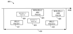
310において、端末デバイス120は、スロット内の第1のシンボルセットに対応する第1のアップリンク制御チャネルを決定する。320において、端末デバイス120は、第1のシンボルセットの後の、スロット内の第2のシンボルセットに対応する第2のアップリンク制御チャネルを決定する。第1及び第2のシンボルセットは、互いにオーバーラップしていない。説明の目的で、第1及び第2のアップリンク制御チャネルの決定について、図4を参照して説明する。図4は、本開示のいくつかの実施形態にかかるスロット内の2つのPUCCHを決定する方法を示す模式図である。
At 310,
一例として、図4は、スロット430内の2つのPUCCHを示す。310において、端末デバイス120は、スロット430の第1のシンボルセット、例えば、シンボル1~5に対応する第1のPUCCH421を決定してもよい。310において、端末デバイス120は、スロット430の第2のシンボルセット、例えば、シンボル7~9に対応する第2のPUCCH422を決定してもよい。第1のシンボルセットは、時間的に第2のシンボルセットよりも先行しているので、第1のPUCCH421は、先のPUCCHとも呼ばれ、第2のPUCCH422は、後のPUCCHとも呼ばれてもよい。先のPUCCH及び後のPUCCHは、別々に決定されてもよい。
As an example, FIG. 4 shows two PUCCHs in
第1のPUCCH421及び第2のPUCCH422は、説明の便宜上URLLC PUCCHとも呼ばれるURLLC専用のPUCCHであってもよいことに留意されたい。PUCCHの数は、限定を示唆することなく説明の目的のためだけであり、1つのスロットに2つよりも多いPUCCHが決定されてもよいことを理解されたい。また、2つよりも多いPUCCHの各ペアは、時間領域又は周波数領域でオーバーラップしないことがある。
Note that the
いくつかの実施形態では、端末デバイス120は、予め構成されたアップリンクリソースに基づいて、第1のPUCCH421及び第2のPUCCH422を決定してもよい。端末デバイス120は、ネットワークデバイス110から、構成されたアップリンクリソースの指示を受信し、この構成されたアップリンクリソースの指示に基づいて、第1のPUCCH421及び第2のPUCCH422を決定してもよい。
In some embodiments,
いくつかの態様では、構成されたアップリンクリソースの指示は、無線リソース制御(RRC:Radio Resource Control)シグナリング、媒体アクセス制御(MAC:medium access control)制御要素(CE:control element)、又はダウンリンク制御情報のうちの少なくとも1つに含まれてもよい。例えば、端末デバイス120は、ネットワークデバイス110からRRCシグナリングを受信し、このRRCシグナリングに含まれる指示に基づいて、第1のPUCCH421及び第2のPUCCH422を決定してもよい。RRCシグナリングは、構成されたアップリンクリソースのグループを複数構成してもよい。同じグループにおけるPUCCHは、時間又は周波数でオーバーラップし、異なるグループにおけるPUCCHはオーバーラップしないことが可能である。MAC CEは、各グループから1つ又は複数のPUCCHを示すために使用されることができ、又は、RRCで構成されたPUCCHグループから1つ又は複数のグループを示すために使用されることができる。構成されたアップリンクリソースの指示は、ネットワークデバイス110からのDCIにも含まれ得る。例えば、DCIは、1つよりも多いPUCCHグループのうちの1つのグループを示すためのグループインジケータを搬送することができ、ここで、ACK/NACK送信のために、示されたグループからさらに1つのPUCCHを選択する。グループインジケータで示されるグループは、PDSCHの受信と示されたPUCCHの送信との間の時間オフセットによって決定されてもよい。例えば、グループインジケータは、PDSCHの受信とPUCCHグループとの間の時間オフセットを指定することで、PUCCHグループを示してもよい。時間オフセットについて、スロットではなくシンボル数でカウントしてもよい。
In some aspects, the indication of the configured uplink resources may be included in at least one of Radio Resource Control (RRC) signaling, medium access control (MAC) control element (CE), or downlink control information. For example,
いくつかの実施形態では、端末デバイス120は、ネットワークデバイス110からのダウンリンク送信に関連付けられた1つよりも多いリソース指示に基づいて、第1のPUCCH421及び第2のPUCCH422を決定してもよい。リソース指示は、DCIにおけるARIであってもよく、各ARIは、ACK/NACK送信用のPUCCHを示してもよい。PUCCHのサブセットは、ARIが示すPUCCHの全てのセットから決定される。このような実施形態では、ダウンリンク送信はURLLCに関連しており、第1のPUCCH421及び第2のPUCCH422はURLLC PUCCHである。
In some embodiments,
一実施形態では、端末デバイス120は、第1のタイプ(例えばURLLC)のダウンリンク送信に関連付けられた第1のリソース指示を決定してもよい。ここで、このダウンリンク送信のDCIは、ACK/NACKがスロットで送信される第1のタイプのダウンリンク送信のDCIのうちの最初のDCIである。本明細書で使用される用語「最初のDCI」は、このDCIが、ACK/NACKが同じスロットで送信されるダウンリンク送信の他のDCIよりも先に、端末デバイス120によって受信されることを意味する。端末デバイス120は、さらに、第1のリソース指示に基づいて第1のアップリンクリソースを選択することで、第1のアップリンク制御チャネルを決定してもよい。
In one embodiment,
さらなる実施形態において、端末デバイス120は、第1のタイプ(例えばURLLC)のさらなるダウンリンク送信に関連付けられた第2のリソース指示を決定してもよい。ここで、このさらなるダウンリンク送信のDCIは、ACK/NACKが同じスロットで送信される第1のタイプのダウンリンク送信のDCIのうちの別のDCIである。例えば、この別のDCIは、最後のDCIであってもよい。本明細書で使用される用語「最後のDCI」は、このDCIが、ACK/NACKが同じスロットで送信されるダウンリンク送信の他のDCIの後に、端末デバイス120によって受信されることを意味する。端末デバイス120は、さらに、第2のリソース指示に基づいて第2のアップリンクリソースを選択することで、第2のアップリンク制御チャネルを決定してもよい。
In a further embodiment,
これらの実施形態は、図4を参照して詳細に説明される。図4は、ネットワークデバイス110からの4つのPDSCHを模式的に示す。図2のPDSCH201~204と同様に、第1のPDSCH401(及びそのDCI)は、第2のPDSCH402(及びそのDCI)よりも前に受信され、第2のPDSCH402(及びそのDCI)は、第3のPDSCH403(及びそのDCI)よりも前に受信され、第3のPDSCH403(及びそのDCI)は、第4のPDSCH404(及びそのDCI)よりも前に受信される。4つのPDSCH401~404に関連するACK/NACK(図示せず)は、スロット430で送信される。リソース指示の一例として、ARI451~454は、それぞれPDSCH401~404に関連付けられている。
These embodiments are described in detail with reference to FIG. FIG. 4 schematically shows four PDSCHs from
1つのPDSCHが別のPDSCHに先立って受信されたことに関して、この別のPDSCHが後のPDSCHと見なされてもよい。例えば、第2のPDSCH402、第3のPDSCH403及び第4のPDSCH404に関して、第1のPDSCH401が先のPDSCHと見なされてもよい。また、第1のPDSCH401、第2のPDSCH402及び第3のPDSCH403に関して、第4のPDSCH404が後のPDSCHと見なされてもよい。一般的に、先のPDSCH(例えばPDSCH401)のACK/NACK送信には、先のPUCCH(PUCCH421)のリソースが割り当てられる。端末デバイス120は、先のPUCCH(PUCCH421)が利用可能である場合、先のPDSCHに関連付けられたARIに基づいて後のPUCCH(PUCCH422)を決定することを許容されないことがある。
With respect to one PDSCH being received prior to another PDSCH, the other PDSCH may be considered the subsequent PDSCH. For example, with respect to the
図4に示す例では、端末デバイス120は、第1のARI451に基づいて第1のPUCCH421を決定してもよい。例えば、端末デバイス120は、第1のARI451によって示されるアップリンクリソースを、第1のPUCCH421のリソースとして構成してもよい。端末デバイス120は、さらに、第4のARI454に基づいて第2のPUCCH422を決定してもよい。例えば、端末デバイス120は、第4のARI454によって示されるアップリンクリソースを、第2のPUCCH422のリソースとして構成してもよい。
In the example shown in FIG. 4 ,
いくつかの実施形態では、異なる容量を有するURLLC PUCCHの第1のリストが、第1のPUCCH421(先のPUCCH)に対して構成されてもよく、異なる容量を有するURLLC PUCCHの第2のリストが、第2のPUCCH422(後のPUCCH)に対して構成されてもよい。これらの場合、端末デバイス120は、第1のリスト又は第2のリストから、最小のPUCCH容量が、同じリストで送信されるUCIビット数を下回らない1つのPUCCHを選択してもよい。例えば、端末デバイス120は、第1のリストから1つのPUCCHを選択して、第1のPUCCH421として使用してもよい。
In some embodiments, a first list of URLLC PUCCHs with different capacities may be configured for the first PUCCH 421 (previous PUCCH) and a second list of URLLC PUCCHs with different capacities may be configured for the second PUCCH 422 (later PUCCH). In these cases,
単一のスロットにおける先のPUCCHと後のPUCCHの決定については、図4を参照して上記で説明した。このように、URLLCに関連するACK/NACKの送信に使用されるPUCCHを決定することができる。なお、図4におけるPDSCH数、ARI数、及び決定されたPUCCH数は、何ら限定されることなく例示の目的のために示されていることを理解されたい。 Determination of earlier PUCCH and later PUCCH in a single slot was described above with reference to FIG. In this way, it is possible to determine the PUCCH used for transmitting ACK/NACK related to URLLC. It should be understood that the PDSCH number, ARI number, and determined PUCCH number in FIG. 4 are shown for illustrative purposes without any limitation.
図3を参照すると、330において、端末デバイス120は、少なくともアップリンク制御情報を第1のアップリンク制御チャネル、例えば、第1のPUCCH421で送信する。いくつかの実施形態では、端末デバイス120は、複数のACK/NACKを第1のPUCCH421及び第2のPUCCH422にマッピングして、スロット430でネットワークデバイス110に送信してもよい。このような実施形態については、図5及び図6を参照して以下に詳細に説明する。
Referring to FIG. 3 , at 330
いくつかの実施形態では、端末デバイス120は、第1のPUCCH421及び第2のPUCCH422を、異なるタイプのUCI、例えば、URLLC送信用のACK/NACK及びCSI、非URLLC送信用のACK/NACK及びCSIと多重化してもよい。このような実施形態については、図7を参照して以下に詳細に説明する。
In some embodiments,
図5は、本開示のいくつかの実施形態にかかるACK/NACKのセットをスロット内の2つのPUCCHにマッピングする方法を示す模式図500である。図5に示す2つのPUCCHは、図4を参照して上述したアプローチによって決定されてもよい。あるいは、他のアプローチによって決定されてもよい。本開示の範囲は、この側面において限定されない。 FIG. 5 is a schematic diagram 500 illustrating how a set of ACK/NACKs are mapped to two PUCCHs in a slot in accordance with some embodiments of the present disclosure. The two PUCCHs shown in FIG. 5 may be determined by the approach described above with reference to FIG. Alternatively, it may be determined by other approaches. The scope of the disclosure is not limited in this aspect.
4つのPDSCH501~504は、図4に示すPDSCHと同様である。図4を参照して上述したように、ダウンリンク送信に関連付けられたリソース指示に基づいて、第1のPUCCH421及び第2のPUCCH422を決定する場合、PDSCH501~504は、PDSCH401~404と同様である。図5に模式的に示すように、第1のPDSCH501は第2のPDSCH502よりも前に受信され、第2のPDSCH502は第3のPDSCH503よりも前に受信され、第3のPDSCH503は第4のPDSCH504よりも前に受信される。ACK/NACK511~514は、それぞれPDSCH501~504に関連している。
The four PDSCHs 501-504 are similar to the PDSCHs shown in FIG. PDSCHs 501-504 are similar to PDSCHs 401-404 when determining a
一般的に、先のPDSCHに関連するACK/NACKは、先のPUCCHにマッピングされる優先度がより高いべきである。すなわち、先のPDSCHに関連するACK/NACKは、先のPUCCHで送信される優先度がより高いべきである。例えば、第2のPUCCH422と比較して、ACK/NACK512は、第1のPUCCH421で送信される優先度がより高い。
In general, ACK/NACK related to earlier PDSCH should have higher priority mapped to earlier PUCCH. That is, ACK/NACK related to previous PDSCH should have higher priority to be sent on previous PUCCH. For example, ACK/
複数のACK/NACK511~514の2つのPUCCH421、422へのマッピングを決定するために、タイムライン要件が定義されてもよい。タイムラインとは、PDSCHの最後のシンボルから一定のシンボル数のところにある。タイムライン要件は、PDSCHのタイムライン後のPUCCHのみが、該PDSCHに関連する対応のACK/NACKの送信に使用できるように、定義されてもよい。PDSCHのタイムライン要件が満たされた場合、該PDSCHに関連するACK/NACKは、先のPUCCH(図5の第1のPUCCH421)にマッピングされ、そうでない場合、該PDSCHに関連するACK/NACKは、後のPUCCH(図5の第2のPUCCH422)にマッピングされる。
A timeline requirement may be defined to determine the mapping of ACK/NACKs 511-514 to two PUCCHs 421,422. The timeline is a certain number of symbols from the last symbol of PDSCH. The timeline requirement may be defined such that only PUCCH after the PDSCH timeline can be used for transmission of the corresponding ACK/NACK associated with that PDSCH. If the PDSCH timeline requirements are met, the ACK/NACK associated with the PDSCH is mapped to the earlier PUCCH (
図5は、第1のPDSCH501に対する第1のタイムライン561、第2のPDSCH502に対する第2のタイムライン562、第3のPDSCH503に対する第3のタイムライン563、及び第4のPDSCH504に対する第4のタイムライン564を模式的に示している。図5に示す例では、ACK/NACK511及びACK/NACK512は、第1のPUCCH421にマッピングされる。従って、端末デバイス120は、ACK/NACK511及びACK/NACK512を、スロット430内の第1のPUCCH421で送信することができる。また、ACK/NACK513及びACK/NACK514は、第2のPUCCH422にマッピングされる。従って、端末デバイス120は、ACK/NACK513及びACK/NACK514を、スロット430内の第2のPUCCH422で送信することができる。
FIG. 5 schematically shows a
図6は、本開示のいくつかの実施形態にかかる複数のACK/NACKをスロット内のPUCCHにマッピングするためのプロセス600を示すフローチャートである。図6及び対応する説明において、インデックス「i」は、ACK/NACKが同じスロットで送信される複数のPDSCHのうち、i番目に受信されるPDSCHを示すために使用される。例えば、第1のPDSCH501はインデックスiが0であり、第2のPDSCH502はインデックスiが1であり、以降は同様である。また、インデックス「j」は、単一のスロット内のPUCCHを示すために使用される。例えば、第1のPUCCH421はインデックスjが0であり、第2のPUCCH422はインデックスjが1であってもよい。
FIG. 6 is a flowchart illustrating a
複数のACK/NACKを単一のスロット内の複数のPUCCHにマッピングするために、本明細書でPDSCHに関連するACK/NACKに対するPUCCHの利用可能性が定義される。本開示では、PDSCHに関連するACK/NACKに対してPUCCHが利用可能である場合、上記のタイムライン要件が満たされ、且つこのPUCCHの容量がこのACK/NACKのビットを運ぶのに十分であることを意味する。 In order to map multiple ACK/NACKs to multiple PUCCHs within a single slot, PUCCH availability for PDSCH-related ACK/NACKs is defined herein. In this disclosure, if PUCCH is available for ACK/NACK associated with PDSCH, it means that the above timeline requirements are met and the capacity of this PUCCH is sufficient to carry the bits of this ACK/NACK.
605において、端末デバイス120は、第1のPDSCH(i=0)、例えば、第1のPDSCH501でプロセス600を開始する。610において、端末デバイス120は、第1のPDSCHに関連するACK/NACKを選択又は決定する。例えば、第1のPDSCH501の場合、端末デバイス120は、ACK/NACK511を選択してもよい。615において、端末デバイス120は、第1のPUCCH(j=0)、例えば、第1のPUCCH421を選択する。620において、端末デバイス120は、i番目のPDSCHに関連するACK/NACKに対してj番目のPUCCHが利用可能であるか否かを決定する。
At 605 ,
端末デバイス120は、620においてj番目のPUCCHがi番目のPDSCHに関連するACK/NACKに対して利用可能であると決定した場合、プロセス600は625に進む。625において、端末デバイス120は、i番目のPDSCHに関連するACK/NACKをj番目のPUCCHにマッピングする。すなわち、端末デバイス120は、i番目のPDSCHに関連するACK/NACKを、i番目のPUCCHで送信することを決定する。図示されないが、i番目のPDSCHに関連するACK/NACKのマッピングの後、プロセス600は、以下に説明されるブロック645に進んでもよい。
If
端末デバイス120は、620においてi番目のPDSCHに関連するACK/NACKに対してj番目のPUCCHが利用できないと決定した場合、プロセス600はブロック630に進む。630において、端末デバイス120は、(現在の)j番目のPUCCHが、スロット内の最後のPUCCHであるか否かを決定する。端末デバイス120が、(現在の)j番目のPUCCHがスロット内の最後のPUCCHであると決定した場合、プロセス600はブロック635に進んでもよい。635において、端末デバイス120は、次のPUCCH(j=j+1)を選択する。例えば、630においてj番目のPUCCHが第1のPUCCH421である場合、635において、端末デバイス120は、第2のPUCCH422を選択してもよい。その後、プロセス600はブロック620に戻り、i番目のPDSCHに関連するACK/NACKに対して(j+1)番目のPUCCHが利用可能であるか否かを決定する。
If
端末デバイス120は、630において(現在の)j番目のPUCCHがスロット内の最後のPUCCHであると決定した場合、端末デバイス120は、i番目のPDSCHに関連するACK/NACKをドロップし、プロセス600はブロック640に進んでもよい。640において、端末デバイス120は、i番目のPDSCHが最後のPDSCHであるか否かを決定する。端末デバイス120は、i番目のPDSCHが最後のPDSCH、例えば、図5に示す第4のPDSCH504であると決定した場合、プロセス600はブロック650に進んでプロセスを終了してもよい。これは、PDSCHに関連するACK/NACKのマッピングが完了したことを意味する。
If
端末デバイス120は、640においてi番目のPDSCHが最後のPDSCHではないと決定した場合、プロセス600はブロック645に進んでもよい。645において、端末デバイス120は、次のPDSCH(i=i+1)を選択する。例えば、640においてi番目のPDSCHが、図5に示す第2のPDSCH502である場合、645において、端末デバイス120は、第3のPDSCH503を選択してもよい。その後、プロセス600はブロック610に戻り、(i+1)番目のPDSCHに関連するACK/NACKをマッピングする。
If
このような実施形態では、ACK/NACKに対するPUCCHの利用可能性に基づいてプロセス600を実行することにより、端末デバイス120は、複数のACK/NACKをスロット内の複数のPUCCHにマッピングし、複数のACK/NACKをスロット内のそれぞれのPUCCHで送信することができる。このように、ACK/NACKを、明確に定義される効果的な方法で送信することができる。
In such embodiments,
上述したように、第1のPUCCH421及び第2のPUCCH422は、異なるタイプのUCIで多重化されてもよい。この場合、特にPUCCHの容量が十分でない場合に、異なるタイプのUCIを配置するためのソリューションを提案する必要がある。以下、このような実施形態について、図7A~図7Bを参照して詳細に説明する。図7Aは、本開示のいくつかの実施形態にかかる異なるタイプのUCIの優先順位を示す模式図701であり、図7Bは、本開示のいくつかの別の実施形態にかかる異なるタイプのUCIの別の優先順位を示す模式図702である。
As mentioned above, the
図7A~図7Bにおいて、第1のPUCCH421及び第2のPUCCH422は、URLLC PUCCHである。ACK/NACK711~714は、URLLCのダウンリンク送信に関連しており、説明の便宜上、このタイプのACK/NACKをURLLC ACK/NACKと呼ぶことがある。図4及び図5と同様に、ACK/NACK711に関連するPDSCHは、ACK/NACK712に関連するPDSCHよりも前に受信され、以降は同様である。さらに、URLLCのダウンリンク送信に関連しないACK/NACKを、非URLLC ACK/NACKと呼ぶこともある。
7A-7B, the
URLLC ACK/NACK711~714に加えて、別のタイプのUCIが第1のPUCCH421及び第2のPUCCH422で送信されてもよい。図7A~図7Bに示すように、非周期的CSI(A-CSI:apperiodic channel state information)715、非URLLC ACK/NACK716、及び周期的/半永続的CSI(P/SP-CSI:periodic/semi-persistent CSI)717はPUCCHで送信される。A-CSIは、URLLC ACK/NACK711~714のうちの1つ、例えば、ACK/NACK712に関連付けられてもよい。2つのPUCCH421及び422の容量は、全てのUCIを送信するために十分ではない可能性があるので、これらの異なるタイプのUCIを送信するために、優先順位を定義する必要がある。
In addition to URLLC ACK/NACK 711 - 714 , another type of UCI may be transmitted on
図7Aに示す優先順位によれば、URLLC ACK/NACK711~714が先に送信されてもよい。URLLC ACK/NACK711~714の送信は、上述のように決定されてもよい。A-CSI715は、全てのURLLC ACK/NACK711~714よりも低い優先度を有する。そして、非URLLC ACK/NACK716は、A-CSI715よりも低い優先度を有する。P/SP-CSI717は、全てのUCIの中で最も低い優先度を有する。図7Aに示す優先順位では、A-CSI715は、全てのURLLC ACK/NACK711~714よりも低い優先度を有するが、全ての非URLLC UCIよりも高い優先度を有する。
According to the order of priority shown in FIG. 7A, URLLC ACK/NACK 711-714 may be sent first. The transmission of URLLC ACK/NACKs 711-714 may be determined as described above.
図7Bに示す別の優先順位では、A-CSI715は、URLLC ACK/NACK712に関連付けられている。例えば、同じDCIは、URLLC ACK/NACK712及びA-CSI715の送信の両方を示してもよい。A-CSI715は、URLLC ACK/NACK712よりも低い優先度を有し、URLLC ACK/NACK713よりも送信される優先度が高くてもよい。
In another priority order shown in FIG. 7B,
図7A~図7Bに示す異なるタイプのUCIの順序は、説明の目的のみであり、それらのスロット内の時間的位置を示すものではないことを理解されたい。端末デバイス120は、図7Aに示す優先順位又は図7Bに示す優先順位に基づいて、これらの異なるタイプのUCIを第1のPUCCH421及び第2のPUCCH422にマッピングしてもよい。優先度の高いUCIは、先のPUCCHにマッピングされるように優先される。同じPUCCHにマッピングされるUCIは互いに多重化される。スロット430に対して構成されたPUCCHの容量が、全てのUCIを運ぶのに十分でない場合、端末デバイス120は、より低い優先度のUCIをドロップしてもよい。
It should be understood that the order of the different types of UCI shown in FIGS. 7A-7B is for illustrative purposes only and does not indicate their temporal position within the slot.
いくつかの場合に、URLLC用のUCIと非URLLC用のUCIとが別々のPUCCHで送信され、スロット内でPUCCHの衝突が発生することがある。URLLC用のUCIと非URLLC用のUCIとの多重化はサポートされていない。そのため、部分的にオーバーラップしているPUCCHに対処するためのソリューションを提案する必要がある。本開示では、2つのPUCCHが互いに部分的にオーバーラップする場合、この2つのPUCCHが少なくとも1つのシンボルにわたってオーバーラップすることを意味する。 In some cases, UCI for URLLLC and UCI for non-URLLC may be transmitted on separate PUCCHs, causing PUCCH collisions within a slot. Multiplexing of UCI for URLLLC and UCI for non-URLLC is not supported. Therefore, there is a need to propose a solution to deal with partially overlapping PUCCH. In this disclosure, if two PUCCHs partially overlap each other, it means that the two PUCCHs overlap over at least one symbol.
図8は、本開示のいくつかの実施形態にかかるスロット430内のオーバーラップしたPUCCHを示す模式図800である。図4、図5、図7と同様のURLLC PUCCH421、422に加えて、図8は、非URLLCのために構成された他のPUCCHを示す。この他のPUCCHについて、説明の便宜上、非URLLC PUCCHと呼ばれる。図示されるように、PUCCH824は、P/SP CSI1の送信のために構成され、PUCCH823は、P/SP CSI2の送信のために構成され、PUCCH825は、非URLLC ACK/NACK1の送信のために構成され、PUCCH826は、非URLLC ACK/NACK2の送信のために構成される。
FIG. 8 is a schematic diagram 800 illustrating overlapping PUCCHs in
図8に示すように、非URLLC PUCCH824は、URLLC PUCCH421と部分的にオーバーラップし、非URLLC PUCCH826は、URLLC PUCCH422と部分的にオーバーラップする。この場合、端末デバイス120は、スロット430で送信されるはずのP/SP CSI1及び非URLLC ACK/NACK2をドロップしてもよい。
As shown in FIG. 8 ,
非URLLC PUCCH823及び非URLLC PUCCH825は、URLLC PUCCH421及び422のいずれともオーバーラップしないので、P/SP CSI2と非URLLC ACK/NACK1はスロット430で送信されることができる。
Since
上記の側面によれば、端末デバイス120で実施される方法が提供される。この方法は、スロット内の第1のシンボルセットに対応する第1のアップリンク制御チャネルを決定することと、第1のシンボルセットの後の、スロット内の第2のシンボルセットに対応する第2のアップリンク制御チャネルを決定することと、少なくとも第1のアップリンク制御チャネルでアップリンク制御情報を送信することと、を含む。
According to the above aspects, a method implemented in
いくつかの実施形態では、第1及び第2のアップリンク制御チャネルを決定することは、ネットワークデバイスから、構成されたアップリンクリソースの指示を受信することと、構成されたアップリンクリソースの指示に基づいて、第1及び第2のアップリンク制御チャネルを決定することとを含む。 In some embodiments, determining the first and second uplink control channels includes receiving an indication of configured uplink resources from a network device and determining the first and second uplink control channels based on the indication of configured uplink resources.
いくつかの実施形態では、指示は、無線リソース制御(RRC)シグナリング、媒体アクセス制御(MAC)制御要素(CE)、及びダウンリンク制御情報のうちの少なくとも1つに含まれる。 In some embodiments, the indication is included in at least one of radio resource control (RRC) signaling, medium access control (MAC) control element (CE), and downlink control information.
いくつかの実施形態では、第1のアップリンク制御チャネルを決定することは、第1のタイプのダウンリンク送信に関連付けられた第1のリソース指示を決定し、ここで、このダウンリンク送信のダウンリンク制御情報(DCI)は、ACK/NACKがスロットで送信される第1のタイプのダウンリンク送信のDCIのうちの最初のDCIであることと、第1のリソース指示に基づいて第1のアップリンクリソースを選択することで、第1のアップリンク制御チャネルを決定することと、を含む。 In some embodiments, determining the first uplink control channel includes determining a first resource indication associated with the first type of downlink transmission, wherein the downlink control information (DCI) for this downlink transmission is the first DCI of the DCI for the first type of downlink transmission in which ACK/NACK is transmitted in a slot; and selecting the first uplink resource based on the first resource indication. and including.
いくつかの実施形態では、第2のアップリンク制御チャネルを決定することは、第1のタイプのさらなるダウンリンク送信に関連付けられた第2のリソース指示を決定し、ここで、このさらなるダウンリンク送信のDCIは、ACK/NACKがスロットで送信される第1のタイプのダウンリンク送信のDCIのうちの最後のDCIであることと、第2のリソース指示に基づいて第2のアップリンクリソースを選択することで、第2のアップリンク制御チャネルを決定することと、を含む。 In some embodiments, determining the second uplink control channel is to determine the second resource instructions associated with the first type of downlink transmission, and here, the DCI of this further downlink transmission is the first type of downlink transmission DC sent by ACK / NACK in a slot. Includes the last DCI of I and to determine the second uplink control channel by selecting a second uplink rally based on the second resource instruction.
いくつかの実施形態では、少なくとも第1のアップリンク制御チャネルでアップリンク制御情報を送信することは、第1のアップリンク制御チャネルで、第1のタイプのダウンリンク送信に関連するACK/NACKを送信することを含む。 In some embodiments, transmitting uplink control information on at least the first uplink control channel includes transmitting ACK/NACK associated with the first type of downlink transmission on the first uplink control channel.
いくつかの実施形態では、上記のダウンリンク送信の後の第1のタイプのさらなるダウンリンク送信に関連するさらなるACK/NACKに対して、第1のアップリンク制御チャネルが利用可能であるか否かを決定することと、第1のアップリンク制御チャネルがさらなるACK/NACKに対して利用可能であることに応答して、第1のアップリンク制御チャネルでさらなるACK/NACKを送信することと、第1のアップリンク制御チャネルがさらなるACK/NACKに対して利用できないことに応答して、第2のアップリンク制御チャネルでさらなるACK/NACKを送信することと、をさらに含む。 In some embodiments, determining whether the first uplink control channel is available for further ACK/NACKs associated with further downlink transmissions of the first type after said downlink transmission; transmitting a further ACK/NACK on the first uplink control channel in response to the first uplink control channel being available for further ACKs/NACKs; responding to the first uplink control channel being unavailable for further ACKs/NACKs; and sending a further ACK/NACK on a second uplink control channel.
いくつかの実施形態では、アップリンク制御情報は、第1のタイプのACK/NACK、及び第2のタイプのACK/NACKを含み、第1のタイプのACK/NACKは、第2のタイプのACK/NACKよりも、第1及び第2のアップリンク制御チャネルで送信される優先度が高く構成される。 In some embodiments, the uplink control information includes a first type ACK/NACK and a second type ACK/NACK, wherein the first type ACK/NACK is configured with a higher priority to be transmitted on the first and second uplink control channels than the second type ACK/NACK.
いくつかの実施形態では、アップリンク制御情報は、第1のタイプのACK/NACKに関連付けられた非周期的チャネル状態情報(A-CSI)をさらに含み、第1のタイプのACK/NACK及びA-CSIは、第2のタイプのACK/NACKよりも、第1及び第2のアップリンク制御チャネルで送信される優先度が高く構成される。 In some embodiments, the uplink control information further includes aperiodic channel state information (A-CSI) associated with the first type ACK/NACK, wherein the first type ACK/NACK and A-CSI are configured with higher priority to be transmitted on the first and second uplink control channels than the second type ACK/NACK.
いくつかの実施形態では、第1及び第2のアップリンク制御チャネルは、第1のタイプであり、この方法は、スロット内で、第2のタイプの第3のアップリンク制御チャネルが存在すると決定したことに応答して、第3のアップリンク制御チャネルのリソースの一部が、第1及び第2のアップリンク制御チャネルのリソースとオーバーラップするか否かを決定することと、第3のアップリンク制御チャネルのリソースの一部が、第1及び第2のアップリンク制御チャネルのリソースのうちの少なくとも1つのリソースとオーバーラップすると決定したことに応答して、第3のアップリンク制御チャネルで送信されるアップリンク制御情報をドロップすることと、をさらに含む。 In some embodiments, the first and second uplink control channels are of a first type, and the method comprises, in response to determining that a third uplink control channel of the second type exists in the slot, determining whether a portion of the resources of the third uplink control channel overlaps with the resources of the first and second uplink control channels; and dropping uplink control information sent on a third uplink control channel in response to determining that it overlaps two resources.
いくつかの実施形態では、第1のタイプは、超高信頼性低遅延通信(URLLC)を含む。 In some embodiments, the first type includes Ultra Reliable Low Latency Communication (URLLC).
図2~図8Gを参照して上記で説明したネットワークデバイス110及び端末デバイス120に関連する全ての動作及び特徴は、同様に方法900~1100に適用可能であり、同様の効果を有することを理解されたい。簡略化のために、詳細は省略する。
It should be understood that all operations and features associated with
図9は、本開示の実施形態の実施に適したデバイス900の簡略的なブロック図である。デバイス900は、図1に示すネットワークデバイス110又は端末デバイス120のさらなる例示的な実施形態と見なされることができる。従って、デバイス900は、ネットワークデバイス110又は端末デバイス120の少なくとも一部で実施され、又はネットワークデバイス110又は端末デバイス120の少なくとも一部として実施されることができる。
FIG. 9 is a simplified block diagram of a
図示されるように、デバイス900は、プロセッサ910と、プロセッサ910に結合されているメモリ920と、プロセッサ910に結合されている適切な送信機(TX)及び受信機(RX)940と、TX/RX940に結合されている通信インターフェースとを含む。メモリ920は、プログラム930の少なくとも一部を格納する。TX/RX940は、双方向通信用である。TX/RX940は、通信を容易にするために少なくとも1つのアンテナを有するが、実際には、本願で言及されるアクセスノードは複数あってもよい。通信インターフェースは、eNB間の双方向通信用のX2インターフェース、モビリティマネジメントエンティティ(MME:Mobility Management Entity)/サービングゲートウェイ(S-GW:Serving Gateway)とeNBとの間の通信用のS1インターフェース、eNBとリレーノード(RN:relay node)との間の通信用のUnインターフェース、又はeNBと端末デバイスとの間の通信用のUuインターフェースなど、他のネットワーク要素との通信に必要な任意のインターフェースを表してもよい。
As shown,
プログラム930は、関連するプロセッサ910によって実行されると、デバイス900が、本明細書で図3~図8を参照して説明したように、本開示の実施形態に従って動作することを可能にするプログラム命令を含むと想定される。本明細書の実施形態は、デバイス900のプロセッサ910によって実行可能なコンピュータソフトウェアにより、又はハードウェアにより、又はソフトウェアとハードウェアとの組み合わせにより実施されてもよい。プロセッサ910は、本開示の様々な実施形態を実施するように構成されてもよい。さらに、プロセッサ910とメモリ920の組み合わせは、本開示の様々な実施形態を実施するのに適した処理手段950を形成してもよい。
メモリ920は、ローカル技術ネットワークに適した任意のタイプのものであってもよく、非限定的な例として、非一時的コンピュータ読み取り可能な記憶媒体、半導体系のメモリデバイス、磁気メモリデバイス及びシステム、光メモリデバイス及びシステム、固定メモリ及びリムーバブルメモリなどの任意の適切なデータ記憶技術を使用して実施されてもよい。デバイス900には1つのメモリ920のみが示されているが、デバイス900には物理的に別個である複数のメモリモジュールがあってもよい。プロセッサ910は、ローカル技術ネットワークに適した任意のタイプのものであってもよく、非限定的な例として、汎用コンピュータ、専用コンピュータ、マイクロプロセッサ、DSP(Digital Signal Processor)、及びマルチコアプロセッサアーキテクチャに基づくプロセッサのうちの1つ又は複数を含んでもよい。デバイス900は、メインプロセッサを同期させるクロックに時間的に従属する特定用途向け集積回路チップなどの複数のプロセッサを有してもよい。
The
一般的に、本開示の様々な実施形態は、ハードウェア又は専用回路、ソフトウェア、ロジック、又はそれらの任意の組み合わせで実施されてもよい。いくつかの態様はハードウェアで実施され、他の態様はコントローラ、マイクロプロセッサ、又は他のコンピューティングデバイスによって実行され得るファームウェア又はソフトウェアで実施されてもよい。本開示の実施形態の様々な態様は、ブロック図、フローチャート、又は他の何らかの画像表現を使用して例示及び説明されたが、本明細書に記載されるこれらのブロック、装置、システム、技術又は方法は、非限定的な例として、ハードウェア、ソフトウェア、ファームウェア、専用回路又はロジック、汎用ハードウェア又はコントローラ又は他のコンピューティングデバイス、又はそれらのいくつかの組み合わせで実施されてもよいことを理解されたい。 In general, various embodiments of the present disclosure may be implemented in hardware or dedicated circuitry, software, logic, or any combination thereof. Some aspects may be implemented in hardware, while other aspects may be implemented in firmware or software, which may be executed by a controller, microprocessor, or other computing device. Although various aspects of the embodiments of the present disclosure have been illustrated and described using block diagrams, flowcharts, or some other pictorial representations, it is to be understood that these blocks, devices, systems, techniques or methods described herein may be implemented in hardware, software, firmware, dedicated circuitry or logic, general purpose hardware or controllers or other computing devices, or some combination thereof, as non-limiting examples.
本開示は、さらに、非一時的なコンピュータ読み取り可能な記憶媒体に有形に格納された少なくとも1つのコンピュータプログラム製品を提供する。コンピュータプログラム製品は、図3~図6Dを参照して上記で説明したプロセス又は方法を実行するために、プログラムモジュールに含まれるものなどの、対象の実プロセッサ又は仮想プロセッサ上のデバイスで実行されるコンピュータ実行可能な命令を含む。一般的に、プログラムモジュールは、特定のタスクを実行したり、特定の抽象データ型を実施したりするルーチン、プログラム、ライブラリ、オブジェクト、クラス、コンポーネント、データ構造などを含む。プログラムモジュールの機能は、様々な実施形態で記載されたプログラムモジュール間で組み合わせる、又は分割されることができる。プログラムモジュールのためのマシン実行可能な命令は、ローカルデバイス又は分散型デバイス内で実行されてもよい。分散型デバイスでは、プログラムモジュールがローカル記憶媒体とリモート記憶媒体の両方に配置されてもよい。 The present disclosure further provides at least one computer program product tangibly stored on a non-transitory computer-readable storage medium. A computer program product comprises computer-executable instructions, such as those contained in program modules, that are executed by a device on a subject real or virtual processor to perform the processes or methods described above with reference to FIGS. 3-6D. Generally, program modules include routines, programs, libraries, objects, classes, components, data structures, etc. that perform particular tasks or implement particular abstract data types. The functionality of the program modules may be combined or split between program modules described in various embodiments. Machine-executable instructions for program modules may be executed within local or distributed devices. In a distributed device, program modules may be located in both local and remote storage media.
本開示の方法を実行するためのプログラムコードは、1つ又は複数のプログラミング言語の任意の組み合わせで書かれてもよい。これらのプログラムコードは、汎用コンピュータ、専用コンピュータ、又は他のプログラム可能なデータ処理装置のプロセッサ又はコントローラに提供されることにより、プログラムコードがプロセッサ又はコントローラによって実行されると、フローチャート及び/又はブロック図に規定される機能/動作が実現される。プログラムコードは、完全にマシン上で実行されてもよく、その一部がマシン上で実行されてもよく、スタンドアロンのソフトウェアパッケージとして実行されてもよく、一部がマシン上で実行され且つ一部がリモートマシン上で実行されてもよく、完全にリモートマシン又はサーバ上で実行されてもよい。 Program code to implement the methods of the present disclosure may be written in any combination of one or more programming languages. These program codes are provided to a processor or controller of a general purpose computer, special purpose computer, or other programmable data processing apparatus such that the program code, when executed by the processor or controller, implements the functions/operations specified in the flowcharts and/or block diagrams. The program code may run entirely on a machine, partly on a machine, as a standalone software package, partly on a machine and partly on a remote machine, or entirely on a remote machine or server.
上記プログラムコードは、命令実行システム、装置、又はデバイスによって、又はそれと関連して使用されるためのプログラムを含む、又は格納することができる任意の有形媒体であり得るマシン読み取り可能な媒体上で具現化されてもよい。マシン読み取り可能な媒体は、マシン読み取り可能な信号媒体又はマシン読み取り可能な記憶媒体であってもよい。マシン読み取り可能な媒体は、電子、磁気、光学、電磁気、赤外線、又は半導体システム、装置、デバイス、あるいは前記の任意の適切な組み合わせを含むが、これらに限定されない。マシン読み取り可能な記憶媒体のより具体的な例として、1つ又は複数のワイヤによる電気的接続、ポータブルコンピュータディスケット、ハードディスク、RAM(Random Access Memory)、ROM(Read Only Memory)、消去可能なプログラム可能な読み取り専用メモリ(EPROM又はフラッシュメモリ)、光ファイバー、ポータブルコンパクトディスク読み取り専用メモリ(CD-ROM)、光学式ストレージデバイス、磁気ストレージデバイス、又は前記の任意の適切な組み合わせが挙げられる。 The program code may be embodied on a machine-readable medium, which may be any tangible medium capable of containing or storing a program for use by or in connection with an instruction execution system, apparatus, or device. A machine-readable medium may be a machine-readable signal medium or a machine-readable storage medium. Machine-readable media include, but are not limited to, electronic, magnetic, optical, electromagnetic, infrared, or semiconductor systems, apparatus, devices, or any suitable combination of the foregoing. As a more specific example of a storage storage medium that can be read, as a more specific example of a single or multiple wires, an electrical connection with one or more wires, a portable computer desk, hard disk, RAM (RANDOM ACCESSS MEMORY), ROM (READ ONLY MEMORY), erasable programmable reading. There are exclusive memory (EPROM or flash memory), optical fiber, portable compact disk dedicated memory (CD -ROM), optical storage device, magnetic storage device, or any appropriate combination above.
さらに、動作が特定の順序で描かれているが、これは、望ましい結果を達成するために、そのような動作が図示の特定の順序又は連続順序で実行されること、又は全ての描かれた動作が実行されることを要求するものとして理解されるべきではない。特定の状況では、マルチタスク及び並列処理が有利である場合がある。同様に、上記の説明にはいくつかの特定の実施形態の詳細が含まれているが、これらは本開示の範囲を限定するものとして解釈されるべきではなく、特定の実施形態に特有の特徴の説明として解釈されるべきである。別々の実施形態の文脈で説明されている特定の特徴は、単一の実施形態に組み合わせて実施されてもよい。逆に、単一の実施形態の文脈で説明されている様々な特徴も、複数の実施形態で別々に、又は任意の適切なサブコンビネーションで実施されてもよい。 Additionally, although acts have been depicted in a particular order, this should not be understood as requiring that such acts be performed in the particular order shown or sequential order, or that all depicted acts be performed, in order to achieve a desired result. Multitasking and parallel processing may be advantageous in certain situations. Similarly, although the above description contains details of certain specific embodiments, these should not be construed as limitations on the scope of the disclosure, but rather as descriptions of the unique features of the specific embodiments. Certain features that are described in the context of separate embodiments may also be implemented in combination in a single embodiment. Conversely, various features that are described in the context of a single embodiment can also be implemented in multiple embodiments separately or in any suitable subcombination.
本開示は、構造的特徴及び/又は方法論的動作に特有の用語で説明されたが、添付の特許請求の範囲で限定される本開示は、必ずしも上述の特定の特徴又は動作に限定されないことを理解されたい。むしろ、上述の特定の特徴及び動作は、特許請求の範囲を実施する例示的な形態として開示されている。 While the disclosure has been described in terms specific to structural features and/or methodological acts, it is to be understood that the disclosure as defined in the appended claims is not necessarily limited to the specific features or acts described above. Rather, the specific features and acts described above are disclosed as example forms of implementing the claims.
Claims (21)
第1のACK/NACK情報の送信のためのスロット内の第1のシンボルセットに対応する第1のアップリンク制御チャネルを決定することと、
前記第1のシンボルセットの後の前記スロット内の第2のシンボルセットであって、第2のACK/NACK情報の送信のための前記第2のシンボルセットに対応する第2のアップリンク制御チャネルを決定することと、
前記第1のシンボルセットに対応する前記第1のアップリンク制御チャネルで前記第1のACK/NACK情報を送信するかどうかを決定することと、
前記第1のアップリンク制御チャネルで前記第1のACK/NACK情報を送信しない場合、前記第2のシンボルセットに対応する前記第2のアップリンク制御チャネルで前記第1のACK/NACK情報を送信することと、
少なくとも前記第1のアップリンク制御チャネルでアップリンク制御情報を送信することと、を含み、
前記第1及び第2のアップリンク制御チャネルは、第1のタイプであり、
前記方法は、
前記スロット内で、第2のタイプの第3のアップリンク制御チャネルが存在すると決定したことに応答して、前記第3のアップリンク制御チャネルのリソースの一部が、前記第1及び第2のアップリンク制御チャネルのリソースとオーバーラップするか否かを決定することと、
前記第3のアップリンク制御チャネルのリソースの一部が、前記第1及び第2のアップリンク制御チャネルのリソースのうちの少なくとも1つのリソースとオーバーラップすると決定したことに応答して、前記第3のアップリンク制御チャネルで送信されるアップリンク制御情報をドロップすることと、をさらに含む、
方法。 A method implemented in a terminal device, comprising:
determining a first uplink control channel corresponding to a first set of symbols in a slot for transmission of first ACK/NACK information;
determining a second uplink control channel that is a second set of symbols in the slot after the first set of symbols and that corresponds to the second set of symbols for transmission of second ACK/NACK information;
determining whether to transmit the first ACK/NACK information on the first uplink control channel corresponding to the first set of symbols;
if not transmitting the first ACK/NACK information on the first uplink control channel, transmitting the first ACK/NACK information on the second uplink control channel corresponding to the second symbol set ;
transmitting uplink control information on at least the first uplink control channel;
the first and second uplink control channels are of a first type;
The method includes:
responsive to determining that a third uplink control channel of a second type is present within the slot, determining whether a portion of the resources of the third uplink control channel overlap with the resources of the first and second uplink control channels;
dropping uplink control information transmitted on the third uplink control channel in response to determining that a portion of the resources of the third uplink control channel overlaps with at least one of the resources of the first and second uplink control channels;
Method.
ネットワークデバイスから、構成されたアップリンクリソースの指示を受信することと、
前記構成されたアップリンクリソースの前記指示に基づいて、前記第1及び第2のアップリンク制御チャネルを決定することと、を含む、
請求項1に記載の方法。 Determining the first and second uplink control channels comprises:
receiving an indication of configured uplink resources from a network device;
determining the first and second uplink control channels based on the indication of the configured uplink resources;
The method of claim 1.
請求項2に記載の方法。 the indication is included in at least one of Radio Resource Control (RRC) signaling, medium access control (MAC) control element (CE), and downlink control information;
3. The method of claim 2.
第1のタイプのダウンリンク送信に関連付けられた第1のリソース指示を決定することと、
前記第1のリソース指示に基づいて第1のアップリンクリソースを選択することで、前記第1のアップリンク制御チャネルを決定することと、を含み、
前記ダウンリンク送信のダウンリンク制御情報(DCI:downlink control information)は、ACK/NACKが前記第1のシンボルセットのスロットで送信される前記第1のタイプのダウンリンク送信のDCIのうちの最初のDCIである、
請求項1に記載の方法。 Determining the first uplink control channel comprises:
determining a first resource indication associated with a first type of downlink transmission;
determining the first uplink control channel by selecting a first uplink resource based on the first resource indication;
The downlink control information (DCI) for the downlink transmission is the first DCI of DCIs for the first type of downlink transmission in which ACK/NACK is transmitted in slots of the first symbol set.
The method of claim 1.
第1のタイプのさらなるダウンリンク送信に関連付けられた第2のリソース指示を決定することと、
前記第2のリソース指示に基づいて第2のアップリンクリソースを選択することで、前記第2のアップリンク制御チャネルを決定することと、を含み、
前記さらなるダウンリンク送信のDCIは、ACK/NACKが前記第1のシンボルセットのスロットで送信される前記第1のタイプのダウンリンク送信のDCIのうちの最後のDCIである、
請求項1に記載の方法。 Determining the second uplink control channel comprises:
determining a second resource indication associated with further downlink transmissions of the first type;
determining the second uplink control channel by selecting a second uplink resource based on the second resource indication;
the DCI of the further downlink transmission is the last DCI of the DCIs of the first type of downlink transmission for which ACK/NACK is transmitted in slots of the first symbol set;
The method of claim 1.
前記第1のアップリンク制御チャネルで、第1のタイプのダウンリンク送信に関連するACK/NACKを送信することを含む、
請求項1に記載の方法。 transmitting the uplink control information on at least the first uplink control channel;
transmitting on the first uplink control channel an ACK/NACK associated with a first type of downlink transmission;
The method of claim 1.
前記第1のアップリンク制御チャネルが前記さらなるACK/NACKに対して利用可能であることに応答して、前記第1のアップリンク制御チャネルで前記さらなるACK/NACKを送信することと、
前記第1のアップリンク制御チャネルが前記さらなるACK/NACKに対して利用できないことに応答して、前記第2のアップリンク制御チャネルで前記さらなるACK/NACKを送信することと、をさらに含む、
請求項6に記載の方法。 determining whether the first uplink control channel is available for further ACK/NACKs associated with further downlink transmissions of the first type after the downlink transmission;
transmitting the further ACK/NACK on the first uplink control channel in response to the first uplink control channel being available for the further ACK/NACK;
transmitting the further ACK/NACK on the second uplink control channel in response to the first uplink control channel being unavailable for the further ACK/NACK;
7. The method of claim 6.
第1のタイプのACK/NACKは、前記第2のタイプのACK/NACKよりも、前記第1及び第2のアップリンク制御チャネルで送信される優先度が高く構成される、
請求項1に記載の方法。 the uplink control information includes a first type ACK/NACK and a second type ACK/NACK;
A first type ACK/NACK is configured with a higher priority to be transmitted on the first and second uplink control channels than the second type ACK/NACK.
The method of claim 1.
前記第1のタイプのACK/NACK及び前記A-CSIは、前記第2のタイプのACK/NACKよりも、前記第1及び第2のアップリンク制御チャネルで送信される優先度が高く構成される、
請求項8に記載の方法。 The uplink control information further includes aperiodic channel state information (A-CSI) associated with the first type ACK/NACK;
The first type ACK / NACK and the A-CSI are configured with a higher priority to be transmitted on the first and second uplink control channels than the second type ACK / NACK,
9. The method of claim 8.
請求項4~9のいずれか一項に記載の方法。 The first type includes ultra-reliable and low latency communication (URLLC).
The method according to any one of claims 4-9.
前記プロセッサに結合され、命令が格納されたメモリとを備え、
前記命令は、前記プロセッサによって実行されると、デバイスに動作を実行させ、
前記動作は、
第1のACK/NACK情報の送信のためのスロット内の第1のシンボルセットに対応する第1のアップリンク制御チャネルを決定することと、
前記第1のシンボルセットの後の前記スロット内の第2のシンボルセットであって、第2のACK/NACK情報の送信のための前記第2のシンボルセットに対応する第2のアップリンク制御チャネルを決定することと、
前記第1のシンボルセットに対応する前記第1のアップリンク制御チャネルで前記第1のACK/NACK情報を送信するかどうかを決定することと、
前記第1のアップリンク制御チャネルで前記第1のACK/NACK情報を送信しない場合、前記第2のシンボルセットに対応する前記第2のアップリンク制御チャネルで前記第1のACK/NACK情報を送信することと、
少なくとも前記第1のアップリンク制御チャネルでアップリンク制御情報を送信することと、を含み、
前記第1及び第2のアップリンク制御チャネルは、第1のタイプであり、
前記動作は、
前記スロット内で、第2のタイプの第3のアップリンク制御チャネルが存在すると決定したことに応答して、前記第3のアップリンク制御チャネルのリソースの一部が、前記第1及び第2のアップリンク制御チャネルのリソースとオーバーラップするか否かを決定することと、
前記第3のアップリンク制御チャネルのリソースの一部が、前記第1及び第2のアップリンク制御チャネルのリソースのうちの少なくとも1つのリソースとオーバーラップすると決定したことに応答して、前記第3のアップリンク制御チャネルで送信されるアップリンク制御情報をドロップすることと、をさらに含む、
デバイス。 a processor;
a memory coupled to the processor and in which instructions are stored;
the instructions, when executed by the processor, cause a device to perform an operation;
The operation is
determining a first uplink control channel corresponding to a first set of symbols in a slot for transmission of first ACK/NACK information;
determining a second uplink control channel that is a second set of symbols in the slot after the first set of symbols and that corresponds to the second set of symbols for transmission of second ACK/NACK information;
determining whether to transmit the first ACK/NACK information on the first uplink control channel corresponding to the first set of symbols;
if not transmitting the first ACK/NACK information on the first uplink control channel, transmitting the first ACK/NACK information on the second uplink control channel corresponding to the second symbol set ;
transmitting uplink control information on at least the first uplink control channel;
the first and second uplink control channels are of a first type;
The operation is
responsive to determining that a third uplink control channel of a second type is present within the slot, determining whether a portion of the resources of the third uplink control channel overlap with the resources of the first and second uplink control channels;
dropping uplink control information transmitted on the third uplink control channel in response to determining that a portion of the resources of the third uplink control channel overlaps with at least one of the resources of the first and second uplink control channels;
device.
ネットワークデバイスから、構成されたアップリンクリソースの指示を受信することと、
前記構成されたアップリンクリソースの前記指示に基づいて、前記第1及び第2のアップリンク制御チャネルを決定することと、を含む、
請求項11に記載のデバイス。 Determining the first and second uplink control channels comprises:
receiving an indication of configured uplink resources from a network device;
determining the first and second uplink control channels based on the indication of the configured uplink resources;
Device according to claim 11 .
請求項12に記載のデバイス。 the indication is included in at least one of radio resource control (RRC) signaling, medium access control (MAC) control element (CE), and downlink control information;
13. Device according to claim 12.
第1のタイプのダウンリンク送信に関連付けられた第1のリソース指示を決定することと、
前記第1のリソース指示に基づいて第1のアップリンクリソースを選択することで、前記第1のアップリンク制御チャネルを決定することと、を含み、
前記ダウンリンク送信のダウンリンク制御情報(DCI)は、ACK/NACKが前記第1のシンボルセットのスロットで送信される前記第1のタイプのダウンリンク送信のDCIのうちの最初のDCIである、
請求項11に記載のデバイス。 Determining the first uplink control channel comprises:
determining a first resource indication associated with a first type of downlink transmission;
determining the first uplink control channel by selecting a first uplink resource based on the first resource indication;
the downlink control information (DCI) of the downlink transmission is the first DCI of DCIs of the first type of downlink transmission in which ACK/NACK is transmitted in slots of the first symbol set;
Device according to claim 11 .
第1のタイプのさらなるダウンリンク送信に関連付けられた第2のリソース指示を決定することと、
前記第2のリソース指示に基づいて第2のアップリンクリソースを選択することで、前記第2のアップリンク制御チャネルを決定することと、を含み、
前記さらなるダウンリンク送信のDCIは、ACK/NACKが前記第1のシンボルセットのスロットで送信される前記第1のタイプのダウンリンク送信のDCIのうちの最後のDCIである、
請求項11に記載のデバイス。 Determining the second uplink control channel comprises:
determining a second resource indication associated with further downlink transmissions of the first type;
determining the second uplink control channel by selecting a second uplink resource based on the second resource indication;
the DCI of the further downlink transmission is the last DCI of the DCIs of the first type of downlink transmission for which ACK/NACK is transmitted in slots of the first symbol set;
Device according to claim 11 .
前記第1のアップリンク制御チャネルで、第1のタイプのダウンリンク送信に関連するACK/NACKを送信することを含む、
請求項11に記載のデバイス。 transmitting the uplink control information on at least the first uplink control channel;
transmitting on the first uplink control channel an ACK/NACK associated with a first type of downlink transmission;
Device according to claim 11 .
前記ダウンリンク送信の後の第1のタイプのさらなるダウンリンク送信に関連するさらなるACK/NACKに対して、前記第1のアップリンク制御チャネルが利用可能であるか否かを決定することと、
前記第1のアップリンク制御チャネルが前記さらなるACK/NACKに対して利用可能であることに応答して、前記第1のアップリンク制御チャネルで前記さらなるACK/NACKを送信することと、
前記第1のアップリンク制御チャネルが前記さらなるACK/NACKに対して利用できないことに応答して、前記第2のアップリンク制御チャネルで前記さらなるACK/NACKを送信することと、をさらに含む
請求項16に記載のデバイス。 The operation is
determining whether the first uplink control channel is available for further ACK/NACKs associated with further downlink transmissions of a first type after the downlink transmission;
transmitting the further ACK/NACK on the first uplink control channel in response to the first uplink control channel being available for the further ACK/NACK;
17. The device of claim 16, further comprising transmitting the further ACK/NACK on the second uplink control channel in response to the first uplink control channel being unavailable for the further ACK/NACK.
前記第1のタイプのACK/NACKは、前記第2のタイプのACK/NACKよりも、前記第1及び第2のアップリンク制御チャネルで送信される優先度が高く構成される、
請求項11に記載のデバイス。 the uplink control information includes a first type ACK/NACK and a second type ACK/NACK;
The first type ACK/NACK is configured with a higher priority to be transmitted on the first and second uplink control channels than the second type ACK/NACK.
Device according to claim 11 .
前記第1のタイプのACK/NACK及び前記A-CSIは、前記第2のタイプのACK/NACKよりも、前記第1及び第2のアップリンク制御チャネルで送信される優先度が高く構成される、
請求項18に記載のデバイス。 The uplink control information further includes aperiodic channel state information (A-CSI) associated with the first type ACK/NACK;
The first type ACK / NACK and the A-CSI are configured with a higher priority to be transmitted on the first and second uplink control channels than the second type ACK / NACK,
19. Device according to claim 18.
請求項14~19のいずれか一項に記載のデバイス。 The first type includes Ultra Reliable Low Latency Communication (URLLC).
A device according to any one of claims 14-19.
Priority Applications (1)
| Application Number | Priority Date | Filing Date | Title |
|---|---|---|---|
| JP2023089690A JP7485157B2 (en) | 2018-10-11 | 2023-05-31 | Method, terminal device, program, and network device |
Applications Claiming Priority (1)
| Application Number | Priority Date | Filing Date | Title |
|---|---|---|---|
| PCT/CN2018/109864 WO2020073283A1 (en) | 2018-10-11 | 2018-10-11 | Method, device and computer readable medium for uplink control information transmission |
Related Child Applications (1)
| Application Number | Title | Priority Date | Filing Date |
|---|---|---|---|
| JP2023089690A Division JP7485157B2 (en) | 2018-10-11 | 2023-05-31 | Method, terminal device, program, and network device |
Publications (2)
| Publication Number | Publication Date |
|---|---|
| JP2022510547A JP2022510547A (en) | 2022-01-27 |
| JP7314992B2 true JP7314992B2 (en) | 2023-07-26 |
Family
ID=70164190
Family Applications (2)
| Application Number | Title | Priority Date | Filing Date |
|---|---|---|---|
| JP2021519760A Active JP7314992B2 (en) | 2018-10-11 | 2018-10-11 | Method, device and program for uplink control information transmission |
| JP2023089690A Active JP7485157B2 (en) | 2018-10-11 | 2023-05-31 | Method, terminal device, program, and network device |
Family Applications After (1)
| Application Number | Title | Priority Date | Filing Date |
|---|---|---|---|
| JP2023089690A Active JP7485157B2 (en) | 2018-10-11 | 2023-05-31 | Method, terminal device, program, and network device |
Country Status (2)
| Country | Link |
|---|---|
| JP (2) | JP7314992B2 (en) |
| WO (1) | WO2020073283A1 (en) |
Families Citing this family (2)
| Publication number | Priority date | Publication date | Assignee | Title |
|---|---|---|---|---|
| KR20210112334A (en) * | 2019-01-10 | 2021-09-14 | 샤프 가부시키가이샤 | Low Latency Physical Uplink Control Channel (PUCCH) Enhancements and Resource Configuration |
| CN114079553B (en) * | 2020-08-19 | 2023-02-21 | 维沃移动通信有限公司 | Uplink transmission method, device and readable storage medium |
Family Cites Families (5)
| Publication number | Priority date | Publication date | Assignee | Title |
|---|---|---|---|---|
| US20120087286A1 (en) * | 2010-10-11 | 2012-04-12 | Pantech Wireless, Inc. | Method for transmitting an ack/nack symbol and apparatus |
| US9949275B2 (en) * | 2013-10-01 | 2018-04-17 | Qualcomm Incorporated | Physical uplink control management in LTE/LTE-A systems with unlicensed spectrum |
| EP3412088B1 (en) * | 2016-04-01 | 2024-07-24 | Lenovo Innovations Limited (Hong Kong) | Carrier determination for a device |
| US10903969B2 (en) * | 2017-03-23 | 2021-01-26 | Apple Inc. | Modular control channel formats for uplink control information in a cellular communication system |
| US11595970B2 (en) * | 2017-03-24 | 2023-02-28 | Qualcomm Incorporated | UE-specific slot structure configuration |
-
2018
- 2018-10-11 WO PCT/CN2018/109864 patent/WO2020073283A1/en active Application Filing
- 2018-10-11 JP JP2021519760A patent/JP7314992B2/en active Active
-
2023
- 2023-05-31 JP JP2023089690A patent/JP7485157B2/en active Active
Non-Patent Citations (3)
| Title |
|---|
| Huawei, HiSilicon,Summary of 7.2.6.2 Layer 1 enhancements[online],3GPP TSG RAN WG1 #94b R1-1811888,Internet<URL:http://www.3gpp.org/ftp/tsg_ran/WG1_RL1/TSGR1_94b/Docs/R1-1811888.zip>,2018年10月09日 |
| Intel Corporation,Layer 1 enhancements for eURLLC[online],3GPP TSG RAN WG1 #94b R1-1810785,Internet<URL:http://www.3gpp.org/ftp/tsg_ran/WG1_RL1/TSGR1_94b/Docs/R1-1810785.zip>,2018年09月29日 |
| MediaTek Inc.,Evaluations and enhancements of NR control channels for URLLC[online],3GPP TSG RAN WG1 #94b R1-1810463,Internet<URL:http://www.3gpp.org/ftp/tsg_ran/WG1_RL1/TSGR1_94b/Docs/R1-1810463.zip>,2018年09月29日 |
Also Published As
| Publication number | Publication date |
|---|---|
| WO2020073283A1 (en) | 2020-04-16 |
| JP2023109997A (en) | 2023-08-08 |
| JP7485157B2 (en) | 2024-05-16 |
| JP2022510547A (en) | 2022-01-27 |
Similar Documents
| Publication | Publication Date | Title |
|---|---|---|
| JP7074199B2 (en) | Methods, terminal devices, and base stations | |
| WO2021007862A1 (en) | Report of harq feedback in sidelink transmission | |
| WO2020243966A1 (en) | Methods for communication, devices, and computer readable medium | |
| US9986557B2 (en) | Communication method in wireless communication system on basis of carrier aggregation | |
| JP7485157B2 (en) | Method, terminal device, program, and network device | |
| JP7290180B2 (en) | Method performed by terminal device and network device, terminal device and network device | |
| WO2021026909A1 (en) | Methods for communication, terminal devices, and computer readable medium | |
| WO2022067677A1 (en) | Method, device and computer storage medium for communication | |
| JP2024116248A (en) | Terminal device, network device, terminal device method, and network device method | |
| JP2023175806A (en) | Terminal device and method executed by terminal device | |
| WO2022205451A1 (en) | Method, device and computer readable medium for communication | |
| WO2022217606A1 (en) | Communication methods, terminal device, network device, and computer-readable media | |
| WO2022061533A1 (en) | Methods for communications, terminal device, network device and computer readable media | |
| JP2023546875A (en) | Terminal device, network device, and method performed by the terminal device | |
| US20230091084A1 (en) | Methods, devices and computer readable media for communications | |
| WO2023272723A1 (en) | Method, device and computer storage medium of communication | |
| US20240314819A1 (en) | Method, device and computer storage medium of communication | |
| WO2022193252A1 (en) | Communication methods, terminal device, network device and computer-readable medium | |
| WO2022095037A1 (en) | Method, device and computer storage medium of communication | |
| US20230403116A1 (en) | Method, device and computer readable medium for communication | |
| JP2024528727A (en) | Method of communication | |
| CN117616710A (en) | Communication method, apparatus, and computer storage medium |
Legal Events
| Date | Code | Title | Description |
|---|---|---|---|
| A521 | Request for written amendment filed |
Free format text: JAPANESE INTERMEDIATE CODE: A523 Effective date: 20210610 |
|
| A621 | Written request for application examination |
Free format text: JAPANESE INTERMEDIATE CODE: A621 Effective date: 20211005 |
|
| A131 | Notification of reasons for refusal |
Free format text: JAPANESE INTERMEDIATE CODE: A131 Effective date: 20220913 |
|
| A977 | Report on retrieval |
Free format text: JAPANESE INTERMEDIATE CODE: A971007 Effective date: 20220913 |
|
| A601 | Written request for extension of time |
Free format text: JAPANESE INTERMEDIATE CODE: A601 Effective date: 20221110 |
|
| A521 | Request for written amendment filed |
Free format text: JAPANESE INTERMEDIATE CODE: A523 Effective date: 20230112 |
|
| A131 | Notification of reasons for refusal |
Free format text: JAPANESE INTERMEDIATE CODE: A131 Effective date: 20230404 |
|
| A521 | Request for written amendment filed |
Free format text: JAPANESE INTERMEDIATE CODE: A523 Effective date: 20230531 |
|
| TRDD | Decision of grant or rejection written | ||
| A01 | Written decision to grant a patent or to grant a registration (utility model) |
Free format text: JAPANESE INTERMEDIATE CODE: A01 Effective date: 20230613 |
|
| A61 | First payment of annual fees (during grant procedure) |
Free format text: JAPANESE INTERMEDIATE CODE: A61 Effective date: 20230626 |
|
| R151 | Written notification of patent or utility model registration |
Ref document number: 7314992 Country of ref document: JP Free format text: JAPANESE INTERMEDIATE CODE: R151 |