JP7312312B2 - Force limiting mechanism for surgical instruments - Google Patents
Force limiting mechanism for surgical instruments Download PDFInfo
- Publication number
- JP7312312B2 JP7312312B2 JP2022506042A JP2022506042A JP7312312B2 JP 7312312 B2 JP7312312 B2 JP 7312312B2 JP 2022506042 A JP2022506042 A JP 2022506042A JP 2022506042 A JP2022506042 A JP 2022506042A JP 7312312 B2 JP7312312 B2 JP 7312312B2
- Authority
- JP
- Japan
- Prior art keywords
- lever
- pair
- drive shaft
- surgical instrument
- jaws
- Prior art date
- Legal status (The legal status is an assumption and is not a legal conclusion. Google has not performed a legal analysis and makes no representation as to the accuracy of the status listed.)
- Active
Links
Images


Classifications
-
- A—HUMAN NECESSITIES
- A61—MEDICAL OR VETERINARY SCIENCE; HYGIENE
- A61B—DIAGNOSIS; SURGERY; IDENTIFICATION
- A61B18/00—Surgical instruments, devices or methods for transferring non-mechanical forms of energy to or from the body
- A61B18/04—Surgical instruments, devices or methods for transferring non-mechanical forms of energy to or from the body by heating
- A61B18/12—Surgical instruments, devices or methods for transferring non-mechanical forms of energy to or from the body by heating by passing a current through the tissue to be heated, e.g. high-frequency current
- A61B18/14—Probes or electrodes therefor
- A61B18/1442—Probes having pivoting end effectors, e.g. forceps
- A61B18/1445—Probes having pivoting end effectors, e.g. forceps at the distal end of a shaft, e.g. forceps or scissors at the end of a rigid rod
-
- A—HUMAN NECESSITIES
- A61—MEDICAL OR VETERINARY SCIENCE; HYGIENE
- A61B—DIAGNOSIS; SURGERY; IDENTIFICATION
- A61B90/00—Instruments, implements or accessories specially adapted for surgery or diagnosis and not covered by any of the groups A61B1/00 - A61B50/00, e.g. for luxation treatment or for protecting wound edges
- A61B90/03—Automatic limiting or abutting means, e.g. for safety
-
- A—HUMAN NECESSITIES
- A61—MEDICAL OR VETERINARY SCIENCE; HYGIENE
- A61B—DIAGNOSIS; SURGERY; IDENTIFICATION
- A61B18/00—Surgical instruments, devices or methods for transferring non-mechanical forms of energy to or from the body
- A61B18/04—Surgical instruments, devices or methods for transferring non-mechanical forms of energy to or from the body by heating
- A61B18/12—Surgical instruments, devices or methods for transferring non-mechanical forms of energy to or from the body by heating by passing a current through the tissue to be heated, e.g. high-frequency current
- A61B18/14—Probes or electrodes therefor
- A61B18/1482—Probes or electrodes therefor having a long rigid shaft for accessing the inner body transcutaneously in minimal invasive surgery, e.g. laparoscopy
-
- A—HUMAN NECESSITIES
- A61—MEDICAL OR VETERINARY SCIENCE; HYGIENE
- A61B—DIAGNOSIS; SURGERY; IDENTIFICATION
- A61B17/00—Surgical instruments, devices or methods, e.g. tourniquets
- A61B17/28—Surgical forceps
- A61B17/29—Forceps for use in minimally invasive surgery
- A61B17/2909—Handles
-
- A—HUMAN NECESSITIES
- A61—MEDICAL OR VETERINARY SCIENCE; HYGIENE
- A61B—DIAGNOSIS; SURGERY; IDENTIFICATION
- A61B18/00—Surgical instruments, devices or methods for transferring non-mechanical forms of energy to or from the body
- A61B18/04—Surgical instruments, devices or methods for transferring non-mechanical forms of energy to or from the body by heating
- A61B18/12—Surgical instruments, devices or methods for transferring non-mechanical forms of energy to or from the body by heating by passing a current through the tissue to be heated, e.g. high-frequency current
- A61B18/14—Probes or electrodes therefor
-
- A—HUMAN NECESSITIES
- A61—MEDICAL OR VETERINARY SCIENCE; HYGIENE
- A61B—DIAGNOSIS; SURGERY; IDENTIFICATION
- A61B17/00—Surgical instruments, devices or methods, e.g. tourniquets
- A61B17/28—Surgical forceps
- A61B17/29—Forceps for use in minimally invasive surgery
- A61B2017/2926—Details of heads or jaws
- A61B2017/2927—Details of heads or jaws the angular position of the head being adjustable with respect to the shaft
- A61B2017/2929—Details of heads or jaws the angular position of the head being adjustable with respect to the shaft with a head rotatable about the longitudinal axis of the shaft
-
- A—HUMAN NECESSITIES
- A61—MEDICAL OR VETERINARY SCIENCE; HYGIENE
- A61B—DIAGNOSIS; SURGERY; IDENTIFICATION
- A61B18/00—Surgical instruments, devices or methods for transferring non-mechanical forms of energy to or from the body
- A61B2018/00315—Surgical instruments, devices or methods for transferring non-mechanical forms of energy to or from the body for treatment of particular body parts
- A61B2018/00345—Vascular system
- A61B2018/00404—Blood vessels other than those in or around the heart
-
- A—HUMAN NECESSITIES
- A61—MEDICAL OR VETERINARY SCIENCE; HYGIENE
- A61B—DIAGNOSIS; SURGERY; IDENTIFICATION
- A61B18/00—Surgical instruments, devices or methods for transferring non-mechanical forms of energy to or from the body
- A61B2018/00571—Surgical instruments, devices or methods for transferring non-mechanical forms of energy to or from the body for achieving a particular surgical effect
- A61B2018/0063—Sealing
-
- A—HUMAN NECESSITIES
- A61—MEDICAL OR VETERINARY SCIENCE; HYGIENE
- A61B—DIAGNOSIS; SURGERY; IDENTIFICATION
- A61B18/00—Surgical instruments, devices or methods for transferring non-mechanical forms of energy to or from the body
- A61B18/04—Surgical instruments, devices or methods for transferring non-mechanical forms of energy to or from the body by heating
- A61B18/12—Surgical instruments, devices or methods for transferring non-mechanical forms of energy to or from the body by heating by passing a current through the tissue to be heated, e.g. high-frequency current
- A61B18/14—Probes or electrodes therefor
- A61B18/1442—Probes having pivoting end effectors, e.g. forceps
- A61B2018/1452—Probes having pivoting end effectors, e.g. forceps including means for cutting
- A61B2018/1455—Probes having pivoting end effectors, e.g. forceps including means for cutting having a moving blade for cutting tissue grasped by the jaws
-
- A—HUMAN NECESSITIES
- A61—MEDICAL OR VETERINARY SCIENCE; HYGIENE
- A61B—DIAGNOSIS; SURGERY; IDENTIFICATION
- A61B90/00—Instruments, implements or accessories specially adapted for surgery or diagnosis and not covered by any of the groups A61B1/00 - A61B50/00, e.g. for luxation treatment or for protecting wound edges
- A61B90/03—Automatic limiting or abutting means, e.g. for safety
- A61B2090/031—Automatic limiting or abutting means, e.g. for safety torque limiting
-
- A—HUMAN NECESSITIES
- A61—MEDICAL OR VETERINARY SCIENCE; HYGIENE
- A61B—DIAGNOSIS; SURGERY; IDENTIFICATION
- A61B90/00—Instruments, implements or accessories specially adapted for surgery or diagnosis and not covered by any of the groups A61B1/00 - A61B50/00, e.g. for luxation treatment or for protecting wound edges
- A61B90/03—Automatic limiting or abutting means, e.g. for safety
- A61B2090/033—Abutting means, stops, e.g. abutting on tissue or skin
Description
関連出願の相互参照
本出願は、2019年7月31日に出願された米国仮特許出願第62/881,078号の優先権を主張する。
CROSS-REFERENCE TO RELATED APPLICATIONS This application claims priority to US Provisional Patent Application No. 62/881,078, filed July 31, 2019.
発明の分野
本発明は、外科手術器具に関し、より具体的には、電気外科手術器具のジョーに印加される力の量を制限するための力制限機構に関する。
FIELD OF THE INVENTION The present invention relates to surgical instruments and, more particularly, to force limiting mechanisms for limiting the amount of force applied to the jaws of an electrosurgical instrument.
関連技術の説明
電気外科用血管シーラは、外科手術中の血管の閉塞および出血の停止に使用される。血管シーラの電極は、一対の対向するジョーによって保持され、高周波(RF)エネルギーを電極に選択的な供給できる電気外科用発電機に相互接続されている。ユーザは、ハンドルアセンブリに関連するレバーを強く握ることによって、シールされる血管の周りでジョーを閉じてもよい。次いで、血管は、クランプされた血管にRFエネルギーを供給することによって、シールされてもよい。可動ブレードは、第二のトリガのユーザアクティブ化に応答して、通電された電極によって生成されるシールの中間部分に沿ってシールされた血管を切断するために、ジョーに追加的に組み込まれてもよい。
Description of the Related Art Electrosurgical vessel sealers are used to occlude blood vessels and stop bleeding during surgical procedures. The electrodes of the vessel sealer are held by a pair of opposing jaws and interconnected to an electrosurgical generator capable of selectively supplying radio frequency (RF) energy to the electrodes. A user may close the jaws around the vessel to be sealed by squeezing a lever associated with the handle assembly. The vessel may then be sealed by applying RF energy to the clamped vessel. A movable blade is additionally incorporated in the jaws for severing the sealed vessel along the intermediate portion of the seal produced by the energized electrodes in response to user activation of the second trigger. good too.
電気外科用血管シーラの使用において生じる一つの問題は、ジョーを閉じるレバーにあまりにも多くの力をユーザが印加することであり、このことは、デバイスの破損につながり得る。したがって、当技術分野において、ハンドルレバーを介してユーザがジョーに印加できる力の量を制限できるアプローチに対する必要性がある。 One problem that arises in the use of electrosurgical vessel sealers is the user applying too much force to the levers that close the jaws, which can lead to failure of the device. Therefore, there is a need in the art for an approach that can limit the amount of force a user can apply to the jaws via the handle lever.
本発明は、力のいかなる余分な印加もジョーに伝達されないようにハンドルレバーの枢動を変えることによって、ユーザがジョーにあまりにも多くの力を印加することを防止する。より具体的には、本発明は、駆動シャフトであって、当該駆動シャフトが、長手方向軸に沿って延在し、かつ当該駆動シャフトが、開位置と閉位置との間で可動の一対のジョーに連結されている、駆動シャフトを有する本体と、ベアリングチューブであって、当該駆動シャフトとともに移動するために当該駆動シャフトの周りに固定されており、かつ当該ベアリングチューブから延在するストップを有する、ベアリングチューブと、当該本体内に画定され、かつ当該長手方向軸に対して斜めに延在する、一対の軌道と、当該一対の軌道内に位置付けられたピボットピンによって当該本体に枢動可能に連結された上端、当該本体から外へ延在する下端、および当該ベアリングチューブの当該ストップと係合する中間部分を有する、レバーと、当該本体内に位置付けられており、かつベアリング面であって、当該ピボットピンを当該軌道の第一の端部に押しやるために、付勢された、ベアリング面を有する、ばねアセンブリと、を有する外科手術器具を含む。レバーは、一対の対向するタインであって、当該一対の対向するタインを通してそれぞれ形成された一対の穴を有し、かつ当該一対の穴が、ピボットピンを受け入れる、一対の対向するタインを有するフォークを含んでもよい。レバーの中間部分は、ベアリングチューブのストップと係合する一対の内側ベアリング面を含んでもよい。内側ベアリング面は、湾曲していてもよい。レバーは、ピボットピンの周りで第一の位置から第二の位置へ枢動可能であってもよく、当該第一の位置において、ベアリングチューブは、ジョーが開位置にあるように、駆動シャフトを位置付けるのであり、当該第二の位置において、ベアリングチューブは、ジョーが閉位置にあるように、駆動シャフトを位置付ける。レバーは、ピボットピンが軌道の第一の端部から軌道の第二の端部に向かってばねアセンブリの付勢に抗して移動している第三の位置へ、中間部分の周りで枢動可能であってもよい。ばねアセンブリは、本体内に固定されたばねホルダを含んでもよい。ばねホルダは、フェルールと、当該フェルールから延在するフランジと、を含んでもよい。ばねアセンブリは、ばねであって、フェルールの周りに少なくとも部分的に位置付けられた、第一の端部を有する、ばねを含んでもよい。ばねアセンブリは、プランジャであって、ばねの第二の端部から延在し、かつピボットピンに当接しているピン係合面を有する、プランジャを含んでもよい。ばねは、ピボットピンの移動をレバーが第二の位置となるまで防止するために、あらかじめ負荷されていてもよい。 The present invention prevents the user from applying too much force to the jaws by altering the pivoting of the handle lever so that any excess application of force is not transmitted to the jaws. More specifically, the present invention relates to a drive shaft extending along a longitudinal axis, the drive shaft being movable between an open position and a closed position. A body having a drive shaft coupled to the jaws and a bearing tube having a stop fixed about the drive shaft for movement with the drive shaft and extending from the bearing tube. , a bearing tube, a pair of tracks defined within the body and extending obliquely to the longitudinal axis, and pivotable to the body by pivot pins positioned within the pair of tracks. a lever having a connected upper end, a lower end extending out of the body, and an intermediate portion engaging the stop of the bearing tube; and a bearing surface positioned within the body, comprising: a spring assembly having a bearing surface biased to urge the pivot pin to the first end of the track. The lever has a pair of opposing tines having a pair of holes respectively formed through the pair of opposing tines, and the pair of holes receiving the pivot pin. may include The intermediate portion of the lever may include a pair of inner bearing surfaces that engage stops on the bearing tube. The inner bearing surface may be curved. The lever may be pivotable about the pivot pin from the first position to the second position, in which the bearing tube engages the drive shaft such that the jaws are in the open position. In the second position the bearing tube positions the drive shaft such that the jaws are in the closed position. A lever pivots about the intermediate portion to a third position in which the pivot pin moves from the first end of the track toward the second end of the track against the bias of the spring assembly. It may be possible. The spring assembly may include a spring holder secured within the body. The spring holder may include a ferrule and a flange extending from the ferrule. The spring assembly may include a spring having a first end positioned at least partially around the ferrule. The spring assembly may include a plunger having a pin engagement surface extending from the second end of the spring and abutting the pivot pin. The spring may be preloaded to prevent movement of the pivot pin until the lever is in the second position.
本発明はまた、外科手術器具に印加される力を制限する方法を含む。第一のステップは、駆動シャフトであって、当該駆動シャフトが、長手方向軸に沿って延在し、かつ当該駆動シャフトが、開位置と閉位置との間で可動の一対のジョーに連結されている、駆動シャフトを有する本体と、ベアリングチューブであって、当該駆動シャフトとともに移動するために当該駆動シャフトの周りに固定されており、かつ当該ベアリングチューブから延在するストップを有する、ベアリングチューブと、当該本体内に画定され、かつ当該長手方向軸に対して斜めに延在する、一対の軌道と、当該一対の軌道内に位置付けられたピボットピンによって当該本体に枢動可能に連結された上端、当該本体から外へ延在する下端、および当該ベアリングチューブの当該ストップと係合する中間部分を有する、レバーと、当該本体内に位置付けられており、かつベアリング面であって、当該ピボットピンを当該軌道の第一の端部に押しやるために、付勢された、ベアリング面を有する、ばねアセンブリと、を提供することを含む。別のステップは、ジョーが閉位置に移動されるように、レバーを作動させてレバーを第一の位置から第二の位置に移動することを含む。さらなるステップは、レバーが中間部分の周りを枢動しかつピボットピンが軌道に沿って移動するように、レバーを作動させ続けることを含む。 The invention also includes a method of limiting force applied to a surgical instrument. The first step is a drive shaft extending along a longitudinal axis and coupled to a pair of jaws movable between open and closed positions. a body having a drive shaft and a bearing tube fixed about the drive shaft for movement with the drive shaft and having a stop extending therefrom; , a pair of tracks defined within the body and extending obliquely to the longitudinal axis, and an upper end pivotally coupled to the body by pivot pins positioned within the pair of tracks. , a lever having a lower end extending out of the body, and an intermediate portion engaging the stop of the bearing tube; providing a spring assembly having a bearing surface biased to urge against the first end of the track. Another step includes actuating the lever to move the lever from the first position to the second position such that the jaws are moved to the closed position. A further step includes continuing to actuate the lever so that it pivots about the intermediate portion and the pivot pin moves along the track.
本発明は、添付図面と併せて以下の発明を実施するための形態を読むことによって、より完全に理解され、かつ認識されるであろう。 The invention will be more fully understood and appreciated upon reading the following detailed description in conjunction with the accompanying drawings.
図を参照すると、同様の番号は、全体を通して同様の部分を指し、ジョー14の間に捕捉された血管の乾燥のためにRFエネルギーをジョー14の電極に供給できる電気外科用発電機16に相互接続された一対の導電性の対向するジョー14を有する血管シーラ12を備える血管シールシステム10が、図1において見られる。ジョー14の寸法および供給されるRFエネルギーの種類は、血管に供給されるエネルギーの熱拡散によって決定される特定の幅の領域内で、血管の乾燥を生じさせる。当技術分野で知られているように、ジョー14は、シーラ12の本体20から延在するレバー18をユーザが操作することに応答した開位置と閉位置との間の移動のために、血管シーラ12に枢動可能に取り付けられる。
Referring to the figures, like numbers refer to like parts throughout and are interconnected to an
図2および図3を参照すると、血管シーラ12は、駆動シャフト28を囲むハウジング本体26からなるハンドルアセンブリ24を含む。駆動シャフト28は、駆動シャフト28の長手方向の移動がジョー14を開位置と閉位置との間で機械的に移動するように、ジョー14に連結される。ハウジング本体26はまた、ジョー14にエネルギーを送達するための配線30、さらにはジョー14が開いている第一の位置からジョー14が閉じている第二の位置にレバー18が移動されるときにそのレバー18を選択的に保持するためのラッチ機構32を囲む。ハウジング本体26は、外側シャフト36に連結されたノブ34を部分的に囲み、当該外側シャフト36は、ノブ34の回転がジョー14を360度にわたって回転させるように、駆動シャフト28を取り囲みかつジョー14を支持する。ハンドルアセンブリ24は、処置された血管を切り離すためにジョー14の間にブレード(図示せず)を延長するための、ナイフトリガ40をさらに含む。ナイフトリガ40は、レバー18に取り付けられたタブ44と係合する、インターロック42を含んでもよく、レバー18が第二の位置に移動されてジョー14が閉じているときにインターロック42を解放するまで、ナイフトリガ40の動作を防止してもよい。
2 and 3, vessel sealer 12 includes a
駆動シャフト28は、レバー18のその開位置と閉位置の間での移動が、対応してジョー14をその開位置と閉位置の間で移動させるように、レバー18に連結される。より具体的には、レバー18は、上端46でレバーピボットピン50によってハウジング本体26に枢動可能に取り付けられる。レバー18は、上端46から、ユーザが掴むためにハウジング本体26から外へ突出する下端52まで延在する。レバー18の中間部分54は、駆動シャフト28に固定されているレバーベアリングチューブ56内に捕らえられている。
A
図4を参照すると、レバーベアリングチューブ56は、近位ストップ60と遠位ストップ62の間に延在する円柱形本体58を有する。レバーベアリングチューブ56は駆動シャフト28に、例えばそれらの間に延在するピン64によって、レバー18によるレバーベアリングチューブ56の移動が駆動シャフト28の長手方向の並進を引き起こしそれによってジョー14の開閉を引き起こすように、固定される。戻りばね66は、駆動シャフト28の周りに位置付けられ、レバーベアリングチューブ56を、遠位ストップ62によってセットされた遠位位置に付勢する。レバーベアリングチューブ56の遠位位置は、ジョー14が開位置にあるように、駆動シャフト28を位置付け、レバーベアリングチューブ56の近位位置は、ジョー14が閉位置にあるように、駆動シャフト28を位置付ける。戻りばね66は、レバー18によって印加されている力がない場合にジョー14が開位置にあるように、レバーベアリングチューブ56を付勢する。開位置から閉位置へのレバー18の移動は、ジョー14が開位置から閉位置に動かされるように、レバーベアリングチューブ56を移動する。
Referring to FIG. 4,
図5を参照すると、レバーピボットピン50は、ハウジング本体26によって形成される軌道70内に位置付けられる。ハウジング本体56は、軌道70が両方の対向するハウジング本体26上に形成されるように、二つの対向する本体半分から形成されるものとして示されており、したがって、ピボットピン50の対向する端部を捕らえるための、長手方向軸X-Xによって画定される平面の両側にある一対の対向する軌道70を含む。軌道70は、ハウジング本体26の長手方向軸X-Xに対して斜めに延在し、かつハウジング本体26によって形成されるばねアセンブリホルダ72に近接して位置付けられる。軌道70は、レバー18がジョー14の完全な閉位置を過ぎてユーザによって移動されるときに、レバーピボットピン50が当該軌道70の中にスライドすることを可能にして、それによってジョー14に対してレバー18によって印加される力の量を制限するように、構成される。以下で説明するように、レバー18の、そのレバー18の閉位置を超える移動は、レバー18がその中間部分54の周りを枢動することにつながる。結果として、軌道70は、レバーピボットピン50がレバー18とともに回転することを可能にするように、向き付けられる。
Referring to FIG. 5,
図6Aおよび図6Bを参照すると、ばねアセンブリ80は、ハウジング本体26のばねアセンブリホルダ72内に、軌道70に近接して位置付けられる。ばねアセンブリ80は、フェルール84およびフランジ86を有する、ばねホルダ82を含む。ばねホルダ82は、ハウジング本体26のばねアセンブリホルダ72内にばね90およびばねアセンブリ80を固定するために、ばね90の第一の端部88を受け入れる。ばね90の第二の端部92は、ばね90の第二の端部92に当接するフランジ96と、レバーピボットピン50と係合するためのピンベアリング面98とを有する、プランジャ94と係合している。ハウジング本体26のばねアセンブリホルダ72内に取り付けられるとき、ばね90は、ピンベアリング面98が、レバーピボットピン50と係合して、レバーピボットピン50を軌道70の近位端に向かって押す付勢力を印加するように、部分的に負荷されて位置付けられる。結果として、レバーピボットピン50は、力がレバー18によってピボットピン50に印加されるのであってばね90の付勢を克服するまで、ハウジング本体26の軌道70の近接する端部に保持される。したがって、ばね90は、さらに圧縮されるように構成されるのでありピボットピン50に印加される所定の量の力に対する応答である。以下で説明するように、レバー18およびジョー14が閉位置に到達した後の、レバー18の、そのレバー18の中間部分54の周りの回転は、この力において提供して、ピボットピン50がばね90の付勢に抗して軌道70内を滴り落ちて移動することにつながる。
6A and 6B,
図7Aおよび図7Bを参照すると、レバー18は、レバー18の中間部分54および上端46を画定する二つのタイン102および104で延在する、フォーク100として構成される。フォーク100は、レバーベアリングチューブ56の周りに延在し、湾曲した内側ベアリング面106および108を含む。レバー18が閉位置を超えて作動されるとき、湾曲した内側ベアリング面106および108は、レバーベアリングチューブ56の近位ストップ60と係合して、レバーベアリングチューブ56を長手方向に移動させる力を印加しかつレバー18の新しい枢動点を作り出す。それぞれ、タイン102および104は、対向する上端110および112で終端し、当該上端110および112は、それらを通して形成される穴114および116を含む。穴114および116は、レバーピボットピン50を受け入れるのであり、かつ、軌道70内を進むレバーピボットピン50を介してレバー18をハウジング本体26に枢動可能に連結する。
7A and 7B,
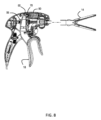
図8を参照すると、レバー18が開位置にあるとき、血管シーラのジョー14は、開いている。この位置では、レバーベアリングチューブ56は、駆動シャフト28がジョー14を完全に開いているように駆動シャフト28が長手方向に並進しているように、そのレバーベアリングチューブ56の最も遠位の場所にある。レバーピボットピン50は、ばねアセンブリ80によって印加されるあらかじめ負荷される力に起因して、軌道70の近位端に保持される。
Referring to FIG. 8, when
図9を参照すると、ユーザなどによる、レバー18の第二の位置への移動によって、レバーベアリングチューブ56が長手方向軸X-Xに沿って近位に引っ張られ、それによって駆動シャフト28が長手方向に移動されて閉鎖ジョー14が閉じられる。ばねアセンブリをあらかじめ負荷することによって供給される力は、レバー18が閉位置へ枢動される間、レバーピボットピン50を定位置に保つのに十分な力を提供するように構成されているから、レバーピボットピン50は、依然として軌道70の近接する端部にある。ジョー14が完全に閉じると、レバーベアリングチューブ56および近位ストップ60は、さらなる近位の長手方向の移動ができず、レバー18およびジョー14は、完全な閉位置にある。
9, movement of
図10を参照すると、ジョー14が完全に閉じている第二の閉位置を超える、レバー18の追加的な移動は、レバーベアリングチューブ56にもジョー14にもさらなる力が与えられない屈曲状態に、レバー18が移動することにつながる。レバーベアリングチューブ56がその最も近位の位置に到達したとき、レバー18への力のさらなる印加は、レバー18をその中間部分54の周りで枢動させる。ここで、湾曲したベアリング面106および108は、当該中間部分54においてレバーベアリングチューブ56の近位ストップ60と係合する。レバー18の、その中間部分54の周りの枢動は、上端110および112を介してレバーピボットピン50に力を与え、当該力は、ばねアセンブリ80のピンベアリング面98に当たって、軌道70内で遠位に、レバーピボットピン50を駆動する。レバー18が完全な閉位置を過ぎて強く握られ続ける場合、ばね90のあらかじめの負荷は、克服され、レバーピボットピン50は、ベアリング面106および108ならびに近位ストップ60によって作り出された新しい枢動点の周りを回転するレバー18の存在として、軌道70内で遠位にスライドする。ベアリング面106および108ならびに近位ストップ60によって作り出される新しい枢動点の周りをレバー18が枢動することの結果として、レバー18は、ジョー14を過剰圧縮するか血管シーラ12を損傷する可能性がある、いかなる長手方向の力もレバーベアリングチューブ56に印加しない。その代わりにレバー18は、レバーピボットピン50がばね90の付勢に抗して軌道70に沿って移動されるように、新しい枢動点の周りを回転し続ける。このようにして、閉位置を超えてレバー18が移動しても、いかなる追加的な閉じる力もジョー14に印加されないように、かつ、レバー18がレバーベアリング58を介して駆動シャフト28にいかなるさらなる力も印加することなく、屈曲位置へ回転するように、レバー18は、ジョー14から実質的に分離される。
Referring to FIG. 10, additional movement of
このようにして、本発明は、ユーザが血管シーラ12のジョーに印加できる力の量を、制限するアプローチを提供する。結果として、本発明は、クランプされた組織に印加されている圧力、およびしたがって当該クランプされた組織の厚さを制限することによって、シールの質を管理するのに役立つ。クランプされた厚さを制御すると、過剰乾燥と、破裂圧の低いシールと、炭化と、圧縮された組織を貫いて切断する可能性と、が低減される。本発明はまた、組織グリップ力を制限することによって、組織の引裂きの可能性を低減する。すなわち、ユーザが過大な器官操作力を印加する場合、組織は、引裂きとは対照的に、スリップする傾向がある。 In this manner, the present invention provides an approach for limiting the amount of force that a user can apply to the jaws of vessel sealer 12 . As a result, the present invention helps manage the quality of the seal by limiting the pressure being applied to the clamped tissue, and thus the thickness of the clamped tissue. Controlling the clamped thickness reduces overdrying, low burst pressure seals, charring and the possibility of cutting through compressed tissue. The present invention also reduces the likelihood of tissue tearing by limiting tissue gripping force. That is, if the user applies excessive organ manipulation forces, the tissue tends to slip as opposed to tearing.
Claims (9)
駆動シャフトを有する本体であって、前記駆動シャフトが長手方向軸に沿って延在し、かつ前記駆動シャフトが開位置と閉位置との間で可動の一対のジョーに連結されている、本体と、
前記駆動シャフトとともに移動するために前記駆動シャフトの周りに固定されているベアリングチューブであって、前記ベアリングチューブから延在するストップを有する、ベアリングチューブと、
前記長手方向軸によって画定される平面の対向する側上に位置付けられており、かつ前記長手方向軸に対して斜めに延在する、一対の軌道と、
前記一対の軌道内に位置付けられたピボットピンによって前記本体に枢動可能に連結された上端、前記本体から外へ延在する下端、および前記ベアリングチューブの前記ストップと係合する中間部分を有する、レバーであって、前記レバーの前記中間部分が、湾曲し前記ベアリングチューブの前記ストップと係合する一対の内側ベアリング面を含む、レバーと、
前記本体内に位置付けられたばねアセンブリであって、前記ピボットピンを前記一対の軌道の第一の端部に押しやるために付勢されたベアリング面を有する、ばねアセンブリと、
を備える、外科手術器具。 A surgical instrument,
a body having a drive shaft, said drive shaft extending along a longitudinal axis and said drive shaft being connected to a pair of jaws movable between open and closed positions; and ,
a bearing tube fixed about the drive shaft for movement with the drive shaft, the bearing tube having a stop extending therefrom;
a pair of tracks positioned on opposite sides of a plane defined by the longitudinal axis and extending obliquely to the longitudinal axis;
having an upper end pivotally connected to the body by pivot pins positioned within the pair of tracks, a lower end extending out from the body, and a middle portion engaging the stop of the bearing tube; a lever, wherein said intermediate portion of said lever includes a pair of inner bearing surfaces that are curved and engage said stops of said bearing tube;
a spring assembly positioned within the body and having a bearing surface biased to urge the pivot pin against the first ends of the pair of tracks;
A surgical instrument comprising:
Applications Claiming Priority (3)
| Application Number | Priority Date | Filing Date | Title |
|---|---|---|---|
| US201962881078P | 2019-07-31 | 2019-07-31 | |
| US62/881,078 | 2019-07-31 | ||
| PCT/US2020/043864 WO2021021803A1 (en) | 2019-07-31 | 2020-07-28 | Force limiting mechanism for surgical instruments |
Publications (2)
| Publication Number | Publication Date |
|---|---|
| JP2022542943A JP2022542943A (en) | 2022-10-07 |
| JP7312312B2 true JP7312312B2 (en) | 2023-07-20 |
Family
ID=72047154
Family Applications (1)
| Application Number | Title | Priority Date | Filing Date |
|---|---|---|---|
| JP2022506042A Active JP7312312B2 (en) | 2019-07-31 | 2020-07-28 | Force limiting mechanism for surgical instruments |
Country Status (8)
| Country | Link |
|---|---|
| US (1) | US20220273390A1 (en) |
| EP (1) | EP4003193A1 (en) |
| JP (1) | JP7312312B2 (en) |
| KR (1) | KR20220044282A (en) |
| CN (1) | CN114206248A (en) |
| AU (1) | AU2020320201B2 (en) |
| CA (1) | CA3147256C (en) |
| WO (1) | WO2021021803A1 (en) |
Families Citing this family (1)
| Publication number | Priority date | Publication date | Assignee | Title |
|---|---|---|---|---|
| WO2023076592A1 (en) * | 2021-10-28 | 2023-05-04 | Conmed Corporation | Bipolar scissor vessel sealer force limiting mechanism |
Citations (3)
| Publication number | Priority date | Publication date | Assignee | Title |
|---|---|---|---|---|
| JP2011526157A (en) | 2008-03-31 | 2011-10-06 | アプライド メディカル リソーシーズ コーポレイション | Electrosurgical system |
| WO2016057281A1 (en) | 2014-10-10 | 2016-04-14 | Ethicon Endo-Surgery, Inc. | Surgical device with overload mechanism |
| JP2017515645A (en) | 2014-05-16 | 2017-06-15 | アプライド メディカル リソーシーズ コーポレイション | Electrosurgical system |
Family Cites Families (9)
| Publication number | Priority date | Publication date | Assignee | Title |
|---|---|---|---|---|
| US7597693B2 (en) * | 2003-06-13 | 2009-10-06 | Covidien Ag | Vessel sealer and divider for use with small trocars and cannulas |
| US7621927B2 (en) * | 2005-03-28 | 2009-11-24 | Ethicon Endo-Surgery, Inc. | Medical instrument with a mechanical coupling |
| US7766910B2 (en) * | 2006-01-24 | 2010-08-03 | Tyco Healthcare Group Lp | Vessel sealer and divider for large tissue structures |
| EP2621390A2 (en) * | 2010-10-01 | 2013-08-07 | Ethicon Endo-Surgery, Inc. | Surgical instrument with jaw member |
| US9113940B2 (en) * | 2011-01-14 | 2015-08-25 | Covidien Lp | Trigger lockout and kickback mechanism for surgical instruments |
| US10070916B2 (en) * | 2013-03-11 | 2018-09-11 | Covidien Lp | Surgical instrument with system and method for springing open jaw members |
| US10092310B2 (en) * | 2014-03-27 | 2018-10-09 | Ethicon Llc | Electrosurgical devices |
| US10172672B2 (en) * | 2016-01-11 | 2019-01-08 | Covidien Lp | Jaw force control for electrosurgical forceps |
| US11007003B2 (en) * | 2016-11-17 | 2021-05-18 | Covidien Lp | Surgical instruments and methods of manufacturing surgical instruments for performing tonsillectomy, adenoidectomy, and other surgical procedures |
-
2020
- 2020-07-28 AU AU2020320201A patent/AU2020320201B2/en active Active
- 2020-07-28 CA CA3147256A patent/CA3147256C/en active Active
- 2020-07-28 US US17/631,008 patent/US20220273390A1/en active Pending
- 2020-07-28 KR KR1020227004334A patent/KR20220044282A/en not_active Application Discontinuation
- 2020-07-28 EP EP20754578.1A patent/EP4003193A1/en active Pending
- 2020-07-28 JP JP2022506042A patent/JP7312312B2/en active Active
- 2020-07-28 CN CN202080055906.7A patent/CN114206248A/en active Pending
- 2020-07-28 WO PCT/US2020/043864 patent/WO2021021803A1/en unknown
Patent Citations (3)
| Publication number | Priority date | Publication date | Assignee | Title |
|---|---|---|---|---|
| JP2011526157A (en) | 2008-03-31 | 2011-10-06 | アプライド メディカル リソーシーズ コーポレイション | Electrosurgical system |
| JP2017515645A (en) | 2014-05-16 | 2017-06-15 | アプライド メディカル リソーシーズ コーポレイション | Electrosurgical system |
| WO2016057281A1 (en) | 2014-10-10 | 2016-04-14 | Ethicon Endo-Surgery, Inc. | Surgical device with overload mechanism |
Also Published As
| Publication number | Publication date |
|---|---|
| AU2020320201A1 (en) | 2022-02-17 |
| CA3147256A1 (en) | 2021-02-04 |
| US20220273390A1 (en) | 2022-09-01 |
| AU2020320201B2 (en) | 2023-05-04 |
| CA3147256C (en) | 2023-10-17 |
| WO2021021803A1 (en) | 2021-02-04 |
| EP4003193A1 (en) | 2022-06-01 |
| CN114206248A (en) | 2022-03-18 |
| KR20220044282A (en) | 2022-04-07 |
| JP2022542943A (en) | 2022-10-07 |
Similar Documents
| Publication | Publication Date | Title |
|---|---|---|
| JP5582788B2 (en) | Apparatus, system, and method for performing an electrosurgical procedure | |
| US9498280B2 (en) | Blade lockout mechanism for surgical forceps | |
| US9867658B2 (en) | Knife deployment mechanisms for surgical forceps | |
| EP2446849B1 (en) | Apparatus for performing an electrosurgical procedure | |
| JP2012232140A (en) | Surgical forceps | |
| JP7312312B2 (en) | Force limiting mechanism for surgical instruments | |
| US20230404650A1 (en) | Scissor style vessel sealer with squeeze activated transection | |
| CA3094808C (en) | Force limiting assembly for surgical instrument | |
| US20190290353A1 (en) | Energy-based surgical instrument having multiple operational configurations | |
| CN114286649B (en) | Force limiting mechanism for surgical instrument | |
| US20220409264A1 (en) | Anti-backdrive mechanism for vessel sealing instrument | |
| CN117442274A (en) | Closing mechanism and anastomat |
Legal Events
| Date | Code | Title | Description |
|---|---|---|---|
| A621 | Written request for application examination |
Free format text: JAPANESE INTERMEDIATE CODE: A621 Effective date: 20220128 |
|
| A131 | Notification of reasons for refusal |
Free format text: JAPANESE INTERMEDIATE CODE: A131 Effective date: 20230131 |
|
| A977 | Report on retrieval |
Free format text: JAPANESE INTERMEDIATE CODE: A971007 Effective date: 20230131 |
|
| A521 | Request for written amendment filed |
Free format text: JAPANESE INTERMEDIATE CODE: A523 Effective date: 20230412 |
|
| TRDD | Decision of grant or rejection written | ||
| A01 | Written decision to grant a patent or to grant a registration (utility model) |
Free format text: JAPANESE INTERMEDIATE CODE: A01 Effective date: 20230704 |
|
| A61 | First payment of annual fees (during grant procedure) |
Free format text: JAPANESE INTERMEDIATE CODE: A61 Effective date: 20230707 |
|
| R150 | Certificate of patent or registration of utility model |
Ref document number: 7312312 Country of ref document: JP Free format text: JAPANESE INTERMEDIATE CODE: R150 |