JP7308844B2 - A new sample set and a new downsampling scheme for linear component sample prediction - Google Patents
A new sample set and a new downsampling scheme for linear component sample prediction Download PDFInfo
- Publication number
- JP7308844B2 JP7308844B2 JP2020540610A JP2020540610A JP7308844B2 JP 7308844 B2 JP7308844 B2 JP 7308844B2 JP 2020540610 A JP2020540610 A JP 2020540610A JP 2020540610 A JP2020540610 A JP 2020540610A JP 7308844 B2 JP7308844 B2 JP 7308844B2
- Authority
- JP
- Japan
- Prior art keywords
- linear model
- values
- sample
- chroma
- sets
- Prior art date
- Legal status (The legal status is an assumption and is not a legal conclusion. Google has not performed a legal analysis and makes no representation as to the accuracy of the status listed.)
- Active
Links
Images


Classifications
-
- H—ELECTRICITY
- H04—ELECTRIC COMMUNICATION TECHNIQUE
- H04N—PICTORIAL COMMUNICATION, e.g. TELEVISION
- H04N19/00—Methods or arrangements for coding, decoding, compressing or decompressing digital video signals
- H04N19/10—Methods or arrangements for coding, decoding, compressing or decompressing digital video signals using adaptive coding
- H04N19/102—Methods or arrangements for coding, decoding, compressing or decompressing digital video signals using adaptive coding characterised by the element, parameter or selection affected or controlled by the adaptive coding
- H04N19/132—Sampling, masking or truncation of coding units, e.g. adaptive resampling, frame skipping, frame interpolation or high-frequency transform coefficient masking
-
- H—ELECTRICITY
- H04—ELECTRIC COMMUNICATION TECHNIQUE
- H04N—PICTORIAL COMMUNICATION, e.g. TELEVISION
- H04N19/00—Methods or arrangements for coding, decoding, compressing or decompressing digital video signals
- H04N19/10—Methods or arrangements for coding, decoding, compressing or decompressing digital video signals using adaptive coding
- H04N19/169—Methods or arrangements for coding, decoding, compressing or decompressing digital video signals using adaptive coding characterised by the coding unit, i.e. the structural portion or semantic portion of the video signal being the object or the subject of the adaptive coding
- H04N19/186—Methods or arrangements for coding, decoding, compressing or decompressing digital video signals using adaptive coding characterised by the coding unit, i.e. the structural portion or semantic portion of the video signal being the object or the subject of the adaptive coding the unit being a colour or a chrominance component
-
- H—ELECTRICITY
- H04—ELECTRIC COMMUNICATION TECHNIQUE
- H04N—PICTORIAL COMMUNICATION, e.g. TELEVISION
- H04N19/00—Methods or arrangements for coding, decoding, compressing or decompressing digital video signals
- H04N19/10—Methods or arrangements for coding, decoding, compressing or decompressing digital video signals using adaptive coding
- H04N19/102—Methods or arrangements for coding, decoding, compressing or decompressing digital video signals using adaptive coding characterised by the element, parameter or selection affected or controlled by the adaptive coding
- H04N19/103—Selection of coding mode or of prediction mode
- H04N19/105—Selection of the reference unit for prediction within a chosen coding or prediction mode, e.g. adaptive choice of position and number of pixels used for prediction
-
- H—ELECTRICITY
- H04—ELECTRIC COMMUNICATION TECHNIQUE
- H04N—PICTORIAL COMMUNICATION, e.g. TELEVISION
- H04N19/00—Methods or arrangements for coding, decoding, compressing or decompressing digital video signals
- H04N19/10—Methods or arrangements for coding, decoding, compressing or decompressing digital video signals using adaptive coding
- H04N19/134—Methods or arrangements for coding, decoding, compressing or decompressing digital video signals using adaptive coding characterised by the element, parameter or criterion affecting or controlling the adaptive coding
- H04N19/156—Availability of hardware or computational resources, e.g. encoding based on power-saving criteria
-
- H—ELECTRICITY
- H04—ELECTRIC COMMUNICATION TECHNIQUE
- H04N—PICTORIAL COMMUNICATION, e.g. TELEVISION
- H04N19/00—Methods or arrangements for coding, decoding, compressing or decompressing digital video signals
- H04N19/10—Methods or arrangements for coding, decoding, compressing or decompressing digital video signals using adaptive coding
- H04N19/169—Methods or arrangements for coding, decoding, compressing or decompressing digital video signals using adaptive coding characterised by the coding unit, i.e. the structural portion or semantic portion of the video signal being the object or the subject of the adaptive coding
- H04N19/17—Methods or arrangements for coding, decoding, compressing or decompressing digital video signals using adaptive coding characterised by the coding unit, i.e. the structural portion or semantic portion of the video signal being the object or the subject of the adaptive coding the unit being an image region, e.g. an object
- H04N19/176—Methods or arrangements for coding, decoding, compressing or decompressing digital video signals using adaptive coding characterised by the coding unit, i.e. the structural portion or semantic portion of the video signal being the object or the subject of the adaptive coding the unit being an image region, e.g. an object the region being a block, e.g. a macroblock
-
- H—ELECTRICITY
- H04—ELECTRIC COMMUNICATION TECHNIQUE
- H04N—PICTORIAL COMMUNICATION, e.g. TELEVISION
- H04N19/00—Methods or arrangements for coding, decoding, compressing or decompressing digital video signals
- H04N19/10—Methods or arrangements for coding, decoding, compressing or decompressing digital video signals using adaptive coding
- H04N19/189—Methods or arrangements for coding, decoding, compressing or decompressing digital video signals using adaptive coding characterised by the adaptation method, adaptation tool or adaptation type used for the adaptive coding
-
- H—ELECTRICITY
- H04—ELECTRIC COMMUNICATION TECHNIQUE
- H04N—PICTORIAL COMMUNICATION, e.g. TELEVISION
- H04N19/00—Methods or arrangements for coding, decoding, compressing or decompressing digital video signals
- H04N19/42—Methods or arrangements for coding, decoding, compressing or decompressing digital video signals characterised by implementation details or hardware specially adapted for video compression or decompression, e.g. dedicated software implementation
-
- H—ELECTRICITY
- H04—ELECTRIC COMMUNICATION TECHNIQUE
- H04N—PICTORIAL COMMUNICATION, e.g. TELEVISION
- H04N19/00—Methods or arrangements for coding, decoding, compressing or decompressing digital video signals
- H04N19/50—Methods or arrangements for coding, decoding, compressing or decompressing digital video signals using predictive coding
Landscapes
- Engineering & Computer Science (AREA)
- Multimedia (AREA)
- Signal Processing (AREA)
- Computing Systems (AREA)
- Theoretical Computer Science (AREA)
- Compression Or Coding Systems Of Tv Signals (AREA)
- Compression, Expansion, Code Conversion, And Decoders (AREA)
- Transmission Systems Not Characterized By The Medium Used For Transmission (AREA)
- Color Television Systems (AREA)
Description
本発明は、所与のビデオ成分のブロックの符号化又は復号、特にそのような成分ブロックのイントラ予測又はそのようなブロックのサンプルの取得に関する。本発明は、別の成分のサンプル、典型的にはルマサンプルから、ビデオデータの成分のブロック、典型的にはクロマ成分のブロックを取得する際の用途を見出す。 The present invention relates to encoding or decoding blocks of a given video component, in particular intra-prediction of such component blocks or obtaining samples of such blocks. The invention finds application in obtaining a component block of video data, typically a chroma component block, from another component sample, typically a luma sample.
ビデオデータの予測符号化は、画素のブロックへのフレームの分割に基づく。画素の各ブロックについて、利用可能なデータ内で予測子ブロックが探索される。この予測子ブロックは、INTER符号化モードにおいて現在のフレームとは異なる参照フレーム内のブロックであってもよく、INTRA符号化モードにおいて現在のフレーム内の隣接画素から生成されるブロックであってもよい。予測子ブロックを決定する異なる方法にしたがって、異なる符号化モードが定義される。符号化の結果は、予測子ブロック、及び符号化されるべきブロックと予測子ブロックとの間の差分からなる残差ブロックのシグナリングである。 Predictive coding of video data is based on dividing a frame into blocks of pixels. For each block of pixels, a predictor block is searched in the available data. This predictor block may be a block in a different reference frame than the current frame in INTER coding mode, or a block generated from neighboring pixels in the current frame in INTRA coding mode. . Different coding modes are defined according to different methods of determining predictor blocks. The result of encoding is the signaling of a predictor block and a residual block consisting of the difference between the block to be coded and the predictor block.
INTRA符号化モードに関しては、通常、直流(DC)モード、プレーナモード、アンギュラモードなど、様々なモードが提案されている。それらの各々は、空間的に隣接するブロックから以前に復号された境界サンプルを使用してブロックのサンプルを予測することを試みる。 Various modes are usually proposed for the INTRA coding mode, such as direct current (DC) mode, planar mode and angular mode. Each of them attempts to predict a block's samples using previously decoded boundary samples from spatially neighboring blocks.
この符号化は、ビデオデータの画素を形成する成分ごとに行われてもよい。RGB(赤-緑-青用)表現は周知であるが、チャネル間冗長性を低減するために、符号化に好ましくはYUV表現が使用される。これらの符号化モードによれば、画素のブロックは、いくつかの、典型的には3つの成分ブロックから構成されると見なされ得る。RGB画素ブロックは、ブロックの画素のR成分の値を含むR成分ブロックと、これらの画素のG成分の値を含むG成分ブロックと、これらの画素のB成分の値を含むB成分ブロックとからなる。同様に、YUV画素ブロックは、Y成分ブロック(ルマ)、U成分ブロック(クロマ)、V成分ブロック(同じくクロマ)から構成される。別の例はYCbCrであり、Cb及びCrはクロマ成分としても知られる。しかしながら、成分間(クロスコンポーネントとしても知られる)相関は、依然として局所的に観察される。 This encoding may be done for each component forming a pixel of the video data. Although the RGB (for red-green-blue) representation is well known, the YUV representation is preferably used for encoding to reduce inter-channel redundancy. According to these encoding modes, a block of pixels can be viewed as being composed of several, typically three, component blocks. The RGB pixel block consists of an R component block containing the R component values of the pixels of the block, a G component block containing the G component values of those pixels, and a B component block containing the B component values of these pixels. Become. Similarly, a YUV pixel block consists of a Y component block (luma), a U component block (chroma) and a V component block (also chroma). Another example is YCbCr, where Cb and Cr are also known as chroma components. However, inter-component (also known as cross-component) correlations are still observed locally.
圧縮効率を向上させるために、現在、Cross-Component Prediction(CCP)の使用が検討されている。CCPの主な用途は、ルマからクロマの予測に関する。これは、ルマサンプルが既に符号化され、符号化されたデータから(デコーダがするように)再構成されており、クロマがルマから予測されることを意味する。しかしながら、変形例は、クロマからクロマの予測のために、又はより一般的には(RGBを含む)第1成分からの第2成分の予測のためにCCPを使用する。 In order to improve compression efficiency, the use of Cross-Component Prediction (CCP) is currently under consideration. The main application of CCP is for luma to chroma prediction. This means that the luma samples have already been encoded and reconstructed from the encoded data (as the decoder does), and the chroma is predicted from the luma. However, a variant uses CCP for chroma-to-chroma prediction, or more generally for prediction of the second component from the first component (including RGB).
Cross-Component Predictionは、クロマ画素のブロックに直接適用されてもよく、残差クロマブロック(クロマブロックとクロマブロック予測子との間の差分を意味する)に適用されてもよい。 Cross-Component Prediction may be applied directly to a block of chroma pixels or to a residual chromablock (meaning the difference between a chromablock and a chromablock predictor).
線形モデル(LM)モードは、決定される1つ又は2つのパラメータ、すなわち傾き(α)及びオフセット(β)に依存して、クロマイントラ予測モードとしてルマからクロマを予測するために線形モデルを使用する。したがって、クロマイントラ予測子は、これらのパラメータを有する線形モデルを使用して、現在のルマブロックの再構成ルマサンプルから導出される。 Linear model (LM) mode uses a linear model to predict chroma from luma as a chroma intra prediction mode, depending on one or two parameters determined: slope (α) and offset (β). do. Chroma intra predictors are therefore derived from the reconstructed luma samples of the current luma block using a linear model with these parameters.
線形性、すなわちパラメータα及びβは、再構成因果サンプルから、特に予測する現在のクロマブロックに隣接するクロマサンプルを含む再構成クロマサンプルセットから導出され、現在のルマブロックに隣接するルマサンプルを含む隣接ルマサンプルセットから導出される。 The linearity, i.e. the parameters α and β, are derived from the reconstructed causal samples, specifically the reconstructed chroma sample set containing the chroma samples adjacent to the current chroma block to be predicted, including the luma samples adjacent to the current luma block. Derived from the adjacent luma sample set.
具体的には、N×Nクロマブロックの場合、上の行のN個の近隣と、左列のN個の近隣とが、導出のための隣接クロマサンプルセットを形成するために使用される。 Specifically, for an N×N chroma block, the N neighbors in the top row and the N neighbors in the left column are used to form the neighboring chroma sample set for derivation.
隣接ルマサンプルセットは、対応するルマブロックの真上のN個の隣接サンプルと、ルマブロックの左側のN個の隣接サンプルからも作成される。 A neighboring luma sample set is also created from the N neighboring samples directly above the corresponding luma block and the N neighboring samples to the left of the luma block.
クロマ成分をサブサンプリングすることにより、ビジュアルレンダリングの著しい劣化なしに、符号化するビデオデータのサイズを低減することが知られている。公知のサブサンプリングモードは、4:1:1、4:2:2、4:2:0とラベル付けされている。 It is known to reduce the size of the video data to be encoded without significant visual rendering degradation by subsampling the chroma components. Known subsampling modes are labeled 4:1:1, 4:2:2 and 4:2:0.
ビデオクロマデータがサブサンプリングされる状況では、N×Nクロマブロックに対応するルマブロックは、N×Nより大きい。その場合、隣接するルマサンプルセットは、そのクロマ解像度に一致するようにダウンサンプリングされる。現在のN×Nクロマブロック内のクロマサンプルを予測するクロマイントラ予測子は、1つ以上のパラメータα及びβが導出された線形モデルと、クロマ解像度に一致するように以前にダウンサンプリングされた現在のルマブロックの再構成ルマサンプルとを使用して生成されなければならない。再構成ルマサンプルをクロマ解像度にダウンサンプリングすることにより、ルマサンプルセットとクロマイントラ予測子との両方を形成するためにクロマサンプルと同数のサンプルを取り出すことが可能になる。 In situations where video chroma data is sub-sampled, the luma block corresponding to an NxN chroma block is larger than NxN. In that case, adjacent luma sample sets are downsampled to match their chroma resolution. A chroma intra predictor that predicts chroma samples within the current N×N chroma block consists of a linear model from which one or more parameters α and β are derived, and a current shall be generated using the reconstructed luma samples of the luma blocks of Downsampling the reconstructed luma samples to chroma resolution makes it possible to retrieve as many samples as chroma samples to form both the luma sample set and the chroma intra predictor.
したがって、クロマイントラ予測子は、エンコーダにおいて符号化される残差クロマブロックを取得するために、現在のクロマブロックから減算される。逆に、デコーダにおいては、クロマイントラ予測子は、復号ブロックの再構成としても知られるクロマブロックを取り出すために、受信された残差クロマブロックに加算される。これはまた、サンプル範囲から外れる加算の結果のクリッピングを伴い得る。 Therefore, the chroma intra predictor is subtracted from the current chromablock to obtain the residual chromablock to be encoded at the encoder. Conversely, at the decoder, the chroma intra predictor is added to the received residual chroma block to derive the chroma block, also known as the reconstruction of the decoded block. This may also involve clipping the results of additions that fall outside the sample range.
場合によっては、この残差クロマブロックは無視でき、したがって符号化中に考慮されない。この場合、上述のクロマイントラ予測子が、クロマブロックそのものとして用いられる。結果として、上記のLMモードは、1つ以上のパラメータを有する線形モデルを使用して、同じフレーム内の別の成分のブロックの関連付けられた(すなわち、同一場所にある又は対応する)再構成サンプルから、所与の成分の現在のブロックについてサンプルを取得することを可能にする。このサンプルは、1つ以上のパラメータが導出された線形モデルと、他の成分のブロック内の関連付けられた再構成サンプルとを使用して取得される。必要に応じて、他の成分のブロックは、現在の成分のブロック解像度に一致するようにダウンサンプリングされたサンプルから作られる。典型的には現在の成分のブロックはクロマブロックであり、他の成分のブロックはルマブロックであるが、一方でこれが当てはまらない場合がある。明確にするため、及び簡単にするために、本明細書で与えられる例はルマブロックからのクロマブロックの予測に焦点を当てるが、説明されるメカニズムは、別の成分からの任意の成分予測に適用され得ることは明らかであるはずである。 In some cases, this residual chroma block is negligible and therefore not considered during encoding. In this case, the chroma intra predictor described above is used as the chroma block itself. As a result, the above LM modes use a linear model with one or more parameters to determine the associated (i.e., co-located or corresponding) reconstruction samples of another component block within the same frame. , allows obtaining samples for the current block of a given component. The samples are obtained using a linear model from which one or more parameters are derived and associated reconstructed samples in blocks of other components. If necessary, blocks of other components are made from samples downsampled to match the block resolution of the current component. Typically the current component's block is the chroma block and the other component's block is the luma block, but on the other hand this may not be the case. For clarity and simplicity, the examples given here focus on predicting a chroma block from a luma block, but the mechanism described can be applied to any component prediction from another component. It should be clear that it can be applied.
Joint Video Exploration Team(JVET)のJoint Exploration Model(JEM)は、既に知られている通常のイントラ予測モードに6つのクロスコンポーネント(ルマからクロマへの)線形モデルモードを追加する。これらのモードはすべて、クロマブロックを予測又は生成するために互いに競合し、その選択は通常、エンコーダ端におけるレート歪み基準に基づいて行われる。 The Joint Exploration Model (JEM) of the Joint Video Exploration Team (JVET) adds six cross-component (luma to chroma) linear model modes to the already known normal intra-prediction modes. All of these modes compete with each other to predict or generate a chroma block, and the selection is typically based on rate-distortion criteria at the encoder end.
この6つのクロスコンポーネント(ルマからクロマへの)線形モデルモードは、再構成ルマサンプルをダウンサンプリングするために使用される異なるダウンサンプリング方式によって、及び/又はパラメータα及びβが導出されるサンプルの異なるサンプルセットによって、互いに異なっている。 The six cross-component (luma-to-chroma) linear model modes are determined by different downsampling schemes used to downsample the reconstructed luma samples and/or by different values of the samples from which the parameters α and β are derived. The sample sets are different from each other.
例えば、サンプルセットは、現在のルマ又はクロマブロックに隣接するサンプルの2つのライン(すなわち、行及び列)から作成されてもよく、これらのラインは、平行であり、クロマ解像度で現在のルマ又はクロマブロックの上及び/又は左の境界の各々に直に接する。このような例示的なサンプルセットは、米国特許第9,736,487号に記載されている。 For example, a sample set may be created from two lines (i.e., rows and columns) of samples adjacent to the current luma or chroma block, these lines being parallel and the current luma or directly abut each of the top and/or left borders of the chroma block. Such an exemplary sample set is described in US Pat. No. 9,736,487.
他の例示的なサンプルセットもまた、米国特許第9,288,500号及び米国特許第9,462,273号に開示されている。 Other exemplary sample sets are also disclosed in US Pat. Nos. 9,288,500 and 9,462,273.
JEMで使用されるダウンサンプリング方式は、6つの再構成ルマサンプルからダウンサンプリングされた再構成ルマサンプルを決定する6タップフィルタだけでなく、6つの再構成ルマサンプルのうちの右上及び右下のサンプル、又は右下及び右下のサンプル、又は上及び左上のサンプルのいずれかを選択する3つの2タップフィルタと、6つの再構成ルマサンプルの上、右上、下、及び右下のサンプルを選択する4タップフィルタとも含む。 The downsampling scheme used in JEM is a 6-tap filter that determines the downsampled reconstructed luma samples from the 6 reconstructed luma samples, as well as the upper right and lower right samples of the 6 reconstructed luma samples. , or three two-tap filters that select either the bottom right and bottom right samples, or the top and top left samples, and the top, top right, bottom, and bottom right samples of the six reconstructed luma samples. Also includes a 4-tap filter.
JEMは処理面で複雑である。例えば、これは、クロマ予測子ブロックサンプルの計算のための線形モデルパラメータの複雑な導出を必要とする。 JEM is complex in terms of processing. For example, this requires complex derivation of linear model parameters for the computation of chroma predictor block samples.
本発明は、前述の問題の1つ以上に対処するために考案された。本発明は、場合によってはクロマイントラ予測を通じて現在のクロマブロックについてクロマサンプルを得るための改善された方法に関する。 SUMMARY OF THE INVENTION The present invention has been devised to address one or more of the problems set forth above. The present invention relates to an improved method for obtaining chroma samples for the current chroma block, possibly through chroma intra prediction.
本発明のある態様によれば、対象エリアにおけるクロマブロックのクロマサンプル値を、同じフレーム内のルマブロックのルマサンプル値から取得するための線形モデルを導出する方法であって、前記線形モデルのパラメータを決定するための2組の値を決定する第1の決定工程と、前記2組の値を用いて前記線形モデルのパラメータを決定する第2の決定工程とを含み、前記2組の各組は2つの変数によって定義され、前記2つの変数の内の第1の変数はルマサンプル値に対応し、前記2つの変数の内の第2の変数はクロマサンプル値に対応し、前記線形モデルのパラメータは、前記線形モデルの傾きに対応するパラメータを含み、前記第2の決定工程において、前記傾きに対応するパラメータの値の大きさは、整数精度において当該傾きを表すためのビット数が5ビットを超えないように制限される方法が提供される。 According to one aspect of the present invention, a method for deriving a linear model for obtaining chroma sample values of a chroma block in an area of interest from luma sample values of luma blocks within the same frame, the linear model parameter and a second determining step of determining parameters of the linear model using the two sets of values, each of the two sets of is defined by two variables, a first of said two variables corresponding to luma sample values, a second of said two variables corresponding to chroma sample values, and of said linear model The parameter includes a parameter corresponding to the slope of the linear model, and in the second determining step, the magnitude of the value of the parameter corresponding to the slope is 5 bits for representing the slope in integer precision. A method is provided that is constrained not to exceed .
本発明の別の態様によれば、対象エリアにおけるクロマブロックのクロマサンプル値を、同じフレーム内のルマブロックのルマサンプル値から取得するための線形モデルを導出する装置であって、前記線形モデルのパラメータを決定するための2組の値を決定する第1の決定手段と、前記2組の値を用いて前記線形モデルのパラメータを決定する第2の決定手段とを含み、前記2組の各組は2つの変数によって定義され、前記2つの変数の内の第1の変数はルマサンプル値に対応し、前記2つの変数の内の第2の変数はクロマサンプル値に対応し、前記線形モデルのパラメータは、前記線形モデルの傾きに対応するパラメータを含み、前記第2の決定手段による前記傾きに対応するパラメータの決定において、当該傾きに対応するパラメータの値の大きさは、整数精度において当該傾きを表すためのビット数が5ビットを超えないように制限される装置が提供される。 According to another aspect of the invention, an apparatus for deriving a linear model for obtaining chroma sample values of a chroma block in an area of interest from luma sample values of luma blocks in the same frame, comprising: a first determining means for determining two sets of values for determining parameters; and a second determining means for determining parameters of the linear model using the two sets of values, each of the two sets of A set is defined by two variables, a first of said two variables corresponding to luma sample values and a second of said two variables corresponding to chroma sample values, said linear model includes a parameter corresponding to the slope of the linear model, and in determining the parameter corresponding to the slope by the second determining means, the magnitude of the value of the parameter corresponding to the slope is the A device is provided in which the number of bits to represent the slope is limited to no more than 5 bits .
本発明の別の態様によれば、画像を符号化するための装置、画像を復号するための装置が提供される。 According to another aspect of the invention, an apparatus for encoding an image, an apparatus for decoding an image are provided.
本発明の別の態様によれば、コンピュータプログラム製品、コンピュータ可読媒体、又はコンピュータプログラムが提供される。 According to another aspect of the invention , a computer program product, computer readable medium, or computer program is provided.
本発明のさらなる態様は、従属請求項において提供される。 Further aspects of the invention are provided in the dependent claims.
さらなる態様によれば、関連付けられた再構成第2成分サンプル値から第1成分サンプル値を取得するための線形モデルを導出する方法であって、2つ以上のセットから1つを取り、各セットは第1成分サンプル値と第2成分サンプル値とを含む、取る事と、2つのうちの前記第1成分サンプル値が、導出された線形モデルを用いてそれぞれのセットの第2成分サンプル値から取得可能となるように、第1成分サンプル値と第2成分サンプル値との変化の比率に基づいて線形モデルを導出することと、を含む。 According to a further aspect, a method of deriving a linear model for obtaining first component sample values from associated reconstructed second component sample values, taking one from two or more sets, each set contains a first component sample value and a second component sample value, and the first component sample value of the two is obtained from each set of second component sample values using a derived linear model deriving a linear model based on the rate of change of the first component sample values and the second component sample values, as obtainable.
第1成分サンプル値と、関連付けられた再構成第2成分サンプル値とは、事前に設定された関係で互いに関連付けられていることが理解される。 It is understood that the first component sample values and the associated reconstructed second component sample values are related to each other in a preset relationship.
適切には、事前に設定された関係は、それらが互いに、同一場所にある又は対応することである。この同一場所にある又は対応することは、各サンプル値それぞれについて、又は第1成分サンプル値のブロック/グループと第2成分サンプル値のブロック/グループとの間で定義されてもよい。 Suitably the preset relationship is that they co-locate or correspond to each other. This co-located or corresponding may be defined for each sample value individually or between a block/group of first component sample values and a block/group of second component sample values.
適切には、事前に設定された関係は、それらが処理される画素の現在のブロックの少なくとも1画素と関連付けられることであり、例えば、それらが、同一場所にある又は対応する、処理されるべき少なくとも1画素のサンプル値であることである。この同一場所にある又は対応の関係は、各サンプル値それぞれについて、又はサンプル値のブロック/グループから画素のブロック/グループに対して定義されてもよい。 Suitably the preset relationship is that they are associated with at least one pixel of the current block of pixels being processed, e.g. It should be a sample value of at least one pixel. This co-located or corresponding relationship may be defined for each sample value individually or from a block/group of sample values to a block/group of pixels.
また、ブロック間又は現在の画素のブロックの少なくとも1画素との事前に設定された関係が、ダウンサンプリング/アップサンプリングの後に確立することができるように、ダウンサンプリング又はアップサンプリング処理が第1成分サンプル値又は第2成分サンプル値のブロックに適用されてもよいことも理解される。 Also, the downsampling or upsampling process is performed on the first component samples so that a preset relationship between blocks or with at least one pixel of the block of the current pixel can be established after downsampling/upsampling. It is also understood that it may be applied to blocks of values or second component sample values.
適切には、第1成分サンプル値及び関連付けられた第2成分サンプル値は、処理されるべき同じ画像又はフレームの画素のブロックに関連付けられる。ここで、第1成分サンプル値と第2成分サンプル値とを含むセットは、第1成分サンプル値と第2成分サンプル値との成分サンプル値セットであることが理解される。したがって、このセットは、第1成分サンプル値及び第2成分サンプル値をその要素として有するnタプルである。適切には、このセットは2タプルである。代わりに、このセットは、2つ以上の数の要素(n個の要素)を有するnタプルである。 Suitably, the first component sample values and the associated second component sample values are associated with blocks of pixels of the same image or frame to be processed. Here, it is understood that the set comprising the first component sample values and the second component sample values is the component sample value set of the first component sample values and the second component sample values. This set is therefore an n-tuple with the first and second component sample values as its elements. Suitably, this set is a 2-tuple. Instead, the set is an n-tuple with two or more elements (n elements).
適切には、第1の成分及び第2の成分の再構成サンプル値は、処理される現在のブロックに隣接する1つ以上のブロックに関連付けられる。適切には、この現在のブロックに隣接する1つ以上のブロックは、現在のブロックの上又は左にある。 Suitably, the reconstructed sample values of the first and second components are associated with one or more blocks adjacent to the current block being processed. Suitably, the one or more blocks adjacent to this current block are above or to the left of the current block.
適切には、取られる2つのセットは、2つ以上のセット内の第2成分サンプル値のうち、最も小さい第2成分サンプル値及び最も大きい第2成分サンプル値を含むセットである。適切には、この取られる2つのセットは、2つ以上のセット内の第1成分サンプル値のうち、最も小さい第1成分サンプル値及び最も大きい第1の成分サンプル値を含むセットである。 Suitably, the two sets taken are the sets containing the smallest second component sample value and the largest second component sample value of the second component sample values in the two or more sets. Suitably, the two sets taken are the sets containing the smallest first component sample value and the largest first component sample value of the first component sample values in the two or more sets.
適切には、この2つのセットを取ることは、2つ以上のセット内の第2成分サンプル値のうち、最も小さい第2成分サンプル値及び最も大きい第2成分サンプル値を含むセットの第1のグループを決定することと、2つ以上のセット内の第1成分サンプル値のうち、最も小さい第1成分サンプル値及び最も大きい第1成分サンプル値を含むセットの第2のグループを決定することと、第1のグループと第2のグループのセットからこの2つのセットを選択することと、を含む。 Suitably, taking the two sets includes a first Determining a group and determining a second group of sets containing the smallest first component sample value and the largest first component sample value of the first component sample values in the two or more sets. , selecting the two sets from the sets of the first group and the second group.
適切には、第1のグループ及び第2のグループのセットからこの2つのセットを選択することは、最も小さい第2成分サンプル値と最も大きい第2成分サンプル値との間の差が、最も小さい第1成分サンプル値と最も大きい第1成分サンプル値との間の差よりも大きい場合には第1のグループを選択し、そうでなければ、第2のグループを選択することを含む。 Suitably, selecting the two sets from the sets of the first group and the second group is such that the difference between the smallest second component sample value and the largest second component sample value is the smallest selecting the first group if greater than the difference between the first component sample value and the largest first component sample value; otherwise selecting the second group.
適切には、第1のグループ及び第2のグループのセットから2つのセットを選択することは、第1のグループと第2のグループのセットのサンプル値の位置を決定することと、その決定されたサンプル値の位置に基づいて2つのセットを選択することと、を含む。適切には、このサンプル値の位置は、処理される第1の成分サンプル値のブロックに関連付けられた再構成第2成分サンプル値のブロックに関して、再構成第2成分サンプル値について決定される。適切には、このサンプル値の位置は、処理される再構成第1成分サンプル値のブロックに関して、再構成第1成分サンプル値について決定される。適切には、このサンプル値の位置は、処理される画素のブロックに関して定義された、関連付けられた/同一場所にある/対応する位置に基づいて決定される。 Suitably, selecting two sets from the set of the first group and the second group comprises determining the positions of the sample values of the set of the first group and the second group, and the determined and selecting between the two sets based on the positions of the sample values obtained. Suitably, the position of this sample value is determined for the reconstructed second component sample values with respect to the block of reconstructed second component sample values associated with the block of first component sample values being processed. Suitably, the position of this sample value is determined for the reconstructed first component sample values with respect to the block of reconstructed first component sample values to be processed. Suitably, the position of this sample value is determined based on the associated/co-located/corresponding position defined for the block of pixels being processed.
適切には、決定されたサンプル値の位置に基づいて2つのセットを選択することは、処理されるブロックに隣接する所定の位置におけるサンプル値を含むセットを選択することを含む。適切には、決定されたサンプル値の位置に基づいて2つのセットを選択することは、第1のグループ及び第2のグループのセットのいずれかが所定の位置におけるサンプル値を含むかどうかを決定することと、所定の位置におけるサンプル値を含むセットを2つのセットのいずれかとして選択することと、を含む。適切には、決定されたサンプル値の位置に基づいて2つのセットを選択することは、所定の位置のサンプル値を含むセットが利用可能でない場合に、第1のグループ及び第2のグループのセットのいずれかが別の所定の位置のサンプル値を含むかどうかを決定することと、その別の所定の位置のサンプル値を含むセットを2つのセットのいずれかとして選択することと、を含む。適切には、その所定の位置又は別の所定の位置は、処理される現在のブロックに隣接する位置のうちの左下又は右上位置である。 Suitably, selecting the two sets based on the determined positions of the sample values comprises selecting the set containing sample values at predetermined positions adjacent to the block being processed. Suitably, selecting two sets based on the determined positions of the sample values determines if any of the sets of the first group and the second group contain the sample values at the given positions. and selecting the set containing the sample value at the given position as one of the two sets. Suitably, selecting the two sets based on the determined positions of the sample values comprises the first group and the second set of groups if no set containing the sample values for the given positions is available. contains sample values at another predetermined position, and selecting the set containing the sample values at the other predetermined position as either of the two sets. Suitably, the predetermined position or another predetermined position is the lower left or upper right position adjacent to the current block being processed.
適切には、セットの第1のグループ及び第2のグループからの2つのセットを選択することは、セットの第1のグループ及び第2のグループからの2つのセット間の距離を比較することを含み、ここで、その距離は、第1及び第2の成分サンプル値の空間において定義され、第1及び第2の成分サンプル値は、2つ以上のセットの各セットが前記空間における位置に対応するように、セットの要素によって定義される。 Suitably selecting two sets from the first and second groups of sets comprises comparing distances between the two sets from the first and second groups of sets. wherein the distance is defined in a space of first and second component sample values, the first and second component sample values being defined in two or more sets, each set corresponding to a position in said space defined by the elements of the set so that
適切には、2つのセットを選択することは、第1のグループ内のセット間の距離が第2のグループ内のセット間の距離よりも大きいかどうかを決定することと、第1のグループのセット間の距離が第2のグループのセット間の距離よりも大きい場合には第1のグループを選択し、そうでない場合には第2のグループを選択することと、を比較する。適切には、この2つのセットを選択することは、セットの第1のグループ及び第2のグループセットからそれらの間に最も大きい距離を有する2つのセットを選択することを含む。 Suitably, selecting the two sets comprises determining whether the distance between the sets in the first group is greater than the distance between the sets in the second group; selecting the first group if the distance between sets is greater than the distance between sets in the second group, otherwise selecting the second group. Suitably, selecting the two sets comprises selecting the two sets from the first group of sets and the second group set with the greatest distance between them.
適切には、2つのセットを選択することは、第1のグループ内のセットの対応する要素が同じ値を有するか、又は異なる値を有するかを決定することと、その対応する要素が同じ値を有さない場合には第1のグループを選択し、対応する値が同じ値を有する又は異なる値を有さない場合には第2のグループを選択することと、を含む。適切には、そのセットの対応する要素は、第1成分サンプル値及び第2成分サンプル値の一方又は両方である。 Suitably, selecting two sets comprises determining whether corresponding elements of the sets in the first group have the same value or different values; and selecting the first group if the corresponding values do not have the same value or different values. Suitably the corresponding members of the set are one or both of the first and second component sample values.
適切には、2つのセットを選択することは、第2のグループ内のセットの対応する要素が同じ値を有するか、又は異なる値を有するかを決定することと、その対応する要素が同じ値を有さない場合には第2のグループを選択し、対応する値が同じ値を有する又は異なる値を有さない場合には第1のグループを選択することと、を含む Suitably, selecting two sets comprises determining whether corresponding elements of sets in the second group have the same value or different values; and selecting the second group if the corresponding values do not have the same value or different values.
適切には、2つのセットを選択することは、第1のグループのセット間の第1成分サンプル値と第2成分サンプル値との変化の比率を取得することと、取得された比率が事前に設定された値より大きいか、等しいか、又は小さいかを決定することと、得られた比率が予め設定された値より大きいか、等しいか、又は小さい場合には第1のグループを選択し、そうでなければ第2のグループを選択することと、を含む。適切には、2つのセットを選択することは、第2のグループのセット間の第1成分サンプル値及び第2成分サンプル値の変化の比率を取得することと、取得された比率が事前に設定された値より大きいか、等しいか、又は小さいかを決定することと、取得された比率が事前に設定された値より大きいか、等しいか、又は小さい場合には第2のグループを選択し、そうでなければ第1のグループを選択することと、を含む。 Suitably, selecting the two sets comprises: obtaining a ratio of changes in the first component sample values and the second component sample values between the sets of the first group; determining if greater than, equal to, or less than a set value; selecting the first group if the resulting ratio is greater than, equal to, or less than the preset value; otherwise selecting the second group. Suitably, selecting the two sets comprises obtaining a ratio of changes in the first component sample values and the second component sample values between the sets of the second group; determining if the obtained ratio is greater than, equal to, or less than the preset value; selecting the second group if the obtained ratio is greater than, equal to, or less than the preset value; otherwise selecting the first group.
適切には、取られる2つのセットは、処理される現在のブロックに関連付けられた第2成分サンプル値のブロックに隣接する1つ以上のブロックからの第2成分サンプル値を含むセットであり、2つのセットを取ることは、それらの第2成分サンプル値に基づいて2つのセットを選択することを含む。適切には、取られる2つのセットは、対応する第2成分サンプル値のブロックの再構成サンプル値のうち最も頻繁に発生する2つの第2成分サンプル値を含むセットである。 Suitably the two sets taken are sets containing second component sample values from one or more blocks adjacent to the block of second component sample values associated with the current block being processed; Taking two sets involves selecting two sets based on their second component sample values. Suitably, the two sets taken are those containing the two most frequently occurring second component sample values of the reconstructed sample values of the corresponding block of second component sample values.
適切には、第2成分の再構成サンプル値は、少なくとも2つのグループに分割され、各グループについて、2つのセットが取られ、取られた2つのセットに基づいて線形モデルが導出される。適切には、あるグループについて取られた2つのセットが、事前に設定された値以下の、そのセット間の第1の成分サンプル値及び第2の成分サンプル値の変化の比を有する場合、そのグループの線形モデルは、別のグループについて取られた2つのセットに基づいて導出される。適切には、あるグループについてとられた2つのセットが、事前に設定された値以下の、セット間の第1の成分サンプル値及び第2の成分サンプル値の変化の比率を有する場合、そのグループの線形モデルは、第2成分の再構成サンプル値がすべて単一のグループ内にあった場合にとられたであろう2つのセットに基づいて導出される。 Suitably the reconstructed sample values of the second component are divided into at least two groups, for each group two sets are taken and a linear model is derived based on the two sets taken. Suitably, if two sets taken for a group have a ratio of change in first component sample value and second component sample value between the sets that is less than or equal to a preset value, then A linear model of a group is derived based on two sets taken for another group. Suitably, if two sets taken for a group have a ratio of change in the first component sample value and the second component sample value between the sets that is less than or equal to a preset value, then the group A linear model of is derived based on the two sets that would have been taken if the reconstructed sample values of the second component were all in a single group.
さらに別の態様によれば、1つ以上の画像をビットストリームへと符号化する又はビットストリームから復号する方法であって、本発明の第1の態様の方法に係る関連付けられた再構成第2成分サンプル値から第1成分サンプル値を取得するための線形モデルを導出する方法が提供される。 According to yet another aspect, a method for encoding into or decoding one or more images into or from a bitstream, comprising associated reconstruction second images according to the method of the first aspect of the present invention. A method is provided for deriving a linear model for obtaining a first component sample value from component sample values.
適切には、本方法は、処理される画像の現在のブロックについての第1成分サンプル値を取得するための複数の線形モデル導出モードのうちの1つを選択することをさらに含み、ここで、その複数の線形モデル導出モードは、単一の線形モデルを使用する第1のモードと、2つ以上の線形モデルを使用する第2のモードとを含み、導出された線形モデルは、選択された線形モデル導出モードで使用可能である。適切には、第1のモードのみが導出された線形モデルを使用する。代わって、第2のモードのみが導出された線形モデルを使用する。 Suitably, the method further comprises selecting one of a plurality of linear model derivation modes for obtaining first component sample values for the current block of the image being processed, wherein: The multiple linear model derivation modes include a first mode using a single linear model and a second mode using two or more linear models, the derived linear models being selected Available in linear model derivation mode. Suitably, we use a linear model from which only the first mode is derived. Instead, we use a linear model from which only the second mode is derived.
さらに別の態様によれば、関連する再構成第2成分サンプル値から第1成分サンプル値を得るための線形モデルを導出するための装置であって、本発明の第1の態様の方法を行うように構成された装置が提供される。 According to yet another aspect, an apparatus for deriving a linear model for obtaining first component sample values from associated reconstructed second component sample values, performing the method of the first aspect of the invention. An apparatus is provided that is configured to:
さらに別の態様によれば、1つ以上の画像をビットストリームへと符号化する又はビットストリームから復号する装置であって、本発明の第2の態様の方法を行うように構成される装置が提供される。 According to yet another aspect, an apparatus for encoding into or decoding from a bitstream one or more images, the apparatus configured to perform the method of the second aspect of the present invention comprises provided.
さらに別の態様によれば、関連付けられた再構成第2成分サンプル値から第1成分サンプル値を取得する方法であって、第1成分サンプル値を取得するための複数の線形モデルモードの中から1つの線形モデルモードを選択することと、その選択された線形モデルモードを使用して第1成分サンプル値を取得することと、を含み、ここで、複数の線形モデルモードのうちの少なくとも1つは、本発明の第1の態様に係る導出方法を使用して導出された線形モデルを使用する、方法が提供される。適切には、複数の線形モデルモードは、単一の線形モデルを使用する第1のモードと、2つ以上の線形モデルを使用する第2のモードとを含む。適切には、第1のモードのみが本発明の第1の態様に係る導出方法を使用する。代わって、第2のモードのみが、本発明の第1の態様による導出方法を用いる。 According to yet another aspect, a method of obtaining first component sample values from associated reconstructed second component sample values, comprising: selecting a linear model mode and obtaining first component sample values using the selected linear model mode, wherein at least one of the plurality of linear model modes; uses a linear model derived using the derivation method according to the first aspect of the invention. Suitably, the multiple linear model modes include a first mode using a single linear model and a second mode using two or more linear models. Suitably only the first mode uses the derivation method according to the first aspect of the invention. Instead, only the second mode uses the derivation method according to the first aspect of the invention.
さらに別の態様によれば、関連付けられた再構成第2成分サンプル値から第1成分サンプル値を得るための装置であって、本発明の第5の態様の方法を行うように構成された装置が提供される。 According to yet another aspect, apparatus for obtaining first component sample values from associated reconstructed second component sample values, the apparatus configured to perform the method of the fifth aspect of the present invention. is provided.
さらに別の態様によれば、本発明の第5の態様に係る関連付けられた再構成第2成分サンプル値から第1の成分サンプル値を取得することを含む、1つ以上の画像をビットストリームへと符号化する方法が提供される。適切には、本方法は、ビットストリームにおいて、第1成分サンプルを取得するために使用可能な線形モデルモードの選択を示す情報を提供することをさらに含む。 According to yet another aspect, converting one or more images into a bitstream comprising obtaining first component sample values from associated reconstructed second component sample values according to the fifth aspect of the present invention. A method is provided to encode . Suitably, the method further comprises providing information in the bitstream indicating a selection of linear model modes available for obtaining the first component samples.
さらに別の態様によれば、1つ以上の画像をビットストリームから復号する方法であって、本発明の第5の態様に係る関連付けられた再構成第2成分サンプル値から第1成分サンプル値を取得することを含む方法が提供される。適切には、本方法は、ビットストリームから、第2成分サンプルを取得するために使用可能な線形モデルモードについての選択を示す情報を取得することと、取得された情報に基づいて行われる複数の線形モデルモードの中から1つの線形モデルモードを選択することと、を含む。 According to yet another aspect, a method of decoding one or more images from a bitstream, comprising: decoding first component sample values from associated reconstructed second component sample values according to the fifth aspect of the invention A method is provided that includes obtaining. Suitably, the method comprises obtaining from the bitstream information indicating a selection for a linear model mode available for obtaining the second component samples; selecting a linear model mode from among the linear model modes.
さらに別の態様によれば、本明細書で説明される方法を行うように構成される、1つ以上の画像をビットストリームへと符号化するための装置が提供される。 According to yet another aspect, there is provided an apparatus for encoding one or more images into a bitstream, configured to perform the methods described herein.
さらに別の態様によれば、実行時に、本明細書で説明される方法を実行させるコンピュータプログラム、及び本明細書で説明される方法を実施するための命令を格納する(非一時的)コンピュータ可読媒体が提供される。 According to yet another aspect, a computer program that, when executed, causes the methods described herein to be performed, and a (non-transitory) computer readable program that stores instructions for performing the methods described herein. A medium is provided.
本発明によれば、添付の特許請求の範囲に記載の装置、方法、コンピュータプログラム(製品)、及びコンピュータ可読記憶媒体が提供される。本発明の実施形態の他の特徴は、添付の特許請求の範囲及び以下の説明で定義される。これらの特徴のいくつかは、ここでは方法を参照して説明されるが、それらは、装置専用のシステム特徴に転置され得る。 According to the present invention, there are provided apparatus, methods, computer programs (products) and computer readable storage media as set forth in the appended claims. Other features of embodiments of the invention are defined in the appended claims and the following description. Although some of these features are described herein with reference to methods, they can be transposed into device-specific system features.
本発明に係る方法の少なくとも一部は、コンピュータで実装されてもよい。したがって、本発明は、完全にハードウェアの実施形態、完全にソフトウェアの実施形態(ファームウェア、常駐ソフトウェア、マイクロコード等を含む。)、又はソフトウェア及びハードウェアの態様を組み合わせる実施形態の形態を取ってもよく、これらは全て、本明細書において「プロセッサ及びメモリ」、「回路」、「モジュール」、又は「システム」と一般に呼ばれてもよい。さらに、本発明は、媒体で実現されるコンピュータ使用可能プログラムコードを有する任意の有形表現媒体で実現されるコンピュータプログラム製品の形態を取ってもよい。 At least part of the method according to the invention may be computer-implemented. Accordingly, the present invention takes the form of an entirely hardware embodiment, an entirely software embodiment (including firmware, resident software, microcode, etc.), or an embodiment combining software and hardware aspects. may all be referred to herein generically as a "processor and memory," "circuit," "module," or "system." Furthermore, the present invention may take the form of a computer program product embodied in any tangible medium of expression having computer-usable program code embodied in the medium.
本発明はソフトウェアで実装できるため、本発明は、任意の適切なキャリア媒体上でプログラム可能機器に提供するためのコンピュータ可読コードとして具体化することができる。有形キャリア媒体は、ハードディスクドライブ、磁気テープ装置又は固体メモリ装置などの記憶媒体を含んでいてもよい。過渡キャリア媒体は、電気信号、電子信号、光信号、音響信号、磁気信号、又は電磁信号、例えば、マイクロ波又はRF信号などの信号を含んでいてもよい。 Since the invention can be implemented in software, the invention can be embodied as computer readable code for provision to programmable equipment on any suitable carrier medium. Tangible carrier media may include storage media such as hard disk drives, magnetic tape devices, or solid state memory devices. Transient carrier media may include signals such as electrical, electronic, optical, acoustic, magnetic, or electromagnetic signals, such as microwave or RF signals.
ここで本発明の実施形態は、単なる例として、以下の図面を参照して記載される。 Embodiments of the invention will now be described, by way of example only, with reference to the following drawings.
図1は、ビデオエンコーダアーキテクチャを示す。ビデオエンコーダにおいて、元のシーケンス101は、HEVCのためのコーディングブロック又はコーディングユニットと呼ばれる画素のブロック102に分割される。次いで、コーディングモードは、各ブロックに影響を及ぼす。典型的に使用されるビデオコーディングには、空間予測又は「INTRAモード」103に基づく符号化モードと、動き推定104及び動き補償105に基づく時間予測又は「INTERモード」に基づく符号化モードと、のコーディングモードの2つのファミリーがある。
FIG. 1 shows a video encoder architecture. In a video encoder, an
INTRAコーディングブロックは、一般に、INTRA予測と呼ばれる処理によってその因果境界にある符号化された画素から予測される。したがって、INTRAコーディングブロックの各画素についての予測子は、予測子ブロックを形成する。INTRAコーディングブロックを予測するためにどの画素が使用されるかに応じて、様々なINTRAモードが、例えばDCモード、プレーナモード及びアンギュラモードが提案される。 An INTRA coded block is generally predicted from the coded pixels at its causal boundaries by a process called INTRA prediction. The predictors for each pixel of the INTRA coding block thus form a predictor block. Depending on which pixels are used to predict the INTRA coding block, various INTRA modes are proposed, eg DC mode, planar mode and angular mode.
図1はビデオエンコーダアーキテクチャの一般的な説明に向けられているが、画素は、ここでは画像の要素に対応し、典型的にはいくつかの成分、例えば赤色成分、緑色成分、及び青色成分からなることに留意されたい。画像サンプルは画像の要素であり、成分1つのみを含む。 Although FIG. 1 is directed to a general description of a video encoder architecture, a pixel here corresponds to an element of an image, typically from several components, e.g. red, green and blue components. It should be noted that An image sample is an element of an image and contains only one component.
時間予測は、まず、参照フレーム116と呼ばれる以前又は将来のフレームにおいて、動き推定ステップ104においてコーディングブロックに最も近い参照領域を見つけることにある。この参照領域が予測子ブロックを構成する。次に、このコーディングブロックは、動き補償ステップ105において、その残差又は残差ブロックを計算するために予測子ブロックを使用して予測される。
Temporal prediction consists first in finding the closest reference region to the coding block in the
空間予測及び時間予測の両方の場合において、残差又は残差ブロックは、コーディングブロックから取得された予測子ブロックを減算することによって計算される。 In both spatial and temporal prediction cases, residuals or residual blocks are computed by subtracting predictor blocks obtained from coding blocks.
INTRA予測では、予測モードが符号化される。 In INTRA prediction, prediction modes are encoded.
時間予測では、使用する参照フレームを示すインデックスと参照フレーム内の参照領域を示す動きベクトルとが符号化される。しかしながら、動きベクトル符号化に関するビットレートコストをさらに低減するために、動きベクトルは直接符号化されない。実際、動きが均一であると仮定すると、動きベクトルを、この動きベクトルとその周囲の動きベクトル(又は動きベクトル予測子)との差として符号化することが特に有利である。例えば、コーディング規格H.264/AVCでは、動きベクトルは、現在のブロックの上及び左に位置する3つのブロックに関連付けられた動きベクトルから計算される中央値ベクトルに関して符号化される。この中央値ベクトルと現在のブロック動きベクトルとの間で計算される残差動きベクトルとも呼ばれる差分のみがビットストリームにおいて符号化される。これは、モジュール「Mv予測及びコーディング」117において処理される。各符号化ベクトルの値は、動きベクトルフィールド118に格納される。予測に使用される隣接動きベクトルは、動きベクトルフィールド118から抽出される。
In temporal prediction, an index indicating a reference frame to be used and a motion vector indicating a reference region within the reference frame are encoded. However, to further reduce the bitrate cost associated with motion vector encoding, motion vectors are not encoded directly. In fact, assuming uniform motion, it is particularly advantageous to encode a motion vector as the difference between this motion vector and its surrounding motion vectors (or motion vector predictors). For example, the coding standard H.264. In H.264/AVC, motion vectors are encoded with respect to a median vector calculated from motion vectors associated with three blocks located above and to the left of the current block. Only the difference, also called residual motion vector, calculated between this median vector and the current block motion vector is encoded in the bitstream. This is processed in module “Mv prediction and coding” 117 . The value of each encoded vector is stored in
HEVC規格は、3つの異なるINTERモード、インターモード、マージモード、及びマージスキップモードを使用し、それらは主に、ビットストリーム110における動き情報(すなわち、そのいわゆる参照フレームインデックスを通した動きベクトル及び関連付けられた参照フレーム)のシグナリングによって互いに異なる。簡単にするために、動きベクトルと動き情報とは、以下においてまとめられる。動きベクトル予測に関して、HEVCは、インターモード又はマージモードのそれぞれに対して最良の動きベクトル予測子又は最良の動き情報を見つけるために、レート歪み競合の間に評価される動きベクトル予測子のいくつかの候補を提供する。動き情報の最良の予測子又は最良の候補に対応するインデックスは、ビットストリーム110に挿入される。このシグナリングのおかげで、デコーダは、予測子又は候補の同じセットを導出することができ、復号されたインデックスにしたがう最良のものを使用する。
The HEVC standard uses three different INTER modes, inter mode, merge mode, and merge skip mode, which are mainly used to capture motion information in the bitstream 110 (i.e., motion vectors and associations through their so-called reference frame indices). different reference frames). For simplicity, motion vectors and motion information are summarized below. With respect to motion vector prediction, HEVC uses a number of motion vector predictors evaluated during rate-distortion competition to find the best motion vector predictor or best motion information for inter mode or merge mode respectively. provide suggestions for An index corresponding to the best predictor or best candidate for motion information is inserted into the
動きベクトル予測子及び候補の導出の設計は、複雑さに大きな影響を与えることなく最良のコーディング効率を達成することに寄与する。HEVCでは、2つの動きベクトル導出が提案され、1つは(Advanced Motion Vector Prediction(AMVP)として知られる)インターモードであり、1つは(マージ導出処理として知られる)マージモードである。 The design of the motion vector predictor and candidate derivation contributes to achieving the best coding efficiency without a significant impact on complexity. In HEVC, two motion vector derivations are proposed, one is inter mode (known as Advanced Motion Vector Prediction (AMVP)) and the other is merge mode (known as merge derivation process).
次に、モジュール106において、現在考慮されているコーディングブロックに対するレート歪み基準を最適化するコーディングモードが選択される。取得された残差データ内の冗長性をさらに低減するために、変換が、典型的にはDCTがモジュール107において残差ブロックに適用され、量子化がモジュール108において取得された係数に適用される。次いで、量子化された係数ブロックは、モジュール109においてエントロピー符号化され、その結果がビットストリーム110に挿入される。
Next, at
次いで、エンコーダは、モジュール111~116において、将来の動き推定のためにフレームのコーディングブロックの各々の復号を行う。これらのステップは、エンコーダ及びデコーダが同じ参照フレーム116を有することを可能にする。コーディングされたフレームを再構成するために、量子化及び変換された残差ブロックの各々は、画素ドメインにおける対応する「再構成」残差ブロックを提供するために、モジュール111において逆量子化され、モジュール112において逆変換される。量子化の損失のために、この「再構成」残差ブロックは、ステップ106で取得された元の残差ブロックと異なる。
The encoder then decodes each of the coding blocks of the frame for future motion estimation in modules 111-116. These steps allow the encoder and decoder to have the
次に、106で選択されたコーディングモード(INTER又はINTRA)にしたがって、この「再構成」残差ブロックは、「事前再構成」ブロック(コーディングブロック)を取得するために、INTER予測子ブロック114又はINTRA予測子ブロック113に加算される。 Then, according to the coding mode (INTER or INTRA) selected at 106, this "reconstructed" residual block is either INTER predictor block 114 or Added to the INTRA predictor block 113 .
次に、「事前再構成」ブロックは、モジュール115において、「再構成」ブロック(コーディングブロック)を取得するために1つ又はいくつかの種類のポストフィルタリングによってフィルタリングされる。同じポストフィルタが(復号ループ内の)エンコーダ及びデコーダで統合され、エンコーダ及びデコーダ端で全く同じ参照フレームを得るために同じ方法で使用される。このポストフィルタリングの目的は、圧縮アーティファクトを除去することである。
The 'pre-reconstructed' blocks are then filtered in
図2は、図1に示されるビデオエンコーダアーキテクチャに対応するビデオデコーダアーキテクチャを示す。 FIG. 2 shows a video decoder architecture corresponding to the video encoder architecture shown in FIG.
ビデオストリーム201は、まずモジュール202においてエントロピー復号される。次いで、取得された各残差ブロック(コーディングブロック)は、「再構成」残差ブロックを取得するために、モジュール203において逆量子化され、モジュール204において逆変換される。これは、エンコーダ端における復号ループの開始と同様である。
次に、ビットストリーム201に示される復号モード(INTRA型復号又はINTER型復号のいずれか)にしたがって、予測子ブロックが構築される。 A predictor block is then constructed according to the decoding mode indicated in bitstream 201 (either INTRA-type decoding or INTER-type decoding).
INTRAモードの場合、INTRA予測子ブロックは、ビットストリーム201において指定されたINTRA予測モードに基づいて決定される(205)。
For INTRA mode, the INTRA predictor block is determined 205 based on the INTRA prediction mode specified in
INTERモードの場合、動き情報はエントロピー復号202の間にビットストリームから抽出される。この動き情報は、例えばHEVC及びJVETにおいて、参照フレームインデックス及び動きベクトル残差から構成される。
For INTER mode, motion information is extracted from the bitstream during
動きベクトル予測子は、動きベクトルフィールドデータ211に格納された既に計算された動きベクトルを使用して(隣接ブロックから)エンコーダによって行われるのと同じ方法で取得される。したがって、それは、動きベクトルを取得するために、抽出された動きベクトル残差ブロックに加算される(210)。この動きベクトルは、次の復号動きベクトルの予測に使用されるために動きベクトルフィールドデータ211に加算される。
Motion vector predictors are obtained in the same way as is done by the encoder (from neighboring blocks) using already calculated motion vectors stored in motion
動きベクトルはまた、INTER予測子ブロックである参照フレーム206内の参照領域の位置を特定するために使用される。
Motion vectors are also used to locate reference regions within
次に、エンコーダの復号ループと同様に、204で取得された「再構成」残差ブロックは、「事前再構成」ブロック(コーディングブロック)を取得するために、INTER予測子ブロック206又はINTRA予測子ブロック205に加算される。 Similar to the decoding loop of the encoder, the 'reconstructed' residual block obtained at 204 is then processed by either the INTER predictor block 206 or the INTRA predictor block to obtain the 'pre-reconstructed' block (coding block). Added to block 205 .
次に、この「事前再構成」ブロックは、エンコーダ端において行われるようにモジュール207においてポストフィルタリングされる(使用するポストフィルタリングのシグナリングは、ビットストリーム201から取り出されてもよい)。
This 'pre-reconstruction' block is then post-filtered in
このようにして、復号器の出力として非圧縮ビデオ209を形成する「再構成」ブロック(コーディングブロック)が得られる。
In this way a "reconstruction" block (coding block) is obtained which forms the
上述した符号化/復号処理は、モノクロフレームに適用されてもよい。しかしながら、大部分の一般的なフレームは、一般にカラーサンプルの3つのアレイで作成されたカラーフレームであり、各アレイは、「色成分」、例えばR(赤)、G(緑)、及びB(青)に対応する。画像の画素は、各成分に対して1つずつ、3つの同一場所にある/対応するサンプルを含む。 The encoding/decoding process described above may be applied to monochrome frames. However, most common frames are color frames, generally made up of three arrays of color samples, each array representing a "color component", e.g., R (red), G (green), and B ( blue). A pixel of an image contains three co-located/corresponding samples, one for each component.
通常、R、G、B成分は高い相関を有している。したがって、画像及びビデオ圧縮においては、他の色空間に色成分を変換することによって、フレームを処理する前に色成分を非相関化することが極めて一般的である。最も一般的なフォーマットはYUV(YCbCr)であり、Yはルマ(又はルミナンス)成分であり、U(Cb)及びV(Cr)はクロマ(又はクロミナンス)成分である。 Normally, R, G and B components have high correlation. Therefore, it is very common in image and video compression to decorrelate the color components before processing the frame by transforming them into another color space. The most common format is YUV (YCbCr), where Y is the luma (or luminance) component and U (Cb) and V (Cr) are the chroma (or chrominance) components.
処理するデータの量を低減するために、色フレームのいくつかの色成分がサブサンプリングされ、その結果、3つの色成分に対して異なるサンプリング比率を有してもよい。サブサンプリング方式は、概念的な2画素高範囲におけるルマサンプル及びクロマサンプルの数を記載する3部分比率J:a:bとして一般に表される。「J」は、概念範囲の水平サンプリング基準(すなわち、画素の幅)、通常は4を定義する。「a」は、J画素の第1の行におけるクロマサンプルの数(Cr、Cb)を定義し、一方で「b」は、J画素の第2の行における(追加の)クロマサンプルの数(Cr、Cb)を定義する。 To reduce the amount of data to process, some color components of the color frame may be sub-sampled, resulting in different sampling ratios for the three color components. The subsampling scheme is commonly expressed as a 3-part ratio J:a:b that describes the number of luma and chroma samples in a notional two pixel height range. "J" defines the horizontal sampling criterion (ie, width in pixels) of the concept area, typically four. 'a' defines the number of chroma samples in the first row of J pixels (Cr, Cb), while 'b' defines the number of (additional) chroma samples in the second row of J pixels ( Cr, Cb) are defined.
サブサンプリング方式では、クロマサンプルの数は、ルマサンプルの数と比較して低減される。 In sub-sampling schemes, the number of chroma samples is reduced compared to the number of luma samples.
4:4:4YUV又はRGBフォーマットは、サブサンプリングを提供せず、ルマ及びクロマフレームが同じサイズW×Hを有する非サブサンプリングフレームに対応する。 A 4:4:4 YUV or RGB format does not provide subsampling and corresponds to non-subsampling frames where the luma and chroma frames have the same size W×H.
4:0:0YUV又はRGBフォーマットは、色成分1つのみを有し、したがってモノクロフレームに対応する。 A 4:0:0 YUV or RGB format has only one color component and thus corresponds to a monochrome frame.
例示的なサンプリングフォーマットは以下のとおりである。 An exemplary sampling format is as follows.
4:2:0YUVフォーマットは、第1の行ではルマサンプルの半分の数のクロマサンプルを有し、第2の行ではクロマサンプルを有さない。したがって、2つのクロマフレームはW/2画素幅及びH/2画素高さであり、そこでルマフレームはW×Hである。 The 4:2:0 YUV format has half as many chroma samples as luma samples in the first row and no chroma samples in the second row. Therefore, two chroma frames are W/2 pixels wide and H/2 pixels high, so the luma frame is W×H.
4:2:2YUVフォーマットは、第1の行ではルマサンプルの半分の数のクロマサンプルと、第2の行ではルマサンプルの半分の数のクロマサンプルとを有する。したがって、2つのクロマフレームはW/2画素幅及びH画素高さであり、ルマフレームはW×Hである。 The 4:2:2 YUV format has half as many chroma samples as luma samples in the first row and half as many chroma samples as luma samples in the second row. Therefore, the two chroma frames are W/2 pixels wide and H pixels high, and the luma frame is W×H.
4:1:1YUVフォーマットは、ルマサンプルよりも第1の行では75%少ないクロマサンプルを有し、第2の行では75%少ないクロマサンプルを有する。したがって、2つのクロマフレームはW/4画素幅及びH画素高さであり、ルマフレームはW×Hである。 The 4:1:1 YUV format has 75% fewer chroma samples in the first row and 75% fewer chroma samples in the second row than luma samples. Therefore, the two chroma frames are W/4 pixels wide and H pixels high, and the luma frame is W×H.
サブサンプリングされるとき、そのフレーム内のクロマサンプルの位置は、ルマサンプル位置と比較してシフトされる。 When sub-sampled, the positions of chroma samples within the frame are shifted relative to the luma sample positions.
図3は、4:2:0YUVフレームに対するルマサンプル(円)に対するクロマサンプル(三角形)の例示的な位置決めを示す。 FIG. 3 shows an exemplary positioning of chroma samples (triangles) relative to luma samples (circles) for a 4:2:0 YUV frame.
図1の符号化処理は、入力フレームの各色成分フレームに適用されてもよい。 The encoding process of FIG. 1 may be applied to each color component frame of the input frame.
色成分間の相関(RGB間、又はRGB-YUV変換にも関わらず残存するYUV間の相関)に起因して、コーディング効率を改善するために、これらの(残存する)相関を利用するためにCross-Component Prediction(CCP)法が開発されてきた。 Due to correlations between color components (correlations between RGB or between YUV that remain despite RGB-YUV conversion), to exploit these (remaining) correlations to improve coding efficiency A Cross-Component Prediction (CCP) method has been developed.
CCP法は、符号化又は復号処理の異なる段階で、特に、(現在の色成分を予測するための)第1の予測段階で、又は(成分の現在の残差ブロックを予測するための)第2の予測段階で適用され得る。 The CCP method can be applied at different stages of the encoding or decoding process, in particular at the first prediction stage (for predicting the current color component) or at the second prediction stage (for predicting the current residual block of the component). It can be applied with two prediction stages.
1つの公知のCCP法は、CCLM(Cross-Component Linear Model prediction)とも呼ばれるLMモードである。これは、ルマYから、より具体的には(エンコーダ端又はデコーダ端の)再構成ルマから、クロマ成分Cb及びCr(又はU及びV)の両方を予測するために使用される。各コンポーネントに対して1つの予測子が生成される。この方法は、(クロマ及びルマ)ブロックレベル、例えば、CTU(コーディングツリーユニット)、CU(コーディングユニット)レベル、PU(予測ユニット)レベル、サブPU、又はTU(変換ユニット)レベルで動作する。 One known CCP method is the LM mode, also called CCLM (Cross-Component Linear Model prediction). It is used to predict both the chroma components Cb and Cr (or U and V) from the luma Y, and more specifically from the reconstructed luma (either at the encoder end or at the decoder end). One predictor is generated for each component. The method operates at the (chroma and luma) block level, eg at the CTU (coding tree unit), CU (coding unit) level, PU (prediction unit) level, sub-PU or TU (transform unit) level.
図4は、一例として、フローチャートを使用して、(以下で参考として使用される)エンコーダ又はデコーダのいずれかによって行われる、LMモードを使用してブロック予測子を生成するための一般的なステップを示す。 FIG. 4 shows, as an example, using a flowchart, the general steps for generating a block predictor using LM mode, performed by either an encoder or a decoder (used as a reference below) indicates
以下の説明では、例示的な第1成分はクロマであり、一方で例示的な第2成分はルマである。 In the following discussion, the exemplary first component is chroma, while the exemplary second component is luma.
符号化又は復号するための現在のクロマブロック502(図5A)と、同じフレーム内の(すなわち、例えば同じCUの)その関連付けられた又は対応する(すなわち、「同一場所にある」)ルマブロック505とを考慮すると、エンコーダ(又はデコーダ)は、ステップ401において、現在のルマブロックに隣接するルマサンプル503を含む隣接ルマサンプルセットRecLを受信する。そして、エンコーダ(又はデコーダ)は、402で示される、現在のクロマブロックに隣接するクロマサンプル501を含む隣接クロマサンプルセットRecCを受信する。いくつかのクロマサンプリングフォーマット及びクロマフェーズについて、ルマサンプル504及び503は、図5Aに示されるように、ルマブロック505に直接接しないことに留意されたい。例えば図5Aでは、左の行RecL′(503)を取得するために、その直接の左の行ではなく、左の第2の行のみが必要である。同様に、上のライン504について、上の第2のラインもまた、図5Aに示されるように、ルマサンプルのダウンサンプリングのために考慮される。
A current chroma block 502 (FIG. 5A) to encode or decode and its associated or corresponding (i.e., "co-located") luma block 505 in the same frame (i.e., for the same CU, for example) , the encoder (or decoder) receives in step 401 a neighboring luma sample set RecL comprising
クロマサンプリングフォーマットが使用される場合(例えば、4:2:0、4:2:2など)、ステップ403において、隣接ルマサンプルセットは、クロマ解像度(すなわち、対応するクロマフレーム/ブロックのサンプル解像度)に一致するようにRecL′404にダウンサンプリングされる。したがって、RecL′は、ダウンサンプリングされる現在のルマブロックに隣接する再構成ルマサンプル504を含む。このダウンサンプリングのおかげで、RecL′及びRecCは、同じ数2Nのサンプルを含む(クロマブロック502はN×Nである)。しかしながら、RecL′を取得するために必要とされるサンプルが少ない従来技術では、ルマ境界の特定のダウンサンプリングが存在する。加えて、RecLとRecCが同じ解像度を有していても、RecL′はローパス畳み込みフィルタを用いることによるRecLのノイズ除去版とみなせる。
If a chroma sampling format is used (e.g., 4:2:0, 4:2:2, etc.), then in
図5Aの例では、隣接ルマ及びクロマサンプルセットは、ダウンサンプリングされた上及び左隣接ルマサンプル並びに上及び左隣接クロマサンプルからそれぞれ作成される。より精密には、2つのサンプルセットの各々は、それらそれぞれのルマ又はクロマブロックの、左の境界に直接接する第1のラインと、上の境界に直接接する第1のラインとから作成される。ダウンサンプリング(図5Aでは4:2:0)により、隣接ルマサンプルRecL′の単一のラインは、ダウンサンプリングされていない再構成ルマサンプルRecLの2つのライン(左又は上)から取得される。 In the example of FIG. 5A, the neighboring luma and chroma sample sets are created from downsampled top and left neighboring luma samples and top and left neighboring chroma samples, respectively. More precisely, each of the two sample sets is made up of the first line directly bordering the left border and the first line directly bordering the top border of their respective luma or chroma block. Due to downsampling (4:2:0 in FIG. 5A), a single line of adjacent luma samples RecL' is obtained from two lines (left or top) of non-downsampled reconstructed luma samples RecL.
米国特許第9,565,428号は、ルマブロックそのものについてではなく、(ステップ408を参照して以下に説明されるように)その上のライン(すなわち、ルマブロックの上の境界に隣接する)についてのみ単一のサンプルを選択するサブサンプリングを使用することを示唆する。提案されるサブサンプリングを図6Aに示す。このアプローチの動機は、上のラインのラインバッファを低減することである。 U.S. Pat. No. 9,565,428 is not about the luma block itself, but the line above it (i.e., adjacent to the upper boundary of the luma block) (as described below with reference to step 408). We suggest using subsampling to select a single sample only for . The proposed subsampling is shown in FIG. 6A. The motivation for this approach is to reduce the line buffer for the top line.
1つ又は2つのパラメータ(傾きα及びオフセットβ)によって定義される線形モデルは、RecL′(存在する場合、そうでなければRecL)及びRecCから導出される。これは、パラメータ406を取得するステップ405である。
A linear model defined by one or two parameters (slope α and offset β) is derived from RecL′ (if present, otherwise RecL) and RecC. This is
LMパラメータα及びβは、以下の式を使用して最小平均二乗法を使用して取得される。

ここで、Mは、考慮されるブロックのサイズに依存する値である。図5A及び図5Bに示されるような正方形のブロックの一般的な場合では、M=2Nである。しかしながら、LMベースのCCPは、Mが例えばブロック高さHとブロック幅Wの和である(長方形のブロック形状の場合)、任意のブロック形状に適用されてもよい。 where M is a value that depends on the size of the block considered. In the general case of square blocks as shown in FIGS. 5A and 5B, M=2N. However, LM-based CCP may be applied to any block shape, where M is, for example, the sum of block height H and block width W (for rectangular block shapes).
この式において重みとして使用されるMの値は、エンコーダ及びデコーダにおける計算オーバーフローを避けるために調整されてもよいことに留意されたい。精密には、32ビット又は64ビットの署名付きアーキテクチャを有する算術を使用するとき、演算のいくつかは、時々オーバーフローし、したがって、(任意のクロスプラットフォーム規格では厳しく禁止される)未指定の挙動を引き起こすことがある。この状況と向き合うために、所与の入力RecL′及びRecC値に与えられた可能な最大の大きさが評価されてもよく、M(及び次に上記の和)は、オーバーフローが起こらないことを保証するために、それに応じてスケーリングされてもよい。 Note that the values of M used as weights in this equation may be adjusted to avoid computational overflow in the encoder and decoder. Precisely, when using arithmetic with 32-bit or 64-bit signed architectures, some of the operations will occasionally overflow, thus exhibiting unspecified behavior (strictly prohibited by any cross-platform standard). can cause. To face this situation, the maximum possible magnitude given given input RecL' and RecC values may be evaluated, and M (and then the sum above) is such that no overflow occurs. To guarantee, it may be scaled accordingly.
パラメータの導出は、通常、図5Aに示されるサンプルセットRecL′及びRecCから行われる。 The parameter derivation is typically done from the sample sets RecL' and RecC shown in FIG. 5A.
サンプルセットのバリエーションが提案されている。 A variation of the sample set is proposed.
例えば、米国特許第9,288,500号は、上の境界に接する外側ラインと左の境界に接する外側ラインとから作成される第1のサンプルセットと、上の境界に接する外側ラインのみから作成される第2のサンプルセットと、左の境界に接する外側ラインのみから成る第3のサンプルセットとを含む、3つの競合サンプルセットを提案する。これらの3つのサンプルセットは、クロマブロックについてのみ図6Bに示されている(したがって、ルマブロックに転置することができる)。 For example, U.S. Pat. No. 9,288,500 describes a first sample set made up of the top bounding outer line and the left bounding outer line, and the top bounding outer line only. We propose three competitive sample sets, including a second set of samples that are bounded by , and a third set that consists only of outer lines that touch the left boundary. These three sample sets are shown in FIG. 6B only for chroma blocks (and can therefore be transposed to luma blocks).
米国特許第9,462,273号は、第2及び第3のサンプルセットを、外側ラインを拡張する追加のサンプルに拡張する(通常、それらの長さを2倍にする)。拡張されたサンプルセットは、クロマブロックについてのみ図6Cに示されている。本文書はまた、ビットストリームで使用されるLMモードをシグナリングするためのシグナリングコストを減少させるために利用可能なLMモードの数の低減を提供する。この低減は、例えば、関連付けられたルマブロックについて選択されたイントラモードに基づいて、前後関係に応じ得る。 US Pat. No. 9,462,273 extends the second and third sample sets with additional samples extending the outer lines (usually doubling their length). The extended sample set is shown in FIG. 6C only for chroma blocks. This document also provides a reduction in the number of available LM modes to reduce the signaling cost for signaling the LM modes used in the bitstream. This reduction may be contextual, eg, based on the intra mode selected for the associated luma block.
米国特許第9,736,487号は、米国特許第9,288,500号のものと同様の3つの競合サンプルセットを提案するが、その都度、考慮される境界に対して平行で直接接する外側隣接サンプルの2つのラインから作成される。これらのサンプルセットは、クロマブロックについてのみ図6Dに示されている。 U.S. Pat. No. 9,736,487 proposes three competing sample sets similar to those of U.S. Pat. No. 9,288,500, but each with an outer It is made up of two lines of adjacent samples. These sample sets are shown in FIG. 6D only for the chroma blocks.
また、米国特許第9,153,040号及び同じパテントファミリーの文書は、境界ごとに単一のラインで作成され、ラインごとに前のセットよりも少ないサンプルを有する、追加のサンプルセットを提案する。 Also, U.S. Pat. No. 9,153,040 and documents in the same patent family propose additional sample sets that are made with a single line per boundary and have fewer samples per line than the previous set. .
図4の処理に戻ると、1つ以上の導出パラメータ406を有する線形モデルを使用して、クロマブロック502についてのクロマイントラ予測子413が、505で表される現在のルマブロックの再構成ルマサンプル407から取得されてもよい。ここでも、クロマサンプリングフォーマット(例えば、4:2:0、4:2:2など)が使用される場合、再構成ルマサンプルは、クロマ解像度(すなわち、対応するクロマフレーム/ブロックのサンプル解像度)に一致するように、ステップ408において、L′409にダウンサンプリングされる。
Returning to the process of FIG. 4, using a linear model with one or more derived
ステップ403と同じダウンサンプリングが使用されてもよく、又はラインバッファの理由のために別のダウンサンプリングが使用されてもよい。例えば、ダウンサンプリングされた値を、ダウンサンプリング位置を囲む左上、上、右上、左下、下、及び右下のサンプルの加重和として提供するために、6タップフィルタが使用されてもよい。周囲のサンプルが欠けている場合、6タップフィルタの代わりに単なる2タップフィルタが用いられる。
The same downsampling as in
再構成ルマサンプルLに適用され、例示的な6タップフィルタの出力L′は、以下のように取得される。

ここで、(i,j)はダウンサンプリングされたブロック内のサンプルの座標であり、>>はビット右シフト演算である。 where (i,j) are the coordinates of the sample within the downsampled block and >> is the bitwise right shift operation.
また、US2017/0244975号に記載されるように、適応的ルマダウンサンプリングが使用されてもよい。ルマブロックの内容のみが、ルマブロックの再構成ルマサンプルごとにどのダウンサンプリングフィルタが使用されるかを決定するために使用される。1タップフィルタが利用可能である。この手法の動機は、ダウンサンプリングされたルマブロックにおけるエッジの伝播を回避することである。 Adaptive luma downsampling may also be used, as described in US2017/0244975. Only the contents of the luma block are used to determine which downsampling filter is used for each reconstructed luma sample of the luma block. A one-tap filter is available. The motivation for this approach is to avoid edge propagation in downsampled luma blocks.
ダウンサンプリングステップ408のおかげで、L′ブロック及びCブロック(クロマブロック502におけるクロマサンプルのセット)は、同じ数N2のサンプルを含む(クロマブロック502はN×Nである)。
Thanks to the
次に、クロマイントラ予測子PredC413の各サンプルは、以下の式にしたがってループ410-411-412を使用して計算される。
PredC[i,j]=α.L′[i,j]+β
Each sample of the chroma
PredC[i,j]=α. L'[i,j]+β
ここで、(i,j)は、クロマ及びルマブロック内のすべてのサンプルの座標である。 where (i,j) are the coordinates of all samples in the chroma and luma blocks.
除算及び乗算を避けるために、この計算は、ルックアップ表及びシフト演算に基づくより複雑でない方法を使用して実装されてもよい。例えば、実際のクロマイントラ予測子導出411は、以下のように行われてもよい。
PredC[i,j]=(A.L′[i,j])>>S+β
To avoid division and multiplication, this computation may be implemented using a less complex method based on lookup tables and shift operations. For example, actual chroma
PredC[i,j]=(A.L'[i,j])>>S+β
ここで、Sは整数であり、Aは以前に述べたルックアップ表を使用してA1及びA2から導出される(α及びβを計算するときに上記で導入される)。これは、実際にはαの再スケーリング値に対応する。この演算(x>>S)は、ビット右シフト演算に対応し、xの整数を2Sで割ったもの(切り捨て)に相当する。 where S is an integer and A is derived from A1 and A2 using the previously mentioned lookup table (introduced above when calculating α and β). This actually corresponds to the rescaling value of α. This operation (x>>S) corresponds to a bitwise right shift operation and is equivalent to the integer of x divided by 2S (truncated).
ダウンサンプリングされたルマブロックのすべてのサンプルが解析された場合に(412)、クロマイントラ予測子413は、エンコーダ端でのクロマブロック502からの減算に(クロマ残差ブロックを取得するために)、又はデコーダ端でのクロマ残差ブロックへの加算(再構成クロマブロックを取得するために)に利用可能である。
When all samples of the downsampled luma block have been analyzed (412), the
このクロマ残差ブロックは、有意ではなく、したがって廃棄することができ、その場合、取得されたクロマイントラ予測子413は、(クロマブロック502を形成する)予測されたクロマサンプルに直接対応することに留意されたい。
This chroma residual block is not significant and can therefore be discarded, in which case the obtained
HEVC規格を規定した標準化グループITU-T VCEG(Q6/16)及びISO/IEC MPEG(JTC 1/SC 29/WG 11)は両方とも、Joint Video Exploration Team(JVET)として知られるジョイント協働取り組みにおいてHEVCの後継のための将来のビデオコーディング技術を研究している。Joint Exploration Model(JEM)は、HEVCツールと、このJVETグループによって選択された新たな追加ツールとを含む。特に、この参照ソフトウェアは、文書JVET-G1001に記載されているように、いくつかのCCPツールを含む。 Both the standardization groups ITU-T VCEG (Q6/16) and ISO/IEC MPEG (JTC 1/SC 29/WG 11) that defined the HEVC standard, in a joint collaborative effort known as the Joint Video Exploration Team (JVET) We are researching future video coding technologies for successors to HEVC. The Joint Exploration Model (JEM) includes HEVC tools and new additional tools selected by this JVET group. In particular, this reference software includes several CCP tools, as described in document JVET-G1001.
JEMでは、合計11個のイントラモードがクロマコーディングに許容される。これらのモードは、5つの従来のイントラモードと、Y(ビットストリーム110、201においてシグナリングされる)からCbを予測する6つのクロスコンポーネントLMモードと、CbからCrを予測する1つのクロスコンポーネントLMモードとを含む。
JEM allows a total of 11 intra modes for chroma-coding. These modes are five conventional intra modes, six cross-component LM modes predicting Cb from Y (signaled in
6つのY-Cb、CC、LMモードのうちの1つは、上述のCCLMであり、そこで隣接ルマサンプルセットRecL′及びクロマサンプルセットRecCは、図5Aに示されるように、それらそれぞれのルマブロック又はクロマブロックの左の境界に直接接する第1のライン及び上の境界に直接接する第1のラインからそれぞれ作成される。 One of the six Y-Cb, CC, LM modes is the CCLM described above, where the adjacent luma sample set RecL' and the chroma sample set RecC are stored in their respective luma blocks as shown in FIG. 5A. or from the first line directly bordering the left border of the chroma block and the first line directly bordering the top border, respectively.
5つの他のY-Cb、CC、LMモードは、多重モデル(MM)として知られる特定の導出に基づく。これらのモードはMMLMとラベル付けされる。 The five other Y-Cb, CC, LM modes are based on specific derivations known as multiple models (MM). These modes are labeled MMLM.
CCLMと比較して、MMLMモードは、2つの線形モデルを使用する。RecL′セットからの隣接する再構成ルマサンプル及びRecCセットからの隣接クロマサンプルは、2つのグループに分類され、各グループは、1つの線形モデルのパラメータα及びβを導出するために使用され、したがって、線形モデルパラメータ(α1,β1)及び(α2,β2)の2つのセットをもたらす。 Compared to CCLM, MMLM mode uses two linear models. Adjacent reconstructed luma samples from the RecL′ set and adjacent chroma samples from the RecC set are classified into two groups, each group used to derive the parameters α and β of one linear model, thus , yields two sets of linear model parameters (α1, β1) and (α2, β2).
例えば、閾値は、RecL′を形成する隣接する再構成ルマサンプルの平均値として算出されてもよい。次に、閾値以下のRecL′[i,j]を有する隣接ルマサンプルがグループ1に分類され、一方で閾値より大きいRecL′[i,j]を有する隣接ルマサンプルはグループ2に分類される。 For example, the threshold may be calculated as the average value of adjacent reconstructed luma samples forming RecL'. Next, adjacent luma samples with RecL'[i,j] less than or equal to the threshold are classified into group 1, while adjacent luma samples with RecL'[i,j] greater than the threshold are classified into group 2.
次に、クロマイントラ予測子(又は現在のクロマブロック602の予測クロマサンプル)は、以下の式に従って求められる。
PredC[i,j]=α1.L′[i,j]+β1, if L′[i,j]≦threshold
PredC[i,j]=α2.L′[i,j]+β2, if L′[i,j]>threshold
The chroma intra predictor (or predicted chroma sample of the current chroma block 602) is then determined according to the following equation.
PredC[i,j]=α 1 . L′[i,j]+β 1 , if L′[i,j]≦threshold
PredC[i,j]=α 2 . L'[i,j]+β 2 , if L'[i,j]>threshold
さらに、CCLMと比較して、MMLMモードは、隣接ルマサンプルセットRecL′及びクロマサンプルセットRecCを使用し、それぞれが、考慮されるブロックの左の境界及び上の境界に対して平行で直接接する外側隣接サンプルの2つのラインから作成される。例は、隣接するルマサンプルの2つのラインが非ダウンサンプリング再構成ルマサンプルの4つのラインから(ダウンサンプリングを使用して)取得される4:2:0サンプリングフォーマットを示す図5Bに示される。 Furthermore, compared to CCLM, the MMLM mode uses a contiguous luma sample set RecL′ and a chroma sample set RecC, respectively, parallel and directly adjacent outer boundaries to the left and top boundaries of the considered block. It is made up of two lines of adjacent samples. An example is shown in FIG. 5B, which shows a 4:2:0 sampling format in which two lines of adjacent luma samples are obtained (using downsampling) from four lines of non-downsampled reconstructed luma samples.
5つのMMLMモードは、(RecL′及び/又はL′を取得するために)クロマ解像度に一致するように再構成ルマサンプルをダウンサンプリングするための5つの異なるダウンサンプリングフィルタによって互いに異なる。 The five MMLM modes differ from each other by five different downsampling filters for downsampling the reconstructed luma samples to match the chroma resolution (to obtain RecL' and/or L').
第1のMMLMモードは、CCLMで使用されるものと同じ6タップフィルタに依存する(図7の参照番号701の6つの黒い点を参照)。第2のMMLMモード~第4のMMLMモードは、ダウンサンプリングされた値を次式の加重和としてそれぞれ提供する2タップフィルタに依存する。
The first MMLM mode relies on the same 6-tap filter as used in CCLM (see the 6 black dots at
ダウンサンプリング位置(図7のフィルタ1、702参照)を囲む(6タップフィルタによって使用される)6つのサンプルの右上及び右下のサンプルは以下の通りである。
L′[i,j]=(L[2i+1,2j]+L[2i+1,2j+1]+1)>>1 (RecLについても同様)
The top right and bottom right samples of the six samples (used by the 6-tap filter) surrounding the downsampling position (see
L'[i,j]=(L[2i+1,2j]+L[2i+1,2j+1]+1)>>1 (same for RecL)
ダウンサンプリング位置(図7のフィルタ2、703参照)を囲む(6タップフィルタによって使用される)6つのサンプルの右下のサンプルは以下の通りである。
L′[i,j]=(L[2i,2j+1]+L[2i+1,2j+1]+1)>>1
The bottom right sample of the 6 samples (used by the 6-tap filter) surrounding the downsampling position (see
L'[i,j]=(L[2i,2j+1]+L[2i+1,2j+1]+1)>>1
ダウンサンプリング位置(図7のフィルタ4、705参照)を囲む(6タップフィルタによって使用される)6つのサンプルの右上のサンプル及び左上のサンプルは以下の通りである。
L′[i,j]=(L[2i,2j]+L[2i+1,2j]+1)>>1
The upper right and upper left samples of the 6 samples (used by the 6-tap filter) surrounding the downsampling position (see
L'[i,j]=(L[2i,2j]+L[2i+1,2j]+1)>>1
第5のMMLMモードは、ダウンサンプリングされた値を、ダウンサンプリング位置(図7のフィルタ3、704参照)を囲む(6タップフィルタによって使用される)6つのサンプルの上サンプル、右上サンプル、下サンプル、及び右下サンプルの加重和として提供する4タップフィルタに依存する。
L′[i,j]=(L[2i,2j]+L[2i,2j+1]+L[2i+1,2j]+L[2i+1,2j+1]+2)>>2
A fifth MMLM mode divides the downsampled value into six samples (used by the 6-tap filter) surrounding the downsampling position (filter 3, see 704 in FIG. 7): top sample, top right sample, bottom sample , and a 4-tap filter provided as a weighted sum of the lower right samples.
L'[i,j]=(L[2i,2j]+L[2i,2j+1]+L[2i+1,2j]+L[2i+1,2j+1]+2)>>2
上述したように、CCLMモード又はMMLMモードは、ビットストリーム110又は201においてシグナリングされなければならない。図8は、JEMの例示的なLMモードシグナリングを示す。第1のバイナリフラグは、現在のブロックがLMモード又はいわゆるDMモードを含む他のイントラモードを使用して予測されるかどうかを示す。LMモードの場合、6つの可能なLMモードがシグナリングされる必要がある。(6タップフィルタを使用する)第1のMMLMモードは、1にセットされた1つの第2のバイナリフラグでシグナリングされる。この第2のバイナリフラグは、残りのモードのために0に設定され、その場合、第3のバイナリフラグは、CCLMモードをシグナリングするために1に設定され、残りのMMLMモードのために0に設定される。次いで、2つの追加のバイナリフラグが、4つの残りのMMLMモードのうちの1つをシグナリングするために使用される。
As mentioned above, CCLM mode or MMLM mode must be signaled in
1つのモードは、各クロマ成分についてシグナリングされる。 One mode is signaled for each chroma component.
上記で導入されたCbからCrへのCCLMモードはDMモードで使用され、残差レベルで適用される。実際、DMモードは、所定の場所においてルマによって使用されたイントラモードをクロマのために使用する。従来、HEVCのようなコーディングモードは、CUの左上隅と同一場所に配置された1つの単一のDMモードを使用する。あまり詳細に説明せず、明確にするために、JVETは、そのような位置をいくつか提供する。次いで、このモードは、予測方法を決定するために使用され、それゆえに、参照/元のデータから減算されると前述の残差データを生じる、クロマ成分について通常のイントラ予測を生成する。Cr残差についての予測は、Cb残差(以下ResidualCb)から以下の式で取得される。
PredCr[i,j]=α.ResidualCb[i,j]
The Cb to Cr CCLM mode introduced above is used in the DM mode and applied at the residual level. In fact, DM mode uses the intra mode used by luma in place for chroma. Conventionally, coding modes like HEVC use one single DM mode co-located with the upper left corner of the CU. Without going into too much detail and for the sake of clarity, JVET provides several such locations. This mode is then used to determine the prediction method, thus producing normal intra-prediction for the chroma components, which when subtracted from the reference/original data yields the aforementioned residual data. The prediction for the Cr residual is obtained from the Cb residual (hereinafter ResidualCb) with the following equation.
PredCr[i,j]=α. ResidualCb[i,j]
ここで、αは、CCLMルマ対クロマ予測と同様の方法で導出される。唯一の差異は、導出されたスケーリング係数が以下のように-0.5のデフォルト値に向かって偏るように、誤差関数におけるデフォルトα値に関連する回帰コストの追加である。

ここで、ResCbiは、隣接する再構成Cbサンプルの値を表し、ResCriは、隣接する再構成Crサンプルを表す。

既知のLMモードは、特に最小二乗ベースの方法を使用して線形モデルパラメータを導出するとき、大きな計算の複雑さを示す。 Known LM modes exhibit large computational complexity, especially when deriving linear model parameters using least-squares-based methods.
本発明は、コーディング効率及び/又は計算の複雑さの観点から状況を改善しようとするものである。 The present invention seeks to improve the situation in terms of coding efficiency and/or computational complexity.
本発明は、直線の方程式に基づく線形モデルのパラメータの決定による、ルマブロックサンプルからクロマ予測子ブロックサンプルを計算するために使用される線形モデルの導出の置換に基づく。この直線は、ブロックの近傍における再構成サンプル対に基づいて定義される2つのサンプル対によって定義される。まず、使用する2つのサンプル対を決定する。次いで、これらの2つのサンプル対から、線形モデルのパラメータが決定される。線形モデルの決定に使用されるサンプル対の数を2つに限定することにより、最小平均二乗法の使用を回避することができる。したがって、提案される方法は、最小平均二乗法を使用する既知の方法よりも計算集約的ではない。 The present invention is based on replacing the derivation of the linear model used to compute the chroma predictor block samples from the luma block samples by determining the parameters of the linear model based on the equation of the line. This straight line is defined by two sample pairs that are defined based on reconstructed sample pairs in the neighborhood of the block. First, determine the two sample pairs to use. From these two sample pairs, the parameters of the linear model are then determined. By limiting the number of sample pairs used in determining the linear model to two, the use of least mean squares can be avoided. Therefore, the proposed method is less computationally intensive than known methods using least mean squares.
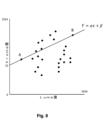
図9は、現在のブロックの近傍におけるサンプル対のセットにおけるルマサンプル値の最小及び最大をここで考慮することによって、この方法の原理を示す。全てのサンプル対は、それらのクロマ値及びそれらのルマ値にしたがって図上に描かれる。2つの異なる点、すなわち点A及び点Bが図上で識別され、各点がサンプル対に対応する。点Aは、RecL′から最も小さいルマ値xAと、RecCから同一場所にあるそのクロマ値yAとを有するサンプル対に対応する。点Bは、最も大きいルマ値xBと、その同一場所にあるクロマ値yBとを有するサンプル対に対応する。 FIG. 9 illustrates the principle of this method by now considering the minimum and maximum luma sample values in a set of sample pairs in the neighborhood of the current block. All sample pairs are drawn on the diagram according to their chroma values and their luma values. Two different points are identified on the diagram, point A and point B, each point corresponding to a sample pair. Point A corresponds to the sample pair with the lowest luma value x A from RecL' and its co-located chroma value y A from RecC. Point B corresponds to the sample pair with the largest luma value x B and its co-located chroma value y B .
図10は、この線形モデルパラメータを導出するための提案された方法のフローチャートを与える。このフローチャートは、図4の簡略化されたバージョンである。この方法は、ステップ1001で取得された隣接ルマサンプルRecL′及びステップ1002で取得されたクロマサンプルRecCに基づく。
FIG. 10 gives a flowchart of the proposed method for deriving this linear model parameter. This flow chart is a simplified version of FIG. This method is based on the adjacent luma sample RecL′ obtained in
ステップ1003では、2つのサンプル対に対応する2つの点A,B(1004)が決定される。第1の実施形態では、これらの2つの点A及びBは、それぞれ最も小さいルマサンプル値xA及び最も大きいルマサンプル値xBを有し、それらの対応するクロマサンプル値yA及びyBを有するサンプル対に対応する。
In
次いで、点Aと点Bとの間の直線の方程式が、ステップ1005で以下の式にしたがって計算される。
α=(yB-yA)/(xB-xA)
β=yA-αxA
The equation of the straight line between points A and B is then calculated in
α=( yB - yA )/( xB - xA )
β=y A -αx A
取得されたこのα,βは、クロマ予測子を生成するために使用される線形モデルパラメータ1006である。
This α,β obtained are the
従来技術で使用されるLMSアルゴリズムに基づく線形モデル導出は、一定の複雑さを有する。この公知の方法では、モデルのαパラメータの計算は、以下の式によって取得される。

計算の複雑さに関するこの式の分析は、以下の結果を与える。B1の計算は、M+1個の乗算及びM個の加算を必要とし、Mはサンプル対の数である。B2の計算は、1個の乗算及び2M個の加算を必要とする。B3の計算は、M+1個の乗算及びM個の加算を必要とし、B4の計算は、1個の乗算及び2M個の加算を必要とする。(B1-B2)/(B3-B4)に対応するαの計算は、2つの追加の加算及び1つの除算を必要とする。 An analysis of this formula for computational complexity gives the following results. Computing B 1 requires M+1 multiplications and M additions, where M is the number of sample pairs. Computing B2 requires 1 multiplication and 2M additions. Computing B 3 requires M+1 multiplications and M additions, and computing B 4 requires 1 multiplication and 2M additions. Computing α corresponding to (B 1 −B 2 )/(B 3 −B 4 ) requires two additional additions and one division.
βを計算するために、1回の乗算、2M+1回の加算及び1回の除算。前述の通り、Mはサンプルの対の数RecC′i及びRecL′iである。 1 multiplication, 2M+1 additions and 1 division to compute β. As before, M is the number of sample pairs RecC'i and RecL'i .
したがって、α及びβのLMS導出の複雑さは、(2M+2+2)回の乗算、(7M+3)回の加算及び2回の除算である。 Therefore, the complexity of the LMS derivation of α and β is (2M+2+2) multiplications, (7M+3) additions and 2 divisions.
対照的に、2点のみを使用して直線の方程式の計算に基づく提案された方法の分析は、以下の結果を与える。報告されるように、導出ステップ1005は、1回の乗算、3回の加算、及び1回の除算のみを必要とする。線形モデルパラメータの生成におけるこの大きな複雑さの低減は、提案されるこの発明の主な利点である。
In contrast, an analysis of the proposed method based on the calculation of the linear equation using only two points gives the following results. As reported, the
最小値及び最大値の探索は、典型的にはソートアルゴリズムに関連するそれ自体の複雑さを有することに留意されたい。その演算は完全に直列ではなく、N個の点は、N個の他の点と比較することができ、N個の最小/最大を生成する。次いで、N/2個の最小点及びN/2個の最大点が、N/2個の他の点と比較され、そして所望の数の最小点及び最大点のみが残るまで、N/4などの数の最大点及び最小点が再び比較され得る。したがって、典型的には、最小及び最大のこの探索は、ほぼ2*N-2回(それぞれN-1回)の比較をもたらす。 Note that searching for minimum and maximum values has its own complexity, typically associated with sorting algorithms. The operation is not fully serial, N points can be compared to N other points to produce N min/max. The N/2 minimum and N/2 maximum points are then compared to N/2 other points, and N/4, etc., until only the desired number of minimum and maximum points remain. The maximum and minimum points of the number of can be compared again. Thus, typically this search for minimum and maximum results in approximately 2*N-2 (N-1 each) comparisons.
既に述べたように、クロマ予測子は、浮動小数点乗算の代わりに整数乗算及びシフト、並びに傾きを計算する際の除算によって算出することができる。この簡略化は、


整数乗算及びシフトのみを使用するために、一実施形態では、この直線の方程式は以下のように得られる。
S=10

S=10
以下において、βは、αがL及びSによって置き換えられる場合にはこの方程式を参照し、そうでなければ従来の方程式β=yA-αxAを参照することに留意されたい。 Note that in the following β refers to this equation if α is replaced by L and S, otherwise to the conventional equation β=y A −αx A.
この導出の別の利点は、シフト値Sが常に同じ値を有することである。これは、特に、この性質を生かしてより簡略化することのできるハードウェア実装にとって興味深い。 Another advantage of this derivation is that the shift value S always has the same value. This is particularly interesting for hardware implementations that can take advantage of this property and be more simplified.
さらに別の実施形態では、Lが大きくなる可能性があるため、Sの値は小さいことが強制され、より大きな乗数演算を必要とする。実際、8ビット値と8ビット値との乗算は、例えば8×16乗算器よりも実装がはるかに容易である。Lの典型的な実用値は、多くの場合、8ビット未満の乗数に等しい。 In yet another embodiment, L can be large, which forces the value of S to be small, requiring a larger multiplier operation. In fact, multiplication of 8-bit values by 8-bit values is much easier to implement than, for example, an 8x16 multiplier. A typical practical value for L is often equal to a multiplier of less than 8 bits.
しかしながら、好ましい実施形態は、固定点として知られる実装形態であり、D=(xB-xA)のすべての値について、おそらく量子化され(例えば、2D+0及び2D+1に対する結果は、単一のものとして格納される)、S/D(1<<S)の値が表に格納される。符号が簡単に取り出されるので、これらは正の値についてのみであることが好ましい。したがって、アレイTABを使用して、Lの計算は以下のようになる。

Qは量子化を制御し、したがって表内の要素の数を制御する。このように、Q=1を使用することは、量子化がないことを意味する。また、ルックアップインデックスは、代わりに、典型的にはR=Q/2である(abs(xB-xA)+R)/Q、又は分割丸めのその変形例とすることができることにも留意されたい。したがって、理想的には、Q=2Pによる除算はPによる右シフトに相当するように、Qは2のべき乗となる。 Q controls the quantization and thus the number of elements in the table. Thus, using Q=1 means no quantization. Also note that the lookup index can instead be (abs(x B −x A )+R)/Q, typically R=Q/2, or a variant thereof with split rounding. want to be Ideally, therefore, Q is a power of 2 so that division by Q=2P is equivalent to a right shift by P.
最後に、その表中の値のいくつかは、0に等しくなくてもよく、abs(xB-xA)又はabs(yB-yA)の低値は、Lの推定を非常に悪くすることがある。ここで、所定の、又は明示的な(スライスヘッダ内、又はPPS若しくはSPSなどのパラメータセット内などの)値が用いられ得る。例えば、4未満のDのすべての値に対して、アレイTABは、デフォルト値、例えば、-S/8(1<<S)を含んでいてもよい。 Finally, some of the values in the table may not be equal to 0, and low values of abs(x B −x A ) or abs(y B −y A ) give very poor estimates of L. I have something to do. Here, predetermined or explicit (such as in slice headers or in parameter sets such as PPS or SPS) values may be used. For example, for all values of D less than 4, array TAB may contain default values, eg, −S/8 (1<<S).
10ビットの内容及びQ=1の場合、アレイ内で最大2048エントリが必要である。上述の符号を有する対称性を利用することによって、これは1024に低減され得る。さらにQを大きくすることで、同様にTABのサイズが小さくなる。 For 10-bit content and Q=1, a maximum of 2048 entries are required in the array. This can be reduced to 1024 by taking advantage of the signed symmetry described above. Further increasing Q similarly reduces the size of the TAB.
CbからCrへの予測を伴うJVETの場合のように、サンプルの一部(RecL若しくはRecCのいずれか、又は両方)が残差サンプル(すなわち、おそらく量子化された2つのブロック間の差分からそれら自体をもたらす)である場合、そこで表サイズ(及びコンテンツ)は、それに応じて適合され得る。 As in the case of JVET with prediction from Cb to Cr, some of the samples (either RecL or RecC, or both) are residual samples (i.e., possibly from the difference between the two quantized blocks to their itself), then the table size (and content) can be adapted accordingly.
別の好ましい実施形態において、以下の式における直線α及びβの2つのパラメータの決定は、整数算術がハードウェアにおいて容易に実装されるために使用され得るように計算される。

より精密には、パラメータα及びβの決定は、整数の乗算及び整数に対するビットシフト演算によってのみ行うことができる。そのような計算は、浮動小数点算術などの他のタイプの算出よりも少ないハードウェア資源(例えば、メモリ及び時間)を利用する。 More precisely, the determination of the parameters α and β can only be done by integer multiplication and bit shift operations on integers. Such computations utilize less hardware resources (eg, memory and time) than other types of computations such as floating point arithmetic.
この整数算術を行うために、以下のステップが行われる。 To perform this integer arithmetic, the following steps are performed.
第1の中間値「pshift」は、扱われるLumaサンプル及びChromaサンプルのビット深度を考慮することによって決定される。このビットシフト値は、αの分母(diffと称される)の指定される最大値を確保する。本実施形態では、この「diff」の最大値は512であるので、それを512エントリを有する表で表現することができる。「diff」の指定の最大値を強制することによって、共通の表(又は表のセット)を、総メモリ要件を低減する様々な異なるビット深度について使用することができる。 The first intermediate value 'pshift' is determined by considering the bit depth of the Luma and Chroma samples to be treated. This bit-shifted value ensures the maximum specified value of the denominator of α (called diff). In this embodiment, the maximum value of this "diff" is 512, so it can be represented in a table with 512 entries. By enforcing a maximum value for the 'diff' specification, a common table (or set of tables) can be used for various different bit depths reducing overall memory requirements.
したがって、pshiftの値は、サンプルのビット深度に依存する(例えば、10ビットを用いてサンプルが符号化される場合には、最大値と最小値との差が1024である)。512エントリの表においてこれを表すために、pshiftが1となるように、2で除算する、又は1でビットシフトする必要がある。pshiftとビット深度の関係は、例えば、以下の表1について抽出される、又は以下の数式によって与えられる。
pShift=(BitDepth>9) ? Bitdepth-9:0
Therefore, the value of pshift depends on the bit depth of the samples (eg, if the samples are coded using 10 bits, the difference between the maximum and minimum values is 1024). To represent this in a 512 entry table, we need to divide by 2 or bit shift by 1 so that pshift is 1. The relationship between pshift and bit depth is, for example, extracted for Table 1 below, or given by the equation below.
pShift=(BitDepth>9) ? Bit depth-9:0
代わりに、これは以下の数式で表すことができる。

ビットシフトの後に「diff」を整数にするように、任意選択の丸め値「add」が計算されてもよい。「add」値は、以下の数式に従いpshiftに関連する。
add=pshift ? 1<<(pshift-1):0 .
An optional rounding value 'add' may be calculated to make 'diff' an integer after bit shifting. The "add" value is related to pshift according to the following formula.
add=pshift ? 1<<(pshift-1): 0 .
代わりに、これは以下の数式で表すことができる。

代わりに、「BitDepth」と「add」との間の直接的な関係は、以下の数式によって提供され得る。
add=(BitDepth>9) ? 1<<(BitDepth-10):0
又は、

add=(BitDepth>9) ? 1<<(BitDepth-10): 0
or
以下の表1は、扱われるLumaサンプル及びChromaサンプルの、8ビットから16ビットまでのビット深度に対応する「pshift」及び「add」の例の値を与える。

この表は、「pshift」及び「add」を再計算する必要を避けるためににメモリに格納されてもよく、これは処理演算の数を減らすことができる。しかしながら、いくつかの実装形態は、処理動作の数にわたるメモリ使用の低減を優先することができ、そのような「pshift」及び「add」が毎回算出されてもよい。 This table may be stored in memory to avoid having to recalculate 'pshift' and 'add', which can reduce the number of processing operations. However, some implementations may prioritize reducing memory usage over the number of processing operations, and such 'pshift' and 'add' may be computed each time.
次いで、「diff」値は、整数算術を使用する処理に適切な手法で、Lumaサンプルの最小値と最大値との間の範囲値を表す。「diff」の値は、「pshift」によって一定の範囲に制約される整数である。この値diffは、以下の式から計算される。
diff=(xB-xA+add)>>pshift
The "diff" value then represents the range of values between the minimum and maximum values of the Luma samples in a manner suitable for processing using integer arithmetic. The value of "diff" is an integer constrained to a certain range by "pshift". This value diff is calculated from the following equation.
diff=(x B −x A +add)>>pshift
次いで、αパラメータ及びβパラメータが計算され、αパラメータ及びβパラメータは、線形モデルインターセプト点A及びBの傾き及び切片を定義することを呼び出すはずである。
α=(yB-yA)/(xB-xA)
β=yA-αxA
The α and β parameters are then calculated, which would call to define the slopes and intercepts of the linear model intercept points A and B.
α=( yB - yA )/( xB - xA )
β=y A -αx A
「diff」が表す値がゼロに等しい場合、α及びβパラメータは以下のように割り当てられる。
α=0
β=yA(又はβ=yB)
If the value represented by "diff" is equal to zero, the α and β parameters are assigned as follows.
α=0
β=y A (or β=y B )
点A又は点Bの使用の選択は、処理演算の数を低減するために、どの点が現在メモリに格納されているかによって決定されてもよい。 The choice of using point A or point B may be determined by which points are currently stored in memory in order to reduce the number of processing operations.
そうでなければ、値「diff」が厳密に正であれば、αの値は、以下の式によって決定される。
α=(((yB-yA)*Floor(2k/diff)+div+add)>>pshift) (1)
Otherwise, if the value "diff" is strictly positive, the value of α is determined by the following equation.
α = (((y B −y A )*Floor(2 k /diff)+div+add)>>pshift) (1)
ここで、関数Floor(x)は、x以下の最大整数値を提供し、
ここで、中間パラメータ「div」は、以下のように計算される。
div=((yB-yA)*(Floor((2k*2k)/diff)-Floor(2k/diff)*2k) 2(k-1))>>k (2)
where the function Floor(x) provides the largest integer value less than or equal to x,
where the intermediate parameter "div" is calculated as follows.
div=(( yB - yA )*(Floor(( 2k * 2k )/diff)-Floor( 2k /diff)* 2k ) 2 (k-1) )>>k (2)
この除算の精度は変数kで表される。k=16の値は、最良のコーディング効率を提供することが見出されており、整数算術を使用してα及びβの正確な表現を可能にする。これは、対応するLumaサンプルを使用する場合に、Chromaサンプルの精密な予測を可能にするだろう。 The precision of this division is represented by the variable k. A value of k=16 has been found to provide the best coding efficiency and allows exact representation of α and β using integer arithmetic. This will allow accurate prediction of Chroma samples when using the corresponding Luma samples.
以下でより詳細に説明されるように、kの値は、各エントリがどのくらいメモリを必要とするかも定義する。k=16の値は、表中のエントリの各々をアドレス指定する際に、2バイトで表現できる16ビットメモリレジスタが使用されることを可能にする。 The value of k also defines how much memory each entry requires, as described in more detail below. A value of k=16 allows a 16-bit memory register, which can be represented by two bytes, to be used in addressing each of the entries in the table.
パラメータβは、点A又は点Bのいずれかであり得る直線の単一の点に直線の方程式を適用することによって決定される。点Aの場合、
β=yA-((α*xA)>>k)
であり、点Bの場合、
β=yB-((α*xB)>>k)である。
The parameter β is determined by applying the equation of the line to a single point on the line, which can be either point A or point B. For point A,
β=y A −((α*x A )>>k)
and for point B,
β=y B −((α*x B )>>k).
点A又は点Bの使用の選択は、処理演算の数を低減するために、どの点が現在メモリに格納されているかによって決定され得る。代わりに、それは、固定の選択であり得るし、例えば標準で定義され得る。 The choice of using point A or point B may be determined by which points are currently stored in memory to reduce the number of processing operations. Alternatively, it can be a fixed choice, eg defined in a standard.
ハードウェアでの実装の観点から、式(1)及び式(2)の項のいくつかは、予め計算された値が格納されている表を用いて置き換えることができる。そのような表の主な利点は、αパラメータ及びβパラメータの導出が行われる度に中間の「Floor」関数を計算することを回避することである。このように、複数の処理演算は、ルックアップ動作によって置き換えられてもよい。 From a hardware implementation point of view, some of the terms in equations (1) and (2) can be replaced with tables containing pre-computed values. The main advantage of such a table is to avoid computing an intermediate 'Floor' function each time the derivation of the α and β parameters is performed. Thus, multiple processing operations may be replaced by lookup operations.
例えば、式(1)を以下のように簡略化して、表TAB1[diff]を使用することによって式(3)を提供することができる。
α= (((yB-yA)*TAB1[diff]+div+add)>>pshift) (3)
For example, equation (1) can be simplified as follows to provide equation (3) by using the table TAB1[diff].
α = (((y B −y A )*TAB1[diff]+div+add)>>pshift) (3)
ここで、TAB1[diff]=Floor(2k/diff)である。 Here, TAB1[diff]=Floor(2 k /diff).
同様に、式(2)は、同じ演算を反復することを避けるために、所定の表TAB1[diff]及びTAB2[diff]を使用して簡略化することができる。
div=((yB-yA)*(TAB2[diff]-TAB1[diff]*2k)K 2(k-1))>>k (4)
Similarly, equation (2) can be simplified using predefined tables TAB1[diff] and TAB2[diff] to avoid repeating the same operation.
div=((y B −y A )*(TAB2[diff]−TAB1[diff]*2 k )K 2 (k−1) )>>k (4)
ここで、TAB2[diff]=Floor((2k*2k)/diff)である。 where TAB2[diff]=Floor((2 k *2 k )/diff).
この式(4)は、以下の式によってさらに簡略化することができる:
div=((yB-yA)*(TAB3[diff])+2(k-1))>>k (5)
This equation (4) can be further simplified by the following equation:
div=((y B −y A )*(TAB3[diff])+2 (k−1) )>>k (5)
ここで、
TAB3[diff]=TAB2[diff]-TAB1[diff]*2k=Floor((2k*2k)/diff)-2k*Floor(2k/diff)である。
here,
TAB3[diff]=TAB2[diff]−TAB1[diff]*2 k =Floor((2 k *2 k )/diff)−2 k *Floor(2 k /diff).
TAB1及びTAB3(並びにTAB2も)は、それぞれN個のエントリN=2(BitDetpth-pshift)を有する表であり、各エントリはkビットによって表される。 TAB1 and TAB3 (and also TAB2) are tables each having N entries N=2 (BitDepth-pshift) , each entry being represented by k bits.
上記の整数変数diffの定義によれば、例えば、10ビットで表現されるLuma又はChromaサンプル値を考えると、最大「diff」値は512である(上記表1aを使用する)。これは、表TAB1及びTAB3(並びにTAB2も)は、それらのそれぞれについて512エントリを有するアレイによって表現することができ、各エントリは「k=16」ビットにコーディングされることを意味する。表1に与えられる「pshift」変数は、処理されるサンプルのビット深度に応じて、同じ数(ここでは512)のエントリを取得することを可能にする。 According to the definition of the integer variable diff above, for example, given a Luma or Chroma sample value represented by 10 bits, the maximum "diff" value is 512 (using Table 1a above). This means that tables TAB1 and TAB3 (and also TAB2) can be represented by arrays with 512 entries for each of them, each entry being coded on 'k=16' bits. The "pshift" variable given in Table 1 makes it possible to obtain the same number of entries (here 512) depending on the bit depth of the samples processed.
前述の通り、これらのアレイ(TAB1~TAB3)は、式(1)及び(2)におけるパラメータα及びβの導出のために実行される演算の数を低減するためにメモリに格納することができる。 As mentioned above, these arrays (TAB1-TAB3) can be stored in memory to reduce the number of operations performed for the derivation of the parameters α and β in equations (1) and (2). .
VVC標準化作業の範囲では、LumaサンプルからChromaサンプルを予測するための線形モデルのαパラメータ及びβパラメータを取り出すための除算を実装するために、そのような方法を用いることができる。しかしながら、驚くべきことに、コーディング効率に悪影響を与えることなく表のサイズ及び各エントリの表現を低減できることが見出されていた。 In the scope of VVC standardization work, such a method can be used to implement division to retrieve the α and β parameters of a linear model for predicting Chroma samples from Luma samples. Surprisingly, however, it has been found that the size of the table and the representation of each entry can be reduced without adversely affecting coding efficiency.
上述したように、各表を格納するために必要な総メモリは、「pshift」値の値に依存し、各エントリを表すためのビット数は、「k」値を使用してコーディングされ得る。上記の実施形態において、2つの表(TAB1及びTAB3)が使用され、各表は512個のエントリを有し、k=16である。これらの2つの表TAB1及びTAB3を表すために必要なメモリは2*512*16=16384ビットであり、2048バイトに格納することができる。 As noted above, the total memory required to store each table depends on the value of the 'pshift' value, and the number of bits to represent each entry can be coded using the 'k' value. In the above embodiment, two tables (TAB1 and TAB3) are used, each table having 512 entries and k=16. The memory required to represent these two tables TAB1 and TAB3 is 2*512*16=16384 bits, which can be stored in 2048 bytes.
ここで、メモリ要件(独立して及び一緒に)を決定するパラメータを修正することが説明されるであろう。 Modifying the parameters that determine memory requirements (independently and together) will now be described.
[各表(アレイ)のエントリ数]
512エントリのサイズを有する表を使用することによって良好な圧縮に達するにもかかわらず、これらの表は相当に大きいと見なされ得るし、それらのサイズは低減されることが望ましい。
[Number of entries in each table (array)]
Although good compression is achieved by using tables with a size of 512 entries, these tables can be considered rather large and it is desirable to reduce their size.
表3及び表4は、エントリの数をそれぞれ512から256及び128エントリに減らすことによって、Bjontegardメトリック(例えば、Bjontegard, Calculation of average PSNR difference between rd-curves, Doc. VCEG-M33 ITU-T Q6/16, April 2001, 79 Z. Xiong, A, Liveris, and S, Cheng for an explanation of how these metrics are determined)に応じたコーディング効率の影響を示す。表のサイズの縮小は、「pshift」の値を1だけ増加させることによって行われる(N=2(BitDetpth-pshift))。「add」の値は、それに応じて調整されてもよい。Nを256又は128に変更することを以下の表2に示す。

この表は、以下の数式で表すことができる。 This table can be represented by the following formula.
[265エントリ]
BitDepth=(BitDepth>8) ? BitDepth=8:0
代わりに、これは以下の数式で表すことができる。

BitDepth=(BitDepth>8) ? BitDepth=8:0
Alternatively, it can be represented by the following formula:
ビットシフトの後に「diff」を整数にするように、任意選択の丸め値「add」が計算されてもよい。「add」値は、以下の数式に従いpshiftに関連する。
add=pshift ? 1<<(pshift-1):0
代わりに、これは以下の式で表すことができる。

add=pshift ? 1<<(pshift-1): 0
Alternatively, it can be expressed as:
代わりに、「BitDepth」と「add」との間の直接的な関係は、以下の数式によって提供され得る。
add=(BitDepth>8) ? 1<<(BitDepth-9):0
又は、

add=(BitDepth>8) ? 1<<(BitDepth-9): 0
or
[128エントリ]
pShift=(BitDepth>7) ? BitDepth-7:0
代わりに、これは以下の数式で表すことができる。

pShift=(BitDepth>7) ? BitDepth-7:0
Alternatively, it can be represented by the following formula:
ビットシフトの後に「diff」を整数にするように、任意選択の丸め値「add」が計算されてもよい。「add」値は、以下の数式に従いpshiftに関連する。
add=pshift ? 1<<(pshift-1):0
代わりに、これは以下の数式で表すことができる。

add=pshift ? 1<<(pshift-1): 0
Alternatively, it can be represented by the following formula:
代わりに、「BitDepth」と「add」との間の直接的な関係は、以下の数式によって提供され得る。
add=(BitDepth>7) ? 1<<(BitDepth-8):0
又は、

add=(BitDepth>7) ? 1<<(BitDepth-8): 0
or
表のサイズの低減は、サンプル値の最大値と最小値との間の差のより粗い表現をもたらす。 Reducing the size of the table results in a coarser representation of the difference between the maximum and minimum sample values.
コーディング効率評価テストは、文書JVET-L1010に定義されているJVET標準化委員会によって使用されるビデオシーケンスのセットに対して行われた。以下の表において、負の値はより良好なコーディング効率を示す一方で、正の値はコーディング効率の減少に対応する。

表3に示されるように、表TAB1及びTAB3におけるエントリ数が1/2に減少したにもかかわらず、驚くべきことにコーディング効率は実質的に影響を受けない。我々は、CCLMモードに影響を及ぼす修正によって導入された損失は非常に限られており、それらがChromaチャネル(U)及び(V)において0.2%未満であり、実質的に無視できる(及びノイズを表す可能性が最も高い)ことを観察できる。 As shown in Table 3, despite the two-fold reduction in the number of entries in tables TAB1 and TAB3, coding efficiency is surprisingly not substantially affected. We find that the losses introduced by the modifications affecting the CCLM modes are very limited, they are less than 0.2% in the Chroma channels (U) and (V) and are virtually negligible (and most likely represent noise).
(上記の表2に示されるように)pshiftの値を追加の1だけ増加させることによって生成された、128の表サイズに対する同様の実験が行われた。

表4に示されるように、よりさらに驚くべきことに、コーディング効率は、表TAB1及びTAB3におけるエントリ数が1/4に減少したにもかかわらず、依然として実質的に影響を受けない。我々は、CCLMモードに影響を及ぼす修正によって導入された損失は、非常に限られており、それらがChromaチャネル(U)及び(V)において0.05%未満であり、実質的に無視できる(及びノイズを表す可能性が最も高い)ことを観察できる。 Even more surprisingly, as shown in Table 4, the coding efficiency is still substantially unaffected even though the number of entries in Tables TAB1 and TAB3 is reduced by a factor of four. We find that the losses introduced by the modifications affecting the CCLM modes are very limited, they are less than 0.05% in the Chroma channels (U) and (V) and are virtually negligible ( and most likely represent noise).
しかしながら、(pshiftを追加の1だけ増加させることによる)表のサイズの64エントリへのさらなる縮小は、以下の表5に示されるように、圧縮性能のより大きな損失をもたらす。

これらの結果は、クラスA2と、その「全体」の図を含まないので部分的である。 These results are partial as they do not include class A2 and its "whole" figure.
上記で示された結果は、2つの点A及びBを使用してパラメータα及びβが導出されるCCLMモードの効率に悪影響を及ぼすことなく、表のサイズを1/2又は1/4にさえ低減できることを示している。 The results shown above reduce the table size by a factor of 2 or even a factor of 4 without adversely affecting the efficiency of the CCLM mode in which the parameters α and β are derived using two points A and B. It shows that it can be reduced.
別の実施形態では、表内のエントリの数(すなわち、pshiftの値)は、ビット深度に依存して変わり得る(例えば、10ビットまでは128(又は256)、及び10ビット超は256(又は512))。これは、(例えば)16ビットによって表されるサンプルを符号化するために、より強力なエンコーダが要求されるであろうし、より大きな表を使用する計算の複雑さはそれほど大きな問題を示さないであろうという事実に起因してもよい。そのような場合、より多くの(例えば512以上の)エントリを使用することによる符号化性能のわずかな増加が優先されてもよい。 In another embodiment, the number of entries in the table (i.e., the value of pshift) may vary depending on the bit depth (e.g., 128 (or 256) up to 10 bits and 256 (or 512)). This would require a more powerful encoder to encode the samples represented by (for example) 16 bits, and the computational complexity using larger tables would not present too much of a problem. may be due to the fact that In such cases, a slight increase in coding performance by using more (eg, 512 or more) entries may be preferred.
[表(アレイ)の各エントリを表すビット数]
表のサイズをさらに縮小するために、表内の各エントリは、1エントリごとに2バイトを使用する初期k=16ビット未満で表現することもできる。kの値を低減させることは、αを整数で表現するために大きさを低減させることに実質的に対応するので、分割の精度を減少させることを表す。以下の表6は、(k=16と比較して)各エントリを表すためのビット数を減少させる場合のコーディング効率の影響を示す。

To further reduce the size of the table, each entry in the table can be represented in less than the initial k=16 bits using 2 bytes per entry. Reducing the value of k corresponds substantially to reducing the magnitude in order to represent α as an integer, and thus represents a reduction in the precision of the split. Table 6 below shows the impact on coding efficiency when reducing the number of bits to represent each entry (compared to k=16).
上記の表6は、8ビット以下でエントリを表現した場合、そのコーディング効率はk=16ビットと比較して本質的に同じであるという驚くべき結果を示す。 Table 6 above shows the surprising result that the coding efficiency is essentially the same when representing entries with 8 bits or less compared to k=16 bits.
上記表は、6~8の区間に含まれるkについて、許容可能なコーディング効率結果が取得されることを示している。同様の結果が、間隔9-15においてkについて達成されるが、そのような表現は、依然として2バイトを必要とし、表を格納するのに必要なメモリを低減する際にそれほど大きな利点を提供しないであろう。 The above table shows that for k contained in the interval 6-8, acceptable coding efficiency results are obtained. Similar results are achieved for k in the interval 9-15, but such a representation still requires 2 bytes and does not offer much advantage in reducing the memory required to store the table. Will.
表6は、5ビット以下のkについて、アルファ(α)の算出が不正確になる際に、除算に起因する大きな劣化が見られることを示す。 Table 6 shows that for k less than or equal to 5 bits, we see significant degradation due to division when the calculation of alpha (α) becomes inaccurate.
したがって、驚くべきことに、性能とストレージとの間の最良の折衷案は、k=8ビットであることが分かった。 Surprisingly, therefore, the best compromise between performance and storage turned out to be k=8 bits.
各エントリが2バイトで表現されるk=16ビットと比較すると、本実施形態は、表TAB1又はTAB3のエントリを表すために単一のバイトのみを使用することが可能である。これは、kを伴うすべての計算の複雑さを減少させ、したがって、それ自体が処理需要を低減させる。 Compared to k=16 bits where each entry is represented by two bytes, the present embodiment can use only a single byte to represent an entry in table TAB1 or TAB3. This reduces the complexity of all computations involving k, thus reducing the processing demands as such.
驚くべきことに、k=6、7、又は8の値は、k=16と同様のコーディング性能を提供し、kの値が大きいほど、わずかに良好なコーディング性能を提供する。 Surprisingly, values of k=6, 7, or 8 provide similar coding performance to k=16, with higher values of k providing slightly better coding performance.
特に驚くべきことに、コーディング性能の任意の顕著な低下を見ることなく、kを全バイト(8ビット)減少させることが可能である。 Particularly surprisingly, it is possible to reduce k by whole bytes (8 bits) without seeing any noticeable degradation in coding performance.
さらに、k=6程度の小さい値にkを低減でき、これを超える場合のみ、検出されるコーディング性能の顕著な低下となることを発見することは驚くべきことである。 Furthermore, it is surprising to find that k can be reduced to values as small as k=6, above which only significant degradation in coding performance is detected.
kを16から8に低減させることによって、各表に使用される総メモリは2の係数だけ低減される。 By reducing k from 16 to 8, the total memory used for each table is reduced by a factor of two.
これは、典型的には、ビットシフトを伴う演算の精度が、ビットシフトパラメータへの値の小さな変化に強く影響され、kの値をわずかな量だけ減少させるときであっても、コーディング性能の大きな劣化が予想されるので、驚くべきことである。しかしながら、上記の結果は、kの値の大きな変化(例えば、16から6まで)が、を無視できる量(0.14%未満)だけコーディング性能を低下させるのみであることを、直感に反して示している。 This typically reduces coding performance even when the accuracy of operations involving bit-shifting is strongly affected by small changes in value to the bit-shift parameters, reducing the value of k by only a small amount. This is surprising because a large deterioration is expected. However, the above results counter-intuitively indicate that large changes in the value of k (e.g., from 16 to 6) only degrade coding performance by a negligible amount (less than 0.14%). showing.
kの選択は、ビット深度(例えば、10ビットまでは8、及び10ビット超は16)に依存して変わってもよい。これは、(例えば)16ビットによって表されるサンプルを符号化するために、より強力なエンコーダが要求されるであろうし、より大きな表を使用する計算の複雑さはそれほど大きな問題を占めさないであろうという事実に起因してもよい。そのような場合、より多くの(例えば8より多い)ビットを使用することによる符号化性能のわずかな増加が優先されてもよい。 The choice of k may vary depending on the bit depth (eg, 8 up to 10 bits and 16 above 10 bits). This would require a more powerful encoder to encode the samples represented by (for example) 16 bits, and the computational complexity of using larger tables would not pose too much of a problem. may be due to the fact that In such cases, a slight increase in coding performance by using more (eg, more than 8) bits may be preferred.
[エントリ数と各エントリを表すビット数との組み合わせ]
以下の表7は、各表の256エントリ(すなわち、上記の表3及び表6に示される結果の2つのセットの組み合わせ)が存在する場合、kを8から5に変えるためのコーディング性能の結果を、k=16のベースライン及び各表の512エントリと比較して示す。

Table 7 below shows the coding performance results for varying k from 8 to 5 when there are 256 entries in each table (i.e. a combination of the two sets of results shown in Tables 3 and 6 above). are shown compared to a baseline of k=16 and 512 entries in each table.
上記のコーディング効率の結果は、単一のバイトを使用して符号化された(すなわちk≦8)256エントリを有する2つの表(TAB1及びTAB3)を使用することによって、2バイトで表現された512エントリを有する2つの表の場合と比較して、同様の結果を得ることができるという驚くべき結果を示す。この実施形態の特定の利点は、コーディング効率結果に影響を及ぼすことなく、これらの表TAB1及びTAB3を格納するのに必要なメモリの1/4の削減である。この特定の実施形態では、2つの表(TAB1及びTAB3)を表すために必要なメモリは、2*256*8=4092ビットであり、512バイトに格納することができる。 The above coding efficiency results were expressed in 2 bytes by using two tables (TAB1 and TAB3) with 256 entries encoded using a single byte (i.e. k≤8). A surprising result is that similar results can be obtained compared to two tables with 512 entries. A particular advantage of this embodiment is a 1/4 reduction in the memory required to store these tables TAB1 and TAB3 without affecting the coding efficiency results. In this particular embodiment, the memory required to represent the two tables (TAB1 and TAB3) is 2*256*8=4092 bits, which can be stored in 512 bytes.
以下の表8は、各表の128エントリ(すなわち、上記の表4及び表6に示される結果の2つのセットの組み合わせ)が存在する場合、kを8から5に変えるためのコーディング性能の結果を、k=16のベースライン及び各表の512エントリと比較して示す。

上記のコーディング効率の結果は、それぞれ単一のバイトを使用して符号化された(すなわちk≦8)128エントリを有する2つの表(TAB1及びTAB3)を使用することによって、2バイト上に表される512エントリを有する2つの表の場合と比較して、同様の結果を取得することができるという驚くべき結果を示す。特に驚くべきことに、いくつかの例では、128エントリを使用すると、256エントリを使用する場合と比較してコーディング性能が実際に向上する。例えば、k=8(エントリごとに1バイト)の場合、その結果は、128の表サイズが256エントリの表と比較して改善されたコーディング性能をもたらすことを示している。 The above coding efficiency results can be expressed on two bytes by using two tables (TAB1 and TAB3) with 128 entries each encoded using a single byte (i.e. k≤8). We show a surprising result that similar results can be obtained compared to the case of two tables with 512 entries. Particularly surprisingly, in some examples, using 128 entries actually improves coding performance compared to using 256 entries. For example, for k=8 (1 byte per entry), the results show that a table size of 128 yields improved coding performance compared to a table of 256 entries.
この実施形態の特定の利点は、コーディング効率結果に影響を及ぼすことなく、これらの表TAB1及びTAB3を格納するのに必要なメモリの1/8の削減である。この特定の実施形態では、2つの表(TAB1及びTAB3)を表すために必要なメモリは、2*128*8=2046ビットであり、256バイトに格納することができる。 A particular advantage of this embodiment is a 1/8 reduction in the memory required to store these tables TAB1 and TAB3 without affecting the coding efficiency results. In this particular embodiment, the memory required to represent the two tables (TAB1 and TAB3) is 2*128*8=2046 bits, which can be stored in 256 bytes.
したがって、CCLMモードは、効率的なハードウェア実装のために整数算術によって実装され得るαパラメータ及びβパラメータを取り出すために、この除算方法を使用することができる。 Therefore, CCLM mode can use this division method to retrieve the α and β parameters, which can be implemented by integer arithmetic for efficient hardware implementation.
特に、表内のエントリの数を低減することと、各エントリのサイズを低減することとの組み合わせは、(予想され得るように)性能の低下の複合化をもたらさず、むしろ、表内のエントリの数の低減と、各エントリのサイズの低減とを組み合わせると、独立して行うのと比較して、実質的に同じ性能が達成されることが示された。 In particular, the combination of reducing the number of entries in the table and reducing the size of each entry does not result in compounded performance degradation (as might be expected); It has been shown that a combination of reducing the number of and reducing the size of each entry achieves substantially the same performance compared to doing it independently.
完全性のために、表9は、k=16及びN=512のベースラインと比較して、N=64エントリの表が使用される場合の部分的な結果を示す。性能の損失は、U及びV成分におけるクラスA1(VVCの主な対象である)にとって有意であることに留意されたい。

[αの表現]
別の実施形態では、αパラメータの値は、「L」ビットで表現できるように修正される。上記のα及びβの導出処理によれば、kが8に等しいとき、αの値が17ビットまで(k=16ならば25ビットまで)到達する可能性がある。αの値を修正する主な理由は、以下の予測式における乗算のビット幅を制限することである。
CC=((x*Lc)>>k)+β
[Expression of α]
In another embodiment, the value of the α parameter is modified so that it can be represented in 'L' bits. According to the above derivation process for α and β, when k equals 8, the value of α can reach up to 17 bits (up to 25 bits if k=16). The main reason for modifying the value of α is to limit the bit width of the multiplications in the prediction equations below.
C C =((x*L c )>>k)+β
ここで、CCは、Luma Lc値に対応するChroma予測値であり、α及びβは、その傾きのパラメータ(上述の通り導出され得る)である。 where C C is the Chroma prediction value corresponding to the Luma Lc value, and α and β are its slope parameters (which can be derived as described above).
ルマサンプルが10ビットでコーディングされる場合、これは、予測のコアループが、計算的に複雑である(及び大量のメモリを利用し得る)17ビットによる10ビットまでの乗算を処理できる必要があることを意味する。本実施形態では、乗算が16ビットを超えないようにαの値を修正する。そのような算出は、ハードウェア実装によく適しており、例えば、16ビットプロセッサは、単一のメモリレジスタを使用して算出を始めることができる。 If the luma samples are coded with 10 bits, this means that the prediction core loop needs to be able to handle multiplications up to 10 bits by 17 bits, which is computationally complex (and can utilize a large amount of memory). means In this embodiment, we modify the value of α so that the multiplication does not exceed 16 bits. Such calculations are well suited to hardware implementations, for example a 16-bit processor can start using a single memory register.
これを達成するためには、αは6ビット以下で表現する必要がある。この6ビット表現に到達するために、より大きい値が指定された範囲内に強制されるように、αの範囲が「クリップ」されてもよい。 To achieve this, α needs to be represented in 6 bits or less. To arrive at this 6-bit representation, the range of α may be "clipped" so that larger values are forced within the specified range.
別の実施形態では、αの大きさは、適切な量で除算し、それに応じてシフトパラメータkを調整することによって、その大きさが小さくなるように決定される。シフト値(k)への調整の量を決定することは、「最上位ビット」位置Pを見つけること(例えば、先行する0を計数するか、又は底が2となる対数をとることによって行われる古典的演算)を含む。この場合、kが制限値L(好ましい実施形態では5又は6)を超える場合には、以下の演算を行う。
α=α>>(P-L)
k=k+L-P
In another embodiment, the magnitude of α is determined to reduce its magnitude by dividing by an appropriate amount and adjusting the shift parameter k accordingly. Determining the amount of adjustment to the shift value (k) is done by finding the "most significant bit" position P (e.g. counting leading zeros or taking the base 2 logarithm classical arithmetic). In this case, if k exceeds a limit L (5 or 6 in the preferred embodiment), perform the following operations.
α=α>>(PL)
k=k+LP
すなわち、αは係数2(P-L)で除算され、kの値は反対の量(L-P)で補償される。 That is, α is divided by a factor of 2 (PL) and the value of k is compensated by the opposite amount (LP).
このLの値は、ビット深度に依存していてもよいが、実装を簡略化するために、いくつかのビット深度に対して同じであり得る。さらに、Lは、符号ビットを考慮することができ、すなわち、L=5である。 This value of L may be bit-depth dependent, but may be the same for several bit-depths to simplify implementation. In addition, L can take into account sign bits, ie L=5.
ほとんどの実装事例において、αの浮動小数点値は、CCLMモードで[-2.0;2.0]の範囲内であることも観察された。6ビットのみの使用は、例えば、間隔[-2.0;2.0]において、この範囲から外れた任意の算出値がその範囲の終点によって置き換えられる、64値を表すことができる It was also observed that in most implementations, the floating-point value of α is in the range [−2.0; 2.0] in CCLM mode. Using only 6 bits can represent, for example, 64 values in the interval [-2.0; 2.0], with any computed value outside this range replaced by the end of the range.
いずれの場合においても、αの任意の範囲へのクリッピングは、その大きさを低減させる前に行われてもよい。これは、大きさ低減処理を始める前に、外れ値を除去することを確実とする。 In either case, clipping to any range of α may be done before reducing its magnitude. This ensures that outliers are removed before starting the magnitude reduction process.
図11は、本発明の実施形態における2つの点(A及びB)を選択する異なる方法を示す。 FIG. 11 shows different ways of selecting two points (A and B) in an embodiment of the invention.
提案されるこの導出の簡略化は、コーディング効率に影響を及ぼす。このコーディング効率損失を低減するために、この2つの点の慎重な選択が非常に重要なステップとなる。 The proposed simplification of this derivation affects coding efficiency. Careful selection of these two points is a very important step to reduce this coding efficiency loss.
前述の第1の実施形態では、隣接するルマサンプル値の最小及び最大は、図11の点A及び点Bに対応して選択される。 In the first embodiment described above, the minimum and maximum adjacent luma sample values are selected corresponding to points A and B in FIG.
代わりの実施形態では、2つの選択された点は、図11の点C及びDであり、これは、隣接するクロマサンプル値の最小及び最大に対応するルマサンプル及びクロマサンプルの対に対応する。この代わりの実施形態は、コーディング効率の観点から興味深い場合がある。 In an alternative embodiment, the two selected points are points C and D in FIG. 11, which correspond to pairs of luma and chroma samples corresponding to minimum and maximum adjacent chroma sample values. This alternative embodiment may be interesting from a coding efficiency point of view.
代わりの実施形態では、セグメント[AB]と[CD]との間の最長セグメントが決定され、[AB]セグメントが[CD]セグメントより長い場合、点A及びBが選択され、そうでなければ点C及びDが選択される。各セグメントの長さはユークリッド距離で計算することができる。しかし、別の距離測度を使用することができる。この実施形態は、2つの第1の点と比較してコーディング効率を向上させる。実際、2つの選択された点が遠い場合、一般に、生成された線形モデルが関連する。その結果、生成されたクロマブロック予測子は、現在のブロックを予測することに関連する。 In an alternative embodiment, the longest segment between segments [AB] and [CD] is determined, and if the [AB] segment is longer than the [CD] segment, points A and B are selected; C and D are selected. The length of each segment can be calculated with the Euclidean distance. However, other distance measures can be used. This embodiment improves the coding efficiency compared to the first two points. In fact, when the two selected points are far apart, generally the linear model generated is relevant. As a result, the generated chroma block predictor is relevant for predicting the current block.
代わりの実施形態では、A、B、C、Dの間に生成され得る全ての可能なセグメントのうち最も長いセグメントが、2つの選択された点を与える。これは、図11に示すセグメント[AB]、[CD]、[AC]、[AD]、[CB]及び[DB]に対応する。この実施形態は、より高い複雑さを対価として、以前のものと比較してコーディング効率を改善する。 In an alternative embodiment, the longest segment of all possible segments that can be generated between A, B, C, D gives the two selected points. This corresponds to the segments [AB], [CD], [AC], [AD], [CB] and [DB] shown in FIG. This embodiment improves coding efficiency compared to the previous one at the cost of higher complexity.
好ましい実施形態では、RecL′ルマサンプル値の最小及び最大を表す点は、このA点及びB点を作成するように設定され、点Aの1つの成分がBからの対応する成分と等しい場合(xB=xA又はyB=yA)、クロマサンプル値C及びDの最小及び最大を表す点が選択される。xB=xA又はyB=yAの場合、その時α(又はL)は、それぞれ無限大又は0に等しく、結果として、クロマ予測子ブロックは、それぞれ、使用不能又はDC予測に相当するため、この実施形態は最良のコーディング効率を取得する。これは、α(又はL)を表す分数の分子又は分母のいずれかが低すぎる(例えば、以下の条件(|α|<0.1)が確認されてもよい)とすぐに当てはまる。わずかな量であっても、(量子化などによる)それに対する任意のエラーはα(又はL)の非常に異なる値を導く。その記録の残りで、そのような事例は、基本的にはほぼ水平又は垂直な傾きであって、それがαであってもLであっても、異常な傾きと呼ばれるものを導く。 In the preferred embodiment, the points representing the minimum and maximum RecL′ luma sample values are set to create this point A and B, and if one component of point A equals the corresponding component from B ( x B =x A or y B =y A ), the points representing the minimum and maximum of the chroma sample values C and D are selected. If x B =x A or y B =y A , then α (or L) is equal to infinity or 0, respectively, so that the chroma predictor block corresponds to disabled or DC prediction, respectively. , this embodiment obtains the best coding efficiency. This applies as soon as either the numerator or denominator of the fraction representing α (or L) is too low (eg the following condition (|α|<0.1) may be verified). Any error in it (due to quantization, etc.), even by a small amount, will lead to very different values of α (or L). In the rest of the record, such cases lead to what are called anomalous tilts, basically near horizontal or vertical tilts, be they α or L.
追加の実施形態では、図11に全て示されているような点のいくつかの対が、αが「異常」でなくなるまでテストされる。この実施形態は、以前の点のコーディング効率を改善するが、計算の複雑さを増加させる。 In additional embodiments, several pairs of points, all of which are shown in FIG. 11, are tested until α is no longer "abnormal". This embodiment improves the coding efficiency of the previous point, but increases the computational complexity.
代わりの一実施形態では、2つの成分(クロマ及びルマ)の最大と最小との間の差が計算される。さらに、最大の差を有する成分は、そのモデルパラメータの計算のためのラインを定義する2つの点を決定するために選択される。この実施形態は、2つの成分が2つのクロマ成分又は2つのRGB成分である場合に効率的である。 In an alternative embodiment, the difference between the maximum and minimum of the two components (chroma and luma) is calculated. Additionally, the component with the largest difference is selected to determine the two points that define the line for calculation of that model parameter. This embodiment is efficient when the two components are two chroma components or two RGB components.
2つの点A及びBの選択は、現在のブロックのサンプルの値に対して行われてもよい。一実施形態では、簡略化線形モデル導出のための2つの点は、現在のダウンサンプリングされたルマブロック(図5の505)のサンプル値に基づいて設定される。ブロックの近傍のサンプル対のルマサンプル値は、ルマブロックのルマサンプル値と比較される。最大の発生率を有する値はxAを生成するために選択され、最大の発生率を有する第2の値はxBを生成するために選択される。対応するクロマ値yA及びyBは、ブロックの近傍のサンプル対における同一場所にあるクロマサンプルの平均値である。α(又はL)が”異常”(0に等しい、又は0に近い(|α|<0.1))の場合、xBは、最も選択された第2の値どころか、選択のより少ないルマ値の一つである。同じ方法で、yBは、同一場所にあるクロマサンプルの平均値である。この実施形態は、最高の複雑さを対価として、以前の実施形態と比較してコーディング効率を向上させる。 The selection of two points A and B may be made on the values of the samples of the current block. In one embodiment, the two points for simplified linear model derivation are set based on sample values of the current downsampled luma block (505 in FIG. 5). The luma sample values of the neighboring sample pairs of the block are compared to the luma sample values of the luma block. The value with the highest incidence is selected to generate xA , and the second value with the highest incidence is selected to generate xB . The corresponding chroma values y A and y B are the average values of the co-located chroma samples in the neighboring sample pairs of the block. If α (or L) is "abnormal" (equal to or close to 0 (|α|<0.1)), then x B is the lesser-chosen luma, rather than the most-chosen second value. one of the values. In the same way, y B is the average value of co-located chroma samples. This embodiment improves coding efficiency compared to previous embodiments at the cost of highest complexity.
2つの点A及びBの選択は、サンプル対の空間位置に対して行われてもよい。 The selection of two points A and B may be made relative to the spatial position of the sample pair.
前述の実施形態では、M対のルマ近隣サンプル及びクロマ近隣サンプルのルマ(A、B)又は/及びクロマ(C、D)の最小値及び最大値を決定する必要がある。これは、追加の複雑さと見なすことができる。したがって、いくつかの実装では、これらの2つの点を最小限の複雑さで取得することが好ましい。 In the above embodiment, it is necessary to determine the minimum and maximum values of luma (A,B) or/and chroma (C,D) of M pairs of luma and chroma neighboring samples. This can be viewed as an additional complication. Therefore, in some implementations it is preferable to obtain these two points with minimal complexity.
一実施形態では、1つの線形モデルは、クロマサンプルRecC(図5の501)及び境界のダウンサンプリングルマサンプルRecL′(503)を用いて生成される。選択された第1の点は、5004と参照されるルマの左行の底部サンプル、及び同一場所にあるクロマサンプル5001である。選択された第2の点は、右上のルマサンプル5003及び同一場所にあるクロマサンプル5002である。この2点の選択は非常に単純であるが、それはまた、値に基づく以前の実施形態よりも効率的ではない。
In one embodiment, one linear model is generated using the chroma samples RecC (501 in FIG. 5) and the boundary downsampled luma samples RecL' (503). The first point selected is the bottom sample of the left row of luma referenced 5004 and the
さらに、例えば画像又はスライスの境界上のブロックについて、上エッジ又は左エッジのうちの1つが存在しない場合、又は例えば複雑性又は誤り耐性の理由のために上エッジ又は左エッジのうちの1つが利用できない場合、その際に2つのサンプル(例えば、利用可能なエッジ上でルマが504又は5003であるもの)が、欠けているものの代わりに選択される。したがって、サンプルを選択するためにいくつかの条件が存在することが分かる。 Further, for blocks on the boundary of an image or slice, for example, if one of the top edge or left edge is not present, or one of the top edge or left edge is used, for example for reasons of complexity or error resilience. If not, then two samples (eg, those with lumas of 504 or 5003 on available edges) are selected in place of the missing ones. Therefore, it can be seen that there are several conditions for selecting samples.
傾きを計算するために十分な点を選択できない場合、又はそれらの点が「異常な」α(又はL)をもたらす場合、そこで代わりにデフォルト点が選択され得るさらなる実施形態が説明される。この実施形態は、適応を伴うMMLMモードにも適用することができる。第1のグループの線形モデルパラメータを作成するために、第1の点は、ルマの左の第2の行の底部サンプル(5009)及び同一場所にあるクロマサンプル(5005)である。加えて、第2の点は、左の第1の行の上のルマサンプル(5010)及び同一場所にあるクロマサンプル(5006)である。 A further embodiment is described in which if not enough points can be selected to calculate the slope, or if they result in an "abnormal" α (or L), then a default point may be selected instead. This embodiment can also be applied to MMLM mode with adaptation. To create the first group of linear model parameters, the first point is the bottom sample of the second row to the left of luma (5009) and the co-located chroma sample (5005). In addition, the second point is the luma sample (5010) above the first row on the left and the co-located chroma sample (5006).
第2のグループの線形モデルパラメータを作成するために、第1の点は、ルマの上の第1のラインの左サンプル(5011)及び同一場所にあるクロマサンプル(5007)である。そして、第2の点は、上の第2のラインの右のルマサンプル(5012)及び同一場所にあるクロマサンプル(5008)である。 To create the second group of linear model parameters, the first point is the left sample of the first line above luma (5011) and the co-located chroma sample (5007). And the second point is the right luma sample (5012) and the co-located chroma sample (5008) of the second line above.
この実施形態は、第1のグループ及び第2のグループについての4つの点の選択を簡略化する。 This embodiment simplifies the selection of four points for the first and second groups.
さらに別の実施形態では、MMLMモードの閾値は、点5010又は5011のルマ値、すなわち、例における左近傍の右上点及び上近傍の左下点、又はこれらの点の平均である。この追加の実施形態は、閾値の計算を簡略化する。
In yet another embodiment, the threshold for the MMLM mode is the luma value of
2点の選択に関連するこれらのすべての実施形態に対するさらなる実施形態では、ルマのダウンサンプリング処理は無効化され、デシメーションによって置き換えられる、すなわち、2つのルマサンプルの1つがRecL′サンプルに使用される。この場合、以下で詳細に説明される、図10のステップ1001及び図12のステップ1201は省略されることになる。この実施形態は、コーディング効率にわずかな影響を及ぼす複雑さを低減する。
In a further embodiment to all these embodiments involving two-point selection, the luma downsampling process is disabled and replaced by decimation, i.e. one of the two luma samples is used for the RecL' sample. . In this case,
点A、B、C及びDは、サンプルの復号バージョンに基づいて決定され、したがって、元のサンプル値と一致しない可能性がある。これは、「異常な」傾きを定義する際に既に述べたように、異常に短いセグメント、又は単にノイズの多い推定を引き起こし得る。A及びCは2つの最も低い点であり、B及びDは2つの最も高い点であり、それらの任意の2つを使用する代わりに、少数の単純な補足演算を対価として、AとCとの間の平均として定義される点E、及びBとDとの間の平均として定義される点Fを使用することができる。
xE=(xA+xC+1)>>1、かつyE=(yA+yC+1)>>1
xF=(xB+xD+1)>>1、かつyF=(yB+yD+1)>>1

x E =(x A +x C +1)>>1 and y E =(y A +y C +1)>>1
xF = ( xB + xD +1) >> 1 and yF = ( yB + yD +1) >> 1
明らかに、yE-yF又はxE-xFが0に等しいか、又は低すぎる(すなわち、導出された傾きが「異常」である)場合、点A、B、C及びDは、より良いパラメータを取得するために通常通り考慮される。 Clearly, points A, B , C and D are more Considered as usual to get good parameters.
これから、モデルにおける傾きの計算に使用される2つの点は、RecL′又はRecCのサンプル値から作られた2つの実際の点ではない可能性があることが理解されるべきである。これは、ステップ1003において「選択」の代わりに「決定」という文言を用いることを説明している。
From this it should be understood that the two points used to calculate the slope in the model may not be the two actual points made from sample values of RecL' or RecC. This explains the use of the word "determine" in
なおさらなる実施形態では、MMLMモードの場合、1つのグループの傾きを定義するα(又はL)パラメータが「異常」である場合、対応するLMパラメータは、LMパラメータの2つ以上のグループの場合、他のグループ又は別のグループのLMパラメータに等しく設定される。図12は、この実施形態を示す。ステップ1203で2つのグループの2つのモデルを定義する(α1,β1)及び(α2,β2)を決定した後、ステップ1204及び1205で、それらが0に等しいかどうかをチェックするためにα1及びα2をテストする。この場合、「異常」の傾きパラメータα(又はL)は、他の傾きパラメータαに等しく設定され、同様に、他のグループの対応するβパラメータ値は、ステップ1206及び1207でも使用される。したがって、その場合、現在のブロックのダウンサンプリングされたルマサンプル値の値が何であっても、パラメータのセット1つのみが使用され、閾値との比較はなく、CCLMモードと同じ複雑さが得られる。この実施形態の利点は、追加の線形モデルパラメータを導出する必要がないことによる、少ない複雑さでのコーディング効率の改善である。
In still further embodiments, for MMLM mode, if the α (or L) parameter defining the slope of one group is "abnormal", the corresponding LM parameter is: It is set equal to the LM parameters of the other group or another group. FIG. 12 shows this embodiment. After determining (α1, β1) and (α2, β2) defining the two models of the two groups in
代わりの実施形態では、1つの傾きパラメータα(又はL)が「異常」であるとき、線形パラメータの1つのセットは、MMLM(これは、1つの上のライン及び1つの隣接行の代わりに、2つの上のライン及び2つの隣接行を用いたCCLM導出に対応する)のすべての初期サンプルを考慮することによって再導出される。この実施形態は、以前のものよりも良好なコーディング効率を与えるが、線形モデルパラメータのセットを再導出する必要があるため、より複雑である。 In an alternative embodiment, when one slope parameter α (or L) is "abnormal", one set of linear parameters is MMLM (which instead of one upper line and one adjacent row (corresponding to the CCLM derivation with two upper lines and two adjacent lines) are re-derived by considering all initial samples. This embodiment gives better coding efficiency than the previous one, but is more complex as it requires re-deriving the set of linear model parameters.
本文書で説明されるような2点を用いた簡略化されたLM導出は、一般に、いくつかのLMモードが競合しているときにすべてのLMS導出を置き換えない場合を除き、古典的なLMS導出よりも効率が低い。 Simplified LM derivations using two points as described in this paper generally do not replace all LMS derivations when several LM modes are in conflict, except for classical LMS Less efficient than derivation.
一実施形態では、2点を用いたLM導出は、クロマブロック予測子を導出するためのCCLMモードについてのみ使用される。この実施形態は、コーディング効率の改善を与える。 In one embodiment, LM derivation with two points is used only for CCLM mode to derive chromablock predictors. This embodiment provides improved coding efficiency.
一実施形態では、2点を用いた導出は、最も複雑な予測方法であるので、MMLMモードについてのみ使用される。 In one embodiment, 2-point derivation is used only for MMLM mode, as it is the most complex prediction method.
一実施形態では、2点を用いたLM導出が、CCLMモード及びMMLMモードのために使用されて、クロマブロック予測子を導出する。この実施形態は、JEMと同様のコーディング効率を有するが、クロマブロック予測子の生成のためにこの簡略化されたLM導出を使用することによって最悪の場合の複雑さを低減する。実際、ルマに基づくクロマ予測は、予測線形モデルモードの中で最悪の場合の複雑さを表すモードである。これは、残差クロマ予測よりも複雑である。 In one embodiment, LM derivation with two points is used for CCLM and MMLM modes to derive chromablock predictors. This embodiment has similar coding efficiency to JEM, but reduces worst-case complexity by using this simplified LM derivation for chroma block predictor generation. In fact, luma-based chroma prediction is the mode that represents the worst-case complexity among predictive linear model modes. This is more complex than residual chroma prediction.
一実施形態では、2点を有するLM導出は、すべてのLMS導出(クロマブロック予測子生成及び残差予測)を置き換える。この実施形態は、JEMと比較してコーディング効率を低下させるが、複雑さを有意に減少させる。これらの2つの実施形態は、パラメータに関するステップ1203において使用される導出方法が何であってもコーディング効率の改善を与えることに留意されたい。
In one embodiment, the LM derivation with two points replaces all LMS derivations (chromablock predictor generation and residual prediction). This embodiment reduces coding efficiency compared to JEM, but significantly reduces complexity. Note that these two embodiments provide improved coding efficiency whatever the derivation method used in
さらに別の実施形態では、傾きパラメータα(又はL)の一方又は両方が「異常」である場合、そこで、ステップS1206及び/又は1207において(-(1<<S)/8のような)デフォルト値が使用され、対応する値βが計算される。 In yet another embodiment, if one or both of the slope parameters α (or L) are “abnormal”, then in steps S1206 and/or 1207 a default (such as −(1<<S)/8) values are used to calculate the corresponding value β.
さらに別の実施形態では、いくつかのLMモードがエンコーダ側で競合しており、シンタックス要素がデコーダ側のビットストリーム中で選択されたLMモードをシグナリングしてもよい。このシグナリングは、どのセットを使用すべきかを示すために、又は少なくともブロックレベル選択の候補を提供するために、スライスレベル(又はPPS、若しくはSPS)であり得る。これらの競合LMモード間の差異のうちの少なくとも1つは、LMパラメータを導出するために使用される2つの点のセットである。2つの点のセット、及びこれらの2つの点を生成する方法は、競合において異なるLMモードを定義する。例えば、1つのLMモードについて、2つの点は最小及び最大ルマ値に基づいて決定され、1つの別のLMモードについて、2つの点は最大及び最小クロマ値に基づいて選択される。 In yet another embodiment, several LM modes are competing on the encoder side, and syntax elements may signal the selected LM mode in the bitstream on the decoder side. This signaling can be at the slice level (or PPS, or SPS) to indicate which set to use, or at least to provide block-level selection candidates. At least one of the differences between these competing LM modes is the set of two points used to derive the LM parameters. The two sets of points and the method of generating these two points define different LM modes in competition. For example, for one LM mode, two points are determined based on minimum and maximum luma values, and for another LM mode, two points are selected based on maximum and minimum chroma values.
別の実施形態は、図5に示されるように、可能な位置から多数のセットを定義することにある。4つのそのような異なる点は、12個までの異なる対を導き得る一方で、傾きパラメータα(又はL)の計算のための式における分子及び分母について最大の値をもたらすものが好ましい可能性がある。エンコーダは、ペアのリストを構築し、ある基準(例えば、ルマ成分における距離、又はルマ成分とクロマ成分との両方を使用するデカルト距離)に応じてそれらをソートし、場合によっては(すなわち、その傾きが他の傾きに近すぎる場合には)それらの一部を除去し、したがって選択及びシグナリングすることができるパラメータのリストを構築する。 Another embodiment consists in defining a number of sets from possible positions, as shown in FIG. While four such different points can lead to up to 12 different pairs, the one that yields the largest values for the numerator and denominator in the formula for the calculation of the slope parameter α (or L) may be preferred. be. The encoder builds a list of pairs, sorts them according to some criterion (e.g. distance in the luma component, or Cartesian distance using both luma and chroma components), and optionally (i.e., its If the slopes are too close to other slopes) remove some of them, thus building a list of parameters that can be selected and signaled.
これらの実施形態の利点は、コーディング効率の向上である。 An advantage of these embodiments is improved coding efficiency.
これらの実施形態の説明は、ルマ成分及びクロマ成分に言及するが、どちらもクロマ成分、又はRGB成分などの他の成分に容易に適合させることができる。一実施形態によれば、本発明は、第2のクロマ成分から第1のクロマ成分サンプル値を予測する際に使用される。別の実施形態では、本発明は、2つ以上の成分の2つ以上のサンプル値から1つの成分のサンプル値を予測する際に使用される。そのような場合、線形モデルは、2つの点/セットに基づいて導出され、各点/セットは、1つの成分のサンプル値、及び2つ以上の成分の2つ以上のサンプル値を含むことが理解される。例えば、2つの成分のサンプル値が、1つの成分のサンプル値を予測するために使用される場合、各点/セットは、3次元空間における位置として表され得、その線形モデルは、再構成サンプル値の2つの点/セットに対応する、3次元空間における2つの位置を通る直線に基づく。 The descriptions of these embodiments refer to luma and chroma components, but either can be easily adapted to chroma components, or other components such as RGB components. According to one embodiment, the present invention is used in predicting a first chroma component sample value from a second chroma component. In another embodiment, the invention is used in predicting a sample value of one component from two or more sample values of two or more components. In such cases, the linear model is derived based on two points/sets, each point/set may contain sample values of one component and two or more sample values of two or more components. understood. For example, if the sample values of two components are used to predict the sample values of one component, each point/set can be represented as a position in a three-dimensional space, and the linear model is the reconstructed sample Based on a straight line through two locations in three-dimensional space, corresponding to two points/sets of values.
図13は、本発明の1つ以上の実施形態の実装のための計算装置1300の概略ブロック図である。計算装置1300は、マイクロコンピュータ、ワークステーション、又は軽い携帯装置などの装置であってもよい。計算装置1300は、以下に接続された通信バスを備える。
FIG. 13 is a schematic block diagram of
-CPUと称される、マイクロプロセッサなどの中央処理装置1301。
- A
-本発明の実施形態に応じた画像の少なくとも一部を符号化又は復号するための方法を実装するために必要な変数又はパラメータを機憂くするために適合されたレジスタと同様に、本発明の実施形態の方法の実行可能コードを格納するための、RAMと称される、そこでメモリ容量は例えば拡張ポートと接続された任意選択のRAMによって拡張され得る、ランダムアクセスメモリ1301。
- the invention, as well as registers adapted to store the variables or parameters necessary to implement the method for encoding or decoding at least part of an image according to an embodiment of the invention;
-ROMと称される、本発明の実施形態を実施するためのコンピュータプログラムを格納するための読み取り専用メモリ1303。
- A read-
-ネットワークインターフェース1304は、典型的には、処理されるデジタルデータがそれを介して送受信される通信ネットワークに接続される。ネットワークインターフェース1304は、単一のネットワークインターフェースであり得るか、異なるネットワークインターフェースのセット(例えば、有線及び無線インターフェース、又は異なる種類の有線又は無線インターフェース)から構成され得る。データパケットは、CPU1301で動作するソフトウェアアプリケーションの制御下で、送信用ネットワークインターフェースに書き込まれるか、受信用ネットワークから読み込まれる。
- The
-ユーザインターフェース1305は、ユーザから入力を受信するために、又はユーザに情報を表示するために使用されてもよい。
- The
-HDで示されるハードディスク1306は、大容量記憶装置として提供されてもよい。
- A
-I/Oモジュールは、ビデオソース又はディスプレイなどの外部装置から/とのデータの受信/送信のために使用されてもよい。 - The I/O module may be used for receiving/transmitting data from/to external devices such as video sources or displays.
この実行可能コードは、読み取り専用メモリ1303、ハードディスク1306、又は例えばディスクなどの取外し可能なデジタル媒体のいずれかに格納されてもよい。変形例によれば、プログラムの実行可能コードは、実行される前にハードディスク1306などの通信装置1300の記憶手段の1つに格納されるように、ネットワークインターフェース1304を介して通信ネットワークによって受信され得る。
This executable code may be stored either in read-
中央処理ユニット1301は、本発明の実施形態による1つ以上のプログラムの命令又はソフトウェアコードの部分の実行を制御及び指示するように適合され、その命令は前述の記憶手段のうちの1つに格納される。CPU1301は、電源投入後、例えばプログラムROM1303又はハードディスク(HD)1306などから、ソフトウェアアプリケーションに関するメインRAMメモリ1302からの命令がロードされた後に、それらの命令を実行することができる。そのようなソフトウェアアプリケーションは、CPU1301によって実行されると、本発明による方法のステップを行わせる。
The
本発明による方法の任意のステップは、PC(「Personal Computer」)、DSP(「Digital Signal Processor」)、又はマイクロコントローラなどのプログラム可能な計算マシンによる命令又はプログラムのセットの実行によって、ソフトウェアにおいて実装されてもよく、そうでなければ、特に最小及び最大選択用のFPGA(「Field-Programmable Gate Array」)、又はASIC(「Application-Specific Integrated Circuit」)などの機械又は専用の構成要素によって、ハードウェアにおいて実装されてもよい。 Any step of the method according to the invention may be implemented in software by execution of a set of instructions or programs by a programmable computing machine such as a PC (“Personal Computer”), a DSP (“Digital Signal Processor”) or a microcontroller. may be implemented in hardware or by mechanical or dedicated components such as FPGAs (“Field-Programmable Gate Arrays”), or ASICs (“Application-Specific Integrated Circuits”), among others, for minimum and maximum selection. may be implemented in hardware.
また、いくつかの例は、説明のためにHEVCに基づくが、本発明はHEVCに限定されないことにも留意されたい。例えば、本発明は、2つ以上の成分のサンプル値間の関係をモデルで推定/予測することができる他の予測/推定処理でも使用することができ、そこでそのモデルは、関連する/関連付けられた成分サンプル値のすべての利用可能なセットから選択された関連する/関連付けられた成分サンプル値の少なくとも2つのセットに基づいて決定される近似モデルである。 Also note that some examples are based on HEVC for purposes of illustration, but the present invention is not limited to HEVC. For example, the present invention can be used with other prediction/estimation processes in which a model can estimate/predict the relationship between sample values of two or more components, where the model is associated/associated a approximation model that is determined based on at least two sets of relevant/associated component sample values selected from all available sets of component sample values in the model.
サンプル対(すなわち、異なる成分についての関連付けられたサンプル値のセット)に対応する各点は、アレイに関して格納及び/又は処理されてもよいことが理解される。例えば、各成分のサンプル値は、その成分の各サンプル値が、例えばそのサンプル値に対するインデックスを使用して、そのアレイの要素を参照することによって参照可能/アクセス可能/取得可能であるように、アレイに格納されてもよい。代わりに、アレイは、サンプル対の各サンプル値をアレイの要素としてアクセス可能/取得可能な各サンプル対を格納及び処理するために使用されてもよい。 It will be appreciated that each point corresponding to a sample pair (ie, a set of associated sample values for different components) may be stored and/or processed with respect to an array. For example, each component's sample value is referenced/accessible/retrievable by referencing an element of the array, e.g., using an index to the sample value, such that each sample value of that component is May be stored in an array. Alternatively, an array may be used to store and process each sample pair with each sample value of the sample pair accessible/retrievable as an element of the array.
また、上述の比較、判定、評価、選択、又は考慮の任意の結果、例えば、符号化処理中に行われる選択は、ビットストリーム中のデータ、例えば、その結果を示すフラグ又はデータから示されるか、又は決定可能であり、その結果、示されるか又は決定された結果は、例えば、復号処理中に実際に比較、判定、評価、選択、又は考慮を行う代わりに、その処理において使用され得ることも理解される。 Also, the results of any of the above comparisons, determinations, evaluations, selections or considerations, e.g. selections made during the encoding process, may be indicated by data in the bitstream, e.g. flags or data indicating the results. or is determinable, such that the indicated or determined result may be used in the decoding process, instead of actually being compared, determined, evaluated, selected, or considered during that process, for example. is also understood.
以上、本発明を具体的な実施形態に基づいて説明したが、本発明は上記実施形態に限定されるものではなく、本発明の要旨を逸脱しない範囲において種々の修正が可能である。 Although the present invention has been described above based on specific embodiments, the present invention is not limited to the above embodiments, and various modifications are possible without departing from the gist of the present invention.
さらに、上述した例示的な実施形態を参照すると、多くのさらなる修正及び変更が当業者へと提案されているが、それは単に例として与えられ、添付のクレームによって単独で決定される本発明の範囲を制限することを意図しない。特に、異なる実施形態からの異なる特徴は、必要に応じて交換されてもよい。 Furthermore, many further modifications and changes will be suggested to those skilled in the art with reference to the exemplary embodiments described above, which are given by way of example only, the scope of the invention being solely determined by the appended claims. is not intended to limit In particular, different features from different embodiments may be interchanged as appropriate.
上述した発明の各実施形態は、単独で実施することもでき、複数の実施の形態を組み合わせて実施することもできる。また、異なる実施形態からの特徴は、必要に応じて組み合わせることができ、又は個々の実施形態からの要素又は特徴の組み合わせが単一の実施形態で有益である場合、組み合わせることができる。 Each embodiment of the invention described above can be implemented independently, or can be implemented by combining multiple embodiments. Also, features from different embodiments may be combined as desired or combined where a combination of elements or features from individual embodiments is beneficial in a single embodiment.
本明細書で開示される各特徴(任意の添付の特許請求の範囲、要約書、及び図面を含む)は、特に明記しない限り、同じ、同等、又は同様の目的に役立つ代替的特徴によって置き換えられ得る。したがって、特に明記しない限り、開示される各特徴は、均等又は同様の特徴の一般的なシリーズの一例にすぎない。 Each feature disclosed in this specification (including any accompanying claims, abstract, and drawings) is superseded by alternative features serving the same, equivalent, or similar purpose, unless stated otherwise. obtain. Thus, unless expressly stated otherwise, each feature disclosed is one example only of a generic series of equivalent or similar features.
請求項において、用語「備える(comprising)」は、他の要素又はステップを除外せず、不定冠詞「1つの(a)」又は「1つの(an)」は、複数を除外しない。異なる特徴が相互に異なる従属請求項で述べられているという単なる事実は、これらの特徴の組み合わせを有利に使用することができないことを示すものではない。 In the claims, the term "comprising" does not exclude other elements or steps, and the indefinite articles "a" or "an" do not exclude a plurality. The mere fact that different features are recited in mutually different dependent claims does not indicate that a combination of these features cannot be used to advantage.
以下の番号付き条項はまた、特定の実施形態を定義する。 The following numbered clauses also define specific embodiments.
(条項1)
同一フレーム内の第2成分ブロックの関連付けられた再構成第2成分サンプルから第1成分ブロックについての第1成分サンプルを取得するための線形モデルを導出する方法であって、
前記第1成分及び前記第2成分の両方の再構成サンプルに基づいて、2点を決定することであって、各点は2つの変数によって定義され、第1の前記変数は第2成分サンプル値に対応し、第2の前記変数は第1成分サンプル値に対応する、決定することと、
2点の傍を通る直線を表す線形方程式のパラメータを決定することと、
直線パラメータによって定義される線形モデルを導出することと、を含む方法。
(Article 1)
A method for deriving a linear model for obtaining first component samples for a first component block from associated reconstructed second component samples of the second component block in the same frame, comprising:
Determining two points based on reconstructed samples of both the first component and the second component, each point defined by two variables, the first of which is the second component sample value and a second said variable corresponds to a first component sample value;
determining the parameters of a linear equation representing a straight line passing by the two points;
deriving a linear model defined by linear parameters.
(条項2)
前記2点は、第2成分ブロックの近傍におけるサンプル対に基づいて決定される、条項1に記載の方法。
(Article 2)
2. The method of clause 1, wherein the two points are determined based on sample pairs in the vicinity of the second component block.
(条項3)
前記2点は、前記第2成分ブロックの近傍における前記サンプル対の前記サンプル値に基づいて決定される、条項2に記載の方法。
(Article 3)
3. The method of clause 2, wherein the two points are determined based on the sample values of the sample pairs in the vicinity of the second component block.
(条項4)
前記2点は、最も小さい前記第2成分サンプル値と、最も大きい前記第2成分サンプル値と、を有する前記サンプル対にそれぞれ対応する、条項3に記載の方法。
(Article 4)
4. The method of clause 3, wherein the two points respectively correspond to the sample pair having the smallest said second component sample value and the largest said second component sample value.
(条項5)
前記2点は、最も小さい前記第1成分サンプル値と、最も大きい前記第1成分サンプル値と、を有する前記サンプル対にそれぞれ対応する、条項3に記載の方法。
(Article 5)
4. The method of clause 3, wherein the two points respectively correspond to the sample pair having the smallest said first component sample value and the largest said first component sample value.
(条項6)
最も小さい第2前記成分サンプル値と、最も大きい前記第2成分サンプル値と、を有するサンプル対にそれぞれ対応する2つの第1の点を決定することと、
最も小さい前記第1成分サンプル値と、最も大きい前記第1成分サンプル値と、を有するサンプル対にそれぞれ対応する2つの第2の点を決定することと、
前記2つの第1の点がより長いセグメントを形成する場合には前記2点を前記2つの第1の点として決定し、そうでなければ前記2点を前記2つの第2の点として決定することと、
を含む、条項3に記載の方法。
(Article 6)
determining two first points respectively corresponding to sample pairs having the smallest second component sample value and the largest second component sample value;
determining two second points respectively corresponding to sample pairs having the smallest and largest first component sample values;
If the two first points form a longer segment, then determining the two points as the two first points, otherwise determining the two points as the two second points. and
The method of Clause 3, comprising
(条項7)
最も小さい前記第2成分サンプル値と、最も大きい前記第2成分サンプル値と、を有するサンプル対にそれぞれ対応する2つの第1の点を決定することと、
最も小さい前記第1成分サンプル値と、最も大きい前記第1成分サンプル値と、を有するサンプル対にそれぞれ対応する2つの第2の点を決定することと、
前記2つの第1の点及び前記2つの第2の点のうちの2点を、最長セグメントを形成する前記2点として決定することと、
を含む、条項3に記載の方法。
(Article 7)
determining two first points respectively corresponding to a sample pair having the smallest said second component sample value and the largest said second component sample value;
determining two second points respectively corresponding to sample pairs having the smallest and largest first component sample values;
determining two of the two first points and the two second points as the two points forming the longest segment;
The method of Clause 3, comprising
(条項8)
最も小さい前記第2成分サンプル値と、最も大きい前記第2成分サンプル値と、を有するサンプル対にそれぞれ対応する2つの第1の点を決定することと、
最も小さい前記第1成分サンプル値と、最も大きい前記第1成分サンプル値と、を有するサンプル対にそれぞれ対応する2つの第2の点を決定することと、
前記2つの第1の点の全ての変数が異なる場合には前記2点を前記2つの第1の点として決定し、そうでなければ前記2点を前記2つの第2の点として決定することと、
を含む、条項3に記載の方法。
(Article 8)
determining two first points respectively corresponding to a sample pair having the smallest said second component sample value and the largest said second component sample value;
determining two second points respectively corresponding to sample pairs having the smallest and largest first component sample values;
Determining the two points as the two first points if all variables of the two first points are different, otherwise determining the two points as the two second points. and,
The method of Clause 3, comprising
(条項9)
最も小さい前記第2成分サンプル値と、最も大きい前記第2成分サンプル値と、を有するサンプル対にそれぞれ対応する2つの第1の点を決定することと、
最も小さい前記第1成分サンプル値と、最も大きい前記第1成分サンプル値と、を有するサンプル対にそれぞれ対応する2つの第2の点を決定することと、
前記2つの第1の2点によって定義される前記直線の傾きパラメータが所与の閾値よりも大きい場合には、前記2点を前記2つの第1の点として決定し、そうでなければ前記2点を前記2つの第2の点として決定することと、
を含む、条項3に記載の方法。
(Article 9)
determining two first points respectively corresponding to a sample pair having the smallest said second component sample value and the largest said second component sample value;
determining two second points respectively corresponding to sample pairs having the smallest and largest first component sample values;
If the slope parameter of the straight line defined by the two first two points is greater than a given threshold, then the two points are determined as the two first points, otherwise the two determining a point as the two second points;
The method of Clause 3, comprising
(条項10)
最も小さい前記第2成分サンプル値と、最も大きい前記第2成分サンプル値と、を有するサンプル対にそれぞれ対応する2つの第1の点を決定することと、
最も小さい前記第1成分サンプル値と、最も大きい前記第1成分サンプル値と、を有するサンプル対にそれぞれ対応する2つの第2の点を決定することと、
前記最も小さい第2成分サンプル値と前記最も大きい第2成分サンプル値との間の差が、前記最も小さい第1成分サンプル値と前記最も大きい第1成分サンプル値との間の差よりも大きい場合には、前記2点を前記2つの第1の点として決定し、そうでなければ前記2点を前記2つの第2の点として決定することと、
を含む、条項3に記載の方法。
(Article 10)
determining two first points respectively corresponding to a sample pair having the smallest said second component sample value and the largest said second component sample value;
determining two second points respectively corresponding to sample pairs having the smallest and largest first component sample values;
if the difference between the smallest second component sample value and the largest second component sample value is greater than the difference between the smallest first component sample value and the largest first component sample value determining said two points as said two first points, otherwise determining said two points as said two second points;
The method of Clause 3, comprising
(条項11)
前記2点は、前記第2成分ブロックの近傍における前記サンプル対の前記第2成分サンプル値の位置に基づいて決定される、条項2に記載の方法。
(Article 11)
3. The method of clause 2, wherein the two points are determined based on the positions of the second component sample values of the sample pairs in the vicinity of the second component block.
(条項12)
前記2点は、前記第2成分ブロックの近傍の所定の位置における前記サンプル対に対応するように決定される、条項11に記載の方法。
(Article 12)
12. The method of
(条項13)
前記2点のうちの少なくとも1つを、所定の位置における前記サンプル対が利用可能でない場合に、第2の所定の位置における前記サンプル対に対応するように決定することをさらに含む、条項12に記載の方法。
(Article 13)
Clause 13, further comprising determining at least one of said two points to correspond to said sample pair at a second predetermined location if said sample pair at a predetermined location is not available. described method.
(条項14)
前記2点は、前記第2成分ブロックの近傍のサンプル対と第2成分ブロックサンプル値とに基づいて決定される、条項1に記載の方法。
(Article 14)
2. The method of clause 1, wherein the two points are determined based on neighboring sample pairs of the second component block and second component block sample values.
(条項15)
前記2点の前記第1の変数は、前記第2成分ブロックの近傍における前記サンプル対のうち、前記第2成分ブロックにおける最大の発生率及び前記第2成分ブロックにおける第2の最大発生率を有するサンプル値として決定され、
前記2点の前記第2の変数は、前記第2成分ブロックの近傍のサンプル対に基づいて、対応する前記第1成分サンプル値として決定される、条項14に記載の方法。
(Article 15)
The first variable of the two points has a maximum occurrence in the second component block and a second maximum occurrence in the second component block among the sample pairs in the neighborhood of the second component block. determined as a sample value,
15. The method of clause 14, wherein the second variables of the two points are determined as the corresponding first component sample values based on neighboring sample pairs of the second component block.
(条項16)
前記第2成分ブロックの前記サンプルは、少なくとも2つのグループに編成され、
2点は、前記第2成分ブロックのサンプルの各グループに対する線形モデルの定義のために決定される、条項1乃至15の何れか一項に記載の方法。
(Article 16)
said samples of said second component block are organized into at least two groups;
16. The method of any one of clauses 1-15, wherein two points are determined for the definition of a linear model for each group of samples of the second component block.
(条項17)
グループについて決定された前記2点が、所定の閾値より小さい傾きパラメータに対応する場合、前記グループによって決定された前記2点は、別のグループについて決定された2点によって置き換えられる、条項16に記載の方法。
(Article 17)
17. Clause 17, wherein the two points determined for a group are replaced by two points determined for another group if the two points determined for the group correspond to a slope parameter less than a predetermined threshold. the method of.
(条項18)
グループについて決定された前記2点が、所定の閾値より小さい傾きパラメータに対応する場合、2つの新しい点が、単一のグループと見なされるすべての前記グループのサンプルに基づいて決定される、条項16に記載の方法。
(Article 18)
Clause 16, if said two points determined for a group correspond to a slope parameter less than a predetermined threshold, two new points are determined based on the samples of all said groups considered as a single group. The method described in .
(条項19)
同一フレーム内の第2成分ブロックの関連付けられた再構成第2成分サンプルから第1成分ブロックについての第1成分サンプルを取得する方法であって、
単一の線形モデルを使用するCCLMモードと、いくつかの線形モデルを使用するMMLMモードとを含む複数の線形モデル導出モードを定義することと、
第1成分ブロックについての前記第1成分サンプルを取得するための前記線形モデル導出モードのうちの1つを選択することと、
を含み、
前記線形モデル導出モードのうちの少なくとも1つは、条項1乃至18の何れか一項に係る導出する方法を使用する、方法。
(Article 19)
A method for obtaining first component samples for a first component block from associated reconstructed second component samples of the second component block in the same frame, comprising:
defining multiple linear model derived modes, including a CCLM mode using a single linear model and an MMLM mode using several linear models;
selecting one of the linear model derivation modes for obtaining the first component samples for a first component block;
including
19. The method, wherein at least one of said linear model derivation modes uses a derivation method according to any one of clauses 1-18.
(条項20)
前記CCLMモードのみが、条項1乃至18の何れか一項に係る導出する方法を使用する、条項19に記載の方法。
(Article 20)
19. The method of clause 19, wherein only the CCLM mode uses the method of derivation according to any one of clauses 1-18.
(条項21)
前記MMLMモードのみが、条項1乃至18の何れか一項に係る導出する方法を使用する、条項19に記載の方法。
(Article 21)
19. The method of clause 19, wherein only the MMLM mode uses the method of derivation according to any one of clauses 1-18.
(条項22)
ビットストリームに1つ以上の画像を符号化する方法であって、前記方法は、条項1乃至18の何れか一項に従って、線形モデルを導出することを含む、方法。
(Article 22)
19. A method of encoding one or more images into a bitstream, said method comprising deriving a linear model according to any one of clauses 1-18.
(条項23)
ビットストリームに1つ以上の画像を符号化する方法であって、前記方法は、条項19乃至21の何れか一項に従って、関連付けられた再構成第2成分サンプルブロックから、前記1つ以上の画像の第1成分ブロックについての第1成分サンプルを取得することを含む、方法。
(Article 23)
22. A method of encoding one or more images into a bitstream, said method comprising: encoding said one or more images from associated reconstructed second component sample blocks according to any one of clauses 19-21; obtaining first component samples for a first component block of .
(条項24)
ビットストリームから1つ以上の画像を復号する方法であって、前記方法は、条項1乃至18の何れか一項に従って、線形モデルを導出することを含む、方法。
(Article 24)
19. A method of decoding one or more images from a bitstream, said method comprising deriving a linear model according to any one of clauses 1-18.
(条項25)
ビットストリームから1つ以上の画像を復号する方法であって、前記方法は、条項19乃至21の何れか一項に従って、関連付けられた再構成第2成分サンプルブロックから、前記1つ以上の画像の第1成分ブロックについての第1成分サンプルを取得することを含む、方法。
(Article 25)
22. A method of decoding one or more images from a bitstream, said method comprising decoding said one or more images from associated reconstructed second component sample blocks according to any one of clauses 19-21. A method comprising obtaining a first component sample for a first component block.
(条項26)
同一フレーム内の第2成分ブロックの関連付けられた再構成第2成分サンプルから第1成分ブロックの第1成分サンプルを取得するための線形モデルを導出するための装置であって、
前記第1成分及び前記第2成分の両方の再構成サンプルに基づいて、2点を決定することであって、各点は2つの変数によって定義され、第1の前記変数は第2成分サンプル値に対応し、第2の前記変数は第1成分サンプル値に対応する、決定することと、
前記2点の傍を通る直線を表す線形方程式のパラメータを決定することと、
直線パラメータによって定義される前記線形モデルを導出することと、のための手段を含む、装置。
(Article 26)
An apparatus for deriving a linear model for obtaining first component samples of a first component block from associated reconstructed second component samples of the second component block in the same frame, comprising:
Determining two points based on reconstructed samples of both the first component and the second component, each point defined by two variables, the first of which is the second component sample value and a second said variable corresponds to a first component sample value;
determining the parameters of a linear equation representing a straight line passing by the two points;
and deriving said linear model defined by linear parameters.
(条項27)
前記2点は、前記第2成分ブロックの近傍におけるサンプル対に基づいて決定される、条項26に記載の装置。
(Article 27)
27. Apparatus according to clause 26, wherein the two points are determined based on sample pairs in the vicinity of the second component block.
(条項28)
前記2点は、前記第2成分ブロックの近傍における前記サンプル対のサンプル値に基づいて決定される、条項27に記載の装置。
(Article 28)
28. Apparatus according to clause 27, wherein the two points are determined based on sample values of the sample pairs in the vicinity of the second component block.
(条項29)
前記2点は、最も大きい前記第2成分サンプル値と、最も小さい前記第2成分サンプル値と、を有するサンプル対にそれぞれ対応する、条項26に記載の装置。
(Article 29)
27. Apparatus according to clause 26, wherein the two points respectively correspond to the sample pair having the largest said second component sample value and the smallest said second component sample value.
(条項30)
前記2点は、最も小さい前記第1成分サンプル値と、最も大きい前記第1成分サンプル値と、を有するサンプル対にそれぞれ対応する、条項26に記載の装置。
(Article 30)
27. Apparatus according to clause 26, wherein the two points respectively correspond to the sample pair having the smallest said first component sample value and the largest said first component sample value.
(条項31)
前記手段は、
最も小さい前記第2成分サンプル値と、最も大きい前記第2成分サンプル値と、を有するサンプル対にそれぞれ対応する2つの第1の点を決定することと、
最も小さい前記第1成分サンプル値と、最も大きい前記第1成分サンプル値と、を有するサンプル対にそれぞれ対応する2つの第2の点を決定することと、
前記2つの第1の点がより長いセグメントを形成する場合には前記2点を前記2つの第1の点として決定し、そうでなければ前記2点を前記2つの第2の点として決定することと、を行うように構成される、条項26に記載の装置。
(Article 31)
Said means are
determining two first points respectively corresponding to a sample pair having the smallest said second component sample value and the largest said second component sample value;
determining two second points respectively corresponding to sample pairs having the smallest and largest first component sample values;
If the two first points form a longer segment, then determining the two points as the two first points, otherwise determining the two points as the two second points. 27. Apparatus according to clause 26, configured to:
(条項32)
前記手段は、
最も小さい前記第2成分サンプル値と、最も大きい前記第2成分サンプル値と、を有するサンプル対にそれぞれ対応する2つの第1の点を決定することと、
最も小さい前記第1成分サンプル値と、最も大きい前記第1成分サンプル値と、を有するサンプル対にそれぞれ対応する2つの第2の点を決定することと、
前記2つの第1の点及び前記2つの第2の点のうちの2点を、最長セグメントを形成する前記2点として決定することと、を行うように構成される、条項26に記載の装置。
(Article 32)
Said means are
determining two first points respectively corresponding to a sample pair having the smallest said second component sample value and the largest said second component sample value;
determining two second points respectively corresponding to sample pairs having the smallest and largest first component sample values;
27. Apparatus according to clause 26, configured to: determine two of said two first points and said two second points as said two points forming a longest segment. .
(条項33)
前記手段は、
最も小さい前記第2成分サンプル値と、最も大きい前記第2成分サンプル値と、を有するサンプル対にそれぞれ対応する2つの第1の点を決定することと、
最も小さい前記第1成分サンプル値と、最も大きい前記第1成分サンプル値と、を有するサンプル対にそれぞれ対応する2つの第2の点を決定することと、
前記2つの第1の点の全ての変数が異なる場合には前記2点を前記2つの第1の点として決定し、そうでなければ前記2点を前記2つの第2の点として決定することと、を行うように構成される、条項26に記載の装置。
(Article 33)
Said means are
determining two first points respectively corresponding to a sample pair having the smallest said second component sample value and the largest said second component sample value;
determining two second points respectively corresponding to sample pairs having the smallest and largest first component sample values;
Determining the two points as the two first points if all variables of the two first points are different, otherwise determining the two points as the two second points. 27. Apparatus according to clause 26, configured to perform and.
(条項34)
前記手段は、
最も小さい前記第2成分サンプル値と、最も大きい前記第2成分サンプル値と、を有するサンプル対にそれぞれ対応する2つの第1の点を決定することと、
最も小さい前記第1成分サンプル値と、最も大きい前記第1成分サンプル値と、を有するサンプル対にそれぞれ対応する2つの第2の点を決定することと、
前記2つの第1の点によって定義される前記直線の傾きパラメータが所与の閾値よりも大きい場合には、前記2点を前記2つの第1の点として決定し、そうでなければ前記2点を前記2つの第2の点として決定することと、を行うように構成される、条項26に記載の装置。
(Article 34)
Said means are
determining two first points respectively corresponding to a sample pair having the smallest said second component sample value and the largest said second component sample value;
determining two second points respectively corresponding to sample pairs having the smallest and largest first component sample values;
if the slope parameter of the straight line defined by the two first points is greater than a given threshold, then the two points are determined as the two first points; as the two second points; and the apparatus according to clause 26.
(条項35)
前記手段は、
最も小さい前記第2成分サンプル値と、最も大きい前記第2成分サンプル値と、を有するサンプル対にそれぞれ対応する2つの第1の点を決定することと、
最も小さい前記第1成分サンプル値と、最も大きい前記第1成分サンプル値と、を有するサンプル対にそれぞれ対応する2つの第2の点を決定することと、
前記最も小さい第2成分サンプル値と前記最も大きい第2成分サンプル値との間の差が、前記最も小さい第1成分サンプル値と前記最も大きい第1成分サンプル値との間の差よりも大きい場合には、前記2点を前記2つの第1の点として決定し、そうでなければ前記2点を前記2つの第2の点として決定することと、を行うように構成される、条項26に記載の装置。
(Article 35)
Said means are
determining two first points respectively corresponding to a sample pair having the smallest said second component sample value and the largest said second component sample value;
determining two second points respectively corresponding to sample pairs having the smallest and largest first component sample values;
if the difference between the smallest second component sample value and the largest second component sample value is greater than the difference between the smallest first component sample value and the largest first component sample value determining said two points as said two first points; otherwise determining said two points as said two second points; Apparatus as described.
(条項36)
前記2点は、前記第2成分ブロックの近傍における前記サンプル対の位置に基づいて決定される、条項27に記載の装置。
(Article 36)
28. Apparatus according to clause 27, wherein the two points are determined based on the position of the sample pair in the vicinity of the second component block.
(条項37)
前記2点は、前記第2成分ブロックの近傍の所定の位置における前記サンプル対に対応するように決定される、条項36に記載の装置。
(Article 37)
37. Apparatus according to clause 36, wherein the two points are determined to correspond to the sample pairs at predetermined locations near the second component block.
(条項38)
前記2点のうちの少なくとも1つを、所定の位置における前記サンプル対が利用可能でない場合に、第2の所定の位置における前記サンプル対に対応するように決定することをさらに含む、条項37に記載の装置。
(Article 38)
Clause 37, further comprising determining at least one of said two points to correspond to said sample pair at a second predetermined location if said sample pair at a predetermined location is not available. Apparatus as described.
(条項39)
前記2点は、前記第2成分ブロックの近傍のサンプル対と第2成分ブロックサンプル値とに基づいて決定される、条項26に記載の装置。
(Article 39)
27. The apparatus of clause 26, wherein the two points are determined based on neighboring sample pairs of the second component block and second component block sample values.
(条項40)
前記2点の前記第1の変数は、前記第2成分ブロックにおける最大の発生率及び前記第2成分ブロックにおける第2の最大の発生率を有するサンプル値として決定され、
前記2点の前記第2の変数は、前記第2成分ブロックの近傍のサンプル対に基づいて、対応する前記第1成分サンプル値として決定される、条項39に記載の装置。
(Article 40)
the first variable of the two points being determined as the sample value having the highest occurrence rate in the second component block and the second highest occurrence rate in the second component block;
40. The apparatus of clause 39, wherein the second variables of the two points are determined as the corresponding first component sample values based on neighboring sample pairs of the second component block.
(条項41)
前記第2成分ブロックの前記サンプルは、少なくとも2つのグループに編成され、
2点は、前記第2成分ブロックのサンプルの各グループに対する線形モデルの定義のために決定される、条項26乃至40の何れか一項に記載の装置。
(Article 41)
said samples of said second component block are organized into at least two groups;
41. Apparatus according to any one of clauses 26-40, wherein two points are determined for the definition of a linear model for each group of samples of the second component block.
(条項42)
グループについて決定された前記2点が、所定の閾値より小さい傾きパラメータに対応する場合、前記グループによって決定された前記2点は、別のグループについて決定された2点によって置き換えられる、条項41に記載の装置。
(Article 42)
42. Clause 41, wherein the two points determined for a group are replaced by two points determined for another group if the two points determined for the group correspond to a slope parameter less than a predetermined threshold. device.
(条項43)
グループについて決定された前記2点が、所定の閾値より小さい傾きパラメータに対応する場合、2つの新しい点が、単一のグループと見なされるすべての前記グループのサンプルに基づいて決定される、条項41に記載の装置。
(Article 43)
Clause 41, if said two points determined for a group correspond to a slope parameter less than a predetermined threshold, two new points are determined based on the samples of all said groups considered as a single group. The apparatus described in .
(条項44)
同一フレーム内の第2成分ブロックの関連付けられた再構成第2成分サンプルから第1成分ブロックについての第1成分サンプルを取得する装置であって、
単一の線形モデルを使用するCCLMモードと、いくつかの線形モデルを使用するMMLMモードとを含む複数の線形モデル導出モードを定義することと、
第1成分ブロックについての前記第1成分サンプルを取得するための前記線形モデル導出モードのうちの1つを選択することと、
のための手段を含み、
前記線形モデル導出モードのうちの少なくともいくつかは、条項1乃至18の何れか一項に係る導出する方法を使用する、装置。
(Article 44)
An apparatus for obtaining first component samples for a first component block from associated reconstructed second component samples of the second component block in the same frame, comprising:
defining multiple linear model derived modes, including a CCLM mode using a single linear model and an MMLM mode using several linear models;
selecting one of the linear model derivation modes for obtaining the first component samples for a first component block;
including means for
19. Apparatus, wherein at least some of said linear model derivation modes use a derivation method according to any one of clauses 1-18.
(条項45)
前記CCLMモードのみが、条項1乃至18の何れか一項に係る導出する方法を使用する、条項44に記載の装置。
(Article 45)
45. Apparatus according to clause 44, wherein only the CCLM mode uses the deriving method according to any one of clauses 1-18.
(条項46)
前記MMLMモードのみが、条項1乃至18の何れか一項に係る導出する方法を使用する、条項44に記載の装置。
(Article 46)
45. Apparatus according to clause 44, wherein only the MMLM mode uses the method of derivation according to any one of clauses 1-18.
(条項47)
条項1乃至18の何れか一項にしたがって線形モデルを導出するための手段を含む、画像を符号化する装置。
(Article 47)
19. Apparatus for encoding an image, comprising means for deriving a linear model according to any one of clauses 1-18.
(条項48)
条項1乃至18の何れか一項にしたがって線形モデルを導出するための手段を含む、画像を復号する装置。
(Article 48)
19. Apparatus for decoding an image, comprising means for deriving a linear model according to any one of clauses 1-18.
(条項49)
プログラム可能機器に読み込まれ実行されるときに、条項1乃至25の何れか一項に係る方法を実装するための命令のシーケンスを含む、プログラム可能機器のためのコンピュータプログラム製品。
(Article 49)
A computer program product for a programmable device comprising a sequence of instructions for implementing a method according to any one of Clauses 1 to 25 when loaded and executed by the programmable device.
(条項50)
装置内のマイクロプロセッサ又はコンピュータシステムによって実行されると、前記装置に条項1乃至25の何れか一項に係る方法を行わせるプログラムを格納する、コンピュータ可読媒体。
(Article 50)
26. A computer readable medium storing a program which, when executed by a microprocessor or computer system in the device, causes the device to perform the method according to any one of Clauses 1 to 25.
(条項51)
実行されると、条項1乃至25の何れか一項に記載の方法を行わせる、コンピュータプログラム。
(Article 51)
26. A computer program which, when run, causes a method according to any one of clauses 1 to 25 to be performed.
Claims (24)
前記線形モデルのパラメータを決定するための2組の値を決定する第1の決定工程と、
前記2組の値を用いて前記線形モデルのパラメータを決定する第2の決定工程と
を含み、
前記2組の各組は2つの変数によって定義され、前記2つの変数の内の第1の変数はルマサンプル値に対応し、前記2つの変数の内の第2の変数はクロマサンプル値に対応し、
前記線形モデルのパラメータは、前記線形モデルの傾きに対応するパラメータを含み、
前記第2の決定工程において、前記傾きに対応するパラメータの値の大きさは、整数精度において当該傾きを表すためのビット数が5ビットを超えないように制限される、方法。 A method for deriving a linear model for obtaining chroma sample values of chroma blocks in an area of interest from luma sample values of luma blocks in the area of interest , comprising:
a first determining step of determining two sets of values for determining parameters of the linear model;
a second determining step of determining parameters of the linear model using the two sets of values;
Each set of said two sets is defined by two variables, a first of said two variables corresponding to luma sample values and a second of said two variables corresponding to chroma sample values. death,
The parameters of the linear model include parameters corresponding to the slope of the linear model;
In the second determining step, the magnitude of the value of the parameter corresponding to the slope is constrained such that the number of bits to represent the slope in integer precision does not exceed 5 bits.
前記線形モデルを用いて前記クロマブロックを符号化する符号化する工程と
を含む、画像を符号化する方法。 deriving the linear model according to the method of any one of claims 1 to 13;
and encoding the chroma blocks using the linear model.
前記線形モデルを用いて前記クロマブロックを復号する復号する工程と
を含む、画像を復号する方法。 deriving the linear model according to the method of any one of claims 1 to 13;
and decoding the chroma blocks using the linear model.
前記線形モデルのパラメータを決定するための2組の値を決定する第1の決定手段と、
前記2組の値を用いて前記線形モデルのパラメータを決定する第2の決定手段と
を含み、
前記2組の各組は2つの変数によって定義され、前記2つの変数の内の第1の変数はルマサンプル値に対応し、前記2つの変数の内の第2の変数はクロマサンプル値に対応し、
前記線形モデルのパラメータは、前記線形モデルの傾きに対応するパラメータを含み、
前記第2の決定手段による前記傾きに対応するパラメータの決定において、当該傾きに対応するパラメータの値の大きさは、整数精度において当該傾きを表すためのビット数が5ビットを超えないように制限される、装置。 An apparatus for deriving a linear model for obtaining chroma sample values of chroma blocks in an area of interest from luma sample values of luma blocks in the area of interest , comprising:
a first determining means for determining two sets of values for determining parameters of said linear model;
a second determining means for determining parameters of the linear model using the two sets of values;
Each set of said two sets is defined by two variables, a first of said two variables corresponding to luma sample values and a second of said two variables corresponding to chroma sample values. death,
The parameters of the linear model include parameters corresponding to the slope of the linear model;
In determining the parameter corresponding to the slope by the second determining means, the magnitude of the value of the parameter corresponding to the slope is limited so that the number of bits for expressing the slope in integer precision does not exceed 5 bits. device.
前記線形モデルを用いて前記クロマブロックを符号化する符号化する手段と
を含む、画像を符号化する装置。 means for deriving the linear model according to any one of claims 16-21;
and encoding means for encoding said chroma blocks using said linear model.
前記線形モデルを用いて前記クロマブロックを復号する復号する手段と
を含む、画像を復号する装置。 means for deriving the linear model according to any one of claims 16-21;
and decoding means for decoding the chroma blocks using the linear model.
Applications Claiming Priority (5)
| Application Number | Priority Date | Filing Date | Title |
|---|---|---|---|
| GB1802972.8 | 2018-02-23 | ||
| GB1802972.8A GB2571313B (en) | 2018-02-23 | 2018-02-23 | New sample sets and new down-sampling schemes for linear component sample prediction |
| GB1820023.8A GB2571403B (en) | 2018-02-23 | 2018-12-07 | New sample sets and new down-sampling schemes for linear component sample prediction |
| GB1820023.8 | 2018-12-07 | ||
| PCT/EP2019/054377 WO2019162414A1 (en) | 2018-02-23 | 2019-02-21 | New sample sets and new down-sampling schemes for linear component sample prediction |
Publications (3)
| Publication Number | Publication Date |
|---|---|
| JP2021517753A JP2021517753A (en) | 2021-07-26 |
| JPWO2019162414A5 JPWO2019162414A5 (en) | 2022-03-01 |
| JP7308844B2 true JP7308844B2 (en) | 2023-07-14 |
Family
ID=61903205
Family Applications (2)
| Application Number | Title | Priority Date | Filing Date |
|---|---|---|---|
| JP2020540610A Active JP7308844B2 (en) | 2018-02-23 | 2019-02-21 | A new sample set and a new downsampling scheme for linear component sample prediction |
| JP2020540627A Active JP7344883B2 (en) | 2018-02-23 | 2019-02-21 | New sample set and new downsampling method for linear component sample prediction |
Family Applications After (1)
| Application Number | Title | Priority Date | Filing Date |
|---|---|---|---|
| JP2020540627A Active JP7344883B2 (en) | 2018-02-23 | 2019-02-21 | New sample set and new downsampling method for linear component sample prediction |
Country Status (11)
| Country | Link |
|---|---|
| US (6) | US11196998B2 (en) |
| EP (2) | EP3756350A1 (en) |
| JP (2) | JP7308844B2 (en) |
| KR (5) | KR102453569B1 (en) |
| CN (4) | CN118433407A (en) |
| BR (1) | BR112020017150A2 (en) |
| GB (2) | GB2571313B (en) |
| MX (6) | MX2020008808A (en) |
| RU (3) | RU2755471C1 (en) |
| TW (5) | TWI831421B (en) |
| WO (2) | WO2019162414A1 (en) |
Families Citing this family (25)
| Publication number | Priority date | Publication date | Assignee | Title |
|---|---|---|---|---|
| WO2020053805A1 (en) | 2018-09-12 | 2020-03-19 | Beijing Bytedance Network Technology Co., Ltd. | Single-line cross component linear model prediction mode |
| GB2571313B (en) * | 2018-02-23 | 2022-09-21 | Canon Kk | New sample sets and new down-sampling schemes for linear component sample prediction |
| EP3823278B1 (en) * | 2018-08-09 | 2024-09-25 | Guangdong Oppo Mobile Telecommunications Corp., Ltd. | Video image component prediction method and device, and computer storage medium |
| CN113132722B (en) * | 2018-08-09 | 2023-02-17 | Oppo广东移动通信有限公司 | Method and apparatus for predicting video image component, and computer storage medium |
| WO2020035837A1 (en) | 2018-08-17 | 2020-02-20 | Beijing Bytedance Network Technology Co., Ltd. | Simplified cross component prediction |
| CA3115177C (en) * | 2018-10-05 | 2024-06-04 | Huawei Technologies Co., Ltd. | Intra prediction method and device |
| CN117939122A (en) | 2018-10-07 | 2024-04-26 | 三星电子株式会社 | Video signal processing method and apparatus for encoding or decoding video signal |
| JP7053954B2 (en) * | 2018-10-08 | 2022-04-12 | ベイジン ダージャー インターネット インフォメーション テクノロジー カンパニー リミテッド | Simplification of cross-component linear model |
| CA3114816C (en) | 2018-10-12 | 2023-08-22 | Guangdong Oppo Mobile Telecommunications Corp., Ltd. | Video image component prediction method and apparatus, and computer storage medium |
| CN117061742A (en) * | 2018-10-12 | 2023-11-14 | 三星电子株式会社 | Method and apparatus for processing video signal by using cross-component linear model |
| WO2020094061A1 (en) * | 2018-11-06 | 2020-05-14 | Beijing Bytedance Network Technology Co., Ltd. | Multi-models for intra prediction |
| US11197005B2 (en) * | 2018-11-08 | 2021-12-07 | Qualcomm Incorporated | Cross-component prediction for video coding |
| CN113170122B (en) | 2018-12-01 | 2023-06-27 | 北京字节跳动网络技术有限公司 | Parameter derivation for intra prediction |
| CN113261291B (en) * | 2018-12-22 | 2024-07-26 | 北京字节跳动网络技术有限公司 | Two-step cross component prediction mode based on multiple parameters |
| AU2020226566A1 (en) * | 2019-02-24 | 2021-08-19 | Beijing Bytedance Network Technology Co., Ltd. | Parameter derivation for intra prediction |
| CN113796086B (en) * | 2019-04-25 | 2023-06-06 | 寰发股份有限公司 | Method and apparatus for encoding or decoding video data |
| CN113632464B (en) * | 2019-05-21 | 2023-04-28 | 华为技术有限公司 | Method and apparatus for inter-component prediction |
| US11909991B2 (en) * | 2019-08-30 | 2024-02-20 | Tencent America LLC | Restrictions on picture width and height |
| CN114830663A (en) * | 2019-12-31 | 2022-07-29 | Oppo广东移动通信有限公司 | Transform method, encoder, decoder, and storage medium |
| US11575909B2 (en) * | 2020-04-07 | 2023-02-07 | Tencent America LLC | Method and apparatus for video coding |
| US11689715B2 (en) | 2020-09-28 | 2023-06-27 | Tencent America LLC | Non-directional intra prediction for L-shape partitions |
| US20220201283A1 (en) * | 2020-12-21 | 2022-06-23 | Ofinno, Llc | Chroma Prediction from Luma for Video Coding |
| US12041260B2 (en) * | 2022-01-31 | 2024-07-16 | Tencent America LLC | Adaptive parameter selection for cross-component prediction in image and video compression |
| US20230412797A1 (en) * | 2022-06-20 | 2023-12-21 | Tencent America LLC | Component dependent intra and inter prediction signaling |
| WO2024010430A1 (en) * | 2022-07-07 | 2024-01-11 | 주식회사 윌러스표준기술연구소 | Video signal processing method using linear model and device therefor |
Citations (5)
| Publication number | Priority date | Publication date | Assignee | Title |
|---|---|---|---|---|
| US20130251028A1 (en) | 2012-03-22 | 2013-09-26 | The Hong Kong University Of Science And Technology | Video encoding and decoding with channel prediction and error correction capability |
| US20200154100A1 (en) | 2018-11-14 | 2020-05-14 | Tencent America LLC | Constrained intra prediction and unified most probable mode list generation |
| JP2022508294A (en) | 2018-12-07 | 2022-01-19 | 北京字節跳動網絡技術有限公司 | Context-based intra-forecasting |
| JP2022515518A (en) | 2018-12-31 | 2022-02-18 | ホアウェイ・テクノロジーズ・カンパニー・リミテッド | Method and device for linear modeling between components for intra-prediction |
| JP2022516808A (en) | 2019-01-09 | 2022-03-02 | ベイジン、ターチア、インターネット、インフォメーション、テクノロジー、カンパニー、リミテッド | Video coding with a cross-component linear model |
Family Cites Families (35)
| Publication number | Priority date | Publication date | Assignee | Title |
|---|---|---|---|---|
| US9769519B2 (en) | 2010-07-16 | 2017-09-19 | Enseo, Inc. | Media appliance and method for use of same |
| US9288500B2 (en) | 2011-05-12 | 2016-03-15 | Texas Instruments Incorporated | Luma-based chroma intra-prediction for video coding |
| US9693070B2 (en) * | 2011-06-24 | 2017-06-27 | Texas Instruments Incorporated | Luma-based chroma intra-prediction for video coding |
| TW201309036A (en) * | 2011-06-28 | 2013-02-16 | Samsung Electronics Co Ltd | Method and apparatus for predicting chrominance component image using luminance component image |
| US9167269B2 (en) | 2011-10-25 | 2015-10-20 | Qualcomm Incorporated | Determining boundary strength values for deblocking filtering for video coding |
| CN103096055B (en) | 2011-11-04 | 2016-03-30 | 华为技术有限公司 | The method and apparatus of a kind of image signal intra-frame prediction and decoding |
| WO2013109898A1 (en) * | 2012-01-19 | 2013-07-25 | Futurewei Technologies, Inc. | Reference pixel reduction for intra lm prediction |
| CN103379321B (en) * | 2012-04-16 | 2017-02-01 | 华为技术有限公司 | Prediction method and prediction device for video image component |
| WO2014154094A1 (en) | 2013-03-26 | 2014-10-02 | Mediatek Inc. | Method of cross color intra prediction |
| AU2013202653A1 (en) * | 2013-04-05 | 2014-10-23 | Canon Kabushiki Kaisha | Method, apparatus and system for generating intra-predicted samples |
| US9894359B2 (en) * | 2013-06-18 | 2018-02-13 | Sharp Kabushiki Kaisha | Illumination compensation device, LM prediction device, image decoding device, image coding device |
| WO2015002444A1 (en) | 2013-07-01 | 2015-01-08 | 삼성전자 주식회사 | Video encoding and decoding method accompanied with filtering, and device thereof |
| KR102467057B1 (en) * | 2013-10-18 | 2022-11-14 | 지이 비디오 컴프레션, 엘엘씨 | Multi-component picture or video coding concept |
| US9860540B2 (en) | 2014-01-03 | 2018-01-02 | Qualcomm Incorporated | Inference of nooutputofpriorpicsflag in video coding |
| KR102051193B1 (en) * | 2014-09-12 | 2019-12-02 | 브이아이디 스케일, 인크. | Inter-component de-correlation for video coding |
| JP6352141B2 (en) * | 2014-09-30 | 2018-07-04 | Kddi株式会社 | Moving picture encoding apparatus, moving picture decoding apparatus, moving picture compression transmission system, moving picture encoding method, moving picture decoding method, and program |
| US9838662B2 (en) * | 2014-10-10 | 2017-12-05 | Qualcomm Incorporated | Harmonization of cross-component prediction and adaptive color transform in video coding |
| CN107079166A (en) * | 2014-10-28 | 2017-08-18 | 联发科技(新加坡)私人有限公司 | The method that guided crossover component for Video coding is predicted |
| US9998742B2 (en) | 2015-01-27 | 2018-06-12 | Qualcomm Incorporated | Adaptive cross component residual prediction |
| CN107409220B (en) * | 2015-01-29 | 2020-07-24 | Vid拓展公司 | Intra-block copy search |
| JP6416060B2 (en) * | 2015-09-02 | 2018-10-31 | 株式会社東芝 | Image compression apparatus, image expansion apparatus, and image transmission system |
| EP3142363A1 (en) * | 2015-09-08 | 2017-03-15 | Thomson Licensing | Methods and devices for encoding and decoding a sequence of pictures, and corresponding computer program product and computer-readable medium |
| US10462439B2 (en) | 2015-10-02 | 2019-10-29 | Vid Scale, Inc. | Color correction with a lookup table |
| WO2017093604A1 (en) | 2015-11-30 | 2017-06-08 | Nokia Technologies Oy | A method, an apparatus and a computer program product for encoding and decoding video |
| US10230961B2 (en) * | 2016-06-03 | 2019-03-12 | Mediatek Inc. | Method and apparatus for template-based intra prediction in image and video coding |
| US10484712B2 (en) * | 2016-06-08 | 2019-11-19 | Qualcomm Incorporated | Implicit coding of reference line index used in intra prediction |
| US10448056B2 (en) | 2016-07-15 | 2019-10-15 | Qualcomm Incorporated | Signaling of quantization information in non-quadtree-only partitioned video coding |
| US10326986B2 (en) * | 2016-08-15 | 2019-06-18 | Qualcomm Incorporated | Intra video coding using a decoupled tree structure |
| US10652575B2 (en) * | 2016-09-15 | 2020-05-12 | Qualcomm Incorporated | Linear model chroma intra prediction for video coding |
| US11025903B2 (en) * | 2017-01-13 | 2021-06-01 | Qualcomm Incorporated | Coding video data using derived chroma mode |
| GB2567249A (en) * | 2017-10-09 | 2019-04-10 | Canon Kk | New sample sets and new down-sampling schemes for linear component sample prediction |
| GB2571313B (en) * | 2018-02-23 | 2022-09-21 | Canon Kk | New sample sets and new down-sampling schemes for linear component sample prediction |
| EP3640795A1 (en) | 2018-10-15 | 2020-04-22 | Mastercard International Incorporated | Apparatus and methods for providing applications to a computing device |
| US11197005B2 (en) * | 2018-11-08 | 2021-12-07 | Qualcomm Incorporated | Cross-component prediction for video coding |
| US11095921B2 (en) * | 2018-12-18 | 2021-08-17 | Tencent America LLC | Method and apparatus for video encoding or decoding |
-
2018
- 2018-02-23 GB GB1802972.8A patent/GB2571313B/en active Active
- 2018-12-07 GB GB1820023.8A patent/GB2571403B/en active Active
-
2019
- 2019-02-18 TW TW111139379A patent/TWI831421B/en active
- 2019-02-18 TW TW108105284A patent/TWI705699B/en active
- 2019-02-18 TW TW109126928A patent/TWI768426B/en active
- 2019-02-18 TW TW111118641A patent/TWI789308B/en active
- 2019-02-18 TW TW108105286A patent/TWI784134B/en active
- 2019-02-21 MX MX2020008808A patent/MX2020008808A/en unknown
- 2019-02-21 JP JP2020540610A patent/JP7308844B2/en active Active
- 2019-02-21 WO PCT/EP2019/054377 patent/WO2019162414A1/en active Application Filing
- 2019-02-21 RU RU2020131082A patent/RU2755471C1/en active
- 2019-02-21 RU RU2022105368A patent/RU2022105368A/en unknown
- 2019-02-21 KR KR1020207027266A patent/KR102453569B1/en active Application Filing
- 2019-02-21 RU RU2020131081A patent/RU2767752C1/en active
- 2019-02-21 US US16/971,669 patent/US11196998B2/en active Active
- 2019-02-21 CN CN202410664346.5A patent/CN118433407A/en active Pending
- 2019-02-21 CN CN202410664348.4A patent/CN118433408A/en active Pending
- 2019-02-21 KR KR1020227034796A patent/KR102578387B1/en active IP Right Grant
- 2019-02-21 EP EP19706618.6A patent/EP3756350A1/en active Pending
- 2019-02-21 KR KR1020227020451A patent/KR102464188B1/en active IP Right Grant
- 2019-02-21 JP JP2020540627A patent/JP7344883B2/en active Active
- 2019-02-21 KR KR1020207027268A patent/KR102356234B1/en active IP Right Grant
- 2019-02-21 EP EP19706619.4A patent/EP3756351A1/en active Pending
- 2019-02-21 CN CN201980014827.9A patent/CN111758256B/en active Active
- 2019-02-21 WO PCT/EP2019/054376 patent/WO2019162413A1/en active Application Filing
- 2019-02-21 US US16/971,642 patent/US11528483B2/en active Active
- 2019-02-21 KR KR1020227002463A patent/KR102412302B1/en active IP Right Grant
- 2019-02-21 BR BR112020017150-6A patent/BR112020017150A2/en unknown
- 2019-02-21 CN CN201980014855.0A patent/CN111758257A/en active Pending
- 2019-02-21 MX MX2020008807A patent/MX2020008807A/en unknown
-
2020
- 2020-08-21 MX MX2023008259A patent/MX2023008259A/en unknown
- 2020-08-21 MX MX2023008260A patent/MX2023008260A/en unknown
- 2020-08-21 MX MX2023011190A patent/MX2023011190A/en unknown
- 2020-08-21 MX MX2023011191A patent/MX2023011191A/en unknown
-
2021
- 2021-11-04 US US17/519,394 patent/US11695933B2/en active Active
-
2022
- 2022-07-25 US US17/814,687 patent/US11924433B2/en active Active
- 2022-07-25 US US17/814,749 patent/US11849119B2/en active Active
-
2023
- 2023-05-17 US US18/319,237 patent/US12010319B2/en active Active
Patent Citations (5)
| Publication number | Priority date | Publication date | Assignee | Title |
|---|---|---|---|---|
| US20130251028A1 (en) | 2012-03-22 | 2013-09-26 | The Hong Kong University Of Science And Technology | Video encoding and decoding with channel prediction and error correction capability |
| US20200154100A1 (en) | 2018-11-14 | 2020-05-14 | Tencent America LLC | Constrained intra prediction and unified most probable mode list generation |
| JP2022508294A (en) | 2018-12-07 | 2022-01-19 | 北京字節跳動網絡技術有限公司 | Context-based intra-forecasting |
| JP2022515518A (en) | 2018-12-31 | 2022-02-18 | ホアウェイ・テクノロジーズ・カンパニー・リミテッド | Method and device for linear modeling between components for intra-prediction |
| JP2022516808A (en) | 2019-01-09 | 2022-03-02 | ベイジン、ターチア、インターネット、インフォメーション、テクノロジー、カンパニー、リミテッド | Video coding with a cross-component linear model |
Non-Patent Citations (3)
| Title |
|---|
| Guillaume Laroche, et al.,Non-CE3: On cross-component linear model simplification,Joint Video Experts Team (JVET) of ITU-T SG 16 WP 3 and ISO/IEC JTC 1/SC 29/WG 11 11th Meeting: Ljubljana, SI, 10-18 July 2018,JVET-K0204-v1,URL:http://phenix.it-sudparis.eu/jvet/doc_end_user/documents/11_Ljubljana/wg11/JVET-K0204-v1.zip,2018年07月02日,pp.1-3,学術文献等DB |
| Jianle Chen, et al.,Algorithm Description of Joint Exploration Test Model 7 (JEM 7),Joint Video Exploration Team (JVET) of ITU-T SG 16 WP 3 and ISO/IEC JTC 1/SC 29/WG 11 7th Meeting: Torino, IT, 13-21 July 2017,JVET-G1001-v1,URL:http://phenix.it-sudparis.eu/jvet/doc_end_user/documents/7_Torino/wg11/JVET-G1001-v1.zip,2017年08月19日,pp.i-iv,pp.1-44,学術文献等DB |
| Jianle Chen, et al.,Chroma intra prediction by reconstructed luma samples,Joint Collaborative Team on Video Coding (JCT-VC) of ITU-T SG16 WP3 and ISO/IEC JTC1/SC29/WG11 3rd Meeting: Guangzhou, CN, 7-15 October, 2010,JCTVC-C206,URL:http://phenix.it-sudparis.eu/jct/doc_end_user/documents/3_Guangzhou/wg11/JCTVC-C206-m18244-v1-JCTVC-C206.zip,2010年10月02日,pp.1-7,学術文献等DB |
Also Published As
Similar Documents
| Publication | Publication Date | Title |
|---|---|---|
| JP7308844B2 (en) | A new sample set and a new downsampling scheme for linear component sample prediction | |
| GB2580078A (en) | Piecewise modeling for linear component sample prediction |
Legal Events
| Date | Code | Title | Description |
|---|---|---|---|
| RD01 | Notification of change of attorney |
Free format text: JAPANESE INTERMEDIATE CODE: A7421 Effective date: 20210103 |
|
| A521 | Request for written amendment filed |
Free format text: JAPANESE INTERMEDIATE CODE: A523 Effective date: 20210113 |
|
| A521 | Request for written amendment filed |
Free format text: JAPANESE INTERMEDIATE CODE: A523 Effective date: 20220218 |
|
| A621 | Written request for application examination |
Free format text: JAPANESE INTERMEDIATE CODE: A621 Effective date: 20220218 |
|
| A977 | Report on retrieval |
Free format text: JAPANESE INTERMEDIATE CODE: A971007 Effective date: 20230110 |
|
| A131 | Notification of reasons for refusal |
Free format text: JAPANESE INTERMEDIATE CODE: A131 Effective date: 20230206 |
|
| A521 | Request for written amendment filed |
Free format text: JAPANESE INTERMEDIATE CODE: A523 Effective date: 20230407 |
|
| TRDD | Decision of grant or rejection written | ||
| A01 | Written decision to grant a patent or to grant a registration (utility model) |
Free format text: JAPANESE INTERMEDIATE CODE: A01 Effective date: 20230605 |
|
| A61 | First payment of annual fees (during grant procedure) |
Free format text: JAPANESE INTERMEDIATE CODE: A61 Effective date: 20230704 |
|
| R151 | Written notification of patent or utility model registration |
Ref document number: 7308844 Country of ref document: JP Free format text: JAPANESE INTERMEDIATE CODE: R151 |