JP7305657B2 - Deodorizing module and drying device provided with same - Google Patents
Deodorizing module and drying device provided with same Download PDFInfo
- Publication number
- JP7305657B2 JP7305657B2 JP2020539268A JP2020539268A JP7305657B2 JP 7305657 B2 JP7305657 B2 JP 7305657B2 JP 2020539268 A JP2020539268 A JP 2020539268A JP 2020539268 A JP2020539268 A JP 2020539268A JP 7305657 B2 JP7305657 B2 JP 7305657B2
- Authority
- JP
- Japan
- Prior art keywords
- light source
- deodorizing module
- photocatalyst filter
- upper housing
- source unit
- Prior art date
- Legal status (The legal status is an assumption and is not a legal conclusion. Google has not performed a legal analysis and makes no representation as to the accuracy of the status listed.)
- Active
Links
Images


Classifications
-
- A—HUMAN NECESSITIES
- A61—MEDICAL OR VETERINARY SCIENCE; HYGIENE
- A61L—METHODS OR APPARATUS FOR STERILISING MATERIALS OR OBJECTS IN GENERAL; DISINFECTION, STERILISATION OR DEODORISATION OF AIR; CHEMICAL ASPECTS OF BANDAGES, DRESSINGS, ABSORBENT PADS OR SURGICAL ARTICLES; MATERIALS FOR BANDAGES, DRESSINGS, ABSORBENT PADS OR SURGICAL ARTICLES
- A61L9/00—Disinfection, sterilisation or deodorisation of air
- A61L9/16—Disinfection, sterilisation or deodorisation of air using physical phenomena
- A61L9/18—Radiation
- A61L9/20—Ultra-violet radiation
- A61L9/205—Ultra-violet radiation using a photocatalyst or photosensitiser
-
- D—TEXTILES; PAPER
- D06—TREATMENT OF TEXTILES OR THE LIKE; LAUNDERING; FLEXIBLE MATERIALS NOT OTHERWISE PROVIDED FOR
- D06F—LAUNDERING, DRYING, IRONING, PRESSING OR FOLDING TEXTILE ARTICLES
- D06F58/00—Domestic laundry dryers
- D06F58/20—General details of domestic laundry dryers
-
- A—HUMAN NECESSITIES
- A61—MEDICAL OR VETERINARY SCIENCE; HYGIENE
- A61L—METHODS OR APPARATUS FOR STERILISING MATERIALS OR OBJECTS IN GENERAL; DISINFECTION, STERILISATION OR DEODORISATION OF AIR; CHEMICAL ASPECTS OF BANDAGES, DRESSINGS, ABSORBENT PADS OR SURGICAL ARTICLES; MATERIALS FOR BANDAGES, DRESSINGS, ABSORBENT PADS OR SURGICAL ARTICLES
- A61L9/00—Disinfection, sterilisation or deodorisation of air
- A61L9/16—Disinfection, sterilisation or deodorisation of air using physical phenomena
- A61L9/18—Radiation
- A61L9/20—Ultra-violet radiation
-
- D—TEXTILES; PAPER
- D06—TREATMENT OF TEXTILES OR THE LIKE; LAUNDERING; FLEXIBLE MATERIALS NOT OTHERWISE PROVIDED FOR
- D06F—LAUNDERING, DRYING, IRONING, PRESSING OR FOLDING TEXTILE ARTICLES
- D06F58/00—Domestic laundry dryers
- D06F58/02—Domestic laundry dryers having dryer drums rotating about a horizontal axis
-
- D—TEXTILES; PAPER
- D06—TREATMENT OF TEXTILES OR THE LIKE; LAUNDERING; FLEXIBLE MATERIALS NOT OTHERWISE PROVIDED FOR
- D06F—LAUNDERING, DRYING, IRONING, PRESSING OR FOLDING TEXTILE ARTICLES
- D06F58/00—Domestic laundry dryers
- D06F58/32—Control of operations performed in domestic laundry dryers
- D06F58/34—Control of operations performed in domestic laundry dryers characterised by the purpose or target of the control
-
- D—TEXTILES; PAPER
- D06—TREATMENT OF TEXTILES OR THE LIKE; LAUNDERING; FLEXIBLE MATERIALS NOT OTHERWISE PROVIDED FOR
- D06F—LAUNDERING, DRYING, IRONING, PRESSING OR FOLDING TEXTILE ARTICLES
- D06F58/00—Domestic laundry dryers
- D06F58/20—General details of domestic laundry dryers
- D06F58/203—Laundry conditioning arrangements
Description
本出願は、脱臭モジュールに関し、より詳細には、乾燥機能をサポートする洗濯機又は乾燥機に適用され、脱臭動作を行う脱臭モジュールに関する。 TECHNICAL FIELD The present application relates to a deodorizing module, and more particularly to a deodorizing module applied to a washing machine or dryer supporting a drying function to perform a deodorizing operation.
近年、乾燥機能をサポートする洗濯機が日常で広く使用されている。乾燥機能をサポートする洗濯機は、衣服に付着した汚染物質を水及び洗剤を用いて除去した後、水に濡れた衣類を、熱風を用いて乾燥させることによって、ユーザーが、水に濡れた衣類を洗濯機から取り出した後、物干し台で別途に乾燥させるという手間を省くことができる。 In recent years, washing machines that support a drying function are widely used in daily life. A washing machine that supports the drying function removes contaminants from clothes using water and detergent, and then dries the wet clothes using hot air, allowing the user to dry the wet clothes. After taking out from the washing machine, you can save the trouble of drying separately on the clothesline.
しかし、このような乾燥機能をサポートする洗濯機は、臭いに弱いという短所を有する。例えば、ユーザーが洗濯機を長い間掃除せず、洗濯機の内部に汚染物質が蓄積された状態で乾燥機能を作動させる場合、熱風によって活性化された臭い粒子が衣類に付着するようになる。この場合、洗濯された衣類に不快な臭いが残るという問題がある。 However, washing machines that support such a drying function have a drawback of being sensitive to odors. For example, if the user does not clean the washing machine for a long time and operates the drying function with contaminants accumulated inside the washing machine, odor particles activated by the hot air will adhere to the clothes. In this case, there is a problem that an unpleasant odor remains on the washed clothes.
本出願の目的は、乾燥機能をサポートする洗濯機又は乾燥機に設置され、脱臭動作を行う脱臭モジュールを提供することにある。 An object of the present application is to provide a deodorizing module that is installed in a washing machine or dryer that supports a drying function and performs a deodorizing operation.
本出願の実施形態に係る流路に設置される脱臭モジュールは、上面及び下面が開放された上部ハウジングと、前記上部ハウジングと締結される下部ハウジングと、前記流路の内側に位置し、前記上部ハウジングの開放された上面を介して前記上部ハウジングに収納される光触媒フィルターと、前記流路の外側に位置し、前記光触媒フィルターに向かって紫外線を照射する少なくとも一つの光源、及び前記少なくとも一つの光源を実装する基板を含む光源ユニットと、前記光触媒フィルターと前記光源ユニットとの間に位置し、前記上部ハウジングの開放された下面を介して前記上部ハウジングに収納される透明部材と、を含む。 A deodorizing module installed in a channel according to an embodiment of the present application includes an upper housing having an open upper surface and a lower surface, a lower housing fastened to the upper housing, a lower housing located inside the channel, and the upper housing a photocatalyst filter accommodated in the upper housing through an open upper surface of the housing; at least one light source positioned outside the flow path for irradiating ultraviolet rays toward the photocatalyst filter; and the at least one light source. and a transparent member positioned between the photocatalyst filter and the light source unit and housed in the upper housing through the open lower surface of the upper housing.
実施形態において、前記下部ハウジングの上面は開放されており、前記光源ユニットは、前記下部ハウジングの開放された上面を介して前記下部ハウジングに収納される。 In one embodiment, the upper surface of the lower housing is open, and the light source unit is accommodated in the lower housing through the open upper surface of the lower housing.
実施形態において、前記上部ハウジングは、前記上部ハウジングの上部に突出して形成され、前記光触媒フィルターの一方の面を固定するフィルター固定部と、前記上部ハウジングの内側面に沿って突出して形成され、前記光触媒フィルターの他方の面が載置されるフィルター載置部と、を含む。 In one embodiment, the upper housing includes a filter fixing part that protrudes from the upper part of the upper housing and fixes one surface of the photocatalytic filter, and a filter fixing part that protrudes along an inner surface of the upper housing, and a filter mounting portion on which the other surface of the photocatalyst filter is mounted.
実施形態において、前記上部ハウジングは、前記フィルター載置部の下端に形成され、前記上部ハウジングの内部を露出させる少なくとも一つの開口部と、前記少なくとも一つの開口部との間に形成された少なくとも一つのリブと、をさらに含む。 In one embodiment, the upper housing includes at least one opening formed at the lower end of the filter mounting portion and exposing the inside of the upper housing and at least one opening formed between the at least one opening. further including four ribs;
実施形態において、前記上部ハウジングは、前記少なくとも一つの開口部の下端に突出して形成され、前記透明部材の一方の面と接触したスペーサーをさらに含む。 In some embodiments, the upper housing further includes a spacer protruding from a lower end of the at least one opening and in contact with one surface of the transparent member.
実施形態において、前記下部ハウジングは、前記下部ハウジングの上端に突出して形成され、前記透明部材の他方の面と接触したスペーサーを含む。 In some embodiments, the lower housing includes a spacer protruding from an upper end of the lower housing and in contact with the other surface of the transparent member.
実施形態において、前記下部ハウジングは、前記下部ハウジングの下面に突出して形成され、前記光源ユニットを固定する少なくとも一つの固定突起をさらに含む。 In some embodiments, the lower housing further includes at least one fixing protrusion that protrudes from the lower surface of the lower housing and fixes the light source unit.
実施形態において、前記下部ハウジングは、前記下部ハウジングの下面に形成され、前記光源ユニットの形状に対応する放熱ホールと、前記光源ユニットに接続された電線を外部に引き出す引き出しホールと、をさらに含む。 In an exemplary embodiment, the lower housing further includes a heat dissipation hole formed on the bottom surface of the lower housing and corresponding to the shape of the light source unit, and an extraction hole for drawing out a wire connected to the light source unit.
実施形態において、前記流路内の空気は、前記上部ハウジングの開放された上面を介して前記光触媒フィルターの一方の面に接触し、前記少なくとも一つの開口部を介して前記光触媒フィルターの他方の面に接触する。 In one embodiment, the air in the channel contacts one side of the photocatalytic filter through the open upper surface of the upper housing, and the other side of the photocatalytic filter through the at least one opening. come into contact with
実施形態において、前記光源ユニットに接触し、前記光源ユニットで発生した熱を外部に放出する放熱部材をさらに含む。 In some embodiments, the display further includes a heat radiating member that contacts the light source unit and radiates heat generated by the light source unit to the outside.
実施形態において、前記基板は放熱基板である。 In embodiments, the substrate is a heat dissipation substrate.
実施形態において、前記流路内に配置され、前記光源ユニットから出射された光を反射する反射板をさらに含む。 In one embodiment, the light source unit further includes a reflector that is arranged in the flow path and reflects the light emitted from the light source unit.
実施形態において、前記反射板は、前記光触媒フィルターに対して所定角度だけ傾斜して配置される。 In one embodiment, the reflector is arranged at a predetermined angle with respect to the photocatalyst filter.
実施形態において、前記流路内に配置され、前記光触媒フィルターに対して所定角度だけ傾斜した流路ガイドをさらに含み、前記流路ガイドの少なくとも一方の面には反射物質がコーティングされる。 In one embodiment, the photocatalyst filter further includes a channel guide disposed in the channel and inclined at a predetermined angle with respect to the photocatalyst filter, and at least one surface of the channel guide is coated with a reflective material.
実施形態において、前記流路内の空気は第1方向に流動し、前記光触媒フィルターは、前記第1方向に垂直な第2方向に延長されるように配置される。 In some embodiments, air in the channel flows in a first direction, and the photocatalyst filter is arranged to extend in a second direction perpendicular to the first direction.
実施形態において、前記流路内の空気は第1方向に流動し、前記光触媒フィルターは、前記第1方向に対して所定角度だけ傾斜するように配置される。 In one embodiment, air in the channel flows in a first direction, and the photocatalyst filter is arranged to be inclined at a predetermined angle with respect to the first direction.
実施形態において、前記光源ユニットは、前記第1方向に対して所定角度だけ傾斜するように配置された前記光触媒フィルターに平行に配置される。 In one embodiment, the light source unit is arranged parallel to the photocatalyst filter arranged to be inclined at a predetermined angle with respect to the first direction.
本出願の実施形態に係る乾燥装置は、内部に洗濯物が投入されるドラムと、前記ドラムの内部に供給される空気を加熱する乾燥ヒーターと、前記乾燥ヒーターによって加熱された熱風をドラムの内部に供給する流路と、前記乾燥ヒーターによって加熱された熱風をドラムの内部に送風する送風ファンと、前記流路に設置され、前記熱風に対する脱臭動作を行う脱臭モジュールと、を含み、前記脱臭モジュールは、上面及び下面が開放された上部ハウジングと、前記上部ハウジングと締結される下部ハウジングと、前記流路の内側に位置し、前記上部ハウジングの開放された上面を介して前記上部ハウジングに収納される光触媒フィルターと、前記流路の外側に位置し、前記光触媒フィルターに向かって紫外線を照射する少なくとも一つの光源、及び前記少なくとも一つの光源を実装する基板を含む光源ユニットと、前記光触媒フィルターと前記光源ユニットとの間に位置し、前記上部ハウジングの開放された下面を介して前記上部ハウジングに収納される透明部材と、を含む。 A drying apparatus according to an embodiment of the present application includes a drum into which laundry is loaded, a drying heater that heats the air supplied to the inside of the drum, and a hot air heated by the drying heater that is supplied to the inside of the drum. , a blower fan for blowing hot air heated by the drying heater to the inside of the drum, and a deodorizing module installed in the flow path and performing a deodorizing operation on the hot air, wherein the deodorizing module includes an upper housing having open top and bottom surfaces, a lower housing coupled to the upper housing, and a housing positioned inside the flow path and received in the upper housing through the open top surface of the upper housing. a light source unit including a photocatalyst filter located outside the channel and irradiating ultraviolet rays toward the photocatalyst filter, and a substrate on which the at least one light source is mounted; the photocatalyst filter and the a transparent member positioned between the light source unit and accommodated in the upper housing through the open lower surface of the upper housing.
実施形態において、前記乾燥ヒーターと前記脱臭モジュールは同時に駆動する。 In embodiments, the dry heater and the deodorizing module are driven simultaneously.
実施形態において、前記乾燥ヒーターの乾燥動作が完了した後で前記脱臭モジュールの脱臭動作が行われる。 In one embodiment, the deodorizing operation of the deodorizing module is performed after the drying operation of the drying heater is completed.
本出願の実施形態に係る脱臭モジュールは、洗濯機又は乾燥機に設置され、脱臭動作を行うことができる。 A deodorizing module according to an embodiment of the present application can be installed in a washing machine or a dryer to perform a deodorizing operation.
本発明は、多様な変更を加えることができ、様々な形態を有し得るので、特定の実施形態を図面に例示し、これを本文で詳細に説明する。しかし、これは、本発明を特定の開示形態に対して限定しようとするものではなく、本発明の思想及び技術範囲に含まれる全ての変更、均等物及び代替物を含むものと理解されるべきである。 Since the invention is susceptible to various modifications and may take various forms, specific embodiments are illustrated in the drawings and will be described in detail herein. However, it is not intended to limit the invention to the particular disclosed form, but should be understood to include all modifications, equivalents and alternatives falling within the spirit and scope of the invention. is.
各図面を説明しながら、類似する参照符号を類似する構成要素に対して使用した。添付の図面において、各構造物の寸法は、本発明の明確性のために実際よりも拡大して示したものである。「第1」及び「第2」などの用語は、多様な構成要素の説明に使用可能であるが、前記各構成要素は、前記各用語によって限定してはならない。前記各用語は、一つの構成要素を他の構成要素から区別する目的でのみ使用される。例えば、本発明の権利範囲を逸脱しない限り、第1構成要素は第2構成要素と命名することができ、これと同様に、第2構成要素も第1構成要素と命名することができる。単数の表現は、文脈上、明白に異なる意味を有さない限り、複数の表現を含む。 Similar reference numerals have been used for similar components while describing the drawings. In the accompanying drawings, the dimensions of each structure are exaggerated for clarity of the invention. Terms such as "first" and "second" may be used to describe various components, but each of the components should not be limited by the terms. The terms are only used to distinguish one component from another. For example, a first component can be named a second component, and similarly a second component can be named a first component, without departing from the scope of the present invention. Singular expressions include plural expressions unless the context clearly dictates a different meaning.
本出願において、「含む」又は「有する」などの用語は、明細書上に記載した特徴、数字、段階、動作、構成要素、部品又はこれらの組み合わせの存在を指定しようとするものであって、一つ又はそれ以上の他の特徴、数字、段階、動作、構成要素、部品又はこれらの組み合わせなどの存在又は付加可能性を予め排除しないものと理解されるべきである。 In this application, terms such as "including" or "having" are intended to designate the presence of any feature, number, step, act, component, part or combination thereof described in the specification, It is to be understood that it does not preclude the presence or addition of one or more other features, figures, steps, acts, components, parts or combinations thereof.
以下、添付の各図面を参照して本発明の好ましい実施形態をより詳細に説明する。 Preferred embodiments of the present invention will now be described in more detail with reference to the accompanying drawings.
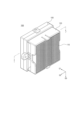
図1は、本出願の実施形態に係る脱臭モジュール100が流路10に設置された状態を簡略に示す図である。
FIG. 1 is a diagram schematically showing a state in which a
本出願の実施形態に係る脱臭モジュール100は、乾燥機能を提供する洗濯機又は乾燥機の流路10に設置され、乾燥動作時に熱風によって溶け出された臭い粒子を、光触媒反応を通じて効果的に除去することができる。
The
図1を参照すると、脱臭モジュール100は、光触媒フィルター110及び光源ユニット140を含む。
Referring to FIG. 1, the
光触媒フィルター110は流路10の内側に位置し、光触媒フィルター110には光触媒物質がコーティング又は吸着されている。光触媒フィルター110は、流路10に沿って流れる空気の進行方向に平行になるように配置され、その結果、空気は、光触媒フィルター110と広い面積にわたって接触し得る。
The
光源ユニット140は、流路10の外側に位置し、光触媒フィルター110に向かって光を照射する。例えば、光源ユニット140は、紫外線波長帯域の光を出射することができ、この場合、紫外線を出射する光源としてはLED(light emitting diode)発光素子が使用可能である。
The
本出願の実施形態において、光触媒フィルター110の光触媒物質は、光源ユニット140から照射される紫外線によって触媒反応を起こすことによって、光触媒と接触する空気内の各種汚染物質、特に臭い粒子を酸化及び還元して分解させることができる。
In the embodiment of the present application, the photocatalyst substance of the
より詳細に説明すると、一般的な洗濯機又は乾燥機で乾燥動作が行われる場合、熱風によって洗濯機又は乾燥機内の汚染物質から臭い粒子が溶け出し、このような活性化された臭い粒子が衣類に付着し、乾燥動作が完了した衣類に不快な臭いが残留する可能性がある。本出願の実施形態に係る脱臭モジュール100は、乾燥動作時に熱風によって活性化された臭い粒子を除去することによって、洗濯された衣類に不快な臭いが残留することを効果的に防止することができる。
More specifically, when a general washing machine or dryer performs a drying operation, hot air causes odor particles to dissolve from contaminants in the washing machine or dryer, and such activated odor particles are transferred to clothing. It may stick to the clothes and leave an unpleasant odor on the clothes after the drying operation is completed. The
また、本出願の実施形態に係る脱臭モジュール100は、流路10の内側に光触媒フィルター110を位置させ、流路10の外側に光源ユニット140を位置させる。これにより、流路10に沿って流れる空気に含まれた水分子が光源ユニット140に浸透することを抑制できるだけでなく、高温の気流によって光源ユニット140が損傷することが防止され得る。
Also, the
一方、本出願の実施形態に係る脱臭モジュール100は、透明部材130をさらに備えてもよい。透明部材130は、光源ユニット140から出射される光を透過する材質で形成される。透明部材130は、光源ユニット140と光触媒フィルター110との間に位置し、光源ユニット140と光触媒フィルター110とを互いに遮断する。これにより、流路10に沿って流れる高温の気流及び水分子が光触媒フィルター110を介して光源ユニット140に浸透することを遮断し、光源ユニット140が保護され得る。
Meanwhile, the
図2~図4は、図1の脱臭モジュール100をさらに詳細に示す図である。具体的に、図2及び図3は、それぞれ脱臭モジュール100の全体的な状態を示す斜視図及び分解斜視図で、図4は、図2の切取線(I-I’)に沿って切断された状態を示す断面図である。
2-4 are diagrams illustrating the
図2~図4を参照すると、脱臭モジュール100は、光触媒フィルター110、上部ハウジング120、透明部材130、光源ユニット140及び下部ハウジング150を含む。
2 to 4, the
光触媒フィルター110は、光触媒物質がコーティング又は吸着し得る材質で形成されてもよい。例えば、光触媒フィルター110は、多孔性のセラミック材質で形成されてもよい。他の例として、光触媒フィルター110は、紙材質、布材質及び/又はプラスチック材質で形成されてもよい。他の例として、光触媒フィルター110は、ニッケル(Ni)、鉄(Fe)、アルミニウム(Al)、クロム(Cr)、ステンレスなどを含む金属フォーム(foam)材質で形成されてもよい。
The
光触媒フィルター110の表面は光触媒物質でコーティングされてもよい。光触媒フィルター110の光触媒物質は、光源ユニット140から照射される紫外線によって触媒反応を起こすことによって、光触媒と接触する空気内の各種汚染物質及び臭い粒子などを酸化及び還元して分解させる。
The surface of the
より詳細に説明すると、光触媒は、バンドギャップ(band gap)エネルギー以上の光に露出されると、電子及び正孔が生成される触媒反応を起こす。これにより、空気内の化合物、例えば、水や有機物質が分解され、水酸基ラジカル(Hydroxy Radical)が形成され得る。水酸基ラジカルは、酸化力が非常に強い物質であって、空気内の汚染物質を分解したり、細菌を殺菌したりする。このような光触媒物質としては、酸化チタン(TiO2)、酸化亜鉛(ZnO)、酸化スズ(SnO2)などを挙げることができる。 In more detail, the photocatalyst causes a catalytic reaction in which electrons and holes are generated when exposed to light having a bandgap energy or higher. This can cause compounds in the air, such as water and organic matter, to decompose and form Hydroxy Radicals. Hydroxyl radicals are substances with very strong oxidizing power, and decompose pollutants in the air and kill bacteria. Titanium oxide (TiO 2 ), zinc oxide (ZnO), tin oxide (SnO 2 ), and the like can be given as such photocatalyst materials.
光触媒の表面で生成された正孔と電子は、再結合速度が非常に速いので、光化学反応に用いる際に限界を有する。よって、Pt、Ni、Mn、Ag、W、Cr、Mo、Znなどの金属又はそれらの酸化物を添加し、正孔と電子の再結合速度を遅延させることができる。正孔と電子の再結合速度が遅延される場合、酸化及び/又は分解させようとする対象物質との接触可能性が増加し、その結果、反応度が高くなり得る。また、光触媒物質のバンドギャップを制御することによって、光触媒の改善された活性も図ることができる。上述した光触媒反応を用いると、空気の殺菌、浄化、脱臭処理などを行うことができる。 Holes and electrons generated on the surface of the photocatalyst have a very high recombination rate, which limits their use in photochemical reactions. Therefore, by adding metals such as Pt, Ni, Mn, Ag, W, Cr, Mo, Zn, or oxides thereof, the recombination rate of holes and electrons can be delayed. If the recombination rate of holes and electrons is slowed, the possibility of contact with the target material to be oxidized and/or decomposed may increase, resulting in higher reactivity. Also, by controlling the bandgap of the photocatalyst material, improved activity of the photocatalyst can be achieved. By using the photocatalytic reaction described above, air can be sterilized, purified, deodorized, and the like.
上部ハウジング120は、第1方向D1から見ると、上面及び下面が開放され、側面の一部が開放された構造を有する。上部ハウジング120は、脱臭モジュール100の外観を形成する。また、上部ハウジング120は、光触媒フィルター110及び透明部材130が設置されるための空間が設けられる。
The
透明部材130は、上部ハウジング120に収納され、上部ハウジング120に対応する形状を有する。例えば、図2~図4に示したように、透明部材130が載置される上部ハウジング120の下面が四角形の開口部の形状である場合、透明部材130は、上部ハウジング120の下面の形状と同一に四角形状に形成されてもよい。但し、これは例示的なものであって、透明部材130の形状は、上部ハウジング120の形状に応じて多様に変形可能である。
The
透明部材130は、光触媒フィルター110と光源ユニット140との間に配置され、光触媒フィルター110と光源ユニット140とを互いに遮断する。例えば、図1に示したように、光触媒フィルター110が流路10内に位置する場合、光触媒フィルター110を介して高温の気流及び/又は水分子が光源ユニット140に浸透し得る。光触媒フィルター110を介して高温の気流及び/又は水分子が光源ユニット140に浸透することを防止するために、透明部材130は、光触媒フィルター110と光源ユニット140との間に配置されてもよく、その結果、光触媒フィルター110と光源ユニット140とが互いに遮断される。
The
続いて、図2~図4を参照すると、光源ユニット140は、下部ハウジング150内に配置され、光触媒フィルター110に向かって光を照射する。光源ユニット140から出射される光の波長帯域は、光触媒フィルター110に提供される光触媒物質に応じて変わり得る。
2 to 4, the
光源ユニット140は、光触媒物質によって波長帯域のうち一部のみを出射することができる。例えば、光源ユニット140は、紫外線波長帯域の光を出射することができ、この場合、光源ユニット140は、約100nm~約420nmの波長帯域の光を出射することができる。但し、これは例示的なものであって、光源ユニット140から出射される光の波長帯域を特に限定するのではない。
The
光を出射するために、光源ユニット140は、光を出射する少なくとも一つの光源を含んでもよい。光源は、光触媒物質と反応する波長帯域の光を出射するものであればさほど限定されない。例えば、光源ユニット140が紫外線波長帯域の光を出射する場合、紫外線を出射する多様な光源が使用可能である。紫外線を出射する光源としては、代表的にLED(light emitting diode)発光素子が使用可能である。光源ユニット140がそれ以外の波長帯域の光を出射する場合、公知の他の光源が使用可能であることは当然である。
To emit light, the
下部ハウジング150は、第1方向D1から見たとき、上面が開放され、下面にはホールが形成された構造を有する。下部ハウジング150は、上部ハウジング120と共に脱臭モジュール100の外観を形成する。また、下部ハウジング150は、光源ユニット140が収納される空間が設けられる。
The
図5及び図6は、図3の光触媒フィルター110をさらに詳細に示す図である。具体的に、図5は、図3の光触媒フィルター110の形状を示す正面図で、図6は、図3の光触媒フィルター110の他の実施形態を示す正面図である。
5 and 6 are diagrams showing the
まず、図5を参照すると、光触媒フィルター110は、複数の貫通ホール111を有するように形成されてもよい。この場合、複数の貫通ホール111のそれぞれは、図5に示したように、四角形の開口部の形態で形成されてもよい。また、複数の貫通ホール111は、格子構造のように規則的な配置を有するように形成されてもよい。但し、これは例示的なものであって、光触媒フィルター110の形状、大きさ、構造及び配置は多様に変更可能である。
First, referring to FIG. 5, the
例えば、図6aに示したように、光触媒フィルター110_1の各貫通ホール111_1は、円形の開口部の形態で形成されてもよい。この場合、各貫通ホール111_1は、円形の周囲に沿って外部圧力を均一に分散させるので、剛性が良好になるという長所を有する。 For example, as shown in FIG. 6a, each through hole 111_1 of the photocatalyst filter 110_1 may be formed in the form of a circular opening. In this case, each through-hole 111_1 has an advantage of good rigidity because the external pressure is uniformly distributed along the circumference of the circle.
一方、各貫通ホール111_1が円形の開口部の形態で形成された場合、同一の面積に可能な限り多くの貫通ホール111_1を形成することによって空気との接触面積を最大化するために、円形の各貫通ホール111_1は、図示したように、ジグザグ状に配置されてもよい。但し、これは例示的なものであって、円形の各貫通ホール111_1は、格子構造又は並列構造のように規則的に配置されてもよい。 On the other hand, when each through-hole 111_1 is formed in the form of a circular opening, the circular opening is formed in order to maximize the air contact area by forming as many through-holes 111_1 as possible in the same area. Each through-hole 111_1 may be arranged in a zigzag pattern as shown. However, this is an example, and the circular through holes 111_1 may be arranged regularly like a lattice structure or a parallel structure.
他の例として、図6b及び図6cに示したように、光触媒フィルター110_2、110_3は、複数のビーズを焼結して形成されてもよい。この場合、光触媒フィルター110_2、110_3の焼結された各ビーズ間には各ポア111_2~111_4が位置してもよい。 As another example, as shown in FIGS. 6b and 6c, the photocatalytic filters 110_2 and 110_3 may be formed by sintering a plurality of beads. In this case, pores 111_2 to 111_4 may be positioned between the sintered beads of the photocatalytic filters 110_2 and 110_3.
空気は、各ポア111_2~111_4を介して光触媒フィルター110_2、110_3の一側から他側に流動し得る。各ポア111_2~111_4の密度によって空気と光触媒フィルター110_2、110_3との接触面積が調節され得る。このために、光触媒フィルター110_2、110_3を形成する各ビーズの大きさ及び焼結工程での条件が調節可能であり、その結果、各ポア111_2~111_4は多様な大きさ及び分布を有し得る。 Air can flow from one side of the photocatalytic filters 110_2, 110_3 to the other side through each of the pores 111_2-111_4. The contact area between the air and the photocatalyst filters 110_2 and 110_3 can be adjusted according to the density of each pore 111_2-111_4. For this purpose, the size of each bead forming the photocatalyst filters 110_2 and 110_3 and the conditions in the sintering process can be adjusted, so that each pore 111_2-111_4 can have various sizes and distributions.
すなわち、各ポア111_2~111_4の大きさに対する配置は、空気の移動速度、光触媒との反応性などを考慮して多様な方式で設定可能である。例えば、後述する図16aのように、空気が光触媒フィルター110を垂直に貫通して流動する場合、空気が留まる時間を増加させるために、各ポア111_2~111_4の大きさ及び密度を順次減少させることができる。
In other words, the size and arrangement of the pores 111_2 to 111_4 can be set in various ways in consideration of air movement speed, reactivity with the photocatalyst, and the like. For example, as shown in FIG. 16a, which will be described later, when air flows vertically through the
一方、図6は、説明の便宜上、各ポアのうち一部に対してのみ示しており、その形態も球形として示した。しかし、実際の各ポアは、図示したものより高い密度で設けられてもよく、各ポアごとに大きさや形状の差があってもよい。 On the other hand, FIG. 6 shows only a part of each pore for convenience of explanation, and its shape is also shown as a sphere. However, each actual pore may be provided at a higher density than illustrated, and each pore may have a difference in size and shape.
図7は、図3の上部ハウジング120をさらに詳細に示す斜視図である。
FIG. 7 is a perspective view showing the
図7を参照すると、上部ハウジング120は、第1胴体部121と第2胴体部122とに区分されてもよい。
Referring to FIG. 7 , the
第1胴体部121は、第1方向D1から見たとき、上面及び下面が開放された構造を有する。第1胴体部121の開放された上面を介して光触媒フィルター110が収納され得る。第1胴体部121には、フィルター固定部121_1、フィルター載置部121_2、フィルター把持溝121_3、開口部121_4、リブ121_5などが形成されている。
The
フィルター固定部121_1は、第1胴体部121に収納された光触媒フィルター110が外部に脱出しないように固定させる役割をする。フィルター固定部121_1は、第1胴体部121の両側面に互いに対向して形成され、第1方向D1及び第3方向D3に沿って突出したフック状に形成される。但し、これは例示的なものであって、光触媒フィルター110を安定的に固定できるものであれば、フィルター固定部121_1の形状は特に制限されない。
The filter fixing part 121_1 serves to fix the
フィルター載置部121_2は、第1胴体部121に収納された光触媒フィルター110を支持する支持台としての役割をする。フィルター載置部121_2は、第1胴体部121の内側面の周囲に沿って形成される。但し、これは例示的なものであって、光触媒フィルター110を安定的に支持できるものであれば、フィルター載置部121_2の形状は特に制限されない。
The filter mounting part 121_2 functions as a support for supporting the
フィルター把持溝121_3は、光触媒フィルター110を装着又は交替するときに容易に把持できるように、第1胴体部121に収納された光触媒フィルター110の一部を外部に露出させる。フィルター把持溝121_3は、例えば、第1胴体部121の両側面に互いに対向して形成されてもよい。
The filter gripping groove 121_3 exposes a portion of the
開口部121_4は、第1胴体部121の下端、より具体的には、フィルター載置部121_2の下端に互いに対向して形成される。図2に示したように、光触媒フィルター110が収納された場合にも、開口部121_4は、光触媒フィルター110によって遮断されておらず、第2方向D2に貫通した構造を有する。
The openings 121_4 are formed to face each other at the lower end of the
一方、リブ121_5は、開口部121_4内に形成され、第1胴体部121を支持する役割をする。図7には、3個のリブ121_5が形成された様子が示されているが、第1胴体部121を安定的に支持できる限り、リブ121_5の個数は特に制限されない。
Meanwhile, the rib 121_5 is formed in the opening 121_4 and serves to support the
続いて、図7を参照すると、第2胴体部122は、第1方向D1から見たとき、上面及び下面が開放された構造を有する。第2胴体部122の開放された下面を介して透明部材130が収納され得る。
Subsequently, referring to FIG. 7, the
第2胴体部122の第2方向D2及び第3方向D3への長さは、第1胴体部121より長くなるように形成されてもよい。これにより、第2胴体部122に挿入される透明部材130の第2方向D2及び第3方向D3への長さは、第1胴体部121に挿入される光触媒フィルター110より長くてもよい。よって、第2胴体部122に収納される透明部材130の大きさは、第1胴体部121に収納される光触媒フィルター110より大きくてもよく、その結果、水分子が光触媒フィルター110を介して光源ユニット140に浸透することをさらに完璧に遮断することができる。
The lengths of the
第2胴体部122には、スペーサー122_1、ハウジング締結部122_2及び流路締結部122_3が形成されている。
A spacer 122_1, a housing fastening portion 122_2, and a channel fastening portion 122_3 are formed in the
スペーサー122_1は、段部から第1方向D1に突出して形成される。第2胴体部122の下面を介して収納された透明部材130はスペーサー122_1と接触し、透明部材130は、スペーサー122_1によって段部から一定距離だけ離隔する。
The spacer 122_1 protrudes from the stepped portion in the first direction D1. The
ハウジング締結部122_2は、第1方向D1に延長されて形成され、上部ハウジング120と下部ハウジング150とを互いに締結する役割をする。例えば、図7に示したように、ハウジング締結部122_2は、第2胴体部122の両側面で互いに対向して形成されてもよい。また、ハウジング締結部122_2は、例えば、その中央に締結ホールを含むように形成されてもよい。
The housing fastening part 122_2 extends in the first direction D1 and serves to fasten the
流路締結部122_3は、第2方向D2に突出した構造で形成される。例えば、図7に示したように、流路締結部122_3は、第2胴体部122の両側面で互いに対向して形成されてもよい。
The channel fastening part 122_3 is formed to have a structure protruding in the second direction D2. For example, as shown in FIG. 7 , the flow passage coupling portions 122_3 may be formed on both side surfaces of the
図8は、図3の下部ハウジング150をさらに詳細に示す斜視図である。
FIG. 8 is a perspective view showing the
図8を参照すると、下部ハウジング150は、上面が開放された第3胴体部151を含み、第3胴体部151には、開放された上面を介して光源ユニット140が収納される。第3胴体部151には、段部152、スペーサー153、固定突起154、基板固定部155、放熱ホール156、引き出しホール157及びハウジング締結突起158が形成されている。
Referring to FIG. 8, the
スペーサー153は、第1方向D1に突出して形成される。スペーサー153は、上部ハウジング120のスペーサー122_1と共に透明部材130に接触する。下部ハウジング150と上部ハウジング120とを締結する場合、下部ハウジング150のスペーサー153と上部ハウジング120のスペーサー122_1とが互いに向かい合った状態で透明部材130に向かって互いに圧力を加えるようになり、その結果、透明部材130は安定的に固定されるようになる。
The
固定突起154は、第1方向D1に突出して形成され、光源ユニット140の固定溝144(図9参照)に対応する形態を有するように形成される。固定突起154が光源ユニット140の固定溝144に結合されることによって、光源ユニット140が下部ハウジング150に安定的に固定され得る。
The fixing
一方、図7には、固定突起154が2個形成された様子が示されている。但し、これは例示的なものであって、光源ユニット140を安定的に固定させることができれば、固定突起154の個数は特に制限されない。
On the other hand, FIG. 7 shows a state in which two fixing
基板固定部155は、第1方向D1及び第2方向D2に突出して形成される。基板固定部155は、光源ユニット140の基板141(図9参照)を固定させる役割をする。図7には、基板固定部155が2個形成されたことが示されているが、光源ユニット140の基板141を安定的に固定できる限り、基板固定部155の個数は特に制限されない。
The
放熱ホール156は、脱臭モジュール100の動作時に光源ユニット140で発生した熱が外部に放出される通路としての役割をする。放熱ホール156は、第1方向から見たとき、下部ハウジング150の下面が開口された形態で形成される。放熱ホール156は、例えば、光源ユニット140の基板141に対応する位置に形成されてもよく、基板141に対応する形態を有してもよい。但し、これは例示的なものであって、光源ユニット140で発生した熱を外部に放出できる限り、放熱ホール156の形態及び形成位置は特に制限されない。
The
引き出しホール157は、光源ユニット140のコネクター143に接続された電線を外部に引き出す通路としての役割をする。引き出しホール157は、例えば、第1方向から見たとき、下部ハウジング150の下面が開口された形態で形成されてもよいが、これに限定されない。
The
ハウジング締結突起158は、第3方向D3に突出して形成される。ハウジング締結突起158は、上部ハウジング120のハウジング締結部122_2と結合され、下部ハウジング150と上部ハウジング120とを互いに締結する。
The
図9~図10は、光源ユニット140をさらに詳細に説明するための図である。具体的に、図9は、基板141に光源142が装着された状態をさらに詳細に示す図で、図10a及び図10bは、光源142の構造をさらに詳細に示す断面図である。
9 and 10 are diagrams for explaining the
まず、図9を参照すると、光源ユニット140は、基板141、光源142、コネクター143、固定溝144及び放熱ホール145を含む。
First, referring to FIG. 9 , the
基板141の上面には光源142が実装される。基板141の一側には、光源142に電源を供給するためのコネクター143が形成される。基板141の両側には、基板141を下部ハウジング150に固定させるときに固定突起154(図8参照)を通過させるための固定溝144が形成される。
A
基板141の中央には、熱を外部に放出するための放熱ホール145が形成される。基板141は、例えば、放熱基板であってもよいが、これに限定されるのではない。他の例として、基板141はプリント回路基板であってもよい。
A
光源142は、基板141の上面に実装され、光触媒フィルター110に向かって光を放出する。図9には、例示的に、基板141の上面に三つの光源142が実装されることが示されているが、光源142の個数はこれに限定されない。例えば、基板141の上面には一つの光源が実装されてもよい。
The
光源ユニット140が複数の光源142を含む場合、各光源は、同一の波長帯域の光を出射したり、互いに異なる波長帯域の光を出射することができる。例えば、各光源は、全ての紫外線波長帯域の光を出射することができる。他の例として、一部の光源は、紫外線波長帯域のうち一部を出射し、残りの光源は、紫外線波長帯域のうち他の波長帯域の一部を出射することができる。
When the
各光源が互いに異なる波長帯域を有する場合、各光源は、多様な順序で配列され得る。例えば、第1波長帯域の光を出射する光源を第1光源とし、第1波長帯域と異なる第2波長帯域の光を出射する光源を第2光源としたとき、第1光源と第2光源とが交互に配列されてもよい。 If the light sources have different wavelength bands, the light sources may be arranged in various orders. For example, when a light source that emits light in a first wavelength band is a first light source and a light source that emits light in a second wavelength band different from the first wavelength band is a second light source, the first light source and the second light source may be alternately arranged.
一方、図9には、光源142が、内部のチップを保護するレンズを含むものとして示されている。但し、これは例示的なものであって、本出願の技術的思想はこれに限定されない。例えば、光源142は、レンズを備えなくてもよく、他の例として、基板141に実装された複数の光源142のうち一部はレンズを備えて、他の一部はレンズを備えなくてもよい。
On the other hand, FIG. 9 shows the
図10aには、本出願の一実施形態に係る光源142に使用されるチップの断面が示されており、図10bには、図10の切取線A-B-B’-A’に沿って切り取られた断面図が示されている。図10a及び図10bを参照すると、本出願の一実施形態に係る光源142は、第1導電型半導体層1111、活性層1112及び第2導電型半導体層1113を含むメサM、第1絶縁層1130、第1電極1140、及び第2絶縁層1150を含んでもよく、さらに、成長基板1110及び第2電極1120を含んでもよい。
FIG. 10a shows a cross-section of a chip used in a
成長基板1110は、第1導電型半導体層1111、活性層1112、及び第2導電型半導体層1113を成長できる基板であれば限定されなく、例えば、サファイア基板、シリコンカーバイド基板、窒化ガリウム基板、窒化アルミニウム基板、シリコン基板などであってもよい。成長基板1110の側面は傾斜面を含んでもよく、その結果、活性層1112で生成された光の抽出が改善され得る。
The
第2導電型半導体層1113は、第1導電型半導体層1111上に配置されてもよく、活性層1112は、第1導電型半導体層1111と第2導電型半導体層1113との間に配置されてもよい。第1導電型半導体層1111、活性層1112、及び第2導電型半導体層1113はIII-V系化合物半導体を含んでもよく、例えば、(Al,Ga,In)Nなどの窒化物系半導体を含んでもよい。第1導電型半導体層1111はn型不純物(例えば、Si)を含んでもよく、第2導電型半導体層1113はp型不純物(例えば、Mg)を含んでもよい。また、その反対であってもよい。活性層1112は、多重量子井戸構造(MQM)を含んでもよい。光源142に順方向バイアスが加えられると、活性層1112で電子と正孔とが結合されながら光を放出するようになる。第1導電型半導体層1111、活性層1112、及び第2導電型半導体層1113は、金属有機化学気相蒸着(MOCVD)又は分子線エピタキシー(MBE)などの技術を用いて成長基板1110上に成長されてもよい。
The second conductivity
光源142は、活性層1112及び第2導電型半導体層1113を含む少なくとも一つのメサMを含んでもよい。メサMは、複数の突出部を含んでもよく、複数の突出部は互いに離隔してもよい。これに限定されることなく、光源142は、互いに離隔した複数のメサMを含んでもよい。メサMの側面は、フォトレジストリフローなどの技術を用いて傾斜するように形成されてもよく、傾斜したメサMの側面は、活性層1112で生成された発光効率を向上させることができる。
The
第1導電型半導体層1111は、メサMを介して露出する第1コンタクト領域R1及び第2コンタクト領域R2を含んでもよい。メサMは、第1導電型半導体層1111上に配置された活性層1112及び第2導電型半導体層1113を除去して形成するので、メサMを除いた部分は、第1導電型半導体層1111の露出した上面であるコンタクト領域になる。第1電極1140は、第1コンタクト領域R1及び第2コンタクト領域R2と接することによって第1導電型半導体層1111と電気的に接続され得る。第1コンタクト領域R1は、第1導電型半導体層1111の外郭に沿ってメサMの周囲に配置されてもよく、具体的には、メサMと光源142の側面との間で第1導電型半導体層の上面外郭に沿って配置されてもよい。第2コンタクト領域R2は、メサMによって少なくとも部分的に取り囲まれてもよい。
The first
第2コンタクト領域R2の長軸方向の長さは、光源142の一辺の長さの0.5倍以上であってもよい。この場合、第1電極1140と第1導電型半導体層1111とが接する領域が増加し得るので、第1電極1140から第1導電型半導体層1111に流れる電流がさらに効果的に分散可能であり、その結果、順方向電圧がさらに減少し得る。
The length in the longitudinal direction of the second contact region R2 may be 0.5 times or more the length of one side of the
第2電極1120は、第2導電型半導体層1113上に配置され、第2導電型半導体層1113と電気的に接続され得る。第2電極1120は、メサM上に形成され、メサMの形状に沿って同一の形状を有してもよい。第2電極1120は、反射金属層1121を含み、さらに、障壁金属層1122を含んでもよく、障壁金属層1122は、反射金属層1121の上面及び側面を覆うことができる。例えば、反射金属層1121のパターンを形成し、その上に障壁金属層1122を形成することによって、障壁金属層1122が反射金属層1121の上面及び側面を覆うように形成されてもよい。例えば、反射金属層1121は、Ag、Ag合金、Ni/Ag、NiZn/Ag、TiO/Ag層を蒸着及びパターニングして形成されてもよい。
The
一方、障壁金属層1122は、Ni、Cr、Ti、Pt、Au又はその複合層で形成されてもよく、具体的には、第2導電型半導体層1113の上面に順次Ni/Ag/[Ni/Ti]2/Au/Tiで形成された複合層であってもよく、さらに具体的には、第2電極1120の上面の少なくとも一部は300Å厚のTi層を含んでもよい。第2電極1120の上面のうち第1絶縁層と接する領域がTi層からなる場合、第1絶縁層1130と第2電極1120との接着力が改善され、光源142の信頼性が改善され得る。
Meanwhile, the
第2電極1120上に電極保護層1160が配置されてもよく、電極保護層1160は、第1電極1140と同一の材料であってもよいが、これに限定されるものではない。
An
第1絶縁層1130は、第1電極1140とメサMとの間に配置されてもよい。第1絶縁層1130を介して、第1電極1140とメサMとが絶縁されてもよく、第1電極1140と第2電極1120とが絶縁されてもよい。第1絶縁層1130は、第1コンタクト領域R1及び第2コンタクト領域R2を部分的に露出させることができる。具体的に、第1絶縁層1130は、開口部1130aを介して第2コンタクト領域R2の一部を露出させることができ、第1絶縁層1130が第1導電型半導体層1111の外郭とメサMとの間で第1コンタクト領域R1の一部の領域のみを覆い、第1コンタクト領域R1の少なくとも一部が露出してもよい。
A first insulating
第1絶縁層1130が第2コンタクト領域R2上で第2コンタクト領域R2の外郭に沿って配置されてもよい。これと同時に、第1絶縁層1130は、第1コンタクト領域R1と第1電極1140とが接する領域よりメサMに隣接するように限定されて配置されてもよい。
A first insulating
第1絶縁層1130は、第2電極1120を露出させる開口部1130bを有してもよい。開口部1130bを介して、第2電極1120はパッド又はバンプなどと電気的に接続され得る。
The first insulating
第1コンタクト領域R1と第1電極1140とが接する領域が第1導電型半導体層の上面の全外郭に沿って配置される。具体的に、第1コンタクト領域R1と第1電極1140とが接する領域は、第1導電型半導体層1111の四つの側面と全て隣接するように配置されてもよく、メサMを完全に取り囲んでもよい。この場合、第1電極1140と第1導電型半導体層1111とが接する領域が増加し得るので、第1電極1140から第1導電型半導体層1111に流れる電流がさらに効果的に分散可能であり、その結果、順方向電圧がさらに減少し得る。
A region where the first contact region R1 and the
本出願の一実施形態において、光源142の第1電極1140及び第2電極1120は、直接或いはパッドを介して基板141に実装されてもよい。
In one embodiment of the present application, the
例えば、光源142がパッドを介して基板141に実装される場合、光源142と基板141との間に配置された二つのパッドが提供されてもよく、二つのパッドのそれぞれは第1電極1140及び第2電極1120に接してもよい。例えば、パッドは、ソルダー又は共晶金属(Eutectic Metal)であってもよいが、これに限定されるものではない。例えば、共晶金属としてAuSnが使用可能である。
For example, when the
他の例として、光源142が基板141に直接実装される場合、光源142の第1電極1140及び第2電極1120が基板141上の配線に直接ボンディングされてもよい。この場合、ボンディング物質は、導電性質を有する接着物質を含んでもよい。例えば、ボンディング物質は、銀(Ag)、スズ(Sn)、及び銅(Cu)のうち少なくともいずれか一つの導電性材料を含んでもよい。但し、これは例示的なものであって、ボンディング物質は、導電性を有する多様な物質を含み得る。
As another example, when the
図1~図10を参照して説明したように、本出願の実施形態に係る脱臭モジュール100は、洗濯機、ドラム洗濯機又は乾燥機の流路10に設置されてもよく、光触媒反応を通じて効果的に脱臭動作を行うことができる。
As described with reference to FIGS. 1 to 10, the
一方、図1~図10に示した脱臭モジュール100の構造は例示的なものであって、本出願の技術的思想はこれに限定されない。例えば、本出願の技術的思想による脱臭モジュール100は、多様に変更及び応用され、流路10に設置されてもよい。以下では、本出願の多様な実施形態に係る脱臭モジュールの適用例及び応用例をさらに詳細に説明する。
On the other hand, the structure of the
図11は、本出願の他の実施形態に係る脱臭モジュール100_1を示す側面図で、図12は、図11の脱臭モジュール100_1が流路10に設置された状態を示す断面図である。 FIG. 11 is a side view showing a deodorizing module 100_1 according to another embodiment of the present application, and FIG. 12 is a sectional view showing the deodorizing module 100_1 of FIG.
図11及び図12の脱臭モジュール100_1は、図1~図10の脱臭モジュール100と類似している。よって、同一又は類似する構成要素は、同一又は類似する参照番号を用いて表記されており、重複する説明は、簡略な説明のために以下で省略する場合がある。
The deodorizing module 100_1 of FIGS. 11 and 12 is similar to the
図11の脱臭モジュール100_1は、図1~図10の脱臭モジュール100に比べてより大きい開口部121_4aを有するように形成される。また、図11の脱臭モジュール100_1のリブ121_5aの長さAは、図1~図10の脱臭モジュール100のリブ121_5に比べてより長い長さを有するように形成される。例えば、リブ121_5aの長さは、流路10の内側面12の直径の1/4以上、3/4以下であってもよい。
The deodorizing module 100_1 of FIG. 11 is formed to have a larger opening 121_4a than the
この場合、図12に示したように、脱臭モジュール100_1の光触媒フィルター110は流路10の中央に位置してもよい。すなわち、図1に示した脱臭モジュール100の光触媒フィルター110が流路10の内側面12に隣接するように位置する一方で、図12に示した脱臭モジュール100_1の光触媒フィルター110は、流路10の内側面12から所定距離だけ離隔して位置する。
In this case, as shown in FIG. 12, the
このとき、脱臭モジュール100_1の各開口部121_4aが空気の移動通路を形成するので、流路10内の空気は、光触媒フィルター110の両側面に接触しながら流れ得る。結局、流路10内の空気が光触媒フィルター110と接触する面積が増加するので、脱臭効率が増加し得る。
At this time, since each opening 121_4a of the deodorizing module 100_1 forms an air movement passage, the air in the
図13は、本出願の他の実施形態に係る脱臭モジュール100_2を示す図である。具体的に、図13aは、放熱部材160を備えた脱臭モジュール100_2の一例を示す図で、図13bは、放熱基板141_1を備えた脱臭モジュール100_2の一例を示す図である。
FIG. 13 is a diagram showing a deodorizing module 100_2 according to another embodiment of the present application. Specifically, FIG. 13a is a diagram showing an example of the deodorizing module 100_2 provided with the
図13の脱臭モジュール100_2は、図1~図10の脱臭モジュール100と類似している。よって、同一又は類似する構成要素は、同一又は類似する参照番号を用いて表記されており、重複する説明は、簡略な説明のために以下で省略する場合がある。
The deodorizing module 100_2 of FIG. 13 is similar to the
図13の脱臭モジュール100_2は、図1~図10の脱臭モジュール100に比べて、光源ユニット140で発生した熱を放出するための放熱構造をさらに備える。
The deodorizing module 100_2 of FIG. 13 further includes a heat dissipation structure for dissipating heat generated by the
例えば、図13aに示したように、脱臭モジュール100_2は、光源ユニット140の熱を外部に放出する放熱部材160をさらに含んでもよい。放熱部材160は、例えば、導電性材料で形成された導電板であってもよく、光源ユニット140の熱を分散して外部に放出する役割をすることができる。
For example, as shown in FIG. 13a, the deodorizing module 100_2 may further include a
他の例として、図13bに示したように、脱臭モジュール100_2の光源ユニット140は放熱基板141_1を備えてもよい。すなわち、脱臭モジュール100_2の各光源142は放熱基板141_1上に実装されてもよい。
As another example, as shown in FIG. 13b, the
放熱基板141_1は、例えば、セラミック材質の上部絶縁基板1411及び下部絶縁基板1412を含んでもよい。上部絶縁基板1411と下部絶縁基板1412は上下に積層されてもよく、前記各絶縁基板の積層には接着物質が用いられてもよい。上部絶縁基板1411の上面には上部導電パターン1413が形成され、下部絶縁基板1412の下面には下部導電パターン1415が形成されてもよい。また、上部絶縁基板1411と下部絶縁基板1412との間には中間導電パターン1414が形成されてもよい。上部導電パターン1413、中間導電パターン1414及び下部導電パターン1415は、Au又はAgなどの金属を材質にして形成されてもよい。
The heat dissipation substrate 141_1 may include, for example, an upper insulating
図13に示したように、脱臭モジュール100_2が放熱構造をさらに備えることによって、光源ユニット140の作動による温度増加又は流路10内の熱風による温度増加から光源ユニット140を保護することができる。
As shown in FIG. 13 , the deodorizing module 100_2 further includes a heat dissipation structure, so that the
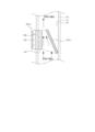
図14及び図15は、本出願の他の実施形態に係る脱臭モジュール100_3、100_4を示す図である。具体的に、図14は、反射板170を含む脱臭モジュール100_3の一実施形態を示す図で、図15は、反射物質がコーティングされた流路ガイド170_1を含む脱臭モジュール100_4の一実施形態を示す図である。
14 and 15 are diagrams showing deodorizing modules 100_3 and 100_4 according to other embodiments of the present application. Specifically, FIG. 14 illustrates an embodiment of a deodorizing module 100_3 including a
図14及び図15の脱臭モジュール100_3、100_4は、図1~図10の脱臭モジュール100と類似している。よって、同一又は類似する構成要素は、同一又は類似する参照番号を用いて表記されており、重複する説明は、簡略な説明のために以下で省略する場合がある。
The deodorizing modules 100_3 and 100_4 of FIGS. 14 and 15 are similar to the
まず、図14を参照すると、脱臭モジュール100_3は、光源ユニット140から出射された紫外線を反射するための反射板170をさらに含む。反射板170は、例えば、反射率が高い物質(例えば、ステンレス、アルミニウム、酸化マグネシウム、テフロン(登録商標)など)で形成されてもよい。他の例として、反射板170は、流路10の内側面12に反射率が高い物質をコーティングすることによって形成されてもよい。
First, referring to FIG. 14, the deodorizing module 100_3 further includes a
反射板170は、光源ユニット140から出射された紫外線を反射させて光触媒フィルター110に向かわせる。よって、紫外線が流路10の内側面12にぶつかって損失することを防止し、脱臭モジュール100の脱臭効率を高めることができる。
The
図15を参照すると、脱臭モジュール100_4は、流路10内の空気を光触媒フィルター110の方向に誘導する流路ガイド170_1を備えており、前記流路ガイド170_1の一方の面に反射物質がコーティングされてもよい。すなわち、図15に示したように、流路ガイド170_1は、光触媒フィルター110の方向に対して所定角度だけ傾斜して配置され、流路10内の空気を光触媒フィルター110の方向に誘導し、光触媒フィルター110に向かい合う流路ガイド170_1の一方の面には反射物質がコーティングされてもよい。この場合、流路ガイド170_1は、光源ユニット140から出射された紫外線を反射させるだけでなく、流路10内の空気を光触媒フィルター110の方向に誘導する。したがって、さらに多くの空気が光触媒フィルター110と接触することによって、脱臭モジュール100_4の脱臭効率が増加し得る。
Referring to FIG. 15, the deodorizing module 100_4 includes a channel guide 170_1 that guides the air in the
さらに、流路ガイド170_1が図15のように光触媒フィルター110の方向に対して所定角度だけ傾斜して配置された場合、空気が流入する開口部121_5bの面積は、空気が吐出される開口部121_5cの面積より大きく、その結果、光触媒フィルター110に誘導された空気が留まる時間が増加する。よって、空気と光触媒フィルター110の反応時間が増加し、脱臭モジュール100_4の脱臭効率がさらに増加し得る。
Further, when the flow path guide 170_1 is arranged at a predetermined angle with respect to the direction of the
一方、図15において、脱臭モジュール100_4は、反射物質がコーティングされた流路ガイド170_1を備えることを説明している。但し、これは例示的なものであって、本出願の技術的思想はこれに限定されない。例えば、脱臭モジュール100_4は、反射物質がコーティングされた流路ガイドの代わりに反射板を備えてもよく、この場合、反射板が流路ガイドとしての役割をすることもできる。 On the other hand, FIG. 15 illustrates that the deodorizing module 100_4 includes a flow path guide 170_1 coated with a reflective material. However, this is an example, and the technical idea of the present application is not limited to this. For example, the deodorizing module 100_4 may include a reflector instead of a flow guide coated with a reflective material, and in this case, the reflector may serve as a flow guide.
図16a~図16dは、本出願の他の実施形態に係る脱臭モジュール100_5~100_8を示す図である。図16a~図16dの脱臭モジュール100_5~100_8は、図1~図10の脱臭モジュール100と類似している。よって、同一又は類似する構成要素は、同一又は類似する参照番号を用いて表記されており、重複する説明は、簡略な説明のために以下で省略する場合がある。
Figures 16a-16d are diagrams showing deodorizing modules 100_5-100_8 according to other embodiments of the present application. The deodorizing modules 100_5-100_8 of FIGS. 16a-16d are similar to the
まず、図16aを参照すると、脱臭モジュール100_5は、光触媒フィルター110_1を備えており、光触媒フィルター110_1は、空気の流動方向に垂直に配置される。この場合、流路10内の空気は、いずれも光触媒フィルター110_1に形成された各貫通ホールを通過して流れ、その結果、光触媒フィルター110_1と接触する空気の量が増加するという長所がある。
First, referring to FIG. 16a, the deodorizing module 100_5 is equipped with a photocatalytic filter 110_1, and the photocatalytic filter 110_1 is arranged perpendicular to the air flow direction. In this case, the air in the
図16bを参照すると、脱臭モジュール100_6の光触媒フィルター110_2は、空気の流動方向に対して所定角度だけ傾斜して配置されてもよい。例えば、光触媒フィルター110_2の傾斜した角度は、光源ユニット140から出射される光の指向角を考慮して設定されてもよい。この場合、流路10内の空気がいずれも光触媒フィルター110_2を通過するだけでなく、光触媒フィルター110_2に十分な量の光が照射され、脱臭モジュール100_6の脱臭効率が増加し得る。
Referring to FIG. 16b, the photocatalyst filter 110_2 of the deodorizing module 100_6 may be inclined at a predetermined angle with respect to the air flow direction. For example, the tilted angle of the photocatalyst filter 110_2 may be set in consideration of the directivity angle of the light emitted from the
図16cを参照すると、脱臭モジュール100_7の光触媒フィルター110_3が空気の流動方向に対して所定角度だけ傾斜して配置され、光源ユニット140_1は、光触媒フィルター110_3に平行に配置されてもよい。この場合、光触媒フィルター110_3にさらに多くの量の光が照射され、脱臭モジュール100_7の脱臭効率がさらに増加し得る。 Referring to FIG. 16c, the photocatalyst filter 110_3 of the deodorizing module 100_7 may be inclined at a predetermined angle with respect to the air flow direction, and the light source unit 140_1 may be arranged parallel to the photocatalyst filter 110_3. In this case, the photocatalyst filter 110_3 is irradiated with a larger amount of light, and the deodorizing efficiency of the deodorizing module 100_7 can be further increased.
図16dを参照すると、脱臭モジュール100_8は光触媒フィルター110_4を備えており、光触媒フィルター110_4は、その断面が半円状を有するように形成されてもよい。例えば、光触媒フィルター110_4は、紙材質、ファブリック材質又は金属フォームを材質にし、その断面が半円状を有するように形成されてもよい。この場合、光触媒フィルター110_1と接触する空気の量が増加し、脱臭モジュール100_8の脱臭効率が増加し得る。 Referring to FIG. 16d, the deodorizing module 100_8 includes a photocatalyst filter 110_4, and the photocatalyst filter 110_4 may be formed to have a semicircular cross section. For example, the photocatalyst filter 110_4 may be made of paper, fabric, or metal foam, and may have a semicircular cross section. In this case, the amount of air contacting the photocatalyst filter 110_1 increases, and the deodorizing efficiency of the deodorizing module 100_8 can increase.
図17は、本出願の実施形態に係る脱臭モジュール100が洗濯機1000に設置された一例を簡略に示す断面図である。
FIG. 17 is a cross-sectional view schematically showing an example in which the
図17を参照すると、乾燥機能をサポートする洗濯機1000が提供される。洗濯機1000としては、説明の便宜上、ドラム洗濯機が例示的に示されている。但し、これは例示的なものであって、一般の洗濯機、乾燥機などが提供されてもよい。
Referring to FIG. 17, a
洗濯機1000は、洗濯水が貯蔵されるタブ1100と、タブ1100の内側に回転可能に設置され、その内部に洗濯物が投入されるドラム1200と、前記ドラム1200を遮蔽するドア1300と、前記ドラムを回転させる駆動モーター1400と、前記ドラム1200の内部に供給される空気を加熱する乾燥ヒーター1500と、前記乾燥ヒーター1500によって加熱された熱風をドラム1200の内部に供給する流路10と、前記乾燥ヒーター1500によって加熱された熱風をドラム1200の内部に強制的に送風する送風ファン1600と、洗濯水を外部に導出する洗濯水吐出部1700とを含む。流路10の熱風吐出口10aはドラム1200の前方に位置し、流路10の湿り空気回収口10bはドラム1200の後方に位置する。
The
本出願の実施形態に係る脱臭モジュール100は流路10に設置される。この場合、脱臭モジュール100は、洗濯水が光源ユニット140に侵入することを防止するために、少なくとも洗濯水吐出部1700より高い位置に設置されることが好ましい。
A
また、脱臭モジュール100は、図17に示したように、乾燥ヒーター1500の後方に設置されてもよいが、これに限定されるのではない。他の例として、脱臭モジュール100は、乾燥ヒーター1500の前方に設置されてもよい。このように、脱臭モジュール100を、乾燥機能をサポートする洗濯機1000の流路10内に設置することによって、洗濯及び乾燥した衣類に対して脱臭動作を行うことができる。
Also, the
図18は、本出願の実施形態に係る脱臭モジュール100の効果を示す実験結果である。
FIG. 18 shows experimental results showing the effect of the
まず、図18に示したように、本出願の実施形態に係る脱臭モジュール100を備えたときに脱臭効果が増加することを確認することができる。
First, as shown in FIG. 18, it can be confirmed that the deodorizing effect increases when the
一方、乾燥ヒーター1500と脱臭モジュール100を同時に駆動したときに脱臭効率が最も良いことを確認することができる。よって、脱臭モジュール100と乾燥ヒーター1500が同時に駆動するように洗濯機1000を制御することが好ましい。
On the other hand, when the drying
但し、この場合、熱風によって脱臭モジュール100の光源ユニット140が損傷するおそれがある。よって、脱臭モジュール100が追加的な放熱構造(図13a及び図13bを参照)を備えるときにのみ、脱臭モジュール100と乾燥ヒーター1500を同時に駆動するように洗濯機1000を制御することもできる。すなわち、例えば、脱臭モジュール100が追加的な放熱構造を備えていない場合、乾燥ヒーター1500による乾燥動作が行われた後で脱臭モジュール100による脱臭動作が行われるように洗濯機1000を制御することもできる。
However, in this case, the hot air may damage the
以上のように、本発明に対して例示した図面を参照して説明したが、本明細書に開示した実施例及び図面によって本発明が限定されることはなく、本発明の技術思想の範囲内で通常の技術者によって多様な変形が可能であることは自明である。併せて、上述した本発明の実施形態を説明しながら本発明の構成による作用効果を明示的に記載して説明していないとしても、該当の構成によって予測可能な効果も認められるべきであることは当然である。
As described above, the present invention has been described with reference to the illustrated drawings, but the present invention is not limited by the embodiments and drawings disclosed in this specification, and is within the scope of the technical concept of the present invention. It is self-evident that various modifications are possible by ordinary engineers. In addition, even if the effects of the configuration of the present invention are not explicitly described and explained while describing the above-described embodiments of the present invention, the predictable effects of the configuration should also be recognized. is a matter of course.
Claims (19)
上面及び下面が開放された上部ハウジングと、
前記上部ハウジングと締結される下部ハウジングと、
前記流路の内側に位置し、前記上部ハウジングの開放された上面を介して前記上部ハウジングに収納される光触媒フィルターと、
前記流路の外側に位置し、前記光触媒フィルターに向かって紫外線を照射する少なくとも一つの光源、及び前記少なくとも一つの光源を実装する基板を含む光源ユニットと、
前記光触媒フィルターと前記光源ユニットとの間に位置し、前記上部ハウジングの開放された下面を介して前記上部ハウジングに収納される透明部材と、を含み、
前記上部ハウジングは、
前記開放された上面を介して前記光触媒フィルターが収納される胴体部と、
前記胴体部に収納された前記光触媒フィルターの一部を外部に露出させるフィルター把持溝と、
前記胴体部の下端に、前記上部ハウジングの内部を露出させる少なくとも一つの開口部と、
前記少なくとも一つの開口部との間に形成され、前記フィルター把持溝の下部に設けられた少なくとも一つのリブと、を含む、脱臭モジュール。 In the deodorizing module installed in the flow path,
an upper housing having open upper and lower surfaces;
a lower housing coupled to the upper housing;
a photocatalyst filter positioned inside the channel and accommodated in the upper housing through the open upper surface of the upper housing;
a light source unit positioned outside the channel and including at least one light source that irradiates ultraviolet light toward the photocatalyst filter and a substrate on which the at least one light source is mounted;
a transparent member positioned between the photocatalyst filter and the light source unit and accommodated in the upper housing through the open lower surface of the upper housing ;
The upper housing is
a body portion in which the photocatalyst filter is accommodated through the opened upper surface;
a filter holding groove that exposes a part of the photocatalyst filter housed in the body;
at least one opening exposing the interior of the upper housing at the lower end of the body;
and at least one rib formed between the at least one opening and provided below the filter gripping groove.
前記光源ユニットは、前記下部ハウジングの開放された上面を介して前記下部ハウジングに収納される、請求項1に記載の脱臭モジュール。 The top surface of the lower housing is open,
2. The deodorizing module according to claim 1, wherein said light source unit is housed in said lower housing via an open upper surface of said lower housing.
前記上部ハウジングの上部に突出して形成され、前記光触媒フィルターの一方の面を固定するフィルター固定部と、
前記上部ハウジングの内側面に沿って突出して形成され、前記光触媒フィルターの他面が載置されるフィルター載置部と、を含む、請求項1に記載の脱臭モジュール。 The upper housing is
a filter fixing part that protrudes from the upper part of the upper housing and fixes one surface of the photocatalyst filter;
2. The deodorizing module according to claim 1, further comprising a filter mounting portion protruding along the inner surface of the upper housing and on which the other surface of the photocatalyst filter is mounted.
前記少なくとも一つの開口部の下端に突出して形成され、前記透明部材の一方の面と接触したスペーサーをさらに含む、請求項1に記載の脱臭モジュール。 The upper housing is
The deodorizing module of claim 1 , further comprising a spacer protruding from a lower end of the at least one opening and in contact with one surface of the transparent member.
前記下部ハウジングの上端に突出し、前記透明部材の他方の面と接触したスペーサーを含む、請求項2に記載の脱臭モジュール。 The lower housing is
3. The deodorizing module according to claim 2, further comprising a spacer protruding from the upper end of said lower housing and in contact with the other surface of said transparent member.
前記下部ハウジングの下面に突出して形成され、前記光源ユニットを固定する少なくとも一つの固定突起をさらに含む、請求項5に記載の脱臭モジュール。 The lower housing is
6. The deodorizing module of claim 5 , further comprising at least one fixing protrusion projecting from the lower surface of the lower housing and fixing the light source unit.
前記下部ハウジングの下面に形成され、前記光源ユニットの形状に対応する放熱ホールと、
前記光源ユニットに接続された電線を外部に引き出す引き出しホールと、をさらに含む、請求項6に記載の脱臭モジュール。 The lower housing is
a heat dissipation hole formed in the lower surface of the lower housing and corresponding to the shape of the light source unit;
7. The deodorizing module according to claim 6 , further comprising a lead-out hole for drawing out an electric wire connected to said light source unit.
前記流路ガイドの少なくとも一方の面には反射物質がコーティングされた、請求項1に記載の脱臭モジュール。 further comprising a channel guide disposed in the channel and inclined at a predetermined angle with respect to the photocatalyst filter;
2. The deodorizing module according to claim 1, wherein at least one surface of said flow path guide is coated with a reflective material.
前記光触媒フィルターは、前記第1方向に垂直な第2方向に延長されるように配置された、請求項1に記載の脱臭モジュール。 air in the flow path flows in a first direction;
The deodorizing module according to claim 1, wherein the photocatalyst filter is arranged to extend in a second direction perpendicular to the first direction.
前記光触媒フィルターは、前記第1方向に対して所定角度だけ傾斜するように配置された、請求項1に記載の脱臭モジュール。 air in the flow path flows in a first direction;
2. The deodorizing module according to claim 1, wherein said photocatalyst filter is arranged to be inclined at a predetermined angle with respect to said first direction.
前記ドラムの内部に供給される空気を加熱する乾燥ヒーターと、
前記乾燥ヒーターによって加熱された熱風をドラムの内部に供給する流路と、
前記乾燥ヒーターによって加熱された熱風をドラムの内部に送風する送風ファンと、
前記流路に設置され、前記熱風に対する脱臭動作を行う脱臭モジュールと、を含み、
前記脱臭モジュールは、
上面及び下面が開放された上部ハウジングと、
前記上部ハウジングと締結される下部ハウジングと、
前記流路の内側に位置し、前記上部ハウジングの開放された上面を介して前記上部ハウジングに収納される光触媒フィルターと、
前記流路の外側に位置し、前記光触媒フィルターに向かって紫外線を照射する少なくとも一つの光源、及び前記少なくとも一つの光源を実装する基板を含む光源ユニットと、
前記光触媒フィルターと前記光源ユニットとの間に位置し、前記上部ハウジングの開放された下面を介して前記上部ハウジングに収納される透明部材と、を含み、
前記上部ハウジングは、
前記開放された上面を介して前記光触媒フィルターが収納される胴体部と、
前記胴体部に収納された前記光触媒フィルターの一部を外部に露出させるフィルター把持溝と、
前記胴体部の下端に、前記上部ハウジングの内部を露出させる少なくとも一つの開口部と、
前記少なくとも一つの開口部との間に形成され、前記フィルター把持溝の下部に設けられた少なくとも一つのリブと、を含む、乾燥装置。 a drum into which laundry is loaded;
a drying heater for heating the air supplied to the inside of the drum;
a flow path for supplying hot air heated by the drying heater to the inside of the drum;
a blower fan for blowing hot air heated by the drying heater into the inside of the drum;
a deodorizing module installed in the flow path and performing a deodorizing operation on the hot air;
The deodorizing module is
an upper housing having open upper and lower surfaces;
a lower housing coupled to the upper housing;
a photocatalyst filter positioned inside the channel and accommodated in the upper housing through the open upper surface of the upper housing;
a light source unit positioned outside the channel and including at least one light source that irradiates ultraviolet light toward the photocatalyst filter and a substrate on which the at least one light source is mounted;
a transparent member positioned between the photocatalyst filter and the light source unit and accommodated in the upper housing through the open lower surface of the upper housing ;
The upper housing is
a body portion in which the photocatalyst filter is accommodated through the opened upper surface;
a filter holding groove that exposes a part of the photocatalyst filter housed in the body;
at least one opening exposing the interior of the upper housing at the lower end of the body;
and at least one rib formed between the at least one opening and provided below the filter gripping groove.
Applications Claiming Priority (3)
| Application Number | Priority Date | Filing Date | Title |
|---|---|---|---|
| KR10-2018-0007653 | 2018-01-22 | ||
| KR1020180007653A KR102627891B1 (en) | 2018-01-22 | 2018-01-22 | Deodorizing module and exsiccating device including the same |
| PCT/KR2019/000779 WO2019143191A1 (en) | 2018-01-22 | 2019-01-18 | Deodorization module and drying apparatus comprising same |
Publications (3)
| Publication Number | Publication Date |
|---|---|
| JP2021511136A JP2021511136A (en) | 2021-05-06 |
| JPWO2019143191A5 JPWO2019143191A5 (en) | 2022-01-24 |
| JP7305657B2 true JP7305657B2 (en) | 2023-07-10 |
Family
ID=67301763
Family Applications (1)
| Application Number | Title | Priority Date | Filing Date |
|---|---|---|---|
| JP2020539268A Active JP7305657B2 (en) | 2018-01-22 | 2019-01-18 | Deodorizing module and drying device provided with same |
Country Status (6)
| Country | Link |
|---|---|
| US (1) | US20200345887A1 (en) |
| EP (1) | EP3744354A4 (en) |
| JP (1) | JP7305657B2 (en) |
| KR (1) | KR102627891B1 (en) |
| CN (1) | CN111065420A (en) |
| WO (1) | WO2019143191A1 (en) |
Families Citing this family (7)
| Publication number | Priority date | Publication date | Assignee | Title |
|---|---|---|---|---|
| KR20200005116A (en) * | 2018-07-05 | 2020-01-15 | 삼성전자주식회사 | Clothes care apparatus |
| KR20210047013A (en) | 2019-10-21 | 2021-04-29 | 삼성전자주식회사 | Clothes dryer |
| CN114165970A (en) * | 2020-09-10 | 2022-03-11 | emz-汉拿两合有限公司 | Air treatment device for household appliances |
| EP3967334A1 (en) * | 2020-09-10 | 2022-03-16 | emz-Hanauer GmbH & Co. KGaA | Air filtration device for a domestic appliance |
| KR102351680B1 (en) * | 2021-03-12 | 2022-01-14 | 위아비 주식회사 | Photocatalysts filter module |
| KR102601645B1 (en) * | 2021-12-07 | 2023-11-14 | 위아비 주식회사 | Air conditioning system with silencer module |
| KR102522050B1 (en) * | 2022-03-10 | 2023-04-14 | 경명현 | sterile air purifier |
Citations (6)
| Publication number | Priority date | Publication date | Assignee | Title |
|---|---|---|---|---|
| JP2007144381A (en) | 2005-11-25 | 2007-06-14 | Takeshi Yamaura | Titanium dioxide-carrying foam glass, photocatalytic cleaning filter and air deodorizing device |
| JP2009295578A (en) | 2008-06-02 | 2009-12-17 | Advanced Optoelectronic Technology Inc | Photocatalyst illuminating device |
| WO2016175274A1 (en) | 2015-04-28 | 2016-11-03 | シャープ株式会社 | Photocatalyst module and refrigerator provided with same |
| JP2016540532A (en) | 2014-01-22 | 2016-12-28 | ハンオン システムズ | PHOTOCATALYST DEVICE AND VEHICLE AIR CONDITIONER INCLUDING THE SAME |
| CN106758062A (en) | 2013-12-02 | 2017-05-31 | 张天奇 | It is suitable to cleaning children, the photocatalyst dryer of infantile clothes |
| JP2017148202A (en) | 2016-02-24 | 2017-08-31 | 日立アプライアンス株式会社 | Filter for removing foreign substance, and washing machine using the same |
Family Cites Families (20)
| Publication number | Priority date | Publication date | Assignee | Title |
|---|---|---|---|---|
| KR20020080734A (en) * | 2001-04-17 | 2002-10-26 | 주식회사 엘에스글로벌 | Device for drying and sterilizing of clothes and control method thereof |
| KR200326646Y1 (en) | 2003-06-20 | 2003-09-17 | 양원규 | The clothes drying machine using the photocatlyst |
| KR100531836B1 (en) * | 2004-04-07 | 2005-11-30 | 엘지전자 주식회사 | Clothing dryer having air treatment device |
| FR2889886A1 (en) * | 2005-08-19 | 2007-02-23 | Saint Gobain | Ultraviolet flat discharge lamp e.g. bronze lamp, for e.g. refrigerator, has flat glass plates delimiting inner space filled of gas, and pair of electrodes associated to one of glass plates, where electrodes are disposed outside inner space |
| KR100949035B1 (en) * | 2007-09-04 | 2010-03-23 | 정훈재 | Clothing of shoes dryer |
| DE102009026712A1 (en) * | 2009-06-04 | 2010-12-09 | BSH Bosch und Siemens Hausgeräte GmbH | Domestic appliance having a surface which has a photocatalyst |
| JP2011092873A (en) * | 2009-10-30 | 2011-05-12 | Sanyo Electric Co Ltd | Photocatalytic structural body and deodorization device |
| JP5275388B2 (en) * | 2011-02-28 | 2013-08-28 | 株式会社東芝 | Lighting device |
| DE102011087583A1 (en) * | 2011-12-01 | 2013-06-06 | BSH Bosch und Siemens Hausgeräte GmbH | Household appliance with a deodorizing system for removing odor-active molecules |
| KR20140095875A (en) * | 2013-01-25 | 2014-08-04 | 서울바이오시스 주식회사 | Air purifying apparatus using ultraviolet light emitting diode |
| EP2759632A1 (en) * | 2013-01-29 | 2014-07-30 | V-Zug AG | Laundry treatment cabinet |
| CN104109970B (en) * | 2013-04-22 | 2018-08-07 | 青岛海尔洗衣机有限公司 | A kind of dryer of setting sterilizing deodoring device |
| TWI627994B (en) * | 2013-07-05 | 2018-07-01 | 日東電工股份有限公司 | Filter element for decomposing contaminants, system for decomposing contaminants and method using the system |
| CN104674530B (en) * | 2013-11-27 | 2018-08-07 | 海尔集团公司 | A kind of dryer with gas cleaning plant |
| KR102014759B1 (en) * | 2014-01-22 | 2019-08-27 | 한온시스템 주식회사 | Air conditioner for vehicle |
| KR20160054731A (en) * | 2014-11-06 | 2016-05-17 | 서울바이오시스 주식회사 | A Compact Air Cleaner Using UV LED and Photocatalytic Filter |
| JPWO2016147792A1 (en) | 2015-03-19 | 2018-02-08 | 国立研究開発法人産業技術総合研究所 | Air cleaner |
| CN204785889U (en) * | 2015-07-10 | 2015-11-18 | 中山市尚层兄弟照明有限公司 | LED shot -light that radiating efficiency is high |
| KR101561981B1 (en) * | 2015-07-27 | 2015-10-22 | 주식회사 기영 | UV-LED lamp unit and total hydrocarbon reducing method |
| KR102637740B1 (en) * | 2016-07-05 | 2024-02-19 | 서울바이오시스 주식회사 | Deodorizing module and storage device including the same |
-
2018
- 2018-01-22 KR KR1020180007653A patent/KR102627891B1/en active IP Right Grant
-
2019
- 2019-01-18 EP EP19741653.0A patent/EP3744354A4/en active Pending
- 2019-01-18 WO PCT/KR2019/000779 patent/WO2019143191A1/en unknown
- 2019-01-18 JP JP2020539268A patent/JP7305657B2/en active Active
- 2019-01-18 CN CN201980003182.9A patent/CN111065420A/en active Pending
-
2020
- 2020-07-22 US US16/935,462 patent/US20200345887A1/en active Pending
Patent Citations (6)
| Publication number | Priority date | Publication date | Assignee | Title |
|---|---|---|---|---|
| JP2007144381A (en) | 2005-11-25 | 2007-06-14 | Takeshi Yamaura | Titanium dioxide-carrying foam glass, photocatalytic cleaning filter and air deodorizing device |
| JP2009295578A (en) | 2008-06-02 | 2009-12-17 | Advanced Optoelectronic Technology Inc | Photocatalyst illuminating device |
| CN106758062A (en) | 2013-12-02 | 2017-05-31 | 张天奇 | It is suitable to cleaning children, the photocatalyst dryer of infantile clothes |
| JP2016540532A (en) | 2014-01-22 | 2016-12-28 | ハンオン システムズ | PHOTOCATALYST DEVICE AND VEHICLE AIR CONDITIONER INCLUDING THE SAME |
| WO2016175274A1 (en) | 2015-04-28 | 2016-11-03 | シャープ株式会社 | Photocatalyst module and refrigerator provided with same |
| JP2017148202A (en) | 2016-02-24 | 2017-08-31 | 日立アプライアンス株式会社 | Filter for removing foreign substance, and washing machine using the same |
Also Published As
| Publication number | Publication date |
|---|---|
| KR102627891B1 (en) | 2024-01-23 |
| CN111065420A (en) | 2020-04-24 |
| EP3744354A1 (en) | 2020-12-02 |
| KR20190089328A (en) | 2019-07-31 |
| WO2019143191A1 (en) | 2019-07-25 |
| JP2021511136A (en) | 2021-05-06 |
| US20200345887A1 (en) | 2020-11-05 |
| EP3744354A4 (en) | 2021-10-27 |
Similar Documents
| Publication | Publication Date | Title |
|---|---|---|
| JP7305657B2 (en) | Deodorizing module and drying device provided with same | |
| JP6985733B2 (en) | Photocatalytic device | |
| US11435097B2 (en) | Air cleaning module | |
| TWI808988B (en) | Air cleaning module | |
| KR102436940B1 (en) | Fluid treatment device | |
| JP2013180178A (en) | Air cleaner and air cleaning system | |
| JP2003290664A (en) | Photocatalyst device, deodorizing device and refrigerator | |
| KR102653707B1 (en) | Deodorizing module and storage device including the same | |
| KR20190019763A (en) | Insect trap | |
| JP2019134888A (en) | Fluid sterilization device | |
| CN114620797A (en) | Fluid treatment device | |
| KR20150125219A (en) | Electric fan for air cleaning and insect capturing | |
| CN114278992B (en) | Air conditioner including light source module and method of operating the same | |
| KR20200030735A (en) | Photocatalyst-based Air Cleaning Module for Attaching and Detaching to Ceiling-Mounted type Electric Lamp Equipped with Sideward Light Emitting Tube type Light Source | |
| JP7149845B2 (en) | air purifier | |
| AU2023200678A1 (en) | Gas purification device | |
| KR20220123355A (en) | Fluid treatment device | |
| JP2021132703A (en) | Air purification apparatus | |
| KR20200115876A (en) | Photocatalyst Module for Attaching and Detaching to Ceiling-Mounted type Electric Lamp Equipped with Sideward type Light Source | |
| KR20200115872A (en) | Photocatalyst Module for Attaching and Detaching to Ceiling-Mounted type Electric Lamp Equipped with Downward type Light Source | |
| JP2022183953A (en) | Drying system, hand drying device and tableware drying device | |
| KR20200115869A (en) | Photocatalyst Module for Attaching and Detaching to Wall Surface Fixed type Electric Lamp Equipped with Downward type Light Source | |
| KR20200115873A (en) | Photocatalyst Module for Attaching and Detaching to Ceiling-Mounted type Electric Lamp Equipped with Upward type Light Source | |
| KR20200030655A (en) | Photocatalyst Module for Placing to Station type Electric Lamp Equipped with Downward Bulb type Light Source | |
| KR20200030716A (en) | Photocatalyst Module for Placing to Ceiling-Mounted type Electric Lamp Equipped with Downward Bulb type Light Source |
Legal Events
| Date | Code | Title | Description |
|---|---|---|---|
| A521 | Request for written amendment filed |
Free format text: JAPANESE INTERMEDIATE CODE: A523 Effective date: 20220113 |
|
| A621 | Written request for application examination |
Free format text: JAPANESE INTERMEDIATE CODE: A621 Effective date: 20220113 |
|
| A977 | Report on retrieval |
Free format text: JAPANESE INTERMEDIATE CODE: A971007 Effective date: 20221021 |
|
| A131 | Notification of reasons for refusal |
Free format text: JAPANESE INTERMEDIATE CODE: A131 Effective date: 20221206 |
|
| A521 | Request for written amendment filed |
Free format text: JAPANESE INTERMEDIATE CODE: A523 Effective date: 20230228 |
|
| TRDD | Decision of grant or rejection written | ||
| A01 | Written decision to grant a patent or to grant a registration (utility model) |
Free format text: JAPANESE INTERMEDIATE CODE: A01 Effective date: 20230606 |
|
| A61 | First payment of annual fees (during grant procedure) |
Free format text: JAPANESE INTERMEDIATE CODE: A61 Effective date: 20230628 |
|
| R150 | Certificate of patent or registration of utility model |
Ref document number: 7305657 Country of ref document: JP Free format text: JAPANESE INTERMEDIATE CODE: R150 |