[1.パチンコ機の全体構造]
本発明の一実施形態であるパチンコ機1について、図面を参照して詳細に説明する。まず、図1乃至図12を参照して本実施形態のパチンコ機1の全体構成について説明する。図1は本発明の一実施形態であるパチンコ機の正面図である。図2はパチンコ機の右側面図であり、図3はパチンコ機の左側面図であり、図4はパチンコ機の背面図である。図5はパチンコ機を右前から見た斜視図であり、図6はパチンコ機を左前から見た斜視図であり、図7はパチンコ機を後ろから見た斜視図である。図8は演出操作ユニットの押圧操作部が上昇位置の時のパチンコ機の正面図であり、図9は演出操作ユニットの押圧操作部が上昇位置の時のパチンコ機を右前から見た斜視図である。また、図10は、本体枠から扉枠を開放させると共に、外枠から本体枠を開放させた状態で前から見たパチンコ機の斜視図である。図11はパチンコ機を扉枠、遊技盤、本体枠、及び外枠に分解して前から見た分解斜視図であり、図12はパチンコ機を扉枠、遊技盤、本体枠、及び外枠に分解して後ろから見た分解斜視図である。
[1. Overall Structure of Pachinko Machine]
A pachinko machine 1 that is an embodiment of the present invention will be described in detail with reference to the drawings. First, the overall configuration of a pachinko machine 1 of this embodiment will be described with reference to FIGS. 1 to 12. FIG. FIG. 1 is a front view of a pachinko machine which is one embodiment of the present invention. 2 is a right side view of the pachinko machine, FIG. 3 is a left side view of the pachinko machine, and FIG. 4 is a rear view of the pachinko machine. 5 is a perspective view of the pachinko machine seen from the front right, FIG. 6 is a perspective view of the pachinko machine seen from the front left, and FIG. 7 is a perspective view of the pachinko machine seen from the rear. FIG. 8 is a front view of the pachinko machine when the pressing operation portion of the effect operation unit is in the raised position, and FIG. 9 is a perspective view of the pachinko machine seen from the front right when the pressing operation portion of the effect operation unit is in the raised position. be. FIG. 10 is a perspective view of the pachinko machine seen from the front with the door frame opened from the body frame and the body frame opened from the outer frame. FIG. 11 is an exploded perspective view of the pachinko machine disassembled into the door frame, game board, main body frame and outer frame and viewed from the front. FIG. 1 is an exploded perspective view viewed from the rear after being disassembled into two parts; FIG.
本実施形態のパチンコ機1は、遊技ホールの島設備(図示しない)に設置される枠状の外枠2と、外枠2の前面を開閉可能に閉鎖する扉枠3と、扉枠3を開閉可能に支持していると共に外枠2に開閉可能に取付けられている本体枠4と、本体枠4に前側から着脱可能に取付けられると共に扉枠3を通して遊技者側から視認可能とされ遊技者によって遊技球B(図89を参照)が打込まれる遊技領域5aを有した遊技盤5と、を備えている。
The pachinko machine 1 of this embodiment comprises a frame-shaped outer frame 2 installed on an island facility (not shown) of a game hall, a door frame 3 for closing the front surface of the outer frame 2 so that it can be opened and closed, and a door frame 3. A body frame 4 which is supported so as to be openable and closable and which is attached to the outer frame 2 so as to be openable and closable; and a game board 5 having a game area 5a into which game balls B (see FIG. 89) are driven by.
外枠2は、正面視の形状が上下に延びた四角形の枠に形成されている。外枠2は、左右に離間しており上下に延びている外枠左組立体10及び外枠右組立体20と、外枠左組立体10及び外枠右組立体20の上端同士を連結している外枠上部材30と、外枠左組立体10及び外枠右組立体20の下端同士を連結している外枠下組立体40と、外枠上部材30の上面左端に取付けられている外枠上ヒンジ組立体50と、外枠左組立体10の右側面下部と外枠下組立体40の上面左端に取付けられている外枠下ヒンジ部材60と、を備えている。
The outer frame 2 is formed in a rectangular frame extending vertically when viewed from the front. The outer frame 2 connects the upper ends of the outer frame left assembly 10 and the outer frame right assembly 20, which are spaced apart in the left and right direction and extend vertically, and the outer frame left assembly 10 and the outer frame right assembly 20. a lower outer frame assembly 40 connecting the lower ends of the left outer frame assembly 10 and the right outer frame assembly 20; and a lower outer frame hinge member 60 attached to the lower right side surface of the left outer frame assembly 10 and the left end of the upper surface of the lower outer frame assembly 40 .
外枠2は、パチンコ機1が設置される遊技ホールの島設備に取付けられ、外枠上ヒンジ組立体50と外枠下ヒンジ部材60とによって、本体枠4の本体枠上ヒンジ部材510と本体枠下ヒンジ組立体520とを同軸上で回転可能に支持して、本体枠4を正面視左側を中心にして前方へ開閉可能に取付けるためのものである。
The outer frame 2 is attached to the island facility of the game hall in which the pachinko machine 1 is installed, and the outer frame upper hinge assembly 50 and the outer frame lower hinge member 60 are connected to the main body frame 4 and the main body. It is for coaxially supporting the lower frame hinge assembly 520 so as to be rotatable, and attaching the body frame 4 so as to be openable and closable forward about the left side in front view.
また、扉枠3は、本体枠4を閉じた時に、外枠下組立体40が、本体枠4における基板ユニット620のスピーカユニット620aと協働して、本体枠スピーカ622のエンクロージャ624の一部を形成し、本体枠スピーカ622の後方へ出力されたサウンドを、位相反転させて前方へ放射することで、より重低音のサウンドを遊技者に聴かせることができるものである。
In addition, when the main body frame 4 is closed, the door frame 3 cooperates with the speaker unit 620a of the board unit 620 in the main body frame 4 so that the lower outer frame assembly 40 is part of the enclosure 624 of the main body frame speaker 622. By inverting the phase of the sound output to the rear of the main body frame speaker 622 and radiating it forward, the player can hear a deeper bass sound.
扉枠3は、遊技球Bが打込まれる遊技盤5の遊技領域5aを前側から視認可能に閉鎖し、遊技領域5a内に打込むための遊技球Bを貯留すると共に、貯留している遊技球Bを遊技領域5a内へ打込むために遊技者が操作するハンドル195を備えているものである。また、扉枠3は、パチンコ機1の前面全体を装飾するものである。
The door frame 3 closes the game area 5a of the game board 5 into which the game ball B is hit so as to be visible from the front side, stores the game ball B to be hit in the game area 5a, and stores the game ball B. It has a handle 195 operated by the player to hit the ball B into the game area 5a. Further, the door frame 3 decorates the entire front surface of the pachinko machine 1. - 特許庁
また、扉枠3は、ハンドル195とは別に遊技者が操作可能な演出操作部301を備えており、遊技者参加型演出が実行された際に、遊技者が演出操作部301を操作することで遊技者が演出に参加できるようになり、遊技球Bによる遊技に加えて、演出操作部301の操作によっても遊技者を楽しませることができるようにしている。
In addition, the door frame 3 is provided with a performance operation unit 301 that can be operated by the player separately from the handle 195, and the player can operate the performance operation unit 301 when the player participation type performance is executed. , the player can participate in the performance, and in addition to the game with the game ball B, the player can also be entertained by the operation of the performance operation unit 301.例文帳に追加
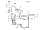
本体枠4は、後部が外枠2の枠内に挿入可能とされると共に遊技盤5の外周を支持可能とされた枠状の本体枠ベースユニット500と、本体枠4を外枠2に対して開閉可能に取付けると共に扉枠3を開閉可能に取付けるための本体枠上ヒンジ部材510及び本体枠下ヒンジ組立体520と、本体枠ベースユニット500を補強している本体枠補強フレーム530と、遊技盤5の遊技領域5a内に遊技球Bを打込むための球発射装置540と、遊技ホールの島設備から供給される遊技球Bを受取る払出ベースユニット550と、払出ベースユニット550で受取った遊技球Bを遊技者側へ払出すための払出ユニット560と、パチンコ機1の電源投入を行うことができる電源スイッチ630aを備える電源基板630のほかに払出制御基板633を有している基板ユニット620と、本体枠ベース501に取付けられた遊技盤5の後側を覆う裏カバー640と、外枠2と本体枠4、及び扉枠3と本体枠4の間を施錠する施錠ユニット650と、を備えている。
The body frame 4 has a frame-like body frame base unit 500 whose rear part can be inserted into the frame of the outer frame 2 and can support the outer periphery of the game board 5, and the body frame 4 is attached to the outer frame 2. a main body frame upper hinge member 510 and a main body frame lower hinge assembly 520 for mounting the door frame 3 so that it can be opened and closed, a main body frame reinforcing frame 530 that reinforces the main body frame base unit 500; A ball launching device 540 for hitting a game ball B into the game area 5a of the board 5, a payout base unit 550 for receiving the game ball B supplied from the island facility of the game hall, and a game received by the payout base unit 550. A board unit 620 having a payout control board 633 in addition to a payout unit 560 for paying out balls B to the player side and a power board 630 having a power switch 630a capable of turning on the power of the pachinko machine 1. a back cover 640 that covers the rear side of the game board 5 attached to the main body frame base 501; I have it.
本体枠4は、遊技球Bを打込むことで遊技が行われる遊技領域5aを有した遊技盤5を保持すると共に、遊技球Bを遊技者側へ払出したり、遊技に使用された遊技球Bをパチンコ機1の後方(遊技ホールの島設備側)へ排出したり、するためのものである。本体枠4は、前方が開放された箱状に形成されており、内部に前方から遊技盤5が着脱可能に収容される。また、本体枠4は、正面左辺側前端の上下において、遊技ホールの島設備に取付けられる枠状の外枠2に開閉可能に取付けられると共に、開放された前面側が閉鎖されるように扉枠3が開閉可能に取付けられる。
The main body frame 4 holds a game board 5 having a game area 5a where a game is played by hitting a game ball B, and also discharges the game ball B to the player side and stores the game ball B used in the game. is discharged to the rear of the pachinko machine 1 (on the island facility side of the game hall). The body frame 4 is formed in a box shape with an open front, and the game board 5 is detachably accommodated therein from the front. The body frame 4 is attached to a frame-shaped outer frame 2 attached to the island facility of the game hall at the top and bottom of the front left side of the front so that it can be opened and closed. is attached so that it can be opened and closed.
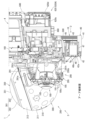
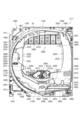
遊技盤5は、遊技者の操作によって遊技球Bが行われる遊技領域5aと、遊技領域5aの外周を区画し外形が正面視略四角形状とされた前構成部材1000と、前構成部材1000の後側に取付けられており遊技領域5aの後端を区画する板状の遊技パネル1100と、遊技パネル1100の後側下部に取付けられている基板ホルダ1200と、基板ホルダ1200の後面に取付けられており主制御基板1310及び設定変更基板1311を有している主制御ユニット1300と、主制御基板1310からの制御信号に基づいて遊技状況を表示する機能表示ユニット1400と、遊技パネル1100の後側に配置されている周辺制御ユニット1500(図12を参照)と、正面視において遊技領域5aの中央に配置されており所定の演出画像を表示可能な演出表示装置1600と、遊技パネル1100の前面に取付けられる表ユニット2000と、遊技パネル1100の後面に取付けられる裏ユニット3000と、を備えている。裏ユニット3000には、遊技状態に応じて可動演出や発光演出を行うことが可能な各種の演出ユニットを備えている。
The game board 5 includes a game area 5a in which a game ball B is played by a player's operation, a front constituent member 1000 that defines the outer periphery of the game area 5a and has a substantially rectangular outer shape when viewed from the front, and a front constituent member 1000. A plate-shaped game panel 1100 attached to the rear side and defining the rear end of the game area 5a, a substrate holder 1200 attached to the lower rear side of the game panel 1100, and a board holder 1200 attached to the rear surface of the substrate holder 1200. Main control unit 1300 having cage main control board 1310 and setting change board 1311; A peripheral control unit 1500 (see FIG. 12) is arranged, an effect display device 1600 is arranged in the center of the game area 5a when viewed from the front and can display a predetermined effect image, and is attached to the front of the game panel 1100. and a back unit 3000 attached to the rear surface of the game panel 1100.例文帳に追加The back unit 3000 is provided with various effect units capable of performing movable effects and light emitting effects according to the game state.
遊技盤5の遊技領域5a内には、遊技球Bと当接し所定のゲージ配列で植設されている複数の障害釘Nと、遊技球Bの受入れ又は通過により遊技者に対して所定の特典(例えば、所定数の遊技球Bの払出し)を付与する一般入賞口2001、第一始動口2004、ゲート2002、第二始動口2005、及び第一大入賞口2006と、を備えている。障害釘Nは、遊技パネル1100の前面に植設されている。一般入賞口2001、第一始動口2004、ゲート2002、第二始動口2005、及び第一大入賞口2006は、表ユニット2000に備えられている。
In the game area 5a of the game board 5, there are a plurality of obstacle nails N planted in a predetermined gauge arrangement in contact with the game ball B, and a predetermined privilege given to the player by receiving or passing the game ball B. It is provided with a general winning opening 2001, a first starting opening 2004, a gate 2002, a second starting opening 2005, and a first big winning opening 2006 that provide (for example, a predetermined number of game balls B payout). The obstacle nail N is planted on the front surface of the game panel 1100. - 特許庁A general winning opening 2001 , a first starting opening 2004 , a gate 2002 , a second starting opening 2005 and a first big winning opening 2006 are provided in the table unit 2000 .
遊技盤5の遊技領域5a内には、遊技者がハンドルユニット180のハンドル195を操作することで、遊技球Bを打込むことができる。これにより、遊技球Bが、遊技領域5a内の一般入賞口2001、第一始動口2004、ゲート2002、第二始動口2005、及び第一大入賞口2006等に、受入れられたり通過したりするように、遊技者に対してハンドル195の打込操作を楽しませることができる。
A game ball B can be hit into the game area 5a of the game board 5 by operating the handle 195 of the handle unit 180 by the player. Thereby, the game ball B is accepted or passed through the general winning opening 2001, the first starting opening 2004, the gate 2002, the second starting opening 2005, the first big winning opening 2006, etc. in the game area 5a. Thus, the player can be entertained with the driving operation of the handle 195 .
また、遊技盤5は、遊技領域5a内に遊技球Bを打込むことで変化する遊技状態に応じて、演出表示装置1600に所定の演出画像を表示させたり、右下ユニット2400、及び裏ユニット3000の裏前周縁装飾ユニット3200、裏上前演出ユニット3300、裏下前演出ユニット3400、裏上後演出ユニット3500、裏下後演出ユニット3600、等により発光演出や可動演出を行わせたりして、遊技者を楽しませることができる。
In addition, the game board 5 causes the effect display device 1600 to display a predetermined effect image, the lower right unit 2400, and the back unit according to the game state changed by hitting the game ball B into the game area 5a. 3000 back front edge decoration unit 3200, back top front effect unit 3300, back bottom front effect unit 3400, back top back effect unit 3500, back bottom back effect unit 3600, etc. are used to perform light emitting effects and movable effects. , can entertain the player.
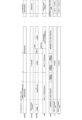
[2.外枠の全体構成]
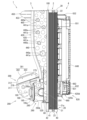
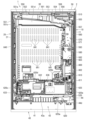
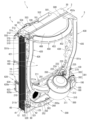
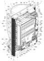
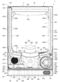
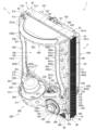
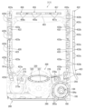
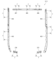
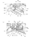
パチンコ機1の外枠2について、図13乃至図18を参照して説明する。図13はパチンコ機における外枠の正面図であり、図14は外枠の背面図であり、図15は外枠の右側面図である。また、図16は外枠を前から見た斜視図であり、図17は外枠を後ろから見た斜視図である。図18は、外枠を主な部材毎に分解して前から見た分解斜視図である。外枠2は、遊技ホール等のパチンコ機1が設置される島設備(図示は省略)に取付けられるものである。外枠2は、正面視の形状が上下に延びた四角形の枠に形成されている。
[2. Overall configuration of the outer frame]
The outer frame 2 of the pachinko machine 1 will be described with reference to FIGS. 13 to 18. FIG. 13 is a front view of the outer frame of the pachinko machine, FIG. 14 is a rear view of the outer frame, and FIG. 15 is a right side view of the outer frame. 16 is a perspective view of the outer frame as seen from the front, and FIG. 17 is a perspective view of the outer frame as seen from the rear. FIG. 18 is an exploded perspective view of the outer frame disassembled into main members and viewed from the front. The outer frame 2 is attached to an island facility (not shown) such as a game hall where the pachinko machine 1 is installed. The outer frame 2 is formed in a rectangular frame extending vertically when viewed from the front.
外枠2は、図示するように、左右に離間しており上下に延びている外枠左組立体10及び外枠右組立体20と、外枠左組立体10及び外枠右組立体20の上端同士を連結している外枠上部材30と、外枠左組立体10及び外枠右組立体20の下端同士を連結している外枠下組立体40と、外枠上部材30の上面左端に取付けられている外枠上ヒンジ組立体50と、外枠左組立体10の右側面下部と外枠下組立体40の上面左端に取付けられている外枠下ヒンジ部材60と、を備えている。
As shown in the figure, the outer frame 2 includes a left outer frame assembly 10 and a right outer frame assembly 20 which are spaced apart in the left and right direction and extend vertically, and a left outer frame assembly 10 and a right outer frame assembly 20. An outer frame upper member 30 connecting the upper ends thereof, an outer frame lower assembly 40 connecting the lower ends of the outer frame left assembly 10 and the outer frame right assembly 20 together, and the upper surface of the outer frame upper member 30 An outer frame upper hinge assembly 50 attached to the left end, and an outer frame lower hinge member 60 attached to the lower right side surface of the outer frame left assembly 10 and the upper left end of the outer frame lower assembly 40. ing.
外枠2は、本体枠4を閉じた時に、外枠下組立体40が、本体枠4における基板ユニット620のスピーカユニット620aと協働して、本体枠スピーカ622のエンクロージャ624の一部を形成していると共に、本体枠スピーカ622の後方へ出力されたサウンドを、位相反転させて前方へ放射することができるものである。
The outer frame 2 forms part of the enclosure 624 of the main body frame speaker 622 when the main body frame 4 is closed. In addition, the sound output to the rear of the main body frame speaker 622 can be phase-inverted and radiated forward.
外枠2は、外枠上ヒンジ組立体50が、本体枠4の本体枠上ヒンジ部材510を着脱可能に支持することができる。外枠2は、外枠上ヒンジ組立体50と外枠下ヒンジ部材60とによって、本体枠4の本体枠上ヒンジ部材510と本体枠下ヒンジ組立体520とを同軸上で回転可能に支持することができ、本体枠4を正面視左側を中心にして前方へ開閉可能に取付けることができる。
In the outer frame 2 , the outer frame upper hinge assembly 50 can detachably support the main body frame upper hinge member 510 of the main body frame 4 . The outer frame 2 coaxially and rotatably supports the main body frame upper hinge member 510 and the main body frame lower hinge assembly 520 of the main body frame 4 by the outer frame upper hinge assembly 50 and the outer frame lower hinge member 60. The body frame 4 can be attached so as to be openable and closable forward with the left side as the center in the front view.
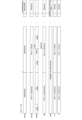
[2-1.外枠左組立体及び外枠右組立体]
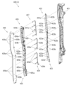
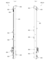
外枠2の外枠左組立体10及び外枠右組立体20について、主に図19を参照して詳細に説明する。図19は、外枠の外枠左組立体及び外枠右組立体を夫々分解して前から見た分解斜視図である。外枠2の外枠左組立体10及び外枠右組立体20は、夫々が上下に延びており、互いに左右に離間して配置されている。外枠左組立体10及び外枠右組立体20は、本体枠4の本体枠上ヒンジ部材510及び本体枠下ヒンジ組立体520を同軸上で回転可能に支持して、外枠2に対して本体枠4を開閉可能に取付けるためのものである。
[2-1. Outer frame left assembly and outer frame right assembly]
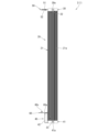
The outer frame left assembly 10 and outer frame right assembly 20 of the outer frame 2 will be described in detail mainly with reference to FIG. FIG. 19 is an exploded perspective view of the left outer frame assembly and the right outer frame assembly of the outer frame, viewed from the front. A left outer frame assembly 10 and a right outer frame assembly 20 of the outer frame 2 each extend vertically and are spaced apart from each other in the left and right direction. The outer frame left assembly 10 and the outer frame right assembly 20 coaxially support a main body frame upper hinge member 510 and a main body frame lower hinge assembly 520 of the main body frame 4 so as to be rotatable with respect to the outer frame 2 . It is for attaching the body frame 4 so that it can be opened and closed.
まず、外枠左組立体10は、前後方向が一定の幅(奥行)で上下に延びている外枠左部材11と、外枠左部材11の右側面上端に取付けられている左上連結部材12と、外枠左部材11の右側面下端に取付けられている左下連結部材13と、を備えている。
First, the left outer frame assembly 10 includes a left outer frame member 11 extending vertically with a constant width (depth) in the front-rear direction, and an upper left connecting member 12 attached to the upper end of the right side surface of the left outer frame member 11 . and a lower left connecting member 13 attached to the lower end of the right side surface of the outer frame left member 11 .
外枠左部材11は、一定の断面形状で上下に延びており、アルミ合金の押出型材によって形成されている。外枠左部材11は、左側面における前後方向を三等分したうちの後側の部位において平坦状に右方へ窪んでいる凹部11aと、右側面における凹部11aとは反対側の部位から右方へ膨出している膨出部11bと、膨出部11bを上下に貫通している空洞部11cと、を備えている。外枠左部材11は、凹部11aや膨出部11bによって、強度・剛性が高められていると共に、空洞部11cによって、重量が軽減されている。
The outer frame left member 11 extends vertically with a constant cross-sectional shape, and is formed of an extruded aluminum alloy. The outer frame left member 11 has a concave portion 11a that is flat and concave to the right at the rear portion of the left side surface that is trisected in the front-rear direction, and a portion that is opposite to the concave portion 11a on the right side surface. It has a bulging portion 11b that bulges in the direction and a hollow portion 11c that vertically penetrates the bulging portion 11b. The left outer frame member 11 has increased strength and rigidity due to the concave portion 11a and the bulging portion 11b, and has a reduced weight due to the hollow portion 11c.
また、外枠左部材11は、左右両側面において、上下に延びた複数の溝が形成されている。左側面の複数の溝は、V字状に形成されており、右側面の複数の溝は、半円形状に形成されている。外枠左部材11は、後述する外枠右組立体20の外枠右部材21と左右対称形状に形成されている。
Further, the outer frame left member 11 is formed with a plurality of vertically extending grooves on both left and right side surfaces. The plurality of grooves on the left side are formed in a V shape, and the plurality of grooves on the right side are formed in a semicircular shape. The outer frame left member 11 is formed in a bilaterally symmetrical shape with the outer frame right member 21 of the outer frame right assembly 20 to be described later.
左上連結部材12は、外枠左部材11の上端と外枠上部材30の左端とを連結するためのものである。左上連結部材12は、水平に延びた平板状の水平固定部12aと、水平固定部12aの左辺における前後方向の中間から上方へ延出している平板状の上横固定部12bと、水平固定部12aの左辺における上横固定部12bの前後両側から下方へ延出している平板状の一対の下横固定部12cと、を備えている。左上連結部材12は、平板状の金属板を屈曲させて形成されている。
The upper left connecting member 12 connects the upper end of the outer frame left member 11 and the left end of the outer frame upper member 30 . The upper left connecting member 12 includes a flat plate-like horizontal fixing portion 12a extending horizontally, a flat plate-like upper horizontal fixing portion 12b extending upward from the middle of the left side of the horizontal fixing portion 12a in the front-rear direction, and a horizontal fixing portion. A pair of flat plate-like lower lateral fixing portions 12c extending downward from both front and rear sides of the upper lateral fixing portion 12b on the left side of the portion 12a are provided. The upper left connecting member 12 is formed by bending a flat metal plate.
左上連結部材12は、後側の下横固定部12cを外枠左部材11の空洞部11c内に挿入させると共に、水平固定部12aを外枠左部材11の上端に当接させ、更に、前側及び後側の下横固定部12cを外枠左部材11の右側面に当接させた状態で、外枠左部材11の左側面の外側から下横固定部12cにビスを捩じ込むことで、外枠左部材11に取付けられる。また、左上連結部材12は、水平固定部12aを外枠上部材30の左端側の下面に当接させると共に、上横固定部12bを外枠上部材30の左側面の切欠部30a内に挿入させた状態で、水平固定部12a及び上横固定部12bを通して外枠上部材30にビスを捩じ込むことで、外枠上部材30に取付けられる。
The upper left connecting member 12 inserts the lower horizontal fixing portion 12c on the rear side into the hollow portion 11c of the left outer frame member 11, and the horizontal fixing portion 12a is brought into contact with the upper end of the left outer frame member 11. By screwing a screw into the lower horizontal fixing portion 12c from the outside of the left side surface of the outer frame left member 11 while the rear lower horizontal fixing portion 12c is in contact with the right side surface of the outer frame left member 11. , is attached to the outer frame left member 11 . The upper left connecting member 12 has the horizontal fixing portion 12a in contact with the lower surface of the left end side of the outer frame upper member 30, and the upper horizontal fixing portion 12b is inserted into the left side cutout portion 30a of the outer frame upper member 30. In this state, it is attached to the outer frame upper member 30 by screwing screws into the outer frame upper member 30 through the horizontal fixing portion 12a and the upper horizontal fixing portion 12b.
左下連結部材13は、外枠左部材11の下端と外枠下組立体40(外枠下部材41)の左端とを連結するためのものである。左下連結部材13は、水平に延びた平板状の水平固定部13aと、水平固定部13aの左辺から上方へ延出していると共に水平固定部13aよりも後方へ延出している平板状の上横固定部13bと、上横固定部13bの下辺における水平固定部13aよりも後側の部位から下方へ延出している平板状の下横固定部13cと、上横固定部13bの後辺から右方へ短く延出している平板状の当接部13dと、を備えている。左下連結部材13は、平板状の金属板を屈曲させて形成されている。
The lower left connecting member 13 is for connecting the lower end of the outer frame left member 11 and the left end of the outer frame lower assembly 40 (outer frame lower member 41). The lower left connecting member 13 includes a horizontally extending flat plate-like horizontal fixing portion 13a, and a flat plate-like upper horizontal fixing portion 13a extending upward from the left side of the horizontal fixing portion 13a and extending rearward from the horizontal fixing portion 13a. A fixing portion 13b, a flat plate-like lower horizontal fixing portion 13c extending downward from a portion of the lower side of the upper horizontal fixing portion 13b on the rear side of the horizontal fixing portion 13a, and a right side of the rear side of the upper horizontal fixing portion 13b. and a flat plate-shaped contact portion 13d that extends short in the direction. The lower left connecting member 13 is formed by bending a flat metal plate.
左下連結部材13は、当接部13dの後面を外枠左部材11の膨出部11bの前面に当接させると共に、上横固定部13bの左側面を外枠左部材11の右側面に当接させ、水平固定部13aの下面を外枠左部材11の下端と一致させた状態で、外枠左部材11の左側面の外側から上横固定部13bにビスを捩じ込むことで、外枠左部材11に取付けられる。また、左下連結部材13は、水平固定部13aを外枠下部材41の左端側の上面に当接させると共に、下横固定部13cを外枠下部材41の左側面の切欠部41aに挿入させた状態で、水平固定部13a及び下横固定部13cを通して外枠下部材41にビスを捩じ込むことで、外枠下部材41に取付けられる。
The lower left connecting member 13 abuts the rear surface of the contact portion 13 d against the front surface of the bulging portion 11 b of the left outer frame member 11 and the left side surface of the upper horizontal fixing portion 13 b against the right side surface of the left outer frame member 11 . With the lower surface of the horizontal fixing portion 13a aligned with the lower end of the outer frame left member 11, a screw is screwed into the upper horizontal fixing portion 13b from the outside of the left side surface of the outer frame left member 11, thereby It is attached to the left frame member 11 . The left lower connecting member 13 has the horizontal fixing portion 13a in contact with the upper surface of the left end side of the outer frame lower member 41, and the lower horizontal fixing portion 13c is inserted into the left side cutout portion 41a of the outer frame lower member 41. In this state, it is attached to the outer frame lower member 41 by screwing screws into the outer frame lower member 41 through the horizontal fixing portion 13a and the lower horizontal fixing portion 13c.
次に、外枠右組立体20は、前後方向が一定の幅(奥行)で上下に延びている外枠右部材21と、外枠右部材21の左側面上端に取付けられている右上連結部材22と、外枠右部材21の左側面下端に取付けられている右下連結部材23と、外枠右部材21の左側面上部に取付けられている上鉤掛部材24と、外枠右部材21の左側面下部に取付けられている下鉤掛部材25と、を備えている。
Next, the right outer frame assembly 20 includes a right outer frame member 21 extending vertically with a constant width (depth) in the front-rear direction, and an upper right connecting member attached to the upper end of the left side surface of the right outer frame member 21. 22, a lower right connecting member 23 attached to the lower end of the left side surface of the right outer frame member 21, an upper hooking member 24 attached to the upper left side surface of the right outer frame member 21, and the right outer frame member 21. and a lower hooking member 25 attached to the lower left side surface.
外枠右部材21は、一定の断面形状で上下に延びており、アルミ合金の押出型材によって形成されている。外枠右部材21は、右側面における前後方向を三等分したうちの後側の部位において平坦状に左方へ窪んでいる凹部21aと、左側面における凹部21aとは反対側の部位から左方へ膨出している膨出部21bと、膨出部21bを上下に貫通している空洞部21cと、を備えている。外枠右部材21は、凹部21aや膨出部21bによって、強度・剛性が高められていると共に、空洞部21cによって、重量が軽減されている。
The right outer frame member 21 extends vertically with a constant cross-sectional shape, and is formed of an extruded aluminum alloy. The right outer frame member 21 has a recess 21a that is flat and recessed leftward at the rear portion of the right side surface that is trisected in the front-rear direction, and a recessed portion 21a that is flat and recessed leftward from the portion opposite to the recessed portion 21a on the left side surface. It has a bulging portion 21b that bulges in the direction and a hollow portion 21c that vertically penetrates the bulging portion 21b. The right outer frame member 21 has increased strength and rigidity due to the concave portion 21a and the bulging portion 21b, and has a reduced weight due to the hollow portion 21c.
また、外枠右部材21は、左右両側面において、上下に延びた複数の溝が形成されている。右側面の複数の溝は、V字状に形成されており、左側面の複数の溝は、半円形状に形成されている。外枠右部材21は、外枠左組立体10の外枠左部材11と左右対称形状に形成されている。
Further, the right outer frame member 21 has a plurality of vertically extending grooves formed on both left and right side surfaces thereof. The plurality of grooves on the right side are formed in a V shape, and the plurality of grooves on the left side are formed in a semicircular shape. The right outer frame member 21 and the left outer frame member 11 of the left outer frame assembly 10 are formed in a bilaterally symmetrical shape.
右上連結部材22は、外枠右部材21の上端と外枠上部材30の右端とを連結するためのものである。右上連結部材22は、水平に延びた平板状の水平固定部22aと、水平固定部22aの右辺における前後方向の中間から上方へ延出している平板状の上横固定部22bと、水平固定部22aの右辺における上横固定部22bの前後両側から下方へ延出している平板状の一対の下横固定部22cと、を備えている。右上連結部材22は、平板状の金属板を屈曲させて形成されている。
The upper right connecting member 22 connects the upper end of the outer frame right member 21 and the right end of the outer frame upper member 30 . The upper right connecting member 22 includes a horizontally extending flat plate-like horizontal fixing portion 22a, a flat plate-like upper horizontal fixing portion 22b extending upward from the middle of the right side of the horizontal fixing portion 22a in the front-rear direction, and a horizontal fixing portion. A pair of flat plate-like lower lateral fixing portions 22c extending downward from both front and rear sides of the upper lateral fixing portion 22b on the right side of the portion 22a are provided. The upper right connecting member 22 is formed by bending a flat metal plate.
右上連結部材22は、後側の下横固定部22cを外枠右部材21の空洞部21c内に挿入させると共に、水平固定部22aを外枠右部材21の上端に当接させ、更に、前側及び後側の下横固定部22cを外枠右部材21の左側面に当接させた状態で、外枠右部材21の右側面の外側から下横固定部22cにビスを捩じ込むことで、外枠右部材21に取付けられる。また、右上連結部材22は、水平固定部22aを外枠上部材30の右端側の下面に当接させると共に、上横固定部22bを外枠上部材30の右側面の切欠部30a内に挿入させた状態で、水平固定部22a及び上横固定部22bを通して外枠上部材30にビスを捩じ込むことで、外枠上部材30に取付けられる。
The upper right connecting member 22 inserts the lower horizontal fixing portion 22c on the rear side into the hollow portion 21c of the right outer frame member 21, and the horizontal fixing portion 22a is brought into contact with the upper end of the right outer frame member 21. By screwing a screw into the lower horizontal fixing portion 22c from the outside of the right side surface of the right outer frame member 21 while the lower horizontal fixing portion 22c on the rear side is in contact with the left side surface of the right outer frame member 21. , is attached to the outer frame right member 21 . The upper right connecting member 22 has the horizontal fixing portion 22a in contact with the lower surface of the right end side of the outer frame upper member 30, and the upper horizontal fixing portion 22b is inserted into the notch portion 30a in the right side surface of the outer frame upper member 30. In this state, it is attached to the outer frame upper member 30 by screwing screws into the outer frame upper member 30 through the horizontal fixing portion 22a and the upper horizontal fixing portion 22b.
右下連結部材23は、外枠右部材21の下端と外枠下組立体40(外枠下部材41)の右端とを連結するためのものである。右下連結部材23は、水平に延びた平板状の水平固定部23aと、水平固定部23aの右辺から上方へ延出していると共に水平固定部23aよりも後方へ延出している平板状の上横固定部23bと、上横固定部23bの下辺における水平固定部23aよりも後側の部位から下方へ延出している平板状の下横固定部23cと、上横固定部23bの後辺から左方へ短く延出している平板状の当接部23dと、を備えている。右下連結部材23は、平板状の金属板を屈曲させて形成されている。
The lower right connecting member 23 is for connecting the lower end of the outer frame right member 21 and the right end of the outer frame lower assembly 40 (outer frame lower member 41). The lower right connecting member 23 includes a horizontally extending flat plate-like horizontal fixing portion 23a and a flat plate-like upper portion extending upward from the right side of the horizontal fixing portion 23a and extending rearward from the horizontal fixing portion 23a. Lateral fixing portion 23b, flat plate-shaped lower lateral fixing portion 23c extending downward from a portion of the lower side of upper lateral fixing portion 23b on the rear side of horizontal fixing portion 23a, and from the rear side of upper lateral fixing portion 23b. and a flat plate-shaped contact portion 23d that extends short to the left. The lower right connecting member 23 is formed by bending a flat metal plate.
右下連結部材23は、当接部23dの後面を外枠右部材21の膨出部21bの前面に当接させると共に、上横固定部23bの右側面を外枠右部材21の左側面に当接させ、水平固定部23aの下面を外枠右部材21の下端と一致させた状態で、外枠右部材21の右側面の外側から上横固定部23bにビスを捩じ込むことで、外枠右部材21に取付けられる。また、右下連結部材23は、水平固定部23aを外枠下部材41の右端側の上面に当接させると共に、下横固定部23cを外枠下部材41の右側面の切欠部41aに挿入させた状態で、水平固定部23a及び下横固定部23cを通して外枠下部材41にビスを捩じ込むことで、外枠下部材41に取付けられる。
The lower right connecting member 23 has the rear surface of the abutting portion 23 d in contact with the front surface of the bulging portion 21 b of the right outer frame member 21 and the right side surface of the upper horizontal fixing portion 23 b on the left side surface of the right outer frame member 21 . With the lower surface of the horizontal fixing portion 23a aligned with the lower end of the right outer frame member 21, a screw is screwed into the upper lateral fixing portion 23b from the outside of the right side surface of the right outer frame member 21. It is attached to the outer frame right member 21 . The lower right connecting member 23 has the horizontal fixing portion 23a in contact with the upper surface of the right end side of the lower outer frame member 41, and the lower lateral fixing portion 23c is inserted into the notch portion 41a in the right side surface of the lower outer frame member 41. In this state, it is attached to the outer frame lower member 41 by screwing screws into the outer frame lower member 41 through the horizontal fixing portion 23a and the lower horizontal fixing portion 23c.
上鉤掛部材24及び下鉤掛部材25は、後述する本体枠4における施錠ユニット650の外枠用鉤653が掛止されるものである。上鉤掛部材24は、前後方向に一定の幅で上下に延びており外枠右部材21の左側面に取付けられる平板状の取付部24aと、取付部24aの前辺から左方へ延出しており上側の外枠用鉤653が掛止される平板状の掛止片部24bと、を備えている。
An outer frame hook 653 of a locking unit 650 in the body frame 4 to be described later is hooked to the upper hooking member 24 and the lower hooking member 25 . The upper hooking member 24 has a flat mounting portion 24a that extends vertically with a constant width in the front-rear direction and is attached to the left side surface of the outer frame right member 21, and extends leftward from the front side of the mounting portion 24a. A flat plate-like hooking piece 24b to which the outer frame hook 653 on the upper side of the cage is hooked is provided.
下鉤掛部材25は、前後方向に一定の幅で上下に延びており外枠右部材21の左側面に取付けられる平板状の取付部25aと、取付部25aの前辺から左方へ延出しており下側の外枠用鉤653が掛止される平板状の掛止片部25bと、掛止片部25bを前後に貫通しており下側の外枠用鉤653が挿通可能な挿通口25cと、を備えている。
The lower hooking member 25 has a flat mounting portion 25a that extends vertically with a constant width in the front-rear direction and is attached to the left side surface of the outer frame right member 21, and extends leftward from the front side of the mounting portion 25a. A flat plate-like hooking piece 25b to which the lower outer frame hook 653 is hooked, and an insertion through which the lower outer frame hook 653 can be inserted through the hooking piece 25b in the front-rear direction. and a mouth 25c.
[2-2.外枠上部材]
外枠2の外枠上部材30について、主に図18を参照して詳細に説明する。外枠上部材30は、左右に離間している外枠左組立体10及び外枠右組立体20の上端同士を連結するためのものである。外枠上部材30は、前後方向の幅が、外枠左部材11及び外枠右部材21の前後方向と略同じ幅で、上下方向の厚さが一定で、左右方向に延びており、木材によって形成されている。外枠上部材30は、左右方向の長さが、後述する外枠下組立体40の外枠下部材41の左右方向の長さと同じに形成されている。
[2-2. Outer frame upper member]
The outer frame upper member 30 of the outer frame 2 will be described in detail mainly with reference to FIG. The outer frame upper member 30 is for connecting the upper ends of the outer frame left assembly 10 and the outer frame right assembly 20 which are separated from each other to the left and right. The outer frame upper member 30 has a width in the front-rear direction substantially the same as the width in the front-rear direction of the outer frame left member 11 and the outer frame right member 21, has a constant vertical thickness, and extends in the left-right direction. formed by The outer frame upper member 30 is formed to have the same lateral length as the lateral length of the outer frame lower member 41 of the outer frame lower assembly 40 described later.
外枠上部材30は、左右両側面における前後方向の中央において、上下に貫通した状態で左右方向中央側へ夫々窪んでいる切欠部30aを備えている。これら左右両端の切欠部30aには、左上連結部材12の上横固定部12b及び右上連結部材22の上横固定部22bが夫々挿入された状態で取付けられる。
The outer frame upper member 30 has cutout portions 30a that penetrate vertically and are recessed toward the center in the left and right direction at the center in the front-rear direction on both left and right side surfaces. The upper lateral fixing portion 12b and the upper lateral fixing portion 22b of the upper left connecting member 12 and the upper lateral fixing portion 22b of the upper right connecting member 22 are respectively inserted into the cutout portions 30a on the left and right ends and attached.
また、外枠上部材30は、左側端部において、上面と前面が一般面よりも窪んだ取付段部30bを備えている。この取付段部30bには、後述する外枠上ヒンジ組立体50が取付けられる。
In addition, the outer frame upper member 30 has a mounting stepped portion 30b at the left end portion, the upper surface and the front surface of which are recessed from the general surface. An outer frame upper hinge assembly 50, which will be described later, is attached to the attachment stepped portion 30b.
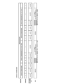
[2-3.外枠下組立体]
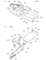
外枠2の外枠下組立体40について、主に図20を参照して詳細に説明する。図20は、外枠の外枠下組立体を分解して前から見た分解斜視図である。外枠下組立体40は、左右に離間している外枠左組立体10及び外枠右組立体20の下端同士を連結すると共に、パチンコ機1において扉枠3よりも下側を閉鎖して装飾するためのものである。
[2-3. Outer frame lower assembly]
The outer frame lower assembly 40 of the outer frame 2 will be described in detail mainly with reference to FIG. FIG. 20 is an exploded front perspective view of the outer frame lower assembly of the outer frame. The outer frame lower assembly 40 connects the lower ends of the outer frame left assembly 10 and the outer frame right assembly 20 which are separated from each other to the left and right, and closes the lower side of the door frame 3 in the pachinko machine 1. It is for decoration.
外枠下組立体40は、左右に離間している外枠左組立体10及び外枠右組立体20の下端同士を連結しており左右に延びている外枠下部材41と、外枠下部材41の前方に配置されており外枠下部材41に沿って左右に延びていると共に後方が開放されている箱状の幕板前部材42と、幕板前部材42の後側に取付けられていると共に外枠下部材41の上面に取付けられており前方が開放されている左右に延びた箱状の幕板後部材43と、幕板後部材43の上面における左端に形成されている球噛防止機構44と、を備えている。
The outer frame lower assembly 40 connects the lower ends of the outer frame left assembly 10 and the outer frame right assembly 20, which are spaced apart in the left and right direction, and extends left and right. A box-shaped curtain plate front member 42 which is arranged in front of the member 41 and extends left and right along the outer frame lower member 41 and whose rear is open is attached to the rear side of the curtain plate front member 42. A box-shaped rear panel member 43 that is attached to the upper surface of the outer frame lower member 41 and extends to the left and right with an open front, and a ball bite prevention formed at the left end on the upper surface of the rear panel member 43 a mechanism 44;
外枠下部材41は、前後方向の幅が、外枠左部材11及び外枠右部材21の前後方向と略同じ幅で、上下方向の厚さが一定で、左右方向に延びており、木材によって形成されている。外枠下部材41は、左右方向の長さが、外枠上部材30の左右方向の長さと同じに形成されている。
The outer frame lower member 41 has a width in the front-rear direction substantially the same as the width in the front-rear direction of the outer frame left member 11 and the outer frame right member 21, has a constant vertical thickness, and extends in the left-right direction. formed by The outer frame lower member 41 is formed to have the same length in the left-right direction as the outer frame upper member 30 in the left-right direction.
外枠下部材41は、左右両側面における前後方向の中央において、上下に貫通した状態で左右方向中央側へ夫々窪んでいる切欠部41aを備えている。これら左右両端の切欠部41aには、左下連結部材13の下横固定部13c及び右下連結部材23の下横固定部23cが夫々挿入された状態で取付けられる。これにより、外枠左部材11及び外枠右部材21の下端同士を連結することができる。
The outer frame lower member 41 has cutout portions 41a that penetrate vertically and are recessed toward the center in the left-right direction at the center in the front-rear direction on both left and right side surfaces. The lower lateral fixing portion 13c of the lower left connecting member 13 and the lower lateral fixing portion 23c of the lower right connecting member 23 are inserted into the cutout portions 41a on both the left and right ends, respectively. Thereby, the lower ends of the outer frame left member 11 and the outer frame right member 21 can be connected.
また、外枠下部材41は、上面から凹んでおり、幕板後部材43の下部が挿入される凹部41bを備えている。凹部41bは、左右に延びていると共に、前後方向中央の後ろ寄りの位置から前端側へ抜けている。この凹部41bにより、幕板前部材42及び幕板後部材43により形成される幕板内部空間40aの容積を可及的に広くしている。
Further, the outer frame lower member 41 is recessed from the upper surface and has a recess 41b into which the lower part of the panel rear member 43 is inserted. The concave portion 41b extends left and right, and extends from a position near the rear in the center in the front-rear direction to the front end side. The concave portion 41b maximizes the volume of the inner space 40a formed by the front panel member 42 and the rear panel member 43. As shown in FIG.
幕板前部材42は、左右方向の長さが外枠下部材41と同じ長さに延びており、高さに対して前後方向の奥行が短い横長の直方体状の箱状に形成されており、後側の全面が開放されている。幕板前部材42は、開放されている後側を、幕板後部材43によって閉鎖することで、幕板後部材43と協働して本体枠スピーカ622のエンクロージャ624の一部となる幕板内部空間40aを形成する。幕板前部材42は、右端付近の前面において、前後に貫通していると共に左右に延びている長孔状の開口部42aを備えている。
The front panel member 42 extends in the left-right direction to the same length as the outer frame lower member 41, and is formed in a horizontally long rectangular parallelepiped box shape with a short depth in the front-rear direction relative to the height. The entire rear side is open. By closing the open rear side of the panel front member 42 with the panel rear member 43, the panel interior becomes a part of the enclosure 624 of the main body frame speaker 622 in cooperation with the panel rear member 43. A space 40a is formed. The curtain plate front member 42 has an elongated opening 42a penetrating in the front-rear direction and extending in the left-right direction on the front surface near the right end.
幕板後部材43は、左右方向の長さが外枠下部材41よりも若干短く延びており、前方が開放された箱状に形成されている。幕板後部材43は、前面に幕板前部材42を取付けることで、幕板前部材42と協働して本体枠スピーカ622のエンクロージャ624の一部となる幕板内部空間40aを形成する。幕板後部材43は、上面における左右方向中央部において、左右に延びていると共に上方へ突出しており幕板内部空間40aと連通している筒状の接続筒部43aを有している。接続筒部43aは、上端が、幕板後部材43の一般的な上面と一致している前端側から後方へ向かうほど上方へ位置するように傾斜している。本実施形態では、接続筒部43aの上端は、45度の角度で傾斜している。
The rear panel member 43 extends in the left-right direction slightly shorter than the outer frame lower member 41, and is formed in a box shape with an open front. By attaching the front panel member 42 to the front surface of the panel rear member 43 , the panel internal space 40 a that forms a part of the enclosure 624 of the main frame speaker 622 is formed in cooperation with the panel front member 42 . The rear panel member 43 has a cylindrical connection tube portion 43a extending in the left-right direction, projecting upward, and communicating with the inner space 40a of the panel at the central portion in the left-right direction of the upper surface. The connecting tube portion 43a has an upper end that is slanted so as to be positioned upward as it goes rearward from the front end side that coincides with the general upper surface of the rear panel member 43 . In this embodiment, the upper end of the connecting tube portion 43a is inclined at an angle of 45 degrees.
この接続筒部43aは、左右方向の長さが、幕板後部材43全体の約1/3の長さに形成されていると共に、前後方向の奥行が、幕板後部材43全体の奥行よりも若干短く形成されている。接続筒部43a内には、前端側と後端側とを結ぶ複数のリブ43bが備えられている。この接続筒部43aの上端には、外枠2に対して本体枠4を閉じた時に、本体枠4における基板ユニット620のスピーカユニット620aにおけるスピーカカバー621の接続部621cが接続されて、スピーカユニット620aの内部空間と連通した状態となり、エンクロージャ624を形成する。
The connecting tube portion 43a is formed so that the length in the left-right direction is approximately 1/3 the length of the entire rear panel member 43, and the depth in the front-rear direction is greater than the depth of the rear panel member 43 as a whole. is also slightly shorter. A plurality of ribs 43b connecting the front end side and the rear end side are provided in the connecting tube portion 43a. When the body frame 4 is closed with respect to the outer frame 2, the connection part 621c of the speaker cover 621 of the speaker unit 620a of the board unit 620 of the body frame 4 is connected to the upper end of the connection tube part 43a, thereby connecting the speaker unit. It communicates with the internal space of 620a to form an enclosure 624. FIG.
球噛防止機構44は、幕板後部材43の上面における左端において、外枠下ヒンジ部材60の部位に遊技球Bが滞留することで、外枠2と本体枠4との間に遊技球Bが挟まれるのを防止するためのものである。
The ball bite prevention mechanism 44 is arranged such that the game ball B stays at the portion of the outer frame lower hinge member 60 at the left end of the upper surface of the rear panel member 43, thereby preventing the game ball B from being held between the outer frame 2 and the main body frame 4. to prevent it from being caught.
球噛防止機構44は、幕板後部材43の上面における左端に形成されており、後述する外枠下ヒンジ部材60が際されるように平坦に形成された載置部44aと、載置部44aの左端において上方へ向かって開口している第一排出口44bと、載置部44aにおける第一排出口44bよりも右方で上方へ向かって開口している第二排出口44cと、載置部44aの後辺及び右辺から上方へ延出している立壁部44dと、立壁部44dの上端から前方へ突出していると共に上面が後方へ向かうに従って上方に位置するように傾斜している上端突出部44eと、を備えている。
The ball bite prevention mechanism 44 is formed at the left end of the upper surface of the rear panel member 43, and includes a mounting portion 44a formed flat so as to face the outer frame lower hinge member 60 described later, and a mounting portion 44a. A first discharge port 44b that opens upward at the left end of the mounting portion 44a, a second discharge port 44c that opens upward to the right of the first discharge port 44b in the mounting portion 44a, An upright wall portion 44d extending upward from the rear and right sides of the placing portion 44a, and an upper end protrusion projecting forward from the upper end of the upright wall portion 44d and having an upper surface inclined upward toward the rear. and a portion 44e.
第一排出口44bは、後述する外枠下ヒンジ部材60の排出孔60dと一致する位置に形成されている。第一排出口44b及び第二排出口44cは、遊技球Bが通過可能な大きさに形成されている。第一排出口44b及び第二排出口44cは、幕板内部空間40aとは連通しておらず、幕板後部材43の後面に開口している。従って、第一排出口44b及び第二排出口44cに進入した遊技球Bを、幕板後部材43の後方へ排出することができる。
The first discharge port 44b is formed at a position coinciding with a discharge hole 60d of the outer frame lower hinge member 60, which will be described later. The first discharge port 44b and the second discharge port 44c are formed in a size through which the game ball B can pass. The first discharge port 44 b and the second discharge port 44 c do not communicate with the inner space 40 a of the curtain plate, and open to the rear surface of the rear panel member 43 . Therefore, the game ball B that has entered the first discharge port 44b and the second discharge port 44c can be discharged behind the curtain plate rear member 43. As shown in FIG.
この球噛防止機構44は、球噛防止機構44は、外枠下ヒンジ部材60と後述する本体枠下ヒンジ組立体520との間の隙間を通して、ピアノ線等の不正な工具が挿入された場合、載置部44aの後端から立上っている立壁部44dにより、不正な工具の侵入を阻止することができる。仮に、不正な工具の先端が立壁部44dに当接することで、上方へ曲がったとしても、立壁部44dの上端に備えられている前方へ突出した上端突出部44eに当接し、これ以上の侵入を阻止することができる。従って、外枠下ヒンジ部材60の部位を介して、不正行為が行われるのを防止することができる。
The ball biting prevention mechanism 44 is designed to prevent an illegal tool such as piano wire from being inserted through a gap between the outer frame lower hinge member 60 and the main body frame lower hinge assembly 520, which will be described later. A standing wall portion 44d rising from the rear end of the mounting portion 44a can prevent an unauthorized tool from entering. Even if the tip of the unauthorized tool abuts against the vertical wall portion 44d and bends upward, it will abut against the upper end projecting portion 44e that protrudes forward provided at the upper end of the vertical wall portion 44d, preventing further intrusion. can be prevented. Therefore, it is possible to prevent fraudulent activity through the portion of the lower outer frame hinge member 60 .
ところで、載置部44aの後端に立壁部44dを備えた場合、外枠2に対して本体枠4を開けた時に、何らかの理由により載置部44a上に落下した遊技球Bが、立壁部44dによって外枠2の後方への移動が阻止されるため、載置部44a上に遊技球Bが滞留し易くなる。そして、載置部44a上に遊技球Bが滞留していると、外枠2に対して本体枠4を閉じる際に、外枠2と本体枠4との間に遊技球Bが挟み込まれてしまい、本体枠4を閉じることができなくなる問題が発生する。
By the way, in the case where the standing wall portion 44d is provided at the rear end of the placing portion 44a, when the main body frame 4 is opened with respect to the outer frame 2, the game ball B that has fallen onto the placing portion 44a for some reason is Since the rearward movement of the outer frame 2 is prevented by 44d, the game ball B tends to stay on the placing portion 44a. When the game ball B remains on the mounting portion 44a, the game ball B is caught between the outer frame 2 and the main body frame 4 when the main body frame 4 is closed with respect to the outer frame 2. As a result, there arises a problem that the body frame 4 cannot be closed.
これに対して、本実施形態の球噛防止機構44では、外枠下ヒンジ部材60上や載置部44a上に落下した遊技球Bを、外枠下ヒンジ部材60の排出孔60dと第一排出口44bを通して、又は、第二排出口44cを通して、遊技球Bを幕板後部材43の後方(外枠2の後方)へ排出することができ、外枠2と本体枠4との間に遊技球Bが挟まれるのを防止することができる。
On the other hand, in the ball biting prevention mechanism 44 of the present embodiment, the game ball B dropped onto the outer frame lower hinge member 60 or the placing portion 44a is discharged from the discharge hole 60d of the outer frame lower hinge member 60 and the first Through the discharge port 44b or through the second discharge port 44c, the game ball B can be discharged behind the curtain board rear member 43 (behind the outer frame 2), and between the outer frame 2 and the main body frame 4 It is possible to prevent the game ball B from being caught.
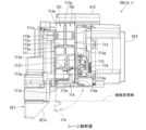
外枠下組立体40は、幕板前部材42及び幕板後部材43の上面に左右に離間して配置されている一対の案内部材45と、幕板前部材42の開口部42aを後側から閉鎖している平板状のグリル部材46と、グリル部材46を挟んで開口部42aを閉鎖するように幕板前部材42の内部に取付けられており前後に延びた二つの円筒を有したポート部材47と、幕板後部材43の接続筒部43aの上端に配置される枠状のシール部材48と、を備えている。
The lower outer frame assembly 40 includes a pair of guide members 45 arranged on the upper surfaces of the front panel member 42 and the rear panel member 43 with a left-right spacing, and closes the opening 42a of the front panel member 42 from the rear side. and a port member 47 having two cylinders extending back and forth, which is mounted inside the front panel member 42 so as to close the opening 42a with the grill member 46 interposed therebetween. , and a frame-shaped seal member 48 arranged at the upper end of the connecting tube portion 43 a of the rear panel member 43 .
一対の案内部材45は、外枠2に対して本体枠4を閉じた時に、扉枠3の下端が当接するものである。案内部材45は、摩擦抵抗の低い低摩擦材料によって形成されており、本体枠4の下端を滑り易くして、開閉を容易にしている。
The pair of guide members 45 are in contact with the lower end of the door frame 3 when the body frame 4 is closed with respect to the outer frame 2 . The guide member 45 is made of a low-friction material with low frictional resistance, and makes the lower end of the body frame 4 slippery to facilitate opening and closing.
グリル部材46は、左右方向へ延びた帯板状で、上下方向へ間隔をあけて設けられている複数の羽根部46bを有している。羽根部46bは、前端側が後端側よりも高くなるように、傾斜した状態で設けられている(図47を参照)。このグリル部材46は、羽根部46b同士の間の隙間を通して、幕板前部材42の内部(幕板内部空間40a)と外部とを通気可能に連通させている。
The grill member 46 has a strip-like shape extending in the left-right direction, and has a plurality of blade portions 46b that are spaced apart in the up-down direction. The blade portion 46b is provided in an inclined state so that the front end side is higher than the rear end side (see FIG. 47). The grille member 46 communicates the interior of the panel front member 42 (the panel interior space 40a) with the outside through the gaps between the blade portions 46b.
ポート部材47は、二つの円筒により、グリル部材46における羽根部46b同士の間の隙間を介して幕板内部空間40a(エンクロージャ624)と外枠2の前方とを連通させている。ポート部材47は、二つの円筒が、所定の内径で所定の長さに形成されており、ヘルムホルツ共鳴の原理により本体枠スピーカ622から後方(エンクロージャ624内)へ発せられた低音を共振・増幅させて、豊かな低音を外枠2の前方(遊技者側)へ放射することができる。つまり、本実施形態では、本体枠スピーカ622のエンクロージャ624がバスレフ型とされており、遊技者に対して重低音を聞かせることができる。
The port member 47 communicates the interior space 40a (enclosure 624) of the curtain plate with the front of the outer frame 2 through the gap between the blade portions 46b of the grill member 46 by means of two cylinders. The port member 47 is formed of two cylinders having a predetermined inner diameter and a predetermined length, and resonates and amplifies the low-pitched sound emitted from the main body frame speaker 622 to the rear (within the enclosure 624) according to the principle of Helmholtz resonance. , a rich low-pitched sound can be radiated forward of the outer frame 2 (toward the player). In other words, in this embodiment, the enclosure 624 of the main body frame speaker 622 is of a bass reflex type, so that the player can hear deep bass sounds.
シール部材48は、外枠2に対して本体枠4を閉じた時に、接続筒部43aの上端と本体枠4におけるスピーカカバー621の接続部621cの下端との間に挟まれて圧縮されるものであり、接続筒部43aと接続部621cとの間から本体枠スピーカ622のエンクロージャ624内の音が漏れるのを防止するものである。
The seal member 48 is sandwiched and compressed between the upper end of the connection tube portion 43a and the lower end of the connection portion 621c of the speaker cover 621 in the main body frame 4 when the main body frame 4 is closed with respect to the outer frame 2. and prevents the sound in the enclosure 624 of the main frame speaker 622 from leaking from between the connecting tube portion 43a and the connecting portion 621c.
本実施形態のグリル部材46によれば、本体枠スピーカ622により幕板内部空間40aから外部へ放出される空気振動を、傾斜している複数の羽根部46bにより、斜め上前方のハンドルカバーユニット290におけるハンドルカバー295の下側の切欠開口部295bを通してハンドルユニット180が収容されているハンドルカバーベース291の前筒部291a内へ向けさせることができる。これにより、遊技者が、ハンドルカバー295(ハンドルカバーベース291の前筒部291a)の内側に手指を突っ込んで、ハンドル195を回転操作(遊技球Bの打込装置)している時に、本体枠スピーカ622を振動させて前筒部291a内へ風を送ることで、遊技者を驚かせることができ、これまでにない演出を行うことができる。
According to the grill member 46 of the present embodiment, the air vibration emitted from the interior space 40a of the curtain board by the main body frame speaker 622 to the outside is transmitted to the handle cover unit 290 diagonally upward and forward by the plurality of inclined blade portions 46b. can be directed into the front cylindrical portion 291a of the handle cover base 291 in which the handle unit 180 is accommodated through the cutout opening 295b on the lower side of the handle cover 295 at the . As a result, when the player is rotating the handle 195 (striking device for the game ball B) by sticking his or her finger inside the handle cover 295 (the front cylindrical portion 291a of the handle cover base 291), the body frame By vibrating the speaker 622 and blowing air into the front cylindrical portion 291a, the player can be surprised and an unprecedented performance can be performed.
また、ポート部材47を前方へ向かって開口させていることから、グリル部材46の複数の羽根部46bを通ってポート部材47から放出される音圧の一部が、前方へ放出されることとなるため、本パチンコ機1の前方に着座している遊技者や、本パチンコ機1が設置されている遊技ホール内を回遊している他の遊技者に対しても、ポート部材47から放出される演出サウンドが聞えることとなり、演出サウンドによっても遊技者の関心を引付けることができ、遊技者に対する訴求力の高いパチンコ機1を提供することができる。
Further, since the port member 47 is opened forward, part of the sound pressure emitted from the port member 47 through the plurality of vanes 46b of the grill member 46 is emitted forward. Therefore, the balls are discharged from the port member 47 to the player sitting in front of the pachinko machine 1 and other players who are wandering around in the game hall where the pachinko machine 1 is installed. The pachinko machine 1 with high appeal to the player can be provided, since the effect sound can also attract the interest of the player.
また、本体枠4に設けられている本体枠スピーカ622のエンクロージャ624に対して、ポート部材47を外枠2の外枠下組立体40に設けていることから、エンクロージャ624の容積を大きくすることができるため、より重低音の演出サウンドを出力することができ、遊技者を楽しませて興趣の低下を抑制させることができる。
Further, since the port member 47 is provided in the outer frame lower assembly 40 of the outer frame 2 with respect to the enclosure 624 of the main body frame speaker 622 provided in the main body frame 4, the volume of the enclosure 624 can be increased. Therefore, it is possible to output an effect sound with a deeper bass, and it is possible to amuse the player and prevent the player from losing interest in the game.
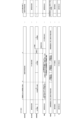
[2-4.外枠上ヒンジ組立体]
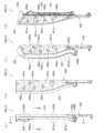
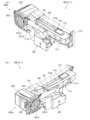
外枠2の外枠上ヒンジ組立体50について、主に図21を参照して詳細に説明する。図21(a)は外枠の外枠上ヒンジ組立体を分解して前上から見た分解斜視図であり、(b)は(a)を前下から見た分解斜視図である。外枠上ヒンジ組立体50は、外枠左組立体10の上端と外枠上部材30の左端に取付けられるものであり、外枠2に対して本体枠4をヒンジ回転可能に取付けるためのものである。外枠上ヒンジ組立体50は、外枠左部材11の凹部11aの上端と外枠上部材30の取付段部30bとに取付けられる外枠上ヒンジ部材51と、外枠上ヒンジ部材51に取付けられているロック部材52と、ロック部材52を外枠上ヒンジ部材51に取付けている取付ビス53と、を備えている。
[2-4. Outer frame upper hinge assembly]
The outer frame upper hinge assembly 50 of the outer frame 2 will be described in detail mainly with reference to FIG. FIG. 21(a) is an exploded perspective view of the outer frame upper hinge assembly of the outer frame and viewed from above, and FIG. 21(b) is an exploded perspective view of (a) viewed from below. The outer frame upper hinge assembly 50 is attached to the upper end of the outer frame left assembly 10 and the left end of the outer frame upper member 30, and is used to attach the main body frame 4 to the outer frame 2 so as to be capable of hinge rotation. is. The outer frame upper hinge assembly 50 is attached to the outer frame upper hinge member 51 attached to the upper end of the recessed portion 11a of the outer frame left member 11 and the mounting step portion 30b of the outer frame upper member 30, and the outer frame upper hinge member 51. and a mounting screw 53 for mounting the locking member 52 to the outer frame upper hinge member 51 .
外枠上ヒンジ部材51は、水平に延びた平板状で外枠上部材30の取付段部30bの上面に取付けられる上固定部51aと、上固定部51aの前辺から前方へ延出している平板状の前方延出部51bと、前方延出部51bの右辺の途中から前方へ向かうに従って前方延出部51bの左右中央へ延びており上下に貫通している軸受溝51cと、上固定部51aの左辺から下方へ延びている平板状の横固定部51dと、前方延出部51bの左辺から前辺を周って軸受溝51cが開口している部位までの端縁から下方へ延びており横固定部51dと連続している平板状の端縁壁部51eと、を備えている。外枠上ヒンジ部材51は、金属板をプレス成型により打抜き・屈曲させて形成されている。外枠上ヒンジ部材51は、軸受溝51c内において、本体枠上ヒンジ部材510の後述する本体枠上ヒンジピン512を回転可能に支持することができる。
The outer frame upper hinge member 51 is in the shape of a horizontally extending flat plate and extends forward from an upper fixing portion 51a attached to the upper surface of the mounting step portion 30b of the outer frame upper member 30 and the front side of the upper fixing portion 51a. A flat plate-like forward extending portion 51b, a bearing groove 51c that extends from the middle of the right side of the forward extending portion 51b to the center of the forward extending portion 51b toward the front and penetrates vertically, and an upper fixing portion. A flat plate-like lateral fixing portion 51d extending downward from the left side of 51a, and an end edge extending downward from the left side of the forward extending portion 51b to the portion where the bearing groove 51c opens around the front side. A flat edge wall portion 51e that is continuous with the cage horizontal fixing portion 51d is provided. The outer frame upper hinge member 51 is formed by punching and bending a metal plate by press molding. The outer frame upper hinge member 51 can rotatably support a later-described main body frame upper hinge pin 512 of the main body frame upper hinge member 510 in the bearing groove 51c.
ロック部材52は、前後に延びている帯板状のロック本体52aと、ロック本体52aの後端から右方へ突出している操作片52bと、ロック本体52aの後端から左方へ延びた後に斜め左前方へ延びている弾性変形可能な棒状の弾性部52cと、ロック本体52aの後端付近で上下に貫通している取付孔52dと、を備えている。ロック部材52は、合成樹脂によって形成されている。ロック部材52は、取付ビス53によって、外枠上ヒンジ部材51における前方延出部51bの下面で、軸受溝51cよりも後側の部位に回動可能に取付けられる。
The lock member 52 includes a band plate-like lock body 52a extending back and forth, an operation piece 52b projecting rightward from the rear end of the lock body 52a, and an operation piece 52b extending leftward from the rear end of the lock body 52a. It has an elastically deformable rod-shaped elastic portion 52c extending obliquely to the left front, and a mounting hole 52d penetrating vertically near the rear end of the lock body 52a. The lock member 52 is made of synthetic resin. The locking member 52 is rotatably attached to the lower surface of the forward extending portion 51b of the outer frame upper hinge member 51 by an attaching screw 53, at a portion rearward of the bearing groove 51c.
ロック部材52は、外枠上ヒンジ部材51に取付けた状態で、ロック本体52aが、平面視で軸受溝51cを遮ることができると共に、前端付近の右側面が、外枠上ヒンジ部材51の端縁壁部51eにおける軸受溝51cの開口まで延びている部位と当接可能となるように前方へ延びている。また、ロック本体52aの後端から左方へ延びている弾性部52cの先端は、外枠上ヒンジ部材51における端縁壁部51eの内周面に当接している。このロック部材52は、弾性部52cの付勢力によって取付孔52dを中心に、前端が左方へ回動する方向に付勢されている。従って、通常の状態では、ロック部材52のロック本体52aの前端付近の右側面が、端縁壁部51eに当接している。この状態では、軸受溝51cにおけるロック本体52aよりも前側の部位に、本体枠上ヒンジ部材510の本体枠上ヒンジピン512を収容可能な空間が形成される。
When the lock member 52 is attached to the outer frame upper hinge member 51 , the lock body 52 a can block the bearing groove 51 c in a plan view, and the right side surface near the front end is the edge of the outer frame upper hinge member 51 . It extends forward so as to come into contact with a portion of the edge wall portion 51e extending to the opening of the bearing groove 51c. The tip of the elastic portion 52c extending leftward from the rear end of the lock body 52a abuts the inner peripheral surface of the edge wall portion 51e of the outer frame upper hinge member 51. As shown in FIG. The locking member 52 is biased in a direction in which the front end thereof rotates leftward about the mounting hole 52d by the biasing force of the elastic portion 52c. Therefore, in a normal state, the right side surface of the lock body 52a of the lock member 52 in the vicinity of the front end is in contact with the edge wall portion 51e. In this state, a space capable of accommodating the main body frame upper hinge pin 512 of the main body frame upper hinge member 510 is formed in a portion of the bearing groove 51c on the front side of the lock body 52a.
このロック部材52は、操作片52bを操作することで、弾性部52cの付勢力に抗してロック本体52aを回動させることができる。そして、操作片52bの操作によって、ロック本体52aを、その前端が左方へ移動する方向へ回動させることで、平面視において軸受溝51cからロック本体52aを後退させることができ、軸受溝51cが全通している状態とすることができる。これにより、軸受溝51c内に本体枠上ヒンジピン512を挿入したり、軸受溝51c内から本体枠上ヒンジピン512を外したりすることができる。
By operating the operation piece 52b, the lock member 52 can rotate the lock body 52a against the biasing force of the elastic portion 52c. By operating the operation piece 52b to rotate the lock body 52a in a direction in which the front end thereof moves leftward, the lock body 52a can be retracted from the bearing groove 51c in a plan view. can be in a state in which the As a result, the main body frame upper hinge pin 512 can be inserted into the bearing groove 51c, or the main body frame upper hinge pin 512 can be removed from the bearing groove 51c.
[2-5.外枠下ヒンジ部材]
外枠2の外枠下ヒンジ部材60について、主に図18を参照して詳細に説明する。外枠下ヒンジ部材60は、水平に延びた平板状の水平部60aと、水平部60aの左辺において前後方向中央よりも後側の部位から上方へ立上っている平板状の立上部60bと、水平部60aの前端付近から上方へ突出している外枠下ヒンジピン60cと、水平部60aを上下に貫通しており遊技球Bが一つのみ通過可能な大きさの排出孔60dと、を備えている。この外枠下ヒンジ部材60は、金属板をプレス成型により打抜き・屈曲させて形成されている。
[2-5. Outer frame lower hinge member]
The outer frame lower hinge member 60 of the outer frame 2 will be described in detail mainly with reference to FIG. The outer frame lower hinge member 60 has a flat plate-like horizontal portion 60a that extends horizontally, and a flat plate-like raised portion 60b that rises upward from a portion rearward of the center in the front-rear direction on the left side of the horizontal portion 60a. , an outer frame lower hinge pin 60c protruding upward from near the front end of the horizontal portion 60a; ing. The lower outer frame hinge member 60 is formed by punching and bending a metal plate by press molding.
外枠下ヒンジ部材60の水平部60aは、平面視において、左辺を底辺とした台形に形成されている。外枠下ヒンジピン60cは、円柱状で、上下方向中央よりも上部が、上端が窄まった円錐台状に形成されている。この外枠下ヒンジピン60cは、水平部60aの前端付近における左寄りの位置に取付けられている。排出孔60dは、水平部60aにおいて、立上部60bの前後方向中央の部位と接し、水平部60aの左辺から右方へ逆U字状に延びるように形成されている。この排出孔60dは、外枠下組立体40における球噛防止機構44の第一排出口44bと、略同じ大きさに形成されている。
The horizontal portion 60a of the outer frame lower hinge member 60 is formed in a trapezoidal shape with the left side as the base in plan view. The outer frame lower hinge pin 60c has a columnar shape, and is formed in a truncated cone shape with an upper end narrowed above the center in the vertical direction. The outer frame lower hinge pin 60c is attached to a leftward position near the front end of the horizontal portion 60a. 60 d of discharge holes are formed in the horizontal part 60a so that it may contact|connect the center part of the front-back direction of the rising part 60b, and may extend rightward from the left side of the horizontal part 60a in an inverted U shape. The discharge hole 60 d is formed to have substantially the same size as the first discharge port 44 b of the ball jam prevention mechanism 44 in the outer frame lower assembly 40 .
外枠下ヒンジ部材60は、外枠2に組立てた状態で、水平部60aの後部が、外枠下組立体40における幕板後部材43の載置部44a上に載置され、図示しないビスによって幕板後部材43に固定されている。また、立上部60bが、外枠左部材11の右側面における膨出部11bよりも前側の部位に、図示しないビスによって取付けられている。この外枠下ヒンジ部材60は、外枠下ヒンジピン60cを、本体枠4の本体枠下ヒンジ組立体520における外枠用下ヒンジ孔521aに挿通させることで、外枠上ヒンジ部材51と協働して本体枠4を開閉可能に取付けることができる。
In the outer frame lower hinge member 60 assembled to the outer frame 2, the rear portion of the horizontal portion 60a is placed on the mounting portion 44a of the curtain plate rear member 43 in the outer frame lower assembly 40, and screwed (not shown). It is fixed to the rear panel member 43 by . The raised portion 60b is attached to the right side surface of the outer frame left member 11 on the front side of the bulging portion 11b with a screw (not shown). The outer frame lower hinge member 60 cooperates with the outer frame upper hinge member 51 by inserting the outer frame lower hinge pin 60c into the outer frame lower hinge hole 521a in the main body frame lower hinge assembly 520 of the main body frame 4. Then, the body frame 4 can be attached so that it can be opened and closed.
また、外枠2を組立てた状態では、排出孔60dが、外枠下組立体40における球噛防止機構44の第一排出口44bと一致している。これにより、水平部60a上の遊技球Bを、排出孔60d及び第一排出口44bを通して、外枠2の後方へ落下(排出)させることができる。詳述すると、外枠2に対して本体枠4を閉じる時に、外枠2と本体枠4との間に落下した遊技球Bが、本体枠4が閉じられるのに従って、外枠2と本体枠4との間が徐々に狭くなることから、間隔が広い後方側へ転動とすることとなり、排出孔60dから排出させることができる。この際に、排出孔60dが、パチンコ機1に組立てた状態で、外枠2に対して本体枠4を閉じた時に、本体枠4の後端と略同じとなる位置に形成されているため、外枠2と本体枠4との間に落下した遊技球Bを、排出孔60dから排出させることで本体枠4よりも後側へ転動するのを阻止し易くすることができ、外枠下ヒンジ部材60の部位に遊技球Bが留まり難くすることができる。
Further, in the assembled state of the outer frame 2, the discharge hole 60d coincides with the first discharge port 44b of the ball bite prevention mechanism 44 in the lower outer frame assembly 40. As shown in FIG. Thereby, the game ball B on the horizontal portion 60a can be dropped (discharged) behind the outer frame 2 through the discharge hole 60d and the first discharge port 44b. More specifically, when the main body frame 4 is closed with respect to the outer frame 2, the game ball B that has fallen between the outer frame 2 and the main body frame 4 is separated from the outer frame 2 and the main body frame as the main body frame 4 is closed. 4 gradually narrows, the ball rolls to the rear side where the gap is wide, and can be discharged from the discharge hole 60d. At this time, the discharge hole 60d is formed at a position that is substantially the same as the rear end of the body frame 4 when the body frame 4 is closed with respect to the outer frame 2 in the state assembled to the pachinko machine 1. By ejecting the game ball B dropped between the outer frame 2 and the main body frame 4 from the ejection hole 60d, it is possible to easily prevent the game ball B from rolling to the rear side of the main body frame 4, and the outer frame It is possible to make it difficult for the game ball B to stay at the part of the lower hinge member 60.例文帳に追加
[3.扉枠の全体構成]
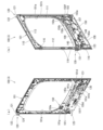
パチンコ機1の扉枠3について、主に図22乃至図30を参照して詳細に説明する。図22はパチンコ機における扉枠の正面図であり、図23は扉枠の背面図であり、図24は扉枠の左側面図であり、図25は扉枠の右側面図である。図26は扉枠を右前から見た斜視図であり、図27は扉枠を左前から見た斜視図であり、図28は扉枠を後ろから見た斜視図である。図29は扉枠を主な部材毎に分解して前から見た分解斜視図であり、図30は扉枠を主な部材毎に分解して後ろから見た分解斜視図である。
[3. Overall configuration of door frame]
The door frame 3 of the pachinko machine 1 will be described in detail mainly with reference to FIGS. 22 to 30. FIG. 22 is a front view of a door frame in a pachinko machine, FIG. 23 is a rear view of the door frame, FIG. 24 is a left side view of the door frame, and FIG. 25 is a right side view of the door frame. 26 is a perspective view of the door frame viewed from the front right, FIG. 27 is a perspective view of the door frame viewed from the front left, and FIG. 28 is a perspective view of the door frame viewed from the back. FIG. 29 is an exploded perspective view of the door frame disassembled into main members and viewed from the front, and FIG. 30 is an exploded perspective view of the door frame disassembled into the main members and viewed from the back.
扉枠3は、外枠2の枠内と略同じ大きさで正面視において上下に延びた四角形に形成されており、本体枠4を介して外枠2の枠内を前側から開閉可能に取付けられている。扉枠3は、遊技球Bが打込まれる遊技盤5の遊技領域5aを前側から視認可能に閉鎖し、遊技領域5a内に打込むための遊技球Bを貯留すると共に、貯留している遊技球Bを遊技領域5a内へ打込むために遊技者が操作するハンドル195を備えているものである。また、扉枠3は、パチンコ機1の前面全体を装飾するものである。
The door frame 3 has substantially the same size as the inside of the outer frame 2 and is formed in a rectangular shape extending vertically when viewed from the front. It is The door frame 3 closes the game area 5a of the game board 5 into which the game ball B is hit so as to be visible from the front side, stores the game ball B to be hit in the game area 5a, and stores the game ball B. It has a handle 195 operated by the player to hit the ball B into the game area 5a. Further, the door frame 3 decorates the entire front surface of the pachinko machine 1. - 特許庁
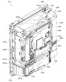
扉枠3は、正面視の外形が上下に延びた四角形で枠状の扉枠ベースユニット100と、扉枠ベースユニット100に着脱可能に取付けられており本体枠4に取付けられた遊技盤5の遊技領域5aを前方から視認可能に閉鎖しているガラスユニット160と、ガラスユニット160の下部を後側から覆うように扉枠ベースユニット100に取付けられている防犯カバー170と、扉枠ベースユニット100の前面右下隅に取付けられているハンドルユニット180と、ハンドルユニット180の外周を覆うハンドルカバーユニット290と、扉枠ベースユニット100の前面下部に取付けられている皿ユニット200と、皿ユニット200の上側で扉枠ベースユニット100の前面左部に取付けられている扉枠左サイドユニット420と、皿ユニットの上側で扉枠ベースユニット100の前面右部に取付けられている扉枠右サイドユニット430と、扉枠左サイドユニット420及び扉枠右サイドユニット430の上側で扉枠ベースユニット100の前面上部に取付けられている扉枠トップユニット450と、を備えている。
The door frame 3 includes a door frame base unit 100 having a rectangular frame shape extending vertically when viewed from the front, and a game board 5 detachably attached to the door frame base unit 100 and attached to the main body frame 4. A glass unit 160 closing the game area 5a so as to be visible from the front, a security cover 170 attached to the door frame base unit 100 so as to cover the lower part of the glass unit 160 from the rear side, and the door frame base unit 100. A handle unit 180 attached to the lower right corner of the front of the door, a handle cover unit 290 covering the outer periphery of the handle unit 180, a tray unit 200 attached to the lower front of the door frame base unit 100, and an upper side of the tray unit 200. A door frame left side unit 420 attached to the front left part of the door frame base unit 100, a door frame right side unit 430 attached to the front right part of the door frame base unit 100 above the dish unit, and a door frame top unit 450 attached to the front upper portion of the door frame base unit 100 above the door frame left side unit 420 and the door frame right side unit 430 .
扉枠ベースユニット100は、正面視の外形が上下に延びた四角形(長方形)に形成されており前後に貫通している扉窓101aを有した扉枠ベース101と、扉枠ベース101の後側で背面視右下隅に取付けられているスピーカダクト103と、扉枠ベース101の後側の下部における背面視右端付近に取付けられている扉枠主中継基板104と、扉枠主中継基板104の背面視左方に取付けられている扉枠副中継基板105と、扉枠副中継基板105の背面視左方に取付けられているハンドル後中継基板106と、扉枠主中継基板104と扉枠副中継基板105の一部とを後側から被覆する扉枠中継基板カバー107と、ハンドル後中継基板106を後側から被覆するハンドル後中継基板カバー108と、配線ケーブルを被覆するケーブルカバー109と、を備えている。
The door frame base unit 100 includes a door frame base 101 having a vertically extending quadrangular (rectangular) outer shape when viewed from the front, and having a door window 101a penetrating in the front and rear directions, and a rear side of the door frame base 101. A speaker duct 103 attached to the lower right corner when viewed from the rear, a door frame main relay board 104 attached near the right end when viewed from the rear on the lower rear side of the door frame base 101, and the rear surface of the door frame main relay board 104. A door frame secondary relay board 105 attached to the left side of the view, a handle rear relay board 106 attached to the rear view left side of the door frame secondary relay board 105, the door frame main relay board 104 and the door frame secondary relay. A door frame relay board cover 107 covering a part of the board 105 from the rear side, a handle rear relay board cover 108 covering the rear handle relay board 106 from the rear side, and a cable cover 109 covering the wiring cable. I have.
また、扉枠ベースユニット100は、扉枠ベース101の後側に取付けられている枠状の扉枠補強ユニット110と、扉枠補強ユニット110に取付けられている扉枠上ヒンジ組立体120及び扉枠下ヒンジ部材125と、扉枠補強ユニット110に取付けられている開閉用のシリンダ錠130と、扉枠ベース101の後側でハンドル後中継基板106の上方に取付けられている球送給ユニット140と、扉枠ベース101の後側の下部における背面視右側に取付けられているファールカバーユニット150と、を備えている。
Further, the door frame base unit 100 includes a frame-shaped door frame reinforcing unit 110 attached to the rear side of the door frame base 101, a door frame upper hinge assembly 120 attached to the door frame reinforcing unit 110, and a door. A frame lower hinge member 125, an opening/closing cylinder lock 130 attached to the door frame reinforcing unit 110, and a ball feeding unit 140 attached above the handle rear relay board 106 on the rear side of the door frame base 101. and a foul cover unit 150 attached to the right side of the lower rear side of the door frame base 101 when viewed from the rear.
扉枠補強ユニット110は、扉枠ベース101の後側に取付けられることで、扉枠ベース101を補強して剛性を付与するものである。扉枠上ヒンジ組立体120及び扉枠下ヒンジ部材125は、扉枠3を本体枠4に対して開閉可能に取付けるためのものである。シリンダ錠130は、本体枠4の施錠ユニット650と協働して、扉枠3と本体枠4との開閉、及び、外枠2と本体枠4との開閉施錠に使用されるものである。
The door frame reinforcing unit 110 is attached to the rear side of the door frame base 101 to reinforce the door frame base 101 and impart rigidity to it. The door frame upper hinge assembly 120 and the door frame lower hinge member 125 are for attaching the door frame 3 to the body frame 4 so as to be openable and closable. The cylinder lock 130 cooperates with the locking unit 650 of the body frame 4 to open and close the door frame 3 and the body frame 4 and to open and close the outer frame 2 and the body frame 4 .
また、球送給ユニット140は、上皿201内の遊技球Bを一つずつ本体枠4の球発射装置540へ供給するためのものである。ファールカバーユニット150は、球発射装置540により発射されて遊技盤5の遊技領域5a内に到達しなかった遊技球B(ファール球)を、下皿202に誘導すると共に、払出装置580から払出された遊技球Bを、上皿201又は下皿202に誘導するためのものである。
Also, the ball feeding unit 140 is for feeding the game balls B in the upper tray 201 to the ball launching device 540 of the body frame 4 one by one. The foul cover unit 150 guides the game ball B (foul ball) that has been shot by the ball launcher 540 and has not reached the game area 5a of the game board 5 to the lower tray 202 and is paid out from the payout device 580. It is for guiding the game ball B to the upper tray 201 or the lower tray 202.例文帳に追加
ガラスユニット160は、透明なガラス板162を有しており扉枠ベース101の扉窓101aを閉鎖している。防犯カバー170は、ガラスユニット160の下部を後方から覆うように扉枠ベース101に取付けられている。ハンドルユニット180は、遊技者が回転操作可能なハンドル195を備えており、ハンドルユニット180は、外周を覆うハンドルカバーユニット290を操作することで、上皿201内の遊技球Bを、球発射装置540によって遊技盤5の遊技領域5a内に打込む遊技を行うためのものである。
The glass unit 160 has a transparent glass plate 162 and closes the door window 101 a of the door frame base 101 . The security cover 170 is attached to the door frame base 101 so as to cover the lower portion of the glass unit 160 from behind. The handle unit 180 has a handle 195 that can be rotated by the player, and the handle unit 180 operates a handle cover unit 290 that covers the outer periphery of the game ball B in the upper tray 201 to release the ball. 540 is used to play a game of hitting the game area 5 a of the game board 5 .
[3-1.扉枠ベースユニットの全体構成]
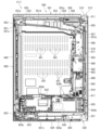
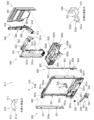
扉枠3の扉枠ベースユニット100について、主に図31乃至図33を参照して詳細に説明する。図31(a)は扉枠の扉枠ベースユニットを前から見た斜視図であり、(b)は扉枠ベースユニットを後ろから見た斜視図である。図32は扉枠ベースユニットを主な部材毎に分解して前から見た分解斜視図であり、図33は扉枠ベースユニットを主な部材毎に分解して後ろから見た分解斜視図である。
[3-1. Overall configuration of door frame base unit]
The door frame base unit 100 of the door frame 3 will be described in detail mainly with reference to FIGS. 31 to 33. FIG. FIG. 31(a) is a front perspective view of the door frame base unit of the door frame, and FIG. 31(b) is a rear perspective view of the door frame base unit. Fig. 32 is an exploded perspective view of the door frame base unit disassembled for each main member and viewed from the front, and Fig. 33 is an exploded perspective view of the door frame base unit disassembled for each main member and viewed from the rear. be.
扉枠ベースユニット100は、正面視左辺側が本体枠4に対してヒンジ回転可能に取付けられ、本体枠4の前面を開閉可能に閉鎖していると共に、本体枠4に取付けられている遊技盤5の遊技領域5aを前方から視認可能としている。扉枠ベースユニット100は、外形が上下に延びた四角形で平板状の扉枠ベース101と、扉枠ベース101の後側で背面視右下隅に取付けられているスピーカダクト103と、を備えている。
The door frame base unit 100 is hinge-rotatably attached to the main body frame 4 at the left side in front view, and closes the front surface of the main body frame 4 so as to be opened and closed. The game area 5a can be visually recognized from the front. The door frame base unit 100 includes a rectangular flat plate door frame base 101 with an outer shape extending vertically, and a speaker duct 103 attached to the rear side of the door frame base 101 at the lower right corner in rear view. .
また、扉枠ベースユニット100は、扉枠ベース101の後側の下部における背面視右端付近に取付けられている扉枠主中継基板104と、扉枠ベース101の後側の下部における扉枠主中継基板104の背面視左方に取付けられている扉枠副中継基板105と、扉枠ベース101の後側の下部における扉枠副中継基板105の背面視左方に取付けられているハンドル後中継基板106と、扉枠ベース101の後側に取付けられており扉枠主中継基板104と扉枠副中継基板105の一部とを後側から被覆する扉枠中継基板カバー107と、扉枠ベース101の後側に取付けられておりハンドル後中継基板106を後側から被覆するハンドル後中継基板カバー108と、扉枠ベース101の後側に取付けられており配線ケーブルを被覆するケーブルカバー109と、を備えている。
The door-frame base unit 100 also includes a door-frame main relay board 104 attached near the right end in the rear view of the lower rear side of the door-frame base 101, and a door-frame main relay board 104 attached to the lower rear side of the door-frame base 101. A door frame secondary relay board 105 attached to the left side of the board 104 in rear view, and a handle rear relay board mounted to the left side of the door frame secondary relay board 105 in the lower rear side of the door frame base 101 in rear view. 106, a door frame relay board cover 107 attached to the rear side of the door frame base 101 and covering the door frame main relay board 104 and part of the door frame sub relay board 105 from the rear side, and the door frame base 101. A rear handle relay board cover 108 attached to the rear side and covering the rear handle relay board 106 from the rear side, and a cable cover 109 attached to the rear side of the door frame base 101 and covering the wiring cable are provided. I have.
更に、扉枠ベースユニット100は、扉枠ベース101の後側に取付けられている枠状の扉枠補強ユニット110と、扉枠補強ユニット110に取付けられている扉枠上ヒンジ組立体120及び扉枠下ヒンジ部材125と、扉枠補強ユニット110に取付けられている開閉用のシリンダ錠130と、扉枠ベース101の後側でハンドル後中継基板106の上方に取付けられている球送給ユニット140と、扉枠ベース101の後側の下部における背面視右側に取付けられているファールカバーユニット150と、を備えている。
Further, the door frame base unit 100 includes a frame-shaped door frame reinforcing unit 110 attached to the rear side of the door frame base 101, a door frame upper hinge assembly 120 attached to the door frame reinforcing unit 110, and a door. A frame lower hinge member 125, an opening/closing cylinder lock 130 attached to the door frame reinforcing unit 110, and a ball feeding unit 140 attached above the handle rear relay board 106 on the rear side of the door frame base 101. and a foul cover unit 150 attached to the right side of the lower rear side of the door frame base 101 when viewed from the rear.
この扉枠ベースユニット100には、前面下隅にハンドルユニット180及びハンドルカバーユニット290が、扉窓101aの下側前面に皿ユニット200が、扉窓101aの左外側前面に扉枠左サイドユニット420が、扉窓101aの右外側前面に扉枠右サイドユニット430が、扉窓101aの上外側前面に扉枠トップユニット450が、夫々取付けられるものである。
The door frame base unit 100 has a handle unit 180 and a handle cover unit 290 at the lower front corner, a tray unit 200 at the lower front of the door window 101a, and a door frame left side unit 420 at the left outer front of the door window 101a. A door frame right side unit 430 is attached to the right outer front surface of the door window 101a, and a door frame top unit 450 is attached to the upper outer front surface of the door window 101a.
また、扉枠ベースユニット100には、扉窓101aを後方から閉鎖するようにガラスユニット160が取付けられると共に、ガラスユニット160の下部を後方から覆うように透明な防犯カバー170が取付けられるものである。
A glass unit 160 is attached to the door frame base unit 100 so as to close the door window 101a from behind, and a transparent security cover 170 is attached to cover the lower part of the glass unit 160 from behind. .
[3-1a.扉枠ベース]
扉枠3における扉枠ベースユニット100の扉枠ベース101について、主に図31乃至図33を参照して詳細に説明する。扉枠ベース101は、正面視の外形が上下に延びた四角形(長方形)に形成されている。扉枠ベース101は、前後に貫通しており、正面視における内周形状が上下に延びた略四角形に形成された扉窓101aを備えている。扉窓101aは、内周を形成している上辺及び左右両辺が、扉枠ベース101の外周辺に夫々接近しており、内周を形成している下辺が、扉枠ベース101の下端から上下方向の約1/3の高さに位置している。このように、扉枠ベース101は、前後に貫通している扉窓101aにより全体が枠状に形成されている。この扉枠ベース101は、合成樹脂により一体成形されている。
[3-1a. door frame base]
The door frame base 101 of the door frame base unit 100 in the door frame 3 will be described in detail mainly with reference to FIGS. 31 to 33. FIG. The door frame base 101 has a quadrangular (rectangular) shape extending vertically when viewed from the front. The door frame base 101 penetrates in the front-rear direction and has a door window 101a formed in a substantially quadrangular shape with an inner peripheral shape extending vertically when viewed from the front. The door window 101a has an upper side and both left and right sides forming the inner periphery thereof, and is close to the outer periphery of the door frame base 101, and a lower side forming the inner periphery extends vertically from the lower end of the door frame base 101. It is located at about 1/3 of the height of the direction. Thus, the door frame base 101 is formed in a frame shape as a whole by the door window 101a penetrating in the front and rear directions. The door frame base 101 is integrally molded of synthetic resin.
扉枠ベース101は、前面における正面視右下隅に形成されており左端側が右端側よりも前方へやや突出するように傾斜しているハンドル取付座面101b(図42等を参照)と、ハンドル取付座面101bと扉窓101aとの間で前後に貫通して扉枠補強ユニット110のシリンダ取付フレーム115が挿入されるシリンダ挿通孔101dと、シリンダ挿通孔101d及びハンドル取付座面101bの正面視左側で前後に貫通しており球送給ユニット140の進入口141a及び球抜口141bを前方に臨ませるための球送給開口101eと、を備えている。
The door frame base 101 has a handle mounting seat surface 101b (see FIG. 42, etc.) which is formed at the lower right corner of the front surface when viewed from the front and is inclined so that the left end side projects slightly forward from the right end side, and a handle mounting seat surface 101b (see FIG. 42). A cylinder insertion hole 101d into which the cylinder mounting frame 115 of the door frame reinforcing unit 110 is inserted through the seat surface 101b and the door window 101a in the front-rear direction, and the left side of the cylinder insertion hole 101d and the handle mounting seat surface 101b in a front view. and a ball feeding opening 101e that penetrates in the front-rear direction and allows the entrance port 141a and the ball extraction port 141b of the ball feeding unit 140 to face forward.
また、扉枠ベース101は、左右方向中央より左寄りで且つハンドル取付座面101bと略同じ高さで前後に貫通しておりファールカバーユニット150の球放出口150dを前方に臨ませる下皿用球通過口101fと、正面視左端付近で扉窓101aの下辺に隣接するように前後に貫通しておりファールカバーユニット150の貫通球通路150aを前方に臨ませる上皿用球通過口101gと、扉窓101aの内周に沿って後面から前方へ向かって窪み、ガラスユニット160のガラス枠161が挿入されるガラスユニット取付部101hと、を備えている。
In addition, the door frame base 101 penetrates in the front and back at a position near the center in the left-right direction and at substantially the same height as the handle mounting seat surface 101b. a passage opening 101f, a ball passage opening 101g for an upper tray that penetrates in the front-rear direction so as to be adjacent to the lower side of the door window 101a in the vicinity of the left end in a front view and faces the through ball passage 150a of the foul cover unit 150 forward, and a door. A glass unit mounting portion 101h recessed forward from the rear surface along the inner circumference of the window 101a and into which the glass frame 161 of the glass unit 160 is inserted is provided.
また、扉枠ベース101は、正面視左下隅(上皿用球通過口101gの下方)に形成されており前後に貫通した縦長の複数のスリット101iを、備えている。複数のスリット101iの後側にスピーカダクト103が取付けられる。また、複数のスリット101iは、パチンコ機1を組立てた状態で、前方に皿ユニット200における皿ユニットベース211のスピーカ口211bが位置していると共に、後方に本体枠4のスピーカユニット620aにおける本体枠スピーカ622が位置しており、本体枠スピーカ622からの音を前方へ放射することができる。
Further, the door frame base 101 is provided with a plurality of longitudinally long slits 101i that are formed in the lower left corner (below the ball passage opening 101g for the upper tray) in a front view and penetrate therethrough in the front-rear direction. A speaker duct 103 is attached to the rear side of the plurality of slits 101i. In addition, in the assembled state of the pachinko machine 1, the plurality of slits 101i are such that the speaker opening 211b of the dish unit base 211 of the dish unit 200 is located in front, and the main body frame of the speaker unit 620a of the main body frame 4 is located in the rear. A speaker 622 is located, and the sound from the main body frame speaker 622 can be radiated forward.
更に、扉枠ベース101は、扉窓101aの下方でハンドル取付座面101bの上方において、前後に貫通している貫通孔101jを備えている。この貫通孔101jは、扉枠ベースユニット100側と皿ユニット200側とを接続する配線ケーブル(図示は省略)が挿通されるものであり、後述する扉枠補強ユニット110における中間補強フレーム114の貫通部114bと一致するように形成されている。
Further, the door frame base 101 is provided with a through hole 101j penetrating back and forth below the door window 101a and above the handle mounting seat surface 101b. A wiring cable (not shown) connecting the door frame base unit 100 side and the tray unit 200 side is inserted through the through hole 101j. It is formed so as to match the portion 114b.
[3-1b.スピーカダクト]
扉枠ベースユニット100のスピーカダクト103について、主に図31乃至図33を参照して詳細に説明する。このスピーカダクト103は、筒状に形成されており、扉枠ベース101の後側において複数のスリット101iが形成されている部位に取付けられる。スピーカダクト103は、パチンコ機1を組立てた状態で、筒状の部位の後端が、本体枠4の本体枠スピーカ622の前方に位置している。これにより、本体枠4の本体枠スピーカ622から放射(出力)された音(サウンド)を、拡散させることなく前方へ誘導することができ、扉枠ベース101の複数のスリット101i及び皿ユニット200の皿ユニットベース211におけるスピーカ口211bを通して、パチンコ機1の前方(遊技者側)へ良好に誘導することができる。
[3-1b. speaker duct]
The speaker duct 103 of the door frame base unit 100 will be described in detail mainly with reference to FIGS. 31 to 33. FIG. This speaker duct 103 is formed in a cylindrical shape and is attached to a portion on the rear side of the door frame base 101 where a plurality of slits 101i are formed. The rear end of the cylindrical portion of the speaker duct 103 is positioned in front of the body frame speaker 622 of the body frame 4 when the pachinko machine 1 is assembled. As a result, the sound radiated (output) from the main body frame speaker 622 of the main body frame 4 can be guided forward without being diffused, and the plurality of slits 101i of the door frame base 101 and the plate unit 200 can be guided forward. Through the speaker port 211b in the dish unit base 211, the player can be guided forward (to the player side) of the pachinko machine 1 in a favorable manner.
また、スピーカダクト103は、筒状の部位の下方の後面に、接続ケーブル503を保持するケーブルホルダ103aを備えている。ケーブルホルダ103aは、扉枠中継基板カバー107よりも正面視左方に配置されており、扉枠主中継基板104及び扉枠副中継基板105に接続されている接続ケーブル503を、扉枠3の左端側へ延びるように保持している。
Moreover, the speaker duct 103 has a cable holder 103a for holding the connection cable 503 on the rear surface below the tubular portion. The cable holder 103a is arranged to the left of the door frame relay board cover 107 in front view, and connects the connection cable 503 connected to the door frame main relay board 104 and the door frame sub relay board 105 to the door frame 3. It is held so as to extend to the left end side.
[3-1c.扉枠主中継基板・扉枠副中継基板・ハンドル後中継基板]
扉枠ベースユニット100の扉枠主中継基板104、扉枠副中継基板105、ハンドル後中継基板106について、主に図32及び図33等を参照して説明する。扉枠主中継基板104は、外形が上下に延びた四角形に形成されており、扉枠ベース101の後側の下部における背面視右下隅に取付けられる。扉枠主中継基板104は、ハンドル後中継基板106と本体枠4の基板ユニット620におけるインターフェイス基板635との接続を中継するためのものであり、本体枠4から延びている接続ケーブル503(図82及び図83を参照)の一部が接続される。
[3-1c. Door frame main relay board/Door frame secondary relay board/Handle rear relay board]
The door frame main relay board 104, door frame sub relay board 105, and rear handle relay board 106 of the door frame base unit 100 will be described mainly with reference to FIGS. The door frame main relay board 104 has a rectangular outer shape extending vertically, and is attached to the lower right corner of the rear side of the door frame base 101 when viewed from the rear. The door frame main relay board 104 is for relaying the connection between the handle rear relay board 106 and the interface board 635 in the board unit 620 of the body frame 4, and the connection cable 503 extending from the body frame 4 (see FIG. 82). and FIG. 83) are connected.
扉枠副中継基板105は、外形が、上下に延びた四角形の上部の正面視右側に左右に延びた四角形が組み合された逆L字状に形成されており、上下に延びている部位が扉枠主中継基板104の背面視左方に隣接するように、扉枠ベース101の後側に取付けられている。扉枠副中継基板105は、ハンドルユニット180のハンドル装飾基板184、皿ユニット200の皿ユニット中継基板214、扉枠左サイドユニット420の扉枠左サイド上装飾基板422及び扉枠左サイド下装飾基板423、扉枠右サイドユニット430の扉枠右サイド上装飾基板432及び扉枠右サイド下装飾基板433、扉枠トップユニット450の扉枠トップ中継基板等と、本体枠4のインターフェイス基板635との接続を中継するためのものであり、本体枠4から延びている接続ケーブル503の残りが接続される。
The door frame sub-relay board 105 is formed in an inverted L shape by combining a square extending left and right on the right side of the upper part of the square extending vertically when viewed from the front. It is attached to the rear side of the door frame base 101 so as to be adjacent to the left side of the door frame main relay board 104 in rear view. The door frame secondary relay board 105 includes the handle decoration board 184 of the handle unit 180, the plate unit relay board 214 of the plate unit 200, the door frame left side upper decoration board 422 of the door frame left side unit 420, and the door frame left side lower decoration board. 423, the door frame right side upper decorative board 432 and door frame right side lower decorative board 433 of the door frame right side unit 430, the door frame top relay board of the door frame top unit 450, etc., and the interface board 635 of the main body frame 4; It is for relaying the connection, and the rest of the connection cable 503 extending from the body frame 4 is connected.
扉枠主中継基板104及び扉枠副中継基板105は、接続端子が後方へ向かって突出するように、扉枠ベース101に取付けられる。扉枠主中継基板104及び扉枠副中継基板105は、扉枠ベースユニット100を組立てた状態で、扉枠主中継基板104と扉枠副中継基板105の上下に延びている部位とが、扉枠中継基板カバー107によって後側が被覆された状態となり、扉枠副中継基板105の残りの部位が、ファールカバーユニット150によって後側が被覆された状態となる。
The door frame main relay board 104 and the door frame sub relay board 105 are attached to the door frame base 101 so that the connection terminals protrude rearward. When the door-frame base unit 100 is assembled, the door-frame main relay board 104 and the door-frame sub-relay board 105 are arranged so that the vertically extending parts of the door-frame main relay board 104 and the door-frame sub-relay board 105 are connected to the door. The rear side is covered with the frame relay board cover 107 , and the rear side of the remaining part of the door frame sub-relay board 105 is covered with the foul cover unit 150 .
ハンドル後中継基板106は、外形が左右に延びた四角形に形成されており、扉枠ベース101の後側における球送給開口101eの下方でハンドル取付座面101bの後側に取付けられる。ハンドル後中継基板106は、扉枠主中継基板104とハンドルユニット180のハンドル回転検知センサ189、ハンドルタッチセンサ192、単発ボタン操作センサ194、及び球送給ユニット140の球送給ソレノイド145との接続を中継するためのものである。ハンドル後中継基板106は、扉枠ベースユニット100を組立てた状態で、ハンドル後中継基板カバー108によって後側が被覆された状態となる。
The post-handle relay board 106 has a rectangular outer shape extending left and right, and is attached to the rear side of the handle mounting seat surface 101b below the ball feeding opening 101e on the rear side of the door frame base 101. As shown in FIG. The post-handle relay board 106 connects the door frame main relay board 104 to the handle rotation detection sensor 189 of the handle unit 180, the handle touch sensor 192, the single button operation sensor 194, and the ball feed solenoid 145 of the ball feed unit 140. It is for relaying. The rear side of the handle relay board 106 is covered with the rear handle relay board cover 108 when the door frame base unit 100 is assembled.
[3-1d.扉枠中継基板カバー・ハンドル後中継基板カバー・ケーブルカバー]
扉枠ベースユニット100の扉枠中継基板カバー107、ハンドル後中継基板カバー108、及びケーブルカバー109について、主に図31乃至図33を参照して説明する。扉枠中継基板カバー107は、扉枠ベース101の後側に取付けることで、扉枠主中継基板104と扉枠副中継基板105の一部(逆L字状の上下に延びている部位)の後側を被覆するものである。扉枠中継基板カバー107は、前方及び正面視左方が開放された箱状に形成されている。扉枠ベースユニット100に組立てた状態では、後側を被覆している扉枠主中継基板104及び扉枠副中継基板105の接続端子が扉枠中継基板カバー107の内部に露出しており、開放されている左側から接続ケーブル503を内部に挿入して、それら端子に接続することができる。
[3-1d. Door frame relay board cover, rear handle relay board cover, cable cover]
The door frame relay board cover 107, the rear handle relay board cover 108, and the cable cover 109 of the door frame base unit 100 will be described mainly with reference to FIGS. 31 to 33. FIG. By attaching the door frame relay board cover 107 to the rear side of the door frame base 101, the door frame main relay board 104 and a part of the door frame sub relay board 105 (parts extending vertically in an inverted L shape) are covered. It covers the rear side. The door frame relay board cover 107 is formed in a box shape that is open at the front and the left side when viewed from the front. When assembled to the door-frame base unit 100, the connection terminals of the door-frame main relay board 104 and the door-frame sub-relay board 105 covering the rear side are exposed inside the door-frame relay board cover 107 and can be opened. A connection cable 503 can be inserted inside from the left side of the housing and connected to these terminals.
ハンドル後中継基板カバー108は、ハンドル後中継基板106の後側を被覆するように扉枠ベース101の後側に取付けられるものである。ケーブルカバー109は、扉枠補強ユニット110における中間補強フレーム114の後側に取付けられ、扉枠主中継基板104と皿ユニット200の球貸操作ユニット220とを接続する配線ケーブル(図示は省略)を被覆するためのものである。ケーブルカバー109は、左右に延びた箱状に形成されており、前面の左端付近と下面の左右方向中央に、配線ケーブルを通すための開口が形成されている。
The post-handle relay board cover 108 is attached to the rear side of the door frame base 101 so as to cover the rear side of the post-handle relay board 106 . The cable cover 109 is attached to the rear side of the intermediate reinforcing frame 114 in the door frame reinforcing unit 110, and connects the door frame main relay board 104 and the ball lending operation unit 220 of the plate unit 200 with a wiring cable (not shown). It is for covering. The cable cover 109 is formed in a box-like shape extending in the left and right direction, and has openings formed near the left end of the front surface and in the center of the lower surface in the left-right direction for passing the wiring cables.
[3-1e.扉枠補強ユニット]
扉枠ベースユニット100の扉枠補強ユニット110について、主に図31乃至図33を参照して詳細に説明する。扉枠補強ユニット110は、扉枠ベース101の後側に取付けられることで、平板状の扉枠ベース101を補強して、扉枠ベースユニット100に剛性を付与している。扉枠補強ユニット110は、左右に離間して配置されている上下に延びた左補強フレーム111及び右補強フレーム112と、左補強フレーム111及び右補強フレーム112の上端同士を連結している左右に延びた上補強フレーム113と、左補強フレーム111の下端から上寄りの位置に左端側が取付けられており右補強フレーム112付近まで右方へ延びた中間補強フレーム114と、中間補強フレーム114の右端と右補強フレーム112とを連結しているシリンダ取付フレーム115と、右補強フレーム112の後側に上下に離間して複数取付けられており本体枠4の施錠ユニット650の扉枠用鉤652が掛止される鉤掛部材116と、を備えている。
[3-1e. Door frame reinforcement unit]
The door frame reinforcement unit 110 of the door frame base unit 100 will be described in detail mainly with reference to FIGS. 31 to 33. FIG. The door frame reinforcing unit 110 is attached to the rear side of the door frame base 101 to reinforce the flat plate-shaped door frame base 101 and impart rigidity to the door frame base unit 100 . The door frame reinforcing unit 110 includes a vertically extending left reinforcing frame 111 and a right reinforcing frame 112 that are spaced apart in the left and right direction, and a left reinforcing frame 111 and a right reinforcing frame 112 that connect the upper ends of the left reinforcing frame 111 and the right reinforcing frame 112 . An extended upper reinforcing frame 113, an intermediate reinforcing frame 114 whose left end is attached at a position near the upper end of the left reinforcing frame 111 and extends rightward to the vicinity of the right reinforcing frame 112, and the right end of the intermediate reinforcing frame 114. A plurality of cylinder mounting frames 115, which are connected to the right reinforcing frame 112, are mounted on the rear side of the right reinforcing frame 112 with a vertical separation therebetween, and the door frame hooks 652 of the locking unit 650 of the body frame 4 are engaged. and a hooking member 116 that is attached.
左補強フレーム111及び右補強フレーム112は、左右方向が一定の幅で、扉枠ベース101の上下の高さと略同じ長さで上下に延びている。右補強フレーム112には、上下方向に離間しており、前後方向に貫通している複数の挿通孔が形成されている。これら挿通孔は、本体枠4に対して扉枠3を閉めた時に、施錠ユニット650の扉枠用鉤652の先端が挿通される。上補強フレーム113は、上下方向が一定の幅で、扉枠ベース101の左右の幅と略同じ長さで左右に延びている。
The left reinforcing frame 111 and the right reinforcing frame 112 have a constant width in the left-right direction, and extend vertically by a length substantially equal to the vertical height of the door frame base 101 . The right reinforcing frame 112 is formed with a plurality of insertion holes that are spaced apart in the vertical direction and penetrate in the front-rear direction. The tips of the door frame hooks 652 of the locking unit 650 are inserted through these insertion holes when the door frame 3 is closed with respect to the body frame 4 . The upper reinforcing frame 113 has a constant width in the vertical direction, and extends in the left and right direction with substantially the same length as the left and right width of the door frame base 101 .
中間補強フレーム114は、上下方向が上補強フレーム113の上下の幅よりも広い幅で左右に延びている。中間補強フレーム114は、左端付近において上端から下方へ四角く切欠かれた切欠部114aと、右端付近において前後に貫通している貫通部114bと、を有している。切欠部114aは、扉枠ベース101の上皿用球通過口101gと、貫通部114bは、扉枠ベース101の貫通孔101jと、夫々一致する位置に形成されている。
The intermediate reinforcing frame 114 extends laterally with a width that is wider in the vertical direction than the vertical width of the upper reinforcing frame 113 . The intermediate reinforcing frame 114 has a notch portion 114a that is rectangularly cut downward from the upper end in the vicinity of the left end, and a through portion 114b that penetrates in the front-rear direction in the vicinity of the right end. The cut-out portion 114a is formed at the position corresponding to the upper tray ball passage opening 101g of the door frame base 101, and the through portion 114b is formed at the position corresponding to the through hole 101j of the door frame base 101, respectively.
シリンダ取付フレーム115は、左右に離間して配置されており正面視において上下に延びた四角形の平板状に形成されている一対の後片部と、一対の後片部の対面している夫々の辺から前方へ平板状に延出している一対の側片部と、一対の前方延出部の前端の辺同士を連結している平板状の前片部と、を備えている。このシリンダ取付フレーム115は、平面視の形状が前方へ突出した凸形状に形成されている。シリンダ取付フレーム115は、左側の後片部が中間補強フレーム114の右端に取付けられ、右側の後片部が右補強フレーム112に取付けられる。このシリンダ取付フレーム115は、前片部にシリンダ錠130が取付けられる。
The cylinder mounting frame 115 includes a pair of rear piece portions which are spaced apart from each other in the left and right direction and formed in a rectangular flat plate shape extending vertically when viewed from the front, and a pair of rear piece portions facing each other. It has a pair of side pieces extending forward from the sides in a flat plate shape, and a flat front piece portion connecting the front ends of the pair of front extending portions to each other. The cylinder mounting frame 115 is formed in a convex shape that protrudes forward in plan view. The cylinder mounting frame 115 has a left rear piece attached to the right end of the intermediate reinforcing frame 114 and a right rear piece attached to the right reinforcing frame 112 . A cylinder lock 130 is attached to the front piece of the cylinder attachment frame 115 .
鉤掛部材116は、右補強フレーム112の後側において、前後に貫通している挿通孔の部位に取付けられている。これら鉤掛部材116は、施錠ユニット650の扉枠用鉤652が掛止される。
The hooking member 116 is attached to an insertion hole penetrating in the front-rear direction on the rear side of the right reinforcing frame 112 . Door frame hooks 652 of the locking unit 650 are hooked to these hooking members 116 .
扉枠補強ユニット110を構成している左補強フレーム111、右補強フレーム112、上補強フレーム113、中間補強フレーム114、シリンダ取付フレーム115、及び鉤掛部材116は、金属板をプレス成型によって打抜き・屈曲することで形成されている。これらは、リベットによって組立てられている。
The left reinforcing frame 111, the right reinforcing frame 112, the upper reinforcing frame 113, the intermediate reinforcing frame 114, the cylinder mounting frame 115, and the hooking member 116, which constitute the door frame reinforcing unit 110, are made by punching and molding metal plates. It is formed by bending. These are assembled with rivets.
扉枠補強ユニット110は、左補強フレーム111、右補強フレーム112、及び上補強フレーム113が、扉枠ベース101の左辺、右辺、及び上辺に沿うように組立てられていると共に、中間補強フレーム114が、扉枠ベース101の扉窓101aの下方に位置するように組立てられている。
The door frame reinforcing unit 110 includes a left reinforcing frame 111, a right reinforcing frame 112, and an upper reinforcing frame 113 assembled along the left side, right side, and upper side of the door frame base 101, and an intermediate reinforcing frame 114. , is assembled to be located below the door window 101a of the door frame base 101. As shown in FIG.
扉枠補強ユニット110は、図示しない複数のビスにより扉枠ベース101の後側に取付けられる。この扉枠補強ユニット110は、扉枠ベース101に取付けた状態で、中間補強フレーム114の切欠部114a及び貫通部114bが、扉枠ベース101の上皿用球通過口101g及び貫通孔101jと一致した状態となると共に、シリンダ取付フレーム115が、扉枠ベース101のシリンダ挿通孔101dに挿入された状態となる。
The door frame reinforcing unit 110 is attached to the rear side of the door frame base 101 with a plurality of screws (not shown). When the door frame reinforcing unit 110 is attached to the door frame base 101, the notch portion 114a and the through portion 114b of the intermediate reinforcing frame 114 are aligned with the upper tray ball passage opening 101g and the through hole 101j of the door frame base 101. At the same time, the cylinder mounting frame 115 is inserted into the cylinder insertion hole 101 d of the door frame base 101 .
[3-1f.扉枠上ヒンジ組立体]
扉枠ベースユニット100の扉枠上ヒンジ組立体120について、主に図31乃至図33を参照して説明する。扉枠上ヒンジ組立体120は、扉枠補強ユニット110の正面視左上隅に取付けられる。扉枠上ヒンジ組立体120は、扉枠3を、扉枠下ヒンジ部材125と協働して本体枠4に対してヒンジ回転可能に取付けるためのものである。扉枠上ヒンジ組立体120は、扉枠補強ユニット110に取付けられるヒンジブラケット121と、ヒンジブラケット121に上下方向へ移動可能に取付けられる扉枠上ヒンジピン122と、扉枠上ヒンジピン122に取付けられる鍔部材123と、扉枠上ヒンジピン122を上方へ移動するように付勢しているロックバネ124と、を備えている。
[3-1f. Door frame upper hinge assembly]
The door frame upper hinge assembly 120 of the door frame base unit 100 will be described mainly with reference to FIGS. 31-33. The door frame upper hinge assembly 120 is attached to the front upper left corner of the door frame reinforcement unit 110 . The door frame upper hinge assembly 120 is for attaching the door frame 3 to the main body frame 4 in cooperation with the door frame lower hinge member 125 so as to be capable of hinge rotation. The door frame upper hinge assembly 120 includes a hinge bracket 121 attached to the door frame reinforcing unit 110, a door frame upper hinge pin 122 attached to the hinge bracket 121 so as to be movable in the vertical direction, and a flange attached to the door frame upper hinge pin 122. A member 123 and a locking spring 124 biasing the door frame upper hinge pin 122 to move upward.
ヒンジブラケット121は、正面視四角形の平板状の取付片121aと、取付片121aの上辺及び下辺から前方へ延出している平板状の突出片121bと、を備えている。ヒンジブラケット121は、取付片121aが扉枠補強ユニット110に取付けられる。ヒンジブラケット121は、金属板を屈曲させて形成されている。
The hinge bracket 121 includes a flat plate-like attachment piece 121a that is square in front view, and flat plate-like projecting pieces 121b that extend forward from the upper and lower sides of the attachment piece 121a. The hinge bracket 121 is attached to the door frame reinforcing unit 110 at the attachment piece 121a. Hinge bracket 121 is formed by bending a metal plate.
扉枠上ヒンジピン122は、円柱状の金属棒をL字状に屈曲させたものである。扉枠上ヒンジピン122は、扉枠上ヒンジ組立体120に組立てた状態で、上下に延びている部位が、ヒンジブラケット121における一対の突出片121bの前端付近において下方から貫通し、上端が上側の突出片121bよりも上方へ延び出していると共に、水平に延びている部位が下側の突出片121bの下面に当接している。扉枠上ヒンジピン122は、上端が本体枠4の本体枠上ヒンジ部材510における上ヒンジ本体511の扉枠用上ヒンジ孔511aに回転可能に挿通される。
The door frame upper hinge pin 122 is formed by bending a cylindrical metal rod into an L shape. When the door frame upper hinge pin 122 is assembled to the door frame upper hinge assembly 120, the vertically extending portion penetrates from below near the front ends of the pair of protruding pieces 121b of the hinge bracket 121, and the upper end extends upward. The portion extending upward from the protruding piece 121b and extending horizontally contacts the lower surface of the lower protruding piece 121b. The upper end of the door frame upper hinge pin 122 is rotatably inserted into the door frame upper hinge hole 511 a of the upper hinge main body 511 of the main body frame upper hinge member 510 of the main body frame 4 .
鍔部材123は、Eリングとされており、扉枠上ヒンジピン122における一対の突出片121bの間となる部位に取付けられている。ロックバネ124は、コイル状に形成されており、鍔部材123とヒンジブラケット121における下側の突出片121bとの間において扉枠上ヒンジピン122の上下に延びている部位の周りに被せられている。このロックバネ124により、鍔部材123を介して扉枠上ヒンジピン122が上方へ付勢されている。
The flange member 123 is an E-ring and is attached to a portion between the pair of protruding pieces 121b of the hinge pin 122 on the door frame. The lock spring 124 is formed in a coil shape, and covers the vertically extending portion of the door frame upper hinge pin 122 between the flange member 123 and the lower projecting piece 121 b of the hinge bracket 121 . The lock spring 124 urges the door frame upper hinge pin 122 upward via the flange member 123 .
扉枠上ヒンジ組立体120は、扉枠上ヒンジピン122がロックバネ124により上方へ付勢された状態となっており、扉枠上ヒンジピン122における下端の水平に延びている部位が下側の突出片121bの下面に当接することで、これ以上の上方への移動が規制されている。この状態では、扉枠上ヒンジピン122の上端が、上側の突出片121bの上面よりも所定量上方に突出している。
In the door frame upper hinge assembly 120, the door frame upper hinge pin 122 is urged upward by the lock spring 124, and the horizontally extending portion of the lower end of the door frame upper hinge pin 122 is the lower projecting piece. Further upward movement is restricted by abutting on the lower surface of 121b. In this state, the upper end of the door frame upper hinge pin 122 protrudes upward by a predetermined amount from the upper surface of the upper projecting piece 121b.
扉枠上ヒンジ組立体120は、扉枠上ヒンジピン122における下端の水平に延びている部位を、ロックバネ124の付勢力に抗してその部位を下方へ移動させると、扉枠上ヒンジピン122を全体的に下方へ移動させることができ、扉枠上ヒンジピン122の上端を、上側の突出片121bの上面よりも下方へ没入させることができる。従って、扉枠上ヒンジ組立体120は、扉枠上ヒンジピン122の上端を、本体枠上ヒンジ部材510の扉枠用上ヒンジ孔511aに対して下方から挿入させたり、下方へ抜いたりすることができる。これにより、扉枠上ヒンジピン122の上端を、本体枠上ヒンジ部材510の扉枠用上ヒンジ孔511aに挿入させることで、扉枠3の正面視上部左端を、本体枠4に対してヒンジ回転可能に支持させることができる。
In the door frame upper hinge assembly 120, when the horizontally extending portion of the lower end of the door frame upper hinge pin 122 is moved downward against the biasing force of the lock spring 124, the door frame upper hinge pin 122 is fully extended. The upper end of the door frame upper hinge pin 122 can be retracted below the upper surface of the upper projecting piece 121b. Therefore, in the door frame upper hinge assembly 120, the upper end of the door frame upper hinge pin 122 can be inserted from below into the door frame upper hinge hole 511a of the main body frame upper hinge member 510 or removed downward. can. As a result, the upper end of the door frame upper hinge pin 122 is inserted into the door frame upper hinge hole 511 a of the main body frame upper hinge member 510 , so that the upper left end of the door frame 3 when viewed from the front is hinge-rotated with respect to the main body frame 4 . can be supported as much as possible.
また、扉枠上ヒンジ組立体120は、扉枠上ヒンジピン122における上下に延びている部位が、後述する扉枠下ヒンジ部材125の扉枠下ヒンジピン126と同軸上に位置している。これにより、扉枠上ヒンジピン122と扉枠下ヒンジピン126とによって、扉枠3を本体枠4に対して良好な状態でヒンジ回転させることができる。
In the door frame upper hinge assembly 120, the vertically extending portion of the door frame upper hinge pin 122 is positioned coaxially with the door frame lower hinge pin 126 of the door frame lower hinge member 125, which will be described later. As a result, the door frame 3 can be hinge-rotated with respect to the main body frame 4 in a favorable state by the door frame upper hinge pin 122 and the door frame lower hinge pin 126 .
[3-1g.扉枠下ヒンジ部材]
扉枠ベースユニット100の扉枠下ヒンジ部材125について、主に図31乃至図33を参照して説明する。扉枠下ヒンジ部材125は、扉枠補強ユニット110の正面視左下隅に取付けられる。扉枠下ヒンジ部材125は、扉枠3を、扉枠上ヒンジ組立体120と協働して本体枠4に対してヒンジ回転可能に取付けるためのものである。
[3-1g. Door frame lower hinge member]
The door frame lower hinge member 125 of the door frame base unit 100 will be described mainly with reference to FIGS. 31 to 33. FIG. The door frame lower hinge member 125 is attached to the lower left corner of the door frame reinforcing unit 110 when viewed from the front. The door frame lower hinge member 125 is for attaching the door frame 3 to the main body frame 4 in cooperation with the door frame upper hinge assembly 120 so as to be capable of hinge rotation.
扉枠下ヒンジ部材125は、扉枠補強ユニット110に取付けられ正面視四角形で平板状の取付片125aと、取付片125aの下辺から前方へ延出している平板状の突出片125bと、突出片125bの前端付近の下面から下方へ突出している扉枠下ヒンジピン126(図22等を参照)と、を備えている。
The door frame lower hinge member 125 includes a flat mounting piece 125a attached to the door frame reinforcing unit 110 and rectangular in front view, a flat plate-shaped projecting piece 125b extending forward from the lower side of the mounting piece 125a, and a projecting piece. A door frame lower hinge pin 126 (see FIG. 22, etc.) protruding downward from the lower surface near the front end of the door frame 125b.
扉枠下ヒンジ部材125の取付片125a及び突出片125bは、金属板を屈曲させて形成されている。扉枠下ヒンジピン126は、円柱状の金属棒で、下端部の外周にテーパ状の面取りが施されている。この扉枠下ヒンジピン126は、扉枠ベースユニット100に組立てた状態で、突出片125bにおける扉枠上ヒンジ組立体120の扉枠上ヒンジピン122の上下に延びている部位と同軸上となる部位に取付けられている。
The mounting piece 125a and the projecting piece 125b of the lower door frame hinge member 125 are formed by bending a metal plate. The door frame lower hinge pin 126 is a cylindrical metal rod, and the outer circumference of the lower end portion is tapered and chamfered. When the door frame base unit 100 is assembled, the door frame lower hinge pin 126 is positioned coaxially with the vertically extending portion of the door frame upper hinge pin 122 of the door frame upper hinge assembly 120 in the protruding piece 125b. installed.
この扉枠下ヒンジ部材125は、扉枠下ヒンジピン126を本体枠下ヒンジ組立体520の扉枠用下ヒンジ孔522aに挿入することで、扉枠3を本体枠4に対してヒンジ回転可能に支持することができる。
The door frame lower hinge member 125 allows the door frame 3 to rotate with respect to the main body frame 4 by inserting the door frame lower hinge pin 126 into the door frame lower hinge hole 522a of the main body frame lower hinge assembly 520. can support.
[3-1h.シリンダ錠]
扉枠3の扉枠ベースユニット100におけるシリンダ錠130について、主に図34乃至図36を参照して詳細に説明する。図34(a)は扉枠のシリンダ錠を前から見た斜視図であり、(b)は(a)のシリンダ錠を後ろ前から見た斜視図であり、(c)は従来のパチンコ機におけるシリンダ錠を前から見た斜視図であり、(d)は(a)のシリンダ錠を後ろから見た斜視図である。図35(a)は図34(a)のシリンダ錠を分解して前から見た分解斜視図であり、(b)は図34(a)のシリンダ錠を分解して後ろから見た分解斜視図である。図36(a)は図34(a)のシリンダ錠の可動機構を正面から示す説明図であり、(b)は(a)の状態から反時計回りの方向へ90度回転させた状態で示すシリンダ錠の説明図であり、(c)は(a)の状態から時計回りの方向へ90度回転させた状態で示すシリンダ錠の説明図である。
[3-1h. cylinder lock]
The cylinder lock 130 in the door frame base unit 100 of the door frame 3 will be described in detail mainly with reference to FIGS. 34 to 36. FIG. Fig. 34 (a) is a perspective view of the cylinder lock of the door frame as seen from the front, (b) is a perspective view of the cylinder lock of (a) as seen from the back and front, and (c) is a conventional pachinko machine. 2 is a front perspective view of the cylinder lock in FIG. 2, and (d) is a rear perspective view of the cylinder lock in (a). Fig. 35(a) is an exploded perspective view of the cylinder lock shown in Fig. 34(a) and viewed from the front, and Fig. 35(b) is an exploded perspective view of the cylinder lock shown in Fig. 34(a) and viewed from the rear. It is a diagram. Fig. 36(a) is an explanatory view showing the movable mechanism of the cylinder lock of Fig. 34(a) from the front, and Fig. 36(b) shows the state rotated counterclockwise by 90 degrees from the state of Fig. 34(a). It is explanatory drawing of a cylinder lock, (c) is explanatory drawing of a cylinder lock shown in the state rotated 90 degrees clockwise from the state of (a).
シリンダ錠130は、扉枠補強ユニット110のシリンダ取付フレーム115に取付けられ、本体枠4の施錠ユニット650と協働して、扉枠3と本体枠4との開閉、及び、外枠2と本体枠4との開閉施錠に使用されるものである。シリンダ錠130は、前後に延びた円柱状のシリンダ本体131と、シリンダ本体131の前端面に形成されている鍵穴132と、シリンダ本体131の後方に設けられており鍵穴132に挿入された正規の鍵を回転させると一緒に回転する回転伝達部材133と、を備えている。
The cylinder lock 130 is attached to the cylinder mounting frame 115 of the door frame reinforcing unit 110, and cooperates with the locking unit 650 of the main body frame 4 to open and close the door frame 3 and the main body frame 4, and to open and close the outer frame 2 and the main body. It is used for opening and closing with the frame 4 . The cylinder lock 130 includes a cylindrical cylinder body 131 extending back and forth, a keyhole 132 formed in the front end face of the cylinder body 131, and a regular keyhole 132 provided behind the cylinder body 131 and inserted into the keyhole 132. and a rotation transmission member 133 that rotates together with the rotation of the key.
シリンダ錠130のシリンダ本体131は、シリンダ取付フレーム115の前片部を後方から貫通して後端が前片部に取付けられている。回転伝達部材133は、後方が開放された円筒状(詳しくは、後方へ向かうに従って直径が大きくなる円錐筒状)に形成されており、中心軸を挟んで対向した位置に後端から前方へ向かって切欠かれた一対の切欠部を有している。回転伝達部材133は、本体枠4における施錠ユニット650の伝達シリンダ654が後方から挿入されるように形成されており、伝達シリンダ654の一対の突起が一対の切欠部内に挿入されることで、回転伝達部材133(鍵穴132に挿入された鍵)の回転を、伝達シリンダ654に伝達させて回転させることができる。
A cylinder body 131 of the cylinder lock 130 penetrates the front piece of the cylinder mounting frame 115 from the rear and the rear end is attached to the front piece. The rotation transmission member 133 is formed in a cylindrical shape (specifically, a conical cylinder shape whose diameter increases toward the rear) with an open rear end, and the rotation transmission member 133 is formed in opposite positions across the central axis from the rear end toward the front. It has a pair of notches that are notched. The rotation transmission member 133 is formed so that the transmission cylinder 654 of the locking unit 650 in the main body frame 4 is inserted from behind. The rotation of the transmission member 133 (the key inserted into the keyhole 132) can be transmitted to the transmission cylinder 654 to rotate.
更に詳述すると、シリンダ錠130は、シリンダ本体131の後端側に設けられており鍵穴132に挿入された正規の鍵を回転させると一緒に回転する第一カム部材134と、シリンダ取付フレーム115におけるシリンダ本体131よりも下方の部位で前後方向の軸周りに対して回転可能に取付けられている第二カム部材135と、上端側が第一カム部材134における回転中心よりも右方の部位で回転可能に取付けられていると共に下端側が第二カム部材135における回転中心よりも右方の部位で回転可能に取付けられている帯板状の第一アーム136と、上端側が第一カム部材134における回転中心よりも下方の部位で回転可能に取付けられていると共に下端側が第二カム部材135における回転中心よりも下方の部位で回転可能に取付けられている帯板状の第二アーム137と、を備えている。
More specifically, the cylinder lock 130 includes a first cam member 134 which is provided on the rear end side of the cylinder main body 131 and rotates together with a regular key inserted into the keyhole 132, and a cylinder mounting frame 115. A second cam member 135 attached rotatably about an axis in the front-rear direction at a portion below the cylinder body 131 in the upper end side rotates at a portion to the right of the rotation center of the first cam member 134 A band plate-shaped first arm 136 that is rotatably attached to the second cam member 135 at the lower end side of the center of rotation of the second cam member 135, and the upper end side is the first cam member 134 that rotates. a strip-shaped second arm 137 which is rotatably attached at a portion below the center and whose lower end side is rotatably attached at a portion below the center of rotation of the second cam member 135; ing.
また、シリンダ錠130は、第二カム部材135(回転伝達部材133)を除いてシリンダ本体131、第一カム部材134、第一アーム136、及び第二アーム137を後方から覆うようにシリンダ取付フレーム115に取付けられている後カバー138と、第一アーム136及び第二アーム137の夫々の上下両端側を、夫々第一カム部材134や第二カム部材135に対して回転可能に取付けているリベット139と、を備えている。
Also, the cylinder lock 130 is mounted on the cylinder mounting frame so as to cover the cylinder main body 131, the first cam member 134, the first arm 136, and the second arm 137 from behind except for the second cam member 135 (rotation transmission member 133). Rivets that rotatably attach the rear cover 138 attached to 115 and the upper and lower end sides of the first arm 136 and the second arm 137 to the first cam member 134 and the second cam member 135, respectively. 139 and .
第一カム部材134は、第一アーム136の上端側が後面側に取付けられていると共に、第二アーム137の上端側が前面側に取付けられている。第二カム部材135は、シリンダ取付フレーム115により後側から回転可能に取付けられており、シリンダ取付フレーム115の前面を挟んだ後側に、回転伝達部材133が一体回転可能に取付けられている。第二カム部材135は、第一アーム136の下端側が前面側に取付けられていると共に、第二アーム137の下端側が第一アーム136よりも前方で前面側に取付けられている。
The first cam member 134 has the upper end side of the first arm 136 attached to the rear side, and the upper end side of the second arm 137 attached to the front side. The second cam member 135 is rotatably attached from the rear side by the cylinder mounting frame 115, and the rotation transmission member 133 is attached to the rear side across the front surface of the cylinder mounting frame 115 so as to be integrally rotatable. The second cam member 135 has the lower end side of the first arm 136 attached to the front side, and the lower end side of the second arm 137 is attached to the front side ahead of the first arm 136 .
第一カム部材134及び第二カム部材135は、夫々において、第一アーム136が取付けられる部位と、第二アーム137が取付けられる部位とが、夫々の回転軸を中心に90度の角度で離隔している。また、第一カム部材134及び第二カム部材135は、夫々において、第一アーム136が取付けられる部位が、第二アーム137が取付けられる部位よりも、回転中心から遠ざかった位置に設けられている。
In each of the first cam member 134 and the second cam member 135, the portion to which the first arm 136 is attached and the portion to which the second arm 137 is attached are spaced apart at an angle of 90 degrees around their respective rotation axes. are doing. In each of the first cam member 134 and the second cam member 135, the portion to which the first arm 136 is attached is located farther from the center of rotation than the portion to which the second arm 137 is attached. .
後カバー138は、左右両側面の下端から外方へ円柱状に突出した軸部138aが、シリンダ取付フレーム115のL字状の係止スリット115bに係止された状態で、上端側が図示しないビスにより、シリンダ取付フレーム115に着脱可能に取付けられている。
The rear cover 138 has a cylindrical shaft portion 138a that protrudes outward from the lower ends of both left and right side surfaces of the rear cover 138. The shaft portion 138a is engaged with the L-shaped engagement slit 115b of the cylinder mounting frame 115. It is detachably attached to the cylinder mounting frame 115 by means of.
このシリンダ錠130は、シリンダ取付フレーム115、シリンダ本体131、回転伝達部材133、第一カム部材134、第二カム部材135、第一アーム136、及び第二アーム137が、金属により形成されている。
In this cylinder lock 130, the cylinder mounting frame 115, the cylinder body 131, the rotation transmission member 133, the first cam member 134, the second cam member 135, the first arm 136 and the second arm 137 are made of metal. .
シリンダ錠130は、扉枠3に組立てた状態で、シリンダ本体131の前端が扉枠右サイドユニット430のシリンダ挿通口440bの前端と略一致した状態となる。
When the cylinder lock 130 is assembled to the door frame 3 , the front end of the cylinder body 131 is substantially aligned with the front end of the cylinder insertion opening 440 b of the door frame right side unit 430 .
ここで、従来のシリンダ錠130Aについて説明する。従来のシリンダ錠130Aは、図34(c)及び(d)に示すように、シリンダ本体131が、シリンダ取付フレーム115Aの前片部を後方から貫通して後端が前片部に取付けられている。このシリンダ錠130Aは、シリンダ本体131の軸芯上に回転伝達部材133が設けられている。
Here, the conventional cylinder lock 130A will be described. As shown in FIGS. 34(c) and 34(d), the conventional cylinder lock 130A has a cylinder main body 131 which penetrates the front piece of the cylinder mounting frame 115A from the rear and the rear end of which is attached to the front piece. there is A rotation transmission member 133 is provided on the axis of a cylinder body 131 of the cylinder lock 130A.
続いて、本実施形態のシリンダ錠130の作動について説明する。従来のシリンダ錠130は、図34(c)及び(d)に示すように、シリンダ本体131の軸芯上に回転伝達部材133が設けられているのに対して、本実施形態のシリンダ錠130は、図34(a)及び(b)等に示すように、シリンダ本体131の軸芯から下方へ離隔した位置に回転伝達部材133が設けられている。
Next, the operation of the cylinder lock 130 of this embodiment will be described. As shown in FIGS. 34(c) and 34(d), the conventional cylinder lock 130 has a rotation transmitting member 133 on the axis of the cylinder body 131. 34(a) and 34(b), etc., a rotation transmission member 133 is provided at a position spaced downward from the axis of the cylinder body 131. As shown in FIGS.
このシリンダ錠130は、通常の状態では、図36(a)に示すように、第一アーム136の上下両端側が、第一カム部材134及び第二カム部材135の夫々において、夫々の回転中心の右方の部位に取付けられていると共に、第二アーム137の上下両端側が、第一カム部材134及び第二カム部材135の夫々において、夫々の回転中心の下方の部位に取付けられている。シリンダ本体131では、正規の鍵によって、通常の状態から、時計回りの方向、及び反時計回りの方向へ、夫々90度の角度で回転することができる。
In the normal state, as shown in FIG. 36(a), the cylinder lock 130 is configured such that the upper and lower end sides of the first arm 136 are aligned with the rotation centers of the first cam member 134 and the second cam member 135, respectively. The upper and lower end sides of the second arm 137 are attached to the lower portions of the rotation centers of the first cam member 134 and the second cam member 135, respectively. The cylinder body 131 can be rotated clockwise and counterclockwise by an angle of 90 degrees from the normal state by using a proper key.
この状態で、鍵穴132に挿入した鍵により、シリンダ本体131のシリンダを介して第一カム部材134を反時計回りの方向へ回転させると、第一アーム136及び第二アーム137が上方へ移動することとなる。この際に、第一アーム136では、上端側が第一カム部材134の回転中心の右方に取付けられているため、第一アーム136により第二カム部材135を反時計回りの方向へ回転させようとする力が大きく作用するのに対して、第二アーム137では、上端側が第一カム部材134の回転中心の下方に取付けられているため、第二アーム137からは第二カム部材135を反時計回りの方向へ回転させようとする力が殆ど作用しない。
In this state, when the first cam member 134 is rotated counterclockwise via the cylinder of the cylinder body 131 by the key inserted into the keyhole 132, the first arm 136 and the second arm 137 move upward. It will happen. At this time, since the upper end side of the first arm 136 is attached to the right of the center of rotation of the first cam member 134, the second cam member 135 should be rotated counterclockwise by the first arm 136. On the other hand, the upper end side of the second arm 137 is attached below the rotation center of the first cam member 134, so that the second cam member 135 is reversed from the second arm 137. Almost no force acts to rotate it in the clockwise direction.
このようにして、第一カム部材134が、通常の状態から反時計回りの方向へ回転すると、主に第一アーム136を介して力が伝達されて、第二カム部材135が反時計回りの方向へ回転し、第二カム部材135と一緒に回転伝達部材133が回転することとなる。この第一カム部材134の反時計回りの方向への回転により上方へ作用する力は、第一アーム136及び第二アーム137が第一カム部材134に取付けられている部位と、第一カム部材134の回転中心との間の左右方向の距離に比例している。そのため、第一カム部材134が、通常の状態から反時計回りの方向へ回転するのに従って、第一アーム136では上方へ作用する力が小さくなるのに対して、第二アーム137では上方へ作用する力が大きくなる。
Thus, when the first cam member 134 rotates counterclockwise from the normal state, force is transmitted mainly through the first arm 136, causing the second cam member 135 to rotate counterclockwise. direction, and the rotation transmission member 133 rotates together with the second cam member 135 . The force that acts upward due to the counterclockwise rotation of the first cam member 134 is generated by the portion where the first arm 136 and the second arm 137 are attached to the first cam member 134 and the portion where the first cam member 134 is attached. 134 is proportional to the horizontal distance from the center of rotation. Therefore, as the first cam member 134 rotates counterclockwise from the normal state, the force acting upward on the first arm 136 decreases, while the force acting upward on the second arm 137 decreases. greater power to do so.
従って、第一カム部材134が、通常の状態から反時計回りの方向への回転角度が45度を越えると、第一アーム136よりも第二アーム137の方が上方へ作用する力が大きくなり、主に第二アーム137を介して、第二カム部材135が反時計回りの方向へ回転することとなる。そして、鍵穴132に挿入した鍵を、通常の状態から、反時計回りの方向へ90度の角度まで回転させることができる(図36(b)を参照)。
Therefore, when the rotation angle of the first cam member 134 in the counterclockwise direction from the normal state exceeds 45 degrees, the upward force acting on the second arm 137 becomes greater than that on the first arm 136 . , mainly via the second arm 137, the second cam member 135 rotates counterclockwise. Then, the key inserted into the keyhole 132 can be rotated counterclockwise by 90 degrees from the normal state (see FIG. 36(b)).
なお、鍵により、通常の状態から反時計回りの方向へ90度回転させた状態から、時計回りの方向へ90度回転させて通常の状態に復帰させる際には、上記とは逆の作用により動作することとなる。
It should be noted that when the key is turned counterclockwise from the normal state by 90 degrees and then rotated clockwise by 90 degrees to return to the normal state, the action opposite to the above is performed. It will work.
一方、通常の状態から、鍵穴132に挿入した鍵により、シリンダ本体131のシリンダを介して第一カム部材134を時計回りの方向へ回転させると、上端側が第一カム部材134の回転中心の右方に取付けられている第一アーム136が下方へ移動すると共に、上端側が第一カム部材134の回転中心の下方に取付けられている第二アーム137が上方へ移動することとなる。この際に、第一アーム136では、上端側が第一カム部材134の回転中心の右方に取付けられているため、第一アーム136により第二カム部材135を時計回りの方向へ回転させようとする力が大きく作用するのに対して、第二アーム137では、上端側が第一カム部材134の回転中心の下方に取付けられているため、第二アーム137からは第二カム部材135を時計回りの方向へ回転させようとする力が殆ど作用しない。
On the other hand, when the key inserted into the keyhole 132 is used to rotate the first cam member 134 clockwise through the cylinder of the cylinder body 131 from the normal state, the upper end side of the first cam member 134 rotates to the right of the center of rotation. As the first arm 136 attached to the side moves downward, the second arm 137 attached to the lower end of the rotation center of the first cam member 134 moves upward. At this time, since the upper end side of the first arm 136 is attached to the right of the center of rotation of the first cam member 134, the second cam member 135 is rotated clockwise by the first arm 136. On the other hand, the upper end of the second arm 137 is attached below the center of rotation of the first cam member 134, so that the second cam member 135 is rotated clockwise from the second arm 137. Almost no force acts to rotate in the direction of .
このようにして、第一カム部材134が、通常の状態から時計回りの方向へ回転すると、主に第一アーム136を介して力が伝達されて、第二カム部材135が時計回りの方向へ回転し、第二カム部材135と一緒に回転伝達部材133が回転することとなる。第一アーム136及び第二アーム137による第一カム部材134の回転を第二カム部材135に伝達する力は、第一アーム136及び第二アーム137が第一カム部材134に取付けられている部位と、第一カム部材134の回転中心との間の左右方向の距離に比例している。そのため、第一カム部材134が、通常の状態から時計回りの方向へ回転するのに従って、第一アーム136では第二カム部材135を回転させようとする力が小さくなるのに対して、第二アーム137では第二カム部材135を回転させようとする力が大きくなる。
Thus, when the first cam member 134 rotates clockwise from the normal state, force is transmitted mainly through the first arm 136, causing the second cam member 135 to rotate clockwise. It rotates, and the rotation transmission member 133 rotates together with the second cam member 135 . The force that transmits the rotation of the first cam member 134 by the first arm 136 and the second arm 137 to the second cam member 135 is the portion where the first arm 136 and the second arm 137 are attached to the first cam member 134. , and the center of rotation of the first cam member 134 in the horizontal direction. Therefore, as the first cam member 134 rotates clockwise from the normal state, the force of the first arm 136 that tends to rotate the second cam member 135 decreases. The arm 137 exerts a greater force to rotate the second cam member 135 .
従って、第一カム部材134が、通常の状態から時計回りの方向への回転角度が45度を越えると、第一アーム136よりも第二アーム137の方が第二カム部材135を回転させようとする力が大きくなり、主に第二アーム137を介して、第二カム部材135が時計回りの方向へ回転することとなる。そして、鍵穴132に挿入した鍵を、通常の状態から、時計回りの方向へ90度の角度まで回転させることができる(図36(c)を参照)。
Therefore, when the rotation angle of the first cam member 134 in the clockwise direction exceeds 45 degrees from the normal state, the second arm 137 will rotate the second cam member 135 more than the first arm 136. As a result, the second cam member 135 rotates clockwise mainly via the second arm 137 . Then, the key inserted into the keyhole 132 can be rotated clockwise by 90 degrees from the normal state (see FIG. 36(c)).
なお、鍵により、通常の状態から時計回りの方向へ90度回転させた状態から、時計回りの方向へ90度回転させて通常の状態に復帰させる際には、上記とは逆の作用により動作することとなる。
It should be noted that when the key is turned clockwise from the normal state by 90 degrees and then rotated clockwise by 90 degrees to return to the normal state, the operation is reversed to that described above. It will be done.
このように、本実施形態のシリンダ錠130によれば、第一カム部材134と第二カム部材135とを、互いに90度の角度で位相させて取付けた第一アーム136と第二アーム137とで連結して、回転を伝達させるようにしているため、第一カム部材134(鍵穴132に挿入された鍵)がどの回転位置にあっても、第一アーム136及び第二アーム137の少なくとも一方により回転を伝達させて、第二カム部材135(回転伝達部材133)を回転させることができ、扉枠3や本体枠4の施錠や開錠を良好なものとすることができる。
As described above, according to the cylinder lock 130 of the present embodiment, the first arm 136 and the second arm 137 in which the first cam member 134 and the second cam member 135 are phased at an angle of 90 degrees to each other. , so that at least one of the first arm 136 and the second arm 137 is engaged regardless of the rotational position of the first cam member 134 (the key inserted into the keyhole 132). , the second cam member 135 (rotation transmission member 133) can be rotated, and the locking and unlocking of the door frame 3 and the body frame 4 can be improved.
また、本実施形態のシリンダ錠130によれば、回転伝達機構としての第一アーム136及び第二アーム137により回転を伝達させることで、シリンダ本体131の軸芯に対して、回転伝達部材133(本体枠4における施錠ユニット650の伝達シリンダ654)の軸芯を、異なる位置に設けることができるため、施錠ユニット650を変更しなくても、扉枠3におけるシリンダ本体131の位置を任意の位置に変更することが可能となり、扉枠3の装飾の邪魔にならない部位にシリンダ本体131(鍵穴132)を設けることができ、扉枠3の装飾性の高いパチンコ機1を提供することができる。
Further, according to the cylinder lock 130 of the present embodiment, rotation is transmitted by the first arm 136 and the second arm 137 as the rotation transmission mechanism, so that the rotation transmission member 133 ( Since the transmission cylinder 654) of the locking unit 650 in the body frame 4 can be provided at a different position, the position of the cylinder body 131 in the door frame 3 can be changed to any position without changing the locking unit 650. The cylinder body 131 (keyhole 132) can be provided in a part that does not interfere with the decoration of the door frame 3, and the pachinko machine 1 with high decorativeness of the door frame 3 can be provided.
また、上述したように、扉枠3においてシリンダ本体131の位置を変更しても、本体枠4における施錠ユニット650を変更する必要がないため、施錠ユニット650を流用することができ、パチンコ機1にかかるコストの増加を抑制させることができる。
Further, as described above, even if the position of the cylinder main body 131 is changed in the door frame 3, there is no need to change the locking unit 650 in the main body frame 4, so that the locking unit 650 can be used. cost increase can be suppressed.
ところで、従来のシリンダ錠130Aでは、シリンダ本体131の後方に回転伝達部材133が設けられているため、当該構成を知見している不正行為者が、前方からシリンダ本体131の後方へ工具を挿入し、当該工具により回転伝達部材133を不正に回転させることで、扉枠3を開けて不正行為を行う恐れがある。これに対して、本実施形態のシリンダ錠130は、シリンダ本体131の軸芯(後方)から離れた位置に回転伝達部材133を設けていることから、シリンダ本体131の後方に工具を挿入して回転伝達部材133を回転させようとしても、当該部位に回転伝達部材133が存在していないため、回転伝達部材133を回転させることができず、扉枠3や本体枠4等を開けた不正行為が行われることを防止することができる。
By the way, in the conventional cylinder lock 130A, since the rotation transmission member 133 is provided behind the cylinder body 131, a fraudulent person who has knowledge of the structure may insert a tool behind the cylinder body 131 from the front. By illegally rotating the rotation transmission member 133 with the tool, the door frame 3 may be opened to commit fraud. On the other hand, in the cylinder lock 130 of the present embodiment, since the rotation transmission member 133 is provided at a position away from the axis (rear) of the cylinder body 131, a tool can be inserted behind the cylinder body 131. Even if an attempt is made to rotate the rotation transmission member 133, the rotation transmission member 133 cannot be rotated because the rotation transmission member 133 does not exist at the relevant portion, and the door frame 3, the body frame 4, etc. are opened. can be prevented from occurring.
更に、シリンダ錠130において、第一アーム136に対して第二アーム137が、第一カム部材134及び第二カム部材135において90度の回転角度で離間した部位同士を連結しているため、第一アーム136又は第二アーム137の一方の第一カム部材134及び第二カム部材135に取付けられている部位が、第一カム部材134の中心と第二カム部材135の中心とを結んだ直線上に位置しても、第一アーム136又は第二アーム137の他方が、第一カム部材134の中心と第二カム部材135の中心とを結んだ直線から最も離れた部位同士を連結している状態となる。従って、第一アーム136又は第二アーム137の一方が、第一カム部材134及び第二カム部材135の死点に位置することで、第一カム部材134からの回転を第二カム部材135へ伝達させることができなくても、第一アーム136又は第二アーム137の他方が、第一カム部材134からの回転を第二カム部材135へ伝達させることができるため、第一カム部材134の回転に大きな抵抗がかかることはなく、鍵穴132に挿入されている鍵を滑らかに回転させることができ、開錠・施錠を容易に行うことができると共に、鍵穴に挿入された鍵を無理に回転させられることを回避させることができ、鍵の破損を防止することができる。
Furthermore, in the cylinder lock 130, the second arm 137 connects the first arm 136 and the second arm 137 to the first cam member 134 and the second cam member 135, which are separated by a rotation angle of 90 degrees. A straight line connecting the center of the first cam member 134 and the center of the second cam member 135 at the part attached to one of the first cam member 134 and the second cam member 135 of the one arm 136 or the second arm 137 Even when positioned above, the other of the first arm 136 or the second arm 137 connects the parts farthest from the straight line connecting the center of the first cam member 134 and the center of the second cam member 135. be in a state where Therefore, by positioning one of the first arm 136 and the second arm 137 at the dead center of the first cam member 134 and the second cam member 135 , the rotation from the first cam member 134 is transferred to the second cam member 135 . Since the other of the first arm 136 or the second arm 137 can transmit the rotation from the first cam member 134 to the second cam member 135 even if it cannot be transmitted, the rotation of the first cam member 134 The key inserted in the keyhole 132 can be smoothly rotated without a large resistance to rotation, and unlocking/locking can be easily performed, and the key inserted in the keyhole can be forcibly rotated. Therefore, it is possible to prevent the key from being damaged.
また、第一アーム136と第二アーム137の二つのアームで鍵穴132に挿入された鍵の回転を偏芯した位置に設けられている回転伝達部材133へ伝達させるようにしているため、何らかの理由により一方のアームが破損しても、残りのアームにより回転を伝達させることができ、信頼性の高いシリンダ錠130を有したパチンコ機1を提供することができる。
In addition, since the two arms of the first arm 136 and the second arm 137 transmit the rotation of the key inserted into the keyhole 132 to the rotation transmission member 133 provided at an eccentric position, for some reason Even if one of the arms is damaged, the rotation can be transmitted by the remaining arm, and the pachinko machine 1 having the highly reliable cylinder lock 130 can be provided.
また、滑らかな棒状(帯板状)の第一アーム136及び第二アーム137により、鍵穴132に挿入された鍵の回転を偏芯した位置に設けられている回転伝達部材133へ伝達させるようにしているため、ギアにより回転を伝達させるようにした場合では、工具の先端をギアの歯に引掛けることでギアが回転して回転伝達部材133が回転させられてしまう恐れがあるが、第一アーム136及び第二アーム137を表面が滑らかな棒状としていることで、工具の先端を第一アーム136や第二アーム137に引っ掛かり難くすることができ、第一アーム136や第二アーム137が動かされることで回転伝達部材133が回転させられてしまうことを回避させることができ、施錠ユニット650が不正に操作されて扉枠3や本体枠4が開錠させられてしまうことを確実に防止することができる。
In addition, the rotation of the key inserted into the keyhole 132 is transmitted to the rotation transmission member 133 provided at an eccentric position by the smooth rod-shaped (strip-shaped) first arm 136 and second arm 137. Therefore, if the rotation is transmitted by a gear, the tip of the tool may be hooked on the teeth of the gear, causing the gear to rotate and the rotation transmission member 133 to rotate. Since the arm 136 and the second arm 137 are rod-shaped with smooth surfaces, it is possible to make it difficult for the tip of the tool to get caught on the first arm 136 and the second arm 137, thereby preventing the first arm 136 and the second arm 137 from moving. It is possible to prevent the rotation transmission member 133 from being rotated, and to reliably prevent the door frame 3 and the body frame 4 from being unlocked due to illegal operation of the locking unit 650.例文帳に追加be able to.
なお、本実施形態のシリンダ錠130では、第一カム部材134の回転を第二カム部材135へ伝達させる回転伝達機構として、第一アーム136と第二アーム137とを用いたものを示したが、これに限定するものではなく、例えば、複数の歯車を用いた回転伝達機構、歯車とラックギアを用いた回転伝達機構、スプロケットとチェーンを用いた回転伝達機構、プーリとベルトを用いた回転伝達機構、等としても良い。
In the cylinder lock 130 of this embodiment, the first arm 136 and the second arm 137 are used as the rotation transmission mechanism for transmitting the rotation of the first cam member 134 to the second cam member 135. , but not limited to, for example, a rotation transmission mechanism using a plurality of gears, a rotation transmission mechanism using a gear and a rack gear, a rotation transmission mechanism using a sprocket and a chain, a rotation transmission mechanism using a pulley and a belt , and so on.
[3-1i.球送給ユニット]
扉枠ベースユニット100の球送給ユニット140について、主に図37及び図38を参照して詳細に説明する。図37(a)は扉枠ベースユニットの球送給ユニットを前から見た斜視図であり、(b)は球送給ユニットを後ろから見た斜視図である。図38(a)は球送給ユニットを分解して前から見た分解斜視図であり、(b)は球送給ユニットの後ケースと不正防止部材を外して後から見た分解斜視図である。球送給ユニット140は、皿ユニット200の上皿201から供給される遊技球Bを一つずつ本体枠4の球発射装置540へ供給することができると共に、上皿201内に貯留された遊技球Bを、上皿球抜ボタン222の操作によって下皿202へ抜くことができるものである。
[3-1i. Ball feeding unit]
The ball feeding unit 140 of the door frame base unit 100 will be described in detail mainly with reference to FIGS. 37 and 38. FIG. FIG. 37(a) is a front perspective view of the ball feeding unit of the door frame base unit, and FIG. 37(b) is a rear perspective view of the ball feeding unit. FIG. 38(a) is an exploded perspective view of the ball feeding unit as seen from the front, and (b) is an exploded perspective view of the ball feeding unit as seen from the rear with the rear case and the tamper-proof member removed. be. The ball feeding unit 140 can supply the game balls B supplied from the upper tray 201 of the tray unit 200 one by one to the ball launching device 540 of the main body frame 4, and also the game balls stored in the upper tray 201. The ball B can be pulled out to the lower tray 202 by operating the upper tray ball ejection button 222. - 特許庁
球送給ユニット140は、皿ユニット200の上皿201から遊技球Bが供給され前後方向に貫通している進入口141a、及び進入口141aの下側に開口する球抜口141bを有し後方が開放された箱状の前カバー141と、前カバー141の後端を閉鎖すると共に前方が開放された箱状で、前後方向に貫通している前カバー141の進入口141aから進入した遊技球Bを球発射装置540へ供給するための打球供給口142aを有した後カバー142と、後カバー142及び前カバー141の間で前後方向へ延びた軸周りに回動可能に軸支され前カバー141の後側で進入口141aと球抜口141bとの間を仕切る仕切部143aを有した球抜部材143と、球抜部材143の仕切部143a上の遊技球Bを一つずつ後カバー142の打球供給口142aへ送り、前カバー141と後カバー142との間で上下方向へ延びた軸周りに回動可能に支持された球送給部材144と、球送給部材144を回動させる球送給ソレノイド145と、を備えている。
The ball feeding unit 140 has an inlet 141a through which game balls B are supplied from the upper plate 201 of the plate unit 200 and penetrates in the front-rear direction, and a ball outlet 141b that opens below the inlet 141a. A box-shaped front cover 141 with an open end, and a box-shaped front cover 141 with a closed rear end and an open front, and a game ball entering from an entrance 141a of the front cover 141 penetrating in the front-rear direction. A rear cover 142 having a batted ball supply port 142a for supplying ball B to the ball launching device 540, and a front cover rotatably supported between the rear cover 142 and the front cover 141 about an axis extending in the front-rear direction. A ball extraction member 143 having a partition part 143a partitioning between an entrance port 141a and a ball extraction port 141b on the rear side of 141, and a rear cover 142 for game balls B on the partition part 143a of the ball extraction member 143 one by one. The ball feeding member 144 is rotatably supported about an axis extending vertically between the front cover 141 and the rear cover 142, and the ball feeding member 144 is rotated. A ball feed solenoid 145 is provided.
この球送給ユニット140は、図示するように、正面視で、球送給部材144が進入口141aの右側に配置されており、球送給部材144の左側に球抜部材143が、球送給部材144の右側に球送給ソレノイド145が夫々配置されている。
As shown in the figure, the ball feeding unit 140 has a ball feeding member 144 arranged on the right side of the entry port 141a in a front view, and a ball extracting member 143 on the left side of the ball feeding member 144. A ball feeding solenoid 145 is arranged on the right side of the feeding member 144 .
球送給ユニット140の前カバー141は、正面視で球抜口141bの左側に、球抜部材143の回転中心に対して同心円状に形成された円弧状のスリット141cを備えており、このスリット141cから後述する球抜部材143の作動棹143cが前方へ延びだすようになっている。また、前カバー141は、進入口141aの上縁から上側が上方へ延びだしており、扉枠3を組立てた際に、上皿球抜後ユニット240における後ベース241の球送給誘導路241b及び球抜誘導路241cの上流端側の後方へ開放されている部位を後側から閉鎖するように形成されている。
The front cover 141 of the ball feeding unit 140 has an arcuate slit 141c formed concentrically with respect to the center of rotation of the ball extracting member 143 on the left side of the ball extracting port 141b in front view. An operating rod 143c of a ball extracting member 143, which will be described later, extends forward from 141c. The upper side of the front cover 141 extends upward from the upper edge of the entry port 141a. And, it is formed so as to close from the rear side the portion that is open rearward on the upstream end side of the ball removal guideway 241c.
球抜部材143は、進入口141aよりも下側で進入口141aと球抜口141bとの間を仕切り上面が球送給部材144の方向へ向かって低くなる仕切部143aと、仕切部143aの球送給部材144とは反対側の端部から下方へ延出すると共に上下方向の中間付近から球抜口141bの下側中央へ向かってく字状に屈曲し下端が前後方向へ延びた軸周りに回動可能に支持される回動棹部143bと、回動棹部143bの上端から前方へ向かって突出する棒状の作動棹143cと、作動棹143cよりも下側で回動棹部143bの側面から仕切部143aとは反対側へ突出した錘部143dと、を備えている。球抜部材143の作動棹143cは、前カバー141に形成された円弧状のスリット141cを通して前方へ突出するように形成されている(図37(a)を参照)。作動棹143cは、扉枠ベース101の球送給開口101eを介して皿ユニット200の上皿球抜ボタン222の押圧操作によって下方へ移動する上皿球抜スライダ242の作動伝達部242bの上端(上面)と当接する。
The ball extraction member 143 has a partition portion 143a which partitions between the entrance port 141a and the ball extraction port 141b on the lower side of the entrance port 141a and whose upper surface becomes lower toward the ball feeding member 144, and the partition portion 143a. Extends downward from the end opposite to the ball feeding member 144 and bends in a dogleg shape from near the middle in the vertical direction toward the center of the lower side of the ball outlet 141b. a rod-shaped operating rod 143c protruding forward from the upper end of the rotating rod 143b; and the rotating rod 143b below the operating rod 143c. and a weight portion 143d projecting from the side surface to the side opposite to the partition portion 143a. An operating rod 143c of the ball extracting member 143 is formed to protrude forward through an arcuate slit 141c formed in the front cover 141 (see FIG. 37(a)). The actuating rod 143c is the upper end of the operation transmitting portion 242b of the upper tray ball removal slider 242 that moves downward when the upper tray ball removal button 222 of the tray unit 200 is pressed through the ball feeding opening 101e of the door frame base 101 ( upper surface).
球送給部材144は、進入口141a及び球抜部材143の仕切部143aの方を向き上下方向へ延びた回転軸芯を中心とした平面視が扇状の遮断部144aと、遮断部144aの後端から回転軸芯側へ円弧状に窪んだ球保持部144bと、球保持部144bの後端から下方へ延出する棒状の棹部144cと、を備えている。球送給部材144における遮断部144aと球保持部144bは、夫々回転軸芯を中心とした約180゜の角度範囲内に隣接して形成されている。また、球送給部材144の球保持部144bは、一つの遊技球Bを保持可能な大きさとされている。球送給部材144は、球送給ソレノイド145の駆動によって回転軸芯と偏芯した位置に配置された棹部144cが左右方向へ移動させられることで、回転軸芯周りに回動する。
The ball feeding member 144 has a fan-shaped cut-off portion 144a centered on a rotation axis extending in the vertical direction toward the entrance port 141a and the partition portion 143a of the ball extraction member 143, and a cut-off portion 144a behind the cut-off portion 144a. It has a ball holding portion 144b recessed in an arc shape from the end toward the center of the rotation axis, and a rod-shaped rod portion 144c extending downward from the rear end of the ball holding portion 144b. The blocking portion 144a and the ball holding portion 144b of the ball feeding member 144 are formed adjacent to each other within an angular range of about 180° around the rotation axis. Also, the ball holding portion 144b of the ball feeding member 144 has a size capable of holding one game ball B. As shown in FIG. The ball feeding member 144 rotates about the rotational axis by driving the ball feeding solenoid 145 to move the rod portion 144c, which is arranged at a position eccentric to the rotational axis, in the left-right direction.
この球送給部材144は、遮断部144aが仕切部143aの方向を向くと同時に球保持部144bが打球供給口142aと連通した方向を向いた供給位置と、球保持部144bが仕切部143aの方向へ向いた保持位置との間で回動するようになっている。球送給部材144が供給位置の時には、球保持部144bに保持された遊技球Bが、打球供給口142aから球発射装置540へ供給されると共に、進入口141aから仕切部143a上に進入した遊技球Bが、遮断部144aによって球保持部144b(打球供給口142a)側への移動が遮断されて仕切部143a上に留まった状態となる。一方、球送給部材144が保持位置へ回動すると、球保持部144bが仕切部143aの方向を向くと共に、球保持部144bの棹部144c側の端部が打球供給口142aを閉鎖した状態となり、仕切部143a上の遊技球Bが一つだけ球保持部144b内に保持される。
The ball feeding member 144 has a feed position in which the blocking portion 144a faces the partition portion 143a and the ball holding portion 144b faces the direction in which the ball holding portion 144b communicates with the batted ball supply port 142a. It is adapted to rotate between a holding position facing the direction. When the ball feeding member 144 is at the supply position, the game ball B held by the ball holding portion 144b is supplied from the hit ball supply port 142a to the ball launching device 540 and enters the partition portion 143a from the entry port 141a. The game ball B is blocked from moving toward the ball holding portion 144b (hit ball supply port 142a) by the blocking portion 144a, and remains on the partition portion 143a. On the other hand, when the ball feeding member 144 rotates to the holding position, the ball holding portion 144b faces the partition portion 143a, and the end of the ball holding portion 144b on the rod portion 144c side closes the hit ball supply port 142a. As a result, only one game ball B on the partition portion 143a is held in the ball holding portion 144b.
また、球送給ユニット140は、球送給ソレノイド145の駆動(通電)によって先端が上下方向へ揺動する球送給作動棹146と、球送給作動棹146における上下方向へ揺動する先端の動きによって前後方向へ延びた軸周りに回動すると共に、球送給部材144を上下方向へ延びた軸周りに回動させる球送給クランク147と、を備えている。
Further, the ball feeding unit 140 includes a ball feeding operating rod 146 whose tip swings vertically by driving (energization) of a ball feeding solenoid 145, and a tip of the ball feeding working rod 146 which swings vertically. and a ball feeding crank 147 which rotates around an axis extending in the front-rear direction by movement of the ball feeding member 144 and rotates the ball feeding member 144 around an axis extending in the vertical direction.
球送給作動棹146は、球送給ソレノイド145の下方の部位に鉄板146aを備えている。球送給作動棹146は、左右に延びており、球送給クランク147とは反対側の端部(右端部)が前後に延びた軸周りに回転可能に前カバー141及び後カバー142に取付けられている。球送給作動棹146は、球送給ソレノイド145が駆動されると、発生する磁力によって鉄板146aが球送給ソレノイド145の方(上方)へ引寄せられ、右端部を中心にして球送給クランク147に近い左端部側が上方へ移動するように回動する。その後、球送給ソレノイド145の駆動が解除されると、磁力が消滅することによって鉄板146aの自重が作用して、右端部を中心にして球送給クランク147に近い左端部側が下方へ移動するように回動して初めの状態に復帰する。これにより、球送給作動棹146は、球送給ソレノイド145によって、球送給クランク147に近い左端部(先端)が上下方向に揺動することとなる。
The ball feeding actuation rod 146 has an iron plate 146a below the ball feeding solenoid 145. As shown in FIG. The ball feeding operating rod 146 extends left and right, and the end (right end) opposite to the ball feeding crank 147 is attached to the front cover 141 and the rear cover 142 so as to be rotatable around the longitudinally extending axis. It is When the ball feed solenoid 145 is driven, the ball feed actuation rod 146 draws the iron plate 146a toward (upward) the ball feed solenoid 145 due to the magnetic force generated, thereby feeding the ball around the right end. The left end near the crank 147 rotates so as to move upward. After that, when the driving of the ball feed solenoid 145 is released, the magnetic force disappears and the weight of the iron plate 146a acts, and the left end near the ball feed crank 147 moves downward around the right end. and return to the initial state. As a result, the left end (tip) of the ball feed operating rod 146 near the ball feed crank 147 is vertically swung by the ball feed solenoid 145 .
球送給クランク147は、球送給作動棹146の上下動する先端と係合可能とされ左右方向へ延びた係合部147aと、係合部147aの球送給作動棹146と係合する側とは反対側に配置され前カバー141と後カバー142との間で前後方向へ延びた軸周りに回動可能に軸支される軸部147bと、軸部147bから上方へ延出しており、球送給部材144における回動中心に対して偏芯した位置から下方へ突出する棒状の棹部144c(図38(b)を参照)と係合する伝達部147cと、を備えている。
The ball feeding crank 147 engages with an engaging portion 147a extending in the left-right direction which can be engaged with the tip of the ball feeding operating rod 146 which moves up and down, and the ball feeding operating rod 146 of the engaging portion 147a. A shaft portion 147b is arranged on the opposite side of the front cover 141 and the rear cover 142 and is rotatably supported around an axis extending in the front-rear direction between the front cover 141 and the rear cover 142, and extends upward from the shaft portion 147b. , and a transmission portion 147c that engages with a rod-shaped rod portion 144c (see FIG. 38(b)) projecting downward from a position eccentric to the rotation center of the ball feeding member 144. As shown in FIG.
この球送給ユニット140は、球送給ソレノイド145の駆動により球送給作動棹146の先端(左端)を上方へ移動させることで、球送給作動棹146を介して球送給クランク147を前後に延びた軸周りに回動させることができる。
This ball feeding unit 140 operates a ball feeding crank 147 via the ball feeding operating rod 146 by moving the tip (left end) of the ball feeding operating rod 146 upward by driving the ball feeding solenoid 145. It can be rotated around an axis extending back and forth.
球送給ユニット140は、球送給ソレノイド145の非駆動時(通常時)では、球送給作動棹146が球送給ソレノイド145の下端から離れて先端が下方へ位置した状態となり、この状態では球送給部材144が供給位置に位置した状態となる。また、球送給ソレノイド145の駆動時では、球送給作動棹146が球送給ソレノイド145の下端に吸引されて先端(左端)が上方へ位置した状態となり、球送給部材144が保持位置へ回動する。つまり、球送給ソレノイド145が駆動される(ONの状態)と、球送給部材144が遊技球Bを一つ受入れ、球送給ソレノイド145の駆動が解除される(OFFの状態)と、球送給部材144が受入れた遊技球Bを球発射装置540側へ送る(供給する)ことができる。この球送給ユニット140における球送給ソレノイド145の駆動は、払出制御基板633の発射制御部633b(図160を参照)により発射ソレノイド542の駆動制御と同期して制御される。
In the ball feeding unit 140, when the ball feeding solenoid 145 is not driven (normal time), the ball feeding operating rod 146 is separated from the lower end of the ball feeding solenoid 145 and the tip is positioned downward. Then, the ball feeding member 144 is positioned at the supply position. Further, when the ball feeding solenoid 145 is driven, the ball feeding actuation rod 146 is attracted to the lower end of the ball feeding solenoid 145 so that the tip (left end) is positioned upward, and the ball feeding member 144 is in the holding position. rotate to. That is, when the ball feeding solenoid 145 is driven (ON state), the ball feeding member 144 receives one game ball B, and when the driving of the ball feeding solenoid 145 is released (OFF state), The game ball B received by the ball feeding member 144 can be sent (supplied) to the ball launching device 540 side. The driving of the ball feeding solenoid 145 in the ball feeding unit 140 is controlled in synchronization with the driving control of the firing solenoid 542 by the firing control section 633b (see FIG. 160) of the payout control board 633.
また、球送給ユニット140は、回動可能に軸支されている球抜部材143か、錘部143dによって正面視反時計周りの方向へ回転するようなモーメントがかかるようになっている。しかしながら、球抜部材143の前方へ突出している作動棹143cが、皿ユニット200の上皿球抜ボタン222の押圧操作によって動作する上皿球抜スライダ242の作動伝達部242bの上端と当接することで、その回動が規制されているため、通常の状態では、球抜部材143の仕切部143aが進入口141aと球抜口141bとの間に位置して仕切っており、球抜口141b側へ遊技球Bが侵入することはない。
Also, the ball feeding unit 140 is applied with a moment to rotate counterclockwise when viewed from the front by the rotatably supported ball extraction member 143 or the weight 143d. However, the actuating rod 143c protruding forward of the ball extracting member 143 may contact the upper end of the operation transmission portion 242b of the upper dish ball extracting slider 242 which is operated by pressing the upper dish ball extracting button 222 of the dish unit 200. Since the rotation is restricted, the partition 143a of the ball removal member 143 is positioned between the entrance port 141a and the ball removal port 141b in a normal state to partition the ball removal port 141b side. The game ball B does not enter into.
そして、遊技者が、皿ユニット200の上皿球抜ボタン222を下方へ押圧操作すると、上皿球抜スライダ242が作動伝達部242bと共に下方へスライドし、作動伝達部242bの下方への移動に伴って作動棹143cも相対的に下方へ移動することとなる。作動伝達部242bと共に作動棹143cが下方へ移動すると、球抜部材143が正面視反時計周りの方向へ回動し、仕切部143aが進入口141aと球抜口141bとの間から移動して仕切りが解除される。これにより、進入口141aから進入した遊技球Bが、球抜口141b側へ落下し、球抜口141bから皿ユニット200における上皿球抜後ユニット240の球抜誘導路241cへと排出され、下皿球供給口211cを介して下皿202へ排出(供給)させることができる。
When the player presses downward the upper tray ball release button 222 of the tray unit 200, the upper tray ball release slider 242 slides downward together with the operation transmission portion 242b, and the operation transmission portion 242b moves downward. Accordingly, the operating rod 143c also moves relatively downward. When the operation rod 143c moves downward together with the operation transmission part 242b, the ball removal member 143 rotates counterclockwise in a front view, and the partition part 143a moves from between the inlet 141a and the ball removal opening 141b. partition is removed. As a result, the game ball B entering from the inlet 141a falls to the side of the ball outlet 141b, and is discharged from the ball outlet 141b to the ball removal guideway 241c of the upper tray post-ball removal unit 240 in the plate unit 200, It can be discharged (supplied) to the lower tray 202 through the lower tray ball supply port 211c.
なお、球抜部材143の作動棹143cが当接する作動伝達部242bが形成されている上皿球抜スライダ242は、バネによって上方へ付勢されているので、仕切部143a上に遊技球Bが勢い良く供給されても、その衝撃を、作動棹143cを介してバネによって吸収させることができ、球抜部材143等が破損するのを防止することができると共に、遊技球Bが仕切部143aで跳ね返るのを防止することができる。
In addition, since the upper tray ball extraction slider 242 formed with the operation transmission part 242b with which the operation rod 143c of the ball extraction member 143 abuts is biased upward by the spring, the game ball B is placed on the partition part 143a. Even if the game ball B is supplied vigorously, the impact can be absorbed by the spring via the operating rod 143c, preventing the ball extracting member 143 and the like from being damaged, and the game ball B being caught in the partition portion 143a. You can prevent bouncing.
また、球送給ユニット140は、後カバー142における打球供給口142aの背面視で右上に前方へ窪んだ矩形状の取付凹部142b(図38(b)等を参照)が形成されていると共に、その取付凹部142b内に不正防止部材148が取付けられている。球送給ユニット140の不正防止部材148は、工具鋼やステンレス等の硬質の金属板により形成されており、後カバー142の取付凹部142b内に対して後側から脱着可能に取付けられている。
In addition, the ball feeding unit 140 is formed with a rectangular attachment recess 142b (see FIG. 38(b), etc.) recessed forward and to the upper right when viewed from the back of the batted ball feed port 142a in the rear cover 142. An anti-tampering member 148 is mounted in the mounting recess 142b. The tamper-proof member 148 of the ball feeding unit 140 is made of a hard metal plate such as tool steel or stainless steel, and is detachably attached to the mounting recess 142b of the rear cover 142 from the rear side.
不正防止部材148は、正面視の外形が左右に延びた長方形状に形成されており、右辺から左方へ所定距離の間において、上下方向略中央で上下に分離している上片部148a及び下片部148bと、上片部148a及び下片部148bの互いに対向している辺の先端側(正面視右端側)でC面取り状に夫々形成されている傾斜部148cと、を備えている。不正防止部材148の上片部148aは、不正防止部材148の一般面に対して、正面視右端が後方へ突出するように屈曲させられている。下片部148bは、不正防止部材148の一般面と同一面上に延びている。これにより、平面視において、上片部148aと下片部148bとによって、右方に向かうに従って広がるV字状の溝を形成している。
The tamper-proof member 148 has a rectangular shape extending left and right when viewed from the front. A lower piece portion 148b and an inclined portion 148c formed in a C-chamfered shape on the tip side (right end side in front view) of the sides of the upper piece portion 148a and the lower piece portion 148b facing each other are provided. . The upper piece 148a of the anti-tamper member 148 is bent with respect to the general surface of the anti-tamper member 148 so that the right end in a front view protrudes rearward. The lower piece 148b extends flush with the general surface of the tamper-proof member 148. As shown in FIG. As a result, in plan view, the upper piece 148a and the lower piece 148b form a V-shaped groove that widens toward the right.
不正防止部材148は、後カバー142の取付凹部142bに取付けられることで、上片部148aと下片部148bとで形成されるV字状の溝が、打球供給口142a内と連通した状態となる。
The anti-tampering member 148 is attached to the mounting recess 142b of the rear cover 142, so that the V-shaped groove formed by the upper piece 148a and the lower piece 148b communicates with the ball supply port 142a. Become.
この不正防止部材148によれば、紐を取付けた不正な遊技球Bを、上皿から球送給ユニット140を介して球発射装置540により遊技領域5a内に打込み、不正な遊技球Bに取付けられた紐を操作して、不正な遊技球Bを第一始動口2004等に出し入れさせるような不正行為が行われる際に、球発射装置540により発射(打球)された不正な遊技球Bの勢いによって、不正な遊技球Bに取付けられた紐を、上片部148aと下片部148bとの間に挿入させた上で、上片部148aと下片部148bとによって形成されたV字状の狭くなった部位により切断させることができ、紐を取付けた不正な遊技球Bを用いた不正行為が行われるのを防止することができる。
According to this tampering prevention member 148, an illicit game ball B to which a string is attached is hit into the game area 5a by the ball launching device 540 from the upper tray via the ball feeding unit 140, and attached to the illicit game ball B. When a fraudulent act is performed such as operating the string that has been set to make the illegal game ball B enter and exit the first starting port 2004, etc., the illegal game ball B shot (hit ball) by the ball launching device 540 is released. By force, the string attached to the illegal game ball B is inserted between the upper piece 148a and the lower piece 148b, and then the V shape formed by the upper piece 148a and the lower piece 148b. It can be cut by the portion with a narrowed shape, and it is possible to prevent a fraudulent act using a fraudulent game ball B to which a string is attached.
[3-1j.ファールカバーユニット]
扉枠ベースユニット100のファールカバーユニット150について、主に図39及び図40を参照して詳細に説明する。図39(a)は扉枠ベースユニットのファールカバーユニットを前から見た斜視図であり、(b)はファールカバーユニットを後ろから見た斜視図である。また、図40は、蓋部材を外した状態のファールカバーユニットの正面図である。ファールカバーユニット150は、扉枠ベース101の後側の下部における背面視右側に取付けられている。ファールカバーユニット150は、球発射装置540により発射されて遊技盤5の遊技領域5a内に到達しなかった遊技球B(ファール球)を、下皿202に誘導すると共に、払出装置580から払出された遊技球Bを、上皿201又は下皿202に誘導するためのものである。ファールカバーユニット150は、図示するように、扉枠ベース101の後側に取付けられ前側が開放された浅い箱状のユニット本体151と、ユニット本体151の前面に取付けられている平板状の蓋部材152と、を備えている。
[3-1j. foul cover unit]
The foul cover unit 150 of the door frame base unit 100 will be described in detail mainly with reference to FIGS. 39 and 40. FIG. FIG. 39(a) is a front perspective view of the foul cover unit of the door frame base unit, and FIG. 39(b) is a rear perspective view of the foul cover unit. FIG. 40 is a front view of the foul cover unit with the lid member removed. The foul cover unit 150 is attached to the rear lower portion of the door frame base 101 on the right side in rear view. The foul cover unit 150 guides the game ball B (foul ball) that has been shot by the ball launcher 540 and has not reached the game area 5a of the game board 5 to the lower tray 202 and is paid out from the payout device 580. It is for guiding the game ball B to the upper tray 201 or the lower tray 202.例文帳に追加As illustrated, the foul cover unit 150 includes a shallow box-shaped unit body 151 attached to the rear side of the door frame base 101 and having an open front side, and a flat lid member attached to the front side of the unit body 151. 152 and .
ファールカバーユニット150は、正面視左上隅において前後に貫通しており本体枠4の下部満タン球経路ユニット610の下部通常払出通路610aと皿ユニット200の上皿球供給口211aとを連通させる貫通球通路150aと、貫通球通路150aの正面視右下側で後方へ向かって開口しており本体枠4の下部満タン球経路ユニット610の下部満タン払出通路610bと連通可能な満タン球受口150bと、を備えている。
The foul cover unit 150 is penetrated in the front-rear direction at the upper left corner in a front view, and is a penetration that communicates the lower normal dispensing passage 610a of the lower full ball path unit 610 of the main body frame 4 and the upper tray ball supply port 211a of the tray unit 200. A ball passage 150a and a full ball receiver that opens rearward on the lower right side of the through ball passage 150a in a front view and can communicate with a lower full discharge passage 610b of a lower full ball passage unit 610 of the body frame 4. and a mouth 150b.
また、ファールカバーユニット150は、満タン球受口150bの正面視右側で上方へ向かって開口しており本体枠4の球発射装置540により発射されにも関わらず遊技領域5a内へ到達しなかった遊技球B(ファール球)を受けるファール球受口150cと、正面視右下隅付近で前方へ向かって開口しており満タン球受口150b及びファール球受口150cに受入れられた遊技球Bを前方へ放出すると共に皿ユニット200の下皿球供給口211cと連通する球放出口150dと、を備えている。
In addition, the foul cover unit 150 is open upward on the right side of the full ball socket 150b when viewed from the front, and even though the ball is fired by the ball launching device 540 of the body frame 4, it does not reach the game area 5a. A foul ball receiving port 150c for receiving a game ball B (foul ball), and a game ball B received by a full ball receiving port 150b and a foul ball receiving port 150c which are open forward near the lower right corner in front view. and a ball discharge port 150d that discharges the balls forward and communicates with the lower plate ball supply port 211c of the plate unit 200. - 特許庁
更に、ファールカバーユニット150は、ユニット本体151及び蓋部材152によって、満タン球受口150b及びファール球受口150cと球放出口150dとの間に形成されており所定量の遊技球Bを貯留可能な広さを有している貯留通路150eを、備えている。
Further, the foul cover unit 150 is formed by the unit main body 151 and the cover member 152 between the full tank ball receiving port 150b and the foul ball receiving port 150c and the ball discharge port 150d, and stores a predetermined amount of game balls B. A storage passageway 150e having a possible width is provided.
貫通球通路150aは、ユニット本体151と蓋部材152の両方に跨って形成されている。満タン球受口150b及びファール球受口150cは、ユニット本体151に形成されている。球放出口150dは、蓋部材152に形成されている。貯留通路150eは、ユニット本体151と蓋部材152とで形成されている。
The ball-through passage 150a is formed across both the unit main body 151 and the lid member 152 . The full tank ball socket 150b and the foul ball socket 150c are formed in the unit main body 151. As shown in FIG. The ball outlet 150d is formed in the lid member 152. As shown in FIG. A storage passage 150 e is formed by a unit main body 151 and a lid member 152 .
また、ファールカバーユニット150は、貯留通路150eの内壁の一部を構成しており下端が回動可能にユニット本体151及び蓋部材152に取付けられている平板状の可動片153と、可動片153の貯留通路150eから遠ざかる方向への回動を検知する満タン検知センサ154と、可動片153を貯留通路150e側へ付勢しているバネ155と、を備えている。
In addition, the foul cover unit 150 constitutes a part of the inner wall of the storage passage 150e. and a spring 155 that biases the movable piece 153 toward the storage passage 150e.
このファールカバーユニット150は、皿ユニット200の下皿202内が遊技球Bで一杯になって、球放出口150dから遊技球Bが下皿202側へ放出されなくなると、貯留通路150e内にある程度の数の遊技球Bを貯留することができる。そして、貯留通路150e内にある程度の数の遊技球Bが貯留されると、遊技球Bの重さによって可動片153の上端がバネ155の付勢力に抗して貯留通路150eから遠ざかる方向へ移動するように可動片153が回動し、その回動が満タン検知センサ154によって検知される。これにより、下皿202が遊技球Bで満タンになっていると判断することができるため、満タン検知センサ154により満タンが検知されると、これ以上の遊技球Bの払出しを停止させると共に、その旨を遊技者や遊技ホールの係員等に報知して、下皿202の満タンを解消させるように促すことができる。
When the lower plate 202 of the plate unit 200 is filled with the game balls B and the game balls B are no longer discharged from the ball discharge port 150d to the lower plate 202 side, the foul cover unit 150 is kept inside the storage passage 150e to some extent. The number of game balls B can be stored. When a certain number of game balls B are stored in the storage passage 150e, the weight of the game balls B causes the upper end of the movable piece 153 to move away from the storage passage 150e against the biasing force of the spring 155. The movable piece 153 rotates so as to do so, and the rotation is detected by the full-tank detection sensor 154 . As a result, it can be determined that the lower tray 202 is filled with the game balls B, so when the full tank detection sensor 154 detects that the tank is full, the further payout of the game balls B is stopped. At the same time, it is possible to inform the player, the staff of the game hall, etc. to that effect and urge them to eliminate the full tank of the lower tray 202.例文帳に追加
また、ファールカバーユニット150は、ユニット本体151の後側で貫通球通路150aの下側に取付けられており、本体枠4の後述する払出ユニット560における下部満タン球経路ユニット610の払出通路開閉扉613の作動突部613aが当接可能な扉開閉当接部150fを備えている(図90を参照)。扉開閉当接部150fは、後面が下方へ向かうに従って前方へ移動するように傾斜している。この扉開閉当接部150fに払出通路開閉扉613の作動突部613aが当接することで、払出通路開閉扉613を回動させて下部通常払出通路610a及び下部満タン払出通路610bの下流端(前側開口)を開放させることができる。
Further, the foul cover unit 150 is attached to the rear side of the unit main body 151 and below the penetrating ball passage 150a, and serves as a lower full-tank ball path unit 610 in the later-described payout unit 560 of the main body frame 4. A door opening/closing abutting portion 150f with which the operating projection 613a of the door 613 can abut is provided (see FIG. 90). The door opening/closing contact portion 150f is inclined so that the rear surface moves forward as it goes downward. When the operating protrusion 613a of the payout passage opening/closing door 613 abuts against the door opening/closing abutment portion 150f, the payout passage opening/closing door 613 is rotated, and the downstream ends of the lower normal payout passage 610a and the lower full payout passage 610b ( front opening) can be opened.
[3-2.ガラスユニット]
扉枠3におけるガラスユニット160について、主に図29及び図30等を参照して詳細に説明する。ガラスユニット160は、扉枠ベースユニット100における扉枠ベース101の扉窓101aを閉鎖するように、後方からガラスユニット取付部101h内に挿入されて着脱可能に取付けられている。このガラスユニット160は、扉枠3を本体枠4に対して閉めた時に、本体枠4に取付けられている遊技盤5の遊技領域5aを遊技者側(前方)から視認可能とすると共に、遊技領域5aの前方を閉鎖するものである。
[3-2. glass unit]
The glass unit 160 in the door frame 3 will be described in detail mainly with reference to FIGS. 29 and 30 and the like. The glass unit 160 is detachably attached by being inserted into the glass unit attachment portion 101h from the rear so as to close the door window 101a of the door frame base 101 in the door frame base unit 100. As shown in FIG. When the door frame 3 is closed with respect to the main body frame 4, the glass unit 160 makes the game area 5a of the game board 5 attached to the main body frame 4 visible from the player side (front). It closes the front of the area 5a.
ガラスユニット160は、扉枠ベース101の扉窓101aの内周形状よりも大きくガラスユニット取付部101hに取付可能な枠状のガラス枠161と、ガラス枠161の枠内を閉鎖し外周がガラス枠161に取付けられている透明な二つのガラス板162と、扉枠ベースユニット100における扉枠ベース101の後側に回転可能に取付けられガラス枠161を扉枠ベース101に取付けるための一対のガラスユニット取付部材163と、を備えている。
The glass unit 160 includes a frame-shaped glass frame 161 that is larger than the inner peripheral shape of the door window 101a of the door frame base 101 and can be attached to the glass unit attachment portion 101h, and a glass frame that closes the inside of the glass frame 161 and has a glass frame on the outer periphery. 161 and a pair of glass units rotatably attached to the rear side of the door frame base 101 in the door frame base unit 100 for mounting the glass frame 161 to the door frame base 101. and a mounting member 163 .
ガラス枠161は、正面視左右上隅よりも下側の位置から外方へ平板状に延出している一対の取付片161aと、下端から下方へ突出していると共に下辺に沿って延びている帯板状の係止片161bと、を有している。ガラス枠161の取付片161aは、ガラスユニット取付部材163の突出部163bと当接可能とされている。係止片161bは、扉枠ベース101と扉枠補強ユニット110の中間補強フレーム114との間の空間内に挿入可能とされている(図96を参照)。二つのガラス板162は、ガラス枠161の前端側と後端側とに夫々取付けられており、互いの間に空間が形成されるように前後に離間している(図96を参照)。
The glass frame 161 includes a pair of flat mounting pieces 161a extending outward from positions below the left and right upper corners in a front view, and a band projecting downward from the lower end and extending along the lower side. and a plate-shaped locking piece 161b. A mounting piece 161 a of the glass frame 161 can abut on a projecting portion 163 b of the glass unit mounting member 163 . The locking piece 161b can be inserted into the space between the door frame base 101 and the intermediate reinforcing frame 114 of the door frame reinforcing unit 110 (see FIG. 96). The two glass plates 162 are attached to the front end side and the rear end side of the glass frame 161, respectively, and are separated from each other in the front-rear direction so as to form a space between them (see FIG. 96).
ガラスユニット取付部材163は、扉枠ベース101の後側で前後に延びた軸線周りに対して回転可能に取付けられる円盤状の基部163aと、基部163aから回転軸線に対して直角方向へ棒状に突出している突出部163bと、を有している。ガラスユニット取付部材163は、扉枠ベース101の後面における扉窓101aの四隅のうち上側の二つの隅の外側に、夫々回転可能に取付けられる。
The glass unit mounting member 163 has a disk-shaped base portion 163a mounted rotatably about an axis extending back and forth on the rear side of the door frame base 101, and a rod-like member protruding from the base portion 163a in a direction perpendicular to the rotation axis. and a projecting portion 163b. The glass unit mounting members 163 are rotatably mounted outside the upper two corners of the four corners of the door window 101a on the rear surface of the door frame base 101, respectively.
ガラスユニット160を扉枠ベース101に取付けるには、まず、扉枠ベース101に取付けられているガラスユニット取付部材163を、突出部163bが基部163aよりも上方に位置するように回転させた状態とする。そして、扉枠ベース101の後側から、ガラスユニット160のガラス枠161の係止片161bを、扉枠ベース101と扉枠補強ユニット110の中間補強フレーム114との間の隙間に上方から挿入した上で、ガラス枠161の前端を扉枠ベース101のガラスユニット取付部101hの後面に当接させる。その後、ガラスユニット取付部材163を、突出部163bが基部163aよりも下方に位置するように回転させて、突出部163bをガラス枠161の取付片161aの後面と当接させる。これにより、ガラスユニット160が扉枠ベース101に取付けられる。
In order to attach the glass unit 160 to the door frame base 101, first, the glass unit attachment member 163 attached to the door frame base 101 is rotated so that the projecting portion 163b is positioned above the base portion 163a. do. Then, from the rear side of the door frame base 101, the locking piece 161b of the glass frame 161 of the glass unit 160 is inserted from above into the gap between the door frame base 101 and the intermediate reinforcing frame 114 of the door frame reinforcing unit 110. Then, the front end of the glass frame 161 is brought into contact with the rear surface of the glass unit mounting portion 101h of the door frame base 101 . After that, the glass unit mounting member 163 is rotated so that the projecting portion 163b is positioned below the base portion 163a, and the projecting portion 163b is brought into contact with the rear surface of the mounting piece 161a of the glass frame 161. Thereby, the glass unit 160 is attached to the door frame base 101 .
ガラスユニット160を扉枠ベース101から取外す場合は、上記と逆の手順により、取外すことができる。これにより、ガラスユニット160は、扉枠ベース101(扉枠ベースユニット100)に対して着脱可能となっている。
When removing the glass unit 160 from the door frame base 101, the procedure can be reversed. Thereby, the glass unit 160 is detachable with respect to the door frame base 101 (door frame base unit 100).
なお、ガラスユニット160では、ガラスユニット取付部材163の突出部163bが、基部163aよりも下方に位置している回転位置の時に、突出部163bによりガラス枠161の後方への移動を規制しているため、ガラスユニット取付部材163に振動等が作用しても、突出部163bが基部163aよりも上方となるように位置へ回転することはない。従って、ガラス枠161の後方への移動の規制が自然に解除されることはなく、ガラスユニット160が扉枠ベース101から自然に外れることはない。
In addition, in the glass unit 160, the rearward movement of the glass frame 161 is regulated by the projecting portion 163b when the projecting portion 163b of the glass unit mounting member 163 is in the rotational position positioned below the base portion 163a. Therefore, even if vibration or the like acts on the glass unit mounting member 163, the projecting portion 163b does not rotate to a position above the base portion 163a. Therefore, the restriction on the rearward movement of the glass frame 161 is not naturally released, and the glass unit 160 is not naturally removed from the door frame base 101 .
[3-3.防犯カバー]
扉枠3における防犯カバー170について、主に図29及び図30等を参照して詳細に説明する。防犯カバー170は、ガラスユニット160の後面下部を覆うように扉枠ベースユニット100の後側に取付けられ、透明な合成樹脂により形成されている。防犯カバー170は、外周が所定形状に形成された平板状の本体部171と、本体部171の外周縁に沿って後方へ短く突出した平板状の後方突片172と、左右に離間して配置され本体部171よりも前方に突出し、扉枠ベース101の後側に係止可能とされている一対の係止片173と、を備えている。
[3-3. Security cover]
The security cover 170 on the door frame 3 will be described in detail mainly with reference to FIGS. 29 and 30 and the like. The security cover 170 is attached to the rear side of the door frame base unit 100 so as to cover the lower rear surface of the glass unit 160, and is made of transparent synthetic resin. The crime prevention cover 170 includes a flat plate-like body portion 171 having an outer periphery formed in a predetermined shape, and a flat plate-like rear projecting piece 172 projecting short rearward along the outer peripheral edge of the body portion 171, and is spaced apart from the left and right. and a pair of locking pieces 173 that protrude forward from the body portion 171 and can be locked to the rear side of the door frame base 101 .
防犯カバー170の本体部171は、扉枠ベースユニット100に取付けた状態で下端がガラスユニット160の下端よりも下方へ突出するように形成されている。また、本体部171は、上端が、パチンコ機1に組立てた状態で、遊技盤5における遊技領域5aの下端に沿った形状に形成されている。詳述すると、本体部171の上端は、後述する前構成部材1000の内レール1002の一部、アウト誘導部1003、右下レール1004の一部、及び右レール1005に沿った形状に形成されており、パチンコ機1に組立てた状態で遊技領域5a内に突出しないように形成されている。
A main body portion 171 of the crime prevention cover 170 is formed such that its lower end protrudes downward beyond the lower end of the glass unit 160 when attached to the door frame base unit 100 . Further, the upper end of the body portion 171 is formed in a shape along the lower end of the game area 5a on the game board 5 when the pachinko machine 1 is assembled. More specifically, the upper end of the body portion 171 is shaped along a portion of an inner rail 1002, an out guide portion 1003, a portion of a lower right rail 1004, and a right rail 1005 of a front component 1000, which will be described later. It is formed so as not to protrude into the game area 5a when assembled to the pachinko machine 1.例文帳に追加
後方突片172は、本体部171の外周縁の略全周に亘って形成されている。従って、防犯カバー170は、本体部171と後方突片172とによって、後方へ開放された浅い箱状に形成されており、強度・剛性が高くなっている。また、後方突片172は、本体部171の外周縁とは異なる本体部171の後面の一部からも後方に突出している。この本体部171の後面の一部から後方に突出している後方突片172は、パチンコ機1に組立てた状態で遊技盤5の前構成部材1000における外レール1001の一部と沿うように形成されている。
The rear projecting piece 172 is formed over substantially the entire circumference of the outer peripheral edge of the body portion 171 . Therefore, the crime prevention cover 170 is formed into a shallow box-like shape that is opened rearward by the body portion 171 and the rear projecting piece 172, and has high strength and rigidity. The rear projecting piece 172 also protrudes rearward from a portion of the rear surface of the main body portion 171 that is different from the outer peripheral edge of the main body portion 171 . A rear projecting piece 172 protruding rearward from a portion of the rear surface of the main body portion 171 is formed along a portion of the outer rail 1001 of the front structural member 1000 of the game board 5 in the assembled state of the pachinko machine 1. ing.
なお、後方突片172は、パチンコ機1に組立てた状態で、遊技盤5における外レール1001と内レール1002との間に位置する部位には形成されていない。これにより、外レール1001と内レール1002との間を通る遊技球B(球発射装置540により発射された遊技球B)が、防犯カバー170の後方突片172に当接することはなく、遊技領域5a内への遊技球Bの打込みを阻害することはない。
In addition, the rear projecting piece 172 is not formed at a portion positioned between the outer rail 1001 and the inner rail 1002 of the game board 5 in the assembled state of the pachinko machine 1 . As a result, the game ball B passing between the outer rail 1001 and the inner rail 1002 (the game ball B shot by the ball shooting device 540) does not come into contact with the rear projecting piece 172 of the security cover 170, and the game area is It does not hinder the hitting of the game ball B into 5a.
一対の係止片173は、扉枠ベースユニット100(スピーカダクト103及びケーブルカバー109)の後側に弾性係止される。これにより、防犯カバー170は、扉枠ベースユニット100に対して容易に着脱することができる。
A pair of locking pieces 173 are elastically locked to the rear side of the door frame base unit 100 (speaker duct 103 and cable cover 109). Thereby, the security cover 170 can be easily attached to and detached from the door frame base unit 100 .
防犯カバー170は、パチンコ機1に組立てた状態で、本体部171の前面がガラスユニット160の後面(ガラス枠161の後端)と当接し、本体部171の下辺から後方へ突出している部位を除いた後方突片172が、前構成部材1000の防犯凹部1009内に挿入された状態となる。また、防犯カバー170は、本体部171の下辺から後方に突出している後方突片172が、前構成部材1000の下面と接するように前構成部材1000の前面よりも後方へ突出している状態となる。これにより、防犯カバー170と遊技盤5(前構成部材1000)との間が、防犯カバー170の後方突片172と前構成部材1000の防犯凹部1009とによって複雑に屈曲した状態となるため、遊技盤5の前面下方より防犯カバー170と前構成部材1000との間を通してピアノ線等の不正な工具を遊技領域5a内に侵入させようとしても、後方突片172や防犯凹部1009に阻まれることとなり、遊技領域5a内への不正な工具の侵入を阻止することができる。
When the security cover 170 is assembled to the pachinko machine 1, the front surface of the main body 171 abuts the rear surface of the glass unit 160 (the rear end of the glass frame 161), and the part protruding rearward from the lower side of the main body 171 is The removed rear projecting piece 172 is inserted into the security recess 1009 of the front structural member 1000 . Also, the security cover 170 is in a state in which the rear projecting piece 172 projecting rearward from the lower side of the main body portion 171 projects further rearward than the front surface of the front structural member 1000 so as to be in contact with the lower surface of the front structural member 1000 . . As a result, the space between the security cover 170 and the game board 5 (the front component 1000) is in a complicatedly bent state by the rear projecting piece 172 of the security cover 170 and the security recess 1009 of the front component 1000. Even if an illegal tool such as a piano wire tries to enter the game area 5a through between the crime prevention cover 170 and the front component member 1000 from the lower front surface of the board 5, it will be blocked by the rear projecting piece 172 and the crime prevention concave portion 1009. , it is possible to prevent unauthorized tools from entering the game area 5a.
[3-4.ハンドルユニット及びハンドルカバーユニット]
扉枠3におけるハンドルユニット180及びハンドルカバーユニット290について、主に図41乃至図47等を参照して詳細に説明する。図41(a)は扉枠におけるハンドルユニット及びハンドルカバーユニットの部位を示す拡大正面図であり、(b)は扉枠におけるハンドルユニット及びハンドルカバーユニットの部位を示す拡大斜視図である。図42はハンドルカバーユニットを分解して前から見た分解斜視図であり、図43はハンドルカバーユニットを分解して後ろから見た分解斜視図である。図44はハンドルユニットを分解して前から見た分解斜視図であり、図45はハンドルユニットを分解して後ろから見た分解斜視図である。図46は、図41(a)におけるイ-イ線で切断した断面図である。図47は、図1におけるア-ア線で切断した断面図である。なお、図46では、外枠2及び本体枠4を省略した扉枠3のみの断面図としている。
[3-4. Handle unit and handle cover unit]
The handle unit 180 and the handle cover unit 290 in the door frame 3 will be described in detail mainly with reference to FIGS. 41 to 47 and the like. FIG. 41(a) is an enlarged front view showing the portion of the handle unit and the handle cover unit in the door frame, and (b) is an enlarged perspective view showing the portion of the handle unit and the handle cover unit in the door frame. 42 is an exploded perspective view of the handle cover unit viewed from the front, and FIG. 43 is an exploded perspective view of the handle cover unit viewed from the rear. 44 is an exploded perspective view of the handle unit as seen from the front, and FIG. 45 is an exploded perspective view of the handle unit as seen from the rear. FIG. 46 is a cross-sectional view taken along line E--E in FIG. 41(a). FIG. 47 is a cross-sectional view taken along line A--A in FIG. Note that FIG. 46 is a sectional view of only the door frame 3 with the outer frame 2 and the body frame 4 omitted.
本実施形態のハンドルユニット180は、外周を覆うハンドルカバーユニット290と一緒に、扉枠ベースユニット100及び皿ユニット200に取付けられ、遊技者が操作することで、上皿201内の遊技球Bを遊技盤5の遊技領域5a内に打込むことができるものである。
The handle unit 180 of this embodiment is attached to the door frame base unit 100 and the tray unit 200 together with the handle cover unit 290 that covers the outer periphery, and the game ball B in the upper tray 201 is moved by the player's operation. It can be driven into the game area 5 a of the game board 5 .
まず、ハンドルユニット180について説明する。ハンドルユニット180は、後述するハンドルカバーユニット290のハンドルカバーベース291を介して後端が扉枠ベース101のハンドル取付座面101bに取付けられるハンドルベース181と、ハンドルベース181の前端に回転可能に取付けられるハンドル195と、ハンドル195の後側に取付けられ後述するハンドルカバーベース291に案内される複数のハンドルガイド196と、ハンドル195の前端側の中央を覆うようにハンドルベース181に取付けられる円盤状のカバー台座183と、カバー台座183の前側に取付けられており前面に複数のLED184aが実装されているハンドル装飾基板184と、ハンドル装飾基板184の前側を覆うようにカバー台座183に取付けられているハンドル前レンズ185と、を備えている。
First, the handle unit 180 will be described. The handle unit 180 is rotatably attached to the front end of the handle base 181, the rear end of which is attached to the handle mounting seat surface 101b of the door frame base 101 via the handle cover base 291 of the handle cover unit 290, which will be described later. a plurality of handle guides 196 attached to the rear side of the handle 195 and guided by a handle cover base 291 to be described later; A cover pedestal 183, a handle decoration substrate 184 attached to the front side of the cover pedestal 183 and having a plurality of LEDs 184a mounted on the front surface, and a handle attached to the cover pedestal 183 so as to cover the front side of the handle decoration substrate 184. a front lens 185;
また、ハンドルユニット180は、ハンドル195の後側でハンドルベース181の前面に取付けられるインナーベース186と、前端にハンドル195が取付けられると共にインナーベース186とハンドルベース181とによって回転可能に取付けられ外周に駆動ギア部187aを有している軸部材187と、軸部材187の駆動ギア部187aと噛合している伝達ギア188と、伝達ギア188と一体回転する検知軸189aを有しハンドルベース181とインナーベース186との間に挟持されているハンドル回転検知センサ189と、を備えている。
The handle unit 180 has an inner base 186 attached to the front of the handle base 181 on the rear side of the handle 195, and the handle 195 is attached to the front end of the handle unit 180. A shaft member 187 having a drive gear portion 187a, a transmission gear 188 meshing with the drive gear portion 187a of the shaft member 187, and a detection shaft 189a that rotates integrally with the transmission gear 188. and a handle rotation detection sensor 189 sandwiched between the base 186 and the base 186 .
更に、ハンドルユニット180は、一端側がハンドルベース181に取付けられると共に他端側がハンドル195に取付けられハンドル195を初期回転位置(正面視で反時計周りの方向への回転端)へ復帰させるように付勢しているハンドル復帰バネ190と、一端側がインナーベース186に取付けられると共に他端側が伝達ギア188に取付けられ伝達ギア188を介してハンドル回転検知センサ189の検知軸189aを正面視で時計回りの方向へ付勢している補助バネ191と、を備えている。
One end of the handle unit 180 is attached to the handle base 181 and the other end of the handle unit 180 is attached to the handle 195 so that the handle 195 can be returned to the initial rotation position (the rotation end in the counterclockwise direction when viewed from the front). A biasing handle return spring 190, one end of which is attached to an inner base 186 and the other end of which is attached to a transmission gear 188, rotates a detection shaft 189a of a handle rotation detection sensor 189 clockwise when viewed from the front. and an auxiliary spring 191 biasing in the direction.
また、ハンドルユニット180は、インナーベース186の後方でハンドルベース181に取付けられているハンドルタッチセンサ192と、先端側がハンドルベース181の前端外周面の正面視おける左側から外方に突出していると共に基端側がインナーベース186の後方でハンドルベース181に前後に延びた軸周りに回転可能に取付けられている単発ボタン193と、単発ボタン193の押圧操作を検知しハンドルベース181に取付けられている単発ボタン操作センサ194と、を備えている。
The handle unit 180 includes a handle touch sensor 192 attached to the handle base 181 behind the inner base 186, and a front end protruding outward from the left side of the outer peripheral surface of the front end of the handle base 181 when viewed from the front. A single-shot button 193 whose end side is attached to the handle base 181 behind the inner base 186 so as to be rotatable around an axis extending back and forth, and a single-shot button 193 attached to the handle base 181 by detecting the pressing operation of the single-shot button 193. and an operation sensor 194 .
ハンドルユニット180のハンドルベース181は、前後に延びた円筒状の基部181aと、基部181aの前端から半径方向へ突出している円盤状の前端部181bと、円筒状の基部181aの外周面から窪んでいると共に軸方向に延びており周方向へ不等間隔で三つ形成されている溝部181cと、を備えている。ハンドルベース181の基部181aは、外径がハンドルカバーユニット290におけるハンドルカバーベース291の後筒部291cの内径よりも若干小さく形成されている。また、三つの溝部181cは、後述するハンドルカバーベース291の三つの突条291dと対応した位置に形成されている。従って、三つの溝部181cを三つの突条291dと一致させた状態で、基部181aをハンドルカバーベース291の後筒部291c内に挿入させることができると共に、三つの溝部181c内に夫々突条291dが挿入されることで、ハンドルベース181がハンドルカバーベース291に対して相対回転不能な状態となる。
The handle base 181 of the handle unit 180 includes a cylindrical base portion 181a extending back and forth, a disc-shaped front end portion 181b protruding radially from the front end of the base portion 181a, and recessed from the outer peripheral surface of the cylindrical base portion 181a. and three groove portions 181c extending in the axial direction and formed at unequal intervals in the circumferential direction. The base portion 181 a of the handle base 181 has an outer diameter slightly smaller than the inner diameter of the rear cylindrical portion 291 c of the handle cover base 291 in the handle cover unit 290 . Also, the three grooves 181c are formed at positions corresponding to three protrusions 291d of the handle cover base 291, which will be described later. Therefore, the base portion 181a can be inserted into the rear tubular portion 291c of the handle cover base 291 with the three grooves 181c aligned with the three protrusions 291d, and the protrusions 291d can be inserted into the three grooves 181c. is inserted, the handle base 181 is brought into a state in which it cannot rotate relative to the handle cover base 291 .
ハンドル195は、円盤状の中央ハブ部195aと、中央ハブ部195aから周方向へ間隔をあけて放射状に外方へ延出している複数(ここでは三つ)のスポーク部195bと、複数のスポーク部195bの先端同士を連結している円環状の外周リング部195cと、回転軸(軸部材187)を中心として円弧状に延びていると共に中央ハブ部195aを前後方向に貫通している二つのスリット195dと、スリット195dよりも回転中心に対して内側の位置から後方に突出しておりハンドル復帰バネ190の他端側が係止される係止突起195eと、を備えている。中央ハブ部195aの外径は、従来のパチンコ機のハンドル一般外周面の外径と略同じである。
The handle 195 includes a disk-shaped central hub portion 195a, a plurality of (here, three) spoke portions 195b radially extending outward from the central hub portion 195a at intervals in the circumferential direction, and a plurality of spokes. An annular outer ring portion 195c connecting the tips of the portions 195b, and two ring portions extending in an arc around the rotating shaft (shaft member 187) and penetrating the central hub portion 195a in the front-rear direction. A slit 195d and a locking projection 195e projecting rearward from a position inside the rotation center relative to the slit 195d and locking the other end side of the handle return spring 190 are provided. The outer diameter of the central hub portion 195a is substantially the same as the outer diameter of the general outer peripheral surface of the handle of a conventional pachinko machine.
ハンドル195の三つのスポーク部195bは、ハンドル195がフリーの状態(回転させていない状態)で、中央ハブ部195aから水平に左方へ延出した一つのスポーク部195bを中心として、時計回り及び反時計回りの方向へ夫々120度の角度の部位から二つのスポーク部195bが延出している。三つのスポーク部195bは、中央ハブ部195aと外周リング部195cとの間に遊技者の指が挿入可能な隙間が形成されるような長さで延出している。
The three spoke portions 195b of the handle 195 rotate clockwise and clockwise around one spoke portion 195b horizontally extending leftward from the central hub portion 195a when the handle 195 is in a free state (not rotated). Two spokes 195b extend counterclockwise from 120 degree angles. The three spoke portions 195b extend to such a length that a gap is formed between the central hub portion 195a and the outer peripheral ring portion 195c so that a player's finger can be inserted thereinto.
ハンドル195の外周リング部195cは、中央ハブ部195aの中心と同軸上に設けられている。外周リング部195cは、U字のアール側を前方へ向けた一定の断面形状で円環状に形成されている。
An outer ring portion 195c of the handle 195 is provided coaxially with the center of the central hub portion 195a. The outer peripheral ring portion 195c is formed in an annular shape with a constant cross-sectional shape in which the rounded side of the U-shape faces forward.
このハンドル195は、全体が透光性を有するように形成されていると共に、部分的に中央ハブ部195aから外周リング部195cまで電気的に連続したメッキ部が施されている。これにより、外周リング部195cのみに触れた状態でも、ハンドルタッチセンサ192によりハンドル195のタッチが検知されるようになっている。従って、外周リング部195cを回しても、遊技球Bを打込むことができる。
The handle 195 is formed so as to be translucent as a whole, and is partially provided with an electrically continuous plating portion from the central hub portion 195a to the outer peripheral ring portion 195c. As a result, the touch of the handle 195 is detected by the handle touch sensor 192 even when only the outer ring portion 195c is touched. Therefore, the game ball B can be hit by rotating the outer ring portion 195c.
ハンドルガイド196は、ハンドル195の中心側へ向かって開放されたコ字状のガイド部196aと、ガイド部196aの前端から中心側へ延出している平板状の取付ステー196bと、を有している。三つのハンドルガイド196は、ガイド部196aがハンドル195における外周リング部195cの後方に位置するように、取付ステー196bがハンドル195のスポーク部195bの後側に取付けられる。ハンドルガイド196は、ガイド部196aの内部に、後述するハンドルカバーベース291のガイド片291gが挿入されることで、前後方向への移動が規制される。
The handle guide 196 has a U-shaped guide portion 196a that opens toward the center of the handle 195, and a flat mounting stay 196b that extends toward the center from the front end of the guide portion 196a. there is The three handle guides 196 have mounting stays 196 b attached to the rear side of the spokes 195 b of the handle 195 so that the guide portions 196 a are positioned behind the outer ring portion 195 c of the handle 195 . A guide piece 291g of a handle cover base 291, which will be described later, is inserted into the guide portion 196a of the handle guide 196, thereby restricting movement in the front-rear direction.
カバー台座183は、ハンドル195における中央ハブ部195a外径よりも小径の円盤状に形成されており、後面から後方へ突出している三つの取付ボス183aを備えている。三つの取付ボス183aは、ハンドル195のスリット195dを前方から貫通してハンドルベース181の前面に取付けられる。カバー台座183の取付ボス183aが、ハンドル195のスリット195dを貫通していることから、取付ボス183aがスリット195dの周方向端部に当接することとなり、ハンドル195の回転角度を規制している。本例では、ハンドル195を、約120度の回転角度の範囲内で回転させることができる。
The cover pedestal 183 is formed in the shape of a disk having a diameter smaller than the outer diameter of the central hub portion 195a of the handle 195, and has three mounting bosses 183a projecting rearward from the rear surface. The three mounting bosses 183a are mounted on the front surface of the handle base 181 through the slits 195d of the handle 195 from the front. Since the mounting boss 183a of the cover pedestal 183 passes through the slit 195d of the handle 195, the mounting boss 183a comes into contact with the circumferential end of the slit 195d, thereby restricting the rotation angle of the handle 195. In this example, the handle 195 can be rotated within an angle of rotation of approximately 120 degrees.
ハンドル装飾基板184は、中心に1個と、中間の円周上に周方向へ一定の間隔をあけた3個と、外周に沿って周方向へ一定の間隔をあけた6個、の合計10個のLED184a(フルカラーLED)が、三重の同心円状に実装されている。これらのLED184aは、中心の1個と、中間の3個と、及び、外周の左上の2個と、外周の右上の2個と、外周の下側の2個と、の5組に分けられている(図72を参照)。このハンドル装飾基板184には、各LED184aを発光させるための固有のアドレスを有した24ビットのLEDドライバ184bが実装されている。このLEDドライバ184bは、最大で24系統まで制御することができ、5組に分けられた10個のLED184aを夫々フルカラーで発光できるように、1組に対して3系統の合計15系統で制御するようにしている。
The number of handle decoration substrates 184 is 1 in the center, 3 in the middle circumference at regular intervals in the circumferential direction, and 6 at regular intervals in the circumferential direction along the outer circumference, for a total of 10. LEDs 184a (full-color LEDs) are mounted in triple concentric circles. These LEDs 184a are divided into 5 groups: 1 in the center, 3 in the middle, 2 in the upper left corner of the outer circumference, 2 in the upper right corner of the outer circumference, and 2 in the lower part of the outer circumference. (see Figure 72). This handle decoration board 184 is mounted with a 24-bit LED driver 184b having a unique address for causing each LED 184a to emit light. This LED driver 184b can control up to 24 systems, and controls 10 LEDs 184a divided into 5 groups with 3 systems for a total of 15 systems so that each can emit light in full color. I'm trying
このハンドル装飾基板184には、図示は省略するが、LED184a及びLEDドライバ184bを駆動するための電力を供給する2本の電力線(1本はアース線)と、周辺制御基板1510からのコマンド及びアドレス等の信号を受信するための1本の制御信号線と、LEDドライバ184bを周辺制御基板1510と同期させるための1本のクロック線と、の4本の電線からなる配線ケーブルが接続されている。そして、このハンドル装飾基板184のLEDドライバ184bでは、周辺制御基板1510(演出制御基板)から制御信号線を介して当該アドレス宛のコマンドを受信すると、そのコマンドに応じて、5組に分けられた10個のLED184aを、各組毎に適宜の色と強さで発光させることができる。
Although not shown, the handle decoration board 184 has two power lines (one is a ground line) for supplying power to drive the LED 184a and the LED driver 184b, and a command and address line from the peripheral control board 1510. , and a clock line for synchronizing the LED driver 184b with the peripheral control board 1510 are connected. . Then, in the LED driver 184b of the handle decoration board 184, when a command addressed to the address is received via the control signal line from the peripheral control board 1510 (effect control board), it is divided into five groups according to the command. Each set of ten LEDs 184a can be illuminated with an appropriate color and intensity.
このように、このハンドル装飾基板184では、LEDドライバ184bを有していることから、接続される配線ケーブルを構成している電線の数よりも多い数のLED184aの発光を、個別(ここでは組毎)に制御することができるため、電線の数を低減させることができ、電気配線にかかる構成を簡略化することができる。
In this way, since the handle decoration board 184 has the LED driver 184b, the light emission of the LEDs 184a, which is larger in number than the number of electric wires constituting the wiring cable to be connected, can be individually (in this case, assembled). Since it is possible to control each unit, the number of electric wires can be reduced, and the configuration of electric wiring can be simplified.
ハンドル前レンズ185は、前面が前方へ丸く膨出しており、透光性を有している。ハンドル前レンズ185は、内部に、透明な部材で立体的に形成されたレンズ部材が備えられている。このハンドル前レンズ185は、ハンドル装飾基板184の前面のLEDを適宜発光させることで、発光装飾させられる。
The handle front lens 185 has a front surface that bulges forward and is translucent. The handle front lens 185 has a lens member inside which is three-dimensionally formed of a transparent member. The steering wheel front lens 185 is decorated with light emission by appropriately lighting the LED on the front surface of the steering wheel decoration substrate 184 .
ハンドル回転検知センサ189は、可変抵抗器とされており、ハンドル195を回転させると、軸部材187及び伝達ギア188を介してハンドル回転検知センサ189の検知軸189aが回転する。この検知軸189aの回転角度に応じてハンドル回転検知センサ189の内部抵抗が変化する。従って、ハンドル195を回転させてハンドル回転検知センサ189の内部抵抗を変化させると、その内部抵抗に応じて後述する球発射装置540における発射ソレノイド542の駆動力が変化することとなり、ハンドル195の回転角度に応じた強さで、遊技球Bを遊技領域5a内へ打込むことができる。
The handle rotation detection sensor 189 is a variable resistor. When the handle 195 is rotated, the detection shaft 189a of the handle rotation detection sensor 189 rotates via the shaft member 187 and transmission gear 188. FIG. The internal resistance of the steering wheel rotation detection sensor 189 changes according to the rotation angle of the detection shaft 189a. Therefore, when the handle 195 is rotated to change the internal resistance of the handle rotation detection sensor 189, the driving force of the firing solenoid 542 in the ball launcher 540, which will be described later, changes according to the internal resistance, and the handle 195 rotates. The game ball B can be hit into the game area 5a with strength corresponding to the angle.
ハンドルタッチセンサ192は、ハンドルユニット180に作用する静電気を検知するものであり、遊技者がハンドル195に接触することで、遊技者から作用する静電気を検知し、遊技者のハンドル195への接触を検出する。そして、ハンドルタッチセンサ192が遊技者の接触を検出している時に、ハンドル195を回動させると、ハンドル回転検知センサ189の検知が受付けられ、ハンドル195の回転角度に応じた強さで発射ソレノイド542の駆動が制御されて、遊技球Bを打込むことができる。
The handle touch sensor 192 detects static electricity acting on the handle unit 180, detects static electricity acting from the player when the player touches the handle 195, and detects the player's contact with the handle 195. To detect. Then, when the handle 195 is rotated while the handle touch sensor 192 is detecting the contact of the player, the detection of the handle rotation detection sensor 189 is received, and the firing solenoid is fired with the strength corresponding to the rotation angle of the handle 195. The drive of 542 is controlled, and the game ball B can be hit.
従って、遊技者がハンドル195に触れずに、何らかの方法でハンドル195を回転させて遊技球Bを遊技領域5a内に打込もうとしても、ハンドルタッチセンサ192が遊技者の接触を検知していないことから、発射ソレノイド542は駆動されず、遊技球Bを打込むことができないようになっている。これにより、遊技者が本来とは異なる方法でハンドル195を回転させて遊技が行われるのを防止することができ、パチンコ機1を設置する遊技ホールに係る負荷(負担)を軽減させることができる。
Therefore, even if the player tries to hit the game ball B into the game area 5a by rotating the handle 195 in some way without touching the handle 195, the handle touch sensor 192 does not detect the contact of the player. Therefore, the shooting solenoid 542 is not driven, and the game ball B cannot be hit. As a result, it is possible to prevent the player from rotating the handle 195 in a manner different from the original one to play the game, and it is possible to reduce the load (burden) on the game hall where the pachinko machine 1 is installed. .
単発ボタン操作センサ194は、遊技者による単発ボタン193の押圧操作を検知するものである。この単発ボタン操作センサ194が単発ボタンの193の操作を検知すると、払出制御基板633の発射制御部633bによって発射ソレノイド542の駆動が停止させられる。従って、遊技者がハンドル195を回転操作中に単発ボタンの193を押圧操作すると、ハンドル195の回転操作を戻さなくても、遊技球Bの発射を一時的に停止させることができると共に、単発ボタン193の押圧操作を解除することで、単発ボタン193を操作する前の打込強さで再び遊技球Bを遊技領域5a内に打込むことができる。
The one-shot button operation sensor 194 detects the pressing operation of the one-shot button 193 by the player. When the single-shot button operation sensor 194 detects the operation of the single-shot button 193, the ejection control unit 633b of the payout control board 633 stops the driving of the ejection solenoid 542. Therefore, when the player presses the single-shot button 193 while rotating the handle 195, the launch of the game ball B can be temporarily stopped without returning the rotating operation of the handle 195, and the single-shot button can be pressed. By canceling the pressing operation of 193, the game ball B can be hit into the game area 5a again with the hitting strength before the single-shot button 193 is operated.
次に、ハンドルカバーユニット290について説明する。ハンドルカバーユニット290は、ハンドルユニット180におけるハンドル195よりも後側の外周を覆い、後端が扉枠ベース101のハンドル取付座面101bに取付けられるハンドルカバーベース291と、ハンドルカバーベース291の外周を覆い、後端が皿ユニット200の皿ユニット本体252に取付けられるインナー292と、インナー292の前側に設けられており、前面に複数のLED293aが実装されている円環状のハンドルカバー装飾基板293と、ハンドルカバー装飾基板293を前方から覆っている円環状の基板カバー294と、インナー292の外周を覆い、後端が皿ユニット200の皿ユニット本体252に取付けられるハンドルカバー295と、を備えている。
Next, the handle cover unit 290 will be explained. The handle cover unit 290 covers the outer periphery of the handle unit 180 on the rear side of the handle 195, and includes a handle cover base 291 whose rear end is attached to the handle mounting seat surface 101b of the door frame base 101, and the outer periphery of the handle cover base 291. An inner 292 whose rear end is attached to the plate unit main body 252 of the plate unit 200, an annular handle cover decorative substrate 293 provided on the front side of the inner 292 and having a plurality of LEDs 293a mounted on the front surface, An annular board cover 294 covering the handle cover decoration board 293 from the front and a handle cover 295 covering the outer periphery of the inner 292 and having the rear end attached to the plate unit main body 252 of the plate unit 200 are provided.
ハンドルカバーベース291は、ハンドル195の外周リング部195cの内径と略同じ内径で前後に延びた筒状の前筒部291aと、前筒部291aの後端から前方へ向かうに従って内径が小さくなるように延びている中壁部291bと、中壁部291bを貫通しハンドルベース181の基部181aを挿入可能な内径で前後に延びている筒状の後筒部291cと、後筒部291cの内周から内側へ突出していると共に前後に延びており、周方向におけるハンドルベース181の溝部181cと対応した位置に複数(ここでは三つ)設けられている突条291dと、を備えている。
The handle cover base 291 includes a cylindrical front cylindrical portion 291a extending in the front-rear direction with an inner diameter substantially equal to the inner diameter of the outer peripheral ring portion 195c of the handle 195, and a front cylindrical portion 291a whose inner diameter decreases forward from the rear end of the front cylindrical portion 291a. a tubular rear tubular portion 291c penetrating through the intermediate wall portion 291b and extending in the front-rear direction with an inner diameter allowing insertion of the base portion 181a of the handle base 181; and the inner periphery of the rear tubular portion 291c. A plurality of (here, three) projections 291d are provided at positions corresponding to the grooves 181c of the handle base 181 in the circumferential direction.
また、ハンドルカバーベース291は、前筒部291aの外周の前端よりも後側の部位から外方へ延出しているフランジ部291eと、フランジ部291eの途中から前筒部291aの前端と同じ位置まで前方へ突出している円筒状の外筒部291fと、前筒部291aの前端とフランジ部291eとの間の部位において、前筒部291aから外方へ突出しているガイド片291gと、前筒部291aの下部において貫通している開口部291hと、を備えている。
In addition, the handle cover base 291 includes a flange portion 291e extending outward from a portion on the rear side of the front end of the outer circumference of the front cylindrical portion 291a, and a portion extending from the middle of the flange portion 291e to the same position as the front end of the front cylindrical portion 291a. A cylindrical outer cylinder portion 291f projecting forward to the front cylinder portion 291f, a guide piece 291g projecting outward from the front cylinder portion 291a at a portion between the front end of the front cylinder portion 291a and the flange portion 291e, a front cylinder and an opening 291h penetrating at the lower portion of the portion 291a.
ハンドルカバーベース291の中壁部291bは、前筒部291aの後端から前後方向の中央付近まで断面が外方へ膨らんだ円弧状に延びている。後筒部291cは、後端が扉枠ベース101のハンドル取付座面101bに取付けられる。この後筒部291cは、ハンドルベース181の基部181aと同じ長さに形成されており、内部にハンドルベース181の基部181aが挿入される。三つの突条291dは、ハンドルベース181の三つの溝部181cと対応しており、溝部181c内に挿入されることで、ハンドルベース181を相対回転不能とすることができる。外筒部291fは、フランジ部291eの径方向の中央よりも外側の位置から前方へ延出している。このハンドルカバーベース291では、フランジ部291eの前面と外筒部291fの外周面とを繋ぐように三角形状のリブが周方向へ複数設けられている。
The middle wall portion 291b of the handle cover base 291 extends in an arcuate cross section from the rear end of the front cylindrical portion 291a to near the center in the front-rear direction. The rear cylindrical portion 291c is attached to the handle mounting seat surface 101b of the door frame base 101 at its rear end. The rear tubular portion 291c is formed to have the same length as the base portion 181a of the handle base 181, and the base portion 181a of the handle base 181 is inserted therein. The three ridges 291d correspond to the three grooves 181c of the handle base 181, and by being inserted into the grooves 181c, the handle base 181 can be made relatively non-rotatable. The outer cylindrical portion 291f extends forward from a position outside the radial center of the flange portion 291e. In the handle cover base 291, a plurality of triangular ribs are provided in the circumferential direction so as to connect the front surface of the flange portion 291e and the outer peripheral surface of the outer cylindrical portion 291f.
ガイド片291gは、前筒部291aの外周と外筒部291fの内周との間の中央から前筒部291a寄りの位置まで、前筒部291aの外周から突出している。ガイド片291gは、約110度の範囲の長さで周方向へ延びており、10度の角度の間隔をあけて、周方向へ三つ設けられている。このガイド片291g同士の間を通して、ハンドルユニット180におけるハンドルガイド196のガイド部196aの後端側を、ガイド片291gよりも後方へ挿入してハンドル195を回転させることで、コ字状のガイド部196a内にガイド片291gを位置させて、ガイド部196a(ハンドル195)の前後方向への移動を規制することができる。
The guide piece 291g protrudes from the outer circumference of the front tubular portion 291a from the center between the outer circumference of the front tubular portion 291a and the inner circumference of the outer tubular portion 291f to a position near the front tubular portion 291a. The guide pieces 291g extend in the circumferential direction with a length in the range of about 110 degrees, and are provided three in the circumferential direction at intervals of 10 degrees. By inserting the rear end side of the guide portion 196a of the handle guide 196 in the handle unit 180 behind the guide piece 291g through the space between the guide pieces 291g and rotating the handle 195, a U-shaped guide portion is formed. A guide piece 291g can be positioned within 196a to restrict movement of the guide portion 196a (handle 195) in the front-rear direction.
開口部291hは、前後方向が前筒部291aの後端からフランジ部291e付近までの長さで、周方向が約90度の角度の範囲の大きさで、前筒部291aを貫通している。
The opening 291h extends from the rear end of the front cylindrical portion 291a to the vicinity of the flange portion 291e in the front-rear direction, and extends through the front cylindrical portion 291a with a size within an angle range of about 90 degrees in the circumferential direction. .
インナー292は、ハンドルカバーベース291の前筒部291aの外径よりも若干大きい内径でフランジ部291eよりも大きい外径の円環状の基部292aと、基部292aの外周縁から後方へ延出している脚部292bと、脚部292bの後端から基部292a付近まで切欠かれており、周方向へ離隔して設けられている複数(ここでは四つ)の切欠部292cと、を有している。基部292aは、前方からハンドルカバーベース291の前筒部291aが挿入されて、フランジ部291eの後方に位置する。脚部292bは、外側へ膨らむような湾曲状に延出しており、後端が皿ユニット200の皿ユニット本体252に取付けられる。切欠部292cは、脚部292bにおける上下の部位と左右の部位に夫々設けられている。
The inner member 292 has an annular base portion 292a with an inner diameter slightly larger than the outer diameter of the front tubular portion 291a of the handle cover base 291 and an outer diameter larger than the flange portion 291e, and extends rearward from the outer peripheral edge of the base portion 292a. It has a leg portion 292b and a plurality of (here, four) notch portions 292c that are cut from the rear end of the leg portion 292b to the vicinity of the base portion 292a and are spaced apart in the circumferential direction. The base portion 292a is positioned behind the flange portion 291e with the front cylindrical portion 291a of the handle cover base 291 inserted from the front. The leg portion 292 b extends outward in a curved shape, and its rear end is attached to the plate unit main body 252 of the plate unit 200 . The notch portions 292c are provided in the upper and lower portions and the left and right portions of the leg portion 292b, respectively.
ハンドルカバー装飾基板293は、ハンドルカバーベース291の前筒部291aの外径よりも若干大きい内径でフランジ部291eと同じ外径の円環状に形成されている。ハンドルカバー装飾基板293は、12個のLED293aと、各LED293aを発光させるための固有のアドレスを有したLEDドライバ293bと、が実装されている。12個のLED293a(フルカラーLED)は、周方向へ間隔をあけて一列に設けられている。これら12個のLED293aは、中心から左下の2個と、左側の2個と、左上の2個と、右上の2個と、右側の2個と、右下の2個と、の6組に分けられている(図72を参照)。LEDドライバ293bは、最大で24系統まで制御することができ、6組に分けられた10個のLED293aを夫々フルカラーで発光できるように、1組に対して3系統の合計18系統で制御するようにしている。
The handle cover decorative substrate 293 is formed in an annular shape with an inner diameter slightly larger than the outer diameter of the front tubular portion 291a of the handle cover base 291 and the same outer diameter as the flange portion 291e. The steering wheel cover decoration board 293 is mounted with 12 LEDs 293a and an LED driver 293b having a unique address for causing each LED 293a to emit light. The 12 LEDs 293a (full-color LEDs) are arranged in a row at intervals in the circumferential direction. These 12 LEDs 293a are divided into 6 sets of 2 on the lower left, 2 on the left, 2 on the upper left, 2 on the upper right, 2 on the right, and 2 on the lower right from the center. divided (see Figure 72). The LED driver 293b can control up to 24 systems, and controls 10 LEDs 293a divided into 6 groups with 3 systems for a total of 18 systems so that each group can emit light in full color. I have to.
このハンドルカバー装飾基板293には、図示は省略するが、LED293a及びLEDドライバ293bを駆動するための電力を供給する2本の電力線(1本はアース線)と、周辺制御基板1510からのコマンド及びアドレス等の信号を受信するための1本の制御信号線と、LEDドライバ293bを周辺制御基板1510と同期させるための1本のクロック線と、の4本の電線からなる配線ケーブルが接続されている。そして、このハンドルカバー装飾基板293のLEDドライバ293bでは、周辺制御基板1510(演出制御基板)から制御信号線を介して当該アドレス宛のコマンドを受信すると、そのコマンドに応じて、6組に分けられた12個のLED293aを、各組毎に適宜の色と強さで発光させることができる。
Although not shown, the steering wheel cover decoration board 293 has two power lines (one of which is a ground line) for supplying power to drive the LED 293a and the LED driver 293b, commands from the peripheral control board 1510 and A wiring cable made up of four wires, one control signal line for receiving signals such as addresses and one clock line for synchronizing the LED driver 293b with the peripheral control board 1510, is connected. there is Then, when the LED driver 293b of the handle cover decoration board 293 receives a command addressed to the address through the control signal line from the peripheral control board 1510 (effect control board), it is divided into six groups according to the command. The 12 LEDs 293a can be made to emit light in appropriate colors and intensities for each set.
基板カバー294は、ハンドルカバーベース291の前筒部291aの外径よりも若干大きい内径でインナー292の基部292aの外径と略同じ外径の円環状の前板部294aと、前板部294aの外周縁が後方へ短く延出している筒状の側板部294bと、を有している。この基板カバー294は、前板部294aがハンドルカバーベース291のフランジ部291eとハンドルカバー装飾基板293との間に位置し、側板部294bがインナー292の基部292aまで延びている。
The substrate cover 294 includes an annular front plate portion 294a having an inner diameter slightly larger than the outer diameter of the front tubular portion 291a of the handle cover base 291 and having an outer diameter substantially equal to the outer diameter of the base portion 292a of the inner 292, and the front plate portion 294a. and a cylindrical side plate portion 294b with an outer peripheral edge of the cylindrical side plate portion 294b extending short rearward. The substrate cover 294 has a front plate portion 294a located between the flange portion 291e of the handle cover base 291 and the handle cover decorative substrate 293, and a side plate portion 294b extending to the base portion 292a of the inner 292. As shown in FIG.
ハンドルカバー295は、前端にハンドルカバーベース291の外筒部291fの外径と同じ内形の前孔295aを有し、後方へ向かうに従って膨出するような紡錘台(かまくら型、或いは、お椀型、等)の筒状に形成されており、後端から前方へ向かって切欠かれた切欠開口部295bが周方向へ複数(ここでは四つ)設けられている。ハンドルカバー295は、インナー292の外周を覆うように形成されており、複数の切欠開口部295bが切欠部292cと一致するように形成されている。ハンドルカバー295の後端は、インナー292を介して皿ユニット200の皿ユニット本体252に取付けられる。
The handle cover 295 has a front hole 295a having the same inner diameter as the outer cylindrical portion 291f of the handle cover base 291 at its front end, and has a spindle frustum (kamakura type or bowl type) that bulges toward the rear. , etc.), and a plurality of (here, four) notch openings 295b are provided in the circumferential direction by notching forward from the rear end. The handle cover 295 is formed so as to cover the outer periphery of the inner 292, and has a plurality of cutout openings 295b that are aligned with the cutouts 292c. The rear end of the handle cover 295 is attached to the plate unit body 252 of the plate unit 200 via the inner 292 .
ハンドルカバー295は、色や透光性(光の透過率)の異なる合成樹脂により2色成形されている。詳述すると、ハンドルカバー295は、内側層3aと外側層3bとの2種類の樹脂により2色成形されており、内側層3aの一部が外側層3bを貫通して外側面に現れることで、円形や放射状の模様が形成されている。つまり、ハンドルカバー295の表面に表れている円形や放射状の模様は、内側層3aであり、円形や放射状の模様は外側層3bの裏側で繋がっている(図71(a)を参照)。なお、ハンドルカバー295を成形する際に、内側層3aを先に射出成形しても良いし、外側層3bを先に射出成形しても良い。
The handle cover 295 is two-color molded with synthetic resins having different colors and translucency (transmittance of light). More specifically, the handle cover 295 is two-color molded with two types of resin, an inner layer 3a and an outer layer 3b, and a portion of the inner layer 3a penetrates the outer layer 3b to appear on the outer surface. , circular and radial patterns are formed. That is, the circular and radial patterns appearing on the surface of the handle cover 295 are the inner layer 3a, and the circular and radial patterns are connected on the back side of the outer layer 3b (see FIG. 71(a)). When molding the handle cover 295, the inner layer 3a may be injection-molded first, or the outer layer 3b may be injection-molded first.
本実施形態のハンドルユニット180及びハンドルカバーユニット290は、図46等に示すように、パチンコ機1に組立てた状態で、ハンドルカバーベース291の前筒部291aの内部に、ハンドルユニット180におけるハンドル195よりも後側の部位が挿入されていると共に、ハンドルカバーユニット290よりも前方側にハンドル195やハンドル前レンズ185等が位置している。ハンドルユニット180のハンドルベース181の後端は、ハンドルカバーユニット290におけるハンドルカバーベース291の後筒部291cの後端を閉鎖している部位を挟んだ状態で、扉枠ベース101のハンドル取付座面101bに取付けられている。
The handle unit 180 and the handle cover unit 290 of this embodiment are assembled to the pachinko machine 1 as shown in FIG. A portion behind the handle cover unit 290 is inserted, and the handle 195, the handle front lens 185, and the like are positioned on the front side of the handle cover unit 290. As shown in FIG. The rear end of the handle base 181 of the handle unit 180 sandwiches the portion of the handle cover unit 290 that closes the rear cylindrical portion 291c of the handle cover base 291, and the handle mounting seat surface of the door frame base 101 is mounted. 101b.
このハンドルユニット180のハンドル195は、中央の中央ハブ部195aが、ハンドルベース181により回転可能に支持されている。また、ハンドル195は、中央ハブ部195aの外側の外周リング部195cが、その後側に取付けられているハンドルガイド196によりハンドルカバーユニット290により回転可能に支持されている。このハンドルガイド196は、ガイド部196aの後端側が、ハンドルカバーベース291における前筒部291aと外筒部291fとの間で、且つ、フランジ部291eとガイド片291gとの間に挿入(係止)されており、前後方向(軸方向)への移動が規制された状態で、回転可能に支持されている。
A handle 195 of the handle unit 180 is rotatably supported by a handle base 181 at a central hub portion 195a. In addition, the handle 195 is rotatably supported by the handle cover unit 290 by the handle guide 196 attached to the rear side of the outer peripheral ring portion 195c of the central hub portion 195a. The rear end side of the guide portion 196a of the handle guide 196 is inserted (locked) between the front cylindrical portion 291a and the outer cylindrical portion 291f of the handle cover base 291 and between the flange portion 291e and the guide piece 291g. ), and is rotatably supported while its movement in the longitudinal direction (axial direction) is restricted.
ハンドル195、及び、ハンドルカバーユニット290におけるハンドルカバーベース291、インナー292、基板カバー294、ハンドルカバー295は、透光性を有するように形成されており、ハンドルカバー装飾基板293のLED293aを発光させることで、ハンドル195の外周リング部195cを発光装飾させることができる他に、ハンドルカバーベース291(前筒部291a)の内部や、ハンドルカバー295、等も発光装飾させることができる。
The handle 195 and the handle cover base 291, the inner 292, the board cover 294, and the handle cover 295 in the handle cover unit 290 are formed to have translucency, and the LED 293a of the handle cover decoration board 293 is made to emit light. In addition to the outer ring portion 195c of the handle 195 being decorated with light, the interior of the handle cover base 291 (front cylindrical portion 291a), the handle cover 295, etc. can also be decorated with light.
ハンドルカバーユニット290は、ハンドルカバー295及びインナー292に、互いに一致する切欠開口部295b及び切欠部292cを有しているため、外側から見た時に、左右両側と下側に、ハンドルカバーベース291の前筒部291aの内部と連通する穴が開いているように見せることができる。これにより、遊技者に対して、ハンドル195の中央ハブ部195aと外周リング部195cとの間を通してハンドルカバーベース291の前筒部291aの内部に手(指)を突っ込む精神的な不安を和らげることができる。
The handle cover unit 290 has cutout openings 295b and cutouts 292c that match each other in the handle cover 295 and the inner 292, so that when viewed from the outside, the handle cover base 291 is positioned on both the left and right sides and on the lower side. It is possible to make it look as if a hole communicating with the inside of the front tubular portion 291a is open. As a result, the player is relieved from the mental anxiety of sticking his/her hand (fingers) into the front cylindrical portion 291a of the handle cover base 291 through between the central hub portion 195a and the outer ring portion 195c of the handle 195. can be done.
なお、ハンドルカバー295の上側の切欠開口部295b(インナー292の上側の切欠部292c)は、皿右装飾ユニット275と扉枠右サイドユニット430とによって閉鎖されている。
The upper cutout opening 295b of the handle cover 295 (the upper cutout 292c of the inner 292) is closed by the right plate decoration unit 275 and the right side unit 430 of the door frame.
本実施形態のハンドルカバーユニット290は、ハンドルユニット180の後側が挿入されているハンドルカバーベース291の前筒部291aの内部が、開口部291hを通して、インナー292及びハンドルカバー295の夫々の下側の切欠部292c及び切欠開口部295bと連通している(図47を参照)。これにより、ハンドル195の中央ハブ部195aと外周リング部195cとの間の隙間を通して、飲み物等の液体や遊技球B等がハンドルカバーベース291の前筒部291a内へ侵入しても、下側の開口部291h、切欠部292c、及び切欠開口部295bを介してハンドルカバーユニット290の下方へ排出させることができる。
In the handle cover unit 290 of the present embodiment, the inside of the front cylindrical portion 291a of the handle cover base 291 into which the rear side of the handle unit 180 is inserted is positioned below the inner 292 and the handle cover 295 through the opening 291h. It communicates with the notch 292c and the notch opening 295b (see FIG. 47). As a result, even if a liquid such as a drink or a game ball B enters the front cylindrical portion 291a of the handle cover base 291 through the gap between the central hub portion 195a and the outer peripheral ring portion 195c of the handle 195, can be discharged below the handle cover unit 290 through the opening 291h, the notch 292c, and the notch opening 295b.
また、ハンドルカバー295の左右両側の切欠開口部295b内に、液体や遊技球Bが侵入した場合は、前筒部291aとインナー292の脚部292bとの間の隙間を通って、下側の切欠開口部295bから下方へ排出することができる。
In addition, when the liquid or the game ball B enters the cutout openings 295b on both the left and right sides of the handle cover 295, it passes through the gap between the front cylinder portion 291a and the leg portion 292b of the inner 292, It can be discharged downward from the notch opening 295b.
また、ハンドルカバーベース291の開口部291h、インナー292の下側の切欠部292c、及びハンドルカバー295の下側の切欠開口部295bは、図47に示すように、外枠2の外枠下組立体40におけるグリル部材46の羽根部46bの傾斜方向の延長線上に設けられている。これにより、本体枠スピーカ622の振動により羽根部46bを介してグリル部材46から斜め上前方へ放出された風(風圧)を、開口部291h、切欠部292c、及び切欠開口部295bを通して、前筒部291a内へ進入させることができる。従って、遊技者が、ハンドルカバー295(ハンドルカバーベース291の前筒部291a)の内側に手指を突っ込んで、ハンドル195を回転操作(遊技球Bの打込装置)している時に、本体枠スピーカ622を振動させて前筒部291a内へ風を送ることで、遊技者を驚かせることができ、これまでにない演出を行うことができる。
47, the opening 291h of the handle cover base 291, the cutout 292c on the lower side of the inner 292, and the cutout opening 295b on the lower side of the handle cover 295 are formed into the outer frame base assembly of the outer frame 2, as shown in FIG. It is provided on the extension line of the slanting direction of the blade portion 46b of the grill member 46 in the three-dimensional structure 40. As shown in FIG. As a result, the wind (wind pressure) emitted obliquely upward and forward from the grill member 46 via the blade portion 46b due to the vibration of the main body frame speaker 622 passes through the opening portion 291h, the cutout portion 292c, and the cutout opening portion 295b to the front cylinder. It can be made to enter into the portion 291a. Therefore, when the player is rotating the handle 195 (striking device for the game ball B) by sticking his/her fingers into the inside of the handle cover 295 (the front tubular portion 291a of the handle cover base 291), the main body frame speaker By vibrating the 622 and blowing air into the front cylindrical portion 291a, the player can be surprised, and an unprecedented performance can be performed.
更に、ハンドルカバー295に切欠開口部295bを有しているため、扉枠3や本体枠4を開ける際に、右側の切欠開口部295bに指を掛けて引っ張ることができ、扉枠3等を開放する時の取っ手とすることができる。
Furthermore, since the handle cover 295 has a cutout opening 295b, when opening the door frame 3 or the body frame 4, the right cutout opening 295b can be pulled with a finger, and the door frame 3 and the like can be pulled. It can be used as a handle when opening.
また、ハンドル195では、外周リング部195cまでメッキ部が施されているため、ハンドルタッチセンサ192がハンドル195のタッチを検知することができ、外周リング部195cだけに触れた状態でも、遊技球Bを打込むことができる。
In addition, since the handle 195 is plated up to the outer ring portion 195c, the handle touch sensor 192 can detect the touch of the handle 195, and even if only the outer ring portion 195c is touched, the game ball B can be typed.
また、ハンドルカバー295に切欠開口部295bを有しているため、ハンドル195の外周リング部195cと切欠開口部295bとに指を掛けて掴むようにすることで、ハンドル195の回転位置を簡単に固定することができ、手をひねり続けていなくても一定の強さで遊技球Bを遊技領域5a内へ打込み続けることができる。このように、多様な方法でハンドル195を回転させて遊技球Bを打込むことができるため、遊技者に適した打込操作を選択可能なパチンコ機1を提供することができる。
In addition, since the handle cover 295 has a cutout opening 295b, the rotational position of the handle 195 can be easily adjusted by placing a finger on the outer ring portion 195c and the cutout opening 295b of the handle 195. It can be fixed, and the game ball B can be continuously hit into the game area 5a with a constant strength even if the hand is not twisted continuously. As described above, the game ball B can be hit by rotating the handle 195 in various ways, so that the pachinko machine 1 can be provided in which the player can select a hitting operation suitable for the player.
このハンドルユニット180は、扉枠ベース101のハンドル取付座面101bに対して、ハンドルカバーユニット290(ハンドルカバーベース291)を介して取付けられる。この扉枠ベース101のハンドル取付座面101bは、平面視において、右端側が左端側よりも後方に位置するように傾斜しており、外側(開放側)を向いているため、ハンドルカバーベース291を介して取付けられるハンドルユニット180も平面視で外側に傾斜(換言すると、パチンコ機1の前面に直交する線に対してその先端部がパチンコ機1の外側に向かうように傾斜している。)して扉枠3に取付固定される。これにより、遊技者がハンドルユニット180のハンドル195が握り易く、違和感がなく回動操作を行わせることができる。
The handle unit 180 is attached to the handle mounting seat surface 101b of the door frame base 101 via a handle cover unit 290 (handle cover base 291). The handle mounting seat surface 101b of the door frame base 101 is slanted so that the right end side is positioned more rearward than the left end side in plan view, and faces outward (open side). The handle unit 180 attached via the hole is also inclined outward in plan view (in other words, the tip is inclined toward the outside of the pachinko machine 1 with respect to a line perpendicular to the front surface of the pachinko machine 1). is attached and fixed to the door frame 3. As a result, the player can easily grasp the handle 195 of the handle unit 180 and can perform the rotation operation without discomfort.
このように、本実施形態のハンドルユニット180及びハンドルカバーユニット290によれば、左辺側を軸芯にして開閉可能に設けられ、遊技盤5の遊技領域5aを前方から視認可能に閉鎖している扉枠3における右下隅に、円盤状の中央ハブ部195aと、中央ハブ部195aから放射状に突出している複数のスポーク部195bと、複数のスポーク部195bの先端同士を繋いでいる円環状の外周リング部195cと、を有するハンドル195を設けていると共に、外周リング部195cから後方へ延びているような筒状のハンドルカバーユニット290を設けているため、従来のパチンコ機におけるハンドルが設けられている部位に、これまでに見たこともないような形態のハンドル195とハンドルカバーユニット290とが見えることとなり、遊技者に対して強いインパクトを与えることができ、遊技者の関心を強く引付けさせることができると共に、遊技者に対して本パチンコ機1での遊技に対する意欲を高めさせることができ、本パチンコ機1が設置されている遊技ホール内を回遊している遊技者に対し、遊技するパチンコ機として本パチンコ機1を選択させ易くすることができる。
As described above, according to the handle unit 180 and the handle cover unit 290 of the present embodiment, the left side is provided to be openable and closable, and the game area 5a of the game board 5 is closed so as to be visible from the front. At the lower right corner of the door frame 3, there is a disk-shaped central hub portion 195a, a plurality of spoke portions 195b projecting radially from the central hub portion 195a, and an annular outer periphery connecting the tips of the plurality of spoke portions 195b. A handle 195 having a ring portion 195c and a cylindrical handle cover unit 290 extending rearward from the outer ring portion 195c is provided, so that the handle in a conventional pachinko machine is provided. A handle 195 and a handle cover unit 290 in a form never seen before can be seen at the site where the player is, which can give a strong impact to the player and strongly attract the player's interest. At the same time, the player can be motivated to play the game with the pachinko machine 1, and the player who is playing in the game hall where the pachinko machine 1 is installed can play the game. This pachinko machine 1 can be easily selected as the pachinko machine to play.
また、ハンドル195における中央ハブ部195aと外周リング部195cとの間を通して遊技者の指をハンドルカバーユニット290(ハンドルカバーベース291の前筒部291a)内へ挿入可能としていることから、遊技者が遊技領域5aに遊技球Bを打込むためにハンドル195を操作する際に、遊技者がハンドル195の中央ハブ部195aを掴むと、遊技者の指がハンドルカバーユニット290内に挿入された状態となるため、ハンドル195の操作に対して、従来のパチンコ機のハンドルとは異なった感覚を遊技者に付与することができ、新感覚の遊技球Bの打込操作により遊技者を楽しませて興趣の低下を抑制させることができる。
In addition, since the player's fingers can be inserted into the handle cover unit 290 (the front cylindrical portion 291a of the handle cover base 291) through the space between the central hub portion 195a and the outer ring portion 195c of the handle 195, the player can When the player grips the central hub portion 195a of the handle 195 when operating the handle 195 to hit the game ball B into the game area 5a, the player's fingers are inserted into the handle cover unit 290. Therefore, the player can be given a feeling different from the handle of the conventional pachinko machine for the operation of the handle 195, and the player can be entertained and entertained by the operation of hitting the game ball B with a new feeling. can be suppressed.
そして、遊技者がハンドル195を操作している時に、本体枠4の基板ユニット620Aにおけるスピーカユニット620aに設けられている本体枠スピーカ622から演出サウンドを出力させると、本体枠スピーカ622の振動によりスピーカボックス623によるエンクロージャ624内の空気が振動し、エンクロージャ624と連通している外枠2における外枠下組立体40の幕板内部空間40a及びポート部材47を通してエンクロージャ624内の空気の振動が音圧(音風)として前方へ放出される。この際に、ポート部材47の前端に設けられているグリル部材46の複数の羽根部46bにより、本体枠スピーカ622からの音圧(音風)を、ハンドルカバー295の切欠開口部295b及びハンドルカバーベース291の開口部291hを通してハンドルカバーユニット290内(ハンドルカバーベース291の前筒部291a内)へ誘導することができ、中央ハブ部195aと外周リング部195cとの間を通してハンドルカバーユニット290内に指を挿入した状態でハンドル195を操作している遊技者の指に対して、音圧による刺激を付与することができる。従って、遊技領域5a内における遊技状態に応じて、ハンドルカバーユニット290内に挿入されている遊技者の手指に、切欠開口部295b及び開口部291hを通してポート部材47からの音圧を供給することで、遊技者を驚かせたり、チャンスの到来を予感させたり、ハンドル操作の操作量を変更させたり、することができ、遊技者を楽しませることができると共に、遊技者を飽きさせ難くすることができ、遊技に対する興趣の低下を抑制させることができる。
Then, when the player operates the handle 195 and causes the main body frame speaker 622 provided in the speaker unit 620a of the board unit 620A of the main body frame 4 to output the production sound, the vibration of the main body frame speaker 622 causes the speaker to be output. The air inside the enclosure 624 due to the box 623 vibrates, and the vibration of the air inside the enclosure 624 through the inner space 40a and the port member 47 of the outer frame lower assembly 40 in the outer frame 2 communicating with the enclosure 624 causes sound pressure. It is emitted forward as (sound wind). At this time, the sound pressure (sound wind) from the main body frame speaker 622 is transmitted to the cutout opening 295b of the handle cover 295 and the handle cover by the plurality of vanes 46b of the grill member 46 provided at the front end of the port member 47. It can be guided into the handle cover unit 290 (inside the front tubular portion 291a of the handle cover base 291) through the opening 291h of the base 291, and into the handle cover unit 290 through between the central hub portion 195a and the outer peripheral ring portion 195c. Sound pressure stimulation can be applied to the player's finger operating the handle 195 with the finger inserted. Accordingly, sound pressure from the port member 47 is supplied to the player's fingers inserted in the handle cover unit 290 through the notch opening 295b and the opening 291h according to the game state in the game area 5a. , the player can be surprised, the player can feel the arrival of a chance, and the operation amount of the steering wheel operation can be changed, which can entertain the player and prevent the player from getting bored. , it is possible to suppress the decline in interest in the game.
また、切欠開口部295b及び開口部291hを通してハンドルカバーユニット290(ハンドルカバーベース291の前筒部291a)内に本体枠スピーカ622からの音圧(音風)を供給することができるため、ハンドルカバーユニット290内を涼しくすることができ、ハンドル195を操作している遊技者の手指まわりの環境を快適にすることで、遊技者にかかるストレスを緩和させて遊技に対する興趣の低下を抑制させることができる。
In addition, sound pressure (sound wind) from the body frame speaker 622 can be supplied into the handle cover unit 290 (the front cylindrical portion 291a of the handle cover base 291) through the cutout opening 295b and the opening 291h. The inside of the unit 290 can be cooled, and the environment around the fingers of the player operating the handle 195 can be made comfortable, thereby relieving the stress on the player and suppressing the loss of interest in the game. can.
また、上述したように、中央ハブ部195aと外周リング部195cとの間を通してハンドルカバーユニット290内に指を挿入した状態でハンドル195を操作している遊技者の指に対して、ハンドル195やハンドルカバーユニット290が設けられている扉枠3とは異なる外枠2の外枠下組立体40に設けられたポート部材47から前方へ放出される音圧(音風)を、グリル部材46の複数の羽根部46bにより誘導して刺激を付与するようにしているため、ハンドル195に振動装置を設けるようにした場合と比較して、ハンドル195に設けられている各種のセンサ(ハンドル回転検知センサ189、ハンドルタッチセンサ192、単発ボタン操作センサ194、等)や軸受機構等にダメージを与えることはなく、ハンドルユニット180を破損し難くすることが可能となり、ハンドルユニット180の破損により遊技者に不快感を与えてしまうことを回避させることができ、遊技者の遊技に対する興趣の低下を抑制させることができる。
In addition, as described above, the handle 195 and the handle 195 may be pressed against the finger of the player operating the handle 195 while inserting the finger into the handle cover unit 290 through the space between the central hub portion 195a and the outer ring portion 195c. The sound pressure (sound wind) emitted forward from the port member 47 provided in the outer frame lower assembly 40 of the outer frame 2 different from the door frame 3 on which the handle cover unit 290 is provided is applied to the grill member 46. Since stimulation is applied by guiding by a plurality of blades 46b, various sensors (handle rotation detection sensor) provided on the handle 195 are reduced compared to the case where the handle 195 is provided with a vibrating device. 189, handle touch sensor 192, single-shot button operation sensor 194, etc.) and the bearing mechanism, etc., and the handle unit 180 can be made difficult to break. It is possible to avoid giving a pleasant feeling, and to suppress the decrease in the player's interest in the game.
更に、ハンドル195に、中央ハブ部195a、スポーク部195b、及び外周リング部195cを有するようにしていることから、ハンドル195が自動車のステアリングホイールのような外観となるため、従来のパチンコ機のハンドルとは外観が大きく異なっていても、遊技者に対してハンドル195の操作が従来のパチンコ機と同様であることを直感的に認識させることが可能となる。従って、本パチンコ機1を初めて見た遊技者であっても、戸惑わせることなく本パチンコ機1のハンドル195を操作させることができ、遊技者を躊躇させることなく遊技するパチンコ機として本パチンコ機1を選択させ易くすることができる。
Furthermore, since the handle 195 has a central hub portion 195a, spoke portions 195b, and an outer peripheral ring portion 195c, the handle 195 has an appearance similar to that of a steering wheel of an automobile. Although the appearance is greatly different from that of the conventional pachinko machine, the player can intuitively recognize that the operation of the handle 195 is the same as that of the conventional pachinko machine. Therefore, even a player who sees the pachinko machine 1 for the first time can operate the handle 195 of the pachinko machine 1 without being confused, and the pachinko machine can be played without hesitation. It is possible to facilitate the selection of the machine 1.
また、ハンドル195の中央ハブ部195aと外周リング部195cとの間を通して遊技者の指を挿入可能なハンドルカバーユニット290の外周面の下側を向いている部位に切欠開口部295b及び開口部291hを設けていることから、前方からハンドルカバーユニット290(ハンドルカバーベース291の前筒部291a)内を見た時に、開口部291h及び下側の切欠開口部295bを通してハンドルカバーユニット290よりも下方が見えることとなり、筒状のハンドルカバーユニット290に対して開放感を付与することができるため、ハンドルカバーユニット290に指を挿入することに対する遊技者の不安感を軽減させることができ、遊技者を躊躇させることなくハンドル195を操作させることができる。
In addition, a notch opening 295b and an opening 291h are provided at a portion facing downward on the outer peripheral surface of the handle cover unit 290 into which the player's fingers can be inserted through between the central hub portion 195a and the outer peripheral ring portion 195c of the handle 195. is provided, when the inside of the handle cover unit 290 (the front cylindrical portion 291a of the handle cover base 291) is viewed from the front, the area below the handle cover unit 290 is visible through the opening 291h and the lower notch opening 295b. Since it is possible to give a sense of openness to the cylindrical handle cover unit 290, it is possible to reduce the player's anxiety about inserting the finger into the handle cover unit 290, and the player can be relieved. The handle 195 can be operated without hesitation.
また、ハンドルカバーユニット290の外周面における下側を向いている部位に、貫通している切欠開口部295b及び開口部291hを設けていると共に、外枠2(外枠下組立体40)のポート部材47を前方へ向かって開口させているため、ハンドルカバーユニット290内に飲み物等の液体や遊技球B等が入っても、下側の切欠開口部295b及び開口部291hから下方へ排出させることができると共に、切欠開口部295b及び開口部291hから下方へ排出された液体等をポート部材47内に入り難くすることができる。
In addition, a cutout opening 295b and an opening 291h are provided through the portion of the outer peripheral surface of the handle cover unit 290 facing downward, and the port of the outer frame 2 (outer frame lower assembly 40) is provided. Since the member 47 is opened forward, even if a liquid such as a drink or a game ball B or the like enters the handle cover unit 290, it can be discharged downward through the lower notch opening 295b and the opening 291h. In addition, it is possible to make it difficult for the liquid discharged downward from the cutout opening 295 b and the opening 291 h to enter the port member 47 .
更に、ハンドル195に、中央ハブ部195a、スポーク部195b、及び外周リング部195cを有するようにしていると共に、前端の径が外周リング部195cと同じ径のハンドルカバーユニット290のハンドルカバー295に複数の切欠開口部295bを設けるようにしているため、中央ハブ部195aにより従来のパチンコ機のハンドルと同じようなに手で掴んで操作したり、スポーク部195bにより指だけで操作したり、外周リング部195cにより自動車のステアリングホイールのような操作をしたり、外周リング部195cと切欠開口部295bとに指を掛けて掴むような操作をしたり、外周リング部195cを跨ぐようにしてハンドルカバーユニット290の内側と外側とを指で摘むような操作をしたりすることができ、多彩な遊技球Bの打込操作(ハンドル操作)が可能なパチンコ機1を提供することができる。従って、遊技状態や遊技者の状態等に応じて、遊技者が操作し易い方法で遊技球Bを遊技領域5aへ打込むことができ、遊技者を飽きさせ難くすることができると共に、遊技者に遊技球Bの打込操作を楽しませることができ、遊技に対する興趣の低下を抑制させることができる。
Further, the handle 195 has a central hub portion 195a, spoke portions 195b, and an outer ring portion 195c, and the handle cover unit 295 of the handle cover unit 290 has the same diameter at the front end as the outer ring portion 195c. Since the notch opening 295b is provided, the central hub portion 195a can be grasped and operated in the same way as the handle of a conventional pachinko machine, the spoke portion 195b can be operated with only fingers, and the outer ring The portion 195c can be operated like a steering wheel of an automobile, the outer ring portion 195c and the notch opening 295b can be gripped by a finger, or the handle cover unit can be operated by straddling the outer ring portion 195c. It is possible to provide the pachinko machine 1 capable of performing an operation such as pinching the inside and outside of the 290 with fingers and capable of various game ball B hitting operations (handle operation). Therefore, the game ball B can be hit into the game area 5a in a manner that is easy for the player to operate according to the game state, the state of the player, etc., and the player is less likely to get bored. It is possible to enjoy the driving operation of the game ball B, and to suppress the decrease in interest in the game.
また、ハンドル195の外周リング部195cと切欠開口部295bとに指を掛けて掴むようにしたり、外周リング部195cを跨ぐようにしてハンドルカバーユニット290の内側と外側とを指で摘むようにしたりすることで、ハンドル195の操作位置を固定することが可能となる。従って、従来のパチンコ機のハンドルと同様のハンドル操作に加えて、従来のパチンコ機では成し得ないハンドル操作も行うことができるため、遊技者に対して多彩なハンドル操作を提供することができ、ハンドル操作を楽しませて遊技者を飽きさせ難くすることができる。
Alternatively, fingers may be hung between the outer peripheral ring portion 195c and the notch opening 295b of the handle 195 to grasp them, or the inner and outer sides of the handle cover unit 290 may be gripped by fingers while straddling the outer peripheral ring portion 195c. By doing so, the operating position of the handle 195 can be fixed. Therefore, in addition to steering wheel operations similar to those of conventional pachinko machines, steering wheel operations that cannot be performed with conventional pachinko machines can be performed, thereby providing a variety of steering wheel operations to the player. , making it difficult for the player to get bored by entertaining the steering wheel operation.
また、ハンドルカバーユニット290の前端の径を、ハンドル195における外周リング部195cの径と同じとしているため、ハンドルカバーユニット290が外周リング部195cから後方へ延びているような形態となり、ハンドルカバーユニット290がハンドル195と一体となっているような外観とすることができ、見栄えを良くして遊技者の関心を引付けることが可能なパチンコ機1とすることができる。
Also, since the diameter of the front end of the handle cover unit 290 is the same as the diameter of the outer ring portion 195c of the handle 195, the handle cover unit 290 extends rearward from the outer ring portion 195c. The appearance can be such that the 290 is integrated with the handle 195, and the pachinko machine 1 can be improved in appearance to attract the attention of the players.
また、ハンドルカバーユニット290の前端の径が外周リング部195cと同じ径であるため、ハンドルカバーユニット290の上下方向の寸法が必要以上に大きくなることを抑制することが可能となり、ハンドルカバーユニット290により遊技領域5a(扉窓101a)が上方へ圧迫されることを抑制することで、遊技領域5aが狭くなることを回避させることができ、相対的に遊技領域5aを大きくすることができると共に、大きな遊技領域5aにより本パチンコ機1を目立たせることができ、遊技者の関心を強く引付けられる訴求力の高いパチンコ機1とすることができる。
In addition, since the diameter of the front end of the handle cover unit 290 is the same as that of the outer ring portion 195c, it is possible to prevent the vertical dimension of the handle cover unit 290 from increasing more than necessary. By suppressing the game area 5a (door window 101a) from being pressed upward, it is possible to avoid narrowing of the game area 5a, and it is possible to relatively enlarge the game area 5a, The pachinko machine 1 can be made conspicuous by the large game area 5a, and the pachinko machine 1 can be highly appealing to strongly attract the interest of the players.
更に、ハンドルカバー装飾基板293のLED293aを適宜発光させることで、ハンドルカバーユニット290(ハンドルカバーベース291の前筒部291a内やハンドルカバー295)やハンドル195の外周リング部195cを発光装飾させることができるため、遊技者がハンドル195を操作していても、遊技者の手によってハンドルカバー295や外周リング部195cの発光装飾が遮られることはなく、ハンドルカバー295や外周リング部195cを目立たせることができ、遊技者の関心を強く引付けることが可能な訴求力の高いパチンコ機1を提供することができる。
Furthermore, by appropriately lighting the LED 293a of the handle cover decoration substrate 293, the handle cover unit 290 (inside the front cylindrical portion 291a of the handle cover base 291 and the handle cover 295) and the outer peripheral ring portion 195c of the handle 195 can be decorated with light. Therefore, even if the player operates the handle 195, the luminous decoration of the handle cover 295 and the outer ring portion 195c is not blocked by the player's hand, and the handle cover 295 and the outer ring portion 195c are conspicuous. It is possible to provide a highly appealing pachinko machine 1 capable of strongly attracting the interest of players.
また、扉枠3におけるヒンジ側とは反対側の右下隅にハンドル195を設けていると共に、ハンドルカバーユニット290のハンドルカバー295における外周面の右側を向いている部位に切欠開口部295bを設けているため、当該切欠開口部295bを、扉枠3を開閉させる時の取っ手に用いることができる。従って、扉枠3に見栄えが悪くなるような取っ手を設ける必要が無く、扉枠3の見栄えを良くすることができる。
A handle 195 is provided at the lower right corner of the door frame 3 on the side opposite to the hinge side, and a notch opening 295b is provided at a portion facing the right side of the outer peripheral surface of the handle cover 295 of the handle cover unit 290. Therefore, the notch opening 295b can be used as a handle for opening and closing the door frame 3. As shown in FIG. Therefore, it is not necessary to provide the door frame 3 with a handle that deteriorates its appearance, and the appearance of the door frame 3 can be improved.
また、ハンドルカバーユニット290(ハンドルカバーベース291)に、ハンドル195の外周リング部195c(ハンドルガイド196)を、周方向へ回転可能に支持すると共に、前後方向への移動を規制するフランジ部291e及びガイド片291gを有するようにしており、ハンドル195の外周リング部195cが前方へ引っ張られても、ガイド片291g等によって外周リング部195cの前方への移動を規制することができるため、外周リング部195cや、外周リング部195cと中央ハブ部195aとを繋いでいるスポーク部195bが変形することはなく、ハンドル195が破損してしまうことを防止することができる。
In addition, the handle cover unit 290 (handle cover base 291) supports an outer peripheral ring portion 195c (handle guide 196) of the handle 195 so as to be rotatable in the circumferential direction, and a flange portion 291e for restricting movement in the front-rear direction, and A guide piece 291g is provided, and even if the outer ring portion 195c of the handle 195 is pulled forward, the forward movement of the outer ring portion 195c can be restricted by the guide piece 291g or the like. 195c and spoke portions 195b connecting the outer ring portion 195c and the central hub portion 195a are not deformed, and the handle 195 can be prevented from being damaged.
また、ハンドルタッチセンサ192により遊技者がハンドル195に触れていることを検知した上で、ハンドル195の操作を受付けて遊技球Bを打込むようにしているため、スポーク部195bや外周リング部195cのみに触れた状態でハンドル195を操作しても遊技球Bを打込むことができ、上述したような多彩な打込操作(ハンドル操作)が可能なパチンコ機1とすることができると共に、遊技者がハンドル195に触れていない状態での遊技球Bの打込みを阻止することができ、道具を用いたハンドル操作が行われることを防止して遊技ホール側の負担を軽減させることができる。
In addition, after detecting that the player is touching the handle 195 by the handle touch sensor 192, since the operation of the handle 195 is received and the game ball B is hit, only the spoke portion 195b and the outer peripheral ring portion 195c are used. The game ball B can be hit even if the handle 195 is operated in a touched state. It is possible to prevent the hitting of the game ball B in a state in which the handle 195 is not touched, prevent the handle operation using a tool, and reduce the burden on the game hall side.
[3-5.皿ユニットの全体構成]
扉枠3における皿ユニット200について、主に図48及び図49を参照して詳細に説明する。図48は扉枠の皿ユニットを見た斜視図であり、図49は皿ユニットを後ろから見た斜視図である。皿ユニット200は、扉枠ベースユニット100の扉枠ベース101の前面における扉窓101aよりも下側の部位に取付けられる。皿ユニット200は、遊技領域5a内に打込むための遊技球Bを貯留する上皿201と、上皿201の下側に配置されており上皿201やファールカバーユニット150から供給される遊技球Bを貯留可能な下皿202と、を備えている。
[3-5. Overall configuration of plate unit]
The plate unit 200 in the door frame 3 will be described in detail mainly with reference to FIGS. 48 and 49. FIG. 48 is a perspective view of the tray unit of the door frame, and FIG. 49 is a perspective view of the tray unit viewed from behind. The plate unit 200 is attached to the front surface of the door frame base 101 of the door frame base unit 100 below the door window 101a. The plate unit 200 includes an upper plate 201 for storing game balls B to be hit into the game area 5a, and the upper plate 201 arranged below the upper plate 201 and game balls supplied from the upper plate 201 and the foul cover unit 150. and a lower tray 202 capable of storing B.
皿ユニット200は、上皿201を有しており扉枠ベースユニット100の扉枠ベース101の前面に取付けられている皿ベースユニット210と、皿ベースユニット210の前面に取付けられており下皿202を有している皿装飾ユニット250と、皿装飾ユニット250及び皿ベースユニット210の前面に取付けられており遊技者が操作可能な演出操作ユニット300と、を備えている。
The tray unit 200 includes an upper tray 201 attached to the front surface of the door frame base 101 of the door frame base unit 100, and a lower tray 202 attached to the front surface of the tray base unit 210. and a performance operation unit 300 attached to the front surface of the plate decoration unit 250 and the plate base unit 210 and operable by the player.
皿ベースユニット210は、左右に延びた平板状の皿ユニットベース211と、皿ユニットベース211の前面上部に取付けられ上皿201を有している上皿本体212と、上皿本体212の右方に取付けられており前方へ突出している取付ベース(図示は省略)と、取付ベースの右方に取付けられている皿ユニット中継基板(図示は省略)と、取付ベースの上面に取付けられている球貸操作ユニット220と、取付ベースの下方に取付けられている上皿球抜前ユニット(図示は省略)と、上皿球抜前ユニットの後方に取付けられている上皿球抜後ユニット240と、を備えている。
The dish base unit 210 includes a plate-like dish unit base 211 extending left and right, an upper dish body 212 attached to the upper front surface of the dish unit base 211 and having the upper dish 201 , and a right side of the upper dish body 212 . Mounting base (illustration omitted) protruding forward attached to the mounting base, Dish unit relay board (illustration omitted) attached to the right of the mounting base, and ball attached to the top surface of the mounting base A rental operation unit 220, an upper tray ball removal pre-unit (not shown) attached below the mounting base, an upper tray post-ball removal unit 240 attached behind the upper tray ball removal pre-unit, It has
皿装飾ユニット250は、皿ユニットベース211の前面下部に取付けられており下皿202を有している下皿本体251と、下皿本体251の外周を覆うように皿ユニットベース211の前面に取付けられる皿ユニット本体252と、下皿本体251の下面に取付けられている下皿球抜ユニット260と、皿ユニット本体252の前面上部に左右に離間して夫々取付けられている皿左装飾ユニット270及び皿右装飾ユニット275と、を備えている。
The dish decoration unit 250 is attached to the front lower part of the dish unit base 211 and is attached to the front surface of the dish unit base 211 so as to cover the lower dish main body 251 having the lower dish 202 and the outer periphery of the lower dish main body 251. a lower plate ball removing unit 260 attached to the lower surface of the lower plate main body 251; a plate left decorative unit 270 attached to the upper front portion of the plate unit main body 252 with a space left and right; A plate right decoration unit 275 is provided.
演出操作ユニット300は、遊技者が操作可能な演出操作部301として、遊技者が接触操作可能な接触操作部302と、遊技者が押圧操作可能な押圧操作部303と、を備えている。演出操作ユニット300は、外面が球形状の演出操作部カバーユニット310と、演出操作部カバーユニット310に内に収容され皿装飾ユニット250の前面に取付けられる操作部ベース315と、操作部ベース315の上面に取付けられている円環状の演出操作部外周装飾基板320と、演出操作部外周装飾基板320の上方を覆っている外周基板カバー325と、操作部ベース315の後側に取付けられている操作部中継基板ユニット330と、を備えている。
The performance operation unit 300 includes, as a performance operation unit 301 operable by the player, a contact operation unit 302 that can be touch-operated by the player and a press operation unit 303 that can be press-operated by the player. The production operation unit 300 includes a production operation part cover unit 310 having a spherical outer surface, an operation part base 315 housed inside the production operation part cover unit 310 and attached to the front surface of the dish decoration unit 250, and an operation part base 315. A ring-shaped effect operation part outer peripheral decoration board 320 attached to the upper surface, an outer periphery board cover 325 covering the upper side of the effect operation part outer periphery decoration board 320, and an operation attached to the rear side of the operation part base 315. and a partial relay board unit 330 .
また、演出操作ユニット300は、演出操作部カバーユニット310から上方へ突出可能とされており演出操作部301が設けられている演出操作部ユニット350と、操作部ベース315に取付けられており演出操作部ユニット350を昇降可能に支持している演出操作部昇降機構360と、演出操作部昇降機構360による演出操作部ユニット350の上方への突出力を調整する突出力調整機構380と、を備えている。
In addition, the effect operation unit 300 is attached to the effect operation unit 350, which can protrude upward from the effect operation unit cover unit 310 and the effect operation unit 301 is provided, and the operation unit base 315, and is attached to the effect operation unit 350. A production operation part elevating mechanism 360 that supports the part unit 350 so that it can be raised and lowered, and a projection force adjustment mechanism 380 that adjusts the upward projection force of the production operation part unit 350 by the production operation part lifting mechanism 360. there is
皿ユニット200は、全体が前方へ膨出しており、左右方向中央において演出操作部301の上面が斜め上前方を向くように演出操作ユニット300が配置されており、上面における演出操作ユニット300の左側に上皿201が演出操作ユニット300の右側に球貸操作ユニット220が配置されていると共に、上皿201の下側で演出操作ユニット300の左側に下皿202が配置されている。
The plate unit 200 bulges forward as a whole, and the production operation unit 300 is arranged so that the upper surface of the production operation unit 301 at the center in the left-right direction faces diagonally upward and forward, and the left side of the production operation unit 300 on the upper surface. An upper plate 201 is arranged on the right side of the production operation unit 300, and a ball renting operation unit 220 is arranged, and a lower plate 202 is arranged on the left side of the production operation unit 300 under the upper plate 201. - 特許庁
[3-5a.上皿]
皿ユニット200の上皿201について、主に図48及び図49等を参照して詳細に説明する。上皿201は、皿ユニットベース211と上皿本体212とによって形成されており、正面視左右の中央より左側の方が大きく前方へ膨出し、上方へ開放された容器状に形成されている。上皿201(上皿本体212)は、扉枠3の左右方向の幅に対して左端から右方へ約1/3の部位が最も前方に膨出している。上皿201は、最も膨出した部位から正面視右方へ向かうに従って、前端が後方へ後退しており、前後方向の奥行が遊技球Bの外径よりも若干大きい誘導通路部201a(図73を参照)を有している。上皿201は、誘導通路部201aを含む底面の全体が、右端側が低くなるように傾斜しており、誘導通路部201aの正面視右端側が、球貸操作ユニット220の下方へ潜り込んでいる。
[3-5a. Fine plate]
The upper plate 201 of the plate unit 200 will be described in detail mainly with reference to FIGS. 48 and 49 and the like. The upper plate 201 is formed by a plate unit base 211 and an upper plate main body 212, and is shaped like a container that bulges forward from the left-right center in a front view and opens upward. The upper tray 201 (upper tray main body 212) bulges most forward at about ⅓ of the width of the door frame 3 in the horizontal direction from the left end to the right. The upper plate 201 has a front end that recedes rearward as it goes to the right in front view from the most bulging part, and the depth in the front-rear direction is slightly larger than the outer diameter of the game ball B. A guide passage portion 201a (Fig. ). The entire bottom surface of the upper tray 201 including the guiding passage portion 201a is inclined so that the right end side is lowered, and the right end side of the guiding passage portion 201a in front view is recessed below the ball lending operation unit 220.例文帳に追加
上皿201は、皿ユニット200に組立てた状態で、その底面が、皿ユニットベース211の上皿球供給口211aよりも下側の位置から上皿球送給口(図示は省略)の上端に対して遊技球Bの外径よりも若干下側の位置へ向かって低くなるように傾斜している。これにより、上皿球供給口211aから前方へ放出された遊技球Bが、上皿201内に受けられて貯留させることができると共に、受けられた遊技球Bを誘導通路部201aの右端側から上皿球送給口を通って球送給ユニット140側へ供給させることができる。
When the upper plate 201 is assembled to the plate unit 200, the bottom surface of the upper plate 201 extends from a position below the upper plate ball supply port 211a of the plate unit base 211 to the upper end of the upper plate ball supply port (not shown). On the other hand, the outer diameter of the game ball B is inclined so as to become lower toward a position slightly below. As a result, the game ball B discharged forward from the upper tray ball supply port 211a can be received and stored in the upper tray 201, and the received game ball B can be discharged from the right end side of the guide passage portion 201a. The ball can be supplied to the ball feeding unit 140 side through the upper dish ball feeding port.
なお、誘導通路部201aには、パチンコ機1において電気的に接地(アース)されている金属製のアース金具が備えられており、遊技球Bが接触(転動)することで、遊技球Bに帯電した静電気を除去させることができる。
In addition, the guiding passage portion 201a is provided with a metal ground fitting that is electrically grounded (grounded) in the pachinko machine 1, and when the game ball B contacts (rolls), the game ball B static electricity can be removed.
[3-5b.下皿]
皿ユニット200の下皿202について、主に図48及び図50等を参照して詳細に説明する。図50(a)は扉枠において下皿球供給口の部位で水平に切断して要部を示す断面図であり、(b)は従来の扉枠において(a)と同じ部位を切断して要部を示す断面図であり、(c)は本実施例品と従来品における下皿での遊技球の貯留数を比較した表である。下皿202は、上皿201の下方で、正面視おいて皿ユニット200(扉枠3)の左右方向中央よりも左側に配置されている。下皿202は、下皿本体251と皿ユニットベース211とで形成されている。下皿202は、遊技球Bを貯留可能な容器状に形成されており、底壁に上下に貫通し遊技球Bを排出可能とされた下皿球抜孔202aを備えている。下皿202の下皿球抜孔202aは、下皿球抜ユニット260の下皿球抜蓋265によって開閉可能に閉鎖されている。
[3-5b. lower plate]
The lower plate 202 of the plate unit 200 will be described in detail mainly with reference to FIGS. 48 and 50 and the like. FIG. 50(a) is a cross-sectional view showing the main part of the door frame cut horizontally at the portion of the lower tray ball supply port, and (b) is a conventional door frame cut at the same portion as (a). It is a cross-sectional view showing the main part, and (c) is a table comparing the number of game balls stored in the lower tray between the product of the present embodiment and the conventional product. The lower tray 202 is arranged below the upper tray 201 and to the left of the center of the tray unit 200 (door frame 3) in the horizontal direction when viewed from the front. The lower plate 202 is formed by a lower plate main body 251 and a plate unit base 211. - 特許庁The lower tray 202 is formed in the shape of a container capable of storing the game balls B, and has a lower tray ball extraction hole 202a through which the game balls B can be discharged through the bottom wall in the vertical direction. The lower tray ball removal hole 202a of the lower tray 202 is closed by a lower tray ball removal lid 265 of the lower tray ball removal unit 260 so as to be openable and closable.
下皿202は、平面視の形状が左右に延びた略四角形に形成されており、左右方向中央より左側の前端が右側よりも前方へ突出している。下皿202は、上下に貫通している下皿球抜孔202aが、右端付近の前端付近に配置されている。この下皿202は、底面が下皿球抜孔202aへ向かって低くなるように傾斜している。下皿202の下皿球抜孔202aは、皿ユニット200に組立てた状態で、下皿球供給口211cの前方に対して左寄りで演出操作ユニット300の下方に位置している。
The lower plate 202 has a substantially quadrangular shape extending leftward and rightward in a plan view, and the front end on the left side of the center in the left-right direction protrudes further forward than on the right side. The lower plate 202 has a lower plate ball extraction hole 202a penetrating vertically, which is arranged near the front end near the right end. The bottom plate 202 is inclined so that its bottom surface becomes lower toward the lower plate ball extraction hole 202a. The lower tray ball extraction hole 202a of the lower tray 202 is positioned below the production operation unit 300 in the left side with respect to the front of the lower tray ball supply port 211c in the assembled state of the tray unit 200. - 特許庁
下皿202は、下皿球抜孔202aを閉鎖している状態で、下皿球供給口211cから前方へ放出された遊技球Bを貯留することができると共に、下皿球抜孔202aを開放することで貯留されている遊技球Bを皿ユニット200の下方(例えば、ドル箱)へ排出させることができる。また、下皿202の下皿球抜孔202aが開放されている状態では、下皿球抜孔202aが下皿球供給口211cの前方に配置されていることから、下皿球供給口211cから前方へ放出された遊技球Bを、最短距離の移動で速やかに下皿球抜孔202aから下方へ排出させることができる。
The lower tray 202 can store the game ball B discharged forward from the lower tray ball supply port 211c in a state where the lower tray ball extraction hole 202a is closed, and the lower tray ball extraction hole 202a can be opened. The stored game balls B can be discharged below the plate unit 200 (for example, a dollar box). Further, when the lower tray ball extraction hole 202a of the lower tray 202 is open, since the lower tray ball extraction hole 202a is arranged in front of the lower tray ball supply port 211c, the ball is moved forward from the lower tray ball supply port 211c. The discharged game ball B can be rapidly discharged downward from the lower tray ball extraction hole 202a by moving the shortest distance.
ここで、従来のパチンコ機では、図50(b)に示すように、ファールカバーユニット150の球放出口150dと連通している皿ベースユニット210における皿ユニットベース211の下皿球供給口211jに対して、その中心軸線上の前方に下皿202の下皿球抜孔202bを設けている。そして、球放出口150dから前方へ放出された遊技球Bが、真直ぐに下皿球抜孔202bへ向かうように、下皿球供給口211jを前方へ真直ぐに延びた筒状としている。これにより、下皿球供給口211jから前方へ放出された遊技球Bを、最短距離の移動で速やかに下皿球抜孔202bから下方へ排出させることができるようにしている。
Here, in the conventional pachinko machine, as shown in FIG. On the other hand, a lower plate ball extraction hole 202b of the lower plate 202 is provided in front of the center axis. The lower tray ball supply port 211j is shaped like a cylinder extending straight forward so that the game ball B discharged forward from the ball outlet 150d goes straight to the lower tray ball extraction hole 202b. As a result, the game ball B discharged forward from the lower dish ball supply port 211j can be quickly discharged downward from the lower dish ball extraction hole 202b by moving the shortest distance.
ところで、下皿球供給口211jにより遊技球Bを下皿球抜孔202bへ向かって真直ぐに誘導させるようにした場合、下皿球抜孔202bが下皿球抜蓋265により閉鎖されていると、下皿球抜孔202bや下皿球供給口211jが下皿202の右端付近に設けられていることから、下皿202内の中央よりも右側の領域において、遊技球Bの貯留が集中してしまう恐れがある。そして、下皿202内の右側の領域に集中した遊技球Bが、下皿球供給口211jの前を塞いでしまうと、ファールカバーユニット150の貯留通路150e内から遊技球Bが下皿202側へ放出されなくなることで、満タン検知センサ154が作動して、下皿202内の左側の領域にまだ余裕があるのにも関わらず、下皿202が満タンであると判定されてしまう恐れがある。
By the way, when the game ball B is guided straight toward the lower tray ball extraction hole 202b by the lower tray ball supply port 211j, if the lower tray ball extraction hole 202b is closed by the lower tray ball extraction lid 265, Since the plate ball extraction hole 202b and the lower plate ball supply port 211j are provided in the vicinity of the right end of the lower plate 202, there is a possibility that the game balls B are concentrated in the region on the right side of the center of the lower plate 202. There is Then, when the game balls B concentrated in the right area in the lower tray 202 block the front of the lower tray ball supply port 211j, the game balls B flow from the storage passage 150e of the foul cover unit 150 toward the lower tray 202 side. As a result, the full-tank detection sensor 154 may be activated and the lower tray 202 may be determined to be full even though there is still room left in the lower tray 202. There is
これに対して、本実施形態では、詳細は後述するが、図50(a)に示すように、下皿球供給口211cの左側の側壁(球誘導部213)を、斜め左前方へ延びるように傾斜させている。詳述すると、下皿球供給口211cにおける左側の側壁を、下皿球抜孔202aの真後ろとなる部位では皿ユニットベース211の前面との間の距離が、少なくとも一つの遊技球Bが流通可能な距離となるように、斜め左前方へ傾斜させている。
On the other hand, in the present embodiment, as shown in FIG. 50(a), the left side wall (ball guiding portion 213) of the lower tray ball supply port 211c is extended obliquely to the left and forward, as shown in FIG. is tilted to More specifically, the distance between the left side wall of the lower tray ball supply port 211c and the front surface of the tray unit base 211 directly behind the lower tray ball extraction hole 202a is such that at least one game ball B can flow. It is tilted diagonally to the left and forward so that it becomes a distance.
また、本実施形態では、図50に示すように、下皿球抜孔202aを、下皿球供給口211cの後端(球放出口150d)の中心軸線(一点鎖線で示す線)よりも左方へ移動させている。
Further, in this embodiment, as shown in FIG. 50, the lower tray ball extraction hole 202a is positioned to the left of the central axis line (the line indicated by the dashed line) of the rear end (ball outlet 150d) of the lower tray ball supply port 211c. are moving to
これにより、下皿球抜孔202aを左方へ移動させることで、下皿202の最も低くなっている部位(下皿球抜孔202aの部位)が、左方へ移動することとなり、下皿球抜孔202aが閉鎖されている状態で、遊技球Bが下皿202内の右側に集中して貯留されることを低減させることができる。そして、下皿202内において、下皿球抜孔202aの部位から複数の遊技球Bが貯留されて、下皿202の後端(皿ユニットベース211の前面)に到達しても、下皿球供給口211cの左側の側壁が斜めに延びて下皿202の後端との間に遊技球Bが流通可能な隙間を形成しているため、ファールカバーユニット150(球放出口150d)や上皿球抜後ユニット240(球抜誘導路241c)から下皿球供給口211c側へ放出された遊技球Bを、斜めに延びた左側の側壁に沿って下皿202内の左側へ誘導して放出させることができ、下皿202内の全体に遊技球Bをきちんと貯留させることができる。
As a result, the lowest portion of the lower plate 202 (the portion of the lower plate ball removal hole 202a) is moved leftward by moving the lower plate ball removal hole 202a to the left. In the state where 202a is closed, it is possible to reduce the concentration of game balls B stored on the right side of the lower tray 202. - 特許庁In the lower tray 202, even if a plurality of game balls B are stored from the portion of the lower tray ball extraction hole 202a and reach the rear end of the lower tray 202 (the front surface of the tray unit base 211), the lower tray balls are supplied. Since the left side wall of the port 211c extends obliquely and forms a gap between it and the rear end of the lower plate 202 through which the game ball B can flow, the foul cover unit 150 (ball discharge port 150d) and the upper plate ball The game ball B released from the post-extraction unit 240 (ball extraction guide path 241c) to the lower tray ball supply port 211c side is guided to the left side in the lower tray 202 along the obliquely extending left side wall and released. , and the game balls B can be properly stored in the entire lower tray 202.例文帳に追加
従って、下皿202内において遊技球Bを貯留できる領域が十分に残っているのにも関わらず、満タン検知センサ154が作動して満タンが報知されてしまうことを防止することができ、下皿202内により多くの遊技球Bを貯留させることができる。
Therefore, it is possible to prevent the full tank detection sensor 154 from operating and notifying that the tank is full even though there is a sufficient area for storing the game balls B in the lower tray 202. More game balls B can be stored in the lower tray 202.例文帳に追加
[3-5c.皿ベースユニット]
皿ユニット200における皿ベースユニット210について、主に図48及び図49を参照して詳細に説明する。皿ベースユニット210は、扉枠ベースユニット100の前面下部に取付けられ左右に延びた平板状の皿ユニットベース211と、皿ユニットベース211の前面上部に取付けられ上皿201を有している上皿本体212と、皿ユニットベース211の後面で右下隅付近に取付けられている皿ユニット中継基板214と、を備えている。
[3-5c. Dish base unit]
The dish base unit 210 in the dish unit 200 will be described in detail mainly with reference to FIGS. 48 and 49. FIG. The dish base unit 210 includes a plate-shaped dish unit base 211 attached to the lower front surface of the door frame base unit 100 and extending to the left and right, and an upper dish 201 attached to the upper front surface of the dish unit base 211. It has a main body 212 and a plate unit relay board 214 attached to the rear surface of the plate unit base 211 near the lower right corner.
また、皿ベースユニット210は、皿ユニットベース211の前面の上部に取付けられている球貸操作ユニット220と、球貸操作ユニット220の下方で皿ユニットベース211の前面に取付けられている上皿球抜前ユニット(図示は省略)と、上皿球抜前ユニットの後方で皿ユニットベース211の後側に取付けられている上皿球抜後ユニット240と、を備えている。
In addition, the plate base unit 210 includes a ball rental operation unit 220 attached to the top of the front surface of the plate unit base 211, and an upper plate ball attached to the front surface of the plate unit base 211 below the ball rental operation unit 220. It has a pre-extraction unit (not shown) and an after-extraction upper tray unit 240 attached to the rear side of the tray unit base 211 behind the pre-extraction upper tray unit.
[3-5c-1.皿ユニットベース]
皿ベースユニット210の皿ユニットベース211について、主に図48及び図49を参照して詳細に説明する。皿ユニットベース211は、扉枠ベースユニット100の扉枠ベース101の前面における扉窓101aの下方に取付けられ、扉枠ベース101の全幅に亘って左右に延びた平板状(後方が開放された浅い箱状)に形成されている。
[3-5c-1. Plate unit base]
The dish unit base 211 of the dish base unit 210 will be described in detail mainly with reference to FIGS. 48 and 49. FIG. The plate unit base 211 is attached below the door window 101a on the front surface of the door frame base 101 of the door frame base unit 100, and extends laterally across the entire width of the door frame base 101. box).
皿ユニットベース211は、正面視左上隅付近で前後に貫通していると共に後方へ筒状に延びている上皿球供給口211aと、上皿球供給口211aの下方で前後に貫通しており前側にパンチングメタルが取付けられているスピーカ口211bと、正面視左右中央に対して左寄りの下部において前後に貫通していると共に後方へ筒状に延びている下皿球供給口211cと、下皿球供給口211cの後方へ筒状に延びている部位の右側壁において遊技球Bが通過可能な大きさに切欠かれている切欠部211dと、下皿球供給口211cの正面視右上側で前後に貫通していると共に上下に延びており上部が上皿本体212の右端に位置する上皿球送給口(図示は省略)と、を備えている。
The plate unit base 211 has an upper plate ball supply port 211a that penetrates in the vicinity of the upper left corner in a front view and extends in a cylindrical shape to the rear, and an upper plate ball supply port 211a that penetrates in the front and rear direction below the upper plate ball supply port 211a. A speaker port 211b to which a punching metal is attached on the front side, a lower plate ball supply port 211c penetrating in the front-rear direction and extending rearward in a cylindrical shape at a lower portion on the left side of the left-right center in front view, and a lower plate. A notch portion 211d cut in the right side wall of the portion extending cylindrically to the rear of the ball supply port 211c to a size through which the game ball B can pass, and a front view upper right side of the lower tray ball supply port 211c. and an upper plate ball feeding port (not shown) extending vertically and having an upper portion positioned at the right end of the upper plate main body 212 .
皿ユニットベース211の上皿球供給口211aは、扉枠3に組立てた状態で、前端が上皿201の後壁に開口し、筒状の後端が扉枠ベース101の上皿用球通過口101gを前側から貫通してファールカバーユニット150の貫通球通路150aの前端と接続している。これにより、払出ユニット560の払出装置580から払出された遊技球Bが、上皿球供給口211aを通って上皿201内に供給(払出)される。
The upper tray ball supply port 211a of the tray unit base 211 has a front end opened to the rear wall of the upper tray 201 in a state assembled to the door frame 3, and a tubular rear end of the upper tray ball passage of the door frame base 101. The opening 101g is penetrated from the front side and connected to the front end of the penetrating ball passage 150a of the foul cover unit 150. As shown in FIG. As a result, the game ball B paid out from the payout device 580 of the payout unit 560 is supplied (paid out) into the upper tray 201 through the upper tray ball supply port 211a.
下皿球供給口211cは、扉枠3に組立てた状態で、前端が下皿202の後壁に開口し、筒状の後端が扉枠ベース101の下皿用球通過口101fを前側から貫通してファールカバーユニット150の球放出口150dの前端と接続している。これにより、ファールカバーユニット150の貯留通路150e内を流通する遊技球Bが、下皿球供給口211cを通って下皿202内に供給される。また、下皿球供給口211cの筒状に延びている部位に形成されている切欠部211dには、上皿球抜後ユニット240の後ベース241における球抜誘導路241cの下流端が接続されている。これにより、上皿201に貯留されている遊技球Bが、上皿球抜ボタン222の操作により、上皿球送給口、球送給ユニット140の進入口141a及び球抜口141b、上皿球抜後ユニット240の球送給誘導路241b及び球抜誘導路241c、及び切欠部211dを介して、下皿球供給口211cから下皿202内に排出される。
The lower tray ball supply port 211c has a front end that opens to the rear wall of the lower tray 202 in a state assembled to the door frame 3, and a cylindrical rear end that passes through the lower tray ball passage opening 101f of the door frame base 101 from the front side. It penetrates and connects with the front end of the ball outlet 150 d of the foul cover unit 150 . As a result, the game balls B flowing through the storage passage 150e of the foul cover unit 150 are supplied into the lower tray 202 through the lower tray ball supply port 211c. A notch portion 211d formed in a cylindrically extending portion of the lower tray ball supply port 211c is connected to the downstream end of the ball extraction guide path 241c in the rear base 241 of the upper tray post-ball extraction unit 240. ing. As a result, the game balls B stored in the upper tray 201 are released by operating the upper tray ball ejection button 222, the upper tray ball feed opening, the entrance 141a and the ball ejection opening 141b of the ball feeding unit 140, and the upper tray. The ball is discharged into the lower tray 202 from the lower tray ball supply port 211c through the ball feed guide path 241b and the ball removal guide path 241c of the post-ball extraction unit 240 and the notch 211d.
上皿球送給口211aは、皿ベースユニット210に組立てた状態で、上皿球抜後ユニット240における後ベース241の球受口(図示は省略)の前方に位置しており、上皿201内の遊技球Bが、上皿球抜後ユニット240の球受口から球送給誘導路241bへ供給される。
The upper tray ball feed opening 211a is positioned in front of the ball receiving opening (not shown) of the rear base 241 in the upper tray post-ball removal unit 240 in the state assembled to the tray base unit 210. The game ball B inside is supplied from the ball receiving opening of the unit 240 after removing the upper tray ball to the ball feeding guide path 241b.
また、本実施形態の皿ユニットベース211は、下皿202内へ供給される遊技球Bを、下皿球抜孔202aから遠い位置へ誘導する球誘導部213を有している。球誘導部213は、上皿201から球抜誘導路241cにより誘導されてきた遊技球Bを、下皿202の下皿球抜孔202aから遠い位置(下皿202の左部)へ誘導するものである。この球誘導部213は、図50(a)に示すように、下皿球供給口211cの内壁の一部を形成している。詳述すると、球誘導部213は、筒状に形成されている下皿球供給口211cの内壁における球抜誘導路241cが開口している右側の内壁と対向している左側の内壁を形成しており、後端側から前端側へ向かうに従って左方へ移動するように傾斜している。この左側の内壁の傾斜(球誘導部213)により、下皿球抜孔202aの真後ろとなる部位では皿ユニットベース211の前面(下皿202の後端)との間に、少なくとも一つの遊技球Bが流通可能な距離(隙間)が形成されている。これにより、上皿201から球抜誘導部241cを流通してきた遊技球Bが、右方から球誘導部213に当接すると、球誘導部213の傾斜により左前方へ誘導されることとなり、遊技球Bを、下皿202における下皿球抜孔202aから遠ざかった下皿202内の左端側へ誘導することができる。つまり、球誘導部213により、下皿202内における最も低くなっている部位(下皿球抜孔202a)から遠い位置へ遊技球Bを誘導することができる。
Further, the plate unit base 211 of this embodiment has a ball guiding portion 213 that guides the game ball B supplied into the lower plate 202 to a position far from the lower plate ball extraction hole 202a. The ball guiding portion 213 guides the game ball B guided from the upper tray 201 by the ball extraction guide path 241c to a position far from the lower tray ball extraction hole 202a of the lower tray 202 (left portion of the lower tray 202). be. As shown in FIG. 50(a), the ball guiding portion 213 forms part of the inner wall of the lower tray ball supply port 211c. More specifically, the ball guiding portion 213 forms a left inner wall facing the right inner wall where the ball extraction guide path 241c is opened in the inner wall of the cylindrically formed lower tray ball supply port 211c. It is inclined so as to move leftward from the rear end side to the front end side. Due to the inclination of the left inner wall (ball guide portion 213), at least one game ball B is placed between the front surface of the plate unit base 211 (the rear end of the lower plate 202) and the portion immediately behind the lower plate ball extraction hole 202a. A distance (gap) is formed through which the liquid can flow. As a result, when the game ball B, which has flowed through the ball extraction guide portion 241c from the upper tray 201, contacts the ball guide portion 213 from the right side, it is guided left forward by the inclination of the ball guide portion 213, and the game is played. The ball B can be guided to the left end side in the lower plate 202 away from the lower plate ball extraction hole 202a in the lower plate 202. - 特許庁In other words, the ball guiding portion 213 can guide the game ball B to a position far from the lowest portion in the lower tray 202 (lower tray ball extraction hole 202a).
ところで、図50(b)に示すように、従来のパチンコ機(従来品とも称する)における下皿球供給口211jは、前後方向へ真直ぐに延びているため、球抜誘導路241cにより誘導された遊技球Bが、下皿球供給口211jの左側の内壁に当接すると、右方へ跳ね返りながら前方へ転動することとなり、下皿202内における下皿球抜孔202bから遠い位置へ送られることはなく、下皿球抜孔202bが設けられている下皿202内の右側の領域に貯留されることとなる。そのため、従来品では、下皿202内の中央よりも右側の領域において、遊技球B(図50(b)において二点鎖線で示す)の貯留が集中してしまい、下皿202内の右側の領域に集中した遊技球Bが、下皿球供給口211jの前を塞いでしまうと、ファールカバーユニット150の貯留通路150e内から遊技球Bが下皿202側へ放出されなくなることで、満タン検知センサ154が作動して、下皿202内の左側の領域にまだ余裕があるのにも関わらず、下皿202が満タンであると判定されてしまう恐れがある。
By the way, as shown in FIG. 50(b), the lower tray ball supply port 211j in the conventional pachinko machine (also referred to as conventional product) extends straight in the front-rear direction, and thus is guided by the ball extraction guideway 241c. When the game ball B contacts the inner wall on the left side of the lower tray ball supply port 211j, it rolls forward while rebounding to the right, and is sent to a position far from the lower tray ball extraction hole 202b in the lower tray 202. Instead, it is stored in the area on the right side of the bottom plate 202 where the bottom plate ball extraction hole 202b is provided. Therefore, in the conventional product, the accumulation of the game balls B (indicated by the two-dot chain line in FIG. 50(b)) concentrates in the region on the right side of the center of the lower tray 202, and the right side in the lower tray 202 When the game balls B concentrated in the area block the front of the lower tray ball supply port 211j, the game balls B are not released from the storage passage 150e of the foul cover unit 150 to the lower tray 202 side, and the tank is full. There is a risk that the detection sensor 154 will be activated and determine that the lower tray 202 is full even though there is still room in the left area within the lower tray 202 .
これに対して、本実施形態では、上述したように、球誘導部213を有しているため、球抜誘導部241cを流通してきた遊技球Bを、下皿202内の左側の領域へ誘導することができる。また、下皿202内において、下皿球抜孔202aの部位から複数の遊技球Bが貯留されて、下皿202の後端(皿ユニットベース211の前面)に到達しても、下皿球供給口211cの左側の側壁(球誘導部213)と下皿202の後端との間を通して、ファールカバーユニット150(球放出口150d)や上皿球抜後ユニット240(球抜誘導路241c)から下皿球供給口211c側へ放出された遊技球Bを、下皿202内の左側へ誘導することができ、下皿202内の全体に亘って遊技球Bを貯留させることができる。従って、下皿202内において遊技球Bを貯留できる領域が十分に残っているのにも関わらず、満タン検知センサ154が作動して満タンが報知されてしまうことを回避させることができ、下皿202内により多くの遊技球Bを貯留させることができる。
On the other hand, in the present embodiment, as described above, since the ball guide portion 213 is provided, the game ball B flowing through the ball extraction guide portion 241c is guided to the left area in the lower tray 202. can do. Also, in the lower tray 202, even if a plurality of game balls B are stored from the portion of the lower tray ball extraction hole 202a and reach the rear end of the lower tray 202 (the front surface of the tray unit base 211), the lower tray balls are supplied. From the foul cover unit 150 (ball discharge port 150d) and the upper tray post-ball removal unit 240 (ball removal guidance path 241c) The game balls B discharged to the lower tray ball supply port 211c side can be guided to the left side in the lower tray 202, and the game balls B can be accumulated throughout the lower tray 202. - 特許庁Therefore, it is possible to prevent the full tank detection sensor 154 from operating and notifying that the tank is full even though there is a sufficient area for storing the game balls B in the lower tray 202. More game balls B can be stored in the lower tray 202.例文帳に追加
そして、上記のような作用効果を裏付けるものとして、本願発明者等は、本実施形態品と、従来品とで、満タン検知センサ154が作動した時に、夫々の下皿202に貯留されている遊技球Bの数を計数した。遊技球Bの計数は、夫々において10回実施した。その結果は、図50(c)の表に示すように、何れの回においても、本実施例の下皿202(本実施例品)の方が、従来品よりも遊技球Bの貯留数が大きく上回っており、平均で従来品よりも遊技球Bを約40%多く貯留することができることが確認された。
Further, as evidence of the above effects, the inventors of the present application have found that when the full tank detection sensor 154 is activated, the fuel is stored in the respective lower trays 202 in the product of the present embodiment and the conventional product. The number of game balls B was counted. The game ball B was counted 10 times in each case. As a result, as shown in the table of FIG. 50(c), the lower tray 202 of the present embodiment (product of the present embodiment) holds more game balls B than the conventional product at any time. It was confirmed that it was possible to store about 40% more game balls B than the conventional product on average.
[3-5c-2.上皿本体]
皿ベースユニット210の上皿本体212について、主に図48及び図49等を参照して詳細に説明する。上皿本体212は、皿ユニットベース211の前面に取付けられ、皿ユニットベース211と協働して上皿201を形成するものである。上皿本体212は、上方及び後方が開放された容器状(皿状)に形成されている。上皿本体212は、左右に延びており、正面視左右の中央より左側の方が大きく前方へ膨出している。上皿本体212は、最も前方へ膨出した部位から正面視右方へ向かうに従って、前端が後方へ後退しており、前後方向の奥行が遊技球Bの外径よりも若干大きい幅に形成されている。上皿本体212の底面は、右端が最も低くなるように傾斜している。上皿本体212は、右端付近の上方が閉鎖されている。
[3-5c-2. Upper plate body]
The upper plate main body 212 of the plate base unit 210 will be described in detail mainly with reference to FIGS. 48 and 49 and the like. The upper plate main body 212 is attached to the front surface of the plate unit base 211 and forms the upper plate 201 in cooperation with the plate unit base 211 . The upper plate main body 212 is formed in a container shape (dish shape) whose upper and rear sides are open. The upper plate main body 212 extends left and right, and bulges forward to a greater extent on the left side than the center in the left and right direction when viewed from the front. The front end of the upper plate body 212 recedes rearward as it goes rightward in front view from the most forwardly bulging portion, and the depth in the front-rear direction is formed to have a width slightly larger than the outer diameter of the game ball B. ing. The bottom surface of the upper plate main body 212 is inclined so that the right end is the lowest. The top plate main body 212 is closed at the upper part near the right end.
上皿本体212は、皿ユニット200に組立てた状態で、右端付近の上方が閉鎖されている部位が、球貸操作ユニット220の下方に潜り込むように取付けられている。また、上皿本体212は、上部における左右方向の中間部に、演出操作ユニット取付部212aが形成されており、この演出操作ユニット取付部212aに演出操作ユニット300の一部が取付けられる。
The upper plate main body 212 is attached so that the portion near the right end, whose upper part is closed, slips under the ball lending operation unit 220 when assembled to the plate unit 200 . In addition, the upper plate main body 212 is formed with an effect operation unit attachment portion 212a in the middle portion in the left-right direction at the upper portion, and part of the effect operation unit 300 is attached to the effect operation unit attachment portion 212a.
[3-5c-3.皿ユニット中継基板]
皿ベースユニット210の皿ユニット中継基板214は、扉枠ベースユニット100における扉枠副中継基板105と、皿左装飾基板273、皿右装飾基板278、及び操作部中継基板332との接続を中継するためのものである。皿ユニット中継基板214は、皿ユニットベース211の後面における右下隅付近に取付けられる。この皿ユニット中継基板214は、皿ユニットベース211に取付けた状態では、後面が皿ユニットベース211の後側に臨んでいる。
[3-5c-3. Dish unit relay board]
The plate unit relay board 214 of the plate base unit 210 relays the connection between the door frame secondary relay board 105 in the door frame base unit 100, the left plate decorative board 273, the right plate decorative board 278, and the operation part relay board 332. It is for The plate unit relay board 214 is attached near the lower right corner on the rear surface of the plate unit base 211 . The rear surface of the plate unit relay board 214 faces the rear side of the plate unit base 211 when attached to the plate unit base 211 .
[3-5c-4.球貸操作ユニット]
皿ベースユニット210の球貸操作ユニット220について、主に図51を参照して説明する。図51は、扉枠の皿ユニットにおける球貸操作ユニットの部位を拡大して示す平面図である。この球貸操作ユニット220は、上皿201に貯留されている遊技球Bを下皿202へ排出したり、パチンコ機1に隣接して設けられた球貸機(図示は省略)に対して現金やプリペイドカードを投入した上で、所定数の遊技球Bを皿ユニット200の上皿201内へ貸出したり、球貸機に投入された現金やプリペイドカードの残量を表示したり、球貸機に投入された現金やプリペイドカードを貸出された遊技球Bの分を差し引いて返却したり、音量を調節したり、光量を調節したり、するためのものである。
[3-5c-4. Ball rental operation unit]
The ball lending operation unit 220 of the plate base unit 210 will be described mainly with reference to FIG. FIG. 51 is a plan view showing an enlarged portion of the ball rental operation unit in the plate unit of the door frame. This ball lending operation unit 220 discharges game balls B stored in the upper tray 201 to the lower tray 202, and cashes a ball lending machine (not shown) provided adjacent to the pachinko machine 1. or a prepaid card, a predetermined number of game balls B are lent to the upper plate 201 of the plate unit 200, the remaining amount of cash and prepaid cards put into the ball lending machine is displayed, and the ball lending machine This is for returning cash or a prepaid card thrown into the machine after subtracting the amount of the rented game ball B, adjusting the sound volume, and adjusting the amount of light.
球貸操作ユニット220は、皿ユニットベース211の前面の上部に取付けられるベース部221と、ベース部221の上面の左端付近に配置されている上皿球抜ボタン222と、ベース部221の上面における上皿球抜ボタン222の右方に配置されており透光性を有した円盤状の球貸操作ベース223と、球貸操作ベース223の前部左側に配置されている球貸ボタン224と、球貸操作ベース223の前部右側に配置されている返却ボタン225と、球貸操作ベース223の後部下方に配置されている球貸表示部226と、ベース部221の外側で球貸ボタン224の前方に配置されている音量調節ボタン227と、音量調節ボタン227の左側に配置されている光量調節ボタン228と、を備えている。
The ball rental operation unit 220 includes a base portion 221 attached to the top of the front surface of the plate unit base 211, an upper plate ball ejection button 222 located near the left end of the upper surface of the base portion 221, and a button on the upper surface of the base portion 221. A translucent disk-shaped ball rental operation base 223 arranged on the right side of the upper tray ball extraction button 222, a ball rental button 224 arranged on the front left side of the ball rental operation base 223, A return button 225 arranged on the front right side of the ball rental operation base 223, a ball rental display unit 226 arranged in the rear lower part of the ball rental operation base 223, and a ball rental button 224 on the outside of the base unit 221. A volume control button 227 arranged in front and a light amount control button 228 arranged on the left side of the volume control button 227 are provided.
上皿球抜ボタン222は、ベース部221の上面から円柱状に上方へ突出しており、遊技者が押圧操作することで下方へ移動することができる。球貸ボタン224は、円形状に形成されており、上面に「玉」の文字が施されている。返却ボタン225は、三角形状に形成されている。球貸表示部226は、三つの7セグメントLEDと一つの砲弾型LEDにより構成されており、発光している状態で透明な球貸操作ベース223を通して遊技者側から良好に視認することができる。
The upper tray ball ejection button 222 projects upward in a columnar shape from the upper surface of the base portion 221, and can be moved downward by being pressed by the player. The ball lending button 224 is formed in a circular shape, and has the letters "ball" on its upper surface. The return button 225 is formed in a triangular shape. The ball rental display unit 226 is composed of three 7-segment LEDs and one cannonball-shaped LED, and can be visually recognized from the player's side through the transparent ball rental operation base 223 while emitting light.
球貸操作ユニット220は、上皿球抜ボタン222を押圧操作することで、上皿201に貯留されている遊技球Bを下皿へ排出することができる。また、球貸機に現金や残金のあるプリペイドカードを投入した上で、球貸ボタン224を押圧操作すると、所定数の遊技球Bが上皿201に供給される。返却ボタン225を押圧操作すると、球貸機に投入されている現金やプリペイドカードに対して、貸出された遊技球Bの分を差し引いて返却する。球貸表示部226には、球貸機に投入されている現金やプリペイドカードの残量が表示される。また、球貸表示部226には、球貸機が故障した時にエラーコードが表示される。
The ball lending operation unit 220 can discharge the game balls B stored in the upper tray 201 to the lower tray by pressing the upper tray ball ejection button 222 . When the ball lending button 224 is pressed after cash or a prepaid card with a balance is inserted into the ball lending machine, a predetermined number of game balls B are supplied to the upper tray 201 . When a return button 225 is pressed, the rented game ball B is deducted from the cash or prepaid card put into the ball lending machine and returned. A ball lending display section 226 displays the remaining amount of cash and prepaid cards put into the ball lending machine. In addition, an error code is displayed on the ball lending display section 226 when the ball lending machine breaks down.
音量調節ボタン227は、扉枠3のトップ中央スピーカ及びトップサイドスピーカと、本体枠4の低音用の本体枠スピーカ622から出力される音楽、音声、効果音、等の演出用のサウンドの音量を調節するためのものである。この音量調節ボタン227は、二つの円を組合せたような双円形のひょうたん型に形成されている。音量調節ボタン227は、一方(上側)の円の中心に「+」の文字が、他方(下側)の円の中心に「-」の文字が夫々施されていると共に、二つの円の間の部位に、スピーカから音が出ているような絵柄が施されている。音量調節ボタン227は、「+」側の円の直径が、「-」側の円の直径よりも大きく形成されている。この音量調節ボタン227は、「+」側を押圧すると音量が大きくなり、「-」側を押圧すると音量が小さくなる。
The volume control button 227 is used to adjust the volume of sound for presentation such as music, voice, and sound effects output from the top central speaker and top side speaker of the door frame 3 and the main body frame speaker 622 for bass sound of the main body frame 4. It is for adjustment. The volume control button 227 is formed in a bicircular gourd shape that looks like a combination of two circles. The volume control button 227 has a "+" character in the center of one (upper) circle and a "-" character in the center of the other (lower) circle. A pattern is applied to the part of , as if the sound is coming out of the speaker. The volume control button 227 is formed such that the diameter of the circle on the "+" side is larger than the diameter of the circle on the "-" side. Pressing the "+" side of the volume control button 227 increases the volume, and pressing the "-" side decreases the volume.
光量調節ボタン228は、扉枠3や遊技盤5に設けられている各種の装飾基板のLEDの光量や、演出表示装置1600の表示画面の明るさを調節するためのものである。この光量調節ボタン228は、二つの円を組合せたような双円形のひょうたん型に形成されている。光量調節ボタン228は、一方(上側)の円の中心に「+」の文字が、他方(下側)の円の中心に「-」の文字が夫々施されていると共に、二つの円の間の部位に、電球の絵柄が施されている。光量調節ボタン228は、「+」側の円の直径が、「-」側の円の直径よりも大きく形成されている。この光量調節ボタン228は、「+」側を押圧すると明るくなり、「-」側を押圧すると暗くなる。
The light amount adjustment button 228 is for adjusting the light amount of LEDs of various decorative boards provided on the door frame 3 and the game board 5 and the brightness of the display screen of the effect display device 1600 . This light amount adjustment button 228 is formed in a bicircular gourd shape that looks like a combination of two circles. The light amount adjustment button 228 has a "+" character in the center of one (upper) circle and a "-" character in the center of the other (lower) circle. A pattern of a light bulb is applied to the part of . The diameter of the circle on the "+" side of the light amount adjustment button 228 is larger than the diameter of the circle on the "-" side. Pressing the "+" side of the light amount adjustment button 228 brightens the light, and pressing the "-" side darkens it.
音量調節ボタン227と光量調節ボタン228は、互いに異なる色(例えば、音量調節ボタン227を白色、光量調節ボタン228を黒色、)とされており、遊技者が間違え難いようにしている。
The volume control button 227 and the light amount control button 228 are colored in different colors (for example, the volume control button 227 is white and the light amount control button 228 is black) so that the player is unlikely to make a mistake.
ところで、演出操作部301の接触操作部302や押圧操作部303を用いて音量や光量を調節するようにした場合、演出操作部301の操作を必要とする遊技者参加型演出が実行されていない時に、演出操作部301を適宜操作して音量や光量等を調節するための設定用のメニューを演出表示装置1600に表示させて調節する項目を選択した上で、接触操作部302を操作して音量の大きさや光量の明るさ等を変更することとなり、音量や光量を調節するのに手間(時間)がかかることとなる。これに対して、本実施形態によれば、音量調節ボタン227や光量調整ボタン228を操作することで、音量や光量を直接(ダイレクト)に調節することができ、音量や光量の調節にかかる手間を簡略化して短時間で調節することが可能なパチンコ機1を提供することができる。
By the way, when the volume and the amount of light are adjusted by using the contact operation portion 302 and the pressing operation portion 303 of the effect operation portion 301, the player participation type effect requiring the operation of the effect operation portion 301 is not executed. Sometimes, the effect operation unit 301 is appropriately operated to display a setting menu for adjusting the volume, the amount of light, etc. on the effect display device 1600, and after selecting an item to be adjusted, the contact operation unit 302 is operated. Since the volume of the sound and the brightness of the amount of light have to be changed, it takes time and effort to adjust the volume and the amount of light. On the other hand, according to the present embodiment, by operating the volume adjustment button 227 and the light amount adjustment button 228, the volume and the light amount can be directly adjusted. can be simplified and adjusted in a short time.
[3-5c-5.上皿球抜後ユニット]
皿ベースユニット210における上皿球抜前ユニット及び上皿球抜後ユニット240について、主に図49を参照して詳細に説明する。上皿球抜後ユニット240は、球貸操作ユニット220の上皿球抜ボタン222が押圧操作された時に、球送給ユニット140と協働して、上皿201内に貯留されている遊技球Bを下皿202へ排出させるためのものである。
[3-5c-5. Unit after upper plate ball removal]
Mainly referring to FIG. 49, a detailed description will be given of the unit before ball removal of the upper plate and the unit after removal of upper plate ball 240 in the plate base unit 210 . The unit 240 after removing the upper tray ball cooperates with the ball feeding unit 140 to operate the game balls stored in the upper tray 201 when the upper tray ball removal button 222 of the ball lending operation unit 220 is pressed. It is for discharging B to the lower tray 202 .
上皿球抜後ユニット240は、上皿球送給口を後方から閉鎖するように皿ユニットベース211の後面に取付けられる後ベース241と、後ベース241の前面に上下方向へスライド可能に取付けられている上皿球抜スライダ242と、上皿球抜スライダ242を上方へ付勢しているバネ(図示は省略)と、後ベース241の後側に取付けられている後カバー244と、を備えている。
The upper tray post-ball removal unit 240 includes a rear base 241 attached to the rear surface of the tray unit base 211 so as to close the upper tray ball feed opening from the rear, and a rear base 241 attached to the front surface of the rear base 241 so as to be vertically slidable. , a spring (not shown) that urges the upper bowl ball extraction slider 242 upward, and a rear cover 244 attached to the rear side of the rear base 241. ing.
後ベース241は、上皿球抜スライダ242をスライド可能に取付ける部位から上方へ突出していると共に前方へ向かって開口しており遊技球Bが通過可能な球受口(図示は省略)と、球受口に受入れられた遊技球Bを後ベース241の後面において下方へ誘導した後に後方へ誘導する球送給誘導路241bと、後ベース241の後面において球送給誘導路241bよりも下側の位置から遊技球Bを下方へ誘導した後に背面視右方へ誘導する球抜誘導路241cと、を備えている。
The rear base 241 protrudes upward from a portion where the upper tray ball removal slider 242 is slidably attached and is open forward, and has a ball socket (not shown) through which the game ball B can pass, and a ball. A ball feeding guideway 241b that guides the game ball B received in the socket downward on the rear surface of the rear base 241 and then guides it backward; A ball removal guidance path 241c for guiding the game ball B downward from the position and then guiding it rightward in rear view is provided.
球受口は、皿ベースユニット210に組立てた状態で、上皿201の誘導通路部201a下流端(正面視右端)において、皿ユニットベース211の上皿球送給口を通して前方へ向かって開口する位置に形成されている。球送給誘導路241bは、扉枠3に組立てた状態で、下部の後方に球送給ユニット140の進入口141aが位置するように形成されている。これにより、上皿201に供給された遊技球Bが、球受口及び球送給誘導路241bを通って球送給ユニット140の進入口141aに進入するようになっている。
The ball receiving port is opened forward through the upper plate ball feeding port of the plate unit base 211 at the downstream end (right end in front view) of the guiding passage portion 201a of the upper plate 201 in the state assembled to the plate base unit 210. formed in position. The ball feeding guide path 241b is formed so that the entry port 141a of the ball feeding unit 140 is positioned at the rear of the lower portion in the assembled state of the door frame 3. As shown in FIG. As a result, the game ball B supplied to the upper tray 201 enters the entrance 141a of the ball feeding unit 140 through the ball receiving port and the ball feeding guide path 241b.
球抜誘導路241cの左右に延びている部位は、上皿球抜スライダ242をスライド可能に取付けている部位よりも背面視右方へ突出していると共に、背面視右端側が低くなるように傾斜しており、背面視右側面に開口している。球抜誘導路241cの左右に延びている部位は、後側が後カバー244によって閉鎖される。球抜誘導路241cは、扉枠3に組立てた状態で、球送給誘導路241bの下方で上下に延びている部位の上部が、球送給ユニット140の球抜口141bの前方に位置すると共に、左右に延びている部位の背面視右端が皿ユニットベース211における下皿球供給口211cの切欠部211dに接続されるように形成されている。これにより、球送給ユニット140の球抜口141bから排出された遊技球Bは、球抜誘導路241c及び切欠部211dを介して下皿球供給口211cから下皿202内へ放出される。
The laterally extending portion of the ball extraction guideway 241c protrudes to the right in rear view from the portion where the upper tray ball extraction slider 242 is slidably attached, and is inclined so that the right end side in rear view is lower. It has an opening on the right side in rear view. A rear cover 244 closes the rear side of the portion of the ball extraction guideway 241c extending to the left and right. The upper portion of the ball extraction guideway 241c that extends vertically below the ball feeding guideway 241b is located in front of the ball extraction opening 141b of the ball feeding unit 140 when assembled to the door frame 3. At the same time, the right end of the laterally extending portion as viewed from the rear is formed so as to be connected to the notch 211d of the lower dish ball supply port 211c of the dish unit base 211 . As a result, the game ball B ejected from the ball outlet 141b of the ball feeding unit 140 is ejected into the lower tray 202 from the lower tray ball supply opening 211c via the ball extraction guide path 241c and the notch 211d.
上皿球抜スライダ242は、正面視の形状が四角形に形成されており、左上隅から前方へ突出している作動受部(図示は省略)と、作動受部の後側となる後面から後方へ突出している作動伝達部242bと、を備えている。作動受部は、上面が平坦に形成されている。また、作動伝達部242bは、上面が後方へ向かうに従って下方へ位置するように傾斜しており、上面の後端と繋がるように下面が水平に延びている。
The upper disk ball removal slider 242 is formed in a rectangular shape when viewed from the front, and includes an operation receiving portion (not shown) projecting forward from the upper left corner and a rear surface on the rear side of the operation receiving portion. and a projecting operation transmission portion 242b. The operation receiving portion has a flat upper surface. Further, the operation transmitting portion 242b has an upper surface that is inclined downward toward the rear, and a lower surface that extends horizontally so as to be connected to the rear end of the upper surface.
上皿球抜スライダ242は、扉枠3に組立てた状態で、作動受部が、皿ユニットベース211を後側から貫通して前方へ突出していると共に、作動受部の上面に上皿球抜ボタン222の下端が当接している。また、上皿球抜スライダ242は、扉枠3に組立てた状態で、作動伝達部242bが、後ベース241の後方に突出していると共に、上面に球送給ユニット140の球抜部材143における作動棹143cが当接している。
When the upper tray ball removal slider 242 is assembled to the door frame 3, the operation receiving portion penetrates the tray unit base 211 from the rear side and protrudes forward. The lower end of button 222 abuts. When the upper tray ball extracting slider 242 is assembled to the door frame 3, the operation transmission part 242b protrudes rearward from the rear base 241, and the operation of the ball extracting member 143 of the ball feeding unit 140 is provided on the upper surface. The rod 143c abuts.
バネは、上端が後ベース241に取付けられていると共に、下端が上皿球抜スライダ242に取付けられており、上皿球抜スライダ242を上方へ付勢している。従って、上皿球抜スライダ242は、バネの付勢力により上方への移動端に位置しており、バネの付勢力に抗することで下方へ移動することができる。
The spring has an upper end attached to the rear base 241 and a lower end attached to the upper disk ball removal slider 242 to urge the upper disk ball removal slider 242 upward. Therefore, the upper bowl ball extracting slider 242 is positioned at the upward movement end by the biasing force of the spring, and can move downward by resisting the biasing force of the spring.
上皿球抜後ユニット240は、バネの付勢力により、上皿球抜スライダ242が上方への移動端に位置させていると共に、上皿球抜スライダ242の作動受部を介して上皿球抜ボタン222を上方への移動端に位置させている。また、バネの付勢力により、上皿球抜スライダ242が上方への移動端に位置させていることから、作動伝達部242bの上面に当接している作動棹143cの下方への移動を阻止しており、球抜部材143の仕切部143aを進入口141aと球抜口141bとの間に位置させて、両者の間を仕切っている。
In the post-upper-disc-ball-extraction unit 240, the upper-disc-ball-extraction slider 242 is positioned at the upper movement end by the biasing force of the spring, and the upper-disc-ball-extraction slider 242 moves through the operation receiving portion of the upper-disc-ball-extraction slider 242. The pull-out button 222 is positioned at the end of upward movement. In addition, since the upper disk ball removal slider 242 is positioned at the upper moving end by the biasing force of the spring, the downward movement of the operating rod 143c in contact with the upper surface of the operation transmitting portion 242b is prevented. A partition portion 143a of the ball removal member 143 is positioned between the entrance port 141a and the ball removal port 141b to separate the two.
従って、上皿球抜ボタン222を押圧していない状態では、球送給ユニット140において進入口141aと球抜口141bとの間が仕切られており、上皿201から球受口へ送られた遊技球Bを、進入口141a及び球送給部材144を介して打球供給口142aから球発射装置540側へ送ることができる。
Therefore, when the upper tray ball ejection button 222 is not pressed, the entrance 141a and the ball ejection opening 141b are partitioned in the ball feeding unit 140, and the ball is sent from the upper tray 201 to the ball receiving opening. The game ball B can be sent to the ball launching device 540 side from the hitting ball supply port 142a via the entrance port 141a and the ball feeding member 144. - 特許庁
一方、上皿球抜ボタン222を、バネの付勢力に抗して下方へ押圧すると、上皿球抜スライダ242が下方へ移動し、上皿球抜スライダ242の作動伝達部242bの上面に当接している球抜部材143の作動棹143cが下方へ移動できるようになり、球抜部材143の錘部143dの荷重により球抜部材143が回動して仕切部143aが進入口141aと球抜口141bとの間から後退する。これにより、上皿201から球受口及び球送給誘導路241bを通って進入口141aに進入した遊技球Bが、進入口141aの下方に開口している球抜口141bから前方へ排出されることとなる。そして、球抜口141bから前方へ排出された遊技球Bは、球抜誘導路241cを通って切欠部211dから下皿球供給口211c内へ誘導された後に、下皿球供給口211cから下皿202内へ放出され、上皿201内の遊技球Bが下皿202内へ排出されることとなる。
On the other hand, when the upper bowl ball ejection button 222 is pressed downward against the biasing force of the spring, the upper bowl ball ejection slider 242 moves downward and hits the upper surface of the operation transmission portion 242b of the upper bowl ball ejection slider 242. The operating rod 143c of the contacting ball extracting member 143 can move downward, and the ball extracting member 143 rotates due to the load of the weight portion 143d of the ball extracting member 143, and the partition portion 143a moves toward the entrance 141a. It retreats from between the mouth 141b. As a result, the game ball B, which has entered the entry port 141a through the ball receiving port and the ball feeding guide path 241b from the upper plate 201, is discharged forward from the ball extraction port 141b opening below the entry port 141a. The Rukoto. Then, the game ball B ejected forward from the ball extraction port 141b passes through the ball extraction guide path 241c and is guided into the lower dish ball supply port 211c from the notch 211d. The game ball B in the upper tray 201 is discharged into the tray 202 and discharged into the lower tray 202 .
上皿球抜ボタン222の下方への押圧を解除すると、バネの付勢力により上皿球抜スライダ242が上方へ移動し、上皿球抜ボタン222が上昇すると共に、作動伝達部242bと当接している作動棹143cにより球抜部材143が回動して進入口141aと球抜口141bとの間に仕切部143aが位置して元の状態に復帰することとなる。
When the downward pressure on the upper tray ball removal button 222 is released, the upper tray ball removal slider 242 moves upward due to the biasing force of the spring, the upper tray ball removal button 222 rises, and comes into contact with the operation transmission part 242b. The ball extraction member 143 is rotated by the operating rod 143c which is engaged, and the partition portion 143a is positioned between the entrance port 141a and the ball extraction port 141b to return to the original state.
このように、上皿球抜後ユニット240によって、上皿201内の遊技球Bを、球送給ユニット140を介して球発射装置540側へ送給したり、下皿202側へ排出したりすることができる。
In this way, the game ball B in the upper tray 201 is fed to the ball launching device 540 side via the ball feeding unit 140 or discharged to the lower tray 202 side by the upper tray ball extraction unit 240. can do.
[3-5d.皿装飾ユニット]
皿ユニット200における皿装飾ユニット250について、主に図22乃至図48等を参照して詳細に説明する。皿装飾ユニット250は、下皿202を有しており皿ベースユニット210の前面に取付けられると共に、左右方向中央に前方から演出操作ユニット300が取付けられるものである。皿装飾ユニット250は、皿ユニット200の略全体を装飾している。
[3-5d. Plate decoration unit]
The dish decoration unit 250 in the dish unit 200 will be described in detail mainly with reference to FIGS. 22 to 48 and the like. The dish decoration unit 250 has a lower dish 202 and is attached to the front surface of the dish base unit 210, and the production operation unit 300 is attached from the front in the center in the horizontal direction. The plate decoration unit 250 decorates substantially the entire plate unit 200. - 特許庁
皿装飾ユニット250は、皿ユニットベース211の前面下部に取付けられ皿ユニットベース211と協働して下皿202を形成する下皿本体251と、下皿本体251の外周を覆うように皿ユニットベース211の前面に取付けられる皿ユニット本体252と、下皿本体251の下面に取付けられている下皿球抜ユニット260と、皿ユニット本体252の前面上部に左右に離間して夫々取付けられている皿左装飾ユニット270及び皿右装飾ユニット275と、を備えている。
The dish decoration unit 250 includes a lower dish main body 251 attached to the front lower portion of the dish unit base 211 and forming the lower dish 202 in cooperation with the dish unit base 211, and a dish unit base covering the outer periphery of the lower dish main body 251. 211, a lower tray ball removal unit 260 attached to the lower surface of the lower tray body 251, and the trays attached to the upper front surface of the tray unit body 252 with a space left and right. A left decoration unit 270 and a plate right decoration unit 275 are provided.
[3-5d-1.下皿本体]
皿装飾ユニット250における下皿本体251について、主に図48及び図50等を参照して詳細に説明する。下皿本体251は、皿ベースユニット210の皿ユニットベース211と協働して下皿202を形成するものである。下皿本体251は、左右に延びていると共に、上方及び後方が開放された容器状(皿状)に形成されている。この下皿本体251は、皿ユニットベース211の前面下部における左右方向中央より左側の部位に、開放されている後方が閉鎖されるように取付けられる。
[3-5d-1. Lower plate body]
The lower plate main body 251 in the plate decoration unit 250 will be described in detail mainly with reference to FIGS. 48 and 50 and the like. The lower plate main body 251 forms the lower plate 202 in cooperation with the plate unit base 211 of the plate base unit 210 . The lower plate main body 251 extends left and right and has a container shape (dish shape) that is open at the top and rear. The lower tray main body 251 is attached to the lower portion of the front surface of the tray unit base 211 on the left side of the center in the left-right direction so that the open rear portion is closed.
下皿本体251は、平面視の形状が左右に延びた略四角形に形成されており、左右方向中央より左側の前端が右側よりも前方へ突出している。下皿本体251には、平面視において、右端の前端付近において、上下に貫通している下皿球抜孔202aが形成されている。下皿本体251は、底面が、下皿球抜孔202aへ向かって低くなるように傾斜している。下皿球抜孔202aは、下皿球抜ユニット260の下皿球抜蓋265によって開閉可能に閉鎖される。
The lower plate main body 251 has a substantially quadrangular shape that extends laterally in a plan view, and the front end on the left side of the center in the horizontal direction protrudes further forward than the right side. In the lower plate main body 251, a lower plate ball extraction hole 202a penetrating vertically is formed in the vicinity of the front end of the right end in a plan view. The bottom surface of the lower tray body 251 is inclined so as to become lower toward the lower tray ball extraction hole 202a. The lower tray ball removal hole 202 a is closed by a lower tray ball removal lid 265 of the lower tray ball removal unit 260 so as to be openable and closable.
下皿本体251は、皿装飾ユニット250に組立てた状態で、外周と下面の一部とが皿ユニット本体252に覆われた状態となる。また、下皿本体は、皿ユニット200に組立てた状態で、底面が皿ユニットベース211の下皿球供給口211cよりも下方に位置していると共に、下皿球抜孔202aが下皿球供給口211cの前方に位置している。これにより、下皿球供給口211cから前方へ放出された遊技球Bを、貯留することができる。
When the lower plate main body 251 is assembled to the plate decoration unit 250 , the outer periphery and part of the lower surface are covered with the plate unit main body 252 . In addition, the bottom surface of the lower tray main body is located below the lower tray ball supply port 211c of the tray unit base 211 when assembled with the tray unit 200. 211c. As a result, the game balls B discharged forward from the lower tray ball supply port 211c can be stored.
[3-5d-2.皿ユニット本体]
皿装飾ユニット250における皿ユニット本体252について、主に図48及び図49等を参照して詳細に説明する。皿ユニット本体252は、皿ベースユニット210における皿ユニットベース211の前面に取付けられ、皿ユニット200の前面を装飾するものである。皿ユニット本体252は、上部側では左右方向の中央が前方へ突出するように膨出しており、下部側では左右方向の左側が前方へ突出するように膨出している。また、皿ユニット本体252は、上面が、左右方向の中央が最も低くなるように湾曲している。皿ユニット本体252は、後方へ開放された箱状に形成されている。
[3-5d-2. Dish unit body]
The plate unit main body 252 of the plate decoration unit 250 will be described in detail mainly with reference to FIGS. 48 and 49 and the like. The dish unit main body 252 is attached to the front surface of the dish unit base 211 of the dish base unit 210 and decorates the front surface of the dish unit 200 . The plate unit main body 252 bulges so that the center in the left-right direction protrudes forward on the upper side, and bulges so that the left side in the left-right direction protrudes forward on the lower side. The top surface of the dish unit main body 252 is curved so that the center in the left-right direction is the lowest. The plate unit main body 252 is formed in a box shape that is open rearward.
皿ユニット本体252は、上部において左右両端から左右方向中央へ向かうに従って前方へ膨出していると共に下方へ延びており左右に離間している上部サイド膨出部252aと、下部において左右方向中央より左側が下皿本体251の外周を被覆するように前方へ膨出している下部前面装飾部252bと、を備えている。
The plate unit main body 252 has upper side protrusions 252a which bulge forward from the left and right ends toward the center in the left and right direction at the top and extend downward and are spaced apart from the left and right at the bottom. and a lower front decorative portion 252b that protrudes forward so as to cover the outer periphery of the lower plate main body 251. - 特許庁
左右の上部サイド膨出部252aは、夫々の前面に皿左装飾ユニット270及び皿右装飾ユニット275が取付けられる。
A left plate decoration unit 270 and a right plate decoration unit 275 are attached to the front surfaces of the left and right upper side protrusions 252a, respectively.
皿ユニット本体252は、左側の上部サイド膨出部252aと下部前面装飾部252bとの間で前後に貫通している下皿開口部252dが形成されている。下皿開口部252dは、遊技者の手指が挿入可能な大きさで、左方へ向かうに従って上下が広くなるように形成されている。下皿開口部252dは、下皿本体251と左側の上部サイド膨出部252aの下面とによって、前後に延びた筒状に形成されている。
The plate unit main body 252 is formed with a lower plate opening 252d penetrating back and forth between the left upper side swelling portion 252a and the lower front decorative portion 252b. The lower plate opening 252d has a size that allows the player's fingers to be inserted therein, and is formed so that the upper and lower sides become wider toward the left. The lower tray opening 252d is formed in a tubular shape extending back and forth by the lower tray main body 251 and the lower surface of the left upper side bulge 252a.
更に、図示は省略するが、皿ユニット本体252は、左右方向中央となる一対の上部サイド膨出部252aの間に形成されており演出操作ユニット300が取付けられる演出操作ユニット取付部を備えている。演出操作ユニット取付部は、皿ユニット本体252の左右方向の幅の約1/3の幅に形成されている。
Furthermore, although illustration is omitted, the plate unit main body 252 is formed between a pair of upper side bulges 252a at the center in the left-right direction, and is provided with an effect operation unit attachment portion to which the effect operation unit 300 is attached. . The performance operation unit mounting portion is formed to have a width of about 1/3 of the width of the plate unit main body 252 in the left-right direction.
皿ユニット本体252は、皿ユニット200に組立てた状態で、皿ベースユニット210の前面を全体的に覆うように形成されており、下皿開口部252dを通してスピーカ口211bが前方へ臨んだ状態となる。
The dish unit main body 252 is formed so as to entirely cover the front surface of the dish base unit 210 when assembled with the dish unit 200, and the speaker port 211b faces forward through the lower dish opening 252d. .
[3-5d-3.下皿球抜ユニット]
皿装飾ユニット250における下皿球抜ユニット260について、主に図27及び図50等を参照して詳細に説明する。下皿球抜ユニット260は、下皿本体251の下面に取付けられ、下皿球抜孔202aを開閉させることで、下皿202に遊技球Bを貯留させたり、下皿202から遊技球Bを排出させたりするためのものである。
[3-5d-3. Lower tray ball removal unit]
The lower plate ball removal unit 260 in the plate decoration unit 250 will be described in detail mainly with reference to FIGS. 27 and 50 and the like. The lower tray ball extraction unit 260 is attached to the lower surface of the lower tray main body 251, and by opening and closing the lower tray ball extraction hole 202a, the game ball B is stored in the lower tray 202 and the game ball B is discharged from the lower tray 202. It is intended for
下皿球抜ユニット260は、下皿球抜ボタン263と、下皿球抜ボタン263の操作により貫通孔を開閉する下皿球抜蓋265と、を備えている。
The lower tray ball removal unit 260 includes a lower tray ball removal button 263 and a lower tray ball removal lid 265 that opens and closes the through hole by operating the lower tray ball removal button 263 .
下皿球抜ユニット260は、皿装飾ユニット250に組立てた状態で、下皿球抜ボタン263が、皿ユニット本体252における下部前面装飾部252bの前面と一致していると共に、下皿球抜蓋265が下皿球抜孔202aを閉鎖している。この通常の状態では、下皿球抜孔202aが下皿球抜蓋265によって閉鎖されており、下皿202に遊技球Bを貯留させることができる。
When the lower tray ball removal unit 260 is assembled to the tray decoration unit 250, the lower tray ball removal button 263 is aligned with the front surface of the lower front decoration part 252b of the tray unit main body 252, and the lower tray ball removal lid. 265 closes the lower tray ball extraction hole 202a. In this normal state, the lower tray ball extraction hole 202a is closed by the lower tray ball extraction lid 265, and the game balls B can be stored in the lower tray 202.例文帳に追加
通常の状態において、下皿球抜ボタン263を後方へ押圧すると、下皿球抜蓋265が移動して、下皿球抜孔202aが開いた状態となり、下皿球抜孔202aを通して下皿202内の遊技球Bを皿ユニット200の下方へ排出させることができる。
In a normal state, when the lower tray ball removal button 263 is pushed backward, the lower tray ball removal lid 265 is moved to open the lower tray ball removal hole 202a. The game ball B can be discharged below the plate unit 200. - 特許庁
なお、下皿球抜ボタン263の押圧により下皿球抜蓋265を移動させると、下皿球抜蓋265が移動したままの状態となり、下皿球抜孔202aが開放されたままの状態で維持され、下皿202内の遊技球Bを連続して下方へ排出させることができる。
When the lower tray ball removal button 263 is pressed to move the lower tray ball removal lid 265, the lower tray ball removal lid 265 remains in the moved state, and the lower tray ball removal hole 202a remains open. , and the game balls B in the lower tray 202 can be continuously discharged downward.
この状態から下皿球抜孔202aを閉鎖するには、下部前面装飾部252bの前面よりも後退している下皿球抜ボタン263を後方へ押圧した後に押圧を放すと、下皿球抜蓋265が通常の状態の位置に復帰し、下皿球抜孔202aが閉鎖された状態となる。これにより、下皿202内に遊技球Bを貯留させることができる。
In order to close the lower tray ball removal hole 202a from this state, the lower tray ball removal button 263, which is retracted from the front surface of the lower front decorative portion 252b, is pushed rearward and then released. returns to its normal position, and the lower tray ball extraction hole 202a is closed. Thereby, the game ball B can be stored in the lower tray 202. - 特許庁
[3-5d-4.皿左装飾ユニット及び皿右装飾ユニット]
皿装飾ユニット250における皿左装飾ユニット270及び皿右装飾ユニット275について、主に図48等を参照して詳細に説明する。皿左装飾ユニット270及び皿右装飾ユニット275は、皿ユニット本体252の上部サイド膨出部252aにおける前面の上部に取付けられる。皿左装飾ユニット270及び皿右装飾ユニット275は、皿ユニット200の上部で演出操作ユニット300の左右両側を装飾するものである。
[3-5d-4. Plate left decorative unit and plate right decorative unit]
The left plate decoration unit 270 and the right plate decoration unit 275 in the plate decoration unit 250 will be described in detail mainly with reference to FIG. 48 and the like. The left plate decoration unit 270 and the right plate decoration unit 275 are attached to the upper part of the front surface of the upper side protrusion 252 a of the plate unit main body 252 . The left plate decoration unit 270 and the right plate decoration unit 275 decorate both the left and right sides of the effect operation unit 300 above the plate unit 200 .
皿左装飾ユニット270は、半円筒状で左右に延びており透光性を有している皿左装飾体271と、皿左装飾体271を貫通している透光性を有した皿左装飾レンズ272と、皿左装飾レンズ272の後側に設けられており前面に複数のLEDが実装されている皿左装飾基板273と、を備えている。
The left plate decoration unit 270 includes a left plate decoration body 271 which is semi-cylindrical and extends left and right and which has translucency, and a left plate decoration which has translucency penetrating the left plate decoration body 271. It is provided with a lens 272 and a left plate decorative substrate 273 provided on the rear side of the left plate decorative lens 272 and having a plurality of LEDs mounted on the front surface.
皿左装飾体271は、左端から右端へ向かうに従って、前方へ移動すると共に下方へ移動するように曲線状に延びており、左側の上部サイド膨出部252aの上部に取付けられる。皿左装飾体271は、前方へ膨出した半円弧が、左端では中心軸が斜め左上に延びていると共に、右端では中心軸が左右に延びており、半円筒が捩れているような形状に形成されている。この皿左装飾体271は、乳白色に形成されている。
The plate left decorative body 271 extends in a curved shape so as to move forward and downward from the left end to the right end, and is attached to the upper portion of the left upper side swelling portion 252a. The left plate ornament 271 has a semi-circular arc projecting forward, with the center axis extending obliquely to the upper left at the left end and the center axis extending left and right at the right end, forming a twisted semi-cylindrical shape. formed. The plate left decorative body 271 is formed milky white.
皿左装飾レンズ272は、皿左装飾体271の前面と一致した状態でその長手方向へ延びている。皿左装飾基板273に実装されている複数のLEDは、フルカラーLEDとされており、発光させることで、皿左装飾体271を発光装飾させることができる。
The left plate decorative lens 272 extends in the longitudinal direction of the left plate decorative body 271 while being aligned with the front surface thereof. A plurality of LEDs mounted on the left plate decoration substrate 273 are full-color LEDs, and by emitting light, the left plate decoration body 271 can be decorated with light.
皿左装飾ユニット270は、扉枠3に組立てた状態で、左端が扉枠左サイドユニット420の下端と連続している。皿左装飾ユニット270は、皿左装飾体271において長手方向の途中にリブを有していないことから、皿左装飾基板273の複数のLEDを発光させると、皿左装飾体271の前面全体を略均一に発光装飾させることができ、蛍光灯が埋め込まれているように見せることができる。
The left plate decoration unit 270 is connected to the lower end of the door frame left side unit 420 at its left end when assembled to the door frame 3 . Since the left plate decoration unit 270 does not have a rib in the middle of the longitudinal direction of the left plate decoration 271, when the plurality of LEDs of the left plate decoration substrate 273 are illuminated, the entire front surface of the left plate decoration 271 is illuminated. It can be decorated with substantially uniform light emission, and can look as if a fluorescent lamp is embedded.
皿右装飾ユニット275は、半円筒状で左右に延びており透光性を有している皿右装飾体276と、皿右装飾体276を貫通している透光性を有した皿右装飾レンズ277と、皿右装飾レンズ277の後側に設けられており前面に複数のLEDが実装されている皿右装飾基板278と、を備えている。
The right plate decoration unit 275 includes a right plate decoration body 276 that is semi-cylindrical and extends in the left and right direction and has translucency, and a right plate decoration that has translucency penetrating through the right plate decoration body 276. A lens 277 and a right plate decorative substrate 278 provided behind the right plate decorative lens 277 and having a plurality of LEDs mounted on the front surface are provided.
皿右装飾体276は、右端から左端へ向かうに従って、前方へ移動すると共に下方へ移動するように曲線状に延びており、右側の上部サイド膨出部252aの上部に取付けられる。皿右装飾体276は、前方へ膨出した半円弧が、右端では中心軸が斜め右上に延びていると共に、左端では中心軸が左右に延びており、半円筒が捩れているような形状に形成されている。この皿右装飾体276は、乳白色に形成されている。
The plate right decorative body 276 extends in a curved shape so as to move forward and downward from the right end to the left end, and is attached to the upper portion of the right upper side swelling portion 252a. The right plate ornament 276 has a semi-circular arc that bulges forward, with the center axis extending obliquely to the upper right at the right end and the center axis extending left and right at the left end, forming a twisted semi-cylindrical shape. formed. The right plate decoration 276 is formed in milky white.
皿右装飾レンズ277は、皿右装飾体276の前面と一致した状態でその長手方向へ延びている。皿右装飾基板278に実装されている複数のLEDは、フルカラーLEDとされており、発光させることで、皿右装飾体276を発光装飾させることができる。
The right plate decorative lens 277 extends in the longitudinal direction of the right plate decorative body 276 while being aligned with the front surface thereof. A plurality of LEDs mounted on the right plate decoration substrate 278 are full-color LEDs, and by emitting light, the right plate decoration 276 can be decorated with light.
皿右装飾ユニット275は、扉枠3に組立てた状態で、右端が扉枠右サイドユニット430の下端と連続している。皿右装飾ユニット275は、皿右装飾体276において長手方向の途中にリブを有していないことから、皿右装飾基板278の複数のLEDを発光させると、皿右装飾体276の前面全体を略均一に発光装飾させることができ、蛍光灯が埋め込まれているように見せることができる。
The plate right decorative unit 275 is connected to the lower end of the door frame right side unit 430 at its right end when assembled to the door frame 3 . Since the right plate decoration unit 275 does not have a rib in the middle of the longitudinal direction of the right plate decoration 276, when the plurality of LEDs of the right plate decoration substrate 278 are lit, the entire front surface of the right plate decoration 276 is illuminated. It can be decorated with substantially uniform light emission, and can look as if a fluorescent lamp is embedded.
皿左装飾ユニット270及び皿右装飾ユニット275は、扉枠3に組立てた状態で、皿装飾ユニット250の皿ユニット本体252における上部サイド膨出部252aの前端よりも一部が上方へ突出しており、上部サイド膨出部252aとの間で皿左装飾ユニット270及び皿右装飾ユニット275側が高くなった段差を形成することができる。これにより、皿左装飾ユニット270及び皿右装飾ユニット275と上部サイド膨出部252aとの段差を利用して、遊技者が指を引掛けることができ、上皿201内の遊技球Bを均したり、後述する演出操作部301を操作したり、する際の指掛りとすることができる。また、皿左装飾ユニット270及び皿右装飾ユニット275と上部サイド膨出部252aとの段差により、上部サイド膨出部252a上の遊技球Bが、前方へ流出することを防止することができる。
The left plate decoration unit 270 and the right plate decoration unit 275 partially protrude upward from the front end of the upper side protrusion 252a of the plate unit main body 252 of the plate decoration unit 250 when assembled on the door frame 3. , and the upper side bulging portion 252a, a step can be formed in which the plate left decorative unit 270 and the plate right decorative unit 275 are higher. As a result, the player can hook his finger on the step between the plate left decoration unit 270 and the plate right decoration unit 275 and the upper side swelling portion 252a, and the game ball B in the upper plate 201 is leveled. Alternatively, it can be used as a finger hold when operating an effect operation unit 301, which will be described later. In addition, the step between the left plate decoration unit 270 and the right plate decoration unit 275 and the upper side bulging portion 252a can prevent the game ball B on the upper side bulging portion 252a from flowing forward.
[3-5e.演出操作ユニットの全体構成]
皿ユニット200における演出操作ユニット300の全体構成について、主に図52乃至図56等を参照して詳細に説明する。図52(a)は演出操作ボタンを上方へ向けた状態で演出操作ユニットを前から見た斜視図であり、(b)は(a)の演出操作ユニットを後ろから見た斜視図である。図53は演出操作ユニットを主な部材毎に分解して前上から見た分解斜視図であり、図54は演出操作ユニットを主な部材毎に分解して前下から見た分解斜視図である。図55(a)は演出操作部ユニットが下降位置で昇降バネ下保持部材が上方へ移動端の位置の状態の演出操作ユニットの断面図であり、(b)は(a)の状態から演出操作部ユニットが上昇位置へ移動した状態の演出操作ユニットの断面図である。図56は、演出操作部ユニットが下降位置で昇降バネ下保持部材が下方へ移動端の位置の状態の演出操作ユニットの断面図である。
[3-5e. Overall configuration of production operation unit]
The overall configuration of the effect operation unit 300 in the plate unit 200 will be described in detail mainly with reference to FIGS. 52 to 56 and the like. FIG. 52(a) is a front perspective view of the production operation unit with the production operation button directed upward, and (b) is a rear perspective view of the production operation unit of (a). Fig. 53 is an exploded perspective view of the production operation unit disassembled for each main member and viewed from above, and Fig. 54 is an exploded perspective view of the production operation unit disassembled for each main member and seen from front and below. be. FIG. 55(a) is a cross-sectional view of the effect operation unit in a state where the effect operation unit is in the lowered position and the lifting/lowering unsprung holding member is at the upper movement end position, and (b) is a effect operation from the state of (a). FIG. 10 is a cross-sectional view of the effect operation unit in a state where the part unit has moved to the raised position; FIG. 56 is a cross-sectional view of the effect operation unit in a state where the effect operation unit is in the lowered position and the elevating unsprung holding member is in the downward movement end position.
演出操作ユニット300は、皿ユニット200における左右方向中央に備えられており、皿ユニット200を装飾していると共に、遊技者参加型演出が実行された際に遊技者が操作して演出に参加することができるものである。演出操作ユニット300は、皿ベースユニット210と皿装飾ユニット250とに取付けられている。
The performance operation unit 300 is provided in the center of the plate unit 200 in the horizontal direction, decorates the plate unit 200, and is operated by the player to participate in the performance when the player participation type performance is executed. It is possible. The performance operation unit 300 is attached to the plate base unit 210 and the plate decoration unit 250. - 特許庁
演出操作ユニット300は、遊技者が操作可能な演出操作部301を備えている。演出操作部301は、遊技者が接触操作可能な接触操作部302と、遊技者が押圧操作可能な押圧操作部303と、から構成され、遊技者の操作を受付けたり、演出操作部301を可動(振動)させたりすることができ、遊技者に対して遊技球Bの打込操作だけでなく、遊技中の演出にも参加することができるようにするものである。演出操作部301は、接触操作部302が押圧操作部303の上部に設けられている。演出操作部301は、接触操作部302及び押圧操作部303が、演出操作ユニット300の外径に対して約5/8の大きさの直径の円形状に形成されている。
The performance operation unit 300 includes a performance operation section 301 that can be operated by the player. The effect operation unit 301 is composed of a contact operation unit 302 that can be touch-operated by the player and a pressing operation unit 303 that can be pressed by the player. (vibration) so that the player can participate not only in the operation of hitting the game ball B but also in the performance during the game. The effect operation section 301 has a contact operation section 302 provided above a pressing operation section 303 . In the effect operation unit 301 , the contact operation part 302 and the press operation part 303 are formed in a circular shape with a diameter about 5/8 the outer diameter of the effect operation unit 300 .
演出操作ユニット300は、皿ユニット200の左右方向中央の前面に設けられ外形が球状の演出操作部カバーユニット310と、演出操作部カバーユニット310が外側に取付けられており皿装飾ユニット250の前面に取付けられる操作部ベース315と、操作部ベース315の上面に設けられており演出操作部カバーユニット310の上部(ユニット上カバー312)を発光装飾させるための複数のLED320aが実装されている演出操作部外周装飾基板320と、演出操作部外周装飾基板320を上方から覆うように操作部ベース315に取付けられている外周基板カバー325と、操作部ベース315の後面に取付けられている操作部中継基板ユニット330と、を備えている。
The production operation unit 300 includes a production operation unit cover unit 310 which is provided on the front surface of the plate unit 200 at the center in the left-right direction and has a spherical outer shape, and the production operation unit cover unit 310 is attached to the outside and is attached to the front surface of the plate decoration unit 250. An operation unit base 315 to be attached, and an effect operation unit provided on the upper surface of the operation unit base 315 and mounted with a plurality of LEDs 320a for illuminating and decorating the upper part of the effect operation unit cover unit 310 (unit top cover 312). An outer periphery decoration board 320, an outer periphery board cover 325 attached to the operation part base 315 so as to cover the performance operation part outer periphery decoration board 320 from above, and an operation part relay board unit attached to the rear surface of the operation part base 315. 330 and.
また、演出操作ユニット300は、演出操作部301を有している演出操作部ユニット350と、演出操作部ユニット350を昇降させる演出操作部昇降機構360と、演出操作部ユニット350の突出力を調整する突出力調整機構380と、を備えている。演出操作部ユニット350は、演出操作部昇降機構360により、演出操作部カバーユニット310の上面から上方へ進退可能に設けられている。
In addition, the effect operation unit 300 includes the effect operation unit 350 having the effect operation unit 301, the effect operation unit elevating mechanism 360 for lifting and lowering the effect operation unit 350, and the projection force of the effect operation unit 350. and a projection force adjustment mechanism 380 for adjusting the projection force. The effect operation section unit 350 is provided so as to be able to advance and retreat upward from the upper surface of the effect operation section cover unit 310 by the effect operation section elevating mechanism 360 .
[3-5e-1.演出操作部カバーユニット]
演出操作ユニット300の演出操作部カバーユニット310について、主に図53乃至図56等を参照して詳細に説明する。演出操作部カバーユニット310は、操作部ベース315を介して、皿装飾ユニット250の皿ユニット本体252の演出操作ユニット取付部に取付けられる。演出操作部カバーユニット310は、皿ユニット200の左右方向中央で演出操作ユニット300の外周(演出操作部ユニット350の周囲)を装飾するものである。
[3-5e-1. Production control unit cover unit]
The effect operation section cover unit 310 of the effect operation unit 300 will be described in detail mainly with reference to FIGS. 53 to 56 and the like. The effect operation unit cover unit 310 is attached to the effect operation unit mounting portion of the plate unit main body 252 of the plate decoration unit 250 via the operation portion base 315 . The effect operation section cover unit 310 decorates the outer periphery of the effect operation unit 300 (the periphery of the effect operation section unit 350) at the center of the dish unit 200 in the left-right direction.
演出操作部カバーユニット310は、上方及び後方へ開放された半球状のユニット下カバー311と、ユニット下カバー311の上方に設けられ演出操作部301が挿通される挿通口312aを有した円環状のユニット上カバー312と、を備えている。ユニット下カバー311は、操作部ベース315の前方及び下方を覆うように半球状に形成されている。ユニット上カバー312は、ユニット下カバー311の外面と連続するように形成されている。つまり、演出操作部カバーユニット310は、外面が略球形に形成されている。因みに、本実施形態の演出操作部カバーユニット310は、直径が216mmの球形状である。
The production operation section cover unit 310 has a hemispherical unit lower cover 311 opened upward and rearward, and an annular shape having an insertion opening 312a provided above the unit lower cover 311 and through which the production operation section 301 is inserted. and a unit top cover 312 . The unit lower cover 311 is formed in a hemispherical shape so as to cover the front and lower sides of the operation portion base 315 . The unit upper cover 312 is formed so as to be continuous with the outer surface of the unit lower cover 311 . In other words, the effect operation section cover unit 310 has a substantially spherical outer surface. Incidentally, the effect operation section cover unit 310 of this embodiment has a spherical shape with a diameter of 216 mm.
演出操作部カバーユニット310は、円環状のユニット上カバー312の軸線が、上方へ向かうに従って前方へ位置するように、傾斜した状態で取付けられる。本実施形態では、鉛直線に対して約18度(18.65度)の角度で傾斜している。
The effect operation section cover unit 310 is attached in an inclined state so that the axis of the annular unit upper cover 312 is positioned forward as it goes upward. In this embodiment, it is inclined at an angle of about 18 degrees (18.65 degrees) with respect to the vertical line.
演出操作部カバーユニット310は、扉枠3に組立てた状態で、その前端が扉枠3の前端となっており、扉枠ベース101の前面からユニット下カバー311の前端までの距離が、扉枠ベース101の左右方向の全幅の約1/2の距離となっている。
The front end of the effect operation section cover unit 310 is the front end of the door frame 3 when assembled on the door frame 3, and the distance from the front surface of the door frame base 101 to the front end of the unit lower cover 311 is the door frame The distance is about 1/2 of the full width of the base 101 in the horizontal direction.
演出操作部カバーユニット310は、少なくともユニット上カバー312が透光性を有しており、後述する演出操作部外周装飾基板320の複数のLEDの発光により、発光装飾させることができる。
At least the upper unit cover 312 of the effect operation section cover unit 310 is translucent, and can be decorated with light by emitting light from a plurality of LEDs of the effect operation section peripheral decoration board 320, which will be described later.
演出操作部カバーユニット310は、皿ユニット200に組立てた状態で、前端が、上皿201や下皿202よりも前方へ大きく突出している。また、演出操作部カバーユニット310は、ユニット下カバー311の左右両側から皿左装飾体271及び皿右装飾体276が外方へ延出するように接続されている。これにより、演出操作ユニット300を目立たせていると共に、一体的な装飾により見栄えを良くしている。
The performance operation part cover unit 310 has a front end projecting farther forward than the upper plate 201 and the lower plate 202 in a state assembled to the plate unit 200.例文帳に追加Further, the effect operation section cover unit 310 is connected so that the left plate decoration 271 and the right plate decoration 276 extend outward from both left and right sides of the unit lower cover 311 . As a result, the effect operation unit 300 is conspicuous, and the integral decoration improves the appearance.
[3-5e-2.操作部ベース]
演出操作ユニット300の操作部ベース315について、主に図53乃至図56等を参照して詳細に説明する。操作部ベース315は、後側が皿ベースユニット210における上皿本体212の演出操作ユニット取付部212aに取付けられる。操作部ベース315は、前方と下方がユニット下カバー311により覆われていると共に、上方がユニット上カバー312及び演出操作部301により覆われている。操作部ベース315は、上方が開放された容器状に形成されている。
[3-5e-2. Operation unit base]
The operation section base 315 of the effect operation unit 300 will be described in detail mainly with reference to FIGS. 53 to 56 and the like. The rear side of the operation unit base 315 is attached to the performance operation unit attachment portion 212 a of the upper plate main body 212 of the plate base unit 210 . The operation unit base 315 is covered with the unit lower cover 311 on the front and the bottom, and is covered with the unit upper cover 312 and the effect operation unit 301 on the top. The operation unit base 315 is formed in a container shape with an open top.
操作部ベース315は、上方が開放された略立方体の箱状の本体部315aと、本体部の上端から外方へ延出しており外周が円形状に形成されているフランジ部315bと、を備えている。本体部315aは、内部に演出操作部ユニット350が収容される。また、本体部315aは、底壁に後述する演出操作部ユニット350における演出操作部昇降機構360の一対のガイドシャフト362と中央シャフト366の下端が取付けられる。また、本体部315aは、底壁の上面において、突出力調整機構380の調整スクリュー384の下端側を回転可能に支持している。更に、本体部315aの後壁の後面に、操作部中継基板ユニット330の基板ベース331が取付けられる。
The operation unit base 315 includes a substantially cubic box-shaped body portion 315a with an open top, and a flange portion 315b extending outward from the upper end of the body portion and having a circular outer periphery. ing. The main body portion 315a accommodates the effect operation portion unit 350 therein. In addition, the lower ends of a pair of guide shafts 362 and a central shaft 366 of a production operation section elevating mechanism 360 in the production operation section unit 350, which will be described later, are attached to the bottom wall of the main body section 315a. Further, the main body portion 315a rotatably supports the lower end side of the adjusting screw 384 of the protrusion force adjusting mechanism 380 on the upper surface of the bottom wall. Further, the board base 331 of the operation section relay board unit 330 is attached to the rear wall of the main body section 315a.
フランジ部315bは、上面に演出操作部外周装飾基板320が載置される。また、フランジ部315bは、演出操作部外周装飾基板320を挟むように、円環状の外周基板カバー325が取付けられる。外周基板カバー325にユニット上カバー312が取付けられている。
The effect operation section peripheral decoration board 320 is placed on the upper surface of the flange section 315b. Further, an annular outer peripheral substrate cover 325 is attached to the flange portion 315b so as to sandwich the effect operation portion outer peripheral decorative substrate 320 therebetween. A unit upper cover 312 is attached to the peripheral board cover 325 .
操作部ベース315は、演出操作ユニット300に組立てた状態で、フランジ部315bの上面が、ユニット下カバー311の上面に対して略同一面上に位置している。
The upper surface of the flange portion 315 b of the operation portion base 315 is positioned substantially flush with the upper surface of the unit lower cover 311 when assembled to the effect operation unit 300 .
[3-5e-3.操作部中継基板ユニット]
演出操作ユニット300の操作部中継基板ユニット330について、主に図53乃至図56等を参照して詳細に説明する。操作部中継基板ユニット330は、操作部ベース315の後面に取付けられている。操作部中継基板ユニット330は、操作部ベース315における本体部315aの後面に取付けられる基板ベース331と、基板ベース331の後面に取付けられる操作部中継基板332と、操作部中継基板332を後方から覆うように基板ベース331に取付けられる基板カバー333と、を備えている。
[3-5e-3. Operation section relay board unit]
The operation section relay board unit 330 of the effect operation unit 300 will be described in detail mainly with reference to FIGS. 53 to 56 and the like. The operating section relay board unit 330 is attached to the rear surface of the operating section base 315 . The operation part relay board unit 330 covers the board base 331 attached to the rear surface of the main body part 315a of the operation part base 315, the operation part relay board 332 attached to the rear surface of the board base 331, and the operation part relay board 332 from behind. and a board cover 333 attached to the board base 331 as shown.
操作部中継基板332は、演出操作部外周装飾基板320(前装飾基板321及び後装飾基板322)、ボタン外装飾基板355、振動モータ356、接触検知センサ本体358、ボタン中装飾基板364、操作ボタン昇降駆動モータ367、押圧検知センサ373、昇降検知センサ374、突出力検知センサ375、及び突出力調整駆動モータ381と、皿ベースユニット210の皿ユニット中継基板214との接続を中継している。
The operation part relay board 332 includes the effect operation part peripheral decoration board 320 (front decoration board 321 and rear decoration board 322), button outer decoration board 355, vibration motor 356, contact detection sensor main body 358, button middle decoration board 364, and operation buttons. It relays connection between the elevation drive motor 367 , the pressure detection sensor 373 , the elevation detection sensor 374 , the protrusion force detection sensor 375 , the protrusion force adjustment drive motor 381 and the plate unit relay board 214 of the plate base unit 210 .
[3-5e-4.演出操作部ユニット]
演出操作ユニット300における演出操作部ユニット350について、主に図53乃至図56等を参照して詳細に説明する。演出操作部ユニット350は、演出操作部カバーユニット310におけるユニット上カバー312の挿通口312aから外方へ臨むように設けられており、接触操作部302や押圧操作部303として機能することができるものである。
[3-5e-4. Production control unit]
The effect operation section unit 350 in the effect operation unit 300 will be described in detail mainly with reference to FIGS. 53 to 56 and the like. The performance operation section unit 350 is provided so as to face outward from the insertion opening 312a of the unit upper cover 312 in the performance operation section cover unit 310, and can function as the contact operation section 302 and the pressing operation section 303. is.
演出操作部ユニット350は、上端側が閉鎖されている有底筒状のボタン本体351と、ボタン本体351内の上部に取付けられている円盤状の接触検知体352と、下方からボタン本体351内に挿入されている円筒状のボタンスリーブ353と、ボタンスリーブ353の下端に取付けられており演出操作部昇降機構360により昇降可能に支持される円盤状のボタンベース354と、ボタンベース354の上方に配置されており上面に複数のLED355aが実装されている円環状のボタン外装飾基板355と、を備えている。
The effect operation unit 350 includes a bottomed tubular button body 351 whose upper end side is closed, a disk-shaped contact detection body 352 attached to the upper part of the button body 351, and a button body 351 from below. A cylindrical button sleeve 353 inserted, a disk-shaped button base 354 attached to the lower end of the button sleeve 353 and supported so as to be able to move up and down by the effect operation unit elevating mechanism 360, and arranged above the button base 354 and an annular button exterior decoration substrate 355 having a plurality of LEDs 355a mounted on the upper surface thereof.
また、演出操作部ユニット350は、ボタン本体351とボタンスリーブ353との間に配置されている振動モータ356と、振動モータ356をボタンスリーブ353に取付けているモータカバー357と、接触検知体352と接続されておりボタンスリーブ353の外周に取付けられる接触検知センサ本体358と、を備えている。
In addition, the effect operation unit 350 includes a vibration motor 356 arranged between the button body 351 and the button sleeve 353, a motor cover 357 attaching the vibration motor 356 to the button sleeve 353, and a contact detection body 352. a contact sensor body 358 connected to and attached to the outer periphery of the button sleeve 353 .
ボタン本体351は、全体が透明に形成されている。ボタン本体351は、上方へ膨出するように湾曲している円盤状の上面部351aと、上面部351aの外周から下方へ延出している筒状の筒状部351bと、筒状部351bの下端から下方へ突出している係止部351cと、を有している。上面部351aは、演出操作部カバーユニット310の球状の表面と同じ直径の球面の一部を構成する形状に形成されている。この上面部351aには、外径の約1/2の直径に形成されている円形の装飾が施されている。上面部351a(筒状部351b)の外径(直径)は、演出操作部カバーユニット310の直径の約5/8である。筒状部351bの長さ(高さ)は、上面部351aの直径の約5/8である。係止部351cは、筒状部の351bの周方向へ等間隔に四つ設けられている。係止部351cは、ボタンベース354に係止される。因みに、本実施形態のボタン本体351は、直径が約127mmである。
The button body 351 is entirely transparent. The button body 351 includes a disk-shaped upper surface portion 351a that is curved to bulge upward, a tubular portion 351b that extends downward from the outer circumference of the upper surface portion 351a, and a tubular portion 351b. and a locking portion 351c protruding downward from the lower end. The upper surface portion 351 a is formed in a shape that constitutes a part of a spherical surface having the same diameter as the spherical surface of the effect operation section cover unit 310 . The upper surface portion 351a is decorated with a circular shape whose diameter is about half the outer diameter. The outer diameter (diameter) of the upper surface portion 351 a (cylindrical portion 351 b ) is about 5/8 of the diameter of the effect operation portion cover unit 310 . The length (height) of the cylindrical portion 351b is about 5/8 of the diameter of the upper surface portion 351a. Four locking portions 351c are provided at equal intervals in the circumferential direction of the cylindrical portion 351b. The locking portion 351 c is locked to the button base 354 . Incidentally, the button body 351 of this embodiment has a diameter of about 127 mm.
接触検知体352は、外周が円形で、外周から一定の幅の内側が上方へ膨出した皿状に形成されている。接触検知体352は、ボタン本体351の上面部351aにおける円形の装飾の下方の部位で、上方へ斜めに膨出しその内側が平坦に形成されている。これにより、接触検知体352がボタン本体351の装飾の一部のように見えるようになっている。接触検知体352は、外周縁の左右両端と後端から下方へ延出した平板状の下方延出片352aを有している。接触検知体352は、ボタン本体351の上面部351aの下面に取付けられている。接触検知体352は、パンチングメタルにより形成されている。接触検知体352は、パンチングメタルの複数の孔により、全体の面積に対する静電容量が抑制されており、誤検知が防止されている。また、接触検知体352をパンチングメタルとしているため、下方に設けられているボタン中装飾基板364のLED364aからの光を上方へ透過させることができ、ボタン本体351の上面部351aの中央部分を良好な状態で発光装飾させることができる。
The contact detection body 352 has a circular outer periphery and is formed in a dish shape in which the inner side of a certain width bulges upward from the outer periphery. The contact detection member 352 is located below the circular decoration on the upper surface portion 351a of the button body 351, and is formed to bulge upward obliquely and have a flat inner surface. Thereby, the contact detection body 352 looks like a part of decoration of the button body 351 . The contact detection member 352 has flat plate-like downward extending pieces 352a extending downward from the left and right ends and the rear end of the outer peripheral edge. The contact detector 352 is attached to the lower surface of the upper surface portion 351 a of the button body 351 . The contact detection body 352 is made of punching metal. The contact detection body 352 has a plurality of holes in the punching metal to suppress the capacitance with respect to the entire area, thereby preventing erroneous detection. In addition, since the contact detection body 352 is made of punching metal, the light from the LED 364a of the button interior decoration substrate 364 provided below can be transmitted upward, and the central portion of the upper surface portion 351a of the button main body 351 can be satisfactorily controlled. It can be decorated with light emission in a normal state.
接触検知体352は、接触検知センサ本体358における接続コネクタの外部電極端子に接続されている。これにより、接触検知体352が静電容量を検知するためのセンサ電極として機能することができ、ボタン本体351の上面や側面への被検知対象(遊技者の手)接触や接近を検知することができる。つまり、接触検知体352と接触検知センサ本体358とで、ボタン本体351を接触操作部302として機能させることができる。
The contact detection body 352 is connected to the external electrode terminal of the connector in the contact detection sensor main body 358 . As a result, the contact detection body 352 can function as a sensor electrode for detecting capacitance, and can detect the contact or approach of the object to be detected (player's hand) to the upper surface or side surface of the button body 351. can be done. In other words, the contact detection body 352 and the contact detection sensor main body 358 allow the button main body 351 to function as the contact operation section 302 .
ボタンスリーブ353は、上下に延びた筒状のスリーブ本体353aと、スリーブ本体353aの下端から外方へ延出している円環状のフランジ部353bと、を有している。ボタンスリーブ353は、全体が透明に形成されている。スリーブ本体353aは、外径がボタン本体351の内径の約4/7であり、長さがボタン本体351の筒状部351bの長さと略同じである。ボタンスリーブ353は、フランジ部353bを通して、ボタン外装飾基板355の複数のLED355aからの光を上方へ透過させることができる。
The button sleeve 353 has a vertically extending tubular sleeve body 353a and an annular flange portion 353b extending outward from the lower end of the sleeve body 353a. The button sleeve 353 is formed entirely transparent. The outer diameter of the sleeve body 353 a is about 4/7 of the inner diameter of the button body 351 , and the length of the sleeve body 353 a is substantially the same as the length of the tubular portion 351 b of the button body 351 . The button sleeve 353 can upwardly transmit light from the plurality of LEDs 355a of the button external decoration substrate 355 through the flange portion 353b.
ボタンベース354は、ボタン本体351の外径と略同じ直径の円盤状であり、ボタン本体351の開放されている下端側を閉鎖するようにボタン本体351の下端に取付けられている。ボタンベース354は、中心に対して対称となる部位で上下に貫通している一対のガイド孔354aと、中心において上下に貫通している中央孔354bと、中央孔の内面から中心へ向かって突出している一対の案内ピン354cと、を備えている。一対のガイド孔354aは、夫々演出操作部昇降機構360のガイドシャフト362が摺動可能に挿入される。中央孔354bは、昇降カム部材371が通過可能な大きさの内径に形成されている。一対の案内ピン354cは、同一軸芯上で互いに対向していると共に、軸芯周りに回転可能に取付けられている。
The button base 354 is disc-shaped with a diameter approximately equal to the outer diameter of the button body 351, and is attached to the lower end of the button body 351 so as to close the open lower end side of the button body 351. As shown in FIG. The button base 354 has a pair of guide holes 354a vertically penetrating at symmetrical portions with respect to the center, a center hole 354b vertically penetrating at the center, and protruding from the inner surface of the center hole toward the center. and a pair of guide pins 354c. The guide shafts 362 of the effect operation section elevating mechanism 360 are slidably inserted into the pair of guide holes 354a. The central hole 354b is formed with an inner diameter large enough for the elevation cam member 371 to pass through. The pair of guide pins 354c face each other on the same axis and are mounted rotatably around the axis.
ボタンベース354は、下方へ延出しており、演出操作部昇降機構360の押圧検知センサ373により検知される平板状の検知片354dを、更に有している。ボタンベース354は、ボタン本体351の係止部351cが外周面に係止される。ボタンベース354は、一対のガイド孔354aに一対のガイドシャフト362が挿通されることで、上下方向へ昇降可能に案内される。また、ボタンベース354は、一対の案内ピン354cが、昇降カム部材371のカム部371aに案内されることで、上下方向へ移動させられる。ボタンベース354は、下面に、演出操作部昇降機構360の一対の昇降バネ365の上端が当接しており、一対の昇降バネ365により上方へ付勢されている。
The button base 354 extends downward, and further has a flat detection piece 354 d that is detected by the press detection sensor 373 of the effect operation section elevating mechanism 360 . The locking portion 351c of the button body 351 of the button base 354 is locked to the outer peripheral surface. A pair of guide shafts 362 are inserted into a pair of guide holes 354a, and the button base 354 is guided so as to be vertically movable. Further, the button base 354 is vertically moved by guiding the pair of guide pins 354 c to the cam portion 371 a of the elevation cam member 371 . The bottom surface of the button base 354 is in contact with the upper ends of the pair of elevating springs 365 of the effect operation section elevating mechanism 360 and is urged upward by the pair of elevating springs 365 .
ボタン外装飾基板355は、上面に複数のLED355aが実装されている。複数のLED355aは、同心円の二重の円周上に列設されている。詳述すると、複数のLED355aは、ボタンスリーブ353のスリーブ本体353aよりもやや外側の部位と、フランジ部353bの幅の中央付近の部位と、に設けられている。ボタン外装飾基板355のLED355aを適宜発光させることで、ボタン本体351の上面における接触検知体352よりも外側の部位と、ボタン本体351の側面(周面)とを発光装飾させることができる。
A plurality of LEDs 355a are mounted on the upper surface of the external button decoration board 355. As shown in FIG. The plurality of LEDs 355a are arranged in a line on a concentric double circumference. More specifically, the plurality of LEDs 355a are provided at a portion slightly outside the sleeve body 353a of the button sleeve 353 and at a portion near the center of the width of the flange portion 353b. By appropriately lighting the LED 355a of the button exterior decoration substrate 355, the portion of the upper surface of the button body 351 outside the contact detection body 352 and the side surface (peripheral surface) of the button body 351 can be decorated with light.
振動モータ356は、回転軸に偏芯した錘が取付けられており、錘を回転させることで振動を発生させることができるものである。振動モータ356は、回転軸が左右方向へ延びるように配置されている。換言すると、振動モータ356は、演出操作部301の進退方向に対して直交する方向へ回転軸が延びるように配置されている。また、振動モータ356は、演出操作部301(演出操作部ユニット350)を上下方向へ案内する一対のガイドシャフト362を通る直線上の部位に設けられている。これにより、振動モータ356からの振動を演出操作部301へ良好に伝達させることができる。また、振動モータ356による振動により、一対のガイド孔354a(一対のガイドシャフト362)への影響を軽減させることができる。
The vibration motor 356 has an eccentric weight attached to the rotating shaft, and can generate vibration by rotating the weight. Vibration motor 356 is arranged such that its rotating shaft extends in the left-right direction. In other words, the vibration motor 356 is arranged so that the rotation axis extends in a direction orthogonal to the advancing/retreating direction of the effect operation section 301 . Also, the vibration motor 356 is provided at a portion on a straight line passing through a pair of guide shafts 362 that guide the effect operation section 301 (the effect operation section unit 350) in the vertical direction. Thereby, the vibration from the vibration motor 356 can be satisfactorily transmitted to the effect operation section 301 . In addition, the vibration caused by the vibration motor 356 can reduce the influence on the pair of guide holes 354a (the pair of guide shafts 362).
接触検知センサ本体358は、静電容量センサである。接触検知センサ本体358は、詳細な図示は省略するが、サージ保護回路、発信回路、検波平滑回路、及び比較回路等を有したセンサICと、出力回路と、センサICや出力回路に電力を供給する定電圧回路と、センサ電極と、接続コネクタと、を有している。接触検知センサ本体358は、内部に有しているセンサ電極の静電容量を検知することができる。また、接触検知センサ本体358の接続コネクタは、センサ電極と接続されている外部電極端子を有しており、当該外部電極端子が接触検知体352に接続されている。つまり、接触検知センサ本体358は、接触検知体352を外部のセンサ電極として機能させることができるものである。接触検知センサ本体358は、センサ電極で静電容量を検知するとともに、外部抵抗で設定される所定の静電容量を越えたときにON信号を出力するものである。なお、本実施形態では、所定の静電容量を超えたときにON信号を出力するものであるが、静電容量の大小に応じて複数段階の信号を出力するものであっても良い。
The contact detection sensor main body 358 is a capacitance sensor. Although detailed illustration is omitted, the contact detection sensor main body 358 includes a sensor IC having a surge protection circuit, a transmission circuit, a detection smoothing circuit, a comparison circuit, etc., an output circuit, and supplies power to the sensor IC and the output circuit. It has a constant voltage circuit, a sensor electrode, and a connector. The contact detection sensor main body 358 can detect the capacitance of the sensor electrodes that it has inside. The connector of the contact detection sensor main body 358 has an external electrode terminal connected to the sensor electrode, and the external electrode terminal is connected to the contact detection body 352 . That is, the contact detection sensor main body 358 can cause the contact detection body 352 to function as an external sensor electrode. The contact detection sensor main body 358 detects the capacitance with the sensor electrodes and outputs an ON signal when the capacitance exceeds a predetermined capacitance set by the external resistance. In the present embodiment, the ON signal is output when the capacitance exceeds a predetermined value, but signals in multiple stages may be output according to the magnitude of the capacitance.
本実施形態の演出操作部ユニット350は、ボタン本体351の上面部351aの下面に、接触検知センサ本体358により静電容量を検知するためのセンサ電極として機能させられる接触検知体352が設けられているため、接触検知体352を介してボタン本体351の上面への被検知対象(遊技者の手)接触や接近を検知することができる。また、演出操作部ユニット350の接触検知体352は、下方へ延出している複数の下方延出片352aを有しているため、演出操作部ユニット350を上方へ突出させた状態で、ボタン本体351の側面への被検知対象(遊技者の手)接触や接近を検知することができる。このようなことから、演出操作部ユニット350は、接触検知体352と接触検知センサ本体358とで、ボタン本体351を接触操作部302として機能させることができる。
The effect operation unit 350 of the present embodiment is provided with a contact detection body 352 that functions as a sensor electrode for detecting capacitance by a contact detection sensor main body 358 on the lower surface of the upper surface portion 351a of the button main body 351. Therefore, it is possible to detect the contact or approach of the object to be detected (player's hand) to the upper surface of the button body 351 via the contact detection body 352 . In addition, since the contact detection body 352 of the effect operation unit 350 has a plurality of downwardly extending pieces 352a extending downward, the button main body can be detected with the effect operation unit 350 projecting upward. It is possible to detect the contact or approach of the object to be detected (player's hand) to the side surface of 351 . Thus, the effect operation section unit 350 can cause the button body 351 to function as the contact operation section 302 with the contact detection body 352 and the contact detection sensor body 358 .
この演出操作部ユニット350は、演出操作部昇降機構360により上下方向へ昇降可能に支持されている。演出操作部ユニット350は、最も下方へ移動した状態(通常の状態)では、ボタン本体351の上面部351aが、演出操作部カバーユニット310のユニット上カバー312の上面と一致しており、演出操作ユニット300が一つの球体に見えるようになっている。そして、演出操作部ユニット350を、演出操作部昇降機構360により通常の状態から上方へ移動させた状態では、ボタン本体351の上面部351aがユニット上カバー312の上面よりも上方へ突出した状態となり、昇降バネ365の付勢力に抗して下方へ押圧することで、押圧操作部303として機能することができる。
The effect operation unit unit 350 is supported by a effect operation unit elevating mechanism 360 so as to be vertically movable. When the effect operation section unit 350 is moved to the lowest position (normal state), the upper surface portion 351a of the button main body 351 is aligned with the upper surface of the unit upper cover 312 of the effect operation section cover unit 310, and the effect operation is performed. The unit 300 looks like one sphere. When the effect operation unit 350 is moved upward from the normal state by the effect operation unit elevating mechanism 360, the upper surface portion 351a of the button body 351 protrudes upward from the upper surface of the unit upper cover 312. By pressing downward against the urging force of the lifting spring 365, it can function as the pressing operation portion 303. As shown in FIG.
詳述すると、演出操作部ユニット350は、最も下方へ移動した状態(通常の状態)では、押圧してもこれ以上下方へ移動することはなく、押圧操作を行うことができない状態となっている。この通常の状態では、ボタンベース354の検知片354dが、演出操作部昇降機構360の押圧検知センサ373により検知されている。そして、演出操作部昇降機構360により演出操作部ユニット350を通常の状態よりも上方へ移動させた状態にすると、ボタンベース354の検知片354dが押圧検知センサ373から離れ、非検知の状態となる。そして、演出操作部ユニット350の上面を下方へ押圧し、昇降バネ365の付勢力に抗して演出操作部ユニット350を下方の移動端まで下降させると、ボタンベース354の検知片354dが押圧検知センサ373により検知される。これにより、演出操作部ユニット350(押圧操作部303)の押圧操作が検知される。
More specifically, when the effect operation section unit 350 is moved to the lowest position (normal state), it does not move further downward even if it is pressed, and is in a state in which the pressing operation cannot be performed. . In this normal state, the detection piece 354 d of the button base 354 is detected by the press detection sensor 373 of the effect operation section elevating mechanism 360 . Then, when the effect operation unit unit 350 is moved upward from the normal state by the effect operation unit elevating mechanism 360, the detection piece 354d of the button base 354 separates from the press detection sensor 373 and becomes a non-detection state. . Then, when the upper surface of the effect operation unit 350 is pushed downward and the effect operation unit 350 is lowered to the lower movement end against the biasing force of the lifting spring 365, the detection piece 354d of the button base 354 detects the pressing force. It is detected by sensor 373 . Thereby, the pressing operation of the effect operation unit 350 (pressing operation unit 303) is detected.
また、演出操作部ユニット350は、パンチングメタルからなる接触検知体352の上方をボタン本体351で覆っているため、接触操作部302を操作する際に、滑らかな球状のボタン本体351の上面に触れることとなり、複数の孔による凹凸を有したパンチングメタルの表面を遊技者が直接触れることはなく、遊技者に対して接触操作部302を滑らかに操作させることができる。また、接触検知体352をボタン本体351で覆っているため、ボタン本体351の表面(上面)に、微細な凹凸や複数の筋等を形成することで、接触操作部302に対して任意の触感を付与させることが可能となり、接触操作部302に対する設計自由度を高めることができ、より遊技者を楽しませられるパチンコ機1を提供することができる。
In addition, since the effect operation unit 350 covers the upper part of the contact detection body 352 made of punching metal with the button main body 351, when the contact operation unit 302 is operated, the upper surface of the smooth spherical button main body 351 is touched. As a result, the player does not directly touch the surface of the punching metal having unevenness due to the plurality of holes, and the player can smoothly operate the contact operation unit 302 . Further, since the contact detection body 352 is covered with the button body 351 , by forming minute unevenness or a plurality of streaks on the surface (upper surface) of the button body 351 , an arbitrary tactile sensation can be given to the contact operation part 302 . can be provided, the degree of freedom in designing the contact operation unit 302 can be increased, and the pachinko machine 1 that can entertain the player more can be provided.
なお、上記では、ボタン本体351を透明なものとしたが、これに限定するものではなく、ボタン本体351を通して下方側が視認し難い、不透明、又は、半透明なものとしても良い。これにより、ボタン本体351を通してパンチングメタルからなる接触検知体352が見え辛くなるため、演出操作部ユニット350の見栄えを良くすることができる。また、ボタン本体351を不透明なものとした場合、透光性を有するようにすることが望ましい。これにより、下方に設けられているボタン外装飾基板355のLED355aやボタン中装飾基板364のLED364a等からの光により、ボタン本体351を発光装飾させることができ、ボタン本体351の発光演出により遊技者を楽しませることができる。
In the above description, the button body 351 is transparent, but the present invention is not limited to this, and the button body 351 may be made opaque or translucent so that the lower side is difficult to see through the button body 351 . This makes it difficult to see the contact detection body 352 made of punching metal through the button body 351, so that the appearance of the effect operation unit 350 can be improved. Further, when the button body 351 is made opaque, it is desirable to have translucency. As a result, the button main body 351 can be illuminated with light emitted from the LED 355a of the outer button decoration board 355 and the LED 364a of the inner button decoration board 364 provided below. can entertain.
[3-5e-5.演出操作部昇降機構]
演出操作ユニット300における演出操作部昇降機構360について、主に図53乃至図56等を参照して詳細に説明する。演出操作部昇降機構360は、操作部ベース315に取付けられており、演出操作部ユニット350を昇降させることができるものである。演出操作部昇降機構360は、演出操作部ユニット350の下方で操作部ベース315の本体部315a内に取付けられており外周が略円形状の昇降機構ベース361と、昇降機構ベース361の中心軸を対称に配置されており下端が操作部ベース315の本体部315aの底壁に取付けられていると共に上端が操作部ベース315及びボタンベース354を貫通して上方へ延出している円柱状の一対のガイドシャフト362と、一対のガイドシャフト362の上端同士を連結しており外周がボタンスリーブ353の内径よりも小さい円盤状の上部ベース363と、上部ベース363の上面に取付けられており上方へ光を照射可能な複数のLED364aが実装されているボタン中装飾基板364と、を備えている。
[3-5e-5. Production operation unit lifting mechanism]
The effect operation section elevating mechanism 360 in the effect operation unit 300 will be described in detail mainly with reference to FIGS. 53 to 56 and the like. The effect operation unit elevating mechanism 360 is attached to the operation unit base 315, and can move the effect operation unit unit 350 up and down. The effect operation unit elevating mechanism 360 is mounted in the main body 315a of the operation unit base 315 below the effect operation unit 350, and has a substantially circular outer circumference. A pair of cylinders arranged symmetrically, the lower ends of which are attached to the bottom wall of the body portion 315a of the operating portion base 315 and the upper ends of which extend upward through the operating portion base 315 and the button base 354. A guide shaft 362 and a disk-shaped upper base 363 which connect the upper ends of the pair of guide shafts 362 and have an outer circumference smaller than the inner diameter of the button sleeve 353, and are mounted on the upper surface of the upper base 363 to direct light upward. and a button interior decoration substrate 364 on which a plurality of irradiable LEDs 364a are mounted.
また、演出操作部昇降機構360は、一対のガイドシャフト362が夫々挿通されておりボタンベース354を上方へ付勢している一対の昇降バネ365と、昇降機構ベース361及びボタンベース354の中心において上下に貫通しており下端が本体部315aの底壁に取付けられていると共に上端が上部ベース363に取付けられている中央シャフト366と、を備えている。
In addition, the effect operation unit elevating mechanism 360 includes a pair of elevating springs 365 through which a pair of guide shafts 362 are respectively inserted and urging the button base 354 upward. and a central shaft 366 that penetrates vertically and has a lower end attached to the bottom wall of the body portion 315 a and an upper end attached to the upper base 363 .
更に、演出操作部昇降機構360は、昇降機構ベース361の下面に回転軸が上方へ突出するように取付けられている操作ボタン昇降駆動モータ367と、操作ボタン昇降駆動モータ367の回転軸に取付けられている平歯車状の昇降駆動ギア368と、昇降駆動ギア368と噛合しており昇降機構ベース361の上側に回転可能に取付けられている平歯車状の従動ギア369と、従動ギア369により回転させられ中央シャフト366が挿通されて回転可能に取付けられている昇降カム駆動ギア部材370と、を備えている。
Furthermore, the effect operation unit elevating mechanism 360 is attached to the operating button elevating drive motor 367 attached to the lower surface of the elevating mechanism base 361 so that the rotating shaft protrudes upward, and the rotating shaft of the operating button elevating drive motor 367. a spur gear-shaped lifting drive gear 368, a spur gear-shaped driven gear 369 that meshes with the lifting drive gear 368 and is rotatably attached to the upper side of the lifting mechanism base 361; and a lift cam drive gear member 370 having a central shaft 366 therethrough and rotatably mounted thereon.
また、演出操作部昇降機構360は、昇降カム駆動ギア部材370と下端が連結されていると共に中央シャフト366が挿通されて回転可能に取付けられており回転することでボタンベース354を昇降させる昇降カム部材371と、昇降駆動ギア368、従動ギア369、及び昇降カム駆動ギア部材370を上方から覆うように昇降機構ベース361の上側に取付けられている円盤状のギアカバー372と、を備えている。
In addition, the effect operation unit elevating mechanism 360 is connected at the lower end to the elevating cam drive gear member 370 and is rotatably attached by inserting the central shaft 366. When rotated, the elevating cam raises and lowers the button base 354. A disk-shaped gear cover 372 is attached to the upper side of the lifting mechanism base 361 so as to cover the lifting drive gear 368, the driven gear 369, and the lifting cam drive gear member 370 from above.
また、演出操作部昇降機構360は、昇降機構ベース361に取付けられており押圧操作部303の押圧操作を検知する押圧検知センサ373と、昇降機構ベース361に取付けられており昇降カム駆動ギア部材370(昇降カム部材371)の回転位置を検知することで演出操作部ユニット350の昇降を検知する昇降検知センサ374と、昇降機構ベース361に取付けられており突出力調整機構380の昇降バネ下保持部材385の昇降を検知することで演出操作部ユニット350の突出力を検知する突出力検知センサ375と、を備えている。
In addition, the effect operation unit elevating mechanism 360 includes a press detection sensor 373 that is attached to the elevating mechanism base 361 and detects the pressing operation of the pressing operation unit 303, and an elevating mechanism base 361 that is attached to the elevation cam drive gear member 370. (Elevation cam member 371) by detecting the rotation position of the elevation detection sensor 374 to detect the elevation of the effect operation unit 350, and the elevation mechanism base 361 attached to the elevation mechanism base 361, the projection force adjustment mechanism 380 of the elevation undersprung holding member A projection force detection sensor 375 that detects the projection force of the effect operation unit 350 by detecting the elevation of the 385 is provided.
昇降機構ベース361は、円盤状に形成されているベース本体361aと、ベース本体361aから下方へ突出している複数の脚部361bと、ベース本体361aを貫通しており一対のガイドシャフト362と共に昇降バネ365が通過可能な一対の貫通孔361cと、を備えている。昇降機構ベース361のベース本体361aは、外径が、操作部ベース315における本体部315aの内周径よりも若干小さい大きさに形成されている。ベース本体361aには、従動ギア369、昇降カム駆動ギア部材370、ギアカバー372、押圧検知センサ373、及び突出力検知センサ375が、上面に取付けられている。また、ベース本体361aには、操作ボタン昇降駆動モータ367、昇降検知センサ374、及び突出力調整駆動モータ381が、下面に取付けられている。昇降機構ベース361は、脚部361bの下端が操作部ベース315における本体部315aの底壁に取付けられる。これにより、操作部ベース315の本体部315aの底壁と昇降機構ベース361のベース本体361aとの間に、突出力調整機構380が配置される空間が形成されている。一対の貫通孔361cは、昇降機構ベース361のベース本体361aにおいて、中心から前方及び後方へ、ベース本体361aの直径の半分の距離の位置に夫々設けられている。
The lifting mechanism base 361 includes a disk-shaped base body 361a, a plurality of legs 361b projecting downward from the base body 361a, and a pair of guide shafts 362 and lifting springs that penetrate the base body 361a. and a pair of through holes 361c through which 365 can pass. The base main body 361 a of the lifting mechanism base 361 is formed to have an outer diameter slightly smaller than the inner peripheral diameter of the main body portion 315 a of the operating portion base 315 . A driven gear 369, an elevation cam drive gear member 370, a gear cover 372, a pressure detection sensor 373, and a projecting force detection sensor 375 are attached to the upper surface of the base body 361a. Further, an operation button elevation drive motor 367, an elevation detection sensor 374, and a protrusion force adjustment drive motor 381 are attached to the bottom surface of the base body 361a. The lifting mechanism base 361 is attached to the bottom wall of the main body portion 315a of the operating portion base 315 at the lower end of the leg portion 361b. Thus, a space in which the projection force adjustment mechanism 380 is arranged is formed between the bottom wall of the main body portion 315a of the operating portion base 315 and the base main body 361a of the lifting mechanism base 361. As shown in FIG. A pair of through-holes 361c are provided in the base body 361a of the lifting mechanism base 361 at positions half the diameter of the base body 361a forward and rearward from the center.
一対のガイドシャフト362は、昇降機構ベース361のベース本体361aにおいて、中心から前方及び後方へ、ベース本体361aの直径の半分の距離の位置に設けられている一対の貫通孔361cを貫通している。中央シャフト366は、昇降機構ベース361のベース本体361aの中心を貫通している。一対のガイドシャフト362及び中央シャフト366は、夫々の下端が操作部ベース315における本体部315aの底壁に取付けられていると共に、夫々の上端が上部ベース363に取付けられている。一対のガイドシャフト362及び中央シャフト366は、金属棒によって形成されている。
The pair of guide shafts 362 pass through a pair of through-holes 361c provided in the base body 361a of the lifting mechanism base 361, forward and rearward from the center, at positions half the diameter of the base body 361a. . The central shaft 366 passes through the center of the base body 361 a of the lifting mechanism base 361 . The pair of guide shafts 362 and central shaft 366 have their respective lower ends attached to the bottom wall of the main body portion 315 a of the operating portion base 315 and their respective upper ends attached to the upper base 363 . A pair of guide shafts 362 and central shaft 366 are formed by metal rods.
上部ベース363は、外径が昇降機構ベース361のベース本体361aの外径の約1/2の大きさに形成されている。上部ベース363は、下方へ突出している下突部を有している。上部ベース363は、下突部をギアカバー372の上突部に当接させることにより、上部ベース363と昇降機構ベース361との間に、昇降カム部材371を収容可能な空間を形成することができる。
The upper base 363 is formed to have an outer diameter approximately half the outer diameter of the base body 361 a of the lifting mechanism base 361 . The upper base 363 has a lower projection projecting downward. The lower protrusion of the upper base 363 is brought into contact with the upper protrusion of the gear cover 372 to form a space between the upper base 363 and the lifting mechanism base 361 in which the lifting cam member 371 can be accommodated. can.
ボタン中装飾基板364は、上面に実装されている複数のLED364aがフルカラーLEDとされている。ボタン中装飾基板364は、複数のLED364aを適宜発光させることで、ボタン本体351の上面の中央部分を発光装飾させることができる。
A plurality of LEDs 364a mounted on the upper surface of the button middle decoration substrate 364 are full-color LEDs. The button interior decoration substrate 364 can light-embellish the central portion of the upper surface of the button body 351 by appropriately emitting light from a plurality of LEDs 364a.
一対の昇降バネ365は、コイルスプリングとされており、夫々においてガイドシャフト362が挿通されている。一対の昇降バネ365は、下端が突出力調整機構380の昇降バネ下保持部材385に当接していると共に、上端がボタンベース354に当接している。
The pair of lifting springs 365 are coil springs, through which the guide shaft 362 is inserted. The pair of lifting springs 365 have their lower ends in contact with the lower lifting spring holding members 385 of the protrusion force adjusting mechanism 380 and their upper ends in contact with the button base 354 .
昇降カム駆動ギア部材370は、従動ギア369と噛合する平歯車状のギア部370aと、ギア部370aから上方へ突出しており昇降カム部材371の下端が連結される連結部370bと、ギア部370aから下方へ筒状に突出していると共に対向している二箇所が切欠かれており昇降検知センサ374により検知される昇降検知片370cと、を備えている。昇降カム駆動ギア部材370は、ギア部370aの中心に中央シャフト366が挿入されることで、回転可能に取付けられる。
The elevation cam driving gear member 370 includes a spur gear-shaped gear portion 370a that meshes with the driven gear 369, a connecting portion 370b that protrudes upward from the gear portion 370a and is connected to the lower end of the elevation cam member 371, and the gear portion 370a. and an elevation detection piece 370c that protrudes downward in a cylindrical shape from the top and is notched at two opposing locations and is detected by an elevation detection sensor 374. The elevation cam driving gear member 370 is rotatably attached by inserting the central shaft 366 into the center of the gear portion 370a.
昇降カム部材371は、円柱状に形成されており、中心に中央シャフト366が挿通されることで、回転可能に取付けられる。昇降カム部材371は、ギアカバー372を貫通しており、上部ベース363と昇降機構ベース361との間に設けられている。昇降カム部材371は、円柱状の外周面において周方向へ180度離間しており、外方へ突出している一対のカム部371aを備えている。一対のカム部371aは、ボタンベース354の案内ピン354cを案内するものである。
The elevation cam member 371 is formed in a cylindrical shape, and is rotatably attached by inserting the central shaft 366 through the center. The elevation cam member 371 penetrates the gear cover 372 and is provided between the upper base 363 and the elevation mechanism base 361 . The elevating cam member 371 has a pair of cam portions 371a that are spaced apart in the circumferential direction by 180 degrees on the cylindrical outer peripheral surface and protrude outward. The pair of cam portions 371 a guides the guide pin 354 c of the button base 354 .
カム部371aは、下端付近において軸芯に対して直角方向へ延びている第一カム371bと、第一カム371bの中間で上方へ窪んでいる係止部371cと、第一カム371bの一方の端部から軸芯と平行に上方へ延びている第二カム371dと、第一カム371bの第二カム371dとは反対側の端部から螺旋状に上方へ延びている第三カム371eと、を備えている(図55等を参照)。第二カム371dと第三カム371eは、同じ高さまで上方へ延びており、隣接するカム部371a同士の間では、ボタンベース354の案内ピン354cの直径よりも小さい距離で離間している。
The cam portion 371a includes a first cam 371b extending in the direction perpendicular to the axis near the lower end, a locking portion 371c recessed upward in the middle of the first cam 371b, and one of the first cams 371b. a second cam 371d extending upward from the end in parallel with the axis; a third cam 371e spirally extending upward from the end of the first cam 371b opposite to the second cam 371d; (see FIG. 55, etc.). The second cam 371 d and the third cam 371 e extend upward to the same height, and the adjacent cam portions 371 a are spaced apart by a distance smaller than the diameter of the guide pin 354 c of the button base 354 .
また、昇降カム部材371は、下端に昇降カム駆動ギア部材370の連結部370bと連結する被連結部371fを備えている。
Further, the lift cam member 371 has a connected portion 371f that connects with the connecting portion 370b of the lift cam drive gear member 370 at its lower end.
昇降カム部材371は、カム部371aの第二カム371dが、昇降カム部材371の平面視において反時計回りの方向へ回転させた時に、第一カム371bの後端側から上方へ延出するように形成されている。昇降カム部材371は、回転することで、カム部371aによりボタンベース354の案内ピン354cを案内することができ、昇降バネ365により上方へ付勢されているボタンベース354(演出操作部ユニット350)を昇降させることができる。
The lift cam member 371 is configured so that when the second cam 371d of the cam portion 371a is rotated counterclockwise in plan view of the lift cam member 371, it extends upward from the rear end side of the first cam 371b. is formed in The elevation cam member 371 can guide the guide pin 354c of the button base 354 by the cam portion 371a by rotating, and the button base 354 (the effect operation portion unit 350) which is urged upward by the elevation spring 365. can be raised and lowered.
ギアカバー372は、昇降バネ365及び昇降カム部材371が通過可能な貫通孔を有している。また、ギアカバー372は、上部ベース363の下突部と対面する部位に、上方へ突出している上突部を有している。ギアカバー372は、上突部を上部ベース363の下突部の下端に当接させることにより、上部ベース363と昇降機構ベース361との間に、昇降カム部材371を収容可能な空間を形成することができる。
The gear cover 372 has a through hole through which the lifting spring 365 and the lifting cam member 371 can pass. Further, the gear cover 372 has an upper protrusion projecting upward at a portion facing the lower protrusion of the upper base 363 . The gear cover 372 forms a space capable of housing the elevation cam member 371 between the upper base 363 and the elevation mechanism base 361 by bringing the upper projection into contact with the lower end of the lower projection of the upper base 363 . be able to.
押圧検知センサ373は、演出操作部ユニット350におけるボタンベース354の検知片354dを検知することで、演出操作部ユニット350(押圧操作部303)の押圧操作を検知するものである。押圧検知センサ373は、演出操作部ユニット350が最も下方へ移動した状態(通常の状態)では、ボタンベース354の検知片354dを常時検知している。この押圧検知センサ373は、演出操作部昇降機構360により演出操作部ユニット350を通常の状態よりも上方へ移動させると、ボタンベース354の検知片354dが離れるため、非検知の状態となる。そして、押圧検知センサ373は、演出操作部ユニット350の上面が下方へ押圧されて、昇降バネ365の付勢力に抗して演出操作部ユニット350が下方の移動端まで下降させると、ボタンベース354の検知片354dを検知し、演出操作部ユニット350(押圧操作部303)の押圧操作を検知することができる。
The pressing detection sensor 373 detects the pressing operation of the effect operation unit 350 (press operation unit 303) by detecting the detection piece 354d of the button base 354 in the effect operation unit 350. The press detection sensor 373 constantly detects the detection piece 354d of the button base 354 when the effect operation section unit 350 is moved to the lowest position (normal state). This press detection sensor 373 is in a non-detection state because the detection piece 354d of the button base 354 is separated when the effect operation unit unit 350 is moved upward by the effect operation unit elevating mechanism 360 from the normal state. Then, when the upper surface of the effect operation unit 350 is pressed downward and the effect operation unit 350 is lowered to the lower movement end against the biasing force of the lifting spring 365, the press detection sensor 373 detects the button base 354. The detection piece 354d can be detected to detect the pressing operation of the effect operation unit 350 (pressing operation unit 303).
昇降検知センサ374は、昇降カム駆動ギア部材370の昇降検知片370cを検知することで、昇降カム駆動ギア部材370の連結部370bに連結されている被連結部371fを介して、昇降カム部材371の回転位置を検知している。
The elevation detection sensor 374 detects the elevation detection piece 370 c of the elevation cam drive gear member 370 , thereby detecting the elevation cam member 371 via the connected portion 371 f connected to the connection portion 370 b of the elevation cam drive gear member 370 . is detected.
突出力検知センサ375は、突出力調整機構380における昇降バネ下保持部材385の検知片385dを検知するものである。
The projection force detection sensor 375 detects the detection piece 385 d of the lift unsprung holding member 385 in the projection force adjustment mechanism 380 .
演出操作部昇降機構360は、前後に並んだ一対のガイドシャフト362によりボタンベース354を介して演出操作部ユニット350を昇降可能に支持することができると共に、一対の昇降バネ365によりボタンベース354を介して演出操作部ユニット350を上方へ付勢することができる。また、演出操作部昇降機構360は、操作ボタン昇降駆動モータ367により昇降カム部材371を回転させることで、演出操作部ユニット350(演出操作部301)を、演出操作部カバーユニット310に対して昇降させることができる。また、演出操作部昇降機構360は、ボタン中装飾基板364に実装されている複数のLED364aを適宜発光させることで、ボタン本体351の上面の中央部分を発光装飾させることができる。
The effect operation unit elevating mechanism 360 can vertically support the effect operation unit 350 via a button base 354 by a pair of guide shafts 362 arranged in the front-rear direction, and the button base 354 is lifted by a pair of elevating springs 365. The effect operation section unit 350 can be urged upward through it. In addition, the effect operation unit elevating mechanism 360 rotates the elevation cam member 371 by the operation button elevation drive motor 367 to move the effect operation unit 350 (effect operation unit 301) up and down with respect to the effect operation unit cover unit 310. can be made In addition, the effect operation section elevating mechanism 360 can light-embellish the central portion of the upper surface of the button body 351 by appropriately lighting a plurality of LEDs 364a mounted on the button interior decoration substrate 364 .
演出操作部昇降機構360は、通常の状態では、昇降カム部材371の下端側に設けられている係止部371cに、ボタンベース354の案内ピン354cが係止されている(図55(a)を参照)。この通常の状態では、ボタンベース354を介して演出操作部ユニット350が下方への移動端に位置しており、演出操作部ユニット350(押圧操作部303)を下方へ押圧しても、演出操作部ユニット350は下方へ移動することはない。従って、通常の状態では、押圧操作部303の押圧操作が検知されない。また、通常の状態では、演出操作部カバーユニット310におけるユニット上カバー312の表面(上面)と、演出操作部ユニット350におけるボタン本体351の上面とが、一致しており、演出操作部カバーユニット310とボタン本体351とで一つの球体を形成している。
In the normal state, the effect operation section lifting mechanism 360 has the guide pin 354c of the button base 354 locked to the locking part 371c provided on the lower end side of the lifting cam member 371 (FIG. 55(a)). ). In this normal state, the effect operation unit 350 is positioned at the downward movement end via the button base 354, and even if the effect operation unit 350 (pressing operation unit 303) is pressed downward, the effect operation is performed. The part unit 350 does not move downward. Therefore, in a normal state, the pressing operation of the pressing operation portion 303 is not detected. In addition, in a normal state, the surface (upper surface) of the unit upper cover 312 of the effect operation section cover unit 310 and the upper surface of the button main body 351 of the effect operation section unit 350 match, and the effect operation section cover unit 310 and the button body 351 form one sphere.
通常の状態(演出操作部ユニット350が下降位置の状態)で、操作ボタン昇降駆動モータ367により昇降駆動ギア368を平面視において反時計回りの方向へ回転させると、昇降駆動ギア368と噛合している従動ギア369を介して昇降カム駆動ギア部材370が平面視反時計回りの方向へ回転し、昇降カム駆動ギア部材370と連結されている昇降カム部材371も同じ方向へ回転することとなる。この昇降カム部材371が反時計回りの方向へ回転すると、図55(a)において正面に見えているカム部371aが右方へ移動することとなり、ボタンベース354の案内ピン354cが、係止部371cから第一カム371bにおける係止部371cの左方の部位へ転動すると共に、案内ピン354cを介してボタンベース354が昇降バネ365の付勢力に抗して僅かに下方へ移動する。
In a normal state (state in which the effect operation section unit 350 is in the lowered position), when the operation button elevation drive motor 367 rotates the elevation drive gear 368 in a counterclockwise direction in a plan view, the elevation drive gear 368 is engaged. The elevation cam driving gear member 370 rotates counterclockwise in plan view via the driven gear 369, and the elevation cam member 371 connected to the elevation cam driving gear member 370 also rotates in the same direction. When the elevation cam member 371 rotates counterclockwise, the cam portion 371a seen from the front in FIG. The button base 354 moves slightly downward against the urging force of the lifting spring 365 via the guide pin 354c while rolling from the 371c to the left part of the engaging portion 371c of the first cam 371b.
そして、昇降カム部材371の回転に伴って、第一カム371bに沿って相対的に左方へ転動する案内ピン354cが、第一カム371bの左端から第二カム371d側へ位置すると、第二カム371dが第一カム371bに対して垂直に上方へ延びていることから、昇降バネ365の付勢力により案内ピン354cが第二カム371dに沿って上方へ移動することとなり、案内ピン354cと一緒にボタンベース354が上昇して、演出操作部ユニット350が上昇位置の状態となる。この状態では、押圧検知センサ373から検知片354dが離れるため、押圧検知センサ373が非検知の状態となっている。
Then, when the guide pin 354c, which rolls relatively leftward along the first cam 371b as the elevation cam member 371 rotates, is positioned from the left end of the first cam 371b toward the second cam 371d, the second cam member 371 rotates. Since the second cam 371d extends vertically upward with respect to the first cam 371b, the guide pin 354c is moved upward along the second cam 371d by the biasing force of the lift spring 365. At the same time, the button base 354 rises, and the effect operation section unit 350 is in the state of the raised position. In this state, since the detection piece 354d is separated from the pressure detection sensor 373, the pressure detection sensor 373 is in a non-detection state.
なお、昇降バネ365の下端が当接している突出力調整機構380の昇降バネ下保持部材385は、詳細は後述するが、突出力調整駆動モータ381により上下方向の様々な位置に移動させることができる。そして、昇降バネ下保持部材385の上下方向の位置に応じて、昇降バネ365の圧縮量を変化させることができるため、昇降バネ365の圧縮量に応じた突出力で演出操作部ユニット350を上昇位置へ突出させることができる。
The lower lifting spring holding member 385 of the protrusion force adjusting mechanism 380 with which the lower end of the lifting spring 365 abuts can be moved to various positions in the vertical direction by the protrusion force adjusting drive motor 381, although the details will be described later. can. Since the compression amount of the lifting spring 365 can be changed according to the vertical position of the lifting spring lower holding member 385, the effect operation unit 350 is lifted with a projecting force corresponding to the compression amount of the lifting spring 365. Can be protruded into position.
演出操作部ユニット350が上昇位置の状態では、図55(b)に示すように、ボタンベース354の案内ピン354cが、一方のカム部371aの第二カム371dと残りのカム部371aの第三カム371eとに接した状態となっている。この状態で、操作ボタン昇降駆動モータ367の駆動が一旦停止される。
When the effect operating unit 350 is in the raised position, as shown in FIG. 55(b), the guide pin 354c of the button base 354 is positioned between the second cam 371d of one cam portion 371a and the third cam portion 371d of the remaining cam portion 371a. It is in contact with the cam 371e. In this state, the driving of the operation button lifting/lowering drive motor 367 is temporarily stopped.
演出操作部ユニット350が上昇位置の状態では、ボタンベース354の上面が上部ベース363の下面に当接しており、ボタンベース354のこれ以上の上方への移動が規制されている。また、演出操作部ユニット350が上昇位置の状態では、演出操作部ユニット350(演出操作部301)全体が上方へ移動していると共に、ボタン本体351の上面部351aがユニット上カバー312の上面よりも上方へ突出している。
When the effect operation section unit 350 is in the raised position, the upper surface of the button base 354 is in contact with the lower surface of the upper base 363, and further upward movement of the button base 354 is restricted. In addition, when the effect operation unit 350 is in the raised position, the entire effect operation unit 350 (effect operation unit 301) is moved upward, and the upper surface part 351a of the button body 351 is above the upper surface of the unit upper cover 312. also protrudes upwards.
この上昇位置の状態で、演出操作部ユニット350のボタン本体351(押圧操作部303)を、昇降バネ365の付勢力よりも強い力で下方へ押圧した場合、演出操作部ユニット350が昇降バネ365の付勢力に抗して下方へ移動し、ボタンベース354がギアカバー372に当接することとなる。ボタンベース354がギアカバー372に当接することで、ボタンベース354が下降位置の状態となり、ボタンベース354と共に演出操作部ユニット350(押圧操作部303)も下降位置の状態となる。
When the button main body 351 (pressing operation portion 303) of the effect operating unit 350 is pressed downward with a force stronger than the biasing force of the lifting spring 365 in the state of this raised position, the effect operating unit 350 , and the button base 354 comes into contact with the gear cover 372 . When the button base 354 comes into contact with the gear cover 372, the button base 354 is in the lowered position, and the effect operation unit 350 (the pressing operation part 303) is also in the lowered position together with the button base 354.
このように、ボタンベース354がギアカバー372に当接すると、ボタンベース354から下方へ突出している検知片354dが、押圧検知センサ373に検知された状態となり、演出操作部ユニットのボタン本体351(押圧操作部303)の押圧が検知される。
In this way, when the button base 354 contacts the gear cover 372, the detection piece 354d protruding downward from the button base 354 is detected by the pressure detection sensor 373, and the button main body 351 ( Pressing of the pressing operation portion 303) is detected.
演出操作部ユニット350(押圧操作部303)を、上昇位置から下降位置へ戻すには、操作ボタン昇降駆動モータ367により、昇降カム部材371を平面視反時計回りの方向へ回転させると、図55(b)において、ボタンベース354の案内ピン354cの左上と当接している第三カム371eが、右方(案内ピン354cの方向)へ移動することとなるため、第三カム371eによって案内ピン354cが下方へ押圧され、案内ピン354cを介してボタンベース354が昇降バネ365の付勢力に抗して下方へ移動することとなる。
In order to return the effect operation section unit 350 (pressing operation section 303) from the raised position to the lowered position, the operation button elevation drive motor 367 rotates the elevation cam member 371 counterclockwise in plan view. In (b), the third cam 371e, which is in contact with the upper left of the guide pin 354c of the button base 354, moves to the right (in the direction of the guide pin 354c). is pressed downward, and the button base 354 moves downward against the biasing force of the lifting spring 365 via the guide pin 354c.
なお、演出操作部ユニット350を下降位置へ戻す際に、突出力調整機構380の突出力調整駆動モータ381により昇降バネ下保持部材385を下方へ移動させて、昇降バネ365の圧縮量を小さくした状態とする(図56を参照)。これにより、演出操作部ユニット350を上方へ付勢している昇降バネ365の付勢力が弱くなるため、ボタンベース354の案内ピン354cを介して昇降カム部材371の第三カム371eに作用する力も弱くなり、昇降カム部材371を回転させる操作ボタン昇降駆動モータ367にかかる負荷を軽減させることができ、操作ボタン昇降駆動モータ367の破損(故障)を低減させることができる。また、操作ボタン昇降駆動モータ367として、トルクの低い安価なものを用いることができる。
In addition, when returning the effect operation section unit 350 to the lowered position, the protrusion force adjustment drive motor 381 of the protrusion force adjustment mechanism 380 moves the lifting spring lower holding member 385 downward to reduce the compression amount of the lifting spring 365. state (see FIG. 56). As a result, the urging force of the elevation spring 365 that urges the effect operation unit 350 upward is weakened, so that the force acting on the third cam 371e of the elevation cam member 371 via the guide pin 354c of the button base 354 also increases. It is possible to reduce the load applied to the operation button elevation drive motor 367 that rotates the elevation cam member 371, thereby reducing damage (failure) of the operation button elevation drive motor 367. Also, as the operation button lifting/lowering drive motor 367, an inexpensive motor with low torque can be used.
そして、昇降カム部材371の回転に伴って案内ピン354cが第三カム371eの下端から第一カム371b側へ移動すると、ボタンベース354の下方への移動が停止し、案内ピン354cが第一カム371bに沿って転動する。その後、案内ピン354cが第一カム371bの途中の係止部371cの位置に到達すると、昇降バネ365の付勢力により案内ピン354cが上方へ窪んだ係止部371c内に挿入されると共に、操作ボタン昇降駆動モータ367による昇降カム部材371の回転を停止させることで、演出操作部ユニット350が元の下降位置の状態となる。
Then, when the guide pin 354c moves from the lower end of the third cam 371e toward the first cam 371b as the elevation cam member 371 rotates, the downward movement of the button base 354 stops, and the guide pin 354c moves toward the first cam. 371b. After that, when the guide pin 354c reaches the position of the locking portion 371c in the middle of the first cam 371b, the guide pin 354c is inserted into the concave locking portion 371c by the urging force of the lift spring 365, and the operation is performed. By stopping the rotation of the elevation cam member 371 by the button elevation drive motor 367, the effect operation section unit 350 returns to the original lowered position.
なお、上記では、演出操作部昇降機構360において、操作ボタン昇降駆動モータ367により昇降カム部材371を反時計回りの方向へ回転させることにより、ボタンベース354の案内ピン354cを、第一カム371b(係止部371c)から第二カム371dへ移動させて、ボタンベース354(ボタン本体351)を下降位置から上昇位置へ一気に突出させる例を説明したが、ボタンベース354の案内ピン354cが昇降カム部材371の係止部371cに係止されてボタン本体351(演出操作部ユニット350)が下降位置に移動している通常の状態において、操作ボタン昇降駆動モータ367により昇降カム部材371を平面視において時計回りの方向へ回転させるようにしても良い。因みに、本実施形態における演出操作部昇降機構360によるボタン本体351(演出操作部ユニット350)の昇降距離は、約40mmである。
In the above description, in the effect operation section lifting mechanism 360, the operation button lifting drive motor 367 rotates the lifting cam member 371 counterclockwise to move the guide pin 354c of the button base 354 to the first cam 371b ( An example has been described in which the button base 354 (the button main body 351) is projected from the lowered position to the raised position at once by moving from the engaging portion 371c) to the second cam 371d. In a normal state where the button main body 351 (the production operation section unit 350) is locked by the locking portion 371c of the 371 and is moving to the lowered position, the operation button lifting drive motor 367 moves the lifting cam member 371 in a plan view. You may make it rotate in the direction of rotation. Incidentally, the lifting distance of the button body 351 (the effect operation unit unit 350) by the effect operation unit elevating mechanism 360 in this embodiment is about 40 mm.
通常の状態で昇降カム部材371を時計周りの方向へ回転させると、案内ピン354cが第一カム371bから第三カム371eへ移動し、昇降バネ365の付勢力により案内ピン354cが第三カム371eに沿って上方へ移動することとなる。そして、案内ピン354cが第三カム371eの途中の位置の時に、昇降カム部材371の回転を停止させると、ボタン本体351を下降位置と上昇位置との間の任意の位置で上方への突出を停止させることができる。そして、ボタン本体351を下降位置よりも上方の位置へ突出させることで、昇降バネ365の付勢力に抗してボタン本体351を下方へ押圧することが可能となり、ボタン本体351を押圧操作部303として機能させることができる。
When the elevation cam member 371 is rotated clockwise in a normal state, the guide pin 354c moves from the first cam 371b to the third cam 371e. will move upward along the When the guide pin 354c is in the middle position of the third cam 371e, if the rotation of the elevation cam member 371 is stopped, the button body 351 can be protruded upward at any position between the lowered position and the raised position. can be stopped. By protruding the button body 351 to a position above the lowered position, the button body 351 can be pushed downward against the biasing force of the lifting spring 365, and the button body 351 can be pushed downward. can function as
なお、第三カム371eによりボタン本体351を上方へ突出させる際には、突出力調整機構380の昇降バネ下保持部材385を下方へ移動させて、昇降バネ365の付勢力を弱くしておくことが望ましい。これにより、昇降カム部材371(操作ボタン昇降駆動モータ367)の回転にかかる負荷を軽減させることができると共に、ボタン本体351の押圧操作の操作感を軽くすることができる。
When the button body 351 is projected upward by the third cam 371e, the lifting spring lower holding member 385 of the protrusion force adjusting mechanism 380 is moved downward to weaken the biasing force of the lifting spring 365. is desirable. As a result, the load applied to the rotation of the elevation cam member 371 (operation button elevation drive motor 367) can be reduced, and the operational feeling of pressing the button body 351 can be reduced.
このように、昇降カム部材371の回転位置に応じて、ボタン本体351(演出操作部ユニット350)の突出量を変化させることができるため、遊技状態に応じて(例えば、第一始動口2004や第二始動口2005への遊技球Bの受入れにより抽選される特別図柄の抽選結果に応じて)、ボタン本体351の突出量を異ならせることで、遊技に対する期待度を遊技者に示唆させることができる。
Thus, depending on the rotational position of the elevation cam member 371, it is possible to change the amount of projection of the button body 351 (effect operation section unit 350), depending on the game state (for example, the first start opening 2004 and By varying the amount of projection of the button body 351 according to the lottery result of the special symbol drawn by receiving the game ball B into the second starting port 2005, it is possible to suggest the player's degree of expectation for the game. can.
なお、昇降カム部材371の第三カム371eの途中に、案内ピン354cを係止可能な浅い凹部を少なくとも一つ設けるようにしても良い。これにより、同じ突出量の位置へ安定してボタン本体351(演出操作部ユニット350)を突出させることができ、突出量のバラツキを防止することができる。また、第三カム371eの途中の少なくとも一か所に凹部を設けるようにした場合、凹部に案内ピン354cが係止されることで、操作ボタン昇降駆動モータ367により昇降カム部材371を回転停止させ続ける必要が無く、操作ボタン昇降駆動モータ367にかかる負荷を軽減させることができる。
At least one shallow concave portion capable of engaging the guide pin 354c may be provided in the middle of the third cam 371e of the elevation cam member 371. As shown in FIG. As a result, the button body 351 (the production operation unit 350) can be stably projected to the position of the same amount of projection, and variations in the amount of projection can be prevented. Further, when a concave portion is provided in at least one place in the middle of the third cam 371e, the guide pin 354c is engaged with the concave portion so that the operation button elevation drive motor 367 stops the elevation cam member 371 from rotating. There is no need to continue, and the load on the operation button lifting drive motor 367 can be reduced.
[3-5e-6.突出力調整機構]
演出操作ユニット300における突出力調整機構380について、主に図53乃至図56等を参照して説明する。突出力調整機構380は、演出操作部ユニット350を上方へ付勢している昇降バネ365の圧縮量を変化させることで、演出操作部ユニット350(押圧操作部303)が上方へ突出する勢い(突出力)を変化させることができるものである。突出力調整機構380は、操作部ベース315における本体部315aの底壁と、昇降機構ベース361のベース本体361aとの間に設けられている。
[3-5e-6. Projection power adjustment mechanism]
The protrusion force adjustment mechanism 380 in the effect operation unit 300 will be described mainly with reference to FIGS. 53 to 56 and the like. The projection force adjustment mechanism 380 changes the amount of compression of the elevation spring 365 that urges the effect operation unit 350 upward, thereby causing the effect operation unit 350 (pressing operation unit 303) to protrude upward ( projection force) can be changed. The projection force adjusting mechanism 380 is provided between the bottom wall of the main body portion 315 a of the operating portion base 315 and the base main body 361 a of the lifting mechanism base 361 .
突出力調整機構380は、昇降機構ベース361のベース本体361aの下面に取付けられている突出力調整駆動モータ381と、突出力調整駆動モータ381の回転軸に取付けられている平歯車状のピニオンギア382と、ピニオンギア382と噛合しておりベース本体361aの下面に回転可能に取付けられている伝達ギア383と、伝達ギア383と噛合している平歯車状のギア部384a、及びギア部384aから下方へ円柱状に延出しており外周にスパイラル状の溝が形成されているスクリュー部384bを有しており、中央シャフト366が挿通されて回転可能に支持されている調整スクリュー384と、調整スクリュー384のスクリュー部384bと噛合しており一対のガイドシャフト362が貫通していると共に一対の昇降バネ365の下端が当接している昇降バネ下保持部材385と、を備えている。
The protrusion force adjustment mechanism 380 includes a protrusion force adjustment drive motor 381 attached to the lower surface of the base body 361a of the lifting mechanism base 361, and a spur gear-shaped pinion gear attached to the rotation shaft of the protrusion force adjustment drive motor 381. 382, a transmission gear 383 that meshes with the pinion gear 382 and is rotatably attached to the lower surface of the base body 361a, a spur gear-shaped gear portion 384a that meshes with the transmission gear 383, and from the gear portion 384a An adjusting screw 384, which has a screw portion 384b extending downward in a cylindrical shape and having a spiral groove formed on its outer periphery, through which a central shaft 366 is inserted and rotatably supported, and an adjusting screw 384, the pair of guide shafts 362 pass therethrough, and the lower ends of the pair of lifting springs 365 are in contact with each other.
突出力調整駆動モータ381は、昇降機構ベース361のベース本体361aの下面との間に隙間が形成されるように、ベース本体361aの下面に取付けられている。突出力調整駆動モータ381は、ベース本体361aとの間の隙間に回転軸が突出している。
The protrusion force adjusting drive motor 381 is attached to the lower surface of the base body 361a of the lifting mechanism base 361 so as to form a gap with the lower surface of the base body 361a. The rotation shaft of the projection force adjusting drive motor 381 protrudes into the gap between it and the base body 361a.
調整スクリュー384は、上下が、操作部ベース315における本体部315aの底壁から、昇降機構ベース361のベース本体361aまでに亘る長さに形成されている。調整スクリュー384のスクリュー部384bは、ギア部384aよりも大きい直径の円柱状に形成されている。
The adjusting screw 384 has a length extending from the bottom wall of the main body portion 315 a of the operating portion base 315 to the base main body 361 a of the lifting mechanism base 361 . A screw portion 384b of the adjusting screw 384 is formed in a cylindrical shape with a diameter larger than that of the gear portion 384a.
昇降バネ下保持部材385は、前後に延びている本体部385aと、本体部385aの中央で上下に貫通しておりスクリュー部384bと螺合している螺合孔385bと、本体部385aの前後両端に設けられており昇降バネ365の下端を収容可能な下方へ凹んだバネ保持凹部385cと、本体部385aの前端から上方へ延出している平板状の検知片385dと、を有している。昇降バネ下保持部材385は、一対のバネ保持凹部385cの中央において、ガイドシャフト362が夫々貫通している。検知片385dは、演出操作部昇降機構360の突出力検知センサ375により検知される。
The lower lifting spring holding member 385 includes a main body portion 385a extending in the front-rear direction, a screw hole 385b that penetrates vertically through the center of the main body portion 385a and is screwed with the screw portion 384b, and a front and rear portion of the main body portion 385a. It has spring holding recesses 385c which are provided at both ends and which are recessed downward to accommodate the lower ends of the lifting springs 365, and flat detection pieces 385d which extend upward from the front end of the body portion 385a. . The lift lower spring holding member 385 is penetrated by the guide shafts 362 at the centers of the pair of spring holding recesses 385c. The detection piece 385 d is detected by the projecting force detection sensor 375 of the effect operation section elevating mechanism 360 .
突出力調整機構380は、突出力調整駆動モータ381によりピニオンギア382を回転させると、伝達ギア383及びギア部384aを介して調整スクリュー384を中央シャフト366の周りに回転させることができる。そして、突出力調整機構380は、突出力調整駆動モータ381により調整スクリュー384を回転させることで、スクリュー部384bと噛合している螺合孔385bにより昇降バネ下保持部材385を上下方向へ移動させることができる。
The protrusion force adjustment mechanism 380 can rotate the adjustment screw 384 around the central shaft 366 via the transmission gear 383 and the gear portion 384a when the pinion gear 382 is rotated by the protrusion force adjustment drive motor 381 . The projection force adjustment mechanism 380 rotates the adjustment screw 384 by the projection force adjustment drive motor 381, thereby vertically moving the lifting unsprung holding member 385 through the screw hole 385b that meshes with the screw portion 384b. be able to.
突出力調整機構380は、昇降バネ下保持部材385を上方へ移動させると、バネ保持凹部385cに保持されている昇降バネ365の下端が上方へ移動することとなり、昇降バネ365の圧縮量が大きくなる。一方、昇降バネ下保持部材385を下方へ移動させると、バネ保持凹部385cに保持されている昇降バネ365の下端が下方へ移動することとなり、昇降バネ365の圧縮量が小さくなる(図56を参照)。つまり、昇降バネ下保持部材385を上方へ移動させると、昇降バネ365による演出操作部ユニット350を上方へ付勢する付勢力を大きくすることができ、昇降バネ下保持部材385を下方へ移動させると、昇降バネ365による演出操作部ユニット350を上方へ付勢する付勢力を小さくすることができる。これにより、突出力調整機構380によって、演出操作部ユニット350の上方への突出力を調整することができる。
In the projection force adjustment mechanism 380, when the lift spring lower holding member 385 is moved upward, the lower end of the lift spring 365 held in the spring holding recess 385c is moved upward, and the compression amount of the lift spring 365 is increased. Become. On the other hand, when the lift spring lower holding member 385 is moved downward, the lower end of the lift spring 365 held in the spring holding recess 385c moves downward, and the compression amount of the lift spring 365 becomes smaller (see FIG. 56). reference). That is, when the lifting/lowering unsprung holding member 385 is moved upward, the urging force of the lifting/lowering spring 365 that urges the effect operation section unit 350 upward can be increased, and the lifting/lowering unsprung holding member 385 is moved downward. As a result, the urging force that urges the effect operation section unit 350 upward by the lifting spring 365 can be reduced. As a result, the projection force adjustment mechanism 380 can adjust the upward projection force of the effect operation section unit 350 .
昇降バネ下保持部材385の検知片385dは、昇降バネ下保持部材385を最も上昇させた時に、突出力検知センサ375により検知される。つまり、昇降バネ365の圧縮量が最も大きくなる状態の時に、検知片385dが突出力検知センサ375により検知される。これにより、突出力調整駆動モータ381により昇降バネ下保持部材385を上方へ移動させている時に、突出力検知センサ375が検知片385dを検知すると、突出力調整駆動モータ381による昇降バネ下保持部材385の上方への移動を停止させるようにすることで、昇降バネ365のこれ以上の圧縮を防止することができ、突出力調整機構380の破損を防止することができる。
The detection piece 385d of the lift unsprung holding member 385 is detected by the projecting force detection sensor 375 when the lift unsprung holding member 385 is raised to the maximum. That is, the detection piece 385d is detected by the projecting force detection sensor 375 when the compression amount of the lifting spring 365 is maximized. As a result, when the protrusion force detection sensor 375 detects the detection piece 385d while the protrusion force adjustment drive motor 381 is moving the lift unsprung member 385 upward, the protrusion force adjustment drive motor 381 moves the lift unsprung member 385 upward. By stopping the upward movement of 385, further compression of the lifting spring 365 can be prevented, and damage to the protrusion force adjusting mechanism 380 can be prevented.
また、突出力調整機構380は、上述したように、演出操作部ユニット350の突出力を適宜調整することができるため、演出操作部ユニット350が下降位置の状態で、接触検知体352によりボタン本体351への被検知対象(例えば、遊技者の手指等)の接触又は接近を検知して、演出操作部昇降機構360により演出操作部ユニット350を突出させて被検知対象に当接させるようにした時に、昇降バネ下保持部材385の上下方向の位置を適宜選択してボタン本体351の突出力を異ならせるようにしても良い。これにより、ボタン本体351が上方へ突出した時に、遊技者の手指等にかかる強さを異ならせることができるため、ボタン本体351が強く当接すると、遊技者に対して何か良いことがあるのではないかと思わせることができ、遊技者の遊技に対する期待感を高めさせることができる。従って、突出力調整機構380によれば、遊技状態に応じて(例えば、第一始動口2004や第二始動口2005への遊技球Bの受入れにより抽選される特別図柄の抽選結果に応じて)、ボタン本体351の突出力を強くしたり弱くしたりすることにより、遊技に対する期待度を遊技者に示唆させることができる。
In addition, as described above, the projection force adjustment mechanism 380 can appropriately adjust the projection force of the effect operation unit 350. Therefore, when the effect operation unit 350 is in the lowered position, the contact detection body 352 detects the button main body. Detecting the contact or approach of an object to be detected (for example, a player's finger, etc.) to 351, the production operation unit unit 350 is protruded by the production operation unit elevating mechanism 360 and brought into contact with the object to be detected. Sometimes, the vertical position of the lifting/lowering unsprung holding member 385 may be appropriately selected to vary the projecting force of the button body 351 . As a result, when the button body 351 protrudes upward, the strength applied to the player's fingers or the like can be varied, so that if the button body 351 strongly abuts, something good will happen to the player. It is possible to make the player think that it is not possible, and to increase the player's expectation for the game. Therefore, according to the projection force adjustment mechanism 380, according to the game state (for example, according to the lottery result of the special symbol that is drawn by receiving the game ball B into the first start port 2004 and the second start port 2005) By increasing or decreasing the projecting force of the button body 351, it is possible to suggest the player's degree of expectation for the game.
ところで、バネの付勢力を変化させる方法として、バネに捩れを加えることにより付勢力を変化させることが考えられる。しかしながら、演出操作部ユニット350を突出させるためには圧縮されたバネ(圧縮コイルバネ)を用いる必要があり、圧縮コイルバネに捩れを加えて付勢力を変化させるようにすると、本来の使用とは異なる無理な応力が圧縮コイルバネに作用することとなり、内部組織が早期に劣化して破損してしまう恐れがある。これに対して、本実施形態の突出力調整機構380では、昇降バネ下保持部材385の上下方向への移動により昇降バネ365の圧縮量を変化させることで、演出操作部ユニット350の突出力(付勢力)を調整するようにしているため、昇降バネ365に無理な応力が作用することはなく、昇降バネ365が早期に劣化してしまうことを低減させることができ、演出操作部ユニット350を長期に亘って安定的に突出させることができる。
By the way, as a method of changing the biasing force of the spring, it is conceivable to change the biasing force by twisting the spring. However, it is necessary to use a compressed spring (compression coil spring) in order to protrude the effect operation section unit 350, and if the compression coil spring is twisted to change the biasing force, it is impossible to use a force different from the original use. A large amount of stress will act on the compression coil spring, and there is a risk that the internal structure will deteriorate and break at an early stage. On the other hand, in the projection force adjusting mechanism 380 of the present embodiment, by changing the compression amount of the lifting spring 365 by moving the lifting spring lower holding member 385 in the vertical direction, the projection force ( Since the biasing force) is adjusted, excessive stress does not act on the lifting spring 365, and early deterioration of the lifting spring 365 can be reduced. It can be made to protrude stably over a long period of time.
[3-5e-7.演出操作ユニットの作用]
次に、演出操作ユニット300の作用について、主に図57及び図58等を参照して詳細に説明する。図57は、演出操作ユニットを押圧操作部の押圧方向から見た平面図において演出操作部外周装飾基板、ボタン外装飾基板、及びボタン内装飾基板の位置関係を示す説明図である。図58(a)は通常の状態で示す皿ユニットの正面図であり、(b)は演出操作部ユニットが上昇位置の時の皿ユニットの正面図である。演出操作ユニット300は、全体が球状に形成されており、上面に遊技者が操作可能な演出操作部301を備えている。演出操作部301は、遊技者の手等の接触や接近による操作が可能な接触操作部302と、押圧操作が可能な押圧操作部303とで構成されている。接触操作部302は、押圧操作部303(ボタン本体351)の上部に設けられている。
[3-5e-7. Action of production operation unit]
Next, the action of the effect operation unit 300 will be described in detail mainly with reference to FIGS. 57 and 58 and the like. FIG. 57 is an explanatory diagram showing the positional relationship of the effect operation section outer peripheral decoration board, button outer decoration board, and button inner decoration board in a plan view of the effect operation unit viewed from the pressing direction of the pressing operation section. FIG. 58(a) is a front view of the plate unit shown in a normal state, and FIG. 58(b) is a front view of the plate unit when the effect operation unit is in the raised position. The performance operation unit 300 is formed in a spherical shape as a whole, and has a performance operation section 301 on the upper surface thereof which can be operated by the player. The effect operation section 301 is composed of a contact operation section 302 capable of being operated by contact or approach of the player's hand, etc., and a pressing operation section 303 capable of pressing operation. The contact operation portion 302 is provided above the pressing operation portion 303 (button main body 351).
演出操作ユニット300は、上方へ突出可能な押圧操作部303(演出操作部ユニット350)の突出方向が、鉛直方向に対して上方が前方へ位置するように傾斜した状態で皿ユニット200に組立てられている。つまり、演出操作部301の中央が、球状の演出操作ユニット300の頂点よりも前方に位置している。これにより、本パチンコ機1の前方に着座した遊技者から、演出操作部301が見え易くなっている。
The effect operation unit 300 is assembled to the plate unit 200 in a state in which the projecting direction of the pressing operation part 303 (the effect operation part unit 350) that can project upward is inclined so that the upper part is positioned forward with respect to the vertical direction. ing. In other words, the center of the effect operation section 301 is positioned forward of the apex of the spherical effect operation unit 300 . As a result, a player seated in front of the pachinko machine 1 can easily see the effect operation section 301.例文帳に追加
演出操作ユニット300は、通常の状態では、押圧操作部303(演出操作部ユニット350)が下降位置の状態となっており、演出操作部ユニット350のボタン本体351の湾曲している上面が、演出操作部カバーユニット310の球面状の表面と一致している。また、通常の状態では、押圧操作部303を下方へ押圧しても、押圧操作部303(演出操作部ユニット350)が下方へ移動することはない。従って、通常の状態では、遊技者に対して演出操作ユニット300が単なる球状の装飾体のように見え、操作可能なものであることを認識させ難くしている。
In the normal state, the effect operation unit 300 has the pressing operation part 303 (the effect operation part unit 350) in the lowered position, and the curved upper surface of the button main body 351 of the effect operation part unit 350 is in the state of the effect. It matches the spherical surface of the operation section cover unit 310 . Further, in a normal state, even if the pressing operation portion 303 is pressed downward, the pressing operation portion 303 (the effect operation portion unit 350) does not move downward. Therefore, in a normal state, the effect operation unit 300 looks like a mere spherical ornament to the player, making it difficult for the player to recognize that it is operable.
演出操作ユニット300は、図57に示すように、押圧操作部303(演出操作部ユニット350)の外周を囲んでいるユニット上カバー312の下方に演出操作部外周装飾基板320が配置されていると共に、押圧操作部303の外縁付近の内側に円環状のボタン外装飾基板355と、更にその内側にボタン中装飾基板364とが配置されている。演出操作ユニット300は、ボタン中装飾基板364を中心にして、ボタン外装飾基板355、演出操作部外周装飾基板320の順に、外方へ配置されている。なお、ボタン中装飾基板364とボタン外装飾基板355の内側のLED355aは、接触検知体352の下方に配置されているが、接触検知体352がパンチングメタルにより形成されていることで透光性を有しているため、それらからの光を上方(遊技者側)へ良好に透過させることができる。
As shown in FIG. 57, the production operation unit 300 has a production operation unit peripheral decoration board 320 arranged below a unit upper cover 312 surrounding the outer circumference of the pressing operation unit 303 (production operation unit unit 350). , an annular button external decoration substrate 355 and an inner button decoration substrate 364 are arranged inside near the outer edge of the pressing operation portion 303 . The effect operation unit 300 is arranged outside in the order of the button outer decoration board 355 and the effect operation part outer periphery decoration board 320 centering on the inside button decoration board 364 . The LEDs 355a inside the button inner decoration substrate 364 and the button outer decoration substrate 355 are arranged below the contact detection body 352, but since the contact detection body 352 is formed of punching metal, it is translucent. Therefore, the light from them can be transmitted upward (toward the player).
演出操作ユニット300は、演出操作部外周装飾基板320のLED320aにより、環状のユニット上カバー312を発光装飾させることができる。また、ボタン外装飾基板355のLED355aにより、ボタン本体351の上面の周縁付近と外周面とを発光装飾させることができる。更に、ボタン中装飾基板364のLED364aにより、ボタン本体351の上面の中央部分を発光装飾させることができる。
The production operation unit 300 can light-embellish the annular unit upper cover 312 by means of the LEDs 320 a of the production operation section peripheral decoration board 320 . In addition, the LEDs 355a of the button external decoration substrate 355 can be used to decorate the vicinity of the peripheral edge of the upper surface of the button body 351 and the outer peripheral surface. Further, the central portion of the upper surface of the button main body 351 can be decorated with light by means of the LED 364a of the button interior decoration substrate 364. FIG.
演出操作部外周装飾基板320の複数のLED320a、ボタン外装飾基板355の複数のLED355a、及びボタン中装飾基板364の複数のLED364aは、夫々において円周上に列設されているため、周方向へ順次発光させることで、押圧操作部303の中央を中心にして光が回転するような発光演出を遊技者に見せることができる。また、複数のLED320a、LED355a、及びLED364aは、同心円状に配置されているため、押圧操作部303の中央から外側へ光が広がるような発光演出や、外側から押圧操作部303の中央へ光が収束するような発光演出を遊技者に見せることができる。
Since the plurality of LEDs 320a of the effect operation section outer peripheral decoration board 320, the plurality of LEDs 355a of the button outer decoration board 355, and the plurality of LEDs 364a of the button inner decoration board 364 are arranged in rows on the circumference, By sequentially emitting light, it is possible to show the player a light-emitting effect in which the light rotates around the center of the pressing operation portion 303 . In addition, since the plurality of LEDs 320a, LEDs 355a, and LEDs 364a are arranged concentrically, light is emitted from the center of the pressing operation unit 303 to the outside, and light is emitted from the outside to the center of the pressing operation unit 303. It is possible to show the player a lighting effect that converges.
演出操作ユニット300は、通常の状態では、図58(a)に示すように、押圧操作部303(演出操作部ユニット350)が、その上面をユニット上カバー312の表面と一致させた下降位置の状態となっている。この状態では、押圧操作部303の押圧操作が不能な状態となっている。一方、接触操作部302では、実行される遊技者参加型演出に応じて、接触操作を可能にすることができる。
In a normal state, the effect operation unit 300 is in a lowered position where the pressing operation part 303 (effect operation part unit 350) is aligned with the surface of the unit top cover 312, as shown in FIG. 58(a). state. In this state, the pressing operation of the pressing operation portion 303 is disabled. On the other hand, the contact operation unit 302 can enable contact operations in accordance with the player-participation type production to be executed.
押圧操作部303(演出操作部ユニット350)を突出させていない通常の状態での演出(遊技者参加型演出)としては、例えば、演出操作ユニット300の上面に触れるように促す演出画像を演出表示装置1600に表示したり、音声や効果音等を出力したりする。そして、接触検知体352によりボタン本体351への接触(又は接近)を検知したら、次の演出段階へ移行させる。なお、接触を検知した時に、ボタン外装飾基板355のLED355aやボタン中装飾基板364のLED364aの発光によりボタン本体351を発光装飾させることで、遊技者に対して接触操作が受付けられたことを認識させることができ、接触操作部302に対する操作感を付与させるようにしても良い。この際に、ボタン本体351の発光色や、発光輝度、発光パターン等により、遊技(例えば、「大当り」遊技のような遊技者が有利となる有利遊技状態の発生)に対する期待度を遊技者に示唆させるようにしても良い。
As an effect (player participatory effect) in a normal state in which the pressing operation part 303 (the effect operation unit 350) is not projected, for example, an effect image prompting the user to touch the upper surface of the effect operation unit 300 is displayed. It displays on the device 1600 and outputs voices, sound effects, and the like. When the contact detection body 352 detects contact (or approach) to the button main body 351, the process proceeds to the next performance stage. When the contact is detected, the LED 355a of the outer button decoration board 355 and the LED 364a of the inner button decoration board 364 emit light to decorate the button body 351, so that the player recognizes that the contact operation has been accepted. The touch operation unit 302 may be given an operational feeling. At this time, the degree of expectation for the game (for example, occurrence of an advantageous game state such as a "jackpot" game in which the player is advantageous) is given to the player by means of the emission color, emission brightness, emission pattern, etc. of the button body 351. You may suggest it.
或いは、接触検知体352によりボタン本体351への接触(又は接近)を検知した時に、振動モータ356の駆動によりボタン本体351を振動させるようにしても良い。これにより、接触操作部302に対する操作感を付与することができ、遊技者に対して接触操作が受付けられたことを強く認識させることができる。なお、この際に、振動モータ356により強い振動を与えたり、弱い振動を与えたり、所定のリズムを有した振動を与えたりすることにより、遊技に対する期待度を遊技者に示唆させるようにしても良い。
Alternatively, when the contact detector 352 detects contact (or approach) to the button body 351 , the vibration motor 356 may be driven to vibrate the button body 351 . As a result, it is possible to impart an operational feeling to the contact operation section 302, and to make the player strongly recognize that the contact operation has been accepted. At this time, the vibration motor 356 may give a strong vibration, a weak vibration, or a vibration having a predetermined rhythm to suggest the player's degree of expectation for the game. good.
また、通常の状態での演出(遊技者参加型演出)としては、演出操作ユニット300の上面に触れるように促す演出画像を演出表示装置1600に表示したり、音声や効果音等を出力したりした後に、接触検知体352によりボタン本体351の上面に対して遊技者(の手や指)の接触を検知したら、演出操作部昇降機構360によりボタン本体351(演出操作部ユニット350)を、昇降バネ365の付勢力により上方へ突出(ポップアップ)させる。詳述すると、通常の状態で、操作ボタン昇降駆動モータ367により、昇降カム部材371を平面視において反時計回りの方向へ回転させると、ボタンベース354の案内ピン354cがカム部371a(第一カム371b)から外れて、一対の昇降バネ365の付勢力により、ボタンベース354と共に演出操作部ユニット350(ボタン本体351、押圧操作部303)が勢いよく上方へ突出して上昇位置の状態となる(図55(b)を参照)。この上昇位置の状態では、ボタン本体351の上面がユニット上カバー312の上面よりも大きく上方に位置しており、ボタン本体351が上方へ突出している。そして、上記のようにボタン本体351が上方へ突出することにより、ボタン本体351に触れた手指が、ボタン本体351と共に上方へ押上げられるため、遊技者を大いに驚かせることができ、遊技者の関心を強く引付けさせることができる。
In addition, as an effect in the normal state (player participation type effect), an effect image is displayed on the effect display device 1600 to prompt the user to touch the upper surface of the effect operation unit 300, or a voice, sound effect, etc. is output. After that, when the contact detection body 352 detects the contact of the player (hand or finger) with the upper surface of the button body 351, the effect operation unit elevating mechanism 360 raises and lowers the button body 351 (effect operation unit unit 350). The urging force of the spring 365 protrudes (pops up) upward. More specifically, in a normal state, when the operation button elevation drive motor 367 rotates the elevation cam member 371 counterclockwise in plan view, the guide pin 354c of the button base 354 moves to the cam portion 371a (first cam). 371b), the button base 354 and the effect operation unit 350 (the button main body 351 and the pressing operation unit 303) vigorously protrude upward due to the urging force of the pair of lifting springs 365 to reach the raised position (Fig. 55(b)). In this elevated position, the upper surface of the button body 351 is positioned significantly higher than the upper surface of the unit upper cover 312, and the button body 351 protrudes upward. As the button body 351 protrudes upward as described above, the finger touching the button body 351 is pushed upward together with the button body 351, so that the player can be greatly surprised. It can attract a lot of attention.
その後、ボタン本体351(押圧操作部303)を押圧操作させる演出へ移行し、遊技者に対して押圧操作部303の押圧操作を楽しませる。詳述すると、ボタン本体351(押圧操作部303)が上昇位置の状態で、ボタン本体351を昇降バネ365の付勢力に抗して下方へ押圧すると、ボタン本体351(演出操作部ユニット350)が下方へ移動し、ボタン本体351の上面がユニット上カバー312の上面と同一面上となると共に、ボタンベース354の検知片354dが押圧検知センサ373により検知される。これにより、ボタン本体351(押圧操作部303)の押圧操作が検知されることとなり、押圧操作を契機として演出を変化させて、遊技者参加型演出により遊技者を楽しませることができる。
After that, the game shifts to an effect of pressing the button body 351 (pressing operation section 303), and the player is entertained by the pressing operation of the pressing operation section 303. FIG. More specifically, when the button body 351 (press operation unit 303) is in the raised position and is pressed downward against the urging force of the lifting spring 365, the button body 351 (the effect operation unit 350) is activated. When the button body 351 moves downward, the upper surface of the button body 351 becomes flush with the upper surface of the unit upper cover 312 , and the detection piece 354 d of the button base 354 is detected by the pressure detection sensor 373 . As a result, the pressing operation of the button main body 351 (pressing operation unit 303) is detected, and the presentation can be changed with the pressing operation as a trigger, and the player can be entertained by the player participation type presentation.
なお、上記の演出の際に、突出力調整機構380により、ボタン本体351を突出させる突出力(勢い)を強くしたり弱くしたりすることで、突出力の強弱によって遊技に対する期待度を遊技者に示唆させるようにしても良い。また、ボタン本体351のポップアップ時や押圧操作時に、振動モータ356によりボタン本体351を振動させるようにしても良い。
In addition, during the above effects, the protrusion force adjustment mechanism 380 is used to increase or decrease the protrusion force (momentum) that causes the button body 351 to protrude. may be suggested. Further, when the button body 351 is popped up or pressed, the vibration motor 356 may vibrate the button body 351 .
演出操作部ユニット350を突出させる演出において、接触検知体352により、遊技者の手指等が、上方へ突出するボタン本体351の移動範囲内(突出範囲内)に接近したことを検知した時に、ボタン本体351(演出操作部ユニット350)を上方へ突出させるようにしても良い。これにより、遊技者の手指等に、ボタン本体351が当接して衝撃が与えられるため、遊技者をビックリさせることができ、遊技者の関心を強く引付けさせることができる。この場合でも、突出力調整機構380により、ボタン本体351が突出かる突出力を強くしたり弱くしたりして、突出力の強弱により遊技に対する期待度を遊技者に示唆させるようにしても良い。
In the effect of projecting the effect operation unit 350, when the contact detection body 352 detects that the player's finger or the like approaches within the moving range (within the projecting range) of the button body 351 projecting upward, the button is activated. The main body 351 (the production operation section unit 350) may be made to protrude upward. As a result, the button main body 351 abuts the player's finger or the like and gives an impact, so that the player can be surprised and the player's interest can be strongly attracted. In this case as well, the projection force adjustment mechanism 380 may be used to increase or decrease the projection force of the button body 351, so that the player's expectations for the game may be suggested by the strength of the projection force.
また、演出操作部ユニット350を突出させる演出において、接触検知体352により、遊技者の手指等が、上方へ突出するボタン本体351の突出範囲外で、突出したボタン本体351から所定距離の範囲内に接近したことを検知した時に、ボタン本体351(演出操作部ユニット350)を上方へ突出させるようにしても良い。これにより、遊技者の手指等に、ボタン本体351の突出により発生する風圧を当てることができるため、遊技者を驚かせることができ、遊技者の関心を強く引付けさせることができる。この場合でも、突出力調整機構380により、ボタン本体351が突出かる突出力を強くしたり弱くしたりして、遊技者の手指等に当る風圧の強弱により遊技に対する期待度を遊技者に示唆させるようにしても良い。
In addition, in the effect of projecting the effect operation unit 350, the contact detection body 352 detects that the player's finger or the like is outside the projecting range of the upward projecting button body 351 and within a predetermined distance from the projecting button body 351. The button main body 351 (the production operation section unit 350) may be projected upward when it is detected that the player approaches the . As a result, the wind pressure generated by the protrusion of the button body 351 can be applied to the player's fingers or the like, so that the player can be surprised and the player's interest can be strongly attracted. Even in this case, the projecting force of the button body 351 is strengthened or weakened by the projecting force adjusting mechanism 380, and the degree of expectation for the game is suggested to the player by the strength of the wind pressure applied to the player's fingers or the like. You can do it.
更に、演出操作部ユニット350を突出させる演出として、接触検知体352による遊技者の手指等の検知に関わらず、ボタン本体351(演出操作部ユニット350)を上方へ突出させるようにしても良い。この際に、突出力調整機構380により、強い突出力でボタン本体351を突出させると、ボタン本体351が勢い良く突出して音(突出音)が発生するため、突出音により遊技者を驚かせることができる。また、突出力調整機構380により、弱い突出力でボタン本体351を突出させると、ボタン本体351が静かに突出することから、遊技者に対してボタン本体351の突出に気付かせ難くすることができ、いつの間にかボタン本体351が突出していることで遊技者を驚かせることができる。
Furthermore, as an effect of projecting the effect operation unit 350, the button body 351 (effect operation unit 350) may be projected upward regardless of the detection of the player's finger or the like by the contact detection body 352. At this time, when the button body 351 is projected with a strong projection force by the projection force adjusting mechanism 380, the button body 351 protrudes vigorously and a sound (projection sound) is generated, so that the projection sound surprises the player. can be done. In addition, when the button body 351 is projected with a weak projection force by the projection force adjustment mechanism 380, the button body 351 projects quietly, so that it is difficult for the player to notice the projection of the button body 351. , the player can be surprised by the fact that the button body 351 suddenly protrudes.
演出操作部ユニット350(ボタン本体351)を突出させた後の演出としては、突出力調整機構380により昇降バネ365の付勢力を弱くして、ボタン本体351(押圧操作部303)を、一般的な押圧ボタンと同様の押圧操作させるような演出を実行するようにしても良い。或いは、突出力調整機構380により昇降バネ365の付勢力を強くして、遊技者に対して、強い力でボタン本体351を押圧させるような演出を実行するようにしても良い。
As an effect after projecting the effect operation unit 350 (button main body 351), the pushing force of the lifting spring 365 is weakened by the projection force adjustment mechanism 380, and the button main body 351 (pressing operation part 303) is generally operated. It is also possible to execute an effect such that a pressing operation similar to that of a pressing button is performed. Alternatively, the pushing force of the lifting spring 365 may be strengthened by the protrusion force adjustment mechanism 380, and an effect may be executed in which the player presses the button body 351 with a strong force.
また、演出操作部ユニット350(ボタン本体351)を突出させた後の演出としては、突出しているボタン本体351に対して接触操作させるような演出を実行するようにしても良い。この際に、接触検知体352には、下方へ延出した下方延出片352aを有しているため、ボタン本体351の側面を接触操作させるようにしても良い。また、この際に、突出力調整機構380により昇降バネ365の付勢力を強くしておくことが望ましく、これにより、突出しているボタン本体351を動き難くすることができ、ボタン本体351(接触操作部302)の接触操作を行い易いものとすることができる。
Further, as an effect after the effect operation section unit 350 (the button body 351) is projected, an effect may be executed in which the projecting button body 351 is touch-operated. At this time, since the contact detector 352 has a downwardly extending piece 352a extending downward, the side surface of the button body 351 may be touched. Also, at this time, it is desirable to increase the biasing force of the lifting spring 365 by the protrusion force adjusting mechanism 380. This makes it difficult to move the protruding button body 351, thereby preventing the button body 351 (contact operation) from moving. 302) can be easily operated.
なお、演出操作部ユニット350を突出させる演出として、上記では、演出操作部昇降機構360において、操作ボタン昇降駆動モータ367により昇降カム部材371を反時計回りの方向へ回転させることにより、ボタンベース354の案内ピン354cを、第一カム371b(係止部371c)から第二カム371dへ移動させて、ボタンベース354(ボタン本体351)を下降位置から上昇位置へ一気に突出させる例を示したが、これに限定するものではない。
In addition, as an effect for projecting the effect operation unit 350, in the effect operation unit elevating mechanism 360, the operation button elevating drive motor 367 rotates the elevating cam member 371 in the counterclockwise direction so that the button base 354 The guide pin 354c is moved from the first cam 371b (locking portion 371c) to the second cam 371d to project the button base 354 (button main body 351) from the lowered position to the raised position at once. It is not limited to this.
例えば、ボタンベース354の案内ピン354cが昇降カム部材371の係止部371cに係止されてボタン本体351(演出操作部ユニット350)が下降位置に移動している通常の状態において、操作ボタン昇降駆動モータ367により昇降カム部材371を平面視において時計回りの方向へ回転させることにより、案内ピン354cを第一カム371bから第三カム371eへ移動させ、第三カム371eの途中で昇降カム部材371の回転を停止させて、ボタン本体351を下降位置と上昇位置との間の位置で上方への突出を停止させるようにしても良い。この際に、突出力調整機構380の昇降バネ下保持部材385を下方へ移動させて、昇降バネ365の付勢力を弱くしておく。
For example, in a normal state in which the guide pin 354c of the button base 354 is locked by the locking portion 371c of the elevation cam member 371 and the button main body 351 (the effect operation section unit 350) is moved to the lowered position, the operation button is lifted and lowered. The drive motor 367 rotates the elevation cam member 371 in the clockwise direction in plan view, thereby moving the guide pin 354c from the first cam 371b to the third cam 371e, and moving the elevation cam member 371 in the middle of the third cam 371e. may be stopped so that the upward projection of the button body 351 is stopped at a position between the lowered position and the raised position. At this time, the lifting spring lower holding member 385 of the protrusion force adjusting mechanism 380 is moved downward to weaken the biasing force of the lifting spring 365 .
このように、昇降カム部材371の第三カム371eによりボタン本体351を途中まで突出させるようにした場合でも、ボタン本体351を押圧操作することができ、ボタン本体351を押圧操作部303として機能させて、遊技者参加型演出を遊技者に楽しませることができる。この場合、昇降カム部材371の回転位置に応じて、ボタン本体351の上方へ突出量を異ならせることができるため、ボタン本体351の突出量に応じて、遊技に対する期待度を示唆させることができ、遊技者を楽しませることができる。
In this way, even when the button body 351 is protruded halfway by the third cam 371e of the elevation cam member 371, the button body 351 can be pressed, and the button body 351 can function as the pressing operation portion 303. Thus, the player can enjoy the player-participation type production. In this case, since the amount of upward protrusion of the button body 351 can be varied according to the rotational position of the elevation cam member 371, the degree of expectation for the game can be suggested according to the amount of protrusion of the button body 351. , can entertain the player.
更に、突出させた演出操作部ユニット350(ボタン本体351)を押圧操作させる演出として、演出操作部ユニット350を突出させた後に、昇降バネ下保持部材385を下方へ移動させて昇降バネ365の圧縮を最小の状態にする。これにより、昇降バネ365の付勢力が最弱の状態となっているため、軽い(弱い)力で演出操作部ユニット350を押圧操作することができ、押圧操作の操作性を高めて押圧操作を楽しませることができる。また、演出操作部ユニット350(ボタン本体351)を押圧操作させる演出として、抽選された特別図柄の抽選結果に応じて、昇降バネ下保持部材385を上下方向の適宜の位置にして昇降バネ365の付勢力を最強から最弱までの何れかの強さとするようにしても良い。これにより、遊技者に演出操作部ユニット350を強く押させたり弱く押させたりすることができるため、演出操作部ユニット350の操作力の違いにより遊技者を楽しませることができると共に、より多彩な演出を提示することができ、遊技者を飽きさせ難くすることができる。
Furthermore, as an effect of pressing the projected effect operation unit 350 (button body 351), after projecting the effect operation unit 350, the lifting spring lower holding member 385 is moved downward to compress the lifting spring 365. be minimized. As a result, since the biasing force of the lifting spring 365 is in the weakest state, the effect operation section unit 350 can be pressed with a light (weak) force, and the operability of the pressing operation is improved. can entertain. In addition, as an effect of pressing the effect operation unit 350 (button main body 351), the lifting spring lower holding member 385 is moved to an appropriate position in the vertical direction according to the lottery result of the special symbol drawn. The biasing force may be any strength from the strongest to the weakest. As a result, the player can be made to press the effect operation unit 350 strongly or weakly, so that the player can be entertained by the difference in the operation force of the effect operation unit 350, and more diverse effects can be achieved. An effect can be presented, and it is possible to make it difficult for the player to get bored.
また、演出操作ユニット300を用いた演出として、接触操作部302(ボタン本体351)への遊技者の手指等の接触に対して複数の接触段階(接近段階)で検知できるように、接触検知体352の静電容量に応じた複数段階の閾値を設け、各段階に応じて演出を変化させるようにしても良い。つまり、遊技者の手指等がボタン本体351(接触検知体352)へ接近するに従って、接触検知体352の静電容量が大きくなることに着目し、その静電容量の大小に対して複数の閾値を設けることで多段階に検知して、演出に活用するようにしても良い。具体的には、例えば、遊技者の手指等がボタン本体351から所定距離以上離れている段階、遊技者の手指等がボタン本体351から所定距離以内でボタン本体351に接触していない段階、遊技者の手指等がボタン本体351に接触している段階、等に分けて、夫々の段階に応じて演出を変化させることで、一つの接触検知センサ本体358でも多彩な演出を遊技者に提示することができ、遊技者を飽きさせ難くして興趣の低下を抑制させることができる。
In addition, as an effect using the effect operation unit 300, a contact detection body is provided so that the contact of the player's finger or the like to the contact operation unit 302 (button body 351) can be detected at a plurality of contact stages (approach stage). A plurality of stages of threshold values corresponding to the capacitance of 352 may be provided, and the effect may be changed according to each stage. In other words, focusing on the fact that the capacitance of the contact detection body 352 increases as the player's finger or the like approaches the button body 351 (contact detection body 352), a plurality of threshold values are set for the magnitude of the capacitance. may be provided to detect in multiple stages and be utilized for production. Specifically, for example, a stage where the player's fingers or the like are away from the button body 351 by a predetermined distance or more, a stage where the player's fingers or the like are within a predetermined distance from the button body 351 and are not in contact with the button body 351, By dividing the stage into stages in which a player's fingers or the like are in contact with the button body 351, etc., and changing the performance according to each stage, even one contact detection sensor body 358 presents a variety of performances to the player. This makes it difficult for the player to get bored and suppresses the decline in interest.
なお、上記の実施形態では、演出操作ユニット300の通常の状態として、図55(a)に示すように、演出操作部ユニット350(ボタン本体351)を下降位置にすると共に、昇降バネ下保持部材385を上方へ移動させた状態を示したが、これに限定するものではなく、図56(a)に示すように、演出操作部ユニット350を下降位置にすると共に、昇降バネ下保持部材385を下方へ移動させた状態としても良い。これにより、通常の状態において、昇降バネ365が強く圧縮されていないため、昇降バネ365が早期に劣化(疲労)することを抑制させることができる。また、強く圧縮された昇降バネ365の付勢力により、ボタンベース354や昇降バネ下保持部材385が早期に劣化(疲労)することを抑制させることができる。
In the above-described embodiment, as a normal state of the production operation unit 300, as shown in FIG. 385 has been moved upward, but this is not a limitation, and as shown in FIG. It may be in a state of being moved downward. As a result, since the lift spring 365 is not strongly compressed in a normal state, early deterioration (fatigue) of the lift spring 365 can be suppressed. Further, the urging force of the strongly compressed lift spring 365 can prevent early deterioration (fatigue) of the button base 354 and the lower lift spring holding member 385 .
このように、本実施形態の演出操作ユニット300によれば、様々なパターンの遊技者参加型演出に用いることができるため、多彩な演出を遊技者に楽しませることができ、遊技者を飽きさせ難くして興趣の低下を抑制させることができる。
As described above, according to the production operation unit 300 of the present embodiment, since it can be used for various patterns of player participation type production, the player can be entertained with various productions, and the player is bored. It is possible to suppress the decrease in interest by making it difficult.
ところで、演出操作ユニット300は、球形状の演出操作部カバーユニット310の上部に、円環状(二つの円弧を合わせた)の演出操作部外周装飾基板320が設けられていると共に、演出操作部外周装飾基板320よりも内側において昇降する演出操作部ユニット350に接触検知センサ本体358が設けられている。また、演出操作部ユニット350のボタンスリーブ353の内部には、位置が固定されているボタン中装飾基板364が設けられている。この接触検知センサ本体358には、静電容量を検知するためのセンサ電極が設けられているため、演出操作部ユニット350を下降位置から上昇位置へ移動させると、接触検知センサ本体358(センサ電極)が演出操作部外周装飾基板320やボタン中装飾基板364に接近することとなり、演出操作部外周装飾基板320やボタン中装飾基板364の接近によりセンサ電極の静電容量が変化して接触検知センサ本体358が誤検知してしまう恐れがある。
By the way, the effect operation unit 300 is provided with an annular (two circular arcs combined) effect operation part outer periphery decoration board 320 on the upper part of the spherical effect operation part cover unit 310, and the effect operation part outer periphery A contact detection sensor main body 358 is provided in the effect operation section unit 350 that moves up and down inside the decoration board 320 . In addition, inside the button sleeve 353 of the effect operating unit 350, a button middle decoration substrate 364 whose position is fixed is provided. Since the contact detection sensor main body 358 is provided with a sensor electrode for detecting capacitance, when the effect operation unit 350 is moved from the lowered position to the raised position, the contact detection sensor main body 358 (sensor electrode ) comes close to the production operation section outer peripheral decoration board 320 and the button middle decoration board 364, and the proximity of the production operation section outer circumference decoration board 320 and the button middle decoration board 364 changes the capacitance of the sensor electrode, and the contact detection sensor There is a possibility that the main body 358 may make an erroneous detection.
そこで、演出操作部外周装飾基板320と接触検知センサ本体358との間、及び、ボタン中装飾基板364と接触検知センサ本体358との間に、グランド(GND)に接続された導電性を有するシールド(例えば、パンチングメタル、金属板、エキスパンドメタル、金網、金属線、金属箔、等)を設けるようにしても良い。これにより、演出操作部ユニット350を上下に移動させることで、接触検知センサ本体358と、演出操作部外周装飾基板320やボタン中装飾基板364との距離が変化しても、接触検知センサ本体358と、演出操作部外周装飾基板320やボタン中装飾基板364との間に、接触検知センサ本体358からの距離が変化しないグランド(GND)に接続されたシールドにより、演出操作部外周装飾基板320やボタン中装飾基板364の接近による静電容量の変化の影響を低減させることができ、接触検知センサ本体358における誤検知を防止することができる。
Therefore, a conductive shield connected to the ground (GND) is provided between the effect operation section outer peripheral decoration board 320 and the contact detection sensor main body 358, and between the button inner decoration board 364 and the contact detection sensor main body 358. (For example, punching metal, metal plate, expanded metal, wire mesh, metal wire, metal foil, etc.) may be provided. As a result, even if the distance between the contact detection sensor main body 358 and the production operation section outer peripheral decoration board 320 or the inside button decoration board 364 changes, the contact detection sensor main body 358 is moved by moving the production operation section unit 350 up and down. , and between the production operation section outer peripheral decoration board 320 and the button middle decoration board 364, a shield connected to a ground (GND) that does not change the distance from the contact detection sensor main body 358 allows the production operation section outer periphery decoration board 320 and the button middle decoration board It is possible to reduce the influence of the change in capacitance due to the approach of the decorative substrate 364 inside the button, and to prevent erroneous detection in the main body 358 of the contact detection sensor.
[3-5f.皿ユニットの別の実施形態]
続いて、上記とは異なる実施形態の皿ユニット200について、主に図59乃至図61等を参照して説明する。図59は、演出操作ユニットの演出操作部ユニットにおいて接触検知体を複数設けた例を示す演出操作部ユニットの平面図である。図60(a)は一つの接触検知センサ本体に複数の接触検知体を接続した例を模式的に示す説明図であり、(b)は(a)において接触検知センサ本体と複数の接触検知体との間に切換部を設けた例を模式的に示す説明図であり、(c)は皿ユニットの皿左装飾ユニット、皿右装飾ユニット、及び演出操作ユニット等を前後方向へ進退可能とし演出操作ユニット等の前側と後側に接触検知体を設けた例を示す説明図である。図61(a)は装飾性を有した接触検知体の一例を示す説明図であり、(b)は演出操作ユニットの別の実施形態を模式的に示す説明図である。なお、図59乃至図61では、上記と同様の構成部分については、同一の符号を付している。
[3-5f. Another embodiment of the plate unit]
Next, a plate unit 200 of an embodiment different from the above will be described mainly with reference to FIGS. 59 to 61 and the like. FIG. 59 is a plan view of an effect operation unit showing an example in which a plurality of contact detectors are provided in the effect operation unit of the effect operation unit. FIG. 60(a) is an explanatory view schematically showing an example in which a plurality of contact detection bodies are connected to one contact detection sensor main body, and (b) shows the contact detection sensor main body and the plurality of contact detection bodies in (a). and (c) is a representation in which the left plate decoration unit, the right plate decoration unit, and the effect operation unit, etc. of the plate unit can move forward and backward. FIG. 4 is an explanatory diagram showing an example in which contact detection bodies are provided on the front side and the rear side of an operation unit or the like; FIG. 61(a) is an explanatory diagram showing an example of a decorative touch detector, and FIG. 61(b) is an explanatory diagram schematically showing another embodiment of the effect operation unit. In addition, in FIGS. 59 to 61, the same reference numerals are given to the same components as above.
図59に示す実施形態は、演出操作部ユニット350のボタン本体351の下側において、接触検知体352を、接触検知体左390Lと接触検知体右390Rとの左右に分割したものとしていると共に、接触検知体左390L及び接触検知体右390Rの夫々に対して、接触検知センサ本体左391L及び接触検知センサ本体右391Rを接続するようにしたものである。この実施形態によれば、ボタン本体351の上面において、例えば、遊技者が手指等を左側から右側へ移動させるようにした場合、まず、遊技者の手指等がボタン本体351の左側に位置すると、接触検知体左390Lの静電容量が変化して接触検知センサ本体左391Lが検知となると共に接触検知体右390Rの静電容量は変化することはなく接触検知センサ本体右391Rは非検知のままとなる。そして、遊技者の手指等がボタン本体351の中央に移動すると、接触検知体左390L及び接触検知体右390Rの両方の静電容量が変化することで接触検知センサ本体左391L及び接触検知センサ本体右391Rの両方が検知となる。更に、遊技者の手指等がボタン本体351の右側に移動すると、接触検知体左390Lの静電容量が元に戻り接触検知センサ本体左391Lが非検知となると共に接触検知体右390Rの静電容量が変化しており接触検知センサ本体右391Rが検知したままとなる。
In the embodiment shown in FIG. 59, the contact detection body 352 is divided into left and right contact detection body 390L and right contact detection body 390R on the lower side of the button main body 351 of the effect operation unit 350. A left contact detection sensor main body 391L and a right contact detection sensor main body 391R are connected to the left contact detection body 390L and the right contact detection body 390R, respectively. According to this embodiment, on the top surface of the button body 351, for example, when the player moves his or her finger or the like from the left side to the right side, when the player's finger or the like is positioned on the left side of the button body 351, The capacitance of the left contact detection body 390L changes and the left contact detection sensor main body 391L becomes detection, while the capacitance of the right contact detection body 390R does not change and the right contact detection sensor body 391R remains non-detection. becomes. Then, when the player's finger or the like moves to the center of the button main body 351, the capacitance of both the left contact detection body 390L and the right contact detection body 390R changes, causing the left contact detection sensor body 391L and the contact detection sensor body to change. Both right 391R are detected. Furthermore, when the player's finger or the like moves to the right side of the button body 351, the capacitance of the left contact detection body 390L returns to its original state, and the left contact detection sensor body 391L becomes non-detection, and the electrostatic capacity of the right contact detection body 390R The capacitance has changed and the right contact detection sensor main body 391R continues to detect.
このように、接触検知体左390L及び接触検知体右390Rによる接触検知センサ本体左391L及び接触検知センサ本体右391Rの検知・非検知の組合せとその変化のバターンにより、遊技者の手指等の動きを検知することができる。これにより、より多彩な動きの接触操作を検知することができ、接触操作部302に対して多彩な接触操作を行わせることが可能な遊技者参加型演出を遊技者に提示することができると共に、接触操作部302を操作する遊技者参加型演出をより楽しませることができる。なお、接触検知体を増設すれば、更に複雑な動作を検知できるようになる。
In this way, the combination of detection and non-detection of the left contact detection sensor main body 391L and the right contact detection sensor main body 391R by the left contact detection body 390L and the right contact detection body 390R and the pattern of the change, the movement of the player's fingers etc. can be detected. As a result, it is possible to detect contact operations with more diverse movements, and to present to the player a player-participation-type effect that allows the contact operation unit 302 to perform various contact operations. , the player-participation-type effect that operates the contact operation unit 302 can be more enjoyable. It should be noted that more complicated motions can be detected by increasing the number of contact detection bodies.
図60(a)に示す実施形態は、一つの接触検知センサ本体392に対して、複数の接触検知体393を接続した例である。この実施形態によれば、複数の接触検知体393を、互いに異なる複数の箇所に夫々設けた状態で、一つの接触検知センサ本体392により、何れかの接触検知体393において人体等の接触を検知することができる。
The embodiment shown in FIG. 60( a ) is an example in which a plurality of contact detection bodies 393 are connected to one contact detection sensor body 392 . According to this embodiment, a single contact detection sensor main body 392 detects contact of a human body or the like at any one of the contact detection bodies 393 in a state in which the plurality of contact detection bodies 393 are provided at a plurality of mutually different locations. can do.
例えば、複数の接触検知体393を、ボタン本体351の内側(下側)に分散配置することで、遊技者の手指等がボタン本体351の表面の何れの部位に接触しても、何れかの接触検知体393により接触を検知することができ、接触操作部302への接触に対する検知精度を高めることができる。
For example, by distributing a plurality of contact detection bodies 393 inside (lower side) of the button body 351, even if the player's finger or the like touches any part of the surface of the button body 351, the A contact can be detected by the contact detection body 393, and the accuracy of detecting contact with the contact operation unit 302 can be improved.
また、複数の接触検知体393を、パチンコ機1における遊技者に触れられたくない部位(例えば、遊技者が怪我をする恐れのある部位、他の遊技者に対して迷惑をかけてしまう恐れのある部位、不正行為が行われる恐れのある部位、等)に設けるようにして、何れかの接触検知体393において人体等を検知した時に、注意や警告等を報知するようにしても良い。
In addition, a plurality of contact detection bodies 393 may be used as a part of the pachinko machine 1 that the player does not want to touch (for example, a part where the player may get injured, or where there is a risk of causing annoyance to other players). A certain part, a part where there is a risk of fraudulent conduct, etc.) may be provided so that when any of the contact detectors 393 detects a human body or the like, a caution or warning may be issued.
また、図60(b)に示す実施形態は、一つの接触検知センサ本体392と複数の接触検知体393との間に、何れかの接触検知体393のみを接触検知センサ本体392と接続させる切換部394を設けた例である。この実施形態によれば、切換部394により複数のうちの何れかの接触検知体352に接続を切換えることで、所望の部位(接触検知体352)のみにおける人体等の接触を検知することができる。なお、切換部394としては、「リレーやトランジスタによるスイッチング回路により切換えるもの」、「その他の電子回路により切換えるもの」、「可動部材(例えば、図60(c)に示すような可動する皿左装飾ユニット270、皿右装飾ユニット275、及び演出操作ユニット300)の移動に伴って切換わるもの」、等が挙げられる。
Further, the embodiment shown in FIG. 60(b) is a switching mechanism that connects only one of the contact detection bodies 393 to the contact detection sensor body 392 between one contact detection sensor body 392 and a plurality of contact detection bodies 393. This is an example in which a portion 394 is provided. According to this embodiment, by switching the connection to one of the plurality of contact detection bodies 352 by the switching unit 394, it is possible to detect contact of a human body or the like only at a desired site (contact detection body 352). . The switching unit 394 may be "switched by a switching circuit using relays or transistors", "switched by other electronic circuits", or "a movable member (for example, a movable dish left decoration as shown in FIG. 60(c)." The unit 270, the plate right decoration unit 275, and the effect operation unit 300 are switched along with the movement".
例えば、演出操作部301(接触操作部302)において、複数の接触検知体393を分散配置し、各接触検知体393により検知される部位を順番に触れさせるような遊技者参加型演出を実行した時に、接触検知センサ本体392と接続される接触検知体393を切換部394により触れる順番で切換えて、当該接触検知体393により遊技者の手指等が接触したか否かを検知するようにしても良い。これにより、複数の接触検知体393によるゲーム性の高い遊技者参加型演出を遊技者に提示することができ、遊技者を楽しませて興趣の低下を抑制させることができる。
For example, in the production operation unit 301 (contact operation unit 302), a plurality of contact detection bodies 393 are arranged in a distributed manner, and a player participation type production is executed such that the parts detected by each contact detection body 393 are touched in order. Sometimes, the contact detection body 393 connected to the contact detection sensor main body 392 is switched in the order of touching by the switching part 394, and the contact detection body 393 detects whether or not the player's finger or the like touches. good. As a result, it is possible to present to the player a player-participation-type presentation with a high game quality by the plurality of contact detection bodies 393, and to entertain the player and suppress the decline in interest.
また、図60(c)に示すように、皿左装飾ユニット270、皿右装飾ユニット275、及び演出操作ユニット300を、前方へ進退できるようにした場合、演出操作ユニット300の前面側に第一接触検知体393aを設けると共に、皿左装飾ユニット270、皿右装飾ユニット275、及び演出操作ユニット300の後側に第二接触検知体393bを設け、演出操作ユニット300等を前方へ突出させる時には、切換部394により第一接触検知体393aと接触検知センサ本体392とを接続し、演出操作ユニット300等を後退させる時には、切換部394により第二接触検知体393bと接触検知センサ本体392とを接続するように切換えるようにしても良い。
Further, as shown in FIG. 60(c), when the left plate decoration unit 270, the right plate decoration unit 275, and the effect operation unit 300 are configured to move forward and backward, the front side of the effect operation unit 300 is the first When the contact detection body 393a is provided and the second contact detection body 393b is provided on the rear side of the plate left decoration unit 270, the plate right decoration unit 275, and the effect operation unit 300, and the effect operation unit 300 and the like are projected forward, The first contact detection body 393a and the contact detection sensor main body 392 are connected by the switching part 394, and when the effect operation unit 300 and the like are retracted, the second contact detection body 393b and the contact detection sensor main body 392 are connected by the switching part 394. You may make it switch so that it may carry out.
これにより、演出操作ユニット300等を前方へ突出(移動)させる時に、第一接触検知体393aにより遊技者の接触又は接近を検知して、演出操作ユニット300等の前方への移動を停止させるようにする。これにより、演出操作ユニット300等が本パチンコ機1の前方に着座している遊技者を無用に圧迫してしまうことを防止することができ、遊技者に不快感を与えてしまうことを回避させることができる。
As a result, when the effect operation unit 300 or the like is protruded (moved) forward, the contact or approach of the player is detected by the first contact detection body 393a, and the forward movement of the effect operation unit 300 or the like is stopped. to As a result, it is possible to prevent the effect operation unit 300 or the like from unnecessarily pressing the player seated in front of the pachinko machine 1, thereby avoiding giving the player an unpleasant feeling. be able to.
一方、演出操作ユニット300等を前方へ突出させると、演出操作ユニット300等の後側には隙間が形成される場合があり、その隙間に遊技者の手指等が挿入されている状態で、演出操作ユニット300等を初めの位置へ後退させると、遊技者の手指等が挟まれて怪我をしてしまう恐れがある。そこで、この実施形態では、前方へ移動させた演出操作ユニット300等を後方へ移動させる際に、切換部394により第二接触検知体393bが接触検知センサ本体392に接続されるように切換える。そして、第二接触検知体393bにより遊技者の手指等を検知した場合には、演出操作ユニット300等の後方への移動を停止させ、演出操作ユニット300等の後側から手指等を離させる旨の案内を遊技者に報知し、第二接触検知体393bが非検知の状態でのみ演出操作ユニット300等を後方へ移動させて最初の状態に復帰させる。これにより、演出操作ユニット300等の後側の隙間により、遊技者が怪我をしてしまうことを防止することができ、パチンコ機1の安全性を高めることができる。
On the other hand, if the effect operation unit 300 or the like is projected forward, a gap may be formed behind the effect operation unit 300 or the like. If the operation unit 300 or the like is retracted to the initial position, the player's fingers or the like may be caught and injured. Therefore, in this embodiment, the second contact detection body 393b is switched to be connected to the contact detection sensor main body 392 by the switching portion 394 when the effect operation unit 300 or the like moved forward is moved backward. Then, when the player's finger or the like is detected by the second contact detection body 393b, the rearward movement of the effect operation unit 300 or the like is stopped, and the finger or the like is released from the rear side of the effect operation unit 300 or the like. is notified to the player, and only when the second contact detection body 393b is in a non-detection state, the effect operation unit 300 and the like are moved backward to return to the initial state. As a result, it is possible to prevent the player from being injured due to the gap behind the effect operation unit 300 and the like, and the safety of the pachinko machine 1 can be enhanced.
また、図61(a)に示す実施形態は、遊技者の手指等の接触を検知する接触検知体395の外形を星形として、装飾性(意匠性)を有するようにしたものである。なお、装飾性を有した接触検知体395の形状は、星形に限定するものではなく、円形状、多角形状、幾何学模様の形状、所定のキャラクタを模した形状、所定のアイテムを模した形状、所定のロゴを模した形状、額縁状の形状、等としても良い。これにより、透明なボタン本体351を通して見える接触検知体395が装飾性(意匠性)を有しているため、接触検知体395自身によりボタン本体351ひいてはパチンコ機1の見栄えを良くすることができ、遊技者に対する訴求力高いパチンコ機1を提供することができる。
Further, in the embodiment shown in FIG. 61(a), the contact detection body 395 for detecting the contact of the player's fingers or the like has a star-shaped outer shape to have decorativeness (design). The shape of the decorative contact detection body 395 is not limited to a star shape, but is circular, polygonal, geometrical, a shape imitating a predetermined character, or a shape imitating a predetermined item. A shape, a shape imitating a predetermined logo, a frame-like shape, or the like may be used. Thereby, the contact detection body 395 which can be seen through the transparent button body 351 has decorativeness (design), so that the appearance of the button body 351 and the pachinko machine 1 can be improved by the contact detection body 395 itself. It is possible to provide a pachinko machine 1 that is highly appealing to players.
更に、上記の実施形態では、接触検知体352をパンチングメタルにより形成したものを示したが、これに限定するものではなく、接触検知体を、金属板、エキスパンドメタル、金網、金属線、メッキ、金属蒸着、箔押し、等により形成するようにしても良く、上記と同様の作用効果を奏することができる。なお、接触検知体は、遊技者の手指等が直接触れないように、透明な表面部材の裏面側に設けることが望ましく、接触検知体の摩耗を回避させることができると共に、表面部材により触感を滑らかなものとすることができる。
Furthermore, in the above embodiment, the contact detection body 352 is formed of punching metal, but the contact detection body is not limited to this. It may be formed by metal vapor deposition, foil stamping, or the like, and the same effect as described above can be obtained. It should be noted that the contact detection body is preferably provided on the back side of the transparent surface member so that the player's fingers do not come into direct contact with it. can be smooth.
更に、上記の実施形態では、接触検知体352の下方にボタン中装飾基板364(LED364a)を設けたものを示したが、これに限定するものではなく、図61(b)に示すように、透明な表面部材396の下側に接触検知体397を設けると共に、その下方に装飾体398を設けるようにしても良い。これにより、表面部材396及び接触検知体397を通して装飾体398が見えることで、表面部材396が設けられている演出操作ユニットの装飾性を高めることができ、パチンコ機1の見栄えを良くすることができる。
Furthermore, in the above-described embodiment, the button interior decoration substrate 364 (LED 364a) is provided below the contact detection body 352, but the present invention is not limited to this, and as shown in FIG. A contact detection body 397 may be provided under the transparent surface member 396, and a decoration body 398 may be provided therebelow. As a result, the decoration body 398 can be seen through the surface member 396 and the contact detection body 397, so that the decorativeness of the performance operation unit provided with the surface member 396 can be enhanced, and the appearance of the pachinko machine 1 can be improved. can.
なお、図61(b)の実施形態において、接触検知体397を金属蒸着により形成し、通常の状態では、接触検知体397の金属光沢により下方に設けられている装飾体398が視認できないようにし、表面部材396への接触の検知等により接触検知体397の下方に設けたLEDにより装飾体398を照明することで、表面部材396及び接触検知体397を通して装飾体398が視認できるようにしても良い。
In the embodiment of FIG. 61(b), the contact detection body 397 is formed by metal vapor deposition, and in a normal state, the metallic luster of the contact detection body 397 prevents the decorative body 398 provided below from being visually recognized. Alternatively, the decoration 398 can be visually recognized through the surface member 396 and the contact detection body 397 by illuminating the decoration 398 with an LED provided below the contact detection body 397 by detecting contact with the surface member 396 or the like. good.
また、接触検知体352を、遊技者から認識不能に形成するようにしても良い。ここで、認識不能な接触検知体としては、「透明な部材により形成したもの」、「ボタン本体等の表面部材の装飾と一体的に見えるように形成したもの」、等が挙げられる。これにより、当該接触検知体352が設けられている演出操作部301では、接触検知体352を認識できないことから、遊技者に対して手指等の接触を検知したり接触操作したりするものではないと錯覚させることができるため、例えば、所定の遊技者参加型演出が実行されて、遊技者の手指等がボタン本体351に接触又は接近した時に、演出操作部昇降機構360によりボタン本体351を上方へ突出させることで、遊技者が初めて接触検知体352(接触操作部302)の存在に気付くこととなり、遊技者を大いに驚かせることができ、遊技者を楽しませて興趣の低下を抑制させることができる。
Also, the contact detection body 352 may be formed so that it cannot be recognized by the player. Here, examples of the unrecognizable contact detection body include "a body formed of a transparent member" and "a body formed so as to be seen integrally with the decoration of the surface member such as the button body". As a result, since the effect operation unit 301 provided with the contact detection body 352 cannot recognize the contact detection body 352, it does not detect the contact of the player's finger or the like or perform a contact operation. For example, when a predetermined player-participation type effect is executed and the player's finger or the like touches or approaches the button body 351, the effect operation unit elevating mechanism 360 moves the button body 351 upward. By causing the player to notice the existence of the contact detection body 352 (contact operation part 302) for the first time, the player can be greatly surprised, and the player can be entertained to suppress the decline in interest. can be done.
[3-6.扉枠左サイドユニット]
扉枠3における扉枠左サイドユニット420について、主に図62乃至図65等を参照して詳細に説明する。図62(a)は扉枠の扉枠左サイドユニットの正面図であり、(b)は扉枠左サイドユニットを前から見た斜視図であり、(c)は扉枠左サイドユニットを後ろから見た斜視図である。図63は扉枠左サイドユニットを分解して前から見た分解斜視図であり、図64は扉枠左サイドユニットを分解して後ろから見た分解斜視図である。図65は、図62(a)においてウ-ウ線で切断した断面図である。扉枠左サイドユニット420は、皿ユニット200の上側で扉枠ベースユニット100の前面左部に取付けられており、正面視において遊技領域5aの左外側を装飾するものである。
[3-6. Door frame left side unit]
The door frame left side unit 420 in the door frame 3 will be described in detail mainly with reference to FIGS. 62 to 65 and the like. Figure 62 (a) is a front view of the door frame left side unit of the door frame, (b) is a perspective view of the door frame left side unit seen from the front, and (c) is a rear view of the door frame left side unit. 1 is a perspective view seen from . FIG. 63 is an exploded perspective view of the door frame left side unit viewed from the front, and FIG. 64 is an exploded perspective view of the door frame left side unit viewed from the back. FIG. 65 is a cross-sectional view taken along line Wu-Wu in FIG. 62(a). The door frame left side unit 420 is attached to the front left portion of the door frame base unit 100 above the plate unit 200, and decorates the left outer side of the game area 5a in front view.
扉枠左サイドユニット420は、扉枠ベースユニット100の扉枠ベース101の前面における扉窓101aの左外側に取付けられる扉枠左サイドベース421と、扉枠左サイドベース421の前面の上部に取付けられており前面に一定の間隔をあけて上下に設設された複数の第一LED422aが実装されている扉枠左サイド上装飾基板422と、扉枠左サイドベース421の前面の下部に取付けられており前面に一定の間隔をあけて上下に設設された複数の第一LED423aが実装されている扉枠左サイド下装飾基板423と、扉枠左サイド上装飾基板422の前側を覆うように扉枠左サイドベース421に取付けられている左サイド上リフレクタ424と、扉枠左サイド下装飾基板423の前側を覆うように扉枠左サイドベース421に取付けられている左サイド下リフレクタ425と、左サイド上リフレクタ424及び左サイド下リフレクタ425の前側を覆うように扉枠左サイドベース421に取付けられている扉枠左サイド装飾体426と、を備えている。
The door frame left side unit 420 is attached to the door frame left side base 421 attached to the left outside of the door window 101a on the front surface of the door frame base 101 of the door frame base unit 100, and to the upper part of the front surface of the door frame left side base 421. A door frame left side upper decorative board 422 on which a plurality of first LEDs 422 a are mounted vertically and arranged at regular intervals on the front surface, and a door frame left side base 421 are attached to the lower front surface of the door frame left side base 421. The front side of the door frame left side lower decoration substrate 423 and the door frame left side upper decoration substrate 422 on which a plurality of first LEDs 423a are mounted vertically at regular intervals on the front surface are covered. A left side upper reflector 424 attached to the door frame left side base 421, a left side lower reflector 425 attached to the door frame left side base 421 so as to cover the front side of the door frame left side lower decorative substrate 423, and a door frame left side decorative body 426 attached to the door frame left side base 421 so as to cover the front side of the left side upper reflector 424 and the left side lower reflector 425 .
また、扉枠左サイドユニット420は、扉枠左サイド上装飾基板422の第一LED422aからの光を前方へ導光する左サイド上導光部材427と、扉枠左サイド下装飾基板423における上下方向の中央よりも上側の第一LED423aからの光を前方へ導光する左サイド中導光部材428と、扉枠左サイド下装飾基板423における上下方向の中央よりも下側の第一LED423aからの光を前方へ導光する左サイド下導光部材429と、を備えている。
In addition, the door frame left side unit 420 includes a left side upper light guide member 427 that guides forward the light from the first LED 422 a of the door frame left side upper decorative board 422 , and upper and lower parts of the door frame left side lower decorative board 423 . From the left side middle light guide member 428 that guides forward the light from the first LED 423a above the center in the direction, and the first LED 423a below the center in the vertical direction on the lower decorative substrate 423 on the left side of the door frame and a left-side lower light guide member 429 that guides the light forward.
扉枠左サイドベース421は、上下に延びており前方へ開放された箱状に形成されている。扉枠左サイドベース421は、色や透光性(光の透過率)の異なる合成樹脂により2色成形されている。詳述すると、扉枠左サイドベース421は、上記のハンドルカバー295と同様に、内側層3aと外側層3bとの2種類の樹脂により2色成形されており、内側層3aの一部が外側層3bを貫通して外側面に現れることで、円形や放射状の模様が形成されている。つまり、扉枠左サイドベース421の表面に表れている円形や放射状の模様は、内側層3aであり、円形や放射状の模様は外側層3bの裏側で繋がっている(図71(a)を参照)。なお、扉枠左サイドベース421を成形する際に、内側層3aを先に射出成形しても良いし、外側層3bを先に射出成形しても良い。
The door frame left side base 421 extends vertically and is shaped like a box that opens forward. The door frame left side base 421 is two-color molded with synthetic resins having different colors and translucency (transmittance of light). More specifically, like the handle cover 295, the door frame left side base 421 is two-color molded with two types of resin, the inner layer 3a and the outer layer 3b, and the inner layer 3a is partly outside. A circular or radial pattern is formed by penetrating the layer 3b and appearing on the outer surface. That is, the circular and radial patterns appearing on the surface of the door frame left side base 421 are the inner layer 3a, and the circular and radial patterns are connected on the back side of the outer layer 3b (see FIG. 71(a). ). When molding the door frame left side base 421, the inner layer 3a may be injection molded first, or the outer layer 3b may be injection molded first.
扉枠左サイド上装飾基板422は、上下に延びた帯板状に形成されている。扉枠左サイド上装飾基板422の前面には、上下方向へ一定の間隔をあけて複数の第一LED422aが実装されていると共に、第一LED422a同士の間に上下に並んで二つずつ第二LED422bが実装されている。また、扉枠左サイド上装飾基板422には、第一LED422a及び第二LED422bを発光させるための固有のアドレスを有した24ビットのLEDドライバ422cが実装されている。
The door frame left side upper decorative substrate 422 is formed in a strip shape extending vertically. A plurality of first LEDs 422a are mounted on the front surface of the upper decorative board 422 on the left side of the door frame at regular intervals in the vertical direction. An LED 422b is mounted. A 24-bit LED driver 422c having a unique address for causing the first LED 422a and the second LED 422b to emit light is mounted on the upper decorative board 422 on the left side of the door frame.
この扉枠左サイド上装飾基板422では、第一LED422aが4個、第二LED422bが8個、の合計12個のフルカラーLEDが実装されている。また、上下両側に第二LED422bが設けられている第一LED422aは、それら第二LED422b同士の中央(間の中心)に設けられている。また、少なくとも第二LED422bは、前面に対して垂直方向の光軸を中心として130度の角度の範囲で光を照射可能な広角のトップビュータイプのLEDである。
A total of 12 full-color LEDs, ie, four first LEDs 422a and eight second LEDs 422b, are mounted on the door frame left side upper decorative board 422. As shown in FIG. Moreover, the first LED 422a having the second LEDs 422b on both upper and lower sides is provided in the center (the center between them) between the second LEDs 422b. Also, at least the second LED 422b is a wide-angle top-view type LED that can irradiate light within an angle range of 130 degrees around the optical axis perpendicular to the front surface.
扉枠左サイド上装飾基板422では、図72に示すように、4個の第一LED422aが、上の2個と残りの2個の2組に分けられている。また、8個の第二LED422bは、上の2個と、上より3個目から5個目までの3個と、上より6個目から8個目までの3個と、の3組に分けられている。LEDドライバ422cは、最大で24系統まで制御することができ、2組に分けられた4個の第一LED422aと、3組に分けられた8個の第二LED422bとを、夫々フルカラーで発光できるように、1組に対して3系統の合計15系統で制御するようにしている。
As shown in FIG. 72, on the door frame left side upper decorative board 422, the four first LEDs 422a are divided into two sets of the upper two and the remaining two. In addition, the eight second LEDs 422b are divided into three sets of two from the top, three from the third to the fifth from the top, and three from the sixth to the eighth from the top. divided. The LED driver 422c can control up to 24 systems, and can emit full-color light from the four first LEDs 422a divided into two groups and the eight second LEDs 422b divided into three groups. Thus, one set is controlled by a total of 15 systems, ie, 3 systems.
この扉枠左サイド上装飾基板422には、図示は省略するが、第一LED422a、第二LED422b、及びLEDドライバ422cを駆動するための電力を供給する2本の電力線(1本はアース線)と、周辺制御基板1510からのコマンド及びアドレス等の信号を受信するための1本の制御信号線と、LEDドライバ422cを周辺制御基板1510と同期させるための1本のクロック線と、の4本の電線からなる配線ケーブルが接続されている。そして、この扉枠左サイド上装飾基板422のLEDドライバ422cでは、周辺制御基板1510(演出制御基板)から制御信号線を介して当該アドレス宛のコマンドを受信すると、そのコマンドに応じて、2組に分けられた4個の第一LED422aと、3組に分けられた8個の第二LED422bとを、各組毎に適宜の色と強さで発光させることができる。
Although not shown, this door frame left side upper decorative board 422 has two power lines (one is a ground line) that supply power for driving the first LED 422a, the second LED 422b, and the LED driver 422c. , one control signal line for receiving signals such as commands and addresses from the peripheral control board 1510, and one clock line for synchronizing the LED driver 422c with the peripheral control board 1510. are connected. Then, in the LED driver 422c of the door frame left side upper decorative board 422, when a command addressed to the address is received via the control signal line from the peripheral control board 1510 (effect control board), two sets of The four first LEDs 422a divided into three groups and the eight second LEDs 422b divided into three groups can be caused to emit light with appropriate color and intensity for each group.
扉枠左サイド下装飾基板423は、上下に延びた帯板状に形成されており、右辺側が凸凹に形成されている。扉枠左サイド下装飾基板423の前面には、上下方向へ一定の間隔をあけて複数の第一LED423aが実装されていると共に、第一LED423a同士の間に上下に並んで二つずつ第二LED423bが実装されている。また、扉枠左サイド下装飾基板423には、第一LED423a及び第二LED423bを発光させるための固有のアドレスを有した24ビットのLEDドライバ423cが実装されている。
The door frame left side lower decorative board 423 is formed in the shape of a strip extending vertically, and the right side thereof is formed unevenly. A plurality of first LEDs 423a are mounted on the front surface of the door frame left side lower decorative board 423 at regular intervals in the vertical direction. An LED 423b is mounted. A 24-bit LED driver 423c having a unique address for causing the first LED 423a and the second LED 423b to emit light is mounted on the door frame left side lower decoration board 423. As shown in FIG.
この扉枠左サイド下装飾基板423では、第一LED423aが6個、第二LED423bが12個、の合計18個のフルカラーLEDが実装されている。また、上下両側に第二LED423bが設けられている第一LED423aは、それら第二LED423b同士の中央(間の中心)に設けられている。また、少なくとも第二LED423bは、前面に対して垂直方向の光軸を中心として130度の角度の範囲で光を照射可能な広角のトップビュータイプのLEDである。
A total of 18 full-color LEDs, ie, 6 first LEDs 423a and 12 second LEDs 423b, are mounted on the door frame left side lower decorative board 423. As shown in FIG. Moreover, the first LED 423a having the second LEDs 423b on both upper and lower sides is provided in the center (the center between them) between the second LEDs 423b. At least the second LED 423b is a wide-angle top-view type LED capable of irradiating light within an angle range of 130 degrees around the optical axis perpendicular to the front surface.
扉枠左サイド下装飾基板423では、図72に示すように、6個の第一LED423aが、上から2個ずつ順番に一組として3組に分けられている。また、12個の第二LED423bは、上より1個目から3個目までの3個と、上より4個目から6個目までの3個と、上より7個目から9個目までの3個と、上より10個目から12個目まで3個と、の4組に分けられている。LEDドライバ423cは、最大で24系統まで制御することができ、3組に分けられた6個の第一LED423aと、4組に分けられた12個の第二LED423bとを、夫々フルカラーで発光できるように、1組に対して3系統の合計21系統で制御するようにしている。
As shown in FIG. 72, on the door frame left side lower decorative board 423, the six first LEDs 423a are divided into three sets of two LEDs in order from the top. In addition, the 12 second LEDs 423b are 3 LEDs from 1st to 3rd from the top, 3 from the 4th to 6th from the top, and 7th to 9th from the top. , and three from the 10th to 12th from the top. The LED driver 423c can control up to 24 systems, and can emit full-color light from the 6 first LEDs 423a divided into 3 groups and the 12 second LEDs 423b divided into 4 groups. Thus, one set is controlled by a total of 21 systems, ie, 3 systems.
この扉枠左サイド下装飾基板423には、図示は省略するが、第一LED423a、第二LED423b、及びLEDドライバ423cを駆動するための電力を供給する2本の電力線(1本はアース線)と、周辺制御基板1510からのコマンド及びアドレス等の信号を受信するための1本の制御信号線と、LEDドライバ423cを周辺制御基板1510と同期させるための1本のクロック線と、の4本の電線からなる配線ケーブルが接続されている。そして、この扉枠左サイド下装飾基板423のLEDドライバ423cでは、周辺制御基板1510(演出制御基板)から制御信号線を介して当該アドレス宛のコマンドを受信すると、そのコマンドに応じて、3組に分けられた6個の第一LED423aと、4組に分けられた12個の第二LED423bとを、各組毎に適宜の色と強さで発光させることができる。
Although not shown, this door frame left side lower decorative board 423 has two power lines (one is a ground line) for supplying power for driving the first LED 423a, the second LED 423b, and the LED driver 423c. , one control signal line for receiving signals such as commands and addresses from the peripheral control board 1510, and one clock line for synchronizing the LED driver 423c with the peripheral control board 1510. are connected. Then, in the LED driver 423c of the door frame left side lower decoration board 423, when a command addressed to the address is received via the control signal line from the peripheral control board 1510 (effect control board), three sets of The six first LEDs 423a divided into four groups and the twelve second LEDs 423b divided into four groups can be caused to emit light in appropriate colors and intensities for each group.
左サイド上リフレクタ424は、扉枠左サイド上装飾基板422に実装されている第二LED422bと対応する位置に前後に貫通している貫通孔424aが形成されていると共に、第一LED422aと対応する位置に前後に延びた筒状の保持筒424bが形成されている。左サイド上リフレクタ424は、貫通孔424a周りの後端が、扉枠左サイド上装飾基板422の前面に当接するように形成されていると共に、貫通孔424aの前面側の周りが、前方へ向かって広がる皿状に形成されている。これにより、第二LED422bからの光を前方へ広く拡散させることができる。
The left side upper reflector 424 has a through hole 424a penetrating back and forth at a position corresponding to the second LED 422b mounted on the door frame left side upper decorative substrate 422, and corresponds to the first LED 422a. A tubular holding tube 424b extending in the front-rear direction is formed at the position. The left side upper reflector 424 is formed so that the rear end around the through hole 424a abuts on the front surface of the door frame left side upper decorative board 422, and the front side around the through hole 424a faces forward. It is shaped like a dish that spreads out. Thereby, the light from the second LED 422b can be widely diffused forward.
左サイド上リフレクタ424の保持筒424bは、後述する左サイド上導光部材427の円柱状の導光軸部427aが挿入されることで、導光軸部427aを前後方向へ真直ぐに保持するものである。この保持筒424bは、貫通孔424a同士の間の中央に設けられている。これにより、保持筒424bを貫通して前方へ突出した左サイド上導光部材427の導光軸部427aにおいて、その上下両側の貫通孔424aより臨んだ扉枠左サイド上装飾基板422の第二LED422bからの光が、導光軸部427aに対して上下両側から均等な光量で照射されることとなり、扉枠左サイド装飾体426の裏側に導光軸部427aの影が写ることを回避させることができる。
A cylindrical light guide shaft portion 427a of a left side upper light guide member 427 described later is inserted into the holding tube 424b of the left side upper reflector 424, thereby holding the light guide shaft portion 427a straight in the front-rear direction. is. This holding tube 424b is provided in the center between the through holes 424a. As a result, in the light guide shaft portion 427a of the left upper light guide member 427 projecting forward through the holding cylinder 424b, the second light guide plate 422 of the door frame left upper decorative substrate 422 facing through the through holes 424a on both upper and lower sides thereof is formed. The light from the LED 422b irradiates the light guide shaft portion 427a with a uniform amount of light from both upper and lower sides, so that the shadow of the light guide shaft portion 427a is prevented from appearing on the back side of the door frame left side decorative body 426. be able to.
また、左サイド上リフレクタ424では、貫通孔424a同士の間の中央(中央線上)に、扉枠左サイドベース421に取付けるための取付孔が設けられている。これにより、取付孔に挿通されたビスの頭部の影が、扉枠左サイド装飾体426の裏側に写らないようになっている。
Further, the left side upper reflector 424 is provided with a mounting hole for mounting to the door frame left side base 421 in the center (on the center line) between the through holes 424a. As a result, the shadow of the head of the screw inserted through the mounting hole is prevented from appearing on the back side of the door frame left side decorative body 426 .
左サイド下リフレクタ425は、扉枠左サイド下装飾基板423に実装されている第二LED423bと対応する位置に前後に貫通している貫通孔425aが形成されていると共に、第一LED423aと対応する位置に前後に延びた筒状の保持筒425bが形成されている。左サイド下リフレクタ425は、貫通孔425a周りの後端が、扉枠左サイド下装飾基板423の前面に当接するように形成されていると共に、貫通孔425aの前面側の周りが、前方へ向かって広がる皿状に形成されている。これにより、第二LED423bからの光を前方へ広く拡散させることができる。
The left side lower reflector 425 has a through hole 425a penetrating back and forth at a position corresponding to the second LED 423b mounted on the door frame left side lower decorative substrate 423, and corresponds to the first LED 423a. A cylindrical holding tube 425b extending back and forth is formed at the position. The left side lower reflector 425 is formed so that the rear end around the through hole 425a abuts on the front surface of the door frame left side lower decorative substrate 423, and the front side around the through hole 425a faces forward. It is shaped like a dish that spreads out. Thereby, the light from the second LED 423b can be widely diffused forward.
左サイド下リフレクタ425の保持筒425bは、後述する左サイド中導光部材428の円柱状の導光軸部428aや左サイド下導光部材429の円柱状の導光軸部429aが挿入されることで、それら導光軸部428aや導光軸部429aを前後方向へ真直ぐに保持するものである。この保持筒425bは、貫通孔425a同士の間の中央に設けられている。これにより、保持筒425bを貫通して前方へ突出した左サイド中導光部材428の導光軸部428aや左サイド下導光部材429の導光軸部429aにおいて、その上下両側の貫通孔425aより臨んだ扉枠左サイド下装飾基板423の第二LED423bからの光が、導光軸部428aや導光軸部429aに対して上下両側から均等な光量で照射されることとなり、扉枠左サイド装飾体426の裏側に導光軸部428aや導光軸部429aの影が写ることを回避させることができる。
A columnar light guide shaft portion 428a of a left side middle light guide member 428 and a columnar light guide shaft portion 429a of a left side lower light guide member 429, which will be described later, are inserted into the holding tube 425b of the left side lower reflector 425. Thus, the light guide shaft portion 428a and the light guide shaft portion 429a are held straight in the front-rear direction. This holding tube 425b is provided in the center between the through holes 425a. As a result, in the light guide shaft portion 428a of the left side middle light guide member 428 and the light guide shaft portion 429a of the left side lower light guide member 429 that protrude forward through the holding tube 425b, the through holes 425a on both upper and lower sides thereof are formed. The light from the second LED 423b of the lower decorative substrate 423 on the left side of the door frame, which faces more closely, irradiates the light guide shaft portion 428a and the light guide shaft portion 429a with a uniform amount of light from both upper and lower sides. It is possible to prevent the shadow of the light guide shaft portion 428a and the light guide shaft portion 429a from appearing on the back side of the side decorative body 426.
また、左サイド下リフレクタ425では、貫通孔425a同士の間の中央(中央線上)に、扉枠左サイドベース421に取付けるための取付孔が設けられている。これにより、取付孔に挿通されたビスの頭部の影が、扉枠左サイド装飾体426の裏側に写らないようになっている。
Further, the left side lower reflector 425 is provided with an attachment hole for attachment to the door frame left side base 421 at the center (on the center line) between the through holes 425a. As a result, the shadow of the head of the screw inserted through the mounting hole is prevented from appearing on the back side of the door frame left side decorative body 426 .
扉枠左サイド装飾体426は、透光性を有した乳白色に形成されている。扉枠左サイド装飾体426は、前方へ膨出した半円弧が上下に延びた形態に形成されている。これにより、扉枠左サイド装飾体426は、後方へ開放された半チューブ状に形成されている。この扉枠左サイド装飾体426は、左右方向の幅の中心に沿って上下方向へ一定の間隔で前後に貫通している複数の開口部426aを有している。複数の開口部426aは、左サイド上リフレクタ424の保持筒424b、及び左サイド下リフレクタ425の保持筒425bと対応した位置に設けられている。これら開口部426aには、左サイド上導光部材427の導光軸部427a、左サイド中導光部材428の導光軸部428a、及び左サイド下導光部材429の導光軸部429a、の夫々の先端が、後方から挿入される。この扉枠左サイド装飾体426は、扉枠左サイドベース421よりも光の透過率の高い合成樹脂により形成されている。また、扉枠左サイド装飾体426は、複数の開口部426aを避けるように、円弧状に窪んだ一定の形状で、左右方向の幅の中心に沿って延びている装飾部426bを、更に有している。
The door frame left side decorative body 426 is formed in translucent milky white. The door frame left side decorative body 426 is formed in a shape in which a forwardly bulging semicircular arc extends vertically. As a result, the door frame left side decorative body 426 is formed in a half-tube shape that is open rearward. The door frame left side decorative body 426 has a plurality of openings 426a penetrating in the front-rear direction at regular intervals in the vertical direction along the center of the width in the horizontal direction. The plurality of openings 426 a are provided at positions corresponding to the holding tube 424 b of the left side upper reflector 424 and the holding tube 425 b of the left side lower reflector 425 . In these openings 426a, the light guide shaft portion 427a of the left upper light guide member 427, the light guide shaft portion 428a of the left middle light guide member 428, the light guide shaft portion 429a of the left lower light guide member 429, are inserted from behind. The door frame left side decoration 426 is made of a synthetic resin having a higher light transmittance than the door frame left side base 421 . In addition, the door frame left side decorative body 426 further includes a decorative portion 426b extending along the center of the width in the left-right direction in a constant arcuate recessed shape so as to avoid the plurality of openings 426a. are doing.
左サイド上導光部材427は、円柱状に前後に延びた四つの導光軸部427aと、四つの導光軸部427aの下端同士を連結しているランナー部427bと、を有しており、透明な素材により形成されている。四つの導光軸部427aは、左サイド上リフレクタ424の四つの保持筒424bと対応するように上下に一定の間隔で設けられている。また、導光軸部427aは、保持筒424bの内径と略同じ直径で前後に延びている。各導光軸部427aは、左サイド上リフレクタ424の保持筒424bを後側から貫通して、扉枠左サイド装飾体426の対応している開口部426aに挿入され、先端面が扉枠左サイド装飾体426の表面と一致した状態となる。この左サイド上導光部材427は、導光軸部427aにより、扉枠左サイド上装飾基板422の第一LED422aからの光を前方へ誘導して、先端から外方へ照射することができ、扉枠左サイド装飾体426の開口部426aを明るく発光させることができる。
The left-side upper light guide member 427 has four light guide shaft portions 427a that extend back and forth in a cylindrical shape, and a runner portion 427b that connects the lower ends of the four light guide shaft portions 427a. , made of a transparent material. The four light guide shafts 427a are provided vertically at regular intervals so as to correspond to the four holding cylinders 424b of the left-side upper reflector 424. As shown in FIG. Further, the light guide shaft portion 427a extends back and forth with a diameter substantially equal to the inner diameter of the holding cylinder 424b. Each light guide shaft 427a passes through the holding tube 424b of the left upper reflector 424 from the rear side and is inserted into the corresponding opening 426a of the door frame left side decorative body 426. It will match the surface of the side decoration 426 . The left-side upper light guide member 427 guides the light from the first LED 422a of the door frame left-side upper decorative substrate 422 forward by the light guide shaft portion 427a, and can irradiate the light outward from the tip. The opening 426a of the door frame left side decorative body 426 can be made to emit bright light.
左サイド中導光部材428は、円柱状に前後に延びた三つの導光軸部428aと、三つの導光軸部428aの下端同士を連結しているランナー部428bと、を有しており、透明な素材により形成されている。三つの導光軸部428aは、左サイド下リフレクタ425の上側三つの保持筒425bと対応するように上下に一定の間隔で設けられている。また、導光軸部428aは、保持筒425bの内径と略同じ直径で前後に延びている。各導光軸部428aは、左サイド下リフレクタ425の保持筒425bを後側から貫通して、扉枠左サイド装飾体426の対応している開口部426aに挿入され、先端面が扉枠左サイド装飾体426の表面と一致した状態となる。この左サイド中導光部材428は、導光軸部428aにより、扉枠左サイド下装飾基板423の第一LED423aからの光を前方へ誘導して、先端から外方へ照射することができ、扉枠左サイド装飾体426の開口部426aを明るく発光させることができる。
The left-side center light guide member 428 has three light guide shaft portions 428a that extend back and forth in a cylindrical shape, and a runner portion 428b that connects the lower ends of the three light guide shaft portions 428a. , made of a transparent material. The three light guide shafts 428a are provided vertically at regular intervals so as to correspond to the upper three holding cylinders 425b of the left-side lower reflector 425. As shown in FIG. In addition, the light guide shaft portion 428a extends back and forth with a diameter substantially the same as the inner diameter of the holding cylinder 425b. Each light guide shaft portion 428a passes through the holding cylinder 425b of the left side lower reflector 425 from the rear side and is inserted into the corresponding opening 426a of the door frame left side decorative body 426. It will match the surface of the side decoration 426 . This left side middle light guide member 428 guides the light from the first LED 423a of the door frame left side lower decorative substrate 423 forward by the light guide shaft portion 428a, and can irradiate it outward from the tip. The opening 426a of the door frame left side decorative body 426 can be made to emit bright light.
左サイド下導光部材429は、円柱状に前後に延びた三つの導光軸部429aと、三つの導光軸部429aの下端同士を連結しているランナー部429bと、を有しており、透明な素材により形成されている。三つの導光軸部429aは、左サイド下リフレクタ425の下側の三つの保持筒425bと対応するように上下に一定の間隔で設けられている。また、導光軸部429aは、保持筒425bの内径と略同じ直径で前後に延びている。各導光軸部429aは、左サイド下リフレクタ425の保持筒425bを後側から貫通して、扉枠左サイド装飾体426の対応している開口部426aに挿入され、先端面が扉枠左サイド装飾体426の表面と一致した状態となる。この左サイド下導光部材429は、導光軸部429aにより、扉枠左サイド下装飾基板423の第一LED423aからの光を前方へ誘導して、先端から外方へ照射することができ、扉枠左サイド装飾体426の開口部426aを明るく発光させることができる。
The left-side lower light guide member 429 has three light guide shaft portions 429a extending back and forth in a cylindrical shape, and a runner portion 429b connecting the lower ends of the three light guide shaft portions 429a. , made of a transparent material. The three light guide shafts 429a are vertically spaced at regular intervals so as to correspond to the three holding cylinders 425b on the lower side of the left-side lower reflector 425. As shown in FIG. Further, the light guide shaft portion 429a extends back and forth with a diameter substantially the same as the inner diameter of the holding cylinder 425b. Each light guide shaft portion 429a passes through the holding cylinder 425b of the left side lower reflector 425 from the rear side and is inserted into the corresponding opening portion 426a of the door frame left side decorative body 426. It will match the surface of the side decoration 426 . The left side lower light guide member 429 guides the light from the first LED 423a of the door frame left side lower decorative substrate 423 forward by the light guide shaft portion 429a, and can irradiate it outward from the tip. The opening 426a of the door frame left side decorative body 426 can be brightly illuminated.
本実施形態の扉枠左サイドユニット420は、扉枠左サイドベース421における円形や放射状の模様の部位の色が、ハンドルカバー295における円形や放射状の模様の部位の色と同じ色に形成されていると共に、扉枠左サイドベース421における円形や放射状の模様の外側の部位の色が、ハンドルカバー295における円形や放射状の模様の外側の部位の色と同じ色に形成されている。
In the door frame left side unit 420 of this embodiment, the color of the circular or radial patterned portion of the door frame left side base 421 is the same color as the circular or radial patterned portion of the handle cover 295 . In addition, the color of the portion of the door frame left side base 421 outside the circular or radial pattern is the same as the color of the portion of the handle cover 295 outside the circular or radial pattern.
本実施形態の扉枠左サイドユニット420は、上下方向の中央より上側の部位が、下側の部位よりも前方へやや突出していると共に下端付近が右側に緩く湾曲している。この扉枠左サイドユニット420は、上端が扉窓101aよりも上方で扉枠上ヒンジ組立体120の下側に位置し、下端が扉窓101aよりも下方で皿ベースユニット210の皿ユニットベース211におけるスピーカ口211bの上側に位置している。また、扉枠左サイドユニット420は、上部が扉枠トップユニット450の左外側に位置している。扉枠左サイドユニット420は、扉枠3に組立てた状態で、扉枠ベース101の扉窓101aの左外側を装飾しており、円柱状の蛍光灯が埋め込まれているように見せている。
In the door frame left side unit 420 of this embodiment, the part above the center in the vertical direction projects slightly forward than the part below, and the vicinity of the lower end gently curves to the right. The upper end of the door frame left side unit 420 is located above the door window 101a and below the door frame upper hinge assembly 120, and the lower end thereof is below the door window 101a and located on the plate unit base 211 of the plate base unit 210. is located above the speaker mouth 211b in the . The upper part of the door frame left side unit 420 is positioned outside the left side of the door frame top unit 450 . The door frame left side unit 420 decorates the left outer side of the door window 101a of the door frame base 101 in a state assembled to the door frame 3, and looks like a cylindrical fluorescent lamp is embedded.
本実施形態の扉枠左サイドユニット420によれば、扉枠左サイド装飾体426の前面よりも後方へある程度離れた位置に、扉枠左サイド上装飾基板422及び扉枠左サイド下装飾基板423を設けているため、それらに実装されている第二LED422b及び第二LED423bからの光が十分に広がった状態で、扉枠左サイド装飾体426の裏側に照射されることとなるため、扉枠左サイド装飾体426を均一に発光装飾させることができる。
According to the door-frame left-side unit 420 of the present embodiment, the door-frame left-side upper decoration substrate 422 and the door-frame left-side lower decoration substrate 423 are placed at a certain distance rearward from the front surface of the door-frame left-side decoration 426 . is provided, the light from the second LED 422b and the second LED 423b mounted on them is sufficiently spread and is irradiated to the back side of the door frame left side decorative body 426, so that the door frame The left side decoration body 426 can be uniformly decorated with light.
また、扉枠左サイド装飾体426の前面から後方へ離れた位置に設けられている扉枠左サイド上装飾基板422の第一LED422a及び扉枠左サイド下装飾基板423の第一LED423aからの光を、左サイド上導光部材427の導光軸部427a、左サイド中導光部材428の導光軸部428a、及び左サイド下導光部材429の導光軸部429aにより前方へ誘導(導光)して、扉枠左サイド装飾体426の開口部426aの部位を、その他の部位よりも点状に明るく発光させることができる。
In addition, light from the first LED 422a of the door frame left side upper decorative board 422 and the first LED 423a of the door frame left side lower decorative board 423 provided at a position away from the front surface of the door frame left side decorative body 426 rearward. is guided forward by the light guide shaft portion 427a of the upper left light guide member 427, the light guide shaft portion 428a of the middle light guide member 428 on the left side, and the light guide shaft portion 429a of the lower light guide member 429 on the left side. As a result, the portion of the opening 426a of the door frame left side decorative body 426 can be illuminated more brightly than the other portions.
また、扉枠左サイド上装飾基板422の第一LED422a及び扉枠左サイド下装飾基板423の第一LED423aと、左サイド上導光部材427の導光軸部427a、左サイド中導光部材428の導光軸部428a及び左サイド下導光部材429の導光軸部429aとを、隣接している二つの第二LED422b及び第二LED423b同士の間の中央に設けている。これにより、導光軸部427a、導光軸部428a及び導光軸部429aに対して、両側の第二LED422bや第二LED423bから均等な光量で光が照射されることとなるため、扉枠左サイド装飾体426に後方から導光軸部427a、導光軸部428a及び導光軸部429aの影が投影されても、当該影が見え辛くなり、扉枠左サイド装飾体426をムラなく面状に発光装飾させることができる。
Also, the first LED 422 a of the door frame left side upper decorative board 422 , the first LED 423 a of the door frame left side lower decorative board 423 , the light guide shaft portion 427 a of the left side upper light guide member 427 , and the left side middle light guide member 428 and the light guide shaft portion 429a of the left side lower light guide member 429 are provided in the center between the adjacent two second LEDs 422b and 423b. As a result, the second LED 422b and the second LED 423b on both sides of the light guide shaft portion 427a, the light guide shaft portion 428a, and the light guide shaft portion 429a irradiate the light with an even amount of light. Even if the shadows of the light guide shaft portion 427a, the light guide shaft portion 428a, and the light guide shaft portion 429a are projected onto the left side decorative body 426 from behind, the shadows are difficult to see, and the door frame left side decorative body 426 is evenly distributed. It can be decorated with light emission in a plane.
更に、扉枠左サイド装飾体426に、複数の開口部426a同士を繋ぐように左右方向の幅の中心に沿って延びている装飾部426bを有するようにしている。これにより、仮に、第二LED422bや第二LED423bからの光により導光軸部427a、導光軸部428a及び導光軸部429aの影が、扉枠左サイド装飾体426に投影されたとしても、当該影が投影される部位に、装飾部426bを有しているため、導光軸部427a、導光軸部428a及び導光軸部429aの影を判り辛くすることができ、扉枠左サイド装飾体426の発光装飾における見栄えを良くすることができる。
Further, the door frame left side decorative body 426 has a decorative portion 426b extending along the width center in the left-right direction so as to connect the plurality of openings 426a. As a result, even if the light from the second LED 422b or the second LED 423b projects the shadow of the light guide shaft portion 427a, the light guide shaft portion 428a, and the light guide shaft portion 429a onto the door frame left side decorative body 426, , Since the decorative portion 426b is provided at the portion where the shadow is projected, the shadow of the light guide shaft portion 427a, the light guide shaft portion 428a, and the light guide shaft portion 429a can be made difficult to understand, and the left side of the door frame The appearance of the luminous decoration of the side decorations 426 can be improved.
[3-7.扉枠右サイドユニット]
次に、扉枠3における扉枠右サイドユニット430について、主に図66乃至図70等を参照して詳細に説明する。図66(a)は扉枠の扉枠右サイドユニットの正面図であり、(b)は扉枠右サイドユニットの右側面図であり、(c)は扉枠右サイドユニットを前から見た斜視図であり、(d)は扉枠右サイドユニットを後ろから見た斜視図である。図67は扉枠右サイドユニットを分解して前から見た分解斜視図であり、図68は扉枠右サイドユニットを分解して後ろから見た分解斜視図である。図69は、図66(a)においてエ-エ線で切断した断面図である。図70は、図66(a)においてオ-オ線で切断した断面図である。扉枠右サイドユニット430は、皿ユニット200の上側で扉枠ベースユニット100の前面右部に取付けられており、正面視において遊技領域5aの右外側を装飾するものである。
[3-7. Door frame right side unit]
Next, the door frame right side unit 430 in the door frame 3 will be described in detail mainly with reference to FIGS. 66 to 70 and the like. Figure 66 (a) is a front view of the door frame right side unit of the door frame, (b) is a right side view of the door frame right side unit, and (c) is a front view of the door frame right side unit. It is a perspective view, and (d) is the perspective view which looked at the door-frame right side unit from the back. FIG. 67 is an exploded perspective view of the door-frame right-side unit viewed from the front, and FIG. 68 is an exploded perspective view of the door-frame right-side unit viewed from the back. FIG. 69 is a cross-sectional view taken along line A--E in FIG. 66(a). FIG. 70 is a cross-sectional view taken along line OO in FIG. 66(a). The door frame right side unit 430 is attached to the front right portion of the door frame base unit 100 above the plate unit 200, and decorates the right outer side of the game area 5a in front view.
扉枠右サイドユニット430は、扉枠ベースユニット100の扉枠ベース101の前面における扉窓101aの右外側に取付けられる扉枠右サイドベース431と、扉枠右サイドベース431の前面の上部に取付けられており前面に一定の間隔をあけて上下に設設された複数の第一LED432aが実装されている扉枠右サイド上装飾基板432と、扉枠右サイドベース431の前面の下部に取付けられており前面に一定の間隔をあけて上下に設設された複数の第一LED433aが実装されている扉枠右サイド下装飾基板433と、扉枠右サイド上装飾基板432及び扉枠右サイド下装飾基板433の前側を覆うように扉枠右サイドベース431に取付けられている右サイドリフレクタ434と、右サイドリフレクタ434の前側を覆うように扉枠右サイドベース431に取付けられている扉枠右サイド装飾体435と、を備えている。
The door frame right side unit 430 is attached to the door frame right side base 431 attached to the right outside of the door window 101a on the front surface of the door frame base 101 of the door frame base unit 100, and to the upper part of the front surface of the door frame right side base 431. A door frame right side upper decorative board 432 on which a plurality of first LEDs 432a are mounted vertically on the front surface at regular intervals, and a door frame right side base 431 are attached to the lower front surface of the door frame. A door frame right side lower decorative board 433, a door frame right side upper decorative board 432, and a door frame right side lower side are mounted. A right side reflector 434 attached to the door frame right side base 431 so as to cover the front side of the decorative substrate 433, and a door frame right side attached to the door frame right side base 431 so as to cover the front side of the right side reflector 434. A side decoration 435 is provided.
また、扉枠右サイドユニット430は、扉枠右サイド上装飾基板432の第一LED423aからの光を前方へ導光する右サイド上導光部材436と、扉枠右サイド下装飾基板433の第一LED433aからの光を前方へ導光する右サイド下導光部材437と、を備えている。
The door-frame right-side unit 430 includes a right-side upper light guide member 436 that guides forward the light from the first LED 423a of the door-frame right-side upper decorative board 432, and a right-side lower decorative board 433 of the door-frame right-side lower decorative board. A right-side lower light guide member 437 that guides light from one LED 433a forward is provided.
更に、扉枠右サイドユニット430は、扉枠右サイドベース431の左側面を覆うように覆い取付けられ、所定形状で左右に貫通している複数の装飾孔438aを有している扉枠右サイド左側面装飾体438と、扉枠右サイド左側面装飾体438と扉枠右サイドベース431との間に設けられており、扉枠右サイド左側面装飾体438の装飾孔438aを閉鎖するように嵌合される装飾部439aを有した透光性を有する右サイド左レンズ439と、扉枠右サイドベース431の右側面を覆うように覆い取付けられ、所定形状で左右に貫通している複数の装飾孔440aを有している扉枠右サイド右側面装飾体440と、扉枠右サイド右側面装飾体440と扉枠右サイドベース431との間に設けられており、扉枠右サイド右側面装飾体440の装飾孔440aを閉鎖するように嵌合される装飾部441aを有した透光性を有する右サイド右レンズ441と、を備えている。
Furthermore, the door frame right side unit 430 is attached so as to cover the left side of the door frame right side base 431, and has a plurality of decorative holes 438a penetrating left and right in a predetermined shape. The left side decoration 438 is provided between the door frame right side left side decoration 438 and the door frame right side base 431 so as to close the decoration hole 438a of the door frame right side left side decoration 438. A light-transmitting right side left lens 439 having a fitting decorative portion 439a, and a plurality of light-transmissive right side left lenses 439 and a right side base 431 of the door frame are mounted so as to cover the right side of the door frame right side base 431, and penetrate left and right in a predetermined shape. A door frame right side right side decoration 440 having a decorative hole 440a is provided between the door frame right side right side decoration 440 and the door frame right side base 431. A translucent right-side right lens 441 having a decorative portion 441a fitted to close the decorative hole 440a of the decorative body 440 is provided.
扉枠右サイドベース431は、左右が略一定の幅で上下に延びている。また、扉枠右サイドベース431は、後端側が、全高に亘って垂直に延びており、前端側が、上端から下方へ略真っ直ぐに上下方向の中央付近まで延びたところで、後側へ湾曲して斜め後方へ延びた後に、下部付近で垂直方向へ湾曲して下端まで垂直に延びている。
The door frame right side base 431 extends vertically with a substantially constant width on the left and right. The door frame right side base 431 has a rear end extending vertically over the entire height, and a front end extending substantially straight downward from the upper end to the vicinity of the center in the vertical direction, and then curved rearward. After extending diagonally rearward, it curves vertically near the bottom and extends vertically to the bottom end.
扉枠右サイドベース431は、扉枠右サイド左側面装飾体438の装飾孔438a及び扉枠右サイド右側面装飾体440の装飾孔440a(右サイド左レンズ439の装飾部439a及び右サイド右レンズ441の装飾部441a)が設けられている高さの部位に、左右の側面側から窪んでおり前方へ前端まで延びている複数のリフレクタ部431aを有している。これらリフレクタ部431aは、装飾部439a及び装飾部441aの内側となる後端側が側面側へ向かって傾斜していると共に、底面が湾曲している。
The door frame right side base 431 has a decorative hole 438a of the door frame right side left side decorative body 438 and a decorative hole 440a of the door frame right side right side decorative body 440 (the decorative portion 439a of the right side left lens 439 and the right side right lens 439). A plurality of reflector portions 431a recessed from the left and right side surfaces and extending forward to the front end are provided at a portion of the height where the decorative portion 441a) of 441 is provided. The reflector portions 431a have rear ends that are inside the decorative portions 439a and 441a, and are inclined toward the side surfaces, and have curved bottom surfaces.
また、扉枠右サイドベース431は、扉枠右サイド左側面装飾体438及び扉枠右サイド右側面装飾体440において前後方向の中央よりも後側に設けられている装飾孔438a及び装飾孔440a(右サイド左レンズ439の装飾部439a及び右サイド右レンズ441の装飾部441a)と対応しているリフレクタ部431aが、装飾部439a及び装飾部441aの内側となる部位を除いた前側の部位が、左右方向へ貫通している(左右の側面から凹んで互いに繋がっている)。
In addition, the door frame right side base 431 is provided with a decorative hole 438a and a decorative hole 440a which are provided behind the front-back direction center in the door frame right side left side decoration 438 and the door frame right side right side decoration 440. The reflector portion 431a corresponding to (decorative portion 439a of the right side left lens 439 and decorative portion 441a of the right side right lens 441) is a , penetrates in the left and right direction (they are recessed from the left and right sides and connected to each other).
これら、扉枠右サイドベース431のリフレクタ部431aは、後述する扉枠右サイド上装飾基板432の第三LED432c及び扉枠右サイド下装飾基板433の第三LED433cから後方へ照射された光を左右方向へ反射して、右サイド左レンズ439の装飾部439a及び右サイド右レンズ441の装飾部441aを発光装飾させるものである(図70等を参照)。
These reflector portions 431a of the door-frame right-side base 431 reflect light emitted backward from a third LED 432c of a door-frame right-side upper decorative substrate 432 and a third LED 433c of a door-frame right-side lower decorative substrate 433, which will be described later. The light is reflected in the direction, and the decorative portion 439a of the right side left lens 439 and the decorative portion 441a of the right side right lens 441 are decorated with light (see FIG. 70, etc.).
扉枠右サイド上装飾基板432は、上下に延びた帯板状に形成されている。扉枠右サイド上装飾基板432の前面には、上下方向へ一定の間隔をあけて複数の第一LED432aが実装されていると共に、第一LED432a同士の間に上下に並んで二つずつ第二LED432bが実装されている。また、扉枠右サイド上装飾基板432の後面には、上下方向へ間隔をあけて複数の第三LED432cが実装されている。更に、扉枠右サイド上装飾基板432には、第一LED432a、第二LED432b、及び第三LED432cを発光させるための固有のアドレスを有した24ビットのLEDドライバ432dが実装されている。
The door frame right side upper decorative substrate 432 is formed in a strip shape extending vertically. A plurality of first LEDs 432a are mounted on the front surface of the upper decorative board 432 on the right side of the door frame at regular intervals in the vertical direction. An LED 432b is mounted. Further, a plurality of third LEDs 432c are mounted on the rear surface of the upper decorative substrate 432 on the right side of the door frame with a gap in the vertical direction. Further, the door frame right side upper decorative board 432 is mounted with a 24-bit LED driver 432d having a unique address for causing the first LED 432a, the second LED 432b, and the third LED 432c to emit light.
この扉枠右サイド上装飾基板432では、第一LED432aが4個、第二LED432bが8個、第三LED432cが4個、の合計16個のフルカラーLEDが実装されている。また、上下両側に第二LED432bが設けられている第一LED432aは、それら第二LED432b同士の中央(間の中心)に設けられている。また、少なくとも第二LED432b及び第三LED432cは、前面に対して垂直方向の光軸を中心として130度の角度の範囲で光を照射可能な広角のトップビュータイプのLEDである。
On this door frame right side upper decorative board 432, a total of 16 full-color LEDs are mounted, including four first LEDs 432a, eight second LEDs 432b, and four third LEDs 432c. Moreover, the first LED 432a having the second LEDs 432b on both upper and lower sides is provided in the center (the center between them) between the second LEDs 432b. Moreover, at least the second LED 432b and the third LED 432c are wide-angle top-view type LEDs capable of emitting light within an angle range of 130 degrees around the optical axis perpendicular to the front surface.
扉枠右サイド上装飾基板432では、図72に示すように、4個の第一LED432aが、上の2個と残りの2個の2組に分けられている。また、8個の第二LED432bは、上の2個と、上より3個目から5個目までの3個と、上より6個目から8個目までの3個と、の3組に分けられている。更に、4個の第三LED432cは、上の2個と残りの2個の2組に分けられている。
As shown in FIG. 72, on the door frame right side upper decorative board 432, the four first LEDs 432a are divided into two sets of the upper two and the remaining two. In addition, the eight second LEDs 432b are divided into three sets of two from the top, three from the third to the fifth from the top, and three from the sixth to the eighth from the top. divided. Furthermore, the four third LEDs 432c are divided into two sets of the top two and the remaining two.
この扉枠右サイド上装飾基板432は、第一LED432aが2組、第二LED432bが3組、第三LED432cが2組、に夫々分けられていることから、各第一LED432a、第二LED432b、及び第三LED432cを夫々フルカラーで発光させるため、1組に対して3系統の合計21系統である。これに対して、扉枠右サイド上装飾基板432のLEDドライバ432dは、最大で24系統まで制御することができることから、上記の21系統に加えて、後述する扉枠右サイド下装飾基板433における2組に分けられている第三LED433cの上側の1組分3系統の合計24系統を制御するようにしている。
This door frame right side upper decorative board 432 is divided into two sets of first LEDs 432a, three sets of second LEDs 432b, and two sets of third LEDs 432c. and the third LED 432c to emit light in full color, respectively, there are 21 systems in total, 3 systems for one set. On the other hand, the LED driver 432d of the door frame right side upper decorative board 432 can control up to 24 systems. He is trying to control a total of 24 systems|strains of 3 systems|strains for 1 group above the 3rd LED433c divided into 2 groups.
この扉枠右サイド上装飾基板432には、図示は省略するが、第一LED432a、第二LED432b、第三LED432c、扉枠右サイド下装飾基板433の上の2個の第三LED433c、及びLEDドライバ432dを駆動するための電力を供給する2本の電力線(1本はアース線)と、周辺制御基板1510からのコマンド及びアドレス等の信号を受信するための1本の制御信号線と、LEDドライバ432dを周辺制御基板1510と同期させるための1本のクロック線と、の4本の電線からなる配線ケーブルが接続されている。そして、この扉枠右サイド上装飾基板432のLEDドライバ432dでは、周辺制御基板1510(演出制御基板)から制御信号線を介して当該アドレス宛のコマンドを受信すると、そのコマンドに応じて、2組に分けられた4個の第一LED432aと、3組に分けられた8個の第二LED432bと、2組に分けられた4個の第三LED432cと、扉枠右サイド下装飾基板433において2組分けられたうちの上側の組の2個の第三LED433cとを、各組毎に適宜の色と強さで発光させることができる。
Although not shown, this door frame right side upper decorative board 432 includes a first LED 432a, a second LED 432b, a third LED 432c, two third LEDs 433c on the door frame right side lower decorative board 433, and an LED Two power lines (one is a ground line) for supplying power for driving the driver 432d, one control signal line for receiving signals such as commands and addresses from the peripheral control board 1510, and an LED A wiring cable consisting of four electric wires, one clock line for synchronizing the driver 432d with the peripheral control board 1510, is connected. Then, in the LED driver 432d of the door frame right side upper decorative board 432, when a command addressed to the address is received via the control signal line from the peripheral control board 1510 (effect control board), two sets of 4 first LEDs 432a divided into 4, 8 second LEDs 432b divided into 3 groups, 4 third LEDs 432c divided into 2 groups, and 2 The two third LEDs 433c in the upper group out of the grouped groups can be caused to emit light with an appropriate color and intensity for each group.
扉枠右サイド下装飾基板433は、上下に延びた帯板状に形成されている。扉枠右サイド下装飾基板433の前面には、上下方向へ一定の間隔をあけて複数の第一LED433aが実装されていると共に、第一LED433a同士の間に上下に並んで二つずつ第二LED433bが実装されている。また、扉枠右サイド下装飾基板433の後面には、上下に間隔をあけて複数の第三LED433cが実装されている。更に、扉枠右サイド下装飾基板433には、第一LED433a、第二LED433b、及び第三LED433cを発光させるための固有のアドレスを有した24ビットのLEDドライバ433dが実装されている。
The door frame right side lower decorative substrate 433 is formed in a strip shape extending vertically. A plurality of first LEDs 433a are mounted on the front surface of the lower decorative board 433 on the right side of the door frame at regular intervals in the vertical direction. An LED 433b is mounted. Further, a plurality of third LEDs 433c are mounted on the rear surface of the lower decoration board 433 on the right side of the door frame at intervals in the vertical direction. Further, the door frame right side lower decoration board 433 is mounted with a 24-bit LED driver 433d having a unique address for causing the first LED 433a, the second LED 433b, and the third LED 433c to emit light.
この扉枠右サイド下装飾基板433では、第一LED433aが6個、第二LED433bが12個、第三LED433cが4個、の合計22個のフルカラーLEDが実装されている。また、上下両側に第二LED433bが設けられている第一LED433aは、それら第二LED433b同士の中央(間の中心)に設けられている。また、少なくとも第二LED433b及び第三LED433cは、前面に対して垂直方向の光軸を中心として130度の角度の範囲で光を照射可能な広角のトップビュータイプのLEDである。
On this door frame right side lower decorative board 433, a total of 22 full-color LEDs, ie, 6 first LEDs 433a, 12 second LEDs 433b, and 4 third LEDs 433c are mounted. Moreover, 1st LED433a in which 2nd LED433b is provided in both upper-lower sides is provided in the center (center between) of those 2nd LED433b. At least the second LED 433b and the third LED 433c are wide-angle top-view type LEDs capable of emitting light within an angle range of 130 degrees around the optical axis perpendicular to the front surface.
扉枠右サイド下装飾基板433では、図72に示すように、6個の第一LED433aが、上から2個ずつ順番に一組として3組に分けられている。また、12個の第二LED433bは、上より1個目から3個目までの3個と、上より4個目から6個目までの3個と、上より7個目から9個目までの3個と、上より10個目から12個目まで3個と、の4組に分けられている。更に、4個の第三LED433cは、上の2個と残りの2個の2組に分けられている。
As shown in FIG. 72, on the door frame right side lower decorative board 433, the six first LEDs 433a are divided into three sets of two LEDs in order from the top. In addition, the twelve second LEDs 433b are three from the first to third from the top, three from the fourth to the sixth from the top, and from the seventh to the ninth from the top. , and three from the 10th to 12th from the top. Furthermore, the four third LEDs 433c are divided into two sets of the upper two and the remaining two.
この扉枠右サイド下装飾基板433は、第一LED433aが3組、第二LED433bが4組、第三LED433cが2組、に夫々分けられていることから、各第一LED433a、第二LED433b、及び第三LED433cを夫々フルカラーで発光させるため、1組に対して3系統の合計27系統である。これに対して、扉枠右サイド下装飾基板433のLEDドライバ433dは、最大で24系統までしか制御できないため、扉枠右サイド下装飾基板433では、2組に分けられている第三LED433cのうち上側の1組分3系統を、扉枠右サイド上装飾基板432のLEDドライバ432dに制御させ、残りの24系統(前側の第一LED433a及び第二LED433bの全部と、後側の第三LED433cの下側の2個)を、扉枠右サイド下装飾基板433のLEDドライバ433dが制御するようにしている。これにより、LEDドライバの数の増加を抑制することができる。
This door frame right side lower decorative board 433 is divided into three sets of first LEDs 433a, four sets of second LEDs 433b, and two sets of third LEDs 433c. and the third LED 433c to emit light in full color, respectively, there are 27 systems in total, 3 systems for one set. On the other hand, the LED driver 433d of the door frame right side lower decoration board 433 can control only up to 24 systems at the maximum. Among them, 3 systems for one set on the upper side are controlled by the LED driver 432d of the upper decorative board 432 on the right side of the door frame, and the remaining 24 systems (all of the first LED 433a and the second LED 433b on the front side, and the third LED 433c on the rear side ) are controlled by the LED driver 433d of the lower decoration board 433 on the right side of the door frame. This can suppress an increase in the number of LED drivers.
この扉枠右サイド下装飾基板433には、図示は省略するが、第一LED433a、第二LED433b、下の2個の第三LED433c、及びLEDドライバ433dを駆動するための電力を供給する2本の電力線(1本はアース線)と、周辺制御基板1510からのコマンド及びアドレス等の信号を受信するための1本の制御信号線と、LEDドライバ433dを周辺制御基板1510と同期させるための1本のクロック線と、の4本の電線からなる配線ケーブルが接続されている。そして、この扉枠右サイド下装飾基板433のLEDドライバ433dでは、周辺制御基板1510(演出制御基板)から制御信号線を介して当該アドレス宛のコマンドを受信すると、そのコマンドに応じて、3組に分けられた6個の第一LED433aと、4組に分けられた12個の第二LED433bと、2組に分けられたうちの下側の組の2個の第三LED433cとを、各組毎に適宜の色と強さで発光させることができる。
Although illustration is omitted, this door frame right side lower decorative board 433 has two LEDs for supplying electric power for driving a first LED 433a, a second LED 433b, two lower third LEDs 433c, and an LED driver 433d. , one control signal line for receiving signals such as commands and addresses from the peripheral control board 1510, and one for synchronizing the LED driver 433d with the peripheral control board 1510. A clock line and a distribution cable consisting of four electric wires are connected. Then, in the LED driver 433d of the door frame right side lower decoration board 433, when a command addressed to the address is received via the control signal line from the peripheral control board 1510 (effect control board), three sets of Six first LEDs 433a divided into four sets, twelve second LEDs 433b divided into four sets, and two third LEDs 433c in the lower set of the two sets, each set It is possible to emit light with an appropriate color and intensity every time.
右サイドリフレクタ434は、扉枠右サイド上装飾基板432の第二LED432b及び扉枠右サイド下装飾基板433の第二LED433bと対応する位置に前後に貫通している貫通孔434aが形成されていると共に、第一LED432a及び第一LED433aと対応する位置に前後に延びた筒状の保持筒434bが形成されている。右サイドリフレクタ434は、貫通孔434a周りの後端が、扉枠右サイド上装飾基板432や扉枠右サイド下装飾基板433の前面に当接するように形成されていると共に、貫通孔434aの前面側の周りが、前方へ向かって広がる皿状に形成されている。これにより、第二LED432b及び第二LED433bからの光を前方へ広く拡散させることができる。
The right side reflector 434 is formed with through holes 434a penetrating back and forth at positions corresponding to the second LED 432b of the door frame right side upper decorative board 432 and the second LED 433b of the door frame right side lower decorative board 433. In addition, a cylindrical holding tube 434b extending back and forth is formed at a position corresponding to the first LED 432a and the first LED 433a. The right side reflector 434 is formed so that the rear end around the through hole 434a abuts on the front surface of the door frame right side upper decorative substrate 432 and the door frame right side lower decorative substrate 433, and the front surface of the through hole 434a. Around the sides it is shaped like a dish widening forward. Thereby, the light from 2nd LED432b and 2nd LED433b can be diffused widely ahead.
右サイドリフレクタ434の保持筒434bは、後述する右サイド上導光部材436の円柱状の導光軸部436aや右サイド下導光部材437の円柱状の導光軸部437aが挿入されることで、導光軸部436aや導光軸部437aを前後方向へ真直ぐに保持するものである。この保持筒434bは、貫通孔434a同士の間の中央に設けられている。これにより、保持筒434bを貫通して前方へ突出した導光軸部436aや導光軸部437aにおいて、その上下両側の貫通孔434aより臨んだ扉枠右サイド上装飾基板432の第二LED432bや扉枠右サイド下装飾基板433の第二LED433bからの光が、導光軸部436aや導光軸部437aに対して上下両側から均等な光量で照射されることとなり、扉枠右サイド装飾体435の裏側に導光軸部436aや導光軸部437aの影が写ることを回避させることができる。
A columnar light guide shaft portion 436a of a right side upper light guide member 436 and a columnar light guide shaft portion 437a of a right side lower light guide member 437, which will be described later, are inserted into the holding tube 434b of the right side reflector 434. , the light guide shaft portion 436a and the light guide shaft portion 437a are held straight in the front-rear direction. This holding cylinder 434b is provided in the center between the through holes 434a. As a result, in the light guide shaft portion 436a and the light guide shaft portion 437a projecting forward through the holding cylinder 434b, the second LED 432b of the door frame right side upper decorative substrate 432 facing through the through holes 434a on both upper and lower sides, The light from the second LED 433b of the lower decorative substrate 433 on the right side of the door frame irradiates the light guide shaft portion 436a and the light guide shaft portion 437a with a uniform amount of light from both upper and lower sides. It is possible to prevent the shadow of the light guide shaft portion 436a and the light guide shaft portion 437a from appearing on the back side of 435.
また、右サイドリフレクタ434では、貫通孔434a同士の間の中央(中央線上)に、扉枠右サイドベース431に取付けるための取付孔が設けられている。これにより、取付孔に挿通されたビスの頭部の影が、扉枠右サイド装飾体435の裏側に写らないようになっている。
Further, the right side reflector 434 is provided with a mounting hole for mounting to the door frame right side base 431 at the center (on the center line) between the through holes 434a. As a result, the shadow of the head of the screw inserted through the mounting hole is prevented from appearing on the back side of the door frame right side decorative body 435 .
扉枠右サイド装飾体435は、透光性を有した乳白色に形成されている。扉枠右サイド装飾体435は、前方へ膨出した半円弧が上下に延びた形態に形成されている。これにより、扉枠右サイド装飾体435は、後方へ開放された半チューブ状に形成されている。この扉枠右サイド装飾体435は、左右方向の幅の中心に沿って上下方向へ一定の間隔で前後に貫通している複数の開口部435aを有している。複数の開口部435aは、右サイドリフレクタ434の保持筒434bと対応した位置に設けられている。これら開口部435aには、右サイド上導光部材436の導光軸部436a、及び右サイド下導光部材437の導光軸部437a、の夫々の先端が、後方から挿入される。この扉枠右サイド装飾体435は、扉枠右サイド左側面装飾体438や扉枠右サイド右側面装飾体440よりも光の透過率の高い合成樹脂により形成されている。扉枠右サイド装飾体435は、扉枠左サイド装飾体426と光の透過率が同じである。また、扉枠右サイド装飾体435は、複数の開口部435aを避けるように、円弧状に窪んだ一定の形状で、左右方向の幅の中心に沿って延びている装飾部435bを、更に有している。
The door frame right side decorative body 435 is formed in translucent milky white. The door frame right side decorative body 435 is formed in a shape in which a forwardly bulging semicircular arc extends vertically. As a result, the door frame right side decorative body 435 is formed in a half-tube shape that is open rearward. This door frame right side decorative body 435 has a plurality of openings 435a penetrating back and forth at regular intervals in the vertical direction along the center of the width in the horizontal direction. The plurality of openings 435a are provided at positions corresponding to the holding cylinders 434b of the right side reflector 434. As shown in FIG. The tip ends of the light guide shaft portion 436a of the right side upper light guide member 436 and the light guide shaft portion 437a of the right side lower light guide member 437 are inserted into these openings 435a from behind. The door frame right side decoration 435 is made of a synthetic resin having a higher light transmittance than the door frame right side left side decoration 438 and the door frame right side right side decoration 440 . The door frame right side decoration 435 has the same light transmittance as the door frame left side decoration 426 . In addition, the door frame right side decorative body 435 further includes a decorative portion 435b extending along the center of the width in the left-right direction in a constant shape recessed in an arc so as to avoid the plurality of openings 435a. are doing.
右サイド上導光部材436は、円柱状に前後に延びた四つの導光軸部436aと、四つの導光軸部436aの下端同士を連結しているランナー部436bと、を有しており、透明な素材により形成されている。四つの導光軸部436aは、右サイドリフレクタ434の上から四つの保持筒434bと対応するように上下に一定の間隔で設けられている。また、導光軸部436aは、保持筒434bの内径と略同じ直径で前後に延びている。各導光軸部436aは、右サイドリフレクタ434の保持筒434bを後側から貫通して、扉枠右サイド装飾体435の対応している開口部435aに挿入され、先端面が扉枠右サイド装飾体435の表面と一致した状態となる。この右サイド上導光部材436は、導光軸部436aにより、扉枠右サイド上装飾基板432の第一LED432aからの光を前方へ誘導して、先端から外方へ照射することができ、扉枠右サイド装飾体435の開口部435aを明るく発光させることができる。
The right-side upper light guide member 436 has four light guide shaft portions 436a extending back and forth in a cylindrical shape, and a runner portion 436b connecting the lower ends of the four light guide shaft portions 436a. , made of a transparent material. The four light guide shafts 436a are provided vertically at regular intervals from above the right side reflector 434 so as to correspond to the four holding cylinders 434b. Further, the light guide shaft portion 436a extends back and forth with a diameter substantially equal to the inner diameter of the holding cylinder 434b. Each light guide shaft portion 436a passes through the holding tube 434b of the right side reflector 434 from the rear side and is inserted into the corresponding opening 435a of the door frame right side decorative body 435. The surface of the decorative body 435 is matched. This right side upper light guide member 436 guides the light from the first LED 432a of the door frame right side upper decorative substrate 432 forward by the light guide shaft portion 436a, and can irradiate it outward from the tip. The opening 435a of the door frame right side decorative body 435 can be brightly illuminated.
右サイド下導光部材437は、円柱状に前後に延びた六つの導光軸部437aと、六つの導光軸部437aの下端同士を連結しているランナー部437bと、を有しており、透明な素材により形成されている。六つの導光軸部437aは、右サイドリフレクタ434の下から六つの保持筒434bと対応するように上下に一定の間隔で設けられている。また、導光軸部437aは、保持筒434bの内径と略同じ直径で前後に延びている。各導光軸部437aは、右サイドリフレクタ434の保持筒434bを後側から貫通して、扉枠右サイド装飾体435の対応している開口部435aに挿入され、先端面が扉枠右サイド装飾体435の表面と一致した状態となる。この右サイド下導光部材437は、導光軸部437aにより、扉枠右サイド下装飾基板433の第一LED433aからの光を前方へ誘導して、先端から外方へ照射することができ、扉枠右サイド装飾体435の開口部435aを明るく発光させることができる。
The right-side lower light guide member 437 has six light guide shaft portions 437a extending back and forth in a cylindrical shape, and a runner portion 437b connecting the lower ends of the six light guide shaft portions 437a. , made of a transparent material. The six light guide shafts 437a are vertically spaced apart from the bottom of the right side reflector 434 so as to correspond to the six holding cylinders 434b. Further, the light guide shaft portion 437a extends back and forth with a diameter substantially equal to the inner diameter of the holding cylinder 434b. Each light guide shaft portion 437a passes through the holding cylinder 434b of the right side reflector 434 from the rear side and is inserted into the corresponding opening 435a of the door frame right side decorative body 435. The surface of the decorative body 435 is matched. This right side lower light guide member 437 guides forward the light from the first LED 433a of the door frame right side lower decorative substrate 433 by the light guide shaft portion 437a, and can irradiate it outward from the tip. The opening 435a of the door frame right side decorative body 435 can be brightly illuminated.
扉枠右サイド左側面装飾体438は、上下に延びた板状に形成されており、所定形状(放射状の模様形状)に左右方向へ貫通した複数の装飾孔438aを有している。扉枠右サイド左側面装飾体438は、前端側が扉枠右サイド装飾体435の後端に沿った形状に形成されている。扉枠右サイド左側面装飾体438は、色や透光性(光の透過率)の異なる合成樹脂により2色成形されている。詳述すると、扉枠右サイド左側面装飾体438は、上記のハンドルカバー295や扉枠左サイドベース421と同様に、内側層3aと外側層3bとの2種類の樹脂により2色成形されており、内側層3aの一部が外側層3bを貫通して外側面に現れることで、円形や放射状の模様が形成されている。つまり、扉枠右サイド左側面装飾体438の表面に表れている円形や放射状の模様の一部は、内側層3aであり、円形や放射状の模様は外側層3bの裏側で繋がっている(図71(a)を参照)。なお、扉枠右サイド左側面装飾体438を成形する際に、内側層3aを先に射出成形しても良いし、外側層3bを先に射出成形しても良い。
The door frame right side left side decoration body 438 is formed in a plate shape extending vertically, and has a plurality of decoration holes 438a penetrating in the left-right direction in a predetermined shape (radial pattern shape). The door frame right side left side decoration 438 has a front end side formed in a shape along the rear end of the door frame right side decoration 435 . The door frame right side left side decorative body 438 is two-color molded with synthetic resins having different colors and translucency (transmittance of light). More specifically, the door-frame right-side left-side decorative body 438 is two-color-molded with two types of resin, the inner layer 3a and the outer layer 3b, in the same manner as the handle cover 295 and the door-frame left-side base 421 described above. A part of the inner layer 3a penetrates the outer layer 3b and appears on the outer surface, thereby forming a circular or radial pattern. In other words, part of the circular or radial pattern appearing on the surface of the door frame right side left side decorative body 438 is the inner layer 3a, and the circular or radial pattern is connected on the back side of the outer layer 3b (Fig. 71(a)). When molding the door frame right side left side decoration body 438, the inner layer 3a may be injection molded first, or the outer layer 3b may be injection molded first.
右サイド左レンズ439は、扉枠右サイド左側面装飾体438の内側(右側)の面に沿った平板状に形成されており、左方へ突出して扉枠右サイド左側面装飾体438の装飾孔438aに内側(右側)から嵌合する装飾部439aを有している。装飾部439aは、装飾孔438aに嵌合させた状態で、表面が扉枠右サイド左側面装飾体438の外側(左側)の面と一致する(図70を参照)。この右サイド左レンズ439は、扉枠右サイド左側面装飾体438よりも光の透過率の高い合成樹脂により形成されている。この右サイド左レンズ439の装飾部439aは、扉枠右サイドベース431におけるリフレクタ部431aの左方に位置しており、扉枠右サイド上装飾基板432の第三LED432cや扉枠右サイド下装飾基板433の第三LED433cからの光により発光装飾することができる。
The right side left lens 439 is formed in a flat plate shape along the inner (right side) surface of the door frame right side left side decoration 438 and protrudes to the left to decorate the door frame right side left side decoration 438 . It has a decorative portion 439a that fits into the hole 438a from the inside (right side). The surface of the decorative portion 439a, when fitted into the decorative hole 438a, matches the outer (left) surface of the door frame right side left side decorative body 438 (see FIG. 70). The right side left lens 439 is made of a synthetic resin having a higher light transmittance than the door frame right side left side decorative body 438 . The decorative portion 439a of the right-side left lens 439 is positioned to the left of the reflector portion 431a in the door-frame right-side base 431, and the third LED 432c of the door-frame right-side upper decorative substrate 432 and the door-frame right-side lower decoration. Light from the third LED 433c of the substrate 433 can be used for decoration.
また、右サイド左レンズ439は、扉枠右サイド左側面装飾体438における内側層3aと同じ色に形成されている。これにより、組立てた状態では、扉枠右サイド左側面装飾体438の装飾孔438aから臨んでいる装飾部439aが、扉枠右サイド左側面装飾体438において2色成形されている放射状の模様の部位と同じように見え、第三LED432cや第三LED433cにより発光装飾される装飾部439aの部位との見分けが付き難くなっている。
Also, the right side left lens 439 is formed in the same color as the inner layer 3 a of the door frame right side left side decoration 438 . As a result, in the assembled state, the decorative portion 439a facing from the decorative hole 438a of the door frame right side left side decoration 438 has a radial pattern molded in two colors on the door frame right side left side decoration 438. It looks the same as the part, and it is difficult to distinguish from the part of the decoration part 439a that is decorated with light emission by the third LED 432c and the third LED 433c.
扉枠右サイド右側面装飾体440は、上下に延びた板状に形成されており、所定形状(放射状の模様形状)に左右方向へ貫通した複数の装飾孔440aを有している。また、扉枠右サイド右側面装飾体440は、シリンダ錠130のシリンダ本体131における前端に鍵穴132を有した円筒状の部位が挿入されるシリンダ挿通口440bを有している。この扉枠右サイド右側面装飾体440は、上下方向が扉枠3の全高と略同じに形成されている。また、扉枠右サイド右側面装飾体440は、上端からシリンダ挿通口440bまでの前端側が、扉枠右サイド装飾体435の後端に沿った形状に形成されている。
The door frame right side right side decorative body 440 is formed in a plate shape extending vertically, and has a plurality of decorative holes 440a penetrating in the horizontal direction in a predetermined shape (radial pattern shape). The door frame right side right side decoration 440 has a cylinder insertion opening 440b into which a cylindrical portion having a keyhole 132 is inserted at the front end of the cylinder body 131 of the cylinder lock 130 . This door frame right side right side decoration 440 is formed so that the vertical direction is substantially the same as the total height of the door frame 3 . Further, the door frame right side right side decoration 440 is formed in a shape along the rear end of the door frame right side decoration 435 on the front end side from the upper end to the cylinder insertion opening 440b.
扉枠右サイド右側面装飾体440は、色や透光性(光の透過率)の異なる合成樹脂により2色成形されている。詳述すると、扉枠右サイド右側面装飾体440は、上記のハンドルカバー295や扉枠左サイドベース421、及び扉枠右サイド左側面装飾体438と同様に、内側層3aと外側層3bとの2種類の樹脂により2色成形されており、内側層3aの一部が外側層3bを貫通して外側面に現れることで、円形や放射状の模様が形成されている。つまり、扉枠右サイド右側面装飾体440の表面に表れている円形や放射状の模様の一部は、内側層3aであり、円形や放射状の模様は外側層3bの裏側で繋がっている(図71(a)を参照)。なお、扉枠右サイド右側面装飾体440を成形する際に、内側層3aを先に射出成形しても良いし、外側層3bを先に射出成形しても良い。
The door frame right side right side decorative body 440 is two-color molded with synthetic resins having different colors and translucency (transmittance of light). More specifically, the door frame right side right side decoration 440 includes the inner layer 3a and the outer layer 3b in the same manner as the handle cover 295, the door frame left side base 421, and the door frame right side left side decoration 438. A part of the inner layer 3a penetrates the outer layer 3b and appears on the outer surface to form a circular or radial pattern. In other words, part of the circular or radial pattern appearing on the surface of the door frame right side right side decorative body 440 is the inner layer 3a, and the circular or radial pattern is connected on the back side of the outer layer 3b (Fig. 71(a)). When molding the door frame right side right side decorative body 440, the inner layer 3a may be injection molded first, or the outer layer 3b may be injection molded first.
右サイド右レンズ441は、扉枠右サイド右側面装飾体440のシリンダ挿通口440bよりも上側の内側(右側)の面に沿った平板状に形成されており、右方へ突出して扉枠右サイド右側面装飾体440の装飾孔440aに内側(左側)から嵌合する装飾部441aを有している。装飾部441aは、装飾孔440aに嵌合させた状態で、表面が扉枠右サイド右側面装飾体440の外側(右側)の面と一致する(図70を参照)。この右サイド右レンズ441は、扉枠右サイド右側面装飾体440よりも光の透過率の高い合成樹脂により形成されている。この右サイド右レンズ441の装飾部441aは、扉枠右サイドベース431におけるリフレクタ部431aの右方に位置しており、扉枠右サイド上装飾基板432の第三LED432cや扉枠右サイド下装飾基板433の第三LED433cからの光により発光装飾することができる。
The right side right lens 441 is formed in a flat plate shape along the inner (right side) surface above the cylinder insertion opening 440b of the door frame right side right side decorative body 440, and protrudes rightward to the right side of the door frame. It has a decorative portion 441a that fits into the decorative hole 440a of the side right side decorative body 440 from the inside (left side). The surface of the decorative portion 441a matches the outer (right) surface of the door frame right side right side decorative body 440 when fitted into the decorative hole 440a (see FIG. 70). The right side right lens 441 is made of a synthetic resin having a higher light transmittance than the door frame right side right side decorative body 440 . The decorative portion 441a of the right-side right lens 441 is located on the right side of the reflector portion 431a in the door-frame right-side base 431, and the third LED 432c of the door-frame right-side upper decorative substrate 432 and the door-frame right-side lower decoration Light from the third LED 433c of the substrate 433 can be used for decoration.
また、右サイド右レンズ441は、扉枠右サイド右側面装飾体440における内側層3aと同じ色に形成されている。これにより、組立てた状態では、扉枠右サイド右側面装飾体440の装飾孔440aから臨んでいる装飾部441aが、扉枠右サイド右側面装飾体440において2色成形されている放射状の模様の部位と同じように見え、第三LED432cや第三LED433cにより発光装飾される装飾部441aの部位との見分けが付き難くなっている。
Also, the right side right lens 441 is formed in the same color as the inner layer 3 a of the door frame right side right side decoration 440 . As a result, in the assembled state, the decorative portion 441a facing from the decorative hole 440a of the door frame right side right side decoration 440 has a radial pattern molded in two colors on the door frame right side right side decoration 440. It looks the same as the part, and is difficult to distinguish from the part of the decoration part 441a that is decorated with light emission by the third LED 432c and the third LED 433c.
本実施形態の扉枠右サイドユニット430は、扉枠右サイド左側面装飾体438及び扉枠右サイド右側面装飾体440における円形や放射状の模様の部位の色が、ハンドルカバー295や扉枠左サイドベース421における円形や放射状の模様の部位の色と同じ色に形成されていると共に、扉枠右サイド左側面装飾体438及び扉枠右サイド右側面装飾体440における円形や放射状の模様の外側の部位の色が、ハンドルカバー295や扉枠左サイドベース421における円形や放射状の模様の外側の部位の色と同じ色に形成されている。
In the door frame right side unit 430 of this embodiment, the colors of the circular or radial pattern portions of the door frame right side left side decoration 438 and the door frame right side right side decoration 440 are the same as those of the handle cover 295 and the door frame left side. It is formed in the same color as the circular or radial patterned portion of the side base 421, and is outside the circular or radial patterns of the door frame right side left side decoration 438 and the door frame right side right side decoration 440. is formed to have the same color as the color of the portion outside the circular or radial pattern on the handle cover 295 and the left side base 421 of the door frame.
本実施形態の扉枠右サイドユニット430は、上下方向の中央より上側の部位が、反対側の扉枠左サイドユニット420における同じ高さの部位よりも前方へ大きく突出している。この扉枠右サイドユニット430は、扉枠3の上端から下端までと略同じ高さに形成されている。扉枠右サイドユニット430は、上部が、扉枠トップユニット450の右外側に位置している。
In the door frame right side unit 430 of the present embodiment, the portion above the center in the vertical direction protrudes forward more than the same height portion of the door frame left side unit 420 on the opposite side. The door frame right side unit 430 is formed to have substantially the same height as the door frame 3 from its upper end to its lower end. The door frame right side unit 430 has an upper portion located outside the right side of the door frame top unit 450 .
扉枠右サイドユニット430は、扉枠3に組立てた状態で、扉枠ベース101の扉窓101aの右外側を装飾しており、扉枠右サイド装飾体435の部位が円柱状の蛍光灯が埋め込まれているように見える。
The door frame right side unit 430, in a state assembled to the door frame 3, decorates the right outer side of the door window 101a of the door frame base 101, and the portion of the door frame right side decorative body 435 is a cylindrical fluorescent lamp. It looks embedded.
扉枠右サイドユニット430は、上から略半部の高さの部位までが前方へ大きく突出しており、衝立を形成している。これにより、遊技ホールの島設備において、右側に隣接して設けられているパチンコ機の前方に着座している遊技者から、扉窓101a(遊技領域5a)内を視認し辛くしている。従って、扉枠右サイドユニット430を衝立状に形成していることから、近隣に位置している遊技者の視線を遮ることができるため、他の遊技者から遊技領域5aの全体を見え辛くすることができ、他の遊技者から見られているような感じを受け難くすることで他の遊技者に気兼ねすることなく遊技を行わせることができる。
The door-frame right-side unit 430 has a substantially half-height portion that protrudes forward greatly from the top, forming a screen. This makes it difficult for a player seated in front of the pachinko machine provided adjacently on the right side of the island facility of the game hall to see the inside of the door window 101a (game area 5a). Therefore, since the door frame right side unit 430 is formed like a screen, it is possible to block the line of sight of players located nearby, making it difficult for other players to see the entire game area 5a. By making it difficult for the player to feel as if he is being watched by other players, the other players can play without hesitation.
本実施形態の扉枠右サイドユニット430によれば、扉枠右サイド装飾体435の前面よりも後方へある程度離れた位置に、扉枠右サイド上装飾基板432及び扉枠右サイド下装飾基板433を設けているため、それらに実装されている第二LED432b及び第二LED433bからの光が十分に広がった状態で、扉枠右サイド装飾体435の裏側に照射されることとなるため、扉枠右サイド装飾体435を均一に発光装飾させることができる。
According to the door-frame right-side unit 430 of the present embodiment, the door-frame right-side upper decorative substrate 432 and the door-frame right-side lower decorative substrate 433 are provided at positions that are somewhat backward from the front surface of the door-frame right-side decorative body 435 . is provided, the light from the second LED 432b and the second LED 433b mounted on them is sufficiently spread and is irradiated to the back side of the door frame right side decorative body 435, so that the door frame The right side decoration body 435 can be uniformly decorated with light.
また、扉枠右サイドユニット430は、扉枠右サイド装飾体435の前面から後方へ離れた位置に設けられている扉枠右サイド上装飾基板432の第一LED432a及び扉枠右サイド下装飾基板433の第一LED433aからの光を、右サイド上導光部材436の導光軸部436a及び右サイド下導光部材437の導光軸部437aにより前方へ誘導(導光)して、扉枠右サイド装飾体435の開口部435aの部位を、その他の部位よりも点状に明るく発光させることができる。
In addition, the door frame right side unit 430 includes the first LED 432a of the door frame right side upper decoration board 432 and the door frame right side lower decoration board 432 provided at a position away from the front surface of the door frame right side decoration body 435 rearward. The light from the first LED 433a of 433 is guided forward by the light guide shaft portion 436a of the right side upper light guide member 436 and the light guide shaft portion 437a of the right side lower light guide member 437, and the door frame The portion of the opening 435a of the right side decorative body 435 can be illuminated more brightly than the other portions.
更に、扉枠右サイドユニット430は、扉枠右サイド上装飾基板432の第三LED432c及び扉枠右サイド下装飾基板433の第三LED433cを発光させることで、扉枠右サイドベース431のリフレクタ部431aを介して、扉枠右サイド左側面装飾体438の装飾孔438aに嵌め込まれている右サイド左レンズ439の装飾部439a、及び扉枠右サイド右側面装飾体440の装飾孔440aに嵌め込まれている右サイド右レンズ441の装飾部441aを、発光装飾させることができる。また、衝立状の扉枠右サイドユニット430の左右の側面の一部(装飾部439a及び装飾部441aの部位)を発光装飾させることができるため、他の遊技者に対して本パチンコ機1を目立たせることができ、遊技者に対する訴求力の高いパチンコ機1を提供することができる。
Further, the door-frame right-side unit 430 emits light from the third LED 432c of the door-frame right-side upper decorative board 432 and the third LED 433c of the door-frame right-side lower decorative board 433, so that the reflector portion of the door-frame right-side base 431 is illuminated. 431a, the decorative portion 439a of the right side left lens 439 fitted into the decorative hole 438a of the door frame right side left side decorative body 438 and the decorative hole 440a of the door frame right side right side decorative body 440. The decorative portion 441a of the right-side right lens 441 that is attached can be decorated with light emission. In addition, since a part of the right and left sides of the screen-like door frame right side unit 430 (parts of the decorative portion 439a and the decorative portion 441a) can be decorated with light, the pachinko machine 1 can be used by other players. It is possible to provide the pachinko machine 1 which can be made conspicuous and has a high appeal to the players.
また、本実施形態の扉枠右サイドユニット430によれば、扉枠右サイド上装飾基板432の前面側の第一LED432a及び第二LED432bと、扉枠右サイド下装飾基板433の前面側の第一LED433a及び第二LED433bとで、前端側の扉枠右サイド装飾体435を発光装飾させるようにしていると共に、扉枠右サイド上装飾基板432の後面側の第三LED432cと、扉枠右サイド下装飾基板433の後面側の第三LED433cとで、扉枠右サイド装飾体435よりも後側の扉枠右サイド左側面装飾体438及び扉枠右サイド右側面装飾体440を発光装飾させるようにしているため、扉枠右サイド上装飾基板432及び扉枠右サイド下装飾基板433の存在により、第一LED432a、第二LED432b、第一LED433a、第二LED433bからの光が、後側の扉枠右サイド左側面装飾体438及び扉枠右サイド右側面装飾体440を照射して発光装飾させたり、第三LED432c及び第三LED433cからの光が、前側の扉枠右サイド装飾体435を照射して発光装飾させたり、することを防止することができる。これにより、扉枠右サイド装飾体435と、その後側の扉枠右サイド左側面装飾体438及び扉枠右サイド右側面装飾体440とを、完全に独立させて発光装飾させることができるため、より演出効果の高い発光演出を遊技者に提示することが可能なパチンコ機1を提供することができる。
Further, according to the door-frame right-side unit 430 of the present embodiment, the first LED 432a and the second LED 432b on the front side of the door-frame right-side upper decorative board 432 and the front-side LED 432b on the front side of the door-frame right-side lower decorative board 433 The first LED 433a and the second LED 433b illuminate the door frame right side decorative body 435 on the front end side, and the third LED 432c on the rear side of the door frame right side upper decorative substrate 432 and the door frame right side. Together with the third LED 433c on the rear side of the lower decorative substrate 433, the door frame right side left side decoration 438 and the door frame right side right side decoration 440 on the rear side of the door frame right side decoration 435 are decorated with light. Therefore, due to the presence of the door frame right side upper decorative board 432 and the door frame right side lower decorative board 433, the light from the first LED 432a, the second LED 432b, the first LED 433a, and the second LED 433b is emitted from the rear door. The frame right side left side decoration 438 and the door frame right side right side decoration 440 are illuminated to be decorated with light, and the light from the third LED 432c and the third LED 433c irradiates the door frame right side decoration 435 on the front side. luminous decoration or prevent it. As a result, the right-side door-frame decoration 435 and the right-side left-side door-frame decoration 438 and right-side right-side door-frame decoration 440 on the rear side can be made completely independent of each other to be decorated with light. It is possible to provide a pachinko machine 1 capable of presenting a player with a light emitting performance with a higher performance effect.
また、扉枠右サイドユニット430は、扉枠右サイド上装飾基板432の第一LED432a及び扉枠右サイド下装飾基板433の第一LED433aと、右サイド上導光部材436の導光軸部436a及び右サイド下導光部材437の導光軸部437aとを、隣接している二つの第二LED432b及び第二LED433b同士の間の中央に設けている。これにより、導光軸部436a及び導光軸部437aに対して、両側の第二LED432bや第二LED433bから均等な光量で光が照射されることとなるため、扉枠右サイド装飾体435に後方から導光軸部436a及び導光軸部437aの影が投影されても、当該影が見え辛くなり、扉枠右サイド装飾体435をムラなく面状に発光装飾させることができる。
In addition, the door frame right side unit 430 includes a first LED 432a of the door frame right side upper decorative board 432, a first LED 433a of the door frame right side lower decorative board 433, and a light guide shaft portion 436a of the right side upper light guide member 436. and the light guide shaft portion 437a of the right side lower light guide member 437 are provided in the center between the adjacent two second LEDs 432b and 433b. As a result, the second LED 432b and the second LED 433b on both sides of the light guide shaft portion 436a and the light guide shaft portion 437a are irradiated with a uniform amount of light. Even if the shadows of the light guide shaft portion 436a and the light guide shaft portion 437a are projected from behind, the shadows are difficult to see, and the door frame right side decorative body 435 can be evenly and planarly decorated with light.
更に、扉枠右サイドユニット430は、扉枠右サイド装飾体435に、複数の開口部435a同士を繋ぐように左右方向の幅の中心に沿って延びている装飾部435bを有するようにしている。これにより、仮に、第二LED432bや第二LED433bからの光により導光軸部436a及び導光軸部437aの影が、扉枠右サイド装飾体435に投影されたとしても、当該影が投影される部位に、装飾部435bを有しているため、導光軸部436a及び導光軸部437aの影を判り辛くすることができ、扉枠右サイド装飾体435の発光装飾における見栄えを良くすることができる。
Further, in the door frame right side unit 430, the door frame right side decoration 435 has a decoration portion 435b extending along the center of the width in the horizontal direction so as to connect the plurality of openings 435a. . As a result, even if the light from the second LED 432b and the second LED 433b causes the shadow of the light guide shaft portion 436a and the light guide shaft portion 437a to be projected onto the door frame right side decorative body 435, the shadow is not projected. Since the decorative portion 435b is provided at the portion where the light guide shaft 436a and the light guide shaft 437a are located, the shadow of the light guide shaft 436a and the light guide shaft 437a can be obscured. be able to.
[3-8.扉枠トップユニット]
扉枠3における扉枠トップユニット450について、主に図29及び図30等を参照して説明する。扉枠トップユニット450は、扉枠左サイドユニット420及び扉枠右サイドユニット430の夫々の上部の間に挟まれるように扉枠ベースユニット100の前面上部に取付けられるものである。
[3-8. Door frame top unit]
The door frame top unit 450 in the door frame 3 will be described mainly with reference to FIGS. 29 and 30 and the like. The door frame top unit 450 is attached to the front upper portion of the door frame base unit 100 so as to be sandwiched between the upper portions of the door frame left side unit 420 and the door frame right side unit 430 .
扉枠トップユニット450は、扉枠ベースユニット100の扉枠ベース101の前面における扉窓101aよりも上側に取付けられる扉枠トップベース451と、扉枠トップベース451の左右両側と前面上部を覆うように扉枠トップベース451に取付けられているトップ上カバー452と、トップ上カバー452の前端に取付けられている扉枠トップ装飾体453と、扉枠トップ装飾体453の下端と扉枠トップベース451の下端とを連結している扉枠トップ底板(図示は省略)と、を備えている。
The door frame top unit 450 includes a door frame top base 451 attached above the door window 101a on the front surface of the door frame base 101 of the door frame base unit 100, and covering the left and right sides of the door frame top base 451 and the upper front surface. a top upper cover 452 attached to a door frame top base 451, a door frame top decoration 453 attached to the front end of the top upper cover 452, the lower end of the door frame top decoration 453 and the door frame top base 451. and a door frame top bottom plate (not shown) connecting the bottom end of the.
また、扉枠トップユニット450は、扉枠トップ装飾体453の後方でトップ上カバー452の前面中央に取付けられており前面に複数のLEDが実装されている扉枠トップ中央装飾基板455と、扉枠トップ装飾体453の後方でトップ上カバー452の前面における扉枠トップ中央装飾基板455の左方に取付けられており前面に複数のLEDが実装されている扉枠トップ左装飾基板456と、扉枠トップ装飾体453の後方でトップ上カバー452の前面における扉枠トップ中央装飾基板455の右方に取付けられており前面に複数のLEDが実装されている扉枠トップ右装飾基板457と、を備えている(図72を参照)。
The door frame top unit 450 includes a door frame top center decoration substrate 455 attached to the front center of the top upper cover 452 behind the door frame top decoration 453 and having a plurality of LEDs mounted on the front surface, and a door frame top decoration substrate 455. a door frame top left decorative board 456 mounted on the left side of the door frame top central decorative board 455 in front of the top cover 452 behind the frame top decorative body 453 and having a plurality of LEDs mounted on the front; a door frame top right decoration board 457 attached to the right side of the door frame top central decoration board 455 on the front surface of the top upper cover 452 behind the frame top decoration 453 and having a plurality of LEDs mounted on the front surface; (see Figure 72).
また、扉枠トップユニット450は、扉枠トップベース451の前面に設けられている一対のトップ中央スピーカ(図示は省略)と、一対のトップ中央スピーカの左右両外側に設けられている一対のトップサイドスピーカ(図示は省略)と、トップ中央スピーカ及びトップサイドスピーカの前方を覆うように扉枠トップ装飾体453の下側に取付けられているトップ下カバー465と、扉枠トップベース451の前面の右端付近に取付けられている扉枠トップ中継基板(図示は省略)と、扉枠トップベース451の上方を覆うようにトップ上カバー452に取付けられている扉枠トップ天板468と、を備えている。
The door frame top unit 450 includes a pair of top center speakers (not shown) provided on the front surface of the door frame top base 451, and a pair of top speakers provided on both left and right sides of the pair of top center speakers. A side speaker (not shown), a top lower cover 465 attached to the lower side of the door frame top decorative body 453 so as to cover the front of the top central speaker and the top side speaker, and the front of the door frame top base 451 A door frame top relay board (not shown) attached near the right end, and a door frame top plate 468 attached to the top upper cover 452 so as to cover the door frame top base 451 above. there is
扉枠トップベース451は、扉枠左サイドユニット420と扉枠右サイドユニット430との間の距離と略同じ長さで左右に延びている。トップ上カバー452は、平面視において、半円弧状に前方へ突出しており、後端から前方へ向かって大きく切欠かれた開口部452aを有している。この開口部452aは、扉枠トップ天板468によって閉鎖される。
The door-frame top base 451 extends laterally by approximately the same length as the distance between the door-frame left-side unit 420 and the door-frame right-side unit 430 . The top cover 452 protrudes forward in a semicircular arc shape in a plan view, and has an opening 452a that is largely notched forward from the rear end. The opening 452 a is closed by a door frame top plate 468 .
扉枠トップ装飾体453は、透光性を有した乳白色に形成されている。扉枠トップ装飾体453は、平面視おいて、トップ上カバー452の前端に沿うように、半円弧状に左右に延びている。また、扉枠トップ装飾体453は、上下方向の中央が前方へ突出するように前面が半円弧状に形成されている。これにより、扉枠トップ装飾体453は、後方へ開放された半チューブ状に形成されている。
The door frame top decorative body 453 is formed in translucent milky white. The door frame top decoration 453 extends laterally in a semicircular shape along the front end of the top cover 452 in plan view. The front surface of the door frame top decoration 453 is formed in a semicircular shape so that the center in the vertical direction protrudes forward. As a result, the door frame top decorative body 453 is formed in a semi-tube shape that is open rearward.
扉枠トップ中央装飾基板455は、左右に延びた帯板状に形成されている。扉枠トップ中央装飾基板455は、前面に実装されている複数のLED455aが、フルカラーLEDとされている。この扉枠トップ中央装飾基板455は、複数のLED455aを適宜発光させることで、扉枠トップ装飾体453の中央部分を発光装飾させることができる。
The door frame top center decorative substrate 455 is formed in a strip shape extending left and right. A plurality of LEDs 455a mounted on the front surface of the door frame top central decorative board 455 are full-color LEDs. The door frame top center decorative substrate 455 can light-embellish the central portion of the door frame top decorative body 453 by appropriately causing a plurality of LEDs 455a to emit light.
扉枠トップ左装飾基板456は、左右に延びた帯板状に形成されている。扉枠トップ左装飾基板456は、前面に実装されている複数のLED456aが、フルカラーLEDとされている。この扉枠トップ左装飾基板456は、複数のLED456aを適宜発光させることで、扉枠トップ装飾体453の左部分を発光装飾させることができる。
The door frame top left decorative substrate 456 is formed in a strip-like shape extending left and right. A plurality of LEDs 456a mounted on the front surface of the door frame top left decorative board 456 are full-color LEDs. The door-frame top left decoration substrate 456 can light-embellish the left portion of the door-frame top decoration 453 by appropriately causing a plurality of LEDs 456a to emit light.
扉枠トップ右装飾基板457は、左右に延びた帯板状に形成されている。扉枠トップ右装飾基板457は、前面に実装されている複数のLED457aが、フルカラーLEDとされている。この扉枠トップ右装飾基板457は、複数のLED457aを適宜発光させることで、扉枠トップ装飾体453の右部分を発光装飾させることができる。
The door frame top right decorative board 457 is formed in the shape of a strip plate extending left and right. A plurality of LEDs 457a mounted on the front surface of the door frame top right decorative substrate 457 are full-color LEDs. The door frame top right decorative substrate 457 can light-embellish the right portion of the door frame top decorative body 453 by appropriately emitting light from a plurality of LEDs 457a.
一対のトップ中央スピーカは、左右に離隔して設けられている。一対のトップ中央スピーカは、フルレンジスピーカとされており、広い周波数帯域で音声や音楽等のサウンドを出力するものである。一対のトップサイドスピーカは、ツイータとされており、音声や音楽等のサウンドの高音域を出力するものである。
A pair of top center speakers are spaced left and right. The pair of top center speakers are full-range speakers that output sounds such as speech and music over a wide frequency band. The pair of top-side speakers are tweeters and output high-pitched sounds such as voice and music.
トップ下カバー465は、無数の貫通孔を有した金属板からなるパンチングメタルによって形成されている。トップ下カバー465を通して、トップ中央スピーカやトップサイドスピーカから出力されたサウンドが、前方且つ下方へ向けて放射される。
The top lower cover 465 is formed of punching metal, which is a metal plate having numerous through holes. Through the top lower cover 465, sounds output from the top center speaker and top side speakers are radiated forward and downward.
扉枠トップ中継基板は、扉枠トップ中央装飾基板455、扉枠トップ左装飾基板456、扉枠トップ右装飾基板457、トップ中央スピーカ、及びトップサイドスピーカと、扉枠ベースユニット100の扉枠副中継基板105との接続を中継するためのものである。
The door frame top relay board includes a door frame top center decorative board 455 , a door frame top left decorative board 456 , a door frame top right decorative board 457 , a top center speaker, a top side speaker, and a door frame secondary of the door frame base unit 100 . It is for relaying the connection with the relay board 105 .
扉枠トップ天板468は、トップ上カバー452の開口部452aを閉鎖するものであり、前端がトップ上カバー452に係止されると共に、後端が扉枠ベースユニット100に取付けられる。
The door frame top plate 468 closes the opening 452 a of the top upper cover 452 , has a front end locked to the top upper cover 452 , and has a rear end attached to the door frame base unit 100 .
扉枠トップユニット450は、扉枠3に組立てた状態で、扉枠ベース101の扉窓101aの上外側を装飾している。扉枠トップユニット450は、扉枠トップ装飾体453の左右両端が、扉枠左サイド装飾体426及び扉枠右サイド装飾体435の上部の内側よりも後方の部位へ前方から沈み込むように接続されている。また、扉枠トップユニット450は、一対のトップ中央スピーカ及び一対のトップサイドスピーカによって、音声や音楽等のサウンドを遊技者側へ出力することができる。
The door frame top unit 450 decorates the upper and outer sides of the door window 101a of the door frame base 101 in a state assembled to the door frame 3. - 特許庁The door frame top unit 450 is connected so that the left and right ends of the door frame top decoration 453 are sunk from the front to the rear portion of the upper inner side of the door frame left side decoration 426 and the door frame right side decoration 435 . It is Further, the door frame top unit 450 can output sounds such as voice and music to the player side through a pair of top center speakers and a pair of top side speakers.
[3-9.扉枠の装飾]
次に、扉枠3の装飾(外装)について、主に図22乃至図28、及び図71等を参照して詳細に説明する。図71(a)は扉枠において2色成形の外側層を不透明にした状態で示す扉枠右サイドユニットの右側面図であり、(b)は(a)において内側層をそのままにして外側層を透明にした状態で示す扉枠右サイドユニットの右側面図である。扉枠3は、図示するように、正面視中央に、ガラスユニット160の透明なガラス板162によって閉鎖されている上下に延びた略四角形の扉窓101aを有している。扉枠3は、皿ユニット200の皿左装飾体271、皿右装飾体276、演出操作ユニット300のユニット上カバー312及びボタン本体351、扉枠左サイドユニット420の扉枠左サイド装飾体426、扉枠右サイドユニット430の扉枠右サイド装飾体435、及び扉枠トップユニット450の扉枠トップ装飾体453によって、扉窓101aの外周が全周に亘って囲まれている。
[3-9. door frame decoration]
Next, the decoration (exterior) of the door frame 3 will be described in detail mainly with reference to FIGS. FIG. 71(a) is a right side view of the door frame right side unit showing a state in which the two-color molded outer layer of the door frame is made opaque, Fig. 10 is a right side view of the door frame right side unit shown in a transparent state. The door frame 3 has, as shown in the figure, a substantially rectangular door window 101a extending vertically and closed by a transparent glass plate 162 of a glass unit 160 at the center in front view. The door frame 3 includes the plate left decoration 271 and the plate right decoration 276 of the plate unit 200, the unit upper cover 312 and the button main body 351 of the production operation unit 300, the door frame left side decoration 426 of the door frame left side unit 420, The door frame right side decoration 435 of the door frame right side unit 430 and the door frame top decoration 453 of the door frame top unit 450 surround the entire periphery of the door window 101a.
扉窓101aの外周を囲っている皿左装飾体271、皿右装飾体276、扉枠左サイド装飾体426、扉枠右サイド装飾体435、及び扉枠トップ装飾体453は、半チューブ状に形成されているため、扉窓101aの全周が蛍光灯で囲まれているような装飾を遊技者に見せることができる。
A plate left decoration 271, a plate right decoration 276, a door frame left side decoration 426, a door frame right side decoration 435, and a door frame top decoration 453 surrounding the outer periphery of the door window 101a are formed in a semi-tubular shape. Since it is formed, it is possible to show the player a decoration in which the entire periphery of the door window 101a is surrounded by fluorescent lights.
扉枠3では、扉窓101aの外周を囲っている皿左装飾体271、皿右装飾体276、ユニット上カバー312、扉枠左サイド装飾体426、扉枠右サイド装飾体435、及び扉枠トップ装飾体453の後方又は下方に、皿左装飾基板273、皿右装飾基板278、演出操作部外周装飾基板320、扉枠左サイド上装飾基板422及び扉枠左サイド下装飾基板423、扉枠右サイド上装飾基板432及び扉枠右サイド下装飾基板433、扉枠トップ中央装飾基板455、扉枠トップ左装飾基板456、及び扉枠トップ右装飾基板457が配置されているため、それら装飾基板のLEDを適宜発光させることで、扉窓101aの外周全体を発光装飾させたり、扉窓101aの外周に沿って光が移動するように発光演出を遊技者に見せたり、することができる。
In the door frame 3, a plate left decoration 271, a plate right decoration 276, a unit top cover 312, a door frame left side decoration 426, a door frame right side decoration 435, and a door frame surround the outer periphery of the door window 101a. Behind or below the top decoration 453 are a left plate decoration board 273, a right plate decoration board 278, an effect operation part outer periphery decoration board 320, a door frame left side upper decoration board 422, a door frame left side lower decoration board 423, and a door frame. Since the right side upper decoration board 432, the door frame right side lower decoration board 433, the door frame top center decoration board 455, the door frame top left decoration board 456, and the door frame top right decoration board 457 are arranged, these decoration boards are arranged. By properly lighting the LEDs, the entire outer periphery of the door window 101a can be decorated with light, or the player can be shown a light emitting performance such that the light moves along the outer periphery of the door window 101a.
扉枠3の皿ユニット200では、左右方向の中央に、上皿201の前後方向の距離よりも直径が大きい球形状の演出操作ユニット300が取付けられている。これにより、皿ユニット200において、大きな球形状の演出操作ユニット300が中央に位置しているため、見た目のインパクトを高めることができ、演出操作ユニット300の演出操作部301(接触操作部302や押圧操作部303)を目立たせることができる。
In the plate unit 200 of the door frame 3, a spherical performance operation unit 300 having a diameter larger than the distance of the upper plate 201 in the front-rear direction is attached to the center in the horizontal direction. As a result, since the large spherical effect operation unit 300 is positioned in the center of the plate unit 200, the visual impact can be enhanced, and the effect operation unit 301 of the effect operation unit 300 (such as the contact operation unit 302 or the pressing operation unit 302) can be The operation unit 303) can be conspicuous.
また、通常の状態では、演出操作部301としてのボタン本体351の上面が、ユニット上カバー312の上面と連続するように一致していることで、一つの球体を形成しているため、遊技者に対して演出操作部301(ボタン本体351)が操作可能であるものと認識させ難くすることができると共に、巨大な球体からなる演出操作ユニット300により、遊技者に対して、一見して他のパチンコ機とは異なるパチンコ機1であることを認識させることができ、遊技者の関心を強く引付けさせることができると共に、遊技者に対する訴求力を高めることができ、遊技するパチンコ機として本パチンコ機1を選択させ易くすることができる。
In addition, in a normal state, the upper surface of the button body 351 as the effect operation section 301 is aligned with the upper surface of the unit upper cover 312 so as to be continuous, thereby forming a single sphere. , the effect operation unit 301 (button body 351) can be made difficult to recognize that the effect operation unit 301 (button body 351) can be operated. This pachinko machine can be made to recognize that it is a pachinko machine 1 different from a pachinko machine, can strongly attract the interest of the player, can enhance the appealing power to the player, and can be used as a pachinko machine to play. It is possible to facilitate the selection of the machine 1.
また、皿ユニット200において、演出操作ユニット300の演出操作部301の中央(中心)を、球状の演出操作ユニット300の頂点よりも前方に位置させているため、演出操作部301(接触操作部302や押圧操作部303)の上面が本パチンコ機1の前方に着座した遊技者の頭(顔)の方向を向くこととなる。従って、皿ユニット200の中央に設けられている巨大な球体が演出操作部301であると認識した遊技者に対して、演出操作部301の全容を見え易くすることができ、演出操作部301を大きく見せることができる。また、遊技者に対して巨大な球体状の演出操作部301を操作してみたいと強く思わせることができ、演出操作部301を操作する遊技者参加型演出の実行に対する期待感を高めさせることができると共に、遊技者参加型演出が実行された時に、遊技者に対して能動的に演出操作部301を操作させることができ、演出操作部301の操作により遊技者参加型演出を楽しませて興趣の低下を抑制させることができる。
In addition, in the plate unit 200, since the center (center) of the effect operation section 301 of the effect operation unit 300 is positioned forward of the apex of the spherical effect operation unit 300, the effect operation section 301 (the contact operation section 302 , and the upper surface of the pressing operation portion 303) faces the head (face) of the player seated in front of the pachinko machine 1. Therefore, the player who recognizes that the gigantic sphere provided in the center of the plate unit 200 is the production operation section 301 can easily see the entire production operation section 301, and the production operation section 301 can be easily seen. You can make it look bigger. In addition, it is possible to make the player strongly want to operate the gigantic spherical performance operation section 301, and to heighten expectations for execution of the player-participation type performance by operating the performance operation section 301.例文帳に追加At the same time, when the player participation type performance is executed, the player can be made to actively operate the performance operation unit 301, and the player participation type performance can be enjoyed by the operation of the performance operation unit 301 to increase interest. A decrease can be suppressed.
続いて、本実施形態の扉枠3の外装は、図2乃至図5等に示すように、その外表面に複数の円形や放射状の模様が施されている。図71では、扉枠3の外装の一部として、扉枠右サイドユニット430を例として示している。
Next, as shown in FIGS. 2 to 5, the exterior of the door frame 3 of this embodiment has a plurality of circular or radial patterns on its outer surface. FIG. 71 shows the door frame right side unit 430 as an example of a part of the exterior of the door frame 3 .
詳述すると、扉枠3の外装として、外表面に施されている複数の円形や放射状の模様は、色や透光性(光の透過率)の異なる2種類の合成樹脂を用いて2色成形により形成されている。扉枠3における模様が施されている外装の部位は、内側層3aと外側層3bとの2種類の樹脂により2色成形されており、内側層3aの一部が外側層3bを貫通して外側面に現れることで、円形や放射状の模様が形成されている。
More specifically, as the exterior of the door frame 3, a plurality of circular and radial patterns applied to the outer surface are formed in two colors using two types of synthetic resins with different colors and translucency (light transmittance). It is formed by molding. The patterned exterior portion of the door frame 3 is two-color molded with two types of resin, an inner layer 3a and an outer layer 3b. Circular and radial patterns are formed by appearing on the outer surface.
例えば、扉枠右サイドユニット430を例に説明すると、図71(a)に示すように、内側層3aにハニカム状の模様を施し、外側層3bを不透明にすると、円形の模様の部位に内側層3aのハニカム状の模様が見え、模様以外の部位は不透明な外側層3bが見えることとなり、円形や放射状の模様が強調された外観の外装となる。
For example, taking the door frame right side unit 430 as an example, as shown in FIG. The honeycomb pattern of the layer 3a can be seen, and the opaque outer layer 3b can be seen in the part other than the pattern.
これに対して、図71(b)に示すように、外側層3bを透明にすると、外側層3bを通して内側層3aに施されているハニカム状の模様が見えるようになり、相対的に円形や放射状の模様が見え辛くなる。つまり、内側層3aに施されているハニカム状の模様が強調された外観の外装となる。
On the other hand, as shown in FIG. 71(b), when the outer layer 3b is made transparent, the honeycomb-like pattern applied to the inner layer 3a can be seen through the outer layer 3b. Radial patterns become difficult to see. In other words, the exterior has an appearance in which the honeycomb-like pattern applied to the inner layer 3a is emphasized.
なお、図71では、外装の一部として2色成形されている扉枠右サイド右側面装飾体440において、装飾孔440aに嵌め込まれている装飾部441aが右サイド右レンズ441の一部として、扉枠右サイド右側面装飾体440とは異なる別部材としているため、外側層3bを透明にしても、装飾孔440a(装飾部441a)の模様は変化しない。
In FIG. 71, in the door frame right side right side decorative body 440 molded in two colors as part of the exterior, the decorative portion 441a fitted into the decorative hole 440a is a part of the right side right lens 441. Since it is a separate member different from the door frame right side right side decoration body 440, even if the outer layer 3b is made transparent, the pattern of the decoration hole 440a (decoration part 441a) does not change.
このように、本実施形態によれば、扉枠3の外装を構成している主な部材を、2色成形により形成しているため、内側層3aと外側層3bとに用いられる材料(合成樹脂)の色や光の透過率等を適宜選択して組み合わせることにより、形状はそのままでも見栄えを大きく異ならせることができる。
As described above, according to the present embodiment, the main members constituting the exterior of the door frame 3 are formed by two-color molding. By appropriately selecting and combining the color of resin), light transmittance, etc., it is possible to greatly change the appearance even if the shape remains the same.
従って、例えば、マイナーチェンジ等の時に、外側層3bを透明にして内側層3aの模様を見えるようにすることで、コストをかけることなくパチンコ機1の外装を変更させることができる。
Therefore, for example, when minor changes are made, the exterior of the pachinko machine 1 can be changed without cost by making the outer layer 3b transparent so that the pattern of the inner layer 3a can be seen.
或いは、製造ロット毎に内側層3aと外側層3bの色等を変更し、異なるロットのパチンコ機1を同一の遊技ホールに出荷して島設備に設置させることで、カラフルな感じにして遊技者に対する訴求力を高めさせたりすることができる。
Alternatively, the colors of the inner layer 3a and the outer layer 3b are changed for each production lot, and the pachinko machines 1 of different lots are shipped to the same game hall and installed on the island equipment, thereby providing a colorful feeling to the players. It is possible to enhance the appeal to
なお、上記の実施形態では、2色成形したものを示したが、これに限定するものではなく、3色成形や4色成形等の多色成型としても良い。具体的には、上記の実施形態では、2色成形の扉枠右サイド右側面装飾体440に、右サイド右レンズ441を組み合わせて外装を構成したものを示したが、3色成形として、扉枠右サイド右側面装飾体440と右サイド右レンズ441とを一体に形成するようにしても良い。
Although two-color molding is shown in the above embodiment, the present invention is not limited to this, and multi-color molding such as three-color molding or four-color molding may be used. Specifically, in the above-described embodiment, the exterior is configured by combining the right side right lens 441 with the two-color molded door frame right side right side decorative body 440. The frame right side right side decorative body 440 and the right side right lens 441 may be integrally formed.
また、上記の実施形態では、円形や放射状の模様を形成したものを示したが、これに限定するものではなく、様々な形状の模様を形成するようにしても良い。
Further, in the above-described embodiment, a circular or radial pattern is formed, but the present invention is not limited to this, and patterns of various shapes may be formed.
このように、本実施形態のパチンコ機1によれば、扉枠3における遊技領域5aが前方へ臨む扉窓101aの外側に設けられるハンドルカバー295、扉枠左サイドベース421、扉枠右サイド左側面装飾体438及び扉枠右サイド右側面装飾体440等装飾体を、光透過率の異なる二つの合成樹脂により2色成形(多色成形)すると共に、当該2色成形により水玉模様の装飾を施すようにしていることから、装飾体を所望の形状に形成すると同時に、装飾体に対して所望の装飾が施されることとなるため、従来のパチンコ機の装飾体のように、所望の形状に形成した上で塗装等により所望の装飾を施す必要が無く、装飾にかかる手間を省略してコストの増加を抑制させることができる。
Thus, according to the pachinko machine 1 of the present embodiment, the handle cover 295, the door frame left side base 421, and the door frame right side left side are provided outside the door window 101a facing forward from the game area 5a of the door frame 3. Decorative bodies such as the surface decorative body 438 and the door frame right side right side decorative body 440 are two-color molded (multicolor molding) with two synthetic resins having different light transmittances, and a polka dot decoration is formed by the two-color molding. Since the decoration body is formed into a desired shape, the desired decoration is applied to the decoration body at the same time. There is no need to apply a desired decoration by painting or the like after forming the substrate in a flat shape.
また、装飾体の装飾を2色成形により形成しているため、使用する合成樹脂の色を変更することで、装飾体の見栄え(外観)を簡単に変更することができる。詳述すると、2色成形により水玉模様の装飾を形成する場合、水玉模様の円の内側を構成している内側層3aと、円の外側を構成している外側層3bと、を夫々光透過率の異なる同じ色で形成した場合、内側層3aと外側層3bとが同じ色であることから水玉模様の円が見え辛くなり、水玉模様の装飾が施されていないような外観となる。一方、水玉模様の円の内側を構成している内側層3aを白色に、円の外側を構成している外側層3bを桃色にした場合、内側層3aと外側層3bとの色の違いにより水玉模様の円が明確に見えるようになり、桃色の地に白の水玉模様の装飾が施されている外観となる。このように、装飾体を形成する際に、使用する合成樹脂の光透過率(色を含む)を適宜選択することで、装飾体の外観を容易に変更することができ、外観の変更にかかるコストを抑制させることができる。
In addition, since the decoration of the decorative body is formed by two-color molding, the appearance (appearance) of the decorative body can be easily changed by changing the color of the synthetic resin used. More specifically, when the polka dot decoration is formed by two-color molding, the inner layer 3a forming the inner side of the polka dot circle and the outer layer 3b forming the outer side of the circle are light-transmissive. When the inner layer 3a and the outer layer 3b are formed in the same color with different ratios, since the inner layer 3a and the outer layer 3b have the same color, the polka-dot circles are difficult to see, and the appearance looks as if the polka-dot decoration is not applied. On the other hand, when the inner layer 3a forming the inner side of the polka dot circle is colored white and the outer layer 3b forming the outer side of the circle is colored pink, the color difference between the inner layer 3a and the outer layer 3b causes The polka-dot circles become clearly visible, giving the appearance of a pink background decorated with white polka-dots. Thus, when forming the decoration, by appropriately selecting the light transmittance (including color) of the synthetic resin to be used, the appearance of the decoration can be easily changed. Cost can be suppressed.
また、上述したように、装飾体を形成する際に、使用する合成樹脂の光透過率(色を含む)を適宜選択することで、装飾体の外観を容易に変更することができることから、製造ロット毎に使用する合成樹脂の組合せを変更し、異なるロットの本パチンコ機1を同一の遊技ホールに出荷して島設備において一列に設置させるようにした場合、当該島設備をカラフルな感じにすることができるため、遊技ホール内を回遊している遊技者に対して強いインパクトを与えることができ、遊技者を誘引可能な訴求力の高いパチンコ機1を提供することができる。
In addition, as described above, when forming the decoration, by appropriately selecting the light transmittance (including color) of the synthetic resin used, the appearance of the decoration can be easily changed. When the combination of synthetic resins used is changed for each lot, and the pachinko machines 1 of different lots are shipped to the same game hall and installed in a row on the island equipment, the island equipment is made colorful. Therefore, it is possible to provide a highly appealing pachinko machine 1 capable of exerting a strong impact on the players who are playing in the game hall and attracting the players.
更に、扉枠3における遊技領域5aが前方へ臨む扉窓101aよりも外側の部位に、光透過率の異なる複数の合成樹脂により2色成形された装飾を有するハンドルカバー295、扉枠左サイドベース421、扉枠右サイド左側面装飾体438、及び扉枠右サイド右側面装飾体440等の装飾体を設けているため、当該装飾体により扉窓101aの外側を装飾して見栄えを良くすることができる。
Further, a handle cover 295 having decorations molded in two colors from a plurality of synthetic resins with different light transmittances on a portion of the door frame 3 outside the door window 101a where the game area 5a faces forward, and a door frame left side base. 421, the door frame right side left side decoration 438, and the door frame right side right side decoration 440 are provided, so that the outside of the door window 101a is decorated with the decorations to improve the appearance. can be done.
また、2色成形されている装飾体の外側層3bを、残りの内側層3aよりも光透過率の低い合成樹脂で形成しているため、外側層3bを通して内側層3aを見え難くすることができ、相対的に内側層3aにより構成される装飾(水玉模様)の境界が明確に見えるようになり、装飾をハッキリ見えるようにすることができる。
Further, since the outer layer 3b of the two-color-molded decorative body is made of a synthetic resin having a lower light transmittance than the remaining inner layer 3a, the inner layer 3a can be made difficult to see through the outer layer 3b. Thus, the boundary of the decoration (polka dot pattern) formed by the inner layer 3a can be clearly seen, and the decoration can be clearly seen.
また、外側層3bの光透過率を残りの内側層3aよりも低くしていることから、外側層3bを通して内側層3aを見え難くすることができるため、初期モデルでは、外側層3bを光透過率の低いものとして内側層3aが外側から透けて見えないようにし、モデルチェンジの際に、外側層3bに光透過率の高い合成樹脂を使用して、内側層3aが透けて見えるようにすることで、装飾体の装飾の見方を大きく変化させることができ、装飾体の形状を変更することなく外観(装飾)を容易に変更することができる。
In addition, since the light transmittance of the outer layer 3b is lower than that of the remaining inner layers 3a, it is possible to make it difficult to see the inner layer 3a through the outer layer 3b. In order to prevent the inner layer 3a from being seen through from the outside, the inner layer 3a can be seen through by using a synthetic resin having a high light transmittance for the outer layer 3b at the time of a model change. Thus, it is possible to greatly change the way of looking at the decoration of the decoration, and it is possible to easily change the appearance (decoration) without changing the shape of the decoration.
また、上述したように、光透過率の低い外側層3bにより、内側層3aを見え難くすることができることから、内側層3aの表面に模様(形状による模様、塗装や印刷やシールの貼り付け等による模様)を施し、初期モデルでは、光透過率の低い不透明な外側層3bにより、外側層3bを通して内側層3aの模様が透けて見えないようにし、モデルチェンジの際に、外側層3bに透明な合成樹脂を使用することで、内側層3aの模様が透けて見えるようにすることができるため、装飾体の形状を変更することなく、装飾体の外観(装飾)を大きく変更することができ、モデルチェンジにかかるコストの増加を抑制させることができる。
In addition, as described above, since the outer layer 3b having a low light transmittance makes it difficult to see the inner layer 3a, the surface of the inner layer 3a has a pattern (pattern by shape, painting, printing, attaching a sticker, etc.). In the initial model, the opaque outer layer 3b with low light transmittance prevents the pattern of the inner layer 3a from being seen through the outer layer 3b. By using such a synthetic resin, the pattern of the inner layer 3a can be seen through, so the appearance (decoration) of the decoration can be greatly changed without changing the shape of the decoration. , it is possible to suppress the increase in cost for model change.
更に、扉枠右サイド左側面装飾体438及び扉枠右サイド右側面装飾体440の内側に、光を照射可能な扉枠右サイド上装飾基板432の第三LED432c及び扉枠右サイド下装飾基板433の第三LED433cを備えていると共に、内側層3aを他よりも光透過率の高い合成樹脂で形成しているため、扉枠右サイド左側面装飾体438及び扉枠右サイド右側面装飾体440の内側に設けられている第三LED432c及び第三LED433cを発光させると、扉枠右サイド左側面装飾体438及び扉枠右サイド右側面装飾体440の表面に形成されている装飾のうち内側層3aの部位(水玉の部位)を明るく発光装飾させることができ、遊技領域5aが臨む扉窓101aの外側を発光装飾させることで、見栄えを良くすることができると共に、遊技者に扉枠右サイド左側面装飾体438及び扉枠右サイド右側面装飾体440の発光装飾を楽しませることができ、遊技者の興趣の低下を抑制させることができる。
Furthermore, the third LED 432c of the door frame right side upper decorative board 432 and the door frame right side lower decorative board that can irradiate the inside of the door frame right side left side decoration 438 and the door frame right side right side decoration 440. 433, and the inner layer 3a is formed of a synthetic resin having a higher light transmittance than the others, the door frame right side left side decoration body 438 and the door frame right side right side decoration body When the third LED 432c and the third LED 433c provided inside the door frame 440 emit light, the inner side of the decorations formed on the surface of the door frame right side left side decoration 438 and the door frame right side right side decoration 440 The portion of the layer 3a (portion of polka dots) can be decorated with bright light, and the outer side of the door window 101a facing the game area 5a can be decorated with light, thereby improving the appearance and allowing the player to see the right side of the door frame. The luminous decorations of the side left side decorative body 438 and the door frame right side right side decorative body 440 can be enjoyed, and the decline in interest of the player can be suppressed.
また、外側層3bの光透過率によっては、内側層3aを通して外側層3bに照射された第三LED432c及び第三LED433cからの光によって、外側層3bも発光装飾させることができるため、扉枠右サイド左側面装飾体438及び扉枠右サイド右側面装飾体440全体を発光装飾させることができ、扉枠右サイド左側面装飾体438及び扉枠右サイド右側面装飾体440を綺麗に見せて遊技者の関心を強く引付けることが可能な訴求力の高いパチンコ機1とすることができる。
Depending on the light transmittance of the outer layer 3b, the light from the third LED 432c and the third LED 433c irradiated to the outer layer 3b through the inner layer 3a can also illuminate the outer layer 3b. The entire side left side decoration body 438 and the door frame right side right side decoration body 440 can be decorated with light emission, and the door frame right side left side decoration body 438 and the door frame right side right side decoration body 440 are displayed neatly and the game is played. Thus, the pachinko machine 1 can be highly appealing, capable of strongly attracting the attention of players.
また、上述したように、扉枠右サイド左側面装飾体438及び扉枠右サイド右側面装飾体440等の装飾体の装飾が、光透過率の異なる複数の合成樹脂の2色成形(多色成形)により形成されているため、表面までの層の数や、使用している合成樹脂の光透過率の違い等によって、第三LED432c及び第三LED433c等のLED(発光手段)を発光させていない時に見える装飾と、LEDを発光させている時に見える装飾とを、異ならせることができ、装飾が変化することで、遊技者の関心を強く引付けさせることができる。詳述すると、例えば、多色成形として2色成形を例に説明すると、内側層3aにおいて、外側層3bにより覆われる部位に所定の形状の孔を形成するようにした場合、LEDを発光させていない状態では、内側層3aにおける表面に露出している部位のみが見える。一方、LEDを発光させると、内側層3aにおける孔が形成されている部位では、内側層3aを通さずにLEDからの光が外側層3bに直接照射されるため、外側層3bの表面に内側層3aの孔の形状が見えるようになり、内側層3aにおける表面に露出している部位と孔の部位とが見えることとなり、LEDを発光させていない時とは異なる装飾が見えることとなる。或いは、例えば、内側層3aを黄色に、外側層3bを青色とした場合、LEDを黄色に発光させると、表面の装飾における内側層3aの部位のみが発光装飾される。一方、LEDを緑色(又は白色)に発光させると、表面における内側層3aの部位と外側層3bの部位の両方が発光装飾されるため、LEDにおいて発光させる光の色によって、装飾体における発光装飾される部位を異ならせることができ、発光装飾される装飾を変化させることができる。このように、LEDの発光により、装飾体の装飾を異ならせることができるため、遊技者の関心を強く引付けることができ、遊技者を楽しませることができる。また、遊技状態に応じてLEDを発光させるようにすることで、装飾体の装飾の変化により、遊技者に対して、チャンスの到来や打込操作の変更(例えば、「右打ち」)等を示唆させるようにすることができ、多彩な演出が可能なパチンコ機1を提供することができる。
In addition, as described above, the decoration of the decorative bodies such as the door frame right side left side decorative body 438 and the door frame right side right side decorative body 440 is two-color molding (multicolor molding) of a plurality of synthetic resins having different light transmittances. Since it is formed by molding), the LEDs (light emitting means) such as the third LED 432c and the third LED 433c emit light depending on the number of layers up to the surface and the difference in light transmittance of the synthetic resin used. The decoration that is visible when the LED is not lit can be made different from the decoration that is visible when the LED is illuminated, and the change in the decoration can strongly attract the player's interest. In detail, for example, taking two-color molding as an example of multi-color molding, when a hole of a predetermined shape is formed in a portion of the inner layer 3a covered by the outer layer 3b, the LED is caused to emit light. Without it, only the surface-exposed portions of the inner layer 3a are visible. On the other hand, when the LED emits light, the light from the LED directly irradiates the outer layer 3b without passing through the inner layer 3a at the portion of the inner layer 3a where the hole is formed. The shape of the hole in the layer 3a becomes visible, and the part exposed to the surface and the part of the hole in the inner layer 3a can be seen, and the decoration different from that when the LED is not illuminated can be seen. Alternatively, for example, when the inner layer 3a is yellow and the outer layer 3b is blue, when the LED emits yellow light, only the portion of the inner layer 3a in the surface decoration is illuminated. On the other hand, when the LED emits green (or white) light, both the inner layer 3a portion and the outer layer 3b portion of the surface are luminous decoration. The parts to be illuminated can be varied, and the decorations to be illuminated can be changed. In this way, the decoration of the decorative body can be made different by the light emission of the LED, so that the player's interest can be strongly attracted and the player can be entertained. In addition, by causing the LED to emit light according to the game state, the change in the decoration of the decorative body informs the player of the arrival of a chance or the change of the hitting operation (for example, "right hitting"). It is possible to provide a pachinko machine 1 capable of suggesting and capable of various performances.
また、扉窓101a(遊技領域5a)の左右両外側に設けられている扉枠左サイド装飾体426と扉枠右サイド装飾体435の夫々の前後方向の突出量を異ならせていることから、本パチンコ機1を左前方から見た時と右前方から見た時の印象(見え方)を異ならせることができるため、本パチンコ機1が設置されている遊技ホール内において、回遊している遊技者が一旦は本パチンコ機1の前方を通り過ぎても反対側から本パチンコ機1に接近した際に、先の回遊の時とは見え方が異なることで本パチンコ機1への関心を引付けさせることができ、遊技するパチンコ機1を選択するために遊技ホール内を回遊している遊技者を本パチンコ機1へ誘引することが可能な訴求力の高いパチンコ機1とすることができる。
In addition, since the door frame left side decorative body 426 and the door frame right side decorative body 435 provided on the left and right outer sides of the door window 101a (game area 5a) have different projection amounts in the front-rear direction, Since the pachinko machine 1 can give different impressions (appearances) when viewed from the left front and from the right front, the pachinko machine 1 is installed in the game hall where the pachinko machine 1 is installed. Even if the player passes in front of the pachinko machine 1 once, when the player approaches the pachinko machine 1 from the opposite side, the appearance of the pachinko machine 1 is different from that of the previous excursion, thereby attracting interest in the pachinko machine 1.例文帳に追加The pachinko machine 1 can be made to have a high appealing power to attract players who are wandering around the game hall to the pachinko machine 1 to select the pachinko machine 1 to play. .
[3-10.扉枠におけるLEDの配置と系統]
次に、扉枠3に設けられている各LEDの配置と制御の系統について、主に図72及び図73等を参照して詳細に説明する。図72は扉枠の各装飾基板を示す正面図であり、図73は扉枠の演出操作ユニットの部位の装飾基板を示す平面図である。扉枠3は、図72に示すように、正面視において右下隅に、遊技者が回転操作することで遊技球Bを遊技盤5の遊技領域5a内へ打込むハンドル195が設けられている。このハンドル195は、中央ハブ部195aと、中央ハブ部195aが外方へ延出している三つのスポーク部195bと、各スポーク部195bの先端同士を繋いでいる円環状の外周リング部195cと、を有しており、自動車のハンドル(ステアリング)と類似した外観を呈している。
[3-10. Arrangement and system of LEDs in the door frame]
Next, the arrangement of each LED provided on the door frame 3 and the control system will be described in detail mainly with reference to FIGS. 72 and 73 and the like. FIG. 72 is a front view showing each decorative board of the door frame, and FIG. 73 is a plan view showing the decorative board of the portion of the effect operation unit of the door frame. As shown in FIG. 72, the door frame 3 is provided with a handle 195 at the lower right corner in the front view, for driving the game ball B into the game area 5a of the game board 5 by the player's rotating operation. The handle 195 includes a central hub portion 195a, three spoke portions 195b from which the central hub portion 195a extends outward, an annular outer ring portion 195c connecting the tips of the spoke portions 195b, and has an appearance similar to that of an automobile steering wheel.
ハンドル195は、中央ハブ部195aの前側がハンドル前レンズ185により覆われており、ハンドル前レンズ185と中央ハブ部195aとの間に、前面に複数のLED184aが実装されているハンドル装飾基板184が設けられている。また、ハンドル195の外周リング部195cの後方に、前面に複数のLED293aが実装されているハンドルカバー装飾基板293が設けられている。
The handle 195 has a central hub portion 195a whose front side is covered with a handle front lens 185. Between the handle front lens 185 and the central hub portion 195a, a handle decoration substrate 184 having a plurality of LEDs 184a mounted on the front surface is provided. is provided. A handle cover decorative substrate 293 having a plurality of LEDs 293a mounted on its front surface is provided behind the outer ring portion 195c of the handle 195. As shown in FIG.
ハンドル装飾基板184は、中心に1個と、中間の円周上に周方向へ一定の間隔をあけた3個と、外周に沿って周方向へ一定の間隔をあけた6個、の合計10個のLED184a(フルカラーLED)が、三重の同心円状に実装されている。これらのLED184aは、中心の1個と、図72において破線で結ばれている中間の3個と、及び夫々が破線で結ばれている、外周の左上の2個と、外周の右上の2個と、外周の下側の2個と、の5組に分けられている。これら5組に分けられたLED184aは、LEDドライバ184bにより15系統で制御されており、各組のLED184aが、適宜色のフルカラーで発光することができる。
The number of handle decoration substrates 184 is 1 in the center, 3 in the middle circumference at regular intervals in the circumferential direction, and 6 at regular intervals in the circumferential direction along the outer circumference, for a total of 10. LEDs 184a (full-color LEDs) are mounted in triple concentric circles. These LEDs 184a are one in the center, three in the middle connected by dashed lines in FIG. and two on the lower side of the outer circumference. The LEDs 184a divided into these five groups are controlled by 15 systems by an LED driver 184b, and the LEDs 184a of each group can emit light in full color as appropriate.
一方、ハンドルカバー装飾基板293には、12個のLED293aが周方向へ間隔をあけて一列に設けられている。これら12個のLED293aは、図72において破線で結んでいるように、中心から左下の2個と、左側の2個と、左上の2個と、右上の2個と、右側の2個と、右下の2個と、の6組に分けられている。これら6組に分けられたLED293aは、LEDドライバ293bにより18系統で制御されており、各組のLED293aが、適宜色のフルカラーで発光することができる。
On the other hand, 12 LEDs 293a are arranged in a line on the handle cover decorative substrate 293 with intervals in the circumferential direction. These 12 LEDs 293a are connected by a dashed line in FIG. 72, two LEDs on the lower left, two on the left, two on the upper left, two on the upper right, and two on the right. It is divided into 6 groups, 2 on the bottom right and . The LEDs 293a divided into these six groups are controlled in 18 systems by an LED driver 293b, and the LEDs 293a of each group can emit light in full color as appropriate.
このように、ハンドル195には、ハンドル装飾基板184とハンドルカバー装飾基板293とが設けられているため、ハンドル195を中心にして光が回転するような発光演出や、ハンドル195の中心へ向かって光が集中するような発光演出や、ハンドル195の外側へ向かって光が広がるような発光演出を、遊技者に見せることができる。また、ハンドルカバー装飾基板293のLED293aにより、ハンドルカバー295の外側や内側を発光装飾させることができる。
In this way, the handle 195 is provided with the handle decoration board 184 and the handle cover decoration board 293, so that light is emitted to rotate around the handle 195, and light is emitted toward the center of the handle 195. A player can be shown a light-emitting effect in which light is concentrated and a light-emitting effect in which light spreads toward the outside of the handle 195.例文帳に追加In addition, the outside and inside of the handle cover 295 can be illuminated by the LEDs 293a of the handle cover decoration substrate 293. FIG.
また、扉枠3は、図示するように、正面視中央に、ガラスユニット160の透明なガラス板162によって閉鎖されている上下に延びた略四角形の扉窓101aを有している。扉枠3は、皿ユニット200の皿左装飾体271、皿右装飾体276、演出操作ユニット300、扉枠左サイドユニット420の扉枠左サイド装飾体426、扉枠右サイドユニット430の扉枠右サイド装飾体435、及び扉枠トップユニット450の扉枠トップ装飾体453によって、扉窓101aの外周が全周に亘って囲まれている。
Further, the door frame 3 has, as shown in the figure, a substantially rectangular door window 101a extending vertically and closed by the transparent glass plate 162 of the glass unit 160 at the center in front view. The door frame 3 includes the plate left decorative body 271 of the plate unit 200, the plate right decorative body 276, the production operation unit 300, the door frame left side decorative body 426 of the door frame left side unit 420, and the door frame of the door frame right side unit 430. The right side decorative body 435 and the door frame top decorative body 453 of the door frame top unit 450 surround the entire outer periphery of the door window 101a.
扉窓101aの外周を囲っている皿左装飾体271、皿右装飾体276、扉枠左サイド装飾体426、扉枠右サイド装飾体435、及び扉枠トップ装飾体453は、半チューブ状に形成されているため、扉窓101aの略全周が蛍光灯で囲まれているような装飾を遊技者に見せることができる。
A plate left decoration 271, a plate right decoration 276, a door frame left side decoration 426, a door frame right side decoration 435, and a door frame top decoration 453 surrounding the outer periphery of the door window 101a are formed in a semi-tubular shape. Since it is formed, it is possible to show the player the decoration that substantially the entire circumference of the door window 101a is surrounded by fluorescent lamps.
この扉枠3では、図72に示すように、扉窓101aの外周を囲っている皿左装飾体271の後方の皿左装飾基板273、皿右装飾体276の後方の皿右装飾基板278、扉枠左サイド装飾体426の後方の扉枠左サイド上装飾基板422及び扉枠左サイド下装飾基板423、扉枠右サイド装飾体435の後方の扉枠右サイド上装飾基板432及び扉枠右サイド下装飾基板433、扉枠トップ装飾体453の後方の扉枠トップ中央装飾基板455及び扉枠トップ左装飾基板456及び扉枠トップ右装飾基板457が、前方へ向けて設けられている。
In this door frame 3, as shown in FIG. 72, a plate left decoration substrate 273 behind the plate left decoration 271 surrounding the outer periphery of the door window 101a, a plate right decoration substrate 278 behind the plate right decoration 276, Door frame left side upper decoration substrate 422 and door frame left side lower decoration substrate 423 behind door frame left side decoration 426, door frame right side upper decoration substrate 432 and door frame right behind door frame right side decoration 435 A side lower decorative board 433, a door frame top central decorative board 455 behind the door frame top decorative body 453, a door frame top left decorative board 456, and a door frame top right decorative board 457 are provided facing forward.
詳述すると、皿左装飾基板273には、左右方向へ一列に並んで前面に実装されている4個のLED273aと、LED273aと後述する皿右装飾基板278のLED273aとを発光させるためのLEDドライバ(図示は省略)と、を備えている。これら4個のLED273aは、図72において破線で結んでいるように、左の2個と、右の2個と、の2組に分けられている。これら2組に分けられたLED273aは、LEDドライバにより6系統で制御されており、各組のLED273aが、適宜色のフルカラーで発光することができる。
More specifically, four LEDs 273a are mounted on the front surface of the plate left decorative substrate 273 in a line in the left-right direction, and an LED driver for causing the LEDs 273a and the LEDs 273a of the plate right decorative substrate 278, which will be described later, to emit light. (illustration is omitted). These four LEDs 273a are divided into two sets, two on the left and two on the right, as connected by a dashed line in FIG. The LEDs 273a divided into these two groups are controlled in six systems by an LED driver, and the LEDs 273a in each group can emit light in full colors as appropriate.
皿右装飾基板278には、左右方向へ一列に並んで前面に実装されている4個のLED278aを備えている。これら4個のLED278aは、図72において破線で結んでいるように、左の2個と、右の2個と、の2組に分けられている。これら2組に分けられたLED278aは、皿左装飾基板273のLEDドライバにより6系統で制御されており、各組のLED278aが、適宜色のフルカラーで発光することができる。
The plate right decorative board 278 has four LEDs 278a mounted on the front surface in a line in the left-right direction. These four LEDs 278a are divided into two sets, two on the left and two on the right, as connected by a dashed line in FIG. The LEDs 278a divided into these two groups are controlled in six systems by the LED driver of the plate left decorative board 273, and the LEDs 278a of each group can emit light in full color as appropriate.
扉枠左サイド上装飾基板422には、上下方向へ一定の間隔をあけて実装されている4個の第一LED422aと、第一LED422a同士の間に上下に並んで二つずつ実装されている8個の第二LED422bと、合計12個の第一LED422a及び第二LED422bを発光させるためLEDドライバ422cと、を備えている。第一LED422a及び第二LED422bは、前面に実装されている。扉枠左サイド上装飾基板422の4個の第一LED422aは、図72において二点鎖線で結んでいるように、上の2個と残りの2個の2組に分けられている。また、8個の第二LED422bは、図72において一点鎖線で結んでいるように、上の2個と、上より3個目から5個目までの3個と、上より6個目から8個目までの3個と、の3組に分けられている。2組に分けられた4個の第一LED422aと、3組に分けられた8個の第二LED422bとは、LEDドライバ422cにより15系統で制御されており、各組の第一LED422aや第二LED422bが、適宜色のフルカラーで発光することができる。
On the upper decorative board 422 on the left side of the door frame, four first LEDs 422a are mounted vertically at regular intervals, and two LEDs 422a are vertically arranged between the first LEDs 422a. It has eight second LEDs 422b and an LED driver 422c for driving a total of twelve first LEDs 422a and second LEDs 422b. The first LED 422a and the second LED 422b are mounted on the front surface. The four first LEDs 422a of the upper decorative substrate 422 on the left side of the door frame are divided into two sets, the upper two and the remaining two, as connected by a two-dot chain line in FIG. The eight second LEDs 422b are connected by a dashed line in FIG. 72, the upper two, the third to fifth from the top, and the sixth to eight from the top. It is divided into three sets of three pieces up to the first one. The four first LEDs 422a divided into two groups and the eight second LEDs 422b divided into three groups are controlled by 15 systems by an LED driver 422c. The LED 422b can emit light in full color as appropriate.
扉枠左サイド下装飾基板423には、上下方向へ一定の間隔をあけて実装されている6個の第一LED423aと、第一LED423a同士の間に上下に並んで二つずつ実装されている12個の第二LED423bと、合計18個の第一LED423a及び第二LED423bを発光させるためのLEDドライバ423cと、を備えている。第一LED423a及び第二LED423bは、前面に実装されている。6個の第一LED423aは、図72において二点鎖線で結んでいるように、上から2個ずつ順番に一組として3組に分けられている。また、12個の第二LED423bは、図72において一点鎖線で結んでいるように、上より1個目から3個目までの3個と、上より4個目から6個目までの3個と、上より7個目から9個目までの3個と、上より10個目から12個目まで3個と、の4組に分けられている。3組に分けられた6個の第一LED423aと、4組に分けられた12個の第二LED423bとは、LEDドライバ423cにより21系統で制御されており、各組の第一LED423aや第二LED423bが、適宜色のフルカラーで発光することができる。
On the lower decorative board 423 on the left side of the door frame, six first LEDs 423a are mounted at regular intervals in the vertical direction, and two of each are mounted vertically between the first LEDs 423a. It has 12 second LEDs 423b and an LED driver 423c for causing a total of 18 first LEDs 423a and second LEDs 423b to emit light. The first LED 423a and the second LED 423b are mounted on the front surface. The six first LEDs 423a are divided into three sets of two LEDs in order from the top, as indicated by the chain double-dashed lines in FIG. 72, the 12 second LEDs 423b are three LEDs from the first to the third from the top and three from the fourth to the sixth from the top , 3 from the 7th to 9th from the top and 3 from the 10th to 12th from the top. The six first LEDs 423a divided into three groups and the twelve second LEDs 423b divided into four groups are controlled in 21 systems by an LED driver 423c. The LED 423b can emit light in full color as appropriate.
扉枠右サイド上装飾基板432には、上下方向へ一定の間隔をあけて前面に実装されている4個の第一LED432aと、第一LED432a同士の間に上下に並んで二つずつ前面に実装されている8個の第二LED432bと、上下方向へ間隔をあけて後面に実装されている4個の第三LED432cと、を備えている。また、扉枠右サイド上装飾基板432は、合計16個の第一LED432a、第二LED432b、第三LED432cと、扉枠右サイド下装飾基板433の2個の第三LED433cとを、発光させるためのLEDドライバ432dを備えている。4個の第一LED432aは、図72において二点鎖線で結んでいるように、上の2個と残りの2個の2組に分けられている。また、8個の第二LED432bは、図72において一点鎖線で結んでいるように、上の2個と、上より3個目から5個目までの3個と、上より6個目から8個目までの3個と、の3組に分けられている。更に、4個の第三LED432cは図72において一点鎖線で結んでいるように、上の2個と残りの2個の2組に分けられている。2組に分けられた第一LED432aと、3組に分けられた第二LED432bと、2組に分けられた第三LED432cと、扉枠右サイド下装飾基板433における2組に分けられた第三LED433cのうちの上側の1組の第三LED433cとは、LEDドライバ432dにより24系統で制御されており、各組の第一LED432a、第二LED432b、第三LED432c、第三LED433cが、適宜色のフルカラーで発光することができる。
On the upper decorative board 432 on the right side of the door frame, four first LEDs 432a are mounted on the front surface at regular intervals in the vertical direction, and two LEDs are arranged vertically between the first LEDs 432a on the front surface. It has eight mounted second LEDs 432b and four third LEDs 432c mounted on the rear surface at intervals in the vertical direction. In addition, the door frame right side upper decorative board 432 emits light from a total of 16 first LEDs 432a, second LEDs 432b, and third LEDs 432c, and two third LEDs 433c of the door frame right side lower decorative board 433. LED driver 432d. The four first LEDs 432a are divided into two sets of the upper two and the remaining two as connected by a two-dot chain line in FIG. The eight second LEDs 432b are connected by a dashed line in FIG. 72, the upper two, the third to fifth from the top, and the sixth to eight from the top. It is divided into three sets of three pieces up to the first one. Furthermore, the four third LEDs 432c are divided into two sets of the upper two and the remaining two, as connected by a dashed line in FIG. The first LED 432a divided into two groups, the second LED 432b divided into three groups, the third LED 432c divided into two groups, and the third group divided into two groups in the door frame right side lower decorative substrate 433 A set of third LEDs 433c on the upper side of the LEDs 433c is controlled by 24 systems by an LED driver 432d. It can emit light in full color.
扉枠右サイド下装飾基板433には、上下方向へ一定の間隔をあけて前面に実装されている6個の第一LED433aと、第一LED433a同士の間に上下に並んで二つずつ前面に実装されている12個の第二LED433bと、上下方向へ間隔をあけて後面に実装されている4個の第三LED433cと、第一LED433a、第二LED433b、下側の2個の第三LED433cを発光させるためのLEDドライバ433dと、を備えている。6個の第一LED433aは、図72において二点鎖線で結んでいるように、上から2個ずつ順番に一組として3組に分けられている。また、12個の第二LED433bは、図72において一点鎖線で結んでいるように、上より1個目から3個目までの3個と、上より4個目から6個目までの3個と、上より7個目から9個目までの3個と、上より10個目から12個目まで3個と、の4組に分けられている。更に、後側の4個の第三LED433cは、図72において破線で結んでいるように、上の2個と残りの2個の2組に分けられている。3組に分けられた6個の第一LED433aと、4組に分けられた12個の第二LED433bと、2組に分けられたうちの下側の1組の2個の第三LED433cとは、LEDドライバ433dにより24系統で制御されており、各組の第一LED433a、第二LED433b、第三LED433cが、適宜色のフルカラーで発光することができる。
On the door frame right side lower decorative board 433, there are six first LEDs 433a mounted on the front surface at regular intervals in the vertical direction, and two LEDs arranged vertically between the first LEDs 433a on the front surface. 12 mounted second LEDs 433b, four third LEDs 433c mounted on the rear surface at intervals in the vertical direction, first LEDs 433a, second LEDs 433b, and two lower third LEDs 433c. and an LED driver 433d for emitting light. The six first LEDs 433a are divided into three sets of two LEDs in order from the top, as indicated by the chain double-dashed lines in FIG. 72, the 12 second LEDs 433b are three LEDs from the first to the third from the top and three from the fourth to the sixth from the top. , 3 from the 7th to 9th from the top and 3 from the 10th to 12th from the top. Further, the rear four third LEDs 433c are divided into two sets of the upper two and the remaining two, as connected by the dashed line in FIG. 6 first LEDs 433a divided into 3 groups, 12 second LEDs 433b divided into 4 groups, and 2 third LEDs 433c in the lower group of the 2 groups , LED driver 433d, and the first LED 433a, the second LED 433b, and the third LED 433c of each set can emit light in full color as appropriate.
本実施形態では、扉窓101aの左側に設けられている扉枠左サイド上装飾基板422及び扉枠左サイド下装飾基板423と、扉窓101aの右側に設けられている扉枠右サイド上装飾基板432及び扉枠右サイド下装飾基板433とが、扉窓101aの左右方向中央を境にして、左右非対称の形状に形成されている。また、扉枠左サイド上装飾基板422及び扉枠左サイド下装飾基板423と、扉枠右サイド上装飾基板432及び扉枠右サイド下装飾基板433とは、前後方向の形状も互いに異なっている。
In this embodiment, the door frame left side upper decoration substrate 422 and the door frame left side lower decoration substrate 423 provided on the left side of the door window 101a and the door frame right side upper decoration substrate 423 provided on the right side of the door window 101a are used. The substrate 432 and the door frame right side lower decorative substrate 433 are formed in a shape asymmetrical with respect to the lateral center of the door window 101a. In addition, the door frame left side upper decoration substrate 422 and the door frame left side lower decoration substrate 423 and the door frame right side upper decoration substrate 432 and the door frame right side lower decoration substrate 433 have different shapes in the front-rear direction. .
なお、扉枠左サイド上装飾基板422及び扉枠左サイド下装飾基板423と、扉枠右サイド上装飾基板432及び扉枠右サイド下装飾基板433とは、夫々の前面に実装されている第一LED422a、第二LED422b、第一LED423a、第二LED423bと、第一LED432a、第二LED432b、第一LED433a、第二LED433bとの数が、互いに同じであると共に、配置及び系統(図72において一点鎖線や二点鎖線で結んだ系統)が左右対称に設けられている。これにより、発光演出を行うためのLEDの点灯パターンのデータの作成を容易なものとすることができる。
The door-frame left-side upper decorative board 422 and the door-frame left-side lower decorative board 423, and the door-frame right-side upper decorative board 432 and the door-frame right-side lower decorative board 433 are mounted on the respective front surfaces. While the numbers of one LED 422a, second LED 422b, first LED 423a, second LED 423b and first LED 432a, second LED 432b, first LED 433a, and second LED 433b are the same, the arrangement and system (one point in FIG. 72 A system connected by a chain line or a two-dot chain line) is provided symmetrically. As a result, it is possible to easily create the data of the lighting pattern of the LEDs for performing the lighting effects.
扉枠トップ中央装飾基板455には、左右方向へ間隔をあけて前面に実装されている6個のLED455aと、LED455aと扉枠トップ左装飾基板456のLED456a及び扉枠トップ右装飾基板457のLED457aとを発光させるためのLEDドライバ(図示は省略)と、を備えている。6個のLED455aは、図72において破線で結んでいるように、左から2個ずつの3組に分けられている。3組に分けられた6個のLED455aは、LEDドライバにより9系統で制御されており、各組のLED455aが、適宜色のフルカラーで発光することができる。
On the door frame top center decorative board 455, there are six LEDs 455a mounted on the front surface at intervals in the left-right direction, the LEDs 455a, the LED 456a of the door frame top left decorative board 456, and the LED 457a of the door frame top right decorative board 457. and an LED driver (not shown) for emitting light. The six LEDs 455a are divided into three groups of two from the left, as connected by dashed lines in FIG. The six LEDs 455a divided into three groups are controlled in nine systems by an LED driver, and each group of LEDs 455a can emit light in full color as appropriate.
扉枠トップ左装飾基板456には、左右方向へあけて前面に実装されている4個のLED456aを、備えている。4個のLED456aは、図72において破線で結んでいるように、左側の2個と右側の2個との2組に分けられている。2組に分けられた4個のLED456aは、扉枠トップ中央装飾基板455のLEDドライバにより、6系統で制御されており、各組のLED456aが、適宜色のフルカラーで発光することができる。
The door frame top left decorative board 456 is provided with four LEDs 456a mounted on the front surface with a left-right opening. The four LEDs 456a are divided into two sets, two on the left side and two on the right side, as connected by a dashed line in FIG. The four LEDs 456a divided into two groups are controlled in six systems by the LED driver of the door frame top center decoration board 455, and each group of LEDs 456a can emit light in full color as appropriate.
扉枠トップ右装飾基板457には、左右方向へあけて前面に実装されている4個のLED457aを、備えている。4個のLED457aは、図72において破線で結んでいるように、左側の2個と右側の2個との2組に分けられている。2組に分けられた4個のLED457aは、扉枠トップ中央装飾基板455のLEDドライバにより、6系統で制御されており、各組のLED457aが、適宜色のフルカラーで発光することができる。
The door frame top right decorative board 457 is provided with four LEDs 457a mounted on the front surface with a left-right direction opening. The four LEDs 457a are divided into two sets, two on the left side and two on the right side, as connected by a dashed line in FIG. The four LEDs 457a divided into two groups are controlled in six systems by the LED driver of the door frame top center decoration board 455, and each group of LEDs 457a can emit light in full color as appropriate.
本実施形態の扉枠3によれば、扉枠左サイド上装飾基板422の第一LED422a、扉枠左サイド下装飾基板423の第一LED423a、扉枠右サイド上装飾基板432の第一LED432a、及び扉枠右サイド下装飾基板433の第一LED433aからの光が、左サイド上導光部材427の導光軸部427a、左サイド中導光部材428の導光軸部428a、左サイド下導光部材429の導光軸部429a、右サイド上導光部材436の導光軸部436a、及び右サイド下導光部材437の導光軸部437aにより、扉枠左サイド装飾体426の開口部426aや扉枠右サイド装飾体435の開口部435aまで誘導されて、外方(前方)へ照射される。これにより、扉枠左サイド装飾体426や扉枠右サイド装飾体435の前面において、点状に明るく発光する発光演出を遊技者に見せることができ、これまでのパチンコ機にはない点状にきらりとスポット発光する発光演出により、遊技者を「ハッ」とさせることができる。
According to the door frame 3 of this embodiment, the first LED 422a of the door frame left side upper decorative board 422, the first LED 423a of the door frame left side lower decorative board 423, the first LED 432a of the door frame right side upper decorative board 432, And the light from the first LED 433a of the door frame right side lower decorative substrate 433 passes through the light guide shaft portion 427a of the left side upper light guide member 427, the light guide shaft portion 428a of the left side middle light guide member 428, and the left side lower guide. The light guide shaft portion 429a of the light member 429, the light guide shaft portion 436a of the right side upper light guide member 436, and the light guide shaft portion 437a of the right side lower light guide member 437 are arranged to form the opening of the door frame left side decorative body 426. The light is guided to 426a and the opening 435a of the door frame right side decorative body 435, and is irradiated outward (forward). As a result, it is possible to show the player a luminous effect of brightly emitting dots in front of the door frame left side decoration body 426 and the door frame right side decoration body 435. A player can be surprised by a light-emitting effect of flashing spot light.
また、扉枠3では、扉窓101aの外周を囲んでいる皿左装飾基板273のLED273a、皿右装飾基板278のLED278a、扉枠左サイド上装飾基板422の第二LED422b、扉枠左サイド下装飾基板423の第二LED423b、扉枠右サイド上装飾基板432の第二LED432b、扉枠右サイド下装飾基板433の第二LED433b、扉枠トップ中央装飾基板455のLED455a、扉枠トップ左装飾基板456のLED456a、及び扉枠トップ右装飾基板457のLED457aを、適宜発光させることにより、扉窓101aの外周全体を発光装飾させたり、扉窓101aの外周に沿って光が移動するように発光演出を遊技者に見せたり、することができる。
In addition, in the door frame 3, the LED 273a of the plate left decorative board 273 surrounding the outer periphery of the door window 101a, the LED 278a of the plate right decorative board 278, the second LED 422b of the door frame left side upper decorative board 422, and the door frame left side lower Second LED 423b of decorative board 423, second LED 432b of door frame right side upper decorative board 432, second LED 433b of door frame right side lower decorative board 433, LED 455a of door frame top center decorative board 455, door frame top left decorative board The LED 456a of 456 and the LED 457a of the door frame top right decorative board 457 are appropriately illuminated to light-embellish the entire outer periphery of the door window 101a, or to perform light emission so that the light moves along the outer periphery of the door window 101a. can be shown to or played by the player.
つまり、扉枠3では、図72において二点鎖線で結ばれているLEDの系統により、扉枠左サイド装飾体426や扉枠右サイド装飾体435の前面において、スポット発光する発光演出を実行することができ、図72において一点鎖線で結ばれているLEDの系統により、扉枠左サイド装飾体426や扉枠右サイド装飾体435が面状に発光(面発光)する発光演出を実行することができる。
That is, in the door frame 3, the system of LEDs connected by the two-dot chain line in FIG. In FIG. 72, the system of the LEDs connected by the dashed line allows the door frame left side decorative body 426 and the door frame right side decorative body 435 to perform planar light emission (surface light emission). can be done.
また、扉枠3によれば、第一LED422a、第一LED423a、第一LED432a、及び第一LED433aからの光を、導光軸部427a、導光軸部428a、導光軸部429a、導光軸部436a、及び導光軸部437aにより、扉枠左サイド装飾体426の開口部426aや扉枠右サイド装飾体435の開口部435aに挿入されている前端まで導光して、そこから前方へ照射しているため、扉枠左サイド装飾体426や扉枠右サイド装飾体435の一般面と比較して、開口部426a及び開口部435aの部位を高輝度で明るくスポット発光させることができる。この際に、扉枠左サイド装飾体426及び扉枠右サイド装飾体435が、遊技領域5aが臨む扉窓101aよりも外側に配置されているため、扉枠左サイド装飾体426の開口部426a及び扉枠右サイド装飾体435の開口部435aの部位を高輝度でスポット発光させても、その眩しさにより扉窓101aから臨む遊技領域5a内が見え辛くなることはなく、扉窓101aを通して遊技領域5a内の遊技球Bや演出画像や装飾体等を良好な状態で視認させることができる。
Further, according to the door frame 3, the light from the first LED 422a, the first LED 423a, the first LED 432a, and the first LED 433a is transferred to the light guide shaft portion 427a, the light guide shaft portion 428a, the light guide shaft portion 429a, and the light guide shaft portion 429a. By the shaft portion 436a and the light guide shaft portion 437a, the light is guided to the front end inserted into the opening 426a of the door frame left side decorative body 426 and the opening 435a of the door frame right side decorative body 435, and forward from there. Therefore, compared with the general surface of the door frame left side decorative body 426 and the door frame right side decorative body 435, the parts of the opening 426a and the opening 435a can be illuminated brightly with high brightness. . At this time, since the door frame left side decoration 426 and the door frame right side decoration 435 are arranged outside the door window 101a facing the game area 5a, the opening 426a of the door frame left side decoration 426 And even if the part of the opening 435a of the door frame right side decoration 435 is spot-lighted with high brightness, the inside of the game area 5a facing from the door window 101a is not difficult to see due to the glare, and the game is played through the door window 101a. The game ball B, the performance image, the decorative body, etc. in the area 5a can be visually recognized in good condition.
また、扉枠3によれば、扉枠左サイド装飾体426及び扉枠右サイド装飾体435を、扉窓101a(遊技領域5a)よりも前方へ突出させていると共に、高輝度でスポット発光する開口部426a及び開口部435aを、前方へ突出した扉枠左サイド装飾体426及び扉枠右サイド装飾体435の前端となる尾根の部位(平面視において前方へ円弧状に突出している前端を結んだ上下方向の線上)に設けているため、スポット発光の光が後方側(扉窓101a側)へ照射されることはない。従って、扉枠左サイド装飾体426及び扉枠右サイド装飾体435におけるスポット発光の光が、扉窓101aに設けられているガラス板162により遊技者側へ反射して、扉窓101aの後方の遊技領域5a内が見え辛くなることはないと共に、高輝度でスポット発光させることで他の遊技者の関心を本パチンコ機1へ向けさせることができる。
Further, according to the door frame 3, the door frame left side decorative body 426 and the door frame right side decorative body 435 are projected forward from the door window 101a (game area 5a), and spot light is emitted with high brightness. The opening 426a and the opening 435a are connected to the front ends of the door frame left side decorative body 426 and the door frame right side decorative body 435 projecting forward (connecting the front ends projecting forward in an arc in plan view). Since it is provided on a straight line in the vertical direction, the light of the spot emission is not irradiated to the rear side (door window 101a side). Therefore, the spot light emitted from the door frame left side decorative body 426 and the door frame right side decorative body 435 is reflected toward the player side by the glass plate 162 provided in the door window 101a, and is emitted behind the door window 101a. The inside of the game area 5a is not difficult to see, and by emitting spot light with high brightness, other players can be attracted to the pachinko machine 1.例文帳に追加
更に、扉枠3によれば、スポット発光する部位を、扉枠3における扉窓101aよりも外側で前方へ突出している扉枠左サイド装飾体426及び扉枠右サイド装飾体435に設けているため、スポット発光する部位がパチンコ機1の外周付近と略同じ位置となる。そのため、本パチンコ機1の前方に遊技者が着座していても、スポット発光する部位が遊技者よりも外側に位置するため、当該遊技者がスポット発光の光を遮ることはない。これにより、扉枠左サイド装飾体426及び扉枠右サイド装飾体435においてスポット発光させると、本パチンコ機1の前方に着座していない他の遊技者からも高輝度のスポット発光の光が見えることとなるため、他の遊技者に対して本パチンコ機1の存在をアピールすることができ、遊技者の関心を強く引付けることができると共に、遊技するパチンコ機を選択するために遊技ホール内を回遊している遊技者を本パチンコ機1へ誘引することが可能な訴求力の高いパチンコ機1とすることができる。
Further, according to the door frame 3, the parts for spot light emission are provided in the door frame left side decorative body 426 and the door frame right side decorative body 435 which protrude forward outside the door window 101a of the door frame 3. Therefore, the spot light emitting portion is located at substantially the same position as the vicinity of the outer periphery of the pachinko machine 1 . Therefore, even if a player is seated in front of the pachinko machine 1, the player does not block the light of the spot light emission because the spot light emitting portion is positioned outside the player. As a result, when the door frame left side decorative body 426 and the door frame right side decorative body 435 are spot-lighted, other players who are not seated in front of the pachinko machine 1 can see the high-intensity spot light. Therefore, the presence of the pachinko machine 1 can be appealed to other players, the interest of the players can be strongly attracted, and the pachinko machine in the game hall can be used to select the pachinko machine to play. It is possible to make the pachinko machine 1 with a high appeal power capable of attracting players who are wandering around to the pachinko machine 1.例文帳に追加
なお、扉枠左サイド装飾体426や扉枠右サイド装飾体435の前面をスポット発光させるためのスポット用LED(第一LED422a、第一LED423a、第一LED432a、第一LED433a)を挟んだ両側の面用LED(第二LED422b、第二LED423b、第二LED432b、第二LED433b)は、同一の系統に属するようにすることが望ましい。これにより、スポット用LEDの光を誘導する導光ピン(導光軸部427a、導光軸部428a、導光軸部429a、導光軸部436a、及び導光軸部437a)を挟んだ両側の面用LEDが同一の点灯態様となるため、導光ピンの両側から同じタイミングで同じ光量の光が照射されることとなり、扉枠左サイド装飾体426や扉枠右サイド装飾体435において導光ピンの影をより一層見え難くすることができる。
In addition, on both sides of the spot LED (first LED 422 a, first LED 423 a, first LED 432 a, first LED 433 a) for spot light emission on the front surface of the door frame left side decorative body 426 and the door frame right side decorative body 435 The surface LEDs (second LED 422b, second LED 423b, second LED 432b, second LED 433b) preferably belong to the same system. As a result, both sides sandwiching the light guide pins (the light guide shaft portion 427a, the light guide shaft portion 428a, the light guide shaft portion 429a, the light guide shaft portion 436a, and the light guide shaft portion 437a) that guide the light of the spot LED Since the surface LEDs have the same lighting mode, the same amount of light is emitted from both sides of the light guide pin at the same timing. The shadow of the optical pin can be made even more difficult to see.
更に、扉枠3は、図73に示すように、演出操作ユニット300の演出操作部301における接触操作部302の下方に設けられており、上面に31個のLED320aが実装されている円環状の演出操作部外周装飾基板320を備えている。この演出操作部外周装飾基板320は、31個のLED320aを発光させるための2個のLEDドライバを、備えている。演出操作部外周装飾基板320は、前装飾基板321と後装飾基板322の二つに分割されている。
Further, as shown in FIG. 73, the door frame 3 is provided below the contact operation portion 302 in the effect operation portion 301 of the effect operation unit 300, and has an annular shape with 31 LEDs 320a mounted on the upper surface. A performance operating section outer peripheral decoration board 320 is provided. This performance operating section outer peripheral decoration board 320 includes two LED drivers for causing the 31 LEDs 320a to emit light. The performance operating section peripheral decoration board 320 is divided into two parts, a front decoration board 321 and a rear decoration board 322 .
演出操作部外周装飾基板320における前装飾基板321には、31個のLED320aのうち18個のLED320aが実装されている。前装飾基板321の18個のLED320aは、6個が内周に近い円周上で間隔をあけて設けられており、3個が内周と外周との中間の円周上で間隔をあけて設けられており、残りの9個が外周に近い円周上で間隔をあけて設けられている。
18 LEDs 320a out of 31 LEDs 320a are mounted on the front decoration board 321 in the effect operation section peripheral decoration board 320. As shown in FIG. Of the 18 LEDs 320a of the front decorative substrate 321, 6 are spaced apart on the circumference near the inner periphery, and 3 are spaced apart on the circumference between the inner periphery and the outer periphery. , and the remaining nine are spaced on the circumference near the outer circumference.
演出操作部外周装飾基板320における後装飾基板322には、残りの13個のLED320aが実装されている。後装飾基板322の13個のLED320aは、4個が内周に近い円周上で円弧の両端付近で間隔をあけて2個ずつ設けられており、3個が内周と外周との中間の円周上で間隔をあけて設けられており、残りの6個が外周に近い円周上で円弧の両端付近で間隔をあけて3個ずつ設けられている。
The remaining 13 LEDs 320a are mounted on the rear decoration board 322 in the effect operation section outer periphery decoration board 320. As shown in FIG. Of the thirteen LEDs 320a of the rear decorative substrate 322, four are provided on the circumference near the inner circumference, two at intervals near both ends of the arc, and three are provided midway between the inner circumference and the outer circumference. They are spaced on the circumference, and the remaining six are spaced three by three near the ends of the arc on the circumference near the outer circumference.
前装飾基板321の18個のLED320aは、図73において一点鎖線で繋いでいるように、内側の円周上の6個が周方向へ2個ずつの3組、中間の円周上の3個が夫々1個ずつの3組、外側の円周上の9個が周方向へ3個ずつの3組、の合計9組に分けられている。また、後装飾基板322の18個のLED320aは、図73において一点鎖線で繋いでいるように、内側の円周上の4個が両端付近の2個ずつの2組、中間の円周上の3個が夫々1個ずつの3組、外側の円周上の9個が両端付近の3個ずつの2組、の合計7組に分けられている。つまり、演出操作部外周装飾基板320では、31個のLED320aが、16組に分けられている。これら16組に分けられたLED320aは、2個のLEDドライバにより48系統で制御されており、各組のLED320aが、適宜色のフルカラーで発光することができる。
The 18 LEDs 320a of the front decoration substrate 321 are connected by a dashed line in FIG. are divided into three sets of one piece each, and three sets of three pieces each of the nine pieces on the outer circumference in the circumferential direction, a total of nine sets. The 18 LEDs 320a of the rear decoration board 322 are connected by a dashed line in FIG. There are 3 sets of 3 pieces each, and 2 sets of 9 pieces near each end of the outer circumference. In other words, on the effect operation section peripheral decoration board 320, 31 LEDs 320a are divided into 16 groups. These 16 groups of LEDs 320a are controlled in 48 systems by two LED drivers, and each group of LEDs 320a can emit light in full color as appropriate.
この演出操作部外周装飾基板320によれば、31個、48系統のLED320aを適宜発光させることで、演出操作部301において光が回転するような発光演出や、光が中心へ集中するような発光演出や、光が外側へ広がるような発光演出を遊技者に見せることができる。
According to this effect operation unit peripheral decoration board 320, by appropriately emitting light from the 31 LEDs 320a of 48 systems, the effect operation unit 301 emits light such that the light rotates or emits light such that the light concentrates at the center. It is possible to show the player a performance or a light emission performance in which the light spreads outward.
更に、扉枠3によると、遊技領域5aが臨む扉窓101aの左右方向の一方と他方の夫々の外側に、互いに前後方向の突出量が異なるように扉窓101aに沿って上下に延びている扉枠左サイドユニット420の扉枠左サイド装飾体426と扉枠右サイドユニット430の扉枠右サイド装飾体435とが設けられており、扉枠左サイド装飾体426と扉枠右サイド装飾体435の夫々の後方に複数の第一LED422aと第二LED422bとが実装されている扉枠左サイド上装飾基板422と複数の第一LED423aと第二LED423bが実装されている扉枠左サイド下装飾基板423、及び複数の第一LED432aと第二LED432bが実装されている扉枠右サイド上装飾基板432と複数の第一LED433aと第二LED433bが実装されている扉枠右サイド下装飾基板433とが設けられていると共に、第一LED422a、第一LED423a、第一LED432a、第一LED433aからの光を扉枠左サイド装飾体426や扉枠右サイド装飾体435の前面付近まで誘導して前方へ照射する左サイド上導光部材427の導光軸部427a、左サイド中導光部材428の導光軸部428a、左サイド下導光部材429の導光軸部429a、右サイド上導光部材436の導光軸部436a、及び右サイド下導光部材437の導光軸部437aを設けているため、扉枠左サイド上装飾基板422、扉枠左サイド下装飾基板423、扉枠右サイド上装飾基板432、扉枠右サイド下装飾基板433の第二LED422b、第二LED423b、第二LED432b、第二LED433bを発光させることで扉枠左サイド装飾体426及び扉枠右サイド装飾体435を面状に発光装飾(面発光)させることができ、扉枠左サイド上装飾基板422、扉枠左サイド下装飾基板423、扉枠右サイド上装飾基板432、扉枠右サイド下装飾基板433の第一LED422a、第一LED423a、第一LED432a、第一LED433aを発光させると、前方へ照射された光が柱状の導光軸部427a、導光軸部428a、導光軸部429a、導光軸部436a、導光軸部437aにより扉枠左サイド装飾体426及び扉枠右サイド装飾体435の前面付近まで誘導された後に、それらの前端(前端面)から前方へ放射されることとなり、扉枠左サイド装飾体426及び扉枠右サイド装飾体435における導光軸部427a、導光軸部428a、導光軸部429a、導光軸部436a、導光軸部437aの先端と対応している部位を点状に発光装飾(スポット発光)させることができる。
Further, according to the door frame 3, the door frame 3 extends vertically along the door window 101a to the outside of the door window 101a facing the game area 5a on one side and the other in the left-right direction so that the amount of protrusion in the front-rear direction differs from each other. A door frame left side decoration 426 of the door frame left side unit 420 and a door frame right side decoration 435 of the door frame right side unit 430 are provided, and the door frame left side decoration 426 and the door frame right side decoration are provided. Door frame left side upper decoration substrate 422 on which a plurality of first LEDs 422a and second LEDs 422b are mounted and door frame left side lower decorations on which a plurality of first LEDs 423a and second LEDs 423b are mounted behind each of 435 A substrate 423, a door frame right side upper decoration substrate 432 on which a plurality of first LEDs 432a and second LEDs 432b are mounted, and a door frame right side lower decoration substrate 433 on which a plurality of first LEDs 433a and second LEDs 433b are mounted. is provided, and the light from the first LED 422a, the first LED 423a, the first LED 432a, and the first LED 433a is guided to the vicinity of the front surface of the door frame left side decoration 426 and the door frame right side decoration 435 and forward Light guide shaft portion 427a of left side upper light guide member 427, light guide shaft portion 428a of left side middle light guide member 428, light guide shaft portion 429a of left side lower light guide member 429, right side upper light guide member 436 and the light guide shaft portion 437a of the right side lower light guide member 437, the upper decorative substrate 422 on the left side of the door frame, the lower decorative substrate 423 on the left side of the door frame, and the right side of the door frame. The second LED 422b, the second LED 423b, the second LED 432b, and the second LED 433b of the upper decorative substrate 432 and the door frame right side lower decorative substrate 433 are caused to emit light, so that the door frame left side decoration 426 and the door frame right side decoration 435 are illuminated. It is possible to make planar light emitting decoration (surface light emission), and the door frame left side upper decoration substrate 422, the door frame left side lower decoration substrate 423, the door frame right side upper decoration substrate 432, and the door frame right side lower decoration substrate 433. When the first LED 422a, the first LED 423a, the first LED 432a, and the first LED 433a are caused to emit light, the light emitted forward passes through the columnar light guide shaft portion 427a, the light guide shaft portion 428a, the light guide shaft portion 429a, and the light guide shaft. After being guided by the portion 436a and the light guide shaft portion 437a to the vicinity of the front surface of the door frame left side decorative body 426 and the door frame right side decorative body 435, the light is radiated forward from the front ends (front end surfaces) of the door frame left side decoration body 426 and the door frame right side decoration body 435. Corresponding to the tip of the light guide shaft portion 427a, the light guide shaft portion 428a, the light guide shaft portion 429a, the light guide shaft portion 436a, and the light guide shaft portion 437a in the frame left side decoration 426 and the door frame right side decoration 435 You can make the part where you are in a point-like light-emitting decoration (spot light emission).
従って、扉枠左サイド上装飾基板422、扉枠左サイド下装飾基板423、扉枠右サイド上装飾基板432、扉枠右サイド下装飾基板433の第一LED422aと第二LED422b、第一LED423aと第二LED423b、第一LED432aと第二LED432b、及び第一LED433aと第二LED433b、を適宜発光させることで、遊技領域5a(扉窓101a)よりも外側に設けられている扉枠左サイド装飾体426及び扉枠右サイド装飾体435の全体を面状に発光装飾させたり、扉枠左サイド装飾体426及び扉枠右サイド装飾体435の一部を点状に発光装飾させたり、扉枠左サイド装飾体426及び扉枠右サイド装飾体435の全体を面状に発光装飾させつつ一部を点状に発光装飾させたり、することができるため、多彩な発光演出を遊技者に見せることができ、遊技者を飽きさせ難くすると共に楽しませて遊技に対する興趣の低下を抑制させることができる。
Therefore, the first LED 422a, the second LED 422b, and the first LED 423a of the door frame left side upper decoration board 422, the door frame left side lower decoration board 423, the door frame right side upper decoration board 432, and the door frame right side lower decoration board 433 are The second LED 423b, the first LED 432a and the second LED 432b, and the first LED 433a and the second LED 433b are caused to emit light appropriately, so that the door frame left side decorative body provided outside the game area 5a (door window 101a) 426 and the right-side door-frame decoration 435 may be light-emitting decorated in a plane, or a part of the left-side door-frame decoration 426 and the right-side door-frame decoration 435 may be light-emitting, or the left side of the door frame may be decorated. The entire side decoration body 426 and the right side decoration body 435 of the door frame can be illuminated in a planar manner and a part thereof can be decorated in a point manner, so that the player can see various lighting effects. This makes it difficult for the player to get tired of the game and keeps the player entertained, thereby suppressing the loss of interest in the game.
この際に、扉枠左サイド上装飾基板422及び扉枠左サイド下装飾基板423の複数の第一LED422a、第二LED422b、第一LED423a、第二LED423bが分けられている系統と、扉枠右サイド上装飾基板432及び扉枠右サイド下装飾基板433の複数の第一LED432a、第二LED432b、第一LED433a、第二LED433bが分けられている系統と、を互いに左右対称としていると共に、夫々において複数の第一LED422a、第一LED423a、第一LED432a、第一LED433aと、複数の第二LED422b、第二LED423b、第二LED432b、第二LED433bと、を互いに異なる系統としているため、扉枠左サイド装飾体426側の第一LED422a、第二LED422b、第一LED423a、第二LED423bと、扉枠右サイド装飾体435側の第一LED432a、第二LED432b、第一LED433a、第二LED433bとの点灯パターンのデータを作成する際に、例えば、扉枠左サイド装飾体426側用のデータを、扉枠右サイド装飾体435側用のデータに流用したり、扉枠左サイド装飾体426側と扉枠右サイド装飾体435側とで同じような流れのデータとしたり、することが可能となることから、点灯パターンのデータの作成にかかる手間を容易なものとすることができ、(同じ作成時間では)より複雑な点灯パターンのデータを構築し易くなり、点灯パターンの多彩な発光演出を遊技者に見せることができると共に、演出効果の高い多彩な発光演出を遊技者に見せることができ、扉窓101aの左右両外側の扉枠左サイド装飾体426及び扉枠右サイド装飾体435における発光演出に対して十分な演出効果を発揮させ得るパチンコ機1を提供することができる。
At this time, a system in which the plurality of first LEDs 422a, second LEDs 422b, first LEDs 423a, and second LEDs 423b of the door frame left side upper decorative board 422 and the door frame left side lower decorative board 423 are divided, and the door frame right side A plurality of first LEDs 432a, second LEDs 432b, first LEDs 433a, and second LEDs 433b of the upper side decoration board 432 and the lower right side decoration board 433 of the door frame are symmetrical to each other. Since the plurality of first LED 422a, first LED 423a, first LED 432a, first LED 433a and the plurality of second LED 422b, second LED 423b, second LED 432b, and second LED 433b are different systems, the door frame left side Lighting patterns of the first LED 422a, second LED 422b, first LED 423a, and second LED 423b on the decorative body 426 side and the first LED 432a, second LED 432b, first LED 433a, and second LED 433b on the door frame right side decorative body 435 side. , for example, the data for the left side of the door frame decoration 426 may be diverted to the data for the right side of the door frame 435, or the left side of the door frame decoration 426 and the door frame Since it is possible to create data with the same flow on the right side decorative body 435 side, it is possible to simplify the labor involved in creating lighting pattern data (with the same creation time ) It becomes easier to construct more complicated lighting pattern data, and it is possible to show the player various light emitting effects of the lighting pattern, and at the same time, it is possible to show the player various light emitting effects with high effects. It is possible to provide the pachinko machine 1 capable of exhibiting a sufficient performance effect for the light emission performance of the door frame left side decorative body 426 and the door frame right side decorative body 435 on both the left and right outer sides of 101a.
また、第一LED422a、第一LED423a、第一LED432a、第一LED433aを間にして設けられている二つの第二LED422b、第二LED423b、第二LED432b、第二LED433bを、同じ系統としていることから、第一LED422a、第一LED423a、第一LED432a、第一LED433a(導光軸部427a、導光軸部428a、導光軸部429a、導光軸部436a、導光軸部437a)を挟むように設けられている二つの第二LED422b、第二LED423b、第二LED432b、第二LED433bが必ず同時に点灯することとなるため、導光軸部427a、導光軸部428a、導光軸部429a、導光軸部436a、導光軸部437aの両側から光が照射されることで、夫々の第二LED422b、第二LED423b、第二LED432b、第二LED433bからの光による導光軸部427a、導光軸部428a、導光軸部429a、導光軸部436a、導光軸部437aの影が打ち消されるように薄くなり、扉枠左サイド装飾体426や扉枠右サイド装飾体435に投影される導光軸部427a、導光軸部428a、導光軸部429a、導光軸部436a、導光軸部437aの影を見え辛くすることができ、扉枠左サイド装飾体426や扉枠右サイド装飾体435をムラなく面状に発光装飾させることができる。
Moreover, since the two second LEDs 422b, second LEDs 423b, second LEDs 432b, and second LEDs 433b provided with the first LED 422a, the first LED 423a, the first LED 432a, and the first LED 433a interposed are the same system. , so as to sandwich the first LED 422a, the first LED 423a, the first LED 432a, the first LED 433a (the light guide shaft portion 427a, the light guide shaft portion 428a, the light guide shaft portion 429a, the light guide shaft portion 436a, the light guide shaft portion 437a). Since the two second LEDs 422b, 2nd LEDs 423b, 2nd LEDs 432b, and 2nd LEDs 433b provided in the are always turned on at the same time, the light guide shaft portion 427a, the light guide shaft portion 428a, the light guide shaft portion 429a, By irradiating light from both sides of the light guide shaft portion 436a and the light guide shaft portion 437a, the light from the respective second LED 422b, second LED 423b, second LED 432b, and second LED 433b light guide shaft portion 427a and guide shaft portion 427a. The shadows of the optical axis portion 428a, the light guide shaft portion 429a, the light guide shaft portion 436a, and the light guide shaft portion 437a become thin so as to cancel out, and are projected onto the door frame left side decorative body 426 and the door frame right side decorative body 435. The shadow of the light guide shaft portion 427a, the light guide shaft portion 428a, the light guide shaft portion 429a, the light guide shaft portion 436a, and the light guide shaft portion 437a can be made difficult to see. The right side decorative body 435 can be evenly and planarly decorated with light.
また、第二LED422b、第二LED423b、第二LED432b、第二LED433bにより面状に発光装飾する扉枠左サイド装飾体426及び扉枠右サイド装飾体435が、第一LED422a、第一LED423a、第一LED432a、第一LED433aにより導光軸部427a、導光軸部428a、導光軸部429a、導光軸部436a、導光軸部437aの前端に対応する部位を点状に発光装飾させることができるため、面状に発光しつつ部分的に点状に発光するような、これまでのパチンコ機では見ることができなかった発光演出を遊技者に見せることができ、点状に明るく発光する発光演出等により遊技者の関心を強く引付けさせることができると共に、これまでのパチンコ機にはない点状にきらりとスポット発光する発光演出により、遊技者を「ハッ」とさせることができ、遊技者に対する訴求力の高いパチンコ機1とすることができる。
In addition, the door frame left side decorative body 426 and the door frame right side decorative body 435, which are planarly decorated with light emission by the second LED 422b, the second LED 423b, the second LED 432b, and the second LED 433b, are the first LED 422a, the first LED 423a, and the second LED 433b. The first LED 432a and the first LED 433a light-embellish the portions corresponding to the front ends of the light guide shaft portions 427a, 428a, 429a, 436a, and 437a in a dotted manner. As a result, it is possible to show the player a lighting effect that could not be seen in previous pachinko machines, such as a planar light and a partial light in a dot shape, and the light is bright in a dot shape. The player's interest can be strongly attracted by the light emission effect, etc., and the player can be surprised by the light emission effect, in which the pachinko machine does not have a conventional pachinko machine. The pachinko machine 1 can be highly appealing to players.
更に、左右方向の一方側(左側)の扉枠左サイド上装飾基板422及び扉枠左サイド下装飾基板423と、他方側(右側)の扉枠右サイド上装飾基板432及び扉枠右サイド下装飾基板433とを、互いに左右非対称の形状としていることから、一見して扉枠左サイド上装飾基板422、扉枠左サイド下装飾基板423、扉枠右サイド上装飾基板432、及び扉枠右サイド下装飾基板433を見分けることができるため、パチンコ機1の組立作業において組み付ける扉枠左サイド上装飾基板422、扉枠左サイド下装飾基板423、扉枠右サイド上装飾基板432、及び扉枠右サイド下装飾基板433を間違えてしまうことを回避させることができ、組立ての作業性を向上させてコストの増加を抑制させることができる。
Furthermore, the door frame left side upper decorative board 422 and the door frame left side lower decorative board 423 on one side (left side) in the horizontal direction, and the door frame right side upper decorative board 432 and the door frame right side lower side on the other side (right side). Since the decorative substrates 433 are asymmetrical to each other, at first glance, the left side of the door frame upper decorative substrate 422, the lower left side of the door frame decorative substrate 423, the upper right side of the door frame decorative substrate 432, and the right side of the door frame. Since the side lower decorative board 433 can be identified, the door frame left side upper decorative board 422, the door frame left side lower decorative board 423, the door frame right side upper decorative board 432, and the door frame to be assembled in the assembly work of the pachinko machine 1. It is possible to avoid mistaking the lower right side decorative substrate 433, improve the workability of assembly, and suppress an increase in cost.
[3-11.装飾基板の識別]
続いて、扉枠3を例にして本パチンコ機1におけるLEDが実装されている各種の装飾基板の識別について、主に図74等を参照して詳細に説明する。図74は、扉枠の扉窓の周囲に設けられている各装飾基板を示す背面図である。ここでは、扉枠3における扉窓101aの周囲に設けられている皿左装飾基板273、皿右装飾基板278、扉枠左サイド上装飾基板422、扉枠左サイド下装飾基板423、扉枠右サイド上装飾基板432、扉枠右サイド下装飾基板433、扉枠トップ中央装飾基板455、扉枠トップ左装飾基板456、及び扉枠トップ右装飾基板457、を例にして詳細に説明する。
[3-11. Identification of decorative substrate]
Next, using the door frame 3 as an example, identification of various decorative boards on which LEDs are mounted in the pachinko machine 1 will be described in detail mainly with reference to FIG. 74 and the like. FIG. 74 is a rear view showing each decorative substrate provided around the door window of the door frame. Here, the plate left decoration substrate 273, the plate right decoration substrate 278, the door frame left side upper decoration substrate 422, the door frame left side lower decoration substrate 423, and the door frame right side are provided around the door window 101a in the door frame 3. The upper side decoration board 432, the lower door frame right side decoration board 433, the door frame top center decoration board 455, the door frame top left decoration board 456, and the door frame top right decoration board 457 will be described in detail as examples.
本実施形態のパチンコ機1では、LEDが実装されている装飾基板に、白色の基板を用いており、当該装飾基板に取付けられる白色以外のLEDドライバや接続コネクタ等は、基板の後面側に取付けるようにしている。これにより、装飾基板の前面に実装されているLEDからの光を、前方側へ反射させて前方の装飾体等をより明るく発光装飾させることができるようにしていると共に、前方(遊技者側)から装飾基板を目立ち難いものとしている。
In the pachinko machine 1 of the present embodiment, a white board is used as the decoration board on which the LEDs are mounted, and the LED drivers and connectors of colors other than white that are attached to the decoration board are attached to the rear side of the board. I'm trying As a result, the light from the LEDs mounted on the front surface of the decoration board is reflected forward, so that the decorations in the front can be illuminated more brightly, and the light from the front (player side) is reflected. This makes the decorative substrate inconspicuous.
なお、白色の装飾基板は、白色のソルダーレジスト(保護材)がコーティングされているものであっても良いし、基板の板材そのものが白色のものであっても良い。
The white decorative substrate may be coated with a white solder resist (protective material), or the board itself may be white.
パチンコ機1では、多くの装飾基板を有していることから、夫々の装飾基板を容易に識別できるように、各装飾基板の後面に互いに異なる識別部7が施されている(図74を参照)。この識別部7は、漢字や仮名、アルファベット、記号、数字、型番、等の文字による文字識別部7aと、互いに異なった色(図74において、濃淡の異なる網掛けで示す)による色識別部7bと、を有している。
Since the pachinko machine 1 has a large number of decorative boards, different identification portions 7 are provided on the rear surface of each decorative board so that each decorative board can be easily identified (see FIG. 74). ). The identification unit 7 includes a character identification unit 7a using characters such as kanji, kana, alphabets, symbols, numerals, model numbers, etc., and a color identification unit 7b using different colors (indicated by shades of different shades in FIG. 74). and have
詳述すると、文字識別部7aとして、皿左装飾基板273では「下左」の文字が、皿右装飾基板278では「下右」の文字が、扉枠左サイド上装飾基板422では「左上」の文字が、扉枠左サイド下装飾基板423では「左下」の文字が、扉枠右サイド上装飾基板432では「右上」の文字が、扉枠右サイド下装飾基板433では「右下」の文字が、扉枠トップ中央装飾基板455では「上中」の文字が、扉枠トップ左装飾基板456では「上左」の文字が、扉枠トップ右装飾基板457では「上右」の文字が、夫々施されている。
More specifically, as the character identification portion 7a, the plate left decorative board 273 has the character "lower left", the plate right decorative board 278 has the character "lower right", and the door frame left side upper decorative board 422 has the character "upper left". , the letters "lower left" on the door frame left side lower decorative board 423, the letters "upper right" on the door frame right side upper decorative board 432, and the letters "lower right" on the door frame right side lower decorative board 433. The characters are "upper middle" on the door frame top center decorative board 455, "upper left" on the door frame top left decorative board 456, and "upper right" on the door frame top right decorative board 457. , respectively.
また、色識別部7bは、装飾基板毎に異なる色としており、後面の略前面に亘って施されている。なお、本実施形態では、図74に示すように、色識別部7bが、後面の全面ではなく、装飾基板に実装されるLED等のハンダ付けの妨げとならないように部分的に施されている。
Further, the color identification portion 7b has a different color for each decorative substrate, and is applied substantially over the front surface of the rear surface. In this embodiment, as shown in FIG. 74, the color identification portion 7b is not provided on the entire rear surface, but partially so as not to hinder the soldering of LEDs and the like mounted on the decorative substrate. .
識別部7は、印刷(シルク印刷)、シールの貼り付け、塗料の塗布、等によって装飾基板に施されている。
The identification portion 7 is applied to the decorative substrate by printing (silk printing), pasting a sticker, applying paint, or the like.
なお、上記では、扉枠3における扉窓101aの周りに設けられている装飾基板を例に説明したが、ハンドルユニット180、演出操作ユニット300、及び遊技盤5、等に設けられている各種の装飾基板に対しても、文字識別部7aや色識別部7b等の識別部7を設けるようにしても良い。
In the above description, the decoration board provided around the door window 101a in the door frame 3 was explained as an example. The decorative substrate may also be provided with identification portions 7 such as the character identification portion 7a and the color identification portion 7b.
また、上記の実施形態では、識別部7として、文字識別部7aと色識別部7bとの両方を施したものを示したが、これに限定するものではなく、文字識別部7aのみとしても良いし、色識別部7bのみとしても良い。
In the above-described embodiment, the identifying section 7 includes both the character identifying section 7a and the color identifying section 7b. Alternatively, only the color identification section 7b may be provided.
本実施形態のパチンコ機1によれば、LEDが実装されている装飾基板に識別部7(文字識別部7aや色識別部7b)を設けているため、似たような形状の装飾基板を容易に区別することができ、組立作業の際に間違った装飾基板を組み付けてしまうことを防止することができると共に、組立ての作業性を向上させることができる。
According to the pachinko machine 1 of this embodiment, since the identification part 7 (the character identification part 7a and the color identification part 7b) is provided on the decoration board on which the LED is mounted, it is easy to make a decoration board with a similar shape. This makes it possible to prevent the wrong decorative substrate from being assembled during the assembly work and to improve the workability of the assembly.
また、パチンコ機1によれば、識別部7を装飾基板の後面に設けているため、装飾基板の前面側を可能な限り白色とすることができ、装飾基板の前面に実装されているLEDからの光を、装飾基板の前面で前方側へ反射させて前方の装飾体等をより明るく発光装飾させることができると共に、装飾基板を前方(遊技者側)から目立ち難くすることができ、見栄えを良くすることができる。
Further, according to the pachinko machine 1, since the identification part 7 is provided on the rear surface of the decoration board, the front side of the decoration board can be made as white as possible, and the LED mounted on the front surface of the decoration board The light is reflected forward on the front surface of the decoration board, so that the decorations in front can be decorated with brighter light emission, and the decoration board can be made inconspicuous from the front (player side), thereby improving the appearance. can do better.
更に、パチンコ機1によれば、識別部7としての色識別部7bを、装飾基板の略全体に亘って施すようにしているため、装飾基板の一部を見ただけで所望(所望の色)の装飾基板であるか否かを認識することができる。従って、組立て等の際に、複数種類の装飾基板が重なっているような状態でも、装飾基板の一部が見えていれば、所望の装飾基板を容易に見つけることができ、組立作業にかかる手間を簡略化することができる。
Furthermore, according to the pachinko machine 1, since the color identification portion 7b as the identification portion 7 is provided over substantially the entire decoration board, the desired color can be obtained by just looking at a part of the decoration board. ) can be recognized as a decorative substrate. Therefore, even when a plurality of kinds of decorative substrates are superimposed during assembly, if a part of the decorative substrate is visible, the desired decorative substrate can be easily found. can be simplified.
また、パチンコ機1によれば、装飾基板毎に色識別部7bの色を異ならせているため、組立て時において、一つのパチンコ機1に必要な装飾基板を用意する際に、同じ色の色識別部7bが施された装飾基板がある場合には、同じ装飾基板が重複して用意されていることを簡単に認識することができる。或いは、用意した装飾基板の色識別部7bにおいて色が足りない場合には、用意されていない装飾基板があることを簡単に認識することができる。従って、パチンコ機1の組立てに必要な装飾基板を用意する際に、余分に装飾基板を用意してしまったり、用意した装飾基板が足りなかったり、していることを簡単に認識することができるため、確実に必要な分だけ装飾基板を用意することができ、組立て時における段取りのし易いパチンコ機1とすることができる。従って、パチンコ機1の組立作業をスムーズに行うことができ、組立てにかかる時間を短縮してコストの増加を抑制させることができる。
Further, according to the pachinko machine 1, since the color of the color identification part 7b is different for each decoration board, when preparing the decoration boards required for one pachinko machine 1 at the time of assembly, the same color can be used. When there is a decorative board provided with the identification portion 7b, it can be easily recognized that the same decorative board is prepared redundantly. Alternatively, when the colors are insufficient in the color identification portion 7b of the prepared decorative board, it is possible to easily recognize that there is a decorative board that is not prepared. Therefore, when preparing the decoration substrates necessary for assembling the pachinko machine 1, it is possible to easily recognize that an extra decoration substrate is prepared or the prepared decoration substrate is insufficient. Therefore, it is possible to surely prepare the required number of decorative substrates, and the pachinko machine 1 can be easily set up at the time of assembly. Therefore, the pachinko machine 1 can be assembled smoothly, the time required for assembly can be shortened, and an increase in cost can be suppressed.
また、パチンコ機1によれば、装飾基板の後面に、他の基板と区別するための識別部7としての文字識別部7aが施されているため、作業者が文字識別部7aの文字を読むことで、当該装飾基板がどの部位のものであるのかを容易に知ることができ、上述と同様の作用効果を奏することができる。
Further, according to the pachinko machine 1, since the character identification portion 7a as the identification portion 7 for distinguishing from the other substrates is provided on the rear surface of the decoration board, the operator can read the characters of the character identification portion 7a. Thus, it is possible to easily know which part the decorative substrate belongs to, and the same effect as described above can be obtained.
更に、パチンコ機1によれば、各装飾基板の前面及び後面を白色としていると共に、後面に識別部7を設けているため、装飾基板の前方に設けられている、装飾体の透明度が高くても、前方(遊技者側)から装飾基板を目立ち難いものとすることができ、装飾体の見栄えを良くすることができると共に、装飾基板の白色の前面によりLEDからの光を前方へ反射させることが可能となり、装飾体をより明るく発光装飾させることができ、演出効果の高い発光演出により遊技者を楽しませて興趣の低下を抑制させることができる。
Furthermore, according to the pachinko machine 1, since the front and rear surfaces of each decoration board are white and the identification section 7 is provided on the rear surface, the transparency of the decoration provided in front of the decoration board is high. Also, the decoration board can be made inconspicuous from the front (player side), the appearance of the decoration can be improved, and the light from the LED is reflected forward by the white front surface of the decoration board. is possible, the decorative body can be decorated with brighter light emission, and the player can be entertained by the light emission performance with high performance effect, and the decline in interest can be suppressed.
また、パチンコ機1によれば、LEDドライバ等の機能部品を、装飾基板の後面に設けており、前方(遊技者側)から機能部品を見えないようにしているため、装飾体を通して機能部品が見えることで見栄えが悪くなることを回避させることができ、装飾体(遊技機)の見栄えを良くすることができる。また、装飾基板の後面に設けることで機能部品を見えないようしているため、目立たないように機能部品を白色(又は黄色)に着色する必要が無く、素のままで機能部品を用いることができ、機能部品に着色する手間を省略してパチンコ機1にかかるコストの増加を抑制させることができる。
In addition, according to the pachinko machine 1, the functional parts such as the LED driver are provided on the rear surface of the decoration board so that the functional parts cannot be seen from the front (player side). It is possible to avoid the deterioration of the appearance due to being visible, and improve the appearance of the decoration (game machine). In addition, since the functional parts are hidden from view by being provided on the back surface of the decorative board, there is no need to color the functional parts white (or yellow) to make them inconspicuous, and the functional parts can be used as they are. It is possible to suppress the increase in the cost of the pachinko machine 1 by omitting the labor of coloring the functional parts.
[3-12.扉枠の作用効果]
本実施形態によれば、パチンコ機1において互いに異なる位置に設けられている複数の接触検知体393に対して、遊技者の接近又は接触を検知したい所望の部位に設けられている接触検知体393と接触検知センサ本体392とが接続されるように切換部394により切換えることで、所望の部位の接触検知体393に遊技者が接近又は接触すると、当該接触検知体393の静電容量が変化することとなり、当該接触検知体393と接続されている接触検知センサ本体392により静電容量の変化を検知することができるため、所望の部位への遊技者の接近又は接触を検知することができ、接触検知センサ本体392の検知に応じて主制御基板1310、周辺制御基板1510、周辺制御部1511、及び演出表示制御部1512等の制御手段により所定の制御を実行することができる。一方、切換部394により所望の部位の接触検知体393と接触検知センサ本体392とを接続している状態では、その他の部位に設けられている接触検知体393と接触検知センサ本体392との接続が切断されることとなるため、その他の部位に遊技者が接近又は接触することでその他の部位に設けられている接触検知体393の静電容量が変化しても、当該接触検知体393が切換部394により接続が切断されていることから、当該接触検知体393の静電容量の変化を検知することはなく、所望の部位の接触検知体393の静電容量のみを確実に検知することができ、誤検知を防止することができる。
[3-12. Effects of door frame]
According to this embodiment, with respect to the plurality of contact detection bodies 393 provided at mutually different positions in the pachinko machine 1, the contact detection body 393 provided at a desired portion to detect the player's approach or contact is detected. and the contact detection sensor main body 392 are switched by the switching unit 394, and when the player approaches or touches the contact detection body 393 at a desired portion, the capacitance of the contact detection body 393 changes. Therefore, since the contact detection sensor main body 392 connected to the contact detection body 393 can detect a change in capacitance, it is possible to detect the player's approach or contact with a desired part, Control means such as the main control board 1310 , the peripheral control board 1510 , the peripheral control section 1511 , and the effect display control section 1512 can execute predetermined control according to the detection of the contact detection sensor main body 392 . On the other hand, in a state where the contact detection body 393 and the contact detection sensor main body 392 are connected by the switching portion 394, the connection between the contact detection body 393 and the contact detection sensor main body 392 provided at the other parts is prevented. is cut, even if the capacitance of the contact detection body 393 provided in the other part changes due to the player approaching or touching the other part, the contact detection body 393 is Since the switching unit 394 has disconnected the connection, the change in the capacitance of the contact detection body 393 is not detected, and only the capacitance of the contact detection body 393 at the desired portion can be reliably detected. It is possible to prevent erroneous detection.
このように、互いに異なる位置に設けられている複数の接触検知体393に対して、接触検知センサ本体392と接続する接触検知体393を切換部394により適宜選択して切換えるようにしているため、複数の接触検知体393に対して一つの接触検知センサ本体392で静電容量を検知することが可能となり、主制御基板1310、周辺制御基板1510、周辺制御部1511、及び演出表示制御部1512等の制御手段において遊技者の接近又は接触の検知にかかるチャンネルの数を少なくとすることができ、相対的に演出に使用できるチャンネルの数を多くすることができる。従って、より多くの演出手段(例えば、可動装飾体、発光装飾体、演出表示装置、等)を制御手段によって制御させることが可能となるため、演出手段の増加によりより多彩な演出を遊技者に提示することができ、遊技者を飽きさせ難くすることができると共に、遊技者を十分に楽しませることができ、遊技に対する興趣の低下を抑制させることができる。
As described above, the contact detection body 393 connected to the contact detection sensor main body 392 is appropriately selected and switched by the switching unit 394 among the plurality of contact detection bodies 393 provided at mutually different positions. It is possible to detect capacitance with one contact detection sensor body 392 for a plurality of contact detection bodies 393, and the main control board 1310, peripheral control board 1510, peripheral control section 1511, effect display control section 1512, etc. In the control means of (1), the number of channels involved in detection of the player's approach or contact can be reduced, and the number of channels that can be used for presentation can be relatively increased. Therefore, since it is possible to control more production means (for example, movable decorations, light-emitting decorations, production display devices, etc.) by the control means, the increase in the production means allows the player to enjoy more diverse productions. It is possible to present the game, make it difficult for the player to get bored, sufficiently entertain the player, and suppress the decline in interest in the game.
また、パチンコ機1における遊技者に触れられたくない複数の部位に、夫々接触検知体393を設けるようにし、遊技状態に応じて切換部394により所望の部位に設けられている接触検知体393と接触検知センサ本体392とを接続し、所望の部位への遊技者の接近又は接触を検知して、主制御基板1310、周辺制御基板1510、周辺制御部1511、及び演出表示制御部1512等の制御手段により所定の注意や警報を放置するようにすることが可能となるため、一つの接触検知センサ本体392でパチンコ機1の広い範囲を監視しつつ、演出に使用できるチャンネルの数を相対的に多くすることができ、上記と同様の作用効果を奏することができる。
In addition, the contact detection bodies 393 are provided at a plurality of parts of the pachinko machine 1 that the player does not want to touch, and the contact detection bodies 393 provided at the desired parts by the switching unit 394 according to the game state. Connects to the contact detection sensor main body 392, detects the player's approach or contact with a desired part, and controls the main control board 1310, the peripheral control board 1510, the peripheral control unit 1511, the effect display control unit 1512, etc. Since it is possible to leave a predetermined caution or alarm by the means, while monitoring a wide range of the pachinko machine 1 with one contact detection sensor main body 392, the number of channels that can be used for production can be relatively reduced. The number can be increased, and the same effects as those described above can be obtained.
また、複数の接触検知体393を一つの接触検知センサ本体392で静電容量を検知するようにしていることから、各接触検知体393と接触検知センサ本体392とが離れて設けられていることとなるため、センサICや出力回路のような電子部品等を有しているセンサ本体を遊技者から見え辛い部位に設けることができ、パチンコ機1の見栄えを良くして遊技者に対する訴求力を高めることができる。
Further, since the capacitance of a plurality of contact detection bodies 393 is detected by one contact detection sensor main body 392, each contact detection body 393 and the contact detection sensor main body 392 are provided separately. Therefore, the sensor main body having electronic parts such as a sensor IC and an output circuit can be provided in a portion that is difficult for the player to see, thereby improving the appearance of the pachinko machine 1 and increasing its appeal to the player. can be enhanced.
更に、接触検知センサ本体392に、複数の接触検知体393を電気的に接続するための接続端子を、予め有するようにしていることから、接触検知体393からの配線を、接触検知センサ本体392の接続端子に接続するだけで、接触検知センサ本体392により接触検知体393の静電容量を検知することができるため、パチンコ機1の組立にかかる手間を容易なものとすることができ、パチンコ機1にかかるコストの増加を抑制させることができる。
Further, since the contact detection sensor main body 392 has connection terminals for electrically connecting the plurality of contact detection bodies 393 in advance, the wiring from the contact detection bodies 393 can be connected to the contact detection sensor main body 392. The electrostatic capacity of the contact detection body 393 can be detected by the contact detection sensor main body 392 simply by connecting to the connection terminal of the pachinko machine 1. An increase in the cost of the machine 1 can be suppressed.
また、接触検知センサ本体392に接続端子を予め設けるようにしており、接触検知体393からの配線を接触検知センサ本体392の接続端子に接続するだけで、接触検知センサ本体392と接触検知体393とを接続することができるため、接触検知センサ本体392のセンサ電極に導電部材を接触させて、当該導電部材を介して接触検知体393と接続するようにした場合と比較して、部品点数を少なくすることができ、パチンコ機1にかかるコストを低減させることができると共に、接触検知体393と接続するための導電部材の取り回しの設計を無くすことができ、接触検知体393や接触検知センサ本体392の配置自由度を高めることができ、上述した作用効果を奏するパチンコ機1を具現化し易くすることができる。
Further, the contact detection sensor main body 392 is provided with connection terminals in advance, and the contact detection sensor main body 392 and the contact detection body 393 can be connected by simply connecting the wiring from the contact detection body 393 to the connection terminal of the contact detection sensor main body 392 . can be connected, compared to the case where a conductive member is brought into contact with the sensor electrode of the contact detection sensor main body 392 and connected to the contact detection body 393 via the conductive member, the number of parts can be reduced. can be reduced, the cost of the pachinko machine 1 can be reduced, and the design of the conductive member for connecting to the contact detection body 393 can be eliminated, and the contact detection body 393 and the contact detection sensor body can be eliminated. It is possible to increase the degree of freedom in arranging the 392, and it is possible to facilitate the realization of the pachinko machine 1 having the above-described effects.
また、接触検知センサ本体392に接続する接触検知体393を切換える切換部394を設けており、切換部394により検知したい接触検知体393を選択することができるため、例えば、複数の接触検知体393を分散配置し、分散配置した複数の接触検知体393を所定の順番で触れさせるような遊技者参加型演出を実行した時に、遊技者が順番に触れるタイミングで切換部394により接触検知センサ本体392と接続される接触検知体393を切換えるようにすることで、遊技者が順番通りに接触検知体393を触れたか否かを検知することができ、ゲーム性の高い遊技者参加型演出を一つの接触検知センサ本体392により実現することが可能となり、より遊技者を楽しませられるパチンコ機1を提供することができる。
Further, a switching unit 394 for switching the contact detection body 393 connected to the contact detection sensor body 392 is provided, and the contact detection body 393 to be detected can be selected by the switching part 394. are dispersedly arranged, and when a player-participation type performance is executed in which the plurality of dispersedly arranged contact detection bodies 393 are touched in a predetermined order, the contact detection sensor body 392 is operated by the switching unit 394 at the timing when the player touches in order. By switching the contact detection bodies 393 connected to the , it is possible to detect whether or not the player has touched the contact detection bodies 393 in order. This can be realized by the contact detection sensor main body 392, and the pachinko machine 1 that can entertain the players more can be provided.
更に、本実施形態によれば、扉枠3の皿ユニット200における演出操作ユニット300おいて、遊技者が押圧操作可能な演出操作部ユニット350におけるボタン本体351に遊技者の手指等が接近又は接触すると、ボタン本体351により遊技者側が覆われている金属板のパチングメタルからなる接触検知体352に遊技者が接近することとなり、接触検知体352の静電容量が変化する。この接触検知体352の静電容量を接触検知センサ本体358により検知していることから、接触検知体352の静電容量の変化を検知することができるため、接触検知体352を介してボタン本体351(演出操作部ユニット350)への遊技者の接近又は接触を検知することができる。
Further, according to the present embodiment, in the effect operation unit 300 in the plate unit 200 of the door frame 3, the player's finger or the like approaches or touches the button body 351 in the effect operation unit 350 that can be pressed by the player. Then, the player approaches the contact detection body 352 made of patching metal, the player side of which is covered with the button body 351, and the capacitance of the contact detection body 352 changes. Since the capacitance of the contact detection body 352 is detected by the contact detection sensor main body 358, the change in the capacitance of the contact detection body 352 can be detected. It is possible to detect the approach or contact of the player to 351 (the effect operation unit 350).
このようにして接触検知体352及び接触検知センサ本体358を用いて演出操作部ユニット350への遊技者の接近又は接触が検知されると、ボタン外装飾基板355、振動モータ356、演出操作部昇降機構360、ボタン中装飾基板364、及び突出力調整機構380等の演出手段により所定の演出が接触検知体352及びボタン本体351を通して遊技者側へ出力されるため、当該演出により遊技者を楽しませることができ、遊技者の遊技に対する興趣の低下を抑制させることができる。この際に、演出操作部ユニット350に遊技者が接近又は接触すると、所定の演出が出力されることから、接触検知体352及び接触検知センサ本体358により演出操作部ユニット350を非接触操作部や接触操作部として機能させることができる。そして、非接触操作部や接触操作部として機能する演出操作部ユニット350を、突出させた時に遊技者が押圧操作可能としていることから、演出操作部ユニット350により非接触操作、接触操作、及び押圧操作のような多彩な演出操作を行うことができるため、押圧操作のみが可能な操作ボタンを備えた従来のパチンコ機とは異なる外観のパチンコ機1を具現化し易くすることができ、他のパチンコ機との差別化を図ることで遊技者に対する訴求力の高いパチンコ機1を提供することができる。
In this way, when the player's approach or contact with the effect operation section unit 350 is detected using the contact detection body 352 and the contact detection sensor main body 358, the button external decoration board 355, the vibration motor 356, the effect operation section lifting and lowering are performed. A predetermined effect is output to the player side through the contact detection body 352 and the button main body 351 by the effect means such as the mechanism 360, the button middle decoration board 364, and the protrusion force adjusting mechanism 380, so that the player is entertained by the effect. It is possible to prevent the player from losing interest in the game. At this time, when the player approaches or touches the effect operation unit 350, a predetermined effect is output. It can be made to function as a contact operation part. Since the effect operation unit 350, which functions as a non-contact operation unit or a contact operation unit, can be pressed by the player when it is projected, the effect operation unit 350 can perform non-contact operation, contact operation, and pressing operation. Since various performance operations such as operations can be performed, it is possible to easily embody the pachinko machine 1 having an appearance different from that of a conventional pachinko machine having an operation button that can only be operated by pressing, and can be used for other pachinko machines. It is possible to provide the pachinko machine 1 that is highly appealing to players by being differentiated from other machines.
また、接触検知センサ本体358による接触検知体352の静電容量の検知に応じて所定の演出を遊技者側に出力するようにしており、静電容量は、接触検知体352(ボタン本体351)と遊技者との距離に応じて異なるため、静電容量の閾値を複数設けて、夫々の閾値毎に異なる演出を出力することが可能となる。従って、ボタン本体351(演出操作部ユニット350)への遊技者の接近から接触までの間(距離)を多段階に分けて検知することが可能となるため、夫々の段階に応じた演出を出力することで、より多彩な演出を遊技者に提示することができ、遊技者を飽きさせ難くして興趣の低下を抑制させることができる。
In addition, according to the detection of the capacitance of the contact detection body 352 by the contact detection sensor main body 358, a predetermined effect is output to the player side. Since it differs depending on the distance between the player and the player, it is possible to provide a plurality of electrostatic capacity thresholds and output a different effect for each threshold. Therefore, since it is possible to detect the distance (distance) from the approach of the player to the button main body 351 (the production operation unit 350) to the contact thereof in multiple stages, the production corresponding to each stage is output. By doing so, it is possible to present more diverse effects to the player, to make it difficult for the player to get bored, and to suppress the decline in interest.
また、接触検知体352の静電容量を検知する接触検知センサ本体358を、接触検知体352から離れて設けているため、センサICや出力回路のような電子部品等を有している接触検知センサ本体358を、演出操作部ユニット350における遊技者から見え辛い部位に設けることができ、パチンコ機1の見栄えを良くして遊技者に対する訴求力を高めることができる。
In addition, since the contact detection sensor main body 358 that detects the capacitance of the contact detection body 352 is provided away from the contact detection body 352, the contact detection device having electronic components such as a sensor IC and an output circuit can be used. The sensor main body 358 can be provided in a portion of the effect operation unit 350 that is difficult for the player to see, and the appearance of the pachinko machine 1 can be improved to enhance the appeal to the player.
また、上述したように、操作ユニットにより非接触操作、接触操作、及び押圧操作のような多彩な演出操作を行うことができるため、遊技者の演出操作が可能となる遊技者参加型演出を実行することで、多彩な演出操作を楽しませることができ、遊技者を飽きさせ難くすることができると共に、遊技者に遊技者参加型演出を楽しませることができ、遊技者の遊技に対する興趣の低下を抑制させることができる。
In addition, as described above, the operation unit can perform a variety of effect operations such as non-contact operation, contact operation, and pressing operation. By doing so, it is possible to entertain a variety of performance operations, to make it difficult for the player to get bored, to make the player enjoy the player-participation type performance, and to reduce the player's interest in the game. can be suppressed.
更に、接触検知センサ本体358により静電容量が検知される接触検知体352を、複数の孔が形成されている金属板からなるパンチングメタルとしているため、複数の孔により遊技者がボタン本体351に接近又は接触していない状態における接触検知体352の静電容量を小さくすることができ、接触検知センサ本体358による誤検知の発生を回避させることができる。従って、複数の孔の数や大きさや配置等を適宜選択することにより、静電容量の増加を抑制しつつ接触検知体352の面積を大きくすることが可能となるため、接触検知体352によるボタン本体351(演出操作部ユニット350)への遊技者の接近又は接触を検知する範囲を広くすることができる。これにより、接触検知体352を大きくして検知範囲を広くすることができるため、上記の実施形態のように、遊技者が押圧操作可能なボタン本体351(演出操作部ユニット350)を大きくすると共に、接触検知体352をボタン本体351の上面部351aと同じような大きさにした場合、遊技者参加型演出の実行により遊技者が演出操作部ユニット350(ボタン本体351)への接近又は接触を要求された時に、ボタン本体351により覆われている接触検知体352がボタン本体351の上面部351aと同じように大きいことから、演出操作部ユニット350への遊技者の手指等を接近又は接触させる移動距離が短くなり、演出操作部ユニット350を素早く操作することができ、遊技者参加型演出において操作タイミングを逃し難くすることができると共に、遊技者参加型演出に確実に参加させることができ、当該演出により遊技者を楽しませて興趣の低下を抑制させることができる。
Furthermore, since the contact detection body 352 whose capacitance is detected by the contact detection sensor main body 358 is made of a punching metal made of a metal plate having a plurality of holes, the player can easily touch the button main body 351 through the plurality of holes. It is possible to reduce the capacitance of the contact detection body 352 in a state of approach or non-contact, and to avoid erroneous detection by the contact detection sensor main body 358 . Therefore, by appropriately selecting the number, size, arrangement, etc. of the plurality of holes, it is possible to increase the area of the contact detection body 352 while suppressing an increase in the capacitance. It is possible to widen the range for detecting the approach or contact of the player to the main body 351 (the effect operation section unit 350). As a result, the contact detection body 352 can be enlarged to widen the detection range. When the contact detection body 352 is made to have the same size as the upper surface portion 351a of the button body 351, the player can approach or touch the performance operation unit 350 (the button body 351) by executing the player participation type performance. When requested, since the contact detection body 352 covered with the button body 351 is as large as the upper surface portion 351a of the button body 351, the player's finger or the like approaches or touches the effect operation unit 350. The movement distance is shortened, the performance operation unit 350 can be operated quickly, the operation timing in the player participation type performance can be made difficult to miss, and the player can surely participate in the player participation type performance. The effect can entertain the player and suppress the decline in interest.
また、接触検知体352を、パンチングメタルとしているため、接触検知体352に形成されている複数の孔を通して、接触検知体352における遊技者側とは反対側に設けられている演出手段としてのボタン中装飾基板364のLED364aからの発光演出を遊技者側へ出力させることができ、当該発光演出を遊技者に確実に楽しませて興趣の低下を抑制させることができる。
In addition, since the contact detection body 352 is made of punching metal, a button as an effect means provided on the opposite side of the contact detection body 352 from the player side through a plurality of holes formed in the contact detection body 352. The light emitting effect from the LED 364a of the middle decoration board 364 can be output to the player side, and the player can surely enjoy the light emitting effect and suppress the decrease in interest.
また、押圧操作が可能な演出操作部ユニット350(ボタン本体351)に、接触検知体352を設けるようにしているため、ある程度の強度・剛性を有した金属板であるパンチングメタルからなる接触検知体352により、演出操作部ユニット350を補強することができ、遊技者が押圧操作をする際に、演出操作部ユニット350(ボタン本体351)を強く押圧したり叩いたりしても、演出操作部ユニット350が変形したり破損したりし難いものとすることができる。従って、接触検知体352により演出操作部ユニット350を破損し難くすることができるため、遊技者に対して演出操作部ユニット350を心置きなく押圧操作させることができ、演出操作部ユニット350を操作する遊技者参加型演出をより楽しませて興趣の低下を抑制させることができる。
In addition, since the effect operation unit 350 (button body 351) that can be pressed is provided with the contact detection body 352, the contact detection body is made of punching metal, which is a metal plate having a certain degree of strength and rigidity. 352 can reinforce the effect operation unit 350, and even if the player strongly presses or hits the effect operation unit 350 (button main body 351) when performing a pressing operation, the effect operation unit unit 350 can be made difficult to be deformed or damaged. Therefore, since the effect operation part unit 350 can be made difficult to be damaged by the contact detection body 352, the effect operation part unit 350 can be operated by pressing the effect operation part unit 350 without worrying about the player. It is possible to make the player participatory performance more enjoyable and suppress the decrease in interest.
更に、接触検知体352を、パンチングメタルとしており、接触検知体352を同じ板厚の金属板から加工したエキスパンドメタルとした場合と比較して、接触検知体352の板厚を薄くすることができるため、接触検知体352を設けるためのスペースを確保し易くすることができ、接触検知体352を設け易くすることができると共に、設計自由度を高めることができ、より遊技者に対する訴求力の高いパチンコ機1を設計し易くすることができる。
Further, the contact detection body 352 is made of punching metal, and the plate thickness of the contact detection body 352 can be made thinner compared to the case where the contact detection body 352 is made of expanded metal processed from a metal plate having the same thickness. Therefore, the space for providing the contact detection body 352 can be easily secured, the contact detection body 352 can be easily provided, the degree of freedom in design can be increased, and the appeal to the player is higher. The pachinko machine 1 can be easily designed.
また、接触検知体352をパンチングメタルとしていることから、エキスパンドメタルと比較して、板厚が一定であるため、プレス加工によって接触検知体352を立体的な所望の形状に容易に加工することが可能となり、ボタン本体351(演出操作部ユニット350)への遊技者の接近又は接触の検知に最適な形状にし易くすることができ、上述した作用効果を確実に具現化することができる。
In addition, since the contact detection body 352 is made of punching metal, the plate thickness is constant compared to expanded metal. The button body 351 (the effect operation unit 350) can be easily made into an optimal shape for detecting the player's approach or contact, and the above-described effects can be reliably realized.
また、演出操作部ユニット350において、接触検知体352の遊技者側をボタン本体351で覆うようにしているため、ボタン本体351により複数の孔が形成されているパンチングメタルからなる接触検知体352を遊技者が直接触れないようにすることができ、複数の孔が形成されている接触検知体352に遊技者が触れることで不快感を与えてしまうことを回避させることができると共に、ボタン本体351を操作部として用いる遊技者参加型演出においてボタン本体351を違和感なく操作させることができ、当該演出を楽しませて興趣の低下を抑制させることができる。
In addition, in the effect operation unit 350, since the player side of the contact detection body 352 is covered with the button body 351, the contact detection body 352 made of punching metal in which a plurality of holes are formed is covered by the button body 351. It is possible to prevent the player from directly touching the contact detection body 352 formed with a plurality of holes, thereby preventing the player from feeling uncomfortable when the contact detection body 352 is formed with a plurality of holes. is used as an operation unit, the button main body 351 can be operated without a sense of incongruity, and the decrease in interest can be suppressed by entertaining the performance.
更に、パンチングメタルからなる接触検知体352の遊技者側をボタン本体351で覆うようにしているため、接触検知体352に形成されている複数の孔に、ほこりや飲食物等の汚れが付着することはなく、清掃にかかる手間を容易なものとすることができ、清掃の容易なパチンコ機1として本パチンコ機1を設置する遊技ホール側の負担を軽減させることができる。
Furthermore, since the player side of the contact detection body 352 made of punching metal is covered with the button body 351, dirt such as dust and food and drink adheres to the plurality of holes formed in the contact detection body 352. Therefore, it is possible to reduce the burden on the game hall side where the pachinko machine 1 is installed as the pachinko machine 1 which is easy to clean.
また、ボタン外装飾基板355、振動モータ356、演出操作部昇降機構360、ボタン中装飾基板364、及び突出力調整機構380等の演出手段を、接触検知体352における遊技者側とは反対側に設け、接触検知体352及びボタン本体351を通して所定の演出を遊技者側に出力可能としており、接触検知センサ本体358によりボタン本体351(演出操作部ユニット350)への遊技者の接近又は接触を検知すると、所定の演出が接触検知体352に形成されている複数の孔及び透明なボタン本体351を通して出力されるため、遊技者の関心を演出操作部ユニット350へ強く引付けさせることができ、演出操作部ユニット350を通して(介して)出力される演出を確実に楽しませて興趣の低下を抑制させることができる。
In addition, the effect means such as the external button decoration board 355, the vibration motor 356, the effect operation part elevating mechanism 360, the internal button decoration board 364, and the projecting force adjustment mechanism 380 are arranged on the opposite side of the contact detection body 352 from the player side. A predetermined effect can be output to the player side through the contact detection body 352 and the button body 351, and the contact detection sensor body 358 detects the player's approach or contact with the button body 351 (effect operation unit 350). Then, a predetermined effect is output through the plurality of holes formed in the contact detection body 352 and the transparent button body 351, so that the player's interest can be strongly attracted to the effect operation unit 350, and the effect is generated. The performance output through (via) the operation section unit 350 can be surely enjoyed, and the decrease in interest can be suppressed.
また、ボタン外装飾基板355、振動モータ356、演出操作部昇降機構360、ボタン中装飾基板364、及び突出力調整機構380等の演出手段を、接触検知体352の遊技者側とは反対側に設けるようにしていることから、接触検知体352により演出手段を覆うような状態となり、接触検知体352(演出操作部ユニット350)と演出手段とをコンパクトに纏めることが可能となるため、上述したような作用効果を奏する演出操作部ユニット350及び演出手段等をパチンコ機1における所望の部位に設け易くすることができ、他のパチンコ機に対して差別化できる訴求力の高いパチンコ機1を提供し易くすることができる。
In addition, the effect means such as the external button decoration board 355, the vibration motor 356, the effect operation part elevating mechanism 360, the internal button decoration board 364, and the projecting force adjustment mechanism 380 are arranged on the opposite side of the contact detection body 352 from the player side. Since it is provided, the effect means is covered by the contact detection body 352, and the contact detection body 352 (the effect operation unit 350) and the effect means can be compactly assembled. To provide a highly appealing pachinko machine 1 capable of being easily provided with a performance operating unit 350 and performance means etc. having such functions and effects at a desired portion of the pachinko machine 1 and being differentiated from other pachinko machines. can be made easier.
更に、本実施形態によれば、扉枠3の皿ユニット200において、上下方向へ進退可能に設けられている演出操作部ユニット350(ボタン本体351)に遊技者が接近又は接触することで、演出操作部ユニット350の接触検知体352の静電容量が変化することから、接触検知センサ本体358により接触検知体352の静電容量を検知することにより、演出操作部ユニット350への遊技者の接近又は接触を検知することができる。そして、接触検知センサ本体358により演出操作部ユニット350への遊技者の接近又は接触が検知されると、演出操作部昇降機構360の昇降バネ365の付勢力により演出操作部ユニット350が上方へ突出するため、遊技者が演出操作部ユニット350に接触していない状態で演出操作部ユニット350が突出すると遊技者に当接(衝突)し、遊技者が演出操作部ユニット350に接触している状態で演出操作部ユニット350が突出すると遊技者を押すような物理的な力による演出を遊技者に提示することができる。従って、これまでのパチンコ機にはない演出により遊技者に対して強いインパクトを与えることができ、遊技者の関心を演出操作部ユニット350へ強く引付けさせることができると共に、遊技者に対して演出操作部ユニット350の突出を確実に気付かせることができる。
Furthermore, according to the present embodiment, the player approaches or touches the effect operation unit 350 (button main body 351) provided to be able to advance and retreat in the vertical direction in the plate unit 200 of the door frame 3. Since the capacitance of the contact detection body 352 of the operation unit 350 changes, the contact detection sensor main body 358 detects the capacitance of the contact detection body 352, so that the player approaches the effect operation unit 350. Or it can detect contact. When the contact detection sensor main body 358 detects the player's approach or contact with the effect operation unit 350, the effect operation unit 350 protrudes upward due to the biasing force of the lifting spring 365 of the effect operation unit elevating mechanism 360. Therefore, if the effect operation unit 350 protrudes while the player is not in contact with the effect operation unit 350, it contacts (collides) with the player, and the player is in contact with the effect operation unit 350. When the effect operation section unit 350 protrudes in , the player can be presented with an effect by a physical force that pushes the player. Therefore, it is possible to give a strong impact to the player by a performance not found in the conventional pachinko machine, to strongly attract the player's interest to the performance operation unit 350, and to the player. It is possible to reliably make the user notice the projection of the effect operation unit 350. - 特許庁
この演出操作部ユニット350を突出させる際に、突出力調整機構380の昇降バネ下保持部材385を、昇降バネ365の上端部側の方向(上方)へ移動させると、昇降バネ365の圧縮が強くなって付勢力を大きくすることができ、昇降バネ365の上端部側から遠ざかる方向(下方)へ移動させると、昇降バネ365の圧縮が弱くなって付勢力を小さくすることができ、昇降バネ下保持部材385を適宜の位置へ移動させることにより、昇降バネ365による演出操作部ユニット350の付勢力を変更することができる。このように、様々な突出力で演出操作部ユニット350を突出させることができるため、物理的な力による演出のバリエーションを増やすことができ、遊技者を飽きさせ難くすることができると共に、演出操作部ユニット350の突出による演出を楽しませることができ、遊技者の遊技に対する興趣の低下を抑制させることができる。
When the effect operation section unit 350 is projected, if the lifting spring lower holding member 385 of the projection force adjustment mechanism 380 is moved in the direction of the upper end portion of the lifting spring 365 (upward), the lifting spring 365 is strongly compressed. When the lift spring 365 is moved in a direction (downward) away from the upper end portion side of the lift spring 365, the compression of the lift spring 365 is weakened and the bias force can be reduced. By moving the holding member 385 to an appropriate position, it is possible to change the urging force of the effect operation section unit 350 by the lifting spring 365 . In this way, since the effect operation section unit 350 can be protruded with various projecting forces, it is possible to increase the variation of the effect by physical force, and it is possible to make the player less likely to get bored, and the effect operation can be performed. It is possible to entertain the performance by the protrusion of the part unit 350, and to suppress the decrease in the player's interest in the game.
また、遊技状態に応じて演出操作部ユニット350の突出力を変更するようにしているため、遊技者が手指等を演出操作部ユニット350に接近又は接触させた時に、強い力で演出操作部ユニット350が当接すると、遊技者に強いインパクトが与えられることで、何か良いこと(例えば、遊技者が有利となる有利遊技状態の発生)があるのではないかと強く思わせることができ、遊技に対する期待感を高めさせて興趣の低下を抑制させることができる。
In addition, since the projecting force of the effect operation unit 350 is changed according to the game state, when the player approaches or touches the effect operation unit 350 with a finger or the like, the effect operation unit 350 is moved with a strong force. When the 350 comes into contact with the player, a strong impact is given to the player, making him strongly think that something good is happening (for example, the occurrence of an advantageous game state in which the player is advantageous), and the game is played. It is possible to suppress the decline in interest by increasing the expectation for.
また、演出操作部ユニット350を、押圧操作が可能な押圧操作部303としているため、遊技者参加型演出を実行した時に、遊技者に対して演出操作部ユニット350を押圧操作させることで、遊技者参加型演出に遊技者を参加させることができ、演出操作部ユニット350の押圧操作を楽しませて興趣の低下を抑制させることができる。
In addition, since the effect operation unit 350 is the pressing operation unit 303 capable of pressing operation, when the player participatory effect is executed, the player can press the effect operation unit 350 to perform the game. It is possible to make the player participate in the player-participation type presentation, and to enjoy the pressing operation of the presentation operation section unit 350, thereby suppressing the decrease in interest.
また、演出操作部ユニット350を押圧操作可能なものとしているため、何時でも押圧操作できるように、演出操作部ユニット350(ボタン本体351の上面)に手指等を置いているような遊技者に対して、演出操作部ユニット350を押圧操作する遊技者参加型演出が実行された時に、演出操作部昇降機構360により演出操作部ユニット350を突出させることで、演出画像やサウンド等により遊技者参加型演出の実行開始を案内しなくても、いち早く遊技者に遊技者参加型演出の実行開始を認識させることができ、演出操作部ユニット350の押圧操作に対する意欲を高めさせて遊技者参加型演出をより一層楽しませることができる。
In addition, since the effect operation unit 350 can be operated by pressing, it is possible to operate the effect operation unit 350 at any time. When the player participatory effect of pressing the effect operating unit 350 is executed, the effect operating unit 350 is protruded by the effect operating unit elevating mechanism 360, so that the player participatory effect is performed by effect images, sounds, etc. Even without guiding the execution start of the performance, the player can be made to quickly recognize the start of execution of the player participation type performance, and the motivation for the pressing operation of the performance operation part unit 350 can be increased to perform the player participation type performance. can entertain you even more.
更に、演出操作部昇降機構360における昇降バネ365の付勢力により演出操作部ユニット350を突出させるようにしているため、駆動モータを用いて演出操作部ユニット350を突出させるようにした場合と比較して、演出操作部ユニット350を容易に勢い良く突出させることができ、上述したような作用効果をより奏し易いものとすることができる。
Furthermore, since the effect operation unit 350 is protruded by the biasing force of the lifting spring 365 in the effect operation unit elevating mechanism 360, it is compared with the case where the effect operation unit 350 is projected using a drive motor. As a result, the effect operation section unit 350 can be protruded easily and vigorously, and the effects described above can be more easily achieved.
また、接触検知センサ本体358によって接触検知体352の静電容量を検知することにより、演出操作部ユニット350への遊技者の接近又は接触を検知するようにしており、接触検知体352の静電容量は、演出操作部ユニット350と遊技者との距離に応じて異なるため、静電容量の閾値を複数設けて、夫々の閾値毎に異なる突出力で演出操作部ユニット350を突出させることが可能となる。従って、接触検知センサ本体358により演出操作部ユニット350への遊技者の手指等の接近から接触までの間(距離)を多段階に分けて検知することが可能となるため、夫々の段階に応じた突出力で突出させることで、より多彩な演出を遊技者に提示することができ、遊技者を飽きさせ難くして興趣の低下を抑制させることができる。
Further, by detecting the electrostatic capacitance of the contact detection body 352 by the contact detection sensor main body 358, the approach or contact of the player to the effect operation unit 350 is detected, and the electrostatic capacity of the contact detection body 352 is detected. Since the capacity varies depending on the distance between the effect operation unit 350 and the player, it is possible to set a plurality of electrostatic capacity thresholds and project the effect operation unit 350 with a different protrusion force for each threshold. becomes. Therefore, the contact detection sensor main body 358 can detect the distance (distance) from the approach of the player's finger or the like to the production operation unit 350 to the contact in multiple stages. By projecting with a projecting power, it is possible to present a more diverse performance to the player, and it is possible to prevent the player from getting tired of it and to suppress the decline in interest.
更に、本実施形態によれば、扉枠3の皿ユニット200において、遊技者参加型演出の実行によりポップアップさせることで、遊技者が進退可能に設けられている演出操作部ユニット350に、遊技者が接近又は接触すると、演出操作部ユニット350の遊技者が接触するボタン本体351の裏側に設けられている接触検知体352の静電容量が変化する。一方、演出操作部ユニット350における接触検知体352と離れて設けられている接触検知センサ本体358では、接触検知体352の静電容量を検知していることから、遊技者の接近又は接触による接触検知体352の静電容量の変化を捉えることができるため、演出操作部ユニット350のボタン本体351への遊技者の接近又は接触を検知することができ、接触検知センサ本体358が静電容量により遊技者を検知することができる。そして、接触検知センサ本体358の検知や遊技者による演出操作部ユニット350の進退(押圧)により、演出操作部外周装飾基板320、ボタン外装飾基板355、演出操作部昇降機構360、ボタン中装飾基板364、突出力調整機構380、及び演出表示装置1600等の演出手段によって所定の演出が実行されることとなる。つまり、遊技者が演出操作部ユニット350を進退させたり演出操作部ユニット350に接近又は接触したりすることで、所定の演出が実行されるため、当該演出により遊技者を楽しませることができ、遊技者の遊技に対する興趣の低下を抑制させることができる。
Furthermore, according to the present embodiment, the plate unit 200 of the door frame 3 is popped up by execution of the player participation type effect, so that the player can enter the effect operation unit 350 which is provided so that the player can advance and retreat. approaches or touches, the capacitance of the contact detection body 352 provided on the back side of the button body 351 of the effect operation unit 350 that the player touches changes. On the other hand, since the contact detection sensor main body 358 provided apart from the contact detection body 352 in the effect operation unit 350 detects the electrostatic capacitance of the contact detection body 352, the contact due to the approach or contact of the player is detected. Since the change in the capacitance of the detection body 352 can be captured, it is possible to detect the player's approach or contact with the button body 351 of the effect operation unit 350, and the contact detection sensor body 358 is detected by the capacitance. A player can be detected. Then, the detection of the contact detection sensor main body 358 and the movement (pressing) of the production operation unit 350 by the player causes the production operation unit outer peripheral decoration board 320, the button outer decoration board 355, the production operation part lifting mechanism 360, and the inside button decoration board. 364, the projection force adjusting mechanism 380, and the effect display device 1600 and other effect means execute a predetermined effect. In other words, when the player advances or retreats the effect operation unit 350 or approaches or touches the effect operation unit 350, a predetermined effect is executed, so that the player can be entertained by the effect. It is possible to suppress the decline in the player's interest in the game.
この際に、遊技者が演出操作部ユニット350に接近又は接触すると、演出が実行されるため、演出操作部ユニット350(ボタン本体351)を演出操作部(非接触操作部、接触操作部)のように機能させることができる。一方、遊技者が演出操作部ユニット350を進退(押圧)させると、演出が実行されるため、演出操作部ユニット350を演出操作部(押圧操作部)のように機能させることができる。このようなことから、遊技者が多彩な演出操作を行うことが可能となるため、遊技者の演出操作が可能となる遊技者参加型演出を実行することで、多彩な演出操作を楽しませることができ、遊技者を飽きさせ難くすることができると共に、遊技者に遊技者参加型演出を楽しませることができ、遊技者の遊技に対する興趣の低下を抑制させることができる。
At this time, when the player approaches or touches the effect operation unit 350, the effect is executed. can function as On the other hand, when the player advances and retreats (presses) the effect operation unit 350, the effect is executed, so the effect operation unit 350 can be made to function like a effect operation unit (pressing operation unit). For this reason, since it is possible for the player to perform a variety of performance operations, the player can enjoy various performance operations by executing a player participation type performance that enables the player to perform the performance operation. As a result, it is possible to make it difficult for the player to get bored, and the player can enjoy the player-participation type presentation, thereby suppressing the decline of the player's interest in the game.
また、演出操作部ユニット350におけるボタン本体351の遊技者が接触する部位付近(上面部351aの下側)に設けられている接触検知体352の静電容量により遊技者を検知するようにしており、接触検知体352の静電容量は、接触検知体352(ボタン本体351)と遊技者との距離に応じて異なるため、所定の演出を実行させる静電容量の閾値を複数設けて、夫々の閾値毎に異なる演出を実行させるようにすることが可能となる。従って、演出操作部ユニット350への遊技者の手指等の接近から接触までの間(距離)を多段階に分けて検知することが可能となるため、夫々の段階に応じて演出を提示することで、より多彩な演出を遊技者に提示することができ、遊技者を飽きさせ難くして興趣の低下を抑制させることができる。
In addition, the player is detected by the electrostatic capacity of the contact detection body 352 provided near the portion of the button body 351 in the effect operation unit 350 that the player touches (below the upper surface portion 351a). , the capacitance of the contact detection body 352 varies depending on the distance between the contact detection body 352 (button body 351) and the player. It is possible to execute a different effect for each threshold. Therefore, since it is possible to detect the distance (distance) from the approach of the player's finger or the like to the production operation unit 350 to the contact thereof in multiple stages, the production can be presented according to each stage. Therefore, it is possible to present more diverse effects to the player, to make it difficult for the player to get tired of the game, and to suppress the loss of interest.
また、接触検知体352及び接触検知センサ本体358による遊技者の検知によって所定の演出が実行されるため、当該演出により接触検知体352及び接触検知センサ本体358を用いた演出操作(非接触操作、接触操作)に対して操作感を付与することができ、遊技者に対して演出操作をより楽しませることができる。
In addition, since a predetermined effect is executed by the detection of the player by the contact detection body 352 and the contact detection sensor body 358, the effect operation (non-contact operation, A sense of operation can be given to the contact operation), and the player can enjoy the performance operation more.
更に、遊技者が進退可能(押圧可能)な演出操作部ユニット350と、演出操作部ユニット350への遊技者の接近又は接触を検知可能な接触検知体352及び接触検知センサ本体358とを備えているため、遊技者参加型演出において、遊技者に、演出操作部ユニット350を進退させる操作(押圧操作)や、演出操作部ユニット350に手指等を接近又は接触させる操作(非接触操作、接触操作)等の多彩な操作を要求することが可能となり、多彩な操作により遊技者に対して遊技者参加型演出への参加意欲を高めさせることができ、遊技者参加型演出に参加させ易くすることができる。そして、遊技者が遊技者参加型演出に参加した際に、演出操作部ユニット350や接触検知体352及び接触検知センサ本体358を用いた多彩な操作により、遊技者を飽きさせ難くすることができると共に、遊技者参加型演出を楽しませることができ、遊技者の興趣の低下を抑制させることができる。
Furthermore, the player is provided with a production operation unit 350 that can be advanced and retreated (pressable), and a contact detection body 352 and a contact detection sensor main body 358 that can detect the approach or contact of the player to the production operation unit 350. Therefore, in the player-participating production, the player has an operation (pressing operation) to advance and retreat the production operation unit 350, an operation to approach or touch the production operation unit 350 with a finger or the like (non-contact operation, contact operation). ), etc., and the various operations can increase the player's desire to participate in the player participation type performance and make it easier for the player to participate in the player participation type performance. can be done. When the player participates in the player-participation type production, various operations using the production operation section unit 350, the contact detection body 352, and the contact detection sensor main body 358 can prevent the player from getting bored. At the same time, it is possible to entertain the player participation type production, and to suppress the decline of the player's interest.
また、演出操作部ユニット350のボタンベース354の案内ピン354cを、演出操作部昇降機構360における昇降カム部材371の係止部371cに係止させることにより演出操作部ユニット350を進退不能にロックすることができるため、演出操作部ユニット350を進退させるような演出が実行されるまでは、案内ピン354cと昇降カム部材371とにより演出操作部ユニット350を進退不能としておくことで、演出操作部ユニット350が勝手に動いたり揺れたりすることを防止することができる。従って、演出操作部ユニット350が勝手に動いたり揺れたりすることで、遊技者に不信感や不安感を抱かせてしまうことを回避させることができ、演出操作部ユニット350による演出をより楽しませられるようにすることができる。
In addition, by engaging the guide pin 354c of the button base 354 of the effect operation unit 350 with the engaging portion 371c of the elevation cam member 371 of the effect operation unit elevating mechanism 360, the effect operation unit 350 is locked so as not to advance or retreat. Therefore, until the effect to move the effect operation unit 350 forward and backward is executed, the effect operation unit 350 is prevented from advancing and retreating by the guide pin 354c and the elevation cam member 371. 350 can be prevented from moving or shaking without permission. Therefore, it is possible to prevent the player from feeling distrust or anxiety due to the arbitrarily moving or swaying of the performance operation unit 350, thereby making the performance by the performance operation unit 350 more enjoyable. can be made available.
更に、演出操作部ユニット350において、接触検知センサ本体358を接触検知体352から離れた位置に設けるようにしているため、センサICや出力回路のような電子部品等を有している接触検知センサ本体358を遊技者から見え辛い部位に設けることができ、パチンコ機1の見栄えを良くすることができる。
Furthermore, in the effect operation unit 350, since the contact detection sensor main body 358 is provided at a position away from the contact detection body 352, the contact detection sensor having electronic parts such as a sensor IC and an output circuit The main body 358 can be provided in a part that is hard to be seen by a player, and the appearance of the pachinko machine 1 can be improved.
また、静電容量を検知するための接触検知体352と、接触検知体352の静電容量を検知するセンサICや出力回路等を有した接触検知センサ本体358とを、別体としていることから、接触検知センサ本体358とは無関係に接触検知体352の形状や素材等を適宜選択することができるため、接触検知体352を、演出操作部ユニット350のボタン本体351の形状や形態や仕様等に最適に対応したものとすることができ、上述したような作用効果を奏するパチンコ機1を確実に具現化することができる。
In addition, since the contact detection body 352 for detecting the capacitance and the contact detection sensor main body 358 having a sensor IC for detecting the capacitance of the contact detection body 352, an output circuit, etc. are separated, Since the shape, material, etc. of the contact detection body 352 can be appropriately selected regardless of the contact detection sensor main body 358, the contact detection body 352 can be matched with the shape, form, specifications, etc. of the button body 351 of the effect operation unit 350. , and the pachinko machine 1 having the above-described effects can be reliably realized.
更に、本実施形態によれば、扉枠3の演出操作ユニット300において、ボタン外装飾基板355やボタン中装飾基板364、又は装飾体398を被覆しているボタン本体351又は表面部材396に遊技者が手指等を接近又は接触させると、ボタン本体351又は表面部材396とボタン外装飾基板355やボタン中装飾基板364又は装飾体398との間に設けられている接触検知体352又は接触検知体397の静電容量が変化し、その変化に応じてボタン外装飾基板355やボタン中装飾基板364又は装飾体398により遊技者側へ光が照射される所定の演出が実行されるため、遊技者側へ照射される光によって遊技者の関心をボタン外装飾基板355やボタン中装飾基板364又は装飾体398へ強く引付けさせることができ、実行された演出により遊技者を楽しませることができる。この際に、ボタン本体351又は表面部材396とボタン外装飾基板355やボタン中装飾基板364又は装飾体398との間に設けられている接触検知体352又は接触検知体397が、ボタン本体351又は表面部材396に設けられている装飾部に沿うように形成されているため、遊技者に対して接触検知体352又は接触検知体397を装飾部の一部のように錯覚させることができ、遊技者に対して接触検知体352又は接触検知体397が遊技者を検出するためのものであるということ認識不能にすることができる。
Furthermore, according to this embodiment, in the effect operation unit 300 of the door frame 3, the player can attach the outer button decoration substrate 355, the inner button decoration substrate 364, or the button main body 351 or the surface member 396 covering the decoration 398. When a finger or the like approaches or touches the button body 351 or the surface member 396, the contact detection body 352 or the contact detection body 397 provided between the button outer decoration substrate 355, the button inner decoration substrate 364, or the decoration body 398. changes, and according to the change, a predetermined effect is executed in which light is emitted to the player side by the external button decorative board 355, the internal button decorative board 364, or the decorative body 398. Therefore, the player side The player's interest can be strongly attracted to the outside button decoration board 355, the inside button decoration board 364, or the decoration body 398 by the light emitted to the button, and the executed performance can entertain the player. At this time, the contact detection body 352 or the contact detection body 397 provided between the button body 351 or the surface member 396 and the outer button decoration substrate 355, the inner button decoration substrate 364, or the decoration body 398 is detected by the button body 351 or the contact detection body 397. Since it is formed along the decorative portion provided on the surface member 396, it is possible to give the player the illusion that the contact detection body 352 or the contact detection body 397 is a part of the decoration portion. It is possible to make it impossible for the player to recognize that the contact detection body 352 or the contact detection body 397 is for detecting the player.
このように、接触検知体352又は接触検知体397を、遊技者側から認識不能としているため、喩え、接触検知体352又は接触検知体397がボタン外装飾基板355やボタン中装飾基板364又は装飾体398(演出)の一部を遮ったとしても、遊技者は接触検知体352又は接触検知体397が気になることはないと共に、ボタン外装飾基板355やボタン中装飾基板364又は装飾体398の手前に接触検知体352又は接触検知体397が設けられていても、接触検知体352又は接触検知体397の存在により遊技者に違和感を与えてしまうことはない。従って、遊技者に対してボタン外装飾基板355やボタン中装飾基板364又は装飾体398による演出を良好な状態で見せることができ、遊技者を楽しませて興趣の低下を抑制させることができる。
In this way, since the contact detection body 352 or the contact detection body 397 is made unrecognizable from the player side, the contact detection body 352 or the contact detection body 397 can be compared with the button external decoration substrate 355, the button inside decoration substrate 364, or the decoration. Even if a part of the body 398 (effect) is blocked, the player will not be bothered by the contact detection body 352 or the contact detection body 397. Even if the contact detection body 352 or the contact detection body 397 is provided in front of the player, the presence of the contact detection body 352 or the contact detection body 397 does not cause the player to feel uncomfortable. Therefore, it is possible to show the player the effects of the outside button decoration board 355, the inside button decoration board 364, or the decoration body 398 in a good state, so that the player can be entertained and the loss of interest can be suppressed.
また、ボタン本体351又は表面部材396への遊技者の手指等の接近又は接触を接触検知体352又は接触検知体397により検出することにより、ボタン本体351又は表面部材396により被覆されているボタン外装飾基板355やボタン中装飾基板364又は装飾体398において遊技者側へ光が照射される演出が実行されるようにしているため、ボタン本体351又は表面部材396を演出操作部301(接触操作部302)のように機能させることができると共に、遊技者に対して光による操作感を付与することができる。従って、例えば、遊技者参加型演出を実行した時に、遊技者の手指等をボタン本体351又は表面部材396へ接近又は接触させるようにし、接触検知体352又は接触検知体397による手指等の接近又は接触の検出によって、ボタン外装飾基板355やボタン中装飾基板364又は装飾体398により演出が実行されることで、遊技者参加型演出に遊技者を参加させることができ、遊技者に遊技者参加型演出を楽しませることができる。
In addition, by detecting the approach or contact of the player's finger or the like to the button body 351 or the surface member 396 by the contact detection body 352 or the contact detection body 397, the button outside covered by the button body 351 or the surface member 396 is detected. Since the decoration board 355, the inside button decoration board 364, or the decorative body 398 is designed to irradiate the player with light, the button body 351 or the surface member 396 can be attached to the effect operation section 301 (contact operation section). 302), and can provide the player with a feeling of operation by light. Therefore, for example, when the player participation type effect is executed, the player's fingers or the like are made to approach or contact the button main body 351 or the surface member 396, and the contact detection body 352 or the contact detection body 397 moves the finger or the like to approach or contact the button body 351 or the surface member 396. Upon detection of contact, an effect is executed by the external button decorative board 355, the internal button decorative board 364, or the decorative body 398, so that the player can participate in the player participation type effect, and the player can participate in the player participation type effect. You can enjoy the type production.
更に、接触検知体352又は接触検知体397によりボタン本体351又は表面部材396への遊技者の接近又は接触を検出するようにしていることから、ボタン本体351又は表面部材396と遊技者の手指等との距離に応じて、ボタン外装飾基板355やボタン中装飾基板364又は装飾体398による演出を異ならせることが可能となるため、遊技者の手指等の動き(位置)によってボタン外装飾基板355やボタン中装飾基板364又は装飾体398による演出を変化させることができ、より多彩な演出を遊技者に見せることができると共に、多彩な演出により遊技者を飽きさせ難くすることができ、遊技者の興趣の低下を抑制させることができる。
Furthermore, since the contact detection body 352 or the contact detection body 397 detects the player's approach or contact with the button body 351 or the surface member 396, the button body 351 or the surface member 396 and the player's finger or the like are detected. Since it is possible to change the effects of the outer button decoration board 355, the inner button decoration board 364, or the decoration 398 according to the distance from the button outer decoration board 355, the movement (position) of the player's fingers, etc. It is possible to change the performance by the decorative board 364 inside the button or the decorative body 398, so that the player can see a more colorful performance, and the colorful performance makes it difficult for the player to get bored. It is possible to suppress the decline in interest in.
また、接触検知体352又は接触検知体397の静電容量の変化を検出するようにしており、遊技者がボタン本体351又は表面部材396へ接近又は接触すると、ボタン本体351又は表面部材396とボタン外装飾基板355やボタン中装飾基板364又は装飾体398との間に設けられている接触検知体352又は接触検知体397の静電容量が変化するため、ボタン本体351又は表面部材396への遊技者の手指等の接近又は接触を容易に検出することができ、上述した作用効果を奏するパチンコ機1を確実に具現化することができる。
In addition, it is designed to detect a change in capacitance of the contact detection body 352 or the contact detection body 397, and when the player approaches or touches the button body 351 or the surface member 396, the button body 351 or the surface member 396 and the button Since the capacitance of the contact detection body 352 or the contact detection body 397 provided between the external decoration board 355, the button interior decoration board 364, or the decoration body 398 changes, the button main body 351 or the surface member 396 is not affected by the game. The pachinko machine 1 that can easily detect the approach or contact of a person's fingers or the like and has the above-described effects can be reliably realized.
また、接触検知体352又は接触検知体397により静電容量の変化を検出させるようにしていることから、接触検知体352又は接触検知体397を導電性の部材とすることができるため、例えば、接触検知体397を金属蒸着膜とした場合、蒸着膜を薄くすることで透明にすることができ、蒸着膜を厚くして金属光沢を有するようにすることで装飾の一部のように見せることができる。或いは、接触検知体352及び接触検知体395を星形やハート形のような意匠性を有する外形のパンチングメタルとした場合、接触検知体352及び接触検知体395を装飾の一部のように見せることができる。このようなことから、遊技者側から認識不能な接触検知体352、接触検知体395、及び接触検知体397とすることができ、上述した作用効果を確実に奏することができる。
Further, since the contact detection body 352 or the contact detection body 397 is adapted to detect a change in capacitance, the contact detection body 352 or the contact detection body 397 can be made of a conductive member. When the contact detection body 397 is a metal vapor deposition film, the vapor deposition film can be made transparent by thinning the vapor deposition film, and the vapor deposition film can be thickened to have a metallic luster so that it looks like a part of the decoration. can be done. Alternatively, when the contact detection body 352 and the contact detection body 395 are made of punching metal having a design like a star or a heart, the contact detection body 352 and the contact detection body 395 look like a part of decoration. be able to. For this reason, the contact detectors 352, 395, and 397 can be made unrecognizable by the player, and the above-described effects can be reliably achieved.
更に、本実施形態によれば、扉枠3の演出操作ユニット300において、上面側(表面側)を覆っている透明なボタン本体351への遊技者の手指等の接近又は接触により静電容量が変化し、その変化により、ボタン外装飾基板355、振動モータ356、演出操作部昇降機構360、ボタン中装飾基板364、突出力調整機構380、及び演出表示装置1600等の演出提示手段によって所定の演出を提示させるための接触検知体395等(接触検知体352、接触検知体左390L、接触検知体右390R、接触検知体393、及び接触検知体397、等を含む)を、意匠性を有する所定の外周形状に形成しているため、接触検知体395自身によってパチンコ機1を装飾することができ、見栄えを良くして遊技者に対する訴求力の高いパチンコ機1を提供することができる。また、接触検知体395等の表面側を透明なボタン本体351で覆い、接触検知体395への遊技者の手指等の接近による接触検知体395等の静電容量の変化に応じて、演出提示手段によりボタン本体351及び接触検知体395等を介して所定の演出を提示するようにしているため、ボタン本体351への遊技者の手指等の接近又は接触に応じて、所定の演出が提示されることとなり、ボタン本体351を演出操作部301として機能させることができる。そして、ボタン本体351を通して見える接触検知体395等が意匠性を有していることから、演出操作部301が意匠性を有しているように見えることとなり、これまでのパチンコ機にはない演出操作部301を備えたパチンコ機1であるとして遊技者に強いインパクトを与えることができ、他のパチンコ機との差別化を図ることが可能な訴求力の高いパチンコ機1とすることができる。また、上述したように、意匠性を有した接触検知体395等により、遊技者に強いインパクトを与えることができるため、接触検知体395等(ボタン本体351)への関心を強く抱かせることができ、ボタン本体351(演出操作部301)の操作に対する期待感を高めさせることができると共に、ボタン本体351を操作する遊技者参加型演出が実行された時に、ボタン本体351の操作を楽しませることができ、遊技者の興趣の低下を抑制させることができる。
Furthermore, according to the present embodiment, in the effect operation unit 300 of the door frame 3, the electrostatic capacity is increased by the approach or contact of the player's finger or the like to the transparent button body 351 covering the upper surface side (surface side). Depending on the change, the button external decoration board 355, the vibration motor 356, the effect operation part lifting mechanism 360, the button inside decoration board 364, the projection force adjustment mechanism 380, and the effect presentation means such as the effect display device 1600 produce a predetermined effect. Contact detection body 395 etc. (including contact detection body 352, left contact detection body 390L, right contact detection body 390R, contact detection body 393, and contact detection body 397, etc.) for presenting the , the pachinko machine 1 can be decorated with the contact detection body 395 itself, and the pachinko machine 1 can be provided with a good appearance and high appeal to players. In addition, the surface side of the contact detection body 395 and the like is covered with a transparent button body 351, and an effect is presented according to the change in the electrostatic capacity of the contact detection body 395 and the like due to the approach of the player's finger or the like to the contact detection body 395. Since a predetermined effect is presented via the button body 351 and the contact detection body 395, etc., the predetermined effect is presented in response to the approach or contact of the player's finger or the like to the button body 351. As a result, the button main body 351 can be made to function as the effect operation section 301 . Since the contact detection body 395 or the like that can be seen through the button body 351 has a design property, the effect operation unit 301 looks like it has a design property. The pachinko machine 1 having the operation part 301 can give a strong impact to a player and can be a highly appealing pachinko machine 1 capable of being differentiated from other pachinko machines. In addition, as described above, the contact detection body 395 and the like having a design can give a strong impact to the player, so that the contact detection body 395 and the like (the button main body 351) can strongly arouse interest in the player. It is possible to heighten expectations for the operation of the button body 351 (performance operation section 301), and to entertain the operation of the button body 351 when the player participatory performance for operating the button body 351 is executed. It is possible to suppress the decline in interest of the player.
また、ボタン本体351への遊技者の手指等の接近又は接触を検知する接触検知体395等が、意匠性を有した外周形状に形成しているため、一見した時に、遊技者によっては演出提示手段により演出を提示させるための演出操作部301(ボタン本体351)の存在に気付かせ難くすることができる。従って、演出操作部301を操作する遊技者参加型演出が実行された時に、遊技者に対してボタン本体351への接近又は接触を促すことで、初めてボタン本体351が接触検知体395等による演出操作部301であることに気付かせることができ、遊技者に意外性を付与して遊技者参加型演出をより楽しませることができる。或いは、演出操作部301を操作する遊技者参加型演出が実行させた時に、遊技者が演出操作部301とは知らずにボタン本体351に手指等を接近又は接触すると、接触検知体395等の静電容量が変化して演出提示手段により演出が提示されるため、遊技者をびっくりさせることができ、提示された演出により遊技者を楽しませて興趣の低下を抑制させることができる。
In addition, since the contact detection body 395 or the like for detecting the approach or contact of the player's finger or the like to the button main body 351 is formed in an outer peripheral shape with a design, at first glance, depending on the player, the effect presentation It is possible to make it difficult for the user to notice the existence of the effect operation unit 301 (the button main body 351) for presenting the effect by means. Therefore, when the player-participation-type effect that operates the effect operation unit 301 is executed, the button body 351 is activated by the contact detection body 395 or the like for the first time by urging the player to approach or touch the button body 351. It is possible to make the player notice that it is the operation unit 301, and to give the player unexpectedness to make the player participation type performance more enjoyable. Alternatively, when the player participatory effect that operates the effect operation unit 301 is executed, if the player approaches or touches the button main body 351 without knowing the effect operation unit 301, the contact detection body 395 or the like is stopped. Since the performance is presented by the performance presenting means by changing the electric capacity, the player can be surprised, and the presented performance can amuse the player and suppress the deterioration of interest.
更に、接触検知体395等における静電容量の変化に応じて演出提示手段により演出を提示するようにしているため、接触検知体395等を覆っているボタン本体351への遊技者の手指等の接近や接触を容易に検知することができ、上述した作用効果を奏するパチンコ機1を具現化し易くすることができる。また、接触検知体395等の静電容量の変化に応じて演出を提示するようにしていることから、接触検知体395等を覆っているボタン本体351への遊技者の手指等の接近から接触までの間(距離)を多段階に分けて検知することが可能となるため、夫々の段階に応じて演出を提示することで、より多彩な演出を遊技者に提示することができ、遊技者を飽きさせ難くして興趣の低下を抑制させることができる。
Furthermore, since the effect is presented by the effect presenting means in accordance with the change in the electrostatic capacity of the contact detection body 395 or the like, the player's finger or the like to the button main body 351 covering the contact detection body 395 or the like is presented. Approach and contact can be easily detected, and the pachinko machine 1 having the above-described effects can be easily realized. In addition, since an effect is presented in accordance with a change in the capacitance of the contact detection body 395 or the like, the player's finger or the like approaches the button main body 351 covering the contact detection body 395 or the like and touches the button body 351 . Since it is possible to detect the interval (distance) in multiple stages, by presenting an effect according to each stage, it is possible to present a more colorful effect to the player. It is possible to suppress the decrease in interest by making it difficult to get tired of.
また、接触検知体395等の外周を所定の形状に形成しているため、導電性を有する接触検知体395等として、パンチングメタル、エキスパンドメタル、金網、のような無機質なものを用いても、接触検知体395等に意匠性を付与することができ、接触検知体395等による見栄えの悪化を防止することができると共に、接触検知体395等を目立たせることができ、上記の作用効果を奏するパチンコ機1を具現化し易くすることができる。
In addition, since the outer periphery of the contact detection body 395 and the like is formed in a predetermined shape, even if an inorganic material such as punching metal, expanded metal, or wire mesh is used as the conductive contact detection body 395 or the like, Designability can be imparted to the contact detection body 395 or the like, deterioration in appearance due to the contact detection body 395 or the like can be prevented, and the contact detection body 395 or the like can be made conspicuous, and the above effects can be achieved. The pachinko machine 1 can be easily realized.
また、接触検知体395等の外周形状を、所定の形状に形成しているため、接触検知体395等を立体的な形状に形成しなくても、意匠性を有したものを構築することができる。従って、接触検知体395等を平面形状や単純な立体形状のものとすることができ、接触検知体395等の製造にかかるコストを低減させることができる。
In addition, since the outer peripheral shape of the contact detection body 395 and the like is formed into a predetermined shape, it is possible to construct a device having designability without forming the contact detection body 395 and the like into a three-dimensional shape. can. Therefore, the contact detection body 395 and the like can be formed in a planar shape or a simple three-dimensional shape, and the manufacturing cost of the contact detection body 395 and the like can be reduced.
更に、接触検知体395等の表面側を透明なボタン本体351で覆うようにしているため、接触検知体395等にほこりや飲食物等の汚れが付着することはなく、清掃にかかる手間を容易なものとすることができる。詳述すると、接触検知体395等に、パンチングメタルのような凹凸を有するものを用いていることから、その凹凸内にほこりや飲食物等の汚れが付着し易くなり、その汚れの清掃に手間がかかることとなるが、接触検知体395等の表面側をボタン本体351で覆っているため、接触検知体395等にパンチングメタルのような凹凸を有するようなものを用いても、ボタン本体351により汚れの付着を防止することができ、清掃の容易なものとして本パチンコ機1を設置する遊技ホール側の負担を軽減させることができる。
Furthermore, since the surface side of the contact detection body 395 and the like is covered with the transparent button main body 351, the contact detection body 395 and the like are prevented from being contaminated with dust, food and drink, etc., and cleaning is easy. can be More specifically, since the contact detection member 395 or the like is made of a material having unevenness such as punching metal, dirt such as dust and food and drink easily adheres to the unevenness, and it is troublesome to clean the dirt. However, since the surface side of the contact detection body 395 and the like is covered with the button main body 351, even if the contact detection body 395 and the like is made of a punching metal having unevenness, the button body 351 This makes it possible to prevent dirt from adhering, and to reduce the burden on the side of the game hall where the pachinko machine 1 is installed as it is easy to clean.
また、接触検知体395等の表面側を透明なボタン本体351で覆うようにしており、遊技者が接触検知体395等に触れないようにしているため、接触検知体395等として金属蒸着膜や箔押し等のような意匠性を高められるものを用いた場合、遊技者が触れることで早期に摩耗してしまうことを防止することができ、接触検知体395等の耐久性を高めることができる。
In addition, since the surface side of the contact detection bodies 395 and the like is covered with the transparent button main body 351 so that the player does not touch the contact detection bodies 395 and the like, the contact detection bodies 395 and the like are made of a metal vapor deposition film or the like. When a material such as foil stamping that enhances the design is used, it is possible to prevent early wear due to touch by the player, and to increase the durability of the contact detection body 395 and the like.
更に、接触検知体395等の表面側を透明なボタン本体351で覆うようにしており、上述したように、透明なボタン本体351により遊技者が接触検知体395等に直接触れないことから、接触検知体395等として手触りの悪いものや遊技者に不快感を与えてしまうようなものを用いることが可能となるため、接触検知体395等に用いる素材の自由度を高めることができ、ニーズに応じた素材により接触検知体395等を形成することができる。
Furthermore, the surface side of the contact detection body 395 and the like is covered with the transparent button body 351, and as described above, the transparent button body 351 prevents the player from directly touching the contact detection body 395 and the like. Since it is possible to use an object that does not feel good to the touch or an object that gives discomfort to the player as the sensing element 395 or the like, it is possible to increase the degree of freedom in the material used for the contact sensing element 395 or the like, and to meet the needs. The contact detection body 395 and the like can be formed from suitable materials.
また、接触検知体395等を覆っているボタン本体351に遊技者の手指等を接近又は接触させることにより、接触検知体395等の静電容量を変化させると、ボタン本体351及び接触検知体395等を介して所定の演出が遊技者に提示されるため、ボタン本体351及び接触検知体395等を介して提示される演出により、遊技者が手指等をボタン本体351に接近又は接触させたことを直感的に認識させることができ、遊技者に対して手指等の動作を楽しませることができる。
In addition, when the player's finger or the like approaches or touches the button body 351 covering the contact detection body 395 or the like to change the capacitance of the contact detection body 395 or the like, the button body 351 and the contact detection body 395 are changed. Since a predetermined effect is presented to the player via the button main body 351 and the contact detection body 395, etc., the player brings his/her finger or the like closer to or touches the button main body 351. can be intuitively recognized, and the player can enjoy the actions of fingers and the like.
また、ボタン本体351及び接触検知体395等を介して遊技者に演出を提示するようにしており、接触検知体395等を覆っているボタン本体351への遊技者の手指等の接近又は接触により、ボタン本体351及び接触検知体395等を介して遊技者に提示される演出が実行されるため、ボタン本体351を接触操作部のように機能させることができると共に、提示される演出により操作感を付与することができ、ボタン本体351を用いた操作(遊技者参加型演出)を楽しませることができる。
In addition, the effect is presented to the player through the button body 351 and the contact detection body 395, etc., and when the player's finger or the like approaches or touches the button body 351 covering the contact detection body 395, etc. , the button main body 351, the contact detection body 395, and the like are executed, the effect presented to the player is executed. can be provided, and the operation using the button body 351 (player participation type performance) can be enjoyed.
更に、本実施形態によれば、複数の操作が可能な演出操作部ユニット350のボタン本体351を操作するために、遊技者が手指等をボタン本体351に接近又は接触させて、接触検知体352(接触検知センサ本体358)により手指等の検知領域内への進入が検知されると、ボタン外装飾基板355の複数のLED355aやボタン中装飾基板364の複数のLED364aの発光によりボタン本体351を通して遊技者に光が照射される発光演出、振動モータ356によるボタン本体351を通して(介して)接触している遊技者の手指等を振動させる演出、演出操作部昇降機構360によるボタン本体351の上方へ突出によりボタン本体351を通して(介して)遊技者に衝撃や押上げや風圧等を付与する演出、等が実行されるため、ボタン本体351を接触操作部302として機能させることができ、遊技者を楽しませることができる。また、この際に、ボタン本体351を通して光や振動、衝撃や押上げや風圧等の演出が遊技者に付与されるため、当該演出により遊技者を驚かせることができると共に、遊技者を楽しませることができ、ボタン本体351の操作に対する意欲を高めさせることができる。そして、遊技者の手指等がボタン本体351に触れた状態で、手指等を適宜動かしてボタン本体351を下方へ押圧することで、ボタン本体351が押圧操作部303として機能するため、接触検知体352による遊技者の手指等の接近又は接触の検知による接触操作と、ボタン本体351の押圧操作とによって、遊技者に多彩な演出操作を楽しませることができ、遊技者を飽きさせ難くして興趣の低下を抑制させることができる。
Furthermore, according to this embodiment, in order to operate the button body 351 of the effect operation unit 350 capable of performing a plurality of operations, the player approaches or touches the button body 351 with a finger or the like, and touches the contact detection body 352. When the entry of a finger or the like into the detection area is detected by (contact detection sensor main body 358), a plurality of LEDs 355a of button outer decoration board 355 and a plurality of LEDs 364a of button inner decoration board 364 emit light to play through button body 351. A light emission effect in which light is emitted to the player, a effect in which the player's finger or the like that is in contact with the button body 351 is vibrated by the vibration motor 356, and a projection upward of the button body 351 by the effect operation unit elevating mechanism 360. , the button body 351 can be made to function as the contact operation unit 302, and the player can enjoy the game. can let Also, at this time, effects such as light, vibration, impact, push-up, wind pressure, etc. are given to the player through the button body 351, so that the player can be surprised and amused by the effects. , and the willingness to operate the button body 351 can be enhanced. Then, when the player's finger or the like touches the button body 351 and moves the finger or the like appropriately to press the button body 351 downward, the button body 351 functions as the pressing operation portion 303, so that the contact detection body The player can be entertained with a variety of performance operations by the contact operation by detecting the approach or contact of the player's finger or the like by 352 and the pressing operation of the button body 351, and the player is less likely to get bored and is interesting. can be suppressed.
また、遊技者の手指等の接近又は接触を検知する検知手段を、接触検知体352と接触検知センサ本体358とで構成し、接触検知体352をボタン本体351の上面部351aの裏面付近に設けるようにしているため、検知回路が設けられている接触検知センサ本体358をボタン本体351の上面部351aから離れたボタンスリーブ353のフランジ部353bに配置しても、接触検知体352によりボタン本体351の上面部351aでの遊技者の手指等の接近又は接触を検知することができ、上記と同様の作用効果を奏することができる。
Also, the detection means for detecting the approach or contact of the player's fingers or the like is composed of the contact detection body 352 and the contact detection sensor main body 358, and the contact detection body 352 is provided near the back surface of the upper surface portion 351a of the button body 351. Therefore, even if the contact detection sensor main body 358 provided with the detection circuit is arranged on the flange portion 353b of the button sleeve 353 away from the upper surface portion 351a of the button main body 351, the contact detection body 352 detects the button main body 351. The approach or contact of the player's fingers or the like on the upper surface portion 351a can be detected, and the same effects as above can be achieved.
更に、遊技者の手指等の接近又は接触を検知する検知手段を、接触検知体352と接触検知センサ本体358とで構成するようにしているため、検知回路が設けられている接触検知センサ本体358をボタン本体351の上面部351a(接触検知体352)から離れたボタンスリーブ353のフランジ部353bに配置することができることから、接触検知センサ本体358を目立ち難い部位に配置することができ、パチンコ機1の見栄えを良くすることができる。
Furthermore, since the detection means for detecting the approach or contact of the player's fingers or the like is composed of the contact detection body 352 and the contact detection sensor main body 358, the contact detection sensor main body 358 provided with the detection circuit can be arranged on the flange portion 353b of the button sleeve 353 away from the upper surface portion 351a (contact detection body 352) of the button body 351, so that the contact detection sensor body 358 can be arranged in an inconspicuous portion, and the pachinko machine 1 can be made to look better.
また、ボタン本体351の裏側(下方)に、ボタン外装飾基板355及びボタン中装飾基板364や、演出操作部昇降機構360、を設けているため、それらによりボタン本体351を通して遊技者に、光や振動、衝撃や押上げや風圧等の演出を付与させ易くすることができ、上記と同様の作用効果を奏することができる。
In addition, on the back side (lower side) of the button body 351, the outer button decoration board 355, the inner button decoration board 364, and the effect operation section lifting mechanism 360 are provided, so that the player can receive light and light through the button body 351. Effects such as vibration, impact, push-up, wind pressure, etc. can be easily imparted, and the same effects as those described above can be achieved.
[4.本体枠の全体構成]
パチンコ機1における本体枠4の全体構成について、主に図75乃至図81を参照して詳細に説明する。図75はパチンコ機における本体枠の正面図であり、図76はパチンコ機における本体枠の背面図である。図77は本体枠を右前から見た斜視図であり、図78は本体枠を左前から見た斜視図であり、図79は本体枠を後ろから見た斜視図である。図80は本体枠を主な部材毎に分解して前から見た分解斜視図であり、図81は本体枠を主な部材毎に分解して後ろから見た分解斜視図である。
[4. Overall configuration of main body frame]
The overall structure of the body frame 4 in the pachinko machine 1 will be described in detail mainly with reference to FIGS. 75 to 81. FIG. 75 is a front view of the body frame of the pachinko machine, and FIG. 76 is a rear view of the body frame of the pachinko machine. 77 is a perspective view of the body frame as seen from the front right, FIG. 78 is a perspective view of the body frame as seen from the front left, and FIG. 79 is a perspective view of the body frame as seen from the rear. FIG. 80 is an exploded perspective view of the main body frame disassembled into main members and viewed from the front, and FIG. 81 is an exploded perspective view of the main body frame disassembled into main members and viewed from the back.
本体枠4は、遊技球Bを打込むことで遊技が行われる遊技領域5aを有した遊技盤5を保持すると共に、遊技球Bを遊技者側へ払出したり、遊技に使用された遊技球Bをパチンコ機1の後方(遊技ホールの島設備側)へ排出したり、するためのものである。本体枠4は、図示するように、前方が開放された箱状に形成されており、内部に前方から遊技盤5が着脱可能に収容される。本体枠4は、正面左辺側前端の上下において、遊技ホールの島設備に取付けられる枠状の外枠2に開閉可能に取付けられると共に、開放された前面側が閉鎖されるように扉枠3が開閉可能に取付けられる。
The main body frame 4 holds a game board 5 having a game area 5a where a game is played by hitting a game ball B, pays out the game ball B to the player side, and stores the game ball B used in the game. is discharged to the rear of the pachinko machine 1 (on the island facility side of the game hall). As shown, the body frame 4 is formed in a box shape with an open front, and the game board 5 is detachably accommodated therein from the front. The body frame 4 is attached openable and closable to a frame-shaped outer frame 2 attached to the island facility of the game hall at the top and bottom of the front end on the left side of the front, and the door frame 3 opens and closes so that the open front side is closed. Mounted possible.
本体枠4は、後部が外枠2の枠内に挿入可能とされると共に遊技盤5の外周を支持可能とされた枠状の本体枠ベースユニット500と、本体枠ベースユニット500の正面視左側の上端に取付けられ外枠2の外枠上ヒンジ組立体50に回転可能に取付けられると共に扉枠3の扉枠上ヒンジ組立体120が回転可能に取付けられる本体枠上ヒンジ部材510と、本体枠ベースユニット500の正面視左側の下端に取付けられ外枠2の外枠下ヒンジ部材60に回転可能に取付けられると共に扉枠3の扉枠下ヒンジ部材125が回転可能に取付けられる本体枠下ヒンジ組立体520と、を備えている。
The body frame 4 includes a frame-shaped body frame base unit 500 whose rear part can be inserted into the frame of the outer frame 2 and can support the outer periphery of the game board 5, and the left side of the body frame base unit 500 when viewed from the front. a body frame top hinge member 510 attached to the upper end and rotatably attached to the outer frame top hinge assembly 50 of the outer frame 2 and to which the door frame top hinge assembly 120 of the door frame 3 is rotatably attached; A main body frame hinge assembly attached to the lower end of the left side of the base unit 500 in front view, rotatably attached to the outer frame lower hinge member 60 of the outer frame 2, and rotatably attached to the door frame lower hinge member 125 of the door frame 3. A solid 520 is provided.
また、本体枠4は、本体枠ベースユニット500の正面視左側面に取付けられる本体枠補強フレーム530と、本体枠ベースユニット500の前面下部に取付けられており遊技盤5の遊技領域5a内に遊技球Bを打込むための球発射装置540と、本体枠ベースユニット500の後側における正面視上辺及び左辺に沿って取付けられている逆L字状の払出ベースユニット550と、払出ベースユニット550の後側に取付けられており遊技者側へ遊技球Bを払出すための払出ユニット560と、本体枠ベースユニット500の後面下部に取付けられている基板ユニット620と、本体枠ベースユニット500の後側に開閉可能に取付けられ本体枠ベース501に取付けられた遊技盤5の後側を覆う裏カバー640と、本体枠ベースユニット500の正面視右側面に取付けられており外枠2と本体枠4、及び扉枠3と本体枠4の間を施錠する施錠ユニット650と、を備えている。
The main body frame 4 includes a main body frame reinforcing frame 530 attached to the left side of the main body frame base unit 500 when viewed from the front, and a main body frame reinforcing frame 530 attached to the front lower portion of the main body frame base unit 500, and is positioned within the game area 5a of the game board 5. A ball launching device 540 for hitting a ball B, an inverted L-shaped payout base unit 550 attached along the upper and left sides of the body frame base unit 500 in a front view on the rear side, and the payout base unit 550. A payout unit 560 attached to the rear side for dispensing game balls B to the player side, a substrate unit 620 attached to the lower rear surface of the main body frame base unit 500, and the rear side of the main body frame base unit 500. a back cover 640 that is openable and closable and covers the rear side of the game board 5 attached to the main body frame base 501; and a locking unit 650 for locking between the door frame 3 and the body frame 4. - 特許庁
本体枠ベースユニット500は、正面視の形状が上下に延びた長方形の枠状に形成されている本体枠ベース501と、扉枠3側と接続するための接続ケーブル503を案内する接続ケーブル案内部材502と、遊技盤5を着脱可能に保持するための遊技盤ロック部材505と、を備えている。
The body frame base unit 500 includes a body frame base 501 formed in a rectangular frame shape extending vertically when viewed from the front, and a connection cable guide member for guiding a connection cable 503 for connection to the door frame 3 side. 502, and a game board locking member 505 for detachably holding the game board 5.
払出ベースユニット550は、本体枠ベースユニット500の本体枠ベース501の後側に取付けられる払出ベース551と、払出ベース551に取付けられており左右に延びた箱状で上方へ開放されている球タンク552と、球タンク552の左側に取付けられており上方へ開放された溝状に左方へ延びているタンクレール553と、タンクレール553の上端に取付けられている第一レールカバー554と、第一レールカバー554から正面視左方に離間してタンクレール553の上端に取付けられている第二レールカバー555と、第一レールカバー554と第二レールカバー555の間の位置でタンクレール553の上端に取付けられている球整流部材556と、タンクレール553の下流側端に取付けられている球止部材557と、を備えている。
The payout base unit 550 includes a payout base 551 attached to the rear side of the body frame base 501 of the body frame base unit 500, and a box-shaped ball tank attached to the payout base 551 extending left and right and opening upward. 552, a tank rail 553 attached to the left side of the ball tank 552 and extending leftward in an upwardly open groove shape, a first rail cover 554 attached to the upper end of the tank rail 553, a second A second rail cover 555 attached to the upper end of the tank rail 553 away from the first rail cover 554 to the left in front view, and a tank rail 553 at a position between the first rail cover 554 and the second rail cover 555. A ball straightening member 556 attached to the upper end and a ball stop member 557 attached to the downstream end of the tank rail 553 are provided.
払出ユニット560は、タンクレール553からの遊技球Bを蛇行状に下方へ誘導する球誘導ユニット570と、球誘導ユニット570により誘導された遊技球Bを払出制御基板633からの指示に基づいて一つずつ払出す払出装置580と、払出装置580を通った遊技球Bを下方へ誘導する上部満タン球経路ユニット600と、上部満タン球経路ユニット600を通った遊技球Bを扉枠3側又は基板ユニット620側へ誘導する下部満タン球経路ユニット610と、を備えている。
The payout unit 560 includes a ball guide unit 570 that guides the game ball B from the tank rail 553 downward in a meandering manner, and the game ball B guided by the ball guide unit 570, based on instructions from the payout control board 633. A payout device 580 that pays out one by one, an upper full ball path unit 600 that guides down the game ball B that has passed through the payout device 580, and a game ball B that has passed through the upper full ball path unit 600 to the door frame 3 side. Alternatively, a lower full ball path unit 610 that guides to the board unit 620 side is provided.
基板ユニット620は、本体枠ベースユニット500の本体枠ベース501に取付けられるスピーカユニット620aと、本体枠ベース501の後面に取付けられるベースユニット620bと、ベースユニット620bの後側に取付けられている電源ユニット620cと、電源ユニット620cの後側に取付けられている払出制御ユニット620dと、スピーカユニット620aの後面に取付けられているインターフェイスユニット620eと、を備えている。
The board unit 620 includes a speaker unit 620a attached to the main body frame base 501 of the main body frame base unit 500, a base unit 620b attached to the rear surface of the main body frame base 501, and a power supply unit attached to the rear side of the base unit 620b. 620c, a payout control unit 620d attached to the rear side of the power supply unit 620c, and an interface unit 620e attached to the rear surface of the speaker unit 620a.
施錠ユニット650は、本体枠ベース501に取付けられるユニットベース651と、ユニットベース651から前方へ突出しており扉枠3と係止可能な複数の扉枠用鉤652と、ユニットベース651から後方へ突出しており外枠2と係止可能な複数の外枠用鉤653と、扉枠用鉤652又は外枠用鉤653を上下方向へ移動させる伝達シリンダ654と、扉枠用鉤652を下方へ付勢していると共に外枠用鉤653を上方へ付勢している錠バネ655と、外枠用鉤653を下方へ移動させる外枠用開錠レバー656と、を備えている。
The locking unit 650 includes a unit base 651 attached to the body frame base 501 , a plurality of door frame hooks 652 protruding forward from the unit base 651 and capable of locking with the door frame 3 , and a unit base 651 protruding rearward. A plurality of outer frame hooks 653 that can be engaged with the outer frame 2, a transmission cylinder 654 that vertically moves the door frame hooks 652 or the outer frame hooks 653, and the door frame hooks 652 are attached downward. It has a lock spring 655 that biases the outer frame hook 653 upward, and an outer frame unlocking lever 656 that moves the outer frame hook 653 downward.
[4-1.本体枠ベースユニット]
本体枠4における本体枠ベースユニット500について、主に図75乃至図83等を参照して詳細に説明する。図82(a)は本体枠における正面左下隅を示す拡大斜視図であり、(b)は本体枠に対して扉枠を開いた時の本体枠の正面左下隅を示す拡大斜視図である。図83は、本体枠に対する扉枠の開閉時における本体枠の接続ケーブル案内部材の動作を示す説明図である。本体枠ベースユニット500は、前方から後部が外枠2の枠内に挿入されると共に、前方から挿入された遊技盤5の外周を保持するものである。
[4-1. Body frame base unit]
The body frame base unit 500 in the body frame 4 will be described in detail mainly with reference to FIGS. 75 to 83 and the like. FIG. 82(a) is an enlarged perspective view showing the front lower left corner of the body frame, and (b) is an enlarged perspective view showing the front lower left corner of the body frame when the door frame is opened with respect to the body frame. FIG. 83 is an explanatory diagram showing the operation of the connection cable guide member of the body frame when the door frame is opened and closed with respect to the body frame. The main body frame base unit 500 has its rear part inserted into the frame of the outer frame 2 from the front and holds the outer periphery of the game board 5 inserted from the front.
本体枠ベースユニット500は、正面視の形状が上下に延びた長方形の枠状に形成されている本体枠ベース501と、本体枠ベース501の前面における左下隅に取付けられており接続ケーブル503を案内する接続ケーブル案内部材502と、本体枠ベース501の前面下部に前後に延びた軸周りに回転可能に取付けられており遊技盤5を着脱可能に保持するための遊技盤ロック部材505と、を備えている。
The body frame base unit 500 includes a body frame base 501 formed in a rectangular frame shape extending vertically when viewed from the front, and a body frame base 501 attached to the lower left corner of the front surface of the body frame base 501 to guide a connection cable 503 . and a game board lock member 505 for detachably holding the game board 5 which is rotatably attached to the front lower part of the main body frame base 501 around an axis extending back and forth. ing.
本体枠ベースユニット500の本体枠ベース501は、正面視の形状が上下に延びた長方形に形成されているベース本体501aと、ベース本体501aの上端よりやや下側の位置から全高の約3/4の高さの範囲で前後に貫通しており遊技盤5が前側から挿入される遊技盤挿入口501bと、遊技盤挿入口501bの下辺を形成しており遊技盤5が載置される遊技盤載置部501cと、遊技盤載置部501cの左右方向中央から上方へ突出しており遊技盤5の下端の左右及び後方への移動を規制する遊技盤規制部501dと、を備えている。
The body frame base 501 of the body frame base unit 500 includes a base body 501a formed in a rectangular shape extending vertically when viewed from the front, and about 3/4 of the total height from a position slightly below the upper end of the base body 501a. A game board insertion opening 501b through which the game board 5 is inserted from the front side, and a game board on which the game board 5 is placed, which forms the lower side of the game board insertion opening 501b. A placing portion 501c and a game board restricting portion 501d that protrudes upward from the center of the game board placing portion 501c in the horizontal direction and restricts the movement of the lower end of the game board 5 in the left, right, and rearward directions.
また、本体枠ベース501は、ベース本体501aの前面における遊技盤載置部501cの正面視右下側で後方へ窪んでおり球発射装置540を取付けるための発射装置取付部501eと、発射装置取付部501eの正面視右側で前後に貫通しており施錠ユニット650の伝達シリンダ654が挿通されるシリンダ挿通口501fと、遊技盤載置部501cの正面視左下側で前後に貫通しており基板ユニット620におけるスピーカユニット620aの本体枠スピーカ622を前方へ臨ませる円形状のスピーカ用開口部501gと、本体枠ベース501は、スピーカ用開口部501gの下方で後方へ窪んでいると共に左右に延びており接続ケーブル案内部材502が取付けられるケーブル取付凹部501hと、ケーブル取付凹部501hの正面視右端上部において前後に貫通しているケーブル挿通口501iと、を備えている。
In addition, the body frame base 501 is recessed rearward on the lower right side of the game board mounting portion 501c in the front view of the base body 501a in front view, and has a launcher attachment portion 501e for attaching the ball launcher 540, and a launcher attachment portion 501e. A cylinder insertion opening 501f through which the transmission cylinder 654 of the locking unit 650 is inserted is inserted in the right side of the portion 501e in the front view, and a substrate unit is inserted in the lower left side of the game board mounting portion 501c in the front view. A circular speaker opening 501g for facing forward the main body frame speaker 622 of the speaker unit 620a at 620, and the main body frame base 501 are recessed rearward below the speaker opening 501g and extend to the left and right. It has a cable attachment recess 501h to which the connection cable guide member 502 is attached, and a cable insertion opening 501i penetrating back and forth at the upper right end of the cable attachment recess 501h in front view.
更に、本体枠ベース501は、ベース本体501aにおける遊技盤挿入口501bの正面視右辺から後方へ板状に延出しており、右側面に施錠ユニット650が取付けられると共に、後端に裏カバー640が回動可能に取付けられる後方延出部501jと、ベース本体501aの後面における正面視左端の上下両端部付近に形成されており、本体枠上ヒンジ部材510及び本体枠下ヒンジ組立体520を取付けるための上ヒンジ取付部501k及び下ヒンジ取付部501lと、を備えている。
Further, the body frame base 501 extends rearward in a plate-like shape from the right side of the game board insertion opening 501b in the base body 501a when viewed from the front. A rear extending portion 501j rotatably attached and a rear extending portion 501j are formed near the upper and lower ends of the left end in the front view on the rear surface of the base body 501a for attaching the main body frame upper hinge member 510 and the main body frame lower hinge assembly 520. An upper hinge mounting portion 501k and a lower hinge mounting portion 501l.
また、本体枠ベース501は、ベース本体501aの前面における施錠ユニット650の伝達シリンダ654が挿通されるシリンダ挿通口501fの下方の位置に、本体枠4に対する扉枠3の開放を検出するための扉枠開放スイッチが取り付けられている。扉枠開放スイッチは、本体枠4に対して扉枠3が開かれる(開放される)と、その押圧が解除されて扉枠3の開放を検出することができるようになっている。扉枠開放スイッチからの検出信号は、払出制御基板633を介して、主制御基板1310へ入力されている。また、本体枠ベース501は、扉枠開放スイッチが取り付けられた位置よりも下方のベース本体501aの後面において、外枠2に対する本体枠4の開放を検出するための本体枠開放スイッチが取り付けられている。本体枠開放スイッチは、外枠2に対して本体枠4が開かれる(開放される)と、その押圧が解除されて本体枠4の開放を検出することができるようになっている。本体枠開放スイッチからの検出信号は、払出制御基板633を介して、主制御基板1310へ入力されている。
Further, the body frame base 501 has a door for detecting opening of the door frame 3 with respect to the body frame 4 at a position below the cylinder insertion opening 501f through which the transmission cylinder 654 of the locking unit 650 is inserted on the front surface of the base body 501a. A frame release switch is installed. When the door frame 3 is opened (released) with respect to the body frame 4, the door frame open switch is depressurized and can detect the opening of the door frame 3. A detection signal from the door frame open switch is input to the main control board 1310 via the payout control board 633 . Further, the body frame base 501 has a body frame open switch for detecting the opening of the body frame 4 with respect to the outer frame 2 on the rear surface of the base body 501a below the position where the door frame open switch is attached. there is When the body frame 4 is opened (released) with respect to the outer frame 2, the body frame open switch is depressing and can detect the opening of the body frame 4. As shown in FIG. A detection signal from the body frame opening switch is input to the main control board 1310 via the payout control board 633 .
本体枠ベース501には、前面における遊技盤載置部501cの下方でスピーカ用開口部501gの右方の位置に、遊技盤ロック部材505が前後に延びた軸周りに回転可能に取付けられる。遊技盤ロック部材505は、遊技盤挿入口501bに挿通された遊技盤5の前方への移動を規制可能とすることで、遊技盤挿入口501bに挿入された遊技盤5を着脱可能としている。
A game board lock member 505 is rotatably attached to the main body frame base 501 around a longitudinally extending axis below the game board placing portion 501c on the front surface and to the right of the speaker opening 501g. The game board lock member 505 enables the game board 5 inserted into the game board insertion opening 501b to be detachable by regulating the forward movement of the game board 5 inserted into the game board insertion opening 501b.
本体枠ベース501のケーブル取付凹部501hは、下ヒンジ取付部501lの右端側からスピーカ用開口部501gよりも右方で遊技盤ロック部材505が取付けられ部位の下方の位置まで左右方向に延びている。ケーブル取付凹部501hは、接続ケーブル案内部材502を収容可能な大きさに形成されており、接続ケーブル案内部材502の右端側を上下に延びた軸周りに回転可能に取付けることができる。
The cable mounting recess 501h of the main body frame base 501 extends in the left-right direction from the right end of the lower hinge mounting portion 501l to a position to the right of the speaker opening 501g and below the portion where the game board lock member 505 is mounted. . The cable attachment recess 501h is formed to have a size that can accommodate the connection cable guide member 502, and the right end side of the connection cable guide member 502 can be rotatably attached about an axis that extends vertically.
本体枠ベースユニット500の接続ケーブル案内部材502は、左右に延びた平板状の案内本体502aと、案内本体502aの上下両辺において夫々前方へ突出していると共に案内本体502aの右端よりも右方へ延出している帯板状の一対の枠片502bと、一対の枠片502bの右端同士を連結している円柱状の取付軸502cと、案内本体502aの上下両端において前後に貫通していると共に左右方向へ列設されている複数の貫通孔502dと、を備えている。
The connection cable guide member 502 of the main body frame base unit 500 includes a flat guide body 502a extending left and right, and both upper and lower sides of the guide body 502a projecting forward and extending rightward from the right end of the guide body 502a. A pair of protruding strip-shaped frame pieces 502b, a cylindrical mounting shaft 502c connecting the right ends of the pair of frame pieces 502b, and a guide body 502a are penetrated in the front-rear direction at the upper and lower ends of the guide body 502a, and a plurality of through holes 502d arranged in a row in the direction.
接続ケーブル案内部材502は、左右方向の長さが、本体枠ベース501のケーブル取付凹部501hの左右方向の長さよりも若干短い長さとされており、ケーブル取付凹部501h内に収容可能な大きさに形成されている。接続ケーブル案内部材502は、取付軸502cが、ケーブル取付凹部501h内における右端付近において上下に延びた軸周りに回転可能に取付けられる。これにより、接続ケーブル案内部材502は、左端側が前方へ突出するように回動(ヒンジ回転)することができる。
The connection cable guide member 502 has a length in the left-right direction slightly shorter than the length in the left-right direction of the cable attachment recess 501h of the main body frame base 501, and has a size that can be accommodated in the cable attachment recess 501h. formed. The connection cable guide member 502 is attached such that an attachment shaft 502c is rotatable around an axis extending vertically near the right end of the cable attachment recess 501h. As a result, the connection cable guide member 502 can rotate (hinge rotation) so that the left end side protrudes forward.
この接続ケーブル案内部材502は、接続ケーブル503を案内するためのものである。接続ケーブル503は、複数の配線コードからなり、一方の端部が基板ユニット620のインターフェイス基板635に接続されると共に、反対側の端部が扉枠3の扉枠主中継基板104及び扉枠副中継基板105に接続される。
This connection cable guide member 502 is for guiding the connection cable 503 . The connection cable 503 is composed of a plurality of wiring cords, one end of which is connected to the interface board 635 of the board unit 620 and the other end of which is connected to the door frame main relay board 104 of the door frame 3 and the door frame secondary board. It is connected to the relay board 105 .
続いて、接続ケーブル案内部材502による作用効果について説明する。接続ケーブル案内部材502は、図83等に示すように、本体枠ベース501に対して、左右方向における扉枠3をヒンジ回転可能に取付ける側(左側)とは反対側の端部(右側端部)が、扉枠3のヒンジ軸と平行に延びた軸周りに回転可能に取付けられる。
Next, the effects of the connection cable guide member 502 will be described. As shown in FIG. 83 and the like, the connection cable guide member 502 is attached to the body frame base 501 at an end (right end) on the side opposite to the side (left side) on which the door frame 3 is rotatably attached to the hinge in the left-right direction. ) is mounted rotatably about an axis extending parallel to the hinge axis of the door frame 3 .
そして、本体枠4のインターフェイス基板635と扉枠3の扉枠主中継基板104及び扉枠副中継基板105とを接続する接続ケーブル503は、インターフェイス基板635に接続されている側が、接続ケーブル案内部材502の案内本体502aの右方から左方へ延びるように案内本体502aの前面に当接させた状態で、案内本体502aの上下両端側に形成されている複数の貫通孔502dのうち左右方向が同じ位置の一組の貫通孔502dに挿通した結束バンド504により、案内本体502aと一緒に締付けられることで、案内本体502aに取付けられる。
The connection cable 503 that connects the interface board 635 of the main body frame 4 and the door frame main relay board 104 and the door frame sub relay board 105 of the door frame 3 has a side connected to the interface board 635 connected to the connection cable guide member. 502 is in contact with the front surface of the guide body 502a so as to extend from the right side to the left side of the guide body 502a. It is attached to the guide body 502a by being tightened together with the guide body 502a by a binding band 504 inserted through a set of through holes 502d at the same position.
本体枠4の接続ケーブル案内部材502は、パチンコ機1に組立て扉枠3を本体枠4に対して閉じた状態で、扉枠3の扉枠主中継基板104及び扉枠副中継基板105の後方に位置している(図83(a)を参照)。この状態では、接続ケーブル503が、接続ケーブル案内部材502から左方へ延び出した後、下ヒンジ取付部501lの前方で曲げ返されて扉枠3のケーブルホルダ103aを通って扉枠中継基板カバー107内へ延出している。扉枠3のケーブルホルダ103aは、接続ケーブル案内部材502の左端よりも左方に配置されている。
The connection cable guide member 502 of the main body frame 4 is assembled to the pachinko machine 1, and in a state in which the door frame 3 is closed with respect to the main body frame 4, the door frame main relay board 104 and the door frame sub-relay board 105 of the door frame 3 are installed. (see FIG. 83(a)). In this state, the connection cable 503 extends leftward from the connection cable guide member 502, bends back in front of the lower hinge mounting portion 501l, passes through the cable holder 103a of the door frame 3, and passes through the door frame relay board cover. 107. The cable holder 103 a of the door frame 3 is arranged to the left of the left end of the connection cable guide member 502 .
この状態で、扉枠3を本体枠4に対して開くようにヒンジ回転させると、接続ケーブル案内部材502の左端側が、接続ケーブル503における扉枠3に取付けられている側によって前方へ引っ張られ、接続ケーブル案内部材502が右端の取付軸502cを中心にして回動することとなる。この際に、本実施形態では、扉枠3の開角度αと、接続ケーブル案内部材502の開角度βとの関係が、 α/2≧β (望ましくは、α/3≧β) を満たすように形成されている(図83(b)を参照)。
In this state, when the hinge is rotated to open the door frame 3 with respect to the main body frame 4, the left end side of the connection cable guide member 502 is pulled forward by the side of the connection cable 503 attached to the door frame 3, The connection cable guide member 502 rotates about the mounting shaft 502c at the right end. At this time, in this embodiment, the relationship between the opening angle α of the door frame 3 and the opening angle β of the connection cable guide member 502 satisfies α/2≧β (preferably α/3≧β). (see FIG. 83(b)).
接続ケーブル案内部材502の開角度βは、扉枠3が閉じている状態(扉枠3の開角度αが0度の状態)では、0度となっている。接続ケーブル案内部材502の開角度βは、扉枠3を開いて開角度αが大きくなるに従って、大きくなるが、開角度αがある程度(例えば、約90度)よりも大きくなると、増加が停止するように推移する。本実施形態では、開角度βの最大角度が、45度未満とされている。
The opening angle β of the connection cable guide member 502 is 0 degrees when the door frame 3 is closed (when the opening angle α of the door frame 3 is 0 degrees). The opening angle β of the connection cable guide member 502 increases as the door frame 3 is opened and the opening angle α increases, but the increase stops when the opening angle α exceeds a certain level (for example, about 90 degrees). transition as follows. In this embodiment, the maximum open angle β is less than 45 degrees.
このように、扉枠3を開けた時に、接続ケーブル案内部材502の左端側が、本体枠ベース501よりも前方へ移動するように接続ケーブル案内部材502が回動するため、接続ケーブル案内部材502に接続ケーブル503が案内されることで、扉枠3と本体枠4との間で接続ケーブル503が垂れ下がってしまうのを防止することができる。
In this manner, when the door frame 3 is opened, the connection cable guide member 502 rotates so that the left end side of the connection cable guide member 502 moves forward from the main body frame base 501 . By guiding the connection cable 503, it is possible to prevent the connection cable 503 from hanging down between the door frame 3 and the body frame 4. - 特許庁
開いた扉枠3を閉める時には、接続ケーブル503における扉枠3に取付けられている部位が相対的に後方へ移動することとなるため、接続ケーブル503によって接続ケーブル案内部材502の左端側が後方へ押圧され、接続ケーブル案内部材502が取付軸502cを中心にして左端側が後方へ移動するように回動することとなる。この際に、接続ケーブル案内部材502が、45度未満の開角度βで開いているため、接続ケーブル案内部材502が扉枠3の閉じる方向への移動を阻害することはなく、扉枠3をスムーズに閉めることができる。また、接続ケーブル503が接続ケーブル案内部材502に案内されているため、扉枠3を閉める際に、接続ケーブル503が扉枠3と本体枠4との間に挟まれることはなく、接続ケーブル503に不具合が生じるのを防止することができる。
When the opened door frame 3 is closed, the portion of the connection cable 503 attached to the door frame 3 moves relatively rearward, so the left end side of the connection cable guide member 502 is pushed rearward by the connection cable 503. As a result, the connection cable guide member 502 rotates about the mounting shaft 502c so that the left end moves rearward. At this time, since the connection cable guide member 502 is opened at an opening angle β of less than 45 degrees, the connection cable guide member 502 does not hinder the movement of the door frame 3 in the closing direction, and the door frame 3 is opened. It can be closed smoothly. Further, since the connection cable 503 is guided by the connection cable guide member 502, the connection cable 503 is not caught between the door frame 3 and the body frame 4 when the door frame 3 is closed. problems can be prevented.
また、本体枠4に対して扉枠3を閉じた時に、接続ケーブル案内部材502に案内されている接続ケーブル503を、180度折返していることから、接続ケーブル503の折返している部位に、折り癖を付けることができる。これにより、扉枠3を開くことで、接続ケーブル503の180度折返されている部位が開くように変化した時に、折り癖により接続ケーブル503に対して閉じようとする力が作用することとなるため、扉枠3を閉じる際に、その折り癖により接続ケーブル503(接続ケーブル案内部材502)が開く方向へ移動するのを阻止することができると共に、接続ケーブル503(接続ケーブル案内部材502)を閉じる方向へ誘導させることができ、扉枠3を円滑に閉じさせることができる。
Further, when the door frame 3 is closed with respect to the main body frame 4, the connection cable 503 guided by the connection cable guide member 502 is folded back 180 degrees. You can get used to it. As a result, when the door frame 3 is opened and the portion of the connection cable 503 folded back 180 degrees is changed to open, a force to close the connection cable 503 is applied due to the crease. Therefore, when the door frame 3 is closed, the crease of the door frame 3 can prevent the connection cable 503 (connection cable guide member 502) from moving in the opening direction, and the connection cable 503 (connection cable guide member 502) can be prevented from moving. It can be guided in the closing direction, and the door frame 3 can be closed smoothly.
更に、扉枠3側において、折返されている接続ケーブル503を接続ケーブル案内部材502の先端よりも扉枠上ヒンジピン122及び扉枠下ヒンジピン126の中心軸(軸芯)に近い位置でケーブルホルダ103aによって保持していることから、本体枠4に対して扉枠3を閉じる際に、ケーブルホルダ103aによって保持されている接続ケーブル503により、接続ケーブル案内部材502の先端側を扉枠上ヒンジピン122及び扉枠下ヒンジピン126の中心軸(軸芯)側へ引寄せることができる。
Further, on the side of the door frame 3, the folded connection cable 503 is attached to the cable holder 103a at a position closer to the central axis (axis) of the upper door frame hinge pin 122 and the lower door frame hinge pin 126 than the tip of the connection cable guide member 502. Therefore, when the door frame 3 is closed with respect to the main body frame 4, the connection cable 503 held by the cable holder 103a guides the leading end of the connection cable guide member 502 to the door frame upper hinge pin 122 and the door frame upper hinge pin 122. It can be pulled toward the central axis (axis) side of the lower door frame hinge pin 126 .
また、本実施形態では、接続ケーブル案内部材502の回転中心を通り、扉枠上ヒンジピン122及び扉枠下ヒンジピン126の中心軸(軸芯)を中心として、スピーカダクト103におけるケーブルホルダ103aよりも扉枠上ヒンジピン122及び扉枠下ヒンジピン126の中心軸(軸芯)側で後方へ突出している部位(押圧部)を通る円に接する接線と、本体枠4の前面と交差する角度が、45度以下となるように構成している。これにより、これにより、本体枠4に対して扉枠3を閉じる時に、押圧部が接続ケーブル503に当接することにより、接続ケーブル503を介して開いている接続ケーブル案内部材502の先端側を閉じる方向へ押圧することができるため、扉枠3の閉方向への移動に伴って接続ケーブル案内部材502をスムーズに閉じさせることができ、扉枠3を確実に閉じることができる。また、扉枠3の開閉に伴って回転(開閉)する接続ケーブル案内部材502の最大開角度βを、45度以下とすることができるため、扉枠3を閉じる際に、接続ケーブル案内部材502を閉じる方向へ確実に回転させることができ、上述と同様の作用効果を奏することができる。
Further, in the present embodiment, the center axis (axis) of the upper door frame hinge pin 122 and the lower door frame hinge pin 126 passes through the rotation center of the connection cable guide member 502, and the door is positioned closer to the speaker duct 103 than the cable holder 103a. The angle between the tangent to the circle passing through the portion (pressing portion) protruding rearward on the central axis (axis) side of the upper frame hinge pin 122 and the lower door frame hinge pin 126 and the front surface of the main body frame 4 is 45 degrees. It is configured as follows. As a result, when the door frame 3 is closed with respect to the main body frame 4, the pressing portion comes into contact with the connection cable 503, thereby closing the tip side of the connection cable guide member 502 that is open through the connection cable 503. Since it can be pressed in the direction, the connection cable guide member 502 can be smoothly closed as the door frame 3 moves in the closing direction, and the door frame 3 can be reliably closed. Further, since the maximum opening angle β of the connection cable guide member 502 that rotates (opens and closes) with the opening and closing of the door frame 3 can be set to 45 degrees or less, when the door frame 3 is closed, the connection cable guide member 502 can be reliably rotated in the closing direction, and effects similar to those described above can be achieved.
[4-2.本体枠上ヒンジ部材]
本体枠4における本体枠上ヒンジ部材510について、主に図80及び図81等を参照して詳細に説明する。本体枠上ヒンジ部材510は、本体枠ベースユニット500の本体枠ベース501における上ヒンジ取付部501kに取付けられ、外枠2の外枠上ヒンジ組立体50に回転可能に取付けられると共に、扉枠3の扉枠上ヒンジ組立体120を回転可能に取付けるものである。
[4-2. Main body frame upper hinge member]
Main body frame upper hinge member 510 in body frame 4 will be described in detail mainly with reference to FIGS. 80 and 81 and the like. The main body frame upper hinge member 510 is attached to the upper hinge attachment portion 501k of the main body frame base 501 of the main body frame base unit 500, is rotatably attached to the outer frame upper hinge assembly 50 of the outer frame 2, and is attached to the door frame 3. is rotatably mounted on the door frame upper hinge assembly 120 of the above.
本体枠上ヒンジ部材510は、水平に延びた平板状の板材の後部が下方へL字状に折り曲げられている上ヒンジ本体511と、上ヒンジ本体511の前端から上方へ円柱状に突出しており外枠上ヒンジ組立体50に軸支される本体枠上ヒンジピン512と、を備えている。上ヒンジ本体511は、水平に延びた部位における本体枠上ヒンジピン512の正面視左側で上下方向に貫通しており扉枠上ヒンジ組立体120を軸支するための扉枠用上ヒンジ孔511aを備えている。
The main body frame upper hinge member 510 includes an upper hinge body 511 in which the rear part of a horizontally extending plate-like plate is bent downward into an L shape, and a columnar shape protruding upward from the front end of the upper hinge body 511. and a main body frame hinge pin 512 pivotally supported by the outer frame hinge assembly 50 . The upper hinge main body 511 has a door frame upper hinge hole 511a which penetrates in the vertical direction on the left side of the main body frame upper hinge pin 512 in the horizontally extending portion and supports the door frame upper hinge assembly 120 pivotally. I have it.
本体枠上ヒンジ部材510は、上ヒンジ本体511における下方へ折り曲げられて上下に延びている部位が、本体枠ベースユニット500の本体枠ベース501における上ヒンジ取付部501kに取付けられる。本体枠上ヒンジ部材510は、本体枠上ヒンジピン512が、外枠上ヒンジ組立体50における外枠上ヒンジ部材51の軸受溝51c内に挿入されて軸支される。上ヒンジ本体511の扉枠用上ヒンジ孔511aには、扉枠3の扉枠上ヒンジ組立体120における扉枠上ヒンジピン122が下方から回転可能に挿入される。
The main body frame upper hinge member 510 is attached to the upper hinge mounting portion 501 k of the main body frame base 501 of the main body frame base unit 500 at a portion of the upper hinge body 511 that is bent downward and extends vertically. The main body frame hinge member 510 is pivotally supported by inserting the main body frame hinge pin 512 into the bearing groove 51 c of the outer frame upper hinge member 51 in the outer frame upper hinge assembly 50 . The door frame upper hinge pin 122 of the door frame upper hinge assembly 120 of the door frame 3 is rotatably inserted from below into the door frame upper hinge hole 511 a of the upper hinge main body 511 .
この本体枠上ヒンジ部材510は、本体枠下ヒンジ組立体520と協働して、本体枠4を外枠2に対してヒンジ回転可能に取付けることができると共に、本体枠4に対して扉枠3をヒンジ回転可能に取付けることができる。
The main body frame upper hinge member 510 cooperates with the main body frame lower hinge assembly 520 to attach the main body frame 4 to the outer frame 2 so as to be capable of hinge rotation, and to attach the main body frame 4 to the door frame. 3 can be hingedly mounted.
[4-3.本体枠下ヒンジ組立体]
本体枠4における本体枠下ヒンジ組立体520について、主に図80及び図81等を参照して詳細に説明する。本体枠下ヒンジ組立体520は、本体枠ベースユニット500の本体枠ベース501における下ヒンジ取付部501lに取付けられ、外枠2の外枠下ヒンジ部材60に回転可能に取付けられると共に、扉枠3の扉枠下ヒンジ部材125が回転可能に取付けられる。
[4-3. Body frame lower hinge assembly]
The main body frame lower hinge assembly 520 in the main body frame 4 will be described in detail mainly with reference to FIGS. 80 and 81 and the like. The main body frame lower hinge assembly 520 is attached to the lower hinge mounting portion 501l of the main body frame base 501 of the main body frame base unit 500, is rotatably attached to the outer frame lower hinge member 60 of the outer frame 2, and is attached to the door frame 3. door frame lower hinge member 125 is rotatably mounted.
本体枠下ヒンジ組立体520は、水平に延びた平板状の板材の後部が上方へL字状に折り曲げられている下ヒンジ第一本体521と、下ヒンジ第一本体521の上側に配置されており水平に延びた平板状の板材の後部が上方へL字状に折り曲げられている下ヒンジ第二本体522と、を備えている。本体枠下ヒンジ組立体520は、下ヒンジ第一本体521の水平に延びている部位から上方へ間隔をあけて下ヒンジ第二本体522の水平に延びている部位が配置されていると共に、下ヒンジ第一本体521の垂直に延びている部位の前面に、下ヒンジ第二本体522の垂直に延びている部位が当接している。
The main body frame lower hinge assembly 520 is arranged above the lower hinge first main body 521 and the lower hinge first main body 521. The lower hinge second main body 522 is formed by bending the rear portion of a horizontally extending flat plate member upward into an L shape. The main body frame lower hinge assembly 520 has a horizontally extending portion of the lower hinge second body 522 spaced upward from a horizontally extending portion of the lower hinge first body 521, The vertically extending portion of the lower hinge second body 522 abuts against the front surface of the vertically extending portion of the first hinge body 521 .
下ヒンジ第一本体521は、水平に延びている部位の前端付近で上下に貫通しており外枠2の外枠下ヒンジ部材60における外枠下ヒンジピン60cが下方から挿入される外枠用下ヒンジ孔521aを有している。外枠用下ヒンジ孔521aは、本体枠上ヒンジ部材510の本体枠上ヒンジピン512と同軸上に形成されている。
The lower hinge first main body 521 penetrates vertically near the front end of the horizontally extending portion, and the outer frame lower hinge pin 60c of the outer frame lower hinge member 60 of the outer frame 2 is inserted from below. It has a hinge hole 521a. The outer frame lower hinge hole 521 a is formed coaxially with the main body frame upper hinge pin 512 of the main body frame upper hinge member 510 .
下ヒンジ第二本体522は、水平に延びている部位の前端付近で上下に貫通しており扉枠3の扉枠下ヒンジ部材125の扉枠下ヒンジピン126が上方から挿入される扉枠用下ヒンジ孔522aと、水平に延びている部位の左辺における扉枠用下ヒンジ孔522aよりも後側の位置から上方へ延出しており扉枠3の回動範囲を規制するための規制片522bと、を備えている。扉枠用下ヒンジ孔522aは、本体枠上ヒンジ部材510の上ヒンジ本体511における扉枠用上ヒンジ孔511aと同軸上に形成されている。
The lower hinge second body 522 penetrates vertically near the front end of the horizontally extending portion, and the door frame lower hinge pin 126 of the door frame lower hinge member 125 of the door frame 3 is inserted from above. A hinge hole 522a, and a restricting piece 522b extending upward from a position rearward of the door frame lower hinge hole 522a on the left side of the horizontally extending portion for restricting the rotation range of the door frame 3. , is equipped with The door frame lower hinge hole 522 a is formed coaxially with the door frame upper hinge hole 511 a in the upper hinge main body 511 of the main body frame upper hinge member 510 .
本体枠下ヒンジ組立体520は、下ヒンジ第一本体521と下ヒンジ第二本体522とにおける垂直に延びている部位が、本体枠ベースユニット500の本体枠ベース501における下ヒンジ取付部501lに取付けられる。本体枠下ヒンジ組立体520は、本体枠上ヒンジ部材510と協働して、本体枠4を外枠2に対してヒンジ回転可能に取付けることができると共に、本体枠4に対して扉枠3をヒンジ回転可能に取付けることができる。
In the main body frame lower hinge assembly 520, the vertically extending portions of the lower hinge first body 521 and the lower hinge second body 522 are attached to the lower hinge mounting portion 501l of the main body frame base 501 of the main body frame base unit 500. be done. The main body frame lower hinge assembly 520 cooperates with the main body frame upper hinge member 510 to attach the main body frame 4 to the outer frame 2 so as to be hinge-rotatable, and to attach the door frame 3 to the main body frame 4 . can be hingedly mounted.
[4-4.本体枠補強フレーム]
本体枠4における本体枠補強フレーム530について、主に図80及び図81等を参照して詳細に説明する。本体枠補強フレーム530は、本体枠ベースユニット500における本体枠ベース501の左側面に取付けられる。本体枠補強フレーム530は、平面視の断面形状が、右側が開放されたコ字状に形成されており、一定の断面形状で上下に延びている。本実施形態では、本体枠補強フレーム530が、金属の押出型材によって形成されている。
[4-4. Body frame reinforcing frame]
Main body frame reinforcement frame 530 in body frame 4 will be described in detail mainly with reference to FIGS. 80 and 81 and the like. The body frame reinforcing frame 530 is attached to the left side surface of the body frame base 501 in the body frame base unit 500 . The main body frame reinforcing frame 530 has a cross-sectional shape in plan view that is U-shaped with an open right side, and extends vertically with a constant cross-sectional shape. In this embodiment, the main body frame reinforcing frame 530 is formed of a metal extrusion.
本体枠補強フレーム530には、前端から右方へ延びている部位の後側に、本体枠ベース501の遊技盤挿入口501bに挿入された遊技盤5が前方及び上下に移動するのを規制する左位置規制部材531が、上下に離間して二つ取付けられている。
The main body frame reinforcing frame 530 has a rear portion extending rightward from the front end thereof, which restricts the forward and vertical movement of the game board 5 inserted into the game board insertion opening 501b of the main body frame base 501. Two left position regulating members 531 are attached with a space therebetween in the vertical direction.
本体枠補強フレーム530は、平面視において右側が開放されたコ字状に形成されている前側に、右方へ開放されていると共に上下に延びている溝部530aを有している。この溝部530aは、本体枠4に対して扉枠3を閉じた時に、扉枠3における扉枠補強ユニット110の左補強フレーム111の後部左端が挿入されるものである。溝部530a内に左補強フレーム111が挿入されることで、平面視において、本体枠補強フレーム530と左補強フレーム111との間の隙間が蛇行した状態となり、パチンコ機1の左側面から不正な工具が内部に挿入されることを防止することができる。本体枠補強フレーム530は、本体枠ベースユニット500の本体枠ベース501の左側(ヒンジ側)を補強していると共に、外枠2と本体枠4の間を通した左側からの本体枠4内(遊技盤5)への不正な工具の差し込みを防止している。
The main body frame reinforcing frame 530 has a groove 530a that opens to the right and extends vertically on the front side that is formed in a U shape with the right side open in a plan view. When the door frame 3 is closed with respect to the main body frame 4, the rear left end of the left reinforcing frame 111 of the door frame reinforcing unit 110 in the door frame 3 is inserted into the groove 530a. By inserting the left reinforcing frame 111 into the groove portion 530a, the gap between the main body frame reinforcing frame 530 and the left reinforcing frame 111 is in a meandering state in plan view, and an unauthorized tool can be inserted from the left side of the pachinko machine 1. can be prevented from being inserted inside. The main body frame reinforcing frame 530 reinforces the left side (hinge side) of the main body frame base 501 of the main body frame base unit 500, and also extends from the left side of the main body frame 4 through between the outer frame 2 and the main body frame 4 ( Prevents unauthorized tools from being inserted into the game board 5).
[4-5.球発射装置]
本体枠4における球発射装置540について、主に図84等を参照して詳細に説明する。図84(a)は本体枠における球発射装置を前から見た斜視図であり、(b)は球発射装置を後ろから見た斜視図である。球発射装置540は、本体枠ベースユニット500の前面下部に取付けられており、扉枠3における皿ユニット200の上皿201に貯留されている遊技球Bを、本体枠4に取付けられた遊技盤5の遊技領域5a内に打込むためのものである。球発射装置540は、扉枠3の前面右下隅のハンドルユニット180のハンドル195の回動角度に応じた強さで遊技球Bを打込むことができる。
[4-5. ball launcher]
The ball launching device 540 in the body frame 4 will be described in detail mainly with reference to FIG. 84 and the like. FIG. 84(a) is a front perspective view of the ball shooting device in the body frame, and FIG. 84(b) is a rear perspective view of the ball shooting device. The ball launching device 540 is attached to the front lower portion of the main body frame base unit 500, and shoots the game balls B stored in the upper tray 201 of the tray unit 200 in the door frame 3 onto the game board attached to the main body frame 4. 5 for hitting into the game area 5a. The ball shooting device 540 can hit the game ball B with a force corresponding to the rotation angle of the handle 195 of the handle unit 180 at the lower right corner of the front surface of the door frame 3 .
球発射装置540は、本体枠ベースユニット500における本体枠ベース501の発射装置取付部501eに取付けられる平板状の発射ベース541と、発射ベース541の正面視右部の後面に取付けられており回動軸が発射ベース541を貫通して前方へ延出しているロータリーソレノイドからなる発射ソレノイド542と、発射ソレノイド542の回転軸に基端が取付けられている打球槌543と、打球槌543の先端付近から左斜め上方へ延出するように発射ベース541の前面に取付けられており遊技球Bが転動可能な発射レール544と、を備えている。
The ball launching device 540 includes a flat plate-shaped launching base 541 attached to the launching device attachment portion 501e of the body frame base 501 in the body frame base unit 500, and is attached to the rear surface of the right portion of the launching base 541 when viewed from the front, and rotates. A firing solenoid 542 consisting of a rotary solenoid whose shaft extends forward through a firing base 541; A shooting rail 544 is attached to the front surface of the shooting base 541 so as to extend obliquely upward to the left and on which the game ball B can roll.
球発射装置540は、扉枠3の球送給ユニット140から遊技球Bが発射レール544の上面右端に供給されるようになっており、発射レール544の上面右端に遊技球Bが供給されている状態で、ハンドル195を回動操作すると、その回動操作角度に応じた強さで発射ソレノイド542が駆動して、打球槌543により遊技球Bを打球する。そして、打球槌543により打たれた遊技球Bは、発射レール544を通って遊技盤5の外レール1001及び内レール1002に案内されて遊技領域5a内に打込まれる。
The ball launching device 540 is configured such that the game ball B is supplied from the ball feeding unit 140 of the door frame 3 to the right end of the upper surface of the launch rail 544, and the game ball B is supplied to the right end of the upper surface of the launch rail 544. In this state, when the handle 195 is rotated, the firing solenoid 542 is driven with a strength corresponding to the rotation angle, and the game ball B is hit by the ball hitting mallet 543 . Then, the game ball B hit by the ball hitting mallet 543 is guided by the outer rail 1001 and the inner rail 1002 of the game board 5 through the shooting rail 544 and hit into the game area 5a.
なお、遊技球Bの打込強さ等の関係で、打球した遊技球Bが遊技領域5a内に到達しなかった場合は、発射レール544と遊技盤5(外レール1001及び内レール1002)との間から、下方のファールカバーユニット150のファール球受口150cへ落下し、ファールカバーユニット150内を通って下皿202に排出される。
It should be noted that if the hit game ball B does not reach the game area 5a due to the hitting strength of the game ball B, etc., the launch rail 544 and the game board 5 (outer rail 1001 and inner rail 1002) From the gap, the ball drops into the foul ball socket 150c of the foul cover unit 150 below, passes through the inside of the foul cover unit 150, and is discharged to the lower tray 202. - 特許庁
[4-6.払出ベースユニット]
本体枠4における払出ベースユニット550について、主に図85等を参照して詳細に説明する。図85(a)は本体枠の払出ベースユニットを前から見た斜視図であり、(b)は払出ベースユニットを後ろから見た斜視図である。払出ベースユニット550は、逆L字状に形成されており、本体枠ベースユニット500の後側に取付けられる。
[4-6. payout base unit]
The payout base unit 550 in the body frame 4 will be described in detail mainly with reference to FIG. 85 and the like. FIG. 85(a) is a front perspective view of the payout base unit of the body frame, and (b) is a rear perspective view of the payout base unit. The payout base unit 550 is formed in an inverted L shape and attached to the rear side of the body frame base unit 500 .
払出ベースユニット550は、本体枠ベースユニット500における本体枠ベース501の後側に取付けられる払出ベース551を備えている。払出ベース551は、前後方向が略一定の幅で左右に延びている天板部551aと、天板部551aの正面視左辺から前後方向の幅が天板部と略同じ幅で下方へ長く延びている左側板部551bと、天板部551aの正面視右辺から前後方向の幅が天板部551aと略同じ幅で下方へ短く延びている右側板部551cと、天板部551aの後辺から右側板部551cの下辺と同じ位置まで下方へ延びている背板上部551dと、左側板部551bの後辺よりも前方寄りの位置から右方へ略一定の幅で下端付近まで延びている背板左部551eと、背板左部551eの右辺から後方へ左側板部551bの後辺と同じ位置まで延びている内側板部551fと、左側板部551bの下辺の前部から右方へ背板左部551eの右辺と略同じ位置まで延びている底板部551gと、底板部551gの右辺と内側板部551fの下辺とを連結している連結板部551hと、を備えている。払出ベース551は、正面視において逆L字状に形成されており、前方とL字の内方へ開放された箱状に形成されている。
The payout base unit 550 includes a payout base 551 attached to the rear side of the main body frame base 501 in the main body frame base unit 500 . The dispensing base 551 includes a top plate portion 551a extending left and right with a substantially constant width in the front-rear direction, and a front-rear width extending downward from the left side of the top plate portion 551a in a front view with substantially the same width as the top plate portion. a right side plate portion 551c extending short downward from the right side of the top plate portion 551a in the front-rear direction with substantially the same width as the top plate portion 551a; and a rear side of the top plate portion 551a. and a back plate upper portion 551d extending downward to the same position as the lower side of the right side plate portion 551c, and a rear plate portion 551b extending from a position closer to the front than the rear side of the left side plate portion 551b to the vicinity of the lower end with a substantially constant width to the right. A back plate left portion 551e, an inner plate portion 551f extending rearward from the right side of the back plate left portion 551e to the same position as the rear side of the left side plate portion 551b, and rightward from the front portion of the lower side of the left side plate portion 551b. A bottom plate portion 551g extending to substantially the same position as the right side of the back plate left portion 551e, and a connecting plate portion 551h connecting the right side of the bottom plate portion 551g and the lower side of the inner plate portion 551f are provided. The payout base 551 is formed in an inverted L shape when viewed from the front, and is formed in a box shape that is open forward and inward of the L shape.
払出ベース551は、天板部551aが本体枠ベース501の遊技盤挿入口501bの左右方向の幅と略同じ長さで左右に延びていると共に、左側板部551bが遊技盤挿入口501bの上下方向の高さと略同じ長さで上下に延びている。払出ベース551は、天板部551a、左側板部551b、及び右側板部551cの前端が本体枠ベース501の後側に取付けられる。
The payout base 551 has a top plate portion 551a extending in the horizontal direction with a length substantially equal to the horizontal width of the game board insertion opening 501b of the main body frame base 501, and a left side plate portion 551b extending above and below the game board insertion opening 501b. It extends vertically with a length substantially equal to the height of the direction. The dispensing base 551 has front ends of a top plate portion 551a, a left side plate portion 551b, and a right side plate portion 551c attached to the rear side of the body frame base 501. As shown in FIG.
また、払出ベース551は、左側板部551b、背板左部551e、及び内側板部551fによって、後方へ開放されており上下に延びている浅い凹部状の部位を備えており、その部位に払出ユニット560が取付けられる。また、払出ベース551は、内側板部551fの正面視右側面の上部において右方へ突出しており、裏カバー640が取付けられる裏カバー取付部551iを有している。
In addition, the dispensing base 551 has a vertically extending shallow concave portion opened rearward by the left side plate portion 551b, the left side portion 551e of the back plate, and the inner side plate portion 551f. A unit 560 is attached. In addition, the dispensing base 551 protrudes rightward from the upper portion of the right side surface of the inner plate portion 551f when viewed from the front, and has a back cover attachment portion 551i to which the back cover 640 is attached.
払出ベースユニット550は、払出ベース551の天板部551aの上面に取付けられており左右に延びた箱状で上方へ開放されている球タンク552と、払出ベース551の左右に延びている部位の上側における球タンク552の左側に取付けられており上方へ開放された溝状に左方へ延びているタンクレール553と、を備えている。
The payout base unit 550 is attached to the upper surface of the top plate portion 551a of the payout base 551, and includes a box-shaped ball tank 552 that extends left and right and is open upward, and a part that extends left and right of the payout base 551. A tank rail 553 is attached to the left side of the ball tank 552 on the upper side and extends leftward in a groove shape that is open upward.
また、払出ベースユニット550は、タンクレール553の上端における左右方向の途中に取付けられている第一レールカバー554と、第一レールカバー554から正面視左方に離間してタンクレール553の上端に取付けられておりタンクレール553の左端まで延びている第二レールカバー555と、第一レールカバー554と第二レールカバー555の間の位置でタンクレール553の上端に取付けられている球整流部材556と、タンクレール553の下端における正面視左端付近に取付けられている球止部材557と、を備えている。
In addition, the dispensing base unit 550 includes a first rail cover 554 attached to the upper end of the tank rail 553 in the middle in the left-right direction, and a first rail cover 554 separated from the first rail cover 554 to the left in the front view to the upper end of the tank rail 553. A second rail cover 555 attached and extending to the left end of the tank rail 553, and a ball straightening member 556 attached to the upper end of the tank rail 553 at a position between the first rail cover 554 and the second rail cover 555. and a ball stop member 557 attached to the lower end of the tank rail 553 near the left end in front view.
球タンク552は、左右方向が払出ベース551の天板部551aの左右方向の幅の約半分の長さに形成されていると共に、前後方向が天板部551aの前後方向の奥行よりも短い長さに形成されている。球タンク552は、天板部551aの上面において、左右方向の右寄りの位置に取付けられている。球タンク552の底面は、左端側が低くなるように傾斜している。球タンク552は、左端側がタンクレール553と連通している。
The ball tank 552 has a length in the left-right direction that is about half the width in the left-right direction of the top plate portion 551a of the dispensing base 551, and a length in the front-rear direction that is shorter than the depth in the front-rear direction of the top plate portion 551a. It is formed The ball tank 552 is mounted on the upper surface of the top plate portion 551a at a rightward position in the left-right direction. The bottom surface of the sphere tank 552 is inclined so that the left end side is lower. The ball tank 552 communicates with the tank rail 553 on the left end side.
タンクレール553は、払出ベース551の天板部551aの上面における左右方向中央より左側の後端付近に取付けられている。タンクレール553は、平面視の形状が、球タンク552と連通している右端から左方且つ後方へ斜めで前後方向の奥行が遊技球Bの外径の数倍の奥行から略一つ分の奥行になるように延びた後に、前後方向の奥行が遊技球Bの外径よりも若干大きい奥行で左方へ真直ぐに延びた形状に形成されている。タンクレール553は、左端側が低くなるように底面が傾斜しており、底面の左端が遊技球Bの外径よりも若干大きい大きさで下方へ向かって開口している。タンクレール553の底面の左端の開口が、払出ユニット560の球誘導ユニット570における誘導通路570aの上端開口と連通している。
The tank rail 553 is attached to the upper surface of the top plate portion 551a of the dispensing base 551 near the rear end on the left side of the center in the left-right direction. The shape of the tank rail 553 in plan view is oblique to the left and rearward from the right end communicating with the ball tank 552, and the depth in the front-rear direction is approximately one minute from the depth several times the outer diameter of the game ball B. After extending to the depth, the depth in the front-rear direction is slightly larger than the outer diameter of the game ball B, and the shape extends straight to the left. The bottom surface of the tank rail 553 is inclined so that the left end side is lower, and the left end of the bottom surface is slightly larger than the outer diameter of the game ball B and opens downward. The left end opening of the bottom surface of the tank rail 553 communicates with the upper end opening of the guide passage 570a in the ball guide unit 570 of the payout unit 560 .
また、タンクレール553は、左方へ真直ぐに延びている部位の上端が、左端側の高さが遊技球Bの外径よりも若干大きい高さとなるように、底面よりも水平に対して急な角度で左端側が低くなるように傾斜している。タンクレール553は、左方へ真直ぐに延びている部位の後端が、天板部551aの後辺と略一致するように天板部551aの上面に取付けられる。また、タンクレール553は、左方へ真直ぐ延びている部位の上端に、第一レールカバー554、第二レールカバー555、球整流部材556、及び球止部材557が取付けられる。
In addition, the upper end of the tank rail 553 extending straight to the left is steeper than the bottom surface with respect to the horizontal so that the height of the left end side is slightly larger than the outer diameter of the game ball B. It is inclined so that the left end side is lower at an angle. The tank rail 553 is attached to the upper surface of the top plate portion 551a so that the rear end of the portion extending straight to the left substantially coincides with the rear side of the top plate portion 551a. A first rail cover 554, a second rail cover 555, a ball straightening member 556, and a ball stop member 557 are attached to the upper end of the portion of the tank rail 553 that extends straight to the left.
第一レールカバー554及び第二レールカバー555は、タンクレール553における左方へ真直ぐに延びている部位の上端に取付けられる。第一レールカバー554及び第二レールカバー555は、タンクレール553の上端の前後方向の奥行が、タンクレール553内の遊技球Bの圧力によって、広がったり、狭くなったりするのを防止するためのものである。
The first rail cover 554 and the second rail cover 555 are attached to the upper end of a portion of the tank rail 553 that extends straight leftward. The first rail cover 554 and the second rail cover 555 are provided to prevent the depth of the upper end of the tank rail 553 in the front-rear direction from widening or narrowing due to the pressure of the game ball B in the tank rail 553. It is.
球整流部材556は、タンクレール553の上端における第一レールカバー554と第二レールカバー555との間に部位において、第一レールカバー554側の端部が前後方向に延びた軸周りに対して回転可能に取付けられている。球整流部材556は、タンクレール553内へ突出し左右方向に延びている整流片556aを備えている(図91を参照)。この整流片556aによって上下二段になって流通している遊技球Bの上段側の遊技球Bの流れを遅らせて、下流側では一段となって流れるように整流することで、タンクレール553内の高さが低くなっても球詰りしないようにしている。
The ball rectifying member 556 is located between the first rail cover 554 and the second rail cover 555 at the upper end of the tank rail 553, and the end on the side of the first rail cover 554 is arranged around the axis extending in the front-rear direction. rotatably mounted. The ball rectifying member 556 has rectifying pieces 556a projecting into the tank rail 553 and extending in the left-right direction (see FIG. 91). By delaying the flow of the game balls B on the upper side of the game balls B that are circulating in two stages, the rectification pieces 556a rectify the flow of the game balls B so that they flow in one stage on the downstream side. Even if the height is lowered, the balls will not be clogged.
球止部材557は、タンクレール553の下面における正面視左端付近において、左右方向へスライド可能に取付けられており、左方へスライドさせることで、タンクレール553の底面左端の開口を閉鎖して、タンクレール553から下流の払出ユニット側へ遊技球Bが流通しないようにすることができる。
The ball stop member 557 is attached to the lower surface of the tank rail 553 near the left end in a front view so as to be slidable in the left-right direction. It is possible to prevent the game ball B from flowing from the tank rail 553 to the downstream payout unit side.
更に、払出ベースユニット550は、払出ベース551の左右に延びている部位の上面における球タンク552の正面視左方に取付けられている外部端子板558を、更に備えている。外部端子板558は、パチンコ機1とパチンコ機1が設置される遊技ホールの島設備との間で電気的な接続を行うためのものである。外部端子板558は、図示は省略するが、本体枠ベース501の遊技盤挿入口501b側へ臨んだアース接続部を備えている。アース接続部には、遊技盤5側から延びたアース線が接続される。
Furthermore, the payout base unit 550 further includes an external terminal plate 558 attached to the left side of the sphere tank 552 in front view on the top surface of the portion extending left and right of the payout base 551 . The external terminal plate 558 is for electrical connection between the pachinko machine 1 and the island facilities of the game hall in which the pachinko machine 1 is installed. Although not shown, the external terminal plate 558 has a ground connection portion facing the game board insertion opening 501b side of the main body frame base 501 . A ground wire extending from the game board 5 side is connected to the ground connection portion.
[4-7.払出ユニットの全体構成]
本体枠4における払出ユニット560の全体構成について、主に図86及び図87等を参照して詳細に説明する。図86(a)は本体枠における払出ユニットを前から見た斜視図であり、(b)は払出ユニットを後ろから見た斜視図である。図87(a)は払出ユニットを主な構成毎に分解して前から見た分解斜視図であり、(b)は払出ユニットを主な構成毎に分解して後ろから見た分解斜視図である。払出ユニット560は、払出ベースユニット550の払出ベース551の背板左部551eの後面に取付けられるものである。
[4-7. Overall configuration of dispensing unit]
The overall configuration of the payout unit 560 in the body frame 4 will be described in detail mainly with reference to FIGS. 86 and 87 and the like. FIG. 86(a) is a front perspective view of the payout unit in the body frame, and (b) is a rear perspective view of the payout unit. FIG. 87(a) is an exploded perspective view of the payout unit disassembled for each main structure and viewed from the front, and (b) is an exploded perspective view of the payout unit disassembled for each main structure and viewed from the back. be. The payout unit 560 is attached to the rear surface of the back plate left portion 551e of the payout base 551 of the payout base unit 550. As shown in FIG.
払出ユニット560は、タンクレール553からの遊技球Bを蛇行状に下方へ誘導する球誘導ユニット570と、球誘導ユニット570の下側に配置されており球誘導ユニット570により誘導された遊技球Bを払出制御基板633からの指示に基づいて一つずつ払出す払出装置580と、払出装置580を通った遊技球Bを下方へ誘導する上部満タン球経路ユニット600と、上部満タン球経路ユニット600を通った遊技球Bを扉枠3側又は基板ユニット620側へ誘導する下部満タン球経路ユニット610と、を備えている。
The payout unit 560 includes a ball guiding unit 570 that guides the game ball B from the tank rail 553 downward in a meandering manner, and a game ball B that is arranged below the ball guiding unit 570 and guided by the ball guiding unit 570. a payout device 580 that pays out one by one based on instructions from the payout control board 633, an upper full ball path unit 600 that guides down the game ball B that has passed through the payout device 580, and an upper full ball path unit A lower full ball path unit 610 that guides the game ball B passing through 600 to the side of the door frame 3 or the side of the board unit 620 is provided.
球誘導ユニット570は、タンクレール553により一列に整列された遊技球Bを、払出装置580へ供給する。払出装置580は、球誘導ユニット570から供給された遊技球Bが流通可能な払出通路580aと、払出通路580aの途中から分岐している球抜通路580bとを有しており、通常の状態では、払出制御基板633からの指示に基づいて払出通路580aから上部満タン球経路ユニット600側へ遊技球Bを放出し、球抜レバー593が操作される球抜通路580bから上部満タン球経路ユニット600側へ遊技球Bを放出するものである。
The ball guiding unit 570 supplies the game balls B aligned in a line by the tank rail 553 to the payout device 580 . The payout device 580 has a payout passage 580a through which the game balls B supplied from the ball guiding unit 570 can flow, and a ball extraction passage 580b branched from the middle of the payout passage 580a. , Based on the instruction from the payout control board 633, the game ball B is released from the payout passage 580a to the upper full ball path unit 600 side, and the ball pull out lever 593 is operated from the ball pull out passage 580b to the upper full ball path unit A game ball B is released to the 600 side.
上部満タン球経路ユニット600は、払出装置580の払出通路580aから放出された遊技球Bと、球抜通路580bから放出された遊技球Bとを、分けて下方へ誘導するものである。下部満タン球経路ユニット610は、上部満タン球経路ユニット600を介して、払出装置580の払出通路580aから放出された遊技球Bを扉枠3側へ誘導し、球抜通路580bから放出された遊技球Bを基板ユニット620側へ誘導するものである。
The upper full ball path unit 600 separates and guides down the game balls B released from the payout passage 580a of the payout device 580 and the game balls B released from the ball withdrawal passage 580b. The lower full ball path unit 610 guides the game ball B released from the payout passage 580a of the payout device 580 to the side of the door frame 3 via the upper full ball path unit 600, and is released from the ball extraction passage 580b. The game ball B is guided to the board unit 620 side.
[4-7a.球誘導ユニット]
払出ユニット560における球誘導ユニット570について、主に図86及び図87等を参照して詳細に説明する。球誘導ユニット570は、払出ベースユニット550における払出ベース551の背板左部551eの後面上部に後方から取付けられ、タンクレール553からの遊技球Bを受取って払出装置580側へ遊技球Bを誘導するためのものである。
[4-7a. ball guidance unit]
The ball guiding unit 570 in the payout unit 560 will be described in detail mainly with reference to FIGS. 86 and 87 and the like. The ball guide unit 570 is attached from the rear to the upper rear surface of the back plate left portion 551e of the payout base 551 in the payout base unit 550, receives the game ball B from the tank rail 553, and guides the game ball B to the payout device 580 side. It is for
球誘導ユニット570は、遊技球Bが流通可能な蛇行状に延びた誘導通路570aを有しており前方へ開放されている箱状の誘導ユニットベース571と、誘導ユニットベース571の前側を閉鎖している平板状の誘導通路前蓋572と、誘導通路570a内を流通する遊技球Bにより可動する可動片部材573と、可動片部材573の可動を検知することで誘導通路570a内の遊技球Bの有無を検知する球切検知センサ574と、を備えている(図91を参照)。
The ball guide unit 570 has a guide passage 570a extending in a meandering manner through which the game ball B flows, and has a box-shaped guide unit base 571 that is open forward, and the front side of the guide unit base 571 is closed. A flat guide passage front cover 572, a movable piece member 573 that is movable by a game ball B flowing through the guide passage 570a, and a game ball B in the guide passage 570a by detecting the movement of the movable piece member 573. It is provided with a ball cutting detection sensor 574 that detects the presence or absence of (see FIG. 91).
球誘導ユニット570は、誘導ユニットベース571及び誘導通路前蓋572の正面視の形状が、上下に延びた四角形に形成されている。誘導通路570aは、誘導ユニットベース571の上面の左端付近において上方へ開口しており、上端から誘導ユニットベース571の高さ方向中央付近まで垂直に下方へ延びた後に、右方へ屈曲し、誘導ユニットベース571の左右方向の幅の間で折返しを繰返しながら蛇行状に下方へ延びて、誘導ユニットベース571の下面の左端付近において下方へ開口している。
In the sphere guide unit 570, the shape of the guide unit base 571 and the guide passage front cover 572 when viewed from the front is a quadrangle extending vertically. The guide passage 570a opens upward near the left end of the top surface of the guide unit base 571, extends vertically downward from the top end to near the center in the height direction of the guide unit base 571, and then bends rightward to guide The guide unit base 571 extends downward in a meandering manner while being repeatedly folded between the widths of the unit base 571 in the horizontal direction, and opens downward near the left end of the lower surface of the guiding unit base 571 .
誘導通路570aは、遊技球Bが流通する流通方向に対して、前後右方の奥行と、左右方向の幅とが、遊技球Bの外径よりも若干大きく形成されており、遊技球Bを一列で誘導することができる。
The guide passage 570a is formed so that the depth in the front-rear right direction and the width in the left-right direction are slightly larger than the outer diameter of the game ball B with respect to the circulation direction in which the game ball B is circulated. It can be guided in a line.
球誘導ユニット570は、上部付近において、可動片部材573が誘導通路570a内へ進退可能に取付けられている。詳しくは、可動片部材573は、上部が誘導通路570aの正面視右外側の部位で前後に延びた軸周りに回転可能に取付けられており、自重により下端の一部が誘導通路570a内へ突出するように形成されている。この可動片部材573は、誘導通路570a内へ突出している部位に遊技球Bが当接することで、突出している部位が遊技球Bに押されて誘導通路570a内から後退して突出していない状態となる。
The ball guide unit 570 has a movable piece member 573 attached near the top thereof so as to be able to move forward and backward into the guide passage 570a. Specifically, the upper portion of the movable piece member 573 is attached to the right outer side of the guide passage 570a in a front view so as to be rotatable around an axis extending back and forth, and a portion of the lower end protrudes into the guide passage 570a due to its own weight. is formed to This movable piece member 573 is in a state where the game ball B abuts on the part protruding into the guide passage 570a, and the protruding part is pushed by the game ball B and retreats from the guide passage 570a and does not protrude. becomes.
球切検知センサ574は、可動片部材573の一部が誘導通路570a内へ突出している時には、可動片部材573を検知せず、可動片部材573の一部が誘導通路570a内から後退して突出していない時には、可動片部材573を検知する。従って、球切検知センサ574は、誘導通路570a内に遊技球Bが存在している時には検知の状態となり、誘導通路570a内に遊技球Bが存在していない時には非検知の状態となる。
The ball cutting detection sensor 574 does not detect the movable piece member 573 when part of the movable piece member 573 protrudes into the guide passage 570a, and part of the movable piece member 573 retreats from the guide passage 570a. When not protruding, the movable piece member 573 is detected. Therefore, the ball-off detection sensor 574 is in a state of detection when the game ball B exists in the guide path 570a, and is in a non-detection state when the game ball B does not exist in the guide path 570a.
球誘導ユニット570は、本体枠4に組立てた状態で、誘導通路570aの上流端が、タンクレール553の下流端と連通していると共に、誘導通路570aの下流端が、払出装置580の払出通路580aの上流端と連通している。球誘導ユニット570は、遊技球Bを誘導する誘導通路570aが蛇行状に延びていることから、球誘導ユニット570の全高によりも誘導通路570aが長く延びており、誘導通路570a内に多くの遊技球Bを貯留することができる。また、球誘導ユニット570は、球切検知センサ574によって誘導通路570a内の遊技球Bの有無を検知することができるため、誘導通路570aを介して球タンク552内の遊技球Bの有無を検知することができる。
When the ball guiding unit 570 is assembled to the body frame 4, the upstream end of the guiding passage 570a communicates with the downstream end of the tank rail 553, and the downstream end of the guiding passage 570a communicates with the dispensing passage of the dispensing device 580. It communicates with the upstream end of 580a. In the ball guide unit 570, since the guide passage 570a for guiding the game ball B extends in a meandering manner, the guide passage 570a extends longer than the total height of the ball guide unit 570, and many games are played in the guide passage 570a. Ball B can be stored. In addition, since the ball guide unit 570 can detect the presence or absence of the game ball B in the guide passage 570a by the ball end detection sensor 574, the presence or absence of the game ball B in the ball tank 552 is detected via the guide passage 570a. can do.
[4-7b.払出装置]
払出ユニット560における払出装置580について、主に図86乃至図89等を参照して詳細に説明する。図88は、払出ユニットの払出装置を払出羽根の前後方向中央で切断した背面断面図である。図89(a)は球抜可動片が開状態の時に払出装置を払出羽根の前後方向中央で切断した背面断面図であり、(b)は(a)におけるA-A線で切断した断面図である。払出装置580は、払出ベースユニット550の払出ベース551における背板左部551eの後面の球誘導ユニット570の下側に後方から着脱可能に取付けられる。
[4-7b. dispensing device]
The payout device 580 in the payout unit 560 will be described in detail mainly with reference to FIGS. 86 to 89 and the like. FIG. 88 is a rear cross-sectional view of the dispensing device of the dispensing unit cut at the center of the dispensing blade in the longitudinal direction. FIG. 89(a) is a rear cross-sectional view of the dispensing device cut at the center of the dispensing blade in the longitudinal direction when the ball ejection movable piece is in the open state, and (b) is a cross-sectional view cut along line AA in (a). is. The payout device 580 is detachably attached from behind to the lower side of the ball guiding unit 570 on the rear surface of the back plate left portion 551e of the payout base 551 of the payout base unit 550 .
払出装置580は、後方へ開放された箱状で遊技球Bが流通可能な払出通路580a及び払出通路580aの途中から分岐している球抜通路580bを有している払出装置本体581と、払出装置本体581を後側から閉鎖している平板状の払出装置後蓋582と、払出装置本体581の前側に取付けられており後方へ開放された浅い箱状の払出装置前蓋583と、を備えている。
The payout device 580 includes a payout device main body 581 having a box-shaped payout passage 580a opened rearward and through which the game balls B can flow, and a ball extraction passage 580b branching from the middle of the payout passage 580a; A flat dispensing device rear lid 582 closing the device main body 581 from the rear side, and a shallow box-shaped dispensing device front lid 583 attached to the front side of the dispensing device main body 581 and opened rearward are provided. ing.
また、払出装置580は、払出装置本体581の後面に取付けられており回転軸が払出装置本体581と払出装置前蓋583との間に突出している払出モータ584と、払出モータ584の回転軸に取付けられている平歯車状の駆動ギア585と、駆動ギア585と噛合しており払出装置本体581と払出装置前蓋583とによって回転可能に取付けられている平歯車状の第一伝達ギア586と、第一伝達ギア586と噛合しており払出装置本体581と払出装置前蓋583とによって回転可能に取付けられている平歯車状の第二伝達ギア587と、第二伝達ギア587と噛合している平歯車状の払出ギア588a及び払出ギア588aよりも外方へ延出している複数の検知片588bを有し払出装置本体581と払出装置前蓋583との間で回転可能に取付けられている払出ギア部材588と、払出装置本体581と払出装置後蓋582との間で払出ギア部材588と一体回転し払出通路580a内に突出している複数の羽根片589aを有した払出羽根589と、払出装置本体581の後側に取付けられており払出ギア部材588の検知片588bを検知する羽根回転検知センサ590と、を備えている。
Dispensing device 580 is attached to the rear surface of dispensing device main body 581 and has a rotating shaft protruding between dispensing device main body 581 and dispensing device front lid 583. A spur-gear-shaped drive gear 585 attached thereto, and a spur-gear-shaped first transmission gear 586 meshing with the drive gear 585 and rotatably attached to the dispensing device main body 581 and the dispensing device front cover 583 , a spur gear-shaped second transmission gear 587 that meshes with the first transmission gear 586 and is rotatably attached to the dispenser main body 581 and the dispensing device front cover 583, and the second transmission gear 587 meshes with the second transmission gear 587. and a plurality of detecting pieces 588b extending outward from the dispensing gear 588a. a payout gear member 588, a payout blade 589 having a plurality of blade pieces 589a rotating integrally with the payout gear member 588 between the payout device main body 581 and the payout device rear lid 582 and protruding into the payout passage 580a; A blade rotation detection sensor 590 that is attached to the rear side of the device main body 581 and detects the detection piece 588b of the dispensing gear member 588 is provided.
更に、払出装置580は、払出通路580aの下流端において払出装置本体581と払出装置後蓋582とによって取付けられており遊技球Bを検知する払出検知センサ591と、払出装置本体581と払出装置後蓋582とによって払出通路580aから分岐する部位で球抜通路580bを開閉可能に取付けられている球抜可動片592と、球抜可動片592が球抜通路580bを閉鎖している位置で保持可能とされており払出装置本体581と払出装置後蓋582とによって上下方向へスライド可能に取付けられている球抜レバー593と、を備えている。
Further, the payout device 580 is attached by a payout device main body 581 and a payout device rear lid 582 at the downstream end of the payout passage 580a. A movable ball removal piece 592 attached to open and close the ball removal passage 580b at a portion branched from the dispensing passage 580a by a lid 582, and the ball removal movable piece 592 can be held at a position where the ball removal passage 580b is closed. and a ball extracting lever 593 attached to the dispensing device main body 581 and the dispensing device rear lid 582 so as to be slidable in the vertical direction.
払出装置580は、平面視の形状が上下に延びた四角形に形成されている。払出装置580は、左右方向の幅が、球誘導ユニット570の左右方向の幅よりも正面視右方へ大きく形成されている。
The dispensing device 580 is formed in a rectangular shape extending vertically in a plan view. Dispensing device 580 has a width in the left-right direction larger than the width in the left-right direction of ball guiding unit 570 toward the right in front view.
払出装置580の払出通路580aは、図88に示すように、背面視において、上流端が左右方向の中央から左寄りの位置で上方へ開口しており、下流端が左右方向の右端付近の位置で下方へ開口している。払出通路580aは、上流端から下方へ向かうに従って少しずつ左方へ移動するように上から全高の約1/3の高さほど下方へ斜めに延び、そこから右方やや斜め下へ折れ曲がった後に、左右の幅の約1/3のところで折れ曲がって払出羽根589の中心(回転軸)へ向かうように下方へ略垂直に延びている。そして、払出羽根589の中心よりも上側において、遊技球Bの外径よりも若干大きい幅で背面視右方へ折れ曲がった後に、払出羽根589の外周との間に遊技球Bよりも若干大きい隙間が形成されるように払出羽根589と同心円の円弧状に下方へ延びた上で、払出羽根589の中心よりも背面視右方の位置で下流端まで下方へ垂直に延びている。
As shown in FIG. 88, the dispensing passage 580a of the dispensing device 580 has an upstream end that opens upward at a position to the left of the center in the left-right direction, and a downstream end that opens at a position near the right end in the left-right direction. It is open downward. The dispensing passage 580a extends obliquely downward from the top to about 1/3 of the total height so as to move leftward little by little as it goes downward from the upstream end, and after bending slightly obliquely downward to the right from there, It bends at about 1/3 of the left and right width and extends substantially vertically downward toward the center (rotational axis) of the delivery blade 589 . Then, above the center of the payout blade 589, after bending to the right in the rear view with a width slightly larger than the outer diameter of the game ball B, a gap slightly larger than the game ball B between the outer circumference of the payout blade 589 is formed, and extends vertically downward to the downstream end at a position on the right side of the center of the delivery blade 589 in the rear view.
払出通路580a内において、払出羽根589よりも下方で下流端の直上に払出検知センサ591が配置されている。
A payout detection sensor 591 is arranged below the payout vane 589 and directly above the downstream end in the payout passage 580a.
球抜通路580bは、払出通路580a内における上流端から斜め下方へ延びて右方へ折れ曲がっている部位で分岐して、背面視左辺に沿って下端まで垂直に延びており、底面の背面視における左端付近で下方へ開口している。
The ball extraction passage 580b extends obliquely downward from the upstream end in the dispensing passage 580a and branches at a portion where it is bent rightward, and extends vertically along the left side of the rear view to the lower end. It opens downward near the left end.
払出装置本体581及び払出装置後蓋582は、払出通路580aと球抜通路580bとが分岐している部位における球抜可動片592が取付けられている側において、互いに対向し遊技球Bの外径よりも狭い隙間を形成するように夫々から後方及び前方へ突出していると共に、夫々が払出通路580aと球抜通路580bの背面視における左側壁と連続するように形成されている本体側ガイド壁581a及び後蓋側ガイド壁582aを備えている。本体側ガイド壁581a及び後蓋側ガイド壁582aは、払出通路580aにおける球抜通路580bと分岐して上から約1/3の高さの位置で背面視右方へ延びている部位の背面視左方の位置に形成されている。本体側ガイド壁581a及び後蓋側ガイド壁582aは、背面視において左斜め上へ窪むように湾曲しており、主に球抜通路580bの側壁を構成するように形成されている。本体側ガイド壁581aと後蓋側ガイド壁582aとの間を通って球抜可動片592が回動する。
The payout device main body 581 and the payout device rear lid 582 are opposed to each other on the side where the ball removal movable piece 592 is attached at the part where the payout passage 580a and the ball removal passage 580b diverge. The body-side guide wall 581a protrudes rearward and forward from each so as to form a narrower gap, and is formed so as to be continuous with the left side walls of the dispensing passage 580a and the ball removal passage 580b in a rear view. and a rear lid side guide wall 582a. The body-side guide wall 581a and the rear lid-side guide wall 582a branch from the ball removal passage 580b in the dispensing passage 580a and extend to the right in the rear view at a position about 1/3 of the height from the top. It is formed in the left position. The main body side guide wall 581a and the rear lid side guide wall 582a are curved so as to be depressed obliquely upward to the left in a rear view, and are formed so as to mainly constitute the side walls of the ball removal passage 580b. The ball removing movable piece 592 rotates through between the main body side guide wall 581a and the rear lid side guide wall 582a.
払出モータ584は、払出装置本体581における払出通路580aが上流端から斜め下方へ延びている部位の背面視右方に取付けられている。駆動ギア585、第一伝達ギア586、第二伝達ギア587、及び払出ギア部材588は、払出装置本体581の前方に配置されており、前側が払出装置前蓋583によって被覆されている。払出ギア部材588は、外方へ延出している平板状の検知片588bが、周方向へ120度の角度の間隔で三つ備えられている。
The payout motor 584 is attached to the right of the portion of the payout device main body 581 where the payout passage 580a extends obliquely downward from the upstream end when viewed from the rear. The drive gear 585 , the first transmission gear 586 , the second transmission gear 587 , and the dispensing gear member 588 are arranged in front of the dispensing device main body 581 and covered with a dispensing device front lid 583 on the front side. The dispensing gear member 588 is provided with three outwardly extending flat detection pieces 588b at angular intervals of 120 degrees in the circumferential direction.
払出羽根589は、払出装置本体581と払出装置後蓋582との間に配置されている。払出羽根589は、外方へ平板状に延出している複数の羽根片589aが、周方向へ120度の角度の間隔で三つ備えられている。羽根片589aは、払出通路580a内における上方から回転軸に向かって延びた後に背面視右方へ延びている部位において、払出通路の側壁との間が遊技球Bの外径よりも狭くなるように、払出通路580a内へ突出している。払出羽根589は、三つの羽根片589aの間に、中心側へ遊技球Bの半径よりも若大きい半径の円弧で窪んだ球収容部589bを備えている。この球収容部589bには、遊技球Bを一つのみ収容可能とされている。これにより、払出羽根589は、羽根片589aによって払出通路580a内の遊技球Bが、払出羽根589よりも下流側へ移動するのを規制することができると共に、背面視時計回りの方向へ回転することで球収容部589bに収容された遊技球Bを下流側へ移動させることができる。
The dispensing blade 589 is arranged between the dispensing device main body 581 and the dispensing device rear lid 582 . The delivery blade 589 has a plurality of blade pieces 589a extending outward in a flat plate shape, and three blade pieces 589a are provided at angular intervals of 120 degrees in the circumferential direction. The wing piece 589a is arranged so that the distance between the wing piece 589a and the side wall of the payout passage is narrower than the outer diameter of the game ball B at the portion extending toward the rotating shaft from above in the payout passage 580a and then extending rightward in rear view. Further, it protrudes into the dispensing passage 580a. The payout blade 589 has a ball housing portion 589b recessed in an arc with a radius slightly larger than the radius of the game ball B toward the center between three blade pieces 589a. Only one game ball B can be accommodated in the ball accommodating portion 589b. As a result, the payout blade 589 can restrict the movement of the game ball B in the payout passage 580a to the downstream side of the payout blade 589 by the blade piece 589a, and rotates clockwise in the rear view. Thus, the game ball B housed in the ball housing portion 589b can be moved downstream.
払出ギア部材588と払出羽根589は、払出装置後蓋582と払出装置前蓋583とによって同軸上で一体回転可能に取付けられている。羽根回転検知センサ590は、背面視において、払出ギア部材588の回転軸の背面視左方に配置されている。羽根回転検知センサ590は、払出羽根589と一体回転する払出ギア部材588の検知片588bを検知することで、払出羽根589の回転を検知するためのものである。
The payout gear member 588 and the payout blade 589 are coaxially attached to the payout device rear cover 582 and the payout device front cover 583 so as to be rotatable together. The blade rotation detection sensor 590 is arranged on the left side of the rotating shaft of the dispensing gear member 588 when viewed from the rear. The blade rotation detection sensor 590 detects the rotation of the delivery blade 589 by detecting the detection piece 588b of the delivery gear member 588 that rotates together with the delivery blade 589 .
球抜可動片592は、上端が、本体側ガイド壁581a及び後蓋側ガイド壁582aの上端において前後に延びた軸周りに回転可能に取付けられている。球抜可動片592は、く字状に屈曲しており、窪んでいる側が払出通路580a内を向くように取付けられている。球抜可動片592は、前後方向の奥行が、本体側ガイド壁581aと後蓋側ガイド壁582aとの間の隙間よりも小さく形成されており、本体側ガイド壁581a及び後蓋側ガイド壁582aの間の隙間を通って、球抜通路580b内へ突出したり球抜通路580b外へ後退したりすることができる。
The upper end of the ball removing movable piece 592 is rotatably attached to the upper ends of the main body side guide wall 581a and the rear cover side guide wall 582a around an axis extending back and forth. The ball removing movable piece 592 is bent in a V-shape, and is attached so that the recessed side faces the inside of the dispensing passage 580a. The ball removing movable piece 592 has a depth in the front-rear direction that is smaller than the gap between the main body side guide wall 581a and the rear lid side guide wall 582a. It can protrude into the ball removal passage 580b or retreat out of the ball removal passage 580b through the gap between them.
球抜レバー593は、球抜可動片592の上端付近の背面視左方において上下方向へスライド可能に、払出装置本体581及び払出装置後蓋582に取付けられている。球抜レバー593は、一部が払出装置後蓋582を貫通して後方へ突出しており、その突出している部位を操作することで、スライドさせることができる。球抜レバー593は、下降端に位置させることで、下部が球抜可動片592と当接可能となり、球抜可動片592の背面視時計回りの方向への回動を規制することができ、球抜可動片592によって球抜通路580bを閉鎖させることができる。また、球抜レバー593は、上昇端に位置させることで、球抜可動片592を球抜通路580bの外側へ回動できるようにすることができ、球抜通路580bを開くことができる(図89を参照)。
The ball removal lever 593 is attached to the dispensing device main body 581 and the dispensing device rear lid 582 so as to be slidable in the vertical direction near the upper end of the ball removal movable piece 592 and to the left in the rear view. A portion of the ball removal lever 593 penetrates the dispensing device rear lid 582 and protrudes rearward, and can be slid by operating the protruding portion. By positioning the ball extracting lever 593 at the lower end, the lower part thereof can come into contact with the ball extracting movable piece 592, and the rotation of the ball extracting movable piece 592 in the clockwise direction in the rear view can be restricted. The ball removal movable piece 592 can close the ball removal passage 580b. Further, by positioning the ball extraction lever 593 at the upper end, the ball extraction movable piece 592 can be turned to the outside of the ball extraction passage 580b, and the ball extraction passage 580b can be opened (Fig. 89).
球抜レバー593を上昇させて球抜可動片592を回動可能な状態とすると、球抜可動片592の上流側で数珠繋ぎのような状態となっていた遊技球Bが、球抜可動片592を越えて球抜通路580b側へ流下することとなる。この際に、球抜通路580bが払出通路580aの上流側から真直ぐに直線状に延びているため、払出通路580aの上流から流下してきた遊技球Bが、真直ぐに球抜通路580b側へ流下すると共に、球抜通路580bの下流側が島設備側に連通していることから、払出羽根589のように遊技球Bの流れを抑制するようなものがないため、遊技球Bが払出通路580a側よりも早く流下することとなる。
When the ball extraction lever 593 is lifted to make the ball extraction movable piece 592 rotatable, the game ball B, which was in a state like a daisy chain on the upstream side of the ball extraction movable piece 592, moves to the ball extraction movable piece 592. and flows down to the ball removal passage 580b side. At this time, since the ball removal passage 580b extends straight from the upstream side of the payout passage 580a, the game ball B flowing down from the upstream side of the payout passage 580a flows straight down to the ball removal passage 580b side. At the same time, since the downstream side of the ball extraction passage 580b communicates with the island facility side, there is no such thing as the payout vane 589 that suppresses the flow of the game ball B, so the game ball B is released from the payout passage 580a side. will flow down quickly.
このように、球抜可動片592を回動可能としている状態では、球抜通路580b内を遊技球Bが早い速度で流下することから、球抜通路580b内に突出している球抜可動片592の下端側に遊技球Bが勢い良く当接することとなるが、球抜可動片592が払出装置本体581の本体側ガイド壁581aと払出装置後蓋582の後蓋側ガイド壁582aとの間を通して球抜通路580bの内面よりも外側へ移動することができることから、その当接の力によって球抜可動片592が球抜通路580bの外側へ移動することとなるため、球抜可動片592が球抜通路580bの壁面と遊技球Bとの間に挟まれることはなく、遊技球Bにより球抜可動片592に強い力が作用しないようにすることができ、遊技球Bの衝突による球抜可動片592の耐久性の低下や破損を抑制させることができる。
In this way, when the ball extraction movable piece 592 is rotatable, the game ball B flows down in the ball extraction passage 580b at a high speed. The game ball B comes into contact with the lower end side of the game ball B vigorously, but the ball removal movable piece 592 passes between the main body side guide wall 581a of the dispensing device main body 581 and the rear lid side guide wall 582a of the dispensing device rear lid 582. Since it can move outward from the inner surface of the ball removal passage 580b, the ball removal movable piece 592 moves to the outside of the ball removal passage 580b by the force of the contact. The game ball B is not sandwiched between the wall surface of the extraction passage 580b and the game ball B, and a strong force can be prevented from acting on the ball extraction movable piece 592 by the game ball B, and the ball extraction movement due to the collision of the game ball B is prevented. It is possible to suppress deterioration in durability and breakage of the piece 592 .
このようなことから、球抜可動片592を破損し難くすることができることから、球抜通路580bの下流側の島設備側へより多くの遊技球Bをより早く排出させることができるため、パチンコ機1の交換やメンテナンス等にかかる時間の増加を抑制させることができ、遊技ホール側の負担を軽減させることができる。
For this reason, since the ball removal movable piece 592 can be made difficult to break, more game balls B can be discharged more quickly to the island facility side downstream of the ball removal passage 580b, so that pachinko It is possible to suppress an increase in the time required for replacement, maintenance, etc. of the machine 1, and to reduce the burden on the game hall side.
また、球抜可動片592が回動可能な状態の時に、球抜可動片592が遊技球Bよりも狭い間隔の本体側ガイド壁581aと後蓋側ガイド壁582aとの間を通して球抜通路580bの外側へ移動するため、球抜通路580b内に突出している球抜可動片592に遊技球Bが当接することで球抜可動片592が本体側ガイド壁581aと後蓋側ガイド壁582aとの間を通して外側へ移動する際に、球抜可動片592と一緒に遊技球Bが本体側ガイド壁581aと後蓋側ガイド壁582aとの間側へ移動しても、遊技球Bよりも間隔の狭い本体側ガイド壁581aと後蓋側ガイド壁582aとの間により、遊技球Bのみが外側への移動を阻止することができる。
Also, when the ball extraction movable piece 592 is in a rotatable state, the ball extraction movable piece 592 passes between the main body side guide wall 581a and the rear lid side guide wall 582a, which are narrower than the game ball B, and the ball extraction passage 580b. , the game ball B comes into contact with the ball removal movable piece 592 projecting into the ball removal passage 580b, so that the ball removal movable piece 592 moves between the main body side guide wall 581a and the rear lid side guide wall 582a. Even if the game ball B moves to the side between the main body side guide wall 581a and the back cover side guide wall 582a together with the ball removal movable piece 592 when moving outward through the gap, the gap is larger than the game ball B. Only the game ball B can be prevented from moving outward by the narrow gap between the main body side guide wall 581a and the rear lid side guide wall 582a.
そして、本体側ガイド壁581aと後蓋側ガイド壁582aとの間によって遊技球Bの外側への移動が阻止されることで、球抜可動片592から遊技球Bが離れることとなり、その後の球抜可動片592の移動が慣性力によることとなるため、球抜可動片592に対して強い力が作用することはなく、球抜可動片592を破損し難くすることができると共に、本体側ガイド壁581aと後蓋側ガイド壁582aとの間から遊技球Bが球抜通路580bの外側へ飛び出すことはなく、遊技球Bを球抜通路580bの下流側へ確実に流通させることができる。
Then, the movement of the game ball B to the outside is blocked by the gap between the main body side guide wall 581a and the rear cover side guide wall 582a, so that the game ball B is separated from the ball removal movable piece 592, and the ball after that is released. Since the movement of the movable ball removal piece 592 is due to inertial force, no strong force acts on the movable ball removal piece 592, making it difficult to damage the movable ball removal piece 592, and the main body side guide. The game ball B does not jump out of the ball extraction passage 580b from between the wall 581a and the rear lid side guide wall 582a, and the game ball B can be reliably circulated downstream of the ball extraction passage 580b.
[4-7c.上部満タン球経路ユニット]
払出ユニット560における上部満タン球経路ユニット600について、主に図86及び図87等を参照して詳細に説明する。上部満タン球経路ユニット600は、払出ベースユニット550における払出ベース551の背板左部551eの後面下部で払出装置580の下側に後方から取付けられる。上部満タン球経路ユニット600は、払出装置580から下方へ放出され遊技球Bを、下部満タン球経路ユニット610へ誘導するためのものである。上部満タン球経路ユニット600は、正面視の形状が上下に延びた四角形に形成されている。
[4-7c. Upper full tank ball path unit]
The upper full ball path unit 600 in the payout unit 560 will be described in detail mainly with reference to FIGS. 86 and 87 and the like. The upper full-tank ball path unit 600 is attached from behind to the lower side of the dispensing device 580 at the lower rear surface of the back plate left portion 551e of the dispensing base 551 in the dispensing base unit 550 . The upper full ball path unit 600 is for guiding the game balls B discharged downward from the payout device 580 to the lower full ball path unit 610 . The upper full-tank ball path unit 600 is formed in a rectangular shape extending vertically when viewed from the front.
上部満タン球経路ユニット600は、払出ベース551に取付けられ後側が開放された箱状の上部満タンベース601と、上部満タンベース601の後側に取付けられており前側が開放された箱状の上部満タンカバー602と、上部満タンカバー602の上端付近に回転可能に取付けられており払出装置580を上方へ押圧可能な払出装置押圧部材603と、を備えている。上部満タンベース601は、正面視右辺から右方へ突出しており、裏カバーを取付けるための裏カバー取付部601aを備えている。
The upper full-tank ball path unit 600 includes a box-shaped upper full-tank base 601 that is attached to the dispensing base 551 and has an open rear side, and a box-shaped upper full-tank base 601 that is attached to the rear side of the upper full-tank base 601 and has an open front side. and a dispensing device pressing member 603 rotatably attached near the upper end of the upper full tank cover 602 and capable of pressing the dispensing device 580 upward. The upper full-tank base 601 protrudes rightward from the right side in a front view, and has a back cover attachment portion 601a for attaching a back cover.
また、上部満タン球経路ユニット600は、上面における正面視左端付近において上方へ開口しており下から全高の約2/3の高さの位置まで左辺に沿って下方へ延出している上部払出球受通路600aと、上部払出球受通路600aと連通しており正面視右方へ全幅の約3/4ほど延びていると共に下から全高の約1/6の高さまで下方へ延出している上部球貯留通路600bと、上部球貯留通路600bの左右方向中央より正面視左側から下方へ延びており下面において下方へ開口している上部通常払出通路600cと、上部通常払出通路600cと隣接し上部球貯留通路600bの左右方向中央より正面視右側から下方へ延びており下面において下方へ開口している上部満タン払出通路600dと、上面における正面視右端付近において上方へ開口して下方へ略垂直に延びた後に下面の右端付近において下方へ開口している上部球抜通路600eと、を備えている(図91を参照)。
In addition, the upper full-tank ball path unit 600 is opened upward near the left end of the upper surface when viewed from the front, and extends downward along the left side from the bottom to a position about 2/3 of the total height. It communicates with the ball receiving passage 600a and the upper delivery ball receiving passage 600a, extends to the right in front view by about 3/4 of the total width, and extends downward from the bottom to about 1/6 of the total height. An upper ball storage passage 600b, an upper normal dispensing passage 600c extending downward from the left-right center of the upper ball storage passage 600b in a front view and opening downward on the lower surface, and an upper portion adjacent to the upper normal dispensing passage 600c. An upper full discharge passage 600d extending downward from the right side of the ball storage passage 600b in the left-right direction and opening downward on the bottom surface, and an upper opening near the right end in the front view on the top surface and substantially perpendicular to the bottom. and an upper ball extraction passage 600e extending downward and opening downward near the right end of the lower surface (see FIG. 91).
上部満タン球経路ユニット600は、下面において、正面視左側から、上部通常払出通路600c、上部満タン払出通路600d、及び上部球抜通路600eが、順に並んで下方へ開口している。上部満タン球経路ユニット600は、払出ユニット560に組立てた状態で、上部払出球受通路600aの上流端が、払出装置580における払出通路580aの下流端の直下で開口しており、上部球抜通路600eの上流端が、払出装置580における球抜通路580bの下流端の直下で開口している。これにより、払出装置580の払出通路580aから放出(払出)された遊技球Bは、上部払出球受通路600a及び上部球貯留通路600bを通って、上部通常払出通路600c又は上部満タン払出通路600dの何れかから下方へ放出される。また、払出装置580の球抜通路580bから下方へ放出された遊技球Bは、上部球抜通路600eを通って下方へ放出される。
On the lower surface of the upper full ball path unit 600, from the left side in front view, an upper normal payout passage 600c, an upper full payout passage 600d, and an upper ball extraction passage 600e are arranged in order and open downward. When the upper full-tank ball path unit 600 is assembled to the payout unit 560, the upstream end of the upper payout ball receiving passage 600a is opened directly below the downstream end of the payout passage 580a in the payout device 580. The upstream end of the passage 600 e opens directly below the downstream end of the ball removal passage 580 b in the dispensing device 580 . As a result, the game ball B released (discharged) from the payout passage 580a of the payout device 580 passes through the upper payout ball receiving passage 600a and the upper ball storage passage 600b, and passes through the upper normal payout passage 600c or the upper full payout passage 600d. is emitted downward from any of the In addition, the game ball B released downward from the ball extraction passage 580b of the payout device 580 is released downward through the upper ball extraction passage 600e.
[4-7d.下部満タン球経路ユニット]
払出ユニット560における下部満タン球経路ユニット610について、主に図86及び図87等を参照して詳細に説明する。下部満タン球経路ユニット610は、払出ベースユニット550における払出ベース551の底板部551gに載置されると共に、上部満タン球経路ユニット600の下部に取付けられる。下部満タン球経路ユニット610は、上部満タン球経路ユニット600から下方へ放出された遊技球Bを、扉枠3側へ誘導したり、基板ユニット620側へ誘導したりするものである。下部満タン球経路ユニット610は、前端側が低くなるように前後方向に延びていると共に、後端が上方へ延びている。
[4-7d. Lower full tank ball route unit]
The lower full ball path unit 610 in the payout unit 560 will be described in detail mainly with reference to FIGS. 86 and 87 and the like. The lower full ball path unit 610 is placed on the bottom plate portion 551g of the payout base 551 of the payout base unit 550 and attached to the lower portion of the upper full ball path unit 600 . The lower full ball path unit 610 guides the game balls B released downward from the upper full ball path unit 600 to the door frame 3 side or the board unit 620 side. The lower full-tank ball path unit 610 extends in the front-rear direction so that the front end side is lower, and the rear end extends upward.
下部満タン球経路ユニット610は、下部通常払出通路610a、下部満タン払出通路610b、及び下部球抜通路610cを有しており前後方向に延びていると共に上方へ開放されている下部満タンベース611と、下部満タンベース611の上側に取付けられている下部満タンカバー612と、下部満タンベース611の前端に前後に延びた軸周りに回動可能に取付けられており下部通常払出通路610a及び下部満タン払出通路610bの下流端開口を開閉可能としている払出通路開閉扉613と、下部通常払出通路610a及び下部満タン払出通路610bの下流端開口を閉鎖する方向へ払出通路開閉扉613を付勢している閉鎖バネ614と、を備えている。
The lower full ball path unit 610 has a lower normal discharge passage 610a, a lower full discharge passage 610b, and a lower ball removal passage 610c. 611, a lower full-tank cover 612 attached to the upper side of the lower full-tank base 611, a lower normal dispensing passage 610a attached to the front end of the lower full-tank base 611 so as to be rotatable about an axis extending back and forth, and A payout passage opening/closing door 613 capable of opening and closing the downstream end opening of the lower full-tank payout passage 610b and a payout passage opening/closing door 613 are attached in a direction to close the downstream end openings of the lower normal payout passage 610a and the lower full-tank payout passage 610b. and a biasing closing spring 614 .
下部満タン球経路ユニット610は、後端の上方へ延びている部位の上面に、正面視左から順に、下部通常払出通路610a、下部満タン払出通路610b、及び下部球抜通路610cが並んだ状態で、夫々の上流端が上方へ向かって開口している。下部通常払出通路610a及び下部満タン払出通路610bは、左右に並んだ状態で前方へ延びた上で、下部満タン球経路ユニット610の前端において前方へ向かって開口している。下部満タン払出通路610bは、下部通常払出通路610aよりも若干低い状態で前方へ延びている。下部球抜通路610cは、下部満タン払出通路610bの正面視右側面に沿って前方へ延びており、前後方向の途中において右方へ向かって開口している。
The lower full-tank ball path unit 610 has a lower normal discharge passage 610a, a lower full-tank discharge passage 610b, and a lower ball removal passage 610c arranged in order from the left in the front view on the upper surface of the part extending upward at the rear end. In this state, each upstream end is open upward. The lower normal payout passage 610a and the lower full payout passage 610b extend forward side by side and open forward at the front end of the lower full ball passage unit 610. As shown in FIG. The lower full-fill dispensing passage 610b extends forward while being slightly lower than the lower normal dispensing passage 610a. The lower ball extraction passage 610c extends forward along the right side surface of the lower full-tank dispensing passage 610b in a front view, and opens rightward in the middle in the front-rear direction.
払出通路開閉扉613は、下部通常払出通路610aと下部満タン払出通路610bとの夫々の前端開口の間の位置で回動可能に取付けられている。この払出通路開閉扉613は、閉鎖バネ614によって正面視時計回りの方向へ付勢されており、通常の状態では、下部通常払出通路610a及び下部満タン払出通路610bの夫々の前端開口(下流端開口)を閉鎖している。払出通路開閉扉613は、前方へ突出している作動突部613aを備えている。作動突部613aは、正面視の形状が、払出通路開閉扉613の回動中心を中心とした短い円弧状に形成されており、前端面が、反時計回りの方向の端部側へ近付くに従って前方へ突出するように傾斜している。この作動突部613aは、本体枠4に対して扉枠3を閉めた時に、扉枠3におけるファールカバーユニット150の扉開閉当接部150fと当接するように形成されている。
The payout passage open/close door 613 is rotatably mounted between the front end openings of the lower normal payout passage 610a and the lower full payout passage 610b. The payout passage opening/closing door 613 is biased clockwise in a front view by a closing spring 614, and in a normal state, the front end openings (downstream ends) of the lower normal payout passage 610a and the lower full payout passage 610b are closed. opening) is closed. The dispensing passage opening/closing door 613 has an operating protrusion 613a protruding forward. The actuating protrusion 613a is formed in a short arc shape centering on the center of rotation of the payout passage opening/closing door 613 when viewed from the front, and the front end surface of the actuating protrusion 613a approaches the end side in the counterclockwise direction. It is slanted to protrude forward. The operating protrusion 613a is formed to contact the door opening/closing contact portion 150f of the foul cover unit 150 in the door frame 3 when the door frame 3 is closed with respect to the body frame 4. As shown in FIG.
下部満タン球経路ユニット610は、払出ユニット560に組立てた状態で、後部上端において上方へ開口している下部通常払出通路610a、下部満タン払出通路610b、下部球抜通路610cが、夫々上部満タン球経路ユニット600の上部通常払出通路600c、上部満タン払出通路600d、及び上部球抜通路600eの下流端の直下に位置している。これにより、上部通常払出通路600cから下方へ放出された遊技球Bは、下部通常払出通路610aを流通し、上部満タン払出通路600dから下方へ放出された遊技球Bは下部満タン払出通路610bを流通し、上部球抜通路600eから下方へ放出された遊技球Bは下部球抜通路610cを流通することとなる。
When the lower full ball path unit 610 is assembled to the payout unit 560, the lower normal payout passage 610a, the lower full payout passage 610b, and the lower ball extraction passage 610c, which are open upward at the upper end of the rear portion, are connected to the upper full ball passage. It is located directly below the downstream ends of the upper normal discharge passage 600c, the upper full tank discharge passage 600d, and the upper ball removal passage 600e of the tank ball path unit 600. As a result, the game ball B released downward from the upper normal payout passage 600c circulates through the lower normal payout passage 610a, and the game ball B released downward from the upper full payout passage 600d passes through the lower full payout passage 610b. , and the game ball B released downward from the upper ball extraction passage 600e flows through the lower ball extraction passage 610c.
また、下部満タン球経路ユニット610は、パチンコ機1に組立てた状態で、下部通常払出通路610a及び下部満タン払出通路610bの前端(下流端)が、扉枠3におけるファールカバーユニット150の貫通球通路150a及び満タン球受口150bの直後で開口している。また、下部球抜通路610cの下流端は、基板ユニット620のベースユニット620bにおける左方へ開口した球抜誘導部627と対向するように開口している。
In addition, when the lower full ball path unit 610 is assembled to the pachinko machine 1, the front ends (downstream ends) of the lower normal payout passage 610a and the lower full payout passage 610b pass through the foul cover unit 150 in the door frame 3. It opens immediately after the ball passage 150a and the full tank ball socket 150b. Further, the downstream end of the lower ball removal passage 610c is opened so as to face the ball removal guide portion 627 opened leftward in the base unit 620b of the board unit 620. As shown in FIG.
下部満タン球経路ユニット610は、通常の状態(本体枠4に対して扉枠3を閉じている状態)では、払出通路開閉扉613の作動突部613aがファールカバーユニット150の扉開閉当接部150fと当接することで、閉鎖バネ614の付勢力に抗して正面視反時計回りの方向へ回動している。これにより、下部通常払出通路610a及び下部満タン払出通路610bの夫々の下流端の開口が開いた状態となっており、ファールカバーユニット150の貫通球通路150a及び満タン球受口150bと連通した状態となっている。
In the normal state (when the door frame 3 is closed with respect to the body frame 4), the lower full-tank ball path unit 610 is such that the actuating projection 613a of the payout passage opening/closing door 613 contacts the door opening/closing of the foul cover unit 150. By coming into contact with the portion 150f, it rotates counterclockwise in front view against the biasing force of the closing spring 614. As shown in FIG. As a result, the openings at the downstream ends of the lower normal payout passage 610a and the lower full payout passage 610b are open, and communicate with the through ball passage 150a and the full ball socket 150b of the foul cover unit 150. state.
一方、本体枠4に対して扉枠3を開いた状態とすると、払出通路開閉扉613の作動突部613aがファールカバーユニット150の扉開閉当接部150fから離れることとなり、払出通路開閉扉613が閉鎖バネ614の付勢力によって正面視時計回りの方向へ回動し、下部通常払出通路610a及び下部満タン払出通路610bの夫々の下流端の開口が閉じられた状態となる。この状態では、下部通常払出通路610a及び下部満タン払出通路610b内の遊技球Bが、夫々の前端開口から前方へ移動することができなくなる。これにより、本体枠4に対して扉枠3を開けても、下部通常払出通路610a及び下部満タン払出通路610bから遊技球Bがこぼれることはない。
On the other hand, when the door frame 3 is opened with respect to the body frame 4, the operating protrusion 613a of the payout passage opening/closing door 613 is separated from the door opening/closing contact portion 150f of the foul cover unit 150, and the payout passage opening/closing door 613 is rotated clockwise in front view by the biasing force of the closing spring 614, and the openings at the downstream ends of the lower normal payout passage 610a and the lower full payout passage 610b are closed. In this state, the game balls B in the lower normal payout passage 610a and the lower full payout passage 610b cannot move forward from the respective front end openings. As a result, even if the door frame 3 is opened with respect to the main body frame 4, the game balls B will not spill from the lower normal payout passage 610a and the lower full payout passage 610b.
[4-7e.払出ユニットにおける遊技球Bの流れ]
続いて、払出ユニット560における遊技球Bの流れについて、主に図91を参照して詳細に説明する。図91は、本体枠における遊技球の流れを示す説明図である。払出ユニット560は、本体枠4に組立てた状態では、払出ベース551の後面に取付けられている。通常の状態では、払出装置580の球抜レバー593が下降端に位置しており、払出通路580aから分岐している球抜通路580bを分岐部分において閉鎖している。また、下部満タン球経路ユニット610では、払出通路開閉扉613が開状態となっている。
[4-7e. Flow of Game Ball B in Payout Unit]
Next, the flow of game balls B in the payout unit 560 will be described in detail mainly with reference to FIG. FIG. 91 is an explanatory diagram showing the flow of game balls in the body frame. The payout unit 560 is attached to the rear surface of the payout base 551 in the state assembled to the body frame 4 . In a normal state, the ball extraction lever 593 of the dispensing device 580 is positioned at the lower end to close the ball extraction passage 580b branching from the dispensing passage 580a at the branched portion. Further, in the lower full-tank ball path unit 610, the dispensing passage open/close door 613 is in an open state.
上方へ開放されている球タンク552には、パチンコ機1を設置している遊技ホール島設備から、例えば、球誘導ユニット570の球切検知センサ574による球切れの検知に基づいて、所定数の遊技球Bが供給される。球タンク552に供給・貯留された遊技球Bは、タンクレール553によって一列に整列された状態で、球誘導ユニット570の誘導通路570aを通って払出装置580の払出通路580a内へと送られる。払出モータ584が回転していない状態では、遊技球Bが払出羽根589よりも下流側へ移動(流下)することができず、払出羽根589よりも上流側に複数の遊技球Bが滞留した状態となる。
In the ball tank 552 opened upward, a predetermined number of balls are supplied from the game hall island facility in which the pachinko machine 1 is installed, for example, based on the ball-out detection sensor 574 of the ball guidance unit 570. A game ball B is supplied. The game balls B supplied and stored in the ball tank 552 are aligned in a line by the tank rail 553 and sent through the guide passage 570a of the ball guide unit 570 into the payout passage 580a of the payout device 580.例文帳に追加When the payout motor 584 is not rotating, the game ball B cannot move (flow down) downstream of the payout vane 589, and a plurality of game balls B stay upstream of the payout vane 589. becomes.
そして、球誘導ユニット570の誘導通路570a内の遊技球Bが可動片部材573を押圧し、球切検知センサ574が可動片部材573を検知することなる。これにより、少なくとも可動片部材573から払出羽根589までの間の通路内に遊技球Bが貯留されていることが判る。
Then, the game ball B in the guide passage 570 a of the ball guide unit 570 presses the movable piece member 573 , and the ball cutting detection sensor 574 detects the movable piece member 573 . As a result, it can be seen that the game ball B is stored in the passage between at least the movable piece member 573 and the payout blade 589 .
この状態で、払出モータ584により払出羽根589が背面視時計周りの方向へ回転すると、球収容部589bに収容された遊技球Bが背面視時計回りの方向へ移動し、払出通路580aにおける払出羽根589よりも下流側へ放出される。そして、払出羽根589(球収容部589b)から放出された遊技球Bは、払出検知センサ591に検知された後に、上部満タン球経路ユニット600の上部払出球受通路600aへと送られる。
In this state, when the payout vane 589 is rotated clockwise by the payout motor 584, the game ball B accommodated in the ball accommodation portion 589b moves clockwise in the back view, and the payout vane in the payout passage 580a 589 is discharged downstream. After being detected by the payout detection sensor 591, the game ball B released from the payout vane 589 (ball housing portion 589b) is sent to the upper payout ball receiving passage 600a of the upper full ball path unit 600.
上部満タン球経路ユニット600の上部払出球受通路600aへ送られた遊技球Bは、通常の状態では、上部球貯留通路600bを通って、上部払出球受通路600aの直下に配置されている上部通常払出通路600cへと流下する。そして、上部通常払出通路600cへと流下した遊技球Bは、下部満タン球経路ユニット610の下部通常払出通路610a、扉枠3のファールカバーユニット150の貫通球通路150aを通って、皿ユニット200における皿ユニットベース211の上皿球供給口211aから上皿201内へ放出される。
The game balls B sent to the upper paid-out ball receiving passage 600a of the upper full ball path unit 600 pass through the upper ball storage passage 600b in a normal state and are arranged directly under the upper paid-out ball receiving passage 600a. It flows down to the upper normal payout passage 600c. Then, the game ball B flowing down to the upper normal payout passage 600c passes through the lower normal payout passage 610a of the lower full ball path unit 610, the penetrating ball passage 150a of the foul cover unit 150 of the door frame 3, and the plate unit 200. , is discharged into the upper plate 201 from the upper plate ball supply port 211a of the plate unit base 211 at .
払出装置580から多くの遊技球Bが払出されて、上皿201内が遊技球Bで一杯になると、上皿球供給口211aから前方へ遊技球Bを放出することができなくなるため、払出装置580から払出された遊技球Bが、下部満タン球経路ユニット610の下部通常払出通路610a内に滞留するようになり、更に遊技球Bが払出されると、下部通常払出通路610aと上流側で連通している上部満タン球経路ユニット600の上部通常払出通路600c内にも滞留することとなる。そして、上部通常払出通路600c内が遊技球Bで一杯になった状態で、更に遊技球Bが払出されると、上部通常払出通路600cの上流側で連通している上部球貯留通路600b内に遊技球Bが滞留し始める共に、遊技球Bが上部通常払出通路600cと隣接している上部満タン払出通路600d側へ流下し初める。
When many game balls B are paid out from the payout device 580 and the upper tray 201 is filled with the game balls B, the game balls B cannot be discharged forward from the upper tray ball supply port 211a, so the payout device. The game ball B paid out from 580 stays in the lower normal payout passage 610a of the lower full ball path unit 610, and when the game ball B is paid out, the lower normal payout passage 610a and the upstream side It will also stay in the upper normal payout passage 600c of the upper full ball path unit 600 that is in communication. When the upper normal payout passage 600c is filled with the game balls B and the game balls B are further paid out, the upper ball storage passage 600b communicating with the upstream side of the upper normal payout passage 600c is filled with the game balls B. As the game ball B begins to stay, the game ball B begins to flow down toward the upper full payout passage 600d adjacent to the upper normal payout passage 600c.
そして、上部満タン払出通路600d側へ流下した遊技球Bは、下部満タン球経路ユニット610の下部満タン払出通路610bを通って、扉枠3のファールカバーユニット150における満タン球受口150bに受けられる。その後、満タン球受口150bに受けられた遊技球Bは、貯留通路150e、球放出口150d、及び皿ユニットベース211の下皿球供給口211cを通って下皿202内へ放出される。これにより、上皿201が遊技球Bで満タンになった状態で、更に遊技球Bが払出された場合、遊技球Bを自動的に下皿202へ払出させることができる。
Then, the game ball B flowing down to the upper full ball payout passage 600d passes through the lower full ball payout passage 610b of the lower full ball path unit 610, and the full ball receiving opening 150b in the foul cover unit 150 of the door frame 3. can be received. After that, the game ball B received by the full ball socket 150b is discharged into the lower tray 202 through the storage passage 150e, the ball outlet 150d, and the lower tray ball supply opening 211c of the tray unit base 211. Thereby, when the upper tray 201 is filled with the game balls B and the game balls B are put out, the game balls B can be automatically put out to the lower tray 202. - 特許庁
なお、下皿202が遊技球Bで一杯になって、下皿球供給口211cから前方へ遊技球Bを放出することができなくなった状態で、更に遊技球Bが払出されると、下皿球供給口211cの上流側のファールカバーユニット150の貯留通路150e内に遊技球Bが滞留して貯留されることとなる。そして、貯留通路150e内にある程度の数の遊技球Bが貯留されると、可動片153が可動して満タン検知センサ154に検知され、上皿201及び下皿202が遊技球Bで満杯(満タン)になっていることを遊技者に音声(例えば「球を抜いてください!」等)で案内すると共に、払出装置580の払出モータ584を、満タン検知センサ154が非検知の状態となるまで一時的に停止させる。
In addition, when the lower tray 202 is filled with the game balls B, and the game balls B cannot be released forward from the lower tray ball supply port 211c, and the game balls B are further paid out, the lower tray The game ball B stays and is stored in the storage passage 150e of the foul cover unit 150 on the upstream side of the ball supply port 211c. When a certain number of game balls B are stored in the storage passage 150e, the movable piece 153 moves and is detected by the full tank detection sensor 154, and the upper tray 201 and the lower tray 202 are filled with game balls B ( The player is informed that the tank is full by voice (for example, ``Please remove the ball! stop temporarily until
パチンコ機1のメンテナンスや交換等の際に、球タンク552内に貯留されている遊技球Bをパチンコ機1から排出する場合は、払出装置580の球抜レバー593を下降端の位置から上方へスライドさせて上昇端の位置の状態とする。その後、球抜可動片592の下端側が遊技球Bに押されて、背面視時計回りの方向へ回動することとなり、球抜可動片592が本体側ガイド壁581aと後蓋側ガイド壁582aとの間を通って、球抜通路580bの外側へ押し出された状態となる。これにより、払出通路580aから分岐している球抜通路580bへ遊技球Bが進入可能となり、上流側の遊技球Bが球抜通路580bを通って下方へ放出される。
When the game balls B stored in the ball tank 552 are ejected from the pachinko machine 1 during maintenance or replacement of the pachinko machine 1, the ball extraction lever 593 of the payout device 580 is moved upward from the lower end position. Slide it to the state of the rising end position. After that, the lower end side of the ball removing movable piece 592 is pushed by the game ball B and rotates clockwise in the rear view, and the ball removing movable piece 592 moves between the main body side guide wall 581a and the rear lid side guide wall 582a. to the outside of the ball removal passage 580b. As a result, the game ball B can enter the ball extraction passage 580b branched from the payout passage 580a, and the game ball B on the upstream side is discharged downward through the ball extraction passage 580b.
この際に、球抜可動片592の部位では、流下する遊技球Bが、球抜可動片592よりも本体側ガイド壁581a及び後蓋側ガイド壁582aに強く当接するため、球抜可動片592が破損し難くなっている。
At this time, at the position of the ball extraction movable piece 592, the falling game ball B contacts the main body side guide wall 581a and the rear lid side guide wall 582a more strongly than the ball extraction movable piece 592, so that the ball extraction movable piece 592 is less likely to break.
そして、払出装置580の球抜通路580bから下方へ放出された遊技球Bは、上部満タン球経路ユニット600の上部球抜通路600e、及び下部満タン球経路ユニット610の下部球抜通路610cを通って、下部球抜通路610cの下流端開口から基板ユニット620の球抜誘導部627へ放出された後に、排出球受部628及び球排出口629を通ってパチンコ機1の後方外部(遊技ホールの島設備側)に排出される。
Then, the game ball B released downward from the ball extraction passage 580b of the payout device 580 passes through the upper ball extraction passage 600e of the upper full ball path unit 600 and the lower ball extraction passage 610c of the lower full ball path unit 610. After passing through and discharged from the downstream end opening of the lower ball removal passage 610c to the ball removal guide portion 627 of the board unit 620, it passes through the discharge ball receiving portion 628 and the ball discharge port 629 to the rear outside of the pachinko machine 1 (game hall island facility side).
[4-8.基板ユニット]
本体枠4における基板ユニット620について、主に図92乃至図96等を参照して詳細に説明する。図92(a)は本体枠の基板ユニットを前から見た斜視図であり、(b)は基板ユニットを後ろから見た斜視図である。図93は、基板ユニットを後ろ下から見た斜視図である。図94は基板ユニットを主な構成毎に分解して前から見た分解斜視図であり、図95は基板ユニットを主な構成毎に分解して後ろから見た分解斜視図である。図96は、左右方向中央で切断したパチンコ機の下部を示す拡大側面断面図である。基板ユニット620は、本体枠ベースユニット500の後面下部に取付けられている。
[4-8. Substrate unit]
The board unit 620 in the body frame 4 will be described in detail mainly with reference to FIGS. 92 to 96 and the like. FIG. 92(a) is a front perspective view of the board unit of the body frame, and FIG. 92(b) is a rear perspective view of the board unit. FIG. 93 is a perspective view of the board unit as viewed from below. FIG. 94 is an exploded perspective view of the board unit disassembled for each main structure and viewed from the front, and FIG. 95 is an exploded perspective view of the board unit disassembled for each main structure and viewed from the back. FIG. 96 is an enlarged side cross-sectional view showing the lower part of the pachinko machine cut at the center in the left-right direction. The board unit 620 is attached to the lower rear surface of the main body frame base unit 500 .
基板ユニット620は、本体枠ベースユニット500における本体枠ベース501の後面における遊技盤載置部501cよりも下側に取付けられるスピーカユニット620aと、スピーカユニット620aの一部を後方から覆うように本体枠ベース501の後面に取付けられるベースユニット620bと、ベースユニット620bの後側に取付けられている電源ユニット620cと、電源ユニット620cの後側に取付けられている払出制御ユニット620dと、払出制御ユニット620dの一部を後方から覆うようにスピーカユニット620aの後面に取付けられているインターフェイスユニット620eと、を備えている。
The substrate unit 620 includes a speaker unit 620a attached to the rear surface of the main body frame base 501 in the main body frame base unit 500 below the game board mounting portion 501c, and a main body frame so as to cover a part of the speaker unit 620a from the rear. A base unit 620b attached to the rear surface of the base 501, a power supply unit 620c attached to the rear side of the base unit 620b, a payout control unit 620d attached to the rear side of the power supply unit 620c, and a payout control unit 620d. and an interface unit 620e attached to the rear surface of the speaker unit 620a so as to partially cover it from the rear.
スピーカユニット620aは、本体枠ベースユニット500における本体枠ベース501の後面における遊技盤載置部501cよりも下側に取付けられるスピーカカバー621と、スピーカカバー621の後面における正面視左端付近において前方へ向けて取付けられている本体枠スピーカ622と、本体枠スピーカ622の後側を覆うようにスピーカカバー621の後側に取付けられており前方へ開放された容器状のスピーカボックス623と、を備えている。
The speaker unit 620a includes a speaker cover 621 attached to the rear surface of the main body frame base 501 of the main body frame base unit 500 below the game board placing portion 501c, and a speaker cover 621 facing forward near the left end of the rear surface of the speaker cover 621 when viewed from the front. and a container-like speaker box 623 that is attached to the rear side of the speaker cover 621 so as to cover the rear side of the main body frame speaker 622 and that opens forward. .
スピーカカバー621は、左右方向へ延びており、正面視左端付近において前後に貫通しており上下に延びた複数のスリットにより構成されている円形状のスピーカ取付部621aと、スピーカ取付部621aの正面視右方側で後方から前方へ膨出するように窪んでいる空間用前凹部621bと、空間用前凹部621bの下面から下方へ突出していると共に左右方向へ延びており斜め下後へ向けて開口している接続部621cと、を備えている。
The speaker cover 621 extends in the left-right direction and has a circular speaker mounting portion 621a formed of a plurality of vertically extending slits penetrating in the vicinity of the left end in front view, and a front surface of the speaker mounting portion 621a. The space front recess 621b is recessed so as to bulge forward from the rear on the right side of the view, and the space front recess 621b protrudes downward from the lower surface of the space front recess 621b and extends in the left and right direction, obliquely downward and rearward. and an open connecting portion 621c.
スピーカカバー621のスピーカ取付部621aに、後側から本体枠スピーカ622が前方へ向けて取付けられる。また、スピーカカバー621の接続部621cは、下端が外枠2の外枠下組立体40における幕板後部材43の接続筒部43aの上端と一致するように45度の角度で傾斜している。本体枠スピーカ622は、主に低音を出力するコーン型スピーカとされている
The body frame speaker 622 is attached to the speaker attachment portion 621a of the speaker cover 621 from the rear side so as to face forward. The connecting portion 621c of the speaker cover 621 is inclined at an angle of 45 degrees so that the lower end thereof coincides with the upper end of the connecting tube portion 43a of the rear panel member 43 of the lower outer frame assembly 40 of the outer frame 2. . The body frame speaker 622 is a cone-shaped speaker that mainly outputs low frequencies.
スピーカボックス623は、前方へ開放された容器状に形成されており、本体枠スピーカ622の後側となる部位が後方へ最も大きく突出しており、正面視右方へ向かうに従って、階段状に後方への突出が小さくなるように形成されている。これにより、スピーカボックス623の正面視中央より右側の後方の空間を十分に確保することができ、ベースユニット620bや電源ユニット620c等が配置できるようにしている。スピーカボックス623は、スピーカカバー621の接続部621cを除いた後面の全体を被覆する(閉じる)ように形成されている。
The speaker box 623 is formed in the shape of a container that opens forward. is formed so that the protrusion of the As a result, a sufficient space can be secured on the right side of the center of the speaker box 623 when viewed from the front, so that the base unit 620b, the power supply unit 620c, and the like can be arranged. The speaker box 623 is formed so as to cover (close) the entire rear surface of the speaker cover 621 excluding the connecting portion 621c.
スピーカユニット620aは、スピーカカバー621とスピーカボックス623とで本体枠スピーカ622から後方へ出力されるサウンドを封じ込めるエンクロージャ624の一部を形成している。このエンクロージャ624は、スピーカカバー621においてスピーカ取付部621aの正面視右方に前方へ膨出した空間用前凹部621bが形成されていることから、スピーカボックス623が右方へ向かうに従って後方への突出量が小さくなるように階段状に形成されていても、本体枠スピーカ622よりも右方の空間を充分に広く確保されている。
The speaker unit 620 a forms part of an enclosure 624 that encloses the sound output from the main frame speaker 622 to the rear with the speaker cover 621 and the speaker box 623 . In the enclosure 624, the speaker cover 621 is formed with a space front concave portion 621b that bulges forward to the right of the speaker mounting portion 621a when viewed from the front. Even if it is formed stepwise so as to reduce the volume, a sufficiently wide space is ensured on the right side of the body frame speaker 622 .
スピーカユニット620aは、外枠2に対して本体枠4を閉じた状態とすると、スピーカカバー621の接続部621cがシール部材48を挟むように接続筒部43aに接続され、本体枠スピーカ622の後方の空間と、外枠2の幕板内部空間40aとが連通した状態となる。従って、本体枠スピーカ622の後側に、スピーカカバー621、スピーカボックス623、幕板前部材42、及び幕板後部材43によって、広い空間のエンクロージャ624を形成することができ、本体枠スピーカ622の後方へ出力されたサウンドを幕板前部材42の開口部42aから前方へ出力(放射)させることができる。
When the body frame 4 is closed with respect to the outer frame 2, the speaker unit 620a is connected to the connection cylinder part 43a so that the connection part 621c of the speaker cover 621 sandwiches the seal member 48, and the body frame speaker 622 is positioned behind the speaker unit 620a. and the inner space 40a of the curtain plate of the outer frame 2 are in communication. Therefore, on the rear side of the main body frame speaker 622, the speaker cover 621, the speaker box 623, the front panel member 42, and the rear panel member 43 can form a wide enclosure 624. It is possible to output (radiate) the sound forward from the opening 42a of the curtain plate front member 42. As shown in FIG.
詳述すると、上述したように、スピーカユニット620aでは、本体枠スピーカ622の後方の空間(エンクロージャ624の一部)を、比較的広い奥行で正面視右方まで延出させて、接続部621c及び接続筒部43aを介して外枠下組立体40側へ連通させていることから、本体枠スピーカ622から後方へ出力されたサウンドにおいて、特に低音域を減衰させることなく、外枠下組立体40側へ伝達させることができると共に、伝達された低音域を二つのポート部材47を通すことで共振・増幅させて幕板前部材42の開口部42aから前方へ放射することができる。
More specifically, as described above, in the speaker unit 620a, the space behind the body-frame speaker 622 (part of the enclosure 624) extends to the right in a front view with a relatively large depth, and the connection portion 621c and Since it is communicated with the lower outer frame assembly 40 through the connecting tube portion 43a, the lower outer frame assembly 40 can be connected to the lower outer frame assembly 40 without particularly attenuating the low frequency range in the sound output from the main frame speaker 622 to the rear. In addition, the transmitted low frequency range can be resonated and amplified by passing through the two port members 47 and radiated forward from the opening 42 a of the front panel member 42 .
この際に、幕板前部材42の開口部42aから前方へ放射されるサウンドは、位相が反転された状態で、放射されるようにしているため、本体枠スピーカ622の前面から出力されて皿ユニット200のスピーカ口211bから放射されたサウンドに対して、増幅させるように共振することとなり、本体枠スピーカ622の口径が小さくても重低音が響く大きなサウンドを出力することができる。
At this time, since the sound radiated forward from the opening 42a of the curtain plate front member 42 is radiated in a phase-inverted state, it is output from the front surface of the main body frame speaker 622, and the sound is output from the plate unit. The sound radiated from the speaker port 211b of 200 resonates so as to be amplified, and even if the diameter of the body frame speaker 622 is small, it is possible to output a loud sound with deep bass.
つまり、本実施形態では、本体枠スピーカ622のエンクロージャ624がバスレフ型とされており、遊技者に対して重低音を聞かせることができる。これにより、本体枠スピーカ622の前面から出力されて皿ユニット200のスピーカ口211bから放射されるサウンドと、本体枠スピーカ622の後面から出力されて外枠2のグリル部材46から放射されるサウンドとによって、豊かな低音を有したサウンドを遊技者に聴かせることができる。
In other words, in this embodiment, the enclosure 624 of the main body frame speaker 622 is of a bass reflex type, so that the player can hear deep bass sounds. As a result, the sound output from the front surface of the main body frame speaker 622 and radiated from the speaker port 211b of the dish unit 200 and the sound output from the rear surface of the main body frame speaker 622 and radiated from the grill member 46 of the outer frame 2 are produced. This allows the player to listen to sound with rich bass.
また、スピーカユニット620aは、スピーカカバー621に、スピーカ取付部621aの下部と空間用前凹部621bとの間の位置で前後方向に貫通している貫通口621dが形成されていると共に、スピーカボックス623に、貫通口621dと連通して筒状に延びており前後に貫通している貫通筒623aが形成されている。スピーカユニット620aに組立てた状態では、貫通口621dと貫通筒623aが互いに連通し、エンクロージャ624とは独立した状態となる。これら貫通口621d及び貫通筒623aには、接続ケーブル503が挿通される。
In the speaker unit 620a, the speaker cover 621 is formed with a through hole 621d penetrating in the front-rear direction at a position between the lower portion of the speaker mounting portion 621a and the space front recess 621b. A through-cylinder 623a extending in a tubular shape communicating with the through-hole 621d and penetrating back and forth is formed. When assembled into the speaker unit 620a, the through hole 621d and the through tube 623a communicate with each other, and the enclosure 624 is independent. The connection cable 503 is inserted through the through-hole 621d and the through-cylinder 623a.
基板ユニット620のベースユニット620bは、スピーカボックス623の一部を後方から覆うように本体枠ベース501の後面に取付けられる前ベース625と、前ベース625の後側に取付けられており後面に電源ユニット620cが取付けられる後ベース626と、を備えている。
The base unit 620b of the board unit 620 includes a front base 625 attached to the rear surface of the main body frame base 501 so as to cover a part of the speaker box 623 from the rear, and a power supply unit attached to the rear side of the front base 625. and a rear base 626 to which 620c is attached.
また、ベースユニット620bは、前ベース625と後ベース626とで協働して形成しており、下部満タン球経路ユニット610の下部球抜通路610cから放出された遊技球Bを受取って正面視右方へ誘導する球抜誘導部627と、球抜誘導部627の下流側で正面視右方において上方へ開口しており遊技盤5から下方に排出された遊技球Bを受ける排出球受部628と、球抜誘導部627及び排出球受部628を通った遊技球Bを下方へ排出する球排出口629と、を備えている。
In addition, the base unit 620b is formed by a front base 625 and a rear base 626 in cooperation, and receives the game ball B released from the lower ball extraction passage 610c of the lower full ball path unit 610 in a front view. A ball ejection guiding part 627 that guides to the right, and a discharged ball receiving part that opens upward on the right side in front view on the downstream side of the ball ejection guiding part 627 and receives the game ball B discharged downward from the game board 5. 628, and a ball ejection port 629 for ejecting downward the game ball B that has passed through the ball extraction guiding portion 627 and the ejection ball receiving portion 628.
球抜誘導部627は、上流端が正面視において左側面の上部に左方へ向けて開口しており、下流端が排出球受部628の左端側に開口している。球抜誘導部627は、本体枠4に組立てた状態で、上流端の開口が、下部満タン球経路ユニット610の下部球抜通路610cの下流端開口と一致するように対向しており、下部球抜通路610cから放出された遊技球Bを受取って、排出球受部628へ誘導することができる。
The ball ejection guide portion 627 has an upstream end that opens leftward on the upper left side surface in a front view, and a downstream end that opens to the left end side of the ejected ball receiving portion 628 . The ball removal guide part 627 faces the downstream end opening of the lower ball removal passage 610c of the lower full ball path unit 610 in a state where it is assembled to the main body frame 4. The game ball B released from the ball extraction passage 610c can be received and guided to the ejected ball receiving portion 628. - 特許庁
排出球受部628は、上方へ開放されていると共に、左右に長く延びている。排出球受部628の底面は、正面視左端が球抜誘導部627の底面と連続しており、右方へ向かうに従って低くなるように傾斜している。
The ejected ball receiving portion 628 is open upward and extends laterally. The bottom surface of the ejected ball receiving portion 628 is continuous with the bottom surface of the ball extraction guide portion 627 at the left end in front view, and is inclined so as to become lower toward the right.
ベースユニット620bは、球タンク552から抜かれた遊技球Bや、遊技盤5から排出された遊技球Bを、球抜誘導部627や排出球受部628によって正面視右方へ誘導した後に、球排出口629から下方へ排出するようにしているため、正面視において左右方向中央より左側の空間を広く確保し易くすることができる。これにより、スピーカユニット620aのエンクロージャ624の空間を広くすることができ、従来のパチンコ機よりも豊かな低音を有したサウンドを遊技者に聴かせることができる。
The base unit 620b guides the game ball B extracted from the ball tank 552 and the game ball B ejected from the game board 5 to the right in the front view after guiding the ball ejection guide part 627 and the ejected ball receiving part 628. Since the ink is discharged downward from the discharge port 629, it is possible to easily secure a wide space on the left side of the center in the left-right direction in front view. As a result, the space of the enclosure 624 of the speaker unit 620a can be widened, and the player can hear a sound having a richer bass than that of the conventional pachinko machine.
基板ユニット620の電源ユニット620cは、ベースユニット620bの後ベース626の後側に取付けられている電源基板630と、電源基板630の後側を覆うように後ベース626に取付けられている電源基板カバー631と、を備えている。
The power supply unit 620c of the board unit 620 includes a power supply board 630 attached to the rear side of the rear base 626 of the base unit 620b, and a power supply board cover attached to the rear base 626 so as to cover the rear side of the power supply board 630. 631 and .
払出制御ユニット620dは、電源ユニット620cにおける電源基板カバー631の後側に着脱可能に取付けられる箱状の払出制御基板ボックス632と、払出制御基板ボックス632内に収容されている払出制御基板633(図96を参照)と、を備えている。払出制御基板633は、皿ユニット200における球貸操作ユニット220の球貸ボタン224の押圧操作や、遊技盤5の主制御基板1310等からの払出コマンドに応じて、払出装置580の払出モータ584を制御して、指示された数の遊技球Bを遊技者側(上皿201又は下皿202)に払出すためのものである。払出制御基板ボックス632は、開閉の痕跡が残るように形成されている。これにより、払出制御基板633に対する不正な改造を察知することができ、不正行為に対する抑止力を高めている。
The payout control unit 620d includes a box-shaped payout control board box 632 detachably attached to the rear side of the power supply board cover 631 in the power supply unit 620c, and a payout control board 633 housed in the payout control board box 632 (Fig. 96) and The payout control board 633 activates the payout motor 584 of the payout device 580 in response to a pressing operation of the ball lending button 224 of the ball lending operation unit 220 in the plate unit 200 or a payout command from the main control board 1310 of the game board 5 or the like. It is for controlling and paying out the designated number of game balls B to the player side (upper tray 201 or lower tray 202). The payout control board box 632 is formed so that traces of opening and closing remain. This makes it possible to detect unauthorized modification of the payout control board 633, thereby increasing the deterrence against fraud.
インターフェイスユニット620eは、スピーカユニット620aにおけるスピーカボックス623の後側に取付けられている基板ベース634と、基板ベース634の後面に取付けられているインターフェイス基板635と、インターフェイス基板635の後側を覆うように基板ベース634に取付けられているインターフェイス基板カバー636と、を備えている。
The interface unit 620e includes a substrate base 634 attached to the rear side of the speaker box 623 in the speaker unit 620a, an interface substrate 635 attached to the rear surface of the substrate base 634, and a rear side of the interface substrate 635. and an interface board cover 636 attached to the board base 634 .
基板ベース634は、スピーカボックス623の後面における本体枠スピーカ622の後方となる後方へ最も突出している部位に取付けられている。インターフェイス基板635は、接続ケーブル503の一方(本体枠4側)の端部が接続されている。インターフェイス基板635は、電源基板630、払出制御基板633、主制御基板1310、周辺制御基板1510、等が接続されると共に、パチンコ機1の外部に設置されているCRユニットと接続される。インターフェイス基板カバー636は、払出制御ユニット620dの一部を覆うように基板ベース634(インターフェイス基板635)よりも正面視右方へ延出している。
The circuit board base 634 is attached to the rear surface of the speaker box 623 at a portion that protrudes most rearward to the rear of the body-frame speaker 622 . The interface board 635 is connected to one end (body frame 4 side) of the connection cable 503 . The interface board 635 is connected to the power supply board 630, the payout control board 633, the main control board 1310, the peripheral control board 1510, and the like, and is connected to the CR unit installed outside the pachinko machine 1. The interface board cover 636 extends rightward in front view from the board base 634 (interface board 635) so as to cover a part of the payout control unit 620d.
[4-9.裏カバー]
本体枠4における裏カバー640について、主に図75乃至図81を参照して詳細に説明する。裏カバー640は、本体枠ベースユニット500の本体枠ベース501の遊技盤挿入口501b内に前方から挿入されて取付けられた遊技盤5の後側を覆うものである。裏カバー640は、正面視における右辺が、本体枠ベース501の後方延出部501jの上下に延びている後端に、上下に延びた軸周りに回転可能に取付けられ、左辺が、払出ベース551の裏カバー取付部551iと上部満タン球経路ユニット600の裏カバー取付部601aとに取付けられる。
[4-9. back cover]
The back cover 640 of the body frame 4 will be described in detail mainly with reference to FIGS. 75 to 81. FIG. The back cover 640 covers the rear side of the game board 5 inserted from the front into the game board insertion opening 501b of the main body frame base 501 of the main body frame base unit 500 . The back cover 640 has its right side in a front view attached to the rear end of the rear extension portion 501j of the main body frame base 501 extending vertically so as to be rotatable about an axis extending vertically. and the back cover mounting portion 601a of the upper full-tank ball path unit 600. As shown in FIG.
裏カバー640は、上下左右に延びた平板の正面視右辺側が前方へ折り曲げられたような形状に形成されており、本体枠4に組立てた状態で、後面が払出ベース551の背板上部551dの後面と略同一面上に位置するように形成されている。裏カバー640は、前後に貫通し上下に延びている複数のスリット641が形成されている。本実施形態では、裏カバー640は、透明な合成樹脂によって形成されており、パチンコ機1の後側から本体枠4内を視認することができる。
The back cover 640 is formed in such a shape that the right side of a flat plate extending vertically and horizontally is bent forward when viewed from the front. It is formed so as to be positioned substantially on the same plane as the rear surface. The back cover 640 is formed with a plurality of slits 641 penetrating in the front-rear direction and extending vertically. In this embodiment, the back cover 640 is made of transparent synthetic resin, and the inside of the body frame 4 can be seen from the rear side of the pachinko machine 1 .
[4-10.施錠ユニット]
本体枠4における施錠ユニット650について、主に図97を参照して詳細に説明する。図97(a)は本体枠の施錠ユニットを前から見た斜視図であり、(b)は施錠ユニットを後ろから見た斜視図である。施錠ユニット650は、本体枠4の本体枠ベース501に取付けられ、本体枠4と扉枠3、本体枠4と外枠2、との間を施錠するものである。
[4-10. locking unit]
Locking unit 650 in body frame 4 will be described in detail mainly with reference to FIG. FIG. 97(a) is a front perspective view of the locking unit of the body frame, and FIG. 97(b) is a back perspective view of the locking unit. The locking unit 650 is attached to the body frame base 501 of the body frame 4 and locks the body frame 4 and the door frame 3 and the body frame 4 and the outer frame 2 .
施錠ユニット650は、本体枠ベース501の後方延出部501jの右側面に取付けられ上下に延びているユニットベース651と、ユニットベース651から前方へ突出しており扉枠3と係止可能な複数の扉枠用鉤652と、ユニットベース651から後方へ突出しており外枠2と係止可能な複数の外枠用鉤653と、ユニットベース651の前端下部から前方へ突出しており回転方向によって扉枠用鉤652又は外枠用鉤653を上下方向へ移動させる伝達シリンダ654と、を備えている。
The locking unit 650 includes a unit base 651 attached to the right side surface of the rearwardly extending portion 501j of the main body frame base 501 and extending vertically, and a plurality of lock units protruding forward from the unit base 651 and capable of engaging with the door frame 3. A door frame hook 652, a plurality of outer frame hooks 653 protruding backward from the unit base 651 and capable of engaging with the outer frame 2, and a door frame protruding forward from the lower front end of the unit base 651, depending on the direction of rotation. and a transmission cylinder 654 for vertically moving the hook 652 or the hook 653 for the outer frame.
また、施錠ユニット650は、扉枠用鉤652を下方へ付勢していると共に外枠用鉤653を上方へ付勢している錠バネ655と、ユニットベース651の前端における伝達シリンダ654よりも上方の位置から前方へ突出しており下方へスライドさせることで、外枠用鉤653を下方へ移動させる外枠用開錠レバー656と、を備えている。
The locking unit 650 also includes a lock spring 655 that biases the door frame hook 652 downward and the outer frame hook 653 upward, and a transmission cylinder 654 at the front end of the unit base 651. An outer frame unlocking lever 656 projects forward from an upper position and slides downward to move the outer frame hook 653 downward.
施錠ユニット650は、本体枠4に組立てた状態で、複数(三つ)の扉枠用鉤652、伝達シリンダ654、及び外枠用開錠レバー656が、本体枠ベース501の前面よりも前方へ突出している。伝達シリンダ654は、本体枠ベース501のシリンダ挿通口501fを通って前方へ突出し、本体枠4に対して扉枠3を閉じた状態とすることで、前端が扉枠3のシリンダ錠130の回転伝達部材133と係合し、鍵穴132に挿入された鍵の回転が伝達されて回転する。
When the locking unit 650 is assembled to the body frame 4 , a plurality (three) of door frame hooks 652 , transmission cylinders 654 , and outer frame unlocking levers 656 are positioned forward of the front surface of the body frame base 501 . Protruding. The transmission cylinder 654 protrudes forward through the cylinder insertion opening 501f of the main body frame base 501, and by closing the door frame 3 with respect to the main body frame 4, the front end of the cylinder lock 130 of the door frame 3 rotates. Engaged with the transmission member 133, the rotation of the key inserted into the keyhole 132 is transmitted and rotated.
施錠ユニット650は、複数(三つ)の扉枠用鉤652が、扉枠3の扉枠ベースユニット100における扉枠補強ユニット110の鉤掛部材116に係止され、複数(二つ)の外枠用鉤653が、外枠2における外枠右組立体20の上鉤掛部材24と下鉤掛部材25とに係止される。
In the locking unit 650, a plurality (three) of door frame hooks 652 are engaged with the hooking member 116 of the door frame reinforcing unit 110 in the door frame base unit 100 of the door frame 3, and a plurality (two) of the door frame hooks 652 are locked. The frame hook 653 is engaged with the upper hook member 24 and the lower hook member 25 of the outer frame right assembly 20 in the outer frame 2 .
施錠ユニット650は、パチンコ機1に組立てた状態で、シリンダ錠130の鍵穴132に対応している鍵を差し込んで、正面視反時計回りの方向へ回転させると、伝達シリンダ654を介して複数の扉枠用鉤652が上方へ移動し、本体枠4に対して扉枠3が開錠される。一方、鍵を正面視時計回りの方向へ回転させると、伝達シリンダ654を介して複数の外枠用鉤653が下方へ移動し、外枠2に対して本体枠4が開錠される。本体枠4に対して扉枠3を開いた状態では、外枠用開錠レバー656を下方へスライドさせると、複数の外枠用鉤653が下方へ移動し、外枠2に対して本体枠4が開錠される。このようにして、本体枠4と扉枠3との間や、本体枠4と外枠2との間の施錠を、開錠することができる。
When the lock unit 650 is assembled to the pachinko machine 1, a key corresponding to the keyhole 132 of the cylinder lock 130 is inserted and rotated counterclockwise in a front view. The door frame hook 652 moves upward and the door frame 3 is unlocked from the body frame 4 . On the other hand, when the key is rotated clockwise in a front view, the plurality of outer frame hooks 653 move downward via the transmission cylinder 654 to unlock the main body frame 4 from the outer frame 2 . When the door frame 3 is opened with respect to the main body frame 4 , sliding the outer frame unlocking lever 656 downward causes the plurality of outer frame hooks 653 to move downward. 4 is unlocked. Thus, locking between the main body frame 4 and the door frame 3 and between the main body frame 4 and the outer frame 2 can be unlocked.
本体枠4と扉枠3との間や、本体枠4と外枠2との間を施錠する場合は、扉枠用鉤652及び外枠用鉤653の先端側が細くなるように傾斜しているため、本体枠4に対して扉枠3を閉じたり、外枠2に対して本体枠4を閉じたりすると、扉枠用鉤652や外枠用鉤653が、鉤掛部材116や上鉤掛部材24及び下鉤掛部材25を乗り越えるように下方や上方へ移動した後に、錠バネ655の付勢力によって施錠状態となる。
When locking between the main body frame 4 and the door frame 3 or between the main body frame 4 and the outer frame 2, the front end sides of the door frame hook 652 and the outer frame hook 653 are inclined to be thin. Therefore, when the door frame 3 is closed with respect to the main body frame 4 or the main body frame 4 is closed with respect to the outer frame 2, the door frame hook 652 and the outer frame hook 653 are moved by the hooking member 116 and the upper hooking member. 24 and the lower hooking member 25, it is locked by the biasing force of the lock spring 655. As shown in FIG.
[4-11.本体枠上部の詳細な構成]
続いて、本体枠4の上部の詳細な構成について、主に図98乃至図105を参照して詳細に説明する。図98(a)は本体枠の平面図であり、(b)は(a)におけるB-B線で切断した断面図である。図99は、本体枠を後ろから見た斜視図において上部を拡大して示す拡大図である。図100(a)は球タンクにタンクレール等を組立てた状態で前上から見た斜視図であり、(b)は(a)を前下から見た斜視図である。図101は、図100(a)を分解して前から見た分解斜視図である。図102は、本体枠上部における球タンクから溢れた遊技球が流通する領域を示す説明図である。図103は、本体枠上部における球タンクから溢れた遊技球の流れを示す説明図である。図104は、本体枠上部における迂回通路への遊技球の流れを示す説明図である。図105は、本体枠をヒンジ側の後ろから見た斜視図においてタンクレール付近を拡大して示す拡大図である。
[4-11. Detailed configuration of the upper part of the body frame]
Next, the detailed configuration of the upper portion of the body frame 4 will be described in detail mainly with reference to FIGS. 98 to 105. FIG. FIG. 98(a) is a plan view of the body frame, and (b) is a cross-sectional view taken along line BB in (a). FIG. 99 is an enlarged view showing an enlarged upper portion of the perspective view of the body frame as viewed from behind. FIG. 100(a) is a perspective view of the sphere tank assembled with tank rails and the like as viewed from above, and FIG. 100(b) is a perspective view of FIG. 100(a) viewed from below. FIG. 101 is an exploded perspective view of FIG. 100(a) exploded and viewed from the front. FIG. 102 is an explanatory diagram showing a region in which game balls overflowing from the ball tank in the upper portion of the main body frame circulate. FIG. 103 is an explanatory diagram showing the flow of game balls overflowing from the ball tank in the upper part of the body frame. FIG. 104 is an explanatory diagram showing the flow of game balls to the detour path in the upper part of the body frame. FIG. 105 is an enlarged view of the vicinity of the tank rail in a perspective view of the body frame viewed from behind the hinge side.
本体枠4は、上述したように、後部が外枠2の枠内に挿入可能とされると共に本体枠上ヒンジ部材510及び本体枠下ヒンジ組立体520により外枠2に対して着脱可能且つヒンジ回転可能に取付けられ遊技盤5の外周を支持可能とされた枠状の本体枠ベース501と、本体枠ベース501の後側における正面視上辺及び左辺に沿って取付けられている逆L字状の払出ベース551と、払出ベース551に取付けられており左右に延びた箱状(容器状)で上方へ開放されている球タンク552と、球タンク552の左側に取付けられており上方へ開放された溝状に左方へ延びているタンクレール553と、タンクレール553の上端の一部に取付けられている第一レールカバー554と、第一レールカバー554から正面視左方に離間してタンクレール553の上端に取付けられている第二レールカバー555と、第一レールカバー554と第二レールカバー555の間の位置でタンクレール553の上端に取付けられている球整流部材556と、タンクレール553の下流側端に取付けられている球止部材557と、払出ベース551の後側でタンクレール553の下流側に取付けられており遊技者側へ遊技球Bを払出すための払出装置580と、を備えている。
As described above, the body frame 4 can be inserted into the frame of the outer frame 2 at its rear portion, and can be attached to and detached from the outer frame 2 by means of the body frame upper hinge member 510 and the body frame lower hinge assembly 520. A frame-shaped body frame base 501 that is rotatably attached and capable of supporting the outer circumference of the game board 5, and an inverted L-shaped body that is attached along the upper and left sides of the body frame base 501 in a front view on the rear side. A payout base 551, a sphere tank 552 that is attached to the payout base 551 and has a box shape (container shape) that extends left and right and opens upward, and a ball tank 552 that is attached to the left side of the ball tank 552 and opens upward. A tank rail 553 extending leftward in a groove shape, a first rail cover 554 attached to a part of the upper end of the tank rail 553, and a tank rail separated from the first rail cover 554 leftward in front view. a second rail cover 555 attached to the upper end of the tank rail 553; A ball stop member 557 attached to the downstream end of the payout base 551, a payout device 580 attached to the downstream side of the tank rail 553 behind the payout base 551 and for paying out game balls B to the player side, It has
球タンク552は、平面視の形状が左右方向へ延びた四角形に形成されており正面視において左側が低くなるように傾斜している底壁552aと、底壁552aの前辺及び後辺から夫々上方へ延びている前壁552b及び後壁552cと、底壁552aの左右両辺から夫々上方へ延びている左側壁552d及び右側壁552eと、を有し、上側が開放されている容器状に形成されている。球タンク552には、パチンコ機1が設置される遊技ホール等の島設備から供給される遊技球Bが貯留される。
The sphere tank 552 has a rectangular shape extending in the left-right direction when viewed from above. It has a front wall 552b and a rear wall 552c extending upward, and a left side wall 552d and a right side wall 552e extending upward from both left and right sides of the bottom wall 552a. It is The ball tank 552 stores game balls B supplied from an island facility such as a game hall where the pachinko machine 1 is installed.
また、球タンク552は、前壁552bにおいて上方から切欠いて残りの外周上端縁よりも低く形成されている越流部552fを有している。この越流部552fは、前壁552bにおける左側壁552dの端部側から反対側(右側壁552e側)の端部へ向かって、前壁552bの左右方向の長さの約3/4の長さに亘って形成されている。
Further, the ball tank 552 has an overflow portion 552f which is cut from above in the front wall 552b and is formed lower than the remaining outer peripheral upper edge. The overflow portion 552f extends from the end of the left side wall 552d of the front wall 552b toward the end of the front wall 552b on the opposite side (the side of the right side wall 552e) with a length of about 3/4 of the length in the left-right direction of the front wall 552b. It is formed over
タンクレール553は、正面視において右端側(上流側)が球タンク552の内部と連通していると共に、球タンク552から遠ざかるように下流側が左右方向の一方側(左方側)へ延びている。タンクレール553は、底部において上流付近から下流端まで延びており遊技球Bの流通方向に直交する幅方向が遊技球Bを一つのみ流通可能に形成されている樋状の主誘導部553aを有している。主誘導部553aは、正面視左方へ向かうほど低くなるように傾斜している。また、主誘導部553aは、平面視において、右端側から左方へ左右方向に延びた軸線に対して平行に右端から左右方向の全長の約1/10の位置まで延びた後に、左方へ向かうに従って後方へ移動するように右端から左右方向の全長の約4/10の位置まで斜めに延び、そこから左右方向に延びた軸線に対して平行に左端まで延びたクランク状に形成されている。タンクレール553は、主誘導部553aにおいて、左端から右方へ左右方向に延びた軸線に対して平行に延びている部位が、同じ幅で上端まで延びており、この部位の上端に第一レールカバー554、第二レールカバー555、及び球整流部材556が取付けられることで上側が閉鎖される。また、タンクレール553は、上側が閉鎖される部位において、遊技球Bが流通する流路の高さが下流端(左端)へ向かうに従って低くなるように形成されており、下流端では遊技球Bが一つのみ流通可能な高さ(遊技球Bの外径よりも若干高い高さ)に形成されている。
The tank rail 553 communicates with the inside of the ball tank 552 on the right end side (upstream side) when viewed from the front, and the downstream side extends to one side (left side) in the left-right direction so as to move away from the ball tank 552 . . The tank rail 553 extends from the vicinity of the upstream to the downstream end at the bottom, and has a gutter-shaped main guiding portion 553a formed so that only one game ball B can flow in the width direction orthogonal to the direction of circulation of the game ball B. have. The main guiding portion 553a is inclined so as to become lower toward the left in front view. In a plan view, the main guiding portion 553a extends leftward from the right end parallel to the axis extending in the leftward and rightward direction from the right end to a position about 1/10 of the total length in the leftward and rightward directions, and then leftward. It is formed in a crank shape extending obliquely from the right end to a position of about 4/10 of the total length in the left-right direction so as to move rearward as it goes, and extending from there to the left end in parallel with the axis extending in the left-right direction. . The main guide portion 553a of the tank rail 553 has a portion extending from the left end to the right in parallel with the axis extending in the left-right direction. The upper side is closed by attaching the cover 554, the second rail cover 555, and the ball straightening member 556. As shown in FIG. In addition, the tank rail 553 is formed so that the height of the passage through which the game ball B flows becomes lower toward the downstream end (left end) at the portion where the upper side is closed, and the game ball B is formed at the downstream end. is formed at a height (slightly higher than the outer diameter of the game ball B) at which only one can be circulated.
また、タンクレール553は、主誘導部553aよりも上方で上流端から上側が閉鎖される部位まで延びており、遊技球Bの流通方向に直交する幅方向へ遊技球Bが複数並ぶように主誘導部553aの幅よりも広く膨出していると共に上流端から下流側へ向かって幅方向が狭くなって主誘導部553aの幅と一致するように変化している膨出部553bを有している。この膨出部553bによって、上流側では幅方向に広がっていた複数の遊技球Bを、下流側へ向かうに従って、幅方向を遊技球B一つ分の幅となるように整列させることができる。また、膨出部553bは、上端側から下方の主誘導部553aへ向かうに従って幅方向が狭くなるように形成されている。このようなことから、タンクレール553は、膨出部553bを流通している複数の遊技球Bを、下流側及び下方側へ向かうに従って、幅方向が一列となるように整列させることができる。
In addition, the tank rail 553 extends above the main guide portion 553a from the upstream end to a portion where the upper side is closed, and the main guide portion 553a is arranged so that a plurality of game balls B are arranged in the width direction orthogonal to the distribution direction of the game balls B. It has a bulging portion 553b that bulges wider than the width of the guide portion 553a and that changes in width direction from the upstream end toward the downstream side so as to match the width of the main guide portion 553a. there is By this bulging portion 553b, a plurality of game balls B spread in the width direction on the upstream side can be aligned so that the width direction becomes the width of one game ball B as it goes downstream. Further, the bulging portion 553b is formed so that the width direction becomes narrower from the upper end toward the main guiding portion 553a downward. Thus, the tank rail 553 can align the plurality of game balls B flowing in the bulging portion 553b so that the width direction is aligned in a row toward the downstream side and downward side.
タンクレール553の膨出部553bは、曲率の中心が内部側に配置されており、三次元的に湾曲した形状に形成されている。膨出部553bは、湾曲している曲率の中心が、主誘導部553aよりも上方に配置されているため、タンクレール553では、主誘導部553aと膨出部553bとの境に、わずかに面取りされた角が形成されている。また、膨出部553bは、上流側よりも下流側の方が、湾曲している曲率が大きく形成されている。このようなことから、三次元的に湾曲している膨出部553bを流通する遊技球Bでは、当接する膨出部553bの位置によって、膨出部553b側からの反力が作用する向きが様々に方向へ変化することとなり、膨出部553b内において球ガミの発生を抑制させることができる。詳述すると、膨出部553bを一定に延びている形状に形成した場合、膨出部553b内を流通する遊技球Bには、膨出部553bの内面から常に一定の方向へ反力が作用することとなり、反力が分散し難くなるため、内部の遊技球Bが常に一定の方向へ押されることで、遊技球Bが逃げ難くなり、球詰り(球ガミ)が発生し易くなる。これに対して、膨出部553bを三次元的な湾曲面としていることから、遊技球Bの位置によって膨出部553bの内面から作用する反力の向きが区々となるため、内部を流通する複数の遊技球Bの押される方向が分散されることで、押された遊技球Bを逃げ易くすることができ、球詰り(球ガミ)を発生し難くすることができる。
The center of curvature of the bulging portion 553b of the tank rail 553 is arranged on the inner side, and the bulging portion 553b is formed in a three-dimensionally curved shape. Since the center of curvature of the bulging portion 553b is located above the main guiding portion 553a, the tank rail 553 has a slight bulge at the boundary between the main guiding portion 553a and the bulging portion 553b. A chamfered corner is formed. Further, the bulging portion 553b is formed to have a larger curvature on the downstream side than on the upstream side. For this reason, in the game ball B flowing through the three-dimensionally curved swelling portion 553b, the direction in which the reaction force from the swelling portion 553b acts depends on the position of the contacting swelling portion 553b. Since the direction changes in various directions, it is possible to suppress the occurrence of spheroids in the bulging portion 553b. More specifically, when the bulging portion 553b is formed in a shape that extends constantly, the game ball B flowing through the bulging portion 553b is always subjected to reaction force in a constant direction from the inner surface of the bulging portion 553b. As a result, the reaction force becomes difficult to disperse, and the game ball B inside is always pushed in a fixed direction, making it difficult for the game ball B to escape and ball clogging (ball jam) is likely to occur. On the other hand, since the bulging portion 553b is a three-dimensional curved surface, the direction of the reaction force acting from the inner surface of the bulging portion 553b varies depending on the position of the game ball B. By dispersing the directions in which the plurality of game balls B to be pushed are dispersed, the pushed game balls B can be easily escaped, and ball clogging (ball jam) can be made difficult to occur.
また、タンクレール553は、透明な素材により形成されており、外側から内部を視認することができるように構成されている。これにより、仮に、タンクレール553内において球詰り(球ガミ)が発生しても、外側からタンクレール553内の遊技球Bの状態を見ることができるため、球詰りしている場所を素早く特定することができる。従って、タンクレール553内での球詰りを、素早く解消させることができるため、球詰りの発生による遊技の中断を可及的に短くすることができ、遊技の中断による遊技者の遊技に対する興趣の低下を抑制させることができる。また、タンクレール553を透明にしていることから、後方からタンクレール553を通して本体枠4に取付けられている遊技盤5の後側(裏ユニット3000)を視認することができるため、遊技盤5の可動演出ユニット等において可動の不具合が発生した時に、遊技盤5を本体枠4に取付けたままの状態で、駆動モータやギアやベルト等の伝達機構の状況を確認することができ、上記と同様の作用効果を奏することができる。
The tank rail 553 is made of a transparent material so that the inside can be seen from the outside. As a result, even if a ball clog (ball jam) occurs in the tank rail 553, the state of the game balls B in the tank rail 553 can be seen from the outside, so the clogged place can be quickly identified. can do. Therefore, since the ball clogging in the tank rail 553 can be quickly eliminated, the interruption of the game due to the occurrence of the clogging of the balls can be shortened as much as possible, and the player's interest in the game due to the interruption of the game can be enhanced. A decrease can be suppressed. In addition, since the tank rail 553 is made transparent, the rear side (back unit 3000) of the game board 5 attached to the main body frame 4 can be seen through the tank rail 553 from the rear. When a problem occurs in the movement of the movable effect unit or the like, the state of the transmission mechanism such as the drive motor, gears, belts, etc. can be checked while the game board 5 is still attached to the main body frame 4, and the same as above. It is possible to achieve the effects of
本体枠4は、球タンク552の前側に備えられ、前後方向へ延びていると共に左右方向におけるタンクレール553の下流側と同じ側(正面視において左側)が球タンク552の左側壁552dよりも外方(左方)へ延びており、球タンク552から前方へ溢れた遊技球Bを球タンク552へ戻すために後端側が越流部552fと同じ高さで前端側が高くなるように傾斜している越流面部501mと、越流面部501mの後端における球タンク552の左側壁552dの外側からタンクレール553における上側が開放されている膨出部553bの上方まで後方へ延び、後端側が低くなるように傾斜していると共に、左右方向において球タンク552から遠ざかっている側(左側)が低くなるように傾斜しており、球タンク552から越流面部501mに溢れた遊技球Bの一部を誘導する迂回通路552gと、を備えている。
The body frame 4 is provided on the front side of the ball tank 552 and extends in the front-rear direction, and the same side (left side in front view) as the downstream side of the tank rail 553 in the left-right direction is outside the left side wall 552 d of the ball tank 552 . In order to return the game balls B overflowing forward from the ball tank 552 to the ball tank 552, the rear end side is at the same height as the overflow portion 552f and the front end side is inclined so that the height is higher. and an overflow surface portion 501m extending rearward from the outside of the left side wall 552d of the ball tank 552 at the rear end of the overflow surface portion 501m to above the bulging portion 553b where the upper side of the tank rail 553 is open, and the rear end side is low. , and the side (left side) away from the ball tank 552 in the left-right direction is inclined to be lower, and part of the game ball B overflowing from the ball tank 552 to the overflow surface portion 501m and a detour passage 552g that guides the
また、本体枠4は、迂回通路552gの左右方向両外側のうち球タンク552の左側壁552dとは反対側に備えられており、左右方向の間隔が遊技球Bの外径よりも広く、底面の高さがタンクレール553における上側が開放されている部位よりも低い排出部551jと、排出部551jを間にして迂回通路552gとは反対側で、越流面部501mよりも低い位置に備えられており、後方から電気配線を接続可能とされている複数の電線接続端子558aを有した外部端子板558と、複数の電線接続端子558a(外部端子板558)の上側を覆い、上面が越流面部501mよりも高い位置で水平に延びている端子カバー551kと、を備えている。
In addition, the main body frame 4 is provided on the side opposite to the left side wall 552d of the ball tank 552 among both left and right outer sides of the detour passage 552g. and a discharge portion 551j whose height is lower than the portion of the tank rail 553 where the upper side is open, and a position lower than the overflow surface portion 501m on the opposite side of the bypass passage 552g across the discharge portion 551j. An external terminal plate 558 having a plurality of wire connection terminals 558a to which electrical wiring can be connected from the rear, and the upper side of the plurality of wire connection terminals 558a (external terminal plate 558) are covered, and the upper surface is overflowed. and a terminal cover 551k extending horizontally at a position higher than the surface portion 501m.
越流面部501mは、本体枠ベース501に形成されている。越流面部501mは、正面視の形状が上下に延びた長方形に形成されているベース本体501aの後面における上辺から遊技球Bの外径の2倍~4倍の距離低い位置から後方へ平板状に延出している。越流面部501mは、左右方向の長さが、本体枠ベース501の左右方向の長さの約1/3の長さに形成されており、正面視における左端が、本体枠ベース501の左端から左右方向の全長の1/3よりも右方に位置している。越流面部501mは、前端から後端までの高さが、遊技球Bの外径の約1/2の高さに形成されている。この越流面部501mは、本体枠4を外枠2に対して閉じた状態で、外枠上部材30との間に、遊技球Bの外径の約2倍の距離の隙間が形成される。
The overflow surface portion 501m is formed on the body frame base 501 . The overflow surface portion 501m is formed in a rectangular shape extending vertically when viewed from the front. extended to The overflow surface portion 501m is formed so that the length in the horizontal direction is about 1/3 of the length in the horizontal direction of the main body frame base 501, and the left end in a front view extends from the left end of the main body frame base 501. It is positioned to the right of 1/3 of the total length in the horizontal direction. The overflow surface portion 501m is formed so that the height from the front end to the rear end is about half the outer diameter of the game ball B. This overflow surface portion 501m forms a gap with a distance of about twice the outer diameter of the game ball B between the main body frame 4 and the outer frame upper member 30 in a state where the body frame 4 is closed with respect to the outer frame 2. .
本体枠ベース501は、越流面部501mの左右両側に配置されており、越流面部501mの前端と同じ高さで略水平に延びている平板状の左段部501n及び右段部501oと、左段部501n及び右段部501oの夫々の左右方向両外側において左段部501n及び右段部501oよりも上端が高く前後方向へ帯板状に延びており、左右方向へ遊技球Bの外径よりも狭い間隔で列設されている複数のリブ501pと、を有している。左段部501nは、前後方向の長さに対して、左右方向の長さが短く形成されている。また、左段部501nは、水平面に対して、正面視において後端右隅が僅かに低くなるように傾斜している。右段部501oは、前後方向の長さに対して、左右方向の長さが長く形成されている。また、右段部501oは、水平面に対して、正面視において後端左隅が僅かに低くなるように傾斜している。
The main body frame base 501 is arranged on both left and right sides of the overflow surface portion 501m, and includes a flat plate-like left step portion 501n and a right step portion 501o extending substantially horizontally at the same height as the front end of the overflow surface portion 501m, The upper end of the left step portion 501n and the right step portion 501o is higher than the left step portion 501n and the right step portion 501o on both left and right outer sides, and extends in the front-rear direction in a strip shape. and a plurality of ribs 501p arranged at intervals narrower than the diameter. The left step portion 501n is formed so that the length in the left-right direction is shorter than the length in the front-rear direction. In addition, the left step portion 501n is inclined with respect to the horizontal plane so that the rear end right corner is slightly lower when viewed from the front. The right stepped portion 501o is longer in the left-right direction than in the front-rear direction. Further, the right stepped portion 501o is inclined with respect to the horizontal plane so that the left corner of the rear end is slightly lower when viewed from the front.
本体枠ベース501の複数のリブ501pは、端子カバー551kの上面よりも高く形成されており、本体枠4を外枠2に対して閉じた状態では、外枠2の外枠上部材30の下面との間の隙間が、遊技球Bの外径よりも狭くなる高さに形成されている。
The plurality of ribs 501p of the main body frame base 501 are formed higher than the upper surface of the terminal cover 551k, and when the main body frame 4 is closed with respect to the outer frame 2, the lower surface of the outer frame upper member 30 of the outer frame 2 is raised. The gap between is formed at a height narrower than the outer diameter of the game ball B.
本体枠ベース501は、本体枠4に組立てた状態で、正面視において、越流面部501mの右端が球タンク552における越流部552fの右端と左右方向が一致していると共に、越流面部501mの左端が迂回通路552gの左端と左右方向が度一致しており、右段部501oの右端が球タンク552の右側壁552eと左右方向が一致している。
When the body frame base 501 is assembled to the body frame 4, the right end of the overflow surface portion 501m is aligned with the right end of the overflow portion 552f of the ball tank 552 in the front view. The right end of the right stepped portion 501o coincides with the right side wall 552e of the ball tank 552 in the left-right direction.
迂回通路552gは、球タンク552と一体に形成されている。なお、以下では、底壁552a、前壁552b、後壁552c、左側壁552d、及び右側壁552eで囲まれた容器状の領域を、単に球タンク552とも称する。迂回通路552gは、球タンク552の左側壁552dの外側から左方へ平板状に延出しており前端が越流部552fと同じ高さで後端が低くなるように傾斜している通路面552hと、通路面552hにおける左側壁552dとは反対側の端辺から上方へ左側壁552dと同じ高さまで延出している堰部と、を有している。迂回通路552gの通路面552hの後端辺は、正面視において後端辺の左端側(堰部552i側)が、球タンク552の後壁552cと同じ位置まで後方に延びており、その左端側から右端側へ向かうに従って前方へ移動するように斜めに延びている。なお、迂回通路552gの通路面552hは、左右方向の傾斜を水平にしてもよい。
The detour passage 552g is formed integrally with the ball tank 552. As shown in FIG. In the following, the container-shaped area surrounded by the bottom wall 552a, the front wall 552b, the rear wall 552c, the left side wall 552d, and the right side wall 552e is simply referred to as the sphere tank 552 as well. The detour passage 552g extends leftward from the outside of the left side wall 552d of the ball tank 552 in a flat plate shape, and has a passage surface 552h whose front end is at the same height as the overflow portion 552f and whose rear end is lower. and a dam portion extending upward from the opposite side of the passage surface 552h to the left side wall 552d to the same height as the left side wall 552d. The rear end side of the passage surface 552h of the detour passage 552g extends rearward to the same position as the rear wall 552c of the ball tank 552 at the left end side (the weir portion 552i side) of the rear end side when viewed from the front. It extends diagonally so as to move forward as it goes from the right end side. In addition, the passage surface 552h of the detour passage 552g may be horizontally inclined in the horizontal direction.
迂回通路552gは、本体枠4に組立てた状態で、後端が、左右方向へクランク状に延びているタンクレール553において、左右方向に対して斜めに延びている部位の前端側と沿うように延びている。つまり、迂回通路552gの後端は、左右方向に対して斜めに延びている。これにより、迂回通路552gにより後方へ誘導された遊技球Bは、斜めになっている後端より、その流通方向が斜めの後端に対して垂直方向となるように変化することとなる。迂回通路552gの斜めに延びている後端は、タンクレール553の斜めに延びている部位と、略平行(タンクレール553内における遊技球Bの流通方向)に延びている。従って、迂回通路552gの後端からは、タンクレール553の流通方向(幅方向)に対して略垂直な方向へ遊技球Bが放出されるため、タンクレール553で幅の広い部位で迂回通路552gからの遊技球Bを受けることができる。また、迂回通路552gからタンクレール553内へは、遊技球Bの流通方向に対して略垂直方向(直角方向)に遊技球Bが供給されるため、迂回通路552gからの遊技球Bによるタンクレール553内での球詰りを発生し難くすることができる。
The detour passage 552g is arranged such that the rear end of the bypass passage 552g is aligned with the front end side of the portion of the tank rail 553 that extends in the left-right direction in a crank-like shape and that extends obliquely in the left-right direction. extended. That is, the rear end of the detour passage 552g extends obliquely with respect to the left-right direction. As a result, the game ball B guided backward by the detour passage 552g changes its distribution direction from the slanted rear end so as to be perpendicular to the slanted rear end. The obliquely extending rear end of the detour passage 552g extends substantially parallel to the obliquely extending portion of the tank rail 553 (distribution direction of the game ball B in the tank rail 553). Therefore, from the rear end of the detour passage 552g, since the game ball B is released in a direction substantially perpendicular to the circulation direction (width direction) of the tank rail 553, the detour passage 552g A game ball B from can be received. In addition, since the game ball B is supplied from the detour passage 552g into the tank rail 553 in a substantially vertical direction (perpendicular direction) to the circulation direction of the game ball B, the tank rail by the game ball B from the detour passage 552g Ball clogging in 553 can be made difficult to occur.
迂回通路552gは、後端が、タンクレール553の下流側へ向かうに従って後方へ移動するように、左右方向に対して斜めに延びているため、迂回通路552gからタンクレール553側へ遊技球Bが放出される際に、斜めに延びている後端により、遊技球Bを、タンクレール553の幅が狭くなっている下流側よりも幅の広くなっている上流側へ放出することができ、幅の広い部位に放出することでタンクレール553内での球ガミの発生を抑制することができる。
Since the rear end of the detour passage 552g extends obliquely with respect to the left-right direction so as to move backward toward the downstream side of the tank rail 553, the game ball B moves from the detour passage 552g to the tank rail 553 side. When released, the obliquely extending rear end allows the game ball B to be released to the upstream side where the width of the tank rail 553 is wider than the downstream side where the width of the tank rail 553 is narrowed. It is possible to suppress the occurrence of ball slugs in the tank rail 553 by releasing it to a wide area of the tank rail 553 .
また、迂回通路552gにより遊技球Bを誘導する部位は、タンクレール553において、球タンク552の左側壁552dの後部と後壁552cの正面視左部の外側に該当している。この部位には、球タンク552内から、球タンク552の案内面部552jの下側(開口部552kの天井側)を潜った遊技球Bが流通する。このようなことから、タンクレール553における迂回通路552gの後方となる部位では、上下方向に積み重なった複数の遊技球Bの高さが、開口部552kの天井の高さ(タンクレール553の壁の高さ)を越えることはない。従って、タンクレール553における球タンク552の下流側、つまり、迂回通路552gの後端側において、上側へ遊技球Bを積み重ねることが可能なスペース(空き)を確保することができるため、迂回通路552gにより後方へ誘導された遊技球Bを、タンクレール553において確実に受取ることができ、タンクレール553から遊技球Bが後方へこぼれることはない。
In addition, the portion where the game ball B is guided by the detour passage 552g corresponds to the rear portion of the left wall 552d of the ball tank 552 and the outer left portion of the rear wall 552c of the tank rail 553 in front view. A game ball B that passes under the guide surface portion 552j of the ball tank 552 (the ceiling side of the opening 552k) from inside the ball tank 552 flows through this portion. For this reason, in the portion behind the detour passage 552g in the tank rail 553, the height of the plurality of game balls B stacked in the vertical direction is the height of the ceiling of the opening 552k (the height of the wall of the tank rail 553). height). Therefore, on the downstream side of the ball tank 552 in the tank rail 553, that is, on the rear end side of the detour passage 552g, a space (empty) in which the game balls B can be stacked upward can be secured, so that the detour passage 552g The tank rail 553 can surely receive the game ball B guided backward by the tank rail 553, and the game ball B does not fall backward from the tank rail 553.例文帳に追加
球タンク552は、前壁552b、後壁552c、及び左側壁552dに囲まれた内側において、左側壁552dにおける越流部552fよりも若干低い位置から右方へ低くなるように延びている平板状の案内面部552jを有している。案内面部552jは、前後方向が前壁552bから後壁552cまで延びている。また、案内面部552jは、正面視において右端辺が、前壁552bにおける左端から前壁552bの左右方向の全長の約1/3の位置から、前壁552bにおける左端から前壁552bの左右方向の全長の約1/9で前壁552bから左側壁552dの前後方向の全長の約1/2付近の位置まで後方へ斜めに延びた後に、左側壁552dと平行に後壁552cの近傍まで延び、そこから後壁552cに平行に前後方向が一定の幅で後壁552cの左端から後壁552cの左右方向の全長の約1/3の位置まで延びた形状に形成されている。
The sphere tank 552 has a flat plate shape extending to the right from a position slightly lower than the overflow portion 552f of the left side wall 552d on the inside surrounded by the front wall 552b, the rear wall 552c, and the left side wall 552d. guide surface portion 552j. The guide surface portion 552j extends in the front-rear direction from the front wall 552b to the rear wall 552c. In addition, the guide surface portion 552j has a right end side extending from the left end of the front wall 552b to the left end of the front wall 552b in the left-right direction from the position about 1/3 of the total length of the front wall 552b in the left-right direction from the left end of the front wall 552b. After extending obliquely rearward from the front wall 552b to about 1/2 of the full length in the front-rear direction of the left side wall 552d at about 1/9 of the full length, it extends in parallel with the left side wall 552d to the vicinity of the rear wall 552c, From there, it extends parallel to the rear wall 552c with a constant width in the front-rear direction from the left end of the rear wall 552c to about 1/3 of the total length in the left-right direction of the rear wall 552c.
球タンク552には、平面視において、上記のような形状に形成されている案内面部552jの右端辺と、当該右端辺の前壁552b側の端と後壁552c側の端とを結んだ直線とで囲まれた領域が、上下方向に貫通するように形成された開口部552kを有している。また、球タンク552は、右側壁552eの前端側と迂回通路552gの堰部552iの前端側に、夫々前壁552bと同一面上で左右方向外方及び上下方向に延びている平板状のフランジ部552lを有している。球タンク552は、前壁552bにおける越流部552fを除いた部位の上端縁と、二つのフランジ部552lの上端縁の高さが、左側壁552dや後壁552cの上端縁(本体枠ベース501の左段部501n及び右段部501oの上面)よりも高く形成されている。
In the spherical tank 552, in a plan view, a straight line connecting the right end side of the guide surface portion 552j formed in the above-described shape and the end of the right end side on the front wall 552b side and the end on the rear wall 552c side. and has an opening 552k penetrating in the vertical direction. Further, the ball tank 552 has flat flanges extending laterally outward and vertically on the same plane as the front wall 552b on the front end side of the right side wall 552e and the front end side of the weir portion 552i of the bypass passage 552g. It has a portion 552l. In the ball tank 552, the height of the upper edge of the portion of the front wall 552b excluding the overflow portion 552f and the upper edge of the two flange portions 552l is equal to the upper edge of the left wall 552d and the rear wall 552c (body frame base 501). upper surface of the left step portion 501n and the right step portion 501o).
球タンク552とタンクレール553は、互いに組立てた状態では、球タンク552の開口部552kに、タンクレール553の上流端(正面視において右端)が接続されている。また、平面視においてクランク状に左右方向へ延びているタンクレール553の斜めに延びている部位とその左側の左右方向へ真直ぐに延びている部位とは、球タンク552よりも後方に位置(突出)している。そして、球タンク552の左側壁552dの左側の迂回通路552gの後端辺は、クランク状に左右方向へ延びているタンクレール553の斜めに延びている部位の前端に位置している。
When the ball tank 552 and the tank rail 553 are assembled together, the upstream end of the tank rail 553 (right end in front view) is connected to the opening 552k of the ball tank 552 . In addition, the obliquely extending portion of the tank rail 553 extending in the left-right direction in a crank shape in a plan view and the portion extending straight in the left-right direction on the left side of the tank rail 553 are positioned (protruded) behind the ball tank 552 . )are doing. The rear end side of the left detour passage 552g of the left side wall 552d of the ball tank 552 is positioned at the front end of the obliquely extending portion of the tank rail 553 extending in the left-right direction in a crank shape.
排出部551jは、払出ベース551の上面に形成されている。排出部551jは、本体枠4に組立てた状態で、迂回通路552gよりも低い高さから球タンク552の底壁552aと同じ高さまで後方へ向かって階段状に低くなるように、球タンク552における正面視左側のフランジ部552lの後側からタンクレール553まで後方へ延びた後に、タンクレール553に沿って左方へタンクレール553の上端よりも高くなる位置(第二レールカバー555の左右方向中央付近の位置)まで延びた上で、後方へ向かって延びている。
The discharge portion 551j is formed on the upper surface of the payout base 551. As shown in FIG. The discharge part 551j is arranged in the ball tank 552 so that when assembled to the main body frame 4, the height lower than the bypass passage 552g is lowered rearward in a stepwise manner to the same height as the bottom wall 552a of the ball tank 552. After extending rearward from the rear side of the flange portion 552l on the left side in front view to the tank rail 553, it extends leftward along the tank rail 553 to a position higher than the upper end of the tank rail 553 (the center of the second rail cover 555 in the left-right direction). position in the vicinity), and then extends backward.
外部端子板558は、後面に複数の電線接続端子558aが左右方向へ並んだ状態で取付けられている。この電線接続端子558aは、レバーの操作により把持部が開いて電気配線の先端を把持することができワンタッチターミナルである。外部端子板558は、本体枠4に組立てた状態で、タンクレール553における上側が第一レールカバー554、第二レールカバー555、及び球整流部材556により閉鎖される部位の前方に配置されている。外部端子板558(複数の電線接続端子558a)の上側を覆う端子カバー551kは、払出ベース551の上面に形成されている。端子カバー551kの上面は、球タンク552におけるフランジ部552lの上端と略同じ高さに形成されている。
The external terminal plate 558 has a plurality of wire connection terminals 558a arranged in the lateral direction on the rear surface thereof. The electric wire connection terminal 558a is a one-touch terminal in which the gripping portion can be opened by operating a lever to grip the tip of the electric wiring. The external terminal plate 558 is arranged in front of the part where the upper side of the tank rail 553 is closed by the first rail cover 554, the second rail cover 555, and the ball rectifying member 556 in a state assembled to the main body frame 4. . A terminal cover 551k that covers the upper side of the external terminal plate 558 (the plurality of wire connection terminals 558a) is formed on the upper surface of the payout base 551. As shown in FIG. The upper surface of the terminal cover 551k is formed at substantially the same height as the upper end of the flange portion 552l of the ball tank 552. As shown in FIG.
次に、パチンコ機1における本体枠4の上部の作用効果について説明する。まず、越流面部501m、左段部501n、右段部501o、及び迂回通路552gは、図102において白抜きの矢印で示すように、越流面部501mと迂回通路552gは後端側が低くなるように傾斜しており、左段部501nは後端右隅が、右段部501oは後端左隅が、夫々低くなるように傾斜している。また、球タンク552の底壁552a及びタンクレール553(主誘導部553a)は、正面視において、夫々左端側が低くなるように傾斜している。また、球タンク552の案内面部552jは、底壁552aとは逆方向の右端側が低くなるように傾斜している。
Next, the function and effect of the upper portion of the body frame 4 in the pachinko machine 1 will be described. First, the overflow surface portion 501m, the left step portion 501n, the right step portion 501o, and the detour passage 552g are arranged such that the rear end side of the overflow surface portion 501m and the detour passage 552g are lowered as indicated by the white arrows in FIG. The left stepped portion 501n has a rear right corner, and the right stepped portion 501o has a rear left corner. Also, the bottom wall 552a of the ball tank 552 and the tank rail 553 (main guide portion 553a) are inclined so that the left end side thereof becomes lower when viewed from the front. Further, the guide surface portion 552j of the ball tank 552 is inclined so that the right end side in the direction opposite to the bottom wall 552a is lowered.
そして、島設備から供給されることで球タンク552内に貯留されている遊技球Bの量が増えてくると、まず初めに、外周上端縁のうち最も高さの低い越流部552fを越えて球タンク552の外側(前方)へ流出させることができ、球タンク552から溢れた遊技球Bを越流面部501mに逃すことができると共に、球タンク552から前方の越流面部501mへ流出させた遊技球Bを、越流面部501mの傾斜により球タンク552内へ戻すことができる(図103を参照)。従って、球タンク552内でのこれ以上の遊技球Bの増加を防止することができるため、球タンク552内において遊技球B同士が強く押し合うこと(球圧の増加)を抑制させることができ、球タンク552内において遊技球B同士の噛み合いによる詰り(所謂、球ガミ)の発生を防止することができる。
Then, when the amount of game balls B stored in the ball tank 552 increases by being supplied from the island equipment, first, the overflow portion 552f, which is the lowest in the upper edge of the outer periphery, is crossed. The game balls B overflowing from the ball tank 552 can escape to the overflow surface portion 501m, and can be made to flow out from the ball tank 552 to the front overflow surface portion 501m. The game ball B can be returned into the ball tank 552 by the inclination of the overflow surface portion 501m (see FIG. 103). Therefore, since it is possible to prevent the game balls B from increasing further in the ball tank 552, it is possible to suppress the game balls B from strongly pushing each other in the ball tank 552 (increase in ball pressure). , it is possible to prevent the occurrence of clogging (so-called ball jam) due to engagement of the game balls B in the ball tank 552 .
また、迂回通路552gを備えていることから、図104に示すように、球タンク552から越流面部501mに溢れた遊技球Bを、迂回通路552gを介してタンクレール553へ送ることができる。これにより、越流面部501mに溜った遊技球Bにより球タンク552内の遊技球Bに後方への押圧力が強く作用することを回避させることができ、球タンク552内における遊技球Bの詰りを防止することができる。また、迂回通路552gを介して遊技球Bをタンクレール553へ送ることができるため、球タンク552や越流面部501mから溢れた遊技球Bが本体枠4の外側(後側)にこぼれるのを防止することができる。従って、本体枠4の外側にこぼれた遊技球Bが、外枠2と本体枠4との間に挟まれて本体枠4が開閉できなくなるような不具合の発生を回避させることができる。
Further, since the bypass passage 552g is provided, as shown in FIG. 104, the game balls B overflowing the overflow surface portion 501m from the ball tank 552 can be sent to the tank rail 553 via the bypass passage 552g. As a result, it is possible to prevent the game balls B accumulated in the overflow surface portion 501m from exerting a strong backward pressure on the game balls B in the ball tank 552, and clogging of the game balls B in the ball tank 552 can be avoided. can be prevented. In addition, since the game ball B can be sent to the tank rail 553 via the detour passage 552g, the game ball B overflowing from the ball tank 552 or the overflow surface portion 501m can be prevented from spilling outside (rear side) of the body frame 4. can be prevented. Therefore, it is possible to avoid the problem that the game ball B spilled outside the body frame 4 is caught between the outer frame 2 and the body frame 4 and the body frame 4 cannot be opened or closed.
更に、球タンク552から越流面部501mに溢れた遊技球Bの一部を、迂回通路552gによりタンクレール553の下流側へ誘導することができると共に、球タンク552から遠ざかっている左側に沿った一定の位置から遊技球Bをタンクレール553へ送ることができるため、迂回通路552gによってタンクレール553へ送られた遊技球Bによる流れ(圧力)をタンクレール553の下流側へ向けさせることができ、タンクレール553内において遊技球B同士が強く押し合うのを抑制して遊技球Bが詰まるのを防止することができる。
Furthermore, a part of the game ball B overflowing from the ball tank 552 to the overflow surface portion 501m can be guided to the downstream side of the tank rail 553 by the detour passage 552g, and along the left side away from the ball tank 552 Since the game ball B can be sent to the tank rail 553 from a fixed position, the flow (pressure) by the game ball B sent to the tank rail 553 by the bypass passage 552g can be directed to the downstream side of the tank rail 553. , it is possible to suppress the game balls B from strongly pushing each other in the tank rail 553 and prevent the game balls B from being clogged.
また、球タンク552の外周上端縁において、越流部552f以外の残りの上端縁の高さを越流部552fよりも高くしていることから、球タンク552と迂回通路552gとの間の球タンク552における左右方向の一方側の左側壁552dの上端縁が、越流部552f、つまり、越流面部501mの後端よりも高くなっている。これにより、球タンク552から越流部552fを越えて越流面部501mに溢れた上で、越流面部501mから迂回通路552gへ流通している遊技球Bが、球タンク552の一方側の左側壁552dにより遮られることで、迂回通路552gから球タンク552側へ戻ってしまうことを防止することができ、迂回通路552g側の遊技球Bが球タンク552内の遊技球Bを押圧して球タンク552内において遊技球Bの詰りが発生することを防止することができる。
In addition, since the height of the upper edge of the outer periphery of the ball tank 552 other than the overflow portion 552f is higher than the overflow portion 552f, the ball between the ball tank 552 and the detour passage 552g The upper edge of the left side wall 552d on one side in the left-right direction of the tank 552 is higher than the overflow portion 552f, that is, the rear end of the overflow surface portion 501m. As a result, after overflowing from the ball tank 552 to the overflow surface portion 501m over the overflow portion 552f, the game ball B circulating from the overflow surface portion 501m to the bypass passage 552g is on the left side of the ball tank 552. By being blocked by the wall 552d, it is possible to prevent the game ball B from returning from the detour passage 552g to the ball tank 552 side, and the game ball B on the detour passage 552g side presses the game ball B in the ball tank 552 and the ball is released. It is possible to prevent clogging of the game balls B in the tank 552 .
更に、上述したように、球タンク552と迂回通路552gとの間の左側壁552dの上端縁が、越流面部501mの後端(迂回通路552gにおける遊技球Bが転動する通路面552h)よりも高くなっているため、越流面部501mを介することなく遊技球Bが球タンク552から迂回通路552gへ溢れてしまうことを防止することができる。これにより、迂回通路552gに対して横(球タンク552)からの遊技球Bの流入を防止することができるため、迂回通路552gにおける遊技球Bの流れを、前端側の越流面部501mから後端側のタンクレール553へ向かう一定の方向の流れとすることができ、迂回通路552gからタンクレール553へ誘導される遊技球Bの圧力を一定方向とすることができる。従って、タンクレール553内において、遊技球Bにかかる圧力の向きがばらばらとなることで遊技球B同士が押し合って噛み込んでしまうことを防止することができ、遊技球Bの詰りの発生を防止することができる。
Furthermore, as described above, the upper edge of the left side wall 552d between the ball tank 552 and the detour passage 552g is positioned from the rear end of the overflow surface portion 501m (passage surface 552h on which the game ball B rolls in the detour passage 552g). Since the height is also high, it is possible to prevent the game balls B from overflowing from the ball tank 552 to the detour passage 552g without passing through the overflow surface portion 501m. As a result, it is possible to prevent the inflow of the game ball B from the side (the ball tank 552) with respect to the detour passage 552g, so that the flow of the game ball B in the detour passage 552g is prevented from the overflow surface portion 501m on the front end side. The flow can be in a constant direction toward the tank rail 553 on the end side, and the pressure of the game ball B guided to the tank rail 553 from the detour passage 552g can be in a constant direction. Therefore, in the tank rail 553, it is possible to prevent the game balls B from pushing each other and getting caught due to the direction of the pressure applied to the game balls B being varied, and the occurrence of clogging of the game balls B can be prevented. can be prevented.
また、タンクレール553の底部に、下流端まで延びている主誘導部553aを備えていることから、タンクレール553内の遊技球Bが主誘導部553aに到達することで、左右方向へ一列に並んだ状態となるため、タンクレール553内の遊技球Bを整列させることができ、遊技球Bを下流側の払出装置580へ確実に誘導することができる。また、タンクレール553における上側が開放されている部位において、複数の遊技球Bが並ぶことが可能な幅の広い膨出部553bを備えているため、迂回通路552gの後端から放出された遊技球Bを確実に受けることができ、上述した作用効果を確実に奏することができる。
In addition, since the bottom of the tank rail 553 is provided with the main guiding portion 553a extending to the downstream end, the game balls B in the tank rail 553 reach the main guiding portion 553a, thereby aligning in the horizontal direction. Since they are aligned, the game balls B in the tank rail 553 can be aligned, and the game balls B can be reliably guided to the payout device 580 on the downstream side. In addition, since the tank rail 553 has a wide bulging portion 553b in which a plurality of game balls B can be arranged in a portion where the upper side of the tank rail 553 is open, the game ball released from the rear end of the detour passage 552g The ball B can be reliably received, and the effects described above can be reliably achieved.
また、タンクレール553の膨出部553bを、上流端から上側が閉鎖されている部位まで延びるようにすると共に、上流端から下流側へ向かって幅方向が狭くなって主誘導部553aの幅と一致するように変化させるようにしているため、複数の遊技球Bが膨出部553b内において下流側へ向かうに従って、それらが幅方向に対して一列となるように整列させられることができる。また、タンクレール553における上側が閉鎖されている部位を、遊技球Bが流通する流路の高さが下流端へ向かうに従って低くなるように形成しているため、上流側(球タンク552側)において高さ方向へ複数段に積み重なっていた複数の遊技球Bを、タンクレール553における上側が閉鎖されている部位を通って下流側へ流通させることで、高さ方向の段数を少なくして一列に整列させることができる。従って、タンクレール553により、複数の遊技球Bを、一列に整列させた状態で下流側(払出装置580側)へ誘導することができる。
In addition, the bulging portion 553b of the tank rail 553 extends from the upstream end to the portion where the upper side is closed, and the width direction becomes narrower from the upstream end toward the downstream side so that the width of the main guiding portion 553a becomes smaller. Since they are changed so as to coincide with each other, a plurality of game balls B can be aligned in a line in the width direction as they go downstream in the bulging portion 553b. In addition, since the part where the upper side of the tank rail 553 is closed is formed so that the height of the flow path through which the game ball B circulates decreases toward the downstream end, the upstream side (the ball tank 552 side) By circulating a plurality of game balls B stacked in multiple stages in the height direction to the downstream side through the portion of the tank rail 553 where the upper side is closed, the number of stages in the height direction is reduced and a row is formed. can be aligned to Therefore, the tank rail 553 can guide a plurality of game balls B to the downstream side (payout device 580 side) in a state of being aligned in a row.
更に、越流面部501m及び迂回通路552gを備えていることから、それらにおいて或る程度の数の遊技球Bを貯留することが可能となると共に、タンクレール553に膨出部553bを備えていることから、タンクレール553内の容積を大きくすることができるため、球タンク552と合わせてより多くの遊技球Bを貯留することができる。
Furthermore, since the overflow surface portion 501m and the detour passage 552g are provided, it is possible to store a certain number of game balls B in them, and the tank rail 553 is provided with a bulging portion 553b. Therefore, since the capacity inside the tank rail 553 can be increased, more game balls B can be stored together with the ball tank 552 .
また、迂回通路552g及び排出部551jを間にして球タンク552とは反対側に、電気配線が接続される複数の電線接続端子558aを備えた外部端子板558と、複数の電線接続端子558a(外部端子板558)の上側を覆う端子カバー551kとを備えているため、島設備から遊技球Bが供給される球タンク552に対して、電線接続端子558a及び端子カバー551kを遠くすることができるため、島設備から供給された遊技球Bが、球タンク552や越流面部501mにおいて跳ねたり勢いよく供給されたりしても、電線接続端子558a等に到達(当接)し難くすることができ、遊技球Bの当接によりショートしたり電気配線が外れたりするような不具合が発生することはない。
In addition, on the side opposite to the ball tank 552 with the bypass passage 552g and the discharge portion 551j in between, an external terminal plate 558 provided with a plurality of wire connection terminals 558a to which electrical wiring is connected, and a plurality of wire connection terminals 558a ( Since it is provided with a terminal cover 551k covering the upper side of the external terminal plate 558), the wire connection terminal 558a and the terminal cover 551k can be distant from the ball tank 552 to which game balls B are supplied from the island facility. Therefore, even if the game ball B supplied from the island facility bounces or is vigorously supplied in the ball tank 552 or the overflow surface portion 501m, it can be made difficult to reach (abut) the wire connection terminal 558a or the like. , the contact of the game ball B does not cause a short circuit or disconnection of the electric wiring.
また、複数の電線接続端子558aを後方へ向けると共に、端子カバー551kの上面を、越流面部501mよりも高くしているため、島設備から球タンク552に供給された遊技球Bが球タンク552や越流面部501mで跳ねても、端子カバー551kの上面に乗り難くすることができると共に、端子カバー551kの上面に遊技球Bが乗っても、後側から落下し難くすることができ上述したような不具合の発生を回避させ易くすることができる。
In addition, since the plurality of wire connection terminals 558a are directed backward and the upper surface of the terminal cover 551k is made higher than the overflow surface portion 501m, the game ball B supplied from the island facility to the ball tank 552 is placed in the ball tank 552. Even if it bounces on the overflow surface portion 501m, it can be made difficult to ride on the upper surface of the terminal cover 551k, and even if the game ball B rides on the upper surface of the terminal cover 551k, it can be made difficult to fall from the rear side. It is possible to easily avoid the occurrence of such a problem.
更に、越流面部501mから球タンク552の案内面部552jに戻された遊技球Bは、案内面部552jの傾斜により球タンク552の上流側(図103において右方向)へ送られる。これにより、案内面部552j上の遊技球Bが、球タンク552内の遊技球Bに対して下流方向へ押圧することを防止することができ、球タンク552内において遊技球Bの詰りが発生することを防止することができる。
Further, the game ball B returned from the overflow surface portion 501m to the guide surface portion 552j of the ball tank 552 is sent to the upstream side of the ball tank 552 (to the right in FIG. 103) due to the inclination of the guide surface portion 552j. As a result, it is possible to prevent the game ball B on the guide surface portion 552j from pressing the game ball B in the ball tank 552 in the downstream direction, and clogging of the game ball B occurs in the ball tank 552. can be prevented.
また、島設備から球タンク552に供給された遊技球Bが、球タンク552や越流面部501mで跳ねて、越流面部501mの左右両側にある左段部501nや右段部501oに乗っても、図103に示すように、それらの傾斜により遊技球Bを越流面部501mや迂回通路552gへ誘導することができ、本体枠4の外側に遊技球Bがこぼれることで不具合が発生するのを防止することができる。
In addition, the game ball B supplied from the island facility to the ball tank 552 bounces on the ball tank 552 and the overflow surface portion 501m, and rides on the left step portion 501n and the right step portion 501o on both left and right sides of the overflow surface portion 501m. Also, as shown in FIG. 103, these inclinations can guide the game ball B to the overflow surface portion 501m and the detour passage 552g. can be prevented.
また、球タンク552からタンクレール553側へ遊技球Bが流通する際に、遊技球Bが案内面部552jの下側を通る構成としているため、案内面部552jによりタンクレール553において上側に積み重なる遊技球Bの量(高さ)を、案内面部552jの下面よりも高くならないように規制することができる。従って、タンクレール553における球タンク552(案内面部552j)の下流側、つまり、迂回通路552gの後端側において、上側へ遊技球Bを積み重ねることが可能なスペース(空き)を確保することができ、迂回通路552gにより誘導された遊技球Bを確実に受取ることができる。
In addition, when the game ball B flows from the ball tank 552 to the tank rail 553 side, the game ball B passes under the guide surface portion 552j, so that the game balls are piled up on the tank rail 553 by the guide surface portion 552j. The amount (height) of B can be regulated so as not to be higher than the lower surface of the guide surface portion 552j. Therefore, on the downstream side of the ball tank 552 (guide surface portion 552j) in the tank rail 553, that is, on the rear end side of the detour passage 552g, a space (empty) capable of stacking the game balls B upward can be secured. , the game ball B guided by the detour passage 552g can be reliably received.
更に、複数の電線接続端子558a及び端子カバー551kを、タンクレール553における上側が閉鎖されている部位の前方に配置しているため、端子カバー551kから後方へ遊技球Bが落下しても、その遊技球Bがタンクレール553に受入れられることはなく、当該遊技球Bがタンクレール553内の遊技球Bに影響を与えて不具合が発生することを防止することができる。
Furthermore, since the plurality of wire connection terminals 558a and the terminal cover 551k are arranged in front of the part where the upper side of the tank rail 553 is closed, even if the game ball B falls backward from the terminal cover 551k, The game ball B is not received by the tank rail 553, and the game ball B can be prevented from affecting the game ball B in the tank rail 553 and causing a problem.
[4-12-1.タンクレール等の第二実施形態]
続いて、本体枠4におけるタンクレール553等の第二実施形態について、主に図106乃至図110等を参照して詳細に説明する。図106は、第二の実施形態のタンクレール等を備えたパチンコ機を後ろから見てタンクレールの部位を拡大して示す斜視図である。図107(a)は図106のタンクレール等を球タンクと共に組立てた状態で示す平面図であり、(b)は(a)のタンクレール等を前から見た斜視図であり、(c)は(a)のタンクレール等を後ろから見た斜視図である。図108(a)は図107のタンクレール等を分解して前から見た分解斜視図であり、(b)は図107のタンクレール等を分解して後ろから見た分解斜視図である。図109は、図107(a)においてカ-カ線で切断したタンクレール等の断面図である。図110は、図107のタンクレール内での遊技球の流れを断面で示す説明図である。上記とは別の第二実施形態のタンクレール553A等は、タンクレール553Aの他に、第一レールカバー554A、第二レールカバー555A、及び球整流部材556Aが、上記の実施形態のタンクレール553、第一レールカバー554、第二レールカバー555、及び球整流部材556とは異なっており、同様の構成については同一の符号を付して説明する。
[4-12-1. Second embodiment of tank rail, etc.]
Next, a second embodiment of the tank rail 553 and the like in the body frame 4 will be described in detail mainly with reference to FIGS. 106 to 110 and the like. FIG. 106 is a perspective view of the pachinko machine provided with the tank rails and the like of the second embodiment, viewed from behind and showing an enlarged portion of the tank rails. Fig. 107(a) is a plan view showing the assembled state of the tank rail etc. of Fig. 106 together with the ball tank, (b) is a perspective view of the tank rail etc. of Fig. 107 as seen from the front, and (c). 2 is a rear perspective view of the tank rail and the like in (a). FIG. Fig. 108(a) is an exploded perspective view of the tank rail and the like in Fig. 107 and viewed from the front, and Fig. 108(b) is an exploded perspective view of the tank rail and the like in Fig. 107 and viewed from the rear. FIG. 109 is a sectional view of the tank rail and the like taken along the carka line in FIG. 107(a). FIG. 110 is an explanatory diagram showing the flow of game balls in the tank rail of FIG. 107 in cross section. The tank rail 553A of the second embodiment, which is different from the above, has a first rail cover 554A, a second rail cover 555A, and a ball straightening member 556A in addition to the tank rail 553A. , the first rail cover 554, the second rail cover 555, and the ball rectifying member 556, and the same components will be described with the same reference numerals.
本実施形態のタンクレール553Aは、球タンク552に貯留されている遊技球Bを整流して、払出ユニット560の球誘導ユニット570へ受渡すものである。このタンクレール553Aは、上方へ開放された溝状に左方へ延びている。タンクレール553Aには、上端側を閉鎖するように第一レールカバー554Aと、第一レールカバー554Aの正面視左方に設けられている第二レールカバー555Aと、第二レールカバー555Aの上側に設けられている球整流部材556Aとが取付けられていると共に、タンクレール553Aの下流側端に遊技球Bの流通を阻止可能な球止部材557が取付けられている。
The tank rail 553A of this embodiment rectifies the game balls B stored in the ball tank 552 and delivers them to the ball guidance unit 570 of the payout unit 560 . The tank rail 553A extends leftward in a groove shape that opens upward. The tank rail 553A has a first rail cover 554A so as to close the upper end side, a second rail cover 555A provided on the left side of the first rail cover 554A in front view, and a A ball straightening member 556A provided is attached, and a ball stop member 557 capable of blocking the circulation of game balls B is attached to the downstream end of the tank rail 553A.
タンクレール553Aは、図107(a)等に示すように、膨出部553bよりも下流側に、前後方向へ蛇行している蛇行部553cを有している。この蛇行部553cにより、遊技球Bの流通速度を抑制させることができる。第一レールカバー554Aは、蛇行部553cよりも上流側(球タンク552側)に取付けられている。
As shown in FIG. 107(a) and the like, the tank rail 553A has a meandering portion 553c meandering in the front-rear direction downstream of the bulging portion 553b. The circulation speed of the game ball B can be suppressed by the meandering portion 553c. The first rail cover 554A is attached upstream (on the ball tank 552 side) of the meandering portion 553c.
第二レールカバー555Aは、タンクレール553Aにおける開放されている上端側において、第一レールカバー554Aから蛇行部553cを含んで下流端(正面視において左端)まで覆うように左右方向へ延びている。第二レールカバー555Aは、タンクレール553Aの上端を閉鎖する板状のカバー部555aと、カバー部555aにおける左右方向中央より上流側の前後両端から上方へ延出している一対の保護壁555bと、一対の保護壁555b同士の間でカバー部555aを貫通している開口部555cと、を有している。一対の保護壁555bは、タンクレール553Aの蛇行部553cが設けられている部位では、蛇行部553cに倣って蛇行した形状に形成されている。開口部555cには、後述する球整流部材556Aの整流片556aが上方から貫通するように挿入される。
The second rail cover 555A extends in the left-right direction so as to cover the open upper end of the tank rail 553A from the first rail cover 554A to the downstream end (left end in front view) including the meandering portion 553c. The second rail cover 555A includes a plate-shaped cover portion 555a that closes the upper end of the tank rail 553A; and an opening 555c penetrating through the cover portion 555a between the pair of protective walls 555b. The pair of protective walls 555b are formed in a meandering shape following the meandering portion 553c of the tank rail 553A at the portion where the meandering portion 553c is provided. Straightening pieces 556a of a ball straightening member 556A, which will be described later, are inserted through the openings 555c from above.
球整流部材556Aは、上流端側が前後に延び軸周りに回転可能に取付けられる。球整流部材556Aは、第二レールカバー555Aにおけるカバー部555aよりも上側で、一対の保護壁555bの間に設けられ、第二レールカバー555Aの開口部555cを貫通してタンクレール553A内へ突出する平板状の整流片556aを有している。この球整流部材556Aは、タンクレール553A内において複数段に積み重なった遊技球Bに対して上から当接することで、遊技球Bの段を崩して一列に整列させ易くしていると共に、最も上側の遊技球Bが下流側へ速く移動することを抑制してタンクレール553Aの下流側において球噛みが発生することを防止するようにしている。
The ball rectifying member 556A extends back and forth at its upstream end side and is attached rotatably around an axis. The ball straightening member 556A is provided above the cover portion 555a of the second rail cover 555A and between the pair of protective walls 555b, penetrates the opening 555c of the second rail cover 555A, and protrudes into the tank rail 553A. It has flat plate-like rectifying pieces 556a. This ball rectifying member 556A abuts on the game balls B stacked in a plurality of stages in the tank rail 553A from above, thereby breaking down the stages of the game balls B and making it easier to align them in a row. The game ball B is restrained from moving rapidly to the downstream side, thereby preventing the occurrence of ball biting on the downstream side of the tank rail 553A.
本実施形態のタンクレール553A等によれば、組立てた状態で、球整流部材556Aが、第二レールカバー555Aにおける一対の保護壁555b同士の間で、保護壁555bの上端よりも下方に位置している。これにより、タンクレール553Aにおける球整流部材556Aが取付けられている部位の前上側に設けられている外部端子板558の電線接続端子558aに接続されている電線(図106において破線で示す)が、球整流部材556Aに対して上方から接触することを防止することができる。ところで、電線接続端子558aに接続された電線が球整流部材556Aに上から接触すると、その電線の重みによって、球整流部材556Aの整流片556aに遊技球Bが当接しても、球整流部材556Aが上方へ回動することができなくなる恐れがあり、球整流部材556Aによる遊技球Bの整流作用を十分に発揮させることができなくなる恐れがある。これに対して、本実施形態では、第二レールカバー555Aの一対の保護壁555bにより、球整流部材556Aに対して電線接続端子558aに接続された電線の接触を防止することができるため、球整流部材556Aの整流片556aに遊技球Bが当接した時に、球整流部材556Aが上方へ回動することができ、整流作用を十分に発揮させて、タンクレール553A内での球噛みや球詰まりの発生を防止することができる。
According to the tank rail 553A and the like of this embodiment, in the assembled state, the ball straightening member 556A is positioned below the upper end of the protective wall 555b between the pair of protective walls 555b in the second rail cover 555A. ing. As a result, the electric wire (indicated by the dashed line in FIG. 106) connected to the electric wire connection terminal 558a of the external terminal plate 558 provided on the front upper side of the portion of the tank rail 553A to which the ball straightening member 556A is attached is It is possible to prevent contact with the ball rectifying member 556A from above. By the way, when the wire connected to the wire connection terminal 558a contacts the ball rectifying member 556A from above, the weight of the wire causes the game ball B to contact the rectifying piece 556a of the ball rectifying member 556A. may not be able to rotate upward, and there is a risk that the rectifying action of the game ball B by the ball rectifying member 556A may not be sufficiently exhibited. In contrast, in this embodiment, the pair of protective walls 555b of the second rail cover 555A can prevent the electric wire connected to the electric wire connection terminal 558a from contacting the ball rectifying member 556A. When the game ball B comes into contact with the rectifying piece 556a of the rectifying member 556A, the ball rectifying member 556A can be rotated upward, and the rectifying action is sufficiently exerted to prevent ball biting and ball bite in the tank rail 553A. The occurrence of clogging can be prevented.
また、タンクレール553Aに蛇行部553cを設けているため、蛇行部553cにより遊技球Bの流通速度を抑制させることができる。ところで、下流側へ向かって高さが狭くなるタンクレール553A内において、複数段に積み重なった遊技球Bのうち、上側の遊技球Bが先に下流側へ移動すると、球噛みが発生し易くなる。これに対して、本実施形態では、上述したように、蛇行部553cによって遊技球Bの流通速度を抑制させることができるため、上側の遊技球Bが先に下流側へ移動してしまうことを抑制させることができ、球噛みの発生を低減させることができる。
Further, since the meandering portion 553c is provided on the tank rail 553A, the circulation speed of the game ball B can be suppressed by the meandering portion 553c. By the way, in the tank rail 553A whose height becomes narrower toward the downstream side, if the upper game ball B among the game balls B stacked in a plurality of stages moves first to the downstream side, ball jamming is likely to occur. . On the other hand, in the present embodiment, as described above, the circulation speed of the game ball B can be suppressed by the meandering portion 553c, thereby preventing the upper game ball B from moving downstream first. can be suppressed, and the occurrence of ball jamming can be reduced.
また、上述したように、第二レールカバー555Aの保護壁555bによって球整流部材556Aへの電線の当接を阻止して、球詰りの発生を防止することができるため、タンクレール553Aを多くの電線が接続される端子板(例えば、外部端子板558)や制御基板の近くに配置したり、タンクレール553Aの近くに多くの電線が接続される端子板や制御基板を配置したり、することができ、タンクレール553A(球タンク552)や端子板等の配置自由度の高いパチンコ機1を提供することができる。
In addition, as described above, the protective wall 555b of the second rail cover 555A prevents the electric wire from contacting the ball rectifying member 556A, thereby preventing ball clogging. Arranging the terminal board (for example, the external terminal board 558) to which the electric wire is connected or near the control board, or arranging the terminal board or the control board to which many electric wires are connected near the tank rail 553A. Therefore, it is possible to provide the pachinko machine 1 with a high degree of freedom in arranging the tank rail 553A (the ball tank 552), the terminal plate, and the like.
[4-12-2.タンクレール等の第三実施形態]
続いて、本体枠4におけるタンクレール553等の第三実施形態について、主に図111乃至図118等を参照して詳細に説明する。図111は、第三実施形態のタンクレール等を備えた本体枠を右後ろから見てタンクレールの部位を拡大して示す斜視図である。図112は、第三実施形態のタンクレール等を備えた本体枠を左後ろから見てタンクレールの部位を拡大して示す斜視図である。図113(a)は外部端子板の部位を拡大して示す本体枠の背面図であり、(b)は上部を拡大して示す本体枠の左側面図である。図114(a)は図113(b)においてD-D線で切断した断面図であり、(b)は図113(a)においてC-C線で切断した断面図である。図115は、図114(b)においてタンクレール付近を拡大して示す説明図である。図116(a)は第三実施形態のタンクレール等を前から見た斜視図であり、(b)は(a)のタンクレール等を右上後ろから見た斜視図であり、(c)は(a)のタンクレール等を右下後ろから見た斜視図である。図117は図116のタンクレール等を分解して前から見た分解斜視図であり、図118は図116のタンクレール等を分解して後ろから見た分解斜視図である。
[4-12-2. Third embodiment of tank rail etc.]
Next, a third embodiment of the tank rail 553 and the like in the body frame 4 will be described in detail mainly with reference to FIGS. 111 to 118 and the like. FIG. 111 is a perspective view showing the body frame provided with the tank rail and the like of the third embodiment, with the tank rail portion enlarged, as seen from the rear right. FIG. 112 is a perspective view showing the body frame provided with the tank rail and the like of the third embodiment, with the tank rail portion enlarged, as viewed from the rear left. FIG. 113(a) is a rear view of the body frame showing an enlarged portion of the external terminal plate, and FIG. 113(b) is a left side view of the body frame showing an enlarged upper portion. 114(a) is a cross-sectional view taken along line DD in FIG. 113(b), and FIG. 114(b) is a cross-sectional view taken along line CC in FIG. 113(a). FIG. 115 is an explanatory diagram showing an enlarged view of the vicinity of the tank rail in FIG. 114(b). Fig. 116(a) is a perspective view of the tank rail and the like of the third embodiment as seen from the front, (b) is a perspective view of the tank rail and the like of (a) as seen from the upper right rear, and (c) is a It is the perspective view which looked at the tank rail etc. of (a) from the lower right back. FIG. 117 is an exploded perspective view of the tank rail and the like in FIG. 116 and viewed from the front, and FIG. 118 is an exploded perspective view of the tank rail and the like in FIG. 116 and viewed from the rear.
第三実施形態のタンクレール等は、上記の第一実施形態のタンクレール等(球タンク552、タンクレール553、第一レールカバー554、第二レールカバー555、球整流部材556、及び球止部材557)の構成に、球整流部材556を上方から覆う保護カバー559を、加えたものであり、上記と同様の構成については同一の符号を付して説明する。
The tank rail and the like of the third embodiment are similar to the tank rail and the like of the first embodiment (the ball tank 552, the tank rail 553, the first rail cover 554, the second rail cover 555, the ball straightening member 556, and the ball stop member 557), a protective cover 559 for covering the ball rectifying member 556 from above is added.
本実施形態のタンクレール等は、払出ベース551の天板部551aの上面に取付けられており左右に延びた箱状で上方へ開放されている球タンク552と、払出ベース551の左右に延びている部位の上側における球タンク552の左側に取付けられていると共に上方へ開放されており溝状に左方へ延びているタンクレール553と、を備えている。
The tank rails and the like of this embodiment are attached to the upper surface of the top plate portion 551a of the payout base 551 and extend left and right into a box-like ball tank 552 that is open upward. A tank rail 553 is attached to the left side of the sphere tank 552 above the portion where it is located, is open upward, and extends leftward in a groove shape.
球タンク552は、左右方向が払出ベース551の天板部551aの左右方向の幅の約半分の長さに形成されていると共に、前後方向が天板部551aの前後方向の奥行よりも短い長さに形成されている。球タンク552は、天板部551aの上面において、左右方向の右寄りの位置に取付けられている。球タンク552の底面は、左端側が低くなるように傾斜している。球タンク552は、左端側がタンクレール553と連通している。
The ball tank 552 has a length in the left-right direction that is about half the width in the left-right direction of the top plate portion 551a of the dispensing base 551, and a length in the front-rear direction that is shorter than the depth in the front-rear direction of the top plate portion 551a. It is formed The ball tank 552 is mounted on the upper surface of the top plate portion 551a at a rightward position in the left-right direction. The bottom surface of the sphere tank 552 is inclined so that the left end side is lower. The ball tank 552 communicates with the tank rail 553 on the left end side.
タンクレール553は、払出ベース551の天板部551aの上面における左右方向中央より左側の後端付近に取付けられている。タンクレール553は、平面視の形状が、球タンク552と連通している右端から左方且つ後方へ斜めで前後方向の奥行が遊技球Bの外径の数倍の奥行から略一つ分の奥行になるように延びた後に、前後方向の奥行が遊技球Bの外径よりも若干大きい奥行で左方へ真直ぐに延びた形状に形成されている。タンクレール553は、左端側が低くなるように底面が傾斜しており、底面の左端が遊技球Bの外径よりも若干大きい大きさで下方へ向かって開口している。タンクレール553の底面の左端の開口が、払出ユニット560の球誘導ユニット570における誘導通路570aの上端開口と連通している。
The tank rail 553 is attached to the upper surface of the top plate portion 551a of the dispensing base 551 near the rear end on the left side of the center in the left-right direction. The shape of the tank rail 553 in plan view is oblique to the left and rearward from the right end communicating with the ball tank 552, and the depth in the front-rear direction is approximately one minute from the depth several times the outer diameter of the game ball B. After extending to the depth, the depth in the front-rear direction is slightly larger than the outer diameter of the game ball B, and the shape extends straight to the left. The bottom surface of the tank rail 553 is inclined so that the left end side is lower, and the left end of the bottom surface is slightly larger than the outer diameter of the game ball B and opens downward. The left end opening of the bottom surface of the tank rail 553 communicates with the upper end opening of the guide passage 570a in the ball guide unit 570 of the payout unit 560 .
また、タンクレール553は、左方へ真直ぐに延びている部位の上端が、左端側の高さが遊技球Bの外径よりも若干大きい高さとなるように、底面よりも水平に対して急な角度で左端側が低くなるように傾斜している。タンクレール553は、左方へ真直ぐに延びている部位の後端が、天板部551aの後辺と略一致するように天板部551aの上面に取付けられる。
In addition, the upper end of the tank rail 553 extending straight to the left is steeper than the bottom surface with respect to the horizontal so that the height of the left end side is slightly larger than the outer diameter of the game ball B. It is inclined so that the left end side is lower at an angle. The tank rail 553 is attached to the upper surface of the top plate portion 551a so that the rear end of the portion extending straight to the left substantially coincides with the rear side of the top plate portion 551a.
このタンクレール553は、左方へ真直ぐに延びている部位(下流へ向かうほど高さが低くなっている部位)の底面に、タンクレール553内のゴミや塵等を落下させることが可能な開口部553dが、複数形成されている。これら開口部553dは、後述する第一レールカバー554、第二レールカバー555、及び球整流部材556の夫々の下方となる部位に設けられている。開口部553dは、タンクレール553の下方及び後方へ向かって開口していると共に、左右に延びており、遊技球Bが通過不能な大きさに形成されている。タンクレール553に遊技球Bが存在している状態では、開口部553dを通して後方から遊技球Bの一部を直接視認することができる。また、開口部553dを通して、タンクレール553内の遊技球Bを、作業者の指や細い棒等により触ることができる。これにより、当該部位において発生した球詰りを、開口部553dを通して解消させることができる。また、開口部553dを通して、当該部位の遊技球Bを介して球整流部材556を持上げることができ、球整流部材556の動作を確認することができる。
The tank rail 553 has an opening on the bottom surface of a portion that extends straight to the left (a portion that decreases in height toward the downstream side) so that dirt and dust in the tank rail 553 can drop. A plurality of portions 553d are formed. These openings 553d are provided at portions below a first rail cover 554, a second rail cover 555, and a ball straightening member 556, which will be described later. The opening 553d is opened downward and rearward of the tank rail 553, extends to the left and right, and is formed in a size that the game ball B cannot pass through. When the game ball B exists on the tank rail 553, a part of the game ball B can be directly visually recognized from behind through the opening 553d. Also, the game ball B in the tank rail 553 can be touched by the operator's finger, a thin stick, or the like through the opening 553d. As a result, ball clogging occurring at that portion can be eliminated through the opening 553d. In addition, through the opening 553d, the ball straightening member 556 can be lifted through the game ball B of the relevant portion, and the operation of the ball straightening member 556 can be confirmed.
また、タンクレール等は、球タンク552よりも左方で、タンクレール553における前後方向が略一定の奥行きで左方へ延びている部位の右端から左方へ所定範囲の上方を閉鎖している第一レールカバー554と、タンクレール553における第一レールカバー554との間に間隔をあけた部位から左端までの上方を閉鎖している第二レールカバー555と、タンクレール553の上端における第一レールカバー554と第二レールカバー555との間の部位に設けられている球整流部材556と、タンクレール553の下面の左端付近に設けられている球止部材557と、第一レールカバー554の左右方向の途中から球整流部材556を跨いで第二レールカバー555の左右方向の途中まで上方を覆っている保護カバー559と、を備えている。
Further, the tank rail or the like is located to the left of the ball tank 552 and closes a predetermined range above the right end of the portion of the tank rail 553 that extends leftward with a substantially constant depth in the front-rear direction. A second rail cover 555 that closes the upper part from the part spaced between the first rail cover 554 and the first rail cover 554 of the tank rail 553 to the left end, and the first rail cover 555 at the upper end of the tank rail 553 A ball straightening member 556 provided between the rail cover 554 and the second rail cover 555, a ball stop member 557 provided near the left end of the lower surface of the tank rail 553, and the first rail cover 554. and a protective cover 559 covering the second rail cover 555 from the middle in the left-right direction to the middle in the left-right direction across the ball rectifying member 556 .
第一レールカバー554及び第二レールカバー555は、タンクレール553における左方へ真直ぐに延びている部位の上端に取付けられている。第一レールカバー554及び第二レールカバー555は、タンクレール553の上端の前後方向の奥行が、タンクレール553内の遊技球Bの圧力によって、広がったり、狭くなったりするのを防止している。
The first rail cover 554 and the second rail cover 555 are attached to the upper end of a portion of the tank rail 553 that extends straight leftward. The first rail cover 554 and the second rail cover 555 prevent the depth of the upper end of the tank rail 553 from widening or narrowing due to the pressure of the game ball B in the tank rail 553. .
球整流部材556は、タンクレール553の上端における第一レールカバー554と第二レールカバー555との間に部位において、第一レールカバー554側の端部が前後方向に延びた軸周りに対して回転可能に取付けられている。球整流部材556は、タンクレール553内へ突出し左右方向に延びている整流片556aを備えている(図114(a)等を参照)。
The ball rectifying member 556 is located between the first rail cover 554 and the second rail cover 555 at the upper end of the tank rail 553, and the end on the side of the first rail cover 554 is arranged around the axis extending in the front-rear direction. rotatably mounted. The ball rectifying member 556 has rectifying pieces 556a projecting into the tank rail 553 and extending in the left-right direction (see FIG. 114(a), etc.).
ところで、タンクレール553では、上下に積み重なっている遊技球Bを一段に整列させるようにしているが、積み重なっている遊技球Bが2段から1段に減ったりする時に、上段の遊技球Bが下段の遊技球Bを追い越そうとすると、それらの遊技球Bが互いに噛み合って動かなくなってしまうことがある(所謂、球ガミによる球詰り)。これに対して、本実施形態の球整流部材556は、タンクレール553内を上下二段になって遊技球Bが流通してくると、上段側の遊技球Bが整流片556aに当接し、当該遊技球Bの流れが遅くなることで下側の遊技球Bを追い越そうとすることを防止することができる。これにより、下段側の遊技球Bが先に下流側へ移動し、その後側に上段側の遊技球Bが移動してくることで、遊技球Bを一段に整列させることができる。この際に、上段側の遊技球Bが整流片556aを下方から押圧することとなるため、整流片556aが上方へ移動するように球整流部材556が移動すると共に、その自重により上段側の遊技球Bを下方へ押圧することができ、球整流部材556(整流片556a)の上下方向への揺動により、上段側の遊技球Bの下段側への移動を促すことができると共に、タンクレール553における当該部位(下流へ向かうほど高さが低くなっている部位)での球詰りの発生を抑制することができる。
By the way, in the tank rail 553, the game balls B stacked up and down are arranged in one row. When trying to overtake the game balls B in the lower stage, the game balls B may mesh with each other and become stuck (so-called ball clogging). On the other hand, in the ball rectifying member 556 of the present embodiment, when the game ball B is circulated in the tank rail 553 in two stages, the game ball B on the upper stage comes into contact with the rectifying piece 556a, By slowing down the flow of the game ball B, it is possible to prevent the player from overtaking the game ball B on the lower side. As a result, the game balls B on the lower side first move to the downstream side, and the game balls B on the upper side move after that, so that the game balls B can be aligned in one row. At this time, since the game ball B on the upper side presses the straightening piece 556a from below, the ball straightening member 556 moves so that the straightening piece 556a moves upward, and the game ball on the upper side due to its own weight The ball B can be pushed downward, and the vertical swing of the ball straightening member 556 (straightening piece 556a) can promote the movement of the game ball B on the upper side to the lower side, as well as the tank rail. It is possible to suppress the occurrence of ball clogging at the relevant portion of 553 (the portion whose height decreases toward the downstream).
球止部材557は、タンクレール553の下面における正面視左端付近において、左右方向へスライド可能に取付けられており、左方へスライドさせることで、タンクレール553の底面左端の開口を閉鎖して、タンクレール553から下流の払出ユニット側へ遊技球Bが流通しないようにすることができる。
The ball stop member 557 is attached to the lower surface of the tank rail 553 near the left end in a front view so as to be slidable in the left-right direction. It is possible to prevent the game ball B from flowing from the tank rail 553 to the downstream payout unit side.
保護カバー559は、左右に延びている帯板状の天板部559aと、天板部559aの後辺の一部から下方へ延出している平板状の後板部559bと、天板部559aの前辺と左辺とから下方へ延出している平板状の前板部559cと、前板部559cから前方へ延出している平板状の誘導板部559dと、を有している。天板部559a及び誘導板部559dは、左端側が低くなるように傾斜している。誘導板部559dは、天板部559aの左方側が前方側から左方へ回り込むように形成されており、当該部位の後端が天板部559aの後端と前後方向が一致している。
The protective cover 559 includes a strip-like top plate portion 559a extending left and right, a flat plate-like rear plate portion 559b extending downward from a part of the rear side of the top plate portion 559a, and a top plate portion 559a. It has a flat plate-like front plate portion 559c extending downward from the front side and the left side thereof, and a flat plate-like guide plate portion 559d extending forward from the front plate portion 559c. The top plate portion 559a and the guide plate portion 559d are inclined so that the left end side is lowered. The guide plate portion 559d is formed such that the left side of the top plate portion 559a wraps around from the front side to the left, and the rear end of this portion coincides with the rear end of the top plate portion 559a in the front-rear direction.
この保護カバー559は、本体枠4に組立てられた状態で、天板部559aが第一レールカバー554の左右方向の途中から第二レールカバー555の左右方向の途中までの上方を覆うように位置しており、球整流部材556との間に空間を形成して、球整流部材556を上下に揺動可能としている。後板部559bは、球整流部材556の後方を覆うように、タンクレール553の上端よりも下方の位置まで延出している。
The protective cover 559 is positioned so that the top plate portion 559a covers the upper portion from the middle of the first rail cover 554 in the left-right direction to the middle of the second rail cover 555 in the left-right direction when assembled to the main body frame 4. A space is formed between the spherical straightening member 556 and the spherical straightening member 556 so that the spherical straightening member 556 can swing up and down. The rear plate portion 559b extends to a position below the upper end of the tank rail 553 so as to cover the rear of the ball straightening member 556. As shown in FIG.
前板部559cは、右端側が天板部559aよりも右方へ延出しており、タンクレール553に沿って球タンク552まで延びている。誘導板部559dは、天板部559aよりも前側の部位が、前板部559cから遊技球Bの直径よりも大きい長さで前方へ突出しており、遊技球Bを左方へ誘導可能に形成されている。誘導板部559dは、タンクレール553の上端の傾斜よりも緩く傾斜している。誘導板部559dの前端は、払出ベース551の後面との間に、遊技球Bが侵入不能な僅かな隙間を形成している。
The front plate portion 559 c extends rightward from the top plate portion 559 a at its right end, and extends to the ball tank 552 along the tank rail 553 . The guiding plate portion 559d projects forward from the front plate portion 559c at a portion on the front side of the top plate portion 559a with a length larger than the diameter of the game ball B, and is formed to be able to guide the game ball B leftward. It is The guide plate portion 559d is inclined more gently than the upper end of the tank rail 553 is inclined. The front end of the guide plate portion 559d forms a slight gap between the rear surface of the payout base 551 and the game ball B, which cannot enter.
保護カバー559は、パチンコ機1に組立てた状態で、外部から球整流部材556への接触を防止することができる。なお、球整流部材556の動作の確認は、タンクレール553の開口部553dに細い棒を挿入して下方から接触させたり、タンクレール553内の遊技球Bを、開口部553dを通して作業者の指等により上方へ押圧することで、遊技球Bを介して持上げたりすることで、確認することができる。
The protective cover 559 can prevent contact with the ball straightening member 556 from the outside in a state where the pachinko machine 1 is assembled. The operation of the ball straightening member 556 can be checked by inserting a thin rod into the opening 553d of the tank rail 553 and contacting it from below, or by inserting the game ball B in the tank rail 553 through the opening 553d. It can be confirmed by pushing it upward by lifting the game ball B, for example.
また、保護カバー559は、誘導板部559dにより、何らかの理由によって外部端子板558の後方に侵入した遊技球Bを、左方へ誘導して本体枠4の左側面より外側へ排出させることができる。
In addition, the protective cover 559 can guide the game ball B, which has entered behind the external terminal plate 558 for some reason, to the left by the guide plate portion 559 d so that it can be discharged to the outside from the left side surface of the body frame 4 . .
本実施形態では、球タンク552、タンクレール553、第一レールカバー554、第二レールカバー555、球整流部材556、及び保護カバー559、等が透明な素材により形成されており、タンクレール553内の遊技球Bを外部から視認することができる。
In this embodiment, the ball tank 552, the tank rail 553, the first rail cover 554, the second rail cover 555, the ball straightening member 556, the protective cover 559, etc. are made of a transparent material. The game ball B can be visually recognized from the outside.
また、タンクレール553の上方を、第一レールカバー554、第二レールカバー555、及び保護カバー559で覆っているため、上方からタンクレール553内に、ゴミや塵等が侵入することを防止することができる。
In addition, since the upper side of the tank rail 553 is covered with the first rail cover 554, the second rail cover 555, and the protective cover 559, it is possible to prevent dirt, dust, etc. from entering the tank rail 553 from above. be able to.
また、第一レールカバー554、第二レールカバー555、及び保護カバー559によりタンクレール553の上方を覆っていることから、上から球整流部材556や遊技球Bに触れることができない。そのため、遊技球B等にゴミや塵等が付着している場合、一レールカバー554、第二レールカバー555、及び保護カバー559等を取外す必要があるが、本実施形態では、タンクレール553の底部に複数の開口部553dを設けていることに意味がある。詳述すると、球整流部材556やタンクレール553内の遊技球Bにゴミや塵等が付着している場合、開口部553dを通して内部の遊技球Bに触れて遊技球Bや遊技球Bを介して球整流部材556を揺らすことができるため、遊技球B等に付着しているゴミや塵等を落すことができる。そして、遊技球B等から落したゴミや塵等を開口部553dを通して外部へ排出させることができる。
In addition, since the top of the tank rail 553 is covered by the first rail cover 554, the second rail cover 555, and the protective cover 559, the ball straightening member 556 and the game ball B cannot be touched from above. Therefore, if dirt or dust adheres to the game ball B or the like, it is necessary to remove the first rail cover 554, the second rail cover 555, the protective cover 559, and the like. It is meaningful to provide a plurality of openings 553d in the bottom. More specifically, when the ball straightening member 556 or the game ball B in the tank rail 553 is covered with dirt or dust, the game ball B inside is touched through the opening 553d, and the game ball B or the game ball B is touched through the opening 553d. Since the ball rectifying member 556 can be shaken by pressing, the dirt, dust, etc. adhering to the game ball B or the like can be dropped. Garbage, dust, etc. dropped from the game ball B or the like can be discharged to the outside through the opening 553d.
ところで、本体枠4では、タンクレール553の前後方向が略一定の奥行きで左方へ延びている部位が、外部端子板558の後方に設けられているため、外部端子板558の電線接続端子558aに接続された電線が球整流部材556に上から接触すると、その電線の重みによって、球整流部材556の整流片556aに遊技球Bが当接しても、球整流部材556が上方へ回動することができなくなる恐れがあり、球整流部材556による遊技球Bの整流作用を十分に発揮させることができなくなる恐れがある。
By the way, in the body frame 4 , the portion where the tank rail 553 extends leftward at a substantially constant depth in the front-rear direction is provided behind the external terminal plate 558 , so that the wire connection terminal 558 a of the external terminal plate 558 is provided. When the electric wire connected to the ball contacts the ball straightening member 556 from above, the ball straightening member 556 rotates upward due to the weight of the wire even if the game ball B contacts the straightening piece 556a of the ball straightening member 556. There is a possibility that the rectifying action of the game ball B by the sphere rectifying member 556 cannot be exhibited sufficiently.
また、外部端子板558の電線接続端子558aは、先端の被覆を剥いた電線が接続されるものであるため、外部端子板558の後方において何らかの理由により遊技球Bが残留した場合、電線接続端子558aへの電線の接続(挿し込み)が不十分であると、残留した遊技球Bによりショートが発生する恐れがある。
In addition, since the wire connection terminal 558a of the external terminal plate 558 is connected to a wire whose tip is stripped of the coating, if the game ball B remains behind the external terminal plate 558 for some reason, the wire connection terminal If the connection (insertion) of the electric wire to 558a is insufficient, there is a possibility that the remaining game ball B may cause a short circuit.
これに対して、本実施形態では、保護カバー559によって球整流部材556の上方を覆っているため、保護カバー559により球整流部材556に対して電線接続端子558aに接続された電線の接触を防止することができる。これにより、球整流部材556の整流片556aに遊技球Bが当接した時に、球整流部材556が上方へ回動することができ、整流作用を十分に発揮させて、タンクレール553内での球噛みや球詰まりの発生を防止することができる。
On the other hand, in this embodiment, since the protective cover 559 covers the upper part of the ball straightening member 556, the protective cover 559 prevents the electric wire connected to the wire connection terminal 558a from contacting the ball straightening member 556. can do. As a result, when the game ball B comes into contact with the rectifying piece 556a of the ball rectifying member 556, the ball rectifying member 556 can be rotated upward, and the rectifying action is sufficiently exerted to allow the ball to move within the tank rail 553. It is possible to prevent the occurrence of ball biting and ball clogging.
ところで、何らかの理由により外部端子板558から電線が抜けて、その先端が外部端子板558の後方に存在している遊技球Bに接触した場合、ショートの発生により必要な情報を遊技ホールのコンピュータが受け取ることができなくなって、遊技ホールでの計数に誤差がでる。これに対して、本実施形態によれば、保護カバー559に誘導板部559dを設けているため、何らかの理由によって外部端子板558の後方に侵入した遊技球Bを、左方へ誘導して本体枠4の左側面より外側へ排出させることができる。これにより、外部端子板558の後方に遊技球Bが残留してしまうことを回避させることができるため、残留した遊技球Bを起因としたショートの発生を防止することができる。従って、電線のショートを回避させることで、必要な情報を遊技ホールのコンピュータ(ホールコン)が確実に受け取れるようにすることができ、遊技ホールでの計数の誤差の発生を抑制することが可能なパチンコ機1を提供することができる。
By the way, if for some reason an electric wire is pulled out from the external terminal plate 558 and the tip of the wire comes into contact with the game ball B existing behind the external terminal plate 558, a short circuit will occur and necessary information will be sent to the game hall computer. It becomes impossible to receive it, and an error occurs in the counting at the game hall. On the other hand, according to this embodiment, since the protective cover 559 is provided with the guide plate portion 559d, the game ball B that has entered the rear of the external terminal plate 558 for some reason is guided to the left and It can be discharged outside from the left side of the frame 4 . As a result, it is possible to prevent the game ball B from remaining behind the external terminal plate 558, thereby preventing the occurrence of a short due to the remaining game ball B. Therefore, by avoiding short-circuiting of electric wires, it is possible to ensure that the computer (hall computer) in the game hall receives the necessary information, and it is possible to suppress the occurrence of counting errors in the game hall. A pachinko machine 1 can be provided.
また、本実施形態によれば、保護カバー559の誘導板部559dにより、遊技球Bを本体枠4の左側面側へ排出させるようにしているため、当該遊技球Bが、本体枠4の後側に設けられている種々の電線や配線に当接して、接続が外れたりショートしたりするような不具合の発生を回避させることができる。
Further, according to this embodiment, since the game ball B is discharged to the left side of the body frame 4 by the guide plate portion 559 d of the protective cover 559 , the game ball B can be discharged behind the body frame 4 . It is possible to avoid the occurrence of troubles such as disconnection or short-circuit due to contact with various electric wires and wiring provided on the side.
[4-13.基板ユニットの別の実施形態]
続いて、上記とは別の実施形態(第二実施形態)の基板ユニット620Aについて、主に図119乃至図124等を参照して詳細に説明する。図119(a)は別の実施形態の基板ユニットの正面図であり、(b)は(a)の基板ユニットを右前から見た斜視図であり、(c)は(a)の基板ユニットを左前から見た斜視図である。図120(a)は図119(a)の基板ユニットを右上後ろから見た斜視図であり、(b)は図119(a)の基板ユニットを右下後ろから見た斜視図である。図121は図119(a)の基板ユニットを分解して前から見た分解斜視図であり、図122は図119(a)の基板ユニットを分解して後ろから見た分解斜視図である。図123(a)は図119(a)におけるキ-キ線で切断した断面図であり、(b)は(a)におけるク-ク線で切断した断面図であり、(c)は(a)におけるケ-ケ線で切断した断面図である。図124は、図119(a)の基板ユニットを備えたパチンコ機において扉枠よりも後側の部位を示す底面図である。
[4-13. Another Embodiment of Substrate Unit]
Subsequently, a substrate unit 620A of another embodiment (second embodiment) different from the above will be described in detail mainly with reference to FIGS. 119 to 124 and the like. FIG. 119(a) is a front view of a board unit of another embodiment, (b) is a perspective view of the board unit of (a) viewed from the front right, and (c) is a board unit of (a). It is the perspective view seen from the left front. 120(a) is a perspective view of the board unit of FIG. 119(a) viewed from the upper right rear, and (b) is a perspective view of the board unit of FIG. 119(a) viewed from the lower right rear. 121 is an exploded perspective view of the board unit of FIG. 119(a) as seen from the front, and FIG. 122 is an exploded perspective view of the board unit of FIG. 119(a) as seen from the rear. FIG. 123(a) is a cross-sectional view cut along the squiggly line in FIG. 119(a), (b) is a cross-sectional view cut along the Ku-ku line in (a), and (c) is a ) is a cross-sectional view cut along the Keke line. FIG. 124 is a bottom view showing a portion behind the door frame in the pachinko machine having the board unit of FIG. 119(a).
本実施形態の基板ユニット620Aは、上記の基板ユニット620に換えて、本体枠ベースユニット500の後面下部に取付けられるものである。本実施形態の基板ユニット620Aでは、ベースユニット660の構成が、上記の基板ユニット620のベースユニット620bと大きく異なっている。ここでは、上記の基板ユニット620と同様の構成については、同じ符号を付し、詳細な説明は省略する。
The board unit 620A of this embodiment is attached to the lower rear surface of the body frame base unit 500 in place of the board unit 620 described above. In the board unit 620A of this embodiment, the configuration of the base unit 660 is significantly different from the base unit 620b of the board unit 620 described above. Here, the same reference numerals are assigned to the same configurations as those of the board unit 620 described above, and detailed description thereof will be omitted.
基板ユニット620Aは、本体枠ベースユニット500における本体枠ベース501の後面における遊技盤載置部501cよりも下側に取付けられるスピーカユニット620aと、スピーカユニット620aの一部を後方から覆うように本体枠ベース501の後面に取付けられるベースユニット660と、ベースユニット660の後側に取付けられている電源ユニット620cと、電源ユニット620cの後側に取付けられている払出制御ユニット620dと、払出制御ユニット620dの一部を後方から覆うようにスピーカユニット620aの後面に取付けられているインターフェイスユニット620eと、を備えている。
The board unit 620A includes a speaker unit 620a attached to the rear surface of the main body frame base 501 in the main body frame base unit 500 below the game board mounting portion 501c, and a main body frame covering a part of the speaker unit 620a from the rear. A base unit 660 attached to the rear surface of the base 501, a power supply unit 620c attached to the rear side of the base unit 660, a payout control unit 620d attached to the rear side of the power supply unit 620c, and a payout control unit 620d. and an interface unit 620e attached to the rear surface of the speaker unit 620a so as to partially cover it from the rear.
ベースユニット660は、スピーカボックス623の一部を後方から覆うように本体枠ベース501の後面に取付けられる前ベース661と、前ベース661の後側に取付けられており後面に電源ユニット620cが取付けられる後ベース662と、前ベース661と後ベース662との間に設けられており、遊技盤5から下方へ排出された遊技球Bが流通するアウト球通路663と、アウト球通路663を流通する遊技球Bを一つずつ検知するアウトセンサ664と、下部満タン球経路ユニット610の下部球抜通路610cから放出された遊技球Bを受取って正面視右方へ誘導する球抜誘導部627と、球抜誘導部627により誘導された遊技球Bが流通し、後ベース662におけるアウト球通路663よりも後方に設けられている球抜排出通路665と、球抜排出通路665の後側を閉鎖するように後ベース662に取付けられている通路壁部材666と、を備えている。
The base unit 660 includes a front base 661 attached to the rear surface of the main body frame base 501 so as to cover part of the speaker box 623 from the rear, and a power supply unit 620c attached to the rear surface of the front base 661 attached to the rear side. A rear base 662, and an out ball passage 663 provided between the front base 661 and the rear base 662, through which game balls B ejected downward from the game board 5 flow, and a game through which the out ball passage 663 is distributed. An out sensor 664 that detects balls B one by one, a ball extraction guide part 627 that receives and guides the game ball B released from the lower ball extraction passage 610c of the lower full ball path unit 610 to the right in front view, The game ball B guided by the ball removal guide part 627 is circulated, and the ball removal discharge passage 665 provided behind the out ball passage 663 in the rear base 662 and the rear side of the ball removal discharge passage 665 are closed. and a passageway wall member 666 attached to the rear base 662 as shown.
前ベース661は、前方へ開放された左右に長い箱状に形成されている。後ベース662は、上下方向へ略一定の高さで左右に延びた平板状の区画壁部662aを有しており、区画壁部662aの前側にアウト球通路663及び球抜誘導部627が形成されていると共に、区画壁部662aの後側に球抜排出通路665が形成されている。後ベース662は、区画壁部662aよりも後側が、後方へ開放された箱状に形成されている。
The front base 661 is formed in the shape of a box that is open forward and elongated in the left and right directions. The rear base 662 has a flat plate-shaped partition wall portion 662a that extends left and right at a substantially constant height in the vertical direction. A ball extraction discharge passage 665 is formed on the rear side of the partition wall portion 662a. The rear base 662 is formed in a box shape that is open rearward on the rear side of the partition wall portion 662a.
ベースユニット660は、前ベース661、後ベース662、及び通路壁部材666が、透明な部材により形成されている。従って、球抜誘導部627、アウト球通路663、及び球抜排出通路665も、透明に形成されている。従って、ベースユニット660の上側や下側から、球抜誘導部627、アウト球通路663、及び球抜排出通路665、の内部を良好に視認することができ、球詰り等を確認し易くなっている。
In the base unit 660, a front base 661, a rear base 662, and a passage wall member 666 are made of transparent members. Accordingly, the ball removal guide portion 627, the out ball passage 663, and the ball removal discharge passage 665 are also formed transparent. Therefore, the inside of the ball removal guiding portion 627, the out ball passage 663, and the ball removal discharge passage 665 can be well visually recognized from the upper side or the lower side of the base unit 660, making it easy to check ball clogging or the like. there is
アウト球通路663は、後ベース662における上下方向へ略一定の高さで左右に延びた平板状の区画壁部662aの前側に、前方が開放された状態で形成されており、開放されている前端が前ベース661により閉鎖されている。
The out ball passage 663 is formed on the front side of a flat plate-like partition wall portion 662a that extends left and right at a substantially constant height in the vertical direction of the rear base 662, and is open at the front. The front end is closed by front base 661 .
アウト球通路663は、パチンコ機1における左右方向の略中央の位置において上方へ開放されていると共に左右に延びている球排出受部663aと、球排出受部663aに受けられた遊技球Bを左右方向へ大きく蛇行させながら一列に整流するアウト球整流部663bと、アウト球整流部663bにより一列に整流された遊技球Bを下方へ誘導する下方誘導部663cと、下方誘導部663cの下端で下方へ向かって開口しており、ベースユニット660の下面から遊技球Bを下方へ排出するアウト球排出口663dと、を有している。アウト球通路663のアウト球排出口663dは、外枠2よりも後方に設けられている(図124を参照)。
The out-ball passage 663 is open upward at a substantially central position in the left-right direction of the pachinko machine 1 and extends in the left-right direction. Out-ball rectifying portion 663b that rectifies in a row while making it meander in the left-right direction, a downward guiding portion 663c that guides downward the game balls B rectified in a row by the out-ball rectifying portion 663b, and the lower end of the downward guiding portion 663c. It has an out ball discharge port 663d which is open downward and discharges the game ball B downward from the lower surface of the base unit 660. - 特許庁An out-ball discharge port 663d of the out-ball passage 663 is provided behind the outer frame 2 (see FIG. 124).
アウト球通路663の球排出受部663aは、前後方向の奥行きが、遊技球Bの外径の約2.5倍に形成されている。球排出受部663aは、右端側が低くなるように緩い角度で傾斜している。
The ball discharge receiving portion 663a of the out ball passage 663 is formed so that the depth in the front-rear direction is approximately 2.5 times the outer diameter of the game ball B. The ball discharge receiving portion 663a is inclined at a gentle angle so that the right end side is lowered.
アウト球整流部663bは、球排出受部663aの右端よりも右方の位置から球排出受部663aの下方へ向かって左端側が低くなるように緩い角度で傾斜している。また、アウト球整流部663bは、下流側(左方)へ向かうに従って、前後方向の奥行きが狭くなり、球排出受部663aの下方となる下流端付近では、遊技球Bの直径よりも若干大きい奥行となっている。また、アウト球整流部663bにおける球排出受部663aの右端よりも左側となる部位は、下流側(左方)へ向かうに従って、上下の高さが低くなり、下流端付近では、遊技球Bの直径よりも若干大きい高さとなっている。これにより、アウト球整流部663bにおいて、遊技球Bを一列に整列させることができる。
The out-ball straightening portion 663b is inclined at a gentle angle from a position to the right of the right end of the discharged ball receiving portion 663a toward the lower side of the discharged ball receiving portion 663a so that the left end side is lower. In addition, the out-ball straightening portion 663b has a depth in the front-rear direction that narrows toward the downstream side (leftward), and is slightly larger than the diameter of the game ball B in the vicinity of the downstream end below the ball discharge receiving portion 663a. It has depth. In addition, the portion of the out-ball rectifying portion 663b that is left of the right end of the ball discharge receiving portion 663a has a lower vertical height as it goes downstream (leftward), and near the downstream end, the game ball B The height is slightly larger than the diameter. As a result, the game balls B can be aligned in a row in the out-ball straightening section 663b.
下方誘導部663cは、球排出受部663aの下方となるアウト球整流部663bの下流端から下方へ延びており、上下方向の途中において、前壁が後壁(区画壁部)と同一面上になるように後方へ小さくクランク状に曲線的に屈曲している。これにより、下方誘導部663cの下流端(アウト球排出口663d)は、後ベース662の区画壁部662aの前面よりも後方に位置している。この下方誘導部663cにおけるクランクしている部位よりも上流側に、アウトセンサ664が設けられている。この下方誘導部663cは、クランク状に屈曲している部位が、水平方向へ延びた部分を有しないように曲線状に形成されているため、アウトセンサ664を通過してクランク状に屈曲している部位に遊技球Bが当接しても、上方のアウトセンサ664側へ跳ね上がることはなく、アウトセンサ664により一つの遊技球Bが2回検知されてしまうのを防止することができる。
The downward guide portion 663c extends downward from the downstream end of the out ball straightening portion 663b below the ball discharge receiving portion 663a. It is bent backward in a small crank shape so that it becomes like this. Thereby, the downstream end (out ball discharge port 663 d ) of the downward guiding portion 663 c is located behind the front surface of the partition wall portion 662 a of the rear base 662 . An out-sensor 664 is provided upstream of the cranked portion of the downward guiding portion 663c. Since the downward guide portion 663c is bent in a crank shape and is formed in a curved shape so as not to have a portion extending in the horizontal direction, the downward guide portion 663c passes the out sensor 664 and bends in a crank shape. Even if the game ball B comes into contact with the part where the game ball B is located, it does not bounce upward toward the out-sensor 664 side, and it is possible to prevent one game ball B from being detected twice by the out-sensor 664 .
アウトセンサ664は、遊技球Bが頻繁に通過するため、耐久性が高く寿命の長い非接触タイプの電磁式の近接スイッチを用いている。
The out sensor 664 uses a non-contact type electromagnetic proximity switch with high durability and long life because the game ball B passes frequently.
球抜誘導部627は、アウト球通路663における球排出受部663aよりも左方に設けられている。球抜誘導部627は、上流端が正面視において左側面の上部に左方へ向けて開口しており、下流側が後方へ屈曲し後ベース662の区画壁部662aの後側まで延びた上で、球抜排出通路665の上流端に接続されている(図123(a)等を参照)。
The ball discharge guide portion 627 is provided to the left of the ball discharge receiving portion 663 a in the out ball passage 663 . The ball removal guide portion 627 has an upstream end that opens toward the left in the upper part of the left side surface in a front view, and a downstream side that bends rearward and extends to the rear side of the partition wall portion 662a of the rear base 662. , is connected to the upstream end of the ball discharge passage 665 (see FIG. 123(a), etc.).
球抜排出通路665は、後ベース662における区画壁部662aの後側に形成されている。球抜排出通路665は、後方へ開放された状態で後ベース662に形成されており、後端側が通路壁部材666により閉鎖されている。この球抜排出通路665は、後端が、後ベース662の後端よりも遊技球Bの外径の一つ分ほど、前方に位置している。つまり、球抜排出通路665と後ベース662の後側に取付けられる電源ユニット620cの電源基板630との間には、遊技球B一つ分以上の隙間が形成されるようになっている。
The ball extraction discharge passage 665 is formed on the rear side of the partition wall portion 662a in the rear base 662. As shown in FIG. The ball discharge passage 665 is formed in the rear base 662 while being open rearward, and the rear end side is closed by a passage wall member 666 . The rear end of the ball discharge passage 665 is located forward of the rear end of the rear base 662 by about one outer diameter of the game ball B. In other words, between the ball discharge path 665 and the power supply board 630 of the power supply unit 620c attached to the rear side of the rear base 662, a gap corresponding to one game ball B or more is formed.
この球抜排出通路665は、上流端(左端)が球抜誘導部627の下流端と接続されており、アウト球通路663の球排出受部663aと同じ傾斜で、球排出受部663aよりも右方へ延びた横誘導部665aと、横誘導部665aの下流端(右端)から下方へ垂直に後ベース662の下面まで延びている縦誘導部665bと、縦誘導部665bの下流端(下端)において下方へ向かって開口している球抜排出口665cと、を有している。球抜排出口665cは、アウト球通路663のアウト球排出口663dよりも若干後方に設けられている(図124を参照)。
The upstream end (left end) of the ball discharge passage 665 is connected to the downstream end of the ball discharge guide portion 627, and has the same inclination as the ball discharge receiving portion 663a of the out ball passage 663, and is inclined more than the ball discharge receiving portion 663a. A lateral guide portion 665a extending to the right, a vertical guide portion 665b extending vertically downward from the downstream end (right end) of the lateral guide portion 665a to the lower surface of the rear base 662, and the downstream end (lower end) of the vertical guide portion 665b. ) has a ball discharge port 665c that opens downward. The ball discharge port 665c is provided slightly behind the out ball discharge port 663d of the out ball passage 663 (see FIG. 124).
また、球抜排出通路665は、縦誘導部665bの左右の内壁において、上下方向へ一定の間隔をあけて交互に内側へ突出している複数の突起665dを有している。球抜排出通路665は、垂直に下方へ延びている縦誘導部665bを流通する遊技球Bが、複数の突起665dに交互に当接することで、遊技球Bをジグザグ状に流下させてその流通速度の増加を抑制することができ、球抜排出口665cから下方へ排出される遊技球Bの速度を抑制することができる。
The ball removal passage 665 has a plurality of projections 665d alternately protruding inward at regular intervals in the vertical direction on the left and right inner walls of the vertical guiding portion 665b. In the ball discharge passage 665, a game ball B flowing through a vertical guiding portion 665b extending vertically downward contacts with a plurality of projections 665d alternately, thereby causing the game ball B to flow down in a zigzag manner and flow. An increase in speed can be suppressed, and the speed of the game ball B ejected downward from the ball ejection port 665c can be suppressed.
この球抜排出通路665は、横誘導部665aと縦誘導部665bとにより単純なL字状の通路としているため、球抜レバー593を操作して球タンク552内の遊技球Bを排出する時に、多くの遊技球Bをスムーズに誘導して排出することができる。
Since this ball discharge passage 665 is a simple L-shaped passage formed by the horizontal guiding portion 665a and the vertical guiding portion 665b, when the ball removing lever 593 is operated to discharge the game ball B in the ball tank 552, , a large number of game balls B can be smoothly guided and discharged.
この実施形態の基板ユニット620Aによれば、遊技領域5a内に打込まれて遊技盤5から排出された遊技球Bを、アウト球通路663の球排出受部663aで受取った上でアウトセンサ664により検知して遊技ホールの島設備側へ排出するようにしている。一方、球タンク552内等の遊技球Bを排出する(抜く)ために、払出装置580の球抜レバー593を操作して球抜通路580b側へ排出された遊技球Bを、アウト球通路663とは分離独立した球抜誘導部627及び球抜排出通路665を通して、遊技ホールの島設備側へ排出するようにしている。これにより、遊技盤5から排出された遊技球Bのみを、アウト球通路663に設けられているアウトセンサ664により検知することができるため、遊技盤5から排出された遊技球Bのみを正確にカウントすることができる。従って、払出装置580の払出検知センサ591によりカウントされた遊技球B(セーフ球)の数と、アウトセンサ664によりカウントされた遊技球B(アウト球)の数とにより、正確な遊技球Bの払出率(出玉率)を算出することが可能なパチンコ機1とすることができる。
According to the board unit 620A of this embodiment, the game ball B that has been struck into the game area 5a and discharged from the game board 5 is received by the ball discharge receiving portion 663a of the out ball passage 663, and then the out sensor 664 is detected and discharged to the island facility side of the game hall. On the other hand, in order to discharge (remove) the game ball B in the ball tank 552 or the like, the ball discharge lever 593 of the payout device 580 is operated to move the game ball B discharged to the ball discharge passage 580b side to the out ball passage 663. The ball is discharged to the island facility side of the game hall through the ball removal guide part 627 and the ball removal discharge passage 665 which are separated and independent. As a result, only the game ball B discharged from the game board 5 can be detected by the out sensor 664 provided in the out ball passage 663, so that only the game ball B discharged from the game board 5 can be accurately detected. can be counted. Therefore, based on the number of game balls B (safe balls) counted by the payout detection sensor 591 of the payout device 580 and the number of game balls B (out balls) counted by the out sensor 664, the number of game balls B can be accurately counted. The pachinko machine 1 is capable of calculating a payout rate (ball payout rate).
アウトセンサ664によりカウントされる遊技球Bの数(アウト球数)は、遊技領域5a内に打込まれて一般入賞口2001、第一始動口2004、ゲート2002、第二始動口2005、第一大入賞口2006、第二大入賞口2007、等の入賞口に受入れられて遊技盤5から排出された遊技球Bの数と、遊技領域5a内に打込まれた後に何れの入賞口に受入れられることなくアウト口1008に受入れられて遊技盤5から排出された遊技球Bの数と、を足したものであり、遊技領域5a内に打込まれた遊技球Bの数(発射球数)のことである。
The number of game balls B counted by the out-sensor 664 (the number of out-balls) is driven into the game area 5a, and the general winning opening 2001, the first starting opening 2004, the gate 2002, the second starting opening 2005, the first The number of game balls B accepted by the big winning hole 2006, the second big winning hole 2007, etc. and ejected from the game board 5, and the number of the winning holes received after hitting into the game area 5a It is the sum of the number of game balls B that have been accepted by the out port 1008 without being discharged and discharged from the game board 5, and the number of game balls B that have been hit into the game area 5a (the number of shot balls). It's about.
なお、払出率(出玉率)は、遊技状態に応じて変化するため、所定期間(例えば、単位時間当り、所定時間当り、一日当たり、等)内の払出率として、「所定期間内の払出数÷所定期間内のアウト球数=所定期間内の払出率」のように算出する。
In addition, since the payout rate (ball payout rate) changes according to the game state, the payout rate within a predetermined period (for example, per unit time, per predetermined time, per day, etc.) is defined as "payout within a predetermined period. number/number of out-balls in a predetermined period=payout rate in a predetermined period".
また、本実施形態によれば、遊技盤5が着脱可能に取付けられる本体枠4の基板ユニット620Aに、遊技盤5から排出された遊技球Bが流通するアウト球通路663を設けると共に、アウト球通路663内を流通する遊技球Bをアウトセンサ664により検知するようにしており、遊技盤5から排出された遊技球Bを検知することができるため、遊技盤5に「アウト球」を検知するアウト球検知ユニットを設ける必要が無く、遊技盤5にかかる構成を簡略化してコストを低減させることができる。
Further, according to the present embodiment, the substrate unit 620A of the main body frame 4 to which the game board 5 is detachably attached is provided with the out ball passage 663 through which the game balls B discharged from the game board 5 flow. The game ball B flowing through the passage 663 is detected by the out sensor 664, and the game ball B ejected from the game board 5 can be detected, so the "out ball" on the game board 5 is detected. There is no need to provide an out-ball detection unit, the configuration of the game board 5 can be simplified, and the cost can be reduced.
更に、本実施形態によれば、球抜排出通路665の後端と、後ベース662の後側に取付けられる電源ユニット620cの電源基板630との間に、遊技球Bの外径よりも大きい隙間を形成するようにしているため、アウト球通路663や球抜排出通路665が電源基板630や払出制御基板633等から遠ざかることとなり、アウト球通路663や球抜排出通路665を多くの遊技球Bが流通することで発生する静電気や誘導電流等による電気的なノイズによる電源基板630や払出制御基板633等への影響を少なくすることができ、遊技球Bの流通による誤作動の少ないパチンコ機1とすることができる。
Furthermore, according to this embodiment, between the rear end of the ball extraction and discharge passage 665 and the power supply board 630 of the power supply unit 620c attached to the rear side of the rear base 662, a gap larger than the outer diameter of the game ball B is provided. , the out-ball passage 663 and the ball discharge passage 665 are kept away from the power supply board 630 and the payout control board 633, etc., and the out-ball passage 663 and the ball discharge passage 665 are used by many game balls B The pachinko machine 1 can reduce the influence on the power supply board 630, the payout control board 633, etc. due to the static electricity, the induced current, etc. generated by the circulation of the game balls B, and the malfunction caused by the circulation of the game balls B is reduced. can be
また、本実施形態によれば、アウト球通路663のアウト球整流部663bにより流通速度が抑制された遊技球Bを、アウトセンサ664により検知するようにしていることから、遊技球Bの流通によりアウトセンサ664にかかる衝撃を弱くすることができるため、アウトセンサ664が早期に消耗して破損してしまうことを低減させることができる。
Further, according to the present embodiment, since the game ball B whose circulation speed is suppressed by the out ball straightening section 663b of the out ball passage 663 is detected by the out sensor 664, the circulation of the game ball B Since the impact applied to the out-sensor 664 can be weakened, it is possible to reduce the possibility that the out-sensor 664 is quickly worn out and damaged.
更に、所定時間当りのセーフ球数と所定時間当りのアウト球数とから算出した所定時間当りの払出率(出玉率)を、遊技者側から視認できるように表示するようにした場合、遊技者としては多くの遊技球Bの払出しを望むことから、表示されている払出率が大きいと、多くの遊技球Bが払出される可能性が高いパチンコ機1であると即座に認識することができ、遊技するパチンコ機1を選択させ易くすることができる。また、払出率を、遊技者側から視認可能に表示するようにした場合、遊技球Bが多く払出されるような不正行為を行うと、表示されている払出率が通常よりも大きくなることから、他の遊技者やパチンコ機1を設置している遊技ホールの係員等が、不正行為に気付き易くなるため、不正行為の実行を躊躇させることができ、不正行為に対する抑止力の高いパチンコ機1とすることができる。
Furthermore, when the payout rate (ball payout rate) per predetermined time calculated from the number of safe balls per predetermined time and the number of out balls per predetermined time is displayed so as to be visible from the player side, Since the player desires to pay out a large number of game balls B, if the displayed payout rate is high, the player can immediately recognize that the pachinko machine 1 is likely to pay out a large number of game balls B. The pachinko machine 1 to be played can be easily selected. In addition, when the payout rate is displayed so that it can be visually recognized from the player side, the displayed payout rate will be larger than usual if a large amount of game balls B are paid out. The pachinko machine 1 having a high deterrence against fraud can make other players, staff members of the game hall where the pachinko machine 1 is installed, etc. easily notice the fraudulent activity, and can make them hesitate to perform the fraudulent activity. can be
また、セーフ球の数とアウト球の数とから算出した払出率を、遊技者側から視認不能な位置に表示するようにした場合、遊技ホールの係員等が見ることで、上記と同様の理由により不正行為を察知することができる。また、パチンコ機1をメンテナンス等する際に、表示されている払出率が通常の値よりも異なる場合は、パチンコ機1内(例えば、障害釘N、主制御基板1310、払出制御基板633、中継基板、コネクタ、配線ケーブル、各種センサ、等)での不具合の可能性が考えられるため、不具合に対して早期に対応することが可能となり、遊技ホール側の負担を軽減させることができる。
In addition, if the payout rate calculated from the number of safe balls and the number of out balls is displayed at a position where the player cannot see it, the staff of the game hall can see it for the same reason as above. can detect fraudulent activity. Also, when performing maintenance on the pachinko machine 1, if the displayed payout rate is different than the normal value, it is possible to change the displayed payout rate inside the pachinko machine 1 (for example, the obstacle nail N, the main control board 1310, the payout control board 633, the relay Boards, connectors, wiring cables, various sensors, etc.) can be considered, so it is possible to deal with problems early, and the burden on the game hall side can be reduced.
更に、遊技盤5から排出された遊技球Bが流通するアウト球通路663にアウトセンサ664を設けているため、遊技盤5に対して排出される遊技球Bを検知するための構成(例えば、アウト球検知ユニット)を設ける必要が無く、遊技盤5にかかるコストを低減させることができると共に、遊技盤5において、排出される遊技球Bを検知するための構成の分だけスペースを確保することが可能となり、確保したスペースに演出装置を設けるようにすることで、より遊技者を楽しませられるパチンコ機1(遊技盤5)とすることができる。
Furthermore, since an out sensor 664 is provided in the out ball passage 663 through which the game ball B discharged from the game board 5 flows, a configuration for detecting the game ball B discharged to the game board 5 (for example, To reduce the cost of a game board 5 without providing an out-ball detection unit, and to secure a space in the game board 5 for the configuration for detecting the discharged game balls B.例文帳に追加By installing a performance device in the secured space, the pachinko machine 1 (game board 5) can entertain the players more.
また、球抜排出通路665に複数の突起665dが交互に突出している縦誘導部665bを有していることから、当該縦誘導部665bを遊技球Bが流通することで、遊技球Bの流通速度を抑制させることができるため、流通する遊技球Bの衝撃による球抜排出通路665内の破損や、球抜排出通路665から排出された遊技球Bを受取る遊技ホールの島設備側の破損、等を防止することができる。
In addition, since the ball extraction and discharge passage 665 has a vertical guide portion 665b in which a plurality of protrusions 665d protrude alternately, the game ball B circulates through the vertical guide portion 665b. Since the speed can be suppressed, damage in the ball discharge passage 665 due to the impact of the circulating game ball B, damage to the island facility side of the game hall that receives the game ball B discharged from the ball discharge passage 665, etc. can be prevented.
また、アウト球通路663に蛇行しているアウト球整流部663bを設けていると共に、球抜排出通路665に複数の突起665dが突出している縦誘導部665bを設けており、それらにより遊技球Bの流通速度を抑制することができることから、アウト球通路663内や球抜排出通路665内を流通する遊技球Bから放出される電気的なノイズを低減させることができるため、近くに設けられている電源基板630や払出制御基板633等への影響を少なくすることができ、遊技球Bの流通による誤作動の少ないパチンコ機1とすることができる。
In addition, the out-ball passage 663 is provided with a meandering out-ball straightening portion 663b, and the ball extraction and discharge passage 665 is provided with a vertical guide portion 665b having a plurality of projecting projections 665d. Since it is possible to suppress the circulation speed of the ball, it is possible to reduce the electrical noise emitted from the game ball B that circulates in the out ball passage 663 and the ball removal discharge passage 665. It is possible to reduce the influence on the power supply board 630, the payout control board 633, etc., and the pachinko machine 1 with less malfunction due to the circulation of the game balls B.
また、アウト球通路663と球抜排出通路665の夫々のアウト球排出口663dと球抜排出口665cを、下方へ向けて開口させるようにしていることから、アウト球通路663や球抜排出通路665から遊技球Bが下方へ排出されることとなるため、島設備において遊技球Bが当該パチンコ機1の後方に設けられている他のパチンコ機や壁等に衝突し難くなり、他のパチンコ機や壁等が破損してしまうことを回避させることができる。また、アウト球通路663や球抜排出通路665から遊技球Bが下方へ排出されるため、排出された遊技球Bが飛び散り難くなり、島設備側においてアウト球通路663や球抜排出通路665から排出された遊技球Bの回収を容易なものとすることができる。
In addition, since the out ball discharge port 663d and the ball discharge port 665c of the out ball passage 663 and the ball discharge passage 665 are opened downward, the out ball passage 663 and the ball discharge passage Since the game ball B is discharged downward from 665, the game ball B is less likely to collide with other pachinko machines or walls provided behind the pachinko machine 1 in the island facility, and other pachinko machines. It is possible to avoid damage to the machine, walls, etc. In addition, since the game ball B is discharged downward from the out-ball passage 663 and the ball discharge passage 665, the discharged game ball B is less likely to scatter. Collection of discharged game balls B can be facilitated.
更に、本体枠4における遊技盤5が取付けられる部位の下方に、球抜排出通路665とアウト球通路663とが形成されたベースユニット660を設けるようにしていることから、遊技盤5において、遊技領域5a内に打込まれた遊技球Bを下方へ排出するだけで、ベースユニット660のアウト球通路663に受渡すことが可能となるため、遊技盤5における遊技球Bの排出にかかる構成を、単純(簡単)な構成とすることができ、遊技盤5にかかるコストを低減させることができる。
Furthermore, since the base unit 660 in which the ball discharge passage 665 and the out ball passage 663 are formed is provided below the portion of the main body frame 4 to which the game board 5 is attached, the game board 5 can be Only by discharging the game ball B struck into the area 5a downward, it becomes possible to deliver it to the out-ball passage 663 of the base unit 660. , the configuration can be simple (simple), and the cost of the game board 5 can be reduced.
また、球抜排出通路665の球抜排出口665cやアウト球通路663のアウト球排出口663dを、外枠2よりも後方に設けていることから、球抜排出通路665やアウト球通路663から排出された遊技球Bが外枠2に衝突することを回避させることができるため、球抜排出通路665やアウト球通路663を勢い良く流通する遊技球Bが、外枠2に衝突することで外枠2が破損してしまうことを回避させることができ、破損し難いパチンコ機1を提供することができる。
Further, since the ball discharge port 665c of the ball discharge passage 665 and the out ball discharge port 663d of the out ball passage 663 are provided behind the outer frame 2, the ball discharge passage 665 and the out ball passage 663 Since it is possible to prevent the discharged game ball B from colliding with the outer frame 2, the game ball B vigorously flowing through the ball discharge passage 665 and the out ball passage 663 collides with the outer frame 2. It is possible to prevent the outer frame 2 from being damaged and to provide the pachinko machine 1 which is hard to be damaged.
また、球抜排出通路665の球抜排出口665cやアウト球通路663のアウト球排出口663dを、外枠2よりも後方に設けているため、島設備側の遊技球Bを回収する部位(アウト受部、バケツ、等)を外枠2に重なる位置まで前進させる必要が無く、パチンコ機1の設置の手間と、パチンコ機1の移動の手間とを軽減させることができる。
In addition, since the ball discharge port 665c of the ball discharge passage 665 and the out ball discharge port 663d of the out ball passage 663 are provided behind the outer frame 2, the part for collecting the game balls B on the island facility side ( An out receiving part, a bucket, etc.) need not be advanced to a position superimposed on the outer frame 2, and labor for installing the pachinko machine 1 and labor for moving the pachinko machine 1 can be reduced.
[4-13a.基板ユニットにおける球排出の別の実施形態]
次に、上記の基板ユニット620Aにおける球排出の別の実施形態について、図125及び図126等を参照して詳細に説明する。図125は、アウト球通路のアウト球排出口に誘導片を設けた例を示す説明図である。図126(a)はアウトセンサを着脱可能とした例を示す説明図であり、(b)は(a)においてアウトセンサを取外した状態を示す説明図である。
[4-13a. Another embodiment of ball ejection in the substrate unit]
Next, another embodiment of ball ejection in the substrate unit 620A will be described in detail with reference to FIGS. 125 and 126 and the like. FIG. 125 is an explanatory diagram showing an example in which a guide piece is provided at the out-ball discharge port of the out-ball passage. FIG. 126(a) is an explanatory diagram showing an example in which the out-sensor is detachable, and (b) is an explanatory diagram showing a state in which the out-sensor is removed in (a).
図125に示す実施形態は、ベースユニット660におけるアウト球通路663の下流端のアウト球排出口663dの部位に、遊技球Bを後側へ誘導する誘導片667を設けたものである。詳述すると、この実施形態では、アウト球通路663の下流端付近において、球抜排出通路665と合流する合流部663eを有している。合流部663eは下方へ開口しており、その開口端がアウト球排出口663d(球抜排出口665c)となっている。そして、誘導片667は、アウト球排出口663dにおける前側の壁から短く後方へ突出している。
In the embodiment shown in FIG. 125, a guiding piece 667 for guiding the game ball B rearward is provided at the out ball outlet 663d at the downstream end of the out ball passage 663 in the base unit 660 . More specifically, in this embodiment, in the vicinity of the downstream end of the out ball passage 663, there is a confluence portion 663e that joins the ball removal discharge passage 665. As shown in FIG. The merging portion 663e opens downward, and the opening end serves as an out-ball discharge port 663d (ball removal discharge port 665c). The guide piece 667 protrudes slightly rearward from the front wall of the out-ball outlet 663d.
この図125の実施形態によれば、アウト球排出口663dから下方へ排出された遊技球Bが誘導片667に当接することで、遊技球Bの排出方向を斜め後下方へ向けさせることができる。これにより、本パチンコ機1を遊技ホールの島設備に設置した時に、島設備の前面よりも後側(島設備内)に設けられている遊技球Bを回収する部位(アウト受部、バケツ、等)側へ、遊技球Bを放出させ易くすることができ、島設備側において遊技球Bを確実に回収させることができる。
According to the embodiment of FIG. 125, the game ball B discharged downward from the out ball discharge port 663d abuts against the guide piece 667, so that the discharge direction of the game ball B can be directed obliquely backward and downward. . As a result, when the pachinko machine 1 is installed in the island facility of the game hall, the part (out receiving part, bucket, etc.), and the game balls B can be reliably collected on the island facility side.
また、図125に示す実施形態によれば、誘導片667により遊技球Bの放出方向を斜め後下方へ向けさせることができるため、アウト球通路663のアウト球排出口663dを、本体枠4に取付けられている遊技盤5の遊技領域5aの直下に近い位置(島設備内における前側に近い位置)に設けても、遊技球Bを島設備内のバケツ等へ確実に受取らせることができる。従って、アウト球通路663(アウト球排出口663d)を、可及的に前方の部位に配置することが可能となることから、本体枠4におけるアウト球通路663の後方のスペースを広くすることができるため、アウト球通路663が電源基板630や払出制御基板633等から遠ざかることで、アウト球通路663を多くの遊技球Bが流通することで発生する静電気や誘導電流等による電気的なノイズによる電源基板630や払出制御基板633等への影響を少なくすることができ、遊技球Bの流通による誤作動の少ないパチンコ機1とすることができる。
In addition, according to the embodiment shown in FIG. Even if it is provided at a position close to directly below the game area 5a of the attached game board 5 (a position close to the front side in the island facility), the game ball B can be reliably received by a bucket or the like in the island facility. Therefore, since the out-ball passage 663 (out-ball discharge port 663d) can be arranged as far forward as possible, the space behind the out-ball passage 663 in the body frame 4 can be widened. Therefore, by moving the out-ball passage 663 away from the power supply board 630, the payout control board 633, etc., the static electricity generated by the circulation of many game balls B in the out-ball passage 663, the electric noise caused by the induced current, etc. The influence on the power supply board 630, the payout control board 633 and the like can be reduced, and the pachinko machine 1 with less malfunction due to the circulation of the game balls B can be provided.
続いて、図126に示す実施形態は、アウト球通路663におけるアウト球排出口663dの部位に、アウトセンサ664を下方から着脱可能としたものである。この実施形態では、アウト球通路663における下方誘導部663cの下流端に形成されアウトセンサ664を収容可能に下方へ開放されているセンサ取付凹部663fと、センサ取付凹部663fに収容されているアウトセンサ664の下方への移動を規制するセンサカバー668と、を備えている。
Next, in the embodiment shown in FIG. 126, an out-ball sensor 664 can be attached to and detached from below at a portion of the out-ball discharge port 663d in the out-ball passage 663. As shown in FIG. In this embodiment, a sensor mounting recess 663f that is formed at the downstream end of the downward guide portion 663c in the out ball passage 663 and opens downward to accommodate the out sensor 664, and an out sensor that is housed in the sensor mounting recess 663f. and a sensor cover 668 that restricts the downward movement of 664 .
センサ取付凹部663fは、ベースユニット660のアウト球通路663におけるアウト球整流部663bの下流端に接続されている下方誘導部663cの下端の部位に形成されている。本実施形態においても、ベースユニット660は透明な部材により形成されており、ベースユニット660の上側や下側から、アウト球通路663内を視認することができる。
The sensor mounting recess 663f is formed at the lower end portion of the downward guiding portion 663c connected to the downstream end of the out-ball straightening portion 663b in the out-ball passage 663 of the base unit 660. As shown in FIG. Also in this embodiment, the base unit 660 is formed of a transparent member, and the inside of the out-ball passage 663 can be visually recognized from above or below the base unit 660 .
センサカバー668は、センサ取付凹部663fよりも長く延びており基端側がベースユニット660に回転可能に取付けられる本体部668aと、本体部668aにおけるセンサ取付凹部663fに収容されているアウトセンサ664の検知孔と一致する部位で遊技球Bが通過可能に貫通している貫通孔668bと、本体部668aにおける基端側とは反対側に設けられており弾性変形可能な係止爪部668cと、を有している。
The sensor cover 668 has a main body portion 668a that extends longer than the sensor mounting recess 663f and is rotatably mounted on the base unit 660 on the base end side. A through hole 668b through which the game ball B can pass through at a portion corresponding to the hole, and an elastically deformable locking claw portion 668c provided on the opposite side of the base end side of the main body portion 668a. have.
このセンサカバー668は、ベースユニット660におけるセンサ取付凹部663fに対してアウト球整流部663bとは反対の外側の部位に、基端側が回転可能に取付けられる。センサカバー668の係止爪部668cは、ベースユニット660におけるセンサ取付凹部663fに対してアウト球整流部663b側の外側に設けられている係止部663gに係止される。
The base end of the sensor cover 668 is rotatably attached to the sensor mounting recess 663f of the base unit 660 on the outside of the sensor mounting recess 663f opposite to the out-ball rectifying portion 663b. An engaging claw portion 668c of the sensor cover 668 is engaged with an engaging portion 663g provided outside the sensor mounting recessed portion 663f of the base unit 660 on the out-ball straightening portion 663b side.
センサカバー668は、アウトセンサ664の検知孔がアウト球通路663と一致するように、センサ取付凹部663f内にアウトセンサ664を収容させた状態で、係止爪部668cが上方へ移動するように回転させて、係止爪部668cを係止部663gに係止させて閉じることで、本体部668aがアウトセンサ664の下面に当接し、アウトセンサ664の下方への移動を規制して、アウトセンサ664をベースユニット660に取付けることができる(図126(a)を参照)。この状態では、センサカバー668の貫通孔668bが、アウトセンサ664の検知孔と一致しており、アウト球通路663を流通した遊技球Bが、アウトセンサ664により検知された後に、貫通孔668bを通って下方へ排出される。このセンサカバー668の貫通孔668bは、アウト球通路663のアウト球排出口663dを兼ねている。
The sensor cover 668 accommodates the out-sensor 664 in the sensor mounting recess 663f so that the detection hole of the out-sensor 664 coincides with the out-ball passage 663, and the locking claw portion 668c moves upward. By rotating and closing the locking claw portion 668c by locking it to the locking portion 663g, the main body portion 668a abuts on the lower surface of the out sensor 664, restricting the downward movement of the out sensor 664, and closing the out sensor. A sensor 664 can be attached to the base unit 660 (see FIG. 126(a)). In this state, the through-hole 668b of the sensor cover 668 coincides with the detection hole of the out-sensor 664, and after the game ball B circulating through the out-ball passage 663 is detected by the out-sensor 664, the through-hole 668b is detected. discharged downwards. The through-hole 668b of the sensor cover 668 also serves as an out-ball outlet 663d of the out-ball passage 663. As shown in FIG.
アウトセンサ664を交換(取外す)場合は、センサカバー668の係止爪部668cを操作することで、係止爪部668cを弾性変形させて係止部663gとの係止を解除させる。そして、係止爪部668cが下方へ移動するように、センサカバー668を本体部668aの基端側を中心にして回転させて開くことで、センサカバー668の本体部668aがアウトセンサ664の下面から遠ざかり、アウトセンサ664をセンサ取付凹部663fから取外すことができる(図126(b)を参照)。
When replacing (removing) the out-sensor 664, by operating the locking claw portion 668c of the sensor cover 668, the locking claw portion 668c is elastically deformed to release the locking with the locking portion 663g. Then, the sensor cover 668 is rotated about the base end side of the body portion 668a to open so that the locking claw portion 668c moves downward. , and the out sensor 664 can be removed from the sensor mounting recess 663f (see FIG. 126(b)).
図126(b)に示すように、本実施形態では、センサカバー668を回転させて開いた状態で、センサカバー668の下端と、二点鎖線で示す接触危惧物の上端(例えば、外枠2における外枠下組立体40の上端面、幕板後部材43の接続筒部43aの上端、等)との間、或いは、本体枠4の下端との間、にある程度の隙間ができるようになっている。これにより、センサカバー668が開いている状態で、本体枠4を外枠2に対して開閉させても、センサカバー668が接触危惧物に接触することはなく、センサカバー668の破損を防止することができる。
As shown in FIG. 126(b), in this embodiment, when the sensor cover 668 is rotated and opened, the lower end of the sensor cover 668 and the upper end of the contact-hazardous object indicated by the two-dot chain line (for example, the outer frame 2) , the upper end surface of the lower outer frame assembly 40, the upper end of the connection tube portion 43a of the rear panel member 43, etc.), or the lower end of the main body frame 4. ing. As a result, even if the body frame 4 is opened and closed with respect to the outer frame 2 while the sensor cover 668 is open, the sensor cover 668 will not come into contact with the contact-threatening object, and damage to the sensor cover 668 can be prevented. be able to.
図126に示す実施形態によれば、アウトセンサ664は、遊技盤5の遊技領域5a内に打込まれた全ての遊技球Bを検知するものであることから、多くの遊技球Bが流通することで早期に消耗して破損する虞があるが、上述したように、センサカバー668を開くことでアウトセンサ664を下方から着脱することができるため、アウトセンサ664の交換を容易に行うことができる。
According to the embodiment shown in FIG. 126, the out sensor 664 detects all the game balls B hit into the game area 5a of the game board 5, so many game balls B circulate. However, as described above, the out-sensor 664 can be attached and detached from below by opening the sensor cover 668, so that the out-sensor 664 can be easily replaced. can.
また、この実施形態によれば、センサカバー668が開いている状態で、本体枠4を外枠2に対して開閉させても、センサカバー668が外枠2等の接触危惧物に接触することはなく、センサカバー668の破損を防止することができる。詳述すると、センサカバー668はアウトセンサ664を下方から支持しているものであるが、アウトセンサ664には上方から多くの遊技球Bが接触することとなるため、多くの遊技球Bの接触による振動によってセンサカバー668の係止爪部668cが外れて、センサカバー668が開いてしまう恐れがある。遊技中にセンサカバー668が開いてアウトセンサ664が下方へ脱落してしまうと、遊技領域5a内に遊技球Bが打込まれているのにも関わらず、アウトセンサ664で遊技球Bが検知されなくなるため、主制御基板1310等により異常の発生が報知されることとなる。この異常発生の報知により、遊技ホールの係員等が異常の確認をするために、本体枠4を外枠2に対して開けることとなるが、開いているセンサカバー668の下端と、外枠2等の接触危惧物との間に隙間があるため、センサカバー668が接触危惧物に接触することなく、本体枠4を開けることができ、センサカバー668の破損を防止することができる。
Further, according to this embodiment, even if the body frame 4 is opened and closed with respect to the outer frame 2 while the sensor cover 668 is open, the sensor cover 668 does not come into contact with the outer frame 2 or other objects that may come into contact. Therefore, damage to the sensor cover 668 can be prevented. More specifically, the sensor cover 668 supports the out-sensor 664 from below. There is a possibility that the locking claw portion 668c of the sensor cover 668 may come off due to the vibration caused by the sensor cover 668 and the sensor cover 668 may open. When the sensor cover 668 opens and the out-sensor 664 drops downward during the game, the out-sensor 664 detects the game ball B even though the game ball B is hit in the game area 5a. Therefore, the main control board 1310 or the like notifies the occurrence of the abnormality. Upon notification of the occurrence of this abnormality, the main body frame 4 is opened with respect to the outer frame 2 so that the staff of the game hall can confirm the abnormality. Since there is a gap between the sensor cover 668 and the contact risky substance, the body frame 4 can be opened without the sensor cover 668 coming into contact with the contact risky substance, and damage to the sensor cover 668 can be prevented.
更に、図126の実施形態によれば、センサ取付凹部663fにおけるアウト球整流部663bとは反対の外側の部位で、センサカバー668の基端側をベースユニット660に対して回転可能に取付けていると共に、ベースユニット660を透明としているため、センサカバー668を開いてアウトセンサ664を取外した状態とすることで、下方からアウト球通路663内を良好に視認することができる。従って、アウト球通路663内において遊技球Bが球詰りした時に、外部からアウト球通路663内を視認することができるため、遊技球Bが球詰りしている場所を一見して特定することができ、遊技球Bの球詰りを早期に解消させることができる。
Furthermore, according to the embodiment of FIG. 126, the base end side of the sensor cover 668 is rotatably attached to the base unit 660 at the outside portion opposite to the out-ball straightening portion 663b in the sensor attachment recess 663f. In addition, since the base unit 660 is transparent, the inside of the out-ball passage 663 can be visually recognized from below by opening the sensor cover 668 and removing the out-sensor 664 . Therefore, when the game balls B are jammed in the out-ball passage 663, the inside of the out-ball passage 663 can be visually recognized from the outside, so that the place where the game balls B are jammed can be specified at a glance. It is possible to eliminate the clogging of the game balls B at an early stage.
また、本実施形態のパチンコ機1によれば、扉枠3における扉枠トップユニット450の上面が、外枠2における外枠上部材30の上面と略同一面上となるように形成されているため、本パチンコ機1をひっくり返して逆さまの状態で直立させることができ、センサカバー668の開閉によるアウトセンサ664の交換作業や、透明なベースユニット660を通した底面側からのアウト球通路663内や球抜排出通路665内の確認作業、等を容易に行うことができる。
Further, according to the pachinko machine 1 of the present embodiment, the upper surface of the door frame top unit 450 in the door frame 3 is formed so as to be substantially flush with the upper surface of the outer frame upper member 30 in the outer frame 2. Therefore, the pachinko machine 1 can be turned over to stand upright in an upside-down state, and the replacement of the out-sensor 664 by opening and closing the sensor cover 668 and the out-ball passage 663 from the bottom side through the transparent base unit 660 can be performed. It is possible to easily perform the confirmation work of the inside and the inside of the ball removal discharge passage 665, and the like.
また、本実施形態によれば、アウトセンサ664が破損しても、アウトセンサ664を容易に交換することができるため、アウトセンサ664の破損により中断していた遊技を早期に再開させることができ、遊技の中断による遊技者の苛立ちを緩和させて興趣の低下を抑制させることができると共に、本パチンコ機1の稼働率の低下を抑制させることができ、遊技ホール側の負担を軽減させることができる。
Further, according to the present embodiment, even if the out-sensor 664 is damaged, the out-sensor 664 can be easily replaced. Thus, it is possible to alleviate the player's frustration due to the interruption of the game, suppress the decline in interest, suppress the decrease in the operating rate of the pachinko machine 1, and reduce the burden on the game hall side. can.
更に、センサカバー668の一方の端部を、回転可能にベースユニット660に取付けていることから、アウトセンサ664を交換する際に、センサカバー668を開いても、センサカバー668がベースユニット660から吊下がった状態となり脱落することはないため、センサカバー668が紛失することを回避させることができる。
Furthermore, since one end of the sensor cover 668 is rotatably attached to the base unit 660, even if the sensor cover 668 is opened when replacing the out-sensor 664, the sensor cover 668 will not be removed from the base unit 660. Since the sensor cover 668 is in a suspended state and does not fall off, loss of the sensor cover 668 can be avoided.
また、アウトセンサ664を下方から保持しているセンサカバー668において、ベースユニット660における多くの遊技球Bが流通するアウト球通路663に近い外側の部位で、前後方向(水平方向)の軸周りに対して回転可能に取付けるようにしているため、遊技球Bの流通によりアウトセンサ664を介してセンサカバー668にかかる下向きの力の分布が、ベースユニット660に回転可能に取付けられている側(一方の端部側)に大きくかかることとなり、相対的に、ベースユニット660の係止部663gに係止されている係止爪部668c側(他方の端部側)では小さくなる。従って、アウトセンサ664を多くの遊技球Bが通過することで、センサカバー668にアウトセンサ664を介して下向きの力が作用しても、回転可能に取付けられている一方の端部側でその多くを受けることができるため、他方の端部側の係止爪部668cでの係止が解除され難くなり、センサカバー668が開いてアウトセンサ664が脱落してしまうことを低減させることができる。
In addition, in the sensor cover 668 that holds the out sensor 664 from below, at the outer part near the out ball passage 663 in which many game balls B in the base unit 660 circulate, Since it is rotatably attached to the base unit 660, the downward force distribution applied to the sensor cover 668 via the out sensor 664 due to the circulation of the game ball B is rotatably attached to the base unit 660 (one side). ), and is relatively small on the locking claw portion 668c side (the other end side) locked to the locking portion 663g of the base unit 660. Therefore, even if a downward force is applied to the sensor cover 668 via the out sensor 664, the sensor cover 668 is rotatably attached to one end of the game ball B passing through the out sensor 664. Since the sensor cover 668 is opened, it is possible to reduce the possibility that the sensor cover 668 is opened and the out sensor 664 is dropped. .
[4-14.基板ユニットの第三実施形態]
次に、上記とは更に異なる第三実施形態の基板ユニット700について、図127乃至図136等を参照して詳細に説明する。図127(a)は電源ユニット、払出制御ユニット、及びインターフェイスユニットを省略して示す第三実施形態の基板ユニットを右前から見た斜視図であり、(b)は(a)の基板ユニットを左前から見た斜視図である。図128(a)は図127の基板ユニットを右上後ろから見た斜視図であり、(b)は(a)の基板ユニットを右下後ろから見た斜視図である。図129(a)は図127の基板ユニットの平面図であり、(b)は(a)におけるコ-コ線で切断した断面図であり、(c)は(a)におけるサ-サ線で切断した断面図であり、図130は図129(a)におけるシ-シ線で切断した断面図である。
[4-14. Third Embodiment of Substrate Unit]
Next, a board unit 700 of a third embodiment, which is different from the above, will be described in detail with reference to FIGS. 127 to 136 and the like. FIG. 127(a) is a perspective view of the board unit of the third embodiment, omitting the power supply unit, payout control unit, and interface unit, as seen from the front right, and (b) is the board unit of (a) 1 is a perspective view seen from . 128(a) is a perspective view of the board unit of FIG. 127 as seen from the upper right rear, and (b) is a perspective view of the board unit of (a) as seen from the lower right rear. 129(a) is a plan view of the substrate unit of FIG. 127, (b) is a cross-sectional view cut along the corrugated line in (a), and (c) is cut along the Sacer line in (a). FIG. 130 is a cross-sectional view taken along the sea line in FIG. 129(a).
図131は図127の基板ユニットを分解して前から見た分解斜視図であり、図132は図127の基板ユニットを分解して後ろから見た分解斜視図である。図133(a)は図127の基板ユニットの球経路部材を前から見た斜視図であり、(b)は図127の基板ユニットの球経路部材を後ろから見た斜視図である。図134は、図127の基板ユニットにおける球詰りの解消を示す説明図である。図135は、図127の基板ユニットにおける線状の不正工具の侵入の阻止を示す説明図である。図136は、図127の基板ユニットにおけるゴミ落としを示す説明図である。
131 is an exploded front perspective view of the substrate unit of FIG. 127, and FIG. 132 is an exploded rear perspective view of the substrate unit of FIG. 133(a) is a front perspective view of the ball path member of the board unit of FIG. 127, and FIG. 133(b) is a back perspective view of the ball path member of the board unit of FIG. FIG. 134 is an explanatory view showing elimination of ball clogging in the substrate unit of FIG. 127; FIG. 135 is an explanatory view showing prevention of entry of a linear unauthorized tool in the substrate unit of FIG. 127. FIG. 136 is an explanatory diagram showing dust removal in the substrate unit of FIG. 127. FIG.
第三実施形態の基板ユニット700は、上記の基板ユニット620及び基板ユニット620Aとはベースユニット710の構成が異なるのみで、その他の構成については同一であるため、ここでは、上記の基板ユニット620や基板ユニット620Aと同様の構成については、同じ符号を付し、詳細な説明は省略する。また、図127乃至図136では、電源ユニット620c、払出制御ユニット620d、及びインターフェイスユニット620eの図示を省略している。
The substrate unit 700 of the third embodiment differs from the substrate unit 620 and the substrate unit 620A described above only in the configuration of the base unit 710, and the other configurations are the same. Components similar to those of the board unit 620A are denoted by the same reference numerals, and detailed description thereof is omitted. 127 to 136, illustration of the power supply unit 620c, the payout control unit 620d, and the interface unit 620e is omitted.
本実施形態の基板ユニット700は、上記の基板ユニット620又は基板ユニット620Aに換えて、本体枠ベースユニット500の後面下部に取付けられるものである。基板ユニット700は、本体枠ベースユニット500における本体枠ベース501の後面における遊技盤載置部501cよりも下側に取付けられるスピーカユニット620aと、スピーカユニット620aの一部を後方から覆うように本体枠ベース501の後面に取付けられるベースユニット710と、ベースユニット710の後側に取付けられている電源ユニット620cと、電源ユニット620cの後側に取付けられている払出制御ユニット620dと、払出制御ユニット620dの一部を後方から覆うようにスピーカユニット620aの後面に取付けられているインターフェイスユニット620eと、を備えている。
The board unit 700 of this embodiment is attached to the lower rear surface of the body frame base unit 500 in place of the board unit 620 or the board unit 620A. The substrate unit 700 includes a speaker unit 620a attached to the rear surface of the main body frame base 501 in the main body frame base unit 500 below the game board mounting portion 501c, and a main body frame covering a part of the speaker unit 620a from the rear. A base unit 710 attached to the rear surface of the base 501, a power supply unit 620c attached to the rear side of the base unit 710, a payout control unit 620d attached to the rear side of the power supply unit 620c, and a payout control unit 620d. and an interface unit 620e attached to the rear surface of the speaker unit 620a so as to partially cover it from the rear.
この基板ユニット700は、遊技盤5から下方へ放出された遊技球Bが流通可能な第一球経路701と、第一球経路701よりも後方に設けられており遊技盤5から下方へ放出された遊技球Bが流通可能な第二球経路702と、第一球経路701を流通している遊技球Bを検知する第一球センサ703と、第二球経路702を流通している遊技球Bを検知する第二球センサ704と、下部満タン球経路ユニット610の下部球抜通路610cから放出された遊技球Bが流通する球抜通路705と、を備えている。第一球経路701及び第二球経路702は、夫々入口が上方へ向けて開口しており、夫々において第一球センサ703及び第二球センサ704で遊技球Bを一つずつ検知した上で下方へ排出する。
This board unit 700 includes a first ball path 701 through which game balls B released downward from the game board 5 can flow, and a first ball path 701 provided behind the first ball path 701 and released downward from the game board 5. A second ball path 702 through which the game ball B can circulate, a first ball sensor 703 for detecting the game ball B circulating in the first ball path 701, and a game ball circulating in the second ball path 702. A second ball sensor 704 for detecting B and a ball extraction passage 705 through which the game ball B released from the lower ball extraction passage 610c of the lower full ball path unit 610 flows. The entrances of the first ball path 701 and the second ball path 702 are open upward, respectively. Eject downwards.
本実施形態では、遊技盤5において、アウト口1008、第一サブアウト口2021及び第二サブアウト口2022に受入れられた遊技球Bが、第一球経路701を流通し、遊技盤5において、一般入賞口2001、第一始動口2004、第二始動口2005、第一大入賞口2006、及び第二大入賞口2007に受入れられた遊技球Bが、第二球経路702を流通するように構成されている。つまり、アウト球が第一球経路701を流通し、セーフ球が第二球経路702を流通するように構成されており、第一球センサ703により全てのアウト球の数をカウントすることができると共に、第二球センサ704により全てのセーフ球の数をカウントすることができる。これにより、遊技盤5の一般入賞口2001、第一始動口2004、第二始動口2005、第一大入賞口2006、及び第二大入賞口2007等の入賞口(入賞口センサ)に対して不正行為が行われた場合、遊技盤5側でのセーフ球の数と、第二球センサ704によりカウントされるセーフ球の数とが異なることとなり、入賞口に対する不正行為を検知することができる。
In this embodiment, on the game board 5, the game ball B received by the out port 1008, the first sub-out port 2021 and the second sub-out port 2022 circulates through the first ball path 701, and on the game board 5, the general winning The game ball B received in the opening 2001, the first starting opening 2004, the second starting opening 2005, the first big winning opening 2006, and the second big winning opening 2007 is configured to flow through the second ball path 702. ing. In other words, out balls flow through the first ball path 701 and safe balls flow through the second ball path 702, and the number of all out balls can be counted by the first ball sensor 703. At the same time, the number of all safe balls can be counted by the second ball sensor 704 . As a result, for the winning openings (winning opening sensor) such as the general winning opening 2001, the first starting opening 2004, the second starting opening 2005, the first big winning opening 2006, and the second big winning opening 2007 of the game board 5 When a fraudulent act is committed, the number of safe balls on the game board 5 side and the number of safe balls counted by the second ball sensor 704 are different, and thus fraudulent action with respect to the winning opening can be detected. .
更に詳述すると、基板ユニット700のベースユニット710は、スピーカボックス623の一部を後方から覆うようにスピーカカバー621の後側に取付けられる前ベース711と、前ベース711の後側に取付けられていると共に後面に電源ユニット620cが取付けられ球抜通路705を有している後ベース712と、前ベース711と後ベース712との間に設けられており第一球経路701及び第二球経路702を有している球経路部材713と、第一球経路701及び第二球経路702内における遊技球Bの球詰りを解消させると共に不正工具の侵入を防止するために前ベース711及び後ベース712に開閉可能に設けられている防犯カバー714と、後ベース712の後側に取付けられ球抜通路705の後端側を閉鎖している通路壁部材715と、後ベース712の後側に取付けられている枠中継基板716と、を備えている。ベースユニット710において、前ベース711、後ベース712、球経路部材713、及び通路壁部材715は、透明に形成されている。
More specifically, the base unit 710 of the board unit 700 includes a front base 711 attached to the rear side of the speaker cover 621 so as to cover a part of the speaker box 623 from the rear, and a front base 711 attached to the rear side of the front base 711. A rear base 712 having a power supply unit 620c attached to its rear surface and having a ball extraction passage 705, and a first ball path 701 and a second ball path 702 provided between the front base 711 and the rear base 712. and a front base 711 and a rear base 712 to eliminate clogging of game balls B in the first ball path 701 and the second ball path 702 and prevent unauthorized tools from entering. a crime prevention cover 714 provided openable and closable on the rear base 712; and a frame relay board 716 . In the base unit 710, the front base 711, the rear base 712, the ball path member 713, and the passage wall member 715 are transparent.
前ベース711は、後方及び上方に開放された左右に長い箱状に形成されている。前ベース711は、内部に球経路部材713が後方から収容される。前ベース711は、前壁によって球経路部材713の第一球経路701の前端側を閉鎖している。前ベース711は、上側の周壁部において左右方向へ長く開口している球受口711aと、下側の周壁部の左右方向中央から右寄りの位置において開口している解消口711bと、を有している。前ベース711は、内部に球経路部材713を収容した状態で、球受口711aから球経路部材713の第一球経路701及び第二球経路702が上方へ臨んでいる。また、前ベース711は、解消口711bの前端側において、防犯カバー714を左右方向に延びた軸周りに回転可能に支持している。
The front base 711 is formed in the shape of a box that is elongated in the left and right direction and is open rearwardly and upwardly. The ball path member 713 is housed inside the front base 711 from behind. The front base 711 closes the front end side of the first ball path 701 of the ball path member 713 with a front wall. The front base 711 has a ball receiving opening 711a that is long in the left-right direction in the upper peripheral wall, and a release opening 711b that is open in the lower peripheral wall at a position to the right of the center in the left-right direction. ing. The front base 711 accommodates the ball path member 713 therein, and the first ball path 701 and the second ball path 702 of the ball path member 713 face upward from the ball socket 711a. Further, the front base 711 supports the crime prevention cover 714 rotatably about an axis extending in the left-right direction at the front end side of the elimination opening 711b.
後ベース712は、後方に開放された左右に長い箱状に形成されている。後ベース712は、前壁によって球経路部材713の第二球経路702の後端側を閉鎖している。後ベース712は、下部満タン球経路ユニット610の下部球抜通路610cから放出された遊技球Bを受取って正面視右方へ誘導した上で下方へ誘導して排出する球抜通路705を、有している。球抜通路705は、箱状の後ベース712内に設けられており、全体が後方へ開放されている。球抜通路705は、通路壁部材715によって後端側が閉鎖されている。後ベース712の球抜通路705におけるスピーカボックス623よりも上側に位置している部位(正面視左端側の部位)は、前後方向に貫通しており、前端側が前ベース711により閉鎖されていると共に、後側が通路壁部材715により閉鎖されている。
The rear base 712 is formed in the shape of a box that is open rearward and elongated in the left and right directions. The rear base 712 closes the rear end side of the second ball path 702 of the ball path member 713 with a front wall. The rear base 712 receives the game ball B released from the lower ball extraction passage 610c of the lower full ball path unit 610, guides it to the right in the front view, and then guides it downward to discharge the ball extraction passage 705. have. The ball removal passage 705 is provided in a box-shaped rear base 712 and is entirely open rearward. The ball removal passage 705 is closed on the rear end side by a passage wall member 715 . A portion of the ball extraction passage 705 of the rear base 712 located above the speaker box 623 (a portion on the left end side in front view) penetrates in the front-rear direction, and the front end side is closed by the front base 711. , the rear side of which is closed by a passage wall member 715 .
また、後ベース712は、球経路部材713の第一球経路701を流通した遊技球Bを受取って後方へ誘導した後に下方へ排出する第一排出誘導部712aと、球経路部材713の第二球経路702を流通した遊技球Bを受取って後方へ誘導した後に下方へ排出する第二排出誘導部712bと、を有している。第一排出誘導部712a及び第二排出誘導部712bの入口側は、後ベース712の前壁よりも前方へ突出しており、第一排出誘導部712aの入口が前方へ向かって開口していると共に、第二排出誘導部712bの入口が上方へ向かって開口している。第一排出誘導部712a及び第二排出誘導部712bの出口は、前後方向が同じ位置に設けられている。第一排出誘導部712a及び第二排出誘導部712bは、前壁よりも後側が後方へ開放されており、通路壁部材715により後端側が閉鎖されている。
In addition, the rear base 712 includes a first ejection guide portion 712a that receives the game ball B that has circulated through the first ball path 701 of the ball path member 713, guides it backward, and then ejects it downward, and a second ball path member 713. It has a second discharge guide portion 712b that receives the game ball B that has circulated through the ball path 702, guides it backward, and then discharges it downward. The entrance sides of the first ejection guide portion 712a and the second ejection guide portion 712b protrude forward from the front wall of the rear base 712, and the entrance of the first ejection guide portion 712a opens forward. , the inlet of the second discharge guide portion 712b is open upward. The outlets of the first ejection guide portion 712a and the second ejection guide portion 712b are provided at the same position in the front-rear direction. The first ejection guide portion 712 a and the second ejection guide portion 712 b are open rearward from the front wall, and are closed at the rear end side by the passage wall member 715 .
後ベース712は、球抜通路705、第一排出誘導部712a、及び第二排出誘導部712bの夫々の出口が、前ベース711の解消口711bよりも正面視左方に位置しており、左から右へ順番に並んで設けられている。球抜通路705の出口は、第一排出誘導部712a及び第二排出誘導部712bの出口に対して、前端側が前方へ大きく広がっていると共に後端側が後方へ小さく広がっている(図128(b)を参照)。つまり、球抜通路705の出口は、第一排出誘導部712a及び第二排出誘導部712bの出口よりも前後方向が大きく(広く)形成されている。
In the rear base 712, the exits of the ball extraction passage 705, the first discharge guide portion 712a, and the second discharge guide portion 712b are located to the left of the dissolving port 711b of the front base 711 in front view. are arranged in order from the right to the left. The exit of the ball removal passage 705 widens greatly forward at the front end and slightly widens rearward at the rear end with respect to the exits of the first discharge guide portion 712a and the second discharge guide portion 712b (Fig. 128(b) )). That is, the outlet of the ball removal passage 705 is formed larger (broader) in the front-rear direction than the outlets of the first ejection guide portion 712a and the second ejection guide portion 712b.
球経路部材713は、箱状の前ベース711内に後方から挿入されて収容されるものである。球経路部材713は、第一球経路701と第二球経路702とを有している。球経路部材713は、右端において上端から下方へ垂直に延出している左壁部713aと、左壁部713aの下端から右方へ向かって低くなるように傾斜している上左棚部713bと、上左棚部713bの右端から下方へ垂直に延出している段壁部713cと、段壁部713cの下端から右方へ向かって低くなるように傾斜している上右棚部713dと、上右棚部713dの右端から斜め左下へ延出している整流壁部713eと、整流壁部713eの下端に対して右方へ離隔している位置から右方へ向かって高くなると共に上右棚部713dよりも右方に延出している下棚部713fと、下棚部713fの右端から左壁部713aの上端と略同じ高さまで垂直に上方へ延出している右壁部713gと、右壁部713gの上端から上右棚部713dの右端と同じ位置まで左方へ延出している上壁部713hと、上壁部713hの左端に接続されており上方へ開放されたコ字状の溝壁部713iと、を有している。溝壁部713iの左端は、上右棚部713dの左右方向中央に対して右寄りの部位に位置している。
The ball path member 713 is inserted into the box-shaped front base 711 from behind and accommodated therein. The ball path member 713 has a first ball path 701 and a second ball path 702 . The ball path member 713 has a left wall portion 713a extending vertically downward from the upper end at the right end, and an upper left shelf portion 713b inclined downward from the lower end of the left wall portion 713a toward the right. , a stepped wall portion 713c extending vertically downward from the right end of the upper left shelf portion 713b, an upper right shelf portion 713d inclined downward from the lower end of the stepped wall portion 713c toward the right, The straightening wall portion 713e extends obliquely downward to the left from the right end of the upper right shelf portion 713d, and the upper right shelf portion rises rightward from a position separated rightward from the lower end of the straightening wall portion 713e. A lower shelf portion 713f that extends to the right from the portion 713d, a right wall portion 713g that extends vertically upward from the right end of the lower shelf portion 713f to substantially the same height as the upper end of the left wall portion 713a, and a right wall portion 713g. An upper wall portion 713h that extends leftward from the upper end of the wall portion 713g to the same position as the right end of the upper right shelf portion 713d, and a U-shaped opening that is connected to the left end of the upper wall portion 713h and opens upward. and a groove wall portion 713i. The left end of the groove wall portion 713i is positioned on the right side of the center of the upper right shelf portion 713d in the left-right direction.
また、球経路部材713は、整流壁部713eの下端から左方へ延出している下壁部上713jと、下壁部上713jの左端から上左棚部713bの下面まで垂直に上方へ延出している中壁部713kと、中壁部713kの左側面の途中から左方へ向かって低くなるように延出している庇部713lと、下棚部713fの左端付近から下方へ短く垂直に延出している垂下壁部713mと、垂下壁部713mの下端から下壁部上713jと平行に左方へ延出している下壁部下713nと、を有している。下壁部下713nにおける整流壁部713eの下端と下棚部713fの左端との間の下方に位置する部位は、遊技球Bが通過可能な大きさで上下に切欠かれている。
The ball path member 713 includes a lower wall portion upper portion 713j extending leftward from the lower end of the rectifying wall portion 713e, and an upper portion extending vertically upward from the left end of the lower wall portion upper portion 713j to the lower surface of the upper left shelf portion 713b. The protruding middle wall portion 713k, the eaves portion 713l extending downward from the middle of the left side surface of the middle wall portion 713k, and the lower shelf portion 713f near the left end of the lower shelf portion 713f extend vertically and vertically. It has an extending hanging wall portion 713m and a lower wall portion lower portion 713n extending leftward from the lower end of the hanging wall portion 713m in parallel with the lower wall portion upper portion 713j. A portion of the lower wall portion lower 713n located below between the lower end of the rectifying wall portion 713e and the left end of the lower shelf portion 713f is notched vertically to a size through which the game ball B can pass.
更に、球経路部材713は、上左棚部713b、下棚部713f、及び上壁部713hの夫々の下面から下方へ延出しており、左右方向に間隔をあけて設けられている複数の阻害リブ713oを、有している。また、球経路部材713は、左壁部713a、上左棚部713b、段壁部713c、上右棚部713d、整流壁部713e、下棚部713f、右壁部713g、溝壁部713i、下壁部上713j、中壁部713k、垂下壁部713m、下壁部下713nで囲まれている空間を前後に仕切っている平板状の仕切壁部713pを、有している。
Further, the ball path member 713 extends downward from the lower surface of each of the upper left shelf portion 713b, the lower shelf portion 713f, and the upper wall portion 713h, and has a plurality of obstacles spaced apart in the left-right direction. It has a rib 713o. The ball path member 713 includes a left wall portion 713a, an upper left shelf portion 713b, a step wall portion 713c, an upper right shelf portion 713d, a rectifying wall portion 713e, a lower shelf portion 713f, a right wall portion 713g, a groove wall portion 713i, It has a flat partition wall portion 713p that divides the space surrounded by the lower wall portion upper portion 713j, the middle wall portion 713k, the hanging wall portion 713m, and the lower wall portion lower portion 713n into front and rear.
また、球経路部材713は、上左棚部713b、上右棚部713d、及び下棚部713fにおいて、夫々の前端と後端から仕切壁部713p側へ向かって凹むように切欠かれている複数の切欠部713qを、有している。夫々の切欠部713qは、基板ユニット700に組立てた時に、前ベース711や後ベース712との間に、遊技球Bの半径よりも前後方向が小さい隙間が形成されるように設けられており、当該隙間を通して第一球経路701内や第二球経路702内のゴミや塵等を下方へ排出させることができる。
In addition, the ball path member 713 has a plurality of cutouts that are recessed from the front and rear ends of the upper left shelf portion 713b, the upper right shelf portion 713d, and the lower shelf portion 713f toward the partition wall portion 713p. has a notch 713q. Each of the notch portions 713q is provided so that a gap in the front-rear direction smaller than the radius of the game ball B is formed between the front base 711 and the rear base 712 when assembled on the board unit 700. Dirt, dust, etc. in the first ball path 701 and the second ball path 702 can be discharged downward through the gap.
また、球経路部材713は、仕切壁部713pの前面における整流壁部713eと下棚部713fとの間の部位に設けられており、左右に延びている複数の案内突条713rを、有している。
Further, the ball path member 713 is provided at a portion between the straightening wall portion 713e and the lower shelf portion 713f on the front surface of the partition wall portion 713p, and has a plurality of laterally extending guide ribs 713r. ing.
更に、球経路部材713は、仕切壁部713pよりも前側において、下壁部上713j、垂下壁部713m、及び下壁部下713nにより囲まれており、第一球センサ703が収容されるセンサ収容部前713sと、仕切壁部713pよりも後側において、下壁部上713j、垂下壁部713m、及び下壁部下713nにより囲まれており、第二球センサ704が収容されるセンサ収容部後713tと、を有している。
Further, the ball path member 713 is surrounded by a lower wall portion upper portion 713j, a hanging wall portion 713m, and a lower wall portion lower portion 713n on the front side of the partition wall portion 713p. It is surrounded by a lower wall portion upper portion 713j, a hanging wall portion 713m, and a lower wall portion lower portion 713n on the rear side of the front portion 713s and the partition wall portion 713p. 713t and.
センサ収容部前713s及びセンサ収容部後713tには、第一球センサ703及び第二球センサ704の検知孔が、整流壁部713eと下棚部713fとの間に部位の下方に位置するように、つまり、検知孔を右側にした状態で、第一球センサ703及び第二球センサ704が収容される。図示は省略するが、第一球センサ703及び第二球センサ704から延びている配線ケーブルは、センサ収容部前713s及びセンサ収容部後713tから中壁部713kよりも左方へ延出している。
In the front 713s of the sensor housing portion and the rear 713t of the sensor housing portion, the detection holes of the first ball sensor 703 and the second ball sensor 704 are positioned below the portion between the straightening wall portion 713e and the lower shelf portion 713f. In other words, the first sphere sensor 703 and the second sphere sensor 704 are accommodated with the detection hole on the right side. Although not shown, the wiring cables extending from the first sphere sensor 703 and the second sphere sensor 704 extend leftward from the inner wall portion 713k from the front 713s of the sensor housing portion and the rear 713t of the sensor housing portion. .
また、球経路部材713は、下壁部下713nの下面における仕切壁部713pよりも前方の部位に設けられており、下方へ突出していると共に後方へ開放されている第一球誘導部713uを、有している。第一球誘導部713uは、基板ユニット700に組立てた時に、後端側の右半分が後ベース712の前面により閉鎖されると共に、左半分が後ベース712の第一排出誘導部712aの入口側に臨んでいる。第一球誘導部713uは、仕切壁部713pの前方において、整流壁部713eと下棚部713fとの間から下方へ流下した遊技球Bを、右方へ誘導した後に後方へ誘導して、後ベース712の第一排出誘導部712aに受渡すことができる。
Further, the ball path member 713 is provided at a portion forward of the partition wall portion 713p on the lower surface of the lower wall portion 713n. have. When the first ball guiding portion 713u is assembled to the board unit 700, the right half of the rear end side is closed by the front surface of the rear base 712, and the left half is the entrance side of the first ejection guiding portion 712a of the rear base 712. is coming. In front of the partition wall portion 713p, the first ball guide portion 713u guides the game ball B flowing downward from between the rectifying wall portion 713e and the lower shelf portion 713f to the right and then to the rear, It can be delivered to the first ejection guiding portion 712 a of the rear base 712 .
一方、球経路部材713における仕切壁部713pよりも後側では、下壁部下713nの下方へ開放されている部位(センサ収容部後713tに収容されている第二球センサ704の検知孔の部位)の下方には、後ベース712の第二排出誘導部712bの上方へ向かって開口している入口が位置する。これにより、仕切壁部713pの後方において、整流壁部713eと下棚部713fとの間から下方へ流下した遊技球Bを、後ベース712の第二排出誘導部712bに受渡すことができる。
On the other hand, on the rear side of the partition wall portion 713p in the ball path member 713, a portion of the lower wall portion lower portion 713n that is open downward (the portion of the detection hole of the second ball sensor 704 housed in the rear sensor housing portion 713t) ) is located below the second discharge guide portion 712 b of the rear base 712 . As a result, the game ball B flowing downward from between the rectifying wall portion 713e and the lower shelf portion 713f behind the partition wall portion 713p can be transferred to the second ejection guide portion 712b of the rear base 712.
上左棚部713bの右端は、前ベース711における解消口711bの左端よりも若干右寄りに位置している。上右棚部713dの右端は、前ベース711における解消口711bの右端よりも右寄りに位置している。下棚部713fの左端は、前ベース711における解消口711bの左端よりも左方に位置している。従って、前ベース711の解消口711bの直上の上方は、整流壁部713eによって覆われている。上左棚部713b、上右棚部713d、及び下棚部713fは、直線状に傾斜している。一方、整流壁部713eは、曲線状に傾斜しており、左端側が下方へ垂直に向くように湾曲している。整流壁部713eと下棚部713fとの間の距離(高さ)は、左端側が一つの遊技球Bが通過可能な高さとなるように、左方へ向かうに従って狭くなるように傾斜している。この整流壁部713eと下棚部713fとにより複数の遊技球Bを一列に整流して下方へ誘導することができる。
The right end of the upper left shelf portion 713b is located slightly to the right of the left end of the dissolution opening 711b in the front base 711. As shown in FIG. The right end of the upper right shelf portion 713 d is positioned to the right of the right end of the dissolution opening 711 b of the front base 711 . The left end of the lower shelf portion 713f is positioned to the left of the left end of the dissolution opening 711b in the front base 711. As shown in FIG. Accordingly, the portion of the front base 711 immediately above the clearance opening 711b is covered with the rectifying wall portion 713e. The upper left shelf portion 713b, the upper right shelf portion 713d, and the lower shelf portion 713f are linearly inclined. On the other hand, the straightening wall portion 713e is inclined in a curved shape, and the left end side is curved downward vertically. The distance (height) between the rectifying wall portion 713e and the lower shelf portion 713f is inclined so as to become narrower toward the left so that the left end side has a height through which one game ball B can pass. . The rectifying wall portion 713e and the lower shelf portion 713f can straighten a plurality of game balls B in a line and guide them downward.
整流壁部713eと下棚部713fとの間は、上述したように、左方(遊技球Bが流通する下流の方向)へ向かうに従って上下の寸法が狭くなるように形成されているため、遊技球Bの流通量等によっては複数の遊技球Bが整流壁部713eと下棚部713fとの間に噛み込んで、球詰りが発生する恐れがある(図134を参照)。この整流壁部713eは、解消口711bの上方に位置していることから、整流壁部713eと下棚部713fとの間で球詰りが発生した場合、防犯カバー714を開いて解消口711bを開放させた状態とし、下方から解消口711b及び下棚部713fの切欠部713qを通して棒状の工具を整流壁部713eと下棚部713fとの間に挿入し、その工具より噛み込んだ遊技球Bを突くことで球詰りを解消させることができる。
Between the rectifying wall portion 713e and the lower shelf portion 713f, as described above, the vertical dimension is formed to narrow toward the left (downstream direction in which the game ball B circulates). Depending on the amount of balls B distributed, a plurality of game balls B may get caught between the rectifying wall portion 713e and the lower shelf portion 713f, resulting in ball clogging (see FIG. 134). Since the straightening wall portion 713e is located above the clearing port 711b, when ball clogging occurs between the straightening wall portion 713e and the lower shelf portion 713f, the security cover 714 is opened to clear the clearing port 711b. In the opened state, a bar-shaped tool is inserted between the straightening wall portion 713e and the lower shelf portion 713f from below through the dissolution port 711b and the notch portion 713q of the lower shelf portion 713f, and the game ball B is bitten by the tool. You can clear the clogged ball by hitting the .
ところで、下棚部713fには、球詰りを解消させたりゴミや塵を下方へ落下させたりするための切欠部713qが設けられているため、ピアノ線やカテーテル等のような線状の不正工具を下方から切欠部713qを通して下棚部713fの上方(第一球経路701や第二球経路702)へ侵入させ、更に不正工具の先端を、球経路部材713(第一球経路701や第二球経路702)から上方へ延出させて、上方に設けられている遊技盤5に対して不正行為が行われる恐れがある。このような不正工具の挿入は、下棚部713fに限らず、切欠部713qが設けられている上左棚部713bや上右棚部713dにおいても同様の危惧がある。
By the way, since the lower shelf 713f is provided with a notch 713q for eliminating ball clogging and for dropping dirt and dust downward, a wire-shaped unauthorized tool such as a piano wire or a catheter may be used. from below through the notch 713q and into the upper part of the lower shelf 713f (the first ball path 701 and the second ball path 702). There is a risk of cheating on the game board 5 provided above by extending upward from the ball path 702). Insertion of such an unauthorized tool is not limited to the lower shelf portion 713f, and there is a similar concern in the upper left shelf portion 713b and the upper right shelf portion 713d in which the notch portion 713q is provided.
これに対して、本実施形態では、上左棚部713b、下棚部713f、及び上壁部713hの下面には、左右方向に離隔し下方へ延出している複数の平板状の阻害リブ713oを設けているため、線状の不正工具の先端が、上左棚部713b、下棚部713f、及び上壁部713hの下面を伝って移動しようとしても、阻害リブ713oに当接して先端の移動を阻止することができ、これ以上の不正工具の挿入を阻止することができる(図135を参照)。従って、球経路部材713(第一球経路701や第二球経路702)を通した遊技盤5への不正行為の実行を防止することができ、本パチンコ機1を設置する遊技ホール側の負担を軽減させることができると共に、不正行為に対する抑止力の高いパチンコ機1を提供することができる。
On the other hand, in the present embodiment, a plurality of flat plate-like obstruction ribs 713o are provided on the lower surfaces of the upper left shelf portion 713b, the lower shelf portion 713f, and the upper wall portion 713h and are spaced apart in the left-right direction and extending downward. is provided, even if the tip of the linear unauthorized tool tries to move along the lower surfaces of the upper left shelf portion 713b, the lower shelf portion 713f, and the upper wall portion 713h, it abuts against the hindrance rib 713o and the tip ends. Movement can be blocked and further unauthorized tool insertion can be blocked (see FIG. 135). Therefore, it is possible to prevent the execution of fraudulent acts on the game board 5 through the ball path member 713 (the first ball path 701 and the second ball path 702), and the burden on the game hall side where the pachinko machine 1 is installed. can be reduced, and the pachinko machine 1 with a high deterrence against fraud can be provided.
なお、上右棚部713dと上左棚部713bにおける中壁部713kよりも右側の部位では、それらの下方及び左右の側方が、切欠部713qが設けられていない整流壁部713e、下壁部上713j、及び中壁部713kにより閉鎖されているため、上右棚部713dと上左棚部713bの該当部位の切欠部713qを通して下方から不正工具が挿入されることはなく、当該部位の切欠部713qを介して不正行為が行わることはない。
In addition, in the portion of the upper right shelf portion 713d and the upper left shelf portion 713b on the right side of the middle wall portion 713k, the lower part and the left and right sides thereof are the rectifying wall portion 713e in which the notch portion 713q is not provided, and the lower wall. Since it is closed by the upper part 713j and the middle wall part 713k, an unauthorized tool cannot be inserted from below through the corresponding cutout part 713q of the upper right shelf part 713d and the upper left shelf part 713b. No fraudulent act is performed through the notch 713q.
球経路部材713は、上述したように、上左棚部713b、上右棚部713d、及び下棚部713fに複数の切欠部713qが設けられているため、切欠部713qを通してゴミや塵を下方へ排出することができる(図136を参照)。上左棚部713bにおけるセンサ収容部前713s及びセンサ収容部後713tの上方に位置している切欠部713qを通して下方へ排出されたゴミ等は、整流壁部713e、下壁部上713j、及び中壁部713kにより囲まれた空間内に収容される。これにより、センサ収容部前713s及びセンサ収容部後713tに収容されている第一球センサ703及び第二球センサ704に対して、ゴミ等が付着することはない。
As described above, the ball path member 713 is provided with a plurality of notches 713q in the upper left shelf 713b, the upper right shelf 713d, and the lower shelf 713f. (see Figure 136). Dust discharged downward through the notch 713q located above the sensor housing front 713s and the sensor housing rear 713t in the upper left shelf 713b is discharged through the rectifying wall 713e, the lower wall upper 713j, and the middle wall 713j. It is housed in the space surrounded by the wall portion 713k. As a result, dust or the like does not adhere to the first sphere sensor 703 and the second sphere sensor 704 housed in the front sensor housing portion 713s and the rear sensor housing portion 713t.
また、センサ収容部前713s及びセンサ収容部後713tに収容されている第一球センサ703及び第二球センサ704の左端側には、配線ケーブルがコネクタにより接続されており、配線ケーブル及びコネクタがセンサ収容部前713s及びセンサ収容部後713tから左方へ突出している。つまり、第一球センサ703及び第二球センサ704の配線ケーブル及びコネクタが中壁部713kよりも左方に突出している。この中壁部713kでは、左側面におけるセンサ収容部前713s及びセンサ収容部後713tの上方の部位から庇部713lが左方へ延出しているため、上方の上左棚部713bに形成されている切欠部713qを通して下方へ落下したゴミや塵が、庇部713lの傾斜により左方へ誘導され、中壁部713kよりも左方に突出している第一球センサ703及び第二球センサ704の配線ケーブル及びコネクタに落下することを防止することができ、ゴミ等を起因とする不具合の発生を回避させることができる。
Further, wiring cables are connected by connectors to the left end sides of the first ball sensor 703 and the second ball sensor 704 housed in the sensor housing front 713s and the sensor housing rear 713t. It protrudes leftward from the front 713s of the sensor housing portion and the rear 713t of the sensor housing portion. That is, the wiring cables and connectors of the first ball sensor 703 and the second ball sensor 704 protrude leftward from the inner wall portion 713k. In this middle wall portion 713k, since the eaves portion 713l extends leftward from the left side above the sensor housing portion front 713s and the sensor housing portion rear 713t, it is formed on the upper left shelf portion 713b. Dirt and dust that have fallen downward through the cutout portion 713q are guided leftward by the inclination of the eaves portion 713l, and the first sphere sensor 703 and the second sphere sensor 704 protruding leftward from the inner wall portion 713k. It is possible to prevent the product from falling on the wiring cable and the connector, thereby avoiding the occurrence of problems caused by dust or the like.
ベースユニット710は、球経路部材713における仕切壁部713pの前方側の左壁部713a、上左棚部713b、段壁部713c、上右棚部713d、整流壁部713e、下棚部713f、右壁部713g、溝壁部713i、第一球誘導部713u、及び後ベース712の第一排出誘導部712aにより第一球経路701を形成していると共に、球経路部材713における仕切壁部713pの後方側の左壁部713a、上左棚部713b、段壁部713c、上右棚部713d、整流壁部713e、下棚部713f、右壁部713g、溝壁部713i、及び後ベース712の第二排出誘導部712bにより第二球経路702を形成している。
The base unit 710 includes a left wall portion 713a on the front side of the partition wall portion 713p in the ball path member 713, an upper left shelf portion 713b, a stepped wall portion 713c, an upper right shelf portion 713d, a straightening wall portion 713e, a lower shelf portion 713f, The right wall portion 713g, the groove wall portion 713i, the first ball guide portion 713u, and the first discharge guide portion 712a of the rear base 712 form the first ball path 701, and the partition wall portion 713p of the ball path member 713 rear left wall portion 713a, upper left shelf portion 713b, step wall portion 713c, upper right shelf portion 713d, straightening wall portion 713e, lower shelf portion 713f, right wall portion 713g, groove wall portion 713i, and rear base 712 A second ball path 702 is formed by the second discharge guide portion 712b.
防犯カバー714は、平板状に形成されており、前端側が左右方向の軸周りに対して回転可能な状態で前ベース711の解消口711bの前端付近に取付けられている。また、防犯カバー714は、後端側に、後ベース712に係止される弾性係止部714aを有している。図130に示すように、この防犯カバー714は、弾性係止部714aを後ベース712に係止して水平にした状態では、解消口711bを閉鎖しており、弾性係止部714aの係止を解除して後端側が下方へ位置するように回転させて垂直にした状態では、解消口711bを開放している。つまり、防犯カバー714により、解消口711bを開閉させることができる。
The crime prevention cover 714 is formed in a flat plate shape, and is attached near the front end of the release opening 711b of the front base 711 in a state where the front end side can rotate about an axis in the left-right direction. Moreover, the security cover 714 has an elastic locking portion 714a that is locked to the rear base 712 on the rear end side. As shown in FIG. 130, the crime prevention cover 714 closes the release port 711b when the elastic locking portion 714a is locked to the rear base 712 and placed horizontally. is released and rotated so that the rear end side is positioned downward to be vertical, the disengagement opening 711b is open. In other words, the security cover 714 can open and close the dissolution opening 711b.
防犯カバー714は、閉じた状態とすることで前ベース711の解消口711bを閉鎖することができるため、解消口711bから線状の不正工具が球経路部材713内(第一球経路701や第二球経路702)へ挿入されることを防止することができる。また、防犯カバー714は、球経路部材713の整流壁部713eと下棚部713fとの間で球詰りが発生した時に、開いた状態とすることで、前ベース711の解消口711bを開放させることができるため、下方から解消口711b及び下棚部713fの切欠部713qを通して棒状の工具を整流壁部713eと下棚部713fとの間に挿入して遊技球Bの球詰りを解消させることができる。この球詰りの解消作業は、外枠2に対して本体枠4を前方へ開いた状態で実施される。
By closing the security cover 714, the removal opening 711b of the front base 711 can be closed. It can be prevented from being inserted into the two ball path 702). In addition, the security cover 714 opens the clearing port 711b of the front base 711 by opening the clogged ball between the straightening wall portion 713e and the lower shelf portion 713f of the ball path member 713. Therefore, a bar-shaped tool can be inserted between the straightening wall portion 713e and the lower shelf portion 713f through the clearing port 711b and the notch portion 713q of the lower shelf portion 713f from below to clear the clogging of the game balls B. can be done. This ball clogging elimination work is carried out with the body frame 4 opened forward with respect to the outer frame 2 .
この防犯カバー714は、解消口711bを開放させた状態(垂直にした状態)では、下端(弾性係止部714a側の端部)が、接触危惧物(ここでは、外枠2における幕板後部材43の接続筒部43a)の高さ(図130において一点鎖線で示す高さ)よりも下方に位置している。従って、球経路部材713内での遊技球Bの球詰りを解消させるために、外枠2に対して本体枠4を前方へ開いた後に、防犯カバー714を開けたままの状態で本体枠4を外枠2に対して閉じようとしても、開いている防犯カバー714が接触危惧物(幕板後部材43の接続筒部43a)に当接し、本体枠4を閉じることができない。これにより、防犯カバー714の閉め忘れを回避させることができ、防犯カバー714を確実に閉じさせて、防犯カバー714による防犯機能を発揮させることができる。
The security cover 714 has a lower end (an end on the side of the elastic locking portion 714a) in a state in which the release port 711b is opened (in a vertical state). It is positioned below the height of the connection tube portion 43a) of the member 43 (the height indicated by the dashed line in FIG. 130). Therefore, in order to eliminate the clogging of game balls B in the ball path member 713, after opening the body frame 4 forward with respect to the outer frame 2, the body frame 4 is opened with the security cover 714 open. is to be closed against the outer frame 2, the open crime prevention cover 714 comes into contact with the contact-hazardous object (the connecting tube portion 43a of the rear panel member 43), and the body frame 4 cannot be closed. As a result, it is possible to avoid forgetting to close the security cover 714, and to securely close the security cover 714 so that the security cover 714 exhibits its crime prevention function.
また、本実施形態では、外枠2に対して本体枠4を閉じている時に、何らかの理由により防犯カバー714が開いた場合、そのままの状態で本体枠4を外枠2に対して開いても、開いている防犯カバー714に前方から接触危惧物が当接することとなるが、防犯カバー714の前端側が左右方向の軸周りに対して回転可能に取付けられていることから、前方から接触危惧物が当接すると防犯カバー714が閉じる方向へ回転するため、防犯カバー714が接触危惧物に引っ掛かることなく本体枠4を開くことができ、防犯カバー714や接触危惧物の破損を回避させることができる。
Further, in this embodiment, if the security cover 714 is opened for some reason while the body frame 4 is closed with respect to the outer frame 2, even if the body frame 4 is opened with respect to the outer frame 2 as it is. , the open crime prevention cover 714 comes into contact with the object that may come into contact with from the front. Since the crime prevention cover 714 rotates in the direction to close when it contacts, the main body frame 4 can be opened without the crime prevention cover 714 being caught by the contact-threatening object, and damage to the security cover 714 and the contact-threatening object can be avoided. .
なお、本実施形態の防犯カバー714は、整流壁部713eと下棚部713fとの間での遊技球Bの球詰りの発生が稀であり、閉じたままの状態を基本としているため、開き難いように弾性係止部714aによる係止が硬めに設定されている。
It should be noted that the security cover 714 of the present embodiment rarely causes clogging of the game balls B between the rectifying wall portion 713e and the lower shelf portion 713f, and is basically kept closed. The locking by the elastic locking portion 714a is set to be hard so as to make it difficult.
通路壁部材715は、後ベース712の後側に取付けられており、後方へ開放されている球抜通路705の後端側を閉鎖している。また、通路壁部材715は、後ベース712における第一排出誘導部712a及び第二排出誘導部712bの出口側において後方へ開放されている部位を閉鎖しており、第一排出誘導部712a及び第二排出誘導部712bを流通してきた遊技球Bを下方へ排出させることができる。更に、通路壁部材715は、後ベース712とで枠中継基板716を挟持していると共に、枠中継基板716の後側を覆っている。
The passage wall member 715 is attached to the rear side of the rear base 712 and closes the rear end side of the ball removal passage 705 that is open rearward. In addition, the passage wall member 715 closes the portion of the rear base 712 that is open rearward on the exit side of the first discharge guide portion 712a and the second discharge guide portion 712b, and closes the first discharge guide portion 712a and the second discharge guide portion 712b. The game ball B that has flowed through the secondary ejection guide portion 712b can be ejected downward. Furthermore, the passage wall member 715 sandwiches the frame relay board 716 with the rear base 712 and covers the rear side of the frame relay board 716 .
枠中継基板716は、後ベース712と通路壁部材715との間に挟持されている。枠中継基板716は、扉枠3のハンドルタッチセンサ192、単発ボタン操作センサ194、第一球センサ703、及び第二球センサ704と、主制御基板1310との接続を中継するためのものである。
The frame relay board 716 is sandwiched between the rear base 712 and the passage wall member 715 . The frame relay board 716 is for relaying the connection between the handle touch sensor 192 of the door frame 3, the single button operation sensor 194, the first ball sensor 703, and the second ball sensor 704 and the main control board 1310. .
本実施形態のベースユニット710は、図129(a)に示すように、前ベース711の球受口711aから、球経路部材713の上左棚部713bと上右棚部713dの一部とが上方へ臨んでおり、遊技盤5から下方へ放出された全ての遊技球Bを受取ることができる。球受口711aを通して上左棚部713bや上右棚部713dに落下した遊技球Bは、右方へ転動して上右棚部713dの右端から下棚部713f上へ流下する。そして、下棚部713fに流下した遊技球Bは、下棚部713fを左方へ転動する。この際に、下棚部713f上において複数の遊技球Bが上下に積み重なっていると、左方へ向かうほど一列になるように上方の整流壁部713eにより崩される。
As shown in FIG. 129(a), the base unit 710 of this embodiment has an upper left shelf portion 713b and a part of an upper right shelf portion 713d of the ball path member 713 extending from the ball socket 711a of the front base 711. It faces upward and can receive all the game balls B discharged downward from the game board 5.例文帳に追加The game ball B dropped to the upper left shelf portion 713b or the upper right shelf portion 713d through the ball socket 711a rolls to the right and flows down from the right end of the upper right shelf portion 713d to the lower shelf portion 713f. Then, the game ball B that has flowed down to the lower shelf portion 713f rolls leftward on the lower shelf portion 713f. At this time, if a plurality of game balls B are piled up and down on the lower shelf 713f, they are collapsed by the upper rectifying wall 713e so as to form a line toward the left.
下棚部713fを左方へ転動した遊技球Bは、下棚部713fの左端から下方へ落下し、仕切壁部713pよりも前方の場合は、センサ収容部前713sに収容されている第一球センサ703に検知された上で第一球誘導部713uを通った後に、後ベース712の第一排出誘導部712aを通って下方へ排出される。一方、仕切壁部713pよりも後方の場合は、センサ収容部後713tに収容されている第二球センサ704に検知された後に、後ベース712の第二排出誘導部712bを通って下方へ排出される。
The game ball B rolling to the left on the lower shelf portion 713f falls downward from the left end of the lower shelf portion 713f, and if it is in front of the partition wall portion 713p, it is stored in the sensor housing portion front 713s. After being detected by the first ball sensor 703 and passing through the first ball guiding portion 713u, the ball passes through the first discharge guiding portion 712a of the rear base 712 and is discharged downward. On the other hand, in the case behind the partition wall portion 713p, after being detected by the second ball sensor 704 housed in the rear sensor housing portion 713t, the ball is discharged downward through the second discharge guide portion 712b of the rear base 712. be done.
このように、本実施形態のベースユニット710では、球経路部材713の仕切壁部713pの前後で互いに分離した経路を遊技球Bが流通して下方へ排出するようにしており、仕切壁部713pよりも前側を第一球経路701としていると共に、仕切壁部713pよりも後側を第二球経路702としている。従って、遊技盤5から球経路部材713の仕切壁部713pよりも前方へ落下した遊技球Bは、第一球経路701を流通し、第一球センサ703により検知された上で下方へ排出させることができる。一方、遊技盤5から球経路部材713の仕切壁部713pよりも後方へ落下した遊技球Bは、第二球経路702を流通し、第二球センサ704により検知された上で下方へ排出させることができる。
As described above, in the base unit 710 of the present embodiment, the game balls B flow through paths separated from each other before and after the partition wall portion 713p of the ball path member 713 and are discharged downward. A first spherical path 701 is located on the front side of the partition wall portion 713p, and a second spherical path 702 is located on the rear side of the partition wall portion 713p. Therefore, the game ball B dropped forward from the partition wall 713p of the ball path member 713 from the game board 5 flows through the first ball path 701, is detected by the first ball sensor 703, and is discharged downward. be able to. On the other hand, the game ball B that has fallen from the game board 5 behind the partition wall portion 713p of the ball path member 713 flows through the second ball path 702, is detected by the second ball sensor 704, and is discharged downward. be able to.
また、ベースユニット710は、球タンク552内等の遊技球Bを抜くために下部満タン球経路ユニット610の下部球抜通路610cから放出された遊技球Bを、後ベース712の球抜通路705を通して下方へ排出することができる。ベースユニット710の第一排出誘導部712a(第一球経路701)、第二排出誘導部712b(第二球経路702)、及び球抜通路705から下方へ排出された遊技球Bは、島設備側の遊技球Bを回収する部位(アウト受部、バケツ、等)に受渡される。
In addition, the base unit 710 moves the game ball B released from the lower ball extraction passage 610c of the lower full ball path unit 610 in order to extract the game ball B in the ball tank 552 or the like into the ball extraction passage 705 of the rear base 712. can be discharged downward through the The game ball B ejected downward from the first ejection guide portion 712a (first ball path 701), the second ejection guide portion 712b (second ball path 702), and the ball extraction passage 705 of the base unit 710 is It is delivered to the part (out receiving part, bucket, etc.) for collecting the game ball B on the side.
本実施形態の基板ユニット700におけるベースユニット710によれば、上左棚部713b、上右棚部713d、及び下棚部713fに複数の切欠部713qを設けていることから、切欠部713qを通してゴミや塵を落下させて第一球経路701や第二球経路702から排除することができるため、ゴミ等が遊技球Bの流通を妨げることを回避させることができ、球詰り等の発生を抑制させることができる。
According to the base unit 710 of the board unit 700 of this embodiment, since the upper left shelf 713b, the upper right shelf 713d, and the lower shelf 713f are provided with a plurality of cutouts 713q, dust can be collected through the cutouts 713q. Since dust can be dropped and removed from the first ball path 701 and the second ball path 702, it is possible to avoid obstruction of the circulation of the game balls B by dust etc., and suppress the occurrence of clogging etc. can be made
また、前ベース711、後ベース712、球経路部材713、及び通路壁部材715を透明に形成しているため、本体枠4に対して扉枠3を前方へ開くと共に、本体枠4から遊技盤5を取外した状態とすることで、ベースユニット710(基板ユニット700)の上方から、球経路部材713(第一球経路701及び第二球経路702)内での遊技球Bの球詰りの有無を容易に確認することができる。そして、球経路部材713における整流壁部713eと下棚部713fとにより遊技球Bを一列に整列させる部位において、下棚部713fに切欠部713qを設けているため、整流壁部713eと下棚部713fとの間で球詰りが発生した場合、外枠2に対して本体枠4を前方へ開くと共に、防犯カバー714を開くことで、解消口711b及び切欠部713qを通して下方から棒状の工具を整流壁部713eと下棚部713fとの間に挿入することができ、その工具より球詰りを解消させることができる。
Further, since the front base 711, the rear base 712, the ball path member 713, and the passage wall member 715 are formed transparently, the door frame 3 can be opened forward with respect to the main body frame 4, and the game board can be opened from the main body frame 4. 5 is removed, from above the base unit 710 (board unit 700), presence or absence of clogging of game balls B in the ball path member 713 (first ball path 701 and second ball path 702). can be easily verified. In addition, since the notch portion 713q is provided in the lower shelf portion 713f at the portion where the game balls B are aligned in a row by the straightening wall portion 713e and the lower shelf portion 713f in the ball path member 713, the straightening wall portion 713e and the lower shelf portion 713f, the body frame 4 is opened forward with respect to the outer frame 2, and the crime prevention cover 714 is opened to remove a rod-shaped tool from below through the clearing opening 711b and the notch 713q. It can be inserted between the rectifying wall portion 713e and the lower shelf portion 713f, and ball clogging can be eliminated by the tool.
更に、下棚部713fにおける整流壁部713eの下方の部位に、下方へ開放された解消口711bを設けていると共に、解消口711bを閉鎖する防犯カバー714を設けているため、解消口711bを通して上記のように球詰りを解消させることができる上に、通常の状態では防犯カバー714により解消口711bを閉鎖しておくことで、解消口711bから線状の不正工具が第一球経路701や第二球経路702に挿入されることを阻止することができ、不正行為に対する抑止力の高いパチンコ機1を提供することができる。
Furthermore, a dissolution opening 711b that opens downward is provided in a portion below the rectifying wall portion 713e in the lower shelf portion 713f, and a security cover 714 that closes the dissolution opening 711b is provided. In addition to being able to eliminate ball clogging as described above, in a normal state, by closing the elimination opening 711b with the security cover 714, a linear illegal tool can be passed from the elimination opening 711b to the first ball path 701 or the like. The pachinko machine 1 can be prevented from being inserted into the second ball path 702 and has a high deterrent effect against fraud.
また、解消口711bを開閉する防犯カバー714を、前端側において左右方向の軸周りに対して回転させることで開閉するようにしていることから、防犯カバー714を閉め忘れた状態で本体枠4を外枠2に対して閉めようとすると、防犯カバー714が接触危惧物(幕板後部材43の接続筒部43a)に当接して、本体枠4を閉じることができなくなるため、防犯カバー714の閉め忘れに気付かせることができ、防犯カバー714を確実に閉じさせて、防犯カバー714による防犯機能を発揮させることができる。
In addition, since the crime prevention cover 714 for opening and closing the release port 711b is opened and closed by rotating it about the axis in the left-right direction at the front end side, the body frame 4 can be opened and closed while the crime prevention cover 714 is forgotten to be closed. If you try to close the outer frame 2, the security cover 714 will come into contact with the potentially dangerous object (connection cylinder 43a of the rear panel member 43), and the body frame 4 will not be able to be closed. The security cover 714 can be made to notice that it has been forgotten to be closed, and the crime prevention cover 714 can be reliably closed so that the crime prevention function of the crime prevention cover 714 can be exhibited.
更に、上左棚部713b、下棚部713f、及び上壁部713hの下面には、左右方向に離隔し下方へ延出している複数の平板状の阻害リブ713oを設けているため、線状の不正工具の先端が、上左棚部713b、下棚部713f、及び上壁部713hの下面を伝って移動しようとしても、阻害リブ713oに当接して先端の移動を阻止することができ、これ以上の不正工具の挿入を阻止することができる。従って、球経路部材713(第一球経路701や第二球経路702)を通した遊技盤5への不正行為の実行を防止することができ、本パチンコ機1を設置する遊技ホール側の負担を軽減させることができると共に、不正行為に対する抑止力の高いパチンコ機1を提供することができる。
Furthermore, since a plurality of flat plate-like obstruction ribs 713o are provided on the lower surfaces of the upper left shelf portion 713b, the lower shelf portion 713f, and the upper wall portion 713h and are spaced apart in the left-right direction and extend downward, linear Even if the tip of the unauthorized tool attempts to move along the lower surfaces of the upper left shelf portion 713b, the lower shelf portion 713f, and the upper wall portion 713h, it abuts against the inhibition rib 713o to prevent the tip from moving. Further insertion of unauthorized tools can be prevented. Therefore, it is possible to prevent the execution of fraudulent acts on the game board 5 through the ball path member 713 (the first ball path 701 and the second ball path 702), and the burden on the game hall side where the pachinko machine 1 is installed. can be reduced, and the pachinko machine 1 with a high deterrence against fraud can be provided.
また、第一球経路701及び第二球経路702は、上記のように、後ベース712の第一排出誘導部712a及び第二排出誘導部712bや球経路部材713により、蛇行したりクランクしたりする複雑な流通経路を構成するようにしているため、第一排出誘導部712aや第二排出誘導部712bの出口側から線状の不正工具を挿入しても、複雑な経路により侵入を阻むことができ、第一球経路701及び第二球経路702を通した遊技盤5への不正工具の侵入を阻止することができる。
Further, the first ball path 701 and the second ball path 702 meander or crank due to the first discharge guide portion 712a and the second discharge guide portion 712b of the rear base 712 and the ball path member 713 as described above. Therefore, even if an illegal linear tool is inserted from the exit side of the first ejection guide part 712a or the second ejection guide part 712b, the entry can be prevented by the complicated path. It is possible to prevent unauthorized tools from entering the game board 5 through the first ball path 701 and the second ball path 702 .
また、第一球センサ703及び第二球センサ704により、遊技盤5から放出された全ての遊技球Bを検知(カウント)することができるため、遊技盤5に対して排出される遊技球Bを検知するための構成(例えば、アウト球検知ユニット)を設ける必要が無く、遊技盤5にかかるコストを低減させることができると共に、遊技盤5において、排出される遊技球Bを検知するための構成の分だけスペースを確保することが可能となり、確保したスペースに演出装置を設けるようにすることで、より遊技者を楽しませられるパチンコ機1(遊技盤5)とすることができる。
Further, since all the game balls B discharged from the game board 5 can be detected (counted) by the first ball sensor 703 and the second ball sensor 704, the game balls B discharged to the game board 5 can be detected (counted). There is no need to provide a configuration (for example, an out-ball detection unit) for detecting the game ball B, and the cost of the game board 5 can be reduced. A space corresponding to the structure can be secured, and by installing a performance device in the secured space, the pachinko machine 1 (game board 5) can entertain the players more.
また、第一球経路701をアウト球が、第二球経路702をセーフ球が、夫々流通するようにしているため、遊技盤5におけるセーフ球のカウント数と、第二球センサ704によるセーフ球のカウント数とを比較することで、遊技盤5に対して不正行為が行われているか否かを判定することができ、不正行為に対する抑止力の高いパチンコ機1を提供することができる。
In addition, out balls flow through the first ball path 701 and safe balls flow through the second ball path 702, respectively. By comparing with the count number of , it is possible to determine whether or not cheating is being performed on the game board 5, and it is possible to provide the pachinko machine 1 with high deterrence against cheating.
更に、所定時間当りのセーフ球数と所定時間当りのアウト球数とから算出した所定時間当りの払出率(出玉率)を、遊技者側から視認できるように表示するようにした場合、遊技者としては多くの遊技球Bの払出しを望むことから、表示されている払出率が大きいと、多くの遊技球Bが払出される可能性が高いパチンコ機1であると即座に認識することができ、遊技するパチンコ機1を選択させ易くすることができる。また、払出率を、遊技者側から視認可能に表示するようにした場合、遊技球Bが多く払出されるような不正行為を行うと、表示されている払出率が通常よりも大きくなることから、他の遊技者やパチンコ機1を設置している遊技ホールの係員等が、不正行為に気付き易くなるため、不正行為の実行を躊躇させることができ、不正行為に対する抑止力の高いパチンコ機1とすることができる。
Furthermore, when the payout rate (ball payout rate) per predetermined time calculated from the number of safe balls per predetermined time and the number of out balls per predetermined time is displayed so as to be visible from the player side, Since the player desires to pay out a large number of game balls B, if the displayed payout rate is high, the player can immediately recognize that the pachinko machine 1 is likely to pay out a large number of game balls B. The pachinko machine 1 to be played can be easily selected. In addition, when the payout rate is displayed so that it can be visually recognized from the player side, the displayed payout rate will be larger than usual if a large amount of game balls B are paid out. The pachinko machine 1 having a high deterrence against fraud can make other players, staff members of the game hall where the pachinko machine 1 is installed, etc. easily notice the fraudulent activity, and can make them hesitate to perform the fraudulent activity. can be
また、セーフ球の数とアウト球の数とから算出した払出率を、遊技者側から視認不能な位置に表示するようにした場合、遊技ホールの係員等が見ることで、上記と同様の理由により不正行為を察知することができる。また、パチンコ機1をメンテナンス等する際に、表示されている払出率が通常の値よりも異なる場合は、パチンコ機1内(例えば、障害釘N、主制御基板1310、払出制御基板633、中継基板、コネクタ、配線ケーブル、各種センサ、等)での不具合の可能性が考えられるため、不具合に対して早期に対応することが可能となり、遊技ホール側の負担を軽減させることができる。
In addition, if the payout rate calculated from the number of safe balls and the number of out balls is displayed at a position where the player cannot see it, the staff of the game hall can see it for the same reason as above. can detect fraudulent activity. Also, when performing maintenance on the pachinko machine 1, if the displayed payout rate is different than the normal value, it is possible to change the displayed payout rate inside the pachinko machine 1 (for example, the obstacle nail N, the main control board 1310, the payout control board 633, the relay Boards, connectors, wiring cables, various sensors, etc.) can be considered, so it is possible to deal with problems early, and the burden on the game hall side can be reduced.
また、第一球経路701及び第二球経路702は、球タンク552内の遊技球Bを排出するための球抜通路705と分離しているため、第一球センサ703や第二球センサ704において球抜きの遊技球Bは計数されない。従って、第一球センサ703及び第二球センサ704により、遊技盤5から放出された遊技球Bのみを正確に計数することができる。
Also, since the first ball path 701 and the second ball path 702 are separated from the ball extraction path 705 for discharging the game ball B in the ball tank 552, the first ball sensor 703 and the second ball sensor 704 The game ball B without a ball is not counted. Therefore, only the game balls B released from the game board 5 can be accurately counted by the first ball sensor 703 and the second ball sensor 704 .
なお、上記の実施形態では、第一球経路701をアウト球が、第二球経路702をセーフ球が、夫々流通するものを示したが、これに限定するものではなく、第一球経路701をセーフ球が第二球経路702をアウト球が夫々流通するようにしても良いし、セーフ球及びアウト球に関わらず遊技盤5から排出された遊技球Bが第一球経路701及び第二球経路702の何れかを流通するものとしても良い。
In the above embodiment, the first ball path 701 is the out ball and the second ball path 702 is the safe ball. Alternatively, the game ball B ejected from the game board 5 may pass through the first ball path 701 and the second ball path 701 regardless of the safe ball or the out ball. Any one of the sphere paths 702 may be flowed.
また、上記の実施形態では、防犯カバー714を回転させることにより解消口711bを開閉させるものを示したが、これに限定するものではなく、前後又は左右にスライドさせることで解消口711bを開閉させるものとしても良い。
Further, in the above embodiment, the security cover 714 is rotated to open and close the dissolution opening 711b. However, the security cover 714 is not limited to this. It is good as a thing.
また、上記の実施形態では、一つの仕切壁部713pにより仕切ることで、遊技盤5から下方へ放出された遊技球Bを、第一球経路701及び第二球経路702の前後に別れた二つの球経路の何れかを通って排出させるものを示したが、これに限定するものではなく、複数の仕切壁部により前後に三つ以上に別れた球経路を備え、何れかの球経路を通って遊技盤5から放出された遊技球Bを下方へ排出させるようにしても良い。
In addition, in the above-described embodiment, by partitioning with one partition wall portion 713p, the game ball B released downward from the game board 5 is separated into the first ball path 701 and the second ball path 702 before and after the two paths. Although it is shown that the ball is discharged through one of the three ball paths, it is not limited to this, and the ball path is divided into three or more in the front and back by a plurality of partition walls, and any ball path is provided. The game ball B released from the game board 5 passing through may be ejected downward.
[5.遊技盤の全体構成]
パチンコ機1における遊技盤5の全体構成について、主に図137乃至図147を参照して詳細に説明する。図137は、パチンコ機においてセンター役物等を不透明にした遊技盤の正面図である。図138は図137の遊技盤を右前から見た斜視図であり、図139は図137の遊技盤を左前から見た斜視図であり、図140は遊技盤を後ろから見た斜視図である。図141は、主制御基板における機能表示ユニットからの配線の引き回しの概略説明図である。図142は、センター役物等を透明にした状態の遊技盤の正面図である。図143は遊技盤を主な部材毎に分解して前から見た分解斜視図であり、図144は遊技盤を主な部材毎に分解して後ろから見た分解斜視図である。図145は、遊技パネルの面と平行に表ユニットを切断して遊技球が流通する遊技領域内と障害釘とを現した状態で示す遊技盤の正面図である。図146は図145の左側を拡大して示す拡大正面図であり、図147は図145の右側を拡大して示す拡大正面図である。
[5. Overall configuration of the game board]
The overall configuration of the game board 5 in the pachinko machine 1 will be described in detail mainly with reference to FIGS. 137 to 147. FIG. FIG. 137 is a front view of a game board in a pachinko machine in which the central accessories and the like are made opaque. 138 is a perspective view of the game board of FIG. 137 viewed from the front right, FIG. 139 is a perspective view of the game board of FIG. 137 viewed from the front left, and FIG. 140 is a perspective view of the game board viewed from the rear. . FIG. 141 is a schematic explanatory diagram of routing of wiring from the function display unit on the main control board. FIG. 142 is a front view of the game board with the center accessories and the like made transparent. 143 is an exploded perspective view of the game board disassembled into main members and viewed from the front, and FIG. 144 is an exploded perspective view of the game board disassembled into main members and viewed from the back. FIG. 145 is a front view of the game board showing a state in which the front unit is cut parallel to the surface of the game panel to expose the inside of the game area in which game balls circulate and the obstacle nails. 146 is an enlarged front view showing the left side of FIG. 145, and FIG. 147 is an enlarged front view showing the right side of FIG.
パチンコ機1の遊技盤5は、遊技者がハンドルユニット180のハンドル195を操作することで遊技球Bが打込まれる遊技領域5aを有している。遊技領域5aには、遊技球Bの受入れ又は通過により遊技者に対して所定の特典(例えば、所定数の遊技球Bの払出し)を付与する一般入賞口2001、ゲート2002、可変入賞口2003、第一始動口2004、第二始動口2005、第一大入賞口2006、第二大入賞口2007、が備えられている。この遊技盤5は、遊技球Bが、遊技領域5a内の一般入賞口2001、ゲート2002、可変入賞口2003、第一始動口2004、第二始動口2005、第一大入賞口2006、及び第二大入賞口2007等に、受入れられる又は通過するように、ハンドル195の打込操作と遊技領域5a内での遊技球Bの流通とを楽しませる遊技を行うためのものである。
The game board 5 of the pachinko machine 1 has a game area 5a into which game balls B are hit by the player's operation of the handle 195 of the handle unit 180 . In the game area 5a, there are a general prize winning port 2001, a gate 2002, a variable prize winning port 2003, a gate 2002, a variable prize winning port 2003, A first starting opening 2004, a second starting opening 2005, a first big winning opening 2006, and a second big winning opening 2007 are provided. In this game board 5, the game ball B has a general winning opening 2001, a gate 2002, a variable winning opening 2003, a first starting opening 2004, a second starting opening 2005, a first big winning opening 2006, and a third opening. It is for performing a game that entertains the driving operation of the handle 195 and the circulation of the game ball B within the game area 5a so as to be accepted or passed through the second prize winning opening 2007 or the like.
遊技盤5は、遊技領域5aの外周を区画し外形が正面視略四角形状とされた前構成部材1000と、前構成部材1000の後側に取付けられており遊技領域5aの後端を区画する板状の遊技パネル1100と、遊技領域5a内において不正に作用する磁気を検知する複数の磁気センサ1050(図160を参照)と、を備えている。遊技パネル1100の前面における遊技領域5a内となる部位には、遊技球Bと当接する複数の障害釘N(図145乃至図147等を参照)が所定のゲージ配列で植設されている。
The game board 5 includes a front structural member 1000 which defines the outer periphery of the game area 5a and has a substantially rectangular outer shape when viewed from the front, and is attached to the rear side of the front structural member 1000 to define the rear end of the game area 5a. It has a plate-shaped game panel 1100 and a plurality of magnetic sensors 1050 (see FIG. 160) for detecting magnetism acting illegally in the game area 5a. A plurality of obstacle nails N (see FIGS. 145 to 147, etc.) that come into contact with the game ball B are planted in a predetermined gauge arrangement in a portion of the front surface of the game panel 1100 within the game area 5a.
また、遊技盤5は、遊技パネル1100の後側下部に取付けられている基板ホルダ1200と、基板ホルダ1200の後面に取付けられており遊技球Bを遊技領域5a内へ打込むことで行われる遊技内容を制御する主制御基板1310(図160等を参照)を有している主制御ユニット1300と、を備えている。
In addition, the game board 5 includes a board holder 1200 attached to the lower rear side of the game panel 1100, and a game board holder 1200 attached to the rear surface of the board holder 1200, which is performed by hitting game balls B into the game area 5a. and a main control unit 1300 having a main control board 1310 (see FIG. 160, etc.) for controlling contents.
また、遊技盤5は、主制御基板1310からの制御信号に基づいて遊技状況を表示し前構成部材1000の左上隅に遊技者側へ視認可能に取付けられている機能表示ユニット1400と、遊技パネル1100の後側に配置されている周辺制御ユニット1500と、正面視において遊技領域5aの中央に配置されており所定の演出画像を表示可能な演出表示装置1600と、遊技パネル1100の後側に配置されており主制御基板1310と周辺制御基板1510との接続を中継しているパネル中継基板(図示は省略)と、遊技パネル1100の前面に取付けられる表ユニット2000と、遊技パネル1100の後面に取付けられる裏ユニット3000と、を更に備えている。
The game board 5 also includes a function display unit 1400 which displays the game status based on control signals from the main control board 1310 and is attached to the upper left corner of the front component 1000 so as to be visible to the player side, and a game panel. A peripheral control unit 1500 arranged on the rear side of 1100, an effect display device 1600 arranged in the center of the game area 5a when viewed from the front and capable of displaying a predetermined effect image, and a game panel 1100 arranged on the rear side. A panel relay board (not shown) that relays the connection between the main control board 1310 and the peripheral control board 1510, a front unit 2000 attached to the front surface of the game panel 1100, and a rear surface of the game panel 1100. and a back unit 3000 to be mounted.
裏ユニット3000の後面に演出表示装置1600が設けられていると共に、演出表示装置1600の後面に周辺制御ユニット1500が設けられている。
A production display device 1600 is provided on the rear surface of the back unit 3000, and a peripheral control unit 1500 is provided on the rear surface of the production display device 1600. - 特許庁
表ユニット2000は、遊技領域5a内に打込まれた遊技球Bを受入可能としており常時開口している複数(ここでは四つ)の一般入賞口2001と、遊技領域5a内の所定位置に設けられており遊技球Bの通過を検知するゲート2002と、遊技球Bがゲート2002を通過することにより抽選される普通図柄の抽選結果に応じて遊技球Bの受入れが可能となる可変入賞口2003と、遊技領域5a内の所定位置に設けられており遊技球Bを受入可能に常時開口している第一始動口2004及び第二始動口2005と、第一始動口2004又は第二始動口2005への遊技球Bの受入れにより抽選される第一特別図柄の抽選結果又は第二特別図柄の抽選結果に応じて遊技球Bの受入れが可能となる第一大入賞口2006と、第一大入賞口2006とは異なる位置に設けられており第一始動口2004又は第二始動口2005への遊技球Bの受入れにより抽選される第一特別図柄の抽選結果又は第二特別図柄の抽選結果に応じて遊技球Bの受入れが可能となる第二大入賞口2007と、遊技領域5a内において不正に作用する磁気を検知する複数の磁気センサ1050(図160を参照)と、を備えている。
The table unit 2000 is provided at a predetermined position in the game area 5a, with a plurality of (here, four) general winning openings 2001 that are capable of receiving the game ball B hit into the game area 5a and are always open. A gate 2002 for detecting the passage of the game ball B, and a variable prize winning opening 2003 for accepting the game ball B according to the lottery result of the normal pattern drawn when the game ball B passes through the gate 2002. And, the first start port 2004 and the second start port 2005, which are provided at a predetermined position in the game area 5a and are always open to receive the game ball B, and the first start port 2004 or the second start port 2005 A first big prize winning port 2006 that enables the acceptance of the game ball B according to the lottery result of the first special pattern or the lottery result of the second special pattern drawn by accepting the game ball B, and the first big prize. Depending on the lottery result of the first special symbol or the lottery result of the second special symbol, which is provided at a position different from the opening 2006 and is drawn by accepting the game ball B into the first start opening 2004 or the second start opening 2005 2007, and a plurality of magnetic sensors 1050 (see FIG. 160) for detecting magnetism acting illegally in the game area 5a.
また、表ユニット2000は、遊技領域5aの所定位置に夫々が設けられており、遊技球Bを受入可能に常時開口している第一サブアウト口2021及び第二サブアウト口2022を、更に備えている。
The front unit 2000 further comprises a first sub-out port 2021 and a second sub-out port 2022 which are provided at predetermined positions in the game area 5a and which are always open to receive the game ball B. .
更に、表ユニット2000は、遊技領域5a内の左右方向中央で遊技領域5aの下端の直上に取付けられており第一始動口2004を有している始動口ユニット2100と、始動口ユニット2100の正面視左方で内レール1002に沿うように設けられており四つの一般入賞口2001を有しているサイドユニット2200と、サイドユニット2200の正面視左方のやや上側に設けられているサイド左上ユニット2300と、遊技領域5a内の正面視右下隅となる始動口ユニット2100の正面視右方に設けられており第二始動口2005及び第二サブアウト口2022を有している右下ユニット2400と、始動口ユニット2100、サイドユニット2200、及び右下ユニット2400よりも上方で遊技領域5a内の正面視略中央やや上寄りに設けられており、可変入賞口2003、第一大入賞口2006、第二大入賞口2007、及び第一サブアウト口2021を有している枠状のセンター役物2500と、センター役物2500の左方で遊技領域5aの上下方向の中央付近に設けられており、ゲート2002を有しているゲート部材2600と、を備えている。
Furthermore, the front unit 2000 includes a starter unit 2100 having a first starter opening 2004 attached directly above the lower end of the game area 5a in the center of the game area 5a in the left-right direction, and a front surface of the starter unit 2100. A side unit 2200 provided along the inner rail 1002 on the left side of the view and having four general prize openings 2001, and a side upper left unit provided slightly above the left side of the side unit 2200 when viewed from the front. 2300, and a lower right unit 2400 having a second starting port 2005 and a second sub-out port 2022, which is provided on the right side of the starting port unit 2100 in front view, which is the lower right corner in front view in the game area 5a, It is provided above the starting port unit 2100, the side unit 2200, and the lower right unit 2400 and slightly above the center in the front view in the game area 5a. A frame-shaped center role 2500 having a big winning slot 2007 and a first sub-out slot 2021, and a gate 2002 provided to the left of the center role 2500 and near the center in the vertical direction of the game area 5a. and a gate member 2600 having a .
また、表ユニット2000は、遊技領域5a内の右部に設けられており、複数の障害釘Nからなる特定障害釘群2700を、備えている。
The front unit 2000 is provided on the right side of the game area 5a, and has a specific obstacle nail group 2700 consisting of a plurality of obstacle nails N. As shown in FIG.
裏ユニット3000は、遊技パネル1100におけるパネルホルダ1120の後面に取付けられ前方が開放されている箱状で後壁に四角い開口部3010aを有している裏箱3010と、裏箱3010の後壁にロックスライダ3020により着脱可能に取付けられている裏箱後ユニット3030と、裏箱後ユニット3030の後方に配置されており裏箱3010の後壁に取付けられている裏基板ユニット3040と、を備えている。
The back unit 3000 is attached to the rear surface of the panel holder 1120 in the game panel 1100 and is open at the front. A back box rear unit 3030 detachably attached by a lock slider 3020, and a back board unit 3040 arranged behind the back box unit 3030 and attached to the rear wall of the back box 3010. there is
また、裏ユニット3000は、裏箱3010内の前端付近の下部に設けられており遊技パネル1100の後方へ誘導された遊技球Bが流通する裏球誘導ユニット3100と、裏箱3010内の前端付近に設けられている裏前周縁装飾ユニット3200と、裏箱3010内における上部で前後方向が裏前周縁装飾ユニット3200と略同じ位置に設けられている裏上前演出ユニット3300と、裏箱3010内における裏前周縁装飾ユニット3200の後方の下部に設けられている裏下前演出ユニット3400と、裏箱3010内における裏上前演出ユニット3300の後方に設けられている裏上後演出ユニット3500(図155等を参照)と、裏箱3010内における裏下前演出ユニット3400の後方に設けられている裏下後演出ユニット3600と、を備えている。
In addition, the back unit 3000 is provided in the lower part near the front end in the back box 3010, and the back ball guiding unit 3100 through which the game balls B guided to the rear of the game panel 1100 circulates, and the front end in the back box 3010 a back front peripheral decoration unit 3200 provided in the back box 3010, a back front front effect unit 3300 provided at an upper part in the back box 3010 at a position substantially the same as the back front peripheral edge decoration unit 3200 in the front-rear direction, and the inside of the back box 3010 A back bottom front effect unit 3400 provided at the lower part behind the back front peripheral decoration unit 3200 in the back box 3010 and a back top back effect unit 3500 provided behind the back top front effect unit 3300 in the back box 3010 (Fig. 155 etc.) and a back bottom post effect unit 3600 provided behind the back bottom front effect unit 3400 in the back box 3010 .
[5-1.前構成部材]
遊技盤5における前構成部材1000について、主に図143及び図144等を参照して詳細に説明する。前構成部材1000は、全体が透明に形成されている。前構成部材1000は、正面視の外形が略正方形とされ、内形が略円形状に前後方向へ貫通しており、内形の内周によって遊技領域5aの外周を区画している。この前構成部材1000は、正面視で左右方向中央から左寄りの下端から時計回りの周方向へ沿って円弧状に延び正面視左右方向中央上端を通り過ぎて右斜め上部まで延びた外レール1001と、外レール1001に略沿って前構成部材1000の内側に配置され正面視左右方向中央下部から正面視左斜め上部まで円弧状に延びた内レール1002と、内レール1002の下端の正面視右側で遊技領域5aの最も低くなった位置に形成されており後方へ向かって低くなるように傾斜しているアウト誘導部1003と、を備えている。
[5-1. Front component]
The front constituent member 1000 of the game board 5 will be described in detail mainly with reference to FIGS. 143 and 144 and the like. The front structural member 1000 is formed transparent as a whole. The front structural member 1000 has a substantially square outer shape when viewed from the front, and an inner shape that penetrates in the front-rear direction in a substantially circular shape. The front component member 1000 includes an outer rail 1001 extending in an arc shape clockwise from the lower end of the center in the left-right direction in a front view, passing through the upper end of the center in the left-right direction in the front view, and extending obliquely upward to the right; The game is played on the inner rail 1002 which is arranged inside the front structural member 1000 substantially along the outer rail 1001 and extends in an arc from the lower center in the horizontal direction when viewed from the front to the oblique upper left when viewed from the front, and the right side of the lower end of the inner rail 1002 when viewed from the front. and an out-guiding portion 1003 formed at the lowest position of the region 5a and inclined so as to become lower toward the rear.
また、前構成部材1000は、アウト誘導部1003の正面視右端から前構成部材1000の右辺付近まで右端側が僅かに高くなるように直線状に傾斜している右下レール1004と、右下レール1004の右端から前構成部材1000の右辺に沿って外レール1001の上端の下側まで延びており上部が前構成部材1000の内側へ湾曲している右レール1005と、右レール1005の上端と外レール1001の上端とを繋いでおり外レール1001に沿って転動して来た遊技球Bが当接する衝止部1006と、を備えている。
In addition, the front component 1000 includes a lower right rail 1004 that is linearly inclined from the right end of the out guide portion 1003 in a front view to the vicinity of the right side of the front component 1000 so that the right end side is slightly higher, and the lower right rail 1004 . from the right end of the front structural member 1000 along the right side of the front structural member 1000 to the lower side of the upper end of the outer rail 1001, the upper portion of which is curved inwardly of the front structural member 1000, and the upper end of the right rail 1005 and the outer rail An impact portion 1006 which connects the upper end of the outer rail 1001 and contacts the game ball B rolling along the outer rail 1001 is provided.
また、前構成部材1000は、内レール1002の上端に回動可能に軸支され、外レール1001との間を閉鎖するように内レール1002の上端から上方へ延出した閉鎖位置と正面視時計回りの方向へ回動して外レール1001との間を開放した開放位置との間でのみ回動可能とされると共に閉鎖位置側へ復帰するように図示しないバネによって付勢された逆流防止部材1007を、備えている。
The front structural member 1000 is rotatably supported by the upper end of the inner rail 1002 and extends upward from the upper end of the inner rail 1002 so as to close the space between the front structural member 1000 and the front view clock. The backflow prevention member is rotatable only between the open position where it is rotated in the surrounding direction to open the gap with the outer rail 1001, and is urged by a spring (not shown) so as to return to the closed position side. 1007 is provided.
更に、前構成部材1000は、枠内における正面視左右方向中央下部で、アウト誘導部1003の後端において前後に貫通しているアウト口1008を備えている。アウト誘導部1003によって後方へ誘導された遊技球Bは、アウト口1008を通って前構成部材1000(遊技パネル1100)の後方へ排出される。
Furthermore, the front structural member 1000 has an out port 1008 penetrating back and forth at the rear end of the out guide portion 1003 at the lower center in the left-right direction in the front view within the frame. The game ball B guided rearward by the out guide section 1003 passes through the out port 1008 and is discharged to the rear of the front constituent member 1000 (game panel 1100).
また、前構成部材1000は、外レール1001及び内レール1002における下端から略垂直に延びた付近の部位の外側、アウト誘導部1003及び右下レール1004の下側、及び右レール1005の外側、の夫々の部位において、前端から後方へ窪んだ防犯凹部1009を備えている。この防犯凹部1009は、遊技盤5を本体枠4に取付けて、本体枠4に対して扉枠3を閉じた状態とすると、扉枠3における防犯カバー170の後方へ突出した後方突片172が挿入された状態となる。これにより、防犯カバー170と遊技盤5(前構成部材1000)との間が、防犯カバー170の後方突片172と前構成部材1000の防犯凹部1009とによって複雑に屈曲した状態となるため、遊技盤5の前面下方より防犯カバー170と前構成部材1000との間を通してピアノ線等の不正な工具を遊技領域5a内に侵入させようとしても、後方突片172や防犯凹部1009に阻まれることとなり、遊技領域5a内への不正な工具の侵入を阻止することができる。
In addition, the front component member 1000 is provided on the outside of the portion near the outer rail 1001 and the inner rail 1002 extending substantially perpendicularly from the lower ends thereof, the lower side of the out guiding portion 1003 and the lower right rail 1004, and the outside of the right rail 1005. Each part has a security recess 1009 recessed rearward from the front end. When the game board 5 is attached to the main body frame 4 and the door frame 3 is closed with respect to the main body frame 4, the security concave portion 1009 projects backward from the security cover 170 on the door frame 3. inserted. As a result, the space between the security cover 170 and the game board 5 (the front component 1000) is in a complicatedly bent state by the rear projecting piece 172 of the security cover 170 and the security recess 1009 of the front component 1000. Even if an illegal tool such as a piano wire tries to enter the game area 5a through between the crime prevention cover 170 and the front component member 1000 from the lower front surface of the board 5, it will be blocked by the rear projecting piece 172 and the crime prevention concave portion 1009. , it is possible to prevent unauthorized tools from entering the game area 5a.
また、前構成部材1000は、正面視左下隅において下端から上方へ切欠かれている切欠部1010を備えている。この切欠部1010は、遊技パネル1100の切欠部1122と一致しており、遊技盤5を本体枠4に取付けた時に、切欠部1010及び切欠部1122を貫通して下部満タン球経路ユニット610の下部通常払出通路610a及び下部満タン払出通路610bの前端開口が前方へ臨むようになっている。
The front structural member 1000 also has a notch portion 1010 that is cut upward from the lower end at the lower left corner in front view. This notch 1010 is aligned with the notch 1122 of the game panel 1100, and when the game board 5 is attached to the main body frame 4, the notch 1010 and the notch 1122 pass through the lower full ball path unit 610. The front end openings of the lower normal payout passage 610a and the lower full payout passage 610b face forward.
更に、前構成部材1000は、正面視において左上隅に形成されており、機能表示ユニット1400が取付けられる機能表示ユニット取付部1011と、左下隅に形成されている証紙貼付部1012と、を備えている。
Further, the front structural member 1000 includes a function display unit mounting portion 1011 formed in the upper left corner in a front view, to which the function display unit 1400 is mounted, and a certificate stamp pasting portion 1012 formed in the lower left corner. there is
また、前構成部材1000は、略全体が透明に形成されており、後側に配置されている遊技パネル1100や裏ユニット3000等を前方から視認することができる。
In addition, the front structural member 1000 is formed substantially entirely transparent, so that the game panel 1100, the back unit 3000, and the like arranged on the rear side can be visually recognized from the front.
[5-2.遊技パネル]
遊技盤5における遊技パネル1100について、主に図143及び図144等を参照して詳細に説明する。遊技パネル1100は、前構成部材1000の後面に取付けられており、表ユニット2000及び裏ユニット3000が取付けられるものである。遊技パネル1100は、外周が枠状の前構成部材1000の内周よりもやや大きく形成されていると共に透明な合成樹脂で形成されている平板状のパネル板1110と、パネル板1110の外周を保持しており前構成部材1000の後側に取付けられると共に後面に裏ユニット3000が取付けられる枠状のパネルホルダ1120と、を備えている。遊技パネル1100の前面には、所定のゲージ配列で複数の障害釘Nが植設されている(図145等を参照)。
[5-2. Game panel]
The game panel 1100 on the game board 5 will be described in detail mainly with reference to FIGS. 143 and 144 and the like. The game panel 1100 is attached to the rear surface of the front structural member 1000, and the front unit 2000 and the back unit 3000 are attached. The game panel 1100 includes a flat panel plate 1110 whose outer circumference is slightly larger than the inner circumference of the frame-shaped front structural member 1000 and which is made of transparent synthetic resin, and the outer circumference of the panel plate 1110 is held. and a frame-like panel holder 1120 attached to the rear side of the front structural member 1000 and to which the back unit 3000 is attached to the rear surface. A plurality of obstacle nails N are planted in a predetermined gauge arrangement on the front surface of the game panel 1100 (see FIG. 145, etc.).
遊技パネル1100のパネル板1110は、アクリル樹脂、ポリカーボネイト樹脂、ポリアリレート樹脂、メタクリル樹脂等の合成樹脂板や、ガラスや金属等の無機質板により形成されている。このパネル板1110の板厚は、パネルホルダよりも薄く、障害釘Nを前面に植設したり表ユニット2000を取付けたりしても十分に保持可能な必要最低限の厚さ(8~10mm)とされている。なお、本実施形態では、透明な合成樹脂板によってパネル板1110が形成されている。
A panel plate 1110 of the game panel 1100 is formed of a synthetic resin plate such as acrylic resin, polycarbonate resin, polyarylate resin, or methacrylic resin, or an inorganic plate such as glass or metal. The thickness of this panel plate 1110 is thinner than that of the panel holder, and is the minimum required thickness (8 to 10 mm) that can be sufficiently held even if the obstacle nail N is implanted in the front surface or the front unit 2000 is attached. It is said that In addition, in this embodiment, the panel plate 1110 is formed of a transparent synthetic resin plate.
パネル板1110は、遊技領域5a内において最も低い位置となり前構成部材1000のアウト口1008と対応した位置が、下端から上方へ窪んでいる。また、パネル板1110には、前後に貫通しており表ユニット2000を取付けるための開口部1112が複数形成されている。
The panel plate 1110 is the lowest position in the game area 5a, and the position corresponding to the out port 1008 of the front structural member 1000 is recessed upward from the lower end. In addition, a plurality of openings 1112 are formed through the panel plate 1110 in the front-rear direction for mounting the front unit 2000 thereon.
また、パネル板1110は、前後に貫通した丸孔及び短い長孔に形成されている複数の位置決孔1113と、上縁と下縁とにおいて夫々左右方向へ離隔しており板厚が薄く形成されている複数の係合段部1114と、を備えている(図148を参照)。位置決孔1113は、パネルホルダ1120の突出ピン(図示は省略)が挿入されることで、パネルホルダ1120との位置決めをするためのものである。係合段部1114は、パネルホルダ1120の係合爪(図示は省略)や係合片(図示は省略)に係合されることで、パネルホルダ1120に対して着脱可能に取付けられるためのものである。
In addition, the panel plate 1110 has a plurality of positioning holes 1113 formed in the form of round holes and short elongated holes penetrating in the front and rear direction, and the upper edge and the lower edge are spaced apart in the left-right direction, respectively, and the plate thickness is formed thin. and a plurality of engagement shoulders 1114 (see FIG. 148). The positioning hole 1113 is for positioning with the panel holder 1120 by inserting a protruding pin (not shown) of the panel holder 1120 . The engaging stepped portion 1114 is detachably attached to the panel holder 1120 by being engaged with an engaging claw (not shown) or an engaging piece (not shown) of the panel holder 1120. is.
パネル板1110は、センター役物2500を取付けるための大きな開口部1112が、正面視において中央よりも上側にオフセットしている。これにより、パネル板1110が枠状となっており、正面視において、遊技球Bの流通方向(枠状の周方向)に対して直交している幅が、中央より上側を除いた、左側及び右側と下側が複数の遊技球Bが並ぶことが可能な広い幅となっており、上側が複数の遊技球Bが並ぶことが不能な狭い幅となっている。
The panel plate 1110 has a large opening 1112 for mounting the center accessory 2500 offset above the center in front view. As a result, the panel plate 1110 has a frame shape, and in a front view, the width perpendicular to the distribution direction of the game ball B (the circumferential direction of the frame shape) is the left side and the left side except for the upper side from the center. The right side and the lower side have a wide width in which a plurality of game balls B can be arranged, and the upper side has a narrow width in which a plurality of game balls B cannot be arranged.
遊技パネル1100のパネルホルダ1120は、パネル板1110を包含する大きさで外形が略四角形状とされ、パネル板1110よりも厚く(本実施形態では、約20mm)形成されている。パネルホルダ1120は、透明な合成樹脂(例えば、熱可塑性合成樹脂)により形成されている。このパネルホルダ1120は、パネル板1110と略同じ大きさで前面側から後方側に向かって凹んでいる保持段部(図示は省略)と、保持段部を略遊技領域5aと同等の大きさで前後方向に貫通している貫通口1121を備えている。
The panel holder 1120 of the game panel 1100 is large enough to include the panel plate 1110 and has a substantially rectangular outer shape, and is thicker than the panel plate 1110 (about 20 mm in this embodiment). The panel holder 1120 is made of transparent synthetic resin (for example, thermoplastic synthetic resin). The panel holder 1120 has a holding stepped portion (not shown) recessed from the front side toward the rear side and having approximately the same size as the panel plate 1110, and the holding stepped portion has a size approximately equal to that of the game area 5a. It has a through hole 1121 penetrating in the front-rear direction.
また、パネルホルダ1120は、正面視左下隅において下端から上方へ切欠かれている切欠部1122を備えている。この切欠部1122は、前構成部材1000の切欠部1010と一致するように形成されており、遊技盤5を本体枠4に取付けた時に、切欠部1010及び切欠部を貫通して貫通して下部満タン球経路ユニット610の下部通常払出通路610a及び下部満タン払出通路610bの前端開口が前方へ臨むようになっている。
In addition, the panel holder 1120 has a notch portion 1122 that is cut upward from the lower end at the lower left corner in front view. This notch portion 1122 is formed to match the notch portion 1010 of the front component member 1000, and when the game board 5 is attached to the main body frame 4, it penetrates through the notch portion 1010 and the notch portion and penetrates the lower part. The front end openings of the lower normal payout passage 610a and the lower full payout passage 610b of the full ball path unit 610 face forward.
更に、パネルホルダ1120には、下端からアウト口1008に対応した位置まで上方へ延びており、後面から前方へ向かって窪んでいるアウト凹部1123が形成されている。アウト凹部1123は、上部がアウト口1008と連通している。
Further, the panel holder 1120 is formed with an out recess 1123 extending upward from the lower end to a position corresponding to the out port 1008 and recessed forward from the rear surface. Out recessed portion 1123 communicates with out port 1008 at its upper portion.
また、パネルホルダ1120は、図示は省略するが、保持段部から前方へ突出しておりパネル板1110の複数の位置決孔1113に夫々が挿入される複数の突出ピンと、保持段部よりも外側に配置されておりパネル板1110の上側と左下の傾斜している部位の係合段部1114に対して弾性係合する三つの係合爪と、保持段部の下外側から上方へ突出しておりパネル板1110の下辺の二つの係合段部1114と夫々係合する一対の係合片と、を備えている。パネルホルダ1120は、前方斜め上からパネル板1110の下辺の係合段部を、係合片に係合させた上で、パネル板1110の上部を後方へ移動させて、上側と左下の傾斜している部位の係合段部1114を係合爪に弾性係合させることで、パネル板1110を保持段部に収容した状態で着脱可能に取付けることができる。この際に、パネル板1110の位置決孔1113に、パネルホルダ1120の突出ピンが挿入され、パネル板1110がパネルホルダ1120に対して所定の位置に位置決めされる。
Although not shown, the panel holder 1120 has a plurality of protruding pins projecting forward from the holding stepped portion and inserted into the plurality of positioning holes 1113 of the panel plate 1110, and a plurality of protruding pins extending outward from the holding stepped portion. Three engaging claws elastically engaged with the engaging stepped portions 1114 at the upper and lower left inclined portions of the panel plate 1110 and projecting upward from the lower outer side of the holding stepped portion, the panel A pair of engaging pieces that engage with the two engaging stepped portions 1114 on the lower side of the plate 1110 are provided. The panel holder 1120 engages the engaging stepped portion on the lower side of the panel plate 1110 with the engaging piece from diagonally above the front, and then moves the upper portion of the panel plate 1110 rearward to tilt the upper side and the lower left side. By elastically engaging the engaging stepped portion 1114 of the portion where the panel plate 1110 is held with the engaging claw, the panel plate 1110 can be detachably attached while being accommodated in the holding stepped portion. At this time, the protruding pins of the panel holder 1120 are inserted into the positioning holes 1113 of the panel plate 1110 to position the panel plate 1110 at a predetermined position with respect to the panel holder 1120 .
この遊技パネル1100は、前側に取付けられる前構成部材1000と共に透明に形成されているため、遊技盤5に組立てた時に、遊技領域5aの境界が明瞭に見えることを低減させることができ、遊技者に対して開放感を与えることができると共に、実際の遊技領域5aの大きさが変わらないものの、遊技者に対して遊技領域5aを大きく(広く)見せることができる。
Since this game panel 1100 is transparently formed together with the front structural member 1000 attached to the front side, when assembled on the game board 5, it is possible to reduce the boundary of the game area 5a from being clearly visible. It is possible to give a sense of openness to the player, and to make the game area 5a appear larger (wider) to the player, although the actual size of the game area 5a does not change.
また、遊技パネル1100を、前構成部材1000と共に透明としているため、演出表示装置1600、表ユニット2000や裏ユニット3000、等からの光を、前方(遊技者側)へ反射させたり屈折させたりすることで発光しているように見せることができ、遊技盤5の全体の装飾性をより高めることができる。
In addition, since the game panel 1100 is made transparent together with the front structural member 1000, light from the effect display device 1600, the front unit 2000, the back unit 3000, etc. is reflected or refracted forward (toward the player). By doing so, it can be made to appear to emit light, and the overall decorativeness of the game board 5 can be further enhanced.
[5-3.基板ホルダ]
遊技盤5における基板ホルダ1200について、主に図143及び図144等を参照して詳細に説明する。基板ホルダ1200は、上方及び前方が開放された横長の箱状に形成されており、底面が左右方向中央へ向かって低くなるように傾斜している。基板ホルダ1200は、底面における左右方向中央において、前端から後方へ向かって切欠かれている排出部1201を有している。この基板ホルダ1200は、遊技盤5に組立てた状態で、遊技パネル1100の後側に取付けられている裏ユニット3000の下部を下側及び後側から覆っていると共に、後面に主制御ユニット1300の主制御基板ボックス1320が取付けられている。
[5-3. Substrate holder]
The substrate holder 1200 on the game board 5 will be described in detail mainly with reference to FIGS. 143 and 144 and the like. The substrate holder 1200 is formed in the shape of a horizontally long box that is open at the top and front, and the bottom surface is slanted downward toward the center in the left-right direction. The substrate holder 1200 has a discharge portion 1201 that is notched rearward from the front end at the center of the bottom surface in the left-right direction. This board holder 1200 covers the lower part of the rear unit 3000 attached to the rear side of the game panel 1100 in the state assembled to the game board 5 from the lower side and the rear side, and the main control unit 1300 is attached to the rear side. A main control board box 1320 is attached.
基板ホルダ1200は、パチンコ機1に組立てた状態で、排出部1201が、本体枠4の基板ユニット620におけるベースユニット620bの排出球受部628の直上に位置している。これにより、アウト口1008を通って遊技パネル1100の後側へ排出された遊技球B、及び、表ユニット2000及び裏ユニット3000から下方へ排出された遊技球B、を全て受けることができ、底面に形成された排出部1201から下方の排出球受部628又はアウト球通路663(図123を参照)へ排出させることができる。アウト球通路663へ排出された遊技球Bは、アウトセンサ664により一つずつ検知(カウント)される。
When the substrate holder 1200 is assembled to the pachinko machine 1 , the ejecting portion 1201 is located directly above the ejected ball receiving portion 628 of the base unit 620 b of the substrate unit 620 of the body frame 4 . As a result, all the game balls B discharged to the rear side of the game panel 1100 through the out port 1008 and the game balls B discharged downward from the front unit 2000 and the back unit 3000 can be received. The ball can be discharged from the discharge part 1201 formed in the lower part to the discharged ball receiving part 628 or the out ball passage 663 (see FIG. 123). The game balls B discharged to the out ball passage 663 are detected (counted) one by one by the out sensor 664 .
[5-4.主制御基板ユニット]
遊技盤5における主制御ユニット1300について、主に図141、図143及び図144等を参照して詳細に説明する。主制御ユニット1300は、基板ホルダ1200の後面に着脱可能に取付けられている。主制御ユニット1300は、遊技内容及び遊技球Bの払出し等を制御する主制御基板1310(図160を参照)と、主制御基板1310を収容しており基板ホルダ1200に取付けられる主制御基板ボックス1320と、を備えている。
[5-4. Main control board unit]
Main control unit 1300 in game board 5 will be described in detail mainly with reference to FIGS. The main control unit 1300 is detachably attached to the rear surface of the substrate holder 1200 . The main control unit 1300 includes a main control board 1310 (see FIG. 160) for controlling game content and the payout of game balls B, etc., and a main control board box 1320 that houses the main control board 1310 and is attached to the board holder 1200. and has.
主制御基板ボックス1320は、カバー体とベース体とから構成されている。カバー体とベース体とは、ポリカーボネイトの樹脂製であり、透明に成型されている。カバー体とベース体とにより形成される内部空間には、主制御基板1310を収容することができるようになっている。カバー体とベース体とがポリカーボネイトの樹脂製により透明に成型されていることにより、主制御基板1310の表面側や裏面側の状態(不正な改変が行われているか否か、又は不正ICが実装されているか否か)を、主制御基板ボックス1320の外側から確認することができるようになっている。また、主制御基板ボックス1320は、カバー体とベース体とにそれぞれ対応するように複数の封印機構を備えており、一つの封印機構を用いて主制御基板ボックス1320を閉じると、次に、主制御基板ボックス1320を開けるためにはその封印機構を破壊する必要があり、主制御基板ボックス1320の開閉の痕跡を残すことができる。したがって、開閉の痕跡を見ることで、主制御基板ボックス1320の不正な開閉を発見することができ、主制御基板1310への不正行為に対する抑止力が高められている。
The main control board box 1320 is composed of a cover body and a base body. The cover body and the base body are made of polycarbonate resin and molded transparently. A main control board 1310 can be accommodated in the internal space formed by the cover body and the base body. Since the cover body and the base body are molded transparently from polycarbonate resin, the state of the front side and the back side of the main control board 1310 (whether or not unauthorized alteration has been made, or whether or not an unauthorized IC is mounted) ) can be confirmed from the outside of the main control board box 1320 . In addition, the main control board box 1320 has a plurality of sealing mechanisms corresponding to the cover body and the base body, respectively. When the main control board box 1320 is closed using one sealing mechanism, the main In order to open the control board box 1320, its sealing mechanism must be destroyed, and the opening and closing of the main control board box 1320 can be left behind. Therefore, by looking at the traces of opening and closing, it is possible to discover unauthorized opening and closing of the main control board box 1320, and the deterrence against tampering with the main control board 1310 is enhanced.
主制御ユニット1300の主制御基板1310は、インターフェイス基板635、周辺制御基板1510、等と接続されている。また、主制御基板1310は、機能表示ユニット1400、一般入賞口センサ3001、第一始動口センサ3002、ゲートセンサ2601、第二始動口センサ2401、第一大入賞口センサ2525、第二大入賞口センサ2561、可変入賞口ソレノイド2522、第一大入賞口ソレノイド2524、第二大入賞口ソレノイド2563、磁気センサ1050、等と接続されている。
A main control board 1310 of the main control unit 1300 is connected to the interface board 635, the peripheral control board 1510, and the like. In addition, the main control board 1310 includes a function display unit 1400, a general winning opening sensor 3001, a first starting opening sensor 3002, a gate sensor 2601, a second starting opening sensor 2401, a first big winning opening sensor 2525, and a second big winning opening. It is connected to the sensor 2561, the variable winning opening solenoid 2522, the first large winning opening solenoid 2524, the second large winning opening solenoid 2563, the magnetic sensor 1050, and the like.
主制御ユニット1300の設定変更基板1311は、パチンコ機1の設定値の切り替えと設定値の確認とを行うことができる設定キースイッチ1311a、設定値を選択して切り替えることができる設定切替ボタン1311b、パチンコ機1の設定値の切り替えが許可されている状態を示す設定変更許可ランプ1311cと、を備えている。設定変更基板1311のコネクタSMCNは、主制御基板1310のコネクタMSCNとコネクタ接続(基板間接続)されている(設定変更基板1311のコネクタSMCNと主制御基板1310のコネクタMSCNとのコネクタ間を、ハーネスを介して、電気的に接続してもよい)。このコネクタ接続(基板間接続)されることにより、設定キースイッチ1311aからの信号、設定切替ボタン1311bからの信号は、主制御基板1310と電気的に接続される。設定変更基板1311は、その右辺及び左辺の上下方向の距離寸法が主制御基板1310の右辺及び左辺の上下方向の距離寸法とほぼ同一であり、その左右方向の距離寸法が主制御基板1310の左右方向の距離寸法と比べて短く、主制御基板1310の右辺と左辺とのそれぞれの中点を通る中心線と、設定変更基板1311の右辺と左辺とのそれぞれの中点を通る中心線と、が合致している。
The setting change board 1311 of the main control unit 1300 includes a setting key switch 1311a capable of switching and confirming setting values of the pachinko machine 1, a setting switching button 1311b capable of selecting and switching setting values, A setting change permission lamp 1311c indicating a state in which switching of the setting value of the pachinko machine 1 is permitted is provided. The connector SMCN of the setting change board 1311 is connected (inter-board connection) to the connector MSCN of the main control board 1310 (connection between the connector SMCN of the setting change board 1311 and the connector MSCN of the main control board 1310 is connected by a harness). ). By this connector connection (connection between boards), the signal from the setting key switch 1311a and the signal from the setting switching button 1311b are electrically connected to the main control board 1310. FIG. The right and left sides of the setting change board 1311 have substantially the same vertical distance as the right and left sides of the main control board 1310 . A center line passing through the midpoints of the right and left sides of the main control board 1310 and a center line passing through the midpoints of the right and left sides of the setting change board 1311 are shorter than the distance dimension in the direction. match.
設定変更基板1311のコネクタSMCNは、設定変更基板1311の右辺に沿って、その上下方向の距離寸法の中心となる位置が中心線上に配置されているとともに、主制御基板1310のコネクタMSCNは、主制御基板1310の左辺に沿って、その上下方向の距離寸法の中心となる位置が中心線上に配置されている。設定変更基板1311の中心線より下方に設定キーが挿入されて回動操作される設定キーシリンダを有する設定キースイッチ1311aが配置され、設定変更基板1311の中心線より上方に押圧操作部を有する設定切替ボタン1311bが配置され、設定変更基板1311の中心線上であって設定キースイッチ1311aの左上方(設定切替ボタン1311bの左下方)に単色(例えば、赤色)に発光することができる設定変更許可ランプ1311cが配置されている。主制御基板1310の中心線より上方であってコネクタMSCNの近傍に小数点付き(いわゆる、ドット付き)7セグメントLED表示器単体で構成される設定表示器1310gが配置され、主制御基板1310の中心線より下方であって中央から右辺へ向かって小数点付き(いわゆる、ドット付き)7セグメントLED表示器が6つ一列に連なって構成されるベースモニタ1310hが配置され、主制御基板1310の下辺の中央寄りに押圧操作部を有するRAMクリアスイッチ1310fが配置されている。
The connector SMCN of the setting change board 1311 is arranged along the right side of the setting change board 1311 so that the center of the distance dimension in the vertical direction is located on the center line. Along the left side of the control board 1310, the center position of the distance dimension in the vertical direction is arranged on the center line. A setting key switch 1311a having a setting key cylinder into which a setting key is inserted and rotated is arranged below the center line of the setting change board 1311, and a pressing operation part is arranged above the center line of the setting change board 1311. A switching button 1311b is arranged, and a setting change permission lamp that can emit a single color (for example, red) on the center line of the setting change board 1311 and above the setting key switch 1311a (lower left of the setting switching button 1311b). 1311c is arranged. Above the center line of the main control board 1310 and near the connector MSCN, a setting display 1310g composed of a single 7-segment LED display with a decimal point (so-called dot) is arranged. A base monitor 1310h composed of six 7-segment LED displays with decimal points (so-called dots) arranged in a row from the center toward the right side is arranged below the center of the lower side of the main control board 1310. A RAM clear switch 1310f having a depressing operation part is arranged in the .
本実施形態では、設定キースイッチ1311aの設定キーシリンダに形成される差し込み口に設定キーが差し込まれる準備が整っている位置(例えば、矩形状を有する差し込み口の長手方向が上下方向へ沿う位置)において、初期位置として設定キースイッチ1311aをOFFとする状態となっている。設定キーシリンダが初期位置にあるときにおいて、差し込み口に設定キーを差し込むことができるとともに、差し込み口から設定キーを抜き取ることができるようになっている。なお、本実施形態では、差し込み口に設定キーが差し込まれた状態のまま、外枠2に対して本体枠4を閉鎖したとしても、遊技ホールの島設備に背向かいで列設される他のパチンコ機の部材(又は遊技ホールの島設備の部材)と設定キーとが互いに干渉せずに損傷しないように設定キースイッチ1311aの奥行き方向の距離寸法を採用している。
In this embodiment, the position where the setting key is ready to be inserted into the insertion opening formed in the setting key cylinder of the setting key switch 1311a (for example, the position where the longitudinal direction of the rectangular insertion opening is along the vertical direction). , the setting key switch 1311a is turned off as an initial position. When the setting key cylinder is at the initial position, the setting key can be inserted into the insertion opening and can be pulled out from the insertion opening. In the present embodiment, even if the main body frame 4 is closed with respect to the outer frame 2 while the setting key is inserted into the insertion port, other players arranged in a line opposite the island facilities of the game hall can be used. The distance dimension of the setting key switch 1311a in the depth direction is adopted so that the member of the pachinko machine (or the member of the island facility of the game hall) and the setting key do not interfere with each other and are not damaged.
設定キーシリンダが初期位置から時計方向へ向かって60度回動操作されて第1のON操作されることにより設定キースイッチ1311aを設定キーONとすることができ、この設定キーONの信号が設定変更基板1311から主制御基板1310の主制御MPU1310aへ入力される。また、設定キーシリンダが初期位置から反時計方向へ向かって60度回転操作されて第2のON操作されることにより設定キースイッチ1311aを決定キーONとすることができ、この決定キーONの信号が設定変更基板1311から主制御基板1310の主制御MPU1310aへ入力される。また、設定キースイッチ1311aを設定キーONした設定キーシリンダの回転位置から元の位置である初期位置(つまり、設定キースイッチ1311aをOFFする設定キーシリンダの回転位置)へ戻すように設定キーシリンダが反時計方向へ向かって60度回転操作されてOFF操作されることにより設定キースイッチ1311aをOFFとすることができるとともに、設定キースイッチ1311aを決定キーONした設定キーシリンダの回転位置から元の位置である初期位置(つまり、設定キースイッチ1311aをOFFする設定キーシリンダの回転位置)へ戻すように設定キーシリンダが時計方向へ向かって60度回転操作されてOFF操作されることにより設定キースイッチ1311aをOFFとすることができる。このOFFの信号が設定変更基板1311から主制御基板1310の主制御MPU1310aへ入力される。本実施形態では、設定キーONという機能と決定キーONという機能とが全く異なる2つの機能を、設定キーシリンが回動操作される方向によって、設定キースイッチ1311aという単体のみで実現することができ、設定キースイッチ1311aという単体のみによって、設定キーONとする操作と決定キーONとする操作とをまとめて行うことができる。
The setting key switch 1311a can be turned ON by turning the setting key cylinder 60 degrees clockwise from the initial position to perform the first ON operation, and the setting key ON signal is set. It is input from the change board 1311 to the main control MPU 1310 a of the main control board 1310 . When the setting key cylinder is turned counterclockwise by 60 degrees from the initial position and turned on for the second ON operation, the setting key switch 1311a can be turned on to turn the decision key ON. is input from the setting change board 1311 to the main control MPU 1310 a of the main control board 1310 . In addition, the setting key cylinder is moved so as to return the setting key switch 1311a from the setting key cylinder rotation position where the setting key is turned ON to the original position (ie, the setting key cylinder rotation position where the setting key switch 1311a is turned OFF). The setting key switch 1311a can be turned off by being rotated counterclockwise 60 degrees and turned off, and the setting key switch 1311a can be moved from the rotational position of the setting key cylinder at which the enter key is turned on to the original position. (that is, the rotational position of the setting key cylinder for turning off the setting key switch 1311a), the setting key cylinder is turned clockwise by 60 degrees to turn off the setting key switch 1311a. can be turned off. This OFF signal is input from the setting change board 1311 to the main control MPU 1310 a of the main control board 1310 . In this embodiment, two completely different functions, that is, the setting key ON function and the enter key ON function, can be realized by only the setting key switch 1311a alone, depending on the direction in which the setting key cylinder is rotated. An operation for turning on the setting key and an operation for turning on the determination key can be collectively performed only by the single setting key switch 1311a.
設定キースイッチ1311aの設定キーシリンダの前面、設定切替ボタン1311bの押圧操作部、及びRAMクリアスイッチ1310fの押圧操作部は、それぞれ対応する主制御基板ボックス1320のカバー体に形成される開口部を介して露出されているものの、設定キースイッチ1311aの設定キーシリンダの前面、設定切替ボタン1311bの押圧操作部、及びRAMクリアスイッチ1310fの押圧操作部とそれぞれ対応する開口部とに形成される「すき間」から針金などを侵入して設定変更基板1311及び主制御基板1310を改変することができないように、これらの開口部に対して針金侵入防止部がカバー体にそれぞれ成型されている構造となっている。設定表示器1310g、及びベースモニタ1310hは、カバー体とベース体とにより形成される内部空間に収容されて全く触れることができないものの、カバー体が、上述したように、透明に成型されているため、カバー体を通して、設定表示器1310gが表示する設定値と、ベースモニタ1310hが表示する球数と、を視認することができるようになっている。
The front surface of the setting key cylinder of the setting key switch 1311a, the pressing operation portion of the setting switching button 1311b, and the pressing operation portion of the RAM clear switch 1310f are connected through openings formed in the cover body of the main control board box 1320, respectively. However, the "gap" formed between the front face of the setting key cylinder of the setting key switch 1311a, the pressing operation portion of the setting switching button 1311b, and the pressing operation portion of the RAM clear switch 1310f and the corresponding openings. In order to prevent a wire or the like from entering and altering the setting change board 1311 and the main control board 1310, a wire penetration prevention portion is molded in the cover body for these openings. . The setting display 1310g and the base monitor 1310h are housed in the internal space formed by the cover and the base and cannot be touched at all. , the set value displayed by the setting display 1310g and the number of balls displayed by the base monitor 1310h can be visually recognized through the cover.
なお、不正な改変を防止するために、設定キースイッチ1311aの設定キーONの信号が伝送される配線パターンと、設定キースイッチ1311aの決定キーONの信号が伝送される配線パターンと、設定キースイッチ1311aのOFFの信号が伝送される配線パターンと、設定切替ボタン1311bからの信号が伝送される配線パターンと、の引き回しとして、設定変更基板1311において相互に近づけないように(相互に離間して)形成されるとともに、設定変更基板1311のコネクタSMCNの端子(主制御基板1310のコネクタMSCNの端子)への接続も離間して形成され、主制御基板1310においても、設定キースイッチ1311aからの各種信号が伝送される配線パターン(つまり、設定キースイッチ1311aの設定キーONの信号が伝送される配線パターン、設定キースイッチ1311aの決定キーONの信号が伝送される配線パターン、及び設定キースイッチ1311aのOFFの信号が伝送される配線パターン)と設定切替ボタン1311bからの信号が伝送される配線パターンとの引き回しも相互に近づけないように(相互に離間して)形成されているとともに、RAMクリアスイッチ1310fからの信号が伝送される配線パターンとの引き回しも相互に近づけないように(相互に離間して)形成されている。
In order to prevent unauthorized modification, a wiring pattern for transmitting a setting key ON signal of the setting key switch 1311a, a wiring pattern for transmitting a decision key ON signal for the setting key switch 1311a, and a setting key switch The wiring pattern to which the OFF signal of 1311a is transmitted and the wiring pattern to which the signal from the setting switching button 1311b is transmitted are routed so that they do not come close to each other on the setting change board 1311 (apart from each other). At the same time, connection to the terminal of the connector SMCN of the setting change board 1311 (the terminal of the connector MSCN of the main control board 1310) is also formed at a distance. is transmitted (that is, a wiring pattern for transmitting the setting key ON signal of the setting key switch 1311a, a wiring pattern for transmitting the setting key ON signal for the setting key switch 1311a, and a wiring pattern for transmitting the setting key ON signal of the setting key switch 1311a, and a wiring pattern for transmitting the setting key ON signal of the setting key switch 1311a. ) and the wiring pattern for transmitting the signal from the setting switch button 1311b are formed so as not to come close to each other (at a distance from each other), and the RAM clear switch 1310f The wiring patterns to which the signals from are transmitted are also formed so as not to come close to each other (at a distance from each other).
設定キースイッチ1311a、設定切替ボタン1311b、及び設定表示器1310gについて簡単に説明する。ここで、まず設定値の設定変更を行う場合について簡単に説明し、現在の設定値の確認表示を行う場合について簡単に説明する。なお、設定キーは、設定値の変更のほかに、設定されている現状の設定値の確認等を行うことができる重要なキーであるため、遊技ホールの店長を含め限られた者のみ所持が許可され、2~3人に限定されている。
The setting key switch 1311a, the setting switching button 1311b, and the setting display 1310g will be briefly described. Here, first, the case of changing the settings of the set values will be briefly described, and the case of displaying the current set values for confirmation will be briefly described. In addition, since the setting key is an important key that can be used not only to change the setting value but also to check the current setting value, etc., only a limited number of people, including the manager of the game hall, can possess it. Permitted and limited to 2-3 people.
設定値の設定変更を行う場合には、パチンコ機1の電源投入時や停電(瞬間的に停電が発生する瞬停)後の電力回復時における復電時において、外枠2に対して本体枠4が開放され、かつ、設定キースイッチ1311aの設定キーシリンダの差し込み口に設定キーが差し込まれ、設定キーシリンダが時計方向へ向かって60度回動操作されて第1のON操作されることで設定キースイッチ1311aが設定キーONされているという「予め定めた設定値変更許可条件」が成立する必要がある。つまり、実際に設定値の設定変更を行う者は、まずパチンコ機1が電源投入されていない状態(パチンコ機1の電源が遮断されている状態)を確認してから、外枠2に対して本体枠4を開放する作業を行い、続いて設定キースイッチ1311aの設定キーシリンダの差し込み口に設定キーを差し込んで時計方向へ向かって60度回動操作して第1のON操作することにより設定キースイッチ1311aを設定キーONし、パチンコ機1の電源投入を行うこととなる。なお、上記した「予め定めた設定値変更許可条件」として、さらにRAMクリアスイッチ1310fの押圧操作部が操作されて操作信号が入力されていることを条件としてもよい。即ち、パチンコ機1の電源投入時や停電(瞬間的に停電が発生する瞬停)後の電力回復時における復電時において、外枠2に対して本体枠4が開放され、設定キースイッチ1311aの設定キーシリンダの差し込み口に設定キーが差し込まれ、設定キーシリンダが時計方向へ向かって60度回動操作されて第1のON操作されることで設定キースイッチ1311aが設定キーONされ、かつRAMクリアスイッチ1310fの押圧操作部が操作されているという「予め定めた設定値変更許可条件」が成立する場合に設定値の設定変更を実行可能としてもよい。
When changing the settings of the set values, when the power of the pachinko machine 1 is turned on or when the power is restored after a power failure (instantaneous power failure that occurs momentarily), the body frame is changed to the outer frame 2. 4 is opened, the setting key is inserted into the insertion port of the setting key cylinder of the setting key switch 1311a, and the setting key cylinder is turned clockwise by 60 degrees to perform the first ON operation. The "predetermined setting value change permitting condition" that the setting key switch 1311a is turned on must be satisfied. In other words, the person who actually changes the setting value must first confirm that the power of the pachinko machine 1 is not turned on (the power of the pachinko machine 1 is cut off), and then check the outer frame 2. After the main body frame 4 is opened, the setting key is inserted into the setting key cylinder insertion port of the setting key switch 1311a and turned clockwise by 60 degrees to perform the first ON operation. The power of the pachinko machine 1 is turned on by turning on the key switch 1311a. As the above-described "predetermined setting value change permission condition", it is also possible to set a condition that an operation signal is input by operating the pressing operation portion of the RAM clear switch 1310f. That is, when power is restored to the pachinko machine 1 or when power is restored after a power failure (instantaneous power failure), the body frame 4 is opened relative to the outer frame 2, and the setting key switch 1311a is activated. The setting key is inserted into the insertion port of the setting key cylinder, and the setting key cylinder is turned clockwise by 60 degrees to perform the first ON operation, thereby turning the setting key switch 1311a on. The setting value may be changed when the "predetermined setting value change permission condition" that the pressing operation portion of the RAM clear switch 1310f is operated is satisfied.
設定値の設定変更を行う者は、まずパチンコ機1が電源投入されていない状態(パチンコ機1の電源が遮断されている状態)を確認してから、外枠2に対して本体枠4を開放する作業を行い、続いて設定キースイッチ1311aの設定キーシリンダの差し込み口に設定キーを差し込み、設定キーシリンダを時計方向へ向かって60度回動操作して第1のON操作することにより設定キースイッチ1311aを設定キーONとする。続いて電源スイッチ630a(図7を参照)を操作してパチンコ機1の電源投入を行う。これにより、設定キーONの信号が設定変更基板1311から主制御基板1310の主制御MPU1310aへ入力される。主制御MPU1310aは、その内蔵されているRAMの特定領域に格納されている現状の設定値(設定キースイッチ1311aの設定キーシリンダが第1のON操作された時点における設定値1~設定値6のうち設定されている値)を設定表示器1310gに表示し、設定変更許可ランプ1311cを消灯した状態から点灯する状態へと切り替える。
A person who changes the setting values must first confirm that the power of the pachinko machine 1 is not turned on (the power of the pachinko machine 1 is cut off), and then attach the main body frame 4 to the outer frame 2. After performing the opening operation, the setting key is inserted into the insertion port of the setting key cylinder of the setting key switch 1311a, and the setting key cylinder is turned clockwise by 60 degrees to perform the first ON operation. The key switch 1311a is set to ON. Subsequently, the pachinko machine 1 is powered on by operating the power switch 630a (see FIG. 7). As a result, a setting key ON signal is input from the setting change board 1311 to the main control MPU 1310 a of the main control board 1310 . The main control MPU 1310a controls the current setting values stored in the specific area of the built-in RAM (setting values 1 to 6 at the time when the setting key cylinder of the setting key switch 1311a is turned ON for the first time). (set value) is displayed on the setting indicator 1310g, and the setting change permission lamp 1311c is switched from the off state to the on state.
設定値の設定変更を行う者は、設定切替ボタン1311bの押圧操作部を押圧操作すると、設定変更基板1311の設定切替ボタン1311bからの検出信号が設定変更基板1311から主制御基板1310の主制御MPU1310aへ入力される。設定値の設定変更を行う者が設定切替ボタン1311bの押圧操作部を押圧操作するごとに、主制御MPU1310aは、設定変更基板1311の設定切替ボタン1311bからの検出信号に基づいて、現状の設定値から値1ずつ増加し、最大値である設定値6に達すると、初期値である設定値1へ戻り、再び値1ずつ増加し、設定値を設定表示器1310gに表示する制御を行う。
When a person who changes the setting value presses the push operation part of the setting change button 1311b, the detection signal from the setting change button 1311b of the setting change board 1311 is transmitted from the setting change board 1311 to the main control MPU 1310a of the main control board 1310. is input to Each time a person who changes the setting of the setting value presses the pressing operation portion of the setting switching button 1311b, the main control MPU 1310a changes the current setting value based on the detection signal from the setting switching button 1311b of the setting change board 1311. When it reaches the maximum set value of 6, it returns to the initial set value of 1, increases again by 1, and controls to display the set value on the setting display 1310g.
設定値の設定変更を行う者は、設定値を決定する場合には、設定キーシリンダを反時計方向へ向かって120度回動操作して(つまり、設定キースイッチ1311aを設定キーONした設定キーシリンダの回転位置から元の位置である初期位置(つまり、設定キースイッチ1311aをOFFする設定キーシリンダの回転位置)へ戻すように反時計方向へ向かって60度回転操作してOFF操作し、さらに反時計方向へ向かって60度回転操作して)第2のON操作することにより設定キースイッチ1311aを決定キーONとする。この決定キーONの信号が設定変更基板1311から主制御基板1310の主制御MPU1310aへ入力される。これにより、主制御MPU1310aは、設定変更して決定した設定値を主制御MPU1310aに内蔵されているRAMの特定領域に格納する。
When the setting value is to be determined, the person who changes the setting value rotates the setting key cylinder counterclockwise by 120 degrees (that is, turns the setting key switch 1311a ON. The cylinder is rotated 60 degrees counterclockwise so as to return from the rotational position of the cylinder to the initial position (i.e., the rotational position of the setting key cylinder for turning off the setting key switch 1311a), and then turned off. The setting key switch 1311a is turned on by rotating it counterclockwise by 60 degrees and performing the second ON operation. This decision key ON signal is input from the setting change board 1311 to the main control MPU 1310 a of the main control board 1310 . As a result, the main control MPU 1310a stores the setting value determined by changing the setting in a specific area of the RAM built in the main control MPU 1310a.
なお、設定キーシリンダを反時計方向へ向かって120度回動操作して(つまり、設定キースイッチ1311aを設定キーONした設定キーシリンダの回転位置から元の位置である初期位置(つまり、設定キースイッチ1311aをOFFする設定キーシリンダの回転位置)へ戻したときに決定キーのONの信号を設定変更基板1311から主制御基板1310の主制御MPU1310aへ入力するようにしてもよく、この場合には設定切替ボタン1311bの押圧操作部を押圧操作して設定値を設定表示器1310gに表示させた後、設定キースイッチ1311aをOFFするだけで設定値を決定してそのまま設定キーを設定キーシリンダから抜くことができるようになり、作業性が向上する。
The setting key cylinder is rotated counterclockwise by 120 degrees (that is, the setting key switch 1311a is turned on from the setting key cylinder rotation position to the initial position (that is, setting key 1311a). When the switch 1311a is returned to the turning position of the setting key cylinder to turn it off, a decision key ON signal may be input from the setting change board 1311 to the main control MPU 1310a of the main control board 1310. In this case, After the setting value is displayed on the setting display 1310g by pressing the pressing operation portion of the setting switching button 1311b, the setting value is determined simply by turning off the setting key switch 1311a, and the setting key is removed from the setting key cylinder. and workability is improved.
設定値の設定変更を行う者は、設定キースイッチ1311aを決定キーONした設定キーシリンダの回転位置から元の位置(つまり、設定キースイッチ1311aをOFFする設定キーシリンダの回転位置)へ戻すように設定キーシリンダが時計方向へ向かって60度回転操作してOFF操作することにより設定キースイッチ1311aをOFFとする。この設定キーOFFの信号が設定変更基板1311から主制御基板1310の主制御MPU1310aへ入力される。これにより、主制御MPU1310aは、設定表示器1310gに対して設定値を表示する状態から非表示する状態へ切り替え、設定変更許可ランプ1311cを点灯する状態から消灯する状態へ切り替える。
A person who changes the setting value should return the setting key switch 1311a from the setting key cylinder rotation position at which the decision key is turned ON to the original position (that is, the setting key cylinder rotation position at which the setting key switch 1311a is turned OFF). The setting key switch 1311a is turned off by turning the setting key cylinder clockwise by 60 degrees and turning it off. This setting key OFF signal is input from the setting change board 1311 to the main control MPU 1310 a of the main control board 1310 . As a result, the main control MPU 1310a switches the setting display 1310g from displaying the setting values to not displaying them, and switches the setting change permission lamp 1311c from lighting to turning off.
設定値の設定変更を行う者は、設定キースイッチ1311aの設定キーシリンダの差し込み口から設定キーを抜き取り、外枠2に対して本体枠4を閉鎖する作業を行い、設定値の設定変更の作業を完了する。
A person who changes the setting value pulls out the setting key from the setting key cylinder insertion port of the setting key switch 1311a, closes the body frame 4 with respect to the outer frame 2, and changes the setting value. to complete.
現在設定されている設定値の確認表示を行う場合には、パチンコ機1の電源投入時や停電(瞬間的に停電が発生する瞬停)後の電力回復された復電後において、外枠2に対して本体枠4が開放され、かつ、設定キースイッチ1311aの設定キーシリンダの差し込み口に設定キーが差し込まれ、設定キーシリンダが時計方向へ向かって60度回動操作されて第1のON操作されることで設定キースイッチ1311aが設定キーONされているという「予め定めた設定値表示許可条件」が成立する必要がある。つまり、実際に現在設定されている設定値の確認表示を行う者は、まずパチンコ機1が電源投入されている状態(停電や瞬停が発生して電力が回復した状態)を確認してから、外枠2に対して本体枠4を開放する作業を行い、続いて設定キースイッチ1311aの設定キーシリンダの差し込み口に設定キーを差し込んで時計方向へ向かって60度回動操作して第1のON操作することにより設定キースイッチ1311aを設定キーONすることとなる。
When confirming and displaying the currently set setting value, when the pachinko machine 1 is turned on or after power is restored after a power failure (instantaneous power failure that occurs momentarily), the outer frame 2 The main body frame 4 is opened, the setting key is inserted into the insertion opening of the setting key cylinder of the setting key switch 1311a, and the setting key cylinder is turned clockwise by 60 degrees to turn the first ON. It is necessary to satisfy the "predetermined set value display permission condition" that the setting key switch 1311a is turned ON by being operated. In other words, the person who actually confirms and displays the set values that are currently set must first confirm that the pachinko machine 1 is powered on (state that power has been restored after a power outage or momentary power failure). Then, the main body frame 4 is opened from the outer frame 2, and then the setting key is inserted into the setting key cylinder insertion opening of the setting key switch 1311a and rotated 60 degrees clockwise to open the first key. is turned on, the setting key switch 1311a is turned on.
現在設定されている設定値の確認表示を行う者は、まずパチンコ機1が電源投入されている状態(停電や瞬停が発生して電力が回復した状態)を確認してから、外枠2に対して本体枠4を開放する作業を行い、続いて設定キースイッチ1311aの設定キーシリンダの差し込み口に設定キーを差し込んで時計方向へ向かって60度回動操作して第1のON操作することにより設定キースイッチ1311aを設定キーONする。この設定キーONの信号が設定変更基板1311から主制御基板1310の主制御MPU1310aへ入力される。主制御MPU1310aは、その内蔵されているRAMの特定領域に格納されている現状の設定値(設定キースイッチ1311aの設定キーシリンダが第1のON操作された時点における設定値1~設定値6のうち設定されている値)を設定表示器1310gに表示する。このとき、設定変更許可ランプ1311cを消灯した状態が維持され、また現在設定されている設定値の確認表示を行う者が設定切替ボタン1311bの押圧操作部を押圧操作しても、この押圧操作に対応して設定値が全く変更されないし、設定表示器1310gに表示された内容も変更されない。
A person who confirms and displays the currently set setting values must first confirm that the pachinko machine 1 is powered on (state that power has been restored after a power failure or momentary power failure), and then confirm that the power is restored. Then, the setting key is inserted into the setting key cylinder insertion port of the setting key switch 1311a and turned clockwise by 60 degrees to perform the first ON operation. Thus, the setting key switch 1311a is turned on. This setting key ON signal is input from the setting change board 1311 to the main control MPU 1310 a of the main control board 1310 . The main control MPU 1310a controls the current setting values stored in the specific area of the built-in RAM (setting values 1 to 6 at the time when the setting key cylinder of the setting key switch 1311a is turned ON for the first time). of which, the set value) is displayed on the setting display 1310g. At this time, the state where the setting change permission lamp 1311c is extinguished is maintained. Correspondingly, the setting value is not changed at all, nor is the content displayed on the setting display 1310g.
現在設定されている設定値の確認表示を行う者は、現在設定されている設定値の確認を完了すると、設定キースイッチ1311aを設定キーONした設定キーシリンダの回転位置から元の位置(つまり、設定キースイッチ1311aをOFFする設定キーシリンダの回転位置)へ戻すように反時計方向へ向かって60度回転操作してOFF操作する。この設定キーOFFの信号が設定変更基板1311から主制御基板1310の主制御MPU1310aへ入力される。
After confirming the currently set value, the person who confirms and displays the currently set value must move the setting key switch 1311a from the setting key cylinder rotation position to the original position (that is, to the original position). The setting key switch 1311a is rotated counterclockwise by 60 degrees so as to return to the turning position of the setting key cylinder for turning off the setting key switch 1311a, and is turned off. This setting key OFF signal is input from the setting change board 1311 to the main control MPU 1310 a of the main control board 1310 .
主制御MPU1310aは、設定表示器1310gに対して設定値を表示する状態から非表示する状態へ切り替える。
The main control MPU 1310a switches the setting display 1310g from displaying the setting value to not displaying the setting value.
現在設定されている設定値の確認表示を行う者は、設定キースイッチ1311aの設定キーシリンダの差し込み口から設定キーを抜き取り、外枠2に対して本体枠4を閉鎖する作業を行い、現在設定されている設定値の確認表示の作業を完了する。
A person who confirms and displays the currently set value pulls out the setting key from the setting key cylinder insertion port of the setting key switch 1311a, closes the body frame 4 with respect to the outer frame 2, and displays the current setting. Complete the task of confirming the setting value displayed.
なお、予め定めた設定値変更許可条件は、上述したように、予め定めた設定値変更許可条件は、パチンコ機1の電源投入時や停電(瞬間的に停電が発生する瞬停)後の電力回復時における復電時において、外枠2に対して本体枠4が開放され、かつ、設定キースイッチ1311aの設定キーシリンダの差し込み口に設定キーが差し込まれ、設定キーシリンダが時計方向へ向かって60度回動操作されて第1のON操作されることで設定キーON操作されていることが必要であるのに対して、予め定めた設定値表示許可条件は、上述したように、パチンコ機1の電源投入時や停電(瞬間的に停電が発生する瞬停)後の電力回復された復電後において、外枠2に対して本体枠4が開放され、かつ、設定キースイッチ1311aの設定キーシリンダの差し込み口に設定キーが差し込まれ、設定キーシリンダが時計方向へ向かって60度回動操作されて第1のON操作されることで設定キーON操作されていることが必要である。このように、予め定めた設定値変更許可条件と予め定めた設定値表示許可条件とは、外枠2に対して本体枠4が開放され、かつ、設定キースイッチ1311aの設定キーシリンダの差し込み口に設定キーが差し込まれ、設定キーシリンダが時計方向へ向かって60度回動操作されて第1のON操作されることで設定キーON操作されているという点で共通する要件があり、予め定めた設定値変更許可条件には「復電時」を要件とするのに対して、予め定めた設定値表示許可条件には「復電後」を要件とする点で相違する。
As described above, the predetermined setting value change permission condition is the power supply when the pachinko machine 1 is turned on or after a power failure (instantaneous power failure that occurs momentarily). When power is restored during recovery, the body frame 4 is opened from the outer frame 2, the setting key is inserted into the setting key cylinder insertion port of the setting key switch 1311a, and the setting key cylinder is turned clockwise. While it is necessary that the setting key is turned ON by being rotated by 60 degrees and the first ON operation is performed, the predetermined setting value display permission condition is the pachinko machine as described above. 1 is turned on or after power is restored after a power failure (an instantaneous power failure), the body frame 4 is opened with respect to the outer frame 2, and the setting key switch 1311a is set. The setting key must be turned ON by inserting the setting key into the insertion port of the key cylinder and rotating the setting key cylinder clockwise by 60 degrees to perform the first ON operation. Thus, the predetermined set value change permission condition and the predetermined set value display permission condition are that the body frame 4 is opened with respect to the outer frame 2 and the setting key cylinder insertion opening of the setting key switch 1311a is opened. , the setting key cylinder is turned clockwise by 60 degrees, and the first ON operation is performed to turn the setting key ON. The setting value change permission condition requires "at the time of power recovery", whereas the predetermined setting value display permission condition requires "after power recovery".
ここで、設定値について簡単に説明すると、「設定値」とは、大当りか否かを抽選判定するための確率や小当りか否かを抽選判定するための確率のほかに、確変時から通常時へ移行する際に抽選判定するための確率、遊技者にとって有利となる領域への振分け率等を変更することができるものであり、遊技者にとって有利となる(つまり、遊技者が獲得することができる遊技球Bの球数を増やすことができる)確率(有利度合い)が予め設定されているものである。本実施形態では、設定値として、設定値1、設定値2、設定値3、設定値4、設定値5、及び設定値6が予め用意されており、設定値1から設定値6へ向かって遊技者にとって有利となる確率(有利度合い)が予め設定されている。主制御基板1310の主制御MPU1310aは、設定値と対応付けた各種抽選判定で用いられる各種テーブル(例えば、大当りに当選したことを示す大当り判定値の割合が規定される大当り判定テーブル、大当り図柄の決定の判定値の割合が規定される大当り図柄決定テーブル、小当りに当選したことを示す小当り判定値の割合が規定される小当り判定テーブル、小当り図柄の決定の判定値の割合が規定される小当り図柄決定テーブル、確変時から通常時への移行決定の判定値の割合が規定される通常時移行判定テーブル等)を選択したり、設定値と対応付けた各種振分け率で用いられる各種テーブル(例えば、振分ける時間が規定される振分けテーブル、モータやソレノイド等の電気的駆動源の駆動を管理するブロック等)を選択したりする。設定値と対応付けた各種抽選判定で用いられる各種テーブルには、各種判定値には所定の割合で割り振られている。なお、各種抽選判定で用いられる各種テーブルは、相互に少なくとも一部の値が異なるように設定され、各種振分け率で用いられる各種テーブルは、相互に少なくとも一部の値が異なるように設定されているものもあれば、一の電気的駆動源の駆動を管理するブロックに対応するテーブルと他の電気的駆動源の駆動を管理するブロックに対応するテーブルとの関係性に基づいて値が異なるように設定されているものもある。また、上述した設定値としては、設定値1から設定値6までに亘る範囲の6つの設定値(整数)としていたが、これと比べて少ない範囲のものでもあってもよいし、多い範囲のものであってもよい。例えば、設定値1~設定値4までに亘る範囲の4つの設定値(整数)としてもよいし、設定値1~設定値8までに亘る範囲の8つの設定値(整数)としてもよい。
Here, to briefly explain the set value, the "set value" is the probability for lottery determination whether it is a big hit or a small hit or not, in addition to the probability It is possible to change the probability of lottery determination when transitioning to time, the allocation rate to areas that are advantageous to the player, etc. The probability (the degree of advantage) of increasing the number of game balls B that can be played is set in advance. In the present embodiment, set value 1, set value 2, set value 3, set value 4, set value 5, and set value 6 are prepared in advance as set values. A probability (advantage degree) of being advantageous to the player is set in advance. The main control MPU 1310a of the main control board 1310 has various tables used in various lottery determinations associated with the set values (for example, a big hit determination table that defines the ratio of the big hit determination value indicating that the big win has been won, A big hit pattern determination table that defines the ratio of the determination value of the decision, a small hit determination table that defines the ratio of the small hit determination value indicating that the small win has been won, and a ratio of the determination value of the determination value of the small hit pattern Select a small hit pattern determination table, a normal transition determination table that defines the ratio of the determination value of the transition determination from the probability variation to the normal time, etc.), or use various distribution rates associated with the set value Various tables (for example, a sorting table that defines a sorting time, a block that manages driving of an electric drive source such as a motor or a solenoid, etc.) is selected. In various tables used in various lottery determinations associated with set values, various determination values are allocated at predetermined ratios. Various tables used in various lottery determinations are set so that at least some values differ from each other, and various tables used for various sorting rates are set so that at least some values differ from each other. The value may differ based on the relationship between the table corresponding to the block managing the drive of one electric drive source and the table corresponding to the block managing the drive of another electric drive source. Some are set to In addition, as the set values described above, six set values (integers) ranging from set value 1 to set value 6 were used, but a smaller range may be used, or a larger range may be used. can be anything. For example, four setting values (integers) ranging from setting value 1 to setting value 4 may be used, or eight setting values (integer) ranging from setting value 1 to setting value 8 may be used.
設定表示器1310gは、上述したように、設定値の表示を行うほかに、主制御MPU1310aが復電時に自身に内蔵されているRAMの内容をチェックして異常があるか否かを判定して異常があると判定した場合、電源遮断時に主制御側電源断時処理が正常に終了していない場合には、自身に内蔵されているRAMに格納されている内容に異常がある(又は信用することができないものである)として、その旨を伝えるエラー表示を行う。本実施形態では、主制御MPU1310aがエラー表示として英字Eを設定表示器1310gに表示するようになっている。
As described above, the setting display 1310g not only displays the set values, but also checks the contents of the internal RAM when the main control MPU 1310a restores power to determine whether or not there is an abnormality. If it is determined that there is an abnormality, and if the main control side power-off processing has not ended normally when the power is turned off, there is an abnormality in the contents stored in the internal RAM (or it is unreliable). is not possible), an error is displayed to that effect. In this embodiment, the main control MPU 1310a displays the letter E on the setting display 1310g as an error indication.
次に、ベースモニタ1310hについて簡単に説明すると、ベースモニタ1310hは、遊技領域5aに発射された遊技球Bのうち、遊技盤5に区画形成される遊技領域5aに設けられるアウト口1008により回収された遊技球Bの球数が表示されるものである。遊技領域5aに発射された遊技球Bのうち、アウト口1008により回収された遊技球Bは、アウトセンサ664(図160等を参照)で検出され、この検出信号がパネル中継基板を介して主制御MPU1310aへ入力される。
Next, the base monitor 1310h will be briefly described. The base monitor 1310h collects game balls B shot into the game area 5a through an out port 1008 provided in the game area 5a defined on the game board 5. The number of game balls B that have been played is displayed. Out of the game balls B launched into the game area 5a, the game balls B recovered by the out port 1008 are detected by the out sensor 664 (see FIG. 160, etc.), and this detection signal is sent to the main unit via the panel relay board. It is input to the control MPU 1310a.
主制御MPU1310aは、アウト口1008により回収された遊技球Bの球数を計数し、計数結果(総数)を、その内蔵されているRAMの特定領域に格納するとともに、ベースモニタ1310hに表示するようになっている。
The main control MPU 1310a counts the number of game balls B collected through the outlet 1008, stores the counting result (total number) in a specific area of the built-in RAM, and displays it on the base monitor 1310h. It has become.
なお、上述した実施形態では、設定キースイッチ1311aを設定キーONした設定キーシリンダの回転位置から元の位置である初期位置(つまり、設定キースイッチ1311aをOFFする設定キーシリンダの回転位置)へ戻すように反時計方向へ向かって60度回転操作してOFF操作し、さらに反時計方向へ向かって60度回転操作して)第2のON操作することにより設定キースイッチ1311aを決定キーONとすることができ、この決定キーONの信号が設定変更基板1311から主制御基板1310の主制御MPU1310aへ入力されるようになっていたが、この設定キースイッチ1311aを初期位置から設定キースイッチ1311aを設定キーONした設定キーシリンダの回転位置までに亘る範囲のみ回動操作することができる設定キースイッチ1311a’としてもよい。この場合、設定キースイッチ1311a’を設定キーONした設定キーシリンダの回転位置から元の位置である初期位置(つまり、設定キースイッチ1311aをOFFする設定キーシリンダの回転位置)へ戻すように反時計方向へ向かって60度回転操作してOFF操作することにより設定キースイッチ1311a’を決定キーONとすることができ、この決定キーONの信号が設定変更基板1311から主制御基板1310の主制御MPU1310aへ入力されるようにしてもよい(設定キースイッチ1311a’の態様を「決定キーの変形例(1)」と記載する場合がある)。
In the above-described embodiment, the setting key switch 1311a is returned from the rotational position of the setting key cylinder at which the setting key is turned ON to the initial position, which is the original position (that is, the rotational position of the setting key cylinder at which the setting key switch 1311a is turned OFF). 60 degrees in the counterclockwise direction to turn it off, and further turn it in the counterclockwise direction by 60 degrees to turn it off. This decision key ON signal is input from the setting change board 1311 to the main control MPU 1310a of the main control board 1310, but the setting key switch 1311a is set from the initial position. The setting key switch 1311a' may be rotatable only within a range up to the rotational position of the setting key cylinder when the key is turned ON. In this case, the setting key switch 1311a' is turned counterclockwise so as to return from the rotational position of the setting key cylinder at which the setting key is turned ON to the initial position (that is, the rotational position of the setting key cylinder at which the setting key switch 1311a is turned OFF) which is the original position. By rotating the setting key switch 1311a' by 60 degrees toward the direction and turning it off, the setting key switch 1311a' can be turned on for the decision key. (the mode of the setting key switch 1311a' may be described as "determination key modification (1)").
また、上述した実施形態では、設定キースイッチ1311aを設定キーONした設定キーシリンダの回転位置から元の位置である初期位置(つまり、設定キースイッチ1311aをOFFする設定キーシリンダの回転位置)へ戻すように反時計方向へ向かって60度回転操作してOFF操作し、さらに反時計方向へ向かって60度回転操作して)第2のON操作することにより設定キースイッチ1311aを決定キーONとすることができ、この決定キーONの信号が設定変更基板1311から主制御基板1310の主制御MPU1310aへ入力されるようになっていたが、これに代えて、設定変更基板1311に押圧操作部を有する決定キーボタンを設けてもよい。この場合、決定キーボタンの押圧操作部は、決定キーボタンと対応する主制御基板ボックス1320のカバー体に形成される開口部を介して露出され、決定キーボタンの押圧操作部と、これに対応する開口部と、に形成される「すき間」から針金などを侵入して設定変更基板1311及び主制御基板1310を改変することができないように、開口部に対して針金侵入防止部がカバー体に成型される構造となる。決定キーボタンの押圧操作部が押圧操作されると、この操作信号が設定変更基板1311から主制御基板1310の主制御MPU1310aへ入力される。主制御MPU1310aは、決定キーボタンからの検出信号に基づいて決定キーボタンの押圧操作部が押圧操作されているときには決定キーONであると判定することができる一方、決定キーボタンの押圧操作部が押圧操作されていないときには決定キーONでないと判定することができる。
In the above-described embodiment, the setting key switch 1311a is returned from the setting key cylinder rotation position at which the setting key is turned ON to the initial position (that is, the setting key cylinder rotation position at which the setting key switch 1311a is turned OFF). 60 degrees in the counterclockwise direction to turn it off, and further turn it in the counterclockwise direction by 60 degrees to turn it off. This decision key ON signal is input from the setting change board 1311 to the main control MPU 1310a of the main control board 1310. An enter key button may be provided. In this case, the push operation portion of the enter key button is exposed through an opening formed in the cover body of main control board box 1320 corresponding to the enter key button. A wire penetration prevention part is attached to the opening so that a wire or the like cannot enter through the "gap" formed in the opening and modify the setting change board 1311 and the main control board 1310. It becomes a structure to be molded. When the pressing operation portion of the enter key button is pressed, this operation signal is input from the setting change board 1311 to the main control MPU 1310 a of the main control board 1310 . The main control MPU 1310a can determine that the enter key is ON when the press operation portion of the enter key button is being pressed based on the detection signal from the enter key button. When the pressing operation is not performed, it can be determined that the determination key is not ON.
なお、設定変更基板1311に決定キーボタンを配置する位置は、設定キースイッチ1311aの近傍であってもよし、設定切替ボタン1311bの近傍であってもよい。主制御基板ボックス1320のカバー体には、決定キーボタンと設定切替ボタン1311bとが混同されないように決定キーボタンと設定切替ボタン1311bとにそれぞれ対応する位置に、各ボタンの名称が印刷されたシールが貼られている(このシールに替えてカバー体に各ボタンの名称が成型されていてもよい)。また、決定キーボタンと設定切替ボタン1311bとが混同されないように、決定キーボタンと設定切替ボタン1311bとのうちいずれか一方の押圧操作部を覆うカバー付きのボタン(押圧操作部を押圧操作するためにカバーを開放する必要がある。)を採用してもよいし、押圧操作部の色を異なるものを採用してもよいし、決定キーボタンと設定切替ボタン1311bとの外形の形状又は押圧操作部の形状が異なるものを採用してもよいし、決定キーボタンとして押圧操作部を有するものでない他の種類のスイッチを採用してもよい。決定キーボタンとして押圧操作部を有するものでない他の種類のスイッチとしては、例えば、レバーを有するトグルスイッチ、スライド部を有するスライドスイッチ、回転操作部を有するロータリースイッチ、ロッカスイッチ、タッチスイッチ等の各種スイッチを挙げることができる。また、設定変更基板1311に決定キーボタンと設定切替ボタン1311bとを設ける場合には、不正な改変を防止するために、決定キーボタンへの配線パターンと設定切替ボタン1311bへの配線パターンとの引き回しとして設定変更基板1311において相互に近づけないように(相互に離間して)形成されるとともに、設定変更基板1311のコネクタSMCNの端子(主制御基板1310のコネクタMSCNの端子)への接続も離間して形成され、主制御基板1310においても、決定キーボタンからの検出信号が伝送される配線パターンと設定切替ボタン1311bからの検出信号が伝送される配線パターンとの引き回しも相互に近づけないように(相互に離間して)形成されている。また、設定変更基板1311に決定キーボタンを設ける場合には、設定キースイッチ1311aを初期位置から設定キースイッチ1311aを設定キーONした設定キーシリンダの回転位置までに亘る範囲のみ回動操作することができる設定キースイッチ1311a’としてもよい(決定キーボタンの態様(設定キースイッチ1311a’の態様を含めてもよい。)を「決定キーの変形例(2)」と記載する場合がある)。
The position where the enter key button is arranged on the setting change board 1311 may be near the setting key switch 1311a or near the setting switching button 1311b. On the cover body of the main control board box 1320, there are stickers printed with the names of each button at positions corresponding to the enter key button and the setting switching button 1311b so as not to confuse the enter key button and the setting switching button 1311b. is affixed (instead of this sticker, the name of each button may be molded on the cover body). In order to avoid confusion between the enter key button and the setting switching button 1311b, a button with a cover (for pressing the pressing operation part) covering the pressing operation part of either the entering key button or the setting switching button 1311b is provided. The cover needs to be opened at the same time.), the color of the pressing operation part may be different, and the outer shape or pressing operation of the enter key button and the setting switching button 1311b may be changed. A switch with a different shape of the part may be adopted, or a switch of a different type that does not have a depressing operation part may be adopted as the enter key button. Other types of switches that do not have a pressing operation portion as the enter key button include, for example, a toggle switch having a lever, a slide switch having a slide portion, a rotary switch having a rotary operation portion, a rocker switch, and a touch switch. Switches can be mentioned. Further, when the setting change board 1311 is provided with the enter key button and the setting switching button 1311b, the wiring pattern to the enter key button and the wiring pattern to the setting switching button 1311b are routed in order to prevent unauthorized modification. are formed so as not to come close to each other on the setting change board 1311 (separated from each other), and the connection to the terminal of the connector SMCN of the setting change board 1311 (the terminal of the connector MSCN of the main control board 1310) is also spaced apart. Also in the main control board 1310, the wiring pattern for transmitting the detection signal from the enter key button and the wiring pattern for transmitting the detection signal from the setting switching button 1311b should not be placed close to each other ( spaced apart from each other). Further, when the setting key button is provided on the setting change board 1311, the setting key switch 1311a can be rotated only in the range from the initial position to the rotation position of the setting key cylinder where the setting key switch 1311a is turned ON. (The form of the Enter key button (which may include the form of the setting key switch 1311a') may be referred to as "Decision key modification (2)").
また、上述した実施形態では、設定キースイッチ1311aを設定キーONした設定キーシリンダの回転位置から元の位置である初期位置(つまり、設定キースイッチ1311aをOFFする設定キーシリンダの回転位置)へ戻すように反時計方向へ向かって60度回転操作してOFF操作し、さらに反時計方向へ向かって60度回転操作して)第2のON操作することにより設定キースイッチ1311aを決定キーONとすることができ、この決定キーONの信号が設定変更基板1311から主制御基板1310の主制御MPU1310aへ入力されるようになっていたが、これに代えて、ハンドルユニット180おける、ハンドル195に手のひらや指が触れているか否かを検出するハンドルタッチセンサ192からの検出信号、及び遊技者の意志によって遊技球Bの打ち出しを強制的に停止するか否かを検出する単発ボタン操作センサ194からの検出信号が、払出制御基板633において分岐されて払出制御基板633を介して、主制御基板1310の主制御MPU1310aへ入力され、これらの検出信号に基づいて決定キーONの有無を判定してもよい。この場合、主制御MPU1310aは、ハンドルタッチセンサ192からの検出信号に基づいてハンドル195に手のひらや指が触れているときには決定キーONであると判定することができる一方、ハンドル195に手のひらや指が触れていないときには決定キーONでないと判定することができるし、及び/又は、単発ボタン操作センサ194からの検出信号に基づいて遊技球Bの打ち出しを強制的に停止しているときには決定キーONであると判定することができる一方、遊技球Bの打ち出しを強制的に停止していないときには決定キーONでないと判定することができる(ハンドルタッチセンサの態様(単発ボタン操作センサの態様を含めてもよい。)を「決定キーの変形例(3)」と記載する場合がある)。
In the above-described embodiment, the setting key switch 1311a is returned from the setting key cylinder rotation position at which the setting key is turned ON to the initial position (that is, the setting key cylinder rotation position at which the setting key switch 1311a is turned OFF). 60 degrees in the counterclockwise direction to turn it off, and further turn it in the counterclockwise direction by 60 degrees to turn it off. This decision key ON signal is input from the setting change board 1311 to the main control MPU 1310a of the main control board 1310. A detection signal from the handle touch sensor 192 that detects whether or not the finger is touching, and a detection from the single-shot button operation sensor 194 that detects whether or not the launch of the game ball B is forcibly stopped by the player's will. A signal may be branched at the payout control board 633 and input to the main control MPU 1310a of the main control board 1310 via the payout control board 633, and whether or not the enter key is ON may be determined based on these detection signals. In this case, the main control MPU 1310a can determine that the decision key is ON when the palm or fingers are in contact with the handle 195 based on the detection signal from the handle touch sensor 192. When it is not touched, it can be determined that the decision key is not ON, and/or when the launch of the game ball B is forcibly stopped based on the detection signal from the single-shot button operation sensor 194, the decision key is ON. On the other hand, when the launch of the game ball B is not forcibly stopped, it can be determined that the enter key is not ON. Good.) may be described as “determination key modification (3)”).
また、上述した実施形態では、設定キースイッチ1311aを設定キーONした設定キーシリンダの回転位置から元の位置である初期位置(つまり、設定キースイッチ1311aをOFFする設定キーシリンダの回転位置)へ戻すように反時計方向へ向かって60度回転操作してOFF操作し、さらに反時計方向へ向かって60度回転操作して)第2のON操作することにより設定キースイッチ1311aを決定キーONとすることができ、この決定キーONの信号が設定変更基板1311から主制御基板1310の主制御MPU1310aへ入力されるようになっていたが、これに代えて、後述する払出制御基板633の発射制御部633bに備える発射タイミング制御回路から発射基準パルスが払出制御基板633において分岐されて払出制御基板633を介して、主制御基板1310の主制御MPU1310aへ入力され、これらの発射基準パルスに基づいて決定キーONの有無を判定してもよい。発射基準パルスは、1分当たり100個の遊技球Bが遊技領域5aに向かって打ち出すことができる基準パルスであり、発振回路からのクロック信号に基づいて生成されるものである。この場合、主制御MPU1310aは、払出制御基板633からの発射基準パルスが入力されると、決定キーONであると判定することができる一方、発射基準パルスが入力されないと、決定キーONでないと判定することができる(発射基準パルスの態様を「決定キーの変形例(4)」と記載する場合がある)。
In the above-described embodiment, the setting key switch 1311a is returned from the setting key cylinder rotation position at which the setting key is turned ON to the initial position (that is, the setting key cylinder rotation position at which the setting key switch 1311a is turned OFF). 60 degrees in the counterclockwise direction to turn it off, and further turn it in the counterclockwise direction by 60 degrees to turn it off. This decision key ON signal was input from the setting change board 1311 to the main control MPU 1310a of the main control board 1310. A firing reference pulse is branched in the payout control board 633 from the firing timing control circuit provided in 633b and is input to the main control MPU 1310a of the main control board 1310 via the payout control board 633. Based on these firing reference pulses, the determination key is selected. The presence or absence of ON may be determined. The launch reference pulse is a reference pulse that allows 100 game balls B to be launched toward the game area 5a per minute, and is generated based on the clock signal from the oscillation circuit. In this case, the main control MPU 1310a can determine that the decision key is ON when the firing reference pulse is input from the payout control board 633, while determining that the decision key is not ON when the firing reference pulse is not input. (The mode of the firing reference pulse may be described as "determination key modification (4)").
また、上述した実施形態では、設定キースイッチ1311aを設定キーONした設定キーシリンダの回転位置から元の位置である初期位置(つまり、設定キースイッチ1311aをOFFする設定キーシリンダの回転位置)へ戻すように反時計方向へ向かって60度回転操作してOFF操作し、さらに反時計方向へ向かって60度回転操作して)第2のON操作することにより設定キースイッチ1311aを決定キーONとすることができ、この決定キーONの信号が設定変更基板1311から主制御基板1310の主制御MPU1310aへ入力されるようになっていたが、パチンコ機1の対面に着座する遊技者の動作を検出することができる測距センサが遊技盤5に設けられ、この測距センサからの検出信号が中継基板を介して周辺制御基板1510へ入力されている場合には、この測距センサからの検出信号が中継基板において分岐されて中継基板を介して主制御基板1310の主制御MPU1310aへ入力され、この検出信号に基づいて決定キーONの有無を判定してもよい。測距センサは、発光部が発した光が扉枠3におけるガラスユニット160の透明なガラス板162を通過して、予め定めた距離寸法内において、遊技者の腕又は手等に反射し、この反射した光が再び透明なガラス板162を通過して受光部で受光されることにより遊技者の動作を検出することができるものである。この場合、主制御MPU1310aは、測距センサからの検出信号が中継基板を介して入力されると、この検出信号に基づいて動作の有無を判定し、動作があると判定したときには決定キーONであると判定することができる一方、動作がないと判定したときには決定キーONでないと判定することができる(測距センサの態様を「決定キーの変形例(5)」と記載する場合がある)。
In the above-described embodiment, the setting key switch 1311a is returned from the setting key cylinder rotation position at which the setting key is turned ON to the initial position (that is, the setting key cylinder rotation position at which the setting key switch 1311a is turned OFF). 60 degrees in the counterclockwise direction to turn it off, and further turn it in the counterclockwise direction by 60 degrees to turn it off. This decision key ON signal was input from the setting change board 1311 to the main control MPU 1310a of the main control board 1310, but the motion of the player sitting opposite the pachinko machine 1 is detected. When a distance measuring sensor that can be used is provided on the game board 5 and a detection signal from this distance measuring sensor is input to the peripheral control board 1510 via a relay board, the detection signal from this distance measuring sensor It may be branched at the relay board and input to the main control MPU 1310a of the main control board 1310 via the relay board, and based on this detection signal, it may be determined whether or not the enter key is ON. The light emitted by the light emitting part of the distance measuring sensor passes through the transparent glass plate 162 of the glass unit 160 in the door frame 3 and is reflected by the player's arm or hand within a predetermined distance dimension. The reflected light passes through the transparent glass plate 162 again and is received by the light-receiving section, thereby detecting the action of the player. In this case, the main control MPU 1310a receives a detection signal from the distance measuring sensor through the relay board, and determines whether or not there is an action based on this detection signal. On the other hand, when it is determined that there is no movement, it is possible to determine that the enter key is not ON (the aspect of the distance measuring sensor may be described as "determination key modification (5)"). .
また、上述した実施形態では、設定キーシリンダが初期位置から時計方向へ向かって60度回動操作されて第1のON操作されることにより設定キースイッチ1311aを設定キーONとすることができ、この設定キーONの信号が設定変更基板1311から主制御基板1310の主制御MPU1310aへ入力され、また、設定キーシリンダが初期位置から反時計方向へ向かって60度回転操作されて第2のON操作されることにより設定キースイッチ1311aを決定キーONとすることができ、この決定キーONの信号が設定変更基板1311から主制御基板1310の主制御MPU1310aへ入力され、また、設定キースイッチ1311aを設定キーONした設定キーシリンダの回転位置から元の位置である初期位置(つまり、設定キースイッチ1311aをOFFする設定キーシリンダの回転位置)へ戻すように設定キーシリンダが反時計方向へ向かって60度回転操作されてOFF操作されることにより設定キースイッチ1311aをOFFとすることができるとともに、設定キースイッチ1311aを決定キーONした設定キーシリンダの回転位置から元の位置である初期位置(つまり、設定キースイッチ1311aをOFFする設定キーシリンダの回転位置)へ戻すように設定キーシリンダが時計方向へ向かって60度回転操作されてOFF操作されることにより設定キースイッチ1311aをOFFとすることができ、このOFFの信号が設定変更基板1311から主制御基板1310の主制御MPU1310aへ入力されるようになっていたが、設定キーON、決定キーON、及びOFFを伝える情報を、シリアル情報として、外部へシリアル出力することができるシリアル出力回路を、設定キースイッチ1311aに設けてもよい。これにより、設定キースイッチ1311aからの信号に対してセキュリティーを向上することができる。このシリアル出力回路が設けられる設定キースイッチ1311aは、設定変更基板1311に備えていたが、これに代えて、主制御基板1310に備えていてもよいし、払出制御基板633に備えていてもよい。このシリアル出力回路からシリアル出力されるシリアル情報が設定変更基板1311から主制御基板1310の主制御MPU1310aへ入力されると、主制御MPU1310aは、受信したシリアル情報から設定キーON、決定キーON、及びOFFのうち、いずれを伝えるものであるかを判別することができる(シリアル回路を有する設定キースイッチ1311aの態様を「決定キーの変形例(6)」と記載する場合がある)。
In the above-described embodiment, the setting key switch 1311a can be turned ON by turning the setting key cylinder 60 degrees clockwise from the initial position to perform the first ON operation. This setting key ON signal is input from the setting change board 1311 to the main control MPU 1310a of the main control board 1310, and the setting key cylinder is rotated 60 degrees counterclockwise from the initial position to perform the second ON operation. By doing so, the setting key switch 1311a can be turned on to set the decision key, and this decision key ON signal is input from the setting change board 1311 to the main control MPU 1310a of the main control board 1310, and the setting key switch 1311a is set. The setting key cylinder is turned 60 degrees counterclockwise so that the setting key cylinder is returned to the initial position (i.e., the setting key cylinder turning position at which the setting key switch 1311a is turned off) from the rotational position of the setting key cylinder at which the key is turned on. The setting key switch 1311a can be turned off by being rotated and turned off, and the setting key switch 1311a can be moved from the rotational position of the setting key cylinder at which the decision key is turned on to the initial position (that is, the setting key). The setting key switch 1311a can be turned off by turning the setting key cylinder 60 degrees clockwise so as to return it to the turning position of the setting key cylinder for turning off the key switch 1311a. This OFF signal is input from the setting change board 1311 to the main control MPU 1310a of the main control board 1310. However, the information for transmitting the setting key ON, enter key ON, and OFF is transmitted to the outside as serial information. A serial output circuit capable of serial output may be provided in the setting key switch 1311a. Thereby, security can be improved with respect to the signal from the setting key switch 1311a. The setting key switch 1311a provided with this serial output circuit is provided on the setting change board 1311, but may be provided on the main control board 1310 or the payout control board 633 instead. . When the serial information serially output from this serial output circuit is input from the setting change board 1311 to the main control MPU 1310a of the main control board 1310, the main control MPU 1310a turns on the setting key, the enter key on, and the It is possible to determine which of OFF is to be transmitted (the mode of the setting key switch 1311a having a serial circuit may be described as "determination key modification (6)").
また、上述した実施形態では、設定キーシリンダが初期位置から時計方向へ向かって60度回動操作されて第1のON操作されることにより設定キースイッチ1311aを設定キーONとすることができ、この設定キーONの信号が設定変更基板1311から主制御基板1310の主制御MPU1310aへ入力され、また、設定キーシリンダが初期位置から反時計方向へ向かって60度回転操作されて第2のON操作されることにより設定キースイッチ1311aを決定キーONとすることができ、この決定キーONの信号が設定変更基板1311から主制御基板1310の主制御MPU1310aへ入力され、また、設定キースイッチ1311aを設定キーONした設定キーシリンダの回転位置から元の位置である初期位置(つまり、設定キースイッチ1311aをOFFする設定キーシリンダの回転位置)へ戻すように設定キーシリンダが反時計方向へ向かって60度回転操作されてOFF操作されることにより設定キースイッチ1311aをOFFとすることができるとともに、設定キースイッチ1311aを決定キーONした設定キーシリンダの回転位置から元の位置である初期位置(つまり、設定キースイッチ1311aをOFFする設定キーシリンダの回転位置)へ戻すように設定キーシリンダが時計方向へ向かって60度回転操作されてOFF操作されることにより設定キースイッチ1311aをOFFとすることができ、このOFFの信号が設定変更基板1311から主制御基板1310の主制御MPU1310aへ入力されるようになっていたが、設定キーON、決定キーON、及びOFFを伝える情報を、パルス信号として、外部へ出力することができるパルス出力回路を、設定キースイッチ1311aに設けてもよい。これにより、設定キースイッチ1311aからの信号に対してセキュリティーを向上することができる。このパルス出力回路が設けられる設定キースイッチ1311aは、設定変更基板1311に備えていたが、これに代えて、主制御基板1310に備えていてもよいし、払出制御基板633に備えていてもよい。このパルス出力回路から出力されるパルス信号は、例えば、設定キーONを伝える情報である場合にはパルス幅が1msに設定され、決定キーONを伝える情報である場合にはパルス幅が3msに設定され、OFFを伝える情報である場合にはパルス幅が5msに設定される。このパルス出力回路から出力されるパルス信号は、設定変更基板1311から主制御基板1310の主制御MPU1310aへ入力されると、主制御MPU1310aは、入力されたパルス信号から設定キーON、決定キーON、及びOFFのうち、いずれを伝える情報であるかを判別することができる(パルス出力回路を有する設定キースイッチ1311aの態様を「決定キーの変形例(7)」と記載する場合がある)。
In the above-described embodiment, the setting key switch 1311a can be turned ON by turning the setting key cylinder 60 degrees clockwise from the initial position to perform the first ON operation. This setting key ON signal is input from the setting change board 1311 to the main control MPU 1310a of the main control board 1310, and the setting key cylinder is rotated 60 degrees counterclockwise from the initial position to perform the second ON operation. By doing so, the setting key switch 1311a can be turned on to set the decision key, and this decision key ON signal is input from the setting change board 1311 to the main control MPU 1310a of the main control board 1310, and the setting key switch 1311a is set. The setting key cylinder is turned 60 degrees counterclockwise so that the setting key cylinder is returned to the initial position (i.e., the setting key cylinder turning position at which the setting key switch 1311a is turned off) from the rotational position of the setting key cylinder at which the key is turned on. The setting key switch 1311a can be turned off by being rotated and turned off, and the setting key switch 1311a can be moved from the rotational position of the setting key cylinder at which the decision key is turned on to the initial position (that is, the setting key). The setting key switch 1311a can be turned off by turning the setting key cylinder 60 degrees clockwise so as to return it to the turning position of the setting key cylinder for turning off the key switch 1311a. This OFF signal is input from the setting change board 1311 to the main control MPU 1310a of the main control board 1310, but the information for transmitting the setting key ON, decision key ON, and OFF is sent to the outside as a pulse signal. A pulse output circuit capable of outputting may be provided in the setting key switch 1311a. Thereby, security can be improved with respect to the signal from the setting key switch 1311a. The setting key switch 1311a provided with this pulse output circuit is provided on the setting change board 1311, but may be provided on the main control board 1310 or the payout control board 633 instead. . The pulse signal output from the pulse output circuit is set to have a pulse width of 1 ms when the information indicates that the setting key is turned on, and is set to a pulse width of 3 ms when the information indicates that the decision key is turned on. If the information indicates OFF, the pulse width is set to 5 ms. When the pulse signal output from this pulse output circuit is input from the setting change board 1311 to the main control MPU 1310a of the main control board 1310, the main control MPU 1310a turns on the set key, the decision key, and OFF (the mode of the setting key switch 1311a having a pulse output circuit may be described as "determination key modification (7)").
また、上述した実施形態では、設定キーシリンダが初期位置から時計方向へ向かって60度回動操作されて第1のON操作されることにより設定キースイッチ1311aを設定キーONとすることができ、この設定キーONの信号が設定変更基板1311から主制御基板1310の主制御MPU1310aへ入力され、また、設定キーシリンダが初期位置から反時計方向へ向かって60度回転操作されて第2のON操作されることにより設定キースイッチ1311aを決定キーONとすることができ、この決定キーONの信号が設定変更基板1311から主制御基板1310の主制御MPU1310aへ入力され、また、設定キースイッチ1311aを設定キーONした設定キーシリンダの回転位置から元の位置である初期位置(つまり、設定キースイッチ1311aをOFFする設定キーシリンダの回転位置)へ戻すように設定キーシリンダが反時計方向へ向かって60度回転操作されてOFF操作されることにより設定キースイッチ1311aをOFFとすることができるとともに、設定キースイッチ1311aを決定キーONした設定キーシリンダの回転位置から元の位置である初期位置(つまり、設定キースイッチ1311aをOFFする設定キーシリンダの回転位置)へ戻すように設定キーシリンダが時計方向へ向かって60度回転操作されてOFF操作されることにより設定キースイッチ1311aをOFFとすることができ、このOFFの信号が設定変更基板1311から主制御基板1310の主制御MPU1310aへ入力されるようになっていたが、設定キーONの信号の電圧レベル、決定キーONの信号の電圧レベル、及びOFFの信号の電圧レベルを、設定変更基板1311から主制御基板1310までに亘る基板間において、中間電位(例えば、ゼロVから5Vまでのうち、2Vから3Vまでの電位)を用い、主制御基板1310においてコンパレータ回路を設けて、コンパレータ回路による比較結果が主制御MPU1310aへ入力されることで、主制御MPU1310aが設定キーONの信号のON/OFF、決定キーONの信号のON/OFF、及びOFFの信号のON/OFFを判定してもよい。これにより、設定キースイッチ1311aからの信号に対してセキュリティーを向上することができる(中間電位を用いる設定キースイッチの態様を「決定キーの変形例(8)」と記載する場合がある)。
In the above-described embodiment, the setting key switch 1311a can be turned ON by turning the setting key cylinder 60 degrees clockwise from the initial position to perform the first ON operation. This setting key ON signal is input from the setting change board 1311 to the main control MPU 1310a of the main control board 1310, and the setting key cylinder is rotated 60 degrees counterclockwise from the initial position to perform the second ON operation. By doing so, the setting key switch 1311a can be turned on to set the decision key, and this decision key ON signal is input from the setting change board 1311 to the main control MPU 1310a of the main control board 1310, and the setting key switch 1311a is set. The setting key cylinder is turned 60 degrees counterclockwise so that the setting key cylinder is returned to the initial position (i.e., the setting key cylinder turning position at which the setting key switch 1311a is turned off) from the rotational position of the setting key cylinder at which the key is turned on. The setting key switch 1311a can be turned off by being rotated and turned off, and the setting key switch 1311a can be moved from the rotational position of the setting key cylinder at which the decision key is turned on to the initial position (that is, the setting key). The setting key switch 1311a can be turned off by turning the setting key cylinder 60 degrees clockwise so as to return it to the turning position of the setting key cylinder for turning off the key switch 1311a. This OFF signal is input from the setting change board 1311 to the main control MPU 1310a of the main control board 1310. The voltage level of the signal is changed between the boards from the setting change board 1311 to the main control board 1310 using an intermediate potential (for example, a potential of 2V to 3V in the range of 0V to 5V), By providing a comparator circuit and inputting the comparison result by the comparator circuit to the main control MPU 1310a, the main control MPU 1310a turns ON/OFF the setting key ON signal, ON/OFF the enter key ON signal, and OFF signal. ON/OFF may be determined. As a result, it is possible to improve the security with respect to the signal from the setting key switch 1311a (the mode of the setting key switch using the intermediate potential is sometimes described as "determination key modification (8)").
また、上述した実施形態では、設定キースイッチ1311aを設定キーONした設定キーシリンダの回転位置から元の位置である初期位置(つまり、設定キースイッチ1311aをOFFする設定キーシリンダの回転位置)へ戻すように反時計方向へ向かって60度回転操作してOFF操作し、さらに反時計方向へ向かって60度回転操作して)第2のON操作することにより設定キースイッチ1311aを決定キーONとすることができ、この決定キーONの信号が設定変更基板1311から主制御基板1310の主制御MPU1310aへ入力されるようになっていたが、これに代えて、払出制御基板633に押圧操作部を有する決定キーボタンを設けてもよい。この場合、決定キーボタンの押圧操作部は、決定キーボタンと対応する払出制御基板ボックス632のカバー体に形成される開口部を介して露出され、決定キーボタンの押圧操作部と、これに対応する開口部と、に形成される「すき間」から針金などを侵入して払出制御基板633を改変することができないように、開口部に対して針金侵入防止部がカバー体に成型される構造となる。決定キーボタンの押圧操作部が押圧操作されると、この操作信号が払出制御基板633から主制御基板1310の主制御MPU1310aへ入力される。主制御MPU1310aは、決定キーボタンからの検出信号に基づいて決定キーボタンの押圧操作部が押圧操作されているときには決定キーONであると判定することができる一方、決定キーボタンの押圧操作部が押圧操作されていないときには決定キーONでないと判定することができる。
In the above-described embodiment, the setting key switch 1311a is returned from the setting key cylinder rotation position at which the setting key is turned ON to the initial position (that is, the setting key cylinder rotation position at which the setting key switch 1311a is turned OFF). 60 degrees in the counterclockwise direction to turn it off, and further turn it in the counterclockwise direction by 60 degrees to turn it off. This decision key ON signal is input from the setting change board 1311 to the main control MPU 1310a of the main control board 1310, but instead of this, the payout control board 633 has a pressing operation part An enter key button may be provided. In this case, the press operation part of the enter key button is exposed through an opening formed in the cover body of the payout control board box 632 corresponding to the enter key button. and a structure in which a wire penetration prevention portion is molded in the cover body for the opening so that a wire or the like cannot enter from the "gap" formed in the opening and modify the payout control board 633. Become. When the pressing operation portion of the enter key button is pressed, this operation signal is input from the payout control board 633 to the main control MPU 1310 a of the main control board 1310 . The main control MPU 1310a can determine that the enter key is ON when the press operation portion of the enter key button is being pressed based on the detection signal from the enter key button. When the pressing operation is not performed, it can be determined that the determination key is not ON.
なお、払出制御基板633に決定キーボタンを配置する位置は、後述する押圧操作部を有するエラー解除スイッチの近傍であってもよい。払出制御基板633のカバー体には、決定キーボタンとエラー解除スイッチとが混同されないように決定キーボタンとエラー解除スイッチとにそれぞれ対応する位置に、各ボタンの名称が印刷されたシールが貼られている(このシールに替えてカバー体に各ボタンの名称が成型されていてもよい)。また、決定キーボタンとエラー解除スイッチとが混同されないように、決定キーボタンとエラー解除スイッチとのうちいずれか一方の押圧操作部を覆うカバー付きのボタン(押圧操作部を押圧操作するためにカバーを開放する必要がある。)を採用してもよいし、押圧操作部の色を異なるものを採用してもよいし、決定キーボタンとエラー解除スイッチとの外形の形状又は押圧操作部の形状が異なるものを採用してもよいし、決定キーボタンとして押圧操作部を有するものでない他の種類のスイッチを採用してもよい。決定キーボタンとして押圧操作部を有するものでない他の種類のスイッチとしては、例えば、レバーを有するトグルスイッチ、スライド部を有するスライドスイッチ、回転操作部を有するロータリースイッチ、ロッカスイッチ、タッチスイッチ等の各種スイッチを挙げることができる。また、払出制御基板633に決定キーボタンとエラー解除スイッチとを設ける場合には、不正な改変を防止するために、決定キーボタンへの配線パターンとエラー解除スイッチへの配線パターンとの引き回しとして払出制御基板633において相互に近づけないように(相互に離間して)形成されるとともに、払出制御基板633のコネクタの端子(主制御基板1310のコネクタの端子)への接続も離間して形成され、主制御基板1310においても、決定キーボタンからの検出信号が伝送される配線パターンとエラー解除スイッチからの検出信号が伝送される配線パターンとの引き回しも相互に近づけないように(相互に離間して)形成されている。また、払出制御基板633に決定キーボタンを設ける場合には、設定キースイッチ1311aを初期位置から設定キースイッチ1311aを設定キーONした設定キーシリンダの回転位置までに亘る範囲のみ回動操作することができる設定キースイッチ1311a’としてもよい(決定キーボタンの態様(設定キースイッチ1311a’の態様を含めてもよい。)を「決定キーの変形例(9)」と記載する場合がある)。
It should be noted that the position where the determination key button is arranged on the payout control board 633 may be in the vicinity of an error release switch having a depressing operation section which will be described later. On the cover body of the payout control board 633, stickers printed with the names of the respective buttons are attached to positions corresponding to the enter key button and the error release switch so as not to confuse the enter key button and the error release switch. (Instead of this sticker, the name of each button may be molded on the cover body). In order to avoid confusion between the enter key button and the error release switch, a button with a cover that covers the depressing operation part of either the enter key button or the error release switch (a cover for depressing the depressing operation part) ) may be adopted, the color of the pressing operation part may be different, the external shape of the enter key button and the error canceling switch, or the shape of the pressing operation part A different type of switch may be employed, or another type of switch that does not have a depressing operation section may be employed as the decision key button. Other types of switches that do not have a pressing operation portion as the enter key button include, for example, a toggle switch having a lever, a slide switch having a slide portion, a rotary switch having a rotary operation portion, a rocker switch, and a touch switch. Switches can be mentioned. Also, when the payout control board 633 is provided with the decision key button and the error cancellation switch, the wiring pattern for the decision key button and the wiring pattern for the error cancellation switch are routed in order to prevent unauthorized modification. In the control board 633, they are formed so as not to come close to each other (at a distance from each other), and the connection to the terminal of the connector of the payout control board 633 (the terminal of the connector of the main control board 1310) is also formed at a distance, Also in the main control board 1310, the wiring pattern for transmitting the detection signal from the enter key button and the wiring pattern for transmitting the detection signal from the error canceling switch should not come close to each other (separately from each other). ) is formed. Further, when the determination key button is provided on the payout control board 633, the setting key switch 1311a can be rotated only in the range from the initial position to the rotation position of the setting key cylinder where the setting key switch 1311a is turned on. (The form of the enter key button (which may include the form of the set key switch 1311a') may be referred to as "variation (9) of the enter key").
また、上述した実施形態では、設定キースイッチ1311aを設定キーONした設定キーシリンダの回転位置から元の位置である初期位置(つまり、設定キースイッチ1311aをOFFする設定キーシリンダの回転位置)へ戻すように反時計方向へ向かって60度回転操作してOFF操作し、さらに反時計方向へ向かって60度回転操作して)第2のON操作することにより設定キースイッチ1311aを決定キーONとすることができ、この決定キーONの信号が設定変更基板1311から主制御基板1310の主制御MPU1310aへ入力されるようになっていたが、これに代えて、払出制御基板633に押圧操作部を有するエラー解除スイッチからの信号が、払出制御基板633において分岐されて払出制御基板633を介して、主制御基板1310の主制御MPU1310aへ入力され、この信号に基づいて決定キーONの有無を判定してもよい。エラー解除スイッチは、上述したように、エラーLED表示器に表示されているエラーを解除するためのものであり、復電後においてパチンコ機1のシステムが起動完了し(各種制御基板の電源時投入時処理を完了して割り込み処理を行っている状態となり)、パチンコ機1の状態としてエラーが発生していない場合には、エラー解除スイッチの押圧操作部を操作することが全くない。そこで、主制御MPU1310aは、エラー解除スイッチからの信号に基づいてエラー解除スイッチの押圧操作部が操作されているときには決定キーONであると判定することができる一方、エラー解除スイッチからの信号に基づいてエラー解除スイッチの押圧操作部が操作されていないときには決定キーONでないと判定することができる。これにより、決定キーONの有無に対してセキュリティーを向上することができる(エラー解除スイッチの態様を「決定キーの変形例(10)」と記載する場合がある)。
In the above-described embodiment, the setting key switch 1311a is returned from the setting key cylinder rotation position at which the setting key is turned ON to the initial position (that is, the setting key cylinder rotation position at which the setting key switch 1311a is turned OFF). 60 degrees in the counterclockwise direction to turn it off, and further turn it in the counterclockwise direction by 60 degrees to turn it off. This decision key ON signal is input from the setting change board 1311 to the main control MPU 1310a of the main control board 1310, but instead of this, the payout control board 633 has a pressing operation part A signal from the error release switch is branched in the payout control board 633 and input to the main control MPU 1310a of the main control board 1310 via the payout control board 633, and based on this signal, it is determined whether or not the decision key is ON. good too. As described above, the error release switch is for releasing the error displayed on the error LED display. When the pachinko machine 1 is in a state where the time processing is completed and an interrupt processing is being performed), and no error has occurred as the state of the pachinko machine 1, the pressing operation portion of the error release switch is not operated at all. Therefore, the main control MPU 1310a can determine that the enter key is ON when the pressing operation portion of the error canceling switch is operated based on the signal from the error canceling switch, while the main control MPU 1310a can determine that the enter key is ON based on the signal from the error canceling switch. Therefore, it can be determined that the decision key is not ON when the depression operation portion of the error canceling switch is not operated. As a result, the security can be improved depending on whether or not the decision key is ON (the mode of the error canceling switch may be referred to as "the modification (10) of the decision key").
また、上述した実施形態では、設定キースイッチ1311aを設定キーONした設定キーシリンダの回転位置から元の位置である初期位置(つまり、設定キースイッチ1311aをOFFする設定キーシリンダの回転位置)へ戻すように反時計方向へ向かって60度回転操作してOFF操作し、さらに反時計方向へ向かって60度回転操作して)第2のON操作することにより設定キースイッチ1311aを決定キーONとすることができ、この決定キーONの信号が設定変更基板1311から主制御基板1310の主制御MPU1310aへ入力されるようになっていたが、これに代えて、払出制御基板633に押圧操作部を有するエラー解除スイッチからの信号の論理を払出制御基板633の払出制御MPUが後述する払出制御部電源投入時処理のポート入力処理において監視してコマンドを作成し、後述する払出制御部電源投入時処理のコマンド送信処理において作成したコマンドを主制御基板1310へ送信し、このコマンドを受信した主制御基板1310の主制御MPU1310aが決定キーONの有無を判定してもよい。エラー解除スイッチは、上述したように、エラーLED表示器に表示されているエラーを解除するためのものであり、復電後においてパチンコ機1のシステムが起動完了し(各種制御基板の電源時投入時処理を完了して割り込み処理を行っている状態となり)、パチンコ機1の状態としてエラーが発生していない場合には、エラー解除スイッチの押圧操作部を操作することが全くない。そこで、主制御MPU1310aは、後述する主制御タイマ割り込み処理における枠コマンド受信処理において、エラー解除スイッチからの信号に基づいて押圧操作部が操作されていると払出制御MPUが判定してその旨を伝えるコマンドを受信したときには決定キーONであると判定することができる一方、エラー解除スイッチからの信号に基づいて押圧操作部が操作されていないと払出制御MPUが判定してその旨を伝えるコマンドを受信したときには決定キーONでないと判定することができる。これにより、決定キーONの有無に対してセキュリティーを向上することができる(エラー解除スイッチの態様2を「決定キーの変形例(11)」と記載する場合がある)。
In the above-described embodiment, the setting key switch 1311a is returned from the setting key cylinder rotation position at which the setting key is turned ON to the initial position (that is, the setting key cylinder rotation position at which the setting key switch 1311a is turned OFF). 60 degrees in the counterclockwise direction to turn it off, and further turn it in the counterclockwise direction by 60 degrees to turn it off. This decision key ON signal is input from the setting change board 1311 to the main control MPU 1310a of the main control board 1310, but instead of this, the payout control board 633 has a pressing operation part The payout control MPU of the payout control board 633 monitors the logic of the signal from the error cancellation switch in the port input process of the payout control unit power-on processing described later, and creates a command, and the payout control unit power-on processing described later. A command created in the command transmission process may be transmitted to the main control board 1310, and the main control MPU 1310a of the main control board 1310 receiving this command may determine whether or not the enter key is ON. As described above, the error release switch is for releasing the error displayed on the error LED display. When the pachinko machine 1 is in a state where the time processing is completed and an interrupt processing is being performed), and no error has occurred as the state of the pachinko machine 1, the pressing operation portion of the error release switch is not operated at all. Therefore, in the main control MPU 1310a, in frame command reception processing in the main control timer interrupt processing described later, the payout control MPU determines that the pressing operation unit is being operated based on the signal from the error cancellation switch, and notifies that effect. When the command is received, it can be determined that the enter key is ON, while the payout control MPU determines that the pressing operation unit is not operated based on the signal from the error release switch, and receives the command to notify that effect. When the button is pressed, it can be determined that the enter key is not ON. As a result, the security can be improved depending on whether or not the enter key is turned on (mode 2 of the error canceling switch may be referred to as "variation (11) of the enter key").
また、上述した実施形態では、RAMクリアスイッチ1310fが主制御基板1310に備えられ、設定キースイッチ1311aを設定キーONした設定キーシリンダの回転位置から元の位置である初期位置(つまり、設定キースイッチ1311aをOFFする設定キーシリンダの回転位置)へ戻すように反時計方向へ向かって60度回転操作してOFF操作し、さらに反時計方向へ向かって60度回転操作して)第2のON操作することにより設定キースイッチ1311aを決定キーONとすることができ、この決定キーONの信号が設定変更基板1311から主制御基板1310の主制御MPU1310aへ入力されるようになっていたが、これに代えて、RAMクリアスイッチ1310fを払出制御基板633に備えるようにして、RAMクリアスイッチ1310fからの操作信号が払出制御基板633の払出制御MPUへ入力されるとともに、払出制御基板633において分岐されて払出制御基板633を介して主制御基板1310の主制御MPU1310aへ入力され、主制御MPU1310aが入力される操作信号に基づいて決定キーONの有無を判定してもよい。RAMクリアスイッチ1310fは、後述するように、復電時に押圧操作部が操作されている場合(正確には、RAMクリアスイッチ1310fの押圧操作部を押圧操作しながらパチンコ機1の電源投入を行う場合)、設定値を変更決定することができる設定変更を行う場合(主制御MPU1310aが後述する設定変更処理を行った場合)には、主制御MPU1310aが自身に内蔵されているRAMの所定領域(RAMの全領域のうち特定領域を除く領域。)を必ずクリアする。そこで、RAMクリアスイッチ1310fの押圧操作部が押圧操作されながらパチンコ機1の電源投入が行われることで主制御MPU1310aが自身に内蔵されているRAMの所定領域を必ずクリアするため、RAMクリアスイッチ1310fを決定キーとして流用することができ、主制御MPU1310aは、払出制御基板633に備えるRAMクリアスイッチ1310fからの操作信号に基づいてRAMクリアスイッチ1310fの押圧操作部が押圧操作されているときには決定キーONであると判定することができる一方、払出制御基板633に備えるRAMクリアスイッチ1310fからの操作信号に基づいてRAMクリアスイッチ1310fの押圧操作部が押圧操作されていないときには決定キーONでないと判定することができる。これにより、決定キーONの有無に対してセキュリティーを向上することができる。
In the above-described embodiment, the RAM clear switch 1310f is provided on the main control board 1310, and the setting key switch 1311a is moved from the rotational position of the setting key cylinder at which the setting key is turned ON to the initial position (that is, the setting key switch). 1311a is rotated counterclockwise 60 degrees to return to the rotational position of the setting key cylinder for turning off 1311a to turn it off, and further rotated counterclockwise 60 degrees to perform a second ON operation. By doing so, the setting key switch 1311a can be turned on for the decision key, and this decision key ON signal is input from the setting change board 1311 to the main control MPU 1310a of the main control board 1310. Instead, the RAM clear switch 1310f is provided in the payout control board 633, and the operation signal from the RAM clear switch 1310f is input to the payout control MPU of the payout control board 633, and is branched in the payout control board 633 to pay out. Input to the main control MPU 1310a of the main control board 1310 via the control board 633, and determination may be made based on an operation signal input to the main control MPU 1310a as to whether or not the enter key is ON. As will be described later, the RAM clear switch 1310f is activated when the depressing operation part is operated at the time of power restoration (more precisely, when the pachinko machine 1 is turned on while depressing the depressing operation part of the RAM clear switch 1310f). ), when performing a setting change that can change and determine the setting value (when the main control MPU 1310a performs a setting change process to be described later), the main control MPU 1310a stores a predetermined area of its own built-in RAM (RAM excluding specific areas) must be cleared. Therefore, since the main control MPU 1310a always clears the predetermined area of the built-in RAM by turning on the power of the pachinko machine 1 while pressing the pressing operation part of the RAM clear switch 1310f, the RAM clear switch 1310f can be diverted as a determination key, and the main control MPU 1310a is based on an operation signal from the RAM clear switch 1310f provided on the payout control board 633. When the pressing operation part of the RAM clear switch 1310f is pressed, the determination key ON On the other hand, based on the operation signal from the RAM clear switch 1310f provided on the payout control board 633, when the pressing operation part of the RAM clear switch 1310f is not pressed, it is determined that the determination key is not ON. can be done. As a result, security can be improved with respect to the presence or absence of the enter key ON.
払出制御基板633に備えるRAMクリアスイッチ1310fの押圧操作部は、RAMクリアスイッチ1310fと対応する払出制御基板ボックス632のカバー体に形成される開口部を介して露出され、RAMクリアスイッチ1310fの押圧操作部と、これに対応する開口部と、に形成される「すき間」から針金などを侵入して払出制御基板633を改変することができないように、開口部に対して針金侵入防止部がカバー体に成型される構造となる。
The pressing operation part of the RAM clear switch 1310f provided on the payout control board 633 is exposed through an opening formed in the cover body of the payout control board box 632 corresponding to the RAM clear switch 1310f, and the RAM clear switch 1310f can be pressed. In order to prevent a wire or the like from entering through the "gap" formed in the portion and the corresponding opening to modify the payout control board 633, the wire penetration prevention portion is provided with the cover body for the opening. It becomes a structure that is molded into
なお、払出制御基板633にRAMクリアスイッチ1310fを配置する位置は、後述する押圧操作部を有するエラー解除スイッチの近傍であってもよい。払出制御基板633のカバー体には、RAMクリアスイッチ1310fとエラー解除スイッチとが混同されないようにRAMクリアスイッチ1310fとエラー解除スイッチとにそれぞれ対応する位置に、各ボタンの名称が印刷されたシールが貼られている(このシールに替えてカバー体に各ボタンの名称が成型されていてもよい)。また、RAMクリアスイッチ1310fとエラー解除スイッチとが混同されないように、RAMクリアスイッチ1310fとエラー解除スイッチとのうちいずれか一方の押圧操作部を覆うカバー付きのボタン(押圧操作部を押圧操作するためにカバーを開放する必要がある。)を採用してもよいし、押圧操作部の色を異なるものを採用してもよいし、RAMクリアスイッチ1310fとエラー解除スイッチとの外形の形状又は押圧操作部の形状が異なるものを採用してもよいし、RAMクリアスイッチ1310fとして押圧操作部を有するものでない他の種類のスイッチを採用してもよい。RAMクリアスイッチ1310fとして押圧操作部を有するものでない他の種類のスイッチとしては、例えば、レバーを有するトグルスイッチ、スライド部を有するスライドスイッチ、回転操作部を有するロータリースイッチ、ロッカスイッチ、タッチスイッチ等の各種スイッチを挙げることができる。また、払出制御基板633にRAMクリアスイッチ1310fとエラー解除スイッチとを設ける場合には、不正な改変を防止するために、RAMクリアスイッチ1310fへの配線パターンとエラー解除スイッチへの配線パターンとの引き回しとして払出制御基板633において相互に近づけないように(相互に離間して)形成されるとともに、払出制御基板633のコネクタの端子(主制御基板1310のコネクタの端子)への接続も離間して形成され、主制御基板1310においても、RAMクリアスイッチ1310fからの操作信号が伝送される配線パターンとエラー解除スイッチからの検出信号が伝送される配線パターンとの引き回しも相互に近づけないように(相互に離間して)形成されている。また、払出制御基板633にRAMクリアスイッチ1310fを設ける場合には、設定キースイッチ1311aを初期位置から設定キースイッチ1311aを設定キーONした設定キーシリンダの回転位置までに亘る範囲のみ回動操作することができる設定キースイッチ1311a’としてもよい(RAMクリアスイッチの態様(設定キースイッチ1311a’の態様を含めてもよい。)を「決定キーの変形例(12)」と記載する場合がある)。
The position where the RAM clear switch 1310f is arranged on the payout control board 633 may be in the vicinity of an error release switch having a depressing operation portion which will be described later. On the cover of the payout control board 633, there are stickers printed with the names of the respective buttons at positions corresponding to the RAM clear switch 1310f and the error release switch so that the RAM clear switch 1310f and the error release switch are not confused. (Instead of this sticker, the name of each button may be molded on the cover). Also, in order to avoid confusion between the RAM clear switch 1310f and the error cancel switch, a button with a cover covering the depressing operation part of either the RAM clear switch 1310f or the error cancel switch (for depressing the depressing operation part) The cover needs to be opened at the same time.), the color of the pressing operation part may be different, and the external shape or pressing operation of the RAM clear switch 1310f and the error canceling switch may be changed. A switch having a different shape may be employed, and a switch of a different type that does not have a pressing operation part may be employed as the RAM clear switch 1310f. Other types of switches that do not have a pressing operation portion as the RAM clear switch 1310f include, for example, a toggle switch having a lever, a slide switch having a slide portion, a rotary switch having a rotary operation portion, a rocker switch, and a touch switch. Various switches can be mentioned. Also, when the RAM clear switch 1310f and the error cancellation switch are provided on the payout control board 633, in order to prevent unauthorized modification, the wiring pattern to the RAM clear switch 1310f and the wiring pattern to the error cancellation switch are routed. are formed so as not to come close to each other on the payout control board 633 (separately from each other), and the connection to the terminal of the connector of the payout control board 633 (the terminal of the connector of the main control board 1310) is also formed at a distance. Also, in the main control board 1310, the wiring pattern to which the operation signal from the RAM clear switch 1310f is transmitted and the wiring pattern to which the detection signal from the error cancellation switch is transmitted should not be brought close to each other (mutually spaced apart). Further, when the RAM clear switch 1310f is provided on the payout control board 633, the setting key switch 1311a must be rotated only within the range from the initial position to the rotational position of the setting key cylinder where the setting key switch 1311a is turned ON. (The mode of the RAM clear switch (the mode of the setting key switch 1311a' may also be included.) may be described as "determination key modification (12)").
また、上述した実施形態では、RAMクリアスイッチ1310fが主制御基板1310に備えられ、設定キースイッチ1311aを設定キーONした設定キーシリンダの回転位置から元の位置である初期位置(つまり、設定キースイッチ1311aをOFFする設定キーシリンダの回転位置)へ戻すように反時計方向へ向かって60度回転操作してOFF操作し、さらに反時計方向へ向かって60度回転操作して)第2のON操作することにより設定キースイッチ1311aを決定キーONとすることができ、この決定キーONの信号が設定変更基板1311から主制御基板1310の主制御MPU1310aへ入力されるようになっていたが、これに代えて、RAMクリアスイッチ1310fを払出制御基板633に備えるようにして、RAMクリアスイッチ1310fからの操作信号の論理を払出制御基板633の払出制御MPUが後述する払出制御部電源投入時処理のポート入力処理において監視してコマンドを作成し、後述する払出制御部電源投入時処理のコマンド送信処理において作成したコマンドを主制御基板1310へ送信し、このコマンドを受信した主制御基板1310の主制御MPU1310aが決定キーONの有無を判定してもよい。RAMクリアスイッチ1310fは、後述するように、復電時に押圧操作部が操作されている場合(正確には、RAMクリアスイッチ1310fの押圧操作部を押圧操作しながらパチンコ機1の電源投入を行う場合)、設定値を変更決定することができる設定変更を行う場合(主制御MPU1310aが後述する設定変更処理を行った場合)には、主制御MPU1310aが自身に内蔵されているRAMの所定領域(RAMの全領域のうち特定領域を除く領域。)を必ずクリアする。そこで、RAMクリアスイッチ1310fの押圧操作部が押圧操作されながらパチンコ機1の電源投入が行われることで主制御MPU1310aが自身に内蔵されているRAMの所定領域を必ずクリアするため、RAMクリアスイッチ1310fを決定キーとして流用することができ、主制御MPU1310aは、後述する主制御タイマ割り込み処理における枠コマンド受信処理において、払出制御基板633に備えるRAMクリアスイッチ1310fからの操作信号に基づいてRAMクリアスイッチ1310fの押圧操作部が操作されていると払出制御MPUが判定してその旨を伝えるコマンドを受信したときには決定キーONであると判定することができる一方、払出制御基板633に備えるRAMクリアスイッチ1310fからの操作信号に基づいてRAMクリアスイッチ1310fの押圧操作部が操作されていないと払出制御MPUが判定してその旨を伝えるコマンドを受信したときには決定キーONでないと判定することができる。これにより、決定キーONの有無に対してセキュリティーを向上することができる(RAMクリアスイッチの態様2(設定キースイッチ1311a’の態様を含めてもよい。)を「決定キーの変形例(13)」と記載する場合がある)。
In the above-described embodiment, the RAM clear switch 1310f is provided on the main control board 1310, and the setting key switch 1311a is moved from the rotational position of the setting key cylinder at which the setting key is turned ON to the initial position (that is, the setting key switch). 1311a is rotated counterclockwise 60 degrees to return to the rotational position of the setting key cylinder for turning off 1311a to turn it off, and further rotated counterclockwise 60 degrees to perform a second ON operation. By doing so, the setting key switch 1311a can be turned on for the decision key, and this decision key ON signal is input from the setting change board 1311 to the main control MPU 1310a of the main control board 1310. Instead, the RAM clear switch 1310f is provided on the payout control board 633, and the logic of the operation signal from the RAM clear switch 1310f is input to the payout control MPU of the payout control board 633. A command is created by monitoring in the process, and the command created in the command transmission process of the payout control unit power-on process described later is transmitted to the main control board 1310, and the main control MPU 1310a of the main control board 1310 that receives this command It may be determined whether or not the determination key is ON. As will be described later, the RAM clear switch 1310f is activated when the depressing operation part is operated at the time of power restoration (more precisely, when the pachinko machine 1 is turned on while depressing the depressing operation part of the RAM clear switch 1310f). ), when performing a setting change that can change and determine the setting value (when the main control MPU 1310a performs a setting change process to be described later), the main control MPU 1310a stores a predetermined area of its own built-in RAM (RAM excluding specific areas) must be cleared. Therefore, since the main control MPU 1310a always clears the predetermined area of the built-in RAM by turning on the power of the pachinko machine 1 while pressing the pressing operation part of the RAM clear switch 1310f, the RAM clear switch 1310f can be diverted as a determination key, and the main control MPU 1310a can use the RAM clear switch 1310f based on the operation signal from the RAM clear switch 1310f provided in the payout control board 633 in the frame command reception process in the main control timer interrupt process described later. When the payout control MPU determines that the depressing operation unit is being operated and receives a command to that effect, it can determine that the enter key is ON. When the payout control MPU determines that the depressing operation portion of the RAM clear switch 1310f is not operated based on the operation signal of , and receives a command to that effect, it can be determined that the decision key is not ON. Thus, it is possible to improve the security against whether or not the Enter key is ON (RAM clear switch mode 2 (the mode of the setting key switch 1311a' may also be included). ”).
また、上述した実施形態では、設定キースイッチ1311aを設定キーONした設定キーシリンダの回転位置から元の位置である初期位置(つまり、設定キースイッチ1311aをOFFする設定キーシリンダの回転位置)へ戻すように反時計方向へ向かって60度回転操作してOFF操作し、さらに反時計方向へ向かって60度回転操作して)第2のON操作することにより設定キースイッチ1311aを決定キーONとすることができ、この決定キーONの信号が設定変更基板1311から主制御基板1310の主制御MPU1310aへ入力されるようになっていたが、これに代えて、満タン検知センサ154、球切検知センサ574、又は払出検知センサ591からの検出信号が払出制御基板633の払出制御MPUへ入力されるとともに、払出制御基板633において分岐されて払出制御基板633を介して主制御基板1310の主制御MPU1310aへ入力され、これらの検出信号に基づいて主制御MPU1310aが決定キーONの有無を判定してもよいし、満タン検知センサ154、球切検知センサ574、又は払出検知センサ591からの検出信号の論理を払出制御基板633の払出制御MPUが後述する払出制御部電源投入時処理のポート入力処理において監視してコマンドを作成し、後述する払出制御部電源投入時処理のコマンド送信処理において作成したコマンドを主制御基板1310へ送信し、このコマンドを受信した主制御基板1310の主制御MPU1310aが決定キーONの有無を判定してもよい。この場合、設定キースイッチ1311aを初期位置から設定キースイッチ1311aを設定キーONした設定キーシリンダの回転位置までに亘る範囲のみ回動操作することができる設定キースイッチ1311a’としてもよい(払出ユニットの態様(設定キースイッチ1311a’の態様を含めてもよい。)を「決定キーの変形例(16)」と記載する場合がある)。
In the above-described embodiment, the setting key switch 1311a is returned from the setting key cylinder rotation position at which the setting key is turned ON to the initial position (that is, the setting key cylinder rotation position at which the setting key switch 1311a is turned OFF). 60 degrees in the counterclockwise direction to turn it off, and further turn it in the counterclockwise direction by 60 degrees to turn it off. This decision key ON signal was input from the setting change board 1311 to the main control MPU 1310a of the main control board 1310. 574 or the detection signal from the payout detection sensor 591 is input to the payout control MPU of the payout control board 633, and branched at the payout control board 633 to the main control MPU 1310a of the main control board 1310 via the payout control board 633 Based on these detection signals, the main control MPU 1310a may determine whether or not the enter key is turned on. is monitored by the payout control MPU of the payout control board 633 in the port input processing of the payout control unit power-on processing described later, and a command is created in the command transmission processing of the payout control unit power-on processing described later. The command may be transmitted to the main control board 1310, and the main control MPU 1310a of the main control board 1310 receiving this command may determine whether or not the enter key is ON. In this case, the setting key switch 1311a may be a setting key switch 1311a' that can be rotated only in the range from the initial position to the rotation position of the setting key cylinder where the setting key switch 1311a is turned on (the payout unit). The aspect (which may include the aspect of the setting key switch 1311a') may be described as "determination key modification (16)").
また、上述した実施形態では、設定キースイッチ1311aを設定キーONした設定キーシリンダの回転位置から元の位置である初期位置(つまり、設定キースイッチ1311aをOFFする設定キーシリンダの回転位置)へ戻すように反時計方向へ向かって60度回転操作してOFF操作し、さらに反時計方向へ向かって60度回転操作して)第2のON操作することにより設定キースイッチ1311aを決定キーONとすることができ、この決定キーONの信号が設定変更基板1311から主制御基板1310の主制御MPU1310aへ入力されるようになっていたが、これに代えて、主制御MPU1310aは、本体枠開放スイッチからの検出信号に基づいて、外枠2に対して本体枠4が閉鎖されたときには決定キーONであると判定することができる一方、外枠2に対して本体枠4が開放されたままの状態が維持されているときには決定キーONでないと判定することができる。この場合、設定キースイッチ1311aを初期位置から設定キースイッチ1311aを設定キーONした設定キーシリンダの回転位置までに亘る範囲のみ回動操作することができる設定キースイッチ1311a’としてもよい(本体枠開放スイッチの態様(設定キースイッチ1311a’の態様を含めてもよい。)を「決定キーの変形例(17)」と記載する場合がある)。なお、この場合、設定値の設定変更を行う者は、決定キーONとするために、外枠2に対して本体枠4を閉鎖する必要があり、決定キーONした後に、外枠2に対して本体枠4を再び開放して、設定キースイッチ1311aの設定キーシリンダの差し込み口から設定キーを抜き取り、外枠2に対して本体枠4を再び閉鎖する必要がある。
In the above-described embodiment, the setting key switch 1311a is returned from the setting key cylinder rotation position at which the setting key is turned ON to the initial position (that is, the setting key cylinder rotation position at which the setting key switch 1311a is turned OFF). 60 degrees in the counterclockwise direction to turn it off, and further turn it in the counterclockwise direction by 60 degrees to turn it off. This decision key ON signal is input from the setting change board 1311 to the main control MPU 1310a of the main control board 1310. When the body frame 4 is closed with respect to the outer frame 2, it can be determined that the decision key is ON based on the detection signal of , while the body frame 4 remains open with respect to the outer frame 2. is maintained, it can be determined that the decision key is not ON. In this case, the setting key switch 1311a may be a setting key switch 1311a' that can be rotated only in the range from the initial position to the rotation position of the setting key cylinder where the setting key switch 1311a is turned on (main body frame open). The form of the switch (which may include the form of the setting key switch 1311a') may be referred to as "determination key modification (17)"). In this case, the person who changes the setting value must close the body frame 4 with respect to the outer frame 2 in order to turn on the enter key. It is necessary to open the body frame 4 again by pressing the button, remove the setting key from the insertion opening of the setting key cylinder of the setting key switch 1311a, and close the body frame 4 with respect to the outer frame 2 again.
また、上述した実施形態では、設定キースイッチ1311aを設定キーONした設定キーシリンダの回転位置から元の位置である初期位置(つまり、設定キースイッチ1311aをOFFする設定キーシリンダの回転位置)へ戻すように反時計方向へ向かって60度回転操作してOFF操作し、さらに反時計方向へ向かって60度回転操作して)第2のON操作することにより設定キースイッチ1311aを決定キーONとすることができ、この決定キーONの信号が設定変更基板1311から主制御基板1310の主制御MPU1310aへ入力されるようになっていたが、これに代えて、主制御MPU1310aは、扉枠開放スイッチからの検出信号に基づいて、本体枠4に対して扉枠3が開放されたときには決定キーONであると判定することができる一方、本体枠4に対して扉枠3が閉鎖されたままの状態が維持されているときには決定キーONでないと判定することができる。この場合、設定キースイッチ1311aを初期位置から設定キースイッチ1311aを設定キーONした設定キーシリンダの回転位置までに亘る範囲のみ回動操作することができる設定キースイッチ1311a’としてもよい(扉枠開放スイッチの態様(設定キースイッチ1311a’の態様を含めてもよい。)を「決定キーの変形例(17)」と記載する場合がある)。なお、この場合、設定値の設定変更を行う者は、決定キーONとするために、本体枠4に対して扉枠3を開放する必要があり、決定キーONした後に、本体枠4に対して扉枠3を再び閉鎖し、設定キースイッチ1311aの設定キーシリンダの差し込み口から設定キーを抜き取り、外枠2に対して本体枠4を閉鎖する必要がある。
In the above-described embodiment, the setting key switch 1311a is returned from the setting key cylinder rotation position at which the setting key is turned ON to the initial position (that is, the setting key cylinder rotation position at which the setting key switch 1311a is turned OFF). 60 degrees in the counterclockwise direction to turn it off, and further turn it in the counterclockwise direction by 60 degrees to turn it off. This decision key ON signal is input from the setting change board 1311 to the main control MPU 1310a of the main control board 1310. When the door frame 3 is opened with respect to the body frame 4, it can be determined that the decision key is ON based on the detection signal of , while the door frame 3 remains closed with respect to the body frame 4. is maintained, it can be determined that the decision key is not ON. In this case, the setting key switch 1311a may be a setting key switch 1311a' that can be rotated only in the range from the initial position to the rotation position of the setting key cylinder where the setting key switch 1311a is turned ON (door frame opening). The form of the switch (which may include the form of the setting key switch 1311a') may be referred to as "determination key modification (17)"). In this case, the person who changes the setting value must open the door frame 3 with respect to the body frame 4 in order to turn on the enter key. Then, it is necessary to close the door frame 3 again, remove the setting key from the setting key cylinder insertion opening of the setting key switch 1311a, and close the body frame 4 with respect to the outer frame 2.
また、上述した実施形態では、設定変更基板1311に備える設定キースイッチ1311aを設定キーONした設定キーシリンダの回転位置から元の位置である初期位置(つまり、設定キースイッチ1311aをOFFする設定キーシリンダの回転位置)へ戻すように反時計方向へ向かって60度回転操作してOFF操作し、さらに反時計方向へ向かって60度回転操作して)第2のON操作することにより設定キースイッチ1311aを決定キーONとすることができ、この決定キーONの信号が設定変更基板1311から主制御基板1310の主制御MPU1310aへ入力されるようになっていたが、この設定キースイッチ1311aを主制御基板1310に備えるようにしてもよい(設定キースイッチの態様を「決定キーの変形例(18)」と記載する場合がある)。
In the above-described embodiment, the setting key switch 1311a provided on the setting change board 1311 is shifted from the rotational position of the setting key cylinder at which the setting key is turned ON to the original position (that is, the setting key cylinder at which the setting key switch 1311a is turned OFF). (rotational position)) to turn it OFF by turning it counterclockwise 60 degrees, and turning it further counterclockwise by 60 degrees) to turn it ON. can be set to turn ON the enter key, and the signal of this enter key ON is input from the setting change board 1311 to the main control MPU 1310a of the main control board 1310. 1310 (the mode of the setting key switch may be described as "determination key modification (18)").
また、上述した実施形態では、設定変更基板1311に備える設定キースイッチ1311aを設定キーONした設定キーシリンダの回転位置から元の位置である初期位置(つまり、設定キースイッチ1311aをOFFする設定キーシリンダの回転位置)へ戻すように反時計方向へ向かって60度回転操作してOFF操作し、さらに反時計方向へ向かって60度回転操作して)第2のON操作することにより設定キースイッチ1311aを決定キーONとすることができ、この決定キーONの信号が設定変更基板1311から主制御基板1310の主制御MPU1310aへ入力されるようになっていたが、この設定キースイッチ1311aを主制御基板1310に備えるとともに、設定キースイッチ1311aを設定キーONした設定キーシリンダの回転位置から初期位置へ回動操作されてOFF操作されることにより設定キースイッチ1311aをOFFとすることができ、このOFFの信号が主制御基板1310の主制御MPU1310aへ入力されることで、主制御MPU1310aは、OFFの信号が入力されたときには決定キーONであると判定することができる一方、OFFの信号が入力されていないときには決定キーONでないと判定することができる。この場合、設定キースイッチ1311aを初期位置から設定キースイッチ1311aを設定キーONした設定キーシリンダの回転位置までに亘る範囲のみ回動操作することができる設定キースイッチ1311a’としてもよい(設定キースイッチの態様2(設定キースイッチ1311a’の態様を含めてもよい。)を「決定キーの変形例(19)」と記載する場合がある)。
In the above-described embodiment, the setting key switch 1311a provided on the setting change board 1311 is shifted from the rotational position of the setting key cylinder at which the setting key is turned ON to the original position (that is, the setting key cylinder at which the setting key switch 1311a is turned OFF). (rotational position)) to turn it OFF by turning it counterclockwise 60 degrees, and turning it further counterclockwise by 60 degrees) to turn it ON. can be set to turn ON the enter key, and the signal of this enter key ON is input from the setting change board 1311 to the main control MPU 1310a of the main control board 1310. 1310, the setting key switch 1311a can be turned off by rotating the setting key cylinder from the rotational position at which the setting key switch 1311a is turned on to the initial position and turning it off. By inputting the signal to the main control MPU 1310a of the main control board 1310, the main control MPU 1310a can determine that the Enter key is ON when the OFF signal is input, while the OFF signal is input. If not, it can be determined that the determination key is not ON. In this case, the setting key switch 1311a may be a setting key switch 1311a' that can be rotated only in a range from the initial position to the rotational position of the setting key cylinder where the setting key switch 1311a is turned on (setting key switch 1311a'). mode 2 (which may include the mode of the setting key switch 1311a') may be described as "determination key modification (19)").
また、上述した実施形態では、設定キースイッチ1311aを設定キーONした設定キーシリンダの回転位置から元の位置である初期位置(つまり、設定キースイッチ1311aをOFFする設定キーシリンダの回転位置)へ戻すように反時計方向へ向かって60度回転操作してOFF操作し、さらに反時計方向へ向かって60度回転操作して)第2のON操作することにより設定キースイッチ1311aを決定キーONとすることができ、この決定キーONの信号が設定変更基板1311から主制御基板1310の主制御MPU1310aへ入力されるようになっていたが、これに代えて、主制御基板1310に押圧操作部を有する決定キーボタンを設けてもよい。この場合、決定キーボタンの押圧操作部は、決定キーボタンと対応する主制御基板ボックス1320のカバー体に形成される開口部を介して露出され、決定キーボタンの押圧操作部と、これに対応する開口部と、に形成される「すき間」から針金などを侵入して主制御基板1310を改変することができないように、開口部に対して針金侵入防止部がカバー体に成型される構造となる。決定キーボタンの押圧操作部が押圧操作されると、この操作信号が主制御基板1310の主制御MPU1310aへ入力される。主制御MPU1310aは、決定キーボタンからの検出信号に基づいて決定キーボタンの押圧操作部が押圧操作されているときには決定キーONであると判定することができる一方、決定キーボタンの押圧操作部が押圧操作されていないときには決定キーONでないと判定することができる。
In the above-described embodiment, the setting key switch 1311a is returned from the rotational position of the setting key cylinder at which the setting key is turned ON to the initial position (that is, the rotational position of the setting key cylinder at which the setting key switch 1311a is turned OFF) which is the original position. 60 degrees in the counterclockwise direction to turn it off, and further turn it in the counterclockwise direction by 60 degrees to turn it off, and then turn it on again to turn the setting key switch 1311a into the enter key ON. This decision key ON signal is input from the setting change board 1311 to the main control MPU 1310a of the main control board 1310. An enter key button may be provided. In this case, the press operation portion of the enter key button is exposed through an opening formed in the cover body of main control board box 1320 corresponding to the enter key button. and a structure in which a wire penetration prevention part is molded in the cover body for the opening so that a wire or the like cannot enter from the "gap" formed in the opening and modify the main control board 1310. Become. When the pressing operation portion of the decision key button is pressed, this operation signal is input to the main control MPU 1310 a of the main control board 1310 . The main control MPU 1310a can determine that the enter key is ON when the press operation portion of the enter key button is being pressed based on the detection signal from the enter key button. When the pressing operation is not performed, it can be determined that the determination key is not ON.
なお、主制御基板1310に決定キーボタンを配置する位置は、RAMクリアスイッチ1310fの近傍であってもよい。主制御基板ボックス1320のカバー体には、決定キーボタンとRAMクリアスイッチ1310fとが混同されないように決定キーボタンとRAMクリアスイッチ1310fとにそれぞれ対応する位置に、各ボタンの名称が印刷されたシールが貼られている(このシールに替えてカバー体に各ボタンの名称が成型されていてもよい)。また、決定キーボタンとRAMクリアスイッチ1310fとが混同されないように、決定キーボタンとRAMクリアスイッチ1310fとのうちいずれか一方の押圧操作部を覆うカバー付きのボタン(押圧操作部を押圧操作するためにカバーを開放する必要がある。)を採用してもよいし、押圧操作部の色を異なるものを採用してもよいし、決定キーボタンとRAMクリアスイッチ1310fとの外形の形状又は押圧操作部の形状が異なるものを採用してもよいし、決定キーボタンとして押圧操作部を有するものでない他の種類のスイッチを採用してもよい。決定キーボタンとして押圧操作部を有するものでない他の種類のスイッチとしては、例えば、レバーを有するトグルスイッチ、スライド部を有するスライドスイッチ、回転操作部を有するロータリースイッチ、ロッカスイッチ、タッチスイッチ等の各種スイッチを挙げることができる。また、主制御基板1310に決定キーボタンとRAMクリアスイッチ1310fとを設ける場合には、不正な改変を防止するために、決定キーボタンへの配線パターンとRAMクリアスイッチ1310fへの配線パターンとの引き回しとして主制御基板1310において相互に近づけないように(相互に離間して)形成されている。また、主制御基板1310に決定キーボタンを設ける場合には、設定キースイッチ1311aを初期位置から設定キースイッチ1311aを設定キーONした設定キーシリンダの回転位置までに亘る範囲のみ回動操作することができる設定キースイッチ1311a’としてもよい(決定キーボタンの態様2(設定キースイッチ1311a’の態様を含めてもよい。)を「決定キーの変形例(20)」と記載する場合がある)。
The position where the enter key button is arranged on the main control board 1310 may be in the vicinity of the RAM clear switch 1310f. On the cover body of the main control board box 1320, there are stickers printed with the names of the respective buttons at positions corresponding to the enter key button and the RAM clear switch 1310f so as not to confuse the enter key button and the RAM clear switch 1310f. is affixed (instead of this sticker, the name of each button may be molded on the cover body). Also, in order not to confuse the enter key button and the RAM clear switch 1310f, a button with a cover covering the depressing operation part of either the enter key button or the RAM clear switch 1310f (for depressing the depressing operation part) The cover must be opened at the same time.), the color of the pressing operation part may be different, and the external shape or pressing operation of the enter key button and the RAM clear switch 1310f may be changed. A switch with a different shape of the part may be adopted, or a switch of a different type that does not have a depressing operation part may be adopted as the enter key button. Other types of switches that do not have a pressing operation portion as the enter key button include, for example, a toggle switch having a lever, a slide switch having a slide portion, a rotary switch having a rotary operation portion, a rocker switch, and a touch switch. Switches can be mentioned. Also, when the enter key button and the RAM clear switch 1310f are provided on the main control board 1310, the wiring pattern for the enter key button and the wiring pattern for the RAM clear switch 1310f should be routed in order to prevent unauthorized modification. are formed so as not to come close to each other on the main control board 1310 (spaced apart from each other). Further, when the enter key button is provided on the main control board 1310, the setting key switch 1311a can be rotated only in the range from the initial position to the rotational position of the setting key cylinder where the setting key switch 1311a is turned on. A setting key switch 1311a' can be used (the mode 2 of the Enter key button (the mode of the setting key switch 1311a' may be included) may be described as "Modified example (20) of the Enter key").
また、上述した実施形態では、設定キースイッチ1311aを設定キーONした設定キーシリンダの回転位置から元の位置である初期位置(つまり、設定キースイッチ1311aをOFFする設定キーシリンダの回転位置)へ戻すように反時計方向へ向かって60度回転操作してOFF操作し、さらに反時計方向へ向かって60度回転操作して)第2のON操作することにより設定キースイッチ1311aを決定キーONとすることができ、この決定キーONの信号が設定変更基板1311から主制御基板1310の主制御MPU1310aへ入力されるようになっていたが、これに代えて、主制御MPU1310aが入力されるRAMクリアスイッチ1310fからの操作信号に基づいて決定キーONの有無を判定してもよい。RAMクリアスイッチ1310fは、後述するように、復電時に押圧操作部が操作されている場合(正確には、RAMクリアスイッチ1310fの押圧操作部を押圧操作しながらパチンコ機1の電源投入を行う場合)、設定値を変更決定することができる設定変更を行う場合(主制御MPU1310aが後述する設定変更処理を行った場合)には、主制御MPU1310aが自身に内蔵されているRAMの所定領域(RAMの全領域のうち特定領域を除く領域。)を必ずクリアする。そこで、RAMクリアスイッチ1310fの押圧操作部が押圧操作されながらパチンコ機1の電源投入が行われることで主制御MPU1310aが自身に内蔵されているRAMの所定領域を必ずクリアするため、RAMクリアスイッチ1310fを決定キーとして流用することができ、主制御MPU1310aは、RAMクリアスイッチ1310fからの操作信号に基づいてRAMクリアスイッチ1310fの押圧操作部が押圧操作されているときには決定キーONであると判定することができる一方、払出制御基板633に備えるRAMクリアスイッチ1310fからの操作信号に基づいてRAMクリアスイッチ1310fの押圧操作部が押圧操作されていないときには決定キーONでないと判定することができる。これにより、決定キーONの有無に対してセキュリティーを向上することができる。この場合、設定キースイッチ1311aを初期位置から設定キースイッチ1311aを設定キーONした設定キーシリンダの回転位置までに亘る範囲のみ回動操作することができる設定キースイッチ1311a’としてもよい(RAMクリアスイッチの態様3(設定キースイッチ1311a’の態様を含めてもよい。)を「決定キーの変形例(21)」と記載する場合がある)。なお、RAMクリアスイッチ1310fの押圧操作部が押圧操作される期間がパチンコ機1の電源投入時と限定されるとともに、RAMクリアスイッチ1310fからの操作信号は、後述するように、払出制御基板633の払出制御MPUに入力されるため、RAMクリアスイッチ1310fが後述するエラー解除スイッチの機能を兼ねるように構成する場合には、払出制御基板633にエラー解除スイッチが不要となる。
In the above-described embodiment, the setting key switch 1311a is returned from the setting key cylinder rotation position at which the setting key is turned ON to the initial position (that is, the setting key cylinder rotation position at which the setting key switch 1311a is turned OFF). 60 degrees in the counterclockwise direction to turn it off, and further turn it in the counterclockwise direction by 60 degrees to turn it off. This decision key ON signal was input from the setting change board 1311 to the main control MPU 1310a of the main control board 1310, but instead of this, a RAM clear switch to which the main control MPU 1310a is input is provided. Whether or not the enter key is ON may be determined based on the operation signal from 1310f. As will be described later, the RAM clear switch 1310f is activated when the depressing operation part is operated at the time of power restoration (more precisely, when the pachinko machine 1 is turned on while depressing the depressing operation part of the RAM clear switch 1310f). ), when performing a setting change that can change and determine the setting value (when the main control MPU 1310a performs a setting change process to be described later), the main control MPU 1310a stores a predetermined area of its own built-in RAM (RAM excluding specific areas) must be cleared. Therefore, since the main control MPU 1310a always clears the predetermined area of the built-in RAM by turning on the power of the pachinko machine 1 while pressing the pressing operation part of the RAM clear switch 1310f, the RAM clear switch 1310f can be used as the determination key, and the main control MPU 1310a determines that the determination key is ON when the depressing operation portion of the RAM clear switch 1310f is pressed based on the operation signal from the RAM clear switch 1310f. On the other hand, based on the operation signal from the RAM clear switch 1310f provided on the payout control board 633, it can be determined that the determination key is not ON when the pressing operation portion of the RAM clear switch 1310f is not pressed. As a result, security can be improved with respect to the presence or absence of the enter key ON. In this case, the setting key switch 1311a may be a setting key switch 1311a' that can be rotated only in the range from the initial position to the rotation position of the setting key cylinder where the setting key switch 1311a is turned on (RAM clear switch). mode 3 (which may include the mode of the setting key switch 1311a') may be described as "determination key modification (21)"). It should be noted that the period during which the pressing operation portion of the RAM clear switch 1310f is pressed is limited to when the pachinko machine 1 is turned on, and the operation signal from the RAM clear switch 1310f is applied to the payout control board 633, as will be described later. Since it is input to the payout control MPU, the payout control board 633 does not need an error canceling switch when the RAM clear switch 1310f is configured to also function as an error canceling switch, which will be described later.
また、上述した実施形態では、設定キースイッチ1311aを設定キーONした設定キーシリンダの回転位置から元の位置である初期位置(つまり、設定キースイッチ1311aをOFFする設定キーシリンダの回転位置)へ戻すように反時計方向へ向かって60度回転操作してOFF操作し、さらに反時計方向へ向かって60度回転操作して)第2のON操作することにより設定キースイッチ1311aを決定キーONとすることができ、この決定キーONの信号が設定変更基板1311から主制御基板1310の主制御MPU1310aへ入力されるようになっていたが、これに代えて、遊技盤5に設けられる、ゲート2002のゲートセンサ2601、各種入賞口の各種センサ(例えば、一般入賞口センサ3001、第一始動口センサ3002、第二始動口センサ2401、可変入賞口センサ2526、第一大入賞口センサ2525、第二大入賞口センサ2561)、本体枠4のアウトセンサ664からの検出信号が入力される主制御MPU1310aがこれらの検出信号に基づいて決定キーONの有無を判定してもよい。この場合、設定キースイッチ1311aを初期位置から設定キースイッチ1311aを設定キーONした設定キーシリンダの回転位置までに亘る範囲のみ回動操作することができる設定キースイッチ1311a’としてもよい(各種センサ等の態様(設定キースイッチ1311a’の態様を含めてもよい。)を「決定キーの変形例(22)」と記載する場合がある)。なお、この場合、設定値の設定変更を行う者は、決定キーONとするために、本体枠4に対して扉枠3を開放して、ゲート2002へ遊技球Bを送り込んだり、各種入賞口へ遊技球Bを送り込んだり、アウト口1008へ遊技球Bを送り込んだりする必要がある。
In the above-described embodiment, the setting key switch 1311a is returned from the setting key cylinder rotation position at which the setting key is turned ON to the initial position (that is, the setting key cylinder rotation position at which the setting key switch 1311a is turned OFF). 60 degrees in the counterclockwise direction to turn it off, and further turn it in the counterclockwise direction by 60 degrees to turn it off. This decision key ON signal is input from the setting change board 1311 to the main control MPU 1310a of the main control board 1310. Gate sensor 2601, various sensors of various winning openings (for example, general winning opening sensor 3001, first starting opening sensor 3002, second starting opening sensor 2401, variable winning opening sensor 2526, first large winning opening sensor 2525, second large The main control MPU 1310a to which the detection signals from the winning opening sensor 2561) and the out sensor 664 of the main body frame 4 are inputted may determine whether or not the decision key is ON based on these detection signals. In this case, the setting key switch 1311a may be a setting key switch 1311a' that can be rotated only in a range from the initial position to the rotation position of the setting key cylinder where the setting key switch 1311a is turned ON (various sensors, etc.). mode (which may include the mode of the setting key switch 1311a') may be described as "determination key modification (22)"). In this case, the person who changes the setting value opens the door frame 3 with respect to the main body frame 4 to turn the decision key ON, sends the game ball B into the gate 2002, or opens various winning ports. It is necessary to send the game ball B to or send the game ball B to the out port 1008 .
また、上述した実施形態では、設定キースイッチ1311aを設定キーONした設定キーシリンダの回転位置から元の位置である初期位置(つまり、設定キースイッチ1311aをOFFする設定キーシリンダの回転位置)へ戻すように反時計方向へ向かって60度回転操作してOFF操作し、さらに反時計方向へ向かって60度回転操作して)第2のON操作することにより設定キースイッチ1311aを決定キーONとすることができ、この決定キーONの信号が設定変更基板1311から主制御基板1310の主制御MPU1310aへ入力されるようになっていたが、これに代えて、主制御MPU1310aがステッピングモータ、DCモータ、ソレノイド等の電気的駆動源の駆動制御を行って可動体(役物)の作動を制御し、光学式センサ(フォトセンサや測距センサ等)から検出信号に基づいて可動体(役物)の原位置や作動位置等を判定する場合には、この光学式センサからの検出信号に基づいて主制御MPU1310aが決定キーONの有無を判定してもよい。この場合、設定キースイッチ1311aを初期位置から設定キースイッチ1311aを設定キーONした設定キーシリンダの回転位置までに亘る範囲のみ回動操作することができる設定キースイッチ1311a’としてもよい(光学式役物センサの態様(設定キースイッチ1311a’の態様を含めてもよい。)を「決定キーの変形例(23)」と記載する場合がある)。なお、この場合、設定値の設定変更を行う者は、決定キーONとするために、本体枠4に対して扉枠3を開放して、光学式センサが可動体(役物)の原位置や作動位置等を検知するように、可動体(役物)を移動させる必要がある。
In the above-described embodiment, the setting key switch 1311a is returned from the setting key cylinder rotation position at which the setting key is turned ON to the initial position (that is, the setting key cylinder rotation position at which the setting key switch 1311a is turned OFF). 60 degrees in the counterclockwise direction to turn it off, and further turn it in the counterclockwise direction by 60 degrees to turn it off. This decision key ON signal was input from the setting change board 1311 to the main control MPU 1310a of the main control board 1310. It controls the operation of the movable body (accessory) by controlling the drive of the electrical drive source such as the solenoid, and the movable body (accessory) based on the detection signal from the optical sensor (photo sensor, distance measurement sensor, etc.) When determining the original position, the operating position, etc., the main control MPU 1310a may determine whether or not the enter key is ON based on the detection signal from this optical sensor. In this case, the setting key switch 1311a may be a setting key switch 1311a' that can be rotated only in a range from the initial position to the rotational position of the setting key cylinder where the setting key switch 1311a is turned ON (optical function). The aspect of the object sensor (which may include the aspect of the setting key switch 1311a') may be described as "determination key modification (23)"). In this case, the person who changes the set value must open the door frame 3 with respect to the body frame 4 so that the optical sensor detects the original position of the movable body (accessory) in order to turn on the enter key. It is necessary to move the movable body (accessory) so as to detect the operating position, etc.
また、上述した実施形態では、設定キースイッチ1311aを設定キーONした設定キーシリンダの回転位置から元の位置である初期位置(つまり、設定キースイッチ1311aをOFFする設定キーシリンダの回転位置)へ戻すように反時計方向へ向かって60度回転操作してOFF操作し、さらに反時計方向へ向かって60度回転操作して)第2のON操作することにより設定キースイッチ1311aを決定キーONとすることができ、この決定キーONの信号が設定変更基板1311から主制御基板1310の主制御MPU1310aへ入力されるようになっていたが、これに代えて、遊技領域5a内における不正な磁気を検知する磁気センサ1050からの検出信号が入力される主制御MPU1310aが磁気センサ1050からの検出信号に基づいて決定キーONの有無を判定してもよい。この場合、設定キースイッチ1311aを初期位置から設定キースイッチ1311aを設定キーONした設定キーシリンダの回転位置までに亘る範囲のみ回動操作することができる設定キースイッチ1311a’としてもよい(磁気センサの態様(設定キースイッチ1311a’の態様を含めてもよい。)を「決定キーの変形例(24)」と記載する場合がある)。なお、この場合、設定値の設定変更を行う者は、決定キーONとするために、パチンコ機1の正面から遊技盤5の前面へ向かって磁石を近づける必要がある。
In the above-described embodiment, the setting key switch 1311a is returned from the setting key cylinder rotation position at which the setting key is turned ON to the initial position (that is, the setting key cylinder rotation position at which the setting key switch 1311a is turned OFF). 60 degrees in the counterclockwise direction to turn it off, and further turn it in the counterclockwise direction by 60 degrees to turn it off. This decision key ON signal is input from the setting change board 1311 to the main control MPU 1310a of the main control board 1310, but instead of this, an illegal magnetism in the game area 5a is detected. The main control MPU 1310a to which the detection signal from the magnetic sensor 1050 is inputted may determine whether or not the enter key is ON based on the detection signal from the magnetic sensor 1050. FIG. In this case, the setting key switch 1311a may be a setting key switch 1311a' that can be rotated only in a range from the initial position to the rotation position of the setting key cylinder at which the setting key switch 1311a is turned on (the magnetic sensor's The mode (which may include the mode of the setting key switch 1311a') may be described as "determination key modification (24)"). In this case, the person who changes the set value needs to bring the magnet close to the front of the game board 5 from the front of the pachinko machine 1 in order to turn on the enter key.
また、上述した実施形態では、設定キースイッチ1311aを設定キーONした設定キーシリンダの回転位置から元の位置である初期位置(つまり、設定キースイッチ1311aをOFFする設定キーシリンダの回転位置)へ戻すように反時計方向へ向かって60度回転操作してOFF操作し、さらに反時計方向へ向かって60度回転操作して)第2のON操作することにより設定キースイッチ1311aを決定キーONとすることができ、この決定キーONの信号が設定変更基板1311から主制御基板1310の主制御MPU1310aへ入力されるようになっていたが、これに代えて、パチンコ機1をゆすったり、叩いたりすることでパチンコ機1に振動を加えて遊技盤5に区画形成される遊技領域5aを流下する遊技球Bの進路を変更して遊技盤5に設けられる各種入賞口やゲート部(ゲート2002)に入球させる不正行為を検知する振動センサを遊技盤5に設ける場合には、主制御MPU1310aが振動センサからの検出信号に基づいて不正行為の有無を判定するとともに、振動センサからの検出信号に基づいて決定キーONの有無を判定してもよい。この場合、設定キースイッチ1311aを初期位置から設定キースイッチ1311aを設定キーONした設定キーシリンダの回転位置までに亘る範囲のみ回動操作することができる設定キースイッチ1311a’としてもよい(振動センサの態様(設定キースイッチ1311a’の態様を含めてもよい。)を「決定キーの変形例(25)」と記載する場合がある)。なお、この場合、設定値の設定変更を行う者は、決定キーONとするために、パチンコ機1をゆすったり、叩いたりする必要がある。
In the above-described embodiment, the setting key switch 1311a is returned from the setting key cylinder rotation position at which the setting key is turned ON to the initial position (that is, the setting key cylinder rotation position at which the setting key switch 1311a is turned OFF). 60 degrees in the counterclockwise direction to turn it off, and further turn it in the counterclockwise direction by 60 degrees to turn it off. This decision key ON signal is input from the setting change board 1311 to the main control MPU 1310a of the main control board 1310, but instead of this, the pachinko machine 1 is shaken or hit. As a result, the pachinko machine 1 is vibrated to change the path of the game ball B flowing down the game area 5a partitioned and formed on the game board 5, thereby causing various winning openings and gates (gates 2002) provided on the game board 5 to move. When the game board 5 is provided with a vibration sensor that detects a fraudulent act of entering a ball, the main control MPU 1310a determines the presence or absence of fraudulent activity based on the detection signal from the vibration sensor, and based on the detection signal from the vibration sensor. It is also possible to determine whether or not the decision key is ON. In this case, the setting key switch 1311a may be a setting key switch 1311a' that can be rotated only in a range from the initial position to the rotational position of the setting key cylinder where the setting key switch 1311a is turned ON (the vibration sensor may The mode (which may include the mode of the setting key switch 1311a') may be described as "determination key modification (25)"). In this case, the person who changes the setting value needs to shake or hit the pachinko machine 1 in order to turn on the decision key.
また、上述した実施形態では、設定キースイッチ1311aを設定キーONした設定キーシリンダの回転位置から元の位置である初期位置(つまり、設定キースイッチ1311aをOFFする設定キーシリンダの回転位置)へ戻すように反時計方向へ向かって60度回転操作してOFF操作し、さらに反時計方向へ向かって60度回転操作して)第2のON操作することにより設定キースイッチ1311aを決定キーONとすることができ、この決定キーONの信号が設定変更基板1311から主制御基板1310の主制御MPU1310aへ入力されるようになっていたが、これに代えて、パチンコ機1に電波を照射して遊技盤5に設けられる各種入賞口の各種センサや払出装置580に設けられる各種センサの誤動作をさせて遊技球Bを不正に獲得する不正行為を検知する電波センサを遊技盤5や払出装置580に設ける場合には、主制御MPU1310aが電波センサからの検出信号に基づいて不正行為の有無を判定するとともに、電波センサからの検出信号に基づいて決定キーONの有無を判定してもよい。この場合、設定キースイッチ1311aを初期位置から設定キースイッチ1311aを設定キーONした設定キーシリンダの回転位置までに亘る範囲のみ回動操作することができる設定キースイッチ1311a’としてもよい(電波センサの態様(設定キースイッチ1311a’の態様を含めてもよい。)を「決定キーの変形例(26)」と記載する場合がある)。なお、この場合、設定値の設定変更を行う者は、決定キーONとするために、パチンコ機1に電波を照射する必要がある。
In the above-described embodiment, the setting key switch 1311a is returned from the setting key cylinder rotation position at which the setting key is turned ON to the initial position (that is, the setting key cylinder rotation position at which the setting key switch 1311a is turned OFF). 60 degrees in the counterclockwise direction to turn it off, and further turn it in the counterclockwise direction by 60 degrees to turn it off. This decision key ON signal is input from the setting change board 1311 to the main control MPU 1310a of the main control board 1310, but instead of this, radio waves are emitted to the pachinko machine 1 to play A game board 5 or a payout device 580 is provided with a radio wave sensor for detecting a fraudulent act of illegally obtaining a game ball B by making various sensors of various winning ports provided on the board 5 or various sensors provided in the payout device 580 malfunction. In this case, the main control MPU 1310a may determine the presence or absence of fraudulent activity based on the detection signal from the radio wave sensor, and may determine the presence or absence of the enter key ON based on the detection signal from the radio wave sensor. In this case, the setting key switch 1311a may be a setting key switch 1311a' that can be rotated only in the range from the initial position to the rotation position of the setting key cylinder where the setting key switch 1311a is turned on (the radio wave sensor The mode (which may include the mode of the setting key switch 1311a') may be described as "determination key modification (26)"). In this case, it is necessary for the person who changes the setting value to irradiate the pachinko machine 1 with radio waves in order to turn on the enter key.
また、上述した実施形態では、設定キースイッチ1311aを設定キーONした設定キーシリンダの回転位置から元の位置である初期位置(つまり、設定キースイッチ1311aをOFFする設定キーシリンダの回転位置)へ戻すように反時計方向へ向かって60度回転操作してOFF操作し、さらに反時計方向へ向かって60度回転操作して)第2のON操作することにより設定キースイッチ1311aを決定キーONとすることができ、この決定キーONの信号が設定変更基板1311から主制御基板1310の主制御MPU1310aへ入力されるようになっていたが、これに代えて、演出操作部ユニット350の押圧操作部303の押圧操作を検知する押圧検知センサ373からの検出信号、演出操作部ユニット350の接触操作部302の接触を検知する接触検知センサ本体358からの検出信号が周辺制御基板1510へ入力されるとともに、周辺制御基板1510において分岐されて主制御基板1310の主制御MPU1310aへ入力され、これらの検出信号に基づいて主制御MPU1310aが決定キーONの有無を判定してもよい。この場合、設定キースイッチ1311aを初期位置から設定キースイッチ1311aを設定キーONした設定キーシリンダの回転位置までに亘る範囲のみ回動操作することができる設定キースイッチ1311a’としてもよい(演出操作ボタンユニットの態様(設定キースイッチ1311a’の態様を含めてもよい。)を「決定キーの変形例(27)」と記載する場合がある)。
In the above-described embodiment, the setting key switch 1311a is returned from the setting key cylinder rotation position at which the setting key is turned ON to the initial position (that is, the setting key cylinder rotation position at which the setting key switch 1311a is turned OFF). 60 degrees in the counterclockwise direction to turn it off, and further turn it in the counterclockwise direction by 60 degrees to turn it off. This decision key ON signal was input from the setting change board 1311 to the main control MPU 1310a of the main control board 1310. A detection signal from the pressure detection sensor 373 that detects the pressing operation of the production operation unit 350 and a detection signal from the contact detection sensor main body 358 that detects the contact of the contact operation unit 302 of the effect operation unit 350 are input to the peripheral control board 1510. It may be branched at the peripheral control board 1510 and input to the main control MPU 1310a of the main control board 1310, and based on these detection signals, the main control MPU 1310a may determine whether or not the enter key is ON. In this case, the setting key switch 1311a may be a setting key switch 1311a' that can be rotated only in the range from the initial position to the rotation position of the setting key cylinder where the setting key switch 1311a is turned ON (effect operation button The form of the unit (which may include the form of the setting key switch 1311a') may be described as "determination key modification (27)").
また、上述した実施形態では、カバー体とベース体とから構成されている主制御基板ボックス1320の内部空間に主制御基板1310及び設定変更基板1311が収容されていたが、設定変更基板1311を別体の設定変更基板ボックスに収容して主制御基板ボックス1320の周囲又は隣接して配置してもよい。主制御基板ボックス1320は、カバー体とベース体とがカシメ部のワンウェイネジ等によりカシメられている。このカシメ部は、封印機構であり、複数備えている。一つの封印機構を用いてカバー体とベース体とがカシメ部のワンウェイネジ等によりカシメられることで主制御基板ボックス1320を閉じることができ、次に、主制御基板ボックス1320を開けるためにはその封印機構を破壊する必要がある。つまり、その封印機構を破壊しない限り、カバー体をベース体から取り外すことができない。このような主制御基板ボックス1320の構造は、設定変更基板ボックスの構造においても、適用することができる。この場合、設定キースイッチ1311aの設定キーシリンダの前面、及び決定キーボタンの押圧操作部は、それぞれと対応する主制御基板ボックス1320のカバー体に形成される開口部を介して露出されているものの、設定キースイッチ1311aの設定キーシリンダの前面、及び決定キーボタンの押圧操作部とそれぞれ対応する開口部とに形成される「すき間」から針金などを侵入して設定変更基板1311を改変することができないように、開口部に対して針金侵入防止部がカバー体に成型される構造となる。なお、設定変更基板ボックスの構造として、上述した主制御基板ボックス1320の構造と異なり、カバー体をベース体から開放又は閉鎖することができるように構成されている場合には、ベース体に対してカバー体の開放を検出することができる設定変更基板カバー体用開閉スイッチを設けてもよい。この場合、設定変更基板カバー体用開閉スイッチからの検出信号を主制御基板1310へ直接入力されるように構成してもよいし、設定変更基板1311を介して主制御基板1310へ(間接)入力されるように構成してもよい。設定変更基板カバー体用開閉スイッチからの検出信号に基づいて、カバー体をベース体から開放されている場合ことを、上述した予め定めた設定値変更許可条件に含むことができる(設定変更基板ボックスの態様を「決定キーの変形例(28)」と記載する場合がある)。
Further, in the above-described embodiment, the main control board 1310 and the setting change board 1311 are accommodated in the internal space of the main control board box 1320 composed of the cover body and the base body. It may be housed in a body setting change board box and arranged around or adjacent to the main control board box 1320 . In the main control board box 1320, the cover body and the base body are crimped by a one-way screw or the like of the crimping portion. This crimping part is a sealing mechanism, and has a plurality of crimping parts. The main control board box 1320 can be closed by crimping the cover body and the base body with a one-way screw or the like of the crimping part using one sealing mechanism. It is necessary to destroy the sealing mechanism. That is, unless the sealing mechanism is destroyed, the cover cannot be removed from the base. Such a structure of the main control board box 1320 can also be applied to the structure of the setting change board box. In this case, the front surface of the setting key cylinder of the setting key switch 1311a and the press operation portion of the enter key button are exposed through openings formed in the cover body of the main control board box 1320 corresponding thereto. It is possible to modify the setting change board 1311 by inserting a wire or the like from the "gap" formed between the front surface of the setting key cylinder of the setting key switch 1311a and the pressing operation portion of the enter key button and the corresponding opening. In order to prevent this, a structure is adopted in which a wire penetration prevention portion is molded in the cover body with respect to the opening. It should be noted that unlike the structure of the main control board box 1320 described above, the configuration of the setting change board box is such that the cover body can be opened or closed from the base body. A setting change board cover open/close switch capable of detecting opening of the cover may be provided. In this case, the detection signal from the setting change board cover opening/closing switch may be directly input to the main control board 1310, or (indirectly) input to the main control board 1310 via the setting change board 1311. may be configured to be Based on the detection signal from the setting change board cover body open/close switch, the case where the cover body is released from the base body can be included in the predetermined setting value change permission condition (setting change board box is sometimes referred to as "determination key modification (28)").
また、上述した実施形態では、設定変更基板1311のコネクタSMCNと主制御基板1310のコネクタMSCNの端子とが接続されるように構成され、不正な改変を防止するために、設定キースイッチ1311aの設定キーONの信号が伝送される配線パターンと、設定キースイッチ1311aの決定キーONの信号が伝送される配線パターンと、設定キースイッチ1311aのOFFの信号が伝送される配線パターンと、設定切替ボタン1311bからの信号が伝送される配線パターンと、の引き回しとして、設定変更基板1311において相互に近づけないように(相互に離間して)形成されるとともに、設定変更基板1311のコネクタSMCNの端子(主制御基板1310のコネクタMSCNの端子)への接続も離間して形成され、主制御基板1310においても、設定キースイッチ1311aからの各種信号が伝送される配線パターン(つまり、設定キースイッチ1311aの設定キーONの信号が伝送される配線パターン、設定キースイッチ1311aの決定キーONの信号が伝送される配線パターン、及び設定キースイッチ1311aのOFFの信号が伝送される配線パターン)と設定切替ボタン1311bからの信号が伝送される配線パターンとの引き回しも相互に近づけないように(相互に離間して)形成されていたが、設定キースイッチ1311aの設定キーONの信号が伝送される配線パターンと、設定キースイッチ1311aの決定キーONの信号が伝送される配線パターンと、のうち、いずれか一方の配線パターンついては、設定変更基板1311のコネクタSMCNと別体に設定変更基板1311に設けられる他のコネクタを介して、主制御基板1310のコネクタMSCNと別体に主制御基板1310に設けられる他のコネクタとコネクタ接続(基板間接続)されてもよく、この設定変更基板1311に設けられる他のコネクタと主制御基板1310に設けられる他のコネクタとを、ハーネスを介して、電気的に接続されてもよい(配線パターンの引き回しの態様を「決定キーの変形例(29)」と記載する場合がある)。
In the above-described embodiment, the connector SMCN of the setting change board 1311 and the terminal of the connector MSCN of the main control board 1310 are connected to each other. A wiring pattern for transmitting a key ON signal, a wiring pattern for transmitting a decision key ON signal of the setting key switch 1311a, a wiring pattern for transmitting an OFF signal for the setting key switch 1311a, and a setting switching button 1311b. The wiring pattern for transmitting the signal from the setting change board 1311 is formed so as not to come close to each other (separated from each other), and the terminals of the connector SMCN of the setting change board 1311 (main control The connection to the terminal of the connector MSCN of the substrate 1310 is also formed at a distance. , a wiring pattern to which a decision key ON signal of the setting key switch 1311a is transmitted, and a wiring pattern to which a setting key switch 1311a OFF signal is transmitted) and a signal from the setting switching button 1311b. was formed so as not to approach each other (separated from each other). 1311a through which the decision key ON signal is transmitted, one of the wiring patterns is connected via another connector provided on the setting change board 1311 separately from the connector SMCN of the setting change board 1311. , connector MSCN of the main control board 1310 and another connector provided on the main control board 1310 separately (connection between boards) may be connected (inter-board connection), and the other connector provided on the setting change board 1311 and the main control board may be connected. It may be electrically connected to another connector provided on the 1310 via a harness (the mode of routing of the wiring pattern may be described as "determination key modification (29)").
また、上述した決定キーの変形例(1)~(29)のうち、適宜選択して組み合わせた態様を採用してもよい(変形例の選択組み合わせの態様を「決定キーの変形例(30)」と記載する場合がある)。
In addition, it is also possible to employ a mode in which one of the above-described modification examples (1) to (29) of the decision key is appropriately selected and combined (the mode of selection and combination of the modification examples is referred to as "Modification example (30) of the decision key"). ”).
また、上述した設定値では、大当りか否かを抽選判定するための確率や小当りか否かを抽選判定するための確率のほかに、確変時から通常時へ移行する際に抽選判定するための確率、遊技者にとって有利となる領域への振分け率等を変更することができるものであり、遊技者にとって有利となる(つまり、遊技者が獲得することができる遊技球Bの球数を増やすことができる)確率(有利度合い)が予め設定されている。本実施形態では、設定値として、設定値1、設定値2、設定値3、設定値4、設定値5、及び設定値6が予め用意されており、設定値1から設定値6へ向かって遊技者にとって有利となる確率(有利度合い)が予め設定されていた。ところで、本実施形態のパチンコ機1には、設定値1~設定値6までに亘って複数の設定値が存在するものの、他のパチンコ機には遊技者にとって有利となる確率(有利度合い)が予め設定される単一の設定値が存在するものもある。つまり、本実施形態のパチンコ機1のように遊技者にとって有利となる確率(有利度合い)が予め複数の設定値として存在して設定変更が必要な遊技仕様のものと、遊技者にとって有利となる確率(有利度合い)が予め単一の設定値のみが存在して設定変更が全く必要ない遊技仕様のものと、がある。ところが、このような遊技仕様に応じて主制御基板1310のハードウェア構成を設計変更するとともに、設定変更基板1311のハードウェア構成を設計変更又は不使用とすると、主制御基板1310及び設定変更基板1311が遊技仕様に依存されることとなるため、遊技仕様に応じてハードウェア構成が類似する又は異なる主制御基板1310及び設定変更基板1311を有することとなる。そこで、主制御基板1310及び設定変更基板1311を、遊技仕様に依存されない、つまりハードウェア構成の設計変更を伴わずに共通して使用することができるものが求められる。
In addition, in the above-mentioned setting value, in addition to the probability for lottery determination whether it is a big hit or not, and the probability for lottery determination whether it is a small hit, for lottery determination when shifting from probability variable time to normal time , the rate of distribution to areas that are advantageous to the player, etc., which is advantageous to the player possible) probability (degree of advantage) is set in advance. In the present embodiment, set value 1, set value 2, set value 3, set value 4, set value 5, and set value 6 are prepared in advance as set values. A probability (advantage degree) of being advantageous to the player is set in advance. By the way, although the pachinko machine 1 of this embodiment has a plurality of set values ranging from set value 1 to set value 6, other pachinko machines have a probability (advantage degree) of being advantageous to the player. Some have a single preset value. That is, the pachinko machine 1 of the present embodiment, which has a game specification in which the probability of being advantageous to the player (the degree of advantage) exists as a plurality of set values in advance and requires setting changes, is advantageous to the player. There are game specifications in which only a single set value of the probability (advantage degree) exists in advance and no setting change is required. However, if the hardware configuration of the main control board 1310 is changed according to such game specifications and the hardware configuration of the setting change board 1311 is changed or not used, the main control board 1310 and the setting change board 1311 depends on the game specifications, the main control board 1310 and the setting change board 1311 have similar or different hardware configurations depending on the game specifications. Therefore, it is desired that the main control board 1310 and the setting change board 1311 can be used in common without depending on the game specifications, that is, without changing the design of the hardware configuration.
例えば、遊技者にとって有利となる確率(有利度合い)が予め単一の設定値のみが存在して設定変更が全く必要ない遊技仕様においては、設定値を遊技者にとって有利となる確率(有利度合い)として使用する必要が全くなくなるため、設定値1、設定値2、設定値3、設定値4、設定値5、及び設定値6を、次のような内容として割り当てるソフトウェアによる設計変更により対応することができる。
For example, in a game specification in which there is only a single set value in advance for the probability (advantage degree) of being advantageous to the player and there is no need to change the setting, the probability (advantage degree) that the set value is advantageous to the player Since there is no need to use it as a can be done.
例えば、主制御MPU1310aが自身に内蔵されているRAMの所定領域(RAMの全領域のうち特定領域を除く領域。)をクリアした後に実機確認動作パターンを複数設定することができる(RAMクリア後におけるパチンコ機1の起動方法にバリエーションを持たせることができる)設定値として使用することができる。この場合には、主制御MPU1310aが制御する対象となっている可動体(役物)の動作、ランプやLED等の発光体の点灯に対して、設定値1として「全動作(可動体(役物)の動作、発光体の点灯)」を指定する実機確認動作パターン1が割り当てられ、設定値2として「可動体(役物)の動作」を指定する実機確認動作パターン2が割り当てられ、設定値3として「発光体の点灯」を指定する実機確認動作パターン3が割り当てられ、設定値4として「可動体(役物)の詳細動作(移動速度の可変、作動領域全体に亘る移動、他の構造体や他の可動体(役物)との干渉チェック、他の可動体(役物)との作動順番などの動作)」を指定する実機確認動作パターン4が割り当てられ、設定値5として「発光体1ポート単位(主制御MPU1310aの所定の出力ポート単位(つまり、1つの出力ポートごと)による発光体の点灯)の点灯」を指定する実機確認動作パターン5が割り当てられ、設定値6として「動作なし」を指定する実機確認動作パターン6が割り当てられる(RAMクリア後の実機確認動作の変更設定の態様を「共通ハードウェア構成による変形例(1)」と記載する場合がある)。なお、主制御MPU1310aは、RAMクリア後の実機確認動作を、後述する主制御側タイマ割り込み処理を繰返し行うことにより可動体(役物)の動作、ランプやLED等の発光体の点灯を行う。主制御MPU1310aからの設定変更コマンドを受信する周辺制御基板1510は、設定変更コマンドに含まれる設定値に応じた内容(実機確認動作パターン)で周辺制御基板1510が制御する対象となっている可動体(役物)の動作、発光体の点灯を行うことができる。このRAMクリア後の実機確認動作の変更設定の態様により、RAMクリア後におけるパチンコ機1の起動方法にバリエーションを持たせることができる。
For example, after the main control MPU 1310a clears a predetermined area of its built-in RAM (an area excluding a specific area out of all areas of the RAM), it is possible to set a plurality of actual machine confirmation operation patterns (after clearing the RAM It can be used as a setting value that allows variation in the method of starting the pachinko machine 1). In this case, the set value 1 is set to "all operations (movable bodies (role Actual machine confirmation operation pattern 1 that specifies "movement of object (object), lighting of light emitter)" is assigned, and real machine confirmation operation pattern 2 that specifies "movable object (character object) operation" is assigned as setting value 2, and set Actual machine confirmation operation pattern 3 that specifies "illumination of light emitting body" is assigned as value 3, and detailed operation of movable body (character object) (variable movement speed, movement over the entire operation area, other An actual machine confirmation operation pattern 4 that specifies "interference check with structures and other movable bodies (accessories), operation order with other movable bodies (accessories)" is assigned, and the setting value 5 is " Actual machine confirmation operation pattern 5 that specifies "lighting of light emitters per port (lighting of light emitters by predetermined output port units (that is, each output port) of the main control MPU 1310a)" is assigned, and set value 6 is " Actual machine confirmation operation pattern 6 specifying "no operation" is assigned (the mode of change setting of actual machine confirmation operation after RAM clearing may be described as "modification (1) by common hardware configuration"). In addition, the main control MPU 1310a performs the operation of the movable body (accessory) and the lighting of the light emitter such as the lamp and the LED by repeatedly performing the operation of confirming the real machine after clearing the RAM and the main control side timer interrupt processing described later. The peripheral control board 1510, which receives the setting change command from the main control MPU 1310a, controls the movable object to be controlled by the peripheral control board 1510 with the content (actual machine confirmation operation pattern) corresponding to the setting value included in the setting change command. It is possible to perform the operation of (accessory) and lighting of the light emitter. By changing and setting the actual machine confirmation operation after clearing the RAM, it is possible to provide variations in the method of starting the pachinko machine 1 after clearing the RAM.
また、例えば、図柄の変動終了後からデモンストレーション(遊技者待ち状態となって行われるデモ演出)となるまでの時間を複数設定することができる設定値として使用することができる。この場合には、設定値1として「10秒」を指定する時間設定パターン1が割り当てられ、設定値2として「15秒」を指定する時間設定パターン2が割り当てられ、設定値3として「20秒」を指定する時間設定パターン3が割り当てられ、設定値4として「25秒」を指定する時間設定パターン4が割り当てられ、設定値5として「30秒」を指定する時間設定パターン5が割り当てられ、設定値6として「35秒」を指定する時間設定パターン6が割り当てられる(図柄の変動終了後から遊技者待ち状態となるまでの時間の変更設定の態様を「共通ハードウェア構成による変形例(2)」と記載する場合がある)。なお、主制御MPU1310aからの設定変更コマンドを受信する周辺制御基板1510は、設定変更コマンドに含まれる設定値に応じた時間(時間設定パターン)でデモンストレーションを開始することができる。この図柄の変動終了後から遊技者待ち状態となるまでの時間の変更設定の態様により、図柄の変動終了後からデモンストレーションとなるまでの時間にバリエーションを持たせることができる。
Also, for example, it can be used as a set value that can set a plurality of times from the end of the pattern fluctuation until the demonstration (demonstration effect performed while waiting for the player). In this case, time setting pattern 1 that specifies "10 seconds" is assigned as setting value 1, time setting pattern 2 that specifies "15 seconds" is assigned as setting value 2, and "20 seconds" is assigned as setting value 3. is assigned, time setting pattern 4 is assigned to specify "25 seconds" as setting value 4, time setting pattern 5 is assigned to specify "30 seconds" as setting value 5, A time setting pattern 6 that specifies "35 seconds" is assigned as the set value 6 (the change setting mode of the time from the end of the pattern variation to the player waiting state is set as "Modified example by common hardware configuration (2 )”). The peripheral control board 1510 that receives the setting change command from the main control MPU 1310a can start the demonstration at a time (time setting pattern) according to the setting value included in the setting change command. By changing and setting the time from the completion of the symbol variation to the player waiting state, the time from the completion of the symbol variation to the demonstration can be varied.
また、例えば、図柄の変動終了後に行われるデモンストレーション(遊技者待ち状態となって行われるデモ演出)の内容を複数設定することができる設定値として使用することができる。この場合には、設定値1として「コミカル演出」を指定するデモ演出設定パターン1が割り当てられ、設定値2として「コミカル演出、可動体(役物)の動作演出」を指定するデモ演出設定パターン2が割り当てられ、設定値3として「シリアス演出」を指定するデモ演出設定パターン3が割り当てられ、設定値4として「シリアル演出、可動体(役物)の動作演出」を指定するデモ演出設定パターン4が割り当てられ、設定値5として「時代劇風演出」を指定するデモ演出設定パターン5が割り当てられ、設定値6として「時代劇風演出、可動体(役物)」を指定するデモ演出設定パターン6が割り当てられる(デモ演出の内容の変更設定の態様を「共通ハードウェア構成による変形例(3)」と記載する場合がある)。なお、主制御MPU1310aからの設定変更コマンドを受信する周辺制御基板1510は、設定変更コマンドに含まれる設定値に応じたデモ演出(デモ演出設定パターン)でデモンストレーションを行うことができる。このデモ演出の内容の変更設定の態様により、図柄の変動終了後に行われるデモ演出の内容にバリエーションを持たせることができる。
In addition, for example, it can be used as a set value that can set a plurality of contents of a demonstration (demonstration performed in a player waiting state) to be performed after the completion of symbol variation. In this case, a demonstration effect setting pattern 1 that designates "comical effect" is assigned as setting value 1, and a demonstration effect setting pattern that designates "comical effect, action effect of movable body (character object)" as setting value 2. 2 is assigned, a demonstration effect setting pattern 3 specifying "serious effect" is assigned as setting value 3, and a demonstration effect setting pattern specifying "serial effect, action effect of movable body (role object)" is assigned as setting value 4. 4 is assigned, a demonstration effect setting pattern 5 that specifies "historical drama effect" is assigned as setting value 5, and a demonstration effect setting that specifies "historical drama effect, movable body (role object)" is assigned as setting value 6. Pattern 6 is assigned (the mode of changing and setting the content of the demonstration effect may be described as "modification (3) based on common hardware configuration"). In addition, the peripheral control board 1510 that receives the setting change command from the main control MPU 1310a can demonstrate with a demonstration effect (demonstration effect setting pattern) according to the setting value included in the setting change command. Depending on the manner of changing and setting the details of the demonstration effect, variations can be given to the details of the demonstration effect performed after the pattern variation is completed.
また、例えば、周辺制御基板1510に備える音量調整スイッチにより調整されるデフォルト音量を複数設定することができる設定値として使用することができる。音量調整スイッチが回転操作されることでデフォルト音量から音量を大きくしたり、小さくしたりすることができる。この場合には、設定値1として「音量1」を指定する音量設定パターン1が割り当てられ、設定値2として「音量2」を指定する音量設定パターン2が割り当てられ、設定値3として「音量3」を指定する音量設定パターン3が割り当てられ、設定値4として「音量4」を指定する音量設定パターン4が割り当てられ、設定値5として「音量5」を指定する音量設定パターン5が割り当てられ、設定値6として「音量6」を指定する音量設定パターン6が割り当てられる(デフォルト音量の変更設定の態様を「共通ハードウェア構成による変形例(4)」と記載する場合がある)。なお、設定値1から設定値6へ向かって音量が大きくなるように設定されている。主制御MPU1310aからの設定変更コマンドを受信する周辺制御基板1510は、設定変更コマンドに含まれる設定値に応じた音量(音量設定パターン)でデフォルト音量が設定される。また、設定値1に割り当てられる「音量1」のデフォルト音量は、音量調整スイッチが音量を小さくする方向へ移動され(音量を大きくする方向と反対方向へ移動され)、音量最小側末端へ移動完了されて最小側音量に調整されたときには、消音となるようにしてもよいし、パチンコ機の前面で立ち止まると、音を認識することができる音量としてもよい。また、設定値6に割り当てられる「音量6」のデフォルト音量は、音量調整スイッチが音量を大きくする方向へ移動され(音量を小さくする方向と反対方向へ移動され)、音量最大側末端へ移動完了されて最大側音量に調整されたときには、最大音量としてもよいし、最大音量の所定割合(例えば、85%)の音量としてもよい。このデフォルト音量の変更設定の態様により、周辺制御基板1510に備える音量調整スイッチにより調整されるデフォルト音量にバリエーションを持たせることができる。
Also, for example, it can be used as a set value for setting a plurality of default sound volumes to be adjusted by the sound volume adjustment switch provided on the peripheral control board 1510 . By rotating the volume control switch, the volume can be increased or decreased from the default volume. In this case, volume setting pattern 1 that specifies "volume 1" is assigned as setting value 1, volume setting pattern 2 that specifies "volume 2" is assigned as setting value 2, and "volume 3" is assigned as setting value 3. is assigned a volume setting pattern 3 that specifies "", a volume setting pattern 4 that specifies "volume 4" is assigned as the setting value 4, a volume setting pattern 5 that specifies "volume 5" is assigned as the setting value 5, A volume setting pattern 6 that designates "volume 6" is assigned as the setting value 6 (the change setting mode of the default volume may be described as "modification (4) based on common hardware configuration"). It should be noted that the volume is set to increase from setting value 1 to setting value 6. FIG. The peripheral control board 1510, which receives the setting change command from the main control MPU 1310a, sets the default sound volume (volume setting pattern) according to the setting value included in the setting change command. In addition, the default volume of "volume 1" assigned to setting value 1 is moved to the direction of decreasing the volume of the volume adjustment switch (moved in the direction opposite to the direction of increasing the volume), and the movement to the end of the minimum volume is completed. When the volume is adjusted to the minimum side volume, the sound may be muted, or the volume may be such that the sound can be recognized when the player stops in front of the pachinko machine. In addition, the default volume of "volume 6" assigned to set value 6 is moved in the direction of increasing the volume of the volume control switch (moved in the direction opposite to the direction of decreasing the volume), and the movement to the maximum volume end is completed. When the volume is adjusted to the maximum side volume, the volume may be set to the maximum volume, or the volume may be set to a predetermined percentage (for example, 85%) of the maximum volume. This mode of changing and setting the default sound volume allows variation in the default sound volume adjusted by the sound volume adjustment switch provided on the peripheral control board 1510 .
また、例えば、各種の不具合、ゴト、及びエラー等のエラー報知におけるエラー報知音の音量を複数設定することができる設定値として使用することができる。各種エラー報知音は、周辺制御基板1510に備える音量調整スイッチの操作により調整することができないもの(つまり、依存されないもの)であり、最大音量とすることでエラー報知音が発するパチンコ機を遊技ホールの店員等の係員が気付きやすいものの、他のパチンコ機で遊技を行っている遊技者に対して、耳障りに感じる場合もある。そこで、各種エラー報知音の音量を調整することができるものも求められる。この場合には、設定値1として「エラー報知音量1」を指定するエラー報知音量設定パターン1が割り当てられ、設定値2として「エラー報知音量2」を指定するエラー報知音量設定パターン2が割り当てられ、設定値3として「エラー報知音量3」を指定するエラー報知音量設定パターン3が割り当てられ、設定値4として「音量4」を指定するエラー報知音量設定パターン4が割り当てられ、設定値5として「エラー報知音量5」を指定するエラー報知音量設定パターン5が割り当てられ、設定値6として「エラー報知音量6(最大音量)」を指定するエラー報知音量設定パターン6が割り当てられる(エラー報知音の音量の変更設定の態様を「共通ハードウェア構成による変形例(5)」と記載する場合がある)。なお、設定値1(消音とならない音量であって、エラー報知音を発するパチンコ機の前面で立ち止まると、そのエラー報知音を認識することができる音量)から設定値6(最大音量であって、エラー報知音を発するパチンコ機から数メートル離れてもそのエラー報知音を十分に認識することができる音量)へ向かってエラー報知音の音量が大きくなるように設定されている。主制御MPU1310aからの設定変更コマンドを受信する周辺制御基板1510は、設定変更コマンドに含まれる設定値に応じたエラー報知音の音量(エラー報知音量設定パターン)でエラー報知音を発する制御を行う。このエラー報知音の音量の変更設定の態様により、エラー報知におけるエラー報知音の音量にバリエーションを持たせることができる。
Also, for example, it can be used as a set value for setting a plurality of sound volumes of error notification sounds for error notification such as various problems, gotos, and errors. Various error notification sounds cannot be adjusted by operating the volume adjustment switch provided on the peripheral control board 1510 (that is, are not dependent), and the pachinko machine that emits the error notification sound by maximizing the volume is used in the game hall. Although it is easy for a staff member such as a store clerk to notice it, it may be offensive to a player who is playing a game with another pachinko machine. Therefore, there is also a demand for a device capable of adjusting the volume of various error notification sounds. In this case, error notification volume setting pattern 1 that specifies "error notification volume 1" is assigned as setting value 1, and error notification volume setting pattern 2 that specifies "error notification volume 2" is assigned as setting value 2. , error notification volume setting pattern 3 that specifies "error notification volume 3" is assigned as setting value 3, error notification volume setting pattern 4 that specifies "volume 4" is assigned as setting value 4, and setting value 5 is assigned as " An error notification volume setting pattern 5 that specifies "error notification volume 5" is assigned, and an error notification volume setting pattern 6 that specifies "error notification volume 6 (maximum volume)" is assigned as a setting value 6 (error notification sound volume is sometimes described as "modification (5) by common hardware configuration"). In addition, setting value 1 (the volume that does not mute the sound, and the volume that allows you to recognize the error notification sound when you stop in front of the pachinko machine that emits the error notification sound) to setting value 6 (the maximum volume, The volume of the error notification sound is set so that the volume of the error notification sound increases toward a volume at which the error notification sound can be sufficiently recognized even if the player is several meters away from the pachinko machine that emits the error notification sound. The peripheral control board 1510, which receives the setting change command from the main control MPU 1310a, performs control to emit an error notification sound at the error notification sound volume (error notification volume setting pattern) corresponding to the setting value included in the setting change command. Depending on the manner of changing and setting the volume of the error notification sound, it is possible to provide variation in the volume of the error notification sound in the error notification.
また、例えば、ランプやLED等の発光体のデフォルト輝度を複数設定することができる設定値として使用することができる。主制御MPU1310aが制御する対象となっている発光体に対して、デフォルト輝度から輝度を高くしたり、低くしたりすることができる。この場合には、設定値1として「輝度1」を指定するデフォルト輝度設定パターン1が割り当てられ、設定値2として「輝度2」を指定するデフォルト輝度設定パターン2が割り当てられ、設定値3として「輝度3」を指定するデフォルト輝度設定パターン3が割り当てられ、設定値4として「輝度4」を指定するデフォルト輝度設定パターン4が割り当てられ、設定値5として「輝度5」を指定するデフォルト輝度設定パターン5が割り当てられ、設定値6として「輝度6」を指定するデフォルト輝度設定パターン6が割り当てられる(デフォルト輝度の変更設定の態様を「共通ハードウェア構成による変形例(6)」と記載する場合がある)。なお、主制御MPU1310aは、デフォルト輝度の変更設定を、後述する主制御側タイマ割り込み処理を繰返し行うことにより発光体の輝度を調整して発光体の点灯、点滅、階調点等を行う。主制御MPU1310aからの設定変更コマンドを受信する周辺制御基板1510は、設定変更コマンドに含まれる設定値に応じたデフォルト輝度(デフォルト輝度設定パターン)に基づいて周辺制御基板1510が制御する対象となっている発光体の輝度を調整して発光体の点灯、点滅、階調点等を行うことができる。このデフォルト輝度の内容の変更設定の態様により、ランプやLED等の発光体のデフォルト輝度にバリエーションを持たせることができる。
Also, for example, it can be used as a set value for setting a plurality of default luminances of light emitters such as lamps and LEDs. It is possible to increase or decrease the brightness from the default brightness for the light emitters to be controlled by the main control MPU 1310a. In this case, the default brightness setting pattern 1 that specifies "brightness 1" is assigned as the setting value 1, the default brightness setting pattern 2 that specifies "brightness 2" is assigned as the setting value 2, and the setting value 3 is " A default brightness setting pattern 3 specifying "brightness 3" is assigned, a default brightness setting pattern 4 specifying "brightness 4" is assigned as the setting value 4, and a default brightness setting pattern specifying "brightness 5" is assigned as the setting value 5. 5 is assigned, and a default brightness setting pattern 6 that specifies "brightness 6" as the setting value 6 is assigned (the mode of change setting of default brightness is sometimes described as "modification (6) by common hardware configuration"). be). Note that the main control MPU 1310a adjusts the luminance of the light emitters by repeatedly performing main control side timer interrupt processing, which will be described later, to change the default luminance, and perform lighting, blinking, gradation points, and the like of the light emitters. The peripheral control board 1510, which receives the setting change command from the main control MPU 1310a, is subject to control by the peripheral control board 1510 based on the default brightness (default brightness setting pattern) according to the setting value included in the setting change command. By adjusting the brightness of the light emitters, lighting, blinking, gradation points, etc. of the light emitters can be performed. Variations can be given to the default brightness of light emitters such as lamps and LEDs by changing and setting the content of the default brightness.
また、例えば、各種の不具合、ゴト、及びエラー等のエラー報知におけるランプやLED等の発光体の輝度を複数設定することができる設定値として使用することができる。主制御MPU1310aが制御する対象となっているランプに対して、設定値1として「エラー報知輝度1」を指定するエラー報知輝度設定パターン1が割り当てられ、設定値2として「エラー報知輝度2」を指定するエラー報知輝度設定パターン2が割り当てられ、設定値3として「エラー報知輝度3」を指定するエラー報知輝度設定パターン3が割り当てられ、設定値4として「エラー報知輝度4」を指定するエラー報知輝度設定パターン4が割り当てられ、設定値5として「エラー報知輝度5」を指定するエラー報知輝度設定パターン5が割り当てられ、設定値6として「エラー報知輝度6(最大輝度)」を指定するエラー報知輝度設定パターン6が割り当てられる(エラー報知における発光体の輝度の変更設定の態様を「共通ハードウェア構成による変形例(7)」と記載する場合がある)。なお、設定値1(消灯とならないものの、ランプの輝度が低く、パチンコ機の前面で立ち止まると、エラー報知を認識することができるランプの輝度)から設定値6(最大輝度)へ向かってランプの輝度が高くなるように設定されている。主制御MPU1310aは、エラー報知における発光体の輝度の変更設定を、後述する主制御側タイマ割り込み処理を繰返し行うことにより発光体の輝度を調整して発光体の点灯、点滅、階調点等を行う。主制御MPU1310aからの設定変更コマンドを受信する周辺制御基板1510は、設定変更コマンドに含まれる設定値に応じたエラー報知輝度(エラー報知輝度設定パターン)に基づいて周辺制御基板1510が制御する対象となっている発光体の輝度を調整して発光体の点灯、点滅、階調点等を行うことができる。このエラー報知における発光体の輝度の変更設定の態様により、エラー報知におけるランプやLED等の発光体の輝度にバリエーションを持たせることができる。
In addition, for example, it can be used as a set value that can set a plurality of luminances of light emitters such as lamps and LEDs for reporting errors such as various defects, gotos, and errors. An error notification luminance setting pattern 1 that designates "error notification luminance 1" as the setting value 1 is assigned to the lamp to be controlled by the main control MPU 1310a, and "error notification luminance 2" is assigned as the setting value 2. An error notification brightness setting pattern 2 is assigned to be specified, an error notification brightness setting pattern 3 specifying "error notification brightness 3" is assigned as a setting value 3, and an error notification specifying "error notification brightness 4" is assigned as a setting value 4. A luminance setting pattern 4 is assigned, an error notification luminance setting pattern 5 specifying "error notification luminance 5" is assigned as the setting value 5, and an error notification specifying "error notification luminance 6 (maximum luminance)" is assigned as the setting value 6. A luminance setting pattern 6 is assigned (the manner of changing the luminance of the light emitter in the error notification may be described as "modification (7) based on common hardware configuration"). In addition, from setting value 1 (the brightness of the lamp is low so that the error notification can be recognized when stopping in front of the pachinko machine even though it does not turn off), the lamp brightness is increased from setting value 6 (maximum brightness). Brightness is set to high. The main control MPU 1310a adjusts the brightness of the light emitters by repeatedly performing the main control side timer interrupt processing, which will be described later, to change the brightness of the light emitters in the error notification, and adjust the lighting, blinking, gradation points, etc. of the light emitters. conduct. The peripheral control board 1510, which receives the setting change command from the main control MPU 1310a, is the object to be controlled by the peripheral control board 1510 based on the error notification luminance (error notification luminance setting pattern) corresponding to the setting value included in the setting change command. By adjusting the brightness of the light emitters, lighting, blinking, gradation points, etc. of the light emitters can be performed. By changing and setting the luminance of the light emitters in this error notification, it is possible to provide variations in the luminance of the light emitters such as lamps and LEDs in the error notification.
また、上述した共通ハードウェア構成による変形例(1)~(7)に割り当てられる各種設定値は、主制御MPU1310aが行う後述する設定値確認表示処理において予め定めた設定値表示許可条件が成立したときに設定表示器1310gに表示されるようになっているが、パチンコ機1の電源投入後から電源遮断時までに亘って常に設定表示器1310gに表示されるようにしてもよい(設定値表示の態様を「共通ハードウェア構成による変形例(8)」と記載する場合がある)。
Further, the various setting values assigned to the modifications (1) to (7) based on the above-described common hardware configuration are determined when the predetermined setting value display permission condition is established in the setting value confirmation display processing (to be described later) performed by the main control MPU 1310a. However, it may be displayed on the setting display 1310g all the time after the pachinko machine 1 is turned on until the power is turned off (set value display (8) may be referred to as "modification (8) by common hardware configuration").
また、上述した共通ハードウェア構成による変形例(1)~(8)のうち、いずれか1つを適宜選択して、上述した決定キーの変形例(30)に採用してもよい。
Also, any one of the modifications (1) to (8) based on the above-described common hardware configuration may be appropriately selected and adopted as the above-described modification (30) of the enter key.
また、上述した予め定めた設定値変更許可条件は、パチンコ機1の電源投入時や停電(瞬間的に停電が発生する瞬停)後の電力回復時における復電時において、外枠2に対して本体枠4が開放され、かつ、設定キースイッチ1311aの設定キーシリンダの差し込み口に設定キーが差し込まれ、設定キーシリンダが時計方向へ向かって60度回動操作されて第1のON操作されることで設定キーON操作されていることが必要であった。RAMクリアスイッチ1310fの押圧操作部を押圧操作しながらパチンコ機1の電源投入が行われると、主制御MPU1310aは、後述する主制御側電源投入時処理において主制御内蔵RAMの全領域のうち特定領域を除いてクリアし、その後、割り込み許可設定などを行うことで遊技を進行する。また、パチンコ機1の復電時において上述した予め定めた設定値変更許可条件が成立すると、主制御MPU1310aは、後述する主制御側電源投入時処理において設定変更処理を行って主制御内蔵RAMの全領域のうち特定領域を除いてクリアし、その後、割り込み許可設定などを行うことで遊技を進行する。つまり、RAMクリアスイッチ1310fの押圧操作部を押圧操作しながらパチンコ機1の電源投入を行う場合、パチンコ機1の復電時において上述した予め定めた設定値変更許可条件が成立する場合には、いずれにおいても、主制御MPU1310aは、後述する主制御側電源投入時処理において主制御内蔵RAMの全領域のうち特定領域を除いてクリアし、その後、割り込み許可設定などを行うことで遊技を進行することとなる。そこで、上述した予め定めた設定値変更許可条件として、パチンコ機1の電源投入時や停電(瞬間的に停電が発生する瞬停)後の電力回復時における復電時において、外枠2に対して本体枠4が開放され、かつ、設定キースイッチ1311aの設定キーシリンダの差し込み口に設定キーが差し込まれ、設定キーシリンダが時計方向へ向かって60度回動操作されて第1のON操作されることで設定キーON操作されていることに加えて、RAMクリアスイッチ1310fの押圧操作部が押圧操作されていてもよい(「予め定めた設定値変更許可条件の変形例」と記載する場合がある)。
In addition, the predetermined setting value change permission condition described above is applied to the outer frame 2 when the pachinko machine 1 is powered on or when power is restored after a power failure (instantaneous power failure that occurs momentarily). Then, the main body frame 4 is opened, the setting key is inserted into the setting key cylinder insertion port of the setting key switch 1311a, and the setting key cylinder is turned clockwise by 60 degrees to perform the first ON operation. Therefore, it was necessary that the setting key had been turned ON. When the pachinko machine 1 is powered on while depressing the depressing operation part of the RAM clear switch 1310f, the main control MPU 1310a clears a specific area out of all the areas of the main control built-in RAM in the main control side power-on processing described later. is cleared except for , and then the game proceeds by performing interrupt permission setting and the like. Further, when the above-described predetermined setting value change permission condition is established at the time of power recovery of the pachinko machine 1, the main control MPU 1310a performs setting change processing in the main control side power-on processing described later, and stores the main control built-in RAM. The game proceeds by clearing the entire area except for the specific area, and then performing interrupt permission setting and the like. In other words, when the power of the pachinko machine 1 is turned on while pressing the pressing operation portion of the RAM clear switch 1310f, when the power supply of the pachinko machine 1 is restored, the above-described predetermined setting value change permission condition is established. In either case, the main control MPU 1310a clears all areas of the main control built-in RAM except for a specific area in the main control side power-on processing described later, and then proceeds with the game by setting interrupt permission etc. It will happen. Therefore, as the above-described predetermined setting value change permission condition, when the pachinko machine 1 is turned on or when the power is restored after a power failure (instantaneous power failure), the outer frame 2 Then, the main body frame 4 is opened, the setting key is inserted into the setting key cylinder insertion port of the setting key switch 1311a, and the setting key cylinder is turned clockwise by 60 degrees to perform the first ON operation. In addition to the ON operation of the setting key, the pressing operation part of the RAM clear switch 1310f may be pressed (this may be described as "a modification of the predetermined setting value change permission condition"). be).
また、上述した予め定めた設定値表示許可条件は、パチンコ機1の電源投入時や停電(瞬間的に停電が発生する瞬停)後の電力回復された復電後において、外枠2に対して本体枠4が開放され、かつ、設定キースイッチ1311aの設定キーシリンダの差し込み口に設定キーが差し込まれ、設定キーシリンダが時計方向へ向かって60度回動操作されて第1のON操作されることで設定キーON操作されていることが必要であった。主制御MPU1310aは、この予め定めた設定値表示許可条件が成立すると、後述する主制御側タイマ割り込み処理の一処理として行われる設定値確認表示処理において、設定されている現状の設定値を設定表示器1310gに表示する。また、RAMクリアスイッチ1310fは、上述したように、パチンコ機1の電源投入を行うときに押圧操作部が押圧操作されている必要があり、押圧操作される期間が限定されていた。そこで、上述した予め定めた設定値表示許可条件として、パチンコ機1の電源投入時や停電(瞬間的に停電が発生する瞬停)後の電力回復時における復電時において、外枠2に対して本体枠4が開放され、かつ、設定キースイッチ1311aの設定キーシリンダの差し込み口に設定キーが差し込まれ、設定キーシリンダが時計方向へ向かって60度回動操作されて第1のON操作されることで設定キーON操作されていることに加えて、RAMクリアスイッチ1310fの押圧操作部が押圧操作されていなくてもよい(「予め定めた設定値表示許可条件の変形例」と記載する場合がある)。この場合、主制御MPU1310aは、予め定めた設定値表示許可条件の変形例が成立すると、設定値確認表示処理を後述する主制御側タイマ割り込み処理の一処理として行わずに後述する主制御側電源投入時処理において、内蔵WDTの初期設定及び起動設定を行う前までに行い、その後、割り込み許可設定などを行うことで遊技を進行することとなる。なお、主制御MPU1310aは、予め定めた設定値表示許可条件の変形例が成立して設定値確認表示処理を行う場合には、まだ割り込み許可設定を行っていないため、主制御側タイマ割り込み処理を行わず、外枠2に対する本体枠4の開放を検出するための本体枠開放スイッチからの検出信号と、設定キースイッチ1311aの設定キーシリンダの差し込み口に設定キーが差し込まれ、設定キーシリンダが初期位置(つまり、設定キースイッチ1311aをOFFする設定キーシリンダの回転位置)から時計方向へ向かって60度回動操作されて第1のON操作されることで設定キースイッチ1311aが設定キーONされ、設定キースイッチ1311aからの設定キーONの信号と、を読み取って後述する入力情報として主制御内蔵RAMの入力情報記憶領域に記憶していない。このため、主制御MPU1310aは、予め定めた設定値表示許可条件の変形例が成立して設定値確認表示処理を行う場合に、外枠2に対する本体枠4の開放を検出するための本体枠開放スイッチからの検出信号と、設定キースイッチ1311aからの設定キーONの信号と、を読み取る。
In addition, the predetermined setting value display permission condition described above is applied to the outer frame 2 after the power is restored after the pachinko machine 1 is turned on or after a power failure (instantaneous power failure that occurs momentarily). Then, the main body frame 4 is opened, the setting key is inserted into the setting key cylinder insertion port of the setting key switch 1311a, and the setting key cylinder is turned clockwise by 60 degrees to perform the first ON operation. Therefore, it was necessary that the setting key had been turned ON. When this predetermined setting value display permission condition is satisfied, the main control MPU 1310a sets and displays the current setting value in the setting value confirmation display processing which is performed as one processing of the main control side timer interrupt processing to be described later. displayed on vessel 1310g. Moreover, as described above, the RAM clear switch 1310f needs to be pressed when the pachinko machine 1 is powered on, and the period of pressing is limited. Therefore, as the above-described predetermined setting value display permission condition, when the pachinko machine 1 is turned on or when the power is restored after a power failure (an instantaneous power failure), the outer frame 2 Then, the main body frame 4 is opened, the setting key is inserted into the setting key cylinder insertion port of the setting key switch 1311a, and the setting key cylinder is turned clockwise by 60 degrees to perform the first ON operation. In addition to the ON operation of the setting key, the pressing operation part of the RAM clear switch 1310f may not be pressed (in the case described as "a modification of the predetermined setting value display permission condition"). there is). In this case, the main control MPU 1310a does not perform the setting value confirmation display processing as one processing of the main control side timer interrupt processing described later when the predetermined modification of the set value display permission condition is satisfied. In the processing at the time of entry, the game proceeds by performing the initial setting and start-up setting of the built-in WDT, and then performing the interrupt permission setting and the like. When the modification of the predetermined setting value display permission condition is established and the setting value confirmation display processing is performed, the main control MPU 1310a does not perform the interrupt permission setting yet, so the main control side timer interrupt processing is performed. A detection signal from the body frame open switch for detecting the opening of the body frame 4 with respect to the outer frame 2 and the setting key is inserted into the setting key cylinder insertion port of the setting key switch 1311a, and the setting key cylinder is initialized. The setting key switch 1311a is turned ON by turning clockwise 60 degrees from the position (that is, the rotational position of the setting key cylinder at which the setting key switch 1311a is turned OFF) and performing the first ON operation. The setting key ON signal from the setting key switch 1311a is read and is not stored in the input information storage area of the main control built-in RAM as input information to be described later. For this reason, the main control MPU 1310a controls the main body frame opening for detecting the opening of the main body frame 4 with respect to the outer frame 2 when the modification of the predetermined setting value display permission condition is established and the setting value confirmation display processing is performed. The detection signal from the switch and the setting key ON signal from the setting key switch 1311a are read.
上述した予め定めた設定値変更許可条件の変形例と上述した予め定めた設定値表示許可条件の変形例とを共に採用することにより、パチンコ機1の電源投入時や停電(瞬間的に停電が発生する瞬停)後の電力回復時における復電時において、外枠2に対して本体枠4が開放され、かつ、設定キースイッチ1311aの設定キーシリンダの差し込み口に設定キーが差し込まれ、設定キーシリンダが時計方向へ向かって60度回動操作されて第1のON操作されることで設定キーON操作されていることを前提として、RAMクリアスイッチ1310fの押圧操作部が押圧操作されているときには、主制御MPU1310aは、後述する主制御側電源投入時処理において設定変更処理を行って主制御内蔵RAMの全領域のうち特定領域を除いてクリアし、その後、割り込み許可設定などを行うことで遊技を進行するのに対して、RAMクリアスイッチ1310fの押圧操作部が押圧操作されていないときには、主制御MPU1310aは、後述する主制御側電源投入時処理において設定値確認表示処理を行い、その後、割り込み許可設定などを行うことで遊技を進行する。この態様を採用することにより、主制御MPU1310aは、遊技の進行を開始すると、設定値確認表示処理が一度も行われない。つまり、主制御MPU1310aは、割り込み許可設定などを行うことで遊技の進行を開始すると、設定されている現状の設定値を設定表示器1310gに表示することが一度もない。主制御MPU1310aは、後述する主制御側電源投入時処理の球数計数処理において遊技盤5に区画形成される遊技領域5aに設けられるアウト口1008を介して本体枠4のアウト球通路663により回収された遊技球Bの球数を計数して後述する主制御側電源投入時処理のポート出力処理においてベースモニタ1310hに出力してアウト口1008により回収された遊技球Bの球数をベースモニタ1310hに表示する。そこで、設定表示器1310gが表示する設定されている現状の設定値を、上述したベースモニタ1310hに表示するようにしてもよい(「ベースモニタの利用方法の変形例」と記載する場合がある)。これにより、主制御MPU1310aは、ベースモニタ1310hを用いて、復電してから割り込み許可設定などを行うことで遊技の進行を開始するまでの期間において、設定されている現状の設定値を表示することができるとともに、復電してから割り込み許可設定などを行うことで遊技の進行を開始すると、アウト口1008(本体枠4のアウト球通路663)により回収された遊技球Bの球数を表示することができるため、設定表示器1310gを設ける必要がなくなりコスト削減に寄与することができる。
By adopting both the above-described modification of the predetermined setting value change permission condition and the modification of the above-described predetermined setting value display permission condition, when the power of the pachinko machine 1 is turned on or a power failure (a momentary power failure occurs) When the power is restored after the momentary power failure that occurs), the main body frame 4 is released from the outer frame 2, and the setting key is inserted into the setting key cylinder insertion port of the setting key switch 1311a. Assuming that the setting key is turned ON by rotating the key cylinder clockwise by 60 degrees and performing the first ON operation, the pressing operation portion of the RAM clear switch 1310f is pressed. Sometimes, the main control MPU 1310a performs setting change processing in the main control side power-on processing described later, clears all areas of the main control built-in RAM except for a specific area, and then performs interrupt permission setting etc. While the game is progressing, when the pressing operation portion of the RAM clear switch 1310f is not pressed, the main control MPU 1310a performs set value confirmation display processing in the main control side power-on processing described later, and then, The game progresses by performing interrupt permission setting and the like. By adopting this mode, the main control MPU 1310a never performs the set value confirmation display process once the progress of the game is started. In other words, the main control MPU 1310a never displays the currently set setting value on the setting display 1310g when the progress of the game is started by performing the interrupt permission setting or the like. The main control MPU 1310a recovers by the out ball passage 663 of the main body frame 4 through the out port 1008 provided in the game area 5a defined on the game board 5 in the ball counting process of the main control side power-on process described later. The number of game balls B collected is counted, and output to the base monitor 1310h in the port output process of the main control side power-on processing to be described later, and the number of game balls B collected by the out port 1008 is displayed on the base monitor 1310h. to display. Therefore, the current set value displayed by the setting display 1310g may be displayed on the base monitor 1310h described above (this may be described as a "modification of how to use the base monitor"). . As a result, the main control MPU 1310a uses the base monitor 1310h to display the current set value that is set during the period from when the power is restored until when the progress of the game is started by performing the interrupt permission setting or the like. In addition, when the progress of the game is started by setting interrupt permission after the power is restored, the number of game balls B collected by the out port 1008 (out ball passage 663 of the main body frame 4) is displayed. Therefore, it is not necessary to provide the setting display 1310g, which contributes to cost reduction.
また、上述した予め定めた設定値変更許可条件の変形例、上述した予め定めた設定値表示許可条件の変形例、及び上述したベースモニタの利用方法の変形例のうち、いずれか一つを適宜選択して、上述した決定キーの変形例(30)に採用してもよい。
Any one of the above-described modification of the predetermined set value change permission condition, the modification of the predetermined setting value display permission condition, and the modification of the method of using the base monitor may be selected as appropriate. It may be selected and employed in the modified example (30) of the enter key described above.
また、上述した予め定めた設定値変更許可条件の変形例、上述した予め定めた設定値表示許可条件の変形例、及び上述したベースモニタの利用方法の変形例のうち、いずれか一つを適宜選択して、上述した共通ハードウェア構成による変形例(1)~(8)に採用してもよい。
Any one of the above-described modification of the predetermined set value change permission condition, the modification of the predetermined setting value display permission condition, and the modification of the method of using the base monitor may be selected as appropriate. It may be selected and employed in modifications (1) to (8) based on the common hardware configuration described above.
[5-5.機能表示ユニット]
遊技盤5における機能表示ユニット1400について、主に図137等を参照して詳細に説明する。機能表示ユニット1400は、遊技領域5aの外側で前構成部材1000の左上隅に取付けられている。機能表示ユニット1400は、パチンコ機1に組立てた状態で、扉枠3の扉窓101aを通して前方(遊技者側)から視認することができる。この機能表示ユニット1400は、主制御基板1310からの制御信号に基づき複数のLEDを用いて、遊技状態(遊技状況)や、普通図柄の抽選結果や特別図柄の抽選結果等を表示するものである。
[5-5. Function display unit]
The function display unit 1400 on the game board 5 will be described in detail mainly with reference to FIG. 137 and the like. The function display unit 1400 is attached to the upper left corner of the front component 1000 outside the game area 5a. The function display unit 1400 can be visually recognized from the front (player side) through the door window 101a of the door frame 3 in the state assembled to the pachinko machine 1. - 特許庁This function display unit 1400 uses a plurality of LEDs based on control signals from the main control board 1310 to display the game state (game situation), the lottery result of normal symbols, the lottery result of special symbols, and the like. .
機能表示ユニット1400は、詳細な図示は省略するが、遊技状態を表示する三つのLEDからなる状態表示器と、ゲート2002への遊技球Bの受入れにより抽選される普通図柄の抽選結果を表示する二つのLEDからなる普通図柄表示器と、ゲート2002への遊技球Bの受入れに係る保留数を表示する二つのLEDからなる普通保留表示器と、を備えている。
Although detailed illustration is omitted, the function display unit 1400 displays a state indicator consisting of three LEDs for displaying the game state, and the lottery result of the normal symbol drawn by receiving the game ball B into the gate 2002. It is provided with a normal symbol display made up of two LEDs and a normal reservation display made up of two LEDs for displaying the number of reservations related to the reception of game balls B to the gate 2002. - 特許庁
また、機能表示ユニット1400は、第一始動口2004への遊技球Bの受入れにより抽選された第一特別図柄の抽選結果を表示する八つのLEDからなる第一特別図柄表示器と、第一始動口2004への遊技球Bの受入れに係る保留数を表示する二つのLEDからなる第一特別保留数表示器と、第二始動口2005への遊技球Bの受入れにより抽選された第二特別図柄の抽選結果を表示する八つのLEDからなる第二特別図柄表示器と、第二始動口2005への遊技球Bの受入れに係る保留数を表示する二つのLEDからなる第二特別保留数表示器と、を備えている。
In addition, the function display unit 1400 includes a first special symbol indicator consisting of eight LEDs for displaying the lottery result of the first special symbol drawn by accepting the game ball B into the first starting port 2004, and a first starting A first special reserved number indicator consisting of two LEDs that displays the number of reservations related to the acceptance of the game ball B to the opening 2004, and a second special design drawn by accepting the game ball B to the second start opening 2005. A second special pattern indicator consisting of eight LEDs that displays the lottery result, and a second special reserved number indicator consisting of two LEDs that displays the number of reservations related to the acceptance of the game ball B to the second start port 2005 and have.
更に、機能表示ユニット1400は、第一特別図柄の抽選結果又は第二特別図柄の抽選結果が「当り」等の時に、第一大入賞口2006や第二大入賞口2007の開閉パターンの繰返し回数(ラウンド数)を表示する五つのLEDからなるラウンド表示器、を備えている。
Furthermore, the function display unit 1400 repeats the opening and closing pattern of the first big winning opening 2006 and the second big winning opening 2007 when the lottery result of the first special symbol or the lottery result of the second special symbol is "win" or the like. A round indicator consisting of five LEDs displaying (number of rounds) is provided.
この機能表示ユニット1400では、備えられているLEDを、適宜、点灯、消灯、及び、点滅、等させることにより、保留数や図柄等を表示することができる。
In this function display unit 1400, the number of reservations, patterns, etc., can be displayed by lighting, extinguishing, blinking, etc. of the provided LEDs as appropriate.
[5-6.周辺制御ユニット]
遊技盤5における周辺制御ユニット1500について、主に図144等を参照して説明する。周辺制御ユニット1500は、裏ユニット3000の裏箱3010の後側に設けられている演出表示装置1600の後方に設けられている。周辺制御ユニット1500は、主制御基板1310からの制御信号に基づいて遊技者に提示する演出を制御する周辺制御基板1510(図160を参照)と、周辺制御基板1510を収容している周辺制御基板ボックス1520と、を備えている。周辺制御基板1510は、発光演出、サウンド演出、及び可動演出、等を制御するための周辺制御部1511と、演出画像を制御するための演出表示制御部1512と、を備えている。
[5-6. Peripheral control unit]
The peripheral control unit 1500 in the game board 5 will be described mainly with reference to FIG. 144 and the like. The peripheral control unit 1500 is provided behind the performance display device 1600 provided behind the back box 3010 of the back unit 3000 . The peripheral control unit 1500 includes a peripheral control board 1510 (see FIG. 160) that controls the effects presented to the player based on control signals from the main control board 1310, and a peripheral control board that houses the peripheral control board 1510. box 1520; The peripheral control board 1510 includes a peripheral control unit 1511 for controlling lighting effects, sound effects, movable effects, and the like, and an effect display control part 1512 for controlling effect images.
周辺制御ユニット1500の周辺制御基板1510は、主制御基板1310、演出操作ユニット300、扉枠3側の各種装飾基板、演出表示装置1600、等と接続されている(図160を参照)。
The peripheral control board 1510 of the peripheral control unit 1500 is connected to the main control board 1310, the effect operation unit 300, various decoration boards on the side of the door frame 3, the effect display device 1600, etc. (see FIG. 160).
周辺制御ユニット1500は、詳細は後述するが、演出表示装置1600を裏箱3010に取付けているセット板1650の後側に取付けられている。
The peripheral control unit 1500 is attached to the rear side of the set plate 1650 that attaches the performance display device 1600 to the back box 3010, although the details will be described later.
[5-7.演出表示装置]
遊技盤5における演出表示装置1600について、主に図143等を参照して説明する。演出表示装置1600は、正面視において遊技領域5aの中央に配置されており、遊技パネル1100の後側に、裏ユニット3000の裏箱3010及びセット板1650を介して取付けられている。演出表示装置1600は、詳細は後述するが、裏箱3010の後壁の略中央の後面に対して、着脱可能に取付けられているセット板1650の前面に取付けられている(図151乃至図153を参照)。演出表示装置1600は、遊技盤5を組立てた状態で、透明な遊技パネル1100や枠状のセンター役物2500の枠内を通して、前側(遊技者側)から視認することができる。
[5-7. Production display device]
The effect display device 1600 on the game board 5 will be described mainly with reference to FIG. 143 and the like. The effect display device 1600 is arranged in the center of the game area 5a when viewed from the front, and is attached to the rear side of the game panel 1100 via the back box 3010 of the back unit 3000 and the set plate 1650 . The effect display device 1600, which will be described in detail later, is attached to the front surface of a set plate 1650 detachably attached to the rear surface of the rear wall of the back box 3010 (see FIGS. 151 to 153). ). The performance display device 1600 can be visually recognized from the front side (player side) through the frame of the transparent game panel 1100 and the frame-like center accessory 2500 in the assembled state of the game board 5 .
演出表示装置1600は、白色LEDをバックライトとした15inchのフルカラーの液晶表示装置であり、縦長の状態で取付けられている。演出表示装置1600は、周辺制御基板1510に接続されており、所定の静止画像や動画を表示することができる。
The effect display device 1600 is a 15-inch full-color liquid crystal display device with a white LED as a backlight, and is mounted vertically. The effect display device 1600 is connected to the peripheral control board 1510 and can display predetermined still images and moving images.
[5-8.表ユニットの全体構成]
遊技盤5における表ユニット2000について、主に図143及び図144等を参照して詳細に説明する。表ユニット2000は、遊技パネル1100に、前方から取付けられており、前端が遊技パネル1100の前面よりも前方へ突出していると共に、後端の一部が遊技パネル1100の開口部1112内に突出している。
[5-8. Overall configuration of table unit]
The front unit 2000 on the game board 5 will be described in detail mainly with reference to FIGS. 143 and 144 and the like. The front unit 2000 is attached to the game panel 1100 from the front, and the front end projects forward from the front surface of the game panel 1100, and the rear end partially projects into the opening 1112 of the game panel 1100. there is
表ユニット2000は、遊技領域5a内に打込まれた遊技球Bを受入可能としており常時開口している複数(ここでは四つ)の一般入賞口2001と、遊技領域5a内の所定位置に設けられており遊技球Bの通過を検知するゲート2002と、遊技球Bがゲート2002を通過することにより抽選される普通図柄の抽選結果に応じて遊技球Bの受入れが可能となる可変入賞口2003と、遊技領域5a内の所定位置に設けられており遊技球Bを受入可能に常時開口している第一始動口2004及び第二始動口2005と、第一始動口2004又は第二始動口2005への遊技球Bの受入れにより抽選される第一特別図柄の抽選結果又は第二特別図柄の抽選結果に応じて遊技球Bの受入れが可能となる第一大入賞口2006と、第一大入賞口2006とは異なる位置に設けられており第一始動口2004又は第二始動口2005への遊技球Bの受入れにより抽選される第一特別図柄の抽選結果又は第二特別図柄の抽選結果に応じて遊技球Bの受入れが可能となる第二大入賞口2007と、を備えている。
The table unit 2000 is provided at a predetermined position in the game area 5a, and a plurality of (here, four) general winning openings 2001 that are capable of receiving the game ball B hit into the game area 5a and are always open. A gate 2002 for detecting the passage of the game ball B, and a variable prize winning opening 2003 for accepting the game ball B according to the lottery result of the normal pattern drawn when the game ball B passes through the gate 2002. And, the first start port 2004 and the second start port 2005, which are provided at a predetermined position in the game area 5a and are always open to receive the game ball B, and the first start port 2004 or the second start port 2005 A first big prize winning port 2006 that enables the acceptance of the game ball B according to the lottery result of the first special pattern or the lottery result of the second special pattern drawn by accepting the game ball B, and the first big prize. Depending on the lottery result of the first special symbol or the lottery result of the second special symbol, which is provided at a position different from the opening 2006 and is drawn by accepting the game ball B into the first start opening 2004 or the second start opening 2005 and a second big prize winning port 2007 that allows the reception of game balls B.
また、表ユニット2000は、遊技領域5aの所定位置に夫々が設けられており、遊技球Bを受入可能に常時開口している第一サブアウト口2021及び第二サブアウト口2022を、更に備えている。
The front unit 2000 further comprises a first sub-out port 2021 and a second sub-out port 2022 which are provided at predetermined positions in the game area 5a and which are always open to receive the game ball B. .
複数(ここでは四つ)の一般入賞口2001は、遊技領域5a内の下部における左右方向中央に対して左側に配置されている。ゲート2002は、遊技領域5a内における正面視左端付近で上下方向の中央からやや下寄りの高さに配置されている。可変入賞口2003は、ゲート2002の右上に配置されている。第一始動口2004は、遊技領域5a内の左右方向中央で最下端にあるアウト口1008の直上に配置されている。第二始動口2005は、遊技領域5a内の下部における第一始動口2004の右方で第一始動口2004よりも上方に配置されている。第一大入賞口2006は、遊技領域5a内における下から約3/4の高さで可変入賞口2003の直上に配置されている。第二大入賞口2007は、遊技領域5a内における下から3/4の高さよりもやや高く遊技流域5aの右端に接近して配置されている。
A plurality of (here, four) general winning holes 2001 are arranged on the left side of the center in the horizontal direction in the lower part of the game area 5a. The gate 2002 is arranged near the left end in the front view in the game area 5a at a height slightly lower than the center in the vertical direction. A variable winning opening 2003 is arranged on the upper right side of the gate 2002 . The first starting port 2004 is arranged right above the out port 1008 at the lowest end at the center in the left-right direction within the game area 5a. The second starting port 2005 is arranged above the first starting port 2004 on the right side of the first starting port 2004 in the lower part of the game area 5a. The first big prize winning opening 2006 is arranged directly above the variable winning opening 2003 at a height of about 3/4 from the bottom in the game area 5a. The second big winning opening 2007 is arranged close to the right end of the game area 5a slightly higher than the height of 3/4 from the bottom in the game area 5a.
第一サブアウト口2021は、第二大入賞口2007と遊技領域5aの左端との間に配置されている。第二サブアウト口2022は、第二始動口2005の右隣りに配置されている。
The first sub-out port 2021 is arranged between the second big winning port 2007 and the left end of the game area 5a. The second sub-out port 2022 is arranged to the right of the second starting port 2005 .
表ユニット2000は、遊技領域5a内の左右方向中央で遊技領域5aの下端の直上に取付けられており第一始動口2004を有している始動口ユニット2100と、始動口ユニット2100の正面視左方で内レール1002に沿うように設けられており四つの一般入賞口2001を有しているサイドユニット2200と、サイドユニット2200の正面視左方のやや上側に設けられているサイド左上ユニット2300と、遊技領域5a内の正面視右下隅となる始動口ユニット2100の正面視右方に設けられており第二始動口2005及び第二サブアウト口2022を有している右下ユニット2400と、を備えている。
The front unit 2000 is attached directly above the lower end of the game area 5a at the center in the left-right direction in the game area 5a, and has a first start opening 2004, and the left side of the start opening unit 2100 On the other hand, a side unit 2200 that is provided along the inner rail 1002 and has four general prize openings 2001, and a side upper left unit 2300 that is provided slightly above the left side of the side unit 2200 when viewed from the front. , A lower right unit 2400 provided on the right side of the starting port unit 2100 in the front view and having a second start port 2005 and a second sub-out port 2022, which is the lower right corner in the game area 5a in the front view. ing.
また、表ユニット2000は、始動口ユニット2100、サイドユニット2200、及び右下ユニット2400よりも上方で遊技領域5a内の正面視略中央やや上寄りに設けられており、可変入賞口2003、第一大入賞口2006、第二大入賞口2007、及び第一サブアウト口2021を有している枠状のセンター役物2500と、センター役物2500の左方で遊技領域5aの上下方向の中央付近に設けられており、ゲート2002を有しているゲート部材2600と、遊技領域5a内の右部に設けられており、複数の障害釘Nからなる特定障害釘群2700と、を備えている。
In addition, the front unit 2000 is provided above the starting opening unit 2100, the side unit 2200, and the lower right unit 2400 and slightly above the center in the front view in the game area 5a. A frame-shaped center role 2500 having a big prize winning port 2006, a second big prize winning port 2007, and a first sub-out port 2021, and to the left of the center role 2500 and near the center in the vertical direction of the game area 5a. A gate member 2600 having a gate 2002 is provided, and a specific obstacle nail group 2700 is provided in the right part of the game area 5a and is composed of a plurality of obstacle nails N.
右下ユニット2400は、詳細は後述するが、第二大入賞口2007に受入れられた遊技球Bを受入可能としており、第二大入賞口2007よりも開口が大きい疑似大入賞口2402と、疑似大入賞口2402に受入れられなかった遊技球Bを遊技パネル1100の後方へ排出する疑似アウト口2404と、を備えている。
Although details will be described later, the lower right unit 2400 can accept the game ball B received in the second large winning opening 2007, and has a pseudo large winning opening 2402 having a larger opening than the second large winning opening 2007, and a pseudo A pseudo-out port 2404 for discharging the game ball B not received in the big winning port 2402 to the rear of the game panel 1100 is provided.
[5-8a.始動口ユニット]
次に、表ユニット2000の始動口ユニット2100について、主に図145等を参照して説明する。表ユニット2000の始動口ユニット2100は、遊技領域5a内において、左右方向中央の下端部付近でアウト口1008の直上に配置されており、遊技パネル1100に前方から取付けられている。始動口ユニット2100は、遊技球Bが一つのみ受入可能な幅で上方へ向かって常時開口している第一始動口2004を有している。
[5-8a. starting unit]
Next, starting unit 2100 of front unit 2000 will be described mainly with reference to FIG. 145 and the like. The starting port unit 2100 of the front unit 2000 is arranged directly above the out port 1008 in the vicinity of the lower end of the center in the left-right direction in the game area 5a, and is attached to the game panel 1100 from the front. The starter opening unit 2100 has a first starter opening 2004 that is always open upward with a width that allows only one game ball B to be received.
始動口ユニット2100は、遊技パネル1100に取付けることで、第一始動口2004が、遊技パネル1100の前面よりも前方に突出した上で、上方へ開放された状態となり、センター役物2500の左右方向中央の直下に位置する。更に詳述すると、始動口ユニット2100の第一始動口2004は、遊技盤5に組立てた状態で、センター役物2500におけるステージ2513の中央放出部2513aの直下に位置している。これにより、ステージ2513の中央放出部2513aから放出された遊技球Bが、高い確率で第一始動口2004に受入れられる。
By attaching the starting port unit 2100 to the game panel 1100, the first starting port 2004 protrudes forward from the front surface of the game panel 1100, and is opened upward, so that the center accessory 2500 can move in the horizontal direction. Located just below the center. More specifically, the first starting port 2004 of the starting port unit 2100 is located directly below the center release portion 2513a of the stage 2513 in the center accessory 2500 in the assembled state on the game board 5. As a result, the game ball B released from the central release portion 2513a of the stage 2513 is received in the first start port 2004 with a high probability.
始動口ユニット2100は、遊技パネル1100に取付けた状態で、第一始動口2004に受入れられた遊技球Bを遊技パネル1100の後方へ誘導し、裏ユニット3000の裏球誘導ユニット3100に受渡すことができる。裏球誘導ユニット3100に受渡された遊技球Bは、第一始動口センサ3002に検知された上で下方へ排出される。
The starting port unit 2100 guides the game ball B received in the first starting port 2004 to the rear of the game panel 1100 in a state attached to the game panel 1100, and delivers it to the back ball guiding unit 3100 of the back unit 3000. can be done. The game ball B delivered to the back ball guidance unit 3100 is detected by the first starting hole sensor 3002 and discharged downward.
[5-8b.サイドユニット]
次に、表ユニット2000のサイドユニット2200について、主に図145等を参照して説明する。表ユニット2000のサイドユニット2200は、遊技領域5a内において、始動口ユニット2100の左方で内レール1002に沿うように延びており、遊技パネル1100に前方から取付けられている。サイドユニット2200は、遊技球Bを常時受入可能に開口している四つの一般入賞口2001を備えている。サイドユニット2200の四つの一般入賞口2001は、内レール1002に沿うように円弧状に列設されている。四つの一般入賞口2001は、夫々が上方へ向けて開口している。
[5-8b. side unit]
Next, the side unit 2200 of the front unit 2000 will be described mainly with reference to FIG. 145 and the like. The side unit 2200 of the front unit 2000 extends along the inner rail 1002 on the left side of the starting port unit 2100 in the game area 5a, and is attached to the game panel 1100 from the front. The side unit 2200 is provided with four general winning openings 2001 which are open to receive game balls B at all times. The four general winning openings 2001 of the side unit 2200 are arranged in an arc along the inner rail 1002 . Each of the four general winning openings 2001 opens upward.
サイドユニット2200は、遊技盤5に組立てた状態で、四つの一般入賞口2001が遊技パネル1100の前面よりも前方に突出している。このサイドユニット2200は、一般入賞口2001に受入れられた遊技球Bを、遊技パネル1100の後方に誘導し、裏ユニット3000の裏球誘導ユニット3100に受渡すことができる。裏球誘導ユニット3100に受渡された遊技球Bは、一般入賞口センサ3001に検知された上で下方へ排出される。
When the side unit 2200 is assembled on the game board 5, the four general winning holes 2001 project forward from the front surface of the game panel 1100. - 特許庁This side unit 2200 can guide the game ball B received in the general winning hole 2001 to the rear of the game panel 1100 and deliver it to the back ball guiding unit 3100 of the back unit 3000 . The game ball B delivered to the back ball guidance unit 3100 is detected by the general winning hole sensor 3001 and discharged downward.
[5-8c.サイド左上ユニット]
次に、表ユニット2000のサイド左上ユニット2300について、主に図145等を参照して説明する。表ユニット2000のサイド左上ユニット2300は、遊技領域5a内において、サイドユニット2200の左方で内レール1002に接するように、遊技パネル1100に前方から取付けられている。サイド左上ユニット2300は、右方へ低くなるように傾斜した棚部2301を有している。
[5-8c. Side upper left unit]
Next, side upper left unit 2300 of front unit 2000 will be described mainly with reference to FIG. 145 and the like. The side upper left unit 2300 of the front unit 2000 is attached to the game panel 1100 from the front so as to contact the inner rail 1002 on the left side of the side unit 2200 in the game area 5a. The upper left side unit 2300 has a shelf 2301 that slopes downward to the right.
サイド左上ユニット2300は、遊技盤5に組立てた状態で、棚部2301が遊技パネル1100の前面よりも前方へ突出している。サイド左上ユニット2300は、センター役物2500の左側を流下してきた遊技球Bを、棚部2301により、センター役物2500の下方となる右方側へ誘導することができる。
When the side upper left unit 2300 is assembled on the game board 5, the shelf 2301 protrudes forward from the front surface of the game panel 1100. - 特許庁The side upper left unit 2300 can guide the game ball B flowing down the left side of the center role 2500 to the right side below the center role 2500 by the shelf part 2301 .
[5-8d.右下ユニット]
次に、表ユニット2000の右下ユニット2400について、主に図147等を参照して詳細に説明する。表ユニット2000の右下ユニット2400は、遊技領域5a内において、正面視右下隅となる始動口ユニット2100の正面視右方に配置されており、遊技パネル1100の前面に前方から取付けられている。この右下ユニット2400は、第二始動口2005と、第二サブアウト口2022と、第二始動口2005に受入れられた遊技球Bを検知する第二始動口センサ2401(図149等を参照)と、を備えている。
[5-8d. lower right unit]
Next, the lower right unit 2400 of the front unit 2000 will be described in detail mainly with reference to FIG. 147 and the like. The lower right unit 2400 of the table unit 2000 is arranged in the game area 5a to the right of the starter unit 2100, which is the lower right corner in the front view, and is attached to the front of the game panel 1100 from the front. This lower right unit 2400 includes a second starting port 2005, a second sub-out port 2022, and a second starting port sensor 2401 (see FIG. 149, etc.) that detects the game ball B received in the second starting port 2005. , is equipped with
また、右下ユニット2400は、左右方向の全幅に亘って左右に延びている疑似大入賞口2402と、疑似大入賞口2402に受入れられた遊技球Bを検知する疑似大入賞口センサ2403と、疑似大入賞口2402の左端付近の下方に設けられている疑似アウト口2404と、を有している。疑似大入賞口2402及び疑似アウト口2404は、前方へ向かって開口している。疑似大入賞口2402は、第二大入賞口2007よりも左右が大きく(広く)開口している。因みに、本実施形態では、疑似大入賞口2402の左右方向の幅が、通常用いられる大入賞口の最大幅の135mmよりも広い、約170mmである。
In addition, the lower right unit 2400 includes a pseudo big winning hole 2402 extending left and right over the full width in the horizontal direction, a pseudo big winning hole sensor 2403 for detecting the game ball B received in the pseudo big winning hole 2402, and a pseudo out port 2404 provided below near the left end of the pseudo big prize winning port 2402 . The pseudo big prize winning opening 2402 and the pseudo out opening 2404 are open forward. The pseudo big prize winning opening 2402 is larger (wider) in the left and right than the second big winning opening 2007 . Incidentally, in the present embodiment, the width in the left-right direction of the pseudo big winning opening 2402 is about 170 mm, which is wider than the maximum width of 135 mm of the usually used big winning opening.
また、右下ユニット2400は、疑似大入賞口2402を開閉可能に閉鎖している疑似大入賞口扉2405と、疑似大入賞口扉2405を開閉させる疑似大入賞口ソレノイド2406(図149等を参照)と、を備えている。疑似大入賞口扉2405は、左右方向に延びた平板状で、下辺が水平方向へ延びた軸周りに対して回転可能に支持されている。
In addition, the lower right unit 2400 includes a pseudo big winning door 2405 that openably closes the pseudo big winning door 2402, and a pseudo big winning door solenoid 2406 that opens and closes the pseudo big winning door 2405 (see FIG. 149, etc.). ), and The pseudo big prize winning door 2405 has a flat plate shape extending in the left-right direction, and its lower side is supported so as to be rotatable about an axis extending in the horizontal direction.
右下ユニット2400は、第二始動口2005が、疑似アウト口2404よりも右方で疑似大入賞口2402の直上に配置されており、第二サブアウト口2022が第二始動口2005の右方に隣接して配置されている。
In the lower right unit 2400, the second starting port 2005 is arranged to the right of the pseudo out port 2404 and directly above the pseudo big prize winning port 2402, and the second sub-out port 2022 is to the right of the second starting port 2005. placed adjacent to each other.
右下ユニット2400は、遊技盤5に組立てた時に、左端がアウト口1008の右側付近に位置していると共に、右端が右レール1005に接近しており、左右方向が右下レール1004の殆どの上方を覆うような長さに形成されている。
When the lower right unit 2400 is assembled on the game board 5, the left end is located near the right side of the out port 1008, the right end is close to the right rail 1005, and the left and right direction is almost the same as the lower right rail 1004. It is formed in a length that covers the upper part.
右下ユニット2400は、遊技パネル1100の前面に当接可能な平板状の台板2407と、台板2407から前方へ突出しており、遊技領域5aとは独立した空間(疑似遊技領域2010)を形成可能な区切部2410と、を有している。台板2407及び区切部2410は、透明な素材により形成されている。第二始動口2005、第二サブアウト口2022、疑似大入賞口2402、及び疑似アウト口2404は、台板2407を貫通するように設けられており、疑似大入賞口センサ2403は、台板2407の後側に設けられている。区切部2410の内側に、疑似大入賞口2402及び疑似アウト口2404が設けられている。
The lower right unit 2400 protrudes forward from a flat base plate 2407 that can come into contact with the front surface of the game panel 1100 and the base plate 2407, forming a space (pseudo game area 2010) independent of the game area 5a. and a possible delimiter 2410 . The base plate 2407 and partition 2410 are made of a transparent material. The second starting port 2005, the second sub-out port 2022, the pseudo big prize winning port 2402, and the pseudo big prize winning port 2404 are provided so as to penetrate the base plate 2407, and the pseudo big prize winning port sensor 2403 is located on the base plate 2407. located on the rear side. A pseudo big prize winning slot 2402 and a pseudo out slot 2404 are provided inside the delimiter 2410 .
区切部2410は、全幅に亘って左右に延出しており右端側が高くなるように傾斜している底壁部2411と、底壁部2411の右端から上方へ延出している第一立壁部2412と、第一立壁部2412の上端から左下へ斜めに延出している右斜壁部2413と、右斜壁部2413の下端から第一立壁部2412まで水平に延出している右横壁部2414と、右横壁部2414から左方へ離隔し右横壁部2414の下端と同じ高さの部位から第一立壁部2412よりも上方へ延出している第二立壁部2415と、第二立壁部2415における第一立壁部2412の上端と同じ高さの部位から第二立壁部2415の下端と同じ高さまで右下へ斜めに延出している左斜壁部2416と、左斜壁部2416の下端から第二立壁部2415よりも左方へ水平に延出している左横壁部2417と、左横壁部2417の左端から底壁部2411の左端と同じ位置まで左下へ斜めに延出している傾斜壁部2418と、傾斜壁部2418の下端から底壁部2411の左端よりも下方の位置まで下方へ延出している第三立壁部2419と、を有している。
The dividing portion 2410 includes a bottom wall portion 2411 extending left and right over the entire width and inclined so that the right end side is higher, and a first vertical wall portion 2412 extending upward from the right end of the bottom wall portion 2411. , a right slanted wall portion 2413 extending obliquely to the lower left from the upper end of the first standing wall portion 2412, a right lateral wall portion 2414 horizontally extending from the lower end of the right slanting wall portion 2413 to the first standing wall portion 2412, A second vertical wall portion 2415 that is separated leftward from the right horizontal wall portion 2414 and extends upward from the first vertical wall portion 2412 from a portion at the same height as the lower end of the right horizontal wall portion 2414 , and A left slanted wall portion 2416 extending obliquely to the lower right from a portion at the same height as the upper end of the single standing wall portion 2412 to the same height as the lower end of the second standing wall portion 2415, and A left lateral wall portion 2417 extending horizontally to the left from the standing wall portion 2415, and an inclined wall portion 2418 extending obliquely downward to the left from the left end of the left lateral wall portion 2417 to the same position as the left end of the bottom wall portion 2411. , and a third standing wall portion 2419 extending downward from the lower end of the inclined wall portion 2418 to a position below the left end of the bottom wall portion 2411 .
底壁部2411は、右下レール1004の左右方向の長さに対して、凡そ遊技球B一つ分短い長さに形成されている。第一立壁部2412と第二立壁部2415との左右方向の間隔は、第二大入賞口2007の左右方向の長さよりも若干短い。右斜壁部2413の下端と左斜壁部2416の下端との間は、第二大入賞口2007の左右方向の長さの凡そ半分の距離である。
The bottom wall portion 2411 is formed to have a length shorter than the length of the lower right rail 1004 in the left-right direction by about one game ball B. As shown in FIG. The horizontal interval between the first standing wall portion 2412 and the second standing wall portion 2415 is slightly shorter than the length of the second big winning opening 2007 in the horizontal direction. The distance between the lower end of the right slanted wall portion 2413 and the lower end of the left slanted wall portion 2416 is approximately half the length of the second big prize winning opening 2007 in the horizontal direction.
第二始動口2005及び第二サブアウト口2022は、左横壁部2417における第二立壁部2415と傾斜壁部2418との間の部位に配置されている。疑似大入賞口2402は、右横壁部2414、左横壁部2417、及び傾斜壁部2418の直下に配置されており、横長の長方形に対して傾斜壁部2418に沿った部位が斜めに切欠かれた形状で前方へ向けて開口している。疑似アウト口2404は、底壁部2411と第三立壁部2419とが交わっている部位に隣接して配置されている。
The second starting port 2005 and the second sub-out port 2022 are arranged at a portion between the second standing wall portion 2415 and the inclined wall portion 2418 in the left lateral wall portion 2417 . The pseudo big prize winning opening 2402 is arranged directly below the right lateral wall portion 2414, the left lateral wall portion 2417, and the inclined wall portion 2418, and the portion along the inclined wall portion 2418 is obliquely cut away from the oblong rectangle. The shape is open towards the front. Pseudo-out port 2404 is arranged adjacent to a portion where bottom wall portion 2411 and third standing wall portion 2419 intersect.
また、右下ユニット2400は、第一立壁部2412、右斜壁部2413、及び右横壁部2414により形成されている三角形の枠の前端側を閉鎖している平板状の右下右装飾部2431と、第二立壁部2415、左斜壁部2416、及び左横壁部2417により形成されている三角形の枠の前端側を閉鎖していると共に第二始動口2005及び第二サブアウト口2022の前方へ延出している平板状の右下左装飾部2432と、右下右装飾部2431と右下左装飾部2432との間の中央に設けられており、下向きの矢印形状で台板2407から前方へ突出している右下中装飾部2433と、を有している(図137等を参照)。
The lower right unit 2400 also includes a flat lower right decorative portion 2431 that closes the front end side of the triangular frame formed by the first standing wall portion 2412, the right oblique wall portion 2413, and the right lateral wall portion 2414. , which closes the front end side of the triangular frame formed by the second vertical wall portion 2415, the left oblique wall portion 2416, and the left lateral wall portion 2417, and forwards the second starting port 2005 and the second sub-out port 2022. It is provided in the center between the extending plate-like right lower left decorative portion 2432 and the lower right right decorative portion 2431 and the lower right left decorative portion 2432, and extends forward from the base plate 2407 in a downward arrow shape. It has a protruding lower right central decorative portion 2433 (see FIG. 137 and the like).
更に、右下ユニット2400は、台板2407の後方に設けられており、疑似大入賞口2402、右下右装飾部2431、右下左装飾部2432、及び右下中装飾部2433を、夫々独立して発光装飾可能な複数のLEDが前面に実装されている右下装飾基板2434を、更に有している。
Furthermore, the lower right unit 2400 is provided behind the base plate 2407, and the pseudo big prize winning opening 2402, the lower right right decorative portion 2431, the lower right left decorative portion 2432, and the lower right middle decorative portion 2433 are independent of each other. It further has a lower right decorative substrate 2434 on which a plurality of LEDs capable of emitting light and decoration are mounted on the front surface.
また、右下ユニット2400は、疑似大入賞口扉2405、右下右装飾部2431、右下左装飾部2432、及び右下中装飾部2433、の夫々の前面に、透光性を有する装飾シールが貼り付けられている。
In addition, the lower right unit 2400 has transparent decorative stickers on the front surfaces of the pseudo grand prize winning door 2405, the lower right decorative portion 2431, the lower right left decorative portion 2432, and the lower right middle decorative portion 2433. is pasted.
右下ユニット2400は、遊技盤5に組立てた状態で、右側と下側に遊技球Bが流通不能な状態で、遊技領域5a内の右下隅に設けられている。右斜壁部2413、第二立壁部2415、及び左斜壁部2416の夫々の上部の周辺には、遊技パネル1100のパネル板1110の前面が前方へ露出しており、当該部位に複数の障害釘Nが植設されている。また、第一立壁部2412から第二立壁部2415までの間の部位は、センター役物2500における第二大入賞口2007の下方に位置している。そして、第二立壁部2415の上端は、後述するセンター役物2500におけるアタッカ左壁部2568の下端付近に位置しており、第二立壁部2415の右側、つまり、区切部2410の内側が、遊技領域5aとは独立した空間(疑似遊技領域2010)となっている。
The lower right unit 2400 is provided in the lower right corner of the game area 5a in a state where the game balls B cannot flow to the right side and the lower side in a state assembled on the game board 5.例文帳に追加The front surface of the panel plate 1110 of the game panel 1100 is exposed forward around the upper portion of each of the right slanted wall portion 2413, the second standing wall portion 2415, and the left slanted wall portion 2416, and a plurality of obstacles are present at these portions. A nail N is planted. A portion between the first standing wall portion 2412 and the second standing wall portion 2415 is located below the second prize winning opening 2007 of the center accessory 2500 . The upper end of the second standing wall portion 2415 is located near the lower end of the attacker left wall portion 2568 in the center accessory 2500 described later, and the right side of the second standing wall portion 2415, that is, the inside of the partition portion 2410, is the game It is a space (pseudo game area 2010) independent of the area 5a.
また、右下ユニット2400は、遊技盤5に組立てた状態で、第二始動口2005が、センター役物2500の右放出通路2565の直下に対してやや右寄りに位置しており、傾斜壁部2418の下端(左端)が、第一始動口2004よりも下方に位置している。第二始動口2005、第二サブアウト口2022、及び傾斜壁部2418の上方においても、遊技パネル1100のパネル板1110の前面が前方へ露出しており、当該部位にも複数の障害釘Nが植設されている。
In addition, in the lower right unit 2400 assembled on the game board 5, the second starting port 2005 is located slightly to the right with respect to directly below the right discharge passage 2565 of the center accessory 2500, and the inclined wall portion 2418 The lower end (left end) of is located below the first starting port 2004 . Above the second starting port 2005, the second sub-out port 2022, and the inclined wall portion 2418, the front surface of the panel plate 1110 of the game panel 1100 is exposed forward, and a plurality of obstacle nails N are also planted in this portion. is set.
更に、右下ユニット2400は、遊技盤5に組立てた状態で、疑似アウト口2404が、アウト口1008から遊技球B約一つ分右上に離れている。また、疑似大入賞口センサ2403を、透明な台板2407等を通して前方から視認することができる。
Further, in the lower right unit 2400 assembled on the game board 5, the pseudo out port 2404 is separated from the out port 1008 by about one game ball B to the upper right. In addition, the pseudo big prize opening sensor 2403 can be visually recognized from the front through the transparent base plate 2407 or the like.
右下ユニット2400は、第二始動口2005に受入れられた遊技球Bを、遊技パネル1100の後方へ案内し、第二始動口センサ2401で検知した上で下方へ排出することができる。また、第二サブアウト口2022に受入れられた遊技球Bを、遊技パネル1100の後方へ案内した上で、下方へ排出することができる。
The lower right unit 2400 can guide the game ball B received in the second starting hole 2005 to the rear of the game panel 1100, detect it by the second starting hole sensor 2401, and discharge it downward. Also, the game ball B received in the second sub-out port 2022 can be guided to the rear of the game panel 1100 and discharged downward.
右下ユニット2400は、区切部2410の内側(疑似遊技領域2010)に疑似大入賞口2402及び疑似アウト口2404を有している。この区切部2410の内側には、第二大入賞口2007に受入れられた遊技球Bのみが流通するように形成されている。
The lower right unit 2400 has a pseudo big prize winning port 2402 and a pseudo out port 2404 inside the delimiter 2410 (pseudo game area 2010). Inside the partitioning portion 2410, only the game ball B received in the second big winning hole 2007 is formed to circulate.
そして、右下ユニット2400は、通常の状態では、疑似大入賞口扉2405が直立した状態となっており、疑似大入賞口扉2405により疑似大入賞口2402が遊技球Bを受入不能に閉鎖されている。この状態で、区切部2410の内側(疑似遊技領域2010)に供給された遊技球Bは、疑似大入賞口2402を閉鎖している疑似大入賞口扉2405の前方を通って、底壁部2411上に流下し、底壁部2411の傾斜に沿って左方へ転動した上で、第三立壁部2419によりこれ以上の左方へ転動が阻止され、当該部位において前方へ向かって開口している疑似アウト口2404に受入れられる。疑似アウト口2404に受入れられた遊技球Bは、遊技領域5a内に戻されることはなく、遊技パネル1100の後方へ案内された後に、下方へ排出される。
In the normal state of the lower right unit 2400, the pseudo big winning door 2405 is in an upright state, and the pseudo big winning door 2402 is closed by the pseudo big winning door 2405 so that the game ball B cannot be received. ing. In this state, the game ball B supplied to the inner side (pseudo game area 2010) of the partitioning portion 2410 passes in front of the pseudo big winning opening door 2405 closing the pseudo big winning opening 2402, and the bottom wall portion 2411 It flows upward, rolls leftward along the slope of the bottom wall portion 2411, and is prevented from further rolling leftward by the third standing wall portion 2419, and opens forward at that portion. is received in the pseudo-out port 2404 . The game ball B received in the pseudo-out port 2404 is not returned into the game area 5a, but is discharged downward after being guided to the rear of the game panel 1100. - 特許庁
右下ユニット2400では、底壁部2411が右下レール1004に接近して設けられていると共に、疑似アウト口2404がアウト口1008に接近して設けられているため、底壁部2411上を左方へ転動して疑似アウト口2404に受入れられた遊技球Bが、恰も、右下レール1004を転動してアウト口1008に受入れられているように遊技者を錯覚させることができる。
In the lower right unit 2400, the bottom wall portion 2411 is provided close to the lower right rail 1004, and the pseudo out port 2404 is provided close to the out port 1008. The game ball B rolled to the left and received by the pseudo out port 2404 can give the player the illusion that it rolls on the lower right rail 1004 and is received by the out port 1008 .
疑似大入賞口2402を閉鎖している疑似大入賞口扉2405は、第一始動口2004や第二始動口2005に遊技球Bが受入れられることで抽選された第一特別図柄の抽選結果や第二特別図柄の抽選結果等に応じて、疑似大入賞口ソレノイド2406に通電されると、下辺側を中心として上端が前方へ移動するように回動し、上端が下端よりもやや上方に位置して後方が低くなるように、台板2407(遊技パネル1100)よりも前方へ突出した状態となる。この状態では、疑似大入賞口2402が遊技球Bを受入可能となっている。そして、疑似大入賞口2402が遊技球Bを受入可能な状態の時に、疑似大入賞口2402の前方へ遊技球Bが流下してくると、前方へ突出している疑似大入賞口扉2405に当接し、疑似大入賞口扉2405の傾斜により後方へ案内されて疑似大入賞口2402に受入れられる。
The pseudo big prize winning opening door 2405 closing the pseudo big winning opening 2402 is the lottery result of the first special symbol drawn by receiving the game ball B in the first start opening 2004 and the second start opening 2005, and the second opening. According to the lottery result of the second special symbol, when the pseudo big prize opening solenoid 2406 is energized, it rotates so that the upper end moves forward around the lower side, and the upper end is positioned slightly above the lower end. It is in a state of protruding forward from the base plate 2407 (game panel 1100) so that the rear becomes lower. In this state, the pseudo big winning opening 2402 can receive the game ball B. Then, when the pseudo big prize winning port 2402 is in a state capable of receiving the game ball B, when the game ball B flows down to the front of the pseudo big winning prize port 2402, it hits the pseudo big winning prize port door 2405 protruding forward. Then, it is guided backward by the inclination of the pseudo big prize winning door 2405 and is received in the pseudo big prize winning port 2402 .
疑似大入賞口2402は、第二大入賞口2007に受入れられずにセンター役物2500から下方へ放出するための右放出通路2565の下方の部位にまでも左方へ延出しているため、疑似大入賞口2402(疑似大入賞口扉2405)が開閉動作をしている時に、右放出通路2565から遊技球Bが下方へ放出されると、当該遊技球Bも疑似大入賞口2402に受入れられているように遊技者を錯覚させることができる。
The pseudo grand prize winning port 2402 is not accepted by the second grand prize winning port 2007 and extends leftward even to the lower part of the right discharge passage 2565 for discharging downward from the center accessory 2500. When the game ball B is released downward from the right discharge passage 2565 while the big winning opening 2402 (pseudo big winning opening door 2405) is opening and closing, the game ball B is also received by the pseudo big winning opening 2402. It is possible to give the illusion that the player is
また、第二始動口2005及び第二サブアウト口2022の直下の部位にも左方へ延びているため、疑似大入賞口2402が開閉動作をしている時に、第二大入賞口2007に受入れられずにセンター役物2500の右放出通路2565から下方へ放出されて第二始動口2005や第二サブアウト口2022に受入れられた遊技球Bが、恰も疑似大入賞口2402に受入れられているように錯覚させることができる。
In addition, since it also extends to the left at a portion immediately below the second starting port 2005 and the second sub-out port 2022, it can be received by the second large prize winning port 2007 when the pseudo large prize winning port 2402 is opening and closing. The game ball B released downward from the right release passage 2565 of the center accessory 2500 and received in the second starting port 2005 and the second sub-out port 2022 is as if received in the pseudo big prize winning port 2402. can be an illusion.
疑似大入賞口2402に受入れられた遊技球Bは、遊技パネル1100の後方に案内され、疑似大入賞口センサ2403に検知された上で下方へ排出される。疑似大入賞口センサ2403は、開いている疑似大入賞口2402を通しても、遊技者側から視認することができる。この疑似大入賞口センサ2403が視認できることで、疑似大入賞口2402が本物の大入賞口であるかのように遊技者を錯覚させることができる。
The game ball B received in the pseudo big winning hole 2402 is guided to the rear of the game panel 1100, detected by the pseudo big winning hole sensor 2403, and discharged downward. The pseudo big winning opening sensor 2403 can be visually recognized from the player side even through the open pseudo big winning opening 2402 . By visually recognizing the pseudo big winning hole sensor 2403, the player can be tricked into thinking that the pseudo big winning hole 2402 is a real big winning hole.
この疑似大入賞口センサ2403は、遊技球Bの検知により所定の演出を実行させたり、遊技球Bの数をカウントすることで疑似大入賞口扉2405を開閉させたり、するためのものである。疑似大入賞口2402に受入れられた遊技球Bの数により疑似大入賞口扉2405を開閉させることで、疑似大入賞口2402が本物の大入賞口であるかのようにより錯覚させ易くすることができる。
The pseudo big winning gate sensor 2403 is for executing a predetermined effect by detecting the game ball B, and for opening and closing the pseudo big winning gate door 2405 by counting the number of the game balls B. . By opening and closing the quasi-big prize door 2405 according to the number of game balls B received in the quasi-big prize mouth 2402, it is possible to make it easier to give the illusion that the quasi-big prize mouth 2402 is a real big prize mouth. can.
本実施形態の右下ユニット2400によれば、通常用いられる大入賞口の最大幅の135mmよりも幅が広く左右に長く延びた疑似大入賞口2402を有しているため、これまでのパチンコ機では見たこともないような大きな大入賞口を備えているものであると、遊技者に錯覚させることができ、遊技者に強いインパクトを与えることができると共に、遊技者に遊技するパチンコ機として本パチンコ機1を積極的に選択させ易くすることができ、遊技者に対する訴求力を高めることができる。
According to the lower right unit 2400 of the present embodiment, since it has a pseudo big winning opening 2402 that is wider than the maximum width of 135 mm of the big winning opening that is normally used and extends long to the left and right, The pachinko machine is equipped with a large prize-winning opening that has never been seen before, and can make a player feel an illusion and give a strong impact to the player. This pachinko machine 1 can be made to be actively selected, and the appeal to the player can be enhanced.
また、右下ユニット2400によれば、疑似大入賞口2402の左右方向が、第二大入賞口2007よりも左右方向が大きい疑似大入賞口2402の上方に、右横壁部2414、左横壁部2417及び傾斜壁部2418を設け、第二大入賞口2007の左右方向の凡そ半分の距離で離間している右横壁部2414と左横壁部2417との間(右斜壁部2413と左斜壁部2416との間)を通って、遊技球Bを疑似大入賞口2402に受れさせるようにしている。これにより、第二大入賞口2007に受入れられた複数の遊技球Bを、狭い範囲に集約させて疑似大入賞口2402へ向かわせることができるため、第二大入賞口2007に受入れられた遊技球Bよりも多くの数の遊技球Bが疑似大入賞口2402に受入れられているように遊技者を錯覚させることができ、遊技者を大いに楽しませて興趣の低下を抑制させることができる。
In addition, according to the lower right unit 2400, the right lateral wall portion 2414 and the left lateral wall portion 2417 are placed above the pseudo big prize winning port 2402 whose lateral direction is larger than that of the second big prize winning port 2007. And an inclined wall portion 2418 is provided, and between the right horizontal wall portion 2414 and the left horizontal wall portion 2417 (the right inclined wall portion 2413 and the left inclined wall portion 2416), and the game ball B is received by the pseudo big winning opening 2402.例文帳に追加As a result, a plurality of game balls B received in the second large prize winning port 2007 can be aggregated in a narrow range and directed to the pseudo large prize winning port 2402, so that the game received in the second large prize winning port 2007 The player can be given the illusion that more game balls B than the balls B are received in the pseudo big winning opening 2402, and the player can be greatly entertained and the decline in interest can be suppressed.
[5-8e.センター役物]
次に、表ユニット2000におけるセンター役物2500について、主に図143乃至図150等を参照して詳細に説明する。図148(a)は表ユニットの右半分をパネル板及び障害釘と共に示す正面図であり、(b)は(a)を前から見た斜視図である。図149(a)は図148においてセンター右前板シール及びセンター右前板を分解して前から見た分解斜視図であり、(b)は図148においてセンター右前板シール及びセンター右前板を分解して後ろから見た分解斜視図である。図150は、図148においてセンター右前板のみを後ろから見た状態で分解して前から見た分解斜視図である。
[5-8e. Center role]
Next, the center accessory 2500 in the table unit 2000 will be described in detail mainly with reference to FIGS. 143 to 150 and the like. FIG. 148(a) is a front view showing the right half of the front unit together with the panel plate and the obstructing nail, and (b) is a perspective view of (a) seen from the front. 149(a) is an exploded perspective view of the center right front plate seal and the center right front plate in FIG. 148, and FIG. 149(b) is an exploded perspective view of the center right front plate seal and the center right front plate in FIG. It is the exploded perspective view seen from the back. 150 is an exploded perspective view from the front of FIG. 148 with only the center right front plate viewed from behind.
表ユニット2000のセンター役物2500は、遊技領域5a内において、始動口ユニット2100よりも上方で、正面視略中央やや上寄りに配置されており、遊技パネル1100におけるパネル板1110の前面に取付けられている。センター役物2500は、透明な枠状に形成されており、遊技パネル1100の後方に設けられた演出表示装置1600や裏ユニット3000に備えられている各種演出ユニット等を前方から視認することができる。
The center accessory 2500 of the front unit 2000 is arranged above the starter unit 2100 in the game area 5a and slightly above the center when viewed from the front, and is attached to the front surface of the panel plate 1110 of the game panel 1100. ing. The center accessory 2500 is formed in the shape of a transparent frame, and the effect display device 1600 provided behind the game panel 1100 and various effect units provided in the back unit 3000 can be visually recognized from the front. .
センター役物2500は、詳細は後述するが、ゲート2002における遊技球Bの通過により抽選される普通図柄の抽選結果に応じて遊技球Bを受入可能に開閉する可変入賞口2003と、第一始動口2004や第二始動口2005への遊技球Bの受入れにより抽選された第一特別図柄の抽選結果や第二特別図柄の抽選結果に応じて遊技球Bを受入可能に開閉する第一大入賞口2006及び第二大入賞口2007と、を備えている。
Although the details will be described later, the center accessory 2500 includes a variable prize winning opening 2003 that opens and closes to accept the game ball B according to the lottery result of the normal symbol that is drawn when the game ball B passes through the gate 2002, and the first starter. A first big prize that opens and closes so that the game ball B can be received according to the lottery result of the first special pattern or the lottery result of the second special pattern drawn by accepting the game ball B into the opening 2004 or the second start opening 2005. An opening 2006 and a second prize winning opening 2007 are provided.
枠状のセンター役物2500は、全周に亘って遊技パネル1100の前面よりも前方へ突出している部位(周壁部2501の一部)を有しており、遊技領域5a内に打込まれた遊技球Bが、枠内に侵入できないようになっている。
The frame-shaped center accessory 2500 has a portion (part of the peripheral wall portion 2501) projecting forward from the front surface of the game panel 1100 over the entire circumference, and is driven into the game area 5a. A game ball B cannot enter the frame.
センター役物2500は、前後方向に延びている枠状の周壁部2501(センターフレームとも称する)と、周壁部2501の外周から突出しており遊技パネル1100のパネル板1110の前面に当接する平板状のフランジ部2502と、周壁部2501の内周から突出している平板状のサポート部2503と、を有している。周壁部2501は、遊技盤5に組立てた状態で、後端が遊技パネル1100のパネル板1110の後面と一致する位置まで後方に延びている。また、周壁部2501は、パネル板1110におけるセンター役物2500が挿入される開口部1112の内周に沿うような形状に形成されている。この周壁部2501は、遊技盤5に組立てた状態で、センター役物2500の外側から枠内の内側への遊技球Bの侵入を防止することができる。
The center accessory 2500 includes a frame-shaped peripheral wall portion 2501 (also referred to as a center frame) extending in the front-rear direction, and a flat plate-shaped portion that protrudes from the outer periphery of the peripheral wall portion 2501 and contacts the front surface of the panel plate 1110 of the game panel 1100. It has a flange portion 2502 and a flat support portion 2503 protruding from the inner periphery of the peripheral wall portion 2501 . The peripheral wall portion 2501 extends rearward until the rear end of the peripheral wall portion 2501 is aligned with the rear surface of the panel plate 1110 of the game panel 1100 when assembled to the game board 5 . Moreover, the peripheral wall portion 2501 is formed in a shape along the inner circumference of the opening portion 1112 of the panel plate 1110 into which the center accessory 2500 is inserted. This peripheral wall part 2501 can prevent the game ball B from entering the inside of the frame from the outside of the center accessory 2500 in a state assembled to the game board 5 .
フランジ部2502とサポート部2503の厚さは、パネル板1110の厚さよりも薄く(パネル板1110の厚さの1/4~1/5の厚さ)形成されている。フランジ部2502とサポート部2503は、前後方向の同じ位置で周壁部2501から突出している。従って、サポート部2503(フランジ部2502)の後面から周壁部2501の後端までの距離が、パネル板1110の厚さと同じである。
The thickness of the flange portion 2502 and the support portion 2503 is formed thinner than the thickness of the panel plate 1110 (1/4 to 1/5 of the thickness of the panel plate 1110). The flange portion 2502 and the support portion 2503 protrude from the peripheral wall portion 2501 at the same position in the front-rear direction. Therefore, the distance from the rear surface of the support portion 2503 (flange portion 2502 ) to the rear end of the peripheral wall portion 2501 is the same as the thickness of the panel plate 1110 .
サポート部2503は、周壁部2501の内周において、部分的に複数設けられている。また、サポート部2503は、周壁部2501におけるフランジ部2502の突出していない部位に設けられており、周壁部2501を補強している。また、サポート部2503は、周壁部2501から突出した端辺が、周壁部2501の正面形状に倣った形状、若しくは、直線状に形成されており、サポート部2503が目立たないようにしている。このサポート部2503は、周壁部2501からの突出量を、サポート部2503の厚さ~パネル板1110の厚さ(1mm~10mm)、の範囲内としており、補強としての効果を発揮させつつ遊技者から目立ち難いようにしている。
A plurality of support portions 2503 are partially provided on the inner circumference of the peripheral wall portion 2501 . The support portion 2503 is provided at a portion of the peripheral wall portion 2501 where the flange portion 2502 does not protrude, and reinforces the peripheral wall portion 2501 . In addition, the support portion 2503 has an edge protruding from the peripheral wall portion 2501 formed in a shape that follows the front shape of the peripheral wall portion 2501 or in a linear shape, so that the support portion 2503 is inconspicuous. The support portion 2503 protrudes from the peripheral wall portion 2501 in a range from the thickness of the support portion 2503 to the thickness of the panel plate 1110 (1 mm to 10 mm). It is made to be inconspicuous from.
センター役物2500は、周壁部2501における正面視左側で遊技パネル1100(パネル板1110)の前面よりも前側の部位において、遊技領域5a内の遊技球Bが進入可能に開口しているワープ入口2511と、ワープ入口2511に進入した遊技球Bを放出可能とされ遊技パネル1100の前面よりも後側で枠内に開口しているワープ出口2512と、ワープ出口2512から放出された遊技球Bを左右方向に転動させた後に遊技領域5a内へ放出可能なステージ2513と、ステージ2513の上方を覆うように設けられているステージカバー2515と、を備えている(図146等を参照)。ステージカバー2515は、ステージ2513上で跳ねた遊技球Bをステージ2513側へ跳ね返すことで、センター役物2500の枠外から枠内への遊技球Bの侵入を防止するためのものである。
The center accessory 2500 has a warp entrance 2511 which is open to the front side of the front surface of the game panel 1100 (panel plate 1110) on the left side of the peripheral wall portion 2501 in front view so that the game ball B in the game area 5a can enter. A warp exit 2512, which is open in the frame on the rear side of the front surface of the game panel 1100 so that the game ball B that has entered the warp entrance 2511 can be released, and the game ball B released from the warp exit 2512 are moved left and right. It is provided with a stage 2513 that can be released into the game area 5a after being rolled in a direction, and a stage cover 2515 that is provided so as to cover the upper side of the stage 2513 (see FIG. 146, etc.). The stage cover 2515 bounces back the game ball B bounced on the stage 2513 to the stage 2513 side, thereby preventing the game ball B from entering from outside the frame of the center accessory 2500 into the frame.
センター役物2500のステージ2513は、左右方向の中央側が窪んだ湾曲状で、始動口ユニット2100の第一始動口2004の直上と対応した位置、つまり、センター役物2500を遊技パネル1100のパネル板1110に取付けた状態で左右方向の略中央の位置が、その左右両側よりも若干高くなるような波状(W字状)に形成されている。このステージ2513は、左右方向中央の左右両側よりも若干高くなっている部位(中央放出部2513a)と、その左右両側の最も低くなっている部位(サイド放出部2513b)とが、前方へ向かって低くなるように傾斜しており、それらの部位から遊技球Bを遊技領域5a内へ放出させることができる。
The stage 2513 of the center role 2500 has a curved shape with the central side in the left-right direction depressed, and is positioned directly above the first start port 2004 of the starter unit 2100, that is, the center role 2500 is positioned on the panel plate of the game panel 1100. It is formed in a wavy shape (W-shape) so that when it is attached to 1110, the substantially central position in the left-right direction is slightly higher than the left and right sides thereof. This stage 2513 has a portion (central release portion 2513a) slightly higher than the left and right sides of the center in the left-right direction and the lowest portion (side release portions 2513b) on both left and right sides, which are arranged in a forward direction. It is inclined so that it may become low, and the game ball B can be discharged into the game area 5a from those parts.
センター役物2500は、遊技盤5に組立てた状態で、ステージ2513の左右方向中央の高くなっている部位(中央放出部2513a)が、始動口ユニット2100の第一始動口2004の直上に位置している。これにより、ステージ2513の中央の中央放出部2513aから遊技球Bが放出されると、極めて高い確率で第一始動口2004に受入れられる。
When the center accessory 2500 is assembled on the game board 5, the raised portion (central release portion 2513a) at the center in the left-right direction of the stage 2513 is positioned directly above the first starting port 2004 of the starting port unit 2100. ing. As a result, when the game ball B is released from the central release portion 2513a in the center of the stage 2513, it is received in the first start port 2004 with a very high probability.
[5-8e-1.第一アタッカ部]
センター役物2500は、枠状の周壁部2501の左外側におけるワープ入口2511の上方に、可変入賞口2003及び第一大入賞口2006を有している第一アタッカ部2520を備えている。センター役物2500の第一アタッカ部2520は、可変入賞口2003を開閉可能に閉鎖している可変入賞口扉2521と、ゲート2002における遊技球Bの通過により抽選された普通図柄の抽選結果に応じて通電されて可変入賞口扉2521を開閉させる可変入賞口ソレノイド2522(図160等を参照)と、可変入賞口2003に受入れられた遊技球Bを検知する可変入賞口センサ2526と、
[5-8e-1. 1st Attacker Division]
The center accessory 2500 has a first attacker part 2520 having a variable winning opening 2003 and a first big winning opening 2006 above the warp entrance 2511 on the left outer side of the frame-shaped peripheral wall part 2501 . The first attacker part 2520 of the center accessory 2500 has a variable winning opening door 2521 that can open and close the variable winning opening 2003, and the game ball B passing through the gate 2002. According to the lottery result of the normal pattern drawn. A variable winning opening solenoid 2522 (see FIG. 160 etc.) that is energized to open and close the variable winning opening door 2521, a variable winning opening sensor 2526 that detects the game ball B received in the variable winning opening 2003,
また、第一アタッカ部2520は、第一大入賞口2006を開閉可能に閉鎖している第一大入賞口扉2523と、第一始動口2004や第二始動口2005への遊技球Bの受入れにより抽選された第一特別図柄の抽選結果や第二特別図柄の抽選結果に応じて通電されて第一大入賞口扉2523を開閉させる第一大入賞口ソレノイド2524(図160等を参照)と、第一大入賞口2006に受入れられた遊技球Bを検知する第一大入賞口センサ2525と、を備えている。
In addition, the first attacker unit 2520 includes a first large winning opening door 2523 that opens and closes the first large winning opening 2006, and a game ball B to the first starting opening 2004 and the second starting opening 2005. 1st large winning opening solenoid 2524 (see FIG. 160 etc.) that is energized according to the lottery result of the first special symbol drawn by and the lottery result of the second special symbol to open and close the first large winning opening door 2523 , and a first big winning hole sensor 2525 for detecting the game ball B received in the first big winning hole 2006 .
更に、第一アタッカ部2520は、可変入賞口2003、第一大入賞口2006、及び左第二案内通路2532の前方に設けられている透明平板状のセンター左前板2527を、備えている(図137等を参照)。
Furthermore, the first attacker section 2520 is provided with a transparent plate-shaped center left front plate 2527 provided in front of the variable winning opening 2003, the first big winning opening 2006, and the left second guide passage 2532 (Fig. 137, etc.).
センター役物2500は、枠状の周壁部2501の左外側におけるワープ入口2511の上方に、第一アタッカ部2520が設けられている。第一アタッカ部2520は、可変入賞口2003と、第一大入賞口2006と、を有している。
The center accessory 2500 is provided with a first attacker part 2520 above the warp entrance 2511 on the left outer side of the frame-shaped peripheral wall part 2501 . The first attacker section 2520 has a variable winning opening 2003 and a first big winning opening 2006 .
可変入賞口2003は、ワープ入口2511の上方に設けられており、周壁部2501の左辺において外方へ延出しているフランジ部2502の前側で、センター役物2500の上下方向の略中央付近において、左方へ向かって開口している。また、第一大入賞口2006は、可変入賞口2003の直上において、遊技球Bの直径よりも若干大きい幅で上方へ向かって開口している。
The variable winning opening 2003 is provided above the warp entrance 2511, in front of the outwardly extending flange portion 2502 on the left side of the peripheral wall portion 2501, near the center in the vertical direction of the center accessory 2500. It is open to the left. In addition, the first big winning hole 2006 is opened upward with a width slightly larger than the diameter of the game ball B directly above the variable winning hole 2003 .
可変入賞口扉2521は、下端側が前後に延びた軸周りに回転可能に支持されており、直立した状態(通常の状態)とすることで、可変入賞口2003に対して遊技球Bを受入可能に閉鎖することができる。この可変入賞口扉2521は、可変入賞口ソレノイド2522に通電されることで、上端が左方へ移動するように回動して、可変入賞口2003を遊技球Bが受入可能な状態(開状態)とすることができる。可変入賞口扉2521が開状態の時には、上端側が下端側よりも高くなっており、右方へ低くなるように傾斜しているため、上方から流下して上面に当接した遊技球Bを右方の可変入賞口2003へ案内することができる。
The variable winning opening door 2521 is rotatably supported on the lower end side around an axis extending back and forth, and can receive a game ball B into the variable winning opening 2003 by setting it in an upright state (normal state). can be closed to When the variable winning opening solenoid 2522 is energized, the variable winning opening door 2521 rotates so that the upper end moves to the left, and the variable winning opening 2003 is in a state (open state) in which the game ball B can be received. ). When the variable winning entrance door 2521 is open, the upper end side is higher than the lower end side, and since it is inclined to be lower rightward, the game ball B flowing down from above and in contact with the upper surface is pushed to the right. It is possible to guide to the variable winning opening 2003 on the other side.
可変入賞口2003に受入れられた遊技球Bは、遊技パネル1100の後方へ案内されて、可変入賞口センサ2526に検知された後に、裏ユニット3000の裏球誘導ユニット3100に受渡されて下方へ排出される。
The game ball B received in the variable winning opening 2003 is guided to the rear of the game panel 1100, and after being detected by the variable winning opening sensor 2526, is delivered to the back ball guiding unit 3100 of the back unit 3000 and discharged downward. be done.
第一大入賞口扉2523は、左方へ低くなるように傾斜した平板状で、フランジ部2502の前面から前方へ進退可能に設けられている。通常の状態では、第一大入賞口扉2523がフランジ部2502から前方へ突出しており、第一大入賞口2006への遊技球Bの受入れを不能な状態としている。この状態で、第一大入賞口扉2523の上方へ流下してきた遊技球Bは、第一大入賞口扉2523の傾斜により左方へ案内され、左第二案内通路2532を流通することとなる。
The first big prize winning opening door 2523 is in the form of a flat plate that is inclined downward to the left, and is provided so as to be able to move forward and backward from the front surface of the flange portion 2502 . In a normal state, the first big winning opening door 2523 protrudes forward from the flange portion 2502, making it impossible to accept the game ball B into the first big winning opening 2006.例文帳に追加In this state, the game ball B that has flowed down to the upper side of the first large winning opening door 2523 is guided leftward by the inclination of the first large winning opening door 2523, and flows through the left second guide passage 2532. .
この第一大入賞口扉2523は、第一大入賞口ソレノイド2524に通電されると、前端がフランジ部2502の前面よりも後方へ後退し、第一大入賞口2006に対して遊技球Bを受入可能な状態とすることができる。この状態で第一大入賞口2006に受入れられた遊技球Bは、フランジ部2502の前方において流下し、第一大入賞口2006と可変入賞口2003との間の高さの部位に設けられている第一大入賞口センサ2525によって検知された上で、可変入賞口2003の直上で遊技パネル1100の後方へ案内される。その後、当該遊技球Bは、裏ユニット3000の裏球誘導ユニット3100に受渡されて、下方へ排出される。
When the first big winning opening solenoid 2524 is energized, the front end of the first big winning opening door 2523 retreats rearward from the front surface of the flange portion 2502 to push the game ball B to the first big winning opening 2006. Acceptable. In this state, the game ball B received in the first big winning hole 2006 flows down in front of the flange part 2502, and is provided at a height between the first big winning hole 2006 and the variable winning hole 2003. After being detected by the first big winning hole sensor 2525 , it is guided to the rear of the game panel 1100 right above the variable winning hole 2003 . After that, the game ball B is delivered to the back ball guiding unit 3100 of the back unit 3000 and ejected downward.
[5-8e-2.左案内通路群]
センター役物2500は、周壁部2501の左外側におけるフランジ部2502の前方に設けられており、遊技球Bが流通可能な複数(ここでは二つ)の通路からなる左案内通路群2530を備えている。換言すると、センター役物2500の周壁部2501と内レール1002との間に、遊技球Bが流通可能な複数(ここでは二つ)の通路からなる左案内通路群2530が設けられている。従って、センター役物2500の左側を遊技球Bが流通するように打込むと、当該遊技球Bが必ず左案内通路群2530を通るように形成されている。
[5-8e-2. Left guidance passage group]
The center accessory 2500 is provided in front of the flange portion 2502 on the left outer side of the peripheral wall portion 2501, and has a left guide passage group 2530 consisting of a plurality of (here, two) passages through which the game balls B can flow. there is In other words, between the peripheral wall portion 2501 of the center accessory 2500 and the inner rail 1002, a left guide passage group 2530 consisting of a plurality of (here, two) passages through which the game balls B can flow is provided. Therefore, when the game ball B hits the left side of the center accessory 2500 so that the game ball B circulates, the game ball B always passes through the left guide path group 2530 .
左案内通路群2530は、遊技盤5に組立てた時に、内レール1002の上端よりも下方、且つ、左方で、遊技領域5aに対して下から2/3程の高さの部位に設けられている。左案内通路群2530は、上下方向が、遊技球Bの直径の約3倍の高さである。左案内通路群2530は、流通している遊技球Bを、良好な状態で視認可能に形成されている。
The left guide passage group 2530 is provided below and to the left of the upper end of the inner rail 1002 when assembled to the game board 5, and is provided at a portion at a height of about 2/3 from the bottom of the game area 5a. ing. The left guide passage group 2530 has a height approximately three times the diameter of the game ball B in the vertical direction. The left guide passage group 2530 is formed so that the game balls B in circulation can be visually recognized in good condition.
左案内通路群2530は、内レール1002に接している左第一案内通路2531と、左第一案内通路2531の右側に設けられている左第二案内通路2532と、から構成されている。左第一案内通路2531と左第二案内通路2532とは、フランジ部2502から前方へ突出している通路壁2533により仕切られている。
The left guide passage group 2530 is composed of a left first guide passage 2531 in contact with the inner rail 1002 and a left second guide passage 2532 provided on the right side of the left first guide passage 2531 . The left first guide passage 2531 and the left second guide passage 2532 are partitioned by a passage wall 2533 projecting forward from the flange portion 2502 .
この左第二案内通路2532の入口よりも下流側に、第一大入賞口2006が設けられている。従って、第一大入賞口2006に遊技球Bを受入れさせたい場合には、左第二案内通路2532に遊技球Bが進入するように、打込操作を行う必要がある。
A first big winning opening 2006 is provided downstream of the entrance of the left second guide passage 2532 . Therefore, when it is desired to receive the game ball B into the first big winning hole 2006 , it is necessary to perform a driving operation so that the game ball B enters the left second guide passage 2532 .
[5-8e-3.右案内通路群]
更に、センター役物2500は、右上隅に設けられており遊技球Bが流通可能な複数(ここでは二つ)の通路からなる右案内通路群2540を備えている。このセンター役物2500は、遊技盤5に組立てた状態で、右案内通路群2540の右端(センター役物2500の右上隅の端部)が、遊技領域5aの内周縁(前構成部材1000の衝止部1006付近の右レール1005)に略接しており、センター役物2500の上方の右側に打込まれた遊技球Bが、必ず右案内通路群2540を通るように形成されている。
[5-8e-3. Right guidance passage group]
Further, the center accessory 2500 has a right guide passage group 2540 which is provided in the upper right corner and consists of a plurality of (here, two) passages through which the game balls B can circulate. When the center role 2500 is assembled on the game board 5, the right end of the right guide path group 2540 (the end of the upper right corner of the center role 2500) is aligned with the inner peripheral edge of the game area 5a (the impact of the front component 1000). It is almost in contact with the right rail 1005 in the vicinity of the stopping portion 1006 , and is formed so that the game ball B struck to the upper right side of the center accessory 2500 always passes through the right guide passage group 2540 .
右案内通路群2540は、上下方向の長さが、遊技領域5aの全高に対して、約1/7の長さである。この右案内通路群2540は、流通している遊技球Bを、良好な状態で視認することができる。
The right guide passage group 2540 has a length in the vertical direction that is about 1/7 of the total height of the game area 5a. This right guide passage group 2540 allows the game balls B in circulation to be visually recognized in good condition.
右案内通路群2540は、センター役物2500における周壁部2501の右外側に設けられており、周壁部2501から離れている右第一案内通路2541と、右第一案内通路2541の右側に設けられている右第二案内通路2542と、から構成されている。右第一案内通路2541の入口と右第二案内通路2542の入口は、左右に離隔している。
The right guide passage group 2540 is provided on the right outer side of the peripheral wall portion 2501 in the center accessory 2500, and is provided on the right side of the right first guide passage 2541 away from the peripheral wall portion 2501 and the right first guide passage 2541. and a right second guide passage 2542. The entrance of the right first guide passage 2541 and the entrance of the right second guide passage 2542 are separated left and right.
右第一案内通路2541は、入口から直下の部位において遊技パネル1100の前面よりも後方へ延出した後に下方へ延出し、その後、入口の直下に対して左寄りの位置で遊技パネル1100の前面よりも前方へ延出した上で、斜め右下へ向かって出口が開口している。また、右第二案内通路2542は、入口から下方へ延出した後に、右方へ屈曲し、右第一案内通路2541の出口の右側に並んだ状態で、斜め右下へ向かって出口が開口している。つまり、右第一案内通路2541と右第二案内通路2542は、左右が交差するように捩れている。
The first right guide passage 2541 extends rearward from the front surface of the game panel 1100 at a portion directly below the entrance, then extends downward, and then extends downward from the front surface of the game panel 1100 at a position on the left side directly below the entrance. After extending forward, the exit opens diagonally to the lower right. In addition, the right second guide passage 2542 extends downward from the entrance and then bends to the right, and the exit opens obliquely to the lower right while being aligned on the right side of the exit of the right first guide passage 2541. are doing. In other words, the right first guide passage 2541 and the right second guide passage 2542 are twisted so that the left and right cross each other.
右案内通路群2540は、センター役物2500を遊技盤5に組立てた状態で、空間形成部2550(特定障害釘群2700)の上方に位置している。また、右第一案内通路2541は、その入口の右端が前構成部材1000の衝止部1006の下端の直下に位置しており、衝止部1006に当接した遊技球Bの殆どが右第一案内通路2541へ進入するように形成されている。
The right guide path group 2540 is located above the space forming part 2550 (specific obstacle nail group 2700) in a state where the center accessory 2500 is assembled on the game board 5. As shown in FIG. In addition, the right first guide passage 2541 has the right end of its entrance located directly below the lower end of the impinging portion 1006 of the front component 1000, and most of the game balls B that hit the impinging portion 1006 It is formed to enter one guide passage 2541 .
右第一案内通路2541に進入した遊技球Bは、センター役物2500の右側の周壁部2501に近い側に放出され、後述する特定障害釘群2700の第一誘導領域2711へ進入する。一方、右第二案内通路2542に進入した遊技球Bは、右レール1005に近い側に放出され、後述する特定障害釘群2700の第二誘導領域2712へ進入する。詳細は後述するが、第二誘導領域2712に進入した遊技球Bは、下流に設けられている第一サブアウト口2021に受入れられる可能性が高くなっていることから、右第二案内通路2542に遊技球Bを進入させると、右第一案内通路2541に侵入させた場合と比較して第一サブアウト口2021に受入れられる可能性が高い。
The game ball B that has entered the right first guide passage 2541 is released to the side near the right peripheral wall portion 2501 of the center accessory 2500, and enters the first guide area 2711 of the specific obstacle nail group 2700, which will be described later. On the other hand, the game ball B that has entered the right second guide passage 2542 is released near the right rail 1005 and enters the second guide area 2712 of the specific obstacle nail group 2700 described later. Although the details will be described later, the game ball B that has entered the second guide area 2712 is more likely to be received by the first sub-out port 2021 provided downstream, so the right second guide passage 2542 When the game ball B is entered, it is more likely to be accepted by the first sub-out port 2021 than when it is entered into the right first guide passage 2541 .
この右案内通路群2540には、右第一案内通路2541を流通している遊技球Bを検知可能な流通検知センサ2543が設けられている(図144を参照)。これにより、例えば、遊技者に「右打ち」を行わせる遊技状況の際に、流通検知センサ2543による遊技球Bの検知数が時間当りで所定数以下の時には、当該遊技状況をより楽しませられるようにするために、「右打ち」を促したり、右第二案内通路2542への進入による第一サブアウト口2021への受入れを回避させるための打込強さを指示したり、することが可能となる。
This right guide passage group 2540 is provided with a circulation detection sensor 2543 capable of detecting the game ball B that is circulating in the right first guide passage 2541 (see FIG. 144). As a result, for example, when the number of game balls B detected by the circulation detection sensor 2543 per hour is less than a predetermined number in a game situation in which the player is forced to hit to the right, the game situation can be enjoyed more. In order to make it so, it is possible to prompt "right hitting" or to instruct the hitting strength for avoiding acceptance to the first sub-out port 2021 by entering the right second guide passage 2542. becomes.
[5-8e-4.空間形成部]
センター役物2500は、右案内通路群2540の下方に設けられている空間形成部2550と、空間形成部2550の下方に設けられている第二アタッカ部2560と、を備えている(図147等を参照)。空間形成部2550は、周壁部2501と右レール1005との間に設けられており、遊技領域5aの全高の約半分の高さに形成されている。第二アタッカ部2560は、第二大入賞口2007及び第一サブアウト口2021を有しており、センター役物2500の右下隅に設けられている。
[5-8e-4. Space forming part]
The center accessory 2500 includes a space forming portion 2550 provided below the right guide passage group 2540 and a second attacker portion 2560 provided below the space forming portion 2550 (see FIG. 147, etc.). ). The space forming portion 2550 is provided between the peripheral wall portion 2501 and the right rail 1005, and is formed at a height approximately half of the total height of the game area 5a. The second attacker section 2560 has a second big winning opening 2007 and a first sub-out opening 2021 and is provided at the lower right corner of the center accessory 2500 .
空間形成部2550では、周壁部2501から右方へ延出しているフランジ部2502が、遊技盤5に組立てた時に、右レール1005に接近した位置まで延出している。センター役物2500の空間形成部2550は、フランジ部2502の右辺から前方へ突出している右壁部2551と、フランジ部2502から前方へ突出しており周壁部2501における空間形成部2550の下部の部位から右下へ延出している誘導壁部2552と、右壁部2551と周壁部2501及び誘導壁部2552との間の部位でフランジ部2502を前後に貫通している開口部2553と、を有している。
In the space forming portion 2550 , the flange portion 2502 extending rightward from the peripheral wall portion 2501 extends to a position close to the right rail 1005 when the game board 5 is assembled. The space forming portion 2550 of the center accessory 2500 includes a right wall portion 2551 protruding forward from the right side of the flange portion 2502, and a portion below the space forming portion 2550 in the peripheral wall portion 2501 protruding forward from the flange portion 2502. It has a guide wall portion 2552 extending rightward and an opening 2553 penetrating the flange portion 2502 in the front-rear direction at a portion between the right wall portion 2551 and the peripheral wall portion 2501 and the guide wall portion 2552. ing.
右壁部2551は、遊技盤5に組立てた時に、右レール1005との間に僅かな隙間を形成するように、右レール1005に沿って延出している。また、右壁部2551は、上部付近に、左右に貫通した切欠部2551aが設けられている。誘導壁部2552は、下端(右端)と右壁部2551との間に、左右方向が遊技球Bの直径の約3倍の間隔が形成されるように設けられている。
The right wall portion 2551 extends along the right rail 1005 so as to form a slight gap with the right rail 1005 when the game board 5 is assembled. Further, the right wall portion 2551 is provided with a notch portion 2551a penetrating left and right in the vicinity of the upper portion thereof. The guide wall portion 2552 is provided so that a space of about three times the diameter of the game ball B is formed in the horizontal direction between the lower end (right end) and the right wall portion 2551 .
開口部2553は、空間形成部2550の略全高に亘って上下に延びている。この開口部2553は、周壁部2501及び誘導壁部2552に近い側が、周壁部2501から一定の距離であり、右壁部2551に近い側が下方へ向かうに従って右壁部2551から遠ざかっている。つまり、空間形成部2550において、フランジ部2502の周壁部2501及び誘導壁部2552に近い側は、周壁部2501及び誘導壁部2552から右方へ一定の幅で上下に延びており、フランジ部2502の右壁部2551に近い側は、下方へ向かうほど左方へ広くなるように上下に延びている。
The opening 2553 extends vertically over substantially the entire height of the space forming portion 2550 . The opening 2553 has a side closer to the peripheral wall 2501 and the guide wall 2552 at a constant distance from the peripheral wall 2501, and a side closer to the right wall 2551 moves away from the right wall 2551 downward. That is, in the space forming portion 2550 , the side of the flange portion 2502 close to the peripheral wall portion 2501 and the guide wall portion 2552 extends vertically with a constant width to the right from the peripheral wall portion 2501 and the guide wall portion 2552 . The side close to the right wall portion 2551 of , extends vertically so as to widen leftward as it goes downward.
開口部2553は、遊技盤5に組立てた時に、遊技パネル1100の前面に植設されている複数の障害釘Nの一部が後方から挿通されている。開口部2553に挿通される複数の障害釘Nは、詳細は後述するが、特定のゲージ配列で植設されている特定障害釘群2700である。つまり、センター役物2500の空間形成部2550は、特定障害釘群2700が配置されている空間を形成している。
When the game board 5 is assembled, some of the plurality of obstacle nails N planted in the front surface of the game panel 1100 are inserted through the opening 2553 from behind. The plurality of obstructing nails N inserted through the opening 2553 are a specific obstructing nail group 2700 implanted in a specific gauge arrangement, which will be described later in detail. That is, the space forming portion 2550 of the center accessory 2500 forms a space in which the specific obstacle nail group 2700 is arranged.
また、空間形成部2550は、フランジ部2502から前方へ膨出していると共に左右に延びており、前後方向へ間隔をあけて設けられている複数の突条部後2554を、有している。突条部後2554は、後述するセンター右前板2555の複数の突条部前2555dと対応する位置で、前後方向が互い違いとなるように設けられている。これにより、空間形成部2550内におけるフランジ部2502の前方を流下している遊技球Bを、突条部前2555d及び突条部後2554により前後方向へ蛇行させながら流下させることができる。
The space forming portion 2550 bulges forward from the flange portion 2502 and extends left and right, and has a plurality of rear projections 2554 spaced apart in the front-rear direction. The rear projections 2554 are provided at positions corresponding to a plurality of front projections 2555d of the center right front plate 2555, which will be described later, so that the front-rear direction is staggered. As a result, the game ball B flowing down in front of the flange portion 2502 in the space forming portion 2550 can be flowed down while meandering in the front-rear direction by the front ridge portion 2555d and the rear ridge portion 2554.
更に、空間形成部2550は、周壁部2501の前端から右壁部2551の前端までの間を覆う透明平板状のセンター右前板2555と、センター右前板2555の前面に貼り付けられている透光性を有するセンター右前板シール2556と、を有している(図149等を参照)。センター右前板2555は、右案内通路群2540の上端まで上方へ延出しており、右案内通路群2540の前側を閉鎖している。
Furthermore, the space forming portion 2550 includes a transparent plate-like center right front plate 2555 that covers the area from the front end of the peripheral wall portion 2501 to the front end of the right wall portion 2551, and a translucent plate attached to the front surface of the center right front plate 2555. and a center right front plate seal 2556 (see FIG. 149, etc.). The center right front plate 2555 extends upward to the upper end of the right guide passage group 2540 and closes the front side of the right guide passage group 2540 .
センター右前板2555は、前後に貫通しており夫々において複数の障害釘N(組釘部2701)の頭部が収容される複数の第一収容部2555aと、前後に貫通しており一つの障害釘Nの頭部が収容される第二収容部2555bと、センター右前板シール2556が貼り付けられる部位で前後に貫通している剥離孔2555cと、後面から後方へ膨出していると共に左右に延びており前後方向へ間隔をあけて設けられている複数の突条部前2555dと、を有している。センター右前板2555は、センター役物2500を遊技パネル1100から取外さないと、センター役物2500から取れないように取付けられている。
The center right front plate 2555 has a plurality of first accommodation portions 2555a that penetrate in the front-rear direction and each accommodates the heads of a plurality of obstacle nails N (comb nail portion 2701), and one obstacle that penetrates in the front-rear direction. A second accommodating portion 2555b for accommodating the head of the nail N, a peeling hole 2555c penetrating back and forth at a portion where the center right front plate seal 2556 is affixed, and bulging rearward from the rear surface and extending left and right. and a plurality of front ridges 2555d spaced apart in the front-rear direction. The center right front plate 2555 is attached so that it cannot be removed from the center role 2500 unless the center role 2500 is removed from the game panel 1100 .
第一収容部2555aは、収容している複数の障害釘N(組釘部2701)の頭部を囲むと共に接している周線に対して、一定の隙間を形成している長孔状に設けられている。本実施形態では、一つの第一収容部2555aが、二つの障害釘Nの頭部を収容する大きさに形成されており、障害釘Nの中心に対して第一収容部2555aの中心が異なって(偏芯して)いる。第二収容部2555bは、障害釘Nと同心円状に形成されている。これら第一収容部2555a及び第二収容部2555bは、後述する特定障害釘群2700の夫々の障害釘Nと一致する部位に設けられている。
The first accommodating portion 2555a is provided in the shape of an elongated hole that forms a certain gap with respect to the peripheral line surrounding and in contact with the heads of the plurality of obstructing nails N (interlocking nail portion 2701) that are accommodated. It is In this embodiment, one first accommodating portion 2555a is formed to have a size to accommodate the heads of two obstructing nails N, and the centers of the first accommodating portions 2555a are different from the centers of the obstructing nails N. It is eccentric. The second accommodating portion 2555b is formed concentrically with the obstructing nail N. As shown in FIG. The first accommodating portion 2555a and the second accommodating portion 2555b are provided at portions corresponding to respective obstructing nails N of a specific obstructing nail group 2700, which will be described later.
なお、第一収容部2555a及び第二収容部2555bにおける障害釘Nの前端(頭部)との間の隙間としては、1mm~3mmの間の範囲内、更には、1.5mm~2.5mmの範囲内とすることが望ましい。この範囲よりも隙間が小さいと、環境の変化によりセンター右前板2555が伸縮した時に障害釘Nに影響を与えて障害釘Nが曲がってしまう恐れがあると共に、遊技盤5に組立てる時に第一収容部2555a及び第二収容部2555bに障害釘Nの前端を収容し難くなって手間がかかることによりコストが増加する恐れがあるためである。また、この範囲よりも隙間が大きいと遊技球Bの当接等による衝撃により障害釘Nが曲がった時の曲がり具合が許容範囲を超えてしまい遊技球Bを意図した流れで流通させることが困難となる恐れがあるためである。
The gap between the front end (head) of the obstructing nail N in the first accommodation portion 2555a and the second accommodation portion 2555b is in the range of 1 mm to 3 mm, preferably 1.5 mm to 2.5 mm. It is desirable to be within the range of If the gap is smaller than this range, when the center right front plate 2555 expands and contracts due to changes in the environment, the obstacle nail N may be affected and the obstacle nail N may be bent. This is because it becomes difficult to accommodate the front end of the obstructing nail N in the portion 2555a and the second accommodation portion 2555b, which is troublesome and may increase the cost. Further, if the gap is larger than this range, the degree of bending of the obstructing nail N when it is bent due to the impact caused by the contact of the game ball B, etc., exceeds the allowable range, making it difficult to circulate the game ball B in the intended flow. This is because there is a risk that
これにより、第一収容部2555aや第二収容部2555bに収容されている障害釘Nの頭部が移動することを制限することが可能となるため、遊技球Bの流通(当接)による衝撃や何らかによる外部からの衝撃等により、障害釘Nが変形(屈曲)してしまうことを抑制することができ、遊技球Bが意図しない流れで流下することを低減させることができると共に、特定障害釘群2700において遊技球Bを安定した状態で流通させることができ、特定障害釘群2700による作用効果を持続的に発揮させることが可能となり、特定障害釘群2700での遊技球Bの動きを楽しませて興趣の低下を抑制させることができる。
As a result, since it is possible to restrict the movement of the head of the obstructing nail N housed in the first housing portion 2555a and the second housing portion 2555b, the impact caused by the distribution (abutment) of the game ball B is reduced. It is possible to suppress deformation (bending) of the obstacle nail N due to external impact or the like, and it is possible to reduce the game ball B from flowing down in an unintended flow. The game ball B can be circulated in a stable state in the obstacle nail group 2700, the effect of the specific obstacle nail group 2700 can be exhibited continuously, and the movement of the game ball B in the specific obstacle nail group 2700. can be entertained and the decline in interest can be suppressed.
また、上述したように、センター右前板2555の第一収容部2555a及び第二収容部2555bにより障害釘Nの変形を抑制することができるため、本パチンコ機1を設置している遊技ホール側での障害釘Nのメンテナンスにかかる手間を低減させることができる。
Further, as described above, deformation of the obstacle nail N can be suppressed by the first accommodation portion 2555a and the second accommodation portion 2555b of the center right front plate 2555. The labor required for maintenance of the obstacle nail N can be reduced.
また、遊技盤5に組立てた状態では、センター右前板2555の前面に貼り付けられているセンター右前板シール2556により、第一収容部2555a及び第二収容部2555bの前側が閉鎖されているため、前方から第一収容部2555aや第二収容部2555bに頭部が収容されている障害釘Nに触れることはできない。これにより、メンテナンス等の際に工具等が当接して障害釘Nが曲がったり、故意に障害釘Nが曲げられたりすることを回避させることができる。また、センター右前板シール2556を介して第一収容部2555a及び第二収容部2555bに頭部が収容されている障害釘Nが曲げられた場合、その痕跡がセンター右前板シール2556に残るため、障害釘Nの不具合に気付き易くすることができる。
Also, in the state assembled to the game board 5, the front sides of the first housing portion 2555a and the second housing portion 2555b are closed by the center right front plate seal 2556 attached to the front surface of the center right front plate 2555. The obstructing nail N whose head is stored in the first storage portion 2555a or the second storage portion 2555b cannot be touched from the front. As a result, it is possible to avoid bending the obstructing nail N due to contact with a tool or the like during maintenance or intentionally bending the obstructing nail N. Further, when the obstacle nail N whose head is accommodated in the first accommodation portion 2555a and the second accommodation portion 2555b through the center right front plate seal 2556 is bent, the trace remains on the center right front plate seal 2556, It is possible to make it easier to notice the failure of the obstructing nail N.
剥離孔2555cは、センター右前板2555の前面にセンター右前板シール2556が貼り付けられている状態で、後側から針金のような棒状部材を挿入し、その棒状部材により後方からセンター右前板シール2556を前方へ押圧することで、センター右前板2555からセンター右前板シール2556の一部を前方へ捲り上がらせることができる。そして、センター右前板シール2556の捲れた部分を作業者が引っ張ることで、センター右前板シール2556をセンター右前板2555から容易に外す(剥がす)ことができる。これにより、製造時においてセンター右前板シール2556の貼り直し作業や廃棄時における分別作業等の作業性を向上させることができる。
With the center right front plate seal 2556 attached to the front surface of the center right front plate 2555, the stripping hole 2555c is formed by inserting a rod-shaped member such as a wire from the rear side, and using the rod-shaped member, removes the center right front plate seal 2556 from the rear. is pushed forward, a part of the center right front plate seal 2556 can be rolled up forward from the center right front plate 2555 . Then, the center right front plate seal 2556 can be easily removed (peeled off) from the center right front plate 2555 by pulling the curled portion of the center right front plate seal 2556 by an operator. As a result, it is possible to improve workability such as re-sticking of the center right front plate seal 2556 at the time of manufacturing and sorting at the time of disposal.
この剥離孔2555cは、遊技盤5に組立てた時に、遊技パネル1100と周壁部2501と誘導壁部2552と閉鎖壁部2566とで囲まれた三角形の部位の前方に設けられているため、剥離孔2555cを通してピアノ線のような線状の不正工具が遊技パネル1100の後側や遊技球Bが流通する部位に差し込まれることを回避させることができ、不正行為が行われることを防止することができる。
This peeling hole 2555c is provided in front of a triangular portion surrounded by the game panel 1100, the peripheral wall portion 2501, the guide wall portion 2552, and the closing wall portion 2566 when the game board 5 is assembled. Through 2555c, it is possible to prevent a linear fraudulent tool such as a piano wire from being inserted into the rear side of the game panel 1100 or the part where the game ball B circulates, thereby preventing fraudulent acts. .
また、剥離孔2555cは、センター右前板シール2556がセンター右前板2555の前面に貼り付けられることで、前方から隠されるため、剥離孔2555cによる見栄えの悪化を抑制させることができると共に、遊技者に対して剥離孔2555cの存在に気付かせ難くすることができ、剥離孔2555cを利用した不正行為を画策させ難くすることができる。
In addition, since the peeling hole 2555c is hidden from the front by attaching the center right front plate seal 2556 to the front surface of the center right front plate 2555, deterioration of the appearance due to the peeling hole 2555c can be suppressed, and the player can On the other hand, it is possible to make it difficult for the user to notice the existence of the peeling hole 2555c, and it is possible to make it difficult to plan a fraudulent act using the peeling hole 2555c.
複数の突条部前2555dは、フランジ部2502から膨出している複数の突条部後2554と対応する位置に設けられている。これら突条部前2555dは、突条部後2554に対して上下方向が互い違いとなるように設けられている。これにより、空間形成部2550内におけるフランジ部2502の前方を流下している遊技球Bを、突条部前2555d及び突条部後2554により前後方向へ蛇行させながら流下させることができる。
The plurality of front projections 2555 d are provided at positions corresponding to the plurality of rear projections 2554 protruding from the flange portion 2502 . The front ridges 2555d are provided so as to alternate in the vertical direction with respect to the rear ridges 2554. As shown in FIG. As a result, the game ball B flowing down in front of the flange portion 2502 in the space forming portion 2550 can be flowed down while meandering in the front-rear direction by the front ridge portion 2555d and the rear ridge portion 2554.
[5-8e-5.第二アタッカ部]
センター役物2500の第二アタッカ部2560は、左右方向に長く上方へ向かって開口している第二大入賞口2007と、第二大入賞口2007の右側に設けられている第一サブアウト口2021と、を有している。第二大入賞口2007は、右端が、誘導壁部2552の右端(下端)から右方へ遊技球Bの直径の2倍弱の部位に位置しており、左端が、遊技領域5a内における全幅の右から約1/3の部位に位置している。第二大入賞口2007は、ステージカバー2515の上端よりも高い位置に設けられている。第一サブアウト口2021は、右側の壁が空間形成部2550の右壁部2551と連続している。
[5-8e-5. Second Attacker Section]
The second attacker part 2560 of the center accessory 2500 consists of a second big prize winning opening 2007 that is elongated in the horizontal direction and that opens upward, and a first sub-out opening 2021 that is provided on the right side of the second big winning opening 2007. and have The second big prize winning opening 2007 has a right end located at a portion slightly less than twice the diameter of the game ball B from the right end (lower end) of the guide wall portion 2552 to the right, and the left end has a full width in the game area 5a. It is located about 1/3 from the right of . The second big prize winning opening 2007 is provided at a position higher than the upper end of the stage cover 2515 . The right wall of the first sub-out port 2021 is continuous with the right wall portion 2551 of the space forming portion 2550 .
また、第二アタッカ部2560は、第二大入賞口2007に受入れられた遊技球Bを検知する第二大入賞口センサ2561と、前後方向に進退することで第二大入賞口2007を開閉可能に閉鎖しており左方へ低くなるように傾斜している平板状の第二大入賞口扉2562と、第一始動口2004や第二始動口2005への遊技球Bの受入れにより抽選された第一特別図柄の抽選結果や第二特別図柄の抽選結果に応じて通電されて第二大入賞口扉2562を開閉させる第二大入賞口ソレノイド2563と、を有している。
In addition, the second attacker part 2560 can open and close the second big winning hole 2007 by moving forward and backward with the second big winning hole sensor 2561 that detects the game ball B received in the second big winning hole 2007. A flat plate-like second large winning opening door 2562 that is closed to the left and inclined to be lower to the left, and the reception of the game ball B to the first start opening 2004 and the second start opening 2005. It has a second large winning opening solenoid 2563 which is energized according to the lottery result of the first special symbol and the lottery result of the second special symbol to open and close the second large winning opening door 2562. - 特許庁
また、第二アタッカ部2560は、フランジ部2502の前方で第二大入賞口扉2562の上方に設けられており遊技球Bが左方へ流通可能なアタッカ通路2564と、第二大入賞口2007よりも左方でアタッカ通路2564の左端から下方へ延出しており遊技球Bを下方へ放出可能な右放出通路2565と、フランジ部2502から前方へ突出していると共にアタッカ通路2564の天井の壁の一部を構成しており誘導壁部2552の下端から周壁部2501まで左方へ延出している閉鎖壁部2566と、を有している。
In addition, the second attacker part 2560 is provided above the second big winning opening door 2562 in front of the flange part 2502, and the game ball B can flow to the left. A right release passage 2565 extending downward from the left end of the attacker passage 2564 on the left side and capable of releasing the game ball B downward, and a wall of the ceiling of the attacker passage 2564 projecting forward from the flange portion 2502 and a closing wall portion 2566 forming a part of the guide wall portion 2552 and extending leftward from the lower end of the guide wall portion 2552 to the peripheral wall portion 2501 .
アタッカ通路2564は、遊技球Bの直径よりも若干広い高さで左方へ低くなるように延出しており、天井の壁が周壁部2501の一部と閉鎖壁部2566とにより構成されていると共に、床の壁が第二大入賞口扉2562により構成されている。このアタッカ通路2564では、フランジ部2502におけるアタッカ通路2564の部位に、前方へ膨出していると共に上下方向へ延びており、左右方向へ間隔をあけて設けられている複数の突条部後2564aと、後述するセンター右下前板2572におけるアタッカ通路2564の部位に、後方へ膨出していると共に上下方向に延びており、複数の突条部後2564aと互い違いになるように左右方向へ間隔をあけて設けられている複数の突条部前(図示は省略)と、が設けられている。複数の突条部前及び突条部後2564aにより、アタッカ通路2564において遊技球Bを、前後方向へ蛇行させながら左方へ流通させることができると共に、流通速度を抑制することができる。
The attacker path 2564 extends to the left with a height slightly wider than the diameter of the game ball B, and the ceiling wall is composed of a part of the peripheral wall portion 2501 and the closing wall portion 2566. In addition, the wall of the floor is composed of the second big winning entrance door 2562 . In this attacker passage 2564, a plurality of rear projections 2564a bulging forward and extending in the vertical direction are provided at intervals in the left-right direction at the portion of the attacker passage 2564 in the flange portion 2502. , in the part of the attacker passage 2564 in the center lower right front plate 2572 to be described later, it bulges rearward and extends in the vertical direction, and is spaced in the left and right direction so as to alternate with the rear ridges 2564a. A plurality of ridges (not shown) are provided. Due to the plurality of front and rear ridges 2564a, the game ball B can be circulated leftward while meandering in the front-rear direction in the attacker passage 2564, and the circulation speed can be suppressed.
右放出通路2565は、遊技球Bの直径よりも若干広い左右の幅で下方へ垂直に延出している。右放出通路2565は、出口がステージ2513とステージカバー2515の上端との間の高さに設けられている。右放出通路2565は、右側の壁がアタッカ左壁部2568により構成されており、左側の壁が周壁部2501の一部により構成されている。
The right release passage 2565 extends vertically downward with a lateral width slightly wider than the diameter of the game ball B. Right discharge passage 2565 has an exit at a height between stage 2513 and the upper end of stage cover 2515 . The right discharge passage 2565 has a right wall formed by the attacker left wall portion 2568 and a left wall formed by a part of the peripheral wall portion 2501 .
更に、第二アタッカ部2560は、第二大入賞口扉2562の右方でフランジ部2502から前方へ突出しており第二大入賞口扉2562の右端よりも高く閉鎖壁部2566の右端よりもやや下方の位置から下方へ延出しているアタッカ右壁部2567と、第二大入賞口扉2562の左方でフランジ部2502から前方へ突出しており第二大入賞口扉2562の左端よりも低い位置から下方へ延出しているアタッカ左壁部2568と、アタッカ右壁部2567の下端から左方へ低くなるように延出している右棚部2569と、右棚部2569との間に左右方向に隙間を形成するようにアタッカ左壁部2568の上端付近から右方へ低くなるように延出している左棚部2570と、左棚部2570と右棚部2569との間の中央に設けられている中壁部2571と、を有している。
Furthermore, the second attacker part 2560 protrudes forward from the flange part 2502 on the right side of the second large prize winning opening door 2562 and is higher than the right end of the second large winning opening door 2562 and slightly higher than the right end of the closing wall part 2566. An attacker right wall portion 2567 extending downward from a lower position, and a position lower than the left end of the second large prize winning port door 2562 protruding forward from the flange portion 2502 on the left side of the second large prize winning port door 2562 and a right shelf portion 2569 extending downward from the lower end of the attacker right wall portion 2567 and the right shelf portion 2569. A left shelf portion 2570 extending downward to the right from near the upper end of the attacker left wall portion 2568 so as to form a gap, and a left shelf portion 2570 provided in the center between the left shelf portion 2570 and the right shelf portion 2569 . and a middle wall portion 2571 that
第二大入賞口2007は、アタッカ右壁部2567とアタッカ左壁部2568とで、左右方向が規定されている。つまり、アタッカ右壁部2567とアタッカ左壁部2568との間の左右方向の幅が、第二大入賞口2007の左右方向の幅である。因みに、本実施形態では、第二大入賞口2007の左右方向の幅が、131mmである。
The second big prize winning opening 2007 is defined in the lateral direction by the attacker right wall portion 2567 and the attacker left wall portion 2568 . That is, the lateral width between the attacker right wall portion 2567 and the attacker left wall portion 2568 is the lateral width of the second prize winning opening 2007 . Incidentally, in this embodiment, the width in the left-right direction of the second big winning opening 2007 is 131 mm.
アタッカ左壁部2568は、アタッカ右壁部2567の下端よりも下方へ延出しており、下端が右方へ短く屈曲している。アタッカ左壁部2568は、遊技盤5に組立てた時に、下端の近傍に右下ユニット2400の第二立壁部2415の上端が接近しており、左右両側に対する遊技球Bの行き来を不能なものとしている。右棚部2569及び左棚部2570は、夫々の下端がアタッカ左壁部2568の下端よりも上方に位置している。右棚部2569の下端部と中壁部2571との間、及び、左棚部2570の下端部と中壁部2571との間には、夫々第二大入賞口センサ2561が設けられている。中壁部2571は、遊技盤5に組立てた時に、右下ユニット2400の右下中装飾部2433の直上に位置している。
The attacker left wall portion 2568 extends downward from the lower end of the attacker right wall portion 2567, and the lower end is bent short to the right. When the attacker left wall portion 2568 is assembled on the game board 5, the upper end of the second standing wall portion 2415 of the lower right unit 2400 is close to the lower end, making it impossible for the game ball B to come and go between the left and right sides. there is The lower ends of the right shelf portion 2569 and the left shelf portion 2570 are positioned above the lower end of the attacker left wall portion 2568 . Between the lower end portion of the right shelf portion 2569 and the middle wall portion 2571 and between the lower end portion of the left shelf portion 2570 and the middle wall portion 2571, the second big winning opening sensor 2561 is provided. The middle wall portion 2571 is positioned directly above the lower right middle decorative portion 2433 of the lower right unit 2400 when assembled to the game board 5 .
第二アタッカ部2560は、アタッカ通路2564、右放出通路2565、及び、アタッカ右壁部2567とアタッカ左壁部2568と右棚部2569と左棚部2570とで形成されている空間、の前方を閉鎖している透明平板状のセンター右下前板2572を、更に有している(図137等を参照)。
The second attacker part 2560 moves in front of the attacker passage 2564, the right discharge passage 2565, and the space formed by the attacker right wall portion 2567, the attacker left wall portion 2568, the right shelf portion 2569, and the left shelf portion 2570. It further has a closed transparent plate-like central lower right front plate 2572 (see FIG. 137 and the like).
第二アタッカ部2560は、通常の状態では、第二大入賞口扉2562の前端がフランジ部2502の前面よりも前方へ突出しており、第二大入賞口2007に対して遊技球Bを受入不能に閉鎖している。第二大入賞口2007を開閉可能に閉鎖している第二大入賞口扉2562は、左右及び前後に延びた平板状に形成されているため、前方から見た時に、見え辛くなっていると共に、開閉の状態が判り難くなっている。
In the normal state, the second attacker part 2560 projects forward from the front end of the second large winning opening door 2562 from the front surface of the flange part 2502, and cannot receive the game ball B to the second large winning opening 2007. is closed to The second big prize winning opening door 2562 which openably closes the second big winning opening 2007 is formed in a flat plate shape extending left and right and front and rear, so that it is difficult to see when viewed from the front. , it is difficult to determine the open/closed state.
この通常の状態で、センター役物2500の右側に打込まれ、右案内通路群2540及び空間形成部2550(特定障害釘群2700)を流下してきた遊技球Bは、誘導壁部2552と右壁部2551との間から第二アタッカ部2560側へ流下することとなる。この際に、右壁部2551に沿って流下してきた遊技球Bは、高い確率で第一サブアウト口2021に受入れられる。第一サブアウト口2021に受入れられた遊技球Bは、遊技パネル1100の後方に案内されて裏ユニット3000の裏球誘導ユニット3100に受渡された上で、下方へ排出されることとなる。
In this normal state, the game ball B struck to the right side of the center accessory 2500 and flowed down the right guide path group 2540 and the space forming part 2550 (specific obstacle nail group 2700) is guided by the guide wall part 2552 and the right wall. 2551 to the second attacker portion 2560 side. At this time, the game ball B flowing down along the right wall portion 2551 is received by the first sub-out port 2021 with a high probability. The game ball B received in the first sub-out port 2021 is guided to the rear of the game panel 1100, delivered to the back ball guiding unit 3100 of the back unit 3000, and discharged downward.
第一サブアウト口2021に受入れられずに、第二大入賞口扉2562上に流下した遊技球Bは、複数の突条部前及び突条部後2564aにより前後方向へ蛇行しながらアタッカ通路2564内を左方へ転動した上で、第二大入賞口扉2562の左端から右放出通路2565へと進入し、右放出通路2565の下端(出口)から遊技領域5a内に戻されることとなる。
The game ball B, which was not accepted by the first sub-out port 2021 and flowed down on the second big prize winning port door 2562, is meandered in the front-rear direction by the plurality of front and rear ridges 2564a, and enters the attacker passage 2564. After rolling to the left, it enters into the right discharge passage 2565 from the left end of the second big prize door 2562, and is returned from the lower end (exit) of the right discharge passage 2565 into the game area 5a.
このセンター役物2500の第二アタッカ部2560は、遊技盤5に組立てた状態で、右下ユニット2400の直上に位置しており、右放出通路2565の右側の壁を構成しているアタッカ左壁部2568の下端に、右下ユニット2400の第二立壁部2415の上端が接近している。これにより、右放出通路2565側と第二立壁部2415の右側との間において遊技球Bの行き来が阻止された状態となっている。つまり、第二立壁部2415よりも右方に、右放出通路2565や遊技領域5aからは進入することが不能な領域(疑似遊技領域2010)が形成されている。
The second attacker part 2560 of the center accessory 2500 is positioned directly above the lower right unit 2400 when assembled on the game board 5, and is the attacker left wall constituting the right wall of the right release passage 2565. The upper end of the second standing wall portion 2415 of the lower right unit 2400 is close to the lower end of the portion 2568 . As a result, between the right release passage 2565 side and the right side of the second standing wall portion 2415, the movement of the game ball B is blocked. In other words, an area (pseudo-game area 2010) that cannot be entered from the right release passage 2565 or the game area 5a is formed to the right of the second standing wall portion 2415.
換言すると、遊技パネル1100の前面と、右下ユニット2400の区切部2410と、第二アタッカ部2560におけるアタッカ左壁部2568、右棚部2569及び左棚部2570、によって仕切られている疑似遊技領域2010が形成されている。この疑似遊技領域2010は、第二大入賞口2007に受入れられた遊技球Bのみが流通可能とされている。
In other words, a pseudo-game area partitioned by the front face of the game panel 1100, the delimiter 2410 of the lower right unit 2400, and the attacker left wall 2568, right shelf 2569 and left shelf 2570 in the second attacker part 2560. 2010 is formed. This pseudo-game area 2010 allows only the game ball B received in the second big winning hole 2007 to circulate.
そして、第一始動口2004や第二始動口2005への遊技球Bの受入れにより抽選された第一特別図柄の抽選結果や第二特別図柄の抽選結果に応じて第二大入賞口ソレノイド2563に通電されると、第二大入賞口扉2562が後退して、第二大入賞口2007が遊技球Bを受入可能な状態となる。この際に、アタッカ通路2564を流通している遊技球Bや、空間形成部2550から第二大入賞口2007へ流下してきた遊技球Bが、第二大入賞口2007に受入れられる。
Then, according to the lottery result of the first special symbol or the lottery result of the second special symbol drawn by accepting the game ball B to the first start port 2004 or the second start port 2005, the second big winning port solenoid 2563 When the power is turned on, the second large prize winning opening door 2562 retreats, and the second large winning prize opening 2007 becomes ready to receive the game ball B. At this time, the game ball B flowing through the attacker passage 2564 and the game ball B flowing down from the space forming section 2550 to the second big prize opening 2007 are accepted by the second big prize opening 2007 .
第二大入賞口2007に受入れられた遊技球Bは、右棚部2569又は左棚部2570を転動した後に、第二大入賞口センサ2561に検知されて下方の疑似遊技領域2010内へ放出されることとなる。この第二アタッカ部2560では、二つの第二大入賞口センサ2561が左右に配置されているため、短時間に多くの遊技球Bが第二大入賞口2007に受入れられても、滞らせることなく、検知することができる。
The game ball B received in the second large winning opening 2007 rolls on the right shelf 2569 or the left shelf 2570, is detected by the second large winning opening sensor 2561, and is released into the pseudo game area 2010 below. It will be done. In this second attacker part 2560, since two second big winning hole sensors 2561 are arranged on the left and right, even if many game balls B are received in the second big winning hole 2007 in a short time, they are not delayed. can be detected without
本実施形態のセンター役物2500によれば、センター右前板2555に、特定障害釘群2700を構成している各組釘部2701の複数の障害釘Nの頭部を収容する第一収容部2555aを設けているため、障害釘Nの頭部が移動することを制限することができ、遊技球Bの流通(当接)による衝撃や何らかによる外部からの衝撃等により、障害釘Nが変形(屈曲)してしまうことを抑制することができる。これにより、遊技球Bが意図しない流れで流下することを低減させることができ、特定障害釘群2700において遊技球Bを安定した状態で流通させることができると共に、特定障害釘群2700による作用効果を持続的に発揮させることが可能となり、特定障害釘群2700での遊技球Bの動きを楽しませて興趣の低下を抑制させることができる。
According to the center accessory 2500 of the present embodiment, the center right front plate 2555 is provided with the first storage portion 2555a for storing the heads of the plurality of obstacle nails N of each nail group 2701 constituting the specific obstacle nail group 2700. is provided, it is possible to limit the movement of the head of the obstacle nail N, and the obstacle nail N is deformed by the impact caused by the circulation (contact) of the game ball B or the impact from the outside. (bending) can be suppressed. As a result, it is possible to reduce the unintended flow down of the game ball B, and the game ball B can be circulated in a stable state in the specific obstacle nail group 2700, and the effects of the specific obstacle nail group 2700. can be exhibited continuously, and the movement of the game ball B in the specific obstacle nail group 2700 can be entertained and the decrease in interest can be suppressed.
また、センター役物2500によれば、第二大入賞口2007を開閉可能に閉鎖している第二大入賞口扉2562を、左右方向及び前後方向へ延びた平板状としていると共に、第二大入賞口扉2562を前後方向へ進退させることで第二大入賞口2007を開閉させるようにしているため、前方から見た時に、第二大入賞口扉2562を見え辛くすることができ、第二大入賞口2007の存在に気付かせ難くすることができる。これにより、第二大入賞口2007の下方に設けられている疑似大入賞口2402(疑似大入賞口扉2405)を相対的に目立たせることができるため、遊技者の関心を疑似大入賞口2402に強く引付けさせることができ、疑似大入賞口2402が本物の大入賞口であるかのように強く錯覚させることができる。従って、これまでのパチンコ機では見たこともないような大きな大入賞口を備えていると、遊技者に錯覚させることができ、遊技者に強いインパクトを与えることができると共に、遊技者に遊技するパチンコ機として本パチンコ機1を積極的に選択させ易くすることができ、遊技者に対する訴求力を高めることができる。
In addition, according to the center accessory 2500, the second large prize winning port door 2562 that openably closes the second large prize winning port 2007 is formed in a flat plate shape extending in the left-right direction and the front-rear direction. Since the second large prize winning port 2007 is opened and closed by moving the winning prize port door 2562 back and forth, the second large prize winning port door 2562 can be made difficult to see when viewed from the front. It is possible to make it difficult for the player to notice the existence of the big prize winning opening 2007 . As a result, it is possible to make the pseudo big winning gate 2402 (pseudo big winning gate door 2405) which is provided below the second big winning gate 2007 relatively conspicuous, so that the player's interest in the virtual big winning gate 2402 can be increased. can be strongly attracted to, and a strong illusion can be made as if the pseudo big prize mouth 2402 is a real big prize mouth. Therefore, if the pachinko machine is provided with a large prize winning opening that has never been seen before, it is possible to make the player feel an illusion, to give a strong impact to the player, and to make the player enjoy the game. This pachinko machine 1 can be made to be positively selected as the pachinko machine to be played, and the appeal to the player can be enhanced.
更に、センター役物2500によれば、周壁部2501におけるフランジ部2502が設けられていない部位に内側へ突出したサポート部2503を設けているため、周壁部2501の強度を補強することができる。これにより、周壁部2501におけるサポート部2503が設けられている部位の外側に遊技球Bが当接しても、周壁部2501が変形したり破損したりすることを防止することができる。また、サポート部2503によりセンター役物2500の強度を高めることができるため、センター役物2500を変形させることなく射出成形型から脱型することができる。
Furthermore, according to the center accessory 2500, since the supporting portion 2503 protruding inward is provided at a portion of the peripheral wall portion 2501 where the flange portion 2502 is not provided, the strength of the peripheral wall portion 2501 can be reinforced. As a result, even if the game ball B comes into contact with the outside of the part of the peripheral wall 2501 where the support part 2503 is provided, the peripheral wall 2501 can be prevented from being deformed or damaged. Further, since the strength of the center accessory 2500 can be increased by the support portion 2503, the center accessory 2500 can be removed from the injection mold without being deformed.
また、透明なサポート部2503を周壁部2501の内周から短く突出させていると共に、周壁部2501の全周に対して部分的に設けているため、サポート部2503が後方に設けられている裏ユニット3000の装飾体や演出表示装置1600の演出画像等の視認性を妨げることを低減させることができる。
In addition, since the transparent support portion 2503 protrudes short from the inner periphery of the peripheral wall portion 2501 and is partially provided on the entire periphery of the peripheral wall portion 2501, the support portion 2503 is provided behind the back. It is possible to reduce hindrance to the visibility of the decorative body of the unit 3000, the effect image of the effect display device 1600, and the like.
更に、サポート部2503を設けることにより、周壁部2501から外方へ突出しているフランジ部2502が設けられていない部位を有するようにしているため、遊技パネル1100(パネル板1110)におけるサポート部2503に近い部位では、周壁部2501に対して可及的に接近した位置に障害釘Nを植設することができる。これにより、遊技領域5a内において複数の障害釘Nによる遊技の領域を可及的に広くすることができ、本来の遊技を楽しませられるパチンコ機1とすることができる。
Furthermore, by providing the support portion 2503, the support portion 2503 in the game panel 1100 (panel plate 1110) has a portion where the flange portion 2502 projecting outward from the peripheral wall portion 2501 is not provided. In the near portion, the obstacle nail N can be implanted at a position as close to the peripheral wall portion 2501 as possible. As a result, the game area of the plurality of obstacle nails N can be made as wide as possible in the game area 5a, and the pachinko machine 1 can be made to enjoy the original game.
また、周壁部2501をパネル板1110の開口部1112の内周形状と同じような形状とした上で、周壁部2501の後端をパネル板1110の後面と同一面上としていると共に、サポート部2503をパネル板1110の前面と略同一面上に設けているため、遊技者に対してサポート部2503を目立ち難くすることができると共に、センター役物2500がパネル板1110と一体化しているように見せることができる。
In addition, the peripheral wall portion 2501 has the same shape as the inner peripheral shape of the opening portion 1112 of the panel plate 1110, and the rear end of the peripheral wall portion 2501 is flush with the rear surface of the panel plate 1110. is provided on substantially the same surface as the front surface of the panel plate 1110, the support part 2503 can be made inconspicuous to the player, and the center accessory 2500 appears to be integrated with the panel plate 1110. be able to.
更に、センター役物2500の全周の一部にサポート部2503を設けているため、全周に亘ってサポート部2503を設けるようにした場合と比較して、センター役物2500の枠内をより広くすることができ、後方に設けられている演出表示装置1600の表示画面をより見え易くすることができる。換言すると、センター役物2500の周壁部2501(センターフレーム)により区画される非流通領域(枠の内側)を大きく見せたい場合、サポート部2503を、周壁部2501の全周の一部に設けるようにしても良い。或いは、サポート部2503を、正面視において、後方に設けられている演出表示装置1600の表示画面とは重ならない程度の延出量とすることが好ましい。
Furthermore, since the support part 2503 is provided on a part of the entire circumference of the center accessory 2500, compared to the case where the support part 2503 is provided over the entire circumference, the inside of the frame of the center accessory 2500 can be further expanded. It can be widened, and the display screen of the effect display device 1600 provided in the rear can be made more visible. In other words, if the non-distribution area (inside the frame) partitioned by the peripheral wall portion 2501 (center frame) of the center accessory 2500 is to be made to look larger, the support portion 2503 is provided along a portion of the entire circumference of the peripheral wall portion 2501. You can do it. Alternatively, it is preferable that the support portion 2503 has an extension amount that does not overlap the display screen of the effect display device 1600 provided behind in a front view.
[5-8f.ゲート部材]
続いて、表ユニット2000におけるゲート部材2600について、主に図143及び図144等を参照して詳細に説明する。表ユニット2000のゲート部材2600は、遊技領域5a内において、センター役物2500の左側に配置されており、遊技パネル1100におけるパネル板1110の前面に取付けられている。更に詳述すると、ゲート部材2600は、遊技領域5aの上下方向の中央かせやや下寄りで、センター役物2500の可変入賞口2003よりも下方の位置に設けられている。ゲート部材2600の直上には、センター役物2500の左案内通路群2530の出口が配置されている。また、ゲート部材2600の右下には、センター役物2500のワープ入口2511が左方へ向かって開口している。
[5-8f. Gate member]
Next, the gate member 2600 in the front unit 2000 will be described in detail mainly with reference to FIGS. 143 and 144 and the like. The gate member 2600 of the front unit 2000 is arranged on the left side of the center accessory 2500 in the game area 5a and attached to the front surface of the panel plate 1110 of the game panel 1100. FIG. More specifically, the gate member 2600 is provided at a position below the variable prize winning opening 2003 of the center accessory 2500 slightly lower than the center skein in the vertical direction of the game area 5a. Right above the gate member 2600, the exit of the left guide passage group 2530 of the center accessory 2500 is arranged. Also, at the lower right of the gate member 2600, the warp entrance 2511 of the center accessory 2500 opens toward the left.
ゲート部材2600は、遊技球Bの通過により可変入賞口2003を開閉させる普通図柄の抽選が行われるゲート2002と、ゲート2002を遊技球Bが通過したことを検知するためのゲートセンサ2601と、を有している。本実施形態では、ゲートセンサ2601における遊技球Bを検知するための検知孔を、ゲート2002としている。
The gate member 2600 includes a gate 2002 for performing a lottery of normal symbols for opening and closing the variable winning opening 2003 by passing the game ball B, and a gate sensor 2601 for detecting that the game ball B has passed through the gate 2002. have. In this embodiment, the detection hole for detecting the game ball B in the gate sensor 2601 is the gate 2002 .
[5-8g.特定障害釘群]
次に、遊技パネル1100の前面に植設されている複数の障害釘Nのうちの特定障害釘群2700について、主に図145及び図147等を参照して詳細に説明する。特定障害釘群2700は、遊技領域5a内の右部で、第二大入賞口2007の上流側に設けられている。本実施形態の特定障害釘群2700は、センター役物2500の空間形成部2550により形成されている空間内に設けられている。
[5-8g. Specified obstacle nail group]
Next, the specific obstacle nail group 2700 among the plurality of obstacle nails N planted on the front surface of the game panel 1100 will be described in detail mainly with reference to FIGS. The specific obstacle nail group 2700 is provided on the upstream side of the second big winning opening 2007 in the right part of the game area 5a. The specific obstacle nail group 2700 of this embodiment is provided in the space formed by the space forming part 2550 of the center accessory 2500 .
特定障害釘群2700は、隣接して配置されている複数の障害釘Nを一つ組としている複数の組釘部2701を有しており、複数の組釘部2701同士が互いに一つの遊技球Bを通過可能な間隔をあけて配置されているものである。本実施形態では、組釘部2701が二つの障害釘Nにより構成されている。
The specific obstacle nail group 2700 has a plurality of interlocking nail parts 2701 in which a plurality of interfering nails N arranged adjacent to each other form one group, and the plurality of interlocking nail parts 2701 are one game ball each other. They are arranged at intervals that allow them to pass through B. In this embodiment, the interlocking nail portion 2701 is composed of two obstructing nails N. As shown in FIG.
特定障害釘群2700は、間隔をあけて配置されている複数の組釘部2701同士の間の部位(間隙部)が、所定のパターンで配列されるように設けられており、複数の組釘部2701により遊技球Bを誘導可能としている。これにより、特定障害釘群2700は、遊技球Bを特定の位置から所望の位置へ所定の確率で誘導可能な誘導領域2710を形成している。
The specific obstacle nail group 2700 is provided so that portions (gap portions) between a plurality of interlocking nail portions 2701 arranged at intervals are arranged in a predetermined pattern. The game ball B can be guided by the part 2701 . Thus, the specific obstacle nail group 2700 forms a guiding area 2710 capable of guiding the game ball B from a specific position to a desired position with a predetermined probability.
特定障害釘群2700により形成される誘導領域2710は、所定の確率で遊技球Bを所望の位置へ誘導することができる。誘導領域2710は、第一誘導領域2711と、第一誘導領域2711の右側に設けられている第二誘導領域2712と、から構成されている。第一誘導領域2711は、右案内通路群2540における右第一案内通路2541の出口から、誘導壁部2552の中央から左側の部位の位置まで、遊技球Bを誘導可能とされている。第二誘導領域2712は、右案内通路群2540における右第二案内通路2542の出口から、誘導壁部2552の中央から右側の部位の位置まで、遊技球Bを誘導可能とされている。
The guide area 2710 formed by the specific obstacle nail group 2700 can guide the game ball B to a desired position with a predetermined probability. The guiding area 2710 is composed of a first guiding area 2711 and a second guiding area 2712 provided on the right side of the first guiding area 2711 . The first guide area 2711 can guide the game ball B from the exit of the right first guide passage 2541 in the right guide passage group 2540 to the position on the left side from the center of the guide wall portion 2552 . The second guide area 2712 can guide the game ball B from the exit of the right second guide path 2542 in the right guide path group 2540 to the position of the right part from the center of the guide wall 2552 .
特定障害釘群2700により形成される第一誘導領域2711及び第二誘導領域2712は、上下方向の中央が右方へ膨出するような円弧状に設けられている。詳述すると、第一誘導領域2711及び第二誘導領域2712において、円弧の外側を形成している複数の組釘部2701において、上端部付近と下端部付近の組釘部2701同士を結んだ直線に対して、円弧の内側を形成している複数の組釘部2701による円弧が接するように設けられている。つまり、第一誘導領域2711及び第二誘導領域2712は、左右方向の幅が、遊技球B二つ分の距離となるように形成されている。第一誘導領域2711及び第二誘導領域2712は、円弧状に延びていることで、垂直に延びている部分が少なくなっており、遊技球Bを左右方向へ蛇行させ易くなっている。
A first guide region 2711 and a second guide region 2712 formed by the specific obstacle nail group 2700 are provided in an arc shape such that the center in the vertical direction bulges rightward. More specifically, in the first guide region 2711 and the second guide region 2712, in a plurality of nail pegs 2701 forming the outer side of the arc, a straight line connecting the pegs 2701 near the upper end and near the lower end. , the arc formed by the plurality of nail pegs 2701 forming the inner side of the arc is provided so as to be in contact therewith. That is, the first guide area 2711 and the second guide area 2712 are formed so that the width in the left-right direction is the distance of two game balls B. As shown in FIG. Since the first guide area 2711 and the second guide area 2712 extend in an arc shape, the portion extending vertically is reduced, making it easier for the game ball B to meander in the left-right direction.
また、第一誘導領域2711及び第二誘導領域2712を形成している複数の組釘部2701は、左右に離間している二つの組釘部2701の間の下方に位置している組釘部2701が、上側の二つの組釘部2701の間の中心よりも右方(円弧の中心から遠い側)に設けられている。これにより、第一誘導領域2711及び第二誘導領域2712の夫々から遊技球Bが外側へ移動し難くしている。
In addition, the plurality of nail pegs 2701 that form the first guide region 2711 and the second guide region 2712 are located below the two pegs 2701 that are spaced apart from each other to the left and right. 2701 is provided to the right of the center between the upper two nail sets 2701 (the side farther from the center of the arc). This makes it difficult for the game ball B to move outward from each of the first guide area 2711 and the second guide area 2712 .
更に、第一誘導領域2711及び第二誘導領域2712を形成している複数の組釘部2701は、円弧状に列設されている複数の組釘部2701の上下に離間している隙間が、右方の列に向かうほど上方に位置するように設けられている。換言すると、第一誘導領域2711及び第二誘導領域2712の左右両側の壁を形成している複数の組釘部2701において、左右方向に対となっている二つの組釘部2701では、右側の組釘部2701の方が高くなるように配置されている。これにより、遊技球Bを左右方向へ蛇行させ易くしている。
Further, in the plurality of nail pegs 2701 forming the first guide region 2711 and the second guide region 2712, the gaps between the pegs 2701 arranged in a circular arc are separated from each other. They are provided so as to be positioned higher toward the right column. In other words, in the plurality of nail pegs 2701 forming the left and right walls of the first guide region 2711 and the second guide region 2712, the two pegs 2701 paired in the left-right direction have the right The peg part 2701 is arranged to be higher. This makes it easier for the game ball B to meander in the left-right direction.
特定障害釘群2700による誘導領域2710は、間隔をあけて配置されている複数の組釘部2701により、左右方向に蛇行するような感じで遊技球Bを下方へ誘導することができる。これにより、一般的な配置で障害釘Nが植設されている領域と比較して、遊技球Bの流下速度を抑制して遅くすることができ、所定位置までの遊技球Bの流下時間(到達時間)を遅延させることができる。また、組釘部2701では二つの障害釘Nを一組とすることで、一つの障害釘Nで構成するよりも、障害釘Nと遊技球Bとの衝突回数を増加させることができ、遊技球Bの落下を遅延させる効果が高くなる。
A guidance area 2710 formed by the specific obstacle nail group 2700 can guide the game ball B downward with a sense of meandering in the left-right direction by means of a plurality of interlocking nail portions 2701 arranged at intervals. As a result, the falling speed of the game ball B can be suppressed and made slower than in the area where the obstacle nail N is planted in a general arrangement, and the falling time of the game ball B to the predetermined position ( time of arrival) can be delayed. In addition, by forming a set of two obstacle nails N in the nail assembly part 2701, it is possible to increase the number of collisions between the obstacle nail N and the game ball B as compared with the case where the obstacle nail N is configured with one obstacle nail N. The effect of delaying the fall of ball B is enhanced.
誘導領域2710では、複数の組釘部2701同士が上下方向にも間隔をあけて配置されているため、誘導されている遊技球Bが、当該間隔の部位を通して左外側や右外側へ移動してしまうこともある。つまり、遊技球Bが、第一誘導領域2711から第二誘導領域2712へ移動したり、第二誘導領域2712から第一誘導領域2711へ移動したり、第一誘導領域2711から左外側へ移動したり、第二誘導領域2712から右外側へ移動したりすることがある。
In the guiding area 2710, since the plurality of nail parts 2701 are arranged with intervals in the vertical direction, the game ball B being guided moves to the left outer side or the right outer side through the part of the interval. Sometimes I put it away. That is, the game ball B moves from the first guide area 2711 to the second guide area 2712, moves from the second guide area 2712 to the first guide area 2711, or moves left outside from the first guide area 2711. or move to the right outside from the second guidance area 2712 .
第一誘導領域2711及び第二誘導領域2712により下端まで誘導された遊技球Bは、誘導壁部2552に当接することとなり、誘導壁部2552とアタッカ右壁部2567との間(第二大入賞口扉2562上、又は、第二大入賞口2007内)へ流下することとなる。
The game ball B guided to the lower end by the first guiding region 2711 and the second guiding region 2712 comes into contact with the guiding wall portion 2552, and is located between the guiding wall portion 2552 and the attacker right wall portion 2567 (the second big prize On the entrance door 2562, or inside the second prize winning entrance 2007).
第一誘導領域2711から左外側へ移動した遊技球Bは、特定障害釘群2700とセンター役物2500の周壁部2501との間で、フランジ部2502に設けられている複数の突条部後2554及びセンター右前板2555に設けられている複数の突条部前2555dにより前後方向に蛇行しながら流下することとなる。そして、誘導壁部2552ら当接して、誘導壁部2552とアタッカ右壁部2567との間(第二大入賞口扉2562上、又は、第二大入賞口2007内)へ流下することとなる。
The game ball B that has moved to the left outside from the first guide area 2711 passes through a plurality of protrusions 2554 provided on the flange portion 2502 between the specific obstacle nail group 2700 and the peripheral wall portion 2501 of the center accessory 2500. And, due to a plurality of front projections 2555d provided on the center right front plate 2555, the water flows down while meandering in the front-rear direction. Then, it comes into contact with the guiding wall portion 2552 and flows down between the guiding wall portion 2552 and the attacker's right wall portion 2567 (on the second big winning opening door 2562 or inside the second big winning opening 2007). .
第二誘導領域2712から右外側へ移動した遊技球Bは、特定障害釘群2700と右壁部2551との間で、フランジ部2502に設けられている複数の突条部後2554及びセンター右前板2555に設けられている複数の突条部前2555dにより前後方向に蛇行しながら流下することとなる。そして、第一サブアウト口2021、又は、誘導壁部2552とアタッカ右壁部2567との間(第二大入賞口扉2562上、又は、第二大入賞口2007内)へ流下することとなる。
The game ball B, which has moved to the right outside from the second guide area 2712, passes between the specific obstruction nail group 2700 and the right wall portion 2551, after a plurality of ridges 2554 provided on the flange portion 2502 and the center right front plate. Due to a plurality of front ridges 2555d provided on 2555, the water flows down while meandering in the front-rear direction. Then, it flows down to the first sub-out port 2021 or between the guide wall portion 2552 and the attacker's right wall portion 2567 (on the second big winning gate door 2562 or inside the second big winning gate 2007).
これにより、右案内通路群2540における右第二案内通路2542に遊技球Bが進入すると、第二誘導領域2712を流通することとなり、遊技球Bが第二誘導領域2712から右外側へ移動すると第一サブアウト口2021に受入れられてしまう可能性がある。つまり、本実施形態では、右案内通路群2540において、右第一案内通路2541よりも右第二案内通路2542の方が、第一サブアウト口2021に遊技球Bが受入れられる確率が高くなっている。従って、遊技者に対して、遊技球Bが右第一案内通路2541に進入するような打込操作を行わせることがでる。つまり、「右打ち」する時に、強めに打込むことで、衝止部1006に近い右第一案内通路2541に遊技球Bが進入し易くなるため、微妙な調整で遊技球Bを打込む必要が無く、打込操作を楽に行わせることができる。
As a result, when the game ball B enters the right second guide passage 2542 in the right guide passage group 2540, it flows through the second guide area 2712, and when the game ball B moves from the second guide area 2712 to the right outside, the There is a possibility that it will be accepted by one sub-out port 2021 . That is, in the present embodiment, in the right guide path group 2540, the right second guide path 2542 has a higher probability of receiving the game ball B into the first sub-out port 2021 than the right first guide path 2541. . Therefore, it is possible for the player to perform a hitting operation such that the game ball B enters the right first guide passage 2541 . In other words, when striking to the right, hitting hard makes it easier for the game ball B to enter the right first guide passage 2541 near the impinging portion 1006, so it is necessary to hit the game ball B with fine adjustment. It is possible to easily perform the driving operation.
ところで、特定障害釘群2700において、一つの障害釘Nのみで組釘部を構成するようにすると、当該障害釘Nに対して、遊技球Bが通過可能な隙間を形成するために対となる他の障害釘Nが、当該障害釘Nを中心として隙間を形成している全ての方向の障害釘Nとなる。つまり、一つの障害釘Nが全ての方向の隙間の形成を担当することとなる。これにより、当該障害釘Nが曲がると、ある方向では隙間が広がり、反対方向では隙間が狭くなるため、一つの障害釘Nの変形により誘導領域2710による遊技球Bの誘導確率が大きく変化することとなり、遊技球Bを安定した状態で流通させることが困難なものとなる。また、当該障害釘Nが曲がった時には、全ての方向に設けられている障害釘Nに対して、所望の距離の隙間となるように調整しなければならず、メンテナンスに多大な手間がかかるものとなる。
By the way, in the specific obstacle nail group 2700, if the interfering nail N alone constitutes the interlocking nail portion, the obstacle nail N is paired to form a gap through which the game ball B can pass. Other obstructing nails N become obstructing nails N in all directions forming a gap with the obstructing nail N as the center. In other words, one obstacle nail N is in charge of forming gaps in all directions. As a result, when the obstacle nail N is bent, the gap widens in one direction and narrows in the opposite direction, so that the deformation of one obstacle nail N greatly changes the guiding probability of the game ball B by the guiding area 2710.例文帳に追加As a result, it becomes difficult to circulate the game balls B in a stable state. In addition, when the obstacle nail N is bent, it is necessary to adjust the obstacle nail N provided in all directions so that the gap is a desired distance, which requires a great deal of time and effort for maintenance. becomes.
これに対して、本実施形態のように複数の障害釘Nにより組釘部2701を構成すると、組釘部2701では或る障害釘Nに対して、隣接している障害釘Nの方向は、隣接している障害釘Nが隙間の形成を担当することとなるため、或る(一つの)障害釘Nが隙間の形成を担当する方向を、一部の方向のみとすることができ、隙間の形成の対となる障害釘Nの数を少なくすることができる。これにより、組釘部2701の一つの障害釘Nが曲がっても、影響を受ける隙間の部位が少ないため、誘導領域2710による遊技球Bの誘導確率の変化を抑制させることができる。また、或る障害釘Nが曲がった時には、一部の方向の障害釘Nとの隙間が所望の距離となる調整すれば良く、全ての方向の隙間を調整する場合と比較して、メンテナンスにかかる手間を低減させることができる。
On the other hand, if the interfering nail portion 2701 is composed of a plurality of obstructing nails N as in this embodiment, the direction of the interfering nail N adjacent to a certain interfering nail N in the interfering nail portion 2701 is as follows. Since adjacent obstructing nails N are in charge of forming the gap, the directions in which a certain (single) obstructing nail N is in charge of forming the gap can be limited to only a part of the directions. can reduce the number of obstructing nails N that form pairs. As a result, even if one obstructing nail N of the nail group 2701 is bent, the area of the gap affected is small, so that the change in the probability of guiding the game ball B by the guiding area 2710 can be suppressed. In addition, when a certain obstructing nail N is bent, it is sufficient to adjust the gap to the obstructing nail N in some directions so as to have a desired distance, which is easier to maintain than when adjusting the gaps in all directions. Such time and effort can be reduced.
本実施形態の特定障害釘群2700は、遊技盤5に組立てた時に、障害釘Nの頭部がセンター右前板2555の第一収容部2555aや第二収容部2555bに挿入されて収容される。複数の障害釘Nにより構成されている組釘部2701は、それらの頭部の周囲が囲まれるように第一収容部2555aに収容される。
When the specific obstacle nail group 2700 of this embodiment is assembled on the game board 5, the head of the obstacle nail N is inserted into the first accommodation portion 2555a or the second accommodation portion 2555b of the center right front plate 2555 and accommodated. The interlocking nail portion 2701 composed of a plurality of obstructing nails N is housed in the first housing portion 2555a so as to surround the heads thereof.
これにより、特定障害釘群2700では、障害釘Nがセンター右前板2555の第一収容部2555aや第二収容部2555bに収容されることで、障害釘Nの頭部が移動することを制限することが可能となるため、遊技球Bの流通(当接)による衝撃や何らかによる外部からの衝撃等により、障害釘Nが変形(屈曲)してしまうことを抑制することができ、遊技球Bが意図しない流れで流下することを低減させることができると共に、特定障害釘群2700において遊技球Bを安定した状態で流通させることが可能となり、特定障害釘群2700による作用効果を持続的に発揮させることができ、特定障害釘群2700での遊技球Bの動きを楽しませて興趣の低下を抑制させることができる。
As a result, in the specific obstacle nail group 2700, the obstacle nail N is accommodated in the first accommodation portion 2555a and the second accommodation portion 2555b of the center right front plate 2555, thereby restricting the movement of the head portion of the obstacle nail N. Therefore, it is possible to suppress deformation (bending) of the obstacle nail N due to an impact due to the circulation (abutment) of the game ball B or an impact from the outside. It is possible to reduce the unintended flow of B, and it is possible to circulate the game ball B in a stable state in the specific obstacle nail group 2700, and the effect of the specific obstacle nail group 2700 is sustained. The movement of the game ball B in the specific obstacle nail group 2700 can be enjoyed and the decrease in interest can be suppressed.
また、特定障害釘群2700では、上述したように、障害釘Nの頭部がセンター右前板2555の第一収容部2555aや第二収容部2555bに収容されることで、障害釘Nの変形を抑制することができるため、本パチンコ機1を設置している遊技ホール側での障害釘Nのメンテナンスにかかる手間を低減させることができる。
Further, in the specific obstacle nail group 2700, as described above, the head of the obstacle nail N is accommodated in the first accommodation portion 2555a or the second accommodation portion 2555b of the center right front plate 2555, thereby preventing the deformation of the obstacle nail N. Since it can be suppressed, it is possible to reduce the labor required for the maintenance of the obstacle nail N on the side of the game hall where the pachinko machine 1 is installed.
また、特定障害釘群2700では、障害釘Nの頭部を収容している第一収容部2555a及び第二収容部2555bが、センター右前板2555の前面に貼り付けられているセンター右前板シール2556により閉鎖されているため、前方から障害釘Nに触れることはできない。これにより、メンテナンス等の際に工具等が当接して障害釘Nが曲がったり、故意に障害釘Nが曲げられたりすることを回避させることができる。また、特定障害釘群2700の障害釘Nが前方から曲げられた場合、その痕跡がセンター右前板シール2556に残るため、障害釘Nの不具合に気付き易くすることができる。
Further, in the specific obstacle nail group 2700, the first accommodation portion 2555a and the second accommodation portion 2555b that accommodate the heads of the obstacle nails N are attached to the center right front plate seal 2556 attached to the front surface of the center right front plate 2555. , the obstacle nail N cannot be touched from the front. As a result, it is possible to avoid bending the obstructing nail N due to contact with a tool or the like during maintenance or intentionally bending the obstructing nail N. Further, when the obstructing nail N of the specific obstructing nail group 2700 is bent from the front, its trace remains on the center right front plate seal 2556, so that the failure of the obstructing nail N can be easily noticed.
また、特定障害釘群2700では、流入してくる遊技球Bを、第一サブアウト口2021と第二大入賞口2007の何れかに振分けるという機能を担っている。この機能は出玉率を左右する重要な機能である。遊技ホールでは、一切の釘調整が禁止されている。従って、本実施形態の特定障害釘群2700では、上述したように、センター役物2500を遊技パネル1100から取外さないとセンター右前板2555を取れないようにしていると共に、センター右前板2555及びセンター右前板シール2556によって特定障害釘群2700の前側を覆っているため、釘調整を一切行うことはできないようにしている。
Further, the specific obstacle nail group 2700 has a function of distributing the inflowing game balls B to either the first sub-out port 2021 or the second prize winning port 2007 . This function is an important function that influences the payout rate. No nail adjustment is allowed in the game hall. Therefore, in the specific obstacle nail group 2700 of this embodiment, as described above, the center right front plate 2555 cannot be removed unless the center accessory 2500 is removed from the game panel 1100, and the center right front plate 2555 and the center Since the right front plate seal 2556 covers the front side of the specific obstacle nail group 2700, it is impossible to perform any nail adjustment.
なお、上記の実施形態では、特定障害釘群2700を形成している複数の組釘部2701を、二つの障害釘Nにより構成したものを示したが、これに限定するものではなく、三つ以上の障害釘Nにより構成しても良い。組釘部2701を三つ以上の障害釘Nにより構成する場合、複数の障害釘Nを一列に配置しても良いし、三角形、四角形、五角形、六角形、のように多角形に配置しても良い。
In the above-described embodiment, the plural interfering nail portions 2701 forming the specific interfering nail group 2700 are configured by two interfering nails N. The obstacle nail N described above may be used. When the interlocking nail portion 2701 is composed of three or more obstacle nails N, the plurality of obstacle nails N may be arranged in a line, or may be arranged in a polygonal shape such as a triangle, quadrangle, pentagon, or hexagon. Also good.
また、上記の実施形態では、特定障害釘群2700による誘導領域2710として、第一誘導領域2711及び第二誘導領域2712の二つの領域で構成したものを示したが、これに限定するものではなく、一つ、又は、三つ以上の領域で構成するようにしても良い。
Further, in the above-described embodiment, the guidance region 2710 by the specific obstacle nail group 2700 is composed of two regions, the first guidance region 2711 and the second guidance region 2712, but is not limited to this. , one, or three or more regions.
本実施形態の特定障害釘群2700によれば、遊技球Bの流下速度を抑制して遅延させることができるため、例えば、下流に設けられている第二アタッカ部2560において、第一特別図柄の抽選結果や第二特別図柄の抽選結果(例えば、「小当り」)に応じて第二大入賞口2007を、遊技球Bが受入可能に短時間の間にパカパカと開閉させるようにすると、遊技者が、第二大入賞口2007に受入可能となるタイミングで遊技球Bが到達するように打込もうとしても、特定障害釘群2700により所望のタイミングで遊技球Bが第二大入賞口2007到達させることを難しくすることができ、遊技球Bを打込むタイミングが取り辛くすることができる。これにより、遊技球Bの打込操作に対して、難易度を付与することができるため、遊技者に遊技のやりがいを喚起して楽しませることができ、興趣の低下を抑制させることができる。また、上記の場合、第二大入賞口2007に遊技球Bを受入れさせ難くすることができるため、本パチンコ機1を設置している遊技ホール側の負担の増加を抑制させることができる。
According to the specific obstruction nail group 2700 of the present embodiment, since it is possible to suppress and delay the flow speed of the game ball B, for example, in the second attacker section 2560 provided downstream, According to the lottery result or the lottery result of the second special symbol (for example, "small hit"), the second big winning opening 2007 is opened and closed in a short time so that the game ball B can be accepted. Even if the player tries to hit the game ball B so that it reaches the second big winning hole 2007 at the timing when it can be accepted, the specific obstacle nail group 2700 causes the game ball B to reach the second big winning hole 2007 at the desired timing. It is possible to make it difficult to reach the ball, and it is possible to make the timing of hitting the game ball B difficult. As a result, the degree of difficulty can be given to the operation of hitting the game ball B, so that the player can be entertained with a rewarding game, and the decline in interest can be suppressed. Further, in the above case, it is possible to make it difficult to accept the game ball B into the second big winning hole 2007, so that an increase in the burden on the game hall side where the pachinko machine 1 is installed can be suppressed.
また、特定障害釘群2700によれば、複数の障害釘Nの植設により遊技球Bの流通速度を抑制させるようにしているため、合成樹脂の部材により構成する場合と比較して、当該構成にかかるコストを低減させることができ、パチンコ機1にかかるコストの増加を抑制させることができる。
Further, according to the specific obstruction nail group 2700, since the circulation speed of the game ball B is suppressed by planting a plurality of obstruction nails N, the configuration of the specific obstacle nail group 2700 can be compared with the case of being composed of a synthetic resin member. cost can be reduced, and an increase in the cost of the pachinko machine 1 can be suppressed.
[5-8h.疑似遊技領域]
次に、表ユニット2000により遊技パネル1100の前方に形成される疑似遊技領域2010について、図147等を参照して詳細に説明する。疑似遊技領域2010は、遊技領域5aとは独立しており、特定の遊技球Bのみが流通可能な領域である。詳しくは、第二大入賞口2007に受入れられた遊技球B(遊技に影響を与えることのなくなった所謂、死球)のみが、流通可能な領域が疑似遊技領域2010である。この疑似遊技領域2010は、遊技領域5aと同一面上に設けられている。
[5-8h. Pseudo-game area]
Next, the pseudo game area 2010 formed in front of the game panel 1100 by the front unit 2000 will be described in detail with reference to FIG. 147 and the like. The pseudo-game area 2010 is independent of the game area 5a, and is an area where only specific game balls B can circulate. More specifically, the pseudo game area 2010 is an area in which only the game ball B received in the second big winning hole 2007 (a so-called hit ball that no longer affects the game) can circulate. This pseudo-game area 2010 is provided on the same plane as the game area 5a.
疑似遊技領域2010は、前方に遊技領域5aが設けられている平板状の遊技パネル1100の前面が露出している部位と、遊技パネル1100における露出している部位に植設されている複数の障害釘Nと、第一始動口2004や第二始動口2005への遊技球Bの受入れにより抽選された第一特別図柄の抽選結果や第二特別図柄の抽選結果に応じて開閉可能な疑似大入賞口2402と、疑似大入賞口2402に受入れられなかった遊技球Bを遊技パネル1100の後方へ排出する疑似アウト口2404と、を有している。つまり、疑似遊技領域2010には、複数の障害釘N、遊技球Bを受入可能な受入口としての疑似大入賞口2402、及び遊技球Bを排出する疑似アウト口2404、を有しており、遊技領域5a内と似たような構成になっている。
The pseudo-game area 2010 consists of a portion where the front surface of a flat-plate-shaped game panel 1100 having a game area 5a provided in front thereof is exposed, and a plurality of obstacles planted in the exposed portions of the game panel 1100. Pseudo big winning that can be opened and closed according to the lottery result of the first special pattern and the lottery result of the second special pattern drawn by receiving the nail N and the game ball B to the first start port 2004 and the second start port 2005. It has an opening 2402 and a pseudo-out opening 2404 for discharging the game ball B not received in the pseudo-big winning opening 2402 to the rear of the game panel 1100. - 特許庁In other words, the pseudo game area 2010 has a plurality of obstacle nails N, a pseudo big prize winning port 2402 as a receiving port capable of receiving the game ball B, and a pseudo out port 2404 for discharging the game ball B, It has a configuration similar to that in the game area 5a.
疑似遊技領域2010は、遊技パネル1100と、右下ユニット2400の区切部2410と、及びセンター役物2500の第二アタッカ部2560とで、形成されている。疑似遊技領域2010は、上端が、第二アタッカ部2560の右棚部2569、左棚部2570、及び中壁部2571により区切られている。疑似遊技領域2010は、右端が、前構成部材1000の右レール1005、区切部2410の第一立壁部2412により区切られている。疑似遊技領域2010は、左端が、第二アタッカ部2560のアタッカ左壁部2568、区切部2410の第二立壁部2415、左横壁部2417、傾斜壁部2418、及び第三立壁部2419により区切られている。疑似遊技領域2010は、下端が、区切部2410の底壁部2411により区切られている。
The pseudo game area 2010 is formed by the game panel 1100, the delimiter 2410 of the lower right unit 2400, and the second attacker part 2560 of the center accessory 2500. The pseudo-game area 2010 is partitioned at the upper end by the right shelf 2569 , the left shelf 2570 and the middle wall 2571 of the second attacker part 2560 . The pseudo game area 2010 is partitioned at the right end by the right rail 1005 of the front component 1000 and the first vertical wall 2412 of the partition 2410 . The left end of the pseudo-game area 2010 is divided by the attacker left wall portion 2568 of the second attacker portion 2560, the second vertical wall portion 2415 of the dividing portion 2410, the left horizontal wall portion 2417, the inclined wall portion 2418, and the third vertical wall portion 2419. ing. The lower end of the pseudo-game area 2010 is separated by the bottom wall portion 2411 of the partition portion 2410 .
疑似遊技領域2010は、第二アタッカ部2560と疑似大入賞口2402との間において、遊技パネル1100の前面が前方へ露出しており、当該部位に複数の障害釘Nが植設されている。
In the simulated game area 2010, the front surface of the game panel 1100 is exposed forward between the second attacker part 2560 and the simulated big winning opening 2402, and a plurality of obstacle nails N are planted in this part.
疑似遊技領域2010への遊技球Bの供給源としての第二大入賞口2007は、第二大入賞口扉2562により開閉される。この第二大入賞口扉2562は、前後方向に進退する平板状に形成されているため、遊技者側からは第二大入賞口扉2562が見辛くなっている。そして、疑似遊技領域2010は、遊技領域5aと同一面上に設けられており、遊技領域5aから仕切っている部位(区切部2410やセンター役物2500のアタッカ左壁部2568等)が、透明に形成されていると共に、遊技パネル1100の露出している部位に複数の障害釘Nが植設されているため、遊技者に対して疑似遊技領域2010を、遊技領域5aの一部であるかのように錯覚させることができる。
The second big winning opening 2007 as a supply source of game balls B to the pseudo game area 2010 is opened and closed by the second big winning opening door 2562 . Since the second large prize winning opening door 2562 is formed in a flat plate shape that advances and retreats in the front-rear direction, the second large winning prize opening door 2562 is difficult to see from the player side. The pseudo-game area 2010 is provided on the same plane as the game area 5a, and the parts (partitioning part 2410, the attacker left wall part 2568 of the center accessory 2500, etc.) partitioned from the game area 5a are made transparent. In addition, since a plurality of obstacle nails N are planted in the exposed portion of the game panel 1100, the player will feel that the simulated game area 2010 is part of the game area 5a. can be an illusion.
疑似遊技領域2010に設けられている疑似大入賞口2402は、上方に設けられている第二大入賞口2007よりも左右方向が長く形成されている。本実施形態では、第二大入賞口2007の左右の大きさが131mmであり、疑似大入賞口2402の左右の大きさが170mmである。この疑似大入賞口2402は、前方へ向かって開口していることから、疑似大入賞口2402を開閉可能としている疑似大入賞口扉2405は、疑似大入賞口2402を閉鎖している状態(通常の状態)では、その面を前方へ向けており、遊技者から疑似大入賞口扉2405が目立つようになっている。
The pseudo big prize winning opening 2402 provided in the pseudo game area 2010 is formed longer in the horizontal direction than the second big winning prize opening 2007 provided above. In this embodiment, the lateral size of the second big prize winning opening 2007 is 131 mm, and the lateral size of the pseudo big winning prize opening 2402 is 170 mm. Since the pseudo big winning opening 2402 is open forward, the pseudo big winning opening door 2405 that can open and close the pseudo big winning opening 2402 closes the pseudo big winning opening 2402 (normally ), the surface faces forward, and the pseudo big winning door 2405 stands out from the player.
このようなことから、遊技者が本パチンコ機1を見た時に、第二大入賞口2007よりも疑似大入賞口2402が目立って見えることとなるため、これまでのパチンコ機では見たこともないような大きな入賞口を備えていると思わせることができ、遊技者の関心を強く引付けさせることができる。
For this reason, when the player looks at the pachinko machine 1, the pseudo-big prize hole 2402 is more conspicuous than the second big prize hole 2007. It is possible to make the player think that the game is provided with an unusually large prize winning opening, and to strongly attract the player's interest.
本実施形態の疑似遊技領域2010は、通常の状態では、疑似大入賞口扉2405が直立した状態となっており、疑似大入賞口扉2405により疑似大入賞口2402が遊技球Bを受入不能に閉鎖されている。また、通常の状態では、第二大入賞口2007が第二大入賞口扉2562により閉鎖されているため、センター役物2500の右側へ打込まれて第二大入賞口扉2562へ流下した遊技球Bは、第二大入賞口扉2562上を左方へ転動し、右放出通路2565を通って遊技領域5a内へ放出される。従って、通常の状態では、疑似遊技領域2010内を遊技球Bが流通することはない。
In the pseudo game area 2010 of the present embodiment, in a normal state, the pseudo big winning door 2405 is upright, and the pseudo big winning door 2402 makes the game ball B unacceptable. Closed. In addition, in a normal state, the second big prize winning port 2007 is closed by the second big winning prize port door 2562, so the game is driven to the right side of the center accessory 2500 and flows down to the second big prize winning port door 2562. The ball B rolls to the left on the second big prize gate door 2562, passes through the right release passage 2565, and is released into the game area 5a. Therefore, in a normal state, the game ball B does not circulate within the pseudo-game area 2010 .
通常の状態から、第一始動口2004や第二始動口2005に遊技球Bが受入れられることで抽選された第一特別図柄の抽選結果や第二特別図柄の抽選結果等に応じて、第二大入賞口扉2562が後退すると、第二大入賞口2007への遊技球Bの受入れが可能な状態となる。この状態で、第二大入賞口2007に遊技球Bが受入れられると、当該遊技球Bが第二大入賞口センサ2561に検知された上で、疑似遊技領域2010に供給される。
From the normal state, according to the lottery result of the first special symbol drawn by receiving the game ball B in the first start port 2004 or the second start port 2005, the lottery result of the second special symbol, etc., the second When the large winning prize opening door 2562 retreats, it becomes possible to receive the game ball B into the second large winning prize opening 2007 . In this state, when the game ball B is received in the second big winning hole 2007 , the game ball B is detected by the second big winning hole sensor 2561 and supplied to the pseudo game area 2010 .
そして、疑似遊技領域2010に供給された遊技球Bは、遊技パネル1100における前方へ露出している部位に植設されている複数の障害釘Nに当接しながら流下することとなる。この際に、疑似大入賞口2402が疑似大入賞口扉2405により閉鎖されていると、疑似遊技領域2010内へ供給された遊技球Bは、疑似大入賞口扉2405の前方を通って、底壁部2411上に流下し、底壁部2411の傾斜に沿って左方へ転動した上で、第三立壁部2419によりこれ以上の左方へ転動が阻止され、当該部位において前方へ向かって開口している疑似アウト口2404が遊技パネル1100の後方へ排出される。つまり、疑似遊技領域2010内から排出される。
Then, the game ball B supplied to the simulated game area 2010 flows down while coming into contact with a plurality of obstacle nails N planted in the front exposed portion of the game panel 1100 . At this time, if the pseudo big winning opening 2402 is closed by the pseudo big winning opening door 2405, the game ball B supplied into the pseudo game area 2010 passes through the front of the pseudo big winning opening door 2405 and reaches the bottom. After flowing down on the wall portion 2411 and rolling leftward along the slope of the bottom wall portion 2411, the third vertical wall portion 2419 prevents further leftward rolling and rolls forward at that portion. A pseudo-out port 2404 that is open to the outside is discharged to the rear of the game panel 1100 . In other words, it is discharged from the pseudo-game area 2010 .
疑似遊技領域2010の疑似アウト口2404は、アウト口1008の右側に接近して設けられているため、遊技者に対して、疑似アウト口2404に受入れられている遊技球Bが、恰もアウト口1008に受入れられているように錯覚させることができる。これにより、疑似遊技領域2010が遊技領域5aの一部であると錯覚させることができる。
Since the pseudo-out port 2404 of the pseudo-game area 2010 is provided close to the right side of the out-port 1008, the game ball B received in the pseudo-out port 2404 will appear to the player as if it were the out port 1008. can give the illusion of being accepted by Thereby, it is possible to give the illusion that the pseudo-game area 2010 is part of the game area 5a.
従って、疑似遊技領域2010内において疑似大入賞口2402の前方を遊技球Bが通過する遊技が、従来のパチンコ機における大入賞口を遊技球Bが通過する遊技と同じであると錯覚させることができ、疑似大入賞口2402に遊技球Bが受入れられないことで、遊技者を残念がらせることができる。一方、疑似遊技領域2010には第二大入賞口2007に受入れられた遊技球Bが流通するため、疑似大入賞口2402に遊技球Bが受入れられなくても、第二大入賞口2007への受入れにより所定数の遊技球Bの払出しが行われる。これにより、疑似大入賞口2402に遊技球Bが受入れられなかったにも関わらず、遊技球Bが払出されるため、遊技者に対して得した気分にさせることができ、遊技者を楽しませて興趣の低下を抑制させることができる。
Therefore, the game in which the game ball B passes in front of the pseudo big winning hole 2402 in the pseudo game area 2010 is the same as the game in which the game ball B passes through the big winning hole in the conventional pachinko machine. It is possible to disappoint the player by not accepting the game ball B into the pseudo big winning hole 2402.例文帳に追加On the other hand, since the game ball B accepted in the second large prize winning port 2007 circulates in the pseudo game area 2010, even if the game ball B is not accepted in the pseudo large prize winning port 2402, the second large prize winning port 2007 A predetermined number of game balls B are paid out by acceptance. As a result, the game ball B is paid out even though the game ball B has not been received in the pseudo big winning opening 2402, so that the player can be made to feel that he or she has won the game, and the player is entertained. It is possible to suppress the decline of interest.
ところで、疑似大入賞口2402を開閉させると、前方から目立つ大きな疑似大入賞口扉2405が開閉動作するため、遊技者に対して疑似大入賞口2402が受入可能となっていることを瞬時に気付かせることができる。これにより、疑似大入賞口2402に遊技球Bが受入れられるように、センター役物2500の右側を狙った遊技球Bの打込操作(所謂「右打ち」)をさせることができる。また、予告の一種として疑似大入賞口2402を開閉動作しても良いし、「右打ち」を遊技者に指示する合図の一つとして疑似大入賞口2402を開閉させても良い。この擬似大入賞口2402は、「右打ち」したときにしか入らないので、遊技者は直感的に理解し易い。
By the way, when the pseudo big prize winning port 2402 is opened and closed, the large pseudo big prize winning port door 2405 conspicuous from the front opens and closes, so the player instantly notices that the pseudo big prize winning port 2402 can be received. can let As a result, the game ball B can be hit to the right side of the center accessory 2500 (so-called “right hitting”) so that the game ball B can be received in the pseudo big winning opening 2402 . Further, the pseudo big prize winning opening 2402 may be opened and closed as a kind of advance notice, or the pseudo big prize winning opening 2402 may be opened and closed as one of the signals for instructing the player to hit to the right. Since this pseudo big prize winning slot 2402 is entered only when the player hits to the right, it is intuitively easy for the player to understand.
このようなことから、例えば、第二大入賞口2007が受入可能となる前に、疑似大入賞口2402をパカパカと開閉動作させて、遊技者に「右打ち」を行わせるようにしても良い。これにより、第二大入賞口2007が受入可能となったタイミングで、「右打ち」した遊技球Bが第二大入賞口2007に到達し易くなるため、遊技者をより楽しませることができ、興趣の低下を抑制させることができる。
For this reason, for example, before the second big winning hole 2007 becomes ready for acceptance, the pseudo big winning hole 2402 may be opened and closed, and the player may be made to "right-handed". . As a result, at the timing when the second large prize winning port 2007 becomes acceptable, the "right-handed" game ball B can easily reach the second large prize winning port 2007, so that the player can be more entertained. A decrease in interest can be suppressed.
そして、第二大入賞口2007が所定の開閉パターンで開閉する「大当り」遊技の時に、疑似大入賞口2402も開閉動作させると、第二大入賞口2007を通して短時間に多くの遊技球Bを疑似遊技領域2010内へ供給させることができ、疑似遊技領域2010内に多くの遊技球Bが流通することで、遊技者に対して疑似遊技領域2010内での遊技球Bの動きや遊技を楽しませることができる。この際に、疑似大入賞口2402が開閉動作すると、遊技球Bが大きな疑似大入賞口2402に受入れられることとなるため、遊技者を大いに楽しませることができ、遊技者の興趣の低下を抑制させることができる。
Then, when the second big winning hole 2007 opens and closes in a predetermined opening/closing pattern during the "jackpot" game, if the pseudo big winning hole 2402 is also opened and closed, many game balls B are thrown through the second big winning hole 2007 in a short time. It can be supplied into the pseudo-game area 2010, and by circulating many game balls B in the pseudo-game area 2010, the player can enjoy the movement and the game of the game ball B in the pseudo-game area 2010. can let At this time, when the pseudo big prize winning port 2402 opens and closes, the game ball B is received in the large pseudo big prize winning port 2402, so that the player can be greatly entertained and the decline in the player's interest is suppressed. can be made
本実施形態では、疑似大入賞口2402の左右方向が、第二大入賞口2007よりも大きく形成されているが、疑似大入賞口2402の上方には、右横壁部2414、左横壁部2417及び傾斜壁部2418が設けられており、右横壁部2414と左横壁部2417との間(右斜壁部2413と左斜壁部2416との間)を通った遊技球Bが、疑似大入賞口2402へ受入れられる。この右横壁部2414と左横壁部2417との間の距離は、第二大入賞口2007の左右方向の距離の約半分となっている。そのため、第二大入賞口2007に受入れられた複数の遊技球Bが、狭い範囲に集約されて疑似大入賞口2402へ向かうこととなるため、第二大入賞口2007に受入れられた遊技球Bよりも多くの数の遊技球Bが疑似大入賞口2402に受入れられているように遊技者を錯覚させることができ、遊技者を大いに楽しませて興趣の低下を抑制させることができる。
In this embodiment, the pseudo big prize winning opening 2402 is formed to be larger in the horizontal direction than the second big winning prize opening 2007. A slanted wall portion 2418 is provided, and a game ball B passing between the right lateral wall portion 2414 and the left lateral wall portion 2417 (between the right slanted wall portion 2413 and the left slanted wall portion 2416) enters the pseudo big winning opening. 2402 is accepted. The distance between the right lateral wall portion 2414 and the left lateral wall portion 2417 is approximately half the distance of the second prize winning opening 2007 in the horizontal direction. Therefore, a plurality of game balls B accepted in the second large prize-winning port 2007 are collected in a narrow range and headed toward the pseudo-big prize-winning port 2402, so that the game balls B received in the second large prize-winning port 2007 The player can be given the illusion that a larger number of game balls B are accepted in the pseudo big winning hole 2402, and the player can be greatly entertained and the decline in interest can be suppressed.
本実施形態の疑似大入賞口2402は、遊技球Bの受入れにより遊技球Bを払出したり、遊技者に特典を付与したりするものではない。従って、疑似大入賞口2402を、従来のパチンコ機の大入賞口では見られないような開閉パターン(例えば、三三七拍子、メヌエット、ワルツ、ボサノヴァ、スウィング、8ビート、16ビート、BGMや所定の音楽のテンポ、等)で開閉させることができ、遊技者を楽しませることができる。
The pseudo big winning opening 2402 of the present embodiment does not pay out the game balls B by accepting the game balls B, or give a privilege to the player. Therefore, the pseudo big prize opening 2402 can be opened and closed in patterns not found in conventional pachinko machine big prize openings (for example, 337 time signature, minuet, waltz, bossa nova, swing, 8 beat, 16 beat, BGM, and predetermined patterns). The tempo of the music, etc.) can be opened and closed to entertain the player.
なお、疑似遊技領域2010内には、障害釘Nの他に、風車Wを備えても良い。疑似遊技領域2010内に風車Wを存在させることによりさらにリアルになり、擬似遊技領域2010と遊技領域5aの区別がし難くなる。
In addition, in the pseudo-game area 2010, a windmill W may be provided in addition to the obstacle nail N. By making the windmill W exist in the pseudo game area 2010, it becomes more realistic, and it becomes difficult to distinguish between the pseudo game area 2010 and the game area 5a.
[5-8i.遊技領域内での遊技球の流れ]
次に、遊技領域5a内での遊技球Bの流れについて、主に図145乃至図147等を参照して詳細に説明する。遊技盤5に組立てた状態では、センター役物2500が遊技領域5aの略中央に設けられている。遊技領域5a内において、センター役物2500の左右両外側の部位と下側の部位に、複数の障害釘Nが所定のゲージ配列で植設されている。また、センター役物2500の左側でサイド左上ユニット2300の上方に、遊技球Bの当接により回転する風車Wが設けられている。
[5-8i. Flow of game balls within the game area]
Next, the flow of the game ball B within the game area 5a will be described in detail mainly with reference to FIGS. 145 to 147 and the like. In the state assembled on the game board 5, the center accessory 2500 is provided substantially in the center of the game area 5a. In the game area 5a, a plurality of obstacle nails N are planted in a predetermined gauge arrangement at both the left and right outer portions and the lower portion of the center accessory 2500. As shown in FIG. In addition, a windmill W that rotates when the game ball B comes into contact is provided on the left side of the center accessory 2500 and above the side upper left unit 2300 .
まず、センター役物2500の左側には、左案内通路群2530、ゲート2002、サイド左上ユニット2300が上から間隔をあけて配置されており、それらの間と、左案内通路群2530の上方とに、複数の障害釘Nが植設されている。左案内通路群2530の上方に植設されている複数の障害釘Nは、左第二案内通路2532の入口の上方に遊技球Bが集められるように配置されている。これにより、センター役物2500の左側へ遊技球Bを打込むと、左第一案内通路2531よりも高い確率で左第二案内通路2532に流通させることができる。左第二案内通路2532を流通した遊技球Bは、センター役物2500に接近した状態で下方へ流通することとなり、高い確率で可変入賞口2003の左方を流下する。
First, on the left side of the center accessory 2500, a left guide passage group 2530, a gate 2002, and a side upper left unit 2300 are arranged with a gap from above, and between them and above the left guide passage group 2530 , a plurality of obstacle nails N are planted. A plurality of obstacle nails N planted above the left guide passage group 2530 are arranged so that game balls B are collected above the entrance of the left second guide passage 2532 . Thereby, when the game ball B is hit to the left side of the center accessory 2500, it can be distributed to the left second guide passage 2532 with a higher probability than the left first guide passage 2531. - 特許庁The game ball B that has circulated through the left second guide passage 2532 circulates downward while approaching the center accessory 2500, and flows down the left side of the variable winning opening 2003 with a high probability.
左第二案内通路2532内の入口付近には、通常の状態では第一大入賞口扉2523により受入不能に閉鎖されている第一大入賞口2006が設けられており、左第二案内通路2532に進入した遊技球Bは、第一大入賞口扉2523上を転動して流下する。そして、第一始動口2004や第二始動口2005への遊技球Bの受入れにより抽選された第一特別図柄の抽選結果や第二特別図柄の抽選結果に応じて第一大入賞口扉2523が後退している時に、左第二案内通路2532に遊技球Bが進入すると、高い確率で第一大入賞口2006に受入れられる。
In the vicinity of the entrance in the left second guide passage 2532, there is provided a first large prize winning port 2006 which is normally closed by the first large prize winning port door 2523 so that it cannot be received. The game ball B that has entered into rolls on the first big winning opening door 2523 and flows down. Then, according to the lottery result of the first special symbol or the lottery result of the second special symbol drawn by accepting the game ball B to the first start port 2004 or the second start port 2005, the first big winning port door 2523 is opened. When the game ball B enters the left second guide passage 2532 while retreating, it is accepted in the first big winning hole 2006 with a high probability.
第一大入賞口2006に受入れられた遊技球Bは、下方に設けられている第一大入賞口センサ2525により検知された後にも遊技パネル1100の後方へ誘導され、裏ユニット3000の裏球誘導ユニット3100を介して下方へ排出される。第一大入賞口センサ2525により遊技球Bが検知されると、所定数の遊技球Bが払出される特典が付与される。
The game ball B received in the first big winning hole 2006 is guided to the rear of the game panel 1100 even after being detected by the first big winning hole sensor 2525 provided below, and the back ball of the back unit 3000 is guided. It is discharged downward through the unit 3100 . When the game ball B is detected by the first big winning hole sensor 2525, a privilege that a predetermined number of game balls B are paid out is provided.
左案内通路群2530とゲート2002との間に植設されている複数の障害釘Nは、可変入賞口2003よりも下方の部位でゲート2002の直上に集められるように配置されている。これにより、センター役物2500の左側へ遊技球Bを打込むと、或る程度の確率でゲート2002を通過させることができる。ゲート2002は、ゲート2002の左外側と右外側の両外側で遊技球Bが下方へ流通するように配置されている。
A plurality of obstructing nails N planted between the left guide passage group 2530 and the gate 2002 are arranged so as to be gathered just above the gate 2002 at a portion below the variable prize winning opening 2003 . As a result, when the game ball B is hit to the left side of the center accessory 2500, it can pass through the gate 2002 with a certain probability. The gate 2002 is arranged so that the game ball B circulates downward on both the left outer side and the right outer side of the gate 2002 .
ゲート2002を遊技球Bが通過すると、普通図柄の抽選が実行される。そして、抽選された普通図柄の抽選結果が「普通当り」であると、可変入賞口2003が、所定時間の間、遊技球Bを受入可能な状態となる。可変入賞口2003が受入可能な状態になっていると、可変入賞口扉2521が左方へ回動しているため、左第二案内通路2532を流通した遊技球Bが、高い確率で可変入賞口2003に受入れられる。可変入賞口2003に受入れられた遊技球Bは、遊技パネル1100の後方へ誘導された後に、可変入賞口センサ2526により検知された上で、裏ユニット3000の裏球誘導ユニット3100に受渡されて下方へ排出される。可変入賞口センサ2526により遊技球Bが検知されると、所定数の遊技球Bが払出される特典が付与される。
When the game ball B passes through the gate 2002, a normal symbol lottery is executed. Then, when the lottery result of the drawn normal symbols is "normal hit", the variable prize winning opening 2003 is in a state capable of receiving the game ball B for a predetermined time. When the variable winning opening 2003 is in an acceptable state, the variable winning opening door 2521 rotates to the left, so that the game ball B circulating through the left second guide passage 2532 has a high probability of variable winning. It is received in mouth 2003 . The game ball B received in the variable winning opening 2003 is guided to the rear of the game panel 1100, and after being detected by the variable winning opening sensor 2526, is transferred to the back ball guiding unit 3100 of the back unit 3000 and downward. is discharged to When the game ball B is detected by the variable winning hole sensor 2526, the privilege that a predetermined number of game balls B are paid out is provided.
ゲート2002とサイド左上ユニット2300との間には、上からワープ入口2511と風車Wが設けられている。ワープ入口2511は、センター役物2500の周壁部2501において左方へ向かって開口している。風車Wは、センター役物2500と内レール1002との間において、センター役物2500寄りに配置されている。
Between the gate 2002 and the side upper left unit 2300, a warp entrance 2511 and a windmill W are provided from above. The warp entrance 2511 opens leftward in the peripheral wall portion 2501 of the center accessory 2500 . The windmill W is arranged between the center accessory 2500 and the inner rail 1002 and closer to the center accessory 2500 .
ゲート2002と風車Wとの間に植設されている複数の障害釘Nは、ゲート2002及びゲート2002の右外側を流通した遊技球Bが、風車Wの中心よりも右側の部位を主に流下するように配置されている。従って、ゲート2002及びゲート2002の右外側を流通した遊技球Bは、ある程度の確率でワープ入口2511に進入することができる。一方、ゲート2002の左外側を流通した遊技球Bは、ワープ入口2511に進入することはない。
A plurality of obstacle nails N planted between the gate 2002 and the windmill W are such that the game ball B flowing through the gate 2002 and the right outer side of the gate 2002 mainly flows down the portion on the right side of the center of the windmill W. are arranged to Therefore, the game ball B that has flowed through the gate 2002 and the right outside of the gate 2002 can enter the warp entrance 2511 with a certain degree of probability. On the other hand, the game ball B that has circulated outside the left side of the gate 2002 does not enter the warp entrance 2511 .
ワープ入口2511に進入した遊技球Bは、ワープ通路を通ってセンター役物2500の枠内に開口しているワープ出口2512から、センター役物2500の左右方向中央部の下端付近に設けられているステージ2513に供給される。ステージ2513に供給された遊技球Bは、ステージ2513上を左右方向へ転動し、中央放出部2513a又はサイド放出部2513bの何れかから遊技領域5a内へ還流するように放出される。
The game ball B that has entered the warp entrance 2511 is provided near the lower end of the central portion of the center role 2500 in the left-right direction from the warp exit 2512 that opens in the frame of the center role 2500 through the warp passage. Provided to stage 2513 . The game ball B supplied to the stage 2513 rolls in the horizontal direction on the stage 2513 and is released so as to flow back into the game area 5a from either the central release portion 2513a or the side release portion 2513b.
ステージ2513の中央放出部2513aは、遊技領域5a内の左右方向中央で第一始動口2004の直上に設けられているため、中央放出部2513aから放出された遊技球Bは、高い確率で第一始動口2004に受入れられる。中央放出部2513aの左右両側のサイド放出部2513bから放出された遊技球Bは、或る程度の確率で第一始動口2004に受入れられる。
Since the center release portion 2513a of the stage 2513 is provided directly above the first starting port 2004 in the center in the left-right direction within the game area 5a, the game ball B released from the center release portion 2513a has a high probability of reaching the first It is received in the starting port 2004 . The game ball B released from the side release portions 2513b on both the left and right sides of the central release portion 2513a is received in the first starting port 2004 with a certain degree of probability.
第一始動口2004に受入れられた遊技球Bは、遊技パネル1100の後方へ誘導された後に、裏ユニット3000の裏球誘導ユニット3100に受渡されて、第一始動口センサ3002により検知された上で基板ホルダ1200上に排出される。第一始動口センサ3002により遊技球Bが検知されると、第一特別図柄の抽選が行われると共に所定数の遊技球Bが払出される等の特典が付与される。
The game ball B received in the first starting hole 2004 is guided to the rear of the game panel 1100, then delivered to the back ball guiding unit 3100 of the back unit 3000, and detected by the first starting hole sensor 3002. is discharged onto the substrate holder 1200 at . When the game ball B is detected by the first starting opening sensor 3002, a lottery for the first special symbol is performed and a privilege such as a predetermined number of game balls B being paid out is provided.
ステージ2513から放出されて第一始動口2004に受入れられなかった遊技球Bは、アウト口1008に受入れられて遊技領域5a外へ排出される。アウト口1008に受入れられた遊技球Bは、アウト誘導部1003により遊技パネル1100の後方へ誘導された後に、下方へ排出される。
The game ball B released from the stage 2513 and not received in the first starting port 2004 is received in the out port 1008 and discharged out of the game area 5a. The game ball B received in the out port 1008 is discharged downward after being guided to the rear of the game panel 1100 by the out guide section 1003 .
風車Wの中心よりも右側を流通した遊技球Bは、高い確率で、センター役物2500の下辺に沿って斜めに上下二段で列設されている複数の障害釘Nのうち、上段側の複数の障害釘N上へ流下する。風車Wの右側を通って上段側の複数の障害釘N上に流下しなかった遊技球Bは、下段側の複数の障害釘N上に流下する。一方、風車Wの中心よりも左側を流通した遊技球Bは、サイド左上ユニット2300の棚部2301上に流下し、棚部2301を右方へ転動した後に下段側の複数の障害釘N上に流下する。
A game ball B that circulates on the right side of the center of the windmill W has a high probability of being positioned on the upper side of a plurality of obstructing nails N that are diagonally arranged along the lower side of the center accessory 2500 in two tiers. It flows down onto a plurality of obstructing nails N. A game ball B that does not flow down on the plurality of obstacle nails N on the upper side through the right side of the windmill W flows down on the plurality of obstacle nails N on the lower side. On the other hand, the game ball B, which has circulated on the left side of the center of the windmill W, flows down onto the shelf 2301 of the side upper left unit 2300, rolls on the shelf 2301 to the right, and then rolls onto the plurality of obstacle nails N on the lower side. flow down to
風車Wの中心よりも右側を流通し、斜めに列設されている複数の障害釘Nの上段側に流下した遊技球Bは、センター役物2500の下方において遊技領域5aの左右方向の中央(第一始動口2004)側へ誘導され、第一始動口2004に受入れられる可能性がある。また、複数の障害釘Nが斜めに列設されている上段側では、遊技球Bが一つ通過可能な隙間が設けられているため、当該隙間を通してサイドユニット2200上へ流下することがあり、サイドユニット2200の一般入賞口2001に受入れられる可能性がある。一般入賞口2001や第一始動口2004に受入れられなかった遊技球Bは、アウト口1008から遊技領域5a外へ排出される。
The game ball B, which has flowed to the right of the center of the windmill W and flowed down to the upper side of the plurality of obstacle nails N arranged diagonally, is located in the center of the game area 5a in the left-right direction ( There is a possibility that it will be guided to the first starting port 2004 ) side and accepted by the first starting port 2004 . In addition, on the upper side where a plurality of obstacle nails N are obliquely arranged, there is a gap through which one game ball B can pass, so it may flow down onto the side unit 2200 through the gap. There is a possibility that it will be accepted in the general winning opening 2001 of the side unit 2200 . The game ball B that has not been received by the general winning hole 2001 or the first starting hole 2004 is discharged from the out hole 1008 to the outside of the game area 5a.
一方、センター役物2500の下方の左部において、斜めに列設されている複数の障害釘Nの下段側へ流下した遊技球Bは、当該複数の障害釘Nにより遊技領域5aの左右方向の中央側へ誘導され、第一始動口2004に受入れられることなくアウト口1008に受入れられて遊技領域5a内から排出される。この下段側では、途中に遊技球Bが一つ通過可能な隙間が複数設けられているため、当該隙間を通してサイドユニット2200に設けられている一般入賞口2001に受入れられる可能性がある。
On the other hand, in the lower left part of the center accessory 2500, the game ball B that has flowed down to the lower side of the plurality of obstacle nails N arranged diagonally is moved in the horizontal direction of the game area 5a by the plurality of obstacle nails N. It is guided to the center side, is received by the out port 1008 without being received by the first starting port 2004, and is discharged from the game area 5a. On the lower side, since a plurality of gaps through which one game ball B can pass are provided on the way, there is a possibility that the game ball B can be received in the general prize winning opening 2001 provided in the side unit 2200 through the gaps.
サイドユニット2200の一般入賞口2001に受入れられた遊技球Bは、遊技パネル1100の後方へ誘導された後に、裏ユニット3000の裏球誘導ユニット3100に受渡され、一般入賞口センサ3001に検知された上で、下方へ排出される。一般入賞口センサ3001により遊技球Bが検知されると、所定数の遊技球Bが払出される特典が付与される。
The game ball B received in the general winning opening 2001 of the side unit 2200 is guided to the rear of the game panel 1100, then transferred to the back ball guidance unit 3100 of the back unit 3000, and detected by the general winning opening sensor 3001. On top, it is discharged downwards. When the game ball B is detected by the general winning hole sensor 3001, a privilege that a predetermined number of game balls B are paid out is provided.
次に、センター役物2500の右側には、右案内通路群2540、空間形成部2550及び特定障害釘群2700、第二アタッカ部2560、右下ユニット2400が、上から順番に配置されている。右案内通路群2540と第二アタッカ部2560との間の空間形成部2550には、複数の障害釘Nからなる特定障害釘群2700が設けられている。
Next, on the right side of the center accessory 2500, a right guide passage group 2540, a space forming section 2550, a specific obstacle nail group 2700, a second attacker section 2560, and a lower right unit 2400 are arranged in order from the top. A specific obstacle nail group 2700 composed of a plurality of obstacle nails N is provided in a space forming portion 2550 between the right guide path group 2540 and the second attacker portion 2560 .
本実施形態の遊技盤5では、センター役物2500の周壁部2501の上辺における左右方向中央付近から右方へ向かって低くなる部位の上方に、遊技球Bが進入する強さで遊技球Bを打込むと、右案内通路群2540の右第一案内通路2541又は右第二案内通路2542の何れかを遊技球Bが流通する。
In the game board 5 of the present embodiment, the game ball B is moved with such a force that the game ball B enters above the portion of the upper side of the peripheral wall portion 2501 of the center accessory 2500 that is lowered toward the right from the vicinity of the center in the left-right direction. When struck, the game ball B circulates through either the right first guide passage 2541 or the right second guide passage 2542 of the right guide passage group 2540 .
センター役物2500の右側を狙って比較的強く打込まれた遊技球Bは、衝止部1006に当接して右案内通路群2540の右第一案内通路2541に進入する。一方、センター役物2500の右側を狙って比較的弱く打込まれた遊技球Bは、センター役物2500の周壁部2501における上端部の上面を右方へ転動して右案内通路群2540の右第二案内通路2542に進入する。
A game ball B hit relatively strongly aiming at the right side of the center accessory 2500 contacts the impinging portion 1006 and enters the right first guide passage 2541 of the right guide passage group 2540 . On the other hand, the game ball B, which is hit relatively weakly aiming at the right side of the center accessory 2500, rolls rightward on the upper surface of the upper end portion of the peripheral wall portion 2501 of the center accessory 2500 and passes through the right guide passage group 2540. Enter the right second guide passage 2542 .
右第一案内通路2541に進入した遊技球Bは、流通検知センサ2543により検知された上で、センター役物2500の周壁部2501と右レール1005との間における周壁部2501に近い側から下方へ放出される。そして、右第一案内通路2541を通った遊技球Bは、空間形成部2550に配置されている特定障害釘群2700の第一誘導領域2711に進入し、第一誘導領域2711内において左右方向へ蛇行しながら流下する。第一誘導領域2711を流通した遊技球Bは、誘導壁部2552に当接すると共に、誘導壁部2552に沿って斜め右下へ流通する。
The game ball B that has entered the right first guide passage 2541 is detected by the circulation detection sensor 2543, and then moves downward from the side near the peripheral wall portion 2501 between the peripheral wall portion 2501 of the center accessory 2500 and the right rail 1005. released. After passing through the right first guide passage 2541, the game ball B enters the first guide area 2711 of the specific obstacle nail group 2700 arranged in the space forming section 2550, and moves in the left-right direction within the first guide area 2711. It flows down while meandering. The game ball B that has circulated through the first guide area 2711 contacts the guide wall portion 2552 and circulates along the guide wall portion 2552 obliquely to the lower right.
第一誘導領域2711の左右両側の壁を構成している複数の組釘部2701は、上下方向の互いの間に、遊技球Bが一つ通過可能な隙間を形成しているため、当該隙間を通して遊技球Bが、第一誘導領域2711の左外側や右外側(第二誘導領域2712)へ移動することがある。第一誘導領域2711から左外側へ移動した遊技球Bは、特定障害釘群2700と周壁部2501との間を通って誘導壁部2552まで流下する。この際に、フランジ部2502の複数の突条部後2554と、センター右前板2555の複数の突条部前2555dとにより、前後方向に蛇行しながら流下する。誘導壁部2552に流下した遊技球Bは、誘導壁部2552に沿って斜め右下へ流通する。第一誘導領域2711から右外側へ移動した遊技球Bは、第二誘導領域2712を流通することとなる。
A plurality of nail pegs 2701 forming walls on both the left and right sides of the first guide region 2711 form a gap between each other in the vertical direction, through which one game ball B can pass. Through, the game ball B may move to the left outer side or the right outer side of the first guide area 2711 (second guide area 2712). The game ball B that has moved to the left outside from the first guide area 2711 flows down to the guide wall section 2552 through between the specific obstacle nail group 2700 and the peripheral wall section 2501 . At this time, due to the plurality of rear projections 2554 of the flange portion 2502 and the plurality of front projections 2555d of the center right front plate 2555, the water flows down while meandering in the front-rear direction. The game ball B that has flowed down to the guide wall portion 2552 circulates obliquely to the lower right along the guide wall portion 2552 . The game ball B that has moved to the right outside from the first guide area 2711 flows through the second guide area 2712 .
一方、右第二案内通路2542に進入した遊技球Bは、センター役物2500の周壁部2501と右レール1005との間における右レール1005に近い側から下方へ放出される。そして、右第二案内通路2542を通った遊技球Bは、空間形成部2550に配置されている特定障害釘群2700の第二誘導領域2712に進入し、第二誘導領域2712内において左右方向へ蛇行しながら流下する。第二誘導領域2712を流通した遊技球Bは、誘導壁部2552に当接すると共に、誘導壁部2552に沿って斜め右下へ流通する。
On the other hand, the game ball B that has entered the right second guide passage 2542 is released downward from the side near the right rail 1005 between the peripheral wall portion 2501 of the center accessory 2500 and the right rail 1005 . After passing through the right second guide passage 2542, the game ball B enters the second guide area 2712 of the specific obstacle nail group 2700 arranged in the space forming section 2550, and moves in the left-right direction within the second guide area 2712. It flows down while meandering. The game ball B that has circulated through the second guide area 2712 contacts the guide wall portion 2552 and circulates along the guide wall portion 2552 obliquely to the lower right.
第二誘導領域2712の左右両側の壁を構成している複数の組釘部2701は、上下方向の互いの間に、遊技球Bが一つ通過可能な隙間を形成しているため、当該隙間を通して遊技球Bが、第二誘導領域2712の左外側(第一誘導領域2711)や右外側へ移動することがある。第二誘導領域2712から左外側へ移動した遊技球Bは、第一誘導領域2711を流通する。第二誘導領域2712から右外側へ移動した遊技球Bは、特定障害釘群2700と右レール1005又は右壁部2551との間を通って、誘導壁部2552と右壁部2551との間の部位まで流下する。この際に、フランジ部2502の複数の突条部後2554と、センター右前板2555の複数の突条部前2555dとにより、前後方向に蛇行しながら流下する。第二誘導領域2712から右外側へ移動した遊技球Bは、高い確率で第一サブアウト口2021に受入れられて、遊技領域5a外に排出される。第一サブアウト口2021に受入れられた遊技球Bは、遊技パネル1100の後方へ誘導された後に、裏ユニット3000の裏球誘導ユニット3100を介して下方へ排出される。
A plurality of pegs 2701 forming the walls on both the left and right sides of the second guide region 2712 form a gap between each other in the vertical direction, through which one game ball B can pass. The game ball B may move to the left outside (the first guiding area 2711) or the right outside of the second guiding area 2712 through. The game ball B that has moved leftward from the second guide area 2712 circulates through the first guide area 2711 . The game ball B that has moved to the right outside from the second guide area 2712 passes between the specific obstacle nail group 2700 and the right rail 1005 or the right wall portion 2551, and passes between the guide wall portion 2552 and the right wall portion 2551. flow down to the part. At this time, due to the plurality of rear projections 2554 of the flange portion 2502 and the plurality of front projections 2555d of the center right front plate 2555, the water flows down while meandering in the front-rear direction. The game ball B that has moved to the right outside from the second guide area 2712 is received by the first sub-out port 2021 with a high probability and is discharged outside the game area 5a. The game ball B received in the first sub-out port 2021 is guided backward of the game panel 1100 and then discharged downward through the back ball guide unit 3100 of the back unit 3000 .
この特定障害釘群2700により誘導された遊技球Bは、一般的なゲージ配列で障害釘Nが植設されている部位と比較して、遊技球Bの流通速度が抑制されて同じ高さでも遅延して流下することとなる。
The game ball B guided by the specific obstacle nail group 2700 is reduced in circulation speed compared to the portion where the obstacle nail N is planted in a general gauge arrangement, and even if the game ball B is at the same height. It will flow down with a delay.
特定障害釘群2700(空間形成部2550)を流通して、第一サブアウト口2021に受入れられなかった遊技球Bは、誘導壁部2552とアタッカ右壁部2567との間から、第二アタッカ部2560の第二大入賞口2007の上方に設けられているアタッカ通路2564に進入する。通常の状態では、第二大入賞口扉2562が前進して第二大入賞口2007を受入不能に閉鎖しているため、アタッカ通路2564に進入した遊技球Bは、第二大入賞口扉2562の上面を左方へ転動した後に、右放出通路2565を通って下方へ放出される。このアタッカ通路2564内では、フランジ部2502の突条部後2564aとセンター右下前板2572の突条部前とにより、遊技球Bが前後方向へ蛇行しなが左方へ転動する。
A game ball B that has passed through the specific obstruction nail group 2700 (space forming portion 2550) and has not been received by the first sub-out port 2021 passes through the second attacker portion from between the guide wall portion 2552 and the attacker right wall portion 2567. 2560 enters the attacker passage 2564 provided above the second big winning opening 2007 . In a normal state, the second large winning opening door 2562 advances and closes the second large winning opening 2007 so that it cannot be received. After rolling leftward on the upper surface of , it is discharged downward through the right discharge passage 2565 . In this attacker passage 2564, the game ball B meanders in the front-rear direction and rolls leftward due to the rear ridge portion 2564a of the flange portion 2502 and the front and rear ridge portion of the center lower right front plate 2572.
第二アタッカ部2560の右放出通路2565から下方へ放出された遊技球Bは、右下ユニット2400(左横壁部2417)との間に植設されている複数の障害釘Nに当接しながら流下する。そして、或る程度の確率で、右放出通路2565の下方において上方へ向かって常時開口している第二始動口2005に受入れられる。また、第二始動口2005への受入確率よりは低いものの、ある程度の確率で、第二始動口2005の右側で開口している第二サブアウト口2022に受入れられる。
The game ball B released downward from the right release passage 2565 of the second attacker portion 2560 flows down while coming into contact with a plurality of obstacle nails N planted between the lower right unit 2400 (left lateral wall portion 2417). do. Then, with a certain degree of probability, it is accepted by the second starting port 2005 that is always open upward below the right discharge passage 2565 . Also, although the probability of acceptance to the second starting port 2005 is lower than that of the second starting port 2005, it is accepted by the second sub-out port 2022 opened on the right side of the second starting port 2005 with a certain probability.
第二始動口2005に受入れられた遊技球Bは、遊技パネル1100の後方へ誘導され、第二始動口センサ2401により検知された上で下方へ排出される。第二始動口センサ2401により遊技球Bが検知されると、第二特別図柄の抽選が行われると共に所定数の遊技球Bが払出される等の特典が付与される。第二サブアウト口2022に受入れられた遊技球Bは、遊技パネル1100の後方へ誘導された後に、下方へ排出される。
The game ball B received by the second starting hole 2005 is guided to the rear of the game panel 1100, detected by the second starting hole sensor 2401, and discharged downward. When the game ball B is detected by the second starting opening sensor 2401, a lottery for the second special symbol is performed and a privilege such as a predetermined number of game balls B being paid out is provided. The game ball B received in the second sub-out port 2022 is discharged downward after being guided to the rear of the game panel 1100 .
右放出通路2565から放出されて、第二始動口2005及び第二サブアウト口2022の何れにも受け入れられなかった遊技球Bは、右下ユニット2400の傾斜壁部2418上を斜め左下へ向かって転動した後に、アウト口1008から遊技領域5a外へ排出される。
The game ball B released from the right release passage 2565 and not received by either the second starting port 2005 or the second sub-out port 2022 rolls obliquely downward to the left on the inclined wall portion 2418 of the lower right unit 2400. After moving, it is discharged from the out port 1008 to the outside of the game area 5a.
第二アタッカ部2560のアタッカ通路2564を流通している遊技球Bは、第一始動口2004や第二始動口2005への遊技球Bの受入れにより抽選された第一特別図柄の抽選結果や第二特別図柄の抽選結果に応じて第二大入賞口扉2562が後退すると、高い確率で第二大入賞口2007に受入れられる。第二大入賞口2007に受入れられた遊技球Bは、下方に設けられている二つの第二大入賞口センサ2561の何れかに検知された後に、疑似遊技領域2010内に供給される。第二大入賞口センサ2561により遊技球Bが検知されると、所定数の遊技球Bが払出される特典が付与される。
The game ball B circulating through the attacker passage 2564 of the second attacker part 2560 is the lottery result of the first special symbol drawn by accepting the game ball B to the first start port 2004 or the second start port 2005 or the second When the second large prize winning port door 2562 retreats according to the lottery result of two special symbols, it is accepted in the second large prize winning port 2007 with a high probability. The game ball B received in the second large winning opening 2007 is supplied to the pseudo game area 2010 after being detected by either of the two second large winning opening sensors 2561 provided below. When the game ball B is detected by the second big winning hole sensor 2561, the privilege that a predetermined number of game balls B are paid out is provided.
第二大入賞口2007から疑似遊技領域2010内に供給された遊技球Bは、疑似遊技領域2010内に植設されている複数の障害釘Nに当接しながら流下する。そして、疑似大入賞口扉2405により疑似大入賞口2402が閉鎖されている時には、疑似大入賞口扉2405の前方を通って底壁部2411上に流下し、底壁部2411の傾斜に沿って左方へ転動した後に疑似アウト口2404に受入れられる。疑似アウト口2404に受入れられた遊技球Bは、遊技パネル1100の後方へ案内された上で、下方へ排出される。
The game ball B supplied from the second big winning opening 2007 into the pseudo game area 2010 flows down while coming into contact with a plurality of obstacle nails N planted in the pseudo game area 2010 . Then, when the pseudo big prize winning opening 2402 is closed by the pseudo big winning prize opening door 2405, it passes in front of the pseudo big winning prize opening door 2405 and flows down onto the bottom wall portion 2411, along the slope of the bottom wall portion 2411. After rolling to the left, it is received in the pseudo-out port 2404 . The game ball B received in the pseudo-out port 2404 is guided to the rear of the game panel 1100 and discharged downward.
疑似遊技領域2010内に遊技球Bが流通している時に、第一始動口2004や第二始動口2005への遊技球Bの受入れにより抽選された第一特別図柄の抽選結果や第二特別図柄の抽選結果に応じて周辺制御基板1510により疑似大入賞口扉2405が前方へ回動していると、高い確率で疑似大入賞口扉2405上に当接して後方の疑似大入賞口2402に受入れられる。疑似大入賞口2402に受入れられた遊技球Bは、遊技パネル1100の後方に案内されて疑似大入賞口センサ2403に検知された後に、下方へ排出される。疑似大入賞口センサ2403による遊技球Bの検知により、所定の演出を実行させることが可能である。
When the game ball B is circulating in the pseudo-game area 2010, the lottery result of the first special pattern drawn by accepting the game ball B to the first start port 2004 and the second start port 2005 and the second special pattern If the pseudo big prize winning door 2405 is rotated forward by the peripheral control board 1510 according to the result of the lottery, there is a high probability that it abuts on the pseudo big prize winning door 2405 and is accepted by the pseudo big prize winning port 2402 behind. be done. The game ball B received in the pseudo big winning hole 2402 is guided to the rear of the game panel 1100, detected by the pseudo big winning hole sensor 2403, and discharged downward. By detecting the game ball B by the pseudo big winning opening sensor 2403, it is possible to execute a predetermined effect.
疑似大入賞口2402を用いた演出としては、抽選された第一特別図柄の抽選結果や第二特別図柄の抽選結果に応じて(例えば、「大当り」、「小当り」、等に応じて)第二大入賞口2007が開いている時には、周辺制御基板1510によって擬似大入賞口2402が演出のため開かれる。その際、周辺制御基板1510では、第二大入賞口2007の開くタイミングを知り得るので、擬似大入賞口2402が遊技球Bを拾う度合いは周辺制御基板1510によって調整可能である。この性質を利用して擬似大入賞口2402がたくさん遊技球Bを拾った時は「大当たり」後に高確率状態(所謂、確変状態)にされることを示唆することができる。逆に擬似大入賞口2402での取りこぼしが多い時は「大当た」り後に低確率状態(所謂、通常の非確変状態)になることを示唆できる。更には、このような取りこぼしの状態により、確率設定(一般的には設定1~6の6段階)を示唆することも出来る。
As an effect using the pseudo big winning opening 2402, according to the lottery result of the first special symbol drawn and the lottery result of the second special symbol (for example, according to "big hit", "small hit", etc.) When the second big winning opening 2007 is open, the peripheral control board 1510 opens the pseudo big winning opening 2402 for the effect. At that time, since the peripheral control board 1510 can know the opening timing of the second big winning hole 2007, the degree to which the pseudo big winning hole 2402 picks up the game ball B can be adjusted by the peripheral control board 1510. Using this property, it is possible to suggest that when the pseudo big winning opening 2402 picks up a lot of game balls B, it will be in a high probability state (so-called probability variable state) after the "jackpot". Conversely, when there are many omissions at the pseudo big winning opening 2402, it can be suggested that a low-probability state (so-called normal non-variable state) occurs after the "jackpot". Furthermore, it is also possible to suggest a probability setting (generally, 6 levels of settings 1 to 6) based on such a state of failure.
このように、本実施形態では、通常の状態で、センター役物2500の右側へ遊技球Bを打込んでも、特典が付与される第二始動口2005に受入れられる可能性しかなく、ゲート2002を通過したり、一般入賞口2001及び第一始動口2004に受入れられたり可能性がないため、センター役物2500の左側へ遊技球Bが流通するような打込操作を行わせることができる。
Thus, in this embodiment, even if the game ball B is hit to the right side of the center accessory 2500 in the normal state, there is only a possibility that it will be accepted in the second start port 2005 where the privilege is given, and the gate 2002 is closed. Since there is no possibility of passing through or being accepted into the general prize winning opening 2001 and the first starting opening 2004, it is possible to perform a driving operation such that the game ball B circulates to the left side of the center accessory 2500.例文帳に追加
詳述すると、第一始動口2004への遊技球Bの受入れにより抽選される第一特別図柄の抽選結果と、第二始動口2005への遊技球Bの受入れにより抽選される第二特別図柄の抽選結果とでは、当該特別図柄の抽選結果を遊技者に示唆するための特別変動時間が、第一特別図柄の抽選結果よりも第二特別図柄の抽選結果の方が長く設定されている。従って、第二特別図柄の抽選結果の方が保留数の消費に時間がかかるため、第一始動口2004及び第二始動口2005に対する単位時間当たりの遊技球Bの受入数が同じであっても、第二始動口2005の方が実行される第二特別図柄の抽選結果の数が少なくなる。また、第二始動口2005に遊技球Bが受入れられても、払出される遊技球Bの数は1個である。このようなことから、通常の状態では、センター役物2500の右側へ遊技球Bを打込んでも、第二始動口2005しか受入れられる可能性がなく、第二始動口2005に受入れられても特典として払出される遊技球Bの数が1個であるため、遊技者に対して、センター役物2500の左側へ遊技球Bを打込ませ易くすることができる。
In detail, the lottery result of the first special symbol drawn by accepting the game ball B to the first start port 2004, and the second special symbol drawn by accepting the game ball B to the second start port 2005. As for the lottery result, the special variation time for suggesting the lottery result of the special pattern to the player is set longer for the lottery result of the second special pattern than the lottery result of the first special pattern. Therefore, since the lottery result of the second special symbol takes more time to consume the number of reservations, even if the number of received game balls B per unit time for the first start port 2004 and the second start port 2005 is the same , the number of lottery results of the second special symbol executed by the second starting port 2005 is smaller. Also, even if the game ball B is received in the second starting port 2005, the number of the game balls B to be paid out is one. For this reason, in the normal state, even if the game ball B is hit to the right side of the center accessory 2500, there is a possibility that it will only be accepted at the second start port 2005, and even if it is accepted at the second start port 2005, it will be a privilege. Since the number of game balls B to be paid out is one, the player can easily hit the game ball B to the left side of the center accessory 2500 .
また、本実施形態では、第一大入賞口2006や第二大入賞口2007に遊技球Bが受入れられると、多くの遊技球Bが払出される特典が付与される。これら第一大入賞口2006や第二大入賞口2007への遊技球Bの受入れを可能とするには、第一始動口2004や第二始動口2005に遊技球Bを受入れさせて、それらが受入可能となるような第一特別図柄や第二特別図柄を抽選させる必要がある。
Further, in the present embodiment, when the game ball B is received in the first big prize hole 2006 or the second big prize hole 2007, the privilege that many game balls B are paid out is provided. In order to enable the acceptance of the game ball B into these first big prize opening 2006 and second big prize opening 2007, the first start opening 2004 and the second start opening 2005 are made to accept the game ball B, and they It is necessary to draw lots for the first special design and the second special design that can be accepted.
このようなことからも、通常の状態では、遊技者に対して、第一始動口2004に遊技球Bが受入れられるように、センター役物2500の左側を遊技球Bが流下するように、遊技球Bの打込操作を行わせることができ、複数の障害釘Nにより案内される遊技球Bの動きを見せてパチンコ機1による本来の遊技を楽しませることができると共に、第一始動口2004への遊技球Bの受入れに対する期待感を高めさせることができる。
For this reason, in a normal state, the player is instructed to allow the game ball B to flow down the left side of the center accessory 2500 so that the game ball B can be accepted by the first starting port 2004. The ball B can be driven in, the movement of the game ball B guided by a plurality of obstacle nails N can be shown, and the original game of the pachinko machine 1 can be enjoyed, and the first start port 2004. It is possible to raise expectations for acceptance of the game ball B to the.
そして、第一始動口2004へ遊技球Bが受入れられることで、第一特別図柄の抽選結果として「当り」(例えば、「小当り」、「中当り」、「大当り」、等)が抽選されると、第一大入賞口2006又は第二大入賞口2007が開閉するため、第一大入賞口2006又は第二大入賞口2007に遊技球Bが受入れられるように、遊技球Bの打込操作を楽しませることができる共に、第一大入賞口2006又は第二大入賞口2007への遊技球Bの受入れに対する期待感を高めさせることができる。
Then, when the game ball B is accepted into the first starting port 2004, "hit" (for example, "small hit", "middle hit", "big hit", etc.) is drawn as a lottery result of the first special symbol. Then, the first big winning hole 2006 or the second big winning hole 2007 opens and closes. The operation can be enjoyed, and the expectation for receiving the game ball B into the first big winning hole 2006 or the second big winning hole 2007 can be heightened.
具体的には、第一大入賞口2006が受入可能となった時には、センター役物2500の左側へ遊技球Bが流通するように打込操作を行わせることができる。一方、第二大入賞口2007が受入可能となった時には、センター役物2500の右側へ遊技球Bが流通するように打込操作(「右打ち」)を行わせることができる。
Specifically, when the first big winning hole 2006 becomes receivable, it is possible to perform a driving operation so that the game ball B circulates to the left side of the center accessory 2500 . On the other hand, when the second big winning hole 2007 becomes acceptable, a hitting operation (“right hitting”) can be performed so that the game ball B circulates to the right side of the center accessory 2500 .
センター役物2500の右側へ遊技球Bを打込む際に、センター役物2500の右側には、右第一案内通路2541と右第二案内通路2542とからなる右案内通路群2540と、特定障害釘群2700による第一誘導領域2711と第二誘導領域2712とからなる誘導領域2710と、が設けられており、流通させる案内通路によって、第二サブアウト口2022に受入れられ易くなるため、所望の案内通路(ここでは、右第一案内通路2541)を遊技球Bが流通するように、遊技球Bの打込強さを調整させることができ、遊技者に対して遊技球Bの打込操作を楽しませることができる。
When hitting the game ball B to the right side of the center role 2500, on the right side of the center role 2500, a right guide path group 2540 consisting of a right first guide path 2541 and a right second guide path 2542 and a specific obstacle A guide region 2710 consisting of a first guide region 2711 and a second guide region 2712 by the nail group 2700 is provided, and the guide passage for circulating makes it easier to be received in the second sub-out port 2022. The hitting strength of the game ball B can be adjusted so that the game ball B circulates through the passage (here, the right first guide passage 2541), and the player is instructed to hit the game ball B. can entertain.
また、第二大入賞口2007は、第一大入賞口2006よりも左右方向が大きく開口しているため、遊技者に対して一見しただけで第二大入賞口2007の方が、短時間に多くの遊技球Bを受入れさせることが可能であると認識させることができる。これにより、第二大入賞口2007が受入可能となると、遊技者に対して、センター役物2500の右側へ遊技球Bが流通するように打込操作を即座に変更させることができ、第二大入賞口2007への遊技球Bの受入れに対する期待感を高めさせて興趣の低下を抑制させることができる。
In addition, since the second big winning hole 2007 has a larger opening in the horizontal direction than the first big winning hole 2006, the second big winning hole 2007 can be opened in a short time to the player just by looking at it. It can be recognized that many game balls B can be accepted. As a result, when the second big winning hole 2007 can be accepted, the player can immediately change the hitting operation so that the game ball B circulates to the right side of the center accessory 2500. It is possible to heighten the expectation for receiving the game ball B into the big prize winning opening 2007 and suppress the decrease in interest.
更に、第二大入賞口2007に遊技球Bが受入れられると、第二大入賞口2007よりも開口が大きい疑似大入賞口2402が設けられている疑似遊技領域2010内に遊技球Bが供給されるため、疑似大入賞口2402への遊技球Bの受入れに対する期待感を高めさせることができると共に、疑似遊技領域2010内での遊技球Bの動きを楽しませることができ、興趣の低下を抑制させることができる。
Furthermore, when the game ball B is received in the second big winning hole 2007, the game ball B is supplied in the pseudo game area 2010 provided with the pseudo big winning hole 2402 having a larger opening than the second big winning hole 2007. Therefore, it is possible to heighten expectations for the acceptance of the game ball B into the pseudo big prize opening 2402, and it is possible to entertain the movement of the game ball B in the pseudo game area 2010, thereby suppressing the decrease in interest. can be made
[5-9.裏ユニットの全体構成]
遊技盤5における裏ユニット3000の全体構成について、主に図143及び図144等を参照して詳細に説明する。裏ユニット3000は、一般入賞口2001に受入れられて遊技パネル1100の後方に誘導された遊技球Bを検知する一般入賞口センサ3001と、第一始動口2004に受入れられて遊技パネル1100の後方に誘導された遊技球Bを検知する第一始動口センサ3002と、を備えている。一般入賞口センサ3001及び第一始動口センサ3002は、裏球誘導ユニット3100に設けられている。
[5-9. Overall configuration of the back unit]
The overall configuration of the back unit 3000 on the game board 5 will be described in detail mainly with reference to FIGS. 143 and 144 and the like. The back unit 3000 includes a general winning hole sensor 3001 for detecting a game ball B received by the general winning hole 2001 and guided to the rear of the game panel 1100, and a first starting hole 2004 to receive the game ball B behind the game panel 1100. A first starting opening sensor 3002 for detecting the guided game ball B is provided. The general winning opening sensor 3001 and the first starting opening sensor 3002 are provided in the back ball induction unit 3100 .
裏ユニット3000は、遊技パネル1100におけるパネルホルダ1120の後面に取付けられ前方が開放されている箱状で後壁に四角い開口部3010aを有している裏箱3010と、裏箱3010の後壁にロックスライダ3020により着脱可能に取付けられている裏箱後ユニット3030と、裏箱後ユニット3030の後方に配置されており裏箱3010の後壁に取付けられている裏基板ユニット3040と、を備えている。
The back unit 3000 is attached to the rear surface of the panel holder 1120 in the game panel 1100 and is open at the front. A back box rear unit 3030 detachably attached by a lock slider 3020, and a back board unit 3040 arranged behind the back box unit 3030 and attached to the rear wall of the back box 3010. there is
また、裏ユニット3000は、裏箱3010内の前端付近の下部に設けられており遊技パネル1100の後方へ誘導された遊技球Bが流通する裏球誘導ユニット3100と、裏箱3010内の前端付近に設けられている裏前周縁装飾ユニット3200と、裏箱3010内における上部で前後方向が裏前周縁装飾ユニット3200と略同じ位置に設けられている裏上前演出ユニット3300と、裏箱3010内における裏前周縁装飾ユニット3200の後方の下部に設けられている裏下前演出ユニット3400と、裏箱3010内における裏上前演出ユニット3300の後方に設けられている裏上後演出ユニット3500(図155等を参照)と、裏箱3010内における裏下前演出ユニット3400の後方に設けられている裏下後演出ユニット3600と、を備えている。
In addition, the back unit 3000 is provided in the lower part near the front end in the back box 3010, and the back ball guiding unit 3100 through which the game balls B guided to the rear of the game panel 1100 circulates, and the front end in the back box 3010 a back front peripheral decoration unit 3200 provided in the back box 3010, a back front front effect unit 3300 provided at an upper part in the back box 3010 at a position substantially the same as the back front peripheral edge decoration unit 3200 in the front-rear direction, and the inside of the back box 3010 A back bottom front effect unit 3400 provided at the lower part behind the back front peripheral decoration unit 3200 in the back box 3010 and a back top back effect unit 3500 provided behind the back top front effect unit 3300 in the back box 3010 (Fig. 155 etc.) and a back bottom post effect unit 3600 provided behind the back bottom front effect unit 3400 in the back box 3010 .
[5-9a.裏箱関係]
次に、裏ユニット3000における裏箱3010関係の構成について、主に図151乃至図153等を参照して詳細に説明する。図151(a)は裏ユニットの裏箱関係の構成を前から見た斜視図であり、(b)は裏ユニットの裏箱関係の構成を後ろから見た斜視図である。図152(a)は図151の裏箱関係を主な部材毎に分解し前から見た分解斜視図であり、(b)は(a)を後ろから見た分解斜視図である。図153(a)は図152における裏箱後ユニットを分解して前から見た分解斜視図であり、(b)は(a)を後ろから見た分解斜視図である。
[5-9a. Back box relation]
Next, the configuration of the back case 3010 in the back unit 3000 will be described in detail mainly with reference to FIGS. 151 to 153 and the like. FIG. 151(a) is a front perspective view of the back box-related configuration of the back unit, and FIG. 151(b) is a rear perspective view of the back box-related configuration of the back unit. FIG. 152(a) is an exploded perspective view of FIG. 151 with respect to the back case separated into main members and viewed from the front, and (b) is an exploded perspective view of (a) viewed from the back. 153(a) is an exploded perspective view of the back box rear unit in FIG. 152 and viewed from the front, and (b) is an exploded perspective view of (a) viewed from the rear.
裏ユニット3000は、前方へ開放された箱状の裏箱3010と、裏箱3010の後壁に取付けられている裏箱後ユニット3030と、裏箱後ユニット3030の後方に設けられており裏箱3010の後側に取付けられている裏基板ユニット3040と、を備えている。裏箱後ユニット3030は、ロックスライダ3020により裏箱3010に対して着脱可能に取付けられている。
The back unit 3000 includes a box-shaped back box 3010 opened forward, a back box rear unit 3030 attached to the rear wall of the back box 3010, and a back box rear unit 3030 provided behind the back box unit 3030. and a back board unit 3040 attached to the rear side of 3010 . The back box rear unit 3030 is detachably attached to the back box 3010 by a lock slider 3020 .
裏箱3010は、前方が開放されている箱状で後壁に四角く貫通している開口部3010aと、開口部3010aの下辺に設けられており裏箱後ユニット3030(セット板1650)が載置される載置面部3010bと、開口部3010aの上辺において枠内の内側から上方へ向かって窪んでいる二つの固定溝3010cと、載置面部3010bの左右方向中央付近の下側に設けられておりロックスライダ3020が左右へスライド可能に取付けられるロック機構部3010dと、を備えている。
The back box 3010 has a box-like shape with an open front, and has a rectangular opening 3010a penetrating through the rear wall, and a back box rear unit 3030 (set plate 1650) provided on the lower side of the opening 3010a. two fixing grooves 3010c recessed upward from the inside of the frame on the upper side of the opening 3010a; and a lock mechanism portion 3010d to which the lock slider 3020 is slidably attached to the left and right.
裏箱3010の開口部3010aは、正面視において縦横の比が、3:4の四角形に形成されている。開口部3010aは、左右方向が、裏箱3010の後壁の左右方向と略同じ大きさに形成されている。また、開口部3010aは、上下方向が、裏箱3010の上下方向の中心に対して上方にオフセット(偏芯)した位置に設けられている。開口部3010aは、19インチの液晶表示装置と同じ大きさに形成されている。
The opening 3010a of the back box 3010 is formed in a quadrangular shape with an aspect ratio of 3:4 when viewed from the front. The opening 3010a is formed to have substantially the same size in the left-right direction as the rear wall of the back box 3010 in the left-right direction. In addition, the opening 3010a is provided at a position that is vertically offset (eccentric) with respect to the center of the back box 3010 in the vertical direction. The opening 3010a is formed to have the same size as a 19-inch liquid crystal display device.
裏箱3010の二つの固定溝3010cには、下方から裏箱後ユニット3030におけるセット板1650の上固定片1651が挿入される。また、裏箱3010のロック機構部3010dには、ロックスライダ3020を背面視において左方へスライドさせた状態で、セット板1650の下固定片1652を後方から挿入させることができる。ロック機構部3010dにセット板1650の下固定片1652を挿入させた状態で、ロックスライダ3020を背面視において右方へスライドさせると、ロックスライダ3020により下固定片1652の後方への移動を阻止することができる。
The upper fixing pieces 1651 of the set plate 1650 in the rear box unit 3030 are inserted into the two fixing grooves 3010c of the back box 3010 from below. Further, the lower fixing piece 1652 of the set plate 1650 can be inserted into the lock mechanism portion 3010d of the back case 3010 from behind while the lock slider 3020 is slid leftward in a rear view. With the lower fixed piece 1652 of the set plate 1650 inserted into the lock mechanism portion 3010d, when the lock slider 3020 is slid rightward in rear view, the lock slider 3020 prevents the lower fixed piece 1652 from moving rearward. be able to.
また、裏箱3010は、前端から外方へ延出している平板状の固定片部3010eを備えている。この固定片部3010eは、前面が遊技パネル1100の後面に当接した状態で、遊技パネル1100に取付けられる。裏箱3010は、裏球誘導ユニット3100等を取付けるためのボスや取付孔等が適宜位置に形成されている。
In addition, the back box 3010 has a flat fixing piece 3010e extending outward from the front end. The fixing piece 3010e is attached to the game panel 1100 with its front surface in contact with the rear surface of the game panel 1100. As shown in FIG. The back box 3010 has bosses, mounting holes, etc. for mounting the back ball guide unit 3100 and the like at appropriate positions.
更に、裏箱3010は、後面に裏基板ユニット3040の軸部3041aを上下方向に延びた軸周りに対して回転可能に支持することが可能な一対の軸支部3010fと、一対の軸支部3010fとは左右方向の反対側の後面に設けられており裏基板ユニット3040の係止爪3041bが係止される係止部3010gと、を備えている。
Further, the back box 3010 has a pair of shaft support portions 3010f capable of supporting the shaft portion 3041a of the back substrate unit 3040 rotatably around the axis extending in the vertical direction on the rear surface, and a pair of shaft support portions 3010f. is provided on the rear surface on the opposite side in the left-right direction, and has an engaging portion 3010g to which the engaging claw 3041b of the rear substrate unit 3040 is engaged.
裏箱後ユニット3030は、裏箱3010の開口部3010aを後方から閉鎖するように後壁に着脱可能に取付けられる。裏箱後ユニット3030は、所定の演出画像を表示可能な演出表示装置1600と、演出表示装置1600が前側に取付けられており裏箱3010に取付けられるセット板1650と、セット板1650の後面に取付けられており周辺制御基板1510が収容されている周辺制御ユニット1500と、から構成されている。
The back box rear unit 3030 is detachably attached to the back wall so as to close the opening 3010a of the back box 3010 from behind. The back box rear unit 3030 includes an effect display device 1600 capable of displaying a predetermined effect image, a set plate 1650 having the effect display device 1600 attached to the front side and attached to the back box 3010, and attached to the rear surface of the set plate 1650. and a peripheral control unit 1500 in which a peripheral control board 1510 is housed.
演出表示装置1600は、縦横の比が3:4の15インチの液晶表示装置である。
The effect display device 1600 is a 15-inch liquid crystal display device with an aspect ratio of 3:4.
セット板1650は、裏箱3010の開口部3010aと同じ大きさの四角形で平板状に形成されている。セット板1650は、上辺から左右方向へ離隔して上方へ突出している二つの上固定片1651と、下辺の左右方向中央付近から下方へ突出している一つの下固定片1652と、を有している。二つの上固定片1651は、裏箱3010の固定溝3010cに挿入される。下固定片1652は、裏箱3010のロック機構部3010dに挿入される。
The set plate 1650 is formed in the shape of a rectangular flat plate having the same size as the opening 3010 a of the back box 3010 . The set plate 1650 has two upper fixing pieces 1651 protruding upward from the upper side in the left-right direction, and one lower fixing piece 1652 protruding downward from near the center of the lower side in the left-right direction. there is The two upper fixing pieces 1651 are inserted into the fixing grooves 3010c of the back box 3010. As shown in FIG. The lower fixing piece 1652 is inserted into the lock mechanism portion 3010 d of the back box 3010 .
また、セット板1650は、前面側に前方へ向かって開放されている枠状の液晶取付部1653を、有している。液晶取付部1653は、演出表示装置1600と対応した大きさに形成されており、前方から演出表示装置1600が嵌め込まれて取付けられる。本実施形態では、正面視において、液晶取付部1653の中心と、セット板1650の中心とが一致している。セット板1650は、透明に形成されている。これにより、セット板1650を通して後方から裏箱3010内を視認することができる。
The set plate 1650 also has a frame-shaped liquid crystal mounting portion 1653 that opens forward on the front side. The liquid crystal mounting portion 1653 is formed in a size corresponding to the effect display device 1600, and the effect display device 1600 is fitted and attached from the front. In this embodiment, the center of the liquid crystal mounting portion 1653 and the center of the set plate 1650 match when viewed from the front. The set plate 1650 is transparent. As a result, the inside of the back case 3010 can be viewed from behind through the set plate 1650 .
周辺制御ユニット1500は、周辺制御部1511及び演出表示制御部1512を有した周辺制御基板1510(図160等を参照)と、周辺制御基板1510を収容している周辺制御基板ボックス1520と、から構成されている。周辺制御ユニット1500は、周辺制御基板ボックス1520の上辺が、セット板1650の上辺よりもやや下方に位置するように、セット板1650の後面に取付けられる。これにより、周辺制御ユニット1500をセット板1650に取付けた時に、周辺制御ユニット1500の下端からセット板1650の下端までの間には、セット板1650の全高の約1/3の高さの領域が形成されている。
The peripheral control unit 1500 comprises a peripheral control board 1510 (see FIG. 160, etc.) having a peripheral control section 1511 and an effect display control section 1512, and a peripheral control board box 1520 housing the peripheral control board 1510. It is Peripheral control unit 1500 is attached to the rear surface of set plate 1650 so that the upper side of peripheral control board box 1520 is positioned slightly below the upper side of set plate 1650 . As a result, when the peripheral control unit 1500 is attached to the set plate 1650, there is a region of about 1/3 of the total height of the set plate 1650 between the lower end of the peripheral control unit 1500 and the lower end of the set plate 1650. formed.
裏基板ユニット3040は、正面視の形状がL字型で前後に薄い箱状の基板ボックス3041と、基板ボックス3041内に収容されているパネル中継基板及び演出駆動基板(図示は省略)と、を備えている。基板ボックス3041は、L字型の上下に延びている部位の外側辺に、裏箱3010の軸支部3010fに回転可能に支持される二つの軸部3041aを有している。また、基板ボックス3041は、L字型の左右に延びている部位の先端に、裏箱3010の係止部3010gに係止される係止爪3041bを有している。
The back board unit 3040 includes a box-shaped board box 3041 that is L-shaped when viewed from the front and is thin in the front and rear, and a panel relay board and effect drive board (not shown) housed in the board box 3041. I have. The board box 3041 has two shafts 3041a rotatably supported by the shaft support 3010f of the back box 3010 on the outer sides of the vertically extending L-shaped portion. Further, the circuit board box 3041 has locking claws 3041b that are locked to the locking portions 3010g of the back box 3010 at the ends of the L-shaped portions extending to the left and right.
この裏基板ユニット3040は、開口部3010a(裏箱後ユニット3030)を跨いで裏箱3010の後側に取付けられる。遊技盤5に組立てた時に、裏基板ユニット3040におけるL字型の上下に延びている部位が、背面視において周辺制御ユニット1500の左方に位置している。また、裏基板ユニット3040におけるL字型の左右に延びている部位は、セット板1650の後方における下端から周辺制御ユニット1500の下端までの間の部位に位置している。
The back substrate unit 3040 is attached to the rear side of the back box 3010 across the opening 3010a (back box unit 3030). When assembled to the game board 5, the vertically extending L-shaped portion of the back board unit 3040 is positioned to the left of the peripheral control unit 1500 in rear view. In addition, the L-shaped portion of the back board unit 3040 extending to the left and right is positioned between the lower end of the rear side of the set plate 1650 and the lower end of the peripheral control unit 1500 .
この裏基板ユニット3040は、係止部3010gと係止爪3041bとの係止を解除して、軸部3041aを中心として係止爪3041bが後方へ移動するように回動させることで、裏箱後ユニット3030の後方を開放させることができ、裏箱3010から取外すことなく裏箱3010から裏箱後ユニット3030を着脱させることができる。
The back board unit 3040 is rotated so that the locking claw 3041b moves rearward about the shaft 3041a by releasing the locking between the locking portion 3010g and the locking claw 3041b. The rear of the rear unit 3030 can be opened, and the rear box unit 3030 can be attached and detached from the rear box 3010 without removing it from the rear box 3010.例文帳に追加
本実施形態では、裏箱3010の後壁に、19インチの液晶表示装置を取付可能な大きさの開口部3010aを設け、当該開口部3010aにセット板1650を取付けるようにしていると共に、セット板1650の前側に15インチの演出表示装置1600を取付けている。これにより、演出表示装置1600が19インチの大きさの時には、当該演出表示装置1600を裏箱3010の開口部3010aに直接取付けることができ、演出表示装置1600が19インチよりも小さい時には、当該演出表示装置1600の大きさに対応したセット板1650を介して裏箱3010の開口部3010aに取付けることができる。従って、裏箱3010はそのままで、セット板1650を変更するだけで大きさの異なる演出表示装置1600を取付けることができる。つまり、従来のパチンコ機では機種の変更に伴って裏箱3010も設計変更しているが、本実施形態のパチンコ機1では、機種が変わっても裏箱3010を共通部品として使用することができ、パチンコ機1にかかるコストを低減させることができる。
In this embodiment, an opening 3010a large enough to mount a 19-inch liquid crystal display device is provided in the rear wall of the back box 3010, and a set plate 1650 is attached to the opening 3010a. A 15-inch production display device 1600 is attached to the front side of 1650. As a result, when the effect display device 1600 has a size of 19 inches, the effect display device 1600 can be directly attached to the opening 3010a of the back box 3010, and when the effect display device 1600 is smaller than 19 inches, the effect display device 1600 can be attached directly to the opening 3010a. The display device 1600 can be attached to the opening 3010a of the back case 3010 via a set plate 1650 corresponding to the size of the display device 1600. FIG. Therefore, the effect display device 1600 having a different size can be attached only by changing the set plate 1650 while leaving the back box 3010 as it is. That is, in the conventional pachinko machine, the design of the back box 3010 is changed according to the model change, but in the pachinko machine 1 of the present embodiment, the back box 3010 can be used as a common part even if the model is changed. , the cost of the pachinko machine 1 can be reduced.
また、演出表示装置1600を、セット板1650を介して裏箱3010に取付けているため、設計変更等により演出表示装置1600の位置を変更したい時に、セット板1650のみを変えることで容易に対応することができ、設計変更等にかかるコストを低減させることができる。
Also, since the effect display device 1600 is attached to the back box 3010 via the set plate 1650, when the position of the effect display device 1600 is desired to be changed due to a design change or the like, it can be easily handled by changing only the set plate 1650.例文帳に追加It is possible to reduce the cost for design change and the like.
なお、上記の実施形態では、セット板1650として透明なものを示したが、これに限定するものではなく、有色透明、有色不透明、等のような色付きのものとしても良い。セット板1650が、遊技者側から視認できる場合には、黒色を含む不透光性の色とすることが望ましい。これにより、遊技者側から島設備内が見えたり後方からの光が見えたりすることで本パチンコ機1の見栄えが悪くなることを回避させることができる。この場合、特に、セット板1650を黒色とすることで、遊技者側からセット板1650が視認可能であっても、セット板1650を目立ち難くすることができるため、パチンコ機1内の演出表示装置1600や他の装飾体等をより目立たせることができ、それらによる演出効果を十分に発揮させ易くすることができる。
In the above embodiment, the set plate 1650 is transparent, but is not limited to this, and may be colored, such as colored transparent, colored opaque, or the like. If the set board 1650 can be visually recognized from the player side, it is desirable to use an opaque color including black. As a result, it is possible to prevent the appearance of the pachinko machine 1 from being degraded due to the inside of the island equipment being seen from the player side or the light coming from behind. In this case, especially by making the set board 1650 black, even if the set board 1650 can be visually recognized from the player side, the set board 1650 can be made inconspicuous. 1600 and other decorations can be made more conspicuous, and it is possible to make it easy to fully exhibit the effect of their presentation.
[5-9b.裏球誘導ユニット]
次に、裏ユニット3000における裏球誘導ユニット3100について、主に図143等を参照して説明する。裏球誘導ユニット3100は、裏箱3010内における前端付近の下部に設けられている。裏球誘導ユニット3100は、一般入賞口2001に受入れられた遊技球Bを検知する一般入賞口センサ3001と、第一始動口2004に受入れられた遊技球Bを検知する第一始動口センサ3002と、遊技盤5に作用する不正な磁気を検知可能な磁気センサ1050と、を有している(図160等を参照)。
[5-9b. back ball induction unit]
Next, the back ball guide unit 3100 in the back unit 3000 will be described mainly with reference to FIG. 143 and the like. The back ball guide unit 3100 is provided in the lower part near the front end inside the back box 3010 . The back ball guidance unit 3100 includes a general winning opening sensor 3001 that detects the game ball B received in the general winning opening 2001, and a first starting opening sensor 3002 that detects the gaming ball B received in the first starting opening 2004. , and a magnetic sensor 1050 capable of detecting illegal magnetism acting on the game board 5 (see FIG. 160, etc.).
裏球誘導ユニット3100は、一般入賞口2001、可変入賞口2003、第一始動口2004、第二始動口2005、第一大入賞口2006、第二大入賞口2007、第一サブアウト口2021、及び第二サブアウト口2022に受入れられて、遊技パネル1100の後方へ誘導された遊技球Bを、受取った上で下端部の左右方向の中央付近に誘導した後に下方へ排出させる排出通路を有している。
The back ball guidance unit 3100 includes a general winning hole 2001, a variable winning hole 2003, a first starting hole 2004, a second starting hole 2005, a first big winning hole 2006, a second big winning hole 2007, a first sub-out hole 2021, and It has a discharge passage for receiving the game ball B received by the second sub-out port 2022 and guided to the rear of the game panel 1100, guiding it to the vicinity of the center in the left-right direction of the lower end part, and then discharging it downward. there is
[5-9c.裏前周縁装飾ユニット]
次に、裏ユニット3000における裏前周縁装飾ユニット3200について、主に図143等を参照して説明する。裏前周縁装飾ユニット3200は、裏箱3010内における前端付近に取付けられている。裏前周縁装飾ユニット3200は、遊技盤5に組立てた時に、遊技領域5aの周縁沿うような環状に形成されている裏前周縁装飾体3201と、裏前周縁装飾体3201を発光装飾させるための複数のLEDが実装されている裏前周縁装飾基板(図示は省略)と、を備えている。
[5-9c. Back front edge decoration unit]
Next, the back front peripheral edge decorative unit 3200 in the back unit 3000 will be described mainly with reference to FIG. 143 and the like. The back front edge decoration unit 3200 is attached in the back box 3010 near the front end. The back front peripheral decoration unit 3200 includes a back front peripheral decoration body 3201 formed in an annular shape along the peripheral edge of the game area 5a when assembled on the game board 5, and a back front peripheral edge decoration body 3201 for luminous decoration. and a back front peripheral decoration board (not shown) on which a plurality of LEDs are mounted.
裏前周縁装飾体3201は、相撲の土俵を模した形状に形成されている。裏前周縁装飾体3201は、透光性を有するように形成されており、裏前周縁装飾基板に実装されているLEDからの光により発光装飾可能とされている。
The back front peripheral decoration body 3201 is formed in a shape imitating a sumo wrestling ring. The back front peripheral edge decoration body 3201 is formed so as to have translucency, and can be decorated with light emitted from LEDs mounted on the back front peripheral edge decoration substrate.
この裏前周縁装飾ユニット3200によれば、裏前周縁装飾体3201により遊技領域5aの周縁を環状に装飾することができ、遊技領域5aの見栄えを良くすることができる。また、裏前周縁装飾体3201を発光装飾させることで、遊技領域5aの周縁を環状に発光させることができ、遊技者の関心を遊技領域5a内に強く引付けさせることができる。
According to the back front peripheral edge decoration unit 3200, the peripheral edge of the game area 5a can be annularly decorated with the back front peripheral edge decoration body 3201, and the appearance of the game area 5a can be improved. In addition, by luminous decoration of the back front peripheral decoration body 3201, the peripheral edge of the game area 5a can be annularly illuminated, and the player's interest can be strongly attracted to the game area 5a.
また、裏前周縁装飾体3201は、裏前周縁装飾基板の複数のLEDにより、周方向へ複数に分割した部位を夫々独立して発光装飾可能としているため、周方向へ光が回転するような発光演出を遊技者に見せることができ、遊技者を楽しませて興趣の低下を抑制させることができる。
In addition, since the back front peripheral edge decoration body 3201 can independently emit light from a plurality of parts divided in the circumferential direction by the plurality of LEDs of the back front peripheral edge decoration substrate, it is possible to rotate the light in the circumferential direction. The light emitting effect can be shown to the player, the player can be entertained, and the loss of interest can be suppressed.
[5-9d.裏上前演出ユニット]
続いて、裏ユニット3000における裏上前演出ユニット3300について、主に図143等を参照して説明する。裏上前演出ユニット3300は、裏箱3010内の上部における前後方向が裏前周縁装飾ユニット3200と略同じ位置に設けられている。裏上前演出ユニット3300は、正面視において左右方向に長い長方形状の裏上前装飾体3310と、裏上前装飾体3310の後方に設けられており前面に複数のLEDが実装されている裏上前装飾基板(図示は省略)と、裏上前装飾体3310を昇降させる裏上前昇降ユニット(図示は省略)と、を備えている。
[5-9d. Back upper front production unit]
Next, the back top front effect unit 3300 in the back unit 3000 will be described mainly with reference to FIG. 143 and the like. The back top front effect unit 3300 is provided in the upper part of the back box 3010 at substantially the same position as the back front peripheral decoration unit 3200 in the front-rear direction. The back top front effect unit 3300 includes a back top front decoration body 3310 that is long in the left-right direction when viewed from the front, and a back top front decoration body 3310 that is provided behind the back top front decoration body 3310 and has a plurality of LEDs mounted on the front surface. An upper front decoration substrate (not shown) and a back upper front lifting unit (not shown) for raising and lowering the back upper front decoration body 3310 are provided.
裏上前装飾体3310は、「横綱」、「大関」、「関脇」、のような相撲の番付の順位が左から並ぶように設けられており、裏上前装飾基板のLEDにより夫々の番付が独立して発光装飾可能とされている。裏上前装飾体3310は、左右方向が演出表示装置1600の前方を横断する長さに形成されている。
The back upper front decoration body 3310 is provided so that sumo ranking rankings such as "yokozuna", "ozeki", and "sekiwake" are arranged from the left, and each ranking is displayed by the LED of the back upper front decoration substrate. can be independently illuminated and decorated. The back upper front decoration 3310 is formed to have a length that crosses the front of the effect display device 1600 in the horizontal direction.
裏上前装飾体3310は、昇降可能に取付けられており、裏上前昇降ユニットにより昇降することができる。裏上前装飾体3310は、裏上前装飾体3310の高さと略同じ高さの範囲内で昇降することができる。この裏上前装飾体3310は、通常の状態では、最も上方へ移動した上昇位置の状態となっている。この状態では、遊技盤5に組立てた時に、正面視において上下方向の中央が内レール1002の上端と略同じ高さに位置しており、遊技領域5aの上部に位置している。裏上前装飾体3310は、その殆どがセンター役物2500の枠内を通して視認することができ、残りの部位が透明な遊技パネル1100のパネル板1110及び透明なセンター役物2500を通して視認することができる。
The back upper front decoration body 3310 is attached so as to be movable up and down, and can be lifted and lowered by the back upper front lifting unit. The front upper back decoration 3310 can move up and down within a range of substantially the same height as the front upper back decoration 3310 . In a normal state, the back upper front decoration 3310 is in a raised position where it is moved to the highest position. In this state, when the game board 5 is assembled, the center in the vertical direction is positioned at substantially the same height as the upper end of the inner rail 1002 in front view, and is positioned above the game area 5a. Most of the back upper front decoration 3310 can be seen through the frame of the center accessory 2500, and the rest can be seen through the transparent panel plate 1110 of the game panel 1100 and the transparent center accessory 2500. can.
この裏上前装飾体3310は、裏上前昇降ユニットにより通常の上昇位置の状態から、下方へ移動して下降位置の状態となることができる。裏上前装飾体3310は、下降位置の状態の時には、上下方向の中央がセンター役物2500における左案内通路群2530の上端と略同じ高さに位置している(図159を参照)。裏上前装飾体3310は、下降位置の状態では、略全体がセンター役物2500の枠内を通して視認することができる。
The back upper front decoration body 3310 can be moved downward from the normal raised position state to the lowered position state by the back upper front lifting unit. When the back upper front decoration 3310 is in the lowered position, the center in the vertical direction is positioned at substantially the same height as the upper end of the left guide passage group 2530 in the center accessory 2500 (see FIG. 159). The back upper front decoration 3310 can be visually recognized through the frame of the center accessory 2500 in the state of the lowered position.
この裏上前演出ユニット3300によれば、裏上前装飾体3310の番付を夫々独立して発光装飾させることができるため、例えば、全ての番付を変動発光装飾させた後に、一つの番付のみが発光装飾されて変動が停止するような発光演出を行うことが可能である。これにより、順位の高い番付が発光装飾させると、遊技者に対してチャンスが到来したと思わせることができ、遊技に対する期待感を高めさせて興趣の低下を抑制させることができる。
According to the back front front effect unit 3300, the numbering of the back front front decoration body 3310 can be independently decorated with light emission. It is possible to perform a light-emitting effect such that the variation is stopped by light-emitting decoration. As a result, when the ranking with a high rank is decorated with light, the player can be made to think that a chance has arrived, and the expectation for the game can be heightened, thereby suppressing the decline in interest.
また、裏上前装飾体3310によれば、また、発光装飾される番付の順位により、遊技者が有利となる有利遊技状態(例えば、「大当り」遊技)が発生する期待度を遊技者に示唆することができる。これにより、裏上前装飾体3310の複数の番付の変動発光装飾が開始されると、遊技者に対して、所望の番付で変動が停止されるか否かによってハラハラ・ドキドキさせることができ、遊技者を楽しませて興趣の低下を抑制させることができる。
In addition, according to the back upper front decoration 3310, the order of the ranking with the luminous decoration suggests to the player the degree of expectation that an advantageous game state (for example, a "jackpot" game) will occur in which the player is advantageous. can do. As a result, when the variable light-emitting decorations of the plurality of rankings of the back upper front decoration body 3310 are started, the player can feel nervous and excited depending on whether or not the variation is stopped at the desired ranking, It is possible to entertain the player and suppress the decline in interest.
更に、裏上前昇降ユニットにより裏上前装飾体3310を上昇位置から下降位置へ移動させると、裏上前装飾体3310が遊技領域5aの中央側へ移動すると共に、演出表示装置1600の前面の上部を遮るため、遊技者の関心を裏上前装飾体3310に強く引付けさせることができ、裏上前装飾体3310に注目させることができる。これにより、上述したような裏上前装飾体3310を使用した発光演出を、遊技者に対して確実に見せることができ、遊技者を楽しませて興趣の低下を抑制させることができる。また、上記のような発光演出が、上昇位置の時よりも下降位置の時に実行されると、遊技者に対してプレミアム感を高めることができるため、発光演出による期待度の示唆の信頼感をより高めさせることができ、遊技に対する期待感を高めさせて興趣の低下を抑制させることができる。
Furthermore, when the back upper front decoration body 3310 is moved from the raised position to the lowered position by the back upper front lifting unit, the back upper front decoration body 3310 moves to the center side of the game area 5a, and the front of the effect display device 1600 Since the upper part is blocked, the attention of the player can be strongly attracted to the upper back decoration body 3310, and the player's attention can be drawn to the upper back decoration body 3310. - 特許庁As a result, it is possible to reliably show the player the light emission effect using the back upper front decoration body 3310 as described above, and it is possible to entertain the player and suppress the decline in interest. In addition, if the above-described light emitting effect is executed at the lowered position rather than at the raised position, it is possible to enhance the sense of premium for the player. It is possible to raise the expectation for the game and suppress the decrease in interest.
[5-9e.裏下前演出ユニット]
次に、裏ユニット3000における裏下前演出ユニット3400について、主に図143等を参照して説明する。裏下前演出ユニット3400は、裏箱3010内における下部で裏前周縁装飾ユニット3200よりも後方に設けられている。裏下前演出ユッニト3400は、左右方向に長い裏下前装飾体3410と、裏下前装飾体3410の後方に設けられており前面に複数のLEDが実装されている裏下前装飾基板(図示は省略)と、裏下前装飾体3410を昇降させる裏下前昇降ユニット(図示は省略)と、を備えている。
[5-9e. Back lower front production unit]
Next, the back bottom front effect unit 3400 in the back unit 3000 will be described mainly with reference to FIG. 143 and the like. The back lower front effect unit 3400 is provided in the lower part in the back box 3010 behind the back front peripheral decoration unit 3200 . The back-bottom front effect unit 3400 includes a back-bottom front decoration body 3410 that is elongated in the left-right direction, and a back-bottom front decoration board (illustrated in the figure) provided behind the back-bottom front decoration body 3410 and having a plurality of LEDs mounted on the front surface. are omitted), and a lower front lifting unit (not shown) that lifts and lowers the front lower front decorative body 3410 .
裏下前装飾体3410は、裏下前装飾基板に実装されている複数のLEDにより発光装飾可能とされている。また、裏下前装飾体3410は、裏下前昇降ユニットにより最も下降した下降位置と、最も上昇した上昇位置と、の間で昇降可能に設けられている。裏下前装飾体3410は、左右方向が演出表示装置1600の前方を横断する長さに形成されている。
The back bottom front decoration body 3410 can be decorated with light emission by a plurality of LEDs mounted on the back bottom front decoration substrate. In addition, the underside front decorative body 3410 is provided so as to be able to move up and down between the lowest lowered position and the highest raised position by the lower back front elevating unit. The back lower front decoration 3410 is formed to have a length that crosses the front of the effect display device 1600 in the horizontal direction.
裏下前装飾体3410は、左右に長いベース装飾体3411と、ベース装飾体3411の左右方向中央に設けられている中央装飾体3412と、中央装飾体3412を前方から被覆可能にベース装飾体3411の左右方向中央の前方に設けられている前左装飾体及3413び前右装飾体3414と、を有している(図156等を参照)。
The back lower front decoration 3410 includes a base decoration 3411 that is long in the left and right direction, a center decoration 3412 provided in the center of the base decoration 3411 in the left-right direction, and a base decoration 3411 that can cover the center decoration 3412 from the front. It has a front left decorative body 3413 and a front right decorative body 3414 provided in front of the center in the left-right direction (see FIG. 156, etc.).
ベース装飾体3411は、綱を模した立体的な形状に形成されており、透光性を有している。中央装飾体3412は、正面視の形状が円形で、「御盃」の文字がレリーフ状に形成されている。中央装飾体3412は、図示しない駆動モータにより、中央を中心として前後方向へ延びた軸周りに対して回転可能に設けられている。
The base decorative body 3411 is formed in a three-dimensional shape resembling a rope and has translucency. The central decorative body 3412 has a circular shape when viewed from the front, and is formed with the characters of "gohan" in relief. The center decorative body 3412 is rotatable about an axis extending in the front-rear direction around the center by a drive motor (not shown).
前左装飾体3413及び前右装飾体3414は、互いに接するように位置しており、左右方向へ互いに離反するように移動可能に設けられている。前左装飾体3413及び前右装飾体3414は、夫々が透光性を有している。前左装飾体3413は、「天」の文字がレリーフ状に形成されている。前右装飾体3414は、「昇」の文字がレリーフ状に形成されている。
The front left decorative body 3413 and the front right decorative body 3414 are positioned so as to be in contact with each other, and are provided so as to move away from each other in the horizontal direction. Each of the front left decorative body 3413 and the front right decorative body 3414 has translucency. The front left decorative body 3413 is formed with the character "heaven" in relief. The front right decorative body 3414 is formed with the character "rise" in relief.
前左装飾体3413及び前右装飾体3414は、通常の状態では、互いに接近して接している閉位置に位置しており、後方に設けられている中央装飾体3412を前方から視認不能に隠している。前左装飾体3413及び前右装飾体3414は、通常の状態から、左右方向へ互いに離反している開位置に移動することができる。この開位置の状態では、前左装飾体3413と前右装飾体3414との間を通して、後方に設けられている中央装飾体3412を前方から視認可能とすることができる。
The front left decorative body 3413 and the front right decorative body 3414 are normally positioned in a closed position in close contact with each other, and hide the central decorative body 3412 provided at the rear invisibly from the front. ing. The front left decorative body 3413 and the front right decorative body 3414 can move from the normal state to the open position separated from each other in the horizontal direction. In this open position state, the center decoration 3412 provided at the rear can be visually recognized from the front through the space between the front left decoration 3413 and the front right decoration 3414 .
裏下前演出ユニット3400は、通常の状態では、裏下前装飾体3410が下降位置に位置している。また、通常の状態では、前左装飾体3413及び前右装飾体3414が、閉位置に位置しており、中央装飾体3412が前方から視認不能となっている。通常の状態の裏下前装飾体3410は、遊技盤5に組立てた時に、上下方向の中央がサイド左上ユニット2300よりも若干上方の高さに位置しており、下端がセンター役物2500の下端と略同じ高さに位置していると共に、上端がワープ入口2511よりも若干下方の高さに位置している。この通常の状態の裏下前装飾体3410は、一部がセンター役物2500の枠内を通して視認可能となっていると共に、残りが透明な遊技パネル1100のパネル板1110及び透明なセンター役物2500を通して視認可能となっている。
In the normal state, the back bottom front effect unit 3400 has the back bottom front decoration body 3410 positioned at the lowered position. In addition, in a normal state, the front left decorative body 3413 and the front right decorative body 3414 are positioned at the closed position, and the central decorative body 3412 is invisible from the front. When the back lower front decoration body 3410 in the normal state is assembled on the game board 5, the center in the vertical direction is located at a height slightly higher than the side upper left unit 2300, and the lower end is the lower end of the center accessory 2500. , and the upper end is positioned slightly lower than the warp entrance 2511 . A portion of the back and front decoration 3410 in the normal state is visible through the frame of the center accessory 2500, and the rest is transparent panel board 1110 of game panel 1100 and transparent center accessory 2500. It is visible through
裏下前装飾体3410は、裏下前昇降ユニットにより下降位置から上昇位置へ移動することができる。裏下前装飾体3410が上昇位置の状態では、上端が上昇位置の裏上前装飾体3310よりも若干下方の高さに位置している(図154を参照)。換言すると、上昇位置の時の裏下前装飾体3410は、上下方向の中央が、第一大入賞口2006と略同じ高さに位置している。また、裏下前装飾体3410は、下降位置と上昇位置との間の任意の位置(高さ)において、前左装飾体3413及び前右装飾体3414を、開位置と閉位置との間で移動させることができる。
The front lower back decoration 3410 can be moved from the lowered position to the raised position by the front lower back lifting unit. When the front lower back decoration body 3410 is in the raised position, the upper end is positioned slightly lower than the front upper back decoration body 3310 in the raised position (see FIG. 154). In other words, the center in the vertical direction of the back lower front decorative body 3410 at the raised position is positioned at substantially the same height as the first big prize winning opening 2006 . In addition, the back lower front decoration 3410 moves the front left decoration 3413 and the front right decoration 3414 between the open position and the closed position at any position (height) between the lowered position and the raised position. can be moved.
この裏下前演出ユニット3400によれば、裏下前装飾体3410を下降位置から上方へ移動させると、遊技領域5aの中央側へ移動すると共に演出表示装置1600の一部を遮るため、遊技者の関心を強く引付けさせることができ、裏下前装飾体3410に注目させることができる。
According to this back bottom front effect unit 3400, when the back bottom front decoration body 3410 is moved upward from the lowered position, it moves to the center side of the game area 5a and blocks part of the effect display device 1600. , and can draw attention to the back lower front decoration body 3410 .
また、裏下前装飾体3410は、前左装飾体3413及び前右装飾体3414を閉位置から開位置へ移動させると、後方に設けられている中央装飾体3412が視認可能となる(出現する)ため、中央装飾体3412の出現によって遊技者に何か良いことがあるのではないかと思わせることができ、遊技に対する期待感を高めさせて興趣の低下を抑制させることができる。
In addition, when the front left decorative body 3413 and the front right decorative body 3414 are moved from the closed position to the open position, the central decorative body 3412 provided at the back becomes visible (appears). ), the appearance of the central decorative body 3412 can make the player think that something good will happen, thereby increasing the player's sense of anticipation for the game and suppressing the decline in interest.
更に、裏下前装飾体3410では、中央装飾体3412を前後方向の軸周りに対して回転させることができるため、前左装飾体3413及び前右装飾体3414を開位置へ移動させて中央装飾体3412を出現させた状態で、当該中央装飾体3412を回転させると、遊技者に対して何か良いことがあるに違いないと強く思わせることができ、遊技者の期待感をより一層高めさせて興趣の低下を抑制させることができる。また、中央装飾体3412を回転させることができるため、中央装飾体3412が視認可能に出現した時に、中央装飾体3412が回転するか否かによって遊技者をドキドキ・ワクワクさせることができ、遊技者を楽しませることができる。
Furthermore, in the back lower front decoration 3410, since the center decoration 3412 can be rotated about the axis in the front-rear direction, the front left decoration 3413 and the front right decoration 3414 are moved to the open position to open the center decoration. By rotating the central decorative body 3412 with the body 3412 appearing, it is possible to make the player strongly believe that something good must happen, thereby further increasing the player's expectation. It is possible to suppress the decline in interest by making it possible. In addition, since the central decorative body 3412 can be rotated, when the central decorative body 3412 appears to be visible, the player can be thrilled and excited by whether or not the central decorative body 3412 rotates. can entertain.
また、裏下前演出ユニット3400は、上述したような裏下前装飾体3410の昇降、前左装飾体3413及び前右装飾体3414の移動による中央装飾体3412の出現、中央装飾体3412の回転、を適宜組合せることにより、多彩な可動演出を遊技者に見せることができ、遊技者を飽きさせ難くして興趣の低下を抑制させることができる。
In addition, the back bottom front effect unit 3400 raises and lowers the back bottom front decoration body 3410 as described above, moves the front left decoration body 3413 and the front right decoration body 3414 to appear the center decoration body 3412, and rotates the center decoration body 3412. By appropriately combining , it is possible to show a variety of movable performances to the player, to make it difficult for the player to get tired of the game, and to suppress the decline in interest.
更に、裏下前演出ユニット3400では、上記のような裏下前装飾体3410の可動演出に加えて、裏下前装飾基板の複数のLEDによる発光演出も可能としているため、より多彩な演出を遊技者に見せることができ、遊技者を楽しませて興趣の低下を抑制させることができる。
Furthermore, in addition to the movable effect of the lower back front decoration body 3410 as described above, the back lower front effect unit 3400 enables light emission effect by a plurality of LEDs of the back lower front decoration substrate, so that more diverse effects can be achieved. The game can be shown to the player, and the player can be entertained and the loss of interest can be suppressed.
[5-9f.裏上後演出ユニット]
次に、裏ユニット3000における裏上後演出ユニット3500について説明する。裏上後演出ユニット3500は、裏箱3010内における上部で裏上前演出ユニット3300の後方に設けられている。裏上後演出ユニット3500は、左右方向に長い裏上後装飾体3510(図155等を参照)と、裏上後装飾体3510の後方に設けられており前面に複数のLEDが実装されている裏上後装飾基板(図示は省略)と、裏上後装飾体3510を昇降させる裏上後昇降ユニット(図示は省略)と、を備えている。
[5-9f. Back side post production unit]
Next, the back up post effect unit 3500 in the back unit 3000 will be described. The back top rear effect unit 3500 is provided at the upper part in the back box 3010 behind the back top front effect unit 3300 . The back top rear effect unit 3500 includes a back top back decoration body 3510 (see FIG. 155 etc.) that is long in the left-right direction, and a back top back decoration body 3510 provided behind the back top back decoration body 3510, and a plurality of LEDs are mounted on the front surface. It is provided with a rear top decoration substrate (illustration is omitted) and a back top rear lifting unit (illustration is omitted) for lifting and lowering the rear top decoration body 3510 .
裏上後装飾体3510は、透光性を有しており、裏上後装飾基板に実装されている複数のLEDにより発光装飾可能とされている。また、裏上後装飾体3510は、裏上後昇降ユニットにより最も上昇した上昇位置と、最も下降した下降位置と、の間で昇降可能に設けられている。更に、裏上後装飾体3510は、裏下前装飾体3410よりも後方に設けられている。
The back upper decoration body 3510 has translucency, and can be decorated with light emission by a plurality of LEDs mounted on the back upper decoration substrate. In addition, the rear upper back decorative body 3510 is provided so as to be able to move up and down between the highest raised position and the lowest lowered position by the rear upper back lifting unit. Furthermore, the back upper back decoration 3510 is provided behind the back lower front decoration 3410 .
裏上後装飾体3510は、優勝カップの上半分を模した形状に形成されており、左右方向の中央に「優」の文字がレリーフ状に形成されている。裏上後装飾体3510は、下端に裏下後装飾体3610が当接することにより、一つの大きな優勝カップを形成することができる(図157等を参照)。裏上後装飾体3510は、裏上前装飾体3310と略同じ高さである。
The back upper rear decoration 3510 is formed in a shape that imitates the upper half of a winning cup, and the letter "Yu" is formed in relief in the center in the left-right direction. The rear upper back decoration 3510 can form one large winning cup by abutting the rear lower back decoration 3610 on the lower end (see FIG. 157, etc.). The upper back decoration 3510 has substantially the same height as the front upper back decoration 3310 .
裏上後演出ユニット3500は、通常の状態では、裏上後装飾体3510が上昇位置に位置している。この状態では、裏上後装飾体3510が、上昇位置の裏上前装飾体3310の後方に位置しており、前方から視認不能となっている。
In the normal state, the upper back rear effect unit 3500 has the upper back rear decorative body 3510 positioned at the raised position. In this state, the rear upper back decoration 3510 is positioned behind the front upper back decoration 3310 in the raised position, and is invisible from the front.
裏上後演出ユニット3500は、裏上後昇降ユニットにより裏上後装飾体3510を下降位置へ移動させた状態では、裏上後装飾体3510の下端が遊技領域5aの上下方向の略中央の高さに位置している。裏上後装飾体3510を上昇位置から下方へ移動させた状態では、演出表示装置1600の前方に位置している。この状態で、裏上後装飾体3510の前方に、裏上前装飾体3310又は裏下前装飾体3410が移動していなければ、センター役物2500の枠内を通して裏上後装飾体3510を視認することができる。
When the back top rear decoration body 3510 is moved to the lowered position by the back top rear lifting unit 3500, the bottom end of the back top rear decoration body 3510 is at the height of the substantially central center of the game area 5a in the vertical direction. is located. In a state in which the back upper rear decoration body 3510 is moved downward from the raised position, it is positioned in front of the effect display device 1600 . In this state, if the front top back decoration 3310 or the front bottom back decoration 3410 has not moved in front of the back top rear decoration 3510, the back top rear decoration 3510 is visible through the frame of the center accessory 2500. can do.
裏上後演出ユニット3500によれば、裏上後装飾体3510を昇降させることで、前方から視認可能に出現させることができるため、裏上後装飾体3510の出現により遊技者を驚かせることができ、遊技者を楽しませて興趣の低下を抑制させることができる。また、裏上後装飾体3510は、裏下後装飾体3610と当接させることで、一つの大きな装飾を形成することができるため、遊技者に対して強いインパクトを与えることができ、遊技者にチャンスが到来した思わせて興趣の低下を抑制させることができる。
According to the back top rear effect unit 3500, the back top rear decoration body 3510 can be raised and lowered so that it can be visually recognized from the front, so that the player can be surprised by the appearance of the back top rear decoration body 3510. It is possible to entertain the player and suppress the loss of interest. In addition, the upper back decoration body 3510 can form one large decoration by bringing it into contact with the rear lower back decoration body 3610, so that a strong impact can be given to the player. It is possible to suppress the decline of interest by making the child think that a chance has arrived.
[5-9g.裏下後演出ユニット]
次に、裏ユニット3000の裏下後演出ユニット3600について説明する。裏下後演出ユニット3600は、裏箱3010内の下部における裏下前演出ユニット3400の後方に設けられている。裏下後演出ユニット3600は、左右方向に長い裏下後装飾体3610(図155等を参照)と、裏下後装飾体3610の後方に設けられており前面に複数のLEDが実装されている裏下後装飾基板(図示は省略)と、裏下後装飾体3610を昇降させる裏下後昇降ユニット(図示は省略)と、を備えている。
[5-9g. Behind-the-scenes production unit]
Next, the rear lower post effect unit 3600 of the rear unit 3000 will be described. The back bottom post effect unit 3600 is provided behind the back bottom front effect unit 3400 in the lower part inside the back box 3010 . The lower back side effect unit 3600 includes a lower back side decoration body 3610 (see FIG. 155, etc.) that is long in the left-right direction, and is provided behind the back side back decoration body 3610, and has a plurality of LEDs mounted on the front surface. It is provided with a back-bottom decoration substrate (not shown) and a back-bottom lift unit (not shown) for raising and lowering the back-bottom decoration body 3610 .
裏下後装飾体3610は、透光性を有しており、裏下後装飾基板に実装されている複数のLEDにより発光装飾可能とされている。また、裏下後装飾体3610は、裏下後昇降ユニットにより、最も下降した下降位置と、最も上昇した上昇位置と、の間で昇降可能に設けられている。
The back underside decoration 3610 has translucency, and can be decorated with light emission by a plurality of LEDs mounted on the back underside decoration substrate. In addition, the rear underside decorative body 3610 is provided so as to be able to move up and down between the lowest lowered position and the highest raised position by the lower back elevation unit.
裏下後装飾体3610は、優勝カップの下半分を模した形状に形成されており、左右方向の中央に「賞」の文字がレリーフ状に形成されている。裏下後装飾体3610は、上端に裏上後装飾体3510が当接することで、一つの大きな優勝カップを形成することができる(図157等を参照)。裏下後装飾体3610は、裏下前装飾体3410と略同じ高さである。
The rear lower back decoration body 3610 is formed in a shape that imitates the lower half of a winning cup, and the letter "prize" is formed in relief in the center in the left-right direction. The rear lower back decorative body 3610 can form one large winning cup by abutting the upper rear decorative body 3510 on the upper end (see FIG. 157, etc.). The lower back decoration body 3610 has substantially the same height as the lower back front decoration body 3410 .
裏下後演出ユニット3600は、通常の状態では、裏下後装飾体3610が下降位置に位置している。この状態では、裏下後装飾体3610が、下降位置の裏下前装飾体3410の後方に位置しており、前方から視認不能となっている。
In the normal state, the underside post effect unit 3600 has the underside afterside decoration 3610 positioned at the lowered position. In this state, the rear lower back decoration body 3610 is located behind the front lower back decoration body 3410 in the lowered position, and is invisible from the front.
裏下後演出ユニット3600は、裏下後昇降ユニットにより裏下後装飾体3610を上昇位置へ移動させた状態では、裏下後装飾体3610の上端が上昇位置の裏上後装飾体3510の下端と略当接する高さに位置している。裏下後装飾体3610を下降位置から上方へ移動させた状態では、演出表示装置1600の前方に位置している。この状態で、裏下後装飾体3610の前方に、裏上前装飾体3310又は裏下前装飾体3410が移動していなければ、センター役物2500の枠内を通して裏下後装飾体3610を視認することができる。
In a state in which the rear bottom rear decoration body 3610 is moved to the raised position by the rear bottom rear lifting unit 3600, the upper end of the rear rear rear decoration body 3610 is the lower end of the rear upper rear decoration body 3510 at the raised position. It is positioned at a height where it almost abuts. In the state in which the rear lower back decoration body 3610 is moved upward from the lowered position, it is positioned in front of the effect display device 1600 . In this state, if the front top back decoration 3310 or front bottom back decoration 3410 has not moved in front of the back bottom rear decoration 3610, the back bottom rear decoration 3610 is visible through the frame of the center accessory 2500. can do.
裏下後演出ユニット3600によれば、裏下後装飾体3610を昇降させることで、前方から視認可能に出現させることができるため、裏下後装飾体3610の出現により遊技者を驚かせることができ、遊技者を楽しませて興趣の低下を抑制させることができる。また、裏下後装飾体3610は、裏上後装飾体3510と当接させることで、一つの大きな装飾を形成することができるため、遊技者に対して強いインパクトを与えることができ、遊技者にチャンスが到来した思わせて興趣の低下を抑制させることができる。
According to the behind-the-back effect unit 3600, the behind-the-back decoration body 3610 can be raised and lowered so that it can be visually recognized from the front. It is possible to entertain the player and suppress the loss of interest. In addition, since the rear lower back decoration body 3610 can form one large decoration by bringing it into contact with the rear upper back decoration body 3510, it is possible to give a strong impact to the player. It is possible to suppress the decline of interest by making the child think that a chance has arrived.
[5-10.遊技盤における演出]
次に、遊技盤5における主な演出について、主に図154乃至図159等を参照して詳細に説明する。図154は、裏ユニットにおける裏下前演出ユニットの裏下前装飾体と裏下後演出ユニットの裏下後装飾体とが夫々上昇位置へ移動している状態を示す遊技盤の正面図である。図155は、裏ユニットにおける裏下前演出ユニットの裏下前装飾体が遊技領域の中央に移動しており、裏下前装飾体の上側に裏上後演出ユニットの裏上後装飾体が移動していると共に、裏下前装飾体の下側に裏下後演出ユニットの裏下後装飾体が移動している状態を示す遊技盤の正面図である。図156は、図155の状態において、裏下前演出ユニットの裏下前装飾体における前左装飾体及び前右装飾体が互いに開位置へ移動して中央装飾体が出現している状態を示す遊技盤の正面図である。
[5-10. Production on the game board]
Next, main effects on the game board 5 will be described in detail mainly with reference to FIGS. 154 to 159 and the like. FIG. 154 is a front view of the game board showing a state in which the back-bottom front decoration body of the back-bottom front effect unit and the back-bottom rear decoration body of the back-bottom post-effect unit in the back unit are respectively moved to the raised positions. . In FIG. 155, the back-bottom front decoration of the back-bottom front effect unit in the back unit is moved to the center of the game area, and the back-up rear decoration of the back-up rear effect unit is moved to the upper side of the back-bottom front decoration. 10 is a front view of the game board showing a state in which the rear-bottom decoration of the rear-bottom effect unit is moved to the lower side of the front-bottom-front decoration. FIG. 156 shows a state in which the front left decoration and the front right decoration in the back bottom front decoration of the back bottom front effect unit are moved to the open position to reveal the center decoration in the state of FIG. 155. FIG. It is a front view of a game board.
また、図157は、裏ユニットにおける裏上後演出ユニットの裏上後装飾体が下降位置に移動していると共に、裏下後演出ユニットり裏下後装飾体が上昇して裏上後装飾体と当接している状態を示す遊技盤の正面図である。図158は、図157の状態において、裏下前演出ユニットの裏下前装飾体における前左装飾体及び前右装飾体が互いに開位置へ移動して中央装飾体が出現している状態を示す遊技盤の正面図である。図159は、裏ユニットにおける裏上前演出ユニットの裏上前装飾体が下降位置に移動していると共に裏上後演出ユニットの裏上後装飾体が裏上前装飾体の後方に移動しており、裏下前演出ユニットの裏下前装飾体が上昇して裏上前装飾体の下側に移動していると共に裏下後演出ユニットの裏下後装飾体が上昇して裏下前装飾体の後方で裏上後装飾体と当接している状態を示す遊技盤の正面図である。
In addition, FIG. 157 shows that the back top rear decorative body of the back top rear effect unit in the back unit is moved to the lowered position, and the back bottom rear decoration body of the back bottom rear effect unit rises and the back top rear decoration body is moved. It is a front view of the game board showing a state in contact with. FIG. 158 shows a state in which the front left decoration and the front right decoration in the back bottom front decoration of the back bottom front effect unit are moved to the open position to reveal the center decoration in the state of FIG. It is a front view of a game board. FIG. 159 shows that the front upper back decoration of the front upper back effect unit in the back unit is moved to the lowered position, and the upper rear decoration of the upper back effect unit of the back upper rear effect unit is moved to the rear of the front upper back decoration. The back bottom front decoration body of the back bottom front effect unit rises and moves to the lower side of the back top front decoration body, and the back bottom rear decoration body of the back bottom rear effect unit rises to the back bottom front decoration. It is a front view of the game board showing a state in which the back of the body is in contact with the rear upper back decoration.
本実施形態の遊技盤5は、遊技領域5aの外周を区画している前構成部材1000、遊技領域5aの後端側を区画している遊技パネル1100、始動口ユニット2100、サイドユニット2200、サイド左上ユニット2300、右下ユニット2400、センター役物2500、及びゲート部材2600が、略全体的に透明に形成されていることから、通常の状態では、図142に示すように、それらを通して、遊技パネル1100の後方に配置されている裏ユニット3000における裏前周縁装飾ユニット3200の裏前周縁装飾体3201、裏上前演出ユニット3300の裏上前装飾体3310、及び裏下前演出ユニット3400の裏下前装飾体3410、等を良好に視認することができると共に、センター役物2500の枠内を通して、演出表示装置1600に表示されている演出画像を、良好に視認することができる。
The game board 5 of this embodiment includes a front component member 1000 that defines the outer periphery of the game area 5a, a game panel 1100 that defines the rear end side of the game area 5a, a starting port unit 2100, a side unit 2200, a side Since the upper left unit 2300, the lower right unit 2400, the center accessory 2500, and the gate member 2600 are formed substantially entirely transparent, in a normal state, as shown in FIG. Back front peripheral decoration 3201 of back front peripheral decoration unit 3200 in back unit 3000 arranged behind 1100, back top front decoration 3310 of back top front effect unit 3300, and back bottom of back bottom front effect unit 3400. The front decorative body 3410 and the like can be visually recognized well, and the effect image displayed on the effect display device 1600 can be visually recognized well through the frame of the center accessory 2500 .
更に詳述すると、裏前周縁装飾ユニット3200の裏前周縁装飾体3201は、遊技領域5aの周縁に沿って環状に設けられており、透明な遊技パネル1100やセンター役物2500等を通して視認することができる。裏上前演出ユニット3300の裏上前装飾体3310は、演出表示装置1600の上端よりも上側で、上下方向の中央が内レール1002の上端と略同じ高さとなる上昇位置に位置しており、殆どがセンター役物2500の枠内を通して視認することができると共に、残りの部位が透明な遊技パネル1100及び透明なセンター役物2500を通して視認することができる。
More specifically, the back front peripheral decoration body 3201 of the back front peripheral decoration unit 3200 is annularly provided along the peripheral edge of the game area 5a, and can be visually recognized through the transparent game panel 1100, the center accessory 2500, and the like. can be done. The back upper front decoration body 3310 of the back upper front effect unit 3300 is positioned above the upper end of the effect display device 1600 and at a raised position where the center in the vertical direction is approximately the same height as the upper end of the inner rail 1002, Most of them can be seen through the frame of the center role 2500 and the rest can be seen through the transparent game panel 1100 and the transparent center role 2500 .
また、裏下前演出ユニット3400の裏下前装飾体3410は、演出表示装置1600の下端付近で上下方向の中央がサイド左上ユニット2300よりも若干上方の高さとなる下降位置に位置しており、一部がセンター役物2500の枠内を通して視認することができると共に、残りが透明な遊技パネル1100及び透明なセンター役物2500を通して視認することができる。裏下前装飾体3410の前左装飾体3413及び前右装飾体3414は、センター役物2500のステージ2513付近の直上に位置している。演出表示装置1600は、センター役物2500の枠内で、裏上前装飾体3310と裏下前装飾体3410との間の四角い領域を通して、良好に視認することができる。
In addition, the back bottom front decoration body 3410 of the back bottom front effect unit 3400 is located in a lowered position near the lower end of the effect display device 1600, where the center in the vertical direction is slightly higher than the side upper left unit 2300. A part can be seen through the frame of the center role 2500 and the rest can be seen through the transparent game panel 1100 and the transparent center role 2500 . The front left decoration 3413 and the front right decoration 3414 of the back lower front decoration 3410 are positioned directly above the center accessory 2500 near the stage 2513 . The effect display device 1600 can be visually recognized well through the square area between the front upper back decoration 3310 and the front lower back decoration 3410 within the frame of the center accessory 2500 .
なお、裏ユニット3000における裏上後演出ユニット3500の裏上後装飾体3510は、裏上前装飾体3310の後方に位置しており、前方から視認することはできない。また、裏下後演出ユニット3600の裏下後装飾体3610は、裏下前装飾体3410の後方に位置しており、前方から視認することはできない。
The back top rear decorative body 3510 of the back top rear effect unit 3500 in the back unit 3000 is positioned behind the back top front decoration body 3310 and cannot be visually recognized from the front. Further, the back bottom rear decorative body 3610 of the back bottom rear effect unit 3600 is positioned behind the back bottom front decoration body 3410 and cannot be visually recognized from the front.
遊技盤5は、第一始動口2004や第二始動口2005に遊技球Bが受入れられることで抽選される第一特別図柄の抽選結果や第二特別図柄の抽選結果に応じて、裏ユニット3000の裏前周縁装飾ユニット3200、裏上前演出ユニット3300、裏下前演出ユニット3400、裏上後演出ユニット3500、及び裏下後演出ユニット3600、等が所定の可動演出や発光演出を行う。また、遊技盤5は、表ユニット2000の右下ユニット2400において、遊技球B(ここでは、遊技に影響を与えることのなくなった所謂、死球)を用いた演出を行う。
The game board 5 is a back unit 3000 according to the lottery result of the first special symbol or the lottery result of the second special symbol drawn by receiving the game ball B in the first start port 2004 or the second start port 2005. A back front peripheral decoration unit 3200, a back top front effect unit 3300, a back bottom front effect unit 3400, a back top rear effect unit 3500, and a back bottom back effect unit 3600 perform predetermined movable effects and light emitting effects. In addition, the game board 5 performs an effect using the game ball B (here, a so-called hit ball that no longer affects the game) in the lower right unit 2400 of the front unit 2000 .
具体的には、例えば、裏ユニット3000を用いて図154乃至157に示すような可動演出を行うことができる。まず、図154に示すように、裏下前演出ユニット3400の裏下前装飾体3410と裏下後演出ユニット3600の裏下後装飾体3610とを、夫々上昇位置へ一緒に移動させる。これにより、演出表示装置1600を横断している裏下前装飾体3410が、演出表示装置1600を縦断するように上方へ移動するため、遊技者の関心を裏下前装飾体3410に引付けさせることができ、何か良いことがあるのではないかと思わせることができる。
Specifically, for example, the back unit 3000 can be used to perform movable effects as shown in FIGS. First, as shown in FIG. 154, the back bottom front decoration 3410 of the back bottom front effect unit 3400 and the back bottom rear decoration 3610 of the back bottom post effect unit 3600 are moved together to the raised position. As a result, the back bottom front decoration body 3410 crossing the performance display device 1600 moves upward so as to traverse the performance display device 1600, so that the player's interest is attracted to the back bottom front decoration body 3410. It can make you wonder if something good is going to happen.
ところで、図154において、裏下前装飾体3410のみを上方へ移動させると、下降位置の裏下後装飾体3610が前方から視認可能な状態となるが、この裏下後装飾体3610は裏上後装飾体3510に対して組となるように形成されているため、裏下後装飾体3610のみが視認できると、中途半端な不自然なものに見えてしまい、遊技領域5aの見栄えが悪くなる恐れがある。また、裏下後装飾体3610が見えると、その不完全な形状から、遊技者によっては他の装飾体と合体するものであると認識させてしまい、後述する裏上後装飾体3510との合同の可動演出を実行した時に、遊技者に与えるインパクトが低下し、十分な演出効果を得られなくなる恐れがある。
By the way, in FIG. 154, when only the front lower back decoration 3410 is moved upward, the rear lower back decoration 3610 in the lowered position becomes visible from the front. Since it is formed so as to be paired with the rear decoration body 3510, if only the backside rear decoration body 3610 is visible, it looks half-baked and unnatural, and the appearance of the game area 5a deteriorates. There is fear. In addition, when the lower back decoration body 3610 is seen, its imperfect shape causes some players to perceive that it is combined with another decoration body, and the combination with the upper back decoration body 3510 to be described later. When the movable effect is executed, the impact given to the player is reduced, and there is a risk that a sufficient effect cannot be obtained.
これに対して、本実施形態では、裏下前装飾体3410と一緒に裏下後装飾体3610を上方へ移動させているため、裏下後装飾体3610を隠したままの状態とすることができ、遊技領域5a内の見栄えが悪くなることを防止することができると共に、裏下後装飾体3610の存在に気付かせ難くすることができ、後述する裏上後装飾体3510との合同の可動演出による演出効果を十分に発揮させることができる。
On the other hand, in the present embodiment, since the rear lower back decoration 3610 is moved upward together with the front lower back decoration 3410, the rear lower back decoration 3610 can remain hidden. It is possible to prevent the appearance of the game area 5a from deteriorating, and it is possible to make it difficult to notice the existence of the lower back decoration body 3610, and it is possible to move jointly with the upper back decoration body 3510 described later. It is possible to sufficiently exhibit the performance effect of the performance.
次に、図154に示す状態から、図155に示すように、裏下前装飾体3410を、遊技領域の中央に移動させる。この際に、上記と同じ理由により、裏下後装飾体3610を、前方に裏下前装飾体3410が位置するように裏下前装飾体3410と一緒に移動させる。また、裏上前装飾体3310と裏下前装飾体3410との間の部位に裏上後装飾体3510を移動させると共に、裏下前装飾体3410の下側に裏下後装飾体3610を移動させる。
Next, from the state shown in FIG. 154, as shown in FIG. 155, the front back decoration 3410 is moved to the center of the game area. At this time, for the same reason as described above, the rear lower back decoration 3610 is moved together with the front lower back decoration 3410 so that the front lower back decoration 3410 is positioned forward. In addition, the upper back decoration 3510 is moved to a portion between the front upper back decoration 3310 and the front lower back decoration 3410, and the lower rear decoration 3610 is moved to the lower side of the lower front decoration 3410. Let
これにより、演出表示装置1600の前面が、裏上後装飾体3510、裏下前装飾体3410、及び裏下後装飾体3610により略覆われた状態となるため、遊技者に対して強いインパクトを与えることができ、何か良いことがあると強く思わせることができる。この状態では、二つで一つの装飾(ここでは、優勝カップ)を形成する裏上後装飾体3510と裏下後装飾体3610とが、互いに上下に離れた状態となっているが、間に裏下前装飾体3410が位置しているため、遊技者に対して上下に長い優勝カップの中間が裏下前装飾体3410によって隠されているように錯覚させることができ、見栄えが悪くなることを回避させることができる。
As a result, the front surface of the effect display device 1600 is substantially covered with the upper back decoration body 3510, the front lower back decoration body 3410, and the back lower decoration body 3610, so that a strong impact is given to the player. You can give and you can convince yourself that something good is going to happen. In this state, the upper back decoration body 3510 and the lower back decoration body 3610 forming one decoration (here, the winning cup) are vertically separated from each other. Since the back bottom front decoration body 3410 is positioned, the player can have an illusion that the middle of the vertically long winning cup is hidden by the back bottom front decoration body 3410, resulting in poor appearance. can be avoided.
そして、図155に示す状態から、図156に示すように、裏下前装飾体3410の前左装飾体3413及び前右装飾体3414を、互いに接近した閉位置から互いに離反した開位置へ移動させて、前左装飾体3413と前右装飾体3414との間に、中央装飾体3412を視認可能に出現させる。これにより、裏下前装飾体3410において、新たに中央装飾体3412が出現することで、遊技者に対して、遊技者が有利となる有利遊技状態(例えば、「大当り」遊技状態)が発生すると強く思わせることができ、有利遊技状態に対する期待感を高めさせて興趣の低下を抑制させることができる。
Then, from the state shown in FIG. 155, as shown in FIG. 156, the front left decorative body 3413 and the front right decorative body 3414 of the back lower front decorative body 3410 are moved from the closed position where they are close to each other to the open position where they are separated from each other. Then, between the front left decoration 3413 and the front right decoration 3414, the center decoration 3412 appears to be visible. As a result, when the center decoration body 3412 newly appears in the back lower front decoration body 3410, an advantageous game state (for example, a "jackpot" game state) in which the player is advantageous to the player is generated. It is possible to make the player think strongly, heighten expectations for an advantageous game state, and suppress a decline in interest.
この前左装飾体3413及び前右装飾体3414を開位置へ移動させる時に、徐々に移動させるようにしたり、開閉を繰り返するようにしたりしても良い。これにより、前左装飾体3413及び前右装飾体3414が開いて中央装飾体3412が出現するか否かによって、遊技者をハラハラ・ドキドキさせることができ、遊技者を楽しませることができる。
When the front left decorative body 3413 and the front right decorative body 3414 are moved to the open position, they may be gradually moved or repeatedly opened and closed. Thus, depending on whether or not the front left decorative body 3413 and the front right decorative body 3414 open and the central decorative body 3412 appears, the player can be thrilled and entertained.
図156に示す状態において、更に、裏下前装飾体3410の中央装飾体3412を回転させるようにしても良い。これにより、中央装飾体3412が回転することで、遊技者に対して、遊技者が有利となる有利遊技状態(例えば、「大当り」遊技状態)が発生すると確信させることができ、有利遊技状態に対する期待感を高めさせて興趣の低下を抑制させることができる。
In the state shown in FIG. 156, the central decorative body 3412 of the back lower front decorative body 3410 may be further rotated. As a result, the rotation of the central decorative body 3412 can convince the player that an advantageous game state (for example, a "jackpot" game state) in which the player is advantageous will occur. It is possible to increase the sense of expectation and suppress the decline in interest.
続いて、図156に示す状態から、図155に示すように裏下前装飾体3410の前左装飾体3413及び前右装飾体3414を閉位置へ移動させた上で、図157に示すように、裏下前装飾体3410を下降位置へ移動させると共に、裏上後装飾体3510及び裏下後装飾体3610を夫々上下方向の中央へ移動させて互いに当接(合体)させる。これにより、遊技領域5aの中央に、大きな優勝カップが出現するため、遊技者に対して、遊技者が有利となる有利遊技状態(例えば、「大当り」遊技状態)が発生すると確信させることができ、有利遊技状態に対する期待感を高めさせて興趣の低下を抑制させることができる。
Subsequently, from the state shown in FIG. 156, the front left decoration 3413 and the front right decoration 3414 of the back bottom front decoration 3410 are moved to the closed position as shown in FIG. , the back lower front decoration 3410 is moved to the lowered position, and the back upper rear decoration 3510 and the back lower rear decoration 3610 are moved to the center in the vertical direction and brought into contact with each other (combined). As a result, a large winning cup appears in the center of the game area 5a, so that the player can be convinced that an advantageous game state (for example, a "jackpot" game state) in which the player has an advantage will occur. , the sense of anticipation for the advantageous game state can be heightened, and the decrease in interest can be suppressed.
その後、図157に示す状態から、図158に示すように、裏下前装飾体3410の前左装飾体3413及び前右装飾体3414を閉位置から開位置へ移動させる。これにより、遊技者に対して、遊技者が有利となる有利遊技状態(例えば、「大当り」遊技状態)が発生すると強く確信させることができ、有利遊技状態に対する期待感を高めさせて興趣の低下を抑制させることができる。
Thereafter, from the state shown in FIG. 157, as shown in FIG. 158, the front left decoration 3413 and the front right decoration 3414 of the back bottom front decoration 3410 are moved from the closed position to the open position. As a result, the player can be strongly convinced that an advantageous game state (for example, a "jackpot" game state) in which the player is advantageous will occur, and the player's expectation for the advantageous game state is heightened and interest is reduced. can be suppressed.
この図158に示す状態において、裏下前装飾体3410の中央装飾体3412を回転させるようにしても良い。これにより、遊技者に対して、遊技者が有利となる有利遊技状態(例えば、「大当り」遊技状態)が発生が確定したと認識させることができ、有利遊技状態に対する期待感を高めさせて興趣の低下を抑制させることができる。
In the state shown in FIG. 158, the center decoration 3412 of the back lower front decoration 3410 may be rotated. As a result, the player can be made to recognize that the occurrence of an advantageous game state (for example, a "jackpot" game state) in which the player is advantageous has been confirmed, and the expectation for the advantageous game state can be heightened. can be suppressed.
なお、上記の実施形態では、図154に示すように、初めの動作として、裏下前装飾体3410(裏下後装飾体3610)を上昇位置へ移動させるものを示したが、これに限定するものではなく、例えば、図159に示すように、裏上前装飾体3310を下降位置に移動させると共に、裏上前装飾体3310と一緒に裏上後装飾体3510を裏上前装飾体3310の後方に移動させ、裏下前装飾体3410を裏上前装飾体3310の下側に移動させると共に、裏下前装飾体3410と一緒に裏下後装飾体3610を裏下前装飾体3410の後方に移動させるようにしても良い。或いは、裏下前装飾体3410を、裏下後装飾体3610と一緒に遊技領域5aの中央に移動させるようにしても良い。これらによっても、上記と同様の作用効果を奏することができる。
In the above-described embodiment, as shown in FIG. 154, the first operation is to move the front lower back decoration body 3410 (the rear lower back decoration body 3610) to the raised position, but the present invention is limited to this. Instead, for example, as shown in FIG. The back lower front decoration body 3410 is moved to the lower side of the back upper front decoration body 3310, and the back lower back decoration body 3610 together with the back lower front decoration body 3410 is moved to the rear of the back lower front decoration body 3410. It is also possible to move to . Alternatively, the front bottom decoration 3410 may be moved together with the rear bottom decoration 3610 to the center of the game area 5a. These can also produce the same effect as the above.
このように、本実施形態の遊技盤5では、上記のような一連の演出が、第一始動口2004や第二始動口2005への遊技球Bの受入れにより抽選された第一特別図柄の抽選結果や第二特別図柄の抽選結果に応じて実行されるものであり、遊技者を楽しませることができる。また、一連の演出は、抽選された第一特別図柄の抽選結果や第二特別図柄の抽選結果に応じて、最後まで進行したり、途中で終了したり、するようにしており、多段階に見せることで、遊技者を飽きさせ難くしている。
Thus, in the game board 5 of the present embodiment, the series of effects as described above is the lottery of the first special symbol drawn by accepting the game ball B into the first start port 2004 or the second start port 2005. It is executed according to the result and the lottery result of the second special symbol, and the player can be entertained. In addition, the series of productions is designed to progress to the end or end in the middle depending on the lottery result of the first special pattern and the lottery result of the second special pattern, and can be performed in multiple stages. By showing it, it is difficult for the player to get bored.
また、本実施形態の遊技盤5では、上記したような可動演出を、発光演出とも適宜組合せることができる共に、演出表示装置1600の表示画面に表示される演出画像(表示演出)とも組合せることができる。これにより、発光演出、表示演出、等を適宜組合せることで多彩なパターンの演出を遊技者に提示することができ、遊技者を飽きさせ難くすることができると共に、各種の演出によって遊技者を楽しませることができ、遊技者の遊技に対する興趣が低下するのを抑制することができる。
In addition, in the game board 5 of the present embodiment, the above-described movable effect can be appropriately combined with the light emitting effect, and can also be combined with the effect image (display effect) displayed on the display screen of the effect display device 1600. be able to. As a result, various patterns of effects can be presented to the player by appropriately combining light emission effects, display effects, etc., and it is possible to make it difficult for the player to get bored, and at the same time, the player can be entertained by various effects. It is possible to keep the player entertained and prevent the player from losing interest in the game.
更に、本実施形態の遊技盤5では、上記のような可動演出が、第一始動口2004や第二始動口2005への遊技球Bの受入れにより抽選された第一特別図柄の抽選結果や第二特別図柄の抽選結果に応じて実行されるものを示したが、これに限定するものではなく、疑似大入賞口センサ2403による遊技球Bの検知に応じて、実行させるようにしても良い。これにより、遊技者が有利となる有利遊技状態(例えば、「大当り」遊技状態)の発生中においても、可動演出を楽しませることができ、遊技者を飽きさせ難くして興趣の低下を抑制することができる。
Furthermore, in the game board 5 of the present embodiment, the movable effect as described above is the lottery result of the first special symbol drawn by accepting the game ball B into the first start port 2004 or the second start port 2005, and the second Although what is executed according to the lottery result of the two special symbols is shown, it is not limited to this, and it may be executed according to the detection of the game ball B by the pseudo large winning opening sensor 2403. As a result, even during the occurrence of an advantageous game state (for example, a ``jackpot'' game state) in which the player is advantageous, the movable performance can be enjoyed, and the player is less likely to get bored, thereby suppressing the decrease in interest. be able to.
[6.制御構成]
次に、パチンコ機1の各種制御を行う制御構成について、図160等を参照して説明する。図160は、パチンコ機の制御構成を概略で示すブロック図である。パチンコ機1の主な制御構成は、図示するように、遊技盤5に取付けられる主制御基板1310及び周辺制御基板1510と、本体枠4に取付けられる払出制御基板633と、から構成されており、夫々の制御が分担されている。主制御基板1310は、遊技動作(遊技の進行)を制御する。周辺制御基板1510は、主制御基板1310からのコマンドに基づいて遊技中の各種演出を制御する周辺制御部1511と、周辺制御部1511からのコマンドに基づいて演出表示装置1600での演出画像の表示を制御する演出表示制御部1512と、を備えている。払出制御基板633は、遊技球Bの払出し等を制御する払出制御部633aと、ハンドル195の回転操作による遊技球Bの発射を制御する発射制御部633bと、を備えている。
[6. Control configuration]
Next, a control configuration for performing various controls of the pachinko machine 1 will be described with reference to FIG. 160 and the like. FIG. 160 is a block diagram schematically showing the control configuration of the pachinko machine. The main control configuration of the pachinko machine 1, as shown, is composed of a main control board 1310 and a peripheral control board 1510 attached to the game board 5, and a payout control board 633 attached to the main body frame 4. Each control is shared. The main control board 1310 controls game operations (game progress). The peripheral control board 1510 controls various effects during the game based on commands from the main control board 1310, and displays an effect image on the effect display device 1600 based on the command from the peripheral control part 1511. and an effect display control unit 1512 that controls the . The payout control board 633 includes a payout control unit 633a that controls payout of the game ball B, and a launch control unit 633b that controls launch of the game ball B by rotating the handle 195. FIG.
[6-1.主制御基板]
遊技の進行を制御する主制御基板1310は、詳細な図示は省略するが、各種処理プログラムや各種コマンドを記憶するROMや一時的にデータを記憶するRAM等が内蔵されるマイクロプロセッサである主制御MPU1310aと、入出力デバイス(I/Oデバイス)としての主制御I/Oポートと、各種検出スイッチからの検出信号が入力される主制御入力回路と、各種ソレノイドを駆動するための主制御ソレノイド駆動回路と、主制御MPU1310aに内蔵されているRAMに記憶された情報を完全に消去するためのRAMクリアスイッチと、設定値の表示やエラー表示を行うための設定表示器1310g、遊技盤5に区画形成される遊技領域5aに設けられるアウト口1008により回収された遊技球Bの球数を表示するためのベースモニタ1310hと、を備えている。主制御MPU1310aは、その内蔵されたROMやRAMのほかに、その動作(システム)を監視するウォッチドックタイマや不正を防止するための機能等も内蔵されている。
[6-1. Main control board]
Although not shown in detail, the main control board 1310 that controls the progress of the game is a main control board that is a microprocessor that contains a ROM that stores various processing programs and various commands, a RAM that temporarily stores data, and the like. MPU 1310a, a main control I/O port as an input/output device (I/O device), a main control input circuit to which detection signals from various detection switches are input, and a main control solenoid drive for driving various solenoids. A circuit, a RAM clear switch for completely erasing information stored in the RAM built in the main control MPU 1310a, a setting display 1310g for displaying set values and errors, and a game board 5. A base monitor 1310h for displaying the number of game balls B collected by the out port 1008 provided in the formed game area 5a is provided. The main control MPU 1310a has built-in ROM and RAM, as well as a watchdog timer for monitoring its operation (system), a function for preventing fraud, and the like.
主制御MPU1310aには、その内蔵されているRAM(以下、「主制御内蔵RAM」と記載する。)や、その内蔵されているROM(以下、「主制御内蔵ROM」と記載する。)のほかに、その動作(システム)を監視するウォッチドックタイマ(以下、「主制御内蔵WDT」と記載する。)や不正を防止するための機能等も内蔵されている。
The main control MPU 1310a includes a built-in RAM (hereinafter referred to as "main control built-in RAM") and a built-in ROM (hereinafter referred to as "main control built-in ROM"). In addition, a watchdog timer (hereinafter referred to as "main control built-in WDT") for monitoring the operation (system) and a function for preventing fraud are also built-in.
また、主制御MPU1310aは、不揮発性のRAMが内蔵されている。この不揮発性のRAMには、主制御MPU1310aを製造したメーカによって個体を識別するためのユニークな符号(世界で1つしか存在しない符号)が付された固有のIDコードが予め記憶されている。この一度付されたIDコードは、不揮発性のRAMに記憶されるため、外部装置を用いても書き換えることができない。主制御MPU1310aは、不揮発性のRAMからIDコードを取り出して参照することができるようになっている。
In addition, the main control MPU 1310a has a built-in non-volatile RAM. This non-volatile RAM pre-stores a unique ID code assigned by the manufacturer of the main control MPU 1310a to identify the individual (there is only one code in the world). Since the ID code assigned once is stored in a non-volatile RAM, it cannot be rewritten using an external device. The main control MPU 1310a can retrieve the ID code from the non-volatile RAM and refer to it.
また、主制御MPU1310aは、電気的なノイズの影響を受けると、ハードウェアによって強制的にリセットがかかる回路も内蔵されている(以下、「内蔵リセット回路」と記載する)。内蔵リセット回路は、主制御MPU1310aの所定のレジスタの内容を監視して、つじつまの合わない内容にレジスタが変化した場合に、電気的なノイズの影響を受けたとして、主制御MPU1310aを強制的にリセットする回路である。このような内蔵リセット回路による強制リセットは、ユーザプログラムによって制御して無効化することができない仕組みとなっている。このため、主制御MPU1310aは、内蔵リセット回路による強制リセットがかかると、後述する主制御側電源断時処理を実行することなく、リセットがかかり、再び、後述する主制御側電源投入時処理を実行することとなる。この場合、主制御側電源断時処理が実行されていないため、後述するように、必ず主制御内蔵RAMのチェックサム(サム値)エラーとなるため、主制御内蔵RAMの内容が完全に消去(クリア)されることとなる。なお、主制御MPU1310aが内蔵リセット回路により強制リセットがかかったとしても、主制御MPU1310aの内蔵リセット回路から払出制御基板633に対してリセット信号を出力することがないため、主制御基板1310(主制御MPU1310a)のみが再起動することとなり、払出制御基板633は起動した状態が維持されている。
The main control MPU 1310a also incorporates a circuit that is forcibly reset by hardware when affected by electrical noise (hereinafter referred to as "internal reset circuit"). The built-in reset circuit monitors the contents of a predetermined register of the main control MPU 1310a, and if the contents of the register change to inconsistent contents, the main control MPU 1310a is forcibly affected by electrical noise. This is the reset circuit. Such a forced reset by the built-in reset circuit cannot be controlled and disabled by a user program. Therefore, when the main control MPU 1310a is forcibly reset by the built-in reset circuit, the reset is applied without executing the main control side power-off processing described later, and the main control side power-on processing described later is executed again. It will be done. In this case, since the main control side power failure processing has not been executed, as will be described later, a checksum (sum value) error will always occur in the main control built-in RAM, so the contents of the main control built-in RAM will be completely erased ( cleared). In addition, even if the main control MPU 1310a is forcibly reset by the built-in reset circuit, the main control board 1310 (main control Only the MPU 1310a) will be restarted, and the payout control board 633 is maintained in a started state.
また、主制御MPU1310aは、遊技に関する各種乱数のうち、大当り遊技を発生させるか否かの決定に用いるための大当り判定用乱数をハードウェアにより更新するハード乱数回路(以下、「主制御内蔵ハード乱数回路」と記載する。)が内蔵されている。この主制御内蔵ハード乱数回路は、予め定めた数値範囲(本実施形態では、最小値として値0~最大値として値65535という数値範囲が予め設定されている。)内において乱数を生成し、初期値として予め定めた値が固定されず(つまり、初期値が固定されず)、主制御MPU1310aがリセットされるごとに異なる値がセットされるように回路構成されている。具体的には、主制御内蔵ハード乱数回路は、主制御MPU1310aがリセットされると、まず、予め定めた数値範囲内における一の値を初期値として、主制御MPU1310aに入力されるクロック信号(主制御MPU1310aと別体に設けた図示しない水晶発振器から出力されるクロック信号)に基づいて高速に予め定めた数値範囲内における他の値を重複することなく次々に抽出し、予め定めた数値範囲内におけるすべての値を抽出し終えると、再び、予め定めた数値範囲内における一の値を抽出して、主制御MPU1310aに入力されるクロック信号に基づいて高速に予め定めた数値範囲内における他の値を重複することなく次々に抽出する。このような高速な抽選を主制御内蔵ハード乱数回路が繰返し行い、主制御MPU1310aは、主制御内蔵ハード乱数回路から値を取得する時点における主制御内蔵ハード乱数回路が抽出した値を大当り判定用乱数としてセットするようになっている。
In addition, the main control MPU 1310a includes a hard random number circuit (hereinafter referred to as "main control built-in hard random number circuit”) is built in. This main control built-in hard random number circuit generates a random number within a predetermined numerical range (in this embodiment, a numerical range of 0 as the minimum value and 65535 as the maximum value is preset), The circuit is configured such that a predetermined value is not fixed (that is, the initial value is not fixed) and a different value is set each time the main control MPU 1310a is reset. Specifically, when the main control MPU 1310a is reset, the main control built-in hard random number circuit first sets one value within a predetermined numerical range as an initial value, and the clock signal (main Based on a clock signal output from a crystal oscillator (not shown) provided separately from the control MPU 1310a, other values within a predetermined numerical range are extracted one after another at high speed without overlapping, and the values within the predetermined numerical range are extracted. When all the values of are extracted, one value within the predetermined numerical range is again extracted, and another value within the predetermined numerical range is extracted at high speed based on the clock signal input to the main control MPU 1310a. Extract values one after another without duplication. Such a high-speed lottery is repeatedly performed by the main control built-in hard random number circuit, and the main control MPU 1310a selects the value extracted by the main control built-in hard random number circuit at the time of acquiring the value from the main control built-in hard random number circuit as a jackpot judgment random number. is set as
主制御入力回路は、その各種入力端子に各種センサからの検出信号がそれぞれ入力された情報を強制的にリセットするためのリセット端子が設けられず、リセット機能を有していない。このため、主制御入力回路は、図示しない主制御システムリセットからのシステムリセット信号が入力されない回路として構成されている。つまり、主制御入力回路は、その各種入力端子に入力されている各種センサからの検出信号に基づく情報が主制御システムリセットによりリセットされないことによって、その情報に基づく各種信号がその各種出力端子から出力される回路として構成されている。
The main control input circuit is not provided with a reset terminal for forcibly resetting information to which detection signals from various sensors are input to its various input terminals, and does not have a reset function. Therefore, the main control input circuit is configured as a circuit to which a system reset signal from a main control system reset (not shown) is not input. In other words, the main control input circuit outputs various signals based on the information from the various output terminals because the information based on the detection signals from the various sensors input to the various input terminals is not reset by the main control system reset. It is configured as a circuit that
主制御基板1310の主制御MPU1310aは、第一始動口2004に受入れられた遊技球Bを検出する第一始動口センサ3002、第二始動口2005に受入れられた遊技球Bを検出する第二始動口センサ2401、一般入賞口2001に受入れられた遊技球Bを検出する一般入賞口センサ3001、ゲート2002を通過した遊技球Bを検知するゲートセンサ2601、第一大入賞口2006に受入れられた遊技球Bを検知する第一大入賞口センサ2525、第二大入賞口2007に受入れられた遊技球Bを検知する第二大入賞口センサ2561、遊技盤5から排出された遊技球Bを検知するアウトセンサ664、遊技領域5a内における不正な磁気を検知する磁気センサ1050、及び遊技盤5に作用する振動を検知する振動センサ、等からの検出信号は、主制御入力回路を介して主制御MPU1310aの所定の入力ポートの入力端子に入力されている。
The main control MPU 1310a of the main control board 1310 includes a first starting opening sensor 3002 that detects the game ball B received in the first starting opening 2004, and a second starting opening that detects the game ball B received in the second starting opening 2005. Opening sensor 2401, general winning opening sensor 3001 for detecting game ball B received in general winning opening 2001, gate sensor 2601 for detecting game ball B passing through gate 2002, game received in first big winning opening 2006 A first big winning hole sensor 2525 for detecting the ball B, a second big winning hole sensor 2561 for detecting the game ball B received in the second big winning hole 2007, and a game ball B discharged from the game board 5 are detected. Detection signals from the out sensor 664, the magnetic sensor 1050 that detects illegal magnetism in the game area 5a, and the vibration sensor that detects vibration acting on the game board 5 are sent to the main control MPU 1310a via the main control input circuit. is input to the input terminal of a predetermined input port.
また、設定変更基板1311に備える設定キースイッチ1311a、設定切替ボタン1311bからのそれぞれの検出信号は、主制御入力回路を介して主制御MPU1310aの所定の入力ポートの入力端子に入力されている。
Detection signals from setting key switches 1311a and setting switching buttons 1311b provided on the setting change board 1311 are input to input terminals of predetermined input ports of the main control MPU 1310a via the main control input circuit.
また、扉枠開放スイッチからの検出信号と本体枠開放スイッチからの検出信号とは、払出制御基板633を介して(経由して、つまり、後述する、払出制御入力回路、そして払出制御出力回路を介すことなく、そのまま)、主制御基板1310へそれぞれ入力されると、主制御入力回路を介して、主制御MPU1310aの所定の入力ポートの入力端子にそれぞれ入力されている。
In addition, the detection signal from the door frame open switch and the detection signal from the main body frame open switch are transmitted via the payout control board 633 (i.e., through the payout control input circuit and the payout control output circuit, which will be described later). When input to the main control board 1310 as they are), they are input to input terminals of predetermined input ports of the main control MPU 1310a via the main control input circuit.
なお、アウトセンサ664、第一始動口センサ3002、及び第二始動口センサ2401からのそれぞれの検出信号は、他の基板を介すことなく、つまり直接、主制御基板1310に入力され、主制御入力回路を介して主制御MPU1310aの所定の入力ポートの入力端子に入力されている。これに対して、一般入賞口センサ3001、ゲートセンサ2601、第一大入賞口センサ2525、第二大入賞口センサ2561、磁気センサ1050、及び振動センサからのそれぞれの検出信号は、パネル中継基板を介して、つまり間接的に、主制御基板1310に入力され、主制御入力回路を介して主制御MPU1310aの所定の入力ポートの入力端子に入力されている。
The detection signals from the out sensor 664, the first starter sensor 3002, and the second starter sensor 2401 are directly input to the main control board 1310 without going through other boards, and the main control It is input to an input terminal of a predetermined input port of the main control MPU 1310a via an input circuit. On the other hand, detection signals from the general winning gate sensor 3001, the gate sensor 2601, the first big winning gate sensor 2525, the second big winning gate sensor 2561, the magnetic sensor 1050, and the vibration sensor are transmitted through the panel relay board. It is input to the main control board 1310 via, that is, indirectly, and is input to the input terminal of a predetermined input port of the main control MPU 1310a via the main control input circuit.
主制御MPU1310aは、これらの検出信号に基づいて、その所定の出力ポートの出力端子から主制御ソレノイド駆動回路に制御信号を出力することにより、主制御ソレノイド駆動回路から可変入賞口ソレノイド2522、第一大入賞口ソレノイド2524、第二大入賞口ソレノイド2563、へそれぞれの駆動信号を、パネル中継基板を介して、つまり間接的に、出力したり、その所定の出力ポートの出力端子から機能表示ユニット1400の状態表示器、普通図柄表示器、普通保留表示器、第一特別図柄表示器、第一特別保留数表示器、第二特別図柄表示器、第二特別保留数表示器、ラウンド表示器、へそれぞれの駆動信号を、他の基板を介すことなく、つまり直接、出力したり、する。また、主制御MPU1310aは、これらの検出信号に基づいて、その所定の出力ポートの出力端子から駆動信号を出力することにより、設定変更基板1311の設定変更許可ランプ1311cへ駆動信号を出力する。
Based on these detection signals, the main control MPU 1310a outputs a control signal from the output terminal of the predetermined output port to the main control solenoid drive circuit, thereby outputting the variable winning opening solenoid 2522 from the main control solenoid drive circuit. Each drive signal to the big winning opening solenoid 2524 and the second big winning opening solenoid 2563 is output via the panel relay board, that is, indirectly, or is output from the output terminal of the predetermined output port to the function display unit 1400. State indicator, normal symbol indicator, normal pending indicator, first special symbol indicator, first special pending number indicator, second special symbol indicator, second special pending number indicator, round indicator, to Each drive signal is directly output without going through another board. Further, the main control MPU 1310a outputs a drive signal to the setting change permission lamp 1311c of the setting change board 1311 by outputting the drive signal from the output terminal of the predetermined output port based on these detection signals.
また、主制御MPU1310aは、その所定の出力ポートの出力端子から遊技に関する各種情報(遊技情報)を出力することにより、払出制御基板633に対して遊技に関する各種情報(遊技情報)を出力したり、その所定の出力ポートの出力端子から信号(停電クリア信号)を出力することにより、停電監視回路に対して信号(停電クリア信号)を出力したり、その所定の出力ポートの出力端子から遊技球Bの発射を許可する旨を伝える発射許可信号を出力することにより、払出制御基板633に対して遊技球Bの発射を許可する旨を伝える発射許可信号を出力したりする。この発射を許可する旨を伝える発射許可信号の論理は、発射を許可するときには発射許可論理に設定される一方、発射を許可しないときには発射許可論理を反転させた発射停止論理(発射非許可論理)に設定される。なお、発射許可信号の論理は、初期値(デフォルト)として、パチンコ機1が電源投入されてから(復電してから)後述する主制御側タイマ割り込み処理における発射許可信号設定処理が開始されるまでに亘って、発射許可論理を反転させた発射停止論理(発射非許可論理)に設定されるようにリセット機能付き主制御出力回路を含むハードウェアにより構成されている。
In addition, the main control MPU 1310a outputs various information (game information) about the game to the payout control board 633 by outputting various information (game information) about the game from the output terminal of the predetermined output port, By outputting a signal (power failure clear signal) from the output terminal of the predetermined output port, a signal (power failure clear signal) is output to the power failure monitoring circuit, or the game ball B is output from the output terminal of the predetermined output port. By outputting a launch permission signal for permitting the launch of the game ball B, a launch permission signal for permitting the launch of the game ball B is output to the payout control board 633 . The logic of the launch permission signal that conveys permission to launch is set to the launch permission logic when launch is permitted, while the launch stop logic (fire non-permission logic) inverts the launch permission logic when launch is not permitted. is set to As for the logic of the firing permission signal, as an initial value (default), after the pachinko machine 1 is powered on (after the power is restored), firing permission signal setting processing in the main control side timer interrupt processing described later is started. Until then, it is configured by hardware including a main control output circuit with a reset function so that the firing stop logic (fire non-permission logic) is set by inverting the firing permission logic.
なお、本実施形態おいて、第一始動口センサ3002、第二始動口センサ2401、可変入賞口センサ2526、ゲートセンサ2601、第一大入賞口センサ2525、第二大入賞口センサ2561、アウトセンサ664には、非接触タイプの電磁式の近接スイッチを用いているのに対して、一般入賞口センサ3001には、接触タイプのON/OFF動作式のメカニカルスイッチを用いている。これは、遊技球Bが、第一始動口2004や第二始動口2005、可変入賞口2003、ゲート2002には頻繁に入球又は通過するため、第一始動口センサ3002、第二始動口センサ2401、及びゲートセンサ2601による遊技球Bの検出も頻繁に発生する。このため、第一始動口センサ3002、第二始動口センサ2401、可変入賞口センサ2526、及びゲートセンサ2601には、耐久性が高く寿命の長い近接スイッチを用いている。
In this embodiment, the first start sensor 3002, the second start sensor 2401, the variable winning sensor 2526, the gate sensor 2601, the first big winning sensor 2525, the second big winning sensor 2561, the out sensor The 664 uses a non-contact type electromagnetic proximity switch, while the general winning hole sensor 3001 uses a contact type ON/OFF mechanical switch. This is because the game ball B frequently enters or passes through the first starting hole 2004, the second starting hole 2005, the variable winning hole 2003, and the gate 2002, so the first starting hole sensor 3002 and the second starting hole sensor 2401 and the detection of the game ball B by the gate sensor 2601 also occur frequently. Therefore, proximity switches with high durability and long life are used for the first starting opening sensor 3002, the second starting opening sensor 2401, the variable winning opening sensor 2526, and the gate sensor 2601.
また、遊技者にとって有利となる有利遊技状態(「大当り」遊技、等)が発生すると、第一大入賞口2006が開放されて遊技球Bが頻繁に入球するため、第一大入賞口センサ2525による遊技球Bの検出も頻繁に発生する。このため、第一大入賞口センサ2525にも、耐久性が高く寿命の長い近接スイッチを用いている。また、遊技領域5aに発射された遊技球Bは、遊技盤5に区画形成される遊技領域5aに設けられるアウト口1008により多量に回収されるため、アウトセンサ664による遊技球Bの検出も頻繁に発生する。このため、アウトセンサ664に対しても、耐久性が高く寿命の長い近接スイッチを用いている。これに対して、遊技球Bが頻繁に入球しない一般入賞口2001には、一般入賞口センサ3001による検出も頻繁に発生しない。このため、一般入賞口センサ3001には、近接スイッチより寿命が短いメカニカルスイッチを用いている。なお、一般入賞口2001に遊技球Bが頻繁に入球するしないに関係なく、耐久性が高く寿命の長い近接スイッチを用いてもよい。
Also, when an advantageous gaming state (such as a "jackpot" game) that is advantageous to the player occurs, the first big winning hole 2006 is opened and the game ball B enters frequently, so that the first big winning hole sensor Detection of game ball B by 2525 also occurs frequently. For this reason, a proximity switch with high durability and long life is also used for the first prize winning opening sensor 2525 . In addition, since a large amount of the game balls B launched into the game area 5a are collected by the out port 1008 provided in the game area 5a that is partitioned and formed on the game board 5, the game balls B are frequently detected by the out sensor 664. occurs in For this reason, a proximity switch with high durability and long life is used for the out sensor 664 as well. On the other hand, detection by the general winning hole sensor 3001 does not occur frequently in the general winning hole 2001 into which the game ball B does not enter frequently. For this reason, a mechanical switch whose life is shorter than that of the proximity switch is used for the general winning hole sensor 3001 . It should be noted that regardless of whether or not the game ball B enters the general winning hole 2001 frequently, a proximity switch with high durability and long life may be used.
また、主制御MPU1310aは、遊技に関する各種情報(遊技情報)及び払出しに関する各種コマンド等を払出制御基板633に送信したり、この払出制御基板633からのパチンコ機1の状態に関する各種コマンド等を受信したりする。更に、主制御MPU1310aは、遊技演出の制御に関する各種コマンド及びパチンコ機1の状態に関する各種コマンドを、主制御I/Oポートを介して周辺制御基板1510の周辺制御部1511に送信したりする。なお、主制御MPU1310aは、その詳細な説明は後述するが、払出制御基板633からパチンコ機1の状態に関する各種コマンドを受信すると、これらの各種コマンドを整形して周辺制御部1511に送信する。
In addition, the main control MPU 1310a transmits various information (game information) related to the game and various commands related to payout to the payout control board 633, and receives various commands related to the state of the pachinko machine 1 from the payout control board 633. or Further, the main control MPU 1310a transmits various commands related to the control of game effects and various commands related to the state of the pachinko machine 1 to the peripheral control unit 1511 of the peripheral control board 1510 via the main control I/O port. The main control MPU 1310 a , which will be described later in detail, receives various commands relating to the state of the pachinko machine 1 from the payout control board 633 , shapes these various commands and transmits them to the peripheral control unit 1511 .
主制御基板1310には、詳細な説明は後述するが、基板ユニット620の電源基板630から各種電圧が供給されている。この主制御基板1310に各種電圧を供給する電源基板630は、電源遮断時にでも所定時間、主制御基板1310に電力を供給するためのバックアップ電源としての電気二重層キャパシタ(以下、単に「キャパシタ」と記載する。)を備えている。このキャパシタにより主制御MPU1310aは、電源遮断時にでも電源断時処理において各種情報をRAMに記憶することができる。この記憶した各種情報は、電源投入時に主制御基板1310のRAMクリアスイッチが操作されると、RAMから完全に消去(クリア)される。このRAMクリアスイッチの操作信号(検出信号)は、払出制御基板633にも出力される。
Various voltages are supplied to the main control board 1310 from the power supply board 630 of the board unit 620, although detailed description will be given later. A power supply board 630 that supplies various voltages to the main control board 1310 is an electric double layer capacitor (hereinafter simply referred to as a "capacitor") as a backup power supply for supplying power to the main control board 1310 for a predetermined period of time even when power is cut off. described.). With this capacitor, the main control MPU 1310a can store various information in the RAM during power-off processing even when the power is off. The stored various information is completely erased (cleared) from the RAM when the RAM clear switch on the main control board 1310 is operated when the power is turned on. The operation signal (detection signal) of this RAM clear switch is also output to the payout control board 633 .
また、主制御基板1310には、停電監視回路が設けられている。この停電監視回路は、電源基板630から供給される各種電圧の低下を監視しており、それらの電圧が停電予告電圧以下となると、停電予告として停電予告信号を出力する。この停電予告信号は、主制御I/Oポートを介して主制御MPU1310aに入力される他に、払出制御基板633等にも出力されている。
Further, the main control board 1310 is provided with a power failure monitoring circuit. This power failure monitoring circuit monitors the drop of various voltages supplied from the power supply substrate 630, and outputs a power failure warning signal as a power failure warning when those voltages become equal to or lower than the power failure warning voltage. This power failure warning signal is input to the main control MPU 1310a via the main control I/O port, and is also output to the payout control board 633 and the like.
[6-2.払出制御基板]
遊技球Bの払出し等を制御する払出制御基板633は、払出しに関する各種制御を行う払出制御部633aと、発射ソレノイド542による発射制御を行うとともに、球送給ソレノイド145による球送給制御を行う発射制御部633bと、パチンコ機1の状態を表示するエラーLED表示器と、エラーLED表示器に表示されているエラーを解除するための押圧操作部を有するエラー解除スイッチと、メンテナンスの際に、球タンク552、タンクレール553、球誘導ユニット570、及び払出装置580内の遊技球Bを、パチンコ機1の外部(上皿201)に排出して、球抜き動作を開始するための球抜スイッチと、を備えている。
[6-2. Payout control board]
A payout control board 633 that controls the payout of game balls B includes a payout control unit 633a that performs various controls related to payout, and a launching control unit that performs shooting control by a shooting solenoid 542 and ball feeding control by a ball feeding solenoid 145. A control unit 633b, an error LED indicator for displaying the state of the pachinko machine 1, an error release switch having a pressing operation unit for releasing the error displayed on the error LED indicator, and a ball A ball extracting switch for discharging the game balls B in the tank 552, the tank rail 553, the ball guiding unit 570, and the payout device 580 to the outside of the pachinko machine 1 (upper tray 201) and starting the ball extracting operation. , is equipped with
[6-2a.払出制御部]
払出制御基板633における払出しに関する各種制御を行う払出制御部633aは、詳細な図示は省略するが、各種処理プログラムや各種コマンドを記憶するROMや一時的にデータを記憶するRAM等が内蔵されるマイクロプロセッサである払出制御MPUと、I/Oデバイスとしての払出制御I/Oポートと、払出制御MPUが正常に動作しているか否かを監視するための外部WDT(外部ウォッチドックタイマ)と、払出装置580の払出モータ584に駆動信号を出力するための払出モータ駆動回路と、払出しに関する各種検出スイッチからの検出信号が入力される払出制御入力回路と、を備えている。払出制御MPUには、その内蔵されたROMやRAMのほかに、不正を防止するため機能等も内蔵されている。
[6-2a. Payout control unit]
The payout control unit 633a, which performs various controls related to payout in the payout control board 633, is a microcontroller that includes a ROM that stores various processing programs and various commands, a RAM that temporarily stores data, etc., although detailed illustration is omitted. A payout control MPU as a processor, a payout control I/O port as an I/O device, an external WDT (external watchdog timer) for monitoring whether the payout control MPU is operating normally, and a payout It has a payout motor drive circuit for outputting a drive signal to the payout motor 584 of the device 580 and a payout control input circuit into which detection signals from various detection switches relating to payout are input. The payout control MPU has built-in ROM and RAM as well as functions for preventing fraud.
払出制御部633aの払出制御MPUは、主制御基板1310からの遊技に関する各種情報(遊技情報)及び払い出しに関する各種コマンドを払出制御I/Oポートを介してシリアル方式で受信したり、主制御基板1310からのRAMクリアスイッチの操作信号(検出信号)が払出制御I/Oポートを介して入力されたりする他に、満タン検知センサ154からの検出信号が入力されたり、球切検知センサ574、払出検知センサ591、及び羽根回転検知センサ590からの検出信号が入力される。
The payout control MPU of the payout control unit 633a receives various information (game information) on the game from the main control board 1310 and various commands on payout in a serial manner via the payout control I/O port. In addition to inputting the operation signal (detection signal) of the RAM clear switch from the payout control I / O port, the detection signal from the full tank detection sensor 154 is input, the ball cut detection sensor 574, payout Detection signals from the detection sensor 591 and the blade rotation detection sensor 590 are input.
球誘導ユニット570の球切検知センサ574、払出装置580の払出検知センサ591及び羽根回転検知センサ590からの検出信号は、払出制御入力回路に入力され、払出制御I/Oポートを介して払出制御MPUに入力される。
Detection signals from the ball cutting detection sensor 574 of the ball guiding unit 570, the payout detection sensor 591 of the payout device 580, and the blade rotation detection sensor 590 are input to the payout control input circuit, and payout control is performed via the payout control I/O port. input to the MPU.
また、本体枠4に対する扉枠3の開放を検出する扉枠開放スイッチ、及び外枠2に対する本体枠4の開放を検出する本体枠開放スイッチからの検出信号は、払出制御入力回路に入力され、払出制御I/Oポートを介して払出制御MPUに入力される。
Detection signals from the door frame open switch for detecting the opening of the door frame 3 with respect to the main body frame 4 and the main body frame open switch for detecting the opening of the main body frame 4 with respect to the outer frame 2 are input to the payout control input circuit, It is input to the payout control MPU via the payout control I/O port.
また、ファールカバーユニット150の満タン検知センサ154からの検出信号、払出装置580の羽根回転検知センサ590からの検出信号、払出装置580の払出検知センサ591からの検出信号、主制御基板1310の停電監視回路からの停電予告信号、エラー解除スイッチからのエラー解除信号は、払出制御入力回路を介して、払出制御MPUの所定の入力ポートへ入力されている。
Further, a detection signal from the full tank detection sensor 154 of the foul cover unit 150, a detection signal from the blade rotation detection sensor 590 of the dispensing device 580, a detection signal from the dispensing detection sensor 591 of the dispensing device 580, and a power failure of the main control board 1310. A power failure warning signal from the monitoring circuit and an error cancellation signal from the error cancellation switch are input to a predetermined input port of the payout control MPU via the payout control input circuit.
払出制御MPUは、払出モータ584を駆動するための駆動信号を、払出制御I/Oを介して払出モータ584に出力したり、パチンコ機1の状態をエラーLED表示器に表示するための信号を、払出制御I/Oポートを介してエラーLED表示器に出力したり、パチンコ機1の状態を示すためのコマンドを、払出制御I/Oポートを介して主制御基板1310にシリアル方式で送信したり、実際に払出した遊技球Bの球数を払出制御I/Oポートを介して外部端子板558に出力したりする。この外部端子板558は、遊技ホール側に設置されたホールコンピュータに接続されている。このホールコンピュータは、パチンコ機1が払出した遊技球Bの球数やパチンコ機1の遊技情報等を把握することにより遊技者の遊技を監視している。
The payout control MPU outputs a drive signal for driving the payout motor 584 to the payout motor 584 via the payout control I/O, and outputs a signal for displaying the state of the pachinko machine 1 on the error LED indicator. , Output to the error LED indicator via the payout control I / O port, and send a command for indicating the state of the pachinko machine 1 to the main control board 1310 via the payout control I / O port in a serial manner. Also, the number of game balls B actually put out is output to the external terminal plate 558 via the payout control I/O port. This external terminal board 558 is connected to a hall computer installed on the game hall side. This hall computer monitors the game played by the player by grasping the number of game balls B paid out by the pachinko machine 1, the game information of the pachinko machine 1, and the like.
エラーLED表示器(図示は省略)は、セグメント表示器であり、英数字や図形等を表示してパチンコ機1の状態を表示している。エラーLED表示器が表示して報知する内容としては、次のようなものがある。例えば、図形「-」が表示されているときには「正常」である旨を報知し、数字「0」が表示されているときには「接続異常」である旨(具体的には、主制御基板1310と払出制御基板633との基板間の電気的な接続に異常が生じている旨)を報知し、数字「1」が表示されているときには「球切れ」である旨(具体的には、球切検知センサ574からの検出信号に基づいて払出装置580内に遊技球Bがない旨)を報知し、数字「2」が表示されているときには「球がみ」である旨(具体的には、羽根回転検知センサ590からの検出信号に基づいて払出装置580の払出通路580aと払出羽根589との間に遊技球Bがかみ込んで払出羽根589が回転困難となっている旨)を報知し、数字「3」が表示されているときには「計数スイッチエラー」である旨(具体的には、払出検知センサ591からの検出信号に基づいて払出検知センサ591に不具合が生じている旨)を報知し、数字「5」が表示されているときには「リトライエラー」である旨(具体的には、払出し動作のリトライ回数が予め設定された上限値に達した旨)を報知し、数字「6」が表示されているときには「満タン」である旨(具体的には、満タン検知センサ154からの検出信号に基づいてファールカバーユニット150内に貯留された遊技球Bで満タンである旨)を報知し、数字「7」が表示されているときには「CR未接続」である旨(払出制御基板633からCRユニットまでに亘るいずれかにおいて電気的な接続が切断されている旨)を報知し、数字「9」が表示されているときには「ストック中」である旨(具体的には、まだ払出していない遊技球Bの球数が予め定めた球数に達している旨)を報知している。
An error LED indicator (not shown) is a segment indicator, and displays the status of the pachinko machine 1 by displaying alphanumeric characters, graphics, and the like. Contents displayed and notified by the error LED indicator include the following. For example, when the figure "-" is displayed, it is notified that it is "normal", and when the number "0" is displayed, it is notified that it is "abnormal connection" (specifically, the main control board 1310 and It informs that an abnormality has occurred in the electrical connection between the boards with the payout control board 633), and when the number "1" is displayed, it means that the ball is out (specifically, the ball is cut Based on the detection signal from the detection sensor 574, it informs that there is no game ball B in the payout device 580), and when the number "2" is displayed, it means that "ball is caught" (specifically, Based on the detection signal from the blade rotation detection sensor 590, the game ball B is caught between the payout passage 580a of the payout device 580 and the payout blade 589, and the payout blade 589 is difficult to rotate). When the number "3" is displayed, it is notified that there is a "counting switch error" (specifically, that the payout detection sensor 591 has malfunctioned based on the detection signal from the payout detection sensor 591). , when the number "5" is displayed, it informs that a "retry error" has occurred (specifically, that the number of retries for the dispensing operation has reached a preset upper limit), and the number "6" is displayed. When displayed, it indicates that the tank is "full" (specifically, the tank is full with game balls B stored in the foul cover unit 150 based on the detection signal from the full tank detection sensor 154). Notifies that when the number "7" is displayed, it is "CR unconnected" (that the electrical connection is cut off anywhere from the payout control board 633 to the CR unit), When the number "9" is displayed, it is notified that the game is "in stock" (specifically, the number of game balls B that have not yet been paid out has reached a predetermined number). .
球貸ボタン224からの遊技球Bの球貸要求信号、及び返却ボタン225からのプリペイドカードの返却要求信号は、CRユニットに入力される。CRユニットは、球貸要求信号に従って貸し出す遊技球Bの球数を指定した信号を、払出制御基板633にシリアル方式で送信し、この信号が払出制御I/Oポートで受信されて払出制御MPUに入力される。またCRユニットは、貸出した遊技球Bの球数に応じて挿入されたプリペイドカードの残度を更新するとともに、その残度の表示信号を球貸操作ユニット220へ出力し、この信号が球貸操作ユニット220の球貸表示部226に入力されて表示される。
A ball lending request signal for the game ball B from the ball lending button 224 and a return requesting signal for the prepaid card from the return button 225 are input to the CR unit. The CR unit transmits a signal designating the number of game balls B to be lent according to the ball lending request signal to the payout control board 633 in a serial manner. is entered. In addition, the CR unit updates the remaining amount of the inserted prepaid card according to the number of rented game balls B, and outputs a signal indicating the remaining amount to the ball lending operation unit 220. It is input to and displayed on the ball rental display section 226 of the operation unit 220 .
[6-2b.発射制御部]
発射制御部633bは、発射ソレノイド542による発射制御と、球送給ソレノイド145による球送給制御と、を行う。発射制御部633bは、詳細に図示は省略するが、発射に関する各種検出スイッチからの検出信号が入力される発射制御入力回路と、定時間毎にクロック信号を出力する発振回路と、このクロック信号に基づいて遊技球Bを遊技領域5aに向かって打ち出すための発射基準パルスを出力する発射タイミング制御回路と、この発射基準パルスに基づいて発射ソレノイド542に駆動信号を出力する発射ソレノイド駆動回路と、発射基準パルスに基づいて球送給ソレノイド145に駆動信号を出力する球送給ソレノイド駆動回路と、を備えている。発射タイミング制御回路は、発振回路からのクロック信号に基づいて、1分当たり100個の遊技球Bが遊技領域5aに向かって打ち出されるよう発射基準パルスを生成して発射ソレノイド駆動回路に出力するとともに、発射基準パルスを所定数倍した球送基準パルスを生成して球送給ソレノイド駆動回路に出力する。
[6-2b. Launch control unit]
The shooting control unit 633b performs shooting control by the shooting solenoid 542 and ball feeding control by the ball feeding solenoid 145. Although not shown in detail, the firing control unit 633b includes a firing control input circuit that receives detection signals from various detection switches related to firing, an oscillation circuit that outputs a clock signal at regular intervals, and an oscillation circuit that outputs a clock signal at regular intervals. A firing timing control circuit that outputs a firing reference pulse for firing the game ball B toward the game area 5a based on the firing timing control circuit, a firing solenoid drive circuit that outputs a drive signal to the firing solenoid 542 based on the firing reference pulse, and a firing and a ball feed solenoid drive circuit that outputs a drive signal to the ball feed solenoid 145 based on the reference pulse. Based on the clock signal from the oscillation circuit, the launch timing control circuit generates a launch reference pulse so that 100 game balls B are launched toward the game area 5a per minute, and outputs the pulse to the launch solenoid drive circuit. , a ball-feeding reference pulse obtained by multiplying the firing reference pulse by a predetermined number is generated and output to the ball-feeding solenoid drive circuit.
ハンドルユニット180の関係では、ハンドル195に手のひらや指が触れているか否かを検出するハンドルタッチセンサ192、及び遊技者の意志によって遊技球Bの打ち出しを強制的に停止するか否かを検出する単発ボタン操作センサ194からの検出信号は、発射制御入力回路に入力された後に、発射タイミング制御回路に入力される。またCRユニットとCRユニット接続端子板とが電気的に接続されると、CR接続信号として発射制御入力回路に入力され、発射タイミング制御回路に入力される。遊技球Bの発射を許可する旨を伝える主制御基板1310からの発射許可信号は、発射制御入力回路に入力された後に、発射タイミング制御回路に入力される。ハンドル195の回転位置に応じて遊技球Bを遊技領域5aに向かって打ち出す強度を電気的に調節するハンドル回転検知センサ189からの信号は、発射ソレノイド駆動回路に入力され。
In relation to the handle unit 180, a handle touch sensor 192 detects whether or not the palm or fingers are in contact with the handle 195, and detects whether or not the launch of the game ball B is forcibly stopped by the will of the player. A detection signal from the single-shot button operation sensor 194 is input to the firing control input circuit and then to the firing timing control circuit. When the CR unit and the CR unit connection terminal plate are electrically connected, the CR connection signal is input to the firing control input circuit and the firing timing control circuit. A launch permission signal from the main control board 1310 for permitting launch of the game ball B is input to the launch timing control circuit after being input to the launch control input circuit. A signal from a handle rotation detection sensor 189, which electrically adjusts the intensity of hitting the game ball B toward the game area 5a according to the rotation position of the handle 195, is input to a launch solenoid drive circuit.
発射タイミング制御回路は、ハンドルタッチセンサ192からの検出信号に基づいてハンドル195に手のひらや指が触れているという発射条件1が成立し、CR接続信号に基づいてCRユニットとCRユニット接続端子板とが電気的に接続されるという発射条件2が成立し、主制御基板1310からの発射許可信号に基づいて遊技球Bの発射が許可されているという発射条件3が成立しなければ、遊技球Bを遊技領域5aに向かって打ち出すための発射基準パルスを出力しないため、例えば、発射ソレノイド駆動回路が発射ソレノイド542に駆動信号を出力せず遊技球Bを発射することができない。
Based on the detection signal from the handle touch sensor 192, the firing timing control circuit satisfies the firing condition 1 that the palm or finger is touching the handle 195, and based on the CR connection signal, connects the CR unit and the CR unit connection terminal plate. are electrically connected to each other, and the shooting condition 3 that game ball B is permitted to be shot based on a launch permission signal from main control board 1310 is not satisfied. , for example, the firing solenoid drive circuit does not output a drive signal to the firing solenoid 542 and the game ball B cannot be fired.
この発射ソレノイド駆動回路は、ハンドル回転検知センサ189からの信号に基づいて、ハンドル195の回転位置に見合う打ち出し強度で遊技球Bを遊技領域5aに向かって打ち出すための駆動電流を、発射基準パルスが入力されたことを契機として、発射ソレノイド542に出力する。一方、球送給ソレノイド駆動回路は、球送基準パルスが入力されたことを契機として、球送給ソレノイド145に一定電流を出力することにより、皿ユニット200の上皿201に貯留された遊技球Bを球送給ユニット140内に1球受入れ、その球送基準パルスの入力が終了したことを契機として、その一定電流の出力を停止することにより受入れた遊技球Bを球発射装置540側へ送る。このように、発射ソレノイド駆動回路から発射ソレノイド542に出力される駆動電流は可変に制御されるのに対して、球送給ソレノイド駆動回路から球送給ソレノイド145に出力される駆動電流は一定に制御されている。
Based on the signal from the handle rotation detection sensor 189, this firing solenoid drive circuit applies a drive current for launching the game ball B toward the game area 5a with a launching strength corresponding to the rotational position of the handle 195. Triggered by the input, it outputs to the firing solenoid 542 . On the other hand, the ball feed solenoid drive circuit outputs a constant current to the ball feed solenoid 145 in response to the input of the ball feed reference pulse, thereby causing the game balls stored in the upper plate 201 of the plate unit 200 to One ball of B is received in the ball feeding unit 140, and when the input of the ball feeding reference pulse is completed, the received game ball B is sent to the ball launching device 540 side by stopping the output of the constant current. send. In this way, the drive current output from the firing solenoid drive circuit to the firing solenoid 542 is variably controlled, while the drive current output from the ball feed solenoid drive circuit to the ball feed solenoid 145 is constant. controlled.
なお、本実施形態では、発射ソレノイド542による発射制御を行うと共に球送給ソレノイド145による球送給制御を行う発射制御部633bを、払出制御基板633に備えたが、電源基板630に備えるように構成してもよい。この場合、主制御基板1310からの発射許可信号は、電源基板630に直接入力されるように構成してもよいし、払出制御基板633を介して電源基板630へ入力されてもよいし、図示しない中継基板を介して電源基板630へ入力されてもよい。
In addition, in this embodiment, the discharge control board 633 is equipped with a firing control section 633b that performs firing control by the firing solenoid 542 and ball feeding control by the ball feeding solenoid 145. may be configured. In this case, the firing permission signal from the main control board 1310 may be configured to be directly input to the power supply board 630, or may be input to the power supply board 630 via the payout control board 633. It may be input to the power supply board 630 via a relay board that does not.
[6-3.周辺制御基板]
周辺制御基板1510は、図160に示すように、主制御基板1310からのコマンドに基づいて演出制御を行う周辺制御部1511と、この周辺制御部1511からの制御データに基づいて、演出表示装置1600の描画制御を行う演出表示制御部1512と、を備えている。
[6-3. Peripheral control board]
Peripheral control board 1510, as shown in FIG. and an effect display control unit 1512 that controls the drawing of
[6-3a.周辺制御部]
周辺制御基板1510における演出制御を行う周辺制御部1511は、詳細な図示は省略するが、CPU、RAM、VDP、VRAM、音源、SATAコントローラ、そして各種I/Oインターフェイス等が1つの半導体チップ上に集積された周辺制御ICと、各種処理プログラムや各種コマンドを記憶する周辺制御ROMと、高音質の演奏を行う音源ICと、この音源ICが参照する音楽、音声、及び効果音等の音情報が記憶されている音ROMと、を備えている。
[6-3a. Peripheral control unit]
The peripheral control unit 1511, which controls the effects in the peripheral control board 1510, has a CPU, RAM, VDP, VRAM, sound source, SATA controller, various I/O interfaces, etc. on one semiconductor chip, although detailed illustration is omitted. An integrated peripheral control IC, a peripheral control ROM that stores various processing programs and various commands, a sound source IC that performs high-quality sound performance, and sound information such as music, voice, and sound effects that the sound source IC refers to. and a stored sound ROM.
周辺制御ICには、1つの半導体チップ上にパラレルI/Oポート、シリアルI/Oポート等を複数集積されており、主制御基板1310から各種コマンドを受信すると、この各種コマンドに基づいて、周辺制御ICのCPUは遊技盤5の各装飾基板に設けられたカラーLED等への点灯信号、点滅信号又は階調点灯信号を出力するための遊技盤側発光データをランプ駆動基板用シリアルI/Oポートから遊技盤5の各装飾基板に送信したり、遊技盤5に設けられた各種演出ユニットを作動させる駆動モータへの駆動信号を出力するための遊技盤側駆動データを遊技盤装飾駆動基板用シリアルI/Oポートから遊技盤5の駆動モータ或いは駆動ソレノイドに送信したり、扉枠3に設けられた振動モータ356、操作ボタン昇降駆動モータ367、及び突出力調整駆動モータ381等への駆動信号を出力するための扉側駆動データと、扉枠3の各装飾基板に設けられたカラーLED等への点灯信号、点滅信号又は階調点灯信号を出力するための扉側発光データと、から構成される扉側駆動発光データを枠装飾駆動基板用シリアルI/Oポートから扉枠3側に送信したり、演出表示装置1600に表示させる画面を示す制御データ(表示コマンド)を表示制御部用シリアルI/Oポートから演出表示制御部1512に送信したり、するほかに、音ROMから音情報を抽出するための制御信号(音コマンド)を音源ICに出力したりする。
The peripheral control IC has a plurality of parallel I/O ports, serial I/O ports, etc. integrated on one semiconductor chip. The CPU of the control IC transmits game board side emission data for outputting a lighting signal, a blinking signal or a gradation lighting signal to the color LED or the like provided on each decoration board of the game board 5 through the serial I/O for the lamp drive board. Game board side drive data for transmitting from the port to each decoration board of the game board 5 and for outputting a drive signal to the drive motor for actuating various effect units provided on the game board 5 is provided for the game board decoration drive board. It is transmitted from the serial I/O port to the drive motor or drive solenoid of the game board 5, or the drive signal to the vibration motor 356 provided on the door frame 3, the operation button lifting drive motor 367, the projection force adjustment drive motor 381, etc. and door-side light emission data for outputting a lighting signal, a blinking signal, or a gradation lighting signal to the color LED or the like provided on each decorative substrate of the door frame 3. The door side drive light emission data to be transmitted to the door frame 3 side from the frame decoration drive board serial I/O port, and the control data (display command) indicating the screen to be displayed on the effect display device 1600 are sent to the display control unit serial In addition to transmitting from the I/O port to the effect display control unit 1512, a control signal (sound command) for extracting sound information from the sound ROM is output to the sound source IC.
扉枠3に設けられた演出操作ユニット300の接触検知センサ本体358、押圧検知センサ373、昇降検知センサ374及び突出力検知センサ375からの検知信号は、周辺制御ICに入力されている。
Detection signals from the contact detection sensor main body 358, the pressure detection sensor 373, the elevation detection sensor 374, and the projecting force detection sensor 375 of the effect operation unit 300 provided on the door frame 3 are input to the peripheral control IC.
また周辺制御ICのCPUは、演出表示制御部1512が正常に動作している旨を伝える信号(動作信号)が演出表示制御部1512から入力されており、この動作信号に基づいて演出表示制御部1512の動作を監視している。
Further, the CPU of the peripheral control IC receives a signal (operation signal) from the performance display control unit 1512 to inform that the performance display control unit 1512 is operating normally, and based on this operation signal, the performance display control unit 1512 activity is monitored.
音源ICは、周辺制御ICのCPUからの制御データ(音コマンド)に基づいて音ROMから音情報を抽出し、扉枠3や本体枠4等に設けられた、トップ中央スピーカ、トップサイドスピーカや、本体枠4の本体枠スピーカ622等から各種演出に合せた音楽及び効果音等のサウンドが流れるように制御を行う。なお、周辺制御基板1510が収容された周辺制御基板ボックスから後方へ突出している音量調整スイッチを回転操作することで、音量を調整することができるようになっている。本実施形態では、扉枠3側のトップ中央スピーカ、トップサイドスピーカと、本体枠4の低音用の本体枠スピーカ622とに、音情報としての音響信号(例えば、2chステレオ信号、4chステレオ信号、2.1chサラウンド信号、或いは、4.1chサラウンド信号、等)を送ることで、従来よりも臨場感のある音響効果(音響演出)を提示することができる。
The sound source IC extracts sound information from the sound ROM based on the control data (sound command) from the CPU of the peripheral control IC, and outputs the sound information to the top center speaker, top side speaker, etc. , the main body frame speaker 622 of the main body frame 4 and the like are controlled so that sounds such as music and sound effects are played in accordance with various presentations. The volume can be adjusted by rotating a volume control switch protruding rearward from the peripheral control board box in which the peripheral control board 1510 is housed. In this embodiment, acoustic signals as sound information (for example, 2ch stereo signal, 4ch stereo signal, By transmitting a 2.1ch surround signal, a 4.1ch surround signal, etc.), it is possible to present a sound effect (sound performance) with a more realistic feeling than before.
なお、周辺制御部1511は、周辺制御ICのCPUに内蔵された内蔵WDT(ウォッチドックタイマ)のほかに、図示しない、外部WDT(ウォッチドックタイマ)も備えており、周辺制御ICのCPUは、内蔵WDTと外部WDTとを併用して自身のシステムが暴走しているか否かを診断している。
The peripheral control unit 1511 includes an external WDT (watchdog timer) (not shown) in addition to a built-in WDT (watchdog timer) built into the CPU of the peripheral control IC. The built-in WDT and the external WDT are used together to diagnose whether or not the own system is running out of control.
この周辺制御ICのCPUから演出表示制御部1512に出力される表示コマンドはシリアル入出力ポートにより行われ、本実施形態では、ビットレート(単位時間あたりに送信できるデータの大きさ)として19.2キロ(k)ビーピーエス(bits per second、以下、「bps」と記載する)が設定されている。一方、周辺制御ICのCPUから遊技盤5側に出力される、初期データ、扉枠側点灯点滅コマンド、遊技盤側点灯点滅コマンド、可動体駆動コマンド等は、表示コマンドと異なる複数のシリアル入出力ポートにより行われ、本実施形態では、ビットレートとして250kbpsが設定されている。
A display command output from the CPU of the peripheral control IC to the effect display control unit 1512 is performed by a serial input/output port. Kilo (k) bps (bits per second, hereinafter referred to as "bps") is set. On the other hand, the initial data, the door frame side lighting and blinking command, the game board side lighting and blinking command, the movable body driving command, etc., which are output from the CPU of the peripheral control IC to the game board 5 side, are multiple serial input/output signals different from the display commands. It is performed by the port, and 250 kbps is set as the bit rate in this embodiment.
[6-3b.演出表示制御部]
演出表示制御部1512は、演出表示装置1600の描画制御を行うものである。演出表示制御部1512は、詳細な図示は省略するが、マイクロプロセッサとしての表示制御MPUと、各種処理プログラム、各種コマンド及び各種データを記憶する表示制御ROMと、演出表示装置1600を表示制御するVDP(Video Display Processorの略)と、演出表示装置1600に表示される画面の各種データを記憶する画像ROMと、この画像ROMに記憶されている各種データが転送されてコピーされる画像RAMと、を備えている。
[6-3b. Effect display control unit]
The effect display control unit 1512 controls drawing of the effect display device 1600 . Although not shown in detail, the effect display control unit 1512 includes a display control MPU as a microprocessor, a display control ROM that stores various processing programs, various commands and various data, and a VDP that controls the display of the effect display device 1600. (abbreviation of Video Display Processor), an image ROM for storing various data of the screen displayed on the effect display device 1600, and an image RAM to which the various data stored in the image ROM are transferred and copied. I have it.
この表示制御MPUは、パラレルI/Oポート、シリアルI/Oポート等を内蔵しており、周辺制御部1511からの制御データ(表示コマンド)に基づいてVDPを制御して演出表示装置1600の描画制御を行っている。なお、表示制御MPUは、正常に動作していると、その旨を伝える動作信号を周辺制御部1511に出力する。また表示制御MPUは、VDPから実行中信号が入力されており、この実行中信号の出力が16msごとに停止されたことを契機として、割り込み処理を行っている。
This display control MPU incorporates a parallel I/O port, a serial I/O port, etc., and controls the VDP based on control data (display commands) from the peripheral control unit 1511 to render the effect display device 1600 . are controlling. When the display control MPU is operating normally, the display control MPU outputs an operation signal to the peripheral control unit 1511 to that effect. Further, the display control MPU receives an in-execution signal from the VDP, and performs interrupt processing when the output of the in-execution signal is stopped every 16 ms.
表示制御ROMは、演出表示装置1600に描画する画面を生成するための各種プログラムのほかに、周辺制御部1511からの制御データ(表示コマンド)と対応するスケジュールデータ、その制御データ(表示コマンド)と対応する非常駐領域転送スケジュールデータ等を複数記憶している。スケジュールデータは、画面の構成を規定する画面データが時系列に配列されて構成されており、演出表示装置1600に描画する画面の順序が規定されている。非常駐領域転送スケジュールデータは、画像ROMに記憶されている各種データを画像RAMの非常駐領域に転送する際に、その順序を規定する非常駐領域転送データが時系列に配列されて構成されている。この非常駐領域転送データは、スケジュールデータの進行に従って演出表示装置1600に描画される画面データを、前もって、画像ROMから画像RAMの非常駐領域に各種データを転送する順序が規定されている。
The display control ROM stores not only various programs for generating screens to be drawn on the effect display device 1600, but also control data (display commands) from the peripheral control unit 1511, corresponding schedule data, the control data (display commands) and A plurality of corresponding nonresident area transfer schedule data and the like are stored. The schedule data is configured by arranging screen data that defines the structure of the screen in time series, and defines the order of the screens to be drawn on the effect display device 1600 . The non-resident area transfer schedule data is configured by arranging non-resident area transfer data in chronological order, which defines the order when various data stored in the image ROM are transferred to the non-resident area of the image RAM. The non-resident area transfer data defines in advance the order of transferring various data from the image ROM to the non-resident area of the image RAM for the screen data to be drawn on the effect display device 1600 according to the progress of the schedule data.
表示制御MPUは、周辺制御部1511からの制御データ(表示コマンド)と対応するスケジュールデータの先頭の画面データを表示制御ROMから抽出してVDPに出力した後に、先頭の画面データに続く画面データを表示制御ROMから抽出してVDPに出力する。このように、表示制御MPUは、スケジュールデータに時系列に配列された画面データを、先頭の画面データから1つずつ表示制御ROMから抽出してVDPに出力する。
The display control MPU extracts the top screen data of the schedule data corresponding to the control data (display command) from the peripheral control unit 1511 from the display control ROM and outputs the screen data following the top screen data to the VDP. It extracts from the display control ROM and outputs it to the VDP. Thus, the display control MPU extracts the screen data arranged in time series in the schedule data one by one from the top screen data from the display control ROM and outputs the extracted data to the VDP.
VDPは、表示制御MPUから出力された画面データが入力されると、この入力された画面データに基づいて画像RAMからスプライトデータを抽出して演出表示装置1600に表示する描画データを生成し、この生成した描画データを、演出表示装置1600に出力する。またVDPは、演出表示装置1600が、表示制御MPUからの画面データを受入れないときに、その旨を伝える実行中信号を表示制御MPUに出力する。なお、VDPは、ラインバッファ方式が採用されている。この「ラインバッファ方式」とは、演出表示装置1600の左右方向を描画する1ライン分の描画データをラインバッファに保持し、このラインバッファに保持した1ライン分の描画データを、演出表示装置1600に出力する方式である。
When the screen data output from the display control MPU is input, the VDP extracts sprite data from the image RAM based on the input screen data, generates drawing data to be displayed on the effect display device 1600, and extracts the sprite data from the image RAM based on the input screen data. The generated drawing data is output to the effect display device 1600 . Also, when the effect display device 1600 does not accept the screen data from the display control MPU, the VDP outputs an execution signal to that effect to the display control MPU. Note that the VDP employs a line buffer method. The "line buffer method" is to hold one line of drawing data for drawing in the horizontal direction of the effect display device 1600 in a line buffer, and transfer the one line of drawing data held in this line buffer to the effect display device 1600. It is a method to output to
画像ROMには、極めて多くのスプライトデータが記憶されており、その容量が大きくなっている。画像ROMの容量が大きくなると、つまり、演出表示装置1600に描画するスプライトの数が多くなると、画像ROMのアクセス速度が無視できなくなり、演出表示装置1600に描画する速度に影響することとなる。そこで、本実施形態では、アクセス速度の速い画像RAMに、画像ROMに記憶されているスプライトデータを転送してコピーし、この画像RAMからスプライトデータを抽出している。なお、スプライトデータは、スプライトをビットマップ形式に展開する前のデータである基データであり、圧縮された状態で画像ROMに記憶されている。
The image ROM stores an extremely large amount of sprite data and has a large capacity. When the capacity of the image ROM increases, that is, when the number of sprites drawn on the effect display device 1600 increases, the access speed of the image ROM cannot be ignored, and the speed of drawing on the effect display device 1600 is affected. Therefore, in this embodiment, the sprite data stored in the image ROM is transferred and copied to the image RAM having a high access speed, and the sprite data is extracted from this image RAM. The sprite data is base data, which is data before the sprite is developed into a bitmap format, and is stored in the image ROM in a compressed state.
ここで、「スプライト」について説明すると、「スプライト」とは、演出表示装置1600に、纏まった単位として表示されるイメージである。例えば、演出表示装置1600に、種々の人物(キャラクタ)を表示させる場合には、夫々の人物を描くためのデータを「スプライト」と呼ぶ。これにより、演出表示装置1600に複数人の人物を表示させる場合には、複数のスプライトを用いることとなる。また人物のほかに、背景を構成する家、山、道路等もスプライトであり、背景全体を1つのスプライトとすることもできる。これらのスプライトは、画面に配置される位置やスプライト同士が重なる場合の上下関係(以下、「スプライトの重ね合わせの順序」と記載する。)が設定されて演出表示装置1600に描画される。
A “sprite” is an image displayed as a unit on the effect display device 1600 . For example, when displaying various persons (characters) on the effect display device 1600, the data for drawing each person is called a "sprite". As a result, when displaying a plurality of persons on the effect display device 1600, a plurality of sprites are used. In addition to the person, the houses, mountains, roads, etc. that make up the background are also sprites, and the entire background can be made into one sprite. These sprites are drawn on the effect display device 1600 after setting the position to be arranged on the screen and the vertical relationship when the sprites are superimposed (hereinafter referred to as "sprite superimposition order").
なお、スプライトは縦横それぞれ64画素の矩形領域を複数張り合わせて構成されている。この矩形領域を描くためのデータを「スプライトキャラクタ」と呼ぶ。小さなスプライトの場合には1つのスプライトキャラクタを用いて表現することができるし、人物など比較的大きいスプライトの場合には、例えば横2×縦3などで配置した合計6個のスプライトキャラクタを用いて表現することができる。背景のように更に大きいスプライトの場合には更に多数のスプライトキャラクタを用いて表現することができる。このように、スプライトキャラクタの数及び配置は、スプライトごとに任意に指定することができるようになっている。
Note that the sprite is constructed by gluing together a plurality of rectangular areas of 64 pixels each in length and width. The data for drawing this rectangular area is called a "sprite character". A small sprite can be expressed using one sprite character, and a relatively large sprite such as a person can be expressed using a total of 6 sprite characters, for example, arranged horizontally 2 times vertically 3 times. can be expressed. Larger sprites such as backgrounds can be represented using more sprite characters. In this way, the number and arrangement of sprite characters can be arbitrarily specified for each sprite.
演出表示装置1600は、その正面から見て左から右に向かって順次、画素に沿った一方向に画素ごとの表示状態を設定する主走査と、その一方向と交差する方向に主走査を繰返し行う副走査と、によって駆動される。演出表示装置1600は、演出表示制御部1512から出力された1ライン分の描画データが入力されると、主走査として演出表示装置1600の正面から見て左から右に向かって順次、1ライン分の画素にそれぞれ出力する。そして1ライン分の出力が完了すると、演出表示装置1600は、副走査として直下のラインに移行し、同様に次ライン分の描画データが入力されると、この次ライン分の描画データに基づいて主走査として演出表示装置1600の正面から見て左から右に向かって順次、1ライン分の画素にそれぞれ出力する。
The effect display device 1600 sequentially repeats the main scanning for setting the display state of each pixel in one direction along the pixels from left to right when viewed from the front and the main scanning in the direction crossing the one direction. It is driven by the sub-scan to be performed. When drawing data for one line output from the effect display control unit 1512 is input, the effect display device 1600 sequentially scans one line from left to right as viewed from the front of the effect display device 1600 as main scanning. are output to each pixel. When the output for one line is completed, the effect display device 1600 shifts to the line immediately below as sub-scanning, and similarly, when drawing data for the next line is input, based on the drawing data for the next line. As main scanning, the pixels are sequentially output from left to right when viewed from the front of the effect display device 1600, respectively, to pixels for one line.
[7.遊技内容]
本実施形態のパチンコ機1による遊技内容について、図145乃至図147等を参照して説明する。本実施形態のパチンコ機1は、扉枠3の前面右下隅に配置されたハンドルユニット180のハンドル195を遊技者が回転操作することで、皿ユニット200の上皿201に貯留された遊技球Bが、遊技盤5における外レール1001と内レール1002との間を通って遊技領域5a内の上部へと打込まれて、遊技球Bによる遊技が開始される。遊技領域5a内の上部へ打込まれた遊技球Bは、その打込強さによってセンター役物2500の左側、或いは、右側の何れかを流下する。なお、遊技球Bの打込強さは、ハンドル195の回転量によって調整することができ、時計回りの方向へ回転させるほど強く打込むことができ、連続で一分間に最大100個の遊技球B、つまり、0.6秒間隔で遊技球Bを打込むことができる。
[7. Game content]
The contents of games played by the pachinko machine 1 of this embodiment will be described with reference to FIGS. 145 to 147 and the like. In the pachinko machine 1 of the present embodiment, the player rotates the handle 195 of the handle unit 180 arranged at the lower right corner of the front surface of the door frame 3, and the game balls B stored in the upper plate 201 of the plate unit 200 are played. is hit into the upper part of the game area 5a through the space between the outer rail 1001 and the inner rail 1002 of the game board 5, and the game with the game ball B is started. The game ball B hit to the upper part of the game area 5a flows down either the left side or the right side of the center accessory 2500 depending on the hitting strength. The hitting strength of the game ball B can be adjusted by the amount of rotation of the handle 195, and the more the handle 195 is rotated in the clockwise direction, the stronger the ball can be hit. B, that is, game balls B can be hit at intervals of 0.6 seconds.
また、遊技領域5a内には、適宜位置に所定のゲージ配列で複数の障害釘Nが遊技パネル1100の前面に植設されており、遊技球Bが障害釘Nに当接することで、遊技球Bの流下速度が抑制されると共に、遊技球Bに様々な動きが付与されて、その動きを楽しませられるようになっている。また、遊技領域5a内には、障害釘Nの他に、遊技球Bの当接により回転する風車Wがサイド左上ユニット2300の上方でセンター役物2500の左方に設けられている。
In addition, in the game area 5a, a plurality of obstacle nails N are planted in a predetermined gauge arrangement at appropriate positions on the front surface of the game panel 1100. When the game ball B comes into contact with the obstacle nail N, the game ball The flowing speed of B is suppressed, and various motions are imparted to the game ball B so that the motion can be enjoyed. Further, in the game area 5a, in addition to the obstacle nail N, a windmill W that rotates when the game ball B comes into contact is provided above the side upper left unit 2300 and to the left of the center accessory 2500. As shown in FIG.
センター役物2500の上部へ打込まれた遊技球Bは、センター役物2500の外周面のうち、最も高くなった部位よりも正面視左側へ進入すると、複数の障害釘Nに当接しながら、センター役物2500の左案内通路群2530の左第一案内通路2531又は左第二案内通路2532の何れかを流通することとなる。左第二案内通路2532内の入口付近には、通常の状態では第一大入賞口扉2523により受入不能に閉鎖されている第一大入賞口2006が設けられており、左第二案内通路2532に進入した遊技球Bは、第一大入賞口扉2523上を転動して流下する。
When the game ball B hit to the upper part of the center role 2500 enters the left side of the outer peripheral surface of the center role 2500 from the highest part in front view, it hits a plurality of obstacle nails N, It will flow through either the left first guide passage 2531 or the left second guide passage 2532 of the left guide passage group 2530 of the center accessory 2500 . In the vicinity of the entrance in the left second guide passage 2532, there is provided a first large prize winning port 2006 which is normally closed by the first large prize winning port door 2523 so that it cannot be received. The game ball B that has entered into rolls on the first big winning opening door 2523 and flows down.
左案内通路群2530を流通した遊技球Bは、ゲート2002の上方に放出され、通常の状態では可変入賞口扉2521により閉鎖されている可変入賞口2003の左右において、左案内通路群2530とゲート2002との間に植設されている複数の障害釘Nに当接した上で、ある程度の確率でゲート2002を通過する。
The game ball B that has circulated through the left guide passage group 2530 is released above the gate 2002, and in the normal state, the left guide passage group 2530 and the gate 2002, and then pass through the gate 2002 with a certain probability.
このゲート2002を遊技球Bが通過してゲートセンサ2601により検知されると、主制御基板1310において普通抽選が行われ、抽選された普通図柄の抽選結果が「普通当り」の場合、可変入賞口扉2521により閉鎖されている可変入賞口2003が所定時間(例えば、0.3~10秒)の間、開状態となり、可変入賞口2003への遊技球Bの受入れが可能となる。
When the game ball B passes through the gate 2002 and is detected by the gate sensor 2601, a normal lottery is performed in the main control board 1310, and when the lottery result of the lottery normal symbol is "normal win", the variable winning opening. The variable winning opening 2003 closed by the door 2521 is in an open state for a predetermined time (for example, 0.3 to 10 seconds), and the receiving of the game ball B into the variable winning opening 2003 becomes possible.
本実施形態では、センター役物2500の周壁部2501に近い部位に可変入賞口2003が設けられているため、左第一案内通路2531よりも左第二案内通路2532を流通させた方が、高い確率で可変入賞口2003に受入れられる。そして、可変入賞口2003に遊技球Bが受入れられると、主制御基板1310及び払出制御基板633を介して払出装置580から所定数(例えば、1~5個)の遊技球Bが、上皿201に払出される。
In this embodiment, since the variable winning opening 2003 is provided in a portion near the peripheral wall portion 2501 of the center accessory 2500, the flow of the left second guide passage 2532 is higher than the left first guide passage 2531. It is accepted in the variable prize winning port 2003 with probability. Then, when the game ball B is received in the variable winning hole 2003, a predetermined number (for example, 1 to 5) of the game ball B from the payout device 580 via the main control board 1310 and the payout control board 633, the upper tray 201 is paid out to
本実施形態では、ゲート2002を遊技球Bが通過することで行われる普通抽選において、普通抽選を開始してから普通図柄の抽選結果を示唆するまでにある程度の時間を設定している(例えば、0.01~60秒、普通変動時間とも称す)。この普通図柄の抽選結果の示唆は、遊技盤5の機能表示ユニット1400に表示される。可変入賞口2003では、普通変動時間の経過後に開状態となる。
In the present embodiment, in the ordinary lottery performed by the game ball B passing through the gate 2002, a certain amount of time is set from the start of the ordinary lottery to the indication of the lottery result of the ordinary symbol (for example, 0.01 to 60 seconds, also referred to as normal fluctuation time). The suggestion of the lottery result of this normal symbol is displayed on the function display unit 1400 of the game board 5 . The variable winning opening 2003 is opened after the normal variable time has elapsed.
なお、遊技球Bがゲート2002を通過してから普通図柄の抽選結果が示唆されるまでの間に、遊技球Bがゲート2002を通過すると、普通図柄の抽選結果の示唆を開始することができないため、普通図柄の抽選結果の示唆の開始を、先の普通図柄の抽選結果の示唆が終了するまで保留するようにしている。また、普通図柄の抽選結果の保留数は、4つまでを上限とし、それ以上については、ゲート2002に遊技球Bが通過しても、保留せずに破棄している。これにより、保留が貯まることで遊技ホール側の負担の増加を抑制している。
If the game ball B passes through the gate 2002 during the period from when the game ball B passes through the gate 2002 to when the normal symbol lottery result is suggested, the normal symbol lottery result cannot be suggested. Therefore, the start of the suggestion of the lottery result of the normal symbol is suspended until the suggestion of the lottery result of the previous normal symbol ends. In addition, the upper limit of the number of reserved lottery results of normal symbols is up to four, and even if the game ball B passes through the gate 2002, it is discarded without being reserved. As a result, an increase in the burden on the game hall side is suppressed by accumulating reservations.
このゲート2002の部位では、遊技球Bが、ゲート2002、ゲート2002の左外側、ゲート2002の右外側、の何れかを流下する。そして、ゲート2002よりも下方へ流下した遊技球Bが、センター役物2500の周壁部2501に開口しているワープ入口2511に進入する。本実施形態では、ゲート2002と風車Wとの間の領域に植設されている複数の障害釘Nにより、ゲート2002の右外側を通過した遊技球Bが、高い確率でワープ入口2511に進入する。
At the site of this gate 2002 , the game ball B flows down either the gate 2002 , the left outside of the gate 2002 , or the right outside of the gate 2002 . Then, the game ball B flowing downward from the gate 2002 enters the warp entrance 2511 opened in the peripheral wall portion 2501 of the center accessory 2500 . In this embodiment, due to a plurality of obstacle nails N planted in the area between the gate 2002 and the windmill W, the game ball B that has passed the right outside of the gate 2002 enters the warp entrance 2511 with a high probability. .
そして、ワープ入口2511に進入した遊技球Bは、ワープ出口2512からステージ2513に供給される。ステージ2513に供給された遊技球Bは、ステージ2513上を転動して左右に行ったり来たりして、左右方向中央部分から前方へ放出される。ステージ2513の中央の中央放出部2513aから遊技球Bが遊技領域5a内に放出されると、その中央放出部2513aが第一始動口2004の直上に位置していることから、高い確率で第一始動口2004に受入れられる。
The game ball B entering the warp entrance 2511 is supplied to the stage 2513 from the warp exit 2512 . The game ball B supplied to the stage 2513 rolls on the stage 2513 and moves back and forth to the left and right, and is released forward from the central portion in the left and right direction. When the game ball B is released into the game area 5a from the central release portion 2513a in the center of the stage 2513, the central release portion 2513a is located directly above the first start port 2004, so there is a high probability that it will be the first ball. It is received in the starting port 2004 .
この第一始動口2004に遊技球Bが受入れられると、主制御基板1310及び払出制御基板633を介して払出装置580から所定数(例えば、3個)の遊技球Bが、上皿201に払出されると共に、主制御基板1310において、第一特別図柄(例えば、「ハズレ」、「小当り」、「2R大当り」、「5R大当り」、「15R大当り」、「確変(確率変更)当り」、「時短(時間短縮)当り」、「確変時短当り」、「確変時短無し当り」、「第二大当り」、等)の抽選が行われる。抽選された第一特別図柄の抽選結果が、「ハズレ」以外であると、遊技者が有利な有利遊技状態が発生する。そして、抽選された第一特別図柄の抽選結果は、所定時間(例えば、0.1~360秒、特別変動時間とも称す)かけて遊技者に示唆される。
When the game ball B is received in the first starting port 2004, a predetermined number (for example, three) of the game ball B is paid out to the upper tray 201 from the payout device 580 via the main control board 1310 and the payout control board 633. At the same time, in the main control board 1310, the first special symbol (for example, "loss", "small hit", "2R big hit", "5R big hit", "15R big hit", "probability change (probability change) hit", A lottery for "time saving (time reduction) hit", "probable variable time saving hit", "probable variable time saving hit", "second big hit", etc.) will be held. If the lottery result of the lottered first special symbol is other than "losing", an advantageous game state in which the player is advantageous occurs. Then, the lottery result of the first special symbol that has been drawn is suggested to the player over a predetermined period of time (for example, 0.1 to 360 seconds, also called special fluctuation time).
本実施形態では、第一始動口2004への遊技球Bの受入れにより特別抽選の開始から抽選された第一特別図柄の抽選結果が示唆されるまで(特別変動時間)の間に、第一始動口2004に遊技球Bが受入れられると、第一特別図柄の抽選結果の示唆を開始することができないため、先に抽選された第一特別図柄の抽選結果の示唆が完了するまで、第一特別図柄の抽選結果の示唆の開始が保留される。この保留される第一特別図柄の抽選結果の保留数は、第一始動口2004に対して、夫々4つまでを上限とし、それ以上については、第一始動口2004に遊技球Bが受入れられても第一特別図柄の抽選結果を保留せずに、破棄している。これにより、保留が貯まることで遊技ホール側の負担の増加を抑制している。
In this embodiment, from the start of the special lottery by the acceptance of the game ball B to the first start port 2004 until the lottery result of the first special symbol drawn is suggested (special fluctuation time), the first start When the game ball B is received in the mouth 2004, it is not possible to start suggesting the lottery result of the first special symbol. The start of suggesting the lottery result of the symbol is suspended. The number of retained lottery results of the first special symbols to be retained is up to four for the first starting port 2004, respectively, and for more than that, the game ball B is accepted by the first starting port 2004. However, the lottery result of the first special symbol is discarded without being reserved. As a result, an increase in the burden on the game hall side is suppressed by accumulating reservations.
センター役物2500のステージ2513から遊技領域5a内に放出された遊技球Bは、始動口ユニット2100の第一始動口2004に受入れられる可能性がある。
The game ball B released from the stage 2513 of the center accessory 2500 into the game area 5a may be received by the first starting port 2004 of the starting port unit 2100 .
ところで、センター役物2500の左側へ流下した遊技球Bが、ワープ入口2511に進入しなかった場合、サイド左上ユニット2300の棚部2301や障害釘Nにより左右方向中央側へ寄せられ、サイドユニット2200の一般入賞口2001、或いは、始動口ユニット2100の第一始動口2004等、に受入れられる可能性がある。そして、一般入賞口2001に遊技球Bが受入れられると、主制御基板1310及び払出制御基板633を介して払出装置580から所定数(例えば、10個)の遊技球Bが、上皿201に払出される。
By the way, if the game ball B that has flowed down to the left side of the center accessory 2500 does not enter the warp entrance 2511, it will be pushed toward the center in the left-right direction by the shelf 2301 of the side upper left unit 2300 and the obstacle nail N, and the side unit 2200 , or the first starting opening 2004 of the starting opening unit 2100, or the like. Then, when the game balls B are received in the general winning hole 2001, a predetermined number (for example, 10) of the game balls B are paid out to the upper tray 201 from the payout device 580 via the main control board 1310 and the payout control board 633. be done.
一方、遊技領域5a内においてセンター役物2500の上部に打込まれた遊技球Bが、センター役物2500の周壁部2501の最も高くなった部位よりも右側に進入すると、センター役物2500の右案内通路群2540の右第一案内通路2541又は右第二案内通路2542の何れかを通って、特定障害釘群2700が植設されている空間形成部2550に放出される。
On the other hand, when the game ball B hit to the upper part of the center role 2500 in the game area 5a enters the right side of the highest portion of the peripheral wall portion 2501 of the center role 2500, the center role 2500 Through either the right first guide passage 2541 or the right second guide passage 2542 of the guide passage group 2540, the nails are discharged into the space forming portion 2550 in which the specific obstacle nail group 2700 is implanted.
センター役物2500の右案内通路群2540は、衝止部1006の近傍に入口が開口している右第一案内通路2541と、右第一案内通路2541の入口から左方へ間隔をあけて入口が開口している右第二案内通路2542と、から構成されている。これにより、衝止部1006に当接する強さで遊技球Bを打込む(所謂、右打ちする)と、右第一案内通路2541に進入し、衝止部1006に当接しない強さ(右打ちよりもある程度弱い強さ)で遊技球Bを打込むと、高い確率で右第二案内通路2542に進入する。つまり、センター役物2500の上部の右側に打込まれた遊技球Bは、その打込強さに応じて、右第一案内通路2541又は右第二案内通路2542の何れかを流通する。
The right guide passage group 2540 of the center accessory 2500 includes a right first guide passage 2541 whose entrance is open near the blocking portion 1006, and an entrance spaced leftward from the entrance of the right first guide passage 2541. and a right second guide passage 2542 that is open. As a result, when the game ball B is hit with the strength to contact the impingement portion 1006 (so-called right hitting), it enters the right first guide passage 2541 and does not contact the impingement portion 1006 (right When the game ball B is hit with a strength somewhat weaker than hitting, it enters the right second guide passage 2542 with a high probability. In other words, the game ball B hit to the upper right side of the center accessory 2500 circulates through either the right first guide passage 2541 or the right second guide passage 2542 according to the hitting strength.
本実施形態では、右第一案内通路2541を流通した遊技球Bが、特定障害釘群2700の第一誘導領域2711に放出され、右第二案内通路2542を流通した遊技球Bが、特定障害釘群2700の第二誘導領域2712に放出される。
In this embodiment, the game ball B that has circulated through the right first guide passage 2541 is released to the first guidance area 2711 of the specific obstacle nail group 2700, and the game ball B that has circulated through the right second guide passage 2542 is released into the specific obstacle It is discharged into second guide region 2712 of nail group 2700 .
特定障害釘群2700に放出された遊技球Bは、誘導領域2710に沿うように左右方向へ蛇行しながら流下する。これにより、特定障害釘群2700の部位では、通常の領域と比較して、遊技球Bの流下速度が抑制されている。
The game ball B released to the specific obstacle nail group 2700 flows down while meandering in the horizontal direction along the guidance area 2710 . As a result, in the specific obstacle nail group 2700, the falling speed of the game ball B is suppressed compared to the normal area.
第一誘導領域2711や第二誘導領域2712では、遊技球Bが当該誘導領域2710から外れることがあり、第二誘導領域2712から右外側へ外れると、下方に設けられている第一サブアウト口2021に高い確率で受入れられる。第一サブアウト口2021に遊技球Bが受入れられると、下流に設けられている第二大入賞口2007や第二始動口2005に受入れられる機会もなく、遊技領域5a外へ排出される。
In the first guide area 2711 and the second guide area 2712, the game ball B may deviate from the guide area 2710, and if it deviates to the right outside from the second guide area 2712, the first sub-out port 2021 provided below accepted with high probability. When the game ball B is received in the first sub-out port 2021, it is discharged out of the game area 5a without a chance of being received in the second big winning port 2007 or the second starting port 2005 provided downstream.
本実施形態では、右第一案内通路2541よりも右第二案内通路2542を流通させた方が、高い確率で第一サブアウト口2021に受入れられるように構成されている。これにより、遊技者に対して、「右打ち」の際に、右第一案内通路2541を遊技球Bが流通するように、遊技球Bの打込操作を行わせるようにすることを可能としている。つまり、「右打ち」の際に、遊技球Bが衝止部1006に当接するような強さで、遊技球Bが打込まれるように、ハンドル195を大きく回転操作する打込操作を促すことができ、比較的楽な打込操作によりパチンコ機1本来の遊技を楽しませ易くしている。
In this embodiment, the first sub-out port 2021 has a higher probability of receiving the fluid through the right second guide passage 2542 than through the right first guide passage 2541 . As a result, it is possible for the player to perform a hitting operation of the game ball B so that the game ball B circulates through the right first guide passage 2541 when "hitting to the right". there is In other words, when hitting to the right, the game ball B is hit with such a force that the game ball B abuts against the impingement portion 1006, so that the hitting operation of rotating the handle 195 by a large amount is encouraged. The pachinko machine 1's original game can be easily enjoyed by a relatively easy driving operation.
特定障害釘群2700(空間形成部2550)を流通し、第一サブアウト口2021に受れられなかった遊技球Bは、誘導壁部2552とアタッカ右壁部2567との間を通って第二アタッカ部2560へ進入する。通常の状態では、第二アタッカ部2560に設けられている第二大入賞口2007が、第二大入賞口扉2562により遊技球Bを受入不能に閉鎖されているため、誘導壁部2552とアタッカ右壁部2567との間を通った遊技球Bは、第二大入賞口扉2562上に流下し、第二大入賞口扉2562上(アタッカ通路2564)を左方へ転動した後に、右放出通路2565を通って第二アタッカ部2560から下方へ放出される。
A game ball B that circulates through the specific obstacle nail group 2700 (space forming portion 2550) and is not received by the first sub-out port 2021 passes between the guide wall portion 2552 and the attacker right wall portion 2567 and passes through the second attacker. Enter section 2560 . In a normal state, the second large winning opening 2007 provided in the second attacker portion 2560 is closed by the second large winning opening door 2562 so that the game ball B cannot be accepted, so that the guide wall portion 2552 and the attacker The game ball B that has passed between the right wall portion 2567 flows down onto the second large winning opening door 2562, rolls leftward on the second large winning opening door 2562 (attacker passage 2564), and then rolls to the right. It is discharged downward from the second attacker portion 2560 through the discharge passage 2565 .
右放出通路2565の下方には、第二始動口2005が設けられていると共に、第二始動口2005の右側に第二サブアウト口2022が、第二始動口2005の左側には右下ユニット2400の傾斜壁部2418が夫々設けられている。また、右放出通路2565の出口と、第二始動口2005、第二サブアウト口2022、及び傾斜壁部2418との間には、複数の障害釘Nが植設されている。従って、右放出通路2565から下方へ放出された遊技球Bは、或る程度の確率で第二始動口2005に受入れられる。また、右放出通路2565から下方へ放出された遊技球Bは、第二始動口2005よりも低い確率で第二サブアウト口2022に受入れられる。第二サブアウト口2022に受入れられた遊技球Bは、遊技領域5a外へ排出される。
A second starting port 2005 is provided below the right discharge passage 2565, a second sub-out port 2022 is provided on the right side of the second starting port 2005, and a lower right unit 2400 is located on the left side of the second starting port 2005. Sloped walls 2418 are provided respectively. A plurality of obstacle nails N are implanted between the outlet of the right discharge passage 2565 and the second starting port 2005, the second sub-out port 2022, and the inclined wall portion 2418. Therefore, the game ball B released downward from the right release passage 2565 is accepted by the second starting port 2005 with a certain degree of probability. In addition, the game ball B released downward from the right release passage 2565 is accepted by the second sub-out port 2022 with a probability lower than that of the second starting port 2005 . The game ball B received in the second sub-out port 2022 is discharged out of the game area 5a.
そして、右放出通路2565から下方へ放出されて、第二始動口2005又は第二サブアウト口2022に受入れられなかった遊技球Bは、傾斜壁部2418上に流下し、傾斜壁部2418の傾斜に沿って斜め左下に転動して、第一始動口2004よりも下方の部位で左方へ放出されてアウト口1008に受入れられる。
Then, the game ball B that is released downward from the right release passage 2565 and has not been received by the second starting port 2005 or the second sub-out port 2022 flows down on the inclined wall portion 2418 and follows the inclination of the inclined wall portion 2418. It rolls obliquely downward to the left along the line, is discharged leftward at a portion below the first starting port 2004 and is received in the out port 1008 .
つまり、通常の状態において、センター役物2500の右側へ遊技球Bを打込むと(「右打ち」すると)、第二始動口2005しか遊技球Bの受入れの機会がない。これにより、通常の状態では、遊技者に対して遊技球Bがセンター役物2500の左側を流通するような打込操作を積極的に行わせることができると共に、センター役物2500の右側(「右打ち」)に対してプレミアム感を付与することができる。
That is, in a normal state, when the game ball B is hit to the right side of the center accessory 2500 ("right hit"), the second starting port 2005 is the only opportunity for receiving the game ball B. As a result, in a normal state, the player can actively perform a hitting operation such that the game ball B circulates on the left side of the center role 2500, and the right side of the center role 2500 (" A feeling of premium can be imparted to a right-handed player.
センター役物2500の右側に打込んだ遊技球Bが、第二始動口2005に受入れられると、主制御基板1310及び払出制御基板633を介して払出装置580から所定数(例えば、1個)の遊技球Bが、上皿201に払出されると共に、主制御基板1310において、第二特別図柄(例えば、「ハズレ」、「小当り」、「2R大当り」、「5R大当り」、「15R大当り」、「確変(確率変更)当り」、「時短(時間短縮)当り」、「確変時短当り」、「確変時短無し当り」、「第二大当り」、等)の抽選が行われる。抽選された第二特別図柄の抽選結果が、「ハズレ」以外であると、遊技者が有利な有利遊技状態が発生する。そして、抽選された第二特別図柄の抽選結果は、第一特別図柄の抽選結果の特別変動時間よりも長い所定時間(例えば、0.1~360秒、特別変動時間とも称す)かけて遊技者に示唆される。
When the game ball B hit to the right side of the center accessory 2500 is received in the second starting port 2005, a predetermined number (for example, one) is sent from the payout device 580 via the main control board 1310 and the payout control board 633. The game ball B is paid out to the upper tray 201, and at the main control board 1310, the second special symbol (for example, "loss", "small hit", "2R big win", "5R big win", "15R big win") , “Probability change (probability change) hit”, “Time saving (time reduction) hit”, “Probability change time saving hit”, “Probability change time saving no hit”, “Second big hit”, etc.) lottery is done. If the lottery result of the lottered second special symbol is other than "losing", an advantageous game state in which the player is advantageous occurs. Then, the lottery result of the drawn second special symbol takes a predetermined time (for example, 0.1 to 360 seconds, also called special variation time) longer than the special variation time of the lottery result of the first special symbol. suggested.
本実施形態では、第二始動口2005への遊技球Bの受入れにより特別抽選の開始から抽選された第二特別図柄の抽選結果が示唆されるまで(特別変動時間)の間に、第二始動口2005に遊技球Bが受入れられると、第二特別図柄の抽選結果の示唆を開始することができないため、先に抽選された第二特別図柄の抽選結果の示唆が完了するまで、第二特別図柄の抽選結果の示唆の開始が保留される。この保留される第二特別図柄の抽選結果の保留数は、第二始動口2005に対して、夫々4つまでを上限とし、それ以上については、第二始動口2005に遊技球Bが受入れられても第二特別図柄の抽選結果を保留せずに、破棄している。これにより、保留が貯まることで遊技ホール側の負担の増加を抑制している。
In this embodiment, from the start of the special lottery by the acceptance of the game ball B to the second start port 2005 until the lottery result of the second special symbol drawn is suggested (special fluctuation time), the second start When the game ball B is received in the mouth 2005, the suggestion of the lottery result of the second special symbol cannot be started. The start of suggesting the lottery result of the symbol is suspended. The number of retained lottery results of the second special symbol to be retained is up to 4 for each of the second start ports 2005, and for more than that, the game balls B are accepted by the second start ports 2005. However, the lottery result of the second special symbol is discarded without being reserved. As a result, an increase in the burden on the game hall side is suppressed by accumulating the holdings.
第二始動口2005への遊技球Bの受入れにより抽選された第二特別図柄の抽選結果の特別変動時間は、第一始動口2004への遊技球Bの受入れにより抽選された第一特別図柄の抽選結果の特別変動時間よりも長く設定されている。これにより、第二特別図柄の抽選結果の方が保留数の消費に時間がかかるため、第一始動口2004及び第二始動口2005に対する単位時間当たりの遊技球Bの受入数が同じであっても、第二始動口2005の方が実行される第二特別図柄の抽選結果の数が少なくなる。従って、通常の状態において、センター役物2500の右側へ遊技球Bを打込んでも、第二始動口2005しか受入れられる可能性がなく、第二特別図柄の抽選結果が実行される頻度が低いため、遊技者に対して遊技球Bがセンター役物2500の左側を流通するような打込操作を積極的に行わせることができる。
The special fluctuation time of the lottery result of the second special symbol drawn by accepting the game ball B into the second start port 2005 is the time of the first special symbol drawn by accepting the game ball B into the first start port 2004. It is set longer than the special fluctuation time of the lottery result. As a result, the second special symbol lottery result takes more time to consume the number of reservations, so the number of accepted game balls B per unit time for the first start port 2004 and the second start port 2005 is the same. Also, the number of lottery results of the second special symbol to be executed in the second starting port 2005 is smaller. Therefore, in the normal state, even if the game ball B is hit to the right side of the center accessory 2500, there is a possibility that only the second starting port 2005 will be accepted, and the frequency with which the lottery result of the second special symbol is executed is low. , the player can be made to positively perform a hitting operation such that the game ball B circulates on the left side of the center accessory 2500. - 特許庁
上記のように、第一始動口2004又は第二始動口2005に遊技球Bが受入れらることで抽選された第一特別図柄の抽選結果又は第二特別図柄の抽選結果により、第一大入賞口2006や第二大入賞口2007が、所定の開閉パターンで開閉して、遊技球Bを受入可能な状態となる。
As described above, according to the lottery result of the first special symbol or the lottery result of the second special symbol drawn by receiving the game ball B in the first start port 2004 or the second start port 2005, the first big prize The opening 2006 and the second big winning opening 2007 are opened and closed in a predetermined opening/closing pattern, and the game ball B can be received.
第一大入賞口2006が受入可能となる場合では、第一大入賞口2006がセンター役物2500の左側の左第二案内通路2532内に設けられているため、遊技者に対して、左第二案内通路2532を遊技球Bが流通するように打込操作を行わせることができる。そして、第一大入賞口2006が遊技球Bを受入可能な開状態の時に、左第二案内通路2532に進入した遊技球Bが第一大入賞口2006に受入れられると、主制御基板1310及び払出制御基板633によって払出装置580から所定数(例えば、10個、又は、13個)の遊技球Bが、上皿201に払出される。
When the first big winning hole 2006 can be accepted, the first big winning hole 2006 is provided in the left second guide passage 2532 on the left side of the center accessory 2500. A driving operation can be performed so that the game ball B flows through the second guide passage 2532 . Then, when the game ball B entering the left second guide passage 2532 is received by the first big winning hole 2006 when the first big winning hole 2006 is open to accept the game ball B, the main control board 1310 and A predetermined number (for example, 10 or 13) of game balls B are paid out to the upper tray 201 from the payout device 580 by the payout control board 633 .
一方、第二大入賞口2007が受入可能となる場合では、第二大入賞口2007がセンター役物2500の右側の下方に設けられているため、遊技者に対して、センター役物2500の右側を遊技球Bが流通するように打込操作を行わせることができる。そして、第二大入賞口2007が遊技球Bを受入可能な開状態の時に、誘導壁部2552とアタッカ右壁部2567との間から第二アタッカ部2560のアタッカ通路2564に進入した遊技球Bが第二大入賞口2007に受入れられると、主制御基板1310及び払出制御基板633によって払出装置580から所定数(例えば、10個、又は、13個)の遊技球Bが、上皿201に払出される。
On the other hand, when the second big winning hole 2007 can be accepted, the second big winning hole 2007 is provided below the right side of the center role 2500. can be driven so that the game ball B circulates. Then, when the second big winning hole 2007 is in an open state capable of receiving the game ball B, the game ball B entered the attacker passage 2564 of the second attacker part 2560 from between the guide wall part 2552 and the attacker right wall part 2567. is accepted in the second big winning hole 2007, a predetermined number (for example, 10 or 13) of game balls B are paid out to the upper tray 201 from the payout device 580 by the main control board 1310 and the payout control board 633. be done.
このように、第一大入賞口2006や第二大入賞口2007が遊技球Bを受入可能な時に、第一大入賞口2006や第二大入賞口2007に遊技球Bを受入れさせることで、多くの遊技球Bを払出させることができるため、遊技者を楽しませることができ、遊技に対する興趣の低下を抑制させることができる。
In this way, when the first big winning hole 2006 and the second big winning hole 2007 can accept the game ball B, by allowing the first big winning hole 2006 and the second big winning hole 2007 to accept the game ball B, Since a large number of game balls B can be paid out, the player can be entertained and the loss of interest in the game can be suppressed.
ところで、本実施形態では、第一特別図柄の抽選結果や第二特別図柄の抽選結果が、例えば、「小当り」の時に、第二大入賞口2007が、遊技球Bを受入可能に短時間の間にパカパカと開閉する(例えば、小当りラッシュ)。この際に、第二大入賞口2007が開いて遊技球Bを受入可能となるタイミングで、第二大入賞口2007を狙って遊技球Bを打込もうとしても、第二大入賞口2007の上流に、遊技球Bの流下速度を遅延させることが可能な特定障害釘群2700が設けられているため、遊技球Bを打込むタイミングが取り辛くなっている。これにより、遊技球Bの打込操作に対して、難易度を付与されることとなるため、遊技のやりがいを喚起して遊技者を楽しませることができ、興趣の低下を抑制させることができる。また、上記の場合、第二大入賞口2007に遊技球Bを受入れさせ難くすることができるため、本パチンコ機1を設置している遊技ホール側の負担の増加を抑制させることができる。
By the way, in this embodiment, when the lottery result of the first special symbol or the lottery result of the second special symbol is, for example, a "small hit", the second big winning hole 2007 can accept the game ball B for a short time. It opens and closes between (for example, a small hit rush). At this time, at the timing when the second big winning hole 2007 opens and the game ball B can be received, even if the game ball B is aimed at the second big winning hole 2007, the second big winning hole 2007 is opened. Since the specific obstruction peg group 2700 capable of delaying the flow speed of the game ball B is provided upstream, it is difficult to get the timing to hit the game ball B. As a result, a degree of difficulty is given to the operation of hitting the game ball B, so that the game can be made worthwhile, the player can be entertained, and the loss of interest can be suppressed. . Further, in the above case, it is possible to make it difficult to accept the game ball B into the second big winning hole 2007, so that an increase in the burden on the game hall side where the pachinko machine 1 is installed can be suppressed.
また、抽選された第一特別図柄の抽選結果や第二特別図柄の抽選結果が、「大当り」の場合、第二大入賞口2007が、遊技球Bを受入可能な開状態となった後に、所定時間(例えば、20秒~40秒)経過、或いは、第二大入賞口2007への所定個数(例えば、10個)の遊技球Bの受入れ、の何れかの条件が充足すると、遊技球Bを受入不能な閉状態とする開閉パターン(一回の開閉パターンを1ラウンドと称す)を、所定回数(所定ラウンド数)繰返す。例えば、「2R大当り」であれば2ラウンド、「5R大当り」であれば5ラウンド、「15R大当り」であれば15ラウンド、夫々繰返して、遊技者に有利な有利遊技状態を発生させる。
In addition, when the lottery result of the first special symbol drawn and the lottery result of the second special symbol are "big hit", after the second big winning opening 2007 is in an open state capable of receiving the game ball B, When a predetermined time (for example, 20 seconds to 40 seconds) elapses, or a predetermined number (for example, 10) of game balls B are accepted into the second big winning hole 2007, the game balls B are satisfied. (one opening/closing pattern is called one round) is repeated a predetermined number of times (predetermined number of rounds). For example, 2 rounds for "2R big win", 5 rounds for "5R big win", and 15 rounds for "15R big win" are repeated to generate an advantageous game state advantageous to the player.
なお、「大当り」では、大当り遊技の終了後に、「大当り」等の第一特別図柄や第二特別図柄が抽選される確率を変更(「確変当り」)したり、第一特別図柄の抽選結果や第二特別図柄の抽選結果を示唆する演出画像の表示時間を変更(「時短当り」)したりする「当り」がある。
In addition, in the "jackpot", after the end of the jackpot game, change the probability that the first special pattern such as "jackpot" and the second special pattern are drawn ("probability hit"), or change the lottery result of the first special pattern And there is a "hit" that changes the display time of the effect image that suggests the lottery result of the second special pattern ("time saving hit").
第一特別図柄の抽選結果や第二特別図柄の抽選結果(例えば、第二特別図柄の抽選結果)が「第二大当り」の場合、第一大入賞口2006又は第二大入賞口2007が、所定のパターンで遊技球Bを受入可能とした後に、有利遊技状態としてST(スペシャル・タイム)を発生させる。このSTとは、予め決められた特定の変動回数の間、確変や時短の状態を維持するものである。
When the lottery result of the first special symbol or the lottery result of the second special symbol (for example, the lottery result of the second special symbol) is the "second big hit", the first big winning port 2006 or the second big winning port 2007 After making it possible to accept game balls B in a predetermined pattern, ST (special time) is generated as an advantageous game state. This ST maintains the state of probability variation and time saving during a predetermined specific number of variations.
本実施形態では、第二大入賞口2007の下方に、第二大入賞口2007に受入れられた遊技球Bのみが流通可能な疑似遊技領域2010を有している。第二大入賞口2007に受入れられた遊技球Bは、第二大入賞口センサ2561により検知された上で、疑似遊技領域2010に進入する。疑似遊技領域2010内に進入した遊技球Bは、疑似遊技領域2010内に植設されている複数の障害釘Nに当接しながら流下し、疑似大入賞口2402が遊技球Bを受入可能な時には、疑似大入賞口2402に遊技球Bが受入れられる。一方、疑似大入賞口2402が遊技球Bを受入不能な時には、疑似大入賞口2402の前方を通って疑似アウト口2404から遊技領域5aに戻されることなく排出される。
In this embodiment, below the second big winning hole 2007, there is a pseudo game area 2010 in which only the game ball B received in the second big winning hole 2007 can circulate. The game ball B received in the second big winning hole 2007 enters the pseudo game area 2010 after being detected by the second big winning hole sensor 2561 . The game ball B that has entered the pseudo game area 2010 flows down while coming into contact with a plurality of obstacle nails N planted in the pseudo game area 2010, and when the pseudo big winning opening 2402 can accept the game ball B. , a game ball B is received in the pseudo big winning opening 2402 . On the other hand, when the pseudo big winning opening 2402 cannot receive the game ball B, it passes in front of the pseudo big winning opening 2402 and is discharged from the pseudo out opening 2404 without being returned to the game area 5a.
この疑似大入賞口2402は、例えば、上記のような「大当り」等により第二大入賞口2007が所定の開閉パターンで遊技球Bを受入可能としている時に、所定の開閉パターンで遊技球Bを受入可能になる。この疑似大入賞口2402は、第二大入賞口2007よりも大きく目立つように設けられているため、第二大入賞口2007に受れられた多くの遊技球Bが、疑似大入賞口2402に受入れられることで、「大当り」遊技中において遊技者を飽きさせ難くして楽しませることができ、遊技者の興趣の低下を抑制させることができる。
For example, when the second big winning opening 2007 is capable of receiving the game ball B in a predetermined opening/closing pattern due to the above-mentioned "jackpot" or the like, the pseudo big winning opening 2402 receives the game ball B in a predetermined opening/closing pattern. become acceptable. Since this pseudo big winning hole 2402 is provided so as to be larger and conspicuous than the second big winning hole 2007, many game balls B received in the second big winning hole 2007 enter the pseudo big winning hole 2402. By being accepted, it is possible to keep the player from getting bored during the "jackpot" game, and to keep the player from losing interest.
本実施形態では、第一特別図柄の抽選結果や第二特別図柄の抽選結果の示唆を、機能表示ユニット1400と演出表示装置1600とで行っている。機能表示ユニット1400では、主制御基板1310によって直接制御されて特別図柄の抽選結果(第一特別図柄の抽選結果及び第二特別図柄の抽選結果)の示唆が行われる。機能表示ユニット1400での特別図柄の抽選結果の示唆は、複数のLEDを、点灯・消灯を繰返して所定時間点滅させ、その後に、点灯しているLEDの組合せによって特別図柄の抽選結果を示唆する。
In this embodiment, the function display unit 1400 and the effect display device 1600 suggest the lottery result of the first special symbol and the lottery result of the second special symbol. The function display unit 1400 is directly controlled by the main control board 1310 to suggest the special symbol lottery results (the first special symbol lottery result and the second special symbol lottery result). Suggestion of the lottery result of the special pattern in the function display unit 1400 is performed by repeatedly lighting and extinguishing a plurality of LEDs, blinking for a predetermined time, and thereafter suggesting the lottery result of the special pattern by the combination of the lit LEDs. .
一方、演出表示装置1600では、主制御基板1310からの制御信号に基づいて、周辺制御基板1510によって間接的に制御され演出画像として特別図柄の抽選結果の示唆が行われる。演出表示装置1600での特別図柄の抽選結果を示唆する演出画像は、複数の絵柄からなる絵柄列を、左右方向へ三つ並べて表示した状態で、各絵柄列を変動させ、変動表示されている絵柄列を順次停止表示させ、停止表示される三つの絵柄列の絵柄が、特別図柄の抽選結果と対応した組合せとなるように夫々の絵柄列が停止表示される。特別図柄の抽選結果が「ハズレ」以外の場合は、三つの絵柄列が停止して各絵柄が停止表示された後に、特別図柄の抽選結果を示唆する確定画像が演出表示装置1600に表示されて、抽選された特別図柄の抽選結果に応じた有利遊技状態(例えば、「小当り」遊技、「大当り」遊技、等)が発生する。
On the other hand, the effect display device 1600 is indirectly controlled by the peripheral control board 1510 based on the control signal from the main control board 1310, and the result of the lottery of the special symbol is suggested as the effect image. The effect image suggesting the lottery result of the special pattern on the effect display device 1600 is displayed by changing each pattern row in a state in which three pattern rows consisting of a plurality of patterns are arranged in the horizontal direction and displayed. The pattern rows are successively stopped and displayed, and the respective pattern rows are stop-displayed so that the patterns of the three stopped-displayed pattern rows are combined corresponding to the lottery result of the special pattern. When the lottery result of the special pattern is other than "losing", after the three pattern rows are stopped and each pattern is stopped and displayed, a finalized image suggesting the lottery result of the special pattern is displayed on the effect display device 1600. - 特許庁, an advantageous game state (for example, a "small hit" game, a "big hit" game, etc.) occurs according to the lottery result of the drawn special symbols.
なお、機能表示ユニット1400での特別図柄の抽選結果を示唆する時間(LEDの点滅時間(特別変動時間))と、演出表示装置1600での特別図柄の抽選結果を示唆する時間(絵柄列が変動して確定画像が表示されるまでの時間)とは、異なっており、機能表示ユニット1400の方が長い時間に設定されている。
It should be noted that the time to suggest the lottery result of the special pattern in the function display unit 1400 (blinking time of the LED (special fluctuation time)) and the time to suggest the lottery result of the special pattern in the effect display device 1600 (the pattern row fluctuates and the time until the finalized image is displayed), and the function display unit 1400 is set to a longer time.
また、周辺制御基板1510では、演出表示装置1600による特別図柄の抽選結果を示唆するための演出画像の表示の他に、抽選された特別図柄の抽選結果に応じて、扉枠3における演出操作ユニット300における演出操作部301の接触操作部302や押圧操作部303を操作させる遊技者参加型演出を行うことができる。遊技者参加型演出では、操作ボタン昇降駆動モータ367により押圧操作部303を上昇させて目立たせることができ、演出操作部301の操作により遊技者参加型演出を楽しませることができる。
In addition, in the peripheral control board 1510, in addition to the display of the effect image for suggesting the lottery result of the special symbol by the effect display device 1600, according to the lottery result of the special symbol drawn, the effect operation unit in the door frame 3 A player-participation type effect can be performed in which the contact operation part 302 and the pressing operation part 303 of the effect operation part 301 in 300 are operated. In the player-participation type performance, the pressing operation section 303 can be raised by the operation button lifting drive motor 367 to make it stand out, and the player-participation type performance can be enjoyed by operating the performance operation section 301 .
また、周辺制御基板1510では、扉枠3に備えられている各装飾基板や、遊技盤5に備えられている各装飾基板、演出表示装置1600、右下ユニット2400、及び裏ユニット3000の裏前周縁装飾ユニット3200、裏上前演出ユニット3300、裏下前演出ユニット3400、裏上後演出ユニット3500、裏下後演出ユニット3600、等を適宜用いて、発光演出や表示演出等を行うことが可能であり、各種の演出によっても遊技者を楽しませることができ、遊技者の遊技に対する興趣が低下するのを抑制することができる。
In the peripheral control board 1510, each decoration board provided on the door frame 3, each decoration board provided on the game board 5, the performance display device 1600, the lower right unit 2400, and the back front of the back unit 3000 are displayed. Peripheral edge decoration unit 3200, back front front effect unit 3300, back bottom front effect unit 3400, back top back effect unit 3500, back bottom back effect unit 3600, etc. can be appropriately used to perform light emission effect, display effect, etc. Thus, the player can be entertained by various effects, and the decline in the player's interest in the game can be suppressed.
更に、周辺制御基板1510では、接触操作部302や押圧操作部303を操作する遊技者参加型演出において、遊技者が操作すべき操作を間違えたり、行わなかったりした時に、正しい操作を行わせるように遊技者にその旨を告知する。
Furthermore, the peripheral control board 1510 is designed to allow the player to perform the correct operation when the player makes a mistake in performing the operation to be performed or does not perform the operation in the player-participation-type effect of operating the contact operation unit 302 or the pressing operation unit 303. to notify the player to that effect.
[8.遊技盤の第二実施形態]
次に、パチンコ機1における第二実施形態の遊技盤5Aについて、主に図161乃至図166等を参照して詳細に説明する。図161は、遊技パネルの面と平行に表ユニットを切断して遊技球が流通する遊技領域内を現した状態で示す第二実施形態の遊技盤の正面図である。図162(a)は第二実施形態の遊技盤におけるセンター役物を前から見た斜視図であり、(b)は第二実施形態の遊技盤におけるセンター役物を後ろから見た斜視図である。図163(a)は図162のセンター役物の右半分においてセンター前右板及び球誘導ユニットを分解して前から見た分解斜視図であり、(b)は(a)を後ろから見た分解斜視図である。図164(a)は図162のセンター役物における球誘導ユニットの正面図であり、(b)は球誘導ユニットの右側面図である。図165(a)は図164におけるス-ス線で切断した断面図であり、(b)は図164におけるセ-セ線で切断した断面図であり、(c)は図164におるソ-ソ線で切断した断面図であり、(d)は図164におけるタ-タ線で切断した断面図である。図166(a)は図164の球誘導ユニットを分解して右前から見た分解斜視図であり、(b)は図164の球誘導ユニットを分解して左前から見た分解斜視図である。
[8. Second embodiment of game board]
Next, the game board 5A of the second embodiment in the pachinko machine 1 will be described in detail mainly with reference to FIGS. 161 to 166 and the like. FIG. 161 is a front view of the game board of the second embodiment showing a state in which the front unit is cut parallel to the surface of the game panel to reveal the inside of the game area in which game balls circulate. FIG. 162(a) is a perspective view of the center accessory on the game board of the second embodiment as seen from the front, and (b) is a perspective view of the center accessory on the game board of the second embodiment as seen from the rear. be. Figure 163(a) is an exploded perspective view of the center front right plate and the ball guide unit in the right half of the center accessory shown in Figure 162 and viewed from the front, and (b) is an exploded perspective view of (a) viewed from behind. It is an exploded perspective view. FIG. 164(a) is a front view of the ball guiding unit in the center accessory of FIG. 162, and (b) is a right side view of the ball guiding unit. 165(a) is a cross-sectional view cut along the Seuss line in FIG. 164, (b) is a cross-sectional view cut along the Sese line in FIG. 164, and (c) is a saw in FIG. 164 is a cross-sectional view taken along line s, and FIG. 164(d) is a cross-sectional view taken along line tarter in FIG. 166(a) is an exploded perspective view of the ball guiding unit of FIG. 164 and viewed from the front right, and FIG. 166(b) is an exploded perspective view of the ball guiding unit of FIG. 164 and viewed from the front left.
第二実施形態の遊技盤5Aは、遊技パネル1100のパネル板1110の開口部1112、及び表ユニット2000の一部の構成が異なるのみである。その他の部位は、第一実施形態の遊技盤5と同じ構成であり、同じ構成の部位については詳細な説明は省略する。
The game board 5A of the second embodiment differs only in the configuration of the opening 1112 of the panel plate 1110 of the game panel 1100 and part of the front unit 2000. FIG. Other parts have the same configuration as the game board 5 of the first embodiment, and detailed descriptions of the parts having the same configuration are omitted.
第二実施形態の遊技盤5Aでは、一般入賞口2001を三つ設けている。また、遊技盤5Aでは、ゲート2002の替りに遊技盤5における右下ユニット2400の第二始動口2005を普通入賞口2008としており、遊技盤5の可変入賞口2003を普通入賞口2008への遊技球Bの受入れにより抽選された普通図柄の抽選結果に応じて開閉する第二始動口2005としている。更に、遊技盤5Aでは、特定障害釘群2700の替りに、遊技球Bを誘導可能な球誘導ユニット2580を設けている。
In the game board 5A of the second embodiment, three general winning openings 2001 are provided. Further, in the game board 5A, instead of the gate 2002, the second starting opening 2005 of the lower right unit 2400 on the game board 5 is used as the normal winning opening 2008, and the variable winning opening 2003 of the game board 5 is used as the normal winning opening 2008. A second starting port 2005 is opened and closed according to the lottery result of the normal symbol lottered by receiving the ball B. Furthermore, in the game board 5A, instead of the specific obstacle nail group 2700, a ball guiding unit 2580 capable of guiding the game ball B is provided.
上記のような相違点により、第二実施形態の遊技盤5Aでは、遊技盤5の可変入賞口センサ2526が第二始動口センサに置き換わっていると共に、遊技盤5の第二始動口センサ2401が普通入賞口センサに置き換わっている。
Due to the above differences, in the game board 5A of the second embodiment, the variable winning opening sensor 2526 of the game board 5 is replaced with the second starting opening sensor, and the second starting opening sensor 2401 of the game board 5 It has been replaced with a normal winning mouth sensor.
遊技盤5Aのセンター役物2500は、右案内通路群2540と第二アタッカ部2560との間の空間形成部2550に設けられており右案内通路群2540を流通した遊技球Bを誘導可能な球誘導ユニット2580と、球誘導ユニット2580の前方を覆うように右案内通路群2540の上端から第二アタッカ部2560の上端まで上下に延びている平板状のセンター右前板2590と、を有している。
The center accessory 2500 of the game board 5A is provided in the space forming part 2550 between the right guide path group 2540 and the second attacker part 2560, and is a ball that can guide the game ball B that has flowed through the right guide path group 2540. It has a guide unit 2580 and a flat center right front plate 2590 extending vertically from the upper end of the right guide passage group 2540 to the upper end of the second attacker part 2560 so as to cover the front of the ball guide unit 2580. .
遊技盤5Aのセンター役物2500の空間形成部2550は、周壁部2501から右方へ延出しているフランジ部2502において上下に長い四角形に貫通している開口部2553と、開口部2553の下方に設けられており球誘導ユニット2580により誘導された遊技球Bが何れかを流通する右下第一通路2550a及び右下第二通路2550bと、を有している。
The space forming portion 2550 of the center accessory 2500 of the game board 5A has an opening 2553 penetrating a vertically elongated rectangular flange portion 2502 extending rightward from the peripheral wall portion 2501, and an opening portion 2553 below the opening portion 2553. It has a lower right first passage 2550a and a lower right second passage 2550b through which the game ball B guided by the ball guiding unit 2580 flows.
右下第一通路2550a及び右下第二通路2550bは、入口から下方へ延出した後に右方へ延出した上で下方へ延出しているクランク状に形成されている。右下第一通路2550aの右側に右下第二通路2550bが設けられている。右下第一通路2550a及び右下第二通路2550bは、前方が開放されており、センター右前板2590により閉鎖される。右下第一通路2550a及び右下第二通路2550bは、遊技盤5Aに組立てた時に、遊技領域5aの上下方向の略中央に位置している。
The lower right first passage 2550a and the lower right second passage 2550b are formed in the shape of a crank that extends downward from the entrance, extends rightward, and then extends downward. A lower right second passage 2550b is provided on the right side of the lower right first passage 2550a. The lower right first passage 2550a and the lower right second passage 2550b are open in front and closed by the center right front plate 2590. As shown in FIG. The lower right first passage 2550a and the lower right second passage 2550b are located substantially in the vertical center of the game area 5a when assembled on the game board 5A.
右下第一通路2550a及び右下第二通路2550bと第二アタッカ部2560との間には、遊技パネル1100のパネル板1110の前面が露出する空間が形成されており、パネル板1110の当該部位に複数の障害釘Nが植設されている。
Between the lower right first passage 2550a and the lower right second passage 2550b and the second attacker portion 2560, a space is formed in which the front surface of the panel plate 1110 of the game panel 1100 is exposed. A plurality of obstacle nails N are planted in the .
右下第二通路2550bは、第一サブアウト口2021の直上において下方へ向かって開口している。これにより、右下第一通路2550aよりも右下第二通路2550bから下方へ放出された遊技球Bの方が、第一サブアウト口2021に受入れられる確率が高くなっている。この右下第二通路2550bには、右案内通路群2540の右第二案内通路2542及び球誘導ユニット2580の第二誘導通路2580bを通った遊技球Bが流通するため、第一サブアウト口2021への遊技球Bの受入確率を低減させるために、遊技者に対して右第一案内通路2541に遊技球Bを進入させる打込操作を積極的に行わせることができる。従って、「右打ち」する時に、強めに打込むことで、衝止部1006に近い右第一案内通路2541に遊技球Bが進入し易くなるため、微妙な調整で遊技球Bを打込む必要が無く、打込操作を楽に行わせることができる。
Right above the first sub-out port 2021, the lower right second passage 2550b opens downward. As a result, the game ball B released downward from the lower right second passage 2550b has a higher probability of being received by the first sub-out port 2021 than the lower right first passage 2550a. Since the game ball B that has passed through the right second guide passage 2542 of the right guide passage group 2540 and the second guide passage 2580b of the ball guide unit 2580 flows through this lower right second passage 2550b, In order to reduce the acceptance probability of the game ball B, the player can be made to positively perform the hitting operation of entering the game ball B into the right first guide passage 2541 . Therefore, when striking to the right, hitting hard makes it easier for the game ball B to enter the right first guide passage 2541 near the impinging portion 1006, so it is necessary to hit the game ball B with fine adjustment. It is possible to easily perform the driving operation.
[8-1.球誘導ユニット]
球誘導ユニット2580は、右案内通路群2540の右第一案内通路2541及び右第二案内通路2542を流通した遊技球Bを、前方から視認可能な状態で、夫々別々に誘導するものである。球誘導ユニット2580は、右第一案内通路2541からの遊技球Bを誘導する第一誘導通路2580aと、右第二案内通路2542からの遊技球Bを誘導する第二誘導通路2580bと、を有している。第一誘導通路2580aの右側に、第二誘導通路2580bが設けられている。第一誘導通路2580a及び第二誘導通路2580bは、遊技球Bを視認可能な状態で左右方向及び前後方向に揺動させながら下方へ誘導することができるものである。
[8-1. ball guidance unit]
The ball guide unit 2580 separately guides the game balls B that have flowed through the right first guide passage 2541 and the right second guide passage 2542 of the right guide passage group 2540 in such a manner that they can be visually recognized from the front. The ball guide unit 2580 has a first guide path 2580a that guides the game ball B from the right first guide path 2541 and a second guide path 2580b that guides the game ball B from the right second guide path 2542. are doing. A second guide passage 2580b is provided on the right side of the first guide passage 2580a. The first guide path 2580a and the second guide path 2580b can guide the game ball B downward while rocking it in the left-right direction and the front-rear direction in a visible state.
球誘導ユニット2580の第一誘導通路2580aは、入口が上端付近において前方へ向かって開口しており、出口が下端において斜め前下へ向かって開口している。また、第二誘導通路2580bは、入口が第一誘導通路2580aの入口よりもやや低い位置で前方へ向かって開口しており、出口が下端において斜め前下に向かって開口している。
The first guide passage 2580a of the ball guide unit 2580 has an inlet opening forward near the upper end and an outlet opening obliquely forward and downward at the lower end. The second guide passage 2580b has an entrance opening forward at a position slightly lower than the entrance of the first guide passage 2580a, and an exit opening obliquely forward and downward at the lower end.
球誘導ユニット2580は、右方へ開放されている第一誘導通路2580aが設けられている左通路部材2581と、左通路部材2581の右側に取付けられており右方へ開放されている第二誘導通路2580bが設けられている右通路部材2582と、右通路部材2582の右側に取付けられている平板状の通路閉鎖板2583と、で構成されている。球誘導ユニット2580は、透明に形成されている。
The sphere guide unit 2580 includes a left passage member 2581 provided with a first guide passage 2580a that opens to the right, and a second guide that is attached to the right side of the left passage member 2581 and opens to the right. It is composed of a right passage member 2582 provided with a passage 2580b and a flat passage closing plate 2583 attached to the right side of the right passage member 2582 . The sphere guiding unit 2580 is made transparent.
左通路部材2581は、前後及び上下に延びた平板状の側壁部2581aと、側壁部2581aの右方を向いている面から右方へ突出していると共に、前後方向の一方側が低くなるように傾斜しており、上下方向に間隔をあけて設けられている複数の傾斜部2581bと、を有している。複数の傾斜部2581bは、上下方向に遊技球Bが流通可能な間隔をあけて設けられていると共に、上下で低くなる側が交互に異なるように設けられている。また、複数の傾斜部2581bは、下側の傾斜部2581bの上端が、上側の傾斜部2581bの下端よりも、遊技球Bが流通可能な間隔をあけて前後方向の外側へ延出するように設けられている。
The left passage member 2581 has a flat plate-shaped side wall portion 2581a that extends in the front-rear and up-down directions, and protrudes rightward from the right-facing surface of the side wall portion 2581a, and is inclined so that one side in the front-rear direction is lower. , and has a plurality of inclined portions 2581b spaced apart in the vertical direction. The plurality of inclined portions 2581b are provided at intervals that allow the game ball B to flow in the vertical direction, and are provided so that the lower sides alternately differ in the upper and lower directions. In addition, the plurality of inclined portions 2581b are arranged such that the upper end of the lower inclined portion 2581b extends outward in the front-rear direction from the lower end of the upper inclined portion 2581b with a space that allows the game ball B to circulate. is provided.
また、左通路部材2581は、夫々の傾斜部2581bの上端部から上側の傾斜部2581bよりも上方へ延出している立壁部2581cと、立壁部2581cの上端から上側の傾斜部2581bの上方へ延出している天壁部2581dと、を有している。
天壁部2581dは、立壁部2581cが立上っている傾斜部2581bの上側の傾斜部2581bと略平行に前後方向へ延出している。また、天壁部2581dは、当該上側の傾斜部2581bの更に上側の傾斜部2581bの下面付近まで前後方向に延出しており、当該更に上側の傾斜部2581bとの間に隙間を形成している。
In addition, the left passage member 2581 includes standing wall portions 2581c extending upward from the upper end portions of the inclined portions 2581b, and extending upward from the upper end of the standing wall portions 2581c to the upper inclined portion 2581b. and a protruding top wall portion 2581d.
The ceiling wall portion 2581d extends in the front-rear direction substantially in parallel with the inclined portion 2581b above the inclined portion 2581b on which the standing wall portion 2581c rises. Further, the top wall portion 2581d extends in the front-rear direction from the upper inclined portion 2581b to near the lower surface of the further upper inclined portion 2581b, forming a gap between the upper inclined portion 2581b and the further upper inclined portion 2581b. .
更に、左通路部材2581は、側壁部2581aにおける上下に離間している傾斜部2581b同士の間の部位から右方へ突出している複数の第一突出部2581eと、側壁部2581aにおける傾斜部2581bの下端と立壁部2581cとの間の部位から右方へ突出している複数の第一突片部2581fと、を有している。第一突出部2581eは、傾斜部2581bの前後方向の中央付近と対応する位置に設けられており、下方の傾斜部2581bと平行に延びた平板状で、先端が細くなるようにな三角形状に形成されている。第一突片部2581fは、上下延びていると共に下端が傾斜部2581bの上面に接しており、上端が右方へ低くなるように傾斜している。
Further, the left passage member 2581 includes a plurality of first projecting portions 2581e projecting rightward from portions between the vertically spaced inclined portions 2581b of the side wall portion 2581a, and the inclined portion 2581b of the side wall portion 2581a. and a plurality of first protruding pieces 2581f protruding rightward from a portion between the lower end and the standing wall portion 2581c. The first projecting portion 2581e is provided at a position corresponding to the vicinity of the center of the inclined portion 2581b in the front-rear direction, and has a flat plate shape extending parallel to the lower inclined portion 2581b, and has a triangular shape with a tapered tip. formed. The first protrusion 2581f extends vertically, has a lower end in contact with the upper surface of the inclined portion 2581b, and has an upper end inclined downward to the right.
左通路部材2581では、最も上側の傾斜部2581bが、後端が低くなるように傾斜していると共に、上端側が円弧状に上方へ延びて第一誘導通路2580aの入口の下辺を形成している。また、最も下側の傾斜部2581bは、前端が低くなるように傾斜していると共に、上側の傾斜部2581bの前端よりも後方に位置しており、第一誘導通路2580aの出口の下辺を形成している。また、最も下側の天壁部2581dは、立壁部2581cの上端からは延出していない。本実施形態の左通路部材2581は、傾斜部2581bが八つ設けられている。
In the left passage member 2581, the uppermost inclined portion 2581b is inclined so that the rear end is lowered, and the upper end extends upward in an arc shape to form the lower side of the entrance of the first guide passage 2580a. . In addition, the lowermost inclined portion 2581b is inclined so that the front end is lower, and is positioned rearward from the front end of the upper inclined portion 2581b, forming the lower side of the exit of the first guide passage 2580a. are doing. Further, the lowermost ceiling wall portion 2581d does not extend from the upper end of the standing wall portion 2581c. The left passage member 2581 of this embodiment is provided with eight inclined portions 2581b.
右通路部材2582は、右方へ開放されている第一誘導通路2580aを閉鎖する平板状の側壁部2582aと、側壁部2582aの左方を向いている面から左方へ突出している複数の第一突出部2582bを、有している。複数の第一突出部2582bは、球誘導ユニット2580に組立てた時に、左通路部材2581の一つの傾斜部2581bにおいて、前後方向に第一突出部2581eを間にして二つずつ設けられている。第一突出部2582bは、第一突出部2581eの上流側が三角形状に左方へ突出しており、第一突出部2581eの下流側が上流側の端辺が傾斜し立壁部2581c付近まで下流側へ延出している台形状に左方へ突出している。
The right passage member 2582 includes a flat side wall portion 2582a that closes the first guide passage 2580a that opens to the right, and a plurality of second guide passages 2582a that protrude leftward from the leftward surface of the side wall portion 2582a. It has one protrusion 2582b. When the ball guide unit 2580 is assembled, the plurality of first protrusions 2582b are provided two by two in the front-rear direction on one inclined portion 2581b of the left passage member 2581 with the first protrusions 2581e interposed therebetween. The upstream side of the first projecting portion 2581e of the first projecting portion 2582b projects to the left in a triangular shape, and the downstream side of the first projecting portion 2581e has an inclined edge on the upstream side and extends downstream to the vicinity of the standing wall portion 2581c. It protrudes to the left in a protruding trapezoidal shape.
また、右通路部材2582は、側壁部2582aの右方を向いている面から右方へ突出していると共に、前後方向の一方側が低くなるように傾斜しており、上下方向に間隔をあけて設けられている複数の傾斜部2582cを、有している。複数の傾斜部2582cは、上下方向に遊技球Bが流通可能な間隔をあけて設けられていると共に、上下で低くなる側が交互に異なるように設けられている。また、複数の傾斜部2582cは、下側の傾斜部2582cの上端が、上側の傾斜部2582cの下端よりも、遊技球Bが流通可能な間隔をあけて前後方向の外側へ延出するように設けられている。
In addition, the right passage member 2582 protrudes rightward from the rightward facing surface of the side wall portion 2582a, is inclined so that one side in the front-rear direction is lower, and is provided with a gap in the vertical direction. It has a plurality of inclined portions 2582c that are aligned. The plurality of inclined portions 2582c are provided at intervals that allow the game balls B to flow in the vertical direction, and are provided so that the lower sides in the upper and lower directions are alternately different. In addition, the plurality of inclined portions 2582c are arranged such that the upper end of the lower inclined portion 2582c extends outward in the front-rear direction from the lower end of the upper inclined portion 2582c with a gap that allows the game ball B to flow. is provided.
また、右通路部材2582は、夫々の傾斜部2582cの上端部から上側の傾斜部2582cよりも上方へ延出している立壁部2582dと、立壁部2582dの上端から上側の傾斜部2582cの上方へ延出している天壁部2582eと、を有している。
天壁部2582eは、立壁部2582dが立上っている傾斜部2582cの上側の傾斜部2582cと略平行に前後方向へ延出している。また、天壁部2582eは、当該上側の傾斜部2582cの更に上側の傾斜部2582cの下面付近まで前後方向に延出しており、当該更に上側の傾斜部2582cとの間に隙間を形成している。
In addition, the right passage member 2582 includes standing wall portions 2582d extending upward from the upper end portions of the inclined portions 2582c and extending upward from the upper end of the standing wall portions 2582d to the upper inclined portion 2582c. and a protruding top wall portion 2582e.
The ceiling wall portion 2582e extends in the front-rear direction substantially in parallel with the inclined portion 2582c above the inclined portion 2582c on which the standing wall portion 2582d rises. In addition, the top wall portion 2582e extends in the front-rear direction to the vicinity of the lower surface of the further upper inclined portion 2582c of the upper inclined portion 2582c, forming a gap with the further upper inclined portion 2582c. .
更に、右通路部材2582は、側壁部2582aにおける上下に離間している傾斜部2582c同士の間の部位から右方へ突出している複数の第二突出部2582fと、側壁部2581aにおける傾斜部2582cの下端と立壁部2582dとの間の部位から右方へ突出している複数の第二突片部2582gと、を有している。第二突片部2582gは、傾斜部2582cの前後方向の中央付近と対応する位置に設けられており、下方の傾斜部2582cと平行に延びた平板状で、先端が細くなるようにな三角形状に形成されている。第二突片部2582gは、上下延びていると共に下端が傾斜部2582cの上面に接しており、上端が右方へ低くなるように傾斜している。
Further, the right passage member 2582 includes a plurality of second projecting portions 2582f projecting rightward from portions between the vertically spaced inclined portions 2582c of the side wall portion 2582a, and the inclined portion 2582c of the side wall portion 2581a. and a plurality of second protruding pieces 2582g protruding rightward from a portion between the lower end and the standing wall portion 2582d. The second protruding piece 2582g is provided at a position corresponding to the vicinity of the center of the inclined portion 2582c in the front-rear direction. is formed in The second projecting piece 2582g extends vertically, has a lower end in contact with the upper surface of the inclined portion 2582c, and has an upper end inclined downward to the right.
右通路部材2582では、最も上側の傾斜部2582cが、後端が低くなるように傾斜しており、前端が第二誘導通路2580bの入口の下辺を形成している。また、最も下側の傾斜部2582cは、前端が低くなるように傾斜していると共に、上側の傾斜部2582cの前端よりも後方に位置しており、第二誘導通路2580bの出口の下辺を形成している。また、最も下側の天壁部2582eは、立壁部2582dの上端からは延出していない。本実施形態の右通路部材2582は、傾斜部2582cが八つ設けられている。
In the right passage member 2582, the uppermost inclined portion 2582c is inclined such that the rear end is lowered, and the front end forms the lower side of the entrance of the second guide passage 2580b. In addition, the lowermost inclined portion 2582c is inclined so that the front end is lower, and is positioned rearward from the front end of the upper inclined portion 2582c, forming the lower side of the outlet of the second guide passage 2580b. are doing. Further, the lowermost ceiling wall portion 2582e does not extend from the upper ends of the standing wall portions 2582d. The right passage member 2582 of this embodiment is provided with eight inclined portions 2582c.
通路閉鎖板2583は、右方へ開放されている第二誘導通路2580bを閉鎖する平板状の側壁部2583aと、側壁部2583aの左方を向いている面から左方へ突出している複数の第二突出部2583bを、有している。複数の第二突出部2583bは、球誘導ユニット2580に組立てた時に、右通路部材2582の一つの傾斜部2582cにおいて、前後方向に第二突出部2582fを間にして二つずつ設けられている。第二突出部2583bは、第二突出部2582fの上流側が三角形状に左方へ突出しており、第二突出部2582fの下流側が上流側の端辺が傾斜し立壁部2582d付近まで下流側へ延出している台形状に左方へ突出している。
The passage closing plate 2583 includes a flat side wall portion 2583a that closes the second guide passage 2580b that opens to the right, and a plurality of second guide passages 2583a that protrude leftward from the leftward surface of the side wall portion 2583a. It has two protrusions 2583b. When the ball guide unit 2580 is assembled, the plurality of second projections 2583b are provided two by two in the front-rear direction on one inclined portion 2582c of the right passage member 2582 with the second projections 2582f therebetween. The second projecting portion 2583b projects leftward in a triangular shape on the upstream side of the second projecting portion 2582f, and the upstream side of the second projecting portion 2582f is inclined and extends downstream to the vicinity of the standing wall portion 2582d. It protrudes to the left in a protruding trapezoidal shape.
本実施形態の球誘導ユニット2580では、遊技球Bが、右案内通路群2540の右第一案内通路2541を通って第一誘導通路2580aに進入すると、左通路部材2581の傾斜部2581bにより後方へ向かって転動する。当該傾斜部2581bの上方には、左から第一突出部2581eが突出していると共に、当該第一突出部2581eと前後するように右から右通路部材2582の第一突出部2582bが二つ突出している。これにより、遊技球Bが、第一突出部2582bにより左方へ誘導された後に、次の第一突出部2581eにより右方へ誘導され、更に次の第一突出部2582bにより再び左方へ誘導されて傾斜部2581bの後端(下端)まで左右方向へ蛇行(揺動)しながら転動する。
In the ball guide unit 2580 of the present embodiment, when the game ball B enters the first guide passage 2580a through the right first guide passage 2541 of the right guide passage group 2540, it moves backward by the inclined portion 2581b of the left passage member 2581. roll towards. A first projecting portion 2581e projects from the left above the inclined portion 2581b, and two first projecting portions 2582b of the right passage member 2582 project from the right so as to be anteroposterior to the first projecting portion 2581e. there is As a result, the game ball B is guided leftward by the first projecting portion 2582b, then guided rightward by the next first projecting portion 2581e, and further guided leftward again by the next first projecting portion 2582b. Then, it rolls while meandering (swinging) in the horizontal direction to the rear end (lower end) of the inclined portion 2581b.
そして、傾斜部2581bの下端から立壁部2581cに沿って下側の傾斜部2581b上に流下する。この際に、先の第一突出部2582bにより左方へ誘導された遊技球Bが、右方へ突出している第一突片部2581fにより右方へ誘導されて下側の傾斜部2581bに流下する。これにより、遊技球Bが上側の傾斜部2581bから下側の傾斜部2581bへ垂直に流下することはない。
Then, it flows down from the lower end of the inclined portion 2581b onto the lower inclined portion 2581b along the standing wall portion 2581c. At this time, the game ball B guided to the left by the first projecting portion 2582b is guided to the right by the first projecting piece portion 2581f projecting to the right and flows down to the lower inclined portion 2581b. do. As a result, the game ball B does not fall vertically from the upper inclined portion 2581b to the lower inclined portion 2581b.
下側の傾斜部2581bに流下した遊技球Bは、当該傾斜部の2581bの傾斜に従って前方へ転動する。この傾斜部2581bの上方においても、左から第一突出部2581eが突出していると共に、当該第一突出部2581eと前後するように右から右通路部材2582の第一突出部2582bが二つ突出している。これにより、後側の第一突片部2581fにより右方へ誘導された遊技球Bが、第一突出部2582bにより左方へ誘導された後に、次の第一突出部2581eにより右方へ誘導され、更に次の第一突出部2582bにより再び左方へ誘導されて傾斜部2581bの前端まで左右方向へ蛇行(揺動)しながら転動する。その後、当該傾斜部2581bの前端から下方へ流下する際に、前側の第一突片部2581fにより右方へ誘導されて更に下側の傾斜部2581b上に流下し、第一誘導通路2580aの出口まで上記のような遊技球Bの動きが繰り返されることとなる。
The game ball B that has flowed down to the lower inclined portion 2581b rolls forward according to the inclination of the inclined portion 2581b. Also above this inclined portion 2581b, a first projecting portion 2581e projects from the left, and two first projecting portions 2582b of the right passage member 2582 project from the right so as to be anteroposterior to the first projecting portion 2581e. there is As a result, the game ball B guided to the right by the first projecting portion 2581f on the rear side is guided to the left by the first projecting portion 2582b, and then guided to the right by the next first projecting portion 2581e. Then, it is again guided to the left by the next first projecting portion 2582b and rolls while meandering (swinging) in the left-right direction to the front end of the inclined portion 2581b. After that, when flowing downward from the front end of the inclined portion 2581b, it is guided to the right by the first projecting piece portion 2581f on the front side and further flows down on the inclined portion 2581b on the lower side, and the outlet of the first guide passage 2580a. Until then, the movement of the game ball B as described above is repeated.
また、球誘導ユニット2580では、遊技球Bが、右案内通路群2540の右第二案内通路2542を通って第二誘導通路2580bに進入すると、右通路部材2582の傾斜部2582cにより後方へ向かって転動する。この第二誘導通路2580bにおいても、上記の第一誘導通路2580aと同様に、遊技球Bが左右方向及び前後方向へ揺動しながら流下する。詳述すると、右通路部材2582の傾斜部2582cの上方には、左から第二突出部2582fが突出していると共に、当該第二突出部2582fと前後するように右から通路閉鎖板2583の第二突出部2583bが二つ突出している。これにより、遊技球Bが、第二突出部2583bにより左方へ誘導された後に、次の第二突出部2582fにより右方へ誘導され、更に次の第二突出部2583bにより再び左方へ誘導されて傾斜部2582cの後端(下端)まで左右方向へ蛇行(揺動)しながら転動する。
Further, in the ball guide unit 2580, when the game ball B enters the second guide passage 2580b through the right second guide passage 2542 of the right guide passage group 2540, it is pushed backward by the inclined portion 2582c of the right passage member 2582. Roll. Also in this second guide path 2580b, similarly to the first guide path 2580a, the game ball B flows down while rocking in the left-right direction and the front-rear direction. More specifically, above the inclined portion 2582c of the right passage member 2582, a second projecting portion 2582f projects from the left, and the second projecting portion 2582f of the passage closing plate 2583 protrudes from the right so as to be anteroposterior to the second projecting portion 2582f. Two protruding portions 2583b protrude. As a result, the game ball B is guided leftward by the second projecting portion 2583b, is guided rightward by the next second projecting portion 2582f, and is again guided leftward by the next second projecting portion 2583b. Then, it rolls while meandering (swinging) in the horizontal direction to the rear end (lower end) of the inclined portion 2582c.
そして、傾斜部2582cの下端から立壁部2582dに沿って下側の傾斜部2582c上に流下する。この際に、先の第二突出部2583bにより左方へ誘導された遊技球Bが、右方へ突出している第二突片部2582gにより右方へ誘導されて下側の傾斜部2582cに流下する。これにより、遊技球Bが上側の傾斜部2582cから下側の傾斜部2582cへ垂直に流下することはない。
Then, it flows down from the lower end of the inclined portion 2582c to the lower inclined portion 2582c along the standing wall portion 2582d. At this time, the game ball B guided to the left by the previous second projecting portion 2583b is guided to the right by the second projecting piece portion 2582g projecting to the right and flows down to the lower inclined portion 2582c. do. As a result, the game ball B does not fall vertically from the upper inclined portion 2582c to the lower inclined portion 2582c.
下側の傾斜部2582cに流下した遊技球Bは、当該傾斜部の2582cの傾斜に従って前方へ転動する。この傾斜部2582cの上方においても、左から第二突出部2582fが突出していると共に、当該第二突出部2582fと前後するように右から通路閉鎖板2583の第二突出部2583bが二つ突出している。これにより、後側の第二突片部2582gにより右方へ誘導された遊技球Bが、第二突出部2583bにより左方へ誘導された後に、次の第二突出部2582fにより右方へ誘導され、更に次の第二突出部2583bにより再び左方へ誘導されて傾斜部2582cの前端まで左右方向へ蛇行(揺動)しながら転動する。その後、当該傾斜部2582cの前端から下方へ流下する際に、前側の第二突片部2582gにより右方へ誘導されて更に下側の傾斜部2582c上に流下し、第二誘導通路2580bの出口まで上記のような遊技球Bの動きが繰り返されることとなる。
The game ball B that has flowed down to the lower inclined portion 2582c rolls forward according to the inclination of the inclined portion 2582c. Above the inclined portion 2582c, a second protrusion 2582f protrudes from the left, and two second protrusions 2583b of the passage closing plate 2583 protrude from the right so as to be anteroposterior to the second protrusion 2582f. there is As a result, the game ball B guided to the right by the second projecting portion 2582g on the rear side is guided to the left by the second projecting portion 2583b, and then guided to the right by the next second projecting portion 2582f. Then, it is again guided to the left by the next second projecting portion 2583b and rolls while meandering (swinging) in the left-right direction to the front end of the inclined portion 2582c. After that, when flowing downward from the front end of the inclined portion 2582c, it is guided to the right by the second projecting piece portion 2582g on the front side and further flows down on the inclined portion 2582c on the lower side, and the outlet of the second guide passage 2580b. Until then, the movement of the game ball B as described above is repeated.
このように、本実施形態の球誘導ユニット2580によれば、右案内通路群2540を通った遊技球Bを、左右方向及び前後方向へ揺動(蛇行)させながら流下させた後に、下方へ放出することができるため、遊技球Bを垂直に流下させたり、スパイラル状の通路により流下させたり、した場合と比較して、同じ高さにおける遊技球Bの滞留時間(流下時間)を長くすることができる。これにより、遊技球Bの流通速度が相対的に遅くなるため、遊技者に対して遊技球Bを見え易くすることができ、遊技球Bの動きを楽しませて興趣の低下を抑制させることができる。
As described above, according to the ball guiding unit 2580 of the present embodiment, the game ball B that has passed through the right guide passage group 2540 is caused to flow down while rocking (meandering) in the left-right direction and the front-rear direction, and then released downward. Therefore, compared with the case where the game ball B is made to flow down vertically or through a spiral passage, the staying time (flowing time) of the game ball B at the same height is lengthened. can be done. As a result, since the circulation speed of the game ball B is relatively slowed down, the game ball B can be easily seen by the player, and the movement of the game ball B can be enjoyed to suppress the decrease in interest. can.
また、球誘導ユニット2580によれば、遊技球Bを左右方向及び前後方向へ揺動(蛇行)させながら流下させていることから、スパイラル状の通路により流下させる場合と比較して、遊技球Bが複雑な動きをすることとなるため、これまでのパチンコ機では見られなかったような遊技球Bの動きにより遊技者を楽しませることができ、興趣の低下を抑制させることができる。
In addition, according to the ball guiding unit 2580, since the game ball B is caused to flow down while swinging (meandering) in the left-right direction and the front-rear direction, compared to the case where the game ball B flows down through a spiral passage, moves in a complicated manner, the player can be entertained by the motion of the game ball B which has not been seen in the past pachinko machines, and the loss of interest can be suppressed.
更に、球誘導ユニット2580によれば、左側面がセンター役物2500の枠内に臨んでいるため、センター役物2500の枠内を通して見ることで、球誘導ユニット2580において遊技球Bが前後方向に蛇行しながら流通しているのを良好な状態で視認することができ、遊技球Bの動きを楽しませることができる。
Furthermore, according to the ball guide unit 2580, since the left side faces the frame of the center role 2500, by looking through the frame of the center role 2500, the game ball B moves forward and backward in the ball guide unit 2580. The circulation of meandering balls can be visually recognized in a good condition, and the movement of the game balls B can be enjoyed.
また、球誘導ユニット2580によれば、遊技球Bの流下速度を抑制して遅延させることができるため、上述した特定障害釘群2700と同様の作用効果を奏することができる。詳述すると、例えば、第一始動口2004や第二始動口2005への遊技球Bの受入れにより抽選された第一特別図柄の抽選結果や第二特別図柄の抽選結果に応じて(例えば、「小当り」の抽選)、球誘導ユニット2580の下方に設けられている第二アタッカ部2560の第二大入賞口2007を、遊技球Bを受入可能に短時間の間にパカパカと開閉させる(例えば、小当りラッシュ)ようにすると、第二大入賞口2007が受入可能となるタイミングで、第二大入賞口2007に遊技球Bが到達するように、遊技者が遊技球Bの打込操作を行うこととなる。この際に、そのタイミングで遊技球Bを打込もうとしても、第二大入賞口2007の上流に、遊技球Bの流下速度を遅延させることが可能な球誘導ユニット2580を設けているため、遊技球Bを打込むタイミングを取り辛くすることができる。これにより、遊技球Bの打込操作に対して、難易度を付与することができるため、遊技のやりがいを喚起して遊技者を楽しませることができ、興趣の低下を抑制させることができる。
Further, according to the ball guiding unit 2580, since the falling speed of the game ball B can be suppressed and delayed, it is possible to achieve the same effect as the specific obstacle nail group 2700 described above. In detail, for example, according to the lottery result of the first special symbol drawn by accepting the game ball B to the first start port 2004 or the second start port 2005 and the lottery result of the second special symbol (for example, " Lottery for "small hit"), the second big winning opening 2007 of the second attacker part 2560 provided below the ball guiding unit 2580 is opened and closed in a short time so that the game ball B can be received (for example, , Small Win Rush), the player drives the game ball B so that the game ball B reaches the second big winning hole 2007 at the timing when the second big winning hole 2007 can be accepted. It will be done. At this time, even if the player attempts to hit the game ball B at that timing, since the ball guidance unit 2580 capable of delaying the flow speed of the game ball B is provided upstream of the second big winning hole 2007, It is possible to make the timing of hitting the game ball B difficult. As a result, a degree of difficulty can be imparted to the operation of hitting the game ball B, so that the game can be made worthwhile, the player can be entertained, and the loss of interest can be suppressed.
更に、球誘導ユニット2580によれば、傾斜部2581bと天壁部2581dとの間、傾斜部2582cと天壁部2582eとの間に、隙間を形成しているため、第一誘導通路2580aや第二誘導通路2580bの内部において球詰りが発生した時に、当該隙間を通して細い棒状の部材を挿入することで、球詰りを解消させることができる。
Furthermore, according to the ball guide unit 2580, gaps are formed between the inclined portion 2581b and the ceiling wall portion 2581d and between the inclined portion 2582c and the ceiling wall portion 2582e. When ball clogging occurs inside the second guide passage 2580b, the ball clogging can be eliminated by inserting a thin rod-shaped member through the gap.
また、球誘導ユニット2580によれば、左通路部材2581、右通路部材2582、及び通路閉鎖板2583によって、遊技球Bを誘導する第一誘導通路2580a及び第二誘導通路2580bを形成しているため、複数の障害釘Nを用いて通路を形成する場合と比較して、遊技球Bの流通により流路が変形(障害釘Nの変形)することはなく、遊技球Bを安定した状態で誘導することができる。
Also, according to the ball guide unit 2580, the left passage member 2581, the right passage member 2582, and the passage closing plate 2583 form the first guide passage 2580a and the second guide passage 2580b for guiding the game ball B. , compared to the case of forming a passage using a plurality of obstacle nails N, the passage of the game ball B is not deformed (deformation of the obstacle nail N), and the game ball B is guided in a stable state. can do.
[8-2.センター右前板]
遊技盤5Aのセンター右前板2590は、透明で平板状に形成されており、右案内通路群2540の上端付近から第二アタッカ部2560の上端までの間の前方を覆うように、センター役物2500における枠状の周壁部2501の右外側の前端に取付けられている。センター右前板2590は、右案内通路群2540、及び空間形成部2550(球誘導ユニット2580を含む)の前方を被覆している。
[8-2. Center right front panel]
The center right front plate 2590 of the game board 5A is transparent and formed in a flat plate shape, and the center accessory 2500 covers the front from near the upper end of the right guide passage group 2540 to the upper end of the second attacker part 2560. is attached to the front end of the right outer side of the frame-shaped peripheral wall portion 2501 in . The center right front plate 2590 covers the front of the right guide passage group 2540 and the space forming portion 2550 (including the ball guiding unit 2580).
センター右前板2590は、下部において、前後に貫通しており夫々において複数の障害釘Nの頭部が収容される複数の第一収容部2590aと、前後に貫通しており一つの障害釘Nの頭部が収容される第二収容部2590bと、前後に貫通している剥離孔2590cと、を有している。
The center right front plate 2590 has, at its lower portion, a plurality of first storage portions 2590a penetrating in the front-rear direction and each accommodating the head of a plurality of obstructing nails N, and a plurality of first accommodating portions 2590a penetrating in the front-rear direction to store the heads of one obstructing nail N. It has a second accommodation portion 2590b in which the head is accommodated, and a peeling hole 2590c penetrating back and forth.
第一収容部2590a及び第二収容部2590bには、右下第一通路2550a及び右下第二通路2550bと第二アタッカ部2560との間において、前面が露出している遊技パネル1100のパネル板1110に植設されている複数の障害釘Nの頭部が収容される。
In the first accommodation portion 2590a and the second accommodation portion 2590b, between the lower right first passage 2550a and the lower right second passage 2550b and the second attacker portion 2560, the panel plate of the game panel 1100 whose front surface is exposed Heads of a plurality of obstacle nails N implanted in 1110 are accommodated.
第一収容部2590aは、収容している複数(図示は省略するが、本実施形態では、二つ又は三つ)の障害釘Nの頭部を囲むと共に接している周線に対して、一定の隙間を形成している長孔状に設けられている。これにより、障害釘Nの中心に対して第一収容部2590aの中心が異なって(偏芯して)いる。第二収容部2590bは、障害釘Nと同心円状に形成されている。これら第一収容部2590a及び第二収容部2590bは、右下第一通路2550a及び右下第二通路2550bと第二アタッカ部2560との間に植設されている夫々の障害釘Nと一致する部位に設けられている。
The first accommodating portion 2590a is arranged to have a constant angle with respect to a circumferential line surrounding and in contact with the heads of a plurality of (not shown, but two or three in this embodiment) obstacle nails N that are accommodated. provided in the shape of an elongated hole forming a gap between the As a result, the center of the first receiving portion 2590a is different (eccentric) from the center of the obstructing nail N. The second accommodating portion 2590b is formed concentrically with the obstructing nail N. As shown in FIG. The first receiving portion 2590a and the second receiving portion 2590b match the obstructing nails N implanted between the lower right first passage 2550a and the lower right second passage 2550b and the second attacker portion 2560, respectively. provided in the part.
これにより、第一収容部2590aや第二収容部2590bに収容されている障害釘Nの頭部が移動することを制限することが可能となるため、遊技球Bの流通(当接)による衝撃や何らかによる外部からの衝撃等により、障害釘Nが変形(屈曲)してしまうことを抑制することができ、遊技球Bが意図しない流れで流下することを低減させることができると共に、遊技球Bを安定した状態で流通させることができ、遊技球Bの動きを楽しませて興趣の低下を抑制させることができる。
As a result, since it is possible to restrict the movement of the head of the obstacle nail N housed in the first housing portion 2590a and the second housing portion 2590b, the impact due to the circulation (abutment) of the game ball B is reduced. It is possible to suppress deformation (bending) of the obstacle nail N due to external impact or the like, and it is possible to reduce the game ball B from flowing down in an unintended flow. The ball B can be distributed in a stable state, and the movement of the game ball B can be enjoyed to suppress the deterioration of interest.
また、上述したように、センター右前板2590の第一収容部2590a及び第二収容部2590bにより障害釘Nの変形を抑制することができるため、本パチンコ機1を設置している遊技ホール側での障害釘Nのメンテナンスにかかる手間を低減させることができる。
In addition, as described above, deformation of the obstacle nail N can be suppressed by the first accommodation portion 2590a and the second accommodation portion 2590b of the center right front plate 2590. The labor required for maintenance of the obstacle nail N can be reduced.
センター右前板2590の剥離孔2590cは、センター右前板2590をセンター役物2500の本体に取付けるための取付ボスに設けられており、取付ボスの取付孔と同軸上に設けられている。この剥離孔2590cは、センター右前板2590の前面に装飾用や保護用等のシールを貼り付けるようにする場合、当該シールを貼り付けた状態で、後側から針金のような棒状部材を挿入し、その棒状部材により後方からシールを前方へ押圧することで、センター右前板2590からシールの一部を前方へ捲り上がらせることができる。そして、シールの捲れた部分を作業者が引っ張ることで、シールをセンター右前板2590から容易に外す(剥がす)ことができる。これにより、製造時においてシールの貼り直し作業や廃棄時における分別作業等の作業性を向上させることができる。
The peeling hole 2590c of the center right front plate 2590 is provided in a mounting boss for mounting the center right front plate 2590 to the main body of the center accessory 2500, and is provided coaxially with the mounting hole of the mounting boss. When a sticker for decoration or protection is attached to the front surface of the center right front plate 2590, a rod-shaped member such as a wire is inserted into the peeling hole 2590c from the rear side while the sticker is attached. A part of the seal can be rolled up forward from the center right front plate 2590 by pressing the seal forward from the rear side with the rod-shaped member. The seal can be easily removed (peeled off) from the center right front plate 2590 by an operator pulling the curled portion of the seal. As a result, it is possible to improve workability such as re-sticking of the seal during manufacturing and sorting during disposal.
この剥離孔2590cは、取付ボスの部位に設けているため、剥離孔2590cを通してピアノ線のような線状の不正工具を遊技パネル1100の後側や遊技球Bが流通する部位に挿し込もうとしても、遊技盤5に組立てた状態では、後側が取付ビスにより閉鎖されており、不正工具が差し込まれることを回避させることができ、不正行為が行われることを防止することができる。
Since this peeling hole 2590c is provided at the portion of the mounting boss, if a linear illegal tool such as a piano wire is inserted through the peeling hole 2590c into the rear side of the game panel 1100 or the portion through which the game ball B circulates, Also, in the state assembled to the game board 5, the rear side is closed by the mounting screw, it is possible to avoid the insertion of an illegal tool, and to prevent the fraudulent act.
なお、センター右前板2590の前面にシールを貼り付けるようにすると、当該シールにより剥離孔2590cを前方から見え難くすることができ、剥離孔2590cによる見栄えの悪化を抑制させることができると共に、遊技者に対して剥離孔2590cの存在に気付かせ難くすることができ、剥離孔2590cを利用した不正行為を画策させ難くすることができる。
If a sticker is attached to the front surface of the center right front plate 2590, the sticker can make it difficult to see the peeling hole 2590c from the front. It is possible to make it difficult for the user to notice the existence of the peeling hole 2590c, and to make it difficult to plan a fraudulent act using the peeling hole 2590c.
また、センター右前板2590の前面にシールを貼り付けるようにすると、遊技盤5に組立てた状態では、センター右前板2590の前面に貼り付けられているシールにより、第一収容部2590a及び第二収容部2590bの前側を閉鎖することができるため、前方から第一収容部2590aや第二収容部2590bに頭部が収容されている障害釘Nに触れることはできない。これにより、メンテナンス等の際に工具等が当接して障害釘Nが曲がったり、故意に障害釘Nが曲げられたりすることを回避させることができる。また、シールを貼るようにすると、当該シールを介して第一収容部2590a及び第二収容部2590bに頭部が収容されている障害釘Nが曲げられた場合、その痕跡がシールに残るため、障害釘Nの不具合に気付き易くすることができる。
In addition, when a sticker is attached to the front surface of the center right front plate 2590, when assembled on the game board 5, the seal attached to the front surface of the center right front plate 2590 allows the first storage portion 2590a and the second storage portion 2590a to be attached. Since the front side of the portion 2590b can be closed, the obstructing nail N whose head is stored in the first storage portion 2590a or the second storage portion 2590b cannot be touched from the front. As a result, it is possible to avoid bending the obstructing nail N due to contact with a tool or the like during maintenance or intentionally bending the obstructing nail N. In addition, when the sticker is attached, when the obstacle nail N whose head is accommodated in the first accommodating portion 2590a and the second accommodating portion 2590b is bent through the sticker, the trace remains on the sticker. It is possible to make it easier to notice the failure of the obstructing nail N.
[9.本発明と実施形態との関係]
本実施形態の遊技盤5におけるセンター役物2500のセンター右前板2555は本発明の保持板に、本実施形態におけるセンター右前板2555の第一収容部2555a及び第二収容部2555bは本発明の収容部に、本実施形態におけるセンター右前板2555の突条部前2555dは本発明の突部に、夫々相当している。
[9. Relationship between the present invention and the embodiment]
The center right front plate 2555 of the center accessory 2500 in the game board 5 of this embodiment is the holding plate of the present invention, and the first storage portion 2555a and the second storage portion 2555b of the center right front plate 2555 of this embodiment are storage portions of the present invention. 2555d in front of the ridge portion of the center right front plate 2555 in this embodiment respectively correspond to the protrusion of the present invention.
[10.本実施形態の特徴的な作用効果]
本実施形態のパチンコ機1によれば、遊技盤5の遊技領域5a内における複数の障害釘Nからなる特定障害釘群2700に遊技球Bが進入すると、所定の誘導領域2701(第一誘導領域2711又は第二誘導領域2712)に沿うように遊技球Bを所定の確率で誘導させることができる。この特定障害釘群2700では、二つの障害釘Nを一組の組釘部2710としている複数の組釘部2710により少なくとも構成するようにしていると共に、複数の組釘部2710同士の間に遊技球Bが通過可能な間隔を設けるようにしているため、組釘部2710の一つの障害釘Nでは、残りの障害釘Nが隣接している方向は遊技球Bが通過可能な隙間を形成していないことから、残りの障害釘Nが隣接していない方向の隙間の形成のみを担当することとなる。つまり、組釘部2710では、一つの障害釘Nにおいて、遊技球Bが通過可能な隙間の形成を担当する方向を一部の方向とすることができる。従って、組釘部2710の一つの障害釘Nが曲がっても、当該組釘部2710と対となっている組釘部2710と形成している隙間の数に対して、影響を受ける隙間の数が少ないため、遊技球Bの流れが大きく変化してしまうことを抑制することができ、遊技球Bを所望の意図した流路で安定した状態で流通させ易くすることができる。
[10. Characteristic effects of the present embodiment]
According to the pachinko machine 1 of the present embodiment, when the game ball B enters the specific obstacle nail group 2700 consisting of a plurality of obstacle nails N in the game area 5a of the game board 5, a predetermined guide area 2701 (first guide area 2711 or the second guidance area 2712) can be guided with a predetermined probability. The specific obstacle nail group 2700 is composed of at least a plurality of interlocking nail portions 2710 in which two interfering nails N constitute a pair of interlocking nail portions 2710. Since a gap is provided through which the ball B can pass, one obstacle nail N of the nail group 2710 forms a gap through which the game ball B can pass in the direction in which the remaining obstacle nails N are adjacent to each other. Therefore, only the formation of the gaps in the directions in which the remaining obstructing nails N are not adjacent to each other is in charge. In other words, in the peg part 2710, in one obstacle peg N, the direction in charge of forming the gap through which the game ball B can pass can be a part of the direction. Therefore, even if one obstacle nail N of the nail group 2710 is bent, the number of gaps affected by the number of gaps formed by the nail group 2710 paired with the nail group 2710 is affected. Therefore, it is possible to suppress a large change in the flow of the game ball B, and to facilitate the circulation of the game ball B in a desired and intended flow path in a stable state.
この際に、センター右前板2555の第一収容部2555aにより、特定障害釘群2700を構成している複数の組釘部2710の夫々の障害釘Nの前端を収容していると共に、センター右前板2555の第二収容部2555bにより特定障害釘群2700を構成している単独の障害釘Nの前端を収容している。組釘部2710では、互いに接近して植設されている二つの障害釘Nの前端を一つの第一収容部2555aに収容するようにしており、互いに接近して植設されている二つの障害釘Nでは、互いに接近している方向へは曲がり難いことから、それらを一組として互いに接近していない方向の部位を第一収容部2555aにより囲むことで、それらの障害釘Nを何れの方向へも曲がり難くすることができる。一方、単独で植設されている一つの障害釘Nの前端を、第二収容部2555bに収容するようにしているため、第二収容部2555bによって当該障害釘Nを曲がり難くすることができる。このようなことから、特定障害釘群2700を構成している複数の組釘部2710の障害釘Nや単独の障害釘Nを、センター右前板2555の第一収容部2555a及び第二収容部2555bにより収容させるようにしているため、遊技球Bの当接や、メンテナンスの際の工具等の当接、等により障害釘Nに衝撃が作用しても、障害釘Nの前端が第一収容部2555aや第二収容部2555bの周壁に当接することで、それ以上の移動を阻止して(複数の)障害釘Nを曲がり難くすることができ、複数の障害釘N(特定障害釘群2700)による遊技球Bの流れを意図した当初の状態(出荷時)のままで維持させることができる。従って、センター右前板2555の複数の第一収容部2555a及び第二収容部2555bによって、特定障害釘群2700を構成している複数の障害釘Nを曲がり難くすることができるため、遊技球Bを安定して意図した流れで流通させることができ、特定障害釘群2700により遊技球Bを所定の確率で誘導することを維持し続けることができると共に、特定障害釘群2700による意図した作用効果を確実に発揮させることができ、パチンコ機1の製造元が想定した性能を長く発揮させることができる。
At this time, the first accommodating portion 2555a of the center right front plate 2555 accommodates the front end of each of the obstructing nails N of the plurality of interfering nail portions 2710 constituting the specific obstructing nail group 2700. The front ends of individual obstructing nails N constituting the specific obstructing nail group 2700 are housed in the second containing portion 2555b of 2555 . In the peg part 2710, the front ends of two obstruction nails N planted close to each other are accommodated in one first accommodating part 2555a, and two obstruction nails planted close to each other are accommodated in one first accommodating part 2555a. Since it is difficult for the nails N to bend in the directions in which they are approaching each other, by surrounding the portions in the direction in which they are not approaching each other with the first accommodation portion 2555a as a set, the obstructing nails N can be bent in any direction. It can also be made difficult to bend. On the other hand, since the front end of one obstacle nail N implanted alone is accommodated in the second accommodation portion 2555b, the obstacle nail N can be made difficult to bend by the second accommodation portion 2555b. For this reason, the interfering nail N of the plurality of interfering nail portions 2710 and the individual interfering nail N constituting the specific interfering nail group 2700 are placed in the first accommodating portion 2555a and the second accommodating portion 2555b of the center right front panel 2555. Therefore, even if impact is applied to the obstacle nail N due to the contact of the game ball B or the contact of a tool or the like during maintenance, the front end of the obstacle nail N will remain in the first accommodation portion. 2555a and the peripheral wall of the second accommodating portion 2555b, it is possible to prevent further movement of the (plurality of) obstacle nails N and make it difficult to bend the plurality of obstacle nails N (specific obstacle nail group 2700). It is possible to maintain the flow of the game ball B by the intended initial state (at the time of shipment). Therefore, it is possible to make it difficult to bend the plurality of obstacle nails N constituting the specific obstacle nail group 2700 by the plurality of first accommodation portions 2555a and the second accommodation portions 2555b of the center right front plate 2555. It is possible to stably circulate in an intended flow, to continue to guide the game ball B with a predetermined probability by the specific obstacle nail group 2700, and to achieve the intended effect of the specific obstacle nail group 2700. The pachinko machine 1 can be exhibited reliably, and the performance assumed by the manufacturer of the pachinko machine 1 can be exhibited for a long time.
また、特定障害釘群2700を複数の組釘部2710や単独の障害釘Nにより構成していることから、植設されている障害釘Nの数を相対的に多くすることができ、より多くの障害釘Nに遊技球Bを当接させることができる。従って、障害釘Nに当接する回数が多くなることで、遊技球Bの流通速度を更に抑制したり、遊技球Bの流通方向を多様な方向へ変化させたり、することが可能となるため、遊技球Bの動きをより楽しませることができ、遊技者の遊技に対する興趣の低下を抑制させることができる。
Further, since the specific obstruction nail group 2700 is composed of a plurality of interlocking nail portions 2710 and a single obstruction nail N, the number of implanted obstruction nails N can be relatively increased. The game ball B can be brought into contact with the obstacle nail N of the . Therefore, by increasing the number of times that the game ball B comes into contact with the obstacle nail N, it is possible to further suppress the circulation speed of the game ball B and change the circulation direction of the game ball B in various directions. The movement of the game ball B can be made more enjoyable, and the decline in the player's interest in the game can be suppressed.
更に、センター右前板2555に、後方へ突出している複数の突条部前2555dを設けるようにしており、センター右前板2555の突条部前2555dに遊技球Bが当接することで、遊技球Bの流通速度を抑制させたり、遊技球Bの流通方向を変化させたり、することができるため、より多彩な遊技球Bの動きを遊技者に見せることができ、遊技者を楽しませて興趣の低下を抑制させることができる。また、センター右前板2555の突条部前2555dは、障害釘Nと違って曲がらないため、複数の突条部前2555dによる遊技球Bの流れを安定して維持させることができ、パチンコ機1の製造元が想定した性能を長く発揮させることができる。
Further, the center right front plate 2555 is provided with a plurality of rearwardly protruding front ridges 2555d. Since the distribution speed of the game ball B can be suppressed and the distribution direction of the game ball B can be changed, the player can see more various movements of the game ball B, which amuses the player and adds interest. A decrease can be suppressed. In addition, since the front 2555d of the ridge portion of the center right front plate 2555 does not bend unlike the obstacle nail N, the flow of the game ball B can be stably maintained by the front 2555d of the plurality of ridge portions, and the pachinko machine 1 The performance expected by the manufacturer can be exhibited for a long time.
また、センター右前板2555に突条部前2555dを設けているため、センター右前板2555の突条部前2555dにより遊技球Bの流通速度を抑制させたり流通方向を変化させたりするような障害釘Nと類似した機能を発揮させることができると共に、センター右前板2555の収容部に障害釘Nの前端を収容させていることからセンター右前板2555を遊技領域5aの前端付近に設けているため、センター右前板2555を、遊技領域5a内における障害釘Nを植設し難い部位に延出させて、当該部位に突条部前2555dを設けることができる。これにより、従来のパチンコ機では障害釘Nを植設することができない部位や特定障害釘群2700よりも外側の部位等に、障害釘Nの替りに突条部前2555dを設けることで遊技球Bに障害釘Nと同様の動きをさせることができるため、より広い範囲で遊技球Bの動きを遊技者に楽しませることができ、遊技者の興趣の低下を抑制させることができる。
In addition, since the center right front plate 2555 is provided with the front ridge portion 2555d, the ridge portion front 2555d of the center right front plate 2555 inhibits the circulation speed of the game ball B or changes the circulation direction. Since the function similar to N can be exhibited and the front end of the obstacle nail N is accommodated in the accommodation part of the center right front plate 2555, the center right front plate 2555 is provided near the front end of the game area 5a. The center right front plate 2555 can be extended to a portion in the game area 5a where the obstructing nail N is difficult to be implanted, and a front ridge portion 2555d can be provided at the portion. As a result, in place of the obstacle nail N, the front ridge portion 2555d is provided in place of the obstacle nail N in a portion where the obstacle nail N cannot be planted in a conventional pachinko machine or in a portion outside the specific obstacle nail group 2700. Since the B can be made to move in the same way as the obstacle nail N, the player can enjoy the movement of the game ball B in a wider range, and the decline in the player's interest can be suppressed.
また、特定障害釘群2700の下流に遊技の進行(第一特別図柄の抽選結果や第二特別図柄の抽選結果)に応じて遊技球Bを受入可能に開閉する第二大入賞口2007を設けるようにしており、特定障害釘群2700において遊技球Bを多くの障害釘Nに当接させることができることから遊技球Bの流通を遅延させることが可能となるため、遊技球Bが特定障害釘群2700により誘導されると、通常の複数の障害釘Nと比較して、下流に設けられている第二大入賞口2007へ遊技球Bを遅延させて到達させることができるため、第二大入賞口2007を狙った遊技球Bの打込みタイミングを取り辛くすることができ、遊技球Bの打込操作に対して所望の難易度を付与することができる。この際に、上述したように特定障害釘群2700の障害釘Nをセンター右前板2555により曲がり難くしているため、特定障害釘群2700により所定の確率で遊技球Bを誘導させ続けることができ、打込操作を確実に所望の難易度とすることができると共に、パチンコ機1の製造元が想定した性能としての打込操作の難易度を長く維持させることができる。このようなことから、遊技者に対して打込操作の意欲を喚起させることができ、遊技球Bの打込操作を楽しませることができると共に、第二大入賞口2007に遊技球Bが受入れられることで達成感を付与することができ、遊技者の興趣の低下を抑制させることができる。また、上述したように、特定障害釘群2700により打込操作に対して難易度を付与することができるため、第二大入賞口2007へ遊技球Bを受入れさせ難くすることができ、第二大入賞口2007への遊技球Bの受入れによる払出しの機会を抑制することで本パチンコ機1を設置している遊技ホール側の負担の増加を抑制することができる。
In addition, downstream of the specific obstacle nail group 2700, a second big prize winning opening 2007 is provided which opens and closes to accept the game ball B according to the progress of the game (lottery result of the first special symbol and lottery result of the second special symbol). Since the game ball B can be brought into contact with many obstacle nails N in the specific obstacle nail group 2700, the circulation of the game ball B can be delayed. When guided by the group 2700, the game ball B can be delayed to reach the second big winning hole 2007 provided downstream compared to the normal plurality of obstacle nails N. The timing of hitting the game ball B aimed at the winning hole 2007 can be made difficult, and a desired degree of difficulty can be imparted to the hitting operation of the game ball B.例文帳に追加At this time, since the obstacle nail N of the specific obstacle nail group 2700 is made difficult to bend by the center right front plate 2555 as described above, the game ball B can be continuously guided by the specific obstacle nail group 2700 with a predetermined probability. Thus, a desired difficulty level can be set for the driving operation without fail, and the difficulty level of the driving operation as the performance assumed by the manufacturer of the pachinko machine 1 can be maintained for a long time. As described above, it is possible to arouse the player's desire for the hitting operation, and the player can enjoy the hitting operation of the game ball B, and the game ball B is accepted in the second prize winning opening 2007. A sense of accomplishment can be imparted by being received, and a decline in interest of the player can be suppressed. In addition, as described above, since the specific obstacle nail group 2700 can impart a degree of difficulty to the driving operation, it is possible to make it difficult to accept the game ball B into the second big winning hole 2007, and the second By suppressing the chance of paying out the game balls B by accepting them into the big winning hole 2007, it is possible to suppress an increase in the burden on the game hall side where the pachinko machine 1 is installed.
更に、センター右前板2555の複数の第一収容部2555aや第二収容部2555bでは、夫々において収容されている障害釘Nの前端との間に隙間を有するようにしているため、温度や湿度のような環境の変化によりセンター右前板2555が伸縮しても、当該隙間により伸縮による第一収容部2555aや第二収容部2555bと障害釘Nとの位置の変化を吸収することができる。従って、センター右前板2555が伸縮しても、複数の障害釘Nが曲がったり、複数の障害釘Nからの抵抗によりセンター右前板2555が破損したり、するようなことを回避させることができる。これにより、センター右前板2555を大きくすることで、伸縮により一方の端部から他方の端部までの距離の変化が大きくなっても、上述したような作用効果を奏することができるため、センター右前板2555を大きくすることができ、遊技領域5aにおける広い範囲に植設されている特定障害釘群2700の複数の障害釘Nを確実に曲がり難くすることができる。従って、特定障害釘群2700により遊技球Bを意図した所定の確率で下流の第二大入賞口2007へ誘導させることができ、意図した遊技球Bの流れによる遊技球Bの動きを楽しませて興趣の低下を抑制させることができると共に、特定障害釘群2700による遊技球Bの流れを安定して維持させることができ、パチンコ機1の製造元が想定した性能を長く発揮させることができる。この大きなセンター右前板2555としては、例えば、高さが遊技領域5aの高さの1/3~3/3の範囲で、左右の幅が遊技領域5aの幅の1/10~10/10の範囲のものを挙げることができる。
Further, since the plurality of first storage portions 2555a and the second storage portions 2555b of the center right front plate 2555 have a gap between them and the front ends of the obstructing nails N stored therein, temperature and humidity are reduced. Even if the center right front plate 2555 expands and contracts due to such environmental changes, the gaps can absorb changes in the positions of the first accommodating portion 2555a or the second accommodating portion 2555b and the obstacle nail N due to expansion and contraction. Therefore, even if the center right front plate 2555 expands and contracts, it is possible to avoid bending of the plurality of obstructing nails N and breakage of the center right front plate 2555 due to resistance from the plurality of obstructing nails N. As a result, by enlarging the center right front plate 2555, even if the change in the distance from one end to the other end becomes large due to expansion and contraction, the above-described effects can be achieved. The plate 2555 can be enlarged, and the plurality of obstacle nails N of the specific obstacle nail group 2700 planted in a wide range in the game area 5a can be reliably made difficult to bend. Therefore, the specific obstacle nail group 2700 can guide the game ball B to the downstream second big winning hole 2007 with an intended predetermined probability, and the movement of the game ball B according to the intended flow of the game ball B can be enjoyed. The decline in interest can be suppressed, the flow of the game balls B by the specific obstacle nail group 2700 can be stably maintained, and the performance assumed by the manufacturer of the pachinko machine 1 can be exhibited for a long time. As this large center right front plate 2555, for example, the height is in the range of 1/3 to 3/3 of the height of the game area 5a, and the left and right width is 1/10 to 10/10 of the width of the game area 5a. A range can be mentioned.
また、センター右前板2555の複数の第一収容部2555aや第二収容部2555bにおいて、特定障害釘群2700の複数の障害釘Nの前端との間に隙間を有するようにしているため、遊技盤に組立てる時に、植設されている複数の障害釘Nの前端を、対応する第一収容部2555aや第二収容部2555bに挿入させ易くすることができ、組立てを容易なものとすることでパチンコ機1にかかるコストの増加を抑制させることができる。
In addition, in the plurality of first accommodation portions 2555a and second accommodation portions 2555b of the center right front plate 2555, since there are gaps between the front ends of the plurality of obstacle nails N of the specific obstacle nail group 2700, the game board The front ends of the implanted obstruction nails N can be easily inserted into the corresponding first receiving portion 2555a and second receiving portion 2555b when assembling the pachinko machine, thereby facilitating assembly. An increase in the cost of the machine 1 can be suppressed.
また、センター右前板2555の前面に第一収容部2555aや第二収容部2555bを閉鎖するセンター右前板シール2556を貼り付けるようにしているため、前方から第一収容部2555aや第二収容部2555bに前端が収容されている障害釘Nに触れることはできない。従って、メンテナンス等の際に工具等が当接して障害釘Nが曲がったり、故意に障害釘Nが曲げられたりすることを回避させることができる。また、この場合、センター右前板シール2556を介して第一収容部2555aや第二収容部2555bに前端が収容されている障害釘Nが曲げられた場合、その痕跡がセンター右前板シール2556に残るため、障害釘Nの不具合に気付き易くすることができる。
In addition, since the center right front plate seal 2556 for closing the first storage portion 2555a and the second storage portion 2555b is attached to the front surface of the center right front plate 2555, the first storage portion 2555a and the second storage portion 2555b are attached from the front. It is not possible to touch the obstructing nail N whose front end is housed in the . Therefore, it is possible to prevent the obstructing nail N from being bent due to contact with a tool or the like during maintenance or the obstructing nail N being intentionally bent. Further, in this case, when the obstacle nail N whose front end is accommodated in the first accommodating portion 2555a or the second accommodating portion 2555b through the center right front plate seal 2556 is bent, the trace remains on the center right front plate seal 2556. Therefore, the failure of the obstructing nail N can be easily noticed.
更に、本実施形態のパチンコ機1によれば、扉枠3における上皿201に貯留されている複数の遊技球Bを、皿ユニットベース211の球抜誘導路241cを通して下皿202に供給すると、上皿201に貯留しきれない遊技球Bを後方から下皿202に供給するためのファールカバーユニット150の貯留通路150eの前方へ開口している下皿球供給口211cの前端付近における右側面から貯留通路150e内に遊技球Bが進入し、反対側の左側面へ転動することとなる。この下皿球供給口211cの反対側の左側面には、前方へ向かうほど他方へ移動するように傾斜している球誘導部213が設けられているため、球抜誘導路241cからの遊技球Bが球誘導部213に沿って転動することとなり、下皿202の底面における高い部位である下皿202の周縁沿って転動し易くなることで遊技球Bが下皿球抜孔202aから遠い左右方向の他方の部位へ転動させることができ、供給された遊技球Bがすぐに下皿球抜孔202aの部位に到達することを抑制させることができる。このようなことから、下皿202におけるもっとも低い下皿球抜孔202aへ向かって周回するように遊技球Bを転動させることができるため、下皿球抜孔202aを中心にした各方向へ均等に遊技球Bを貯留させることができ、貯留通路150eの下皿球供給口211c付近に遊技球Bを溜まり難くすることができる。つまり、下皿202において遊技球Bの貯留に余裕のある早い段階で貯留通路150e(球抜誘導路241c)の下皿球供給口211c付近が遊技球Bにより詰まることを低減させることができるため、下皿202に対して遊技者が均さなくても可及的に多くの遊技球Bを貯留させることができる。従って、「大当り」遊技のような遊技者が有利な有利遊技状態の時等に、下皿202内の遊技球Bをドル箱等への排出を促す案内が頻繁に実行されることを低減させることができるため、遊技者に対して煩わしさを感じさせ難くすることができ、遊技に対する興趣の低下を抑制させることができる。
Furthermore, according to the pachinko machine 1 of the present embodiment, when a plurality of game balls B stored in the upper tray 201 of the door frame 3 are supplied to the lower tray 202 through the ball removal guiding path 241c of the tray unit base 211, From the right side in the vicinity of the front end of the lower tray ball supply port 211c that opens forward in the storage passage 150e of the foul cover unit 150 for supplying the game balls B that cannot be stored in the upper tray 201 to the lower tray 202 from behind The game ball B enters the storage passage 150e and rolls to the left side on the opposite side. On the left side opposite to the lower tray ball supply port 211c, there is provided a ball guiding portion 213 which is inclined so as to move to the other side as it goes forward, so that game balls from the ball extraction guiding path 241c are provided. B rolls along the ball guiding portion 213, making it easier to roll along the periphery of the lower plate 202, which is a high portion on the bottom surface of the lower plate 202, so that the game ball B is far from the lower plate ball extraction hole 202a. It can be rolled to the other part in the left-right direction, and the supplied game ball B can be prevented from immediately reaching the part of the lower tray ball extraction hole 202a. From such a thing, since the game ball B can be rolled so as to revolve toward the lowest lower tray ball extraction hole 202a in the lower tray 202, evenly in each direction centering on the lower tray ball extraction hole 202a The game balls B can be stored, and it is possible to make it difficult for the game balls B to accumulate in the vicinity of the lower tray ball supply port 211c of the storage passage 150e. That is, it is possible to reduce clogging of the game balls B in the vicinity of the lower tray ball supply port 211c of the storage passage 150e (ball extraction guideway 241c) at an early stage when the game balls B are stored in the lower tray 202. As many game balls B as possible can be stored even if the player does not level the bottom tray 202.例文帳に追加Therefore, when the player is in an advantageous game state such as a "jackpot" game, the frequent execution of guidance for prompting the discharge of the game ball B in the lower tray 202 to the dollar box or the like can be reduced. Therefore, it is possible to make it difficult for the player to feel annoyed, and it is possible to prevent the player from losing interest in the game.
また、貯留通路150eの下皿球供給口211cの左側面を、球誘導部213として前方へ向かうほど他方へ移動するように傾斜させていることから、下皿202において貯留通路150eの下皿球供給口211cの前方にまで複数の遊技球Bが溜っても、当該遊技球Bの溜りと球誘導部213との間に遊技球Bが流通可能な隙間を形成することが可能となるため、当該隙間を通して上皿201に貯留しきれずに下皿202に送られた遊技球Bや球抜誘導路241cからの遊技球B等を、下皿202における左方の部位に送ることができ、下皿202に対して可及的に多くの遊技球Bを貯留させることができる。
In addition, since the left side surface of the lower tray ball supply port 211c of the storage passage 150e is inclined as the ball guiding portion 213 so as to move to the other side toward the front side, the lower tray ball of the storage passage 150e in the lower tray 202 Even if a plurality of game balls B accumulate in front of the supply port 211c, it is possible to form a gap through which the game balls B can flow between the pool of the game balls B and the ball guide portion 213. The game ball B sent to the lower tray 202 without being stored in the upper tray 201 through the gap, the game ball B from the ball extraction guideway 241c, etc. can be sent to the left part of the lower tray 202, As many game balls B as possible can be stored on the plate 202.例文帳に追加
また、貯留通路150eの前方へ向かって開口している下皿球供給口211cの中心を、下皿202の下皿球抜孔202aの中心よりも右方側に位置させるようにしており、貯留通路150eの出口の左右方向の中心と下皿球抜孔202aの中心とを一致させた場合(図50(b)を参照)と比較して、下皿202における下皿球抜孔202aの右方側の領域を広くすることが可能となるため、下皿202において貯留通路150eの下皿球供給口211cを塞ぐまで遊技球Bが貯留された時の遊技球Bの貯留数をより多くすることができる。従って、上記したような球誘導部213による作用効果と合わせることで、下皿202に対して遊技者が均さなくても可及的に多くの遊技球Bを貯留させることができ、上述した作用効果をより奏し易いパチンコ機1を提供することができる。
In addition, the center of the lower tray ball supply port 211c, which opens toward the front of the storage passage 150e, is located on the right side of the center of the lower tray ball extraction hole 202a of the lower tray 202. Compared to the case where the center of the outlet 150e in the horizontal direction coincides with the center of the lower tray ball extraction hole 202a (see FIG. 50(b)), the right side of the lower tray ball extraction hole 202a in the lower tray 202 is Since the area can be widened, the number of stored game balls B can be increased when the game balls B are stored in the lower tray 202 until the lower tray ball supply port 211c of the storage passage 150e is blocked. . Therefore, in combination with the function and effect of the ball guiding portion 213 as described above, it is possible to store as many game balls B as possible without leveling the lower plate 202 by the player. It is possible to provide the pachinko machine 1 which is more likely to exhibit its effects.
ところで、図50(b)のような従来のパチンコ機1では、下皿202において遊技球Bの貯留に余裕があっても、下皿球供給口211j付近が遊技球Bにより詰まることで、下皿202へ遊技球Bを供給することができなくなる。これにより、下皿202にはまだ余裕があるのにも関わらず、満タン検知センサ154がONになってしまい、遊技球Bの払出しが停止してしまう。すると、遊技者によっては、下皿202に余裕があるのにも関わらず、払出しが停止されることで不信感を抱いてしまい、興趣を低下させてしまう恐れがある。或いは、下皿202に余裕があるのにも関わらず、下皿球抜孔202bを開いて遊技球Bをドル箱へ移させるような案内が実行されると、煩わしく感じてしまい興趣を低下させてしまう恐れがある。これに対して、本実施形態によれば、上述したように、遊技者が均さなくても下皿202に対して満タンに近い状態まで可及的に多くの遊技球Bを貯留させることができるため、払出しが停止された時に下皿202を見ると、下皿202には余裕がなくて満タンであると即座に認識することができ、遊技者に抵抗感を与えることなく下皿球抜孔202aを開かせてドル箱へ移させることができると共に、多くの遊技球Bが払出されていることを認識させることができ、遊技者を楽しませて興趣の低下を抑制させることができる。
By the way, in the conventional pachinko machine 1 as shown in FIG. The game ball B cannot be supplied to the plate 202. - 特許庁As a result, although the lower tray 202 still has room, the full-tank detection sensor 154 is turned on, and the payout of the game balls B is stopped. Then, depending on the player, the payout is stopped despite the fact that the lower tray 202 has room, and there is a risk that the player will feel distrust and lose interest in the game. Alternatively, if guidance is executed to open the lower tray ball extraction hole 202b and move the game ball B to the dollar box in spite of the fact that the lower tray 202 has room, the player feels annoyed and loses interest. There is a risk that it will be lost. On the other hand, according to the present embodiment, as described above, even if the player does not level the bottom plate 202, as many game balls B as possible can be stored until the bottom tray 202 is almost full. Therefore, when the player looks at the lower tray 202 when the payout is stopped, the player can immediately recognize that the lower tray 202 has no room and is full, without giving the player a sense of resistance. The ball extraction hole 202a can be opened and moved to the dollar box, and the player can be made to recognize that many game balls B have been paid out, thereby entertaining the player and suppressing the decline in interest. .
更に、本実施形態のパチンコ機1によれば、本体枠4における払出ベースユニット550のタンクレール553内において遊技球Bが滞った時(所謂、球詰りが発生した時)には、タンクレール553の底部(主誘導部553a)において貫通している複数の開口部553dの何れかを通して、外部から球詰りしている遊技球Bに触れることで、遊技球Bを崩して球詰りを解消させることができる。従って、タンクレール553内での球詰りを容易に解消させることができることから、遊技の中断時間を可及的に短くすることができるため、遊技の中断により遊技者に与える不快感を低減させることができ、遊技者の遊技に対する興趣の低下を抑制させることができる。
Furthermore, according to the pachinko machine 1 of the present embodiment, when the game ball B is stuck in the tank rail 553 of the payout base unit 550 in the main body frame 4 (when a so-called ball jam occurs), the tank rail 553 By touching the clogged game ball B from the outside through any of a plurality of openings 553d penetrating at the bottom (main guide part 553a) of the game ball B, the clogged game ball B is broken and clogged. can be done. Therefore, since the clogging of balls in the tank rail 553 can be easily eliminated, the interruption time of the game can be shortened as much as possible, so that the discomfort given to the player due to the interruption of the game can be reduced. It is possible to suppress the decline in the player's interest in the game.
また、タンクレール553の上部に、上下方向へ揺動可能な球整流部材556を設けているため、タンクレール553において上下に積み重なっている遊技球Bに、球整流部材556が上方から当接している状態で、遊技球Bが流通すると、上下に積み重なっている遊技球Bの高さが変化するため、その高さの変化により球整流部材556が上下方向へ揺動することとなる。この球整流部材556が上下方向へ揺動することで、球整流部材556と当接している上側の遊技球Bに抵抗がかかり、下側の遊技球Bよりも速く下流側へ移動しようとすることを防止することができ、一列に並んでいる下側の遊技球Bの列に割り込むように下方へ移動させて遊技球B同士が噛み合うことを回避させることができる。また、球整流部材556が下方へ移動する際に、上側の遊技球Bを下方へ叩くこととなるため、上側の遊技球Bを崩落させて上下に積み重なっている遊技球Bを崩すことができ、遊技球Bの球詰りの発生を抑制させることができると共に、球詰りによる遊技の中断を可及的に低減させることができ、遊技の中断による興趣の低下を抑制させることができる。
In addition, since the ball straightening member 556 that can swing in the vertical direction is provided on the upper part of the tank rail 553, the ball straightening member 556 comes into contact with the game balls B stacked vertically on the tank rail 553 from above. When the game balls B circulate in this state, the height of the game balls B stacked vertically changes, and the change in height causes the ball straightening member 556 to swing vertically. By swinging the ball rectifying member 556 in the vertical direction, resistance is applied to the upper game ball B in contact with the ball rectifying member 556, and the lower game ball B tends to move to the downstream side faster than the lower game ball B. It is possible to prevent the game balls B from engaging with each other by moving downward so as to cut into the row of the lower game balls B arranged in a row. Further, when the ball straightening member 556 moves downward, the upper game ball B is hit downward, so that the upper game ball B can be collapsed and the game balls B stacked up and down can be broken. In addition, it is possible to suppress the occurrence of clogging of the game balls B, to reduce the interruption of the game due to clogging as much as possible, and to suppress the deterioration of the interest caused by the interruption of the game.
更に、上述したように、タンクレール553内において遊技球Bが流通することで、球整流部材556により遊技球Bを上方から下方へ叩くことができるため、その叩きにより遊技球Bに付着しているゴミや塵等を落すことが可能となると共に、タンクレール553を振動させてタンクレール553内のゴミや塵等を開口部553dから下方へ排出させ易くすることができる。従って、タンクレール553内のゴミや塵等を可及的に低減させることができるため、ゴミや塵等に起因した球詰りを発生させ難くすることができ、上述同様の作用効果を奏することができる。
Furthermore, as described above, by circulating the game ball B in the tank rail 553, the game ball B can be hit downward by the ball rectifying member 556. In addition, the tank rail 553 can be vibrated to make it easier to discharge the dirt, dust, etc. in the tank rail 553 downward from the opening 553d. Therefore, since the dirt, dust, etc. in the tank rail 553 can be reduced as much as possible, it is possible to make it difficult for balls to clog due to dirt, dust, etc., and the same effect as described above can be achieved. can.
また、複数の開口部553dの少なくとも一つを球整流部材556が設けられている部位の下方に設けているため、タンクレール553における球整流部材556の下方の部位においてゴミや塵等に起因した球詰りを発生させ難くすることができ、上述した作用効果をより奏し易いパチンコ機1を提供することができる。
In addition, since at least one of the plurality of openings 553d is provided below the portion where the ball straightening member 556 is provided, dirt, dust, etc. It is possible to provide the pachinko machine 1 which can make it difficult for ball jamming to occur and can more easily exhibit the above-described effects.
また、タンクレール553における遊技球Bの誘導方向へ、上述したような作用効果を有する開口部553dを複数設けるようにしているため、タンクレール553内の何れの部位で球詰りが発生しても、最も近い位置の開口部553dを通して球詰りを解消させることができ、上述した作用効果を確実に奏することが可能なパチンコ機1を提供することができる。
In addition, since a plurality of openings 553d having the above-described effects are provided in the direction in which the game ball B is guided in the tank rail 553, even if the ball clogging occurs in any part of the tank rail 553, It is possible to provide the pachinko machine 1 that can eliminate ball clogging through the opening 553d at the closest position and can reliably achieve the above-described effects.
更に、開口部553dを、遊技球Bの誘導方向へ長く延びるようにしているため、開口部553dの開口を相対的に大きくすることができ、タンクレール553の底部を転動している遊技球Bからゴミや塵等を下方へ排出させ易くすることができる。従って、タンクレール553内のゴミや塵等を可及的に少なくすることができ、上述した作用効果を奏するパチンコ機1を具現化し易くすることができる。
Furthermore, since the opening 553d extends long in the guiding direction of the game ball B, the opening of the opening 553d can be made relatively large, and the game ball rolling on the bottom of the tank rail 553 It is possible to make it easier to discharge dirt, dust, etc. from B downward. Therefore, it is possible to reduce dust, dust, etc. in the tank rail 553 as much as possible, and it is possible to easily embody the pachinko machine 1 having the above-described effects.
また、開口部553dを、下方及び後方へ向かって開口させるようにしているため、遊技球Bを通過不能で且つ転動(流通)の妨げとなり難くしつつ、外部から接触可能な大きさの開口部553dとすることができ、上述した作用効果を奏するパチンコ機1を具現化し易くすることができる。
In addition, since the opening 553d is opened downward and rearward, the game ball B cannot pass through and is less likely to interfere with rolling (circulation), while the opening is large enough to be contacted from the outside. 553d, it is possible to facilitate the realization of the pachinko machine 1 that exhibits the above-described effects.
更に、開口部553dを、下方及び後方へ向かって開口させているため、下方から覗き込まなくても後方から見るだけで、開口部553dを通して内部の遊技球Bを容易に視認することができる。従って、タンクレール553が不透明であっても、球詰りが発生している場所を容易に特定することができるため、球詰りを容易に解消させることができ、上述した作用効果を確実に奏するパチンコ機1を提供することができる。
Furthermore, since the opening 553d is opened downward and rearward, the game ball B inside can be easily visually recognized through the opening 553d only by looking from the rear without looking in from below. Therefore, even if the tank rail 553 is opaque, it is possible to easily identify the place where the clogged ball occurs, so that the clogged ball can be easily eliminated, and the pachinko machine reliably exhibits the above-described effects. Machine 1 can be provided.
また、タンクレール553における球整流部材556の下方の部位に、少なくとも一つの開口部553dを設けるようにしているため、タンクレール553内において複数の遊技球Bが充填されている状態で、外部から開口部553dを通して上方へ押圧するように遊技球Bに触れることで、複数の遊技球Bを介して球整流部材556を上方へ押圧させることができる。この際に、球整流部材556の上方への移動を確認することで、球整流部材556が揺動可能な状態であるか否かを確認することができ、球整流部材556による上記のような遊技球Bの整列効果を確実に発揮させて球詰りを抑制させることができる。また、開口部553dを通して球整流部材556の状態を容易に確認することができるため、メンテナンスの際の作業性を高めることができ、本パチンコ機1を設置している遊技ホール側の負担を軽減させることができる。
In addition, since at least one opening 553d is provided in the portion below the ball straightening member 556 in the tank rail 553, in a state in which a plurality of game balls B are filled in the tank rail 553, By touching the game ball B so as to press upward through the opening 553d, the ball straightening member 556 can be pressed upward through the plurality of game balls B. At this time, by confirming the upward movement of the ball straightening member 556, it is possible to confirm whether or not the ball straightening member 556 is in a swingable state. The aligning effect of the game balls B can be surely exerted to suppress ball clogging. In addition, since the state of the ball straightening member 556 can be easily confirmed through the opening 553d, workability in maintenance can be improved, and the burden on the gaming hall side where the pachinko machine 1 is installed can be reduced. can be made
また、球整流部材556を上下方向へ揺動可能な状態でタンクレール553の上方を覆っている透明な保護カバー559を、設けているため、保護カバー559により上方からタンクレール553内にゴミや塵等が侵入することを防止することができ、上述したような作用効果を確実に奏することが可能なパチンコ機1を提供することができる。
In addition, since a transparent protective cover 559 is provided to cover the upper part of the tank rail 553 in a state in which the ball rectifying member 556 can be swung in the vertical direction, the protective cover 559 prevents dust and dirt from entering the tank rail 553 from above. It is possible to provide the pachinko machine 1 that can prevent dust and the like from entering and that can reliably achieve the above-described effects.
更に、球整流部材556やタンクレール553を覆う保護カバー559を透明にしているため、保護カバー559を通して外部から球整流部材556の様子を見ることができ、球整流部材556の状態を容易に確認することができる。また、保護カバー559を通してタンクレール553内の様子を見ることができるため、球詰りが発生した時に、発生個所を容易に見つけることができる。このようなことから、メンテナンスにかかる手間を低減させることができ、上述したような作用効果を確実に奏することができる。
Furthermore, since the protective cover 559 that covers the ball straightening member 556 and the tank rail 553 is made transparent, the state of the ball straightening member 556 can be seen from the outside through the protective cover 559, and the state of the ball straightening member 556 can be easily confirmed. can do. In addition, since the state inside the tank rail 553 can be seen through the protective cover 559, when ball clogging occurs, the location of the occurrence can be easily found. As a result, maintenance work can be reduced, and the effects described above can be reliably achieved.
また、上述したように、球整流部材556により遊技球Bを上方から下方へ叩くことで、遊技球Bに付着しているゴミや塵等を落すことが可能となると共に、開口部553dによりタンクレール553内のゴミや塵等を外部へ排出することができるため、可及的にゴミや塵等の付着の少ない遊技球Bを払出装置580に供給することができ、払出装置580でのゴミや塵等に起因した不具合の発生を低減させることができる。
In addition, as described above, by hitting the game ball B from above to below with the ball straightening member 556, it is possible to drop dust and dirt adhering to the game ball B, and the opening portion 553d can be used to clean the tank. Since the garbage, dust, etc. in the rail 553 can be discharged to the outside, the game balls B with as little dust, dust, etc. as possible can be supplied to the payout device 580, and the garbage in the payout device 580 can be reduced. It is possible to reduce the occurrence of defects caused by dust, etc.
更に、本実施形態のパチンコ機1によれば、本体枠4における払出ベースユニット550において、先端の被覆が除去された電線が後方から接続されている外部端子板558558に、複数の遊技球Bが貯留されている球タンク552が右方向に隣接して設けられていると共に、球タンク552から払出装置580へ遊技球Bを整列させて誘導するタンクレール553が外部端子板558よりも下方且つ後方の部位で左右方向に延出しており、このタンクレール553の上部に積み重なっている遊技球Bを崩落させることが可能な上下に揺動する球整流部材556が設けられている。そして、タンクレール553の上方の一部及び球整流部材556の上方を覆っている天板部559cと天板部559cよりも前方且つ下方で遊技球Bを左方向の外方へ誘導可能な誘導板部559dと、を有する保護カバー559を、備えている。これにより、保護カバー559の誘導板部559dを、タンクレール553の上方の天板部559cと、外部端子板558との間で、天板部559cよりも低い位置に設けているため、外部端子板558に接続されて後方へ垂れ下がる電線を、外部端子板558との天板部559cとの間で橋のように架け渡すことができ、誘導板部559dの部位において電線の下方に遊技球Bが流通可能な隙間を形成することができる。そのため、外部端子板558に後方から接続されている電線が、保護カバー559の天板部559cに垂れ下がっても、天板部559cと外部端子板558との間の誘導板部559dにおいて、遊技球Bが流通可能な高さ方向の隙間を確保することが可能となることで、誘導板部559dによる遊技球Bの左方向への誘導が電線により阻害されることはなく、保護カバー559の誘導板部559dによって、外部端子板558付近の遊技球Bを、外部端子板558から遠ざかる左方向の外方へ誘導することができ、遊技球Bを外部端子板558の後方から確実に排除して外部端子板558の付近に遊技球Bが滞留することを防止することができる。従って、外部端子板558への電線の差し込みが不完全であったり何らかの理由により電線が後方へ引っ張られたりすることで、外部端子板558に接続されている電線が抜けてしまっても、抜けた電線の先端が接触するような遊技球Bが、外部端子板558の付近には存在していないため、電線の先端が遊技球Bに接触することはなく、電線のショートを回避させることができる。そして、電線のショートを回避させることで、必要な情報を遊技ホールのコンピュータ(ホールコン)が確実に受け取れるようにすることができ、遊技ホールでの計数の誤差の発生を抑制することが可能なパチンコ機1を提供することができる。
Further, according to the pachinko machine 1 of the present embodiment, in the payout base unit 550 of the main body frame 4, a plurality of game balls B are connected to the external terminal plate 558558 to which the electric wire with the coating removed from the tip is connected from behind. A stored ball tank 552 is provided adjacent to the right direction, and a tank rail 553 for aligning and guiding the game balls B from the ball tank 552 to the payout device 580 is below and behind the external terminal plate 558. A ball straightening member 556 is provided which extends in the left-right direction at the portion of the tank rail 553 and swings up and down so that the game balls B stacked on top of the tank rail 553 can collapse. Then, a top plate portion 559c covering an upper part of the tank rail 553 and an upper portion of the ball straightening member 556 and a guide that can guide the game ball B outward in the left direction in front of and below the top plate portion 559c A protective cover 559 having a plate portion 559d is provided. As a result, the guide plate portion 559d of the protective cover 559 is provided between the top plate portion 559c above the tank rail 553 and the external terminal plate 558 at a position lower than the top plate portion 559c. An electric wire connected to the plate 558 and hanging backward can be bridged between the external terminal plate 558 and the top plate portion 559c like a bridge, and the game ball B is placed below the electric wire at the portion of the guide plate portion 559d. can form a gap through which the liquid can flow. Therefore, even if the electric wire connected to the external terminal plate 558 from behind hangs down on the top plate portion 559c of the protective cover 559, the game ball is Since it is possible to secure a gap in the height direction through which B can flow, the guidance of the game ball B to the left by the guide plate portion 559d is not hindered by the electric wire, and the guidance of the protective cover 559 By the plate portion 559d, the game ball B near the external terminal plate 558 can be guided outward in the left direction away from the external terminal plate 558, and the game ball B can be reliably removed from behind the external terminal plate 558. It is possible to prevent the game ball B from staying near the external terminal plate 558 . Therefore, even if the electric wire connected to the external terminal plate 558 is pulled out due to incomplete insertion of the electric wire into the external terminal plate 558 or the electric wire is pulled backward for some reason, Since the game ball B with which the tip of the electric wire contacts does not exist near the external terminal plate 558, the tip of the electric wire does not contact the game ball B, and the short circuit of the electric wire can be avoided. . By avoiding short-circuiting of electric wires, it is possible to ensure that the computer (hall computer) in the game hall receives the necessary information, and it is possible to suppress the occurrence of counting errors in the game hall. A pachinko machine 1 can be provided.
また、球整流部材556、及びタンクレール553の上方の少なくとも一部を保護カバー559の天板部559cにより覆うようにしているため、外部端子板558に接続されている電線が、何らかの理由により外部端子板558から抜けてしまっても、天板部559cによって抜けた電線の先端がタンクレール553内の遊技球Bに接触してしまうことを回避させることができ、遊技球Bとの接触による電線のショートを防止して上記と同様の作用効果を奏することかできる。
In addition, since the top plate portion 559c of the protective cover 559 covers at least a portion of the upper portion of the ball rectifying member 556 and the tank rail 553, the electric wire connected to the external terminal plate 558 may Even if it comes off from the terminal plate 558, the top plate portion 559c can prevent the tip of the wire that has come off from contacting the game ball B in the tank rail 553, and the wire is pulled out due to contact with the game ball B. short-circuit can be prevented, and the same effects as described above can be achieved.
また、上述したように、電線のショートを回避させることができることから、電線のショートによりホールコンに対して必要な情報を確実に受け取れるようにして計数に誤差が生じないようにすることができるため、当該誤差の発生等によるメンテナンスを回避させることができ、本パチンコ機1を設置している遊技ホール側の負担を軽減させることができる。
In addition, as described above, short-circuiting of the electric wire can be avoided, so that necessary information can be reliably received by the hall controller due to short-circuiting of the electric wire, and errors in counting can be prevented. , it is possible to avoid maintenance due to the occurrence of the error, etc., and to reduce the burden on the game hall side where the pachinko machine 1 is installed.
更に、保護カバー559の誘導板部559dにより遊技球Bを左方向の外方へ誘導させるようにしているため、何らかの理由により保護カバー559上に遊技球Bが流下してきても、当該遊技球Bを遊技機の左右方向の外側へ落下させることができ、遊技機の後側へ遊技球Bが落下することを回避させることができる。従って、本パチンコ機1の後側において垂れ下がっている電線に遊技球Bが当接することはないため、後側に垂れ下がっている電線に遊技球Bが引っ掛かって滞留したり、電線に遊技球Bが当接することで外部端子板558から電線が抜けてしまったり、するような恐れがなく、パチンコ機1の後側での遊技球Bの滞留や、外部端子板558からの電線の抜け、等による不具合の発生を低減させることができる。
Furthermore, since the guide plate portion 559d of the protective cover 559 guides the game ball B outward in the left direction, even if the game ball B falls onto the protective cover 559 for some reason, the game ball B can be dropped to the outside of the game machine in the horizontal direction, and the game ball B can be prevented from falling to the rear side of the game machine. Therefore, since the game ball B does not come into contact with the electric wire hanging down on the rear side of the pachinko machine 1, the game ball B may get caught on the electric wire hanging down on the rear side and stay there, or the game ball B may be caught on the electric wire. There is no fear that the electric wire will be pulled out from the external terminal plate 558 due to contact, and the game ball B will stay behind the pachinko machine 1, the electric wire will be pulled out from the external terminal plate 558, etc. It is possible to reduce the occurrence of defects.
ところで、タンクレール553では、上下に積み重なっている遊技球Bを一段に整列させるようにしているが、積み重なっている遊技球Bが2段から1段に減ったりする時に、上段の遊技球Bが下段の遊技球Bを追い越そうとすると、それらの遊技球Bが互いに噛み合って動かなくなってしまうことがある(所謂、球ガミによる球詰り)。これに対して、本実施形態では、タンクレール553の上部に球整流部材556を設けているため、タンクレール553において上下に積み重なっている遊技球Bに、球整流部材556が上方から当接している状態で、遊技球Bが流通すると、上下に積み重なっている遊技球Bの高さが変化するため、その高さの変化により球整流部材556が上下方向へ揺動することとなる。この球整流部材556が上下方向へ揺動することで、球整流部材556と当接している上側の遊技球Bに抵抗がかかり、下側の遊技球Bを追い越そうとすることを防止することができ、一列に並んでいる下側の遊技球Bの後ろに割り込むように下方へ移動させて遊技球B同士が噛み合うことを回避させることができる。また、球整流部材556が下方へ移動する際に、上側の遊技球Bを下方へ叩くこととなるため、上側の遊技球Bを崩落させて上下に積み重なっている遊技球Bを崩すことができ、遊技球Bの球詰りの発生を防止することができると共に、タンクレール553及び球整流部材556により、球タンク552において積み重なっている遊技球Bを整列させて払出装置へ供給することができ、払出装置580により遊技球Bを滞りなく払出させることができる。
By the way, in the tank rail 553, the game balls B stacked up and down are arranged in one row. When trying to overtake the game balls B in the lower stage, the game balls B may mesh with each other and become stuck (so-called ball clogging). On the other hand, in this embodiment, since the ball straightening member 556 is provided in the upper part of the tank rail 553, the ball straightening member 556 contacts the game balls B stacked up and down on the tank rail 553 from above. When the game balls B circulate in this state, the height of the game balls B stacked vertically changes, and the change in height causes the ball straightening member 556 to swing vertically. By swinging the ball rectifying member 556 in the vertical direction, resistance is applied to the upper game ball B in contact with the ball rectifying member 556, preventing the lower game ball B from being overtaken. It is possible to prevent the game balls B from engaging with each other by moving downward so as to cut in behind the lower game balls B arranged in a line. Further, when the ball straightening member 556 moves downward, the upper game ball B is hit downward, so that the upper game ball B can be collapsed and the game balls B stacked up and down can be broken. , the game balls B can be prevented from being clogged, and the tank rail 553 and the ball straightening member 556 can align the game balls B stacked in the ball tank 552 and supply them to the payout device, The game ball B can be paid out without delay by the payout device 580.例文帳に追加
そして、保護カバー559における天板部559cにより球整流部材556の上方を被覆しているため、外部端子板558から垂れ下がった電線が保護カバー559の天板部559cに当接することで球整流部材556に当らないようにすることができ、電線の当接により球整流部材556が上下方向へ揺動することができなくなることを防止することができる。従って、球整流部材556の上方に外部端子板558から電線が垂れ下がっていても、保護カバー559により保護されて球整流部材556が上下方向へ揺動することができるため、球整流部材556の揺動により積み重なっている遊技球Bを確実に崩落させることができ、球詰りの発生を防止することができる。
Since the top plate portion 559c of the protective cover 559 covers the upper part of the ball rectifying member 556, the wires hanging down from the external terminal plate 558 come into contact with the top plate portion 559c of the protective cover 559, causing the ball rectifying member 556 to It is possible to prevent the sphere rectifying member 556 from being unable to swing in the vertical direction due to the contact of the electric wire. Therefore, even if the electric wire hangs down from the external terminal plate 558 above the ball rectifying member 556, the ball rectifying member 556 is protected by the protective cover 559 so that the ball rectifying member 556 can swing vertically. The game balls B piled up can be surely collapsed by the movement, and the occurrence of ball clogging can be prevented.
また、保護カバー559の天板部559cにより球整流部材556の上方を被覆しているため、何らかの理由により球整流部材556へ向けて遊技球Bが流下しても、保護カバー559の天板部559cにより球整流部材556に当接する前に遊技球Bを外部端子板558から遠ざかる方向へ誘導して排除することができる。これにより、球整流部材556に遊技球Bが載ることで上下方向への揺動ができなくなることを回避させることができ、球整流部材556により積み重なっている遊技球Bを崩落させて球詰りの発生を防止することができる。
In addition, since the top plate portion 559c of the protective cover 559 covers the upper part of the ball straightening member 556, even if the game ball B flows down toward the ball straightening member 556 for some reason, the top plate portion of the protective cover 559 The game ball B can be guided in a direction away from the external terminal plate 558 and eliminated before contacting the ball straightening member 556 by 559c. As a result, it is possible to avoid that the game balls B are placed on the ball rectifying member 556 and cannot swing in the vertical direction. occurrence can be prevented.
また、タンクレール553を外部端子板558の後方を通るように左右方向へ延出させるようしているため、タンクレール553の容積を大きくすることができ、球タンク552と合わせて本パチンコ機1における払出し用の遊技球Bの貯留量を可及的に多くすることができる。従って、多くの遊技球Bが払出される「大当り」遊技等の遊技者が有利な有利遊技状態の時に、払出す遊技球Bが無くなる(所謂、球切れする)ことで、遊技者に不快感を与えてしまうことを回避させることができ、遊技者の遊技に対する興趣の低下を抑制させることができる。
In addition, since the tank rail 553 extends in the left-right direction so as to pass behind the external terminal plate 558, the volume of the tank rail 553 can be increased. The amount of stored game balls B for payout in can be increased as much as possible. Therefore, when the player is in an advantageous game state such as a "jackpot" game in which a large number of game balls B are paid out, the game balls B to be paid out run out (so-called ball runs out), and the player feels uncomfortable. It is possible to prevent the player from giving the game a loss of interest in the game.
更に、本実施形態のパチンコ機1によれば、遊技盤5における遊技領域5aが前方に設けられている遊技パネル1100の後方に、前後に貫通している開口部3010aを有する箱状の裏箱3000を設けており、裏箱3000の開口部3010aの位置に、所定の演出画像を表示可能な演出表示装置1600を、開口部3010aと同じ大きさの時には直接裏箱3010に着脱可能に取付け、開口部3010aよりも小さい時にはセット板1650を介して裏箱3010に着脱可能に取付けるようにしているため、演出表示装置1600の大きさが開口部3010aよりも小さい時には、セット板1650を介して裏箱3010に演出表示装置1600を取付けることができる。詳述すると、本実施形態では、裏箱3010の開口部3010aを19inchの大きさの演出表示装置が取付けられる大きさとしており、この開口部3010aに対応した19inchの大きさのセット板1650に15inchの演出表示装置1600を取付けた上で、当該セット板1650を開口部3010aに嵌め込んで裏箱3010に取付けている。これにより、裏箱3010にセット板1650を介して15inchの演出表示装置1600を取付けることができる。
Furthermore, according to the pachinko machine 1 of the present embodiment, a box-shaped back box having an opening 3010a penetrating back and forth behind the game panel 1100 in front of which the game area 5a of the game board 5 is provided. 3000 is provided, and at the position of the opening 3010a of the back box 3000, a performance display device 1600 capable of displaying a predetermined performance image is detachably attached directly to the back box 3010 when the size is the same as the opening 3010a, Since it is detachably attached to the back box 3010 via the set plate 1650 when it is smaller than the opening 3010a, when the size of the effect display device 1600 is smaller than the opening 3010a, it can be attached to the back via the set plate 1650. A presentation display device 1600 can be attached to the box 3010 . More specifically, in this embodiment, the opening 3010a of the back box 3010 is sized to accommodate a 19-inch performance display device, and a 19-inch set plate 1650 corresponding to the opening 3010a has a 15-inch After attaching the effect display device 1600, the set plate 1650 is fitted into the opening 3010a and attached to the back box 3010. - 特許庁As a result, the 15-inch performance display device 1600 can be attached to the back box 3010 via the set plate 1650 .
従って、機種変更や設計変更により演出表示装置1600の大きさを変更する場合、裏箱3010を変更しなくても演出表示装置1600の大きさに合わせたセット板1650により演出表示装置1600を取付けることができるため、裏箱3010をそのまま使用することができ、パチンコ機1にかかるコストの増加を抑制させることができる。これにより、パチンコ機1にかかるコストの増加を抑制しつつ、従来とは異なる大きさの演出表示装置1600を設けることができるため、演出表示装置1600の大きさが異なることで従来のパチンコ機とは異なる見栄えのパチンコ機1とし易くして遊技者の関心を強く引付けさせることができ、遊技者に対する訴求力の高いパチンコ機1を提供することができる。
Therefore, when the size of the performance display device 1600 is changed due to model change or design change, the performance display device 1600 can be attached by a set plate 1650 matching the size of the performance display device 1600 without changing the back box 3010. Therefore, the back box 3010 can be used as it is, and an increase in the cost of the pachinko machine 1 can be suppressed. As a result, the effect display device 1600 having a size different from the conventional one can be provided while suppressing an increase in the cost of the pachinko machine 1. Therefore, the effect display device 1600 having a different size can be compared with the conventional pachinko machine. It is possible to provide a pachinko machine 1 with a high appeal to the player by making it easier to make the pachinko machine 1 with different appearances to strongly attract the player's interest.
また、裏箱3010を箱状にしており、裏箱3010の強度・剛性が高くなることから、大きな(重い)演出表示装置1600を取付けても、十分に支持することができるため、演出表示装置1600が取付けられる開口部3010aを可及的に大きくすることが可能となり、裏箱3010(パチンコ機)に対して最も大きな(ここでは、19inch)演出表示装置1600を取付けられるようにすることができる。また、機種変更や設計変更により演出表示装置1600の前方に種々の装飾体や演出装置等として裏前周縁装飾ユニット3200、裏上前演出ユニット3300、裏下前演出ユニット3400、裏上後演出ユニット3500、及び裏下後演出ユニット3600を設けることで、前方から視認可能となる範囲が変更される場合、当該範囲に最適な大きさの演出表示装置1600(ここでは、15inch)を、セット板1650を介して裏箱3010に取付けることができる。従って、セット板1650を用いることで、様々な大きさの演出表示装置1600を取付けることができるため、パチンコ機1に対して無用に大きな演出表示装置1600が設けられてしまうことを回避させることができ、パチンコ機1にかかるコストの増加を抑制させることができる。
In addition, since the back box 3010 is box-shaped and the strength and rigidity of the back box 3010 are high, even if a large (heavy) effect display device 1600 is attached, it can be sufficiently supported. The opening 3010a to which the 1600 is attached can be made as large as possible, and the largest effect display device 1600 (here, 19 inches) can be attached to the back box 3010 (pachinko machine). . In addition, due to model changes and design changes, various decorations and effects such as a back front peripheral edge decoration unit 3200, a back top front effect unit 3300, a back bottom front effect unit 3400, and a back top rear effect unit are provided in front of the effect display device 1600. 3500 and the back and bottom rear effect unit 3600, when the range that can be seen from the front is changed, the effect display device 1600 (here, 15 inches) of the optimum size for the range is set to the set plate 1650. can be attached to the back box 3010 via the . Therefore, by using the set plate 1650, it is possible to attach the effect display device 1600 of various sizes, so that it is possible to prevent the pachinko machine 1 from being provided with an unnecessarily large effect display device 1600.例文帳に追加Therefore, an increase in the cost of the pachinko machine 1 can be suppressed.
更に、裏箱3010の開口部3010aに配置されるセット板1650を介して演出表示装置1600を裏箱3010に取付けるようにしているため、設計変更等により裏箱3010に対する演出表示装置1600の位置を変更する場合、裏箱3010を変更しなくてもセット板1650を変更するだけで演出表示装置1600の位置を変更することができ、パチンコ機1にかかるコストの増加を抑制させることができると共に、より効果的な位置に演出表示装置1600を設けることができ、遊技者に対する訴求力の高いパチンコ機1を提供することができる。
Furthermore, since the effect display device 1600 is attached to the back box 3010 via the set plate 1650 arranged in the opening 3010a of the back box 3010, the position of the effect display device 1600 with respect to the back box 3010 may be changed due to design changes or the like. In the case of change, the position of the performance display device 1600 can be changed only by changing the set plate 1650 without changing the back box 3010, and an increase in the cost of the pachinko machine 1 can be suppressed. The effect display device 1600 can be provided at a more effective position, and the pachinko machine 1 with high appeal to the players can be provided.
また、演出表示装置1600の大きさが、開口部3010aよりも小さい時には、セット板1650を介して演出表示装置1600を裏箱3010に取付けるようにしているため、演出表示装置1600と開口部3010aとの間をセット板1650により閉鎖することができる。従って、本パチンコ機1が設置されている遊技ホールの島設備において、演出表示装置1600と開口部3010aとの間の隙間から、埃やゴミ、遊技球B等がパチンコ機1内に侵入することを防止することができ、遊技の中断の原因となる不具合の発生を回避させることができると共に、遊技の中断により遊技者の興趣を低下させてしまうことを防止することができ、遊技者を楽しませて興趣の低下を抑制させることができる。
Also, when the effect display device 1600 is smaller than the opening 3010a, the effect display device 1600 is attached to the back box 3010 via the set plate 1650, so that the effect display device 1600 and the opening 3010a can be closed by a set plate 1650. Therefore, in the island facility of the game hall in which the pachinko machine 1 is installed, dust, dirt, game balls B, etc. cannot enter the pachinko machine 1 through the gap between the performance display device 1600 and the opening 3010a. can be prevented, it is possible to avoid the occurrence of defects that cause the interruption of the game, and it is possible to prevent the player's interest from decreasing due to the interruption of the game, so that the player can enjoy it. It is possible to suppress the decline in interest.
また、演出表示装置1600を裏箱3010に取付けるためのセット板1650を、透明で平板状にしているため、セット板1650を介して演出表示装置1600を裏箱3010に取付けた時に、演出表示装置1600と開口部3010aとの間を通して、前方から後方を、或いは、後方から前方を、視認することができる。従って、パチンコ機1の外部から内部を確認したり、パチンコ機1の内部から本パチンコ機1が設置されている遊技ホールの島設備内を確認したりすることができ、メンテナンスにかかる手間を容易なものとすることで遊技ホール側の負担を軽減させることができる。
In addition, since the set plate 1650 for attaching the effect display device 1600 to the back box 3010 is transparent and flat, when the effect display device 1600 is attached to the back box 3010 via the set plate 1650, the effect display device Through the space between 1600 and the opening 3010a, it is possible to visually recognize from the front to the rear or from the rear to the front. Therefore, it is possible to check the inside of the pachinko machine 1 from the outside and to check the inside of the island facility of the game hall where the pachinko machine 1 is installed from the inside of the pachinko machine 1, thereby facilitating maintenance. By doing so, the burden on the game hall side can be reduced.
また、セット板1650を平板状としていることから、セット板1650による前後方向のスペースの占有率を低くすることができるため、相対的に箱状の裏箱3010の内部において装飾体や演出装置等を配置するためのスペースを確保し易くすることができ、より高い効果を期待することが可能な装飾体や演出装置等としての裏前周縁装飾ユニット3200、裏上前演出ユニット3300、裏下前演出ユニット3400、裏上後演出ユニット3500、及び裏下後演出ユニット3600を設けることが可能となり、遊技者に対する訴求力の高いパチンコ機1を提供することができる。
In addition, since the set plate 1650 is formed in a flat plate shape, the space occupied by the set plate 1650 in the front-rear direction can be reduced. The back front peripheral edge decoration unit 3200, the back top front effect unit 3300, and the back bottom front as a decorative body, a performance device, etc. that can easily secure a space for arranging and can expect a higher effect. A production unit 3400, a back-up post-production unit 3500, and a back-down post-production unit 3600 can be provided, and the pachinko machine 1 highly appealing to players can be provided.
更に、遊技領域5aが前方に設けられている遊技パネル1100の後方に、裏箱3010を設けるようにしているため、前方から見た時に遊技パネル1100を通して裏箱3010に取付けられている演出表示装置1600による演出画像を視認することができ、演出画像を遊技者に楽しませることができる。また、遊技領域5a内に演出画像が見える従来のパチンコ機と似たような感じのパチンコ機1とすることができるため、従来のパチンコ機に慣れた遊技者に対して見た目による安心感を付与することができ、遊技するパチンコ機として本パチンコ機1を選択させ易くすることができる。
Furthermore, since the back box 3010 is provided behind the game panel 1100 in front of which the game area 5a is provided, the performance display device is attached to the back box 3010 through the game panel 1100 when viewed from the front. The effect image by 1600 can be visually recognized, and the player can be entertained by the effect image. In addition, since the pachinko machine 1 can be made to have a feeling similar to that of a conventional pachinko machine in which a performance image can be seen in the game area 5a, the player who is familiar with the conventional pachinko machine can be given a sense of security by appearance. This pachinko machine 1 can be easily selected as the pachinko machine to be played.
また、裏箱3010の内部に配置されている裏前周縁装飾ユニット3200、裏上前演出ユニット3300、裏下前演出ユニット3400、裏上後演出ユニット3500、及び裏下後演出ユニット3600によりパチンコ機を特徴付けることが可能となるため、遊技者の関心を引付けさせ易いパチンコ機1とすることができ、遊技者に対する訴求力の高いパチンコ機1を提供することができる。また、裏箱3010の内部に配置されている裏前周縁装飾ユニット3200、裏上前演出ユニット3300、裏下前演出ユニット3400、裏上後演出ユニット3500、及び裏下後演出ユニット3600による演出により、遊技者を楽しませることができると共に、裏前周縁装飾ユニット3200、裏上前演出ユニット3300、裏下前演出ユニット3400、裏上後演出ユニット3500、及び裏下後演出ユニット3600の演出と、演出表示装置1600の演出画像と、を適宜組合せることにより、多彩な演出を遊技者に見せることができ、遊技者を飽きさせ難くして興趣の低下を抑制させることができる。
In addition, a pachinko machine is provided by a back front peripheral decoration unit 3200, a back top front effect unit 3300, a back bottom front effect unit 3400, a back top post effect unit 3500, and a back bottom after effect unit 3600 arranged inside the back box 3010. can be characterized, the pachinko machine 1 can easily attract the player's interest, and the pachinko machine 1 highly appealing to the player can be provided. In addition, the back front peripheral decoration unit 3200, the back top front effect unit 3300, the back bottom front effect unit 3400, the back top after effect unit 3500, and the back bottom after effect unit 3600 arranged inside the back box 3010 , the back front peripheral decoration unit 3200, the back upper front production unit 3300, the back lower front production unit 3400, the back upper rear production unit 3500, and the back lower rear production unit 3600, and By appropriately combining the effect image of the effect display device 1600, it is possible to show various effects to the player, to prevent the player from getting bored, and to suppress the decrease in interest.
また、裏箱3010に対して演出表示装置1600を着脱可能に取付けているため、演出表示装置1600が故障した時に、裏箱3010から演出表示装置1600を容易に取外すことができ、メンテナンスにかかる手間を低減させて本パチンコ機1を設置している遊技ホール側の負担を軽減させることができる。
In addition, since the effect display device 1600 is detachably attached to the back box 3010, when the effect display device 1600 breaks down, the effect display device 1600 can be easily removed from the back box 3010, thus requiring maintenance. can be reduced to reduce the burden on the game hall side where the pachinko machine 1 is installed.
更に、本実施形態のパチンコ機1によれば、遊技球Bにより遊技が行われる遊技盤5Aの遊技領域5a内には、センター役物2500の球誘導ユニット2580において左右方向に設けられている遊技球Bが流通可能な第一誘導通路2580a及び第二誘導通路2580bと、第一誘導通路2580a及び第二誘導通路2580bの下流側に遊技の進行(抽選された特別図柄の抽選結果)に応じて遊技球Bが受入可能となる第二大入賞口2007と、が設けられているため、抽選された特別図柄の抽選結果に応じて第二大入賞口2007が受入可能な状態になると、第二大入賞口2007に遊技球Bを受入れさせるために、遊技者に対して、遊技球Bが第一誘導通路2580a又は第二誘導通路2580bを流通するように遊技領域5a内へ遊技球Bを打込ませることができ、第一誘導通路2580aの入口及び第二誘導通路2580bの入口を狙った遊技球Bの打込操作(「右打ち」)を行わせることができると共に、遊技領域5a内に打込まれた遊技球Bが、第二大入賞口2007に受入れられ易い所望の第一誘導通路2580aにより案内されるか否かによって遊技者をハラハラ・ドキドキさせることができ、遊技者の期待感を高めさせて興趣の低下を抑制させることができる。また、第二大入賞口2007が受入可能となるタイミングで、第一誘導通路2580a又は第二誘導通路2580bを通った遊技球Bが第二大入賞口2007に到達するように、遊技者に対し遊技球Bの打込操作を促して遊技領域5aに遊技球Bを打込ませることができ、遊技球Bの打込操作を楽しませて興趣の低下を抑制させることができる。
Furthermore, according to the pachinko machine 1 of the present embodiment, within the game area 5a of the game board 5A where a game is played with the game balls B, the ball guidance unit 2580 of the center accessory 2500 is provided in the left-right direction. 1st guide passage 2580a and 2580b through which the ball B can flow, and the downstream side of the 1st guide passage 2580a and the second guide passage 2580b according to the progress of the game (lottery result of the special symbol drawn) Since the second big winning hole 2007 that can accept the game ball B is provided, when the second big winning hole 2007 becomes acceptable according to the lottery result of the drawn special symbol, the second big winning hole 2007 In order to accept the game ball B into the big winning opening 2007, the player is asked to hit the game ball B into the game area 5a so that the game ball B flows through the first guide path 2580a or the second guide path 2580b. It is possible to make the game ball B hit the entrance of the first guide passage 2580a and the entrance of the second guide passage 2580b ("right shot"), and to perform the operation ("right shot") within the game area 5a. Depending on whether or not the hit game ball B is guided by the desired first guide path 2580a which is easily accepted into the second big winning hole 2007, the player can be thrilled and excited, and the player's sense of anticipation. can be made to raise and the decline of interest can be suppressed. Also, at the timing when the second big winning hole 2007 can be accepted, the game ball B passing through the first guide path 2580a or the second guiding path 2580b reaches the second big winning hole 2007 The hitting operation of the game ball B can be urged to hit the game ball B into the game area 5a, and the hitting operation of the game ball B can be enjoyed to suppress the deterioration of interest.
そして、第一誘導通路2580a又は第二誘導通路2580bに遊技球Bが進入すると、夫々において前後方向の一方側が低くなるように傾斜している側を交互に異ならせて、上下方向に複数設けられている左通路部材2581の傾斜部2581b又は右通路部材2582の傾斜部2582cと、各傾斜部2581bや傾斜部2582cの下端から上方へ延出している立壁部2581cや立壁部2582dとにより、遊技球Bが前後方向へジグザグ状に下方へ案内されると共に、各傾斜部2581bや傾斜部2582cの上方において側壁部2581aや側壁部2582aから突出している第一突出部2581e及び第一突出部2582bや第二突出部2582f及び通路閉鎖板2583の第二突出部2583bと、上側の傾斜部2581bや傾斜部2582cの下端と下側の傾斜部2581bや傾斜部2582cの上端との間の部位で側壁部2581aや側壁部2582aから突出している第一突片部2581fや第二突片部2582gとにより遊技球Bが左右方向へ蛇行状に案内されることとなる。これにより、視認可能な状態で遊技球Bが左右方向及び前後方向に揺動しながら下方へ案内されるため、従来のパチンコ機1では見たこともないような遊技球Bの動きを遊技者に見せることができ、遊技者に遊技球Bの動きを楽しませて興趣の低下を抑制させることができる。
Then, when the game ball B enters the first guide path 2580a or the second guide path 2580b, a plurality of vertically inclined sides are alternately provided so that one side in the front-rear direction is lower. The inclined portion 2581b of the left passage member 2581 or the inclined portion 2582c of the right passage member 2582, and the vertical wall portion 2581c and the vertical wall portion 2582d extending upward from the lower ends of the respective inclined portions 2581b and 2582c allow the game ball B is guided downward in a zigzag manner in the front-rear direction, and a first projecting portion 2581e, a first projecting portion 2582b, and a second projecting portion 2582b project from the side wall portion 2581a and the side wall portion 2582a above the respective inclined portions 2581b and 2582c. The side wall portion 2581a is located between the second projecting portion 2582f and the second projecting portion 2583b of the passage closing plate 2583, the lower end of the upper inclined portion 2581b or the inclined portion 2582c, and the upper end of the lower inclined portion 2581b or the inclined portion 2582c. The game ball B is guided in a meandering manner in the horizontal direction by the first projecting piece portion 2581f and the second projecting piece portion 2582g projecting from the side wall portion 2582a. As a result, the game ball B is guided downward while rocking in the left-right direction and the front-rear direction in a visible state, so that the player can experience the movement of the game ball B that has never been seen in the conventional pachinko machine 1. , and the player can enjoy the movement of the game ball B, thereby suppressing the loss of interest.
この際に、傾斜部2581bや傾斜部2582cの左右両側に設けられている側壁部2581aや側壁部2582aや側壁部2583aによって遊技球Bが傾斜部2581bや傾斜部2582cから左右両外側へ移動することを規制することができると共に、下側の傾斜部2581bや傾斜部2582cの上端から上方へ延出している立壁部2581cや立壁部2582dによって、上側の傾斜部2581bや傾斜部2582cから下側の傾斜部2581bや傾斜部2582cへ移動する遊技球Bが前後方向の外方への脱落することを防止することができるため、複数の傾斜部2581bや傾斜部2582cに沿って遊技球Bを案内することができ、上述した作用効果を確実に奏することができる。
At this time, the side wall portion 2581a, the side wall portion 2582a, and the side wall portion 2583a provided on the left and right sides of the inclined portion 2581b and the inclined portion 2582c move the game ball B from the inclined portion 2581b and the inclined portion 2582c to the left and right outer sides. In addition, the vertical wall portion 2581c or the vertical wall portion 2582d extending upward from the upper end of the lower inclined portion 2581b or the inclined portion 2582c allows the downward inclination from the upper inclined portion 2581b or the inclined portion 2582c. Since it is possible to prevent the game ball B moving to the part 2581b and the inclined part 2582c from dropping outward in the front-rear direction, the game ball B can be guided along the plurality of inclined parts 2581b and the inclined parts 2582c. It is possible to reliably achieve the above-described effects.
第一誘導通路2580aや第二誘導通路2580bには、前後方向の一方側が低くなるように傾斜している複数の傾斜部2581bや傾斜部2582cを有していることから、傾斜部2581bや傾斜部2582cにおいて案内されている遊技球Bを前方から見ると、自由な流下と比較して流下速度が遅くなっていると共に、遊技球Bの前後方向の位置が不明確に見えるため、遊技者に対して遊技球Bが重力に抗してゆっくり流下しているように見せることが可能となり、これまでのパチンコ機では見ることのできなかった遊技球Bの動きを遊技者に見せることができ、遊技者を楽しませて興趣の低下を抑制させることができる。
Since the first guide passage 2580a and the second guide passage 2580b have a plurality of inclined portions 2581b and 2582c that are inclined so that one side in the front-rear direction is lower, the inclined portions 2581b and the inclined portions When the game ball B guided at 2582c is viewed from the front, the speed of the game ball B flowing down is slower than that of a free flow, and the position of the game ball B in the forward and backward direction looks unclear. As a result, it is possible to make it appear as if the game ball B is slowly flowing down against the gravity, so that the player can see the movement of the game ball B, which could not be seen in the conventional pachinko machine, and the game is played. It is possible to entertain the person and suppress the decline of interest.
このように、第一誘導通路2580aや第二誘導通路2580bにより遊技球Bを左右方向及び前後方向に揺動させながら下方へ案内することができるため、遊技球Bを自由に流下させる場合と比較して、遊技球Bの流下速度を相対的に遅くする(遅延させる)ことができる。これにより、遊技領域5a内での遊技球Bの滞在時間を長くすることができるため、遊技者に対して遊技球Bの動きを長い時間楽しませることができ、遊技者を飽きさせ難くして興趣の低下を抑制させることができる。
In this way, since the game ball B can be swung in the left-right direction and the front-rear direction and guided downward by the first guide path 2580a and the second guide path 2580b, compared with the case where the game ball B is allowed to flow freely. As a result, the falling speed of the game ball B can be relatively slowed down (delayed). As a result, the staying time of the game ball B in the game area 5a can be lengthened, so that the player can enjoy the movement of the game ball B for a long time, and the player is less likely to get bored. A decrease in interest can be suppressed.
ところで、案内通路として、遊技球Bを螺旋状に流下させるものにすると、螺旋状に流下する遊技球Bが幾度となく螺旋状の最も手前となる部位を通過するため、遊技球Bの流下速度に対するタイミングが取り易い。そのため、「小当り」等の時に、比較的容易に遊技球Bを下流側の第二大入賞口2007に受入れさせることが可能となるため、遊技者によっては遊技球Bの打込操作に対して早期に飽きてしまい、興趣を低下させてしまう恐れがあった。これに対して、本実施形態の球誘導ユニット2580では、遊技球Bが第一誘導通路2580aや第二誘導通路2580bにより案内されると、第一誘導通路2580a内や第二誘導通路2580b内において左右方向及び前後方向へ遊技球Bが揺動することで流通速度が抑制されるため、遊技領域5a内の他の領域と比較して遊技球Bが下流側の第二大入賞口2007へ遅延して到達することとなり、第二大入賞口2007を狙った遊技球Bの打込みのタイミングを取り辛くすることができ、打込操作に対して難易度を付与することができる。これにより、遊技者に対して打込操作の意欲を喚起させることができ、遊技球Bの打込み操作を楽しませることができると共に、第二大入賞口2007に遊技球Bが受入れられることで達成感を付与することができ、遊技者の興趣の低下を抑制させることができる。
By the way, if the guide passage is designed to allow the game ball B to spirally flow down, the spirally flowing game ball B will pass through the most front portion of the spiral many times. It is easy to get the timing for Therefore, at the time of a "small hit" or the like, it is possible to relatively easily accept the game ball B into the second big winning hole 2007 on the downstream side. There was a risk that they would get bored early and lose their interest. On the other hand, in the ball guide unit 2580 of the present embodiment, when the game ball B is guided by the first guide path 2580a or the second guide path 2580b, Since the circulation speed is suppressed by rocking the game ball B in the left-right direction and the front-rear direction, the game ball B is delayed to the second big winning opening 2007 on the downstream side compared to other areas in the game area 5a. As a result, the timing of hitting the game ball B aimed at the second big winning hole 2007 can be made difficult, and a degree of difficulty can be imparted to the hitting operation. As a result, it is possible to arouse the player's desire for the hitting operation, and the player can enjoy the hitting operation of the game ball B, and the game ball B is accepted in the second prize winning opening 2007, which is achieved. It is possible to impart a sense of excitement to the player and suppress the decline in the interest of the player.
また、第一誘導通路2580aや第二誘導通路2580bによって第二大入賞口2007を狙った遊技球Bの打込操作に対して難易度を付与することができるため、第二大入賞口2007へ遊技球Bを受入れさせ難くすることができる。これにより、第一誘導通路2580aや第二誘導通路2580bにより第二大入賞口2007へ遊技球Bを受入れさせ難いため、第二大入賞口2007への遊技球Bの受入れにより所定数の遊技球Bが払出される機会を低減させることができ、本パチンコ機1を設置している遊技ホール側の負担の増加を抑制することができる。
In addition, since it is possible to impart a degree of difficulty to the driving operation of the game ball B aimed at the second large winning opening 2007 by the first guiding passage 2580a and the second guiding passage 2580b, the second large winning opening 2007 It is possible to make it difficult to accept the game ball B. As a result, since it is difficult to accept the game ball B to the second large winning opening 2007 by the first guide path 2580a and the second guide path 2580b, a predetermined number of game balls are received by accepting the game ball B to the second large winning opening 2007. It is possible to reduce the chance of B being paid out, and to suppress an increase in the burden on the game hall side where the pachinko machine 1 is installed.
更に、第一誘導通路2580a内や第二誘導通路2580b内において遊技球Bが詰まった場合(球詰りが発生した場合)、連通部としての左通路部材2581の傾斜部2581bと天壁部2581dとの間の隙間、右通路部材2582の傾斜部2582cと天壁部2582eとの間の隙間、を通して外部から細い棒状の部材を挿入し当該遊技球Bを突くことで、詰りを簡単に解消させることができる。従って、遊技中に第一誘導通路2580a内や第二誘導通路2580b内において球詰りが発せしても、早期に解消させることができるため、遊技の中断時間を可及的に短くすることができ、遊技者の遊技に対する興趣の低下を抑制させることができる。
Furthermore, when the game ball B is clogged in the first guide passage 2580a or the second guide passage 2580b (when ball clogging occurs), the inclined portion 2581b of the left passage member 2581 as a communicating portion and the ceiling wall portion 2581d The clogging can be easily eliminated by inserting a thin rod-like member from the outside through the gap between them and the gap between the inclined part 2582c of the right passage member 2582 and the top wall part 2582e and striking the game ball B. can be done. Therefore, even if a clogged ball occurs in the first guide path 2580a or the second guide path 2580b during the game, it can be resolved early, so that the game interruption time can be shortened as much as possible. , it is possible to suppress the decline in the player's interest in the game.
また、第一誘導通路2580a及び第二誘導通路2580bを左右方向に設けているため、第一誘導通路2580aや第二誘導通路2580bの夫々において案内されている遊技球Bを遊技者に見せることができ、遊技球Bの動きを楽しませて興趣の低下を抑制させることができる。
In addition, since the first guide path 2580a and the second guide path 2580b are provided in the horizontal direction, the player can see the game balls B guided in the first guide path 2580a and the second guide path 2580b, respectively. It is possible to entertain the movement of the game ball B and suppress the deterioration of interest.
更に、本実施形態のパチンコ機1によれば、遊技者が遊技を行うために遊技球Bを遊技領域5a内へ打込むと、遊技領域5a内に植設されている複数の障害釘Nによって、遊技球Bが様々な動きをしながら流下することとなり、遊技領域5a内の下流端まで流下した遊技球Bはアウト口1008から排出される。この遊技領域5a内には、遊技の進行(第一始動口2004や第二始動口2005への遊技球Bの受入れにより抽選される第一特別図柄の抽選結果や第二特別図柄の抽選結果)に応じて開閉する第二大入賞口2007が設けられているため、第二大入賞口2007が遊技球Bを受入可能な状態の時に、遊技球Bが第二大入賞口2007に受入れられると、当該遊技球Bが第二大入賞口センサ2561により検知された上で疑似遊技領域2010を流通することとなる。この疑似遊技領域2010においても複数の障害釘Nが植設されているため、これらの障害釘Nにより遊技球Bが様々な動きをしながら流下することとなり、疑似遊技領域2010内の下流端まで流下した遊技球Bは、アウト口1008と隣接している疑似アウト口2404から排出される。そして、この疑似遊技領域2010には、第二大入賞口2007よりも開口の大きい疑似大入賞口2402が設けられているため、遊技の進行に応じて疑似大入賞口2402が遊技球Bを受入可能な状態となり、疑似大入賞口2402に受入れられた遊技球Bは第二大入賞口センサ2561により検知される。
Furthermore, according to the pachinko machine 1 of the present embodiment, when the player hits the game ball B into the game area 5a in order to play a game, the plurality of obstacle nails N planted in the game area 5a , the game ball B flows down while making various movements, and the game ball B that has flowed down to the downstream end in the game area 5 a is discharged from the out port 1008 . In this game area 5a, the progress of the game (lottery result of the first special symbol drawn by accepting the game ball B to the first start port 2004 and the second start port 2005 and the lottery result of the second special symbol) Since the second large prize winning port 2007 that opens and closes according to the is provided, when the game ball B is accepted in the second large prize winning port 2007 when the second large prize winning port 2007 is in a state capable of receiving the game ball B , the game ball B is detected by the second big winning hole sensor 2561 and then circulates in the pseudo game area 2010 . Since a plurality of obstacle nails N are also planted in this pseudo game area 2010, the game ball B flows down while making various movements due to these obstacle nails N, and reaches the downstream end in the pseudo game area 2010. The game ball B that has flowed down is discharged from a pseudo-out port 2404 adjacent to the out port 1008. - 特許庁And, in this pseudo game area 2010, since a pseudo big winning hole 2402 having a larger opening than the second big winning hole 2007 is provided, the pseudo big winning hole 2402 receives the game ball B as the game progresses. A game ball B received in the pseudo big winning hole 2402 is detected by the second big winning hole sensor 2561 .
これにより、遊技領域5aと疑似遊技領域2010とには複数の障害釘Nが夫々に植設されているため、複数の障害釘Nにより遊技球Bが複雑な動きをしながら流下することとなり、遊技者に遊技球Bの動きを楽しませることができると共に、遊技者を飽きさせ難くすることができる。また、遊技領域5aのアウト口1008と疑似遊技領域2010の疑似アウト口2404とが隣接しているため、遊技者に対して疑似遊技領域2010が遊技領域5aの一部であるかのように錯覚させることができる。更に、第二大入賞口2007の第二大入賞口扉2562扉を、前後方向へ移動するものとしているため、正面(遊技者)から見た時に、第二大入賞口扉2562の存在を判り難くすることができ、相対的に、開閉可能な疑似大入賞口2402(疑似大入賞口扉2405)を引き立たせて目立たせることができる。そして、この疑似大入賞口2402の開口を第二大入賞口2007よりも大きくしていることから、第二大入賞口2007に受入れられた遊技球Bが再び遊技領域5aを流通するように錯覚させると共に、遊技領域5aこれまでのパチンコ機では見たこともない巨大な大入賞口が設けられているように錯覚させることができるため、遊技者に対して強いインパクトを与えることができ、遊技者の関心を強く引付けさせることができると共に、疑似遊技領域2010内での遊技球Bの有無に関わらず遊技者に対して疑似遊技領域2010に強く注目させることができ、遊技者に対する訴求力の高いパチンコ機1を提供することができる。
As a result, since a plurality of obstacle nails N are planted in the game area 5a and the pseudo-game area 2010, respectively, the game ball B flows down while making complicated movements due to the plurality of obstacle nails N. The player can enjoy the movement of the game ball B, and the player can hardly get bored. In addition, since the out port 1008 of the game area 5a and the pseudo out port 2404 of the pseudo game area 2010 are adjacent to each other, the player has the illusion that the pseudo game area 2010 is part of the game area 5a. can be made Furthermore, since the door 2562 of the second large prize winning port 2007 is designed to move in the front-rear direction, the existence of the second large prize winning port door 2562 can be seen when viewed from the front (player). It is possible to make it difficult, and it is possible to make the openable and closable pseudo big winning opening 2402 (pseudo big winning opening door 2405) stand out relatively. And since the opening of this pseudo big winning hole 2402 is made larger than the second big winning hole 2007, it gives the illusion that the game ball B received in the second big winning hole 2007 circulates again in the game area 5a. In addition, since the game area 5a can give the illusion of being provided with a huge prize winning opening that has never been seen in a pachinko machine so far, a strong impact can be given to the player, and the game can be played. While being able to strongly attract the interest of a player, it is possible to make the player strongly pay attention to the pseudo game area 2010 regardless of the presence or absence of the game ball B in the pseudo game area 2010, and the appeal to the player. It is possible to provide the pachinko machine 1 with high
また、疑似大入賞口2402の開口を第二大入賞口2007よりも大きくしているため、疑似大入賞口2402が遊技球Bを受入可能な状態の時には、短時間で多くの遊技球Bを受入れさせることができることを、遊技者に対して瞬時に認識させることが可能となり、疑似大入賞口2402に遊技者の関心を強く引付けさせることができ、疑似大入賞口2402への遊技球Bの受入れに対する期待感を高めさせて興趣の低下を抑制させることができると共に、疑似遊技領域2010内に設けられている疑似大入賞口2402が、遊技領域5a内に設けられている本物の大入賞口であると遊技者に思わせることができる。また、遊技者に対して、通常は閉鎖されている疑似大入賞口2402に遊技球Bが受入れられることで、遊技者に所定の特典(例えば、遊技球Bの払出し、遊技者が有利となる有利遊技状態の発生、等)が付与されるのではないかと強く思わせることができ、遊技者の遊技に対する期待感を高めさせることができる。
In addition, since the opening of the pseudo big winning hole 2402 is made larger than the second big winning hole 2007, when the pseudo big winning hole 2402 is in a state where it can receive the game balls B, many game balls B can be delivered in a short time. It is possible to make the player instantly recognize that it can be accepted, strongly attract the player's interest to the pseudo big winning hole 2402, and throw the game ball B into the pseudo big winning hole 2402.例文帳に追加It is possible to suppress the decline of interest by increasing the expectation for the acceptance of the game, and the pseudo big prize opening 2402 provided in the pseudo game area 2010 is a real big prize provided in the game area 5a. A player can be made to think that it is a mouth. In addition, since the game ball B is accepted by the player in the pseudo-big winning opening 2402 which is normally closed, the player receives a predetermined privilege (for example, the game ball B is paid out, which is advantageous to the player). It is possible to make the player strongly think that the occurrence of an advantageous game state, etc.) will be given, and to increase the player's expectation for the game.
このようなことから、遊技の進行に応じて第二大入賞口2007及び疑似大入賞口2402が開放されて遊技球Bを受入可能な状態になると、遊技者に対して第二大入賞口2007を狙って遊技球Bを遊技領域5a内へ打込ませるようにすることができ、遊技者を楽しませることができる。そして、開いている第二大入賞口2007に遊技球Bが受入れられて疑似遊技領域2010内に供給されると、疑似遊技領域2010内に植設されている複数の障害釘Nにより遊技球Bが様々な動きをしながら流下し、遊技球Bの動きを楽しませることができると共に、当該遊技球Bが疑似大入賞口2402に受入れられるか否かによって遊技者をハラハラ・ドキドキさせることができ、遊技者を楽しませて興趣の低下を抑制させることができる。
For this reason, when the second big winning hole 2007 and the pseudo big winning hole 2402 are opened according to the progress of the game and become ready to receive the game ball B, the second big winning hole 2007 is opened to the player. The game ball B can be driven into the game area 5a aiming at , and the player can be entertained. Then, when the game ball B is received in the open second big winning hole 2007 and supplied into the pseudo game area 2010, the game ball B is caused by a plurality of obstacle nails N planted in the pseudo game area 2010. While making various movements, the movement of the game ball B can be enjoyed, and the player can be thrilled and excited depending on whether or not the game ball B is accepted in the pseudo big winning opening 2402. , the player can be entertained and the decline in interest can be suppressed.
また、遊技の進行に応じて疑似大入賞口2402が開放されて遊技球Bの受入れが可能となると、遊技者に対してチャンスが到来したと思わせることができ、疑似大入賞口2402(第二大入賞口2007)を狙った遊技球Bの打込操作を行わせることができると共に、疑似大入賞口2402に多くの遊技球Bが受入れられることで遊技者を楽しませることができ、遊技者の遊技に対する興趣の低下を抑制させることができる。
In addition, when the pseudo big winning opening 2402 is opened according to the progress of the game and it becomes possible to accept the game ball B, the player can be made to think that a chance has arrived, and the pseudo big winning opening 2402 (first It is possible to drive the game ball B aiming at the two major winning openings 2007), and to entertain the player by receiving many game balls B in the pseudo large winning opening 2402. It is possible to suppress the decline in interest in the game of the player.
また、疑似大入賞口2402の開口を第二大入賞口2007よりも大きいものとしているため、遊技者に対してこれまでのパチンコ機では見たこともないような巨大な大入賞口を備えているように誤認させることができ、遊技者に強いインパクトを与えて本パチンコ機1への関心を強く引付けさせることができると共に、遊技するパチンコ機として本パチンコ機1を選択させ易くすることができ、遊技者に対する訴求力の高いパチンコ機1を提供することができる。そして、「大当り」等により第二大入賞口2007が所定の開閉パターンで開閉すると共に疑似大入賞口2402が開閉すると、上述したように、遊技者に対してチャンスの到来により第二大入賞口2007(疑似大入賞口2402)を狙った遊技球Bの打込操作を行わせることができ、遊技者を大いに楽しませて興趣の低下を抑制させることができる。この際に、疑似遊技領域2010を流通する遊技球Bが、第二大入賞口2007に受入れられて遊技を終えたもの(遊技に影響を与えることのなくなった所謂、死球)であることから、疑似大入賞口2402に受入れられても遊技者に対して遊技球Bの払出しのような特典が付与されることはなく、本パチンコ機1を設置する遊技ホール側の負担の増加を抑制させることができる。また、第二大入賞口2007に受入れられた全ての遊技球Bに対して払出しが行われることから、遊技者に対して恰も疑似大入賞口2402への遊技球Bの受入れにより払出しが行われているように錯覚させることができ、疑似大入賞口2402への遊技球Bの受入れを楽しませることができる。更に、第二大入賞口2007に受入れられた全ての遊技球Bに対して払出しが行われることから、第二大入賞口2007の下流側の疑似大入賞口2402に受入れられなかった遊技球Bに対しても払出しが行われるため、遊技者に対して、疑似大入賞口2402に受入れられた遊技球Bの数に対して払出される遊技球Bの数が多いように錯覚させることができ、遊技者に対して得した気分にさせることができると共に、遊技者を楽しませることができ、興趣の低下を抑制させることができる。
In addition, since the opening of the pseudo big prize opening 2402 is made larger than the second big prize winning opening 2007, the player is provided with a huge big winning opening that has never been seen in a pachinko machine so far. It is possible to make the player misunderstand that the pachinko machine 1 is there, give a strong impact to the player, make the player strongly interested in the pachinko machine 1, and make it easy for the player to select the pachinko machine 1 as a pachinko machine to play. It is possible to provide a pachinko machine 1 that is highly appealing to players. Then, when the second big winning hole 2007 opens and closes in a predetermined opening/closing pattern and the pseudo big winning hole 2402 opens and closes due to a "jackpot" or the like, as described above, the second big winning hole comes with a chance for the player. It is possible to make the player perform the driving operation of the game ball B aiming at 2007 (pseudo big winning hole 2402), and to greatly entertain the player and suppress the decline in interest. At this time, since the game ball B that circulates in the pseudo game area 2010 is accepted by the second big winning hole 2007 and finished the game (so-called hit ball that no longer affects the game), To suppress an increase in the burden on a game hall side in which the pachinko machine 1 is installed without giving a privilege such as the payout of a game ball B to a player even if the ball is accepted in a pseudo big winning hole 2402.例文帳に追加can be done. In addition, since the payout is performed for all the game balls B accepted in the second big prize winning port 2007, the game ball B is paid out to the player by accepting the game balls B in the pseudo big prize winning port 2402. It is possible to give the illusion that the game ball B is there, and to entertain the acceptance of the game ball B into the pseudo big winning opening 2402.例文帳に追加Furthermore, since the payout is performed for all the game balls B accepted in the second big winning hole 2007, the game balls B that were not accepted in the pseudo big winning hole 2402 on the downstream side of the second big winning hole 2007 , the player can be given the illusion that the number of game balls B paid out is greater than the number of game balls B accepted in the pseudo-big prize opening 2402. , the player can be made to feel that he or she has won, and the player can be entertained, thereby suppressing the loss of interest.
また、疑似大入賞口2402を、「大当り」や、遊技者が有利な遊技状態になる予告として、遊技球Bを受入可能に開閉させるようにしても良い。これにより、疑似大入賞口2402がパカパカと開閉することで、遊技者に対してチャンスの到来を示唆することができ、遊技者の遊技に対する期待感を高めさせて興趣の低下を抑制させることができる。この予告としては、例えば、疑似大入賞口2402の開閉速度や開閉回数等により、有利な遊技状態となる期待度の高低を示唆することができる。或いは、疑似大入賞口2402を、三三七拍子のようなリズムや、パチンコ機1のコンセプトに沿った音楽のリズムで開閉させることで、期待度の高低や「大当り」後の遊技状態(例えば、時短状態、確変状態)等を示唆することもできる。このように、疑似大入賞口2402の開閉動作によって、多彩な演出を遊技者に提示することができ、遊技者を飽きさせ難くすることができる。
In addition, the pseudo big prize winning opening 2402 may be opened and closed to accept the game ball B as a "big hit" or as an advance notice that the player will be in an advantageous gaming state. Thus, by opening and closing the pseudo big winning opening 2402, it is possible to suggest the arrival of a chance to the player, to increase the player's expectation for the game, and to suppress the decline in interest. can. As this advance notice, for example, it is possible to indicate the degree of expectation for an advantageous gaming state based on the opening/closing speed and the number of opening/closing times of the pseudo big prize winning opening 2402 . Alternatively, by opening and closing the pseudo-big prize opening 2402 with a rhythm such as 337 beat or the rhythm of music in line with the concept of the pachinko machine 1, the degree of expectation and the game state after the "big hit" (for example , time-saving state, probability variable state), etc. can also be suggested. In this way, the opening and closing operations of the pseudo big prize winning opening 2402 can present various effects to the player, making it difficult for the player to get bored.
更に、通常の状態では、第二大入賞口2007が閉じて遊技球Bを受入不能としていることから、疑似大入賞口2402が開放されていても、疑似大入賞口2402が設けられている疑似遊技領域2010に遊技球Bを流通させることはできないため、疑似遊技領域2010内での遊技球Bの流通に対してプレミアム感を付与することができ、遊技の進行に応じて第二大入賞口2007が受入可能となるように遊技者の期待感を高めさせることができる。
Furthermore, in the normal state, the second large winning opening 2007 is closed and the game ball B cannot be accepted, so even if the pseudo large winning opening 2402 is open, the pseudo large winning opening 2402 is provided. Since the game ball B cannot be circulated in the game area 2010, a premium feeling can be imparted to the circulation of the game ball B within the pseudo game area 2010, and the second large winning opening is opened according to the progress of the game. It is possible to raise the player's expectations so that 2007 becomes acceptable.
また、第二大入賞口2007から疑似遊技領域2010に供給された遊技球Bを、遊技領域5a内に戻すことなく疑似アウト口2404から排出するようにしていることから、疑似遊技領域2010が遊技領域5aとは独立した特別の領域(プレミアムな領域)であると遊技者に強く思わせることができるため、遊技者に対して疑似遊技領域2010内での遊技球Bの流通を強く願わせることができ、遊技の進行に応じて疑似大入賞口2402が開閉している時に、遊技球Bを疑似遊技領域2010内に流通させるために第二大入賞口2007を狙って積極的に遊技球Bの打込ませることが可能となり、遊技者を楽しませて興趣の低下を抑制させることができる。
In addition, since the game ball B supplied to the pseudo-game area 2010 from the second big winning opening 2007 is discharged from the pseudo-out port 2404 without being returned to the game area 5a, the pseudo-game area 2010 is a game Since it is possible to make the player strongly think that it is a special area (premium area) independent of the area 5a, the player strongly desires the circulation of the game balls B within the pseudo game area 2010.例文帳に追加can be done, and when the pseudo big prize winning port 2402 is opened and closed according to the progress of the game, the game ball B is actively aimed at the second big prize winning port 2007 in order to circulate the game ball B in the pseudo game area 2010. can be driven into the game, and the player can be entertained and the loss of interest can be suppressed.
また、第二大入賞口2007に受入れられて疑似遊技領域2010内に供給された遊技球Bが、疑似大入賞口2402に受入れられなかった場合、疑似遊技領域2010内の下流端の疑似アウト口2404から排出されるため、疑似アウト口2404が、遊技領域5a内の下流端に設けられているアウト口1008と同様のものであると遊技者に対して思わせることができ、疑似大入賞口2402への遊技球Bの受入れを遊技領域5a内に設けられている開閉可能な第二大入賞口2007と同様に違和感なく楽しませて興趣の低下を抑制させることができる。
In addition, when the game ball B supplied to the pseudo game area 2010 is accepted in the second big winning opening 2007 is not accepted in the pseudo big winning opening 2402, the pseudo out opening at the downstream end in the pseudo game area 2010 2404, the player can be made to think that the pseudo-out port 2404 is similar to the out-port 1008 provided at the downstream end in the game area 5a, and the pseudo big prize winning port The acceptance of the game ball B into 2402 can be enjoyed without a sense of incongruity in the same way as the openable and closable second big winning hole 2007 provided in the game area 5a, and the decrease in interest can be suppressed.
また、疑似大入賞口2402に受入れられなかった遊技球Bを排出する疑似アウト口2404を、遊技領域5a内の下流端に設けられているアウト口1008に隣接するように設けているため、第二大入賞口2007から疑似遊技領域2010に供給されて疑似大入賞口2402に受入れられなかった遊技球Bが恰もアウト口1008から排出されているように見せることができる。
In addition, since the pseudo out port 2404 for discharging the game ball B that is not accepted in the pseudo big winning port 2402 is provided adjacent to the out port 1008 provided at the downstream end in the game area 5a, The game ball B supplied to the pseudo game area 2010 from the second major prize winning port 2007 and not received in the pseudo big prize winning port 2402 can be made to appear as if it is discharged from the out port 1008.例文帳に追加
更に、疑似遊技領域2010には、第二大入賞口センサ2561に検知されて遊技を終えた遊技球B(遊技に影響を与えることのなくなった所謂、死球)が供給されているため、疑似遊技領域2010内では遊技に影響を与えることのなくなった遊技球Bを演出に用いている。従って、例えば、遊技球Bに類似した疑似遊技球が封入されている演出装置と比較して、演出のために疑似遊技球を循環させる機構を設ける必要が無く、パチンコ機1にかかるコストの増加を抑制させることができる。
Furthermore, the pseudo-game area 2010 is supplied with the game ball B (so-called dead ball that no longer affects the game) that has been detected by the second large winning opening sensor 2561 and finished the game. In the area 2010, the game ball B, which no longer affects the game, is used for the effect. Therefore, for example, compared with a performance device in which pseudo game balls similar to game balls B are enclosed, there is no need to provide a mechanism for circulating pseudo game balls for presentation, and the cost of the pachinko machine 1 is increased. can be suppressed.
また、疑似大入賞口センサ2403により疑似大入賞口2402への遊技球Bの受入れを検知することができるため、遊技球Bの検知によって、所定の演出を実行することができ、遊技者をより楽しませて興趣の低下を抑制させることが可能なパチンコ機1を提供することができる。
In addition, since the pseudo big winning hole sensor 2403 can detect the acceptance of the game ball B into the pseudo big winning hole 2402, the detection of the game ball B can execute a predetermined effect, making the player more attractive. It is possible to provide a pachinko machine 1 capable of entertaining players and suppressing the loss of interest.
また、疑似大入賞口センサ2403を遊技者から視認可能にしていることから、疑似遊技領域2010内に遊技を終えた遊技球B(遊技に影響を与えることのなくなった所謂、死球)が流通するようにしても、遊技者に対して疑似大入賞口2402が本物の大入賞口であると錯覚させることができるため、遊技の進行に応じて開閉している疑似大入賞口2402への遊技球Bの受入れを強く願わせることができ、第二大入賞口2007(疑似大入賞口2402)を狙った遊技球Bの打込みを楽しませて興趣の低下を抑制させることができる。
In addition, since the pseudo big winning opening sensor 2403 is made visible to the player, the game ball B that has finished playing (so-called dead ball that no longer affects the game) circulates in the pseudo game area 2010. Even if this is done, the player can be given the illusion that the pseudo big winning hole 2402 is a real big winning hole. It is possible to strongly desire acceptance of B, and it is possible to enjoy hitting the game ball B aiming at the second big winning hole 2007 (pseudo big winning hole 2402) and suppress the decline of interest.
[11.主制御基板の各種制御処理]
次に、パチンコ機1の遊技の進行に応じて、主制御基板1310が行う各種制御処理について、図167~図172を参照して説明する。図167は主制御側電源投入時処理の一例を示すフローチャートであり、図168は図167の主制御側電源投入時処理のつづきを示すフローチャートであり、図169は主制御側タイマ割り込み処理の一例を示すフローチャートであり、図170は設定変更処理の一例を示すフローチャートであり、図171は設定値確認表示処理の一例を示すフローチャートであり、図172はエラー表示処理の一例を示すフローチャートである。まず、遊技制御に用いられる各種乱数について説明し、続いて初期値更新型のカウンタの動き、主制御側電源投入時処理、主制御側タイマ割り込み処理、設定変更処理、設定値確認表示処理、エラー表示処理について説明する。
[11. Various control processing of the main control board]
Next, various control processes performed by the main control board 1310 according to the progress of the game of the pachinko machine 1 will be described with reference to FIGS. 167 to 172. FIG. FIG. 167 is a flowchart showing an example of main control side power-on processing, FIG. 168 is a flowchart showing a continuation of the main control side power-on processing of FIG. 167, and FIG. 169 is an example of main control side timer interrupt processing. 170 is a flowchart showing an example of setting change processing, FIG. 171 is a flowchart showing an example of setting value confirmation display processing, and FIG. 172 is a flowchart showing an example of error display processing. First, various random numbers used for game control will be explained, followed by the movement of the initial value update type counter, main control side power on processing, main control side timer interrupt processing, setting change processing, setting value confirmation display processing, error Display processing will be described.
[11-1.各種乱数]
遊技制御に用いられる各種乱数として、大当り遊技や小当り遊技を発生させるか否かの決定に用いるための特別乱数と、この特別乱数の初期値の決定に用いるための当り判定用初期値決定乱数と、大当り遊技を発生させないときにリーチ(リーチはずれ)を発生させるか否かの決定に用いるためのリーチ判定用乱数と、機能表示ユニット1400の第一特別図柄表示器及び第二特別図柄表示器で変動表示される特別図柄の変動表示パターンの決定に用いるための変動表示パターン用乱数と、大当り遊技を発生させるときに機能表示ユニット1400の第一特別図柄表示器及び第二特別図柄表示器で導出表示される大当り図柄や小当り図柄の決定(当り種別の決定)に用いるための図柄乱数と、この図柄乱数の初期値の決定に用いるための大当り図柄用初期値決定用乱数等が用意されている。またこれらの乱数に加えて、可変入賞口2003へ遊技球Bを誘導可能な可変入賞口扉2521を開閉動作させるか否かの決定に用いるための普通図柄当り判定用乱数と、この普通図柄当り判定用乱数の初期値の決定に用いるための普通図柄当り判定用初期値決定乱数と、機能表示ユニット1400の普通図柄表示器で変動表示される普通図柄の変動表示パターンの決定に用いるための普通図柄変動表示パターン用乱数等が用意されている。
[11-1. Various random numbers]
As various random numbers used for game control, a special random number for use in determining whether or not to generate a big win game or a small win game, and an initial value determination random number for hit determination for use in determining the initial value of this special random number And, a reach determination random number for use in determining whether or not to generate a reach (reach loss) when not generating a jackpot game, and a first special symbol display device and a second special symbol display device of the function display unit 1400 A random number for the variable display pattern for use in determining the variable display pattern of the special symbols to be variably displayed in the function display unit 1400 when generating a jackpot game with the first special symbol display device and the second special symbol display device A symbol random number for use in determining the jackpot symbols and small winning symbols to be derived and displayed (determination of the hit type) and a random number for determining the initial value of the jackpot symbol for use in determining the initial value of the symbol random number are prepared. ing. Further, in addition to these random numbers, a normal symbol per determination random number for use in determining whether or not to open and close the variable winning entrance door 2521 capable of guiding the game ball B to the variable winning entrance 2003, and this normal symbol per An initial value determination random number for determination per normal symbol for use in determining the initial value of the random number for determination, and a normal pattern for determining the variable display pattern of the normal symbol variably displayed on the normal symbol display device of the function display unit 1400 Random numbers for symbol variation display patterns and the like are prepared.
このような遊技制御に用いられる各種乱数のうち、特別乱数はハードウェアにより更新されるのに対して、他の各種乱数はソフトウェアにより更新されるようになっている。
Of the various random numbers used for such game control, the special random numbers are updated by hardware, while the other random numbers are updated by software.
[11-2.初期値更新型のカウンタの動き]
例えば、特別乱数は、主制御MPU1310aに内蔵される主制御内蔵ハード乱数回路によりハードウェアにより直接更新されるようになっている。この主制御内蔵ハード乱数回路は、主制御MPU1310aがリセットされると、まず、予め定めた数値範囲内における一の値を初期値として、主制御MPU1310aに入力されるクロック信号に基づいて高速に予め定めた数値範囲内における他の値を次々に抽出し、予め定めた数値範囲内におけるすべての値を抽出し終えると、再び、予め定めた数値範囲内における一の値を抽出して、主制御MPU1310aに入力されるクロック信号に基づいて高速に予め定めた数値範囲内における他の値を次々に抽出する。このような高速な抽選を主制御内蔵ハード乱数回路が繰り返し行い、主制御MPU1310aは、主制御内蔵ハード乱数回路から値を取得する時点における主制御内蔵ハード乱数回路が抽出した値を特別乱数としてセットするようになっている。
[11-2. Operation of initial value update type counter]
For example, the special random number is directly updated by hardware by a main control built-in hard random number circuit built into the main control MPU 1310a. When the main control MPU 1310a is reset, the main control built-in hard random number circuit first uses one value within a predetermined numerical range as an initial value, and performs a high-speed preselection based on the clock signal input to the main control MPU 1310a. Other values within the predetermined numerical range are extracted one after another, and when all values within the predetermined numerical range are extracted, one value within the predetermined numerical range is extracted again, and the main control Based on the clock signal input to the MPU 1310a, other values within a predetermined numerical range are extracted one after another at high speed. The main control built-in hard random number circuit repeats such a high-speed lottery, and the main control MPU 1310a sets the value extracted by the main control built-in hard random number circuit at the time of acquiring the value from the main control built-in hard random number circuit as a special random number. It is designed to
これに対して、普通図柄当り判定用乱数を更新するカウンタは、最小値から最大値までに亘る予め定めた固定数値範囲内において更新され、この最小値から最大値までに亘る範囲を、後述する主制御側タイマ割り込み処理が行われるごとに値1ずつ加算されることでカウントアップする。このカウンタは、普通図柄当り判定用初期値決定乱数から最大値に向かってカウントアップし、続いて最小値から普通図柄当り判定用初期値決定乱数に向かってカウントアップする。普通図柄当り判定用乱数の最小値から最大値までに亘る範囲をカウンタがカウントアップし終えると、普通図柄当り判定用初期値決定乱数は更新される。このようなカウンタの更新方法を「初期値更新型のカウンタ」という。普通図柄当り判定用初期値決定乱数は、普通図柄当り判定用乱数を更新するカウンタの固定数値範囲から一の値を抽選する初期値抽選処理を実行して得ることができるようになっている。
On the other hand, the counter for updating the random number for determining a normal symbol is updated within a predetermined fixed numerical range ranging from the minimum value to the maximum value, and the range ranging from the minimum value to the maximum value will be described later. Each time the main control side timer interrupt processing is performed, the value is incremented by 1 to count up. This counter counts up from the initial value determination random number for normal symbol hit determination toward the maximum value, and then counts up from the minimum value toward the initial value determination random number for normal symbol hit determination. When the counter finishes counting up the range from the minimum value to the maximum value of the normal symbol hit determination random number, the normal symbol hit determination initial value determination random number is updated. Such a counter updating method is called an "initial value updating type counter". The initial value determination random number for normal symbol hit determination can be obtained by executing an initial value lottery process of drawing one value from a fixed numerical range of a counter for updating the normal symbol hit determination random number.
なお、本実施形態では、払出制御基板633のRAMクリアスイッチ(RWMスイッチ633d)が電源投入時に操作された場合や、後述する、主制御側電源投入時処理において主制御MPU1310aの主制御内蔵RAMに記憶されている各種情報を数値とみなしてその合計を算出して得たチェックサムの値(サム値)が主制御側電源断時処理(電源断時)において記憶されているチェックサムの値(サム値)と一致していない場合など、主制御内蔵RAMの全領域のうち特定領域を除いてをクリアする場合には、普通図柄当り判定用初期値決定乱数は、主制御MPU1310aがその内蔵する不揮発性のRAMからIDコードを取り出し、この取り出したIDコードに基づいて普通図柄当り判定用乱数を更新するカウンタの固定数値範囲から常に同一の固定値を導出する初期値導出処理を実行し、この導出した固定値がセットされる仕組みとなっている。つまり、普通図柄当り判定用初期値決定乱数は、初期値導出処理の実行によりIDコードに基づいて導出された同一の固定値が常に上書き更新されるようになっている。このように、普通図柄当り判定用初期値決定乱数にセットされる値は、IDコードを利用して導出されており、主制御MPU1310aを製造したメーカによって主制御MPU1310aに内蔵する不揮発性のRAMにIDコードを記憶させるとIDコードが外部装置を用いても書き換えられないという第1のセキュリティ対策と、主制御内蔵RAMの全領域のうち特定領域を除いてをクリアする場合に初期値導出処理を実行することによってIDコードに基づいて同一の固定値を導出するという第2のセキュリティ対策と、による2段階のセキュリティ対策が講じられることよって解析されるのを防止している。
In this embodiment, when the RAM clear switch (RWM switch 633d) of the payout control board 633 is operated when the power is turned on, the main control built-in RAM of the main control MPU 1310a in the main control side power-on process, which will be described later The checksum value (sum value) obtained by calculating the sum of the stored various information as numerical values is the stored checksum value ( sum value), etc., when clearing except for a specific area out of all areas of the main control built-in RAM, the initial value determination random number for determining per normal symbol is built in by the main control MPU 1310a An ID code is extracted from a non-volatile RAM, and an initial value derivation process is executed for always deriving the same fixed value from a fixed numerical range of a counter for updating the random number for determining a normal winning pattern based on the extracted ID code. It is a mechanism in which the derived fixed value is set. That is, the initial value determination random number for determining a normal per symbol is always overwritten with the same fixed value derived based on the ID code by executing the initial value deriving process. In this way, the value set to the initial value determination random number for normal per symbol determination is derived using the ID code, and is stored in the non-volatile RAM incorporated in the main control MPU 1310a by the manufacturer that manufactured the main control MPU 1310a. The first security measure is to prevent the ID code from being rewritten using an external device once the ID code is stored. A second security measure of deriving the same fixed value based on the ID code by execution is taken to prevent analysis by taking a two-step security measure.
ここで、主制御MPU1310aに内蔵する不揮発性のRAMからIDコードを取り出し、この取り出したIDコードを普通図柄当り判定用初期値決定乱数として用いる利点について説明する。例えば、賞球として払い出される遊技球を不正に獲得しようとする者が何らかの方法で遊技盤5を入手して分解し、主制御MPU1310aに内蔵する不揮発性のRAMに予め記憶されているIDコードを不正に取得し、普通図柄当り判定用乱数を更新するカウンタの値と普通図柄当り判定値とが一致するタイミングを把握することができたとしても、そのIDコードが個体を識別するためのユニークな符号が付されたものであるため、他の遊技盤5’に備える主制御MPU1310a’に内蔵する不揮発性のRAMに予め記憶されているIDコードとまったく異なるものとなる。つまり他の遊技盤5’においては、普通図柄当り判定用乱数を更新するカウンタの値と普通図柄当り判定値とが一致するタイミングも、入手した遊技盤5のものとまったく異なる。換言すると、入手した遊技盤5を分解して解析して得たIDコードは、他の遊技盤5’、つまり他のパチンコ機1’において、まったく役に立たないものであるため、分解して解析した得た所定間隔ごとに瞬停を発生させ、その所定間隔ごとに、ゲート2002に遊技球を通過させたとしても、可変入賞口扉2521を開閉動作させて可変入賞口2003へ遊技球Bを誘導可能な状態を発生させることができない。
Here, the advantage of taking out the ID code from the non-volatile RAM built in the main control MPU 1310a and using the taken out ID code as the initial value determination random number for normal per symbol determination will be described. For example, a person who illegally obtains game balls to be paid out as prize balls obtains the game board 5 by some means, disassembles it, and uses the ID code stored in advance in the non-volatile RAM built in the main control MPU 1310a. Even if it is possible to grasp the timing at which the value of the counter for updating the normal symbol hit determination random number obtained illegally and the normal symbol hit determination value coincide with each other, the ID code is unique for identifying the individual. Since the code is attached, it is completely different from the ID code stored in advance in the non-volatile RAM built in the main control MPU 1310a' provided in the other game board 5'. That is, in the other game board 5', the timing at which the value of the counter for updating the normal symbol hit determination random number coincides with the normal symbol hit determination value is completely different from that of the obtained game board 5'. In other words, the ID code obtained by disassembling and analyzing the obtained game board 5 is completely useless in the other game board 5', that is, in the other pachinko machine 1', so it is disassembled and analyzed. Even if the game ball is caused to pass through the gate 2002 at each predetermined interval, the variable winning port door 2521 is opened and closed to guide the game ball B to the variable winning port 2003. A possible state cannot be generated.
[11-3.主制御側電源投入時処理]
まず、パチンコ機1に電源が投入されると、デフォルトとして予め定めたアドレスにスタックポインタが設定されるように主制御MPU1310aが回路構成されている。このスタックポインタは、例えば、使用中の記憶素子(レジスタ)の内容を一時記憶するためにスタックに積んだアドレスを示したり、サブルーチンを終了して本ルーチンに復帰するときの本ルーチンの復帰アドレスを一時記憶するためにスタックに積んだアドレスを示したりするものであり、スタックが積まれるごとにスタックポインタが進む。
[11-3. Main control side power-on processing]
First, when the pachinko machine 1 is powered on, the main control MPU 1310a is circuit-configured such that the stack pointer is set to a predetermined address as a default. This stack pointer indicates, for example, the address stacked on the stack to temporarily store the contents of the memory element (register) in use, or the return address of this routine when returning to this routine after terminating a subroutine. It indicates the address stacked on the stack for temporary storage, and the stack pointer advances each time the stack is stacked.
主制御MPU1310aによる制御の下、図167及び図168に示すように、主制御側電源投入時処理を行う。この主制御側電源投入時処理が開始されると、主制御MPU1310aは、RAMアクセス許可の設定を行う(ステップS10)。このRAMアクセス許可の設定により主制御内蔵RAMに対する更新を行うことができる。
Under the control of the main control MPU 1310a, as shown in FIGS. 167 and 168, main control side power-on processing is performed. When this main control side power-on process is started, the main control MPU 1310a sets RAM access permission (step S10). By setting this RAM access permission, it is possible to update the main control built-in RAM.
ステップS10に続いて、主制御MPU1310aは、停電クリア処理を行う(ステップS12)。この停電クリア処理では、ウェイトタイマ処理を行い、停電監視回路からの停電予告信号が入力されているか否かを判定する。電源投入時から所定電圧となるまでの間では電圧がすぐに上がらない。一方、停電又は瞬停(電力の供給が一時停止する現象)となるときでは電圧が下がり、停電予告電圧より小さくなると、停電監視回路から停電予告として停電予告信号が入力される。電源投入時から所定電圧に上がるまでの間では同様に電圧が停電予告電圧より小さくなると、停電監視回路から停電予告信号が入力される。そこで、ウェイトタイマ処理では、電源投入後、電圧が停電予告電圧より大きくなって安定するまで待つための処理であり、本実施形態では、待ち時間(ウェイトタイマ)として200ミリ秒(ms)が設定されている。
Following step S10, the main control MPU 1310a performs power failure clear processing (step S12). In this power failure clearing process, wait timer processing is performed to determine whether or not a power failure warning signal is input from the power failure monitoring circuit. The voltage does not rise immediately after the power is turned on until it reaches the predetermined voltage. On the other hand, when a power failure or momentary power failure (phenomenon in which the power supply is temporarily stopped) occurs, the voltage drops, and when it becomes smaller than the power failure warning voltage, a power failure warning signal is input from the power failure monitoring circuit as a power failure warning. Similarly, when the voltage becomes smaller than the power failure warning voltage during the period from when the power is turned on until it rises to a predetermined voltage, a power failure warning signal is input from the power failure monitoring circuit. Therefore, in the wait timer process, after the power is turned on, the process waits until the voltage becomes larger than the blackout warning voltage and becomes stable. In this embodiment, the wait time (wait timer) is set to 200 milliseconds (ms). It is
ステップS12に続いて、主制御MPU1310aは、RAMクリアスイッチが操作されているか否かを判定する(ステップS14)。RAMクリアスイッチは、3つの機能を兼用する機能(RAMクリアスイッチ、設定切替ボタン、及びエラー解除スイッチ)を有し、ここでは、主制御内蔵RAMの所定領域に記憶された情報を完全に消去するためのRAMクリアスイッチの機能として作動する。この判定では、主制御MPU1310aは、RAMクリアスイッチからの操作信号(RAMクリア信号)の論理がHIであるときにはRAMクリアを行うと判断してRAMクリアスイッチが操作されていないと判定する一方、RAMクリアスイッチからの操作信号(RAMクリア信号)の論理がLOWであるときにはRAMクリアを行うと判断してRAMクリアスイッチが操作されていると判定する。なお、本ルーチンである主制御側電源投入時処理が開始されてからステップS14の判定までに亘る期間内において、極めて短時間であるため、実際には、RAMクリアスイッチの押圧操作部を押圧操作する者は、RAMクリアスイッチの押圧操作部を押圧操作しながらパチンコ機1の電源投入を行うこととなる。
Following step S12, the main control MPU 1310a determines whether or not the RAM clear switch has been operated (step S14). The RAM clear switch has three functions (RAM clear switch, setting switch button, and error cancel switch), and completely erases the information stored in a predetermined area of the main control built-in RAM. functions as a RAM clear switch for In this determination, the main control MPU 1310a determines that the RAM clear is to be performed when the logic of the operation signal (RAM clear signal) from the RAM clear switch is HI, and determines that the RAM clear switch is not operated. When the logic of the operation signal (RAM clear signal) from the clear switch is LOW, it is determined that the RAM clear is to be performed and the RAM clear switch is operated. It should be noted that the period from the start of the main control side power-on processing, which is this routine, to the determination in step S14 is extremely short. The player turns on the power of the pachinko machine 1 while pressing the pressing operation portion of the RAM clear switch.
ステップS14の判定において、主制御MPU1310aは、RAMクリアスイッチが操作されていると判定したときには、RAMクリア報知フラグRCL-FLGに値1をセットする(ステップS16A)。一方、ステップS14の判定において、主制御MPU1310aは、RAMクリアスイッチが操作されていないと判定したときには、RAMクリア報知フラグRCL-FLGに値0をセットする(ステップS16B)。つまり、主制御MPU1310aは、電源投入時から所定時間に亘って、主制御MPU1310aに内蔵されたRAM(つまり、主制御内蔵RAM)の初期化を行うRAMクリア処理を実行可能な状態とする。上述したRAMクリア報知フラグRCL-FLGは、主制御MPU1310aの主制御内蔵RAMに記憶されている、確率変動、未払い出し賞球等の遊技に関する遊技情報、及びその他の情報(例えば、メイン賞球数情報出力判定用カウンタの値を示す情報等)を含む各種情報を消去するか否かを示すフラグであり、各種情報を消去するとき値1、各種情報を消去しないとき値0にそれぞれ設定される。なお、ステップS16A及びステップS16BでセットされたRAMクリア報知フラグRCL-FLGの値は、主制御MPU1310aの汎用記憶素子(汎用レジスタ)に記憶される。
When the main control MPU 1310a determines in step S14 that the RAM clear switch has been operated, it sets the value 1 to the RAM clear notification flag RCL-FLG (step S16A). On the other hand, when the main control MPU 1310a determines in step S14 that the RAM clear switch has not been operated, it sets the value 0 to the RAM clear notification flag RCL-FLG (step S16B). That is, the main control MPU 1310a makes it possible to perform RAM clear processing for initializing the RAM (that is, the main control built-in RAM) built into the main control MPU 1310a for a predetermined time after the power is turned on. The RAM clear notification flag RCL-FLG described above is stored in the main control built-in RAM of the main control MPU 1310a, game information related to games such as probability fluctuations, unpaid prize balls, and other information (for example, the number of main prize balls This flag indicates whether or not to erase various types of information, including information indicating the value of the information output determination counter, etc.). . The value of the RAM clear notification flag RCL-FLG set in steps S16A and S16B is stored in the general-purpose storage element (general-purpose register) of the main control MPU 1310a.
ステップS16A又はステップS16Bに続いて、本体枠4の開放及び設定キーのON操作があるか否かを判定する(ステップS18)。この判定では、主制御MPU1310aは、外枠2に対する本体枠4の開放を検出するための本体枠開放スイッチ4bからの検出信号と、設定キースイッチ1311aの設定キーシリンダの差し込み口に設定キーが差し込まれ、設定キーシリンダが初期位置(つまり、設定キースイッチ1311aをOFFする設定キーシリンダの回転位置)から時計方向へ向かって60度回動操作されてON操作されることで設定キースイッチ1311aが設定キーONされ、設定キースイッチ1311aからの設定キーONの信号と、に基づいて行う。なお、本ルーチンである主制御側電源投入時処理が開始されてからステップS18の判定までに亘る期間内において、極めて短時間であるため、実際には、設定キースイッチ1311aをON操作する者は、設定キースイッチ1311aをON操作したのちにパチンコ機1の電源投入を行うこととなる。
Following step S16A or step S16B, it is determined whether or not the body frame 4 has been opened and the setting key has been turned ON (step S18). In this determination, the main control MPU 1310a receives a detection signal from the body frame opening switch 4b for detecting the opening of the body frame 4 with respect to the outer frame 2, and detects whether the setting key is inserted into the setting key cylinder insertion port of the setting key switch 1311a. Then, the setting key cylinder is rotated 60 degrees clockwise from the initial position (that is, the rotational position of the setting key cylinder at which the setting key switch 1311a is turned off) to turn it on, thereby setting the setting key switch 1311a. This is done based on the setting key ON signal from the setting key switch 1311a when the key is turned ON. It should be noted that the period from the start of the main control side power-on processing, which is this routine, to the determination in step S18 is extremely short, and therefore the person who actually turns on the setting key switch 1311a , the power of the pachinko machine 1 is turned on after the setting key switch 1311a is turned on.
ステップS18の判定において、主制御MPU1310aは、本体枠開放スイッチ4bからの検出信号により外枠2に対して本体枠4が開放されていると判定し、かつ、設定キーONの信号により設定キースイッチ1311aが設定キーONされていると判定したときには、設定キーONフラグCS-FLGに値1をセットする(ステップS20A)。一方、ステップS18の判定において、主制御MPU1310aは、本体枠開放スイッチ4bからの検出信号により外枠2に対して本体枠4が開放されていないと判定し、及び/又は、設定キーONの信号により設定キースイッチ1311aが設定キーONされていないと判定したときには、設定キーONフラグCS-FLGに値0をセットする(ステップS20B)。設定キーONフラグCS-FLGは、主制御MPU1310aの主制御内蔵RAMの所定領域(後述する、特定領域における設定値専用領域)に格納されている現状の設定値(設定キースイッチ1311aの設定キーシリンダがON操作された時点における設定値1~設定値6のうち設定されている値)の設定変更や確認表示を行うことを許可するか否かを示すフラグであり、設定値の設定変更や確認表示を行うことを許可するとき値1、設定値の設定変更や確認表示を行うことを許可しないとき値0にそれぞれ設定される。なお、ステップS20A及びステップS20Bでセットされた設定キーONフラグCS-FLGの値は、主制御MPU1310aの汎用記憶素子(汎用レジスタ)に記憶される。
In the determination of step S18, the main control MPU 1310a determines that the main body frame 4 is opened with respect to the outer frame 2 from the detection signal from the main body frame open switch 4b, and furthermore, determines that the setting key switch is turned on by the setting key ON signal. When 1311a determines that the setting key is ON, it sets the value 1 to the setting key ON flag CS-FLG (step S20A). On the other hand, in the determination of step S18, the main control MPU 1310a determines that the body frame 4 is not opened with respect to the outer frame 2 based on the detection signal from the body frame open switch 4b, and/or the setting key ON signal. When it is determined that the setting key switch 1311a is not turned ON, the setting key ON flag CS-FLG is set to 0 (step S20B). The setting key ON flag CS-FLG is the current setting value (setting key cylinder of the setting key switch 1311a) stored in a predetermined area (a setting value dedicated area in a specific area, which will be described later) of the main control built-in RAM of the main control MPU 1310a. is a flag that indicates whether or not it is permitted to change or confirm the setting of the set value 1 to set value 6 at the time when is turned ON. A value of 1 is set when display is permitted, and a value of 0 is set when setting changes of set values and confirmation display are not permitted. The value of the setting key ON flag CS-FLG set in steps S20A and S20B is stored in the general storage element (general purpose register) of the main control MPU 1310a.
ステップS20A又はステップS20Bに続いて、主制御MPU1310aは、ウェイト時間待機処理を行う(ステップS22)。このウェイト時間待機処理では、周辺制御基板1510の描画制御を行うシステムが起動する(ブートする)まで待っている。本実施形態では、ブートするまでの待機時間(ブートタイマ)として2.5秒(s)が設定されている。周辺制御基板1510は、主制御MPU1310aがウェイト時間待機処理を完了する時点において、主制御基板1310(主制御MPU1310a)からの各種コマンドを受信することができる状態となっている。なお、主制御MPU1310aがウェイト時間待機処理を完了する時点において、払出制御基板633が周辺制御基板1510と比べて短時間でブート完了するため、払出制御基板633は、主制御基板1310(主制御MPU1310a)からの各種コマンドを受信することができる状態となっている。
Following step S20A or step S20B, the main control MPU 1310a performs wait time standby processing (step S22). In this wait time waiting process, the process waits until the system that performs drawing control of the peripheral control board 1510 is activated (booted). In this embodiment, 2.5 seconds (s) is set as the waiting time (boot timer) until booting. The peripheral control board 1510 is ready to receive various commands from the main control board 1310 (main control MPU 1310a) when the main control MPU 1310a completes the wait time standby process. In addition, when the main control MPU 1310a completes the wait time waiting process, the payout control board 633 completes booting in a shorter time than the peripheral control board 1510. ) can receive various commands.
ステップS22に続いて、主制御MPU1310aは、停電予告信号が入力されているか否かを判定する(ステップS24)。上述したように、パチンコ機1の電源を遮断したり、停電又は瞬停したりするときには、電圧が停電予告電圧以下となると、停電予告として停電予告信号が停電監視回路から入力される。ステップS24の判定は、この停電予告信号に基づいて行う。ステップS24の判定において、主制御MPU1310aは、停電予告信号の入力があると判定したときには、ステップS24の判定に再び戻り、停電予告信号の入力があり続ける限り、ステップS24の判定を繰り返し行う。なお、ステップS24の判定がステップS22のウェイト時間待機処理に続いて行われる点についての詳細な説明を後述する。
Following step S22, the main control MPU 1310a determines whether or not a power failure warning signal has been input (step S24). As described above, when the power of the pachinko machine 1 is cut off, or when a power failure or momentary power failure occurs, if the voltage drops below the power failure warning voltage, a power failure warning signal is input from the power failure monitoring circuit as a power failure warning. The determination in step S24 is made based on this power failure warning signal. When the main control MPU 1310a determines in step S24 that the power failure warning signal has been input, it returns to step S24 and repeats the determination in step S24 as long as the power failure warning signal continues to be input. A detailed description of the fact that the determination in step S24 is performed following the wait time standby process in step S22 will be given later.
ステップS24の判定において、主制御MPU1310aは、停電予告信号の入力がないと判定したときには、RAMクリア報知フラグRCL-FLGが値1、且つ、設定キーONフラグCS-FLGが値1であるか否かを判定する(ステップS25)。主制御MPU1310aは、RAMクリア報知フラグRCL-FLGが値1、且つ、設定キーONフラグCS-FLGが値1であると判定したことによって、予め定めた設定値変更許可条件が成立していると判定する。
When the main control MPU 1310a determines in step S24 that the power failure warning signal has not been input, it determines whether the RAM clear notification flag RCL-FLG has a value of 1 and the setting key ON flag CS-FLG has a value of 1. (Step S25). The main control MPU 1310a determines that the RAM clear notification flag RCL-FLG has a value of 1 and the setting key ON flag CS-FLG has a value of 1, so that the predetermined set value change permission condition is satisfied. judge.
ステップS25の判定において、主制御MPU1310aは、RAMクリア報知フラグRCL-FLGが値1、且つ、設定キーONフラグCS-FLGが値1でないと判定したときには、RAMクリア報知フラグRCL-FLGが値1、且つ、設定キーONフラグCS-FLGが値0であるか否かを判定する(ステップS26)。主制御MPU1310aは、RAMクリア報知フラグRCL-FLGが値1、且つ、設定キーONフラグCS-FLGが値0であると判定したことによって、予め定めた設定値変更許可条件が成立していないが、予め定めた設定値変更許可条件が成立した場合と同様に各種情報を消去すると判定する。
When the main control MPU 1310a determines in step S25 that the RAM clear notification flag RCL-FLG is not 1 and the setting key ON flag CS-FLG is not 1, the RAM clear notification flag RCL-FLG is set to 1. Also, it is determined whether or not the setting key ON flag CS-FLG is 0 (step S26). The main control MPU 1310a determines that the RAM clear notification flag RCL-FLG has a value of 1 and the setting key ON flag CS-FLG has a value of 0, so that the predetermined set value change permission condition is not satisfied. , it is determined to erase various information in the same manner as when a predetermined set value change permission condition is satisfied.
ステップS26の判定において、主制御MPU1310aは、RAMクリア報知フラグRCL-FLGが値1、且つ、設定キーONフラグCS-FLGが値0でないと判定したときには、チェックサムの算出を行う(ステップS29)。このチェックサムは、主制御内蔵RAMに記憶されている各種情報を数値とみなしてその合計を算出するものである。
When the main control MPU 1310a determines in step S26 that the RAM clear notification flag RCL-FLG is not 1 and the setting key ON flag CS-FLG is not 0, it calculates a checksum (step S29). . This checksum is calculated by regarding the various information stored in the main control built-in RAM as numerical values and calculating the total.
ステップS29に続いて、主制御MPU1310aは、算出したチェックサムの値(サム値)が後述する主制御側電源断時処理(電源断時)において記憶されているチェックサムの値(サム値)と一致しているか否かを判定する(ステップS30)。ステップS30において、主制御MPU1310aは、一致していると判定したときには、バックアップフラグBK-FLGが値1であるか否かを判定する(ステップS32)。このバックアップフラグBK-FLGは、各種情報、チェックサムの値(サム値)及びバックアップフラグBK-FLGの値等の遊技バックアップ情報を後述する主制御側電源断時処理において主制御内蔵RAMに記憶保持したか否かを示すフラグであり、主制御側電源断時処理を正常に終了したとき値1、主制御側電源断時処理を正常に終了していないとき値0にそれぞれ設定される。なお、主制御基板1310の製造ラインの検査工程において、検査のために製造してから最初に主制御基板1310が電源投入される際における、ステップS29のチェックサムの算出と、ステップS30の判定と、についての詳細な説明を後述する。
Following step S29, the main control MPU 1310a compares the calculated checksum value (sum value) with the checksum value (sum value) stored in the main control side power-off processing (at power-off), which will be described later. It is determined whether or not they match (step S30). When the main control MPU 1310a determines in step S30 that they match, it determines whether or not the backup flag BK-FLG is 1 (step S32). This backup flag BK-FLG stores game backup information such as various information, checksum value (sum value) and backup flag BK-FLG value in the main control built-in RAM in the main control side power failure processing described later. It is set to a value of 1 when the main-control-side power-off process has been completed normally, and set to a value of 0 when the main-control-side power-off process has not been completed normally. In the inspection process of the manufacturing line of the main control board 1310, when the main control board 1310 is powered on for the first time after manufacturing for inspection, the calculation of the checksum in step S29 and the determination in step S30 are performed. , will be described later.
ステップS30の判定において、主制御MPU1310aは、チェックサムの値(サム値)が一致していないと判定したときには、又はステップS32の判定において、主制御MPU1310aは、バックアップフラグBK-FLGが値1でない(値0である)とき、つまり主制御側電源断時処理を正常に終了していないと判定したときには、エラー表示処理を行い(ステップS33)、無限ループに入る。この無限ループにより、エラー表示処理が終了した状態を維持することとなり、遊技を進行することが全くできない状態となり、パチンコ機1の電源を遮断して、再び電源を投入することとなる。このエラー表示処理では、その詳細な説明を後述するが、主制御内蔵RAMの内容に異常があると判定した場合、又は、電源遮断時に主制御側電源断時処理が正常に終了していないと判定した場合には、主制御内蔵RAMに格納されている内容に異常がある(又は信用することができないものである)として、その旨を伝えるエラー表示を行う。本実施形態では、主制御MPU1310aがエラー表示として英字Eを設定表示器1310gに表示するようになっている。
When the main control MPU 1310a determines in step S30 that the checksum values (sum values) do not match, or in the determination of step S32, the main control MPU 1310a determines that the backup flag BK-FLG is not 1. When (the value is 0), that is, when it is determined that the main control side power failure processing has not ended normally, an error display processing is performed (step S33), and an infinite loop is entered. Due to this infinite loop, the state in which the error display processing is terminated is maintained, and the game cannot be progressed at all, and the power of the pachinko machine 1 is cut off and then turned on again. This error display process will be described in detail later, but if it is determined that there is an abnormality in the contents of the main control built-in RAM, or if the main control side power supply interruption processing has not completed normally at the time of power supply interruption, If it is determined, the content stored in the main control built-in RAM is determined to be abnormal (or unreliable), and an error message is displayed to that effect. In this embodiment, the main control MPU 1310a displays the letter E on the setting display 1310g as an error display.
なお、パチンコ機1の電源遮断を行い、外枠2に対して本体枠4が開放し、かつ、設定キーシリンダが初期位置(つまり、設定キースイッチ1311aをOFFする設定キーシリンダの回転位置)から時計方向へ向かって60度回動操作してON操作したのちに、払出制御基板633のRAMクリアスイッチの押圧操作部を操作しながらパチンコ機1の電源投入を行うことにより、再び本ルーチンである主制御側電源投入時処理が開始される。主制御MPU1310aは、上述したステップS14の判定において、RAMクリアスイッチの押圧操作部が操作されていると判定して、上述したステップS16Aにおいて、RAMクリア報知フラグRCL-FLGに値1をセットするとともに、上述したステップS18の判定において、本体枠開放スイッチ4bからの検出信号により外枠2に対して本体枠4が開放されていると判定し、かつ、設定キーONの信号により設定キースイッチ1311aが設定キーONされていると判定して、上述したステップS20Aにおいて、設定キーONフラグCS-FLGに値1をセットするため、上述したステップS25の判定において、RAMクリア報知フラグRCL-FLGが値1、且つ、設定キーONフラグCS-FLGが値1であるとして、予め定めた設定値変更許可条件が成立していると判定して、後述するステップS37の設定変更処理に続いて、後述するステップS38の処理において、主制御内蔵RAMの全領域のうち特定領域を除いてクリアすることによりRAMエラーを解除して遊技を進行することができるようになっている(以下、「第1のRAMエラー解除方法」と記載する)。
The pachinko machine 1 is powered off, the body frame 4 is opened with respect to the outer frame 2, and the setting key cylinder is shifted from the initial position (that is, the rotation position of the setting key cylinder at which the setting key switch 1311a is turned off). After turning it clockwise by 60 degrees and turning it on, the pachinko machine 1 is powered on while operating the pressing operation part of the RAM clear switch of the payout control board 633, and this routine is executed again. The main control side power-on processing is started. The main control MPU 1310a determines that the pressing operation portion of the RAM clear switch is being operated in the determination of step S14 described above, and sets the value 1 to the RAM clear notification flag RCL-FLG in step S16A described above. In step S18 described above, it is determined that the body frame 4 is opened with respect to the outer frame 2 by the detection signal from the body frame opening switch 4b, and the setting key switch 1311a is turned on by the setting key ON signal. Since it is determined that the setting key is ON and the value 1 is set to the setting key ON flag CS-FLG in the above-described step S20A, the RAM clear notification flag RCL-FLG is set to the value 1 in the determination of the above-described step S25. Also, it is determined that the setting key ON flag CS-FLG is 1, and that the predetermined set value change permission condition is satisfied. In the process of S38, by clearing all areas of the main control built-in RAM except for a specific area, the RAM error can be canceled and the game can proceed (hereinafter referred to as "first RAM error “Release method”).
この第1のRAMエラー解除方法とは別の方法として、パチンコ機1の電源遮断を行い、設定キーシリンダが初期位置(つまり、設定キースイッチ1311aをOFFする設定キーシリンダの回転位置)のままで、払出制御基板633のRAMクリアスイッチの押圧操作部を押圧操作しながらパチンコ機1の電源投入を行うことにより、再び本ルーチンである主制御側電源投入時処理が開始される。主制御MPU1310aは、上述したステップS14の判定において、RAMクリアスイッチの押圧操作部が操作されていると判定して、上述したステップS16Aにおいて、RAMクリア報知フラグRCL-FLGに値1をセットするのに対し、上述したステップS18において、本体枠開放スイッチ4bからの検出信号により外枠2に対して本体枠4が開放されていないと判定し、及び/又は、設定キーONの信号により設定キースイッチ1311aが設定キーONされていないと判定して、上述したステップS20Bにおいて、設定キーONフラグCS-FLGに値0をセットするため、上述したステップS26の判定において、RAMクリア報知フラグRCL-FLGが値1、且つ、設定キーONフラグCS-FLGが値0であるとして、つまり予め定めた設定値変更許可条件が成立していないが、予め定めた設定値変更許可条件が成立した場合と同様に各種情報を消去すると判定して、後述するステップS38の処理において、主制御内蔵RAMの全領域のうち特定領域を除いてクリアすることによりRAMエラーを解除して遊技を進行することができるようになっている(以下、「第2のRAMエラー解除方法」と記載する)。
As a method different from this first RAM error canceling method, the pachinko machine 1 is powered off, and the setting key cylinder remains at the initial position (that is, the setting key cylinder rotation position for turning off the setting key switch 1311a). By turning on the power of the pachinko machine 1 while pressing the pressing operation portion of the RAM clear switch of the payout control board 633, the main control side power-on processing, which is this routine, is started again. The main control MPU 1310a determines that the pressing operation portion of the RAM clear switch is being operated in the determination of step S14 described above, and sets the value 1 to the RAM clear notification flag RCL-FLG in step S16A described above. On the other hand, in step S18 described above, it is determined that the body frame 4 is not opened with respect to the outer frame 2 by the detection signal from the body frame opening switch 4b, and/or the setting key switch is turned on by the setting key ON signal. 1311a determines that the setting key is not turned ON, and sets the value 0 to the setting key ON flag CS-FLG in step S20B. Assuming that the value is 1 and the setting key ON flag CS-FLG is 0, that is, the predetermined set value change permission condition is not satisfied, the predetermined set value change permission condition is satisfied. It is determined that various information should be erased, and in the processing of step S38 described later, all areas of the main control built-in RAM are cleared except for a specific area, thereby canceling the RAM error and allowing the game to proceed. (hereinafter referred to as "second RAM error canceling method").
このように、本実施形態では、ステップS30の判定において、主制御MPU1310aは、チェックサムの値(サム値)が一致していないと判定したときには、又はステップS32の判定において、主制御MPU1310aは、バックアップフラグBK-FLGが値1でない(値0である)とき、つまり主制御側電源断時処理を正常に終了していないと判定したときには、ステップS33のエラー表示を行って、主制御内蔵RAMに格納されている内容に異常がある(又は信用することができないものである)の旨を伝える場合には、第1のRAMエラー解除方法と第2のRAMエラー解除方法との2つの解除方法により行うことができるようになっている。これにより、設定値の設定変更を全く行う必要がない場合には、RAMクリアスイッチによる第2のRAMエラー解除方法を行うことによりRAMエラーを解除することができるようになっている。
Thus, in this embodiment, when the main control MPU 1310a determines that the checksum values (sum values) do not match in the determination of step S30, or in the determination of step S32, the main control MPU 1310a When the backup flag BK-FLG is not 1 (is 0), that is, when it is determined that the main control side power failure processing has not been completed normally, an error is displayed in step S33, and the main control built-in RAM If there is an abnormality in the contents stored in the RAM (or it is unreliable), there are two cancellation methods: the first RAM error cancellation method and the second RAM error cancellation method. It can be done by As a result, when there is no need to change the settings of the set values, the RAM error can be cleared by performing the second RAM error clearing method using the RAM clear switch.
一方、ステップS32の判定において、主制御MPU1310aは、バックアップフラグBK-FLGが値1であるとき、つまり主制御側電源断時処理を正常に終了したと判定したときには、復電時として主制御内蔵RAMの作業領域を設定する(ステップS34)。この設定は、主制御MPU1310aに内蔵されたROM(つまり、主制御内蔵ROM)から復電時情報を読み出し、この復電時情報を主制御内蔵RAMの作業領域にセットする。これにより、遊技バックアップ情報から各種情報を読み出してこの各種情報に応じた各種コマンドを主制御内蔵RAMの所定記憶領域に記憶する。また、主制御MPU1310aは、主制御内蔵RAMの特定領域における設定値専用領域に格納されている設定値に基づいて遊技を進行することとなる。なお、「復電」とは、電源を遮断した状態から電源を投入した状態のほかに、停電又は瞬停からその後の電力の復旧した状態、不正手段(例えば、不正行為者が腕の裾に隠した高周波出力装置)からの高周波が主制御基板1310に照射されて主制御MPU1310a自体がリセットし、その後に復帰した状態も含める。
On the other hand, in the determination of step S32, when the backup flag BK-FLG is 1, that is, when the main control MPU 1310a determines that the main control side power failure processing has been completed normally, the main control built-in A working area of the RAM is set (step S34). For this setting, the power recovery information is read from the ROM built in the main control MPU 1310a (that is, the main control built-in ROM), and this power recovery information is set in the work area of the main control built-in RAM. As a result, various information is read out from the game backup information, and various commands corresponding to the various information are stored in a predetermined storage area of the main control built-in RAM. Further, the main control MPU 1310a progresses the game based on the set values stored in the set value dedicated area in the specific area of the main control built-in RAM. In addition to the state in which the power is turned on after the power has been cut off, the term “recovery of power” refers to the state in which the power is restored after a power outage or instantaneous A state in which the main control board 1310 is irradiated with a high frequency from a hidden high frequency output device) and the main control MPU 1310a itself is reset and then restored is also included.
ステップS34に続いて、主制御MPU1310aは、バックアップフラグBK-FLGに値0をセットする(ステップS36)。これにより、これ以後の各種処理が行われることにより各種情報、チェックサムの値(サム値)等が変更されるため、後述する主制御側電源断時処理を正常に終了してバックアップフラグBK-FLGに値1がセットされないと、後述するように、主制御内蔵RAMの全領域のうち特定領域を除いてがクリアされることとなる。
After step S34, the main control MPU 1310a sets the backup flag BK-FLG to 0 (step S36). As a result, various types of information, checksum values (sum values), etc. are changed as a result of subsequent various processing, so that the main control side power failure processing described later is normally terminated and the backup flag BK- is set. If FLG is not set to 1, all areas of the main control built-in RAM are cleared except for a specific area, as will be described later.
ステップS36の判定に続いて、主制御MPU1310aは、RAMクリア報知フラグRCL-FLGが値0、且つ、設定キーONフラグCS-FLGが値1であるか否かを判定する(ステップS27)。主制御MPU1310aは、RAMクリア報知フラグRCL-FLGが値0、且つ、設定キーONフラグCS-FLGが値1であると判定したことによって、予め定めた設定値表示許可条件が成立していると判定する。
Following the determination in step S36, the main control MPU 1310a determines whether the RAM clear notification flag RCL-FLG is 0 and the setting key ON flag CS-FLG is 1 (step S27). The main control MPU 1310a judges that the predetermined setting value display permission condition is satisfied by judging that the RAM clear notification flag RCL-FLG is 0 and the setting key ON flag CS-FLG is 1. judge.
ステップS27の判定において、主制御MPU1310aは、RAMクリア報知フラグRCL-FLGが値0、且つ、設定キーONフラグCS-FLGが値1であるとして、予め定めた設定値表示許可条件が成立していると判定したときには、設定値確認表示処理を行う(ステップS28)。この設定値確認表示処理では、その詳細な説明を後述するが、主制御内蔵RAMの特定領域における設定値専用領域に格納されている設定値を設定表示器1310gに表示する。
In step S27, the main control MPU 1310a determines that the RAM clear notification flag RCL-FLG has a value of 0 and the setting key ON flag CS-FLG has a value of 1, and the predetermined set value display permission condition is established. When it is determined that there is, a setting value confirmation display process is performed (step S28). In this set value confirmation display process, which will be described later in detail, the set values stored in the set value dedicated area in the specific area of the main control built-in RAM are displayed on the setting display 1310g.
一方、ステップS25の判定において、主制御MPU1310aは、RAMクリア報知フラグRCL-FLGが値1、且つ、設定キーONフラグCS-FLGが値1であると判定したとき、つまり予め定めた設定値変更許可条件が成立していると判定したときには、設定変更処理を行う(ステップS37)。この設定変更処理では、その詳細な説明を後述するが、払出制御基板633のRAMクリアスイッチからの信号に基づいてい行う。RAMクリアスイッチは、上述したように、3つの機能を兼用する機能(RAMクリアスイッチ、設定切替ボタン、及びエラー解除スイッチ)を有し、ここでは、設定値を選択して切り替えるための設定切替ボタンの機能として作動する。RAMクリアスイッチの押圧操作部が操作されるごとにその旨を伝える信号(設定値の選択切替信号)が入力されて、設定値を変更して設定表示器1310gに表示し、設定キースイッチ1311aの設定キーシリンダがON操作からOFF操作されたことで設定キースイッチ1311aからのOFFの信号に基づいて、変更した設定値を決定し、主制御MPU1310aに内蔵されているRAMの所定領域に格納する。
On the other hand, in the determination of step S25, when the main control MPU 1310a determines that the RAM clear notification flag RCL-FLG is value 1 and the setting key ON flag CS-FLG is value 1, that is, the predetermined setting value is changed. When it is determined that the permission condition is satisfied, setting change processing is performed (step S37). This setting change process, which will be detailed later, is performed based on a signal from the RAM clear switch of the payout control board 633 . As described above, the RAM clear switch has three functions (the RAM clear switch, the setting switching button, and the error canceling switch). functions as a function of Every time the depressing operation portion of the RAM clear switch is operated, a signal (setting value selection switching signal) is input to change the setting value and display it on the setting display 1310g. Based on the OFF signal from the setting key switch 1311a when the setting key cylinder is turned from ON to OFF, the changed set value is determined and stored in a predetermined area of the RAM built in the main control MPU 1310a.
ステップS37の処理、又はステップS26の判定において、主制御MPU1310aは、RAMクリア報知フラグRCL-FLGが値1、且つ、設定キーONフラグCS-FLGが値0であると判定したとき、つまり予め定めた設定値変更許可条件が成立していないが、予め定めた設定値変更許可条件が成立した場合と同様に各種情報を消去すると判定したときには、主制御内蔵RAMの全領域のうち特定領域を除いてクリアする(ステップS38)。ここでは、主制御MPU1310aは、値0を主制御内蔵RAMの所定領域(主制御内蔵RAMの全領域のうち特定領域を除く領域。)に書き込むことよって行う。本実施形態では、RAMクリア報知フラグRCL-FLGが値0でない(値1である)とき、つまり各種情報を消去すると判定したときに加えて、設定変更処理を終了すると、必ず、主制御内蔵RAMの全領域のうち特定領域を除いて(主制御内蔵RAMの所定領域(主制御内蔵RAMの全領域のうち特定領域を除く領域。)を)クリアするようになっている。ここで、「特定領域」とは、設定値が格納される設定値専用領域と、遊技盤5に区画形成される遊技領域5aに設けられるアウト口1008、第一サブアウト口2021及び第二サブアウト口2022により回収された遊技球の球数の計数結果(総数)が格納されるアウト球計数専用領域と、から構成されている。設定値専用領域は、後述する設定変更処理において設定変更される設定値が格納され、アウト球計数専用領域は、後述する球数計数処理において計数されるアウト口1008、第一サブアウト口2021及び第二サブアウト口2022により回収された遊技球の球数の計数結果(総数)が格納される。
In the process of step S37 or the determination of step S26, when the main control MPU 1310a determines that the RAM clear notification flag RCL-FLG is 1 and the setting key ON flag CS-FLG is 0, that is, the predetermined Although the set value change permission condition is not satisfied, when it is determined to erase various information in the same way as when the predetermined set value change permission condition is satisfied, all areas of the main control built-in RAM except for a specific area to clear (step S38). Here, the main control MPU 1310a writes the value 0 to a predetermined area of the main control built-in RAM (all areas of the main control built-in RAM excluding a specific area). In this embodiment, when the value of the RAM clear notification flag RCL-FLG is not 0 (is 1), that is, when it is determined to erase various information, and when the setting change process ends, the main control built-in RAM (a predetermined area of the main control built-in RAM (an area of the entire area of the main control built-in RAM excluding the specific area)) is cleared. Here, the "specific area" includes a setting value dedicated area in which setting values are stored, an out port 1008, a first sub-out port 2021 and a second sub-out port provided in the game area 5a divided and formed on the game board 5. 2022 and an out-ball counting dedicated area in which the counting result (total number) of the number of game balls collected by 2022 is stored. The set value dedicated area stores set values to be changed in the setting change process described later, and the out ball count dedicated area stores the out hole 1008, the first sub-out hole 2021 and the first sub-out hole 2021 that are counted in the ball number counting process described later. A counting result (total number) of the number of game balls collected by the second sub-out port 2022 is stored.
なお、主制御MPU1310aは、初期値として主制御内蔵ROMから所定値を読み出して、セットしてもよい。また、主制御MPU1310aは、払出制御基板633のRAMクリアスイッチの押圧操作部が操作された旨を伝える信号(RAMクリア信号)の論理がRAMクリアを指示するもので各種情報を消去するとき、サム値が一致していないとき、又は主制御側電源断時処理を正常に終了していないときには、主制御MPU1310aの不揮発性のRAMに予め記憶された固有のIDコードを取り出し、この取り出したIDコードに基づいて普通図柄当り判定用乱数を更新するカウンタの固定数値範囲から常に同一の固定値を導出する初期値導出処理を行い、この固定値を、上述した普通図柄当り判定用乱数の初期値の決定に用いるための普通図柄当り判定用初期値決定乱数にセットする。
The main control MPU 1310a may read out a predetermined value from the main control built-in ROM and set it as an initial value. In addition, the main control MPU 1310a, when erasing various information, the logic of the signal (RAM clear signal) that tells that the pressing operation part of the RAM clear switch of the payout control board 633 has been operated instructs the RAM clear. If the values do not match, or if the main control side power failure processing has not been completed normally, the unique ID code pre-stored in the non-volatile RAM of the main control MPU 1310a is taken out, and this taken out ID code An initial value derivation process for always deriving the same fixed value from the fixed numerical range of the counter that updates the random number for determination per normal symbol is performed, and this fixed value is the initial value of the random number for determination per normal symbol described above. It is set to the initial value determination random number for normal design hit determination for use in determination.
ステップS38に続いて、主制御MPU1310aは、初期設定として主制御内蔵RAMの作業領域を設定する(ステップS40)。この設定は、主制御内蔵ROMから初期情報を読み出してこの初期情報を主制御内蔵RAMの作業領域にセットされることにより実施される。これにより、遊技バックアップ情報が初期化され、例えばメイン賞球数情報出力判定用カウンタの値は、初期値である値0に設定(セット)される。また、主制御MPU1310aは、主制御内蔵RAMの特定領域における設定値専用領域に格納されている設定値に基づいて遊技を進行することとなる。
Following step S38, the main control MPU 1310a sets the working area of the main control built-in RAM as initial setting (step S40). This setting is carried out by reading the initial information from the main control built-in ROM and setting this initial information in the work area of the main control built-in RAM. As a result, the game backup information is initialized, and for example, the value of the main prize number information output determination counter is set (set) to 0, which is the initial value. Further, the main control MPU 1310a progresses the game based on the set values stored in the set value dedicated area in the specific area of the main control built-in RAM.
ステップS36,S28又はステップS40に続いて、主制御MPU1310aは、主制御内蔵WDTの初期値設定及び起動設定を行う(ステップS41)。ここでは、主制御MPU1310aの動作(システム)が正常動作しているか否かを監視する主制御内蔵WDTに初期値を設定するために主制御MPU1310aに内蔵されるウォッチドックタイマコントロールレジスタ(以下、「WDTコントロールレジスタ」と記載する。)にタイマ設定値を設定して主制御内蔵WDTを起動させて主制御MPU1310aをリセットするまでの計時を開始する。主制御内蔵WDTが起動すると、主制御内蔵WDTによる計時が開始され、この計時された時間がタイマ設定値で設定された時間に達するまでに、主制御MPU1310aに内蔵されるウォッチドックタイマクリアレジスタ(以下、「WDTクリアレジスタ」と記載する。)にタイマクリア設定値をセットしないと、主制御内蔵WDTにより主制御MPU1310aが強制的にリセットされるようになっている。これに対して、主制御内蔵WDTが起動して計時が開始されると、この計時された時間がタイマ設定値で設定された時間に達するまでにWDTクリアレジスタにタイマクリア設定値をセットすると、主制御内蔵WDTによる計時がクリアされて、再び計時が開始されるようになっている。このように、主制御内蔵WDTによる計時をタイマ設定値で設定された時間に達するまでにクリアして再び計時を開始するという処理を繰り返し行うことにより主制御MPU1310aの動作(システム)が正常動作しているか否かを監視することができる。
Following steps S36, S28 or step S40, the main control MPU 1310a performs initial value setting and activation setting of the main control built-in WDT (step S41). Here, a watchdog timer control register (hereinafter referred to as " A timer set value is set in the WDT control register") to activate the main control built-in WDT and start counting time until the main control MPU 1310a is reset. When the main control built-in WDT is activated, the main control built-in WDT starts clocking, and the watch dog timer clear register built in the main control MPU 1310a ( hereinafter referred to as "WDT clear register"), the main control built-in WDT will forcibly reset the main control MPU 1310a. On the other hand, when the main control built-in WDT is activated and starts timing, if the timer clear set value is set in the WDT clear register before the clocked time reaches the time set by the timer set value, The clocking by the main control built-in WDT is cleared and clocking is restarted. In this way, the operation (system) of the main control MPU 1310a can be operated normally by repeating the process of clearing the clocking by the main control built-in WDT until the time set by the timer set value is reached and restarting the clocking. It is possible to monitor whether or not
ステップS41に続いて、主制御MPU1310aは、割り込み初期設定を行う(ステップS42)。この設定は、後述する主制御側タイマ割り込み処理が行われるときの割り込み周期を設定するものである。本実施形態では、4ミリ秒(ms)に設定されている。
Following step S41, the main control MPU 1310a performs interrupt initialization (step S42). This setting is to set the interrupt cycle when the main control side timer interrupt processing to be described later is performed. In this embodiment, it is set to 4 milliseconds (ms).
ステップS42に続いて、主制御MPU1310aは、シリアル通信初期設定を行う(ステップS44)。ここでは、主制御MPU1310aに内蔵される各種シリアル入出力ポート(例えば、払出制御基板633に対するシリアル入出力ポート(受信チャンネル及び送信チャンネル)、周辺制御基板1510に対するシリアル入出力ポート(受信チャンネル及び送信チャンネル)に対応する、送信シリアルポートプリスケーラに通信速度の設定やパリティ有無の設定等を行うとともに、送信シリアルポートコントロールレジスタに送信回路の初期化の設定や送信許可の設定等を行う。
Following step S42, the main control MPU 1310a performs serial communication initialization (step S44). Here, various serial input/output ports built in the main control MPU 1310a (for example, a serial input/output port (receiving channel and transmitting channel) for the payout control board 633, a serial input/output port (receiving channel and transmitting channel) for the peripheral control board 1510 ), the transmission serial port prescaler is set for the communication speed and the presence or absence of parity, and the transmission serial port control register is set for initialization of the transmission circuit and transmission permission.
ステップS44に続いて、主制御MPU1310aは、試験信号出力ポート初期化設定を行う(ステップS46)。ここでは、遊技機の試験機関において、各種検査情報を出力するための図示しない試験信号出力ポートを、電源投入時に初期化設定(OFFデータ出力に設定)等を行う。
Following step S44, the main control MPU 1310a initializes the test signal output port (step S46). Here, a test signal output port (not shown) for outputting various test information is initialized (set to OFF data output) when the power is turned on in the game machine testing facility.
ステップS46に続いて、主制御MPU1310aは、主制御内蔵ハード乱数回路の起動設定を行う(ステップS48)。ここでは、遊技に関する各種乱数のうち、大当り遊技を発生させるか否かの決定に用いるための特別乱数を、ハードウェアにより更新するために主制御MPU1310aに内蔵されるハード乱数コントロールレジスタに乱数をラッチして取得するという設定等を行うとともに、ハード乱数設定レジスタに主制御内蔵ハード乱数回路の起動等を設定する。これらの設定により主制御内蔵ハード乱数回路が起動すると、主制御MPU1310aに入力されるクロック信号に基づいて高速に予め定めた数値範囲内における他の値を重複することなく次々に抽出し、予め定めた数値範囲内におけるすべての値を抽出し終えると、再び、予め定めた数値範囲内における一の値を抽出して、主制御MPU1310aに入力されるクロック信号に基づいて高速に予め定めた数値範囲内における他の値を重複することなく次々に抽出する。なお、主制御MPU1310aは、主制御内蔵ハード乱数回路から乱数(乱数値)を取得するときには、主制御内蔵ハード乱数回路にラッチ信号を出力し、このラッチ信号が入力された際における主制御内蔵ハード乱数回路が抽出した乱数(乱数値)を、主制御MPU1310aに内蔵されるハード乱数ラッチレジスタから取得するようになっている。主制御MPU1310aは、この取得した乱数値を特別乱数としてセットする。
Following step S46, the main control MPU 1310a performs activation setting of the main control built-in hard random number circuit (step S48). Here, among various random numbers related to the game, a special random number for use in determining whether or not to generate a jackpot game is latched in a hardware random number control register built into the main control MPU 1310a in order to update the hardware. In addition to setting the hardware random number setting register to activate the hard random number circuit incorporated in the main control. When the main control built-in hard random number circuit is activated by these settings, other values within a predetermined numerical range are rapidly extracted one after another without duplication based on the clock signal input to the main control MPU 1310a, and the predetermined When all values within the numerical range have been extracted, one value within the predetermined numerical range is again extracted, and the predetermined numerical range is rapidly extracted based on the clock signal input to the main control MPU 1310a. successively extract the other values in the , without duplication. When the main control MPU 1310a acquires a random number (random value) from the main control built-in hardware random number circuit, it outputs a latch signal to the main control built-in hardware random number circuit. A random number (random value) extracted by the random number circuit is obtained from a hard random number latch register built in the main control MPU 1310a. The main control MPU 1310a sets the acquired random number as a special random number.
ステップS48に続いて、主制御MPU1310aは、電源投入時に送信するコマンドの予約設定を行う(ステップS50)。ここでは、ステップS34の主制御内蔵RAMの作業領域の設定において主制御内蔵RAMの作業領域にセットされた復電時情報に基づいて、電源投入(復電)した旨を伝えるために、電源投入に区分される電源投入時状態コマンド、電源投入時主制御復帰先コマンド、そして電源投入時メイン賞球数情報出力判定用カウンタ通知コマンドを作成して送信情報として主制御内蔵RAMの送信情報記憶領域に記憶する。主制御内蔵RAMの送信情報記憶領域には、ステップS34の主制御内蔵RAMの作業領域の設定において、遊技バックアップ情報から各種情報を読み出してこの各種情報に応じた各種コマンドが記憶されている場合もある。このような場合には、まず各種情報のうち遊技情報に応じた各種コマンドの送信完了後に、続いて電源投入時状態コマンド、電源投入時主制御復帰先コマンド、そして電源投入時メイン賞球数情報出力判定用カウンタ通知コマンドが送信されることとなる。これらのコマンドは、後述する主制御側タイマ割り込み処理において送信されるようになっている。なお、ステップS50において電源投入時に送信するコマンドの予約設定が行われる点についての詳細な説明を後述する。
Following step S48, the main control MPU 1310a sets a reservation for a command to be transmitted when the power is turned on (step S50). Here, based on the power recovery information set in the work area of the main control built-in RAM in the setting of the work area of the main control built-in RAM in step S34, the power is turned on to notify that the power has been turned on (power has been restored). Create a power-on state command, a main control return destination command when power is turned on, and a counter notification command for determining the number of main prize balls information output when power is turned on, and use it as transmission information in the transmission information storage area of the main control built-in RAM. memorize to In the transmission information storage area of the main control built-in RAM, in the setting of the work area of the main control built-in RAM in step S34, various information is read from the game backup information and various commands corresponding to this various information are stored. be. In such a case, first, after completing the transmission of various commands corresponding to the game information among the various information, then the state command at power-on, the main control return destination command at power-on, and the main prize number information at power-on. An output determination counter notification command is transmitted. These commands are transmitted in main control side timer interrupt processing, which will be described later. A detailed description of the reservation setting of the command to be transmitted when the power is turned on in step S50 will be given later.
ステップS50に続いて、主制御MPU1310aは、割り込み許可設定を行う(ステップS52)。この設定によりステップS42で設定した割り込み周期、つまり4msごとに後述する主制御側タイマ割り込み処理が繰り返し行われる。
Following step S50, the main control MPU 1310a performs interrupt permission setting (step S52). With this setting, the main control side timer interrupt process described later is repeatedly performed at the interrupt period set at step S42, that is, every 4 ms.
ステップS52に続いて、主制御MPU1310aは、停電予告信号が入力されているか否かを判定する(ステップS54)。パチンコ機1の電源を遮断したり、停電又は瞬停したりするときには、上述したように、電圧が停電予告電圧以下となると、停電予告として停電予告信号が停電監視回路から主制御MPU1310aに入力される。ステップS54の判定は、この停電予告信号に基づいて行う。
Following step S52, the main control MPU 1310a determines whether or not a power failure warning signal has been input (step S54). When the power supply of the pachinko machine 1 is cut off, power failure or momentary power failure occurs, as described above, when the voltage drops below the power failure warning voltage, a power failure warning signal is input from the power failure monitoring circuit to the main control MPU 1310a as a power failure warning. be. The determination in step S54 is made based on this power failure warning signal.
ステップS54の判定において、主制御MPU1310aは、停電予告信号の入力がないと判定したときには、非当落乱数更新処理を行う(ステップS56)。この非当落乱数更新処理では、上述した、リーチ判定用乱数、変動表示パターン用乱数、大当り図柄用初期値決定用乱数、及び小当り図柄用初期値決定用乱数等を更新する。このように、非当落乱数更新処理では、当落判定(大当り判定)にかかわらない乱数をソフトウェアにより更新する。なお、上述した、普通図柄当り判定用乱数、普通図柄当り判定用初期値決定乱数及び普通図柄変動表示パターン用乱数等もこの非当落乱数更新処理により更新される。
When the main control MPU 1310a determines in step S54 that there is no input of the power failure warning signal, the main control MPU 1310a performs a non-hit/fall random number update process (step S56). In this non-hit-lose random number update process, the above-described ready-to-win determination random number, variable display pattern random number, big win symbol initial value determination random number, small winning symbol initial value determination random number, etc. are updated. In this way, in the non-hit-lose random number update process, software updates the random numbers that are not related to the hit-lose determination (big hit determination). Incidentally, the above-described random numbers for normal symbol hit determination, normal symbol hit determination initial value determination random numbers, normal symbol variation display pattern random numbers, etc. are also updated by this non-hit-lose random number update process.
ステップS56に続いて、再びステップS54に戻り、主制御MPU1310aは、停電予告信号の入力があるか否かを判定し、この停電予告信号の入力がなければ、ステップS56で非当落乱数更新処理を行い、ステップS54~ステップS56を繰り返し行う。なお、このステップS54~ステップS56の処理を「主制御側メイン処理」という。
After step S56, the process returns to step S54, and the main control MPU 1310a determines whether or not a power failure warning signal has been input. Then, steps S54 to S56 are repeated. The processing of steps S54 to S56 is called "main control side main processing".
一方、ステップS54の判定において、主制御MPU1310aは、停電予告信号の入力があったと判定したときには、割り込み禁止設定を行う(ステップS58)。この設定により後述する主制御側タイマ割り込み処理が行われなくなり、主制御内蔵RAMへの書き込みを防ぎ、上述した、遊技情報、及びその他の情報を含む各種情報の書き換えを保護している。
On the other hand, when the main control MPU 1310a determines in step S54 that the power failure warning signal has been input, the main control MPU 1310a performs interrupt prohibition setting (step S58). With this setting, the main control side timer interrupt processing, which will be described later, is not performed, preventing writing to the main control built-in RAM, and protecting the above-mentioned game information and various information including other information from being rewritten.
ステップS58に続いて、主制御MPU1310aは、停電クリア信号を出力開始する(ステップS60)。ここでは、ステップS12の停電クリア処理において停電クリア信号を出力開始した処理と同一の処理を行う。
Following step S58, the main control MPU 1310a starts outputting a power failure clear signal (step S60). Here, the same process as the process of starting to output the power failure clear signal in the power failure clear process of step S12 is performed.
ステップS60に続いて、主制御MPU1310aは、例えば、機能表示ユニット1400の各種表示器、可変入賞口ソレノイド2522、第一大入賞口ソレノイド2524、第二大入賞口ソレノイド2563、特殊モニタ等に出力している駆動信号を停止する(ステップS62)。
Following step S60, the main control MPU 1310a outputs to, for example, various displays of the function display unit 1400, the variable winning opening solenoid 2522, the first large winning opening solenoid 2524, the second large winning opening solenoid 2563, a special monitor, etc. stop the driving signal (step S62).
ステップS62に続いて、主制御MPU1310aは、チェックサムの算出を行ってこの算出した値を記憶する(ステップS64)。このチェックサムは、上述したチェックサムの値(サム値)及びバックアップフラグBK-FLGの値の記憶領域を除く、主制御内蔵RAMの作業領域の遊技情報を数値とみなしてその合計を算出する。
After step S62, the main control MPU 1310a calculates the checksum and stores the calculated value (step S64). This checksum is calculated by considering the game information in the work area of the main control built-in RAM, excluding the storage area for the checksum value (sum value) and the value of the backup flag BK-FLG, as numerical values.
ステップS64に続いて、主制御MPU1310aは、バックアップフラグBK-FLGに値1をセットする(ステップS66)。これにより、遊技バックアップ情報の記憶が完了する。
After step S64, the main control MPU 1310a sets the backup flag BK-FLG to 1 (step S66). This completes the storage of the game backup information.
ステップS66に続いて、主制御MPU1310aは、RAMアクセス禁止の設定を行う(ステップS68)。このRAMアクセス禁止の設定により主制御内蔵RAMに対するアクセスが行うことができなくなることよって主制御内蔵RAMの内容の更新を防止することができる。
Following step S66, the main control MPU 1310a sets RAM access prohibition (step S68). This setting of RAM access prohibition disables access to the main control built-in RAM, thereby preventing the contents of the main control built-in RAM from being updated.
ステップS68に続いて、無限ループに入る。この無限ループでは、ステップS41において起動した主制御内蔵WDTに対して主制御MPU1310aに内蔵されるWDTクリアレジスタにタイマクリア設定値をセットし、主制御内蔵WDTによる計時をクリアして再び計時を開始させることができなくなることによって、主制御内蔵WDTにより主制御MPU1310aが強制的にリセットされることとなる。その後、主制御MPU1310aは、この主制御側電源投入時処理を再び行う。なお、ステップS58~ステップS68の処理及び無限ループを「主制御側電源断時処理」という。
Following step S68, an infinite loop is entered. In this infinite loop, the timer clear setting value is set in the WDT clear register built into the main control MPU 1310a for the main control built-in WDT activated in step S41, and the clocking by the main control built-in WDT is cleared, and the clocking starts again. As a result, the main control MPU 1310a is forcibly reset by the main control built-in WDT. After that, the main control MPU 1310a performs the main control side power-on process again. The processing of steps S58 to S68 and the infinite loop are referred to as "main control side power failure processing".
主制御MPU1310aは、上述したように、電気的なノイズの影響を受けると、内蔵リセット回路による強制リセットがかかる。この場合、主制御MPU1310aは、ステップS54の判定を行うことができず、主制御側電源断時処理を行うことができない。このため、主制御MPU1310aは、内蔵リセット回路による強制リセットがかかると、主制御側電源断時処理を実行することなく、リセットがかかり、再び、主制御側電源投入時処理を実行することとなる。つまり、主制御側電源断時処理が実行されないことにより、内蔵リセット回路による強制リセットがかかる直前に基づく主制御側電源断時処理におけるチェックサムの値(サム値)が記憶されていないため、前回電源遮断時において主制御側電源断時処理が実行されて記憶されたチェックサムの値(サム値)と、内蔵リセット回路による強制リセットがかかって再起動するときにステップS28で算出したチェックサムの値(サム値)と、が一致するはずがなく、必ず主制御内蔵RAMのチェックサム(サム値)エラーとなって、ステップS38の処理において主制御内蔵RAMの全領域のうち特定領域を除いて完全に消去(クリア)されることとなる。
As described above, when the main control MPU 1310a is affected by electrical noise, it is forcibly reset by the built-in reset circuit. In this case, the main control MPU 1310a cannot perform the determination of step S54, and cannot perform the main control side power failure processing. Therefore, when the main control MPU 1310a is forcibly reset by the built-in reset circuit, the main control MPU 1310a is reset without executing the main-control-side power-off processing, and the main-control-side power-on processing is executed again. . In other words, the checksum value (sum value) in the main control side power failure processing based on immediately before the forced reset by the built-in reset circuit is not stored because the main control side power failure processing is not executed. The checksum value (sum value) stored when the main control side power failure processing is executed at the time of power failure, and the checksum calculated in step S28 when restarting after forced reset by the built-in reset circuit. There is no way that the value (sum value) and the value (sum value) match, and it always becomes a checksum (sum value) error in the main control built-in RAM, and in the processing of step S38, out of the entire area of the main control built-in RAM, except for a specific area It will be completely erased (cleared).
パチンコ機1(主制御MPU1310a)は、停電したとき又は瞬停したときにはリセットがかかり、その後の電力の復旧により、この主制御側電源投入時処理を行う。
The pachinko machine 1 (main control MPU 1310a) is reset when there is a power failure or momentary power failure.
なお、ステップS30では主制御内蔵RAMに記憶されている遊技バックアップ情報が正常なものであるか否かを検査し、続いてステップS32では主制御側電源断時処理が正常に終了された否かを検査している。このように、主制御内蔵RAMに記憶されている遊技バックアップ情報を2重にチェックすることにより遊技バックアップ情報が不正行為により記憶されたものであるか否かを検査している。
In step S30, it is checked whether or not the game backup information stored in the main control internal RAM is normal. are inspecting. In this way, by double checking the game backup information stored in the main control built-in RAM, it is inspected whether or not the game backup information has been stored by fraud.
また、ステップS25の判定において、設定変更許可フラグCS-FLGが値0でない(値1である)とき、つまり設定値の設定変更を行うことを許可するときには、ステップS37の設定変更処理を行い、ステップS38の処理において主制御内蔵RAMの全領域のうち特定領域を除いて完全に消去(クリア)し、ステップS26の判定において、RAMクリア報知フラグRCL-FLGが値0でない(値1である)とき、つまり各種情報を消去すると判定したときには、ステップS38の処理において主制御内蔵RAMの全領域のうち特定領域を除いて完全に消去(クリア)する。このように、復電時に押圧操作部が操作されている場合(正確には、RAMクリアスイッチの押圧操作部を押圧操作しながらパチンコ機1の電源投入を行う場合)、設定値を変更決定することができる設定変更を行う場合(主制御MPU1310aが設定変更処理を行った場合)には、主制御MPU1310aが主制御内蔵RAMの所定領域を必ずクリアする。これは、RAMクリアスイッチの押圧操作部が押圧操作される場合には、例えば、遊技ホールの営業が終了した際に、パチンコ機1が遊技者にとって有利な状態(例えば、確率変動(確変)当りとなっている状態等)である場合には、次の営業開始までに、上述した遊技バックアップ情報を消去(クリア)する必要があるため、遊技ホールの店員等の係員は、RAMクリアスイッチの押圧操作部を押圧操作しながらパチンコ機1の電源投入する必要がある。また、設定値を変更決定する場合には、設定変更処理が行われると、(結果的に現状の設定値が維持される場合であっても、設定変更処理が行われる前の設定値により得た遊技情報等の各種情報を含む遊技バックアップ情報を主制御内蔵RAMから消去(クリア)する必要がある。設定キーは、上述したように、設定値の変更のほかに、設定されている現状の設定値の確認等を行うことができる重要なキーであるため、遊技ホールの店長を含め限られた者のみ所持が許可され、2~3人に限定されている。本実施形態では、設定値が変更決定されなくても、つまり限定された特定の者だけが所持する設定キーがなくても、遊技ホールの店員等の係員は、遊技バックアップ情報を消去(クリア)する必要があるときにRAMクリアスイッチの押圧操作部を押圧操作しながらパチンコ機1の電源投入を行うことにより、遊技バックアップ情報を主制御内蔵RAMから消去(クリア)することができるようになっている。
Further, when it is determined in step S25 that the setting change permission flag CS-FLG is not 0 (is 1), that is, when it is permitted to change the setting value, setting change processing is performed in step S37, In the process of step S38, all areas of the main control built-in RAM are completely erased (cleared) except for a specific area, and in the determination of step S26, the RAM clear notification flag RCL-FLG is not 0 (is 1). When it is determined that the various information should be erased, in the process of step S38, all areas of the main control built-in RAM are completely erased (cleared) except for a specific area. In this way, when the pressing operation part is operated at the time of power restoration (more precisely, when the pachinko machine 1 is powered on while pressing the pressing operation part of the RAM clear switch), the setting value is changed and determined. When changing settings that can be performed (when the main control MPU 1310a performs setting change processing), the main control MPU 1310a always clears a predetermined area of the main control built-in RAM. This is because when the pressing operation portion of the RAM clear switch is pressed, for example, when the game hall is closed, the pachinko machine 1 is in an advantageous state for the player (for example, probability variation (probability variation)). state, etc.), it is necessary to erase (clear) the game backup information described above before the start of the next business. It is necessary to turn on the power of the pachinko machine 1 while pressing the operation unit. Also, when deciding to change the setting value, if the setting change process is performed (even if the current setting value is maintained as a result, the setting value obtained before the setting change process is performed) It is necessary to erase (clear) the game backup information including various information such as game information etc. from the main control built-in RAM.As described above, the setting key can change the set value as well as the current setting Since it is an important key that can be used to check the setting values, etc., only a limited number of people, including the manager of the game hall, are allowed to possess it, and the number is limited to 2 to 3 people. is not determined to be changed, that is, even if there is no setting key possessed only by a limited specific person, a staff member such as a game hall clerk can delete (clear) the game backup information from the RAM By turning on the power of the pachinko machine 1 while pressing the pressing operation portion of the clear switch, the game backup information can be erased (cleared) from the main control built-in RAM.
ここで、ステップS24の停電予告信号の有無の判定をステップS22のウェイト時間待機処理に続いて行う点について説明する。まず、ステップS24の停電予告信号の有無の判定がない場合における問題点について、つまりステップS22のウェイト時間待機処理の後に、ステップS26のRAMクリアフラグの値の判定を行ってその後の処理をすすめる場合における問題点について説明する。
Here, it will be described that the determination of the presence/absence of the power failure warning signal in step S24 is performed following the wait time standby process in step S22. First, regarding the problem in the case where there is no determination of the presence or absence of the power failure warning signal in step S24, that is, when the value of the RAM clear flag is determined in step S26 after the wait time standby processing in step S22, and the subsequent processing proceeds. I will explain the problems in
主制御MPU1310aの電源端子であるVDD端子には、上述したように、停電又は瞬停が発生して遊技ホールの島設備からの電源が遮断された場合に、電解コンデンサMC2に充電された電荷が停電又は瞬停が発生してから約7ミリ秒(ms)という期間に亘って+5Vとして印加されるようになっている。つまり、瞬停や停電により遊技ホールの島設備からの電源が遮断された状態であっても、電解コンデンサMC2というハードウェアに充電された電荷が+5Vとして印加されることにより、遊技ホールの島設備からの電源が遮断されてから約7msという時間が経過するまでの期間内に、主制御側電源断時処理を完了することができるようになっている。これは、遊技者が遊技を行っている際に、つまり、主制御側メイン処理又は後述する主制御側タイマ割り込み処理を行っている際に、停電又は瞬停が発生して遊技ホールの島設備からの電源が遮断された場合において、主制御側電源断時処理を確実に完了することができるようになっている。
The VDD terminal, which is the power supply terminal of the main control MPU 1310a, is charged with the electrolytic capacitor MC2 when a power failure or momentary power failure occurs and the power supply from the island facility of the game hall is cut off as described above. +5 V is applied for a period of about 7 milliseconds (ms) after the occurrence of a power failure or momentary power failure. In other words, even if the power supply from the island facility of the game hall is cut off due to a momentary power failure or power failure, the charge charged in the hardware of the electrolytic capacitor MC2 is applied as +5 V, and the island facility of the game hall The main control-side power-off process can be completed within a period of about 7 ms after the power supply is cut off from the main control side. This is because when a player is playing a game, that is, when performing a main control side main process or a main control side timer interrupt process to be described later, a power failure or momentary power failure occurs and the island equipment of the game hall When the power supply from the main control side is cut off, the main control side power cut-off processing can be reliably completed.
ところが、極めて稀な現象として、復電時にステップS22のウェイト時間待機処理において、周辺制御基板1510の描画制御を行うシステムが起動する(ブートする)までの待機時間(ブートタイマ:本実施形態では、2.5秒が設定されている。)を計時開始し、その待機時間に達する直前で、仮に瞬停又は停電が発生すると、主制御MPU1310aの電源端子であるVDD端子に電解コンデンサMC2というハードウェアに充電された電荷が+5Vとして印加されるものの、約7msという期間内に、ステップS42で割り込み初期設定が行われ、その後、ステップS52で割り込み許可設定が行われることにより、後述する主制御側タイマ割り込み処理が行われて、主制御内蔵RAMの内容が更新されても、主制御側電源投入時処理における主制御側電源断時処理を完了することができなくなる場合がある。このため、主制御内蔵RAMの内容に基づく、チェックサムを算出した値が記憶されることなく再び復電時に主制御側電源投入時処理を開始することとなる。
However, as an extremely rare phenomenon, in the wait time waiting process of step S22 when the power is restored, the waiting time (boot timer) until the system that performs drawing control of the peripheral control board 1510 starts up (boots). 2.5 seconds is set.), and if an instantaneous power failure or power failure occurs immediately before reaching the standby time, a hardware called an electrolytic capacitor MC2 is connected to the VDD terminal, which is the power supply terminal of the main control MPU 1310a. is applied as +5 V, but within a period of about 7 ms, interrupt initial setting is performed in step S42, and then interrupt permission setting is performed in step S52. Even if interrupt processing is performed and the contents of the main control built-in RAM are updated, it may not be possible to complete the main-control-side power-off processing in the main-control-side power-on processing. Therefore, the main control side power-on processing is started when the power is restored again without storing the value obtained by calculating the checksum based on the contents of the main control built-in RAM.
そうすると、今回の復電時において主制御側電源投入時処理を開始して、瞬停や停電が発生することなく、ステップS22のウェイト時間待機処理を完了し、その後、ステップS28で主制御内蔵RAMの内容に基づくチェックサムを算出した値と、瞬停又は停電が発生した直前における主制御内蔵RAMに記憶されている値と、をステップS30で比較判定すると、チェックサムの値が一致するはずがなく、ステップS38で主制御内蔵RAMの全領域のうち特定領域を除いてクリアすることなる。換言すると、復電時にRAMクリアスイッチが遊技ホールの店員等の係員により操作されてRAMクリアという遊技ホールの店員等の係員による意思表示がなくても、強制的に主制御内蔵RAMに記憶されている上述した遊技バックアップ情報を消去(クリア)することとなるという問題がある。
Then, when the power is restored this time, the main control side power-on processing is started, and the wait time standby processing of step S22 is completed without occurrence of an instantaneous power failure or power failure. and the value stored in the main control built-in RAM immediately before the momentary power failure or power failure occurred. Instead, in step S38, all areas of the main control built-in RAM are cleared except for a specific area. In other words, when the power is restored, the RAM clear switch is operated by a game hall clerk or other attendant, and even if the game hall clerk or other attendant does not indicate the intention of clearing the RAM, the memory is forcibly stored in the main control built-in RAM. There is a problem that the game backup information described above is deleted (cleared).
そこで、本実施形態では、ステップS22のウェイト時間待機処理の直後に、停電予告信号が入力されているか否かの判定を行う処理をステップS24として設けて、停電予告信号が入力されているときには、ステップS24の判定に再び戻り、停電予告信号の入力があり続ける限り、ステップS24の判定を繰り返し行うようになっている。これにより、遊技の進行を行うことができないようになっている。ステップS22のウェイト時間待機処理を行う前に、ステップS16A又はステップS16BにおいてRAMクリア報知フラグRCL-FLGに値が設定されるものの、RAMクリア報知フラグRCL-FLGの値は、上述したように、主制御MPU1310aの汎用記憶素子(汎用レジスタ)に記憶されるため、ステップS10でRAMアクセス許可の設定が行われていても、主制御内蔵RAMの内容(遊技情報)が全く変更されない。
Therefore, in the present embodiment, immediately after the wait time standby process of step S22, a process for determining whether or not a power failure warning signal is input is provided as step S24, and when the power failure warning signal is input, Returning to the determination of step S24, the determination of step S24 is repeatedly performed as long as the power failure warning signal continues to be input. As a result, the game cannot be progressed. Before the wait time standby process of step S22 is performed, although a value is set in the RAM clear notification flag RCL-FLG in step S16A or step S16B, the value of the RAM clear notification flag RCL-FLG is mainly Since it is stored in the general-purpose storage element (general-purpose register) of the control MPU 1310a, even if RAM access permission is set in step S10, the contents (game information) of the main control built-in RAM are not changed at all.
このように、ステップS22のウェイト時間待機処理の直後に、停電予告信号が入力されているか否かの判定を行う処理をステップS24として設けて、停電予告信号が入力されているときには(つまり、ステップS22のウェイト時間待機処理で待機した後にパチンコ機1への電源が遮断されるとステップS24の判定により判定されたときには)、ステップS24の判定に再び戻り、停電予告信号の入力があり続ける限り、ステップS24の判定を繰り返し行うことにより、遊技の進行を行うことができず、遊技情報、及びその他の情報(例えば、メイン賞球数情報出力判定用カウンタの値を示す情報等)を含む各種情報が更新されることを防止することができ、チェックサムの算出結果に変動が生ずることがないようになっている。これにより、主制御基板1310の主制御MPU1310aは、再起動した際に、ステップS28のチェックサムの算出結果と、ステップS64のチェックサムの算出記憶した値と、が一致していると判定することとなるため、主制御内蔵RAMに記憶保持される瞬停や停電が発生する直前の遊技情報を初期化することがない。したがって、復電時において、瞬停や停電が発生する直前の遊技情報が初期化されることを防止することができる。
In this way, immediately after the wait time standby process of step S22, a process of determining whether or not the power failure warning signal is input is provided as step S24, and when the power failure warning signal is input (that is, step When it is determined by the determination of step S24 that the power to the pachinko machine 1 is cut off after waiting in the wait time standby process of S22), the process returns to the determination of step S24 again, and as long as the power failure warning signal continues to be input, By repeating the determination in step S24, the game cannot be progressed, and various information including game information and other information (for example, information indicating the value of the main prize number information output determination counter) can be prevented from being updated, so that the checksum calculation result does not fluctuate. As a result, when the main control MPU 1310a of the main control board 1310 is restarted, it determines that the checksum calculation result in step S28 matches the checksum calculation and stored value in step S64. Therefore, the game information stored in the main control built-in RAM and held immediately before the momentary power failure or power failure occurs is not initialized. Therefore, when the power is restored, it is possible to prevent the game information immediately before the momentary power failure or power failure from being initialized.
また、ステップS22のウェイト時間待機処理の直後に、停電予告信号が入力されているか否かの判定を行う処理をステップS24として設けて、停電予告信号が入力されていないときには(つまり、ステップS22のウェイト時間待機処理で待機した後にパチンコ機1への電源が遮断されないとステップS24の判定により判別されたときには)、主制御基板1310の主制御MPU1310aが遊技の進行を行っている際に、パチンコ機1への電源が遮断されても、主制御MPU1310aの電源端子であるVDD端子に、電解コンデンサMC2による電源の供給により、この遊技の進行による遊技情報、及びその他の情報(例えば、メイン賞球数情報出力判定用カウンタの値を示す情報等)を含む各種情報を記憶するためのバックアップ処理であるステップS58~ステップS68の処理及び無限ループにより構成される主制御側電源断時処理を主制御基板1310の主制御MPU1310aが完了することができるようになっているため、主制御MPU1310aの主制御MPU1310aは、再起動した際に、ステップS28のチェックサムの算出結果と、バックアップ処理においてチェックサムの算出結果(つまり、ステップS64のチェックサムの算出記憶した値)と、が一致していると判定することとなるため、主制御内蔵RAMに記憶保持される瞬停や停電が発生する直前の遊技情報を初期化することがない。つまり、瞬停や停電が発生する直前の遊技情報に復元されて主制御基板1310を起動することができるようになっている。
Further, immediately after the wait time waiting process of step S22, a process of determining whether or not a power failure warning signal is input is provided as step S24, and when the power failure warning signal is not input (that is, step S22 When it is determined by the determination in step S24 that the power to the pachinko machine 1 is not cut off after waiting in the wait time standby process), when the main control MPU 1310a of the main control board 1310 is progressing the game, the pachinko machine 1, the supply of power from the electrolytic capacitor MC2 to the VDD terminal, which is the power supply terminal of the main control MPU 1310a, supplies game information and other information (for example, the number of main prize balls) according to the progress of the game. Information indicating the value of the information output determination counter), which is a backup process for storing various information including the process of steps S58 to S68 and the process when the main control side power is turned off, which is composed of an infinite loop, is performed by the main control board. Since the main control MPU 1310a of 1310 can be completed, the main control MPU 1310a of the main control MPU 1310a, when it restarts, receives the checksum calculation result in step S28 and the checksum calculation in the backup process. Since it is determined that the result (that is, the calculated and stored value of the checksum in step S64) matches, the game information immediately before the momentary power failure or power failure that is stored and held in the main control built-in RAM is not initialized. That is, the main control board 1310 can be activated by restoring the game information immediately before the momentary power failure or power failure occurs.
更に、ステップS22のウェイト時間待機処理の直後に、ステップS24で停電予告信号が入力されていると判定したときには主制御内蔵WDTにより主制御MPU1310aが強制的にリセットさせることで主制御内蔵RAMの内容を全く更新することなく再び主制御側電源断時処理を開始することができる一方、ステップS22のウェイト時間待機処理の直後に、ステップS24で停電予告信号が入力されていないと判定したときにはこれまで通りハードウェアによる約7msという「瞬停又は停電時電源確保期間」以内に主制御側電源断時処理を確実に完了することができるようになっている。つまり、本実施形態では、復電時に主制御側電源投入時処理を行っている際に瞬停や停電が発生して遊技ホールの島設備からの電源が遮断された場合であって、主制御MPU1310aの電源端子であるVDD端子に、電解コンデンサMC2に充電された電荷が停電又は瞬停が発生してから約7ミリ秒(ms)という期間に亘って+5Vとして印加されるようになっているため、電解コンデンサMC2というハードウェアによる約7msという「瞬停又は電源確保期間」内において主制御側電源断時処理を完了することができない場合においては、ステップS22のウェイト時間待機処理の直後におけるステップS24で停電予告信号が入力されているか否かの判定を行い、停電予告信号が入力されているときには、ステップS24の判定に再び戻り、停電予告信号の入力があり続ける限り、ステップS24の判定を繰り返し行うことにより、遊技の進行を行うことができないようになっている。
Furthermore, immediately after the wait time standby process in step S22, when it is determined in step S24 that a power failure warning signal has been input, the main control built-in WDT causes the main control MPU 1310a to forcibly reset the contents of the main control built-in RAM. On the other hand, immediately after the wait time standby process of step S22, when it is determined that the power failure warning signal has not been input in step S24, the power failure warning signal has not been input. As a result, the main control side power failure processing can be reliably completed within the "power supply securing period for momentary power failure or power failure" of about 7 ms by hardware. In other words, in the present embodiment, when the main control side power-on processing is performed at the time of power restoration, an instantaneous power failure or power failure occurs and the power supply from the island facility of the game hall is cut off. The electric charge charged in the electrolytic capacitor MC2 is applied to the VDD terminal, which is the power supply terminal of the MPU 1310a, as +5 V for a period of about 7 milliseconds (ms) after the power failure or momentary power failure occurs. Therefore, if the main control side power failure processing cannot be completed within the "instantaneous power failure or power supply securing period" of about 7 ms by the hardware of the electrolytic capacitor MC2, the step immediately after the wait time standby process of step S22 In S24, it is determined whether or not a power failure warning signal is input, and when the power failure warning signal is input, the process returns to the determination of step S24, and as long as the power failure warning signal continues to be input, the determination of step S24 is continued. By repeating this, the game cannot be progressed.
このようなソフトウェアにより遊技の進行が行うことができないようにされることでステップS24より後のステップ(具体的には、ステップS42で割り込み初期設定を行って、その後に、ステップS52で割り込み許可を設定して後述する主制御側タイマ割り込み処理を開始するという制御フロー)への進行を阻止することで主制御内蔵RAMの内容(遊技情報、及びその他の情報(例えば、メイン賞球数情報出力判定用カウンタの値を示す情報等)を含む各種情報)が更新されることを回避することができるという仕組みを採用した。このように停電又は瞬停が発生して遊技ホールの島設備からの電源が遮断された際に、主制御内蔵RAMの内容(遊技情報、及びその他の情報(例えば、メイン賞球数情報出力判定用カウンタの値を示す情報等)を含む各種情報)が全く変更されないようにソフトウェアで賄う部分と、主制御側電源断時処理を確実に完了して主制御内蔵RAMの内容(遊技情報、及びその他の情報(例えば、メイン賞球数情報出力判定用カウンタの値を示す情報等)を含む各種情報)が全く変更されないようにハードウェアで賄う部分と、に2つに分けて構成することにより、主制御内蔵RAMの内容(遊技情報、及びその他の情報(例えば、メイン賞球数情報出力判定用カウンタの値を示す情報等)を含む各種情報)が変更されることを確実に防止することができるようになっている。
By preventing the progress of the game by such software, the steps after step S24 (specifically, the interrupt initialization is performed in step S42, and then the interrupt permission is enabled in step S52). By blocking the progress to the control flow of setting and starting the main control side timer interrupt processing described later), the contents of the main control built-in RAM (game information and other information (for example, main prize number information output determination A mechanism was adopted in which updating of various information (including information indicating the value of the counter for use) can be avoided. In this way, when a power failure or momentary power failure occurs and the power supply from the island facility of the game hall is cut off, the contents of the main control built-in RAM (game information and other information (for example, main prize number information output judgment (Information indicating the value of the counter for use, etc.)) is covered by software so that it is not changed at all, and the contents of the main control built-in RAM (game information, and Other information (for example, information indicating the value of the counter for determining the output of the number of main prize balls) and other information are not changed at all. , The content of the main control built-in RAM (various information including game information and other information (for example, information indicating the value of the counter for determining the output of the number of main prize balls information, etc.)) is reliably prevented from being changed. can be done.
次に、ステップS50において電源投入時に送信するコマンドの予約設定が行われる点について説明する。ステップS50では、上述したように、ステップS34の主制御内蔵RAMの作業領域の設定において主制御内蔵RAMの作業領域にセットされた復電時情報に基づいて、電源投入(復電)した旨を伝えるために、電源投入に区分される電源投入時状態コマンド、電源投入時主制御復帰先コマンド、そして電源投入時メイン賞球数情報出力判定用カウンタ通知コマンドを作成して送信情報として主制御内蔵RAMの送信情報記憶領域に記憶する。この電源投入時主制御復帰先コマンドは、可変入賞口ソレノイド2522の駆動状態を指示する情報と、第一大入賞口ソレノイド2524の駆動状態を指示する情報と、第二大入賞口ソレノイド2563の駆動状態を指示する情報と、から主として構成されている。ここでは、まず電源投入時主制御復帰先コマンドに、可変入賞口ソレノイド2522の駆動状態を指示する情報と、第一大入賞口ソレノイド2524の駆動状態を指示する情報と、第二大入賞口ソレノイド2563の駆動状態を指示する情報と、が含まれていない場合における問題点、つまり、ステップS50において電源投入時主制御復帰先コマンドが電源投入時に送信するコマンドの予約設定が行われない場合における問題点について説明する。
Next, a description will be given of the fact that a command to be transmitted at power-on is reserved in step S50. In step S50, as described above, based on the power recovery time information set in the work area of the main control built-in RAM in the setting of the work area of the main control built-in RAM in step S34, it is determined that the power has been turned on (power has been restored). In order to communicate, create a power-on state command that is classified as power-on, a main control return destination command when power is turned on, and a counter notification command for determining the number of main prize balls information output when power is turned on, and incorporate the main control as transmission information. Stored in the transmission information storage area of the RAM. This main control return destination command at power-on includes information indicating the driving state of the variable winning opening solenoid 2522, information indicating the driving state of the first large winning opening solenoid 2524, and driving of the second large winning opening solenoid 2563. It consists mainly of information that indicates the state. Here, first, in the power-on main control return destination command, information indicating the driving state of the variable winning opening solenoid 2522, information indicating the driving state of the first large winning opening solenoid 2524, and information indicating the driving state of the second large winning opening solenoid H.2563 drive state information and the problem in the case where the command is not included, that is, in step S50, the problem in the case where the reservation setting of the command to be transmitted when the power is turned on is not performed for the main control return destination command at power on. I will explain the points.
例えば、周辺制御基板1510が大当り遊技の画面(例えば、大当り遊技演出の画面)を演出表示装置1600の表示領域に表示制御している際に、主制御基板1310が第二大入賞口ソレノイド2563を駆動して第二大入賞口2007が開閉部材により開放されているときに瞬停や停電が発生して、その後に復電すると、主制御基板1310は、ステップS34の主制御内蔵RAMの作業領域の設定において主制御内蔵RAMの作業領域にセットされた復電時情報に基づいて、瞬停又は停電が発生する直前の遊技状態に復元されることにより、第二大入賞口ソレノイド2563の駆動を開始して第二大入賞口2007が開閉部材により閉鎖されている状態から開放されている状態へ移行することとなる。
For example, when the peripheral control board 1510 controls the display of the big win game screen (for example, the big win game effect screen) in the display area of the effect display device 1600, the main control board 1310 turns the second big winning opening solenoid 2563. When an instantaneous power failure or power failure occurs while the second big prize winning port 2007 is driven and opened by the opening and closing member, and then the power is restored, the main control board 1310 moves to the work area of the main control built-in RAM in step S34. Based on the power restoration information set in the work area of the main control built-in RAM in the setting of, by restoring to the game state immediately before the momentary power failure or power failure occurs, the second big winning opening solenoid 2563 is driven. Starting, the state in which the second big prize winning port 2007 is closed by the opening/closing member is shifted to the state in which it is open.
ところが、瞬停や停電が発生すると、周辺制御基板1510は、復電時において、主制御基板1310からの各種コマンドを受信して復帰するようになっているため、瞬停や停電が発生して、その後に復電すると、周辺制御基板1510は、復電時において主制御基板1310から受信した電源投入時状態コマンドが指示する確率及び時短状態に基づいて復帰することができる。しかし、主制御基板1310が遊技状態として大当り遊技を発生させているときに、瞬停や停電が発生して、その後に復電すると、周辺制御基板1510は、復電時において主制御基板1310から受信した電源投入時状態コマンドが指示する確率及び時短状態に基づいて、確率及び時短状態に応じて画面を演出表示装置1600の表示領域に表示して復帰することができても、大当り遊技のどのラウンドであるか全く表示することができない。つまり、例えば第二大入賞口2007に遊技球が入球して第二大入賞口センサ2561によって検出され、第二大入賞口2007に入球した遊技球の球数を伝える大入賞口1カウント表示コマンドを主制御基板1310が周辺制御基板1510に送信して周辺制御基板1510が受信したとしても、周辺制御基板1510は、確率及び時短状態に応じて画面に第二大入賞口2007に入球した遊技球の球数が演出表示装置1600の表示領域に表示することができても、大当り遊技のどのラウンド(つまり、何回目のラウンド)であるか全く表示することができない。
However, when an instantaneous power failure or power failure occurs, the peripheral control board 1510 receives various commands from the main control board 1310 and recovers when power is restored. Then, when the power is restored, the peripheral control board 1510 can return based on the probability and time saving state indicated by the power-on state command received from the main control board 1310 at the time of power restoration. However, when the main control board 1310 is generating a jackpot game as a game state, an instantaneous power failure or power failure occurs, and then the power is restored, the peripheral control board 1510 will receive the power from the main control board 1310 at the time of power restoration. Based on the probability and the time saving state indicated by the received power-on state command, even if the screen can be displayed in the display area of the effect display device 1600 according to the probability and the time saving state and returned, any of the jackpot games Round or cannot be displayed at all. That is, for example, when a game ball enters the second big winning hole 2007, it is detected by the second big winning hole sensor 2561, and the number of the game balls entering the second big winning hole 2007 is counted as one big winning hole. Even if the main control board 1310 transmits the display command to the peripheral control board 1510 and the peripheral control board 1510 receives the display command, the peripheral control board 1510 enters the second big winning hole 2007 on the screen according to the probability and the time saving state. Even if the number of played game balls can be displayed in the display area of the effect display device 1600, it is not possible to display at all which round (that is, what round) of the jackpot game.
このような状況において、主制御基板1310は、例えば大当り遊技の4ラウンド(4回目のラウンド)を終了するときには、第二大入賞口ソレノイド2563の駆動を停止して第二大入賞口2007が開閉部材により開放されている状態から閉鎖されている状態へ移行する旨(つまり、第二大入賞口2007のラウンド間の閉鎖開始)を指示する大入賞口1閉鎖表示コマンドを主制御基板1310から周辺制御基板1510に送信し、主制御基板1310が大当り遊技の5ラウンド(5回目のラウンド)を開始するときには、第二大入賞口ソレノイド2563の駆動を開始して第二大入賞口2007が開閉部材により閉鎖されている状態から開放されている状態へ移行する旨(つまり、第二大入賞口2007の5回目のラウンドの開放開始)を指示する大入賞口開放5回目表示コマンドを主制御基板1310から周辺制御基板1510へ送信する。これにより、周辺制御基板1510は、大当り遊技の5ラウンドの開始という画面を、上述した確率及び時短状態に応じた画面からようやく切り替えて演出表示装置1600の表示領域に表示することとなる。
In such a situation, the main control board 1310 stops driving the second big winning port solenoid 2563 and opens and closes the second big winning port 2007, for example, when finishing four rounds (fourth round) of the jackpot game. The main control board 1310 issues a large prize winning port 1 close display command to indicate that the state of being opened by a member is changed to the state of being closed (that is, the start of closing the second large prize winning port 2007 between rounds). When sending to the control board 1510, when the main control board 1310 starts the 5th round (fifth round) of the jackpot game, start driving the second large winning opening solenoid 2563 and the second large winning opening 2007 opens and closes member The main control board 1310 issues a 5th large winning opening opening display command to instruct the transition from the closed state to the open state (that is, the start of opening the 5th round of the 2nd large winning opening 2007). to the peripheral control board 1510. As a result, the peripheral control board 1510 finally switches the screen of the start of the 5th round of the jackpot game from the screen according to the probability and time saving state described above and displays it in the display area of the effect display device 1600 .
また、例えば、第二始動口2005へ遊技球が受入可能となる遊技状態となって遊技者に有利な遊技状態となっている旨を伝える画面(例えば、可変入賞口扉2521が開いている旨を遊技者に伝える画面)を周辺制御基板1510が演出表示装置1600の表示領域に表示制御している際に、主制御基板1310が可変入賞口ソレノイド2522を駆動して可変入賞口扉2521を開動作させて第二始動口2005へ遊技球Bを誘導可能な状態となっているときに瞬停や停電が発生して、その後に復電すると、主制御基板1310は、ステップS34の主制御内蔵RAMの作業領域の設定において主制御内蔵RAMの作業領域にセットされた復電時情報に基づいて、瞬停又は停電が発生する直前の遊技状態に復元されることにより、可変入賞口ソレノイド2522の駆動を開始して可変入賞口扉2521を閉動作させて第二始動口2005を閉鎖する状態へ移行することとなる。
In addition, for example, a screen (for example, a screen indicating that the variable winning entrance door 2521 is open) is displayed to the effect that the game state is such that the game ball can be received into the second start opening 2005 and the game state is advantageous to the player. to the player) in the display area of the effect display device 1600, the main control board 1310 drives the variable winning door solenoid 2522 to open the variable winning door 2521. A momentary power failure or power failure occurs when the game ball B can be guided to the second start port 2005 by operating it, and when the power is restored after that, the main control board 1310 incorporates the main control of step S34. Based on the power recovery information set in the work area of the main control built-in RAM in the setting of the work area of the RAM, by restoring the game state immediately before the momentary power failure or power failure occurs, the variable winning opening solenoid 2522 Driving is started and the variable winning opening door 2521 is closed, and the second start opening 2005 is closed.
ところが、瞬停や停電が発生すると、周辺制御基板1510は、復電時において、主制御基板1310からの各種コマンドを受信して復帰するようになっているため、瞬停や停電が発生して、その後に復電すると、周辺制御基板1510は、復電時において主制御基板1310から受信した電源投入時状態コマンドに基づいて復帰することができる。しかし、主制御基板1310が遊技状態として可変入賞口2003へ遊技球が受入可能となる遊技状態となって遊技者に有利な遊技状態を発生させているときに、瞬停や停電が発生して、その後に復電すると、周辺制御基板1510は、復電時において主制御基板1310から受信した電源投入時状態コマンドが指示する確率及び時短状態に基づいて、確率及び時短状態に応じて画面を演出表示装置1600の表示領域に表示して復帰することができても、可変入賞口2003へ遊技球が受入可能となる遊技状態となって遊技者に有利な遊技状態となっている旨を伝える画面を周辺制御基板1510が演出表示装置1600の表示領域に全く表示することができない。このため、パチンコ機の前面に着座する遊技者は、瞬停や停電が発生したことに驚いて、復電時において、瞬停や停電が発生する直前における可変入賞口2003へ遊技球が受入可能となる遊技状態であることを忘れている場合もあり、このような場合には、復電時における遊技状態として可変入賞口2003へ遊技球が受入可能となる遊技状態に復帰されているにもかかわらず、復電時に演出表示装置1600の表示領域に遊技を指示する画面(つまり、可変入賞口2003へ遊技球を入球させるという遊技を指示する画面)が表示されないことにより、遊技者がどのような遊技を行えば分からなくなるという問題もあった。
However, when an instantaneous power failure or power failure occurs, the peripheral control board 1510 receives various commands from the main control board 1310 and recovers when power is restored. , and then when the power is restored, the peripheral control board 1510 can be restored based on the power-on state command received from the main control board 1310 at the time of power restoration. However, when the main control board 1310 is in a game state in which a game ball can be received into the variable prize winning port 2003 as a game state and a game state advantageous to the player is generated, an instantaneous power failure or power failure occurs. , When the power is restored after that, the peripheral control board 1510 produces a screen according to the probability and the time saving state based on the probability and the time saving state indicated by the power-on state command received from the main control board 1310 at the time of power restoration. Even if it can be displayed in the display area of the display device 1600 and can be returned, a game state in which a game ball can be received into the variable prize winning opening 2003 is reached and a game state advantageous to the player is displayed. can not be displayed at all in the display area of the effect display device 1600 by the peripheral control board 1510 . Therefore, a player sitting in front of the pachinko machine is surprised at the momentary power failure or power failure, and when the power is restored, the game ball can be received into the variable winning opening 2003 just before the momentary power failure or power failure occurs. In such a case, even if the game state is returned to the game state in which the game ball can be received into the variable winning opening 2003 as the game state at the time of power restoration, Regardless, when the power is restored, the screen for instructing the game (that is, the screen for instructing the game to enter the game ball into the variable winning opening 2003) is not displayed in the display area of the effect display device 1600. There is also a problem that if such a game is played, it becomes difficult to understand.
このように、上述した2つの例においては、瞬停又は停電直前における遊技状態に、復電後、速やかに復帰することができないという問題があった。換言すると、パチンコ機の前面に着座する遊技者は、瞬停や停電が発生して、その後に復電すると、パチンコ機のシステムがかたまった状態、いわゆるフリーズした状態に見えて故障したと勘違いするという問題があった。
As described above, in the two examples described above, there is a problem that the game state immediately before the momentary power failure or power failure cannot be quickly restored after the power is restored. In other words, a player sitting in front of the pachinko machine, when an instantaneous power failure or power failure occurs, and then the power is restored, the system of the pachinko machine appears to be in a stuck state, a so-called frozen state, and misunderstands that it has failed. There was a problem.
そこで、本実施形態では、主制御基板1310が電源投入時(電源投入する場合のほかに、停電や瞬停が発生して電力が回復する復電時も含む。)において、電源投入時状態コマンドと電源投入時主制御復帰先コマンドとを周辺制御基板1510に送信するために、ステップS50において、電源投入に区分される電源投入時状態コマンド、電源投入時主制御復帰先コマンド、そして電源投入時メイン賞球数情報出力判定用カウンタ通知コマンドを作成して送信情報として主制御内蔵RAMの送信情報記憶領域に記憶するようになっている。そして、これらのコマンドは、後述する主制御側タイマ割り込み処理において送信されるようになっている。
Therefore, in the present embodiment, when the main control board 1310 is powered on (including when the power is turned on, and when power is restored after a power failure or momentary power failure), the power-on state command and a command to return to main control at power-on to the peripheral control board 1510, in step S50, a state command at power-on classified as power-on, a command to return to main control at power-on, and a command at power-on A counter notification command for main prize number information output determination is created and stored as transmission information in the transmission information storage area of the main control built-in RAM. These commands are transmitted in main control-side timer interrupt processing, which will be described later.
これにより、周辺制御基板1510は、主制御基板1310から受信した電源投入時状態コマンドと電源投入時主制御復帰先コマンドとに基づいて、例えば、上述した例では、大当り遊技の4ラウンドにおいて、瞬停や停電が発して、その後に復電すると、主制御基板1310の復帰先として、第二大入賞口ソレノイド2563の駆動を開始して第二大入賞口2007が開閉部材により閉鎖されている状態から開放されている状態へ移行する旨を周辺制御基板1510に伝えることができるため、周辺制御基板1510は、大当り遊技の4ラウンドである旨を特定した画面(つまり、何回目のラウンドであるかを示す画面)を演出表示装置1600の表示領域に表示することができないものの、大当り遊技であって第二大入賞口ソレノイド2563の駆動を開始して第二大入賞口2007が開閉部材により開放されている状態である旨を伝える画面(例えば、「大当りです。第二大入賞口が開放されています。第二大入賞口に遊技球を入球させるように遊技を行ってください。」というメッセージを遊技者に伝える画面)を演出表示装置1600の表示領域に表示してパチンコ機の前面に着座する遊技者に復電後において第二大入賞口2007に遊技球を入球させるという遊技を指示することができるし、また例えば、上述した例では、可変入賞口2003へ遊技球が受入可能となる遊技状態となって遊技者に有利な遊技状態となっている状態において、瞬停や停電が発して、その後に復電すると、主制御基板1310の復帰先として、可変入賞口ソレノイド2522の駆動を開始して可変入賞口扉2521を開動作させて可変入賞口2003へ遊技球Bを誘導可能な状態となっている旨を伝える画面(例えば、「可変入賞口が開いています。可変入賞口に遊技球を入球させるように遊技を行ってください。」というメッセージを遊技者に伝える画面)を周辺制御基板1510が演出表示装置1600の表示領域に表示してパチンコ機の前面に着座する遊技者に復電後において可変入賞口2003へ遊技球を入球させるという遊技を指示することができる。
As a result, the peripheral control board 1510 receives from the main control board 1310, based on the power-on state command and the power-on main control return destination command, for example, in the above example, in the four rounds of the jackpot game, instantaneously When power is restored after a power outage or power outage occurs, the main control board 1310 returns to a state in which the second large winning opening solenoid 2563 starts to be driven and the second large winning opening 2007 is closed by the opening and closing member. Since it is possible to transmit to the peripheral control board 1510 that it will shift to the open state, the peripheral control board 1510 is a screen that specifies that it is 4 rounds of the jackpot game (that is, how many rounds ) can not be displayed in the display area of the effect display device 1600, but it is a jackpot game, and the driving of the second large winning opening solenoid 2563 is started, and the second large winning opening 2007 is opened by the opening and closing member. A screen that tells you that you are in a state where the to the player) is displayed in the display area of the effect display device 1600, and the player seated in front of the pachinko machine is instructed to enter a game ball into the second prize winning hole 2007 after power is restored. In addition, for example, in the above-described example, in a state in which a game ball can be received into the variable winning opening 2003 and in a state in which the game state is advantageous to the player, an instantaneous power failure or power failure occurs. When the power is restored after that, the driving of the variable winning opening solenoid 2522 is started as the return destination of the main control board 1310, the variable winning opening door 2521 is opened, and the game ball B can be guided to the variable winning opening 2003. (For example, a screen that conveys to the player the message ``The variable winning opening is open. Please play the game so that the game ball enters the variable winning opening.'') is displayed on the display area of the effect display device 1600 by the peripheral control board 1510, and the player sitting in front of the pachinko machine can be instructed to enter a game ball into the variable winning hole 2003 after power is restored. .
これにより、瞬停や停電が発して、その後に復電する際に、周辺制御基板1510の復帰先を主制御基板1310側で細かく指示することができる。したがって、瞬停又は停電直前における遊技状態に、復電後、速やかに復帰することができる。換言すると、パチンコ機の前面に着座する遊技者は、瞬停や停電が発生して、その後に復電すると、パチンコ機のシステムがかたまった状態、いわゆるフリーズした状態に見えて故障したと勘違いすることを防止することができる。
As a result, when power is restored after an instantaneous power failure or power failure, the main control board 1310 can give detailed instructions on the return destination of the peripheral control board 1510 . Therefore, it is possible to quickly return to the game state immediately before the momentary power failure or power failure after power is restored. In other words, a player sitting in front of the pachinko machine, when an instantaneous power failure or power failure occurs, and then the power is restored, the system of the pachinko machine appears to be in a stuck state, a so-called frozen state, and misunderstands that it has failed. can be prevented.
次に、主制御基板1310の製造ラインの検査工程である主制御基板検査工程において、検査のために製造してから最初に主制御基板1310が電源投入される際における、ステップS28のチェックサムの算出と、ステップS30の判定と、について説明する。主制御基板検査工程において、検査のために製造してから最初に主制御基板1310が電源投入されると、上述した、バックアップ処理であるステップS58~ステップS68の処理及び無限ループにより構成される主制御側電源断時処理を主制御基板1310の主制御MPU1310aは、一度も実行していない状態であるため、ステップS28で主制御内蔵RAMの内容に基づくチェックサムを算出しても、ステップS30で比較判定において、チェックサムの値が一致するはずがなく、ステップS38で主制御内蔵RAMの全領域のうち特定領域を除いて必ずクリアすることなる。
Next, in the main control board inspection process, which is the inspection process of the manufacturing line of the main control board 1310, the checksum of step S28 when the main control board 1310 is powered on for the first time after manufacturing for inspection. The calculation and the determination in step S30 will be described. In the main control board inspection process, when the main control board 1310 is powered on for the first time after manufacturing for inspection, the main control board configured by the above-described backup processing of steps S58 to S68 and an infinite loop. Since the main control MPU 1310a of the main control board 1310 has never executed the control-side power-off processing, even if the checksum based on the contents of the main control built-in RAM is calculated in step S28, in step S30 In the comparison judgment, the checksum values cannot match, and in step S38, all areas of the main control built-in RAM are cleared except for a specific area.
これにより、ステップS50において電源投入時に送信するコマンドの予約設定が行われると、電源投入に区分される電源投入時状態コマンド、電源投入時主制御復帰先コマンド、そして電源投入時メイン賞球数情報出力判定用カウンタ通知コマンドを作成して送信情報として主制御内蔵RAMの送信情報記憶領域に記憶することにより、電源投入時状態コマンド、電源投入時主制御復帰先コマンド、そして電源投入時メイン賞球数情報出力判定用カウンタ通知コマンドという3つのコマンドのみが送信情報として主制御内蔵RAMの送信情報記憶領域に記憶される状態となる。そして、これらのコマンドは、後述する主制御側タイマ割り込み処理において、まず電源投入時状態コマンドが送信され、続いて電源投入時主制御復帰先コマンドが送信され、続いて電源投入時メイン賞球数情報出力判定用カウンタ通知コマンドが送信されるようになっている。これを利用して、主制御基板検査工程においては、検査のために製造してから最初に主制御基板1310が電源投入されると、主制御基板1310から最初のコマンドとして電源投入時状態コマンドが主制御基板検査工程の検査装置へ送信されることとなる。
As a result, when the reservation setting of the command to be transmitted at the time of power-on is performed in step S50, the state command at power-on classified as power-on, the main control return destination command at power-on, and the main prize number information at power-on By creating an output determination counter notification command and storing it as transmission information in the transmission information storage area of the main control built-in RAM, the power-on state command, the main control return destination command when power is turned on, and the main prize ball when power is turned on. Only three commands, namely, the number information output determination counter notification command, are stored as transmission information in the transmission information storage area of the main control built-in RAM. Then, in the main control side timer interrupt processing to be described later, these commands first transmit a power-on state command, then transmit a main control return destination command when power is turned on, and then transmit the number of main prize balls when power is turned on. An information output determination counter notification command is transmitted. Utilizing this, in the main control board inspection process, when the main control board 1310 is powered on for the first time after manufacturing for inspection, the main control board 1310 issues a power-on status command as the first command. It will be sent to the inspection device in the main control board inspection process.
ところで、電源投入時状態コマンドは、電源投入時(電源投入する場合のほかに、停電や瞬停が発生して電力が回復する復電時も含む。)に、RAMクリアスイッチが操作されてRAMクリアを行う場合にその旨を指示する情報と、電源投入時(電源投入する場合のほかに、停電や瞬停が発生して電力が回復する復電時も含む。)に、上述した、低確率時短状態、高確率時短状態、低確率非時短状態、及び高確率非時短状態のうち、いずれの状態(確率及び時短状態)で復帰するかを指示する情報と、パチンコ機の機種コードを示す情報と、から構成されている。ここでは、電源投入時状態コマンドにパチンコ機の機種コードを示す情報が含まれていない場合における問題点について説明する。
By the way, the power-on state command is used when the power is turned on (including when the power is turned on, and when power is restored after a power failure or momentary power failure) when the RAM clear switch is operated and the RAM is cleared. When the power is turned on (including when the power is turned on, and when the power is restored after a power failure or momentary power failure), the above-mentioned low Information indicating which state (probability and time-saving state) to return from among probability time-saving state, high probability time-saving state, low probability non-time-saving state, and high probability non-time-saving state, and the model code of the pachinko machine It consists of information and Here, a problem in the case where the information indicating the model code of the pachinko machine is not included in the power-on state command will be described.
パチンコ機の機種コードは、パチンコ機1(正確には、主制御基板1310)として、いわゆる、マックスタイプ、ミドルタイプ、甘デジタイプをそれぞれ作成するときに、どの作品の版権に対するものであるのか、どのような遊技仕様(例えば、確率変動が生ずると、次回大当り遊技が発生するまでその状態が継続されるという遊技仕様のほかに、特別図柄の変動回数が限定(例えば、30回や70回)された状態で確率変動が生ずるという遊技仕様(いわゆる、ST機)など))であるのか、を特定することができるものである。
The model code of the pachinko machine is the copyright of which work when creating the so-called max type, middle type, and sweet digital type as the pachinko machine 1 (more precisely, the main control board 1310). What kind of game specifications (for example, when a probability change occurs, in addition to the game specifications that the state will continue until the next big hit game occurs, the number of times the special symbol changes is limited (for example, 30 times or 70 times) It is possible to specify whether it is a game specification (such as a so-called ST machine) that a probability fluctuation occurs in a state of being played.
パチンコ機1を製造するメーカの製造ラインにおいては、主制御基板1310を製造する際に、複数種類の作品の版権に対する主制御基板1310が混在する場合がある。そうすると、製造ラインの作業者は、複数種類の作品の版権(例えば、映画A、映画B、ドラマC、映画D、漫画E、及び漫画Fという作品の版権)のうち、どの作品の版権に対する主制御基板1310を製造するために主制御基板1310が製造ラインに流れているのか分からなくなったり、複数種類の作品の版権のうち、一の版権(例えば、映画Dという作品の版権)に対する主制御基板1310を製造するために主制御基板1310が製造ラインに流れているにもかかわらず、他の版権(例えば、漫画Fという作品の版権)に対する主制御基板1310を製造するために主制御基板1310が製造ラインに流れているという思い込みや勘違いもある。
In the manufacturing line of the manufacturer that manufactures the pachinko machine 1, when manufacturing the main control boards 1310, there are cases where the main control boards 1310 for copyrights of a plurality of types of works are mixed. Then, the worker of the production line is the owner of the copyright of which work out of the copyrights of multiple kinds of works (for example, the copyright of works such as movie A, movie B, drama C, movie D, manga E, and manga F). It becomes unclear whether the main control board 1310 is flowing to the production line to manufacture the control board 1310, or the main control board for one copyright (for example, the copyright for the work called movie D) among the copyrights of multiple types of works. Although the main control board 1310 is being sent to the production line to manufacture 1310, the main control board 1310 is required to manufacture the main control board 1310 for other copyrights (for example, the copyright of the work Manga F). There is also an assumption and misunderstanding that it flows to the production line.
このため、パチンコ機1を製造するメーカの製造ラインにおいて、主制御基板1310を製造する際に、複数種類の作品の版権に対する主制御基板1310が混在すると、製造ラインの作業者は、製造ラインで製造した主制御基板1310がどの作品の版権に対するものなのかを確認することができないし、同一作品の版権に対しても、どの機種タイプ(マックスタイプ、ミドルタイプ、甘デジタイプのうち、いずれのタイプ)であるのか、そしてどのような遊技仕様(確率変動が生ずると、次回大当り遊技が発生するまでその状態が継続されるという遊技仕様やST機)であるのかを確認することもできない。
For this reason, when manufacturing the main control board 1310 on the production line of the manufacturer that manufactures the pachinko machine 1, if the main control board 1310 for the copyright of a plurality of types of works is mixed, the worker of the production line may It is not possible to confirm which work the manufactured main control board 1310 is copyrighted, and even if the same work is copyrighted, which model type (max type, middle type, sweet digital type) type), and what kind of game specification (game specification or ST machine in which the state is continued until the next big win game occurs when the probability fluctuation occurs).
これにより、パチンコ機1を製造するメーカの製造ラインにおいて、主制御基板1310を製造する際に、複数種類の作品の版権に対する主制御基板1310が混在すると、複数種類の作品の版権に対する主制御基板1310が混在したまま、遊技盤5に主制御基板1310を取り付けるための遊技盤組立ラインへ送られることとなる。このため、遊技盤組立ラインの作業者は、作品の版権に対する遊技盤5と対応しない主制御基板1310を遊技盤5に取り付ける場合もあった。これにより、結果として、遊技盤5の生産効率が低下するという問題があった。
As a result, when manufacturing the main control board 1310 in the production line of the manufacturer that manufactures the pachinko machine 1, if the main control board 1310 for the copyright of a plurality of types of works coexists, the main control board for the copyrights of a plurality of types of works is produced. With 1310 mixed, it is sent to the game board assembly line for attaching the main control board 1310 to the game board 5 . For this reason, the operator of the game board assembly line sometimes attaches to the game board 5 the main control board 1310 that does not correspond to the game board 5 with respect to the copyright of the work. As a result, there is a problem that the production efficiency of the game board 5 is lowered.
そこで、本実施形態では、主制御基板1310が電源投入時(電源投入する場合のほかに、停電や瞬停が発生して電力が回復する復電時も含む。)において、パチンコ機の機種コードを示す情報を含む電源投入時状態コマンドを周辺制御基板1510に送信するために、ステップS50において、電源投入に区分される電源投入時状態コマンド、電源投入時主制御復帰先コマンド、そして電源投入時メイン賞球数情報出力判定用カウンタ通知コマンドを作成して送信情報として主制御内蔵RAMの送信情報記憶領域に記憶するようになっている。そして、これらのコマンドは、後述する主制御側タイマ割り込み処理において送信されるようになっている。
Therefore, in this embodiment, when the main control board 1310 is turned on (including when the power is turned on, and when the power is restored after a power failure or momentary power failure), the model code of the pachinko machine In step S50, in order to transmit a power-on state command including information indicating to the peripheral control board 1510, a power-on state command classified as power-on, a power-on main control return destination command, and a power-on A counter notification command for main prize number information output determination is created and stored as transmission information in the transmission information storage area of the main control built-in RAM. These commands are transmitted in main control-side timer interrupt processing, which will be described later.
これにより、パチンコ機1を製造するメーカの製造ラインの作業者は、製造ラインの検査工程である主制御基板検査工程において、主制御基板1310を電源投入することにより、検査装置が主制御基板1310から受信した電源投入時状態コマンドに含まれるパチンコ機の機種コードを示す情報に基づいて、つまり、パチンコ機の機種コードを示す情報を構成する、上述した、機種タイプを示すマックスタイプ、ミドルタイプ、及び甘デジタイプのうち、いずれのタイプであるかを特定するためのシリーズコードと、作品の版権を特定するための版権コードと、遊技仕様(例えば、確率変動が生ずると、次回大当り遊技が発生するまでその状態が継続されるという遊技仕様のほかに、特別図柄の変動回数が限定された状態で確率変動が生ずるという遊技仕様(ST機)など)を特定するための遊技仕様コードと、に基づいて、検査モニタに表示する詳細な機種情報を目視することにより、主制御基板1310がどの作品の版権に対するものなのかを判別することができるとともに、同一作品の版権に対しても、どの機種タイプ(マックスタイプ、ミドルタイプ、及び甘デジタイプのうち、いずれのタイプ)であるのか、そしてどのような遊技仕様(確率変動が生ずると、次回大当り遊技が発生するまでその状態が継続されるという遊技仕様やST機)であるのかを判別することもできるようになっている。
As a result, an operator on the production line of the maker that manufactures the pachinko machine 1 turns on the main control board 1310 in the main control board inspection process, which is the inspection process of the production line, so that the inspection device can operate the main control board 1310. Based on the information indicating the model code of the pachinko machine included in the power-on state command received from the above-mentioned max type, middle type, and sweet digital type, the series code for specifying which type it is, the copyright code for specifying the copyright of the work, and the game specifications (for example, when the probability fluctuation occurs, the next big hit game will occur In addition to the game specification that the state continues until the game specification code for specifying the game specification (ST machine, etc.) that the probability fluctuation occurs in a state where the number of fluctuations of special symbols is limited, Based on this, by visually checking the detailed model information displayed on the inspection monitor, it is possible to determine which work the main control board 1310 belongs to. The type (max type, middle type, and sweet digital type), and what kind of game specifications (when probability fluctuation occurs, that state will continue until the next big hit game occurs) It is also possible to determine whether it is a game specification or ST machine).
これにより、パチンコ機1を製造するメーカの製造ラインにおいて、主制御基板1310を製造する際に、複数種類の作品の版権に対する主制御基板1310が混在しても、製造ラインの主制御基板検査工程の作業者は、検査モニタを目視して主制御基板1310の機種タイプ、作品の版権、及び遊技仕様を正確に判別することができることによって、作品の版権に対する主制御基板1310ごとに分別して後続の遊技盤組立ラインへ送ることができる。そして、遊技盤組立ラインの作業者は、作品の版権に対する遊技盤5と対応する主制御基板1310を遊技盤5に確実に取り付けることができ、作品の版権に対する遊技盤5と対応しない主制御基板1310を遊技盤5に取り付けるという作業によって生ずる遊技盤5の生産効率の低下を防止することができる。したがって、遊技盤5の生産効率の向上に寄与することができる。
As a result, when manufacturing the main control board 1310 on the production line of the manufacturer that manufactures the pachinko machine 1, even if the main control board 1310 for copyright of a plurality of types of works is mixed, the main control board inspection process of the production line The operator can accurately determine the model type of the main control board 1310, the copyright of the work, and the game specifications by looking at the inspection monitor, so that the main control board 1310 for the copyright of the work can be sorted into the following. It can be sent to the game board assembly line. The operator of the game board assembly line can surely attach the main control board 1310 corresponding to the game board 5 for the copyright of the work to the game board 5, and the main control board 1310 not corresponding to the game board 5 for the copyright of the work. It is possible to prevent a decrease in the production efficiency of the game board 5 caused by the work of attaching the 1310 to the game board 5.例文帳に追加Therefore, it is possible to contribute to the improvement of the production efficiency of the game board 5 .
[11-4.主制御側タイマ割り込み処理]
次に、主制御側タイマ割り込み処理について説明する。この主制御側タイマ割り込み処理は、図167及び図168に示した主制御側電源投入時処理において設定された割り込み周期(本実施形態では、4ms)ごとに繰り返し行われる。
[11-4. Main control side timer interrupt processing]
Next, main control side timer interrupt processing will be described. This main-control-side timer interrupt processing is repeatedly performed for each interrupt period (4 ms in this embodiment) set in the main-control-side power-on processing shown in FIGS. 167 and 168 .
主制御側タイマ割り込み処理が開始されると、主制御MPU1310aは、図169に示すように、レジスタバンクの切替を行う(ステップS100)。主制御MPU1310aの汎用記憶素子(汎用レジスタ)には、第1のレジスタバンクと第2のレジスタバンクとから構成される2つのレジスタバンクがある。第1のレジスタバンクは上述した主制御側電源投入時処理における主制御メイン処理において使用される一方、第2のレジスタバンクは本ルーチンである主制御側タイマ割り込み処理において使用される。ステップS100では、本ルーチンである主制御側タイマ割り込み処理において第2のレジスタバンクを使用するため、主制御側電源投入時処理における主制御メイン処理において使用されている第1のレジスタバンクから第2のレジスタタンクへのレジスタバンクの切り替えを行う。なお、本実施形態では、本ルーチンである主制御側タイマ割り込み処理が開始されるときに、各レジスタをスタックに退避する処理は必要ないようになっている。
When the main control side timer interrupt processing is started, the main control MPU 1310a switches register banks as shown in FIG. 169 (step S100). The general-purpose storage elements (general-purpose registers) of the main control MPU 1310a have two register banks consisting of a first register bank and a second register bank. The first register bank is used in the main control main process in the main control side power-on process described above, while the second register bank is used in the main control side timer interrupt process, which is this routine. In step S100, since the second register bank is used in the main control side timer interrupt processing of this routine, the first register bank used in the main control main processing in the main control side power-on processing to the second switch the register bank to the other register tank. In this embodiment, when the main control side timer interrupt processing of this routine is started, it is not necessary to save each register to the stack.
ステップS100に続いて、主制御MPU1310aは、タイマ減算処理を行う(ステップS102)。このタイマ減算処理では、例えば、後述する特別図柄及び特別電動役物制御処理で決定される変動表示パターンに従って機能表示ユニット1400の第一特別図柄表示器及び第二特別図柄表示器が点灯する時間、後述する普通図柄及び普通電動役物制御処理で決定される普通図柄変動表示パターンに従って機能表示ユニット1400の普通図柄表示器が点灯する時間のほかに、主制御基板1310(主制御MPU1310a)が送信した各種コマンドを払出制御基板633が正常に受信した旨を伝える払主ACK信号が入力されているか否かを判定する際にその判定条件として設定されているACK信号入力判定時間等の時間管理を行う。具体的には、変動表示パターン又は普通図柄変動表示パターンの変動時間が5秒間であるときには、タイマ割り込み周期が4msに設定されているので、このタイマ減算処理を行うごとに変動時間を4msずつ減算し、その減算結果が値0になることで変動表示パターン又は普通図柄変動表示パターンの変動時間を正確に計っている。
Following step S100, the main control MPU 1310a performs timer subtraction processing (step S102). In this timer subtraction process, for example, the time during which the first special symbol display device and the second special symbol display device of the function display unit 1400 light up according to the variable display pattern determined by the special symbol and special electric accessory control processing described later, In addition to the time when the normal symbol display device of the function display unit 1400 is lit according to the normal symbol fluctuation display pattern determined by the normal symbol and normal electric accessory control processing described later, the main control board 1310 (main control MPU 1310a) transmitted Time management such as ACK signal input judgment time set as a judgment condition when judging whether or not the payer ACK signal that informs that the payout control board 633 has normally received various commands is input or not. . Specifically, when the variation time of the variation display pattern or the normal symbol variation display pattern is 5 seconds, the timer interrupt cycle is set to 4 ms, so each time this timer subtraction process is performed, the variation time is subtracted by 4 ms. When the subtraction result becomes 0, the fluctuation time of the fluctuation display pattern or the normal symbol fluctuation display pattern is accurately measured.
本実施形態では、ACK信号入力判定時間が100msに設定されている。このタイマ減算処理を行うごとにACK信号入力判定時間が4msずつ減算し、その減算結果が値0になることでACK信号入力判定時間を正確に計っている。なお、これらの各種時間及びACK信号入力判定時間は、時間管理情報として主制御内蔵RAMの時間管理情報記憶領域に記憶される。
In this embodiment, the ACK signal input determination time is set to 100 ms. Each time this timer subtraction process is performed, the ACK signal input determination time is subtracted by 4 ms, and the subtraction result becomes 0, thereby accurately measuring the ACK signal input determination time. These various times and the ACK signal input determination time are stored as time management information in the time management information storage area of the main control built-in RAM.
ステップS102に続いて、主制御MPU1310aは、スイッチ入力処理を行う(ステップS104)。このスイッチ入力処理では、主制御MPU1310aの各種入力ポートの入力端子に入力されている各種信号を読み取り、入力情報として主制御内蔵RAMの入力情報記憶領域に記憶する。具体的には、主制御MPU1310aは、例えば、ゲートセンサ2601からの検出信号、一般入賞口センサ3001からの検出信号、第一始動口センサ3002からの検出信号、第二始動口センサ2401からの検出信号、可変入賞口センサ2526からの検出信号、第一大入賞口センサ2524からの検出信号、第二大入賞口センサ2561からの検出信号、アウトセンサ664からの検出信号、第一球センサ703、及び第二球センサ704からの検出信号、磁気センサ1050からの検出信号、RAMクリアスイッチからの操作信号(RAMクリア信号)、扉枠開放スイッチからの検出信号、本体枠開放スイッチ4bからの検出信号、設定キースイッチ1311aからの信号、設定切替ボタンからの信号、後述する賞球制御処理で送信した賞球コマンドを払出制御基板633が正常に受信した旨を伝える払出制御基板633からの払主ACK信号、をそれぞれ読み取り、入力情報として主制御内蔵RAMの入力情報記憶領域に記憶する。また、第一始動口センサ3002からの検出信号、第二始動口センサ2401からの検出信号をそれぞれ読み取ると、これと対応するその他に区分される始動口入賞コマンドを送信情報として主制御内蔵RAMの送信情報記憶領域に記憶する。つまり、第一始動口センサ3002からの検出信号があると、これと対応する始動口入賞コマンドが送信情報として主制御内蔵RAMの送信情報記憶領域に記憶されるし、第二始動口センサ2401からの検出信号があると、これと対応する始動口入賞コマンドが送信情報として主制御内蔵RAMの送信情報記憶領域に記憶されるようになっている。
Following step S102, the main control MPU 1310a performs switch input processing (step S104). In this switch input process, various signals input to input terminals of various input ports of the main control MPU 1310a are read and stored as input information in the input information storage area of the main control built-in RAM. Specifically, the main control MPU 1310a detects, for example, the detection signal from the gate sensor 2601, the detection signal from the general winning opening sensor 3001, the detection signal from the first starting opening sensor 3002, and the detection from the second starting opening sensor 2401. signal, detection signal from variable winning opening sensor 2526, detection signal from first big winning opening sensor 2524, detection signal from second big winning opening sensor 2561, detection signal from out sensor 664, first ball sensor 703, and a detection signal from the second ball sensor 704, a detection signal from the magnetic sensor 1050, an operation signal from the RAM clear switch (RAM clear signal), a detection signal from the door frame open switch, and a detection signal from the body frame open switch 4b. , a signal from the setting key switch 1311a, a signal from the setting switching button, and a payout control board 633 that informs that the payout control board 633 has normally received a prize ball command transmitted in the prize ball control process described later. , are read and stored as input information in the input information storage area of the main control built-in RAM. Also, when the detection signal from the first starting opening sensor 3002 and the detection signal from the second starting opening sensor 2401 are read, the corresponding starting opening winning command classified into others is used as transmission information in the main control built-in RAM. Store in the transmission information storage area. That is, when there is a detection signal from the first start sensor 3002, the corresponding start start winning command is stored as transmission information in the transmission information storage area of the main control built-in RAM, and from the second start sensor 2401 When there is a detection signal of , the starting opening winning command corresponding to this is stored as transmission information in the transmission information storage area of the main control built-in RAM.
なお、本実施形態では、主制御MPU1310aの各種入力ポートのすべての入力端子に入力されている状態(空き端子処理が施されているものも含める。)は、このスイッチ入力処理が開始されると、まず1回目としてそれぞれ読み取られ、所定時間(例えば、10μs)経過した後、2回目としてそれぞれ再び読み取られる。そして、この2回目に読み取られた結果と、1回目に読み取られた結果と、を比較する。この比較結果のうち、同結果となっているものがあるか否かを判定する。同結果でないものについては、さらに、3回目として再び読み取られ、この3回目に読み取られた結果と、2回目に読み取られた結果と、を比較する。この比較結果のうち、同結果となっているものがあるか否かを再び判定する。同結果でないものについては、さらに、4回目として再び読み取られ、この4回目に読み取られた結果と、3回目に読み取られた結果と、を比較する。この比較結果のうち、同結果となっているものがあるか否かを再び判定する。同結果とならいものについては、遊技球の入球がないものとして、又は入力を無視するものとして扱う。
Note that in this embodiment, when the switch input processing is started, the state in which all the input terminals of the various input ports of the main control MPU 1310a are input (including those subjected to empty terminal processing). , are read first, and after a predetermined time (for example, 10 μs) has elapsed, they are read again for the second time. Then, the result of the second reading is compared with the result of the first reading. It is determined whether or not there are any of the comparison results that are the same. If the results are not the same, they are read again for the third time, and the result of the third reading is compared with the result of the second reading. It is determined again whether or not there are any of the comparison results that are the same. If the results are not the same, they are read again for the fourth time, and the result of the fourth reading is compared with the result of the third reading. It is determined again whether or not there are any of the comparison results that are the same. If the result is the same, it is treated as if there is no entry of the game ball or as if the input is ignored.
このように、スイッチ入力処理では、主制御MPU1310aの各種入力ポートのすべての入力端子に入力されている状態(空き端子処理が施されているものも含める。)を、1回目~3回目に亘って比較する2度読み取りと、2回目~4回目に亘って比較する2度読み込みと、による計2回の2度読み取りを行うことによって、チャタリングやノイズ等の影響による誤検出を回避することができるようになっているため、ゲートセンサ2601からの検出信号、一般入賞口センサ3001からの検出信号、第一始動口センサ3002からの検出信号、第二始動口センサ2401からの検出信号、可変入賞口センサ2526からの検出信号、第一大入賞口センサ2524からの検出信号、第二大入賞口センサ2561からの検出信号、アウトセンサ664、第一球センサ703、及び第二球センサ704からの検出信号、磁気センサ1050からの検出信号、RAMクリアスイッチからの操作信号(RAMクリア信号)、扉枠開放スイッチからの検出信号、本体枠開放スイッチ4bからの検出信号、設定キースイッチ1311aからの信号、設定切替ボタンからの信号、後述する賞球制御処理で送信した賞球コマンドを払出制御基板633が正常に受信した旨を伝える払出制御基板633からの払主ACK信号の信頼性を高めることができる。
In this way, in the switch input processing, the states in which all the input terminals of the various input ports of the main control MPU 1310a are input (including those subjected to vacant terminal processing) are checked for the first to third times. It is possible to avoid erroneous detection due to the effects of chattering, noise, etc. Since it is possible, the detection signal from the gate sensor 2601, the detection signal from the general winning opening sensor 3001, the detection signal from the first starting opening sensor 3002, the detection signal from the second starting opening sensor 2401, and the variable winning A detection signal from the mouth sensor 2526, a detection signal from the first big prize mouth sensor 2524, a detection signal from the second big prize mouth sensor 2561, an out sensor 664, a first ball sensor 703, and a second ball sensor 704. Detection signal, detection signal from magnetic sensor 1050, operation signal from RAM clear switch (RAM clear signal), detection signal from door frame open switch, detection signal from body frame open switch 4b, signal from setting key switch 1311a , the signal from the setting switching button, and the payout control board 633 that informs that the payout control board 633 has normally received the prize ball command transmitted in the prize ball control process described later can be improved in reliability. can.
ステップS104に続いて、主制御MPU1310aは、入力端子不具合監視処理を行う(ステップS105)。この入力端子不具合監視処理では、主制御MPU1310aの各種入力ポートの入力端子のうち、空き端子処理が施されているものの状態を、ステップS104のスイッチ入力処理において取得した情報に基づいて行う。具体的には、例えば、主制御MPU1310aの入力ポートPAの入力端子PA7は、空き端子処理としてグランド(GND)に接地されているため、常に論理状態がLOWとなっている。そこで、入力端子不具合監視処理では、各種入力ポートの入力端子のうち、空き端子処理が施されている入力端子の論理状態がLOWとなっているか否かをステップS104のスイッチ入力処理において取得した情報に基づいて行う。主制御MPU1310aは、空き端子処理が施されている入力端子の論理状態がLOWとなっていないと判定したときには、主制御MPU1310aの周辺回路に不具合が発生している旨を伝える報知表示に区分される不具合コマンドを送信情報として主制御内蔵RAMの送信情報記憶領域に記憶する。
Following step S104, the main control MPU 1310a performs input terminal malfunction monitoring processing (step S105). In this input terminal failure monitoring process, the state of the input terminals of the various input ports of the main control MPU 1310a that have undergone empty terminal processing is checked based on the information obtained in the switch input process of step S104. Specifically, for example, the input terminal PA7 of the input port PA of the main control MPU 1310a is grounded to the ground (GND) as an idle terminal processing, so the logic state is always LOW. Therefore, in the input terminal failure monitoring process, the information obtained in the switch input process in step S104 determines whether or not the logic state of the input terminal to which the idle terminal process is performed is LOW among the input terminals of the various input ports. based on When the main control MPU 1310a determines that the logic state of the input terminal to which the empty terminal processing is applied is not LOW, the main control MPU 1310a classifies the information display to inform that the peripheral circuit of the main control MPU 1310a has a problem. The defective command is stored as transmission information in the transmission information storage area of the main control built-in RAM.
ステップS105に続いて、主制御MPU1310aは、当落乱数更新処理を行う(ステップS106)。この当落乱数更新処理では、上述した、図柄乱数を更新する。またこれらの乱数に加えて、図168に示した主制御側電源投入時処理(主制御側メイン処理)におけるステップS56の非当落乱数更新処理で更新される、大当り図柄用初期値決定用乱数、及び小当り図柄用初期値決定用乱数も更新する。これらの大当り図柄用初期値決定用乱数、及び小当り図柄用初期値決定用乱数は、主制御側メイン処理及びこの主制御側タイマ割り込み処理においてそれぞれ更新されることでランダム性をより高めている。これに対して、図柄乱数は、当落判定(当り判定)にかかわる乱数であるためこの当落乱数更新処理が行われるごとにのみ、それぞれのカウンタがカウントアップする。なお、上述した、普通図柄当り判定用乱数、普通図柄当り判定用初期値決定乱数もこの当落乱数更新処理により更新される。
Following step S105, the main control MPU 1310a performs win-loss random number update processing (step S106). In this winning/losing random number update process, the above-described symbol random number is updated. Also, in addition to these random numbers, the random number for determining the initial value for the jackpot symbol, which is updated in the non-hit-lose random number update process of step S56 in the main control side power-on process (main control side main process) shown in FIG. 168, And the random number for determining the initial value for the small winning symbol is also updated. These big hit symbol initial value determination random numbers and small winning symbol initial value determination random numbers are updated in the main control side main processing and this main control side timer interrupt processing, respectively, thereby enhancing the randomness. . On the other hand, since the symbol random number is a random number related to win/lose determination (win/lose determination), each counter counts up only each time this win/lose random number update process is performed. Incidentally, the above-described normal symbol hit determination random number and normal symbol hit determination initial value determination random number are also updated by this win/lose random number update process.
例えば、普通図柄当り判定用乱数を更新するカウンタは、上述したように、初期値更新型のカウンタであり、最小値から最大値までに亘る予め定めた固定数値範囲内において更新され、この最小値から最大値までに亘る範囲を、この主制御側タイマ割り込み処理が行われるごとに値1ずつ加算されることでカウントアップする。普通図柄当り判定用初期値決定乱数から最大値に向かってカウントアップし、続いて最小値から普通図柄当り判定用初期値決定乱数に向かってカウントアップする。普通図柄当り判定用乱数の最小値から最大値までに亘る範囲をカウンタがカウントアップし終えると、この当落乱数更新処理により当り判定用初期値決定乱数は更新される。普通図柄当り判定用初期値決定乱数は、普通図柄当り判定用乱数を更新するカウンタの固定数値範囲から一の値を抽選する初期値抽選処理を実行して得ることができるようになっている。
For example, the counter for updating the random number for determining per normal symbol is, as described above, an initial value update type counter, and is updated within a predetermined fixed numerical range ranging from the minimum value to the maximum value, and this minimum value to the maximum value is counted up by incrementing the value by 1 each time this main control side timer interrupt processing is performed. The initial value determination random number for normal symbol hit determination is counted up toward the maximum value, and then the minimum value is counted up toward the initial value determination random number for normal symbol hit determination. When the counter finishes counting up the range from the minimum value to the maximum value of the normal symbol hit determination random number, the hit determination initial value determination random number is updated by this win/lose random number update process. The initial value determination random number for normal symbol hit determination can be obtained by executing an initial value lottery process of drawing one value from a fixed numerical range of a counter for updating the normal symbol hit determination random number.
本実施形態では、大当り図柄用初期値決定用乱数、及び小当り図柄用初期値決定用乱数を、図168に示した主制御側電源投入時処理(主制御側メイン処理)におけるステップS56の非当落乱数更新処理、及び本ルーチンである主制御側タイマ割り込み処理におけるステップS106の当落乱数更新処理でそれぞれ更新しているが、割り込みタイマが発生するごとに本ルーチンの処理時間にムラが生じて次の割り込みタイマが発生するまでの残り時間内において主制御側メイン処理を繰り返し実行することによりステップS56の非当落乱数更新処理の実行回数がランダムとなる場合には、大当り図柄用初期値決定用乱数、及び小当り図柄用初期値決定用乱数をステップS56の非当落乱数更新処理においてのみ更新する仕組みとしてもよい。
In this embodiment, the random number for determining the initial value for the big hit symbol and the random number for determining the initial value for the small winning symbol are set to the non The win/lose random number update process and the win/lose random number update process of step S106 in the main control side timer interrupt process, which is this routine, are updated respectively, but each time an interrupt timer occurs, the processing time of this routine becomes uneven. If the number of executions of the non-win-lose random number update process in step S56 is random by repeatedly executing the main control side main process within the remaining time until the interrupt timer is generated, the random number for determining the initial value for the jackpot symbol , and the small-hit symbol initial value determination random number may be updated only in the non-hit-lose random number update process of step S56.
ステップS106に続いて、主制御MPU1310aは、球数計数処理を行う(ステップS107)。この球数計数処理では、上述した入力情報記憶領域から入力情報を読み出してこの入力情報に基づいて、アウトセンサ664からの検出信号が入力されて遊技盤5から排出されてアウト球通路663を流通する遊技球(遊技領域5a内に打込まれて一般入賞口2001、可変入賞口2003、第一始動口2004、第二始動口2005、第二大入賞口2007、等の入賞口に受入れられて遊技盤5から排出された遊技球と、遊技領域5a内に打込まれた後に何れの入賞口に受入れられることなくアウト口1008、第一サブアウト口2021及び第二サブアウト口2022のいずれかに受入れられて遊技盤5から排出された遊技球)をアウトセンサ664が検出した場合には総回収球カウンタの値に値1を加算する(インクリメントする)演算を行い、第一球センサ703からの検出信号が入力されてアウト口1008、第一サブアウト口2021及び第二サブアウト口2022に受入れられて第一球経路701を流通する遊技球を第一球センサ703が検出した場合には、アウト口1008、第一サブアウト口2021及び第二サブアウト口2022により回収された遊技球、いわゆるアウト球の球数の計数をカウントするアウト球カウンタの値に値1を加算する(インクリメントする)演算を行い、第二球センサ704からの検出信号が入力されて遊技領域5a内に打込まれて一般入賞口2001、可変入賞口2003、第一始動口2004、第二始動口2005、第二大入賞口2007、等の入賞口に受け入れられて第二球経路702を流通する遊技球を第二球センサ704が検出した場合には、一般入賞口2001、可変入賞口2003、第一始動口2004、第二始動口2005、第二大入賞口2007、等の入賞口に受入れられた遊技球、いわゆるセーフ球の球数の計数をカウントするセーフ球カウンタの値に値1を加算する(インクリメントする)演算を行う。つまり、球数計数処理では、アウトセンサ664が一般入賞口2001、可変入賞口2003、第一始動口2004、第二始動口2005、第二大入賞口2007、等の入賞口に受け入れられた遊技球とアウト口1008、第一サブアウト口2021及び第二サブアウト口2022に受け入れられた遊技球との両方を検出し、第一球センサ703がアウト口1008、第一サブアウト口2021及び第二サブアウト口2022により回収された遊技球を検出し、第二球センサ704が一般入賞口2001、可変入賞口2003、第一始動口2004、第二始動口2005、第二大入賞口2007、等の入賞口に受け入れられた遊技球を検出する。
Following step S106, the main control MPU 1310a performs ball count processing (step S107). In this number-of-balls counting process, input information is read out from the above-described input information storage area, and based on this input information, a detection signal from the out sensor 664 is input, the ball is ejected from the game board 5, and circulates through the out-ball passage 663. A game ball (which is driven into the game area 5a and accepted by a winning opening such as a general winning opening 2001, a variable winning opening 2003, a first starting opening 2004, a second starting opening 2005, a second large winning opening 2007, etc. The game ball ejected from the game board 5 is received in any one of the out port 1008, the first sub-out port 2021 and the second sub-out port 2022 without being received in any prize winning port after being hit into the game area 5a. When the out sensor 664 detects a game ball ejected from the game board 5 after being picked up, an operation is performed to add (increment) the value of the total recovered ball counter by 1, and the detection from the first ball sensor 703 is performed. When the first ball sensor 703 detects the game ball received by the out port 1008, the first sub-out port 2021, and the second sub-out port 2022 after the signal is input and circulates through the first ball path 701, the out port 1008 is detected. , the value of the out-ball counter that counts the number of game balls collected by the first sub-out port 2021 and the second sub-out port 2022 (so-called out balls) is added (incremented) by 1, A detection signal from the two-ball sensor 704 is input and driven into the game area 5a, and the general winning opening 2001, the variable winning opening 2003, the first starting opening 2004, the second starting opening 2005, the second big winning opening 2007, When the second ball sensor 704 detects a game ball that is accepted by a winning opening such as the second ball path 702 and flows through the second ball path 702, the general winning opening 2001, the variable winning opening 2003, the first start opening 2004, the second start A safe ball counter that counts the number of game balls, so-called safe balls, received in the winning openings such as the opening 2005 and the second big winning opening 2007 is added (incremented) by 1. . That is, in the number-of-balls counting process, the out-sensor 664 is accepted by the winning openings such as the general winning opening 2001, the variable winning opening 2003, the first starting opening 2004, the second starting opening 2005, the second big winning opening 2007, and the like. Both the ball and the game ball received in the out port 1008, the first sub-out port 2021 and the second sub-out port 2022 are detected, and the first ball sensor 703 detects the out port 1008, the first sub-out port 2021 and the second sub-out port. 2022 detects the collected game balls, and the second ball sensor 704 detects the winning openings such as the general winning opening 2001, the variable winning opening 2003, the first starting opening 2004, the second starting opening 2005, the second big winning opening 2007, etc. Detects a game ball accepted by
そして、主制御MPU1310aは、演算結果である総回収球カウンタの値を一般入賞口2001、可変入賞口2003、第一始動口2004、第二始動口2005、第二大入賞口2007、等の入賞口に受け入れられた遊技球とアウト口1008、第一サブアウト口2021及び第二サブアウト口2022に受け入れられた遊技球との総数として主制御内蔵RAMの特定領域における総回収球計数専用領域に格納し、アウト球カウンタの値をアウト口1008、第一サブアウト口2021及び第二サブアウト口2022により回収されたアウト球の総数として主制御内蔵RAMの特定領域におけるアウト球計数専用領域に格納し、セーフ球カウンタの値を一般入賞口2001、可変入賞口2003、第一始動口2004、第二始動口2005、第二大入賞口2007、等の入賞口に受け入れられたセーフ球の総数として主制御内蔵RAMの特定領域におけるセーフ球計数専用領域に格納する。また、総回収球カウンタの値に対する払出数(払い出された賞球の総数)の割合、つまり打ち込まれた遊技球の総数に対する払出数(払い出された賞球の総数)の割合を算出し、その算出結果を主制御内蔵RAMの特定領域におけるベース算出領域に格納するとともに、特殊モニタに表示する点灯信号の出力を設定し、出力情報として出力情報記憶領域に記憶する。
Then, the main control MPU 1310a sets the value of the total collected ball counter, which is the calculation result, to the general winning opening 2001, the variable winning opening 2003, the first starting opening 2004, the second starting opening 2005, the second big winning opening 2007, and the like. The total number of the game balls received in the mouth and the game balls received in the out port 1008, the first sub-out port 2021 and the second sub-out port 2022 is stored in the total collected ball count dedicated area in the specific area of the main control built-in RAM. , the value of the out-ball counter is stored as the total number of out-balls collected by the out-ball outlet 1008, the first sub-outbox 2021 and the second sub-outbox 2022 in the out-ball counting dedicated area in the specific area of the main control built-in RAM. The counter value is stored in the main control built-in RAM as the total number of safe balls received in the winning openings such as the general winning opening 2001, the variable winning opening 2003, the first starting opening 2004, the second starting opening 2005, the second big winning opening 2007, etc. Store in the area dedicated to safe ball counting in a specific area of . In addition, the ratio of the number of payouts (total number of paid out prize balls) to the value of the total collected ball counter, that is, the ratio of the number of payouts (total number of paid out prize balls) to the total number of game balls hit is calculated. Then, the calculation result is stored in the base calculation area in the specific area of the main control built-in RAM, the output of the lighting signal to be displayed on the special monitor is set, and the output information is stored in the output information storage area.
また、主制御MPU1310aは、総回収球カウンタの値が値10で割り切れる場合、つまり、一般入賞口2001、可変入賞口2003、第一始動口2004、第二始動口2005、第二大入賞口2007、等の入賞口やアウト口1008、第一サブアウト口2021及び第二サブアウト口2022で回収される遊技球の総数が10球に達するごとに、その旨を伝える球回収コマンドを作成し、送信情報として出力情報記憶領域に記憶する。なお、主制御MPU1310aは、演算結果である回収球カウンタの値や、アウト球カウンタの値、セーフ球カウンタの値のそれぞれが最大値(本実施形態では、値65535)に達して、さらに回収球カウンタやアウト球カウンタ、セーフ球カウンタの値に値1だけ加算(インクリメント)すると、回収球カウンタやアウト球カウンタ、セーフ球カウンタの値がオーバーフローして値0となり、この値0から加算する演算を行う。
In addition, the main control MPU 1310a, when the value of the total collected ball counter is divisible by the value 10, that is, the general winning opening 2001, the variable winning opening 2003, the first starting opening 2004, the second starting opening 2005, and the second big winning opening 2007 Each time the total number of game balls collected at the winning openings such as , the out opening 1008, the first sub-out opening 2021 and the second sub-out opening 2022 reaches 10 balls, a ball collection command is created to notify that effect, and the transmission information is stored in the output information storage area. Note that the main control MPU 1310a determines that each of the recovered ball counter value, the out ball counter value, and the safe ball counter value, which are the calculation results, reaches the maximum value (value 65535 in this embodiment), and the recovered ball When the value of the counter, out-ball counter, and safe-ball counter is incremented by 1, the values of the recovered-ball counter, out-ball counter, and safe-ball counter overflow and become 0. conduct.
ステップS107に続いて、主制御MPU1310aは、賞球制御処理を行う(ステップS108)。この賞球制御処理では、上述した入力情報記憶領域から入力情報を読み出してこの入力情報に基づいて遊技球を払い出すための賞球コマンドを作成したり、主制御基板1310と払出制御基板633との基板間の接続状態を確認するためのセルフチェックコマンドを作成したりする。そして作成した賞球コマンドやセルフチェックコマンドを主払シリアルデータとして払出制御基板633に送信する。例えば、第二大入賞口2007に遊技球が1球、入球すると、賞球として15球を払い出す賞球コマンドを作成するとともに、賞球として払い出す予定の遊技球の球数が10球に達しているため、その旨を伝えるためにメイン賞球数情報出力信号の出力を設定し、出力情報として出力情報記憶領域に記憶し、賞球コマンドを払出制御基板633に送信したり、この賞球コマンドを払出制御基板633が正常に受信完了した旨を伝える払主ACK信号が所定時間内に入力されないときには主制御基板1310と払出制御基板633との基板間の接続状態を確認するセルフチェックコマンドを作成して払出制御基板633に送信したりする。
Following step S107, the main control MPU 1310a performs prize ball control processing (step S108). In this prize ball control process, input information is read out from the input information storage area described above, and a prize ball command for paying out game balls is created based on this input information. Create a self-check command to check the connection status between boards. Then, the generated prize ball command and self-check command are transmitted to the payout control board 633 as main payment serial data. For example, when one game ball enters the second big prize hole 2007, a prize ball command is created to pay out 15 prize balls, and the number of game balls to be paid out as prize balls is 10. , the output of the main prize number information output signal is set to notify that effect, stored as output information in the output information storage area, and the prize ball command is sent to the payout control board 633, or this Self-check for confirming the connection state between the main control board 1310 and the payout control board 633 when the payout control board 633 does not input the payer ACK signal to inform that the payout control board 633 has normally received the prize ball command within a predetermined time. A command is created and transmitted to the payout control board 633 .
また、ステップS108の賞球制御処理では、上述した入力情報記憶領域から入力情報を読み出してこの入力情報に基づいて、賞球として払い出す予定の遊技球の球数が10球に達している場合には、その旨を伝えるためにその他に区分されるメイン賞球数情報出力コマンドを作成し、送信情報として送信情報記憶領域に記憶する。メイン賞球数情報出力コマンドは、メイン賞球数情報出力判定用カウンタの値に基づいて作成されるようになっている。このメイン賞球数情報出力判定用カウンタの値は、上述した入力情報記憶領域から入力情報を読み出してこの入力情報に基づいて、つまり遊技盤5に設けられる一般入賞口2001、可変入賞口2003、第一始動口2004、第二始動口2005、第二大入賞口2007、等の各種入賞口(以下、「遊技盤5に設けられる各種入賞口」と記載する。)に入球した遊技球に基づいて、賞球として払い出す予定の遊技球の球数をカウントするものであり、ステップS108の賞球制御処理において、主制御内蔵RAMの賞球予定情報記憶領域に記憶更新されるようになっている。ステップS108の賞球制御処理では、主制御内蔵RAMの賞球予定情報記憶領域に記憶されるメイン賞球数情報出力判定用カウンタの値を読み出し、この読み出したメイン賞球数情報出力判定用カウンタの値に、上述した入力情報記憶領域から入力情報を読み出してこの入力情報に基づいて、賞球として払い出す予定の遊技球の球数を加算し、この加算した球数を示す値が値10を超えているときには(つまり、賞球として払い出す予定の遊技球の球数が10球に達しているときには)、その旨を伝えるためにメイン賞球数情報出力コマンドを作成し、送信情報として出力情報記憶領域に記憶するとともに、その超えた球数を示す値を、メイン賞球数情報出力判定用カウンタの値として、上述した主制御内蔵RAMの賞球予定情報記憶領域に記憶更新するようになっている。
Further, in the prize ball control process of step S108, when the number of game balls scheduled to be paid out as prize balls reaches 10, the input information is read out from the above-mentioned input information storage area and based on this input information. , a main award number information output command classified as other is created to convey that effect, and is stored as transmission information in the transmission information storage area. The main prize number information output command is created based on the value of the main prize number information output determination counter. The value of the main prize number information output determination counter is determined based on the input information read out from the above-described input information storage area. To a game ball entered into various winning openings such as the first starting opening 2004, the second starting opening 2005, the second big winning opening 2007 (hereinafter referred to as "various winning openings provided on the game board 5") Based on this, the number of game balls scheduled to be paid out as prize balls is counted, and in the prize ball control process of step S108, the memory is updated in the prize ball schedule information storage area of the main control built-in RAM. ing. In the prize ball control process of step S108, the value of the main prize ball number information output determination counter stored in the prize ball schedule information storage area of the main control built-in RAM is read, and the read main prize ball number information output determination counter is read. is read from the input information storage area, and based on this input information, the number of game balls scheduled to be paid out as prize balls is added to the value of 10. (that is, when the number of game balls to be paid out as prize balls reaches 10), a main prize number information output command is created to notify that effect, and as transmission information In addition to storing in the output information storage area, the value indicating the exceeded number of balls is stored and updated in the prize ball schedule information storage area of the main control built-in RAM as the value of the main prize number information output judgment counter value. It has become.
ステップS108に続いて、主制御MPU1310aは、枠コマンド受信処理を行う(ステップS110)。払出制御基板633は、状態表示に区分される1バイト(8ビット)の各種コマンド(例えば、枠状態1コマンド、エラー解除ナビコマンド、及び枠状態2コマンド)を送信する。枠コマンド受信処理では、各種コマンドを払主シリアルデータとして正常に受信すると、その旨を払出制御基板633に伝える情報を、出力情報として主制御内蔵RAMの出力情報記憶領域に記憶する。また、主制御MPU1310aは、その正常に払主シリアルデータとして受信したコマンドを2バイト(16ビット)のコマンドに整形し(状態表示に区分される各種コマンド(枠状態1コマンド、エラー解除ナビコマンド、及び枠状態2コマンド))、送信情報として上述した送信情報記憶領域に記憶する。
Following step S108, the main control MPU 1310a performs frame command reception processing (step S110). The payout control board 633 transmits various 1-byte (8-bit) commands (eg, frame state 1 command, error cancellation navigation command, and frame state 2 command) divided into state displays. In the frame command reception process, when various commands are normally received as payer serial data, information to notify the payout control board 633 is stored as output information in the output information storage area of the main control built-in RAM. In addition, the main control MPU 1310a formats the command normally received as the payer serial data into a 2-byte (16-bit) command (various commands classified into status display (frame status 1 command, error cancellation navigation command, and frame state 2 command)) are stored as transmission information in the transmission information storage area described above.
ステップS110に続いて、主制御MPU1310aは、不正行為検出処理を行う(ステップS112)。この不正行為検出処理では、賞球に関する異常状態を確認する。電波照射による不正行為(以下、「電波照射ゴト」と記載する。)が行われていると判断すると、電波照射ゴトカウンタの値を値1だけ加算(インクリメント)する。この電波ゴトカウンタの値は、不正行為検出処理において電波照射ゴトが行われると判断されるごとに、インクリメントされるものであり、RAMクリアされると、初期値として値0(ゼロ)がセットされるようになっている。電波照射ゴトカウンタの値が上限値に達すると(本実施形態では、不正行為検出処理が主制御側タイマ割り込み処理が行われる割り込み周期である4msに基づいて、上限値として値250が設定されている。)、電波照射ゴトが行われている旨を伝える報知表示に区分される電波照射ゴト報知コマンドを作成し、送信情報として上述した送信情報記憶領域に記憶する。
Following step S110, the main control MPU 1310a performs fraud detection processing (step S112). In this fraudulent act detection process, an abnormal state regarding the prize balls is checked. If it is determined that a fraudulent act by radio wave irradiation (hereinafter referred to as "radio wave irradiation") is being performed, the value of the radio wave irradiation counter is incremented by one. The value of this radio wave counter is incremented each time radio wave irradiation is determined in the fraudulent act detection process, and when the RAM is cleared, the value 0 (zero) is set as an initial value. It has become so. When the value of the radio wave irradiation goto counter reaches the upper limit value (in this embodiment, the value 250 is set as the upper limit value based on 4 ms, which is the interrupt cycle at which the main control side timer interrupt processing is performed in the fraud detection processing. ), a radio wave irradiation notification command classified into a notification display indicating that radio wave irradiation is being performed is created, and stored as transmission information in the transmission information storage area described above.
また、ステップS112の不正行為検出処理では、上述した入力情報記憶領域から入力情報を読み出し、磁気センサ1050からの検出信号が入力されているときには、磁石を用いた不正行為(以下、「磁石ゴト」と記載する。)が行われていると判断し、磁石ゴトカウンタの値を値1だけ加算(インクリメント)する。この磁石ゴトカウンタの値は、不正行為検出処理において電波照射ゴトが行われると判断されるごとに、インクリメントされるものであり、遊技バックアップ情報に含まれるものであり、RAMクリアされると、初期値として値0(ゼロ)がセットされるようになっている。磁石ゴトカウンタの値が上限値に達すると(本実施形態では、不正行為検出処理が主制御側タイマ割り込み処理が行われる割り込み周期である4msに基づいて、上限値として値250が設定されている。)、電波照射ゴトが行われている旨を伝える報知表示に区分される磁石ゴト報知コマンドを作成し、送信情報として上述した送信情報記憶領域に記憶する。本実施形態では、このような仕組みによって磁石ゴトを確実に検出して報知することにより、遊技ホールの店員等の係員が磁石ゴトを早い段階で発見することができることに寄与することができるようになっている。
Further, in the fraud detection process in step S112, input information is read from the above-described input information storage area, and when a detection signal from the magnetic sensor 1050 is input, fraud using a magnet (hereinafter referred to as "magnet goto") is detected. ) is being performed, and the value of the magnetic goto counter is incremented by one. The value of this magnet counter is incremented each time it is determined that radio wave irradiation is performed in the fraud detection process, and is included in the game backup information. A value of 0 (zero) is set as the value. When the value of the magnetic goto counter reaches the upper limit value (in this embodiment, the value 250 is set as the upper limit value based on 4 ms, which is the interrupt cycle at which the main control side timer interrupt processing is performed in the fraudulent act detection processing). ), a magnet informing command classified into informing display indicating that radio wave irradiation is being performed is created, and stored as transmission information in the transmission information storage area described above. In the present embodiment, by reliably detecting and notifying the magnetic goto with such a mechanism, it is possible to contribute to the fact that the staff such as the store clerk of the game hall can discover the magnetic goto at an early stage. It's becoming
また、ステップS112の不正行為検出処理では、例えば、上述した入力情報記憶領域から入力情報を読み出し、大当り遊技でない場合に第一大入賞口センサ2525や第二大入賞口センサ2561からの検出信号が入力されているとき(第一大入賞口2006や第二大入賞口2007に遊技球が入球するとき)等の大入賞口異常入賞発生には、異常状態として報知表示に区分される入賞異常表示コマンドを作成し、送信情報として上述した送信情報記憶領域に記憶したり、セーフ球計数専用領域に格納されているセーフ球カウンタの値が、一般入賞口センサ3001、可変入賞口センサ2526、第一始動口センサ3002、第二始動口センサ2401、第一大入賞口センサ2525、及び第二大入賞口センサ2561で検出した遊技球の総数、つまり実際に一般入賞口2001、可変入賞口2003、第一始動口2004、第二始動口2005、第一大入賞口2006、第二大入賞口2007、等の入賞口に受け入れられた遊技球の総数、と異なる場合に、異常状態として報知表示に区分される入賞異常表示コマンドを作成し、送信情報として上述した送信情報記憶領域に記憶するようになっている。
Further, in the fraudulent act detection process of step S112, for example, the input information is read from the above-described input information storage area, and the detection signal from the first big winning hole sensor 2525 or the second big winning hole sensor 2561 is detected when the game is not a jackpot game. When inputting (when a game ball enters the first big winning hole 2006 or the second big winning hole 2007), etc., when the big winning hole abnormal winning occurs, the winning abnormality classified as an abnormal state is displayed. A display command is created and stored as transmission information in the transmission information storage area described above. The total number of game balls detected by the first starting opening sensor 3002, the second starting opening sensor 2401, the first large winning opening sensor 2525, and the second large winning opening sensor 2561, that is, the actual general winning opening 2001, the variable winning opening 2003, When different from the total number of game balls received in the winning openings such as the first starting opening 2004, the second starting opening 2005, the first big winning opening 2006, the second big winning opening 2007, etc., an abnormal state is indicated on the notification display. A classified winning abnormality display command is created and stored as transmission information in the transmission information storage area described above.
なお、ステップS112の不正行為検出処理では、電波照射ゴト及び/又は、磁石ゴトを検出したときには、不正行為の検出として不正行為検出フラグFD-FLGに値1をセットする一方、電波照射ゴト及び磁石ゴトを検出していないときには、不正行為の未検出として不正行為検出フラグFD-FLGに値0をセットする。この不正行為検出フラグFD-FLGは、遊技バックアップ情報に含まれるものであり、RAMクリアされると、初期値として値0(ゼロ)がセットされるようになっている。また、大入賞口異常入賞発生を検出したときにも、不正行為の検出として、不正行為検出フラグFD-FLGに値1をセットするようにしてもよい。
In the fraud detection process in step S112, when the radio wave irradiation goto and/or the magnet goto are detected, the value 1 is set to the fraud detection flag FD-FLG as detection of fraud, while the radio wave emission goto and the magnet When no fraud is detected, the value 0 is set to the fraud detection flag FD-FLG as no fraud is detected. This fraud detection flag FD-FLG is included in the game backup information, and is set to 0 (zero) as an initial value when the RAM is cleared. Further, when detecting the occurrence of an abnormal winning of a large winning opening, the value 1 may be set to the fraud detection flag FD-FLG as detection of fraud.
ステップS112に続いて、主制御MPU1310aは、発射許可信号設定処理を行う(ステップS113)。この発射許可信号設定処理では、遊技球Bの発射を払出制御基板633の発射制御部633bに対して許可する旨を伝える発射許可信号の論理を設定する。具体的には、主制御MPU1310aは、上述した不正行為検出フラグFD-FLGの値に基づいて、不正行為検出フラグFD-FLGが値0であるとき、つまり不正行為の未検出であると判定したときには発射許可信号の論理として発射許可論理に設定し、出力情報として上述した出力情報記憶領域に記憶する一方、不正行為検出フラグFD-FLGが値0でない(値1である)とき、つまり不正行為の検出であると判定したときには発射許可信号の論理として発射許可論理を反転させた発射停止論理(発射非許可論理)に設定し、出力情報として上述した出力情報記憶領域に記憶する。なお、主制御MPU1310aは、上述した入力情報記憶領域から入力情報を読み出してこの入力情報に基づいて、扉枠開放スイッチからの検出信号が入力されて本体枠4に対して扉枠3が開放されていると扉枠開放スイッチが検出した場合、本体枠開放スイッチ4bからの検出信号が入力されて外枠2に対して本体枠4が開放されていると本体枠開放スイッチ4bが検出した場合には、発射許可信号の論理として発射許可論理を反転させた発射停止論理(発射非許可論理)に設定し、出力情報として上述した出力情報記憶領域に記憶する。発射許可信号の論理は、初期値(デフォルト)として、パチンコ機1が電源投入されてから(復電してから)本ルーチンである主制御側タイマ割り込み処理におけるステップS113の発射許可信号設定処理が開始されるまでに亘って、発射許可論理を反転させた発射停止論理(発射非許可論理)に設定されるようにリセット機能付き主制御出力回路を含むハードウェアにより構成されている。
Following step S112, the main control MPU 1310a performs firing enable signal setting processing (step S113). In this shooting permission signal setting process, the logic of the shooting permission signal that tells the shooting control section 633b of the payout control board 633 that the shooting of the game ball B is allowed is set. Specifically, the main control MPU 1310a determines that fraud has not been detected when the fraud detection flag FD-FLG is 0 based on the value of the fraud detection flag FD-FLG. Sometimes, the logic of the firing permission signal is set to the firing permission logic and stored as output information in the output information storage area described above. is detected, the logic of the firing permission signal is set to firing stop logic (fire non-permission logic) obtained by inverting the firing permission logic, and is stored as output information in the output information storage area described above. The main control MPU 1310a reads the input information from the above-described input information storage area, and based on this input information, receives a detection signal from the door frame opening switch to open the door frame 3 with respect to the main body frame 4. When the door frame open switch detects that the door frame open switch 4b detects that the body frame open switch 4b is open with respect to the outer frame 2, a detection signal is input from the body frame open switch 4b. is set to a firing stop logic (fire non-permission logic) obtained by inverting the firing permission logic as the logic of the firing permission signal, and is stored as output information in the output information storage area described above. As an initial value (default), the logic of the firing permission signal is set after the power of the pachinko machine 1 is turned on (after the power is restored). It is configured by hardware including a main control output circuit with a reset function so that the firing stop logic (fire non-permission logic) that is the inversion of the firing permission logic is set until the start of the firing.
ステップS113に続いて、主制御MPU1310aは、特別図柄及び特別電動役物制御処理を行う(ステップS114)。この特別図柄及び特別電動役物制御処理では、主制御内蔵ハード乱数回路にラッチ信号を出力し、ラッチ信号が入力された際における主制御内蔵ハード乱数回路が抽出した乱数(乱数値)を、主制御MPU1310aに内蔵されるハード乱数ラッチレジスタから取得し、この取得した乱数値を特別乱数としてセットする。そして特別乱数(つまり、主制御MPU1310aに内蔵されるハード乱数ラッチレジスタから取得した乱数値)と、主制御内蔵ROMに予め記憶されている大当り判定値と、が一致するか否かを判定(大当り遊技を発生させるか否かを判定(「特別抽選」という。))したり、図柄乱数を更新するカウンタの値を取り出して主制御内蔵ROMに大当り種別や小当り種別に応じて予め記憶されている当り種別判定値のいずれと一致するか否かを判定(当り種別を決定)したりする。
Following step S113, the main control MPU 1310a performs special symbol and special electric accessary product control processing (step S114). In this special symbol and special electric accessory control processing, a latch signal is output to the main control built-in hard random number circuit, and the random number (random value) extracted by the main control built-in hard random number circuit when the latch signal is input is A hard random number latch register built in the control MPU 1310a is obtained, and the obtained random number is set as a special random number. Then, it is determined whether or not the special random number (that is, the random value obtained from the hard random number latch register built into the main control MPU 1310a) and the big hit judgment value stored in advance in the main control built-in ROM match (big hit A counter value for determining whether or not to generate a game (referred to as a "special lottery") or updating the symbol random number is taken out and stored in advance in the main control built-in ROM according to the type of big win or small win. It determines whether it matches with any of the hit type determination values (determines the hit type).
これらの判定結果(抽選結果)が第一始動口センサ3002によるものである場合には特図1同調演出関連の各種コマンドを作成する一方、その判定結果(抽選結果)が第二始動口センサ2401によるものである場合には特図2同調演出関連の各種コマンドを作成し、送信情報として送信情報記憶領域に記憶するとともに、特別図柄の変動表示パターンを上述した変動表示パターン用乱数に基づいて決定し、その決定した特別図柄の変動表示パターンに従って機能表示ユニット1400の第一特別図柄表示器又は第二特別図柄表示器を点灯させるよう機能表示ユニット1400の第一特別図柄表示器又は第二特別図柄表示器への点灯信号の出力を設定し、出力情報として上述した出力情報記憶領域に記憶する。また、発生させる遊技状態に応じて、例えば大当り遊技となるときには、大当り関連に区分される各種コマンド(大当りオープニングコマンド、大入賞口1開放N回目表示コマンド、大入賞口1閉鎖表示コマンド、大入賞口1カウント表示コマンド、大当りエンディングコマンド、及び大当り図柄表示コマンド)を作成し、送信情報として送信情報記憶領域に記憶したり、例えば、開閉部材を開閉動作させるよう第二大入賞口ソレノイド2563への駆動信号の出力を設定し、出力情報として出力情報記憶領域に記憶したり、第二大入賞口2007が閉鎖状態から開放状態となる回数(ラウンド)が2回であるときには、機能表示ユニット1400のラウンド表示器の2ラウンド表示ランプを点灯させるよう2ラウンド表示ランプへの点灯信号の出力を設定し、出力情報として出力情報記憶領域に記憶したり、ラウンドが15回であるときには、機能表示ユニット1400のラウンド表示器の15ラウンド表示ランプを点灯させるよう15ラウンド表示ランプへの点灯信号の出力を設定し、出力情報として出力情報記憶領域に記憶したり、時短発生の有無を所定の色で点灯させるよう機能表示ユニット1400の状態表示器への点灯信号の出力を設定し、出力情報として出力情報記憶領域に記憶したりする。
When these determination results (lottery results) are due to the first start opening sensor 3002, while creating various commands related to the special figure 1 tuning effect, the determination results (lottery results) are the second start opening sensor 2401 If it is due to, various commands related to special figure 2 tuning effect are created and stored as transmission information in the transmission information storage area, and the variable display pattern of the special symbol is determined based on the above-described random number for the variable display pattern. Then, the first special symbol indicator or the second special symbol of the function display unit 1400 to light up the first special symbol indicator or the second special symbol indicator of the function display unit 1400 according to the determined special symbol fluctuation display pattern The output of the lighting signal to the indicator is set, and stored as the output information in the output information storage area described above. In addition, depending on the game state to be generated, for example, when it becomes a big win game, various commands classified as related to big wins (big win opening command, big winning mouth 1 open Nth time display command, big winning mouth 1 closing display command, big winning 1 count display command, jackpot ending command, and jackpot pattern display command) and stored as transmission information in the transmission information storage area, for example, to open and close the opening and closing member to the second big winning opening solenoid 2563 When the output of the drive signal is set and stored as output information in the output information storage area, or when the number of times (round) that the second big prize winning port 2007 changes from the closed state to the open state is two times, the function display unit 1400 The function display unit 1400 sets the output of the lighting signal to the 2nd round display lamp so as to light the 2nd round display lamp of the round indicator and stores it in the output information storage area as output information, or when the number of rounds is 15. Set the output of the lighting signal to the 15 round display lamp so as to light the 15 round display lamp of the round indicator, store it in the output information storage area as output information, or light the presence or absence of time saving in a predetermined color The output of the lighting signal to the status indicator of the function display unit 1400 is set and stored as the output information in the output information storage area.
ステップS114に続いて、主制御MPU1310aは、普通図柄及び普通電動役物制御処理を行う(ステップS116)。この普通図柄及び普通電動役物制御処理では、上述した入力情報記憶領域から入力情報を読み出してこの入力情報に基づいて普通入賞口入賞処理を行う。この普通入賞口入賞処理では、入力情報からゲートセンサ2601からの検出信号が入力ポートの入力端子に入力されていたか否かを判定する。この判定結果に基づいて、検出信号が入力ポートの入力端子に入力されていたときには、上述した普通図柄当り判定用乱数を更新するカウンタの値等を抽出して普通入賞口入賞情報として主制御内蔵RAMの普通入賞口入賞情報記憶領域に記憶する。
Following step S114, the main control MPU 1310a performs normal symbol and normal electric accessary product control processing (step S116). In this normal symbol and normal electric accessary product control process, the input information is read from the above-described input information storage area, and the normal winning opening winning process is performed based on this input information. In this normal winning opening winning process, it is determined from the input information whether or not the detection signal from the gate sensor 2601 has been input to the input terminal of the input port. Based on this judgment result, when the detection signal is input to the input terminal of the input port, the value of the counter for updating the above-mentioned normal symbol per judgment random number is extracted and incorporated into the main control as normal winning opening winning prize information. It is stored in the normal winning opening winning information storage area of the RAM.
この普通入賞口入賞情報記憶領域には、第0区画~第3区画(4つの区画)が設けられており、第0区画、第1区画、第2区画、そして第3区画の順に普通入賞口入賞情報が格納されるようになっている。例えば普通入賞口入賞情報が普通入賞口入賞情報記憶の第0区画~第2区画に格納されている場合、ゲートセンサ2601からの検出信号が入力ポートの入力端子に入力されていたときには普通入賞口入賞情報を普通入賞口入賞情報記憶の第3区画に格納する。
0th section to 3rd section (four sections) are provided in this normal winning opening winning information storage area, and the normal winning opening is provided in order of 0th section, 1st section, 2nd section, and 3rd section. Winning information is stored. For example, if the normal winning opening winning information is stored in the 0th to 2nd sections of the normal winning opening winning information storage, when the detection signal from the gate sensor 2601 is input to the input terminal of the input port, the normal winning opening Winning information is stored in the third section of the normal winning opening winning information storage.
普通入賞口入賞情報は普通入賞口入賞情報記憶の第0区画に格納されているものが主制御内蔵RAMの作業領域にセットされる。この普通入賞口入賞情報がセットされると、普通入賞口入賞情報記憶の第1区画の普通入賞口入賞情報が普通入賞口入賞情報記憶の第0区画に、普通入賞口入賞情報記憶の第2区画の普通入賞口入賞情報が普通入賞口入賞情報記憶の第1区画に、普通入賞口入賞情報記憶の第3区画の普通入賞口入賞情報が普通入賞口入賞情報記憶の第2区画に、それぞれシフトされて普通入賞口入賞情報記憶の第3区画が空き領域となる。例えば、普通入賞口入賞情報記憶の第1区画~第2区画に普通入賞口入賞情報が記憶されている場合には、普通入賞口入賞情報記憶の第1区画の普通入賞口入賞情報が普通入賞口入賞情報記憶の第0区画に、普通入賞口入賞情報記憶の第2区画の普通入賞口入賞情報が普通入賞口入賞情報記憶の第1区画にそれぞれシフトされて普通入賞口入賞情報記憶の第2区画及び普通入賞口入賞情報記憶の第3区画が空き領域となる。ここで、普通入賞口入賞情報記憶の第1区画~第3区画に普通入賞口入賞情報が格納されていると、格納された普通入賞口入賞情報の総数を保留球として機能表示ユニット1400の普通保留表示器を点灯させるよう、上述した普通入賞口入賞情報に基づいて機能表示ユニット1400の普通保留表示器の点灯信号の出力を設定し、出力情報として上述した出力情報記憶領域に記憶する。
The normal winning opening winning information stored in the 0th section of the normal winning opening winning information storage is set in the work area of the main control built-in RAM. When the normal winning opening winning information is set, the normal winning opening winning information in the first section of the normal winning opening winning information storage is stored in the 0th section of the normal winning opening winning information storage and the second section of the normal winning opening winning information storage. The normal winning entry winning information of the section is stored in the first section of the normal winning entry winning information storage, and the normal winning entry winning information of the third section of the normal winning entry winning information storage is stored in the second section of the normal winning entry winning information storage. After shifting, the third section of the normal winning opening winning information storage becomes an empty area. For example, when the normal winning entry winning information is stored in the first and second sections of the normal winning entry winning information storage, the normal winning entry winning information in the first section of the normal winning entry winning information storage is the normal winning. The normal winning entry winning prize information in the second division of the normal winning entry winning information storage is shifted to the 0th section of the normal winning entry winning information storage, and the normal winning entry winning prize information in the second section of the normal winning entry winning prize information storage is shifted to the first section of the normal winning entry winning prize information storage. The 2nd section and the 3rd section of the normal winning opening prize information storage become empty areas. Here, if the normal winning opening winning information is stored in the first section to the third section of the normal winning opening winning information storage, the total number of the stored normal winning opening winning information is regarded as a reserved ball, and the normal winning opening of the function display unit 1400 In order to light up the suspension indicator, the output of the lighting signal for the normal suspension indicator of the function display unit 1400 is set based on the above-described normal winning opening winning information, and is stored as the output information in the above-described output information storage area.
普通入賞口入賞処理に続いて、主制御内蔵RAMの作業領域にセットされた普通入賞口入賞情報を読み出し、この読み出した普通入賞口入賞情報から普通図柄当り判定用乱数の値を取り出して主制御内蔵ROMに予め記憶されている普通図柄当り判定値と一致するか否かを判定する(「普通抽選」という)。この判定結果(普通抽選による抽選結果)により可変入賞口扉2521を開閉動作させるか否かが決定する。この決定で開閉動作をさせる場合には、可変入賞口扉2521が開動作した状態となることで可変入賞口2003へ遊技球が受入可能となる遊技状態となって遊技者に有利な遊技状態なる。この決定と対応する普通図柄の変動表示パターンを上述した普通図柄変動表示パターン用乱数に基づいて決定し、普図同調演出関連に区分される各種コマンドを作成し、送信情報として上述した送信情報記憶領域に記憶するとともに、その決定した普通図柄の変動表示パターンに従って機能表示ユニット1400の普通図柄表示器を点灯させるよう機能表示ユニット1400の普通図柄表示器への点灯信号の出力を設定し、出力情報として上述した出力情報記憶領域に記憶する。
Following the normal winning opening winning process, the normal winning opening winning information set in the work area of the main control built-in RAM is read, and the value of the random number for normal symbol per determination is taken out from the read normal winning opening winning information and the main control is performed. It is determined whether or not the value coincides with the normal symbol hit determination value pre-stored in the built-in ROM (referred to as "normal lottery"). Whether or not to open and close the variable winning opening door 2521 is determined based on this determination result (lottery result by ordinary lottery). When the opening and closing operation is to be performed by this determination, the variable winning opening door 2521 is opened so that the game ball can be received into the variable winning opening 2003, and the game state is advantageous to the player. . The normal symbol variation display pattern corresponding to this determination is determined based on the above-described random number for the normal symbol variation display pattern, various commands classified into the normal symbol synchronization effect are created, and the above-described transmission information storage is performed as transmission information. In addition to storing in the area, output of the lighting signal to the normal symbol display of the function display unit 1400 is set so as to light the normal symbol display of the function display unit 1400 according to the determined normal symbol variation display pattern, and the output information is stored in the output information storage area described above.
また、例えばその取り出した普通図柄当り判定用乱数の値が主制御内蔵ROMに予め記憶されている普通図柄当り判定値と一致しているときには、普通電役演出関連の各種コマンドを作成し、送信情報として送信情報記憶領域に記憶するとともに、可変入賞口扉2521を開閉動作させるよう可変入賞口ソレノイド2522への駆動信号の出力を設定し、出力情報として上述した出力情報記憶領域に記憶する一方、その取り出した普通図柄当り判定用乱数の値が主制御内蔵ROMに予め記憶されている普通図柄当り判定値と一致していないときには、上述した普通図柄変動表示パターン用乱数に基づいて普通図柄変動表示パターンを決定し、普図同調演出関連に区分される各種コマンドを作成し、送信情報として上述した送信情報記憶領域に記憶するとともに、その決定した普通図柄変動表示パターンに従って機能表示ユニット1400の普通図柄表示器を点灯させるよう機能表示ユニット1400の普通図柄表示器への点灯信号の出力を設定し、出力情報として上述した出力情報記憶領域に記憶する。なお、本例では普通抽選の当選確率(普通当りとなる確率)は2分の1となっている。
Further, for example, when the value of the extracted random number for judging normal symbol hit matches the normal hit judgment value stored in advance in the main control built-in ROM, various commands related to normal electric role performance are created and transmitted. While storing as information in the transmission information storage area, setting the output of the drive signal to the variable winning opening solenoid 2522 so as to open and close the variable winning opening door 2521, and storing as output information in the output information storage area described above, When the value of the taken-out random number for normal symbol hit determination does not coincide with the normal symbol hit determination value pre-stored in the main control built-in ROM, the normal symbol variation display is performed based on the above-described normal symbol variation display pattern random number. A pattern is determined, various commands classified into the normal pattern synchronization production relation are created, stored as transmission information in the transmission information storage area described above, and the normal pattern of the function display unit 1400 according to the determined normal pattern fluctuation display pattern. The output of the lighting signal to the normal symbol display device of the function display unit 1400 is set so as to light the display device, and is stored as the output information in the output information storage area described above. In this example, the probability of winning the normal lottery (probability of winning a normal prize) is 1/2.
ステップS116に続いて、主制御MPU1310aは、ポート出力処理を行う(ステップS118)。このポート出力処理では、主制御MPU1310aの各種出力ポートの出力端子から、上述した出力情報記憶領域から出力情報を読み出してこの出力情報に基づいて各種信号を出力する。この主制御MPU1310aは、例えば、出力情報に基づいて主制御MPU1310aの所定の出力ポートの出力端子から、払出制御基板633からの各種コマンドを正常に受信完了したときには主払ACK信号を払出制御基板633に出力したり、大当り遊技であるときには第一大入賞口2006や第二大入賞口2007の開閉部材の開閉動作を行う第一大入賞口ソレノイド2524や第二大入賞口ソレノイド2563に駆動信号を出力したり、第二始動口2005を開閉させるための可変入賞口扉2521の開閉動作を行う可変入賞口ソレノイド2522に駆動信号を出力したりするほかに、15ラウンド大当り情報出力信号、2ラウンド大当り情報出力信号、小当り情報出力信号、特別図柄表示情報出力信号、普通図柄表示情報出力信号、時短中情報出力信号、始動口入賞情報出力信号等の遊技に関する各種情報(遊技情報)信号を払出制御基板633に出力したり、発射許可論理又は発射停止論理(発射非許可論理)に設定された発射許可信号を払出制御基板633に出力したり、打ち込まれた遊技球の総数に対する払出数(払い出された賞球の総数)の割合を表示する特殊モニタに表示信号を出力したり、主制御内蔵RAMの特定領域における設定値専用領域に格納されている設定値を設定表示器1310gに表示するための点灯信号を出力したりする。
Following step S116, the main control MPU 1310a performs port output processing (step S118). In this port output process, output information is read from the output information storage area described above from the output terminals of various output ports of the main control MPU 1310a, and various signals are output based on this output information. This main control MPU 1310a, for example, from the output terminal of the predetermined output port of the main control MPU 1310a based on the output information, when the various commands from the payout control board 633 has been normally received, the payout control board 633 Or, when it is a jackpot game, a driving signal is sent to the first big winning opening solenoid 2524 and the second big winning opening solenoid 2563 for opening and closing the opening and closing members of the first big winning opening 2006 and the second big winning opening 2007. In addition to outputting a drive signal to the variable winning opening solenoid 2522 that performs the opening and closing operation of the variable winning opening door 2521 for opening and closing the second start opening 2005, 15 rounds jackpot information output signal, 2 rounds jackpot Information output signal, small hit information output signal, special symbol display information output signal, normal symbol display information output signal, information output signal during time saving information output signal, starting entrance winning information output signal, etc. Payout control of various information (game information) signals related to games output to the substrate 633, output a firing permission signal set to firing permission logic or firing stop logic (fire non-permission logic) to the payout control substrate 633, or output the number of payouts (payout To output a display signal to a special monitor that displays the ratio of the total number of prize balls won), and to display the setting value stored in the setting value exclusive area in the specific area of the main control built-in RAM on the setting display 1310g and output a lighting signal.
ステップS118に続いて、主制御MPU1310aは、周辺制御基板コマンド送信処理を行う(ステップS120)。この周辺制御基板コマンド送信処理では、上述した送信情報記憶領域から送信情報を読み出してこの送信情報を主周シリアルデータとして周辺制御基板1510に送信する。この送信情報には、本ルーチンである主制御側タイマ割り込み処理で作成した、特図1同調演出関連に区分される各種コマンド、特図2同調演出関連に区分される各種コマンド、大当り関連に区分される各種コマンド(例えば、第二大入賞口2007に入球した遊技球を検出した際に第二大入賞口センサ2561からの検出信号に基づいて大入賞口カウントコマンドに相当する大入賞口1カウント表示コマンド)、電源投入に区分される各種コマンド、普図同調演出関連に区分される各種コマンド、普通電役演出関連に区分される各種コマンド、報知表示に区分される各種コマンド、状態表示に区分される各種コマンド、テスト関連に区分される各種コマンド及びその他に区分される各種コマンド(例えば、主制御基板1310が遊技盤5に設けられる各種入賞口に入球した遊技球に基づいて賞球として払い出す予定の遊技球の球数が10球に達するごとにその旨をメイン賞球数情報としてメイン賞球数情報出力信号を、外部端子板558を介して、ホールコンピュータへ伝えることを指示するメイン賞球数情報出力コマンドなど)、及び特定履歴に区分される各種コマンド(例えば、一般入賞口2001、可変入賞口2003、第一始動口2004、第二始動口2005、第一大入賞口2006、第二大入賞口2007、等の入賞口やアウト口1008、第一サブアウト口2021及び第二サブアウト口2022で回収される遊技球の球数が10球に達するごとにその旨を伝える球回収コマンド、設定値が設定変更された旨を伝える設定変更コマンド、主制御内蔵RAMに格納されている内容に異常がある(又は信用することができないものである)旨を伝えるエラー表示コマンド、主制御内蔵RAMの特定領域における後述する設定値専用領域に格納されている設定値を確認する旨を伝える設定キーのON操作コマンド等)が記憶されている。主周シリアルデータは、1パケットが3バイトに構成されている。具体的には、主周シリアルデータは、1バイト(8ビット)の記憶容量を有するコマンドの種類を示すステータスと、1バイト(8ビット)の記憶容量を有する演出のバリエーションを示すモードと、ステータス及びモードを数値とみなしてその合計を算出したサム値と、から構成されており、このサム値は、送信時に作成されている。
Following step S118, the main control MPU 1310a performs peripheral control board command transmission processing (step S120). In this peripheral control board command transmission process, the transmission information is read from the transmission information storage area described above, and this transmission information is transmitted to the peripheral control board 1510 as main peripheral serial data. This transmission information includes various commands that are classified into special figure 1 synchronization effect related, various commands that are classified into special figure 2 synchronization effect related, and are classified into big hit related Various commands (for example, when detecting a game ball entering the second large winning opening 2007, based on the detection signal from the second large winning opening sensor 2561, the large winning opening 1 corresponding to the large winning opening count command count display command), various commands categorized as power-on, various commands categorized as related to general map synchronization effect, various commands categorized as normal electric role effect related, various commands as categorized as notification display, status display Various commands classified, various commands classified into test-related commands, and various commands classified into others (for example, the main control board 1310 can control prize balls based on game balls entered into various winning holes provided on the game board 5). Each time the number of game balls scheduled to be put out reaches 10, a main prize number information output signal is transmitted to the hall computer via the external terminal plate 558 as main prize number information. main winning ball number information output command, etc.), and various commands classified into specific history (for example, general winning opening 2001, variable winning opening 2003, first starting opening 2004, second starting opening 2005, first big winning opening 2006, the second big prize winning hole 2007, etc., the out hole 1008, the first sub-out hole 2021, and the second sub-out hole 2022, every time the number of game balls collected reaches 10 balls A collection command, a setting change command that informs that the setting value has been changed, an error display command that informs that there is an abnormality (or is unreliable) in the contents stored in the main control built-in RAM, A setting key ON operation command for confirming a setting value stored in a setting value dedicated area described later in a specific area of the control built-in RAM, etc.) is stored. One packet of the main circumferential serial data is composed of 3 bytes. Specifically, the main peripheral serial data includes a status indicating the type of command having a storage capacity of 1 byte (8 bits), a mode indicating variations of effects having a storage capacity of 1 byte (8 bits), and a status and a sum value calculated by considering the mode as a numerical value, and this sum value is created at the time of transmission.
この周辺制御基板コマンド送信処理では、主周シリアルデータとして各種コマンドを構成する、ステータス、モード、そしてサム値という順番で周辺制御基板1510に送信する。主制御MPU1310aの電源端子であるVDD端子には、上述したように、停電又は瞬停が発生した場合に、電解コンデンサMC2に充電された電荷が+5Vとして印加されるようになっているため、主制御MPU1310aに内蔵される主周シリアル送信ポートは、少なくとも、その送信バッファレジスタにセットされたコマンドをシリアル管理部により送信シフトレジスタに転送して送信シフトレジスタから主周シリアルデータとして送信完了することができるようになっている。パチンコ機1への電源投入するときや、電源投入後に停電又は瞬停が発生して電力が回復する復電時には、図168に示した主制御側電源投入時処理におけるステップS50の電源投入時に送信するコマンドの予約設定において、復電した旨を伝えるために、電源投入に区分される電源投入時状態コマンド、電源投入時主制御復帰先コマンド、そして電源投入時メイン賞球数情報出力判定用カウンタ通知コマンドを作成して送信情報として主制御内蔵RAMの送信情報記憶領域に記憶しているため、主周シリアルデータとして、電源投入時状態コマンドを構成する、ステータス、モード、そしてサム値という順番で周辺制御基板1510に送信し、続いて電源投入時主制御復帰先コマンドを構成する、ステータス、モード、そしてサム値という順番で周辺制御基板1510に送信し、続いて電源投入時メイン賞球数情報出力判定用カウンタ通知コマンドを構成する、ステータス、モード、そしてサム値という順番で周辺制御基板1510に送信する。なお、主制御内蔵RAMの送信情報記憶領域には、主制御側電源投入時処理におけるステップS34の主制御内蔵RAMの作業領域の設定において、遊技バックアップ情報から各種情報を読み出してこの各種情報に応じた各種コマンドが記憶されている場合もある。このような場合には、まず各種情報のうち遊技情報に応じた各種コマンドの送信完了後に、続いて電源投入時状態コマンド、電源投入時主制御復帰先コマンド、そして電源投入時メイン賞球数情報出力判定用カウンタ通知コマンドが送信されることとなる。
In this peripheral control board command transmission processing, status, mode, and sum value, which constitute various commands as main peripheral serial data, are transmitted to the peripheral control board 1510 in this order. The VDD terminal, which is the power supply terminal of the main control MPU 1310a, is applied as +5 V to the VDD terminal, which is the power supply terminal of the main control MPU 1310a, in the event of a power failure or momentary power failure. The main-circumference serial transmission port incorporated in the control MPU 1310a can at least transfer the command set in the transmission buffer register to the transmission shift register by the serial management section, and complete transmission from the transmission shift register as main-circumference serial data. It is possible. When power is turned on to the pachinko machine 1, or when power is restored after a power failure or momentary power failure occurs after the power is turned on, the In order to notify that the power has been restored in the reservation setting of the command to be performed, a power-on state command that is classified as power-on, a main control return destination command at power-on, and a counter for determining the number of main prize balls information output at power-on Since the notification command is created and stored as transmission information in the transmission information storage area of the main control built-in RAM, the order of the status, mode, and sum value that constitutes the power-on state command as the main peripheral serial data Transmit to the peripheral control board 1510, then transmit to the peripheral control board 1510 in the order of status, mode, and sum value, which constitute the main control return destination command when power is turned on, and then main prize ball number information when power is turned on. The status, mode, and sum value, which constitute the output determination counter notification command, are transmitted to the peripheral control board 1510 in this order. In addition, in the transmission information storage area of the main control built-in RAM, in the setting of the work area of the main control built-in RAM in step S34 in the main control side power-on process, various information is read from the game backup information and various commands may be stored. In such a case, first, after completing the transmission of various commands corresponding to the game information among the various information, then the state command at power-on, the main control return destination command at power-on, and the main prize number information at power-on. An output determination counter notification command is transmitted.
なお、一般入賞口2001、可変入賞口2003、第一始動口2004、第二始動口2005、第一大入賞口2006、第二大入賞口2007、等の入賞口やアウト口1008、第一サブアウト口2021及び第二サブアウト口2022で回収される遊技球の球数が10球に達するごとにその旨を伝える球回収コマンドを周辺制御基板1510へ送信すると、周辺制御基板1510における周辺制御ICのCPUは、受信した球回収コマンドごとに、一般入賞口2001、可変入賞口2003、第一始動口2004、第二始動口2005、第一大入賞口2006、第二大入賞口2007、等の入賞口やアウト口1008、第一サブアウト口2021及び第二サブアウト口2022で回収される遊技球の球数を計数して、図示しないリアルタイムクロックICの内蔵RAMに記憶保持される球回収情報(計数した値(つまり一般入賞口2001、可変入賞口2003、第一始動口2004、第二始動口2005、第一大入賞口2006、第二大入賞口2007、等の入賞口やアウト口1008、第一サブアウト口2021及び第二サブアウト口2022で回収される遊技球の球数の総数)と更新した日時とを対応付けた情報)を更新する。なお、球回収コマンドを受信できずに、遊技ホールの営業時間が終了してパチンコ機1が電源遮断されると、結果的に、最後に計数した値(つまり一般入賞口2001、可変入賞口2003、第一始動口2004、第二始動口2005、第一大入賞口2006、第二大入賞口2007、等の入賞口やアウト口1008、第一サブアウト口2021及び第二サブアウト口2022で回収される遊技球の球数の総数)と更新した日時とを対応付けた球回収情報が図示しないリアルタイムクロックICの内蔵RAMに記憶保持される。遊技ホールの営業を開始するときにパチンコ機1が電源投入されると、周辺制御基板1510における周辺制御ICのCPUは、図示しないリアルタイムクロックICの内蔵RAMに記憶保持される球回収情報を、営業開始した日から再び球回収情報を作成するようになっており、図示しないリアルタイムクロックICの内蔵RAMに球回収情報が球回収履歴情報として記憶保持されるようになっている。なお、図示しないリアルタイムクロックICの内蔵RAMに球回収情報として記憶保持される計数した値は、その日に値0(ゼロ)から計数した値を用いてもよいし、その日に値0(ゼロ)から計数した値とこれまでの計数した値の総和との両方を用いてもよい。
In addition, winning openings such as general winning opening 2001, variable winning opening 2003, first starting opening 2004, second starting opening 2005, first big winning opening 2006, second big winning opening 2007, out opening 1008, first sub-out Every time the number of game balls collected at the port 2021 and the second sub-out port 2022 reaches 10, a ball collection command is transmitted to the peripheral control board 1510, and the CPU of the peripheral control IC in the peripheral control board 1510 Winning openings such as general winning opening 2001, variable winning opening 2003, first starting opening 2004, second starting opening 2005, first big winning opening 2006, second big winning opening 2007, etc. The number of game balls collected at the out port 1008, the first sub-out port 2021 and the second sub-out port 2022 is counted, and ball collection information (counted value (That is, the general winning opening 2001, the variable winning opening 2003, the first starting opening 2004, the second starting opening 2005, the first large winning opening 2006, the second large winning opening 2007, etc., the out opening 1008, the first sub-out Information that associates the total number of game balls collected at the port 2021 and the second sub-out port 2022 with the updated date and time) is updated. It should be noted that if the pachinko machine 1 is powered off due to the end of the business hours of the game hall without being able to receive the ball collection command, the last counted value (that is, the general winning opening 2001 and the variable winning opening 2003 , 1st starting port 2004, 2nd starting port 2005, 1st big winning port 2006, 2nd big winning port 2007, etc. are collected at the winning ports, the out port 1008, the first sub-out port 2021 and the second sub-out port 2022. Ball recovery information in which the total number of game balls played) is associated with the updated date and time is stored in the built-in RAM of the real-time clock IC (not shown). When the pachinko machine 1 is turned on when the game hall starts operating, the CPU of the peripheral control IC in the peripheral control board 1510 stores and retains the ball collection information stored in the built-in RAM of the real-time clock IC (not shown). The ball recovery information is created again from the start date, and the ball recovery information is stored and held in the built-in RAM of the real-time clock IC (not shown) as ball recovery history information. It should be noted that the counted value to be stored as ball collection information in the built-in RAM of the real-time clock IC (not shown) may be a value counted from 0 (zero) on that day, or a value counted from 0 (zero) on that day. Both the counted value and the sum of the counted values so far may be used.
ステップS120に続いて、主制御MPU1310aは、主制御内蔵WDTのクリアを行い(ステップS122)、このルーチンを終了する。ステップS122の主制御内蔵WDTのクリアは、主制御MPU1310aに内蔵されるWDTクリアレジスタにタイマクリア設定値をセットすることにより行う。これにより、主制御内蔵WDTによる計時がクリアされる。そして、主制御内蔵WDTによる計時が再び開始されることによって、主制御内蔵WDTにより主制御MPU1310aが強制的にリセットされずに済む。
Following step S120, the main control MPU 1310a clears the main control built-in WDT (step S122) and terminates this routine. The clearing of the main control built-in WDT in step S122 is performed by setting the timer clear set value in the WDT clear register built into the main control MPU 1310a. As a result, the clocking by the main control built-in WDT is cleared. Then, by restarting the clocking by the main control built-in WDT, the main control MPU 1310a can be prevented from being forcibly reset by the main control built-in WDT.
なお、主制御基板1310は、上述したように、遊技の進行を行っている際に、パチンコ機1への電源が遮断される前に、遊技の進行による遊技情報を記憶するための上述したバックアップ処理を実行して完了することができるとともに、復電時において、主制御基板1310による遊技の進行の復帰先として、バックアップ処理を実行した遊技情報に基づいて、パチンコ機1への電源が遮断される際における、本ルーチンにおけるステップS118のポート出力処理による電気的駆動源である可変入賞口ソレノイド2522、第一大入賞口ソレノイド2524や第二大入賞口ソレノイド2563の駆動状態を指示する電源投入時主制御復帰先コマンドを周辺制御基板1510へ出力することができるようになっている。つまり、主制御基板1310は、図168に示した主制御側電源投入時処理におけるステップS50の電源投入時に送信するコマンドの予約設定において、図167に示した同処理におけるステップS34の主制御内蔵RAMの作業領域の設定において主制御内蔵RAMの作業領域にセットされた復電時情報に基づいて、電源投入(復電)した旨を伝えるために、電源投入に区分される電源投入時状態コマンド、電源投入時主制御復帰先コマンド、そして電源投入時メイン賞球数情報出力判定用カウンタ通知コマンドを作成して送信情報として主制御内蔵RAMの送信情報記憶領域に記憶し、本ルーチンにおけるステップS120の周辺制御基板コマンド送信処理において、主周シリアルデータとして、電源投入時状態コマンドを構成する、ステータス、モード、そしてサム値という順番で周辺制御基板1510に送信し、続いて電源投入時主制御復帰先コマンドを構成する、ステータス、モード、そしてサム値という順番で周辺制御基板1510に送信し、続いて電源投入時メイン賞球数情報出力判定用カウンタ通知コマンドを構成する、ステータス、モード、そしてサム値という順番で周辺制御基板1510に送信する。
In addition, as described above, the main control board 1310 has the above-described backup function for storing the game information according to the progress of the game before the power supply to the pachinko machine 1 is cut off while the game is progressing. The process can be executed and completed, and at the time of power restoration, the power to the pachinko machine 1 is cut off based on the game information that has executed the backup process as a return destination for the progress of the game by the main control board 1310. When the power is turned on to indicate the driving state of the variable winning opening solenoid 2522, the first big winning opening solenoid 2524, and the second big winning opening solenoid 2563, which are the electric drive sources by the port output processing of step S118 in this routine A main control return destination command can be output to the peripheral control board 1510 . In other words, the main control board 1310, in the reservation setting of the command to be transmitted at step S50 in the power-on process on the main control side shown in FIG. In order to notify that the power has been turned on (power has been restored) based on the power recovery information set in the work area of the main control built-in RAM in the setting of the work area of , a power-on state command classified as power-on, When the power is turned on, the main control return destination command and when the power is turned on, the main prize number information output determination counter notification command is created and stored as transmission information in the transmission information storage area of the main control built-in RAM, and in step S120 of this routine. In the peripheral control board command transmission process, as main peripheral serial data, the status, mode, and sum value that constitute the power-on state command are transmitted to the peripheral control board 1510 in this order, and then the main control return destination at power-on. The status, mode, and sum value constituting the command are transmitted to the peripheral control board 1510 in this order, followed by the status, mode, and sum value constituting the counter notification command for determining the output of the main winning ball number information at power-on. are transmitted to the peripheral control board 1510 in this order.
このため、周辺制御基板1510は、主制御基板1310からの電源投入時主制御復帰先コマンドに基づいて、復電時における主制御基板1310による遊技の進行の復帰先を演出表示装置1600の表示領域において演出表示することができる。これにより、遊技者が遊技を行っている際に、瞬停や停電が発生して、その後に復電するときに、瞬停又は停電直前における遊技状態に、復電後、速やかに復帰することができるとともに、主制御基板1310による遊技の進行の復帰先を演出表示装置1600の表示領域において演出表示して報知することができるため、パチンコ機1のシステムがかたまった状態、いわゆるフリーズした状態に遊技者に見えて故障したと勘違いされることを防止することができる。したがって、瞬停又は停電直前における遊技状態に、復電後、速やかに復帰することにより、遊技者に故障したと勘違いされることを防止することができる。
For this reason, the peripheral control board 1510, based on the power-on main control return destination command from the main control board 1310, sets the return destination of the progress of the game by the main control board 1310 when the power is restored to the display area of the effect display device 1600. can be displayed in As a result, when a momentary power failure or power failure occurs while a player is playing a game and power is subsequently restored, the game state immediately before the power failure or power failure can be quickly restored after the power is restored. In addition, since the return destination of the progress of the game by the main control board 1310 can be displayed in the display area of the effect display device 1600 and notified, the system of the pachinko machine 1 is in a stuck state, a so-called frozen state. It is possible to prevent a player from misunderstanding that the machine is out of order. Therefore, it is possible to prevent a player from misunderstanding a malfunction by quickly returning to the game state immediately before the momentary power failure or power failure after power is restored.
また、主制御基板1310の製造ラインの検査工程である主制御基板検査工程において、検査のために製造してから最初に主制御基板1310が電源投入されると、上述したように、図167に示した主制御側電源投入時処理におけるステップS38で主制御内蔵RAMの全領域のうち特定領域を除いて必ずクリアすることなる。これにより、図168に示した同処理におけるステップS50の電源投入時に送信するコマンドの予約設定において、電源投入時に送信するコマンドの予約設定が行われると、電源投入に区分される電源投入時状態コマンド、電源投入時主制御復帰先コマンド、そして電源投入時メイン賞球数情報出力判定用カウンタ通知コマンドを作成して送信情報として主制御内蔵RAMの送信情報記憶領域に記憶することにより、電源投入時状態コマンド、電源投入時主制御復帰先コマンド、そして電源投入時メイン賞球数情報出力判定用カウンタ通知コマンドという3つのコマンドのみが送信情報として主制御内蔵RAMの送信情報記憶領域に記憶される状態となり、本ルーチンにおけるステップS120の周辺制御基板コマンド送信処理において、主周シリアルデータとして、電源投入時状態コマンドを構成する、ステータス、モード、そしてサム値という順番で主制御基板検査工程の検査装置に送信し、続いて電源投入時主制御復帰先コマンドを構成する、ステータス、モード、そしてサム値という順番で主制御基板検査工程の検査装置に送信し、続いて電源投入時メイン賞球数情報出力判定用カウンタ通知コマンドを構成する、ステータス、モード、そしてサム値という順番で主制御基板検査工程の検査装置に送信する。主制御基板検査工程の検査装置は、主制御基板1310から受信した電源投入時状態コマンドに含まれるパチンコ機の機種コードを示す情報に基づいて、つまり、パチンコ機の機種コードを示す情報を構成する、上述した、機種タイプを示すマックスタイプ、ミドルタイプ、及び甘デジタイプのうち、いずれのタイプであるかを特定するためのシリーズコードと、作品の版権を特定するための版権コードと、遊技仕様(例えば、確率変動が生ずると、次回大当り遊技が発生するまでその状態が継続されるという遊技仕様のほかに、特別図柄の変動回数が限定された状態で確率変動が生ずるという遊技仕様(ST機)など)を特定するための遊技仕様コードと、に基づいて、主制御基板検査工程の検査モニタに詳細な機種情報を表示するようになっている。
In addition, in the main control board inspection process, which is the inspection process of the manufacturing line of the main control board 1310, when the main control board 1310 is powered on for the first time after manufacturing for inspection, as described above, FIG. At step S38 in the main control side power-on processing shown, all areas of the main control built-in RAM are always cleared except for a specific area. As a result, in the reservation setting of the command to be transmitted at power-on in step S50 in the same processing shown in FIG. , main control return destination command when power is turned on, and main prize number information output determination counter notification command when power is turned on and stored as transmission information in the transmission information storage area of the main control built-in RAM. A state in which only three commands, namely, the status command, the main control return destination command when power is turned on, and the counter notification command for main prize number information output judgment command when power is turned on, are stored as transmission information in the transmission information storage area of the main control built-in RAM. Then, in the peripheral control board command transmission processing of step S120 in this routine, the status, mode, and sum value, which constitute the state command at the time of power-on, are sent as the main peripheral serial data to the inspection device in the main control board inspection process in this order. Then, transmit to the inspection device in the main control board inspection process in the order of status, mode, and sum value, which constitute the main control return destination command when power is turned on, and then output main prize ball number information when power is turned on. The status, mode, and sum value, which constitute the determination counter notification command, are transmitted to the inspection device in the main control board inspection process in this order. The inspection device in the main control board inspection process configures the information representing the model code of the pachinko machine based on the information representing the model code of the pachinko machine included in the power-on state command received from the main control board 1310. , the series code for specifying which type is the above-mentioned model type from the max type, middle type, and sweet digital type, the copyright code for specifying the copyright of the work, and the game specifications (For example, when a probability change occurs, in addition to the game specification that the state continues until the next big hit game occurs, the game specification that the probability change occurs with a limited number of special symbol changes (ST machine ), etc.), and detailed model information is displayed on the inspection monitor in the main control board inspection process.
[11-5.設定変更処理]
次に、設定変更処理について説明する。この設定変更処理は、図167に示した主制御側電源投入時処理におけるステップS37において行われる処理である。
[11-5. Setting change process]
Next, setting change processing will be described. This setting change process is a process performed in step S37 in the main control side power-on process shown in FIG.
設定変更処理が開始されると、主制御MPU1310aは、図170に示すように、現状の設置値を取得する(ステップS200)。ここでは、主制御MPU1310aは、主制御内蔵RAMの特定領域における設定値専用領域に格納されている設定値を取得する。この設定値を取得するときには、読み出してもよいし、取り出してもよいが、設定値を取り出す場合には、取り出した設定値を所定領域にセットする。
When the setting change process is started, the main control MPU 1310a acquires the current setting values as shown in FIG. 170 (step S200). Here, the main control MPU 1310a acquires the set values stored in the set value dedicated area in the specific area of the main control built-in RAM. When acquiring this setting value, it may be read out or taken out. When the setting value is taken out, the taken out setting value is set in a predetermined area.
ステップS200に続いて、主制御MPU1310aは、チェックサムの算出を行う(ステップS202)。このチェックサムは、主制御内蔵RAMに記憶されている各種情報を数値とみなしてその合計を算出するものであり、図167に示した主制御側電源投入時処理におけるステップS28において行われるチェックサムの算出と同一の処理である。
Following step S200, the main control MPU 1310a calculates a checksum (step S202). This checksum is calculated by considering various information stored in the main control built-in RAM as numerical values and calculating the sum. This is the same processing as the calculation of .
ステップS202に続いて、主制御MPU1310aは、算出したチェックサムの値(サム値)が図168に示した主制御側電源投入時処理における主制御側電源断時処理(電源断時)において記憶されているチェックサムの値(サム値)と一致しているか否かを判定する(ステップS204)。ステップS204において、主制御MPU1310aは、一致していると判定したときには、バックアップフラグBK-FLGが値1であるか否かを判定する(ステップS206)。ステップS204の判定、及びステップS206の判定は、図167に示した主制御側電源投入時処理におけるステップS30の判定、及びステップS32の判定とそれぞれ同一の判定である。バックアップフラグBK-FLGは、上述したように、各種情報、チェックサムの値(サム値)及びバックアップフラグBK-FLGの値等の遊技バックアップ情報を後述する主制御側電源断時処理において主制御内蔵RAMに記憶保持したか否かを示すフラグであり、主制御側電源断時処理を正常に終了したとき値1、主制御側電源断時処理を正常に終了していないとき値0にそれぞれ設定される。
Subsequent to step S202, the main control MPU 1310a stores the calculated checksum value (sum value) in the main-control-side power-off processing (at power-off) in the main-control-side power-on processing shown in FIG. It is determined whether or not the checksum value (sum value) matches (step S204). When the main control MPU 1310a determines in step S204 that they match, it determines whether or not the backup flag BK-FLG is 1 (step S206). The determination in step S204 and the determination in step S206 are the same as the determination in step S30 and the determination in step S32 in the main control side power-on processing shown in FIG. 167, respectively. As described above, the backup flag BK-FLG stores game backup information such as various information, the checksum value (sum value), and the value of the backup flag BK-FLG in the main control side power failure processing described later. A flag indicating whether or not data is stored in the RAM, and is set to a value of 1 when the main control side power failure processing has been completed normally, and to a value of 0 when the main control side power failure processing has not been completed normally. be done.
ステップS204の判定において、主制御MPU1310aは、チェックサムの値(サム値)が一致していないと判定したときには、又はステップS206の判定において、主制御MPU1310aは、バックアップフラグBK-FLGが値1でない(値0である)とき、つまり主制御側電源断時処理を正常に終了していないと判定したときには、ステップS200で取得した設定値が正常範囲であるか否かを判定する(ステップS208)。ここで、「正常範囲」とは、設定値が設定変更することができる値であり、本実施形態では、設定値1、設定値2、設定値3、設定値4、設定値5、及び設定値6までの値に予め設定されている。ステップS208の判定へフローチャートがすすむことにより、主制御内蔵RAMの内容に異常があると判定した場合、又は、電源遮断時に主制御側電源断時処理が正常に終了していないと判定した場合となっているため、主制御内蔵RAMに格納されている内容に異常がある(又は信用することができないものである)。そこで、ステップS208の判定において、主制御MPU1310aは、ステップS200で取得した、主制御内蔵RAMの特定領域における設定値専用領域に格納されている設定値が正常範囲である設定値1~設定値6のうちいずれかの値となっているか否かを判定し、正常範囲であると判定したときにはその設定値をそのまま使用する。
When the main control MPU 1310a determines in step S204 that the checksum values (sum values) do not match, or in the determination of step S206, the main control MPU 1310a determines that the backup flag BK-FLG is not 1. When (the value is 0), that is, when it is determined that the main-control-side power-off processing has not ended normally, it is determined whether or not the set value acquired in step S200 is within the normal range (step S208). . Here, the "normal range" is a value that can be set and changed. It is preset to values up to a value of 6. When it is determined that there is an abnormality in the contents of the main control built-in RAM by proceeding to the determination of step S208, or when it is determined that the main control side power-off processing has not been completed normally at the time of power-off. Therefore, the contents stored in the main control built-in RAM are abnormal (or unreliable). Therefore, in the determination of step S208, the main control MPU 1310a determines that the setting values stored in the setting value dedicated area in the specific area of the main control built-in RAM acquired in step S200 are within the normal range of setting values 1 to 6. It is determined whether or not it is in any of the values, and when it is determined that it is within the normal range, the set value is used as it is.
一方、ステップS208の判定において、主制御MPU1310aは、正常範囲でないと判定したときにはステップS200で取得した設定値に対して初期値である設定値1を設定する(ステップS210)。なお、ステップS208の判定では、ステップS200で取得した、主制御内蔵RAMの特定領域における設定値専用領域に格納されている設定値が正常範囲である設定値1~設定値6のうちいずれかの値となっているか否かを判定しているが、このステップS208の判定を行わずに、ステップS204の判定において、主制御MPU1310aは、チェックサムの値(サム値)が一致していないと判定したときには、又はステップS206の判定において、主制御MPU1310aは、バックアップフラグBK-FLGが値1でない(値0である)とき、つまり主制御側電源断時処理を正常に終了していないと判定したときには、ステップS210の処理にすすみ、ステップS200で取得した設定値に対して初期値である設定値1を設定するようにしてもよい。
On the other hand, when the main control MPU 1310a determines that it is out of the normal range in the determination of step S208, it sets the setting value 1, which is the initial value, to the setting value acquired in step S200 (step S210). In the determination of step S208, the setting value stored in the setting value dedicated area in the specific area of the main control built-in RAM obtained in step S200 is within the normal range of setting values 1 to 6. However, the main control MPU 1310a determines that the checksum value (sum value) does not match in the determination of step S204 without performing the determination of step S208. or in the determination in step S206, the main control MPU 1310a determines that the backup flag BK-FLG is not 1 (is 0), that is, the main control side power failure processing has not been completed normally. In some cases, the process of step S210 may proceed to set the setting value 1, which is the initial value, to the setting value obtained in step S200.
ステップS206の判定において、主制御MPU1310aは、バックアップフラグBK-FLGが値1であるとき、つまり主制御側電源断時処理を正常に終了したと判定したときには、又はステップS208の判定において、主制御MPU1310aは、正常範囲であると判定したときには、又はステップS210に続いて、主制御MPU1310aは、設定変更許可ランプ1310zに点灯信号を出力して設定変更許可ランプ1310zを点灯する(ステップS212)。
In the determination of step S206, the main control MPU 1310a determines that the backup flag BK-FLG is 1, that is, when it determines that the main control side power failure processing has ended normally, or in the determination of step S208, the main control MPU 1310a When the MPU 1310a determines that it is within the normal range, or following step S210, the main control MPU 1310a outputs a lighting signal to the setting change permission lamp 1310z to light the setting change permission lamp 1310z (step S212).
ステップS212に続いて、主制御MPU1310aは、設定値を設定表示器1310gに表示するための点灯信号を設定表示器1310gに出力して設定表示器1310gに対して設定値を表示する(ステップS214)。
Following step S212, the main control MPU 1310a outputs a lighting signal for displaying the setting value on the setting display 1310g to the setting display 1310g, and displays the setting value on the setting display 1310g (step S214). .
ステップS214に続いて、主制御MPU1310aは、設定切替ボタンが操作されているか否かを判定する(ステップS216)。この判定は、設定切替ボタンからの検出信号を読み取り、設定切替ボタンからの検出信号が入力されているか否かを判定する。主制御MPU1310aは、設定切替ボタンからの検出信号が入力されているときには設定切替ボタンが操作されていると判定する一方、設定切替ボタンからの検出信号が入力されていないときには設定切替ボタンが操作されていないと判定する。
Following step S214, the main control MPU 1310a determines whether or not the setting switching button has been operated (step S216). This determination reads the detection signal from the setting switching button, and determines whether or not the detection signal from the setting switching button is input. The main control MPU 1310a determines that the setting switching button is operated when the detection signal from the setting switching button is input, and determines that the setting switching button is operated when the detection signal from the setting switching button is not input. determine that it is not.
ステップS216の判定において、主制御MPU1310aは、設定切替ボタンが操作されていると判定したときには、設定値に値1を加算する(インクリメントする)演算を行って更新する(ステップS218)。このとき、ステップS200で設定値を取得するときにおいて、主制御内蔵RAMの特定領域における設定値専用領域に格納されている設定値を取り出して所定領域にセットしている場合には、この所定領域にセットした設定値に値1を加算する(インクリメントする)こととなる。
When the main control MPU 1310a determines in step S216 that the setting switching button has been operated, the main control MPU 1310a updates the setting value by adding (incrementing) 1 (step S218). At this time, when the setting value is acquired in step S200, if the setting value stored in the setting value dedicated area in the specific area of the main control built-in RAM is taken out and set in the predetermined area, this predetermined area 1 is added (incremented) to the set value set in .
ステップS218に続いて、主制御MPU1310aは、ステップS216で更新した設定値を設定表示器1310gに表示するための点灯信号を設定表示器1310gに出力して設定表示器1310gに対して更新した設定値を表示する(ステップS220)。
Following step S218, the main control MPU 1310a outputs a lighting signal to the setting display 1310g for displaying the setting value updated in step S216 on the setting display 1310g, and displays the updated setting value on the setting display 1310g. is displayed (step S220).
ステップS220に続いて、又はステップS216の判定において、主制御MPU1310aは、設定切替ボタンが操作されていないと判定したときには、主制御MPU1310aは、決定キーが操作されたか否かを判定する(ステップS222)。この判定では、主制御MPU1310aは、設定キースイッチ1311aの設定キーシリンダの差し込み口に設定キーが差し込まれ、設定キースイッチ1311aを設定キーONした設定キーシリンダの回転位置から反時計方向へ向かって設定キーシリンダが120度回動操作されて(つまり、設定キースイッチ1311aを設定キーONした設定キーシリンダの回転位置から元の位置である初期位置(つまり、設定キースイッチ1311aをOFFする設定キーシリンダの回転位置)へ戻すように反時計方向へ向かって60度回転操作されてOFF操作し、さらに反時計方向へ向かって60度回転操作されて)第2のON操作することによりことで設定キースイッチ1311aが決定キーONされ、設定キースイッチ1311aからの決定キーONの信号に基づいて行い、設定キースイッチ1311aからの決定キーONの信号が入力されているときには決定キーが操作されたと判定する一方、設定キースイッチ1311aからの決定キーONの信号が入力されていないときには決定キーが操作されていないと判定する。
Following step S220 or in the judgment of step S216, when the main control MPU 1310a judges that the setting switching button has not been operated, the main control MPU 1310a judges whether or not the decision key has been operated (step S222). ). In this determination, the main control MPU 1310a sets the setting key switch 1311a counterclockwise from the setting key cylinder rotation position where the setting key is inserted into the setting key cylinder insertion port of the setting key switch 1311a and the setting key switch 1311a is turned on. When the key cylinder is turned 120 degrees (that is, the setting key cylinder turns from the setting key switch 1311a to the initial position (that is, the setting key cylinder turning off the setting key switch 1311a), the setting key switch 1311a is turned off. (rotation position) is turned counterclockwise by 60 degrees to turn it OFF, and further turned counterclockwise by 60 degrees to turn it back to the second ON operation. 1311a determines that the enter key has been operated based on the enter key ON signal from the setting key switch 1311a, and determines that the enter key has been operated when the enter key ON signal is input from the setting key switch 1311a; When the determination key ON signal is not input from the setting key switch 1311a, it is determined that the determination key has not been operated.
ステップS222の判定において、主制御MPU1310aは、決定キーが操作されていないと判定したときには、ステップS216の判定に再び戻り、設定切替ボタンが操作されているか否かを判定する。ステップS216の判定において、主制御MPU1310aは、設定切替ボタンが操作されていると判定したときには、ステップS218、そしてステップS220の処理を再び行い、ステップS222の判定を行い、決定キーが操作されていないと判定したときには、ステップS216の判定に再び戻り、決定キーが操作されるまで、設定切替ボタンが操作されると、操作されるごとに設定値が値1ずつ加算され更新されて設定表示器1310gに表示され、設定切替ボタンが操作されないと、直前に設定切替ボタンが操作され更新された設定値が設定表示器1310gに表示される。なお、ステップS222の判定で決定キーが操作されたと判定されるまでに、仮に停電や瞬停が発生して復電しても、停電や瞬停が発生する直前に更新した設定値が主制御内蔵RAMの特定領域における設定値専用領域に格納されないため、破棄され、主制御内蔵RAMの特定領域における設定値専用領域に格納される設定値が変更されない。
When the main control MPU 1310a determines in step S222 that the enter key has not been operated, it returns to the determination in step S216 to determine whether or not the setting switching button has been operated. When the main control MPU 1310a determines in step S216 that the setting switching button has been operated, the main control MPU 1310a performs steps S218 and S220 again, determines step S222, and determines that the enter key has not been operated. When the determination is made, the process returns to the determination of step S216, and each time the setting switching button is operated, the setting value is incremented by 1 and updated until the enter key is operated. , and if the setting switching button is not operated, the setting value updated by operating the setting switching button immediately before is displayed on the setting display 1310g. Even if a power failure or momentary power failure occurs and the power is restored before it is determined in step S222 that the enter key has been operated, the set value updated immediately before the power failure or momentary power failure occurs is used by the main controller. Since it is not stored in the set value dedicated area in the specific area of the built-in RAM, it is discarded and the set value stored in the set value dedicated area in the specific area of the main control built-in RAM is not changed.
一方、ステップS222の判定において、主制御MPU1310aは、決定キーが操作されたと判定したときには、主制御内蔵RAMの特定領域における設定値専用領域に更新した設定値を格納する(ステップS224)。このとき、ステップS200で設定値を取得するときにおいて、主制御内蔵RAMの特定領域における設定値専用領域に格納されている設定値を取り出して所定領域にセットしている場合には、この所定領域にセットした設定値に対して更新されるため、この更新された設定値を、主制御内蔵RAMの特定領域における設定値専用領域へ戻すこととなる。このステップS224の処理完了の後に、仮に停電や瞬停が発生して復電しても、停電や瞬停が発生する前に決定キーが操作されたときにおける更新した設定値が主制御内蔵RAMの特定領域における設定値専用領域に格納されている。
On the other hand, when the main control MPU 1310a determines in step S222 that the decision key has been operated, it stores the updated set value in the set value dedicated area in the specific area of the main control built-in RAM (step S224). At this time, when the setting value is acquired in step S200, if the setting value stored in the setting value dedicated area in the specific area of the main control built-in RAM is taken out and set in the predetermined area, this predetermined area , the updated setting value is returned to the setting value dedicated area in the specific area of the main control built-in RAM. Even if a power failure or momentary power failure occurs after the processing of step S224 is completed and the power is restored, the updated set values when the enter key is operated before the power failure or momentary power failure occur are stored in the main control built-in RAM. is stored in the set value dedicated area in the specific area of
ステップS224に続いて、主制御MPU1310aは、設定キーのOFF操作があるか否かを判定する(ステップS226)。この判定では、主制御MPU1310aは、設定キースイッチ1311aの設定キーシリンダの差し込み口に設定キーが差し込まれ、設定キースイッチ1311aを決定キーONした設定キーシリンダの回転位置から初期位置(つまり、設定キースイッチ1311aをOFFする設定キーシリンダの回転位置)へ戻すように設定キーシリンダが時計方向へ向かって60度回転操作されてしてOFF操作することで設定キースイッチ1311aがOFFされ、設定キースイッチ1311aからのOFFの信号に基づいて行い、設定キースイッチ1311aからのOFFの信号が入力されているときには設定キーがOFF操作されたと判定する一方、設定キースイッチ1311aからのOFFの信号が入力されていないときには設定キーがOFF操作されていないと判定する。
After step S224, the main control MPU 1310a determines whether or not there is an OFF operation of the setting key (step S226). In this determination, the main control MPU 1310a moves the setting key cylinder from the initial position (that is, setting key 1311a) from the rotational position of the setting key cylinder when the setting key is inserted into the setting key cylinder insertion port of the setting key switch 1311a and the decision key is turned on. The setting key cylinder is turned clockwise by 60 degrees so as to return to the turning position of the setting key cylinder for turning off the switch 1311a. When the OFF signal is input from the setting key switch 1311a, it is determined that the setting key has been turned OFF. Sometimes it is determined that the setting key has not been turned off.
ステップS226の判定において、主制御MPU1310aは、設定キーがOFF操作されていないと判定したときには、ステップS226の判定に再び戻り、設定キーがOFF操作されるまで、ステップS226の判定を繰り返し行う。
When the main control MPU 1310a determines in step S226 that the setting key has not been turned OFF, the main control MPU 1310a returns to the determination in step S226 and repeats the determination in step S226 until the setting key is turned OFF.
一方、ステップS226の判定において、主制御MPU1310aは、設定キーがOFF操作されたと判定したときには、更新した設定値を設定表示器1310gに表示するための点灯信号の設定表示器1310gへの出力を停止して設定表示器1310gに対して更新した設定値を非表示とする(ステップS228)。
On the other hand, when the main control MPU 1310a determines in step S226 that the setting key has been turned off, the main control MPU 1310a stops outputting the lighting signal to the setting display 1310g for displaying the updated setting values on the setting display 1310g. Then, the updated setting values are hidden from the setting display 1310g (step S228).
ステップS228に続いて、主制御MPU1310aは、設定変更許可ランプ1310zへの点灯信号を停止して設定変更許可ランプ1310zを消灯する(ステップS230)。
After step S228, the main control MPU 1310a stops the lighting signal to the setting change permission lamp 1310z to turn off the setting change permission lamp 1310z (step S230).
ステップS230に続いて、主制御MPU1310aは、設定変更許可フラグCS-FLGに値0をセットする(ステップS232)。この設定変更許可フラグCS-FLGは、上述したように、主制御内蔵RAMの特定領域における設定値専用領域に格納されている現状の設定値(設定キースイッチ1311aの設定キーシリンダが第1のON操作された時点における設定値1~設定値6のうち設定されている値)の設定変更を行うことを許可するか否かを示すフラグであり、設定値の設定変更を行うことを許可するとき値1、設定値の設定変更を行うことを許可しないとき値0にそれぞれ設定される。ステップS232の処理では、設定変更許可フラグCS-FLGに値0をセットすることにより、これより以後、設定値の設定変更を行うことを許可しない。
After step S230, the main control MPU 1310a sets the setting change permission flag CS-FLG to 0 (step S232). This setting change permission flag CS-FLG is, as described above, the current set value stored in the set value dedicated area in the specific area of the main control built-in RAM (the setting key cylinder of the setting key switch 1311a is turned on at the first ON state). A flag indicating whether or not to permit setting change of setting value (the value set among setting values 1 to 6 at the time of operation), and when permitting setting change of setting value It is set to a value of 1, and to a value of 0 when it is not permitted to change the setting of the set value. In the processing of step S232, the value 0 is set to the setting change permission flag CS-FLG, thereby disallowing the setting change of the setting values thereafter.
ステップS232に続いて、主制御MPU1310aは、ステップS224で格納した設定値が正常範囲であるか否かを判定する(ステップS233)。「正常範囲」とは、ステップS208の判定のものと同一であり、上述したように、本実施形態では、設定値1、設定値2、設定値3、設定値4、設定値5、及び設定値6までの値に予め設定されている。ステップS233の判定において、主制御MPU1310aは、設定値が異常な値となっていないか再確認するために、ステップS224で主制御内蔵RAMの特定領域における設定値専用領域に格納した設定値が正常範囲である設定値1~設定値6のうちいずれかの値となっているか否かを判定し、正常範囲であると判定したときにはその設定値をそのまま使用する。
After step S232, the main control MPU 1310a determines whether the set value stored in step S224 is within the normal range (step S233). "Normal range" is the same as the determination in step S208. It is preset to values up to a value of 6. In the determination of step S233, the main control MPU 1310a determines whether the set value stored in the set value exclusive area in the specific area of the main control built-in RAM in step S224 is normal in order to reconfirm whether the set value is abnormal. A determination is made as to whether or not the value is within the range of set values 1 to 6, and if it is determined to be within the normal range, the set value is used as it is.
ステップS233の判定において、主制御MPU1310aは、正常範囲であると判定したときにはシリアル通信初期設定を行い(ステップS234)、続いて、設定変更コマンドを作成して送信情報を設定し(ステップS236)、続いて、ステップS236で設定した送信情報(設定変更コマンド)を主周シリアルデータとして周辺制御基板1510に送信する周辺制御基板送信コマンド送信処理を行い(ステップS238)、本ルーチンを終了する。ステップS234のシリアル通信初期設定は、図168に示した主制御側電源投入時処理におけるステップS44のシリアル通信初期設定と同一の処理であり、ステップS238の周辺制御基板送信コマンド送信処理は、図169に示した主制御側タイマ割り込み処理におけるステップS120の周辺制御基板送信コマンド送信処理と同一の処理である。ここで、ステップS234のシリアル通信初期設では、ステップS44のシリアル通信初期設より先に行って、ステップS238の周辺制御基板送信コマンド送信処理においてステップS236で設定した送信情報(設定変更コマンド)を主周シリアルデータとして周辺制御基板1510に送信しているが、これは、図168に示した主制御側電源投入時処理におけるステップS50において電源投入時に送信するコマンドの予約設定される前に、優先して、設定値が設定変更された旨を設定変更コマンドにより周辺制御基板1510へ伝えるためである。なお、設定変更コマンドは、設定変更された設定値と設定値格納完了とを伝えるコマンドである。周辺制御基板1510における周辺制御ICのCPUは、設定変更コマンドを受信すると、図示しないリアルタイムクロックICの内蔵RAMに記憶保持される設定値履歴情報(設定値と日時とを対応付けた情報)を更新する。
In the judgment of step S233, when the main control MPU 1310a judges that it is within the normal range, the main control MPU 1310a performs serial communication initialization (step S234), then creates a setting change command to set transmission information (step S236), Subsequently, peripheral control board transmission command transmission processing is performed to transmit the transmission information (setting change command) set in step S236 to the peripheral control board 1510 as main peripheral serial data (step S238), and this routine ends. The serial communication initial setting in step S234 is the same as the serial communication initial setting in step S44 in the main control side power-on processing shown in FIG. This is the same processing as the peripheral control board transmission command transmission processing of step S120 in the main control side timer interrupt processing shown in FIG. Here, in the serial communication initialization in step S234, the transmission information (setting change command) set in step S236 is mainly transmitted in the peripheral control board transmission command transmission processing in step S238 prior to the serial communication initialization in step S44. Although it is transmitted to the peripheral control board 1510 as peripheral serial data, it is prioritized before the reservation setting of the command to be transmitted at power-on in step S50 in the processing at power-on on the main control side shown in FIG. This is to inform the peripheral control board 1510 that the setting value has been changed by the setting change command. The setting change command is a command for notifying the changed setting value and the completion of storing the setting value. When the CPU of the peripheral control IC in the peripheral control board 1510 receives the setting change command, it updates the setting value history information (information that associates the setting value with the date and time) stored in the built-in RAM of the real-time clock IC (not shown). do.
一方、ステップS233の判定において、主制御MPU1310aは、正常範囲でないと判定したときにはエラー表示処理を行い(ステップS240)、無限ループに入る。この無限ループにより、エラー表示処理が終了した状態を維持することとなり、遊技を進行することが全くできない状態となり、パチンコ機1の電源を遮断して、再び電源を投入することとなる。このエラー表示処理では、その詳細な説明を後述するが、主制御内蔵RAMの内容に異常があると判定した場合、又は、電源遮断時に主制御側電源断時処理が正常に終了していないと判定した場合には、主制御内蔵RAMに格納されている内容に異常がある(又は信用することができないものである)として、その旨を伝えるエラー表示を行う。本実施形態では、主制御MPU1310aがエラー表示として英字Eを設定表示器1310gに表示するようになっている。
On the other hand, when the main control MPU 1310a determines in step S233 that it is not within the normal range, it performs error display processing (step S240) and enters an infinite loop. Due to this infinite loop, the state in which the error display processing is terminated is maintained, and the game cannot be progressed at all, and the power of the pachinko machine 1 is cut off and then turned on again. This error display process will be described in detail later, but if it is determined that there is an abnormality in the contents of the main control built-in RAM, or if the main control side power supply interruption processing has not completed normally at the time of power supply interruption, If it is determined, the content stored in the main control built-in RAM is determined to be abnormal (or unreliable), and an error message is displayed to that effect. In this embodiment, the main control MPU 1310a displays the letter E on the setting display 1310g as an error display.
[11-6.設定値確認表示処理]
次に、設定値確認表示処理について説明する。この設定値確認表示処理は、図169に示した主制御側タイマ割り込み処理におけるステップS117において行われる処理である。
[11-6. Setting value confirmation display process]
Next, setting value confirmation display processing will be described. This setting value confirmation display process is a process performed in step S117 in the main control side timer interrupt process shown in FIG.
設定値確認表示処理が開始されると、主制御MPU1310aは、図171に示すように、確認表示フラグDCS-FLGが値0であるか否かを判定する(ステップS350)。この確認表示フラグDCS-FLGは、主制御内蔵RAMの特定領域における設定値専用領域に格納されている設定値を確認するためのフラグであり、設定値を確認表示しているとき値1、設定値を確認表示していないとき値0にそれぞれ設定される。
When the setting value confirmation display process is started, the main control MPU 1310a determines whether or not the confirmation display flag DCS-FLG is 0 (step S350), as shown in FIG. This confirmation display flag DCS-FLG is a flag for confirming the setting value stored in the setting value dedicated area in the specific area of the main control built-in RAM. Each is set to the value 0 when the value is not being acknowledged.
ステップS350の判定において、主制御MPU1310aは、確認表示フラグDCS-FLGが値0であるとき、つまり設定値を確認表示していないときには、本体枠4の開放及び設定キーのON操作があるか否かを判定する(ステップS352)。この判定では、主制御MPU1310aは、上述した入力情報記憶領域から入力情報を読み出してこの入力情報に基づいて、外枠2に対する本体枠4の開放を検出するための本体枠開放スイッチ4bからの検出信号と、設定キースイッチ1311aの設定キーシリンダの差し込み口に設定キーが差し込まれ、設定キーシリンダが初期位置(つまり、設定キースイッチ1311aをOFFする設定キーシリンダの回転位置)から時計方向へ向かって60度回動操作されて第1のON操作されることで設定キースイッチ1311aが設定キーONされ、設定キースイッチ1311aからの設定キーONの信号と、により、外枠2に対して本体枠4が開放されていると判定し、かつ、設定キーONの信号により設定キースイッチ1311aが設定キーONされていると判定したことによって、予め定めた設定値表示許可条件が成立していると判定する一方、本体枠開放スイッチ4bからの検出信号により外枠2に対して本体枠4が開放されていないと判定し、及び/又は、設定キーONの信号により設定キースイッチ1311aが設定キーONされていないと判定したことによって、予め定めた設定値表示許可条件が成立していないと判定する。
In the determination of step S350, when the confirmation display flag DCS-FLG is 0, that is, when the setting value is not displayed for confirmation, the main control MPU 1310a determines whether the body frame 4 has been opened and the setting key has been turned on. is determined (step S352). In this determination, the main control MPU 1310a reads the input information from the above-described input information storage area and, based on this input information, detects the opening of the main body frame 4 with respect to the outer frame 2. A setting key is inserted into the setting key cylinder insertion port of the setting key switch 1311a, and the setting key cylinder moves clockwise from the initial position (that is, the rotational position of the setting key cylinder at which the setting key switch 1311a is turned off). The setting key switch 1311a is turned ON by being rotated by 60 degrees and the first ON operation is performed. is open, and it is determined that the setting key switch 1311a is turned ON by the setting key ON signal, thereby determining that the predetermined setting value display permission condition is established. On the other hand, it is determined that the body frame 4 is not opened with respect to the outer frame 2 by the detection signal from the body frame opening switch 4b, and/or the setting key switch 1311a is turned on by the setting key ON signal. It is determined that the predetermined setting value display permission condition is not satisfied by determining that there is no display.
ステップS352の判定において、主制御MPU1310aは、予め定めた設定値表示許可条件が成立していないと判定したときには、そのまま本ルーチンを終了する一方、予め定めた設定値表示許可条件が成立していると判定したときには、設定値を確認表示するとして確認表示フラグDCS-FLGに値1をセットし(ステップS354)、続いて、現状の設置値を取得する(ステップS356)。ここでは、主制御MPU1310aは、主制御内蔵RAMの特定領域における設定値専用領域に格納されている設定値を取得する。
When the main control MPU 1310a determines in step S352 that the predetermined setting value display permission condition is not satisfied, the main control MPU 1310a terminates this routine as it is, while the predetermined setting value display permission condition is satisfied. When it is determined that the setting value is to be displayed for confirmation, the confirmation display flag DCS-FLG is set to 1 (step S354), and then the current setting value is acquired (step S356). Here, the main control MPU 1310a acquires the set values stored in the set value dedicated area in the specific area of the main control built-in RAM.
ステップS356に続いて、主制御MPU1310aは、ステップS356で取得した設定値が正常範囲であるか否かを判定する(ステップS357)。「正常範囲」とは、図170の設定変更処理におけるステップS208の判定、及びステップS233の判定のものと同一であり、上述したように、本実施形態では、設定値1、設定値2、設定値3、設定値4、設定値5、及び設定値6までの値に予め設定されている。ステップS357の判定において、主制御MPU1310aは、設定値が異常な値となっていないか再確認するために、ステップS356で取得した設定値(つまり、主制御内蔵RAMの特定領域における設定値専用領域に格納されている設定値)が正常範囲である設定値1~設定値6のうちいずれかの値となっているか否かを判定し、正常範囲であると判定したときにはその設定値をそのまま使用する。
Following step S356, the main control MPU 1310a determines whether or not the set value acquired in step S356 is within the normal range (step S357). The “normal range” is the same as the determination in step S208 and the determination in step S233 in the setting change process of FIG. A value of 3, a set value of 4, a set value of 5, and a set value of 6 are set in advance. In the determination of step S357, the main control MPU 1310a reconfirms whether or not the setting value is abnormal, so that the setting value acquired in step S356 (that is, the setting value dedicated area in the specific area of the main control built-in RAM set value stored in ) is within the normal range of set values 1 to 6, and if it is determined to be within the normal range, the set value is used as it is. do.
ステップS357の判定において、主制御MPU1310aは、正常範囲であると判定したときにはステップS356で取得した設定値を設定表示器1310gに表示するための点灯信号を設定表示器1310gに出力して設定表示器1310gに対して設定値を表示する(ステップS358)。
In the determination of step S357, when the main control MPU 1310a determines that it is within the normal range, the main control MPU 1310a outputs a lighting signal to the setting display 1310g for displaying the setting value acquired in step S356 on the setting display 1310g. The set value is displayed for 1310g (step S358).
ステップS360に続いて、主制御MPU1310aは、設定キーのON操作コマンドを作成して送信情報として主制御内蔵RAMの送信情報記憶領域に記憶し、設定キーのON操作コマンドの設定を行い(ステップS360)、本ルーチンを終了する。この設定キーのON操作コマンドは、図169に示した主制御側タイマ割り込み処理におけるステップS120の周辺制御基板コマンド送信処理において送信されるようになっている。設定キーのON操作コマンドは、本ルーチンである設定値確認表示処理が開始された旨(つまり、主制御内蔵RAMの特定領域における設定値専用領域に格納されている設定値を確認する旨)を伝えるコマンドである。
Following step S360, the main control MPU 1310a creates a setting key ON operation command, stores it as transmission information in the transmission information storage area of the main control built-in RAM, and sets the setting key ON operation command (step S360). ) to end the routine. This setting key ON operation command is transmitted in the peripheral control board command transmission processing of step S120 in the main control side timer interrupt processing shown in FIG. The ON operation command of the setting key indicates that the set value confirmation display process, which is this routine, has started (that is, confirms the set value stored in the set value exclusive area in the specific area of the main control built-in RAM). This is the command to send.
なお、周辺制御基板1510における周辺制御ICのCPUは、設定キーのON操作コマンドを受信すると、図示しないリアルタイムクロックICの内蔵RAMに記憶保持される設定キーのON操作履歴情報(設定値を確認した旨と日時とを対応付けた情報)を更新する。
When the CPU of the peripheral control IC in the peripheral control board 1510 receives the setting key ON operation command, the setting key ON operation history information (set value confirmed) stored in the built-in RAM of the real-time clock IC (not shown) is stored. (Information that associates the message with the date and time) is updated.
また、周辺制御基板1510における周辺制御ICのCPUは、設定キーのON操作コマンドを受信すると、上述した、球回収履歴情報、設定値履歴情報、エラー表示履歴情報、及び設定キーのON操作履歴情報等の特定履歴情報を表示許可することができるという予め定めた特定履歴情報表示許可条件が成立する状態となる。周辺制御基板1510における周辺制御ICのCPUは、この予め定めた特定履歴情報表示許可条件が成立する状態において特定履歴情報を確認する者が接触操作部302の回転操作及び押圧操作部303の押圧操作を行うことにより、これまで表示していた画像から特定履歴情報を選択表示する特定履歴情報表示画像へ切り替えて演出表示装置1600の表示領域に表示する制御を行う。
Further, when the CPU of the peripheral control IC in the peripheral control board 1510 receives the ON operation command of the setting key, the above-described ball collection history information, set value history information, error display history information, and setting key ON operation history information are generated. A predetermined specific history information display permitting condition is satisfied that the display of the specific history information can be permitted. The CPU of the peripheral control IC in the peripheral control board 1510 is configured so that a person who confirms the specific history information can perform the rotation operation of the contact operation unit 302 and the pressing operation of the pressing operation unit 303 in a state where the predetermined condition for permitting display of the specific history information is satisfied. , the image that has been displayed so far is switched to a specific history information display image for selectively displaying specific history information, and control is performed to display it in the display area of the effect display device 1600 .
一方、ステップS350の判定において、主制御MPU1310aは、確認表示フラグDCS-FLGが値0でない(値1である)とき、つまり設定値を確認表示しているときには、設定キーのOFF操作があるか否かを判定する(ステップS362)。この判定では、主制御MPU1310aは、上述した入力情報記憶領域から入力情報を読み出してこの入力情報に基づいて、設定キースイッチ1311aの設定キーシリンダの差し込み口に設定キーが差し込まれ、設定キースイッチ1311aを決定キーONした設定キーシリンダの回転位置から初期位置(つまり、設定キースイッチ1311aをOFFする設定キーシリンダの回転位置)へ戻すように設定キーシリンダが時計方向へ向かって60度回転操作されてしてOFF操作することで設定キースイッチ1311aがOFFされ、設定キースイッチ1311aからのOFFの信号により行い、設定キースイッチ1311aからのOFFの信号が入力されているときには設定キーがOFF操作されたと判定する一方、設定キースイッチ1311aからのOFFの信号が入力されていないときには設定キーがOFF操作されていないと判定する。
On the other hand, in the determination of step S350, when the confirmation display flag DCS-FLG is not 0 (is 1), that is, when the setting value is being displayed for confirmation, the main control MPU 1310a determines whether the setting key has been turned OFF. It is determined whether or not (step S362). In this determination, the main control MPU 1310a reads the input information from the above-described input information storage area, and based on this input information, inserts the setting key into the insertion port of the setting key cylinder of the setting key switch 1311a, and the setting key switch 1311a is pressed. The setting key cylinder is rotated clockwise by 60 degrees so as to return from the rotational position of the setting key cylinder at which the decision key is turned on to the initial position (that is, the rotational position of the setting key cylinder at which the setting key switch 1311a is turned off). The setting key switch 1311a is turned off by turning off the setting key switch 1311a. When the setting key switch 1311a receives an off signal from the setting key switch 1311a, it is determined that the setting key has been turned off. On the other hand, when the OFF signal is not input from the setting key switch 1311a, it is determined that the setting key has not been turned off.
ステップS362の判定において、主制御MPU1310aは、設定キーがOFF操作されていないと判定したときには、そのまま本ルーチンを終了する一方、設定キーがOFF操作されたと判定したときには、設定値を確認表示しないとして確認表示フラグDCS-FLGに値0をセットし(ステップS364)、続いて、ステップS356で取得した設定値を設定表示器1310gに表示するための点灯信号の設定表示器1310gへの出力を停止して設定表示器1310gに対してその取得した設定値を非表示とし(ステップS366)、続いて、設定キーのOFF操作コマンドを作成して送信情報として主制御内蔵RAMの送信情報記憶領域に記憶し、設定キーのOFF操作コマンドの設定を行い(ステップS368)、本ルーチンを終了する。この設定キーのOFF操作コマンドは、図169に示した主制御側タイマ割り込み処理におけるステップS120の周辺制御基板コマンド送信処理において送信されるようになっている。設定キーのOFF操作コマンドは、本ルーチンである設定値確認表示処理が終了された旨(つまり、主制御内蔵RAMの特定領域における設定値専用領域に格納されている設定値を確認完了した旨)を伝えるコマンドである。
When the main control MPU 1310a determines in step S362 that the setting key has not been turned off, the main control MPU 1310a terminates this routine as it is. The confirmation display flag DCS-FLG is set to 0 (step S364), and then the output of the lighting signal to the setting display 1310g for displaying the set value acquired in step S356 on the setting display 1310g is stopped. Then, the acquired setting value is hidden from the setting display 1310g (step S366), and then a setting key OFF operation command is created and stored as transmission information in the transmission information storage area of the main control built-in RAM. , the OFF operation command of the setting key is set (step S368), and this routine is terminated. This setting key OFF operation command is transmitted in the peripheral control board command transmission processing of step S120 in the main control side timer interrupt processing shown in FIG. The OFF operation command of the setting key indicates that the set value confirmation display process, which is this routine, has ended (that is, indicates that the set values stored in the set value dedicated area in the specific area of the main control built-in RAM have been confirmed). is a command that tells
なお、周辺制御基板1510における周辺制御ICのCPUは、設定キーのOFF操作コマンドを受信すると、上述した予め定めた特定履歴情報表示許可条件が成立しない状態となる。このとき、周辺制御基板1510における周辺制御ICのCPUは、上述した特定履歴情報表示画像を演出表示装置1600の表示領域に表示する制御を行っていた場合には、特定履歴情報表示画像に切り替える直前まで演出表示装置1600の表示領域に表示されていた画像へ切り替えて元へ戻す制御を行う。
When the CPU of the peripheral control IC in the peripheral control board 1510 receives the setting key OFF operation command, the above-described predetermined specific history information display permission condition is not satisfied. At this time, when the CPU of the peripheral control IC in the peripheral control board 1510 performs control to display the above-mentioned specific history information display image in the display area of the effect display device 1600, immediately before switching to the specific history information display image. Control is performed to switch to the image displayed in the display area of the effect display device 1600 and return to the original image.
一方、ステップS357の判定において、主制御MPU1310aは、正常範囲でないと判定したときには割り込み非許可設定を行う(ステップS370)。この設定により、4msごとに繰り返し行われていた図169に示した主制御側タイマ割り込み処理が停止されることとなる。
On the other hand, when the main control MPU 1310a determines that it is not within the normal range in the determination of step S357, it sets interrupt non-permission (step S370). With this setting, the main control side timer interrupt processing shown in FIG. 169, which has been repeatedly performed every 4 ms, is stopped.
ステップS370に続いて、主制御MPU1310aは、エラー表示処理を行い(ステップS372)、続いて、主制御内蔵WDTのクリアを行い続ける無限ループに入る(ステップS374)。この無限ループにより、主制御内蔵WDTのクリアを行い続けることとなるが、これは、主制御内蔵WDTを一度起動すると停止することができないため、主制御内蔵WDTのクリアを行い続けることにより、主制御MPU1310aに内蔵されるWDTクリアレジスタにタイマクリア設定値をセットすることで主制御内蔵WDTによる計時がクリアされ、主制御内蔵WDTによる計時が再び開始されることによって、主制御内蔵WDTにより主制御MPU1310aが強制的にリセットされずに済む。また、この無限ループにより、エラー表示処理が終了した状態を維持することとなり、遊技を進行することが全くできない状態となり、パチンコ機1の電源を遮断して、再び電源を投入することとなる。このエラー表示処理では、その詳細な説明を後述するが、主制御内蔵RAMの内容に異常があると判定した場合、又は、電源遮断時に主制御側電源断時処理が正常に終了していないと判定した場合には、主制御内蔵RAMに格納されている内容に異常がある(又は信用することができないものである)として、その旨を伝えるエラー表示を行う。本実施形態では、主制御MPU1310aがエラー表示として英字Eを設定表示器1310gに表示するようになっている。
After step S370, the main control MPU 1310a performs error display processing (step S372), and then enters an infinite loop in which the main control built-in WDT continues to be cleared (step S374). Due to this infinite loop, the main control built-in WDT continues to be cleared. By setting the timer clear set value in the WDT clear register built into the control MPU 1310a, the clocking by the main control built-in WDT is cleared, and when the clocking by the main control built-in WDT is restarted, the main control by the main control built-in WDT is started. The MPU 1310a does not have to be forcibly reset. In addition, the infinite loop keeps the state in which the error display processing is finished, so that the game cannot be progressed at all, and the power of the pachinko machine 1 is cut off and then turned on again. This error display process will be described in detail later, but if it is determined that there is an abnormality in the contents of the main control built-in RAM, or if the main control side power supply interruption processing has not completed normally at the time of power supply interruption, If it is determined, the content stored in the main control built-in RAM is determined to be abnormal (or unreliable), and an error message is displayed to that effect. In this embodiment, the main control MPU 1310a displays the letter E on the setting display 1310g as an error display.
[11-7.エラー表示処理]
次に、エラー表示処理について説明する。このエラー表示処理は、図167に示した主制御側電源投入時処理におけるステップS33において行われる処理であり、図167に示した主制御側電源投入時処理におけるステップS37において行われる処理(図170に示した設定変更処理におけるステップS240において行われる処理)であり、図171に示した設定値確認表示処理におけるステップS372において行われる処理である。
[11-7. Error display processing]
Next, error display processing will be described. This error display process is the process performed in step S33 in the main control side power-on process shown in FIG. 167, and the process performed in step S37 in the main control side power-on process shown in FIG. 171), and is the process performed in step S372 in the setting value confirmation display process shown in FIG.
エラー表示処理が開始されると、主制御MPU1310aは、図172に示すように、発射許可信号の停止を行う(ステップS400)。発射許可信号は、上述したように、遊技球Bの発射を払出制御基板633の発射制御部633bに対して許可する旨を伝えるものであり、その論理が発射許可論理に設定されると、発射を許可する旨を伝えることができる一方、その論理が発射許可論理を反転させた発射停止論理(発射非許可論理)に設定されると、発射を停止(非許可)する旨を伝えることができる。
When the error display process is started, the main control MPU 1310a stops the firing permission signal as shown in FIG. 172 (step S400). As described above, the launch permission signal informs the launch control unit 633b of the payout control board 633 that the launch of the game ball B is permitted. On the other hand, if the logic is set to the firing stop logic (fire non-permission logic) that is the inverse of the launch permission logic, it is possible to tell that the launch is to be stopped (non-permission). .
本ルーチンであるエラー表示処理が図167に示した主制御側電源投入時処理におけるステップS33において行われる処理又は図167に示した主制御側電源投入時処理におけるステップS37において行われる処理の一処理(具体的には、図170に示した設定変更処理におけるステップS240において行われる処理)として開始されると、主制御MPU1310aは、図168に示した主制御側電源投入時処理におけるステップS52の割り込み許可設定を行うことができないため、図169に示した主制御側タイマ割り込み処理を行うことができず、同処理におけるステップS113の発射許可信号設定処理を行うことができない。発射許可信号は、主制御MPU1310aの所定の出力ポートの出力端子からリセット機能付き主制御出力回路を介して払出制御基板633の発射制御部633bに出力されるため、復電時において、リセット機能付き主制御出力回路がリセットされ、その論理は、発射許可論理を反転させた発射停止論理(発射非許可論理)となっている。
The error display process of this routine is one of the processes performed in step S33 in the main control side power on process shown in FIG. 167 or the process performed in step S37 in the main control side power on process shown in FIG. (Specifically, the process performed in step S240 in the setting change process shown in FIG. 170), the main control MPU 1310a interrupts step S52 in the main control side power-on process shown in FIG. Since the permission setting cannot be performed, the main control side timer interrupt processing shown in FIG. 169 cannot be performed, and the firing permission signal setting processing of step S113 in the same processing cannot be performed. Since the firing permission signal is output to the firing control section 633b of the payout control board 633 from the output terminal of the predetermined output port of the main control MPU 1310a via the main control output circuit with reset function, at the time of power recovery, The main control output circuit is reset, and its logic is fire stop logic (fire non-permission logic) which is the inverse of the fire enable logic.
そこで、本ルーチンであるエラー表示処理が図167に示した主制御側電源投入時処理におけるステップS33において行われる処理又は図167に示した主制御側電源投入時処理におけるステップS37において行われる処理の一処理(具体的には、図170に示した設定変更処理におけるステップS240において行われる処理)として開始されると、主制御MPU1310aは、ステップS400において、復電してから本ルーチンであるエラー表示処理が開始された後においても、遊技球Bが発射されることを確実に防止するために、発射許可信号の論理を発射停止論理(発射非許可論理)に設定して、その所定の出力ポートの出力端子からリセット機能付き主制御出力回路を介して払出制御基板633の発射制御部633bに出力する。
Therefore, the error display processing of this routine is the processing performed in step S33 in the main-control-side power-on processing shown in FIG. 167 or the processing performed in step S37 in the main-control-side power-on processing shown in FIG. When started as one process (specifically, the process performed in step S240 in the setting change process shown in FIG. 170), the main control MPU 1310a restores the power in step S400 and then displays an error display in this routine. In order to reliably prevent the game ball B from being shot even after the process has started, the logic of the launch permission signal is set to the firing stop logic (fire non-permission logic), and its predetermined output port is set. output terminal to the discharge control unit 633b of the payout control board 633 via the main control output circuit with a reset function.
本ルーチンであるエラー表示処理が図171に示した設定値確認表示処理におけるステップS372において行われる処理として開始されると、主制御MPU1310aは、図171に示した設定値確認表示処理におけるステップS357の判定において主制御内蔵RAMの内容に異常があると判定している。主制御MPU1310aは、図168に示した主制御側電源投入時処理におけるステップS52の割り込み許可設定をすでに行っているものの、本ルーチンであるエラー表示処理が開始される前にすでに図171に示した設定値確認表示処理におけるステップS370において割り込み非許可設定が行われているため、本ルーチンであるエラー表示処理を終了すると、上述したように、無限ループに入るため、図169に示した主制御側タイマ割り込み処理を行うことができず、同処理におけるステップS113の発射許可信号設定処理を行うことができない。
When the error display process, which is this routine, is started as the process performed in step S372 in the setting value confirmation display process shown in FIG. In the determination, it is determined that there is an abnormality in the contents of the main control built-in RAM. Although the main control MPU 1310a has already performed the interrupt permission setting in step S52 in the main control side power-on process shown in FIG. 168, the error display process shown in FIG. Since the interrupt non-permission setting is performed in step S370 in the setting value confirmation display processing, when the error display processing of this routine ends, an infinite loop is entered as described above. Timer interrupt processing cannot be performed, and firing enable signal setting processing in step S113 in the same processing cannot be performed.
そこで、本ルーチンであるエラー表示処理が図171に示した設定値確認表示処理におけるステップS372において行われる処理として開始されると、主制御MPU1310aは、ステップS400において、主制御内蔵RAMの内容に異常がある状態で遊技球Bが発射されることを確実に防止するために、発射許可信号の論理を発射停止論理(発射非許可論理)に設定して、その所定の出力ポートの出力端子からリセット機能付き主制御出力回路を介して払出制御基板633の発射制御部633bに出力する。
Therefore, when the error display process, which is this routine, is started as the process performed in step S372 in the setting value confirmation display process shown in FIG. In order to reliably prevent the game ball B from being fired in a certain state, the logic of the firing permission signal is set to firing stop logic (fire non-permission logic) and reset from the output terminal of the predetermined output port. Output to the firing control section 633b of the payout control board 633 via the main control output circuit with function.
ステップS400に続いて、エラー表示として英字Eを設定表示器1310gに表示するための点灯信号を設定表示器1310gに出力して設定表示器1310gに対してエラー表示する(ステップS402)。
Following step S400, a lighting signal for displaying the letter E on the setting display 1310g as an error display is output to the setting display 1310g to display an error on the setting display 1310g (step S402).
ステップS402に続いて、主制御MPU1310aは、機能表示ユニット1400に対してエラー表示を行う(ステップS404)。このステップS404では、機能表示ユニット1400のの各種表示器をすべて点灯するための点灯信号を機能表示ユニット1400に出力して、機能表示ユニット1400に対してエラー表示する。
Following step S402, the main control MPU 1310a displays an error on the function display unit 1400 (step S404). In this step S404, a lighting signal for lighting all the various indicators of the function display unit 1400 is output to the function display unit 1400, and an error is displayed on the function display unit 1400. FIG.
ステップS404に続いて、主制御MPU1310aは、シリアル通信初期設定を行い(ステップS406)、続いて、エラー表示コマンドを作成して送信情報を設定し(ステップS408)、続いて、ステップS406で設定した送信情報(エラー表示コマンド)を主周シリアルデータとして周辺制御基板1510に送信する周辺制御基板送信コマンド送信処理を行い(ステップS410)、本ルーチンを終了する。
Following step S404, the main control MPU 1310a performs serial communication initialization (step S406), then creates an error display command and sets transmission information (step S408), and then sets in step S406. A peripheral control board transmission command transmission process for transmitting transmission information (error display command) to the peripheral control board 1510 as main peripheral serial data is performed (step S410), and this routine ends.
ステップS406のシリアル通信初期設定は、図170に示した設定変更処理におけるステップS234のシリアル通信初期設定と、図168に示した主制御側電源投入時処理におけるステップS44のシリアル通信初期設定と、同一の処理であり、ステップS410の周辺制御基板送信コマンド送信処理は、図170に示した設定変更処理におけるステップS238の周辺制御基板送信コマンド送信処理と、図169に示した主制御側タイマ割り込み処理におけるステップS120の周辺制御基板送信コマンド送信処理と同一の処理である。本ルーチンであるエラー表示処理が図167に示した主制御側電源投入時処理におけるステップS33において行われる処理、図167に示した主制御側電源投入時処理におけるステップS37において行われる処理(図170に示した設定変更処理におけるステップS240において行われる処理)、及び図171に示した設定値確認表示処理におけるステップS372において行われる処理としてそれぞれ開始されて終了すると、上述したように、無限ループに入り、この無限ループにより、エラー表示処理が終了した状態を維持することとなり、遊技を進行することが全くできない状態となる。
The serial communication initial setting in step S406 is the same as the serial communication initial setting in step S234 in the setting change process shown in FIG. 170 and the serial communication initial setting in step S44 in the main control side power-on process shown in FIG. The peripheral control board transmission command transmission process of step S410 is the peripheral control board transmission command transmission process of step S238 in the setting change process shown in FIG. 170 and the main control side timer interrupt process shown in FIG. This is the same processing as the peripheral control board transmission command transmission processing in step S120. The error display processing, which is this routine, is the processing performed in step S33 in the main-control-side power-on processing shown in FIG. 171) and step S372 in the setting value confirmation display process shown in FIG. Due to this infinite loop, the state in which the error display process is completed is maintained, and the game cannot be progressed at all.
そこで、本実施形態では、ステップS406のシリアル通信初期設を行って、ステップS410の周辺制御基板送信コマンド送信処理においてステップS408で設定した送信情報(エラー表示コマンド)を主周シリアルデータとして周辺制御基板1510に送信している。
Therefore, in the present embodiment, serial communication initialization is performed in step S406, and the transmission information (error display command) set in step S408 is used as main peripheral serial data in peripheral control board transmission command transmission processing in step S410. Sending to 1510.
なお、エラー表示コマンドは、主制御内蔵RAMに格納されている内容に異常がある(又は信用することができないものである)旨を伝えるコマンドである。周辺制御基板1510における周辺制御ICのCPUは、エラー表示コマンドを受信すると、図示しないリアルタイムクロックICの内蔵RAMに記憶保持されるエラー表示履歴情報(エラー表示コマンドと受信した日時とを対応付けた情報)を更新する。
The error display command is a command to notify that there is an abnormality (or that the content stored in the main control built-in RAM is unreliable). When the CPU of the peripheral control IC in the peripheral control board 1510 receives the error display command, the CPU of the peripheral control IC stores and holds error display history information (information that associates the error display command with the received date and time) in the internal RAM of the real-time clock IC (not shown). ).
また、周辺制御基板1510における周辺制御ICのCPUは、エラー表示コマンドを受信すると、演出表示装置1600の表示領域に、青色の背景画像に「RAMエラーが発生しました。係員をお呼びください。」という白色の文字のメッセージ画像を表示する制御を行うとともに、「RAMエラーが発生しました。係員をお呼びください。」というアナウンスを、周辺制御基板1510に備える音量調整スイッチが回転操作されることにより調整された音量に依存されず、最大音量となるように強制的に設定して各種スピーカ(トップ中央スピーカ、トップサイドスピーカや、本体枠4の本体枠スピーカ等)から流す制御を行う。エラー表示コマンドによるRAMエラー報知を行う処理は、優先順位が最も高い処理であり、周辺制御基板1510における周辺制御ICのCPUが他のエラーを伝えるコマンドを受信した後にエラー表示コマンドを受信すると、RAMエラー報知を最優先で行う。
In addition, when the CPU of the peripheral control IC in the peripheral control board 1510 receives the error display command, the display area of the effect display device 1600 displays a blue background image saying "A RAM error has occurred. Please call an attendant." Control is performed to display a message image of white characters, and an announcement of "A RAM error has occurred. Please call a member of staff." Control is performed so that the sound is forcibly set to the maximum volume without being dependent on the volume of the speaker (top center speaker, top side speaker, body frame speaker of the body frame 4, etc.). The processing for notifying the RAM error by means of the error display command is the processing with the highest priority. Prioritize error reporting.
[12.払出制御基板の各種制御処理]
次に、払出制御基板633が行う各種制御処理について、図173~図176を参照して説明する。図173は払出制御部電源投入時処理の一例を示すフローチャートであり、図174は図173の払出制御部電源投入時処理のつづきを示すフローチャートであり、図175は図174に続いて払出制御部電源投入時処理のつづきを示すフローチャートであり、図176は払出制御部タイマ割り込み処理の一例を示すフローチャートである。まず、払出制御部電源投入時処理について説明し、続いて払出制御部タイマ割り込み処理について説明する。
[12. Various control processing of payout control board]
Next, various control processes performed by the payout control board 633 will be described with reference to FIGS. 173 to 176. FIG. FIG. 173 is a flow chart showing an example of processing when power is turned on for the payout control unit, FIG. 174 is a flow chart showing the continuation of the processing when power is turned on for the payout control unit in FIG. FIG. 176 is a flow chart showing the continuation of the power-on process, and FIG. 176 is a flow chart showing an example of the payout control section timer interrupt process. First, the payout control unit power-on processing will be described, and then the payout control unit timer interrupt processing will be described.
[12-1.払出制御部電源投入時処理]
まず、パチンコ機1に電源が投入されると、払出制御基板633における払出制御部633aの払出制御MPUによる制御の下、図173~図175に示すように、払出制御部電源投入時処理を行う。この払出制御部電源投入時処理が開始されると、払出制御MPUは、割り込みモードの設定を行う(ステップS500)。この割り込みモードは、払出制御MPUの割り込みの優先順位を設定するものである。本実施形態では、後述する払出制御部タイマ割り込み処理が優先順位として最も高く設定されており、この払出制御部タイマ割り込み処理の割り込みが発生すると、優先的にその処理を行う。
[12-1. Dispensing control unit power-on processing]
First, when the pachinko machine 1 is powered on, under the control of the payout control MPU of the payout control unit 633a in the payout control board 633, as shown in FIGS. . When this payout control unit power-on process is started, the payout control MPU sets the interrupt mode (step S500). This interrupt mode is for setting the priority of the interrupt of the payout control MPU. In the present embodiment, the payout control unit timer interrupt processing, which will be described later, is set to have the highest priority.
ステップS500に続いて、払出制御MPUは、入出力設定(I/Oの入出力設定)を行う(ステップS502)。このI/Oの入出力設定では、払出制御MPUの各種入力ポート及び各種出力ポートの設定等を行う。
Following step S500, the payout control MPU performs input/output setting (input/output setting of I/O) (step S502). In this I/O input/output setting, various input ports and various output ports of the payout control MPU are set.
ステップS502に続いて、払出制御MPUは、ウェイトタイマ処理1を行い(ステップS506)、停電予告信号が入力されているか否かを判定する(ステップS508)。電源投入時から所定電圧となるまでの間では電圧がすぐに上がらない。一方、停電又は瞬停(電力の供給が一時停止する現象)となるときでは電圧が下がり、停電予告電圧より小さくなると、主制御基板1310の停電監視回路から停電予告として停電予告信号が入力される。電源投入時から所定電圧に上がるまでの間では同様に電圧が停電予告電圧より小さくなると主制御基板1310の停電監視回路から停電予告信号が入力される。そこで、ステップS506のウェイトタイマ処理1は、電源投入後、電圧が停電予告電圧より大きくなって安定するまで待つための処理であり、本実施形態では、待ち時間(ウェイトタイマ)として200ミリ秒(ms)が設定されている。ステップS508の判定では、主制御基板1310の停電監視回路からの停電予告信号に基づいて行う。
Following step S502, the payout control MPU performs wait timer processing 1 (step S506), and determines whether or not a power failure warning signal is input (step S508). The voltage does not rise immediately after the power is turned on until it reaches the predetermined voltage. On the other hand, when a power failure or momentary power failure occurs (a phenomenon in which the power supply is temporarily stopped), the voltage drops, and when it becomes lower than the power failure warning voltage, a power failure warning signal is input from the power failure monitoring circuit of the main control board 1310 as a power failure warning. . Similarly, when the voltage becomes lower than the power failure warning voltage after the power is turned on until it rises to a predetermined voltage, a power failure warning signal is input from the power failure monitoring circuit of the main control board 1310 . Therefore, the wait timer process 1 in step S506 is a process for waiting until the voltage becomes larger than the blackout warning voltage after the power is turned on and stabilized. ms) is set. The determination in step S508 is made based on a power failure warning signal from the power failure monitoring circuit of the main control board 1310. FIG.
ステップS508に続いて、払出制御MPUは、払出制御基板633のRAMクリアスイッチが操作されているか否かを判定する(ステップS512)。この判定は、RAMクリアスイッチからの操作信号の論理に基づいて、RAMクリアスイッチからの操作信号(RAMクリア信号)の論理がHIであるときにはRAMクリアを行うことを指示するものではないと判断してRAMクリアスイッチが操作されていないと判定する一方、RAMクリアスイッチからの操作信号(RAMクリア信号)の論理がLOWであるときにはRAMクリアを行うことを指示するものであると判断してRAMクリアスイッチが操作されていると判定する。
Following step S508, the payout control MPU determines whether or not the RAM clear switch of the payout control board 633 is operated (step S512). This determination is based on the logic of the operation signal from the RAM clear switch, and when the logic of the operation signal (RAM clear signal) from the RAM clear switch is HI, it is determined that the RAM clear is not instructed. On the other hand, when the logic of the operation signal (RAM clear signal) from the RAM clear switch is LOW, it is determined that the RAM clear is instructed, and the RAM is cleared. It is determined that the switch is operated.
ステップS512の判定において、払出制御MPUは、RAMクリアスイッチが操作されていると判定したときには、払出RAMクリア報知フラグHRCL-FLGに値1をセットする(ステップS514)。つまり、払出制御MPUは、電源投入時から所定時間に亘って、払出制御MPUに内蔵されたRAM(つまり、払出制御内蔵RAM)の初期化を行うRAMクリア処理を実行可能な状態とする。
When the payout control MPU determines in step S512 that the RAM clear switch has been operated, it sets the payout RAM clear notification flag HRCL-FLG to 1 (step S514). That is, the payout control MPU makes it possible to perform RAM clear processing for initializing the RAM (that is, payout control built-in RAM) built in the payout control MPU for a predetermined period of time after the power is turned on.
一方、ステップS512の判定において、払出制御MPUは、RAMクリアスイッチが操作されていないと判定したときには、払出RAMクリア報知フラグHRCL-FLGに値0をセットする(ステップS516)。この払出RAMクリア報知フラグHRCL-FLGは、払出制御MPUの払出制御内蔵RAMに記憶されている、例えば、各種フラグ、各種情報記憶領域に記憶されている各種情報等(例えば、賞球情報記憶領域に記憶されている、賞球ストック数PBS、実球計数PB、駆動指令数DRV、不整合カウンタINCC等や、CR通信情報記憶領域に記憶されている、PRDY信号の論理の状態が設定されているPRDY信号出力設定情報等)の払い出しに関する払出情報を消去するか否かを示すフラグであり、払出情報を消去するとき値1、払出情報を消去しないとき値0にそれぞれ設定される。なお、ステップS514及びステップS516でセットされた払出RAMクリア報知フラグHRCL-FLGは、払出制御MPUの汎用記憶素子(汎用レジスタ)に記憶される。
On the other hand, when the payout control MPU determines in step S512 that the RAM clear switch has not been operated, it sets the payout RAM clear notification flag HRCL-FLG to 0 (step S516). This payout RAM clear notification flag HRCL-FLG is stored in the payout control built-in RAM of the payout control MPU, for example, various flags, various information stored in various information storage areas (for example, prize ball information storage area The logic state of the prize ball stock number PBS, real ball count PB, drive command number DRV, inconsistency counter INCC, etc., and the PRDY signal stored in the CR communication information storage area are set. This is a flag indicating whether or not to erase the payout information related to payout (PRDY signal output setting information, etc.). Note that the payout RAM clear notification flag HRCL-FLG set in steps S514 and S516 is stored in the general-purpose storage element (general-purpose register) of the payout control MPU.
ステップS514又はステップS516に続いて、払出制御MPUは、払出制御内蔵RAMへのアクセスを許可する設定を行う(ステップS518)。この設定により払出制御内蔵RAMへのアクセスができ、例えば払出情報の書き込み(記憶)又は読み出しを行うことができる。
Following step S514 or step S516, the payout control MPU performs setting to permit access to the payout control built-in RAM (step S518). This setting enables access to the payout control built-in RAM, and enables writing (storage) or reading of payout information, for example.
ステップS518に続いて、払出制御MPUは、スタックポインタの設定を行う(ステップS520)。スタックポインタは、例えば、使用中の記憶素子(レジスタ)の内容を一時記憶するためにスタックに積んだアドレスを示したり、サブルーチンを終了して本ルーチンに復帰するときの本ルーチンの復帰アドレスを一時記憶するためにスタックに積んだアドレスを示したりするものであり、スタックが積まれるごとにスタックポインタが進む。ステップS520では、スタックポインタに初期アドレスをセットし、この初期アドレスから、レジスタの内容、復帰アドレス等をスタックに積んで行く。そして最後に積まれたスタックから最初に積まれたスタックまで、順に読み出すことによりスタックポインタが初期アドレスに戻る。
After step S518, the payout control MPU sets the stack pointer (step S520). The stack pointer indicates, for example, an address stacked on the stack to temporarily store the contents of a storage element (register) in use, or a temporary return address of this routine when returning to this routine after terminating a subroutine. It indicates the address stacked on the stack for storage, and the stack pointer advances each time the stack is stacked. In step S520, the initial address is set in the stack pointer, and from this initial address, the register contents, return address, etc. are stacked on the stack. Then, the stack pointer returns to the initial address by sequentially reading from the last stacked stack to the first stacked stack.
ステップS520に続いて、払出制御MPUは、払出RAMクリア報知フラグHRCL-FLGが値0である否かを判定する(ステップS522)。払出RAMクリア報知フラグHRCL-FLGは、上述したように、払出情報を消去するとき値1、払出情報を消去しないとき値0にそれぞれ設定される。
After step S520, the payout control MPU determines whether or not the payout RAM clear notification flag HRCL-FLG is 0 (step S522). As described above, the payout RAM clear notification flag HRCL-FLG is set to the value 1 when the payout information is erased, and to the value 0 when the payout information is not erased.
ステップS522の判定において、払出制御MPUは、払出RAMクリア報知フラグHRCL-FLGが値0であるとき、つまり払出情報を消去しないと判定したときには、チェックサムの算出を行う(ステップS524)。このチェックサムは、払出制御内蔵RAMに記憶されている払出情報を数値とみなしてその合計を算出するものである。
In the determination of step S522, the payout control MPU calculates a checksum when the payout RAM clear notification flag HRCL-FLG is 0, that is, when it determines not to erase the payout information (step S524). This checksum is calculated by regarding the payout information stored in the payout control built-in RAM as numerical values and calculating the total.
ステップS524に続いて、払出制御MPUは、算出したチェックサムの値が後述する払出制御部電源断時処理(電源断時)において記憶されているチェックサムの値と一致しているか否かを判定する(ステップS526)。ステップS526において、払出制御MPUは、一致していると判定したときには、払出バックアップフラグHBK-FLGが値1であるか否かを判定する(ステップS528)。この払出バックアップフラグHBK-FLGは、払出情報、チェックサムの値等の払出バックアップ情報を後述する払出制御部電源断時処理において払出制御内蔵RAMに記憶保持したか否かを示すフラグであり、払出制御部電源断時処理を正常に終了したとき値1、払出制御部電源断時処理を正常に終了していないとき値0にそれぞれ設定される。
Following step S524, the payout control MPU determines whether the calculated checksum value matches the checksum value stored in payout control unit power-off processing (at power-off) described later. (step S526). When the payout control MPU determines that they match in step S526, it determines whether or not the payout backup flag HBK-FLG is 1 (step S528). This payout backup flag HBK-FLG is a flag indicating whether or not payout backup information such as payout information and checksum value is stored in the payout control built-in RAM in payout control unit power failure processing described later. The value is set to 1 when the control unit power failure processing is normally completed, and the value 0 is set when the payout control unit power failure processing is not completed normally.
ステップS528の判定において、払出制御MPUは、払出バックアップフラグHBK-FLGが値1であるとき、つまり払出制御部電源断時処理を正常に終了したと判定したときには、復電時として払出制御内蔵RAMの作業領域を設定する(ステップS530)。この設定では、払出バックアップフラグHBK-FLGに値0がセットされるほかに、払出制御MPUに内蔵されたROM(つまり、払出制御内蔵ROM)から復電時情報が読み出され、この復電時情報が払出制御内蔵RAMの作業領域にセットされる。これにより、払出制御内蔵RAMに記憶されている上述した払出バックアップ情報である、各種フラグ、各種情報記憶領域に記憶されている各種情報等(例えば、賞球情報記憶領域に記憶されている、賞球ストック数PBS、実球計数PB、駆動指令数DRV、不整合カウンタINCC等や、CR通信情報記憶領域に記憶されている、PRDY信号の論理の状態が設定されているPRDY信号出力設定情報、時間管理情報記憶領域に記憶されている不整合カウンタリセット判定時間等)の払い出しに関する払出情報に基づいて各種処理に使用する情報が設定される。なお、「復電」とは、電源を遮断した状態から電源を投入した状態のほかに、停電又は瞬停からその後の電力の復旧した状態も含める。
In the determination of step S528, the payout control MPU, when the payout backup flag HBK-FLG is the value 1, that is, when it is determined that the payout control unit power failure processing has been normally completed, payout control built-in RAM is set (step S530). In this setting, in addition to setting the value 0 to the payout backup flag HBK-FLG, the information at the time of power recovery is read from the ROM built in the payout control MPU (that is, the payout control built-in ROM). Information is set in the working area of the payout control built-in RAM. As a result, various flags, which are the above-mentioned payout backup information stored in the payout control built-in RAM, various information stored in the various information storage areas (for example, prizes stored in the prize ball information storage area) Ball stock number PBS, actual ball count PB, drive command number DRV, inconsistency counter INCC, etc., and PRDY signal output setting information stored in the CR communication information storage area, in which the logic state of the PRDY signal is set, Information used for various processes is set based on payout information related to payout of mismatch counter reset determination time, etc., stored in the time management information storage area. It should be noted that the term "recovery of power" includes not only the state in which the power is turned on after the power has been cut off, but also the state in which the power has been restored after a power failure or momentary power failure.
一方、ステップS522の判定において、払出制御MPUは、払出RAMクリア報知フラグHRCL-FLGが値0でない(値1である)とき、つまり払出情報を消去すると判定したときには、又はステップS526の判定において、払出制御MPUは、チェックサムの値が一致していないと判定したときには、又はステップS528の判定において、払出制御MPUは、払出バックアップフラグHBK-FLGが値1でない(値0である)とき、つまり払出制御部電源断時処理を正常に終了していないと判定したときには、払出制御内蔵RAMの全領域をクリアする(ステップS532)。これにより、払出制御内蔵RAMに記憶されている払出バックアップ情報がクリアされる。
On the other hand, in the determination of step S522, the payout control MPU, when the payout RAM clear notification flag HRCL-FLG is not 0 (is 1), that is, when it determines to erase the payout information, or in the determination of step S526, When the payout control MPU determines that the checksum values do not match, or in the determination of step S528, when the payout backup flag HBK-FLG is not 1 (is 0), that is, When it is determined that the payout control unit power-off process is not normally completed, the entire area of the payout control built-in RAM is cleared (step S532). As a result, the payout backup information stored in the payout control built-in RAM is cleared.
ステップS532に続いて、払出制御MPUは、初期設定として払出制御内蔵RAMの作業領域を設定する(ステップS534)。この設定は、払出制御内蔵ROMから初期情報を読み出してこの初期情報を払出制御内蔵RAMの作業領域にセットする。
Following step S532, the payout control MPU sets the working area of the payout control built-in RAM as an initial setting (step S534). For this setting, the initial information is read from the payout control built-in ROM and this initial information is set in the work area of the payout control built-in RAM.
ステップS530又はステップS534に続いて、払出制御MPUは、割り込み初期設定を行う(ステップS536)。この設定は、後述する払出制御部タイマ割り込み処理が行われるときの割り込み周期を設定するものである。本実施形態では、2msに設定されている。
Following step S530 or step S534, the payout control MPU performs interrupt initialization (step S536). This setting is to set the interrupt period when the later-described payout control unit timer interrupt process is performed. In this embodiment, it is set to 2 ms.
ステップS536に続いて、払出制御MPUは、割り込み許可設定を行う(ステップS538)。この設定によりステップS536で設定した割り込み周期、つまり2msごとに払出制御部タイマ割り込み処理が繰り返し行われる。
Following step S536, the payout control MPU performs interrupt permission setting (step S538). Due to this setting, the interrupt period set in step S536, that is, the payout control unit timer interrupt process is repeated every 2 ms.
ステップS538に続いて、払出制御MPUは、ウォッチドックタイマクリアレジスタHWCLに値Aをセットする(ステップS539)。このウォッチドックタイマクリアレジスタHWCLに、値A、値Bそして値Cを順にセットすることによりウォッチドックタイマがクリア設定される。
Following step S538, the payout control MPU sets the value A to the watchdog timer clear register HWCL (step S539). The watchdog timer is cleared by setting value A, value B and value C in this watchdog timer clear register HWCL in this order.
ステップS539に続いて、払出制御MPUは、停電予告信号が入力されているか否かを判定する(ステップS540)。パチンコ機1の電源を遮断したり、停電又は瞬停したりするときには、上述したように、電圧が停電予告電圧以下となると、停電予告として停電予告信号が主制御基板1310の停電監視回路から入力される。ステップS540の判定は、この停電予告信号に基づいて行う。
Following step S539, the payout control MPU determines whether or not a power failure warning signal has been input (step S540). When the power supply of the pachinko machine 1 is shut off, power failure or momentary power failure occurs, as described above, when the voltage drops below the power failure warning voltage, a power failure warning signal is input from the power failure monitoring circuit of the main control board 1310 as a power failure warning. be done. The determination in step S540 is made based on this power failure warning signal.
ステップS540の判定において、払出制御MPUは、停電予告信号の入力がないと判定したときには、2ms経過フラグHT-FLGが値1であるか否かを判定する(ステップS542)。この2ms経過フラグHT-FLGは、後述する、2msごとに処理される払出制御部タイマ割り込み処理で2msを計時するフラグであり、2ms経過したとき値1、2ms経過していないとき値0にそれぞれ設定される。
In the judgment of step S540, when the payout control MPU judges that there is no power failure warning signal input, it judges whether or not the 2 ms elapsed flag HT-FLG is 1 (step S542). This 2 ms elapsed flag HT-FLG is a flag that counts 2 ms in a payout control unit timer interrupt process that is processed every 2 ms, which will be described later. set.
ステップS542の判定において、払出制御MPUは、2ms経過フラグHT-FLGが値0であるとき、つまり2ms経過していないと判定したときには、ステップS540に戻り、払出制御MPUは、停電予告信号が入力されているか否かを判定する。
In the determination of step S542, when the 2 ms elapsed flag HT-FLG is 0, that is, when it is determined that 2 ms has not elapsed, the payout control MPU returns to step S540, and the payout control MPU receives the power failure warning signal. Determine whether or not
一方、ステップS542の判定において、払出制御MPUは、2ms経過フラグHT-FLGが値1であるとき、つまり2ms経過したと判定したときには、2ms経過フラグHT-FLGに値0をセットする(ステップS544)。
On the other hand, in the determination of step S542, the payout control MPU sets the value 0 to the 2 ms elapsed flag HT-FLG when the 2 ms elapsed flag HT-FLG is the value 1, that is, when it is determined that 2 ms has elapsed (step S544 ).
ステップS544に続いて、払出制御MPUは、ウォッチドックタイマクリアレジスタHWCLに値Bをセットする(ステップS546)。このとき、ウォッチドックタイマクリアレジスタHWCLには、ステップS539においてセットされた値Aに続いて値Bがセットされる。
After step S544, the payout control MPU sets the value B in the watchdog timer clear register HWCL (step S546). At this time, a value B is set in the watchdog timer clear register HWCL following the value A set in step S539.
ステップS546に続いて、払出制御MPUは、ポート出力処理を行う(ステップS548)。このポート出力処理では、払出制御内蔵RAMの出力情報記憶領域から各種情報を読み出してこの各種情報に基づいて各種信号を払出制御MPUの各種出力ポートの出力端子から出力する。出力情報記憶領域には、例えば、主制御基板1310からの払い出しに関する各種コマンド(賞球コマンドやセルフチェックコマンド)を正常に受信した旨を伝える払主ACK情報、払出モータ584への駆動制御を行う駆動情報、払出モータ584が実際に遊技球を払い出した球数の賞球数情報、エラーLED表示器に表示するLED表示情報等の各種情報が記憶されており、この出力情報に基づいて払出制御MPUの所定の出力ポートの出力端子から、主制御基板1310からの払い出しに関する各種コマンドを正常に受信したときには払主ACK信号を主制御基板1310に出力したり、払出モータ584に駆動信号を出力したり、払出モータ584が実際に遊技球を払い出した球数を賞球数情報出力信号として外部端子板558に出力したり(本実施形態では、払出モータ584が実際に10個の遊技球を払い出すごとに外部端子板558に賞球数情報出力信号を出力している。
Following step S546, the payout control MPU performs port output processing (step S548). In this port output process, various kinds of information are read from the output information storage area of the payout control built-in RAM, and various signals are output from the output terminals of the various output ports of the payout control MPU based on the various information. In the output information storage area, for example, the payout motor 584 is controlled by paying out payout motor 584 with payout ACK information that tells that various commands related to payout from the main control board 1310 (a prize ball command and a self-check command) have been received normally. Various information such as drive information, prize ball number information of the number of game balls actually paid out by the payout motor 584, and LED display information displayed on the error LED display are stored, and payout control is performed based on this output information. When various commands related to payout from the main control board 1310 are normally received from the output terminal of the predetermined output port of the MPU, the payer ACK signal is output to the main control board 1310 or the drive signal is output to the payout motor 584. Alternatively, the number of balls actually paid out by the payout motor 584 is output to the external terminal plate 558 as a winning ball number information output signal (in this embodiment, the payout motor 584 actually pays out 10 game balls). A prize number information output signal is output to the external terminal plate 558 each time the ball is played.
具体的には、賞球数情報を出力するか否かを判定するための賞球数情報出力判定用カウンタが設けられており、この賞球数情報出力判定用カウンタは、払出モータ584が実際に払い出した遊技球の球数を、後述するステップS550のポート入力処理で払出検知センサ591からの検出信号に基づいて、カウントするものであり、払出モータ584が実際に払い出した遊技球の球数を監視するための図示しない処理(プログラム)により払出制御内蔵RAMの賞球情報記憶領域に記憶更新されるようになっている。
Specifically, a winning ball number information output determination counter is provided for determining whether or not to output the winning ball number information. The number of game balls put out is counted based on the detection signal from the payout detection sensor 591 in the port input process of step S550 described later, and the number of game balls actually put out by the payout motor 584 is stored and updated in the prize ball information storage area of the payout control built-in RAM by a process (program) not shown for monitoring.
この払出モータ584が実際に払い出した遊技球の球数を監視するための図示しない処理(プログラム)では、払出制御内蔵RAMの賞球情報記憶領域に記憶される賞球数情報出力判定用カウンタの値に、後述するステップS550のポート入力処理で払出検知センサ591からの検出信号に基づいて、払出モータ584が実際に払い出した遊技球の球数を加算して記憶更新する。
In the process (program) (not shown) for monitoring the number of game balls actually put out by the payout motor 584, the number of prize balls information output determination counter stored in the prize ball information storage area of the payout control built-in RAM The number of game balls actually put out by the payout motor 584 is added to the value based on the detection signal from the payout detection sensor 591 in the port input process of step S550 to be described later, and the memory is updated.
ステップS548のポート出力処理では、この賞球情報記憶領域から賞球数情報出力判定用カウンタの値を読み出し、この読み出した賞球数情報出力判定用カウンタの値が値10を超えているときには(つまり、払出モータ584が実際に払い出した遊技球の球数が10球に達しているときには)外部端子板558に賞球数情報出力信号を出力するとともに(このとき、その超えた球数を示す値を、賞球数情報出力判定用カウンタの値として上述した払出制御内蔵RAMの賞球情報記憶領域に記憶更新する。)、エラーLED表示器に表示信号を出力する。
In the port output process of step S548, the value of the prize number information output determination counter value is read from the prize ball information storage area. In other words, when the number of game balls actually paid out by the payout motor 584 reaches 10, a prize number information output signal is output to the external terminal plate 558 (at this time, the number of balls exceeded is indicated). The value is stored and updated in the prize ball information storage area of the above-mentioned payout control built-in RAM as the value of the counter for determining the number of prize balls information output), and a display signal is output to the error LED indicator.
ステップS548に続いて、払出制御MPUは、ポート入力処理を行う(ステップS550)。このポート入力処理では、払出制御MPUの各種入力ポートの入力端子に入力されている各種信号を読み取り、入力情報として払出制御内蔵RAMの入力情報記憶領域に記憶する。例えば、RAMクリアスイッチの操作信号(RAMクリア信号)、羽根回転検知センサ590からの検出信号、払出検知センサ591からの検出信号、満タン検知センサ154からの検出信号、CRユニットからのBRQ信号、BRDY信号及びCR接続信号、後述するコマンド送信処理で送信した各種コマンドを主制御基板1310が正常に受信した旨を伝える主制御基板1310からの主払ACK信号等、をそれぞれ読み取り、入力情報として入力情報記憶領域に記憶する。
Following step S548, the payout control MPU performs port input processing (step S550). In this port input process, various signals input to the input terminals of various input ports of the payout control MPU are read and stored as input information in the input information storage area of the payout control built-in RAM. For example, RAM clear switch operation signal (RAM clear signal), detection signal from blade rotation detection sensor 590, detection signal from dispensing detection sensor 591, detection signal from full tank detection sensor 154, BRQ signal from CR unit, The BRDY signal, CR connection signal, main payment ACK signal from the main control board 1310 that tells that the main control board 1310 has normally received various commands transmitted in the command transmission process described later, etc. are read and input as input information. Store in the information storage area.
ステップS550に続いて、払出制御MPUは、タイマ更新処理を行う(ステップS552)。このタイマ更新処理では、払出モータ584の回転軸の回転が伝達される払出羽根589による球ガミ状態が生じているか否かの判定を行う際にその判定条件として設定されている球ガミ判定時間、払出羽根589の定位置判定を行わない際に設定されているスキップ判定時間、下皿202が貯留された遊技球で満タンであるか否かの判定を行う際にその判定条件として設定されている満タン判定時間、球切検知センサ574からの検出信号により球誘導ユニット570の誘導通路570a内に取り込まれた遊技球の球数が所定数以上となっているか否かの判定を行う際にその判定条件として設定されている球切れ判定時間等の時間管理を行うほかに、払出羽根589の球収容部589bに受け止められて払い出された遊技球の球数と、実際に払出検知センサ591で検出された球数と、の不一致によるつじつまの合わない遊技球の払い出しを、繰り返し行っているか否かを監視するための不整合カウンタINCCをリセットするか否かの判定を行う際にその判定条件と設定されている不整合カウンタリセット判定時間の時間管理を行う。例えば、球ガミ判定時間が5005msに設定されているときには、タイマ割り込み周期が2msに設定されているので、このタイマ更新処理を行うごとに球ガミ判定時間を2msずつ減算し、その減算結果が値0になることで球ガミ判定時間を正確に計っている。なお、これらの各種判定時間は、時間管理情報として払出制御内蔵RAMの時間管理情報記憶領域に記憶される。
Following step S550, the payout control MPU performs timer update processing (step S552). In this timer update process, when determining whether or not the ball is stuck due to the payout vane 589 to which the rotation of the rotating shaft of the payout motor 584 is transmitted, the ball stickiness determination time set as the determination condition; Skip determination time that is set when the fixed position determination of the payout blade 589 is not performed, is set as the determination condition when determining whether or not the bottom tray 202 is full with the game balls stored During the full tank determination time, it is determined whether or not the number of game balls taken into the guide passage 570a of the ball guide unit 570 by the detection signal from the ball run-out detection sensor 574 is a predetermined number or more. In addition to performing time management such as the ball out judgment time set as the judgment condition, the number of game balls received and paid out by the ball housing portion 589b of the payout blade 589 and the actual payout detection sensor 591 When determining whether or not to reset an inconsistency counter INCC for monitoring whether or not inconsistent game ball payouts due to inconsistency between the number of balls detected in step 1 and the number of balls detected in step 1 are repeated Time management is performed for the mismatch counter reset determination time that is set as the condition. For example, when the ball jam determination time is set to 5005 ms, the timer interrupt period is set to 2 ms. By setting it to 0, it accurately measures the time it takes to determine if the ball is stuck. These various determination times are stored as time management information in the time management information storage area of the RAM with built-in payout control.
ステップS552に続いて、払出制御MPUは、CR通信処理を行う(ステップS554)。このCR通信処理では、上述した入力情報記憶領域から入力情報を読み出してこの入力情報に基づいて、CRユニットからの各種信号(BRQ信号、BRDY信号及びCR接続信号)が入力されているか否かを判定する。CRユニットからの各種信号に基づいて、払出制御MPUは、CRユニットと各種信号のやり取りを行う。ステップS530の払出制御内蔵RAMの作業領域を設定する処理において、上述したように、払出制御内蔵RAMに記憶されている払出バックアップ情報である、各種フラグ、各種情報記憶領域に記憶されている各種情報等(例えば、賞球情報記憶領域に記憶されている、賞球ストック数PBS、実球計数PB、駆動指令数DRV、不整合カウンタINCC等や、CR通信情報記憶領域に記憶されている、PRDY信号の論理の状態が設定されているPRDY信号出力設定情報等)の払い出しに関する払出情報に基づいて各種処理に使用する情報が設定される。
Following step S552, the payout control MPU performs CR communication processing (step S554). In this CR communication process, input information is read out from the above-described input information storage area, and based on this input information, whether or not various signals (BRQ signal, BRDY signal and CR connection signal) are input from the CR unit is checked. judge. Based on various signals from the CR unit, the payout control MPU exchanges various signals with the CR unit. In the process of setting the work area of the payout control built-in RAM in step S530, as described above, various flags, which are payout backup information stored in the payout control built-in RAM, and various information stored in the various information storage areas etc. (for example, prize ball stock number PBS, real ball count PB, drive command number DRV, mismatch counter INCC, etc. stored in the prize ball information storage area, and PRDY stored in the CR communication information storage area Information to be used for various processes is set based on payout information related to payout such as PRDY signal output setting information in which the logic state of the signal is set.
この処理によって、例えば、瞬停又は停電しても、復電時における、賞球ストック数PBS、実球計数PB、駆動指令数DRV、不整合カウンタINCC等の値を、払出バックアップ情報として記憶した、瞬停又は停電する直前における、賞球ストック数PBS、実球計数PB、駆動指令数DRV、不整合カウンタINCC等の値に復元することができる。これにより、払出装置580による遊技球の払出動作を実行している際に、瞬停又は停電して払出動作を続行することができなくなっても、復電時に、その払出動作を続行することができるため、過不足なく遊技球を上皿201や下皿202に払い出すことができる。換言すれば、払出制御MPUは、CR通信処理において、CRユニットと各種信号のやり取りを行いながら、遊技球を上皿201や下皿202に払い出している際に、瞬停又は停電してCRユニットと各種信号のやり取りが遮断され、遊技球の払い出しを続行することができなくなっても、復電時における、賞球ストック数PBS、実球計数PB、駆動指令数DRV、不整合カウンタINCC等の値が、払出バックアップ情報として記憶された、瞬停又は停電する直前における、賞球ストック数PBS、実球計数PB、駆動指令数DRV、不整合カウンタINCC等の値に復元されることによって、瞬停又は停電する直前における、パチンコ機1(払出制御MPU)とCRユニットとによる各種信号のやり取りを、復電時から継続することができるとともに、遊技球の払い出しを引き続き行うことができるようになっている。
By this process, for example, even if there is an instantaneous power failure or power failure, the values of the prize ball stock number PBS, the actual ball count PB, the drive command number DRV, the mismatch counter INCC, etc. at the time of power restoration are stored as payout backup information. It is possible to restore the values of the prize ball stock number PBS, the real ball count PB, the drive command number DRV, the mismatch counter INCC, etc. just before the momentary power failure or power failure. As a result, even if the payout operation of the game balls is executed by the payout device 580 and cannot be continued due to an instantaneous power failure or power failure, the payout operation can be continued when the power is restored. Therefore, the game balls can be put out to the upper tray 201 and the lower tray 202 just enough. In other words, the payout control MPU, while exchanging various signals with the CR unit in the CR communication process, when the gaming balls are being put out to the upper tray 201 or the lower tray 202, the momentary power failure or power failure causes the CR unit Even if the exchange of various signals is cut off and the game ball payout cannot be continued, the prize ball stock number PBS, the actual ball count PB, the drive command number DRV, the mismatch counter INCC, etc. at the time of power restoration By restoring the value stored as payout backup information to the value of the prize ball stock number PBS, the real ball count PB, the drive command number DRV, the mismatch counter INCC, etc. immediately before the momentary power failure or power failure, the instantaneous The exchange of various signals between the pachinko machine 1 (payout control MPU) and the CR unit immediately before a power failure or power failure can be continued from the time of power restoration, and the payout of game balls can be continued. ing.
このように、パチンコ機1(払出制御MPU)とCRユニットとによる各種信号のやり取りは、瞬停又は停止しても、復電時に、瞬停又は停止する直前の状態に復元されるようになっており、瞬停又は停止による影響によってパチンコ機1(払出制御MPU)とCRユニットとによる各種信号が変化しないようになっている。したがって、パチンコ機1(払出制御MPU)とCRユニットとによる各種信号のやり取りの信頼性を高めることができる。
In this way, the exchange of various signals between the pachinko machine 1 (payout control MPU) and the CR unit is restored to the state immediately before the momentary power failure or stoppage when the power is restored even if the momentary power failure or stoppage occurs. This prevents the various signals from the pachinko machine 1 (payout control MPU) and the CR unit from changing due to the effects of an instantaneous power failure or stoppage. Therefore, the reliability of exchange of various signals between the pachinko machine 1 (payout control MPU) and the CR unit can be enhanced.
また、CR通信情報記憶領域に記憶される各種情報は、払出バックアップ情報に含まれている。CR通信処理では、復電時に、ステップS530の払出制御内蔵RAMの作業領域を設定する処理において設定された、払出制御内蔵RAMに記憶されているCR通信情報記憶領域からPRDY信号出力設定情報を読み出してこの読み出したPRDY信号出力設定情報が、例えば貸球を払い出すための払出動作が不可能である旨を伝えるPRDY信号の論理の状態に設定されている場合には、そのPRDY信号を払出制御MPUの所定の出力ポートの出力端子からCRユニットへ出力する。そして、主要動作設定処理の一処理として行われる、例えばリトライ動作監視処理において、払出バックアップ情報に含まれている、払出制御内蔵RAMに記憶されている賞球情報記憶領域の不整合カウンタINCCの値に基づいて、この不整合カウンタINCCの値が不整合しきい値INCTHより小さいか否かを判定し、不整合カウンタINCCの値が不整合しきい値INCTHより小さくないときには、リトライ動作が異常動作していると判断して、つまり払出装置580による遊技球の払出動作が異常状態であると判断して、リトライエラーフラグRTERR-FLGに値1をセットし、払出球ガミ動作判定設定処理において、CRユニットへのエラー状態の出力の設定として、例えばCRユニットと通信中でないときには貸球を払い出すための払出動作が不可能である旨を伝えるPRDY信号の論理の状態(LOW)をPRDY信号出力設定情報に設定してCR通信情報記憶領域に記憶する。
Various information stored in the CR communication information storage area is included in the payout backup information. In the CR communication process, when the power is restored, the PRDY signal output setting information is read from the CR communication information storage area stored in the payout control built-in RAM, which is set in the process of setting the work area of the payout control built-in RAM in step S530. If the PRDY signal output setting information read out by the lever is set to, for example, the logic state of the PRDY signal indicating that the payout operation for paying out the rental balls is impossible, the PRDY signal is put out and controlled. Output from the output terminal of a predetermined output port of the MPU to the CR unit. Then, in, for example, a retry operation monitoring process that is performed as one process of the main operation setting process, the value of the inconsistency counter INCC in the prize ball information storage area stored in the payout control built-in RAM, which is included in the payout backup information to determine whether the value of the mismatch counter INCC is smaller than the mismatch threshold INCTH, and if the value of the mismatch counter INCC is not smaller than the mismatch threshold INCTH, the retry operation is abnormal. In other words, it is determined that the game ball payout operation by the payout device 580 is in an abnormal state, the value 1 is set to the retry error flag RTERR-FLG, and in the payout ball stick operation determination setting process, As an error state output setting to the CR unit, for example, the logical state (LOW) of the PRDY signal that informs that the dispensing operation for dispensing rental balls is impossible when not communicating with the CR unit is output. It is set in the setting information and stored in the CR communication information storage area.
これにより、CR通信処理では、復電時から次のタイマ割り込みで、このPRDY信号の論理の状態を、CR通信情報記憶領域から読み出してそのPRDY信号を払出制御MPUの所定の出力ポートの出力端子からCRユニットへ出力する。このように、例えば、瞬停する直前において、払出装置580による遊技球の払出動作が異常状態であった場合には、復電時に、その状態が復元されるため、復電してから極めて早い段階で、貸球を払い出すための払出動作が不可能である旨を伝えるPRDY信号を払出制御MPUの所定の出力ポートの出力端子からCRユニットへ出力することができ、CRユニットに払出装置580による遊技球の払出動作が異常状態である旨を伝えることができる。これにより、復電時から極めて早い段階で、CRユニットからの無駄な貸球要求信号であるBRDYが出力されるのを防止することができる。
As a result, in the CR communication process, the logic state of the PRDY signal is read from the CR communication information storage area at the next timer interrupt after the power is restored, and the PRDY signal is sent to the output terminal of the predetermined output port of the payout control MPU. to the CR unit. In this way, for example, if the game ball payout operation by the payout device 580 is in an abnormal state immediately before the momentary power failure, the state is restored when the power is restored. At this stage, a PRDY signal indicating that the dispensing operation for dispensing the rental balls is impossible can be output from the output terminal of a predetermined output port of the dispensing control MPU to the CR unit. It is possible to inform that the game ball payout operation by is in an abnormal state. As a result, it is possible to prevent the CR unit from outputting BRDY, which is a useless ball rental request signal, at an extremely early stage after power is restored.
また、CR通信処理では、ステップS550のポート入力処理で、払出制御内蔵RAMの入力情報記憶領域からCR接続信号を読み出してこのCR接続信号に基づいて、その論理がHIであるとき、つまりパチンコ機1が電源投入されているときであって、払出制御基板633とCRユニットとが電気的に接続されているときには、貸球を払い出すための払出動作が可能である旨を伝えるために、PRDY信号の論理の状態をHIとして払出制御MPUの所定の出力ポートの出力端子からCRユニットへ出力する一方、その論理がLOWであるとき、つまりパチンコ機1が電源投入されているときであって、払出制御基板633とCRユニットとが電気的に接続されていないときには、貸球を払い出すための払出動作が不可能である旨を伝えるために、PRDY信号の論理の状態をLOWとして払出制御MPUの所定の出力ポートの出力端子からCRユニットへ出力する。なお、1回の払出動作を開始した旨又は終了した旨を伝えるEXS信号の論理の状態は、EXS信号出力設定情報として払出制御内蔵RAMのCR通信情報記憶領域に記憶され、払出制御基板633とCRユニットとが電気的に接続されているか否かを伝えるCR接続信号は、CR接続情報として状態情報記憶領域に記憶されるようになっている。
Further, in the CR communication process, in the port input process of step S550, the CR connection signal is read from the input information storage area of the payout control built-in RAM. 1 is turned on and the payout control board 633 and the CR unit are electrically connected, PRDY is used to notify that the payout operation for paying out the ball is possible. While outputting the logic state of the signal as HI to the CR unit from the output terminal of the predetermined output port of the payout control MPU, when the logic is LOW, that is, when the pachinko machine 1 is powered on, When the payout control board 633 and the CR unit are not electrically connected, the payout control MPU sets the logic state of the PRDY signal to LOW in order to notify that the payout operation for paying out the rental balls is impossible. is output to the CR unit from the output terminal of the predetermined output port. In addition, the logic state of the EXS signal that informs the start or end of one payout operation is stored as EXS signal output setting information in the CR communication information storage area of the payout control built-in RAM, and the payout control board 633 and A CR connection signal that tells whether or not the CR unit is electrically connected is stored in the state information storage area as CR connection information.
ステップS554に続いて、払出制御MPUは、満タン及び球切れチェック処理を行う(ステップS556)。この満タン及び球切れチェック処理では、上述した入力情報記憶領域から入力情報を読み出してこの入力情報に基づいて、満タン検知センサ154からの検出信号により上述した下皿202が貯留された遊技球で満タンとなっているか否かを判定したり、球切検知センサ574からの検出信号により上述した球誘導ユニット570の誘導通路570a内に取り込まれた遊技球の球数が所定数以上となっているか否かを判定したりする。例えば、下皿202が貯留された遊技球で満タンとなっているか否かの判定は、タイマ割り込み周期2msを利用して、今回の満タン及び球切れチェック処理で満タン検知センサ154からの検出信号がON、前回(2ms前)の満タン及び球切れチェック処理で満タン検知センサ154からの検出信号がOFFとなったとき、つまり満タン検知センサ154からの検出信号がOFFからONに遷移したときには、ステップS552のタイマ更新処理で上述した満タン判定時間の計時を開始する。そしてタイマ更新処理で満タン判定時間が値0となったとき、つまり満タン判定時間となったときには、この満タン及び球切れチェック処理で満タン検知センサ154からの検出信号がONであるか否かを判定する。この判定では、満タン検知センサ154からの検出信号がONであるときには、下皿202が貯留された遊技球で満タンであるとしてその旨を伝える満タン情報を上述した状態情報記憶領域に記憶する。一方、満タン検知センサ154からの検出信号がOFFであるときには、下皿202が貯留された遊技球で満タンでないとしてその旨を伝える満タン情報を状態情報記憶領域域に記憶する。
Following step S554, the payout control MPU performs full tank and out-of-ball check processing (step S556). In this full-tank and ball-out check process, input information is read out from the above-described input information storage area, and based on this input information, a game ball stored in the lower tray 202 is detected by a detection signal from the full-tank detection sensor 154. , and the number of game balls introduced into the guide passage 570a of the above-mentioned ball guide unit 570 by the detection signal from the ball run-out detection sensor 574 exceeds a predetermined number. and determine whether or not For example, the determination of whether or not the bottom tray 202 is full of stored game balls is made by using the timer interrupt period of 2 ms, and the full tank detection sensor 154 is detected in the current full tank and out of ball check processing. When the detection signal is ON, and the detection signal from the full tank detection sensor 154 is turned OFF in the previous (2 ms ago) full tank and bulb out check process, that is, the detection signal from the full tank detection sensor 154 is turned from OFF to ON. When the transition is made, timing of the full-tank determination time described above is started in the timer update process of step S552. Then, when the full-tank determination time becomes 0 in the timer update process, that is, when the full-tank determination time is reached, the full-tank and out-of-ball check process checks whether the detection signal from the full-tank detection sensor 154 is ON. determine whether or not In this determination, when the detection signal from the full-tank detection sensor 154 is ON, full-tank information indicating that the lower tray 202 is full of stored game balls is stored in the above-described state information storage area. do. On the other hand, when the detection signal from the full tank detection sensor 154 is OFF, it is determined that the lower tray 202 is not full of stored game balls, and full tank information is stored in the state information storage area.
球誘導ユニット570の誘導通路570a内に取り込まれた遊技球の球数が所定数以上となっているか否かの判定も、タイマ割り込み周期2msを利用して、今回の満タン及び球切れチェック処理で球切れスイッチからの検出信号がON、前回(2ms前)の満タン及び球切れチェック処理で球切れスイッチからの検出信号がOFFとなったとき、つまり球切検知センサ574からの検出信号がOFFからONに遷移したときには、ステップS552のタイマ更新処理で上述した球切れ判定時間の計時を開始する。そしてタイマ更新処理で球切れ判定時間が値0となったとき、つまり球切れ判定時間となったときには、この満タン及び球切れチェック処理で球切検知センサ574からの検出信号がONであるか否かを判定する。この判定では、球切検知センサ574からの検出信号がONであるときには、球誘導ユニット570の誘導通路570a内に取り込まれた遊技球の球数が所定数以上であるとしてその旨を伝える球切れ情報を状態情報記憶領域に記憶する一方、球切検知センサ574からの検出信号がOFFであるときには、球誘導ユニット570の誘導通路570a内に取り込まれた遊技球の球数が所定数以上でないとしてその旨を伝える球切れ情報を状態情報記憶領域に記憶する。
Judgment whether or not the number of game balls taken into the guide passage 570a of the ball guide unit 570 is equal to or greater than a predetermined number is also performed using the timer interrupt period of 2 ms in the current full tank and ball exhaustion check process. When the detection signal from the ball-out switch is ON, and the detection signal from the ball-out switch is OFF in the previous (2ms ago) full tank and ball-out check processing, that is, the detection signal from the ball-out detection sensor 574 is When it transitions from OFF to ON, it starts counting the above-mentioned dead ball determination time in the timer updating process of step S552. Then, when the dead ball determination time becomes 0 in the timer update process, that is, when the dead ball determination time is reached, whether the detection signal from the dead ball detection sensor 574 is ON in this full tank and dead ball check process determine whether or not In this determination, when the detection signal from the ball run-out detection sensor 574 is ON, the number of game balls taken into the guide passage 570a of the ball guide unit 570 is determined to be equal to or greater than a predetermined number, and the ball run-out is communicated. While the information is stored in the state information storage area, when the detection signal from the ball cut detection sensor 574 is OFF, it is assumed that the number of game balls taken into the guidance passage 570a of the ball guidance unit 570 is not equal to or greater than a predetermined number. Bulb-out information to that effect is stored in the state information storage area.
ステップS556に続いて、払出制御MPUは、コマンド受信処理を行う(ステップS558)。このコマンド受信処理では、主制御基板1310からの払い出しに関する各種コマンド(賞球コマンドやセルフチェックコマンド)を受信する。この各種コマンドを正常に受信したときには、その旨を伝える払主ACK情報を上述した出力情報記憶領域に記憶する。一方、各種コマンドを正常に受信できなかったときには、主制御基板1310と払出制御基板633との基板間の接続に異常が生じている(各種コマンド信号に異常が生じている)旨を伝える接続異常情報を上述した状態情報記憶領域に記憶する。
Following step S556, the payout control MPU performs command reception processing (step S558). In this command reception process, various commands related to payout from the main control board 1310 (prize ball command and self-check command) are received. When these various commands are normally received, payer ACK information to that effect is stored in the output information storage area described above. On the other hand, when various commands can not be received normally, there is an abnormality in the connection between the main control board 1310 and the payout control board 633 (abnormalities occur in various command signals). Information is stored in the state information storage area described above.
ステップS558に続いて、払出制御MPUは、コマンド解析処理を行う(ステップS560)。このコマンド解析処理では、ステップS558で受信したコマンドの解析を行い、その解析したコマンドを受信コマンド情報として払出制御内蔵RAMの受信コマンド情報記憶領域に記憶する。
Following step S558, the payout control MPU performs command analysis processing (step S560). In this command analysis process, the command received in step S558 is analyzed, and the analyzed command is stored as received command information in the received command information storage area of the payout control built-in RAM.
ステップS560に続いて、払出制御MPUは、主要動作設定処理を行う(ステップS562)。この主要動作設定処理では、賞球、貸球、球抜き及び球ガミ等の動作設定を行ったり、リトライ動作の判定を行ったり、未払い出しの球数(賞球ストック数)を監視したりする。
Following step S560, the payout control MPU performs main action setting processing (step S562). In this main operation setting process, operation settings such as prize balls, rental balls, ball removal, and ball picking are performed, retry operation is determined, and the number of unpaid balls (the number of prize balls in stock) is monitored. .
ステップS562に続いて、払出制御MPUは、LED表示データ作成処理を行う(ステップS564)。このLED表示データ作成処理では、上述した状態情報記憶領域から各種情報を読み出し、払出制御基板633のエラーLED表示器に表示する表示データを作成してLED表示情報として上述した出力情報記憶領域に記憶する。例えば、状態情報記憶領域から上述した球切れ情報を読み出し、この球切れ情報に基づいて、球誘導ユニット570の誘導通路570a内に取り込まれた遊技球の球数が所定数以上でないときには、対応する表示データ(本実施形態では、表示値1(数字「1」))を作成してLED表示情報を出力情報記憶領域に記憶する。
Following step S562, the payout control MPU performs LED display data creation processing (step S564). In this LED display data creation process, various information is read from the above-described state information storage area, display data to be displayed on the error LED indicator of the payout control board 633 is created, and stored as LED display information in the above-described output information storage area. do. For example, the above-mentioned out-of-ball information is read from the state information storage area, and based on this out-of-ball information, when the number of game balls taken into the guiding passage 570a of the ball guiding unit 570 is not equal to or greater than a predetermined number, a corresponding action is taken. Display data (in this embodiment, display value 1 (number "1")) is created, and LED display information is stored in the output information storage area.
ステップS564に続いて、払出制御MPUは、コマンド送信処理を行う(ステップS566)。このコマンド送信処理では、上述した状態情報記憶領域から各種情報を読み出し、この各種情報に基づいて状態表示に区分される各種コマンド(枠状態1コマンド、エラー解除ナビコマンド及び枠状態2コマンド)を作成して主制御基板1310に送信する。例えば、状態情報記憶領域から球切れ情報を読み出すと、この球切れ情報に基づいて、球誘導ユニット570の誘導通路570a内に取り込まれた遊技球の球数が所定数以上でないときには、枠状態1コマンドを作成して主制御基板1310に送信したりする。
Following step S564, the payout control MPU performs command transmission processing (step S566). In this command transmission process, various types of information are read out from the above-described state information storage area, and various commands (frame state 1 command, error cancellation navigation command, and frame state 2 command) classified into state displays are created based on the various types of information. and transmit it to the main control board 1310 . For example, when the out-of-ball information is read out from the state information storage area, and based on this out-of-ball information, if the number of game balls introduced into the guidance passage 570a of the ball guiding unit 570 is not equal to or greater than a predetermined number, frame state 1 It creates commands and transmits them to the main control board 1310 .
ステップS566に続いて、払出制御MPUは、ウォッチドックタイマクリアレジスタHWCLに値Cをセットする(ステップS568)。ステップS568でウォッチドックタイマクリアレジスタHWCLに値Cがセットされることにより、ウォッチドックタイマクリアレジスタHWCLには、ステップS546においてセットされた値Bに続いて値Cがセットされる。これにより、ウォッチドックタイマクリアレジスタHWCLには、値A、値Bそして値Cが順にセットされ、ウォッチドックタイマがクリア設定される。
After step S566, the payout control MPU sets the value C in the watchdog timer clear register HWCL (step S568). By setting the value C in the watchdog timer clear register HWCL in step S568, the value C is set in the watchdog timer clear register HWCL following the value B set in step S546. As a result, the value A, the value B, and the value C are sequentially set in the watchdog timer clear register HWCL, and the watchdog timer is cleared.
ステップS568に続いて、再びステップS539に戻り、払出制御MPUは、ウォッチドックタイマクリアレジスタHWCLに値Aをセットし、ステップS540で停電予告信号が入力されているか否かを判定し、この停電予告信号の入力がなければ、ステップS542で2ms経過フラグHT-FLGが値1であるか否かを判定し、この2ms経過フラグHT-FLGが値1であるとき、つまり2ms経過したときには、ステップS544で2ms経過フラグHT-FLGに値0をセットし、ステップS546でウォッチドックタイマクリアレジスタHWCLに値Bをセットし、ステップS548でポート出力処理を行い、ステップS550でポート入力処理を行い、ステップS552でタイマ更新処理を行い、ステップS554でCR通信処理を行い、ステップS556で満タン及び球切れチェック処理を行い、ステップS558でコマンド受信処理を行い、ステップS560でコマンド解析処理を行い、ステップS562で主要動作設定処理を行い、ステップS564でLED表示データ作成処理を行い、ステップS566でコマンド送信処理を行い、ステップS568でウォッチドックタイマクリアレジスタHWCLに値Cをセットし、ステップS539~ステップS568を繰り返し行う。なお、このステップS539~ステップS568の処理を「払出制御部メイン処理」という。
Following step S568, returning to step S539, the payout control MPU sets the value A to the watchdog timer clear register HWCL, determines in step S540 whether or not a power failure warning signal is input, and determines whether or not the power failure warning signal is input. If no signal is input, it is determined in step S542 whether or not the 2 ms elapsed flag HT-FLG is 1. If the 2 ms elapsed flag HT-FLG is 1, that is, 2 ms has elapsed, step S544. At step S546, the value 0 is set to the 2 ms elapsed flag HT-FLG, the value B is set to the watchdog timer clear register HWCL at step S546, port output processing is performed at step S548, port input processing is performed at step S550, and step S552. performs timer update processing, performs CR communication processing in step S554, performs full tank and out-of-ball check processing in step S556, performs command reception processing in step S558, performs command analysis processing in step S560, and performs command analysis processing in step S562. Main operation setting processing is performed, LED display data creation processing is performed in step S564, command transmission processing is performed in step S566, value C is set in the watchdog timer clear register HWCL in step S568, and steps S539 to S568 are repeated. conduct. The processing of steps S539 to S568 is called "payout control unit main processing".
主制御基板1310による遊技の進行に応じて払出制御部メイン処理の処理内容が異なってくる。このため、払出制御MPUの処理に要する時間が変動することとなる。そこで、払出制御MPUは、ステップS548のポート出力処理において、主制御基板1310からの払い出しに関する各種コマンドを正常に受信した旨を伝える払主ACK信号を、優先して主制御基板1310に出力している。これにより、払出制御MPUは、変動する他の処理を十分に行えるよう、その処理時間を確保している。
Depending on the progress of the game by the main control board 1310, the processing contents of the payout control unit main processing differ. Therefore, the time required for the processing of the payout control MPU will vary. Therefore, in the port output process of step S548, the payout control MPU preferentially outputs to the main control board 1310 a payer ACK signal that indicates that various commands related to payout from the main control board 1310 have been normally received. there is Thereby, the payout control MPU secures the processing time so as to sufficiently perform other processing that fluctuates.
一方、ステップS540の判定において、払出制御MPUは、停電予告信号の入力があったと判定したときには、割り込み禁止設定を行う(ステップS570)。この設定により後述する払出制御部タイマ割り込み処理が行われなくなり、払出制御内蔵RAMへの書き込みを防ぎ、上述した払出情報の書き換えを保護している。
On the other hand, when it is determined in step S540 that the power failure warning signal has been input, the payout control MPU sets interrupt prohibition (step S570). Due to this setting, the later-described payout control unit timer interrupt processing is not performed, preventing writing to the payout control built-in RAM and protecting the rewriting of the payout information described above.
ステップS570に続いて、払出制御MPUは、払出モータ584への駆動信号の出力を停止する(ステップS574)。これにより、遊技球の払い出しを停止する。
Following step S570, the payout control MPU stops outputting the drive signal to the payout motor 584 (step S574). As a result, the payout of game balls is stopped.
ステップS574に続いて、払出制御MPUは、ウォッチドックタイマのクリア設定を行う(ステップS576)。このクリア設定は、上述したように、ウォッチドックタイマクリアレジスタHWCLに値A、値Bそして値Cを順にセットすることにより行われる。
Following step S574, the payout control MPU clears the watchdog timer (step S576). This clear setting is performed by sequentially setting the value A, the value B, and the value C in the watchdog timer clear register HWCL, as described above.
ステップS576に続いて、払出制御MPUは、チェックサムの算出を行ってこの算出した値を記憶する(ステップS578)。このチェックサムは、ステップS524で算出したチェックサムの値及び払出バックアップフラグHBK-FLGの値の記憶領域を除く、払出制御内蔵RAMの作業領域の払出情報を数値とみなしてその合計を算出する。
After step S576, the payout control MPU calculates the checksum and stores the calculated value (step S578). This checksum is calculated by considering the payout information in the work area of the payout control built-in RAM, excluding the storage area for the checksum value calculated in step S524 and the value of the payout backup flag HBK-FLG, as numerical values.
ステップS578に続いて、払出制御MPUは、払出バックアップフラグHBK-FLGに値1をセットする(ステップS580)。これにより、払出バックアップ情報の記憶が完了する。
After step S578, the payout control MPU sets the payout backup flag HBK-FLG to 1 (step S580). This completes the storage of the payout backup information.
ステップS580に続いて、払出制御MPUは、払出制御内蔵RAMへのアクセスの禁止設定を行う(ステップS582)。この設定により払出制御内蔵RAMへのアクセスが禁止され書き込み及び読み出しができなくなり、払出制御内蔵RAMに記憶されている払出バックアップ情報が保護される。
Following step S580, the payout control MPU performs prohibition setting of access to the payout control built-in RAM (step S582). With this setting, access to the payout control built-in RAM is prohibited, writing and reading become impossible, and the payout backup information stored in the payout control built-in RAM is protected.
ステップS582に続いて、払出制御MPUは、無限ループに入る。この無限ループでは、ウォッチドックタイマクリアレジスタHWCLに値A、値Bそして値Cを順にセットしないためウォッチドックタイマがクリア設定されなくなる。このため、払出制御MPUにリセットがかかり、その後、この払出制御部電源投入時処理を再び行う。なお、ステップS570~ステップS582の処理及び無限ループを「払出制御部電源断時処理」という。
Following step S582, the payout control MPU enters an infinite loop. In this infinite loop, the watchdog timer is not cleared because the watchdog timer clear register HWCL is not set to the values A, B and C in that order. For this reason, the payout control MPU is reset, and thereafter the payout control unit power-on process is performed again. Incidentally, the processing of steps S570 to S582 and the infinite loop are referred to as "payout control unit power failure processing".
パチンコ機1(払出制御MPU)は、停電したとき又は瞬停したときにはリセットがかかり、その後の電力の復旧により払出制御部電源投入時処理を行う。
The pachinko machine 1 (payout control MPU) is reset when there is a power failure or momentary power failure, and the payout control unit power-on processing is performed by the subsequent restoration of power.
なお、ステップS526では払出制御内蔵RAMに記憶されている払出バックアップ情報が正常なものであるか否かを検査し、続いてステップS528では払出制御部電源断時処理が正常に終了されたか否かを検査している。このように、払出制御内蔵RAMに記憶されている払出バックアップ情報を2重にチェックすることにより払出バックアップ情報が不正行為により記憶されたものであるか否かを検査している。
In step S526, it is checked whether or not the payout backup information stored in the payout control built-in RAM is normal, and in step S528, it is checked whether or not the payout control unit power failure processing has been completed normally. are inspecting. In this way, by double-checking the payout backup information stored in the payout control built-in RAM, it is inspected whether or not the payout backup information has been stored by fraud.
[22-2.払出制御部タイマ割り込み処理]
次に、払出制御部タイマ割り込み処理について説明する。この払出制御部タイマ割り込み処理は、図173~図175に示した払出制御部電源投入時処理において設定された割り込み周期(本実施形態では、2ms)ごとに繰り返し行われる。
[22-2. Dispensing Control Unit Timer Interrupt Processing]
Next, the payout control section timer interrupt processing will be described. This payout control unit timer interrupt process is repeated every interrupt period (2 ms in this embodiment) set in the payout control unit power-on process shown in FIGS. 173 to 175.
払出制御部タイマ割り込み処理が開始されると、払出制御MPUは、図176に示すように、タイマ割り込みを禁止に設定してレジスタの切替(退避)を行う(ステップS590)。ここでは、上述した払出制御部メイン処理で使用していた汎用記憶素子(汎用レジスタ)から補助レジスタに切り替える。この補助レジスタを払出制御部タイマ割り込み処理で使用することにより汎用レジスタの値が上書きされなくなる。これにより、払出制御部メイン処理で使用していた汎用レジスタの内容の破壊を防いでいる。
When the payout control unit timer interrupt process is started, the payout control MPU, as shown in FIG. 176, disables the timer interrupt and switches (saves) the register (step S590). Here, the general-purpose storage element (general-purpose register) used in the payout control unit main processing described above is switched to the auxiliary register. By using this auxiliary register in the payout control unit timer interrupt process, the value of the general-purpose register is not overwritten. This prevents destruction of the contents of general-purpose registers used in the payout control unit main processing.
ステップS590に続いて、払出制御MPUは、2ms経過フラグHT-FLGに値1をセットする(ステップS592)。この2ms経過フラグHT-FLGは、この払出制御部タイマ割り込み処理が行われるごとに、つまり2msごとに2msを計時するフラグであり、2ms経過したとき値1、2ms経過していないとき値0にそれぞれ設定される。
Following step S590, the payout control MPU sets the value 1 to the 2 ms elapsed flag HT-FLG (step S592). This 2 ms elapsed flag HT-FLG is a flag that counts 2 ms each time this payout control unit timer interrupt processing is performed, that is, every 2 ms, and has a value of 1 when 2 ms has elapsed, and a value of 0 when 2 ms has not elapsed. set respectively.
ステップS592に続いて、払出制御MPUは、レジスタの切替(復帰)を行う(ステップS594)。この復帰は、払出制御部タイマ割り込み処理で使用していた補助レジスタから汎用記憶素子(汎用レジスタ)に切り替える。この汎用レジスタを払出制御部メイン処理で使用することにより補助レジスタの値が上書きされなくなる。これにより、払出制御部タイマ割り込み処理で使用していた補助レジスタの内容の破壊を防いでいる。
After step S592, the payout control MPU switches (restores) the register (step S594). This return is switched from the auxiliary register used in the payout control unit timer interrupt process to the general-purpose storage element (general-purpose register). By using this general-purpose register in the payout control unit main processing, the value of the auxiliary register is not overwritten. This prevents destruction of the contents of the auxiliary register used in the payout control unit timer interrupt processing.
ステップS594に続いて、払出制御MPUは、割り込み許可の設定を行い(ステップS596)、このルーチンを終了する。
Following step S594, the payout control MPU sets interrupt permission (step S596), and ends this routine.
[13.周辺制御基板の各種制御処理]
次に、主制御基板1310(主制御MPU1310a)から各種コマンドを受信する周辺制御基板1510の各種処理について、図177~図181を参照して説明する。図177は周辺制御部電源投入時処理の一例を示すフローチャートであり、図178は周辺制御部Vブランク割り込み処理の一例を示すフローチャートであり、図179は周辺制御部1msタイマ割り込み処理の一例を示すフローチャートであり、図180は周辺制御部コマンド受信割り込み処理の一例を示すフローチャートであり、図181は周辺制御部停電予告信号割り込み処理の一例を示すフローチャートである。まず、周辺制御部電源投入時処理について説明し、続いて周辺制御部Vブランク割り込み処理、周辺制御部1msタイマ割り込み処理、周辺制御部コマンド受信割り込み処理、周辺制御部停電予告信号割り込み処理について説明する。なお、本実施形態では、割り込み処理の優先順位として、周辺制御部停電予告信号割り込み処理が最も高く設定され、続いて周辺制御部1msタイマ割り込み処理、周辺制御部コマンド受信割り込み処理、そして周辺制御部Vブランク割り込み処理という順番に設定されている。
[13. Various control processing of the peripheral control board]
Next, various processes of the peripheral control board 1510 for receiving various commands from the main control board 1310 (main control MPU 1310a) will be described with reference to FIGS. 177 to 181. FIG. FIG. 177 is a flow chart showing an example of the peripheral control unit power-on processing, FIG. 178 is a flow chart showing an example of the peripheral control unit V blank interrupt processing, and FIG. 179 is a flow chart showing an example of the peripheral control unit 1 ms timer interrupt processing. 180 is a flow chart showing an example of peripheral control unit command reception interrupt processing, and FIG. 181 is a flow chart showing an example of peripheral control unit power outage notice signal interrupt processing. First, peripheral control unit power-on processing will be described, followed by peripheral control unit V-blank interrupt processing, peripheral control unit 1ms timer interrupt processing, peripheral control unit command reception interrupt processing, and peripheral control unit power failure warning signal interrupt processing. . In this embodiment, as the priority of interrupt processing, the peripheral control unit power failure warning signal interrupt processing is set to the highest priority, followed by the peripheral control unit 1 ms timer interrupt processing, the peripheral control unit command reception interrupt processing, and the peripheral control unit command reception interrupt processing. It is set in the order of V blank interrupt processing.
周辺制御基板1510の周辺制御IC1510a(以下、「周辺制御基板1510の周辺制御IC」と記載する場合がある。)は、上述したように、CPU、RAM、VDP、VRAM、音源、SATAコントローラ、そして各種I/Oインターフェイス等が1つの半導体チップ上に集積されている。
The peripheral control IC 1510a of the peripheral control board 1510 (hereinafter sometimes referred to as "peripheral control IC of the peripheral control board 1510") includes the CPU, RAM, VDP, VRAM, sound source, SATA controller, and Various I/O interfaces and the like are integrated on one semiconductor chip.
[13-1.周辺制御部電源投入時処理]
まず、周辺制御部電源投入時処理について、図177を参照して説明する。パチンコ機1に電源が投入されると、周辺制御基板1510の周辺制御ICのCPUによる制御の下、図177に示すように、周辺制御部電源投入時処理を行う。この周辺制御部電源投入時処理が開始されると、周辺制御ICのCPUは、初期設定処理を行う(ステップS1000)。この初期設定処理では、周辺制御IC自身を初期化する処理と、ホットスタート/コールドスタートの判定処理と、リセット後のウェイトタイマを設定する処理、各種の制御情報(周辺データ)を転送する処理等を行う。周辺制御ICのCPUは、まず周辺制御IC自身を初期化する処理を行うが、周辺制御ICを初期化する処理にかかる時間は、マイクロ秒(μs)オーダーであり、極めて短い時間で周辺制御ICを初期化することができる。これにより、周辺制御ICのCPUは、割り込み許可が設定された状態となることによって、例えば、後述する周辺制御部コマンド受信割り込み処理において、主制御基板1310から出力される、遊技演出の制御に関するコマンドやパチンコ機1の状態に関するコマンド等の各種コマンドを受信することができる状態となる。
[13-1. Peripheral control unit power-on processing]
First, the peripheral controller power-on process will be described with reference to FIG. When the pachinko machine 1 is powered on, under the control of the CPU of the peripheral control IC of the peripheral control board 1510, as shown in FIG. When the peripheral control unit power-on processing is started, the CPU of the peripheral control IC performs initial setting processing (step S1000). This initial setting process includes a process of initializing the peripheral control IC itself, a process of determining hot start/cold start, a process of setting a wait timer after resetting, a process of transferring various control information (peripheral data), and the like. I do. The CPU of the peripheral control IC first performs processing to initialize the peripheral control IC itself. can be initialized. As a result, the CPU of the peripheral control IC is in a state in which the interrupt permission is set, so that, for example, in the peripheral control unit command reception interrupt processing to be described later, the command related to the control of the game effect output from the main control board 1310 and various commands such as commands relating to the state of the pachinko machine 1 can be received.
ステップS1000に続いて、周辺制御ICのCPUは、現在時刻情報取得処理を行う(ステップS1002)。この現在時刻情報取得処理では、図示しないリアルタイムクロックICの内蔵RAMから、年月日を特定するカレンダー情報と時分秒を特定する時刻情報とを取得して、周辺制御ICのRAMに、現在のカレンダー情報、現在の時刻情報をセットする。
Following step S1000, the CPU of the peripheral control IC performs current time information acquisition processing (step S1002). In this current time information acquisition process, calendar information specifying the date and time information specifying the hour, minute, and second are acquired from the built-in RAM of the real-time clock IC (not shown), and the current time information is stored in the RAM of the peripheral control IC. Set calendar information and current time information.
本実施形態では、周辺制御ICのCPUがリアルタイムクロックICの内蔵RAMからカレンダー情報と時刻情報とを取得するのは、電源投入時の1回のみとなっている。また周辺制御ICのCPUは、この現在時刻情報取得処理を行った後に、図示しない外部WDTにクリア信号を出力して周辺制御ICのCPUにリセットがかからないようにしている。
In this embodiment, the CPU of the peripheral control IC acquires calendar information and time information from the built-in RAM of the real-time clock IC only once when power is turned on. Further, the CPU of the peripheral control IC outputs a clear signal to an external WDT (not shown) after executing the current time information acquisition processing so that the CPU of the peripheral control IC is not reset.
ステップS1002に続いて、周辺制御ICのCPUは、Vブランク信号検出フラグVB-FLGに値0をセットする(ステップS1004)。このVブランク信号検出フラグVB-FLGは、後述する周辺制御部定常処理を実行するか否かを決定するためのフラグであり、周辺制御部定常処理を実行するとき値1、周辺制御部定常処理を実行しないとき値0にそれぞれ設定される。Vブランク信号検出フラグVB-FLGは、周辺制御ICのCPUからの画面データ(画面の構成を規定する情報)を受け入れることができる状態である旨を伝えるVブランク信号が周辺制御ICのVDPから入力されたことを契機として実行される後述する周辺制御部Vブランク信号割り込み処理において値1がセットされるようになっている。このステップS1004では、Vブランク信号検出フラグVB-FLGに値0をセットすることによりVブランク信号検出フラグVB-FLGを一度初期化している。また周辺制御ICのCPUは、このVブランク信号検出フラグVB-FLGに値0をセットした後に、外部WDTにクリア信号を出力して周辺制御ICのCPUにリセットがかからないようにしている。
Following step S1002, the CPU of the peripheral control IC sets the value 0 to the V blank signal detection flag VB-FLG (step S1004). This V blank signal detection flag VB-FLG is a flag for determining whether or not to execute the peripheral control unit steady processing described later. are set to the value 0 when not executed. The V-blank signal detection flag VB-FLG receives a V-blank signal from the VDP of the peripheral control IC, which indicates that the screen data (information specifying the configuration of the screen) from the CPU of the peripheral control IC can be accepted. A value of 1 is set in peripheral controller V blank signal interrupt processing, which will be described later. In this step S1004, the V blank signal detection flag VB-FLG is initialized once by setting the value 0 to the V blank signal detection flag VB-FLG. After setting the V blank signal detection flag VB-FLG to 0, the CPU of the peripheral control IC outputs a clear signal to the external WDT so that the CPU of the peripheral control IC is not reset.
ステップS1004に続いて、周辺制御ICのCPUは、Vブランク信号検出フラグVB-FLGが値1であるか否かを判定する(ステップS1006)。周辺制御ICのCPUは、Vブランク信号検出フラグVB-FLGが値1でない(値0である)と判定したときには、再びステップS1006に戻ってVブランク信号検出フラグVB-FLGが値1であるか否かを繰り返し判定する。このような判定を繰り返すことにより、周辺制御部定常処理を実行するまで待機する状態となる。また周辺制御ICのCPUは、このVブランク信号検出フラグVB-FLGが値1であるか否かを判定した後に、外部WDTにクリア信号を出力して周辺制御ICのCPUにリセットがかからないようにしている。
Following step S1004, the CPU of the peripheral control IC determines whether or not the V blank signal detection flag VB-FLG is 1 (step S1006). When the CPU of the peripheral control IC determines that the V blank signal detection flag VB-FLG is not 1 (is 0), it returns to step S1006 to check whether the V blank signal detection flag VB-FLG is 1. Repeatedly determine whether or not By repeating such a determination, a standby state is established until the peripheral controller steady-state processing is executed. After determining whether the V blank signal detection flag VB-FLG is 1 or not, the CPU of the peripheral control IC outputs a clear signal to the external WDT so that the CPU of the peripheral control IC is not reset. ing.
ステップS1006の判定において、周辺制御ICのCPUは、Vブランク信号検出フラグVB-FLGが値1であるとき、つまり周辺制御部定常処理を実行すると判定したときには、まず定常処理中フラグSP-FLGに値1をセットする(ステップS1008)。この定常処理中フラグSP-FLGは、周辺制御部定常処理を実行中であるとき値1、周辺制御部定常処理を実行完了したとき値0にそれぞれセットされる。
In the determination in step S1006, when the V blank signal detection flag VB-FLG is 1, that is, when determining to execute the peripheral control unit steady processing, the CPU of the peripheral control IC first sets the steady processing flag SP-FLG. A value of 1 is set (step S1008). The steady-state processing flag SP-FLG is set to a value of 1 when the peripheral control unit steady processing is being executed, and set to a value of 0 when the execution of the peripheral control unit steady processing is completed.
ステップS1008に続いて、周辺制御ICのCPUは、1ms割り込みタイマ起動処理を行う(ステップS1010)。この1ms割り込みタイマ起動処理では、後述する周辺制御部1msタイマ割り込み処理を実行するための1ms割り込みタイマを起動するとともに、この1ms割り込みタイマが起動して周辺制御部1msタイマ割り込み処理が実行された回数をカウントするための1msタイマ割り込み実行回数STNに値1をセットして1msタイマ割り込み実行回数STNの初期化も行う。この1msタイマ割り込み実行回数STNは周辺制御部1msタイマ割り込み処理で更新される。
Following step S1008, the CPU of the peripheral control IC performs 1ms interrupt timer activation processing (step S1010). In this 1 ms interrupt timer start processing, a 1 ms interrupt timer for executing peripheral control unit 1 ms timer interrupt processing, which will be described later, is started, and the number of times the peripheral control unit 1 ms timer interrupt processing is executed by the 1 ms interrupt timer being started is counted. 1 ms timer interrupt execution count STN is set to 1 to initialize the 1 ms timer interrupt execution count STN. This 1 ms timer interrupt execution count STN is updated by the peripheral control unit 1 ms timer interrupt processing.
ステップS1010に続いて、周辺制御ICのCPUは、演出操作ユニット監視処理を行う(ステップS1014)。この演出操作ユニット監視処理では、後述する周辺制御部1msタイマ割り込み処理における演出操作ユニット情報取得処理において、演出操作ユニット300に設けられた第一回転検知センサ347、第二回転検知センサ348、押圧検知センサ373、昇降検知センサ374等の各種検知センサ(以下、「演出操作ユニット300に設けられた各種センサ」と記載する。)からの検出信号に基づいて接触操作部302の回転(回転方向)及び押圧操作部303の操作等を取得した各種情報(例えば、演出操作ユニット300に設けられた各種センサからの検出信号に基づいて作成する接触操作部302の回転(回転方向)履歴情報、及び押圧操作部303の操作履歴情報など。)がセットされる周辺制御ICのRAMに基づいて、接触操作部302の回転方向や押圧操作部303の操作有無を監視し、接触操作部302の回転方向や押圧操作部303の操作の状態を遊技演出に反映するか否かを適宜決定する。具体的には、演出操作ユニット情報取得処理で音量が調節されていれば調節後の音量に応じて音生成用スケジュールデータを書き換え、輝度が調節されていれば調節後の輝度に応じて発光態様生成用スケジュールデータを書き換る。これにより、音量や輝度の調節がリアルタイムに反映されて調節後の音量や輝度で演出が進行するようになる。
Following step S1010, the CPU of the peripheral control IC performs effect operation unit monitoring processing (step S1014). In this production operation unit monitoring process, in the production operation unit information acquisition process in the peripheral control unit 1 ms timer interrupt process described later, the first rotation detection sensor 347, the second rotation detection sensor 348, and the press detection provided in the production operation unit 300 Rotation (direction of rotation) and rotation of the contact operation unit 302 based on detection signals from various detection sensors such as the sensor 373 and the elevation detection sensor 374 (hereinafter referred to as "various sensors provided in the production operation unit 300"). Various kinds of information obtained by operating the pressing operation unit 303 (for example, rotation (rotating direction) history information of the contact operation unit 302 created based on detection signals from various sensors provided in the effect operation unit 300, and pressing operation Operation history information of the contact operation unit 303, etc.) is set in the RAM of the peripheral control IC. It is appropriately determined whether or not to reflect the operation state of the operation unit 303 in the game presentation. Specifically, if the sound volume has been adjusted in the effect operation unit information acquisition process, the schedule data for sound generation is rewritten according to the adjusted volume, and if the brightness has been adjusted, the lighting mode is changed according to the adjusted brightness. Rewrite the schedule data for generation. As a result, the adjustment of the volume and brightness is reflected in real time, and the performance proceeds with the adjusted volume and brightness.
なお、周辺制御ICのCPUは、演出操作ユニット監視処理の一処理としてランプパレット設定処理も行う。ランプパレット設定処理では、輝度指定値、通常パレット値、及び特殊パレット値から構成されるランプパレット設定テーブルに基づいて、直接光として用いられるLEDの輝度と、間接光として用いられるLEDの輝度と、をそれぞれ設定する。演出の進行中において、ランプパレット設定処理を実行して、遊技者(又は遊技ホールの店員等の係員)が演出操作部301(接触操作部302、押圧操作部303)を操作して、第1輝度指定値から最大輝度となる第31輝度指定値までに亘る一の輝度指定値を設定した場合には、その設定した輝度指定値となるように、周辺制御ICのRAMにセットした上述した階調情報を更新することができるようになっている。
Note that the CPU of the peripheral control IC also performs a lamp palette setting process as one process of the effect operation unit monitoring process. In the lamp palette setting process, the luminance of LEDs used as direct light, the luminance of LEDs used as indirect light, and respectively. During the progress of the production, the lamp pallet setting process is executed, the player (or the staff such as the store clerk of the game hall) operates the production operation unit 301 (the contact operation unit 302, the pressing operation unit 303), and the first When one specified brightness value ranging from the specified brightness value to the 31st specified brightness value, which is the maximum brightness, is set, the above-described scale set in the RAM of the peripheral control IC is set so as to achieve the specified specified brightness value. Tone information can be updated.
ここで、ランプパレット設定テーブルを構成する輝度指定値、通常パレット値、及び特殊パレット値について簡単に説明する。輝度指定値は、最小輝度(消灯)となる第0(ゼロ)輝度指定値から最大輝度となる第31輝度指定値までに亘る32段階の範囲のうち、一の輝度指定値を設定することができる値であり、第0(ゼロ)輝度指定値~第31輝度指定値と対応して後述する通常パレット値、及び特殊パレット値がそれぞれ予め設定されている。遊技者(又は遊技ホールの店員等の係員)は、操作可能な演出操作部301(接触操作部302、押圧操作部303)を操作して、第1輝度指定値から最大輝度となる第31輝度指定値までに亘る一の輝度指定値を設定することができる。
Here, the brightness designation value, normal palette value, and special palette value that constitute the lamp palette setting table will be briefly described. As the brightness specification value, one brightness specification value can be set in a range of 32 levels ranging from the 0th (zero) brightness specification value that is the minimum brightness (lights off) to the 31st brightness specification value that is the maximum brightness. A normal palette value and a special palette value, which will be described later, are set in advance corresponding to the 0 (zero) luminance designation value to the 31st luminance designation value, respectively. A player (or a staff member such as a store clerk in a game hall) operates an operable effect operation section 301 (a contact operation section 302 and a pressing operation section 303) to obtain a 31st luminance that is the maximum luminance from the first luminance specified value. A specified brightness value can be set up to a specified value.
例えば、遊技者(又は遊技ホールの店員等の係員)は、接触操作部302を時計回りに回転操作する場合であって現状の輝度が仮に最小輝度(消灯)となる第0(ゼロ)輝度指定値の次に輝度が高い段階となる第1輝度指定値に設定されているときには、第1輝度指定値から最大輝度である第31輝度指定値へ向かって予め定めた数式(例えば、直線的なトーンカーブ、又はスプライン曲線的なトーンカーブ)に沿って、間接光として用いられるLEDの輝度と、直接光として用いられるLEDの輝度と、を高くするように変化する一方、接触操作部302を反時計回りに回転操作する場合であって現状の輝度が最大輝度に設定されているときには、最大輝度である第31輝度指定値から第1輝度指定値へ向かって予め定めた数式(例えば、直線的なトーンカーブ、又はスプライン曲線的なトーンカーブ)に沿って、間接光として用いられるLEDの輝度と、直接光として用いられるLEDの輝度と、を低くするように変化する。遊技者(又は遊技ホールの店員等の係員)が接触操作部302を回転操作して所望の輝度を選択して押圧操作部303を押圧操作すると、選択した所望の輝度が確定する。なお、本実施形態では、演出の進行中において、遊技者(又は遊技ホールの店員等の係員)が輝度を設定できる場合が予め用意されており、このときに、遊技者(又は遊技ホールの店員等の係員)が接触操作部302、及び押圧操作部303の操作により所望の輝度に設定することができるようになっている。また、演出の進行中における演出表示装置1600の表示領域の所定位置には、遊技者(又は遊技ホールの店員等の係員)が接触操作部302を操作すると、第1輝度指定値~第31輝度指定値までの位置を示す棒状のインジケータが表示されることで、遊技者(又は遊技ホールの店員等の係員)の所望の輝度がどの程度のものであるかを画像として視覚的に示すことができるようになっている。また、本実施形態では、初期値(デフォルト)として第14輝度指定値が設定されるようになっている。
For example, the player (or a staff member such as a store clerk in a game hall) designates the 0th (zero) brightness assuming that the current brightness is the minimum brightness (turns off) when the contact operation unit 302 is rotated clockwise. When the value is set to the first specified brightness value, which is the next highest level of brightness, a predetermined mathematical expression (for example, a linear While the brightness of the LED used as indirect light and the brightness of the LED used as direct light are changed to be higher along the tone curve or spline tone curve, the touch operation unit 302 is reversed. When the current brightness is set to the maximum brightness in the case of the clockwise rotation operation, a predetermined mathematical formula (for example, linear or spline tone curve), the luminance of the LED used as indirect light and the luminance of the LED used as direct light are changed to be lower. When the player (or an attendant such as a game hall clerk) rotates the contact operation unit 302 to select a desired luminance and presses the push operation unit 303, the selected desired luminance is confirmed. In this embodiment, a case is prepared in advance where the player (or a staff member such as a game hall clerk) can set the brightness while the effect is in progress. , etc.) can set a desired brightness by operating the contact operation unit 302 and the press operation unit 303 . In addition, when the player (or a staff member such as a store clerk in the game hall) operates the touch operation unit 302, the predetermined luminance value to the 31st luminance are displayed at predetermined positions in the display area of the effect display device 1600 during the progress of the effect. By displaying a bar-shaped indicator that indicates the position up to the specified value, it is possible to visually indicate in the form of an image how much brightness the player (or staff such as a game hall clerk) desires. It is possible. Further, in the present embodiment, the 14th luminance specified value is set as an initial value (default).
通常パレット値は、直接光として照射される遊技盤側に設けられる各種装飾基板や扉枠側に設けられる各種装飾基板に実装される各種LEDの輝度が上述した階調情報として設定されるものである。通常パレット値は、最小値である最小パレット値(20%)から最大値である最大パレット値(100%)へ向かって5%刻みで17段階のうち、一の段階が選択され、上述した輝度指定値である第0(ゼロ)輝度指定値~第31輝度指定値までに亘る32段階の範囲のうち、一の輝度指定と対応するパレット値が予め定めた数式(例えば、直線的なトーンカーブ、又はスプライン曲線的なトーンカーブ)に沿ってそれぞれ設定されている。
Normally, the pallet value is set as the above-mentioned gradation information for the brightness of various LEDs mounted on various decorative boards provided on the game board side and various decorative boards provided on the door frame side that are directly irradiated as light. be. For the normal palette value, one level is selected from among 17 levels in 5% increments from the minimum palette value (20%), which is the minimum value, to the maximum palette value (100%), which is the maximum value. A formula (for example, a linear tone curve , or a spline-like tone curve).
最小パレット値(20%)は、上述した輝度指定値である第0(ゼロ)輝度指定値~第31輝度指定値までに亘る32段階の範囲のうち、一の輝度指定と対応する最大パレット値(100%)に対して20%の値であり、他のパレット値も同様に、括弧書きに記載される値(%)が、上述した輝度指定値である第0(ゼロ)輝度指定値~第31輝度指定値までに亘る32段階の範囲のうち、一の輝度指定と対応する最大パレット値(100%)に対しての値となる。
The minimum palette value (20%) is the maximum palette value corresponding to one luminance designation in the 32-step range from the 0 (zero) luminance designation value to the 31st luminance designation value, which is the luminance designation value described above. (100%) is a value of 20%, and similarly for the other palette values, the values (%) written in parentheses are the above-described brightness specified values, 0 (zero) brightness specified value ~ It is the value for the maximum palette value (100%) corresponding to one luminance designation in the range of 32 levels up to the 31st luminance designation value.
本実施形態では、通常パレット値は、直接光として照射される遊技盤側に設けられる各種装飾基板や扉枠側に設けられる各種装飾基板に対して、最大パレット値(100%)が予め選択され上述した階調情報として設定されていると共に、直接光として照射される遊技盤側に設けられる各種装飾基板のうち、図示しない特定の装飾基板(遊技者に眩しく感じられるLED)に対して、パレット値(50%)が予め選択され上述した階調情報として設定されている。
In this embodiment, the maximum palette value (100%) is normally selected in advance for various decorative substrates provided on the game board side and various decorative substrates provided on the door frame side, which are directly irradiated as light. Among the various decorative boards provided on the side of the game board that are set as the gradation information described above and that are directly illuminated as light, the pallet A value (50%) is selected in advance and set as the gradation information described above.
特殊パレット値は、間接光として照射される導光板に利用される各種装飾基板に実装される各種LEDの輝度が上述した階調情報として設定されるものである。特殊パレット値は、通常パレット値と異なり、1段階のみ存在し、上述した輝度指定値である第0(ゼロ)輝度指定値~第31輝度指定値までに亘る32段階の範囲のうち、一の輝度指定と対応するパレット値が予め定めた数式(例えば、直線的なトーンカーブ、又はスプライン曲線的なトーンカーブ)に沿って上述した階調情報として設定されている。
The special palette value is set as the gradation information described above for the brightness of various LEDs mounted on various decorative substrates used for the light guide plate irradiated as indirect light. Unlike the normal palette value, the special palette value has only one level, and is one of the 32 levels ranging from the 0 (zero) brightness specified value to the 31st brightness specified value, which are the brightness specified values described above. Palette values corresponding to luminance designations are set as the gradation information described above along predetermined mathematical expressions (for example, linear tone curves or spline curve-like tone curves).
間接光として用いられるLEDの輝度は、上述したように、直接光として用いられるLEDの輝度と同一のものとすると、導光板による間接光が直接光と比べて暗くなる。そこで、本実施形態では、間接光として用いられるLEDの輝度は、直接光として用いられるLEDの輝度に対して設定される通常パレット値を用いず、特殊パレット値を用いて設定されるようになっており、最小輝度(消灯)となる第0(ゼロ)輝度指定値の次に輝度が高い段階となる第1輝度指定値を、導光板が間接光により発光している状態を視認することができる最低の輝度として、通常パレット値が最大パレット値(100%)に設定された場合における第18輝度指定値とほぼ等しい値に設定され、第1輝度指定値から第31輝度指定値までの範囲のうち、一の輝度指定値と対応するパレット値が予め定めた数式(例えば、直線的なトーンカーブ、又はスプライン曲線的なトーンカーブ)に沿って設定されるようになっている。
As described above, if the brightness of the LED used as indirect light is the same as the brightness of the LED used as direct light, the indirect light from the light guide plate is darker than the direct light. Therefore, in this embodiment, the brightness of the LED used as indirect light is set using a special palette value instead of using the normal palette value set for the brightness of the LED used as direct light. It is possible to visually recognize the state in which the light guide plate emits light by indirect light at the first luminance designated value, which is the next highest luminance step after the 0th (zero) luminance designated value, which is the minimum luminance (lights off). As the lowest possible brightness, it is set to a value almost equal to the 18th brightness specified value when the normal palette value is set to the maximum palette value (100%), and the range from the 1st brightness specified value to the 31st brightness specified value Among them, one luminance designation value and the corresponding palette value are set according to a predetermined formula (for example, a linear tone curve or a spline tone curve).
このように、ランプパレット設定処理では、輝度指定値、通常パレット値、及び特殊パレット値から構成されるランプパレット設定テーブルに基づいて、直接光として用いられるLEDの輝度と、間接光として用いられるLEDの輝度と、をそれぞれ設定する際に、直接光として用いられるLEDの輝度に対して、遊技者(又は遊技ホールの店員等の係員)が接触操作部302、及び押圧操作部303の操作による輝度指定値と対応する通常パレット値に沿って設定される一方、間接光として用いられるLEDの輝度に対して、遊技者(又は遊技ホールの店員等の係員)が接触操作部302、及び押圧操作部303の操作による輝度指定値と対応する特殊パレット値に沿って設定されるようになっている。これにより、直接光として用いられるLEDの輝度が眩しいと感じて、その輝度を小さくするために、遊技者が接触操作部302、及び押圧操作部303を操作して設定する場合において、直接光として用いられるLEDの輝度を最も小さい輝度(つまり、最小輝度(消灯)となる第0(ゼロ)輝度指定値の次に輝度が高い段階となる第1輝度指定値)に設定し、これに連動して、間接光として用いられるLEDの輝度も最も小さい輝度(つまり、最小輝度(消灯)となる第0(ゼロ)輝度指定値の次に輝度が高い段階となる第1輝度指定値)に設定したとしても、間接光として用いられるLEDの輝度は、通常パレット値が最大パレット値(100%)に設定された場合における第18輝度指定値とほぼ等しい値に設定されるようになっているため、導光板が間接光により発光している状態を視認することができる最低の輝度が設定される。
Thus, in the lamp palette setting process, the brightness of the LED used as direct light and the LED When setting the brightness and the brightness of the LED used as direct light, the player (or a staff member such as a store clerk in the game hall) operates the contact operation unit 302 and the pressing operation unit 303. Brightness by operating While set according to the normal palette value corresponding to the specified value, the player (or a staff member such as a store clerk in the game hall) touches the contact operation unit 302 and the pressing operation unit for the brightness of the LED used as indirect light. It is set according to the special palette value corresponding to the luminance specified value by the operation of 303 . As a result, when the player feels that the brightness of the LED used as the direct light is dazzling and sets the brightness by operating the contact operation section 302 and the pressing operation section 303 in order to reduce the brightness, The brightness of the LED used is set to the lowest brightness (that is, the first brightness specified value that is the next highest brightness level after the 0th (zero) brightness specified value that is the minimum brightness (lights off)), and in conjunction with this In addition, the brightness of the LED used as indirect light is also set to the lowest brightness (that is, the first brightness specified value that is the next highest level of brightness after the 0th (zero) brightness specified value that is the minimum brightness (lights off)). Even so, the brightness of the LED used as indirect light is set to a value approximately equal to the 18th brightness specified value when the normal palette value is set to the maximum palette value (100%). The minimum brightness is set so that the light guide plate can be visually recognized as emitting light by indirect light.
また、発光態様を設計するプログラマーは、直接光として用いられるLEDに対して、遊技盤側に設けられる各種装飾基板や扉枠側に設けられる各種装飾基板に実装される各種LEDの輝度を個別に設定しなくても、演出の流れに伴う発光態様を設定して、遊技盤側に設けられる各種装飾基板や扉枠側に設けられる各種装飾基板に実装される各種LEDの発光態様による演出の流れを見てから、眩しすぎる(又は、少し暗い輝度の方が演出効果をより発揮できる)特定の装飾基板に対して通常パレット値を小さいパレット値(例えば、50%)に設定するとともに、他の装飾基板に対して通常パレット値を最大パレット値(100%)に設定することで、全体の発光態様のバランスを極めて簡単に変更することができる。つまり、遊技者(又は遊技ホールの店員等の係員)は、操作可能な演出操作部301(接触操作部302、押圧操作部303)を操作して第1輝度指定値から最大輝度となる第31輝度指定値までに亘る一の輝度指定値を設定したとしても、特定の装飾基板に対しては一の輝度指定値と対応する小さいパレット値(例えば、50%)が設定されるのに対して、他の装飾基板に対しては一の輝度指定値と対応する最大パレット値(100%)がそれぞれ設定されるようになっているため、相互に設定された発光態様の関係(明るい、又は暗いという関係)を崩すことなく、極めて簡単に輝度調節を行うことができる。
In addition, the programmer who designs the light emission mode individually adjusts the brightness of various LEDs mounted on various decorative substrates provided on the game board side and various decorative substrates provided on the door frame side for the LEDs used as direct light. Even without setting, the light emission mode accompanying the flow of performance is set, and the flow of performance by the light emission mode of various LEDs mounted on various decorative substrates provided on the game board side and various decorative substrates provided on the door frame side. , set the normal palette value to a small palette value (for example, 50%) for a specific decorative substrate that is too bright (or a slightly darker luminance can produce a more dramatic effect), and other By setting the normal palette value to the maximum palette value (100%) for the decorative substrate, the balance of the overall light emission mode can be changed very easily. That is, the player (or a staff member such as a store clerk in the game hall) operates the operable effect operation section 301 (contact operation section 302, pressing operation section 303) to obtain the maximum brightness from the first brightness specified value to the 31st brightness. Even if one specified brightness value is set up to the specified brightness value, a small palette value (for example, 50%) corresponding to one specified brightness value is set for a particular decorative board. , one brightness designation value and the corresponding maximum palette value (100%) are set for the other decoration boards, respectively, so that the relationship between the mutually set light emission modes (bright or dark The brightness can be adjusted very easily without destroying the relationship of .
更に、導光板による間接光は、直接光と比べて輝度の調整が難しいものの、間接光として用いられるLEDに対しては、通常パレット値と異なる(つまり、通常パレット値と独立した)特殊パレット値により輝度を設定することができるようになっている。これにより、間接光として用いられるLEDの輝度は特殊パレット値により管理されるとともに、直接光として用いられるLEDの輝度は通常パレット値により管理されるようになっているため、間接光として用いられるLEDの輝度と、直接光として用いられるLEDの輝度と、を容易にそれぞれ調整することができる。
Furthermore, indirect light from the light guide plate is more difficult to adjust the brightness than direct light, but for LEDs used as indirect light, a special palette value different from the normal palette value (that is, independent from the normal palette value) The brightness can be set by . As a result, the brightness of the LED used as indirect light is managed by the special palette value, and the brightness of the LED used as direct light is managed by the normal palette value. and the brightness of the LED used as direct light can be easily adjusted.
ステップS1014に続いて、周辺制御ICのCPUは、表示データ出力処理を行う(ステップS1016)。この表示データ出力処理では、後述する表示データ作成処理において、周辺制御ICのVDPが周辺制御ICのCPUからの指示に基づいてSDRAMから画像データを読み出して周辺制御ICのVRAM上に生成した1画面分(1フレーム分)の描画データを液晶出力基板1530に出力する。これにより、演出表示装置1600にさまざまな画面(画像)が描画(表示)される。なお、表示データ出力処理では、周辺制御ICのVDPの描画能力を超える描画を行った場合には、生成した1画面分(1フレーム分)の描画データを出力することをキャンセルするようになっている。これにより、処理時間の遅れを防止することができるが、いわゆるコマ落ちが発生することとなるものの、後述する音データ出力処理による、トップ中央スピーカ、トップサイドスピーカや、本体枠4の本体枠スピーカ622等の各種スピーカ(以下、「各種スピーカ」と記載する。)から各種演出に合わせた音楽や効果音等の演出音による演出を優先することができる仕組みとなっている。
Following step S1014, the CPU of the peripheral control IC performs display data output processing (step S1016). In this display data output process, the VDP of the peripheral control IC reads image data from the SDRAM based on instructions from the CPU of the peripheral control IC and generates one screen on the VRAM of the peripheral control IC in the display data creation process to be described later. Drawing data for one frame is output to the liquid crystal output substrate 1530 . As a result, various screens (images) are drawn (displayed) on the effect display device 1600 . In the display data output process, when drawing is performed in excess of the drawing capability of the VDP of the peripheral control IC, the output of the generated drawing data for one screen (one frame) is canceled. there is As a result, it is possible to prevent a delay in the processing time. 622 and the like (hereinafter referred to as "various speakers") can give priority to performances by sound effects such as music and sound effects that match various performances.
ステップS1016に続いて、周辺制御ICのCPUは、音データ出力処理を行う(ステップS1018)。この音データ出力処理では、後述する音データ作成処理において、周辺制御ICの音源が周辺制御ICのCPUからの指示に基づいてSDRAMから音データを読み出し、設定される出力チャンネルから各種スピーカに出力する。これにより、各種スピーカから各種演出に合せた音楽及び効果音等のサウンドが流れる。
Following step S1016, the CPU of the peripheral control IC performs sound data output processing (step S1018). In this sound data output process, in the sound data creation process to be described later, the sound source of the peripheral control IC reads sound data from the SDRAM based on instructions from the CPU of the peripheral control IC, and outputs the data to various speakers from the set output channel. . As a result, sounds such as music and sound effects are played from various speakers in accordance with various presentations.
ステップS1018に続いて、周辺制御ICのCPUは、スケジューラ更新処理を行う(ステップS1020)。このスケジューラ更新処理では、周辺制御ICのRAMにセットされた各種スケジュールデータを更新する。例えば、スケジューラ更新処理では、画面生成用スケジュールデータを構成する時系列に配列された画面データのうち、先頭の画面データから何番目の画面データを周辺制御ICのVDPに出力するのかを指示するために、ポインタを更新する。
Following step S1018, the CPU of the peripheral control IC performs scheduler update processing (step S1020). In this scheduler update process, various schedule data set in the RAM of the peripheral control IC are updated. For example, in the scheduler update process, out of the screen data arranged in time series constituting the schedule data for screen generation, to instruct which screen data from the first screen data is to be output to the VDP of the peripheral control IC. , update the pointer.
またスケジューラ更新処理では、発光態様生成用スケジュールデータを構成する時系列に配列された発光データのうち、先頭の発光データから何番目の発光データを出力対象とするのかを指示するために、ポインタを更新する。
Further, in the scheduler update process, a pointer is set to indicate the number of light emission data to be output from the top light emission data among the light emission data arranged in time series constituting the schedule data for light emission mode generation. Update.
またスケジューラ更新処理では、音生成用スケジュールデータを構成する時系列に配列された、音楽や効果音等の演出音の音データ、報知音や告知音の音データを指示する音指令データのうち、先頭の音指令データから何番目の音指令データを周辺制御ICの音源に出力するのかを指示するために、ポインタを更新する。
Further, in the scheduler update process, among the sound data of the production sounds such as music and sound effects arranged in time series constituting the schedule data for sound generation, and the sound command data instructing the sound data of the notification sounds and notification sounds, The pointer is updated to indicate what number of sound command data from the first sound command data is to be output to the sound source of the peripheral control IC.
またスケジューラ更新処理では、電気的駆動源スケジュールデータを構成する時系列に配列されたモータやソレノイド等の電気的駆動源の駆動データのうち、先頭の駆動データから何番目の駆動データを出力対象とするのかを指示するために、ポインタを更新する。電気的駆動源スケジュールデータを構成する時系列に配列されたモータやソレノイド等の電気的駆動源の駆動データは、後述する、1msタイマ割り込みが発生するごとに繰り返し実行される周辺制御部1msタイマ割り込み処理におけるモータ及びソレノイド駆動処理で更新される。この1msタイマ割り込みが発生するごとに繰り返し実行されるモータ及びソレノイド駆動処理では、ポインタが指示する駆動データに従ってモータやソレノイド等の電気的駆動源を駆動するとともに、時系列に規定された次の駆動データにポインタを更新し、自身の処理を実行するごとに、ポインタを更新する。つまり、モータ及びソレノイド駆動処理において更新したポインタの指示する駆動データは、スケジューラ更新処理において強制的に更新される仕組みとなっているため、仮に、モータ及びソレノイド駆動処理においてポインタが何らかの原因で本来指示するはずの駆動データから他の駆動データを指示することとなっても、スケジューラ更新処理において本来指示するはずの駆動データに指示するように強制的に更新されるようになっている。
Further, in the scheduler update process, among the drive data of the electric drive sources such as motors and solenoids arranged in time series that constitute the electric drive source schedule data, the drive data of which order from the head drive data is to be output. Update the pointer to indicate what to do. The drive data of the electric drive sources such as motors and solenoids arranged in time series, which constitute the electric drive source schedule data, are repeatedly executed each time a 1 ms timer interrupt is generated by the peripheral control unit 1 ms timer interrupt, which will be described later. It is updated in the motor and solenoid drive processing in the processing. In the motor and solenoid drive processing, which is repeatedly executed each time this 1ms timer interrupt occurs, the electric drive source such as the motor or solenoid is driven according to the drive data indicated by the pointer, and the next drive specified in time series is executed. Update the pointer to the data and update the pointer each time you do your own work. In other words, the drive data indicated by the pointer updated in the motor and solenoid drive process is forcibly updated in the scheduler update process. Even if another drive data is instructed from the drive data that should be instructed, the scheduler update process is forcibly instructed to the drive data that should be instructed.
ステップS1020に続いて、周辺制御ICのCPUは、受信コマンド解析処理を行う(ステップS1022)。この受信コマンド解析処理では、主制御基板1310から送信された各種コマンドを、後述する周辺制御部コマンド受信割り込み処理において受信してその受信した各種コマンドの解析を行うとともに、演出の各種設定に用いられる乱数(例えば保留先読み関連の演出に用いられる乱数)の更新を行う。主制御基板1310からの各種コマンドは、周辺制御部コマンド受信割り込み処理で受信されて周辺制御ICのRAMに記憶されるようになっており、この受信コマンド解析処理では、周辺制御ICのRAMに記憶された各種コマンドの解析を行う。周辺制御ICのCPUは、解析した各種コマンドに基づいて、画面生成用スケジュールデータ、発光態様生成用スケジュールデータ、音生成用スケジュールデータ、及び電気的駆動源スケジュールデータ等を、周辺制御ROMから読み出して(抽出して)周辺制御ICのRAMにセットする。
Following step S1020, the CPU of the peripheral control IC performs received command analysis processing (step S1022). In this received command analysis processing, various commands transmitted from the main control board 1310 are received in the peripheral control unit command reception interrupt processing to be described later, and the received various commands are analyzed and used for various settings of effects. Update the random number (for example, the random number used for pending lookahead-related effects). Various commands from the main control board 1310 are received by the peripheral control unit command reception interrupt processing and stored in the RAM of the peripheral control IC. Analyzes various commands received. The CPU of the peripheral control IC reads screen generation schedule data, light emission mode generation schedule data, sound generation schedule data, electric drive source schedule data, etc. from the peripheral control ROM based on the analyzed various commands. (extracted) and set in the RAM of the peripheral control IC.
なお、周辺制御ICのCPUは、受信コマンド解析処理の一処理としてランプパレット設定処理も行う。ランプパレット設定処理では、上述した輝度指定値、通常パレット値、及び特殊パレット値から構成されるランプパレット設定テーブルに基づいて、直接光として用いられるLEDの輝度と、間接光として用いられるLEDの輝度と、をそれぞれ設定する。周辺制御ICは、主制御基板1310からの各種コマンドを解析し、この解析した各種コマンドに基づいて、発光態様生成用スケジュールデータを周辺制御ROMから読み出して(抽出して)、ランプパレット設定処理を実行して、遊技者(又は遊技ホールの店員等の係員)が演出操作部301(接触操作部302、押圧操作部303)を操作して、上述した、第1輝度指定値から最大輝度となる第31輝度指定値までに亘る一の輝度指定値を設定した場合には、その設定した輝度指定値となるように、上述した階調情報を更新して周辺制御ICのRAMにセットすることができるようになっている。
Note that the CPU of the peripheral control IC also performs a lamp palette setting process as one process of the received command analysis process. In the lamp palette setting process, the luminance of the LED used as direct light and the luminance of the LED used as indirect light are determined based on the lamp palette setting table composed of the above-described luminance designation value, normal palette value, and special palette value. and , respectively. The peripheral control IC analyzes various commands from the main control board 1310, reads out (extracts) the schedule data for generating the lighting mode from the peripheral control ROM based on the analyzed various commands, and executes the lamp palette setting process. Execution, the player (or staff such as game hall staff) operates the effect operation unit 301 (contact operation unit 302, press operation unit 303), the above-mentioned, from the first specified luminance value to the maximum luminance When one specified brightness value is set up to the 31st brightness specified value, the grayscale information described above can be updated and set in the RAM of the peripheral control IC so as to achieve the set brightness specified value. It is possible.
また、周辺制御ICのCPUは、この周辺制御部コマンド割り込み処理で受信された主制御基板1310からのコマンドが、例えば、始動口入賞演出の開始を指示するための始動口入賞コマンド、普通図柄の保留数(0~4個)を識別するための普通図柄記憶コマンド、特別図柄の変動表示に同期して演出表示装置1600において装飾図柄の変動表示等の変動演出の開始を指示するための変動パターンコマンド、始動保留数が変化すると出力される図柄記憶コマンド、第一大入賞口206や第二大入賞口2007に遊技球が受け入れられる度に出力された大入賞口1カウント表示コマンドであるか否かを解析し、現在、どの遊技状態であるかを認識する。
In addition, the CPU of the peripheral control IC, the command from the main control board 1310 received in this peripheral control unit command interrupt processing, for example, a start winning prize command for instructing the start of the starting winning prize effect, normal symbol Normal design storage command for identifying the number of reservations (0 to 4), variation pattern for instructing the start of variable performance such as variable display of decorative symbols in the performance display device 1600 in synchronization with the variable display of special symbols Command, pattern storage command output when the number of start pending changes, big winning opening 1 count display command output each time a game ball is accepted in the first big winning opening 206 or the second big winning opening 2007 It analyzes whether or not, and recognizes which game state it is at present.
主制御基板1310からの各種コマンドは、周辺制御部コマンド受信割り込み処理で受信されて周辺制御ICのRAMに記憶されるようになっており、受信コマンド解析処理では、周辺制御ICのRAMに記憶された各種コマンドの解析を行う。各種コマンドには、特図1同調演出関連に区分される各種コマンド、特図2同調演出関連に区分される各種コマンド、大当り関連に区分される各種コマンド、電源投入に区分される各種コマンド、普図同調演出関連に区分される各種コマンド、普通電役演出関連に区分される各種コマンド、報知表示に区分される各種コマンド、状態表示に区分される各種コマンド、テスト関連に区分される各種コマンド及びその他に区分される各種コマンドがある。また、周辺制御基板1510は受信したコマンドに基づいて予告等に関する抽選処理を実行し、該抽選結果に基づいて画面生成用スケジュールデータ、発光態様生成用スケジュールデータ、音生成用スケジュールデータ、及び電気的駆動源スケジュールデータ等を、周辺制御ROMから読み出して(抽出して)周辺制御ICのRAMにセットする。これにより周辺制御基板1510の抽選結果に応じた演出が実行されるようになる。
Various commands from the main control board 1310 are received by the peripheral control unit command reception interrupt processing and stored in the RAM of the peripheral control IC. Analyze various commands. Various commands include various commands classified as related to special figure 1 synchronization effect, various commands classified as related to special figure 2 synchronization effect, various commands classified as jackpot related, various commands classified as power on, normal Various commands classified as related to figure synchronization effects, various commands classified as normal electric role effects related, various commands classified as notification display, various commands classified as status display, various commands classified as test related, and In addition, there are various commands classified. In addition, the peripheral control board 1510 executes lottery processing related to advance notice and the like based on the received command, and based on the result of the lottery, schedule data for screen generation, schedule data for light emission mode generation, schedule data for sound generation, and electrical Drive source schedule data and the like are read out (extracted) from the peripheral control ROM and set in the RAM of the peripheral control IC. As a result, an effect corresponding to the lottery result of the peripheral control board 1510 is executed.
なお、周辺制御ROMには、周辺制御部1511、周辺制御部1511等を制御する各種制御プログラム、各種データ、各種制御データ、及び各種スケジュールデータが予め記憶されている。各種スケジュールデータには、演出表示装置1600に描画する画面を生成する画面生成用スケジュールデータ、各種LEDの発光態様を生成する発光態様生成用スケジュールデータ、音楽や効果音等の演出音を生成する音生成用スケジュールデータ、及びモータやソレノイド等の電気的駆動源の駆動態様を生成する電気的駆動源スケジュールデータ等がある。画面生成用スケジュールデータは、画面の構成を規定する画面データが時系列に配列されて構成されており、演出表示装置1600に描画する画面の順序が規定されている。発光態様生成用スケジュールデータは、各種LEDの発光態様を規定する発光態様データが時系列に配列されて構成されている。音生成用スケジュールデータは、音指令データが時系列に配列されて構成されており、音楽や効果音が流れる順番が規定されている。この音指令データには、周辺制御ICの内蔵音源における複数の出力チャンネルのうち、どの出力チャンネルを使用するのかを指示するための出力チャンネル番号と、周辺制御ICの内蔵音源における複数のトラックのうち、どのトラックに音楽及び効果音等の音データを組み込むのかを指示するためのトラック番号と、が規定されている。電気的駆動源スケジュールデータは、モータやソレノイド等の電気的駆動源の駆動データが時系列に配列されて構成されており、モータやソレノイド等の電気的駆動源の動作が規定されている。
The peripheral control ROM stores in advance the peripheral control unit 1511, various control programs for controlling the peripheral control unit 1511 and the like, various data, various control data, and various schedule data. The various schedule data include screen generation schedule data for generating a screen to be drawn on the effect display device 1600, light emission mode generation schedule data for generating light emission modes of various LEDs, and sound for generating sound effects such as music and sound effects. There are generation schedule data and electric drive source schedule data for generating the driving mode of electric drive sources such as motors and solenoids. The screen generation schedule data is configured by arranging screen data that defines the structure of the screen in time series, and defines the order of the screens to be drawn on the effect display device 1600 . The schedule data for generating the lighting mode is configured by arranging the lighting mode data defining the lighting modes of various LEDs in chronological order. The sound generation schedule data is configured by arranging sound command data in time series, and defines the order in which music and sound effects are played. This sound command data includes an output channel number for indicating which of the plurality of output channels of the built-in sound source of the peripheral control IC is to be used, and a number of tracks of the built-in sound source of the peripheral control IC. , and a track number for indicating in which track sound data such as music and sound effects are to be incorporated. The electric drive source schedule data is configured by arranging drive data of electric drive sources such as motors and solenoids in time series, and defines operations of the electric drive sources such as motors and solenoids.
ステップS1022に続いて、周辺制御ICのCPUは、警告処理を行う(ステップS1024)。この警告処理では、ステップS1022の受信コマンド解析処理で解析したコマンドに、報知表示に区分される各種コマンドが含まれているときには、各種異常報知を実行するための異常表示態様に設定されている、画面生成用スケジュールデータ、発光態様生成用スケジュールデータ、音生成用スケジュールデータ、及び電気的駆動源スケジュールデータ等を、周辺制御ROMから読み出して(抽出して)周辺制御ICのRAMにセットする。なお、警告処理では、複数の異常が同時に発生した場合には、予め登録した優先度の高い順から異常報知から行われ、その異常が解決して残っている他の異常報知に自動的に遷移するようになっている。これにより、一の異常が発生した後であってその異常を解決する前に他の異常が発生して一の異常が発生しているという情報を失うことなく、複数の異常を同時に監視することができる。
Following step S1022, the CPU of the peripheral control IC performs warning processing (step S1024). In this warning process, when the commands analyzed in the received command analysis process in step S1022 include various commands classified as notification displays, an abnormality display mode for executing various abnormality notifications is set. Screen generation schedule data, light emission mode generation schedule data, sound generation schedule data, electric drive source schedule data, and the like are read (extracted) from the peripheral control ROM and set in the RAM of the peripheral control IC. In addition, in the warning process, when multiple abnormalities occur at the same time, the abnormality notification is performed in the order of the priority registered in advance, and the abnormality notification is automatically changed to the remaining abnormality notification after the abnormality is resolved. It is designed to Thus, a plurality of abnormalities can be simultaneously monitored without losing information that one abnormality has occurred due to the occurrence of another abnormality after the occurrence of one abnormality and before the abnormality is resolved. can be done.
ステップS1024に続いて、周辺制御ICのCPUは、RCT取得情報更新処理を行う(ステップS1026)。このRTC取得情報更新処理では、ステップS1002の現在時刻情報取得処理で取得して周辺制御ICのRAMに記憶されたカレンダー情報と時刻情報とを更新する。このRCT取得情報更新処理により、周辺制御ICのRAMに記憶される時刻情報である時分秒が更新され、この更新される時刻情報に基づいて周辺制御ICのRAMに記憶されるカレンダー情報である年月日が更新される。
Following step S1024, the CPU of the peripheral control IC performs RCT acquisition information update processing (step S1026). In this RTC acquisition information update process, the calendar information and time information acquired in the current time information acquisition process in step S1002 and stored in the RAM of the peripheral control IC are updated. By this RCT acquisition information updating process, the hour, minute, and second, which are the time information stored in the RAM of the peripheral control IC, are updated, and based on this updated time information, the calendar information is stored in the RAM of the peripheral control IC. Date is updated.
ステップS1026に続いて、周辺制御ICのCPUは、表示データ作成処理を行う(ステップS1030)。この表示データ作成処理では、ステップS1020のスケジューラ更新処理においてポインタが更新されて、画面生成用スケジュールデータを構成する時系列に配列された画面データのうち、そのポインタが示す画面データを、周辺制御ROMから読み出して(抽出して)周辺制御ICのVDPに出力する。
Following step S1026, the CPU of the peripheral control IC performs display data creation processing (step S1030). In this display data creation process, the pointer is updated in the scheduler update process of step S1020, and the screen data indicated by the pointer out of the screen data arranged in time series constituting the schedule data for screen generation is stored in the peripheral control ROM. is read (extracted) from and output to VDP of the peripheral control IC.
周辺制御ICのVDPは、周辺制御ICのCPUから画面データが入力されると、この入力された画面データに基づいて、SDRAMから画像データを読み出して演出表示装置1600に描画(表示)する1画面分(1フレーム分)の描画データを内蔵VRAMに生成する。
When screen data is input from the CPU of the peripheral control IC, the VDP of the peripheral control IC reads out image data from the SDRAM based on the input screen data and renders (displays) one screen on the effect display device 1600. Minutes (one frame) of drawing data is generated in the built-in VRAM.
ステップS1030に続いて、周辺制御ICのCPUは、音データ作成処理を行う(ステップS1032)。この音データ作成処理では、ステップS1020のスケジューラ更新処理においてポインタが更新されて、音生成用スケジュールデータを構成する時系列に配列された音指令データのうち、そのポインタが指示する音指令データを、周辺制御ROMから読み出して(抽出して)周辺制御ICのRAMにセットする。周辺制御ICの音源は、周辺制御ICのCPUから音指令データが入力されると、SDRAMから音データを読み出して音指令データに規定されたトラック番号に従って音楽及び効果音等の音データを組み込むとともに、出力チャンネル番号に従って使用する出力チャンネルを設定する。
Following step S1030, the CPU of the peripheral control IC performs sound data creation processing (step S1032). In this sound data creation process, the pointer is updated in the scheduler update process of step S1020, and among the sound command data arranged in time series constituting the schedule data for sound generation, the sound command data indicated by the pointer is It is read (extracted) from the peripheral control ROM and set in the RAM of the peripheral control IC. When sound command data is input from the CPU of the peripheral control IC, the sound source of the peripheral control IC reads the sound data from the SDRAM and incorporates sound data such as music and sound effects according to the track number specified in the sound command data. , set the output channel to use according to the output channel number.
なお、音データ作成処理では、この音データ作成処理を行うごとに(つまり、周辺制御部定常処理を行うごとに)、音量調整スイッチからの音量調整操作信号に基づいて、音量調整スイッチの回転位置を特定している。周辺制御ICのCPUは、音量調整スイッチの回転位置と対応する音量となるように、周辺制御ICの音源を制御して、ステップS1018の音データ出力処理において、この音データ作成処理で設定した出力チャンネルから音データを各種スピーカに出力する。これにより、各種スピーカから各種演出に合せた音楽及び効果音等のサウンドが流れるようになっている。
In the sound data creation process, each time the sound data creation process is performed (that is, each time the peripheral control unit steady-state process is performed), the rotational position of the volume adjustment switch is changed based on the volume adjustment operation signal from the volume adjustment switch. are identified. The CPU of the peripheral control IC controls the sound source of the peripheral control IC so that the sound volume corresponding to the rotational position of the volume adjustment switch is obtained, and in the sound data output processing of step S1018, the output set in the sound data generation processing is performed. Sound data is output from each channel to various speakers. As a result, sounds such as music and sound effects are played from various speakers in accordance with various presentations.
具体的には、音量調整スイッチを回動操作することにより抵抗値が可変し、音量スイッチの回転位置における抵抗値により分圧された電圧を、アナログ値からデジタル値に変換して、値0~値1023までの1024段階の値に変換している。本実施形態では、1024段階の値を7つに分割して基板ボリューム0~6として管理している。基板ボリューム0では消音、基板ボリューム6では最大音量に設定されており、基板ボリューム0から基板ボリューム6に向かって音量が大きくなるようにそれぞれ設定されている。基板ボリューム0~6に設定された音量となるように周辺制御ICの音源を制御して扉枠3側のトップ中央スピーカ、トップサイドスピーカと、本体枠4の低音用の本体枠スピーカから音楽や効果音が流れるようになっている。このように、音量調整スイッチの回動操作に基づく音量調整により扉枠3側のトップ中央スピーカ、トップサイドスピーカと、本体枠4の低音用の本体枠スピーカから音楽や効果音が流れるようになっている。
Specifically, the resistance value is changed by rotating the volume control switch, and the voltage divided by the resistance value at the rotation position of the volume switch is converted from an analog value to a digital value, and the value is 0 to 0. It is converted into values in 1024 steps up to a value of 1023. In this embodiment, the values of 1024 steps are divided into 7 and managed as substrate volumes 0-6. The board volume 0 is set to mute, and the board volume 6 is set to the maximum sound volume. The sound source of the peripheral control IC is controlled so that the volume is set to the board volume 0 to 6, and music and music are played from the top center speaker and top side speaker on the side of the door frame 3, and the body frame speaker for bass sound of the body frame 4. Sound effects are flowing. In this way, by adjusting the volume based on the turning operation of the volume control switch, music and sound effects are played from the top center speaker and top side speaker on the side of the door frame 3, and the body frame speaker for bass sound on the body frame 4. ing.
なお、音指令データには、音データを組み込むトラックの音量を調節するためのサブボリューム値も含まれており、周辺制御ICの内蔵音源における複数のトラックには、音楽や効果音等の演出音の音データとその音量を調節するサブボリューム値のほかに、パチンコ機1の不具合の発生やパチンコ機1に対する不正行為をホールの店員等に報知するための報知音の音データとその音量を調節するサブボリューム値が組み込まれる。
The sound command data also includes a sub-volume value for adjusting the volume of the track in which the sound data is incorporated. In addition to the sound data and the sub-volume value for adjusting the sound volume, the sound data and the sound volume of the notification sound for notifying the hall clerk of the occurrence of a malfunction of the pachinko machine 1 and the fraudulent action against the pachinko machine 1 are adjusted. Contains the subvolume value to be used.
具体的には、演出音に対しては、上述した、音量調整スイッチが回動操作されて調節された基板ボリュームがサブボリューム値として設定され、報知音に対しては、音量調整スイッチの回動操作に基づく音量調整に全く依存されず最大音量がサブボリューム値として設定されるようになっている。演出音のサブボリューム値は、電源投入後の所定期間(具体的には周辺制御部が初期設定処理(ステップS1000)及び現在時刻設定処理(ステップS1002)を終了するまでの期間)や特別図柄表示器(第一特別図柄表示器、第二特別図柄表示器)において特別図柄(第一特別図柄、第二特別図柄)の変動表示を開始又は停止するときの一定期間(この例では周辺制御部にて変動パターンコマンドを受信してから装飾図柄の変動表示開始後に0.5秒経過するまでや、周辺制御部にて停止表示コマンドを受信してから装飾図柄の確定表示後に0.5秒経過するまで)を除き、演出操作ユニット300の接触操作部302や押圧操作部303を操作することで調節することができるようになっている。
Specifically, for the production sound, the substrate volume adjusted by rotating the volume adjustment switch is set as the sub-volume value, and for the notification sound, the substrate volume adjusted by rotating the volume adjustment switch is set. The maximum volume is set as the sub volume value without depending on the volume adjustment based on the operation. The sub-volume value of the effect sound is set for a predetermined period after the power is turned on (specifically, the period until the peripheral control unit completes the initial setting process (step S1000) and the current time setting process (step S1002)) and the special symbol display. A certain period of time (in this example, the peripheral control unit 0.5 seconds after receiving the variable pattern command and starting the variable display of the decorative pattern, or 0.5 seconds after the stop display command is received by the peripheral control unit and after the fixed display of the decorative pattern. ) can be adjusted by operating the contact operation section 302 and the pressing operation section 303 of the effect operation unit 300 .
このように、本例のパチンコ機1では電源投入後の所定期間(具体的には周辺制御部が初期設定処理(ステップS1000)及び現在時刻設定処理(ステップS1002)を終了するまでの期間)や特別図柄表示器(第一特別図柄表示器、第二特別図柄表示器)において特別図柄(第一特別図柄、第二特別図柄)の変動表示を開始又は停止するときの一定期間(この例では周辺制御部にて変動パターンコマンドを受信してから装飾図柄の変動表示開始後に0.5秒経過するまでや、周辺制御部にて停止表示コマンドを受信してから装飾図柄の確定表示後に0.5秒経過するまで)を除き、演出操作ユニット300の接触操作部302や押圧操作部303を操作することで、音データ作成処理において音量調整スイッチの回転位置における抵抗値により分圧された電圧を基板ボリューム0~6の7段階の値に変換し、さらに音量調整スイッチの回転位置における抵抗値により分圧された電圧に対して、演出操作ユニット300の接触操作部302や押圧操作部303の操作に応じて所定値を加算又は減算することによって、基板ボリュームの値を増やしたり、又は減らしたりして基板ボリュームを設定することで演出音のサブボリューム値を調節できるようになっている。
Thus, in the pachinko machine 1 of this example, a predetermined period after power-on (specifically, the period until the peripheral control unit completes the initial setting process (step S1000) and the current time setting process (step S1002)), A certain period of time when starting or stopping the variable display of special symbols (first special symbol, second special symbol) in the special symbol indicator (first special symbol indicator, second special symbol indicator) (in this example, peripheral Until 0.5 seconds have passed since the start of the variable display of the decorative pattern after receiving the variation pattern command in the control unit, or 0.5 seconds after the peripheral control unit has received the stop display command and after the fixed display of the decorative pattern. Seconds have elapsed), by operating the touch operation unit 302 or the press operation unit 303 of the effect operation unit 300, the voltage divided by the resistance value at the rotation position of the volume adjustment switch in the sound data creation process is applied to the substrate. The voltage is converted into seven levels of volume 0 to 6, and further divided by the resistance value at the rotational position of the volume control switch. By adding or subtracting a predetermined value accordingly, the sub-volume value of the effect sound can be adjusted by increasing or decreasing the value of the substrate volume to set the substrate volume.
また、音指定データには、出力するチャンネルの音量を調節するためのマスターボリューム値も含まれており、周辺制御ICの内蔵音源における複数の出力チャンネルには、周辺制御ICの内蔵音源における複数のトラックうち、使用するトラックに組み込まれた演出音の音データと、使用するトラックに組み込まれた演出音の音量を調節するサブボリューム値と、を合成して、この合成した演出音の音量を、実際に、扉枠3側のトップ中央スピーカ、トップサイドスピーカと、本体枠4の低音用の本体枠スピーカから流れる音量となるマスターボリューム値まで増幅し、この増幅した演出音をシリアル化してオーディオデータとして出力するようになっている。
The sound designation data also includes a master volume value for adjusting the volume of the channel to be output. Of the tracks, the sound data of the effect sound incorporated in the track to be used and the sub-volume value for adjusting the volume of the effect sound incorporated in the track to be used are synthesized, and the volume of the synthesized effect sound is Actually, it is amplified up to a master volume value which is the sound volume flowing from the top center speaker and the top side speaker on the side of the door frame 3 and the main body frame speaker for bass of the main body frame 4, and serializes this amplified production sound to audio data. It is designed to be output as
本実施形態では、マスターボリューム値は一定値に設定されており、合成した演出音の音量が最大音量であるときに、マスターボリューム値まで増幅されることにより、扉枠3側のトップ中央スピーカ、トップサイドスピーカと、本体枠4の低音用の本体枠スピーカから流れる音量が許容最大音量となるように設定されている。具体的には、演出音に対しては、周辺制御ICの内蔵音源における複数のトラックのうち、使用するトラックに組み込まれた演出音の音データと、使用するトラックに組み込まれた演出音の音量を調節するサブボリューム値として設定された音量調整スイッチが回動操作されて調節された基板ボリュームと、を合成して、この合成した演出音の音量を、実際に、扉枠3側のトップ中央スピーカ、トップサイドスピーカと、本体枠4の低音用の本体枠スピーカから流れる音量となるマスターボリューム値まで増幅し、この増幅した演出音をシリアル化してオーディオデータとして出力し、報知音に対しては、使用するトラックに組み込まれた報知音の音データと、使用するトラックに組み込まれた報知音の音量を調節するサブボリューム値として設定された音量調整スイッチの回動操作に基づく音量調整に全く依存されず最大音量と、を合成して、この合成した報知音の音量を、実際に、扉枠3側のトップ中央スピーカ、トップサイドスピーカと、本体枠4の低音用の本体枠スピーカから流れる音量となるマスターボリューム値まで増幅し、この増幅した報知音をシリアル化してオーディオデータとして出力する。
In this embodiment, the master volume value is set to a constant value, and when the volume of the synthesized effect sound is the maximum volume, the top center speaker on the side of the door frame 3 is amplified to the master volume value, The volume of sound emitted from the top side speaker and the main body frame speaker for bass sound of the main body frame 4 is set to be the maximum allowable volume. Specifically, for the sound effects, among the plurality of tracks in the built-in sound source of the peripheral control IC, the sound data of the sound effects incorporated in the track to be used and the volume of the sound effects incorporated in the track to be used and the board volume adjusted by rotating the volume adjustment switch set as the sub-volume value for adjusting the volume of the synthesized production sound, and the volume of the synthesized effect sound is actually adjusted to the center of the top on the side of the door frame 3. Amplifies to the master volume value that is the volume of the sound that flows from the speaker, the top side speaker, and the main body frame speaker for bass of the main body frame 4, serializes this amplified production sound, and outputs it as audio data. , The sound data of the informational sound incorporated in the track to be used and the volume adjustment based on the turning operation of the volume control switch set as the sub-volume value for adjusting the volume of the informational sound incorporated in the track to be used. The volume of the synthesized notification sound is actually output from the top center speaker and top side speaker on the side of the door frame 3, and the main body frame speaker for bass sound of the main body frame 4. Then, the amplified notification sound is serialized and output as audio data.
ここで、演出音が扉枠3側のトップ中央スピーカ、トップサイドスピーカと、本体枠4の低音用の本体枠スピーカから流れている場合に、パチンコ機1の不具合の発生やパチンコ機1に対する不正行為をホールの店員等に報知するため報知音を流す制御について簡単に説明すると、まず演出音が組み込まれているトラックのサブボリューム値を強制的に消音に設定し、この演出音が組み込まれたトラックの音データと、その消音に設定したサブボリューム値と、報知音が組み込まれたトラックの音データと、報知音の音量が最大音量に設定されたサブボリューム値と、を合成し、この合成した演出音の音量と報知音の音量とを、実際に、扉枠3側のトップ中央スピーカ、トップサイドスピーカと、本体枠4の低音用の本体枠スピーカから流れる音量となるマスターボリューム値まで増幅し、この増幅した演出音及び報知音をシリアル化してオーディオデータとして出力する。つまり、実際に、扉枠3側のトップ中央スピーカ、トップサイドスピーカと、本体枠4の低音用の本体枠スピーカから流れる音は、最大音量の報知音だけが流れることとなる。このとき、演出音は消音となっているため、扉枠3側のトップ中央スピーカ、トップサイドスピーカと、本体枠4の低音用の本体枠スピーカから流れないものの、演出音は、上述した音生成用スケジュールデータに従って進行している。
Here, when the performance sound is played from the top center speaker, the top side speaker on the side of the door frame 3, and the main body frame speaker for low sound of the main body frame 4, the pachinko machine 1 malfunctions and the pachinko machine 1 is fraudulent. To briefly explain the control of playing the notification sound to notify the staff of the hall of the action, first, the sub-volume value of the track in which the sound effect is incorporated is forcibly set to mute, and the sound effect is incorporated. The sound data of the track, the sub-volume value set to mute, the sound data of the track in which the informational sound is incorporated, and the sub-volume value in which the volume of the informational sound is set to the maximum volume are synthesized, and this synthesis is performed. The volume of the produced sound and the volume of the notification sound are amplified to a master volume value which is the volume actually flowing from the top central speaker on the side of the door frame 3, the top side speaker, and the body frame speaker for bass of the body frame 4. Then, the amplified effect sound and notification sound are serialized and output as audio data. In other words, only the notification sound with the maximum volume is actually emitted from the top center speaker, the top side speaker on the side of the door frame 3, and the body frame speaker for bass sound of the body frame 4. At this time, since the production sound is muted, the production sound does not flow from the top center speaker and top side speaker on the side of the door frame 3, and the main body frame speaker for bass sound of the main body frame 4, but the production sound is generated as described above. progressing according to the schedule data for
本実施形態では、報知音は所定期間(例えば、90秒)だけ扉枠3側のトップ中央スピーカ、トップサイドスピーカと、本体枠4の低音用の本体枠スピーカから流れるようになっており、この所定期間経過すると、これまで消音に強制的に設定された音生成用スケジュールデータに従って進行している演出音の音量が、音量調整スイッチが回動操作されて調節された基板ボリュームがサブボリューム値として再び設定され(このとき、演出操作ユニット300の接触操作部302や押圧操作部303を操作することで演出音の音量が調節されている場合には、その調節された演出音のサブボリューム値に設定され)、扉枠3側のトップ中央スピーカ、トップサイドスピーカと、本体枠4の低音用の本体枠スピーカから流れるようになっている。
In this embodiment, the notification sound is made to flow from the top central speaker on the side of the door frame 3, the top side speaker, and the body frame speaker for bass sounds of the body frame 4 for a predetermined period (for example, 90 seconds). After a predetermined period of time has passed, the volume of the effect sound progressing according to the schedule data for sound generation that has been forcibly set to mute is changed to the substrate volume adjusted by rotating the volume control switch as the sub volume value. set again (at this time, if the volume of the effect sound is adjusted by operating the contact operation unit 302 or the press operation unit 303 of the effect operation unit 300, the adjusted sub-volume value of the effect sound ), and the sound flows from the top center speaker, the top side speaker on the side of the door frame 3, and the body frame speaker for bass sound on the body frame 4.
このように、演出音が扉枠3側のトップ中央スピーカ、トップサイドスピーカと、本体枠4の低音用の本体枠スピーカから流れている場合に、パチンコ機1の不具合の発生やパチンコ機1に対する不正行為をホールの店員等に報知するため報知音が流れるときには、演出音の音量が消音になって報知音が扉枠3側のトップ中央スピーカ、トップサイドスピーカと、本体枠4の低音用の本体枠スピーカから流れるものの、この消音となった演出音は、音生成用スケジュールデータに従って進行しているため、報知音が所定期間経過して扉枠3側のトップ中央スピーカ、トップサイドスピーカと、本体枠4の低音用の本体枠スピーカから流れなくなると、演出音は、報知音が流れ始めたところから再び流れ始めるのではなく、報知音が流れ始めて所定期間経過した時点まで音生成用スケジュールデータに従って進行したところから再び流れ始めるようになっている。
In this way, when the performance sound is flowing from the top center speaker and the top side speaker on the side of the door frame 3 and the body frame speaker for bass sound of the body frame 4, the pachinko machine 1 malfunctions and the pachinko machine 1 does not work. When a notification sound is played to notify a hall clerk or the like of a fraudulent act, the volume of the effect sound is muted and the notification sound is emitted from the top center speaker and the top side speaker on the side of the door frame 3 and the bass sound of the main body frame 4. Although it flows from the main body frame speaker, this muted effect sound progresses according to the schedule data for sound generation. When the main body frame speaker for bass sound of the main body frame 4 stops flowing, the effect sound does not start to flow again from the point where the informative sound started to flow, but the schedule data for sound generation until a predetermined period has passed since the informative sound started to flow. It is designed to start flowing again from the point where it progressed according to
また、報知音や告知音は、音量調整スイッチの回転操作に基づく音量調整に全く依存されずに流れる仕組みとなっており、消音から最大音量までの音量をプログラムにより周辺制御ICのCPUが周辺制御ICの音源を制御して調整することができるようになっている。このプログラムにより調整される音量は、消音から最大音量までを滑らかに変化させることができるようになっている。例えば、遊技ホールの店員等の係員が音量調整スイッチを回転操作して音量を小さく設定した場合であっても、各種スピーカから流れる音楽や効果音等の演出音が小さくなるものの、パチンコ機1に不具合が発生しているときや遊技者が不正行為を行っているときには大音量(本実施形態では、最大音量)に設定した報知音を流すことができる。したがって、演出音の音量を小さくしても、報知音により遊技ホールの店員等の係員が不具合の発生や遊技者の不正行為を気付き難くなることを防止することができる。
In addition, the notification sound and notification sound are not dependent on the volume adjustment based on the rotation operation of the volume adjustment switch, and the CPU of the peripheral control IC controls the peripheral volume from muted to maximum volume by program. The sound source of the IC can be controlled and adjusted. The volume adjusted by this program can be smoothly changed from mute to maximum volume. For example, even if an attendant such as a store clerk in a game hall rotates the volume control switch to set the volume to a low volume, the performance sounds such as music and sound effects played from various speakers become small, but the pachinko machine 1 does not. When a problem occurs or the player is cheating, a notification sound set to a high volume (maximum volume in this embodiment) can be played. Therefore, even if the volume of the effect sound is reduced, it is possible to prevent the notification sound from making it difficult for staff members such as store clerks in the game hall to notice the occurrence of a problem or the player's dishonesty.
ステップS1032に続いて、周辺制御ICのCPUは、バックアップ処理を行う(ステップS1034)。このバックアップ処理では、周辺制御ICのRAMに記憶されている内容を周辺制御ICのRAMに設けられる定常処理用バックアップ領域にコピーしてバックアップするとともに、SDRAMに記憶されている内容をSDRAMに設けられる定常処理用バックアップ領域にコピーしてバックアップする。
Following step S1032, the CPU of the peripheral control IC performs backup processing (step S1034). In this backup process, the contents stored in the RAM of the peripheral control IC are copied to a backup area for regular processing provided in the RAM of the peripheral control IC for backup, and the contents stored in the SDRAM are provided in the SDRAM. Copy and back up to the backup area for regular processing.
ステップS1034に続いて、周辺制御ICのCPUは、WDTクリア処理を行う(ステップS1036)。このWDTクリア処理では、外部WDTにクリア信号を出力して周辺制御ICのCPUにリセットがかからないようにしている。
Following step S1034, the CPU of the peripheral control IC performs WDT clear processing (step S1036). In this WDT clearing process, a clear signal is output to the external WDT so that the CPU of the peripheral control IC is not reset.
ステップS1036に続いて、周辺制御ICのCPUは、周辺制御部定常処理の実行完了として定常処理中フラグSP-FLGに値0をセットし(ステップS1038)、再びステップS1004に戻り、Vブランク信号検出フラグVB-FLGに値0をセットして初期化し、後述する周辺制御部Vブランク信号割り込み処理においてVブランク信号検出フラグVB-FLGに値1がセットされるまで、ステップS1006の判定を繰り返し行う。つまりステップS1006では、Vブランク信号検出フラグVB-FLGに値1がセットされるまで待機し、ステップS1006でVブランク信号検出フラグVB-FLGが値1であると判定されると、ステップS1008~ステップS1038の処理を行い、再びステップS1004に戻る。このように、ステップS1006でVブランク信号検出フラグVB-FLGが値1であると判定されると、ステップS1008~ステップS1038の処理を行うようになっている。ステップS1008~ステップS1038の処理を「周辺制御部定常処理」という。
Following step S1036, the CPU of the peripheral control IC sets the steady-state processing flag SP-FLG to 0 as execution completion of the steady-state processing of the peripheral control unit (step S1038), returns to step S1004 again, and detects the V blank signal. The flag VB-FLG is initialized by setting a value of 0, and the determination in step S1006 is repeated until the V blank signal detection flag VB-FLG is set to a value of 1 in the peripheral control unit V blank signal interrupt process, which will be described later. That is, in step S1006, the system waits until the value 1 is set to the V blank signal detection flag VB-FLG. The process of S1038 is performed, and the process returns to step S1004. Thus, when it is determined in step S1006 that the V blank signal detection flag VB-FLG has a value of 1, steps S1008 to S1038 are performed. The processing from step S1008 to step S1038 is called "peripheral control unit regular processing".
この周辺制御部定常処理では、まずステップS1008で周辺制御部定常処理を実行中であるとして定常処理中フラグSP-FLGに値1をセットすることから開始し、ステップS1010で1ms割り込みタイマ起動処理を行い、ステップS1014、・・・、そしてステップS1036の各処理を行って最後にステップS1038において周辺制御部定常処理の実行完了として定常処理中フラグSP-FLGに値0をセットすると、完了することとなる。周辺制御部定常処理は、ステップS1006でVブランク信号検出フラグVB-FLGが値1であるときに実行される。このVブランク信号検出フラグVB-FLGは、上述したように、周辺制御ICのCPUからの画面データを受け入れることができる状態である旨を伝えるVブランク信号が周辺制御ICのVDPから周辺制御ICのCPUに入力されたことを契機として実行される後述する周辺制御部Vブランク信号割り込み処理において値1がセットされるようになっている。本実施形態では、演出表示装置1600のフレーム周波数(1秒間あたりの画面更新回数)として、上述したように、概ね秒間30fpsに設定しているため、Vブランク信号が入力される間隔は、約33.3ms(=1000ms÷30fps)となっている。つまり、周辺制御部定常処理は、約33.3msごとに繰り返し実行されるようになっている。
In this peripheral control unit steady-state processing, first, in step S1008, the value 1 is set to the steady-state processing flag SP-FLG assuming that the peripheral control unit steady-state processing is being executed. , and step S1036, and finally in step S1038, the normal processing in-progress flag SP-FLG is set to 0 to indicate completion of execution of the peripheral control unit steady processing, and the processing is completed. Become. The peripheral controller steady-state processing is executed when the V blank signal detection flag VB-FLG is 1 in step S1006. This V-blank signal detection flag VB-FLG, as described above, is a V-blank signal that indicates that the screen data from the CPU of the peripheral control IC can be accepted. A value of 1 is set in a peripheral control unit V blank signal interrupt process, which will be described later, which is executed in response to the input to the CPU. In this embodiment, as described above, the frame frequency (the number of screen updates per second) of the effect display device 1600 is set to approximately 30 fps per second. .3 ms (=1000 ms/30 fps). That is, the peripheral controller steady-state processing is repeatedly executed approximately every 33.3 ms.
[13-2.周辺制御部Vブランク信号割り込み処理]
次に、周辺制御ICのCPUからの画面データを受け入れることができる状態である旨を伝えるVブランク信号が周辺制御ICのVDPから入力されたことを契機として実行する周辺制御部Vブランク信号割り込み処理について説明する。この周辺制御部Vブランク信号割り込み処理が開始されると、周辺制御ICのCPUは、図178に示すように、定常処理中フラグSP-FLGが値0であるかを判定する(ステップS1045)。この定常処理中フラグSP-FLGは、上述したように、図177の周辺制御部電源投入時処理におけるステップS1008~ステップS1038の周辺制御部定常処理を実行中であるとき値1、周辺制御部定常処理を実行完了したとき値0にそれぞれセットされる。
[13-2. Peripheral control unit V blank signal interrupt processing]
Next, peripheral control unit V blank signal interrupt processing executed when a V blank signal is input from the VDP of the peripheral control IC to indicate that screen data from the CPU of the peripheral control IC can be accepted. will be explained. When this peripheral control unit V blank signal interrupt process is started, the CPU of the peripheral control IC determines whether or not the steady process flag SP-FLG is 0 as shown in FIG. 178 (step S1045). As described above, the steady-state processing flag SP-FLG has a value of 1 when the peripheral control unit steady-state processing of steps S1008 to S1038 in the peripheral control unit power-on processing of FIG. Each of them is set to a value of 0 when the processing is completed.
ステップS1045の判定において、周辺制御ICのCPUは、定常処理中フラグSP-FLGが値0でない(値1である)とき、つまり周辺制御部定常処理を実行中であると判定したときには、そのままこのルーチンを終了する。一方、ステップS1045の判定において、周辺制御ICのCPUは、定常処理中フラグSP-FLGが値0であるとき、つまり周辺制御部定常処理を実行完了したと判定したときには、Vブランク信号検出フラグVB-FLGに値1をセットし(ステップS1050)、このルーチンを終了する。このVブランク信号検出フラグVB-FLGは、上述したように、周辺制御部定常処理を実行するか否かを決定するためのフラグであり、周辺制御部定常処理を実行するとき値1、周辺制御部定常処理を実行しないとき値0にそれぞれ設定される。
In the determination of step S1045, when the CPU of the peripheral control IC determines that the steady-state processing flag SP-FLG is not 0 (is 1), that is, it determines that the peripheral control unit steady-state processing is being executed, Exit the routine. On the other hand, in the determination of step S1045, when the steady-state processing flag SP-FLG is 0, that is, when the CPU of the peripheral control IC determines that the execution of the steady-state processing of the peripheral control unit is completed, the V blank signal detection flag VB -FLG is set to 1 (step S1050), and this routine ends. As described above, the V blank signal detection flag VB-FLG is a flag for determining whether or not to execute the peripheral control unit steady processing. They are each set to a value of 0 when no routine processing is executed.
本実施形態では、ステップS1045の判定で定常処理中フラグSP-FLGが値0であるか否か、つまり周辺制御部定常処理を実行完了したか否かを判定し、周辺制御部定常処理を実行完了したときにはステップS1050でVブランク信号検出フラグVB-FLGに値1をセットするようになっているが、これは、周辺制御部定常処理を実行中であるときに、Vブランク信号が入力されてVブランク信号検出フラグVB-FLGに値1をセットすると、図177の周辺制御部電源投入時処理におけるステップS1006の判定で周辺制御部定常処理を実行するものとして、現在実行中の周辺制御部定常処理を途中で強制的にキャンセルして周辺制御部定常処理を最初から実行開始するため、これを防止する目的で、図177の周辺制御部電源投入時処理(周辺制御部定常処理)におけるステップS1008で定常処理中フラグSP-FLGに値1をセットすることで周辺制御部定常処理を実行中である旨を、本ルーチンである周辺制御部Vブランク信号割り込み処理に伝えるとともに、図177の周辺制御部電源投入時処理(周辺制御部定常処理)におけるステップS1038で定常処理中フラグSP-FLGに値0をセットすることで周辺制御部定常処理を実行完了した旨を、本ルーチンである周辺制御部Vブランク信号割り込み処理に伝えることにより、本ルーチンである周辺制御部Vブランク信号割り込み処理におけるステップS1045の判定で定常処理中フラグSP-FLGが値0であるか否か、つまり周辺制御部定常処理を実行完了したか否かを判定するようになっている。換言すると、Vブランク信号が入力されて次のVブランク信号が入力されるまでに周辺制御部定常処理を実行完了することができず、いわゆる処理落ちした場合の処置である。
In this embodiment, it is determined in step S1045 whether the steady-state processing flag SP-FLG is 0, that is, whether or not the peripheral control unit steady-state processing has been completed, and the peripheral control unit steady-state processing is executed. When the processing is completed, the V blank signal detection flag VB-FLG is set to 1 in step S1050. When the V blank signal detection flag VB-FLG is set to a value of 1, it is determined in step S1006 in the peripheral control unit power-on process of FIG. Since the processing is forcibly canceled in the middle and the execution of the peripheral control unit steady processing is started from the beginning, in order to prevent this, step S1008 in the peripheral control unit power-on processing (peripheral control unit steady processing) in FIG. By setting the value 1 to the steady-state processing flag SP-FLG, the fact that the peripheral control unit steady-state processing is being executed is notified to the peripheral control unit V blank signal interrupt processing, which is this routine, and the peripheral control of FIG. By setting the steady-state processing flag SP-FLG to 0 in step S1038 in the power-on processing (peripheral control unit steady-state processing), the peripheral control unit of this routine indicates that the peripheral control unit steady-state processing has been completed. By notifying the V blank signal interrupt processing, it is determined whether or not the steady processing flag SP-FLG is 0 in the determination in step S1045 in the peripheral control unit V blank signal interrupt processing of this routine, that is, whether the peripheral control unit steady processing has been completed. In other words, this is a measure to be taken when the peripheral controller steady-state processing cannot be completed until the next V-blank signal is input after the V-blank signal is input.
これにより、今回の周辺制御部定常処理においては、約33.3msという時間でその処理を完了できず処理落ちした場合には、図177の周辺制御部電源投入時処理におけるステップS1006の判定で次回のVブランク信号が入力されるまで待機する状態となる。つまり、処理落ちした今回の周辺制御部定常処理を実行するための時間が約66.6msとなる。通常、図177の周辺制御部電源投入時処理(周辺制御部定常処理)におけるステップS1010で1ms割り込みタイマの起動により1ms割り込みタイマが発生するごとに繰り返し実行する、後述する周辺制御部1msタイマ割り込み処理は1回の周辺制御部定常処理に対して32回だけ実行されるものの、上述した処理落ちした今回の周辺制御部定常処理が存在する場合には、周辺制御部1msタイマ割り込み処理が64回ではなく、32回だけ実行されるようになっている。つまり、周辺制御部定常処理が処理落ちした場合であっても、周辺制御部定常処理による演出の進行状態とタイマ割り込み制御である周辺制御部1msタイマ割り込み処理による演出の進行状態との整合性が崩れないようになっている。したがって、周辺制御部定常処理が処理落ちした場合であっても演出の進行状態を確実に整合させることができる。
As a result, in the current peripheral control unit steady-state processing, if the processing cannot be completed within about 33.3 ms and the processing fails, the next processing will be performed by the determination in step S1006 in the peripheral control unit power-on processing in FIG. is in a standby state until the V blank signal is input. In other words, the time required to execute the current peripheral controller steady-state processing that failed is approximately 66.6 ms. Peripheral control unit 1 ms timer interrupt processing, which is normally executed every time a 1 ms interrupt timer occurs by activating a 1 ms interrupt timer in step S1010 in the peripheral control unit power-on processing (peripheral control unit regular processing) in FIG. is executed only 32 times for one peripheral control unit steady process, but if there is the current peripheral control unit steady process that failed as described above, the peripheral control unit 1ms timer interrupt process is executed 64 times. is executed only 32 times. In other words, even if the peripheral control unit steady processing fails, the progress state of the effect by the peripheral control unit steady processing and the progress state of the effect by the peripheral control unit 1ms timer interrupt processing, which is timer interrupt control, are not consistent. It is designed not to collapse. Therefore, even if the peripheral controller steady-state processing fails, it is possible to reliably match the state of progress of the presentation.
[13-3.周辺制御部1msタイマ割り込み処理]
次に、図177の周辺制御部電源投入時処理の周辺制御部定常処理におけるステップS1010で1ms割り込みタイマの起動により1ms割り込みタイマが発生するごとに繰り返し実行する周辺制御部1msタイマ割り込み処理について説明する。この周辺制御部1msタイマ割り込み処理が開始されると、周辺制御ICのCPUは、図179に示すように、1msタイマ割り込み実行回数STNが33回より小さいか否かを判定する(ステップS1100)。この1msタイマ割り込み実行回数STNは、上述したように、図177の周辺制御部電源投入時処理の周辺制御部定常処理におけるステップS1010の1ms割り込みタイマ起動処理で1ms割り込みタイマが起動して本ルーチンである周辺制御部1msタイマ割り込み処理が実行された回数をカウントするカウンタである。本実施形態では、演出表示装置1600のフレーム周波数(1秒間あたりの画面更新回数)として、上述したように、概ね秒間30fpsに設定しているため、Vブランク信号が入力される間隔は、約33.3ms(=1000ms÷30fps)となっている。つまり、周辺制御部定常処理は、約33.3msごとに繰り返し実行されるようになっているため、周辺制御部定常処理におけるステップS1010で1ms割り込みタイマを起動した後、次の周辺制御部定常処理が実行されるまでに、周辺制御部1msタイマ割り込み処理が32回だけ実行されるようになっている。具体的には、周辺制御部定常処理におけるステップS1010で1ms割り込みタイマが起動されると、まず1回目の1msタイマ割り込みが発生し、2回目、・・・、そして32回目の1msタイマ割り込みが順次発生することとなる。
[13-3. Peripheral control unit 1 ms timer interrupt processing]
Next, the peripheral control unit 1 ms timer interrupt processing which is repeatedly executed every time the 1 ms interrupt timer is generated by starting the 1 ms interrupt timer in step S1010 in the peripheral control unit steady process of the peripheral control unit power-on processing of FIG. 177 will be described. . When this peripheral control unit 1ms timer interrupt processing is started, the CPU of the peripheral control IC determines whether or not the 1ms timer interrupt execution count STN is less than 33, as shown in FIG. 179 (step S1100). As described above, the 1ms timer interrupt execution count STN is determined by this routine after the 1ms interrupt timer is started by the 1ms interrupt timer start processing of step S1010 in the peripheral control unit steady processing of the peripheral control unit power-on processing of FIG. This is a counter that counts the number of times that a certain peripheral control unit 1ms timer interrupt process has been executed. In this embodiment, as described above, the frame frequency (the number of screen updates per second) of the effect display device 1600 is set to approximately 30 fps per second. .3 ms (=1000 ms/30 fps). That is, since the peripheral control unit steady processing is repeatedly executed at intervals of about 33.3 ms, after starting the 1 ms interrupt timer in step S1010 in the peripheral control unit steady processing, the next peripheral control unit steady processing is executed. is executed, the peripheral controller 1ms timer interrupt process is executed only 32 times. Specifically, when the 1 ms interrupt timer is activated in step S1010 in the peripheral control unit steady process, the first 1 ms timer interrupt occurs, the second, . will occur.
ステップS1100の判定において、周辺制御ICのCPUは、1msタイマ割り込み実行回数STNが33回より小さくないとき、つまり33回目の1msタイマ割り込みが発生してこの周辺制御部1msタイマ割り込み処理が開始されたと判定したときには、そのままこのルーチンを終了する。33回目の1msタイマ割り込みの発生が次回のVブランク信号の発生よりたまたま先行した場合には、本実施形態では、割り込み処理の優先順位として、周辺制御部1msタイマ割り込み処理の方が周辺制御部Vブランク割り込み処理と比べて高く設定されているものの、この33回目の1msタイマ割り込みによる周辺制御部1msタイマ割り込み処理の開始を強制的にキャンセルするようになっている。換言すると、本実施形態では、Vブランク信号が周辺制御基板1510のシステム全体を支配する信号であるため、33回目の1msタイマ割り込みの発生が次回のVブランク信号の発生よりたまたま先行した場合には、周辺制御部Vブランク割り込み処理を実行するために33回目の1msタイマ割り込みによる周辺制御部1msタイマ割り込み処理の開始が強制的にキャンセルさせられている。そして、Vブランク信号の発生により周辺制御部定常処理におけるステップS1010で1ms割り込みタイマを再び起動した後、新たに1回目の1msタイマ割り込みの発生による周辺制御部1msタイマ割り込み処理を開始するようになっている。
In step S1100, the CPU of the peripheral control IC determines that the 1 ms timer interrupt process has started when the 1 ms timer interrupt execution count STN is not less than 33, that is, the 33rd 1 ms timer interrupt has occurred. When the determination is made, this routine is terminated as it is. If the occurrence of the 33rd 1 ms timer interrupt happens to precede the next occurrence of the V blank signal, in the present embodiment, the priority of the interrupt processing is given to the peripheral control unit 1 ms timer interrupt processing. Although it is set higher than the blank interrupt processing, the start of the peripheral control unit 1 ms timer interrupt processing due to this 33rd 1 ms timer interrupt is forcibly canceled. In other words, in this embodiment, since the V blank signal is a signal that governs the entire system of the peripheral control board 1510, if the 33rd 1 ms timer interrupt happens to precede the next V blank signal, , the start of the peripheral control unit 1 ms timer interrupt processing due to the 33rd 1 ms timer interrupt is forcibly canceled in order to execute the peripheral control unit V blank interrupt processing. Then, after the 1ms interrupt timer is restarted in step S1010 in the peripheral control unit regular processing due to the generation of the V blank signal, the peripheral control unit 1ms timer interrupt processing is newly started due to the generation of the first 1ms timer interrupt. ing.
一方、ステップS1100の判定において、周辺制御ICのCPUは、1msタイマ割り込み実行回数STNが33回より小さいと判定したときには、1msタイマ割り込み実行回数STNに値1だけ足す(インクリメントする、ステップS1102)。この1msタイマ割り込み実行回数STNに値1が足されることにより、図177の周辺制御部電源投入時処理の周辺制御部定常処理におけるステップS1010の1ms割り込みタイマ起動処理で1ms割り込みタイマが起動して本ルーチンである周辺制御部1msタイマ割り込み処理が実行された回数が1回分だけ増えることとなる。
On the other hand, when the CPU of the peripheral control IC determines in step S1100 that the 1 ms timer interrupt execution count STN is smaller than 33, it adds 1 to the 1 ms timer interrupt execution count STN (increments it, step S1102). By adding the value 1 to the 1 ms timer interrupt execution count STN, the 1 ms interrupt timer is activated by the 1 ms interrupt timer activation processing of step S1010 in the peripheral control unit steady processing of the peripheral control unit power-on processing of FIG. The number of times the peripheral control unit 1 ms timer interrupt processing, which is this routine, is executed increases by one.
ステップS1102に続いて、モータ及びソレノイド駆動処理を行う(ステップS1104)。このモータ及びソレノイド駆動処理では、周辺制御ICのRAMにセットされた電気的駆動源スケジュールデータを構成する時系列に配列されたモータやソレノイド等の電気的駆動源の駆動データのうち、ポインタが指示する駆動データに従って、モータやソレノイド等の電気的駆動源を駆動するとともに、時系列に規定された次の駆動データにポインタを更新し、このモータ及びソレノイド駆動処理を実行するごとに、ポインタを更新する。これにより、周辺制御ICのCPUが管理するモータやソレノイド等の電気的駆動源(例えば、扉枠3に設けられる電気的駆動源や遊技盤5に設けられる各種演出ユニットに備える電気的駆動源等)は、電気的駆動源スケジュールデータに従って駆動される。
Following step S1102, motor and solenoid drive processing is performed (step S1104). In this motor and solenoid drive processing, a pointer indicates the drive data of the electric drive sources such as motors and solenoids arranged in time series constituting the electric drive source schedule data set in the RAM of the peripheral control IC. In accordance with the drive data, an electric drive source such as a motor or solenoid is driven, and the pointer is updated to the next drive data specified in time series. Every time this motor and solenoid drive processing is executed, the pointer is updated. do. As a result, an electric drive source such as a motor or solenoid managed by the CPU of the peripheral control IC (for example, an electric drive source provided in the door frame 3, an electric drive source provided in various effect units provided in the game board 5, etc.) ) are driven according to the electrical drive source schedule data.
ステップS1104に続いて、周辺制御ICのCPUは、可動体情報取得処理を行う(ステップS1106)。この可動体情報取得処理では、遊技盤5に設けられる各種演出ユニットに備える各種センサからの検出信号が入力されているか否かを判定することにより各種センサからの検出信号の履歴情報(例えば、原位置履歴情報、可動位置履歴情報など。)を作成し、周辺制御ICのRAMにセットする。周辺制御ICのCPUは、周辺制御ICのRAMにセットされる各種センサからの検出信号の履歴情報に基づいて、遊技盤5に設けられる各種演出ユニットに備える各種可動体の原位置(待機位置)を設定したり、可動位置を取得したりすることにより、可動位置を把握する。
Following step S1104, the CPU of the peripheral control IC performs movable body information acquisition processing (step S1106). In this movable body information acquisition process, it is determined whether or not detection signals from various sensors provided in various effect units provided on the game board 5 have been input. position history information, movable position history information, etc.) and set it in the RAM of the peripheral control IC. The CPU of the peripheral control IC, based on the history information of the detection signals from the various sensors set in the RAM of the peripheral control IC, the original position (standby position) of the various movable bodies provided in the various effect units provided on the game board 5 or acquire the movable position to grasp the movable position.
ステップS1106に続いて、周辺制御ICのCPUは、演出操作ユニット情報取得処理を行う(ステップS1108)。この演出操作ユニット情報取得処理では、演出操作ユニット300に設けられた各種センサからの検出信号が入力されているか否かを判定することにより各種センサからの検出信号の履歴情報(例えば、接触操作部302の回転(回転方向)履歴情報、及び押圧操作部303の操作履歴情報など。)を作成し、周辺制御ICのRAMにセットする。周辺制御ICのRAMにセットされる各種センサからの検出信号の履歴情報から接触操作部302や押圧操作部303の操作有無を取得することができる。本実施形態のパチンコ機1では、演出操作部301を操作することにより、トップ中央スピーカ、トップサイドスピーカや、本体枠4の本体枠スピーカから出力される演出音の音量を調節したり、扉枠3や遊技盤5に備える各種装飾基板に複数実装される各種LEDの輝度を調節したりすることができるようになっている。
Following step S1106, the CPU of the peripheral control IC performs effect operation unit information acquisition processing (step S1108). In this effect operation unit information acquisition process, by determining whether or not detection signals from various sensors provided in the effect operation unit 300 are input, history information of detection signals from various sensors 302 rotation (rotation direction) history information and operation history information of the pressing operation unit 303, etc.) are created and set in the RAM of the peripheral control IC. Whether or not the contact operation unit 302 or the pressing operation unit 303 has been operated can be obtained from history information of detection signals from various sensors set in the RAM of the peripheral control IC. In the pachinko machine 1 of this embodiment, by operating the effect operation unit 301, the volume of the effect sound output from the top central speaker, the top side speaker, and the main body frame speaker of the main body frame 4 can be adjusted, and the door frame 3 and the brightness of various LEDs mounted on various decorative boards provided on the game board 5 can be adjusted.
ステップS1108に続いて、周辺制御ICのCPUは、バックアップ処理を行い(ステップS1110)、このルーチンを終了する。このバックアップ処理では、周辺制御ICのRAMに記憶されている内容を周辺制御ICのRAMに設けられる1msタイマ割り込み処理用バックアップ領域にコピーしてバックアップするとともに、SDRAMに記憶されている内容をSDRAMに設けられる1msタイマ割り込み処理用バックアップ領域にコピーしてバックアップする。なお、本実施形態では、周辺制御ICのRAMに設けられる1msタイマ割り込み処理用バックアップ領域と、周辺制御ICのRAMに設けられる定常処理用バックアップ領域と、は異なる領域に設定されているとともに、SDRAMに設けられる1msタイマ割り込み処理用バックアップ領域と、SDRAMに設けられる定常処理用バックアップ領域と、は異なる領域に設定されている。
Following step S1108, the CPU of the peripheral control IC performs backup processing (step S1110) and ends this routine. In this backup processing, the contents stored in the RAM of the peripheral control IC are copied to a backup area for 1 ms timer interrupt processing provided in the RAM of the peripheral control IC for backup, and the contents stored in the SDRAM are copied to the SDRAM. It is backed up by copying it to the provided backup area for 1ms timer interrupt processing. In this embodiment, the backup area for 1 ms timer interrupt processing provided in the RAM of the peripheral control IC and the backup area for regular processing provided in the RAM of the peripheral control IC are set in different areas, and the SDRAM The backup area for 1 ms timer interrupt processing provided in the SDRAM and the backup area for regular processing provided in the SDRAM are set in different areas.
このように、周辺制御部1msタイマ割り込み処理では、1msという期間内において、演出の進行としてステップS1104~ステップS1108の演出に関する各種処理を実行している。これに対して、図177の周辺制御部電源投入時処理における周辺制御部定常処理では、約33.3msという期間内において、演出の進行としてステップS1014~ステップS1032の演出に関する各種処理を実行している。周辺制御部1msタイマ割り込み処理では、ステップS1100で1msタイマ割り込み実行回数STNが値33より小さくないとき、つまり33回目の1msタイマ割り込みが発生してこの周辺制御部1msタイマ割り込み処理が開始されたときには、そのままこのルーチンを終了するようになっているため、仮に、33回目の1msタイマ割り込みの発生が次回のVブランク信号の発生よりたまたま先行した場合でも、この33回目の1msタイマ割り込みによる周辺制御部1msタイマ割り込み処理の開始を強制的にキャンセルし、Vブランク信号の発生により周辺制御部定常処理におけるステップS1010で1ms割り込みタイマを再び起動した後、新たに1回目の1msタイマ割り込みの発生による周辺制御部1msタイマ割り込み処理を開始するようになっている。つまり、周辺制御部定常処理による演出の進行状態とタイマ割り込み制御である周辺制御部1msタイマ割り込み処理による演出の進行状態との整合性が崩れないようになっている。したがって、演出の進行状態を確実に整合させることができる。
As described above, in the peripheral control unit 1ms timer interrupt process, various processes relating to the effects of steps S1104 to S1108 are executed within a period of 1ms as the progress of the effects. On the other hand, in the peripheral control unit steady-state processing in the peripheral control unit power-on processing of FIG. there is In the peripheral controller 1ms timer interrupt processing, when the 1ms timer interrupt execution count STN is not less than the value 33 in step S1100, that is, when the 33rd 1ms timer interrupt occurs and this peripheral controller 1ms timer interrupt processing is started, Therefore, even if the occurrence of the 33rd 1ms timer interrupt happens to precede the next occurrence of the V-blank signal, the peripheral control unit will not be affected by the 33rd 1ms timer interrupt. After forcibly canceling the start of the 1 ms timer interrupt processing and restarting the 1 ms interrupt timer again in step S1010 in the peripheral control unit steady-state processing due to the generation of the V blank signal, the peripheral control is performed by newly generating the first 1 ms timer interrupt. 1 ms timer interrupt processing is started. That is, consistency between the progress state of the effect by the peripheral control unit steady processing and the progress state of the effect by the peripheral control unit 1ms timer interrupt process which is the timer interrupt control is prevented from collapsing. Therefore, it is possible to reliably match the state of progress of the production.
また、上述したように、Vブランク信号が出力される間隔は、演出表示装置1600の液晶サイズによって多少変化するし、周辺制御ICが実装された周辺制御基板1510の製造ロットにおいてもVブランク信号が出力される間隔が多少変化する場合もある。本実施形態では、Vブランク信号が周辺制御基板1510のシステム全体を支配する信号であるため、33回目の1msタイマ割り込みの発生が次回のVブランク信号の発生よりたまたま先行した場合には、周辺制御部Vブランク割り込み処理を実行するために33回目の1msタイマ割り込みによる周辺制御部1msタイマ割り込み処理の開始が強制的にキャンセルさせられている。つまり本実施形態では、Vブランク信号が出力される間隔が多少変化する場合であっても、33回目の1msタイマ割り込みによる周辺制御部1msタイマ割り込み処理の開始を強制的にキャンセルすることによって、このVブランク信号が出力される間隔が多少変化することによる時間ズレを吸収することができるようになっている。
Further, as described above, the interval at which the V blank signal is output varies somewhat depending on the size of the liquid crystal of the effect display device 1600, and the V blank signal is output even in the manufacturing lot of the peripheral control board 1510 on which the peripheral control IC is mounted. The output interval may change slightly. In this embodiment, the V blank signal is a signal that governs the entire system of the peripheral control board 1510. Therefore, if the 33rd 1 ms timer interrupt happens to precede the next V blank signal, the peripheral control In order to execute the part V blank interrupt process, the start of the peripheral control part 1 ms timer interrupt process due to the 33rd 1 ms timer interrupt is forcibly canceled. In other words, in the present embodiment, even if the interval at which the V blank signal is output changes slightly, by forcibly canceling the start of the peripheral controller 1ms timer interrupt processing by the 33rd 1ms timer interrupt, this It is possible to absorb the time lag due to slight changes in the interval at which the V blank signal is output.
[13-4.周辺制御部コマンド受信割り込み処理]
次に、主制御基板1310からの各種コマンドを受信する周辺制御部コマンド受信割り込み処理について説明する。周辺制御ICのCPUは、主制御基板1310からの各種コマンドがシリアルデータとして送信開始されると、これを契機として、主周シリアルデータを周辺制御ICのシリアルI/Oポートで1バイト(8ビット)の情報を受信バッファに取り込み、この取り込みが完了すると、これを契機として割り込みが発生し、周辺制御部コマンド受信割り込み処理を行う。主周シリアルデータは、1パケットが3バイトに構成されており、1バイト目としてステータスが割り振られ、2バイト目としてモードが割り振られ、3バイト目としてステータスとモードとを数値とみなしてその合計を算出したサム値が割り振られている。
[13-4. Peripheral control unit command reception interrupt processing]
Next, the peripheral controller command reception interrupt processing for receiving various commands from the main control board 1310 will be described. When various commands from the main control board 1310 start to be sent as serial data, the CPU of the peripheral control IC uses this as a trigger to transmit the main peripheral serial data to the serial I/O port of the peripheral control IC by 1 byte (8 bits). ) is fetched into the reception buffer, and when this fetching is completed, an interrupt occurs with this as a trigger, and the peripheral controller command reception interrupt processing is performed. One packet of the main-circumference serial data consists of 3 bytes. The 1st byte is the status, the 2nd byte is the mode, and the 3rd byte is the status and mode. is assigned a sum value calculated from
周辺制御部コマンド受信割り込み処理が開始されると、周辺制御ICのCPUは、図180に示すように、1バイト受信期間タイマがタイムアウトしたか否かを判定する(ステップS1200)。この1バイト受信期間タイマは、主制御基板1310から送信される主周シリアルデータのうち、1バイト(8ビット)の情報を受信し得る期間を設定するものである。
When the peripheral controller command reception interrupt process is started, the CPU of the peripheral controller IC determines whether or not the 1-byte reception period timer has timed out, as shown in FIG. 180 (step S1200). This 1-byte reception period timer sets a period during which 1-byte (8-bit) information of the main cycle serial data transmitted from the main control board 1310 can be received.
ステップS1200の判定において、周辺制御ICのCPUは、1バイト受信期間タイマがタイムアウトしていないとき、つまり主制御基板1310から送信される主周シリアルデータのうち、1バイト(8ビット)の情報を受信し得る期間内であると判定したときには、周辺制御ICのシリアルI/Oポートの受信バッファから受信した1バイトの情報を取り込み(ステップS1202)、受信カウンタSRXCに値1を加える(インクリメントする、ステップS1204)。この受信カウンタSRXCは、受信バッファから取り出した回数を示すカウンタであり、主周シリアルデータの1バイト目であるステータスを受信バッファから取り出すと値1、主周シリアルデータの2バイト目であるモードを受信バッファから取り出すと値2、主周シリアルデータの3バイト目であるサム値を受信バッファから取り出すと値3となる。なお、受信カウンタSRXCは、電源投入時等に初期値0がセットされる。
In the determination of step S1200, the CPU of the peripheral control IC, when the 1-byte reception period timer has not timed out, that is, out of the main peripheral serial data transmitted from the main control board 1310, reads 1-byte (8-bit) information. When it is determined that it is within the period in which reception is possible, the 1-byte information received from the reception buffer of the serial I/O port of the peripheral control IC is fetched (step S1202), and the value 1 is added (incremented) to the reception counter SRXC. step S1204). This reception counter SRXC is a counter that indicates the number of times the main circumference serial data is read out from the reception buffer. When it is taken out from the reception buffer, the value is 2, and when the sum value, which is the third byte of the main-circumference serial data, is taken out from the reception buffer, the value is 3. An initial value of 0 is set to the reception counter SRXC when the power is turned on.
ステップS1204に続いて、受信カウンタSRXCが値3であるか否か、つまり主周シリアルデータの3バイト目であるサム値を受信バッファから取り出したか否かを判定する(ステップS1206)。この判定では、主周シリアルデータの1バイト目であるステータスに続いて、主周シリアルデータの2バイト目であるモード、そして主周シリアルデータの3バイト目であるサム値を、順に受信バッファから取り出したか否かを判定している。
Following step S1204, it is determined whether or not the reception counter SRXC is 3, that is, whether or not the sum value, which is the third byte of the main circumferential serial data, has been extracted from the reception buffer (step S1206). In this determination, following the status, which is the first byte of the main-circumference serial data, the mode, which is the second byte of the main-circumference serial data, and the sum value, which is the third byte of the main-circumference serial data, are sequentially sent from the receive buffer. It is determined whether or not it has been taken out.
ステップS1206の判定において、周辺制御ICのCPUは、受信カウンタSRXCが値3でないとき、つまり主周シリアルデータの1バイト目であるステータスに続いて、まだ主周シリアルデータの2バイト目であるモード、そして主周シリアルデータの3バイト目であるサム値を、順に受信バッファから取り出していないと判定したときには、1バイト受信期間タイマのセットを行い(ステップS1208)、このルーチンを終了する。ステップS1208で1バイト受信期間タイマがセットされることで、主周シリアルデータの2バイト目であるモード又は主周シリアルデータの3バイト目であるサム値を受信し得る期間が設定される。
In the judgment of step S1206, the CPU of the peripheral control IC, when the value of the reception counter SRXC is not 3, that is, after the status, which is the first byte of the main peripheral serial data, is still the second byte of the main peripheral serial data. Then, when it is determined that the sum value, which is the third byte of the main-circumference serial data, has not been taken out from the reception buffer in order, a 1-byte reception period timer is set (step S1208), and this routine ends. A 1-byte reception period timer is set in step S1208, thereby setting a period during which the mode, which is the second byte of the main cycle serial data, or the sum value, which is the third byte of the main cycle serial data, can be received.
一方、ステップS1206の判定において、周辺制御ICのCPUは、受信カウンタSRXCが値3であるとき、つまり主周シリアルデータの1バイト目であるステータスに続いて、主周シリアルデータの2バイト目であるモード、そして主周シリアルデータの3バイト目であるサム値を、順に受信バッファから取り出したと判定したときには、受信カウンタSRXCに初期値0をセットし(ステップS1210)、サム値を算出する(ステップS1212)。この算出は、ステップS1202で受信バッファからすでに取り出した、主周シリアルデータの1バイト目であるステータスと、主周シリアルデータの2バイト目であるモードと、を数値とみなしてその合計(サム値)を算出する。
On the other hand, in the determination in step S1206, when the reception counter SRXC is 3, the CPU of the peripheral control IC, following the status, which is the first byte of the main peripheral serial data, reads the second byte of the main peripheral serial data. In a certain mode, and when it is determined that the sum value, which is the third byte of the main-circumference serial data, is sequentially taken out from the reception buffer, the initial value 0 is set to the reception counter SRXC (step S1210), and the sum value is calculated (step S1212). This calculation is performed by considering the status, which is the first byte of the main-circumference serial data, and the mode, which is the second-byte of the main-circumference serial data, which have already been extracted from the reception buffer in step S1202, as numerical values, and summing them (sum value ) is calculated.
ステップS1212に続いて、ステップS1202で受信バッファからすでに取り出した主周シリアルデータの3バイト目であるサム値と、ステップS1212で算出したサム値と、が一致しているか否かを判定する(ステップS1214)。ステップS1202で受信バッファからすでに取り出した主周シリアルデータの3バイト目であるサム値は、主制御基板1310からの主周シリアルデータのうち、主周シリアルデータの3バイト目として割り振られたサム値であるため、ステップS1212で算出したサム値と一致しているはずである。ところが、パチンコ機1は、遊技ホールの島設備から遊技球が供給されており、遊技球は、互いにこすれ合って帯電すると、静電放電してノイズを発生するため、パチンコ機1はノイズの影響を受けやすり環境下にある。
Following step S1212, it is determined whether or not the sum value, which is the third byte of the main circumferential serial data already extracted from the reception buffer in step S1202, matches the sum value calculated in step S1212 (step S1214). The sum value, which is the third byte of the main-circumference serial data already extracted from the reception buffer in step S1202, is the sum value assigned as the third byte of the main-circumference serial data among the main-circumference serial data from the main control board 1310. Therefore, it should match the sum value calculated in step S1212. However, the pachinko machine 1 is supplied with game balls from the island facilities of the game hall, and when the game balls rub against each other and become electrically charged, electrostatic discharge occurs and noise is generated. in a receptive environment.
そこで、本実施形態では、周辺制御基板1510側において、受信した主周シリアルデータの1バイト目として割り振られたステータスと、主周シリアルデータの2バイト目として割り振られたモードと、を数値とみなしてその合計(サム値)を算出し、この算出したサム値が、主制御基板1310からの主周シリアルデータのうち、主周シリアルデータの3バイト目として割り振られたサム値と一致しているか否かを判定している。これにより、周辺制御ICのCPUは、主制御基板1310と周辺制御基板1510との基板間において、主周シリアルデータがノイズの影響を受けて正規と異なる主周シリアルデータに変化したか否かを判定することができる。
Therefore, in this embodiment, on the side of the peripheral control board 1510, the status assigned as the first byte of the received main peripheral serial data and the mode assigned as the second byte of the main peripheral serial data are regarded as numerical values. The total (sum value) is calculated using the main control board 1310, and does this calculated sum value match the sum value assigned as the 3rd byte of the main peripheral serial data among the main peripheral serial data from the main control board 1310? is determining whether or not As a result, the CPU of the peripheral control IC determines whether or not the main peripheral serial data has been affected by noise between the main control substrate 1310 and the peripheral control substrate 1510 and has changed to non-normal main peripheral serial data. can judge.
ステップS1214の判定において、周辺制御ICのCPUは、ステップS1202で受信バッファからすでに取り出した主周シリアルデータの3バイト目であるサム値と、ステップS1212で算出したサム値と、が一致していると判定したときには、受信した、主周シリアルデータの1バイト目として割り振られたステータスと、主周シリアルデータの2バイト目として割り振られたモードとを、周辺制御ICのRAMに記憶し(ステップS1216)、このルーチンを終了する。
In step S1214, the CPU of the peripheral control IC determines that the sum value, which is the third byte of the main peripheral serial data already extracted from the reception buffer in step S1202, matches the sum value calculated in step S1212. When it is determined, the status assigned as the first byte of the received main peripheral serial data and the mode assigned as the second byte of the received main peripheral serial data are stored in the RAM of the peripheral control IC (step S1216 ), exiting this routine.
一方、ステップS1200の判定において、周辺制御ICのCPUは、1バイト受信期間タイマがタイムアウトしていないとき、つまり主制御基板1310から送信される主周シリアルデータのうち、1バイト(8ビット)の情報を受信し得る期間を超えていると判定したときには、又はステップS1214の判定において、周辺制御ICのCPUは、ステップS1202で受信バッファからすでに取り出した主周シリアルデータの3バイト目であるサム値と、ステップS1212で算出したサム値と、が一致していないと判定したときには、そのままこのルーチンを終了する。
On the other hand, in the judgment of step S1200, when the 1-byte reception period timer has not timed out, the CPU of the peripheral control IC determines that 1 byte (8 bits) of the main peripheral serial data transmitted from the main control board 1310 is When it is determined that the period for which information can be received has passed, or in the determination in step S1214, the CPU of the peripheral control IC reads the sum value, which is the third byte of the main peripheral serial data already extracted from the reception buffer in step S1202. and the sum value calculated in step S1212 do not match, the routine ends.
[13-5.周辺制御部停電予告信号割り込み処理]
次に、主制御基板1310の停電監視回路からの停電予告信号が主制御基板1310から入力されたことを契機として実行する周辺制御部停電予告信号割り込み処理について説明する。この周辺制御部停電予告信号割り込み処理が開始されると周辺制御ICのCPUは、図181に示すように、まず2マイクロ秒タイマを起動し(ステップS1300)、停電予告信号が入力されているか否かを判定する(ステップS1302)。ステップS1302の判定において、周辺制御ICのCPUは、停電予告信号が入力されていないと判定したときには、そのままこのルーチンを終了する。
[13-5. Peripheral control unit blackout warning signal interrupt processing]
Next, a description will be given of the peripheral controller power outage warning signal interrupt process executed when the power outage warning signal from the power outage monitoring circuit of the main control board 1310 is input from the main control board 1310 as a trigger. 181, the CPU of the peripheral control IC starts a 2-microsecond timer (step S1300) to determine whether a power failure warning signal has been input. (step S1302). If the CPU of the peripheral control IC determines in step S1302 that the power failure warning signal has not been input, it ends this routine.
一方、ステップS1302の判定において、周辺制御ICのCPUは、停電予告信号が入力されていると判定したときには、2マイクロ秒経過したか否かを判定する(ステップS1304)。この判定では、ステップS1300で起動したタイマが2マイクロ秒経過した否かを判定している。ステップS1304の判定において、周辺制御ICのCPUは、2マクロ秒経過していないときには、ステップS1302に戻り、停電予告信号が入力されているか否かを判定し、停電予告信号が入力されていないと判定したときにはそのままこのルーチンを終了する一方、停電予告信号が入力されていると判定したときには、再びステップS1304で2マイクロ秒経過したか否かを判定する。つまりステップS1304の判定では、本ルーチンである周辺制御部停電予告信号割り込み処理が開始されて2マイクロ秒間、停電予告信号が入力され続けているか否かを判定している。
On the other hand, when the CPU of the peripheral control IC determines in step S1302 that the power failure warning signal has been input, it determines whether or not 2 microseconds have elapsed (step S1304). In this determination, it is determined whether or not the timer started in step S1300 has passed 2 microseconds. If it is determined in step S1304 that two macroseconds have not elapsed, the CPU of the peripheral control IC returns to step S1302 to determine whether or not a power failure warning signal has been input. If so, this routine is terminated, and if it is determined that a power failure warning signal has been input, it is again determined in step S1304 whether or not 2 microseconds have elapsed. In other words, in the determination of step S1304, it is determined whether or not the power failure warning signal has been input for 2 microseconds after the start of the peripheral control unit power failure warning signal interrupt process, which is this routine.
ステップS1304の判定において、周辺制御ICのCPUは、本ルーチンである周辺制御部停電予告信号割り込み処理が開始されて2マイクロ秒間、停電予告信号が入力され続けていると判定したときには、節電処理を行う(ステップS1306)。この節電処理では、演出表示装置1600のバックライトの消灯、遊技盤5に設けられるモータやソレノイドへの励磁OFF、各種LEDの消灯等を順次実行することによりパチンコ機1のシステム全体の消費電力を抑えることによって、パチンコ機1の電力が遮断されても周辺制御ICのCPUが動作可能な時間である20ミリ秒の期間だけ安定動作を確保している。
In the determination in step S1304, when the CPU of the peripheral control IC determines that the power failure warning signal continues to be input for 2 microseconds after the start of the peripheral control unit power failure warning signal interrupt processing, which is this routine, the power saving process is performed. (step S1306). In this power saving process, the power consumption of the entire system of the pachinko machine 1 is reduced by sequentially executing the turning off of the backlight of the performance display device 1600, turning off the excitation of the motors and solenoids provided on the game board 5, and turning off various LEDs. By suppressing, stable operation is ensured only for a period of 20 milliseconds, which is the time during which the CPU of the peripheral control IC can operate even if the power to the pachinko machine 1 is cut off.
ステップS1306に続いて、周辺制御ICのCPUは、コマンド受信待機処理を行う(ステップS1308)。このコマンド受信待機処理では、主制御基板1310が送信中の各種コマンドがある場合を想定して、送信中のコマンドを周辺制御ICが受信することができるように、少なくとも、17ミリ秒の期間だけ待機するようになっている。コマンドを受信すると、上述した、周辺制御部コマンド受信割り込み処理が開始されて周辺制御ICのRAMに受信したコマンドが記憶される。
Following step S1306, the CPU of the peripheral control IC performs command reception standby processing (step S1308). In this command reception standby process, assuming that there are various commands being transmitted by the main control board 1310, a period of at least 17 milliseconds is set so that the peripheral control ICs can receive the commands being transmitted. It is supposed to wait. When the command is received, the above-described peripheral control section command reception interrupt processing is started and the received command is stored in the RAM of the peripheral control IC.
ステップS1308に続いて、周辺制御ICのCPUは、コマンドのバックアップ処理を行う(ステップS1310)。このコマンドのバックアップ処理では、周辺制御ICのRAMに記憶されているコマンドを周辺制御ICのRAMに設けられる定常処理用バックアップ領域にコピーしてバックアップする。
Following step S1308, the CPU of the peripheral control IC performs command backup processing (step S1310). In this command backup process, commands stored in the RAM of the peripheral control IC are copied to a backup area for regular processing provided in the RAM of the peripheral control IC and backed up.
ステップS1310に続いて、周辺制御ICのCPUは、停電予告信号が入力されているか否かを判定する(ステップS1312)。ステップS1312の判定において、周辺制御ICのCPUは、停電予告信号が入力されていると判定したときには、WDTクリア処理を行う(ステップS1314)。このWDTクリア処理では、外部WDTにクリア信号を出力して周辺制御ICのCPUにリセットがかからないようにする。
Following step S1310, the CPU of the peripheral control IC determines whether or not a power failure warning signal has been input (step S1312). When the CPU of the peripheral control IC determines in step S1312 that the power failure warning signal has been input, it performs WDT clear processing (step S1314). In this WDT clearing process, a clear signal is output to the external WDT so that the CPU of the peripheral control IC is not reset.
一方、ステップS1312の判定において、周辺制御ICのCPUは、停電予告信号が入力されていないと判定したとき、又はステップS1314に続いて、再びステップS1312に戻り、停電予告信号が入力されているか否かを判定する。つまり、停電予告信号が入力されているか否かを無限に判定し続けることとなる。このように無限に判定し続けることにより、ステップS1312の判定において、周辺制御ICのCPUは、停電予告信号が入力されていないと判定したときには、外部WDTにクリア信号を出力することができなくなり、周辺制御ICのCPUにリセットがかかる一方、ステップS1312の判定において、周辺制御ICのCPUは、停電予告信号が入力されていると判定したときには、ステップS1314でWDTクリア処理を行い、周辺制御ICのCPUにリセットがかからない。なお、周辺制御ICのCPUにリセットがかかると、図177に示した周辺制御部電源投入時処理が再び開始されることとなる。
On the other hand, when the CPU of the peripheral control IC determines in step S1312 that the power failure warning signal has not been input, or after step S1314, it returns to step S1312 again to determine whether the power failure warning signal has been input. determine whether In other words, it is endlessly determined whether or not the power failure warning signal is input. By endlessly continuing the determination in this way, when the CPU of the peripheral control IC determines in step S1312 that the power failure warning signal has not been input, it is no longer possible to output a clear signal to the external WDT. While the CPU of the peripheral control IC is reset, if the CPU of the peripheral control IC determines in step S1312 that the power failure warning signal has been input, the CPU of the peripheral control IC performs WDT clear processing in step S1314. CPU is not reset. When the CPU of the peripheral control IC is reset, the power-on processing of the peripheral control unit shown in FIG. 177 is started again.
このように、ステップS1312による判定で無限ループにおいて停電予告信号の入力が継続する場合には、ステップS1314でWDTクリア処理が実行されることによって停電状態になる直前で周辺制御ICのCPUにリセットがかからないようになっている。これに対して、ステップS1312による判定で無限ループにおいて停電予告信号の入力が継続されず解除された場合には、WDTクリア処理が実行されないため、外部WDTにクリア信号を出力が中断されるようになっている。これにより、ノイズなどで本ルーチンである周辺制御部停電予告信号割り込み処理が誤って開始され、そのノイズが2マイクロ秒の期間を超えて発生することでステップS1302の判定を通過したとしても、ステップS1312による判定で無限ループにおいて停電予告信号の入力が継続されず解除された場合には、ステップS1314のWDTクリア処理が実行されないことにより周辺制御ICのCPUにリセットがかかるようになっているため、そのようなノイズに対して自動的にリセット復帰することで対応することができるようになっている。
As described above, if the input of the power failure warning signal continues in the infinite loop as determined by step S1312, the CPU of the peripheral control IC is reset immediately before the power failure state by executing the WDT clearing process in step S1314. It is designed not to take. On the other hand, if it is determined in step S1312 that the input of the power failure warning signal is canceled without being continued in the infinite loop, the WDT clear processing is not executed, so that the output of the clear signal to the external WDT is interrupted. It's becoming As a result, even if the peripheral control unit blackout warning signal interrupt processing, which is this routine, is erroneously started due to noise or the like, and the noise is generated beyond the period of 2 microseconds and the judgment in step S1302 is passed, step If it is determined in S1312 that the input of the power failure warning signal is not continued and canceled in the infinite loop, the CPU of the peripheral control IC is reset because the WDT clear processing of step S1314 is not executed. Such noise can be dealt with by automatically resetting.
[遊技内容]
次に、パチンコ機1における第三実施形態の遊技盤5による遊技内容について、図182を参照して説明する。図182は、第三実施形態の遊技盤の正面図である。
[Game content]
Next, game contents by the game board 5 of the third embodiment in the pachinko machine 1 will be described with reference to FIG. FIG. 182 is a front view of the game board of the third embodiment.
第三実施形態の遊技盤5では、第一実施形態のセンター役物2500の左側の領域に設けられている三つの一般入賞口2001のうちの一つを第二始動口2005とし、第一実施形態のセンター役物2500の右側の領域に設けられている第二始動口2005を一般入賞口2001としている。その他の部位は、第一実施形態の遊技盤5と同じ構成であり、同じ構成の部位については詳細な説明は省略する。
In the game board 5 of the third embodiment, one of the three general winning openings 2001 provided in the area on the left side of the center accessory 2500 of the first embodiment is used as the second starting opening 2005, and the first execution The second start opening 2005 provided in the area on the right side of the center accessory 2500 of the form is used as the general winning opening 2001 . Other parts have the same configuration as the game board 5 of the first embodiment, and detailed descriptions of the parts having the same configuration are omitted.
本実施形態のパチンコ機1は、扉枠3の前面右下隅に配置されたハンドルユニット180のハンドル195を遊技者が回転操作することで、皿ユニット200の上皿201に貯留された遊技球Bが、遊技盤5における外レール1001と内レール1002との間を通って遊技領域5a内の上部へと打込まれて、遊技球Bによる遊技が開始される。遊技領域5a内の上部へ打込まれた遊技球Bは、その打込強さによってセンター役物2500の左側、或いは、右側の何れかを流下する。なお、遊技球Bの打込強さは、ハンドル195の回転量によって調整することができ、時計回りの方向へ回転させるほど強く打込むことができ、連続で一分間に最大100個の遊技球B、つまり、0.6秒間隔で遊技球Bを打込むことができる。
In the pachinko machine 1 of this embodiment, the game balls B stored in the upper plate 201 of the plate unit 200 are rotated by the player rotating the handle 195 of the handle unit 180 arranged at the lower right corner of the front surface of the door frame 3 . is hit into the upper part of the game area 5a through the space between the outer rail 1001 and the inner rail 1002 of the game board 5, and the game with the game ball B is started. The game ball B hit to the upper part of the game area 5a flows down either the left side or the right side of the center accessory 2500 depending on the hitting strength. The hitting strength of the game ball B can be adjusted by the amount of rotation of the handle 195. The more the handle 195 is rotated in the clockwise direction, the stronger the ball can be hit. B, that is, game balls B can be hit at intervals of 0.6 seconds.
また、遊技領域5aのうち、センター役物2500の左側の領域には、遊技球Bが入球可能な入球口として、可変入賞口2003、第一始動口2004、第二始動口2005、第一大入賞口2006が設けられており、センター役物2500の右側の領域には、遊技球Bが入球可能な入球口として、第二大入賞口2007が設けられている。このうち、第一始動口2004、第二始動口2005については、上方が常に開状態であり、遊技球Bの受入れが常に可能であるのに対し、可変入賞口2003、第一大入賞口2006、第二大入賞口2007については、通常の状態では閉鎖されており、所定条件の成立時に開状態となることで、遊技球Bの受入れが可能となる。
In addition, in the area on the left side of the center accessory 2500 in the game area 5a, there are a variable winning opening 2003, a first starting opening 2004, a second starting opening 2005, and a A first prize winning port 2006 is provided, and a second prize winning port 2007 is provided in the area on the right side of the center accessory 2500 as a ball entrance into which the game ball B can enter. Of these, the first start opening 2004 and the second start opening 2005 are always open at the top, and the reception of the game ball B is always possible, while the variable winning opening 2003 and the first big winning opening 2006 , The second big winning hole 2007 is closed in a normal state, and is opened when a predetermined condition is established, thereby allowing the reception of the game ball B.
また、遊技領域5a内には、適宜位置に所定のゲージ配列で複数の障害釘Nが遊技パネル1100の前面に植設されており、遊技球Bが障害釘Nに当接することで、遊技球Bの流下速度が抑制されると共に、遊技球Bに様々な動きが付与されて、その動きを楽しませられるようになっている。また、遊技領域5a内には、障害釘Nの他に、遊技球Bの当接により回転する風車Wがサイド左上ユニット2300の上方でセンター役物2500の左方に設けられている。
In addition, in the game area 5a, a plurality of obstacle nails N are planted in a predetermined gauge arrangement at appropriate positions on the front surface of the game panel 1100, and when the game ball B comes into contact with the obstacle nail N, the game ball The flowing speed of B is suppressed, and various motions are imparted to the game ball B so that the motion can be enjoyed. Further, in the game area 5a, in addition to the obstacle nail N, a windmill W that rotates when the game ball B comes into contact with it is provided above the side upper left unit 2300 and to the left of the center accessory 2500. As shown in FIG.
センター役物2500の上部へ打込まれた遊技球Bは、センター役物2500の外周面のうち、最も高くなった部位よりも正面視左側へ進入すると、複数の障害釘Nに当接しながら、センター役物2500の左案内通路群2530の左第一案内通路2531又は左第二案内通路2532の何れかを流通することとなる。左第二案内通路2532内の入口付近には、通常の状態では第一大入賞口扉2523により受入不能に閉鎖されている第一大入賞口2006が設けられており、左第二案内通路2532に進入した遊技球Bは、第一大入賞口扉2523上を転動して流下する。
When the game ball B hit to the upper part of the center role 2500 enters the left side of the outer peripheral surface of the center role 2500 from the highest part in front view, it hits a plurality of obstacle nails N, It will flow through either the left first guide passage 2531 or the left second guide passage 2532 of the left guide passage group 2530 of the center accessory 2500 . In the vicinity of the entrance in the left second guide passage 2532, there is provided a first large prize winning port 2006 which is normally closed by the first large prize winning port door 2523 so that it cannot be received. The game ball B that has entered into rolls on the first big winning opening door 2523 and flows down.
左案内通路群2530を流通した遊技球Bは、ゲート2002の上方に放出され、通常の状態では可変入賞口扉2521により閉鎖されている可変入賞口2003の左右において、左案内通路群2530とゲート2002との間に植設されている複数の障害釘Nに当接した上で、ある程度の確率でゲート2002を通過する。
The game ball B that has passed through the left guide path group 2530 is released above the gate 2002, and in the normal state, the left guide path group 2530 and the gate 2002, and then pass through the gate 2002 with a certain probability.
このゲート2002を遊技球Bが通過してゲートセンサ2601により検知されると、主制御基板1310において普通抽選が行われ、抽選された普通図柄の抽選結果が「普通当り」の場合、可変入賞口扉2521により閉鎖されている可変入賞口2003が所定時間(例えば、0.3~10秒)の間、開状態となり、可変入賞口2003への遊技球Bの受入れが可能となる。本例では、低確率非時短状態および高確率非時短状態における普通抽選で普通図柄の抽選結果が「普通当り」になる確率が0/100とされており、それ以外の遊技状態(高確率時短状態、低確率時短状態A、低確率時短状態B、低確率時短状態C)における普通抽選で普通図柄の抽選結果が「普通当り」になる確率が100/100とされている。すなわち、低確率非時短状態および高確率非時短状態では、一部の特異な状況(高確率時短状態、低確率時短状態A、低確率時短状態B、低確率時短状態Cが終了した後に可変入賞口扉2521の開放動作の一部が継続してしまった状況)を除いて、可変入賞口2003に遊技球Bが受け入れられる可能性が極めて低く設定され、高確率時短状態、低確率時短状態A、低確率時短状態B、低確率時短状態Cでは、可変入賞口2003に遊技球Bが受け入れられる可能性が低確率非時短状態および高確率非時短状態よりも高くなるように設定されている。
When the game ball B passes through the gate 2002 and is detected by the gate sensor 2601, a normal lottery is performed in the main control board 1310, and when the lottery result of the lottery normal symbol is "normal win", the variable winning opening. The variable winning opening 2003 closed by the door 2521 is in an open state for a predetermined time (for example, 0.3 to 10 seconds), and the receiving of the game ball B into the variable winning opening 2003 becomes possible. In this example, the probability that the lottery result of the normal pattern will be "normal hit" in the normal lottery in the low probability non-time saving state and the high probability non-time saving state is 0/100, and other game states (high probability time saving State, low probability time saving state A, low probability time saving state B, low probability time saving state C) in the normal lottery, the probability that the lottery result of the normal pattern will be “normal hit” is 100/100. That is, in the low-probability non-time-saving state and high-probability non-time-saving state, some peculiar situations (high-probability short-time state, low-probability short-time state A, low-probability short-time state B, low-probability short-time state C After the variable winning Except for the situation where a part of the opening operation of the mouth door 2521 has continued), the possibility of receiving the game ball B in the variable winning opening 2003 is set to be extremely low, and the high probability time saving state, the low probability time saving state A , In the low probability time saving state B and the low probability time saving state C, the possibility that the game ball B is accepted in the variable winning opening 2003 is set to be higher than the low probability non time saving state and the high probability non time saving state.
本実施形態では、センター役物2500の周壁部2501に近い部位に可変入賞口2003が設けられているため、左第一案内通路2531よりも左第二案内通路2532を流通させた方が、高い確率で可変入賞口2003に受入れられる。そして、可変入賞口2003に遊技球Bが受入れられると、主制御基板1310及び払出制御基板633を介して払出装置580から所定数(例えば、1~5個)の遊技球Bが、上皿201に払出される。
In this embodiment, since the variable winning opening 2003 is provided in a portion near the peripheral wall portion 2501 of the center accessory 2500, the flow of the left second guide passage 2532 is higher than the left first guide passage 2531. It is accepted in the variable prize winning port 2003 with probability. Then, when the game ball B is received in the variable winning hole 2003, a predetermined number (for example, 1 to 5) of the game ball B from the payout device 580 via the main control board 1310 and the payout control board 633, the upper tray 201 is paid out to
本実施形態では、ゲート2002を遊技球Bが通過することで行われる普通抽選において、普通抽選を開始してから普通図柄の抽選結果を示唆するまでにある程度の時間を設定している(例えば、0.01~60秒、普通変動時間とも称す)。この普通図柄の抽選結果の示唆は、遊技盤5の機能表示ユニット1400に表示される。可変入賞口2003では、普通変動時間の経過後に開状態となる。
In the present embodiment, in the ordinary lottery performed by the game ball B passing through the gate 2002, a certain amount of time is set from the start of the ordinary lottery to the indication of the lottery result of the ordinary symbol (for example, 0.01 to 60 seconds, also referred to as normal fluctuation time). The suggestion of the lottery result of this normal symbol is displayed on the function display unit 1400 of the game board 5 . The variable winning opening 2003 is opened after the normal variable time has elapsed.
なお、遊技球Bがゲート2002を通過してから普通図柄の抽選結果が示唆されるまでの間に、遊技球Bがゲート2002を通過すると、普通図柄の抽選結果の示唆を開始することができないため、普通図柄の抽選結果の示唆の開始を、先の普通図柄の抽選結果の示唆が終了するまで保留するようにしている。また、普通図柄の抽選結果の保留数は、4つまでを上限とし、それ以上については、ゲート2002に遊技球Bが通過しても、保留せずに破棄している。これにより、保留が貯まることで遊技ホール側の負担の増加を抑制している。
If the game ball B passes through the gate 2002 during the period from when the game ball B passes through the gate 2002 to when the normal symbol lottery result is suggested, the normal symbol lottery result cannot be suggested. Therefore, the start of the suggestion of the lottery result of the normal symbol is suspended until the suggestion of the lottery result of the previous normal symbol ends. In addition, the upper limit of the number of reserved lottery results of normal symbols is up to four, and even if the game ball B passes through the gate 2002, it is discarded without being reserved. As a result, an increase in the burden on the game hall side is suppressed by accumulating the holdings.
このゲート2002の部位では、遊技球Bが、ゲート2002、ゲート2002の左外側、ゲート2002の右外側、の何れかを流下する。そして、ゲート2002よりも下方へ流下した遊技球Bが、センター役物2500の周壁部2501に開口しているワープ入口2511に進入する。本実施形態では、ゲート2002と風車Wとの間の領域に植設されている複数の障害釘Nにより、ゲート2002の右外側を通過した遊技球Bが、高い確率でワープ入口2511に進入する。
At the site of this gate 2002 , the game ball B flows down either the gate 2002 , the left outside of the gate 2002 , or the right outside of the gate 2002 . Then, the game ball B flowing downward from the gate 2002 enters the warp entrance 2511 opened in the peripheral wall portion 2501 of the center accessory 2500 . In this embodiment, due to a plurality of obstacle nails N planted in the area between the gate 2002 and the windmill W, the game ball B that has passed the right outside of the gate 2002 enters the warp entrance 2511 with a high probability. .
そして、ワープ入口2511に進入した遊技球Bは、ワープ出口2512からステージ2513に供給される。ステージ2513に供給された遊技球Bは、ステージ2513上を転動して左右に行ったり来たりして、左右方向中央部分から前方へ放出される。ステージ2513の中央の中央放出部2513aから遊技球Bが遊技領域5a内に放出されると、その中央放出部2513aが第一始動口2004の直上に位置していることから、高い確率で第一始動口2004に受入れられる。
The game ball B entering the warp entrance 2511 is supplied to the stage 2513 from the warp exit 2512 . The game ball B supplied to the stage 2513 rolls on the stage 2513 and moves back and forth to the left and right, and is released forward from the central portion in the left-right direction. When the game ball B is released into the game area 5a from the center release portion 2513a in the center of the stage 2513, the center release portion 2513a is located directly above the first start port 2004, so there is a high probability that it will be the first ball. It is received in the starting port 2004 .
センター役物2500の左側に打込んだ遊技球Bが、第一始動口2004に受入れられると、主制御基板1310及び払出制御基板633を介して払出装置580から所定数(例えば、3個)の遊技球Bが、上皿201に払出されると共に、主制御基板1310において、第一特別図柄(例えば、「外れ」、「小当り」、「大当り」、「即時短当り」、等)の抽選が行われる。抽選された第一特別図柄の抽選結果が、「外れ」以外であると、遊技者が有利な有利遊技状態が発生する。そして、抽選された第一特別図柄の抽選結果は、所定時間(例えば、0.1~360秒、特別変動時間とも称す)かけて遊技者に示唆される。
When the game ball B hit to the left side of the center accessory 2500 is received in the first starting port 2004, a predetermined number (for example, three) of The game ball B is paid out to the upper tray 201, and at the main control board 1310, the lottery of the first special symbols (for example, "miss", "small hit", "big hit", "immediate short hit", etc.) is done. If the lottery result of the lottered first special symbol is other than "missing", an advantageous game state in which the player is advantageous occurs. Then, the lottery result of the first special symbol that has been drawn is suggested to the player over a predetermined period of time (for example, 0.1 to 360 seconds, also called special fluctuation time).
ところで、センター役物2500の左側へ流下した遊技球Bが、ワープ入口2511に進入しなかった場合、サイド左上ユニット2300の棚部2301や障害釘Nにより左右方向中央側へ寄せられ、サイドユニット2200の一般入賞口2001、第二始動口2005、或いは、始動口ユニット2100の第一始動口2004等、に受入れられる可能性がある。そして、一般入賞口2001に遊技球Bが受入れられると、主制御基板1310及び払出制御基板633を介して払出装置580から所定数(例えば、10個)の遊技球Bが、上皿201に払出される。
By the way, if the game ball B that has flowed down to the left side of the center accessory 2500 does not enter the warp entrance 2511, it will be pushed toward the center in the left-right direction by the shelf 2301 of the side upper left unit 2300 and the obstacle nail N, and the side unit 2200 general prize winning opening 2001, second starting opening 2005, or first starting opening 2004 of starting opening unit 2100, etc. Then, when the game balls B are received in the general winning hole 2001, a predetermined number (for example, 10) of the game balls B are paid out to the upper tray 201 from the payout device 580 via the main control board 1310 and the payout control board 633. be done.
第一始動口2004、第二始動口2005については、いずれも上方が常に開状態であり、遊技球Bの受入れが常に可能である。しかしながら、第一始動口2004に対しては、センター役物2500のステージ2513から遊技領域5a内に放出された遊技球Bが高い確率で受入れられるが、第二始動口2005に対しては、センター役物2500のステージ2513から遊技領域5a内に放出された遊技球Bが受入れられる可能性がない。このため、センター役物2500の左側に打込んだ遊技球Bについては、第二始動口2005よりも高い確率で第一始動口2004に受け入れられる。
Regarding the first starting port 2004 and the second starting port 2005, the upper part is always open, and the reception of the game ball B is always possible. However, for the first start port 2004, the game ball B released from the stage 2513 of the center accessory 2500 into the game area 5a is accepted with a high probability, but for the second start port 2005, the center There is no possibility that the game ball B released into the game area 5a from the stage 2513 of the accessory 2500 will be accepted. Therefore, the game ball B hit to the left side of the center accessory 2500 is received by the first starting hole 2004 with a higher probability than the second starting hole 2005.例文帳に追加
センター役物2500の左側に打込んだ遊技球Bが、第二始動口2005又は可変入賞口2003に受入れられると、主制御基板1310及び払出制御基板633を介して払出装置580から所定数(例えば、1個)の遊技球Bが、上皿201に払出されると共に、主制御基板1310において、第二特別図柄(例えば、「外れ」、「小当り」、「大当り」、「即時短当り」、等)の抽選が行われる。抽選された第二特別図柄の抽選結果が、「外れ」以外であると、遊技者が有利な有利遊技状態が発生する。そして、抽選された第二特別図柄の抽選結果は、所定時間(例えば、0.1~360秒、特別変動時間とも称す)かけて遊技者に示唆される。
When the game ball B hit to the left side of the center accessory 2500 is received in the second starting port 2005 or the variable winning port 2003, a predetermined number (for example, , 1) game ball B is paid out to the upper tray 201, and in the main control board 1310, the second special symbol (for example, "miss", "small hit", "big hit", "immediate short hit") , etc.) will be selected. If the lottery result of the lottered second special symbol is other than "loss", an advantageous game state in which the player is advantageous occurs. Then, the lottery result of the lottery second special symbol is suggested to the player over a predetermined period of time (for example, 0.1 to 360 seconds, also called special fluctuation time).
本実施形態では、第一始動口2004、第二始動口2005又は可変入賞口2003への受入れ順で、第一始動口2004への遊技球Bの受入れによる第一特別図柄の抽選や、第二始動口2005又は可変入賞口2003への遊技球Bの受入れによる第二特別図柄の抽選が行われる。つまり、第一始動口2004への遊技球Bの受入れによる第一特別図柄の抽選結果の示唆や、第二始動口2005又は可変入賞口2003への遊技球Bの受入れによる第二特別図柄の抽選結果の示唆については、第一始動口2004、第二始動口2005又は可変入賞口2003への受入れ順で行われる。
In this embodiment, in the order of acceptance to the first start port 2004, the second start port 2005 or the variable winning port 2003, the lottery of the first special symbol by accepting the game ball B to the first start port 2004, the second A lottery for the second special symbol is performed by accepting the game ball B into the starting port 2005 or the variable winning port 2003. - 特許庁That is, the suggestion of the lottery result of the first special symbol by accepting the game ball B to the first start port 2004, and the lottery of the second special symbol by the acceptance of the game ball B to the second start port 2005 or the variable winning port 2003 Suggestion of the result is made in the order of acceptance to the first starting port 2004, the second starting port 2005 or the variable prize winning port 2003.
第一始動口2004、第二始動口2005又は可変入賞口2003への遊技球Bの受入れにより特別抽選の開始から抽選された特別図柄(第一特別図柄、第二特別図柄)の抽選結果が示唆されるまで(特別変動時間)の間に、第一始動口2004に遊技球Bが受入れられると、第一特別図柄の抽選結果の示唆を開始することができないため、先に抽選された特別図柄(第一特別図柄、第二特別図柄)の抽選結果の示唆が完了するまで、第一特別図柄の抽選結果の示唆の開始が保留される。この保留される第一特別図柄の抽選結果の保留数は、第一始動口2004に対して、4つまでを上限とし、それ以上については、第一始動口2004に遊技球Bが受入れられても第一特別図柄の抽選結果を保留せずに、破棄している。これにより、保留が貯まることで遊技ホール側の負担の増加を抑制している。
Lottery results of special symbols (first special symbol, second special symbol) drawn from the start of the special lottery by accepting the game ball B to the first start port 2004, the second start port 2005 or the variable winning port 2003 suggest. If the game ball B is received in the first starting port 2004 during the period (special fluctuation time), the suggestion of the lottery result of the first special symbol cannot be started, so the special symbol that was previously drawn. The start of the suggestion of the lottery result of the first special symbol is suspended until the suggestion of the lottery result of (the first special symbol, the second special symbol) is completed. The number of retained lottery results of the first special symbols to be retained is up to four with respect to the first starting port 2004, and for more than that, the game ball B is accepted in the first starting port 2004. Also discarded without holding the lottery result of the first special symbol. As a result, an increase in the burden on the game hall side is suppressed by accumulating reservations.
同様に、第一始動口2004、第二始動口2005又は可変入賞口2003への遊技球Bの受入れにより特別抽選の開始から抽選された特別図柄(第一特別図柄、第二特別図柄)の抽選結果が示唆されるまで(特別変動時間)の間に、第二始動口2005又は可変入賞口2003に遊技球Bが受入れられると、第二特別図柄の抽選結果の示唆を開始することができないため、先に抽選された特別図柄(第一特別図柄、第二特別図柄)の抽選結果の示唆が完了するまで、第二特別図柄の抽選結果の示唆の開始が保留される。この保留される第二特別図柄の抽選結果の保留数は、第二始動口2005及び可変入賞口2003に対して、4つまでを上限とし、それ以上については、第二始動口2005又は可変入賞口2003に遊技球Bが受入れられても第二特別図柄の抽選結果を保留せずに、破棄している。これにより、保留が貯まることで遊技ホール側の負担の増加を抑制している。
Similarly, a lottery of special symbols (first special symbol, second special symbol) drawn from the start of the special lottery by accepting the game ball B into the first start port 2004, the second start port 2005 or the variable winning port 2003 Until the result is suggested (special fluctuation time), if the game ball B is accepted in the second starting port 2005 or the variable winning port 2003, it is not possible to start suggesting the lottery result of the second special symbol. , The start of the suggestion of the lottery result of the second special symbol is withheld until the suggestion of the lottery result of the previously drawn special symbols (first special symbol, second special symbol) is completed. The number of retained lottery results of the second special symbol to be retained is up to four with respect to the second start port 2005 and the variable winning port 2003, and for more than that, the second starting port 2005 or the variable winning Even if the game ball B is received in the mouth 2003, the lottery result of the second special symbol is discarded without being reserved. As a result, an increase in the burden on the game hall side is suppressed by accumulating reservations.
通常の状態においては、センター役物2500の右側へ遊技球Bを打込んでも、第一始動口2004、第二始動口2005又は可変入賞口2003へ受入れられる可能性がないため、遊技者に対して遊技球Bがセンター役物2500の左側を流通するような打込操作を積極的に行わせることができる。
In a normal state, even if the game ball B is hit to the right side of the center accessory 2500, there is no possibility that it will be accepted into the first start hole 2004, the second start hole 2005, or the variable winning hole 2003. Then, the game ball B can positively perform the hitting operation so that the game ball B circulates on the left side of the center accessory 2500.例文帳に追加
一方、遊技領域5a内においてセンター役物2500の上部に打込まれた遊技球Bが、センター役物2500の周壁部2501の最も高くなった部位よりも右側に進入すると、センター役物2500の右案内通路群2540の右第一案内通路2541又は右第二案内通路2542の何れかを通って、特定障害釘群2700が植設されている空間形成部2550に放出される。
On the other hand, when the game ball B hit to the upper part of the center role 2500 in the game area 5a enters the right side of the highest portion of the peripheral wall portion 2501 of the center role 2500, the center role 2500 Through either the right first guide passage 2541 or the right second guide passage 2542 of the guide passage group 2540, the nails are discharged into the space forming portion 2550 in which the specific obstacle nail group 2700 is planted.
センター役物2500の右案内通路群2540は、衝止部1006の近傍に入口が開口している右第一案内通路2541と、右第一案内通路2541の入口から左方へ間隔をあけて入口が開口している右第二案内通路2542と、から構成されている。これにより、衝止部1006に当接する強さで遊技球Bを打込む(所謂、右打ちする)と、右第一案内通路2541に進入し、衝止部1006に当接しない強さ(右打ちよりもある程度弱い強さ)で遊技球Bを打込むと、高い確率で右第二案内通路2542に進入する。つまり、センター役物2500の上部の右側に打込まれた遊技球Bは、その打込強さに応じて、右第一案内通路2541又は右第二案内通路2542の何れかを流通する。
The right guide passage group 2540 of the center accessory 2500 includes a right first guide passage 2541 whose entrance is open near the blocking portion 1006, and an entrance spaced leftward from the entrance of the right first guide passage 2541. and a right second guide passage 2542 that is open. As a result, when the game ball B is hit with the strength to contact the impingement portion 1006 (so-called right hitting), it enters the right first guide passage 2541 and does not hit the impingement portion 1006 (right When the game ball B is hit with a strength somewhat weaker than hitting, it enters the right second guide passage 2542 with a high probability. In other words, the game ball B hit to the upper right side of the center accessory 2500 flows through either the right first guide passage 2541 or the right second guide passage 2542 according to the hitting strength.
本実施形態では、右第一案内通路2541を流通した遊技球Bが、特定障害釘群2700の第一誘導領域2711に放出され、右第二案内通路2542を流通した遊技球Bが、特定障害釘群2700の第二誘導領域2712に放出される。
In this embodiment, the game ball B that has circulated through the right first guide passage 2541 is released into the first guidance area 2711 of the specific obstacle nail group 2700, and the game ball B that has circulated through the right second guide passage 2542 is released into the specific obstacle nail group 2700. It is discharged into second guide region 2712 of nail group 2700 .
特定障害釘群2700に放出された遊技球Bは、誘導領域2710に沿うように左右方向へ蛇行しながら流下する。これにより、特定障害釘群2700の部位では、通常の領域と比較して、遊技球Bの流下速度が抑制されている。
The game ball B released to the specific obstacle nail group 2700 flows down while meandering in the horizontal direction along the guidance area 2710 . As a result, in the specific obstacle nail group 2700, the falling speed of the game ball B is suppressed compared to the normal area.
第一誘導領域2711や第二誘導領域2712では、遊技球Bが当該誘導領域2710から外れることがあり、第二誘導領域2712から右外側へ外れると、下方に設けられている第一サブアウト口2021に高い確率で受入れられる。第一サブアウト口2021に遊技球Bが受入れられると、下流に設けられている第二大入賞口2007や第二始動口2005に受入れられる機会もなく、遊技領域5a外へ排出される。
In the first guide area 2711 and the second guide area 2712, the game ball B may deviate from the guide area 2710, and if it deviates to the right outside from the second guide area 2712, the first sub-out port 2021 provided below accepted with high probability. When the game ball B is received in the first sub-out port 2021, it is discharged out of the game area 5a without a chance of being received in the second big winning port 2007 or the second starting port 2005 provided downstream.
本実施形態では、右第一案内通路2541よりも右第二案内通路2542を流通させた方が、高い確率で第一サブアウト口2021に受入れられるように構成されている。これにより、遊技者に対して、「右打ち」の際に、右第一案内通路2541を遊技球Bが流通するように、遊技球Bの打込操作を行わせるようにすることを可能としている。つまり、「右打ち」の際に、遊技球Bが衝止部1006に当接するような強さで、遊技球Bが打込まれるように、ハンドル195を大きく回転操作する打込操作を促すことができ、比較的楽な打込操作によりパチンコ機1本来の遊技を楽しませ易くしている。
In this embodiment, the first sub-out port 2021 has a higher probability of receiving the fluid through the right second guide passage 2542 than through the right first guide passage 2541 . As a result, it is possible for the player to perform a hitting operation of the game ball B so that the game ball B circulates through the right first guide passage 2541 when "hitting to the right". there is In other words, when hitting to the right, the game ball B is hit with such a force that the game ball B abuts against the impingement portion 1006, so that the hitting operation of rotating the handle 195 by a large amount is encouraged. The pachinko machine 1's original game can be easily enjoyed by a relatively easy driving operation.
特定障害釘群2700(空間形成部2550)を流通し、第一サブアウト口2021に受入れられなかった遊技球Bは、誘導壁部2552とアタッカ右壁部2567との間を通って第二アタッカ部2560へ進入する。通常の状態では、第二アタッカ部2560に設けられている第二大入賞口2007が、第二大入賞口扉2562により遊技球Bを受入不能に閉鎖されているため、誘導壁部2552とアタッカ右壁部2567との間を通った遊技球Bは、第二大入賞口扉2562上に流下し、第二大入賞口扉2562上(アタッカ通路2564)を左方へ転動した後に、右放出通路2565を通って第二アタッカ部2560から下方へ放出される。
A game ball B that has circulated through the specific obstacle nail group 2700 (space forming portion 2550) and has not been received by the first sub-out port 2021 passes between the guide wall portion 2552 and the attacker right wall portion 2567 and passes through the second attacker portion. Enter 2560. In a normal state, the second large winning opening 2007 provided in the second attacker portion 2560 is closed by the second large winning opening door 2562 so that the game ball B cannot be accepted, so that the guide wall portion 2552 and the attacker The game ball B that has passed between the right wall portion 2567 flows down onto the second large winning opening door 2562, rolls leftward on the second large winning opening door 2562 (attacker passage 2564), and then rolls to the right. It is discharged downward from the second attacker portion 2560 through the discharge passage 2565 .
右放出通路2565の下方には、一般始動口2001が設けられていると共に、一般始動口2001の右側に第二サブアウト口2022が、一般始動口2001の左側には右下ユニット2400の傾斜壁部2418が夫々設けられている。また、右放出通路2565の出口と、一般始動口2001、第二サブアウト口2022、及び傾斜壁部2418との間には、複数の障害釘Nが植設されている。従って、右放出通路2565から下方へ放出された遊技球Bは、或る程度の確率で一般始動口2001に受入れられる。また、右放出通路2565から下方へ放出された遊技球Bは、一般始動口2001よりも低い確率で第二サブアウト口2022に受入れられる。第二サブアウト口2022に受入れられた遊技球Bは、遊技領域5a外へ排出される。
A general starting port 2001 is provided below the right discharge passage 2565, a second sub-out port 2022 is provided on the right side of the general starting port 2001, and an inclined wall portion of the lower right unit 2400 is on the left side of the general starting port 2001. 2418 are provided respectively. A plurality of obstacle nails N are implanted between the outlet of the right discharge passage 2565 and the general starting port 2001, the second sub-out port 2022, and the inclined wall portion 2418. Therefore, the game ball B released downward from the right release passage 2565 is accepted by the general starting port 2001 with a certain degree of probability. In addition, the game ball B released downward from the right release passage 2565 is received in the second sub-out port 2022 with a probability lower than that of the general start port 2001 . The game ball B received in the second sub-out port 2022 is discharged out of the game area 5a.
そして、右放出通路2565から下方へ放出されて、一般始動口2001又は第二サブアウト口2022に受入れられなかった遊技球Bは、傾斜壁部2418上に流下し、傾斜壁部2418の傾斜に沿って斜め左下に転動して、第一始動口2004よりも下方の部位で左方へ放出されてアウト口1008に受入れられる。
Then, the game ball B that is released downward from the right release passage 2565 and has not been received by the general starting port 2001 or the second sub-out port 2022 flows down onto the inclined wall portion 2418 and along the inclination of the inclined wall portion 2418. and rolls obliquely downward to the left, is released leftward at a portion below the first starting port 2004 and is received in the out port 1008 .
つまり、通常の状態において、センター役物2500の右側へ遊技球Bを打込むと(「右打ち」すると)、第一始動口2004、第二始動口2005又は可変入賞口2003への受入れの機会がない。これにより、通常の状態では、遊技者に対して遊技球Bがセンター役物2500の左側を流通するような打込操作を積極的に行わせることができると共に、センター役物2500の右側(「右打ち」)に対してプレミアム感を付与することができる。
In other words, in the normal state, when the game ball B is hit to the right side of the center accessory 2500 ("right hit"), the first starting port 2004, the second starting port 2005 or the variable winning port 2003 Opportunity of acceptance There is no As a result, in a normal state, the player can actively perform a hitting operation such that the game ball B circulates on the left side of the center role 2500, and the right side of the center role 2500 (" A feeling of premium can be imparted to a right-handed player.
上記のように、第一始動口2004又は第二始動口2005に遊技球Bが受入れられることで抽選された第一特別図柄の抽選結果又は第二特別図柄の抽選結果により、第一大入賞口2006や第二大入賞口2007が、所定の開閉パターンで開閉して、遊技球Bを受入可能な状態となる。
As described above, according to the lottery result of the first special symbol or the lottery result of the second special symbol drawn by accepting the game ball B in the first start port 2004 or the second start port 2005, the first big winning port 2006 and the second big prize winning opening 2007 are opened and closed in a predetermined opening and closing pattern, and the game ball B can be received.
第一大入賞口2006が受入可能となる場合では、第一大入賞口2006がセンター役物2500の左側の左第二案内通路2532内に設けられているため、遊技者に対して、左第二案内通路2532を遊技球Bが流通するように打込操作を行わせることができる。そして、第一大入賞口2006が遊技球Bを受入可能な開状態の時に、左第二案内通路2532に進入した遊技球Bが第一大入賞口2006に受入れられると、主制御基板1310及び払出制御基板633によって払出装置580から所定数(例えば、10個、又は、13個)の遊技球Bが、上皿201に払出される。
When the first big winning hole 2006 can be accepted, the first big winning hole 2006 is provided in the left second guide passage 2532 on the left side of the center accessory 2500. A driving operation can be performed so that the game ball B flows through the second guide passage 2532 . Then, when the game ball B entering the left second guide passage 2532 is received by the first big winning hole 2006 when the first big winning hole 2006 is open to accept the game ball B, the main control board 1310 and A predetermined number (for example, 10 or 13) of game balls B are paid out to the upper tray 201 from the payout device 580 by the payout control board 633 .
一方、第二大入賞口2007が受入可能となる場合では、第二大入賞口2007がセンター役物2500の右側の下方に設けられているため、遊技者に対して、センター役物2500の右側を遊技球Bが流通するように打込操作を行わせることができる。そして、第二大入賞口2007が遊技球Bを受入可能な開状態の時に、誘導壁部2552とアタッカ右壁部2567との間から第二アタッカ部2560のアタッカ通路2564に進入した遊技球Bが第二大入賞口2007に受入れられると、主制御基板1310及び払出制御基板633によって払出装置580から所定数(例えば、10個、又は、13個)の遊技球Bが、上皿201に払出される。
On the other hand, when the second big winning hole 2007 can be accepted, the second big winning hole 2007 is provided below the right side of the center role 2500. can be driven so that the game ball B circulates. Then, when the second big winning hole 2007 is in an open state capable of receiving the game ball B, the game ball B entered the attacker passage 2564 of the second attacker part 2560 from between the guide wall part 2552 and the attacker right wall part 2567. is accepted in the second big winning hole 2007, a predetermined number (for example, 10 or 13) of game balls B are paid out to the upper tray 201 from the payout device 580 by the main control board 1310 and the payout control board 633. be done.
このように、第一大入賞口2006や第二大入賞口2007が遊技球Bを受入可能な時に、第一大入賞口2006や第二大入賞口2007に遊技球Bを受入れさせることで、多くの遊技球Bを払出させることができるため、遊技者を楽しませることができ、遊技に対する興趣の低下を抑制させることができる。
In this way, when the first big winning hole 2006 and the second big winning hole 2007 can accept the game ball B, by allowing the first big winning hole 2006 and the second big winning hole 2007 to accept the game ball B, Since a large number of game balls B can be paid out, the player can be entertained and the loss of interest in the game can be suppressed.
ところで、本実施形態では、抽選された第一特別図柄の抽選結果や第二特別図柄の抽選結果が「大当り」の場合、大当り遊技として、第二大入賞口2007が、遊技球Bを受入可能な開状態となった後に、所定時間(例えば、20秒~40秒)経過、或いは、第二大入賞口2007への所定個数(例えば、10個)の遊技球Bの受入れ、の何れかの条件が充足すると、遊技球Bを受入不能な閉状態とする開閉パターン(一回の開閉パターンを1ラウンドと称す)を、所定回数(所定ラウンド数)繰返す。例えば、「5R大当り」であれば5ラウンド、「10R大当り」であれば10ラウンド、夫々繰返して、遊技者に有利な有利遊技状態を発生させる。この際に、第二大入賞口2007が開いて遊技球Bを受入可能となるタイミングで、第二大入賞口2007を狙って遊技球Bを打込もうとしても、第二大入賞口2007の上流に、遊技球Bの流下速度を遅延させることが可能な特定障害釘群2700が設けられているため、遊技球Bを打込むタイミングが取り辛くなっている。これにより、遊技球Bの打込操作に対して、難易度を付与されることとなるため、遊技のやりがいを喚起して遊技者を楽しませることができ、興趣の低下を抑制させることができる。また、上記の場合、第二大入賞口2007に遊技球Bを受入れさせ難くすることができるため、本パチンコ機1を設置している遊技ホール側の負担の増加を抑制させることができる。
By the way, in the present embodiment, when the lottery result of the first special symbol drawn or the lottery result of the second special symbol is "big win", the second big winning hole 2007 can accept the game ball B as a big win game. A predetermined time (eg, 20 seconds to 40 seconds) has elapsed after the open state, or a predetermined number (eg, 10) of game balls B are received into the second big winning opening 2007. When the conditions are satisfied, the opening/closing pattern (one opening/closing pattern is called one round) in which the game ball B is in a closed state is repeated for a predetermined number of times (a predetermined number of rounds). For example, 5 rounds are repeated for a "5R jackpot", and 10 rounds are repeated for a "10R jackpot" to generate an advantageous game state advantageous to the player. At this time, at the timing when the second big winning hole 2007 opens and the game ball B can be received, even if the game ball B is aimed at the second big winning hole 2007, the second big winning hole 2007 is opened. Since the specific obstruction peg group 2700 capable of delaying the flow speed of the game ball B is provided upstream, it is difficult to get the timing to hit the game ball B. As a result, a degree of difficulty is given to the operation of hitting the game ball B, so that the game can be made worthwhile, the player can be entertained, and the loss of interest can be suppressed. . Further, in the above case, it is possible to make it difficult to accept the game ball B into the second big winning hole 2007, so that an increase in the burden on the game hall side where the pachinko machine 1 is installed can be suppressed.
なお、「大当り」では、大当り遊技の終了後に、「大当り」等の第一特別図柄や第二特別図柄が抽選される確率が高くなるように変更(「確変当り」)したり、可変入賞口2003への遊技球Bの受入れが容易となるように変更(「時短当り」)したりする「当り」がある。例えば、普通抽選が行われる際に、普通図柄の抽選結果が「普通当り」となる確率を高くしたり、普通図柄の抽選結果が「普通当り」の場合において、可変入賞口扉2521により閉鎖されている可変入賞口2003が開状態となる時間や回数を増加したりすることにより、可変入賞口2003への遊技球Bの受入れを容易としている。
In addition, in the "jackpot", after the jackpot game is over, the probability that the first special pattern or the second special pattern such as the "jackpot" will be drawn is changed ("variable hit") to increase the probability of being drawn. There is a "hit" to change ("time saving hit") so that the acceptance of the game ball B to 2003 is facilitated. For example, when the normal lottery is performed, the probability that the lottery result of the normal pattern is "normal hit" is increased, or when the lottery result of the normal pattern is "normal hit", the variable winning entrance door 2521 is closed. By increasing the time and the number of times that the variable winning opening 2003 is open, acceptance of the game ball B into the variable winning opening 2003 is facilitated.
また、第一特別図柄の抽選結果や第二特別図柄の抽選結果が「小当り」の場合には、小当り遊技として、第一大入賞口2006が、遊技球Bを受入可能に短時間の間にパカパカと開閉する(例えば、小当りラッシュ)。
In addition, when the lottery result of the first special symbol or the lottery result of the second special symbol is "small win", the first big winning hole 2006 can receive the game ball B for a short time as a small win game. It opens and closes in between (for example, a small hit rush).
また、第一特別図柄の抽選結果や第二特別図柄の抽選結果が「即時短当り」の場合には、大当り遊技や小当り遊技を実行せず、第一大入賞口2006又は第二大入賞口2007が、遊技球Bを受入可能な開状態とならないが、その後、予め決められた特定の変動回数の間、有利遊技状態として時短の状態を維持するものとしている。
In addition, when the lottery result of the first special symbol or the lottery result of the second special symbol is "immediate short winning", the big winning game or the small winning game is not executed, and the first big winning port 2006 or the second big winning The opening 2007 does not open to accept the game ball B, but after that, it maintains the time-saving state as an advantageous game state for a predetermined specific number of fluctuations.
本実施形態では、第二大入賞口2007の下方に、第二大入賞口2007に受入れられた遊技球Bのみが流通可能な疑似遊技領域2010を有している。第二大入賞口2007に受入れられた遊技球Bは、第二大入賞口センサ2561により検知された上で、疑似遊技領域2010に進入する。疑似遊技領域2010内に進入した遊技球Bは、疑似遊技領域2010内に植設されている複数の障害釘Nに当接しながら流下し、疑似大入賞口2402が遊技球Bを受入可能な時には、疑似大入賞口2402に遊技球Bが受入れられる。一方、疑似大入賞口2402が遊技球Bを受入不能な時には、疑似大入賞口2402の前方を通って疑似アウト口2404から遊技領域5aに戻されることなく排出される。
In this embodiment, below the second big winning hole 2007, there is a pseudo game area 2010 in which only the game ball B received in the second big winning hole 2007 can circulate. The game ball B received in the second big winning hole 2007 enters the pseudo game area 2010 after being detected by the second big winning hole sensor 2561 . The game ball B that has entered the pseudo game area 2010 flows down while coming into contact with a plurality of obstacle nails N planted in the pseudo game area 2010, and when the pseudo big winning opening 2402 can accept the game ball B. , a game ball B is received in the pseudo big winning opening 2402 . On the other hand, when the pseudo big winning opening 2402 cannot receive the game ball B, it passes in front of the pseudo big winning opening 2402 and is discharged from the pseudo out opening 2404 without being returned to the game area 5a.
この疑似大入賞口2402は、例えば、上記のような「大当り」等により第二大入賞口2007が所定の開閉パターンで遊技球Bを受入可能としている時に、所定の開閉パターンで遊技球Bを受入可能になる。この疑似大入賞口2402は、第二大入賞口2007よりも大きく目立つように設けられているため、第二大入賞口2007に受入れられた多くの遊技球Bが、疑似大入賞口2402に受入れられることで、「大当り」遊技中において遊技者を飽きさせ難くして楽しませることができ、遊技者の興趣の低下を抑制させることができる。
For example, when the second big winning opening 2007 is capable of receiving the game ball B in a predetermined opening/closing pattern due to the above-mentioned "jackpot" or the like, the pseudo big winning opening 2402 receives the game ball B in a predetermined opening/closing pattern. become acceptable. Since this pseudo big winning hole 2402 is provided so as to be larger and conspicuous than the second big winning hole 2007, many game balls B accepted in the second big winning hole 2007 are accepted into the pseudo big winning hole 2402. As a result, it is possible to keep the player from getting bored during the "jackpot" game, and to keep the player from losing interest.
本実施形態では、第一特別図柄の抽選結果や第二特別図柄の抽選結果の示唆を、機能表示ユニット1400と演出表示装置1600とで行っている。機能表示ユニット1400では、主制御基板1310によって直接制御されて特別図柄の抽選結果(第一特別図柄の抽選結果及び第二特別図柄の抽選結果)の示唆が行われる。機能表示ユニット1400での特別図柄の抽選結果の示唆は、複数のLEDを、点灯・消灯を繰返して所定時間点滅させ、その後に、点灯しているLEDの組合せによって特別図柄の抽選結果を示唆する。
In this embodiment, the function display unit 1400 and the effect display device 1600 suggest the lottery result of the first special symbol and the lottery result of the second special symbol. The function display unit 1400 is directly controlled by the main control board 1310 to suggest the special symbol lottery results (the first special symbol lottery result and the second special symbol lottery result). Suggestion of the lottery result of the special pattern in the function display unit 1400 is performed by repeatedly lighting and extinguishing a plurality of LEDs, blinking for a predetermined time, and thereafter suggesting the lottery result of the special pattern by the combination of the lit LEDs. .
一方、演出表示装置1600では、主制御基板1310からの制御信号に基づいて、周辺制御基板1510によって間接的に制御され演出画像として特別図柄の抽選結果の示唆が行われる。演出表示装置1600での特別図柄の抽選結果を示唆する演出画像は、複数の絵柄からなる絵柄列を、左右方向へ三つ並べて表示した状態で、各絵柄列を変動させ、変動表示されている絵柄列を順次停止表示させ、停止表示される三つの絵柄列の絵柄が、特別図柄の抽選結果と対応した組合せとなるように夫々の絵柄列が停止表示される。特別図柄の抽選結果が「外れ」以外の場合は、三つの絵柄列が停止して各絵柄が停止表示された後に、特別図柄の抽選結果を示唆する確定画像が演出表示装置1600に表示されて、抽選された特別図柄の抽選結果に応じた有利遊技状態(例えば、「小当り」遊技、「大当り」遊技、「時短」遊技、等)が発生する。
On the other hand, the effect display device 1600 is indirectly controlled by the peripheral control board 1510 based on the control signal from the main control board 1310, and the result of the lottery for the special symbol is suggested as the effect image. The performance image suggesting the lottery result of the special pattern in the performance display device 1600 is displayed by changing each pattern row in a state in which three pattern rows consisting of a plurality of patterns are arranged in the horizontal direction and displayed. The pattern rows are successively stop-displayed, and the respective pattern rows are stop-displayed so that the patterns of the three stop-displayed pattern rows are combined corresponding to the lottery result of the special pattern. When the lottery result of the special pattern is other than "lost", the effect display device 1600 displays a finalized image suggesting the lottery result of the special pattern after the three pattern rows are stopped and each pattern is stopped and displayed. , Advantageous game states (for example, "small winning" game, "big winning" game, "time saving" game, etc.) are generated according to the lottery result of the drawn special symbols.
なお、機能表示ユニット1400での特別図柄の抽選結果を示唆する時間(LEDの点滅時間(特別変動時間))と、演出表示装置1600での特別図柄の抽選結果を示唆する時間(絵柄列が変動して確定画像が表示されるまでの時間)とは、異なっており、機能表示ユニット1400の方が長い時間に設定されている。
It should be noted that the time to suggest the lottery result of the special pattern in the function display unit 1400 (blinking time of the LED (special fluctuation time)) and the time to suggest the lottery result of the special pattern in the effect display device 1600 (the pattern row fluctuates and the time until the finalized image is displayed), and the function display unit 1400 is set to a longer time.
また、周辺制御基板1510では、演出表示装置1600による特別図柄の抽選結果を示唆するための演出画像の表示の他に、抽選された特別図柄の抽選結果に応じて、扉枠3における演出操作ユニット300における演出操作部301の接触操作部302や押圧操作部303を操作させる遊技者参加型演出を行うことができる。遊技者参加型演出では、操作ボタン昇降駆動モータ367により押圧操作部303を上昇させて目立たせることができ、演出操作部301の操作により遊技者参加型演出を楽しませることができる。
In addition, in the peripheral control board 1510, in addition to the display of the effect image for suggesting the lottery result of the special symbol by the effect display device 1600, according to the lottery result of the special symbol drawn, the effect operation unit in the door frame 3 A player-participation type effect can be performed in which the contact operation part 302 and the pressing operation part 303 of the effect operation part 301 in 300 are operated. In the player participatory effect, the pressing operation part 303 can be raised by the operation button lifting drive motor 367 to make it stand out, and the player participatory effect can be enjoyed by operating the effect operation part 301 .
また、周辺制御基板1510では、扉枠3に備えられている各装飾基板や、遊技盤5に備えられている各装飾基板、演出表示装置1600、右下ユニット2400、及び裏ユニット3000の裏前周縁装飾ユニット3200、裏上前演出ユニット3300、裏下前演出ユニット3400、裏上後演出ユニット3500、裏下後演出ユニット3600、等を適宜用いて、発光演出や表示演出等を行うことが可能であり、各種の演出によっても遊技者を楽しませることができ、遊技者の遊技に対する興趣が低下するのを抑制することができる。
In the peripheral control board 1510, each decoration board provided on the door frame 3, each decoration board provided on the game board 5, the performance display device 1600, the lower right unit 2400, and the back front of the back unit 3000 are displayed. Peripheral edge decoration unit 3200, back front front effect unit 3300, back bottom front effect unit 3400, back top back effect unit 3500, back bottom back effect unit 3600, etc. can be appropriately used to perform light emission effect, display effect, etc. Thus, the player can be entertained by various effects, and the decline in the player's interest in the game can be suppressed.
更に、周辺制御基板1510では、接触操作部302や押圧操作部303を操作する遊技者参加型演出において、遊技者が操作すべき操作を間違えたり、行わなかったりした時に、正しい操作を行わせるように遊技者にその旨を告知する。
Furthermore, the peripheral control board 1510 is designed to allow the player to perform the correct operation when the player makes a mistake in performing the operation to be performed or does not perform the operation in the player-participation-type effect of operating the contact operation unit 302 or the pressing operation unit 303. to notify the player to that effect.
[主制御基板の制御処理]
次に、主制御基板1310(特に主制御MPU1310a)で実行される制御処理の例について説明する。図183は、上記特別図柄及び特別電動役物制御処理(ステップS114)についてその手順を示すフローチャートである。
[Control processing of main control board]
Next, an example of control processing executed by the main control board 1310 (especially the main control MPU 1310a) will be described. FIG. 183 is a flow chart showing the procedure of the special symbol and special electric accessary product control process (step S114).
いま、各種の抽選処理に供される乱数が更新されたとすると(ステップS106)、同図183に示されるように、この主制御基板1310の主制御MPU1310aはまず、上記第一始動口センサ3002による検出信号がオン状態(第一始動口2004への入球あり)にあることを条件に(ステップS231)、第一特別図柄の第一特別乱数を上記乱数カウンタから取得してこれをRAMの第一特別図柄保留記憶領域に格納するなどの第一始動口通過処理を実行する(ステップS232)。また、上記第二始動口センサ2401による検出信号がオン状態(第二始動口2005への入球あり)にあることを条件に(ステップS233)、第二特別図柄の第二特別乱数を上記乱数カウンタから取得してこれをRAMの第二特別図柄保留記憶領域に格納するなどの第二始動口通過処理を実行する(ステップS234)。
Now, assuming that the random numbers used for various lottery processes have been updated (step S106), as shown in FIG. On the condition that the detection signal is in the ON state (there is a ball entering the first starting port 2004) (step S231), the first special random number of the first special symbol is obtained from the random number counter and stored in the RAM. A first start opening passing process such as storing in one special symbol reservation storage area is executed (step S232). Also, on the condition that the detection signal by the second starting port sensor 2401 is in the ON state (there is a ball entering the second starting port 2005) (step S233), the second special random number of the second special symbol is the random number A second starting port passing process such as acquiring from the counter and storing it in the second special symbol reservation storage area of the RAM is executed (step S234).
次いで、大当り遊技に制御している旨を示す大当り実行中フラグがセットされているか否かを判別し(ステップS235)、大当り実行中フラグがセットされていれば、大当り遊技の制御を行う大当り制御処理(ステップS240)を実行する。なお、大当り制御処理では、特別図柄(第一特別図柄、第二特別図柄)の変動表示停止時における表示態様についての抽選処理の結果が「大当りA」を示唆する態様となったときに、10R大当り遊技に応じて第二大入賞口2007を開閉制御する処理を実行する。また、「大当りB」を示唆する態様となったときに、5R大当り遊技に応じて第二大入賞口2007を開閉制御する処理を実行し、「大当りC」を示唆する態様となったときに、10R大当り遊技に応じて第二大入賞口2007を開閉制御する処理を実行する。
Next, it is determined whether or not a flag during execution of a jackpot indicating that the jackpot game is being controlled is set (step S235), and if the flag during execution of a jackpot is set, jackpot control for controlling the jackpot game. The process (step S240) is executed. In addition, in the big hit control process, when the result of the lottery process for the display mode at the time of stopping the variable display of the special symbols (first special symbol, second special symbol) becomes a mode suggesting "big hit A", 10R A process of controlling the opening and closing of the second big winning opening 2007 is executed according to the big winning game. In addition, when the state of suggesting "big win B" is reached, processing for controlling the opening and closing of the second big winning port 2007 is executed according to the 5R big win game, and when the state of suggesting "big win C" is reached. , 10R jackpot game according to the processing of opening and closing the second big winning opening 2007 is executed.
また、大当り制御処理(ステップS240)では、第二大入賞口2007の開放制御を行った後、高確率フラグ、時短フラグ、及び時短回数カウンタの各セット処理を実行する。高確率フラグは、高確率状態であることを示すフラグであり、特別図柄の変動停止時における抽選処理の結果が「大当りA」を示唆する態様となったことに基づく10R大当り遊技を終了するとき、「大当りB」を示唆する態様となったことに基づく5R大当り遊技を終了するときにセットされる。そして、高確率フラグは、次に大当りとなったときに後述する図194に示す特別図柄停止処理でリセットされる。
Also, in the jackpot control process (step S240), after performing the opening control of the second big winning opening 2007, each set process of a high probability flag, a time saving flag, and a time saving number counter is executed. The high-probability flag is a flag indicating a high-probability state, and when the 10R jackpot game is terminated based on the fact that the result of the lottery process at the time when the fluctuation of the special symbol is stopped is in a mode suggesting a "jackpot A". , is set when the 5R jackpot game is terminated based on the state suggesting "jackpot B". Then, the high probability flag is reset by special symbol stop processing shown in FIG.
また、時短フラグは、時短状態であることを示すフラグであり、特別図柄の変動停止時における抽選処理の結果が「大当りA」や「大当りC」を示唆する態様となったことに基づく10R大当り遊技を終了するとき、「即時短当りA~C」を示唆する態様となったときにセットされる。そして、時短フラグは、次に大当りとなったとき、又は時短回数カウンタのカウンタ値が「0」になったときに後述する図194に示す特別図柄停止処理でリセットされる。
In addition, the time saving flag is a flag indicating a time saving state, and the 10R big hit based on the fact that the result of the lottery process when the fluctuation of the special symbol is stopped has become a mode suggesting "big hit A" or "big hit C". When the game ends, it is set when the mode suggests "immediate short hits A to C". Then, the time saving flag is reset by the special symbol stop processing shown in FIG. 194 to be described later when the next big hit or when the counter value of the time saving number counter becomes "0".
また、時短回数カウンタは、時短状態の継続回数としての特別図柄(第一特別図柄及び第二特別図柄)の変動表示の残り回数を示すカウンタであり、「大当りA」や「大当りC」を示唆する態様となったことに基づく10R大当り遊技を終了するとき、「即時短当りA~C」を示唆する態様となったときに、時短状態の継続回数がセットされる。そして、時短回数カウンタは、そのカウンタ値が「0」になるまで特別図柄の変動表示を実行するごとにカウントダウンされるが、カウンタ値が「0」になるよりも前に次の大当りとなったときには、後述する図194に示す特別図柄停止処理でリセットされる(カウンタ値を「0」に戻す)。
In addition, the time-saving number counter is a counter that indicates the remaining number of variable display of special symbols (first special symbol and second special symbol) as the number of times the time-saving state continues, suggesting "big hit A" or "big hit C". When ending the 10R jackpot game based on the mode of doing so, when the mode of suggesting ``immediate short wins A to C'' is reached, the number of times of continuation of the time saving state is set. The time-saving frequency counter is counted down every time the variable display of the special pattern is executed until the counter value becomes "0", but the next big hit occurs before the counter value becomes "0". Sometimes, it is reset (the counter value is returned to "0") by the special symbol stop processing shown in FIG. 194 which will be described later.
また、大当り実行中フラグがセットされていなければ、小当り遊技に制御している旨を示す小当り実行中フラグがセットされているか否かを判別し(ステップS236)、小当り実行中フラグがセットされていれば、小当り遊技の制御を行う小当り制御処理(ステップS239)を実行する。なお、小当り制御処理では、特別図柄(第一特別図柄、第二特別図柄)の変動表示停止時における表示態様についての抽選処理の結果が「小当り」を示唆する態様となったときに、小当り遊技に応じて第一大入賞口2006を開閉制御する処理を実行する。
Also, if the big hit running flag is not set, it is determined whether or not the small winning running flag indicating that the small winning game is being controlled is set (step S236), and the small winning running flag is set. If it is set, a small winning control process (step S239) for controlling a small winning game is executed. In addition, in the small hit control process, when the result of the lottery process for the display mode at the time of stopping the variable display of the special symbols (first special symbol, second special symbol) becomes a mode suggesting "small hit", A process of opening and closing the first big winning opening 2006 according to the small winning game is executed.
また、小当り実行中フラグがセットされていなければ、特別図柄(第一特別図柄、第二特別図柄)の変動表示停止時における表示態様にかかる抽選処理を含む特別図柄プロセス処理を実行する(ステップS238)。本例では、第一特別図柄の第一特別乱数を上記乱数カウンタから取得したとき、及び第二特別図柄の第二特別乱数を上記乱数カウンタから取得したときに、いずれも共通した特別図柄保留記憶領域に格納し、その特別図柄保留記憶領域に格納した順序で、第一特別図柄及び第二特別図柄の変動表示を実行するように構成されている。
Also, if the flag during execution of the small hit is not set, a special symbol process including a lottery process related to the display mode at the time of stopping the variable display of the special symbol (first special symbol, second special symbol) is executed (step S238). In this example, when the first special random number of the first special design is obtained from the random number counter, and when the second special random number of the second special design is obtained from the random number counter, both are common special design reserved storage It is configured to execute the variable display of the first special design and the second special design in the order stored in the area and stored in the special design reservation storage area.
図184は、上記第一始動口通過処理(ステップS232)についてその手順を示すフローチャートである。
FIG. 184 is a flow chart showing the procedure of the first starting port passing process (step S232).
いま、上記ステップS231の処理において、上記第一始動口センサ3002がオン状態にあり、上記第一始動口2004への遊技球の入球があったと判断されたとすると、同図184に示されるように、上記主制御基板1310の主制御MPU1310aは、ステップS241の処理として、まず、上記第一特別乱数、上記リーチ乱数、上記第一図柄乱数、上記変動乱数を上記乱数カウンタから取得する。
Now, in the process of step S231, if it is determined that the first starting hole sensor 3002 is in the ON state and the game ball has entered the first starting hole 2004, as shown in FIG. Then, the main control MPU 1310a of the main control board 1310 first acquires the first special random number, the reach random number, the first symbol random number, and the variable random number from the random number counter as the process of step S241.
次いで上記主制御基板1310の主制御MPU1310aは、特別図柄保留記憶領域に記憶される第一特別乱数の個数を示す第一特別保留数カウンタによるカウンタ値を主制御内蔵RAMから取得し、このカウンタ値に基づいて上記第一保留記憶数がその最大値(上限値)である「4」であるか否かの判断を行う(ステップS242)。このステップS242の処理において、上記第一保留記憶数がその最大値でないと判断された場合には、上記第一特別図柄の変動表示制御を新たに保留の状態とすべく、以下のステップS243~S245の処理を行うこととなる。すなわち、まず、上記ステップS243の処理として、上記第一特別保留数カウンタをカウントアップ(1加算)する。次いで、ステップS244の処理として、上記ステップS241で取得された各乱数を、上記主制御内蔵RAMの記憶領域のうちの上記第一特別保留数カウンタによるカウンタ値及び上記第二特別保留数カウンタによるカウンタ値からなる合算値に対応する特別図柄保留記憶領域に格納する。
Next, the main control MPU 1310a of the main control board 1310 acquires the counter value by the first special reservation number counter indicating the number of first special random numbers stored in the special symbol reservation storage area from the main control built-in RAM, and this counter value (step S242). In the process of step S242, if it is determined that the first pending memory number is not the maximum value, the following steps S243 to the following steps S243 to newly suspend the variable display control of the first special symbol. The processing of S245 is to be performed. That is, first, as the process of step S243, the first special reservation number counter is counted up (1 is added). Next, as the process of step S244, each random number obtained in step S241 is stored in the storage area of the main control built-in RAM by the counter value of the first special reservation number counter and the counter value of the second special reservation number counter. It is stored in the special symbol reservation storage area corresponding to the total value consisting of values.
また、主制御基板1310の主制御MPU1310aは、ステップS241で取得した上記第一特別乱数、上記リーチ乱数、上記第一図柄乱数、上記変動乱数に基づいて、第一特別図柄の変動表示の表示結果を大当り、小当り、即時短当りとするか否か、大当りとなる場合には大当りの種類、小当りとなる場合には小当りの種類、即時短当りとなる場合には即時短当りの種類、大当り、小当り、即時短当りとならない場合には演出表示装置1600で実行される遊技演出としてリーチ演出を実行するか、実行する遊技演出の態様種別(変動パターンの種別)などの事前判定情報を、当該始動入賞に応じた変動表示を開始する以前に判定する演出事前判定処理を実行した後(ステップS245)、処理を終了する。
In addition, the main control MPU 1310a of the main control board 1310 is based on the first special random number, the reach random number, the first symbol random number, and the fluctuation random number acquired in step S241, the display result of the variation display of the first special symbol. is a big win, a small win, or an immediate short win, the type of big win in the case of a big win, the type of small win in the case of a small win, and the type of an immediate short win in the case of an immediate short win Preliminary determination information such as whether to execute a ready-to-win effect as a game effect executed by the effect display device 1600 when a big hit, a small win, or an immediate short win does not occur, or the type of game effect to be executed (variation pattern type). is executed before the variable display corresponding to the start winning is started (step S245), and then the process is terminated.
ただし、上記ステップS242の処理において、上記第一保留記憶数がその最大値であると判断された場合には、上記第一特別図柄の変動表示制御は新たに保留されない。すなわち、ステップS243~ステップS245の処理を実行することなく処理を終了することで、上記第一特別図柄の変動表示制御を新たに保留の状態としない。
However, in the process of step S242, when it is determined that the first reserved memory number is the maximum value, the variable display control of the first special symbol is not newly reserved. That is, by ending the process without executing the process of steps S243 to S245, the variable display control of the first special symbol is not newly suspended.
また、第一始動口2004へ遊技球が入球したことに基づいて第一保留記憶数が変化すると機能表示ユニット1400における第一特別保留数表示器の二つのLEDの点灯状態を第一保留記憶数に対応するように更新するとともに、上記周辺制御基板コマンド送信処理(ステップS120)にて第一保留記憶数を指示するコマンド(第一保留数指定コマンド0~4(特別図柄1記憶コマンド0~4))をセットして周辺制御基板1510に送信するようになっている。なお、周辺制御基板1510の周辺制御ICは第一保留数指定コマンド0~4(特別図柄1記憶コマンド0~4)を受信したことに基づいて第一保留記憶数を演出表示装置1600に表示するようになっている。
In addition, when the number of the first reservation memory changes based on the game ball entering the first start port 2004, the lighting state of the two LEDs of the first special reservation number indicator in the function display unit 1400 is changed to the first reservation memory. In addition to updating to correspond to the number, a command (first reservation number designation command 0 to 4 (special symbol 1 storage command 0 to 4)) is set and transmitted to the peripheral control board 1510 . In addition, the peripheral control IC of the peripheral control board 1510 displays the first reserved memory number on the effect display device 1600 based on the reception of the first reserved number designation command 0-4 (special symbol 1 memory command 0-4). It's like
図185は、上記演出事前判定処理(ステップS245)についてその手順を示すフローチャートである。主制御基板1310の主制御MPU1310aは、演出事前判定処理を開始すると、図示しない事前判定テーブルと上記ステップS241で取得した乱数又は後述するステップS251で取得した乱数、具体的には特別乱数(第一特別乱数、第二特別乱数)、図柄乱数(第一図柄乱数、第二図柄乱数)、リーチ乱数、変動乱数とを比較することにより大当り、小当り、即時短当りとするか否か、大当りとなる場合には大当りの種類、小当りとなる場合には小当りの種類、即時短当りとなる場合には即時短当りの種類、大当り、小当り、即時短当りとならない場合には演出表示装置1600で実行される遊技演出としてリーチ演出を実行するか、実行する遊技演出の態様種別(変動パターンの種別)、を特定する(ステップS261)。
FIG. 185 is a flow chart showing the procedure of the effect preliminary determination process (step S245). The main control MPU 1310a of the main control board 1310, when starting the effect pre-determination process, uses the pre-determination table (not shown) and the random number obtained in step S241 or the random number obtained in step S251 described later, specifically the special random number (first special random number, second special random number), symbol random number (first symbol random number, second symbol random number), reach random number, and fluctuating random number are compared to determine whether a big hit, a small hit, or an immediate short hit. If it becomes a big win, if it becomes a small win, it will be a small win, if it will be an immediate short win, it will be an immediate short win, and if it will not be a big win, a small win, or an immediate short win, the effect display device. Whether the ready-to-win effect is executed as the game effect to be executed at 1600 or the mode type (type of variation pattern) of the game effect to be executed is specified (step S261).
そして、特定した事前判定情報(大当り、小当り、即時短当りとするか否か、大当りとなる場合には大当りの種類、小当りとなる場合には小当りの種類、即時短当りとなる場合には即時短当りの種類、大当り、小当り、即時短当りとならない場合には演出表示装置1600で実行される遊技演出としてリーチ演出を実行するか、実行する遊技演出の態様種別(変動パターンの種別)など)と、取得した特別乱数の種別(第一特別乱数、第二特別乱数)と、取得した特別乱数に対応して記憶される保留記憶数(保留数カウンタの値)と、に応じた事前判定コマンドをセットする。例えば、第一始動口通過処理のステップS245で実行される第一特別図柄に関する演出事前判定処理では、特定した事前判定情報と、第一特別乱数を取得したことと、第一保留記憶数(第一特別保留数カウンタの値)と、に応じた第一特別図柄事前判定コマンドをセットし、後述する第二始動口通過処理のステップS255で実行される第二特別図柄に関する演出事前判定処理では、特定した事前判定情報と、第二特別乱数を取得したことと、第二保留記憶数(第二特別保留数カウンタの値)と、に応じた第二特別図柄事前判定コマンドをセットする(ステップS262)。
Then, the specified advance judgment information (whether it is a big hit, a small win, or an immediate short win, if it is a big hit, the type of big hit, if it is a small hit, the type of small hit, if it is an immediate short hit, , the type of immediate short hit, the big hit, the small hit, and when it is not an immediate short hit, the reach effect is executed as the game effect executed by the effect display device 1600, or the mode type of the game effect to be executed (variation pattern type), etc.), the type of the acquired special random number (first special random number, second special random number), and the pending memory number (value of the pending number counter) stored corresponding to the acquired special random number set the pre-determined command. For example, in the effect pre-determination process related to the first special symbol executed in step S245 of the first starting opening passage process, the specified pre-determination information, the acquisition of the first special random number, and the first reservation memory number (the One special pending number counter value), and set the first special symbol pre-determination command according to, and in the second special symbol performance pre-determination process executed in step S255 of the second start opening passage process described later, Set the second special symbol pre-determination command according to the specified pre-determination information, the acquisition of the second special random number, and the second reservation memory number (second special reservation number counter value) (step S262 ).
そして、上記周辺制御基板コマンド送信処理(ステップS120)で主制御基板1310から周辺制御基板1510に事前判定コマンドが送信されることにより、始動入賞が発生した第一始動口2004や第二始動口2005に対応して記憶される保留記憶数に加え、発生した始動入賞に基づく特別図柄の変動表示の表示結果を大当り、小当り、即時短当りとするか否か、大当りとなる場合には大当りの種類、小当りとなる場合には小当りの種類、即時短当りとなる場合には即時短当りの種類、大当り、小当り、即時短当りとならない場合には演出表示装置1600で実行される遊技演出としてリーチ演出を実行するか、実行する遊技演出の態様種別(変動パターンの種別)などの事前判定情報を、当該始動入賞に応じた変動表示を開始する以前に周辺制御基板1510に搭載される周辺制御ICが把握できるようになる。
Then, by transmitting the pre-determination command from the main control board 1310 to the peripheral control board 1510 in the peripheral control board command transmission process (step S120), the first start opening 2004 and the second start opening 2005 where the start winning has occurred In addition to the number of reserved memories stored corresponding to , whether the display result of the variable display of the special symbols based on the generated starting prize is a big win, a small win, or an immediate short win, and if it is a big win, it is a big win. Type, type of small win in the case of a small win, type of an immediate short win in the case of an immediate short win, big win, small win, and in the case of not an immediate short win, the game executed by the performance display device 1600 Preliminary determination information such as the ready-to-win effect is executed as the effect or the type of game effect to be executed (variation pattern type) is mounted on the peripheral control board 1510 before starting the variable display according to the start winning. Peripheral control IC can be grasped.
なお、周辺制御基板1510に搭載される周辺制御ICは主制御基板1310から事前判定コマンドを受信すると、受信した事前判定コマンドによって示される事前判定情報を記憶するようになっている。具体的には、周辺制御ICのRAMには、特別図柄(第一特別図柄、第二特別図柄)の変動表示に関する事前判定情報を記憶する保留記憶領域が設けられている。
When the peripheral control IC mounted on the peripheral control board 1510 receives the pre-determination command from the main control board 1310, it stores the pre-determination information indicated by the received pre-determination command. Specifically, the RAM of the peripheral control IC is provided with a reserved storage area for storing pre-determination information regarding variable display of special symbols (first special symbol, second special symbol).
また、保留記憶領域は第一保留記憶領域数及び第二保留記憶領域数を合算した保留記憶数に対応する1~8の記憶領域を有しており、周辺制御ICは受信した事前判定コマンドによって示される事前判定情報を1番目(最先)の記憶領域から順に格納する。そして、n番目(n=1~7)の記憶領域に事前判定情報が格納されている場合に事前判定コマンドを受信するとn+1番目(n=1~7)の記憶領域に通知された事前判定情報を格納し、特別図柄(第一特別図柄、第二特別図柄)の変動表示開始を通知する変動パターンコマンド(第一変動パターンコマンド、第二変動パターンコマンド)を受信すると受信した変動パターンコマンドに応じて保留記憶領域の1番目の記憶領域に格納されている事前判定情報を破棄してN番目(N=2~8)の記憶領域に格納されている事前判定情報をN-1番目(N=2~8)番目の記憶領域に移動させる(保留記憶領域に格納されている事前判定情報をシフトする)。これにより、上記特別図柄(第一特別図柄、第二特別図柄)の事前判定情報が、変動表示開始の保留が発生した順序を特定可能に記憶されるとともに最先の事前判定情報から順に破棄されるようになる。
In addition, the reserved storage area has 1 to 8 storage areas corresponding to the number of reserved storage areas obtained by summing the number of the first reserved storage area and the number of the second reserved storage area, and the peripheral control IC The indicated advance determination information is stored in order from the first (earliest) storage area. Then, when the advance judgment command is received when the advance judgment information is stored in the nth (n=1 to 7) storage area, the advance judgment information notified to the (n+1)th storage area (n=1 to 7). is stored, and when receiving a variation pattern command (first variation pattern command, second variation pattern command) that notifies the start of variation display of a special symbol (first special symbol, second special symbol), according to the received variation pattern command discard the prior determination information stored in the first storage area of the reserved storage area, and replace the prior determination information stored in the Nth (N=2 to 8) storage area with the (N-1)th (N= 2 to 8)th storage area (shift the pre-determination information stored in the reserved storage area). As a result, the pre-determination information of the special symbols (the first special symbol, the second special symbol) is stored in such a manner that the order in which the start of the variable display is postponed can be specified, and is discarded in order from the earliest pre-determination information. Become so.
このように変動表示制御が保留の状態とされた時点では、その変動表示制御を未実行の状態(保留状態)にて維持するにもかかわらず、その変動表示制御の大当り期待度(疑似当選確率)についてはこれを先行して、例えば、その保留表示の新規出力時や保留消化に応じた保留表示のシフト表示時などの予め定められたタイミングにて報知することが可能とされるようになる。
When the variable display control is placed in a suspended state in this way, even though the variable display control is maintained in an unexecuted state (suspended state), the degree of expectation for the big hit (pseudo winning probability) of the variable display control ) can be notified at a predetermined timing, such as when the pending display is newly output or when the pending display is shifted according to the completion of the pending display. .
図186は、上記第二始動口通過処理(ステップS234)についてその手順を示すフローチャートである。
FIG. 186 is a flow chart showing the procedure of the second starting opening passing process (step S234).
いま、上記ステップS233の処理において、上記第二始動口センサ2401がオン状態にあり、上記第二始動口2005への遊技球の入球があったと判断されたとすると、同図186に示されるように、上記主制御基板1310の主制御MPU1310aは、ステップS251の処理として、まず、上記第二特別乱数、上記リーチ乱数、上記第二図柄乱数、上記変動乱数を上記乱数カウンタから取得する。
Now, in the process of step S233, if it is determined that the second starting hole sensor 2401 is in the ON state and the game ball has entered the second starting hole 2005, as shown in FIG. Then, the main control MPU 1310a of the main control board 1310 first acquires the second special random number, the reach random number, the second symbol random number, and the variable random number from the random number counter as the process of step S251.
次いで上記主制御基板1310の主制御MPU1310aは、上記第二特別保留数カウンタによるカウンタ値を主制御内蔵RAMから取得し、このカウンタ値に基づいて上記第二保留記憶数がその最大値(上限値)である「4」であるか否かの判断を行う(ステップS252)。このステップS252の処理において、上記第二保留記憶数がその最大値でないと判断された場合には、上記第二特別図柄の変動表示制御を新たに保留の状態とすべく、以下のステップS253~S255の処理を行うこととなる。すなわち、まず、上記ステップS253の処理として、上記第二特別保留数カウンタをカウントアップ(1加算)する。次いで、ステップS254の処理として、上記ステップS251で取得された各乱数を、上記主制御内蔵RAMの記憶領域のうちの上記第一特別保留数カウンタによるカウンタ値及び上記第二特別保留数カウンタによるカウンタ値からなる合算値に対応する特別図柄保留記憶領域に格納する。
Next, the main control MPU 1310a of the main control board 1310 acquires the counter value of the second special reservation number counter from the main control built-in RAM, and based on this counter value, the second reservation storage number is set to its maximum value (upper limit value ) (step S252). In the processing of this step S252, when it is determined that the second pending memory number is not the maximum value, the following steps S253- The process of S255 will be performed. That is, first, as the process of step S253, the second special reservation number counter is counted up (1 is added). Next, as the process of step S254, each random number obtained in step S251 is stored in the storage area of the main control built-in RAM by the counter value of the first special reservation number counter and the counter value of the second special reservation number counter. It is stored in the special symbol reservation storage area corresponding to the total value consisting of values.
また、主制御基板1310の主制御MPU1310aは、ステップS251で取得した上記第二特別乱数、上記リーチ乱数、上記第二図柄乱数、上記変動乱数に基づいて、第二特別図柄の変動表示の表示結果を大当り、小当り、即時短当りとするか否か、大当りとなる場合には大当りの種類、小当りとなる場合には小当りの種類、即時短当りとなる場合には即時短当りの種類、大当り、小当り、即時短当りとならない場合には演出表示装置1600で実行される遊技演出としてリーチ演出を実行するか、実行する遊技演出の態様種別(変動パターンの種別)などの事前判定情報を、当該始動入賞に応じた変動表示を開始する以前に判定する演出事前判定処理を実行した後(ステップS255)、処理を終了する。
In addition, the main control MPU 1310a of the main control board 1310 is based on the second special random number, the reach random number, the second symbol random number, and the fluctuation random number acquired in step S251, the display result of the variation display of the second special symbol. is a big win, a small win, or an immediate short win, the type of big win in the case of a big win, the type of a small win in the case of a small win, and the type of an immediate short win in the case of an immediate short win Preliminary determination information such as whether a ready-to-win effect is executed as a game effect executed by the effect display device 1600 when a big hit, a small win, or an immediate short win is not achieved, or the type of game effect to be executed (variation pattern type). is executed before the variable display corresponding to the start winning is started (step S255), and then the process is terminated.
ただし、上記ステップS252の処理において、上記第二保留記憶数がその最大値であると判断された場合には、上記第二特別図柄の変動表示制御は新たに保留されない。すなわち、ステップS253~ステップS255の処理を実行することなく処理を終了することで、上記第二特別図柄の変動表示制御を新たに保留の状態としない。
However, in the processing of step S252, when it is determined that the second reserved memory number is the maximum value, the variable display control of the second special symbol is not newly reserved. That is, by ending the processing without executing the processing of steps S253 to S255, the variable display control of the second special symbol is not newly suspended.
また、第二始動口2005へ遊技球が入球したことに基づいて第二保留記憶数が変化すると機能表示ユニット1400における第二特別保留数表示器の二つのLEDの点灯状態を第二保留記憶数に対応するように更新するとともに、上記周辺制御基板コマンド送信処理(ステップS120)にて第二保留記憶数を指示するコマンド(第二保留数指定コマンド0~4(特別図柄2記憶コマンド0~4))をセットして周辺制御基板1510に送信するようになっている。なお、周辺制御基板1510の周辺制御ICは第二保留数指定コマンド0~4(特別図柄2記憶コマンド0~4)を受信したことに基づいて第二保留記憶数を演出表示装置1600に表示するようになっている。
In addition, when the second reservation memory number changes based on the game ball entering the second start port 2005, the lighting state of the two LEDs of the second special reservation number indicator in the function display unit 1400 is changed to the second reservation memory. In addition to updating to correspond to the number, a command (second reservation number designation command 0 to 4 (special symbol 2 storage command 0 to 4)) is set and transmitted to the peripheral control board 1510 . In addition, the peripheral control IC of the peripheral control board 1510 displays the second reserved memory number on the effect display device 1600 based on the reception of the second reserved number designation command 0-4 (special symbol 2 memory command 0-4). It's like
このように、本例のパチンコ機1では第一始動口2004へ遊技球が入球したことに基づく第一保留記憶数の上限は「4」にされるとともに、第二始動口2005へ遊技球が入球したことに基づく第二保留記憶数の上限は「4」にされている。なお、時短状態中には、通常状態時よりも可変入賞口2003への遊技球Bの受入れが容易となるため、第二保留記憶数が上限となっている期間が長く続くことで第一始動口2004や第二始動口2005に遊技球が入球しても大当りの抽選の機会が得られなかったという遊技者に不利な状態となることは抑制されている。
Thus, in the pachinko machine 1 of this example, the upper limit of the number of first reserved memories based on the game ball entering the first start port 2004 is set to "4", and the game ball enters the second start port 2005. The upper limit of the number of second reserved memories based on entering the ball is set to "4". In addition, during the time saving state, it becomes easier to accept the game ball B into the variable winning opening 2003 than during the normal state, so the period in which the second retention memory number is the upper limit continues for a long time. Even if a game ball enters the opening 2004 or the second starting opening 2005, the player is prevented from being in a disadvantageous state in which he cannot get a chance to win a lottery.
図187は、特別図柄プロセス処理(ステップS238)についてその手順を示すフローチャートである。特別図柄プロセス処理では、上述の特別図柄プロセスフラグに応じて、以下の5つのプロセス処理の1つを選択的に実行することとなる。
FIG. 187 is a flow chart showing the procedure for the special symbol process (step S238). In the special symbol process, one of the following five processes is selectively executed according to the above-described special symbol process flag.
1.主制御MPU1310aのRAMに格納されている特別乱数(第一特別乱数、第二特別乱数)を読み出し、読み出した特別乱数に基づいて上記特別図柄の変動制御停止時における表示態様についての抽選処理などが行われる特別図柄通常処理(ステップS280)
2.特別図柄の変動制御停止時における表示態様についての抽選処理の結果に基づいて特別図柄の変動制御停止時の態様の決定処理などが行われる特別図柄停止図柄設定処理(ステップS281)
3.変動乱数に基づいて上記機能表示ユニット1400の特別図柄表示器(第一特別図柄表示器、第二特別図柄表示器)に表示される特別図柄の変動態様や、上記演出表示装置1600に特別図柄に対応して実行される演出表示の変動態様についての抽選処理などが行われる変動パターン設定処理(ステップS282)
4.機能表示ユニット1400の特別図柄表示器における上記特別図柄の変動表示が停止されるまで待機する特別図柄変動処理(ステップS283)
5.特別図柄の変動制御停止時における表示態様についての抽選処理の結果に基づいて決定された特別図柄の変動制御停止時の態様が上記機能表示ユニット1400の特別図柄表示器に表示されるように上記特別図柄の変動表示を停止させる特別図柄停止処理(ステップS284)
1. The special random numbers (first special random number, second special random number) stored in the RAM of the main control MPU 1310a are read, and based on the read special random numbers, the lottery process for the display mode at the time of stopping the fluctuation control of the special symbols, etc. Performed special symbol normal processing (step S280)
2. Special symbol stop symbol setting process (step S281) in which determination processing of the mode when the variation control of the special symbol is stopped is performed based on the result of the lottery process for the display mode when the variation control of the special symbol is stopped.
3. Based on the fluctuating random numbers, the special symbols displayed on the special symbol display device (first special symbol display device, second special symbol display device) of the function display unit 1400 are changed. Variation pattern setting processing (step S282) in which lottery processing and the like are performed for the variation mode of the effect display to be executed correspondingly
4. Special symbol variation processing (step S283) to wait until the special symbol variation display on the special symbol display device of the function display unit 1400 is stopped.
5. The display mode when the special symbol variation control is stopped is such that the special symbol display mode when the special symbol variation control is stopped is displayed on the special symbol display device of the function display unit 1400, which is determined based on the result of the lottery process. Special symbol stop processing (step S284) for stopping the variable display of symbols
なお、上記特別図柄プロセスフラグは、上記主制御側電源投入時処理(図167参照)において、上記特別図柄通常処理(ステップS280)を行うべき旨を示すよう操作されている。
The special symbol process flag is operated to indicate that the special symbol normal process (step S280) should be performed in the main control side power-on process (see FIG. 167).
図188は、上記特別図柄通常処理(ステップS280)についてその手順を示すフローチャートである。
FIG. 188 is a flow chart showing the procedure of the special symbol normal process (step S280).
上記特別図柄プロセスフラグが当該第一特別図柄通常処理を行うべき旨を示しているときは、同図188に示されるように、上記主制御基板1310の主制御MPU1310aは、まず、ステップS301の処理として、上記第一特別保留数カウンタによるカウンタ値及び上記第二特別保留数カウンタのカウンタ値に基づいて保留の状態にある特別図柄(第一特別図柄、第二特別乱数)の変動表示制御があるか否かの判断を行う。この結果、保留の状態にある特別図柄の変動表示制御があると判断された場合には、次にステップS302の処理として、上記主制御MPU1310aのRAMの特別図柄保留記憶領域に格納されている特別図柄の表示態様に関わる乱数(例えば、特別乱数(第一特別乱数、第二特別乱数)、図柄乱数(第一図柄乱数、第二図柄乱数)、リーチ乱数、変動乱数)のうちの最先の記憶領域に格納された乱数を同RAMから読み出す。そして次に、ステップS303及びS304の処理として、上記読み出された特別乱数が第一特別乱数である場合には上記第一特別保留数カウンタをカウントダウンし、第二特別乱数である場合には上記第二特別保留数カウンタをカウントダウンするとともに、上記主制御MPUのRAMの特別図柄保留記憶領域の各記憶領域に格納されている上記特別図柄の変動表示停止時における表示態様に関わる乱数(特別乱数(第一特別乱数、第二特別乱数)、図柄乱数(第一図柄乱数、第二図柄乱数)、リーチ乱数、変動乱数)を先入れ先出し(First-In First-Out)の態様にてシフト操作する。
When the special symbol process flag indicates that the first special symbol normal process should be performed, as shown in FIG. As, there is a variable display control of special symbols (first special symbol, second special random number) in a pending state based on the counter value of the first special pending number counter and the counter value of the second special pending number counter or not. As a result, if it is determined that there is a variable display control of the special symbols in the pending state, then as the process of step S302, the special symbols stored in the special symbol pending storage area of the RAM of the main control MPU 1310a Random number related to the display mode of the design (for example, special random number (first special random number, second special random number), design random number (first design random number, second design random number), reach random number, variable random number) The random number stored in the storage area is read out from the same RAM. Then, as the processing of steps S303 and S304, when the read special random number is the first special random number, the first special reserved number counter is counted down, and when the read special random number is the second special random number, the above While counting down the second special reservation number counter, a random number related to the display mode at the time of stopping the variable display of the special design stored in each storage area of the special design reservation storage area of the RAM of the main control MPU (special random number ( First special random number, second special random number), symbol random number (first symbol random number, second symbol random number), reach random number, variable random number) are shifted in a First-In First-Out manner.
具体的には、特別図柄保留記憶領域は1~8の8つの記憶領域を有し、始動入賞の発生に応じて抽出した乱数を1番目(最先)の領域から順に記憶する。そして、n番目(n=1~7)の記憶領域に乱数が記憶されている場合に始動入賞が発生するとn+1番目(n=1~7)の記憶領域に抽出した乱数を記憶し、1番目の記憶領域に格納された乱数に基づく変動表示の開始条件が成立すると1番目の記憶領域に記憶されている各種乱数を読み出すとともにN番目(N=2~8)の記憶領域に記憶されている各種乱数をN-1番目(N=2~8)番目の記憶領域に移動させる。これにより、上記特別図柄の変動表示制御の保留が発生した順序を特定可能に記憶されるとともに最先の保留(最も先に発生した保留)から順に変動表示制御の保留が解除されるようになる。
Specifically, the special symbol reservation storage area has eight storage areas 1 to 8, and stores the random numbers extracted according to the occurrence of the start winning in order from the first (first) area. Then, when the random number is stored in the n-th (n=1 to 7) storage area and the start winning is generated, the extracted random number is stored in the (n+1)-th storage area (n=1 to 7), and the first When the conditions for starting the variable display based on the random numbers stored in the storage area are satisfied, various random numbers stored in the first storage area are read and stored in the Nth (N=2 to 8) storage area. Various random numbers are moved to the N-1th (N=2 to 8)th storage area. As a result, the order in which the suspension of the variable display control of the special symbols occurs is memorized so as to be identifiable, and the suspension of the variable display control is released in order from the earliest suspension (the earliest suspension). .
そしてその後、ステップS305の処理として、上記読み出された特別乱数が第一特別乱数である場合にはその第一特別乱数、第二特別乱数である場合にはその第二特別乱数に基づいて上記大当り、上記小当り、上記即時短当りの当落についての抽選処理である当り判定処理を行う。その後、上記特別図柄停止図柄設定処理(ステップS281)にプロセス移行されるよう上述の特別図柄プロセスフラグが更新された時点で(ステップS306)、この処理を終了する。
After that, as the process of step S305, if the read special random number is the first special random number, the first special random number, and if it is the second special random number, based on the second special random number, the above Win determination processing, which is lottery processing for winning and losing the big win, the small win and the immediate short win, is carried out. After that, when the above special symbol process flag is updated (step S306) so as to shift to the special symbol stop symbol setting process (step S281), this process is terminated.
図189は、上記当り判定処理(ステップS305)についてその手順を示すフローチャートである。
FIG. 189 is a flow chart showing the procedure of the hit determination process (step S305).
上記主制御基板1310の主制御MPU1310aは、現在の遊技状態が高確率状態(高確率非時短状態、高確率時短状態)であれば(ステップS311)、図190(A)に示す高確率時の抽選テーブルを選択し(ステップS312)、現在の遊技状態が低確率状態(低確率非時短状態、低確率時短状態)であれば(ステップS311)、図190(B)に示す低確率時の抽選テーブルを選択し(ステップS313)、選択した抽選テーブルと特別図柄通常処理のステップS302で読み出した特別乱数(第一特別乱数、第二特別乱数)とを比較する(ステップS314)。
The main control MPU 1310a of the main control board 1310, if the current gaming state is a high probability state (high probability non-time saving state, high probability time saving state) (step S311), at the time of high probability shown in FIG. 190 (A) Select the lottery table (step S312), if the current gaming state is a low probability state (low probability non-time saving state, low probability time saving state) (step S311), the lottery at the time of low probability shown in FIG. 190 (B) A table is selected (step S313), and the selected lottery table and the special random numbers (first special random number, second special random number) read in step S302 of the special symbol normal process are compared (step S314).
図190(A),(B)に示す抽選テーブルは、特別乱数の種類毎(第一特別乱数、第二特別乱数)に、遊技状態が低確率時(低確率非時短状態(通常状態)、低確率時短状態)の場合に使用する低確率時の抽選テーブルと、遊技状態が高確率時(高確率非時短状態、高確率時短状態)の場合に使用する高確率時の抽選テーブルと、を備えている。そして、第一特別乱数と比較するために参照される低確率時の抽選テーブルでは、設定値1である場合に1/319、設定値2である場合に1/309、設定値3である場合に1/299、設定値4である場合に1/289、設定値5である場合に1/279、設定値6である場合に1/269の大当り確率で第一特別乱数が大当りに当選したことを示す大当り判定値と一致し、設定値1~6のいずれにおいても同一とされる3/319の即時短当り確率で第一特別乱数が即時短当りに当選したことを示す即時短当り判定値と一致し、それ以外の第一特別乱数が上記外れであることを示す外れ判定値と一致するように上記第一特別乱数がそれぞれ関連付けされている。また、第二特別乱数と比較するために参照される低確率時の抽選テーブルでは、設定値1である場合に1/319、設定値2である場合に1/309、設定値3である場合に1/299、設定値4である場合に1/289、設定値5である場合に1/279、設定値6である場合に1/269の大当り確率で第二特別乱数が大当りに当選したことを示す大当り判定値と一致し、設定値1~6のいずれにおいても同一とされる144/319の小当り確率で第二特別乱数が小当りに当選したことを示す小当り判定値と一致し、それ以外の第二特別乱数が上記外れであることを示す外れ判定値と一致するように上記第二特別乱数がそれぞれ関連付けされている。また、高確率時の抽選テーブルでは、低確率時の抽選テーブルに比べて設定値毎の大当り確率が10倍に高められるように構成されている。
Figure 190 (A), the lottery table shown in (B), for each type of special random number (first special random number, second special random number), when the gaming state is low probability (low probability non-time saving state (normal state), A low probability lottery table used in the case of low probability time saving state) and a high probability lottery table used when the game state is high probability (high probability non time saving state, high probability time saving state) I have it. Then, in the low-probability lottery table referred to for comparison with the first special random number, 1/319 when the set value is 1, 1/309 when the set value is 2, and 3 when the set value is 3. 1/299 at the set value of 4, 1/289 at the set value of 4, 1/279 at the set value of 5, and 1/269 at the set value of 6. Instant short hit determination indicating that the first special random number has won an immediate short hit with an immediate short hit probability of 3/319, which is the same for any of the set values 1 to 6. The first special random numbers are associated with each other such that the first special random numbers match the value and match the deviation determination value indicating that the other first special random numbers are the deviation. In addition, in the lottery table at low probability referred to for comparison with the second special random number, 1/319 when the setting value is 1, 1/309 when the setting value is 2, and 3 when the setting value is 3 1/299 at the set value of 4, 1/289 at the set value of 4, 1/279 at the set value of 5, and 1/269 at the set value of 6. It matches the big hit judgment value indicating that the second special random number has won a small hit with a small hit probability of 144/319, which is the same for any of the set values 1 to 6. The second special random numbers are associated with each other such that the second special random numbers match the deviation determination value indicating that the other second special random numbers are deviations. In addition, the lottery table for the high probability is constructed such that the probability of a big win for each set value is ten times higher than that for the lottery table for the low probability.
上記において、第一特別乱数と比較するために参照される抽選テーブルでは、小当り判定値が設けられていないのに対し、第二特別乱数と比較するために参照される抽選テーブルでは、小当り判定値が設けられている。これにより、時短状態では、可変入賞口2003への遊技球Bの受入れが容易となり、可変入賞口2003への始動入賞に基づく第二特別図柄の変動表示が実行され易いことに加え、可変入賞口2003への始動入賞により小当りに当選する可能性があることから、遊技者の持ち球をあまり減らすことなく遊技を行うことができる。
In the above, the lottery table referred to for comparison with the first special random number does not have a small hit determination value, whereas the lottery table referred to for comparison with the second special random number has a small hit A judgment value is provided. As a result, in the time-saving state, it becomes easy to accept the game ball B into the variable winning hole 2003, and in addition to the fact that the variable display of the second special symbol based on the starting winning to the variable winning hole 2003 is easily executed, the variable winning hole Since there is a possibility of winning a small prize due to the start winning in 2003, the game can be played without reducing the number of balls in the player's possession.
また、第一特別乱数と比較するために参照される抽選テーブルでは、即時短当り判定値が設けられているのに対し、第二特別乱数と比較するために参照される抽選テーブルでは、即時短当り判定値が設けられていない。これにより、非時短状態では、可変入賞口2003への遊技球Bの受入れが困難であり、第一始動口2004への始動入賞に基づく第一特別図柄の変動表示が主流になっているが、第一始動口2004への始動入賞により即時短当りに当選する可能性があることから、非時短状態での不利な遊技が行われている状態であっても、期待をもって遊技を行うことができる。
Further, in the lottery table referred to for comparison with the first special random number, an immediate short hit determination value is provided, whereas in the lottery table referred to for comparison with the second special random number, an immediate short Hit judgment value is not set. As a result, in the non-time-saving state, it is difficult to accept the game ball B to the variable winning opening 2003, and the first special symbol variation display based on the starting winning to the first starting opening 2004 is mainstream. Since there is a possibility of winning an immediate short win by starting winning to the first starting port 2004, even in a state where a disadvantageous game is being played in a non-time saving state, the game can be played with expectation. .
上記主制御基板1310の主制御MPU1310aは、上記抽選テーブルと特別乱数(特別図柄通常処理のステップS302で読み出した特別乱数(第一特別乱数、第二特別乱数))との比較の結果、大当り、小当り、即時短当りのいずれかとすると判定した場合には(ステップS315)、当該変動が大当り、小当り、即時短当りのいずれかに当選していることを示す当りフラグ(大当りフラグ、小当りフラグ、即時短当りフラグ)をセットし(ステップS316)、当り判定処理を終了する。
The main control MPU 1310a of the main control board 1310 compares the lottery table with the special random number (special random number (first special random number, second special random number) read in step S302 of the special symbol normal process), and as a result, a big hit, When it is determined to be either a small hit or an immediate short hit (step S315), a hit flag (big hit flag, small hit A flag, an immediate short hit flag) is set (step S316), and the hit determination process is terminated.
一方、大当りと小当りと即時短当りのいずれにも当選していない場合、即ち外れとすると判定した場合には、リーチ判定テーブルとステップS302で読み出したリーチ乱数とを比較する(ステップS317)。
On the other hand, if none of the big win, small win, or immediate short win is won, that is, if it is determined to be out, the reach determination table is compared with the reach random number read in step S302 (step S317).
図示しないリーチ判定テーブルは、上記主制御内蔵ROMに記憶され、遊技状態が時短状態時の場合に使用する時短状態時のリーチ判定テーブルと、遊技状態が非時短状態時の場合に使用する非時短状態時のリーチ判定テーブルと、を備えている。そして、時短状態時のリーチ判定テーブルでは、1種類のリーチ乱数がリーチすることを示すリーチ判定値と一致し、71種類のリーチ乱数がリーチしないことを示すリーチ判定値と一致するように上記リーチ乱数がそれぞれ関連付けされている。
The reach determination table (not shown) is stored in the main control built-in ROM, and is used when the game state is a time saving state. and a reach determination table at the time of state. Then, in the reach determination table during the time saving state, the reach determination value indicating that one type of reach random number will reach, and the reach determination value indicating that 71 types of reach random numbers will not reach. A random number is associated with each.
また、非時短状態時のリーチ判定テーブルでは、時短状態時のリーチ判定テーブルに設定されるリーチ乱数と同一のリーチ乱数を含む5種類のリーチ乱数がリーチすることを示すリーチ判定値と一致し、67種類のリーチ乱数がリーチしないことを示すリーチ判定値と一致するように上記リーチ乱数がそれぞれ関連付けされている。このように、この実施の形態では、非時短状態時では、リーチすることを示すリーチ判定値が時短状態時よりも高められる。
In addition, in the reach determination table in the non-time-saving state, five types of reach random numbers including the same reach random number as the reach random number set in the reach determination table in the time-saving state match the reach determination value indicating that the reach is reached, The reach random numbers are associated with each of the 67 types of reach random numbers so as to match the reach determination value indicating that the reach is not reached. Thus, in this embodiment, in the non-time saving state, the reach determination value indicating reaching is increased more than in the time saving state.
上記主制御基板1310の主制御MPU1310aは、選択したリーチ判定テーブルとステップS302で読み出したリーチ乱数との比較の結果(ステップS317)、リーチ外れとすると判定した場合には(ステップS318)、当該変動がリーチとなることを示すリーチフラグをセットして処理を終了する(ステップS319)。
The main control MPU 1310a of the main control board 1310 compares the selected reach determination table with the reach random number read in step S302 (step S317). is set, and the process is terminated (step S319).
図191は、上記特別図柄停止図柄設定処理(ステップS281)についてその手順を示すフローチャートである。
FIG. 191 is a flow chart showing the procedure of the special symbol stop symbol setting process (step S281).
上記特別図柄プロセスフラグが当該特別図柄停止図柄設定処理を行うべき旨を示しているときは、同図191に示されるように、上記主制御基板1310の主制御MPU1310aは、まず、特別図柄の変動表示停止時における表示態様の抽選処理の結果、すなわち上記当り判定処理(ステップS305)の結果を判別する。抽選処理結果の判別は、大当りフラグ、小当りフラグ、即時短当りフラグがセットされているか否か(ステップS321)を判別することにより行う。
When the special symbol process flag indicates that the special symbol stop symbol setting process should be performed, as shown in FIG. The result of the lottery process for the display mode when the display is stopped, that is, the result of the win determination process (step S305) is discriminated. The determination of the result of the lottery process is performed by determining whether or not the big hit flag, the small hit flag and the immediate short hit flag are set (step S321).
主制御MPU1310aは、ステップS321で大当りフラグがセットされていれば、特別図柄通常処理のステップS302で読み出した図柄乱数(第一図柄乱数、第二図柄乱数)と図190(C)に示す大当り時の図柄決定テーブルとを比較することにより(ステップS322)、大当りの種類を決定し、該決定した大当りの種類に対応する特別図柄の変動制御停止時の態様(特別図柄の停止図柄)を決定する(ステップS323)。
If the big hit flag is set in step S321, the main control MPU 1310a reads out the symbol random number (first symbol random number, second symbol random number) in step S302 of the special symbol normal process and the big hit time shown in FIG. 190 (C) (Step S322), the type of the big win is determined by comparing with the symbol determination table (step S322), and the mode (stopping pattern of the special symbol) of the special symbol corresponding to the determined kind of the big win is determined. (Step S323).
具体的には、
1.第二大入賞口2007を長時間開放(例えば29秒)した後又は第二大入賞口2007に遊技球が10個入賞したことが上記第二大入賞口センサ2561で検出されたときに閉鎖させる開閉パターンを10回(10ラウンド)繰り返すことで遊技球が第二大入賞口2007に入球可能(容易)な10R大当り遊技に制御し、大当り遊技の終了後に次の大当りになるまで、高確率時短状態に制御する大当りA
2.第二大入賞口2007を長時間開放(例えば29秒)した後又は第二大入賞口2007に遊技球が10個入賞したことが上記第二大入賞口センサ2561で検出されたときに閉鎖させる開閉パターンを5回(5ラウンド)繰り返すことで遊技球が第二大入賞口2007に入球可能(容易)な5R大当り遊技に制御し、大当り遊技の終了後に次の大当りになるまで、高確率非時短状態に制御する大当りB
3.第二大入賞口2007を長時間開放(例えば29秒)した後又は第二大入賞口2007に遊技球が10個入賞したことが上記第二大入賞口センサ2561で検出されたときに閉鎖させる開閉パターンを10回(10ラウンド)繰り返すことで遊技球が第二大入賞口2007に入球可能(容易)な10R大当り遊技に制御し、大当り遊技の終了後に特別図柄(第一特別図柄、第二特別図柄)の変動表示が100回実行されるまでの間に大当りとならなければ時短状態が終了される低確率時短状態Aに制御する大当りC
4.第二大入賞口2007を長時間開放(例えば29秒)した後又は第二大入賞口2007に遊技球が10個入賞したことが上記第二大入賞口センサ2561で検出されたときに閉鎖させる開閉パターンを10回(10ラウンド)繰り返すことで遊技球が第二大入賞口2007に入球可能(容易)な10R大当り遊技に制御し、大当り遊技の終了後に特別図柄(第一特別図柄、第二特別図柄)の変動表示が599回実行されるまでの間に大当りとならなければ時短状態が終了される低確率時短状態Aに制御する大当りD
の4種類の大当りの中からいずれかの大当りに決定する。
in particular,
1. After the second big winning hole 2007 is opened for a long time (for example, 29 seconds) or when the second big winning hole sensor 2561 detects that 10 game balls have won the second big winning hole 2007, it is closed. By repeating the opening/closing pattern 10 times (10 rounds), the game ball is controlled (easily) into a 10R jackpot game in which the game ball can (easily) enter the second jackpot 2007, and after the jackpot game is finished, the next jackpot is achieved with a high probability. Jackpot A controlled in a time-saving state
2. After the second big winning hole 2007 is opened for a long time (for example, 29 seconds) or when the second big winning hole sensor 2561 detects that 10 game balls have won the second big winning hole 2007, it is closed. By repeating the opening/closing pattern five times (five rounds), the game ball is controlled to enter the second big winning hole 2007 (easily) into a 5R big win game, and after the big win game ends, the next big win is achieved with a high probability. Jackpot B to control in a non-time saving state
3. After the second big winning hole 2007 is opened for a long time (for example, 29 seconds) or when the second big winning hole sensor 2561 detects that 10 game balls have won the second big winning hole 2007, it is closed. By repeating the opening and closing pattern 10 times (10 rounds), the game ball is controlled to a 10R big win game that can (easily) enter the second big winning hole 2007, and after the big win game ends, special symbols (first special symbol, second A big hit C controlled to a low probability time saving state A in which the time saving state is terminated if the big hit is not achieved before the variable display of two special symbols) is executed 100 times.
4. After the second big winning hole 2007 is opened for a long time (for example, 29 seconds) or when the second big winning hole sensor 2561 detects that 10 game balls have won the second big winning hole 2007, it is closed. By repeating the opening and closing pattern 10 times (10 rounds), the game ball is controlled to a 10R big win game that can (easily) enter the second big winning hole 2007, and after the big win game ends, special symbols (first special symbol, second A big hit D controlled to a low-probability time-saving state A in which the time-saving state is terminated if the big hit is not achieved before the variable display of two special symbols is executed 599 times.
One of the four types of jackpots is determined.
なお、第一図柄乱数と比較される大当り時の図柄決定テーブルは、大当りAと大当りBと大当りCと大当りDに判定値が振り分けられている。具体的には、第一図柄乱数(例えば1~100の乱数値)に対し、「大当りA:大当りB:大当りC:大当りD=25:25:49:1」となる割合で判定値が振り分けられている。一方、第二図柄乱数と比較される大当り図柄決定テーブルは、大当りAと大当りCに判定値が振り分けられているが、大当りBと大当りDに判定値が振り分けられていない。具体的には、第二図柄乱数(例えば1~100の乱数値)に対し、「大当りA:大当りC=70:30」となる割合で判定値が振り分けられている。また、本例のパチンコ機1では第一図柄乱数と比較される大当り図柄決定テーブルに比べて第二図柄乱数と比較される大当り図柄決定テーブルでは、大当りAと判定される確率が高くなるように構成され、第一始動口2004への始動入賞に基づく第一特別図柄の変動表示よりも第二始動口2005又は可変入賞口2003への始動入賞に基づく第二特別図柄の変動表示が実行された場合に遊技者に有利な状態となるようになっている。
The symbol determination table at the time of the big win, which is compared with the first symbol random number, assigns judgment values to the big win A, the big win B, the big win C and the big win D. Specifically, for the first symbol random number (for example, a random number of 1 to 100), the determination value is distributed at a ratio of "jackpot A: jackpot B: jackpot C: jackpot D = 25: 25: 49: 1" It is On the other hand, in the big win symbol determination table compared with the second symbol random number, the judgment values are sorted to the big wins A and C, but the judgment values are not sorted to the big wins B and D. Specifically, the judgment value is distributed to the second symbol random number (for example, a random number of 1 to 100) at a ratio of "jackpot A:jackpot C=70:30". Further, in the pachinko machine 1 of this embodiment, the probability of being determined as a big hit A in the jackpot pattern determination table compared with the second pattern random number is higher than in the jackpot pattern determination table compared with the first pattern random number. The variable display of the second special symbol based on the starting winning to the second starting opening 2005 or the variable winning opening 2003 was executed rather than the variable display of the first special design based on the starting winning to the first starting opening 2004. In this case, the player is in an advantageous state.
また、大当りの種類を決定すると大当りの種類に応じた停止図柄を特別図柄の停止時の態様として決定する。具体的には、大当りAに決定した場合には大当り図柄として大当りA図柄に決定し、大当りBに決定した場合には大当り図柄として大当りB図柄に決定し、大当りCに決定した場合には大当り図柄として大当りC図柄に決定し、大当りDに決定した場合には大当り図柄として大当りD図柄に決定する。
Further, when the type of the big win is determined, a stop pattern corresponding to the type of the big win is determined as a mode when the special symbols are stopped. Specifically, when the big win A is determined, the big win A pattern is determined as the big win pattern, when the big win B is determined, the big win B pattern is determined as the big win pattern, and when the big win C is determined, the big win is determined. A big win C pattern is determined as a pattern, and when a big win D is determined, a big win D pattern is determined as a big win pattern.
また、主制御基板1310の主制御MPU1310aは、ステップS321で即時短当りフラグがセットされていれば、特別図柄通常処理のステップS302で読み出した図柄乱数(第一図柄乱数、第二図柄乱数)と図190(D)に示す即時短当り時の図柄決定テーブルとを比較することにより(ステップS322)、即時短当りの種類を決定し、該決定した即時短当りの種類に対応する特別図柄の変動制御停止時の態様(特別図柄の停止図柄)を決定する(ステップS323)。
In addition, the main control MPU 1310a of the main control board 1310, if the immediate short hit flag is set in step S321, the symbol random number read in step S302 of the special symbol normal process (first symbol random number, second symbol random number) and By comparing with the symbol determination table at the time of immediate short winning shown in FIG. 190 (D) (step S322), the type of immediate short winning is determined, and the variation of special symbols corresponding to the determined type of immediate short winning A mode (stop symbol of a special symbol) at the time of control stop is determined (step S323).
具体的には、
1.大当り遊技や小当り遊技に制御せず、特別図柄(第一特別図柄、第二特別図柄)の変動表示が100回実行されるまでの間に大当りとならなければ時短状態が終了される低確率時短状態Cに制御する即時短当りA
2.大当り遊技や小当り遊技に制御せず、特別図柄(第一特別図柄、第二特別図柄)の変動表示が40回実行されるまでの間に大当りとならなければ時短状態が終了される低確率時短状態Cに制御する即時短当りB
3.大当り遊技や小当り遊技に制御せず、特別図柄(第一特別図柄、第二特別図柄)の変動表示が20回実行されるまでの間に大当りとならなければ時短状態が終了される低確率時短状態Cに制御する即時短当りC
の3種類の即時短当りの中からいずれかの即時短当りに決定する。
in particular,
1. A low probability that the time-saving state is terminated unless a big hit is achieved before the variable display of the special symbols (first special symbol, second special symbol) is executed 100 times without controlling to the big winning game or the small winning game. Immediate short hit A to control to time saving state C
2. A low probability of ending the time-saving state unless a big win is achieved before the variable display of special symbols (first special symbol, second special symbol) is executed 40 times without controlling to a big win game or a small win game. Immediate short hit B to control to time saving state C
3. A low probability that the time-saving state is terminated unless a big hit is achieved before the variable display of the special symbols (first special symbol, second special symbol) is executed 20 times without controlling to the big winning game or the small winning game. Immediate short hit C to control to time saving state C
Any one of the three types of immediate short hits is determined.
なお、第一図柄乱数と比較される即時短当り時の図柄決定テーブルは、即時短当りAと即時短当りBと即時短当りCに判定値が振り分けられている。具体的には、第一図柄乱数(例えば1~100の乱数値)に対し、「即時短当りA:即時短当りB:即時短当りC=10:20:70」となる割合で判定値が振り分けられている。一方、第二特別乱数に基づく抽選により即時短当りに当選することがないため、第二図柄乱数と比較される即時短当り時の図柄決定テーブルは、即時短当りAと即時短当りBと即時短当りCに判定値が振り分けられていない。ただし、第二特別乱数に基づく抽選により即時短当りに当選するようにし、第二図柄乱数と比較される即時短当り時の図柄決定テーブルについても、即時短当りAと即時短当りBと即時短当りCに判定値を「即時短当りA:即時短当りB:即時短当りC=10:20:70」となる割合で振り分けられるようにしてもよい。また、本例のパチンコ機1では特別乱数に基づく抽選により即時短当りに当選した後に、図柄乱数と比較される即時短当り時の図柄決定テーブルを用いて、即時短当りの種類を決定するようにしているが、特別乱数と比較するために参照される抽選テーブルにおいて、即時短当りAとなる判定値、即時短当りBとなる判定値、即時短当りCとなる判定値を設定するようにし、それぞれの判定値と特別図柄が一致した場合に即時短当りA、即時短当りB、即時短当りCに当選するように決定してもよい。つまり、特別乱数に基づく抽選だけで、即時短当りの種類を決定してもよい。
In addition, the symbol determination table at the time of immediate short winning which is compared with the first symbol random number has determination values distributed to immediate short winning A, immediate short winning B and immediate short winning C. Specifically, for the first symbol random number (for example, a random value of 1 to 100), the judgment value is the ratio of "immediate short hit A: immediate short hit B: immediate short hit C = 10: 20: 70" are distributed. On the other hand, since there is no instant short winning by lottery based on the second special random number, the symbol determination table for immediate short winning compared with the second symbol random number is immediate short winning A and immediate short winning B. The judgment value is not distributed to the short hit C. However, an immediate short win is won by lottery based on the second special random number, and the symbol determination table for the immediate short win compared with the second random number is also an immediate short win A, an immediate short win B, and an immediate short win. The judgment value may be distributed to the hit C at a ratio of "immediate short hit A:immediate short hit B:immediate short hit C=10:20:70". In addition, in the pachinko machine 1 of this embodiment, after an immediate short winning is won by lottery based on special random numbers, the type of immediate short winning is determined using a symbol determination table for immediate short winning that is compared with the symbol random numbers. However, in the lottery table that is referenced for comparison with the special random numbers, the determination value for immediate short win A, the determination value for immediate short win B, and the judgment value for immediate short win C are set. , it may be determined to win an immediate short win A, an immediate short win B, or an immediate short win C when the respective judgment values and the special symbols match. That is, the type of immediate short winning may be determined only by lottery based on special random numbers.
また、即時短当りの種類を決定すると即時短当りの種類に応じた停止図柄を特別図柄の停止時の態様として決定する。具体的には、即時短当りAに決定した場合には即時短当り図柄として即時短当りA図柄に決定し、即時短当りBに決定した場合には即時短当り図柄として即時短当りB図柄に決定し、即時短当りCに決定した場合には即時短当り図柄として即時短当りC図柄に決定する。
Further, when the type of immediate short winning is determined, a stop pattern corresponding to the type of immediate short winning is determined as a mode of stopping the special symbols. Specifically, when it is decided to be an immediate short hit A, it is decided to be an immediate short hit A pattern as an immediate short hit pattern, and when it is decided to be an immediate short hit B, it is decided to be an immediate short hit B pattern as an immediate short hit pattern. When it is determined to be an immediate short winning C, it is determined to be an immediate short winning C symbol as an immediate short winning symbol.
また、主制御基板1310の主制御MPU1310aは、ステップS321で小当りフラグがセットされていれば、特別図柄通常処理のステップS302で読み出した図柄乱数(第一図柄乱数、第二図柄乱数)と図190(E)に示す小当り時の図柄決定テーブルとを比較することにより(ステップS322)、小当りの種類を決定し、該決定した小当りの種類に対応する特別図柄の変動制御停止時の態様(特別図柄の停止図柄)を決定する(ステップS323)。
In addition, the main control MPU 1310a of the main control board 1310, if the small hit flag is set in step S321, the symbol random number read in step S302 of the special symbol normal process (first symbol random number, second symbol random number) and the figure By comparing with the symbol determination table at the time of the small hit shown in 190 (E) (step S322), the type of the small hit is determined, and when the variation control of the special symbol corresponding to the determined type of the small hit is stopped. A mode (stop symbol of the special symbol) is determined (step S323).
具体的には、
1.第一大入賞口2006を短時間開放(例えば80ms)した後に閉鎖させる開閉パターンを2回実行して遊技球が第一大入賞口2006に入球可能(容易)な小当り遊技に制御する小当り
に決定する。
in particular,
1. The opening and closing pattern in which the first big winning hole 2006 is opened for a short time (for example, 80 ms) and then closed is executed twice to control the small winning game in which the game ball can enter the first big winning hole 2006 (easily). Decide accordingly.
なお、第二図柄乱数と比較される小当り図柄決定テーブルは、小当りに判定値が振り分けられている。具体的には、第二図柄乱数(例えば1~100の乱数値)の全てに対し1種類の「小当り」が選択される判定値が設定されている。一方、第一特別乱数に基づく抽選により小当りに当選することがないため、第一図柄乱数と比較される小当り時の図柄決定テーブルは、小当りに判定値が振り分けられていない。ただし、第一特別乱数に基づく抽選により小当りに当選するようにし、第一図柄乱数と比較される小当り時の図柄決定テーブルについても、小当りに判定値が振り分けられるようにしてもよい。また、本例のパチンコ機1では1種類の小当りしか設定していないが、第一大入賞口2006の開放時間や開放回数が異なる複数種類の小当りを設定するようにし、図柄乱数と比較される小当り時の図柄決定テーブルを用いて、複数種類の小当りの中からいずれかの小当りに決定してもよい。
In addition, the judgment value is distributed to the small hit in the small hit design determination table compared with the second design random number. Specifically, a determination value is set for selecting one type of "small hit" for all of the second symbol random numbers (for example, random numbers of 1 to 100). On the other hand, since no small win is won by lottery based on the first special random number, the symbol determination table at the time of the small win compared with the first symbol random number does not distribute the determination value to the small win. However, a small win may be won by lottery based on the first special random number, and a judgment value may be distributed to the small win in the symbol determination table at the time of the small win compared with the first symbol random number. In addition, although only one type of small win is set in the pachinko machine 1 of this example, a plurality of types of small wins with different opening times and opening times of the first big winning hole 2006 are set and compared with the pattern random numbers. Any one of a plurality of types of small wins may be determined by using a symbol determination table for the small wins.
また、小当りの種類を決定すると小当りの種類に応じた停止図柄を第一特別図柄の停止時の態様として決定する。具体的には、小当りに決定した場合には小当り図柄に決定する。
Further, when the type of the small win is determined, the stop pattern corresponding to the type of the small win is determined as the mode of the stop of the first special symbol. Specifically, when it is determined to be a small hit, it is determined to be a small hit symbol.
主制御基板1310の主制御MPU1310aは、大当りフラグと小当りフラグと即時短当りフラグのいずれもセットされていない場合には、外れ図柄に決定する(ステップS324)。そして、こうして停止図柄についての決定処理が行われた後は、主制御基板1310の主制御MPU1310aは、ステップS328の処理として、上記抽選結果(大当りの種類、即時短当りの種類、小当り、リーチ外れ、外れのいずれかを指示(特別図柄の停止図柄の態様を指示するものであってもよい))が上記周辺制御基板1510に送信されるよう抽選結果それぞれに応じた判定結果通知コマンドをセットする(ステップS328)。そしてその後は、ステップS329の処理として、上記変動パターン設定処理(ステップS282)にプロセス移行されるよう上記特別図柄プロセスフラグを更新した時点で、この処理を終了する。
The main control MPU 1310a of the main control board 1310, when none of the big hit flag, the small hit flag and the immediate short hit flag is set, determines the design to be out (step S324). After the determination process for the stop symbol is performed in this way, the main control MPU 1310a of the main control board 1310 performs the process of step S328 as the lottery result (big hit type, immediate short hit type, small hit, reach A determination result notification command corresponding to each lottery result is set so that an instruction (which may be an instruction for the mode of a stop symbol of a special symbol) is transmitted to the peripheral control board 1510. (step S328). After that, as the process of step S329, this process is terminated when the special symbol process flag is updated so as to shift to the variation pattern setting process (step S282).
周辺制御部1511は、受信した判定結果通知コマンド及び変動パターンコマンドに基づいて演出表示装置1600を表示制御する(左・中・右の装飾図柄を変動表示して左装飾図柄→右装飾図柄→中装飾図柄の順序で停止表示させる(なお左・中・右の装飾図柄を同一図柄で同期して変動表示し同時に停止表示する場合もある))。具体的には、周辺制御部1511は、演出表示装置1600に表示される装飾図柄の変動停止時の態様(停止図柄)として、受信した判定結果通知コマンドから大当りAを特定した場合には大当りA図柄(左・中・右の装飾図柄が「0」~「9」の図柄のうち同一の奇数図柄となる組合せ)に決定し、大当りBに決定した場合には大当りB図柄(左・中・右の装飾図柄が「579」の図柄となる組合せ)に決定し、大当りCに決定した場合には大当りC図柄(左・中・右の装飾図柄が「0」~「9」の図柄のうち同一の偶数図柄となる組合せ)に決定し、大当りDに決定した場合には大当りD図柄(左・中・右の装飾図柄が「0」~「9」の図柄のうち同一の偶数図柄となる組合せ)に決定する。なお、大当りC、大当りDに決定した場合には、共通する偶数図柄の組合せが表示可能であり、図柄組合せを表示した段階では何れの当りであるかを遊技者に明示せず、大当りDであることの期待感を付与して遊技継続させるようにしている。また、即時短当りAに決定した場合には即時短当りA図柄(左・中・右の装飾図柄が「549」の図柄となる組合せ)に決定し、即時短当りBに決定した場合には即時短当りB図柄(左・中・右の装飾図柄が「549」の図柄となる組合せ)に決定し、即時短当りCに決定した場合には即時短当りC図柄(左・中・右の装飾図柄が「549」の図柄となる組合せ)に決定する。なお、即時短当りA、即時短当りB、即時短当りCに決定した場合には、共通する「549」の組合せが表示可能であり、図柄組合せを表示した段階では何れの当りであるかを遊技者に明示せず、より有利な即時短当りであることの期待感を付与して遊技継続させるようにしている。また、小当りに決定した場合には小当り図柄(左・中・右の装飾図柄が「135」の図柄となる組合せ)に決定する。また、リーチ外れを特定した場合にはリーチを伴った外れ図柄(左・右の装飾図柄が「0」~「9」の同一の図柄の組み合わせであって中装飾図柄が異なる図柄の組み合わせ;リーチ外れ図柄)に決定し、外れを特定した場合には、リーチを伴わない外れ図柄(左・中・右の装飾図柄のうち少なくとも左・右の装飾図柄が異なる図柄となる組合せ。ただし、即時短当りB図柄、即時短当りC図柄、小当り図柄は除く)に決定し、変動パターンコマンドから特定される変動時間の経過時(遊技演出の終了時)においてその決定された停止図柄を演出表示装置1600に表示制御する。また、詳しくは後述するが、本実施例では即時短当りA、即時短当りB、即時短当りCに決定した場合であっても、そのときの遊技状態が低確率非時短状態以外の遊技状態(高確率時短状態、高確率非時短状態、低確率時短状態)であれば、即時短当りA、即時短当りB、即時短当りCに対応した時短フラグや時短回数カウンタをセットする処理を実行しないため、低確率非時短状態以外の遊技状態では、即時短当りA、即時短当りB、即時短当りCが決定されたとしても即時短当りA~C図柄(左・中・右の装飾図柄が「549」の図柄となる組合せ)を決定せずに、上述した「リーチを伴わない外れ図柄」を決定するようにしている。
The peripheral control unit 1511 controls the display of the effect display device 1600 based on the received determination result notification command and the variation pattern command (left, middle, and right decorative symbols are variably displayed, and left decorative design → right decorative design → middle Stop and display in the order of the decorative patterns (the left, middle and right decorative patterns may be synchronously displayed with the same pattern and stopped and displayed at the same time)). Specifically, when the peripheral control unit 1511 specifies the jackpot A from the received determination result notification command as a mode (stop pattern) when the variation of the decorative pattern displayed on the effect display device 1600 is stopped, the jackpot A is determined. Designs (left, middle, right decorative patterns are "0" to "9" patterns with the same odd number design) are determined, and if it is determined to be a big hit B, a big hit B pattern (left, middle, If the right decorative pattern is a combination of "579" patterns), and if the jackpot C is decided, the jackpot C pattern (left, middle, right decorative patterns are "0" to "9" patterns) ), and if the jackpot D is determined, the jackpot D pattern (the left, middle and right decorative patterns are the same even number pattern among the patterns "0" to "9"). combination). When the big win C or the big win D is determined, a combination of common even-numbered symbols can be displayed. The game is continued by imparting a feeling of anticipation of something. Also, if it is determined to be an immediate short hit A, it is determined to be an immediate short hit A pattern (a combination in which the left, middle, and right decorative patterns are "549" symbols), and if it is determined to be an immediate short hit B Immediate short hit B pattern (left, middle, right decorative pattern is a combination of "549" pattern), and when it is decided to be immediate short hit C, immediate short hit C pattern (left, middle, right The decorative pattern is determined to be a combination of "549" patterns. In addition, when the immediate short win A, the immediate short win B, and the immediate short win C are determined, the common combination of "549" can be displayed, and at the stage of displaying the symbol combination, it is possible to determine which hit is. The game is continued by imparting a sense of anticipation of a more advantageous immediate short win without clearly indicating it to the player. In addition, when it is determined to be a small hit, it is determined to be a small winning pattern (a combination in which the left, middle and right decorative patterns are "135"). In addition, when the reach out is specified, the out pattern with the reach (the left and right decorative patterns are a combination of the same patterns of "0" to "9" and the middle decorative patterns are different; the reach If it is determined to be an outlier pattern) and the outlier is specified, the outlier pattern without reach (a combination of at least the left and right decorative patterns of the left, middle, and right decorative patterns are different patterns. However, immediate short Winning B symbols, immediate short winning C symbols, and minor winning symbols are determined), and when the variation time specified from the variation pattern command elapses (at the end of the game performance), the determined stop symbol is displayed on the performance display device. 1600 for display control. In addition, although it will be described in detail later, in this embodiment, even if it is determined to be an immediate short hit A, an immediate short hit B, or an immediate short hit C, the game state at that time is a game state other than the low probability non-time saving state If it is (high probability time saving state, high probability non-time saving state, low probability time saving state), the process of setting the time saving flag and the time saving number counter corresponding to the immediate short hit A, the immediate short hit B, and the immediate short hit C is executed. Since it does not, in the game state other than the low probability non-time saving state, even if the immediate short hit A, the immediate short hit B, and the immediate short hit C are determined, the immediate short hit A to C patterns (left, middle, right decorative patterns is a combination of "549" symbols), and the above-described "outlier symbols without reach" are determined.
図192は、上記変動パターン設定処理(ステップS282)についてその手順を示すフローチャートである。
FIG. 192 is a flow chart showing the procedure of the variation pattern setting process (step S282).
上記特別図柄プロセスフラグが当該変動パターン設定処理を行うべき旨を示しているときは、同図192に示されるように、上記主制御基板1310の主制御MPU1310aは、大当りフラグがセットされていれば(ステップS341)、特別図柄停止図柄設定処理のステップS323で決定した大当りの種類及び遊技状態に応じた大当り時の変動パターンテーブル(図示しない)を選択し(ステップS342)、小当りフラグがセットされて入れば(ステップS341)、特別図柄停止図柄設定処理のステップS325で決定した小当りの種類及び遊技状態に応じた小当り時の変動パターンテーブル(図示しない)を選択し(ステップS342)、即時短当りフラグがセットされて入れば(ステップS341)、特別図柄停止図柄設定処理のステップS325で決定した即時短当りの種類及び遊技状態に応じた即時短当り時の変動パターンテーブル(図示しない)を選択する(ステップS342)。また、リーチフラグがセットされていれば(ステップS343)、リーチ時の変動パターンテーブル(図示しない)を選択し(ステップS344)、大当りフラグ、小当りフラグ、即時短フラグ、リーチフラグのいずれもセットされていない場合、すなわち通常の外れ(リーチ演出を実行しない外れ)となる場合には、外れ時の変動パターンテーブル(図示しない)を選択する(ステップS345)。
When the special symbol process flag indicates that the variation pattern setting process should be performed, as shown in FIG. (Step S341), select the variation pattern table (not shown) at the time of big hit according to the type of big win and the game state determined in step S323 of the special symbol stop symbol setting process (step S342), and set the small hit flag. If entered (step S341), a variation pattern table (not shown) at the time of the small hit determined in step S325 of the special symbol stop symbol setting process and the game state are selected (step S342), and immediately If the short hit flag is set (step S341), a variation pattern table (not shown) at the time of immediate short hit according to the type of immediate short hit determined in step S325 of the special symbol stop symbol setting process and the game state is displayed. Select (step S342). Also, if the reach flag is set (step S343), select a fluctuation pattern table (not shown) at the time of reach (step S344), and set any of the big hit flag, the small hit flag, the immediate short flag, and the reach flag. If not, that is, if it becomes a normal loss (a loss that does not execute a ready-to-win effect), a variation pattern table for loss (not shown) is selected (step S345).
そして、選択した変動パターンテーブルと特別図柄通常処理のステップS302で読み出した変動乱数とを比較することにより実行する変動パターンを決定し(ステップS348)、決定した変動パターンを開始することを周辺制御基板1510に通知する変動パターンコマンドをセットして機能表示ユニット1400の特別図柄表示器(第一特別図柄表示器、第二特別表示器)に表示される特別図柄(第一特別図柄、第二特別図柄)の変動表示を開始する(ステップS349)。また、主制御MPU1310aは、変動パターンを決定すると決定した変動パターンに対応して設定されている変動時間を変動タイマに設定する(ステップS350)。これにより、こうして決定された変動時間だけ機能表示ユニット1400の特別図柄表示器及び上記演出表示装置1600にて演出制御が行われるようになる。
Then, the variation pattern to be executed is determined by comparing the selected variation pattern table and the variation random number read in step S302 of the special symbol normal process (step S348), and the peripheral control board to start the determined variation pattern Set the variation pattern command to be notified to 1510 and set the special design (first special design, second special design) displayed on the special design indicator (first special design indicator, second special indicator) of the function display unit 1400 ) is started (step S349). In addition, the main control MPU 1310a sets the variation time set corresponding to the determined variation pattern to the variation timer (step S350). As a result, the effect control is performed by the special symbol display device of the function display unit 1400 and the effect display device 1600 only for the fluctuation time thus determined.
なお、本例の変動パターンテーブルは、特別乱数(第一特別乱数、第二特別乱数)及び図柄乱数(第一図柄乱数、第二図柄乱数)に基づく判定結果毎に複数種類設けられている。また、各変動パターンテーブルに設定される変動パターンには上記特別図柄(第一特別図柄、第二特別図柄)の変動表示制御に要する所定の時間(変動時間)を示す複数の変動時間情報が上記変動乱数にそれぞれ対応して関連付けされるかたちで記憶されている。しかして、主制御MPU1310aは、特別乱数及び図柄乱数に基づく判定結果に応じた複数種類の変動パターンテーブルのうち、選択した変動パターンテーブルと特別図柄通常処理のステップS302で読み出した変動乱数とを比較し、上記読み出した変動乱数に関連付けされている変動時間情報をこのテーブルから取得することで、上記特別図柄(第一特別図柄、第二特別図柄)の変動パターンを決定する。これにより、上記特別図柄(第一特別図柄、第二特別図柄)の変動パターンについての抽選処理が行われるようになる。なお、上記変動パターンテーブルは、上記主制御MPU1310aのROMに記憶されている。
In addition, the variation pattern table of this example is provided with a plurality of types for each determination result based on special random numbers (first special random number, second special random number) and symbol random numbers (first symbol random number, second symbol random number). In addition, the variation pattern set in each variation pattern table includes a plurality of variation time information indicating a predetermined time (variation time) required for variation display control of the special symbol (first special symbol, second special symbol). It is stored in such a way that it is associated with each variable random number. Thus, the main control MPU 1310a compares the selected variation pattern table and the variation random number read out in step S302 of the special symbol normal processing among the plurality of types of variation pattern tables according to the determination result based on the special random number and the symbol random number. Then, by acquiring the fluctuation time information associated with the read fluctuation random number from this table, the fluctuation pattern of the special design (first special design, second special design) is determined. As a result, the lottery process for the variation pattern of the special symbols (first special symbol, second special symbol) is performed. The variation pattern table is stored in the ROM of the main control MPU 1310a.
また、本例のリーチ時の変動パターンテーブルでは、いずれのリーチ演出を実行するかを示す判定値と変動乱数とを比較することにより実行するリーチ演出の態様種別を決定するように設定されている。例えば、リーチ演出のうちスーパーリーチ演出は、ノーマルリーチ演出よりも大当り期待度が高く、スーパーリーチ演出が実行されたときには、大当り遊技に対する遊技者の期待度が高まるようになっている。
In addition, in the fluctuation pattern table at the time of reach in this example, it is set so as to determine the mode type of reach effect to be executed by comparing the judgment value indicating which reach effect is to be executed and the fluctuation random number. . For example, in the super ready-to-win performance among the ready-to-win performances, the degree of expectation for the big win is higher than that in the normal ready-to-win performance, and when the super ready-to-win performance is executed, the player's degree of expectation for the big winning game is increased.
また、詳しくは後述するが、RAMクリアを伴う電源投入後や大当り遊技の実行後、低確率状態における特別図柄の変動表示が600回(救済回数カウンタ=600)に達する特別図柄の変動表示の実行時においては、所定条件の成立時に特定変動パターンテーブルを選択し、特定変動パターンテーブルを選択した場合には、特定変動パターン(後述するお助けモードL前兆演出用の変動パターン)を決定するようにしている。そして、特定変動パターンを決定した場合には、低確率状態における特別図柄の変動表示が600回(救済回数カウンタ=600)に達する特別図柄の変動表示でしか実行されることのないお助けモードL前兆演出を実行するようにしている。
In addition, although the details will be described later, after turning on the power with clearing the RAM or after executing a jackpot game, the variable display of special symbols in a low probability state reaches 600 times (relief number counter = 600). Execution of variable display of special symbols. In some cases, a specific variation pattern table is selected when a predetermined condition is established, and when the specific variation pattern table is selected, a specific variation pattern (variation pattern for help mode L omen effect, which will be described later) is determined. ing. Then, when the specific variation pattern is determined, the help mode L in which the variation display of the special symbols in the low probability state reaches 600 times (relief number counter = 600) is executed only with the variation display of the special symbols. The foreshadowing effect is executed.
また、特別図柄の変動表示制御が開始されると、次にステップS351の処理として、時短状態の継続回数がセットされる時短回数カウンタのカウンタ値が「0」であるか否かを判断する。そして、このカウンタ値が「0」でなければ、該時短回数カウンタをカウントダウンした後(ステップS352)、同時短回数カウンタのカウンタ値が「0」であるか否かをさらに判断する(ステップS353)。そしてこの結果、同カウンタ値が「0」であれば、上記時短状態の制御(時短制御)を終了することを示す時短終了フラグをセットする(ステップS354)。
Further, when the variable display control of the special symbols is started, next, as the process of step S351, it is determined whether or not the counter value of the time saving number counter for setting the number of continuations of the time saving state is "0". Then, if this counter value is not "0", after counting down the time saving number counter (step S352), it is further determined whether or not the counter value of the simultaneous short number counter is "0" (step S353). . As a result, if the counter value is "0", a time saving end flag indicating that the control of the time saving state (time saving control) ends is set (step S354).
上記ステップS351の処理にて時短回数カウンタのカウンタ値が「0」であると判断された場合、上記ステップS353の処理にて時短回数カウンタが「0」でないと判断された場合には、その時点でステップS355の処理に移行する。そして、上記特別図柄変動処理(ステップS283)にプロセス移行されるよう上述の特別図柄プロセスフラグを更新した時点で、この処理を終了する。
When it is determined that the counter value of the time saving number counter is "0" in the process of step S351, when it is determined that the time saving number counter is not "0" in the process of step S353, at that point , the process proceeds to step S355. Then, when the above special symbol process flag is updated so as to shift to the special symbol variation process (step S283), this process is terminated.
図193は、上記特別図柄変動処理(ステップS283)についてその手順を示すフローチャートである。
FIG. 193 is a flow chart showing the procedure of the special symbol variation process (step S283).
上記特別図柄プロセスフラグが当該特別図柄変動処理を行うべき旨を示しているときは、同図193に示されるように、上記主制御基板1310の主制御MPU1310aは、まず、ステップS371の処理として、上記変動パターンについての抽選処理(ステップS282)で決定した変動パターンに応じた変動時間が設定される変動タイマを1減算する。そして、変動時間タイマが0、すなわち、上記抽選された変動時間が経過したと判断されると(ステップS372)、次にステップS373の処理に移行する。すなわち、このステップS373の処理において、上記特別図柄停止処理(ステップS284)にプロセス移行されるよう上述の特別図柄プロセスフラグを更新した時点で、この処理を終了する。
When the special symbol process flag indicates that the special symbol variation process should be performed, as shown in FIG. 1 is subtracted from the variable timer for which the variable time corresponding to the variable pattern determined in the lottery process (step S282) for the variable pattern is set. When it is determined that the variable time timer is 0, that is, the selected variable time has elapsed (step S372), the process proceeds to step S373. That is, in the process of this step S373, this process is terminated when the above-mentioned special symbol process flag is updated so as to shift to the special symbol stop process (step S284).
図194は、上記特別図柄停止処理(ステップS284)についてその手順を示すフローチャートである。
FIG. 194 is a flow chart showing the procedure of the special symbol stop process (step S284).
上記第一特別図柄プロセスフラグが当該第一特別図柄停止処理を行うべき旨を示しているときは、同図194に示されるように、上記主制御基板1310の主制御MPU1310aは、まず、ステップS381の処理として、上記特別図柄停止図柄設定処理にて決定された停止図柄を上記機能表示ユニット1400の特別図柄表示器に表示させるための表示制御を行うとともに、上記演出表示装置1600に特別図柄の停止図柄に応じた装飾図柄の表示結果の導出表示を指示する停止表示コマンドを上記周辺制御基板1510へのコマンドとしてセットする(ステップS382)。
When the first special symbol process flag indicates that the first special symbol stop process should be performed, as shown in FIG. As the process of , display control is performed to display the stop symbol determined in the special symbol stop symbol setting process on the special symbol display device of the function display unit 1400, and the special symbol is stopped on the effect display device 1600. A stop display command instructing derivation display of the display result of the decorative pattern corresponding to the pattern is set as a command to the peripheral control board 1510 (step S382).
次いで、主制御基板1310の主制御MPU1310aは、上記時短終了フラグがセットされているときには(ステップS383)、時短終了フラグをリセットするとともに、時短フラグをリセットする(ステップS384)。これにより特別図柄(第一特別図柄、第二特別図柄)の所定回数(例えば、100回、40回、20回等の各種の時短状態に応じた回数)の変動表示が実行されたときに時短制御(時短状態の制御)を終了させて非時短制御(通常状態の制御)を開始するようになる。
Next, when the time saving end flag is set, the main control MPU 1310a of the main control board 1310 resets the time saving end flag and resets the time saving flag (step S384). As a result, when the variable display of the special symbols (first special symbol, second special symbol) is performed a predetermined number of times (for example, the number of times corresponding to various time saving states such as 100 times, 40 times, 20 times, etc.) Control (time saving state control) is ended and non-time saving control (normal state control) is started.
また、上記主制御基板1310の主制御MPU1310aは、上記大当りフラグがセットされているときは(ステップS386)、大当り遊技を開始することを示す大当り開始コマンドをセットし(ステップS387)、大当り遊技の実行中であることを示す大当り実行中フラグをセットし(ステップS388)、大当り遊技の開始までの待機時間(大当り遊技を開始する旨の表示等を行う時間)をインターバルタイマにセットする(ステップS389)。なお、ステップS389では、大当りの種類に応じたラウンド数を、ラウンドの残り回数を示す大当り回数カウンタにセットする処理も実行される。大当り回数カウンタは大当り制御処理(ステップS240)においてラウンドの実行毎に1ずつ減算され、大当り回数カウンタが「0」になったときに主制御基板1310の主制御MPU1310aが規定ラウンド数を実行したと判断して大当り遊技を終了させるように制御する。また、大当りフラグがセットされているときは(ステップS386)、上記高確率フラグがセットされている場合には該高確率フラグをリセットし、上記時短フラグがセットされている場合には該時短フラグをリセットし、さらに時短回数カウンタのカウンタ値が「0」でない場合には同カウンタ値をリセット(「0」に戻す)する。
Further, when the big win flag is set (step S386), the main control MPU 1310a of the main control board 1310 sets a big win start command indicating to start the big win game (step S387), and starts the big win game. A jackpot execution flag indicating that the game is in progress is set (step S388), and a standby time until the start of the jackpot game (time for displaying the start of the jackpot game, etc.) is set in the interval timer (step S389). ). In step S389, a process of setting the number of rounds corresponding to the type of big win to the number of big wins counter indicating the number of remaining rounds is also executed. The jackpot number counter is decremented by 1 each time a round is executed in the jackpot control process (step S240). It is controlled to make a judgment and end the big winning game. Also, when the jackpot flag is set (step S386), when the high probability flag is set, the high probability flag is reset, and when the time saving flag is set, the time saving flag is reset, and if the counter value of the time saving number counter is not "0", the counter value is reset (returned to "0").
なお、大当り開始コマンドは、周辺制御基板1510に送信されるコマンドであり、大当りの種類に応じて個々に用意されている。ステップS387では、大当りの種類(大当りA、大当りB、大当りC、大当りD)に応じた大当り開始コマンド(大当りA開始コマンド、大当りB開始コマンド、大当りC開始コマンド、大当りD開始コマンド)をセットする。これにより、大当り開始コマンドによって指示された大当りの種類に応じた大当り遊技の演出が演出表示装置1600、ランプ・LED及びスピーカ等により実行される。なお、本実施例では、大当りC開始コマンドと大当りD開始コマンドに応じた大当り遊技の演出として共通演出(演出表示装置1600、ランプ・LED及びスピーカ等により実行される演出が同じ演出)が設定されている。また、大当りC開始コマンドと大当りD開始コマンドに応じた大当り遊技の演出を共通演出にするのであれば、大当りC開始コマンドと大当りD開始コマンドとを別のコマンドにせず、同一コマンドに設定しておいてもよい。
The jackpot start command is a command sent to the peripheral control board 1510, and is individually prepared according to the type of jackpot. In step S387, a jackpot start command (jackpot A start command, jackpot B start command, jackpot C start command, jackpot D start command) corresponding to the type of jackpot (jackpot A, jackpot B, jackpot C, jackpot D) is set. . As a result, the effect of the big win game corresponding to the kind of the big win instructed by the big win start command is executed by the effect display device 1600, the lamp/LED, the speaker, and the like. In addition, in the present embodiment, a common effect (the effect executed by the effect display device 1600, lamps, LEDs, speakers, etc. is the same) is set as the effect of the jackpot game corresponding to the jackpot C start command and the jackpot D start command. ing. Also, if the performance of the big win game corresponding to the big win C start command and the big win D start command is to be a common performance, the big win C start command and the big win D start command are set to the same command instead of different commands. You can leave it.
また、大当り遊技の実行中であることを示す大当り実行中フラグは、大当り遊技を終了するとき、具体的には大当り制御処理(ステップS240)で大当りの種類に応じた第二大入賞口2007の開閉制御(例えば第二大入賞口2007を長時間開放(例えば29秒)した後又は第二大入賞口2007に遊技球が10個入賞したことが上記第二大入賞口センサ2525で検出されたときに閉鎖させる開閉パターンを10回、又は5回繰り返す開閉制御)を終了したとき(大当り遊技で実行可能な全てのラウンド)にリセットされる。大当り実行中フラグがリセットされることにより特別図柄及び特別電動役物制御処理(ステップS114)で大当り制御処理(ステップS240)を実行しないようにされる一方、機能表示ユニット1400の第一特別図柄表示器における第一特別図柄の変動表示及び機能表示ユニット1400の第二特別図柄表示器における第二特別図柄の変動表示を実行可能な状態になる。
In addition, the jackpot execution flag indicating that the jackpot game is being executed is, when the jackpot game is ended, specifically the second jackpot winning opening 2007 corresponding to the jackpot type in the jackpot control process (step S240). After opening and closing control (for example, opening the second large winning opening 2007 for a long time (for example, 29 seconds), or that 10 game balls have won the second large winning opening 2007 The second large winning opening sensor 2525 detects It is reset when the opening/closing control that repeats the opening/closing pattern that is closed 10 times or 5 times) is completed (all rounds that can be executed in the big hit game). While the jackpot control process (step S240) is not executed in the special pattern and special electric auditors product control process (step S114) by resetting the jackpot executing flag, the function display unit 1400 displays the first special pattern. It becomes possible to perform the variable display of the first special symbol on the device and the variable display of the second special symbol on the second special symbol display device of the function display unit 1400 .
また、上記小当りフラグがセットされていれば(ステップS386)、主制御基板1310の主制御MPU1310aは、小当り遊技を開始することを示す小当り開始コマンドをセットし(ステップS387)、小当り遊技の実行中であることを示す小当り実行中フラグをセットし(ステップS388)、小当り遊技の開始までの待機時間(小当り遊技を開始する旨の表示等を行う時間)をインターバルタイマにセットする(ステップS389)。なお、小当り開始コマンドは、周辺制御基板1510に送信されるコマンドであり、小当りの種類に応じて個々に用意されている。ステップS389では、小当りの種類に応じた小当り開始コマンドをセットする。これにより、小当り開始コマンドによって指示された小当りの種類に応じた小当り遊技の演出が演出表示装置1600、ランプ・LED及びスピーカ等により実行される。
Further, if the small hit flag is set (step S386), the main control MPU 1310a of the main control board 1310 sets a small hit start command indicating to start the small hit game (step S387), A small winning running flag indicating that the game is being executed is set (step S388), and the waiting time until the start of the small winning game (time for displaying the start of the small winning game, etc.) is set to the interval timer. set (step S389). In addition, the small hit start command is a command transmitted to the peripheral control board 1510, and is individually prepared according to the kind of the small hit. In step S389, a small-hit start command is set according to the type of small-hit. As a result, the production of the small-hit game corresponding to the kind of the small-hit instructed by the small-hit start command is executed by the production display device 1600, the lamp/LED, the speaker, and the like.
また、小当り遊技の実行中であることを示す小当り実行中フラグは、小当り遊技を終了するとき、具体的には小当り制御処理(ステップS241)で小当りの種類に応じた第一大入賞口2006の開閉制御(例えば第一大入賞口2006を短時間開放(例えば80ms)した後に閉鎖させる開閉パターンを2回繰り返す開閉制御)を終了したときにリセットされる。小当り実行中フラグがリセットされることにより特別図柄及び特別電動役物制御処理(ステップS114)で小当り制御処理(ステップS2341)を実行しないようにされる一方、機能表示ユニット1400の第一特別図柄表示器における第一特別図柄の変動表示及び機能表示ユニット1400の第二特別図柄表示器における第二特別図柄の変動表示を実行可能な状態になる。
In addition, when the small hit running flag indicating that the small hit game is being executed, when the small hit game is ended, specifically, the first It is reset when the opening/closing control of the big winning hole 2006 (for example, the opening/closing control in which the first big winning hole 2006 is opened for a short time (for example, 80 ms) and then closed is repeated twice). While the small hit control process (step S2341) is not executed in the special symbol and special electric auditors product control process (step S114) by resetting the small hit executing flag, the first special of the function display unit 1400 The variable display of the first special symbol on the symbol display and the variable display of the second special symbol on the second special symbol display of the function display unit 1400 can be executed.
また、上記大当りフラグや上記小当りフラグがセットされていない場合に、上記即時短当りフラグがセットされていれば(ステップS390)、高確率フラグや時短フラグがセットされておらず低確率非時短状態であるか否かを判断する(ステップS391)。そして、低確率非時短状態であれば、時短フラグをセットするとともに、即時短当りの種類に応じた時短状態の継続回数を、時短状態の継続回数としての特別図柄(第一特別図柄及び第二特別図柄)の変動表示の残り回数を示す時短回数カウンタにセットする(ステップS392)。具体的には、即時短当りAである場合には時短回数カウンタに「100」をセットし、即時短当りBである場合には時短回数カウンタに「40」をセットし、即時短当りCである場合には時短回数カウンタに「20」をセットする。一方、低確率非時短状態以外の遊技状態として、高確率時短状態、高確率非時短状態、低確率時短状態であれば、時短フラグや時短回数カウンタをセットする処理を実行しない。
In addition, when the big hit flag and the small hit flag are not set, if the immediate short hit flag is set (step S390), the high probability flag and the time saving flag are not set and the low probability non time saving It is determined whether or not it is in the state (step S391). Then, if it is a low probability non-time saving state, the time saving flag is set, and the number of times the time saving state continues according to the type of the immediate short time special symbol (first special symbol and second Special symbol) is set to a time saving number counter indicating the remaining number of times of variable display (step S392). Specifically, if it is an immediate short hit A, set "100" to the time saving number counter, if it is an immediate short hit B, set "40" to the time saving number counter, and in the immediate short hit C If there is, "20" is set in the time saving number counter. On the other hand, if the gaming state other than the low probability non-time saving state is a high probability time saving state, a high probability non time saving state, or a low probability time saving state, the process of setting the time saving flag or the time saving counter is not executed.
上記したように、低確率状態において、即時短当りになった場合には、即時短当りに基づく時短状態に制御するのに対し、高確率状態において、即時短状態になった場合には、即時短当りに基づく時短状態に制御していない。このように、「即時短当り」については、低確率状態での不利な遊技が行われていることに対する救済を目的としており、即時短当りに基づく時短状態では、可変入賞口2003への遊技球Bの受入れが容易となるため、遊技者の持ち球をあまり減らすことなく遊技を行うことができる。
As described above, in the low probability state, when it becomes an immediate short hit, it controls to the time saving state based on the immediate short hit, whereas in the high probability state, when it becomes an immediate short state, immediately It is not controlled in a time-saving state based on a short hit. In this way, the "immediate short hit" is aimed at relieving the fact that a disadvantageous game is being played in a low probability state, and in the time saving state based on the immediate short hit, the game ball to the variable winning opening 2003 Since it becomes easy to accept B, the game can be played without reducing the number of balls the player has.
また、時短状態において、即時短当りになった場合には、新たに即時短当りに基づく時短状態に制御することなく、既に制御されている時短状態を継続するものとしている。このように、「即時短当り」については、非時短状態での不利な遊技が行われていることに対する救済を目的としており、既に時短状態に制御されている状態では、新たに即時短当りに基づく時短状態に制御しないようにしている。なお、別例として、時短状態において、即時短当りになった場合には、既に制御されている時短状態を終了するようにし、新たに即時短当りに基づく時短状態に制御してもよい。また、別例として、時短状態において、即時短当りになった場合には、既に制御されている時短状態にかかる時短回数の残り回数と、即時短当りに基づく時短状態にかかる時短回数とを比較して、時短回数が多いほうに制御してもよい。また、別例として、時短状態において、即時短当りになった場合には、既に制御されている時短状態にかかる時短回数の残り回数に対して、即時短当りに基づく時短状態にかかる時短回数を加算するように制御してもよい。
In addition, in the time saving state, when it becomes an immediate short hit, the already controlled time saving state is continued without newly controlling to the time saving state based on the immediate short hit. In this way, the "immediate short hit" is aimed at relieving the disadvantageous game in the non-time saving state, and in the state that is already controlled in the time saving state, the new immediate short hit I try not to control it in a time-saving state based on it. As another example, in the time-saving state, when an immediate short-time hit occurs, the already-controlled time-shortening state may be ended, and a new time-saving state based on the immediate short time may be controlled. Also, as another example, in the time-saving state, if it becomes an immediate short-time hit, compare the remaining number of time-saving times in the already controlled time-saving state with the number of time-saving times in the time-saving state based on the immediate short time hit. Then, control may be performed so that the number of times of time saving is greater. Also, as another example, in the time-saving state, if it becomes an immediate short-time hit, the number of time-saving times in the time-saving state based on the immediate short-time hit is calculated against the remaining number of time-saving times in the time-saving state that is already controlled. It may be controlled to add.
また、低確率状態において、即時短当りになった場合には、即時短当り図柄を停止表示するとともに、時短フラグをセットするが、時短フラグをセットするタイミングについては、即時短当り図柄の停止を維持する時間である確定時間の開始時でもよいし、終了時でもよい。このうち、確定時間の開始時に時短フラグをセットする場合には、即時短当りに基づく時短状態に制御することになり、可変入賞口2003への遊技球Bの受入れが容易となる状態を迅速に付与することができる。また、確定時間の終了時に時短フラグをセットする場合には、即時短当り図柄の停止後の確定時間を用いて、即時短当りに基づく時短状態の開始を通知する演出を実行することができ、即時短当り図柄の停止前である特別図柄の変動表示中には当落演出に特化することができる。即時短当りに基づく時短状態の開始を通知する演出を実行する場合には、即時短当り図柄の停止後の確定時間を通常の確定時間(例えば1秒)よりも長い特定確定時間(例えば10秒)にしておく等が例示できる。
In addition, in the low probability state, when it becomes an immediate short winning pattern, the immediate short winning pattern is stopped and displayed, and the time saving flag is set. It may be at the start or end of the fixed time, which is the time to be maintained. Of these, when the time saving flag is set at the start of the fixed time, control is performed to the time saving state based on the immediate short hit, and the state in which the game ball B is easily accepted into the variable winning hole 2003 is quickly established. can be granted. In addition, when the time saving flag is set at the end of the fixed time, the fixed time after the stop of the immediate short winning pattern is used to execute the effect of notifying the start of the time saving state based on the immediate short winning, During the variable display of the special symbols, which is before the immediate short winning symbols are stopped, it is possible to specialize in the win-lose performance. When executing the performance notifying the start of the time saving state based on the immediate short win, the fixed time after the stop of the immediate short win pattern is set to a specific fixed time (for example, 10 seconds) longer than the normal fixed time (for example, 1 second). ) can be exemplified.
また、大当りフラグや小当りフラグがセットされていない場合、即ち即時短当りや外れとなるときには、大当り遊技や小当り遊技を実行しないことから、次回の特別図柄の変動表示を開始するまでの待機時間(特別図柄の停止図柄を表示している時間)をインターバルタイマにセットし(ステップS392)、ステップS393に移行する。なお、本実施例では、即時短当りや外れとなるときには共通の待機時間をインターバルタイマにセットするようにしているが、即時短当りになるときには、外れになるときよりも長時間とされる特別な待機時間をインターバルタイマにセットするようにしてもよい。これにより、外れではなく即時短当りであることを待機時間の長さの相違で遊技者に認知させることが可能となる。また、このように特別な待機時間を設ける場合には、この特別な待機時間内に、外れではなく即時短当りであることを遊技者に認知させる演出を実行するようにしてもよい。
Further, when the big win flag or the small win flag is not set, that is, when it becomes an immediate short win or a loss, the big win game or the small win game is not executed, so the waiting time until the start of the next special symbol variation display is established. The time (the time during which the special symbols are stopped) is set in the interval timer (step S392), and the process proceeds to step S393. In addition, in this embodiment, when it becomes an immediate short hit or a loss, a common waiting time is set to the interval timer, but when it becomes an immediate short hit, it is a special time longer than when it comes off. An interval timer may be set to an appropriate waiting time. As a result, it is possible for the player to recognize that it is not a miss but an immediate short hit by the difference in the length of the waiting time. In addition, when a special waiting time is provided in this way, an effect may be executed during this special waiting time for the player to recognize that it is an immediate short win rather than a loss.
上記ステップS386~ステップS393の処理を実行すると、上記主制御基板1310の主制御MPU1310aは、特別図柄の変動回数に関する所定条件の成立により時短状態に制御するか否かを判断する救済回数カウント処理(ステップS394)を実行し、特別図柄プロセスフラグを初期値である特別図柄通常処理にプロセス移行されるように更新した時点で(ステップS395)、この処理を終了する。
When the processing of steps S386 to S393 is executed, the main control MPU 1310a of the main control board 1310 determines whether or not to control the time saving state by the establishment of a predetermined condition regarding the number of fluctuations in the special symbol. Step S394) is executed, and when the special symbol process flag is updated so that the process is shifted to the special symbol normal process which is the initial value (step S395), this process is terminated.
図195は、上記救済回数カウント処理(ステップS394)についてその手順を示すフローチャートである。
FIG. 195 is a flow chart showing the procedure of the relief number counting process (step S394).
上記主制御基板1310の主制御MPU1310aは、RAMクリアを伴う電源投入後時に、低確率状態における特別図柄の変動回数に応じて加算カウントされる救済回数カウンタの初期値を「0」にセットする。また、上記大当りフラグがセットされているときは(ステップS3941)、低確率状態における特別図柄の変動回数を示す救済回数カウンタのカウント値をリセットして初期値である「0」に戻す(ステップS3942)。
The main control MPU 1310a of the main control board 1310 sets the initial value of the relief number counter, which is added and counted according to the number of fluctuations of the special symbol in the low-probability state, to "0" after power-on with RAM clear. Also, when the big hit flag is set (step S3941), the count value of the relief number counter indicating the number of variations of the special symbol in the low probability state is reset to the initial value "0" (step S3942). ).
また、上記大当りフラグがセットされていない場合には、高確率フラグがセットされておらず低確率状態(低確率非時短状態、低確率時短状態)であるか否かを判断する(ステップS3943)。そして、低確率状態であれば、救済回数カウンタのカウント値に+1加算し(ステップS3944)、さらに救済回数カウンタのカウント値が「600」になった場合には(ステップS3945)、時短フラグをセットするとともに、時短状態の継続回数としての特別図柄(第一特別図柄及び第二特別図柄)の変動表示の残り回数を示す時短回数カウンタにセットする(ステップS3946)。具体的には、救済回数カウンタのカウント値が「600」になった場合に、時短回数カウンタに「700」をセットする。なお、図示しないが、低確率状態のうち低確率非時短状態の一部においては、救済回数カウンタのカウント値に+1加算しないようにしている。
Also, if the big hit flag is not set, it is determined whether the high probability flag is not set and the low probability state (low probability non-time saving state, low probability time saving state) (step S3943) . Then, if the probability is low, +1 is added to the count value of the relief number counter (step S3944), and if the count value of the relief number counter reaches "600" (step S3945), the time saving flag is set. At the same time, it is set to a time saving number counter indicating the remaining number of variable display of the special symbols (first special symbol and second special symbol) as the number of continuations of the time saving state (step S3946). Specifically, when the count value of the relief number counter reaches "600", the time saving number counter is set to "700". In addition, although not shown, in a part of the low-probability non-time-saving state among the low-probability states, +1 is not added to the count value of the relief counter.
上記したように、救済回数カウンタは、低確率状態における特別図柄の変動表示を実行するごとにカウントするようにし、その低確率状態における特別図柄の変動回数が600回に達することで、時短状態に制御するものとしている。また、救済回数カウンタは、低確率状態であれば、非時短状態であるか時短状態であるかにかかわらず、特別図柄の変動表示をカウントしている。また、主制御基板1310では、周辺制御基板1510に向けて図柄確定コマンドを送信するときに、救済回数カウンタによる特別図柄の変動回数をカウントアップしている。一方、救済回数カウンタは、高確率状態における特別図柄の変動表示を実行してもカウントしていない。このように、特別図柄の変動回数に関する所定条件の成立による時短状態の制御については、低確率状態での不利な遊技が行われていることに対する救済を目的としており、時短状態では、可変入賞口2003への遊技球Bの受入れが容易となるため、遊技者の持ち球をあまり減らすことなく遊技を行うことができる。また、時短回数として700回が設定されており、時短状態において特別図柄の変動表示が700回に達するよりも前に、次回の「大当り」が得られる確率が非常に高くなっているため、時短状態では、期待をもって遊技を行うことができる。また、時短回数としての700回は、設定値6の1/269であっても必ずしも次回の「大当り」が得られることにならない回数とされており、700回という長期の時短状態であっても遊技者に緊張感を付与して遊技継続させることができる。こうしたことから救済回数カウンタを用いた「特別図柄の変動回数に関する所定条件の成立による時短状態の制御」で付与される時短回数については、次回の「大当り」が得られる可能性が高いものの、緊張感が皆無にならない程度の回数(大当りが得られない可能性が少なくとも3%以上は発生する回数)にしておくことが好ましい。また、救済回数カウンタを用いた「特別図柄の変動回数に関する所定条件の成立による時短状態の制御」で付与される時短回数については、救済回数カウンタの限度値(遊技者が実践した変動回数)と同等、或いはそれよりも多い回数にしておくことで、救済回数カウンタの限度値に達するまでに遊技者に与えた残念感を払拭する満足感を付与することが可能となる。
As described above, the relief number counter counts each time the special symbol variation display in the low probability state is executed, and when the number of variations in the special symbol in the low probability state reaches 600 times, the time saving state is entered. It is intended to be controlled. In addition, if the relief frequency counter is in a low probability state, regardless of whether it is a non-working time saving state or a working hours saving state, it counts the variable display of special symbols. Further, in the main control board 1310, when transmitting the symbol determination command toward the peripheral control board 1510, the relief number counter counts up the number of variations of the special symbol. On the other hand, the number-of-rescues counter does not count even if the variable display of special symbols in the high-probability state is executed. In this way, the control of the time saving state by the establishment of the predetermined condition regarding the number of times of fluctuation of the special symbol is aimed at relieving the disadvantageous game in the low probability state, and in the time saving state, the variable winning opening Since it becomes easy to accept the game ball B into the 2003, the game can be played without reducing the number of balls held by the player. In addition, 700 times are set as the number of times of time saving, and the probability of obtaining the next "big hit" is very high before the fluctuation display of the special symbol reaches 700 times in the time saving state, so the time saving In the state, the game can be played with anticipation. In addition, 700 times as the number of times of time saving is the number of times that the next "jackpot" will not necessarily be obtained even if it is 1/269 of the set value 6, even if it is a long-term time saving state of 700 times To allow a player to continue playing while giving a sense of tension to the player. For this reason, the number of times of saving time given by "control of the time saving state by establishment of predetermined conditions regarding the number of fluctuations of special symbols" using the relief number counter has a high possibility of getting the next "big hit", but the tension It is preferable to set the number of times to such an extent that the feeling does not disappear (the number of times at least 3% or more of the possibility of not getting a big hit occurs). In addition, with regard to the number of times of saving time given in the "control of the time saving state due to the establishment of a predetermined condition regarding the number of fluctuations of special symbols" using the relief number counter, the limit value of the relief number counter (the number of fluctuations practiced by the player) and By setting the number of times equal to or greater than that, it is possible to give the player a sense of satisfaction that dispels the feeling of regret given to the player until the limit value of the relief number counter is reached.
また、大当りになった場合には、救済回数カウンタをリセットするのに対し、小当りや即時短当りになった場合には、救済回数カウンタをリセットしていない。即ち、大当りにならない限りは、低確率状態における特別図柄の変動回数のカウントを継続することになる。このように、特別図柄の変動回数に関する所定条件の成立による時短状態の制御については、大当り遊技が行われていない状態が継続していることに対する救済を目的としており、時短状態では、可変入賞口2003への遊技球Bの受入れが容易となるため、遊技者の持ち球をあまり減らすことなく遊技を行うことができる。また、時短回数として700回が設定されており、時短状態において特別図柄の変動表示が700回に達するよりも前に、次回の「大当り」が得られる確率が非常に高くなっているため、時短状態では、期待をもって遊技を行うことができる。
Further, when a big win is achieved, the number of relief counters are reset, whereas when a small win or an immediate short win is achieved, the number of relief counters are not reset. That is, unless a big hit is achieved, the counting of the number of variations of the special symbols in the low probability state is continued. In this way, the control of the time saving state by establishment of a predetermined condition regarding the number of fluctuations of special symbols is aimed at relieving the state that the jackpot game is not performed continues, and in the time saving state, the variable winning opening Since it becomes easy to accept the game ball B into the 2003, the game can be played without reducing the number of balls held by the player. In addition, 700 times are set as the number of times of time saving, and the probability of obtaining the next "big hit" is very high before the fluctuation display of the special symbol reaches 700 times in the time saving state, so the time saving In the state, the game can be played with anticipation.
なお、救済回数カウンタについては、大当りになった場合だけでなく、RAMクリアを伴う電源投入した場合にもリセットされる。即ち、電源投入時に設定値の設定変更を行った場合や、RAMクリアスイッチ1310fを操作しながら電源投入した場合には、主制御MPU1310aが自身に内蔵されているRAMの所定領域(RAMの全領域のうち特定領域を除く領域。)をクリアすることから、救済回数カウンタがリセットされる。このように、救済回数カウンタについては、ホール管理者が適宜リセットすることを可能にしている。一方、電源投入時に設定値の設定確認を行った場合や、RAMクリアスイッチ1310fを操作しないで電源投入した場合には、RAMクリアしないことから、低確率状態における特別図柄の変動回数のカウントがリセットされず、電源投入後には、電源遮断時に記憶された低確率状態における特別図柄の変動回数のカウントからカウントを再開するようになっている。
The relief number counter is reset not only when a big win is achieved but also when power is turned on with RAM clearing. That is, when the setting value is changed when the power is turned on, or when the power is turned on while operating the RAM clear switch 1310f, the main control MPU 1310a clears a predetermined area of the internal RAM (the entire area of the RAM). area except for the specific area) is cleared, the relief number counter is reset. In this way, the relief number counter can be reset by the hall manager as appropriate. On the other hand, if the setting value is confirmed when the power is turned on, or if the power is turned on without operating the RAM clear switch 1310f, the RAM is not cleared, so the count of the number of fluctuations in the special symbol in the low probability state is reset. After the power is turned on, counting is restarted from counting the number of variations of the special symbols in the low-probability state stored when the power is turned off.
また、低確率状態における特別図柄の変動回数が600回に達した変動表示において、即時短当りになった場合には、即時短当りに基づく時短状態よりも優先して、低確率状態における特別図柄の変動回数が600回に達することに基づく時短状態に制御するものとしている。これは、即時短当りに基づく時短状態が、特別図柄の変動表示が20~100回に達するまでの間の時短付与であるのに対し、低確率状態における特別図柄の変動回数が600回に達することに基づく時短状態が、700回に達するまでの間の時短付与であり、遊技者に有利な時短付与を優先するようにしている。ただし、低確率状態における特別図柄の変動回数が600回に達した変動表示において、即時短当りになった場合には、即時短当りに基づく時短状態に制御するようにしてもよい。
In addition, in the variable display in which the number of times of variation of the special symbols in the low probability state has reached 600 times, when it becomes an immediate short hit, the special symbols in the low probability state are prioritized over the time saving state based on the immediate short hit. The number of fluctuations reaches 600 times. This is a time-saving state based on an immediate short hit, which is a time-saving grant until the fluctuation display of the special pattern reaches 20 to 100 times, while the number of fluctuations of the special pattern in the low probability state reaches 600 times. The time-saving state based on this is the time-saving provision until reaching 700 times, and priority is given to the time-saving provision that is advantageous to the player. However, in the variable display in which the number of fluctuations of the special symbol in the low probability state reaches 600 times, when the immediate short winning is achieved, control may be performed to the time saving state based on the immediate short winning.
[遊技状態の遷移]
図196は、遊技状態の遷移を示す説明図である。図196に示すように、遊技状態としては、大別して、低確率状態か高確率状態かの違い、非時短状態か時短状態かの違いがある。なお、電源投入時には、遊技状態が低確率非時短状態にある。
[Transition of game state]
FIG. 196 is an explanatory diagram showing the transition of game states. As shown in FIG. 196, the gaming state is roughly divided into a low probability state and a high probability state, and a non-time saving state and a time saving state. In addition, when the power is turned on, the game state is in a low probability non-time saving state.
高確率状態では、低確率状態よりも大当り確率が高くなるように設定されている。また、低確率状態から高確率状態への移行については、特別図柄の抽選結果が「大当り」となることを契機として移行することを可能としている。なお、大当り確率については、パチンコ機1の設定値を切り替えることによっても変更することができる。一方、小当り確率や即時短当り確率については、低確率状態と高確率状態とで変化せず、パチンコ機1の設定値を切り替えることによっても変化しない。
In the high-probability state, the probability of a big hit is set to be higher than in the low-probability state. In addition, the transition from the low-probability state to the high-probability state can be made when the lottery result of the special symbols becomes a "jackpot". It should be noted that the jackpot probability can also be changed by switching the set value of the pachinko machine 1 . On the other hand, the small-hit probability and the immediate short-hit probability do not change between the low-probability state and the high-probability state, and do not change even when the set value of the pachinko machine 1 is switched.
時短状態では、非時短状態よりも可変入賞口2003への遊技球Bの受入れが容易となるように設定されている。例えば、普通抽選が行われる際に、普通図柄の抽選結果が「普通当り」となる確率を高くしたり、普通図柄の抽選結果が「普通当り」の場合において、可変入賞口扉2521により閉鎖されている可変入賞口2003が開状態となる時間や回数を増加したりすることにより、可変入賞口2003への遊技球Bの受入れを容易としている。これにより、非時短状態では、可変入賞口2003への遊技球Bの受入れが困難或いは不能であるため、第一始動口2004や第二始動口2005へ遊技球Bを入球させる遊技が主流になるのに対し、時短状態では、可変入賞口2003への遊技球Bの受入れが非時短状態に比べて容易であるため、可変入賞口2003へ遊技球Bを入球させる遊技が主流になっている。また、時短状態では、可変入賞口2003への遊技球Bの受入れが非時短状態に比べて容易であるため、遊技者の持ち球をあまり減らすことなく遊技を行うことができる。
In the time-saving state, it is set so that the reception of the game ball B to the variable winning opening 2003 becomes easier than in the non-time-saving state. For example, when the normal lottery is performed, the probability that the lottery result of the normal pattern is "normal hit" is increased, or when the lottery result of the normal pattern is "normal hit", the variable winning entrance door 2521 is closed. By increasing the time and the number of times that the variable winning opening 2003 is open, acceptance of the game ball B into the variable winning opening 2003 is facilitated. As a result, in the non-time-saving state, it is difficult or impossible to accept the game ball B into the variable winning opening 2003, so the game in which the game ball B is entered into the first start opening 2004 or the second start opening 2005 is mainstream. On the other hand, in the time-saving state, it is easier to accept the game ball B into the variable winning hole 2003 than in the non-time-saving state. there is In addition, in the time-saving state, it is easier to accept the game ball B into the variable winning opening 2003 than in the non-time-saving state.
また、非時短状態から時短状態への移行については、特別図柄の抽選結果が「大当り」や「即時短当り」となることを契機として移行することを可能にしている。なお、特別図柄の抽選結果が「大当り」である場合には、大当り遊技を実行した後に、時短状態に移行するのに対し、特別図柄の抽選結果が「即時短当り」である場合には、大当り遊技を実行せず、時短状態に移行する点で異なるものとなっている。加えて、特別図柄の抽選結果が「大当り」や「即時短当り」にならない場合であっても、特別図柄の変動回数に関する所定条件が成立することで、非時短状態から時短状態へ移行することを可能にしている。本例では、電源投入後や大当り遊技の実行後、低確率状態における特別図柄の変動回数をカウントするようにし、その低確率状態における特別図柄の変動回数が600回に達することで、非時短状態から時短状態へ移行することを可能にしている。
In addition, regarding the transition from the non-time-saving state to the time-saving state, it is possible to shift when the lottery result of the special pattern becomes "big hit" or "immediate short hit". In addition, when the lottery result of the special design is "big hit", after executing the big hit game, it shifts to the time saving state. It is different in that the jackpot game is not executed and the shift to the time-saving state is made. In addition, even if the lottery result of the special pattern does not become a ``big hit'' or an ``immediate short hit'', a predetermined condition regarding the number of fluctuations of the special pattern is established, so that the non-working time saving state is shifted to the working time saving state. making it possible. In this example, after the power is turned on or after the execution of the jackpot game, the number of fluctuations in the special design in the low probability state is counted, and when the number of fluctuations in the special design in the low probability state reaches 600 times, a non-time saving state It makes it possible to shift from to the time saving state.
具体的には、特別図柄の抽選結果が「大当りA」である場合には、10R大当り遊技の実行後、次回に「大当り」となるまでの間、高確率時短状態に制御する。また、特別図柄の抽選結果が「大当りB」である場合には、5R大当り遊技の実行後、次回に「大当り」となるまでの間、高確率非時短状態に制御する。また、特別図柄の抽選結果が「大当りC」である場合には、10R大当り遊技の実行後、特別図柄の変動表示が100回に達するまでの間、低確率時短状態Aに制御する。ただし、特別図柄の変動表示が100回に達するよりも前に、特別図柄の抽選結果が「大当り」となった場合には、その時点で、低確率時短状態Aを終了する。また、特別図柄の抽選結果が「大当りD」である場合には、10R大当り遊技の実行後、特別図柄の変動表示が599回に達するまでの間、低確率時短状態Aに制御する。ただし、特別図柄の変動表示が599回に達するよりも前に、特別図柄の抽選結果が「大当り」となった場合には、その時点で、低確率時短状態Aを終了する。また、特別図柄の変動表示が599回に達した際には、その直後に特別図柄の変動回数が600回に達することで、非時短状態から時短状態(低確率時短状態B)へと再び移行することを可能にしており、低確率時短状態Aから低確率時短状態Bへと略連続するかたちで遊技進行させることを可能にしている。また、特別図柄の抽選結果が「大当りA」や「大当りB」である場合には、高確率時短状態や高確率非時短状態に制御する期間として、次回に「大当り」となるまでの間を設定しているが、そのような期間については、例えば、特別図柄の変動表示が10000回に達するまでの間とし、特別図柄の変動表示が10000回に達するよりも前に、次回の「大当り」が得られる確率が非常に高くなっている回数としてもよい。
Specifically, when the lottery result of the special symbols is "big hit A", control is performed in a high probability time saving state after the execution of the 10R big win game until the next "big hit". Further, when the lottery result of the special symbols is "big hit B", the game is controlled to a high probability non-time-saving state after the execution of the 5R big win game until the next "big win". In addition, when the lottery result of the special pattern is "big hit C", the game is controlled to the low-probability time-saving state A until the variable display of the special pattern reaches 100 times after the execution of the 10R big win game. However, when the lottery result of the special symbols becomes a "jackpot" before the variable display of the special symbols reaches 100 times, the low-probability time-saving state A is ended at that point. In addition, when the lottery result of the special pattern is "big win D", the low probability time saving state A is controlled until the variable display of the special pattern reaches 599 times after the execution of the 10R big win game. However, when the lottery result of the special symbols becomes a "jackpot" before the variable display of the special symbols reaches 599 times, the low-probability time-saving state A is ended at that point. In addition, when the fluctuation display of the special pattern reaches 599 times, immediately after that, the number of fluctuations of the special pattern reaches 600 times, and the non-time saving state to the time saving state (low probability time saving state B) again. It is possible to make it possible to progress the game from the low probability time saving state A to the low probability time saving state B in a substantially continuous manner. In addition, if the lottery result of the special pattern is "jackpot A" or "jackpot B", the period until the next "jackpot" is used as the period for controlling the high probability time saving state or the high probability non-time saving state. Although it is set, such a period is, for example, until the variable display of special symbols reaches 10,000 times, and before the variable display of special symbols reaches 10,000 times, the next "jackpot" is set. It may be the number of times that the probability of obtaining is very high.
また、特別図柄の抽選結果が「小当り」である場合には、小当り遊技の実行後、小当り遊技前の遊技状態に制御する。つまり、特別図柄の抽選結果が「小当り」となることを契機としては、遊技状態が変化しない。なお、特別図柄の抽選結果が「小当り」である場合には、小当り遊技中にも小当り遊技前の遊技状態を継続して制御するようにしてもよい。この場合にも、特別図柄の抽選結果が「小当り」となることを契機としては、遊技状態が変化しない。
Further, when the lottery result of the special symbol is "small hit", after the execution of the small win game, the game state before the small win game is controlled. In other words, the game state does not change when the lottery result of the special symbols becomes a "minor win". In addition, when the lottery result of the special symbol is "small win", the game state before the small win game may be continuously controlled even during the small win game. In this case as well, the game state does not change when the result of the lottery for the special symbols becomes a "minor win".
また、特別図柄の抽選結果が「即時短当り」である場合には、大当り遊技を実行せず、特別図柄の変動表示が所定回数に達するまでの間、低確率時短状態Cに制御する。ここで、所定回数としては、特別図柄の抽選結果が「即時短当りA」である場合には、100回、「即時短当りB」である場合には、40回、「即時短当りC」である場合には、20回が設定されている。ただし、特別図柄の変動表示が所定回数に達するよりも前に、特別図柄の抽選結果が「大当り」となった場合には、その時点で、低確率時短状態Cを終了する。
Further, when the lottery result of the special pattern is "immediate short win", the big win game is not executed, and the low probability time saving state C is controlled until the variable display of the special pattern reaches a predetermined number of times. Here, the predetermined number of times is 100 times when the lottery result of the special symbol is "immediate short win A", 40 times when it is "immediate short win B", and "immediate short win C". , 20 times is set. However, when the lottery result of the special symbols becomes a ``big hit'' before the variable display of the special symbols reaches a predetermined number of times, the low-probability time-saving state C is terminated at that time.
上記においては、低確率非時短状態において、特別図柄の抽選結果が「即時短当り」となった場合のみ、低確率時短状態Cに制御するものとしている。一方、低確率非時短状態以外の遊技状態として、高確率非時短状態、高確率時短状態、低確率時短状態A、低確率時短状態B、低確率時短状態Cにおいては、特別図柄の抽選結果が「即時短当り」となった場合に、必ずしも低確率時短状態Cに制御せず、特別図柄の抽選結果が「即時短当り」となる前の遊技状態を維持するものとしている。つまり、低確率非時短状態以外の遊技状態については、特別図柄の抽選結果が「即時短当り」となることを契機として低確率時短状態Cに制御しない「即時短当り図柄無効期間」として設定している。このように、「即時短当り」については、低確率非時短状態での不利な遊技が行われていることに対する救済を目的としており、「即時短当り」となることを契機とする低確率時短状態Cでは、可変入賞口2003への遊技球Bの受入れが容易となるため、遊技者の持ち球をあまり減らすことなく遊技を行うことができる。
In the above, in the low-probability non-time-saving state, control to the low-probability time-saving state C is performed only when the lottery result of the special symbol becomes "immediate short hit". On the other hand, as a game state other than the low probability non-time saving state, high probability non-time saving state, high probability time saving state, low probability time saving state A, low probability time saving state B, low probability time saving state C, lottery results of special symbols When "immediate short winning" occurs, the game state is not necessarily controlled to the low-probability time saving state C, and the game state before the lottery result of the special symbol becomes "immediate short winning" is maintained. In other words, for game states other than the low-probability non-time-saving state, it is set as an "immediate short-time-saving design invalid period" that is not controlled to the low-probability time-saving state C when the special symbol lottery result becomes "immediate short-time hit". ing. In this way, for "immediate short hit", the purpose is to relieve the disadvantageous game in the low probability non-time saving state, low probability time saving triggered by becoming "immediate short hit" In the state C, since it becomes easy to accept the game ball B into the variable winning hole 2003, the game can be played without reducing the number of balls in the player's possession.
なお、本例では、低確率非時短状態において、特別図柄の抽選結果が「即時短当り」となった場合に、低確率時短状態Cに制御しているが、低確率非時短状態の一部においては、特別図柄の抽選結果が「即時短当り」となることを契機として低確率時短状態Cに制御しない「即時短当り図柄無効期間」として設定している。詳細については、後述する。
In addition, in this example, in the low probability non-time saving state, when the lottery result of the special symbol is "immediate short hit", it is controlled to the low probability time saving state C, but part of the low probability non-time saving state , it is set as an "immediate short winning design invalid period" that does not control to the low probability time saving state C when the lottery result of the special symbol becomes "immediate short winning". Details will be described later.
なお、上記では、低確率非時短状態において、特別図柄の抽選結果が「即時短当り」となった場合のみ、低確率時短状態Cに制御するものとしているが、少なくとも低確率状態において、特別図柄の抽選結果が「即時短当り」となった場合のみ、低確率時短状態Cに制御するものであればよい。つまり、低確率非時短状態だけでなく、低確率時短状態A~Cにおいても、特別図柄の抽選結果が「即時短当り」となった場合に、既に制御されている低確率時短状態A~Cを終了し、低確率時短状態Cに制御してもよい。また、別例として、低確率時短状態A~Cにおいて、特別図柄の抽選結果が「即時短当り」となった場合には、既に制御されている低確率時短状態A~Cにかかる時短回数の残り回数と、特別図柄の抽選結果が「即時短当り」となることを契機とする低確率時短状態Cにかかる時短回数とを比較して、時短回数が多いほうに制御してもよい。また、別例として、低確率時短状態A~Cにおいて、特別図柄の抽選結果が「即時短当り」となった場合には、既に制御されている低確率時短状態A~Cにかかる時短回数の残り回数に対して、特別図柄の抽選結果が「即時短当り」となることを契機とする低確率時短状態Cにかかる時短回数を加算するように制御してもよい。
In the above, in the low probability non-time saving state, only when the lottery result of the special symbol becomes "immediate short hit", but it is assumed to be controlled to the low probability time saving state C, at least in the low probability state, the special symbol Only when the lottery result is "immediate short hit", it is only necessary to control to the low probability time saving state C. In other words, not only in the low-probability non-time-saving state, but also in the low-probability time-saving state A to C, when the lottery result of the special symbol is "immediate short hit", the already controlled low-probability time-saving state A to C , and may be controlled to the low-probability reduction of working hours state C. Also, as another example, in the low-probability time-saving states A to C, if the lottery result of the special pattern is "immediate short hit", the number of time-saving times applied to the already controlled low-probability time-saving states A to C The number of remaining times may be compared with the number of times of time saving in the low-probability time saving state C triggered by the result of lottery of the special pattern being ``immediate short hit'', and the number of times of time saving may be controlled to be larger. Also, as another example, in the low-probability time-saving states A to C, if the lottery result of the special pattern is "immediate short hit", the number of time-saving times applied to the already controlled low-probability time-saving states A to C It may be controlled so as to add the number of times of time saving in the low-probability time saving state C triggered by the fact that the lottery result of the special symbol becomes "immediate short hit" to the remaining number of times.
また、上記では、特別図柄の抽選結果が「即時短当り」となった場合に、即時短当りの種類によって時短回数(低確率時短状態Cに制御することとなる特別図柄の変動回数)を異ならせているが、即時短当りの種類によって低確率時短状態Cの内容が異なるものであればよい。具体的には、即時短当りの種類によって、普通図柄の抽選結果が「普通当り」の場合に遊技球Bの受入れが可能となる可変入賞口2003の開放時間や開放回数が異なるものであってもよく、また、その可変入賞口2003の開放時間や開放回数と時短回数との両方が異なるものであってもよい。
Also, in the above, when the lottery result of the special symbol is "immediate short hit", the number of times of time saving (the number of fluctuations of the special symbol to be controlled to the low probability time saving state C) varies depending on the type of immediate short hit. However, the content of the low probability time saving state C may be different depending on the type of immediate short hit. Specifically, depending on the type of immediate short hit, the opening time and the number of times of opening of the variable winning opening 2003 that can accept the game ball B when the lottery result of the normal symbol is "normal hit" are different. Also, both the opening time and the number of opening times of the variable winning opening 2003 and the number of times of shortening working hours may be different.
また、特別図柄の抽選結果が「即時短当り」となった場合には、機能表示ユニット1400での特別図柄の変動表示において、特別図柄の停止図柄として他の停止図柄とは異なる固有の即時短当り図柄(即時短当りA~C図柄で異なるものとしてもよい)を停止表示するとともに、演出表示装置1600での装飾図柄の変動表示において、装飾図柄の停止図柄として共通の即時短当り図柄(「549」の図柄組合せ)を停止表示するものとしている。ただし、低確率非時短状態以外の遊技状態(高確率非時短状態、高確率時短状態、低確率時短状態A、低確率時短状態B、低確率時短状態C)や「即時短当り図柄無効期間」において、特別図柄の抽選結果が「即時短当り」となった場合には、機能表示ユニット1400での特別図柄の変動表示において、特別図柄の停止図柄として即時短当り図柄を停止表示する一方、演出表示装置1600での装飾図柄の変動表示において、装飾図柄の停止図柄として即時短当り図柄(「549」の図柄組合せ)を停止表示せず、即時短当り図柄とは異なる図柄(本例では、外れ図柄)を停止表示するものとしている。このように、低確率非時短状態以外の遊技状態(高確率非時短状態、高確率時短状態、低確率時短状態A、低確率時短状態B、低確率時短状態C)や「即時短当り図柄無効期間」においては、特別図柄の抽選結果が「即時短当り」となった場合に、演出表示装置1600での装飾図柄の停止図柄によって、その旨を示唆しないことから、「即時短当り」の当選を遊技者に気付かれ難くし、「即時短当り」が無効になったことに対する損失感を軽減することができる。
In addition, when the lottery result of the special symbol is "immediate short hit", in the variable display of the special symbol on the function display unit 1400, the stop symbol of the special symbol is a unique instant short that is different from the other stop symbols. The winning patterns (immediate short winning A to C patterns may be different) are stopped and displayed, and in the variable display of the decorative patterns on the effect display device 1600, the common immediate short winning patterns (" 549” symbol combination) is stopped and displayed. However, game states other than low-probability non-time-saving state (high-probability non-time-saving state, high-probability time-saving state, low-probability time-saving state A, low-probability time-saving state B, low-probability time-saving state C) and "immediate short-time pattern invalid period" , when the lottery result of the special symbol is "immediate short hit", in the variable display of the special symbol in the function display unit 1400, the immediate short winning symbol is stop-displayed as the stop symbol of the special symbol. In the variable display of the decorative design on the display device 1600, the immediate short winning design (symbol combination of "549") is not stopped and displayed as the stop design of the decorative design, and a design different from the immediate short winning design (in this example, the pattern) is to be stopped and displayed. In this way, the game state other than the low probability non-time saving state (high probability non-time saving state, high probability time saving state, low probability time saving state A, low probability time saving state B, low probability time saving state C) and "immediate short winning pattern invalid In the "period", when the lottery result of the special pattern is "immediate short hit", the stop pattern of the decorative pattern on the production display device 1600 does not suggest that effect, so "immediate short hit" is won. can be made difficult for the player to notice, and the sense of loss caused by the invalidation of the "immediate short win" can be reduced.
また、特別図柄の抽選結果が「大当り」や「即時短当り」にならない場合であっても、特別図柄の変動回数に関する所定条件が成立することで、大当り遊技を実行せず、特別図柄の変動表示が所定回数に達するまでの間、低確率時短状態Bに制御する。ここで、所定回数としては、700回が設定されている。ただし、特別図柄の変動表示が所定回数に達するよりも前に、特別図柄の抽選結果が「大当り」となった場合には、その時点で、低確率時短状態Bを終了する。
Further, even when the lottery result of the special symbols does not result in a ``big win'' or an ``immediate short win'', a predetermined condition regarding the number of fluctuations of the special symbols is established, so that the big win game is not executed and the special symbols fluctuate. Until the display reaches a predetermined number of times, it is controlled to the low probability time saving state B. Here, 700 times is set as the predetermined number of times. However, when the lottery result of the special symbols becomes a "big hit" before the variable display of the special symbols reaches a predetermined number of times, the low probability time saving state B is ended at that time.
上記においては、RAMクリアを伴う電源投入後や大当り遊技の実行後、上述した救済回数カウンタを用いて低確率状態における特別図柄の変動回数を初期値である「0」から加算カウントするようにし、その低確率状態における特別図柄の変動回数が600回に達することで、低確率時短状態Bに制御するものとしている。ここで、RAMクリアを伴う電源投入後や大当り遊技の実行後には、低確率状態における特別図柄の変動回数のみをカウントしており、高確率状態においては、特別図柄の変動回数のカウントの対象としない「カウント抑制期間」として設定している。一方、低確率状態であれば、非時短状態であるか時短状態であるかにかかわらず、特別図柄の変動回数のカウントの対象としている。また、特別図柄の抽選結果が「大当り」となることを契機として大当り遊技を実行した場合には、低確率状態における特別図柄の変動回数のカウントをリセットしている。このように、特別図柄の変動回数に関する所定条件の成立による低確率時短状態Bの制御については、低確率状態での不利な遊技が行われていることや、大当り遊技が行われていない状態が継続していることに対する救済を目的としており、低確率時短状態Bでは、可変入賞口2003への遊技球Bの受入れが容易となるため、遊技者の持ち球をあまり減らすことなく遊技を行うことができる。また、所定回数として700回が設定されており、低確率時短状態Bにおいて特別図柄の変動表示が700回に達するよりも前に、次回の「大当り」が得られる確率が非常に高くなっているため、低確率時短状態Bでは、期待をもって遊技を行うことができる。
In the above, after turning on the power with clearing the RAM or after executing the jackpot game, the number of fluctuations of the special symbols in the low probability state is counted by adding from the initial value "0" using the above-mentioned relief number counter, It is assumed that the low probability time saving state B is controlled by the number of fluctuations of the special symbol in the low probability state reaching 600 times. Here, after turning on the power with clearing the RAM or after executing a jackpot game, only the number of variations of the special symbols in the low probability state is counted, and in the high probability state, the number of variations of the special symbols is not counted. It is set as a "count suppression period" that does not On the other hand, if it is in a low probability state, regardless of whether it is a non-time saving state or a time saving state, the number of times of variation of special symbols is counted. In addition, when a jackpot game is executed with the result of the lottery of the special symbols becoming "big win", the count of the number of fluctuations of the special symbols in the low probability state is reset. Thus, regarding the control of the low-probability time-saving state B due to the establishment of a predetermined condition regarding the number of fluctuations in the special symbol, the disadvantageous game in the low-probability state is performed, and the state in which the jackpot game is not performed The purpose is to relieve the continuation, and in the low-probability time-saving state B, it is easy to accept the game ball B into the variable winning opening 2003, so that the player can play without reducing the number of balls held by the player. can be done. In addition, 700 times is set as the predetermined number of times, and the probability of obtaining the next "big hit" before the variable display of the special symbol reaches 700 times in the low probability time saving state B is very high. Therefore, in the low probability time saving state B, the game can be played with expectation.
なお、本例では、RAMクリアを伴う電源投入後や大当り遊技の実行後、低確率状態における特別図柄の変動回数(第一特別図柄と第二特別図柄の大当り以外の変動回数)をカウントしているが、低確率状態のうち低確率非時短状態の一部においては、特別図柄の変動回数のカウントの対象としない「カウント抑制期間」として設定している。詳細については、後述する。
In addition, in this example, after turning on the power with clearing the RAM or after executing the jackpot game, the number of fluctuations of the special symbols in the low probability state (the number of fluctuations other than the first special symbol and the second special symbol big hit) is counted. However, in some of the low-probability non-time-saving states among the low-probability states, it is set as a "count suppression period" that does not count the number of variations of special symbols. Details will be described later.
また、本例では、低確率状態における特別図柄の変動回数が600回に達した場合に、低確率時短状態Bに制御しているが、その低確率状態における特別図柄の変動回数については、大当り確率より算出される大当りとなるまでの特別図柄の変動回数の期待値(例えば、大当り確率が1/319であれば319回)よりも多くするものとしている。このため、RAMクリアを伴う電源投入後や大当り遊技の実行後において、低確率状態における特別図柄の変動回数が600回に達するよりも前に、次回の「大当り」が得られる確率が高いものとなっている。
Also, in this example, when the number of fluctuations in the special design in the low probability state reaches 600 times, it is controlled to the low probability time saving state B, but the number of fluctuations in the special design in the low probability state is a big hit. It is assumed to be larger than the expected value (for example, 319 times if the probability of a big hit is 1/319) of the number of variations of the special symbols until the big win calculated from the probability. Therefore, after the power is turned on with RAM clearing or after the big win game is executed, the probability of getting the next "big win" is high before the number of variations of the special symbols in the low probability state reaches 600 times. It's becoming
また、本例では、大当り遊技の実行時だけでなく、RAMクリアを伴う電源投入時にも、低確率状態における特別図柄の変動回数のカウントをリセットしている。即ち、電源投入時に設定値の設定変更を行った場合や、RAMクリアスイッチ1310fを操作しながら電源投入した場合には、主制御MPU1310aが自身に内蔵されているRAMの所定領域(RAMの全領域のうち特定領域を除く領域。)をクリアすることから、低確率状態における特別図柄の変動回数のカウントがリセットされる。このように、救済回数カウンタについては、ホール管理者が適宜リセットすることを可能にしている。一方、電源投入時に設定値の設定確認を行った場合や、RAMクリアスイッチ1310fを操作しないで電源投入した場合には、RAMクリアしないことから、低確率状態における特別図柄の変動回数のカウントがリセットされず、電源投入後には、電源遮断時に記憶された低確率状態における特別図柄の変動回数のカウントからカウントを再開するようになっている。
In addition, in this example, the count of the number of variations of the special symbol in the low probability state is reset not only when the jackpot game is executed but also when the power is turned on with RAM clearing. That is, when the setting value is changed when the power is turned on, or when the power is turned on while operating the RAM clear switch 1310f, the main control MPU 1310a clears a predetermined area of the built-in RAM (the entire area of the RAM). area except for the specific area.) is cleared, the count of the number of times the special symbol changes in the low probability state is reset. In this way, the relief number counter can be reset by the hall manager as appropriate. On the other hand, if the setting value is confirmed when the power is turned on, or if the power is turned on without operating the RAM clear switch 1310f, the RAM is not cleared, so the count of the number of special symbol fluctuations in the low probability state is reset. After the power is turned on, the counting is resumed from the count of the number of variations of the special symbols in the low probability state stored when the power is turned off.
また、RAMクリアを伴う電源投入後や大当り遊技の実行後、低確率状態における特別図柄の変動回数が600回に達した変動表示において、特別図柄の抽選結果が「大当り」になった場合には、大当り遊技の実行後に、大当りの種類に対応する遊技状態(高確率時短状態、高確率非時短状態、低確率時短状態A)に制御するものであって、大当り遊技の実行後には、低確率時短状態Bに制御しないものとしている。
In addition, after the power is turned on with RAM clearing or after the execution of the jackpot game, in the variable display in which the number of fluctuations of the special symbols in the low probability state has reached 600 times, if the lottery result of the special symbols is "big hit" , After execution of the jackpot game, the game state corresponding to the type of jackpot (high probability time saving state, high probability non-time saving state, low probability time saving state A) is controlled, and after execution of the jackpot game, low probability. It is assumed that the time saving state B is not controlled.
また、RAMクリアを伴う電源投入後や大当り遊技の実行後、低確率状態における特別図柄の変動回数が600回に達した変動表示において、特別図柄の抽選結果が「小当り」になった場合には、小当り遊技の実行後に、低確率時短状態Bに制御するものとしている。
In addition, after the power is turned on with RAM clearing or after the execution of the jackpot game, in the variable display in which the number of times the special symbols have changed in the low probability state has reached 600 times, when the lottery result of the special symbols is a "small hit" is supposed to be controlled to the low probability time saving state B after execution of the small hit game.
また、RAMクリアを伴う電源投入後や大当り遊技の実行後、低確率状態における特別図柄の変動回数が600回に達した変動表示において、特別図柄の抽選結果が「即時短当り」になった場合には、低確率時短状態Bに制御するものとしている。これは、特別図柄の抽選結果が「即時短当り」となることを契機とする低確率時短状態Cが、特別図柄の変動表示が20~100回に達するまでの間の時短付与であるのに対し、特別図柄の変動回数に関する所定条件の成立による低確率時短状態Bが、700回に達するまでの間の時短付与であり、遊技者に有利な時短付与を優先するようにしている。ただし、RAMクリアを伴う電源投入後や大当り遊技の実行後、低確率状態における特別図柄の変動回数が600回に達した変動表示において、特別図柄の抽選結果が「即時短当り」になった場合には、特別図柄の抽選結果が「即時短当り」となることを契機とする低確率非時短状態Cに制御するようにしてもよい。
In addition, when the special symbol lottery result is "immediate short hit" in the variable display in which the number of special symbol variations in the low probability state has reached 600 times after the power is turned on with RAM clearing or after the execution of the jackpot game. , it is assumed to be controlled to the low-probability short working hours state B. This is a low-probability time-saving state C triggered by the fact that the lottery result of the special design is "immediate short hit" is a time-saving grant until the variable display of the special design reaches 20 to 100 times. On the other hand, the low-probability time-saving state B due to establishment of a predetermined condition regarding the number of times of variation of the special symbol is a time-saving grant until it reaches 700 times, and the time-saving grant advantageous to the player is prioritized. However, after turning on the power with clearing the RAM or after executing a jackpot game, if the special symbol lottery result is "immediate short win" in the variable display in which the number of special symbol variations in the low probability state has reached 600 times. Alternatively, it may be controlled to a low-probability non-time-saving state C triggered by the fact that the lottery result of the special symbol becomes "immediate short hit".
また、RAMクリアを伴う電源投入後や大当り遊技の実行後、低確率状態における特別図柄の変動回数が600回に達することで、低確率時短状態Bに制御する場合には、演出表示装置1600において、低確率時短状態Bを開始する旨を通知するようにしている。例えば、低確率時短状態Bの開始時や、低確率状態における特別図柄の変動回数が600回に達した変動表示において、低確率時短状態Bを開始する旨を通知すればよい。
Also, after the power is turned on with RAM clearing or after the execution of the jackpot game, the number of fluctuations of the special symbol in the low probability state reaches 600 times, and when controlling to the low probability time saving state B, in the effect display device 1600 , to notify that the low-probability time-saving state B is started. For example, at the start of the low probability time saving state B, or in the variation display when the number of times of fluctuation of the special symbol in the low probability state has reached 600 times, it may be notified that the low probability time saving state B is started.
ところで、時短状態は、時短状態の終了条件の成立により終了するものとしている。本例では、低確率時短状態Bや低確率時短状態Cの制御中において、特別図柄の変動表示が所定回数(特別図柄の抽選結果が「大当り」や「即時短当り」になることを契機として設定された規定回数)に達したときに、低確率非時短状態に移行するものとしている。なお、これ以外にも、例えば、低確率時短状態Bや低確率時短状態Cの制御中において、特別図柄の変動表示が行われるごとに時短状態を終了するか否かの終了抽選を行い、その終了抽選により時短状態の終了が決められたときや、特別図柄の抽選結果が「小当り」となる回数が所定回数に達したときに、時短状態の終了条件が成立するものとしてもよい。
By the way, it is assumed that the time saving state is ended when the condition for ending the time saving state is satisfied. In this example, during the control of the low-probability time-saving state B and the low-probability time-saving state C, the variable display of the special symbol is a predetermined number of times (when the lottery result of the special symbol becomes a "big hit" or "immediate short hit") When it reaches the set specified number of times), it is assumed to transition to a low-probability non-time-saving state. In addition to this, for example, during the control of the low-probability time-saving state B and the low-probability time-saving state C, an end lottery is performed to determine whether to end the time-saving state each time the special symbol is changed. When the end of the time saving state is determined by the ending lottery, or when the number of times that the lottery result of the special pattern is a 'small hit' reaches a predetermined number, the end condition of the time saving state may be established.
機能表示ユニット1400は、詳細な図示は省略するが、遊技状態を表示する三つのLEDからなる状態表示器と、ゲート2002への遊技球Bの受入れにより抽選される普通図柄の抽選結果を表示する二つのLEDからなる普通図柄表示器と、ゲート2002への遊技球Bの受入れに係る保留数を表示する二つのLEDからなる普通保留表示器と、を備えている。このような状態表示器において、特別図柄の抽選結果が「大当り」や「小当り」となった場合には、特別図柄の変動表示の停止時(大当り図柄や小当り図柄の停止時)と同時に「時短に対応する状態表示LED」を発光させることがなく、大当り遊技や小当り遊技の終了時に「時短に対応する状態表示LED」を発光させる。一方、特別図柄の抽選結果が「即時短当り」となった場合には、特別図柄の変動表示の停止時(即時短当り図柄の停止時)と同時に「時短に対応する状態表示LED」を発光させることから、大当り、小当り以外の当りであることを外部に容易に認識させることができる。
Although detailed illustration is omitted, the function display unit 1400 displays a state indicator consisting of three LEDs for displaying the game state, and the lottery result of the normal symbol drawn by receiving the game ball B into the gate 2002. It is provided with a normal symbol display made up of two LEDs and a normal reservation display made up of two LEDs for displaying the number of reservations related to the reception of game balls B to the gate 2002. - 特許庁In such a state indicator, when the lottery result of the special symbols is "big win" or "minor win", at the same time when the variable display of the special symbols is stopped (when the big win symbols and the small win symbols are stopped). To light up a ``state display LED corresponding to time saving'' at the end of a big winning game or a small winning game without lighting ``state display LED corresponding to time saving''. On the other hand, when the lottery result of the special pattern is "immediate short hit", the "status display LED corresponding to time saving" is emitted at the same time when the variable display of the special pattern is stopped (when the immediate short hit pattern is stopped). Therefore, it is possible to make the outside easily recognize that the winning is other than the big win and the small win.
また、特別図柄の抽選結果が「外れ」となった場合には、特別図柄の変動表示の停止時(外れ図柄の停止時)と同時に「時短に対応する状態表示LED」を発光させることがない。一方、RAMクリアを伴う電源投入後や大当り遊技の実行後、上述した救済回数カウンタを用いて低確率状態における特別図柄の変動回数(第一特別図柄と第二特別図柄の大当り以外の変動回数)を初期値である「0」から加算カウントするようにし、その低確率状態における特別図柄の変動回数が600回に達することで、低確率時短状態Bに制御するものとしている。このような低確率状態における特別図柄の変動回数が600回に達した特別図柄の変動表示を実行する場合には、特別図柄の変動表示の停止時(外れ図柄の停止時)と同時に「時短に対応する状態表示LED」を発光させることから、通常の外れでないことを外部に容易に認識させることができる。
In addition, when the lottery result of the special pattern is "lost", the "state display LED corresponding to time saving" is not illuminated at the same time as the stop of the variable display of the special pattern (when the lost pattern is stopped). . On the other hand, after turning on the power with clearing the RAM or after executing the jackpot game, the number of fluctuations of the special symbols in the low probability state using the above-mentioned relief number counter (the number of fluctuations other than the first special symbol and the second special symbol big hit) is added and counted from the initial value "0", and when the number of fluctuations of the special symbol in the low probability state reaches 600 times, the low probability time saving state B is controlled. When executing the variable display of the special symbols in such a low probability state that the number of variations of the special symbols has reached 600 times, at the same time when the variable display of the special symbols is stopped (when the missing symbols are stopped) Since the corresponding status display LED' is caused to emit light, it is possible to make the outside easily recognize that the normal deviation is not caused.
[救済回数到達時の時短制御に関する演出例]
本例では、RAMクリアを伴う電源投入後や大当り遊技の実行後、低確率状態における特別図柄の変動回数(第一特別図柄と第二特別図柄の大当り以外の変動回数)をカウントするようにし、その低確率状態における特別図柄の変動回数が600回に達することで、低確率時短状態Bに制御しているが、低確率状態における特別図柄の変動回数が600回に達するよりも前の期間には、その600回目の特別図柄の変動表示に向けて所定の演出を実行している。ここでは、低確率状態における特別図柄の変動回数が600回に達するまでの具体的な演出例について、図197を参照して説明する。
[Example of production related to time saving control when the number of relief times is reached]
In this example, after turning on the power with clearing the RAM or after executing the jackpot game, the number of variations of the special symbols in the low probability state (the number of variations of the first special symbol and the second special symbol other than the big hit) is counted, By reaching 600 times the number of fluctuations in the special design in the low probability state, it is controlled to the low probability time saving state B, but in the period before the number of fluctuations in the special design in the low probability state reaches 600 times is executing a predetermined effect toward the 600th special symbol variable display. Here, with reference to FIG. 197, a specific production example until the number of variations of the special symbols in the low probability state reaches 600 will be described.
図197(A)に示すように、主制御基板1310から周辺制御基板1510に変動パターンコマンドが送信されると、演出表示装置1600の中央部において、装飾図柄1600aの変動表示が実行される。具体的には、変動パターンコマンドに対応する変動時間が経過するまでの間、左・中・右の装飾図柄1600aを変動表示し、左装飾図柄→右装飾図柄→中装飾図柄の順序で停止表示する。装飾図柄1600aの停止図柄としては、抽選結果に対応する図柄が停止表示される。
As shown in FIG. 197(A), when a variation pattern command is transmitted from the main control board 1310 to the peripheral control board 1510, the variation display of the decorative pattern 1600a is executed in the central part of the effect display device 1600. FIG. Specifically, until the variation time corresponding to the variation pattern command elapses, the left, middle, and right decorative patterns 1600a are variably displayed, and the display is stopped in the order of left decorative pattern→right decorative pattern→middle decorative pattern. do. As the stop design of the decorative design 1600a, the design corresponding to the lottery result is stopped and displayed.
また、主制御基板1310から周辺制御基板1510に変動パターンコマンドが送信されたときには、演出表示装置1600の右上部において、装飾図柄よりも小さく目立ち難い識別図柄1600bの変動表示が実行される。具体的には、変動パターンコマンドに対応する変動時間が経過するまでの間、識別図柄1600bとして〇、×を変動表示し、〇、×のいずれかで停止表示する。識別図柄1600bの停止図柄としては、抽選結果が当り(大当り、小当り、即時短当り)である場合に〇、抽選結果が外れである場合に×が停止表示される。なお、本例とは別に、抽選結果が即時短当りであることをできるだけ秘匿することを目的とする場合には、識別図柄1600bの停止図柄としては、抽選結果が大当り、小当りである場合に〇、抽選結果が即時短当り、外れである場合に×が停止表示されるようにし、識別図柄1600bの停止図柄からは即時短当りであることを認知しにくくするようにしてもよい。
Further, when a variation pattern command is transmitted from the main control board 1310 to the peripheral control board 1510, in the upper right part of the effect display device 1600, a variable display of an identification pattern 1600b that is smaller than the decorative pattern and is less conspicuous is executed. Specifically, until the variation time corresponding to the variation pattern command elapses, the identification symbol 1600b is variably displayed as ◯ and x, and is stopped at either ◯ or x. As the stop symbol of the identification symbol 1600b, when the lottery result is a win (big win, small win, immediate short win), ◯ is stop-displayed, and when the lottery result is a loss, x is stop-displayed. In addition to this example, when the purpose is to conceal the fact that the lottery result is an immediate short win as much as possible, the stop symbol of the identification symbol 1600b may be a big win or a small win when the lottery result is a big win or a small win. If the lottery result is an immediate short win or a loss, the x may be stop-displayed to make it difficult to recognize the immediate short win from the stop pattern of the identification pattern 1600b.
また、演出表示装置1600の下部においては、第一特別図柄の保留表示1600c(第一特別図柄の変動表示が待機されている状態)や、第二特別図柄の保留表示1600d(第二特別図柄の変動表示が待機されている状態)を可能にしている。具体的には、第一特別図柄の保留表示1600cについては、その保留数の分だけ、演出表示装置1600の左下部に〇で表示し、第二特別図柄の保留表示1600dについては、その保留数の分だけ、演出表示装置1600の右下部に□で表示する。そして、保留表示されている特別図柄の変動表示を開始するときには、その開始分の保留表示1600c,1600dを消去する。ただし、特別図柄の保留表示1600c,1600dについては、保留表示されている特別図柄の変動表示の開始後、その特別図柄の変動表示が終了するまでの間、継続して表示するようにしてもよい。
In addition, in the lower part of the effect display device 1600, the first special symbol pending display 1600c (the state in which the variable display of the first special symbol is on standby) and the second special symbol pending display 1600d (the second special symbol The state in which the variable display is waiting) is enabled. Specifically, for the reserved display 1600c of the first special symbol, the reserved number is displayed in the lower left corner of the effect display device 1600, and the reserved display 1600d of the second special symbol is the reserved number. is displayed in the lower right portion of the effect display device 1600 with squares. Then, when the variable display of the reserved symbols is started, the reserved displays 1600c and 1600d for the start are erased. However, the reserved displays 1600c and 1600d of the special symbols may be displayed continuously from the start of the variable display of the reserved special symbols to the end of the variable display of the special symbols. .
また、演出表示装置1600の左上部においては、現在の遊技状態を示す状態表示が実行される。本例では、現在の遊技状態が低確率非時短状態であり、その低確率非時短状態に対応する「通常中」を表示している。
Also, in the upper left part of the effect display device 1600, a state display indicating the current game state is executed. In this example, the current gaming state is a low probability non-time saving state, and displays "normally" corresponding to the low probability non-working time saving state.
また、低確率状態における特別図柄の変動回数が600回に達するよりも前の期間として、500回目の特別図柄の変動表示からは、装飾図柄1600a(特別図柄)の変動表示を停止するごとに、演出表示装置1600の上部において、低確率状態における特別図柄の変動回数が何回目であるのかを通知するカウント演出が実行される。本例では、500回目の特別図柄の変動表示の停止時であり、低確率状態における特別図柄の変動回数が500回であることに対応する「500変動」という救済予告画像Aを表示している。このように、カウント演出を実行することで、低確率状態における特別図柄の変動回数が600回に近づくことを楽しみにして遊技を行うことができる。
In addition, as a period before the number of fluctuations in the special design in the low probability state reaches 600 times, from the 500th fluctuation display of the special design, every time the fluctuation display of the decorative design 1600a (special design) is stopped, In the upper part of the effect display device 1600, a count effect is executed to notify how many times the special symbols have changed in the low probability state. In this example, it is the time when the 500th variation display of the special symbol is stopped, and the relief notice image A of "500 variation" corresponding to the 500th variation of the special symbol in the low probability state is displayed. . In this way, by executing the count effect, it is possible to play the game with anticipation that the number of variations of the special symbols in the low-probability state approaches 600 times.
具体的には、特別図柄の変動停止時に、主制御基板1310から周辺制御基板1510に図柄確定コマンドを送信することにより、演出表示装置1600における装飾図柄1600aの変動表示を停止しているが、低確率状態における特別図柄の変動回数が500回になると、図柄確定コマンドを送信する際に、その図柄確定コマンドとは別に、主制御基板1310から周辺制御基板1510に救済カウントコマンドを送信している。この救済カウントコマンドについては、低確率状態における特別図柄の変動回数が500~600回までの間、図柄確定コマンドを送信するごとに周辺制御基板1510に毎回送信している。そして、周辺制御基板1510は、救済カウントコマンドを受信した回数をカウントする専用のカウンタを有しており、これにより救済カウントコマンドを受信した回数を記憶することとしている。このように、周辺制御基板1510では、救済カウントコマンドを受信した回数をカウントすることにより、1回目に救済カウントコマンドを受信することで、低確率状態における特別図柄の変動回数が500回に達したことを認識し、2回目に救済カウントコマンドを受信することで、低確率状態における特別図柄の変動回数が501回に達したことを認識する、といったように低確率状態における特別図柄の変動回数が何回目であるのかを把握可能であり、この把握した変動回数に基づき、演出表示装置1600における装飾図柄1600aの変動表示の停止時において、低確率状態における特別図柄の変動回数が何回目であるのかを通知するカウント演出を実行可能としている。また、主制御基板1310から周辺制御基板1510に救済カウントコマンドとしては前述した態様に限らず、低確率状態における特別図柄の変動回数が500~600回までの間、図柄確定コマンドを送信するごとに主制御基板1310から周辺制御基板1510に毎回別のコマンドを送信するようにしてもよい。この場合でも、周辺制御基板1510は、救済カウントコマンド1を受信することで、低確率状態における特別図柄の変動回数が500回に達したことを認識し、救済カウントコマンド2を受信することで、低確率状態における特別図柄の変動回数が501回に達したことを認識する、といったように低確率状態における特別図柄の変動回数が何回目であるのかを把握可能になり、前述と同等のカウント演出が可能になる。
Specifically, when the fluctuation of the special symbol is stopped, by transmitting a symbol confirmation command from the main control board 1310 to the peripheral control board 1510, the variable display of the decorative symbol 1600a in the effect display device 1600 is stopped. When the number of fluctuations of the special symbol in the probability state reaches 500 times, when transmitting the symbol determination command, the main control board 1310 transmits a relief count command to the peripheral control board 1510 separately from the symbol determination command. This relief count command is transmitted to the peripheral control board 1510 each time the symbol confirmation command is transmitted, while the number of times the special symbol changes in the low probability state is 500 to 600 times. The peripheral control board 1510 has a dedicated counter for counting the number of times the relief count command is received, and stores the number of times the relief count command is received. In this way, the peripheral control board 1510 counts the number of times the relief count command is received, and by receiving the relief count command for the first time, the number of variations of the special symbol in the low probability state reaches 500 times. Recognizing that, by receiving the relief count command for the second time, recognizing that the number of fluctuations in the special design in the low probability state has reached 501 times, and the number of fluctuations in the special design in the low probability state It is possible to grasp how many times it is, and based on this grasped number of fluctuations, at the time of stopping the variable display of the decorative pattern 1600a in the effect display device 1600, how many times is the special pattern in the low probability state? It is possible to execute a count effect that notifies. In addition, the relief count command from the main control board 1310 to the peripheral control board 1510 is not limited to the above-described mode, and every time a design determination command is transmitted, the number of fluctuations in the special design in the low probability state is 500 to 600 times. A different command may be sent from the main control board 1310 to the peripheral control board 1510 each time. Even in this case, by receiving the relief count command 1, the peripheral control board 1510 recognizes that the number of fluctuations in the special symbol in the low probability state has reached 500 times, and receives the relief count command 2, It is possible to grasp how many times the number of times the special pattern has changed in the low probability state, such as recognizing that the number of times the special pattern has changed in the low probability state has reached 501 times. becomes possible.
図197(B),(C)に示すように、低確率状態における特別図柄の変動回数が600回に達するよりも前の期間として、597回目の特別図柄の変動表示からは、装飾図柄1600a(特別図柄)の変動表示を停止するごとに、カウント演出として、低確率状態における特別図柄の変動回数が何回目であるのかを示す装飾図柄1600aの停止図柄で停止表示している。本例では、低確率状態における特別図柄の変動回数が597回目である場合に、特別図柄の抽選結果が外れであることを条件に、装飾図柄1600aの停止図柄として「597」という救済予告用の図柄組合せを選択設定し、通常の外れの停止図柄に替えて停止表示している。この救済予告用の図柄組合せは、リーチ演出が実行されない場合とリーチ演出が実行される場合の両方で表示可能であり、リーチ演出が実行される場合(リーチ外れの場合)には、前述したリーチを伴った外れ図柄(左・右の装飾図柄が「0」~「9」の同一の図柄の組み合わせであって中装飾図柄が異なる図柄の組み合わせ;リーチ外れ図柄)を変動表示の結果として一旦は表示するものの、その後に「597」等の救済予告用の図柄組合せに変更表示される。また、597回目の特別図柄の変動表示からは、演出表示装置1600の上部において、低確率状態における特別図柄の変動回数が600回に達することで実行される「お助けモード」が間近であることを示す「お助け間近!」という救済予告画像Bを表示している。
As shown in FIGS. 197(B) and (C), as a period before the number of special symbol variations in the low probability state reaches 600 times, from the 597th special symbol variation display, the decorative symbol 1600a ( Each time the variable display of the special symbol) is stopped, as a count effect, the stop symbol of the decorative symbol 1600a indicating how many times the special symbol has changed in the low probability state is stopped and displayed. In this example, when the number of fluctuations of the special symbols in the low-probability state is 597, on the condition that the lottery result of the special symbols is lost, the stop symbol of the decorative symbol 1600a is "597" for relief notice. A combination of symbols is selected and set, and is stopped and displayed in place of the normal out-of-stop symbols. This relief notice symbol combination can be displayed both when the ready-to-win effect is not executed and when the ready-to-win effect is executed. (Combination of patterns with different left and right decorative patterns with the same pattern of "0" to "9" and different patterns in the middle decorative pattern; Reach off pattern) as a result of the fluctuation display once Although it is displayed, it is changed and displayed to a symbol combination for relief notice such as "597". In addition, from the 597th special symbol variation display, the upper part of the effect display device 1600 is close to the "help mode" that is executed when the number of special symbol variations in the low probability state reaches 600 times. is displayed.
また、低確率状態における特別図柄の変動回数が600回に達するよりも前の期間において、600回目の特別図柄の変動表示として抽選結果が外れとされる変動表示を実行することとなる特別図柄の保留があった場合には、第一特別図柄の保留表示1600cとして、600回目の特別図柄の変動表示を実行することとなる特別図柄の保留であることを示す特別な絵柄の保留表示(図197(C)~(G)の左下に表示されている顔保留)を表示している。これにより、低確率状態における特別図柄の変動回数が600回に達するよりも前の期間において、特別な絵柄の保留表示に対応する特別図柄の変動表示が実行されることで「お助けモード」に突入することを遊技者が事前に知ることができる。
In addition, during the period before the number of times the special symbols change in the low probability state reaches 600 times, as the 600th special symbol variation display, a variation display in which the lottery result is lost is executed. If there is a hold, as a hold display 1600c of the first special pattern, a special design hold display (Fig. 197 (C) to (G), which are displayed at the lower left, are displayed. As a result, in the period before the number of fluctuations of the special symbols in the low probability state reaches 600 times, the variable display of the special symbols corresponding to the pending display of the special symbols is executed to enter the "help mode". The player can know in advance that it will rush.
図197(D),(E)に示すように、低確率状態における特別図柄の変動回数が598回目である場合には、特別図柄の抽選結果が外れであることを条件に、装飾図柄1600aの停止図柄として「598」という救済予告用の図柄組合せを選択設定し、通常の外れの停止図柄に替えて停止表示している。
As shown in FIGS. 197(D) and (E), when the number of variations of the special symbol in the low probability state is the 598th, on the condition that the lottery result of the special symbol is lost, the decorative symbol 1600a is displayed. As a stop symbol, a rescue notice symbol combination of "598" is selected and set, and is stopped and displayed in place of the normal off stop symbol.
図197(F),(G)に示すように、低確率状態における特別図柄の変動回数が599回目である場合には、特別図柄の抽選結果が外れであることを条件に、装飾図柄1600aの停止図柄として「599」という救済予告用の図柄組合せを選択設定し、通常の外れの停止図柄に替えて停止表示している。
As shown in FIGS. 197(F) and (G), when the number of fluctuations of the special symbol in the low probability state is 599, on the condition that the lottery result of the special symbol is out, the decorative symbol 1600a is displayed. As a stop symbol, a rescue notice symbol combination of "599" is selected and set, and is stopped and displayed in place of the normal off stop symbol.
図197(H),(I)に示すように、低確率状態における特別図柄の変動回数が600回目である場合には、特別図柄の抽選結果が外れであることを条件に、装飾図柄1600aの停止図柄として「600」という救済予告用の図柄組合せを選択設定し、通常の外れの停止図柄に替えて停止表示している。また、600回目の特別図柄の変動表示の停止時には、演出表示装置1600の上部において、低確率状態における特別図柄の変動回数が600回に達したことを示す「CHANCE!」という救済示唆画像を表示している。
As shown in FIGS. 197(H) and (I), when the number of fluctuations of the special symbol in the low probability state is 600, on the condition that the lottery result of the special symbol is lost, the decorative symbol 1600a is displayed. As a stop symbol, a symbol combination for relieving notice of "600" is selected and set, and is stopped and displayed in place of the normal stop symbol that is out. In addition, when the 600th special symbol variation display is stopped, a remedy suggesting image "CHANCE!" indicating that the number of special symbol variations in the low-probability state has reached 600 times is displayed on the upper part of the effect display device 1600. are doing.
なお、低確率状態における特別図柄の変動回数が500回目を超えてから600回目に到達するまでの間(カウント演出を実行している間)に特別図柄の抽選結果が大当りになった場合には、その大当りとなった特別図柄の変動表示を最後にカウント演出が終了される。
In addition, when the lottery result of the special design becomes a big hit during the period from when the number of fluctuations of the special design in the low probability state exceeds 500 times to when it reaches the 600th time (while the count effect is being executed) , and the count effect is finished at the end of the variable display of the special symbol that has become a big hit.
図197(J)に示すように、低確率状態における特別図柄の変動回数が600回に達したときには、低確率時短状態Bに制御し、専用の時短状態を付与するようになっている。本例では、低確率状態における特別図柄の変動回数が600回に達することで、それ以降に特別図柄の変動表示が700回行われるまでの間(低確率状態における特別図柄の総変動回数が1300回に達するまでの間)、低確率時短状態Bに制御するものであり、そのような低確率時短状態Bに制御する期間(700回の特別図柄の変動表示)を「お助けモードL」と呼称している。演出表示装置1600では、600回目の装飾図柄1600a(特別図柄)の変動表示の停止時において、「お助けモードL」に突入することを通知するように「お助けモードL突入!!」という救済確定画像を表示している。図197(J)では、「お助けモードL突入!!」という文字表示に横に、図197(C)~(G)の左下に表示されていた顔保留を移動・拡大させて表示することで、顔保留が「お助けモードL」に対応していたことを明示している。
As shown in FIG. 197 (J), when the number of fluctuations in the special symbol in the low probability state reaches 600 times, control is performed to the low probability time saving state B, and a dedicated time saving state is given. In this example, the number of fluctuations of the special symbols in the low probability state reaches 600 times, and until the fluctuation display of the special symbols is performed 700 times after that (the total number of fluctuations of the special symbols in the low probability state is 1300 until reaching the time), it is controlled to the low probability time saving state B, and the period of control to such a low probability time saving state B (variation display of special symbols 700 times) is called “help mode L” are called. In the effect display device 1600, at the time of stopping the variable display of the decorative pattern 1600a (special pattern) for the 600th time, a remedy of "Enter the help mode L!" A confirmed image is displayed. In FIG. 197(J), the face hold displayed at the bottom left of FIGS. 197(C) to (G) is displayed by moving and enlarging it next to the character display of "Enter help mode L!" , clearly indicates that face hold corresponds to "help mode L".
図197(K)に示すように、「お助けモードL」に突入した後、特別図柄の保留がない場合には、直ぐには装飾図柄1600a(特別図柄)の変動表示が開始されず、演出表示装置1600の下部において、現在設定されている音量レベルを示す音量調整バーや、現在設定されている光量レベルを示す光量調整バーを表示している。なお、音量調整バーは、音量ボタンを操作して音量レベルを変更するのに伴い、メモリ表示を変更することが可能であり、光量調整バーは、光量ボタンを操作して光量レベルを変更するのに伴い、メモリ表示を変更することが可能である。また、装飾図柄1600a(特別図柄)の変動表示中や、装飾図柄(特別図柄)の非変動表示中においては、音量レベルや光量レベルの変更を可能にしている。このように、装飾図柄1600a(特別図柄)の変動表示の停止後において、特別図柄の保留がなく、装飾図柄1600a(特別図柄)の変動表示が実行されていない場合には、音量調整バーや光量調整バーを表示することで、音量レベルや光量レベルの変更が可能な期間であることを知ることができる。
As shown in FIG. 197(K), after entering the "help mode L", when there is no suspension of the special design, the variable display of the decorative design 1600a (special design) is not immediately started, and the effect display is performed. At the bottom of the device 1600, a volume adjustment bar indicating the currently set volume level and a light amount adjustment bar indicating the currently set light amount level are displayed. The volume adjustment bar can change the memory display as the volume level is changed by operating the volume button, and the light amount adjustment bar can be operated by operating the light amount button to change the light amount level. Along with this, it is possible to change the memory display. In addition, during variable display of the decorative pattern 1600a (special pattern) and during non-variable display of the decorative pattern (special pattern), it is possible to change the volume level and the light quantity level. Thus, after stopping the variable display of the decorative design 1600a (special design), if there is no suspension of the special design and the variable display of the decorative design 1600a (special design) is not executed, the volume adjustment bar and the light amount By displaying the adjustment bar, it is possible to know that it is a period during which the volume level and the light amount level can be changed.
また、「お助けモードL」に突入した後には、演出表示装置1600の左上部において、現在の遊技状態を示す状態表示として、低確率時短状態Bの制御中であることを示す「お助けモードL中」という救済中画像を表示している。また、低確率時短状態Bでは、可変入賞口2003への遊技球Bの受入れが容易となるため、演出表示装置1600の右上部においては、演出表示装置1600よりも左側に位置する可変入賞口2003を狙うように発射指示する「左打ち!」の矢印バーを表示している。この救済中画像と矢印バーは、装飾図柄1600a(特別図柄)の変動表示が実行されていない場合にも継続して表示可能であり、前述した音量調整バーや光量調整バーには隠されない(あるいは重ならない)表示位置に継続して表示され、低確率時短状態Bであるにも拘らず遊技者が誤って離席してしまうことがないようにしている。また、前述した「お助け間近!」という救済予告画像Bや、「CHANCE!」という救済示唆画像の表示についても、装飾図柄1600a(特別図柄)の変動表示が実行されていない場合に継続して表示可能であり、これら画像も前述した音量調整バーや光量調整バーには隠されない(あるいは重ならない)表示位置に継続して表示され、低確率時短状態Bが間近であるにも拘らず遊技者が誤って離席してしまうことがないようにしている。
In addition, after entering the "help mode L", in the upper left part of the effect display device 1600, as a state display indicating the current game state, "help mode A rescue-in-progress image of "L in progress" is displayed. In addition, in the low-probability time-saving state B, since it is easier to accept the game ball B into the variable winning opening 2003, in the upper right part of the performance display device 1600, the variable winning opening 2003 located on the left side of the performance display device 1600 It displays an arrow bar of "Left hit!" This relief image and arrow bar can be continuously displayed even when the variable display of the decorative pattern 1600a (special pattern) is not executed, and is not hidden by the volume adjustment bar or light amount adjustment bar described above (or It is continuously displayed at the display position (not overlapping) so that the player does not accidentally leave the seat despite being in the low-probability time-saving state B. In addition, the display of the relief notice image B "Help is imminent!" and the relief suggestion image "CHANCE!" It can be displayed, and these images are also continuously displayed at display positions that are not hidden (or do not overlap) with the volume adjustment bar or light amount adjustment bar described above, and the player to ensure that they do not accidentally leave their desks.
図197(L)に示すように、「お助けモードL」に突入した後、特別図柄の保留がなく、さらに所定期間(例えば、30秒)が経過するまでの間、各種入賞口への入球がない場合には、演出表示装置1600において、パチンコ機1のコンセプトを紹介するデモ演出(デモンストレーション)が実行される。デモ演出では、その終了時において、遊技者が遊技にのめり込み過ぎることを防止するための「のめり込み防止表示」(図示省略)も実行される。上述した救済中画像と矢印バーは、デモ演出中にも継続して表示可能であり、前述したデモ演出や「のめり込み防止表示」には隠されない(あるいは重ならない)表示位置に継続して表示され、低確率時短状態Bであるにも拘らず遊技者が誤って離席してしまうことがないようにしている。また、前述した「お助け間近!」という救済予告画像Bや、「CHANCE!」という救済示唆画像の表示についても、デモ演出中に継続して表示可能であり、これら画像もデモ演出や「のめり込み防止表示」により隠されない(あるいは重ならない)表示位置に継続して表示され、低確率時短状態Bが間近であるにも拘らず遊技者が誤って離席してしまうことがないようにしている。
As shown in FIG. 197 (L), after entering the "help mode L", there is no holding of special symbols, and until a predetermined period (for example, 30 seconds) elapses, entry into various winning ports When there is no ball, the effect display device 1600 executes a demonstration effect for introducing the concept of the pachinko machine 1. - 特許庁At the end of the demonstration effect, an "addiction prevention display" (not shown) is also executed to prevent the player from becoming too addicted to the game. The rescue image and the arrow bar described above can be displayed continuously even during the demonstration effect, and are continuously displayed in a display position that is not hidden (or overlapped) by the demo effect or the "immersion prevention display" described above. , the player is prevented from accidentally leaving the seat despite being in the low-probability time-saving state B.例文帳に追加In addition, the display of the rescue notice image B "Help is imminent!" and the rescue suggestion image "CHANCE!" It is continuously displayed at a display position that is not hidden (or does not overlap) by "prevention display" so that the player does not accidentally leave the seat even though the low-probability time-saving state B is imminent. .
図197(M)に示すように、「お助けモードL」に突入した後、可変入賞口2003などの各種入賞口への入球があった場合には、装飾図柄1600aの変動表示が実行される。なお、デモ演出の実行中において、可変入賞口2003などの各種入賞口への入球があった場合には、その時点でデモ演出だけを終了し、救済中画像と矢印バーの表示を継続する。
As shown in FIG. 197(M), after entering the "helper mode L", when a ball enters various prize winning openings such as the variable winning opening 2003, the variable display of the decorative pattern 1600a is executed. be. It should be noted that, during execution of the demonstration effect, if a ball is entered into various winning holes such as the variable winning hole 2003, only the demonstration effect is terminated at that point, and the image during relief and the arrow bar continue to be displayed. .
図197(N)に示すように、「お助けモードL」の実行中、即ち低確率時短状態Bの制御中において、700回目の装飾図柄1600a(特別図柄)の変動表示が実行されるとき(低確率状態における特別図柄の総変動回数が1300回に達したとき)には、演出表示装置1600の右上部において、「お助けモードL」の実行中における最後の装飾図柄1600a(特別図柄)の変動表示であることを通知する「お助けラスト!」という救済終了画像を表示している。
As shown in FIG. 197 (N), during the execution of the "help mode L", that is, during the control of the low probability time saving state B, when the variation display of the 700th decorative pattern 1600a (special pattern) is executed ( When the total number of variations of the special symbols in the low probability state reaches 1300 times), in the upper right part of the effect display device 1600, the last decorative symbol 1600a (special symbol) during the execution of the "help mode L" A relief completion image of "Help last!" is displayed to notify that the display is variable.
図197(O)に示すように、「お助けモードL」の実行後、即ち低確率時短状態Bの制御中における700回目の装飾図柄1600a(特別図柄)の変動表示の停止後(低確率状態における特別図柄の総変動回数が1300回目の装飾図柄1600a(特別図柄)の変動表示の停止後)には、低確率時短状態Bを終了して低確率非時短状態に移行することから、演出表示装置1600の左上部において、現在の遊技状態が「お助けモードL」を経た低確率非時短状態であることを通知する「通常中」を表示している。また、演出表示装置1600の右上部には、「お助けモードL」が1回実行されたことを外部から把握しうるように「お助けL:1回」という救済履歴画像を表示している。なお、「お助けモードL」の実行中、即ち低確率時短状態Bの制御中において、700回目の装飾図柄1600a(特別図柄)の変動表示が実行されるよりも前に、抽選結果が「大当り」となった場合には、低確率時短状態Bを終了して「大当り」の種類に対応する遊技状態に移行することから、その時点で「お助けモードL」を終了するようにしている。
As shown in FIG. 197 (O), after the execution of "help mode L", that is, after the stop of the 700th decorative pattern 1600a (special pattern) during the control of the low probability time saving state B (low probability state (After stopping the variable display of the decorative pattern 1600a (special pattern) for the 1300th time), the low probability time saving state B is terminated and the transition to the low probability non-time saving state is performed. In the upper left part of the device 1600, "normal" is displayed to notify that the current game state is a low probability non-time saving state after "help mode L". In addition, in the upper right part of the effect display device 1600, a relief history image of "Help L: 1 time" is displayed so that it can be grasped from the outside that "Help mode L" has been executed once. . In addition, during the execution of "help mode L", that is, during the control of the low probability time saving state B, the lottery result is "big hit ', the low-probability time-saving state B is ended and the game state shifts to the game state corresponding to the type of 'jackpot', so the 'help mode L' is ended at that point.
(第二始動口への入球時におけるカウント演出の制限)
上記したように、低確率状態における特別図柄の変動回数(第一特別図柄と第二特別図柄の大当り以外の変動回数)が600回に達するよりも前の期間として、500~600回目の特別図柄の変動表示については、装飾図柄(特別図柄)の変動表示を停止するごとに、低確率状態における特別図柄の変動回数が何回目であるのかを通知するカウント演出を実行している。ただし、第二始動口2005の入球時には、当該入球を認識することが困難な態様で第二特別図柄(装飾図柄)の変動表示を実行している。加えて、第二特別図柄の変動表示の停止時点では、主制御基板1310での救済回数カウンタをカウントアップするものの、カウント演出で通知される特別図柄の変動回数を増加しないように実行している。このような第二始動口2005への入球時におけるカウント演出の制限について、以下に説明する。
(Restrictions on count effects when a ball enters the second starting hole)
As described above, as a period before the number of fluctuations in the special symbol in the low probability state (the number of fluctuations other than the first special symbol and the second special symbol big hit) reaches 600 times, the 500th to 600th special symbols As for the variable display, every time the variable display of the decorative design (special design) is stopped, a count effect is executed to notify how many times the special design has changed in the low probability state. However, when entering the second starting port 2005, the variable display of the second special symbol (decorative symbol) is performed in a manner that makes it difficult to recognize the entering ball. In addition, at the time of stopping the variable display of the second special symbol, although the counter for the number of rescues in the main control board 1310 is counted up, it is executed so as not to increase the number of variations of the special symbol notified by the count effect. . Restrictions on the count effect when the ball enters the second starting port 2005 will be described below.
本例では、遊技領域5aのうち、センター役物2500の左側の領域には、遊技球Bが入球可能な入球口として、可変入賞口2003、第一始動口2004、第二始動口2005、第一大入賞口2006が設けられている。このうち、第一始動口2004、第二始動口2005については、上方が常に開状態であることから、低確率非時短状態において、いずれにも入球することが可能になっている。しかしながら、第一始動口2004に対しては、センター役物2500のステージ2513から遊技領域5a内に放出された遊技球Bが高い確率で受入れられるが、第二始動口2005に対しては、センター役物2500のステージ2513から遊技領域5a内に放出された遊技球Bが受入れられる可能性がない。このため、センター役物2500の左側に打込んだ遊技球Bについては、第二始動口2005よりも高い確率で第一始動口2004に入球することとなる。また、第二始動口2005については、一般入賞口2001と同じ形状であり、第一始動口2004に対して目立たない形状であることから、低確率非時短状態においては、わざわざ第二始動口2005への入球を狙うことがなく、第二始動口2005への入球があったとしても気づきにくいものとなっている。
In this example, in the area on the left side of the center accessory 2500 in the game area 5a, a variable winning opening 2003, a first starting opening 2004, and a second starting opening 2005 are provided as entrances into which the game ball B can enter. , and a first prize winning port 2006 are provided. Of these, the first starting port 2004 and the second starting port 2005 are always open at the top, so it is possible to enter both in the low probability non-time saving state. However, for the first start port 2004, the game ball B released from the stage 2513 of the center accessory 2500 into the game area 5a is accepted with a high probability, but for the second start port 2005, the center There is no possibility that the game ball B released into the game area 5a from the stage 2513 of the accessory 2500 will be accepted. Therefore, the game ball B hit to the left side of the center accessory 2500 will enter the first starting hole 2004 with a higher probability than the second starting hole 2005 . In addition, the second starting port 2005 has the same shape as the general winning port 2001 and is inconspicuous with respect to the first starting port 2004, so in the low probability non-time saving state, the second starting port 2005 Even if a ball enters the second starting port 2005, it is difficult to notice it.
また、第一始動口2004へ入球したときには、第一特別図柄の変動表示を実行し、第二始動口2005へ入球したときには、第二特別図柄の変動表示を実行するものであり、それぞれの特別図柄の変動表示については、第一始動口2004、第二始動口2005への入球順で実行している。
Also, when the ball enters the first starting port 2004, the first special symbol is displayed in a variable manner, and when the ball enters the second starting port 2005, the second special symbol is displayed in a variable manner. The variable display of the special symbols is executed in the order of entering the first starting port 2004 and the second starting port 2005.
また、低確率非時短状態において、第一始動口2004へ入球して第一特別図柄の抽選が外れであったときには、第一特別図柄の変動表示を実行するとともに、演出表示装置1600での装飾図柄の変動表示を実行している。また、第一特別図柄(装飾図柄)の変動時間としては、5~10秒程度(リーチを伴わない外れの場合)が設定されている。つまり、低確率非時短状態において、第一始動口2004へ入球して第一特別図柄の抽選が外れであったときには、当該入球を認識することが容易な態様で第一特別図柄(装飾図柄)の変動表示を実行している。
Also, in the low probability non-time saving state, when the ball enters the first start port 2004 and the lottery of the first special symbol is lost, the variable display of the first special symbol is executed, and the effect display device 1600 A variable display of decorative patterns is being executed. Also, the variation time of the first special symbol (decorative symbol) is set to about 5 to 10 seconds (in the case of deviation without reach). That is, in a low probability non-time saving state, when the lottery of the first special symbol is lost by entering the first starting port 2004, the first special symbol (decoration symbol) is executed.
一方、低確率非時短状態において、第二始動口2005へ入球して第二特別図柄の抽選が外れや小当りであったときには、第二特別図柄の変動表示を実行するが、演出表示装置1600での装飾図柄の変動表示の実行を制限している。また、第二特別図柄の変動時間としては、第一特別図柄の変動時間よりも極端に短くした0.1秒程度(リーチを伴わない外れの場合)が設定されている。また、第一特別図柄の変動表示中には、演出表示装置1600での装飾図柄の変動表示に伴う演出音を、スピーカから出力しているのに対し、第二特別図柄の変動表示中には、演出表示装置1600での装飾図柄の変動表示に伴う演出音を、スピーカから出力していない。つまり、低確率非時短状態において、第二始動口2005へ入球して第二特別図柄の抽選が外れや小当りであったときには、当該入球を認識することが困難な態様で第二特別図柄の変動表示を実行している。これにより、低確率非時短状態においては、第二始動口2005への入球に気づき難くなり、低確率状態における特別図柄の変動回数が何回目であるのかを把握し難くすることができる。なお、低確率非時短状態において、第二始動口2005へ入球して第二特別図柄の抽選が大当りであったときには、演出表示装置1600での装飾図柄の変動表示の実行を制限することなく、第一特別図柄と同様にリーチを伴う変動、演出表示装置1600での装飾図柄の変動表示に伴う演出音の出力を実行する。
On the other hand, in the low-probability non-time-saving state, when the ball enters the second starting port 2005 and the lottery of the second special pattern is lost or a small hit, the variable display of the second special pattern is executed, but the effect display device. 1600 restricts the execution of variable display of decorative patterns. In addition, as the variation time of the second special symbol, about 0.1 second (in the case of loss without reach), which is extremely shorter than the variation time of the first special symbol, is set. Also, during the variable display of the first special symbol, the effect sound associated with the variable display of the decorative symbol on the effect display device 1600 is output from the speaker, while the variable display of the second special symbol is output. , the effect sound associated with the variable display of the decorative pattern on the effect display device 1600 is not output from the speaker. That is, in the low probability non-time saving state, when the ball is entered into the second start port 2005 and the lottery of the second special pattern is lost or a small hit, the second special in a manner in which it is difficult to recognize the ball The variable display of the pattern is executed. Thereby, in the low-probability non-time-saving state, it becomes difficult to notice the ball entering the second starting port 2005, and it is possible to make it difficult to grasp how many times the special symbol changes in the low-probability state. In addition, in the low-probability non-time-saving state, when the ball enters the second starting port 2005 and the lottery of the second special pattern is a big hit, the performance display device 1600 does not limit the execution of the variable display of the decorative pattern. , Variation accompanied by reach in the same manner as the first special symbol, and output of effect sound accompanying the variable display of the decorative symbol on the effect display device 1600 are executed.
本例では、前述したとおり、特別図柄の変動停止時に、主制御基板1310から周辺制御基板1510に図柄確定コマンドを送信し、周辺制御基板1510が図柄確定コマンドを受信することにより、演出表示装置1600における装飾図柄の変動表示を停止しているが、低確率状態における特別図柄の変動回数が500回になると、図柄確定コマンドを送信する際に、その図柄確定コマンドとは別に、主制御基板1310から周辺制御基板1510に救済カウントコマンドを送信している。この救済カウントコマンドについては、低確率状態における特別図柄の変動回数が500~600回までの間、図柄確定コマンドを送信するごとに周辺制御基板1510に送信している。そして、周辺制御基板1510では、救済カウントコマンドを受信した回数をカウントすることにより、低確率状態における特別図柄の変動回数が何回目であるのかを把握するようにし、演出表示装置1600における装飾図柄の変動表示の停止時において、低確率状態における特別図柄の変動回数が何回目であるのかを通知するカウント演出を実行している。
In this example, as described above, when the fluctuation of the special symbols is stopped, the main control board 1310 transmits a symbol determination command to the peripheral control board 1510, and the peripheral control board 1510 receives the symbol determination command, whereby the effect display device 1600 , but when the number of fluctuations of the special symbols in the low probability state reaches 500 times, when transmitting the symbol confirmation command, separately from the symbol confirmation command, from the main control board 1310 A relief count command is sent to the peripheral control board 1510 . This relief count command is transmitted to the peripheral control board 1510 each time a symbol determination command is transmitted while the number of special symbol variations in the low probability state is 500 to 600 times. Then, the peripheral control board 1510 counts the number of times the relief count command is received, thereby grasping how many times the special pattern changes in the low-probability state. When the variable display is stopped, a count effect is executed to notify how many times the special symbols have changed in the low probability state.
ここで、低確率非時短状態において、第一始動口2004へ入球したときには、第一特別図柄の変動表示を実行しているが、第一特別図柄の変動停止時には、救済カウントコマンドとして、主制御基板1310から周辺制御基板1510に救済カウントコマンドAを送信している。そして、主制御基板1310では、救済回数カウンタをカウントアップし、周辺制御基板1510では、救済カウントコマンドAを受信した回数をカウントすることにより、低確率状態における第一特別図柄の変動回数が何回目であるのかを把握するようにし、第一特別図柄(装飾図柄)の変動表示の停止時において、カウント演出で通知される特別図柄の変動回数を増加するように実行している。
Here, in the low probability non-time saving state, when entering the first starting port 2004, the variation display of the first special symbol is executed, but when the variation of the first special symbol stops, as a relief count command, the main A relief count command A is transmitted from the control board 1310 to the peripheral control board 1510 . Then, the main control board 1310 counts up the relief number counter, and the peripheral control board 1510 counts the number of times the relief count command A is received, thereby determining the number of fluctuations of the first special symbol in the low probability state. In order to grasp whether it is, and at the time of stopping the variable display of the first special design (decorative design), it is executed so as to increase the number of times of variation of the special design notified by the count effect.
一方、低確率非時短状態において、第二始動口2005へ入球したときには、第二特別図柄の変動表示を実行しているが、第二特別図柄の変動停止時には、救済カウントコマンドとして、主制御基板1310から周辺制御基板1510に救済カウントコマンドBを送信している。そして、主制御基板1310では、救済回数カウンタをカウントアップし、周辺制御基板1510では、救済カウントコマンドBを受信した回数をカウントすることにより、低確率状態における第二特別図柄の変動回数が何回目であるのかを把握するようにしているが、第二特別図柄の変動表示の停止時においては、カウント演出で通知される特別図柄の変動回数を増加しないようにし、実際の特別図柄の変動回数とズレを生じさせるようにしている。つまり、カウント演出の実行中において、第二始動口2005へ入球したときには、主制御基板1310での救済回数カウンタによる特別図柄の変動回数と、周辺制御基板1510でのカウント演出で通知される特別図柄の変動回数と、が一致しないこととなる。このように、カウント演出の実行中において、第二始動口2005へ入球したときには、主制御基板1310での救済回数カウンタをカウントアップするものの、カウント演出で通知される特別図柄の変動回数を増加しないことから、第二始動口2005への入球に気づき難くなり、カウント演出からは、実際の特別図柄の変動回数が何回目であるのかを把握し難くすることができる。
On the other hand, in the low probability non-time saving state, when the ball is entered into the second start port 2005, the variation display of the second special symbol is executed, but when the variation of the second special symbol stops, the main control as a relief count command A relief count command B is transmitted from the board 1310 to the peripheral control board 1510 . Then, the main control board 1310 counts up the relief number counter, and the peripheral control board 1510 counts the number of times the relief count command B is received, thereby determining the number of times the second special symbol changes in the low probability state. However, when the variation display of the second special symbol is stopped, the number of variations of the special symbol notified by the count effect is not increased, and the actual number of variations of the special symbol I am trying to create a gap. In other words, during the execution of the count effect, when the ball enters the second start port 2005, the number of times the special symbol changes due to the relief counter on the main control board 1310 and the special symbol notified by the count effect on the peripheral control board 1510 The number of fluctuations in the design does not match. In this way, when the ball enters the second starting port 2005 during the execution of the count effect, the number of rescue counters on the main control board 1310 is counted up, but the number of fluctuations of the special symbols notified in the count effect is increased. Since it does not, it becomes difficult to notice the ball entering the second starting port 2005, and from the count effect, it is possible to make it difficult to grasp how many times the actual special symbol has changed.
そして、周辺制御基板1510では、救済カウントコマンドBを受信した回数をカウントしているが、その救済カウントコマンドBを受信した回数分については、カウント演出の実行中における所定のタイミングで、カウント演出で通知される特別図柄の変動回数に対して加算するように実行している。本例では、所定のタイミングとして、カウント演出の実行中における500~600回目の特別図柄の変動表示のうち、カウント演出で通知される特別図柄の変動回数が520回、540回、560回、580回、596回が設定されており、これら回数に達したときに、カウント演出で通知される特別図柄の変動回数に対して救済カウントコマンドBを受信した回数分(加算せずに蓄積した差分)を加算するように実行している。つまり、例えば、カウント演出で通知される特別図柄の変動回数が520回であるときには、500~520回目の特別図柄の変動表示中に第二始動口2005へ入球した入球数が「救済カウントコマンドBを受信した回数分(加算せずに蓄積した差分)」に相当し、その回数分がカウント演出で通知される特別図柄の変動回数に対して加算されることとなる。これにより、カウント演出で通知される特別図柄の変動回数については、突如として一気に増加する可能性があることから、期待をもってカウント演出に注目することができる。なお、救済カウントコマンドBを受信した回数の算出は、差分を演算によって算出する手法でもよいし、救済カウントコマンドBを受信した回数だけを別途カウントするカウンタを設け、所定のタイミング毎にその値を参照してクリアする手法としてもよい。
The peripheral control board 1510 counts the number of times the relief count command B is received. It is executed so as to be added to the number of fluctuations in the notified special symbol. In this example, as the predetermined timing, among the 500th to 600th fluctuation display of the special symbols during the execution of the count effect, the number of times of variation of the special symbol notified in the count effect is 520 times, 540 times, 560 times, 580 times. times, 596 times are set, and when these times are reached, the number of times the relief count command B is received for the number of times of fluctuation of the special symbol notified in the count effect (difference accumulated without addition) is executed to add That is, for example, when the number of times of variation of the special symbol notified in the count effect is 520 times, the number of balls entered into the second start port 2005 during the 500th to 520th variation display of the special symbol is "relief count It corresponds to the number of times command B is received (difference accumulated without addition)", and the number of times is added to the number of variations of the special symbols notified by the count effect. As a result, there is a possibility that the number of variations of the special symbols notified by the count effect may suddenly increase at once, so that the count effect can be paid attention to with anticipation. The number of times the relief count command B has been received may be calculated by calculating a difference. Alternatively, a counter may be separately provided to count only the number of times the relief count command B has been received, and the value thereof may be calculated at each predetermined timing. A method of referring to and clearing may also be used.
上記では、所定のタイミングとして、カウント演出で通知される特別図柄の変動回数が所定の回数であるときに、そのカウント演出で通知される特別図柄の変動回数に対して、救済カウントコマンドBを受信した回数分を加算しているが、これ以外にも、所定のタイミングとしては、特別図柄の変動回数が所定の回数であるときや、救済カウントコマンドBを受信した回数が所定の回数に達したとき、抽選により救済カウントコマンドBを受信した回数分を加算することが決定されたとき、所定のエラーや報知が解消されたとき等であってもよい。
In the above, as the predetermined timing, when the number of times of variation of the special symbol notified by the count effect is a predetermined number, the relief count command B is received for the number of times of variation of the special symbol notified by the count effect. In addition to this, as a predetermined timing, when the number of fluctuations in the special symbol reaches a predetermined number of times, or when the number of times the relief count command B is received reaches a predetermined number of times. When it is decided by lottery to add the number of times the relief count command B is received, or when a predetermined error or notification is eliminated.
図198は、カウント演出の実行中に第二始動口2005へ入球した場合における具体的な演出例である。
FIG. 198 is a concrete example of effect when the ball enters the second start hole 2005 during execution of the count effect.
図198(A)に示すように、低確率状態における特別図柄の変動回数が600回に達するよりも前の期間として、500回目の特別図柄の変動表示からは、装飾図柄1600a(特別図柄)の変動表示を停止するごとに、演出表示装置1600の上部において、低確率状態における特別図柄の変動回数が何回目であるのかを通知するカウント演出が実行される。本例では、505回目の特別図柄の変動表示の停止時であり、低確率状態における特別図柄の変動回数が505回であることに対応する「505変動」という救済予告画像Aを表示している。なお、特別図柄(装飾図柄1600a)の変動表示中において、第二始動口2005への入球があった場合には、演出表示装置1600の下部において、第二特別図柄の保留表示1600d(第二特別図柄の変動表示が待機されている状態)を表示しているが、その第二特別図柄の保留表示1600dについては、第一特別図柄の保留表示1600cよりも目立たない態様で表示することが好ましい。これにより、カウント演出の実行中においては、第二始動口2005への入球に気づき難くすることができる。また、カウント演出の実行中において第二始動口2005への入球に一層気づき難くするという観点では、第二特別図柄の保留表示1600dを演出表示装置1600に表示しないようにしても良い。
As shown in FIG. 198(A), as a period before the number of fluctuations in the special design in the low probability state reaches 600 times, from the 500th special design fluctuation display, the decorative design 1600a (special design) Every time the variable display is stopped, a count effect is executed in the upper part of the effect display device 1600 to notify how many times the special symbols have changed in the low probability state. In this example, it is the time when the 505th special symbol variation display is stopped, and a relief notice image A of "505 variation" corresponding to the fact that the special symbol variation number in the low probability state is 505 times is displayed. . In addition, during the variable display of the special symbol (decorative symbol 1600a), if there is a ball entering the second start port 2005, the second special symbol pending display 1600d (second The state where the variable display of the special symbol is waiting) is displayed, but it is preferable to display the reserved display 1600d of the second special symbol in a less conspicuous manner than the reserved display 1600c of the first special symbol. . As a result, it is possible to make it difficult to notice the ball entering the second start opening 2005 during execution of the count effect. Also, from the viewpoint of making it more difficult to notice the ball entering the second starting port 2005 during the execution of the count effect, the second special symbol pending display 1600d may not be displayed on the effect display device 1600.
図198(B),(C)に示すように、カウント演出の実行中において、506回目の特別図柄の変動表示として、第二始動口2005への入球に基づく第二特別図柄の変動表示を実行する場合には、第二特別図柄の変動時間として0.1秒が経過するまでの間、装飾図柄1600aの変動表示を実行せず、装飾図柄1600aが停止した状態を継続して表示している。ただし、演出表示装置1600の右上部に表示されている識別図柄1600bについては、第二特別図柄の変動時間として0.1秒が経過するまでの間、変動表示を実行している。このような第二特別図柄の変動表示の停止時には、カウント演出で通知される特別図柄の変動回数に対して加算しないように実行している。つまり、低確率状態における特別図柄の変動回数が506回目(救済回数カウンタ=506)であるものの、カウント演出で通知される特別図柄の変動回数としては、「505変動」のままで変化せず、未加算(差分)の変動が「1」存在する状態となる。
As shown in FIGS. 198(B) and (C), during the execution of the count effect, as the 506th special symbol variation display, the second special symbol variation display based on the ball entering the second starting port 2005 is displayed. In the case of execution, the variable display of the decorative design 1600a is not executed until 0.1 seconds have passed as the fluctuation time of the second special design, and the state in which the decorative design 1600a is stopped is displayed continuously. there is However, for the identification symbol 1600b displayed in the upper right portion of the effect display device 1600, the variable display is performed until 0.1 seconds elapse as the second special symbol variation time. When the variable display of such a second special symbol is stopped, it is executed so as not to be added to the number of variations of the special symbol notified by the count effect. That is, although the number of fluctuations of the special symbols in the low probability state is the 506th time (relief number counter = 506), the number of fluctuations of the special symbols notified in the count effect remains "505 variations" and does not change. The state is such that there is "1" in the unadded (difference) variation.
図198(D),(E)に示すように、カウント演出の実行中において、507回目の特別図柄の変動表示として、第一始動口2004への入球に基づく第一特別図柄の変動表示を実行する場合には、その第一特別図柄(装飾図柄1600a)の変動停止時において、カウント演出で通知される特別図柄の変動回数に対して加算するように実行している。つまり、低確率状態における特別図柄の変動回数が507回目(救済回数カウンタ=507)であるものの、カウント演出で通知される特別図柄の変動回数としては、「506変動」を表示している。ここでも、未加算(差分)の変動が「1」存在する状態が維持されている。
As shown in FIGS. 198(D) and (E), during the execution of the count effect, as the 507th special symbol variation display, the first special symbol variation display based on the ball entering the first starting port 2004 is displayed. In the case of execution, when the variation of the first special symbol (decorative symbol 1600a) is stopped, it is performed so as to be added to the number of variations of the special symbol notified by the count effect. That is, although the number of special symbol variations in the low probability state is the 507th (relief number counter=507), "506 variation" is displayed as the number of special symbol variations notified in the count effect. Here, too, the state in which the unadded (difference) variation is "1" is maintained.
図198(F)に示すように、カウント演出の実行中において、521回目の特別図柄の変動表示として、第一始動口2004への入球に基づく第一特別図柄の変動表示を実行する場合には、その第一特別図柄(装飾図柄1600a)の変動停止時において、カウント演出で通知される特別図柄の変動回数に対して加算するように実行している。本例では、低確率状態における特別図柄の変動回数が521回目(救済回数カウンタ=521)であるものの、カウント演出で通知される特別図柄の変動回数としては、「519変動」を表示している。つまり、ここでは、未加算(差分)の変動が「2」存在する状態となっている。
As shown in FIG. 198(F), during the execution of the count effect, as the 521st special symbol variation display, when executing the first special symbol variation display based on the ball entering the first start port 2004 , when the first special symbol (decorative symbol 1600a) stops fluctuating, it is executed so as to be added to the number of variations of the special symbol notified by the count effect. In this example, although the number of special symbol variations in the low-probability state is the 521st (relief number counter = 521), "519 variation" is displayed as the number of special symbol variations notified in the count effect. . That is, here, there is a state in which there are "2" fluctuations that have not been added (differences).
図198(G),(H)に示すように、カウント演出の実行中において、522回目の特別図柄の変動表示として、第一始動口2004への入球に基づく第一特別図柄の変動表示を実行する場合には、演出表示装置1600の上部において、カウント演出で通知される特別図柄の変動回数が増加するチャンスであることを示す「増加チャンス!」という増加演出画像を表示している。そして、カウント演出で通知される特別図柄の変動回数が500~520回目である特別図柄の変動表示中において、第二始動口2005へ入球した入球数が2つであると(未加算(差分)の変動が「2」存在すると)、第一特別図柄(装飾図柄1600a)の変動停止時において、カウント演出で通知される特別図柄の変動回数に対して+2が加算されることとなる。つまり、低確率状態における特別図柄の変動回数が522回目(救済回数カウンタ=522)であるのに対し、カウント演出で通知される特別図柄の変動回数としては、「520変動+2変動!」を表示しており、特別図柄の変動回数が一致することとなり、未加算(差分)の変動が「0」の状態になる。
As shown in FIGS. 198(G) and (H), during the execution of the count effect, as the 522nd special symbol variation display, the first special symbol variation display based on the ball entering the first starting port 2004 is displayed. When it is executed, an increase effect image "Increase chance!" is displayed on the upper part of the effect display device 1600 to indicate that there is a chance to increase the number of variations of the special symbols notified by the count effect. Then, during the variation display of the special symbols in which the number of variations of the special symbols notified in the count effect is the 500th to 520th, if the number of balls entered into the second start port 2005 is two (not added ( difference), when the variation of the first special symbol (decorative symbol 1600a) is stopped, +2 is added to the number of variations of the special symbol notified by the count effect. In other words, while the number of variations of the special symbols in the low probability state is the 522nd (relief number counter = 522), the number of variations of the special symbols notified in the count effect is displayed as "520 variations + 2 variations!" Then, the number of fluctuations of the special symbols will match, and the fluctuation of the unadded (difference) will be in the state of "0".
図198(I),(J)に示すように、カウント演出の実行中において、523回目の特別図柄の変動表示として、第一始動口2004への入球に基づく第一特別図柄の変動表示を実行する場合には、その第一特別図柄(装飾図柄1600a)の変動停止時において、カウント演出で通知される特別図柄の変動回数に対して加算するように実行している。つまり、低確率状態における特別図柄の変動回数が523回目(救済回数カウンタ=523)であるのに対し、カウント演出で通知される特別図柄の変動回数としては、「523変動」を表示している。
As shown in FIGS. 198(I) and (J), during the execution of the count effect, as the 523rd special symbol variation display, the first special symbol variation display based on the ball entering the first starting port 2004 is displayed. In the case of execution, when the variation of the first special symbol (decorative symbol 1600a) is stopped, it is performed so as to be added to the number of variations of the special symbol notified by the count effect. That is, while the number of fluctuations of the special symbols in the low probability state is the 523rd (relief number counter = 523), "523 fluctuations" is displayed as the number of fluctuations of the special symbols notified in the count effect. .
詳しくは上記したが、カウント演出の実行中において、597~600回目の特別図柄の変動表示においては、装飾図柄1600a(特別図柄)の変動表示を停止するごとに、カウント演出として、低確率状態における特別図柄の変動回数が何回目であるのかを示す装飾図柄1600aの停止図柄(救済予告画像B)で停止表示している。このような期間において、第二始動口2005への入球に基づく第二特別図柄の変動表示を実行する場合にも、装飾図柄1600aの変動表示を実行せず、低確率状態における特別図柄の変動回数が何回目であるのかを示す装飾図柄1600aの停止図柄を表示していない。ただし、第二特別図柄の変動表示を実行する場合を除いては、低確率状態における特別図柄の変動回数が、実際に何回目であるのかを示す装飾図柄1600aの停止図柄(救済予告画像B)で停止表示するようにしている。例えば、カウント演出の実行中において、597~600回目の特別図柄の変動表示のうち、598回目の特別図柄の変動表示のみが第二特別図柄の変動表示であり、それ以外の特別図柄の変動表示が第一特別図柄の変動表示である場合には、低確率状態における特別図柄の変動回数が何回目であるのかを示す装飾図柄1600aの停止図柄(救済予告画像B)として「597」→「599」→「600」の順で停止表示するようにしており、598回目の特別図柄の変動表示(第二特別図柄の変動表示)を除いたかたちでカウント演出を進行させる。なお、仮にカウント演出の実行中において、597~600回目の特別図柄の変動表示の全てが第二特別図柄の変動表示であった場合は、低確率状態における特別図柄の変動回数が何回目であるのかを示す装飾図柄1600aの停止図柄(救済予告画像B)が一切行われることなく、600回目の特別図柄の変動表示にて図197(J)のような救済確定画像が表示されることとなる。このような場合には、突如として「お助けモードL」が開始されるという別の驚きを遊技者に付与することができ、カウント演出が非実行であっても興趣の低下を回避することができる。
As described above in detail, during the execution of the count effect, in the variable display of the 597th to 600th special symbols, each time the variable display of the decorative symbol 1600a (special symbol) is stopped, as a count effect, in the low probability state A stop symbol (relief notice image B) of a decorative symbol 1600a indicating how many times the special symbol has changed is stopped and displayed. In such a period, even when executing the variable display of the second special symbol based on the ball entering the second starting port 2005, the variable display of the decorative symbol 1600a is not executed, and the special symbol is varied in the low probability state. The stop pattern of the decorative pattern 1600a indicating the number of times is not displayed. However, except for the case where the variable display of the second special symbol is executed, the stop symbol of the decorative symbol 1600a (relief notice image B) showing how many times the special symbol actually changes in the low probability state. I'm trying to stop at . For example, during the execution of the count effect, of the 597th to 600th special symbol variation displays, only the 598th special symbol variation display is the second special symbol variation display, and the other special symbol variation displays. is the variation display of the first special symbol, the stop symbol (relief notice image B) of the decorative symbol 1600a indicating how many times the special symbol has changed in the low probability state is changed from "597" to "599". ”→“600”, and the count effect proceeds in the form of excluding the 598th special symbol variable display (second special symbol variable display). In addition, temporarily during the execution of the count effect, if all the 597th to 600th special symbol variation display is the second special symbol variation display, the number of special symbol variations in the low probability state is what number 197(J) is displayed in the 600th special symbol fluctuation display without any stop symbol (relief notice image B) of the decorative symbol 1600a indicating whether or not . In such a case, it is possible to give the player another surprise that the "help mode L" is suddenly started, thereby avoiding a decrease in interest even if the count effect is not executed. can.
また、上記したように、装飾図柄1600a(特別図柄)の変動表示中や、装飾図柄1600a(特別図柄)の非変動表示中においては、音量ボタンを操作して音量レベルの変更や、光量ボタンを操作して光量レベルの変更を可能にしている。この点、装飾図柄1600a(特別図柄)の変動表示の停止後において、特別図柄の保留がない場合には、装飾図柄1600aの変動表示が実行されておらず、音量ボタンや光量ボタンを操作したときに、その操作音をスピーカから出力している。これに対し、カウント演出の実行中において、第二始動口2005への入球に基づく第二特別図柄の変動表示を実行する場合には、装飾図柄1600aの変動表示が実行されていないにもかかわらず、音量ボタンや光量ボタンを操作したときに、その操作音をスピーカから出力しないように制限している。これにより、カウント演出の実行中において、第二始動口2005への入球に基づく第二特別図柄の変動表示を実行する場合には、音量ボタンや光量ボタンを操作したときの操作音によって、遊技中の演出音が阻害されることがない。また、装飾図柄1600aの非変動表示中において、音量ボタンや光量ボタンを操作したときに、その操作音がスピーカから出力されるかどうかによって、第二特別図柄の変動表示中であるかどうかを確認することもできる。
Also, as described above, during the variable display of the decorative pattern 1600a (special pattern) and during the non-variable display of the decorative pattern 1600a (special pattern), the volume button is operated to change the volume level, and the light amount button is pressed. It is possible to change the light intensity level by operating it. In this respect, after stopping the variable display of the decorative design 1600a (special design), if there is no suspension of the special design, the variable display of the decorative design 1600a is not executed, and when the volume button or the light amount button is operated In addition, the operation sound is output from the speaker. On the other hand, during the execution of the count effect, when executing the variable display of the second special symbol based on the ball entering the second starting port 2005, the variable display of the decorative symbol 1600a is not executed. First, when the volume button and the light amount button are operated, the operation sound is restricted so that it is not output from the speaker. As a result, during the execution of the count effect, when executing the variable display of the second special symbol based on the ball entering the second start port 2005, the operation sound when the volume button or the light amount button is operated makes the game The production sound inside is not hindered. In addition, while the decorative pattern 1600a is being displayed non-variably, when the volume button or the light amount button is operated, whether or not the operation sound is output from the speaker confirms whether or not the second special pattern is being variably displayed. You can also
本例では、第一始動口2004へ入球したときには、第一特別図柄の変動表示を実行し、第二始動口2005へ入球したときには、第二特別図柄の変動表示を実行するものであり、それぞれの特別図柄の変動表示については、第一始動口2004、第二始動口2005への入球順で実行している。これに対し、第一特別図柄の変動表示と、第二特別図柄の変動表示と、を同時期に実行するように構成してもよい。具体的には、第二始動口2005については、低確率非時短状態で多量に入球するように配置される。このとき、第二始動口2005に頻繁に入球するようになるが、第二始動口2005への入球に基づく第二特別図柄の変動時間については、低確率非時短状態において、極めて長い時間(例えば、180秒)が設定されている。つまり、第二始動口2005への入球に基づく第二特別図柄の変動表示については、低確率非時短状態において、頻繁には実行されないことから、第一始動口2004へ入球させ、第一特別図柄の変動表示を実行させることが遊技の主流となる。そして、このような構成においては、第二特別図柄の変動表示を実行する際に、演出表示装置1600での装飾図柄1600aの変動表示の実行を制限するようにし、その第二特別図柄の変動表示の停止時においては、カウント演出で通知される特別図柄の変動回数を増加しないように実行している。また、カウント演出で通知されなかった第二特別図柄の変動回数については、カウント演出の実行中における所定のタイミングで、カウント演出で通知される特別図柄の変動回数に対して加算するように実行している。これにより、上記と同様の効果を奏することができる。そして、特殊な大当り遊技(大当り遊技後に、非時短状態に制御する大当り)の後や、特別図柄の変動回数が所定回数(例えば、電源投入後に600変動)に達した後には、第二始動口2005への入球に基づく第二特別図柄の変動時間を短くし、第二始動口2005への入球に基づく第二特別図柄の変動表示が頻繁に実行されるようにする。これにより、低確率状態における特別図柄の変動回数が600回(救済回数カウンタ=600)に達することで、非時短状態から時短状態へ移行することを可能にしているが、特殊な大当り遊技(大当り遊技後に、非時短状態に制御する大当り)の後や、特別図柄の変動回数が所定回数(例えば、電源投入後に600変動)に達した後には、低確率状態における特別図柄の変動回数が600回(救済回数カウンタ=600)に容易に近づくようになり、期待をもって遊技を継続することができる。
In this example, when the ball is entered into the first start port 2004, the variation display of the first special symbol is executed, and when the ball is entered into the second start port 2005, the variation display of the second special symbol is executed. , The variable display of each special symbol is executed in the order of entering the first start port 2004 and the second start port 2005. On the other hand, the variable display of the first special symbol and the variable display of the second special symbol may be performed at the same time. Specifically, the second starting port 2005 is arranged so that a large number of balls enter in a low-probability non-time-saving state. At this time, the second start port 2005 is frequently entered, but the second special symbol variation time based on the second start port 2005 is extremely long in the low probability non-time saving state. (for example, 180 seconds) is set. In other words, the variable display of the second special symbol based on the ball entering the second starting port 2005 is not frequently executed in the low probability non-time saving state, so the ball is entered into the first starting port 2004, and the first Execution of variable display of special symbols is the mainstream of the game. In such a configuration, when executing the variable display of the second special design, the performance display device 1600 limits the execution of the variable display of the decorative design 1600a, and the variable display of the second special design. At the time of stop, it is executed so as not to increase the number of variations of the special symbols notified by the count effect. In addition, regarding the number of variations of the second special symbol not notified in the count effect, at a predetermined timing during the execution of the count effect, it is executed so as to be added to the number of variations in the special symbol notified in the count effect. ing. Thereby, there can exist an effect similar to the above. Then, after a special jackpot game (jackpot controlled in a non-time-saving state after the jackpot game) or after the number of fluctuations of the special symbols reaches a predetermined number (for example, 600 fluctuations after turning on the power), the second start port The variation time of the second special symbol based on the ball entering the second starting port 2005 is shortened so that the variation display of the second special symbol based on the ball entering the second starting port 2005 is frequently executed. As a result, the number of fluctuations of the special symbols in the low probability state reaches 600 times (relief counter = 600), making it possible to shift from the non-time-saving state to the time-saving state. After the game, after a big hit controlled in a non-time-saving state) or after the number of times of variation of special symbols reaches a predetermined number (for example, 600 variations after turning on the power), the number of times of variation of special symbols in a low probability state is 600 times. (Relief number counter=600) can be easily approached, and the game can be continued with anticipation.
なお、上記では、低確率非時短状態および高確率非時短状態における普通抽選で普通図柄の抽選結果が「普通当り」になる確率が0/100とされ、それ以外の遊技状態(高確率時短状態、低確率時短状態A、低確率時短状態B、低確率時短状態C)における普通抽選で普通図柄の抽選結果が「普通当り」になる確率が100/100とされるようにしたが、これに限定されるものではなく、低確率非時短状態および高確率非時短状態における普通抽選で普通図柄の抽選結果が「普通当り」になる確率が1/100とされ、それ以外の遊技状態(高確率時短状態、低確率時短状態A、低確率時短状態B、低確率時短状態C)における普通抽選で普通図柄の抽選結果が「普通当り」になる確率が100/100とされるようにしてもよい。この場合、低確率非時短状態にて可変入賞口2003に遊技球Bが受け入れられる可能性が若干高まり、救済カウントコマンドBを送信する頻度が増加する(第二始動口2005への入球に伴う第二特別図柄の変動表示の停止時だけでなく、可変入賞口2003への入球に伴う第二特別図柄の変動表示の停止時にも救済カウントコマンドBが送信される)ため、上記したように、救済カウントコマンドBを受信した回数分を所定のタイミングで加算する演出での加算幅をより大きくすることができ、遊技興趣を一層向上させることができる。また、低確率非時短状態にて可変入賞口2003に遊技球Bが受け入れられる可能性があるものについては、上方が常に開状態とされた第二始動口2005を必ずしも設ける必要はなく、可変入賞口2003への入球に起因する救済カウントコマンドBだけを用いて、それを受信した回数分を所定のタイミングで加算する演出を行うようにしてもよい。
In the above, the probability that the lottery result of the normal pattern will be "normal hit" in the normal lottery in the low probability non-time saving state and the high probability non-time saving state is 0/100, and other game states (high probability time saving state , low-probability short-time work state A, low-probability short-time work state B, low-probability short-time work state C), the probability that the lottery result of the normal pattern will be "normal hit" is set to 100/100. It is not limited, and the probability that the lottery result of the normal pattern will be "normal hit" in the normal lottery in the low probability non-time saving state and the high probability non-time saving state is 1/100, and other game states (high probability In the ordinary lottery in the short working hours state, the low probability short working hours state A, the low probability short working hours state B, and the low probability short working hours state C), the probability that the lottery result of the normal pattern will be "normal hit" may be set to 100/100. . In this case, the probability that the game ball B is accepted in the variable winning opening 2003 in the low probability non-time saving state increases slightly, and the frequency of transmitting the relief count command B increases (accompanied by the ball entering the second start opening 2005 Relief count command B is transmitted not only when the variable display of the second special symbol is stopped, but also when the variable display of the second special symbol is stopped due to the ball entering the variable winning opening 2003). , the range of addition in the effect of adding the number of times the relief count command B is received at a predetermined timing can be increased, and the amusement of the game can be further improved. In addition, for those in which the game ball B may be accepted in the variable winning opening 2003 in a low probability non-time saving state, it is not necessary to necessarily provide the second start opening 2005 whose upper side is always open, variable winning By using only the relief count command B caused by the ball entering the mouth 2003, an effect may be performed in which the number of times it is received is added at a predetermined timing.
また、上記では、遊技領域5aのうち、センター役物2500の左側の領域に、ゲート2002、可変入賞口2003、第一始動口2004および第二始動口2005を設けるようにしたが、ゲート2002、可変入賞口2003、第二始動口2005を遊技領域5aのうち、センター役物2500の右側の領域に設けるようにしてもよい。このような場合でも、通常時(低確率非時短状態)に遊技者が誤って右打ちをしてしまった発射球等が可変入賞口2003や第二始動口2005に入球する可能性があり、そうした入球に伴う第二特別図柄の変動表示の停止時にも救済カウントコマンドBを送信するようにし、上記したように、救済カウントコマンドBを受信した回数分を所定のタイミングで加算する演出を行うことで、上述と同等の遊技効果を奏することができる。
Further, in the above description, the gate 2002, the variable prize winning opening 2003, the first starting opening 2004 and the second starting opening 2005 are provided in the area on the left side of the center accessory 2500 in the game area 5a. The variable winning opening 2003 and the second starting opening 2005 may be provided in the area on the right side of the center accessory 2500 in the game area 5a. Even in such a case, there is a possibility that a shot ball or the like that the player accidentally hits to the right during normal time (low probability non-time saving state) may enter the variable winning opening 2003 or the second starting opening 2005. , the relief count command B is transmitted even when the variable display of the second special symbol accompanying such a ball entry is stopped, and as described above, the effect of adding the number of times the relief count command B is received at a predetermined timing. By doing so, a game effect equivalent to that described above can be achieved.
また、上記では、第二特別図柄の変動表示の停止時においては、カウント演出で通知される特別図柄の変動回数を増加させないようにし、実際の特別図柄の変動回数とズレを生じさせるものであり、そのズレについてはできるだけ遊技者に認識させなうようにすることが望ましい。この点を鑑みると、パチンコ機1の前に遊技者が着座した通常の姿勢にて、遊技ホールに設けられる一般的なデータ表示器を遊技者が見難くなるように構成されている方が望ましい。例えば、遊技ホールに設けられる一般的なデータ表示器はパチンコ機1の上方に位置していることから、本パチンコ機1の扉枠トップユニット450を、その上方側が透視できないよう装飾すると共に、遊技者側(前方側)への突出量を、本パチンコ機1の前に着座した遊技者が見上げる視線を遮ってデータ表示器が見難くなる程度に設計しておく方が好ましい。なお、データ表示器が見難くなる程度に扉枠トップユニット450を突出させる場合は、一般的なデータ表示器に設けられる係員呼出ボタンも操作しにくくなることが考えられるため、本パチンコ機1の扉枠3に係員呼出ボタンを設けることとし、その操作信号を外部端子板558を通じてデータ表示器に送信できるようにしておくことが望ましい。
In addition, in the above, when the variable display of the second special symbol is stopped, the number of variations of the special symbol notified by the count effect is not increased, and a deviation from the actual number of variations of the special symbol is caused. , it is desirable to make the player unaware of the discrepancy as much as possible. In view of this point, it is desirable that the player should be configured so that it is difficult for the player to see the general data display installed in the game hall when the player sits in front of the pachinko machine 1 in a normal posture. . For example, since the general data display provided in the game hall is located above the pachinko machine 1, the door frame top unit 450 of the pachinko machine 1 is decorated so that the upper side cannot be seen through, and the game It is preferable to design the amount of protrusion toward the player side (front side) to such an extent that the player seated in front of the pachinko machine 1 obstructs the player's line of sight and makes the data display difficult to see. If the door frame top unit 450 is protruded to such an extent that the data display becomes difficult to see, it may become difficult to operate the attendant call button provided on a general data display. It is desirable to provide a staff call button on the door frame 3 and to transmit the operation signal to the data display through the external terminal board 558 .
(変形例)
次に、上記の演出例とは一部が異なる変形例について、以下に説明する。変形例では、RAMクリアを伴う電源投入後や大当り遊技の実行後、低確率状態における特別図柄の変動回数(第一特別図柄と第二特別図柄の大当り以外の変動回数)を救済回数カウンタに対してカウントするようにし、その低確率状態における特別図柄の変動回数が600回(救済回数カウンタ=600)に達することで、低確率時短状態Bに制御する点で同じであるが、救済回数カウンタに対しては、特別図柄の変動表示時だけでなく、特別図柄の非変動表示時にもカウントすることを可能にしている。
(Modification)
Next, a modified example that is partially different from the above-described effect example will be described below. In the modified example, after turning on the power with clearing the RAM or after executing the jackpot game, the number of fluctuations of the special symbol in the low probability state (the number of fluctuations of the first special symbol and the second special symbol other than the big hit) is calculated for the relief number counter. It is the same in that it is controlled to the low-probability time-saving state B by reaching 600 times (relief counter = 600) in the low-probability state, and the number of times the special symbol changes in the low-probability state. On the other hand, it is possible to count not only during the variable display of the special symbols, but also during the non-variable display of the special symbols.
変形例でも、特別図柄の変動停止時に、主制御基板1310から周辺制御基板1510に図柄確定コマンドを送信することにより、演出表示装置1600における装飾図柄の変動表示を停止しているが、低確率状態における特別図柄の変動回数が500回になると、図柄確定コマンドを送信する際に、その図柄確定コマンドとは別に、主制御基板1310から周辺制御基板1510に救済カウントコマンドAを送信している。この救済カウントコマンドAについては、低確率状態における特別図柄の変動回数が500~600回までの間、図柄確定コマンドを送信するごとに周辺制御基板1510に毎回送信している。そして、周辺制御基板1510は、救済カウントコマンドAを受信した回数をカウントする専用のカウンタを有しており、これにより救済カウントコマンドAを受信した回数を記憶することとしている。このように、周辺制御基板1510では、救済カウントコマンドAを受信した回数をカウントすることにより、1回目に救済カウントコマンドを受信することで、低確率状態における特別図柄の変動回数が500回に達したことを認識し、2回目に救済カウントコマンドを受信することで、低確率状態における特別図柄の変動回数が501回に達したことを認識する、といったように低確率状態における特別図柄の変動回数が何回目であるのかを把握可能であり、この把握した変動回数に基づき、演出表示装置1600における装飾図柄の変動表示の停止時において、カウント演出で通知される特別図柄の変動回数を増加するように実行可能としている。
Also in the modified example, when the fluctuation of the special symbols is stopped, by transmitting a symbol determination command from the main control board 1310 to the peripheral control board 1510, the variable display of the decorative symbols in the effect display device 1600 is stopped, but the low probability state When the number of fluctuations in the special design reaches 500 times, when transmitting the design determination command, the main control board 1310 transmits a relief count command A to the peripheral control board 1510 separately from the design determination command. This relief count command A is transmitted to the peripheral control board 1510 every time a symbol determination command is transmitted, while the special symbol variation frequency in the low probability state is 500 to 600 times. The peripheral control board 1510 has a dedicated counter for counting the number of times the relief count command A is received, and stores the number of times the relief count command A is received. Thus, in the peripheral control board 1510, by counting the number of times the relief count command A is received, by receiving the relief count command for the first time, the number of fluctuations of the special symbol in the low probability state reaches 500 times. By recognizing that it has been done, and receiving the relief count command for the second time, recognizing that the number of times of special design fluctuations in the low probability state has reached 501 times, the number of times of special design fluctuations in the low probability state It is possible to grasp how many times it is, and based on this grasped number of fluctuations, at the time of stopping the variable display of the decorative pattern in the production display device 1600, the number of fluctuations of the special pattern notified by the count production is increased. is executable.
変形例では、特別図柄の変動表示を実行しない入賞口(例えば、一般入賞口2001)へ入球する等の特定条件が成立したときには、特別図柄の変動表示を実行しないものの、主制御基板1310では、救済回数カウンタをカウントアップしている。つまり、変形例では、特別図柄の変動表示を実行していないことから、装飾図柄の変動表示も実行されておらず、特定条件が成立するだけで、救済回数カウンタによる特別図柄の変動回数をカウントアップすることを可能にしている。このとき、図柄確定コマンドを送信することはないが、主制御基板1310から周辺制御基板1510に救済カウントコマンドBを送信している。この救済カウントコマンドBについては、低確率状態における特別図柄の変動回数が500~600回までの間、特定条件が成立するごとに周辺制御基板1510に送信している。そして、主制御基板1310では、救済回数カウンタによる特別図柄の変動回数をカウントアップし、周辺制御基板1510では、救済カウントコマンドBを受信した回数をカウントすることにより、特定条件が成立した回数が何回目であるのかを把握するようにしているが、特定条件の成立時においては、カウント演出で通知される特別図柄の変動回数を増加しないようにし、実際の特別図柄の変動回数とズレを生じさせるようにしている。つまり、カウント演出の実行中において、特定条件が成立したときには、主制御基板1310での救済回数カウンタによる特別図柄の変動回数と、周辺制御基板1510でのカウント演出で通知される特別図柄の変動回数と、が一致しないこととなる。このように、カウント演出の実行中において、特定条件が成立したときには、主制御基板1310での救済回数カウンタによる特別図柄の変動回数をカウントアップするものの、カウント演出で通知される特別図柄の変動回数を増加しないことから、特定条件の成立に気づき難くなり、カウント演出からは、主制御基板1310での救済回数カウンタによる特別図柄の変動回数が何回目であるのかを把握し難くすることができる。
In the modified example, when a specific condition such as entering a winning hole (for example, general winning hole 2001) that does not execute variable display of special symbols is established, variable display of special symbols is not executed, but in main control board 1310 , counts up the relief number counter. In other words, in the modified example, since the variable display of the special symbols is not executed, the variable display of the decorative symbols is not executed, and only when the specific condition is established, the number of times the special symbols are varied is counted by the relief number counter. allows you to upgrade. At this time, the pattern confirmation command is not transmitted, but the relief count command B is transmitted from the main control board 1310 to the peripheral control board 1510 . This relief count command B is transmitted to the peripheral control board 1510 each time a specific condition is satisfied while the number of variations of the special symbol in the low probability state is 500 to 600 times. Then, the main control board 1310 counts up the number of times the special symbols are changed by the relief number counter, and the peripheral control board 1510 counts the number of times the relief count command B is received, thereby determining the number of times the specific condition is established. I try to grasp whether it is the second time, but when a specific condition is met, I do not increase the number of variations of the special symbols notified by the count effect, and the actual number of variations of the special symbols and the deviation are caused. I'm trying In other words, during the execution of the count effect, when the specific condition is satisfied, the number of times of special design fluctuations by the relief number counter on the main control board 1310 and the number of times of special design fluctuations notified by the count effect on the peripheral control board 1510 and do not match. In this way, when a specific condition is established during the execution of the count effect, although the number of times of variation of the special symbols is counted up by the counter for the number of times of relief in the main control board 1310, the number of times of variation of the special symbols notified by the count effect is not increased, it becomes difficult to notice the establishment of the specific condition, and it is possible to make it difficult to grasp how many times the special symbol is changed by the relief number counter on the main control board 1310 from the count presentation.
上記では、特別図柄の変動表示を実行しない入賞口(例えば、一般入賞口2001)へ入球したときに、特定条件が成立しているが、これ以外にも、入賞口への入球に関係なく、抽選により救済回数カウンタをカウントアップすることが決定されたときに、特定条件が成立するようにしてもよい。
In the above description, the specific condition is satisfied when the ball is entered into a winning opening that does not execute variable display of special symbols (for example, general winning opening 2001). Instead, the specific condition may be established when it is decided by lottery to count up the relief number counter.
そして、周辺制御基板1510では、救済カウントコマンドBを受信した回数をカウントしているが、その救済カウントコマンドBを受信した回数分については、カウント演出の実行中における所定のタイミングで、カウント演出で通知される特別図柄の変動回数に対して加算するように実行している。本例では、所定のタイミングとして、カウント演出の実行中における500~600回目の特別図柄の変動表示のうち、カウント演出で通知される特別図柄の変動回数が520回、540回、560回、580回、596回が設定されており、これら回数に達したときに、カウント演出で通知される特別図柄の変動回数に対して救済カウントコマンドBを受信した回数分(加算せずに蓄積した差分)を加算するように実行している。つまり、例えば、カウント演出で通知される特別図柄の変動回数が520回であるときには、500~520回目の特別図柄の変動表示中に特定条件が成立した回数が「救済カウントコマンドBを受信した回数分(加算せずに蓄積した差分)」に相当し、その回数分がカウント演出で通知される特別図柄の変動回数に対して加算されることとなる。これにより、カウント演出で通知される特別図柄の変動回数については、突如として一気に増加する可能性があることから、期待をもってカウント演出に注目することができる。なお、救済カウントコマンドBを受信した回数の算出は、差分を演算によって算出する手法でもよいし、救済カウントコマンドBを受信した回数だけを別途カウントするカウンタを設け、所定のタイミング毎にその値を参照してクリアする手法としてもよい。
The peripheral control board 1510 counts the number of times the relief count command B is received. It is executed so as to be added to the number of fluctuations in the notified special symbol. In this example, as the predetermined timing, among the 500th to 600th fluctuation display of the special symbols during the execution of the count effect, the number of variations of the special symbol notified in the count effect is 520 times, 540 times, 560 times, 580 times. times, 596 times are set, and when these times are reached, the number of times the relief count command B is received for the number of times of fluctuation of the special symbol notified in the count effect (difference accumulated without addition) is executed to add That is, for example, when the number of fluctuations in the special symbols notified in the count effect is 520 times, the number of times that the specific condition is satisfied during the 500th to 520th special symbol fluctuation display is the number of times the relief count command B is received. Minutes (difference accumulated without addition)", and the number of times is added to the number of times of special symbol fluctuation notified by the count effect. As a result, there is a possibility that the number of fluctuations of the special symbols notified in the count effect may suddenly increase at once, so that the count effect can be paid attention to with anticipation. The number of times the relief count command B has been received may be calculated by calculating the difference. Alternatively, a separate counter may be provided to count only the number of times the relief count command B has been received, and the value thereof may be calculated at predetermined timings. A method of referring to and clearing may also be used.
上記では、所定のタイミングとして、カウント演出で通知される特別図柄の変動回数が所定の回数であるときに、そのカウント演出で通知される特別図柄の変動回数に対して、救済カウントコマンドBを受信した回数分を加算しているが、これ以外にも、所定のタイミングとしては、特別図柄の変動回数が所定の回数であるときや、救済カウントコマンドBを受信した回数が所定の回数に達したとき、抽選により救済カウントコマンドBを受信した回数分を加算することが決定されたとき、所定のエラーや報知が解消されたとき等であってもよい。
In the above, as a predetermined timing, when the number of times of variation of the special symbol notified by the count effect is a predetermined number, the relief count command B is received for the number of times of variation of the special symbol notified by the count effect. In addition to this, as a predetermined timing, when the number of times of variation of the special symbol reaches a predetermined number of times, or when the number of times the relief count command B is received reaches a predetermined number of times. When it is decided by lottery to add the number of times the relief count command B is received, or when a predetermined error or notification is eliminated.
なお、特別図柄や装飾図柄の変動停止時には、主制御基板1310での救済回数カウンタによる特別図柄の変動回数をカウントアップするとともに、外部端子板558を介して、パチンコ機1の外部に向けて救済回数カウンタによる特別図柄の変動回数に関する情報を出力している。同様に、特定条件の成立時にも、主制御基板1310での救済回数カウンタによる特別図柄の変動回数をカウントアップするとともに、外部端子板558を介して、外部に向けて救済回数カウンタによる特別図柄の変動回数に関する情報を出力している。これにより、特定条件の成立時においては、救済回数カウンタによる特別図柄の変動回数をカウントアップするのに対し、カウント演出で通知される特別図柄の変動回数を増加しないように実行していることから、カウント演出からは、主制御基板1310での救済回数カウンタによる特別図柄の変動回数が何回目であるのかを把握できないが、外部からは、主制御基板1310での救済回数カウンタによる特別図柄の変動回数が何回目であるのかを把握することができる。つまり、ホール管理者は、主制御基板1310での救済回数カウンタによる特別図柄の変動回数が異常に増加することがないかをチェックすることで、不正に特定条件を成立させようとする行為が行われていないかを監視することができる。
It should be noted that when the variation of the special symbols and decorative symbols is stopped, the number of times of variation of the special symbols is counted up by the relief frequency counter on the main control board 1310, and the relief is directed to the outside of the pachinko machine 1 via the external terminal plate 558. Outputs information about the number of times the special symbol changes by the number counter. Similarly, when a specific condition is satisfied, the number of special symbol variations is counted up by the relief number counter on the main control board 1310, and the special symbol by the relief number counter is sent to the outside through the external terminal board 558. Outputs information about the number of fluctuations. As a result, when the specific condition is established, the counter counts up the number of variations of the special symbols, while the number of variations of the special symbols notified by the count effect is not increased. , From the count effect, it is not possible to grasp the number of times the special symbol has changed by the relief number counter on the main control board 1310, but from the outside, the special symbol variation by the relief number counter on the main control board 1310 It is possible to grasp how many times the number of times is. In other words, the hall manager checks whether the number of fluctuations of the special symbol by the relief number counter on the main control board 1310 increases abnormally, thereby illegally attempting to establish a specific condition. It is possible to monitor whether the
また、パチンコ機1に対して磁石や振動を検知するなどの特別な異常が発生した場合には、遊技の進行を停止している。つまり、特別な異常が発生した場合には、第一始動口2004や第二始動口2005への入球があったとしても、特別図柄や装飾図柄の変動表示を実行せず、主制御基板1310での救済回数カウンタによる特別図柄の変動回数をカウントアップしないで、特別な異常が発生する前の情報(主制御基板1310での救済回数カウンタによる特別図柄の変動回数)を保持するようにしている。同様に、特別な異常が発生した場合には、特定条件が成立したとしても、主制御基板1310での救済回数カウンタによる特別図柄の変動回数をカウントアップしないで、特別な異常が発生する前の情報(主制御基板1310での救済回数カウンタによる特別図柄の変動回数)を保持するようにしている。これにより、特別な異常が発生した場合には、主制御基板1310での救済回数カウンタによる特別図柄の変動回数に対し、不正にカウントアップしようとする行為を防止することができる。
Further, when a special abnormality such as detection of a magnet or vibration occurs in the pachinko machine 1, progress of the game is stopped. In other words, when a special abnormality occurs, even if there is a ball entering the first start port 2004 or the second start port 2005, the main control board 1310 does not execute the variable display of the special symbol or the decorative symbol. without counting up the number of fluctuations of the special symbol by the counter of the number of times of relief in the main control board 1310, the information before the occurrence of the special abnormality (the number of times of variation of the special symbol by the number of relief counter of the main control board 1310) is held. . Similarly, when a special abnormality occurs, even if a specific condition is established, the number of fluctuations of the special symbol is not counted up by the relief number counter in the main control board 1310, and the number of fluctuations before the special abnormality occurs. Information (the number of fluctuations of the special symbol by the relief number counter in the main control board 1310) is held. As a result, when a special abnormality occurs, it is possible to prevent an act of illegally counting up the number of fluctuations of the special symbol by the relief number counter on the main control board 1310 .
[即時短当りに関する演出例]
本例では、低確率非時短状態において、抽選結果が「即時短当り」になった場合に、低確率時短状態Cに制御している。ここでは、抽選結果が「即時短当り」になるまでの具体的な演出例について、図199を参照して説明する。
[Example of directing for immediate short hit]
In the present example, in the low probability non-shortening working hours state, when the lottery result becomes "immediate short hit", it is controlled to the low probability short working hours state C. Here, with reference to FIG. 199, a specific example of effect until the lottery result becomes "immediate short hit" will be described.
図199(A)に示すように、主制御基板1310から周辺制御基板1510に変動パターンコマンドが送信されると、演出表示装置1600の中央部において、装飾図柄1600aの変動表示が実行される。具体的には、変動パターンコマンドに対応する変動時間が経過するまでの間、左・中・右の装飾図柄1600aを変動表示し、左装飾図柄→右装飾図柄→中装飾図柄の順序で停止表示する。装飾図柄1600aの停止図柄としては、抽選結果に対応する図柄が停止表示される。
As shown in FIG. 199(A), when a variation pattern command is transmitted from the main control board 1310 to the peripheral control board 1510, the variation display of the decorative pattern 1600a is executed in the central part of the effect display device 1600. FIG. Specifically, until the variation time corresponding to the variation pattern command elapses, the left, middle, and right decorative patterns 1600a are variably displayed, and the display is stopped in the order of left decorative pattern→right decorative pattern→middle decorative pattern. do. As the stop design of the decorative design 1600a, the design corresponding to the lottery result is stopped and displayed.
また、主制御基板1310から周辺制御基板1510に変動パターンコマンドが送信されたときには、演出表示装置1600の右上部において、装飾図柄よりも小さく目立ち難い識別図柄1600bの変動表示が実行される。具体的には、変動パターンコマンドに対応する変動時間が経過するまでの間、識別図柄1600bとして〇、×を変動表示し、〇、×のいずれかで停止表示する。識別図柄1600bの停止図柄としては、抽選結果が当り(大当り、小当り、即時短当り)である場合に〇、抽選結果が外れである場合に×が停止表示される。なお、本例とは別に、抽選結果が即時短当りであることをできるだけ秘匿することを目的とする場合には、識別図柄1600bの停止図柄としては、抽選結果が大当り、小当りである場合に〇、抽選結果が即時短当り、外れである場合に×が停止表示されるようにし、識別図柄1600bの停止図柄からは即時短当りであることを認知しにくくするようにしてもよい。
Further, when a variation pattern command is transmitted from the main control board 1310 to the peripheral control board 1510, in the upper right part of the effect display device 1600, a variable display of an identification pattern 1600b that is smaller than the decorative pattern and is less conspicuous is executed. Specifically, until the variation time corresponding to the variation pattern command elapses, the identification symbol 1600b is variably displayed as ◯ and x, and is stopped at either ◯ or x. As the stop symbol of the identification symbol 1600b, when the lottery result is a win (big win, small win, immediate short win), ◯ is stop-displayed, and when the lottery result is a loss, x is stop-displayed. In addition to this example, when the purpose is to conceal the fact that the lottery result is an immediate short win as much as possible, the stop symbol of the identification symbol 1600b may be a big win or a small win when the lottery result is a big win or a small win. If the lottery result is an immediate short win or a loss, the x may be stop-displayed to make it difficult to recognize the immediate short win from the stop pattern of the identification pattern 1600b.
また、演出表示装置1600の下部においては、第一特別図柄の保留表示1600c(第一特別図柄の変動表示が待機されている状態)や、第二特別図柄の保留表示1600d(第二特別図柄の変動表示が待機されている状態)を可能にしている。具体的には、第一特別図柄の保留表示1600cについては、その保留数の分だけ、演出表示装置1600の左下部に〇で表示し、第二特別図柄の保留表示1600dについては、その保留数の分だけ、演出表示装置1600の右下部に□で表示する。そして、保留表示されている特別図柄の変動表示を開始するときには、その開始分の保留表示1600c,1600dを消去する。ただし、特別図柄の保留表示1600c,1600dについては、保留表示されている特別図柄の変動表示の開始後、その特別図柄の変動表示が終了するまでの間、継続して表示するようにしてもよい。
In addition, in the lower part of the effect display device 1600, the first special symbol pending display 1600c (the state in which the variable display of the first special symbol is on standby) and the second special symbol pending display 1600d (the second special symbol A state in which the variable display is on standby) is enabled. Specifically, for the reserved display 1600c of the first special symbol, the reserved number is displayed in the lower left corner of the effect display device 1600, and the reserved display 1600d of the second special symbol is the reserved number. is displayed in the lower right portion of the effect display device 1600 with squares. Then, when the variable display of the reserved symbols is started, the reserved displays 1600c and 1600d for the start are erased. However, the reserved displays 1600c and 1600d of the special symbols may be continuously displayed from the start of the variable display of the reserved special symbols to the end of the variable display of the special symbols. .
また、演出表示装置1600の左上部においては、現在の遊技状態を示す状態表示が実行される。本例では、現在の遊技状態が低確率非時短状態であり、その低確率非時短状態に対応する「通常中」を表示している。
Also, in the upper left part of the effect display device 1600, a state display indicating the current game state is executed. In this example, the current gaming state is a low probability non-time saving state, and displays "normally" corresponding to the low probability non-working time saving state.
図199(B),(C)に示すように、装飾図柄1600a(特別図柄)の変動表示中に、第一始動口2004に入球し、抽選結果が「即時短当り」となる特別図柄の保留があった場合には、第一特別図柄の保留表示1600cとして、抽選結果が「即時短当り」となる特別図柄の保留であることを示唆する特別な絵柄の保留表示(図199(B),(C)の左下に表示されている顔保留)を表示している。また、特別な絵柄の保留表示に対しては、「助けようか?」という吹き出しのコメントを表示し、抽選結果が「即時短当り」となる特別図柄の保留であることに気づきやすくなっている。これにより、抽選結果が「即時短当り」となる特別図柄の変動表示が開始されるよりも前の期間において、特別な絵柄の保留表示に対応する特別図柄の変動表示が実行されることで「お助けモード」に突入することを事前に知ることができる。また、本例では、前述した600回目の特別図柄の変動表示を実行することとなる特別図柄の保留であることを示す特別な絵柄の保留表示(図197(C)~(G)の左下に表示されている顔保留)と、抽選結果が「即時短当り」となる特別図柄の保留であることを示唆する特別な絵柄の保留表示(図199(B),(C)の左下に表示されている顔保留)において、共通の「顔保留」の画像を用いているが、「助けようか?」という吹き出しのコメントの有無によって「600回目の特別図柄の変動表示」を意図するものか、「即時短当り」を意図するものかを区別できるようになっている。なお、「600回目の特別図柄の変動表示」を意図するものか、「即時短当り」を意図するものかをより確実に区別できるようにするならば、共通の絵柄の保留画像でありながらもその色彩パターンを相違させるようにしたり、夫々を互いに形状の異なる絵柄の保留画像にしておくことが好ましい。
As shown in FIGS. 199(B) and (C), during the variable display of the decorative pattern 1600a (special pattern), the ball enters the first starting port 2004, and the lottery result is "immediate short hit". When there is a hold, as a hold display 1600c of the first special pattern, a hold display of a special design that suggests that the lottery result is the hold of the special design that becomes "immediate short hit" (Fig. 199 (B) , face hold displayed in the lower left of (C)). In addition, for the display of a special pattern on hold, a comment with a balloon saying "Shall we help?" . As a result, in the period before the start of the variable display of the special symbols in which the lottery result is "immediate short hit", the variable display of the special symbols corresponding to the pending display of the special symbols is executed. You can know in advance that you will enter "help mode". In addition, in this example, the above-mentioned 600th special symbol variable display will be executed. Displayed face pending), and a special pattern pending display (displayed at the lower left of FIGS. 199B and 199C), which suggests that the lottery result is a special pattern pending of ``immediate short win''. In the face hold), the common "face hold" image is used, but depending on the presence or absence of the balloon comment "Shall I help?" It is possible to distinguish whether it is intended for "immediate short hit". In addition, if it is possible to more reliably distinguish whether the intention is to "variate display of special symbols for the 600th time" or to intend "immediate short hit", even though it is a reserved image of a common design It is preferable to make the color patterns different from each other, or hold the images with patterns different in shape from each other.
本例では、「即時短当り」となる特別図柄の保留であることを示唆する特別な絵柄の保留表示を表示する具体例として、第一始動口2004などの各種入賞口への入球時に、主制御基板1310から周辺制御基板1510に事前判定コマンドを送信することにより、周辺制御基板1510では、事前判定情報(大当り、小当り、即時短当りとするか否か、大当りとなる場合には大当りの種類、小当りとなる場合には小当りの種類、即時短当りとなる場合には即時短当りの種類、大当り、小当り、即時短当りとならない場合には演出表示装置1600で実行される遊技演出としてリーチ演出を実行するか、実行する遊技演出の態様種別(変動パターンの種別)など)を特定している。そして、事前判定情報として、即時短当りになることを特定した場合には、保留表示を表示する際に、特別な絵柄の保留表示で表示し、抽選結果が「即時短当り」となる特別図柄の保留であることを示唆する先読み演出を実行している。なお、特別な絵柄の保留表示については、即時短当りの種類によって絵柄を異ならせてもよい。また、特別な絵柄の保留表示については、事前判定情報として、即時短当りになることを特定した場合だけでなく、即時短当りにならない場合にも表示することを可能とし、そのような特別な絵柄の保留表示が表示されても即時短当りにならないガセ演出を実行するようにしてもよい。また、事前判定情報として即時短当りになることを特定して特別な絵柄の保留表示を表示する場合には、演出表示装置1600に直ちに特別な絵柄の保留表示を表示するようにしてもよいし、演出表示装置1600に通常の保留画像(前述した「○」の保留画像など)を一旦表示した後、所定タイミングで音声や振動、キャラクタ画像等を伴う所定の変化演出を行い、そうした変化演出を経て通常の保留画像から特別な絵柄の保留表示へと変化させるようにしてもよい。加えて、事前判定情報として即時短当りになることを特定していない場合に、通常の保留画像(前述した「○」の保留画像など)を一旦表示した後、所定タイミングで音声や振動、キャラクタ画像等を伴う所定の変化演出を行い、そうした変化演出を経て通常の保留画像のまま維持する(特別な絵柄の保留表示へと変化させない)ガセの演出を行うようにしてもよい。
In this example, as a specific example of displaying a special pattern pending display that suggests that the special pattern is reserved for "immediate short hit", when the ball enters various winning ports such as the first start port 2004, By transmitting a prejudgment command from the main control board 1310 to the peripheral control board 1510, the peripheral control board 1510 receives the prejudgment information (whether to make a big hit, a small hit, or an immediate short hit, a big hit in the case of a big hit). type of small win, type of small win, type of immediate short win in case of immediate short win, big win, small win, and in case of no immediate short win, performance display device 1600 executes. Whether the ready-to-win effect is executed as the game effect, or the mode type of the game effect to be executed (type of variation pattern, etc.) is specified. Then, when it is specified as the advance determination information that it will be an immediate short hit, when displaying the reserved display, a special pattern is displayed with a reserved display, and the lottery result is a special pattern of "immediate short hit". is executing a look-ahead effect that suggests that it is pending. In addition, as for the pending display of the special pattern, the pattern may be changed according to the type of immediate short hit. In addition, regarding the pending display of a special pattern, it is possible to display it not only when it is specified that it will be an immediate short hit as preliminary judgment information, but also when it is not an immediate short hit, and such a special pattern can be displayed. A false effect that does not result in a short hit may be executed immediately even if the reserved display of the pattern is displayed. In addition, when specifying that it will be an immediate short win as the advance determination information and displaying the pending display of the special pattern, the effect display device 1600 may immediately display the pending display of the special pattern. , After temporarily displaying a normal pending image (such as the above-mentioned pending image of "○") on the effect display device 1600, perform a predetermined change effect with voice, vibration, character image, etc. at a predetermined timing, and perform such a change effect. After that, the normal reserved image may be changed to a reserved display of a special pattern. In addition, if it is not specified that it will be an immediate short hit as the pre-determination information, once the normal pending image (such as the above-mentioned “○” pending image) is displayed, then at a predetermined timing Voice, vibration, character A predetermined change effect with an image or the like may be performed, and after such change effect, a fake effect may be performed in which the normal reserved image is maintained (not changed to a reserved display of a special pattern).
上記したように、事前判定情報として、即時短当りになることを特定した場合には、保留表示を表示する際に、抽選結果が「即時短当り」となる特別図柄の保留であることを示唆する先読み演出を実行しているが、そのような「即時短当り」を示唆する先読み演出については、一部の期間で実行しないように制限している。具体的には、低確率非時短状態において、即時短当りになった場合には、特別図柄の変動表示が所定回数(本例では、20回、40回、100回のいずれか)に達するまでの間、低確率時短状態Cに制御しているが、そのような即時短当りに対応する即時短当り図柄の停止後には、「即時短当り」を示唆する先読み演出の実行を制限している。ここで、低確率非時短状態以外の遊技状態として、高確率非時短状態、高確率時短状態、低確率時短状態A、低確率時短状態B、低確率時短状態Cにおいては、即時短当りになった場合に、低確率時短状態Cに制御しない「即時短当り図柄無効期間」として設定している。つまり、即時短当りに対応する即時短当り図柄の停止後における低確率時短状態Cにおいては、抽選結果が「即時短当り」になる可能性があるものの、抽選結果が「即時短当り」になることで再び低確率時短状態Cに制御することがない。また、即時短当り図柄無効期間において、即時短当りとなった場合には、機能表示ユニット1400での特別図柄の変動表示において、特別図柄の停止図柄として即時短当り図柄を停止表示する一方、演出表示装置1600での装飾図柄の変動表示において、装飾図柄の停止図柄として即時短当り図柄を停止表示せず、即時短当り図柄とは異なる図柄(本例では、外れ図柄)を停止表示するものとしている。この点、本例では、即時短当りに対応する即時短当り図柄の停止後において、事前判定情報として、即時短当りになることを特定した場合であっても、「即時短当り」を示唆する先読み演出を実行しないことで、即時短当り図柄無効期間で即時短当りが無効になることを把握することがなく、即時短当りが無効になることに対する損失感を軽減することができる。
As described above, if it is specified that it will be an immediate short hit as the pre-determination information, when displaying the pending display, it suggests that the lottery result is a special pattern hold that is "immediate short hit" However, the pre-reading effect that suggests such an "immediate short hit" is restricted so as not to be executed in a part of the period. Specifically, in the low probability non-time saving state, when it becomes an immediate short hit, until the variable display of the special symbol reaches a predetermined number of times (in this example, either 20 times, 40 times, or 100 times) During the period, it is controlled to the low probability time saving state C, but after stopping the immediate short winning pattern corresponding to such an immediate short winning, the execution of the look-ahead performance suggesting "immediate short winning" is restricted. . Here, as a game state other than the low probability non-time-saving state, in the high probability non-time-saving state, high probability time-saving state, low probability time-saving state A, low probability time-saving state B, low probability time-saving state C, it becomes an immediate short hit In the case of, it is set as "immediate short hit design invalid period" which is not controlled to low probability time saving state C. In other words, in the low-probability time-saving state C after the stop of the immediate short-hit symbol corresponding to the immediate short-hit, although the lottery result may be "immediate short-hit", the lottery result becomes "immediate short-hit". By doing so, it is not controlled to the low-probability time-saving state C again. Further, in the immediate short winning design invalid period, when the immediate short winning is realized, in the variable display of the special symbols in the function display unit 1400, the immediate short winning symbols are stop-displayed as the stop symbols of the special symbols. In the variable display of the decorative symbols on the display device 1600, the immediate short winning symbols are not stopped and displayed as the stop symbols of the decorative symbols, and the symbols different from the immediate short winning symbols (in this example, the missing symbols) are stopped and displayed. there is In this regard, in this example, even if it is specified that the immediate short hit will be the immediate short hit as the pre-determination information after the stop of the immediate short hit symbol corresponding to the immediate short hit, the "immediate short hit" is suggested. By not executing the look-ahead performance, it is possible to reduce the sense of loss caused by the invalidation of the immediate short win without grasping that the immediate short win will be invalidated in the immediate short win pattern invalid period.
また、低確率時短状態Cに制御しない「即時短当り図柄無効期間」として設定された低確率非時短状態以外の遊技状態(高確率非時短状態、高確率時短状態、低確率時短状態A、低確率時短状態B、低確率時短状態C)においては、最終回の変動表示以降に変動表示することとなる第一始動口2004の保留についても、「即時短当り」を示唆する先読み演出の実行を制限している。例えば、即時短当りAに対応して100回の低確率時短状態Cに制御される場合、その最終回(100回目)の特別図柄の変動表示中に第一始動口2004に4個の遊技球が入球し、その中に抽選結果が「即時短当り」となる特別図柄の保留が含まれていたとしても最終回の変動表示中に発生した全ての保留に対して「即時短当り」を示唆する先読み演出は実行しないようにしている。ただし、このような最終回の変動表示以降に変動表示することとなる第一始動口2004の保留については、「即時短当り図柄無効期間」の終了後に変動表示が行われるものであることから、「即時短当り」を示唆する先読み演出の実行は制限するものの、「即時短当り図柄無効期間」の終了後に即時短当りとなった場合には、機能表示ユニット1400での特別図柄の変動表示において、特別図柄の停止図柄として即時短当り図柄を停止表示するとともに、演出表示装置1600での装飾図柄1600aの変動表示において、装飾図柄1600aの停止図柄として即時短当り図柄(「547」の図柄の組み合わせ)を停止表示するものとしている。これにより、「即時短当り図柄無効期間」内については、「即時短当り」を示唆する先読み演出を実行しないようにしつつも、「即時短当り図柄無効期間」の終了後には、通常の遊技中に即時短当りになるときと同様に即時短当りの発生を遊技者に把握させることができる。
In addition, the game state other than the low-probability non-time-saving state (high-probability non-time-saving state, high-probability time-saving state, low-probability time-saving state A, low Probable time saving state B, low probability time saving state C), even for the holding of the first start port 2004 that will be displayed in a variable display after the final variable display, the execution of the look-ahead production that suggests “immediate short hit” restricted. For example, when it is controlled to the low probability time saving state C of 100 times corresponding to the immediate short hit A, four game balls are placed in the first start port 2004 during the variable display of the special symbol of the final round (100th time) Enters the ball, and even if the lottery result includes a special design reservation that results in an "immediate short hit", the "immediate short hit" will be applied to all the holds that occurred during the final variable display. The suggested look-ahead effect is not executed. However, regarding the suspension of the first starting port 2004 that will be displayed after the final variable display, since the variable display is performed after the end of the "immediate short winning symbol invalid period", Although the execution of the look-ahead effect suggesting the "immediate short hit" is restricted, when the immediate short hit occurs after the "immediate short hit symbol invalid period" ends, the special symbol fluctuating display on the function display unit 1400 , The immediate short winning design is stopped and displayed as the special design stop design, and in the variable display of the decorative design 1600a on the effect display device 1600, the immediate short winning design ("547" design combination as the stop design of the decorative design 1600a) ) shall be displayed in a stopped state. As a result, during the "immediate short winning pattern invalid period", while not executing the look-ahead effect suggesting "immediate short winning", after the "immediate short winning symbol invalid period" ends, during the normal game A player can be made to grasp the occurrence of an immediate short winning in the same way as when the immediate short winning occurs.
なお、低確率非時短状態において、即時短当りになった場合には、特別図柄の変動表示が所定回数(本例では、20回、40回、100回のいずれか)に達するまでの間、低確率時短状態Cに制御しているが、特別図柄の変動表示が所定回数に達した後には、低確率非時短状態に移行している。そして、即時短当りに対応する即時短当り図柄の停止後において、特別図柄の変動表示が所定回数に達した後には、事前判定情報として、即時短当りになることを特定した場合に、「即時短当り」を示唆する先読み演出を実行することが可能となっている。これにより、即時短当りに対応する即時短当り図柄の停止後において、特別図柄の変動表示が所定回数に達した後には、「即時短当り」を示唆する先読み演出が実行されるかどうかに注目させることができる。
It should be noted that, in the low-probability non-time-saving state, when it becomes an immediate short hit, until the variable display of the special symbol reaches a predetermined number of times (in this example, either 20 times, 40 times, or 100 times), Although it is controlled to the low probability time saving state C, after the variable display of the special symbol reaches a predetermined number of times, it is shifted to the low probability non time saving state. Then, after the stop of the immediate short winning pattern corresponding to the immediate short winning, after the variable display of the special symbols reaches a predetermined number of times, when it is specified that the immediate short winning is specified as the preliminary determination information, "immediately It is possible to execute a look-ahead effect that suggests a short hit. As a result, after the stop of the immediate short winning pattern corresponding to the immediate short winning, after the variable display of the special symbols reaches a predetermined number of times, attention is paid to whether or not the look-ahead performance suggesting the "immediate short winning" is executed. can be made
また、先読み演出としては、事前判定情報として、即時短当りになることを特定した場合に、保留表示1600c,1600dを表示する際に、抽選結果が「即時短当り」となる特別図柄の保留であることを示唆する先読み演出を実行するだけでなく、事前判定情報として、大当りになることを特定した場合に、保留表示1600c,1600dを表示する際に、抽選結果が「大当り」となる特別図柄の保留であることを示唆する先読み演出を実行している。そして、即時短当りに対応する即時短当り図柄の停止後には、「即時短当り」を示唆する先読み演出の実行を制限しているのに対し、「大当り」を示唆する先読み演出の実行を制限していない。このように、即時短当りに対応する即時短当り図柄の停止後には、先読み演出の全部を制限しておらず、「即時短当り」を示唆する先読み演出の実行のみを制限していることから、先読み演出が実行されるかどうかに期待をもって注目させることができる。
In addition, as a look-ahead effect, when it is specified that it will be an immediate short hit as the advance determination information, when the reservation display 1600c, 1600d is displayed, the lottery result is "immediate short hit". In addition to executing a look-ahead performance suggesting that something will happen, a special pattern in which a lottery result is a ``big hit'' when displaying pending displays 1600c and 1600d when it is specified as prior determination information that a big win will occur. It is executing a look-ahead effect that suggests that it is pending. After stopping the immediate short-hit pattern corresponding to the immediate short-hit, the execution of the look-ahead performance suggesting "immediate short-hit" is restricted, while the execution of the look-ahead performance suggesting "big hit" is restricted. not. In this way, after the immediate short winning pattern corresponding to the immediate short winning is stopped, all of the look-ahead performance is not restricted, but only the execution of the look-ahead performance suggesting "immediate short winning" is restricted. , it is possible to draw attention to whether or not the look-ahead effect will be executed with anticipation.
図199(D),(E)に示すように、抽選結果が「即時短当り」となる装飾図柄(特別図柄)の変動表示を実行すると、その停止時には、装飾図柄1600aの停止図柄として「547」の図柄(外れ図柄のうち特定の図柄)で停止表示するとともに、数字図柄に付随する絵図柄が同一の図柄となるように停止表示している。
As shown in FIGS. 199(D) and (E), when the variable display of decorative symbols (special symbols) in which the lottery result is "immediate short winning" is executed, the stop symbol of the decorative symbol 1600a is "547". (a specific symbol among the missing symbols) is stopped and displayed, and the symbols associated with the number symbols are stopped and displayed so that they are the same symbols.
図199(F)に示すように、低確率非時短状態において、抽選結果が「即時短当り」となったときには、低確率時短状態Cに制御し、時短付与するようになっている。本例では、低確率非時短状態において、抽選結果が「即時短当り」となることで、特別図柄の変動表示が所定回数に達するまでの間、低確率時短状態Cに制御するものであり、そのような低確率時短状態Cに制御する期間を「お助けモードS」と呼称している。演出表示装置1600では、抽選結果が「即時短当り」となる装飾図柄1600a(特別図柄)の変動表示の停止時において、「お助けモードS」に突入することを通知するように「お助けモードS突入!!」という救済確定画像を表示している。なお、所定回数としては、抽選結果が「即時短当りA」である場合には、100回、「即時短当りB」である場合には、40回、「即時短当りC」である場合には、20回が設定されている。
As shown in FIG. 199 (F), in the low probability non-time saving state, when the lottery result becomes "immediate short hit", it is controlled to the low probability time saving state C and time saving is given. In this example, in the low-probability non-time-saving state, the lottery result is "immediate short hit", until the variable display of the special symbol reaches a predetermined number of times, it is controlled to the low-probability time-saving state C, The period of control to such a low probability time saving state C is called "help mode S". In the effect display device 1600, when the variable display of the decorative pattern 1600a (special pattern) where the lottery result is "immediate short win" is stopped, the "help mode" is notified to enter the "help mode S". S rush!!” is displayed. The predetermined number of times is 100 times if the lottery result is "immediate short win A", 40 times if "immediate short win B", and "immediate short win C". is set to 20 times.
図199(G)に示すように、「お助けモードS」に突入した後、特別図柄の保留がない場合には、直ぐには装飾図柄1600a(特別図柄)の変動表示が開始されず、演出表示装置1600の下部において、現在設定されている音量レベルを示す音量調整バーや、現在設定されている光量レベルを示す光量調整バーを表示している。なお、音量調整バーは、音量ボタンを操作して音量レベルを変更するのに伴い、メモリ表示を変更することが可能であり、光量調整バーは、光量ボタンを操作して光量レベルを変更するのに伴い、メモリ表示を変更することが可能である。また、装飾図柄1600a(特別図柄)の変動表示中や、装飾図柄1600a(特別図柄)の非変動表示中においては、音量レベルや光量レベルの変更を可能にしている。このように、装飾図柄1600a(特別図柄)の変動表示の停止後において、特別図柄の保留がなく、装飾図柄1600a(特別図柄)の変動表示が実行されていない場合には、音量調整バーや光量調整バーを表示することで、音量レベルや光量レベルの変更が可能な期間であることを知ることができる。
As shown in FIG. 199(G), after entering the "help mode S", when there is no suspension of the special design, the variable display of the decorative design 1600a (special design) is not immediately started, and the effect display is performed. At the bottom of the device 1600, a volume adjustment bar indicating the currently set volume level and a light amount adjustment bar indicating the currently set light amount level are displayed. The volume adjustment bar can change the memory display as the volume level is changed by operating the volume button, and the light amount adjustment bar can be operated by operating the light amount button to change the light amount level. Along with this, it is possible to change the memory display. In addition, during variable display of the decorative pattern 1600a (special pattern) and during non-variable display of the decorative pattern 1600a (special pattern), it is possible to change the sound volume level and the light amount level. Thus, after stopping the variable display of the decorative design 1600a (special design), if there is no suspension of the special design and the variable display of the decorative design 1600a (special design) is not executed, the volume adjustment bar and the light amount By displaying the adjustment bar, it is possible to know that it is a period during which the volume level and the light amount level can be changed.
また、「お助けモードS」に突入した後には、演出表示装置1600の左上部において、現在の遊技状態を示す状態表示として、低確率時短状態Cの制御中であることを示す「お助けモードS中」という救済中画像を表示している。また、低確率時短状態Cでは、可変入賞口2003への遊技球Bの受入れが容易となるため、演出表示装置1600の右上部においては、演出表示装置1600よりも左側に位置する可変入賞口2003を狙うように発射指示する「左打ち!」の矢印バーを表示している。この救済中画像と矢印バーは、装飾図柄1600a(特別図柄)の変動表示が実行されていない場合にも継続して表示可能であり、前述した音量調整バーや光量調整バーには隠されない(あるいは重ならない)表示位置に継続して表示され、低確率時短状態Cであるにも拘らず遊技者が誤って離席してしまうことがないようにしている。
Also, after entering the "help mode S", in the upper left part of the effect display device 1600, as a state display indicating the current game state, the "help mode A rescue-in-progress image "S" is displayed. In addition, in the low-probability time-saving state C, it becomes easier to accept the game ball B into the variable winning opening 2003. It displays an arrow bar of "Left hit!" This relief image and arrow bar can be continuously displayed even when the variable display of the decorative pattern 1600a (special pattern) is not executed, and is not hidden by the volume adjustment bar or light amount adjustment bar described above (or It is continuously displayed at the display position (not overlapping) to prevent the player from accidentally leaving the seat despite being in the low-probability time-saving state C.
図199(H)に示すように、「お助けモードS」に突入した後、特別図柄の保留がなく、さらに所定期間(例えば、30秒)が経過するまでの間、各種入賞口への入球がない場合には、演出表示装置1600において、パチンコ機1のコンセプトを紹介するデモ演出(デモンストレーション)が実行される。デモ演出では、その終了時において、遊技者が遊技にのめり込み過ぎることを防止するための「のめり込み防止表示(図示省略)」も実行される。上述した救済中画像と矢印バーは、デモ演出中にも継続して表示可能であり、前述したデモ演出や「のめり込み防止表示」には隠されない(あるいは重ならない)表示位置に継続して表示され、低確率時短状態Cであるにも拘らず遊技者が誤って離席してしまうことがないようにしている。
As shown in FIG. 199(H), after entering the "help mode S", there is no holding of special symbols, and until a predetermined period (for example, 30 seconds) elapses, entry into various winning ports When there is no ball, the effect display device 1600 executes a demonstration effect for introducing the concept of the pachinko machine 1. - 特許庁At the end of the demonstration effect, an "addiction prevention display (not shown)" is also executed to prevent the player from becoming too addicted to the game. The rescue image and the arrow bar described above can be displayed continuously even during the demonstration effect, and are continuously displayed in a display position that is not hidden (or overlapped) by the demo effect or the "immersion prevention display" described above. , the player is prevented from accidentally leaving the seat in spite of being in the low-probability time-saving state C.
図199(I)に示すように、「お助けモードS」に突入した後、可変入賞口2003などの各種入賞口への入球があった場合には、装飾図柄1600aの変動表示が実行される。なお、デモ演出の実行中において、可変入賞口2003などの各種入賞口への入球があった場合には、その時点でデモ演出だけを終了し、救済中画像と矢印バーの表示を継続する。
As shown in FIG. 199(I), after entering the "help mode S", when there is a ball entering various prize winning openings such as the variable winning opening 2003, the variable display of the decorative pattern 1600a is executed. be. It should be noted that, during execution of the demonstration effect, if a ball is entered into various winning holes such as the variable winning hole 2003, only the demonstration effect is terminated at that point, and the image during relief and the arrow bar continue to be displayed. .
図199(J)に示すように、「お助けモードS」の実行中、即ち低確率時短状態Cの制御中において、所定回数目(例えば、抽選結果が「即時短当りA」である場合に100回目)の装飾図柄1600a(特別図柄)の変動表示が実行されるときには、演出表示装置1600の右上部において、「お助けモードS」の実行中における最後の装飾図柄1600a(特別図柄)の変動表示であることを通知する「お助けラスト!」という救済終了画像を表示している。
As shown in FIG. 199 (J), during the execution of "help mode S", that is, during the control of the low probability time saving state C, the predetermined number of times (for example, the lottery result is "immediate short hit A" when 100th time), when the variable display of the decorative design 1600a (special design) is executed, in the upper right part of the effect display device 1600, the last decorative design 1600a (special design) during the execution of the "help mode S" is changed. A relief end image of "Help Last!" is displayed to notify that the display is on.
図199(K)に示すように、「お助けモードS」の実行後、即ち低確率時短状態Cの制御中における所定回数目(例えば、抽選結果が「即時短当りA」である場合に100回目)の装飾図柄(特別図柄)の変動表示の停止後には、低確率時短状態Cを終了して低確率非時短状態に移行することから、演出表示装置1600の左上部において、現在の遊技状態が「お助けモードS」を経た低確率非時短状態であることを通知する「通常中」を表示している。また、演出表示装置1600の右上部には、「お助けモードS」が1回実行されたことを外部から把握しうるように「お助けS:1回」という救済履歴画像を表示している。なお、「お助けモードS」の実行中、即ち低確率時短状態Cの制御中において、所定回数目の装飾図柄1600a(特別図柄)の変動表示が実行されるよりも前に、抽選結果が「大当り」となった場合には、低確率時短状態Cを終了して「大当り」の種類に対応する遊技状態に移行することから、その時点で「お助けモードS」を終了するようにしている。
As shown in FIG. 199 (K), after the execution of "help mode S", that is, in the control of the low-probability time-saving state C a predetermined number of times (for example, if the lottery result is "immediate short hit A" 100 th) after the stop of the variable display of the decorative pattern (special pattern), the low probability time saving state C is terminated and the state is shifted to the low probability non time saving state, so in the upper left part of the effect display device 1600, the current game state displays "normal" to notify that it is a low-probability non-time-saving state that has passed through "help mode S". Also, in the upper right part of the effect display device 1600, a relief history image of "Help S: 1 time" is displayed so that it can be recognized from the outside that the "Help mode S" has been executed once. . In addition, during the execution of the "help mode S", that is, during the control of the low probability time saving state C, the lottery result is " In the case of a "jackpot", the low-probability time-saving state C is terminated and the game state shifts to the game state corresponding to the type of "jackpot", so the "help mode S" is terminated at that point. .
[カウント抑制期間について]
本例では、RAMクリアを伴う電源投入後や大当り遊技の実行後、低確率状態における特別図柄の変動回数(救済回数カウンタ)をカウントするようにし、その低確率状態における特別図柄の変動回数が600回(救済回数カウンタ=600)に達することで、低確率時短状態Bに制御するものとしている。ここで、RAMクリアを伴う電源投入後や大当り遊技の実行後には、低確率状態における特別図柄の変動回数のみをカウントしており、高確率状態においては、特別図柄の変動回数のカウントの対象としない「カウント抑制期間」として設定している。一方、低確率状態であれば、非時短状態であるか時短状態であるかにかかわらず、特別図柄の変動回数のカウントの対象としているが、低確率状態のうち低確率非時短状態の一部については、特別図柄の変動回数のカウントの対象としない「カウント抑制期間」として設定している。このような低確率状態のうち低確率非時短状態の一部に設定されるカウント抑制期間について、図200を参照して説明する。図200は、カウント抑制期間を示すタイムチャートである。
[Regarding the count suppression period]
In this example, after turning on the power with clearing the RAM or after executing a jackpot game, the number of variations of the special symbols in the low probability state (relief number counter) is counted, and the number of variations of the special symbols in the low probability state is 600. It is assumed that the low-probability time-saving state B is controlled by reaching the number of times (relief number counter = 600). Here, after turning on the power with clearing the RAM or after executing a jackpot game, only the number of variations of the special symbols in the low probability state is counted, and in the high probability state, the number of variations of the special symbols is not counted. It is set as a "count suppression period" that does not On the other hand, if it is a low probability state, regardless of whether it is a non-working time saving state or a working hours saving state, it is subject to counting the number of fluctuations of special symbols, but part of the low probability non working hours state among the low probability states , is set as a "count suppression period" that is not subject to counting the number of fluctuations in special symbols. With reference to FIG. 200, the count suppression period set to a part of low-probability non-shortening of working hours state among such low-probability states is demonstrated. FIG. 200 is a time chart showing count suppression periods.
まず、カウント有効期間では、低確率非時短状態において、第一始動口2004や第二始動口2005へ入球し、特別図柄の変動表示を実行したときに、主制御基板1310での救済回数カウンタをカウントアップし、低確率時短状態Bに制御することとなる救済回数カウンタ=600に近づくように更新している。一方、カウント抑制期間では、低確率非時短状態において、第一始動口2004や第二始動口2005へ入球し、特別図柄の変動表示を実行したときに、主制御基板1310での救済回数カウンタをカウントアップしないことから、低確率時短状態Bに制御することとなる救済回数カウンタ=600に近づかないように更新している。
First, in the count valid period, in the low probability non-time saving state, when entering the first start port 2004 or the second start port 2005 and executing the variable display of the special symbol, the relief number counter on the main control board 1310 is counted up, and the number of relief counters that will be controlled to the low-probability time-saving state B is updated so as to approach 600. On the other hand, in the count suppression period, in the low probability non-time saving state, when entering the first start port 2004 or the second start port 2005 and executing the variable display of the special symbol, the relief counter at the main control board 1310 is not counted up, it is updated so as not to approach the relief number counter = 600 that will be controlled to the low probability time saving state B.
また、カウント抑制期間としては、複数種類が設けられている。カウント抑制期間Aについては、低確率非時短状態において、第一始動口2004や第二始動口2005へ入球し、特別図柄の変動表示を実行したときに、主制御基板1310での救済回数カウンタをカウントアップしないで、その救済回数カウンタを維持するようにしている。また、カウント抑制期間Bについては、低確率非時短状態において、第一始動口2004や第二始動口2005へ入球し、特別図柄の変動表示を実行したときに、主制御基板1310での救済回数カウンタをカウントダウンし、低確率時短状態Bに制御することとなる救済回数カウンタ=600から遠ざかるように更新している。つまり、カウント抑制期間Bについては、低確率時短状態Bに制御することとなる救済回数カウンタ=600から遠ざかり、その後に救済回数カウンタ=600に達することが困難になることから、カウント抑制期間Aよりも不利な期間となっている。
Moreover, a plurality of types are provided as the count suppression period. Regarding the count suppression period A, in the low probability non-time saving state, when entering the first start port 2004 or the second start port 2005 and executing the variable display of the special symbol, the relief number counter in the main control board 1310 is not counted up, and the relief number counter is maintained. In addition, for the count suppression period B, in the low probability non-time saving state, when entering the first start port 2004 or the second start port 2005 and executing the variable display of the special symbol, relief at the main control board 1310 The number counter is counted down and updated so as to move away from the relief number counter = 600 that will be controlled to the low probability time saving state B. That is, for the count suppression period B, the relief number counter = 600, which will be controlled to the low-probability time-saving state B, is distant from the relief number counter = 600, and then it becomes difficult to reach the relief number counter = 600. is also an unfavorable period.
また、カウント抑制期間は、低確率非時短状態において、抽選によりカウント抑制期間を発生させることが決定されたときに、カウント抑制期間の開始条件が成立し、カウント抑制期間を発生させている。本例では、抽選によりカウント抑制期間を発生させることが決定されたときに、その旨を通知しないことで、カウント抑制期間を突然に発生させている。このため、カウント抑制期間の開始時においては、そのカウント抑制期間を開始したかどうかに気づき難くなっている。ただし、抽選によりカウント抑制期間を発生させることが決定されたときには、その旨を通知するようにしてもよい。また、本例では、低確率非時短状態において、抽選によりカウント抑制期間を発生させることが決定されたときに、カウント抑制期間の開始条件が成立しているが、これ以外にも、例えば、低確率非時短状態において、特別図柄の変動回数が所定回数(例えば、200回)になったときに、カウント抑制期間の開始条件が成立するようにしてもよい。
In addition, in the low-probability non-time-saving state, when it is determined by lottery to generate the count suppression period, the start condition of the count suppression period is established, and the count suppression period is generated. In this example, when it is decided by lottery to generate the count suppression period, the count suppression period is suddenly generated by not notifying the fact. Therefore, at the start of the count suppression period, it is difficult to notice whether or not the count suppression period has started. However, when it is determined by lottery that the count suppression period should be generated, the fact may be notified. In addition, in this example, in the low probability non-time saving state, when it is determined to generate the count suppression period by lottery, the start condition of the count suppression period is satisfied, but in addition to this, for example, low In the probability non-time-saving state, when the number of fluctuations in the special symbol reaches a predetermined number (for example, 200 times), the start condition of the count suppression period may be established.
また、カウント抑制期間の開始後においては、特別図柄の変動回数が所定回数(例えば、10回)になったときに、カウント抑制期間の終了条件が成立し、カウント抑制期間を終了させている。ただし、これ以外にも、例えば、カウント抑制期間の開始後において、抽選によりカウント抑制期間を終了させることが決定されたときに、カウント抑制期間の終了条件が成立するようにしてもよい。
Further, after the start of the count suppression period, when the number of variations of the special symbol reaches a predetermined number (for example, 10 times), the end condition of the count suppression period is established, and the count suppression period is terminated. However, in addition to this, for example, after the start of the count suppression period, the end condition of the count suppression period may be established when it is decided by lottery to end the count suppression period.
図200に示すように、低確率非時短状態におけるカウント有効期間では、第一始動口2004や第二始動口2005へ入球し、特別図柄の変動表示を実行するごとに、主制御基板1310での救済回数カウンタをカウントアップしている。本例では、特別図柄の変動表示A~Cを実行するときに、主制御基板1310での救済回数カウンタをカウントアップし、救済回数カウンタが450→451→452に変化している。
As shown in FIG. 200, in the count valid period in the low probability non-time saving state, each time entering the first starting port 2004 or the second starting port 2005 and performing the variable display of the special symbol, the main control board 1310 is counting up the relief number counter. In this example, when the variable displays A to C of the special symbols are executed, the relief number counter in the main control board 1310 is counted up, and the relief number counter changes from 450→451→452.
また、低確率非時短状態におけるカウント有効期間では、第一始動口2004や第二始動口2005へ入球し、特別図柄の変動表示を実行するごとに、外部端子部558を介して、パチンコ機1の外部に向けて特別図柄の変動回数に関する情報を出力している。具体的には、外部端子部558を介して、ホールコンピュータや、パチンコ機1の上部に設けられる外部情報装置が接続されている。そして、外部表示装置には、特別図柄の変動回数に関する情報や、大当り回数に関する情報などを表示するようにしている。本例では、特別図柄の変動表示A~Cを実行するときに、外部表示装置に向けて特別図柄の変動回数に関する情報を出力し、外部表示装置に表示される特別図柄の変動回数が450→451→452に変化している。
In addition, in the count valid period in the low probability non-time saving state, each time the ball enters the first start port 2004 or the second start port 2005 and the special symbol variation display is performed, the pachinko machine via the external terminal unit 558 Information on the number of fluctuations in special symbols is output to the outside of 1. Specifically, a hall computer and an external information device provided on the top of the pachinko machine 1 are connected via the external terminal portion 558 . The external display device displays information about the number of variations of the special symbols, information about the number of big hits, and the like. In this example, when executing the variable displays A to C of the special symbols, information regarding the number of times of variation of the special symbols is output toward the external display device, and the number of times of variation of the special symbols displayed on the external display device is 450→ It has changed from 451 to 452.
また、低確率非時短状態におけるカウント有効期間では、第一始動口2004や第二始動口2005へ入球し、特別図柄の変動表示を実行するごとに、演出表示装置1600において、変動パターンに対応する演出を実行する際に、通常演出を実行している。
In addition, in the count valid period in the low probability non-time saving state, every time the ball is entered into the first start port 2004 or the second start port 2005 and the special symbol variation display is performed, the effect display device 1600 corresponds to the variation pattern. When executing the production to be performed, the normal production is executed.
次いで、カウント抑制期間Aの開始条件が成立して開始されるカウント抑制期間Aでは、第一始動口2004や第二始動口2005へ入球し、特別図柄の変動表示を実行するごとに、主制御基板1310での救済回数カウンタをカウントアップしないで、その救済回数カウンタを維持するようにしている。本例では、カウント抑制期間Aにおいて、特別図柄の変動表示D,Eなどを実行するときに、主制御基板1310での救済回数カウンタをカウントアップしないで、その救済回数カウンタを452で維持するようにしている。
Next, in the count suppression period A that is started when the conditions for starting the count suppression period A are satisfied, each time the ball enters the first start port 2004 or the second start port 2005 and the special symbol is displayed, the main The relief number counter in the control board 1310 is maintained without counting up. In this example, during the count suppression period A, when the special symbol variation displays D, E, etc. are executed, the relief number counter in the main control board 1310 is not counted up, and the relief number counter is maintained at 452. I have to.
また、カウント抑制期間Aでは、第一始動口2004や第二始動口2005へ入球し、特別図柄の変動表示を実行するごとに、外部表示装置に向けて特別図柄の変動回数に関する情報を出力している。本例では、カウント抑制期間Aにおいて、特別図柄の変動表示D,Eなどを実行するときに、外部表示装置に向けて特別図柄の変動回数に関する情報を出力し、外部表示装置に表示される特別図柄の変動回数が453→454→(1変動につき+1)に変化している。
In addition, in the count suppression period A, every time the ball enters the first start port 2004 or the second start port 2005 and the special symbol variation display is executed, information regarding the number of special symbol variations is output to the external display device. are doing. In this example, in the count suppression period A, when performing the special symbol variation display D, E, etc., information about the number of special symbol variations is output to the external display device, and the special symbol displayed on the external display device is displayed. The number of symbol variations has changed from 453 → 454 → (+1 per variation).
また、カウント抑制期間Aでは、演出表示装置1600において、1回目の特別図柄の変動表示である特別図柄の変動表示Dと、2回目以降の特別図柄の変動表示である特別図柄の変動表示Eなどと、で異なる演出を実行している。ここで、カウント抑制期間Aのうち、1回目の特別図柄の変動表示の実行中である特別図柄の変動表示Dの実行中には、変動パターンに対応する演出を実行する際に、カウント有効期間における特別図柄の変動表示A~Cと背景画像などの点で同じである共通の演出を実行している。このように、カウント抑制期間Aの開始時には、その旨を明確に通知していないことから、カウント有効期間であるかカウント抑制期間Aであるかを認識することが困難であり、カウント有効期間よりも不利な期間が開始されたことに気付かせ難くすることができる。
In addition, in the count suppression period A, in the effect display device 1600, the special symbol variation display D, which is the first special symbol variation display, and the special symbol variation display E, which is the second and subsequent special symbol variation displays, etc. , and different productions are being performed. Here, in the count suppression period A, during the execution of the special symbol variation display D that is being executed for the first time of the special symbol variation display, when performing the effect corresponding to the variation pattern, the count valid period A common effect that is the same as the variable display A to C of the special symbols in the background image is executed. As described above, when the count suppression period A starts, it is not clearly notified to that effect, so it is difficult to recognize whether it is the count valid period or the count suppression period A. can also make it harder to notice that an adverse period has started.
一方、カウント抑制期間Aのうち、2回目以降の特別図柄の変動表示の実行中である特別図柄の変動表示Eなどの実行中には、変動パターンに対応する演出を実行する際に、カウント抑制期間Aであることを示唆するピンチ演出1(特定演出)を実行している。ここで、ピンチ演出1としては、カウント抑制期間Aであることを示唆する背景画像(カウント有効期間における特別図柄の変動表示A~Cとは異なる背景画像)やミニキャラを表示したり、カウント抑制期間Aであることを示唆する音声や発光を出力したりする演出を実行している。このように、カウント抑制期間Aでは、1回目の特別図柄の変動表示を除き、その旨を示唆していることから、カウント抑制期間Aであると推測することができる。また、カウント抑制期間Aのうち、1回目の特別図柄の変動表示の実行中に限り、ピンチ演出1を実行しないことで、カウント抑制期間Aの開始が早々に気付かれることを防止することができる。
On the other hand, in the count suppression period A, during the execution of the special symbol variation display E, etc., which is the second or subsequent special symbol variation display, when performing the effect corresponding to the variation pattern, the count is suppressed. A pinch effect 1 (specific effect) that suggests period A is being executed. Here, as the pinch effect 1, a background image suggesting that it is the count suppression period A (a background image different from the special symbol fluctuation display A to C during the count valid period), a mini character, or a count suppression period An effect such as outputting a sound or emitting light suggesting that it is A is executed. As described above, in the count suppression period A, it can be assumed that it is the count suppression period A since it is suggested except for the first variable display of the special symbols. In addition, by not executing the pinch performance 1 only during the execution of the first variation display of the special symbols in the count suppression period A, it is possible to prevent the start of the count suppression period A from being noticed early. .
なお、上記では、カウント抑制期間Aの開始時(特別図柄の変動表示Dの実行中)において、ピンチ演出1(特定演出)を実行していないが、そのカウント抑制期間Aの開始時から、ピンチ演出1を実行するようにしてもよい。
In the above, at the start of the count suppression period A (during the execution of the variable display D of the special symbol), the pinch effect 1 (specific effect) is not executed, but from the start of the count suppression period A, the pinch Production 1 may be executed.
次いで、カウント抑制期間Aの終了条件が成立して開始されるカウント有効期間では、第一始動口2004や第二始動口2005へ入球し、特別図柄の変動表示を実行するごとに、主制御基板1310での救済回数カウンタをカウントアップしている。本例では、特別図柄の変動表示F~Hを実行するときに、主制御基板1310での救済回数カウンタをカウントアップし、救済回数カウンタが453→454→455に変化している。
Next, in the count valid period that is started when the end condition of the count suppression period A is satisfied, the main control The counter for the number of repairs on the board 1310 is counted up. In this example, when executing the variable displays F to H of the special symbols, the relief number counter in the main control board 1310 is counted up, and the relief number counter changes from 453→454→455.
また、カウント有効期間では、第一始動口2004や第二始動口2005へ入球し、特別図柄の変動表示を実行するごとに、外部表示装置に向けて特別図柄の変動回数に関する情報を出力している。本例では、カウント有効期間において、特別図柄の変動表示F~Hを実行するときに、外部表示装置に向けて特別図柄の変動回数に関する情報を出力し、外部表示装置に表示される特別図柄の変動回数が463→464→465に変化している。
In addition, during the count valid period, every time the ball enters the first start port 2004 or the second start port 2005 and the special symbol variation display is executed, information regarding the number of special symbol variations is output to the external display device. ing. In this example, during the count valid period, when the special symbol variation displays F to H are executed, information regarding the number of special symbol variations is output to the external display device, and the special symbol displayed on the external display device is displayed. The number of fluctuations changes from 463→464→465.
また、カウント有効期間では、第一始動口2004や第二始動口2005へ入球し、特別図柄の変動表示を実行するごとに、演出表示装置1600において、変動パターンに対応する演出を実行する際に、通常演出を実行している。
In addition, in the count valid period, each time the ball enters the first start port 2004 or the second start port 2005 and the special symbol is displayed in a variable manner, the effect display device 1600 performs the effect corresponding to the variation pattern. , the normal rendition is running.
次いで、カウント抑制期間Bの開始条件が成立して開始されるカウント抑制期間Bでは、第一始動口2004や第二始動口2005へ入球し、特別図柄の変動表示を実行するごとに、主制御基板1310での救済回数カウンタをカウントダウンしている。本例では、カウント抑制期間Bにおいて、特別図柄の変動表示Iなどを実行するときに、主制御基板1310での救済回数カウンタをカウントダウンし、救済回数カウンタが454→(1変動につき-1)に変化している。
Next, in the count suppression period B that is started when the conditions for starting the count suppression period B are satisfied, each time the ball enters the first start port 2004 or the second start port 2005 and the special symbol is displayed, the main The relief number counter in the control board 1310 is counted down. In this example, during the count suppression period B, when executing the variation display I of the special symbol, etc., the relief number counter in the main control board 1310 is counted down, and the relief number counter is 454 → (-1 per 1 variation). is changing.
また、カウント抑制期間Bでは、第一始動口2004や第二始動口2005へ入球し、特別図柄の変動表示を実行するごとに、外部表示装置に向けて特別図柄の変動回数に関する情報を出力している。本例では、カウント抑制期間Bにおいて、特別図柄の変動表示Iを実行するときに、外部表示装置に向けて特別図柄の変動回数に関する情報を出力し、外部表示装置に表示される特別図柄の変動回数が466→(1変動につき+1)に変化している。
In addition, in the count suppression period B, every time the ball enters the first start port 2004 or the second start port 2005 and the special symbol variation display is executed, information regarding the number of special symbol variations is output to the external display device. are doing. In this example, during the count suppression period B, when executing the special symbol variation display I, information regarding the number of special symbol variations is output to the external display device, and the special symbol variation displayed on the external display device is output. The number of times has changed from 466 to (+1 per 1 change).
また、カウント抑制期間Bでは、第一始動口2004や第二始動口2005へ入球し、特別図柄の変動表示を実行するごとに、変動パターンに対応する演出を実行しているが、変動パターンに対応する演出を実行する際に、カウント有効期間における特別図柄の変動表示F~Hと背景画像などの点で同じである共通の演出を実行している。このように、カウント抑制期間Bの実行時には、その旨を明確に通知していないことから、カウント有効期間であるかカウント抑制期間Bであるかを認識することが困難であり、カウント有効期間よりも不利な期間が実行されていることに気付かせ難くすることができる。
In addition, in the count suppression period B, the ball enters the first start port 2004 or the second start port 2005, and each time the variable display of the special symbol is performed, the effect corresponding to the variation pattern is performed. When executing the production corresponding to , a common production that is the same in terms of the background image and the like as the variable display F to H of the special symbols in the count valid period is executed. As described above, when the count suppression period B is executed, since the fact is not clearly notified, it is difficult to recognize whether it is the count valid period or the count suppression period B. can also make it difficult to notice that an unfavorable period is running.
次いで、カウント抑制期間Bの終了条件が成立して開始されるカウント有効期間では、第一始動口2004や第二始動口2005へ入球し、特別図柄の変動表示を実行するごとに、主制御基板1310での救済回数カウンタをカウントアップしている。本例では、特別図柄の変動表示Jを実行するときに、主制御基板1310での救済回数カウンタをカウントアップし、救済回数カウンタが443に変化している。
Next, in the count valid period that is started when the end condition of the count suppression period B is satisfied, the main control The counter for the number of repairs on the board 1310 is counted up. In this example, when the variable display J of the special symbol is executed, the relief number counter in the main control board 1310 is counted up, and the relief number counter is changed to 443.
また、カウント有効期間では、第一始動口2004や第二始動口2005へ入球し、特別図柄の変動表示を実行するごとに、外部表示装置に向けて特別図柄の変動回数に関する情報を出力している。本例では、カウント有効期間において、特別図柄の変動表示Jを実行するときに、外部表示装置に向けて特別図柄の変動回数に関する情報を出力し、外部表示装置に表示される特別図柄の変動回数が476に変化している。
In addition, during the count valid period, every time the ball enters the first start port 2004 or the second start port 2005 and the special symbol variation display is executed, information regarding the number of special symbol variations is output to the external display device. ing. In this example, when the special symbol variation display J is executed during the count valid period, information regarding the number of variations of the special symbols is output to the external display device, and the number of variations of the special symbols displayed on the external display device is output. is changed to 476.
また、カウント有効期間では、第一始動口2004や第二始動口2005へ入球し、特別図柄の変動表示を実行するごとに、演出表示装置1600において、変動パターンに対応する演出を実行する際に、通常演出を実行している。
In addition, in the count valid period, each time the ball enters the first start port 2004 or the second start port 2005 and the special symbol is displayed in a variable manner, the effect display device 1600 performs the effect corresponding to the variation pattern. , the normal rendition is running.
上記したように、外部表示装置に表示される特別図柄の変動回数に関する情報については、カウント抑制期間Aやカウント抑制期間Bが発生した場合に、主制御基板1310での救済回数カウンタと一致しないものとなる。つまり、外部表示装置に表示される特別図柄の変動回数に関する情報を視認したとしても、低確率時短状態Bに制御することとなる救済回数カウンタ=600に対して、救済回数カウンタが何変動目であるのかを把握することができない。このため、外部表示装置に表示される特別図柄の変動回数に関する情報が、低確率時短状態Bに制御することとなる救済回数カウンタ=600に対する目安にしかならず、救済回数カウンタが何変動目であるのかを推測させる楽しみを与えることができる。
As described above, regarding the information on the number of fluctuations of the special symbols displayed on the external display device, when the count suppression period A or the count suppression period B occurs, the relief number counter in the main control board 1310 does not match. becomes. In other words, even if the information about the number of fluctuations of the special symbols displayed on the external display device is viewed, the number of relief counters that will be controlled to the low probability time saving state B is 600. can't figure out if there is. Therefore, the information on the number of fluctuations of the special symbols displayed on the external display device is only a guideline for the number of relief counters = 600 that will be controlled to the low-probability time-saving state B, and the number of fluctuations of the number of relief counters. You can give fun to guess.
また、カウント抑制期間Bでは、第一始動口2004や第二始動口2005へ入球し、特別図柄の変動表示を実行するごとに、主制御基板1310での救済回数カウンタをカウントダウンしているが、そのカウント抑制期間Bについては、救済回数カウンタ=600に達するよりも前の低確率非時短状態の制御中よりも、救済回数カウンタ=600に達した後の低確率非時短状態の制御中のほうが実行率が高くなる(開始条件が成立する確率が高くなる)ように構成している。ここで、救済回数カウンタは、低確率非時短状態におけるカウント有効期間において、特別図柄の変動回数をカウントするものであり、低確率非時短状態において、救済回数カウンタ=600に達することで、低確率時短状態Bに制御している。そして、低確率時短状態Bにおいて、大当りにならずに特別図柄の変動表示を700回実行すると、再び低確率非時短状態に制御し、救済回数カウンタをカウントアップ可能としている。この点、救済回数カウンタ=600に達して低確率時短状態Bに制御した後の低確率非時短状態においては、既に低確率時短状態Bの制御を1回獲得した後であることから、2回目の低確率時短状態Bの獲得については、1回目よりも困難としている。つまり、救済回数カウンタ=600に達して低確率時短状態Bに制御した後の低確率非時短状態においては、カウント抑制期間Bの実行率を高くすることで、1回目よりも低確率時短状態Bの獲得が困難となり、過度な救済を抑制することができる。
In addition, in the count suppression period B, each time the ball enters the first starting port 2004 or the second starting port 2005 and the special symbol variation display is executed, the relief number counter in the main control board 1310 is counted down. , Regarding the count suppression period B, during the control of the low probability non-time-saving state after reaching the relief number counter = 600, than during the control of the low-probability non-time-saving state before reaching the relief number counter = 600 The execution rate is higher (the probability that the start condition is satisfied is higher). Here, the relief number counter counts the number of variations of the special symbol in the count valid period in the low probability non-time saving state, and in the low probability non-time saving state, the relief number counter = 600 By reaching, low probability It is controlled to the time saving state B. Then, in the low-probability time-saving state B, when the variable display of the special symbols is executed 700 times without a big hit, the low-probability non-time-saving state is controlled again, and the number-of-relief counter can be counted up. In this regard, in the low-probability non-time-saving state after reaching the relief number counter = 600 and controlling to the low-probability time-saving state B, the control of the low-probability time-saving state B is already obtained once. The acquisition of the low-probability time-saving state B is more difficult than the first time. In other words, in the low-probability non-time-saving state after reaching the relief number counter = 600 and controlling to the low-probability time-saving state B, by increasing the execution rate of the count suppression period B, the low-probability time-saving state B than the first time acquisition becomes difficult, and excessive bailouts can be suppressed.
また、カウント抑制期間Aやカウント抑制期間Bについては、ホール管理者の操作により強制的に終了させることを可能としている。具体的には、カウント抑制期間Aやカウント抑制期間Bにおいて、電源をオフにした後、RAMクリアを伴う電源投入した場合には、カウント有効期間に戻るようにしている。これにより、カウント抑制期間Aやカウント抑制期間Bが発生していることで、遊技者が遊技を敬遠している場合には、ホール管理者の操作によりカウント抑制期間Aやカウント抑制期間Bを終了させればよく、カウント有効期間に戻すことで、期待をもって遊技に新規で参加させることができる。
Further, the count suppression period A and the count suppression period B can be forcibly terminated by the hall manager's operation. Specifically, when the power is turned off during the count suppression period A or the count suppression period B and then the power is turned on while clearing the RAM, the valid count period is resumed. As a result, when the player avoids playing the game due to the occurrence of the count suppression period A or the count suppression period B, the count suppression period A or the count suppression period B is terminated by the operation of the hall manager. By resetting the valid count period, the player can participate in the game with anticipation.
[即時短当り図柄無効期間について]
本例では、低確率非時短状態において、即時短当りになった場合に、低確率時短状態Cに制御するものとしている。ここで、低確率非時短状態以外の遊技状態として、高確率非時短状態、高確率時短状態、低確率時短状態A、低確率時短状態B、低確率時短状態Cにおいては、即時短当りになった場合に、低確率時短状態Cに制御しない「即時短当り図柄無効期間」として設定している。また、低確率非時短状態の一部についても、即時短当りになった場合に、低確率時短状態Cに制御しない「即時短当り図柄無効期間」として設定している。このような低確率非時短状態の一部に設定される即時短当り図柄無効期間について、図201を参照して説明する。図201は、即時短当り図柄無効期間を示すタイムチャートである。
[About immediate short winning design invalid period]
In this example, in the low-probability non-time-saving state, it is assumed to be controlled to the low-probability time-saving state C when it becomes an immediate short hit. Here, as a game state other than the low probability non-time-saving state, in the high probability non-time-saving state, high probability time-saving state, low probability time-saving state A, low probability time-saving state B, low probability time-saving state C, it becomes an immediate short hit In the case of, it is set as "immediate short hit design invalid period" which is not controlled to low probability time saving state C. In addition, for a part of the low-probability non-time-saving state, when it becomes an immediate short-time hit, it is set as an "immediate short-time winning symbol invalid period" that is not controlled to the low-probability time-saving state C. The immediate short per design invalid period which is set to the part of such low probability non time saving state, referring to Figure 201 you explain. Figure 201 is a time chart showing an immediate short winning symbol invalid period.
まず、即時短当り図柄有効期間では、低確率非時短状態において、即時短当りになった場合に、低確率時短状態Cに制御している。一方、即時短当り図柄無効期間では、低確率非時短状態において、即時短当りになった場合に、低確率時短状態Cに制御しないで、即時短当りとなる前の遊技状態として、低確率非時短状態を維持するようにしている。
First, in the immediate short winning design effective period, in the low probability non-working time saving state, when it becomes an immediate short hitting, it is controlled to the low probability time saving state C. On the other hand, in the immediate short hit design invalid period, in the low probability non-time saving state, when it becomes an immediate short hit, without controlling to the low probability time saving state C, as a game state before becoming an immediate short hit, low probability non I try to keep it short.
また、即時短当り図柄無効期間としては、複数種類が設けられている。即時短当り図柄無効期間Aについては、即時短当り図柄無効期間Bと比べて、開始条件が同じであり、終了条件が異なるものとしている。
In addition, a plurality of types are provided as the immediate short winning symbol invalid period. As for the immediate short winning design invalid period A, compared with the immediate short winning design invalid period B, the starting condition is the same and the ending condition is different.
また、即時短当り図柄無効期間は、低確率非時短状態において、抽選により即時短当り図柄無効期間を発生させることが決定されたときに、即時短当り図柄無効期間の開始条件が成立し、即時短当り図柄無効期間を発生させている。本例では、抽選により即時短当り図柄無効期間を発生させることが決定されたときに、その旨を通知しないことで、即時短当り図柄無効期間を突然に発生させている。このため、即時短当り図柄無効期間の開始時においては、その即時短当り図柄無効期間を開始したかどうかに気づき難くなっている。ただし、抽選により即時短当り図柄無効期間を発生させることが決定されたときには、その旨を通知するようにしてもよい。また、本例では、低確率非時短状態において、抽選により即時短当り図柄無効期間を発生させることが決定されたときに、即時短当り図柄無効期間の開始条件が成立しているが、これ以外にも、例えば、低確率非時短状態において、特別図柄の変動回数が所定回数(例えば、200回)になったときに、即時短当り図柄無効期間の開始条件が成立するようにしてもよい。
In addition, the immediate short winning design invalid period, when it is determined to generate the immediate short winning design invalid period by lottery in the low probability non-time saving state, the conditions for starting the immediate short winning design invalid period are established, immediately A short hit design invalid period is generated. In this example, when it is decided to generate an immediate short winning design invalid period by lottery, the immediate short winning design invalid period is suddenly generated by not notifying that effect. Therefore, at the start of the immediate short winning design invalid period, it is difficult to notice whether or not the immediate short winning design invalid period has started. However, when it is determined by lottery to generate an immediate short winning symbol invalid period, it may be notified to that effect. In addition, in this example, when it is determined to generate an immediate short winning design invalid period by lottery in the low probability non-time saving state, the conditions for starting the immediate short winning design invalid period are established, but other than this Also, for example, in a low-probability non-time-saving state, when the number of fluctuations of special symbols reaches a predetermined number (for example, 200 times), the conditions for starting the immediate short winning symbol invalid period may be established.
また、即時短当り図柄無効期間のうち、即時短当り図柄無効期間Aの開始後において、特別図柄の変動回数が所定回数(例えば、10回)になったときに、即時短当り図柄無効期間Aの終了条件が成立し、即時短当り図柄無効期間Aを終了させている。一方、即時短当り図柄無効期間Bの開始後においては、抽選により即時短当り図柄無効期間Bを終了させることが決定されたときに、即時短当り図柄無効期間Bの終了条件が成立し、即時短当り図柄無効期間Bを終了させている。
Further, in the immediate short winning design invalid period, after the start of the immediate short winning design invalid period A, when the number of fluctuations of the special symbols reaches a predetermined number (for example, 10 times), the immediate short winning symbol invalid period A. is satisfied, and the immediate short hit symbol invalid period A is terminated. On the other hand, after the start of the immediate short winning design invalid period B, when it is determined by lottery to end the immediate short winning design invalid period B, the termination condition of the immediate short winning design invalid period B is established, and immediately. The short hit symbol invalid period B is ended.
なお、即時短当り図柄有効期間において、即時短当りとなった場合には、機能表示ユニット1400での特別図柄の変動表示において、特別図柄の停止図柄として即時短当り図柄を停止表示するとともに、演出表示装置1600での装飾図柄の変動表示において、装飾図柄の停止図柄として即時短当り図柄を停止表示するものとしている。一方、即時短当り図柄無効期間において、即時短当りとなった場合には、機能表示ユニット1400での特別図柄の変動表示において、特別図柄の停止図柄として即時短当り図柄を停止表示する一方、演出表示装置1600での装飾図柄の変動表示において、装飾図柄の停止図柄として即時短当り図柄を停止表示せず、即時短当り図柄とは異なる図柄(本例では、外れ図柄)を停止表示するものとしている。このように、即時短当り図柄無効期間においては、即時短当りとなった場合に、演出表示装置1600での装飾図柄の停止図柄によって、その旨を示唆しないことから、即時短当りが無効になったことに対する損失感を軽減することができる。
In addition, in the instant short winning design effective period, when the immediate short winning is achieved, in the variable display of the special symbols in the function display unit 1400, the immediate short winning symbols are stopped and displayed as the stop symbols of the special symbols. In the variable display of the decorative symbols on the display device 1600, the immediate short winning symbols are stopped and displayed as the stop symbols of the decorative symbols. On the other hand, in the immediate short winning design invalid period, when the immediate short winning is realized, in the variable display of the special symbols in the function display unit 1400, the immediate short winning symbols are stopped and displayed as the stop symbols of the special symbols. In the variable display of the decorative symbols on the display device 1600, the immediate short winning symbols are not stopped and displayed as the stop symbols of the decorative symbols, and the symbols different from the immediate short winning symbols (outlier symbols in this example) are stopped and displayed. there is Thus, in the immediate short winning design invalid period, when the immediate short winning becomes the immediate short winning, the stop design of the decorative design in the production display device 1600 does not suggest that fact, so the immediate short winning is invalidated. You can reduce your sense of loss.
図201に示すように、低確率非時短状態における即時短当り図柄有効期間では、第一始動口2004や第二始動口2005へ入球するごとに、特別図柄の変動表示A~Cを実行している。このような即時短当り図柄有効期間では、外部端子部558を介して、パチンコ機1の外部に向けて即時短当り図柄の停止に関する情報を出力可能としている。つまり、即時短当り図柄有効期間において、即時短当りとなった場合には、パチンコ機1の外部に向けて即時短当り図柄の停止に関する情報を出力するのに対し、即時短当りとならなかった場合には、パチンコ機1の外部に向けて即時短当り図柄の停止に関する情報を出力していない。また、外部端子部558を介して、ホールコンピュータや、パチンコ機1の上部に設けられる外部情報装置が接続されている。そして、外部表示装置には、特別図柄の変動回数に関する情報や、大当り回数に関する情報、即時短当り回数に関する情報などを表示するようにしている。このように、ホールコンピュータに対して即時短当り図柄の停止に関する情報を出力することにより、即時短当りになったことをホール管理者が知ることができ、外部表示装置に対して即時短当り図柄の停止に関する情報を出力することにより、即時短当りになったことを遊技者が知ることができる。
As shown in FIG. 201, in the immediate short per pattern effective period in the low probability non-time saving state, every time the ball enters the first start port 2004 or the second start port 2005, to execute the variable display A ~ C of the special symbol ing. In such an immediate short-hit symbol effective period, it is possible to output information regarding the stoppage of the immediate short-hit symbol to the outside of the pachinko machine 1 via the external terminal portion 558 . In other words, in the immediate short winning pattern effective period, when the immediate short winning is achieved, the information regarding the stop of the immediate short winning symbols is output to the outside of the pachinko machine 1, whereas the immediate short winning pattern is not achieved. In this case, the information regarding the stop of the immediate short winning pattern is not output to the outside of the pachinko machine 1.例文帳に追加Also, a hall computer and an external information device provided on the top of the pachinko machine 1 are connected via the external terminal portion 558 . The external display device displays information on the number of variations of special symbols, information on the number of big hits, information on the number of instant short hits, and the like. Thus, by outputting the information about the stop of the immediate short winning pattern to the hall computer, the hall manager can know that the immediate short winning pattern has occurred, and the immediate short winning pattern is displayed on the external display device. By outputting the information about the stop of the game, the player can know that the short win has occurred immediately.
また、低確率非時短状態における即時短当り図柄有効期間では、第一始動口2004や第二始動口2005へ入球し、特別図柄の変動表示A~Cを実行するごとに、演出表示装置1600において、変動パターンに対応する演出を実行する際に、通常演出を実行している。
In addition, in the immediate short winning symbol valid period in the low probability non-time saving state, every time the ball enters the first start port 2004 or the second start port 2005 and the special symbol variation display A to C is executed, the effect display device 1600 , when executing the production corresponding to the variation pattern, the normal production is executed.
次いで、即時短当り図柄無効期間Aの開始条件が成立して開始される即時短当り図柄無効期間Aでは、第一始動口2004や第二始動口2005へ入球するごとに、特別図柄の変動表示D,Eなどを実行している。このような即時短当り図柄無効期間Aでは、外部端子部558を介して、パチンコ機1の外部に向けて即時短当り図柄の停止に関する情報を出力不能としている。つまり、即時短当り図柄無効期間Aにおいて、即時短当りとなった場合には、パチンコ機1の外部に向けて即時短当り図柄の停止に関する情報を出力していない。このように、即時短当り図柄無効期間Aにおいて、即時短当りとなった場合であっても、ホールコンピュータに対して即時短当り図柄の停止に関する情報を出力しないことから、即時短当りになったことをホール管理者が知ることができず、外部表示装置に対して即時短当り図柄の停止に関する情報を出力しないことから、即時短当りになったことを遊技者が知ることができない。
Next, in the immediate short winning design invalid period A, which is started when the conditions for starting the immediate short winning symbol invalid period A are satisfied, the special symbols fluctuate each time the ball enters the first start opening 2004 or the second start opening 2005. Displays D, E, etc. are being executed. In such an immediate short-hit design invalid period A, it is impossible to output information regarding the stop of the immediate short-hit design to the outside of the pachinko machine 1 via the external terminal portion 558 . That is, in the immediate short winning design invalid period A, when the immediate short winning occurs, the information regarding the stop of the immediate short winning symbol is not output to the outside of the pachinko machine 1.例文帳に追加In this way, even if an immediate short winning pattern occurs during the immediate short winning pattern invalid period A, the information regarding the stoppage of the immediate short winning pattern is not output to the hall computer, so that the immediate short winning pattern is obtained. Since the hall manager cannot know this and the information regarding the stop of the immediate short winning pattern is not output to the external display device, the player cannot know that the immediate short winning has been achieved.
また、即時短当り図柄無効期間Aでは、演出表示装置1600において、1回目の特別図柄の変動表示である特別図柄の変動表示Dと、2回目以降の特別図柄の変動表示である特別図柄の変動表示Eなどと、で異なる演出を実行している。ここで、即時短当り図柄無効期間Aのうち、1回目の特別図柄の変動表示の実行中である特別図柄の変動表示Dの実行中には、変動パターンに対応する演出を実行する際に、即時短当り図柄有効期間における特別図柄の変動表示A~Cと背景画像などの点で同じである共通の演出を実行している。このように、即時短当り図柄無効期間Aの開始時には、その旨を明確に通知していないことから、即時短当り図柄有効期間であるか即時短当り図柄無効期間Aであるかを認識することが困難であり、即時短当り図柄有効期間よりも不利な期間が開始されたことに気付かせ難くすることができる。
In addition, in the immediate short winning design invalid period A, in the effect display device 1600, the special symbol fluctuation display D that is the first special symbol fluctuation display, and the special symbol fluctuation display that is the second and subsequent special symbol fluctuation displays. Different effects are executed in display E and the like. Here, during the execution of the special symbol variation display D, which is the first special symbol variation display being performed, during the immediate short winning symbol invalid period A, when executing the effect corresponding to the variation pattern, A common performance that is the same as the background image and the variable display A to C of the special symbols in the immediate short winning symbol validity period is executed. In this way, when the immediate short winning design invalid period A is started, since the fact is not clearly notified, it is possible to recognize whether it is the immediate short winning design valid period or the immediate short winning design invalid period A. is difficult, and it is possible to make it difficult to notice that a period more disadvantageous than the immediate short winning symbol valid period has started.
一方、即時短当り図柄無効期間Aのうち、2回目以降の特別図柄の変動表示の実行中である特別図柄の変動表示Eなどの実行中には、変動パターンに対応する演出を実行する際に、即時短当り図柄無効期間Aであることを示唆するピンチ演出2(無効対応演出)を実行している。ここで、ピンチ演出2としては、即時短当り図柄無効期間Aであることを示唆する背景画像(即時短当り図柄有効期間における特別図柄の変動表示A~Cとは異なる背景画像)やミニキャラを表示したり、即時短当り図柄無効期間Aであることを示唆する音声や発光を出力したりする演出を実行している。このように、即時短当り図柄無効期間Aでは、1回目の特別図柄の変動表示を除き、その旨を示唆していることから、即時短当り図柄無効期間間Aであると推測することができる。また、即時短当り図柄無効期間Aのうち、1回目の特別図柄の変動表示の実行中に限り、ピンチ演出2を実行しないことで、即時短当り図柄無効期間Aの開始が早々に気付かれることを防止することができる。
On the other hand, during the execution of the special symbol variation display E, etc., which is the second or subsequent special symbol variation display in the immediate short winning symbol invalid period A, when executing the effect corresponding to the variation pattern , Pinch production 2 (invalid corresponding production) that suggests that it is an immediate short winning symbol invalid period A is executed. Here, as the pinch effect 2, a background image suggesting that it is an immediate short winning design invalid period A (a background image different from the special symbol fluctuation display A to C in the immediate short winning design valid period) and a mini character are displayed. Or, an effect of outputting a sound or light emission suggesting that it is an immediate short hit symbol invalid period A is executed. In this way, in the immediate short winning design invalid period A, except for the first variable display of special symbols, it is suggested that it is the immediate short winning design invalid period A. . In addition, the start of the immediate short winning design invalid period A can be quickly noticed by not executing the pinch performance 2 only during the execution of the variable display of the first special symbol in the immediate short winning design invalid period A. can be prevented.
なお、上記では、即時短当り図柄無効期間Aの開始時(特別図柄の変動表示Dの実行中)において、ピンチ演出2(無効対応演出)を実行していないが、その即時短当り図柄無効期間Aの開始時から、ピンチ演出2を実行するようにしてもよい。
In the above, at the start of the immediate short winning design invalid period A (during the execution of the special symbol fluctuation display D), the pinch production 2 (invalid corresponding production) is not executed, but the immediate short winning design invalid period The pinch effect 2 may be executed from the start of A.
また、即時短当り図柄無効期間Aは、特別図柄の変動回数が所定回数(例えば、10回)になったときに、即時短当り図柄無効期間Aの終了条件が成立し、即時短当り図柄無効期間Aを終了させているが、即時短当り図柄無効期間Aの終了条件が成立するよりも前の数回の特別図柄の変動表示(例えば、4変動)においては、演出表示装置1600において、即時短当り図柄無効期間Aが終了するまでの特別図柄の変動表示の残り回数を示すカウント表示を表示している。これにより、即時短当り図柄無効期間Aが終了するまでの間、期待をもって遊技を継続することができる。
Further, in the immediate short-hit design invalid period A, when the number of fluctuations of the special symbols reaches a predetermined number (for example, 10 times), the end condition of the immediate short-hit design invalid period A is established, and the immediate short-hit design invalid period A is established. Although the period A is terminated, in the fluctuation display of the special symbols several times (for example, 4 fluctuations) before the termination condition of the immediate short winning symbol invalid period A is satisfied, the effect display device 1600 immediately A count display showing the remaining number of variable display of special symbols until the short winning symbol invalid period A ends is displayed. Thereby, the game can be continued with anticipation until the immediate short winning symbol invalid period A ends.
次いで、即時短当り図柄無効期間Aの終了条件が成立して開始される即時短当り図柄有効期間では、第一始動口2004や第二始動口2005へ入球するごとに、特別図柄の変動表示F~Hを実行している。このような即時短当り図柄有効期間では、外部端子部558を介して、パチンコ機1の外部に向けて即時短当り図柄の停止に関する情報を出力可能としている。つまり、即時短当り図柄有効期間において、即時短当りとなった場合には、パチンコ機1の外部に向けて即時短当り図柄の停止に関する情報を出力するのに対し、即時短当りとならなかった場合には、パチンコ機1の外部に向けて即時短当り図柄の停止に関する情報を出力していない。
Next, in the immediate short-hit design effective period started when the end condition of the immediate short-hit design invalid period A is established, every time the ball is entered into the first start port 2004 or the second start port 2005, a special symbol is displayed in a variable manner. Running F to H. In such an immediate short-hit symbol effective period, it is possible to output information regarding the stoppage of the immediate short-hit symbol to the outside of the pachinko machine 1 via the external terminal portion 558 . In other words, in the immediate short winning pattern effective period, when the immediate short winning is achieved, the information regarding the stop of the immediate short winning symbols is output to the outside of the pachinko machine 1, but the immediate short winning is not achieved. In this case, the information regarding the stop of the immediate short winning pattern is not output to the outside of the pachinko machine 1.例文帳に追加
また、即時短当り図柄有効期間では、第一始動口2004や第二始動口2005へ入球し、特別図柄の変動表示F~Hを実行するごとに、演出表示装置1600において、変動パターンに対応する演出を実行する際に、通常演出を実行している。
In addition, in the immediate short winning symbol effective period, each time the ball enters the first start port 2004 or the second start port 2005 and the special symbol variation display F to H is executed, the effect display device 1600 corresponds to the variation pattern. When executing the production to be performed, the normal production is executed.
次いで、即時短当り図柄無効期間Bの開始条件が成立して開始される即時短当り図柄無効期間Bでは、第一始動口2004や第二始動口2005へ入球するごとに、特別図柄の変動表示Iなどを実行している。このような即時短当り図柄無効期間Bでは、外部端子部558を介して、パチンコ機1の外部に向けて即時短当り図柄の停止に関する情報を出力不能としている。つまり、即時短当り図柄無効期間Bにおいて、即時短当りとなった場合には、パチンコ機1の外部に向けて即時短当り図柄の停止に関する情報を出力していない。このように、即時短当り図柄無効期間Bにおいて、即時短当りとなった場合であっても、ホールコンピュータに対して即時短当り図柄の停止に関する情報を出力しないことから、即時短当りになったことをホール管理者が知ることができず、外部表示装置に対して即時短当り図柄の停止に関する情報を出力しないことから、即時短当りになったことを遊技者が知ることができない。
Next, in the immediate short winning design invalid period B which is started when the conditions for starting the immediate short winning symbol invalid period B are established, the special symbols fluctuate each time the ball enters the first start opening 2004 or the second start opening 2005. Display I, etc. are being executed. In such an immediate short-hit design invalid period B, it is impossible to output information about the stop of the immediate short-hit design to the outside of the pachinko machine 1 through the external terminal portion 558 . That is, in the immediate short winning design invalid period B, when the immediate short winning is achieved, the information regarding the stop of the immediate short winning symbol is not output to the outside of the pachinko machine 1.例文帳に追加In this way, in the immediate short winning design invalid period B, even if the immediate short winning is achieved, since the information regarding the stop of the immediate short winning symbol is not output to the hall computer, the immediate short winning is achieved. Since the hall manager cannot know this and the information regarding the stop of the immediate short winning pattern is not output to the external display device, the player cannot know that the immediate short winning has been achieved.
また、即時短当り図柄無効期間Bでは、演出表示装置1600において、1回目の特別図柄の変動表示である特別図柄の変動表示Iと、2回目以降の特別図柄の変動表示である特別図柄の変動表示と、で異なる演出を実行している。ここで、即時短当り図柄無効期間Bのうち、1回目の特別図柄の変動表示の実行中である特別図柄の変動表示Iの実行中には、変動パターンに対応する演出を実行する際に、即時短当り図柄有効期間における特別図柄の変動表示F~Gと背景画像などの点で同じである共通の演出を実行している。このように、即時短当り図柄無効期間Bの開始時には、その旨を明確に通知していないことから、即時短当り図柄有効期間であるか即時短当り図柄無効期間Bであるかを認識することが困難であり、即時短当り図柄有効期間よりも不利な期間が開始されたことに気付かせ難くすることができる。
In addition, in the immediate short winning design invalid period B, in the effect display device 1600, the special symbol fluctuation display I that is the first special symbol fluctuation display, and the special symbol fluctuation display that is the second and subsequent special symbol fluctuation display. Different effects are being performed on the display and on the display. Here, during the execution of the special symbol variation display I, which is the execution of the first special symbol variation display, in the immediate short winning symbol invalid period B, when executing the effect corresponding to the variation pattern, A common performance that is the same as the variable display F to G of the special symbols in the immediate short winning symbol validity period in terms of the background image and the like is executed. In this way, when the immediate short winning design invalid period B is started, since it is not clearly notified to that effect, it is possible to recognize whether it is the immediate short winning design valid period or the immediate short winning design invalid period B. is difficult, and it is possible to make it difficult to notice that a period more disadvantageous than the immediate short winning symbol valid period has started.
一方、即時短当り図柄無効期間Bのうち、2回目以降の特別図柄の変動表示の実行中である特別図柄の変動表示の実行中には、変動パターンに対応する演出を実行する際に、即時短当り図柄無効期間Bであることを示唆するピンチ演出2(無効対応演出)を実行している。ここで、ピンチ演出2としては、即時短当り図柄無効期間Bであることを示唆する背景画像(即時短当り図柄有効期間における特別図柄の変動表示A~Cとは異なる背景画像)やミニキャラを表示したり、即時短当り図柄無効期間Bであることを示唆する音声や発光を出力したりする演出を実行している。このように、即時短当り図柄無効期間Bでは、1回目の特別図柄の変動表示を除き、その旨を示唆していることから、即時短当り図柄無効期間間Bであると推測することができる。また、即時短当り図柄無効期間Aのうち、1回目の特別図柄の変動表示の実行中に限り、ピンチ演出2を実行しないことで、即時短当り図柄無効期間Bの開始が早々に気付かれることを防止することができる。なお、即時短当り図柄無効期間Bであることを示唆するピンチ演出2は、即時短当り図柄無効期間Aであることを示唆するピンチ演出2と同じであるが、演出内容を異ならせてもよい。
On the other hand, during the execution of the variable display of the special symbols, which is the second and later variable display of the special symbols in the immediate short winning symbol invalid period B, when executing the performance corresponding to the variation pattern, A pinch performance 2 (invalid corresponding performance) that suggests that it is a short hit symbol invalid period B is executed. Here, as the pinch effect 2, a background image suggesting that it is the immediate short winning design invalid period B (background image different from the special symbol fluctuation display A to C in the immediate short winning symbol valid period) and a mini character are displayed. Or, an effect of outputting a sound or light emission suggesting that it is an immediate short hit symbol invalid period B is executed. In this way, in the immediate short winning design invalid period B, except for the first variable display of special symbols, it is suggested that it is the immediate short winning design invalid period B. . In addition, the start of the immediate short winning design invalid period B can be quickly noticed by not executing the pinch performance 2 only during the execution of the first special symbol fluctuation display in the immediate short winning design invalid period A. can be prevented. In addition, the pinch performance 2 suggesting that it is the immediate short winning design invalid period B is the same as the pinch performance 2 suggesting that it is the immediate short winning design invalid period A, but the performance contents may be changed. .
なお、上記では、即時短当り図柄無効期間Bの開始時(特別図柄の変動表示Iの実行中)において、ピンチ演出2(無効対応演出)を実行していないが、その即時短当り図柄無効期間Bの開始時から、ピンチ演出2を実行するようにしてもよい。
In the above, at the start of the immediate short winning design invalid period B (during the execution of the special symbol fluctuation display I), the pinch production 2 (invalid corresponding production) is not executed, but the immediate short winning design invalid period The pinch effect 2 may be executed from the start of B.
また、即時短当り図柄無効期間Bは、抽選により即時短当り図柄無効期間Bを終了させることが決定されたときに、即時短当り図柄無効期間Bの終了条件が成立し、即時短当り図柄無効期間Bを終了させているが、即時短当り図柄無効期間Bの終了条件が成立するよりも前には、演出表示装置1600において、即時短当り図柄無効期間Aが終了するよりも前に実行されているカウント表示を表示していない。これは、即時短当り図柄無効期間Bの終了条件が、抽選により即時短当り図柄無効期間Bを終了させることが決定されたときであることから、即時短当り図柄無効期間Bの終了タイミングを事前に判別できないためである。
In addition, in the immediate short winning design invalid period B, when it is decided by lottery to end the immediate short winning design invalid period B, the end condition of the immediate short winning design invalid period B is satisfied and the immediate short winning design invalid period B is invalidated. Although the period B is ended, it is executed before the immediate short winning design invalid period A ends in the effect display device 1600 before the end condition of the immediate short winning design invalid period B is established. is not displaying the count display. This is because the end condition of the immediate short winning design invalid period B is when it is decided by lottery to end the immediate short winning design invalid period B, so the end timing of the immediate short winning design invalid period B is set in advance. This is because it is not possible to distinguish between
次いで、即時短当り図柄無効期間Bの終了条件が成立して開始される即時短当り図柄有効期間では、第一始動口2004や第二始動口2005へ入球したときに、特別図柄の変動表示Jを実行している。このような即時短当り図柄有効期間では、外部端子部558を介して、パチンコ機1の外部に向けて即時短当り図柄の停止に関する情報を出力可能としている。つまり、即時短当り図柄有効期間において、即時短当りとなった場合には、パチンコ機1の外部に向けて即時短当り図柄の停止に関する情報を出力するのに対し、即時短当りとならなかった場合には、パチンコ機1の外部に向けて即時短当り図柄の停止に関する情報を出力していない。
Next, in the immediate short-hit design valid period started when the end condition of the immediate short-hit design invalid period B is established, when the ball is entered into the first start port 2004 or the second start port 2005, the variable display of the special symbols. I am running J. In such an immediate short-hit symbol effective period, it is possible to output information regarding the stoppage of the immediate short-hit symbol to the outside of the pachinko machine 1 via the external terminal portion 558 . In other words, in the immediate short winning pattern effective period, when the immediate short winning is achieved, the information regarding the stop of the immediate short winning symbols is output to the outside of the pachinko machine 1, but the immediate short winning is not achieved. In this case, the information regarding the stop of the immediate short winning pattern is not output to the outside of the pachinko machine 1.例文帳に追加
また、即時短当り図柄有効期間では、第一始動口2004や第二始動口2005へ入球し、特別図柄の変動表示Jを実行したときに、演出表示装置1600において、変動パターンに対応する演出を実行する際に、通常演出を実行している。
In addition, in the immediate short winning symbol valid period, when entering the first start port 2004 or the second start port 2005 and executing the variation display J of the special symbol, the effect display device 1600 shows the effect corresponding to the variation pattern. When executing, normal production is executed.
上記したように、即時短当り図柄無効期間Aは、特別図柄の変動回数が所定回数(例えば、10回)になったときに、即時短当り図柄無効期間Aの終了条件が成立し、即時短当り図柄無効期間Aを終了させているが、即時短当り図柄無効期間Aの終了条件が成立するよりも前において、抽選により即時短当り図柄無効期間Aを終了させることが決定されたときには、即時短当り図柄無効期間Aの終了条件が成立し、即時短当り図柄無効期間Aを強制的に終了させてもよい。本例では、即時短当り図柄無効期間Aの終了条件が成立するよりも前の数回の特別図柄の変動表示(例えば、4変動)においては、演出表示装置1600において、即時短当り図柄無効期間Aが終了するまでの特別図柄の変動表示の残り回数を示すカウント表示を表示しているが、即時短当り図柄無効期間Aを強制的に終了する場合には、カウント表示の終了を待たずに、カウント表示が途中であっても強制的に終了するようにしている。
As described above, in the immediate short winning design invalid period A, when the number of fluctuations of the special symbols reaches a predetermined number (for example, 10 times), the end condition of the immediate short winning design invalid period A is established, and the immediate short winning symbol invalid period A The winning pattern invalid period A is terminated, but when it is determined by a lottery to terminate the immediate short winning design invalid period A before the conditions for terminating the immediate short winning design invalid period A are established, the immediate short winning symbol invalid period A is immediately terminated. The end condition of the short winning design invalid period A may be satisfied, and the immediate short winning design invalid period A may be forcibly terminated. In this example, in the special symbol fluctuation display (for example, 4 fluctuations) several times before the end condition of the immediate short winning design invalid period A is satisfied, the immediate short winning symbol invalid period A count display indicating the remaining number of variable display of the special symbols until A is completed is displayed, but in the case of forcibly ending the immediate short winning design invalid period A, the count display is not completed. , is forcibly terminated even if the count display is in progress.
また、即時短当り図柄無効期間Aや即時短当り図柄無効期間Bについては、ホール管理者の操作により強制的に終了させることを可能としている。具体的には、即時短当り図柄無効期間Aや即時短当り図柄無効期間Bにおいて、電源をオフにした後、RAMクリアを伴う電源投入した場合には、即時短当り図柄有効期間に戻るようにしている。これにより、即時短当り図柄無効期間Aや即時短当り図柄無効期間Bが発生していることで、遊技者が遊技を敬遠している場合には、ホール管理者の操作により即時短当り図柄無効期間Aや即時短当り図柄無効期間Bを終了させればよく、即時短当り図柄有効期間に戻すことで、期待をもって遊技に新規で参加させることができる。
Further, the immediate short winning symbol invalid period A and the immediate short winning symbol invalid period B can be forcibly terminated by the hall manager's operation. Specifically, in the immediate short winning design invalid period A or the immediate short winning design invalid period B, after the power is turned off, when the power is turned on with RAM clearing, the immediate short winning design valid period is returned. ing. As a result, when the player avoids playing the game due to the occurrence of the immediate short winning pattern invalid period A or the immediate short winning symbol invalid period B, the immediate short winning symbol invalidation is performed by the hall manager's operation. The period A or the immediate short-hit design invalid period B may be terminated, and by returning to the immediate short-hit design valid period, new participation in the game can be expected.
上記したように、低確率状態のうち低確率非時短状態の一部については、特別図柄の変動回数のカウントの対象としない「カウント抑制期間」として設定している。そして、カウント抑制期間のうち、カウント抑制期間Aについては、低確率非時短状態において、第一始動口2004や第二始動口2005へ入球し、特別図柄の変動表示を実行したときに、主制御基板1310での救済回数カウンタをカウントアップしないで、その救済回数カウンタを維持するようにしている。このようなカウント抑制期間Aでは、即時短当りになった場合であっても低確率時短状態Cに制御しない「即時短当り図柄無効期間」を同時期に発生するようにしてもよい。このようなカウント抑制期間Aと即時短当り図柄無効期間を併用する場合について、図202を参照して説明する。図202は、カウント抑制期間Aと即時短当り図柄無効期間の併用時を示すタイムチャートである。
As described above, for a part of the low probability non-time saving state among the low probability states, it is set as a "count suppression period" that does not count the number of times of variation of special symbols. Then, of the count suppression period, for the count suppression period A, in the low probability non-time saving state, when entering the first start port 2004 or the second start port 2005 and executing the variable display of the special symbol, the main The relief number counter in the control board 1310 is maintained without counting up. In such a count suppression period A, an "immediate short winning symbol invalid period" in which control is not performed to the low probability time saving state C even when an immediate short winning occurs may be generated at the same time. A case where such a count suppression period A and an immediate short winning symbol invalid period are used together will be described with reference to FIG. 202 . FIG. 202 is a time chart showing the combined use of the count suppression period A and the immediate short winning symbol invalid period.
図202に示すように、カウント有効期間では、即時短当り図柄有効期間を同時期に発生させていることから、そのようなカウント有効期間において、即時短当りになった場合に、低確率時短状態Cに制御している。
As shown in FIG. 202, in the count valid period, since the immediate short per symbol valid period is generated at the same time, in such a count valid period, when it becomes an immediate short hit, low probability time saving state Controlled to C.
また、カウント抑制期間Aでは、即時短当り図柄無効期間を同時期に発生させている。つまり、カウント抑制期間Aにおいて、即時短当りになった場合には、低確率時短状態Cに制御しないで、即時短当りとなる前の遊技状態として、低確率非時短状態を維持するようにしている。ここで、カウント抑制期間A及び即時短当り図柄無効期間のうち、1回目の特別図柄の変動表示の実行中である特別図柄の変動表示Dの実行中には、変動パターンに対応する演出を実行する際に、カウント有効期間における特別図柄の変動表示A~Cと背景画像などの点で同じである共通の演出を実行している。一方、カウント抑制期間A及び即時短当り図柄無効期間のうち、2回目以降の特別図柄の変動表示の実行中である特別図柄の変動表示Eなどの実行中には、変動パターンに対応する演出を実行する際に、カウント抑制期間A及び即時短当り図柄無効期間であることを示唆するピンチ演出2(無効対応演出)を実行している。
Further, in the count suppression period A, an immediate short winning symbol invalid period is generated at the same time. That is, in the count suppression period A, when it becomes an immediate short hit, it is not controlled to the low probability time saving state C, and the low probability non-time saving state is maintained as the game state before becoming an immediate short hit. there is Here, during the execution of the special symbol variation display D, which is during the execution of the first special symbol variation display, in the count suppression period A and the immediate short winning symbol invalid period, an effect corresponding to the variation pattern is performed. When doing so, a common effect that is the same as the variable display A to C of the special symbols in the count valid period and the background image is executed. On the other hand, in the count suppression period A and the immediate short winning symbol invalid period, during the execution of the special symbol variation display E etc. during the second and subsequent special symbol variation display, the effect corresponding to the variation pattern is performed. At the time of execution, a pinch effect 2 (ineffective corresponding effect) that suggests that it is a count suppression period A and an immediate short winning symbol invalid period is executed.
一方、カウント抑制期間Bでは、即時短当り図柄無効期間を同時期に発生させていない。つまり、カウント抑制期間Bにおいて、即時短当りになった場合には、低確率時短状態Cに制御している。ここで、カウント抑制期間Bでは、第一始動口2004や第二始動口2005へ入球し、特別図柄の変動表示を実行するごとに、変動パターンに対応する演出を実行しているが、変動パターンに対応する演出を実行する際に、カウント有効期間における特別図柄の変動表示F~Hと背景画像などの点で同じである共通の演出を実行している。
On the other hand, during the count suppression period B, the immediate short winning symbol invalid period is not generated at the same time. That is, in the count suppression period B, when it becomes an immediate short hit, it is controlled to the low probability time saving state C. Here, in the count suppression period B, every time the ball enters the first start port 2004 or the second start port 2005 and the variation display of the special symbol is executed, the effect corresponding to the variation pattern is executed. When the effect corresponding to the pattern is executed, the common effect that is the same as the background image and the like in the variable displays F to H of the special symbol during the valid counting period is executed.
上記したように、カウント抑制期間Bについては、低確率非時短状態において、第一始動口2004や第二始動口2005へ入球し、特別図柄の変動表示を実行したときに、主制御基板1310での救済回数カウンタをカウントダウンし、低確率時短状態Bに制御することとなる救済回数カウンタ=600から遠ざかるように更新している。つまり、カウント抑制期間Bについては、低確率時短状態Bに制御することとなる救済回数カウンタ=600から遠ざかり、その後に救済回数カウンタ=600に達することが困難になることから、カウント抑制期間Aよりも不利な期間となっている。そして、カウント抑制期間Bにおいて、即時短当り図柄無効期間を同時期に発生させると、救済回数カウンタ=600に達することが困難になるだけでなく、即時短当りになった場合であっても低確率時短状態Cに制御することがなくなり、低確率時短状態(低確率時短状態B、低確率時短状態C)が得られる確率が極端に低くなってしまう。この点、本例では、カウント抑制期間Bにおいて、即時短当り図柄無効期間を同時期に発生させないことで、極端に不利な期間が発生することを防止することができる。
As described above, for the count suppression period B, in the low probability non-time saving state, enter the first start port 2004 or the second start port 2005, when performing the variable display of the special symbol, the main control board 1310 is counted down, and updated so as to move away from the number of relief counter=600 that will be controlled to the low-probability short working hours state B. That is, for the count suppression period B, the relief number counter = 600, which will be controlled to the low probability time saving state B, and then it becomes difficult to reach the relief number counter = 600, so from the count suppression period A is also an unfavorable period. Then, in the count suppression period B, if the immediate short winning symbol invalid period is generated at the same time, not only it becomes difficult to reach the relief number counter = 600, but even if it becomes an immediate short winning, it will be low. It is no longer controlled to the probability of short working hours state C, and the probability of obtaining a low probability of short working hours state (low probability of short working hours state B, low probability of short working hours state C) becomes extremely low. In this regard, in this example, in the count suppression period B, by not causing the immediate short winning symbol invalid period to occur at the same time, it is possible to prevent an extremely disadvantageous period from occurring.
[RTC演出の優先について]
本例では、周辺制御基板1510は、電源投入時において、図示しないリアルタイムクロックICの内蔵RAMから、年月日を特定するカレンダー情報と時分秒を特定する時刻情報とを取得して、周辺制御ICのRAMに、現在のカレンダー情報、現在の時刻情報をセットしている。そして、周辺制御基板1510では、そのようなRTC(リアルタイムクロック)の情報を用いて、電源投入から所定期間(例えば、3時間)が経過するごとに、図柄変動演出(変動パターンに対応する演出)とは別に、RTC演出を実行している。このRTC演出では、演出表示装置1600の演出表示、可動体A~Cの動作、ランプ発光や音声出力により、図柄変動演出(変動パターンに対応する演出)とは別の専用の演出を実行することから、図柄変動演出(変動パターンに対応する演出)とは別の楽しみを与えることができ、パチンコ機1の稼働率が高くなることを期待することができる。
[Regarding the priority of RTC production]
In this example, when the power is turned on, the peripheral control board 1510 acquires calendar information specifying the date and time information specifying the hour, minute, and second from the built-in RAM of the real-time clock IC (not shown), and controls the peripherals. Current calendar information and current time information are set in the RAM of the IC. Then, in the peripheral control board 1510, using such RTC (real time clock) information, every time a predetermined period (for example, 3 hours) elapses after the power is turned on, a symbol variation effect (effect corresponding to the variation pattern) is generated. Separately, the RTC effect is executed. In this RTC effect, the effect display of the effect display device 1600, the operation of the movable bodies A to C, the light emission of the lamp, and the sound output are used to execute a dedicated effect different from the symbol variation effect (effect corresponding to the variation pattern). Therefore, it is possible to provide enjoyment different from the pattern variation performance (performance corresponding to the variation pattern), and it is possible to expect that the operating rate of the pachinko machine 1 increases.
RTC演出と、図柄変動演出(変動パターンに対応する演出)とは、いずれも演出表示装置1600の演出表示、可動体A~Cの動作、ランプ発光や音声出力を実行するものであり、演出に用いられる演出要素が重複している(少なくとも一部が重複している)。ここで、RTC演出は、電源投入から所定期間(例えば、3時間)が経過するごとに実行するものであることから、RTC演出の実行タイミングと、低確率時短状態Bに制御することとなる特別図柄の変動表示が600回(救済回数カウンタ=600)に達する前後における演出の実行タイミングと、が重複してしまうことがある。同様に、低確率時短状態Cに制御することとなる即時短当りとなる前後における演出の実行タイミングと、が重複してしまうことがある。このような場合には、RTC演出の実行を優先し、特別図柄の変動表示が600回(救済回数カウンタ=600)に達する前後における演出や、即時短当りとなる前後における演出の一部を制限するようにしている。ここでは、まず、RTC演出や、特別図柄の変動表示が600回(救済回数カウンタ=600)に達する前後における演出について説明した後、特別図柄の変動表示が600回(救済回数カウンタ=600)に達するよりも前にRTC演出の開始条件が成立した場合、特別図柄の変動表示が600回(救済回数カウンタ=600)に達した後にRTC演出の開始条件が成立した場合について説明する。そして、即時短当りとなる前後における演出について説明した後、即時短当りとなるよりも前にRTC演出の開始条件が成立した場合、即時短当りとなった後にRTC演出の開始条件が成立した場合について説明する。
The RTC production and the pattern variation production (production corresponding to the variation pattern) are both executed by the production display of the production display device 1600, the movement of the movable bodies A to C, the light emission of the lamp, and the sound output. The production elements used are duplicated (at least partially duplicated). Here, since the RTC effect is to be executed every time a predetermined period (for example, 3 hours) elapses after the power is turned on, the execution timing of the RTC effect and the low probability time saving state B will be controlled. The execution timing of the effect before and after the pattern variation display reaches 600 times (relief number counter=600) may overlap. Similarly, the execution timing of the production before and after the immediate short hit to be controlled to the low probability time saving state C may overlap. In such a case, priority is given to the execution of the RTC production, and the production before and after the variable display of the special symbol reaches 600 times (relief number counter = 600) and part of the production before and after the immediate short win are restricted. I am trying to Here, first, after explaining the RTC effect and the effect before and after the variable display of special symbols reaches 600 times (relief counter = 600), the variable display of special symbols reaches 600 times (relief counter = 600). A case where the start condition of the RTC effect is met before reaching, and a case where the start condition of the RTC effect is met after the variable display of the special symbol reaches 600 times (relief number counter=600) will be explained. After explaining the performance before and after the immediate short winning, when the conditions for starting the RTC performance are established before the immediate short winning, and when the conditions for starting the RTC performance are established after the immediate short winning. will be explained.
図203は、RTC演出の演出進行を示すタイムチャートである。図203に示すように、電源投入から所定時間(例えば、3時間)が経過してRTC演出の開始条件が成立するt1よりも前には、RTC演出を実行しておらず、図柄変動演出(変動パターンに対応する演出)を実行可能な通常演出状態にしている。通常演出状態では、図柄変動(例えば、図柄変動A)を実行する場合に、図柄変動演出として変動パターンに対応する演出を実行している。そして、図柄変動演出では、演出表示装置1600の演出表示、可動体A~Cの動作、ランプ発光、音声発光などの演出内容に関して、主制御基板1310で決定される変動パターンに設定されており、その変動パターンに基づいて、演出表示装置1600の演出表示、可動体A~Cの動作、ランプ発光、音声発光などの演出内容を実行している。
FIG. 203 is a time chart showing the progress of the RTC presentation. As shown in FIG. 203, before t1 when a predetermined time (for example, 3 hours) has passed since the power was turned on and the conditions for starting the RTC effect are satisfied, the RTC effect is not executed, and the symbol variation effect ( The production corresponding to the variation pattern) is in a normal production state in which execution is possible. In the normal effect state, when the symbol variation (for example, symbol variation A) is executed, the effect corresponding to the variation pattern is executed as the symbol variation effect. In the pattern variation effect, the effect display of the effect display device 1600, the movement of the movable bodies A to C, the light emission of the lamp, the light emission of the sound, etc. are set to a variation pattern determined by the main control board 1310, Based on the variation pattern, the effect display of the effect display device 1600, the motion of the movable bodies A to C, the light emission of the lamp, the light emission of the sound, and the like are executed.
なお、演出表示装置1600では、図柄変動演出として、装飾図柄の変動表示を実行するとともに、抽選結果を示唆する演出表示を実行している。また、可動体A~Cについては、抽選結果を示唆する演出表示に連動して所定のタイミングで、可動体A~Cが動作するようにしている。また、ランプ発光では、抽選結果を示唆する演出表示に連動して所定のタイミングで、遊技盤5や扉枠3の各種装飾基板に搭載されているLEDが発光するようにしている。また、音声出力では、抽選結果を示唆する演出表示中において、スピーカからBGMが出力されるようにしている。
Incidentally, the effect display device 1600 executes the variable display of the decorative symbols as the symbol variable effect, and also executes the effect display suggesting the result of the lottery. Further, the movable bodies A to C are made to move at a predetermined timing in conjunction with the effect display suggesting the result of the lottery. Further, in the lamp light emission, LEDs mounted on various decorative substrates of the game board 5 and the door frame 3 emit light at a predetermined timing in conjunction with the effect display suggesting the result of the lottery. In the audio output, BGM is output from the speaker during the effect display suggesting the result of the lottery.
次いで、t1において、電源投入から所定時間(例えば、3時間)が経過してRTC演出の開始条件が成立したときには、RTC演出を実行するRTC演出状態にしている。図柄変動Bの実行中にt1が到来した場合には、図柄変動演出の実行を制限し、RTC演出を優先して実行している。そして、RTC演出では、演出表示装置1600の演出表示、可動体A~Cの動作、ランプ発光、音声発光などの演出内容に関して、RTC用の演出内容を実行している。なお、RTC演出状態は、RTC演出の開始条件が成立するt1から所定時間(例えば、10分)が経過してRTC演出の終了条件が成立するt4になるまでの間、実行を継続し、t4において、RTC演出状態から通常演出状態に移行するようになっている。
Next, at t1, when a predetermined time (for example, 3 hours) has passed since the power was turned on and the conditions for starting the RTC presentation are established, the RTC presentation state is set to execute the RTC presentation. When t1 arrives during execution of the symbol variation B, the execution of the symbol variation performance is restricted and the RTC performance is preferentially executed. In the RTC effect, the effect contents for the RTC are executed with respect to the effect display of the effect display device 1600, the motion of the movable bodies A to C, the light emission of the lamp, the light emission of the sound, and the like. Note that the RTC effect state continues execution until t4 when the end condition of the RTC effect is satisfied after a predetermined time (for example, 10 minutes) has passed from t1 when the condition for starting the RTC effect is satisfied. , the RTC presentation state is shifted to the normal presentation state.
具体的には、演出表示装置1600では、まず、t1~t2までの間、RTC演出の開始までをカウントダウン(例えば、3→2→1)するRTCカウントダウン表示を実行している。RTCカウントダウン表示については、図柄変動に依存することなくt1で開始し、図柄変動に依存することなくt1から3秒間が経過したt2の時点で終了するようにしている。つまり、RTCカウントダウン表示は、t1からt2までの3秒間実行している。そして、t2~txまでの間、RTC演出の開始を伝えるRTC開始表示を実行している。RTC開始表示については、図柄変動に依存することなくt2で開始し、少なくともt2から5秒間が経過したt3までの間は実行し、図柄変動に依存してt3以降に最初に図柄変動(図柄変動D)が開始されるtxの時点で終了するようにしている。つまり、RTC開始表示は、t2からtxまでの5秒+αの可変の時間実行している。なお、t3以降に図柄変動(図柄変動演出)が開始されない期間が発生している場合には、t3以降に図柄変動Dが開始されるのを待って、RTC開始表示を終了している。
Specifically, the effect display device 1600 first executes an RTC countdown display that counts down (for example, 3→2→1) until the start of the RTC effect from t1 to t2. The RTC countdown display starts at t1 regardless of the pattern variation and ends at t2 after 3 seconds have elapsed from t1 regardless of the pattern variation. That is, the RTC countdown display is performed for three seconds from t1 to t2. During the period from t2 to tx, the RTC start display is executed to notify the start of the RTC presentation. Regarding the RTC start display, it starts at t2 without depending on the pattern variation, is executed at least from t2 to t3 when 5 seconds have passed, and depends on the pattern variation, the first pattern variation after t3 (symbol variation D) ends at the time tx when D) starts. That is, the RTC start display is executed for a variable time of 5 seconds+α from t2 to tx. If there is a period after t3 when the symbol variation (symbol variation performance) is not started, the RTC start display is finished after waiting for the symbol variation D to start after t3.
そして、演出表示装置1600では、txからRTC演出の終了条件が成立するt4までの間、RTC演出以外では実行されることのないRTC用の演出表示を実行している。RTC用の演出表示については、t3以降に最初に図柄変動(図柄変動D)が開始されるのを待って開始するものであることから、t3以降に図柄変動Dを早々に開始させようとする意欲をもって遊技を行わせることができる。
The effect display device 1600 executes the RTC effect display that is not executed except for the RTC effect from tx to t4 when the RTC effect end condition is satisfied. Since the effect display for RTC is to be started after waiting for the first pattern variation (symbol variation D) to start after t3, the symbol variation D is to be started early after t3. It is possible to make the player play the game with desire.
また、可動体A~Cについては、t2~t3までの間、演出表示装置1600でのRTC開始表示の実行に伴い、可動体A~Cが順次動作するようにしている。具体的には、t2~t3までの間、可動体AのRTC開始動作、可動体BのRTC開始動作、可動体CのRTC開始動作を順次実行している。一方、RTC演出状態であるt1~t4のうち、t2~t3の期間を除いては、RTC演出で可動体A~Cを用いておらず、可動体A~Cについては、図柄変動演出(変動パターンに対応する演出)で指定される動作を実行している。
As for the movable bodies A to C, the movable bodies A to C are made to move sequentially in accordance with the execution of the RTC start display on the effect display device 1600 from t2 to t3. Specifically, from t2 to t3, the RTC start operation of the movable body A, the RTC start operation of the movable body B, and the RTC start operation of the movable body C are sequentially executed. On the other hand, in the RTC rendering state t1 to t4, except for the period of t2 to t3, the movable bodies A to C are not used in the RTC rendering, and the movable bodies A to C are in the symbol variation rendering (fluctuation The action specified in the production corresponding to the pattern) is being performed.
また、ランプ発光では、t1~t4までの間、RTC演出の実行に伴い、遊技盤5や扉枠3の各種装飾基板に搭載されているLEDがRTC用の発光パターンで発光するようにしている。また、音声出力では、t1~t4までの間、RTC演出の実行に伴い、スピーカからRTC用のBGMが出力されるようにしている。
In addition, in lamp light emission, the LEDs mounted on various decorative substrates of the game board 5 and the door frame 3 emit light in the light emission pattern for RTC during the period from t1 to t4 as the RTC effect is executed. . Also, in audio output, BGM for RTC is output from a speaker during the period from t1 to t4 as the RTC effect is executed.
(お助けモードL演出の制限)
図204は、特別図柄の変動表示が600回(救済回数カウンタ=600)に達する前後における演出進行を示すタイムチャートである。図204に示すように、RAMクリアを伴う電源投入後や大当り遊技の実行後、低確率状態における特別図柄の変動表示が600回(救済回数カウンタ=600)に達する図柄変動Bを実行する場合には、図柄変動Bの停止時であるt5の時点で、低確率非時短状態から低確率時短状態Bに移行している。また、t5よりも前には、「お助けモードL」が間近であることを示唆する「お助けモードL前兆演出」を実行するお助けモードL前兆演出状態にするのに対し、t5からは、「お助けモードL」の実行中であることを示す「お助けモードL演出」を実行するお助けモードL演出状態に移行している。なお、本例では、低確率状態における特別図柄の変動回数が600回(救済回数カウンタ=600)に達することで、特別図柄の変動表示が700回に達するまでの間、低確率時短状態Bに制御するものであり、そのような低確率時短状態Bに制御する期間を「お助けモードL」と呼称している。そして、お助けモードL演出状態は、低確率時短状態Bにおける特別図柄の変動表示が700回に達するまでの間、大当りにならない場合には700回目の図柄変動Xの停止時であるt6の時点で、大当りになる場合にはその大当りとなる図柄変動の停止時であるt6の時点で、低確率時短状態Bから低確率非時短状態に移行するとともに、お助けモードL演出状態から通常演出状態に移行するようになっている。
(Limitation of help mode L production)
FIG. 204 is a time chart showing the progress of the effect before and after the variable display of special symbols reaches 600 times (relief number counter=600). As shown in FIG. 204, after the power is turned on with RAM clearing or after the execution of the jackpot game, when the special symbol variation display in the low probability state reaches 600 times (relief number counter = 600), symbol variation B is executed. , at the time of t5 when the symbol variation B is stopped, the low-probability non-time-saving state transitions to the low-probability time-saving state B. In addition, before t5, the help mode L precursor effect state is set to execute the "help mode L precursor effect" suggesting that the "help mode L" is imminent. , to the help mode L presentation state for executing the "help mode L presentation" indicating that the "help mode L" is being executed. In this example, the number of fluctuations in the special design in the low probability state reaches 600 times (relief number counter = 600), so that the fluctuation display of the special design reaches 700 times. The period of control to such a low probability time saving state B is called "help mode L". Then, the help mode L production state is the point of time t6 when the 700th symbol variation X is stopped when the special symbol variation display in the low probability time saving state B reaches 700 times and the big hit does not occur. In the case of a big hit, at the time of t6 when the pattern variation that becomes the big hit is stopped, the low-probability time-saving state B shifts to the low-probability non-time-saving state, and the help mode L production state is changed to the normal production state. are expected to migrate to
上記した演出例では、演出表示装置1600における装飾図柄の変動表示の停止時において、低確率状態における特別図柄の変動表示が500~600回に達するまでの間、低確率状態における特別図柄の変動回数が何回目であるのかを通知するカウント演出を実行しているが、そのようなカウント演出が「お助けモードL前兆演出」に相当している。また、低確率時短状態Bの制御を開始した後には、演出表示装置1600において、低確率時短状態Bの制御中であることを示す「お助けモードL中」を表示しているが、そのような表示が「お助けモードL演出」に相当している。
In the above-described effect example, when the variable display of the decorative pattern in the effect display device 1600 is stopped, until the variable display of the special symbol in the low probability state reaches 500 to 600 times, the number of fluctuations in the special symbol in the low probability state A count effect for notifying how many times has been reached is executed, and such a count effect corresponds to the "help mode L omen effect". In addition, after starting the control of the low-probability time-saving state B, the effect display device 1600 displays "in help mode L" indicating that the low-probability time-saving state B is under control, but such corresponds to the "help mode L effect".
具体的には、演出表示装置1600では、t5よりも前に、お助けモードL演出の開始までをカウントダウン(例えば、低確率状態における特別図柄の変動回数が何回目であるのかを通知するカウント演出)するお助けモードL前兆用の演出表示を実行している。そして、t5よりも後には、お助けモードLの実行中(低確率時短状態Bの制御中)であることを示すお助けモードL用の演出表示を実行している。なお、t5以降に図柄変動(図柄変動演出)が開始されない期間(例えば、図柄変動Cと図柄変動Dとの間)が発生している場合にも、その期間において、お助けモードL用の演出表示を継続して実行している。
Specifically, in the effect display device 1600, before t5, the countdown until the start of the help mode L effect ) is executed. Then, after t5, the effect display for the help mode L indicating that the help mode L is being executed (during control of the low-probability time-saving state B) is executed. It should be noted that even if there is a period (for example, between the symbol variation C and the symbol variation D) in which the symbol variation (symbol variation effect) does not start after t5, during that period, the effect for the help mode L Display is running continuously.
また、可動体A~Cについては、t5よりも前のお助けモードL前兆演出、及びt5よりも後のお助けモードL演出で可動体A~Cを用いておらず、図柄変動演出(変動パターンに対応する演出)で指定される動作を実行している。
In addition, regarding the movable bodies A to C, the movable bodies A to C are not used in the help mode L precursor effect before t5 and the help mode L effect after t5, and the symbol variation effect (variation The action specified in the production corresponding to the pattern) is being performed.
また、ランプ発光では、t5よりも前に、お助けモードL前兆演出の実行に伴い、遊技盤5や扉枠3の各種装飾基板に搭載されているLEDがお助けモードL前兆用の発光パターンで発光するようにし、t5よりも後に、お助けモードL演出の実行に伴い、お助けモードL用の発光パターンで発光するようにしている。また、音声出力では、t5よりも前に、お助けモードL前兆演出の実行に伴い、スピーカからお助けモードL前兆用のBGMが出力されるようにし、t5よりも後に、お助けモードL演出の実行に伴い、スピーカからお助けモードL用のBGMが出力されるようにしている。
In addition, in the lamp light emission, before t5, with the execution of the help mode L omen effect, the LEDs mounted on the various decorative substrates of the game board 5 and the door frame 3 are illuminated in the light emission pattern for the help mode L omen. , and after t5, light is emitted in the light emission pattern for the help mode L along with the execution of the help mode L effect. In the audio output, before t5, BGM for the help mode L precursor is output from the speaker along with the execution of the help mode L precursor effect, and after t5, the help mode L effect is output. , BGM for the help mode L is output from the speaker.
図205は、特別図柄の変動表示が600回(救済回数カウンタ=600)に達するよりも前にRTC演出の開始条件が成立した場合の演出進行を示すタイムチャートである。本例では、電源投入から所定時間(例えば、3時間)が経過してRTC演出の開始条件が成立するt1の時点で、お助けモードL前兆演出状態であるか、お助けモードL演出状態であるか、お助けモードL前兆演出状態やお助けモードL演出状態でない通常演出状態であるかを判定している。上記では、t1の時点で通常演出状態であると判定した場合について説明しており、以下では、t1の時点でお助けモードL前兆演出状態やお助けモードL演出状態であると判定した場合について説明している。
FIG. 205 is a time chart showing the progress of the effect when the condition for starting the RTC effect is established before the variable display of the special symbol reaches 600 times (relief number counter=600). In this example, at time t1 when a predetermined time (for example, 3 hours) has passed since the power was turned on and the conditions for starting the RTC effect are established, the help mode L precursor effect state or the help mode L effect state is established. It is determined whether it is in a normal presentation state other than the help mode L precursor presentation state or the help mode L presentation state. In the above description, the case where it is determined to be in the normal effect state at time t1 will be described. Below, the case in which it is determined to be in the help mode L precursor effect state or the help mode L effect state at time t1 will be described. Explaining.
図205に示すように、RTC演出の開始条件が成立するt1が到来した時点で、お助けモードL前兆演出状態である場合には、お助けモードL前兆演出状態からRTC演出状態に移行している。また、RAMクリアを伴う電源投入後や大当り遊技の実行後、低確率状態における特別図柄の変動表示が600回(救済回数カウンタ=600)に達する図柄変動Bを実行する場合には、図柄変動Bの停止時であるt5の時点で、低確率非時短状態から低確率時短状態Bに移行している。
As shown in FIG. 205, at the time t1 at which the condition for starting the RTC effect is established, if the help mode L predictive effect state is reached, the help mode L predictive effect state is shifted to the RTC effect state. there is Further, after power-on accompanied by RAM clearing or execution of a jackpot game, when executing symbol variation B, the variation display of special symbols in the low probability state reaches 600 times (rescue number counter = 600), symbol variation B At the time of t5, which is the time of stopping, the low probability non-shortening working hours state is shifted to the low probability short working hours state B.
具体的には、演出表示装置1600では、t1の時点で、お助けモードL演出の開始までをカウントダウン(例えば、低確率状態における特別図柄の変動回数が何回目であるのかを通知するカウント演出)するお助けモードL前兆用の演出表示の実行中であり、t1から、低確率状態における特別図柄の変動表示が600回(救済回数カウンタ=600)に達する図柄変動Bの停止時であるt5までの間には、お助けモードL前兆用の演出表示を継続して実行している。そして、t5よりも後には、低確率時短状態Cに制御することから、お助けモードLの実行中(低確率時短状態Bの制御中)であることを示すお助けモードL用の演出表示を実行している。つまり、t1~txまでの間には、RTC演出としてのRTCカウントダウン表示やRTC開始表示を実行していない。
Specifically, the effect display device 1600 counts down until the start of the help mode L effect at time t1 (for example, a count effect that notifies how many times the special symbol changes in the low probability state). Effect display for the help mode L is being executed, and from t1 to t5 when the symbol variation B stops when the variation display of the special symbols in the low probability state reaches 600 times (relief number counter = 600). During this time, the effect display for the help mode L omen is continuously executed. Then, after t5, since it is controlled to the low probability time saving state C, the effect display for the help mode L indicating that the help mode L is being executed (low probability time saving state B is being controlled) Running. That is, during the period from t1 to tx, the RTC countdown display and the RTC start display as RTC effects are not executed.
また、演出表示装置1600では、txからRTC演出の終了条件が成立するt4までの間、お助けモードL用の演出表示に加えて、RTC演出以外では実行されることのないRTC用の演出表示を実行している。RTC用の演出表示については、t3以降に最初に図柄変動(図柄変動D)が開始されるのを待って開始するようになっている。このような状態では、例えば、表示領域の全体を用いてRTC用の演出表示を実行し、表示領域の左上部において低確率時短状態Bの制御中であることを示す「お助けモードL中」を表示するようにお助けモードL用の演出表示を実行している。
Further, in the effect display device 1600, during the period from tx to t4 when the end condition of the RTC effect is satisfied, in addition to the effect display for the help mode L, the effect display for the RTC which is not executed except for the RTC effect is displayed. running The effect display for RTC is started after waiting for the first symbol variation (symbol variation D) to start after t3. In such a state, for example, the entire display area is used to perform the effect display for RTC, and in the upper left part of the display area indicates that the low probability time saving state B is under control "In help mode L" The effect display for the help mode L is executed so as to display .
また、可動体A~Cについては、t2~t3までの間、演出表示装置1600でのRTC開始表示を実行していないにもかかわらず、可動体A~Cが順次動作するようにしている。具体的には、t2~t3までの間、可動体AのRTC開始動作、可動体BのRTC開始動作、可動体CのRTC開始動作を順次実行している。このように、低確率状態における特別図柄の変動表示が600回(救済回数カウンタ=600)に達する図柄変動Bの実行中において、可動体A~CのRTC開始動作を開始するt2が到来した場合には、図柄変動演出(変動パターンに対応する演出)で指定される動作を終了し、可動体A~CのRTC開始動作を強制的に開始するようにしている。そして、可動体A~CのRTC開始動作の実行中において、低確率状態における特別図柄の変動表示が600回(救済回数カウンタ=600)に達する図柄変動Bの停止時であるt5が到来した場合には、実行中の可動体A~CのRTC開始動作を終了することなく継続して実行するようにしている。また、RTC演出状態であるt1~t4のうち、t2~t3については、可動体A~Cに対して、図柄変動演出(変動パターンに対応する演出)で指定される動作を実行していないが、t2~t3の期間を除いては、RTC演出で可動体A~Cを用いておらず、可動体A~Cに対して、図柄変動演出(変動パターンに対応する演出)で指定される動作を実行している。
Further, as for the movable bodies A to C, the movable bodies A to C are made to operate sequentially even though the RTC start display is not executed on the effect display device 1600 from t2 to t3. Specifically, from t2 to t3, the RTC start operation of the movable body A, the RTC start operation of the movable body B, and the RTC start operation of the movable body C are sequentially executed. In this way, during the execution of the symbol variation B, the variation display of the special symbols in the low probability state reaches 600 times (relief number counter=600), and when t2 for starting the RTC start operation of the movable bodies A to C arrives. 2, the motion designated by the pattern variation effect (the effect corresponding to the variation pattern) is terminated, and the RTC start motion of the movable bodies A to C is forcibly started. Then, during the execution of the RTC start motion of the movable bodies A to C, when the special symbol variation display in the low probability state reaches 600 times (relief number counter = 600), and when the symbol variation B stops, t5 arrives. , the RTC start operation of the movable bodies A to C being executed is continued without ending. Further, among t1 to t4, which are in the RTC effect state, for t2 to t3, the motions specified by the symbol variation effect (effect corresponding to the variation pattern) are not executed with respect to the movable bodies A to C. , Except for the period of t2 to t3, the movable objects A to C are not used in the RTC production, and the movements specified in the symbol variation production (production corresponding to the variation pattern) for the movable objects A to C running
また、ランプ発光では、t1~t3までの間、演出表示装置1600でのRTCカウントダウン表示やRTC開始表示を実行していないにもかかわらず、遊技盤5や扉枠3の各種装飾基板に搭載されているLEDがRTC用の発光パターンで発光するようにし、t4までの間、RTC用の発光パターンで継続して発光している。つまり、t1~t3までの間には、演出表示装置1600でのお助けモードL前兆用の演出表示やお助けモードL用の演出表示を実行しているにもかかわらず、遊技盤5や扉枠3の各種装飾基板に搭載されているLEDがお助けモードL前兆用の発光パターンやお助けモードL用の発光パターンで発光していない。また、音声出力では、t1~t3までの間、演出表示装置1600でのRTCカウントダウン表示やRTC開始表示を実行していないにもかかわらず、スピーカからRTC用のBGMが出力されるようにし、t4までの間、RTC用のBGMが継続して出力されている。つまり、t1~t3までの間には、演出表示装置1600でのお助けモードL前兆用の演出表示やお助けモードL用の演出表示を実行しているにもかかわらず、スピーカからお助けモードL前兆用のBGMやお助けモードL用のBGMが出力されていない。
In addition, in the lamp light emission, although the RTC countdown display and the RTC start display are not executed on the effect display device 1600 from t1 to t3, various decorative substrates of the game board 5 and the door frame 3 are mounted. The LEDs that are being used are made to emit light in the light emission pattern for RTC, and until t4, they continue to emit light in the light emission pattern for RTC. In other words, during the period from t1 to t3, even though the effect display for the help mode L omen and the effect display for the help mode L are executed on the effect display device 1600, the game board 5 and the door The LEDs mounted on the various decorative substrates of the frame 3 do not emit light in the light emission pattern for the help mode L omen or the light emission pattern for the help mode L. In the audio output, even though the effect display device 1600 does not perform the RTC countdown display or the RTC start display from t1 to t3, BGM for RTC is output from the speaker, and t4. Until then, BGM for RTC is continuously output. In other words, during the period from t1 to t3, even though the effect display for the help mode L omen and the effect display for the help mode L are executed on the effect display device 1600, the help mode is displayed from the speaker. The BGM for the L omen and the BGM for the help mode L are not output.
上記したように、可動体A~CのRTC開始動作の実行中において、低確率状態における特別図柄の変動表示が600回(救済回数カウンタ=600)に達する図柄変動Bの停止時であるt5が到来した場合には、実行中の可動体A~CのRTC開始動作を終了することなく継続して実行している。これにより、t1~t2までの間には、演出表示装置1600でのRTC開始表示を実行していないが、可動体A~CのRTC開始動作を途中で終了することなく全部を実行することで、外部に向けてRTC演出が開始される旨を知らせることができ、RTC演出の開始が認識されないことを防止することができる。
As described above, during the execution of the RTC start motion of the movable bodies A to C, t5 is the time when the symbol variation B stops when the special symbol variation display in the low probability state reaches 600 times (relief number counter = 600). When it arrives, the RTC start operation of the movable bodies A to C being executed is continued without ending. As a result, during the period from t1 to t2, the effect display device 1600 does not perform the RTC start display, but the RTC start operation of the movable bodies A to C can be performed without ending in the middle. , the start of the RTC presentation can be notified to the outside, and the start of the RTC presentation can be prevented from being unrecognized.
また、RTC演出と、図柄変動演出(変動パターンに対応する演出)とは、いずれも演出表示装置1600の演出表示、可動体A~Cの動作、ランプ発光や音声出力を実行するものであり、演出に用いられる演出要素が重複している(少なくとも一部が重複している)。このとき、RTC演出の開始条件が成立するt1が到来した時点で、お助けモードL前兆演出状態である場合には、お助けモードL前兆演出で用いられる演出表示装置1600の演出表示については、実行しているのに対し、お助けモードL前兆演出で用いられる可動体A~Cの動作、ランプ発光や音声出力については、実行を制限している。つまり、お助けモードL前兆演出で用いられる演出要素のうち、一部の実行を制限している。同様に、t1よりも後に、低確率状態における特別図柄の変動表示が600回(救済回数カウンタ=600)に達する図柄変動Bの停止時であるt5が到来した場合には、お助けモードL演出を実行するタイミングであるが、お助けモードL演出で用いられる演出表示装置1600の演出表示については、実行しているのに対し、お助けモードL演出で用いられる可動体A~Cの動作、ランプ発光や音声出力については、実行を制限している。つまり、お助けモードL演出で用いられる演出要素のうち、一部の実行を制限している。これにより、RTC演出の開始条件が成立するt1が到来した時点から、可動体A~Cの動作、ランプ発光や音声出力については、RTC演出で用いることが可能であることから、外部に向けてRTC演出の実行中である旨を知らせることができ、RTC演出の実行が認識されないことを防止することができる。
In addition, the RTC effect and the pattern variation effect (effect corresponding to the variation pattern) are both effect display of the effect display device 1600, movement of the movable bodies A to C, lamp emission, and sound output. Rendering elements used for rendering are duplicated (at least partially duplicated). At this time, if the help mode L precursor effect state is reached at the time t1 when the RTC effect start condition is satisfied, the effect display of the effect display device 1600 used in the help mode L precursor effect is as follows. While it is being executed, the execution of the actions of the movable bodies A to C, the light emission of the lamps, and the sound output used in the help mode L omen effect is restricted. That is, the execution of some of the effect elements used in the help mode L omen effect is restricted. Similarly, after t1, if t5, which is the time when the symbol variation B stops, reaches 600 times (relief number counter = 600) of the special symbol variation display in the low probability state, help mode L production. Regarding the effect display of the effect display device 1600 used in the help mode L effect, while it is being executed, the operation of the movable bodies A to C used in the help mode L effect, Execution of lamp lighting and sound output is restricted. That is, the execution of some of the effect elements used in the help mode L effect is restricted. As a result, from the time t1 when the conditions for starting the RTC effect are established, the actions of the movable bodies A to C, the light emission of the lamps, and the sound output can be used in the RTC effect. It is possible to notify that the RTC presentation is being executed, and to prevent the execution of the RTC presentation from being unrecognized.
一方、RTC演出の開始条件が成立するt1が到来した時点から、演出表示装置1600の演出表示については、お助けモードL前兆演出やお助けモードL演出で用いられている。演出表示装置1600については、遊技盤5の中央部分に設けられていることから、遊技者がもっとも注目する部分であり、そのような演出表示装置1600に対しては、お助けモードL前兆演出表示やお助けモードL演出表示を実行することから、低確率状態における特別図柄の変動表示が600回(救済回数カウンタ=600)に達して低確率時短状態Bに制御する旨を見逃すことがなく、低確率時短状態Bの制御開始が認識されないことを防止することができる。
On the other hand, the effect display of the effect display device 1600 is used in the help mode L precursor effect and the help mode L effect from the time t1 at which the RTC effect start condition is established. Since the effect display device 1600 is provided in the central part of the game board 5, it is the part that the player pays most attention to. And since the help mode L effect display is executed, the variable display of the special symbol in the low probability state reaches 600 times (relief number counter = 600) and it is controlled to the low probability time saving state B without overlooking, It is possible to prevent that the control start of the low probability time saving state B is not recognized.
上記した可動体A~Cとしては、遊技者が接触可能な可動体と、遊技者が接触不能な可動体と、がある。具体的には、可動体Aは、遊技盤5に取り付けられた裏上前演出ユニット3300であり、可動体Bは、遊技盤5に取り付けられた裏下前演出ユニット3400であり、これらの可動体は、遊技者が接触不能とされている。一方、可動体Cは、扉枠3の皿ユニット200に取り付けられた演出操作ユニット300の演出操作部301であり、遊技者が接触可能とされている。そして、可動体A~Cは、RTC演出の実行中において、RTC開始動作を順次実行し、それぞれの可動体が動作するようにしている。ここで、可動体A~Cについては、正常に動作するかどうかを監視しているが、可動体Cに対して、正常に動作しない異常が発生した場合には、遊技者のイタズラにより可動体Cが正常に動作しない可能性が高くなっている。このため、RTC演出の実行中において、可動体Cが正常に動作しない異常が発生した場合には、遊技者へのペナルティとして、お助けモードL前兆演出やお助けモードL演出で用いられる演出要素のうち一部の実行を制限している期間を延長するようにしている。つまり、RTC演出の終了条件が成立するt4になった後にも、お助けモードL前兆演出やお助けモードL演出で用いられる演出要素のうち一部の実行を制限している状態を継続するようにしている。なお、遊技者へのペナルティとしては、お助けモードL前兆演出やお助けモードL演出で用いられる演出要素のうち一部の実行を制限している状態において、その制限度合いを強くするものであればよく、例えば、RTC演出の実行中において、お助けモードL前兆演出やお助けモードL演出として実行が制限されていない演出表示装置1600の演出表示についても、実行を制限するようにしてもよい。このように、RTC演出の実行中において、可動体Cが正常に動作しない異常が発生した場合には、遊技者にペナルティが与えられることで、可動体Cに対して遊技者がイタズラしないように働きかけることができる。
As the movable bodies A to C, there are movable bodies that can be contacted by the player and movable bodies that cannot be contacted by the player. Specifically, the movable body A is an upper back front effect unit 3300 attached to the game board 5, the movable body B is a lower back front effect unit 3400 attached to the game board 5, and these movable bodies are movable. The body is made inaccessible to the player. On the other hand, the movable body C is the effect operation section 301 of the effect operation unit 300 attached to the plate unit 200 of the door frame 3, and can be touched by the player. Then, the movable bodies A to C sequentially execute the RTC start motion during the execution of the RTC effect, so that each movable body operates. Here, the movable bodies A to C are monitored to see if they operate normally. There is a high possibility that C will not work properly. For this reason, during the execution of the RTC effect, if an abnormality occurs in which the movable body C does not operate normally, the effect elements used in the help mode L precursor effect and the help mode L effect are given as a penalty to the player. We are trying to extend the period that restricts the execution of some of them. In other words, even after t4 when the end condition of the RTC production is satisfied, the state where the execution of some of the production elements used in the help mode L premonition production and the help mode L production is restricted continues. I have to. In addition, as a penalty for the player, in the state where the execution of some of the effect elements used in the help mode L precursor effect and the help mode L effect is restricted, the degree of restriction may be strengthened. For example, during the execution of the RTC effect, the effect display of the effect display device 1600 whose execution is not restricted as the help mode L precursor effect or the help mode L effect may also be limited in execution. . As described above, when an abnormality occurs in which the movable body C does not operate normally during the execution of the RTC effect, a penalty is given to the player so that the player does not mischief with the movable body C. can work.
図206は、特別図柄の変動表示が600回(救済回数カウンタ=600)に達した後にRTC演出の開始条件が成立した場合の演出進行を示すタイムチャートである。図206に示すように、RTC演出の開始条件が成立するt1が到来した時点で、お助けモードL演出状態である場合には、お助けモードL演出状態からRTC演出状態に移行している。また、RTC演出の開始条件が成立するt1が到来した時点で、既に低確率時短状態Bに制御されている。
FIG. 206 is a time chart showing the progress of the effect when the conditions for starting the RTC effect are satisfied after the variable display of the special symbol reaches 600 times (relief number counter=600). As shown in FIG. 206, at the time t1 at which the condition for starting the RTC effect is established, if the help mode L effect state is reached, the help mode L effect state is shifted to the RTC effect state. Moreover, when t1 when the start condition of RTC production|presentation is satisfied arrives, it is already controlled by the low probability time saving state B. FIG.
具体的には、演出表示装置1600では、t1の時点で、お助けモードLの実行中(低確率時短状態Bの制御中)であることを示すお助けモードL用の演出表示を実行しているが、t1~t2までの間には、お助けモードL用の演出表示に加えて、RTC演出の開始までをカウントダウン(例えば、3→2→1)するRTCカウントダウン表示を実行している。また、t2~txまでの間には、RTC演出の開始を伝えるRTC開始表示を実行している。そして、tx~txまでの間には、txからRTC演出の終了条件が成立するt4までの間には、お助けモードL用の演出表示に加えて、RTC演出以外では実行されることのないRTC用の演出表示を実行している。RTC用の演出表示については、t3以降に最初に図柄変動(図柄変動D)が開始されるのを待って開始するようになっている。このような状態では、例えば、表示領域の全体を用いてRTCカウントダウン表示、RTC開始表示、RTC用の演出表示を実行し、表示領域の左上部において低確率時短状態Bの制御中であることを示す「お助けモードL中」を表示するようにお助けモードL用の演出表示を実行している。
Specifically, in the effect display device 1600, at the time of t1, the effect display for the help mode L indicating that the help mode L is being executed (controlling the low probability time saving state B) is executed. However, during the period from t1 to t2, in addition to the effect display for the help mode L, the RTC countdown display that counts down (for example, 3→2→1) until the start of the RTC effect is executed. Also, during the period from t2 to tx, the RTC start display is executed to notify the start of the RTC presentation. Between tx and tx, during the period from tx to t4 when the end condition of the RTC effect is met, in addition to the effect display for the help mode L, no other effect than the RTC effect is executed. A presentation display for RTC is being executed. The effect display for RTC is started after waiting for the first symbol variation (symbol variation D) to start after t3. In such a state, for example, the RTC countdown display, RTC start display, and RTC effect display are performed using the entire display area, and the low probability time saving state B is being controlled in the upper left part of the display area. Effect display for the help mode L is executed so as to display "in help mode L".
また、可動体A~Cについては、t2~t3までの間、演出表示装置1600でのRTC開始表示の実行に伴い、可動体A~Cが順次動作するようにしている。具体的には、t2~t3までの間、可動体AのRTC開始動作、可動体BのRTC開始動作、可動体CのRTC開始動作を順次実行している。このように、お助けモードLの実行中(低確率時短状態Bの制御中)における図柄変動Bの実行中において、可動体A~CのRTC開始動作を開始するt2が到来した場合には、図柄変動演出(変動パターンに対応する演出)で指定される動作を終了し、可動体A~CのRTC開始動作を強制的に開始するようにしている。また、RTC演出状態であるt1~t4のうち、t2~t3については、可動体A~Cに対して、図柄変動演出(変動パターンに対応する演出)で指定される動作を実行していないが、t2~t3の期間を除いては、RTC演出で可動体A~Cを用いておらず、可動体A~Cに対して、図柄変動演出(変動パターンに対応する演出)で指定される動作を実行している。
As for the movable bodies A to C, the movable bodies A to C are made to move sequentially in accordance with the execution of the RTC start display on the effect display device 1600 from t2 to t3. Specifically, from t2 to t3, the RTC start operation of the movable body A, the RTC start operation of the movable body B, and the RTC start operation of the movable body C are sequentially executed. In this way, during the execution of the help mode L (during the control of the low probability time saving state B) during the execution of the symbol variation B, when t2 to start the RTC start operation of the movable bodies A to C arrives, The action designated by the pattern variation effect (the effect corresponding to the variation pattern) is ended, and the RTC start motion of the movable bodies A to C is forcibly started. Further, among t1 to t4, which are in the RTC effect state, for t2 to t3, the motion specified by the symbol variation effect (effect corresponding to the variation pattern) is not executed for the movable bodies A to C. , Except for the period of t2 to t3, the movable objects A to C are not used in the RTC production, and the movements specified by the symbol variation production (production corresponding to the variation pattern) for the movable objects A to C running
また、ランプ発光では、t1~t4までの間、RTC演出の実行に伴い、遊技盤5や扉枠3の各種装飾基板に搭載されているLEDがRTC用の発光パターンで発光するようにしている。つまり、t1~t3までの間には、演出表示装置1600でのお助けモードL用の演出表示を実行しているにもかかわらず、遊技盤5や扉枠3の各種装飾基板に搭載されているLEDがお助けモードL用の発光パターンで発光していない。また、音声出力では、t1~t4までの間、RTC演出の実行に伴い、スピーカからRTC用のBGMが出力されるようにしている。つまり、t1~t3までの間には、演出表示装置1600でのお助けモードL用の演出表示を実行しているにもかかわらず、スピーカからお助けモードL用のBGMが出力されていない。
In addition, in lamp light emission, the LEDs mounted on various decorative substrates of the game board 5 and the door frame 3 emit light in the light emission pattern for RTC during the period from t1 to t4 as the RTC effect is executed. . That is, between t1 and t3, even though the effect display for the help mode L is executed in the effect display device 1600, various decorative substrates of the game board 5 and the door frame 3 are installed. LED is not emitting light in the light emission pattern for help mode L. Also, in audio output, BGM for RTC is output from a speaker during the period from t1 to t4 as the RTC effect is executed. In other words, during the period from t1 to t3, the BGM for the help mode L is not output from the speaker even though the effect display for the help mode L is executed on the effect display device 1600.
上記したように、RTC演出と、図柄変動演出(変動パターンに対応する演出)とは、いずれも演出表示装置1600の演出表示、可動体A~Cの動作、ランプ発光や音声出力を実行するものであり、演出に用いられる演出要素が重複している(少なくとも一部が重複している)。このとき、RTC演出の開始条件が成立するt1が到来した時点で、お助けモードL演出状態である場合には、お助けモードL演出で用いられる演出表示装置1600の演出表示については、実行しているのに対し、お助けモードL演出で用いられる可動体A~Cの動作、ランプ発光や音声出力については、実行を制限している。つまり、お助けモードL演出で用いられる演出要素のうち、一部の実行を制限している。これにより、RTC演出の開始条件が成立するt1が到来した時点から、可動体A~Cの動作、ランプ発光や音声出力については、RTC演出で用いることが可能であることから、外部に向けてRTC演出の実行中である旨を知らせることができ、RTC演出の実行が認識されないことを防止することができる。
As described above, the RTC effect and the pattern variation effect (effect corresponding to the variation pattern) are both the effect display of the effect display device 1600, the movement of the movable bodies A to C, the light emission of the lamp, and the sound output. , and the production elements used for production are duplicated (at least partially duplicated). At this time, if the help mode L effect state is reached at the time t1 when the start condition of the RTC effect is satisfied, the effect display of the effect display device 1600 used in the help mode L effect is executed. On the other hand, the operation of the movable bodies A to C used in the help mode L effect, the light emission of the lamp, and the sound output are restricted. That is, the execution of some of the effect elements used in the help mode L effect is restricted. As a result, from the time t1 when the conditions for starting the RTC effect are established, the actions of the movable bodies A to C, the light emission of the lamps, and the sound output can be used in the RTC effect. It is possible to inform that the RTC presentation is being executed, and prevent the execution of the RTC presentation from being unrecognized.
一方、お助けモードLの実行中(低確率時短状態Bの制御中)において、RTC演出の開始条件が成立するt1が到来した時点から、演出表示装置1600の演出表示については、お助けモードL演出で用いられている。演出表示装置1600については、遊技盤5の中央部分に設けられていることから、遊技者がもっとも注目する部分であり、そのような演出表示装置1600に対しては、お助けモードL演出表示を実行することから、お助けモードLの実行中(低確率時短状態Bの制御中)である旨を見逃すことがなく、お助けモードLの実行中(低確率時短状態Bの制御中)である旨が認識されないことを防止することができる。
On the other hand, during the execution of the help mode L (during the control of the low-probability time-saving state B), from the time t1 when the condition for starting the RTC effect is satisfied, the effect display of the effect display device 1600 is the help mode L used in the performance. Since the effect display device 1600 is provided in the central part of the game board 5, it is the part that the player pays most attention to. Since it is executed, it is not overlooked that the help mode L is being executed (low probability time saving state B is being controlled), and the help mode L is being executed (low probability time saving state B is being controlled). It is possible to prevent that the effect is not recognized.
(お助けモードS演出の制限)
図207は、即時短当りとなる前後における演出進行を示すタイムチャートである。図207に示すように、即時短当りとなる図柄変動Bを実行する場合には、図柄変動Bの停止時であるt5の時点で、低確率非時短状態から低確率時短状態Cに移行している。また、t5よりも前には、即時短当りとなる図柄変動Bの実行中において、「お助けモードS」に突入することを示唆する「お助けモードS前兆演出」を実行するお助けモードS前兆演出状態にするのに対し、t5からは、「お助けモードS」の実行中であることを示す「お助けモードS演出」を実行するお助けモードS演出状態に移行している。なお、本例では、即時短当りとなることで、特別図柄の変動表示が20~100回に達するまでの間、低確率時短状態Cに制御するものであり、そのような低確率時短状態Cに制御する期間を「お助けモードS」と呼称している。そして、お助けモードS演出状態は、低確率時短状態Cにおける特別図柄の変動表示が20~100回に達するまでの間、大当りにならない場合には20~100回目の図柄変動Xの停止時であるt6の時点で、大当りになる場合にはその大当りとなる図柄変動の停止時であるt6の時点で、低確率時短状態Cから低確率非時短状態に移行するとともに、お助けモードS演出状態から通常演出状態に移行するようになっている。
(Limitation of help mode S production)
FIG. 207 is a time chart showing the performance progress before and after the instant short hit. As shown in FIG. 207, in the case of executing the symbol variation B that becomes an immediate short hit, at the time t5 when the symbol variation B is stopped, the low probability non-time saving state is shifted to the low probability time saving state C. there is In addition, before t5, during the execution of the symbol variation B that becomes an immediate short hit, the help mode S that executes the "help mode S premonition effect" suggesting that the "help mode S" will be entered. In contrast to the foreshadowing state, from t5, the state shifts to the help mode S effect state in which the "help mode S effect" indicating that the "help mode S" is being executed is executed. In this example, by becoming an immediate short hit, until the fluctuation display of the special symbol reaches 20 to 100 times, it is controlled to the low probability time saving state C, such a low probability time saving state C The period during which the control is performed is called "help mode S". And, in the help mode S effect state, until the fluctuation display of the special pattern reaches 20 to 100 times in the low-probability time-saving state C, if the big hit does not occur, the 20th to 100th pattern fluctuation X is stopped. At a certain time t6, when the big hit is achieved, at the time t6 when the pattern variation that becomes the big hit is stopped, the low-probability time-saving state C shifts to the low-probability non-time-saving state, and the help mode S production state. It is designed to shift from to the normal production state.
上記した演出例では、即時短当りとなる図柄変動演出(変動パターンに対応する演出)として、装飾図柄の変動表示を実行し、即時短当りの停止図柄で停止する演出表示を実行しているが、そのような即時短当りとなる図柄変動演出が「お助けモードS前兆演出」に相当している。また、低確率時短状態Cの制御を開始した後には、演出表示装置1600において、低確率時短状態Cの制御中であることを示す「お助けモードS中」を表示しているが、そのような表示が「お助けモードS演出」に相当している。
In the above-mentioned production example, as the pattern fluctuation production (production corresponding to the fluctuation pattern) that becomes an immediate short hit, the variable display of the decorative pattern is executed, and the production display that stops at the stop design of the immediate short hit is executed. , Such an immediate short winning symbol variation effect corresponds to "help mode S omen effect". In addition, after starting the control of the low-probability time-saving state C, the effect display device 1600 displays "in help mode S" indicating that the low-probability time-saving state C is under control, but such corresponds to the "help mode S effect".
具体的には、演出表示装置1600では、t5よりも前に、即時短当りとなる図柄変動Bの実行中において、図柄変動演出としてお助けモードS前兆用の演出表示を実行している。そして、t5よりも後には、お助けモードSの実行中(低確率時短状態Cの制御中)であることを示すお助けモードS用の演出表示を実行している。なお、t5以降に図柄変動(図柄変動演出)が開始されない期間(例えば、図柄変動Cと図柄変動Dとの間)が発生している場合にも、その期間において、お助けモードS用の演出表示を継続して実行している。
Specifically, in the effect display device 1600, before t5, during the execution of the symbol variation B that becomes an immediate short hit, the effect display for the help mode S precursor is executed as the symbol variation effect. After t5, the effect display for the help mode S indicating that the help mode S is being executed (the low-probability time saving state C is being controlled) is executed. It should be noted that even if there is a period (for example, between the symbol variation C and the symbol variation D) in which the symbol variation (symbol variation effect) does not start after t5, during that period, the effect for the help mode S Display is running continuously.
また、可動体A~Cについては、t5よりも後のお助けモードS演出で可動体A~Cを用いておらず、図柄変動演出(変動パターンに対応する演出)で指定される動作を実行している。
In addition, regarding the movable bodies A to C, the movable bodies A to C are not used in the help mode S effect after t5, and the action specified in the pattern variation effect (the effect corresponding to the variation pattern) is executed. are doing.
また、ランプ発光では、t5よりも前に、即時短当りとなる図柄変動Bの実行中におけるお助けモードS前兆演出の実行に伴い、遊技盤5や扉枠3の各種装飾基板に搭載されているLEDがお助けモードS前兆用の発光パターンで発光するようにし、t5よりも後に、お助けモードS演出の実行に伴い、お助けモードS用の発光パターンで発光するようにしている。また、音声出力では、t5よりも前に、即時短当りとなる図柄変動Bの実行中におけるお助けモードS前兆演出の実行に伴い、スピーカからお助けモードS前兆用のBGMが出力されるようにし、t5よりも後に、お助けモードS演出の実行に伴い、スピーカからお助けモードS用のBGMが出力されるようにしている。
In addition, in the lamp light emission, before t5, along with the execution of the help mode S precursor effect during the execution of the symbol variation B that becomes an immediate short hit, it is mounted on various decorative substrates of the game board 5 and the door frame 3. The LED is made to emit light in the light emission pattern for the help mode S omen, and after t5, it is made to emit light in the light emission pattern for the help mode S along with the execution of the help mode S presentation. In addition, in the voice output, before t5, BGM for the help mode S omen is output from the speaker along with the execution of the help mode S omen effect during the execution of the symbol variation B that becomes an immediate short hit. After t5, BGM for the help mode S is output from the speaker along with the execution of the help mode S effect.
図208は、即時短当りとなるよりも前にRTC演出の開始条件が成立した場合の演出進行を示すタイムチャートである。本例では、電源投入から所定時間(例えば、3時間)が経過してRTC演出の開始条件が成立するt1の時点で、お助けモードS前兆演出状態であるか、お助けモードS演出状態であるか、お助けモードS前兆演出状態やお助けモードS演出状態でない通常演出状態であるかを判定している。上記では、t1の時点で通常演出状態であると判定した場合について説明しており、以下では、t1の時点でお助けモードS前兆演出状態やお助けモードS演出状態であると判定した場合について説明している。
FIG. 208 is a time chart showing the progress of the performance when the conditions for starting the RTC performance are met before the immediate short win. In this example, at time t1 when a predetermined time (for example, 3 hours) has passed since the power was turned on and the conditions for starting the RTC effect are established, the help mode S precursor effect state or the help mode S effect state is established. It is determined whether it is in a normal effect state other than the help mode S premonition effect state or the help mode S effect state. In the above description, the case where it is determined to be in the normal effect state at time t1 will be described. Below, the case in which it is determined to be in the help mode S precursor effect state or the help mode S effect state at time t1 will be described. Explaining.
図208に示すように、RTC演出の開始条件が成立するt1が到来した時点で、お助けモードS前兆演出状態である場合には、お助けモードS前兆演出状態からRTC演出状態に移行している。また、即時短当りとなる図柄変動Bを実行する場合には、図柄変動Bの停止時であるt5の時点で、低確率非時短状態から低確率時短状態Cに移行している。
As shown in FIG. 208, at the time t1 at which the RTC effect start condition is established, if the help mode S precursor effect state is reached, the help mode S precursor effect state is shifted to the RTC effect state. there is In addition, when executing the symbol variation B that becomes an immediate short hit, the low probability non-time saving state changes to the low probability time saving state C at time t5 when the symbol variation B is stopped.
具体的には、演出表示装置1600では、t1の時点で、図柄変動演出としてお助けモードS前兆用の演出表示の実行中であり、t1から、即時短当りとなる図柄変動Bの停止時であるt5までの間には、お助けモードS前兆用の演出表示を継続して実行している。そして、t5よりも後には、低確率時短状態Cに制御することから、お助けモードSの実行中(低確率時短状態Cの制御中)であることを示すお助けモードS用の演出表示を実行している。つまり、t1~txまでの間には、RTC演出としてのRTCカウントダウン表示やRTC開始表示を実行していない。
Specifically, in the effect display device 1600, at time t1, the effect display for help mode S omen is being executed as a symbol variation effect, and from t1, when the symbol variation B that becomes an immediate short win is stopped. Until a certain time t5, the effect display for the help mode S sign is continuously executed. And after t5, since it is controlled to the low probability time saving state C, the effect display for the help mode S indicating that the help mode S is being executed (controlling the low probability time saving state C) Running. That is, during the period from t1 to tx, the RTC countdown display and the RTC start display as RTC effects are not executed.
また、演出表示装置1600では、txからRTC演出の終了条件が成立するt4までの間、お助けモードS用の演出表示に加えて、RTC演出以外では実行されることのないRTC用の演出表示を実行している。RTC用の演出表示については、t3以降に最初に図柄変動(図柄変動D)が開始されるのを待って開始するようになっている。このような状態では、例えば、表示領域の全体を用いてRTC用の演出表示を実行し、表示領域の左上部において低確率時短状態Cの制御中であることを示す「お助けモードS中」を表示するようにお助けモードS用の演出表示を実行している。
Further, in the effect display device 1600, in addition to the effect display for the help mode S, during the period from tx to t4 when the end condition of the RTC effect is satisfied, the effect display for the RTC which is not executed except for the RTC effect is displayed. running The effect display for RTC is started after waiting for the pattern variation (symbol variation D) to start after t3. In such a state, for example, the display for the RTC is executed using the entire display area, indicating that the low-probability time-saving state C is being controlled in the upper left part of the display area "In help mode S" The effect display for the help mode S is executed so as to display .
また、可動体A~Cについては、t2~t3までの間、演出表示装置1600でのRTC開始表示を実行していないにもかかわらず、可動体A~Cが順次動作するようにしている。具体的には、t2~t3までの間、可動体AのRTC開始動作、可動体BのRTC開始動作、可動体CのRTC開始動作を順次実行している。このように、即時短当りとなる図柄変動Bの実行中において、可動体A~CのRTC開始動作を開始するt2が到来した場合には、図柄変動演出(変動パターンに対応する演出)で指定される動作を終了し、可動体A~CのRTC開始動作を強制的に開始するようにしている。そして、可動体A~CのRTC開始動作の実行中において、即時短当りとなる図柄変動Bの停止時であるt5が到来した場合には、実行中の可動体A~CのRTC開始動作を終了することなく継続して実行するようにしている。また、RTC演出状態であるt1~t4のうち、t2~t3については、可動体A~Cに対して、図柄変動演出(変動パターンに対応する演出)で指定される動作を実行していないが、t2~t3の期間を除いては、RTC演出で可動体A~Cを用いておらず、可動体A~Cに対して、図柄変動演出(変動パターンに対応する演出)で指定される動作を実行している。
Further, as for the movable bodies A to C, the movable bodies A to C are made to operate sequentially even though the RTC start display is not executed on the effect display device 1600 from t2 to t3. Specifically, from t2 to t3, the RTC start operation of the movable body A, the RTC start operation of the movable body B, and the RTC start operation of the movable body C are sequentially executed. In this way, during the execution of the symbol variation B that becomes an immediate short win, when the time t2 for starting the RTC start motion of the movable bodies A to C arrives, the symbol variation effect (the effect corresponding to the variation pattern) is specified. , and forcibly starts the RTC start operation of the movable bodies A to C. Then, during the execution of the RTC start operation of the movable bodies A to C, when t5, which is the time to stop the symbol variation B that becomes an immediate short hit, arrives, the RTC start operation of the movable bodies A to C being executed is started. I'm trying to keep it running without terminating. Further, among t1 to t4, which are in the RTC effect state, for t2 to t3, the motion specified by the symbol variation effect (effect corresponding to the variation pattern) is not executed for the movable bodies A to C. , Except for the period of t2 to t3, the movable objects A to C are not used in the RTC production, and the movements specified by the symbol variation production (production corresponding to the variation pattern) for the movable objects A to C running
また、ランプ発光では、t1~t3までの間、演出表示装置1600でのRTCカウントダウン表示やRTC開始表示を実行していないにもかかわらず、遊技盤5や扉枠3の各種装飾基板に搭載されているLEDがRTC用の発光パターンで発光するようにし、t4までの間、RTC用の発光パターンで継続して発光している。つまり、t1~t3までの間には、演出表示装置1600でのお助けモードS前兆用の演出表示やお助けモードS用の演出表示を実行しているにもかかわらず、遊技盤5や扉枠3の各種装飾基板に搭載されているLEDがお助けモードS前兆用の発光パターンやお助けモードS用の発光パターンで発光していない。また、音声出力では、t1~t3までの間、演出表示装置1600でのRTCカウントダウン表示やRTC開始表示を実行していないにもかかわらず、スピーカからRTC用のBGMが出力されるようにし、t4までの間、RTC用のBGMが継続して出力されている。つまり、t1~t3までの間には、演出表示装置1600でのお助けモードS前兆用の演出表示やお助けモードS用の演出表示を実行しているにもかかわらず、スピーカからお助けモードS前兆用のBGMやお助けモードS用のBGMが出力されていない。
In addition, in the lamp light emission, although the RTC countdown display and the RTC start display are not executed on the effect display device 1600 from t1 to t3, various decorative substrates of the game board 5 and the door frame 3 are mounted. The LEDs that are being used are made to emit light in the light emission pattern for RTC, and until t4, they continue to emit light in the light emission pattern for RTC. In other words, during the period from t1 to t3, even though the effect display for the help mode S precursor and the effect display for the help mode S are executed on the effect display device 1600, the game board 5 and the door The LEDs mounted on various decorative substrates of the frame 3 do not emit light in the light emission pattern for the sign of the help mode S or the light emission pattern for the help mode S. In the audio output, even though the effect display device 1600 does not perform the RTC countdown display or the RTC start display from t1 to t3, BGM for RTC is output from the speaker, and t4. Until then, BGM for RTC is continuously output. In other words, during the period from t1 to t3, even though the effect display for the help mode S omen and the effect display for the help mode S are executed on the effect display device 1600, the help mode is displayed from the speaker. The BGM for the S omen and the BGM for the help mode S are not output.
上記したように、可動体A~CのRTC開始動作の実行中において、即時短当りとなる図柄変動Bの停止時であるt5が到来した場合には、実行中の可動体A~CのRTC開始動作を終了することなく継続して実行している。これにより、t1~t2までの間には、演出表示装置1600でのRTC開始表示を実行していないが、可動体A~CのRTC開始動作を途中で終了することなく全部を実行することで、外部に向けてRTC演出が開始される旨を知らせることができ、RTC演出の開始が認識されないことを防止することができる。
As described above, during the execution of the RTC start operation of the movable bodies A to C, when t5, which is the time to stop the symbol variation B that becomes an immediate short hit, comes, the RTC of the movable bodies A to C being executed The start operation continues to run without finishing. As a result, during the period from t1 to t2, the effect display device 1600 does not perform the RTC start display, but the RTC start operation of the movable bodies A to C can be performed without ending in the middle. , the start of the RTC presentation can be notified to the outside, and the start of the RTC presentation can be prevented from being unrecognized.
また、RTC演出と、図柄変動演出(変動パターンに対応する演出)とは、いずれも演出表示装置1600の演出表示、可動体A~Cの動作、ランプ発光や音声出力を実行するものであり、演出に用いられる演出要素が重複している(少なくとも一部が重複している)。このとき、RTC演出の開始条件が成立するt1が到来した時点で、お助けモードS前兆演出状態である場合には、お助けモードS前兆演出で用いられる演出表示装置1600の演出表示については、実行しているのに対し、お助けモードS前兆演出で用いられる可動体A~Cの動作、ランプ発光や音声出力については、実行を制限している。つまり、お助けモードS前兆演出で用いられる演出要素のうち、一部の実行を制限している。同様に、t1よりも後に、即時短当りとなる図柄変動Bの停止時であるt5が到来した場合には、お助けモードS演出を実行するタイミングであるが、お助けモードS演出で用いられる演出表示装置1600の演出表示については、実行しているのに対し、お助けモードS演出で用いられる可動体A~Cの動作、ランプ発光や音声出力については、実行を制限している。つまり、お助けモードS演出で用いられる演出要素のうち、一部の実行を制限している。これにより、RTC演出の開始条件が成立するt1が到来した時点から、可動体A~Cの動作、ランプ発光や音声出力については、RTC演出で用いることが可能であることから、外部に向けてRTC演出の実行中である旨を知らせることができ、RTC演出の実行が認識されないことを防止することができる。
In addition, the RTC effect and the pattern variation effect (effect corresponding to the variation pattern) are both effect display of the effect display device 1600, movement of the movable bodies A to C, lamp emission, and sound output. Rendering elements used for rendering are duplicated (at least partially duplicated). At this time, if the help mode S precursor effect state is reached at the time t1 when the RTC effect start condition is satisfied, the effect display of the effect display device 1600 used in the help mode S precursor effect is as follows. While it is being executed, the execution of the actions of the movable bodies A to C, the light emission of the lamp, and the sound output used in the help mode S omen effect is restricted. That is, the execution of some of the effect elements used in the help mode S omen effect is restricted. Similarly, after t1, when t5, which is the stopping time of the symbol variation B that becomes an immediate short hit, comes, it is the timing to execute the help mode S effect, but it is used in the help mode S effect. While the effect display of the effect display device 1600 is executed, the operation of the movable bodies A to C used in the help mode S effect, the light emission of the lamp, and the sound output are restricted. In other words, the execution of some of the effect elements used in the help mode S effect is restricted. As a result, from the time t1 when the conditions for starting the RTC effect are established, the actions of the movable bodies A to C, the light emission of the lamps, and the sound output can be used in the RTC effect. It is possible to notify that the RTC presentation is being executed, and to prevent the execution of the RTC presentation from being unrecognized.
一方、RTC演出の開始条件が成立するt1が到来した時点から、演出表示装置1600の演出表示については、お助けモードS前兆演出やお助けモードS演出で用いられている。演出表示装置1600については、遊技盤5の中央部分に設けられていることから、遊技者がもっとも注目する部分であり、そのような演出表示装置1600に対しては、お助けモードS前兆演出表示やお助けモードS演出表示を実行することから、即時短当りとなることで低確率時短状態Cに制御する旨を見逃すことがなく、低確率時短状態Cの制御開始が認識されないことを防止することができる。
On the other hand, the effect display of the effect display device 1600 is used in the help mode S precursor effect and the help mode S effect from the time t1 at which the RTC effect start condition is established. Since the effect display device 1600 is provided in the central portion of the game board 5, it is the part that the player pays the most attention to. Since the performance display of the help mode S is executed, the fact that the control to the low-probability time-saving state C is to be controlled by the immediate short hit is not overlooked, and the control start of the low-probability time-saving state C is prevented from being unrecognized. be able to.
上記した可動体A~Cとしては、遊技者が接触可能な可動体と、遊技者が接触不能な可動体と、がある。具体的には、可動体Aは、遊技盤5に取り付けられた裏上前演出ユニット3300であり、可動体Bは、遊技盤5に取り付けられた裏下前演出ユニット3400であり、これらの可動体は、遊技者が接触不能とされている。一方、可動体Cは、扉枠3の皿ユニット200に取り付けられた演出操作ユニット300の演出操作部301であり、遊技者が接触可能とされている。そして、可動体A~Cは、RTC演出の実行中において、RTC開始動作を順次実行し、それぞれの可動体が動作するようにしている。ここで、可動体A~Cについては、正常に動作するかどうかを監視しているが、可動体Cに対して、正常に動作しない異常が発生した場合には、遊技者のイタズラにより可動体Cが正常に動作しない可能性が高くなっている。このため、RTC演出の実行中において、可動体Cが正常に動作しない異常が発生した場合には、遊技者へのペナルティとして、お助けモードS前兆演出やお助けモードS演出で用いられる演出要素のうち一部の実行を制限している期間を延長するようにしている。つまり、RTC演出の終了条件が成立するt4になった後にも、お助けモードS前兆演出やお助けモードS演出で用いられる演出要素のうち一部の実行を制限している状態を継続するようにしている。なお、遊技者へのペナルティとしては、お助けモードS前兆演出やお助けモードS演出で用いられる演出要素のうち一部の実行を制限している状態において、その制限度合いを強くするものであればよく、例えば、RTC演出の実行中において、お助けモードS前兆演出やお助けモードS演出として実行が制限されていない演出表示装置1600の演出表示についても、実行を制限するようにしてもよい。このように、RTC演出の実行中において、可動体Cが正常に動作しない異常が発生した場合には、遊技者にペナルティが与えられることで、可動体Cに対して遊技者がイタズラしないように働きかけることができる。
As the movable bodies A to C, there are movable bodies that can be contacted by the player and movable bodies that cannot be contacted by the player. Specifically, the movable body A is an upper back front effect unit 3300 attached to the game board 5, the movable body B is a lower back front effect unit 3400 attached to the game board 5, and these movable bodies are movable. The body is made inaccessible to the player. On the other hand, the movable body C is the effect operation section 301 of the effect operation unit 300 attached to the plate unit 200 of the door frame 3, and can be touched by the player. Then, the movable bodies A to C sequentially execute the RTC start motion during the execution of the RTC effect, so that each movable body operates. Here, the movable bodies A to C are monitored to see if they operate normally. There is a high possibility that C will not work properly. For this reason, during the execution of the RTC effect, if an abnormality occurs in which the movable body C does not operate normally, the effect elements used in the help mode S precursor effect and the help mode S effect are given as a penalty to the player. We are trying to extend the period that restricts the execution of some of them. In other words, even after t4 when the end condition of the RTC effect is satisfied, the state where the execution of some of the effect elements used in the help mode S premonitory effect and the help mode S effect is restricted continues. I have to. In addition, as a penalty for the player, if the execution of some of the effect elements used in the help mode S omen effect and the help mode S effect is restricted, the degree of restriction will be strengthened. For example, during the execution of the RTC effect, the effect display of the effect display device 1600 whose execution is not restricted as the help mode S premonition effect or the help mode S effect may also be limited in execution. . As described above, when an abnormality occurs in which the movable body C does not operate normally during the execution of the RTC effect, a penalty is given to the player so that the player does not mischief with the movable body C. can work.
図209は、即時短当りとなった後にRTC演出の開始条件が成立した場合の演出進行を示すタイムチャートである。図209に示すように、RTC演出の開始条件が成立するt1が到来した時点で、お助けモードS演出状態である場合には、お助けモードS演出状態からRTC演出状態に移行している。また、RTC演出の開始条件が成立するt1が到来した時点で、既に低確率時短状態Cに制御されている。
FIG. 209 is a time chart showing the progress of the performance when the conditions for starting the RTC performance are established after the immediate short win. As shown in FIG. 209, at the time t1 at which the condition for starting the RTC effect is established, if the help mode S effect state is reached, the help mode S effect state is shifted to the RTC effect state. Moreover, when t1 when the start condition of RTC production|presentation is satisfied arrives, it is already controlled by the low probability time saving state C. FIG.
具体的には、演出表示装置1600では、t1の時点で、お助けモードSの実行中(低確率時短状態Cの制御中)であることを示すお助けモードS用の演出表示を実行しているが、t1~t2までの間には、お助けモードS用の演出表示に加えて、RTC演出の開始までをカウントダウン(例えば、3→2→1)するRTCカウントダウン表示を実行している。また、t2~txまでの間には、RTC演出の開始を伝えるRTC開始表示を実行している。そして、tx~txまでの間には、txからRTC演出の終了条件が成立するt4までの間には、お助けモードS用の演出表示に加えて、RTC演出以外では実行されることのないRTC用の演出表示を実行している。RTC用の演出表示については、t3以降に最初に図柄変動(図柄変動D)が開始されるのを待って開始するようになっている。このような状態では、例えば、表示領域の全体を用いてRTCカウントダウン表示、RTC開始表示、RTC用の演出表示を実行し、表示領域の左上部において低確率時短状態Cの制御中であることを示す「お助けモードS中」を表示するようにお助けモードS用の演出表示を実行している。
Specifically, in the effect display device 1600, at the time of t1, the effect display for the help mode S indicating that the help mode S is being executed (controlling the low probability time saving state C) is performed. However, during the period from t1 to t2, in addition to the effect display for the help mode S, an RTC countdown display that counts down (for example, 3→2→1) until the start of the RTC effect is executed. Also, during the period from t2 to tx, the RTC start display is executed to notify the start of the RTC presentation. Between tx and tx, during the period from tx to t4 when the end condition of the RTC effect is satisfied, in addition to the effect display for the help mode S, nothing other than the RTC effect is executed. A presentation display for RTC is being executed. The effect display for RTC is started after waiting for the first symbol variation (symbol variation D) to start after t3. In such a state, for example, the entire display area is used to perform RTC countdown display, RTC start display, and RTC effect display, and in the upper left part of the display area, it is indicated that the low probability time saving state C is being controlled. Effect display for the help mode S is executed so as to display "in help mode S".
また、可動体A~Cについては、t2~t3までの間、演出表示装置1600でのRTC開始表示の実行に伴い、可動体A~Cが順次動作するようにしている。具体的には、t2~t3までの間、可動体AのRTC開始動作、可動体BのRTC開始動作、可動体CのRTC開始動作を順次実行している。このように、お助けモードSの実行中(低確率時短状態Cの制御中)における図柄変動Bの実行中において、可動体A~CのRTC開始動作を開始するt2が到来した場合には、図柄変動演出(変動パターンに対応する演出)で指定される動作を終了し、可動体A~CのRTC開始動作を強制的に開始するようにしている。また、RTC演出状態であるt1~t4のうち、t2~t3については、可動体A~Cに対して、図柄変動演出(変動パターンに対応する演出)で指定される動作を実行していないが、t2~t3の期間を除いては、RTC演出で可動体A~Cを用いておらず、可動体A~Cに対して、図柄変動演出(変動パターンに対応する演出)で指定される動作を実行している。
As for the movable bodies A to C, the movable bodies A to C are made to move sequentially in accordance with the execution of the RTC start display on the effect display device 1600 from t2 to t3. Specifically, from t2 to t3, the RTC start operation of the movable body A, the RTC start operation of the movable body B, and the RTC start operation of the movable body C are sequentially executed. In this way, during the execution of the help mode S (during the control of the low probability time saving state C) during the execution of the symbol variation B, when t2 to start the RTC start operation of the movable bodies A to C arrives, The action designated by the pattern variation effect (the effect corresponding to the variation pattern) is ended, and the RTC start motion of the movable bodies A to C is forcibly started. Further, among t1 to t4, which are in the RTC effect state, for t2 to t3, the motion specified by the symbol variation effect (effect corresponding to the variation pattern) is not executed for the movable bodies A to C. , Except for the period of t2 to t3, the movable objects A to C are not used in the RTC production, and the movements specified by the symbol variation production (production corresponding to the variation pattern) for the movable objects A to C running
また、ランプ発光では、t1~t4までの間、RTC演出の実行に伴い、遊技盤5や扉枠3の各種装飾基板に搭載されているLEDがRTC用の発光パターンで発光するようにしている。つまり、t1~t3までの間には、演出表示装置1600でのお助けモードS用の演出表示を実行しているにもかかわらず、遊技盤5や扉枠3の各種装飾基板に搭載されているLEDがお助けモードS用の発光パターンで発光していない。また、音声出力では、t1~t4までの間、RTC演出の実行に伴い、スピーカからRTC用のBGMが出力されるようにしている。つまり、t1~t3までの間には、演出表示装置1600でのお助けモードS用の演出表示を実行しているにもかかわらず、スピーカからお助けモードS用のBGMが出力されていない。
In addition, in lamp light emission, the LEDs mounted on various decorative substrates of the game board 5 and the door frame 3 emit light in the light emission pattern for RTC during the period from t1 to t4 as the RTC effect is executed. . That is, between t1 and t3, even though the effect display for the help mode S is executed in the effect display device 1600, the game board 5 and the door frame 3 are mounted on various decorative substrates. LED is not emitting light in the light emission pattern for help mode S. Also, in audio output, BGM for RTC is output from a speaker during the period from t1 to t4 as the RTC effect is executed. In other words, during the period from t1 to t3, BGM for the help mode S is not output from the speaker even though the effect display for the help mode S is being executed on the effect display device 1600. FIG.
上記したように、RTC演出と、図柄変動演出(変動パターンに対応する演出)とは、いずれも演出表示装置1600の演出表示、可動体A~Cの動作、ランプ発光や音声出力を実行するものであり、演出に用いられる演出要素が重複している(少なくとも一部が重複している)。このとき、RTC演出の開始条件が成立するt1が到来した時点で、お助けモードS演出状態である場合には、お助けモードS演出で用いられる演出表示装置1600の演出表示については、実行しているのに対し、お助けモードS演出で用いられる可動体A~Cの動作、ランプ発光や音声出力については、実行を制限している。つまり、お助けモードS演出で用いられる演出要素のうち、一部の実行を制限している。これにより、RTC演出の開始条件が成立するt1が到来した時点から、可動体A~Cの動作、ランプ発光や音声出力については、RTC演出で用いることが可能であることから、外部に向けてRTC演出の実行中である旨を知らせることができ、RTC演出の実行が認識されないことを防止することができる。
As described above, the RTC effect and the pattern variation effect (effect corresponding to the variation pattern) are both the effect display of the effect display device 1600, the movement of the movable bodies A to C, the light emission of the lamp, and the sound output. , and the production elements used for production are duplicated (at least partially duplicated). At this time, if the help mode S effect state is reached at the time t1 when the RTC effect start condition is established, the effect display of the effect display device 1600 used in the help mode S effect is executed. On the other hand, the actions of the movable bodies A to C used in the help mode S effect, the light emission of the lamps, and the voice output are restricted. In other words, the execution of some of the effect elements used in the help mode S effect is restricted. As a result, from the time t1 when the conditions for starting the RTC effect are established, the actions of the movable bodies A to C, the light emission of the lamps, and the sound output can be used in the RTC effect. It is possible to notify that the RTC presentation is being executed, and to prevent the execution of the RTC presentation from being unrecognized.
一方、お助けモードSの実行中(低確率時短状態Cの制御中)において、RTC演出の開始条件が成立するt1が到来した時点から、演出表示装置1600の演出表示については、お助けモードS演出で用いられている。演出表示装置1600については、遊技盤5の中央部分に設けられていることから、遊技者がもっとも注目する部分であり、そのような演出表示装置1600に対しては、お助けモードS演出表示を実行することから、お助けモードSの実行中(低確率時短状態Cの制御中)である旨を見逃すことがなく、お助けモードSの実行中(低確率時短状態Cの制御中)である旨が認識されないことを防止することができる。
On the other hand, during the execution of the help mode S (during the control of the low-probability time-saving state C), from the time t1 when the conditions for starting the RTC effect are satisfied, the effect display of the effect display device 1600 is the help mode S used in the performance. Since the effect display device 1600 is provided in the central part of the game board 5, it is the part that the player pays the most attention to, and for such a effect display device 1600, the help mode S effect display is displayed. Since it is executed, the fact that the help mode S is being executed (low probability time saving state C being controlled) is not overlooked, and the help mode S is being executed (low probability time saving state C being controlled) It is possible to prevent that the effect is not recognized.
(お助けモードL前兆演出の制限)
図204で説明したように、RAMクリアを伴う電源投入後や大当り遊技の実行後、低確率状態における特別図柄の変動表示が600回(救済回数カウンタ=600)に達する図柄変動Bを実行する場合には、図柄変動Bの停止時であるt5の時点で、低確率非時短状態から低確率時短状態Bに移行している。また、t5よりも前には、「お助けモードL」が間近であることを示唆する「お助けモードL前兆演出」を実行するお助けモードL前兆演出状態にするのに対し、t5からは、「お助けモードL」の実行中であることを示す「お助けモードL演出」を実行するお助けモードL演出状態に移行している。なお、本例では、低確率状態における特別図柄の変動回数が600回(救済回数カウンタ=600)に達することで、特別図柄の変動表示が700回に達するまでの間、低確率時短状態Bに制御するものであり、そのような低確率時短状態Bに制御する期間を「お助けモードL」と呼称している。
(Restriction of help mode L omen production)
As explained with reference to FIG. 204, after turning on the power with clearing the RAM or after executing a jackpot game, when executing the symbol variation B, the variation display of the special symbols in the low probability state reaches 600 times (relief number counter=600). In , at the time of t5 when the symbol variation B is stopped, the low-probability non-time-saving state transitions to the low-probability time-saving state B. In addition, before t5, the help mode L precursor effect state is set to execute the "help mode L precursor effect" suggesting that the "help mode L" is imminent. , to the help mode L presentation state for executing the "help mode L presentation" indicating that the "help mode L" is being executed. In this example, the number of fluctuations in the special design in the low probability state reaches 600 times (relief number counter = 600), so that the fluctuation display of the special design reaches 700 times. The period of control to such a low probability time saving state B is called "help mode L".
上記した演出例では、演出表示装置1600における装飾図柄の変動表示の停止時において、低確率状態における特別図柄の変動表示が500~600回に達するまでの間、低確率状態における特別図柄の変動回数が何回目であるのかを通知するカウント演出を実行しているが、そのようなカウント演出が「お助けモードL前兆演出」に相当している。このようなカウント演出について、主制御基板1310では、低確率状態における特別図柄の変動停止時に救済回数カウンタをカウントアップし、主制御基板1310から周辺制御基板1510に救済回数カウンタに関する情報(救済カウントコマンド)を送信することにより、周辺制御基板1510では、低確率状態における特別図柄の変動回数が何回目であるのかを把握するようにし、特別図柄(装飾図柄)の変動表示の停止時において、低確率状態における特別図柄の変動回数が何回目であるのかを通知するカウント演出を実行している。つまり、カウント演出は、主制御基板1310で決定される変動パターンに指示される演出とは別に、周辺制御基板1510で決定される演出として実行されている。
In the above-described effect example, when the variable display of the decorative pattern in the effect display device 1600 is stopped, until the variable display of the special symbol in the low probability state reaches 500 to 600 times, the number of fluctuations in the special symbol in the low probability state A count effect for notifying how many times has been reached is executed, and such a count effect corresponds to the "help mode L omen effect". With respect to such a count effect, the main control board 1310 counts up the relief number counter when the fluctuation of the special symbol stops in a low probability state, and the main control board 1310 sends the peripheral control board 1510 information on the relief number counter (relief count command ), so that the peripheral control board 1510 can grasp how many times the special symbols have changed in the low probability state, and when the special symbols (decorative symbols) are stopped, the low probability A count effect is executed to notify how many times the number of times the special symbol has changed in the state. That is, the count effect is executed as the effect determined by the peripheral control board 1510 separately from the effect indicated by the variation pattern determined by the main control board 1310 .
本例では、RAMクリアを伴う電源投入後や大当り遊技の実行後、低確率状態における特別図柄の変動表示が600回(救済回数カウンタ=600)に達する図柄変動Bを実行する場合において、主制御基板1310で決定される変動パターンとして、お助けモードL前兆演出用の変動パターンを決定可能としている。ここで、低確率状態における特別図柄の変動表示が600回(救済回数カウンタ=600)に達していない図柄変動を実行する場合には、主制御基板1310で決定される変動パターンとして、通常の変動パターンを決定しており、お助けモードL前兆演出用の変動パターンを決定することがない。そして、お助けモードL前兆演出用の変動パターンを決定した場合には、低確率状態における特別図柄の変動表示が600回(救済回数カウンタ=600)に達する図柄変動Bでしか実行されることのないお助けモードL前兆演出を実行することにより、低確率時短状態Bに制御される「お助けモードL」が実行される旨を事前に知ることができる。
In this example, after turning on the power with clearing the RAM or after executing the jackpot game, the special symbol variation display in the low probability state reaches 600 times (relief number counter = 600) In the case of executing symbol variation B, the main control As the variation pattern determined by the substrate 1310, the variation pattern for the help mode L precursor effect can be determined. Here, in the case where the special symbol variation display in the low probability state does not reach 600 times (relief number counter = 600), when the symbol variation is executed, the variation pattern determined by the main control board 1310 is the normal variation. The pattern is determined, and the variation pattern for the help mode L omen effect is not determined. Then, when the variation pattern for the help mode L omen effect is determined, the variation display of the special symbol in the low probability state is executed only with the symbol variation B reaching 600 times (rescue number counter = 600). It is possible to know in advance that the "help mode L" that is controlled to the low-probability time-saving state B will be executed by executing the help mode L precursor effect.
なお、「お助けモードL前兆演出」として、上記したカウント演出を実行しない場合において、低確率状態における特別図柄の変動表示が600回(救済回数カウンタ=600)に達する図柄変動Bを実行する際に、お助けモードL前兆演出用の変動パターンを決定した場合には、その変動パターンに対応する演出(お助けモードL前兆演出)を実行することにより、低確率時短状態Bに制御される「お助けモードL」が実行される旨を事前に知ることができるのに対し、お助けモードL前兆演出用の変動パターンを決定しないで通常の変動パターンを決定した場合には、その変動パターンに対応する演出(お助けモードL前兆演出でない演出)を実行することにより、低確率時短状態Bに制御される「お助けモードL」が実行される旨を事前に知ることができない。なお、本例では、「お助けモードL前兆演出」として、上記したカウント演出を実行していないが、お助けモードL前兆演出用の変動パターンを決定するか否かにかかわらず、上記したカウント演出を実行してもよい。また、本例では、低確率状態における特別図柄の変動表示が600回(救済回数カウンタ=600)に達する図柄変動Bを実行する場合において、お助けモードL前兆演出用の変動パターンを決定可能としているが、低確率状態における特別図柄の変動表示が600回(救済回数カウンタ=600)に達するよりも前の図柄変動であればよく、例えば、複数回の図柄変動(例えば、597~600回や500~600回)にまたがって、お助けモードL前兆演出用の変動パターンを決定可能としてもよい。
In addition, as the "help mode L omen effect", when the above-described count effect is not executed, the special symbol variation display in the low probability state reaches 600 times (relief number counter = 600) When executing symbol variation B In addition, when the variation pattern for the help mode L omen production is determined, the production corresponding to the variation pattern (help mode L omen production) is executed to control the low-probability time-saving state B. While it is possible to know in advance that the "help mode L" will be executed, if a normal variation pattern is determined without determining the variation pattern for the help mode L precursor effect, the variation pattern will be used. It is not possible to know in advance that the 'help mode L' controlled to the low-probability time-saving state B is executed by executing the corresponding performance (performance other than the help mode L precursor performance). In this example, the above-described count effect is not executed as the "help mode L omen effect". You may perform a performance. In addition, in this example, when the special symbol variation display in the low probability state reaches 600 times (relief number counter = 600) and symbol variation B is executed, the variation pattern for help mode L omen effect can be determined. However, it is sufficient if the symbol variation is before the special symbol variation display in the low probability state reaches 600 times (relief number counter = 600). 500 to 600 times), the variation pattern for the help mode L foreshadowing may be determined.
また、本例では、低確率状態における特別図柄の変動表示が600回(救済回数カウンタ=600)に達する図柄変動Bを実行する場合に、お助けモードL前兆演出用の変動パターン(特定変動パターン)を決定するための特別な操作部である特定変動パターン実行ボタン(図示しない)を、パチンコ機1の裏面側に設けている。なお、特定変動パターン実行ボタンとしては、電源投入に係る電源スイッチ630aとは別に、遊技者が操作および視認できない箇所に設けられている操作部であればよく、回転スイッチ式の操作部や、押下スイッチ式の操作部、あるいは、管理者が所持する特殊な工具(細棒など)や鍵を挿入して操作するタイプの操作部等が例示できる。このうち、管理者が所持する特殊な工具(細棒など)や鍵を挿入して操作するタイプの操作部であれば、ホールで意図せずに誤操作してしまうことを抑止することもできる。
In addition, in this example, when the special symbol variation display in the low probability state reaches 600 times (relief number counter = 600), when symbol variation B is executed, the variation pattern for help mode L omen effect (specific variation pattern ) is provided on the back side of the pachinko machine 1, a specific variation pattern execution button (not shown), which is a special operation unit for determining . In addition, the specific variation pattern execution button may be any operation unit provided in a place where the player cannot operate and visually recognize it, apart from the power switch 630a related to turning on the power. Examples include a switch-type operation unit, or a type operation unit operated by inserting a special tool (thin rod, etc.) or a key possessed by an administrator. Of these, if the operation unit is operated by inserting a special tool (such as a thin stick) possessed by the administrator or by inserting a key, unintentional erroneous operations in the hall can be suppressed.
具体的には、電源投入時に特定変動パターン実行ボタンを操作した場合には、低確率状態における特別図柄の変動表示が600回(救済回数カウンタ=600)に達する図柄変動Bを実行する際に、お助けモードL前兆演出用の変動パターンを決定している。一方、電源投入時に特定変動パターン実行ボタンを操作していない場合には、低確率状態における特別図柄の変動表示が600回(救済回数カウンタ=600)に達する図柄変動Bを実行する際に、お助けモードL前兆演出用の変動パターンを決定しないで通常の変動パターンを決定している。つまり、ホール管理者が電源投入時に特定変動パターン実行ボタンを操作するか否かによって、低確率状態における特別図柄の変動表示が600回(救済回数カウンタ=600)に達する図柄変動Bを実行する際に、お助けモードL前兆演出用の変動パターンを決定するか否かを選択可能にしている。このように、電源投入時に特定変動パターン実行ボタンを操作していない場合には、低確率状態における特別図柄の変動表示が600回(救済回数カウンタ=600)に達する図柄変動Bを実行する際に、お助けモードL前兆演出用の変動パターンに対応するお助けモードL前兆演出を実行することがなく、次の図柄変動Cでお助けモードLの実行中(低確率時短状態Bの制御中)であることを示すお助けモードL演出が突然実行されることから、当りにならないで時短が付与されるインパクトを強く与えることができる。
Specifically, when the specific variation pattern execution button is operated when the power is turned on, when the variation display of the special symbol in the low probability state reaches 600 times (relief counter = 600), when executing the symbol variation B, The variation pattern for help mode L omen production is determined. On the other hand, if the specific variation pattern execution button is not operated when the power is turned on, when the special symbol variation display in the low probability state reaches 600 times (relief counter = 600), when executing symbol variation B, Help mode L A normal variation pattern is determined without determining a variation pattern for the foreshadowing effect. That is, depending on whether or not the hole manager operates the specific variation pattern execution button when the power is turned on, when executing the symbol variation B, the variation display of the special symbol in the low probability state reaches 600 times (relief counter = 600) In addition, it is possible to select whether or not to determine the variation pattern for the help mode L omen effect. In this way, when the specific variation pattern execution button is not operated when the power is turned on, the special symbol variation display in the low probability state reaches 600 times (relief counter = 600) When executing symbol variation B , Help mode L The help mode L corresponding to the change pattern for the sign effect is not executed, and the help mode L is being executed with the next pattern change C (low probability time saving state B is being controlled) Since the help mode L effect indicating that is is suddenly executed, it is possible to give a strong impact of giving time saving without getting hit.
なお、お助けモードLの実行中(低確率時短状態Bの制御中)には、図柄変動を実行するときに、主制御基板1310で決定される変動パターンとして、お助けモードL演出用の変動パターンを決定している。つまり、低確率時短状態Bの制御開始後、低確率時短状態Bにおける特別図柄の変動表示が700回に達するまでの図柄変動では、お助けモードL演出用の変動パターンを決定している。このお助けモードL演出用の変動パターンについては、電源投入時に特定変動パターン実行ボタンを操作したか否かにかかわらず、お助けモードLの実行中(低確率時短状態Bの制御中)に決定するようにしている。つまり、電源投入時に特定変動パターン実行ボタンを操作した場合には、低確率状態における特別図柄の変動表示が600回(救済回数カウンタ=600)に達する前後において、低確率時短状態Bへ移行するよりも前にお助けモードL前兆演出を実行し、低確率時短状態Bへ移行した後にお助けモードL演出を実行している。一方、電源投入時に特定変動パターン実行ボタンを操作していない場合には、低確率状態における特別図柄の変動表示が600回(救済回数カウンタ=600)に達する前後において、低確率時短状態Bへ移行するよりも前にお助けモードL前兆演出を実行することがなく、低確率時短状態Bへ移行した後にお助けモードL演出を実行している。このように、電源投入時に特定変動パターン実行ボタンを操作していない場合には、低確率時短状態Bへ移行するよりも前にお助けモードL前兆演出を実行することがなく、低確率時短状態Bへ移行した後にお助けモードL演出が突然実行されることから、当りにならないで時短が付与されるインパクトを強く与えることができる。
In addition, during the execution of the help mode L (during the control of the low-probability time-saving state B), when executing the pattern variation, as a variation pattern determined by the main control board 1310, the variation for the help mode L production determine the pattern. That is, after the start of control of the low-probability time saving state B, the pattern variation until the special symbol variation display in the low-probability time saving state B reaches 700 times determines the variation pattern for the help mode L production. Regarding the variation pattern for this help mode L production, regardless of whether the specific variation pattern execution button is operated when the power is turned on, the help mode L is being executed (low probability time saving state B is being controlled). I am trying to In other words, when the specific variation pattern execution button is operated when the power is turned on, before and after the variation display of the special symbol in the low probability state reaches 600 times (relief counter = 600), rather than moving to the low probability time saving state B The help mode L precursor effect is executed before, and the help mode L effect is executed after shifting to the low probability time saving state B. On the other hand, if the specific variation pattern execution button is not operated when the power is turned on, before and after the variation display of the special symbol in the low probability state reaches 600 times (relief counter = 600), transition to low probability time saving state B The help mode L performance is executed after shifting to the low-probability time-saving state B without executing the help mode L premonition performance before doing so. In this way, when the specific variation pattern execution button is not operated when the power is turned on, the help mode L precursor effect is not executed before transitioning to the low-probability time-saving state B, and the low-probability time-saving state Since the help mode L presentation is suddenly executed after the transition to B, it is possible to give a strong impact of saving working hours without getting hit.
また、電源投入時にRAMクリアスイッチ1310fを操作しながら電源スイッチ630aを操作し、RAMクリアを伴う電源投入が行われた場合にも、RAMクリアスイッチ1310fや電源スイッチ630aとは別の特定変動パターン実行ボタンを電源投入時に操作していなければ、低確率状態における特別図柄の変動表示が600回(救済回数カウンタ=600)に達する図柄変動Bを実行する際に、お助けモードL前兆演出用の変動パターンを決定することがない(通常の変動パターンを決定する)。つまり、ホール管理者がRAMクリアを伴う電源投入を行うか否かだけでは、低確率状態における特別図柄の変動表示が600回(救済回数カウンタ=600)に達する図柄変動Bを実行する際に、お助けモードL前兆演出用の変動パターンを決定するか否かが変化しないことから、ホール管理者が必要に応じて電源投入時に特定変動パターン実行ボタンを操作し、図柄変動Bを実行する際に、お助けモードL前兆演出用の変動パターンを決定することを可能にしている。
Also, when the power switch 630a is operated while operating the RAM clear switch 1310f when the power is turned on, and the power is turned on with RAM clearing, a specific variation pattern different from the RAM clear switch 1310f and the power switch 630a is executed. If the button is not operated when the power is turned on, the special symbol variation display in the low probability state reaches 600 times (relief number counter = 600). No pattern determination (determines normal variation pattern). In other words, depending only on whether or not the hall manager turns on the power with RAM clearing, when executing the symbol variation B, the variation display of the special symbol in the low probability state reaches 600 times (relief number counter = 600). Since there is no change in whether or not to determine the variation pattern for the help mode L omen effect, when the hall manager operates the specific variation pattern execution button when the power is turned on as necessary and executes the symbol variation B , help mode L makes it possible to determine the variation pattern for the foreshadowing.
上記では、ホール管理者が電源投入時に特定変動パターン実行ボタンを操作するか否かによって、低確率状態における特別図柄の変動表示が600回(救済回数カウンタ=600)に達する図柄変動Bを実行する際に、お助けモードL前兆演出用の変動パターンを決定するか否かを異ならせているが、以下のように構成してもよい。具体的には、電源投入後に既に大当り(大当り遊技)が得られており、その後に低確率状態における特別図柄の変動表示が600回(救済回数カウンタ=600)に達した場合には、その600回(救済回数カウンタ=600)に達する図柄変動Bを実行する際に、お助けモードL前兆演出用の変動パターンを決定している。一方、電源投入後に大当り(大当り遊技)が得られていない状態で、低確率状態における特別図柄の変動表示が600回(救済回数カウンタ=600)に達した場合には、その600回(救済回数カウンタ=600)に達する図柄変動Bを実行する際に、お助けモードL前兆演出用の変動パターンを決定しないで通常の変動パターンを決定している。つまり、低確率状態における特別図柄の変動表示が600回(救済回数カウンタ=600)に達するよりも前に既に大当り(大当り遊技)が得られているか否かによって、その600回(救済回数カウンタ=600)に達する図柄変動Bを実行する際に、お助けモードL前兆演出用の変動パターンを決定するか否かを異ならせている。このような構成においては、既に得られている大当り(大当り遊技)の対価として、低確率時短状態Bへ移行するよりも前にお助けモードL前兆演出を実行することが可能であり、お助けモードL前兆演出を楽しませることができる。
In the above, depending on whether or not the hole manager operates the specific variation pattern execution button when the power is turned on, the special symbol variation display in the low probability state reaches 600 times (relief number counter = 600) Symbol variation B is executed. In this case, whether or not the variation pattern for the help mode L omen effect is determined is made different, but the configuration may be as follows. Specifically, when the jackpot (jackpot game) has already been obtained after the power is turned on, and after that the variable display of the special symbols in the low probability state reaches 600 times (relief number counter = 600), the 600 When the symbol variation B reaches the times (relief number counter=600), the variation pattern for the help mode L precursor effect is determined. On the other hand, in a state where a big hit (jackpot game) is not obtained after the power is turned on, if the fluctuation display of the special symbol in the low probability state reaches 600 times (relief number counter = 600), the 600 times (relief number Counter = 600), when the pattern variation B is executed, the normal variation pattern is determined without determining the variation pattern for the help mode L precursor effect. That is, depending on whether a big hit (jackpot game) has already been obtained before the variable display of the special symbols in the low probability state reaches 600 times (relief counter = 600), the 600 times (relief counter = 600) 600), it is made different whether or not to determine the variation pattern for the help mode L omen effect. In such a configuration, it is possible to execute the help mode L precursor effect before moving to the low-probability time-saving state B as a consideration for the already obtained jackpot (jackpot game). It is possible to entertain the mode L omen production.
また、上記では、電源投入時に特定変動パターン実行ボタンを操作していない場合には、低確率状態における特別図柄の変動表示が600回(救済回数カウンタ=600)に達する図柄変動Bを実行する際に、お助けモードL前兆演出用の変動パターンを決定しないで通常の変動パターンを決定しているが、以下のように構成してもよい。具体的には、電源投入後において、低確率状態における特別図柄の変動表示が600回(救済回数カウンタ=600)に達した場合には、低確率非時短状態から低確率時短状態Bに移行するものであるが、電源投入後における1回目の低確率時短状態B(お助けモードL)では、低確率時短状態Bへ移行するよりも前にお助けモードL前兆演出用の変動パターンを決定することがない(通常の変動パターンを決定する)のに対し、電源投入後における2回目以降の低確率時短状態B(お助けモードL)では、低確率時短状態Bへ移行するよりも前にお助けモードL前兆演出用の変動パターンを決定している。つまり、電源投入後における1回目の低確率時短状態B(お助けモードL)であるか否かによって、低確率時短状態Bへ移行するよりも前の図柄変動Bを実行する際に、お助けモードL前兆演出用の変動パターンを決定するか否かを異ならせている。このような構成においては、電源投入後における1回目の低確率時短状態B(お助けモードL)で、既に低確率非時短状態から低確率時短状態Bに移行可能であることが知られており、電源投入後における2回目以降の低確率時短状態B(お助けモードL)では、低確率時短状態Bへ移行するよりも前にお助けモードL前兆演出を新たに実行することで、演出が単調になることを防止することができる。
Also, in the above, if the specific variation pattern execution button is not operated when the power is turned on, the special symbol variation display in the low probability state reaches 600 times (relief counter = 600) When executing symbol variation B In addition, although the normal variation pattern is determined without determining the variation pattern for the help mode L omen effect, the configuration may be as follows. Specifically, after the power is turned on, when the variable display of the special symbol in the low probability state reaches 600 times (relief number counter = 600), it moves from the low probability non-time saving state to the low probability time saving state B. However, in the first low-probability time-saving state B (help mode L) after turning on the power, the variation pattern for the help mode L precursor effect is determined before transitioning to the low-probability time-saving state B. While there is no (determines the normal fluctuation pattern), in the second and later low-probability time-saving state B (help mode L) after turning on the power, before moving to the low-probability time-saving state B The variation pattern for help mode L omen production is determined. That is, depending on whether it is the first low-probability time-saving state B (help mode L) after power-on, when executing the symbol variation B before transitioning to the low-probability time-saving state B, help It is differentiated whether or not the variation pattern for mode L portent effect is determined. In such a configuration, it is known that in the first low-probability time-saving state B (help mode L) after turning on the power, it is already possible to shift from the low-probability non-time-saving state to the low-probability time-saving state B. , In the low-probability time-saving state B (help mode L) after the second time after turning on the power, by newly executing the help mode L precursor effect before moving to the low-probability time-saving state B, the production is It can prevent monotony.
[救済回数カウンタのリセットについて]
上記では、RAMクリアを伴う電源投入後や大当り遊技の実行後、主制御基板1310での救済回数カウンタを用いて低確率状態における特別図柄の変動回数を初期値である「0」から加算カウントするようにし、その低確率状態における特別図柄の変動回数が600回(救済回数カウンタ=600)に達することで、低確率時短状態Bに制御するものとしている。このような救済回数カウンタについては、RAMクリアを伴う電源投入時や大当り遊技の実行時において、低確率状態における特別図柄の変動回数のカウントをリセットしている。しかしながら、低確率状態における特別図柄の変動回数については、低確率非時短状態から低確率時短状態Bに移行するかどうかに直結するものであることから、救済回数カウンタのカウントをリセットするか否かについては、RAMクリアを伴う電源投入であるか否かにかかわらず、ホール管理者が電源投入時に選択できる構成であることが好ましい。本例では、電源投入時において、救済回数カウンタのカウントをリセットするか否かを可能にする構成について、以下に説明する。
[Regarding resetting the relief counter]
In the above, after turning on the power with clearing the RAM or after executing a jackpot game, the number of fluctuations of the special symbol in the low probability state is counted by adding from the initial value "0" using the relief number counter in the main control board 1310. In this way, when the number of fluctuations in the special symbol in the low probability state reaches 600 times (relief number counter = 600), the low probability time saving state B is controlled. With respect to such a relief number counter, when power is turned on with RAM clearing or when a jackpot game is executed, the count of the number of fluctuations of special symbols in a low probability state is reset. However, regarding the number of fluctuations of the special symbol in the low probability state, since it is directly linked to whether to transition from the low probability non-time saving state to the low probability time saving state B, whether to reset the count of the relief number counter Regarding the above, it is preferable that the configuration allows the hall manager to make a selection when the power is turned on, regardless of whether the power is turned on with RAM clearing. In this example, a configuration that enables whether or not to reset the counter for the number of repairs when the power is turned on will be described below.
本例では、電源投入時において、救済回数カウンタのカウントをリセットするための特別な操作部である救済維持ボタン(図示しない)を、パチンコ機1の裏面側に設けている。なお、救済維持ボタンとしては、電源投入に係る電源スイッチ630aとは別に、遊技者が操作および視認できない箇所に設けられている操作部であればよく、回転スイッチ式の操作部や、押下スイッチ式の操作部、あるいは、管理者が所持する特殊な工具(細棒など)や鍵を挿入して操作するタイプの操作部等が例示できる。このうち、管理者が所持する特殊な工具(細棒など)や鍵を挿入して操作するタイプの操作部であれば、ホールで意図せずに誤操作してしまうことを抑止することもできる。
In this example, a relief maintenance button (not shown), which is a special operation unit for resetting the count of the relief number counter when the power is turned on, is provided on the back side of the pachinko machine 1 . It should be noted that, apart from the power switch 630a related to turning on the power, the relief maintenance button may be an operation unit provided at a location where the player cannot operate or visually recognize the operation unit. , or a type of operation unit that is operated by inserting a special tool (such as a thin rod) or a key possessed by the administrator. Of these, if the operation unit is operated by inserting a special tool (such as a thin stick) possessed by the administrator or by inserting a key, unintentional erroneous operations in the hall can be suppressed.
具体的には、電源投入時に救済維持ボタンを操作した場合には、低確率状態における特別図柄の変動回数(救済回数カウンタ)のカウントをリセットしないで維持している。一方、電源投入時に救済維持ボタンを操作していない場合には、低確率状態における特別図柄の変動回数(救済回数カウンタ)のカウントをリセットしている。つまり、ホール管理者が救済維持ボタンを操作するか否かによって、低確率状態における特別図柄の変動回数(救済回数カウンタ)のカウントをリセットするか否かを選択可能にしている。このように、電源投入時に救済維持ボタンを操作した場合には、低確率状態における特別図柄の変動回数(救済回数カウンタ)のカウントを維持することから、低確率非時短状態から低確率時短状態Bに移行するまでの低確率状態における特別図柄の変動表示が少ない回数で済むことになるのに対し、電源投入時に救済維持ボタンを操作していない場合には、低確率状態における特別図柄の変動回数(救済回数カウンタ)のカウントをリセットすることから、低確率非時短状態から低確率時短状態Bに移行するまでの低確率状態における特別図柄の変動表示が多くの回数必要となり、ホール管理者がホール環境に応じてリセットするか否かを選択することができる。
Specifically, when the relief maintenance button is operated when the power is turned on, the count of the number of special symbol variations (relief number counter) in the low probability state is maintained without being reset. On the other hand, when the relief maintenance button is not operated when the power is turned on, the count of the number of variations of the special symbol (relief number counter) in the low probability state is reset. That is, depending on whether or not the hall manager operates the relief maintenance button, it is possible to select whether or not to reset the count of the number of variations of the special symbol (relief number counter) in the low probability state. In this way, when the relief maintenance button is operated when the power is turned on, since the count of the number of fluctuations of the special symbol in the low probability state (relief counter) is maintained, the low probability non-time saving state to the low probability time saving state B While the number of times that the special symbols are changed in the low probability state until the transition to , does not need to operate the relief maintenance button when the power is turned on, the number of times the special symbols fluctuate in the low probability state Since the count of (relief number counter) is reset, it is necessary to change the special symbols in the low probability state from the low probability non-time saving state to the low probability time saving state B many times. It is possible to select whether or not to reset according to the environment.
図210は、RAMクリアを実行するための電源投入時の操作を示すRAMクリア条件の一覧である。本例では、電源投入時(電源スイッチ630aの操作時)において、RAMクリアスイッチ1310fを操作するRAMクリア操作が行われている場合と、設定キースイッチ1311aをON操作する設定変更操作(RAMクリアスイッチ1310fおよび設定キースイッチ1311aをON操作する設定変更操作でもよい。)が行われている場合には、主制御MPU1310aに内蔵されているRAMを初期化するRAMクリアを実行し、遊技状態を初期化(低確率非時短状態に設定)している。また、設定値については、主制御基板1310aに内蔵されているRAMの特定領域に記憶されており、設定変更操作が行われた場合に、既に設定されている設定値(電源投入前における電源遮断時の設定値)を変更可能にしている。また、低確率状態における特別図柄の変動回数(救済回数カウンタ)のカウントについては、主制御基板1310aに内蔵されているRAMの第2の特定領域に記憶されており、電源投入時に救済維持ボタンを操作した場合に、カウントを維持可能にしている。
FIG. 210 is a list of RAM clear conditions indicating power-on operations for executing RAM clear. In this example, when the power is turned on (when the power switch 630a is operated), a RAM clear operation is performed by operating the RAM clear switch 1310f, and a setting change operation is performed by turning on the setting key switch 1311a (RAM clear switch). 1310f and the setting key switch 1311a may be turned on.) is performed, execute RAM clear for initializing the RAM built in the main control MPU 1310a, and initialize the game state. (Set to low-probability non-time-saving state). In addition, the setting values are stored in a specific area of the RAM built in the main control board 1310a. hour setting value) can be changed. In addition, regarding the count of the number of fluctuations of the special symbols in the low probability state (relief number counter), it is stored in the second specific area of the RAM built in the main control board 1310a, and the relief maintenance button is pressed when the power is turned on. When operated, the count can be maintained.
図210に示すように、RAMクリア操作時において、救済維持ボタンを操作している場合には、主制御MPU1310aに内蔵されているRAMを初期化するRAMクリアを実行し、遊技状態を初期化する。また、周辺制御基板1510での周辺制御ICのRAMについては、電源遮断時にバックアップを作成していないことから、演出状態を初期状態に戻している。また、設定値の設定変更や確認表示については行われず、既に設定されている設定値(電源投入前における電源遮断時の設定値)を維持している。また、低確率状態における特別図柄の変動回数(救済回数カウンタ)のカウントについては、カウントを維持している。また、遊技状態の初期化については、RAMクリア操作後、主制御MPU1310aへ入力されるRAMクリア信号がONと判定されるタイミングで実行している。また、外部に知らせる報知態様としては、RAMクリア信号がONと判定されるタイミングから所定期間が経過するまでの間、遊技盤5や扉枠3の各種装飾基板に搭載されているLEDを青色で発光するようにし、スピーカから「遊技状態をクリアしました。設定値、救済回数は維持しています。」という音声を出力するようにしている。したがって、RAMクリア操作時において、救済維持ボタンを操作している場合には、既に設定されている設定値を維持しつつ、低確率状態における特別図柄の変動回数(救済回数カウンタ)に対するカウントについては、電源遮断時の続きからカウントするようになっている。
As shown in FIG. 210, during the RAM clear operation, if the relief maintenance button is operated, the RAM built in the main control MPU 1310a is initialized to initialize the game state. . In addition, since the RAM of the peripheral control IC in the peripheral control board 1510 is not backed up when the power is turned off, the rendering state is returned to the initial state. In addition, the setting value is not changed or displayed for confirmation, and the already set setting value (the setting value when the power is turned off before the power is turned on) is maintained. In addition, regarding the count of the number of fluctuations of the special symbols (relief number counter) in the low probability state, the count is maintained. Also, the initialization of the game state is executed at the timing when the RAM clear signal input to the main control MPU 1310a is determined to be ON after the RAM clear operation. In addition, as a notification mode to be notified to the outside, LEDs mounted on various decorative substrates of the game board 5 and the door frame 3 are lit in blue until a predetermined period has elapsed from the timing when the RAM clear signal is determined to be ON. It is made to emit light, and a voice saying "The game state has been cleared. The set value and the number of rescues are maintained." are output from the speaker. Therefore, during the RAM clearing operation, if the relief maintenance button is operated, while maintaining the set value that has already been set, the count for the number of special symbol fluctuations (relief counter) in the low probability state , the count continues from when the power was cut off.
なお、周辺制御基板1510での周辺制御ICのRAMについては、電源遮断時にバックアップを作成していないことから、電源遮断時に実行中の演出に関する情報が失われることとなり、その後の電源投入後の演出状態については、初期状態で実行し、主制御基板1310から周辺制御基板1510に演出に関するコマンドが送信されるのを待って、演出状態が復帰するようになっている。
Since the RAM of the peripheral control IC in the peripheral control board 1510 is not backed up when the power is turned off, the information about the effect being executed will be lost when the power is turned off. As for the state, it is executed in the initial state, and after waiting for a command relating to the effect to be transmitted from the main control board 1310 to the peripheral control board 1510, the effect state is restored.
また、RAMクリア操作時において、救済維持ボタンを操作していない場合には、主制御MPU1310aに内蔵されているRAMを初期化するRAMクリアを実行し、遊技状態を初期化する。また、周辺制御基板1510での周辺制御ICのRAMについては、電源遮断時にバックアップを作成していないことから、演出状態を初期状態に戻している。また、設定値の設定変更や確認表示については行われず、既に設定されている設定値(電源投入前における電源遮断時の設定値)を維持している。また、低確率状態における特別図柄の変動回数(救済回数カウンタ)のカウントについては、カウントをリセットしている。また、遊技状態の初期化やカウントのリセットについては、RAMクリア操作後、主制御MPU1310aへ入力されるRAMクリア信号がONと判定されるタイミングで実行している。また、外部に知らせる報知態様としては、RAMクリア信号がONと判定されるタイミングから所定期間が経過するまでの間、遊技盤5や扉枠3の各種装飾基板に搭載されているLEDを黄色で発光するようにし、スピーカから「遊技状態と救済回数をクリアしました。設定値は維持しています。」という音声を出力するようにしている。したがって、RAMクリア操作時において、救済維持ボタンを操作していない場合には、既に設定されている設定値を維持しつつ、低確率状態における特別図柄の変動回数(救済回数カウンタ)に対するカウントについては、初期値である「0」からカウントするようになっている。
Also, during the RAM clearing operation, if the relief maintenance button is not operated, RAM clearing for initializing the RAM built in the main control MPU 1310a is executed to initialize the game state. In addition, since the RAM of the peripheral control IC in the peripheral control board 1510 is not backed up when the power is turned off, the rendering state is returned to the initial state. In addition, the setting value is not changed or displayed for confirmation, and the already set setting value (the setting value when the power is turned off before the power is turned on) is maintained. In addition, regarding the count of the number of variations of the special symbols (relief number counter) in the low probability state, the count is reset. In addition, initialization of the game state and resetting of the count are executed at the timing when the RAM clear signal input to the main control MPU 1310a is determined to be ON after the RAM clear operation. In addition, as a notification mode to be notified to the outside, LEDs mounted on various decorative substrates of the game board 5 and the door frame 3 are lit in yellow until a predetermined period has passed from the timing when the RAM clear signal is determined to be ON. It is made to emit light, and a voice saying "The game state and the number of rescues have been cleared. The set value is maintained." is output from the speaker. Therefore, during the RAM clear operation, if the relief maintenance button is not operated, while maintaining the set value that has already been set, the number of fluctuations in the special symbol in the low probability state (relief number counter) for the count , is counted from the initial value "0".
一方、設定変更操作時において、救済維持ボタンを操作している場合には、主制御MPU1310aに内蔵されているRAMを初期化するRAMクリアを実行し、遊技状態を初期化する。また、周辺制御基板1510での周辺制御ICのRAMについては、電源遮断時にバックアップを作成していないことから、演出状態を初期状態に戻している。また、設定値の設定変更が可能であり、設定値の設定変更では、既に設定されている設定値(電源投入前における電源遮断時の設定値)を維持した状態から、設定切替ボタン1311bを操作するごとに値1ずつ増加し、最大値である設定値6に達すると、初期値である設定値1へ戻り、再び値1ずつ増加することを可能にしている。また、低確率状態における特別図柄の変動回数(救済回数カウンタ)のカウントについては、カウントを維持している。また、遊技状態の初期化については、設定変更操作後、設定キースイッチ1311aをOFF操作して設定変更操作が終了したと判定したタイミング(主制御MPU1310aへ入力される設定キーOFFの信号が入力タイミング)で実行している。なお、設定変更操作が終了したと判定したタイミングでは、設定変更して決定した設定値を主制御MPU1310aに内蔵されているRAMの特定領域に格納している。また、外部に知らせる報知態様としては、設定変更操作が終了したと判定したタイミングから所定期間が経過するまでの間、遊技盤5や扉枠3の各種装飾基板に搭載されているLEDを緑色で発光するようにし、スピーカから「設定値を変更し、遊技状態をクリアしました。設定値は維持しています。」という音声を出力するようにしている。したがって、設定変更操作時において、救済維持ボタンを操作している場合には、設定値の設定変更を可能にしつつ、低確率状態における特別図柄の変動回数(救済回数カウンタ)に対するカウントについては、電源遮断時の続きからカウントするようになっている。
On the other hand, when the relief maintenance button is operated at the time of setting change operation, RAM clear for initializing the RAM built in the main control MPU 1310a is executed to initialize the game state. In addition, since the RAM of the peripheral control IC in the peripheral control board 1510 is not backed up when the power is turned off, the rendering state is returned to the initial state. In addition, the setting value can be changed. To change the setting value, the setting change button 1311b is operated from the state in which the already set value (the setting value when the power is turned off before the power is turned on) is maintained. The value increases by 1 each time, and when it reaches the maximum set value of 6, it returns to the set value of 1, which is the initial value, and it is possible to increase the value by 1 again. In addition, regarding the count of the number of fluctuations of the special symbols (relief number counter) in the low probability state, the count is maintained. Also, regarding the initialization of the game state, after the setting change operation, the setting key switch 1311a is turned OFF and it is determined that the setting change operation is completed (the input timing is the setting key OFF signal input to the main control MPU 1310a). ). At the timing when it is determined that the setting change operation is completed, the set value decided by the setting change is stored in a specific area of the RAM built in the main control MPU 1310a. In addition, as a notification mode to be notified to the outside, LEDs mounted on various decorative substrates of the game board 5 and the door frame 3 are lit in green for a predetermined period from the timing when it is determined that the setting change operation is completed. It is made to emit light, and a voice saying "The set value has been changed and the game state has been cleared. The set value is maintained." is output from the speaker. Therefore, during the setting change operation, if the relief maintenance button is operated, while enabling the setting value to be changed, the power supply It is designed to count from the continuation of the interruption.
また、設定変更操作時において、救済維持ボタンを操作していない場合には、主制御MPU1310aに内蔵されているRAMを初期化するRAMクリアを実行し、遊技状態を初期化する。また、周辺制御基板1510での周辺制御ICのRAMについては、電源遮断時にバックアップを作成していないことから、演出状態を初期状態に戻している。また、設定値の設定変更が可能であり、設定値の設定変更では、既に設定されている設定値(電源投入前における電源遮断時の設定値)を維持した状態から、設定切替ボタン1311bを操作するごとに値1ずつ増加し、最大値である設定値6に達すると、初期値である設定値1へ戻り、再び値1ずつ増加することを可能にしている。また、低確率状態における特別図柄の変動回数(救済回数カウンタ)のカウントについては、カウントをリセットしている。また、遊技状態の初期化やカウントのリセットについては、設定変更操作後、設定キースイッチ1311aをOFF操作して設定変更操作が終了したと判定したタイミング(主制御MPU1310aへ入力される設定キーOFFの信号が入力タイミング)で実行している。なお、設定変更操作が終了したと判定したタイミングでは、設定変更して決定した設定値を主制御MPU1310aに内蔵されているRAMの特定領域に格納している。また、外部に知らせる報知態様としては、設定変更操作が終了したと判定したタイミングから所定期間が経過するまでの間、遊技盤5や扉枠3の各種装飾基板に搭載されているLEDを白色で発光するようにし、スピーカから「設定値を変更し、遊技状態と救済回数をクリアしました。」という音声を出力するようにしている。したがって、設定変更操作時において、救済維持ボタンを操作していない場合には、設定値の設定変更を可能にしつつ、低確率状態における特別図柄の変動回数(救済回数カウンタ)に対するカウントについては、初期値である「0」からカウントするようになっている。
Also, during the setting change operation, if the relief maintenance button is not operated, RAM clear for initializing the RAM built in the main control MPU 1310a is executed to initialize the game state. In addition, since the RAM of the peripheral control IC in the peripheral control board 1510 is not backed up when the power is turned off, the rendering state is returned to the initial state. In addition, the setting value can be changed. To change the setting value, the setting change button 1311b is operated from the state in which the already set value (the setting value when the power is turned off before the power is turned on) is maintained. The value increases by 1 each time, and when it reaches the maximum set value of 6, it returns to the set value of 1, which is the initial value, and it is possible to increase the value by 1 again. In addition, regarding the count of the number of variations of the special symbols (relief number counter) in the low probability state, the count is reset. In addition, regarding the initialization of the game state and the reset of the count, after the setting change operation, the setting key switch 1311a is turned OFF and it is determined that the setting change operation is completed (the timing of turning OFF the setting key input to the main control MPU 1310a). signal is input timing). At the timing when it is determined that the setting change operation is completed, the set value decided by the setting change is stored in a specific area of the RAM built in the main control MPU 1310a. In addition, as a notification mode to be notified to the outside, LEDs mounted on various decorative substrates of the game board 5 and the door frame 3 are lit in white for a predetermined period from the timing when it is determined that the setting change operation is completed. It is made to emit light, and the sound "The game state and the number of rescues have been cleared by changing the set value" is output from the speaker. Therefore, at the time of setting change operation, if the relief maintenance button is not operated, while enabling the setting value to be changed, the count for the number of special symbol fluctuations (relief counter) in the low probability state is initially It counts from the value "0".
また、詳しくは上記したが、電源投入時において、主制御内蔵RAMの内容に異常があると判定した場合、又は、電源遮断時に主制御側電源断時処理が正常に終了していないと判定した場合には、主制御内蔵RAMに格納されている内容に異常がある(又は信用することができないものである)として、その旨を伝えるエラー表示を行っている。このようなRAMエラーが発生している場合には、特定異常フラグをONし、パチンコ機1の電源を遮断して、再び電源を投入する際に、設定変更操作を行うことにより、RAMエラーを解除して遊技を進行することができるようになっている。具体的には、特定異常フラグのON時(RAMエラーの発生時)において、設定変更操作を行っている場合には、その設定変更操作時に救済維持ボタンを操作しているか否かにかかわらず、遊技状態を初期化するとともに、設定値の設定変更を可能にしている。設定値の設定変更では、初期値である最低値の設定値1を仮設定した状態から、設定切替ボタン1311bを操作するごとに値1ずつ増加し、最大値である設定値6に達すると、初期値である設定値1へ戻り、再び値1ずつ増加することを可能にしている。また、低確率状態における特別図柄の変動回数(救済回数カウンタ)のカウントについては、カウントをリセットしている。また、遊技状態の初期化やカウントのリセットについては、設定変更操作後、設定キースイッチ1311aをOFF操作して設定変更操作が終了したと判定したタイミング(主制御MPU1310aへ入力される設定キーOFFの信号が入力タイミング)で実行している。なお、設定変更操作が終了したと判定したタイミングでは、設定変更して決定した設定値を主制御MPU1310aに内蔵されているRAMの特定領域に格納している。
In addition, as described above in detail, when it is determined that there is an abnormality in the contents of the main control built-in RAM when the power is turned on, or when the power is turned off, it is determined that the main control side power failure processing has not completed normally. In such a case, the contents stored in the main control built-in RAM are assumed to be abnormal (or unreliable), and an error message is displayed to that effect. When such a RAM error occurs, the specific error flag is turned ON, the power to the pachinko machine 1 is turned off, and when the power is turned on again, the RAM error is corrected by performing a setting change operation. You can proceed with the game by canceling it. Specifically, when the specific error flag is ON (when a RAM error occurs), if a setting change operation is performed, regardless of whether the relief maintenance button is operated at the time of the setting change operation, The game state is initialized, and the setting value can be changed. In the setting change of the set value, the value is increased by 1 each time the setting switch button 1311b is operated from the state in which the set value 1, which is the lowest value, which is the initial value, is provisionally set, and when the set value 6, which is the maximum value, is reached, It is possible to return to the set value 1, which is the initial value, and increase the value by 1 again. In addition, regarding the count of the number of variations of the special symbols (relief number counter) in the low probability state, the count is reset. In addition, regarding the initialization of the game state and the reset of the count, after the setting change operation, the setting key switch 1311a is turned OFF and it is determined that the setting change operation is completed (when the setting key OFF input to the main control MPU 1310a is determined). signal is input timing). At the timing when it is determined that the setting change operation is completed, the set value decided by the setting change is stored in a specific area of the RAM built in the main control MPU 1310a.
上記では、特定異常フラグのON時(RAMエラーの発生時)において、設定変更操作を行っている場合には、その設定変更操作時に救済維持ボタンを操作しているか否かにかかわらず、低確率状態における特別図柄の変動回数(救済回数カウンタ)のカウントをリセットしている。これは、RAMエラーの発生時には、主制御内蔵RAMに格納されている内容に異常があり、低確率状態における特別図柄の変動回数(救済回数カウンタ)のカウントにも異常がある可能性があることから、カウントをリセットすることにより、遊技の公平性を保つことができるようになっている。なお、特定異常フラグのON時(RAMエラーの発生時)において、設定変更操作でない電源投入を行った場合には、RAMエラーを解除することなく特定異常フラグがONの状態を継続するようにしている。
In the above, when the specific error flag is ON (when a RAM error occurs), if a setting change operation is performed, regardless of whether or not the relief maintenance button is operated at the time of the setting change operation, a low probability Resets the count of the number of special symbol fluctuations (relief number counter) in the state. This is because when a RAM error occurs, there is an abnormality in the contents stored in the main control built-in RAM, and there is a possibility that there is an abnormality in the counting of the number of fluctuations in special symbols (relief number counter) in a low probability state. Therefore, the fairness of the game can be maintained by resetting the count. When the specific error flag is ON (when a RAM error occurs), if the power is turned on without changing the settings, the specific error flag will remain ON without resetting the RAM error. there is
本例では、電源投入時に救済維持ボタンを操作する場合として、RAMクリア操作時において、救済維持ボタンを操作している場合には、既に設定されている設定値を維持しつつ、低確率状態における特別図柄の変動回数(救済回数カウンタ)に対するカウントについては、電源遮断時の続きからカウントするのに対し、設定変更操作時において、救済維持ボタンを操作している場合には、設定値の設定変更を可能にしつつ、低確率状態における特別図柄の変動回数(救済回数カウンタ)に対するカウントについては、電源遮断時の続きからカウントするようになっている。また、電源投入時に救済維持ボタンを操作しない場合として、RAMクリア操作時において、救済維持ボタンを操作していない場合には、既に設定されている設定値を維持しつつ、低確率状態における特別図柄の変動回数(救済回数カウンタ)に対するカウントについては、初期値である「0」からカウントするのに対し、設定変更操作時において、救済維持ボタンを操作していない場合には、設定値の設定変更を可能にしつつ、低確率状態における特別図柄の変動回数(救済回数カウンタ)に対するカウントについては、初期値である「0」からカウントするようになっている。つまり、電源投入時においては、設定値の設定変更をしたいか否か、低確率状態における特別図柄の変動回数(救済回数カウンタ)のカウントを維持したいか否か、によって、ホール管理者が所定の操作部を操作すればよく、ホール管理者がホール環境に応じて4つのパターンから選択的に実行することができる。例えば、ホールの営業開始時における電源投入時に救済維持ボタンを操作した場合には、低確率状態における特別図柄の変動回数(救済回数カウンタ)のカウントを維持することから、低確率非時短状態から低確率時短状態Bに移行するまでの低確率状態における特別図柄の変動表示が少ない回数で済むことになり、ホールの営業開始から早々に低確率時短状態Bに移行することを遊技者に期待させることができる。一方、ホールの営業開始時における電源投入時に救済維持ボタンを操作していない場合には、低確率状態における特別図柄の変動回数(救済回数カウンタ)のカウントをリセットすることから、低確率非時短状態から低確率時短状態Bに移行するまでの低確率状態における特別図柄の変動表示が多くの回数必要となり、ホールの営業開始から早々に低確率時短状態Bに移行することがなく、遊技者の期待が早々に高まることがない。
In this example, when the relief maintenance button is operated when the power is turned on, when the relief maintenance button is operated during the RAM clearing operation, while maintaining the set value already set, in the low probability state Regarding the count for the number of fluctuations of special symbols (relief number counter), it counts from the continuation of the power shutdown, but when the setting change operation is performed, if the relief maintenance button is operated, the set value setting change , the count for the number of special symbol variations (relief number counter) in the low probability state is continued from the time of power cutoff. In addition, as a case where the relief maintenance button is not operated when the power is turned on, when the relief maintenance button is not operated at the time of the RAM clearing operation, while maintaining the set value already set, special symbols in the low probability state Regarding the count for the number of fluctuations (relief number counter), the count starts from the initial value "0". , the count for the number of special symbol variations (relief number counter) in the low probability state is counted from the initial value "0". That is, when the power is turned on, the hall manager determines a predetermined number depending on whether or not the user wants to change the setting value and whether or not he/she wants to maintain the count of the number of times the special symbol changes (relief number counter) in the low-probability state. All that is required is to operate the operation unit, and the hall manager can selectively execute from four patterns according to the hall environment. For example, if the relief maintenance button is operated when the power is turned on at the start of the hall, the number of special symbol fluctuations in the low probability state (relief counter) is maintained. To make a player expect that the special pattern is changed and displayed in a low probability state until the shift to the probability time saving state B is performed only a small number of times, and that the hall shifts to the low probability time saving state B as soon as possible after the opening of the hall. can be done. On the other hand, if the relief maintenance button is not operated when the power is turned on at the start of the hall, the count of the number of special symbol fluctuations (relief counter) in the low probability state is reset, so the low probability non-time saving state A large number of variable display of special symbols in the low probability state from to the transition to the low probability time saving state B is required, and the player does not shift to the low probability time saving state B early from the opening of the hall. does not rise prematurely.
なお、電源投入時に救済維持ボタンを操作するか否かにかかわらず、RAMクリア操作や設定変更操作でない通常の電源投入(RAMクリアスイッチ1310fおよび設定キースイッチ1311aをON操作しないで電源スイッチ630aの操作のみ)が行われた場合には、主制御MPU1310aに内蔵されているRAMを初期化するRAMクリアを実行せず、電源遮断時に作成しているバックアップに基づき、遊技状態を電源遮断時の状態に復帰させている。また、周辺制御基板1510での周辺制御ICのRAMについては、電源遮断時にバックアップを作成していないことから、演出状態を初期状態に戻している。また、設定値の設定変更や確認表示については行われず、既に設定されている設定値(電源投入前における電源遮断時の設定値)を維持している。また、低確率状態における特別図柄の変動回数(救済回数カウンタ)のカウントについては、カウントを維持している。また、外部に知らせる報知態様としては、RAMクリア信号がONと判定されるタイミングから所定期間が経過するまでの間、遊技盤5や扉枠3の各種装飾基板に搭載されているLEDを紫色で発光するようにし、スピーカから「遊技状態を復帰しました。設定値、救済回数は維持しています。」という音声を出力するようにしている。したがって、通常の電源投入である場合には、既に設定されている設定値を維持しつつ、低確率状態における特別図柄の変動回数(救済回数カウンタ)に対するカウントについては、電源遮断時の続きからカウントし、遊技状態についても、電源遮断時の状態に復帰するようになっている。
Regardless of whether or not the relief/maintenance button is operated at power-on, normal power-on without RAM clear operation or setting change operation (operation of power switch 630a without ON operation of RAM clear switch 1310f and setting key switch 1311a). only) is performed, the RAM is cleared to initialize the RAM built in the main control MPU 1310a, and the game state is changed to the state at the time of power interruption based on the backup created at the time of power interruption. I am returning it. In addition, since the RAM of the peripheral control IC in the peripheral control board 1510 is not backed up when the power is turned off, the rendering state is returned to the initial state. In addition, the setting value is not changed or displayed for confirmation, and the already set setting value (the setting value when the power is turned off before the power is turned on) is maintained. In addition, regarding the count of the number of fluctuations of the special symbols (relief number counter) in the low probability state, the count is maintained. In addition, as a notification mode to be notified to the outside, LEDs mounted on various decorative substrates of the game board 5 and the door frame 3 are displayed in purple for a predetermined period from the timing when the RAM clear signal is determined to be ON. It is made to emit light, and a sound saying "The game state has been restored. The set value and the number of rescues are maintained." are output from the speaker. Therefore, in the case of normal power-on, while maintaining the set value that has already been set, the count for the number of special symbol fluctuations (relief counter) in the low probability state will continue from the time of power-off. Also, the game state is restored to the state when the power was cut off.
また、本例では、遊技状態の初期化した際に、低確率状態における特別図柄の変動回数(救済回数カウンタ)のカウントを維持したか、リセットしたかによって、外部に知らせる報知態様を異ならせている。これにより、例えば、ホール管理者が間違えて電源投入時に救済維持ボタンを操作してしまい、低確率状態における特別図柄の変動回数(救済回数カウンタ)のカウントを維持した場合であっても、外部に知らせる報知態様によりその間違いに気づくことができ、ホール管理者が意図しないでカウントを維持してしまうことを防止することができる。
In addition, in this example, when the game state is initialized, depending on whether the count of the number of fluctuations of special symbols (relief number counter) in the low probability state is maintained or reset, the notification mode to be notified to the outside is changed. there is As a result, for example, even if the hole manager mistakenly operates the relief maintenance button when the power is turned on and maintains the count of the number of special symbol fluctuations (relief counter) in the low probability state, external The error can be noticed by the reporting mode, and it is possible to prevent the hall manager from unintentionally keeping the count.
上記では、救済維持ボタンを設ける構成としたが、例えば、救済維持ボタンを設けない構成とした場合にも、電源投入時において、低確率状態における特別図柄の変動回数(救済回数カウンタ)のカウントを維持するか否かを、ホール管理者がホール環境に応じて選択することができる構成とすることが好ましい。このような構成においては、例えば、設定キースイッチ1311aをON操作しないRAMクリア操作が行われている場合には、既に設定されている設定値を維持しつつ、低確率状態における特別図柄の変動回数(救済回数カウンタ)に対するカウントについては、電源遮断時の続きからカウントするのに対し、設定キースイッチ1311aをON操作する設定変更操作が行われている場合には、設定値の設定変更を可能にしつつ、低確率状態における特別図柄の変動回数(救済回数カウンタ)に対するカウントについては、初期値である「0」からカウントしている。これにより、ホール管理者が設定変更操作でなくRAMクリア操作を行った場合のみ、低確率状態における特別図柄の変動回数(救済回数カウンタ)のカウントをリセットしないで維持することができ、ホール管理者のニーズに合わせることができる。
In the above, the configuration is provided with the relief maintenance button, but for example, even if the configuration is not provided with the relief maintenance button, when the power is turned on, the number of fluctuations of the special symbol (relief counter) in the low probability state is counted. It is preferable to adopt a configuration in which the hall manager can select whether to maintain or not according to the hall environment. In such a configuration, for example, when the RAM clear operation is performed without turning ON the setting key switch 1311a, while maintaining the set value already set, the number of fluctuations of the special symbol in the low probability state Regarding the count for the (relief number counter), the count is continued from the time when the power is cut off. On the other hand, the count for the number of variations of the special symbols (relief number counter) in the low probability state is counted from "0" which is the initial value. As a result, only when the hall manager performs the RAM clear operation instead of the setting change operation, the count of the number of variations of the special symbols (relief number counter) in the low probability state can be maintained without being reset. can meet the needs of
また、救済維持ボタンを設けない構成とした場合にも、電源投入時において、低確率状態における特別図柄の変動回数(救済回数カウンタ)のカウントを維持したい場合には、ホール管理者が何らかの操作部を操作する構成とすることが好ましい。具体的には、何らかの操作部としては、設定変更操作としての設定キースイッチ1311aのON操作であってもよい。このような構成においては、電源投入時において、設定キースイッチ1311aをON操作する設定変更操作が行われている場合には、設定値の設定変更を可能にしつつ、低確率状態における特別図柄の変動回数(救済回数カウンタ)に対するカウントについては、電源遮断時の続きからカウントするのに対し、設定キースイッチ1311aをON操作しないRAMクリア操作が行われている場合には、既に設定されている設定値を維持しつつ、低確率状態における特別図柄の変動回数(救済回数カウンタ)に対するカウントについては、初期値である「0」からカウントしている。これにより、電源投入時において、ホール管理者が設定キースイッチ1311aをON操作しなければ、低確率状態における特別図柄の変動回数(救済回数カウンタ)のカウントをリセットするようになり、ホール管理者が意図しないでカウントを維持してしまうことを防止することができる。
Also, even in the case where the relief maintenance button is not provided, when the power is turned on, if it is desired to maintain the count of the number of variations of the special symbol in the low probability state (relief counter), the hall manager may use some operation unit. is preferably configured to operate. Specifically, the ON operation of the setting key switch 1311a as a setting change operation may be used as some operation unit. In such a configuration, at the time of power-on, when the setting change operation of turning ON the setting key switch 1311a is performed, while enabling the setting change of the setting value, the fluctuation of the special symbol in the low probability state Regarding the count for the number of times (relief number counter), the counting continues from the time when the power is cut off. is maintained, the count for the number of special symbol variations (relief number counter) in the low probability state is counted from the initial value "0". As a result, when the power is turned on, if the hall manager does not turn on the setting key switch 1311a, the count of the number of fluctuations of the special symbols (relief number counter) in the low probability state is reset. It is possible to prevent unintentional maintenance of the count.
なお、救済維持ボタンを設ける構成とした場合には、RAMクリア操作または設定変更操作のいずれを操作するか、救済維持ボタンを操作するか否か、によって、ホール管理者が4つのパターンから選択的に実行することが可能であるのに対し、救済維持ボタンを設けない構成とした場合には、RAMクリア操作または設定変更操作のいずれを操作するかだけであり、ホール管理者が2つのパターンしか選択的に実行することができない。このため、パチンコ機1に救済維持ボタンを設けない場合には、ホール側で操作することが可能な操作部を設けるようにし、ホール管理者が選択しうるパターンが増加するようにしてもよい。
In the case of a configuration in which a relief maintenance button is provided, the hole manager can select from four patterns depending on whether to operate the RAM clear operation or the setting change operation, and whether to operate the relief maintenance button. On the other hand, in the case of a configuration without a relief maintenance button, there is only a RAM clear operation or a setting change operation, and the hall manager has only two patterns. Cannot be selectively executed. For this reason, when the pachinko machine 1 is not provided with a relief maintenance button, an operation unit that can be operated on the hall side may be provided to increase the patterns that can be selected by the hall manager.
本例では、機能表示ユニット1400での特別図柄の変動表示において、特別図柄の停止図柄を停止表示するとともに、演出表示装置1600での装飾図柄の変動表示において、装飾図柄の停止図柄を停止表示するものとしている。そして、低確率状態における特別図柄の変動回数(救済回数カウンタ)のカウントについては、特別図柄の停止時にカウントしている。また、大当りとなった場合には、機能表示ユニット1400での特別図柄の変動表示において、特別図柄の停止図柄として大当り図柄を停止表示するとともに、演出表示装置1600での装飾図柄の変動表示において、装飾図柄の停止図柄として大当り図柄を停止表示するものとしている。そして、大当り図柄の停止後には、大当り遊技を実行するものの、低確率状態における特別図柄の変動回数(救済回数カウンタ)のカウントについては、大当り遊技開始前である大当り図柄の停止時にリセットしている。このような構成において、特別図柄の変動表示の実行中に電源を遮断し、その後の電源投入時にRAMクリア操作や設定変更操作が行われている場合には、主制御MPU1310aに内蔵されているRAMを初期化するRAMクリアを実行し、変動状態を初期化する(変動表示されていない状態にする)ことから、電源投入時には、実行中の特別図柄の変動表示に復帰することはない。また、大当り遊技を実行するよりも前の大当りに基づく特別図柄の変動表示の実行中に電源を遮断し、その後の電源投入時にRAMクリア操作や設定変更操作が行われている場合には、主制御MPU1310aに内蔵されているRAMを初期化するRAMクリアを実行し、変動状態を初期化する(変動表示されていない状態にする)ことから、実行中の大当りに基づく特別図柄の変動表示に復帰することがなく、その後に予定されていた大当り遊技も実行されることがない。
In this example, in the variable display of the special symbols on the function display unit 1400, the stop symbols of the special symbols are stop-displayed, and in the variable display of the decorative symbols on the production display device 1600, the stop symbols of the decorative symbols are stop-displayed. I am assuming. And, regarding the counting of the number of variations of the special symbols in the low-probability state (relief number counter), it is counted when the special symbols are stopped. Further, in the case of a big hit, in the variable display of the special symbols on the function display unit 1400, the jackpot symbols are stopped and displayed as the stop symbols of the special symbols, and in the variable display of the decorative symbols on the effect display device 1600, The jackpot pattern is stopped and displayed as the stop pattern of the decorative pattern. After the jackpot pattern is stopped, the jackpot game is executed, but the count of the number of variations of the special patterns (relief number counter) in the low probability state is reset when the jackpot pattern is stopped before the jackpot game is started. . In such a configuration, if the power is cut off during the execution of the variable display of the special symbol, and if the RAM clear operation or setting change operation is performed when the power is turned on after that, the RAM built in the main control MPU 1310a is executed to initialize the variable state, and the variable state is initialized (the variable display is not performed), so that when the power is turned on, the variable display of the special pattern being executed is not restored. In addition, if the power is cut off during the execution of the variable display of the special symbols based on the big win prior to the execution of the big win game, and the RAM clear operation or setting change operation is performed when the power is turned on after that, the main Execute RAM clear for initializing the RAM built in the control MPU 1310a, and initialize the variation state (to the state where the variation is not displayed), thereby returning to the variation display of the special symbol based on the big hit being executed. Therefore, the jackpot game scheduled after that is not executed.
上記した構成において、大当りに基づく特別図柄の変動表示の実行中に電源を遮断し、その後の電源投入時におけるRAMクリア操作時に救済維持ボタンを操作している場合には、遊技状態を初期化する際に、実行中の大当りに基づく特別図柄の変動表示を初期化し、既に設定されている設定値を維持しつつ、低確率状態における特別図柄の変動回数(救済回数カウンタ)に対するカウントについては、電源遮断時の続きからカウントするのに対し、電源投入時における設定変更操作時に救済維持ボタンを操作している場合には、遊技状態を初期化する際に、実行中の大当りに基づく特別図柄の変動表示を初期化し、設定値の設定変更を可能にしつつ、低確率状態における特別図柄の変動回数(救済回数カウンタ)に対するカウントについては、電源遮断時の続きからカウントするようになっている。また、大当りに基づく特別図柄の変動表示の実行中に電源を遮断し、その後の電源投入時におけるRAMクリア操作時に救済維持ボタンを操作していない場合には、遊技状態を初期化する際に、実行中の大当りに基づく特別図柄の変動表示を初期化し、既に設定されている設定値を維持しつつ、低確率状態における特別図柄の変動回数(救済回数カウンタ)に対するカウントについては、初期値である「0」からカウントするのに対し、電源投入時における設定変更操作時に救済維持ボタンを操作していない場合には、遊技状態を初期化する際に、実行中の大当りに基づく特別図柄の変動表示を初期化し、設定値の設定変更を可能にしつつ、低確率状態における特別図柄の変動回数(救済回数カウンタ)に対するカウントについては、初期値である「0」からカウントするようになっている。つまり、大当りに基づく特別図柄の変動表示の実行中に電源を遮断し、その後の電源投入時(RAMクリア操作時、設定変更操作時)においては、遊技状態を初期化する際に、実行中の大当りに基づく特別図柄の変動表示を初期化するものの、設定値の設定変更をしたいか否か、低確率状態における特別図柄の変動回数(救済回数カウンタ)のカウントを維持したいか否か、によって、ホール管理者が所定の操作部を操作すればよく、ホール管理者がホール環境に応じて4つのパターンから選択的に実行することができる。
In the above configuration, when the power is cut off during execution of the variable display of the special symbols based on the big win, and the relief maintenance button is operated when the RAM is cleared when the power is turned on after that, the game state is initialized. At the time, while initializing the special symbol variation display based on the running jackpot and maintaining the set value that has already been set, the number of special symbol variations (relief counter) in the low probability state is counted. In contrast to counting from the continuation at the time of interruption, if the relief maintenance button is operated at the time of setting change operation at the time of power on, when initializing the game state, fluctuation of special symbols based on the jackpot being executed While the display is initialized and the setting value can be changed, the count for the number of fluctuations of the special symbols (relief number counter) in the low probability state is continued from the time of the power shutdown. In addition, if the power is cut off during execution of the variable display of the special symbols based on the big hit, and the relief maintenance button is not operated when the RAM is cleared when the power is turned on after that, when initializing the game state, The variable display of the special symbols based on the jackpot being executed is initialized, and while maintaining the set value already set, the count for the number of variations of the special symbols (relief number counter) in the low probability state is the initial value. In contrast to counting from "0", if the relief maintenance button is not operated at the time of setting change operation at the time of turning on the power, when the game state is initialized, the variable display of special symbols based on the jackpot being executed is performed. is initialized, and the setting value can be changed, and the count for the number of special symbol variations (relief number counter) in the low probability state is counted from the initial value "0". In other words, when the power is turned off during the execution of the variable display of the special symbols based on the big hit, and when the power is turned on after that (when the RAM is cleared or when the settings are changed), when the game state is initialized, Although the variable display of special symbols based on the big hit is initialized, depending on whether or not to change the setting of the set value, or whether to maintain the count of the number of special symbol variations (relief number counter) in the low probability state, A hall manager may operate a predetermined operation unit, and the hall manager can selectively execute from four patterns according to the hall environment.
また、本例では、低確率状態における特別図柄の変動回数(第一特別図柄と第二特別図柄の大当り以外の変動回数)をカウントするようにし、その低確率状態における特別図柄の変動回数が600回に達することで、低確率時短状態Bに制御しているが、例えば、従来のパチンコ機1のRAMクリア処理のように遊技の進行に関する全ての制御について初期化を行う構成を付加すると、特別図柄の変動表示中にRAMクリア処理が行われることで低確率状態における特別図柄の変動回数(救済回数カウンタ)のカウントまでもがリセットされてしまうこととなり、パチンコ機1の製造過程等で低確率時短状態Bに移行することを確認することが困難とされる虞がある。この点、本例では、低確率状態における特別図柄の変動回数が600回に達するまでの間に、大当りとなって大当りに基づく特別図柄の変動表示を実行した場合であっても、大当りに基づく特別図柄の変動表示の実行中に電源を遮断し、その後の電源投入時(RAMクリア操作時、設定変更操作時)に救済維持ボタンを操作することで、遊技状態を初期化する際に、実行中の大当りに基づく特別図柄の変動表示を初期化しつつも、低確率状態における特別図柄の変動回数(救済回数カウンタ)に対するカウントについては、電源遮断時の続きからカウントすることができ、パチンコ機1の製造過程において、改めて特別図柄の変動表示を行うことが可能になり、低確率時短状態Bに移行することの確認を容易化することができる。
In addition, in this example, the number of variations of the special symbol in the low probability state (the number of variations other than the first special symbol and the second special symbol big hit) is counted, and the number of variations of the special symbol in the low probability state is 600. By reaching the time, it is controlled to the low probability time saving state B, but for example, if you add a configuration that initializes all the controls related to the progress of the game like the RAM clear processing of the conventional pachinko machine 1, special Since the RAM clearing process is performed while the symbols are displayed in a variable state, even the count of the number of variations of the special symbols (relief number counter) in the low probability state is reset, and the probability is low in the manufacturing process of the pachinko machine 1 or the like. There is a possibility that it may be difficult to confirm the transition to the time saving state B. In this regard, in this example, even if a big win is made and the special symbol variation display based on the big win is executed before the number of times of special symbol variations in the low probability state reaches 600 times, it is based on the big win. When the game state is initialized by shutting off the power supply during execution of the variable display of special symbols and then operating the relief maintenance button when turning on the power (during RAM clear operation, setting change operation), execution While initializing the variation display of the special symbols based on the middle jackpot, the number of times of variation of the special symbols (relief number counter) in the low probability state can be counted from the continuation of the power shutdown, and the pachinko machine 1 In the manufacturing process, it is possible to perform variable display of special symbols again, and it is possible to facilitate confirmation of transition to the low-probability time-saving state B.
また、パチンコ機1の製造過程において、低確率時短状態Bに移行する際の各種の演出を確認したい場合には、外れになる場合においても、低確率状態における特別図柄の変動回数が600回目に達する変動表示中や、その直前の変動表示中に、大当りになるか否かに拘らず電源を遮断し、その後の電源投入時(RAMクリア操作時、設定変更操作時)に救済維持ボタンを操作することで、実行中の特別図柄の変動表示を初期化しつつも、低確率状態における特別図柄の変動回数(救済回数カウンタ)に対するカウントについては、電源遮断時の続きからカウントすることができ、パチンコ機1の製造過程において、改めて600回目の特別図柄の変動表示等を行うことが可能になり、低確率時短状態Bに移行する過程の演出確認を容易化することができる。
Also, in the manufacturing process of the pachinko machine 1, if you want to check various effects when transitioning to the low-probability time-saving state B, even if you are out, the number of times the special symbol changes in the low-probability state is the 600th time. During the fluctuation display to reach or during the fluctuation display immediately before that, the power is cut off regardless of whether or not the jackpot will be achieved, and the relief maintenance button is operated when the power is turned on after that (during RAM clear operation, setting change operation) By doing so, while the variable display of the special symbols being executed is initialized, the number of times of variation of the special symbols (relief number counter) in the low probability state can be counted from the continuation of the power shutdown, and the pachinko In the manufacturing process of the machine 1, it is possible to perform the 600th special pattern variable display and the like again, and it is possible to facilitate confirmation of the effect in the process of shifting to the low probability time saving state B.
また、実行中の特別図柄の変動表示を初期化する際には、記憶されている各種の保留に関する情報(第一特別図柄の抽選結果の保留、第二特別図柄の抽選結果の保留)も初期化するようにしておくことで、低確率時短状態Bに移行することの確認や、低確率時短状態Bに移行する過程の演出確認を行う際に、作業者が第一特別図柄と第二特別図柄のいずれを実行するか選択して600回目に達する変動表示や、その直前の変動表示を任意のタイミングに実行することが可能であり、確認作業の自由度を高めることができる。また、本作業は、電源投入時(RAMクリア操作時、設定変更操作時)に救済維持ボタンを操作することで繰り返し実行可能であり、この点でも確認作業の自由度を高めることができる。
Also, when initializing the variable display of the special symbols being executed, the information on the various reservations stored (holding of the lottery result of the first special design, holding of the lottery result of the second special design) is also initialized. By doing so, when confirming the transition to the low-probability time-saving state B and confirming the production of the process of transitioning to the low-probability time-saving state B, the worker has the first special pattern and the second special It is possible to select which of the patterns to execute and to execute the variable display reaching the 600th time or the variable display immediately before that at any timing, so that the degree of freedom of confirmation work can be increased. In addition, this work can be repeatedly executed by operating the relief maintenance button when the power is turned on (during RAM clear operation, setting change operation), and in this respect also, the degree of freedom in confirmation work can be increased.
上記では、救済維持ボタンを設ける構成としたが、例えば、救済維持ボタンを設けない構成とした場合にも、600回に達する特別図柄の変動表示や大当りに基づく特別図柄の変動表示の実行中に電源を遮断し、その後の電源投入時(RAMクリア操作時、設定変更操作時)において、低確率状態における特別図柄の変動回数(救済回数カウンタ)のカウントを維持するか否かを、ホール管理者がホール環境に応じて選択することができる構成とすることが好ましい。このような構成においては、ホール管理者が設定変更操作またはRAMクリア操作のいずれか一方を行った場合のみ、実行中の変動表示を消去しつつも、低確率状態における特別図柄の変動回数(救済回数カウンタ)のカウントをリセットしないで維持することで、ホール管理者のニーズに合わせることができる。
In the above description, the relief maintenance button is provided. However, for example, even if the relief maintenance button is not provided, during the execution of the variable display of the special symbols up to 600 times or the variable display of the special symbols based on the big hit. When the power is turned off and the power is subsequently turned on (during RAM clear operation, setting change operation), the hall manager determines whether to maintain the count of the number of special symbol fluctuations (relief number counter) in the low probability state. can be selected according to the hall environment. In such a configuration, only when the hall manager performs either the setting change operation or the RAM clear operation, while erasing the variation display being executed, the number of variations of the special symbol in the low probability state (relief By maintaining the count of the number counter) without resetting, it is possible to meet the needs of the hall manager.
なお、本例では、時短状態の制御中に電源を遮断し、その後の電源投入時におけるRAMクリア操作時に救済維持ボタンを操作している場合には、実行中の変動表示を初期化する際に、既に設定されている設定値を維持しつつ、低確率状態における特別図柄の変動回数(救済回数カウンタ)に対するカウントについては、電源遮断時の続きからカウントするのに対し、電源投入時における設定変更操作時に救済維持ボタンを操作している場合には、実行中の変動表示を初期化する際に、時短状態から低確率非時短状態に初期化し、設定値の設定変更を可能にしつつ、低確率状態における特別図柄の変動回数(救済回数カウンタ)に対するカウントについては、電源遮断時の続きからカウントするようになっている。また、時短状態の制御中に電源を遮断し、その後の電源投入時におけるRAMクリア操作時に救済維持ボタンを操作していない場合には、実行中の変動表示を初期化する際に、時短状態から低確率非時短状態に初期化し、既に設定されている設定値を維持しつつ、低確率状態における特別図柄の変動回数(救済回数カウンタ)に対するカウントについては、初期値である「0」からカウントするのに対し、電源投入時における設定変更操作時に救済維持ボタンを操作していない場合には、実行中の変動表示を初期化する際に、時短状態から低確率非時短状態に初期化し、設定値の設定変更を可能にしつつ、低確率状態における特別図柄の変動回数(救済回数カウンタ)に対するカウントについては、初期値である「0」からカウントするようになっている。つまり、時短状態の制御中に電源を遮断し、その後の電源投入時(RAMクリア操作時、設定変更操作時)においては、実行中の変動表示を初期化する際に、時短状態から低確率非時短状態に初期化するものの、設定値の設定変更をしたいか否か、低確率状態における特別図柄の変動回数(救済回数カウンタ)のカウントを維持したいか否か、によって、ホール管理者が所定の操作部を操作すればよく、ホール管理者がホール環境に応じて4つのパターンから選択的に実行することができる。
In this example, if the power is turned off during the control of the time saving state, and the relief maintenance button is operated during the RAM clear operation at the time of subsequent power on, when initializing the variable display being executed , While maintaining the set value that has already been set, the count for the number of special symbol fluctuations (relief number counter) in the low probability state is counted from the continuation when the power is turned off, whereas the setting change when the power is turned on If you are operating the relief maintenance button at the time of operation, when initializing the variable display during execution, it will be initialized from the time saving state to the low probability non-time saving state, and the setting value can be changed, while the low probability Regarding the count for the number of fluctuations of the special symbols in the state (relief number counter), the counting continues from the time when the power is cut off. Also, if the power is turned off during control of the time saving state, and the relief maintenance button is not operated during the RAM clear operation when the power is turned on after that, when initializing the variable display being executed, from the time saving state While initializing to a low-probability non-time-saving state and maintaining the set value that has already been set, the count for the number of fluctuations (relief counter) of special symbols in the low-probability state is counted from the initial value "0". On the other hand, if the relief maintenance button is not operated when changing the settings when the power is turned on, when initializing the variable display being executed, the time saving state is initialized to a low probability non-time saving state, and the set value , the count for the number of special symbol variations (relief number counter) in the low probability state is counted from the initial value "0". In other words, when the power is turned off during the control of the time saving state, and then when the power is turned on (RAM clear operation, setting change operation), when initializing the variable display being executed, from the time saving state to a low probability non Although it is initialized to the time saving state, whether you want to change the setting value or whether you want to maintain the count of the number of special symbol fluctuations (relief counter) in the low probability state, the hall manager determines the predetermined All that is required is to operate the operation unit, and the hall manager can selectively execute from four patterns according to the hall environment.
上記では、大当りとなった場合には、大当り図柄の停止後には大当り遊技を実行するものとし、低確率状態における特別図柄の変動回数(救済回数カウンタ)のカウントについては、大当り図柄の停止時にリセットするものしたが、これとは別の例として、大当りとなった場合に限り、低確率状態における特別図柄の変動回数(救済回数カウンタ)のカウントについては、大当り図柄の停止時でなく、大当り遊技の終了時(例えば最終回のラウンド終了後に設定されるエンディング期間の経過時など)にリセットするようにしてもよい。つまり、外れや小当りとなった場合には、低確率状態における特別図柄の変動回数(救済回数カウンタ)のカウントについて特別図柄の停止時にカウントするが、大当りとなった場合には、低確率状態における特別図柄の変動回数(救済回数カウンタ)のカウントについて特別図柄の停止時ではなく、その後の大当り遊技の終了時までリセットするタイミングを遅延させるようにしてもよい。このような構成においては、大当り遊技の実行中に電源を遮断し、その後の電源投入時にRAMクリア操作や設定変更操作が行われている場合には、主制御MPU1310aに内蔵されているRAMを初期化するRAMクリアを実行し、大当り遊技を消去するように遊技状態を初期化(低確率非時短状態に設定)することから、実行中の大当り遊技に復帰することがない。
In the above, when the jackpot is achieved, the jackpot game is executed after the jackpot pattern is stopped, and the count of the number of fluctuations of the special patterns (relief number counter) in the low probability state is reset when the jackpot pattern is stopped. However, as another example, only in the case of a big hit, the count of the number of times the special symbols fluctuate in the low probability state (relief number counter) is counted not when the big win symbols are stopped, but when the big win game is played. (for example, when an ending period set after the end of the final round elapses). In other words, in the case of a miss or a small hit, the count of the number of variations of the special symbols (relief number counter) in the low probability state is counted when the special symbols are stopped, but in the case of a big hit, the low probability state. The timing of resetting the count of the number of fluctuations of the special symbols (relief number counter) may be delayed not until the stop of the special symbols but until the subsequent end of the big win game. In such a configuration, if the power is cut off during execution of the jackpot game, and if the RAM clear operation or setting change operation is performed when the power is turned on after that, the RAM built in the main control MPU 1310a is initialized. Since the game state is initialized (set to a low-probability non-time-saving state) so as to erase the jackpot game by clearing the RAM to be changed, the jackpot game under execution is not returned.
上記した構成において、大当り遊技の実行中に電源を遮断し、その後の電源投入時におけるRAMクリア操作時に救済維持ボタンを操作している場合には、遊技状態を初期化する際に、実行中の大当り遊技を初期化し、既に設定されている設定値を維持しつつ、低確率状態における特別図柄の変動回数(救済回数カウンタ)に対するカウントについては、電源遮断時の続きからカウントするのに対し、電源投入時における設定変更操作時に救済維持ボタンを操作している場合には、遊技状態を初期化する際に、実行中の大当り遊技を初期化し、設定値の設定変更を可能にしつつ、低確率状態における特別図柄の変動回数(救済回数カウンタ)に対するカウントについては、電源遮断時の続きからカウントするようになっている。また、大当り遊技の実行中に電源を遮断し、その後の電源投入時におけるRAMクリア操作時に救済維持ボタンを操作していない場合には、遊技状態を初期化する際に、実行中の大当り遊技を初期化し、既に設定されている設定値を維持しつつ、低確率状態における特別図柄の変動回数(救済回数カウンタ)に対するカウントについては、初期値である「0」からカウントするのに対し、電源投入時における設定変更操作時に救済維持ボタンを操作していない場合には、遊技状態を初期化する際に、実行中の大当り遊技を初期化し、設定値の設定変更を可能にしつつ、低確率状態における特別図柄の変動回数(救済回数カウンタ)に対するカウントについては、初期値である「0」からカウントするようになっている。つまり、大当り遊技の実行中に電源を遮断し、その後の電源投入時(RAMクリア操作時、設定変更操作時)においては、遊技状態を初期化する際に、実行中の大当り遊技を初期化するものの、設定値の設定変更をしたいか否か、低確率状態における特別図柄の変動回数(救済回数カウンタ)のカウントを維持したいか否か、によって、ホール管理者が所定の操作部を操作すればよく、ホール管理者がホール環境に応じて4つのパターンから選択的に実行することができる。
In the above configuration, if the power is cut off during execution of the jackpot game and the relief maintenance button is operated during the RAM clearing operation when the power is turned on after that, when initializing the game state, While initializing the jackpot game and maintaining the set value that has already been set, the count for the number of special symbol fluctuations (relief number counter) in the low probability state is counted from the continuation of the power shutdown, whereas the power supply When the relief maintenance button is operated at the time of the setting change operation at the time of input, when the game state is initialized, the jackpot game being executed is initialized, and the setting value can be changed while the low probability state. Regarding the count for the number of times of fluctuation of special symbols (relief number counter) in , it is designed to count from the continuation when the power is cut off. In addition, if the power is cut off during execution of the jackpot game and the relief maintenance button is not operated when the RAM is cleared when the power is turned on after that, the jackpot game that is being executed is not restarted when the game state is initialized. While maintaining the set value that has already been initialized and set, the count for the number of special symbol variations (relief number counter) in the low probability state is counted from the initial value "0", whereas the power is turned on If the relief maintenance button is not operated at the time of the setting change operation at the time, when the game state is initialized, the running jackpot game is initialized, and while the setting value can be changed, in the low probability state The count for the number of variations of the special symbol (relief number counter) is started from the initial value "0". In other words, the power is turned off during execution of the jackpot game, and when the power is turned on after that (when the RAM is cleared or when the setting is changed), the jackpot game being executed is initialized when the game state is initialized. However, if the hall manager operates a predetermined operation unit depending on whether or not he/she wants to change the setting value, or whether or not he or she wants to maintain the count of the number of special symbol fluctuations (relief number counter) in the low probability state, Well, the hall manager can selectively execute from four patterns according to the hall environment.
また、本例では、低確率状態における特別図柄の変動回数(第一特別図柄と第二特別図柄の大当り以外の変動回数)をカウントするようにし、その低確率状態における特別図柄の変動回数が600回に達することで、低確率時短状態Bに制御しているが、例えば、従来のパチンコ機1のRAMクリア処理のように遊技の進行に関する全ての制御について初期化を行う構成を付加すると、大当り遊技中にRAMクリア処理が行われることで低確率状態における特別図柄の変動回数(救済回数カウンタ)のカウントまでもがリセットされてしまうこととなり、パチンコ機1の製造過程等で低確率時短状態Bに移行することを確認することが困難とされる虞がある。この点、低確率状態における特別図柄の変動回数が600回に達するまでの間に、大当りとなって大当り遊技が発生した場合には、大当り遊技の実行中に電源を遮断し、その後の電源投入時(RAMクリア操作時、設定変更操作時)に救済維持ボタンを操作することで、遊技状態を初期化する際に、実行中の大当り遊技を初期化しつつも、低確率状態における特別図柄の変動回数(救済回数カウンタ)に対するカウントについては、電源遮断時の続きからカウントすることができ、パチンコ機1の製造過程において、低確率時短状態Bに移行することの確認を容易化することができる。
In addition, in this example, the number of variations of the special symbol in the low probability state (the number of variations other than the first special symbol and the second special symbol big hit) is counted, and the number of variations of the special symbol in the low probability state is 600. By reaching the time, it is controlled to the low-probability time-saving state B, but for example, if you add a configuration that initializes all the controls related to the progress of the game like the RAM clear processing of the conventional pachinko machine 1, a big hit By performing RAM clear processing during the game, even the count of the number of fluctuations of special symbols (relief number counter) in the low probability state is also reset, and the low probability time saving state B in the manufacturing process of the pachinko machine 1 etc. It may be difficult to confirm the transition to In this regard, if a big hit is made and a big win game occurs before the number of variations of the special symbols in the low-probability state reaches 600 times, the power is turned off during the execution of the big win game, and then turned on. By operating the relief maintenance button at time (during RAM clearing operation, setting change operation), when initializing the game state, while initializing the jackpot game being executed, fluctuation of special symbols in the low probability state The count for the number of times (relief number counter) can be counted from the continuation of the power shutdown, and in the manufacturing process of the pachinko machine 1, it is possible to easily confirm that the state is shifted to the low probability time saving state B.
上記では、救済維持ボタンを設ける構成としたが、例えば、救済維持ボタンを設けない構成とした場合にも、大当り遊技の実行中に電源を遮断し、その後の電源投入時(RAMクリア操作時、設定変更操作時)において、低確率状態における特別図柄の変動回数(救済回数カウンタ)のカウントを維持するか否かを、ホール管理者がホール環境に応じて選択することができる構成とすることが好ましい。このような構成においては、ホール管理者が設定変更操作またはRAMクリア操作のいずれか一方を行った場合のみ、低確率状態における特別図柄の変動回数(救済回数カウンタ)のカウントをリセットしないで維持することで、ホール管理者のニーズに合わせることができる。
In the above description, the relief maintenance button is provided. However, for example, even if the relief maintenance button is not provided, the power is cut off during execution of the jackpot game, and when the power is turned on after that (during the RAM clearing operation, (during setting change operation), the hole manager can select whether to maintain the count of the number of special symbol fluctuations (relief number counter) in the low probability state according to the hall environment. preferable. In such a configuration, only when the hall manager performs either the setting change operation or the RAM clear operation, the count of the number of variations of the special symbols (relief number counter) in the low probability state is maintained without being reset. By doing so, it is possible to meet the needs of the hall manager.
上記では、救済維持ボタンを設ける構成としたが、例えば、救済維持ボタンを設けない構成とした場合にも、大当り遊技中に電源を遮断し、その後の電源投入時(RAMクリア操作時、設定変更操作時)において、低確率状態における特別図柄の変動回数(救済回数カウンタ)のカウントを維持するか否かを、ホール管理者がホール環境に応じて選択することができる構成とすることが好ましい。このような構成においては、ホール管理者が設定変更操作またはRAMクリア操作のいずれか一方を行った場合のみ、大当り遊技を消去しつつも低確率状態における特別図柄の変動回数(救済回数カウンタ)のカウントをリセットしないで維持することで、ホール管理者のニーズに合わせることができる。
In the above, the configuration is provided with a relief maintenance button. During operation), it is preferable that the hole manager can select whether or not to maintain the count of the number of special symbol variations (relief number counter) in the low probability state according to the hall environment. In such a configuration, only when the hall manager performs either the setting change operation or the RAM clear operation, the number of variations of the special symbols (relief number counter) in the low probability state while erasing the jackpot game. By maintaining the count without resetting it, it is possible to meet the needs of the hall manager.
また、詳しくは上記したが、演出表示装置1600では、「お助けモードL前兆演出」として、低確率状態における特別図柄の変動表示が500~600回に達するまでの間、低確率状態における特別図柄の変動回数が何回目であるのかを通知するカウント演出を実行している。このような低確率状態における特別図柄の変動回数(救済回数カウンタ)に対する現在のカウントについては、低確率状態における特別図柄の変動表示が500~600回以外でもホール管理者がカウントをリセットするか否かを確認できるように、設定値の設定変更や設定値の表示確認が行われている期間にも表示するようにし、ホール管理者が確認可能としている。以下では、設定値の設定変更や設定値の表示確認が行われている期間に表示する履歴表示について説明する。
In addition, as described above in detail, in the effect display device 1600, as "help mode L omen effect", until the variable display of the special symbol in the low probability state reaches 500 to 600 times, the special symbol in the low probability state A count effect is executed to notify how many times the number of fluctuations is. Regarding the current count of the number of fluctuations of special symbols (relief number counter) in such a low probability state, whether the hall manager resets the count even if the fluctuation display of special symbols in the low probability state is other than 500 to 600 times. In order to check whether the setting value is being changed, the setting value is also displayed during the period when the setting value is being changed or the display confirmation of the setting value is being performed, so that the hall manager can check. In the following, the history display displayed during the period in which the setting value is changed or the display of the setting value is being checked will be described.
図211は、設定値の設定変更や設定値の表示確認が行われている期間に表示可能な履歴表示を示すものである。本例では、電源投入時に救済維持ボタンが操作されずに設定変更操作が行われて、設定値の設定変更が行われている状態を示す。設定変更操作が行われた場合には、既に設定されている設定値(電源投入前における電源遮断時の設定値)を変更可能にしている。
FIG. 211 shows a history display that can be displayed during a period in which the setting value is being changed or the display of the setting value is being checked. This example shows a state in which a setting change operation is performed without the relief maintenance button being operated when the power is turned on, and the setting value is being changed. When the setting change operation is performed, the already set set value (the set value when the power is turned off before the power is turned on) can be changed.
図211(A),(B)は、設定値の設定変更が行われている状態の演出表示装置1600の表示画面を示しており、図211(A)は、設定値の設定変更が開始された直後の表示画面であり、画面中央で「設定変更中」というメッセージ画像が表示されるとともに、その下に履歴表示に切換するための案内画像(演出操作部310を示す操作画像)が表示される。図211(B)は、演出操作部310が操作された場合に、図211(A)の表示画面から切り換わった履歴表示画像である。
211(A) and (B) show the display screen of the effect display device 1600 in a state in which the setting value is being changed, and FIG. This is the display screen immediately after the display, in which a message image of "setting change in progress" is displayed in the center of the screen, and a guide image (operation image showing effect operation unit 310) for switching to history display is displayed below it. be. FIG. 211(B) is a history display image switched from the display screen of FIG. 211(A) when the effect operation section 310 is operated.
図211(B)では、1画面で過去12回分の履歴を1行ごとに確認可能な第1履歴表示部が表示されており、RTCの情報に基づく「日時情報」、上述した特別図柄の変動表示や大当り遊技等を含めた遊技状態が初期化されたか否かの「遊技状態に関する情報」、現在の設定値を表す「設定値に関する情報」、「救済回数カウンタのカウント値に関する情報」、「RAMクリア操作や設定変更操作などの作業情報」」が左から順に記録されている。これらの情報は、RAMクリア操作や設定変更操作が行われても消去されることがないように主制御基板1310の特定の記憶領域に記憶されている。つまり、図211(A),(B)の表示は、設定値の設定変更や設定値の表示確認が行われている期間に主制御基板1310が記憶する各種情報を周辺制御基板1510に送信して、周辺制御基板1510によって生成および展開される演出画像である。
In FIG. 211(B), a first history display section is displayed in which the history of the past 12 times can be checked line by line on one screen, and the "date and time information" based on the information of the RTC, and the fluctuation of the special symbol described above are displayed. "Information on game state" indicating whether or not the game state has been initialized, including display and jackpot games, "Information on set value" indicating the current set value, "Information on count value of relief number counter", " "Work information such as RAM clear operation and setting change operation" is recorded in order from the left. These pieces of information are stored in a specific storage area of the main control board 1310 so as not to be erased even if a RAM clear operation or a setting change operation is performed. In other words, the displays of FIGS. 211A and 211B transmit various information stored in the main control board 1310 to the peripheral control board 1510 while the setting value is being changed or the display of the setting value is being checked. , which is an effect image generated and developed by the peripheral control board 1510 .
また、図211(B)のうち、第1履歴表示部の一番下の行に示す履歴(2020/3/9 7:15:00)は、現在の設定変更操作に係る表示であり、「設定値に関する情報」の箇所には「変更中」という情報が記録されており、設定値が確定することで更新される。また、第1履歴表示部の左下には、図211(A)に示す表示画面に戻すための案内画像(演出操作部310を示す操作画像)が表示され、第1履歴表示部の右下には、現在の「救済回数カウンタのカウント値に関する情報」が強調して表示される。
Also, in FIG. 211(B), the history (2020/3/9 7:15:00) shown in the bottom line of the first history display portion is a display related to the current setting change operation. The information "under change" is recorded in the section "Information on set value", and is updated when the set value is confirmed. In addition, at the lower left of the first history display section, a guide image (operation image showing the effect operation section 310) for returning to the display screen shown in FIG. , the current "information on the count value of the number of relief counters" is highlighted.
現在の「救済回数カウンタのカウント値に関する情報」としては、「RAMクリア後の変動回数」と「大当り後の変動回数」の2つがあり、「RAMクリア後の変動回数」には、救済維持ボタンが操作されずにRAMクリア操作や設定変更操作が行われて救済回数カウンタのカウント値が初期値にリセットされた場合に、その初期値からカウントされた変動回数の総数が表示される。また、「大当り後の変動回数」には、遊技の進行過程で大当り遊技が実行され、救済回数カウンタのカウント値が初期値にリセットされた場合に、その初期値からカウントされた変動回数が表示される。つまり、遊技の進行過程で大当り遊技が実行されていない場合には、「大当り後の変動回数」はゼロが表示され、「RAMクリア後の変動回数」にだけ数値が記録されることになる。なお、図211(B)の例では、遊技の進行過程で大当り遊技が実行された場合を示すものであり、「大当り後の変動回数」には「412」が記録され、「RAMクリア後の変動回数」には「2995」だけ記録されており、ホール管理者は「大当り後の変動回数」である「412」によって救済回数カウンタのカウント値を認識することができる。
The current "information on the count value of the relief number counter" has two types, "the number of variations after clearing the RAM" and "the number of variations after the big hit". When a RAM clear operation or a setting change operation is performed without is operated and the count value of the relief counter is reset to the initial value, the total number of variations counted from the initial value is displayed. In addition, in the "number of fluctuations after jackpot", when a jackpot game is executed in the course of the game and the count value of the relief number counter is reset to the initial value, the number of fluctuations counted from the initial value is displayed. be done. In other words, when the jackpot game is not executed in the process of progressing the game, 'the number of fluctuations after the big win' is displayed as zero, and the numerical value is recorded only in the 'the number of fluctuations after clearing the RAM'. In addition, in the example of FIG. 211(B), it shows a case where a big hit game is executed in the process of progressing the game, and "412" is recorded in the "number of fluctuations after the big hit", and "after clearing the RAM" is recorded. Only "2995" is recorded in the "number of fluctuations", and the hall manager can recognize the count value of the relief number counter by "412" which is the "number of fluctuations after the big win".
本例では、電源投入時に救済維持ボタンが操作されずに設定変更操作が行われていることから、設定キースイッチ1311aをOFF操作して設定変更操作を終了した時点で、RAMクリアを実行し、救済回数カウンタのカウント値が初期値にリセットされることとなる。つまり、救済回数カウンタのカウント値が初期値にリセットされるよりも前に、ホール管理者は「大当り後の変動回数」である「412」によって救済回数カウンタのカウント値(初期化前のカウント値)を認識することができる。そして、救済回数カウンタのカウント値(初期化前のカウント値)を認識したうえで、救済回数カウンタのカウント値を維持したくなった場合には、設定変更操作を終了することなく(設定キースイッチ1311aをOFF操作することなく)電源を遮断し、その後の電源投入時に救済維持ボタンを操作し、救済回数カウンタのカウント値を維持するようにすればよい。
In this example, since the setting change operation is performed without the relief maintenance button being operated when the power is turned on, the RAM is cleared when the setting key switch 1311a is turned off and the setting change operation is completed. The count value of the relief number counter is reset to the initial value. In other words, before the count value of the relief number counter is reset to the initial value, the hall manager sets the count value of the relief number counter (the count value before initialization) by "412", which is the "number of fluctuations after the jackpot". ) can be recognized. After recognizing the count value of the remedy number counter (the count value before initialization), if you want to maintain the count value of the remedy number counter, you can do so without ending the setting change operation (setting key switch 1311a), and then when the power is turned on, the relief maintenance button is operated to maintain the count value of the relief number counter.
図211(C)は、設定変更操作が終了した状態の演出表示装置1600の表示画面を示しており、図211(B)の表示画面から継続して履歴表示画像を表示している。また、図211(C)の表示画面は、設定キースイッチ1311aをOFF操作して設定変更操作が終了してから、所定時間(例えば、10秒)が経過するまでの間、表示するものとし、所定時間が経過した後には、その履歴表示画面を消去するものとしている。また、図211(C)のうち、第1履歴表示部の一番下の行に示す履歴(2020/3/9 7:15:00)における「設定値に関する情報」の箇所には、設定変更操作の終了により設定値が確定していることから、その確定値(本例では「4」)が更新されて表示される。また、本例では、電源投入時に救済維持ボタンが操作されずに設定変更操作が行われた場合について示しており、設定キースイッチ1311aをOFF操作して設定変更操作を終了した時点で、RAMクリアを実行し、救済回数カウンタのカウント値が初期値にリセットされていることから、「RAMクリア後の変動回数」及び「大当り後の変動回数」には、その初期値であるゼロに更新されて表示される。なお、日時情報についても、設定変更操作を終了した時点で更新して表示するようにしても良い。
FIG. 211(C) shows the display screen of the effect display device 1600 in a state where the setting change operation is finished, and the history display image is displayed continuously from the display screen of FIG. 211(B). The display screen of FIG. 211(C) is displayed until a predetermined time (for example, 10 seconds) elapses after the setting key switch 1311a is turned off and the setting change operation is completed. After the predetermined time has passed, the history display screen is erased. Further, in FIG. 211(C), in the history (March 9, 2020 7:15:00) shown in the bottom line of the first history display area, "information about setting value" indicates that the setting change Since the set value is fixed by the end of the operation, the fixed value ("4" in this example) is updated and displayed. This example shows the case where the setting change operation is performed without operating the relief maintenance button when the power is turned on. , and since the count value of the relief number counter is reset to the initial value, the "number of fluctuations after clearing the RAM" and the "number of fluctuations after the jackpot" are updated to their initial values of zero. Is displayed. Note that the date and time information may also be updated and displayed when the setting change operation is completed.
なお、設定変更操作時に救済維持ボタンを操作している場合には、設定キースイッチ1311aをOFF操作して設定変更操作を終了した時点で、RAMクリアを実行しながらも、救済回数カウンタのカウント値を維持することから、「RAMクリア後の変動回数」及び「大当り後の変動回数」については、設定変更操作中に表示されていた値(「RAMクリア後の変動回数」には「2995」、「大当り後の変動回数」には「412」)が更新されることなく継続して表示される。
If the relief maintenance button is operated at the time of the setting change operation, the count value of the relief number counter is maintained even though the RAM is cleared when the setting key switch 1311a is turned off to end the setting change operation. , the values displayed during the setting change operation ("2995" for the "number of fluctuations after clearing the RAM", "412") is continuously displayed in the "variation number after big win" without being updated.
上記したように、設定値の設定変更や設定値の表示確認が行われている期間において、ホール管理使者が任意の操作を行うことにより、低確率状態における特別図柄の変動回数(救済回数カウンタ)に対する現在のカウントを確認でき、ホール管理者が救済回数カウンタのカウント値をリセットするか否かを不用意に周囲に漏らさずに判断することができる。つまり、ホール管理者が救済回数カウンタのカウント値をリセットしたい場合には、電源を遮断した後の電源投入時に救済維持ボタンを操作せずに、低確率状態における特別図柄の変動回数(救済回数カウンタ)のカウントをリセットすればよく、ホール管理者が救済回数カウンタのカウント値をリセットしたくない場合には、電源を遮断した後の電源投入時に救済維持ボタンを操作するようにし、低確率状態における特別図柄の変動回数(救済回数カウンタ)のカウントを維持するようにすればよい。
As described above, during the period in which the setting value is changed and the display of the setting value is being checked, the number of times the special symbol changes in the low probability state (relief number counter) by performing any operation by the hall manager It is possible to check the current count for the counter, and determine whether or not the hall manager resets the count value of the counter for the number of rescues without carelessly leaking it to the surroundings. In other words, if the hall manager wants to reset the count value of the relief number counter, the number of fluctuations of the special symbol in the low probability state (relief number counter ), and if the hall manager does not want to reset the count value of the relief number counter, operate the relief maintenance button when turning on the power after turning off the power, and in a low probability state A count of the number of special symbol variations (relief number counter) may be maintained.
また、第2履歴表示部には、上記に加えて、例えば、低確率状態における特別図柄の変動回数が600回(救済回数カウンタ=600)に達することで低確率時短状態Bに制御した回数、等を表示してもよい。
Also, in the second history display unit, in addition to the above, for example, the number of times the special symbol changes in the low probability state reaches 600 times (relief counter = 600). etc. may be displayed.
また、設定値の設定変更や設定値の表示確認が行われている期間には、球発射装置540から遊技球Bを発射する発射制御を行うことができない状態にしている。これは、設定値の設定変更や設定値の表示確認が行われている期間には、低確率状態における特別図柄の変動回数(救済回数カウンタ)に対する現在のカウント(設定値の設定変更や設定値の表示確認の開始時のカウント)を表示しているが、そのような期間に球発射装置540から遊技球Bを発射可能にすると、第一始動口2004や第二始動口2005への入球時に低確率状態における特別図柄の変動回数(救済回数カウンタ)をカウントアップしてしまい、表示中のカウントとズレが生じてしまう。この点、設定値の設定変更や設定値の表示確認が行われている期間には、球発射装置540から遊技球Bを発射する発射制御を行うことができない状態にすることで、表示中のカウントとズレが生じることがなく、ホール管理者が現在のカウントを正確に把握することができる。
In addition, during the period in which the setting of the set value is changed or the display of the set value is being checked, the ball launching device 540 is in a state in which the game ball B is not controlled to be shot. This is the current count (setting change or setting value (count at the start of display confirmation) is displayed, but if the game ball B can be launched from the ball launcher 540 during such a period, the ball enters the first start port 2004 or the second start port 2005 Occasionally, the number of fluctuations of special symbols (relief number counter) in a low probability state is counted up, resulting in a discrepancy with the count being displayed. In this regard, during the period in which the set value is being changed or the display of the set value is being checked, the ball launching device 540 is set to a state in which the game ball B is shot out so as not to be able to be controlled. The hall manager can accurately grasp the current count without any deviation from the count.
[電断時における時短演出の復帰について]
上記では、低確率時短状態として、低確率時短状態A~Cが設定されている。具体的には、特別図柄の抽選結果が「大当りC」である場合に、10R大当り遊技の実行後、次回に「大当り」となるまでの間、低確率時短状態Aに制御している。また、RAMクリアを伴う電源投入後や大当り遊技の実行後、低確率状態における特別図柄の変動回数(救済回数カウンタ)をカウントするようにし、低確率状態における特別図柄の変動回数が600回(救済回数カウンタ=600)に達するまでの間に大当りにならず、低確率状態における特別図柄の変動回数が600回(救済回数カウンタ=600)に達した場合には、特別図柄の抽選結果が当りでないにもかかわらず、その後の特別図柄の変動回数が所定回数(本例では、700回)に達するまでの間、低確率時短状態Bに制御している。また、特別図柄の抽選結果が「即時短当り」の場合には、大当り遊技を実行せず、即時短当り図柄の停止後において特別図柄の変動回数が所定回数(本例では、20~100回)に達するまでの間、低確率時短状態Cに制御している。
[Regarding the return of the short-time production at the time of power failure]
In the above, low probability time saving state AC is set as the low probability time saving state. Specifically, when the lottery result of the special symbol is "big hit C", the low probability time saving state A is controlled until the next "big hit" after the execution of the 10R big win game. In addition, after the power is turned on with RAM clearing or after the execution of the jackpot game, the number of special symbol variations in the low probability state (relief counter) is counted, and the number of special symbol variations in the low probability state is 600 times (relief When the number of times of variation of the special symbols in the low probability state reaches 600 times (relief times counter=600), the lottery result of the special symbols is not a hit. Nevertheless, it is controlled to the low probability time saving state B until the number of fluctuations in the subsequent special symbol reaches a predetermined number (700 times in this example). In addition, when the lottery result of the special design is "immediate short hit", the big hit game is not executed, and after the immediate short hit design is stopped, the number of fluctuations of the special design is a predetermined number (20 to 100 times in this example). ), it is controlled to the low-probability time-saving state C until it reaches.
また、低確率時短状態A~Cに制御する期間には、それぞれの時短状態に対応する演出を実行している。具体的には、低確率時短状態Aに対応する演出としては、低確率時短状態Aの制御中であることを示す「時短演出」を実行し、例えば、演出表示装置1600の表示領域の左上部において「時短遊技中」を表示している。また、低確率時短状態Bに対応する演出としては、お助けモードLの実行中(低確率時短状態Bの制御中)であることを示す「お助けモードL演出」を実行し、例えば、上記した演出例で示したように、演出表示装置1600の表示領域の左上部において「お助けモードL中」を表示している。また、低確率時短状態Cに対応する演出としては、お助けモードSの実行中(低確率時短状態Cの制御中)であることを示す「お助けモードS演出」を実行し、例えば、上記した演出例で示したように、演出表示装置1600の表示領域の左上部において「お助けモードS中」を表示している。これ以外にも、「時短演出」、「お助けモードL演出」、「お助けモードS演出」では、それぞれの演出特有の背景画像やミニキャラを表示することや、音声や発光を出力することを可能にしている。
In addition, during the period of control to the low-probability time-saving states A to C, production corresponding to each time-saving state is executed. Specifically, as an effect corresponding to the low probability time saving state A, a “time saving effect” indicating that the low probability time saving state A is under control is executed, for example, the upper left part of the display area of the effect display device 1600 , "During time-saving game" is displayed. In addition, as an effect corresponding to the low probability time saving state B, a “help mode L effect” indicating that the help mode L is being executed (low probability time saving state B is being controlled) is executed, for example, the above As shown in the effect example, the upper left part of the display area of the effect display device 1600 displays "in help mode L". In addition, as an effect corresponding to the low probability time saving state C, a “help mode S effect” indicating that the help mode S is being executed (controlling the low probability time saving state C) is executed, for example, the above As shown in the effect example, the upper left part of the display area of the effect display device 1600 displays "in help mode S". In addition to this, in "time saving effect", "help mode L effect", and "help mode S effect", it is possible to display background images and mini characters unique to each effect, and to output sound and light emission. making it possible.
本例では、パチンコ機1の電源の遮断時(電断時)において、実行中の低確率時短状態の種別を主制御内蔵RAMに記憶するようにし、再び電源を投入する際に、電断前に実行中の低確率状態の種別に対応するコマンドを主制御基板1310から周辺制御基板1510に向けて送信している。これにより、再び電源を投入した後において、電断前に実行されている時短状態に対応する演出に復帰するようになり、再び電源を投入した後においても、低確率時短状態A~Cのいずれに制御されているかを知ることができる。具体的には、電断時において、低確率時短状態Aに対応する演出として「時短演出」の実行中である場合には、再び電源を投入する際に、低確率時短状態Aに対応するコマンドを周辺制御基板1510に向けて送信し、再び電源を投入した後において、「時短演出」に復帰するように実行している。また、電断時において、低確率時短状態Bに対応する演出として「お助けモードL演出」の実行中である場合には、再び電源を投入する際に、低確率時短状態Bに対応するコマンドを周辺制御基板1510に向けて送信し、再び電源を投入した後において、「お助けモードL演出」に復帰するように実行している。また、電断時において、低確率時短状態Cに対応する演出として「お助けモードS演出」の実行中である場合には、再び電源を投入する際に、低確率時短状態Cに対応するコマンドを周辺制御基板1510に向けて送信し、再び電源を投入した後において、「お助けモードS演出」に復帰するように実行している。
In this example, when the power of the pachinko machine 1 is cut off (at the time of power cut), the type of low probability time saving state being executed is stored in the main control built-in RAM, and when the power is turned on again, before the power cut A command corresponding to the type of low-probability state being executed is transmitted from the main control board 1310 to the peripheral control board 1510 . As a result, after the power is turned on again, the effect corresponding to the time saving state that is being executed before the power failure is restored, and even after the power is turned on again, any of the low probability time saving states A to C It is possible to know whether it is controlled by Specifically, at the time of power failure, if the "time saving effect" is being executed as the effect corresponding to the low probability time saving state A, when the power is turned on again, the command corresponding to the low probability time saving state A is sent to the peripheral control board 1510, and after the power is turned on again, it is executed so as to return to the "time saving effect". Also, at the time of power failure, if the "help mode L effect" is being executed as the effect corresponding to the low probability time saving state B, when the power is turned on again, the command corresponding to the low probability time saving state B is sent to the peripheral control board 1510, and after the power is turned on again, the "help mode L effect" is executed. In addition, at the time of power failure, if the "help mode S effect" is being executed as an effect corresponding to the low probability time saving state C, when the power is turned on again, a command corresponding to the low probability time saving state C is sent to the peripheral control board 1510, and after the power is turned on again, the "help mode S effect" is executed.
また、電断時において、低確率時短状態A~Cのうち低確率時短状態Cに対応する演出として「お助けモードS演出」の実行中である場合には、再び電源を投入した後において、「お助けモードS演出」に復帰するように実行しているが、「お助けモードS演出」の復帰時においては、「お助けモードS演出」の一部の演出が復帰しないように実行している。例えば、「お助けモードS演出」の実行中には、上記した演出例で示したように、演出表示装置1600の表示領域の左上部において「お助けモードS中」を表示しているが、「お助けモードS演出」の復帰時においては、その「お助けモードS中」を表示しないように制限するのに対し、演出特有の背景画像やミニキャラを表示することや、音声や発光を出力することについては復帰するように実行している。これは、低確率時短状態Cに制御する期間については、時短状態の制御中における特別図柄の変動回数が20~100回と少なく、低確率時短状態Aや低確率時短状態Bと比べて、遊技者に不利な遊技が行われている。この点、「お助けモードS演出」の復帰時においては、演出表示装置1600に「お助けモードS中」を表示しないように制限することで、低確率時短状態Cの制御に復帰したことが把握し難くなり、低確率時短状態Cでの不利な遊技に対する不満が生じることを抑制することができる。
Also, at the time of power failure, if the "help mode S effect" is being executed as the effect corresponding to the low probability time saving state C among the low probability time saving states A to C, after turning on the power again, It is executed so as to return to the ``help mode S effect'', but when the ``help mode S effect'' returns, part of the effect of the ``help mode S effect'' is not restored. ing. For example, during the execution of the "help mode S effect", as shown in the above effect example, "help mode S in progress" is displayed in the upper left part of the display area of the effect display device 1600. When returning from "help mode S effect", it is restricted not to display "in help mode S", but it is possible to display the background image and mini characters peculiar to the effect, and output sound and light emission. About to be back running. This is, for the period of control to the low probability time saving state C, the number of times of special symbol fluctuation during the control of the time saving state is as small as 20 to 100 times, compared to the low probability time saving state A and the low probability time saving state B, the game A game that is disadvantageous to a person is being played. In this regard, at the time of returning to the "help mode S effect", by restricting the effect display device 1600 not to display "in the help mode S", it is possible to return to the control of the low probability time saving state C. It becomes difficult to grasp, and dissatisfaction with disadvantageous games in the low-probability time-saving state C can be suppressed.
また、再び電源を投入した後には、電断前に実行されている時短状態に対応する演出に復帰するように実行しているが、時短状態に対応する演出に復帰するよりも前には、演出表示装置1600において、一時的に共通の復帰画像(本例では「左打ち!」の矢印バーの表示と、「時短に復帰します」のメッセージ表示)を所定期間に亘り表示するようにしている。つまり、時短状態に対応する演出として、「時短演出」、「お助けモードL演出」、「お助けモードS演出」のいずれに復帰する場合にも、一時的に共通の復帰画像を表示することから、その時点では、いずれの演出に復帰するのかを把握することができない。このように、一時的に共通の復帰画像を表示した時点では、低確率時短状態Aの制御中であるか、低確率時短状態Bの制御中であるか、低確率時短状態Cであるかが把握できないことから、「時短演出」、「お助けモードL演出」、「お助けモードS演出」のいずれかに復帰していずれの時短状態であるのかを知るために、早々に遊技を開始させる意欲を生じさせることができる。なお、「時短演出」、「お助けモードL演出」、「お助けモードS演出」のいずれかに復帰するタイミングとしては、共通の復帰画像を表示した後に、次の特別図柄の変動表示が開始されるタイミングであることが好ましい。なお、この共通の復帰画像は、時短状態以外の状態で電断して電源を投入した後には表示されることはない。
In addition, after the power is turned on again, it is executed so as to return to the production corresponding to the time saving state that was executed before the power failure, but before returning to the production corresponding to the time saving state, In the effect display device 1600, the common return image (in this example, the display of the arrow bar of "Left shot!" And the message display of "I will return in a short time") are temporarily displayed for a predetermined period. there is In other words, a common return image is temporarily displayed when returning to any of the "time saving effect", the "help mode L effect", and the "help mode S effect" as effects corresponding to the time saving state. Therefore, at that time, it is not possible to grasp which production to return to. In this way, at the time of temporarily displaying the common return image, whether the low probability time saving state A is being controlled, the low probability time saving state B is being controlled, or the low probability time saving state C is Since it is not possible to grasp it, the game is started early in order to return to one of the ``time saving performance'', ``help mode L performance'', and ``help mode S performance'' and to know which time saving state it is. can generate motivation. In addition, as for the timing of returning to one of the “time saving effect”, “help mode L effect”, and “help mode S effect”, after displaying the common return image, the next special symbol will start to be displayed. It is preferable that it is the timing when the Note that this common return image is not displayed after the power is turned off and the power is turned on in a state other than the time saving state.
また、詳しくは上記したが、電源投入時において、主制御内蔵RAMの内容に異常があると判定した場合、又は、電源遮断時に主制御側電源断時処理が正常に終了していないと判定した場合には、主制御内蔵RAMに格納されている内容に異常がある(又は信用することができないものである)として、その旨を伝えるエラー表示を行っている。そして、電断時において、時短状態に対応する演出の実行中であり、再び電源を投入した後において、このようなRAMエラーが発生している場合には、電断前に実行されている時短状態に対応する演出に復帰しないように実行している。これは、電断前において、不正に遊技状態を移行することにより、電源投入時においてRAMエラーが発生した可能性があり、このようなRAMエラーが発生した場合には、電断前に実行されている時短状態に対応する演出に復帰させず、いずれの時短状態であるのかを知らせないというペナルティを遊技者に与えることで、不正に遊技状態を移行させる等の不正行為をしないように働きかけることができる。
In addition, as described above in detail, when it is determined that there is an abnormality in the contents of the main control built-in RAM when the power is turned on, or when the power is turned off, it is determined that the main control side power failure processing has not completed normally. In such a case, the contents stored in the main control built-in RAM are assumed to be abnormal (or unreliable), and an error message is displayed to that effect. Then, at the time of power failure, if the effect corresponding to the time saving state is being executed and such a RAM error occurs after the power is turned on again, the time saving that was being performed before the power failure It is executed so as not to return to the production corresponding to the state. This is because there is a possibility that a RAM error occurred when the power was turned on due to unauthorized transition to the game state before the power failure, and if such a RAM error occurs, it will be executed before the power failure. By giving the player a penalty of not returning to the performance corresponding to the working time saving state and not notifying which working time saving state it is, the player is encouraged not to commit fraudulent acts such as illegally shifting the game state. can be done.
[時短制御中における即時短当りの扱いについて]
上記では、時短状態において、即時短当りになった場合には、新たに即時短当りに基づく時短状態に制御することなく、既に制御されている時短状態を継続するものとしているが、変形例として、時短状態において、即時短当りになった場合には、既に制御されている時短状態にて実行可能な特別図柄の変動表示の残り回数と、即時短当りに基づく新たな時短状態にて実行可能な特別図柄の変動表示の回数とを比較するようにし、該比較結果に応じてその後の遊技進行態様を決定するようにしてもよい。具体的には、既に制御されている時短状態にて実行可能な特別図柄の変動表示の残り回数よりも即時短当りに基づく新たな時短状態にて実行可能な特別図柄の変動表示の回数のほうが多い場合には、既に制御されている時短状態から、即時短当りに基づく新たな時短状態に切り替える制御が例示できる。このような変形例について、以下に説明する。
[Regarding the handling of immediate short hits during time saving control]
In the above, in the time saving state, when it becomes an immediate short hit, without newly controlling the time saving state based on the immediate short hit, the already controlled time saving state is continued, but as a modification , In the time saving state, if it becomes an immediate short hit, it can be executed in a new time saving state based on the remaining number of variable display of special symbols that can be executed in the already controlled time saving state and the immediate short hit It is also possible to compare with the number of times of variable display of special symbols, and determine the subsequent game progress mode according to the comparison result. Specifically, the number of variable display of special symbols that can be executed in a new time-saving state based on the immediate short-time hit is more than the remaining number of variable display of special symbols that can be executed in the already controlled time-saving state. If there are many, control can be exemplified to switch from the already controlled time saving state to a new time saving state based on the immediate short hit. Such modifications will be described below.
図212は、変形例の抽選テーブル及び図柄決定テーブルである。図212(A)に示すように、第二特別乱数と比較するために参照される低確率時の抽選テーブルには、即時短当り判定値が設けられている点で、図190(A)とは異なり、第一特別乱数と比較するために参照される低確率時の抽選テーブルや、第二特別乱数と比較するために参照される低確率時の抽選テーブルにおける即時短当り判定値以外の判定値(大当り判定値、小当り判定値)については、図190(A)と同じである。同様に、図212(B)に示すように、第二特別乱数と比較するために参照される高確率時の抽選テーブルには、即時短当り判定値が設けられている点で、図190(B)とは異なり、第一特別乱数と比較するために参照される低確率時の抽選テーブルや、第二特別乱数と比較するために参照される低確率時の抽選テーブルにおける即時短当り判定値以外の判定値(大当り判定値、小当り判定値)については、図190(B)と同じである。これにより、時短状態では、可変入賞口2003への遊技球Bの受入れが容易となり、可変入賞口2003への始動入賞に基づく第二特別図柄の変動表示が実行され易いことに加え、可変入賞口2003への始動入賞により即時短当りに当選する可能性があることから、時短状態での有利な遊技が行われている状態であっても、さらに期待をもって遊技を行うことができる。
FIG. 212 shows the lottery table and symbol determination table of the modification. As shown in FIG. 212 (A), the lottery table at the time of low probability referred to for comparison with the second special random number is provided with an immediate short hit determination value, and FIG. 190 (A) and Unlike the first special random number, the lottery table at low probability that is referenced to compare with the second special random number, the immediate short hit judgment value in the lottery table at low probability that is referenced to compare with the second special random number The values (big hit determination value, small hit determination value) are the same as in FIG. 190(A). Similarly, as shown in FIG. 212 (B), the lottery table at the time of high probability referred to for comparison with the second special random number is provided with an immediate short hit determination value, so FIG. 190 ( B), the instant short hit judgment value in the low probability lottery table referred to for comparison with the first special random number and the low probability lottery table referred to for comparison with the second special random number Other determination values (big hit determination value, small hit determination value) are the same as in FIG. 190(B). As a result, in the time-saving state, it becomes easy to accept the game ball B into the variable winning hole 2003, and in addition to the fact that the variable display of the second special symbol based on the starting winning to the variable winning hole 2003 is easily executed, the variable winning hole Since there is a possibility of winning an immediate short win by the start winning to 2003, even in a state where an advantageous game is played in a time saving state, the game can be played with further expectations.
また、図212(D)に示すように、第二図柄乱数と比較される即時短当り時の図柄決定テーブルには、即時短当りAと即時短当りBと即時短当りCに判定値が振り分けられている点で、図190(D)とは異なり、第一図柄乱数と比較される即時短当り時の図柄決定テーブルについては、図190(D)と同じである。つまり、第二特別乱数に基づく抽選により即時短当りに当選した後には、第二図柄乱数と比較される即時短当り時の図柄決定テーブルを用いて、即時短当りの種類(即時短当りA、即時短当りB、即時短当りCのいずれか)を決定するようにしている。なお、図212(C)に示す大当り時の図柄決定テーブルや、図212(E)に示す小当り時の図柄決定テーブルについては、図190(C)に示す大当り時の図柄決定テーブルや、図190(E)に示す小当り時の図柄決定テーブルと同じである。
In addition, as shown in FIG. 212(D), in the symbol determination table at the time of the immediate short hit that is compared with the second symbol random number, the determination value is sorted into the immediate short win A, the immediate short win B, and the immediate short win C. Unlike FIG. 190(D), the symbol determination table at the time of the immediate short hit to be compared with the first symbol random number is the same as that of FIG. 190(D). In other words, after winning the immediate short hit by lottery based on the second special random number, the type of immediate short hit (immediate short hit A, Either the immediate short hit B or the immediate short hit C) is determined. It should be noted that the symbol determination table for the big hit shown in FIG. 212(C) and the symbol determination table for the small hit shown in FIG. This is the same as the symbol determination table for small hits shown in 190(E).
本例では、低確率時短状態として、低確率時短状態A~Cが設定されている。具体的には、特別図柄の抽選結果が「大当りC」である場合に、10R大当り遊技の実行後、特別図柄の変動回数が100回に達するまでの間、低確率時短状態Aに制御している。また、特別図柄の抽選結果が「大当りD」である場合に、10R大当り遊技の実行後、特別図柄の変動回数が599回に達するまでの間、低確率時短状態Aに制御している。また、RAMクリアを伴う電源投入後や大当り遊技の実行後、低確率状態における特別図柄の変動回数(救済回数カウンタ)をカウントするようにし、低確率状態における特別図柄の変動回数が600回(救済回数カウンタ=600)に達するまでの間に大当りにならず、低確率状態における特別図柄の変動回数が600回(救済回数カウンタ=600)に達した場合には、大当り遊技を実行しないもかかわらず、その後の特別図柄の変動回数が所定回数(本例では、700回)に達するまでの間、低確率時短状態Bに制御している。また、特別図柄の抽選結果が「即時短当り」の場合には、大当り遊技を実行しないもかかわらず、即時短当り図柄の停止後において特別図柄の変動回数が所定回数(本例では、即時短当り図柄の種別に応じた20回、40回、100回)に達するまでの間、低確率時短状態Cに制御している。なお、即時短当りに基づく低確率時短状態Cにおける特別図柄の変動表示の回数として、「即時短当りA」である場合には、100回、「即時短当りB」である場合には、40回、「即時短当りC」である場合には、20回が設定されている。
In this example, low probability time saving state AC is set as the low probability time saving state. Specifically, when the lottery result of the special pattern is "big hit C", after the execution of the 10R big hit game, until the number of fluctuations of the special pattern reaches 100 times, control is performed to the low probability time saving state A. there is In addition, when the lottery result of the special pattern is ``big hit D'', the game is controlled to the low-probability time-saving state A until the number of fluctuations of the special pattern reaches 599 times after the execution of the 10R big win game. In addition, after the power is turned on with RAM clearing or after the execution of the jackpot game, the number of special symbol variations in the low probability state (relief counter) is counted, and the number of special symbol variations in the low probability state is 600 times (relief When the number of variations of the special symbol in the low probability state reaches 600 times (relief number counter=600), the big win game is not executed. , Until the number of fluctuations in the subsequent special symbols reaches a predetermined number (700 times in this example), it is controlled to the low probability time saving state B. In addition, when the lottery result of the special symbol is "immediate short hit", the number of times of change of the special symbol after the stop of the immediate short hit symbol is a predetermined number (in this example, immediate short win) even though the big win game is not executed. Until reaching 20 times, 40 times, 100 times according to the type of winning pattern), it is controlled to the low probability time saving state C. In addition, as the number of times of variable display of the special symbol in the low probability time saving state C based on the immediate short hit, in the case of "immediate short hit A", 100 times, and in the case of "immediate short hit B", 40 20 times is set in the case of "immediate short hit C".
図213は、低確率時短状態Bの制御中における即時短当り時を示すタイムチャートである。まず、低確率時短状態Bの制御中において、即時短当りになった場合には、低確率時短状態Bにて実行可能な特別図柄の変動表示の残り回数と、即時短当りに基づく低確率時短状態Cにて実行可能な特別図柄の変動表示の回数と、を比較している。そして、低確率時短状態Bにて実行可能な特別図柄の変動表示の残り回数よりも、即時短当りに基づく低確率時短状態Cにて実行可能な特別図柄の変動表示の回数のほうが多い場合には、即時短当り図柄の停止後において低確率時短状態Bから低確率時短状態Cに切り替えるように制御している(低確率時短状態Cへの切り替えを有効にする)。また、低確率時短状態Bから低確率時短状態Cに切り替えた場合には、低確率時短状態Bにて実行可能な特別図柄の変動表示の残り回数は破棄し、低確率時短状態Cにて実行可能な特別図柄の変動表示の回数(即時短当り図柄の種別に応じた20回、40回、100回)を新たに計数するように制御している。つまり、低確率時短状態Bから低確率時短状態Cに切り替えた場合には、低確率時短状態Bにて実行されるはずであった特別図柄の変動表示の回数よりも低確率時短状態に制御する期間が延長されるものとなっている。一方、即時短当りに基づく低確率時短状態Cにて実行可能な特別図柄の変動表示の回数よりも、低確率時短状態Bにて実行可能な特別図柄の変動表示の残り回数のほうが多い場合には、即時短当り図柄の停止後において低確率時短状態Cに切り替えることなく低確率時短状態Bを維持し、低確率時短状態Bにて実行可能な特別図柄の変動表示の残り回数の分だけ、低確率時短状態Bが継続するように制御している(低確率時短状態Cへの切り替えを無効にする)。このように、低確率時短状態Bの制御中に即時短当りになった場合には、特別図柄の変動表示の回数が多いほうの低確率時短状態を選択して実行することから、遊技者に残念感や損失感を与えず、有利な状態を出来るだけ長く実行することができ、期待をもって遊技を継続することができる。
FIG. 213 is a time chart showing the immediate short hit time during control of the low probability time saving state B. FIG. First, during the control of the low probability time saving state B, when it becomes an immediate short hit, the remaining number of variable display of special symbols that can be executed in the low probability time saving state B and the low probability time saving based on the immediate short hit The number of times of variable display of special symbols that can be executed in state C is compared. And when the number of times of variable display of special symbols that can be executed in low-probability time-saving state C based on immediate short hit is greater than the remaining number of times of variable display of special symbols that can be executed in low-probability time-saving state B is controlled to switch from the low-probability time saving state B to the low-probability time-saving state C after the immediate short-time winning design is stopped (switching to the low-probability time saving state C is enabled). Also, when switching from the low-probability time-saving state B to the low-probability time-saving state C, the remaining number of variable display of special symbols executable in the low-probability time-saving state B is discarded and executed in the low-probability time-saving state C It is controlled to newly count the number of times of variable display of possible special symbols (20 times, 40 times, 100 times according to the type of immediate short winning symbol). That is, when switching from the low-probability time-saving state B to the low-probability time-saving state C, control is performed to a low-probability time-saving state than the number of times of variable display of special symbols that should have been executed in the low-probability time-saving state B. The period is extended. On the other hand, when the remaining number of variable display of special symbols executable in low probability time saving state B is greater than the number of variable display of special symbols executable in low probability time saving state C based on immediate short hit maintains the low-probability time-saving state B without switching to the low-probability time-saving state C after the immediate short-hit pattern is stopped, and the remaining number of variable display of special symbols that can be executed in the low-probability time-saving state B, It is controlled so that the low-probability reduction of working hours state B continues (disables switching to the low-probability reduction of working hours state C). Thus, when an immediate short hit occurs during control of the low-probability time-saving state B, the low-probability time-saving state with a larger number of variable display of special symbols is selected and executed, so that the player can An advantageous state can be executed for as long as possible without giving a feeling of regret or loss, and the game can be continued with anticipation.
図213に示すように、低確率時短状態Bの制御中において、N回目の特別図柄の変動表示にて「即時短当りA」になった場合には、「700-N<100」(N=低確率時短状態Bにて既に実行された特別図柄の変動表示の回数)の切替条件が成立したときに、即時短当りA図柄の停止後において低確率時短状態Bから低確率時短状態Cに切り替えるように制御している。つまり、低確率時短状態Bにおける601~700回目の特別図柄の変動表示の実行中に「即時短当りA」になった場合には、即時短当りA図柄の停止後において低確率時短状態Bから低確率時短状態Cに切り替えるように制御している。一方、低確率時短状態Bにおける1~600回目の特別図柄の変動表示の実行中に「即時短当りA」になった場合には、即時短当りA図柄の停止後において低確率時短状態Bを維持するように制御している。このように、低確率時短状態Bにおける1~600回目の特別図柄の変動表示の実行中においては、「即時短当りA」になった場合に低確率時短状態Cへの切替が無効となる期間として設定されるのに対し、低確率時短状態Bにおける601~700回目の特別図柄の変動表示の実行中においては、「即時短当りA」になった場合に低確率時短状態Cへの切替が有効となる期間として設定されている。
As shown in FIG. 213, during the control of the low probability time saving state B, when it becomes "immediate short hit A" in the N-th special symbol fluctuation display, "700-N < 100" (N = When the switching condition of (the number of variable display of the special pattern already executed in the low-probability time-saving state B) is established, the low-probability time-saving state B is switched to the low-probability time-saving state C after stopping the immediate short winning A pattern. controlled as follows. That is, if it becomes "immediate short hit A" during the execution of the variable display of the 601st to 700th special symbols in the low probability time saving state B, from the low probability time saving state B after the stop of the immediate short hit A symbol It is controlled to switch to the low probability time saving state C. On the other hand, if it becomes "immediate short hit A" during the execution of the variable display of the 1st to 600th special symbols in the low probability time saving state B, the low probability time saving state B after the immediate short hit A symbol stops controlled to maintain. Thus, during the execution of the variable display of the 1st to 600th special symbols in the low probability time saving state B, the period in which switching to the low probability time saving state C is invalid when it becomes "immediate short hit A" On the other hand, during the execution of the variable display of the 601st to 700th special symbols in the low-probability time-saving state B, switching to the low-probability time-saving state C when it becomes "immediate short-time hit A" It is set as a valid period.
また、低確率時短状態Bの制御中において、N回目の特別図柄の変動表示にて「即時短当りB」になった場合には、「700-N<40」(N=低確率時短状態Bにて既に実行された特別図柄の変動表示の回数)の切替条件が成立したときに、即時短当りB図柄の停止後において低確率時短状態Bから低確率時短状態Cに切り替えるように制御している。つまり、低確率時短状態Bにおける661~700回目の特別図柄の変動表示の実行中に「即時短当りB」になった場合には、即時短当りB図柄の停止後において低確率時短状態Bから低確率時短状態Cに切り替えるように制御している。一方、低確率時短状態Bにおける1~660回目の特別図柄の変動表示の実行中に「即時短当りB」になった場合には、即時短当りB図柄の停止後において低確率時短状態Bを維持するように制御している。このように、低確率時短状態Bにおける1~660回目の特別図柄の変動表示の実行中においては、「即時短当りB」になった場合に低確率時短状態Cへの切替が無効となる期間として設定されるのに対し、低確率時短状態Bにおける661~700回目の特別図柄の変動表示の実行中においては、「即時短当りB」になった場合に低確率時短状態Cへの切替が有効となる期間として設定されている。
Also, during the control of the low-probability time-saving state B, if it becomes "immediate short-time hit B" in the N-th special symbol variation display, "700-N<40" (N = low-probability time-saving state B When the switching condition of (number of times of variable display of special symbols already executed in ) is satisfied, control is performed to switch from the low probability time saving state B to the low probability time saving state C after the immediate short winning B pattern is stopped. there is That is, if it becomes "immediate short hit B" during the execution of the variable display of the 661st to 700th special symbols in the low probability time saving state B, from the low probability time saving state B after the stop of the immediate short hit B symbol It is controlled to switch to the low probability time saving state C. On the other hand, if it becomes "immediate short hit B" during the execution of the variable display of the 1st to 660th special symbols in the low probability time saving state B, the low probability time saving state B will be displayed after the immediate short hit B pattern is stopped. controlled to maintain. Thus, during the execution of the variable display of the 1st to 660th special symbols in the low probability time saving state B, the period in which switching to the low probability time saving state C is invalid when it becomes "immediate short hit B" On the other hand, during the execution of the variable display of the 661st to 700th special symbols in the low-probability time-saving state B, switching to the low-probability time-saving state C when it becomes "immediate short-time hit B" It is set as a valid period.
また、低確率時短状態Bの制御中において、N回目の特別図柄の変動表示にて「即時短当りC」になった場合には、「700-N<20」(N=低確率時短状態Bにて既に実行された特別図柄の変動表示の回数)の切替条件が成立したときに、即時短当りC図柄の停止後において低確率時短状態Bから低確率時短状態Cに切り替えるように制御している。つまり、低確率時短状態Bにおける681~700回目の特別図柄の変動表示の実行中に「即時短当りC」になった場合には、即時短当りC図柄の停止後において低確率時短状態Bから低確率時短状態Cに切り替えるように制御している。一方、低確率時短状態Bにおける1~680回目の特別図柄の変動表示の実行中に「即時短当りC」になった場合には、即時短当りC図柄の停止後において低確率時短状態Bを維持するように制御している。このように、低確率時短状態Bにおける1~680回目の特別図柄の変動表示の実行中においては、「即時短当りC」になった場合に低確率時短状態Cへの切替が無効となる期間として設定されるのに対し、低確率時短状態Bにおける681~700回目の特別図柄の変動表示の実行中においては、「即時短当りC」になった場合に低確率時短状態Cへの切替が有効となる期間として設定されている。
Also, during the control of the low-probability time-saving state B, if it becomes "immediate short-time hit C" in the Nth fluctuation display of the special symbol, "700-N<20" (N = low-probability time-saving state B When the switching condition of (the number of times of variable display of special symbols already executed in ) is satisfied, the control is performed to switch from the low probability time saving state B to the low probability time saving state C after the immediate short winning C pattern is stopped. there is That is, if it becomes "immediate short hit C" during the execution of the variable display of the 681st to 700th special symbols in the low probability time saving state B, from the low probability time saving state B after the stop of the immediate short hit C symbol It is controlled to switch to the low probability time saving state C. On the other hand, if it becomes "immediate short hit C" during the execution of the variable display of the 1st to 680th special symbols in the low probability time saving state B, the low probability time saving state B after the immediate short hit C symbol is stopped controlled to maintain. Thus, during the execution of the variable display of the 1st to 680th special symbols in the low probability time saving state B, the period in which switching to the low probability time saving state C is invalid when it becomes "immediate short hit C" On the other hand, during the execution of the variable display of the 681st to 700th special symbols in the low probability time saving state B, switching to the low probability time saving state C when it becomes "immediate short hit C" It is set as a valid period.
次に、低確率時短状態Bの制御中における即時短当り時の前後における演出進行について説明する。本例では、低確率時短状態Bの制御中における601~700回目の特別図柄の変動表示のうち、N回目の特別図柄の変動表示(図柄変動Z)の時点で「即時短当りA」となり、即時短当りA図柄の停止後において低確率時短状態Bから低確率時短状態Cに切り替えるように制御する場合について説明している。
Next, the production progress before and after the immediate short hit during the control of the low probability time saving state B will be described. In this example, of the 601st to 700th special symbol variation display during the control of the low probability time saving state B, at the time of the Nth special symbol variation display (symbol variation Z) "immediate short hit A", The case of controlling to switch from the low probability time saving state B to the low probability time saving state C after the stop of the immediate short winning A symbol is described.
具体的には、低確率時短状態Bの制御中における1~600回目の特別図柄の変動表示の実行中においては、「即時短当りA」になった場合に低確率時短状態Cへの切替が無効となる期間として設定されている。そして、低確率時短状態Cへの切替が無効となる期間には、「即時短当りA」になった場合に低確率時短状態Bの制御中における特別図柄の変動表示の残り回数を維持し、低確率時短状態に制御する期間を延長することがないことから、後述する延長獲得演出の実行不能期間として設定されている。また、低確率時短状態Cへの切替が無効となる期間には、「お助けモードL」の実行中(低確率時短状態Bの制御中)であることを示す「お助けモードL演出」を実行している。
Specifically, during the execution of the variable display of the 1st to 600th special symbols during the control of the low probability time saving state B, switching to the low probability time saving state C when it becomes "immediate short hit A" It is set as an invalid period. Then, during the period in which switching to the low-probability time-saving state C is invalid, when the "immediate short-time hit A" is reached, the remaining number of variable display of the special symbol during the control of the low-probability time-saving state B is maintained, Since the period for controlling to the low probability time saving state is not extended, it is set as an unexecutable period of the extended acquisition effect described later. In addition, during the period when switching to the low-probability time-saving state C is invalid, the "help mode L production" indicating that the "help mode L" is being executed (low-probability time-saving state B being controlled) Running.
また、低確率時短状態Bの制御中における681回目以降の特別図柄の変動表示の実行中においては、「即時短当りA」になった場合に低確率時短状態Cへの切替が有効となる期間として設定されている。そして、低確率時短状態Cへの切替が有効となる期間には、「即時短当りA」になった場合に低確率時短状態Bから低確率時短状態Cに切り替えるように制御し、低確率時短状態に制御する期間を延長することから、後述する延長獲得演出の実行可能期間として設定されている。また、低確率時短状態Cへの切替が有効となる期間には、「お助けモードL」の実行中(低確率時短状態Bの制御中)であることを示す「お助けモードL演出」を実行するのに加え、演出表示装置1600において、低確率時短状態に制御する期間の延長が可能な期間であることを示す「延長チャンス表示」を実行している。ここで、「延長チャンス表示」は、演出表示装置1600にて延長に関するメッセージ画像(「キャラクタXが出現すれば時短延長されるかも・・・」というメッセージ画像)が表示される演出表示が例示できる(図示省略)。これにより、「延長チャンス表示」の実行中においては、後述する延長獲得演出を実行するか否かに注目させ、低確率時短状態に制御する期間が延長されるかどうかを楽しむことができる。
Also, during the execution of the variable display of the special symbol after the 681st time during the control of the low probability time saving state B, the period during which switching to the low probability time saving state C is effective when it becomes "immediate short hit A" is set as Then, during the period when switching to the low probability time saving state C is effective, when it becomes "immediate short hit A", control is performed to switch from the low probability time saving state B to the low probability time saving state C, and the low probability time saving state Since the period of control to the state is extended, it is set as an executable period of the extended acquisition effect described later. In addition, during the period when switching to the low-probability time-saving state C is effective, the "help mode L effect" indicating that the "help mode L" is being executed (low-probability time-saving state B is being controlled) In addition to executing, in the production|presentation display apparatus 1600, it is performing the "extension chance display" which shows that it is the period in which extension of the period controlled to a low probability time saving state is possible. Here, the "extension chance display" can be exemplified by an effect display in which a message image regarding the extension ("If character X appears, the time may be shortened and extended...") is displayed on the effect display device 1600. (illustration omitted). As a result, during the execution of the "extension chance display", attention can be paid to whether or not the extension acquisition effect described later is to be executed, and the player can enjoy whether or not the period of control to the low-probability time-saving state is extended.
また、低確率時短状態Bの制御中における681回目以降の特別図柄の変動表示のうち、N回目の特別図柄の変動表示である図柄変動Zの実行中において、即時短当りとなった場合には、「延長獲得演出」を実行し、即時短当りA図柄の停止後において低確率時短状態Bから低確率時短状態Cに切り替えるように制御し、低確率状態に制御する期間を延長している。ここで、「延長獲得演出」は、演出表示装置1600の画面端からキャラクタXが出現するかどうかを煽る表示を行い、演出表示装置1600の画面中央にキャラクタXが出現する成功パターン(低確率時短状態に制御する期間が延長されることに成功する演出)と、演出表示装置1600の画面端からキャラクタXが出現しない失敗パターン(低確率時短状態に制御する期間が延長されることに失敗する演出)とのいずれかのパターンが行われる演出である(図示省略)。また、図柄変動Zの実行中においては、延長獲得演出の実行可能期間として設定されており、低確率時短状態に制御する期間が延長されるか否かを通知する「延長獲得演出」を実行し、即時短当りとなった場合に実行される「延長獲得演出」では、低確率時短状態に制御する期間が延長されることに成功する演出(成功パターンの延長獲得演出)を実行している。これにより、「延長獲得演出」の実行中においては、低確率時短状態に制御する期間が延長されるかどうかに期待をもって注目させることができる。
Also, during the execution of the symbol variation Z, which is the N-th variation display of the special symbols, among the variation displays of the special symbols after the 681st time during the control of the low probability time saving state B, when it becomes an immediate short hit , ``extended acquisition performance'' is executed, and control is performed to switch from the low-probability time-saving state B to the low-probability time-saving state C after the immediate short winning A pattern is stopped, and the period of control to the low-probability state is extended. Here, the “extended acquisition effect” is a display that encourages whether or not the character X will appear from the end of the screen of the effect display device 1600, and a successful pattern in which the character X appears in the center of the screen of the effect display device 1600 (low probability time saving effect). A production that succeeds in extending the period of control to the state) and a failure pattern in which the character X does not appear from the end of the screen of the production display device 1600 (a production that fails to extend the period of control to the low-probability time-saving state) ) (not shown). In addition, during the execution of the pattern variation Z, it is set as an executable period of the extended acquisition performance, and the "extended acquisition performance" that notifies whether the period of control to the low probability time saving state is extended or not is executed. In the ``extended acquisition performance'' executed when an immediate short win is achieved, a performance (extended acquisition performance of a successful pattern) is executed to succeed in extending the period of control to the low-probability time-saving state. As a result, during the execution of the "extended acquisition performance", it is possible to draw attention to whether or not the period of control to the low-probability time-saving state is extended.
なお、低確率非時短状態の制御中において即時短当りになった場合には、即時短当り図柄の停止後において低確率時短状態Cに制御しているが、「延長獲得演出」については、低確率非時短状態の制御中において即時短当りになった場合に実行されることのない演出である。これにより、低確率時短状態Bの制御中においては、低確率非時短状態とは異なる演出を楽しむことができる。
It should be noted that, if the immediate short hit during the control of the low probability non-time saving state, it is controlled to the low probability time saving state C after the stop of the immediate short hit pattern, but for the "extended acquisition effect", low It is an effect that is not executed when it becomes an immediate short hit during the control of the probability non-time saving state. Thereby, during the control of the low-probability time-saving state B, it is possible to enjoy an effect different from the low-probability non-time-saving state.
また、低確率時短状態Bの制御中における681回目以降の特別図柄の変動表示の実行中においては、延長獲得演出の実行可能期間として設定されており、即時短当りにならない場合にも、低確率時短状態に制御する期間が延長されるか否かを通知する「延長獲得演出」を実行可能にしている。本例では、低確率時短状態Bの制御中におけるN-2回目の特別図柄の変動表示である図柄変動Xの実行中において、即時短当りにならないが「延長獲得演出」を実行し、即時短当りにならない場合に実行される「延長獲得演出」では、低確率時短状態に制御する期間が延長されることに失敗するガセ演出(失敗パターンの延長獲得演出)を実行している。このような図柄変動Xの実行中においては、「延長獲得演出」を実行しているが、即時短当りでないことから、即時短当り図柄を停止表示することがない。
In addition, during the execution of the variable display of the special symbol after the 681st time during the control of the low probability time saving state B, it is set as an executable period of the extended acquisition performance, and even if it does not become an immediate short hit, the low probability It is possible to execute an “extended acquisition effect” that notifies whether the period of control to the time saving state is extended or not. In this example, during the execution of the symbol variation X which is the N-2th special symbol variation display during the control of the low probability time saving state B, although it does not become an immediate short hit, the "extended acquisition effect" is executed, and the immediate short In the "extended acquisition performance" that is executed when the win does not occur, a fake performance (failure pattern extension acquisition performance) that fails to extend the period of control to the low-probability time-saving state is executed. While the symbol variation X is being executed, the "extended acquisition effect" is executed, but since the immediate short winning pattern is not executed, the immediate short winning pattern is not stopped and displayed.
また、低確率時短状態Bから低確率時短状態Cに切り替えた後には、さらに「即時短当り」になった場合に新たな低確率時短状態Cへの切替が有効となる期間として設定されている。このような場合にも、低確率時短状態Cにて実行可能な特別図柄の変動表示の残り回数と、即時短当りに基づく新たな低確率時短状態Cにて実行可能な特別図柄の変動表示の回数と、を比較するようにし、即時短当りに基づく新たな低確率時短状態Cにて実行可能な特別図柄の変動表示の回数のほうが多い場合には、即時短当り図柄の停止後において低確率時短状態Cから新たな低確率時短状態Cに切り替えるように制御している。つまり、即時短当りに基づく新たな低確率時短状態Cにて実行可能な特別図柄の変動表示の回数のほうが多い場合には、低確率時短状態に制御する期間を延長するようになっている。また、新たな低確率時短状態Cへの切替が有効となる期間には、延長獲得演出の実行可能期間として設定されている。
In addition, after switching from the low-probability time-saving state B to the low-probability time-saving state C, it is set as a period in which switching to a new low-probability time-saving state C becomes effective when it becomes "immediate short hit". . Even in such a case, the remaining number of variable display of special symbols executable in the low probability time saving state C and the variable display of special symbols executable in the new low probability time saving state C based on the immediate short hit When the number of times of variable display of special symbols that can be executed in the new low-probability time-saving state C based on the immediate short winning is greater, the probability is low after the immediate short winning symbols are stopped. It is controlled to switch from the time saving state C to a new low probability time saving state C. In other words, when the number of times of variable display of special symbols that can be executed in the new low-probability time-saving state C based on the immediate short hit is greater, the period of control to the low-probability time-saving state is extended. In addition, during the period in which switching to the new low-probability short working hours state C is effective, it is set as an executable period of the extended acquisition effect.
また、低確率時短状態Bから低確率時短状態Cに切り替えた場合には、その低確率時短状態Cの制御中において、低確率時短状態Cに対応する「お助けモードS」の実行中であることを示す「お助けモードS演出」に切り替えておらず、低確率時短状態Bで実行されていた「お助けモードL演出」を継続して実行している。このように、低確率時短状態Bから低確率時短状態Cに切り替える前後では、「お助けモードL演出」を実行している点で変化しないことから、低確率時短状態Bの制御が継続(延長)したかのように見せることができる。また、低確率時短状態Bから低確率時短状態Cに切り替えた後には、さらに「即時短当り」になった場合に新たな低確率時短状態Cへの切替が有効となる期間として設定されることから、演出表示装置1600において、「延長チャンス表示」を継続して実行している。
Also, when switching from the low probability time saving state B to the low probability time saving state C, during the control of the low probability time saving state C, the "help mode S" corresponding to the low probability time saving state C is being executed. It is not switched to the "help mode S effect" indicating that, and the "help mode L effect" that has been executed in the low probability time saving state B is continuously executed. In this way, before and after switching from the low-probability time-saving state B to the low-probability time-saving state C, the control of the low-probability time-saving state B continues (extended ). In addition, after switching from the low-probability short-time state B to the low-probability short-time state C, it is set as a period in which switching to a new low-probability short-time state C becomes effective when it becomes “immediate short hit”. Since then, the effect display device 1600 continues to execute the "extended chance display".
図214は、大当りCを契機に開始された100回の低確率時短状態Aの制御中における即時短当り時を示すタイムチャートである。まず、低確率時短状態Aの制御中において、即時短当りになった場合には、低確率時短状態Aにて実行可能な特別図柄の変動表示の残り回数と、即時短当りに基づく低確率時短状態Cにて実行可能な特別図柄の変動表示の回数と、を比較している。そして、低確率時短状態Aにて実行可能な特別図柄の変動表示の残り回数よりも、即時短当りに基づく低確率時短状態Cにて実行可能な特別図柄の変動表示の回数のほうが多い場合には、即時短当り図柄の停止後において低確率時短状態Aから低確率時短状態Cに切り替えるように制御している(低確率時短状態Cへの切り替えを有効にする)。また、低確率時短状態Aから低確率時短状態Cに切り替えた場合には、低確率時短状態Aにて実行可能な特別図柄の変動表示の残り回数は破棄し、低確率時短状態Cにて実行可能な特別図柄の変動表示の回数(即時短当り図柄の種別に応じた20回、40回、100回)を新たに計数するように制御している。つまり、低確率時短状態Aから低確率時短状態Cに切り替えた場合には、低確率時短状態Aにて実行されるはずであった特別図柄の変動表示の回数よりも低確率時短状態に制御する期間が延長されるものとなっている。一方、即時短当りに基づく低確率時短状態Cにて実行可能な特別図柄の変動表示の回数よりも、低確率時短状態Aにて実行可能な特別図柄の変動表示の残り回数のほうが多い場合には、即時短当り図柄の停止後において低確率時短状態Cに切り替えることなく低確率時短状態Aを維持し、低確率時短状態Aにて実行可能な特別図柄の変動表示の残り回数の分だけ、低確率時短状態Aが継続するように制御している(低確率時短状態Cへの切り替えを無効にする)。このように、低確率時短状態Aの制御中に即時短当りになった場合には、特別図柄の変動表示の回数が多いほうの低確率時短状態を選択して実行することから、遊技者に残念感や損失感を与えず、有利な状態を出来るだけ長く実行することができ、期待をもって遊技を継続することができる。
FIG. 214 is a time chart showing an immediate short hit during control of 100 low-probability short working hours state A started with a big hit C as a trigger. First, during the control of the low probability time saving state A, when it becomes an immediate short hit, the remaining number of variable display of special symbols that can be executed in the low probability time saving state A and the low probability time saving based on the immediate short hit The number of times of variable display of special symbols that can be executed in state C is compared. And when the number of times of variable display of special symbols executable in low probability time saving state C based on immediate short hit is larger than the remaining number of times of variable display of special symbols executable in low probability time saving state A is controlled to switch from the low-probability time saving state A to the low-probability time-saving state C after the immediate short-time winning design is stopped (switching to the low-probability time saving state C is enabled). Also, when switching from the low-probability time-saving state A to the low-probability time-saving state C, the remaining number of variable display of special symbols that can be executed in the low-probability time-saving state A is discarded, and executed in the low-probability time-saving state C. It is controlled to newly count the number of times of variable display of possible special symbols (20 times, 40 times, 100 times according to the type of immediate short winning symbol). That is, when switching from the low-probability time-saving state A to the low-probability time-saving state C, control is performed to a low-probability time-saving state than the number of times of variable display of special symbols that should have been executed in the low-probability time-saving state A. The period is extended. On the other hand, when the remaining number of variable display of special symbols executable in low probability time saving state A is greater than the number of variable display of special symbols executable in low probability time saving state C based on immediate short hit maintains the low-probability time-saving state A without switching to the low-probability time-saving state C after the immediate short-hit design is stopped, and the remaining number of variable display of special symbols that can be executed in the low-probability time-saving state A, It is controlled so that the low-probability reduction of working hours state A continues (disables switching to the low-probability reduction of working hours state C). Thus, when an immediate short hit occurs during control of the low-probability time-saving state A, the low-probability time-saving state with a higher number of variable display of special symbols is selected and executed, so that the player can An advantageous state can be executed for as long as possible without giving a feeling of regret or loss, and the game can be continued with anticipation.
図214に示すように、低確率時短状態Aの制御中において、N回目の特別図柄の変動表示にて「即時短当りA」になった場合には、「100-N<100」(N=低確率時短状態Bにて既に実行された特別図柄の変動表示の回数)の切替条件が成立したときに、即時短当りA図柄の停止後において低確率時短状態Aから低確率時短状態Cに切り替えるように制御している。つまり、低確率時短状態Aにおける1~100回目の特別図柄の変動表示の実行中に「即時短当りA」になった場合には、即時短当りA図柄の停止後において低確率時短状態Aから低確率時短状態Cに切り替えるように制御している。このように、低確率時短状態Aにおける1~100回目の特別図柄の変動表示の実行中においては、「即時短当りA」になった場合に低確率時短状態Cへの切替が有効となる期間として設定されている。
As shown in FIG. 214, during the control of the low probability time saving state A, when it becomes "immediate short hit A" in the N-th special symbol fluctuation display, "100-N < 100" (N = When the switching condition of (the number of variable display of the special pattern already executed in the low-probability time-saving state B) is established, the low-probability time-saving state A is switched to the low-probability time-saving state C after stopping the immediate short winning A pattern. controlled as follows. That is, if it becomes "immediate short hit A" during the execution of the variable display of the 1st to 100th special symbols in the low probability time saving state A, from the low probability time saving state A after the immediate short hit A symbol stops It is controlled to switch to the low probability time saving state C. Thus, during the execution of the variable display of the 1st to 100th special symbols in the low probability time saving state A, the period during which switching to the low probability time saving state C is effective when it becomes "immediate short hit A" is set as
また、低確率時短状態Aの制御中において、N回目の特別図柄の変動表示にて「即時短当りB」になった場合には、「100-N<40」(N=低確率時短状態Bにて既に実行された低確率時短状態Aにおける特別図柄の変動表示の回数)の切替条件が成立したときに、即時短当りB図柄の停止後において低確率時短状態Aから低確率時短状態Cに切り替えるように制御している。つまり、低確率時短状態Aにおける61~100回目の特別図柄の変動表示の実行中に「即時短当りB」になった場合には、即時短当りB図柄の停止後において低確率時短状態Aから低確率時短状態Cに切り替えるように制御している。一方、低確率時短状態Aにおける1~60回目の特別図柄の変動表示の実行中に「即時短当りB」になった場合には、即時短当りB図柄の停止後において低確率時短状態Aを維持するように制御している。このように、低確率時短状態Aにおける1~60回目の特別図柄の変動表示の実行中においては、「即時短当りB」になった場合に低確率時短状態Cへの切替が無効となる期間として設定されるのに対し、低確率時短状態Aにおける61~100回目の特別図柄の変動表示の実行中においては、「即時短当りB」になった場合に低確率時短状態Cへの切替が有効となる期間として設定されている。
Also, during the control of the low-probability time-saving state A, if it becomes "immediate short-time hit B" in the N-th special symbol variation display, "100-N<40" (N = low-probability time-saving state B The number of times of variable display of special symbols in the low-probability time-saving state A that has already been executed) When the switching condition is satisfied, from the low-probability time-saving state A to the low-probability time-saving state C controlled to switch. In other words, if it becomes "immediate short hit B" during the execution of the variable display of the 61st to 100th special symbols in the low probability time saving state A, from the low probability time saving state A after the immediate short hit B symbol is stopped It is controlled to switch to the low probability time saving state C. On the other hand, if it becomes "immediate short hit B" during the execution of the variable display of the 1st to 60th special symbols in the low probability time saving state A, the low probability time saving state A after the immediate short hit B pattern stops controlled to maintain. Thus, during the execution of the variable display of the 1st to 60th special symbols in the low probability time saving state A, the period during which switching to the low probability time saving state C is invalid when it becomes "immediate short hit B" On the other hand, during the execution of the variable display of the 61st to 100th special symbols in the low-probability time-saving state A, switching to the low-probability time-saving state C when it becomes "immediate short-time hit B" It is set as a valid period.
また、低確率時短状態Aの制御中において、N回目の特別図柄の変動表示にて「即時短当りC」になった場合には、「100-N<20」(N=低確率時短状態Bにて既に実行された低確率時短状態Aにおける特別図柄の変動表示の回数)の切替条件が成立したときに、即時短当りC図柄の停止後において低確率時短状態Aから低確率時短状態Cに切り替えるように制御している。つまり、低確率時短状態Aにおける81~100回目の特別図柄の変動表示の実行中に「即時短当りC」になった場合には、即時短当りC図柄の停止後において低確率時短状態Aから低確率時短状態Cに切り替えるように制御している。一方、低確率時短状態Aにおける1~80回目の特別図柄の変動表示の実行中に「即時短当りC」になった場合には、即時短当りC図柄の停止後において低確率時短状態Aを維持するように制御している。このように、低確率時短状態Aにおける1~80回目の特別図柄の変動表示の実行中においては、「即時短当りC」になった場合に低確率時短状態Cへの切替が無効となる期間として設定されるのに対し、低確率時短状態Aにおける81~100回目の特別図柄の変動表示の実行中においては、「即時短当りC」になった場合に低確率時短状態Cへの切替が有効となる期間として設定されている。
Also, during the control of the low-probability time-saving state A, if it becomes "immediate short-time hit C" in the N-th special symbol variation display, "100-N<20" (N = low-probability time-saving state B When the switching condition of the number of variable display of special symbols in the low probability time saving state A that has already been executed) is satisfied, from the low probability time saving state A to the low probability time saving state C after the immediate short hit C symbol is stopped controlled to switch. That is, if the "immediate short hit C" during the execution of the variable display of the 81st to 100th special symbols in the low probability time saving state A, from the low probability time saving state A after the stop of the immediate short hit C symbol It is controlled to switch to the low probability time saving state C. On the other hand, if it becomes "immediate short hit C" during the execution of the variable display of the 1st to 80th special symbols in the low probability time saving state A, the low probability time saving state A after the immediate short hit C symbol stops controlled to maintain. Thus, during the execution of the variable display of the 1st to 80th special symbols in the low probability time saving state A, the period in which switching to the low probability time saving state C is invalid when it becomes "immediate short hit C" On the other hand, during the execution of the variable display of the 81st to 100th special symbols in the low probability time saving state A, switching to the low probability time saving state C when it becomes "immediate short hit C" It is set as a valid period.
次に、低確率時短状態Aの制御中における即時短当り時の前後における演出進行について説明する。本例では、低確率時短状態Aの制御中における1~100回目の特別図柄の変動表示のうち、N回目の特別図柄の変動表示(図柄変動Z)の時点で「即時短当りA」となり、即時短当りA図柄の停止後において低確率時短状態Aから低確率時短状態Cに切り替えるように制御する場合について説明している。
Next, the production progress before and after the immediate short hit during the control of the low probability time saving state A will be described. In this example, of the 1st to 100th special symbol variation display during the control of the low probability time saving state A, at the time of the Nth special symbol variation display (symbol variation Z) "immediate short hit A", A case of controlling to switch from the low probability time saving state A to the low probability time saving state C after the stop of the immediate short hitting A symbol is described.
具体的には、低確率時短状態Aの制御中における1~100回目の特別図柄の変動表示の実行中においては、「即時短当りA」になった場合に低確率時短状態Cへの切替が有効となる期間として設定されている。そして、低確率時短状態Cへの切替が有効となる期間には、「即時短当りA」になった場合に低確率時短状態Aから低確率時短状態Cに切り替えるように制御し、低確率時短状態に制御する期間を延長することから、延長獲得演出の実行可能期間として設定されている。また、低確率時短状態Cへの切替が有効となる期間には、低確率時短状態Aの制御中であることを示す「引き戻しモード演出」を実行するのに加え、演出表示装置1600において、低確率時短状態に制御する期間の延長が可能な期間であることを示す「延長チャンス表示」を実行している。ここで、「延長チャンス表示」は、演出表示装置1600にて延長に関するメッセージ画像(「キャラクタXが出現すれば時短延長されるかも・・・」というメッセージ画像)が表示される演出表示が例示できる(図示省略)。これにより、「延長チャンス表示」の実行中においては、延長獲得演出を実行するか否かに注目させ、低確率時短状態に制御する期間が延長されるかどうかを楽しむことができる。
Specifically, during the execution of the variable display of the 1st to 100th special symbols during the control of the low probability time saving state A, switching to the low probability time saving state C when it becomes "immediate short hit A" It is set as a valid period. Then, during the period when switching to the low probability time saving state C is effective, when it becomes "immediate short hit A", it is controlled to switch from the low probability time saving state A to the low probability time saving state C, and the low probability time saving state Since the period of control to the state is extended, it is set as an executable period of the extended acquisition effect. In addition, during the period when switching to the low-probability time-saving state C is valid, in addition to executing the “pull-back mode effect” indicating that the low-probability time-saving state A is being controlled, in the effect display device 1600, the low "Extension chance display" is executed to indicate that it is possible to extend the period of control to the probability time saving state. Here, the "extension chance display" can be exemplified by an effect display in which a message image regarding the extension ("If character X appears, the time may be shortened and extended...") is displayed on the effect display device 1600. (illustration omitted). As a result, during the execution of the "extension chance display", attention can be paid to whether or not the extension acquisition performance is to be executed, and it is possible to enjoy whether or not the period of control to the low-probability time-saving state is extended.
また、低確率時短状態Aの制御中における1~100回目の特別図柄の変動表示のうち、N回目の特別図柄の変動表示である図柄変動Zの実行中において、即時短当りとなった場合には、「延長獲得演出」を実行し、即時短当りA図柄の停止後において低確率時短状態Aから低確率時短状態Cに切り替えるように制御し、低確率状態に制御する期間を延長している。ここで、「延長獲得演出」は、演出表示装置1600の画面端からキャラクタXが出現するかどうかを煽る表示を行い、演出表示装置1600の画面中央にキャラクタXが出現する成功パターン(低確率時短状態に制御する期間が延長されることに成功する演出)と、演出表示装置1600の画面端からキャラクタXが出現しない失敗パターン(低確率時短状態に制御する期間が延長されることに失敗する演出)とのいずれかのパターンが行われる演出である(図示省略)。また、図柄変動Zの実行中においては、延長獲得演出の実行可能期間として設定されており、低確率時短状態に制御する期間が延長されるか否かを通知する「延長獲得演出」を実行し、即時短当りとなった場合に実行される「延長獲得演出」では、低確率時短状態に制御する期間が延長されることに成功する演出(成功パターンの延長獲得演出)を実行している。これにより、「延長獲得演出」の実行中においては、低確率時短状態に制御する期間が延長されるかどうかに期待をもって注目させることができる。
Also, during the execution of the symbol variation Z, which is the Nth special symbol variation display, among the 1st to 100th special symbol variation displays during the control of the low probability time saving state A, when it becomes an immediate short hit Executes the "extended acquisition performance", controls to switch from the low probability time saving state A to the low probability time saving state C after the immediate short winning A pattern is stopped, and extends the period of control to the low probability state. . Here, the “extended acquisition effect” is a display that encourages whether or not the character X will appear from the end of the screen of the effect display device 1600, and a successful pattern in which the character X appears in the center of the screen of the effect display device 1600 (low probability time saving effect). A production that succeeds in extending the period of control to the state) and a failure pattern in which the character X does not appear from the end of the screen of the production display device 1600 (a production that fails to extend the period of control to the low-probability time-saving state) ) (not shown). In addition, during the execution of the pattern variation Z, it is set as an executable period of the extended acquisition performance, and the "extended acquisition performance" that notifies whether the period of control to the low probability time saving state is extended or not is executed. In the ``extension acquisition performance'' executed when an immediate short win is achieved, a performance (extension acquisition performance of a success pattern) is executed to succeed in extending the period of control to the low-probability time-saving state. As a result, during the execution of the "extended acquisition performance", it is possible to draw attention to whether or not the period of control to the low-probability time-saving state will be extended.
なお、低確率非時短状態の制御中において即時短当りになった場合には、即時短当り図柄の停止後において低確率時短状態Cに制御しているが、「延長獲得演出」については、低確率非時短状態の制御中において即時短当りになった場合に実行されることのない演出である。これにより、低確率時短状態Aの制御中においては、低確率非時短状態とは異なる演出を楽しむことができる。
It should be noted that, if the immediate short hit during the control of the low probability non-time saving state, it is controlled to the low probability time saving state C after the stop of the immediate short hit pattern, but for the "extended acquisition effect", low It is an effect that is not executed when it becomes an immediate short hit during the control of the probability non-time saving state. Thereby, during the control of the low-probability time-saving state A, it is possible to enjoy an effect different from the low-probability non-time-saving state.
また、低確率時短状態Aの制御中における1~100回目の特別図柄の変動表示の実行中においては、延長獲得演出の実行可能期間として設定されており、即時短当りにならない場合にも、低確率時短状態に制御する期間が延長されるか否かを通知する「延長獲得演出」を実行可能にしている。本例では、低確率時短状態Aの制御中におけるN-2回目の特別図柄の変動表示である図柄変動Xの実行中において、即時短当りにならないが「延長獲得演出」を実行し、即時短当りにならない場合に実行される「延長獲得演出」では、低確率時短状態に制御する期間が延長されることに失敗するガセ演出(失敗パターンの延長獲得演出)を実行している。このような図柄変動Xの実行中においては、「延長獲得演出」を実行しているが、即時短当りでないことから、即時短当り図柄を停止表示することがない。
In addition, during the execution of the variable display of the special symbols for the 1st to 100th times during the control of the low probability time saving state A, it is set as an executable period of the extended acquisition effect, and even if it does not become an immediate short hit, the low It is possible to execute an “extended acquisition effect” that notifies whether the period of control to the probability time saving state is extended or not. In this example, during the execution of the symbol variation X which is the N-2th special symbol variation display during the control of the low probability time saving state A, although it does not become an immediate short hit, the "extended acquisition effect" is executed, and the immediate short In the "extended acquisition performance" that is executed when the win does not occur, a fake performance (failure pattern extension acquisition performance) that fails to extend the period of control to the low-probability time-saving state is executed. While the symbol variation X is being executed, the "extended acquisition effect" is executed, but since the immediate short winning pattern is not executed, the immediate short winning pattern is not stopped and displayed.
また、低確率時短状態Aから低確率時短状態Cに切り替えた後には、さらに「即時短当り」になった場合に新たな低確率時短状態Cへの切替が有効となる期間として設定されている。このような場合にも、低確率時短状態Cにて実行可能な特別図柄の変動表示の残り回数と、即時短当りに基づく新たな低確率時短状態Cにて実行可能な特別図柄の変動表示の回数と、を比較するようにし、即時短当りに基づく新たな低確率時短状態Cにて実行可能な特別図柄の変動表示の回数のほうが多い場合には、即時短当り図柄の停止後において低確率時短状態Cから新たな低確率時短状態Cに切り替えるように制御している。つまり、即時短当りに基づく新たな低確率時短状態Cにて実行可能な特別図柄の変動表示の回数のほうが多い場合には、低確率時短状態に制御する期間を延長するようになっている。また、新たな低確率時短状態Cへの切替が有効となる期間には、延長獲得演出の実行可能期間として設定されている。
In addition, after switching from the low-probability time-saving state A to the low-probability time-saving state C, it is set as a period in which switching to a new low-probability time-saving state C becomes effective when it becomes "immediate short hit". . Even in such a case, the remaining number of variable display of special symbols executable in the low probability time saving state C and the variable display of special symbols executable in the new low probability time saving state C based on the immediate short hit When the number of times of variable display of special symbols that can be executed in the new low-probability time-saving state C based on the immediate short winning is greater, the probability is low after the immediate short winning symbols are stopped. It is controlled to switch from the time saving state C to a new low probability time saving state C. In other words, when the number of times of variable display of special symbols that can be executed in the new low-probability time-saving state C based on the immediate short hit is greater, the period of control to the low-probability time-saving state is extended. In addition, during the period in which switching to the new low-probability short working hours state C is effective, it is set as an executable period of the extended acquisition effect.
また、低確率時短状態Aから低確率時短状態Cに切り替えた場合には、その低確率時短状態Cの制御中において、低確率時短状態Cに対応する「お助けモードS」の実行中であることを示す「お助けモードS演出」に切り替えておらず、低確率時短状態Aで実行されていた「引き戻しモード演出」を継続して実行している。このように、低確率時短状態Aから低確率時短状態Cに切り替える前後では、「引き戻しモード演出」を実行している点で変化しないことから、低確率時短状態Aの制御が継続(延長)したかのように見せることができる。また、低確率時短状態Aから低確率時短状態Cに切り替えた後には、さらに「即時短当り」になった場合に新たな低確率時短状態Cへの切替が有効となる期間として設定されることから、演出表示装置1600において、「延長チャンス表示」を継続して実行している。
Also, when switching from the low probability time saving state A to the low probability time saving state C, during the control of the low probability time saving state C, the "help mode S" corresponding to the low probability time saving state C is being executed. It is not switched to the "help mode S effect" indicating that, and the "pull back mode effect" that has been executed in the low probability time saving state A is continuously executed. In this way, before and after switching from the low-probability time-saving state A to the low-probability time-saving state C, the control of the low-probability time-saving state A continues (extended) because it does not change in that the “pull-back mode effect” is performed. You can make it look like In addition, after switching from the low-probability time-saving state A to the low-probability time-saving state C, it is set as a period in which switching to a new low-probability time-saving state C becomes effective when it becomes “immediate short hit”. Since then, the effect display device 1600 continues to execute the "extended chance display".
上記では、低確率時短状態Aや低確率時短状態Bの制御中におけるN回目の特別図柄の変動表示である図柄変動Zの実行中において、即時短当りとなった場合には、その即時短当りとなった図柄変動Zの時点で、低確率時短状態に制御する期間が延長される旨を通知する「延長獲得演出」(成功パターンの延長獲得演出)を実行しているが、「延長獲得演出」については、以下のようなタイミングで実行してもよい。すなわち、即時短当りとなった図柄変動Zの時点で「延長獲得演出」を実行せず、低確率時短状態Cに切り替えた後において、即時短当りとなる前に設定されている低確率時短状態Aや低確率時短状態Bにて実行可能な特別図柄の変動表示の回数が満了するタイミングで、「延長獲得演出」(成功パターンの延長獲得演出)を実行してもよい。例えば、低確率時短状態Aにて実行可能な特別図柄の変動表示の回数が100回に設定されており、低確率時短状態Aの制御中における80回目の特別図柄の変動表示である図柄変動Zの実行中において、即時短当りとなった場合には、低確率時短状態Cに切り替えた後において、即時短当りとなる前に設定されている低確率時短状態Aにて実行可能な特別図柄の変動表示の回数が100回に達するタイミングで「延長獲得演出」を実行し、その時点での低確率時短状態Cにて実行可能な特別図柄の変動表示の残り回数を通知するようにしている。これにより、「延長獲得演出」を実行するまでの間、即時短当りになったことに気付くことがなく、低確率時短状態に制御する期間が突然延長されたかのように見せることができる。
In the above, during the execution of the symbol variation Z, which is the N-th special symbol variation display during the control of the low probability time saving state A and the low probability time saving state B, when it becomes an immediate short hit, the immediate short hit At the time of the pattern fluctuation Z, the "extended acquisition effect" (extended acquisition effect of the success pattern) is executed to notify that the period of control to the low probability time saving state will be extended, but the "extended acquisition effect ” may be executed at the following timing. That is, after switching to the low probability time saving state C without executing the "extension acquisition effect" at the time of the symbol fluctuation Z that became an immediate short hit, the low probability time saving state that is set before becoming an immediate short hit At the timing when the number of times of variable display of special symbols that can be executed in A or low-probability time-saving state B expires, "extended acquisition effect" (extended acquisition effect of success pattern) may be executed. For example, the number of variable display of special symbols that can be executed in the low probability time saving state A is set to 100 times, and the 80th special symbol variation display during the control of the low probability time saving state A Pattern variation Z During the execution, if it becomes an immediate short hit, after switching to the low probability time saving state C, a special symbol that can be executed in the low probability time saving state A set before becoming an immediate short hit At the timing when the number of times of variable display reaches 100 times, ``extended acquisition performance'' is executed, and the remaining number of times of variable display of special symbols that can be executed in the low-probability time-saving state C at that time is notified. As a result, it is possible to make it look as if the period of control to the low-probability time-saving state is suddenly extended without noticing the immediate short-time winning until the ``extended acquisition performance'' is executed.
また、低確率時短状態Aや低確率時短状態Bの制御中におけるN回目の特別図柄の変動表示である図柄変動Zの実行中において、即時短当りとなった場合には、その即時短当りとなった図柄変動Zの時点で、低確率時短状態に制御する期間が延長される旨を通知する「延長獲得演出」(成功パターンの延長獲得演出)を実行しているが、「延長獲得演出」の実行中に電断が発生した場合には、再び電源を投入した後において、「延長獲得演出」の実行に対する復帰処理を行うようにしている。このように、「延長獲得演出」の実行中に電断が発生した場合であっても、再び電源を投入した後において、「延長獲得演出」を実行することで、低確率時短状態に制御する期間が延長される旨を認識可能することができ、低確率時短状態に制御する期間がいつまで継続するのかが把握できなくなることを防止することができる。
Also, during the execution of the symbol variation Z, which is the variation display of the N-th special symbol during the control of the low-probability time-saving state A and the low-probability time-saving state B, when it becomes an immediate short hit, the immediate short hit and At the time of the pattern fluctuation Z, the "extended acquisition effect" (extended acquisition effect of the successful pattern) is executed to notify that the period of control to the low probability time saving state will be extended, but the "extended acquisition effect" When power failure occurs during the execution of , after the power is turned on again, the return processing for the execution of the "extended acquisition effect" is performed. In this way, even if a power failure occurs during the execution of the ``extension acquisition effect'', the ``extension acquisition effect'' is executed after the power is turned on again to control the low probability time saving state. It is possible to recognize that the period is extended, and to prevent the inability to grasp how long the period of control to the low-probability short working hours state continues.
次に、大当りDを契機に開始された599回の低確率時短状態Aの制御中における即時短当り時について説明する。先に説明した「大当りCを契機に開始された100回の低確率時短状態A」との混同を防ぐため、以下では、説明の便宜上、大当りDを契機に開始された599回の低確率時短状態Aについては、「低確率時短状態A2」として記載する。
Next, the immediate short hit time during the control of the low probability time saving state A of 599 times started in the wake of the big hit D will be described. In order to prevent confusion with "100 low-probability time-saving state A that was started in the wake of the jackpot C" described earlier, below, for convenience of explanation, 599 low-probability time-savings started in the wake of the jackpot D State A is described as "low-probability time-saving state A2".
低確率時短状態A2の制御中において、即時短当りになった場合には、低確率時短状態A2にて実行可能な特別図柄の変動表示の残り回数に拘らず、即時短当り図柄の停止後において低確率時短状態Cに切り替えることなく低確率時短状態A2を維持し、低確率時短状態A2にて実行可能な特別図柄の変動表示の残り回数の分だけ、低確率時短状態A2が継続するように制御している(低確率時短状態Cへの切り替えを無効にする)。すなわち、低確率時短状態A2の制御中においては、上述した「即時短当り図柄無効期間(特別図柄の抽選結果が「即時短当り」となることを契機として低確率時短状態Cに制御しない期間)」と同様の制御が行われる。低確率時短状態A2は、前述したとおり、599回の特別図柄の変動表示を経て低確率時短状態Bへと連続的に続くものであり、こうした低確率時短状態A2の途中で低確率時短状態Cに切り替わってしまうと、そのタイミングによっては、低確率時短状態Bとの連続性が断たれてしまう虞があるが、本例ではそのような遊技者に不利な事態を回避することが出来る。また、例えば501回目以降の特別図柄の変動表示にて100回の低確率時短状態Cに切り替わる場合には、上記した不利な事態は起きないものの、何らの利益も無い低確率時短状態Cになってしまうことから、低確率時短状態C本来の面白みを低下させてしまう懸念があるが、本例ではそのような遊技者に懸念を回避することが出来る。
During the control of the low-probability time-saving state A2, when it becomes an immediate short-hit, regardless of the remaining number of fluctuation display of the special symbols that can be executed in the low-probability time-saving state A2, after the immediate short-hit design is stopped. The low-probability time-saving state A2 is maintained without switching to the low-probability time-saving state C, and the low-probability time-saving state A2 continues for the remaining number of variable display of the special symbols that can be executed in the low-probability time-saving state A2. Controlling (disable switching to low-probability time-saving state C). That is, during the control of the low-probability time-saving state A2, the above-mentioned "immediate short-hit design invalid period (period not controlled to low-probability time-saving state C triggered by the special symbol lottery result becoming "immediate short hit") ” is performed. Low probability time saving state A2, as described above, is one that continues continuously to low probability time saving state B through 599 times of special symbol fluctuation display, and in the middle of such low probability time saving state A2 Low probability time saving state C If it switches to , depending on the timing, there is a risk that the continuity with the low probability time saving state B will be cut off, but in this example, such a disadvantageous situation for the player can be avoided. Also, for example, when switching to the low probability time saving state C 100 times in the variable display of the special symbol after the 501st time, although the above-described disadvantageous situation does not occur, it becomes a low probability time saving state C without any profit Therefore, there is a concern that the original interest of the low-probability time saving state C will be reduced, but in this example, such concerns can be avoided for the player.
上記では、低確率時短状態Aと低確率時短状態C、低確率時短状態Bと低確率時短状態Cについては、同じ時短性能に設定されている。つまり、低確率時短状態A~Cでは、普通抽選が行われる際に、普通図柄の抽選結果が「普通当り」となる確率を高くしたり、普通図柄の抽選結果が「普通当り」の場合において、可変入賞口扉2521により閉鎖されている可変入賞口2003が開状態となる時間や回数を増加したりすることにより、可変入賞口2003への遊技球Bの受入れを容易としているが、その普通図柄の抽選結果が「普通当り」となる確率や、可変入賞口2003が開状態となる時間や回数が同じとされている。これに対し、低確率時短状態Aと低確率時短状態C、低確率時短状態Bと低確率時短状態Cについては、異なる時短性能に設定されるように構成してもよい。このような構成においては、普通図柄の抽選結果が「普通当り」となる確率が高いほど、また、可変入賞口2003が開状態となる時間や回数が多いほど、可変入賞口2003への遊技球Bの受入れが容易となり、時短性能が高いものとされている。
In the above, the low probability of reducing working hours state A and the low probability of reducing working hours state C, the low probability of reducing working hours state B and the low probability of reducing working hours state C are set to the same reduction of working hours performance. In other words, in the low-probability time-saving states A to C, when the normal lottery is performed, the probability that the lottery result of the normal pattern is "normal hit" is increased, and the lottery result of the normal pattern is "normal hit". , By increasing the time and the number of times that the variable winning opening 2003 closed by the variable winning opening door 2521 is in an open state, acceptance of the game ball B into the variable winning opening 2003 is facilitated. The probability that the lottery result of the symbol is "normal hit" and the time and number of times that the variable prize winning opening 2003 is open are set to be the same. On the other hand, the low probability of reducing working hours state A and the low probability of reducing working hours state C, the low probability of reducing working hours state B and the low probability of reducing working hours state C may be configured to be set to different time saving performances. In such a configuration, the higher the probability that the lottery result of the normal pattern is "normal winning", the more the time and the number of times that the variable winning opening 2003 is open, the more the game ball to the variable winning opening 2003. It is easy to accept B, and it is said that the time saving performance is high.
具体的には、低確率時短状態Aや低確率時短状態Bにおける第1の時短制御と、低確率時短状態Cにおける第2の時短制御とを設定し、例えば、第1の時短制御よりも第2の時短制御のほうが時短性能が高い場合には、低確率時短状態Aや低確率時短状態Bの制御中に即時短当りになった場合に、即時短当り図柄の停止後において低確率時短状態Aや低確率時短状態Bから低確率時短状態Cに切り替えるように制御している。一方、第2の時短制御よりも第1の時短制御のほうが時短性能が高い場合には、低確率時短状態Aや低確率時短状態Bの制御中に即時短当りになった場合に、即時短当り図柄の停止後において低確率時短状態Cに切り替えず、低確率時短状態Aや低確率時短状態Bを維持するように制御している。これにより、低確率時短状態Aや低確率時短状態Bの制御中においては、遊技者に有利な時短性能である低確率時短状態Cに切り替えられるかどうかを楽しむことができる。
Specifically, the first time-saving control in the low-probability time-saving state A and the low-probability time-saving state B, and the second time-saving control in the low-probability time-saving state C are set. When the time saving control of 2 has higher time saving performance, when it becomes an immediate short hit during the control of the low probability time saving state A or the low probability time saving state B, the low probability time saving state after the immediate short hitting pattern stops. It is controlled to switch from A or low probability shortening working hours state B to low probability shortening working hours state C. On the other hand, if the first time-saving control has higher time-saving performance than the second time-saving control, when the immediate short hit occurs during the control of the low probability time-saving state A or the low probability time-saving state B, immediate short It is controlled so as to maintain the low probability time saving state A and the low probability time saving state B without switching to the low probability time saving state C after the stop of the winning pattern. As a result, during the control of the low-probability time-saving state A and the low-probability time-saving state B, it is possible to enjoy whether the player can switch to the low-probability time-saving state C, which is time-saving performance advantageous to the player.
また、上記では、第2の時短制御よりも第1の時短制御のほうが時短性能が高い場合には、低確率時短状態Aや低確率時短状態Bの制御中に即時短当りになった場合に、即時短当り図柄の停止後において低確率時短状態Aや低確率時短状態Bを維持するように制御しているが、これに加え、即時短当りになった時点で、低確率時短状態Aや低確率時短状態Bにて実行可能な特別図柄の変動表示の残り回数と、即時短当りに基づく低確率時短状態Cにて実行可能な特別図柄の変動表示の回数と、を比較するようにし、即時短当りに基づく低確率時短状態Cにて実行可能な特別図柄の変動表示の回数のほうが多い場合には、即時短当り図柄の停止後において低確率時短状態Aや低確率時短状態Bから低確率時短状態Cに切り替えるように制御してもよい。これにより、低確率時短状態Aや低確率時短状態Bにて実行可能な特別図柄の変動表示の残り回数が少ないときには、低確率時短状態に制御する期間が延長されることとなる低確率時短状態Cに切り替えられるかどうかを楽しむことができる。
Also, in the above, if the first time-saving control than the second time-saving control has a higher time-saving performance, when it becomes an immediate short hit during the control of the low probability time-saving state A or the low probability time-saving state B , It is controlled to maintain the low probability time saving state A and low probability time saving state B after the immediate short hit pattern is stopped, but in addition to this, when it becomes an immediate short hit, the low probability time saving state A and The remaining number of variable display of special symbols executable in the low-probability time-saving state B and the number of variable display of special symbols executable in the low-probability time-saving state C based on the immediate short hit are compared, If the number of variable display of special symbols that can be executed in the low-probability short-time state C based on the immediate short hit is larger, the low-probability short-time state A or the low-probability short-time state B after the stop of the immediate short-time hit pattern You may control to switch to the probability time saving state C. As a result, when the remaining number of variable display of special symbols that can be executed in the low probability time saving state A or the low probability time saving state B is small, the low probability time saving state that the period of control to the low probability time saving state is extended. You can enjoy whether you can switch to C or not.
また、上記では、低確率非時短状態にて即時短当りになった場合と、低確率時短状態Aや低確率時短状態Bにて即時短当りになった場合とで、同一期間、且つ、同一の時短性能で低確率時短状態Cを制御するようにしたが、これとは別に、即時短当りになった時の遊技状態に応じて、低確率時短状態Cの期間や時短性能を相違させるようにしてもよい。例えば、大当りCを契機とする100回の低確率非時短状態Aにて即時短当りAになった場合には、この即時短当りAに基づく低確率時短状態Cとして上記した通り100回の低確率時短状態Cへと切り替え制御する一方で、低確率非時短状態Bにて即時短当りAになった場合には、この即時短当りAに基づく低確率時短状態Cとして120回の低確率時短状態Cへと切り替え制御するようにしてもよい。また、例えば、大当りCを契機とする100回の低確率非時短状態Aにて即時短当りAになった場合には、この即時短当りAに基づく低確率時短状態Cとして上記した第1の時短制御を伴う低確率時短状態Cへと切り替え制御する一方で、低確率非時短状態Bにて即時短当りAになった場合には、この即時短当りAに基づく低確率時短状態Cとして第2の時短制御を伴う低確率時短状態Cへと切り替え制御するようにしてもよい。
Also, in the above, the same period and the same I tried to control the low-probability time-saving state C with the time-saving performance, but apart from this, depending on the game state when it became an immediate short hit, the period of the low-probability time-saving state C and the time-saving performance were to be different. can be For example, when it becomes an immediate short hit A in a low probability non-time saving state A of 100 times triggered by the jackpot C, 100 times low as described above as a low probability time saving state C based on this immediate short hit A While switching to the probability short working state C, when it becomes an immediate short hit A in the low probability non-short working state B, 120 low probability short working hours as a low probability short working state C based on this immediate short hit A Switching to state C may be controlled. Also, for example, when the immediate short hit A occurs in the low probability non-time saving state A 100 times triggered by the big hit C, the first above-described low probability time saving state C based on this immediate short hit A While switching to the low-probability time-saving state C with time-saving control, when it becomes an immediate short-time hit A in the low-probability non-time-saving state B, the low-probability time-saving state C based on this immediate short time A is second. You may make it switch-control to the low probability time-saving state C with 2 time-saving control.
また、別の例としては、大当りCを契機とする100回の低確率非時短状態Aにて即時短当りAになった場合には、この即時短当りAに基づく低確率時短状態Cとして上記した通り100回の低確率時短状態Cへと切り替え制御する一方で、即時短当りAに基づく低確率時短状態Cにて再び即時短当りAになった場合には、この2回目の即時短当りAに基づく低確率時短状態Cとして120回の低確率時短状態Cへと切り替え制御するようにしてもよい。また、例えば、大当りCを契機とする100回の低確率非時短状態Aにて即時短当りAになった場合には、この即時短当りAに基づく低確率時短状態Cとして上記した第2の時短制御を伴う低確率時短状態Cへと切り替え制御する一方で、この即時短当りAに基づく低確率時短状態Cにて再び即時短当りAになった場合には、この2回目の即時短当りAに基づく低確率時短状態Cとして第3の時短制御(第2の時短制御よりも時短性能が高い時短制御)を伴う低確率時短状態Cへと切り替え制御するようにしてもよい。
As another example, when the immediate short hit A occurs in the low probability non-time saving state A 100 times triggered by the jackpot C, the low probability time saving state C based on this immediate short hit A is described above. While controlling switching to the low probability time saving state C 100 times as described, when it becomes the immediate short hit A again in the low probability time saving state C based on the immediate short hit A, this second immediate short hit You may make it switch-control to 120 times of low probability time-saving states C as low-probability time-saving state C based on A. Also, for example, when the immediate short hit A occurs in the low probability non-time saving state A 100 times triggered by the big hit C, the second above-described low probability time saving state C based on this immediate short hit A While switching to the low-probability time-saving state C with time-saving control, when it becomes the immediate short-time hit A again in the low-probability time-saving state C based on this immediate short-time hit A, this second immediate short-time hit Switching control to the low probability time saving state C with the third time saving control (time saving control with higher time saving performance than the second time saving control) as the low probability time saving state C based on A may be performed.
このように即時短当りになった時の遊技状態に応じて、低確率時短状態Cの期間や時短性能を相違させるようにすることで、即時短当りを用いた遊技性を一層多彩にでき、興趣向上を図ることができる。
In this way, the period of the low-probability time-saving state C and the time-saving performance are varied according to the game state when the instant short-hit occurs. Interest can be improved.
[IDコードの不一致時における設定示唆演出の制限]
(IDコードについて)
本実施形態では、本体枠4に対して、遊技領域5aを前方から視認可能な遊技盤5が取り付けられており、扉枠3に対して、扉枠ベースユニット100の前面上部に取付けられている扉枠トップユニット450(飾り部材)や、皿装飾ユニット250及び皿ベースユニット210の前面に取付けられており遊技者が操作可能な演出操作ユニット300(操作装置)が取り付けられている。図215に示すように、遊技盤5、扉枠トップユニット450、演出操作ユニット300については、ホールにおける遊技島に対してパチンコ機1が取り付けられている状態で、それぞれ着脱することが可能であり、機種のシリーズごとに1つのグループとして、予め決められている遊技盤5、扉枠トップユニット450、演出操作ユニット300をセットで設置することが可能になっている。つまり、新たな機種のシリーズに変更するときには、ホールにおける遊技島に対してパチンコ機1が取り付けられている状態で、変更前の機種のシリーズに対応する遊技盤5、扉枠トップユニット450、演出操作ユニット300を取り外した後、新たな機種のシリーズに対応する遊技盤5、扉枠トップユニット450、演出操作ユニット300を取り付けることになる。このような構成にすることで、機種変更時に遊技性だけでなく遊技機外観も一新したい場合に、本体枠4や扉枠3(扉枠ベースユニット100)を変更するコストを抑制でき、効率的に遊技性および遊技機外観を一新することができる。
[Restrictions on setting suggestion effects when ID codes do not match]
(About ID code)
In this embodiment, a game board 5 is attached to the main body frame 4 so that the game area 5a can be viewed from the front, and is attached to the door frame 3 at the upper front portion of the door frame base unit 100. A door frame top unit 450 (decorative member), and an effect operation unit 300 (operating device) attached to the front surface of the dish decoration unit 250 and the dish base unit 210 and operable by the player are attached. As shown in FIG. 215, the game board 5, the door frame top unit 450, and the effect operation unit 300 can be attached and detached while the pachinko machine 1 is attached to the game island in the hall. , the predetermined game board 5, the door frame top unit 450, and the performance operation unit 300 can be installed as a set as one group for each model series. That is, when changing to a new model series, the game board 5, the door frame top unit 450, and the effect corresponding to the model series before the change are installed in a state where the pachinko machine 1 is attached to the game island in the hall. After removing the operation unit 300, the game board 5 corresponding to the new model series, the door frame top unit 450, and the performance operation unit 300 are attached. By adopting such a configuration, when it is desired to update not only the playability but also the appearance of the game machine when changing the model, the cost of changing the main body frame 4 and the door frame 3 (door frame base unit 100) can be suppressed, and efficiency can be increased. It is possible to completely renovate the game performance and the appearance of the game machine.
遊技盤5に取り付けられている周辺制御基板1510は、扉枠トップユニット450に取り付けられている扉枠トップ中継基板(図示は省略)と電気的に接続されている。扉枠トップ中継基板は、扉枠トップ中央装飾基板455、扉枠トップ左装飾基板456、扉枠トップ右装飾基板457、トップ中央スピーカ、及びトップサイドスピーカと、扉枠ベースユニット100の扉枠副中継基板105との接続を中継するためのものである。これにより、周辺制御基板1510の周辺制御部1511は、扉枠トップ中継基板を介して、例えば、扉枠トップ中央装飾基板455、扉枠トップ左装飾基板456、扉枠トップ右装飾基板457に搭載されている各種LEDを発光制御することができる。
A peripheral control board 1510 attached to the game board 5 is electrically connected to a door frame top relay board (not shown) attached to the door frame top unit 450 . The door frame top relay board includes a door frame top center decorative board 455 , a door frame top left decorative board 456 , a door frame top right decorative board 457 , a top center speaker, a top side speaker, and a door frame secondary of the door frame base unit 100 . It is for relaying the connection with the relay board 105 . As a result, the peripheral control unit 1511 of the peripheral control board 1510 is mounted on, for example, the door frame top center decoration board 455, the door frame top left decoration board 456, and the door frame top right decoration board 457 via the door frame top relay board. The light emission of various LEDs can be controlled.
また、遊技盤5に取り付けられている周辺制御基板1510は、演出操作ユニット300に取り付けられている操作部中継基板332と電気的に接続されている。操作部中継基板332は、演出操作部外周装飾基板320(前装飾基板321及び後装飾基板322)、ボタン外装飾基板355、振動モータ356、接触検知センサ本体358、ボタン中装飾基板364、操作ボタン昇降駆動モータ367、押圧検知センサ373、昇降検知センサ374、突出力検知センサ375、及び突出力調整駆動モータ381と、皿ベースユニット210の皿ユニット中継基板214との接続を中継するためのものである。これにより、周辺制御基板1510の周辺制御部1511は、操作部中継基板332を介して、例えば、前装飾基板321、後装飾基板322に搭載されている各種LEDを発光制御することができる。
Also, the peripheral control board 1510 attached to the game board 5 is electrically connected to the operation section relay board 332 attached to the effect operation unit 300 . The operation part relay board 332 includes the effect operation part peripheral decoration board 320 (front decoration board 321 and rear decoration board 322), button outer decoration board 355, vibration motor 356, contact detection sensor main body 358, button middle decoration board 364, and operation buttons. It is for relaying connection between the elevation drive motor 367, the pressure detection sensor 373, the elevation detection sensor 374, the projection force detection sensor 375, the projection force adjustment drive motor 381, and the plate unit relay board 214 of the plate base unit 210. be. As a result, the peripheral control unit 1511 of the peripheral control board 1510 can control light emission of various LEDs mounted on the front decoration board 321 and the rear decoration board 322 via the operation part relay board 332, for example.
図216に示すように、扉枠トップユニット450に取り付けられている扉枠トップ中継基板や、演出操作ユニット300に取り付けられている操作部中継基板332には、機種のシリーズを識別するためのユニークな符号(世界で1つしか存在しない符号)が付された特別な情報である固有のIDコードが予め記憶されている。このIDコードは、機種のシリーズごとに固有のIDコードが付されており、外部装置を用いても書き換えることができない。そして、周辺制御基板1510の周辺制御部1511は、扉枠トップ中継基板や操作部中継基板332からIDコードを取り出して参照することができるようになっている。また、周辺制御部1511に内蔵されているRAMには、扉枠トップ中継基板や操作部中継基板332に付されているIDコードを参照するためのテーブルが記憶されている。このテーブルに記憶されているIDコードは、遊技盤5に対して、機種のシリーズが一致する扉枠トップユニット450に取り付けられている扉枠トップ中継基板のIDコードと、機種のシリーズが一致する演出操作ユニット300に取り付けられている操作部中継基板332のIDコードと、のそれぞれと一致するものとなっている。
As shown in FIG. 216, the door frame top relay board attached to the door frame top unit 450 and the operation part relay board 332 attached to the effect operation unit 300 are provided with unique numbers for identifying the model series. A unique ID code, which is special information to which a unique code (a unique code that exists in the world) is added, is stored in advance. This ID code is unique to each model series and cannot be rewritten using an external device. The peripheral control unit 1511 of the peripheral control board 1510 can take out the ID code from the door frame top relay board and the operation part relay board 332 and refer to it. The RAM built in the peripheral controller 1511 stores a table for referring to the ID code attached to the door frame top relay board and the operation part relay board 332 . The ID code stored in this table matches the ID code of the door frame top relay board attached to the door frame top unit 450 whose model series matches that of the game board 5. The ID code of the operation part relay board 332 attached to the effect operation unit 300 and the ID code of the operation part relay board 332 are matched with each other.
そして、電源投入時には、周辺制御基板1510の周辺制御部1511は、参照テーブルに記憶されているIDコードと、扉枠トップユニット450に取り付けられている扉枠トップ中継基板のIDコードと、が一致しているか否か、及び、参照テーブルに記憶されているIDコードと、演出操作ユニット300に取り付けられている操作部中継基板332のIDコードと、が一致しているか否かを所定の判定期間内に判定している。ここで、遊技盤5に対して、機種のシリーズが一致する(正規の関係にある)扉枠トップユニット450が取り付けられている場合には、参照テーブルに記憶されているIDコードと、扉枠トップユニット450に取り付けられている扉枠トップ中継基板のIDコードと、が一致し、一方、遊技盤5に対して、機種のシリーズが一致しない(正規の関係にない)扉枠トップユニット450が取り付けられている場合には、それぞれのIDコードが一致することがない。同様に、遊技盤5に対して、機種のシリーズが一致する(正規の関係にある)演出操作ユニット300が取り付けられている場合には、参照テーブルに記憶されているIDコードと、演出操作ユニット300に取り付けられている操作部中継基板332のIDコードと、が一致し、一方、遊技盤5に対して、機種のシリーズが一致しない(正規の関係にない)演出操作ユニット300が取り付けられている場合には、参照テーブルに記憶されているIDコードと、演出操作ユニット300に取り付けられている操作部中継基板332のIDコードと、が一致することがない。
When the power is turned on, the peripheral control unit 1511 of the peripheral control board 1510 determines that the ID code stored in the reference table matches the ID code of the door frame top relay board attached to the door frame top unit 450. A predetermined determination period for determining whether or not they match, and whether or not the ID code stored in the reference table and the ID code of the operation section relay board 332 attached to the effect operation unit 300 match. judged within. Here, when the door frame top unit 450 matching the model series (in a regular relationship) is attached to the game board 5, the ID code stored in the reference table and the door frame The ID code of the door frame top relay board attached to the top unit 450 matches, while the model series of the door frame top unit 450 does not match the game board 5 (not in a regular relationship). If installed, the respective ID codes will not match. Similarly, when an effect operation unit 300 matching the model series (in a regular relationship) is attached to the game board 5, the ID code stored in the reference table and the effect operation unit The ID code of the operation part relay board 332 attached to the 300 matches the ID code, and on the other hand, the production operation unit 300 is attached to the game board 5 with a model series that does not match (not in a regular relationship). If there is, the ID code stored in the reference table and the ID code of the operation section relay board 332 attached to the effect operation unit 300 do not match.
また、遊技盤5に対して扉枠トップユニット450のIDコードのみが一致していない場合には、演出表示装置1600を用いて、機種のシリーズが一致しない演出操作ユニット300が取り付けられている旨を通知するエラー中報知パターン1(例えば「扉枠トップユニットの種類を確認してください」の表示)を実行する。また、遊技盤5に対して演出操作ユニット300のIDコードのみが一致していない場合には、演出表示装置1600を用いて、機種のシリーズが一致しない演出操作ユニット300が取り付けられている旨を通知するエラー中報知パターン2(例えば「演出操作ユニットの種類を確認してください」の表示)を実行する。また、遊技盤5に対して扉枠トップユニット450のIDコードと、演出操作ユニット300のIDコードとのいずれもが一致していない場合には、演出表示装置1600を用いて、機種のシリーズが一致しない扉枠トップユニット450と、機種のシリーズが一致しない演出操作ユニット300とが取り付けられている旨を通知するエラー中報知パターン3(例えば「扉枠トップユニットと演出操作ユニットの種類を確認してください」の表示)を実行する。
When only the ID code of the door frame top unit 450 does not match the game board 5, the effect display device 1600 is used to indicate that the effect operation unit 300 whose model series does not match is attached. In-error notification pattern 1 (for example, display of "Please check the type of the door frame top unit") is executed. Further, when only the ID code of the effect operation unit 300 does not match the game board 5, the effect display device 1600 is used to indicate that the effect operation unit 300 whose model series does not match is attached. In-error notification pattern 2 to be notified (for example, display of "Please check the type of the effect operation unit") is executed. Further, when the ID code of the door frame top unit 450 and the ID code of the effect operation unit 300 do not match with the game board 5, the effect display device 1600 is used to display the model series. Error notification pattern 3 (for example, "Check the types of the door frame top unit and the production operation unit") to notify that the door frame top unit 450 that does not match and the production operation unit 300 that does not match the model series is installed. display).
一方、扉枠3に対して扉枠トップユニット450や演出操作ユニット300が取り付けられていない場合、電源投入時において、周辺制御基板1510の周辺制御部1511は、扉枠トップ中継基板や操作部中継基板332からIDコードを取り出して参照することができない。このような場合、電源投入時には、周辺制御基板1510の周辺制御部1511は、参照テーブルに記憶されているIDコードと、扉枠トップユニット450に取り付けられている扉枠トップ中継基板のIDコードと、が一致しているか否か、及び、参照テーブルに記憶されているIDコードと、演出操作ユニット300に取り付けられている操作部中継基板332のIDコードと、が一致しているか否かを判定する際に、周辺制御基板1510の周辺制御部1511へのIDコードの入力がなく、そのIDコードを確認することができない。具体的には、電源投入時において、周辺制御基板1510の周辺制御部1511は、所定の判定期間を過ぎても扉枠トップ中継基板や操作部中継基板332からIDコードが入力されない場合に未接続の状態であると判定する。
On the other hand, when the door frame top unit 450 and the effect operation unit 300 are not attached to the door frame 3, when the power is turned on, the peripheral control unit 1511 of the peripheral control board 1510 is connected to the door frame top relay board and the operation part relay board. The ID code cannot be retrieved from the substrate 332 and referenced. In such a case, when the power is turned on, the peripheral control unit 1511 of the peripheral control board 1510 reads the ID code stored in the reference table and the ID code of the door frame top relay board attached to the door frame top unit 450. and whether the ID code stored in the reference table and the ID code of the operation section relay board 332 attached to the effect operation unit 300 match. At that time, the ID code is not input to the peripheral control unit 1511 of the peripheral control board 1510, and the ID code cannot be confirmed. Specifically, when the power is turned on, the peripheral control unit 1511 of the peripheral control board 1510 is disconnected if the ID code is not input from the door frame top relay board or the operation part relay board 332 even after a predetermined determination period. It is determined to be in the state of
また、遊技盤5に対して扉枠トップユニット450のIDコードのみが確認できない(取得できない)場合には、演出表示装置1600を用いて、演出操作ユニット300が取り付けられていない旨を通知するエラー中報知パターン4(例えば「扉枠トップユニットの接続を確認してください」の表示)を実行する。また、遊技盤5に対して演出操作ユニット300のIDコードのみが確認できない(取得できない)場合には、演出表示装置1600を用いて、演出操作ユニット300が取り付けられていない旨を通知するエラー中報知パターン5(例えば「演出操作ユニットの接続を確認してください」の表示)を実行する。また、遊技盤5に対して扉枠トップユニット450のIDコードと、演出操作ユニット300のIDコードとのいずれもが確認できない(取得できない)場合には、演出表示装置1600を用いて、扉枠トップユニット450と、演出操作ユニット300とが取り付けられていない旨を通知するエラー中報知パターン6(例えば「扉枠トップユニットと演出操作ユニットの接続を確認してください」の表示)を実行する。
In addition, when only the ID code of the door frame top unit 450 cannot be confirmed (cannot be obtained) with respect to the game board 5, the effect display device 1600 is used to notify that the effect operation unit 300 is not attached. Medium notification pattern 4 (for example, display of "Please check the connection of the door frame top unit") is executed. In addition, when only the ID code of the effect operation unit 300 cannot be confirmed (cannot be obtained) with respect to the game board 5, the effect display device 1600 is used to notify that the effect operation unit 300 is not attached. Information pattern 5 (for example, display of "Please check the connection of the production operation unit") is executed. Further, when neither the ID code of the door frame top unit 450 nor the ID code of the effect operation unit 300 can be confirmed (acquired) with respect to the game board 5, the effect display device 1600 is used to display the door frame. An error notification pattern 6 (for example, display of "Please check the connection between the door frame top unit and the effect operation unit") for notifying that the top unit 450 and the effect operation unit 300 are not attached is executed.
ここで、遊技盤5については、扉枠トップユニット450に取り付けられている扉枠トップ中継基板のIDコードや、演出操作ユニット300に取り付けられている操作部中継基板332のIDコードが一致しているか否かにかかわらず、通常の演出(変動中の演出や非変動中の演出)の実行時において、遊技盤5の発光基板に搭載されている各種LEDを発光制御することができる。同様に、遊技盤5については、扉枠トップユニット450や演出操作ユニット300のうち、IDコードが確認できていない部品がある場合にも、通常の演出(変動中の演出や非変動中の演出)の実行時において、遊技盤5の発光基板に搭載されている各種LEDを発光制御することができる。
Here, regarding the game board 5, the ID code of the door frame top relay board attached to the door frame top unit 450 and the ID code of the operation part relay board 332 attached to the effect operation unit 300 match. Various LEDs mounted on the light emitting board of the game board 5 can be controlled to emit light, regardless of whether or not there is, during execution of normal effects (effects during variation and effects during non-variation). Similarly, regarding the game board 5, even if there is a part for which the ID code has not been confirmed among the door frame top unit 450 and the effect operation unit 300, normal effects (effects during fluctuation and effects during non-variation ), the light emission of various LEDs mounted on the light emitting board of the game board 5 can be controlled.
また、扉枠トップユニット450について、参照テーブルに記憶されているIDコードと、扉枠トップユニット450に取り付けられている扉枠トップ中継基板のIDコードと、が一致している場合には、通常の演出(変動中の演出や非変動中の演出)の実行時において、扉枠トップ中継基板を介して、例えば、扉枠トップ中央装飾基板455、扉枠トップ左装飾基板456、扉枠トップ右装飾基板457に搭載されている各種LEDを発光制御することができるのに対し、一致していない場合には、その機種のシリーズが一致しない(正規の関係にない)扉枠トップユニット450の発光基板に搭載されている各種LEDを発光制御することがなく、その各種LEDが消灯した状態になる。また、扉枠トップユニット450が取り付けられおらず、扉枠トップ中継基板のIDコードが確認できていない場合には、扉枠トップユニット450の発光基板に搭載されている各種LEDを発光制御することがない。
Further, regarding the door frame top unit 450, when the ID code stored in the reference table matches the ID code of the door frame top relay board attached to the door frame top unit 450, normally (effect during fluctuation or effect during non-fluctuation) is executed, via the door frame top relay board, for example, door frame top center decoration board 455, door frame top left decoration board 456, door frame top right Light emission of various LEDs mounted on the decorative board 457 can be controlled, but if they do not match, the light emission of the door frame top unit 450 does not match the model series (there is no regular relationship). Various LEDs mounted on the board are not controlled to emit light, and the various LEDs are turned off. In addition, when the door frame top unit 450 is not attached and the ID code of the door frame top relay board cannot be confirmed, the light emission of various LEDs mounted on the light emitting board of the door frame top unit 450 is controlled. There is no
同様に、演出操作ユニット300について、参照テーブルに記憶されているIDコードと、演出操作ユニット300に取り付けられている操作部中継基板332のIDコードと、が一致している場合には、通常の演出(変動中の演出や非変動中の演出)の実行時において、操作部中継基板332を介して、例えば、前装飾基板321、後装飾基板322に搭載されている各種LEDを発光制御することができるのに対し、一致していない場合には、その機種のシリーズが一致しない(正規の関係にない)演出操作ユニット300の発光基板に搭載されている各種LEDを発光制御することがなく、その各種LEDが消灯した状態になる。また、演出操作ユニット300が取り付けられおらず、操作部中継基板332のが確認できていない場合には、演出操作ユニット300の発光基板に搭載されている各種LEDを発光制御することがない。
Similarly, for the effect operation unit 300, when the ID code stored in the reference table matches the ID code of the operation section relay board 332 attached to the effect operation unit 300, normal At the time of execution of effects (effects during variation and effects during non-variation), various LEDs mounted on the front decoration board 321 and the rear decoration board 322, for example, are controlled to emit light via the operation part relay board 332. On the other hand, if they do not match, the various LEDs mounted on the light emitting board of the production operation unit 300 that does not match the series of the model (not in a regular relationship) are not controlled to emit light. The various LEDs are turned off. Further, when the effect operation unit 300 is not attached and the operation part relay board 332 is not confirmed, the various LEDs mounted on the light emitting board of the effect operation unit 300 are not controlled.
また、所定の実行条件の成立時には、遊技盤5の発光基板に搭載されている各種LEDを発光制御するときに、遊技盤5の周辺に位置する部材として、扉枠トップユニット450の発光基板に搭載されている各種LEDと、演出操作ユニット300の発光基板に搭載されている各種LEDと、の発光制御を協働して行っている。これにより、遊技盤5だけでなく、扉枠トップユニット450や演出操作ユニット300を用いた一体的な発光演出を実行することができる。ただし、扉枠トップユニット450や演出操作ユニット300のうち、遊技盤5に対してIDコードが一致しない部品については、その一致しない部品の発光基板に搭載されている各種LEDを発光制御することがないことから、発光演出に参加することができない。同様に、扉枠トップユニット450や演出操作ユニット300のうち、扉枠3に取り付けられておらず、IDコードが確認できていない部品については、その確認できていない部品の発光基板に搭載されている各種LEDを発光制御することがないことから、発光演出に参加することができない。
Further, when a predetermined execution condition is established, when controlling light emission of various LEDs mounted on the light emitting board of the game board 5, the light emitting board of the door frame top unit 450 as a member positioned around the game board 5 Light emission control of various mounted LEDs and various LEDs mounted on the light emitting board of the effect operation unit 300 is performed in cooperation. As a result, not only the game board 5 but also the door frame top unit 450 and the effect operation unit 300 can be used to perform an integrated light emitting effect. However, among the door frame top unit 450 and the effect operation unit 300, for parts whose ID codes do not match the game board 5, it is possible to control light emission of various LEDs mounted on the light emitting boards of the parts that do not match. Therefore, it is not possible to participate in the lighting performance. Similarly, among the door frame top unit 450 and the production operation unit 300, the parts that are not attached to the door frame 3 and whose ID codes cannot be confirmed are mounted on the light emitting boards of the parts that have not been confirmed. Since there is no light emission control for the various LEDs that are present, it is not possible to participate in the light emission effect.
本例では、本体枠4に対して遊技盤5を着脱することが可能であり、その遊技盤5は、予め決められている本体枠4に対して設置することが可能になっている。そして、遊技盤5に取り付けられている周辺制御基板1510は、本体枠4のインターフェイス基板635と電気的に接続されている。本体枠4のインターフェイス基板635は、扉枠3の扉枠主中継基板104及び扉枠副中継基板105を介して、扉枠3における扉窓101aの周囲に設けられている皿左装飾基板273、皿右装飾基板278、扉枠左サイド上装飾基板422、扉枠左サイド下装飾基板423、扉枠右サイド上装飾基板432、扉枠右サイド下装飾基板433、扉枠トップ中央装飾基板455、扉枠トップ左装飾基板456、及び扉枠トップ右装飾基板457と接続されている。これにより、周辺制御基板1510の周辺制御部1511は、本体枠4のインターフェイス基板635、扉枠3の扉枠主中継基板104及び扉枠副中継基板105を介して、扉枠3における扉窓101aの周囲に設けられている皿左装飾基板273、皿右装飾基板278、扉枠左サイド上装飾基板422、扉枠左サイド下装飾基板423、扉枠右サイド上装飾基板432、扉枠右サイド下装飾基板433、扉枠トップ中央装飾基板455、扉枠トップ左装飾基板456、及び扉枠トップ右装飾基板457に搭載されている各種LEDを発光制御することができる。
In this example, the game board 5 can be attached to and detached from the body frame 4, and the game board 5 can be installed on the body frame 4 determined in advance. The peripheral control board 1510 attached to the game board 5 is electrically connected to the interface board 635 of the main body frame 4 . The interface board 635 of the main body frame 4 includes the plate left decorative board 273 provided around the door window 101a of the door frame 3 via the door frame main relay board 104 and the door frame sub relay board 105 of the door frame 3. Plate right decorative board 278, door frame left side upper decorative board 422, door frame left side lower decorative board 423, door frame right side upper decorative board 432, door frame right side lower decorative board 433, door frame top center decorative board 455, It is connected to the door frame top left decorative board 456 and the door frame top right decorative board 457 . As a result, the peripheral control unit 1511 of the peripheral control board 1510 controls the door window 101 a of the door frame 3 via the interface board 635 of the main body frame 4 , the door frame main relay board 104 and the door frame sub relay board 105 of the door frame 3 . Plate left decorative board 273, plate right decorative board 278, door frame left side upper decorative board 422, door frame left side lower decorative board 423, door frame right side upper decorative board 432, door frame right side Light emission of various LEDs mounted on the lower decoration board 433, the door frame top center decoration board 455, the door frame top left decoration board 456, and the door frame top right decoration board 457 can be controlled.
図216に示すように、本体枠4のインターフェイス基板635には、機種のシリーズを識別するためのユニークな符号(世界で1つしか存在しない符号)が付された特別な情報である固有のIDコードが予め記憶されている。このIDコードは、機種のシリーズごとに固有のIDコードが付されており、外部装置を用いても書き換えることができない。そして、周辺制御基板1510の周辺制御部1511は、インターフェイス基板635からIDコードを取り出して参照することができるようになっている。また、周辺制御部1511に内蔵されているRAMには、インターフェイス基板635に付されているIDコードを参照するためのテーブルが記憶されている。このテーブルに記憶されているIDコードは、機種のシリーズが一致する本体枠4のインターフェイス基板635のIDコードと一致するものとなっている。
As shown in FIG. 216, the interface board 635 of the body frame 4 has a unique ID, which is special information attached with a unique code (a code that is unique in the world) for identifying the model series. A code is pre-stored. This ID code is unique to each model series and cannot be rewritten using an external device. The peripheral control unit 1511 of the peripheral control board 1510 can take out the ID code from the interface board 635 and refer to it. A RAM built in the peripheral controller 1511 stores a table for referring to the ID code attached to the interface board 635 . The ID code stored in this table matches the ID code of the interface board 635 of the body frame 4 that matches the model series.
そして、電源投入時には、周辺制御基板1510の周辺制御部1511は、参照テーブルに記憶されているIDコードと、本体枠4のインターフェイス基板635のIDコードと、が一致しているか否かを所定の判定期間内に判定している。ここで、機種のシリーズが一致する(正規の関係にある)本体枠4に対して、遊技盤5が取り付けられている場合には、参照テーブルに記憶されているIDコードと、本体枠4のインターフェイス基板635のIDコードと、が一致し、一方、機種のシリーズが一致しない(正規の関係にない)本体枠4に対して、遊技盤5が取り付けられている場合には、参照テーブルに記憶されているIDコードと、本体枠4のインターフェイス基板635のIDコードと、が一致することがない。そして、参照テーブルに記憶されているIDコードと、本体枠4のインターフェイス基板635のIDコードと、が一致していない場合には、機種のシリーズが一致しない(正規の関係にない)本体枠4に対して、遊技盤5が取り付けられていることから、球発射装置540から遊技球Bを発射する発射制御を行うことができず、遊技を停止することとしている。
When the power is turned on, the peripheral control unit 1511 of the peripheral control board 1510 determines whether or not the ID code stored in the reference table matches the ID code of the interface board 635 of the main frame 4. Judging within the judgment period. Here, when the game board 5 is attached to the main body frame 4 that matches the model series (there is a legitimate relationship), the ID code stored in the reference table and the main body frame 4 If the game board 5 is attached to the body frame 4 that matches the ID code of the interface board 635, but the model series does not match (there is no regular relationship), it is stored in the reference table. The ID code stored in the main body frame 4 and the ID code of the interface board 635 of the body frame 4 do not match each other. If the ID code stored in the reference table and the ID code of the interface board 635 of the body frame 4 do not match, the model series do not match (there is no regular relationship). On the other hand, since the game board 5 is attached, it is not possible to perform the shooting control for shooting the game ball B from the ball shooting device 540, and the game is stopped.
なお、上記したように、所定の実行条件の成立時には、遊技盤5の発光基板に搭載されている各種LEDを発光制御するときに、遊技盤5の周辺に位置する部材として、扉枠トップユニット450の発光基板に搭載されている各種LEDと、演出操作ユニット300の発光基板に搭載されている各種LEDと、の発光制御を協働して行っているが、扉枠3の発光基板に搭載されている各種LEDについても、発光制御を協働して行うことができる。これにより、遊技盤5、扉枠トップユニット450や演出操作ユニット300だけでなく、扉枠3を用いた一体的な発光演出を実行することができる。
As described above, when a predetermined execution condition is satisfied, the door frame top unit is used as a member positioned around the game board 5 when controlling light emission of various LEDs mounted on the light emitting board of the game board 5. Light emission control of various LEDs mounted on the light emitting board of 450 and various LEDs mounted on the light emitting board of the effect operation unit 300 is performed in cooperation. Light emission control can also be performed cooperatively for the various LEDs provided. As a result, not only the game board 5, the door frame top unit 450 and the effect operation unit 300, but also the door frame 3 can be used to perform an integrated light emitting effect.
(設定示唆演出について)
本実施形態では、図柄の変動中や非変動中において、遊技盤5の発光基板に搭載されている各種LED、扉枠トップユニット450の発光基板に搭載されている各種LED、演出操作ユニット300の発光基板に搭載されている各種LED、扉枠3の発光基板に搭載されている各種LED、等を用いて、現在設定されている設定値を示唆する設定示唆演出を実行している。なお、現在設定されている設定値については、主制御基板1310側のRAMに記憶されており、所定のタイミング(設定値の変更完了時や、図柄の変動開始時のタイミング等)で、現在設定されている設定値に関するコマンドを周辺制御基板1510側に送信することで、周辺制御基板1510側において、現在設定されている設定値を把握することができる。
(About setting suggestion production)
In this embodiment, various LEDs mounted on the light emitting board of the game board 5, various LEDs mounted on the light emitting board of the door frame top unit 450, and the effect operation unit 300 are Various LEDs mounted on the light-emitting board, various LEDs mounted on the light-emitting board of the door frame 3, etc. are used to execute a setting suggesting effect suggesting the set value currently set. In addition, the currently set value is stored in the RAM on the main control board 1310 side, and at a predetermined timing (when the change of the set value is completed, when the pattern starts to change, etc.), the current setting By transmitting a command related to the currently set value to the peripheral control board 1510 side, the currently set value can be grasped on the peripheral control board 1510 side.
設定示唆演出では、現在設定されている設定値に応じた演出として、示唆演出A~Dのいずれかを実行している。具体的には、示唆演出A~Dのいずれを実行するかの実行判定(実行抽選)を行うが、その実行判定においては、示唆演出を実行すると判断したときに周辺制御MPUで所定の乱数値Xを取得し、設定値6を示唆する示唆演出A、高設定値(設定値4~6)の可能性が高いことを示唆する示唆演出B、偶数の設定値(設定値2、4、6)の可能性が高いことを示唆する示唆演出C、奇数の設定値(1、3、5)の可能性が高いことを示唆する示唆演出Dのいずれかを、現在設定されている設定値と乱数値Xに応じて決定する。
In the setting suggesting effect, any one of the suggesting effects A to D is executed as the effect corresponding to the set value currently set. Specifically, an execution determination (execution lottery) is performed as to which of the suggestive effects A to D is to be executed. X is obtained, suggestive effect A suggesting a set value of 6, suggestive effect B suggesting that there is a high possibility of a high set value (set values 4 to 6), even set values (set values 2, 4, 6 ), or a suggestion effect D suggesting that the odd set values (1, 3, 5) are likely to be the currently set value. Determined according to the random value X.
ここで、現在設定されている設定値が設定値1である場合には、示唆演出Dを高い確率(示唆演出A:示唆演出B:示唆演出C:示唆演出D=0:1:1:8)で決定する示唆演出振分テーブル1を参照して乱数値Xに応じた演出決定が行われる。また、現在設定されている設定値が設定値2である場合には、示唆演出Cを高い確率(示唆演出A:示唆演出B:示唆演出C:示唆演出D=0:1:8:1)で決定する示唆演出振分テーブル2を参照して乱数値Xに応じた演出決定が行われる。また、現在設定されている設定値が設定値3である場合には、示唆演出Dを高い確率(示唆演出A:示唆演出B:示唆演出C:示唆演出D=0:1:1:8)で決定する示唆演出振分テーブル3を参照して乱数値Xに応じた演出決定が行われる。また、現在設定されている設定値が設定値4である場合には、示唆演出Bや示唆演出Cを高い確率(示唆演出A:示唆演出B:示唆演出C:示唆演出D=0:5:4:1)で決定する示唆演出振分テーブル4を参照して乱数値Xに応じた演出決定が行われる。また、現在設定されている設定値が設定値5である場合には、示唆演出Bや示唆演出Dを高い確率(示唆演出A:示唆演出B:示唆演出C:示唆演出D=0:5:1:4)で決定する示唆演出振分テーブル5を参照して乱数値Xに応じた演出決定が行われる。また、現在設定されている設定値が設定値6である場合には、設定値1~5である場合に決定することがない設定値6を示唆する示唆演出Aを含んで示唆演出A~Dを所定の確率(示唆演出A:示唆演出B:示唆演出C:示唆演出D=3:4:2:1)で決定する示唆演出振分テーブル6を参照して乱数値Xに応じた演出決定が行われる。つまり、示唆演出A~Dは、現在の設定値が何れであっても出力される可能性があることから、設定値が確定するものではないが、示唆演出Aを実行したときには、現在設定されている設定値が設定値6であることが確定する。このように、示唆演出を実行したときには、その示唆演出から把握しうる設定値の示唆に応じた期待をもつことができる。
Here, when the set value currently set is the set value 1, the suggestive effect D has a high probability (suggestive effect A: suggestive effect B: suggestive effect C: suggestive effect D=0:1:1:8 ), an effect is determined according to the random number value X with reference to the suggested effect distribution table 1 determined in step 1). Further, when the set value currently set is the set value 2, there is a high probability that the suggestive effect C is performed (suggestive effect A: suggestive effect B: suggestive effect C: suggestive effect D=0:1:8:1). An effect is determined according to the random value X with reference to the suggested effect distribution table 2 determined by . Further, when the set value currently set is the set value 3, there is a high probability that the suggestive effect D is performed (suggestive effect A: suggestive effect B: suggestive effect C: suggestive effect D=0:1:1:8). An effect is determined according to the random value X with reference to the suggested effect distribution table 3 determined by . In addition, when the currently set value is set value 4, there is a high probability that suggestive effect B or suggestive effect C is performed (suggestive effect A: suggestive effect B: suggestive effect C: suggestive effect D=0:5: 4: 1) refers to the suggested effect distribution table 4 determined in 1), effect determination corresponding to the random value X is performed. In addition, when the currently set value is 5, the probability that the suggestive effect B or the suggestive effect D is high (suggestive effect A: suggestive effect B: suggestive effect C: suggestive effect D = 0: 5: 1:4), referring to the suggested effect allocation table 5, the effect is determined according to the random value X. Further, when the set value currently set is set value 6, suggestive effects A to D including suggestive effect A suggesting set value 6 which is not decided when set values are 1 to 5. with a predetermined probability (suggestive effect A: suggestive effect B: suggestive effect C: suggestive effect D=3:4:2:1). is done. In other words, the suggestive effects A to D may be output regardless of the current set value, so the set value is not fixed, but when the suggestive effect A is executed, the currently set value is set. It is determined that the setting value that is being used is the setting value of 6. In this way, when the suggestive effect is executed, the user can have an expectation corresponding to the suggestion of the set value that can be grasped from the suggestive effect.
そして、示唆演出の実行時には、示唆演出の種別ごとに所定の発光色で発光させる演出データを用いて、遊技盤5の発光基板に搭載されている各種LED、扉枠トップユニット450の発光基板に搭載されている各種LED、演出操作ユニット300の発光基板に搭載されている各種LED、扉枠3の発光基板に搭載されている各種LED、等を発光制御している。具体的には、設定値6を示唆する示唆演出Aとしては、レインボー発光態様(レインボー色)で点灯し、高設定値(設定値4~6)の可能性が高いことを示唆する示唆演出Bとしては、赤色で点滅し、偶数の設定値(設定値2、4、6)の可能性が高いことを示唆する示唆演出Cとしては、青色で点滅し、奇数の設定値(1、3、5)の可能性が高いことを示唆する示唆演出Dとしては、緑色で点滅するように発光制御している。
When the suggestive effect is executed, various LEDs mounted on the light emitting board of the game board 5 and the light emitting board of the door frame top unit 450 are illuminated using effect data for emitting light in a predetermined color for each type of suggestive effect. Various LEDs mounted, various LEDs mounted on the light emitting board of the effect operation unit 300, various LEDs mounted on the light emitting board of the door frame 3, and the like are controlled to emit light. Specifically, as a suggestive effect A suggesting a set value of 6, a suggestive effect B that lights up in a rainbow light emission mode (rainbow color) and suggests that the possibility of a high set value (set values 4 to 6) is high. As flashes in red, suggesting that the possibility of even setting values (setting values 2, 4, 6) is high. As the suggestion effect D suggesting that the possibility of 5) is high, light emission is controlled to blink in green.
図217及び図218に示すように、遊技盤5の発光基板に搭載されている各種LED、扉枠トップユニット450の発光基板に搭載されている各種LED、演出操作ユニット300の発光基板に搭載されている各種LED、扉枠3の発光基板に搭載されている各種LEDは、複数のグループに分けられてグループ毎に発光制御することが可能であり、グループ毎に所定の発光色で発光させることが可能である。
As shown in FIGS. 217 and 218, various LEDs mounted on the light emitting board of the game board 5, various LEDs mounted on the light emitting board of the door frame top unit 450, and mounted on the light emitting board of the effect operation unit 300 The various LEDs mounted on the door frame 3 and the various LEDs mounted on the light emitting board of the door frame 3 can be divided into a plurality of groups and light emission can be controlled for each group, and each group can be caused to emit light of a predetermined color. is possible.
まず、詳しくは上記したが、遊技盤5に取り付けられた裏前周縁装飾ユニット3200は、遊技盤5に組立てた時に、遊技領域5aの周縁沿うような環状に形成されている裏前周縁装飾体3201と、裏前周縁装飾体3201を発光装飾させるための複数のLEDが実装されている裏前周縁装飾基板(図示は省略)と、を備えており、裏前周縁装飾体3201は、裏前周縁装飾基板の複数のLEDにより、周方向へ複数に分割した部位を夫々独立して発光装飾可能としている。図217に示すように、遊技盤5の発光基板として、裏前周縁装飾基板に実装されている複数のLEDは、裏前周縁装飾体3201のうち、左上部を発光装飾させるための裏前周縁装飾基板に実装されている複数のLEDがLED1、左下部を発光装飾させるための裏前周縁装飾基板に実装されている複数のLEDがLED2、右下部を発光装飾させるための裏前周縁装飾基板に実装されている複数のLEDがLED3、右上部を発光装飾させるための裏前周縁装飾基板に実装されている複数のLEDがLED4、に分けられて、LED1~4のグループ毎にLEDを発光制御して同一グループのLEDを同一色に発光制御することが可能になっている。
First, as described above in detail, the back front peripheral edge decoration unit 3200 attached to the game board 5 is a back front peripheral edge decoration body formed in an annular shape along the peripheral edge of the game area 5a when assembled to the game board 5. 3201, and a back front peripheral decoration board (not shown) on which a plurality of LEDs are mounted for luminous decoration of the back front peripheral decoration 3201. The back front peripheral decoration 3201 A plurality of LEDs on the peripheral edge decoration substrate enable each of the plurality of parts divided in the circumferential direction to be independently decorated with light. As shown in FIG. 217, a plurality of LEDs mounted on the back front peripheral edge decoration board as the light emitting substrate of the game board 5 are mounted on the back front peripheral edge decorative body 3201 for luminous decoration on the upper left part of the back front peripheral edge. A plurality of LEDs mounted on the decoration board is LED1, a plurality of LEDs mounted on the back front peripheral edge decoration board for decorating the lower left part is LED2, and a back front peripheral edge decoration board for decorating the lower right part is LED2. A plurality of LEDs mounted on the board is divided into LED3, and a plurality of LEDs mounted on the back front peripheral decoration board for decorating the upper right part is LED4. It is possible to control the LEDs in the same group to emit light of the same color.
図218に示すように、扉枠トップユニット450の発光基板に搭載されている各種LEDは、扉枠トップ左装飾基板456に実装される複数のLEDがLED5、扉枠トップ中央装飾基板455に実装される複数のLEDがLED6、扉枠トップ右装飾基板457に実装される複数のLEDがLED7、に分けられて、LED5~7のグループ毎にLEDを発光制御して同一グループのLEDを同一色に発光制御することが可能になっている。
As shown in FIG. 218, various LEDs mounted on the light emitting substrate of the door frame top unit 450 are mounted on the door frame top left decoration substrate 456, LED5 is mounted on the door frame top center decoration substrate 455, and a plurality of LEDs are mounted on the door frame top center decoration substrate 455. The plurality of LEDs mounted on the door frame top right decorative board 457 is divided into LED6, and the plurality of LEDs mounted on the door frame top right decorative substrate 457 is divided into LED7, and the LEDs of the same group are controlled to emit the same color for each group of LEDs 5 to 7. It is possible to control the light emission to
また、演出操作ユニット300の発光基板に搭載されている各種LEDは、演出操作部外周装飾基板320のうち、前装飾基板321に実装される複数のLEDがLED8、後装飾基板322に実装される複数のLEDがLED9、、に分けられて、LED8~9のグループ毎にLEDを発光制御して同一グループのLEDを同一色に発光制御することが可能になっている。
Various LEDs mounted on the light-emitting substrate of the effect operation unit 300 are mounted on the front decoration substrate 321 of the effect operation unit peripheral decoration substrate 320, and LED 8 is mounted on the rear decoration substrate 322. A plurality of LEDs are divided into LEDs 9, . . . , and it is possible to control the light emission of the LEDs for each group of the LEDs 8 to 9 to control the light emission of the LEDs in the same group to the same color.
また、扉枠3の発光基板に搭載されている各種LEDは、扉枠左サイドユニット420の扉枠左サイド上装飾基板422に実装される複数のLEDがLED10、扉枠左サイドユニット420の扉枠左サイド下装飾基板423に実装される複数のLEDがLED11、皿左装飾レンズ272の後側に設けられる皿左装飾基板273、及び皿右装飾レンズ277の後側に設けられる皿右装飾基板278に実装される複数のLEDがLED12、扉枠右サイドユニット430の扉枠右サイド下装飾基板433に実装される複数のLEDがLED13、扉枠右サイドユニット430の扉枠右サイド上装飾基板432に実装される複数のLEDがLED14、に分けられて、LED11~14のグループ毎にLEDを発光制御して同一グループのLEDを同一色に発光制御することが可能になっている。
Various LEDs mounted on the light-emitting board of the door frame 3 are LED 10 mounted on the door-frame left-side upper decoration board 422 of the door-frame left-side unit 420, and the door frame left-side unit 420 has a door frame. A plurality of LEDs mounted on the frame left side lower decorative substrate 423 are LED 11, a plate left decorative substrate 273 provided behind the plate left decorative lens 272, and a plate right decorative substrate provided behind the plate right decorative lens 277. 278 is LED 12, the plurality of LEDs mounted on the door frame right side lower decoration substrate 433 of the door frame right side unit 430 is LED 13, and the door frame right side upper decoration substrate of the door frame right side unit 430 is LED 12. A plurality of LEDs mounted on 432 are divided into LEDs 14, and it is possible to control the light emission of the LEDs for each group of the LEDs 11 to 14 and control the light emission of the LEDs in the same group to the same color.
また、遊技盤5の発光基板としては、上記した裏前周縁装飾基板以外にも、可変入賞口2003を発光装飾させるための可変入賞口装飾基板(図示は省略)、第一始動口2004を発光装飾させるための第一始動口装飾基板(図示は省略)、第二始動口2005を発光装飾させるための第二始動口装飾基板(図示は省略)、を備えている。本例では、遊技盤5の発光基板に搭載されている各種LEDのうち、可変入賞口装飾基板に実装される複数のLEDがLED15、第一始動口装飾基板に実装される複数のLEDがLED16、第二始動口装飾基板に実装される複数のLEDがLED17、に分けられて、LED15~17のグループ毎にLEDを発光制御して同一グループのLEDを同一色に発光制御することが可能になっている。
In addition, as the light-emitting substrate of the game board 5, in addition to the above-described back front peripheral edge decoration substrate, a variable winning opening decoration substrate (not shown) for decorating the variable winning opening 2003 with light emission, and the first starting opening 2004 A first starting port decorative substrate (not shown) for decoration and a second starting port decorative substrate (not shown) for decorating the second starting port 2005 with light emission are provided. In this example, among the various LEDs mounted on the light-emitting substrate of the game board 5, the plurality of LEDs mounted on the variable winning opening decoration substrate is LED 15, and the plurality of LEDs mounted on the first start opening decoration substrate is LED 16. , and the plurality of LEDs mounted on the second starting port decoration board are divided into LEDs 17, and the LEDs in the same group can be controlled to emit the same color by controlling the emission of the LEDs for each group of the LEDs 15 to 17. It's becoming
図219は、図柄の変動中の演出として実行される示唆演出の一例を示すタイミングチャートである。ここでは、電源投入時おいて、遊技盤5に対して扉枠トップユニット450や演出操作ユニット300のIDコードが一致し、図柄の変動中において、設定値6を示唆する示唆演出Aとして、レインボー発光態様で点灯する発光演出を実行する場合について、以下に説明する。
FIG. 219 is a timing chart showing an example of a suggestive effect executed as an effect during symbol variation. Here, when the power is turned on, the ID codes of the door frame top unit 450 and the effect operation unit 300 match those of the game board 5, and the rainbow A case of executing a light emitting effect of lighting in a light emitting mode will be described below.
まず、周辺制御基板1510における周辺制御ICのCPUは、主制御基板1310から変動パターンコマンドを受信すると、変動パターンコマンドから特定される変動パターンに応じた演出として、特別図柄の変動表示に同期して演出表示装置1600において装飾図柄の変動表示等の変動演出を開始し、演出表示装置1600の表示に連動して遊技盤5のLED1~4、扉枠トップユニット450のLED5~7、演出操作ユニット300のLED8~9、扉枠3のLED10~14を発光制御する(タイミングt0)。そして、装飾図柄の変動表示を開始してからの経過時間が予め決められている所定のタイミングに達すると、演出表示装置1600にて演出操作ユニット300の演出操作部301を促す表示(例えば「演出操作ボタンを押せ!」)を行うボタン操作促進演出を実行する。
First, when the CPU of the peripheral control IC in the peripheral control board 1510 receives a variation pattern command from the main control board 1310, as an effect according to the variation pattern specified from the variation pattern command, synchronize with the variation display of the special symbol. The effect display device 1600 starts a variable effect such as a variable display of decorative patterns, and in conjunction with the display of the effect display device 1600, the LEDs 1 to 4 of the game board 5, the LEDs 5 to 7 of the door frame top unit 450, and the effect operation unit 300 and LEDs 10 to 14 of the door frame 3 are controlled (timing t0). Then, when the elapsed time from the start of the variable display of the decorative pattern reaches a predetermined timing, the effect display device 1600 displays a display prompting the effect operation unit 301 of the effect operation unit 300 (for example, "effect Push the operation button!”) is executed.
そして、タイミングt1で演出操作ユニット300の演出操作部301が遊技者によって押圧操作されるか又は演出操作ユニット300の演出操作部301が押圧操作されることなくボタン有効期間(例えば5秒)が経過すると、遊技盤5のLED1~2を「赤色」、遊技盤5のLED3~4を「紫色」、扉枠トップユニット450のLED5~6を「青色」、扉枠トップユニット450のLED7、及び扉枠3のLED8を「緑色」、扉枠3のLED9、及び扉枠3のLED10を「オレンジ色」、扉枠3のLED11~12を「黄色」、扉枠3のLED13~14を「白色」、で発光させる。つまり、遊技盤5のLED1~4、扉枠トップユニット450のLED5~7、演出操作ユニット300のLED8~9、扉枠3のLED10~14については、2つのグループ毎に異なる発光色で発光させる。
Then, at timing t1, the effect operation unit 301 of the effect operation unit 300 is pressed by the player, or the button valid period (for example, 5 seconds) elapses without the effect operation unit 301 of the effect operation unit 300 being pressed. Then, LEDs 1 and 2 of the game board 5 are "red", LEDs 3 and 4 of the game board 5 are "purple", LEDs 5 and 6 of the door frame top unit 450 are "blue", LED 7 of the door frame top unit 450, and the door The LED 8 of the frame 3 is "green", the LED 9 of the door frame 3 and the LED 10 of the door frame 3 are "orange", the LEDs 11-12 of the door frame 3 are "yellow", and the LEDs 13-14 of the door frame 3 are "white". , to flash. That is, the LEDs 1 to 4 of the game board 5, the LEDs 5 to 7 of the door frame top unit 450, the LEDs 8 to 9 of the effect operation unit 300, and the LEDs 10 to 14 of the door frame 3 are caused to emit light of different colors for each two groups. .
そして、遊技盤5のLED1~4、扉枠トップユニット450のLED5~7、演出操作ユニット300のLED8~9、扉枠3のLED10~14については、所定期間(例えば0.1秒)毎に、「赤色」で発光しているLEDを「紫色」、「紫色」で発光しているLEDを「青色」「青色」で発光しているLEDを「緑色」、「緑色」で発光しているLEDを「オレンジ色」、「オレンジ色」で発光しているLEDを「黄色」、「黄色」で発光しているLEDを「白色」、「白色」で発光しているLEDを「赤色」、に変更する。このように、遊技盤5のLED1~4、扉枠トップユニット450のLED5~7、演出操作ユニット300のLED8~9、扉枠3のLED10~14については、所定期間(例えば0.1秒)毎に、2つのグループ毎のLEDの発光色を「赤色→紫色→青色→緑色→オレンジ色→黄色→白色→赤色」の予め決められた順序で変更するようにし、タイミングt10に達するまでの間(例えば5秒間)、そのような規則的な変更を繰り返すようにしている。
Then, the LEDs 1 to 4 of the game board 5, the LEDs 5 to 7 of the door frame top unit 450, the LEDs 8 to 9 of the effect operation unit 300, and the LEDs 10 to 14 of the door frame 3 are changed every predetermined period (for example, 0.1 second). , the LED emitting in "red" is "purple", the LED emitting in "purple" is in "blue", the LED emitting in "blue" is in "green", and the LED emitting in "green" The LED is "orange", the LED emitting "orange" is "yellow", the LED emitting "yellow" is "white", the LED emitting "white" is "red", change to In this way, the LEDs 1 to 4 of the game board 5, the LEDs 5 to 7 of the door frame top unit 450, the LEDs 8 to 9 of the effect operation unit 300, and the LEDs 10 to 14 of the door frame 3 are set for a predetermined period (for example, 0.1 second). each time, the luminescent color of the LEDs in each of the two groups is changed in a predetermined order of "red→purple→blue→green→orange→yellow→white→red" until timing t10 is reached. (For example, 5 seconds), such regular changes are repeated.
このように、遊技盤5のLED1~4、扉枠トップユニット450のLED5~7、演出操作ユニット300のLED8~9、扉枠3のLED10~14は、それぞれの発光色を短い単位発光時間で複数の発光色に順番に切り替えるように制御することで、これらLEDが協働して視覚的にレインボー発光態様の発光がなされているかのように視認させることができるようになり、インパクトのある発光演出を実行することができる。また、遊技盤5のLED1~4、扉枠トップユニット450のLED5~7、演出操作ユニット300のLED8~9、扉枠3のLED10~14は、LED1~14を連動させて制御し、LED1~14を2つのグループ毎に異なる発光色で発光するように複数の色で発光させ、さらに短時間で発光色を切り換えることで、通常よりもインパクトのある発光演出を実行することができる。
In this way, the LEDs 1 to 4 of the game board 5, the LEDs 5 to 7 of the door frame top unit 450, the LEDs 8 to 9 of the effect operation unit 300, and the LEDs 10 to 14 of the door frame 3 emit light in a short unit time. By controlling the sequential switching of a plurality of luminescent colors, it is possible to visually recognize that these LEDs are cooperating to emit light in a rainbow luminescence mode, resulting in an impactful luminescence. can perform the performance. In addition, the LEDs 1 to 4 of the game board 5, the LEDs 5 to 7 of the door frame top unit 450, the LEDs 8 to 9 of the effect operation unit 300, and the LEDs 10 to 14 of the door frame 3 are controlled by interlocking the LEDs 1 to 14. 14 are caused to emit light in a plurality of colors so that each two groups emit light in different colors, and furthermore, by switching the light emission colors in a short time, a light emission performance with more impact than usual can be executed.
なお、本例では、レインボー発光態様の発光として、複数のLEDを用いて7色を同時期に出現させ、それぞれの発光色を規則的に切り替えるようにしているが、同時期に出現させる発光色としては、7色である必要はなく、予め定められた3色以上の多色が同時期に出現するものであればよい。
In this example, as light emission in the rainbow light emission mode, seven colors are caused to appear at the same time using a plurality of LEDs, and the respective light emission colors are regularly switched. , it is not necessary to use seven colors, and it is sufficient that three or more predetermined colors appear at the same time.
一方、設定値6を示唆する示唆演出Aとして、レインボー発光態様で点灯する発光演出を実行する場合には、遊技盤5のLED1~4、扉枠トップユニット450のLED5~7、演出操作ユニット300のLED8~9、扉枠3のLED10~14が関与しているのに対し、遊技盤5のLED15~17が関与していない。そして、遊技盤5のLED15~17については、示唆演出Aの実行期間において、レインボー発光態様を構成する発光色とは関係なく、変動パターンに応じた発光演出を継続するようにしている。
On the other hand, as the suggestion effect A suggesting the set value 6, when executing the light emission effect lighting in the rainbow light emission mode, the LEDs 1 to 4 of the game board 5, the LEDs 5 to 7 of the door frame top unit 450, the effect operation unit 300 The LEDs 8-9 of the door frame 3 and the LEDs 10-14 of the door frame 3 are involved, while the LEDs 15-17 of the game board 5 are not involved. As for the LEDs 15 to 17 of the game board 5, during the execution period of the suggestive effect A, the light emitting effect corresponding to the variation pattern is continued regardless of the light emitting colors constituting the rainbow light emitting mode.
また、設定値6を示唆する示唆演出Aとして、レインボー発光態様で点灯する発光演出の実行期間においては、演出表示装置1600の表示領域を複数の表示領域に分けて、複数の表示領域それぞれを異なる表示色で表示するレインボー態様の演出画像を表示する。このようなレインボー態様の演出画像では、所定期間(例えば0.1秒)毎に、複数の表示領域それぞれで表示されている表示色を「赤色→紫色→青色→緑色→オレンジ色→黄色→白色→赤色」の予め決められた順序で変更するようにし、タイミングt10に達するまでの間(例えば5秒間)、そのような規則的な変更を繰り返すようにしている。なお、レインボー態様の演出画像を表示する対象としては、演出表示装置1600の表示領域の全部に表示される演出画像、例えば、背景画像を対象としてもよいし、演出表示装置1600の表示領域の一部に表示される演出画像、例えば、キャラクタやアイテム等の演出画像を対象としてもよい。
Further, as the suggestive effect A suggesting the set value 6, the display area of the effect display device 1600 is divided into a plurality of display areas, and each of the plurality of display areas is different during the execution period of the light emitting effect lighting in the rainbow light emitting mode. A rainbow mode effect image displayed in display colors is displayed. In such a rainbow effect image, the display colors displayed in each of the plurality of display areas are changed to "red→purple→blue→green→orange→yellow→white" every predetermined period (for example, 0.1 second). → Red" is changed in a predetermined order, and such regular changes are repeated until timing t10 is reached (for example, 5 seconds). It should be noted that the object for displaying the effect image in the rainbow mode may be a effect image displayed in the entire display area of the effect display device 1600, for example, a background image, or may be a part of the display area of the effect display device 1600. Effect images displayed on the screen, for example, effect images of characters, items, and the like, may be targeted.
また、詳しくは上記したが、遊技盤5に取り付けられた裏上前演出ユニット3300は、正面視において左右方向に長い長方形状の裏上前装飾体3310と、裏上前装飾体3310の後方に設けられており前面に複数のLEDが実装されている裏上前装飾基板(図示は省略)と、裏上前装飾体3310を昇降させる裏上前昇降ユニット(図示は省略)と、を備えている。そして、裏上前装飾体3310は、「横綱」、「大関」、「関脇」、のような相撲の7つの番付の順位が左から並ぶように設けられており、裏上前装飾基板のLEDにより7つの夫々の番付が独立して発光装飾可能とされている。本例では、設定値6を示唆する示唆演出Aとして、レインボー発光態様で点灯する発光演出の実行期間において、7つの番付の表示体それぞれを異なる発光色で発光するレインボー発光態様で点灯させる。このようなレインボー発光態様の表示体では、7つの番付それぞれで発光している発光色を「赤色→紫色→青色→緑色→オレンジ色→黄色→白色→赤色」の予め決められた順序で変更するようにし、タイミングt10に達するまでの間(例えば5秒間)、そのような規則的な変更を繰り返すようにしている。
Further, as described above in detail, the front upper back effect unit 3300 attached to the game board 5 includes a front upper back decoration body 3310 which is long in the left-right direction when viewed from the front, and a rear upper front decoration body 3310. Equipped with a back top front decoration board (not shown) provided with a plurality of LEDs mounted on the front surface, and a back top front lifting unit (not shown) for lifting and lowering the back top front decoration body 3310 there is The back upper front decoration body 3310 is provided so that seven sumo rankings such as "yokozuna", "ozeki", and "sekiwake" are arranged from the left, and the LED of the back upper front decoration board , each of the seven numbers can be independently decorated with light. In this example, as a suggestive effect A suggesting a set value 6, seven numbered display bodies are lit in a rainbow light emitting mode of emitting different light colors during the execution period of the light emitting effect of lighting in the rainbow light emitting mode. In such a rainbow luminous display, the luminous colors emitted in each of the seven numbers are changed in a predetermined order of "red→purple→blue→green→orange→yellow→white→red". Such regular changes are repeated until timing t10 is reached (for example, 5 seconds).
上記で説明したように、図柄の変動中において、設定値6を示唆する示唆演出Aを実行する場合には、遊技盤5のLED1~4、扉枠トップユニット450のLED5~7、演出操作ユニット300のLED8~9、扉枠3のLED10~14が関与してレインボー発光態様で点灯する発光演出を実行しているが、示唆演出B~Dを実行する場合にも、同じくLED1~14が関与して発光演出を実行している。つまり、高設定値(設定値4~6)の可能性が高いことを示唆する示唆演出Bを実行する場合には、遊技盤5のLED1~4、扉枠トップユニット450のLED5~7、演出操作ユニット300のLED8~9、扉枠3のLED10~14が関与して赤色で点滅する発光演出を実行し、偶数の設定値(設定値2、4、6)の可能性が高いことを示唆する示唆演出Cを実行する場合には、同じくLED1~14が関与して青色で点滅する発光演出を実行し、奇数の設定値(1、3、5)の可能性が高いことを示唆する示唆演出Dを実行する場合には、同じくLED1~14が関与して緑色で点滅する発光演出を実行するようにしている。
As explained above, when executing the suggestion effect A suggesting the set value 6 during the fluctuation of the pattern, the LEDs 1 to 4 of the game board 5, the LEDs 5 to 7 of the door frame top unit 450, the effect operation unit LEDs 8 to 9 of 300 and LEDs 10 to 14 of the door frame 3 are involved in performing a rainbow lighting effect, but LEDs 1 to 14 are also involved when suggesting effects B to D are performed. Then, the light emission effect is executed. That is, in the case of executing the suggestion effect B suggesting that there is a high possibility of a high set value (set values 4 to 6), the LEDs 1 to 4 of the game board 5, the LEDs 5 to 7 of the door frame top unit 450, the effect LEDs 8 to 9 of the operation unit 300 and LEDs 10 to 14 of the door frame 3 are involved to execute a red blinking light emission effect, suggesting that the even number setting values (setting values 2, 4, and 6) are highly likely. When the suggestion effect C is executed, the LEDs 1 to 14 are also involved to execute the light emission effect of blinking in blue, suggesting that the probability of the odd set value (1, 3, 5) is high. When the effect D is to be executed, the LEDs 1 to 14 are similarly involved to execute the light emission effect of blinking in green.
具体的には、高設定値(設定値4~6)の可能性が高いことを示唆する示唆演出Bを実行する場合には、タイミングt1で演出操作ユニット300の演出操作部301が遊技者によって押圧操作されるか又は演出操作ユニット300の演出操作部301が押圧操作されることなくボタン有効期間(例えば5秒)が経過すると、遊技盤5のLED1~4、扉枠トップユニット450のLED5~7、演出操作ユニット300のLED8~9、扉枠3のLED10~14を「赤色」で点滅するように発光させる。また、偶数の設定値(設定値2、4、6)の可能性が高いことを示唆する示唆演出Cを実行する場合には、同じくLED1~14を「青色」で点滅するように発光させる。また、奇数の設定値(1、3、5)の可能性が高いことを示唆する示唆演出Dを実行する場合には、同じくLED1~14を「緑色」で点滅するように発光させる。つまり、遊技盤5のLED1~4、扉枠トップユニット450のLED5~7、演出操作ユニット300のLED8~9、扉枠3のLED10~14については、グループ毎に同一の発光色で点滅するように発光させる。
Specifically, in the case of executing the suggestion effect B suggesting that the possibility of a high set value (set values 4 to 6) is high, the effect operation unit 301 of the effect operation unit 300 is operated by the player at timing t1. When the button effective period (for example, 5 seconds) passes without being pressed or the effect operation unit 301 of the effect operation unit 300 is pressed, LEDs 1 to 4 of the game board 5 and LEDs 5 to 4 of the door frame top unit 450 7. Make the LEDs 8-9 of the effect operation unit 300 and the LEDs 10-14 of the door frame 3 flash in red. Also, in the case of executing the suggestion effect C suggesting that there is a high possibility of even-numbered set values (set values 2, 4, and 6), the LEDs 1 to 14 are similarly caused to flash in "blue". Also, when executing the suggestive effect D suggesting that the probability of the odd set value (1, 3, 5) is high, the LEDs 1 to 14 are similarly caused to flash in "green". That is, the LEDs 1 to 4 of the game board 5, the LEDs 5 to 7 of the door frame top unit 450, the LEDs 8 to 9 of the effect operation unit 300, and the LEDs 10 to 14 of the door frame 3 are made to flash in the same color for each group. to emit light.
(IDコードの不一致時における設定示唆演出の制限について)
上記では、電源投入時おいて、遊技盤5に対して扉枠トップユニット450や演出操作ユニット300のIDコードがいずれも一致した場合について説明したが、遊技盤5に対して扉枠トップユニット450や演出操作ユニット300のIDコードのいずれか一方または両方が一致しない場合には、示唆演出を実行する際に、示唆演出A~Dに対応する発光色での発光演出の少なくとも一部が制限されている。同様に、扉枠3に対して扉枠トップユニット450や演出操作ユニット300のいずれか一方または両方が接続されていない場合には、示唆演出を実行する際に、示唆演出A~Dに対応する発光色での発光演出の少なくとも一部が制限されている。
(Restrictions on setting suggestion effects when ID codes do not match)
In the above description, the case where the ID codes of the door frame top unit 450 and the effect operation unit 300 match those of the game board 5 when the power is turned on has been described. and the ID code of the effect operation unit 300 do not match, at least a part of the light emitting effect in the light emitting colors corresponding to the suggestive effects A to D is restricted when the suggestive effect is executed. ing. Similarly, when either one or both of the door frame top unit 450 and the effect operation unit 300 are not connected to the door frame 3, when the suggestive effect is executed, the suggestive effects A to D are performed. At least a part of the light emission effect in the light emission color is restricted.
本例では、遊技盤5に対して扉枠トップユニット450のIDコードが一致している場合には、扉枠トップユニット450のLED5~7を発光制御することができるのに対し、IDコードが一致していない場合には、扉枠トップユニット450のLED5~7を発光制御することがなく、そのLED5~7が消灯した状態になる。同様に、遊技盤5に対して演出操作ユニット300のIDコードが一致している場合には、演出操作ユニット300のLED8~9を発光制御することができるのに対し、IDコードが一致していない場合には、演出操作ユニット300のLED8~9を発光制御することがなく、そのLED8~9が消灯した状態になる。つまり、扉枠トップユニット450や演出操作ユニット300のうち、遊技盤5に対してIDコードが一致しない部品については、その一致しない部品の発光基板に搭載されている各種LEDを発光制御することがなく、図柄の変動中や非変動中において、そのLEDが消灯した状態になる。
In this example, when the ID code of the door frame top unit 450 matches the game board 5, the LEDs 5 to 7 of the door frame top unit 450 can be controlled to emit light. If they do not match, the LEDs 5 to 7 of the door frame top unit 450 are not controlled to emit light, and the LEDs 5 to 7 are extinguished. Similarly, when the ID code of the effect operation unit 300 matches the game board 5, the LEDs 8 to 9 of the effect operation unit 300 can be controlled to emit light. If not, the LEDs 8 to 9 of the effect operation unit 300 are not controlled to emit light, and the LEDs 8 to 9 are extinguished. That is, among the door frame top unit 450 and the effect operation unit 300, for parts whose ID codes do not match the game board 5, it is possible to control light emission of various LEDs mounted on the light emitting boards of the parts that do not match. Instead, the LED is turned off while the pattern is fluctuating or not fluctuating.
図220は、遊技盤5に対してIDコードが一致しない部品がある場合において、図柄の変動中の演出として実行される示唆演出の一例を示すタイミングチャートである。ここでは、電源投入時おいて、遊技盤5に対して扉枠トップユニット450や演出操作ユニット300のうち、扉枠トップユニット450のIDコードが一致せず、図柄の変動中において、設定値6を示唆する示唆演出Aとして、レインボー発光態様で点灯する発光演出の実行が決定されている場合について、以下に説明する。なお、遊技盤5に対して演出操作ユニット300のIDコードが一致していない場合や、遊技盤5に対して扉枠トップユニット450や演出操作ユニット300の両方のIDコードが一致していない場合についても、示唆演出の実行期間において、同様の制御が行われる。
FIG. 220 is a timing chart showing an example of a suggestive effect that is executed as an effect during symbol fluctuation when there is a part whose ID code does not match the game board 5 . Here, when the power is turned on, the ID code of the door frame top unit 450 out of the door frame top unit 450 and the effect operation unit 300 does not match the game board 5, and during the pattern fluctuation, the set value 6 As the suggestive effect A suggesting that, the case where execution of the light emitting effect of lighting in the rainbow light emitting mode is determined will be described below. If the ID code of the effect operation unit 300 does not match the game board 5, or if the ID codes of both the door frame top unit 450 and the effect operation unit 300 do not match the game board 5 , the same control is performed during the execution period of the suggestive effect.
まず、周辺制御基板1510における周辺制御ICのCPUは、主制御基板1310から変動パターンコマンドを受信すると、変動パターンコマンドから特定される変動パターンに応じた演出として、特別図柄の変動表示に同期して演出表示装置1600において装飾図柄の変動表示等の変動演出を開始し、演出表示装置1600の表示に連動して遊技盤5のLED1~4、演出操作ユニット300のLED8~9、扉枠3のLED10~14を発光制御する(タイミングt0)。このとき、遊技盤5に対してIDコードが一致していない扉枠トップユニット450については、扉枠トップユニット450のLED5~7を発光制御することがなく、そのLED5~7が消灯した状態になる。そして、装飾図柄の変動表示を開始してからの経過時間が予め決められている所定のタイミングに達すると、演出表示装置1600にて演出操作ユニット300の演出操作部301に対する操作を促す表示(例えば「演出操作ボタンを押せ!」)を行うボタン操作促進演出を実行する(タイミングtA)。
First, when the CPU of the peripheral control IC in the peripheral control board 1510 receives a variation pattern command from the main control board 1310, as an effect according to the variation pattern specified from the variation pattern command, synchronize with the variation display of the special symbol. In the effect display device 1600, a variable effect such as a variable display of decorative symbols is started, and in conjunction with the display of the effect display device 1600, LEDs 1 to 4 of the game board 5, LEDs 8 to 9 of the effect operation unit 300, and LED 10 of the door frame 3 14 are controlled to emit light (timing t0). At this time, for the door frame top unit 450 whose ID code does not match the game board 5, the LEDs 5 to 7 of the door frame top unit 450 are not controlled to emit light, and the LEDs 5 to 7 are turned off. Become. Then, when the elapsed time from the start of the variable display of the decorative pattern reaches a predetermined timing, the effect display device 1600 displays a display prompting an operation to the effect operation unit 301 of the effect operation unit 300 (for example, "Press the production operation button!") is executed (timing tA).
そして、タイミングtAでボタン操作促進演出を開始すると、遊技盤5のLED1~4、扉枠トップユニット450のLED5~7、演出操作ユニット300のLED8~9、扉枠3のLED10~14のうち、遊技盤5に対してIDコードが一致していない扉枠トップユニット450のLED5~7だけでなく、遊技盤5に対してIDコードが一致している演出操作ユニット300のLED8~9、遊技盤5のLED1~4、扉枠3のLED10~14についても、そのLEDが消灯した状態になる。つまり、遊技盤5に対して扉枠トップユニット450のIDコードが一致しない場合には、扉枠トップユニット450だけでなく、遊技盤5に対してIDコードが一致する演出操作ユニット300が含まれるように、遊技盤5のLED1~4、扉枠トップユニット450のLED5~7、演出操作ユニット300のLED8~9、扉枠3のLED10~14が消灯した状態になる。
Then, when the button operation promotion effect is started at timing tA, among the LEDs 1 to 4 of the game board 5, the LEDs 5 to 7 of the door frame top unit 450, the LEDs 8 to 9 of the effect operation unit 300, and the LEDs 10 to 14 of the door frame 3, Not only the LEDs 5 to 7 of the door frame top unit 450 whose ID code does not match the game board 5, but also the LEDs 8 to 9 of the effect operation unit 300 whose ID code matches the game board 5, the game board LEDs 1 to 4 of door frame 5 and LEDs 10 to 14 of door frame 3 are also extinguished. That is, when the ID code of the door frame top unit 450 does not match the game board 5, not only the door frame top unit 450 but also the effect operation unit 300 whose ID code matches the game board 5 is included. Thus, the LEDs 1 to 4 of the game board 5, the LEDs 5 to 7 of the door frame top unit 450, the LEDs 8 to 9 of the effect operation unit 300, and the LEDs 10 to 14 of the door frame 3 are turned off.
そして、タイミングt1で演出操作ユニット300の演出操作部301が遊技者によって押圧操作されるか又は演出操作ユニット300の演出操作部301が押圧操作されることなくボタン有効期間(例えば5秒)が経過すると、設定値6を示唆する示唆演出Aとして、レインボー発光態様で点灯する発光演出を実行するタイミングであるものの、タイミングt10に達するまでの間(例えば5秒間)、そのレインボー発光態様で点灯する発光演出を実行することがない。具体的には、遊技盤5のLED1~4、扉枠トップユニット450のLED5~7、演出操作ユニット300のLED8~9、扉枠3のLED10~14のうち、遊技盤5に対してIDコードが一致していない扉枠トップユニット450のLED5~7だけでなく、遊技盤5に対してIDコードが一致している演出操作ユニット300のLED8~9、遊技盤5のLED1~4についても、そのLEDが消灯した状態になる。つまり、遊技盤5に対して扉枠トップユニット450のIDコードが一致しない場合には、扉枠トップユニット450だけでなく、遊技盤5に対してIDコードが一致する演出操作ユニット300が含まれるように、遊技盤5のLED1~4、扉枠トップユニット450のLED5~7、演出操作ユニット300のLED8~9、扉枠3のLED10~14が消灯した状態になる。
Then, at timing t1, the effect operation unit 301 of the effect operation unit 300 is pressed by the player, or the button effective period (for example, 5 seconds) elapses without the effect operation unit 301 of the effect operation unit 300 being pressed. Then, as the suggestion effect A suggesting the set value 6, although it is the timing to execute the light emitting effect of lighting in the rainbow light emitting mode, until the timing t10 is reached (for example, 5 seconds), light is emitted in the rainbow light emitting mode. No performance is performed. Specifically, among the LEDs 1 to 4 of the game board 5, the LEDs 5 to 7 of the door frame top unit 450, the LEDs 8 to 9 of the effect operation unit 300, and the LEDs 10 to 14 of the door frame 3, the ID code for the game board 5 Not only the LEDs 5 to 7 of the door frame top unit 450 that do not match, but also the LEDs 8 to 9 of the effect operation unit 300 whose ID code matches the game board 5, and the LEDs 1 to 4 of the game board 5 The LED is turned off. That is, when the ID code of the door frame top unit 450 does not match the game board 5, not only the door frame top unit 450 but also the effect operation unit 300 whose ID code matches the game board 5 is included. Thus, the LEDs 1 to 4 of the game board 5, the LEDs 5 to 7 of the door frame top unit 450, the LEDs 8 to 9 of the effect operation unit 300, and the LEDs 10 to 14 of the door frame 3 are turned off.
一方、タイミングt1からタイミングt10に達するまでの間には、遊技盤5のLED1~4、扉枠トップユニット450のLED5~7、演出操作ユニット300のLED8~9が消灯した状態になるのに対し、扉枠3のLED10~14が赤色で点灯した状態になる。つまり、遊技盤5に対して扉枠トップユニット450のIDコードが一致しない場合には、遊技盤5のLED1~4、扉枠トップユニット450のLED5~7、演出操作ユニット300のLED8~9、扉枠3のLED10~14が関与してレインボー発光態様で点灯する発光演出に代えて、扉枠3のLED10~14が関与して赤色で点灯する発光演出を実行するようにしている。
On the other hand, from the timing t1 to the timing t10, the LEDs 1 to 4 of the game board 5, the LEDs 5 to 7 of the door frame top unit 450, and the LEDs 8 to 9 of the effect operation unit 300 are turned off. , the LEDs 10 to 14 of the door frame 3 are lit in red. That is, when the ID code of the door frame top unit 450 does not match the game board 5, LEDs 1 to 4 of the game board 5, LEDs 5 to 7 of the door frame top unit 450, LEDs 8 to 9 of the effect operation unit 300, The LEDs 10 to 14 of the door frame 3 participate in the light emission effect of lighting in the rainbow light emission mode, and the LEDs 10 to 14 of the door frame 3 participate in the light emission effect of lighting in red.
上記したように、遊技盤5に対してIDコードが一致しない部品がない(全ての部品で一致する)場合には、設定値6を示唆する示唆演出Aの実行期間(タイミングt1~t10)において、遊技盤5のLED1~4、扉枠トップユニット450のLED5~7、演出操作ユニット300のLED8~9、扉枠3のLED10~14を用いてレインボー発光態様で点灯する発光演出を実行するのに対し、遊技盤5に対してIDコードが一致しない部品がある場合には、設定値6を示唆する示唆演出Aの実行期間(タイミングt1~t10)において、LED1~14を用いてレインボー発光態様で点灯する発光演出の実行を抑制している。ここで、遊技盤5に対して扉枠トップユニット450のIDコードが一致しない場合には、扉枠トップユニット450のLED5~7を発光制御することができないことから、それ以外のLED(遊技盤5のLED1~4、演出操作ユニット300のLED8~9、扉枠3のLED10~14)を用いてレインボー発光態様で点灯する発光演出を実行しようとすると、レインボー発光態様を構成する発光色の一部が欠けた不完全な態様となり、レインボー発光態様が成立しない態様で発光することになる。このため、遊技盤5に対してIDコードが一致しない部品がある場合には、設定値6を示唆する示唆演出Aの実行期間(タイミングt1~t10)において、遊技盤5に対してIDコードが一致する部品を含めてレインボー発光態様で点灯する発光演出の実行を抑制することで、レインボー発光態様が成立しない態様で発光することを防止し、設定値6を示唆する示唆演出Aが実行されているかどうか判別できないような状況が発生することを防止することができる。
As described above, if there is no part whose ID code does not match the game board 5 (all parts match), during the execution period (timings t1 to t10) of the suggestion effect A suggesting the set value 6 , LEDs 1 to 4 of the game board 5, LEDs 5 to 7 of the door frame top unit 450, LEDs 8 to 9 of the effect operation unit 300, and LEDs 10 to 14 of the door frame 3 are used to light up in a rainbow light emission mode. On the other hand, if there is a part whose ID code does not match the game board 5, the LEDs 1 to 14 are used to emit rainbow light during the execution period (timings t1 to t10) of the suggestion effect A that suggests the set value 6. The execution of the light emitting effect that lights up is suppressed. If the ID code of the door frame top unit 450 does not match the game board 5, the LEDs 5 to 7 of the door frame top unit 450 cannot be controlled to emit light. 5 LEDs 1 to 4, LEDs 8 to 9 of the effect operation unit 300, and LEDs 10 to 14 of the door frame 3) are used to perform a light emission effect that lights up in a rainbow light emission mode. This results in an incomplete form in which a part is missing, and the light is emitted in a form in which the rainbow light emission form is not established. Therefore, if there is a part whose ID code does not match the game board 5, the ID code for the game board 5 is not issued during the execution period (timings t1 to t10) of the suggestion effect A suggesting the set value 6. By suppressing the execution of the lighting effect of lighting in the rainbow lighting mode including the matching parts, it is possible to prevent lighting in a mode in which the rainbow lighting mode is not established, and the suggestion performance A suggesting the set value 6 is executed. It is possible to prevent the occurrence of a situation in which it is not possible to determine whether or not there is
また、上記したように、遊技盤5に対してIDコードが一致しない部品がない(全ての部品で一致する)場合には、設定値6を示唆する示唆演出Aを実行するタイミングt1で、変動パターンコマンドから特定される変動パターンに応じた演出の実行を停止しているのに対し、遊技盤5に対してIDコードが一致しない部品がある場合には、設定値6を示唆する示唆演出Aを実行するタイミングt1よりも前のタイミングtAで、変動パターンコマンドから特定される変動パターンに応じた演出の実行を停止し、遊技盤5のLED1~4、扉枠トップユニット450のLED5~7、演出操作ユニット300のLED8~9が消灯した状態になるようにしている。これにより、設定値6を示唆する示唆演出Aの実行期間(タイミングt1~t10)において、遊技盤5のLED1~4、扉枠トップユニット450のLED5~7、演出操作ユニット300のLED8~9、扉枠3のLED10~14を用いてレインボー発光態様で点灯する発光演出を実行し得ない旨を、事前にそれとなく知らせることができる。
Further, as described above, when there is no part whose ID code does not match the game board 5 (all parts match), at the timing t1 at which the suggestion effect A suggesting the set value 6 is executed, the variable While the execution of the performance corresponding to the variation pattern specified from the pattern command is stopped, when there is a part whose ID code does not match the game board 5, the suggestion performance A suggesting the set value 6. At the timing tA before the timing t1 to execute, stop the execution of the effect according to the variation pattern specified from the variation pattern command, LED1 ~ 4 of the game board 5, LED5 ~ 7 of the door frame top unit 450, The LEDs 8 to 9 of the effect operation unit 300 are turned off. As a result, during the execution period (timing t1 to t10) of the suggestive effect A suggesting the set value 6, the LEDs 1 to 4 of the game board 5, the LEDs 5 to 7 of the door frame top unit 450, the LEDs 8 to 9 of the effect operation unit 300, It is possible to inform in advance that the LEDs 10 to 14 of the door frame 3 cannot perform the light emitting effect of lighting in the rainbow light emitting mode.
また、上記したように、遊技盤5に対してIDコードが一致しない部品がない(全ての部品で一致する)場合には、設定値6を示唆する示唆演出Aの実行期間(タイミングt1~t10)において、扉枠3のLED10~14を、レインボー発光態様を構成する一部の発光色で変化するように発光させているのに対し、遊技盤5に対してIDコードが一致しない部品がある場合には、設定値6を示唆する示唆演出Aの実行期間(タイミングt1~t10)において、扉枠3のLED10~14を、発光色が変化することなく、赤色で点灯するように発光させている。ここで、遊技盤5に対してIDコードが一致しない部品がない(全ての部品で一致する)場合において、高設定値(設定値4~6)の可能性が高いことを示唆する示唆演出Bを実行する場合には、扉枠3のLED10~14を、赤色で点滅するように発光させている。つまり、遊技盤5に対してIDコードが一致しない部品がある場合には、扉枠3のLED10~14に対して、示唆演出Aとしてレインボー発光態様で点灯する発光演出に代えて、示唆演出Bに類似した赤色で点灯する発光演出を実行している。これにより、設定値6を示唆する示唆演出Aの実行期間(タイミングt1~t10)において、レインボー発光態様で点灯する発光演出を実行しないことから、設定値6である旨を知らせることができないものの、扉枠3のLED10~14を用いて赤色で点灯する発光演出を実行することで、高設定値(設定値4~6)の可能性が高いかのように知らせることができ、何ら期待がもてない状況が発生することを防止することができる。
Further, as described above, when there is no part whose ID code does not match the game board 5 (all parts match), the execution period of the suggestion effect A suggesting the setting value 6 (timing t1 to t10 ), the LEDs 10 to 14 of the door frame 3 are made to emit light so as to change in part of the emission colors constituting the rainbow light emission mode, while there are parts whose ID codes do not match the game board 5. In this case, during the execution period (timings t1 to t10) of the suggestion effect A suggesting the set value 6, the LEDs 10 to 14 of the door frame 3 are illuminated in red without changing the emission color. there is Here, when there is no part whose ID code does not match with the game board 5 (all parts match), a suggestion effect B suggesting that there is a high possibility of a high set value (set values 4 to 6). , the LEDs 10 to 14 of the door frame 3 are caused to flash red. In other words, if there is a part whose ID code does not match the game board 5, the LEDs 10 to 14 of the door frame 3 are replaced with a suggestive effect B in which the LEDs 10 to 14 are lit in a rainbow light-emitting mode as a suggestive effect A. It is performing a lighting effect that lights up in red similar to. As a result, during the execution period (timings t1 to t10) of the suggestion effect A suggesting the set value 6, the light emission effect lighting in the rainbow light emission mode is not executed, so that the setting value 6 cannot be notified, By using the LEDs 10 to 14 of the door frame 3 to light up in red, it is possible to indicate as if there is a high possibility of a high set value (set values 4 to 6), and nothing can be expected. You can prevent the situation from occurring.
なお、遊技盤5に対してIDコードが一致しない部品がある場合には、高設定値(設定値4~6)の可能性が高いことを示唆する示唆演出Bの実行期間(タイミングt1~t10)において、遊技盤5のLED1~4、扉枠トップユニット450のLED5~7、演出操作ユニット300のLED8~9、扉枠3のLED10~14が関与して赤色で点滅する発光演出に代えて、扉枠3のLED10~14が関与して赤色で点灯する発光演出を実行している。また、遊技盤5に対してIDコードが一致しない部品がある場合には、偶数の設定値(設定値2、4、6)の可能性が高いことを示唆する示唆演出Cの実行期間(タイミングt1~t10)において、遊技盤5のLED1~4、扉枠トップユニット450のLED5~7、演出操作ユニット300のLED8~9、扉枠3のLED10~14が関与して青色で点滅する発光演出に代えて、扉枠3のLED10~14が関与して青色で点灯する発光演出を実行している。また、遊技盤5に対してIDコードが一致しない部品がない(全ての部品で一致する)場合には、奇数の設定値(1、3、5)の可能性が高いことを示唆する示唆演出Dの実行期間(タイミングt1~t10)において、遊技盤5のLED1~4、扉枠トップユニット450のLED5~7、演出操作ユニット300のLED8~9、扉枠3のLED10~14が関与して緑色で点滅する発光演出に代えて、扉枠3のLED10~14が関与して緑色で点灯する発光演出を実行している。
It should be noted that if there is a part whose ID code does not match the game board 5, the execution period (timing t1 to t10 ), the LEDs 1 to 4 of the game board 5, the LEDs 5 to 7 of the door frame top unit 450, the LEDs 8 to 9 of the effect operation unit 300, and the LEDs 10 to 14 of the door frame 3 are involved, instead of flashing in red. , the LEDs 10 to 14 of the door frame 3 are involved to perform a red lighting effect. In addition, when there is a part whose ID code does not match the game board 5, the execution period (timing) of the suggestive effect C suggesting that the possibility of even-numbered set values (set values 2, 4, and 6) is high. t1 to t10), the LEDs 1 to 4 of the game board 5, the LEDs 5 to 7 of the door frame top unit 450, the LEDs 8 to 9 of the effect operation unit 300, and the LEDs 10 to 14 of the door frame 3 are involved in the blue flashing effect. Instead, the LEDs 10 to 14 of the door frame 3 are involved to perform a blue lighting effect. In addition, when there is no part whose ID code does not match with the game board 5 (all parts match), a suggestive effect suggesting that there is a high possibility that the odd set values (1, 3, 5) are present. During the execution period of D (timings t1 to t10), LEDs 1 to 4 of the game board 5, LEDs 5 to 7 of the door frame top unit 450, LEDs 8 to 9 of the effect operation unit 300, and LEDs 10 to 14 of the door frame 3 are involved. Instead of the green flashing light emitting effect, the LEDs 10 to 14 of the door frame 3 are involved to perform the green light emitting effect.
本例では、遊技盤5に対してIDコードが一致しない部品がない(全ての部品で一致する)場合には、設定値6を示唆する示唆演出Aの実行期間(タイミングt1~t10)において、遊技盤5のLED1~4、扉枠トップユニット450のLED5~7、演出操作ユニット300のLED8~9、扉枠3のLED10~14が関与してレインボー発光態様で点灯する発光演出を実行しているのに対し、遊技盤5のLED15~17については、レインボー発光態様を構成する発光色とは関係なく、変動パターンに応じた発光演出を継続している。これに対し、遊技盤5に対してIDコードが一致しない部品がある場合にも、設定値6を示唆する示唆演出Aの実行期間(タイミングt1~t10)において、遊技盤5のLED15~17については、遊技盤5のLED1~4、扉枠トップユニット450のLED5~7、演出操作ユニット300のLED8~9のようにLEDが消灯した状態にならず、変動パターンに応じた発光演出を継続するようにしている。これにより、設定値6を示唆する示唆演出Aの実行期間(タイミングt1~t10)において、レインボー発光態様で点灯する発光演出を実行しないものの、遊技盤5のLED15~17については、変動パターンに応じた発光演出を継続することで、その変動パターンに応じた発光演出に対して期待がもてる状況を維持することができる。
In this example, when there is no part whose ID code does not match the game board 5 (all parts match), during the execution period (timings t1 to t10) of the suggestion effect A suggesting the set value 6, LEDs 1 to 4 of the game board 5, LEDs 5 to 7 of the door frame top unit 450, LEDs 8 to 9 of the effect operation unit 300, and LEDs 10 to 14 of the door frame 3 are involved to execute a light emitting effect of lighting in a rainbow light emitting mode. On the other hand, the LEDs 15 to 17 of the game board 5 continue to emit light in accordance with the variation pattern regardless of the colors of light that constitute the rainbow light emission mode. On the other hand, even if there is a part whose ID code does not match the game board 5, the LEDs 15 to 17 of the game board 5 will be LEDs 1 to 4 of the game board 5, LEDs 5 to 7 of the door frame top unit 450, LEDs 8 to 9 of the effect operation unit 300 are not turned off, and the light emission effect according to the variation pattern is continued. I'm trying As a result, during the execution period (timings t1 to t10) of the suggestion effect A suggesting the set value 6, the light emission effect of lighting in the rainbow light emission mode is not executed, but the LEDs 15 to 17 of the game board 5 are changed according to the variation pattern. By continuing the light emission effect, it is possible to maintain a state in which expectations are given to the light emission effect corresponding to the variation pattern.
なお、遊技盤5の発光基板に搭載されている各種LEDのうち、可変入賞口装飾基板に実装される複数のLEDがLED15、第一始動口装飾基板に実装される複数のLEDがLED16、第二始動口装飾基板に実装される複数のLEDがLED17、に分けられているが、これらの装飾基板のLED実装面に白色のソルダーレジスト(保護材)がコーティングされて反射効率を高めるように構成されている。このため、複数のフルカラーで発光可能なLEDを多種多様な色で発光させた場合でも全ての光を均一に反射させて鮮やかに発色させることが可能になり、LED15により可変入賞口2003、LED16により第一始動口2004、LED17により第二始動口2005のそれぞれをより明るく、そして鮮やかに(クリアに)発光装飾することができ、演出効果を高めることができる。また、LED15~17については、単色(例えば赤色)でのみ発光するLEDを用いてもよく、そのようなLEDを用いた場合にも、LED15により可変入賞口2003、LED16により第一始動口2004、LED17により第二始動口2005のそれぞれをより明るく、そして鮮やかに(クリアに)発光装飾することができ、演出効果を高めることができる。
In addition, among the various LEDs mounted on the light-emitting substrate of the game board 5, the plurality of LEDs mounted on the variable winning opening decoration substrate is LED 15, the plurality of LEDs mounted on the first start opening decoration substrate is LED 16, the second A plurality of LEDs mounted on the two-start decorative substrate are divided into LEDs 17, and the LED mounting surfaces of these decorative substrates are coated with a white solder resist (protective material) to increase the reflection efficiency. It is For this reason, even when a plurality of LEDs capable of emitting full-color light are emitted in a wide variety of colors, it is possible to uniformly reflect all the light and produce vivid colors. The first starting port 2004 and the second starting port 2005 can be decorated with brighter and more vivid (clear) light emission by the LED 17, and the production effect can be enhanced. Also, for the LEDs 15 to 17, an LED that emits light only in a single color (for example, red) may be used. The LEDs 17 can make each of the second start ports 2005 brighter and more vividly (clearly) luminous and decorated, thereby enhancing the presentation effect.
また、本例では、遊技盤5に対してIDコードが一致しない部品がある場合には、遊技盤5に対してIDコードが一致しない部品がない(全ての部品で一致する)場合と同じく、設定値6を示唆する示唆演出Aの実行期間(タイミングt1~t10)において、演出表示装置1600の表示領域を複数の表示領域に分けて、複数の表示領域それぞれを異なる表示色で表示するレインボー態様の演出画像を表示している。つまり、遊技盤5に対してIDコードが一致しない部品がある場合には、設定値6を示唆する示唆演出Aの実行期間(タイミングt1~t10)において、遊技盤5のLED1~4、扉枠トップユニット450のLED5~7、演出操作ユニット300のLED8~9、扉枠3のLED10~14を用いてレインボー発光態様で点灯する発光演出を実行しないのに対し、演出表示装置1600については、レインボー態様の演出画像を表示するようにしている。これにより、演出表示装置1600の表示領域の周囲の発光領域(LED1~14による発光)に注目している限りは、設定値6を示唆する示唆演出Aが実行されているかどうか判別できないが、演出表示装置1600の表示領域に注目することで、レインボー態様の演出画像により設定値6が示唆されていることを把握することができる。
In addition, in this example, when there is a part whose ID code does not match the game board 5, the same as the case where there is no part whose ID code does not match the game board 5 (all parts match), During the execution period (timings t1 to t10) of the suggestive effect A suggesting the set value 6, the display area of the effect display device 1600 is divided into a plurality of display areas, and each of the plurality of display areas is displayed in a different display color. is displayed. In other words, if there is a part whose ID code does not match the game board 5, during the execution period (timings t1 to t10) of the suggestion effect A suggesting the set value 6, the LEDs 1 to 4 of the game board 5 and the door frame The LEDs 5 to 7 of the top unit 450, the LEDs 8 to 9 of the effect operation unit 300, and the LEDs 10 to 14 of the door frame 3 are not used to perform the lighting effects in the rainbow light emission mode. The effect image of the mode is displayed. As a result, as long as attention is paid to the light emitting area (light emitted by LEDs 1 to 14) around the display area of the effect display device 1600, it cannot be determined whether or not the suggestive effect A suggesting the set value 6 is being executed. By paying attention to the display area of the display device 1600, it can be understood that the setting value 6 is suggested by the effect image in the rainbow mode.
また、本例では、遊技盤5に対してIDコードが一致しない部品がある場合には、遊技盤5に対してIDコードが一致しない部品がない(全ての部品で一致する)場合と同じく、設定値6を示唆する示唆演出Aの実行期間(タイミングt1~t10)において、裏上前装飾体3310における7つの番付の表示体それぞれを異なる発光色で発光するレインボー発光態様で点灯させている。つまり、遊技盤5に対してIDコードが一致しない部品がある場合には、設定値6を示唆する示唆演出Aの実行期間(タイミングt1~t10)において、遊技盤5のLED1~4、扉枠トップユニット450のLED5~7、演出操作ユニット300のLED8~9、扉枠3のLED10~14を用いてレインボー発光態様で点灯する発光演出を実行しないのに対し、裏上前装飾体3310については、7つの番付の表示体それぞれを異なる発光色で発光するレインボー発光態様で点灯するようにしている。これにより、演出表示装置1600の表示領域の周囲の発光領域(LED1~14による発光)に注目している限りは、設定値6を示唆する示唆演出Aが実行されているかどうか判別できないが、演出表示装置1600の表示領域の上部にかかる裏上前装飾体3310に注目することで、レインボー発光態様での発光により設定値6が示唆されていることを把握することができる。
Further, in this example, when there is a part whose ID code does not match with the game board 5, the same as the case where there is no part whose ID code does not match with the game board 5 (all parts match), During the execution period (timings t1 to t10) of the suggestion effect A suggesting the set value 6, the seven numbered display bodies in the back upper front decoration body 3310 are lit in a rainbow luminous mode that emits light of different luminous colors. In other words, when there is a part whose ID code does not match the game board 5, during the execution period (timings t1 to t10) of the suggestion effect A suggesting the set value 6, the LEDs 1 to 4 of the game board 5 and the door frame The LEDs 5 to 7 of the top unit 450, the LEDs 8 to 9 of the effect operation unit 300, and the LEDs 10 to 14 of the door frame 3 are not used to perform the light emitting effect of lighting in the rainbow light emitting mode. , and the seven numbered display bodies are lit in a rainbow luminous mode in which the luminous colors are different from each other. As a result, as long as attention is focused on the light emitting area (light emission by the LEDs 1 to 14) around the display area of the effect display device 1600, it cannot be determined whether or not the suggestive effect A suggesting the set value 6 is being executed. By paying attention to the back top front decoration 3310 over the display area of the display device 1600, it can be understood that the set value 6 is suggested by the light emission in the rainbow light emission mode.
また、本例では、遊技盤5に対してIDコードが一致しない部品がある場合には、設定値6を示唆する示唆演出Aを実行するタイミングt1よりも前のタイミングtAで、変動パターンコマンドから特定される変動パターンに応じた演出の実行を停止し、遊技盤5のLED1~4、扉枠トップユニット450のLED5~7、演出操作ユニット300のLED8~9が消灯した状態になるようにしているが、少なくとも設定値6を示唆する示唆演出Aを実行するタイミングt1よりも前の段階であればよく、例えば、示唆演出を実行することとなる図柄の変動開始時(タイミングt0)から、遊技盤5のLED1~4、扉枠トップユニット450のLED5~7、演出操作ユニット300のLED8~9が消灯した状態になるようにしてもよい。このような構成においては、図柄の変動開始時から示唆演出を実行するまでの間において、レインボー発光態様で点灯する発光演出を予期させる予告演出として、遊技盤5のLED1~4、扉枠トップユニット450のLED5~7、演出操作ユニット300のLED8~9を発光制御する場合であっても、そのような予告演出を実行しないようになり、レインボー発光態様で点灯する発光演出への期待を遊技者が抱くことを抑止することができる。また、示唆演出を実行することとなる図柄の変動表示よりも前の図柄の変動表示から、遊技盤5のLED1~4、扉枠トップユニット450のLED5~7、演出操作ユニット300のLED8~9が消灯した状態になるようにしてもよい。このような構成においては、示唆演出を実行することとなる図柄の変動表示よりも前において、レインボー発光態様で点灯する発光演出を予期させる先読み演出として、遊技盤5のLED1~4、扉枠トップユニット450のLED5~7、演出操作ユニット300のLED8~9を発光制御する場合であっても、そのような先読み演出を実行しないようになり、レインボー発光態様で点灯する発光演出への期待を遊技者が抱くことを抑止することができる。
Further, in this example, if there is a part whose ID code does not match the game board 5, at the timing tA before the timing t1 at which the suggestion effect A suggesting the set value 6 is executed, the variation pattern command Execution of the effect according to the specified variation pattern is stopped, and the LEDs 1 to 4 of the game board 5, the LEDs 5 to 7 of the door frame top unit 450, and the LEDs 8 to 9 of the effect operation unit 300 are turned off. However, it is sufficient if it is at least at a stage before the timing t1 at which the suggestive effect A suggesting the set value 6 is executed. The LEDs 1 to 4 of the board 5, the LEDs 5 to 7 of the door frame top unit 450, and the LEDs 8 to 9 of the effect operation unit 300 may be turned off. In such a configuration, the LEDs 1 to 4 of the game board 5, the door frame top unit, and the LEDs 1 to 4 of the game board 5 are used as an advance notice effect to anticipate the light emission effect that lights up in the rainbow light emission mode from the start of the pattern variation to the execution of the suggestive effect. 450 LEDs 5 to 7 and the effect operation unit 300 LEDs 8 to 9 are controlled to emit light, such a notice effect is not executed, and the player expects a light-emitting effect of lighting in a rainbow light-emitting mode. can be deterred from holding. In addition, LEDs 1 to 4 of the game board 5, LEDs 5 to 7 of the door frame top unit 450, and LEDs 8 to 9 of the effect operation unit 300 from the symbol variation display before the symbol variation display to execute the suggestive effect. may be turned off. In such a configuration, LEDs 1 to 4 of the game board 5, the top of the door frame, and the LEDs 1 to 4 of the game board 5 are used as a look-ahead effect to anticipate the light-emitting effect of lighting in the rainbow light-emitting mode before the variable display of the symbol that is to execute the suggestive effect. Even when the LEDs 5 to 7 of the unit 450 and the LEDs 8 to 9 of the effect operation unit 300 are controlled to emit light, such a prefetch effect is not executed, and the expectation of the light emitting effect of lighting in the rainbow light emitting mode is expected in the game. It can deter people from holding.
また、本例では、遊技盤5に対してIDコードが一致しない部品がある場合には、設定値6を示唆する示唆演出Aの実行期間(タイミングt1~t10)において、遊技盤5のLED1~4、扉枠トップユニット450のLED5~7、演出操作ユニット300のLED8~9が消灯した状態になるようにしているが、設定値6を示唆する示唆演出Aの実行期間(タイミングt1~t10)の終了後にも、遊技盤5のLED1~4、扉枠トップユニット450のLED5~7、演出操作ユニット300のLED8~9が消灯した状態を継続するようにしてもよい。このような構成においては、示唆演出の終了後において、例えば、図柄の変動停止時に当り図柄になることに伴い再びレインボー発光態様で点灯する発光演出を実行する場合や、当り図柄になった後の当り遊技中に再びレインボー発光態様で点灯する発光演出を実行する場合であっても、遊技盤5のLED1~4、扉枠トップユニット450のLED5~7、演出操作ユニット300のLED8~9が消灯した状態にすることから、レインボー発光態様で点灯する発光演出をまとめて、レインボー発光態様が成立しない態様で発光することを防止することができる。
Further, in this example, if there is a part whose ID code does not match the game board 5, during the execution period (timings t1 to t10) of the suggestion effect A suggesting the set value 6, the LED 1 to 4. The LEDs 5 to 7 of the door frame top unit 450 and the LEDs 8 to 9 of the effect operation unit 300 are turned off, but the execution period of the suggestion effect A suggesting the set value 6 (timing t1 to t10) , LEDs 1 to 4 of the game board 5, LEDs 5 to 7 of the door frame top unit 450, and LEDs 8 to 9 of the effect operation unit 300 may continue to be extinguished. In such a configuration, after completion of the suggestive effect, for example, when the pattern fluctuation is stopped and the winning pattern becomes a winning pattern, a light emitting effect of lighting again in the rainbow light emitting mode is executed, or after the winning pattern is reached. Even when executing the light emitting effect of lighting in the rainbow light emitting mode again during the winning game, the LEDs 1 to 4 of the game board 5, the LEDs 5 to 7 of the door frame top unit 450, and the LEDs 8 to 9 of the effect operation unit 300 are extinguished. Since the state is set, it is possible to combine the light emission effect of lighting in the rainbow light emission mode and prevent light emission in a state in which the rainbow light emission mode is not established.
また、本例では、電源投入時において、遊技盤5に対して扉枠トップユニット450や演出操作ユニット300のIDコードが一致しているか否かを判定しているが、遊技盤5に対して扉枠トップユニット450や演出操作ユニット300が接続されていない場合にも遊技盤5に対してIDコードが一致しない部品がある場合と同様の処理が行われる。つまり、電源投入時において、遊技盤5に対して扉枠トップユニット450や演出操作ユニット300が接続されていない場合には、遊技盤5に対してIDコードが一致しない部品がある場合と同様に、設定値6を示唆する示唆演出Aの実行期間(タイミングt1~t10)において、遊技盤5のLED1~4、扉枠トップユニット450のLED5~7、演出操作ユニット300のLED8~9、扉枠3のLED10~14を用いてレインボー発光態様で点灯する発光演出の実行を抑制している。
In this example, when the power is turned on, it is determined whether or not the ID codes of the door frame top unit 450 and the effect operation unit 300 match the game board 5 . Even when the door frame top unit 450 and the effect operation unit 300 are not connected, the same processing as when there is a component whose ID code does not match with the game board 5 is performed. In other words, when the power is turned on, if the door frame top unit 450 and the effect operation unit 300 are not connected to the game board 5, the game board 5 has parts whose ID codes do not match. , during the execution period (timing t1 to t10) of the suggestive effect A suggesting the set value 6, the LEDs 1 to 4 of the game board 5, the LEDs 5 to 7 of the door frame top unit 450, the LEDs 8 to 9 of the effect operation unit 300, the door frame 3 LEDs 10 to 14 are used to suppress the execution of the light emitting effect of lighting in the rainbow light emitting mode.
上記については、電源投入時において、遊技盤5に対して扉枠トップユニット450や演出操作ユニット300のIDコードが一致しているか否かを判定(接続されているか否かの判定を含む。)するものであり、電源投入後において、遊技盤5に対して扉枠トップユニット450や演出操作ユニット300のIDコードが一致しているか否かを判定していないことから、電源投入後において、遊技盤5に対して扉枠トップユニット450や演出操作ユニット300が取り外された場合には、その取り外された旨を検出することができない。このため、電源投入後において、遊技盤5に対して取り外された部品については、LEDが消灯した状態になるものの、それ以外の部品のLEDについては、設定値6を示唆する示唆演出Aの実行期間(タイミングt1~t10)において、レインボー発光態様で点灯する発光演出の実行対象となり、レインボー発光態様が成立しない態様で発光することとなる。つまり、電源投入時において、遊技盤5に対して扉枠トップユニット450や演出操作ユニット300のIDコードが一致していない場合(接続されていない場合を含む。)には、設定値6を示唆する示唆演出Aの実行期間(タイミングt1~t10)において、レインボー発光態様で点灯する発光演出の実行を制限しているのに対し、電源投入後において、遊技盤5に対して扉枠トップユニット450や演出操作ユニット300が取り外された場合(接続されていない場合を含む。)には、設定値6を示唆する示唆演出Aの実行期間(タイミングt1~t10)において、レインボー発光態様が成立しない態様で発光することとなる。これにより、電源投入後において、遊技盤5に対して扉枠トップユニット450や演出操作ユニット300が取り外された場合(接続されていない場合を含む。)には、その痕跡を外部に向けて報知することになり、扉枠トップユニット450や演出操作ユニット300の接続に関して不具合が生じたことを外部に知らせることができる。
Regarding the above, when the power is turned on, it is determined whether or not the ID codes of the door frame top unit 450 and the effect operation unit 300 match those of the game board 5 (including determination of whether or not they are connected). Since it is not determined whether or not the ID code of the door frame top unit 450 or the effect operation unit 300 matches the game board 5 after the power is turned on, the game is not played after the power is turned on. When the door frame top unit 450 and the effect operation unit 300 are removed from the board 5, the removal cannot be detected. For this reason, after the power is turned on, the LEDs of the parts removed from the game board 5 are turned off, but the LEDs of the other parts execute the suggestion effect A suggesting the set value 6. During a period (timings t1 to t10), the light emitting effect of lighting in the rainbow light emitting mode is executed, and light is emitted in a mode in which the rainbow light emitting mode is not established. That is, when the power is turned on, if the ID code of the door frame top unit 450 or the effect operation unit 300 does not match the game board 5 (including the case that they are not connected), the setting value 6 is suggested. In the execution period (timings t1 to t10) of the suggestive effect A, the execution of the light emitting effect lighting in the rainbow light emitting mode is restricted, but after the power is turned on, the door frame top unit 450 for the game board 5 or when the effect operation unit 300 is removed (including when it is not connected), the rainbow light emission mode is not established during the execution period (timings t1 to t10) of the suggestion effect A suggesting the set value 6. will emit light. As a result, when the door frame top unit 450 or the effect operation unit 300 is removed from the game board 5 after the power is turned on (including when they are not connected), the traces thereof are notified to the outside. As a result, it is possible to inform the outside that there is a problem with the connection of the door frame top unit 450 and the effect operation unit 300 .
また、電源投入後、遊技盤5に対して扉枠トップユニット450や演出操作ユニット300が取り外された後において、その取り外された部位に、遊技盤5に対してIDコードが一致する部品が接続された場合であっても、そのIDコードが一致する部品が接続されている旨を検出することができない。このため、遊技盤5に対して接続されたIDコードが一致する部品については、LEDが消灯した状態になるものの、それ以外の部品のLEDについては、設定値6を示唆する示唆演出Aの実行期間(タイミングt1~t10)において、レインボー発光態様で点灯する発光演出の実行対象となり、レインボー発光態様が成立しない態様で発光することとなる。一方、電源投入後、遊技盤5に対して扉枠トップユニット450や演出操作ユニット300が取り外された後において、その取り外された部位に、遊技盤5に対してIDコードが一致しない部品が接続された場合には、そのIDコードが一致しない部品が接続されている旨を検出することができない。このため、遊技盤5に対して接続されたIDコードが一致しない部品については、LEDが消灯した状態になるものの、それ以外の部品のLEDについては、設定値6を示唆する示唆演出Aの実行期間(タイミングt1~t10)において、レインボー発光態様で点灯する発光演出の実行対象となり、レインボー発光態様が成立しない態様で発光することとなる。これにより、電源投入後において、遊技盤5に対して扉枠トップユニット450や演出操作ユニット300が取り外された場合(接続されていない場合を含む。)には、その後に遊技盤5に対してIDコードが一致する部品やIDコードが一致しない部品のいずれが接続された場合であっても、遊技盤5に対して扉枠トップユニット450や演出操作ユニット300が取り外されたという痕跡を外部に向けて報知することになり、扉枠トップユニット450や演出操作ユニット300の接続に関して再び不具合が生じないように対処する必要があることを外部に知らせることができる。
Further, after the power is turned on, after the door frame top unit 450 and the effect operation unit 300 are removed from the game board 5, a part having an ID code matching the game board 5 is connected to the removed part. Even if it is connected, it cannot be detected that the component with the matching ID code is connected. For this reason, the LEDs of the parts connected to the game board 5 with the matching ID code are turned off, but for the LEDs of the other parts, the suggestion effect A that suggests the set value 6 is executed. During a period (timings t1 to t10), the light emitting effect of lighting in the rainbow light emitting mode is executed, and light is emitted in a mode in which the rainbow light emitting mode is not established. On the other hand, after the power is turned on, after the door frame top unit 450 and the effect operation unit 300 are removed from the game board 5, a part whose ID code does not match the game board 5 is connected to the removed part. If so, it cannot be detected that a component whose ID code does not match is connected. For this reason, the LEDs of the parts connected to the game board 5 whose ID codes do not match are turned off, but the LEDs of the other parts execute the suggestion effect A suggesting the set value 6. During a period (timings t1 to t10), the light emitting effect of lighting in the rainbow light emitting mode is executed, and light is emitted in a mode in which the rainbow light emitting mode is not established. As a result, when the door frame top unit 450 and the effect operation unit 300 are removed from the game board 5 after the power is turned on (including when they are not connected), Regardless of whether a component with a matching ID code or a component with a non-matching ID code is connected, traces of removal of the door frame top unit 450 and the performance operation unit 300 from the game board 5 are externally provided. It is possible to inform the outside that it is necessary to deal with the connection of the door frame top unit 450 and the effect operation unit 300 so that the problem does not occur again.
また、本例では、電源投入時において、遊技盤5に対して扉枠トップユニット450や演出操作ユニット300のIDコードが一致しているか否かを判定(接続されているか否かの判定を含む。)しているが、電源投入後において、遊技盤5に対して扉枠トップユニット450や演出操作ユニット300のIDコードを入力するようにし、遊技盤5に対して扉枠トップユニット450や演出操作ユニット300のIDコードが一致しているか否かを判定(接続されているか否かの判定を含む。)するようにしてもよい。また、遊技盤5に対して扉枠トップユニット450や演出操作ユニット300のIDコードが一致しているか否かを判定(接続されているか否かの判定を含む。)するための操作スイッチをパチンコ機1の裏面側に設け、電源投入後に操作スイッチを操作したときに、遊技盤5に対して扉枠トップユニット450や演出操作ユニット300のIDコードが一致しているか否かを判定(接続されているか否かの判定を含む。)するようにしてもよい。このような構成によれば、電源投入後において、遊技盤5に対して扉枠トップユニット450や演出操作ユニット300が取り外された場合には、その後に操作スイッチを操作することで、その取り外された旨を検出することができる。つまり、操作スイッチを操作した時点で、遊技盤5に対して扉枠トップユニット450や演出操作ユニット300が接続されていない場合には、遊技盤5に対してIDコードが一致しない部品がある場合と同様に、設定値6を示唆する示唆演出Aの実行期間(タイミングt1~t10)において、遊技盤5のLED1~4、扉枠トップユニット450のLED5~7、演出操作ユニット300のLED8~9、扉枠3のLED10~14を用いてレインボー発光態様で点灯する発光演出を実行しないように抑制している。
Also, in this example, when the power is turned on, it is determined whether or not the ID codes of the door frame top unit 450 and the effect operation unit 300 match those of the game board 5 (including determination of whether or not they are connected). ), after the power is turned on, the ID code of the door frame top unit 450 and the effect operation unit 300 is input to the game board 5, and the door frame top unit 450 and effect are input to the game board 5. It may be determined whether or not the ID codes of the operation units 300 match (including determination of whether or not they are connected). In addition, an operation switch for judging whether or not the ID code of the door frame top unit 450 and the effect operation unit 300 match with the game board 5 (including judgment of whether or not they are connected) is set to pachinko. It is provided on the back side of the machine 1, and when the operation switch is operated after the power is turned on, it is determined whether the ID code of the door frame top unit 450 or the effect operation unit 300 matches the game board 5 (connected (including determination of whether or not According to such a configuration, when the door frame top unit 450 or the effect operation unit 300 is removed from the game board 5 after the power is turned on, the removal can be performed by operating the operation switch thereafter. can be detected. In other words, if the door frame top unit 450 and the effect operation unit 300 are not connected to the game board 5 at the time the operation switch is operated, there is a component whose ID code does not match the game board 5. Similarly, in the execution period (timing t1 to t10) of the suggestive effect A suggesting the set value 6, the LEDs 1 to 4 of the game board 5, the LEDs 5 to 7 of the door frame top unit 450, and the LEDs 8 to 9 of the effect operation unit 300 , the LEDs 10 to 14 of the door frame 3 are suppressed so as not to perform the light emitting effect of lighting in the rainbow light emitting mode.
また、本例では、設定値6を示唆する示唆演出Aの実行時において、遊技盤5のLED1~4、扉枠トップユニット450のLED5~7、演出操作ユニット300のLED8~9、扉枠3のLED10~14を用いてレインボー発光態様で点灯する発光演出を実行しているが、そのようなレインボー発光態様で点灯する発光演出については、示唆演出以外の演出で実行してもよく、例えば、図柄の変動表示中において、当りとなる可能性が高いことを示唆する高期待度演出で実行するようにしてもよい。このような構成においても、遊技盤5に対してIDコードが一致しない部品がない(全ての部品で一致する)場合には、高期待度演出の実行期間において、遊技盤5のLED1~4、扉枠トップユニット450のLED5~7、演出操作ユニット300のLED8~9、扉枠3のLED10~14を用いてレインボー発光態様で点灯する発光演出を実行するのに対し、遊技盤5に対してIDコードが一致しない部品がある場合には、高期待度演出の実行期間において、レインボー発光態様で点灯する発光演出を実行しないように抑制している。
Also, in this example, when the suggestive effect A suggesting the set value 6 is executed, the LEDs 1 to 4 of the game board 5, the LEDs 5 to 7 of the door frame top unit 450, the LEDs 8 to 9 of the effect operation unit 300, and the door frame 3 LEDs 10 to 14 are used to perform a lighting effect of lighting in a rainbow light emitting mode, but the light emitting effect of lighting in such a rainbow light emitting mode may be performed in a performance other than a suggestive effect, for example, During the variable display of the symbols, it may be executed with a high-expectation effect suggesting that there is a high possibility of winning. Even in such a configuration, if there is no part whose ID code does not match with the game board 5 (all parts match), LEDs 1 to 4 of the game board 5, The LEDs 5 to 7 of the door frame top unit 450, the LEDs 8 to 9 of the effect operation unit 300, and the LEDs 10 to 14 of the door frame 3 are used to execute a light emitting effect that lights up in a rainbow light emitting mode. When there is a component whose ID code does not match, it is suppressed not to perform the light emission effect of lighting in the rainbow light emission mode during the execution period of the high expectation effect.
また、本例では、機種変更時に、遊技盤5、扉枠トップユニット450および演出操作ユニット300を変更することができるようにしたが、他の態様にしても良い。たとえば、扉枠3(扉枠ベースユニット100)に対して扉枠トップユニット450と演出操作ユニット300だけでなく、他の装飾ユニットも機種変更時に変更できるようにしておいてもよく、一例としては、扉枠3に設けられる扉窓101aの上方に位置する上装飾ユニット(上記実施例の扉枠トップユニット450に類似)、扉窓101aの右方に位置する右装飾ユニット、扉窓101aの左方に位置する左装飾ユニット、扉窓101aの下方に位置する下装飾ユニット(上記実施例の演出操作ユニット300に類似)といった少なくとも4点の装飾ユニットを機種変更時に変更できるようにしておいてもよい。これにより、機種変更に伴う遊技機外観の変化を一層大きくし、遊技者に一層の新鮮さを与えることが出来る。なお、これら4点の装飾ユニットの各々に複数のLEDを設け、且つ、各々にIDコードを設定しておき、上述と同様に一致/不一致/未装着の判定を行うようにすることで、上述したレインボー発光態様等の発光演出に関して上述と同等の処理を行うことが可能になり、上述と同等の遊技効果を奏することができる。
In addition, in this example, the game board 5, the door frame top unit 450 and the effect operation unit 300 can be changed when the model is changed, but other modes may be adopted. For example, for the door frame 3 (door frame base unit 100), not only the door frame top unit 450 and the effect operation unit 300, but also other decoration units may be changed when the model is changed. , an upper decorative unit (similar to the door frame top unit 450 of the above embodiment) located above the door window 101a provided in the door frame 3, a right decorative unit located to the right of the door window 101a, and a left side of the door window 101a. Even if at least four decoration units such as the left decoration unit positioned on the left side and the lower decoration unit positioned below the door window 101a (similar to the effect operation unit 300 of the above embodiment) can be changed when the model is changed. good. As a result, it is possible to further increase the change in the appearance of the gaming machine due to the model change, and to provide the player with a newer sense of freshness. A plurality of LEDs are provided for each of these four decoration units, and an ID code is set for each. It is possible to perform the same processing as described above with respect to the light emission effect such as the rainbow light emission mode, and it is possible to achieve the same game effect as described above.
[レインボー演出の実行時における当落のボタン演出]
本実施形態では、図柄の変動表示中に、当りとなる可能性が高いことを示唆する高期待度演出として、レインボー演出(レインボー発光態様で点灯する発光演出)を実行している。そして、レインボー演出を実行しただけでは、当りになるかどうかを判別することができないが、そのレインボー演出の実行中において、所定の操作部を操作したときに、当りになるかどうかを判別することが可能な遊技者操作演出(ボタン演出)を実行している。
[The win-or-lose button effect when the rainbow effect is executed]
In this embodiment, during the variable display of symbols, a rainbow effect (luminous effect of lighting in a rainbow luminous mode) is executed as a high expectation effect suggesting that there is a high possibility of winning. Only by executing the rainbow performance, it is not possible to determine whether or not the winning will occur, but it is possible to determine whether or not the winning occurs when operating a predetermined operation part during the execution of the rainbow performance. A player operation effect (button effect) is being executed.
本例では、変動パターンに応じた演出として、図柄の変動表示中に高期待度演出としてのレインボー演出を実行可能とし、図柄の変動表示の結果として当りが導出される当り時のレインボー演出と、図柄の変動表示中にレインボー演出を実行するものの、図柄の変動表示の結果として外れが導出される外れ時のレインボー演出と、が設定されている。つまり、当り時には、当り時のレインボー演出を実行する変動パターンを決定することを可能とし、外れ時には、外れ時のレインボー演出を実行する変動パターンを決定することを可能としている。そして、外れ時には、他の外れ時の演出を実行する変動パターンよりも外れ時のレインボー演出を実行する変動パターンを決定する割合を低くすることで、他の外れ時の演出よりも外れ時のレインボー演出の実行頻度が低くなるようにしている。これにより、レインボー演出の実行時には、当り時のレインボー演出であるか外れ時のレインボー演出であるかを判別できないものの、当り時のレインボー演出の実行である割合が高く、当りとなる可能性が高いことを示唆するようになっている。
In this example, as an effect corresponding to the variation pattern, it is possible to execute a rainbow effect as a high-expectation effect during the variable display of the symbols, and a rainbow effect at the time of winning in which the winning is derived as a result of the variable display of the symbols, Although the rainbow effect is executed during the variable display of the symbols, the rainbow effect at the time of loss is set as a result of the variable display of the symbols. In other words, it is possible to determine the variation pattern for performing the rainbow performance at the time of winning, and to determine the variation pattern for performing the rainbow performance at the time of losing at the time of loss. Then, when it is out, by lowering the ratio of determining the variation pattern that executes the rainbow effect at the time of deviation from the variation pattern that executes the effect at the time of other deviation, the rainbow at the time of deviation is lower than the effect at the time of other deviation The execution frequency of the production is set to be low. As a result, when the rainbow effect is executed, it cannot be determined whether it is the rainbow effect at the time of winning or the rainbow effect at the time of losing, but the ratio of execution of the rainbow effect at the time of winning is high, and the possibility of winning is high. It suggests that
また、本例では、図柄の変動表示中において、上記した示唆演出Aとして設定値6を示唆する演出を実行可能としており、高期待度演出としてのレインボー演出とは、レインボー発光態様で点灯する発光演出を実行する点で同じである。つまり、高期待度演出としてのレインボー演出の実行時には、示唆演出Aの実行時と同様に、演出表示装置1600の表示に連動して遊技盤5のLED1~4、扉枠トップユニット450のLED5~7、演出操作ユニット300のLED8~9、扉枠3のLED10~14を用いてレインボー発光態様で点灯する発光演出を実行している。具体的には、装飾図柄の変動表示を開始してからの経過時間が予め決められている所定のタイミング(設定値6を示唆する示唆演出Aの実行タイミングとは異なるタイミング)に達すると(タイミングt1)、遊技盤5のLED1~2を「赤色」、遊技盤5のLED3~4を「紫色」、扉枠トップユニット450のLED5~6を「青色」、扉枠トップユニット450のLED7、及び扉枠3のLED8を「緑色」、扉枠3のLED9、及び扉枠3のLED10を「オレンジ色」、扉枠3のLED11~12を「黄色」、扉枠3のLED13~14を「白色」、で発光させる。つまり、遊技盤5のLED1~4、扉枠トップユニット450のLED5~7、演出操作ユニット300のLED8~9、扉枠3のLED10~14については、2つのグループ毎に異なる発光色で発光させる。
Also, in this example, during the variable display of the symbols, it is possible to execute an effect suggesting a set value of 6 as the suggestion effect A mentioned above, and the rainbow effect as the high expectation effect means light emitting in a rainbow light emission mode. They are the same in that they perform the production. That is, when executing the rainbow effect as a high-expectation effect, LEDs 1 to 4 of the game board 5 and LEDs 5 to 4 of the door frame top unit 450 are interlocked with the display of the effect display device 1600 in the same manner as when the suggestive effect A is executed. 7. Using the LEDs 8 to 9 of the effect operation unit 300 and the LEDs 10 to 14 of the door frame 3, a light emitting effect of lighting in a rainbow light emitting mode is executed. Specifically, when the elapsed time from the start of the variable display of the decorative pattern reaches a predetermined timing (timing different from the execution timing of the suggestive effect A suggesting the set value 6) (timing t1), LEDs 1-2 of the game board 5 are "red", LEDs 3-4 of the game board 5 are "purple", LEDs 5-6 of the door frame top unit 450 are "blue", LED 7 of the door frame top unit 450, and The LED 8 of the door frame 3 is "green", the LED 9 of the door frame 3 and the LED 10 of the door frame 3 are "orange", the LEDs 11-12 of the door frame 3 are "yellow", and the LEDs 13-14 of the door frame 3 are "white". , to emit light. That is, the LEDs 1 to 4 of the game board 5, the LEDs 5 to 7 of the door frame top unit 450, the LEDs 8 to 9 of the effect operation unit 300, and the LEDs 10 to 14 of the door frame 3 are caused to emit light of different colors for each two groups. .
そして、遊技盤5のLED1~4、扉枠トップユニット450のLED5~7、演出操作ユニット300のLED8~9、扉枠3のLED10~14については、所定期間(例えば0.1秒)毎に、「赤色」で発光しているLEDを「紫色」、「紫色」で発光しているLEDを「青色」「青色」で発光しているLEDを「緑色」、「緑色」で発光しているLEDを「オレンジ色」、「オレンジ色」で発光しているLEDを「黄色」、「黄色」で発光しているLEDを「白色」、「白色」で発光しているLEDを「赤色」、に変更する。このように、遊技盤5のLED1~4、扉枠トップユニット450のLED5~7、演出操作ユニット300のLED8~9、扉枠3のLED10~14については、所定期間(例えば0.1秒)毎に、2つのグループ毎のLEDの発光色を「赤色→紫色→青色→緑色→オレンジ色→黄色→白色→赤色」の予め決められた順序で変更するようにし、タイミングt10に達するまでの間(例えば10秒間)、そのような規則的な変更を繰り返すようにしている。
Then, the LEDs 1 to 4 of the game board 5, the LEDs 5 to 7 of the door frame top unit 450, the LEDs 8 to 9 of the effect operation unit 300, and the LEDs 10 to 14 of the door frame 3 are changed every predetermined period (for example, 0.1 second). , the LED emitting light in "red" is "purple", the LED emitting light in "purple" is "blue", the LED emitting light in "blue" is "green", and the LED emitting light in "green" The LED is "orange", the LED emitting "orange" is "yellow", the LED emitting "yellow" is "white", the LED emitting "white" is "red", change to In this way, the LEDs 1 to 4 of the game board 5, the LEDs 5 to 7 of the door frame top unit 450, the LEDs 8 to 9 of the effect operation unit 300, and the LEDs 10 to 14 of the door frame 3 are set for a predetermined period (for example, 0.1 second). each time, the luminescent color of the LEDs in each of the two groups is changed in a predetermined order of "red→purple→blue→green→orange→yellow→white→red" until timing t10 is reached. (for example, 10 seconds), such regular changes are repeated.
このように、遊技盤5のLED1~4、扉枠トップユニット450のLED5~7、演出操作ユニット300のLED8~9、扉枠3のLED10~14は、それぞれの発光色を短い単位発光時間で複数の発光色に順番に切り替えるように制御することで、これらLEDが協働して視覚的にレインボー発光態様の発光がなされているかのように視認させることができるようになり、インパクトのある発光演出を実行することができる。また、遊技盤5のLED1~4、扉枠トップユニット450のLED5~7、演出操作ユニット300のLED8~9、扉枠3のLED10~14は、LED1~14を連動させて制御し、LED1~14を2つのグループ毎に異なる発光色で発光するように複数の色で発光させ、さらに短時間で発光色を切り換えることで、通常よりもインパクトのある発光演出を実行することができる。
In this way, the LEDs 1 to 4 of the game board 5, the LEDs 5 to 7 of the door frame top unit 450, the LEDs 8 to 9 of the effect operation unit 300, and the LEDs 10 to 14 of the door frame 3 emit light in a short unit time. By controlling the sequential switching of a plurality of luminescent colors, it is possible to visually recognize that these LEDs are cooperating to emit light in a rainbow luminescence mode, resulting in an impactful luminescence. can perform the performance. In addition, the LEDs 1 to 4 of the game board 5, the LEDs 5 to 7 of the door frame top unit 450, the LEDs 8 to 9 of the effect operation unit 300, and the LEDs 10 to 14 of the door frame 3 are controlled by interlocking the LEDs 1 to 14. 14 are caused to emit light in a plurality of colors so that each two groups emit light in different colors, and furthermore, by switching the light emission colors in a short time, a light emission performance with more impact than usual can be executed.
なお、本例では、レインボー発光態様の発光として、複数のLEDを用いて7色を同時期に出現させ、それぞれの発光色を規則的に切り替えるようにしているが、同時期に出現させる発光色としては、7色である必要はなく、予め定められた3色以上の多色が同時期に出現するものであればよい。
In this example, as light emission in the rainbow light emission mode, seven colors are emitted at the same time using a plurality of LEDs, and the respective light emission colors are regularly switched. , it is not necessary to use seven colors, and it is sufficient that three or more predetermined colors appear at the same time.
また、レインボー演出の実行期間においては、演出表示装置1600の表示領域を複数の表示領域に分けて、複数の表示領域それぞれを異なる表示色で表示するレインボー態様の演出画像を表示する。このようなレインボー態様の演出画像では、所定期間(例えば0.1秒)毎に、複数の表示領域それぞれで表示されている表示色を「赤色→紫色→青色→緑色→オレンジ色→黄色→白色→赤色」の予め決められた順序で変更するようにし、タイミングt10に達するまでの間(例えば5秒間)、そのような規則的な変更を繰り返すようにしている。なお、レインボー態様の演出画像を表示する対象としては、演出表示装置1600の表示領域の全部に表示される演出画像、例えば、背景画像を対象としてもよいし、演出表示装置1600の表示領域の一部に表示される演出画像、例えば、キャラクタやアイテム等の演出画像を対象としてもよい。
Further, during the execution period of the rainbow effect, the display area of the effect display device 1600 is divided into a plurality of display areas, and a rainbow mode effect image is displayed in which each of the plurality of display areas is displayed in a different display color. In such a rainbow effect image, the display colors displayed in each of the plurality of display areas are changed to "red→purple→blue→green→orange→yellow→white" every predetermined period (for example, 0.1 second). → Red" is changed in a predetermined order, and such regular changes are repeated until timing t10 is reached (for example, 5 seconds). It should be noted that the target for displaying the effect image in the rainbow mode may be an effect image displayed in the entire display area of the effect display device 1600, for example, a background image, or may be a target image in one of the display areas of the effect display device 1600. Effect images displayed on the screen, for example, effect images of characters, items, and the like, may be targeted.
本例では、レインボー演出の面白みをさらに高めて遊技興趣の更なる向上を図ることを目的に、レインボー演出の実行中において、所定の操作部を操作したときに、当りになるかどうかを判別することが可能なボタン演出を実行し、ボタン演出A~Cのいずれかを実行している。ここでは、ボタン演出Aを伴うレインボー演出、ボタン演出Bを伴うレインボー演出、および、ボタン演出Cを伴うレインボー演出のそれぞれを実行する場合について、以下に説明する。
In this example, for the purpose of further enhancing the fun of the rainbow effect and further improving the amusement of the game, it is determined whether or not a hit will occur when a predetermined operation unit is operated during the execution of the rainbow effect. button effects are executed, and one of the button effects A to C is executed. Here, a case of executing each of the rainbow effect with the button effect A, the rainbow effect with the button effect B, and the rainbow effect with the button effect C will be described below.
(ボタン演出Aを伴うレインボー演出)
まず、皿ユニット200には、演出操作ユニット300における演出操作部301の右側において、遊技者が操作可能な光量調節ボタン228が設けられている。扉枠3や遊技盤5に設けられている発光装飾体のLEDとして、遊技盤5のLED1~4、扉枠トップユニット450のLED5~7、演出操作ユニット300のLED8~9、扉枠3のLED10~14については、光量調節ボタン228を用いた光量調整操作が行われることで、段階的に光量を調整することを可能にしている。例えば、LEDの光量の段階を1(最低の光量)→2→3→4→5(最大の光量)と調整することを可能にし、光量調節ボタン228を上方向に操作して段階が大きくなるほど、LEDの光量が増加し、光量調節ボタン228を下方向に操作して段階が小さくなるほど、LEDの光量が減少するようにしている。なお、発光装飾体のLEDについては、図柄の変動中や非変動中のいずれにおいても光量の調整を可能にしている。
(Rainbow effect with button effect A)
First, the plate unit 200 is provided with a light amount adjustment button 228 that can be operated by the player on the right side of the effect operation section 301 in the effect operation unit 300 . As the LEDs of the light emitting decorations provided on the door frame 3 and the game board 5, LEDs 1 to 4 of the game board 5, LEDs 5 to 7 of the door frame top unit 450, LEDs 8 to 9 of the effect operation unit 300, and LEDs of the door frame 3 As for the LEDs 10 to 14, the light amount adjustment operation is performed using the light amount adjustment button 228, thereby making it possible to adjust the light amount in stages. For example, it is possible to adjust the level of the light intensity of the LED from 1 (minimum light intensity) → 2 → 3 → 4 → 5 (maximum light intensity). , the light amount of the LED increases, and the light amount of the LED decreases as the light amount adjustment button 228 is operated downward to decrease the step. As for the LEDs of the light-emitting decorations, it is possible to adjust the amount of light both during the pattern change and during the non-change.
ボタン演出Aでは、レインボー演出の実行中において、光量調節ボタン228を操作したときに、扉枠3や遊技盤5に設けられている発光装飾体のLEDのうち、少なくともレインボー発光態様を構成するLED(遊技盤5のLED1~4、扉枠トップユニット450のLED5~7、演出操作ユニット300のLED8~9、扉枠3のLED10~14)の光量を調整できるかどうかの演出を実行し、当りになるかどうかを判別することができる。本例では、当り時のレインボー演出の実行中である場合には、光量調節ボタン228を操作したときに、光量を調整することができ、当りであることを把握することができるのに対し、外れ時のインボー演出の実行中である場合には、光量調節ボタン228を操作したときに、光量を調整することができず、外れであることを把握することができる。
In the button effect A, during execution of the rainbow effect, when the light amount adjustment button 228 is operated, at least the LEDs that constitute the rainbow light emission mode among the LEDs of the light emitting decorations provided on the door frame 3 and the game board 5 (LEDs 1 to 4 of the game board 5, LEDs 5 to 7 of the door frame top unit 450, LEDs 8 to 9 of the effect operation unit 300, LEDs 10 to 14 of the door frame 3). It is possible to determine whether or not In this example, when the rainbow effect at the time of winning is being executed, the amount of light can be adjusted when the light amount adjustment button 228 is operated, and it is possible to grasp that it is a win. When the in-bow effect at the time of failure is being executed, when the light intensity adjustment button 228 is operated, the light intensity cannot be adjusted, and the failure can be grasped.
図221は、レインボー演出の実行中のボタン演出Aの一例を示すタイミングチャートである。まず、周辺制御基板1510における周辺制御ICのCPUは、主制御基板1310から変動パターンコマンドを受信すると、変動パターンコマンドから特定される変動パターンに応じた演出として、特別図柄の変動表示に同期して演出表示装置1600において装飾図柄の変動表示等の変動演出を開始する。そして、当り時のレインボー演出を実行する当り時の変動パターンが決定されている場合、または、外れ時のレインボー演出を実行する外れ時の変動パターンが決定されている場合には、図柄の変動表示を開始してからの経過時間が予め決められている所定のタイミング(タイミングt1)に達すると、遊技盤5のLED1~4、扉枠トップユニット450のLED5~7、演出操作ユニット300のLED8~9、扉枠3のLED10~14を用いてレインボー発光態様で点灯する発光演出(レインボー演出)を開始し、タイミングt10に達するまでの間(例えば10秒間)、そのレインボー発光態様で点灯する発光演出を継続している。
FIG. 221 is a timing chart showing an example of button effect A during execution of rainbow effect. First, when the CPU of the peripheral control IC in the peripheral control board 1510 receives a variation pattern command from the main control board 1310, as an effect according to the variation pattern specified from the variation pattern command, synchronize with the variation display of the special symbol. In the effect display device 1600, a variable effect such as a variable display of decorative symbols is started. Then, when the variation pattern at the time of winning to execute the rainbow effect at the time of winning is determined, or when the variation pattern at the time of losing to perform the rainbow effect at the time of losing is determined, the variation display of the pattern When the elapsed time from the start reaches a predetermined timing (timing t1), the LEDs 1 to 4 of the game board 5, the LEDs 5 to 7 of the door frame top unit 450, and the LEDs 8 to 7 of the effect operation unit 300 9. Start a light emitting effect (rainbow effect) that lights up in a rainbow light emitting mode using the LEDs 10 to 14 of the door frame 3, and until timing t10 is reached (for example, 10 seconds), a light emitting effect that lights up in that rainbow light emitting mode is continuing.
また、レインボー演出の実行期間(タイミングt1~t10)には、演出表示装置1600において、光量調節ボタン228に対する操作を促す表示(例えば「光量調節ボタンを押せ!」)を行うボタン操作促進演出を実行するとともに、光量調節ボタン228を操作することで光量を調整できたときに当りであり、光量を調整できなかったときに外れである旨を説明する表示(例えば「光量を調整できれば当り!光量を調整できなければ外れ!」)を行う説明演出を実行する。
In addition, during the execution period of the rainbow effect (timings t1 to t10), the effect display device 1600 executes a button operation promotion effect in which a display prompting the operation of the light amount adjustment button 228 (for example, "press the light amount adjustment button!") is performed. At the same time, a display explaining that it is a hit when the light amount can be adjusted by operating the light amount adjustment button 228 and is a failure when the light amount cannot be adjusted (for example, "If the light amount can be adjusted, it will be a hit! If you can't adjust, you're out!") is executed.
当り時のレインボー演出を実行する当り時の変動パターンが決定されている場合には、その当り時のレインボー演出の実行期間(タイミングt1~t10)において、光量調節ボタン228に対する操作により光量の調整が可能な光量調整可能期間に設定する。この光量調整可能期間には、光量調節ボタン228に対して操作したときに、扉枠3や遊技盤5に設けられている発光装飾体のLEDのうち、少なくともレインボー発光態様を構成するLED(遊技盤5のLED1~4、扉枠トップユニット450のLED5~7、演出操作ユニット300のLED8~9、扉枠3のLED10~14)の光量が変化することとなる。これにより、レインボー演出の実行期間(タイミングt1~t10)において、光量の調整ができたときには、実行中の図柄の変動表示が当りになることを把握することができ、当りになるかどうかを知るために、光量調節ボタン228に対して積極的に操作するように促進することができる。
When the winning variation pattern for executing the winning rainbow effect is determined, the light amount can be adjusted by operating the light amount adjustment button 228 during the execution period of the winning rainbow effect (timings t1 to t10). Set to a possible light intensity adjustable period. During this light amount adjustable period, when the light amount adjustment button 228 is operated, at least the LEDs (game buttons) that constitute the rainbow light emitting mode among the LEDs of the light emitting decorations provided on the door frame 3 and the game board 5 The light amount of LEDs 1 to 4 of the board 5, LEDs 5 to 7 of the door frame top unit 450, LEDs 8 to 9 of the effect operation unit 300, and LEDs 10 to 14 of the door frame 3 changes. As a result, when the amount of light can be adjusted during the execution period (timings t1 to t10) of the rainbow effect, it is possible to grasp that the variable display of the pattern being executed will be a hit, and to know whether or not it will be a hit. Therefore, it is possible to encourage the user to actively operate the light amount adjustment button 228 .
一方、外れ時のレインボー演出を実行する外れ時の変動パターンが決定されている場合には、その外れ時のレインボー演出の実行期間(タイミングt1~t10)において、光量調節ボタン228に対する操作により光量の調整が不能な光量調整不能期間に設定する。この光量調整不能期間には、光量調節ボタン228に対して操作したときに、扉枠3や遊技盤5に設けられている発光装飾体のLEDのうち、少なくともレインボー発光態様を構成するLED(遊技盤5のLED1~4、扉枠トップユニット450のLED5~7、演出操作ユニット300のLED8~9、扉枠3のLED10~14)の光量が変化しないこととなる。これにより、レインボー演出の実行期間(タイミングt1~t10)において、光量の調整ができなかったときには、実行中の図柄の変動表示が外れになることを把握することができ、当りになるかどうかを知るために、光量調節ボタン228に対して積極的に操作するように促進することができる。
On the other hand, when the variation pattern for the rainbow effect at the time of failure is determined, the amount of light is changed by operating the light amount adjustment button 228 during the execution period of the rainbow effect at the time of failure (timings t1 to t10). Set the light amount adjustment disabled period in which adjustment is disabled. During this light amount adjustment impossible period, when the light amount adjustment button 228 is operated, at least the LEDs (game The light amounts of LEDs 1 to 4 of the board 5, LEDs 5 to 7 of the door frame top unit 450, LEDs 8 to 9 of the effect operation unit 300, and LEDs 10 to 14 of the door frame 3 do not change. As a result, when the amount of light cannot be adjusted during the execution period (timings t1 to t10) of the rainbow effect, it is possible to grasp that the variable display of the pattern being executed will be lost, and whether or not it will be a hit can be determined. In order to know, it can be encouraged to actively operate the light amount adjustment button 228 .
本例では、扉枠3や遊技盤5に設けられている発光装飾体のLEDのうち、レインボー発光態様を構成するLED(遊技盤5のLED1~4、扉枠トップユニット450のLED5~7、演出操作ユニット300のLED8~9、扉枠3のLED10~14)については、光量の調整を可能にしているのに対し、レインボー発光態様を構成しないLED(遊技盤5のLED15~17)については、光量の調整を不能にし、常に一定の光量で発光するようにしている。これにより、レインボー演出の実行期間(タイミングt1~t10)において、光量調節ボタン228を操作したときに、当り時のレインボー演出の実行中であれば、光量が不変であるLED(レインボー発光態様を構成しないLED)に対して、光量が変化可能なLED(レインボー発光態様を構成するLED)の光量が相対的に変化するのに対し、外れ時のレインボー演出の実行中であれば、光量が不変であるLED(レインボー発光態様を構成しないLED)に対して、光量が変化可能なLED(レインボー発光態様を構成するLED)の光量が相対的に変化することとなる。このことから、レインボー演出の実行期間(タイミングt1~t10)において、光量調節ボタン228を操作したときに、光量を調整できたかどうかを容易に認識することができ、実行中の図柄の変動表示が当りになるかどうかを明確に把握することができる。
In this example, among the LEDs of the light emitting decorations provided on the door frame 3 and the game board 5, the LEDs (LEDs 1 to 4 of the game board 5, LEDs 5 to 7 of the door frame top unit 450, LEDs 5 to 7 of the door frame top unit 450, LEDs 8 to 9 of the production operation unit 300 and LEDs 10 to 14 of the door frame 3) are capable of adjusting the amount of light. , making it impossible to adjust the amount of light, and always emitting light with a constant amount of light. As a result, when the light amount adjustment button 228 is operated during the execution period of the rainbow effect (timings t1 to t10), if the rainbow effect at the time of winning is being executed, the LED (rainbow light emitting mode) whose light amount is unchanged is set. The light amount of the LED whose light amount can be changed (the LED that constitutes the rainbow light emission mode) changes relatively to the light amount of the LED that does not change). The light amount of the LED whose light amount can be changed (the LED that constitutes the rainbow light emission mode) changes relative to a certain LED (the LED that does not constitute the rainbow light emission mode). Therefore, when the light amount adjustment button 228 is operated during the execution period of the rainbow effect (timings t1 to t10), it is possible to easily recognize whether or not the light amount has been adjusted. You can clearly see if it's a hit or not.
また、外れ時のレインボー演出の実行期間(タイミングt1~t10)において、光量調節ボタン228を操作したにもかかわらず光量を調整できなかった場合、外れ時のレインボー演出の実行後には、演出表示装置1600において、実行中の図柄の変動表示が当りになることを認識させない特定画像を表示している。具体的には、演出表示装置1600において、実行中の図柄の変動表示が外れであり、残念な結果になったことを通知する表示(例えば「残念!」)や、光量調節ボタン228を操作したときに光量を調整できなかった状態が光量を調整できる状態に戻されたことを通知する表示(例えば「もう光量調整できるよ!」)を実行している。これにより、レインボー演出の実行期間(タイミングt1~t10)において、光量調節ボタン228を操作したときに、光量を調整できたかどうかを認識できなかった場合であっても、レインボー演出の実行後に表示される特定画像によって、実行中の図柄の変動表示が外れであることを明確に把握することができる。
Further, in the execution period (timing t1 to t10) of the rainbow effect at the time of failure, if the light quantity cannot be adjusted even though the light amount adjustment button 228 is operated, after the rainbow effect at the time of failure is executed, the effect display device At 1600, a specific image is displayed that does not make the players aware that the variable display of the symbol being executed is a win. Specifically, in the effect display device 1600, a display (for example, "Sorry!") notifying that the variable display of the pattern being executed is off and the result is disappointing, or the operation of the light amount adjustment button 228 Sometimes, a display (for example, "You can now adjust the light amount!") is displayed to notify that the state in which the light amount cannot be adjusted has returned to the state in which the light amount can be adjusted. As a result, even if it is not possible to recognize whether or not the light amount has been adjusted when the light amount adjustment button 228 is operated during the rainbow effect execution period (timings t1 to t10), the rainbow effect is displayed after execution. It is possible to clearly grasp that the variable display of the symbol being executed is out of order by the specific image.
本例では、レインボー演出の実行期間(タイミングt1~t10)において、外れ時のレインボー演出を実行した場合には、外れ時のレインボー演出を終了した後に特定期間(例えば3分)が経過するまでの間、外れ時のレインボー演出を実行する外れ時の変動パターンを決定することがなく、再び外れ時のレインボー演出を実行することがないように制限している。一方、外れ時のレインボー演出を終了した後に特定期間(例えば3分)が経過するまでの間には、当り時のレインボー演出を実行する当り時の変動パターンを決定することが可能であり、当り時のレインボー演出については、その実行を制限していない。これにより、特定期間のような短期間で、外れ時のレインボー演出を繰り返すことがなく、当りとなる可能性が高いことを示唆する高期待度演出として実行されているレインボー演出に対する信頼を失うことがなく、次回のレインボー演出が実行されることを楽しみに待機することができる。
In this example, in the execution period of the rainbow effect (timings t1 to t10), when the rainbow effect at the time of failure is executed, a specific period (for example, 3 minutes) elapses after the rainbow effect at the time of failure ends. In the meantime, the variation pattern for executing the rainbow performance at the time of failure is not determined, and the rainbow performance at the time of failure is not performed again. On the other hand, it is possible to determine the winning variation pattern for executing the winning rainbow effect until a specific period (for example, 3 minutes) has passed after the end of the rainbow effect at the time of winning. There is no restriction on the execution of the rainbow effect of time. As a result, in a short period such as a specific period, the rainbow performance at the time of failure will not be repeated, and the rainbow performance that is performed as a high-expectation performance that suggests that there is a high possibility of winning will be lost. There is no need to wait for the next rainbow effect to be executed.
なお、本例では、レインボー演出の実行期間(タイミングt1~t10)において、光量調節ボタン228を操作したかどうかにかかわらず、予め決められた時間が経過することで、そのレインボー演出を終了するようにしているが、外れ時のレインボー演出を実行している場合には、予め決められた時間が経過する前であっても、光量調節ボタン228を操作して光量を調整できなかったことを認識させた時点(光量調節ボタン228を操作した時点)で、その外れ時のレインボー演出を終了するようにしてもよい。これにより、光量調節ボタン228を操作して光量を調整できなかったことを認識した後には、レインボー演出を継続することがなく、実行中の図柄の変動表示が外れであるにもかかわらずレインボー演出が実行されているという不快感を軽減することができる。
In this example, during the execution period of the rainbow effect (timings t1 to t10), regardless of whether or not the light amount adjustment button 228 is operated, the rainbow effect is terminated when a predetermined time elapses. However, when the rainbow effect at the time of detachment is executed, it is recognized that the light amount cannot be adjusted by operating the light amount adjustment button 228 even before the predetermined time has passed. At the time when the light amount adjustment button 228 is operated (at the time when the light amount adjustment button 228 is operated), the rainbow effect at the time of detachment may be ended. As a result, after recognizing that the amount of light cannot be adjusted by operating the light amount adjustment button 228, the rainbow effect is not continued, and the rainbow effect is produced even though the variable display of the pattern being executed is not displayed. is being executed.
また、本例では、レインボー演出の実行期間(タイミングt1~t10)に演出表示装置1600において、光量調節ボタン228に対する操作を促す表示(例えば「光量調節ボタンを押せ!」)を行うボタン操作促進演出を実行するようにしたが、これに限らず、レインボー演出の実行期間(タイミングt1~t10)に演出表示装置1600において、光量調節ボタン228に対する操作を有効にしつつも、光量調節ボタン228に対する操作を促す表示(例えば「光量調節ボタンを押せ!」)を行うボタン操作促進演出を実行しないようにしてもよい。これにより、上述した演出がレインボー演出の実行期間(タイミングt1~t10)の発生中の「隠し演出」として機能することとなり、光量調節ボタン228を普段から積極的に操作する遊技者に対しては、当りになるかどうかを早期に把握させ、光量調節ボタン228を普段から積極的に操作しない遊技者に対しては、レインボー演出の実行後に図柄の変動表示の結果として当り結果(後述する当り時の注意喚起メッセージや外れ時の注意喚起メッセージでもよい。)が表示されるかどうかに注目させて、当りになるかどうかをじっくり楽しませることができる。
Also, in this example, during the execution period of the rainbow effect (timings t1 to t10), the effect display device 1600 displays a button operation prompting effect for prompting the operation of the light amount adjustment button 228 (for example, "press the light amount adjustment button!"). , but not limited to this, in the effect display device 1600 during the rainbow effect execution period (timings t1 to t10), while enabling the operation of the light amount adjustment button 228, the operation of the light amount adjustment button 228 is performed. It is also possible not to execute the button operation prompting effect for prompting display (for example, "press the light amount adjustment button!"). As a result, the above-described effect functions as a "hidden effect" during the execution period of the rainbow effect (timings t1 to t10). For a player who does not usually actively operate the light amount adjustment button 228, a winning result (a winning time to be described later) is displayed as a result of a variable display of symbols after execution of the rainbow effect. A warning message or a warning message at the time of loss may be used.) is displayed, and the user can be thoroughly entertained as to whether or not the player wins.
また、本例では、外れ時のレインボー演出の実行期間(タイミングt1~t10)において、光量調節ボタン228を操作したにもかかわらず光量を調整できなかった場合、外れ時のレインボー演出の実行後には、演出表示装置1600において、実行中の図柄の変動表示が当りになることを認識させない特定画像を表示するようにしたが、これに加えて、外れ時のレインボー演出の実行期間(タイミングt1~t10)において、光量調節ボタン228に近い箇所に設けられる音量調節ボタン227が操作された場合にも、光量調節ボタン228が操作された場合と同様に特定画像を表示するようにしてもよい。これにより、遊技者が限られた実行期間(タイミングt1~t10)で光量調節ボタン228ではなく音量調節ボタン227を誤って操作してしまった場合でも、光量調節ボタン228を操作しようとした意思があるものと見なして演出進行することができ、光量調節ボタン228を操作した場合と同様の演出効果を発揮することができる。なお、この場合、当り時のレインボー演出の実行期間(タイミングt1~t10)において、光量調節ボタン228ではなく音量調節ボタン227が操作された場合には、レインボー発光態様を構成するLED(遊技盤5のLED1~4、扉枠トップユニット450のLED5~7、演出操作ユニット300のLED8~9、扉枠3のLED10~14)の光量は変化することがないが、そうした場合には光量調節ボタン228が操作されたときには行われない特殊な通知(例えば「それは光量調整じゃないよ!」)を実行するようにして、誤操作であることを促すようにしておくことが好ましい。
Also, in this example, if the light amount cannot be adjusted despite the operation of the light amount adjustment button 228 during the execution period (timings t1 to t10) of the rainbow effect at the time of disconnection, after the rainbow effect at the time of disconnection is executed In the effect display device 1600, a specific image is displayed that does not make the player recognize that the variable display of the symbol being executed will be a hit. ), when the volume control button 227 provided near the light amount adjustment button 228 is operated, the specific image may be displayed in the same manner as when the light amount adjustment button 228 is operated. As a result, even if the player erroneously operates the volume control button 227 instead of the light level control button 228 during the limited execution period (timings t1 to t10), the intention to operate the light level control button 228 can be confirmed. The effect can be proceeded assuming that it exists, and the same effect as when the light amount adjustment button 228 is operated can be exhibited. In this case, when the volume control button 227 is operated instead of the light amount control button 228 during the execution period (timing t1 to t10) of the rainbow effect at the time of winning, the LED (game board 5 LEDs 1 to 4, LEDs 5 to 7 of the door frame top unit 450, LEDs 8 to 9 of the effect operation unit 300, and LEDs 10 to 14 of the door frame 3) do not change, but in such a case, the light amount adjustment button 228 It is preferable to issue a special notification (for example, "That's not light intensity adjustment!") that is not performed when is operated, to prompt that it is an erroneous operation.
また、本例では、図柄の変動表示中の演出としてボタン演出Aを伴うレインボー演出を実行するようにしたが、これに限らず、図柄の変動表示中ではない当り遊技中等の特定の期間にボタン演出Aを伴うレインボー演出を行うようにしても良い。この場合は、ボタン演出Aによるレインボー演出の状況(光量が調整されるかどうか)に応じて、実行中の当り遊技後に何らかの遊技利益(確率変動や時短など)が付与されるかどうかを遊技者に認識させるようにすればよい。
In addition, in this example, the rainbow effect accompanied by the button effect A is executed as the effect during the variable display of the symbols, but this is not the only option. A rainbow effect accompanied by the effect A may be performed. In this case, depending on the status of the rainbow effect (whether or not the amount of light is adjusted) by the button effect A, the player decides whether or not some kind of game profit (probability fluctuation, time reduction, etc.) will be given after the winning game being executed. should be made to recognize it.
また、本例では、始動入賞に伴う図柄の変動表示中の演出としてボタン演出Aを伴うレインボー演出を実行するようにしたが、これに限らず、始動入賞を伴わずに行う演出としてボタン演出Aを伴うレインボー演出を実行するようにしてもよい。具体的には、始動入賞が中々発生しない状況が続くと遊技者に嫌悪感や苛立ちを与えてしまうため、それを緩和する一環として、始動入賞が発生しないまま一定期間が経過したときに、図柄の変動表示を模したダミーの演出を開始するようにし、その演出の中でボタン演出Aを伴うレインボー演出を実行することが例示できる。この場合は、ボタン演出Aを伴うレインボー演出として外れ時のレインボー演出を実行するようにし、そのレインボー演出の実行期間(タイミングt1~t10)においては、光量調節ボタン228を操作したとしても光量を調整できないようにして、ダミー演出の結果として当りにならないことを遊技者に認識させるようにすればよい。
In addition, in this example, the rainbow effect accompanied by the button effect A is executed as the effect during the variable display of the symbols associated with the start winning, but this is not the only option, and the button effect A is an effect performed without the start winning. You may make it perform the rainbow production accompanying. Specifically, if the start-up winning does not occur for a long time, it will give the player a sense of disgust and irritation. For example, a dummy effect simulating the variable display of is started, and a rainbow effect accompanied by a button effect A is executed in the effect. In this case, as the rainbow effect accompanying the button effect A, the rainbow effect at the time of failure is executed, and during the execution period of the rainbow effect (timings t1 to t10), the light amount is adjusted even if the light amount adjustment button 228 is operated. By disabling it, the player can be made to recognize that the dummy performance will not result in a win.
(ボタン演出Bを伴うレインボー演出)
ボタン演出Bでは、レインボー演出の実行中において、演出操作ユニット300の演出操作部301を操作したときに、扉枠3や遊技盤5に設けられている発光装飾体のLEDのうち、レインボー発光態様を構成するLED(遊技盤5のLED1~4、扉枠トップユニット450のLED5~7、演出操作ユニット300のLED8~9、扉枠3のLED10~14)を用いたレインボー演出を継続するかどうかの演出を実行し、当りになるかどうかを判別することができる。本例では、当り時のレインボー演出の実行中である場合には、演出操作部301を操作したときに、レインボー演出を終了することなく、予め決められた時間が経過するまでの間継続し、当りであることを把握することができるのに対し、外れ時のインボー演出の実行中である場合には、演出操作部301を操作したときに、レインボー演出を終了し、外れであることを把握することができる。
(Rainbow effect with button effect B)
In the button effect B, during execution of the rainbow effect, when the effect operation unit 301 of the effect operation unit 300 is operated, the LEDs of the light emitting decorations provided on the door frame 3 and the game board 5 are in the rainbow light emission mode. (LEDs 1 to 4 of the game board 5, LEDs 5 to 7 of the door frame top unit 450, LEDs 8 to 9 of the effect operation unit 300, LEDs 10 to 14 of the door frame 3) to continue the rainbow effect using , and it can be determined whether or not it will be a hit. In this example, when the rainbow effect at the time of winning is being executed, when the effect operation unit 301 is operated, the rainbow effect continues until a predetermined time elapses without ending, While it is possible to grasp that it is a hit, if the in-bow performance at the time of loss is being executed, the rainbow performance is ended when the performance operation unit 301 is operated, and it is grasped that it is a loss. can do.
図222は、レインボー演出の実行中のボタン演出Bの一例を示すタイミングチャートである。まず、周辺制御基板1510における周辺制御ICのCPUは、主制御基板1310から変動パターンコマンドを受信すると、変動パターンコマンドから特定される変動パターンに応じた演出として、特別図柄の変動表示に同期して演出表示装置1600において装飾図柄の変動表示等の変動演出を開始する。そして、当り時のレインボー演出を実行する当り時の変動パターンが決定されている場合、または、外れ時のレインボー演出を実行する外れ時の変動パターンが決定されている場合には、図柄の変動表示を開始してからの経過時間が予め決められている所定のタイミング(タイミングt1)に達すると、遊技盤5のLED1~4、扉枠トップユニット450のLED5~7、演出操作ユニット300のLED8~9、扉枠3のLED10~14を用いてレインボー発光態様で点灯する発光演出(レインボー演出)を開始し、タイミングt10に達するまでの間(例えば10秒間)、そのレインボー発光態様で点灯する発光演出を継続している。
FIG. 222 is a timing chart showing an example of button effect B during execution of rainbow effect. First, when the CPU of the peripheral control IC in the peripheral control board 1510 receives a variation pattern command from the main control board 1310, as an effect according to the variation pattern specified from the variation pattern command, synchronize with the variation display of the special symbol. In the effect display device 1600, a variable effect such as a variable display of decorative symbols is started. Then, when the variation pattern at the time of winning to execute the rainbow effect at the time of winning is determined, or when the variation pattern at the time of losing to perform the rainbow effect at the time of losing is determined, the variation display of the pattern When the elapsed time from the start reaches a predetermined timing (timing t1), the LEDs 1 to 4 of the game board 5, the LEDs 5 to 7 of the door frame top unit 450, and the LEDs 8 to 7 of the effect operation unit 300 9. Start a light emitting effect (rainbow effect) that lights in the rainbow light emitting mode using the LEDs 10 to 14 of the door frame 3, and until timing t10 is reached (for example, 10 seconds), the light emitting effect that lights in the rainbow light emitting mode is continuing.
また、レインボー演出の実行期間(タイミングt1~t10)には、演出表示装置1600において、演出操作部301に対する操作を促す表示(例えば「演出操作ボタンを押せ!」)を行うボタン操作促進演出を実行するとともに、演出操作部301の操作後にも実行中のレインボー演出が継続したときに当りであり、演出操作部301の操作時に実行中のレインボー演出が終了したときに外れである旨を説明する表示(例えば「レインボーが継続すれば当り!レインボーが継続しなければ外れ!」)を行う説明演出を実行する。
Further, during the execution period of the rainbow effect (timings t1 to t10), the effect display device 1600 executes a button operation prompting effect for prompting the user to operate the effect operation unit 301 (for example, "press the effect operation button!"). At the same time, a display explaining that it is a hit when the rainbow effect being executed continues even after the operation of the effect operation part 301 is continued, and that it is a loss when the rainbow effect being executed when the effect operation part 301 is operated ends. (For example, "If the rainbow continues, you win! If the rainbow does not continue, you lose!") is executed.
当り時のレインボー演出を実行する当り時の変動パターンが決定されている場合には、その当り時のレインボー演出の実行期間(タイミングt1~t10)において、演出操作部301を操作したとしても、扉枠3や遊技盤5に設けられている発光装飾体のLEDのうち、レインボー発光態様を構成するLED(遊技盤5のLED1~4、扉枠トップユニット450のLED5~7、演出操作ユニット300のLED8~9、扉枠3のLED10~14)を用いたレインボー演出を終了することなく継続するようにしている。これにより、レインボー演出の実行期間(タイミングt1~t10)において、演出操作部301の操作後にも実行中のレインボー演出が継続したときには、実行中の図柄の変動表示が当りになることを把握することができ、当りになるかどうかを知るために、演出操作部301に対して積極的に操作するように促進することができる。
When the winning variation pattern for executing the winning rainbow effect is determined, even if the effect operation unit 301 is operated during the execution period of the winning rainbow effect (timings t1 to t10), the door is opened. Of the LEDs of the light emitting decorations provided on the frame 3 and the game board 5, the LEDs that constitute the rainbow light emission mode (LEDs 1 to 4 of the game board 5, LEDs 5 to 7 of the door frame top unit 450, LEDs 5 to 7 of the effect operation unit 300 The rainbow effect using the LEDs 8 to 9 and the LEDs 10 to 14 of the door frame 3 continues without ending. As a result, in the execution period of the rainbow performance (timings t1 to t10), when the rainbow performance being executed continues even after the operation of the performance operation part 301, the variable display of the pattern being executed will be a hit. In order to know whether or not the game is a hit, it is possible to encourage the player to actively operate the effect operation unit 301 .
一方、外れ時のレインボー演出を実行する外れ時の変動パターンが決定されている場合には、その外れ時のレインボー演出の実行期間(タイミングt1~t10)において、演出操作部301を操作したときに、扉枠3や遊技盤5に設けられている発光装飾体のLEDのうち、レインボー発光態様を構成するLED(遊技盤5のLED1~4、扉枠トップユニット450のLED5~7、演出操作ユニット300のLED8~9、扉枠3のLED10~14)を用いたレインボー演出を終了し、そのレインボー発光態様を構成するLEDについては、レインボー発光態様での発光から非発光、あるいは、単色での発光へ切り替えるようにしている。これにより、レインボー演出の実行期間(タイミングt1~t10)において、演出操作部301の操作時に実行中のレインボー演出が終了したときには、実行中の図柄の変動表示が外れになることを把握することができ、当りになるかどうかを知るために、演出操作部301に対して積極的に操作するように促進することができる。
On the other hand, when the variation pattern at the time of failure to execute the rainbow effect at the time of failure is determined, when the effect operation unit 301 is operated during the execution period of the rainbow effect at the time of failure (timings t1 to t10) , Of the LEDs of the light emitting decorations provided on the door frame 3 and the game board 5, the LEDs that constitute the rainbow light emission mode (LEDs 1 to 4 of the game board 5, LEDs 5 to 7 of the door frame top unit 450, production operation unit 300 LEDs 8 to 9 and door frame 3 LEDs 10 to 14) are completed, and the LEDs constituting the rainbow light emission mode change from light emission in the rainbow light emission mode to non-light emission, or light emission in a single color. I am trying to switch to As a result, during the execution period of the rainbow effect (timings t1 to t10), when the effect operation unit 301 is operated and the rainbow effect being executed ends, it can be grasped that the variable display of the symbol being executed is lost. In order to know whether the game is a hit or not, it is possible to encourage the player to actively operate the effect operation unit 301 .
本例では、レインボー演出の実行期間(タイミングt1~t10)において、遊技盤5のLED1~4、扉枠トップユニット450のLED5~7、演出操作ユニット300のLED8~9、扉枠3のLED10~14が関与してレインボー発光態様で点灯する発光演出を実行しているのに対し、遊技盤5のLED15~17については、レインボー発光態様を構成する発光色とは関係なく、変動パターンに応じた発光演出を実行している。そして、外れ時のレインボー演出の実行期間(タイミングt1~t10)において、演出操作部301を操作したときに、レインボー発光態様を構成するLED(遊技盤5のLED1~4、扉枠トップユニット450のLED5~7、演出操作ユニット300のLED8~9、扉枠3のLED10~14)については、レインボー発光態様での発光から非発光、あるいは、単色での発光へ切り替えるのに対し、レインボー発光態様を構成しないLED(遊技盤5のLED15~17)については、変動パターンに応じた発光演出の実行による所定態様での発光を継続するようにしている。これにより、外れ時のレインボー演出の実行期間(タイミングt1~t10)において、演出操作部301を操作したときに、例えば、扉枠3や遊技盤5に設けられている発光装飾体のLEDの全てに対して、レインボー発光態様での発光から非発光に切り換えると、LEDの全てが消灯してパチンコ機1が故障したとの誤認を与えかねないが、扉枠3や遊技盤5に設けられている発光装飾体のLEDの少なくとも一部に対して、変動パターンに応じた発光演出の実行による所定態様での発光を継続することで、そのような誤認を与えることを防止することができる。
In this example, during the rainbow effect execution period (timing t1 to t10), LEDs 1 to 4 of the game board 5, LEDs 5 to 7 of the door frame top unit 450, LEDs 8 to 9 of the effect operation unit 300, and LEDs 10 to 10 of the door frame 3 14 is involved in executing the light emitting effect of lighting in the rainbow light emitting mode, while the LEDs 15 to 17 of the game board 5 are controlled according to the variation pattern regardless of the light emitting colors constituting the rainbow light emitting mode. A lighting effect is being executed. Then, during the execution period (timing t1 to t10) of the rainbow effect at the time of loss, when the effect operation unit 301 is operated, the LEDs (LEDs 1 to 4 of the game board 5, the door frame top unit 450) that constitute the rainbow light emission mode LEDs 5 to 7, LEDs 8 to 9 of the effect operation unit 300, and LEDs 10 to 14 of the door frame 3) are switched from light emission in the rainbow light emission mode to non-light emission or to light emission in a single color, whereas the rainbow light emission mode is switched. The non-configured LEDs (LEDs 15 to 17 of the game board 5) continue to emit light in a predetermined mode by executing a light emission effect according to the variation pattern. As a result, during the execution period (timing t1 to t10) of the rainbow effect at the time of disconnection, when the effect operation unit 301 is operated, for example, all the LEDs of the light emitting decorations provided on the door frame 3 and the game board 5 On the other hand, if the light emission in the rainbow light emission mode is switched to non-light emission, all the LEDs are extinguished, which may cause misunderstanding that the pachinko machine 1 is out of order. Such misrecognition can be prevented by continuing to emit light in a predetermined mode by executing a light emission effect in accordance with the variation pattern for at least some of the LEDs of the light emitting decoration.
なお、本例では、レインボー演出の実行期間(タイミングt1~t10)において、演出操作部301を操作することで、実行中のレインボー演出を継続するか否かを確認することができるものとしているが、演出操作部301の他にも遊技者が操作可能な演出用の操作部を複数設けることとし、それらを全てボタン演出Bの操作対象としてもよい。これにより、レインボー演出の実行期間(タイミングt1~t10)に演出操作部301以外を誤って操作してしまい、ボタン演出Bによる面白みを遊技者が認識できなくなることを回避することが出来る。なお、複数の演出用の操作部としては、例えば、遊技者が操作することで光量を調整することが可能な光量調節ボタン228や、遊技者が操作することで音量を調整することが可能な音量調節ボタン227も含むようにしておき、これらを操作することで、実行中のレインボー演出を継続するか否かを確認することができるものとしてもよい。
In this example, during the execution period of the rainbow effect (timings t1 to t10), by operating the effect operation unit 301, it is possible to confirm whether or not to continue the rainbow effect being executed. In addition to the effect operation unit 301, a plurality of operation units for effects that can be operated by the player may be provided, and all of them may be used as the operation targets of the button effect B. As a result, it is possible to prevent the player from recognizing the interest of the button production B by mistakenly operating a part other than the production operation unit 301 during the execution period of the rainbow production (timings t1 to t10). Note that the operation units for a plurality of presentations include, for example, a light amount adjustment button 228 that can be operated by the player to adjust the amount of light, and a button 228 that can be operated by the player to adjust the volume. A volume control button 227 may also be included, and by operating these buttons, it may be possible to confirm whether or not to continue the rainbow effect being executed.
また、本例では、ボタン演出Aを伴うレインボー演出の実行時に、光量調節ボタン228を操作したにもかかわらず光量を調整できなかった場合、外れ時のレインボー演出の実行後には、演出表示装置1600において、実行中の図柄の変動表示が当りになることを認識させない特定画像を表示しているが、ボタン演出Bを伴うレインボー演出の実行時にも同様に、演出操作部301を操作してレインボー演出が終了した場合、実行中の図柄の変動表示が当りになることを認識させない特定画像を表示してもよい。具体的には、演出表示装置1600において、実行中の図柄の変動表示が外れであり、残念な結果になったことを通知する表示(例えば「残念!」)を実行してもよい。これにより、レインボー演出の実行期間(タイミングt1~t10)において、その終了間際などに演出操作部301を操作して、演出操作部301の操作によってレインボー演出が終了したかどうかを認識できなかった場合であっても、レインボー演出の実行後に表示される特定画像によって、実行中の図柄の変動表示が外れであることを明確に把握することができる。
Further, in this example, when the rainbow effect accompanying the button effect A is executed, if the light amount cannot be adjusted even though the light amount adjustment button 228 is operated, the effect display device 1600 is displayed after the rainbow effect at the time of detachment is executed. , a specific image is displayed that does not make the player recognize that the variable display of the symbols being executed will be a hit. Similarly, when the rainbow effect accompanying the button effect B is executed, the effect operation unit 301 is operated to perform the rainbow effect. is completed, a specific image may be displayed that does not make the player recognize that the variable display of the symbols being executed will be a win. Specifically, in the effect display device 1600, a display (for example, "Sorry!") may be executed to notify that the variable display of the symbol being executed is out of order, resulting in a disappointing result. As a result, in the execution period of the rainbow effect (timings t1 to t10), when the effect operation unit 301 is operated just before the end of the effect operation unit 301 and it is not possible to recognize whether the rainbow effect has ended by the operation of the effect operation unit 301. Even so, the specific image displayed after the execution of the rainbow effect makes it possible to clearly grasp that the variable display of the symbols being executed is incorrect.
また、本例では、レインボー演出の実行期間(タイミングt1~t10)に演出表示装置1600において、演出操作部301に対する操作を促す表示(例えば「演出操作ボタンを押せ!」)を行うボタン操作促進演出を実行するようにしたが、これに限らず、レインボー演出の実行期間(タイミングt1~t10)に演出表示装置1600において、演出操作部301に対する操作を有効にしつつも、演出操作部301に対する操作を促す表示(例えば「演出操作ボタンを押せ!」)を行うボタン操作促進演出を実行しないようにしてもよい。これにより、上述した演出がレインボー演出の実行期間(タイミングt1~t10)の発生中の「隠し演出」として機能することとなり、演出操作部301を普段から積極的に操作する遊技者に対しては、当りになるかどうかを早期に把握させ、演出操作部301を普段から積極的に操作しない遊技者に対しては、レインボー演出の実行後に図柄の変動表示の結果として当り結果(後述する当り時の注意喚起メッセージや外れ時の注意喚起メッセージでもよい。)が表示されるかどうかに注目させて、当りになるかどうかをじっくり楽しませることができる。
Further, in this example, during the execution period of the rainbow effect (timings t1 to t10), the effect display device 1600 displays a button operation prompting effect for prompting the user to operate the effect operation unit 301 (for example, "press the effect operation button!"). is not limited to this, in the effect display device 1600 during the rainbow effect execution period (timings t1 to t10), while enabling the operation to the effect operation unit 301, the operation to the effect operation unit 301 is performed. It is also possible not to execute the button operation prompting effect for prompting display (for example, "Press the effect operation button!"). As a result, the above-described effect functions as a "hidden effect" during the execution period of the rainbow effect (timings t1 to t10). For players who do not usually actively operate the effect operation unit 301, after the execution of the rainbow effect, the result of the winning result (at the time of winning described later) is displayed as a result of the fluctuation display of the symbol. A warning message or a warning message at the time of loss may be used.) is displayed, and the user can be thoroughly entertained as to whether or not the player wins.
また、本例では、図柄の変動表示中の演出としてボタン演出Bを伴うレインボー演出を実行するようにしたが、これに限らず、図柄の変動表示中ではない当り遊技中等の特定の期間にボタン演出Bを伴うレインボー演出を行うようにしても良い。この場合は、ボタン演出Bによるレインボー演出の状況(途中終了するかどうか)に応じて、実行中の当り遊技後に何らかの遊技利益(確率変動や時短など)が付与されるかどうかを遊技者に認識させるようにすればよい。
Also, in this example, the rainbow effect accompanied by the button effect B is executed as the effect during the variable display of the symbols, but this is not the only option. A rainbow effect accompanied by the effect B may be performed. In this case, the player recognizes whether or not some kind of game profit (probability fluctuation, time reduction, etc.) is given after the winning game being executed, depending on the status of the rainbow effect by the button effect B (whether it ends in the middle or not). You should let it run.
また、本例では、始動入賞に伴う図柄の変動表示中の演出としてボタン演出Bを伴うレインボー演出を実行するようにしたが、これに限らず、始動入賞を伴わずに行う演出としてボタン演出Bを伴うレインボー演出を実行するようにしてもよい。具体的には、始動入賞が中々発生しない状況が続くと遊技者に嫌悪感や苛立ちを与えてしまうため、それを緩和する一環として、始動入賞が発生しないまま一定期間が経過したときに、図柄の変動表示を模したダミーの演出を開始するようにし、その演出の中でボタン演出Bを伴うレインボー演出を実行することが例示できる。この場合は、ボタン演出Bを伴うレインボー演出として外れ時のレインボー演出を実行するようにし、そのレインボー演出の実行期間(タイミングt1~t10)においては、演出操作部301を操作したときにレインボー演出を終了するようにして、ダミー演出の結果として当りにならないことを遊技者に認識させるようにすればよい。
Further, in this example, the rainbow effect accompanied by the button effect B is executed as the effect during the variable display of the symbols associated with the start winning, but the present invention is not limited to this, and the button effect B is performed without the start winning. You may make it perform the rainbow production accompanying. Specifically, if the start-up winning does not occur for a long time, it will give the player a sense of disgust and irritation. For example, a dummy effect simulating the variable display of is started, and a rainbow effect accompanied by a button effect B is executed in the effect. In this case, as a rainbow effect accompanying the button effect B, the rainbow effect at the time of failure is executed. The game may be terminated so that the player can recognize that the dummy effect will not result in a win.
(ボタン演出Cを伴うレインボー演出)
まず、皿ユニット200には、演出操作ユニット300における演出操作部301の右側において、遊技者が操作可能な音量調節ボタン227が設けられている。各種スピーカ(本体枠スピーカ622等)から出力される音声については、音量調節ボタン227を用いた音量調整操作が行われることで、段階的に音量を調整することを可能にしている。例えば、各種スピーカから出力される音量の段階を1(最低の音量)→2→3→4→5(最大の音量)と調整することを可能にし、音量調節ボタン227を上方向に操作して段階が大きくなるほど、各種スピーカから出力される音量が増加し、音量調節ボタン227を下方向に操作して段階が小さくなるほど、各種スピーカから出力される音量が減少するようにしている。なお、本例では、最低段階(1)の音量はボリュームゼロであり、すべての演出音が非可聴の状態となる。また、各種スピーカから出力される音声については、図柄の変動中や非変動中のいずれにおいても音量の調整を可能にしている。
(Rainbow effect with button effect C)
First, the plate unit 200 is provided with a volume control button 227 that can be operated by the player on the right side of the effect operation section 301 in the effect operation unit 300 . The sound output from various speakers (main body frame speaker 622, etc.) can be adjusted step by step by performing a volume adjustment operation using the volume adjustment button 227. FIG. For example, the level of volume output from various speakers can be adjusted from 1 (minimum volume) → 2 → 3 → 4 → 5 (maximum volume). As the level increases, the volume output from the various speakers increases, and as the level is decreased by operating the volume control button 227 downward, the volume output from the various speakers decreases. In this example, the volume of the lowest level (1) is zero volume, and all the production sounds are inaudible. In addition, the volume of sounds output from various speakers can be adjusted both while the patterns are changing and when they are not changing.
本例では、ボタン演出Cを伴うレインボー演出の実行中にて、遊技者による音量調節ボタン227によらず音量を強制的に最低段階(1)にし、今回のレインボー演出の開始に伴い、レインボー演出に対応するBGM等の演出音を含めて何らの演出音も遊技者が認識できない非可聴の状態に強制的に変更している。詳しくは後述するが、本例のボタン演出Cでは、こうした非可聴の状態で音量調節ボタン227が上方向に操作されて音量の段階を上げた際に、レインボー演出に対応するBGM等の演出音が非可聴の状態から可聴の状態に変化するかどうかの演出を実行し、それにより当りになるかどうかを判別できるようにしている。本例では、当り時のレインボー演出の実行中である場合には、音量調節ボタン227を操作したときにレインボー演出に対応するBGM等の演出音が非可聴の状態から可聴の状態に変化し、これによって当りであることを把握することができるのに対し、外れ時のインボー演出の実行中である場合には、音量調節ボタン227を操作してもレインボー演出に対応するBGM等の演出音が非可聴の状態が維持され、これによって外れであることを把握させるようにしている。
In this example, during the execution of the rainbow effect accompanied by the button effect C, the volume is forcibly set to the lowest level (1) regardless of the volume control button 227 by the player, and with the start of the rainbow effect this time, the rainbow effect Any effect sound, including the effect sound such as BGM corresponding to , is forcibly changed to an inaudible state in which the player cannot recognize. Although details will be described later, in the button effect C of this example, when the volume control button 227 is operated upward in such an inaudible state to raise the volume level, effect sound such as BGM corresponding to the rainbow effect is generated. It is possible to determine whether or not the player will be successful by performing a presentation as to whether or not the player changes from an inaudible state to an audible state. In this example, when the rainbow effect at the time of winning is being executed, when the volume control button 227 is operated, the effect sound such as BGM corresponding to the rainbow effect changes from an inaudible state to an audible state, In this way, it is possible to grasp that the hit is a hit, but if the in-bow effect is being executed when the player misses, even if the volume control button 227 is operated, the effect sound such as BGM corresponding to the rainbow effect is generated. The non-audible state is maintained, thereby making it possible to grasp that it is out.
また、本例では、上記に加えて音量調節ボタン227が操作されて音量の段階を変更するときには、操作確認音として特定の音声(例えばピピピ)を出力するものであるが、ボタン演出Cを伴うレインボー演出では、音量調節ボタン227が操作された際の操作確認音の出力有無も用いて、当りになるかどうかを判別できるようにしている。本例では、当り時のレインボー演出の実行中である場合には、音量調節ボタン227を操作しても、各種スピーカから特定の音声(例えばピピピ)を出力することがなく、これによって当りであることを把握することができるのに対し、外れ時のインボー演出の実行中である場合には、音量調節ボタン227を操作したときに、各種スピーカから特定の音声(例えばピピピ)を出力し、これによって外れであることを把握することができる。
In addition to the above, in this example, when the volume control button 227 is operated to change the level of the volume, a specific sound (for example, beep-beep) is output as an operation confirmation sound, but the button effect C is accompanied. In the rainbow effect, it is possible to determine whether or not the player will win by using whether or not an operation confirmation sound is output when the volume control button 227 is operated. In this example, when the rainbow effect at the time of winning is being executed, even if the volume control button 227 is operated, a specific sound (for example, beep-beep) is not output from the various speakers, and thus a win is achieved. On the other hand, when the in-bow effect is being executed when the player is out, when the volume control button 227 is operated, a specific sound (for example, beep) is output from various speakers. It is possible to grasp that it is out by
つまり、本例では、当り時のレインボー演出の実行中である場合には、音量調節ボタン227を操作したときにレインボー演出に対応するBGM等の演出音が非可聴の状態から可聴の状態に変化するものの、この場合には音量調節ボタン227の操作に応じて操作確認音である特定の音声(例えばピピピ)を出力することがないようにしている。一方、外れ時のインボー演出の実行中である場合には、音量調節ボタン227を操作してもレインボー演出に対応するBGM等の演出音が非可聴の状態が維持されるが、この場合には音量調節ボタン227の操作に応じて操作確認音である特定の音声(例えばピピピ)だけは出力するようにしている。以下、こうした演出の詳細について説明する。
That is, in this example, when the rainbow effect at the time of winning is being executed, when the volume control button 227 is operated, the effect sound such as BGM corresponding to the rainbow effect changes from an inaudible state to an audible state. However, in this case, a specific sound (for example, beep-beep) as an operation confirmation sound is not output in response to the operation of the volume control button 227 . On the other hand, when the in-bow effect is being executed, even if the volume control button 227 is operated, the effect sound such as BGM corresponding to the rainbow effect is kept inaudible. Only a specific sound (for example, beep-beep) as an operation confirmation sound is output according to the operation of the volume control button 227 . The details of such effects will be described below.
図223は、レインボー演出の実行中のボタン演出Cの一例を示すタイミングチャートである。まず、周辺制御基板1510における周辺制御ICのCPUは、主制御基板1310から変動パターンコマンドを受信すると、変動パターンコマンドから特定される変動パターンに応じた演出として、特別図柄の変動表示に同期して演出表示装置1600において装飾図柄の変動表示等の変動演出を開始する。そして、当り時のレインボー演出を実行する当り時の変動パターンが決定されている場合、または、外れ時のレインボー演出を実行する外れ時の変動パターンが決定されている場合には、図柄の変動表示を開始してからの経過時間が予め決められている所定のタイミング(タイミングt1)に達すると、遊技盤5のLED1~4、扉枠トップユニット450のLED5~7、演出操作ユニット300のLED8~9、扉枠3のLED10~14を用いてレインボー発光態様で点灯する発光演出(レインボー演出)を開始し、タイミングt10に達するまでの間(例えば10秒間)、そのレインボー発光態様で点灯する発光演出を継続している。
FIG. 223 is a timing chart showing an example of the button effect C during execution of the rainbow effect. First, when the CPU of the peripheral control IC in the peripheral control board 1510 receives a variation pattern command from the main control board 1310, as an effect according to the variation pattern specified from the variation pattern command, synchronize with the variation display of the special symbol. In the effect display device 1600, a variable effect such as a variable display of decorative symbols is started. Then, when the variation pattern at the time of winning to execute the rainbow effect at the time of winning is determined, or when the variation pattern at the time of losing to perform the rainbow effect at the time of losing is determined, the variation display of the pattern When the elapsed time from the start reaches a predetermined timing (timing t1), the LEDs 1 to 4 of the game board 5, the LEDs 5 to 7 of the door frame top unit 450, and the LEDs 8 to 7 of the effect operation unit 300 9. Start a light emitting effect (rainbow effect) that lights in the rainbow light emitting mode using the LEDs 10 to 14 of the door frame 3, and until timing t10 is reached (for example, 10 seconds), the light emitting effect that lights in the rainbow light emitting mode is continuing.
また、レインボー演出の実行期間(タイミングt1~t10)には、演出表示装置1600において、音量調節ボタン227に対する操作を促す表示(例えば「音量調節ボタンを押せ!」)を行うボタン操作促進演出を実行するとともに、音量調節ボタン227を操作することでレインボー演出に対応するBGM等の演出音が非可聴の状態から可聴の状態に変化したときに当りであり、音量調節ボタン227を操作してもレインボー演出に対応するBGM等の演出音が非可聴の状態が維持される(可聴の状態に変化しない)ときに外れである旨を説明する表示(例えば「可聴の状態に変化すれば当り!可聴の状態に変化しなければ外れ!」)を行う説明演出を実行する。
Further, during the execution period of the rainbow effect (timings t1 to t10), the effect display device 1600 executes a button operation promotion effect in which a display prompting the operation of the volume control button 227 (for example, "press the volume control button!") is performed. At the same time, by operating the volume control button 227, it is a hit when the effect sound such as BGM corresponding to the rainbow effect changes from an inaudible state to an audible state. When the non-audible state of the production sound such as BGM corresponding to the production is maintained (it does not change to the audible state), a display explaining that it is out (for example, "If it changes to the audible state, it is a hit! Audible If the state does not change, you are out!") is executed.
当り時のレインボー演出を実行する当り時の変動パターンが決定されている場合には、その当り時のレインボー演出の実行期間(タイミングt1~t10)において、音量調節ボタン227を操作したときに、レインボー演出に対応するBGM等の演出音が非可聴の状態から可聴の状態に変化するようにしている。つまり、レインボー演出に対応するBGM等の演出音が非可聴の状態から可聴の状態に変化するかどうかを確認するためには、音量調節ボタン227を操作する必要がある。なお、操作確認音として特定の音声(例えばピピピ)については、音量調節ボタン227を操作したときに出力しないようにしている。これにより、レインボー演出の実行期間(タイミングt1~t10)において、音量調節ボタン227を操作して、レインボー演出に対応するBGM等の演出音が非可聴の状態から可聴の状態に変化したときには、実行中の図柄の変動表示が当りになることを把握することができ、当りになるかどうかを知るために、音量調節ボタン227に対して積極的に操作するように促進することができる。
When the winning variation pattern for executing the winning rainbow effect is determined, when the volume control button 227 is operated during the execution period of the winning rainbow effect (timings t1 to t10), the rainbow A performance sound such as BGM corresponding to the performance changes from an inaudible state to an audible state. In other words, it is necessary to operate the volume control button 227 in order to confirm whether the effect sound such as BGM corresponding to the rainbow effect changes from the non-audible state to the audible state. Note that a specific sound (for example, beep-beep) as the operation confirmation sound is not output when the volume control button 227 is operated. As a result, during the execution period of the rainbow effect (timings t1 to t10), when the sound volume control button 227 is operated and the effect sound such as BGM corresponding to the rainbow effect changes from an inaudible state to an audible state, execution It can be grasped that the variable display of the inside pattern will be a hit, and in order to know whether it will be a hit or not, it is possible to encourage the user to actively operate the volume control button 227.例文帳に追加
一方、外れ時のレインボー演出を実行する外れ時の変動パターンが決定されている場合には、その外れ時のレインボー演出の実行期間(タイミングt1~t10)において、音量調節ボタン227を操作したときに、レインボー演出に対応するBGM等の演出音が非可聴の状態が維持される(可聴の状態に変化しない)ようにしている。つまり、レインボー演出に対応するBGM等の演出音が非可聴の状態が維持される(可聴の状態に変化しない)かどうかを確認するためには、音量調節ボタン227を操作する必要がある。また、音量調節ボタン227を操作したときには、操作確認音として特定の音声(例えばピピピ)を出力するようにしている。これにより、レインボー演出の実行期間(タイミングt1~t10)において、音量調節ボタン227を操作して、レインボー演出に対応するBGM等の演出音が非可聴の状態が維持される(可聴の状態に変化しない)とともに、操作確認音として特定の音声(例えばピピピ)が出力されたときには、実行中の図柄の変動表示が外れになることを把握することができ、外れになるかどうかを知るために、音量調節ボタン227に対して積極的に操作するように促進することができる。
On the other hand, when the variation pattern for the rainbow performance at the time of failure is determined, when the volume control button 227 is operated during the execution period of the rainbow performance at the time of failure (timings t1 to t10). , and BGM corresponding to the rainbow effect are maintained in an inaudible state (not changed to an audible state). In other words, it is necessary to operate the volume control button 227 in order to confirm whether or not the non-audible state of the effect sound such as BGM corresponding to the rainbow effect is maintained (not changed to the audible state). Further, when the volume control button 227 is operated, a specific sound (eg, beep-beep) is output as an operation confirmation sound. As a result, during the execution period of the rainbow effect (timings t1 to t10), the volume control button 227 is operated to maintain the non-audible state of the effect sound such as BGM corresponding to the rainbow effect (change to audible state). not), and when a specific sound (for example, beep) is output as an operation confirmation sound, it is possible to grasp that the fluctuation display of the pattern being executed will be off, and in order to know whether it is off, It is possible to encourage the user to actively operate the volume control button 227 .
上記したように、外れ時のレインボー演出の実行期間(タイミングt1~t10)において、音量調節ボタン227を操作したときには、レインボー演出に対応するBGM等の演出音が非可聴の状態が維持される(可聴の状態に変化しない)だけでなく、操作確認音として特定の音声(例えばピピピ)を出力するようにしている。これにより、外れ時のレインボー演出の実行期間(タイミングt1~t10)において、音量調節ボタン227を操作したときに、何らの音声も出力されないと、その操作が受け付けられたかどうかを確認することができないが、操作確認音として特定の音声(例えばピピピ)を出力することで、そのような確認を適切に行うことができる。
As described above, when the volume control button 227 is operated during the execution period (timings t1 to t10) of the rainbow effect at the time of loss, the effect sound such as BGM corresponding to the rainbow effect is kept inaudible ( not only audible state), but also a specific sound (for example, beep-beep) is output as an operation confirmation sound. As a result, if no sound is output when the volume adjustment button 227 is operated during the execution period (timings t1 to t10) of the rainbow effect at the time of loss, it cannot be confirmed whether the operation has been accepted. However, by outputting a specific sound (for example, beep-beep) as the operation confirmation sound, such confirmation can be performed appropriately.
なお、本例では、レインボー演出の実行期間(タイミングt1~t10)において、音量調節ボタン227を操作したかどうかにかかわらず、予め決められた時間が経過することで、そのレインボー演出を終了するようにしているが、外れ時のレインボー演出を実行している場合には、予め決められた時間が経過する前であっても、音量調節ボタン227を操作してレインボー演出に対応するBGM等の演出音が非可聴の状態が維持される(可聴の状態に変化しない)ことを認識させた時点(音量調節ボタン227を操作した時点)で、その外れ時のレインボー演出を終了するようにしてもよい。これにより、音量調節ボタン227を操作してレインボー演出に対応するBGM等の演出音が非可聴の状態が維持される(可聴の状態に変化しない)ことを認識した後には、レインボー演出を継続することがなく、実行中の図柄の変動表示が外れであるにもかかわらずレインボー演出が実行されているという不快感を軽減することができる。
In this example, regardless of whether or not the volume adjustment button 227 is operated during the execution period of the rainbow effect (timings t1 to t10), the rainbow effect is terminated when a predetermined time elapses. However, when the rainbow effect at the time of loss is being executed, the volume control button 227 is operated even before the predetermined time elapses, and the effect such as BGM corresponding to the rainbow effect is produced. At the time when it is recognized that the sound is maintained in an inaudible state (it does not change to an audible state) (when the volume control button 227 is operated), the rainbow effect at that time may end. . Accordingly, after recognizing that the non-audible state of the BGM or the like corresponding to the rainbow effect is maintained (not changed to the audible state) by operating the volume control button 227, the rainbow effect is continued. Therefore, it is possible to reduce the unpleasant feeling that the rainbow effect is being executed even though the variable display of the pattern being executed is out.
また、本例では、レインボー演出の実行中のボタン演出Cとして、音量調節ボタン227を操作したときにレインボー演出に対応するBGM等の演出音が非可聴の状態から可聴の状態に変化するかどうかの演出を実行し、レインボー演出に対応するBGM等の演出音が非可聴の状態から可聴の状態に変化しなかった場合に、操作確認音として特定の音声(例えばピピピ)を出力するようにしているが、これに限らず、レインボー演出に対応するBGM等の演出音が非可聴の状態から可聴の状態に変化するかどうかの演出を実行せず、音量調節ボタン227を操作したときに操作確認音として特定の音声(例えばピピピ)を出力しないかどうかの演出のみ実行するように構成してもよい。このような構成では、当り時のレインボー演出の実行中である場合には、音量調節ボタン227を操作したときに操作確認音として特定の音声(例えばピピピ)を出力することがなく、当りであることを把握することができるのに対し、外れ時のインボー演出の実行中である場合には、音量調節ボタン227を操作したときに操作確認音として特定の音声(例えばピピピ)を出力するようにし、外れであることを把握することができる。また、これに加えて、操作確認音として特定の音声(例えばピピピ)を出力しないかどうかの演出については、音量調節ボタン227を用いるだけでなく、音量調節ボタン227を含めた複数の操作部(演出操作部301、光量調節ボタン228、音量調節ボタン227)をも用いるように構成してもよい。このような構成では、当り時のレインボー演出の実行中である場合には、複数の操作部(演出操作部301、光量調節ボタン228、音量調節ボタン227)のいずれを操作しても、操作確認音として特定の音声(例えばピピピ)を出力することがなく、当りであることを把握することができるのに対し、外れ時のインボー演出の実行中である場合には、複数の操作部(演出操作部301、光量調節ボタン228、音量調節ボタン227)のいずれかを操作したときに、操作確認音として特定の音声(例えばピピピ)を出力するようにし、外れであることを把握することができる。
Further, in this example, as the button effect C during execution of the rainbow effect, whether or not the effect sound such as BGM corresponding to the rainbow effect changes from an inaudible state to an audible state when the volume control button 227 is operated. is executed, and if the effect sound such as BGM corresponding to the rainbow effect does not change from the non-audible state to the audible state, a specific sound (for example, beep) is output as the operation confirmation sound. However, not limited to this, the operation confirmation is performed when the volume control button 227 is operated without executing the effect of whether the effect sound such as BGM corresponding to the rainbow effect changes from the non-audible state to the audible state. It may be configured to execute only an effect as to whether or not to output a specific voice (for example, beep-beep) as a sound. With such a configuration, when the rainbow effect at the time of winning is being executed, when the volume control button 227 is operated, a specific sound (for example, beep) is not output as an operation confirmation sound, and the win is achieved. On the other hand, when the invoking effect at the time of disconnection is being executed, a specific sound (for example, beep) is output as an operation confirmation sound when the volume control button 227 is operated. , it is possible to grasp that it is out of line. In addition to this, as for the production of whether or not to output a specific sound (for example, beep) as an operation confirmation sound, not only the volume control button 227 but also a plurality of operation units including the volume control button 227 ( The effect operation unit 301, the light amount adjustment button 228, and the volume adjustment button 227) may also be used. In such a configuration, when the rainbow effect at the time of winning is being executed, any of the plurality of operation units (the effect operation unit 301, the light amount adjustment button 228, the volume adjustment button 227) can be operated to confirm the operation. It is possible to grasp that it is a hit without outputting a specific sound (for example, beep) as a sound. When any one of the operation unit 301, the light amount adjustment button 228, and the volume adjustment button 227) is operated, a specific sound (for example, beep-beep) is output as an operation confirmation sound, so that it is possible to grasp the disconnection. .
上記した構成では、当り時のレインボー演出の実行期間(タイミングt1~t10)において、複数の操作部(演出操作部301、光量調節ボタン228、音量調節ボタン227)のいずれを操作しても、各種スピーカから特定の音声(例えばピピピ)を出力しないようにしている。同じく、外れ時のレインボー演出の実行期間(タイミングt1~t10)において、複数の操作部(演出操作部301、光量調節ボタン228、音量調節ボタン227)のうち、各種スピーカから特定の音声が出力されることとなる操作部を除いては、いずれを操作しても、各種スピーカから特定の音声(例えばピピピ)を出力しないようにしている。このため、演出表示装置1600においては、複数の操作部(演出操作部301、光量調節ボタン228、音量調節ボタン227)のそれぞれを操作したときに、その操作したことに対応する表示(例えば「ボタンを操作したよ」)を行うようにしている。これにより、レインボー演出の実行期間(タイミングt1~t10)において、複数の操作部(演出操作部301、光量調節ボタン228、音量調節ボタン227)のいずれかを操作したときに、何らの音声も出力されないと、その操作が受け付けられたかどうかを確認することができないが、操作したことに対応する表示を行うことで、そのような確認を適切に行うことができる。
In the above configuration, during the execution period (timing t1 to t10) of the rainbow effect at the time of winning, even if any of the plurality of operation units (effect operation unit 301, light amount adjustment button 228, volume adjustment button 227) is operated, various A specific sound (for example, beep-beep) is not output from the speaker. Similarly, during the execution period (timing t1 to t10) of the rainbow effect at the time of loss, a specific sound is output from various speakers among the plurality of operation units (effect operation unit 301, light amount adjustment button 228, volume adjustment button 227). With the exception of the different operating units, no particular sound (for example, beep-beep) is output from the various speakers regardless of which one is operated. Therefore, in the production display device 1600, when each of the plurality of operation units (the production operation unit 301, the light amount adjustment button 228, the volume adjustment button 227) is operated, a display corresponding to the operation (for example, "button I manipulated "). As a result, during the execution period of the rainbow effect (timings t1 to t10), any sound is output when any one of the plurality of operation units (the effect operation unit 301, the light amount adjustment button 228, the volume adjustment button 227) is operated. Otherwise, it is not possible to confirm whether the operation has been accepted or not.
また、本例では、レインボー演出の実行期間(タイミングt1~t10)に演出表示装置1600において、音量調節ボタン227に対する操作を促す表示(例えば「音量調節ボタンを押せ!」)を行うボタン操作促進演出を実行するようにしたが、これに限らず、レインボー演出の実行期間(タイミングt1~t10)に演出表示装置1600において、音量調節ボタン227に対する操作を有効にしつつも、音量調節ボタン227に対する操作を促す表示(例えば「音量調節ボタンを押せ!」)を行うボタン操作促進演出を実行しないようにしてもよい。これにより、上述した演出がレインボー演出の実行期間(タイミングt1~t10)の発生中の「隠し演出」として機能することとなり、音量調節ボタン227を普段から積極的に操作する遊技者に対しては、当りになるかどうかを早期に把握させ、音量調節ボタン227を普段から積極的に操作しない遊技者に対しては、レインボー演出の実行後に図柄の変動表示の結果として当り結果(後述する当り時の注意喚起メッセージや外れ時の注意喚起メッセージでもよい。)が表示されるかどうかに注目させて、当りになるかどうかをじっくり楽しませることができる。
Further, in this example, during the execution period of the rainbow effect (timings t1 to t10), the effect display device 1600 displays a button operation prompting effect for prompting the operation of the volume control button 227 (for example, "press the volume control button!"). is not limited to this, in the effect display device 1600 during the rainbow effect execution period (timings t1 to t10), the operation of the volume control button 227 is enabled while the operation of the volume control button 227 is enabled. It is also possible not to execute the button operation prompting effect for prompting display (for example, "press the volume control button!"). As a result, the above-described effect functions as a "hidden effect" during the execution period of the rainbow effect (timings t1 to t10). For a player who does not usually actively operate the volume control button 227, a winning result (hitting time, which will be described later) is displayed as a result of the variable display of symbols after the execution of the rainbow effect. A warning message or a warning message at the time of loss may be used.) is displayed, and the user can be thoroughly entertained as to whether or not the player wins.
また、本例では、ボタン演出Aを伴うレインボー演出の実行時に、光量調節ボタン228を操作したにもかかわらず光量を調整できなかった場合、外れ時のレインボー演出の実行後には、演出表示装置1600において、実行中の図柄の変動表示が当りになることを認識させない特定画像を表示しているが、ボタン演出Cを伴うレインボー演出の実行時にも同様に、音量調節ボタン227を操作したにもかかわらずレインボー演出に対応するBGM等の演出音が非可聴の状態から可聴の状態に変化しなかった場合、外れ時のレインボー演出の実行後には、実行中の図柄の変動表示が当りになることを認識させない特定画像を表示してもよい。具体的には、演出表示装置1600において、実行中の図柄の変動表示が外れであり、残念な結果になったことを通知する表示(例えば「残念!」)や、音量調節ボタン227を操作したときに音量を調整できなかった状態が音量を調整できる状態に戻されたことを通知する表示(例えば「もう音量調整できるよ!」)を実行してもよい。これにより、レインボー演出の実行期間(タイミングt1~t10)において、音量調節ボタン227を操作したときにレインボー演出に対応するBGM等の演出音が非可聴の状態から可聴の状態に変化したかどうかを認識できなかった場合であっても、レインボー演出の実行後に表示される特定画像によって、実行中の図柄の変動表示が外れであることを明確に把握することができる。
Further, in this example, when the rainbow effect accompanying the button effect A is executed, if the light amount cannot be adjusted even though the light amount adjustment button 228 is operated, the effect display device 1600 is displayed after the rainbow effect at the time of detachment is executed. , a specific image is displayed that does not make the player recognize that the variable display of the symbols being executed will be a hit. First of all, if the effect sound such as BGM corresponding to the rainbow effect does not change from the inaudible state to the audible state, after the rainbow effect at the time of failure is executed, the fluctuation display of the pattern being executed will be a hit. A specific image that is not recognized may be displayed. Specifically, in the effect display device 1600, the variable display of the pattern being executed is out, and the display (for example, "Sorry!") notifying that the result is disappointing, Sometimes, a display (for example, "You can now adjust the volume!") may be displayed to notify that the state in which the volume cannot be adjusted is restored to the state in which the volume can be adjusted. As a result, during the execution period of the rainbow effect (timings t1 to t10), it is determined whether or not the effect sound such as BGM corresponding to the rainbow effect changes from an inaudible state to an audible state when the volume control button 227 is operated. Even if it cannot be recognized, it is possible to clearly grasp that the variable display of the pattern being executed is out of order by the specific image displayed after the execution of the rainbow effect.
上記した構成では、外れ時のレインボー演出の実行期間(タイミングt1~t10)において、音量調節ボタン227を操作したにもかかわらずレインボー演出に対応するBGM等の演出音が非可聴の状態から可聴の状態に変化しなかった場合、外れ時のレインボー演出の実行後には、演出表示装置1600において、実行中の図柄の変動表示が当りになることを認識させない特定画像を表示するようにしたが、これに加えて、外れ時のレインボー演出の実行期間(タイミングt1~t10)において、音量調節ボタン227に近い箇所に設けられる光量調節ボタン228が操作された場合にも、音量調節ボタン227が操作された場合と同様に特定画像を表示するようにしてもよい。これにより、遊技者が限られた実行期間(タイミングt1~t10)で音量調節ボタン227ではなく光量調節ボタン228を誤って操作してしまった場合でも、音量調節ボタン227を操作しようとした意思があるものと見なして演出進行することができ、音量調節ボタン227を操作した場合と同様の演出効果を発揮することができる。なお、この場合、当り時のレインボー演出の実行期間(タイミングt1~t10)において、音量調節ボタン227ではなく光量調節ボタン228が操作された場合には、レインボー演出に対応するBGM等の演出音が非可聴の状態から可聴の状態に変化することがないが、そうした場合には音量調節ボタン227が操作されたときには行われない特殊な通知(例えば「それは音量調整じゃないよ!」)を実行するようにして、誤操作であることを促すようにしておくことが好ましい。
In the above-described configuration, during the execution period (timings t1 to t10) of the rainbow effect at the time of loss, the effect sound such as BGM corresponding to the rainbow effect changes from an inaudible state to an audible state despite the operation of the volume control button 227. When the state does not change, after the execution of the rainbow performance at the time of loss, the performance display device 1600 displays a specific image that does not make the player recognize that the variable display of the symbols being executed will be a win. In addition, when the light amount adjustment button 228 provided near the volume adjustment button 227 is operated during the execution period (timing t1 to t10) of the rainbow effect at the time of detachment, the volume adjustment button 227 is also operated. A specific image may be displayed as in the case. As a result, even if the player mistakenly operates the light amount control button 228 instead of the volume control button 227 during a limited execution period (timings t1 to t10), the intention to operate the volume control button 227 can be confirmed. The effect can be proceeded assuming that it exists, and the same effect as when the volume control button 227 is operated can be exhibited. In this case, when the light amount adjustment button 228 is operated instead of the volume control button 227 during the execution period of the rainbow effect at the time of winning (timings t1 to t10), effect sounds such as BGM corresponding to the rainbow effect It does not change from the non-audible state to the audible state, but if it does, it executes a special notification that is not given when the volume control button 227 is operated (for example, "That's not volume control!"). In this way, it is preferable to prompt that it is an erroneous operation.
また、本例では、図柄の変動表示中の演出としてボタン演出Cを伴うレインボー演出を実行するようにしたが、これに限らず、図柄の変動表示中ではない当り遊技中等の特定の期間にボタン演出Cを伴うレインボー演出を行うようにしても良い。この場合は、ボタン演出Cによる音声出力の状況(レインボー演出に対応するBGM等の演出音が非可聴の状態から可聴の状態に変化するかどうかや、操作確認音として特定の音声(例えばピピピ)を出力しないかどうか)に応じて、実行中の当り遊技後に何らかの遊技利益(確率変動や時短など)が付与されるかどうかを遊技者に認識させるようにすればよい。
In addition, in this example, the rainbow effect accompanied by the button effect C is executed as the effect during the variable display of the symbols, but this is not the only option. A rainbow effect accompanied by the effect C may be performed. In this case, the state of the sound output by the button effect C (whether the effect sound such as BGM corresponding to the rainbow effect changes from an inaudible state to an audible state, and a specific sound (for example, beep beep) as the operation confirmation sound is not output), the player may be made to recognize whether or not some kind of game profit (probability variation, time reduction, etc.) will be given after the winning game being executed.
また、本例では、始動入賞に伴う図柄の変動表示中の演出としてボタン演出Cを伴うレインボー演出を実行するようにしたが、これに限らず、始動入賞を伴わずに行う演出としてボタン演出Cを伴うレインボー演出を実行するようにしてもよい。具体的には、始動入賞が中々発生しない状況が続くと遊技者に嫌悪感や苛立ちを与えてしまうため、それを緩和する一環として、始動入賞が発生しないまま一定期間が経過したときに、図柄の変動表示を模したダミーの演出を開始するようにし、その演出の中でボタン演出Cを伴うレインボー演出を実行することが例示できる。この場合は、ボタン演出Cを伴うレインボー演出として外れ時のレインボー演出を実行するようにし、そのレインボー演出の実行期間(タイミングt1~t10)においては、音量調節ボタン227を操作したにもかかわらずレインボー演出に対応するBGM等の演出音が非可聴の状態から可聴の状態に変化しないようにしたり、音量調節ボタン227を操作したときに操作確認音として特定の音声(例えばピピピ)を出力するようにしたりして、ダミー演出の結果として当りにならないことを遊技者に認識させるようにすればよい。
In addition, in this example, the rainbow effect accompanied by the button effect C is executed as the effect during the variable display of the symbols associated with the start winning, but the present invention is not limited to this, and the button effect C is performed without the start winning. You may make it perform the rainbow production accompanying. Specifically, if the start-up winning does not occur for a long time, it will give the player a sense of disgust and irritation. For example, a dummy effect simulating the variable display of is started, and a rainbow effect accompanied by a button effect C is executed in the effect. In this case, as the rainbow effect accompanied by the button effect C, the rainbow effect at the time of failure is executed. The effect sound such as BGM corresponding to the effect is prevented from changing from an inaudible state to an audible state, and a specific sound (for example, beep) is output as an operation confirmation sound when the volume control button 227 is operated. The player may be made to recognize that the result of the dummy effect is not a win.
また、上記では、ボタン演出Aを伴うレインボー演出、ボタン演出Bを伴うレインボー演出、ボタン演出Cを伴うレインボー演出を各々個別の演出として実行したが、これらボタン演出を複合させたレインボー演出を実行するようにしても良い。例えば、ボタン演出Aとボタン演出Bの要素を備えた複合ボタン演出Dを伴うレインボー演出、ボタン演出Aとボタン演出Cの要素を備えた複合ボタン演出Eを伴うレインボー演出、ボタン演出Bとボタン演出Cの要素を備えた複合ボタン演出Fを伴うレインボー演出、ボタン演出Aとボタン演出Bとボタン演出Cの要素を備えた複合ボタン演出Gを伴うレインボー演出を実行可能にしても良い。より具体的に説明すると、例えば、複合ボタン演出Gを伴うレインボー演出では、複数の操作部(光量調節ボタン228、演出操作部301、音量調節ボタン227)のうち遊技者が操作する対象によって、光量が変化するかどうかの演出(光量調節ボタン228を用いるボタン演出Aの要素)、レインボー演出を継続するかどうかの演出(演出操作部301を用いるボタン演出Bの要素)、レインボー演出に対応するBGM等の演出音が非可聴の状態から可聴の状態に変化するかどうかの演出(音量調節ボタン227を用いるボタン演出Cの要素)、のいずれを実行するかが変化するものであり、複数の操作部(光量調節ボタン228、演出操作部301、音量調節ボタン227)のいずれかを操作して、その操作に対応する演出のの結果が導出されることで終了するものである。他の複合ボタン演出は、複合ボタン演出Gから一部の演出要素が欠落したものであり、複合ボタン演出Gよりも遊技者が操作する対象が限られたものになる。つまり、複数の操作部(光量調節ボタン228、演出操作部301、音量調節ボタン227)のうち一部の操作部に対して操作したときのみ、その操作に対応する演出の結果が導出されることとなる。こうした複合ボタン演出では、レインボー演出に対して何れのボタン演出を実行するか(レインボー演出を何れのボタン演出で進行させるか)に関して遊技者に選択する余地を与えることになるため、遊技者が任意でレインボー演出の進行態様を選択可能になる。このため、上述した各種ボタン演出と同等の演出効果が得られるだけでなく、レインボー演出の面白みを一層高めることができる。
In the above description, the rainbow effect with button effect A, the rainbow effect with button effect B, and the rainbow effect with button effect C are executed as individual effects. You can do it. For example, a rainbow effect with a compound button effect D having elements of button effect A and button effect B, a rainbow effect with a compound button effect E having elements of button effect A and button effect C, a button effect B and a button effect A rainbow effect accompanied by a compound button effect F having elements of C, and a rainbow effect accompanied by a compound button effect G having elements of button effect A, button effect B and button effect C may be executed. More specifically, for example, in the rainbow effect with the composite button effect G, the light intensity is determined by the object operated by the player among the plurality of operation units (the light amount adjustment button 228, the effect operation unit 301, and the volume adjustment button 227). (element of button effect A using light amount adjustment button 228), effect of whether to continue rainbow effect (element of button effect B using effect operation unit 301), BGM corresponding to rainbow effect Effect of whether or not the effect sound changes from an inaudible state to an audible state (an element of the button effect C using the volume control button 227). By operating one of the units (light amount adjustment button 228, effect operation unit 301, volume control button 227), the result of the effect corresponding to the operation is derived, and the process ends. Other composite button effects are obtained by missing a part of the effect elements from the composite button effect G, and the objects operated by the player are more limited than the composite button effect G. That is, only when some of the plurality of operation units (the light amount adjustment button 228, the effect operation unit 301, the volume control button 227) are operated, the result of the effect corresponding to the operation is derived. becomes. In such a composite button effect, the player is allowed to select which button effect is to be executed for the rainbow effect (which button effect is to be used for the rainbow effect). , it becomes possible to select the progress mode of the rainbow effect. Therefore, it is possible not only to obtain the same effect as the various button effects described above, but also to further enhance the interest of the rainbow effect.
(ボタン演出後における特定の注意喚起メッセージ)
詳しくは上記したが、ボタン演出A~Cのうちボタン演出Bでは、レインボー演出の実行中において、演出操作ユニット300の演出操作部301を操作したときに、扉枠3や遊技盤5に設けられている発光装飾体のLEDのうち、レインボー発光態様を構成するLED(遊技盤5のLED1~4、扉枠トップユニット450のLED5~7、演出操作ユニット300のLED8~9、扉枠3のLED10~14)を用いたレインボー演出を継続するかどうかの演出を実行し、当りになるかどうかを判別することができる。本例では、当り時のレインボー演出の実行中である場合には、演出操作部301を操作したときに、レインボー演出を終了することなく、予め決められた時間が経過するまでの間継続し、当りであることを把握することができるのに対し、外れ時のインボー演出の実行中である場合には、演出操作部301を操作したときに、レインボー演出を終了し、外れであることを把握することができる。
(Specific alert message after button effect)
As described above in detail, in the button effect B of the button effects A to C, during execution of the rainbow effect, when the effect operation unit 301 of the effect operation unit 300 is operated, the door frame 3 and the game board 5 are provided. Of the LEDs of the light emitting decorations, the LEDs that constitute the rainbow light emitting mode (LEDs 1 to 4 of the game board 5, LEDs 5 to 7 of the door frame top unit 450, LEDs 8 to 9 of the effect operation unit 300, LED 10 of the door frame 3 14) is executed to determine whether or not the rainbow effect is to be continued, and it is possible to determine whether or not the player will win. In this example, when the rainbow effect at the time of winning is being executed, when the effect operation unit 301 is operated, the rainbow effect continues until a predetermined time elapses without ending, While it is possible to grasp that it is a hit, if the in-bow performance at the time of loss is being executed, the rainbow performance is ended when the performance operation unit 301 is operated, and it is grasped that it is a loss. can do.
図224は、レインボー演出の実行中のボタン演出Bにおいて、演出操作部301の操作がない場合の一例を示すタイミングチャートである。上記において、当り時のレインボー演出を実行する当り時の変動パターンが決定されている場合には、その当り時のレインボー演出の実行期間(タイミングt1~t10)において、演出操作部301を操作したときに、扉枠3や遊技盤5に設けられている発光装飾体のLEDのうち、レインボー発光態様を構成するLED(遊技盤5のLED1~4、扉枠トップユニット450のLED5~7、演出操作ユニット300のLED8~9、扉枠3のLED10~14)を用いたレインボー演出を終了することなく継続するのに対し、演出操作部301を操作しなかったときにも、当り時のレインボー演出の実行期間(タイミングt1~t10)が経過するのを待って、レインボー演出を終了するようにしている。また、外れ時のレインボー演出を実行する外れ時の変動パターンが決定されている場合には、その外れ時のレインボー演出の実行期間(タイミングt1~t10)において、演出操作部301を操作したときに、扉枠3や遊技盤5に設けられている発光装飾体のLEDのうち、レインボー発光態様を構成するLED(遊技盤5のLED1~4、扉枠トップユニット450のLED5~7、演出操作ユニット300のLED8~9、扉枠3のLED10~14)を用いたレインボー演出を終了するのに対し、演出操作部301を操作したかったときには、外れ時のレインボー演出の実行期間(タイミングt1~t10)が経過するのを待って、レインボー演出を終了するようにしている。つまり、レインボー演出の実行期間(タイミングt1~t10)において、演出操作部301を操作しなかったときには、いずれもレインボー演出の実行期間(タイミングt1~t10)が経過するのを待って、レインボー演出を終了することから、レインボー演出の終了時点で、当り時のレインボー演出であったのか外れ時のレインボー演出であったのかを認識することができない。
FIG. 224 is a timing chart showing an example in which the effect operation section 301 is not operated in the button effect B during execution of the rainbow effect. In the above, when the variation pattern at the time of winning to execute the rainbow effect at the time of winning is determined, when the effect operation unit 301 is operated during the execution period of the rainbow effect at the time of winning (timing t1 to t10) 2, among the LEDs of the light emitting decorations provided on the door frame 3 and the game board 5, the LEDs that constitute the rainbow light emission mode (LEDs 1 to 4 of the game board 5, LEDs 5 to 7 of the door frame top unit 450, production operation While the rainbow performance using the LEDs 8-9 of the unit 300 and the LEDs 10-14 of the door frame 3 continues without ending, even when the performance operation unit 301 is not operated, the rainbow performance at the time of winning is continued. After the execution period (timings t1 to t10) elapses, the rainbow effect is finished. In addition, when the variation pattern at the time of failure to execute the rainbow effect at the time of failure is determined, when the effect operation unit 301 is operated during the execution period of the rainbow effect at the time of failure (timing t1 to t10) , Of the LEDs of the light emitting decorations provided on the door frame 3 and the game board 5, the LEDs that constitute the rainbow light emission mode (LEDs 1 to 4 of the game board 5, LEDs 5 to 7 of the door frame top unit 450, production operation unit 300 (LEDs 8 to 9, door frame 3 LEDs 10 to 14), the rainbow effect using the door frame 3) is completed. ) to end the rainbow effect. In other words, when the effect operation unit 301 is not operated during the rainbow effect execution period (timings t1 to t10), the rainbow effect is executed after the rainbow effect execution period (timings t1 to t10) elapses. Since it ends, it is not possible to recognize whether it was the rainbow effect at the time of winning or the rainbow effect at the time of losing at the time of the end of the rainbow effect.
この点、本例では、外れ時のレインボー演出の実行期間(タイミングt1~t10)において、演出操作部301を操作することなく、その外れ時のレインボー演出の実行期間(タイミングt1~t10)が経過した後には、演出表示装置1600において、実行されていたレインボー演出が外れ時のレインボー演出であることを通知するとともに、外れ時のレインボー演出に対応する外れ時の注意喚起メッセージを通知する表示(例えば「このレインボーは偽者なので店員に文句言うなよ」)を実行する。このように、演出操作部301を操作することなく、外れ時のレインボー演出の実行期間(タイミングt1~t10)が経過した後には、実行されていたレインボー演出が外れ時のレインボー演出であることを通知することで、当り時のレインボー演出であると誤認することがない。また、レインボー演出については、当りとなる可能性が高いことを示唆する高期待度演出として実行されていることから、外れ時のレインボー演出であることを通知しただけでは、遊技者の不満が外部(ホール店員)に向きかねないが、外れ時の注意喚起メッセージを通知することで、遊技者の不満が外部(ホール店員)に向くことを防止することができる。
In this regard, in this example, during the execution period of the rainbow effect at the time of failure (timings t1 to t10), the performance operation unit 301 is not operated, and the execution period of the rainbow effect at the time of failure (timings t1 to t10) elapses. After that, the effect display device 1600 notifies that the rainbow effect being executed is the rainbow effect at the time of failure, and also displays a warning message at the time of failure corresponding to the rainbow effect at the time of failure (for example, "Don't complain to the clerk because this rainbow is fake"). In this way, after the execution period (timings t1 to t10) of the rainbow effect at the time of failure has elapsed without operating the effect operation unit 301, it is possible to confirm that the rainbow effect being executed is the rainbow effect at the time of failure. By notifying it, there is no misunderstanding that it is a rainbow effect at the time of winning. In addition, since the rainbow effect is executed as a high-expectation effect that suggests that the possibility of winning is high, simply notifying that it is a rainbow effect at the time of losing will not cause the player's dissatisfaction to the outside. (Hall clerk), but by notifying a message to call attention when the game comes off, it is possible to prevent the player's dissatisfaction from being directed to the outside (hall clerk).
上記したように、演出操作部301を操作することなく、外れ時のレインボー演出の実行期間(タイミングt1~t10)が経過した後には、演出表示装置1600において、実行されていたレインボー演出が外れ時のレインボー演出であることを通知するとともに、外れ時のレインボー演出に対応する外れ時の注意喚起メッセージを通知する表示(例えば「このレインボーは偽者なので店員に文句言うなよ」)を実行しているが、そのような外れ時の注意喚起メッセージについては、レインボー発光態様を構成する色の数(本例では7色)よりも少ない色の数で構成されている。これにより、外れ時のレインボー演出の実行中においては、レインボー発光態様を構成する色の数により遊技意欲が向上させられているものの、外れ時のレインボー演出の実行後においては、レインボー発光態様を構成する色の数(本例では7色)よりも少ない色の数で表示することで、その向上した遊技意欲を減退させることができ、外れ時の注意喚起メッセージ等の表示を効果的に通知することができる。なお、レインボー演出の実行期間(タイミングt1~t10)においては、演出表示装置1600の表示領域を複数の表示領域に分けて、複数の表示領域それぞれを異なる表示色で表示するレインボー態様の演出画像を表示しており、レインボー演出の実行期間(タイミングt1~t10)が経過した後には、そのレインボー態様の演出画像を消去するものとしている。
As described above, after the execution period (timings t1 to t10) of the rainbow effect at the time of failure has elapsed without operating the effect operation unit 301, the effect display device 1600 displays the rainbow effect that has been executed when the rainbow effect is not performed. In addition to notifying that it is a rainbow effect, a display (for example, "This rainbow is a fake, so don't complain to the clerk") is displayed to notify you of a warning message when it is off corresponding to the rainbow effect. However, such a warning message at the time of deviation is composed of fewer colors than the number of colors (seven colors in this example) constituting the rainbow light emission mode. As a result, while the rainbow performance at the time of failure is being executed, the desire to play the game is improved by the number of colors constituting the rainbow light emission mode, but after the rainbow performance at the time of failure is executed, the rainbow light emission mode is configured. By displaying with fewer colors than the number of colors (in this example, 7 colors), the improved desire to play can be reduced, and the display of a warning message, etc. when the game is lost can be effectively notified. be able to. In the execution period of the rainbow effect (timings t1 to t10), the display area of the effect display device 1600 is divided into a plurality of display areas, and a rainbow mode effect image is displayed in which each of the plurality of display areas is displayed in a different display color. After the execution period of the rainbow effect (timings t1 to t10) has passed, the effect image in the rainbow mode is erased.
また、本例では、演出操作部301を操作することなく、外れ時のレインボー演出の実行期間(タイミングt1~t10)が経過した後には、演出表示装置1600において、実行されていたレインボー演出が外れ時のレインボー演出であることを通知するとともに、外れ時のレインボー演出に対応する外れ時の注意喚起メッセージを通知する表示(例えば「このレインボーは偽者なので店員に文句言うなよ」)を実行しているが、そのような外れ時の注意喚起メッセージ等の表示中において、演出操作部301を操作したときには、その外れ時の注意喚起メッセージ等の表示を消去することが可能になっている。これにより、外れ時の注意喚起メッセージ等の表示中においては、遊技意欲が減退している状態が継続することとなるが、遊技者の意志によって演出操作部301を操作することで、そのような状態を終了させることができる。なお、本例では、外れ時の注意喚起メッセージ等の表示中において、演出操作部301を操作したときには、その外れ時の注意喚起メッセージ等の表示を消去しているが、演出操作部301を操作したときには、演出表示装置1600において、外れ時の注意喚起メッセージ等の表示の前面側に所定の表示物(演出操作部301の操作に対応する表示)を表示するようにし、外れ時の注意喚起メッセージ等の表示の少なくとも一部を隠蔽することで、外れ時の注意喚起メッセージ等の表示を遊技者に視認困難または視認不可能となるように構成してもよい。このような構成によっても、遊技者の意志によって演出操作部301を操作することで、外れ時の注意喚起メッセージ等の表示を遊技者に視認困難または視認不可能にして、遊技意欲が減退している状態を終了させることができる。
Further, in this example, after the execution period (timings t1 to t10) of the rainbow effect at the time of loss has elapsed without operating the effect operation unit 301, the rainbow effect that has been executed in the effect display device 1600 is released. In addition to notifying that it is a rainbow effect at the time, a display that notifies the attention message at the time of loss corresponding to the rainbow effect at the time of loss (for example, "This rainbow is a fake, so don't complain to the clerk") is executed. However, when the effect operation unit 301 is operated during the display of such a warning message or the like at the time of failure, it is possible to erase the display of the warning message or the like at the time of failure. As a result, during the display of the warning message or the like at the time of loss, the state in which the player's desire to play continues to decline. state can be terminated. In this example, when the effect operation unit 301 is operated during the display of the warning message or the like when the player is out, the display of the warning message or the like is erased, but the effect operation unit 301 is operated. Then, in the effect display device 1600, a predetermined display object (display corresponding to the operation of the effect operation unit 301) is displayed on the front side of the display of the warning message, etc. at the time of loss, and the warning message at the time of loss. By hiding at least a part of the display such as, the display such as the warning message at the time of detachment may be configured to be difficult or invisible to the player. Even with such a configuration, by operating the performance operation unit 301 according to the player's will, the display of a warning message or the like when the player is out is made difficult or invisible to the player, and the player's desire to play is reduced. You can end your current state.
一方、当り時のレインボー演出の実行期間(タイミングt1~t10)において、演出操作部301を操作したかどうかにかかわらず、その当り時のレインボー演出の実行期間(タイミングt1~t10)が経過した後には、実行中の図柄の変動表示が当りになることを通知する表示(「このレインボーは当り!」)を実行する。そして、所定期間が経過した後に、当り時のレインボー演出に対応する当り時の注意喚起メッセージとして、過度に遊技にのめり込むことを防止するための表示(例えば「このレインボーは当りだけどのめり込まないで」)を実行する。これにより、レインボー演出については、当りとなる可能性が高いことを示唆する高期待度演出として実行されており、そのレインボー演出が当り時のレインボー演出であることを通知することで、遊技者の遊技意欲が過度に向上している状態が発生することとなるが、当り時のレインボー演出の実行後においては、実行中の図柄の変動表示が当りになることを通知する表示を実行した後に当り時の注意喚起メッセージを通知することで、その後の遊技において、遊技者が過度に遊技にのめり込むことを防止することができる。
On the other hand, during the execution period of the rainbow effect at the time of winning (timings t1 to t10), regardless of whether or not the effect operation unit 301 is operated, after the execution period of the rainbow effect at the time of winning (timings t1 to t10) has passed. executes a display ("This rainbow is a win!") to notify that the variable display of the symbol being executed will be a win. After a predetermined period of time has passed, a display for preventing excessive immersion in the game (for example, "This rainbow is just a win, but don't get addicted to it") is displayed as a warning message at the time of the win corresponding to the rainbow effect at the time of the win. ). As a result, the rainbow effect is executed as a high-expectation effect suggesting that the possibility of winning is high, and by notifying that the rainbow effect is the rainbow effect at the time of winning, the player can A state in which the willingness to play is excessively increased occurs, but after the execution of the rainbow effect at the time of winning, the display for notifying that the variation display of the symbol being executed will be a win is executed. By notifying the time alert message, it is possible to prevent the player from becoming excessively absorbed in the game in the subsequent game.
上記したように、外れ時のレインボー演出の実行後には、演出表示装置1600において、外れ時の注意喚起メッセージを通知する表示を実行しているのに対し、当り時のレインボー演出の実行後には、演出表示装置1600において、当り時の注意喚起メッセージを通知する表示を実行している。ただし、外れ時のレインボー演出の実行後には、その直後に、外れ時の注意喚起メッセージを通知する表示を実行しているのに対し、当り時のレインボー演出の実行後には、実行中の図柄の変動表示が当りになることを通知する表示を実行した後に、当り時の注意喚起メッセージを通知する表示を実行している。これにより、当り時のレインボー演出の実行後、その直後に、当り時の注意喚起メッセージを通知する表示を実行すると、レインボー演出が当り時のレインボー演出であったことに対する余韻を楽しむことができないが、所定期間が経過した後(実行中の図柄の変動表示が当りになることを通知する表示を実行した後)に、当り時の注意喚起メッセージを通知する表示を実行することで、そのような余韻の楽しみに対する阻害を防止することができる。
As described above, after the execution of the rainbow effect at the time of winning, the effect display device 1600 executes the display of notifying the attention calling message at the time of losing. In the effect display device 1600, a display is executed to notify a message to call attention at the time of winning. However, after the execution of the rainbow effect at the time of loss, immediately after that, a display that notifies the attention message at the time of loss is displayed, while after the execution of the rainbow effect at the time of the hit, After executing the display for notifying that the variable display will be a hit, the display for notifying the attention calling message at the time of winning is executed. As a result, immediately after the execution of the rainbow performance at the time of winning, if the display for notifying the attention calling message at the time of winning is executed, the rainbow performance is the rainbow performance at the time of winning, but the afterglow cannot be enjoyed. , After a predetermined period of time has passed (after executing the display notifying that the variable display of the symbol being executed will be a hit), by executing the display notifying the attention alert message at the time of winning, such It is possible to prevent hindrance to enjoyment of reverberation.
また、本例では、当り時の注意喚起メッセージ等の表示中において、演出操作部301を操作したときには、演出表示装置1600において、当り時の注意喚起メッセージ等の表示の前面側に所定の表示物(演出操作部301の操作に対応する表示)を表示するようにし、当り時の注意喚起メッセージ等の表示の少なくとも一部を隠蔽することで、当り時の注意喚起メッセージ等の表示を遊技者に視認困難または視認不可能となるように構成してもよい。このような構成によって、当り時の注意喚起メッセージ等の表示中においては、遊技者の遊技意欲が過度に向上している状態を終了させることとなるが、遊技者の意志によって演出操作部301を操作することで、当り時の注意喚起メッセージ等の表示を遊技者に視認困難または視認不可能にして、そのような状態が継続し過ぎないように構成することができる。
Further, in this example, when the effect operation unit 301 is operated during the display of a warning message or the like at the time of winning, a predetermined display object is displayed on the front side of the display of the warning message or the like at the time of winning in the effect display device 1600. (display corresponding to the operation of the performance operation unit 301) is displayed, and at least a part of the display of the warning message, etc. at the time of winning is hidden, so that the display of the warning message, etc. at the time of winning is displayed to the player. It may be configured to be invisible or invisible. With such a configuration, the state in which the player's willingness to play is excessively increased during the display of the warning message or the like at the time of winning is ended, but the effect operation section 301 is turned off by the player's will. By operating it, it is possible to make the display of a warning message or the like at the time of winning invisible or invisible to the player, so that such a state does not continue too long.
なお、本例では、レインボー演出の実行中にボタン演出Bを実行する場合について説明したが、同じくボタン演出Aやボタン演出Cを実行する場合についても、外れ時のレインボー演出の実行期間(タイミングt1~t10)において、演出操作部301を操作することなく、その外れ時のレインボー演出の実行期間(タイミングt1~t10)が経過した後には、演出表示装置1600において、外れ時のレインボー演出に対応する外れ時の注意喚起メッセージを通知する表示を実行するように構成してもよい。
In this example, the case where the button effect B is executed while the rainbow effect is being executed has been described. to t10), without operating the effect operation unit 301, after the execution period (timings t1 to t10) of the rainbow effect at the time of failure has passed, the effect display device 1600 responds to the rainbow effect at the time of failure. It may be configured to execute a display that notifies an alert message at the time of detachment.
また、本例では、当り時のレインボー演出の実行期間(タイミングt1~t10)において、演出操作部301を操作したかどうかにかかわらず、その当り時のレインボー演出の実行期間(タイミングt1~t10)が経過した後には、実行中の図柄の変動表示が当りになることを通知する表示を実行した後に、当り時のレインボー演出に対応する当り時の注意喚起メッセージを通知する表示を実行しているが、その当り時の注意喚起メッセージを通知する表示の実行期間よりも、外れ時の注意喚起メッセージを通知する表示の実行期間のほうが長くなるように構成することが好ましい。これにより、演出操作部301を操作することなく、外れ時のレインボー演出の実行期間(タイミングt1~t10)が経過した後には、外れ時の注意喚起メッセージを通知することで、実行されていたレインボー演出が外れ時のレインボー演出であることを認識することができるが、外れ時の注意喚起メッセージを通知する表示の実行期間を長くすることで、そのような認識を確実にすることができる。また、当り時の注意喚起メッセージを通知する表示の実行期間や、外れ時の注意喚起メッセージを通知する表示の実行期間については、その前に実行されるレインボー演出の実行期間(タイミングt1~t10)よりも短くなるように構成することが好ましい。これにより、当り時の注意喚起メッセージや外れ時の注意喚起メッセージの表示中においては、遊技意欲が減退している状態が継続することとなるが、それらの注意喚起メッセージを表示する実行期間を短くすることで、過度に遊技意欲が減退している状態が継続することを防止することができる。
Further, in this example, regardless of whether or not the effect operation unit 301 is operated during the execution period of the rainbow effect at the time of winning (timings t1 to t10), the execution period of the rainbow effect at the time of winning (timings t1 to t10). After the elapse of, after executing a display notifying that the variable display of the symbol being executed will be a win, a display is executed to notify a message to alert attention at the time of winning corresponding to the rainbow effect at the time of winning. However, it is preferable that the execution period of the display for notifying the attention calling message at the time of the hit is longer than the execution period of the display for notifying the attention calling message at the time of the hit. As a result, after the execution period (timings t1 to t10) of the rainbow effect at the time of failure has elapsed without operating the effect operation unit 301, by notifying the attention message at the time of failure, the rainbow effect that has been executed is displayed. Although it is possible to recognize that the effect is a rainbow effect when the effect is lost, such recognition can be ensured by extending the execution period of the display for notifying the warning message when the effect is lost. In addition, regarding the execution period of the display that notifies the attention message at the time of winning and the execution period of the display that notifies the attention message at the time of loss, the execution period of the rainbow effect executed before that (timings t1 to t10) It is preferable to configure it so as to be shorter than . As a result, during the display of the alert message at the time of winning and the alert message at the time of loss, the state in which the motivation to play is reduced continues, but the execution period for displaying these alert messages is shortened. By doing so, it is possible to prevent the continuation of a state in which the player's desire to play is excessively reduced.
[模擬レインボー演出]
図柄の変動表示中に行う演出には、遊技者が滅多に遭遇、体験できない演出(上記のレインボー演出など)が多く存在し、近年では、これら演出の面白みを遊技者が体感することなく遊技機の稼動が低下していってしまうことがあった。そこで、本実施形態では、こうした演出を遊技者に認知させうる特定期間として、図柄の非変動表示中である待機状態中に「演出紹介期間」を発生させるようにしている。本実施形態の演出紹介期間では、パチンコ機1のスペック等の機種紹介等に加えて、図柄の非変動表示中であるにもかかわらず、当り時のレインボー演出を模したようなレインボー発光態様で点灯する模擬レインボー演出を実行するようにしている。この演出紹介期間については、図柄の変動表示の終了後、図柄を変動表示していない状態が所定期間(例えば30秒)経過したときに開始され、その中の所定時期に模擬レインボー演出を実行するようにしている。
[Simulated rainbow effect]
There are many effects (such as the above-mentioned rainbow effect) that players rarely encounter or experience in the effects performed during the variable display of patterns. There were times when the operation of the Therefore, in this embodiment, as a specific period during which the player can recognize such an effect, an "effect introduction period" is generated during the standby state during non-variable display of symbols. In the effect introduction period of the present embodiment, in addition to the model introduction such as the specs of the pachinko machine 1, even though the symbols are displayed non-variably, the rainbow light emission mode imitates the rainbow effect at the time of winning. A lighting simulated rainbow effect is executed. This effect introduction period is started when a predetermined period (for example, 30 seconds) elapses after the variable display of the patterns is finished, and the simulated rainbow effect is executed at a predetermined time. I'm trying
本例では、図柄の変動表示中において、上記した示唆演出Aとして設定値6を示唆する演出を実行可能としており、当り時のレインボー演出や模擬レインボー演出とは、レインボー発光態様で点灯する発光演出を実行する点で同じである。つまり、当り時のレインボー演出や模擬レインボー演出の実行時には、示唆演出Aの実行時と同様に、演出表示装置1600の表示に連動して遊技盤5のLED1~4、扉枠トップユニット450のLED5~7、演出操作ユニット300のLED8~9、扉枠3のLED10~14を用いてレインボー発光態様で点灯する発光演出を実行している。具体的には、当り時のレインボー演出の実行時である場合には、装飾図柄の変動表示を開始してからの経過時間が予め決められている所定のタイミングに達すると(タイミングt1)、遊技盤5のLED1~2を「赤色」、遊技盤5のLED3~4を「紫色」、扉枠トップユニット450のLED5~6を「青色」、扉枠トップユニット450のLED7、及び扉枠3のLED8を「緑色」、扉枠3のLED9、及び扉枠3のLED10を「オレンジ色」、扉枠3のLED11~12を「黄色」、扉枠3のLED13~14を「白色」、で発光させるようにしている。また、模擬レインボー演出の実行時である場合には、演出紹介期間を開始してからの経過時間が予め決められている所定のタイミングに達すると(タイミングt1)、遊技盤5のLED1~2を「赤色」、遊技盤5のLED3~4を「紫色」、扉枠トップユニット450のLED5~6を「青色」、扉枠トップユニット450のLED7、及び扉枠3のLED8を「緑色」、扉枠3のLED9、及び扉枠3のLED10を「オレンジ色」、扉枠3のLED11~12を「黄色」、扉枠3のLED13~14を「白色」、で発光させるようにしている。つまり、遊技盤5のLED1~4、扉枠トップユニット450のLED5~7、演出操作ユニット300のLED8~9、扉枠3のLED10~14については、2つのグループ毎に異なる発光色で発光させる。
In this example, during the variable display of symbols, it is possible to execute an effect suggesting a set value of 6 as the suggestion effect A mentioned above. is the same in that it executes That is, when executing the rainbow effect at the time of winning or the simulated rainbow effect, LEDs 1 to 4 of the game board 5 and LED 5 of the door frame top unit 450 are interlocked with the display of the effect display device 1600 in the same way as when the suggestive effect A is executed. 7, LEDs 8 to 9 of the production operation unit 300 and LEDs 10 to 14 of the door frame 3 are used to perform a light emission production that lights up in a rainbow light emission mode. Specifically, when it is time to execute the rainbow effect at the time of winning, when the elapsed time from the start of the variable display of the decorative pattern reaches a predetermined timing (timing t1), the game is played. LEDs 1-2 of the board 5 are "red", LEDs 3-4 of the game board 5 are "purple", LEDs 5-6 of the door frame top unit 450 are "blue", LED 7 of the door frame top unit 450, and door frame 3 LED 8 is "green", LED 9 of the door frame 3 and LED 10 of the door frame 3 are "orange", LEDs 11-12 of the door frame 3 are "yellow", and LEDs 13-14 of the door frame 3 are "white". I am trying to let Further, when the simulated rainbow effect is executed, when the elapsed time from the start of the effect introduction period reaches a predetermined timing (timing t1), the LEDs 1 and 2 of the game board 5 are turned on. LEDs 3 and 4 of the game board 5 are "purple", LEDs 5 and 6 of the door frame top unit 450 are "blue", LED 7 of the door frame top unit 450 and LED 8 of the door frame 3 are "green", the door The LED 9 of the frame 3 and the LED 10 of the door frame 3 are "orange", the LEDs 11-12 of the door frame 3 are "yellow", and the LEDs 13-14 of the door frame 3 are "white". That is, the LEDs 1 to 4 of the game board 5, the LEDs 5 to 7 of the door frame top unit 450, the LEDs 8 to 9 of the effect operation unit 300, and the LEDs 10 to 14 of the door frame 3 are caused to emit light of different colors for each two groups. .
そして、遊技盤5のLED1~4、扉枠トップユニット450のLED5~7、演出操作ユニット300のLED8~9、扉枠3のLED10~14については、所定期間(例えば0.1秒)毎に、「赤色」で発光しているLEDを「紫色」、「紫色」で発光しているLEDを「青色」「青色」で発光しているLEDを「緑色」、「緑色」で発光しているLEDを「オレンジ色」、「オレンジ色」で発光しているLEDを「黄色」、「黄色」で発光しているLEDを「白色」、「白色」で発光しているLEDを「赤色」、に変更する。このように、遊技盤5のLED1~4、扉枠トップユニット450のLED5~7、演出操作ユニット300のLED8~9、扉枠3のLED10~14については、所定期間(例えば0.1秒)毎に、2つのグループ毎のLEDの発光色を「赤色→紫色→青色→緑色→オレンジ色→黄色→白色→赤色」の予め決められた順序で変更するようにし、タイミングt10に達するまでの間(例えば10秒間)、そのような規則的な変更を繰り返すようにしている。
Then, the LEDs 1 to 4 of the game board 5, the LEDs 5 to 7 of the door frame top unit 450, the LEDs 8 to 9 of the effect operation unit 300, and the LEDs 10 to 14 of the door frame 3 are changed every predetermined period (for example, 0.1 second). , the LED emitting in "red" is "purple", the LED emitting in "purple" is in "blue", the LED emitting in "blue" is in "green", and the LED emitting in "green" The LED is "orange", the LED emitting "orange" is "yellow", the LED emitting "yellow" is "white", the LED emitting "white" is "red", change to In this way, the LEDs 1 to 4 of the game board 5, the LEDs 5 to 7 of the door frame top unit 450, the LEDs 8 to 9 of the effect operation unit 300, and the LEDs 10 to 14 of the door frame 3 are set for a predetermined period (for example, 0.1 second). each time, the luminescent color of the LEDs in each of the two groups is changed in a predetermined order of "red→purple→blue→green→orange→yellow→white→red" until timing t10 is reached. (For example, 10 seconds), such regular changes are repeated.
このように、遊技盤5のLED1~4、扉枠トップユニット450のLED5~7、演出操作ユニット300のLED8~9、扉枠3のLED10~14は、それぞれの発光色を短い単位発光時間で複数の発光色に順番に切り替えるように制御することで、これらLEDが協働して視覚的にレインボー発光態様の発光がなされているかのように視認させることができるようになり、インパクトのある発光演出を実行することができる。また、遊技盤5のLED1~4、扉枠トップユニット450のLED5~7、演出操作ユニット300のLED8~9、扉枠3のLED10~14は、LED1~14を連動させて制御し、LED1~14を2つのグループ毎に異なる発光色で発光するように複数の色で発光させ、さらに短時間で発光色を切り換えることで、通常よりもインパクトのある発光演出を実行することができる。
In this way, the LEDs 1 to 4 of the game board 5, the LEDs 5 to 7 of the door frame top unit 450, the LEDs 8 to 9 of the effect operation unit 300, and the LEDs 10 to 14 of the door frame 3 each emit light in a short unit light emission time. By controlling the sequential switching of a plurality of luminescent colors, it becomes possible to visually recognize that these LEDs are cooperating to emit light in a rainbow luminescence mode, resulting in an impactful luminescence. can perform the performance. In addition, the LEDs 1 to 4 of the game board 5, the LEDs 5 to 7 of the door frame top unit 450, the LEDs 8 to 9 of the effect operation unit 300, and the LEDs 10 to 14 of the door frame 3 are controlled by interlocking the LEDs 1 to 14. 14 are caused to emit light in a plurality of colors so that each two groups emit light in different colors, and furthermore, by switching the light emission colors in a short time, a light emission performance with more impact than usual can be executed.
なお、本例では、レインボー発光態様の発光として、複数のLEDを用いて7色を同時期に出現させ、それぞれの発光色を規則的に切り替えるようにしているが、同時期に出現させる発光色としては、7色である必要はなく、予め定められた3色以上の多色が同時期に出現するものであればよい。
In this example, as light emission in the rainbow light emission mode, seven colors are emitted at the same time using a plurality of LEDs, and the respective light emission colors are regularly switched. , it is not necessary to use seven colors, and it is sufficient that three or more predetermined colors appear at the same time.
また、当り時のレインボー演出が実行されるときと、模擬レインボー演出が実行されるときとで、演出表示装置1600に表示される表示内容を異ならせてもよい。例えば、当り時のレインボー演出が実行されるときには、並行して図柄を表示するが、模擬レインボー演出が実行されるときには、並行して図柄を表示しないように構成してもよい。これにより、模擬レインボー演出の実行時において、当り時のレインボー演出の実行中であるとの誤認を生じることがない。なお、演出表示装置1600に表示される表示内容については、これに限らず、例えば、模擬レインボー演出が実行されるときに「模擬中」等の表示を実行するようにしてもよい。
Further, the display contents displayed on the effect display device 1600 may differ between when the rainbow effect at the time of winning is executed and when the simulated rainbow effect is executed. For example, when the rainbow effect at the time of winning is executed, the patterns are displayed in parallel, but when the simulated rainbow effect is executed, the patterns may not be displayed in parallel. As a result, during the execution of the simulated rainbow effect, misunderstanding that the rainbow effect at the time of winning is being executed does not occur. Note that the display content displayed on the effect display device 1600 is not limited to this, and for example, when the simulated rainbow effect is executed, a display such as "simulating" may be executed.
また、当り時のレインボー演出と模擬レインボー演出は、遊技盤5のLED1~4、扉枠トップユニット450のLED5~7、演出操作ユニット300のLED8~9、扉枠3のLED10~14を用いてレインボー発光態様で点灯する発光演出を実行する点で同じであるが、同演出の制御プログラムとせず、別演出の制御プログラムとして設けるようにし、それらの制御プログラムを実行することが好ましい。つまり、当り時のレインボー演出の制御プログラムと模擬レインボー演出の制御プログラムは、別演出の制御プログラムとして、周辺制御基板1510のROMに記憶されている。これにより、当り時のレインボー演出の制御プログラムと模擬レインボー演出の制御プログラムのいずれか一方に異常が発生したとしても、いずれか他方については、正常に制御プログラムを実行することができ、異常の発生時における演出の不実行を最小限に留めることができる。
In addition, the rainbow effect and the simulated rainbow effect at the time of winning are performed using LEDs 1 to 4 of the game board 5, LEDs 5 to 7 of the door frame top unit 450, LEDs 8 to 9 of the effect operation unit 300, and LEDs 10 to 14 of the door frame 3. Although it is the same in that the light emitting effect of lighting in the rainbow light emitting mode is executed, it is preferable to provide a control program of a different effect instead of the control program of the same effect, and to execute those control programs. That is, the control program for the rainbow effect at the time of winning and the control program for the simulated rainbow effect are stored in the ROM of the peripheral control board 1510 as control programs for different effects. As a result, even if an abnormality occurs in one of the control program for the rainbow effect at the time of winning and the control program for the simulated rainbow effect, the control program for the other can be executed normally, and an abnormality occurs. It is possible to minimize the non-execution of production at times.
このように、図柄の非変動表示中である待機状態中にも、当り時のレインボー演出を模したようなレインボー発光態様で点灯する模擬レインボー演出を実行することで、遊技者が滅多に遭遇、体験できないレインボー演出を、図柄の非変動表示中である待機状態中に遊技者が体感することができ、図柄の変動表示中に当り時のレインボー演出が実行されうることを遊技者に認知させることができる。
In this way, even during the standby state in which the symbols are displayed in a non-variable manner, the simulated rainbow effect is executed in which the rainbow light is emitted in a manner simulating the rainbow effect at the time of winning. To allow a player to experience a rainbow performance that cannot be experienced during a standby state in which patterns are displayed non-variably, and to make a player recognize that a winning rainbow performance can be executed during the variable display of patterns. can be done.
(模擬レインボー演出の終了後における「のめり込み防止」に関する注意喚起メッセージの表示について)
なお、上記のような演出紹介期間にて模擬レインボー演出を行う場合、「あの演出に遭遇するまで遊技してやろう」など、演出紹介の度を超えて遊技者の遊技意欲を過剰に高めてしまい、遊技への「のめり込み」が生じてしまう虞がある。そこで、本例では、模擬レインボー演出により遊技への「のめり込み」が生じてしまうことをケアするために、以下の特殊な処理を行うようにしている。
(Regarding the display of a warning message regarding "prevention of addiction" after the simulated rainbow effect ends)
In addition, when performing a simulated rainbow effect during the effect introduction period as described above, the player's desire to play is excessively increased beyond the introduction of the effect, such as "Let's play until you encounter that effect". There is a risk that "addiction" to the game will occur. Therefore, in this example, the following special processing is performed in order to prevent the simulated rainbow effect from causing the player to become “addicted” to the game.
図225は、模擬レインボー演出の実行後にのめり込み防止表示を実行する場合の一例を示すタイミングチャートである。本例では、図柄の変動表示中に、当りが確定する当り確定演出として、当り時のレインボー演出を実行しているが、当り時のレインボー演出としては、当り時のレインボー演出A~Cのいずれかを実行している。また、図柄の非変動表示中である演出紹介期間の実行中に、模擬レインボー演出を実行しているが、模擬レインボー演出としては、模擬レインボー演出A~Cのいずれかを実行している。そして、当り時のレインボー演出A~Cのそれぞれ、模擬レインボー演出A~Cのそれぞれについては、そのレインボー演出の実行期間において、遊技盤5のLED1~4、扉枠トップユニット450のLED5~7、演出操作ユニット300のLED8~9、扉枠3のLED10~14を用いてレインボー発光態様で点灯する発光演出を実行する点で同じであるが、裏上前装飾体3310を初期位置から出現位置に動作させるか否かや、裏上前装飾体3310における7つの番付の表示体それぞれを異なる発光色で発光するレインボー発光態様で点灯させるか否かの点で異なるものとしている。なお、詳しくは上記したが、遊技盤5に取り付けられた裏上前演出ユニット3300は、正面視において左右方向に長い長方形状の裏上前装飾体3310と、裏上前装飾体3310の後方に設けられており前面に複数のLEDが実装されている裏上前装飾基板(図示は省略)と、裏上前装飾体3310を昇降させる裏上前昇降ユニット(図示は省略)と、を備えており、所定の演出条件が成立すると、裏上前装飾体3310を初期位置から出現位置に可動して、演出表示装置1600の前面側に裏上前装飾体3310が出現することを可能にしている。
FIG. 225 is a timing chart showing an example of a case where the immersion prevention display is executed after execution of the simulated rainbow effect. In this example, during the variable display of the symbols, the rainbow effect at the time of winning is executed as the winning confirmation effect for confirming the win. are running In addition, while the simulated rainbow effect is being executed during the performance introduction period during which the symbols are displayed in a non-variable manner, any one of the simulated rainbow effects A to C is executed as the simulated rainbow effect. For each of the rainbow effects A to C at the time of winning and each of the simulated rainbow effects A to C, LEDs 1 to 4 of the game board 5, LEDs 5 to 7 of the door frame top unit 450, LEDs 8 to 9 of the production operation unit 300 and LEDs 10 to 14 of the door frame 3 are the same in that the lighting production is executed in a rainbow light emission mode, but the back upper front decoration body 3310 is changed from the initial position to the appearance position. It differs in whether or not it is operated and whether or not the seven numbered display bodies in the back upper front decoration body 3310 are lit in a rainbow light emission mode in which each of the seven numbered display bodies emits light of different emission colors. As described above in detail, the front upper back effect unit 3300 attached to the game board 5 includes a front upper back decoration body 3310 that is long in the left-right direction when viewed from the front, and a rear upper front decoration body 3310. Equipped with a back top front decoration board (not shown) provided with a plurality of LEDs mounted on the front surface, and a back top front lifting unit (not shown) for lifting and lowering the back top front decoration body 3310 When a predetermined effect condition is satisfied, the upper back decoration body 3310 is moved from the initial position to the appearance position so that the front upper back decoration body 3310 can appear on the front side of the performance display device 1600.例文帳に追加.
具体的には、当り時のレインボー演出Aや模擬レインボー演出Aでは、レインボー演出の実行期間(タイミングt1~t10)において、裏上前装飾体3310が初期位置から出現位置に動作することなく、初期位置で維持するものとし、裏上前装飾体3310については、7つの番付の表示体それぞれを用いてレインボー発光態様で点灯しないようにしている。また、当り時のレインボー演出Bや模擬レインボー演出Bでは、レインボー演出の実行期間(タイミングt1~t10)において、裏上前装飾体3310が初期位置から出現位置に動作するものとし、裏上前装飾体3310については、7つの番付の表示体それぞれを用いてレインボー発光態様で点灯するようにしている。また、当り時のレインボー演出Cや模擬レインボー演出Cでは、レインボー演出の実行期間(タイミングt1~t10)の実行期間において、裏上前装飾体3310が初期位置から出現位置に動作することなく、初期位置で維持するものとし、裏上前装飾体3310については、7つの番付の表示体それぞれを用いてレインボー発光態様で点灯するようにしている。
Specifically, in the rainbow effect A at the time of winning or the simulated rainbow effect A, during the execution period of the rainbow effect (timings t1 to t10), the front upper back decorative body 3310 does not move from the initial position to the appearance position. The back upper front decoration 3310 is prevented from lighting in the rainbow luminous mode by using each of the seven numbered display bodies. In addition, in the rainbow effect B at the time of winning and the simulated rainbow effect B, during the execution period of the rainbow effect (timings t1 to t10), it is assumed that the front upper back decoration body 3310 moves from the initial position to the appearance position, and the front upper back decoration. As for the body 3310, each of the seven numbered indicators is used to light up in a rainbow luminous manner. In addition, in the rainbow effect C at the time of winning and the simulated rainbow effect C, during the execution period of the rainbow effect (timings t1 to t10), the front upper back decoration body 3310 does not move from the initial position to the appearance position. The back upper front decoration body 3310 is lit in a rainbow luminescence mode using each of the seven numbered display bodies.
本例では、図柄の変動表示の終了後、図柄を変動表示していない状態が所定期間(例えば30秒)経過したときに、演出紹介期間を開始している。そして、演出紹介期間では、演出表示装置1600を用いてパチンコ機1の機種紹介等の表示(ムービー)を実行するようにし、その終了段階では、パチンコ機1の機種タイトルのロゴ表示を実行している。このとき、パチンコ機1の機種タイトルのロゴ表示中において、模擬レインボー演出A~Cのいずれかを実行するようにし、模擬レインボー演出A~Cの実行期間において、遊技盤5のLED1~4、扉枠トップユニット450のLED5~7、演出操作ユニット300のLED8~9、扉枠3のLED10~14を用いてレインボー発光態様で点灯する発光演出を実行している。なお、パチンコ機1の機種タイトルのロゴ表示中においては、その機種タイトルのロゴ表示を対象として、レインボー態様の演出画像を表示している。つまり、機種タイトルのロゴ表示を複数の表示領域に分けて、複数の表示領域それぞれを異なる表示色で表示するレインボー態様の演出画像を表示している。このようなレインボー態様の演出画像では、所定期間(例えば0.1秒)毎に、複数の表示領域それぞれで表示されている表示色を「赤色→紫色→青色→緑色→オレンジ色→黄色→白色→赤色」の予め決められた順序で変更するようにし、タイミングt10に達するまでの間(例えば5秒間)、そのような規則的な変更を繰り返すようにしている。
In this example, after the completion of the variable display of the symbols, when a predetermined period of time (for example, 30 seconds) has passed without the variable display of the symbols, the effect introduction period is started. During the effect introduction period, the effect display device 1600 is used to display (movie) the model introduction of the pachinko machine 1, etc., and at the end stage, the logo of the model title of the pachinko machine 1 is displayed. there is At this time, during the display of the logo of the model title of the pachinko machine 1, one of the simulated rainbow effects A to C is executed, and during the execution period of the simulated rainbow effects A to C, the LEDs 1 to 4 and the door of the game board 5 are displayed. Using the LEDs 5 to 7 of the frame top unit 450, the LEDs 8 to 9 of the effect operation unit 300, and the LEDs 10 to 14 of the door frame 3, a rainbow lighting effect is performed. While the logo of the model title of the pachinko machine 1 is being displayed, a rainbow effect image is displayed for the logo of the model title. In other words, the display of the logo of the model title is divided into a plurality of display areas, and a rainbow effect image is displayed in which each of the plurality of display areas is displayed in a different display color. In such a rainbow effect image, the display colors displayed in each of the plurality of display areas are changed to "red→purple→blue→green→orange→yellow→white" every predetermined period (for example, 0.1 second). → Red" is changed in a predetermined order, and such regular changes are repeated until timing t10 is reached (for example, 5 seconds).
次いで、機種タイトルのロゴ表示の終了時には、実行中の模擬レインボー演出A~Cのいずれかを終了し、機種タイトルのロゴ表示の終了後には、演出表示装置1600において、パチンコ機1を製造したメーカーのロゴ表示を実行するようにし、その後、過度に遊技にのめり込むことを防止するための「のめり込み防止」に関する注意喚起メッセージ(例えば「パチンコは適度に楽しむものです。のめり込みに注意しましょう」)の表示を実行している。そして、「のめり込み防止」に関する注意喚起メッセージの表示を実行することで、演出紹介期間を終了することとしている。ここで、模擬レインボー演出A~Cの実行時には、当りが確定する当り確定演出として実行されている当り時のレインボー演出A~Cと同様の演出を実行していることから、遊技者の遊技意欲が過度に向上している状態が発生しかねないが、模擬レインボー演出A~Cの実行後においては、パチンコ機1を製造したメーカーのロゴ表示を実行した後に「のめり込み防止」に関する注意喚起メッセージの表示を実行することで、その後の遊技において、遊技者が過度に遊技にのめり込むことを防止することができる。
Next, when the model title logo display ends, one of the simulated rainbow effects A to C being executed ends, and after the model title logo display ends, the manufacturer that manufactured the pachinko machine 1 is displayed on the effect display device 1600. After that, display a warning message about "prevention of addiction" to prevent excessive addiction (e.g. "Pachinko is something to be enjoyed in moderation. Be careful not to get addicted"). running Then, by executing the display of a warning message regarding "prevention of addiction", the effect introduction period is terminated. Here, when the simulated rainbow effects A to C are executed, since the same effects as the rainbow effects A to C at the time of winning are executed as the winning confirmation effects for confirming the winning, the player's willingness to play the game is enhanced. However, after the execution of the simulated rainbow effects A to C, after the logo of the manufacturer that manufactured the pachinko machine 1 is displayed, a warning message regarding "prevention of addiction" is displayed. By executing the display, it is possible to prevent the player from becoming excessively absorbed in the game in the subsequent game.
上記したように、模擬レインボー演出Aでは、模擬レインボー演出Aの実行期間(タイミングt1~t10)において、裏上前装飾体3310が初期位置から出現位置に動作することなく、初期位置で維持するものとし、裏上前装飾体3310については、7つの番付の表示体それぞれを用いてレインボー発光態様で点灯しないようにしている。このことから、模擬レインボー演出Aの実行後には、裏上前装飾体3310を出現位置から初期位置に戻すための動作が必要なく、「のめり込み防止」に関する注意喚起メッセージの表示を開始するまでの期間が短いものとなっている。つまり、模擬レインボー演出Aの実行後において、パチンコ機1を製造したメーカーのロゴ表示の実行期間が短く、「のめり込み防止」に関する注意喚起メッセージを表示する開始タイミングが早いものとなっている。
As described above, in the simulated rainbow effect A, during the execution period of the simulated rainbow effect A (timings t1 to t10), the front upper back decoration 3310 does not move from the initial position to the appearing position and is maintained at the initial position. As for the back upper front decoration body 3310, each of the seven numbered display bodies is used so as not to light up in the rainbow light emission mode. From this, after the simulated rainbow effect A is executed, there is no need for an operation to return the front upper back decoration body 3310 from the appearance position to the initial position, and the period until the display of the warning message regarding "prevention of immersion" is started. is short. That is, after execution of the simulated rainbow effect A, the execution period of displaying the logo of the manufacturer of the pachinko machine 1 is short, and the start timing of displaying the warning message regarding "prevention of addiction" is early.
一方、模擬レインボー演出Bでは、模擬レインボー演出Bの実行期間(タイミングt1~t10)において、裏上前装飾体3310が初期位置から出現位置に動作するものとし、裏上前装飾体3310については、7つの番付の表示体それぞれを用いてレインボー発光態様で点灯するようにしている。ここで、模擬レインボー演出Bの実行後には、裏上前装飾体3310を出現位置から初期位置に戻すための動作が必要であり、「のめり込み防止」に関する注意喚起メッセージの表示よりも前に実行される機種タイトルのロゴ表示の実行期間において、裏上前装飾体3310を出現位置から初期位置に戻すための動作を実行することとしている。このことから、模擬レインボー演出Bの実行後には、「のめり込み防止」に関する注意喚起メッセージの表示を開始するまでの期間が長いものとなっている。つまり、模擬レインボー演出Bの実行後において、パチンコ機1を製造したメーカーのロゴ表示の実行期間が長く、「のめり込み防止」に関する注意喚起メッセージを表示する開始タイミングが遅いものとなっている。
On the other hand, in the simulated rainbow effect B, during the execution period (timings t1 to t10) of the simulated rainbow effect B, the front upper back decoration 3310 moves from the initial position to the appearance position. Each of the seven numbered indicators is used to light up in a rainbow luminescence mode. Here, after execution of the simulated rainbow effect B, an operation for returning the front upper back decoration body 3310 from the appearance position to the initial position is required, and is executed before the display of the warning message regarding "prevention of immersion". During the period during which the logo of the model title is displayed, an operation is performed to return the front upper back decoration 3310 from the appearance position to the initial position. For this reason, after the simulated rainbow effect B is executed, it takes a long time to start displaying the warning message regarding "prevention of addiction". That is, after execution of the simulated rainbow effect B, the execution period of displaying the logo of the manufacturer of the pachinko machine 1 is long, and the start timing of displaying the warning message regarding "prevention of addiction" is late.
また、模擬レインボー演出Cでは、模擬レインボー演出Cの実行期間(タイミングt1~t10)において、裏上前装飾体3310が初期位置から出現位置に動作することなく、初期位置で維持するものとし、裏上前装飾体3310については、7つの番付の表示体それぞれを用いてレインボー発光態様で点灯するようにしている。ここで、模擬レインボー演出Cでは、模擬レインボー演出Bと比べて、裏上前装飾体3310における7つの番付の表示体それぞれを用いてレインボー発光態様で点灯する点で同じであることから、模擬レインボー演出Cの実行時には、裏上前装飾体3310を初期位置で維持するものの、裏上前装飾体3310が初期位置から出現位置に動作するかどうかに注目することになる。このことから、模擬レインボー演出Cの実行後には、裏上前装飾体3310に対して注目している可能性があり、早いタイミングで「のめり込み防止」に関する注意喚起メッセージを表示すると、その「のめり込み防止」に関する注意喚起メッセージを見逃す可能性がある。この点、模擬レインボー演出Cの実行後には、機種タイトルのロゴ表示の実行期間において、裏上前装飾体3310を出現位置から初期位置に戻すための動作を必要としていないが、、模擬レインボー演出Bの実行後と同じく、「のめり込み防止」に関する注意喚起メッセージの表示を開始するまでの期間が長いものとなっている。つまり、模擬レインボー演出Cの実行後において、パチンコ機1を製造したメーカーのロゴ表示の実行期間が長く、「のめり込み防止」に関する注意喚起メッセージを表示する開始タイミングを遅いものとすることで、その「のめり込み防止」に関する注意喚起メッセージを見逃すことを防止することができる。
Further, in the simulated rainbow effect C, during the execution period of the simulated rainbow effect C (timings t1 to t10), the back upper front decoration body 3310 is maintained at the initial position without moving from the initial position to the appearance position. The upper front decorative body 3310 is lit in a rainbow luminescence mode using each of the seven numbered display bodies. Here, the simulated rainbow effect C is the same as the simulated rainbow effect B in that each of the seven numbered display bodies in the back upper front decoration body 3310 is lit in a rainbow light emission mode. When the effect C is executed, the front upper back decoration 3310 is maintained at the initial position, but attention is paid to whether the front upper back decoration 3310 moves from the initial position to the appearing position. For this reason, after the simulated rainbow effect C is executed, there is a possibility that the user is paying attention to the back upper front decoration body 3310. ” may be missed. In this regard, after the execution of the simulated rainbow effect C, it is not necessary to return the front upper back decoration body 3310 from the appearance position to the initial position during the execution period of displaying the logo of the model title, but the simulated rainbow effect B As with the execution of , it takes a long time to start displaying the warning message regarding "prevention of addiction". In other words, after the simulated rainbow effect C is executed, the execution period of displaying the logo of the manufacturer that manufactured the pachinko machine 1 is long, and by delaying the start timing of displaying the warning message regarding "prevention of addiction", the " It is possible to prevent the user from overlooking the warning message regarding "prevention of immersion".
本例では、模擬レインボー演出A~Cでは、その模擬レインボー演出A~Cの実行期間(タイミングt1~t10)において、遊技盤5のLED1~4、扉枠トップユニット450のLED5~7、演出操作ユニット300のLED8~9、扉枠3のLED10~14を用いてレインボー発光態様で点灯する発光演出を実行している。加えて、模擬レインボー演出Aでは、その模擬レインボー演出Aの実行期間(タイミングt1~t10)において、裏上前装飾体3310における7つの番付の表示体それぞれを用いてレインボー発光態様で点灯しないのに対し、模擬レインボー演出B,Cでは、その模擬レインボー演出B,Cの実行期間(タイミングt1~t10)において、裏上前装飾体3310における7つの番付の表示体それぞれを用いてレインボー発光態様で点灯するようにしている。つまり、模擬レインボー演出B,Cでは、模擬レインボー演出Aよりも、レインボー発光態様で点灯する発光演出に関与する部材(発光する領域)が多くなるように構成している。そして、模擬レインボー演出B,Cでは、模擬レインボー演出Aよりも、「のめり込み防止」に関する注意喚起メッセージを表示する開始タイミングが遅くなるように構成している。このように、模擬レインボー演出B,Cの実行時においては、その後に実行される「のめり込み防止」に関する注意喚起メッセージを表示する開始タイミングが遅くなることで、レインボー発光態様で点灯する発光演出に関与する部材(発光する領域)が多いことにより遊技意欲が高くなっている状態を、注意喚起メッセージを表示されるまで適度に楽しませることができる。
In this example, in the simulated rainbow effects A to C, during the execution period (timings t1 to t10) of the simulated rainbow effects A to C, the LEDs 1 to 4 of the game board 5, the LEDs 5 to 7 of the door frame top unit 450, and the effect operation The LEDs 8 to 9 of the unit 300 and the LEDs 10 to 14 of the door frame 3 are used to perform a lighting effect of lighting in a rainbow light emission mode. In addition, in the simulated rainbow effect A, during the execution period (timings t1 to t10) of the simulated rainbow effect A, each of the seven numbered display bodies in the back upper front decoration body 3310 is used to not light in the rainbow light emission mode. On the other hand, in the simulated rainbow effects B and C, during the execution period (timings t1 to t10) of the simulated rainbow effects B and C, each of the seven numbered display bodies in the back upper front decoration body 3310 is lit in the rainbow light emission mode. I am trying to That is, the simulated rainbow effects B and C are configured so that there are more members (light-emitting areas) involved in the light emitting effect that is lit in the rainbow light emitting mode than the simulated rainbow effect A. In the simulated rainbow effects B and C, the start timing of displaying the warning message regarding "prevention of addiction" is later than in the simulated rainbow effect A. - 特許庁In this way, when the simulated rainbow effects B and C are executed, the start timing of displaying the warning message regarding "prevention of addiction" to be executed later is delayed, thereby contributing to the light-emitting effect of lighting in the rainbow light-emitting mode. It is possible to moderately enjoy the state in which the desire to play is high due to the large number of members (light-emitting regions) that emit light until the warning message is displayed.
また、本例では、模擬レインボー演出Bでは、模擬レインボー演出Bの実行期間(タイミングt1~t10)において、裏上前装飾体3310を初期位置から出現位置に動作しているが、出現位置として裏上前装飾体3310が初期位置から移動する距離については、複数段階で変化することを可能にしている。このため、模擬レインボー演出Bの実行後には、裏上前装飾体3310を出現位置から初期位置に戻すために移動する距離が異なることから、「のめり込み防止」に関する注意喚起メッセージの表示を開始するまでの期間(機種タイトルのロゴ表示の実行期間)については、その移動する距離に応じて可変となるようにしている。例えば、模擬レインボー演出Bの実行期間(タイミングt1~t10)において、出現位置として裏上前装飾体3310が初期位置から移動した距離が長い場合には、模擬レインボー演出Bの実行後において、「のめり込み防止」に関する注意喚起メッセージの表示を開始するまでの期間を長くしている。これに対し、模擬レインボー演出Aでは、模擬レインボー演出Aの実行期間(タイミングt1~t10)の実行期間において、裏上前装飾体3310が初期位置から出現位置に動作することなく、初期位置で維持していることから、模擬レインボー演出Aの実行後において、裏上前装飾体3310を出現位置から初期位置に戻すための動作が必要なく、「のめり込み防止」に関する注意喚起メッセージの表示を開始するまでの期間(機種タイトルのロゴ表示の実行期間)が固定となるようにしている。
Further, in this example, in the simulated rainbow effect B, during the execution period (timings t1 to t10) of the simulated rainbow effect B, the back upper front decoration body 3310 moves from the initial position to the appearance position. The distance that the upper front decoration 3310 moves from the initial position can be changed in a plurality of steps. For this reason, after execution of the simulated rainbow effect B, since the movement distance for returning the front upper back decoration 3310 from the appearance position to the initial position is different, until the display of the warning message regarding "prevention of immersion" is started. (duration during which the logo of the model title is displayed) is variable according to the moving distance. For example, during the execution period of the simulated rainbow effect B (timings t1 to t10), if the distance that the front upper back decoration 3310 has moved from the initial position as the appearance position is long, after the simulated rainbow effect B is executed, "immersion The period before starting to display a warning message regarding "prevention" is lengthened. On the other hand, in the simulated rainbow effect A, during the execution period of the simulated rainbow effect A (timings t1 to t10), the front upper back decoration body 3310 does not move from the initial position to the appearance position and is maintained at the initial position. Therefore, after the simulated rainbow effect A is executed, there is no need for an operation to return the front upper back decoration body 3310 from the appearance position to the initial position, and until the display of the warning message regarding "prevention of immersion" is started. period (execution period for displaying the logo of the model title) is fixed.
また、本例では、模擬レインボー演出Aと、模擬レインボー演出Bとの実行期間を同じとし、レインボー発光態様で点灯する発光演出を実行する期間を同じとしているが、模擬レインボー演出Bでは、裏上前装飾体3310が初期位置から出現位置に動作することから、模擬レインボー演出Aよりも実行期間が長くなるようにしてもよい。また、上記したように、模擬レインボー演出Bの実行後には、裏上前装飾体3310を出現位置から初期位置に戻すために移動する距離に応じて、「のめり込み防止」に関する注意喚起メッセージの表示を開始するまでの期間(機種タイトルのロゴ表示の実行期間)が可変となるようにしている。これにより、模擬レインボー演出Bの実行期間が長くなった場合にも、「のめり込み防止」に関する注意喚起メッセージの表示を開始するまでの期間(機種タイトルのロゴ表示の実行期間)を可変にすることで、「のめり込み防止」に関する注意喚起メッセージの表示の終了による一連の演出紹介期間の完了タイミングを可能な限り早くすることができ、一連の演出紹介期間の実行期間が不必要に長くなってしまうことを防止することができる。
In addition, in this example, the execution period of the simulated rainbow effect A and the simulated rainbow effect B are the same, and the period of executing the light emitting effect of lighting in the rainbow light emitting mode is the same. Since the front decoration 3310 moves from the initial position to the appearing position, the execution period may be longer than that of the simulated rainbow effect A. Further, as described above, after the execution of the simulated rainbow effect B, a warning message regarding "prevention of immersion" is displayed according to the distance that the front upper back decorative body 3310 moves to return from the appearance position to the initial position. The period until the start (the execution period of displaying the logo of the model title) is made variable. As a result, even if the execution period of the simulated rainbow effect B becomes long, the period until the warning message regarding "prevention of addiction" starts to be displayed (execution period of the logo display of the model title) can be made variable. , it is possible to make the completion timing of the series of effect introduction periods by ending the display of the warning message regarding "prevention of addiction" as early as possible, and prevent the execution period of the series of effect introduction periods from becoming unnecessarily long. can be prevented.
また、本例では、模擬レインボー演出A~Cの実行後には、所定期間が経過した後において、「のめり込み防止」に関する注意喚起メッセージの表示を開始しているが、当り時のレインボー演出A~Cの実行後にも、所定期間が経過した後において、「のめり込み防止」に関する注意喚起メッセージの表示を開始している。これにより、当り時のレインボー演出A~Cの実行時には、当りが確定する当り確定演出として実行されていることから、遊技者の遊技意欲が過度に向上している状態が発生しかねないが、当り時のレインボー演出A~Cの実行後に「のめり込み防止」に関する注意喚起メッセージの表示を実行することで、その後の遊技において、遊技者が過度に遊技にのめり込むことを防止することができる。
Further, in this example, after the execution of the simulated rainbow effects A to C, after a predetermined period of time has passed, the display of the warning message regarding "prevention of addiction" is started. , after a predetermined period of time has elapsed, the display of the warning message regarding "prevention of addiction" is started. As a result, when the rainbow performances A to C at the time of winning are executed, the performance is executed as a confirmed winning performance in which the winning is confirmed, so that the player's willingness to play may be excessively increased. By executing the display of a warning message regarding ``prevention of addiction'' after execution of the rainbow performances A to C at the time of winning, the player can be prevented from being excessively addicted to the game in subsequent games.
上記では、当り時のレインボー演出A~Cの実行後において、「のめり込み防止」に関する注意喚起メッセージの表示を実行しているが、当り時のレインボー演出A~Cの実行後における「のめり込み防止」に関する注意喚起メッセージの表示の実行期間よりも、模擬レインボー演出A~Cの実行後における「のめり込み防止」に関する注意喚起メッセージの表示の実行期間のほうが長くなるように構成することが好ましい。これにより、模擬レインボー演出A~Cの実行時には、当り確定演出でないにもかかわらず遊技者の遊技意欲が過度に向上しかねないが、「のめり込み防止」に関する注意喚起メッセージの表示の実行期間を長くすることで、そのような遊技意欲が過度に向上している状態を確実に減退させることができる。また、「のめり込み防止」に関する注意喚起メッセージの表示の実行期間については、その前に実行されるレインボー演出の実行期間(タイミングt1~t10)よりも短くなるように構成することが好ましい。これにより、「のめり込み防止」に関する注意喚起メッセージの表示中においては、遊技意欲が過度に向上している状態を減退させることとなるが、その注意喚起メッセージを表示する実行期間を短くすることで、過度に遊技意欲が減退することを防止することができる。
In the above, after the execution of the rainbow effects A to C at the time of winning, the display of the warning message regarding "prevention of getting stuck" is executed, but after the execution of the rainbow effects A to C at the time of winning It is preferable that the execution period of the display of the warning message regarding "prevention of addiction" after execution of the simulated rainbow effects A to C is longer than the execution period of the display of the warning message. As a result, when the simulated rainbow effects A to C are executed, the player's desire to play the game may be excessively increased even though the effect is not determined to be a hit, but the execution period of the display of the warning message regarding "prevention of addiction" is lengthened. By doing so, it is possible to reliably reduce such a state in which the desire to play is excessively increased. In addition, it is preferable that the execution period of the display of the warning message regarding "prevention of addiction" be shorter than the execution period (timings t1 to t10) of the rainbow effect executed before it. As a result, during the display of the caution message regarding "prevention of addiction", the state in which the player's motivation to play is excessively increased is reduced. It is possible to prevent excessive decrease in desire to play.
(模擬レインボー演出Aの終了後における「のめり込み防止」に関する注意喚起メッセージの消去について)
本例では、模擬レインボー演出Aでは、模擬レインボー演出Aの実行期間(タイミングt1~t10)において、遊技盤5のLED1~4、扉枠トップユニット450のLED5~7、演出操作ユニット300のLED8~9、扉枠3のLED10~14を用いてレインボー発光態様で点灯する発光演出を実行しているが、裏上前装飾体3310が初期位置から出現位置に動作することなく、初期位置で維持するものとし、裏上前装飾体3310については、7つの番付の表示体それぞれを用いてレインボー発光態様で点灯しないようにしている。このような模擬レインボー演出Aの実行中には、模擬レインボー演出B,Cと比べると、過度に遊技者の遊技意欲が向上している状態になっておらず、模擬レインボー演出Aの実行後において、「のめり込み防止」に関する注意喚起メッセージの表示を実行する必要性が感じられない。そこで、本例では、模擬レインボー演出Aの実行後に限り、「のめり込み防止」に関する注意喚起メッセージの表示中において、演出操作部301を操作したときには、その「のめり込み防止」に関する注意喚起メッセージの表示を消去することを可能にしている。
(Regarding erasing the warning message regarding "prevention of addiction" after the end of the simulated rainbow effect A)
In this example, in the simulated rainbow effect A, during the execution period of the simulated rainbow effect A (timings t1 to t10), LEDs 1 to 4 of the game board 5, LEDs 5 to 7 of the door frame top unit 450, and LEDs 8 to 8 of the effect operation unit 300 9. The LEDs 10 to 14 of the door frame 3 are used to light up in a rainbow light-emitting mode, but the back upper front decoration 3310 does not move from the initial position to the appearance position and is maintained at the initial position. As for the back top front decoration 3310, each of the seven numbered display bodies is used so as not to light up in the rainbow luminescence mode. During the execution of the simulated rainbow effect A, compared with the simulated rainbow effects B and C, the player's desire to play is not excessively improved, and after the simulated rainbow effect A is executed. , I don't feel the need to display a warning message about "prevention of immersion". Therefore, in this example, only after the simulated rainbow effect A is executed, when the effect operation unit 301 is operated while the warning message about "prevention of addiction" is being displayed, the display of the warning message about "prevention of addiction" is erased. make it possible to
図226は、模擬レインボー演出の実行後におけるのめり込み防止表示を消去する場合の一例を示すタイミングチャートである。上記したように、模擬レインボー演出Aの実行後には、「のめり込み防止」に関する注意喚起メッセージの表示を実行しているが、そのような「のめり込み防止」に関する注意喚起メッセージの表示中において、演出操作部301を操作したときには、その「のめり込み防止」に関する注意喚起メッセージの表示を消去することが可能になっている。これにより、模擬レインボー演出Aの実行中においては、レインボー発光態様で点灯する発光演出の実行により遊技意欲が向上させられているものの、模擬レインボー演出Aの実行後においては、「のめり込み防止」に関する注意喚起メッセージの表示を実行することで、その向上した遊技意欲を減退させることができ、「のめり込み防止」に関する注意喚起メッセージの表示を効果的に通知することができる。また、「のめり込み防止」に関する注意喚起メッセージの表示中においては、遊技者の意志によって演出操作部301を操作することで、「のめり込み防止」に関する注意喚起メッセージの表示を消去することができ、過度に遊技意欲が減退している状態が継続することを防止することができる。
FIG. 226 is a timing chart showing an example of erasing the immersion prevention display after execution of the simulated rainbow effect. As described above, after the simulated rainbow effect A is executed, a warning message regarding "prevention of addiction" is displayed. When 301 is operated, it is possible to erase the display of the warning message regarding "prevention of immersion". As a result, while the simulated rainbow effect A is being executed, the desire to play the game is improved by the execution of the light emitting effect of lighting up in the rainbow light emitting mode, but after the simulated rainbow effect A is executed, attention is paid to "prevention of addiction". By executing the display of the call-out message, the improved desire to play can be reduced, and the display of the call-out message regarding "prevention of addiction" can be effectively notified. In addition, during the display of the warning message regarding "prevention of addiction", the display of the warning message regarding "prevention of addiction" can be erased by operating the effect operation unit 301 at will of the player. It is possible to prevent the continuation of a state in which the desire to play is reduced.
一方、模擬レインボー演出Bでは、模擬レインボー演出Bの実行期間(タイミングt1~t10)において、遊技盤5のLED1~4、扉枠トップユニット450のLED5~7、演出操作ユニット300のLED8~9、扉枠3のLED10~14を用いてレインボー発光態様で点灯する発光演出を実行しているだけでなく、裏上前装飾体3310が初期位置から出現位置に動作するものとし、裏上前装飾体3310については、7つの番付の表示体それぞれを用いてレインボー発光態様で点灯するようにしている。つまり、模擬レインボー演出Bの実行中においては、模擬レインボー演出Aよりも、レインボー発光態様で点灯する発光演出に関与する部材(発光する領域)が多く、過度に遊技意欲が向上させられている状態になっている。このため、模擬レインボー演出Bの実行後には、「のめり込み防止」に関する注意喚起メッセージの表示を実行しているが、そのような「のめり込み防止」に関する注意喚起メッセージの表示中において、演出操作部301を操作したとしても、その「のめり込み防止」に関する注意喚起メッセージの表示を消去することが不能になっている。これにより、模擬レインボー演出Bの実行後においては、演出操作部301を操作したかどうかにかかわらず、「のめり込み防止」に関する注意喚起メッセージの表示を予め決められた期間にわたって実行することで、過度に遊技意欲が向上させられている状態を確実に減退させることができ、「のめり込み防止」に関する注意喚起メッセージの表示を効果的に通知することができる。
On the other hand, in the simulated rainbow effect B, during the execution period of the simulated rainbow effect B (timings t1 to t10), LEDs 1 to 4 of the game board 5, LEDs 5 to 7 of the door frame top unit 450, LEDs 8 to 9 of the effect operation unit 300, It is assumed that the LEDs 10 to 14 of the door frame 3 are used to perform a light emitting effect of lighting in a rainbow light emitting mode, and the back top front decoration body 3310 moves from the initial position to the appearance position, and the back top front decoration body As for 3310, each of the seven numbered indicators is used to light up in a rainbow luminescence mode. In other words, during the execution of the simulated rainbow effect B, there are more members (light emitting regions) involved in the light emitting effect that lights up in the rainbow light emitting mode than in the simulated rainbow effect A, and the game motivation is excessively increased. It has become. For this reason, after the simulated rainbow effect B is executed, a warning message regarding "prevention of addiction" is displayed. Even if you operate it, it is impossible to erase the display of the warning message regarding "prevention of addiction". As a result, after the simulated rainbow effect B is executed, regardless of whether or not the effect operation unit 301 is operated, by executing the display of the warning message regarding "prevention of immersion" for a predetermined period, excessive It is possible to reliably reduce the state in which the player's desire to play is enhanced, and to effectively notify the display of a warning message regarding "prevention of addiction".
また、本例では、模擬レインボー演出Aの実行後、「のめり込み防止」に関する注意喚起メッセージの表示中において、演出操作部301を操作したときには、その「のめり込み防止」に関する注意喚起メッセージの表示を消去することを可能にしているが、模擬レインボー演出Aの実行後、「のめり込み防止」に関する注意喚起メッセージの表示を開始するまでの期間(機種タイトルのロゴ表示の実行期間)において、演出操作部301を操作したときにも、その「のめり込み防止」に関する注意喚起メッセージの表示を消去する(実行しない)ことを可能にしている。これにより、「のめり込み防止」に関する注意喚起メッセージの表示を開始するよりも前に、遊技者の意志によって演出操作部301を操作することで、「のめり込み防止」に関する注意喚起メッセージの表示を非表示とすることができ、「のめり込み防止」に関する注意喚起メッセージの表示により遊技意欲が減退する状態が発生することを事前に防止することができる。同様に、模擬レインボー演出Aの実行中において、演出操作部301を操作したときにも、模擬レインボー演出Aの実行後において、「のめり込み防止」に関する注意喚起メッセージの表示を消去する(実行しない)ことを可能にしている。このような構成によっても、「のめり込み防止」に関する注意喚起メッセージの表示を開始するよりも前に、遊技者の意志によって演出操作部301を操作することで、「のめり込み防止」に関する注意喚起メッセージの表示を非表示とすることができ、「のめり込み防止」に関する注意喚起メッセージの表示により遊技意欲が減退する状態が発生することを事前に防止することができる。
Further, in this example, after execution of the simulated rainbow effect A, when the effect operation unit 301 is operated during the display of the warning message about "prevention of addiction", the display of the warning message about "prevention of addiction" is erased. However, during the period from the execution of the simulated rainbow effect A to the start of the display of the warning message regarding "prevention of addiction" (execution period of displaying the logo of the model title), the effect operation unit 301 is operated. It is also possible to erase (not execute) the display of the warning message regarding "prevention of addiction". As a result, the display of the warning message regarding "prevention of addiction" can be hidden by operating the effect operation unit 301 at will of the player before the display of the warning message regarding "prevention of addiction" is started. It is possible to prevent the occurrence of a state in which the player's desire to play is diminished due to the display of the warning message regarding "prevention of addiction". Similarly, when the effect operation unit 301 is operated during the execution of the simulated rainbow effect A, the display of the warning message regarding "prevention of addiction" is erased (not executed) after the simulated rainbow effect A is executed. making it possible. Even with such a configuration, by operating the effect operation unit 301 according to the player's will before starting the display of the caution message regarding "prevention of addiction", the warning message regarding "prevention of addiction" is displayed. can be hidden, and it is possible to prevent the occurrence of a state in which the desire to play is reduced due to the display of the warning message regarding "prevention of addiction".
(模擬レインボー演出の実行制限について)
本例では、図柄の非変動表示中である演出紹介期間の実行中に、模擬レインボー演出A~Cとして、レインボー発光態様で点灯する発光演出を実行するようにし、模擬レインボー演出A~Cの実行後において、「のめり込み防止」に関する注意喚起メッセージの表示を実行している。このような模擬レインボー演出A~Cの実行中には、遊技者の遊技意欲が向上している状態になることから、遊技にのめり込みやすい遊技者に対しては、そもそもレインボー発光態様で点灯する発光演出を実行することの危険性があった。そこで、本例では、演出操作部301とは別に、遊技者が操作可能な所定の操作部を新たに設けるようにし、所定の操作部に対して特定行為を検出したときに、模擬レインボー演出A~Cの実行を制限することで、遊技者の遊技意欲が向上している状態にならないように予防することを可能にしている。
(Regarding execution restrictions for simulated rainbow effects)
In this example, during the execution of the effect introduction period during which the symbols are displayed in a non-variable manner, the simulated rainbow effects A to C are executed to light up in the rainbow light emitting mode, and the simulated rainbow effects A to C are executed. Afterwards, a warning message regarding "prevention of addiction" is displayed. During the execution of the simulated rainbow effects A to C, since the player's desire to play is enhanced, the player who is likely to be absorbed in the game may have light emission that lights up in the rainbow light emission mode in the first place. There was a danger of performing the rendition. Therefore, in this example, in addition to the effect operation unit 301, a predetermined operation unit that can be operated by the player is newly provided, and when a specific action is detected with respect to the predetermined operation unit, the simulated rainbow effect A By restricting the execution of to C, it is possible to prevent the player from becoming more motivated to play.
図227は、模擬レインボー演出を実行制限する場合の一例を示すタイミングチャートである。まず、パチンコ機1の前面側には、遊技者が操作可能な「のめり込み防止スイッチ」(図示しない)が設けられている。のめり込み防止スイッチについては、一度目に奥まで押下したときに押下位置で維持し、二度目に奥まで押下することで初期位置に戻るように構成されているノック式が採用されている。そして、のめり込み防止スイッチを押下位置で維持するように操作して特定行為Aを検出した場合には、模擬レインボー演出A~Cの実行タイミングが到来したときに、模擬レインボー演出A~Cを実行せず、遊技盤5のLED1~4、扉枠トップユニット450のLED5~7、演出操作ユニット300のLED8~9、扉枠3のLED10~14を用いてレインボー発光態様で点灯する発光演出を実行しないように制限している。加えて、特定行為Aを検出していない場合には、模擬レインボー演出Aの実行後には、「のめり込み防止」に関する注意喚起メッセージの表示を実行するものとしているが、特定行為Aを検出した場合には、「のめり込み防止」に関する注意喚起メッセージの表示についても実行しないように制限している。また、特定行為Aを検出した場合には、遊技を行うことができない状態、例えば、ハンドル195を操作しても球発射装置540から遊技球Bが発射されない状態や、遊技球Bが第一始動口2004等の各種入球口に入球したとしても図柄の変動表示が開始されない状態に制御している。
FIG. 227 is a timing chart showing an example of limiting the execution of the simulated rainbow effect. First, on the front side of the pachinko machine 1, an "addiction prevention switch" (not shown) that can be operated by the player is provided. The anti-immersion switch adopts a knock type that is configured to maintain the depressed position when pushed all the way down the first time, and return to the initial position when pushed all the way down the second time. Then, when the specific action A is detected by operating the immersion prevention switch to maintain it at the depressed position, the simulated rainbow effects A to C are executed when the execution timing of the simulated rainbow effects A to C comes. First, LEDs 1 to 4 of the game board 5, LEDs 5 to 7 of the door frame top unit 450, LEDs 8 to 9 of the effect operation unit 300, and LEDs 10 to 14 of the door frame 3 are used to light up in a rainbow light emission mode. are restricted to In addition, when the specific action A is not detected, after the simulated rainbow effect A is executed, a warning message regarding "prevention of addiction" is displayed, but when the specific action A is detected also restricts the display of warning messages regarding "prevention of addiction". Further, when the specific action A is detected, the state in which the game cannot be played, for example, the state in which the game ball B is not fired from the ball launching device 540 even if the handle 195 is operated, or the state in which the game ball B is first started Control is made so that even if the ball enters various entrances such as the mouth 2004, the variable display of the symbols is not started.
のめり込み防止スイッチについては、パチンコ機1の前面側に設けられており、遊技者が操作可能であるものの、遊技者の家族やホール関係者が操作することを想定している。そして、遊技者が遊技にのめり込んだ状態であると遊技者の家族やホール関係者が判断した場合には、遊技を止めさせるように、遊技者の家族やホール関係者がのめり込み防止スイッチを操作すればよい。ここで、模擬レインボー演出A~Cの実行中においては、レインボー発光態様で点灯する発光演出の実行により遊技意欲が向上させられている状態になるものであるが、遊技者の家族やホール関係者がのめり込み防止スイッチを操作することで、模擬レインボー演出A~Cを実行することがなく、遊技者が遊技にのめり込んだ状態になることを事前に防止することができる。また、遊技者の家族やホール関係者がのめり込み防止スイッチを操作したときには、そもそも遊技を止めさせることを目的としていることから、模擬レインボー演出A~Cを実行しないだけでなく、模擬レインボー演出A~Cの実行後の「のめり込み防止」に関する注意喚起メッセージの表示についても実行しないものとしている。
The immersion prevention switch is provided on the front side of the pachinko machine 1 and can be operated by the player, but is assumed to be operated by the player's family or persons involved in the hall. When the player's family member or hall staff member determines that the player is immersed in the game, the player's family member or hall staff member operates the addiction prevention switch to stop the game. Just do it. Here, while the simulated rainbow effects A to C are being executed, the player's motivation to play is enhanced by the execution of the light emitting effect of lighting in the rainbow light emitting mode. By operating the addiction prevention switch, it is possible to prevent the player from becoming addicted to the game without executing the simulated rainbow performances A to C. In addition, when the player's family member or person involved in the hall operates the immersion prevention switch, since the purpose is to stop the game in the first place, the simulated rainbow effects A to C are not executed, and the simulated rainbow effects A to C are not executed. It is also assumed that the display of the warning message regarding "prevention of immersion" after execution of C is not executed.
また、パチンコ機1の前面側には、「のめり込み防止スイッチ」とは別に、遊技者が操作可能な「のめり込み予防スイッチ」(図示しない)が設けられている。のめり込み予防スイッチについては、のめり込み防止スイッチと同様に、一度目に奥まで押下したときに押下位置で維持し、二度目に奥まで押下することで初期位置に戻るように構成されているノック式が採用されている。そして、のめり込み予防スイッチを押下位置で維持するように操作して特定行為Bを検出した場合には、のめり込み防止スイッチを押下位置で維持するように操作して特定行為Aを検出した場合と同じく、模擬レインボー演出A~Cの実行タイミングが到来したときに、模擬レインボー演出A~Cを実行せず、遊技盤5のLED1~4、扉枠トップユニット450のLED5~7、演出操作ユニット300のLED8~9、扉枠3のLED10~14を用いてレインボー発光態様で点灯する発光演出を実行しないように制限している。ただし、のめり込み予防スイッチを押下位置で維持するように操作して特定行為Bを検出した場合には、のめり込み防止スイッチを押下位置で維持するように操作して特定行為Aを検出した場合とは異なり、「のめり込み防止」に関する注意喚起メッセージの表示を実行するものとしている。
Further, on the front side of the pachinko machine 1, in addition to the "addiction prevention switch", an "addiction prevention switch" (not shown) that can be operated by the player is provided. As for the immersion prevention switch, there is a knock type that, like the immersion prevention switch, maintains the depressed position the first time it is pushed all the way down, and returns to the initial position the second time it is pushed all the way down. Adopted. Then, when specific action B is detected by operating the addiction prevention switch to maintain it at the depressed position, as in the case of detecting specific action A by operating the addiction prevention switch to maintain it at the depressed position, When the execution timing of the simulated rainbow effects A to C arrives, the simulated rainbow effects A to C are not executed, and the LEDs 1 to 4 of the game board 5, the LEDs 5 to 7 of the door frame top unit 450, and the LED 8 of the effect operation unit 300 are turned on. 9, the LEDs 10 to 14 of the door frame 3 are restricted so as not to perform the light emitting effect of lighting in the rainbow light emitting mode. However, when specific action B is detected by operating the addiction prevention switch to keep it in the depressed position, it differs from the case where specific action A is detected by operating the addiction prevention switch to maintain it in the depressed position. , to display a warning message regarding "prevention of immersion".
のめり込み予防スイッチについては、パチンコ機1の前面側に設けられており、遊技者が操作することを想定している。そして、遊技者が遊技にのめり込んだ状態になることを危惧した場合には、遊技にのめり込んだ状態になる演出が発生しないように、自身がのめり込み予防スイッチを操作すればよい。ここで、模擬レインボー演出A~Cの実行中においては、レインボー発光態様で点灯する発光演出の実行により遊技意欲が向上させられている状態になるものであるが、遊技者自身がのめり込み予防スイッチを操作することで、模擬レインボー演出A~Cを実行することがなく、遊技者が遊技にのめり込んだ状態になることを事前に防止することができる。また、模擬レインボー演出A~Cを実行しない一方で、模擬レインボー演出A~Cの実行後の「のめり込み防止」に関する注意喚起メッセージの表示については実行することで、「のめり込み防止」に関する注意喚起メッセージの表示により遊技意欲が減退する状態が発生し、遊技者が遊技にのめり込んだ状態になることを防止することができる。
The addiction prevention switch is provided on the front side of the pachinko machine 1, and is assumed to be operated by a player. When the player fears that he or she will become addicted to the game, the player himself/herself operates the addiction prevention switch so as not to generate an effect that causes the player to become addicted to the game. Here, while the simulated rainbow effects A to C are being executed, the player's desire to play the game is enhanced by the execution of the light emitting effect that lights up in the rainbow light emitting mode, but the player himself/herself must turn on the addiction prevention switch. By operating it, the simulated rainbow effects A to C are not executed, and the player can be prevented from becoming absorbed in the game. In addition, while not executing the simulated rainbow effects A to C, by executing the display of the warning message regarding "prevention of addiction" after the execution of the simulated rainbow effects A to C, the warning message regarding "prevention of addiction" is displayed. It is possible to prevent the player from becoming absorbed in the game due to the occurrence of a state in which the player's desire to play is reduced due to the display.
本例では、模擬レインボー演出A~Cを実行しないように制限する「のめり込み防止スイッチ」として、「のめり込み強防止スイッチ」と「のめり込み弱防止スイッチ」が設けられている。のめり込み強防止スイッチについては、一度目に奥まで押下したときに押下位置で維持し、模擬レインボー演出A~Cを実行しないように制限した状態において、二度目に奥まで押下することで初期位置に戻したとしても、模擬レインボー演出A~Cを実行しないように制限した状態を解除することがなく、電源を再投入しない限りは継続するものとしている。これにより、遊技者の家族やホール関係者がのめり込み防止スイッチを操作した後には、遊技者がのめり込み防止スイッチを操作したとしても、模擬レインボー演出A~Cを実行することがなく、遊技を行うことができない状態も継続することから、確実に遊技を止めさせることができる。一方、のめり込み弱防止スイッチについては、一度目に奥まで押下したときに押下位置で維持し、模擬レインボー演出A~Cを実行しないように制限した状態において、二度目に奥まで押下することで初期位置に戻したときに、模擬レインボー演出A~Cを実行しないように制限した状態を解除することができる。
In this example, a "strong immersion prevention switch" and a "weak immersion prevention switch" are provided as "immersion prevention switches" for restricting execution of the simulated rainbow effects A to C. The strong immersion prevention switch is held in the depressed position the first time it is pushed all the way down, and in a state where simulated rainbow effects A to C are restricted so that it is not executed, pushing it all the way back a second time returns it to the initial position. Even if it is returned, the state in which the simulated rainbow effects A to C are not executed will not be released, and will continue unless the power is turned on again. As a result, even if the player operates the addiction prevention switch after the player's family member or a person involved in the hall operates the addiction prevention switch, the game can be played without executing the simulated rainbow performances A to C. Since the state in which it is impossible to play continues, the game can be stopped reliably. On the other hand, the weak immersion prevention switch is maintained at the depressed position when pushed all the way down the first time, and in a state where the simulated rainbow effects A to C are restricted so that they are not executed, the switch is pushed all the way back the second time to the initial state. When it is returned to the position, it is possible to release the restricted state in which the simulated rainbow effects A to C are not executed.
また、のめり込み防止スイッチについては、パチンコ機1の前面側に設けられており、遊技者の家族やホール関係者だけでなく、遊技者も操作することを可能にしているが、遊技者が操作しえないようにホール関係者がリモコン等を用意し、パチンコ機1から離れた位置からリモコン等を操作して特定行為Aを検出することも可能に構成することが好ましい。これにより、パチンコ機1に対して遊技者が着座している状態であっても、遊技者の家族やホール関係者がパチンコ機1から離れた位置からリモコン等を操作して特定行為Aを検出させることができる。また、パチンコ機1の前面側にのめり込み防止スイッチを設けることなく、リモコン等にのめり込み防止スイッチを設けた場合には、遊技者が勝手にのめり込み防止スイッチを操作することができないことから、模擬レインボー演出A~Cを実行しないように制限した状態を遊技者が解除することができず、遊技を止めさせることができる。
In addition, the immersion prevention switch is provided on the front side of the pachinko machine 1 and can be operated not only by the player's family members and persons involved in the hall, but also by the player. It is preferable that a person involved in the hall prepares a remote control or the like so that the specific action A can be detected by operating the remote control or the like from a position away from the pachinko machine 1.例文帳に追加As a result, even when the player is seated on the pachinko machine 1, the player's family member or a person involved in the hall operates the remote control or the like from a position away from the pachinko machine 1 to detect the specific action A. can be made In addition, if the addiction prevention switch is not provided on the front side of the pachinko machine 1 but is provided on a remote controller or the like, the player cannot operate the addiction prevention switch without permission, so a simulated rainbow effect is required. The player cannot cancel the state in which the execution of A to C is restricted, and the game can be stopped.
また、本例では、「のめり込み弱防止スイッチ」や「のめり込み予防スイッチ」については、一度目に奥まで押下したときに押下位置で維持し、模擬レインボー演出A~Cを実行しないように制限した状態において、二度目に奥まで押下することで初期位置に戻したときに、直ぐには制限した状態を解除することがなく、所定期間(例えば10秒)が経過したときに、制限した状態を解除するものとしている。つまり、二度目に奥まで押下することで初期位置に戻してから所定期間が経過するまでの間には、模擬レインボー演出A~Cを実行しないように制限した状態が継続している。これにより、模擬レインボー演出A~Cの実行タイミングの直前において、二度目に奥まで押下することで初期位置に戻したとしても、模擬レインボー演出A~Cを実行することがなく、遊技者が遊技にのめり込んだ状態になることを効果的に防止することができる。
In addition, in this example, the ``weak addiction prevention switch'' and the ``addiction prevention switch'' are maintained at the depressed position when pushed to the back for the first time, and the simulated rainbow effects A to C are restricted so as not to be executed. , the restricted state is not immediately released when it is returned to the initial position by pressing it all the way down for the second time, and the restricted state is released after a predetermined period (e.g., 10 seconds) has passed. I am assuming. In other words, the state in which the simulated rainbow effects A to C are not executed continues until the predetermined period elapses after the button is pushed all the way down for the second time to return to the initial position. As a result, immediately before the execution timing of the simulated rainbow effects A to C, even if the player returns to the initial position by pressing all the way down for the second time, the simulated rainbow effects A to C are not executed, and the player can play the game. It is possible to effectively prevent the state of becoming immersed in.
また、「のめり込み防止スイッチ」や「のめり込み予防スイッチ」の操作中(解除していない状態)においては、模擬レインボー演出A~Cを実行せず、遊技盤5のLED1~4、扉枠トップユニット450のLED5~7、演出操作ユニット300のLED8~9、扉枠3のLED10~14を用いてレインボー発光態様で点灯する発光演出を実行しないように制限しているが、例えば、そのレインボー発光態様で点灯する発光演出に代えて、遊技盤5のLED1~4、扉枠トップユニット450のLED5~7、演出操作ユニット300のLED8~9、扉枠3のLED10~14の少なくとも一部を単色で点灯させ、「のめり込み防止スイッチ」や「のめり込み予防スイッチ」の操作中であることを外部に向けて報知するように構成してもよい。また、「のめり込み防止スイッチ」や「のめり込み予防スイッチ」の種類ごとに、遊技盤5のLED1~4、扉枠トップユニット450のLED5~7、演出操作ユニット300のLED8~9、扉枠3のLED10~14の少なくとも一部を点灯させる発光色を異ならせるように構成してもよい。これにより、「のめり込み防止スイッチ」や「のめり込み予防スイッチ」の操作中であるときに、模擬レインボー演出A~Cを実行しないように制限した状態であることを、外部から簡単に把握することができる。
In addition, while the "addiction prevention switch" or "addiction prevention switch" is being operated (not released), the simulated rainbow effects A to C are not executed, and the LEDs 1 to 4 of the game board 5 and the door frame top unit 450 LEDs 5 to 7, LEDs 8 to 9 of the effect operation unit 300, and LEDs 10 to 14 of the door frame 3 are restricted so as not to execute the light emitting effect lighting in the rainbow light emitting mode, for example, in the rainbow light emitting mode At least part of the LEDs 1 to 4 of the game board 5, the LEDs 5 to 7 of the door frame top unit 450, the LEDs 8 to 9 of the effect operation unit 300, and the LEDs 10 to 14 of the door frame 3 are lit in a single color instead of the lighting effect. It may be configured to notify the outside that the ``addiction prevention switch'' or the ``addiction prevention switch'' is being operated. Also, for each type of "addiction prevention switch" or "addiction prevention switch", LEDs 1 to 4 of the game board 5, LEDs 5 to 7 of the door frame top unit 450, LEDs 8 to 9 of the effect operation unit 300, LED 10 of the door frame 3 14 may be configured to emit light of different colors. As a result, it is possible to easily recognize from the outside that the simulated rainbow effects A to C are restricted from being executed while the ``addiction prevention switch'' or ``addiction prevention switch'' is being operated. .
[レインボー発光の確認について]
本実施形態では、図柄の変動表示中に、当りが確定する当り確定演出として、当り時のレインボー演出(レインボー発光態様で点灯する発光演出)を実行しているが、何らかの不具合によって当り時のレインボー演出が適切に実行されない場合、遊技興趣の低下要因になってしまう虞がある。特に、当り時のレインボー演出の出現率は極めて低いために、レインボー発光態様で点灯する発光演出を正常に実行できるかどうかについての確認はホールや工場等でも困難であった。そこで本例では、当り時のレインボー演出とは別のタイミングでレインボー発光態様を確認可能にしている。具体的には、図柄の非変動表示中である演出紹介期間の実行中に、模擬レインボー演出として、当り時のレインボー演出と同じくレインボー発光態様で点灯する発光演出を実行するようにし、レインボー発光態様で点灯する発光演出を正常に実行できるかどうかをホールや工場等で容易に確認できるようにしている。なお、演出紹介期間については、図柄の変動表示の終了後、図柄を変動表示していない状態が所定期間(例えば30秒)経過したときに開始される演出であって、パチンコ機1の機種紹介等に加えて、模擬レインボー演出を実行することとしている。そして、本例では、模擬レインボー演出については、当り時のレインボー演出と比べて、そのレインボー演出の実行期間において、遊技盤5のLED1~4、扉枠トップユニット450のLED5~7、演出操作ユニット300のLED8~9、扉枠3のLED10~14を用いてレインボー発光態様で点灯する発光演出を実行する点で同じであるが、レインボー発光態様を構成する発光色を規則的に切り替えるタイミングを早くするか遅くするかの点で異なるものとしている。
[Confirmation of rainbow emission]
In this embodiment, during the variable display of the symbols, a rainbow effect at the time of winning (luminescence effect lighting in a rainbow light emission mode) is executed as a winning confirmation effect for confirming the win. If the performance is not properly executed, there is a risk that it will become a factor in lowering the interest in the game. In particular, since the appearance rate of the rainbow effect at the time of winning is extremely low, it has been difficult even in halls, factories, etc. to confirm whether or not the light emitting effect of lighting in the rainbow light emitting mode can be normally executed. Therefore, in this example, it is made possible to confirm the rainbow light emitting mode at a timing different from the rainbow effect at the time of winning. Specifically, during the execution of the effect introduction period during which the symbols are displayed in a non-variable manner, as the simulated rainbow effect, the light emitting effect of lighting in the rainbow light emitting mode is executed in the same way as the rainbow effect at the time of winning. It is possible to easily check in a hall, a factory, etc., whether or not the lighting effect of lighting up can be normally executed. The effect introduction period is an effect that is started when a predetermined period of time (for example, 30 seconds) elapses after the variable display of symbols is finished, and the model introduction of the pachinko machine 1 is performed. In addition to etc., a simulated rainbow effect is to be executed. In this example, as for the simulated rainbow effect, compared with the rainbow effect at the time of winning, during the execution period of the rainbow effect, LEDs 1 to 4 of the game board 5, LEDs 5 to 7 of the door frame top unit 450, and the effect operation unit LEDs 8 to 9 of 300 and LEDs 10 to 14 of the door frame 3 are the same in that the lighting effect is executed in the rainbow light emission mode, but the timing of regularly switching the light emission colors constituting the rainbow light emission mode is advanced. They are different in terms of whether they are slowed down or slowed down.
本例では、図柄の変動表示中において、上記した示唆演出Aとして設定値6を示唆する演出を実行可能としており、当り時のレインボー演出や模擬レインボー演出とは、レインボー発光態様で点灯する発光演出を実行する点で同じである。つまり、当り時のレインボー演出や模擬レインボー演出の実行時には、示唆演出Aの実行時と同様に、演出表示装置1600の表示に連動して遊技盤5のLED1~4、扉枠トップユニット450のLED5~7、演出操作ユニット300のLED8~9、扉枠3のLED10~14を用いてレインボー発光態様で点灯する発光演出を実行している。具体的には、当り時のレインボー演出の実行時である場合には、装飾図柄の変動表示を開始してからの経過時間が予め決められている所定のタイミングに達すると(タイミングt1)、遊技盤5のLED1~2を「赤色」、遊技盤5のLED3~4を「紫色」、扉枠トップユニット450のLED5~6を「青色」、扉枠トップユニット450のLED7、及び扉枠3のLED8を「緑色」、扉枠3のLED9、及び扉枠3のLED10を「オレンジ色」、扉枠3のLED11~12を「黄色」、扉枠3のLED13~14を「白色」、で発光させるようにしている。また、模擬レインボー演出の実行時である場合には、演出紹介期間を開始してからの経過時間が予め決められている所定のタイミングに達すると(タイミングt1)、遊技盤5のLED1~2を「赤色」、遊技盤5のLED3~4を「紫色」、扉枠トップユニット450のLED5~6を「青色」、扉枠トップユニット450のLED7、及び扉枠3のLED8を「緑色」、扉枠3のLED9、及び扉枠3のLED10を「オレンジ色」、扉枠3のLED11~12を「黄色」、扉枠3のLED13~14を「白色」、で発光させるようにしている。つまり、遊技盤5のLED1~4、扉枠トップユニット450のLED5~7、演出操作ユニット300のLED8~9、扉枠3のLED10~14については、2つのグループ毎に異なる発光色で発光させる。
In this example, during the variable display of symbols, it is possible to execute an effect suggesting a set value of 6 as the suggestion effect A mentioned above. is the same in that it executes That is, when executing the rainbow effect at the time of winning or the simulated rainbow effect, LEDs 1 to 4 of the game board 5 and LED 5 of the door frame top unit 450 are interlocked with the display of the effect display device 1600 in the same way as when the suggestive effect A is executed. 7, LEDs 8 to 9 of the production operation unit 300 and LEDs 10 to 14 of the door frame 3 are used to perform a light emission production that lights up in a rainbow light emission mode. Specifically, when it is time to execute the rainbow effect at the time of winning, when the elapsed time from the start of the variable display of the decorative pattern reaches a predetermined timing (timing t1), the game is played. LEDs 1-2 of the board 5 are "red", LEDs 3-4 of the game board 5 are "purple", LEDs 5-6 of the door frame top unit 450 are "blue", LED 7 of the door frame top unit 450, and door frame 3 LED 8 is "green", LED 9 of the door frame 3 and LED 10 of the door frame 3 are "orange", LEDs 11-12 of the door frame 3 are "yellow", and LEDs 13-14 of the door frame 3 are "white". I am trying to let Further, when the simulated rainbow effect is executed, when the elapsed time from the start of the effect introduction period reaches a predetermined timing (timing t1), the LEDs 1 and 2 of the game board 5 are turned on. LEDs 3 and 4 of the game board 5 are "purple", LEDs 5 and 6 of the door frame top unit 450 are "blue", LED 7 of the door frame top unit 450 and LED 8 of the door frame 3 are "green", the door The LED 9 of the frame 3 and the LED 10 of the door frame 3 are "orange", the LEDs 11-12 of the door frame 3 are "yellow", and the LEDs 13-14 of the door frame 3 are "white". That is, the LEDs 1 to 4 of the game board 5, the LEDs 5 to 7 of the door frame top unit 450, the LEDs 8 to 9 of the effect operation unit 300, and the LEDs 10 to 14 of the door frame 3 are caused to emit light of different colors for each two groups. .
そして、遊技盤5のLED1~4、扉枠トップユニット450のLED5~7、演出操作ユニット300のLED8~9、扉枠3のLED10~14については、所定期間(例えば0.1秒)毎に、「赤色」で発光しているLEDを「紫色」、「紫色」で発光しているLEDを「青色」「青色」で発光しているLEDを「緑色」、「緑色」で発光しているLEDを「オレンジ色」、「オレンジ色」で発光しているLEDを「黄色」、「黄色」で発光しているLEDを「白色」、「白色」で発光しているLEDを「赤色」、に変更する。このように、遊技盤5のLED1~4、扉枠トップユニット450のLED5~7、演出操作ユニット300のLED8~9、扉枠3のLED10~14については、所定期間(例えば0.1秒)毎に、2つのグループ毎のLEDの発光色を「赤色→紫色→青色→緑色→オレンジ色→黄色→白色→赤色」の予め決められた順序で変更するようにし、タイミングt10に達するまでの間(例えば10秒間)、そのような規則的な変更を繰り返すようにしている。
Then, the LEDs 1 to 4 of the game board 5, the LEDs 5 to 7 of the door frame top unit 450, the LEDs 8 to 9 of the effect operation unit 300, and the LEDs 10 to 14 of the door frame 3 are changed every predetermined period (for example, 0.1 second). , the LED emitting light in "red" is "purple", the LED emitting light in "purple" is "blue", the LED emitting light in "blue" is "green", and the LED emitting light in "green" The LED is "orange", the LED emitting "orange" is "yellow", the LED emitting "yellow" is "white", the LED emitting "white" is "red", change to In this way, the LEDs 1 to 4 of the game board 5, the LEDs 5 to 7 of the door frame top unit 450, the LEDs 8 to 9 of the effect operation unit 300, and the LEDs 10 to 14 of the door frame 3 are set for a predetermined period (for example, 0.1 second). each time, the luminescent color of the LEDs in each of the two groups is changed in a predetermined order of "red→purple→blue→green→orange→yellow→white→red" until timing t10 is reached. (for example, 10 seconds), such regular changes are repeated.
本例では、図柄の変動表示中において、当り時のレインボー演出を実行するだけでなく、図柄の非変動表示中である演出紹介期間の実行中においても、模擬レインボー演出として、当り時のレインボー演出と同じくレインボー発光態様で点灯する発光演出を実行している。このように、模擬レインボー演出の実行時においては、遊技盤5のLED1~4、扉枠トップユニット450のLED5~7、演出操作ユニット300のLED8~9、扉枠3のLED10~14を用いてレインボー発光態様で点灯する発光演出を正常に実行できるかどうかを確認することができる。また、模擬レインボー演出の実行時においては、LEDの発光色を「赤色→紫色→青色→緑色→オレンジ色→黄色→白色→赤色」の予め決められた順序で変更する状態を随時観察することで、LED1~14のそれぞれが、レインボー発光態様を構成する発光色のそれぞれで正常に発光できるかどうかを確認することができ、いずれかのLEDの発光に異常が発生していないかを容易に発見することができる。
In this example, not only is the rainbow performance at the time of winning during the variable display of the symbols, but also during the performance introduction period during the non-variable display of the symbols, the rainbow performance at the time of the winning is performed as a simulated rainbow performance. As with the above, a lighting effect of lighting in the rainbow lighting mode is executed. Thus, when the simulated rainbow effect is executed, LEDs 1 to 4 of the game board 5, LEDs 5 to 7 of the door frame top unit 450, LEDs 8 to 9 of the effect operation unit 300, and LEDs 10 to 14 of the door frame 3 are used. It is possible to confirm whether or not the light emitting effect of lighting in the rainbow light emitting mode can be executed normally. In addition, when the simulated rainbow effect is executed, the state of changing the light emission color of the LED in a predetermined order of "red → purple → blue → green → orange → yellow → white → red" can be observed at any time. , LEDs 1 to 14 can normally emit light in each of the colors constituting the rainbow light emission mode, and it is easy to find out whether any abnormality has occurred in the light emission of any of the LEDs. can do.
また、当り時のレインボー演出では、遊技盤5のLED1~4、扉枠トップユニット450のLED5~7、演出操作ユニット300のLED8~9、扉枠3のLED10~14のいずれかのLEDの発光に異常が発生していない場合、それぞれの発光色を短い単位発光時間で複数の発光色に順番に切り替えるように制御することで、これらLEDが協働して視覚的にレインボー発光態様の発光がなされているかのように視認させることができるようになり、インパクトのある発光演出を実行することができる。また、遊技盤5のLED1~4、扉枠トップユニット450のLED5~7、演出操作ユニット300のLED8~9、扉枠3のLED10~14は、LED1~14を連動させて制御し、LED1~14を2つのグループ毎に異なる発光色で発光するように複数の色で発光させ、さらに短時間で発光色を切り換えることで、通常よりもインパクトのある発光演出を実行することができる。
Also, in the rainbow effect at the time of winning, any of the LEDs 1 to 4 of the game board 5, the LEDs 5 to 7 of the door frame top unit 450, the LEDs 8 to 9 of the effect operation unit 300, and the LEDs 10 to 14 of the door frame 3 emit light. If there is no abnormality in the LEDs, by controlling each emission color to be switched in turn to a plurality of emission colors in a short unit emission time, these LEDs cooperate to visually emit rainbow emission mode. It becomes possible to visually recognize as if it is being done, and it is possible to execute a lighting effect with impact. In addition, the LEDs 1 to 4 of the game board 5, the LEDs 5 to 7 of the door frame top unit 450, the LEDs 8 to 9 of the effect operation unit 300, and the LEDs 10 to 14 of the door frame 3 are controlled by interlocking the LEDs 1 to 14. 14 are caused to emit light in a plurality of colors so that each two groups emit light in different colors, and furthermore, by switching the light emission colors in a short time, a light emission performance with more impact than usual can be executed.
なお、本例では、レインボー発光態様の発光として、複数のLEDを用いて7色を同時期に出現させ、それぞれの発光色を規則的に切り替えるようにしているが、同時期に出現させる発光色としては、7色である必要はなく、予め定められた3色以上の多色が同時期に出現するものであればよい。
In this example, as light emission in the rainbow light emission mode, seven colors are emitted at the same time using a plurality of LEDs, and the respective light emission colors are regularly switched. , it is not necessary to use seven colors, and it is sufficient that three or more predetermined colors appear at the same time.
また、当り時のレインボー演出が実行されるときと、模擬レインボー演出が実行されるときとで、演出表示装置1600に表示される表示内容を異ならせてもよい。例えば、当り時のレインボー演出が実行されるときには、並行して図柄を表示するが、模擬レインボー演出が実行されるときには、並行して図柄を表示しないように構成してもよい。これにより、模擬レインボー演出の実行時において、当り時のレインボー演出の実行中であるとの誤認を生じることがない。なお、演出表示装置1600に表示される表示内容については、これに限らず、例えば、模擬レインボー演出が実行されるときに「模擬中」等の表示を実行するようにしてもよい。
Further, the display contents displayed on the effect display device 1600 may differ between when the rainbow effect at the time of winning is executed and when the simulated rainbow effect is executed. For example, when the rainbow effect at the time of winning is executed, the patterns are displayed in parallel, but when the simulated rainbow effect is executed, the patterns may not be displayed in parallel. As a result, during the execution of the simulated rainbow effect, there is no possibility of erroneously recognizing that the rainbow effect at the time of winning is being executed. Note that the display content displayed on the effect display device 1600 is not limited to this, and for example, when the simulated rainbow effect is executed, a display such as "simulating" may be executed.
また、当り時のレインボー演出と模擬レインボー演出は、遊技盤5のLED1~4、扉枠トップユニット450のLED5~7、演出操作ユニット300のLED8~9、扉枠3のLED10~14を用いてレインボー発光態様で点灯する発光演出を実行する点で同じであるが、同演出の制御プログラムとせず、別演出の制御プログラムとして設けるようにし、それらの制御プログラムを実行することが好ましい。つまり、当り時のレインボー演出の制御プログラムと模擬レインボー演出の制御プログラムは、別演出の制御プログラムとして、周辺制御基板1510のROMに記憶されている。これにより、当り時のレインボー演出の制御プログラムと模擬レインボー演出の制御プログラムのいずれか一方に異常が発生したとしても、いずれか他方については、正常に制御プログラムを実行することができ、異常の発生時における演出の不実行を最小限に留めることができる。
In addition, the rainbow effect and the simulated rainbow effect at the time of winning are performed using LEDs 1 to 4 of the game board 5, LEDs 5 to 7 of the door frame top unit 450, LEDs 8 to 9 of the effect operation unit 300, and LEDs 10 to 14 of the door frame 3. Although it is the same in that the light emitting effect of lighting in the rainbow light emitting mode is executed, it is preferable to provide a control program of a different effect instead of the control program of the same effect, and to execute those control programs. That is, the control program for the rainbow effect at the time of winning and the control program for the simulated rainbow effect are stored in the ROM of the peripheral control board 1510 as control programs for different effects. As a result, even if an abnormality occurs in one of the control program for the rainbow effect at the time of winning and the control program for the simulated rainbow effect, the control program for the other can be executed normally, and an abnormality occurs. It is possible to minimize the non-execution of production at times.
図228は、模擬レインボー演出の実行時にLEDの発光確認が行われる場合の一例を示すタイミングチャートである。本例では、遊技盤5のLED1~4、扉枠トップユニット450のLED5~7、演出操作ユニット300のLED8~9、扉枠3のLED10~14については、所定期間毎に、2つのグループ毎のLEDの発光色を「赤色→紫色→青色→緑色→オレンジ色→黄色→白色→赤色」の予め決められた順序で変更しているが、当り時のレインボー演出の実行時には、通常速度(例えば0.1秒)でLEDの発光色が切り換えられるのに対し、模擬レインボー演出の実行時には、通常速度よりも遅くした速度(例えば1秒)でLEDの発光色が切り換えられるように、レインボー発光態様で点灯する発光演出を開始している。つまり、模擬レインボー演出の実行時には、当り時のレインボー演出と比べて、LEDの発光色が切り替えられる間隔が長くなるように、レインボー発光態様で点灯する発光演出を開始している。そして、模擬レインボー演出の開始後において、LEDの発光色が切り替えられて、LED1~14のそれぞれのLEDに対して少なくともレインボー発光態様を構成する発光色の全てが出現した後には、当り時のレインボー演出と同じく、通常速度(例えば0.1秒)でLEDの発光色が切り換えられるように、レインボー発光態様で点灯する発光演出を実行している。このように、模擬レインボー演出の開始時においては、LEDの発光色が切り替えられる間隔が長いことから、LED1~14のそれぞれが、レインボー発光態様を構成する発光色のそれぞれで正常に発光できるかどうかをゆっくりと確認することができ、いずれかのLEDの発光に異常が発生していないかを容易に発見することができる。また、模擬レインボー演出の開始後においては、LEDの発光色が切り替えられる間隔を通常速度に戻すことで、当り時のレインボー演出のように、通常速度(例えば0.1秒)でLEDの発光色を切り替えることが可能であることも確認することができる。
FIG. 228 is a timing chart showing an example of the case where LED light emission confirmation is performed during execution of the simulated rainbow effect. In this example, the LEDs 1 to 4 of the game board 5, the LEDs 5 to 7 of the door frame top unit 450, the LEDs 8 to 9 of the effect operation unit 300, and the LEDs 10 to 14 of the door frame 3 are divided into two groups every predetermined period. The light emission color of the LED is changed in a predetermined order of "red → purple → blue → green → orange → yellow → white → red", but when the rainbow effect at the time of the hit is executed, the normal speed (for example 0.1 second), while the simulated rainbow effect is executed, the rainbow emission mode is set so that the LED emission color is switched at a speed slower than the normal speed (for example, 1 second). A light emitting effect that lights up with is started. In other words, when the simulated rainbow effect is executed, the light emission effect of lighting in the rainbow light emission mode is started so that the intervals at which the light emission colors of the LEDs are switched are longer than in the rainbow effect at the time of winning. Then, after the start of the simulated rainbow effect, the luminescent colors of the LEDs are switched, and after all of the luminescent colors constituting at least the rainbow luminescent mode appear for each of the LEDs 1 to 14, the rainbow at the time of winning appears. As with the effect, a light-emitting effect of lighting in a rainbow light-emitting mode is executed so that the luminescent color of the LED can be switched at a normal speed (for example, 0.1 second). In this way, at the start of the simulated rainbow effect, since the intervals at which the LED emission colors are switched are long, it is possible to determine whether each of the LEDs 1 to 14 can normally emit light in each of the emission colors constituting the rainbow emission mode. can be slowly confirmed, and it is possible to easily find out whether an abnormality has occurred in the light emission of any of the LEDs. In addition, after the start of the simulated rainbow effect, by returning the interval at which the luminescent color of the LED is switched to the normal speed, the luminescent color of the LED at the normal speed (for example, 0.1 seconds) like the rainbow effect at the time of winning It can also be confirmed that it is possible to switch between
また、詳しくは上記したが、演出紹介期間については、図柄の変動表示の終了後(電源投入後でもよい)、図柄を変動表示していない状態が所定期間(例えば30秒)経過したときに開始している。そして、演出紹介期間では、演出表示装置1600を用いてパチンコ機1の機種紹介等の表示(ムービー)を実行するようにし、その終了段階では、パチンコ機1の機種タイトルのロゴ表示を実行している。このとき、パチンコ機1の機種タイトルのロゴ表示中において、模擬レインボー演出を実行するようにし、模擬レインボー演出の実行期間において、遊技盤5のLED1~4、扉枠トップユニット450のLED5~7、演出操作ユニット300のLED8~9、扉枠3のLED10~14を用いてレインボー発光態様で点灯する発光演出を実行している。これに対し、当り時のレインボー演出の実行中には、演出表示装置1600において、パチンコ機1の機種タイトルのロゴ表示を実行していない。これにより、レインボー発光態様で点灯する発光演出の実行時には、演出表示装置1600において、パチンコ機1の機種タイトルのロゴ表示が実行されているかどうかを視認することで、実行中のレインボー演出が模擬レインボー演出であるかどうかを把握することができ、ひいてはLEDの発光に異常が発生していないかを確認するための演出であることを把握することができる。
In addition, as described above in detail, the effect introduction period is started when a predetermined period of time (for example, 30 seconds) elapses after the variable display of the symbols is completed (or after the power is turned on). are doing. During the effect introduction period, the effect display device 1600 is used to display (movie) the model introduction of the pachinko machine 1, etc., and at the end stage, the logo of the model title of the pachinko machine 1 is displayed. there is At this time, while the logo of the model title of the pachinko machine 1 is being displayed, the simulated rainbow effect is executed, and during the execution period of the simulated rainbow effect, LEDs 1 to 4 of the game board 5, LEDs 5 to 7 of the door frame top unit 450, Using the LEDs 8 to 9 of the effect operation unit 300 and the LEDs 10 to 14 of the door frame 3, a light emitting effect of lighting in a rainbow light emitting mode is executed. On the other hand, during execution of the rainbow effect at the time of winning, the effect display device 1600 does not display the logo of the model title of the pachinko machine 1 . As a result, at the time of execution of the light emission effect of lighting in the rainbow light emission mode, the effect display device 1600 visually confirms whether or not the logo of the model title of the pachinko machine 1 is being displayed, whereby the rainbow effect being executed is simulated. It is possible to grasp whether it is an effect or not, and it is possible to grasp that it is an effect for confirming whether or not an abnormality has occurred in the light emission of the LED.
なお、本例では、当り時のレインボー演出の実行中には、演出表示装置1600の表示領域の全部に表示される演出画像(例えば、背景画像)や、演出表示装置1600の表示領域の一部に表示される演出画像(例えば、キャラクタやアイテム等の演出画像)を対象として、レインボー態様の演出画像を表示している。これに対し、模擬レインボー演出の実行中には、演出表示装置1600において、機種タイトルのロゴ表示や背景画像、キャラクタやアイテム等を対象として、レインボー態様の演出画像を表示しないように構成している。これにより、レインボー発光態様で点灯する発光演出の実行時には、演出表示装置1600において、演出表示装置1600にレインボー態様の演出画像が表示されているかどうかを視認することで、実行中のレインボー演出が模擬レインボー演出であるかどうかを容易に把握することができ、ひいてはLEDの発光に異常が発生していないかを確認するための演出であることを容易に把握することができる。
In this example, during execution of the rainbow effect at the time of winning, an effect image (for example, a background image) displayed in the entire display area of the effect display device 1600 or a part of the display area of the effect display device 1600 A rainbow mode effect image is displayed for the effect image (for example, a effect image of a character, an item, or the like) displayed in the . On the other hand, during execution of the simulated rainbow effect, the effect display device 1600 is configured not to display the rainbow mode effect image for the logo display of the model title, the background image, characters, items, and the like. . As a result, at the time of execution of the light emission effect of lighting in the rainbow light emission mode, the effect display device 1600 visually confirms whether or not the effect image in the rainbow mode is displayed on the effect display device 1600, thereby simulating the rainbow effect being executed. It is possible to easily grasp whether it is a rainbow effect or not, and furthermore it is possible to easily grasp that the effect is for confirming whether or not an abnormality has occurred in the light emission of the LED.
また、本例では、当り時のレインボー演出の実行中には、裏上前装飾体3310が初期位置から出現位置に動作することを可能とし、裏上前装飾体3310については、7つの番付の表示体それぞれを用いてレインボー発光態様で点灯するようにしている。これに対し、模擬レインボー演出の実行中には、裏上前装飾体3310が初期位置から出現位置に動作することなく、初期位置で維持するものとし、裏上前装飾体3310については、7つの番付の表示体それぞれを用いてレインボー発光態様で点灯しないようにしている。なお、詳しくは上記したが、遊技盤5に取り付けられた裏上前演出ユニット3300は、正面視において左右方向に長い長方形状の裏上前装飾体3310と、裏上前装飾体3310の後方に設けられており前面に複数のLEDが実装されている裏上前装飾基板(図示は省略)と、裏上前装飾体3310を昇降させる裏上前昇降ユニット(図示は省略)と、を備えており、所定の演出条件が成立すると、裏上前装飾体3310を初期位置から出現位置に可動して、演出表示装置1600の前面側に裏上前装飾体3310が出現することを可能にしている。これにより、レインボー発光態様で点灯する発光演出の実行時には、裏上前装飾体3310を初期位置から出現位置に動作させるか否かや、裏上前装飾体3310における7つの番付の表示体それぞれを異なる発光色で発光するレインボー発光態様で点灯させるか否かを視認することで、実行中のレインボー演出が模擬レインボー演出であるかどうかを容易に把握することができ、ひいてはLEDの発光に異常が発生していないかを確認するための演出であることを容易に把握することができる。
In addition, in this example, during execution of the rainbow effect at the time of winning, the front upper back decoration body 3310 can move from the initial position to the appearance position, and the front upper back decoration body 3310 has seven numbers. Each display member is used to light up in a rainbow light emission mode. On the other hand, during execution of the simulated rainbow effect, the front upper back decoration 3310 is maintained at the initial position without moving from the initial position to the appearance position. Each numbered indicator is used so that it does not light up in a rainbow luminescence mode. As described above in detail, the front upper back effect unit 3300 attached to the game board 5 includes a front upper back decoration body 3310 that is long in the left-right direction when viewed from the front, and a rear upper front decoration body 3310. Equipped with a back top front decoration board (not shown) provided with a plurality of LEDs mounted on the front surface, and a back top front lifting unit (not shown) for lifting and lowering the back top front decoration body 3310 When a predetermined effect condition is satisfied, the upper back decoration body 3310 is moved from the initial position to the appearance position so that the front upper back decoration body 3310 can appear on the front side of the performance display device 1600.例文帳に追加. As a result, at the time of executing the light emitting effect of lighting in the rainbow light emitting mode, whether or not the front upper back decoration body 3310 is moved from the initial position to the appearance position, and each of the seven numbered display bodies in the front upper back decoration body 3310 is displayed. By visually checking whether or not the lighting is performed in a rainbow light emission mode that emits light of different colors, it is possible to easily grasp whether the rainbow effect being executed is a simulated rainbow effect, and eventually, if there is an abnormality in the light emission of the LED. It can be easily grasped that it is an effect for confirming whether or not it has occurred.
このように、当り時のレインボー演出や模擬レインボー演出の実行中には、遊技盤5のLED1~4、扉枠トップユニット450のLED5~7、演出操作ユニット300のLED8~9、扉枠3のLED10~14を用いてレインボー発光態様で点灯する発光演出を実行する点で同じであるが、演出表示装置1600にレインボー態様の演出画像を表示するか否かや、裏上前装飾体3310を初期位置から出現位置に動作させるか否かや、裏上前装飾体3310における7つの番付の表示体それぞれを異なる発光色で発光するレインボー発光態様で点灯させるか否かの点で異なるものとしている。つまり、模擬レインボー演出の実行中には、当り時のレインボー演出で実行される演出内容の一部が欠落するように、不完全な演出内容で演出を実行するようにしている。これにより、レインボー発光態様で点灯する発光演出の実行時には、不完全な演出内容で演出を実行しているか否かを視認することで、実行中のレインボー演出が模擬レインボー演出であるかどうかを容易に把握することができ、ひいてはLEDの発光に異常が発生していないかを確認するための演出であることを容易に把握することができる。また、当り時のレインボー演出の実行時には、遊技盤5のLED1~4、扉枠トップユニット450のLED5~7、演出操作ユニット300のLED8~9、扉枠3のLED10~14を用いてレインボー発光態様で点灯する発光演出に関連した演出として、裏上前装飾体3310の動作や裏上前装飾体3310でのレインボー発光態様の点灯を加えて、関連する部材が多くなるように一体的な演出を実行することから、模擬レインボー演出よりも演出に面白みを与え、遊技者の注目しうる演出とすることができる。
Thus, during execution of the rainbow effect at the time of winning or the simulated rainbow effect, the LEDs 1 to 4 of the game board 5, the LEDs 5 to 7 of the door frame top unit 450, the LEDs 8 to 9 of the effect operation unit 300, and the door frame 3 It is the same in that the LEDs 10 to 14 are used to light up in a rainbow light emission mode, but whether or not to display a rainbow mode effect image on the effect display device 1600, and the back top front decoration body 3310 is initialized. Whether or not to move from the position to the appearing position, and whether or not the seven numbered display bodies in the back upper front decoration body 3310 are lit in a rainbow light emission mode that emits light of different colors are different. In other words, during the execution of the simulated rainbow effect, the effect is executed with imperfect effect contents so that part of the effect contents executed in the rainbow effect at the time of winning is missing. As a result, at the time of execution of the light emission effect of lighting in the rainbow light emission mode, it is easy to determine whether or not the rainbow effect being executed is the simulated rainbow effect by visually confirming whether the effect is being executed with incomplete content of the effect. In addition, it is possible to easily grasp that the effect is for confirming whether or not there is an abnormality in the light emission of the LED. In addition, when the rainbow effect at the time of winning is executed, rainbow light is emitted using LEDs 1 to 4 of the game board 5, LEDs 5 to 7 of the door frame top unit 450, LEDs 8 to 9 of the effect operation unit 300, and LEDs 10 to 14 of the door frame 3. As a production related to the light emitting production that lights up in a manner, the operation of the front upper back decoration body 3310 and the lighting of the rainbow light emission form in the front upper back decoration body 3310 are added, and an integrated production is performed so that the number of related members increases. is executed, it is possible to make the performance more interesting than the simulated rainbow performance and to make the performance attracting the player's attention.
なお、上記では、当り時のレインボー演出や模擬レインボー演出の実行中には、遊技盤5のLED1~4、扉枠トップユニット450のLED5~7、演出操作ユニット300のLED8~9、扉枠3のLED10~14を用いてレインボー発光態様で点灯する発光演出を実行する点で同じとしているが、模擬レインボー演出の実行中には、レインボー発光態様を構成するLED(遊技盤5のLED1~4、扉枠トップユニット450のLED5~7、演出操作ユニット300のLED8~9、扉枠3のLED10~14)の一部でLEDが点灯しないように構成してもよい。このような構成では、模擬レインボー演出の実行中において、レインボー発光態様を構成する発光色の一部が欠けた不完全な態様となり、レインボー発光態様が成立しない態様で発光することから、視覚的な相違が明確となり、実行中のレインボー演出が模擬レインボー演出であるかどうかを容易に把握することができる。
In the above, during execution of the rainbow effect at the time of winning or the simulated rainbow effect, LEDs 1 to 4 of the game board 5, LEDs 5 to 7 of the door frame top unit 450, LEDs 8 to 9 of the effect operation unit 300, door frame 3 The LEDs 10 to 14 of the game board 5 are the same in that the light emitting effect of lighting in the rainbow light emitting mode is executed. Some of the LEDs 5-7 of the door frame top unit 450, the LEDs 8-9 of the effect operation unit 300, and the LEDs 10-14 of the door frame 3 may be configured so as not to light up. With such a configuration, during the execution of the simulated rainbow effect, the luminescent color that constitutes the rainbow luminous mode is partially missing, and light is emitted in a mode in which the rainbow luminous mode is not established. The difference becomes clear, and it is possible to easily grasp whether the rainbow effect being executed is a simulated rainbow effect.
また、詳しくは上記したが、皿ユニット200には、演出操作ユニット300における演出操作部301の右側において、遊技者が操作可能な光量調節ボタン228が設けられている。扉枠3や遊技盤5に設けられている発光装飾体のLEDとして、遊技盤5のLED1~4、扉枠トップユニット450のLED5~7、演出操作ユニット300のLED8~9、扉枠3のLED10~14については、光量調節ボタン228を用いた光量調整操作が行われることで、段階的に光量を調整することを可能にしている。例えば、LEDの光量の段階を1(最低の光量)→2→3→4→5(最大の光量)と調整することを可能にし、光量調節ボタン228を上方向に操作して段階が大きくなるほど、LEDの光量が増加し、光量調節ボタン228を下方向に操作して段階が小さくなるほど、LEDの光量が減少するようにしている。なお、発光装飾体のLEDについては、図柄の変動中や非変動中のいずれにおいても光量の調整を可能にしている。
As described above in detail, the plate unit 200 is provided with a light amount adjustment button 228 that can be operated by the player on the right side of the effect operation section 301 in the effect operation unit 300 . As the LEDs of the light emitting decorations provided on the door frame 3 and the game board 5, LEDs 1 to 4 of the game board 5, LEDs 5 to 7 of the door frame top unit 450, LEDs 8 to 9 of the effect operation unit 300, and LEDs of the door frame 3 As for the LEDs 10 to 14, the light amount adjustment operation is performed using the light amount adjustment button 228, thereby making it possible to adjust the light amount in stages. For example, it is possible to adjust the level of the light intensity of the LED from 1 (minimum light intensity) → 2 → 3 → 4 → 5 (maximum light intensity). , the light amount of the LED increases, and the light amount of the LED decreases as the light amount adjustment button 228 is operated downward to decrease the step. As for the LEDs of the light-emitting decorations, it is possible to adjust the amount of light both during the pattern change and during the non-change.
上記について、当り時のレインボー演出や模擬レインボー演出の実行中には、光量調節ボタン228を操作したときに、扉枠3や遊技盤5に設けられている発光装飾体のLEDのうち、少なくともレインボー発光態様を構成するLED(遊技盤5のLED1~4、扉枠トップユニット450のLED5~7、演出操作ユニット300のLED8~9、扉枠3のLED10~14)の光量を調整することを可能にしている。これにより、模擬レインボー演出の実行中には、遊技盤5のLED1~4、扉枠トップユニット450のLED5~7、演出操作ユニット300のLED8~9、扉枠3のLED10~14を用いてレインボー発光態様で点灯する発光演出を正常に実行できるかどうかを確認するだけでなく、LED1~14のそれぞれが、正常に光量を調整できるかどうかも確認することができる。
Regarding the above, during the execution of the rainbow effect at the time of winning or the simulated rainbow effect, when the light amount adjustment button 228 is operated, at least the rainbow It is possible to adjust the light amount of the LEDs (LEDs 1 to 4 of the game board 5, LEDs 5 to 7 of the door frame top unit 450, LEDs 8 to 9 of the effect operation unit 300, and LEDs 10 to 14 of the door frame 3) that constitute the light emission mode. I have to. As a result, during execution of the simulated rainbow effect, the rainbow effect is generated using the LEDs 1 to 4 of the game board 5, the LEDs 5 to 7 of the door frame top unit 450, the LEDs 8 to 9 of the effect operation unit 300, and the LEDs 10 to 14 of the door frame 3. It is possible not only to confirm whether or not the light emitting effect of lighting in the light emitting mode can be normally executed, but also to confirm whether or not each of the LEDs 1 to 14 can normally adjust the light amount.
本例では、少なくとも模擬レインボー演出の実行中において、扉枠3や遊技盤5に設けられている発光装飾体のLEDのうち、レインボー発光態様を構成するLED(遊技盤5のLED1~4、扉枠トップユニット450のLED5~7、演出操作ユニット300のLED8~9、扉枠3のLED10~14)については、光量の調整を可能にしているのに対し、レインボー発光態様を構成しないLED(遊技盤5のLED15~17)については、光量の調整を不能にし、常に一定の光量で発光した状態で維持するようにしている。つまり、模擬レインボー演出の実行中には、光量調節ボタン228を操作したときに、光量が不変であるLED(レインボー発光態様を構成しないLED)に対して、光量が変化可能なLED(レインボー発光態様を構成するLED)の光量が相対的に変化することとなる。これにより、模擬レインボー演出の実行中には、光量調節ボタン228を操作したときに、レインボー発光態様を構成するLEDに対して正常に光量を調整できるかどうかを容易に確認することができる。なお、レインボー発光態様を構成しないLED(遊技盤5のLED15~17)については、光量の調整を不能にし、常に一定の光量で発光した状態で維持するだけでなく、その発光色についても維持することが好ましい。これにより、模擬レインボー演出の実行中には、レインボー発光態様を構成しないLEDに対して注目することがなく、レインボー発光態様を構成するLEDに対して、それぞれのLEDの発光色が正常に切り替えられるかどうかの確認に注目させることができる。
In this example, at least during execution of the simulated rainbow effect, among the LEDs of the light-emitting decorations provided on the door frame 3 and the game board 5, the LEDs that constitute the rainbow light-emitting mode (LEDs 1 to 4 of the game board 5, the door LEDs 5 to 7 of the frame top unit 450, LEDs 8 to 9 of the effect operation unit 300, and LEDs 10 to 14 of the door frame 3) enable adjustment of the amount of light, whereas LEDs (game As for the LEDs 15 to 17) of the board 5, the amount of light cannot be adjusted, so that the LEDs 15 to 17) always emit a constant amount of light. That is, during execution of the simulated rainbow effect, when the light amount adjustment button 228 is operated, LEDs whose light amount is variable (LEDs that do not constitute the rainbow light emission mode) are replaced with LEDs whose light amount is unchanged (LEDs that do not constitute the rainbow light emission mode). The light amount of the LEDs constituting the ) is relatively changed. As a result, when the light quantity adjusting button 228 is operated during execution of the simulated rainbow presentation, it can be easily confirmed whether or not the light quantities of the LEDs constituting the rainbow light emitting mode can be normally adjusted. It should be noted that the LEDs (LEDs 15 to 17 of the game board 5) that do not constitute the rainbow light emission mode are not allowed to adjust the light intensity, and not only are they always maintained in a state of emitting light with a constant light intensity, but also the color of the emitted light is maintained. is preferred. Thus, during the execution of the simulated rainbow effect, the LEDs that do not constitute the rainbow light emission mode are not noticed, and the light emission colors of the respective LEDs that constitute the rainbow light emission mode are normally switched. You can focus on checking whether
一方、当り時のレインボー演出の実行中においても、扉枠3や遊技盤5に設けられている発光装飾体のLEDのうち、レインボー発光態様を構成するLED(遊技盤5のLED1~4、扉枠トップユニット450のLED5~7、演出操作ユニット300のLED8~9、扉枠3のLED10~14)については、光量の調整を可能にしているのに対し、レインボー発光態様を構成しないLED(遊技盤5のLED15~17)については、光量の調整を不能にし、発光させる場合に常に一定の光量で発光させているが、常に発光した状態で維持する必要がなく、例えば、点滅した状態とし、図柄の変動表示中における装飾性が失われないようにしている。なお、模擬レインボー演出の実行中と同じく、レインボー発光態様を構成しないLED(遊技盤5のLED15~17)については、光量の調整を不能にし、発光させる場合に常に一定の光量で発光させるだけでなく、その発光色についても維持することが好ましい。これにより、当り時のレインボー演出の実行中には、レインボー発光態様を構成しないLEDに対して注目することがなく、レインボー発光態様を構成するLEDに対して、レインボー発光態様で点灯する発光演出が実行されていることに注目させることができる。
On the other hand, even during the execution of the rainbow effect at the time of winning, among the LEDs of the light emitting decorations provided on the door frame 3 and the game board 5, the LEDs that constitute the rainbow light emission mode (LEDs 1 to 4 of the game board 5, the door LEDs 5 to 7 of the frame top unit 450, LEDs 8 to 9 of the effect operation unit 300, and LEDs 10 to 14 of the door frame 3) enable adjustment of the amount of light, whereas LEDs (game Regarding the LEDs 15 to 17) of the board 5, the light intensity cannot be adjusted, and when they are emitted, they are always emitted with a constant light intensity. The decorativeness is not lost during the variable display of the pattern. As in the execution of the simulated rainbow effect, the LEDs (LEDs 15 to 17 of the game board 5) that do not constitute the rainbow light emission mode cannot be adjusted in light quantity, and when they are caused to emit light, they are always emitted at a constant light quantity. In addition, it is preferable to maintain the emission color. As a result, during execution of the rainbow effect at the time of winning, attention is not paid to the LEDs that do not constitute the rainbow light emission mode, and the light emission effect that the LEDs that constitute the rainbow light emission mode are lit in the rainbow light emission mode is performed. It can draw attention to what is being done.
また、本例では、模擬レインボー演出の実行中において、レインボー発光態様で点灯する発光演出を正常に実行できるかどうかを確認するようにしているが、模擬レインボー演出の実行中において、演出操作部301を操作したときに、その模擬レインボー演出を終了することが可能になっている。具体的には、模擬レインボー演出の実行中において、演出操作部301を操作したときに、扉枠3や遊技盤5に設けられている発光装飾体のLEDのうち、レインボー発光態様を構成するLED(遊技盤5のLED1~4、扉枠トップユニット450のLED5~7、演出操作ユニット300のLED8~9、扉枠3のLED10~14)を用いたレインボー演出を終了し、そのレインボー発光態様を構成するLEDについては、レインボー発光態様での発光から非発光、あるいは、単色での発光へ切り替えるようにしている。これにより、工場での製造確認の際に、模擬レインボー演出を実行させて、レインボー発光態様で点灯する発光演出を正常に実行できるかどうかを確認した後には、模擬レインボー演出の実行中の任意のタイミングで演出操作部301を操作することで、模擬レインボー演出を任意のタイミングで終了することができ、その確認後における不必要なレインボー演出の実行が、他の製造確認等に影響を及ぼすことを阻止することができる。また、模擬レインボー演出の終了後には、レインボー発光態様を構成するLEDについて、レインボー発光態様での発光から非発光、あるいは、単色での発光へ切り替えることで、模擬レインボー演出が終了したことを明確に知らせることができる。
In addition, in this example, while the simulated rainbow effect is being executed, it is checked whether or not the light emitting effect of lighting in the rainbow light emitting mode can be normally executed. When you operate , it is possible to end the simulated rainbow effect. Specifically, during execution of the simulated rainbow effect, when the effect operation unit 301 is operated, among the LEDs of the light-emitting decorations provided on the door frame 3 and the game board 5, the LEDs that constitute the rainbow light-emitting mode (LEDs 1 to 4 of the game board 5, LEDs 5 to 7 of the door frame top unit 450, LEDs 8 to 9 of the effect operation unit 300, LEDs 10 to 14 of the door frame 3) is completed, and the rainbow light emission mode is changed. Constituent LEDs are switched from emitting light in a rainbow light emitting mode to non-light emitting or to emitting light in a single color. As a result, at the time of manufacturing confirmation at the factory, the simulated rainbow effect is executed, and after confirming whether or not the light emitting effect of lighting in the rainbow light emitting mode can be normally executed, any event during the simulated rainbow effect is performed. By operating the effect operation unit 301 at the appropriate timing, the simulated rainbow effect can be terminated at any time, and unnecessary execution of the rainbow effect after the confirmation does not affect other manufacturing confirmations. can be prevented. In addition, after the simulated rainbow effect is finished, the LEDs that constitute the rainbow light emitting mode are switched from emitting light in the rainbow light emitting mode to non-light emitting or emitting light in a single color, thereby clearly indicating that the simulated rainbow effect has ended. can let you know.
一方、当り時のレインボー演出の実行中においては、演出操作部301を操作したとしても、その当り時のレインボー演出を終了することがない。これにより、当り時のレインボー演出の実行中には、その当り時のレインボー演出が途中で終了することがなく、当りが確定する確定演出が実行されていることを確実に知らせることができる。
On the other hand, while the rainbow effect at the time of winning is being executed, even if the effect operation unit 301 is operated, the rainbow effect at the time of winning is not ended. Thus, during the execution of the rainbow performance at the time of winning, the rainbow performance at the time of winning does not end in the middle, and it is possible to surely notify that the fixed performance for determining the winning is being executed.
また、変形例として、少なくとも模擬レインボー演出の実行中において、扉枠3や遊技盤5に設けられている発光装飾体のLEDのうち、レインボー発光態様を構成するLED(遊技盤5のLED1~4、扉枠トップユニット450のLED5~7、演出操作ユニット300のLED8~9、扉枠3のLED10~14)については、レインボー発光態様を構成する発光色でLEDの発光が変化するのに対し、レインボー発光態様を構成しないLED(遊技盤5のLED15~17)については、LEDが発光しない状態、あるいは、発光色が変化しないでLEDが発光する状態(点滅もしない)となるように構成してもよい。これにより、模擬レインボー演出の実行中には、レインボー発光態様を構成しないLEDに対して注目することがなく、レインボー発光態様を構成するLEDに対して、それぞれのLEDの発光色が正常に切り替えられるかどうかの確認に注目させることができる。
Further, as a modification, at least during execution of the simulated rainbow effect, among the LEDs of the light emitting decorations provided on the door frame 3 and the game board 5, the LEDs (LEDs 1 to 4 of the game board 5) that constitute the rainbow light emission mode , LEDs 5 to 7 of the door frame top unit 450, LEDs 8 to 9 of the effect operation unit 300, and LEDs 10 to 14 of the door frame 3), the light emission of the LEDs changes with the light emission color that constitutes the rainbow light emission mode, The LEDs (LEDs 15 to 17 of the game board 5) that do not constitute the rainbow light emission mode are configured so that they do not emit light, or they emit light without changing the emission color (not flashing). good too. Thus, during the execution of the simulated rainbow effect, the LEDs that do not constitute the rainbow light emission mode are not noticed, and the light emission colors of the respective LEDs that constitute the rainbow light emission mode are normally switched. You can focus on checking whether
上記の変形例についても、少なくとも模擬レインボー演出の実行中において、演出操作部301を操作したときには、その模擬レインボー演出を終了し、レインボー発光態様を構成するLED(遊技盤5のLED1~4、扉枠トップユニット450のLED5~7、演出操作ユニット300のLED8~9、扉枠3のLED10~14)について、レインボー発光態様での発光から非発光、あるいは、単色での発光へ切り替えるようにしている。これに対し、レインボー発光態様を構成しないLED(遊技盤5のLED15~17)については、演出操作部301を操作したときには、LEDが発光しない状態、あるいは、発光色が変化しないでLEDが発光する状態(点滅もしない)を維持するようにしている。これにより、模擬レインボー演出の実行中において、演出操作部301を操作したときには、レインボー発光態様を構成するLEDの発光状況のみが変化することになり、模擬レインボー演出が終了したことを明確に知らせることができる。
Also in the above modification, when the effect operating unit 301 is operated at least during execution of the simulated rainbow effect, the simulated rainbow effect is terminated, and the LEDs (LEDs 1 to 4 of the game board 5, door The LEDs 5 to 7 of the frame top unit 450, the LEDs 8 to 9 of the effect operation unit 300, and the LEDs 10 to 14 of the door frame 3) are switched from rainbow light emission to non-light emission or to single color light emission. . On the other hand, for the LEDs (LEDs 15 to 17 of the game board 5) that do not constitute the rainbow light emission mode, when the effect operation unit 301 is operated, the LEDs do not emit light, or the LEDs emit light without changing the emission color. I am trying to maintain the state (not blinking). Thus, when the performance operation part 301 is operated during execution of the simulated rainbow performance, only the light emission state of the LEDs constituting the rainbow light emission mode is changed, and the end of the simulated rainbow performance is clearly notified. can be done.
一方、変形例として、当り時のレインボー演出の実行中においては、扉枠3や遊技盤5に設けられている発光装飾体のLEDのうち、レインボー発光態様を構成するLED(遊技盤5のLED1~4、扉枠トップユニット450のLED5~7、演出操作ユニット300のLED8~9、扉枠3のLED10~14)については、レインボー発光態様を構成する発光色でLEDの発光が変化するのに対し、レインボー発光態様を構成しないLED(遊技盤5のLED15~17)については、LEDが点滅した状態や、LEDの発光色が変化する状態にすることが可能となるように構成してもよい。これにより、当り時のレインボー演出の実行中には、レインボー発光態様を構成しないLEDに対しても、図柄の変動表示中における装飾性が失われることがない。
On the other hand, as a modified example, during the execution of the rainbow effect at the time of winning, among the LEDs of the light emitting decorations provided on the door frame 3 and the game board 5, the LEDs that constitute the rainbow light emission mode (LED 1 of the game board 5 4, LEDs 5 to 7 of the door frame top unit 450, LEDs 8 to 9 of the effect operation unit 300, and LEDs 10 to 14 of the door frame 3), the light emission of the LEDs changes with the light emission colors that constitute the rainbow light emission mode. On the other hand, the LEDs (the LEDs 15 to 17 of the game board 5) that do not constitute the rainbow light emission mode may be configured so that the LEDs can be made to flash or change their emission colors. . As a result, during the execution of the rainbow effect at the time of winning, even for the LEDs that do not constitute the rainbow light emission mode, the decorativeness during the variable display of the pattern is not lost.
また、本例では、模擬レインボー演出の実行中において、各種始動口(第一始動口2004や第二始動口2005)への入球により図柄の変動表示を開始するときには、その模擬レインボー演出を終了(演出紹介期間を終了)するようにしているのに対し、模擬レインボー演出の実行中において、各種始動口(第一始動口2004や第二始動口2005)への入球がなくても、演出操作部301を操作したときには、その模擬レインボー演出を終了することが可能になっている。これにより、工場での製造確認の際に、実行中のレインボー演出を終了させたい場合には、各種始動口に入球させる必要がなく、演出操作部301を操作するだけでよい。また、パチンコ機1の前面側には、演出操作部301の他にも、光量調節ボタン228や音量調節ボタン227など、複数の操作部が設けられているが、複数の操作部のうち、演出操作部301を操作したときのみ、実行中のレインボー演出を終了することが可能になっている。これにより、例えば、光量調節ボタン228を操作したとしても、実行中の模擬レインボー演出を終了することがなく、レインボー発光態様を構成するLED(遊技盤5のLED1~4、扉枠トップユニット450のLED5~7、演出操作ユニット300のLED8~9、扉枠3のLED10~14)のそれぞれが、正常に光量を調整できるかどうかの確認を十分に行うことができる。
Also, in this example, during execution of the simulated rainbow effect, when the variable display of the symbols is started by entering the various starting ports (the first starting port 2004 and the second starting port 2005), the simulated rainbow effect ends. (End of the effect introduction period), while the simulated rainbow effect is being executed, even if there is no entry into various start ports (first start port 2004 and second start port 2005), the effect When the operation unit 301 is operated, the simulated rainbow effect can be terminated. As a result, at the time of manufacturing confirmation at the factory, when it is desired to terminate the rainbow effect being executed, it is not necessary to enter the ball into various starting holes, and the effect operation section 301 can be operated. Further, on the front side of the pachinko machine 1, in addition to the production operation unit 301, a plurality of operation units such as a light amount adjustment button 228 and a volume adjustment button 227 are provided. Only when the operation unit 301 is operated, the rainbow effect being executed can be terminated. As a result, for example, even if the light amount adjustment button 228 is operated, the simulated rainbow effect being executed will not end, and the LEDs (LEDs 1 to 4 of the game board 5, the door frame top unit 450) that constitute the rainbow light emission mode will not end. It is possible to sufficiently confirm whether or not each of the LEDs 5 to 7, the LEDs 8 to 9 of the effect operation unit 300, and the LEDs 10 to 14 of the door frame 3 can normally adjust the amount of light.
また、本例では、図柄を変動表示していない状態が所定期間(例えば30秒)経過したときに開始される演出紹介期間の実行中において、模擬レインボー演出を実行し、レインボー発光態様で点灯する発光演出を正常に実行できるかどうかを確認するようにしているが、電源投入後において、模擬レインボー演出を強制的に開始するための特別な操作部である模擬開始操作部をパチンコ機1の裏面側に設け、電源投入後に模擬開始操作部を操作したときに、模擬レインボー演出を開始し、レインボー発光態様で点灯する発光演出を正常に実行できるかどうかを確認することが可能になっている。また、電源投入後に模擬開始操作部を操作してから所定期間(例えば10秒)が経過するまでは、模擬レインボー演出を開始することなく、その所定期間が経過した後に、模擬レインボー演出を開始するようにしている。これにより、例えば、工場でのライン作業等における製造確認の際に、電源投入後の任意のタイミングで模擬開始操作部を操作することで、模擬レインボー演出を任意のタイミングで開始することができるようになり、電源投入して模擬開始操作部を操作する作業工程と、点灯確認する作業工程とのあいだに生ずる時間差による問題(確認ミス、確認漏れ等)を解消し、レインボー発光態様で点灯する発光演出を正常に実行できるかどうかの確認作業の効率を高めることができる。また、パチンコ機1の裏面側に設けられている模擬開始操作部を操作してから所定期間が経過するまでの間(模擬レインボー演出の開始を待機している間)に、パチンコ機1の前面側でレインボー発光態様とは別の発光態様(例えば単色の発光態様や、レインボー発光態様よりも少ない複数発光色の発光態様など)で点灯する発光演出を実行可能にしておき、ライン作業の態様によって上述した時間差を利用してこれらの確認を可能にしておいてもよい。これにより、パチンコ機1の前面側で実行されるレインボー発光態様で点灯する発光演出の確認ミス、確認漏れを防ぐだけでなく、確認作業の効率を一層高めることが可能になる。なお、模擬開始操作部としては、電源投入に係る電源スイッチ630aとは別に、遊技者が操作および視認できない箇所に設けられている操作部であればよく、回転スイッチ式の操作部や、押下スイッチ式の操作部、あるいは、管理者が所持する特殊な工具(細棒など)や鍵を挿入して操作するタイプの操作部等が例示できる。このうち、管理者が所持する特殊な工具(細棒など)や鍵を挿入して操作するタイプの操作部であれば、模擬開始操作部による作用を工場だけで機能させることもでき、ホールで意図せずに誤操作してしまうことを抑止することもできる。
In addition, in this example, during the execution of the effect introduction period that starts when a predetermined period (for example, 30 seconds) elapses of the state in which the symbols are not variably displayed, the simulated rainbow effect is executed and the lighting is performed in the rainbow light emission mode. It is designed to confirm whether or not the luminescence effect can be executed normally, but after the power is turned on, the simulated start operation part, which is a special operation part for forcibly starting the simulated rainbow effect, is placed on the back of the pachinko machine 1. When a simulated start operating part is operated after turning on the power, the simulated rainbow performance is started and it is possible to confirm whether or not the light emission performance of lighting in the rainbow light emission mode can be normally executed. Further, the simulated rainbow performance is not started until a predetermined period (for example, 10 seconds) elapses after the simulated start operation unit is operated after the power is turned on, and the simulated rainbow performance is started after the predetermined period has passed. I'm trying As a result, for example, when confirming manufacturing in line work at a factory, the simulated rainbow effect can be started at any timing by operating the simulation start operation section at any timing after power is turned on. This eliminates problems (confirmation mistakes, omissions, etc.) caused by the time difference between the work process of turning on the power and operating the simulated start operation part and the work process of checking the lighting, and the light emission that lights up in the rainbow light emission mode. It is possible to improve the efficiency of confirmation work whether or not the performance can be normally executed. In addition, during the period from when the simulation start operation unit provided on the back side of the pachinko machine 1 is operated until a predetermined period elapses (while waiting for the start of the simulated rainbow effect), the front surface of the pachinko machine 1 On the side, it is made possible to perform a light emission effect that lights up in a light emission mode other than the rainbow light emission mode (for example, a single color light emission mode, a light emission mode with a plurality of colors less than the rainbow light emission mode, etc.), and depending on the line work mode These confirmations may be made possible using the time difference described above. As a result, it is possible not only to prevent erroneous confirmation and omission of confirmation of the lighting effect of lighting in the rainbow luminous mode executed on the front side of the pachinko machine 1, but also to further improve the efficiency of the confirmation work. It should be noted that the simulated start operation unit may be any operation unit that is provided at a location that the player cannot operate or visually recognize, apart from the power switch 630a related to turning on the power. An operation part of a formula, or an operation part of a type operated by inserting a special tool (such as a thin rod) or a key possessed by an administrator can be exemplified. Of these, if the operation part is operated by inserting a special tool (thin rod, etc.) or key possessed by the manager, the action of the simulated start operation part can be made to function only in the factory, and in the hall Unintentional erroneous operations can also be prevented.
上記において、模擬レインボー演出を強制的に開始するための模擬開始操作部は、パチンコ機1の裏面側に設けられるのに対し、模擬レインボー演出を終了するための演出操作部301は、パチンコ機1の前面側に設けられている。これにより、電源投入後に模擬開始操作部を操作し、模擬レインボー演出を開始した後において、演出操作部301を操作するためには、パチンコ機1の前面側に回り込む必要があり、工場の製造確認の際には、パチンコ機1の前面側で実行されるレインボー発光態様で点灯する発光演出を正常に実行できるかどうかの確認をし忘れることがなく、演出操作部301を操作して模擬レインボー演出を終了させることを防止することができる。
In the above, the simulated start operation unit for forcibly starting the simulated rainbow effect is provided on the back side of the pachinko machine 1, whereas the effect operation unit 301 for ending the simulated rainbow effect is provided on the pachinko machine 1 is provided on the front side of the As a result, it is necessary to go around to the front side of the pachinko machine 1 in order to operate the simulation start operation section 301 after the simulation start operation section is operated after the power is turned on and the simulated rainbow performance is started, and the production confirmation at the factory. In this case, the simulated rainbow effect is operated by operating the effect operation part 301 without forgetting to confirm whether or not the light emission effect of lighting in the rainbow light emission mode executed on the front side of the pachinko machine 1 can be normally executed. can be prevented from terminating.
(レインボー発光以外の確認との関係について)
上記したように、本実施形態では、図柄の変動表示中に、当りが確定する当り確定演出として、当り時のレインボー演出(レインボー発光態様で点灯する発光演出)を実行することに加え、当り時のレインボー演出とは別のタイミングで模擬レインボー演出を実行し、レインボー発光態様での発光を確認可能にしている。つまり、扉枠3や遊技盤5に設けられている発光装飾体のLEDのうち、レインボー発光態様を構成するLED(遊技盤5のLED1~4、扉枠トップユニット450のLED5~7、演出操作ユニット300のLED8~9、扉枠3のLED10~14)については、模擬レインボー演出の実行中に正常に点灯するかどうかを確認できるようにしているが、レインボー発光態様を構成しないLED(遊技盤5のLED15~17)については、模擬レインボー演出とは別のタイミングで、正常に点灯するかどうかを確認できるようにしている。また、ハンドル195への接触についても、模擬レインボー演出とは別のタイミングで、正常に検出されるかどうかを確認できるようにしている。
(Relationship with confirmation other than rainbow emission)
As described above, in the present embodiment, during the variable display of the symbols, in addition to executing the rainbow effect at the time of winning (luminescence effect lighting in the rainbow light emission mode) as the winning confirmation effect for confirming the win, A simulated rainbow effect is executed at a timing different from the rainbow effect of , so that light emission in the rainbow light emission mode can be confirmed. That is, among the LEDs of the light-emitting decorations provided on the door frame 3 and the game board 5, the LEDs (LEDs 1 to 4 of the game board 5, LEDs 5 to 7 of the door frame top unit 450, production operation Regarding the LEDs 8-9 of the unit 300 and the LEDs 10-14 of the door frame 3), it is possible to check whether they are lit normally during execution of the simulated rainbow effect, but LEDs that do not constitute the rainbow light-emitting mode (game board 5 LEDs 15 to 17) can be checked whether they are lit normally at a timing different from the simulated rainbow effect. In addition, it is possible to check whether contact with the steering wheel 195 is normally detected at a timing different from the simulated rainbow effect.
図237は、電源投入後に模擬レインボー演出以外の確認期間が設けられる場合の一例を示すタイミングチャートである。本例では、電源投入後において、扉枠3や遊技盤5に設けられている発光装飾体のLEDのうち、レインボー発光態様を構成しないLED(遊技盤5のLED15~17)の全てのLEDを点灯した状態で維持するようにしている。また、レインボー発光態様を構成しないLED(遊技盤5のLED15~17)の発光色については、単色(例えば、赤色や青色)で発光するようにしている。これにより、電源投入後には、レインボー発光態様を構成しないLED(遊技盤5のLED15~17)が点灯しているか否かを視認することで、そのLEDの発光に異常が発生していないかどうかを確認することができる。
FIG. 237 is a timing chart showing an example of a case where a confirmation period other than the simulated rainbow effect is provided after the power is turned on. In this example, after the power is turned on, all the LEDs (LEDs 15 to 17 of the game board 5) that do not constitute the rainbow light emission mode among the LEDs of the light-emitting decorations provided on the door frame 3 and the game board 5 are turned off. I try to keep it lit. Further, the LEDs (LEDs 15 to 17 of the game board 5) that do not constitute the rainbow light emitting mode emit light in a single color (for example, red or blue). As a result, after the power is turned on, it is possible to visually check whether or not the LEDs (LEDs 15 to 17 of the game board 5) that do not constitute the rainbow light emission mode are lit, thereby determining whether there is an abnormality in the light emission of the LEDs. can be confirmed.
また、電源投入後において、レインボー発光態様を構成しないLED(遊技盤5のLED15~17)については、光量の調整を不能にし、常に一定の光量で発光した状態で維持するようにしている。つまり、電源投入後には、光量調節ボタン228を操作したとしても、レインボー発光態様を構成しないLED(遊技盤5のLED15~17)の光量が変化しないこととなる。これにより、電源投入後には、レインボー発光態様を構成しないLED(遊技盤5のLED15~17)の光量が暗くなり過ぎることがなく、そのLEDの発光に異常が発生していないかどうかを確認することができる。なお、レインボー発光態様を構成しないLED(遊技盤5のLED15~17)については、光量の調整を不能にし、常に一定の光量で発光した状態で維持するだけでなく、その発光色についても維持することが好ましい。これにより、電源投入後には、レインボー発光態様を構成しないLED(遊技盤5のLED15~17)が正常に点灯するかどうかの確認のみに注目させることができる。
In addition, after the power is turned on, the LEDs (LEDs 15 to 17 of the game board 5) that do not constitute the rainbow light emission mode cannot be adjusted in light quantity, and are always maintained in a state of emitting light with a constant light quantity. That is, after the power is turned on, even if the light amount adjustment button 228 is operated, the light amount of the LEDs (LEDs 15 to 17 of the game board 5) that do not constitute the rainbow light emission mode does not change. As a result, after the power is turned on, the amount of light of the LEDs (LEDs 15 to 17 of the game board 5) that do not constitute the rainbow light emission mode does not become too dark, and it is confirmed whether or not there is an abnormality in the light emission of the LEDs. be able to. It should be noted that the LEDs (LEDs 15 to 17 of the game board 5) that do not constitute the rainbow light emission mode cannot be adjusted in light quantity, and not only is it maintained in a state of emitting light with a constant light quantity, but also the light emission color is maintained. is preferred. As a result, after the power is turned on, only the confirmation of whether or not the LEDs (the LEDs 15 to 17 of the game board 5) that do not constitute the rainbow light emission mode are normally lit can be made to be noticed.
また、電源投入後には、扉枠3や遊技盤5に設けられている発光装飾体のLEDのうち、レインボー発光態様を構成しないLED(遊技盤5のLED15~17)の全てのLEDを点灯した状態で維持するようにしているが、レインボー発光態様を構成するLED(遊技盤5のLED1~4、扉枠トップユニット450のLED5~7、演出操作ユニット300のLED8~9、扉枠3のLED10~14)については、レインボー発光態様で点灯する発光演出を実行しないように制限している。具体的には、レインボー発光態様を構成するLED(遊技盤5のLED1~4、扉枠トップユニット450のLED5~7、演出操作ユニット300のLED8~9、扉枠3のLED10~14)のうち、少なくとも一部のLED、例えば、扉枠3のLED10~14を点灯した状態にしている。また、レインボー発光態様を構成するLED(遊技盤5のLED1~4、扉枠トップユニット450のLED5~7、演出操作ユニット300のLED8~9、扉枠3のLED10~14)の発光色については、レインボー発光態様を構成しないLED(遊技盤5のLED15~17)とは異なる色である単色(例えば、緑色や黄色)で発光することで、レインボー発光態様を構成しないLED(遊技盤5のLED15~17)の発光に異常が発生していないかどうかの確認期間である旨を通知している。このように、レインボー発光態様を構成しないLED(遊技盤5のLED15~17)の発光に異常が発生していないかどうかの確認期間には、レインボー発光態様を構成するLED(遊技盤5のLED1~4、扉枠トップユニット450のLED5~7、演出操作ユニット300のLED8~9、扉枠3のLED10~14)において、レインボー発光態様で点灯する発光演出を実行しないことから、レインボー発光態様での発光の切り替わりに注目することがなく、レインボー発光態様を構成しないLED(遊技盤5のLED15~17)に対して、それぞれのLEDが正常に点灯するかどうかの確認に注目させることができる。また、レインボー発光態様を構成するLED(遊技盤5のLED1~4、扉枠トップユニット450のLED5~7、演出操作ユニット300のLED8~9、扉枠3のLED10~14)については、量調節ボタン228を操作したとしても、光量が変化しないようにしており、レインボー発光態様を構成しないLED(遊技盤5のLED15~17)が正常に点灯するかどうかの確認に影響を及ぼすことを阻止している。
Further, after the power is turned on, among the LEDs of the light-emitting decorations provided on the door frame 3 and the game board 5, all the LEDs (LEDs 15 to 17 of the game board 5) that do not constitute the rainbow light emission mode are turned on. LEDs (LEDs 1-4 of the game board 5, LEDs 5-7 of the door frame top unit 450, LEDs 8-9 of the effect operation unit 300, LED 10 of the door frame 3 14) is restricted so as not to execute the light emitting effect of lighting in the rainbow light emitting mode. Specifically, among the LEDs (LEDs 1 to 4 of the game board 5, LEDs 5 to 7 of the door frame top unit 450, LEDs 8 to 9 of the effect operation unit 300, and LEDs 10 to 14 of the door frame 3) constituting the rainbow light emission mode , at least some of the LEDs, for example, the LEDs 10 to 14 of the door frame 3 are lit. In addition, regarding the emission colors of the LEDs (LEDs 1 to 4 of the game board 5, LEDs 5 to 7 of the door frame top unit 450, LEDs 8 to 9 of the effect operation unit 300, and LEDs 10 to 14 of the door frame 3) that constitute the rainbow light emission mode, , By emitting light in a single color (for example, green or yellow) that is different from the LEDs (LEDs 15 to 17 of the game board 5) that do not constitute the rainbow light emission mode, the LEDs that do not constitute the rainbow light emission mode (LED 15 of the game board 5) 17) is notified that it is a confirmation period to see if there is any abnormality in light emission. In this way, during the period for checking whether or not there is an abnormality in the light emission of the LEDs (the LEDs 15 to 17 of the game board 5) that do not constitute the rainbow light emission mode, the LEDs that constitute the rainbow light emission mode (the LED 1 of the game board 5) 4, LEDs 5 to 7 of the door frame top unit 450, LEDs 8 to 9 of the effect operation unit 300, and LEDs 10 to 14 of the door frame 3) do not execute the light emitting effect of lighting in the rainbow light emitting mode. Instead of paying attention to the switching of the light emission, the attention can be paid to confirming whether each LED (LEDs 15 to 17 of the game board 5) that does not constitute the rainbow light emission mode is normally lit. Also, the LEDs (LEDs 1 to 4 of the game board 5, LEDs 5 to 7 of the door frame top unit 450, LEDs 8 to 9 of the effect operation unit 300, LEDs 10 to 14 of the door frame 3) constituting the rainbow light emission mode are adjusted Even if the button 228 is operated, the amount of light does not change, and the LEDs (LEDs 15 to 17 of the game board 5) that do not constitute the rainbow light emission mode are prevented from affecting the confirmation of whether or not they are lit normally. ing.
本例では、電源投入後において、ハンドル195への接触が正常に検出されるかどうかを確認できるようにしている。つまり、電源投入後には、ハンドル195への接触が正常に検出されるかどうかの確認期間を設けている。パチンコ機1においては、ハンドルタッチセンサ192によってハンドル195に遊技者が接触しているかどうかを主制御基板1310側で検出し、ハンドル195への接触が検出されている状態で、遊技者がハンドル195を操作することでハンドル回転検知センサ189が主制御基板1310側で検出し、遊技盤5の遊技領域5a内に遊技球Bを打ち込む(球発射装置540から遊技球Bを発射する)ことを可能にしている。つまり、ハンドル195に遊技者が接触したとしても、そのハンドル195への接触が正常に検出されない場合には、遊技球Bを打ち込むことができないこととなる。このため、電源投入後には、ハンドル195への接触が正常に検出されるかどうかの確認期間を設けることで、ホール管理者等がハンドル195に対して接触するようになり、ハンドル195への接触が正常に検出されるかどうかを確認することができる。
In this example, after the power is turned on, it is possible to check whether contact with the handle 195 is normally detected. That is, after the power is turned on, a confirmation period is provided to check whether contact with the handle 195 is normally detected. In the pachinko machine 1, the handle touch sensor 192 detects whether or not the player is touching the handle 195 on the main control board 1310 side. is detected by the handle rotation detection sensor 189 on the main control board 1310 side, and the game ball B can be driven into the game area 5a of the game board 5 (the game ball B can be shot from the ball launcher 540). I have to. In other words, even if the player touches the handle 195, the game ball B cannot be hit unless the contact with the handle 195 is normally detected. For this reason, after the power is turned on, by providing a confirmation period to see if the contact with the handle 195 is normally detected, the hall manager or the like comes into contact with the handle 195, and the contact with the handle 195 is prevented. can be checked to see if it is successfully detected.
また、ハンドル195への接触が正常に検出されるかどうかの確認期間において、ホール管理者等がハンドル195に対して接触したときに、ハンドル195への接触が正常に検出されている場合には、その正常に検出されている旨を外部に向けて報知するようにしている。具体的には、扉枠3や遊技盤5に設けられている発光装飾体のLEDとは別に、ハンドル195への接触が正常に検出されている旨を報知するためのLEDを設けるようにしている。また、ホール管理者等がハンドル195に対して接触したときに、ハンドル195への接触が正常に検出されている場合には、スピーカから確認音を出力するようにしている。これにより、電源投入後には、ホール管理者等がハンドル195に対して接触したときに、ハンドル195への接触が正常に検出されるかどうかを適切に確認することができる。
Also, during the period for checking whether or not the contact with the handle 195 is normally detected, if the contact with the handle 195 is normally detected when the hall manager or the like touches the handle 195, , is notified to the outside to the effect that it is normally detected. Specifically, in addition to the LEDs of the light-emitting decorations provided on the door frame 3 and the game board 5, an LED is provided to notify that contact with the handle 195 is normally detected. there is Further, when the hall manager or the like touches the handle 195, if the contact with the handle 195 is normally detected, a confirmation sound is output from the speaker. As a result, when the hall manager or the like touches the handle 195 after the power is turned on, it can be properly confirmed whether the contact with the handle 195 is normally detected.
また、上記したように、電源投入後には、扉枠3や遊技盤5に設けられている発光装飾体のLEDのうち、レインボー発光態様を構成するLED(遊技盤5のLED1~4、扉枠トップユニット450のLED5~7、演出操作ユニット300のLED8~9、扉枠3のLED10~14)については、レインボー発光態様で点灯する発光演出を実行しないように制限している。つまり、電源投入後において、ハンドル195への接触が正常に検出されるかどうかの確認期間には、レインボー発光態様を構成するLED(遊技盤5のLED1~4、扉枠トップユニット450のLED5~7、演出操作ユニット300のLED8~9、扉枠3のLED10~14)については、レインボー発光態様で点灯する発光演出を実行しないように制限している。このように、ハンドル195への接触が正常に検出されるかどうかの確認期間には、レインボー発光態様を構成するLED(遊技盤5のLED1~4、扉枠トップユニット450のLED5~7、演出操作ユニット300のLED8~9、扉枠3のLED10~14)において、レインボー発光態様で点灯する発光演出を実行しないことから、レインボー発光態様での発光の切り替わりに注目することがなく、ハンドル195への接触が正常に検出されるかどうかの確認に注目させることができる。
Further, as described above, after the power is turned on, among the LEDs of the light emitting decorations provided on the door frame 3 and the game board 5, the LEDs (LEDs 1 to 4 of the game board 5, the door frame LEDs 5 to 7 of the top unit 450, LEDs 8 to 9 of the effect operation unit 300, and LEDs 10 to 14 of the door frame 3) are restricted so as not to perform the lighting effect of lighting in the rainbow light emission mode. In other words, after the power is turned on, the LEDs (LEDs 1 to 4 of the game board 5, LEDs 5 to 7. The LEDs 8 to 9 of the effect operation unit 300 and the LEDs 10 to 14 of the door frame 3) are restricted so as not to perform the light emitting effect lighting in the rainbow light emitting mode. In this way, during the confirmation period whether contact with the handle 195 is normally detected, the LEDs (LEDs 1 to 4 of the game board 5, LEDs 5 to 7 of the door frame top unit 450, LEDs 5 to 7 of the door frame top unit 450, the effect In the LEDs 8 to 9 of the operation unit 300 and the LEDs 10 to 14 of the door frame 3), since the light emission effect of lighting in the rainbow light emission mode is not performed, the switch of light emission in the rainbow light emission mode is not noticed, and the handle 195 is operated. attention can be drawn to confirming whether the contact is successfully detected.
詳しくは上記したが、本例では、電源投入後において、模擬レインボー演出を強制的に開始するための特別な操作部である模擬開始操作部をパチンコ機1の裏面側に設け、電源投入後に模擬開始操作部を操作したときに、模擬レインボー演出を開始し、レインボー発光態様で点灯する発光演出を正常に実行できるかどうかを確認することが可能になっている。また、電源投入後に模擬開始操作部を操作してから所定期間(例えば10秒)が経過するまでは、模擬レインボー演出を開始することなく、その所定期間が経過した後に、模擬レインボー演出を開始するようにしている。これにより、電源投入後において、レインボー発光態様を構成しないLED(遊技盤5のLED15~17)の発光に異常が発生していないかどうかを確認した後や、ハンドル195への接触が正常に検出されるかどうかを確認した後には、その確認期間中の任意のタイミングで模擬開始操作部を操作することで、模擬レインボー演出を任意のタイミングで開始することができる。また、模擬開始操作部を操作してから所定期間が経過した後に、模擬レインボー演出を開始することから、例えば、工場でのライン作業等における製造確認の際に、模擬開始操作部を操作する作業工程と、点灯確認する作業工程とのあいだに生ずる時間差による問題(確認ミス、確認漏れ等)を解消し、レインボー発光態様を構成するLED(遊技盤5のLED1~4、扉枠トップユニット450のLED5~7、演出操作ユニット300のLED8~9、扉枠3のLED10~14)において、レインボー発光態様で点灯する発光演出を正常に実行できるかどうかの確認作業の効率を高めることができる。
As described above in detail, in this example, a simulation start operation unit, which is a special operation unit for forcibly starting the simulated rainbow effect after the power is turned on, is provided on the back side of the pachinko machine 1, and the simulation is performed after the power is turned on. When the start operation unit is operated, the simulated rainbow effect is started, and it is possible to confirm whether or not the light emission effect of lighting in the rainbow light emission mode can be normally executed. Further, the simulated rainbow performance is not started until a predetermined period (for example, 10 seconds) elapses after the simulated start operation unit is operated after the power is turned on, and the simulated rainbow performance is started after the predetermined period has passed. I'm trying As a result, after the power is turned on, it is confirmed whether or not there is an abnormality in the light emission of the LEDs (LEDs 15 to 17 of the game board 5) that do not constitute the rainbow light emission mode, and the contact with the handle 195 is normally detected. After confirming whether or not to be performed, the simulated rainbow effect can be started at any timing by operating the simulation start operation part at any timing during the confirmation period. In addition, since the simulated rainbow effect is started after a predetermined period of time has elapsed since the operation of the simulated start operation unit, for example, when confirming production in line work at a factory, etc., the operation of operating the simulated start operation unit Problems (confirmation mistakes, omissions, etc.) caused by the time difference between the process and the work process of checking the lighting are solved, and the LEDs (LEDs 1 to 4 of the game board 5 and the door frame top unit 450 that constitute the rainbow light emission mode) LEDs 5-7, LEDs 8-9 of the effect operation unit 300, and LEDs 10-14 of the door frame 3) can improve the efficiency of confirmation work whether or not the light-emitting effect lighting in the rainbow light-emitting mode can be normally executed.
上記において、模擬開始操作部を操作してから所定期間が経過するまでの間(模擬レインボー演出の開始を待機している間)には、模擬開始操作部を操作する前に実行されている確認期間を継続するようにし、その所定期間が経過した時点(模擬レインボー演出を開始する時点)で、模擬開始操作部を操作する前に実行されている確認期間を終了するようにしている。つまり、模擬開始操作部を操作してから所定期間が経過するまでの間(模擬レインボー演出の開始を待機している間)には、模擬レインボー演出を開始しておらず、レインボー発光態様で点灯する発光演出を実行していないことから、模擬開始操作部を操作する前と同じく、レインボー発光態様を構成しないLED(遊技盤5のLED15~17)が正常に点灯するかどうかの確認や、ハンドル195への接触が正常に検出されるかどうかの確認に注目させることができる。
In the above, during the period from when the simulated start operation section is operated until the predetermined period elapses (while waiting for the start of the simulated rainbow effect), the confirmation executed before the simulated start operation section is operated The period is continued, and when the predetermined period elapses (when the simulated rainbow performance is started), the confirmation period executed before operating the simulated start operating part is terminated. In other words, during the period from when the simulated start operation unit is operated until the predetermined period elapses (while the simulated rainbow effect is waiting for the start of the simulated rainbow effect), the simulated rainbow effect is not started, and the lighting is in the rainbow light emission mode. Since the light emission effect is not executed, it is confirmed whether the LEDs (LEDs 15 to 17 of the game board 5) that do not constitute the rainbow light emission mode are normally lit, as before the operation of the simulated start operation section. Attention can be drawn to confirming whether a touch to 195 is successfully detected.
具体的には、模擬開始操作部を操作してから所定期間が経過するまでの間(模擬レインボー演出の開始を待機している間)には、模擬開始操作部を操作する前と同じく、扉枠3や遊技盤5に設けられている発光装飾体のLEDのうち、レインボー発光態様を構成しないLED(遊技盤5のLED15~17)の全てのLEDを点灯した状態で維持するようにし、その所定期間が経過した時点(模擬レインボー演出を開始する時点)で、レインボー発光態様を構成しないLED(遊技盤5のLED15~17)の全てのLEDを点灯した状態を終了するようにしている。これにより、模擬開始操作部を操作する作業工程と、点灯確認する作業工程とのあいだに生ずる時間差を利用して、レインボー発光態様を構成しないLED(遊技盤5のLED15~17)の発光に異常が発生していないかどうかを確認することができる。また、例えば、模擬開始操作部を操作するよりも前にレインボー発光態様で点灯する発光演出を正常に実行できるかどうかを確認しなかった場合にも、模擬開始操作部を操作した後にレインボー発光態様で点灯する発光演出を正常に実行できるかどうかを確認することが可能であることから、確認ミス、確認漏れ等が発生することを防止することができる。ただし、レインボー発光態様を構成しないLED(遊技盤5のLED15~17)の発光態様については、模擬開始操作部を操作する前に実行されている発光態様とは別の発光態様(例えば、異なる発光色や、常に点灯した状態でなく点滅した状態など)で発光するようにしている。これにより、レインボー発光態様を構成しないLED(遊技盤5のLED15~17)の発光態様によって、模擬開始操作部を操作した後であるのかどうかを明確に把握することができる。
Specifically, during the period from when the simulated start operation unit is operated until a predetermined period elapses (while the simulated rainbow effect is waiting to start), the door Of the LEDs of the light emitting decorations provided on the frame 3 and the game board 5, all the LEDs (LEDs 15 to 17 of the game board 5) that do not constitute the rainbow light emission mode are maintained in a lighting state, and When a predetermined period of time elapses (when the simulated rainbow performance is started), the lighting state of all the LEDs (LEDs 15 to 17 of the game board 5) not constituting the rainbow light emission mode is terminated. As a result, by using the time difference that occurs between the work process of operating the simulated start operation section and the work process of confirming lighting, the light emission of the LEDs (LEDs 15 to 17 of the game board 5) that do not constitute the rainbow light emission mode is abnormal. can be checked to see if it has occurred. Further, for example, even if it is not confirmed whether or not the light emission effect of lighting in the rainbow light emission mode can be normally executed before operating the simulated start operation section, the rainbow light emission mode is performed after the simulated start operation section is operated. Since it is possible to confirm whether or not the light emitting effect of lighting up can be normally executed, it is possible to prevent confirmation errors, confirmation omissions, and the like from occurring. However, regarding the light emission mode of the LEDs (LEDs 15 to 17 of the game board 5) that do not constitute the rainbow light emission mode, a different light emission mode (for example, a different light emission mode) from the light emission mode executed before operating the simulation start operation section (e.g. color, blinking instead of always lit). As a result, it is possible to clearly grasp whether or not the simulated start operation section has been operated by the light emission mode of the LEDs (LEDs 15 to 17 of the game board 5) that do not constitute the rainbow light emission mode.
同様に、模擬開始操作部を操作してから所定期間が経過するまでの間(模擬レインボー演出の開始を待機している間)には、模擬開始操作部を操作する前と同じく、ハンドル195への接触が正常に検出されるかどうかの確認期間を継続するようにし、その所定期間が経過した時点(模擬レインボー演出を開始する時点)で、ハンドル195への接触が正常に検出されるかどうかの確認期間を終了するようにしている。つまり、模擬開始操作部を操作してから所定期間が経過するまでの間(模擬レインボー演出の開始を待機している間)において、ホール管理者等がハンドル195に対して接触したときに、ハンドル195への接触が正常に検出されている場合には、その正常に検出されている旨を外部に向けて報知するようにしている。これにより、模擬開始操作部を操作する作業工程と、点灯確認する作業工程とのあいだに生ずる時間差を利用して、ハンドル195への接触が正常に検出されるかどうかを確認することができる。また、例えば、模擬開始操作部を操作するよりも前にハンドル195への接触が正常に検出されるかどうかを確認しなかった場合にも、模擬開始操作部を操作した後にハンドル195への接触が正常に検出されるかどうかを確認することが可能であることから、確認ミス、確認漏れ等が発生することを防止することができる。
Similarly, during the period from when the simulated start operation unit is operated until a predetermined period elapses (while the simulated rainbow effect is waiting to start), the handle 195 is operated in the same manner as before the simulated start operation unit is operated. The period for confirming whether the contact is normally detected is continued, and when the predetermined period has passed (when the simulated rainbow effect is started), whether the contact with the handle 195 is normally detected. to end the confirmation period. In other words, when the hall manager or the like touches the handle 195 during the period from when the simulated start operation unit is operated until the predetermined period elapses (while waiting for the start of the simulated rainbow effect), the handle When the contact to 195 is normally detected, the fact that the contact is normally detected is notified to the outside. Thus, it is possible to confirm whether or not the contact with the handle 195 is normally detected by using the time difference generated between the work process of operating the simulated start operation part and the work process of confirming the lighting. Further, for example, even if it is not confirmed whether contact with the handle 195 is normally detected before operating the simulated start operation section, contact with the handle 195 after operating the simulated start operation section is detected. Since it is possible to check whether or not is normally detected, it is possible to prevent confirmation errors, confirmation omissions, and the like from occurring.
なお、電源投入後に模擬開始操作部を操作しなかった場合には、電源投入してから所定期間(例えば、30秒)が経過した時点で、電源投入後に実行されている確認期間を終了するようにしている。つまり、電源投入後に模擬開始操作部を操作しなかった場合には、電源投入してから所定期間(例えば、30秒)が経過した時点で、レインボー発光態様を構成しないLED(遊技盤5のLED15~17)が正常に点灯するかどうかの確認期間や、ハンドル195への接触が正常に検出されるかどうかの確認期間を終了するようにしている。なお、電源投入後に実行されている確認期間を終了する所定期間としては、レインボー発光態様を構成しないLED(遊技盤5のLED15~17)が正常に点灯するかどうかの確認や、ハンドル195への接触が正常に検出されるかどうかの確認を十分に行うことができる期間が設けられている。このように、電源投入後に模擬開始操作部を操作しなかった場合には、電源投入後に実行されている確認期間の直後に模擬レインボー演出を開始することがないが、模擬レインボー演出については、図柄を変動表示していない状態が所定期間(例えば30秒)経過したときに開始される演出紹介期間の実行中に実行するものであることから、そのような実行時に、レインボー発光態様で点灯する発光演出を正常に実行できるかどうかを確認することができる。
Note that if the simulation start operation unit is not operated after the power is turned on, the confirmation period that is being executed after the power is turned on is terminated when a predetermined period (for example, 30 seconds) has passed since the power was turned on. I have to. In other words, if the simulation start operation unit is not operated after the power is turned on, the LEDs (the LEDs 15 of the game board 5) that do not constitute the rainbow light emission mode will be displayed after a predetermined period (for example, 30 seconds) has passed since the power was turned on. 17) is normally lit, and the confirmation period of whether contact with the steering wheel 195 is normally detected is terminated. In addition, as a predetermined period for ending the confirmation period that is executed after the power is turned on, it is confirmed whether the LEDs (LEDs 15 to 17 of the game board 5) that do not constitute the rainbow light emission mode light up normally, and whether the handle 195 is turned on. A period of time is provided that is sufficient to confirm whether contact is successfully detected. In this way, if the simulated start operation unit is not operated after the power is turned on, the simulated rainbow effect will not start immediately after the confirmation period that is being executed after the power is turned on. is executed during the execution of the effect introduction period that starts when a predetermined period (for example, 30 seconds) elapses of the state in which the is not variably displayed. It is possible to check whether the performance can be executed normally.
また、模擬レインボー演出が開始された後にも、ハンドル195への接触によりハンドル195への接触が正常に検出されるかどうかを確認可能にしてもよい。具体的には、電源投入後に模擬開始操作部を操作しなかった場合には、電源投入してから所定期間(例えば、30秒)が経過した時点で、電源投入後に実行されている確認期間を終了するが、その確認期間の終了後に延長確認期間を発生させ、その延長確認期間内のハンドル195への接触によりハンドル195への接触が正常に検出されるかどうかを確認可能にしてもよい。なお、延長確認期間を設ける場合は、その延長確認期間内に模擬レインボー演出の実行条件が成立して、延長確認期間と模擬レインボー演出とが並行して実行される可能性がある。このような場合、延長確認期間内にハンドル195への接触があると、演出操作部301を操作したときと同じく、扉枠3や遊技盤5に設けられている発光装飾体のLEDのうち、レインボー発光態様を構成するLED(遊技盤5のLED1~4、扉枠トップユニット450のLED5~7、演出操作ユニット300のLED8~9、扉枠3のLED10~14)を用いたレインボー演出を終了し、そのレインボー発光態様を構成するLEDについては、レインボー発光態様での発光から非発光、あるいは、単色での発光へ切り替えるようにすればよい。
Further, it may be possible to check whether contact with the handle 195 is normally detected by contact with the handle 195 even after the simulated rainbow effect is started. Specifically, if the simulated start operation unit is not operated after power is turned on, the confirmation period that is being executed after power is turned on is canceled when a predetermined period (for example, 30 seconds) has passed since power was turned on. After the end of the confirmation period, an extended confirmation period may be generated so that it can be confirmed whether contact with the handle 195 is normally detected by contact with the handle 195 during the extended confirmation period. When an extended confirmation period is provided, there is a possibility that the conditions for executing the simulated rainbow effect are established within the extended confirmation period, and the extended confirmation period and the simulated rainbow effect are executed in parallel. In such a case, if there is contact with the handle 195 within the extension confirmation period, similarly to when the effect operation unit 301 is operated, among the LEDs of the light emitting decorations provided on the door frame 3 and the game board 5, The rainbow effect using the LEDs (LEDs 1 to 4 of the game board 5, LEDs 5 to 7 of the door frame top unit 450, LEDs 8 to 9 of the effect operation unit 300, and LEDs 10 to 14 of the door frame 3) constituting the rainbow light emission mode is finished. However, the LEDs constituting the rainbow light emission mode may be switched from light emission in the rainbow light emission mode to non-light emission or to light emission in a single color.
なお、演出操作部301の操作により模擬レインボー演出を終了させるのは、不必要な模擬レインボー演出の終了を主目的にしている一方、ハンドル195への接触により模擬レインボー演出を終了させるのは、不必要な模擬レインボー演出の終了ではなく、ハンドル195への接触が正常に検出されるかどうかの確認を主目的にしている。また、こうした違いを明確にしておくために、演出操作部301の操作時と、ハンドル195への接触時には、発光とは異なる制御箇所(例えば音制御など)で一部異なる処理を行うようにしておくことが好ましい。例えば、演出操作部301の操作により模擬レインボー演出を終了させるときにのみ固有の演出終了音を出力するようにしておき、これにより、演出操作部301の操作およびハンドル195への接触により模擬レインボー演出を終了させる点は共通していても、演出終了音の有無により、不必要な模擬レインボー演出の終了であるのか否かを作業者に確実に認識させることができる。
The main purpose of ending the simulated rainbow effect by operating the effect operation unit 301 is to end the unnecessary simulated rainbow effect. The main purpose is not to end the required simulated rainbow effect, but to confirm whether contact with the handle 195 is normally detected. In addition, in order to clarify such a difference, when operating the effect operation unit 301 and when the handle 195 is touched, partly different processing is performed at a control point different from light emission (for example, sound control). It is preferable to keep For example, a unique effect end sound is output only when the simulated rainbow effect is terminated by operating the effect operating unit 301, so that the simulated rainbow effect is produced by operating the effect operating unit 301 and touching the handle 195. , the presence or absence of the performance end sound makes it possible for the operator to surely recognize whether or not the unnecessary simulated rainbow performance is over.
また、上記した例では、ハンドル195への接触時に確認音(演出終了音とは異なる音)を出すようにしているため、この確認音を延長確認期間内のハンドル195への接触により出力するようにすれば、演出終了音と確認音との違いにより、ハンドル195への接触が正常に検出されるかどうかの確認であるのか否かを作業者に確実に認識させることもできる。また、この確認音としては、延長確認期間内のハンドル195への接触時の確認音Aと、延長確認期間に先行する確認期間内のハンドル195への接触時の確認音Bと、を設けるようにしてもよく、この確認音A、Bの違いにより、ハンドル195への接触が正常に検出されるかどうかの確認であるのか否かに加え、延長確認期間での確認であるか否かも作業者に確実に認識させることができる。
Further, in the above example, since a confirmation sound (sound different from the production end sound) is emitted when the handle 195 is touched, the confirmation sound is output when the handle 195 is touched during the extended confirmation period. Then, the difference between the effect end sound and the confirmation sound allows the operator to reliably recognize whether the contact with the handle 195 is normally detected or not. As the confirmation sound, a confirmation sound A when contacting the handle 195 during the extended confirmation period and a confirmation sound B when contacting the handle 195 within the confirmation period preceding the extension confirmation period are provided. In addition to checking whether the contact with the handle 195 is normally detected or not, the difference between the confirmation sounds A and B can be used to determine whether or not the confirmation is during the extended confirmation period. can make people recognize it.
また、本例では、図柄の変動表示中や、未だ図柄の変動表示が行われていない保留が記憶されている状況で、電源をオフにした場合には、そのような情報が記憶されており、電源投入後においては、そのような情報が復帰して、図柄の変動表示を再開することとしている。このような電源投入後においては、レインボー発光態様を構成しないLED(遊技盤5のLED15~17)が正常に点灯するかどうかの確認期間や、ハンドル195への接触が正常に検出されるかどうかの確認期間を設けないようにしている。これにより、図柄の変動表示中や、未だ図柄の変動表示が行われていない保留が記憶されている状況で、電源をオフにした場合には、電源投入後において、図柄の変動表示を早々に再開することができ、遊技の再開に影響を及ぼすことを阻止することができる。
Further, in this example, when the power is turned off in a state where the variable display of the symbols is being performed or a hold state in which the variable display of the symbols is not yet performed is stored, such information is stored. After the power is turned on, such information is restored and the variable display of the symbols is resumed. After the power is turned on, it is checked whether the LEDs (LEDs 15 to 17 of the game board 5) that do not constitute the rainbow light emission mode are lit normally, and whether contact with the handle 195 is normally detected. There is no confirmation period for As a result, when the power is turned off while the variable display of the patterns is being displayed or in the state where the variable display of the patterns is not yet performed and the hold is stored, the variable display of the patterns can be started as soon as possible after the power is turned on. It can be restarted and prevented from affecting the restart of the game.
また、本例では、パチンコ機1をゆすったり、叩いたりすることでパチンコ機1に加えられる振動を検知する振動センサによって、振動を検知している状態や、パチンコ機1に磁石を近づけることでパチンコ機1に加えられる磁気を検知する磁気センサ1050によって、磁気を検知している状態が発生した場合には、振動や磁気によって不正行為が行われている可能性があり、そのような異常が発生した旨を外部に報知するようにしている。そして、電源投入後、レインボー発光態様を構成しないLED(遊技盤5のLED15~17)が正常に点灯するかどうかの確認期間や、ハンドル195への接触が正常に検出されるかどうかの確認期間において、振動や磁気の検知による異常が発生した場合には、そのような確認期間を強制的に終了するようにしている。これにより、レインボー発光態様を構成しないLED(遊技盤5のLED15~17)が正常に点灯するかどうかの確認期間や、ハンドル195への接触が正常に検出されるかどうかの確認期間においては、ホール管理者等が確認作業を行っているが、そのような確認作業中を狙って、振動や磁気によって不正行為が行われることを防止することができる。
In addition, in this example, a vibration sensor that detects the vibration applied to the pachinko machine 1 by shaking or hitting the pachinko machine 1 detects the vibration, and by moving a magnet close to the pachinko machine 1, If the magnetic sensor 1050 for detecting the magnetism applied to the pachinko machine 1 detects the magnetism, there is a possibility that the vibration or the magnetism is causing fraudulent activity, and such an abnormality may occur. We are trying to inform the outside that it has occurred. After the power is turned on, there is a confirmation period for confirming whether or not the LEDs (LEDs 15 to 17 of the game board 5) that do not constitute the rainbow light emission mode are normally lit, and a confirmation period for confirming whether contact with the handle 195 is normally detected. , when an abnormality occurs due to detection of vibration or magnetism, such confirmation period is forcibly terminated. As a result, during the confirmation period whether or not the LEDs (LEDs 15 to 17 of the game board 5) that do not constitute the rainbow light emission mode are normally lit, and during the confirmation period whether or not the contact with the handle 195 is normally detected, A hall manager or the like is performing confirmation work, and it is possible to prevent fraudulent acts due to vibration or magnetism during such confirmation work.
また、電源投入後においては、裏上前装飾体3310が正常に動作するか否かを確認するために、裏上前装飾体3310を初期位置から出現位置に可動して、演出表示装置1600の前面側に裏上前装飾体3310が出現する初期動作を行うようにしている。このような場合、裏上前装飾体3310が初期位置から出現位置に可動した後には、出現位置から初期位置に戻すための復帰制御を行うようにし、裏上前装飾体3310が初期位置に復帰していない場合には、周辺制御基板1510側で初期位置エラーが発生していると判断している。そして、電源投入後においては、レインボー発光態様を構成しないLED(遊技盤5のLED15~17)が正常に点灯するかどうかの確認期間や、ハンドル195への接触が正常に検出されるかどうかの確認期間が設けられているが、仮に、これらの確認期間を裏上前装飾体3310の初期動作と並行させる場合には、裏上前装飾体3310の初期動作に対して注目してしまい、確認期間での確認が疎かになってしまう可能性がある。このため、裏上前装飾体3310の初期動作については、レインボー発光態様を構成しないLED(遊技盤5のLED15~17)が正常に点灯するかどうかの確認期間や、ハンドル195への接触が正常に検出されるかどうかの確認期間が終了した後に実行することが好ましい。これにより、確認期間での確認と、裏上前装飾体3310の初期動作での確認とをそれぞれ、作業者に確実に行わせることができる。
In addition, after the power is turned on, in order to confirm whether the front upper back decoration 3310 operates normally, the front upper back decoration 3310 is moved from the initial position to the appearance position, and the effect display device 1600 is displayed. An initial operation is performed in which the back upper front decoration body 3310 appears on the front side. In such a case, after the front upper back decoration body 3310 is moved from the initial position to the appearing position, return control is performed to return the upper front decoration body 3310 from the appearing position to the initial position, and the front upper back decoration body 3310 returns to the initial position. If not, it is determined that an initial position error has occurred on the peripheral control board 1510 side. After the power is turned on, there is a period for confirming whether the LEDs (LEDs 15 to 17 of the game board 5) that do not constitute the rainbow light emission mode are lit normally, and for checking whether contact with the handle 195 is normally detected. Confirmation periods are provided, but if these confirmation periods were to be performed in parallel with the initial operation of the front upper back decoration 3310, attention would be focused on the initial operation of the front upper back decoration 3310, and confirmation would not be possible. There is a possibility that the confirmation in the period will be neglected. Therefore, for the initial operation of the back upper front decoration body 3310, it is confirmed whether the LEDs (LEDs 15 to 17 of the game board 5) that do not constitute the rainbow light emission mode are lit normally, and whether the contact with the handle 195 is normal. It is preferable to execute it after the confirmation period of whether or not it is detected. This allows the operator to reliably perform confirmation during the confirmation period and confirmation during the initial operation of the front upper back decoration 3310 .
(レインボー発光の確認用のレインボー単独装飾部について)
上記したように、本実施形態では、図柄の変動表示中に、当りが確定する当り確定演出として、当り時のレインボー演出(レインボー発光態様で点灯する発光演出)を実行することに加え、当り時のレインボー演出とは別のタイミングで、レインボー発光態様での発光を確認可能にしている。具体的には、図柄の非変動表示中である演出紹介期間の実行中に、模擬レインボー演出として、当り時のレインボー演出と同じくレインボー発光態様で点灯する発光演出を実行するようにし、レインボー発光態様で点灯する発光演出を正常に実行できるかどうかをホールや工場等で確認できるようにしている。なお、演出紹介期間については、図柄の変動表示の終了後、図柄を変動表示していない状態が所定期間(例えば30秒)経過したときに開始される演出であって、パチンコ機1の機種紹介等に加えて、模擬レインボー演出を実行することとしている。しかしながら、模擬レインボー演出の実行時において、レインボー発光態様で点灯する発光演出を正常に実行できている場合には、模擬レインボー演出の実行タイミングであることを把握できるものの、レインボー発光態様で点灯する発光演出を正常に実行できていない場合には、模擬レインボー演出の実行タイミングが到来したのかどうかを把握することができなかった。そこで本例では、模擬レインボー演出の実行時において、遊技盤5のLED1~4、扉枠トップユニット450のLED5~7、演出操作ユニット300のLED8~9、扉枠3のLED10~14を用いてレインボー発光態様で点灯する発光演出を実行することに加え、それらの複数の部材とは別に装着することが可能なレインボー単独装飾部1700を設けるようにし、そのレインボー単独装飾部1700のLEDをレインボー発光態様で点灯する通知演出を実行することにより模擬レインボー演出の実行中である旨を通知するようにし、レインボー発光態様で点灯する発光演出を正常に実行できるかどうかをホールや工場等で確認するためのタイミングであることが明確となるようにしている。
(Regarding the independent rainbow decorative part for checking the rainbow light emission)
As described above, in the present embodiment, during the variable display of the symbols, in addition to executing the rainbow effect at the time of winning (luminescence effect lighting in the rainbow light emission mode) as the winning confirmation effect for confirming the win, It is possible to check the light emission in the rainbow light emission mode at a timing different from the rainbow effect of . Specifically, during the execution of the effect introduction period during which the symbols are displayed in a non-variable manner, as the simulated rainbow effect, the light emitting effect of lighting in the rainbow light emitting mode is executed in the same way as the rainbow effect at the time of winning. It is possible to check in halls, factories, etc. whether the lighting effect of lighting up can be performed normally. The effect introduction period is an effect that is started when a predetermined period of time (for example, 30 seconds) elapses after the variable display of symbols is finished, and the model introduction of the pachinko machine 1 is performed. In addition to etc., a simulated rainbow effect is to be executed. However, at the time of execution of the simulated rainbow effect, if the light emitting effect of lighting in the rainbow light emitting mode can be normally executed, although it is possible to grasp that it is time to execute the simulated rainbow effect, light emitting in the rainbow light emitting mode is performed. When the production was not executed normally, it was not possible to grasp whether or not the execution timing of the simulated rainbow production had come. Therefore, in this example, when the simulated rainbow effect is executed, LEDs 1 to 4 of the game board 5, LEDs 5 to 7 of the door frame top unit 450, LEDs 8 to 9 of the effect operation unit 300, and LEDs 10 to 14 of the door frame 3 are used. In addition to executing a light emitting effect of lighting in a rainbow light emitting mode, a rainbow independent decoration part 1700 which can be attached separately from the plurality of members is provided, and the LED of the rainbow independent decoration part 1700 emits rainbow light. In order to notify that the simulated rainbow effect is being executed by executing the notification effect of lighting in the mode, and to check in the hall, factory, etc. whether the lighting effect of lighting in the rainbow light emission mode can be normally executed. It is made clear that it is the timing of
図229は、遊技盤5にレインボー単独装飾部1700を装着した例を示す説明図である。レインボー単独装飾部1700は、遊技盤5に対して、前面側から装着することが可能に設けられている。具体的には、遊技盤5(遊技領域5a)の右下領域において、レインボー単独装飾部1700を接続するための接続端子が露出しており、その接続端子にレインボー単独装飾部1700を接続することで、周辺制御基板1510が、レインボー単独装飾部1700に設けられているLEDの発光制御を可能にしている。
FIG. 229 is an explanatory diagram showing an example in which the game board 5 is equipped with the rainbow independent decoration portion 1700 . The rainbow independent decoration part 1700 is provided so as to be attachable to the game board 5 from the front side. Specifically, in the lower right area of the game board 5 (game area 5a), a connection terminal for connecting the rainbow independent decoration section 1700 is exposed, and the rainbow independent decoration section 1700 is connected to the connection terminal. , the peripheral control board 1510 enables light emission control of the LEDs provided in the rainbow independent decoration portion 1700 .
本例では、遊技盤5に対して、レインボー単独装飾部1700を前面側から装着するものであることから、本体枠4に対して遊技盤5が取り付けられた状態であっても、レインボー単独装飾部1700を容易に脱着することができる。このため、模擬レインボー演出の実行時には、遊技盤5のLED1~4、扉枠トップユニット450のLED5~7、演出操作ユニット300のLED8~9、扉枠3のLED10~14を用いてレインボー発光態様で点灯する発光演出を実行しているが、そのレインボー発光態様で点灯する発光演出を正常に実行できるかどうかをホールや工場等で確認するときのみ、模擬レインボー演出の実行タイミングを知るために、遊技盤5に対してレインボー単独装飾部1700を装着するようにしてもよい。なお、遊技盤5に対してレインボー単独装飾部1700を装着せず、取り外した状態においても、遊技盤5の前面側の装飾性が保たれるように構成している。
In this example, the rainbow independent decoration part 1700 is attached to the game board 5 from the front side. The part 1700 can be easily attached and detached. Therefore, when the simulated rainbow effect is executed, the rainbow light emission mode is performed using the LEDs 1 to 4 of the game board 5, the LEDs 5 to 7 of the door frame top unit 450, the LEDs 8 to 9 of the effect operation unit 300, and the LEDs 10 to 14 of the door frame 3. However, in order to know the execution timing of the simulated rainbow effect, only when checking in the hall, factory, etc., whether the light emitting effect of lighting in the rainbow light emission mode can be normally executed. A rainbow independent decorative portion 1700 may be attached to the game board 5 . In addition, even when the rainbow independent decorative portion 1700 is not attached to the game board 5 and is removed, the decorativeness of the front side of the game board 5 is maintained.
また、レインボー単独装飾部1700には、後述するように、縦方向にそれぞれ3個、横方向にそれぞれ7個の合計21個のLEDが実装される基板を備えているが、そのLEDの前方には、LEDからの直視光を緩和するために、透明のカバー体(図示しない)を備えている。そして、遊技盤5に対してレインボー単独装飾部1700を取り外す際には、LEDが実装される基板ごと取り外すことが可能であるが、LEDが実装される基板を取り外さずに、カバー体のみを取り外すことも可能にしている。これにより、例えば、レインボー単独装飾部1700におけるLEDの発光が見難い場合などには、カバー体のみを取り外せばよく、模擬レインボー演出の実行中である旨を容易に把握することができる。
In addition, as will be described later, the independent rainbow decorative portion 1700 is provided with a substrate on which 21 LEDs in total, 3 LEDs in the vertical direction and 7 LEDs in the horizontal direction, are mounted. is provided with a transparent cover body (not shown) to mitigate direct viewing light from the LEDs. When the rainbow independent decorative portion 1700 is removed from the game board 5, it is possible to remove the board on which the LEDs are mounted, but only the cover body is removed without removing the board on which the LEDs are mounted. It also makes it possible. As a result, for example, when it is difficult to see the light emission of the LEDs in the rainbow independent decoration portion 1700, it is possible to easily grasp that the simulated rainbow effect is being executed by removing only the cover body.
また、レインボー単独装飾部1700については、遊技盤5の前面側のうち、遊技領域5a内に設けられている。このため、本体枠4に対して扉枠3を閉鎖している状態においても、パチンコ機1の前方から扉窓101aを通じて、レインボー単独装飾部1700を容易に視認できるようになっている。また、模擬レインボー演出の実行時には、遊技盤5のLED1~4、扉枠トップユニット450のLED5~7、演出操作ユニット300のLED8~9、扉枠3のLED10~14を用いてレインボー発光態様で点灯する発光演出を実行しているが、このうち遊技盤5のLED1~4が設けられる発光装飾体については、遊技球Bが流下する領域よりも後側に位置しているのに対し、レインボー単独装飾部1700については、遊技球Bが流下する領域よりも前側に位置している。つまり、遊技盤5のLED1~4が設けられる発光装飾体は、遊技球Bが前側を流下することが可能であるのに対し、レインボー単独装飾部1700は、遊技球Bが前側を流下しないように構成されている。これにより、レインボー単独装飾部1700のLEDをレインボー発光態様で点灯した際に、遊技球Bの流下によって視認が妨げられることがなく、模擬レインボー演出の実行中である旨を容易に把握することができる。
Further, the rainbow independent decoration portion 1700 is provided in the game area 5a on the front side of the game board 5. As shown in FIG. Therefore, even when the door frame 3 is closed with respect to the body frame 4, the rainbow independent decorative portion 1700 can be easily visually recognized from the front of the pachinko machine 1 through the door window 101a. Further, when the simulated rainbow effect is executed, LEDs 1 to 4 of the game board 5, LEDs 5 to 7 of the door frame top unit 450, LEDs 8 to 9 of the effect operation unit 300, and LEDs 10 to 14 of the door frame 3 are used to emit rainbow light. A lighting effect is executed. Of these, the light emitting decorations on which the LEDs 1 to 4 of the game board 5 are provided are located behind the area where the game ball B flows down, whereas the rainbow The independent decorative portion 1700 is located on the front side of the area where the game ball B flows down. In other words, the light-emitting decoration provided with the LEDs 1 to 4 of the game board 5 allows the game ball B to flow down the front side, whereas the rainbow independent decoration part 1700 prevents the game ball B from flowing down the front side. is configured to As a result, when the LED of the rainbow independent decoration part 1700 is lit in the rainbow light emission mode, the user can easily grasp that the simulated rainbow effect is being executed without hindering the visibility due to the game ball B flowing down. can.
図230は、レインボー単独装飾部1700を示す説明図である。レインボー単独装飾部1700には、縦方向にそれぞれ3個、横方向にそれぞれ7個の合計21個のLEDが実装される基板を備えている。そして、模擬レインボー演出の実行時には、レインボー単独装飾部1700のLEDを用いてレインボー発光態様で点灯する通知演出を実行するようにしている。つまり、模擬レインボー演出の実行時において、遊技盤5のLED1~4、扉枠トップユニット450のLED5~7、演出操作ユニット300のLED8~9、扉枠3のLED10~14を用いてレインボー発光態様で点灯する発光演出を実行するのに同期して、レインボー単独装飾部1700のLEDを用いてレインボー発光態様で点灯する通知演出を実行するようにしている。具体的には、模擬レインボー演出の実行時である場合には、演出紹介期間を開始してからの経過時間が予め決められている所定のタイミングに達すると(タイミングt1)、レインボー単独装飾部1700のA列の3つのLEDを、それぞれ「赤色、紫色、青色」で発光させるようにしている。つまり、レインボー単独装飾部1700のA列の3つのLEDについては、予め定められた3色が同時期に出現するように発光させている。
FIG. 230 is an explanatory diagram showing the rainbow independent decoration portion 1700. FIG. The independent rainbow decoration part 1700 has a substrate on which 21 LEDs in total, 3 LEDs in the vertical direction and 7 LEDs in the horizontal direction, are mounted. Then, when the simulated rainbow effect is executed, a notification effect is executed in which the LED of the rainbow independent decoration portion 1700 is used to light up in the rainbow light emission mode. That is, when the simulated rainbow effect is executed, the rainbow light emission mode is performed using the LEDs 1 to 4 of the game board 5, the LEDs 5 to 7 of the door frame top unit 450, the LEDs 8 to 9 of the effect operation unit 300, and the LEDs 10 to 14 of the door frame 3. In synchronism with the execution of the light emitting effect of lighting up with , the LED of the rainbow independent decoration part 1700 is used to execute the notification effect of lighting in the rainbow light emitting mode. Specifically, when it is time to execute the simulated rainbow effect, when the elapsed time from the start of the effect introduction period reaches a predetermined timing (timing t1), the rainbow independent decoration unit 1700 are made to emit light in "red, purple, and blue", respectively. In other words, the three LEDs in the row A of the rainbow independent decorative portion 1700 are caused to emit light so that three predetermined colors appear at the same time.
そして、レインボー単独装飾部1700のLEDについては、所定期間(例えば0.1秒)毎に、A列→B列→C列→D列→E列→F列→G列の順で、それぞれの列の3つのLEDが発光するように切り替えられる。また、レインボー単独装飾部1700のA列の3つのLEDについては、「赤色、紫色、青色」で発光し、B列の3つのLEDについては、「紫色、青色、緑色」で発光し、C列の3つのLEDについては、「青色、緑色、オレンジ色」で発光し、D列の3つのLEDについては、「緑色、オレンジ色、黄色」で発光し、E列の3つのLEDについては、「オレンジ色、黄色、白色」で発光し、F列の3つのLEDについては、「黄色、白色、赤色」で発光し、G列の3つのLEDについては、「白色、赤色、紫色」で発光するものとしている。このように、レインボー単独装飾部1700のLEDについては、所定期間(例えば0.1秒)毎に、3色のうち1色を変更するようにし、同時期に出現する発光色が切り換えられるように制御することで、これらLEDが協働して視覚的にレインボー発光態様の発光がなされているかのように視認させることができる。そして、模擬レインボー演出の実行中においては、そのような規則的な発光色の切り替え(3つのLEDが発光する列の切り替え)を繰り返すようにしている。
Then, the LEDs of the rainbow independent decoration portion 1700 are changed in the order of row A→row B→row C→row D→row E→row F→row G every predetermined period (for example, 0.1 seconds). Three LEDs in a row are switched to light up. In addition, the three LEDs in row A of the rainbow independent decorative portion 1700 emit light in "red, purple, and blue," the three LEDs in row B emit light in "purple, blue, and green," and the LEDs in row C emit light. for the three LEDs in row E emit "blue, green, and orange"; for the three LEDs in row D, emit in "green, orange, and yellow"; and for the three LEDs in row E, " The three LEDs in row F emit in "yellow, white, red", and the three LEDs in row G emit in "white, red, purple". I am assuming. In this way, one of the three colors of the LEDs of the rainbow independent decoration portion 1700 is changed every predetermined period (for example, 0.1 seconds) so that the emitted colors appearing at the same time can be switched. By controlling, it is possible to make visually as if these LEDs cooperate to emit light in a rainbow light emission mode. Then, during the execution of the simulated rainbow effect, such regular switching of the emission colors (switching of the columns in which the three LEDs emit light) is repeated.
図231は、レインボー単独装飾部1700の装着時に模擬レインボー演出を実行する場合の一例を示すタイミングチャートである。本例では、模擬レインボー演出の実行時において、遊技盤5のLED1~4、扉枠トップユニット450のLED5~7、演出操作ユニット300のLED8~9、扉枠3のLED10~14を用いてレインボー発光態様で点灯する発光演出を実行するのに同期して、レインボー単独装飾部1700のLEDを用いてレインボー発光態様で点灯する通知演出を実行するようにしている。このように、レインボー単独装飾部1700は、模擬レインボー演出(レインボー発光態様で点灯する発光演出)と同じく、レインボー発光態様で点灯することから、模擬レインボー演出の実行中である旨を把握することができ、レインボー発光態様で点灯する発光演出を正常に実行できるかどうかをホールや工場等で確認するためのタイミングであることの目安にすることができる。また、模擬レインボー演出の実行時において、レインボー発光態様を構成するLED(遊技盤5のLED1~4、扉枠トップユニット450のLED5~7、演出操作ユニット300のLED8~9、扉枠3のLED10~14)の一部でLEDが点灯しない異常が発生している場合には、レインボー発光態様を構成する発光色の一部が欠けた不完全な態様となり、レインボー発光態様が成立しない態様で発光することから、模擬レインボー演出の実行中であるかどうかを把握することが困難であるが、そのような異常が発生しているか否かにかかわらず、レインボー単独装飾部1700については、レインボー発光態様で点灯する通知演出を実行するようにしている。これにより、模擬レインボー演出の実行時において、レインボー発光態様を構成するLEDの一部でLEDが点灯しない異常が発生している場合には、レインボー単独装飾部1700との視覚的な相違が生じることから、模擬レインボー演出の実行中であるにもかかわらず、レインボー発光態様で点灯する発光演出を正常に実行できていない旨を容易に把握することができる。
FIG. 231 is a timing chart showing an example of executing a simulated rainbow effect when the rainbow independent decoration portion 1700 is attached. In this example, when the simulated rainbow effect is executed, the rainbow effect is performed using the LEDs 1 to 4 of the game board 5, the LEDs 5 to 7 of the door frame top unit 450, the LEDs 8 to 9 of the effect operation unit 300, and the LEDs 10 to 14 of the door frame 3. In synchronism with the execution of the light emitting effect of lighting in the light emitting mode, the LED of the rainbow independent decoration portion 1700 is used to execute the notification effect of lighting in the rainbow light emitting mode. In this way, the rainbow independent decoration section 1700 lights up in the rainbow light emission mode, just like the simulated rainbow effect (lighting effect in which the rainbow light emission mode is lit), so that it is possible to grasp that the simulated rainbow effect is being executed. This can be used as a guideline for determining whether it is time to check in a hall, factory, or the like whether or not the lighting effect of lighting in the rainbow light emission mode can be normally executed. In addition, when the simulated rainbow effect is executed, the LEDs constituting the rainbow light emission mode (LEDs 1 to 4 of the game board 5, LEDs 5 to 7 of the door frame top unit 450, LEDs 8 to 9 of the effect operation unit 300, LED 10 of the door frame 3 If there is an abnormality in which the LED does not light up in part of 14), it becomes an incomplete mode in which part of the luminescent colors that make up the rainbow light emission mode is missing, and light is emitted in a mode in which the rainbow light emission mode does not hold. Therefore, it is difficult to know whether the simulated rainbow effect is being executed or not. I am trying to execute a notification effect that lights up with. As a result, during execution of the simulated rainbow effect, if there is an abnormality in which some of the LEDs that make up the rainbow light emission mode do not light up, a visual difference from the rainbow independent decoration portion 1700 will occur. Therefore, even though the simulated rainbow effect is being executed, it can be easily grasped that the light emission effect of lighting in the rainbow light emission mode cannot be normally executed.
なお、レインボー単独装飾部1700については、図柄の非変動表示中である演出紹介期間の実行中における模擬レインボー演出の実行タイミングだけでなく、図柄の変動表示中における当り時のレインボー演出の実行タイミングにも、遊技盤5に対して装着するようにしてもよい。つまり、レインボー単独装飾部1700については、常に、遊技盤5に対して装着するようにしてもよい。このような場合、当り時のレインボー演出の実行時において、遊技盤5のLED1~4、扉枠トップユニット450のLED5~7、演出操作ユニット300のLED8~9、扉枠3のLED10~14を用いてレインボー発光態様で点灯する発光演出を実行するのに同期して、レインボー単独装飾部1700のLEDを用いてレインボー発光態様で点灯する通知演出を実行するようにしている。このように、レインボー単独装飾部1700は、当り時のレインボー演出(レインボー発光態様で点灯する発光演出)と同じく、レインボー発光態様で点灯することから、当り時のレインボー演出の実行中である旨を把握することができ、当りが確定する当り確定演出が実行されていることの目安にすることができる。また、当り時のレインボー演出の実行時において、レインボー発光態様を構成するLED(遊技盤5のLED1~4、扉枠トップユニット450のLED5~7、演出操作ユニット300のLED8~9、扉枠3のLED10~14)の一部でLEDが点灯しない異常が発生している場合には、レインボー発光態様を構成する発光色の一部が欠けた不完全な態様となり、レインボー発光態様が成立しない態様で発光することから、当り時のレインボー演出の実行中であるかどうかを把握することが困難であるが、そのような異常が発生しているか否かにかかわらず、レインボー単独装飾部1700については、レインボー発光態様で点灯する通知演出を実行するようにしている。これにより、当り時のレインボー演出の実行時において、レインボー発光態様を構成するLEDの一部でLEDが点灯しない異常が発生している場合であっても、レインボー単独装飾部1700におけるレインボー発光態様での発光を視認することで、当り時のレインボー演出の実行中である旨を把握することができ、遊技者にとって有益な情報を見逃さないようにすることができる。
Regarding the rainbow independent decoration unit 1700, not only the execution timing of the simulated rainbow effect during the execution of the effect introduction period during the non-variation display of the symbols, but also the execution timing of the rainbow effect at the time of winning during the variable display of the symbols. may be attached to the game board 5. In other words, the rainbow independent decorative portion 1700 may be attached to the game board 5 at all times. In such a case, when executing the rainbow effect at the time of winning, the LEDs 1 to 4 of the game board 5, the LEDs 5 to 7 of the door frame top unit 450, the LEDs 8 to 9 of the effect operation unit 300, and the LEDs 10 to 14 of the door frame 3 In synchronism with the execution of the light emitting effect of lighting in the rainbow light emitting mode using the LED of the rainbow independent decoration part 1700, the notification effect of lighting in the rainbow light emitting mode is performed. In this way, the rainbow independent decoration section 1700 lights up in the rainbow light emission mode, which is the same as the rainbow effect at the time of winning (lighting effect of lighting in the rainbow light emission mode), so that it is possible to indicate that the rainbow effect at the time of winning is being executed. This can be grasped, and can be used as a guideline for execution of a win confirmation performance in which a win is confirmed. Also, when the rainbow effect at the time of winning is executed, the LEDs (LEDs 1 to 4 of the game board 5, LEDs 5 to 7 of the door frame top unit 450, LEDs 8 to 9 of the effect operation unit 300, door frame 3 If there is an abnormality in which some of the LEDs 10 to 14) do not light up, it will be an incomplete mode in which part of the luminescent colors that make up the rainbow light emission mode is missing, and the rainbow light emission mode will not be established. , it is difficult to know whether the rainbow effect at the time of winning is being executed. , a notification effect of lighting in a rainbow light emission mode is executed. As a result, when the rainbow effect at the time of winning is executed, even if there is an abnormality in which some of the LEDs constituting the rainbow light emission mode do not light up, the rainbow light emission mode in the rainbow independent decoration part 1700 is generated. By visually recognizing the light emission of , it is possible to grasp that the rainbow effect at the time of winning is being executed, and it is possible to prevent the player from overlooking useful information.
また、詳しくは上記したが、模擬レインボー演出の実行中において、レインボー発光態様で点灯する発光演出を正常に実行できるかどうかを確認した後には、演出操作部301を操作することで、その模擬レインボー演出を終了することが可能になっている。これにより、工場での製造確認の際に、模擬レインボー演出を実行させて、レインボー発光態様で点灯する発光演出を正常に実行できるかどうかを確認した後には、模擬レインボー演出の実行中の任意のタイミングで演出操作部301を操作することで、模擬レインボー演出を任意のタイミングで終了することができ、その確認後における不必要なレインボー演出の実行が、他の製造確認等に影響を及ぼすことを阻止することができる。また、模擬レインボー演出の実行時において、演出操作部301を操作したときには、遊技盤5のLED1~4、扉枠トップユニット450のLED5~7、演出操作ユニット300のLED8~9、扉枠3のLED10~14を用いてレインボー発光態様で点灯する発光演出を終了するだけでなく、レインボー単独装飾部1700のLEDを用いてレインボー発光態様で点灯する通知演出を終了するようにしている。具体的には、レインボー単独装飾部1700のLEDについて、レインボー発光態様での発光から非発光へ切り替えるようにしている。このように、模擬レインボー演出の実行時において、演出操作部301を操作したときには、レインボー単独装飾部1700のLEDについて、レインボー発光態様での発光から非発光へ切り替えることで、模擬レインボー演出が終了したことを明確に知らせることができる。
As described above in detail, after confirming whether or not the light emitting effect of lighting in the rainbow light emitting mode can be normally executed during the execution of the simulated rainbow effect, the simulated rainbow effect can be operated by operating the effect operation unit 301. It is possible to end the production. As a result, at the time of manufacturing confirmation at the factory, the simulated rainbow effect is executed, and after confirming whether or not the light emitting effect of lighting in the rainbow light emitting mode can be normally executed, any event during the simulated rainbow effect is performed. By operating the effect operation unit 301 at the appropriate timing, the simulated rainbow effect can be terminated at any time, and unnecessary execution of the rainbow effect after the confirmation does not affect other manufacturing confirmations. can be prevented. Also, when the simulated rainbow effect is executed, when the effect operation unit 301 is operated, the LEDs 1 to 4 of the game board 5, the LEDs 5 to 7 of the door frame top unit 450, the LEDs 8 to 9 of the effect operation unit 300, and the door frame 3 In addition to ending the light emitting effect of lighting in the rainbow light emitting mode using the LEDs 10 to 14, the LED of the rainbow independent decoration portion 1700 is used to end the notification effect of lighting in the rainbow light emitting mode. Specifically, the LED of the rainbow independent decorative portion 1700 is switched from emitting light in the rainbow light emitting mode to non-emitting light. In this way, when the effect operation unit 301 is operated during execution of the simulated rainbow effect, the LED of the rainbow independent decoration part 1700 is switched from light emission in the rainbow light emission mode to non-light emission, thereby completing the simulated rainbow effect. can be clearly communicated.
レインボー単独装飾部1700については、遊技盤5に対して装着していない場合にも、周辺制御基板1510側で異常が発生していると判断することがなく、当り時のレインボー演出や模擬レインボー演出の実行時には、通常通りに、遊技盤5のLED1~4、扉枠トップユニット450のLED5~7、演出操作ユニット300のLED8~9、扉枠3のLED10~14を用いてレインボー発光態様で点灯する発光演出を実行するようにしている。これにより、レインボー発光態様で点灯する発光演出を正常に実行できるかどうかをホールや工場等で確認するときのみ、模擬レインボー演出の実行タイミングを知るために、遊技盤5に対してレインボー単独装飾部1700を装着するようにし、それ以外の期間には、レインボー単独装飾部1700を取り外すことを可能にしている。また、遊技盤5に対してレインボー単独装飾部1700を装着している状態において、レインボー単独装飾部1700のLEDの一部が点灯しない等、レインボー単独装飾部1700におけるレインボー発光態様で点灯する通知演出を正常に実行できない場合にも、周辺制御基板1510側で異常が発生していると判断することがない。つまり、当り時のレインボー演出や模擬レインボー演出の実行時には、通常通りに、遊技盤5のLED1~4、扉枠トップユニット450のLED5~7、演出操作ユニット300のLED8~9、扉枠3のLED10~14を用いてレインボー発光態様で点灯する発光演出を実行するものとし、当り時のレインボー演出や模擬レインボー演出の実行に影響を及ぼすことを阻止することができる。なお、レインボー発光態様を構成するLED(遊技盤5のLED1~4、扉枠トップユニット450のLED5~7、演出操作ユニット300のLED8~9、扉枠3のLED10~14)の一部が点灯しない異常が発生している場合にも、周辺制御基板1510側で異常が発生していると判断することがなく、当り時のレインボー演出や模擬レインボー演出の実行時には、レインボー発光態様を構成する発光色の一部が欠けた不完全な態様(レインボー発光態様が成立しない態様)で発光するようにしている。
Regarding the rainbow independent decoration part 1700, even when it is not attached to the game board 5, it is not determined that an abnormality has occurred on the side of the peripheral control board 1510, and the rainbow effect at the time of winning and the simulated rainbow effect are performed. When executing, as usual, LEDs 1 to 4 of the game board 5, LEDs 5 to 7 of the door frame top unit 450, LEDs 8 to 9 of the effect operation unit 300, and LEDs 10 to 14 of the door frame 3 are lit in a rainbow light emission mode. It is designed to execute a light emission effect to be performed. As a result, only when it is confirmed in a hall, a factory, or the like, whether or not the light emitting effect of lighting in the rainbow light emitting mode can be normally executed, the rainbow independent decoration portion is displayed on the game board 5 in order to know the execution timing of the simulated rainbow effect. 1700 is worn, and the rainbow independent decorative portion 1700 can be removed during other periods. In addition, in the state where the rainbow independent decoration part 1700 is attached to the game board 5, a part of the LED of the rainbow independent decoration part 1700 does not light up. cannot be executed normally, it is not determined that an abnormality has occurred on the peripheral control board 1510 side. In other words, when executing the rainbow effect at the time of winning or the simulated rainbow effect, the LEDs 1 to 4 of the game board 5, the LEDs 5 to 7 of the door frame top unit 450, the LEDs 8 to 9 of the effect operation unit 300, and the door frame 3 A light emission effect of lighting in a rainbow light emission mode using the LEDs 10 to 14 is executed, and it is possible to prevent the execution of the rainbow effect at the time of winning and the simulated rainbow effect from being affected. In addition, some of the LEDs (LEDs 1 to 4 of the game board 5, LEDs 5 to 7 of the door frame top unit 450, LEDs 8 to 9 of the effect operation unit 300, and LEDs 10 to 14 of the door frame 3) that constitute the rainbow light emission mode are lit. Even if an abnormality occurs that does not occur, the peripheral control board 1510 side does not determine that an abnormality has occurred, and when the rainbow performance at the time of winning or the simulated rainbow performance is executed, light emission constituting the rainbow light emission mode. Light is emitted in an incomplete mode (a mode in which a rainbow light emission mode is not established) in which a part of the color is missing.
なお、レインボー単独装飾部1700は、複数の部材を用いずに単独の部材として、レインボー発光態様で点灯することを可能にしているが、裏上前装飾体3310についても、複数の部材を用いずに単独の部材として、7つの番付の表示体それぞれを用いてレインボー発光態様で点灯することを可能にしている。しかしながら、模擬レインボー演出の実行中には、裏上前装飾体3310が初期位置から出現位置に動作することなく、初期位置で維持するものとし、裏上前装飾体3310については、7つの番付の表示体それぞれを用いてレインボー発光態様で点灯しないようにしている。このため、裏上前装飾体3310については、レインボー発光態様で点灯することが可能であるものの、模擬レインボー演出の実行中である旨を把握することができず、レインボー発光態様で点灯する発光演出を正常に実行できるかどうかをホールや工場等で確認するためのタイミングであることの目安にすることができない。また、裏上前装飾体3310は、遊技盤5の裏側に取付けられていることから、本体枠4に対して遊技盤5が取り付けられた状態では、遊技盤5に対して裏上前装飾体3310を脱着することができない。つまり、裏上前装飾体3310は、遊技盤5に対して、レインボー単独装飾部1700のように前面側から容易に脱着することができず、レインボー発光態様で点灯する発光演出を正常に実行できるかどうかをホールや工場等で確認するときのみ、遊技盤5に対して裏上前装飾体3310を装着することが困難になっている。また、遊技盤5に対して裏上前装飾体3310を取り外した状態では、遊技盤5の前面側の装飾性が保たれないことから、裏上前装飾体3310は、レインボー単独装飾部1700のように模擬レインボー演出の実行タイミングの確認用の部材として適していないものとなっている。
In addition, the rainbow independent decoration part 1700 enables lighting in the rainbow light emission mode as a single member without using a plurality of members, but the back upper front decoration body 3310 also does not use a plurality of members. In addition, as a single member, each of the seven numbered indicators can be used to light up in a rainbow luminescence mode. However, during the execution of the simulated rainbow effect, the front upper back decoration 3310 is maintained at the initial position without moving from the initial position to the appearance position. Each of the display bodies is used so as not to light up in the rainbow emission mode. Therefore, although it is possible to light up the back upper front decoration body 3310 in the rainbow light emission mode, it is not possible to grasp that the simulated rainbow effect is being executed, and the light emission effect is lit in the rainbow light emission mode. It is not possible to use it as a guideline for checking whether it can be executed normally in the hall or at the factory. In addition, since the back top front decoration 3310 is attached to the back side of the game board 5 , when the game board 5 is attached to the main body frame 4 , the back top front decoration is attached to the game board 5 . 3310 cannot be detached. In other words, the back upper front decoration 3310 cannot be easily attached and detached from the front side of the game board 5 like the rainbow independent decoration part 1700, and the light emitting effect of lighting in the rainbow light emitting mode can be normally performed. It is difficult to attach the back upper front decoration 3310 to the game board 5 only when checking whether it is in a hall or a factory. In addition, when the back upper front decoration 3310 is removed from the game board 5, the decorativeness of the front side of the game board 5 is not maintained. As such, it is not suitable as a member for checking the execution timing of the simulated rainbow effect.
上記したように、レインボー単独装飾部1700には、21個のLEDが実装される基板を備えている。具体的には、レインボー単独装飾部1700の基板の前面(遊技者に対向する前側を向いた面部)において、トップビュータイプのLEDが実装されている。トップビュータイプのLEDは、レインボー単独装飾部1700の前方(遊技者側)に向けて光を照射することが可能である。このため、模擬レインボー演出の実行時において、レインボー単独装飾部1700のLEDを用いてレインボー発光態様で点灯する通知演出を実行する際に、レインボー発光態様を構成する発光色のそれぞれを明るく視認させることができる。
As described above, the rainbow single decoration portion 1700 includes a substrate on which 21 LEDs are mounted. Specifically, a top-view type LED is mounted on the front surface of the substrate of the rainbow independent decoration portion 1700 (the surface portion facing the front side facing the player). The top-view type LED can irradiate light toward the front (toward the player) of the independent rainbow decoration section 1700 . For this reason, when executing the simulated rainbow effect, when executing the notification effect in which the LEDs of the rainbow independent decoration portion 1700 are lit in the rainbow light emission mode, each of the luminescent colors forming the rainbow light emission mode should be visually recognized brightly. can be done.
また、レインボー単独装飾部1700の基板としては、少なくとも前面(遊技者に対向する前側を向いた面部)が白色で塗色されている白基板が用いられている。そして、前面にLEDが実装される基板として、白基板が用いられる場合には、白基板以外の基板(例えば、黒基板や緑基板)が用いられる場合よりも高い反射率で光を反射することが可能である。このため、模擬レインボー演出の実行時において、レインボー単独装飾部1700のLEDを用いてレインボー発光態様で点灯する通知演出を実行する際に、レインボー発光態様を構成する発光色のそれぞれを明るく視認させることができる。
Also, as the substrate of the rainbow independent decoration portion 1700, a white substrate is used in which at least the front surface (the surface portion facing the front side facing the player) is painted white. When a white substrate is used as the substrate on which LEDs are mounted on the front surface, light is reflected with a higher reflectance than when a substrate other than the white substrate (for example, a black substrate or a green substrate) is used. is possible. For this reason, when executing the simulated rainbow effect, when executing the notification effect in which the LEDs of the rainbow independent decoration portion 1700 are lit in the rainbow light emission mode, each of the luminescent colors forming the rainbow light emission mode should be visually recognized brightly. can be done.
また、レインボー単独装飾部1700の基板の前面(遊技者に対向する前側を向いた面部)のうち、実装されているLEDのそれぞれの周囲には、レインボー発光態様を構成する発光色と同じ色のソルダーレジストからなる被覆膜が形成されている。つまり、レインボー単独装飾部1700の基板の前面に実装されている21個のLEDは、それぞれのLEDが、レインボー発光態様を構成する発光色である「赤色、紫色、青色、緑色、オレンジ色、黄色、白色」のいずれかで発光するようにしているが、ソルダーレジストからなる被覆膜については、そのLEDの発光色と同じ色を用いるようにしている。具体的には、レインボー発光態様を構成する発光色のうち、「赤色」で発光するLEDの周囲には、「赤色」のソルダーレジストからなる被覆膜を形成し、「紫色」で発光するLEDの周囲には、「紫色」のソルダーレジストからなる被覆膜を形成し、「青色」で発光するLEDの周囲には、「青色」のソルダーレジストからなる被覆膜を形成し、「緑色」で発光するLEDの周囲には、「緑色」のソルダーレジストからなる被覆膜を形成し、「オレンジ色」で発光するLEDの周囲には、「オレンジ色」のソルダーレジストからなる被覆膜を形成し、「黄色」で発光するLEDの周囲には、「黄色」のソルダーレジストからなる被覆膜を形成し、「白色」で発光するLEDの周囲には、「白色」のソルダーレジストからなる被覆膜を形成するようにしている。ここで、ソルダーレジストからなる被覆膜として、レインボー発光態様を構成する発光色と同じ色を用いた場合には、レインボー発光態様を構成する発光色と異なる色を用いた場合よりも高い反射率で、そのレインボー発光態様を構成する発光色を反射することが可能である。このため、模擬レインボー演出の実行時において、レインボー単独装飾部1700のLEDを用いてレインボー発光態様で点灯する通知演出を実行する際に、レインボー発光態様を構成する発光色のそれぞれを鮮明に視認させることができる。
In addition, on the front surface of the substrate of the rainbow independent decoration portion 1700 (the surface portion facing the front side facing the player), around each of the mounted LEDs, the same color as the luminescent color constituting the rainbow luminous mode is provided. A coating film made of solder resist is formed. In other words, the 21 LEDs mounted on the front surface of the substrate of the independent rainbow decorative portion 1700 are luminescent colors of red, purple, blue, green, orange, and yellow that constitute the rainbow luminescent mode. , white, etc., and the same color as that of the LED is used for the coating film made of the solder resist. Specifically, a coating film made of a "red" solder resist is formed around the LED emitting "red" light among the emission colors constituting the rainbow emission mode, and the LED emitting "purple" light is formed. A coating film made of a “purple” solder resist is formed around the LED that emits “blue” light, and a coating film made of a “blue” solder resist is formed around the “green” LED. A coating film made of "green" solder resist is formed around the LED that emits light in , and a coating film made of "orange" solder resist is formed around the LED that emits light in "orange". A coating film made of a “yellow” solder resist is formed around the LED that emits “yellow” light, and a “white” solder resist is formed around the LED that emits “white” light. A coating film is formed. Here, when the same color as the luminescent color constituting the rainbow luminous mode is used as the coating film made of the solder resist, the reflectance is higher than when the luminescent color different from the luminescent color constituting the rainbow luminous mode is used. , it is possible to reflect the emission colors that make up the rainbow emission mode. Therefore, when executing the simulated rainbow effect, when executing the notification effect of lighting in the rainbow light emission mode using the LEDs of the rainbow independent decoration part 1700, each of the luminescent colors constituting the rainbow light emission mode is clearly visible. be able to.
また、上記したソルダーレジストからなる被覆膜については、白色のソルダーレジストをベースとして、レインボー発光態様を構成する発光色と同じ色のソルダーレジストを付加するようにしている。ソルダーレジストからなる被覆膜として、白色のソルダーレジストが用いられる場合には、白色以外のソルダーレジストが用いられる場合よりも高い反射率で光を反射することが可能である。このため、模擬レインボー演出の実行時において、レインボー単独装飾部1700のLEDを用いてレインボー発光態様で点灯する通知演出を実行する際に、レインボー発光態様を構成する発光色のそれぞれを明るく視認させることができる。なお、ソルダーレジストからなる被覆膜として、ベースとなる白色のソルダーレジストの割合を多くするほど、高い反射率で光を反射することが可能であることから、ソルダーレジストからなる被覆膜については、レインボー発光態様を構成する発光色と同じ色のソルダーレジストよりも、ベースとなる白色のソルダーレジストの割合を多くするほうが好ましい。
As for the coating film made of the solder resist described above, a white solder resist is used as a base, and a solder resist having the same color as the emission color constituting the rainbow light emission mode is added. When a white solder resist is used as the coating film made of solder resist, it is possible to reflect light with a higher reflectance than when a non-white solder resist is used. For this reason, when executing the simulated rainbow effect, when executing the notification effect in which the LEDs of the rainbow independent decoration portion 1700 are lit in the rainbow light emission mode, each of the luminescent colors forming the rainbow light emission mode should be visually recognized brightly. can be done. In addition, as the coating film made of solder resist, the higher the ratio of the base white solder resist, the higher the reflectance of light can be reflected. It is preferable to increase the ratio of the white solder resist as a base rather than the solder resist of the same color as the emission color constituting the rainbow light emission mode.
なお、本例では、当り時のレインボー演出や模擬レインボー演出の実行時において、遊技盤5のLED1~4、扉枠トップユニット450のLED5~7、演出操作ユニット300のLED8~9、扉枠3のLED10~14を用いてレインボー発光態様で点灯する発光演出を実行する際に、それぞれのLEDについては、レインボー発光態様を構成する発光色である「赤色→紫色→青色→緑色→オレンジ色→黄色→白色」の順序で発光するようにしているが、レインボー単独装飾部1700のLEDのように、それぞれのLEDが、レインボー発光態様を構成する発光色である「赤色、紫色、青色、緑色、オレンジ色、黄色、白色」のいずれかで発光するようにしてもよい。つまり、遊技盤5のLED1~4、扉枠トップユニット450のLED5~7、演出操作ユニット300のLED8~9、扉枠3のLED10~14については、それぞれのLEDがフルカラーLEDではなく、レインボー単独装飾部1700のように単色のLEDが用いられてもよい。そして、レインボー単独装飾部1700のように、例えば、予め定められた3色が同時期に出現するようにし、その3色を規則的に切り替えることで、レインボー発光態様を実現することができる。このような場合、レインボー発光態様に関与するLEDの基板としては、レインボー単独装飾部1700と同じく、少なくとも前面(遊技者に対向する前側を向いた面部)が白色で塗色されている白基板が用いられている。また、レインボー発光態様に関与するLEDの基板の前面(遊技者に対向する前側を向いた面部)のうち、実装されているLEDのそれぞれの周囲には、レインボー単独装飾部1700と同じく、レインボー発光態様を構成する発光色と同じ色のソルダーレジストからなる被覆膜が形成されている。また、ソルダーレジストからなる被覆膜については、白色のソルダーレジストをベースとして、レインボー発光態様を構成する発光色と同じ色のソルダーレジストを付加するようにしている。これにより、当り時のレインボー演出や模擬レインボー演出の実行時において、遊技盤5のLED1~4、扉枠トップユニット450のLED5~7、演出操作ユニット300のLED8~9、扉枠3のLED10~14を用いてレインボー発光態様で点灯する発光演出を実行する際に、レインボー単独装飾部1700と同様の効果を発揮することができる。また、レインボー発光態様に関与するLEDの基板の前面(遊技者に対向する前側を向いた面部)のうち、実装されているLEDのそれぞれの周囲には、レインボー発光態様を構成する発光色と同じ色のソルダーレジストからなる被覆膜が形成されていることで、LEDの発光色がソルダーレジストの色と一致していない場合には、LEDが正しい位置に取付けられていないことを把握することができる。
In this example, when the rainbow effect at the time of winning or the simulated rainbow effect is executed, the LEDs 1 to 4 of the game board 5, the LEDs 5 to 7 of the door frame top unit 450, the LEDs 8 to 9 of the effect operation unit 300, and the door frame 3 When executing the light emitting effect of lighting in the rainbow light emitting mode using the LEDs 10 to 14 of the above, each LED has the light emitting colors that make up the rainbow light emitting mode, "red → purple → blue → green → orange → yellow → White", but like the LEDs of the rainbow independent decoration part 1700, each LED has the emission colors "red, purple, blue, green, orange It may be made to emit light in either color, yellow, or white. In other words, the LEDs 1 to 4 of the game board 5, the LEDs 5 to 7 of the door frame top unit 450, the LEDs 8 to 9 of the effect operation unit 300, and the LEDs 10 to 14 of the door frame 3 are not full-color LEDs, but rainbow single LEDs. A monochromatic LED may be used as in the decoration part 1700 . Then, like the rainbow independent decoration portion 1700, for example, three predetermined colors appear at the same time, and the three colors are regularly switched to realize a rainbow light emission mode. In such a case, as the substrate of the LEDs involved in the rainbow light emission mode, a white substrate having at least the front surface (the surface portion facing the front side facing the player) painted in white, like the rainbow independent decoration portion 1700, is used. used. In addition, on the front surface of the substrate of the LEDs involved in the rainbow light emission mode (the surface portion facing the front side facing the player), around each of the mounted LEDs, like the rainbow independent decorative portion 1700, rainbow light emission A coating film made of a solder resist having the same color as the emission color constituting the embodiment is formed. As for the coating film made of the solder resist, a white solder resist is used as a base, and a solder resist having the same color as the emission color forming the rainbow light emission mode is added. As a result, when executing the rainbow effect at the time of winning or the simulated rainbow effect, LEDs 1 to 4 of the game board 5, LEDs 5 to 7 of the door frame top unit 450, LEDs 8 to 9 of the effect operation unit 300, and LEDs 10 to 10 of the door frame 3 14 can be used to produce the same effect as the rainbow independent decoration section 1700 when executing the light emission effect of lighting in the rainbow light emission mode. In addition, on the front surface of the substrate of the LEDs involved in the rainbow light emission mode (the surface portion facing the front side facing the player), around each of the mounted LEDs, the same color as the light emitting color that constitutes the rainbow light emission mode is provided. Due to the formation of a coating film made of colored solder resist, if the color of the light emitted from the LED does not match the color of the solder resist, it can be understood that the LED is not mounted in the correct position. can.
上記において、レインボー発光態様に関与するLEDの基板としては、少なくとも前面(遊技者に対向する前側を向いた面部)が白色で塗色されている白基板が用いられているが、レインボー発光態様に関与しないLEDの基板としては、レインボー発光態様を構成する発光色と異なる色(例えば、黒色や緑色)で塗色されている基板が用いられている。これにより、レインボー発光態様に関与するLEDについては、高い反射率で光を反射することが可能であるのに対し、レインボー発光態様に関与しないLEDについては、高い反射率で光を反射することが困難となることから、光の視認性に差異が生じるようになり、当り時のレインボー演出や模擬レインボー演出の実行時において、レインボー発光態様を構成する発光色が際立つように視認させることができる。
In the above description, as the substrate of the LEDs involved in the rainbow light emission mode, a white substrate is used in which at least the front surface (the surface portion facing the front side facing the player) is painted white. As the substrate of the LED not involved, a substrate coated with a color (for example, black or green) different from the luminescent color constituting the rainbow emission mode is used. As a result, the LEDs involved in the rainbow light emission mode can reflect light with high reflectance, while the LEDs not involved in the rainbow light emission mode can reflect light with high reflectance. Since it becomes difficult, a difference occurs in the visibility of the light, and when the rainbow performance at the time of winning or the simulated rainbow performance is executed, the luminous colors constituting the rainbow luminescence mode can be visually recognized so as to stand out.
なお、レインボー単独装飾部1700については、その基板の前面(遊技者に対向する前側を向いた面部)にLEDが実装されており、LEDからの直視光を遊技者が視認するように構成されているが、これに限らず、LEDからの光を導光する導光部を設けるようにし、導光部からの間接光を遊技者が視認するように構成してもよい。このような別例について、図232を参照して説明する。図232は、別例のレインボー単独装飾部1700を示す説明図である。別例のレインボー単独装飾部1700には、横並びで7個のLEDが実装される基板を備えているが、その基板は、遊技盤5の盤面に対して垂直方向に設けられている。そして、別例のレインボー単独装飾部1700の基板の前面に実装されている7個のLEDは、それぞれのLEDが、レインボー発光態様を構成する発光色である「赤色、紫色、青色、緑色、オレンジ色、黄色、白色」のいずれかで発光するようにしている。このような場合、例えば、予め定められた3色が同時期に出現するようにし、その3色を規則的に切り替えることで、レインボー発光態様を実現することができる。また、7個のLEDに近接するように導光部が設けられており、導光部の側方からLEDの光を照射することによって、LEDの発光色で導光部を発光させることができる。なお、7個のLEDが実装される基板の前側(遊技者に対向する前側)には、LEDからの直視光を遊技者が視認することがないように、カバー部で覆われている。このように、LEDからの光を導光する導光部を設けるようにし、導光部からの間接光を遊技者が視認するように構成することで、レインボー発光態様に関与するLEDの直視光が、視認する際の目の負担になるといった状況が発生することを防止することができる。
In addition, regarding the rainbow independent decoration part 1700, an LED is mounted on the front surface of the substrate (the surface part facing the front side facing the player), and the direct light from the LED is configured so that the player can visually recognize it. However, the present invention is not limited to this, and a light guide section may be provided to guide the light from the LED so that the player can visually recognize the indirect light from the light guide section. Such another example will be described with reference to FIG. FIG. 232 is an explanatory diagram showing another example of a rainbow independent decoration portion 1700. FIG. The independent rainbow decoration part 1700 of another example is provided with a board on which seven LEDs are mounted side by side, and the board is provided in a direction perpendicular to the board surface of the game board 5 . The seven LEDs mounted on the front surface of the substrate of the independent rainbow decorative portion 1700 of another example have the luminescent colors of red, purple, blue, green, and orange that constitute the rainbow luminescent mode. It is designed to emit light in either color, yellow, or white. In such a case, for example, by causing three predetermined colors to appear at the same time and switching the three colors regularly, a rainbow light emission mode can be realized. In addition, a light guide portion is provided so as to be close to the seven LEDs, and by irradiating the LED light from the side of the light guide portion, the light guide portion can be caused to emit light in the color emitted by the LED. . The front side of the board on which the seven LEDs are mounted (the front side facing the player) is covered with a cover so that the player does not see the direct light from the LEDs. In this way, by providing a light guide section for guiding light from the LEDs and configuring the player to visually recognize the indirect light from the light guide section, the direct-view light of the LEDs involved in the rainbow light emission mode can be obtained. However, it is possible to prevent the occurrence of a situation in which the eyes become a burden when visually recognizing.
また、別例のレインボー単独装飾部1700についても、遊技盤5に対して容易に脱着することを可能にしているが、LEDが実装される基板を取り外さずに、導光部のみを取り外すことも可能にしている。ここで、導光部のみを取り外した場合には、導光部でLEDからの光を導光することがなくなり、LEDの発光(発光色)を認識することができなくなる。このため、レインボー発光態様で点灯する発光演出を正常に実行できるかどうかをホールや工場等で確認する確認期間のみ、模擬レインボー演出の実行タイミングを知るために、導光部を取り付けるようにし、それ以外の期間には、導光部を取り外すようにして用いることができる。また、導光部を取り外したとしても、遊技盤5の前面側の装飾性を保つことができることから、別例のレインボー単独装飾部1700では、LEDが実装される基板を含む別例のレインボー単独装飾部1700の全部を取り外さず、導光部のみを取り外すことが好適なものとなっている。
In addition, the separate rainbow decoration part 1700 can be easily detached from the game board 5, but it is also possible to remove only the light guide part without removing the board on which the LED is mounted. making it possible. Here, when only the light guide portion is removed, the light from the LED is no longer guided by the light guide portion, and the light emission (light emission color) of the LED cannot be recognized. For this reason, only during the confirmation period in which it is confirmed in halls, factories, etc., whether or not the luminescence effect of lighting in the rainbow luminescence mode can be normally executed, the light guide part is attached in order to know the execution timing of the simulated rainbow effect. During other periods, the light guide section can be removed for use. In addition, even if the light guide portion is removed, the decorativeness of the front side of the game board 5 can be maintained. It is preferable to remove only the light guide portion without removing the entire decoration portion 1700 .
[異常検出時におけるレインボー発光の制限について]
本実施形態では、図柄の変動表示中に、少なくとも当り時のレインボー演出(レインボー発光態様で点灯する発光演出)の実行を可能にしているが、何らかの不具合や異常によって当り時のレインボー演出が適切に実行されない場合、遊技興趣の低下要因になってしまう虞がある。そこで本例では、何らかの不具合や異常が発生している場合には、当り時のレインボー演出の実行時において、遊技盤5のLED1~4、扉枠トップユニット450のLED5~7、演出操作ユニット300のLED8~9、扉枠3のLED10~14を用いてレインボー発光態様で点灯する発光演出の実行を制限するようにしている。
[Restrictions on rainbow emission when an error is detected]
In this embodiment, it is possible to execute at least the rainbow effect at the time of winning (the light emitting effect of lighting in the rainbow light emission mode) during the variable display of the pattern, but the rainbow effect at the time of winning may not be appropriate due to some trouble or abnormality. If it is not executed, there is a risk that it will become a factor in lowering the interest in the game. Therefore, in this example, if some kind of trouble or abnormality occurs, LEDs 1 to 4 of the game board 5, LEDs 5 to 7 of the door frame top unit 450, and the effect operation unit 300 are activated during execution of the rainbow effect at the time of winning. LEDs 8 to 9 and LEDs 10 to 14 of the door frame 3 are used to limit the execution of the light emitting effect of lighting in a rainbow light emitting mode.
本例では、図柄の変動表示中に、少なくとも当り時のレインボー演出の実行を可能にするものであればよく、その他にも、レインボー発光態様で点灯する発光演出を実行するレインボー演出として、上記で説明したような、図柄の変動表示中に外れ時のレインボー演出を実行したり、図柄の変動表示中に示唆演出Aとして設定値6を示唆する演出を実行したり、図柄の非変動表示中に模擬レインボー演出を実行したりすることを可能にしてもよい。このようなレインボー演出は、レインボー発光態様で点灯する発光演出を実行する点で同じである。つまり、レインボー演出の実行時には、演出表示装置1600の表示に連動して遊技盤5のLED1~4、扉枠トップユニット450のLED5~7、演出操作ユニット300のLED8~9、扉枠3のLED10~14を用いてレインボー発光態様で点灯する発光演出を実行している。具体的には、レインボー演出の実行時である場合には、装飾図柄の変動表示を開始してからの経過時間が予め決められている所定のタイミングに達すると(タイミングt1)、遊技盤5のLED1~2を「赤色」、遊技盤5のLED3~4を「紫色」、扉枠トップユニット450のLED5~6を「青色」、扉枠トップユニット450のLED7、及び扉枠3のLED8を「緑色」、扉枠3のLED9、及び扉枠3のLED10を「オレンジ色」、扉枠3のLED11~12を「黄色」、扉枠3のLED13~14を「白色」、で発光させるようにしている。つまり、遊技盤5のLED1~4、扉枠トップユニット450のLED5~7、演出操作ユニット300のLED8~9、扉枠3のLED10~14については、2つのグループ毎に異なる発光色で発光させる。
In this example, it is sufficient that at least the execution of the rainbow effect at the time of winning is possible during the variable display of the symbols. As described above, during the variable display of the symbols, the rainbow effect is executed, and during the variable display of the symbols, the effect of suggesting the setting value 6 as the suggestion effect A is executed, and during the non-variable display of the symbols It may be possible to execute a simulated rainbow effect. Such a rainbow effect is the same in that a light emitting effect of lighting in a rainbow light emitting mode is executed. That is, when the rainbow effect is executed, the LEDs 1 to 4 of the game board 5, the LEDs 5 to 7 of the door frame top unit 450, the LEDs 8 to 9 of the effect operation unit 300, and the LED 10 of the door frame 3 are linked to the display of the effect display device 1600. 14 is used to perform a light emitting effect of lighting in a rainbow light emitting mode. Specifically, in the case of execution of the rainbow effect, when the elapsed time from the start of the variable display of the decorative symbols reaches a predetermined timing (timing t1), the game board 5 LEDs 1 and 2 are "red", LEDs 3 and 4 of the game board 5 are "purple", LEDs 5 and 6 of the door frame top unit 450 are "blue", LED 7 of the door frame top unit 450 and LED 8 of the door frame 3 are "blue". LED 9 of the door frame 3 and LED 10 of the door frame 3 are "orange", LEDs 11-12 of the door frame 3 are "yellow", and LEDs 13-14 of the door frame 3 are "white". ing. That is, the LEDs 1 to 4 of the game board 5, the LEDs 5 to 7 of the door frame top unit 450, the LEDs 8 to 9 of the effect operation unit 300, and the LEDs 10 to 14 of the door frame 3 are caused to emit light of different colors for each two groups. .
そして、遊技盤5のLED1~4、扉枠トップユニット450のLED5~7、演出操作ユニット300のLED8~9、扉枠3のLED10~14については、所定期間(例えば0.1秒)毎に、「赤色」で発光しているLEDを「紫色」、「紫色」で発光しているLEDを「青色」「青色」で発光しているLEDを「緑色」、「緑色」で発光しているLEDを「オレンジ色」、「オレンジ色」で発光しているLEDを「黄色」、「黄色」で発光しているLEDを「白色」、「白色」で発光しているLEDを「赤色」、に変更する。このように、遊技盤5のLED1~4、扉枠トップユニット450のLED5~7、演出操作ユニット300のLED8~9、扉枠3のLED10~14については、所定期間(例えば0.1秒)毎に、2つのグループ毎のLEDの発光色を「赤色→紫色→青色→緑色→オレンジ色→黄色→白色→赤色」の予め決められた順序で変更するようにし、タイミングt10に達するまでの間(例えば10秒間)、そのような規則的な変更を繰り返すようにしている。
Then, the LEDs 1 to 4 of the game board 5, the LEDs 5 to 7 of the door frame top unit 450, the LEDs 8 to 9 of the effect operation unit 300, and the LEDs 10 to 14 of the door frame 3 are changed every predetermined period (for example, 0.1 second). , the LED emitting in "red" is "purple", the LED emitting in "purple" is in "blue", the LED emitting in "blue" is in "green", and the LED emitting in "green" The LED is "orange", the LED emitting "orange" is "yellow", the LED emitting "yellow" is "white", the LED emitting "white" is "red", change to In this way, the LEDs 1 to 4 of the game board 5, the LEDs 5 to 7 of the door frame top unit 450, the LEDs 8 to 9 of the effect operation unit 300, and the LEDs 10 to 14 of the door frame 3 are set for a predetermined period (for example, 0.1 second). each time, the luminescent color of the LEDs in each of the two groups is changed in a predetermined order of "red→purple→blue→green→orange→yellow→white→red" until timing t10 is reached. (For example, 10 seconds), such regular changes are repeated.
このように、遊技盤5のLED1~4、扉枠トップユニット450のLED5~7、演出操作ユニット300のLED8~9、扉枠3のLED10~14は、それぞれの発光色を短い単位発光時間で複数の発光色に順番に切り替えるように制御することで、これらLEDが協働して視覚的にレインボー発光態様の発光がなされているかのように視認させることができるようになり、インパクトのある発光演出を実行することができる。また、遊技盤5のLED1~4、扉枠トップユニット450のLED5~7、演出操作ユニット300のLED8~9、扉枠3のLED10~14は、LED1~14を連動させて制御し、LED1~14を2つのグループ毎に異なる発光色で発光するように複数の色で発光させ、さらに短時間で発光色を切り換えることで、通常よりもインパクトのある発光演出を実行することができる。
In this way, the LEDs 1 to 4 of the game board 5, the LEDs 5 to 7 of the door frame top unit 450, the LEDs 8 to 9 of the effect operation unit 300, and the LEDs 10 to 14 of the door frame 3 each emit light in a short unit light emission time. By controlling the sequential switching of a plurality of luminescent colors, it becomes possible to visually recognize that these LEDs are cooperating to emit light in a rainbow luminescence mode, resulting in an impactful luminescence. can perform the performance. In addition, the LEDs 1 to 4 of the game board 5, the LEDs 5 to 7 of the door frame top unit 450, the LEDs 8 to 9 of the effect operation unit 300, and the LEDs 10 to 14 of the door frame 3 are controlled by interlocking the LEDs 1 to 14. 14 are caused to emit light in a plurality of colors so that each two groups emit light in different colors, and furthermore, by switching the light emission colors in a short time, a light emission performance with more impact than usual can be executed.
なお、本例では、レインボー発光態様の発光として、複数のLEDを用いて7色を同時期に出現させ、それぞれの発光色を規則的に切り替えるようにしているが、同時期に出現させる発光色としては、7色である必要はなく、予め定められた3色以上の多色が同時期に出現するものであればよい。
In this example, as light emission in the rainbow light emission mode, seven colors are emitted at the same time using a plurality of LEDs, and the respective light emission colors are regularly switched. , it is not necessary to use seven colors, and it is sufficient that three or more predetermined colors appear at the same time.
また、レインボー演出の実行期間においては、演出表示装置1600の表示領域を複数の表示領域に分けて、複数の表示領域それぞれを異なる表示色で表示するレインボー態様の演出画像を表示する。このようなレインボー態様の演出画像では、所定期間(例えば0.1秒)毎に、複数の表示領域それぞれで表示されている表示色を「赤色→紫色→青色→緑色→オレンジ色→黄色→白色→赤色」の予め決められた順序で変更するようにし、タイミングt10に達するまでの間(例えば5秒間)、そのような規則的な変更を繰り返すようにしている。なお、レインボー態様の演出画像を表示する対象としては、演出表示装置1600の表示領域の全部に表示される演出画像、例えば、背景画像を対象としてもよいし、演出表示装置1600の表示領域の一部に表示される演出画像、例えば、キャラクタやアイテム等の演出画像を対象としてもよい。
Further, during the execution period of the rainbow effect, the display area of the effect display device 1600 is divided into a plurality of display areas, and a rainbow mode effect image is displayed in which each of the plurality of display areas is displayed in a different display color. In such a rainbow effect image, the display colors displayed in each of the plurality of display areas are changed to "red→purple→blue→green→orange→yellow→white" every predetermined period (for example, 0.1 second). → Red" is changed in a predetermined order, and such regular changes are repeated until timing t10 is reached (for example, 5 seconds). It should be noted that the target for displaying the effect image in the rainbow mode may be an effect image displayed in the entire display area of the effect display device 1600, for example, a background image, or may be a target image in one of the display areas of the effect display device 1600. Effect images displayed on the screen, for example, effect images of characters, items, and the like, may be targeted.
(裏上前装飾体(可動体)の異常検出時)
詳しくは上記したが、遊技盤5に取り付けられた裏上前演出ユニット3300は、正面視において左右方向に長い長方形状の裏上前装飾体3310と、裏上前装飾体3310の後方に設けられており前面に複数のLEDが実装されている裏上前装飾基板(図示は省略)と、裏上前装飾体3310を昇降させる裏上前昇降ユニット(図示は省略)と、を備えており、所定の演出条件が成立すると、裏上前装飾体3310を初期位置から出現位置に可動して、演出表示装置1600の前面側に裏上前装飾体3310が出現することを可能にしている。また、裏上前装飾体3310は、初期位置から出現位置に可動して演出に用いられた後、所定の演出終了条件が成立すると、出現位置から初期位置に戻すための復帰制御を行うようにしている。このような復帰制御においては、裏上前装飾体3310が初期位置に復帰したか否かを、検出センサを用いて検出するようにし、裏上前装飾体3310が初期位置に復帰していない場合には、周辺制御基板1510側で初期位置エラーが発生していると判断している。そして、裏上前装飾体3310に対して初期位置エラーが発生していると判断した場合には、その後に所定の演出条件が成立したとしても、裏上前装飾体3310を初期位置から出現位置に可動するための可動制御を行うことを制限している。また、裏上前装飾体3310に対して初期位置エラーが発生していると判断した場合には、裏上前装飾体3310を出現位置から初期位置に戻すための復帰制御を、複数回行うようにし、裏上前装飾体3310が初期位置に復帰した場合には、周辺制御基板1510側で初期位置エラーが発生しているとの判断を解消するようにしている。
(When an abnormality is detected in the back upper front decoration (movable body))
As described above in detail, the front upper back effect unit 3300 attached to the game board 5 includes a front upper back decoration body 3310 which is long in the left-right direction in a front view, and a front upper back decoration body 3310 provided behind the front upper back decoration body 3310. A back top front decoration board (not shown) on which a plurality of LEDs are mounted on the front surface, and a back top front lifting unit (not shown) that lifts and lowers the back top front decoration body 3310. When a predetermined performance condition is satisfied, the back top front decoration body 3310 is moved from the initial position to the appearance position so that the back top front decoration body 3310 can appear on the front side of the performance display device 1600.例文帳に追加In addition, after the back upper front decoration body 3310 is moved from the initial position to the appearance position and used for the production, when a predetermined production end condition is established, the return control for returning from the appearance position to the initial position is performed. ing. In such return control, it is detected using a detection sensor whether or not the front upper back decoration 3310 has returned to the initial position. , it is determined that an initial position error has occurred on the peripheral control board 1510 side. Then, when it is determined that an initial position error has occurred with respect to the front upper back decoration body 3310, even if a predetermined rendering condition is satisfied after that, the front upper back decoration body 3310 is moved from the initial position to the appearance position. It restricts the movement control for moving to. Further, when it is determined that an initial position error has occurred with respect to the front upper back decoration 3310, return control for returning the front upper back decoration 3310 from the appearance position to the initial position is performed multiple times. Then, when the back upper front decoration body 3310 returns to the initial position, the judgment that the initial position error has occurred on the peripheral control board 1510 side is canceled.
上記では、図柄の変動表示中や非変動表示中において、所定の演出条件が成立すると、裏上前装飾体3310を初期位置から出現位置に可動して、演出表示装置1600の前面側に裏上前装飾体3310が出現することを可能にしているが、この他にも、例えば、電源投入時において、裏上前装飾体3310が正常に動作するか否かを確認するために、裏上前装飾体3310を初期位置から出現位置に可動して、演出表示装置1600の前面側に裏上前装飾体3310が出現することを可能にしている。このような場合にも、裏上前装飾体3310が初期位置から出現位置に可動した後には、出現位置から初期位置に戻すための復帰制御を行うようにし、同様に、裏上前装飾体3310が初期位置に復帰していない場合には、周辺制御基板1510側で初期位置エラーが発生していると判断している。
In the above, when a predetermined effect condition is satisfied during the variable display of the pattern or during the non-variable display, the front upper back decoration body 3310 is moved from the initial position to the appearance position, and the upper front decoration body 3310 is moved to the front side of the effect display device 1600. Although the front decoration 3310 is made possible to appear, in addition to this, for example, when the power is turned on, in order to confirm whether the back top front decoration 3310 operates normally, the back top front decoration 3310 By moving the decoration 3310 from the initial position to the appearance position, the back upper front decoration 3310 can appear on the front side of the performance display device 1600.例文帳に追加Even in such a case, after the front upper back decoration body 3310 is moved from the initial position to the appearing position, return control is performed to return the upper front decoration body 3310 from the appearing position to the initial position. has not returned to the initial position, it is determined that an initial position error has occurred on the peripheral control board 1510 side.
図233は、裏上前装飾体3310の初期位置エラー時にレインボー演出を実行する場合の一例を示すタイミングチャートである。本例では、レインボー演出の実行時において、演出表示装置1600の表示に連動して遊技盤5のLED1~4、扉枠トップユニット450のLED5~7、演出操作ユニット300のLED8~9、扉枠3のLED10~14を用いてレインボー発光態様で点灯する発光演出を実行しているが、これとは別に、レインボー演出の実行時には、裏上前装飾体3310における7つの番付の表示体を用いてレインボー発光態様で点灯する発光演出を実行している。ここで、裏上前装飾体3310は、「横綱」、「大関」、「関脇」、のような相撲の7つの番付の順位が左から並ぶように設けられており、裏上前装飾基板のLEDにより7つの夫々の番付が独立して発光装飾可能とされている。そして、レインボー演出の実行時には、7つの番付の表示体それぞれを異なる発光色で発光するレインボー発光態様で点灯させる。このようなレインボー発光態様の表示体では、7つの番付それぞれで発光している発光色を「赤色→紫色→青色→緑色→オレンジ色→黄色→白色→赤色」の予め決められた順序で変更するようにし、タイミングt10に達するまでの間(例えば5秒間)、そのような規則的な変更を繰り返すようにしている。
FIG. 233 is a timing chart showing an example of a case where a rainbow effect is executed when an initial position error of the back upper front decoration body 3310 occurs. In this example, when the rainbow effect is executed, LEDs 1 to 4 of the game board 5, LEDs 5 to 7 of the door frame top unit 450, LEDs 8 to 9 of the effect operation unit 300, and the door frame are interlocked with the display of the effect display device 1600. 3 LEDs 10 to 14 are used to perform a light emitting effect of lighting in a rainbow light emitting mode, but separately from this, when the rainbow effect is performed, seven numbered display bodies in the back upper front decoration body 3310 are used. A light emitting effect of lighting in a rainbow light emitting mode is executed. Here, the back upper front decoration body 3310 is provided so that seven sumo rankings such as "yokozuna", "ozeki", and "sekiwake" are arranged from the left. Each of the seven numbers can be decorated independently with LEDs. Then, when the rainbow effect is executed, the seven numbered display bodies are lit in a rainbow luminous mode in which the luminous colors are different from each other. In such a rainbow luminous display, the luminous colors emitted in each of the seven numbers are changed in a predetermined order of "red→purple→blue→green→orange→yellow→white→red". Such regular changes are repeated until timing t10 is reached (for example, 5 seconds).
そして、裏上前装飾体3310に対して初期位置エラーが発生していない場合には、レインボー演出の実行時において、裏上前装飾体3310における7つの番付の表示体を用いてレインボー発光態様で点灯する発光演出を実行するのに対し、裏上前装飾体3310に対して初期位置エラーが発生している場合には、レインボー演出の実行時において、裏上前装飾体3310における7つの番付の表示体を用いてレインボー発光態様で点灯する発光演出を実行することがなく、裏上前装飾体3310における7つの番付の表示体を消灯した状態としている。つまり、裏上前装飾体3310に対して初期位置エラーが発生している場合には、レインボー演出の実行時において、裏上前装飾体3310における7つの番付の表示体を用いてレインボー発光態様で点灯する発光演出の実行を制限している。例えば、裏上前装飾体3310に対して初期位置エラーが発生している場合において、裏上前装飾体3310における7つの番付の表示体を用いてレインボー発光態様で点灯する発光演出を実行すると、そのレインボー発光態様で点灯する発光演出が目立つことで、裏上前装飾体3310に対して初期位置エラーが発生している旨に気付きやすくなってしまう。しかしながら、本例では、裏上前装飾体3310に対して初期位置エラーが発生している場合において、裏上前装飾体3310における7つの番付の表示体を用いてレインボー発光態様で点灯する発光演出を実行しないことで、裏上前装飾体3310に対して初期位置エラーが発生している旨に気付きやすくなる状況が発生することを防止することができる。
Then, when an initial position error has not occurred with respect to the back upper front decoration 3310, when the rainbow effect is executed, the seven numbered display bodies in the back upper front decoration 3310 are used in the rainbow light emission mode. In contrast to executing the light emitting effect of lighting, if an initial position error occurs with respect to the back upper front decoration 3310, seven rankings in the back upper front decoration 3310 are performed during the execution of the rainbow effect. The seven numbered display bodies in the back upper front decoration body 3310 are turned off without executing the light emitting effect of lighting in the rainbow light emission mode using the display bodies. In other words, when an initial position error occurs with respect to the back upper front decoration 3310, when the rainbow effect is executed, the seven numbered display bodies in the back upper front decoration 3310 are used to emit rainbow light. Execution of lighting effect is restricted. For example, when an initial position error occurs with respect to the front upper back decoration 3310, when the seven numbered display bodies in the front upper back decoration 3310 are used to perform lighting in a rainbow light emission mode, The conspicuous light emission effect of lighting in the rainbow light emission mode makes it easy to notice that an initial position error has occurred with respect to the back upper front decoration body 3310 . However, in this example, when an initial position error occurs with respect to the back upper front decoration 3310, the seven numbered display bodies in the back upper front decoration 3310 are used to light up in a rainbow light emission mode. is not executed, it is possible to prevent the occurrence of a situation in which it is easy to notice that an initial position error has occurred with respect to the back upper front decoration body 3310 .
また、裏上前装飾体3310に対して初期位置エラーが発生していない場合には、レインボー演出の実行時において、遊技盤5のLED1~4、扉枠トップユニット450のLED5~7、演出操作ユニット300のLED8~9、扉枠3のLED10~14を用いてレインボー発光態様で点灯する発光演出を実行するのに対し、裏上前装飾体3310に対して初期位置エラーが発生している場合には、レインボー演出の実行時において、遊技盤5のLED1~4、扉枠トップユニット450のLED5~7、演出操作ユニット300のLED8~9、扉枠3のLED10~14を用いてレインボー発光態様で点灯する発光演出を実行することがなく、遊技盤5のLED1~4、扉枠トップユニット450のLED5~7、演出操作ユニット300のLED8~9、扉枠3のLED10~14を消灯した状態としている。つまり、裏上前装飾体3310に対して初期位置エラーが発生している場合には、レインボー演出の実行時において、裏上前装飾体3310における7つの番付の表示体を用いてレインボー発光態様で点灯する発光演出の実行を制限するだけでなく、遊技盤5のLED1~4、扉枠トップユニット450のLED5~7、演出操作ユニット300のLED8~9、扉枠3のLED10~14を用いてレインボー発光態様で点灯する発光演出の実行を制限している。例えば、裏上前装飾体3310に対して初期位置エラーが発生している場合において、遊技盤5のLED1~4、扉枠トップユニット450のLED5~7、演出操作ユニット300のLED8~9、扉枠3のLED10~14を用いてレインボー発光態様で点灯する発光演出のみ実行すると、裏上前装飾体3310における7つの番付の表示体を用いてレインボー発光態様で点灯する発光演出が実行されないことに違和感が生じてしまい、裏上前装飾体3310に対して初期位置エラーが発生している旨に気付きやすくなってしまう。しかしながら、本例では、裏上前装飾体3310に対して初期位置エラーが発生している場合において、遊技盤5のLED1~4、扉枠トップユニット450のLED5~7、演出操作ユニット300のLED8~9、扉枠3のLED10~14を用いてレインボー発光態様で点灯する発光演出も実行しないことで、裏上前装飾体3310に対して初期位置エラーが発生している旨に気付きやすくなる状況が発生することを防止することができる。
Further, when an initial position error has not occurred for the back upper front decoration 3310, when the rainbow effect is executed, LEDs 1 to 4 of the game board 5, LEDs 5 to 7 of the door frame top unit 450, effect operation When an initial position error occurs with respect to the back upper front decoration body 3310, while the light emission effect of lighting in the rainbow light emission mode is executed using the LEDs 8 to 9 of the unit 300 and the LEDs 10 to 14 of the door frame 3 , when the rainbow effect is executed, the rainbow light emission mode is performed using the LEDs 1 to 4 of the game board 5, the LEDs 5 to 7 of the door frame top unit 450, the LEDs 8 to 9 of the effect operation unit 300, and the LEDs 10 to 14 of the door frame 3. LEDs 1 to 4 of the game board 5, LEDs 5 to 7 of the door frame top unit 450, LEDs 8 to 9 of the effect operation unit 300, and LEDs 10 to 14 of the door frame 3 are turned off and In other words, when an initial position error occurs with respect to the back upper front decoration 3310, when the rainbow effect is executed, the seven numbered display bodies in the back upper front decoration 3310 are used to emit rainbow light. In addition to restricting the execution of the light emitting effect that lights up, LEDs 1 to 4 of the game board 5, LEDs 5 to 7 of the door frame top unit 450, LEDs 8 to 9 of the effect operation unit 300, and LEDs 10 to 14 of the door frame 3 Execution of the light emission effect of lighting in the rainbow light emission mode is restricted. For example, when an initial position error occurs with respect to the back upper front decorative body 3310, the LEDs 1 to 4 of the game board 5, the LEDs 5 to 7 of the door frame top unit 450, the LEDs 8 to 9 of the effect operation unit 300, the door If only the LEDs 10 to 14 of the frame 3 are used to perform the lighting effect in the rainbow light emitting mode, the seven numbered display bodies in the back upper front decoration body 3310 are used to perform the lighting effect in the rainbow light emitting mode. A sense of incongruity arises, and it becomes easy to notice that an initial position error has occurred with respect to the back upper front decoration body 3310 . However, in this example, when an initial position error occurs with respect to the back upper front decorative body 3310, LEDs 1 to 4 of the game board 5, LEDs 5 to 7 of the door frame top unit 450, and LED 8 of the effect operation unit 300 9. A situation in which it is easy to notice that an initial position error has occurred with respect to the back upper front decoration body 3310 by not executing the light emission effect of lighting in the rainbow light emission mode using the LEDs 10 to 14 of the door frame 3. can be prevented from occurring.
なお、上記では、裏上前装飾体3310に対して初期位置エラーが発生している場合には、レインボー演出の実行時において、遊技盤5のLED1~4、扉枠トップユニット450のLED5~7、演出操作ユニット300のLED8~9、扉枠3のLED10~14を消灯した状態としているが、別例として、遊技盤5のLED1~4、扉枠トップユニット450のLED5~7、演出操作ユニット300のLED8~9、扉枠3のLED10~14が関与してレインボー発光態様で点灯する発光演出に代えて、扉枠3のLED10~14が関与して単色(例えば、赤色や青色)で点灯する発光演出を実行するようにしてもよい。これにより、裏上前装飾体3310に対して初期位置エラーが発生している場合には、レインボー演出の実行時において、レインボー発光態様で点灯する発光演出を実行しないものの、扉枠3のLED10~14については、単色(例えば、赤色や青色)で点灯する発光演出を実行することで、発光演出に対して期待がもてる状況を維持することができる。
In the above description, if an initial position error has occurred with respect to the back upper front decorative body 3310, LEDs 1 to 4 of the game board 5 and LEDs 5 to 7 of the door frame top unit 450 are displayed during execution of the rainbow effect. , LEDs 8-9 of the production operation unit 300 and LEDs 10-14 of the door frame 3 are turned off, but as another example, LEDs 1-4 of the game board 5, LEDs 5-7 of the door frame top unit 450, production operation unit LEDs 8 to 9 of 300 and LEDs 10 to 14 of the door frame 3 are involved and instead of lighting in a rainbow light emission mode, LEDs 10 to 14 of the door frame 3 are involved and lit in a single color (for example, red or blue). You may make it perform the light emission production|presentation which carries out. As a result, when an initial position error occurs with respect to the back upper front decorative body 3310, the LEDs 10 to 10 of the door frame 3 do not execute the light emitting effect of lighting in the rainbow light emitting mode during the execution of the rainbow effect. As for 14, by executing a light emitting effect of lighting in a single color (for example, red or blue), it is possible to maintain a state in which expectations are given to the light emitting effect.
また、上記では、レインボー演出の実行時において、遊技盤5のLED1~4、扉枠トップユニット450のLED5~7、演出操作ユニット300のLED8~9、扉枠3のLED10~14を用いてレインボー発光態様で点灯する発光演出とは別に、裏上前装飾体3310における7つの番付の表示体を用いてレインボー発光態様で点灯する発光演出を実行しているが、そのようなレインボー発光態様で点灯する発光演出を別々に実行せず、一体的に実行するようにしてもよい。つまり、レインボー演出の実行時において、遊技盤5のLED1~4、扉枠トップユニット450のLED5~7、演出操作ユニット300のLED8~9、扉枠3のLED10~14、裏上前装飾体3310が一体的となって、レインボー発光態様が成立する態様で発光するようにしてもよい。このような構成においては、例えば、裏上前装飾体3310に対して初期位置エラーが発生している場合において、遊技盤5のLED1~4、扉枠トップユニット450のLED5~7、演出操作ユニット300のLED8~9、扉枠3のLED10~14を用いてレインボー発光態様で点灯する発光演出のみ実行すると、レインボー発光態様を構成する発光色の一部が欠けた不完全な態様となり、レインボー発光態様が成立しない態様で発光することになる。このため、本例では、裏上前装飾体3310に対して初期位置エラーが発生している場合において、遊技盤5のLED1~4、扉枠トップユニット450のLED5~7、演出操作ユニット300のLED8~9、扉枠3のLED10~14を用いてレインボー発光態様で点灯する発光演出も実行しないことで、レインボー発光態様が成立しない態様で発光することを防止し、レインボー演出が実行されているかどうか判別できないような状況が発生することを防止することができる。
Further, in the above, when the rainbow effect is executed, the rainbow effect is performed using the LEDs 1 to 4 of the game board 5, the LEDs 5 to 7 of the door frame top unit 450, the LEDs 8 to 9 of the effect operation unit 300, and the LEDs 10 to 14 of the door frame 3. In addition to the light emitting effect of lighting in the light emitting mode, the light emitting effect of lighting in the rainbow light emitting mode is performed using the seven numbered display bodies in the back upper front decorative body 3310. Lighting in such a rainbow light emitting mode is performed. The light emission effect to be performed may not be performed separately, but may be performed integrally. That is, when the rainbow effect is executed, LEDs 1 to 4 of the game board 5, LEDs 5 to 7 of the door frame top unit 450, LEDs 8 to 9 of the effect operation unit 300, LEDs 10 to 14 of the door frame 3, back upper front decoration 3310 may be integrated to emit light in such a manner that a rainbow light emission mode is established. In such a configuration, for example, when an initial position error occurs with respect to the back upper front decorative body 3310, LEDs 1 to 4 of the game board 5, LEDs 5 to 7 of the door frame top unit 450, and the effect operation unit If only LEDs 8 to 9 of 300 and LEDs 10 to 14 of the door frame 3 are used to light up in the rainbow light emission mode, part of the light emission colors that make up the rainbow light emission mode is missing, resulting in an incomplete state of rainbow light emission. Light is emitted in a manner in which the manner does not hold. Therefore, in this example, when an initial position error occurs with respect to the back upper front decorative body 3310, the LEDs 1 to 4 of the game board 5, the LEDs 5 to 7 of the door frame top unit 450, and the effect operation unit 300 By not executing the light emission effect of lighting in the rainbow light emission mode using the LEDs 8 to 9 and the LEDs 10 to 14 of the door frame 3, it is possible to prevent light emission in a state in which the rainbow light emission mode is not realized, and whether the rainbow effect is executed. It is possible to prevent the occurrence of a situation in which it is not possible to determine what is going on.
本例では、裏上前装飾体3310に対して初期位置エラーが発生している場合には、レインボー演出の実行時において、裏上前装飾体3310における7つの番付の表示体を用いてレインボー発光態様で点灯する発光演出を実行しないようにしているが、電源投入時から数時間などの所定時間が経過した後に裏上前装飾体3310に対して初期位置エラーが発生した場合には、その後のレインボー演出の実行時において、裏上前装飾体3310における7つの番付の表示体を用いてレインボー発光態様で点灯する発光演出を実行するようにしている。このような場合には、レインボー演出の実行時において、遊技盤5のLED1~4、扉枠トップユニット450のLED5~7、演出操作ユニット300のLED8~9、扉枠3のLED10~14を用いてレインボー発光態様で点灯する発光演出も実行するようにしている。例えば、電源投入時から数時間などの所定時間が経過するまでの間、レインボー発光態様で点灯する発光演出を実行しているにもかかわらず、遊技を継続している状況で、所定時間が経過した後に突然、レインボー発光態様で点灯する発光演出を実行しないようにすると、レインボー発光態様で点灯する発光演出が実行されないことに違和感が生じてしまう。しかしながら、本例では、電源投入時から数時間などの所定時間が経過した後に裏上前装飾体3310に対して初期位置エラーが発生した場合において、レインボー発光態様で点灯する発光演出を実行することで、そのような違和感が生じることを防止することができる。
In this example, when an initial position error occurs with respect to the back upper front decoration 3310, rainbow light emission is performed using the seven numbered display bodies in the back upper front decoration 3310 during the execution of the rainbow effect. However, if an initial position error occurs with respect to the back upper front decorative body 3310 after a predetermined time such as several hours has passed since the power was turned on, then At the time of execution of the rainbow effect, the luminous effect of lighting in the rainbow luminous mode using the seven numbered display bodies in the back upper front decoration body 3310 is executed. In such a case, when the rainbow effect is executed, LEDs 1 to 4 of the game board 5, LEDs 5 to 7 of the door frame top unit 450, LEDs 8 to 9 of the effect operation unit 300, and LEDs 10 to 14 of the door frame 3 are used. In addition, a light emission effect of lighting in a rainbow light emission mode is also executed. For example, until a predetermined period of time, such as several hours, has elapsed since the power was turned on, the predetermined period of time has elapsed despite the execution of the light emitting effect of lighting in the rainbow light emitting mode, while the game continues. If the light emission effect of lighting in the rainbow light emission mode is suddenly prohibited after the light emission mode is set, a sense of incongruity arises when the light emission effect of lighting in the rainbow light emission mode is not executed. However, in this example, when an initial position error occurs with respect to the back top front decoration body 3310 after a predetermined time such as several hours has passed since the power was turned on, the light emission effect of lighting in the rainbow light emission mode is executed. Therefore, it is possible to prevent such discomfort from occurring.
また、本例では、裏上前装飾体3310に対して初期位置エラーが発生している場合には、レインボー演出の実行時において、裏上前装飾体3310における7つの番付の表示体を用いてレインボー発光態様で点灯する発光演出を実行しないようにしているが、そのような初期位置エラーが発生してから数時間などの所定時間が経過した後には、その後のレインボー演出の実行時において、裏上前装飾体3310における7つの番付の表示体を用いてレインボー発光態様で点灯する発光演出を実行するようにしている。このような場合には、レインボー演出の実行時において、遊技盤5のLED1~4、扉枠トップユニット450のLED5~7、演出操作ユニット300のLED8~9、扉枠3のLED10~14を用いてレインボー発光態様で点灯する発光演出も実行するようにしている。このような場合、裏上前装飾体3310に対して初期位置エラーが発生してから数時間などの所定時間が経過するまでの間、初期位置エラーを解消しようとする作業が行われていないことになる。この点、本例では、裏上前装飾体3310に対して初期位置エラーが発生してから数時間などの所定時間が経過した後には、レインボー演出の実行時において、レインボー発光態様で点灯する発光演出を実行することで、裏上前装飾体3310が目立つことから、裏上前装飾体3310に対して初期位置エラーが発生している旨に気付きやすくなり、初期位置エラーを解消しようとする作業が行われていない状況が継続することを防止することができる。
In addition, in this example, when an initial position error occurs with respect to the back upper front decoration 3310, seven numbered display bodies in the back upper front decoration 3310 are used during the execution of the rainbow effect. Although the light emission effect of lighting in the rainbow light emission mode is not executed, after a predetermined time such as several hours has passed since such an initial position error occurred, when the rainbow effect is subsequently executed, Using the seven numbered display bodies in the upper front decorative body 3310, a light emitting effect of lighting in a rainbow light emitting mode is executed. In such a case, when the rainbow effect is executed, LEDs 1 to 4 of the game board 5, LEDs 5 to 7 of the door frame top unit 450, LEDs 8 to 9 of the effect operation unit 300, and LEDs 10 to 14 of the door frame 3 are used. In addition, a light emission effect of lighting in a rainbow light emission mode is also executed. In such a case, the work to eliminate the initial position error should not be performed until a predetermined time such as several hours has passed since the initial position error occurred with respect to the back upper front decoration body 3310 . become. In this regard, in this example, after a predetermined time such as several hours has passed since the initial position error occurred with respect to the back upper front decoration body 3310, light is emitted in a rainbow light emission mode during execution of the rainbow effect. By executing the presentation, the back upper front decoration body 3310 is conspicuous, so that it becomes easy to notice that an initial position error has occurred with respect to the back upper front decoration body 3310, and work to eliminate the initial position error. It is possible to prevent the continuation of the situation in which the
また、本例では、裏上前装飾体3310に対して初期位置エラーが発生している場合には、レインボー演出の実行時において、裏上前装飾体3310における7つの番付の表示体を用いてレインボー発光態様で点灯する発光演出に加えて、遊技盤5のLED1~4、扉枠トップユニット450のLED5~7、演出操作ユニット300のLED8~9、扉枠3のLED10~14を用いてレインボー発光態様で点灯する発光演出を実行しないようにしているが、レインボー発光態様を構成するLED(裏上前装飾体3310、遊技盤5のLED1~4、扉枠トップユニット450のLED5~7、演出操作ユニット300のLED8~9、扉枠3のLED10~14)については、レインボー演出以外の演出でも用いられている。そして、裏上前装飾体3310に対して初期位置エラーが発生している場合には、レインボー演出(当り時のレインボー演出や外れ時のレインボー演出)を実行する変動パターンを決定してレインボー演出を実行する図柄の変動表示中において、レインボー演出以外の演出を実行する際に、レインボー発光態様を構成するLEDを点灯しないようにしている。これに対し、レインボー演出を実行しない変動パターンを決定してレインボー演出を実行しない図柄の変動表示中においては、レインボー演出以外の演出を実行する際に、レインボー発光態様を構成するLEDを点灯するようにしている。このような構成においては、図柄の変動開始時からレインボー演出を実行するまでの間において、例えば、レインボー演出を予期させる予告演出として、裏上前装飾体3310、遊技盤5のLED1~4、扉枠トップユニット450のLED5~7、演出操作ユニット300のLED8~9を発光制御する場合であっても、そのような予告演出を実行しないようになり、レインボー演出への期待を遊技者が抱くことを抑止することができる。
In addition, in this example, when an initial position error occurs with respect to the back upper front decoration 3310, seven numbered display bodies in the back upper front decoration 3310 are used during the execution of the rainbow effect. In addition to the light emitting effect that lights up in the rainbow light emitting mode, the rainbow using the LEDs 1 to 4 of the game board 5, the LEDs 5 to 7 of the door frame top unit 450, the LEDs 8 to 9 of the effect operation unit 300, and the LEDs 10 to 14 of the door frame 3 Although the light emitting effect of lighting in the light emitting mode is not executed, the LEDs constituting the rainbow light emitting mode (back upper front decoration body 3310, LEDs 1 to 4 of the game board 5, LEDs 5 to 7 of the door frame top unit 450, effect The LEDs 8 to 9 of the operation unit 300 and the LEDs 10 to 14 of the door frame 3 are also used for effects other than the rainbow effect. Then, when an initial position error occurs with respect to the back upper front decorative body 3310, a variation pattern for executing a rainbow effect (a rainbow effect at the time of winning or a rainbow effect at the time of losing) is determined and the rainbow effect is performed. During the variable display of the symbols to be executed, when performing effects other than the rainbow effect, the LEDs constituting the rainbow light emission mode are not lit. On the other hand, during the variable display of the symbols that do not execute the rainbow effect by determining the variation pattern that does not execute the rainbow effect, the LEDs that constitute the rainbow light emitting mode are lit up when executing the effect other than the rainbow effect. I have to. In such a configuration, during the period from the start of the pattern variation to the execution of the rainbow effect, for example, as a notice effect that anticipates the rainbow effect, the back upper front decoration body 3310, the LEDs 1 to 4 of the game board 5, the door Even when the LEDs 5 to 7 of the frame top unit 450 and the LEDs 8 to 9 of the performance operation unit 300 are controlled to emit light, such advance notice performance is not executed, and the player has expectations for the rainbow performance. can be deterred.
また、本例では、レインボー演出(当り時のレインボー演出や外れ時のレインボー演出)の実行時において、裏上前装飾体3310、遊技盤5のLED1~4、扉枠トップユニット450のLED5~7、演出操作ユニット300のLED8~9、扉枠3のLED10~14が関与してレインボー発光態様で点灯する発光演出を実行しているのに対し、遊技盤5のLED15~17については、レインボー発光態様を構成する発光色とは関係なく、変動パターンに応じた発光演出を継続している。これに対し、裏上前装飾体3310に対して初期位置エラーが発生している場合には、レインボー演出の実行時において、遊技盤5のLED15~17については、裏上前装飾体3310、遊技盤5のLED1~4、扉枠トップユニット450のLED5~7、演出操作ユニット300のLED8~9、扉枠3のLED10~14のようにLEDが消灯した状態にならず、変動パターンに応じた発光演出を継続するようにしている。これにより、裏上前装飾体3310に対して初期位置エラーが発生している場合には、レインボー演出の実行時において、レインボー発光態様で点灯する発光演出を実行しないものの、遊技盤5のLED15~17については、変動パターンに応じた発光演出を継続することで、その変動パターンに応じた発光演出に対して期待がもてる状況を維持することができる。
In addition, in this example, when executing the rainbow effect (rainbow effect at the time of winning or rainbow effect at the time of loss), the back upper front decorative body 3310, the LEDs 1 to 4 of the game board 5, and the LEDs 5 to 7 of the door frame top unit 450 , LEDs 8 to 9 of the effect operation unit 300 and LEDs 10 to 14 of the door frame 3 are involved in performing a light emission effect of lighting in a rainbow light emission mode, whereas LEDs 15 to 17 of the game board 5 emit rainbow light. Regardless of the luminous color that constitutes the mode, the luminous effect is continued according to the variation pattern. On the other hand, if an initial position error has occurred with respect to the back top front decoration 3310, the LEDs 15 to 17 of the game board 5 are set to the back top front decoration 3310 and the game LEDs 1 to 4 of the board 5, LEDs 5 to 7 of the door frame top unit 450, LEDs 8 to 9 of the effect operation unit 300, and LEDs 10 to 14 of the door frame 3 are not turned off, The lighting performance is continued. As a result, when an initial position error occurs with respect to the back upper front decorative body 3310, the LEDs 15 to 15 of the game board 5 do not execute the light emitting effect of lighting in the rainbow light emitting mode during the execution of the rainbow effect. As for 17, by continuing the light emission effect according to the variation pattern, it is possible to maintain a situation where the light emission effect according to the variation pattern is expected.
また、本例では、、裏上前装飾体3310に対して初期位置エラーが発生している場合には、初期位置エラーが発生していない場合と同じく、レインボー演出の実行時において、演出表示装置1600の表示領域を複数の表示領域に分けて、複数の表示領域それぞれを異なる表示色で表示するレインボー態様の演出画像を表示している。つまり、裏上前装飾体3310に対して初期位置エラーが発生している場合には、レインボー演出の実行時において、裏上前装飾体3310、遊技盤5のLED1~4、扉枠トップユニット450のLED5~7、演出操作ユニット300のLED8~9、扉枠3のLED10~14が関与してレインボー発光態様で点灯する発光演出を実行しないのに対し、演出表示装置1600については、レインボー態様の演出画像を表示するようにしている。これにより、演出表示装置1600の表示領域の周囲の発光領域(裏上前装飾体3310、LED1~14による発光)に注目している限りは、レインボー演出が実行されているかどうか判別できないが、演出表示装置1600の表示領域に注目することで、レインボー態様の演出画像によりレインボー演出が実行されていることを把握することができる。
Further, in this example, when an initial position error occurs with respect to the back upper front decoration body 3310, the effect display device is displayed during execution of the rainbow effect, as in the case where the initial position error does not occur. The display area 1600 is divided into a plurality of display areas, and a rainbow effect image is displayed in which each of the plurality of display areas is displayed in a different display color. In other words, when an initial position error occurs with respect to the back top front decoration 3310, the back top front decoration 3310, the LEDs 1 to 4 of the game board 5, and the door frame top unit 450 are displayed when the rainbow effect is executed. LEDs 5 to 7, LEDs 8 to 9 of the effect operation unit 300, and LEDs 10 to 14 of the door frame 3 are involved and do not execute the light emitting effect of lighting in the rainbow light emitting mode. A performance image is displayed. As a result, as long as attention is focused on the light-emitting area around the display area of the effect display device 1600 (back upper front decoration body 3310, light emission by LEDs 1 to 14), it is not possible to determine whether the rainbow effect is being executed. By paying attention to the display area of the display device 1600, it can be understood that the rainbow effect is being executed by the effect image in the rainbow mode.
(レインボー態様の演出画像を視認しえない状況の発生時)
上記したように、レインボー演出の実行時には、演出表示装置1600の表示領域を複数の表示領域に分けて、複数の表示領域それぞれを異なる表示色で表示するレインボー態様の演出画像を表示しているが、レインボー態様の演出画像については、それよりも前面側に別の画像を表示する等すると、遊技者が視認することができなくなる。このように、演出表示装置1600におけるレインボー態様の演出画像を視認しえない状況が発生している場合には、裏上前装飾体3310、遊技盤5のLED1~4、扉枠トップユニット450のLED5~7、演出操作ユニット300のLED8~9、扉枠3のLED10~14が関与してレインボー発光態様で点灯する発光演出の実行を制限している。
(When a situation occurs in which the rainbow mode effect image cannot be visually recognized)
As described above, when the rainbow effect is executed, the display area of the effect display device 1600 is divided into a plurality of display areas, and a rainbow effect image is displayed in which each of the plurality of display areas is displayed in a different display color. As for the effect image in the rainbow mode, if another image is displayed on the front side of the effect image, the player cannot see it. In this way, when there is a situation in which the rainbow mode effect image on the effect display device 1600 cannot be visually recognized, the back upper front decoration body 3310, the LEDs 1 to 4 of the game board 5, and the door frame top unit 450 LEDs 5 to 7, LEDs 8 to 9 of the effect operation unit 300, and LEDs 10 to 14 of the door frame 3 are involved to limit the execution of the light emitting effect lighting in the rainbow light emitting mode.
具体的には、演出表示装置1600におけるレインボー態様の演出画像を視認しえない状況が発生する場合として、光量調節ボタン228を用いた光量調整操作時や、音量調節ボタン227を用いた音量調整操作時が挙げられる。本例の皿ユニット200には、演出操作ユニット300における演出操作部301の右側において、遊技者が操作可能な光量調節ボタン228が設けられている。扉枠3や遊技盤5に設けられている発光装飾体のLEDとして、遊技盤5のLED1~4、扉枠トップユニット450のLED5~7、演出操作ユニット300のLED8~9、扉枠3のLED10~14については、光量調節ボタン228を用いた光量調整操作が行われることで、段階的に光量を調整することを可能にしている。例えば、LEDの光量の段階を1(最低の光量)→2→3→4→5(最大の光量)と調整することを可能にし、光量調節ボタン228を上方向に操作して段階が大きくなるほど、LEDの光量が増加し、光量調節ボタン228を下方向に操作して段階が小さくなるほど、LEDの光量が減少するようにしている。皿ユニット200には、演出操作ユニット300における演出操作部301の右側において、遊技者が操作可能な音量調節ボタン227が設けられている。各種スピーカ(本体枠スピーカ622等)から出力される音声については、音量調節ボタン227を用いた音量調整操作が行われることで、段階的に音量を調整することを可能にしている。例えば、各種スピーカから出力される音量の段階を1(最低の音量)→2→3→4→5(最大の音量)と調整することを可能にし、音量調節ボタン227を上方向に操作して段階が大きくなるほど、各種スピーカから出力される音量が増加し、音量調節ボタン227を下方向に操作して段階が小さくなるほど、各種スピーカから出力される音量が減少するようにしている。なお、光量や音量については、図柄の変動中や非変動中のいずれにおいても調整を可能にしている。
Specifically, when a situation occurs in which the rainbow-mode effect image on the effect display device 1600 cannot be visually recognized, a light amount adjustment operation using the light amount adjustment button 228 or a volume adjustment operation using the volume adjustment button 227 is performed. time. The plate unit 200 of this example is provided with a light amount adjustment button 228 that can be operated by the player on the right side of the effect operation section 301 in the effect operation unit 300 . As the LEDs of the light emitting decorations provided on the door frame 3 and the game board 5, LEDs 1 to 4 of the game board 5, LEDs 5 to 7 of the door frame top unit 450, LEDs 8 to 9 of the effect operation unit 300, and LEDs of the door frame 3 As for the LEDs 10 to 14, the light amount adjustment operation is performed using the light amount adjustment button 228, thereby making it possible to adjust the light amount in stages. For example, it is possible to adjust the level of the light intensity of the LED from 1 (minimum light intensity) → 2 → 3 → 4 → 5 (maximum light intensity). , the light amount of the LED increases, and the light amount of the LED decreases as the light amount adjustment button 228 is operated downward to decrease the step. The plate unit 200 is provided with a volume control button 227 that can be operated by the player on the right side of the effect operation section 301 in the effect operation unit 300 . The sound output from various speakers (main body frame speaker 622, etc.) can be adjusted step by step by performing a volume adjustment operation using the volume adjustment button 227. FIG. For example, the level of volume output from various speakers can be adjusted from 1 (minimum volume) → 2 → 3 → 4 → 5 (maximum volume). As the level increases, the volume output from the various speakers increases, and as the level is decreased by operating the volume control button 227 downward, the volume output from the various speakers decreases. It should be noted that the amount of light and sound volume can be adjusted both while the pattern is changing and when it is not changing.
そして、光量調節ボタン228を用いた光量調整操作時には、演出表示装置1600の表示領域において、LEDの光量の段階を知らせるための光量調整画像を表示するようにし、音量調節ボタン227を用いた音量調整操作時には、演出表示装置1600の表示領域において、各種スピーカから出力される音量の段階を知らせるための音量調整画像を表示するようにしている。これらの光量調整画像や音量調整画像については、演出表示装置1600におけるレインボー態様の演出画像よりも前面側に表示するものとしている。このため、光量調節ボタン228を用いた光量調整操作時や、音量調節ボタン227を用いた音量調整操作時には、光量調整画像や音量調整画像によって、レインボー態様の演出画像の少なくとも一部を視認しえない状況になることから、周辺制御基板1510側でレインボー態様の演出画像を視認しえない状況が発生していると判断している。また、光量調節ボタン228を用いた光量調整操作や、音量調節ボタン227を用いた音量調整操作の終了に伴い、所定時間(例えば、2~3秒)が経過した後には、光量調整画像や音量調整画像を消去するようにし、レインボー態様の演出画像を視認しうる状況に戻ることから、周辺制御基板1510側でレインボー態様の演出画像を視認しえない状況が発生しているとの判断を解消するようにしている。
When the light amount adjustment operation is performed using the light amount adjustment button 228, a light amount adjustment image is displayed in the display area of the effect display device 1600 to indicate the level of the light amount of the LED, and the volume adjustment button 227 is used to adjust the volume. At the time of operation, in the display area of the effect display device 1600, a volume adjustment image is displayed for informing the stages of the volume output from the various speakers. These light amount adjustment image and sound volume adjustment image are displayed on the front side of the rainbow mode effect image on the effect display device 1600 . Therefore, at least part of the rainbow effect image can be visually recognized by the light amount adjustment image and the volume adjustment image when the light amount adjustment operation is performed using the light amount adjustment button 228 and the volume adjustment operation is performed using the volume adjustment button 227. Therefore, it is determined that the peripheral control board 1510 side is in a situation where the rainbow effect image cannot be visually recognized. In addition, after a predetermined time (for example, 2 to 3 seconds) elapses with the end of the light amount adjustment operation using the light amount adjustment button 228 and the volume adjustment operation using the volume adjustment button 227, the light amount adjustment image and the volume Since the adjustment image is erased and the situation returns to the state where the rainbow mode effect image can be visually recognized, the judgment that the rainbow mode effect image cannot be visually recognized on the side of the peripheral control board 1510 is eliminated. I am trying to
また、演出表示装置1600におけるレインボー態様の演出画像を視認しえない状況が発生する場合として、演出表示装置1600の前面側において、裏上前装飾体3310が出現位置に可動したままで異常停止している場合が挙げられる。本例の裏上前装飾体3310は、所定の演出条件が成立すると、初期位置から出現位置に可動して、演出表示装置1600の前面側に裏上前装飾体3310が出現することを可能にしている。また、裏上前装飾体3310は、初期位置から出現位置に可動して演出に用いられた後、所定の演出終了条件が成立すると、出現位置から初期位置に戻すための復帰制御を行うようにしているが、このような復帰制御においては、裏上前装飾体3310が出現位置に可動したままで異常停止し、裏上前装飾体3310が初期位置に復帰していない場合がある。このような場合には、裏上前装飾体3310の異常停止によって、レインボー態様の演出画像の少なくとも一部を視認しえない状況になることから、周辺制御基板1510側でレインボー態様の演出画像を視認しえない状況が発生していると判断している。また、裏上前装飾体3310が出現位置で異常停止していると判断した場合には、裏上前装飾体3310を出現位置から初期位置に戻すための復帰制御を、複数回行うようにし、裏上前装飾体3310が初期位置に復帰した場合には、レインボー態様の演出画像を視認しうる状況に戻ることから、周辺制御基板1510側でレインボー態様の演出画像を視認しえない状況が発生しているとの判断を解消するようにしている。
In addition, as a situation where the rainbow mode effect image in the effect display device 1600 cannot be visually recognized, the front side of the effect display device 1600 is abnormally stopped while the back upper front decoration body 3310 is moved to the appearance position. There are cases where The back top front decoration body 3310 of this example moves from the initial position to the appearance position when a predetermined rendering condition is established, and the back top front decoration body 3310 can appear on the front side of the rendering display device 1600. ing. In addition, after the back upper front decoration body 3310 is moved from the initial position to the appearance position and used for the production, when a predetermined production end condition is established, the return control for returning from the appearance position to the initial position is performed. However, in such return control, the front upper back decoration 3310 may stop abnormally while being moved to the appearance position, and the front upper back decoration 3310 may not return to the initial position. In such a case, due to the abnormal stoppage of the back upper front decoration body 3310, at least a part of the rainbow effect image cannot be visually recognized. It is determined that an invisible situation has occurred. Further, when it is determined that the front upper back decoration 3310 is abnormally stopped at the appearance position, the return control for returning the front upper back decoration 3310 from the appearance position to the initial position is performed a plurality of times, When the back upper front decoration body 3310 returns to the initial position, the situation returns to a state in which the rainbow mode effect image can be visually recognized, so a situation occurs in which the rainbow mode effect image cannot be visually recognized on the peripheral control board 1510 side. I'm trying to get rid of the judgment that I'm doing it.
図234は、演出表示装置1600におけるレインボー態様の演出画像を視認しえない状況の発生時にレインボー演出を実行する場合の一例を示すタイミングチャートである。本例では、演出表示装置1600におけるレインボー態様の演出画像を視認しえない状況が発生していない場合には、レインボー演出の実行時において、裏上前装飾体3310、遊技盤5のLED1~4、扉枠トップユニット450のLED5~7、演出操作ユニット300のLED8~9、扉枠3のLED10~14が関与してレインボー発光態様で点灯する発光演出を実行するのに対し、演出表示装置1600におけるレインボー態様の演出画像を視認しえない状況が発生している場合には、レインボー演出の実行時において、裏上前装飾体3310、遊技盤5のLED1~4、扉枠トップユニット450のLED5~7、演出操作ユニット300のLED8~9、扉枠3のLED10~14が関与してレインボー発光態様で点灯する発光演出を実行することがなく、それらを消灯した状態としている。つまり、演出表示装置1600におけるレインボー態様の演出画像を視認しえない状況が発生している場合には、レインボー演出の実行時において、演出表示装置1600の表示領域の周囲の発光領域(裏上前装飾体3310、LED1~14による発光)におけるレインボー発光態様で点灯する発光演出の実行を制限している。例えば、演出表示装置1600におけるレインボー態様の演出画像を視認しえない状況が発生している場合において、演出表示装置1600の表示領域の周囲の発光領域におけるレインボー発光態様で点灯する発光演出のみ実行すると、レインボー態様の演出画像が視認しえないことに違和感が生じてしまう。しかしながら、本例では、演出表示装置1600におけるレインボー態様の演出画像を視認しえない状況が発生している場合において、演出表示装置1600の表示領域の周囲の発光領域におけるレインボー発光態様で点灯する発光演出を実行しないことで、そのような違和感が生じることを防止することができる。
FIG. 234 is a timing chart showing an example of a case where the rainbow effect is executed when the rainbow mode effect image in the effect display device 1600 cannot be visually recognized. In this example, when there is no situation in which the rainbow-mode effect image on the effect display device 1600 cannot be visually recognized, when the rainbow effect is executed, the back upper front decorative body 3310 and the LEDs 1 to 4 of the game board 5 are displayed. , the LEDs 5 to 7 of the door frame top unit 450, the LEDs 8 to 9 of the effect operation unit 300, and the LEDs 10 to 14 of the door frame 3 are involved in executing the light emitting effect of lighting in the rainbow light emitting mode, whereas the effect display device 1600 In the event that the rainbow effect image cannot be visually recognized, the back upper front decoration 3310, the LEDs 1 to 4 of the game board 5, and the LED 5 of the door frame top unit 450 are displayed when the rainbow effect is executed. 7, the LEDs 8 to 9 of the effect operation unit 300 and the LEDs 10 to 14 of the door frame 3 do not execute the light emitting effect of lighting in the rainbow light emitting mode, and are in a state of being extinguished. In other words, when a situation occurs in which the rainbow-mode effect image on the effect display device 1600 cannot be visually recognized, when the rainbow effect is executed, the light-emitting area around the display area of the effect display device 1600 decoration 3310, light emission by LEDs 1 to 14), the execution of the light emission effect of lighting in the rainbow light emission mode is restricted. For example, when there is a situation in which the rainbow mode effect image on the effect display device 1600 cannot be visually recognized, only the light emission effect of lighting in the rainbow light emission mode in the light emitting area around the display area of the effect display device 1600 is executed. , a sense of incongruity arises when the effect image in the rainbow mode cannot be visually recognized. However, in this example, when a situation occurs in which the rainbow-mode effect image on the effect display device 1600 cannot be visually recognized, the light-emitting area around the display area of the effect display apparatus 1600 emits light in the rainbow-light-emission mode. By not executing the effect, it is possible to prevent such discomfort from occurring.
また、本例では、演出表示装置1600におけるレインボー態様の演出画像を視認しえない状況が発生している場合には、レインボー演出の実行時において、裏上前装飾体3310、遊技盤5のLED1~4、扉枠トップユニット450のLED5~7、演出操作ユニット300のLED8~9、扉枠3のLED10~14が関与してレインボー発光態様で点灯する発光演出を実行しないようにしているが、レインボー演出の実行期間において、レインボー態様の演出画像を視認しうる状況に戻されたとしても、その残り時間においては、レインボー発光態様で点灯する発光演出を実行しない状況を継続するようにしている。例えば、レインボー演出の実行期間のうち、レインボー態様の演出画像を視認しうる状況に戻された後の残り時間が短すぎる場合には、裏上前装飾体3310、遊技盤5のLED1~4、扉枠トップユニット450のLED5~7、演出操作ユニット300のLED8~9、扉枠3のLED10~14が関与してレインボー発光態様で点灯する発光演出を実行したとしても、レインボー演出が実行されているかどうか判別できない可能性がある。このため、本例では、レインボー演出の実行期間において、レインボー態様の演出画像を視認しうる状況に戻されたとしても、その残り時間においては、レインボー発光態様で点灯する発光演出を実行しない状況を継続することで、レインボー演出が実行されているかどうか判別できない状況が発生することを防止することができる。
Further, in this example, when a situation occurs in which the rainbow mode effect image on the effect display device 1600 cannot be visually recognized, when the rainbow effect is executed, the back upper front decorative body 3310 and the LED 1 of the game board 5 are displayed. 4, the LEDs 5 to 7 of the door frame top unit 450, the LEDs 8 to 9 of the effect operation unit 300, and the LEDs 10 to 14 of the door frame 3 are involved so as not to execute the light emitting effect of lighting in the rainbow light emitting mode, In the execution period of the rainbow performance, even if the situation where the performance image of the rainbow mode can be visually recognized is restored, the situation in which the light emission performance of lighting in the rainbow light emission mode is not executed is continued for the remaining time. For example, in the execution period of the rainbow effect, if the remaining time after returning to the state where the rainbow mode effect image can be visually recognized is too short, the back upper front decoration body 3310, the LEDs 1 to 4 of the game board 5, Even if the LEDs 5 to 7 of the door frame top unit 450, the LEDs 8 to 9 of the effect operation unit 300, and the LEDs 10 to 14 of the door frame 3 are involved to execute the light emitting effect of lighting in the rainbow light emitting mode, the rainbow effect is not executed. It may not be possible to determine whether For this reason, in this example, even if the situation is restored in which the effect image in the rainbow mode can be visually recognized during the execution period of the rainbow effect, in the remaining time, the lighting effect in which the rainbow light emission mode is lit is not executed. By continuing, it is possible to prevent the occurrence of a situation in which it is not possible to determine whether or not the rainbow effect is being executed.
なお、上記では、演出表示装置1600におけるレインボー態様の演出画像を視認しえない状況が発生している場合には、レインボー演出の実行時において、遊技盤5のLED1~4、扉枠トップユニット450のLED5~7、演出操作ユニット300のLED8~9、扉枠3のLED10~14を消灯した状態としているが、別例として、遊技盤5のLED1~4、扉枠トップユニット450のLED5~7、演出操作ユニット300のLED8~9、扉枠3のLED10~14が関与してレインボー発光態様で点灯する発光演出に代えて、扉枠3のLED10~14が関与して単色(例えば、赤色や青色)で点灯する発光演出を実行するようにしてもよい。これにより、演出表示装置1600におけるレインボー態様の演出画像を視認しえない状況が発生している場合には、レインボー演出の実行時において、レインボー発光態様で点灯する発光演出を実行しないものの、扉枠3のLED10~14については、単色(例えば、赤色や青色)で点灯する発光演出を実行することで、発光演出に対して期待がもてる状況を維持することができる。
In the above description, if there is a situation in which the rainbow mode effect image on the effect display device 1600 cannot be visually recognized, the LEDs 1 to 4 of the game board 5 and the door frame top unit 450 are displayed when the rainbow effect is executed. , LEDs 8-9 of the effect operation unit 300, and LEDs 10-14 of the door frame 3 are turned off. , LEDs 8 to 9 of the production operation unit 300 and LEDs 10 to 14 of the door frame 3 are involved, instead of lighting in a rainbow light emission mode, the LEDs 10 to 14 of the door frame 3 are involved in a single color (for example, red or You may make it perform the light emission production|presentation which lights in blue). As a result, when a situation occurs in which the rainbow-mode effect image on the effect display device 1600 cannot be visually recognized, the light-emitting effect of lighting in the rainbow-light-emitting mode is not executed during the execution of the rainbow effect, but the door frame is displayed. 3, the LEDs 10 to 14 are illuminated in a single color (for example, red or blue), thereby maintaining a state in which expectations for the light emission effect can be expected.
また、本例では、レインボー演出(当り時のレインボー演出や外れ時のレインボー演出)の実行時において、裏上前装飾体3310、遊技盤5のLED1~4、扉枠トップユニット450のLED5~7、演出操作ユニット300のLED8~9、扉枠3のLED10~14が関与してレインボー発光態様で点灯する発光演出を実行しているのに対し、遊技盤5のLED15~17については、レインボー発光態様を構成する発光色とは関係なく、変動パターンに応じた発光演出を継続している。これに対し、演出表示装置1600におけるレインボー態様の演出画像を視認しえない状況が発生している場合には、レインボー演出の実行時において、遊技盤5のLED15~17については、裏上前装飾体3310、遊技盤5のLED1~4、扉枠トップユニット450のLED5~7、演出操作ユニット300のLED8~9、扉枠3のLED10~14のようにLEDが消灯した状態にならず、変動パターンに応じた発光演出を継続するようにしている。これにより、演出表示装置1600におけるレインボー態様の演出画像を視認しえない状況が発生している場合には、レインボー演出の実行時において、レインボー発光態様で点灯する発光演出を実行しないものの、遊技盤5のLED15~17については、変動パターンに応じた発光演出を継続することで、その変動パターンに応じた発光演出に対して期待がもてる状況を維持することができる。
In addition, in this example, when executing the rainbow effect (rainbow effect at the time of winning or rainbow effect at the time of loss), the back upper front decorative body 3310, the LEDs 1 to 4 of the game board 5, and the LEDs 5 to 7 of the door frame top unit 450 , LEDs 8 to 9 of the effect operation unit 300 and LEDs 10 to 14 of the door frame 3 are involved in performing a light emission effect of lighting in a rainbow light emission mode, whereas LEDs 15 to 17 of the game board 5 emit rainbow light. Regardless of the luminous color that constitutes the mode, the luminous effect is continued according to the variation pattern. On the other hand, if there is a situation in which the rainbow mode effect image on the effect display device 1600 cannot be visually recognized, the LEDs 15 to 17 of the game board 5 are displayed with the back top front decoration when the rainbow effect is executed. Body 3310, LEDs 1 to 4 of the game board 5, LEDs 5 to 7 of the door frame top unit 450, LEDs 8 to 9 of the effect operation unit 300, LEDs 10 to 14 of the door frame 3 LEDs do not turn off and fluctuate The light emitting effect corresponding to the pattern is continued. As a result, when there is a situation in which the rainbow-mode effect image on the effect display device 1600 cannot be visually recognized, the game board does not execute the light-emitting effect of lighting in the rainbow-light-emitting mode during the execution of the rainbow effect. As for the LEDs 15 to 17 of No. 5, by continuing the light emission effect according to the variation pattern, it is possible to maintain a state in which the light emission effect according to the variation pattern can be expected.
また、本例では、演出表示装置1600におけるレインボー態様の演出画像を視認しうる状況では、球詰まり(例えば、払出装置580から多くの遊技球Bが払出されて、上皿201が遊技球Bで一杯になった状態)等の異常が発生したとしても、レインボー演出の実行時において、裏上前装飾体3310、遊技盤5のLED1~4、扉枠トップユニット450のLED5~7、演出操作ユニット300のLED8~9、扉枠3のLED10~14が関与してレインボー発光態様で点灯する発光演出を実行するようにしている。例えば、演出表示装置1600におけるレインボー態様の演出画像を視認しうる状況では、演出表示装置1600の表示領域の周囲の発光領域におけるレインボー発光態様で点灯する発光演出を実行しないようにすると、レインボー発光態様で点灯する発光演出が実行されないことに違和感が生じてしまう。しかしながら、本例では、演出表示装置1600におけるレインボー態様の演出画像を視認しうる状況において、レインボー発光態様で点灯する発光演出を実行することで、そのような違和感が生じることを防止することができる。
Further, in this example, in a situation where the rainbow mode effect image on the effect display device 1600 can be visually recognized, a ball jam (for example, many game balls B are paid out from the payout device 580 and the upper tray 201 is filled with game balls B) Even if an abnormality such as a full state) occurs, when the rainbow effect is executed, the back upper front decorative body 3310, the LEDs 1 to 4 of the game board 5, the LEDs 5 to 7 of the door frame top unit 450, and the effect operation unit LEDs 8 to 9 of 300 and LEDs 10 to 14 of the door frame 3 are involved to execute a light emitting effect of lighting in a rainbow light emitting mode. For example, in a situation where a rainbow-mode effect image on the effect display device 1600 can be visually recognized, if the light-emitting area around the display area of the effect display device 1600 is not lit in the rainbow-light-emission mode, the rainbow-light-emission mode is not executed. A sense of incongruity arises when the lighting effect of lighting up is not executed. However, in this example, it is possible to prevent such a sense of incongruity from occurring by executing the light emitting effect of lighting in the rainbow light emitting mode in a situation where the effect image in the rainbow mode can be visually recognized on the effect display device 1600. .
(パチンコ機の異常検出時)
上記したように、レインボー演出の実行時には、演出表示装置1600の表示に連動して遊技盤5のLED1~4、扉枠トップユニット450のLED5~7、演出操作ユニット300のLED8~9、扉枠3のLED10~14を用いてレインボー発光態様で点灯する発光演出を実行しているが、パチンコ機1に対して何らかの異常が発生している場合には、演出表示装置1600の表示に連動して遊技盤5のLED1~4、扉枠トップユニット450のLED5~7、演出操作ユニット300のLED8~9、扉枠3のLED10~14を用いてレインボー発光態様で点灯する発光演出の実行を制限している。また、パチンコ機1に対する異常の種類によっては、レインボー発光態様を構成するLED(裏上前装飾体3310、遊技盤5のLED1~4、扉枠トップユニット450のLED5~7、演出操作ユニット300のLED8~9、扉枠3のLED10~14)以外の発光についても、実行を制限するようにしている。
(When an abnormality is detected in a pachinko machine)
As described above, when the rainbow effect is executed, LEDs 1 to 4 of the game board 5, LEDs 5 to 7 of the door frame top unit 450, LEDs 8 to 9 of the effect operation unit 300, and the door frame are interlocked with the display of the effect display device 1600. 3 LEDs 10 to 14 are used to light up in a rainbow light emission mode, but if some abnormality occurs in the pachinko machine 1, the display of the effect display device 1600 is interlocked. LEDs 1 to 4 of the game board 5, LEDs 5 to 7 of the door frame top unit 450, LEDs 8 to 9 of the effect operation unit 300, and LEDs 10 to 14 of the door frame 3 are used to limit the execution of the light emitting effect of lighting in the rainbow light emitting mode. ing. In addition, depending on the type of abnormality in the pachinko machine 1, the LEDs (back upper front decoration 3310, LEDs 1 to 4 of the game board 5, LEDs 5 to 7 of the door frame top unit 450, and the effect operation unit 300 that constitutes the rainbow light emission mode) Execution of light emission other than the LEDs 8 to 9 and the LEDs 10 to 14) of the door frame 3 is also restricted.
具体的には、パチンコ機1に対する異常として、不正行為が行われている可能性が低い第1の異常と、不正行為が行われている可能性が中程度である第2の異常と、不正行為が行われている可能性が高い第3の異常と、がある。第1の異常としては、払出装置580から多くの遊技球Bが払出されて、上皿201及び下皿202内が遊技球Bで一杯になり、上皿201及び下皿202へ遊技球Bを放出することができなくなる状態がある。このような状態では、払出装置580から多くの遊技球Bが払い出されただけであり、主制御基板1310側で第1の異常が発生していると判断している。また、上皿201及び下皿202から球抜きを行い、上皿201及び下皿202へ遊技球Bを放出することができる状態に戻された場合には、主制御基板1310側で第1の異常が発生しているとの判断を解消するようにしている。
Specifically, the abnormalities in the pachinko machine 1 are a first abnormality that has a low possibility of fraud, a second abnormality that has a medium possibility of fraud, and a fraudulent activity. There is a third anomaly in which the action is likely to occur. As the first abnormality, many game balls B are paid out from the payout device 580, the upper tray 201 and the lower tray 202 are filled with the game balls B, and the game balls B are delivered to the upper tray 201 and the lower tray 202. There is a state where it becomes impossible to release. In such a state, many game balls B are simply paid out from the payout device 580, and it is determined that the first abnormality has occurred on the main control board 1310 side. Also, when the ball is removed from the upper tray 201 and the lower tray 202 and the game ball B is returned to the state where it can be released to the upper tray 201 and the lower tray 202, the main control board 1310 side performs the first It is designed to eliminate the judgment that an abnormality has occurred.
また、第2の異常としては、外枠2に対して本体枠4が開放している状態がある。このような状態では、ホール店員が外枠2に対して本体枠4を開放しただけである可能性もあり、主制御基板1310側で第2の異常が発生していると判断している。また、外枠2に対して本体枠4が閉鎖された場合には、主制御基板1310側で第2の異常が発生しているとの判断を解消するようにしている。
Moreover, as a second abnormality, there is a state in which the body frame 4 is open with respect to the outer frame 2 . In such a state, there is a possibility that the hall clerk simply opened the body frame 4 with respect to the outer frame 2, and it is determined that the second abnormality has occurred on the main control board 1310 side. Further, when the main body frame 4 is closed with respect to the outer frame 2, the determination that the second abnormality has occurred on the main control board 1310 side is cancelled.
また、第3の異常としては、パチンコ機1をゆすったり、叩いたりすることでパチンコ機1に加えられる振動を検知する振動センサによって、振動を検知している状態や、パチンコ機1に磁石を近づけることでパチンコ機1に加えられる磁気を検知する磁気センサ1050によって、磁気を検知している状態がある。このような状態では、振動や磁気によって不正行為が行われている可能性があり、振動センサや磁気センサからの検出信号が入力されているときに、主制御基板1310側で第3の異常が発生していると判断している。また、振動や磁気を検知していない状態に戻された場合であっても、主制御基板1310側で第3の異常が発生しているとの判断を解消することがなく、電源を再投入することで、主制御基板1310側で第3の異常が発生しているとの判断を解消するようにしている。
Further, as a third abnormality, a state in which vibration is detected by a vibration sensor that detects vibration applied to the pachinko machine 1 by shaking or hitting the pachinko machine 1, or a state in which a magnet is attached to the pachinko machine 1 There is a state in which magnetism is detected by the magnetic sensor 1050 that detects the magnetism applied to the pachinko machine 1 by bringing it closer. In such a state, there is a possibility that a fraudulent act is being carried out due to vibration or magnetism, and a third abnormality occurs on the main control board 1310 side while the detection signal from the vibration sensor or magnetic sensor is being input. I believe it is happening. In addition, even if the state is returned to a state in which no vibration or magnetism is detected, the main control board 1310 side does not cancel the determination that the third abnormality has occurred, and the power is turned on again. By doing so, the determination that the third abnormality has occurred on the main control board 1310 side is eliminated.
図235は、第1~第3の異常発生時にレインボー演出を実行する場合の一例を示すタイミングチャートである。本例では、第1~第3の異常が発生していない場合には、レインボー演出の実行時において、裏上前装飾体3310、遊技盤5のLED1~4、扉枠トップユニット450のLED5~7、演出操作ユニット300のLED8~9、扉枠3のLED10~14が関与してレインボー発光態様で点灯する発光演出を実行している。これに対し、第1の異常が発生している場合には、レインボー演出の実行時において、扉枠3のLED10~14だけが単色(例えば、赤色や青色)で点灯するエラー通知演出を実行するようにし、残りの裏上前装飾体3310、遊技盤5のLED1~4、扉枠トップユニット450のLED5~7、演出操作ユニット300のLED8~9については、レインボー発光態様で点灯する発光演出を実行している。これにより、レインボー発光態様で点灯する発光演出に対して期待がもてる状況を維持しつつ、パチンコ機1に対して何らかの異常が発生している旨に気付かせることができる。
FIG. 235 is a timing chart showing an example of the case where the rainbow effect is executed when the first to third abnormalities occur. In this example, when the first to third abnormalities have not occurred, the upper front decorative body 3310, the LEDs 1 to 4 of the game board 5, and the LEDs 5 to 4 of the door frame top unit 450 are displayed during execution of the rainbow effect. 7. The LEDs 8 to 9 of the production operation unit 300 and the LEDs 10 to 14 of the door frame 3 are involved to perform the lighting production in a rainbow light emission mode. On the other hand, when the first abnormality occurs, an error notification effect is executed in which only the LEDs 10 to 14 of the door frame 3 are lit in a single color (for example, red or blue) during execution of the rainbow effect. As for the remaining back upper front decorative body 3310, LEDs 1 to 4 of the game board 5, LEDs 5 to 7 of the door frame top unit 450, and LEDs 8 to 9 of the effect operation unit 300, the light emission effect is lit in the rainbow light emission mode. Running. As a result, it is possible to make the pachinko machine 1 aware that some kind of abnormality has occurred while maintaining a state in which expectations are given to the light emitting effect of lighting in the rainbow light emitting mode.
また、第2の異常や第3の異常が発生している場合には、レインボー演出の実行時において、裏上前装飾体3310、遊技盤5のLED1~4、扉枠トップユニット450のLED5~7、演出操作ユニット300のLED8~9、扉枠3のLED10~14が関与してレインボー発光態様で点灯する発光演出を実行することがなく、レインボー発光態様を構成するLED(裏上前装飾体3310、LED1~14)については、単色(例えば、赤色や青色)で点灯するエラー通知演出を実行している。つまり、レインボー演出の実行時よりも前に第2の異常や第3の異常が発生している場合には、演出表示装置1600の表示領域の周囲の発光領域(裏上前装飾体3310、LED1~14)におけるレインボー発光態様で点灯する発光演出の実行を制限している。これにより、レインボー演出の実行中であることを把握することができない状況が発生し、パチンコ機1に対して何らかの異常が発生している旨に気付かせることができる。
In addition, when the second abnormality or the third abnormality occurs, when the rainbow effect is executed, the back upper front decoration body 3310, the LEDs 1 to 4 of the game board 5, and the LEDs 5 to 4 of the door frame top unit 450 7. The LEDs (back top front decoration body 3310, LEDs 1 to 14), an error notification effect is executed in which they are illuminated in a single color (eg, red or blue). In other words, if the second abnormality or the third abnormality occurs before the execution of the rainbow effect, the light emitting area around the display area of the effect display device 1600 (back upper front decoration 3310, LED 1 14) restricts the execution of the light emitting effect of lighting in the rainbow light emitting mode. As a result, a situation occurs in which it is not possible to grasp that the rainbow performance is being executed, and it is possible to make the pachinko machine 1 aware that some kind of abnormality has occurred.
本例では、第1~第3の異常が発生していない場合には、レインボー演出(当り時のレインボー演出や外れ時のレインボー演出)の実行時において、裏上前装飾体3310、遊技盤5のLED1~4、扉枠トップユニット450のLED5~7、演出操作ユニット300のLED8~9、扉枠3のLED10~14が関与してレインボー発光態様で点灯する発光演出を実行しているのに対し、遊技盤5のLED15~17については、レインボー発光態様を構成する発光色とは関係なく、変動パターンに応じた発光演出を継続している。これに対し、第1の異常が発生している場合には、レインボー演出の実行時において、遊技盤5のLED15~17については、扉枠3のLED10~14のようにLEDがエラー通知した状態にならず、変動パターンに応じた発光演出を継続するようにしている。このように、第1の異常が発生している場合には、レインボー演出の実行時において、変動パターンに応じた発光演出を継続することで、その変動パターンに応じた発光演出に対して期待がもてる状況を維持することができる。
In this example, when the first to third abnormalities do not occur, the back upper front decorative body 3310 and the game board 5 are executed when the rainbow effect (rainbow effect at the time of winning or rainbow effect at the time of losing) is executed. LEDs 1-4, LEDs 5-7 of the door frame top unit 450, LEDs 8-9 of the effect operation unit 300, and LEDs 10-14 of the door frame 3 participate in the rainbow light emission mode. On the other hand, the LEDs 15 to 17 of the game board 5 continue to emit light in accordance with the variation pattern regardless of the colors of light that constitute the rainbow light emission mode. On the other hand, when the first abnormality occurs, the LEDs 15 to 17 of the game board 5, like the LEDs 10 to 14 of the door frame 3, indicate an error during the execution of the rainbow effect. Instead, the light emission effect corresponding to the variation pattern is continued. In this way, when the first abnormality occurs, the light emission effect corresponding to the variation pattern is continued during execution of the rainbow effect, so that the light emission effect corresponding to the variation pattern is expected. Able to maintain favorable conditions.
同様に、第2の異常が発生している場合には、レインボー演出の実行時において、遊技盤5のLED15~17については、レインボー発光態様を構成するLED(裏上前装飾体3310、LED1~14)のようにLEDがエラー通知した状態にならず、変動パターンに応じた発光演出を継続するようにしている。これにより、第2の異常が発生している場合には、レインボー演出の実行時において、レインボー発光態様で点灯する発光演出を実行しないものの、遊技盤5のLED15~17については、変動パターンに応じた発光演出を継続することで、パチンコ機1に対して何らかの異常が発生している旨を通知しながらも、変動パターンに応じた発光演出に対して期待がもてる状況を維持することができる。
Similarly, when the second abnormality occurs, when the rainbow effect is executed, the LEDs 15 to 17 of the game board 5 that constitute the rainbow light emission mode (upper back front decoration 3310, LED 1 to As in 14), the LED does not give an error notification, and the light emitting effect corresponding to the variation pattern is continued. As a result, when the second abnormality occurs, the light emission effect of lighting in the rainbow light emission mode is not executed during the execution of the rainbow effect, but the LEDs 15 to 17 of the game board 5 are illuminated according to the variation pattern. By continuing the luminous performance, it is possible to maintain a state in which expectations for the luminous performance corresponding to the variation pattern can be expected while notifying the Pachinko machine 1 that some abnormality has occurred. .
一方、第3の異常が発生している場合には、レインボー演出の実行時において、遊技盤5のLED15~17については、レインボー発光態様を構成するLED(裏上前装飾体3310、LED1~14)のようにLEDを単色(例えば、赤色や青色)で点灯してエラー通知した状態とし、変動パターンに応じた発光演出を中止するようにしている。これにより、第3の異常が発生している場合には、レインボー演出の実行時において、レインボー発光態様で点灯する発光演出を実行しないだけでなく、遊技盤5のLED15~17についても、変動パターンに応じた発光演出を実行しないことで、変動パターンに応じた発光演出に対して期待がもてる状況を排除して、パチンコ機1に対して何らかの不正行為が行われている旨に気付かせることができる。
On the other hand, when the third abnormality occurs, the LEDs 15 to 17 of the game board 5 (rear upper front decorations 3310, LEDs 1 to 14 ), the LED is turned on in a single color (for example, red or blue) to notify an error, and the light emitting effect corresponding to the variation pattern is stopped. As a result, when the third abnormality occurs, not only does the light emitting effect of lighting in the rainbow light emitting mode not be performed during the execution of the rainbow effect, but also the LEDs 15 to 17 of the game board 5 are changed to a variation pattern. By not executing the light emission performance corresponding to the change pattern, the situation in which the light emission performance corresponding to the variation pattern is expected is eliminated, and the pachinko machine 1 is made aware that some fraudulent act is being performed. can be done.
また、本例では、レインボー演出の実行時において、演出表示装置1600の表示領域を複数の表示領域に分けて、複数の表示領域それぞれを異なる表示色で表示するレインボー態様の演出画像を表示しているが、第1~第3の異常が発生している場合には、演出表示装置1600において、その異常の種類を通知する画像を表示している。ただし、第1の異常が発生している場合には、その異常の種類を通知する画像を表示しても、レインボー態様の演出画像を視認しうる状況を維持するのに対し、第2の異常や第3の異常が発生している場合には、その異常の種類を通知する画像を表示したときに、レインボー態様の演出画像を視認しえない状況とし、レインボー態様の演出画像によっては、レインボー演出の実行中であることを把握できないようにしている。
Further, in this example, when the rainbow effect is executed, the display area of the effect display device 1600 is divided into a plurality of display areas, and a rainbow mode effect image is displayed in which each of the plurality of display areas is displayed in a different display color. However, when one of the first to third abnormalities has occurred, the effect display device 1600 displays an image notifying the type of the abnormality. However, when the first abnormality has occurred, even if the image for notifying the type of abnormality is displayed, the rainbow-mode effect image can be visually recognized. or a third abnormality occurs, when the image that notifies the type of abnormality is displayed, the rainbow mode effect image is made invisible, and depending on the rainbow mode effect image, the rainbow mode effect image is displayed. It is made so that it cannot be grasped that the performance is being executed.
図236は、レインボー演出の実行中に第1~第3の異常が発生した場合の一例を示すタイミングチャートである。本例では、レインボー演出の実行期間において、裏上前装飾体3310、遊技盤5のLED1~4、扉枠トップユニット450のLED5~7、演出操作ユニット300のLED8~9、扉枠3のLED10~14が関与してレインボー発光態様で点灯する発光演出を実行している。そして、レインボー演出の実行期間において、第1の異常が発生した場合には、扉枠3のLED10~14だけが単色(例えば、赤色や青色)で点灯するエラー通知演出を実行するようにし、残りの裏上前装飾体3310、遊技盤5のLED1~4、扉枠トップユニット450のLED5~7、演出操作ユニット300のLED8~9については、レインボー発光態様で点灯する発光演出を継続するようにしている。これにより、レインボー発光態様で点灯する発光演出に対して期待がもてる状況を維持しつつ、パチンコ機1に対して何らかの異常が発生している旨に気付かせることができる。
FIG. 236 is a timing chart showing an example of a case where the first to third abnormalities occur during execution of the rainbow effect. In this example, during the execution period of the rainbow effect, the back upper front decorative body 3310, the LEDs 1 to 4 of the game board 5, the LEDs 5 to 7 of the door frame top unit 450, the LEDs 8 to 9 of the effect operation unit 300, and the LED 10 of the door frame 3 14 are involved in performing a lighting effect of lighting in a rainbow light emission mode. Then, in the execution period of the rainbow effect, when the first abnormality occurs, an error notification effect is executed in which only the LEDs 10 to 14 of the door frame 3 are lit in a single color (for example, red or blue), and the rest Back upper front decoration 3310, LEDs 1 to 4 of game board 5, LEDs 5 to 7 of door frame top unit 450, and LEDs 8 to 9 of effect operation unit 300 continue the light emission effect that lights up in the rainbow light emission mode. ing. As a result, it is possible to make the pachinko machine 1 aware that some kind of abnormality has occurred while maintaining a state in which the player can expect the light emitting effect of lighting in the rainbow light emitting mode.
また、レインボー演出の実行期間において、第2の異常や第3の異常が発生した場合には、裏上前装飾体3310、遊技盤5のLED1~4、扉枠トップユニット450のLED5~7、演出操作ユニット300のLED8~9、扉枠3のLED10~14が関与してレインボー発光態様で点灯する発光演出を中止し、レインボー発光態様を構成するLED(裏上前装飾体3310、LED1~14)については、単色(例えば、赤色や青色)で点灯するエラー通知演出を実行している。つまり、レインボー演出の実行期間において、第2の異常や第3の異常が発生した場合には、演出表示装置1600の表示領域の周囲の発光領域(裏上前装飾体3310、LED1~14)におけるレインボー発光態様で点灯する発光演出の実行を制限している。これにより、レインボー演出の実行中であることを把握することができない状況が発生し、パチンコ機1に対して何らかの異常が発生している旨に気付かせることができる。
In addition, when the second abnormality or the third abnormality occurs during the execution period of the rainbow effect, the back upper front decoration body 3310, the LEDs 1 to 4 of the game board 5, the LEDs 5 to 7 of the door frame top unit 450, The LEDs 8 to 9 of the production operation unit 300 and the LEDs 10 to 14 of the door frame 3 are involved to stop the light emission production lighting in the rainbow light emission mode, and the LEDs (back upper front decoration 3310, LEDs 1 to 14 ), an error notification effect that lights up in a single color (eg, red or blue) is executed. That is, in the execution period of the rainbow effect, when the second abnormality or the third abnormality occurs, in the light emitting area (back upper front decoration body 3310, LEDs 1 to 14) around the display area of the effect display device 1600 Execution of the light emission effect of lighting in the rainbow light emission mode is restricted. As a result, a situation occurs in which it is not possible to grasp that the rainbow performance is being executed, and it is possible to make the pachinko machine 1 aware that some kind of abnormality has occurred.
本例では、レインボー演出(当り時のレインボー演出や外れ時のレインボー演出)の実行期間において、裏上前装飾体3310、遊技盤5のLED1~4、扉枠トップユニット450のLED5~7、演出操作ユニット300のLED8~9、扉枠3のLED10~14が関与してレインボー発光態様で点灯する発光演出を実行しているのに対し、遊技盤5のLED15~17については、レインボー発光態様を構成する発光色とは関係なく、変動パターンに応じた発光演出を継続している。これに対し、レインボー演出の実行期間において、第1の異常が発生した場合には、遊技盤5のLED15~17については、扉枠3のLED10~14のようにLEDがエラー通知した状態にならず、変動パターンに応じた発光演出を継続するようにしている。このように、レインボー演出の実行期間において、第1の異常が発生した場合には、変動パターンに応じた発光演出を継続することで、その変動パターンに応じた発光演出に対して期待がもてる状況を維持することができる。
In this example, during the execution period of the rainbow effect (rainbow effect at the time of winning and rainbow effect at the time of loss), the back upper front decorative body 3310, the LEDs 1 to 4 of the game board 5, the LEDs 5 to 7 of the door frame top unit 450, the effect The LEDs 8-9 of the operation unit 300 and the LEDs 10-14 of the door frame 3 are involved in performing a light-emitting effect of lighting in the rainbow light-emitting mode, whereas the LEDs 15-17 of the game board 5 are in the rainbow light-emitting mode. Regardless of the constituent luminescent color, the luminous effect continues according to the variation pattern. On the other hand, when the first abnormality occurs during the execution period of the rainbow effect, the LEDs 15 to 17 of the game board 5 are not in a state of error notification like the LEDs 10 to 14 of the door frame 3. Instead, the light emission effect corresponding to the variation pattern is continued. In this way, when the first abnormality occurs during the execution period of the rainbow effect, the light emission effect corresponding to the variation pattern is continued, so that the light emission effect corresponding to the variation pattern can be expected. Situation can be maintained.
同様に、レインボー演出の実行期間において、第2の異常が発生した場合には、遊技盤5のLED15~17については、レインボー発光態様を構成するLED(裏上前装飾体3310、LED1~14)のようにLEDがエラー通知した状態にならず、変動パターンに応じた発光演出を継続するようにしている。これにより、レインボー演出の実行期間において、第2の異常が発生した場合には、レインボー発光態様で点灯する発光演出を中止するものの、遊技盤5のLED15~17については、変動パターンに応じた発光演出を継続することで、パチンコ機1に対して何らかの異常が発生している旨を通知しながらも、変動パターンに応じた発光演出に対して期待がもてる状況を維持することができる。
Similarly, when the second abnormality occurs during the execution period of the rainbow effect, the LEDs 15 to 17 of the game board 5 (rear upper front decorations 3310, LEDs 1 to 14) constituting the rainbow light emission mode , the LED does not give an error notification, and the light emitting effect corresponding to the variation pattern is continued. As a result, when the second abnormality occurs during the execution period of the rainbow effect, the light emitting effect of lighting in the rainbow light emitting mode is stopped, but the LEDs 15 to 17 of the game board 5 emit light according to the variation pattern. By continuing the performance, the pachinko machine 1 is notified that some kind of abnormality has occurred, but it is possible to maintain a state in which the light emission performance corresponding to the variation pattern can be expected.
一方、レインボー演出の実行期間において、第3の異常が発生した場合には、遊技盤5のLED15~17については、レインボー発光態様を構成するLED(裏上前装飾体3310、LED1~14)のようにLEDを単色(例えば、赤色や青色)で点灯してエラー通知した状態とし、変動パターンに応じた発光演出を中止するようにしている。これにより、レインボー演出の実行期間において、第3の異常が発生した場合には、レインボー発光態様で点灯する発光演出を中止するだけでなく、遊技盤5のLED15~17についても、変動パターンに応じた発光演出を中止することで、変動パターンに応じた発光演出に対して期待がもてる状況を排除して、パチンコ機1に対して何らかの不正行為が行われている旨に気付かせることができる。
On the other hand, when the third abnormality occurs during the execution period of the rainbow effect, the LEDs (back upper front decorations 3310, LEDs 1 to 14) constituting the rainbow light emission mode for the LEDs 15 to 17 of the game board 5 , the LED is turned on in a single color (for example, red or blue) to notify an error, and the light emitting effect corresponding to the variation pattern is stopped. As a result, when the third abnormality occurs during the execution period of the rainbow effect, not only is the light emitting effect lighting in the rainbow light emitting mode stopped, but also the LEDs 15 to 17 of the game board 5 are turned on according to the variation pattern. By canceling the luminous performance, it is possible to eliminate the situation in which the luminous performance corresponding to the variation pattern is expected, and make the pachinko machine 1 aware that some fraudulent act is being performed. .
また、本例では、レインボー演出の実行時において、演出表示装置1600の表示領域を複数の表示領域に分けて、複数の表示領域それぞれを異なる表示色で表示するレインボー態様の演出画像を表示しているが、レインボー演出の実行期間において、第1~第3の異常が発生した場合には、演出表示装置1600において、その異常の種類を通知する画像を表示している。ただし、第1の異常が発生した場合には、その異常の種類を通知する画像を表示しても、レインボー態様の演出画像を視認しうる状況を維持するのに対し、第2の異常や第3の異常が発生した場合には、その異常の種類を通知する画像を表示したときに、レインボー態様の演出画像を視認しえない状況とし、レインボー態様の演出画像によっては、レインボー演出の実行中であることを把握できないようにしている。
Further, in this example, when the rainbow effect is executed, the display area of the effect display device 1600 is divided into a plurality of display areas, and a rainbow mode effect image is displayed in which each of the plurality of display areas is displayed in a different display color. However, when the first to third abnormalities occur during the execution period of the rainbow effect, the effect display device 1600 displays an image notifying the type of the abnormality. However, when the first abnormality occurs, even if the image for notifying the type of abnormality is displayed, the situation in which the rainbow mode effect image can be visually recognized is maintained. When the abnormality 3 occurs, when the image for notifying the type of abnormality is displayed, the rainbow mode performance image is made invisible, and depending on the rainbow mode performance image, the rainbow performance is being executed. I try not to grasp that it is.
また、本例では、第2の異常が発生している場合には、レインボー演出の実行時において、裏上前装飾体3310、遊技盤5のLED1~4、扉枠トップユニット450のLED5~7、演出操作ユニット300のLED8~9、扉枠3のLED10~14が関与してレインボー発光態様で点灯する発光演出を実行しないようにしている。同様に、レインボー演出の実行期間において、第2の異常が発生した場合には、裏上前装飾体3310、遊技盤5のLED1~4、扉枠トップユニット450のLED5~7、演出操作ユニット300のLED8~9、扉枠3のLED10~14が関与してレインボー発光態様で点灯する発光演出を中止するようにしている。このような状況下で、レインボー演出の実行期間において、第2の異常が解消されたとしても、その残り時間においては、レインボー発光態様で点灯する発光演出を実行しない状況を継続するようにしている。例えば、レインボー演出の実行期間のうち、レインボー態様の演出画像を視認しうる状況に戻された後の残り時間が短すぎる場合には、裏上前装飾体3310、遊技盤5のLED1~4、扉枠トップユニット450のLED5~7、演出操作ユニット300のLED8~9、扉枠3のLED10~14が関与してレインボー発光態様で点灯する発光演出を実行したとしても、レインボー演出が実行されているかどうか判別できない可能性がある。このため、本例では、レインボー演出の実行期間において、第2の異常が解消されたとしても、その残り時間においては、レインボー発光態様で点灯する発光演出を実行しない状況を継続することで、レインボー演出が実行されているかどうか判別できない状況が発生することを防止することができる。
In addition, in this example, when the second abnormality occurs, the back upper front decoration 3310, the LEDs 1 to 4 of the game board 5, and the LEDs 5 to 7 of the door frame top unit 450 are displayed during execution of the rainbow effect. , the LEDs 8 to 9 of the effect operation unit 300 and the LEDs 10 to 14 of the door frame 3 are involved so as not to execute the light emitting effect of lighting in the rainbow light emitting mode. Similarly, in the execution period of the rainbow effect, when the second abnormality occurs, the back upper front decoration body 3310, the LEDs 1 to 4 of the game board 5, the LEDs 5 to 7 of the door frame top unit 450, the effect operation unit 300 LEDs 8 to 9 and LEDs 10 to 14 of the door frame 3 are involved to stop the light emitting effect of lighting in the rainbow light emitting mode. Under such circumstances, even if the second abnormality is eliminated during the execution period of the rainbow effect, the situation where the light emission effect of lighting in the rainbow light emission mode is not executed continues for the remaining time. . For example, in the execution period of the rainbow effect, if the remaining time after returning to the state where the rainbow mode effect image can be visually recognized is too short, the back upper front decoration body 3310, the LEDs 1 to 4 of the game board 5, Even if the LEDs 5 to 7 of the door frame top unit 450, the LEDs 8 to 9 of the effect operation unit 300, and the LEDs 10 to 14 of the door frame 3 are involved to execute the light emitting effect of lighting in the rainbow light emitting mode, the rainbow effect is not executed. It may not be possible to determine whether Therefore, in this example, even if the second abnormality is resolved during the execution period of the rainbow effect, for the remaining time, the situation where the light emission effect of lighting in the rainbow light emission mode is not executed continues. It is possible to prevent the occurrence of a situation in which it is impossible to determine whether or not the performance is being executed.
[レインボー発光のLEDの増減を伴うレインボー演出]
上記では、図柄の変動表示中に、当りとなる可能性が高いことを示唆する高期待度演出として、レインボー演出を実行するようにし、レインボー演出の実行時には、演出表示装置1600の表示に連動して遊技盤5のLED1~4、扉枠トップユニット450のLED5~7、演出操作ユニット300のLED8~9、扉枠3のLED10~14を用いてレインボー発光態様で点灯する発光演出を実行しているが、本例では、レインボー発光態様に関与する発光装飾体として、複数のLEDが環状に並べられている環状装飾部1710を設けるようにし、レインボー演出の実行時には、環状装飾部1710のLEDを用いてレインボー発光態様で点灯する発光演出を実行する場合ついて、以下に説明する。このような環状装飾部1710については、レインボー発光態様に関与するLEDの数が増減することを可能にしており、レインボー発光態様で点灯する発光演出に対するインパクトを変化させることができるようにしている。
[Rainbow production with increase and decrease of rainbow-emitting LEDs]
In the above, during the variable display of the symbols, the rainbow effect is executed as a high-expectation effect suggesting that there is a high possibility of winning. LEDs 1 to 4 of the game board 5, LEDs 5 to 7 of the door frame top unit 450, LEDs 8 to 9 of the effect operation unit 300, and LEDs 10 to 14 of the door frame 3 are used to light up in a rainbow light emission mode. However, in this example, an annular decorative portion 1710 in which a plurality of LEDs are arranged in a ring is provided as a light-emitting decoration that participates in the rainbow light emission mode. A case of executing a light emitting effect of lighting in a rainbow light emitting mode using the light will be described below. With such an annular decorative portion 1710, it is possible to increase or decrease the number of LEDs involved in the rainbow light emission mode, and to change the impact on the light emission effect of lighting in the rainbow light emission mode.
図238は、環状装飾部1710を示す説明図である。環状装飾部1710には、内側において、7個のLEDが環状に並べられている第1の環状装飾部1710Aと、外側において、第1の環状装飾部1710AよりもLEDの数が多い14個のLEDが並べられている第2の環状装飾部1710Bと、が設けられている。そして、環状装飾部1710は、第1の環状装飾部1710Aと第2の環状装飾部1710Bのそれぞれで、レインボー発光態様で点灯させることを可能にしている。なお、環状装飾部1710は、遊技盤5の前面側のうち、遊技領域5a内に設けられる発光装飾体の一つとして設けられている。
FIG. 238 is an explanatory diagram showing the annular decorative portion 1710. FIG. Annular decoration 1710 has a first annular decoration 1710A in which seven LEDs are arranged in a ring on the inside, and 14 LEDs on the outside, the number of which is larger than that of first annular decoration 1710A. A second annular decorative portion 1710B in which LEDs are arranged is provided. Further, the annular decorative portion 1710 enables each of the first annular decorative portion 1710A and the second annular decorative portion 1710B to be lit in a rainbow emission mode. The ring-shaped decoration part 1710 is provided as one of the light-emitting decorations provided in the game area 5 a on the front side of the game board 5 .
本例では、第1の環状装飾部1710AのLEDが関与してレインボー発光態様で点灯する発光演出の実行期間において、第1の環状装飾部1710AのLEDそれぞれを異なる発光色で発光するレインボー発光態様で点灯させる。このようなレインボー発光態様の第1の環状装飾部1710Aでは、第1の環状装飾部1710AのLEDそれぞれで発光している発光色を「赤色→紫色→青色→緑色→オレンジ色→黄色→白色→赤色」の予め決められた順序で変更するようにし、そのような規則的な変更を繰り返すようにしている。
In this example, the LEDs of the first annular decorative portion 1710A are involved in the rainbow luminous mode in which the LEDs of the first annular decorative portion 1710A emit light in different colors during the execution period of the lighting effect in which the LEDs of the first annular decorative portion 1710A are lit in the rainbow luminous mode. to turn it on. In the first annular decorative portion 1710A having such a rainbow light emitting mode, the colors of light emitted by the respective LEDs of the first annular decorative portion 1710A are set as follows: red→purple→blue→green→orange→yellow→white→ Red" is changed in a predetermined order, and such regular changes are repeated.
また、第2の環状装飾部1710BのLEDが関与してレインボー発光態様で点灯する発光演出の実行期間において、第2の環状装飾部1710Bにおける隣接する2つのLEDを1つのグループとして、2つのLEDのグループそれぞれを異なる発光色で発光するレインボー発光態様で点灯させる。このようなレインボー発光態様の第2の環状装飾部1710Bでは、2つのLEDのグループそれぞれで発光している発光色を「赤色→紫色→青色→緑色→オレンジ色→黄色→白色→赤色」の予め決められた順序で変更するようにし、そのような規則的な変更を繰り返すようにしている。
In addition, in the execution period of the light emitting effect in which the LEDs of the second annular decorative portion 1710B are involved and lit in the rainbow light emission mode, two LEDs adjacent to each other in the second annular decorative portion 1710B are grouped into two LEDs. are lit in a rainbow luminescence mode in which each group of .lambda. In the second annular decorative portion 1710B having such a rainbow light emission mode, the light emission colors emitted by each of the two LED groups are set in advance to "red→purple→blue→green→orange→yellow→white→red". I try to make changes in a fixed order and repeat such regular changes.
このように、第1の環状装飾部1710AのLEDや第2の環状装飾部1710BのLEDについては、それぞれの発光色を短い単位発光時間で複数の発光色に順番に切り替えるように制御することで、これらLEDが協働して視覚的にレインボー発光態様の発光がなされているかのように視認させることができるようになり、インパクトのある発光演出を実行することができる。また、第1の環状装飾部1710AのLEDについては、7個のLEDを連動させて制御し、7個のLEDを異なる発光色で発光するように複数の色で発光させ、さらに短時間で発光色を切り換えることで、通常よりもインパクトのある発光演出を実行することができる。同様に、第2の環状装飾部1710BのLEDについては、14個のLEDを連動させて制御し、2つのLEDのグループそれぞれを異なる発光色で発光するように複数の色で発光させ、さらに短時間で発光色を切り換えることで、通常よりもインパクトのある発光演出を実行することができる。
In this way, the LEDs of the first annular decoration portion 1710A and the LEDs of the second annular decoration portion 1710B are controlled so that the respective emission colors are sequentially switched to a plurality of emission colors in a short unit emission time. , these LEDs cooperate with each other to make it visually visible as if rainbow light emission mode is being performed, and it is possible to execute light emission effects with impact. In addition, as for the LEDs of the first annular decorative portion 1710A, the seven LEDs are interlocked and controlled, the seven LEDs are caused to emit light in a plurality of colors so as to emit light in different colors, and further emit light in a short time. By switching the color, it is possible to execute a lighting effect with more impact than usual. Similarly, for the LEDs of the second annular decorative portion 1710B, the 14 LEDs are interlocked and controlled to emit light in a plurality of colors so that each of the two groups of LEDs emits light in a different color, and a short By switching the luminescent color with time, it is possible to execute a luminous effect with more impact than usual.
なお、本例では、レインボー発光態様の発光として、複数のLEDを用いて7色を同時期に出現させ、それぞれの発光色を規則的に切り替えるようにしているが、同時期に出現させる発光色としては、7色である必要はなく、予め定められた3色以上の多色が同時期に出現するものであればよい。
In this example, as light emission in the rainbow light emission mode, a plurality of LEDs are used to cause seven colors to appear at the same time, and the respective light emission colors are regularly switched. , it is not necessary to use seven colors, and it is sufficient that three or more predetermined colors appear at the same time.
本例では、変動パターンに応じた演出として、図柄の変動表示中に高期待度演出としてのレインボー演出を実行可能とし、図柄の変動表示の結果として当りが導出される当り時のレインボー演出と、図柄の変動表示中にレインボー演出を実行するものの、図柄の変動表示の結果として外れが導出される外れ時のレインボー演出と、が設定されている。つまり、当り時には、当り時のレインボー演出を実行する変動パターンを決定することを可能とし、外れ時には、外れ時のレインボー演出を実行する変動パターンを決定することを可能としている。そして、外れ時には、他の外れ時の演出を実行する変動パターンよりも外れ時のレインボー演出を実行する変動パターンを決定する割合を低くすることで、他の外れ時の演出よりも外れ時のレインボー演出の実行頻度が低くなるようにしている。これにより、レインボー演出の実行時には、当り時のレインボー演出であるか外れ時のレインボー演出であるかを判別できないものの、当り時のレインボー演出の実行である割合が高く、当りとなる可能性が高いことを示唆するようになっている。
In this example, as an effect corresponding to the variation pattern, it is possible to execute a rainbow effect as a high-expectation effect during the variable display of the symbols, and a rainbow effect at the time of winning in which the winning is derived as a result of the variable display of the symbols, Although the rainbow effect is executed during the variable display of the symbols, the rainbow effect at the time of loss is set as a result of the variable display of the symbols. In other words, it is possible to determine the variation pattern for executing the rainbow performance at the time of winning, and to determine the variation pattern for executing the rainbow performance at the time of losing at the time of loss. Then, when it is out, by lowering the ratio of determining the variation pattern that executes the rainbow effect at the time of deviation from the variation pattern that executes the effect at the time of other deviation, the rainbow at the time of deviation is lower than the effect at the time of other deviation The execution frequency of the production is set to be low. As a result, when the rainbow effect is executed, it cannot be determined whether it is the rainbow effect at the time of winning or the rainbow effect at the time of losing, but the ratio of execution of the rainbow effect at the time of winning is high, and the possibility of winning is high. It suggests that
図239は、環状装飾部1710を用いたレインボー演出の一例を示すタイミングチャートである。まず、周辺制御基板1510における周辺制御ICのCPUは、主制御基板1310から変動パターンコマンドを受信すると、変動パターンコマンドから特定される変動パターンに応じた演出として、特別図柄の変動表示に同期して演出表示装置1600において装飾図柄の変動表示等の変動演出を開始する。そして、当り時のレインボー演出を実行する当り時の変動パターンが決定されている場合、または、外れ時のレインボー演出を実行する外れ時の変動パターンが決定されている場合には、図柄の変動表示を開始してからの経過時間が予め決められている所定のタイミングに達すると、環状装飾部1710のうち、第1の環状装飾部1710Aを用いてレインボー発光態様で点灯する発光演出(レインボー演出)を開始する。
FIG. 239 is a timing chart showing an example of a rainbow effect using the annular decorative portion 1710. FIG. First, when the CPU of the peripheral control IC in the peripheral control board 1510 receives a variation pattern command from the main control board 1310, as an effect according to the variation pattern specified from the variation pattern command, synchronize with the variation display of the special symbol. In the effect display device 1600, a variable effect such as a variable display of decorative symbols is started. Then, when the variation pattern at the time of winning to execute the rainbow effect at the time of winning is determined, or when the variation pattern at the time of losing to perform the rainbow effect at the time of losing is determined, the variation display of the pattern When the elapsed time from the start reaches a predetermined timing, the first annular decorative portion 1710A among the annular decorative portions 1710 is used to light up in a rainbow luminous mode (rainbow effect). to start.
また、第1の環状装飾部1710Aを用いたレインボー演出の実行期間には、演出表示装置1600において、後続のレインボー演出(第2の環状装飾部1710Bを用いたレインボー演出)が実行されたときに当りであり、後続のレインボー演出(第2の環状装飾部1710Bを用いたレインボー演出)が実行されなかったときに外れである旨を説明する表示(例えば「第2の環状装飾部1710Bでレインボー発光すれば当り!第2の環状装飾部1710Bでレインボー発光しなければ外れ!」)を行う説明演出を実行している。
Further, during the execution period of the rainbow effect using the first annular decorative portion 1710A, in the effect display device 1600, when the subsequent rainbow effect (rainbow effect using the second annular decorative portion 1710B) is executed It is a hit, and a display explaining that it is a loss when the subsequent rainbow effect (rainbow effect using the second annular decoration part 1710B) is not executed (for example, "Rainbow light emission with the second annular decoration part 1710B If you do, you win! If the second annular decorative portion 1710B emits rainbow light, you lose!") is executed.
当り時のレインボー演出を実行する当り時の変動パターンが決定されている場合には、第1の環状装飾部1710Aを用いてレインボー発光態様で点灯する発光演出を開始した後、所定のタイミングで、第1の環状装飾部1710Aを用いたレインボー発光態様で点灯する発光演出に加えて、第2の環状装飾部1710Bを用いたレインボー発光態様で点灯する発光演出を実行している。つまり、第1の環状装飾部1710AのLEDと、第2の環状装飾部1710BのLEDのいずれもが、レインボー発光態様で点灯する発光演出を実行することとなる。これにより、第1の環状装飾部1710Aを用いたレインボー発光態様で点灯する発光演出の開始後において、第2の環状装飾部1710Bを用いたレインボー発光態様で点灯する発光演出が実行されたときには、実行中の図柄の変動表示が当りになることを把握することができ、当りになるかどうかを知るために、第2の環状装飾部1710Bを用いたレインボー発光態様で点灯する発光演出が実行されるかどうかに注目させることができる。
When the variation pattern at the time of winning to execute the rainbow effect at the time of winning is determined, after starting the light emitting effect of lighting in the rainbow light emitting mode using the first annular decorative portion 1710A, at a predetermined timing, In addition to the lighting effect of lighting in the rainbow lighting mode using the first annular decoration part 1710A, the lighting effect of lighting in the rainbow lighting mode using the second annular decoration part 1710B is executed. In other words, both the LEDs of the first annular decorative portion 1710A and the LEDs of the second annular decorative portion 1710B are lit in the rainbow light emission mode. As a result, when the light emitting effect of lighting in the rainbow light emitting mode using the second annular decorative portion 1710B is executed after the light emitting effect of lighting in the rainbow light emitting mode using the first annular decorative portion 1710A is started, It is possible to grasp that the variable display of the pattern being executed will be a hit, and in order to know whether it will be a hit or not, a light emitting effect of lighting in a rainbow light emitting mode using the second annular decoration portion 1710B is executed. You can draw attention to whether
また、当り時のレインボー演出として、第1の環状装飾部1710Aを用いてレインボー発光態様で点灯する発光演出を開始した後、所定のタイミングで、第2の環状装飾部1710Bを用いたレインボー発光態様で点灯する発光演出を実行した場合には、演出表示装置1600において、実行中の図柄の変動表示が当りになることを認識させる特定画像を表示している。具体的には、演出表示装置1600において、実行中の図柄の変動表示が当りであり、喜ばしい結果になったことを通知する表示(例えば「おめでとう!」)を実行している。これにより、第2の環状装飾部1710Bに対して故障や異常が発生する等し、第2の環状装飾部1710Bを用いたレインボー発光態様で点灯する発光演出を実行した旨を認識できなかった場合であっても、演出表示装置1600に表示される特定画像によって、実行中の図柄の変動表示が当りであることを明確に把握することができる。
In addition, as a rainbow effect at the time of winning, after starting the light emitting effect of lighting in the rainbow light emitting mode using the first annular decorative part 1710A, at a predetermined timing, the rainbow light emitting mode using the second annular decorative part 1710B. , the effect display device 1600 displays a specific image for recognizing that the variable display of the symbols being executed will be a win. Specifically, in the effect display device 1600, a display (for example, "Congratulations!") is executed to notify that the variable display of the symbols being executed is a win and the result is a happy one. As a result, a failure or abnormality occurs in the second annular decorative portion 1710B, and it is not possible to recognize that the light emitting effect of lighting in the rainbow light emitting mode using the second annular decorative portion 1710B has been executed. Even so, from the specific image displayed on the effect display device 1600, it is possible to clearly grasp that the variable display of the symbols being executed is a win.
また、当り時のレインボー演出として、第1の環状装飾部1710Aを用いてレインボー発光態様で点灯する発光演出を開始した後、所定のタイミングで、第2の環状装飾部1710Bを用いたレインボー発光態様で点灯する発光演出を実行した場合には、演出表示装置1600の表示領域を複数の表示領域に分けて、複数の表示領域それぞれを異なる表示色で表示するレインボー態様の演出画像を表示している。このようなレインボー態様の演出画像では、所定期間(例えば0.1秒)毎に、複数の表示領域それぞれで表示されている表示色を「赤色→紫色→青色→緑色→オレンジ色→黄色→白色→赤色」の予め決められた順序で変更するようにし、そのような規則的な変更を繰り返すようにしている。なお、レインボー態様の演出画像を表示する対象としては、演出表示装置1600の表示領域の全部に表示される演出画像、例えば、背景画像を対象としてもよいし、演出表示装置1600の表示領域の一部に表示される演出画像、例えば、キャラクタやアイテム等の演出画像を対象としてもよい。これにより、第2の環状装飾部1710Bに対して故障や異常が発生する等し、第2の環状装飾部1710Bを用いたレインボー発光態様で点灯する発光演出を実行した旨を認識できなかった場合であっても、演出表示装置1600に表示される特定画像によって、実行中の図柄の変動表示が当りであることを明確に把握することができる。
In addition, as a rainbow effect at the time of winning, after starting the light emitting effect of lighting in the rainbow light emitting mode using the first annular decorative part 1710A, at a predetermined timing, the rainbow light emitting mode using the second annular decorative part 1710B. , the display area of the effect display device 1600 is divided into a plurality of display areas, and a rainbow mode effect image is displayed in which each of the plurality of display areas is displayed in a different display color. . In such a rainbow effect image, the display colors displayed in each of the plurality of display areas are changed to "red→purple→blue→green→orange→yellow→white" every predetermined period (for example, 0.1 second). → Red” is changed in a predetermined order, and such regular changes are repeated. It should be noted that the object for displaying the effect image in the rainbow mode may be a effect image displayed in the entire display area of the effect display device 1600, for example, a background image, or may be a part of the display area of the effect display device 1600. Effect images displayed on the screen, for example, effect images of characters, items, and the like, may be targeted. As a result, when a failure or abnormality occurs in the second annular decorative portion 1710B, and it is not possible to recognize that the light emitting effect of lighting in the rainbow light emitting mode using the second annular decorative portion 1710B has been executed. Even so, from the specific image displayed on the effect display device 1600, it is possible to clearly grasp that the variable display of the symbol being executed is a win.
一方、外れ時のレインボー演出を実行する外れ時の変動パターンが決定されている場合には、第1の環状装飾部1710Aを用いてレインボー発光態様で点灯する発光演出を開始した後、第2の環状装飾部1710Bを用いたレインボー発光態様で点灯する発光演出を実行していない。つまり、第1の環状装飾部1710Aを用いてレインボー発光態様で点灯する発光演出を開始した後、所定のタイミングになったとしても、第2の環状装飾部1710Bを用いたレインボー発光態様で点灯する発光演出を実行することがなく、第2の環状装飾部1710BのLEDが消灯した状態のままであり、第1の環状装飾部1710AのLEDだけがレインボー発光態様で点灯した状態を継続している。これにより、第1の環状装飾部1710Aを用いたレインボー発光態様で点灯する発光演出の開始後において、第2の環状装飾部1710Bを用いたレインボー発光態様で点灯する発光演出が実行されなかったときには、実行中の図柄の変動表示が外れになることを把握することができ、当りになるかどうかを知るために、第2の環状装飾部1710Bを用いたレインボー発光態様で点灯する発光演出が実行されるかどうかに注目させることができる。
On the other hand, when the variation pattern at the time of deviation to execute the rainbow effect at the time of deviation is determined, after starting the light emission effect of lighting in the rainbow light emission mode using the first annular decorative portion 1710A, the second The light emitting effect of lighting in the rainbow light emitting mode using the annular decorative portion 1710B is not executed. In other words, even if the predetermined timing comes after the light emitting effect of lighting in the rainbow light emission mode using the first annular decorative portion 1710A is started, the lighting is performed in the rainbow light emission mode using the second annular decorative portion 1710B. No light emission effect is executed, the LED of the second annular decorative portion 1710B remains turned off, and only the LED of the first annular decorative portion 1710A continues to be lit in the rainbow light emission mode. . Thus, when the light emitting effect of lighting in the rainbow light emitting mode using the second annular decorative part 1710B is not executed after the light emitting effect of lighting in the rainbow light emitting mode using the first annular decorative part 1710A is started. , In order to know that the variable display of the pattern being executed will be missed, and to know whether it will be a hit or not, a light emitting effect that lights up in a rainbow light emitting mode using the second annular decoration part 1710B is executed. You can draw attention to whether or not
また、外れ時のレインボー演出として、第1の環状装飾部1710Aを用いてレインボー発光態様で点灯する発光演出を開始した後、第2の環状装飾部1710Bを用いたレインボー発光態様で点灯する発光演出を実行しなかった場合には、所定のタイミングで、演出表示装置1600において、実行中の図柄の変動表示が当りになることを認識させない特定画像を表示している。具体的には、演出表示装置1600において、実行中の図柄の変動表示が外れであり、残念な結果になったことを通知する表示(例えば「残念!」)を実行している。これにより、第2の環状装飾部1710Bに対して故障や異常が発生する等し、第2の環状装飾部1710Bを用いたレインボー発光態様で点灯する発光演出を実行しない旨を認識できなかった場合であっても、演出表示装置1600に表示される特定画像によって、実行中の図柄の変動表示が外れであることを明確に把握することができる。
In addition, as a rainbow effect at the time of detachment, after starting the light emitting effect of lighting in the rainbow light emitting mode using the first annular decorative portion 1710A, the light emitting effect of lighting in the rainbow light emitting mode using the second annular decorative portion 1710B is started. is not executed, at a predetermined timing, the effect display device 1600 displays a specific image that does not make one recognize that the variable display of the symbols being executed will be a win. Specifically, in the effect display device 1600, a display (for example, "Unfortunate!") is executed to notify that the variable display of the symbol being executed is out of order, resulting in a disappointing result. As a result, a failure or abnormality occurs in the second annular decorative portion 1710B, and it is not possible to recognize that the rainbow lighting effect using the second annular decorative portion 1710B is not executed. Even so, from the specific image displayed on the effect display device 1600, it is possible to clearly grasp that the variable display of the symbols being executed is out of order.
また、外れ時のレインボー演出として、第1の環状装飾部1710Aを用いてレインボー発光態様で点灯する発光演出を開始した後、第2の環状装飾部1710Bを用いたレインボー発光態様で点灯する発光演出を実行しなかった場合には、所定のタイミングで、演出表示装置1600において、レインボー態様の演出画像を表示しないようにしている。
In addition, as a rainbow effect at the time of detachment, after starting the light emitting effect of lighting in the rainbow light emitting mode using the first annular decorative portion 1710A, the light emitting effect of lighting in the rainbow light emitting mode using the second annular decorative portion 1710B is started. is not executed, the effect display device 1600 does not display the effect image in the rainbow mode at a predetermined timing.
本例では、当り時のレインボー演出の実行時には、第1の環状装飾部1710Aを用いてレインボー発光態様で点灯する発光演出を開始した後、所定のタイミングで、第2の環状装飾部1710Bを用いたレインボー発光態様で点灯する発光演出を追加して実行するのに対し、外れのレインボー演出の実行時には、第1の環状装飾部1710Aを用いてレインボー発光態様で点灯する発光演出を開始した後、所定のタイミングで、第2の環状装飾部1710Bを用いたレインボー発光態様で点灯する発光演出を実行しないで、第1の環状装飾部1710Aを用いてレインボー発光態様で点灯する発光演出を継続するようにしている。つまり、当り時のレインボー演出の実行時には、第1の環状装飾部1710AのLEDだけでなく、第2の環状装飾部1710BのLEDについてもレインボー発光態様で点灯するようになり、レインボー発光態様に関与するLEDの数が増加するようになっている。これにより、レインボー発光態様に関与するLEDの数が増加するかどうかによって、実行中の図柄の変動表示が当りになるかどうかを簡単に把握することができる。また、レインボー発光態様に関与するLEDの数が増加することで、実行中の図柄の変動表示が当りになることに相まって、遊技者の遊技意欲を過剰に高めることができる。
In this example, when the rainbow effect at the time of winning is executed, the second annular decoration part 1710B is used at a predetermined timing after starting the light emission effect of lighting in the rainbow light emission mode using the first annular decoration part 1710A. While the light emitting effect of lighting in the rainbow light emitting mode is additionally executed, when the rainbow effect of being out is executed, after starting the light emitting effect of lighting in the rainbow light emitting mode using the first annular decorative portion 1710A, At a predetermined timing, the light emitting effect of lighting in the rainbow light emitting mode using the second annular decorative portion 1710B is not executed, and the light emitting effect of lighting in the rainbow light emitting mode using the first annular decorative portion 1710A is continued. I have to. That is, when the rainbow effect at the time of winning is executed, not only the LED of the first annular decorative portion 1710A but also the LED of the second annular decorative portion 1710B are lit in the rainbow light emission mode, and participate in the rainbow light emission mode. The number of LEDs used is increasing. As a result, it is possible to easily grasp whether or not the variable display of the symbols being executed will be successful depending on whether or not the number of LEDs involved in the rainbow light emission mode is increased. In addition, by increasing the number of LEDs involved in the rainbow light emitting mode, it is possible to excessively increase the player's willingness to play, coupled with the fact that the variable display of the symbols being executed is a win.
なお、本例では、当り時のレインボー演出の実行時には、第1の環状装飾部1710AのLEDと、第2の環状装飾部1710BのLEDのそれぞれで、レインボー発光態様で点灯するように構成しているが、第1の環状装飾部1710Aと、第2の環状装飾部1710Bが一体となって、レインボー発光態様で点灯するように構成してもよい。また、当り時のレインボー演出の実行時には、第1の環状装飾部1710AのLEDがレインボー発光態様で点灯した状態に加えて、第2の環状装飾部1710BのLEDがレインボー発光態様で点灯するように構成しているが、第1の環状装飾部1710AのLEDがレインボー発光態様で点灯した状態から、第1の環状装飾部1710AのLEDが消灯した状態とし、第2の環状装飾部1710BのLEDがレインボー発光態様で点灯する状態に切り替えるように構成してもよい。このような構成においても、第1の環状装飾部1710Aよりも第2の環状装飾部1710BのほうがLEDの数が多いことから、当り時のレインボー演出の実行時には、レインボー発光態様に関与するLEDの数が増加することとなる。
In this example, the LEDs of the first annular decorative portion 1710A and the LEDs of the second annular decorative portion 1710B are configured to illuminate in a rainbow luminous mode when executing the rainbow effect at the time of winning. However, the first annular decorative portion 1710A and the second annular decorative portion 1710B may be integrally configured to emit light in a rainbow luminescence mode. Further, when the rainbow effect at the time of winning is executed, in addition to the state in which the LED of the first annular decorative portion 1710A is lit in the rainbow light emission mode, the LED of the second annular decoration portion 1710B is lit in the rainbow light emission mode. The LED of the first annular decorative portion 1710A is turned on in the rainbow light emission mode, the LED of the first annular decorative portion 1710A is turned off, and the LED of the second annular decorative portion 1710B is turned off. It may be configured to switch to a state of lighting in a rainbow light emission mode. Even in such a configuration, the number of LEDs in the second annular decorative portion 1710B is larger than that in the first annular decorative portion 1710A. number will increase.
当り時のレインボー演出として、第1の環状装飾部1710Aと第2の環状装飾部1710Bを用いたレインボー発光態様で点灯する発光演出を実行した後には、図柄の変動表示の結果として当り結果(当り図柄)を通知するようにしているが、当り結果の通知中においては、第2の環状装飾部1710Bを用いたレインボー発光態様で点灯する発光演出を実行することなく、第1の環状装飾部1710Aを用いたレインボー発光態様で点灯する発光演出だけを実行している。つまり、当り時のレインボー演出の実行時には、第1の環状装飾部1710AのLEDと、第2の環状装飾部1710BのLEDのいずれもが点灯した状態であるのに対し、当り時のレインボー演出の実行後における当り結果の通知中には、第2の環状装飾部1710BのLEDを消灯した状態とし、第1の環状装飾部1710AのLEDだけがレインボー発光態様で点灯するようにしている。このような場合、当り時のレインボー演出の実行後における当り結果の通知中には、当り時のレインボー演出の実行時よりも、レインボー発光態様に関与するLEDの数が減少するようになっている。ここで、当り時のレインボー演出の実行時には、第1の環状装飾部1710Aと第2の環状装飾部1710Bを用いたレインボー発光態様で点灯する発光演出を実行していることから、遊技者の遊技意欲が過度に向上している状態が発生しかねないが、当り時のレインボー演出の実行後における当り結果の通知中には、第1の環状装飾部1710Aを用いたレインボー発光態様で点灯する発光演出だけを実行することで、遊技者の遊技意欲が過度に向上している状態を減退させ、その後の遊技において、遊技者が過度に遊技にのめり込むことを防止することができる。
As the rainbow effect at the time of winning, after executing the light emitting effect of lighting in the rainbow light emitting mode using the first annular decorative portion 1710A and the second annular decorative portion 1710B, the winning result (hit symbol) is notified, but during the notification of the winning result, the first annular decorative portion 1710A does not execute the light emitting effect of lighting in the rainbow light emitting mode using the second annular decorative portion 1710B. Only the light emitting effect of lighting in the rainbow light emitting mode using is executed. That is, both the LED of the first annular decoration portion 1710A and the LED of the second annular decoration portion 1710B are lit when executing the rainbow effect at the time of winning. During the notification of the winning result after execution, the LED of the second annular decorative portion 1710B is turned off, and only the LED of the first annular decorative portion 1710A is lit in a rainbow light emission mode. In such a case, during the notification of the winning result after execution of the rainbow effect at the time of winning, the number of LEDs involved in the rainbow light emitting mode is reduced compared to when the rainbow effect at the time of winning is executed. . Here, when executing the rainbow effect at the time of winning, since the light emitting effect of lighting in the rainbow light emitting mode using the first annular decorative portion 1710A and the second annular decorative portion 1710B is executed, the player's game Although there is a possibility that a state in which the motivation is excessively increased, during the notification of the winning result after the execution of the rainbow effect at the time of winning, light emission that lights up in the rainbow light emission mode using the first annular decorative portion 1710A is performed. By executing only the performance, the state in which the player's desire to play the game is excessively increased can be reduced, and in subsequent games, the player can be prevented from being excessively absorbed in the game.
上記では、当り時のレインボー演出の実行後における当り結果の通知中には、第1の環状装飾部1710Aを用いたレインボー発光態様で点灯する発光演出を実行しており、外れ時のレインボー演出における第1の環状装飾部1710Aを用いたレインボー発光態様で点灯する発光演出と同様の演出を実行しているが、同様の演出である必要はなく、当り時のレインボー演出の実行時よりも、レインボー発光態様に対するインパクトが減少するように構成するものであればよい。また、当り時のレインボー演出の実行後における当り結果の通知中には、当り時のレインボー演出の実行時よりも、レインボー発光態様に関与するLEDの数が減少するようにしているが、これに限らず、当り時のレインボー演出の実行時よりも、レインボー発光態様に対するインパクトが減少するように構成するものであればよい。例えば、当り時のレインボー演出の実行時には、レインボー発光態様で点灯する発光演出を実行する際に、通常速度(例えば0.1秒)でLEDの発光色が切り換えられるのに対し、当り時のレインボー演出の実行後における当り結果の通知中には、レインボー発光態様で点灯する発光演出を実行する際に、通常速度よりも遅くした速度(例えば1秒)でLEDの発光色が切り換えられるように構成してもよい。つまり、当り時のレインボー演出の実行後における当り結果の通知中には、当り時のレインボー演出の実行時と比べて、LEDの発光色が切り替えられる間隔が長くなるように、レインボー発光態様で点灯する発光演出を実行してもよい。このような構成においても、当り時のレインボー演出の実行後における当り結果の通知中には、LEDの発光色が切り替えられる間隔が長くなることから、遊技者の遊技意欲が過度に向上している状態を減退させ、その後の遊技において、遊技者が過度に遊技にのめり込むことを防止することができる。
In the above, after the execution of the rainbow effect at the time of winning, during the notification of the winning result, the light emitting effect of lighting in the rainbow light emitting mode using the first annular decorative portion 1710A is executed. Although the same effect as the light emitting effect of lighting in the rainbow light emitting mode using the first annular decorative portion 1710A is executed, it is not necessary to be the same effect. Any configuration may be used as long as the impact on the light emission mode is reduced. In addition, during the notification of the winning result after execution of the rainbow effect at the time of winning, the number of LEDs involved in the rainbow light emission mode is reduced compared to when the rainbow effect at the time of winning is executed. The configuration is not limited to this, and may be configured so that the impact on the rainbow light emission mode is reduced compared to when the rainbow effect is executed at the time of winning. For example, when executing the rainbow effect at the time of winning, the light emitting color of the LED is switched at a normal speed (for example, 0.1 second) when executing the light emitting effect of lighting in the rainbow light emission mode, whereas the rainbow at the time of winning During the notification of the winning result after the execution of the performance, the light emitting color of the LED is switched at a slower speed than the normal speed (for example, 1 second) when the light emitting performance of lighting in the rainbow light emitting mode is executed. You may In other words, during the notification of the winning result after the execution of the rainbow effect at the time of winning, the light is lit in the rainbow light emission mode so that the interval at which the light emission color of the LED is switched is longer than when the rainbow effect at the time of winning is performed. You may perform the light emission production|presentation which carries out. Even in such a configuration, the player's desire to play the game is excessively increased because the interval at which the LED emission color is switched becomes longer while the winning result is being notified after the execution of the rainbow effect at the time of winning. By reducing the state, it is possible to prevent the player from becoming excessively absorbed in the game in subsequent games.
また、例えば、当り時のレインボー演出の実行時には、レインボー発光態様で点灯する発光演出を実行する際に、LEDの光量を高くするのに対し、当り時のレインボー演出の実行後における当り結果の通知中には、レインボー発光態様で点灯する発光演出を実行する際に、LEDの光量を低くするように構成してもよい。つまり、当り時のレインボー演出の実行後における当り結果の通知中には、当り時のレインボー演出の実行時と比べて、LEDの光量が低くなるように、レインボー発光態様で点灯する発光演出を実行してもよい。このような構成においても、当り時のレインボー演出の実行後における当り結果の通知中には、LEDの光量が低くなることから、遊技者の遊技意欲が過度に向上している状態を減退させ、その後の遊技において、遊技者が過度に遊技にのめり込むことを防止することができる。
Further, for example, when executing the rainbow effect at the time of winning, the light amount of the LED is increased when executing the light emitting effect of lighting in the rainbow light emission mode, while the winning result is notified after the rainbow effect at the time of winning is executed. In some cases, the amount of light emitted from the LED may be reduced when executing the lighting effect of lighting in the rainbow light emission mode. In other words, during the notification of the winning result after the execution of the rainbow effect at the time of winning, the light emission effect of lighting in the rainbow light emission mode is executed so that the light amount of the LED becomes lower than that when the rainbow effect at the time of winning is executed. You may Even in such a configuration, the amount of light emitted from the LED is reduced during the notification of the winning result after the execution of the rainbow effect at the time of winning, so that the state in which the player's willingness to play is excessively increased is reduced. In the subsequent game, it is possible to prevent the player from becoming excessively absorbed in the game.
また、当り時のレインボー演出の実行時には、第1の環状装飾部1710AのLEDがレインボー発光態様で点灯するのに加え、第2の環状装飾部1710BのLEDがレインボー発光態様で点灯するだけでなく、演出表示装置1600において、レインボー態様の演出画像を表示しているが、当り時のレインボー演出の実行後における当り結果の通知中には、第1の環状装飾部1710AのLEDがレインボー発光態様で点灯するだけで、第2の環状装飾部1710BのLEDがレインボー発光態様で点灯せず、演出表示装置1600において、レインボー態様の演出画像を表示しないようにしている。このような構成においても、当り時のレインボー演出の実行後における当り結果の通知中には、演出表示装置1600にレインボー態様の演出画像が表示されないことから、遊技者の遊技意欲が過度に向上している状態を減退させ、その後の遊技において、遊技者が過度に遊技にのめり込むことを防止することができる。
Further, when the rainbow effect at the time of winning is executed, the LED of the first annular decorative portion 1710A lights up in the rainbow light emitting mode, and the LED of the second annular decorative portion 1710B lights up in the rainbow light emitting mode. In the effect display device 1600, the effect image in the rainbow mode is displayed, but during the notification of the winning result after the execution of the rainbow effect at the time of winning, the LED of the first annular decorative portion 1710A is lit in the rainbow light emitting mode. Only by turning on, the LED of the second annular decorative portion 1710B does not light up in the rainbow light emission mode, and the effect display device 1600 does not display the rainbow mode effect image. Even in such a configuration, since the effect image in the rainbow mode is not displayed on the effect display device 1600 during the notification of the winning result after the execution of the rainbow effect at the time of winning, the player's willingness to play is excessively increased. It is possible to prevent the player from being excessively absorbed in the game in the subsequent game.
詳しくは上記したが、遊技盤5に対しては、レインボー単独装飾部1700を装着することを可能にしており、模擬レインボー演出や当り時のレインボー演出などのレインボー演出の実行中には、遊技盤5のLED1~4、扉枠トップユニット450のLED5~7、演出操作ユニット300のLED8~9、扉枠3のLED10~14を用いてレインボー発光態様で点灯する発光演出を実行するのに同期して、レインボー単独装飾部1700のLEDを用いてレインボー発光態様で点灯する通知演出を実行することを可能にしている。これにより、レインボー演出の実行中には、レインボー発光態様を構成するLEDの一部でLEDが点灯しない異常が発生している場合であっても、レインボー単独装飾部1700におけるレインボー発光態様での発光を視認することで、レインボー演出の実行中である旨を把握することができるようになっている。この点、本例では、当り時のレインボー演出の実行時には、第1の環状装飾部1710Aと第2の環状装飾部1710Bを用いてレインボー発光態様で点灯する発光演出を実行するのに同期して、レインボー単独装飾部1700のLEDを用いてレインボー発光態様で点灯する通知演出を実行するのに対し、当り時のレインボー演出の実行後における当り結果の通知中には、第1の環状装飾部1710Aを用いてレインボー発光態様で点灯する発光演出を実行しているが、レインボー単独装飾部1700のLEDについては、レインボー発光態様で点灯する通知演出を実行しないようにしている。これについては、当り時のレインボー演出の実行時には、当り時のレインボー演出の実行中である旨を把握させ、遊技者にとって有益な情報を見逃さないようにすることが重要であることから、第1の環状装飾部1710Aや第2の環状装飾部1710BのLEDの一部でLEDが点灯しない異常が発生している場合であっても、レインボー単独装飾部1700におけるレインボー発光態様での発光を視認することで、当り時のレインボー演出の実行中である旨を把握することができる構成としている。これに対し、当り時のレインボー演出の実行後における当り結果の通知中には、第1の環状装飾部1710Aを用いてレインボー発光態様で点灯する発光演出を実行しているが、遊技者にとって有益な情報でなく、必ずしも遊技者に伝えるべき情報でないことから、第1の環状装飾部1710AのLEDの一部でLEDが点灯しない異常が発生しているかどうかにかかわらず、レインボー単独装飾部1700のLEDがレインボー発光態様で点灯しない構成としている。
As described above in detail, the game board 5 can be equipped with a rainbow independent decoration part 1700, and during execution of rainbow effects such as a simulated rainbow effect and a rainbow effect at the time of winning, the game board 5 LEDs 1 to 4, door frame top unit 450 LEDs 5 to 7, effect operation unit 300 LEDs 8 to 9, and door frame 3 LEDs 10 to 14 are used to perform a light emitting effect that lights up in a rainbow light emitting mode. Thus, it is possible to execute a notification effect in which the LED of the rainbow independent decoration portion 1700 is lit in a rainbow light emission mode. As a result, during execution of the rainbow effect, even if there is an abnormality in which some of the LEDs constituting the rainbow light emission mode do not light up, the rainbow independent decorative portion 1700 emits light in the rainbow light emission mode. By visually recognizing , it is possible to grasp that the rainbow effect is being performed. In this regard, in this example, when the rainbow effect at the time of winning is executed, the first annular decorative portion 1710A and the second annular decorative portion 1710B are used to perform the lighting effect in the rainbow luminous mode in synchronism with the execution of the rainbow effect. , the LED of the rainbow independent decoration part 1700 is used to execute the notification effect of lighting in the rainbow light emission mode, while the notification of the winning result after the execution of the rainbow effect at the time of winning is performed, the first annular decoration part 1710A However, the LED of the rainbow independent decoration part 1700 is not executed in the notification effect of lighting in the rainbow light emission mode. Regarding this, when the rainbow effect at the time of winning is executed, it is important to let the player know that the rainbow effect at the time of winning is being executed so that the player does not miss information that is beneficial to the player. Even if some of the LEDs of the annular decorative portion 1710A and the second annular decorative portion 1710B have an abnormality in which the LEDs do not light up, the rainbow independent decorative portion 1700 emits light in the rainbow luminous mode. By doing so, it is possible to grasp that the rainbow effect at the time of winning is being executed. On the other hand, during the notification of the winning result after the execution of the rainbow effect at the time of winning, the light emitting effect of lighting in the rainbow light emitting mode using the first annular decorative portion 1710A is executed, which is beneficial for the player. This information is not necessarily information that should be conveyed to the player. The configuration is such that the LED does not light up in the rainbow light emission mode.
なお、本例では、外れ時のレインボー演出を実行した場合には、外れ時のレインボー演出を終了した後に特定期間(例えば3分)が経過するまでの間、外れ時のレインボー演出を実行する外れ時の変動パターンを決定することがなく、再び外れ時のレインボー演出を実行することがないように制限している。一方、外れ時のレインボー演出を終了した後に特定期間(例えば3分)が経過するまでの間には、当り時のレインボー演出を実行する当り時の変動パターンを決定することが可能であり、当り時のレインボー演出については、その実行を制限していない。これにより、特定期間のような短期間で、外れ時のレインボー演出を繰り返すことがなく、当りとなる可能性が高いことを示唆する高期待度演出として実行されているレインボー演出に対する信頼を失うことがなく、次回のレインボー演出が実行されることを楽しみに待機することができる。また、外れ時のレインボー演出を終了した後に特定期間が経過するよりも前に、レインボー演出として、第1の環状装飾部1710Aを用いてレインボー発光態様で点灯する発光演出を開始した場合には、そのレインボー演出が外れ時のレインボー演出であることがなく、第2の環状装飾部1710Bを用いたレインボー発光態様で点灯する発光演出を追加して実行するのを待たずに、当り時のレインボー演出の実行中である旨を把握することができる。
In this example, when the rainbow effect at the time of failure is executed, the rainbow effect at the time of failure is executed until a specific period (for example, 3 minutes) elapses after the rainbow effect at the time of failure is completed. It is restricted so that the change pattern of time is not determined and the rainbow effect when it is out again is not executed. On the other hand, it is possible to determine the winning variation pattern for executing the winning rainbow effect until a specific period (for example, 3 minutes) has passed after the end of the rainbow effect at the time of winning. There is no restriction on the execution of the rainbow effect of time. As a result, in a short period such as a specific period, the rainbow performance at the time of failure will not be repeated, and the rainbow performance that is performed as a high-expectation performance that suggests that there is a high possibility of winning will be lost. There is no need to wait for the next rainbow effect to be executed. In addition, when the rainbow effect is started before the specific period elapses after the rainbow effect at the time of disconnection ends, the rainbow effect is started in which the first annular decorative portion 1710A is used to light up in the rainbow light emission mode, The rainbow performance is not the rainbow performance at the time of winning, and the rainbow performance at the time of winning is performed without waiting for adding and executing the light emission performance lighting in the rainbow light emission mode using the second annular decoration part 1710B. is being executed.
また、本例では、図柄の変動表示中の演出としてレインボー演出(当り時のレインボー演出、外れ時のレインボー演出)を実行するようにしたが、これに限らず、図柄の変動表示中ではない当り遊技中等の特定の期間において、第1の環状装飾部1710Aを用いてレインボー発光態様で点灯する発光演出の実行後に、第2の環状装飾部1710Bを用いてレインボー発光態様で点灯する発光演出を実行するかどうかのレインボー演出を行うようにしてもよい。この場合には、第1の環状装飾部1710Aを用いてレインボー発光態様で点灯する発光演出の実行後に、第2の環状装飾部1710Bを用いてレインボー発光態様で点灯する発光演出を実行するかどうかのレインボー演出の状況に応じて、実行中の当り遊技後に何らかの遊技利益(確率変動や時短など)が付与されるかどうかを遊技者に認識させるようにすればよい。また、第2の環状装飾部1710Bを用いてレインボー発光態様で点灯する発光演出を実行した後には、遊技者にとって有益な情報が得られた後であることから、第2の環状装飾部1710Bを用いたレインボー発光態様で点灯する発光演出を実行することなく、第1の環状装飾部1710Aを用いたレインボー発光態様で点灯する発光演出だけを実行するように構成すればよい。このような構成により、遊技者の遊技意欲が過度に向上している状態を減退させ、その後の遊技において、遊技者が過度に遊技にのめり込むことを防止することができる。
In addition, in this example, a rainbow effect (a rainbow effect at the time of winning and a rainbow effect at the time of losing) is executed as the effect during the variable display of the symbols, but this is not the only option. During a specific period such as during a game, after the first annular decorative portion 1710A is used to perform the lighting effect in the rainbow light emitting mode, the second annular decorative portion 1710B is used to perform the lighting effect in the rainbow light emitting mode. A rainbow effect may be performed as to whether or not to perform. In this case, whether or not to execute the light emitting effect of lighting in the rainbow light emitting mode using the second annular decorative portion 1710B after the light emitting effect of lighting in the rainbow light emitting mode using the first annular decorative portion 1710A is executed. Depending on the situation of the rainbow effect, the player may be made to recognize whether or not some kind of game profit (probability variation, time reduction, etc.) will be given after the winning game being executed. In addition, after executing the light emitting effect of lighting in the rainbow light emitting mode using the second annular decorative portion 1710B, since it is after obtaining useful information for the player, the second annular decorative portion 1710B is turned off. Only the light emitting effect of lighting in the rainbow light emitting mode using the first annular decorative portion 1710A may be executed without executing the light emitting effect of lighting in the rainbow light emitting mode used. With such a configuration, it is possible to reduce the state in which the player's desire to play is excessively increased, and prevent the player from becoming excessively absorbed in the game in subsequent games.
また、詳しくは上記したが、レインボー演出(当り時のレインボー演出、外れ時のレインボー演出)の実行中には、所定の操作部を操作したときに、当りになるかどうかを判別することが可能なボタン演出として、ボタン演出Aを伴うレインボー演出、ボタン演出Bを伴うレインボー演出、および、ボタン演出Cを伴うレインボー演出を行うようにしてもよい。また、レインボー演出(当り時のレインボー演出、外れ時のレインボー演出)の実行中には、演出表示装置1600において、所定の操作部に対する操作を促す表示(例えば「光量調節ボタンを押せ!」)を行うボタン操作促進演出を実行しないようにし、ボタン演出A~Cがレインボー演出(当り時のレインボー演出、外れ時のレインボー演出)の実行中の「隠し演出」として機能するように構成してもよい。例えば、ボタン演出Aとして、当り時のレインボー演出の実行中には、光量調節ボタン228に対して操作したときに、扉枠3や遊技盤5に設けられている発光装飾体のLEDのうち、少なくともレインボー発光態様を構成するLED(遊技盤5のLED1~4、扉枠トップユニット450のLED5~7、演出操作ユニット300のLED8~9、扉枠3のLED10~14)の光量が変化するのに対し、外れ時のレインボー演出の実行中には、光量調節ボタン228に対して操作したときに、扉枠3や遊技盤5に設けられている発光装飾体のLEDのうち、少なくともレインボー発光態様を構成するLED(遊技盤5のLED1~4、扉枠トップユニット450のLED5~7、演出操作ユニット300のLED8~9、扉枠3のLED10~14)の光量が変化しないこととなる。つまり、レインボー演出として、第1の環状装飾部1710Aを用いてレインボー発光態様で点灯する発光演出を開始した後において、光量の調整ができたときには、そのレインボー演出が外れ時のレインボー演出であることがなく、第2の環状装飾部1710Bを用いたレインボー発光態様で点灯する発光演出を追加して実行するのを待たずに、当り時のレインボー演出の実行中である旨を把握することができる。これにより、光量調節ボタン228を普段から積極的に操作する遊技者に対しては、当りになるかどうかを早期に把握させ、光量調節ボタン228を普段から積極的に操作しない遊技者に対しては、第2の環状装飾部1710Bを用いたレインボー発光態様で点灯する発光演出を追加して実行するかどうかに注目させて、当りになるかどうかをじっくり楽しませることができる。
In addition, as described above in detail, during the execution of the rainbow effect (rainbow effect at the time of hit, rainbow effect at the time of loss), it is possible to determine whether or not it will be a hit when a predetermined operation unit is operated. As such button effects, a rainbow effect with button effect A, a rainbow effect with button effect B, and a rainbow effect with button effect C may be performed. Also, during the execution of the rainbow effect (rainbow effect at the time of hit, rainbow effect at the time of loss), the effect display device 1600 displays a display prompting the operation of a predetermined operation unit (for example, "press the light amount adjustment button!"). It may be configured so that the button operation prompting effect to be performed is not executed, and the button effects A to C function as a "hidden effect" during execution of the rainbow effect (rainbow effect at the time of hit, rainbow effect at the time of loss). . For example, as the button effect A, during execution of the rainbow effect at the time of winning, when the light amount adjustment button 228 is operated, among the LEDs of the light emitting decorations provided on the door frame 3 and the game board 5, The amount of light of at least the LEDs (LEDs 1-4 of the game board 5, LEDs 5-7 of the door frame top unit 450, LEDs 8-9 of the effect operation unit 300, and LEDs 10-14 of the door frame 3) that constitute the rainbow light emission mode changes. On the other hand, during execution of the rainbow effect at the time of disconnection, when the light amount adjustment button 228 is operated, at least the rainbow light emission mode among the LEDs of the light emitting decorations provided on the door frame 3 and the game board 5 (LEDs 1-4 of the game board 5, LEDs 5-7 of the door frame top unit 450, LEDs 8-9 of the effect operation unit 300, and LEDs 10-14 of the door frame 3) do not change. That is, as the rainbow effect, after the light emission effect of lighting in the rainbow light emission mode using the first annular decorative portion 1710A is started, when the light amount can be adjusted, the rainbow effect is the rainbow effect when the rainbow effect is off. Without waiting for the addition and execution of the light emitting effect of lighting in the rainbow light emitting mode using the second annular decorative portion 1710B, it is possible to grasp that the rainbow effect at the time of winning is being executed. . As a result, the player who usually positively operates the light amount adjustment button 228 can quickly grasp whether or not he/she will win, and the player who does not normally operate the light amount adjustment button 228 positively can be prevented from doing so. , it is possible to make the player pay attention to whether or not to additionally execute the light emitting effect of lighting in the rainbow light emitting mode using the second annular decorative portion 1710B, and to thoroughly enjoy whether or not the player will win.
また、本例では、当り時のレインボー演出の実行時には、第1の環状装飾部1710Aと第2の環状装飾部1710Bを用いたレインボー発光態様で点灯する発光演出を実行するのに対し、当り時のレインボー演出の実行後における当り結果の通知中には、第1の環状装飾部1710Aを用いたレインボー発光態様で点灯する発光演出だけを実行しているが、当り時のレインボー演出の実行後における当り結果の通知中には、当り時のレインボー演出の実行時と比べて、レインボー発光態様で点灯する発光演出の実行期間が長くなるように構成している。ここで、当り時のレインボー演出の実行後における当り結果の通知中には、当り時のレインボー演出の実行時よりも、レインボー発光態様に関与するLEDの数が減少していることから、レインボー発光態様で点灯しているかどうかを認識し難いものとなっているが、当り時のレインボー演出の実行時よりも、レインボー発光態様で点灯する発光演出の実行期間を長くすることで、レインボー発光態様で点灯しているかどうかを確実に認識させることができる。
In addition, in this example, when the rainbow effect at the time of winning is executed, the light emitting effect of lighting in the rainbow light emission mode using the first annular decorative portion 1710A and the second annular decorative portion 1710B is executed. During the notification of the winning result after the execution of the rainbow effect, only the light emitting effect of lighting in the rainbow light emitting mode using the first annular decorative portion 1710A is executed, but after the rainbow effect at the time of winning During the notification of the winning result, the execution period of the light emission effect of lighting in the rainbow light emission mode is longer than that of the execution of the rainbow effect at the time of winning. Here, during the notification of the winning result after the execution of the rainbow effect at the time of winning, the number of LEDs involved in the rainbow light emission mode is reduced compared to when the rainbow effect at the time of winning is executed. Although it is difficult to recognize whether or not it is lit in the rainbow lighting mode, by making the execution period of the lighting in the rainbow lighting mode longer than when the rainbow performance is performed at the time of winning, the rainbow lighting mode is performed. It is possible to reliably recognize whether or not the light is on.
本発明のレインボー演出については、各種のレインボー演出を必要に応じて個々に説明しているが、これらのレインボー演出のいずれかのみ実行するものでもよいし、これらのレインボー演出の組み合わせにより並行して実行するものでもよい。例えば、レインボー演出として、当り時のレインボー演出、外れ時のレインボー演出、模擬レインボー演出を並行して実行するように構成してもよい。また、本発明のレインボー演出では、遊技盤5のLED1~4だけでなく、遊技盤5以外の部材のLED(扉枠トップユニット450のLED5~7、演出操作ユニット300のLED8~9、扉枠3のLED10~14)を用いてレインボー発光態様で点灯する発光演出を実行しているが、複数のLEDを用いてレインボー発光態様を実現するものであればよく、例えば、遊技盤5のLEDだけを用いてレインボー発光態様で点灯する発光演出を実行するように構成してもよい。
Regarding the rainbow effect of the present invention, various rainbow effects are individually described as necessary, but only one of these rainbow effects may be executed, or these rainbow effects may be combined in parallel. It can be executed. For example, as the rainbow effect, a rainbow effect at the time of winning, a rainbow effect at the time of losing, and a simulated rainbow effect may be executed in parallel. In addition, in the rainbow effect of the present invention, not only the LEDs 1 to 4 of the game board 5, but also the LEDs of the members other than the game board 5 (LEDs 5 to 7 of the door frame top unit 450, LEDs 8 to 9 of the effect operation unit 300, door frame 3 LEDs 10 to 14) are used to perform a lighting effect in which the rainbow light emission mode is lit. may be used to execute a light emitting effect of lighting in a rainbow light emitting mode.
[新たな態様の時短制御]
上述では、大当り遊技の終了後に時短状態に制御する一般的な遊技機に関して例示したが、以下のように新たな態様で時短状態に制御して遊技興趣の更なる向上を図るようにしてもよい。
[Time saving control of new mode]
In the above description, an example has been given of a general gaming machine that is controlled to a time-saving state after the end of a jackpot game, but it is also possible to control to a time-saving state in a new manner as follows to further improve the game interest. .
(時短突発図柄の停止表示を契機とした時短制御)
本実施形態の遊技機は、大当り遊技の終了後に制御される通常の時短状態(上述した低確率時短状態、高確率時短状態)とは別に、第一特別図柄の変動表示が予め定められた「時短突発図柄」で停止したことを契機に、特殊な時短状態(低確率時短状態)が実行されるように制御されている。具体的には、第一始動口2004への遊技球Bの受入れにより抽選された第一特別図柄の抽選結果として、大当たり、小当り、外れの何れとも異なる「時短当り」に当選した場合に、それに基づいて、機能表示ユニット1400の第一特別図柄表示器に予め定められた時短突発図柄(大当たり、小当り、外れの何れとも異なる図柄)を停止表示させ、何らの当り遊技も実行することなく、その停止表示時間の経過に基づき時短フラグをONにし、時短状態(低確率時短状態)に制御することが可能である。このように時短突発図柄の停止表示を契機とした時短制御を実施することで、通常の遊技進行過程で突如として時短状態(低確率時短状態)に移行させることができ、遊技性の幅を広げるとともに、遊技者に驚きや意外性を与えて遊技興趣を向上させることができる。また、本実施例では第一特別図柄のみに時短突発図柄を設定しているが、第二特別図柄についても時短突発図柄を設定してもよい。この場合、第一特別図柄と第二特別図柄とでは異なる態様の時短突発図柄を機能表示ユニット1400の第一特別図柄表示器、第二特別図柄表示器に表示することが好ましい。
(Time saving control triggered by stop display of time saving sudden pattern)
In the gaming machine of this embodiment, the variable display of the first special symbol is predetermined in addition to the normal time saving state (low probability time saving state and high probability time saving state described above) that is controlled after the end of the big hit game. It is controlled so that a special time-saving state (low-probability time-saving state) is executed when it stops at "time-saving sudden pattern". Specifically, as a lottery result of the first special symbol drawn by accepting the game ball B into the first start port 2004, when winning a "time saving hit" different from any of the big hit, the small hit, and the loss, Based on this, the first special symbol display device of the function display unit 1400 is caused to stop and display a predetermined time-saving sudden symbol (a symbol different from any of the big win, the small win, and the loss), without executing any winning game. , It is possible to turn on the time saving flag based on the lapse of the stop display time and control to the time saving state (low probability time saving state). In this way, by performing time-saving control triggered by the stop display of time-saving sudden symbols, it is possible to suddenly shift to a time-saving state (low-probability time-saving state) in the normal game progress process, and expand the range of game characteristics. At the same time, it is possible to improve the amusement of the game by giving surprise and surprise to the player. Further, in the present embodiment, the time saving sudden design is set only in the first special design, but the time saving sudden design may also be set for the second special design. In this case, it is preferable to display time-saving sudden designs in different modes on the first special symbol display and the second special symbol display of the function display unit 1400 for the first special symbol and the second special symbol.
また、第一特別図柄の抽選結果として、時短突発図柄の停止表示の契機となる「時短当り」の当選態様は、前述した実施例における低確率時の大当り判定テーブルでは、設定値1である場合の大当り確率である1/319と小当り確率である3/319の中間である2/319の確率で第一特別乱数が時短当りに当選したことを示す時短当り判定値と一致と一致するように上記第一特別乱数が関連付けて設定されている。また、高確率時の当り判定テーブルでは、時短当り判定値は設定されておらず、所謂確変中には時短当りが発生しないようになっている。
In addition, as the lottery result of the first special symbol, the winning mode of "time saving hit" that triggers the stop display of the time saving sudden symbol is set value 1 in the jackpot determination table at the time of low probability in the above-described embodiment. The probability of 2/319, which is the middle of 1/319 which is the probability of a big hit and 3/319 which is a probability of a small hit is set in association with the first special random number. In addition, in the hit determination table at the time of high probability, the time saving hit determination value is not set, so that the time saving hit does not occur during the so-called probability variation.
なお、本実施形態の遊技機は、前述したように、電源投入時において、ホール管理者が設定キーを用いて大当り確率の異なる設定値1~6のいずれかを設定することが可能であるが、時短当りの当選態様は当該設定値に拘らず一律(何れの設定値であっても2/319の確率)にすることが好ましく、このようにしておくことで、設定値に拘らない固有の特典(大当りとは異なる特典)として遊技設計を簡易に行うことが可能になる。
In the gaming machine of the present embodiment, as described above, when the power is turned on, the hall manager can use the setting key to set any one of set values 1 to 6 with different jackpot probabilities. , It is preferable that the winning mode per time saving is uniform regardless of the set value (probability of 2/319 for any set value). It is possible to easily design a game as a privilege (a privilege different from a big hit).
また、時短突発図柄は複数設けることが可能であり、時短突発図柄の停止表示を契機とした時短状態(低確率時短状態)の発生期間については、例えば、時短突発図柄Aの場合は30回の図柄変動、時短突発図柄Bの場合は50回の図柄変動、時短突発図柄Cの場合は100回の図柄変動(通常の時短状態と同じ期間)など、時短突発図柄の種類に応じて時短状態(低確率時短状態)の発生期間を個別に設定することができる。時短突発図柄A~Cの決定は、大当たり種別や小当り種別を決定する際と同様に、前述した当り種別の決定に用いるための図柄乱数を用いて決定される。また、これに限らず、時短状態(低確率時短状態)の発生期間を図柄乱数以外の別の抽選手段による抽選によって変動開始時に決定するようにしてもよい。また、低確率時の大当り判定テーブルに設定される時短当り判定値を時短当り判定値A、時短当り判定値B、時短当り判定値Cのように区分けして、時短当り判定値によって時短突発図柄A~Cのいずれかが導出されるように制御を簡素化してもよい。
In addition, it is possible to provide multiple time-saving sudden patterns, and the period of occurrence of the time-saving state (low-probability time-saving state) triggered by the stop display of the time-saving sudden design is, for example, 30 times in the case of time-saving sudden design A. Pattern change, 50 times of pattern fluctuation in the case of time saving sudden pattern B, 100 times of pattern change in the case of time saving sudden pattern C (same period as normal time saving state), etc. Depending on the type of time saving sudden pattern ( It is possible to set the occurrence period of low probability short working hours state) individually. The determination of the time-saving sudden patterns A to C is determined using the symbol random numbers for use in determining the hit types described above, in the same manner as when determining the jackpot types and minor hit types. Also, not limited to this, the occurrence period of the time saving state (low probability time saving state) may be determined at the start of fluctuation by lottery by another lottery means other than the symbol random number. In addition, the time reduction hit determination value set in the big hit determination table at the time of low probability is classified into the time reduction hit determination value A, the time reduction hit determination value B, and the time reduction hit determination value C, and the time reduction sudden pattern is determined according to the time reduction hit determination value. Control may be simplified such that any one of A to C is derived.
また、時短突発図柄の停止表示を契機とした時短制御は、時短突発図柄が表示された後(時短突発図柄の確定停止時間の経過時)に、次の特別図柄の変動表示が開始されるか否か(特別図柄の保留があるか否か)に拘らず作動を開始するように構成され、時短突発図柄の停止表示時間の経過時や、時短突発図柄の停止表示に先立つ変動表示中には、表示や音、ランプ等を特定態様で制御する特定演出を実行して、「大当りを経由することなく時短状態(低確率時短状態)が作動開始すること」を遊技者に向けて報知するようにすることが好ましい。これにより、時短突発図柄が停止表示された際に遊技者の持ち球が無くなってしまった場合等であっても、時短突発図柄が停止表示されたままの状態で当該遊技機から遊技者が離席してしまうことを抑制できる。また、上記に限らず、時短突発図柄の停止表示を契機とした時短制御が行われることをできるだけ秘匿しておくことを重視する場合には、時短突発図柄の停止表示に先立つ変動表示中には、通常時にも行う共通の演出(予告やリーチ等)を行うようにし、液晶表示装置にも外れ時と同等の図柄組み合わせを表示し、その後に突如として、表示や音、ランプ等を特定態様で制御する特定演出を実行して遊技者に認知させるようにしてもよい。
In addition, the time saving control triggered by the stop display of the time saving sudden design is after the time saving sudden design is displayed (when the fixed stop time of the time saving sudden design has elapsed) Whether the variable display of the next special design is started It is configured to start operation regardless of whether or not (whether or not there is a hold of a special pattern), and when the stop display time of the time saving sudden pattern has elapsed, or during the fluctuation display prior to the stop display of the time saving sudden pattern , Execute a specific effect that controls display, sound, lamps, etc. in a specific manner, and notify the player that ``the time saving state (low probability time saving state) will start operating without going through a big hit'' It is preferable to As a result, even if the player runs out of balls when the time-saving sudden symbols are stopped and displayed, the player can leave the gaming machine while the time-saving sudden symbols are still displayed. It is possible to suppress sitting. In addition, not limited to the above, when emphasizing that the time saving control is performed triggered by the stop display of the time saving sudden design as much as possible, during the fluctuation display prior to the stop display of the time saving sudden design , To perform common effects (notice, reach, etc.) that are normally performed, display the same pattern combination as when the liquid crystal display device is disconnected, and then suddenly display, sound, lamp, etc. in a specific manner. A specific performance to be controlled may be executed to make the player aware of it.
時短突発図柄の停止表示を契機とした時短制御は、時短状態(低確率時短状態)である場合に有効とされ、所謂確変等の高確率時短状態や高確率非時短状態である場合は無効とされる。ここでいう「無効」とは、上述した時短当りか否かに関する判定(第一特別図柄の抽選や第二特別図柄の抽選)自体は行うものの、その判定の結果が如何なるものであっても(時短当りに当選しても当選しなくても)、時短突発図柄の停止表示を契機とした時短制御を開始しないようにすることである。
Time-saving control triggered by the stop display of time-saving sudden patterns is effective when it is in a time-saving state (low-probability time-saving state), and is invalid when it is in a high-probability time-saving state such as a so-called probability change or a high-probability non-time-saving state. be done. "Invalid" here means that although the above-mentioned judgment on whether or not it is a time saving hit (lottery for the first special pattern and lottery for the second special pattern) itself is performed, no matter what the result of the judgment is ( To prevent the start of time-saving control triggered by the stop display of a time-saving sudden pattern regardless of whether the time-saving hit is won or not.
また、時短突発図柄の停止表示を契機とした時短制御で開始された時短状態(低確率時短状態)の終了条件としては、前述したように、規定の変動表示が行われて発生期間が終了した場合のほか、従来の大当り遊技に制御されることを終了条件としてもよいし、大当り遊技とは別の小当り遊技(大当り遊技よりも当選確率が高いが、出球が少ない当り)に所定回数(例えば20回)制御されたことを終了条件とすることも可能である。特に、時短突発図柄の停止表示を契機とした時短制御で開始された時短状態(低確率時短状態)の終了条件として、小当り遊技の実行回数を終了条件に設定しておく場合、その小当り遊技における第一大入賞口2006や第二大入賞口2007等の開閉態様を大当り遊技に比べて短時間にしておくことで、遊技進行過程で突如として時短状態(低確率時短状態)が開始され、さらに、比較的分かり難い時期(小当り遊技の実行回数)に突如として時短状態(低確率時短状態)が終了する、といった新たな遊技態様を実現でき、遊技性の幅を一層広げることができる。
In addition, as the end condition of the time saving state (low probability time saving state) started by the time saving control triggered by the stop display of the time saving sudden pattern, as described above, the occurrence period ended after the specified fluctuation display was performed In addition to the case, the end condition may be that it is controlled by a conventional big hit game, or a small hit game different from the big hit game (hit probability is higher than the big hit game, but the number of balls released is less) a predetermined number of times It is also possible to set the termination condition to have been controlled (for example, 20 times). In particular, when the number of executions of the small hit game is set as the end condition for the end condition of the time saving state (low probability time saving state) started by the time saving control triggered by the stop display of the time saving sudden pattern, the small hit By setting the opening and closing modes of the first big prize opening 2006 and the second big prize opening 2007 in the game to a short period of time compared to the jackpot game, a time saving state (low probability time saving state) is suddenly started in the course of the game progress. Furthermore, it is possible to realize a new game mode in which the time-saving state (low-probability time-saving state) suddenly ends at a relatively incomprehensible time (the number of executions of the small winning game), and the range of game characteristics can be further expanded. .
(救済回数を契機とした時短制御)
前述した実施形態では、時短突発図柄の停止表示に基づいて時短状態(低確率時短状態)が作動する態様を説明したが、別の時短制御として、大当りが得られていない状況下における特別図柄の変動回数が所定の救済回数に達したことを契機として、時短状態(低確率時短状態)を作動させるように制御することが可能である。このような救済回数を契機とした時短制御の主目的は、長期に亘って大当りを得られていない遊技者を救済するものであり、この観点からすると、時短状態(低確率時短状態)の開始契機となる救済回数は、大当り遊技が実行される確率の約3倍程度の値(予め設定された任意の回数)に設定しておくことが好ましく、本実施形態では、例えば「1000回」が設定されている。また、変動回数のカウント(加算式あるいは減算式)を開始する契機(開始時期)としては、大当り遊技の終了後を起点とすることができ、大当り遊技終了後に制御される通常の時短状態(低確率時短状態)での変動回数もカウント対象にし、カウント開始の起点が多様化してしまうような制御の複雑化を回避している。なお、高確率時短状態や高確率非時短状態など遊技者に十分な利益を付与している状態での変動回数は、カウント非対象にしている。また、こうしたカウントは、RAMクリアに係る操作や設定変更に係る操作が行われることによってリセット(初期化)することができ、リセットされた場合は、大当り遊技の終了直後と同様に初期値からカウントを開始するようになっている。
(Time-saving control triggered by the number of rescues)
In the above-described embodiment, the mode in which the time saving state (low probability time saving state) operates based on the stop display of the time saving sudden pattern was described, but as another time saving control, the special pattern in the situation where the big hit is not obtained It is possible to control to operate the time saving state (low-probability time saving state) triggered by the fact that the number of fluctuations has reached the predetermined number of reliefs. The main purpose of time saving control triggered by such relief times is to help players who have not been able to get a big hit for a long time, and from this point of view, the start of a time saving state (low probability time saving state) It is preferable to set the number of relief times as a trigger to a value (an arbitrary number set in advance) that is approximately three times the probability of executing a jackpot game. is set. In addition, the trigger (start timing) to start counting the number of fluctuations (addition type or subtraction type) can be after the end of the big hit game as the starting point, and the normal time saving state (low The number of fluctuations in the probability time saving state) is also counted to avoid complication of control that diversifies the starting point of counting. In addition, the number of fluctuations in a state in which sufficient profit is given to the player, such as a high probability time saving state or a high probability non-time saving state, is not counted. In addition, such a count can be reset (initialized) by performing an operation related to RAM clearing or an operation related to setting change, and when reset, the count starts from the initial value in the same manner as immediately after the end of the jackpot game. is set to start.
また、救済回数を契機とした時短制御で開始される時短状態(低確率時短状態)の発生期間については、予め任意の期間を設定することが可能であり、例えば、700回の図柄変動など、次回の大当りを確約した回数を設定しておくことも可能である。なお、本実施形態の遊技機は、電源投入時において、ホール管理者が設定キーを用いて設定値1~6のいずれかを設定することが可能であるが、救済回数を契機とした時短制御で開始される時短状態(低確率時短状態)の発生期間および救済回数については、いずれの設定値が設定されているかに拘らず一定の期間としている。
In addition, it is possible to set an arbitrary period in advance for the occurrence period of the time saving state (low probability time saving state) that is started by the time saving control triggered by the number of relief times, for example, 700 times of pattern fluctuation, etc. It is also possible to set the number of times the next big win is guaranteed. In addition, in the gaming machine of the present embodiment, when the power is turned on, the hall manager can set any of the setting values 1 to 6 using the setting key. Regarding the occurrence period and the number of relief times of the time saving state (low probability time saving state) started with, it is a constant period regardless of which set value is set.
また、上述では、RAMクリアに係る操作や設定変更に係る操作が行われることによって、救済回数のカウントをリセット(初期化)することを例示したが、これに関し、例えば、以下のような態様にしてもよい。すなわち、RAMクリアに係る操作と設定変更に係る操作のいずれが行われた場合であっても上述した救済回数のカウント自体はリセットするものの、RAMクリアに係る操作が行われた場合と設定変更に係る操作が行われた場合の一方側でのみ、その後の変動表示に伴う救済回数のカウントを開始することとし、他方側では、その後の変動表示に伴う救済回数のカウントを開始しない(救済回数に到達しても時短状態(低確率時短状態)が作動することがないようにする)ようにしてもよい。このようにすることで、特別図柄の変動回数が救済回数に達した際に時短状態(低確率時短状態)が開始されるか否かによって、設定変更に係る操作が行われた否かを遊技者が認知・推測するという新たなゲーム性を付与でき、遊技性の幅を一層広げることが可能になる。また、設定値が上位設定(例えば設定値4~6)から下位設定(例えば設定値1~3)に格下げした場合に救済回数のカウントを開始するようにし、設定値が上位設定(例えば設定値4~6)を維持している場合には救済回数のカウントを開始しないようにする等、遊技者に対する有利・不利の度合いに応じて、救済回数を契機とした時短制御を変更してもよい。
Further, in the above description, the reset (initialization) of the count of the number of repairs is exemplified by performing an operation related to RAM clearing or an operation related to setting change. may That is, regardless of whether an operation related to RAM clearing or an operation related to setting change is performed, although the count itself of the number of relief times described above is reset, if an operation related to RAM clearing is performed or a setting change is performed, When such an operation is performed, only one side will start counting the number of reliefs associated with the subsequent variable display, and the other side will not start counting the number of reliefs associated with the subsequent variable display. You may try to prevent the time saving state (low probability time saving state) from operating even if it arrives. By doing this, depending on whether the time saving state (low probability time saving state) is started when the number of times of fluctuation of the special symbol reaches the number of relief, the game determines whether or not the operation related to the setting change is performed It is possible to provide a new game feature that allows people to recognize and guess, and to further expand the range of game features. In addition, when the setting value is downgraded from the higher setting (for example, setting values 4 to 6) to the lower setting (for example, setting value 1 to 3), the number of repairs is started to be counted. 4 to 6) are maintained, the time saving control triggered by the number of reliefs may be changed according to the degree of advantage or disadvantage to the player, such as not starting the counting of the number of reliefs. .
また、救済回数を契機とした時短制御で開始された時短状態(低確率時短状態)の終了条件としては、前述した発生期間(例えば、700回の図柄変動など)に到達した場合のほか、従来の大当り遊技が行われたことを終了条件としてもよいし、小当り遊技が所定回数(例えば10回)行われたことを終了条件とすることも可能である。特に、救済回数を契機とした時短制御で開始された時短状態(低確率時短状態)の終了条件として、小当り遊技の実行回数を終了条件に設定しておく場合は、その小当り遊技の実行態様として、その小当り遊技における第一大入賞口2006や第二大入賞口2007等の開閉態様を大当り遊技に比べて短時間にしておくことで、時短状態(低確率時短状態)の発生時期は明確にしつつも、その終了時期だけは比較的分かり難い時期(小当り遊技の実行回数)にすることができ、遊技性の幅を一層広げることができる。
In addition, as the termination condition of the time saving state (low probability time saving state) started by the time saving control triggered by the number of relief times, in addition to reaching the above-mentioned occurrence period (for example, 700 times of pattern fluctuation etc.), conventional It is also possible to set the end condition that the big hit game is played, or the end condition that the small win game is played a predetermined number of times (for example, 10 times). In particular, if the number of executions of the small hit game is set as the end condition for the end condition of the time saving state (low probability time saving state) started by the time saving control triggered by the number of relief times, the execution of the small winning game As a mode, by keeping the opening and closing mode of the first big winning mouth 2006, the second big winning mouth 2007, etc. in the small winning game for a short time compared to the big winning game, the time of occurrence of the time saving state (low probability time saving state) is clarified, only the ending time can be made relatively difficult to understand (the number of executions of the small winning game), and the range of game characteristics can be further expanded.
また、前述した新規な2種類の時短制御(時短突発図柄の停止表示を契機とした時短制御、救済回数を契機とした時短制御)を複合して遊技に用いることも可能であり、従来の時短制御と組み合わせることにより、時短状態(低確率時短状態)の作動パターンを多様化することが可能となり、遊技性の幅を一層広げることが可能となる。なお、時短突発図柄の停止表示を契機とした時短制御と、救済回数を契機とした時短制御とを複合して遊技に用いる場合には、双方の発生契機が重複して発生してしまった場合の制御複雑化を回避するために、互いの有利度合いに関連付けて予め優先順位を設定しておくことが望ましい。例えば、救済回数を契機とした時短制御で開始された時短状態(低確率時短状態)にあるときには、高確率時短状態や高確率非時短状態のときと同様に時短突発図柄の停止表示を契機とした時短制御を無効化しておき、有利な時短状態から不利な時短状態への移行は行わないしておくことが例示できる。
In addition, it is also possible to combine the two types of new time-saving control described above (time-saving control triggered by the stop display of the time-saving sudden pattern, and time-saving control triggered by the number of times of relief) in the game. By combining with control, it becomes possible to diversify the operation pattern of the time saving state (low probability time saving state), and it becomes possible to further expand the range of game characteristics. In addition, when the time-saving control triggered by the stop display of the time-saving sudden pattern and the time-saving control triggered by the number of times of relief are used in combination in the game, when both occurrence opportunities overlap In order to avoid complication of control, it is desirable to set the priority in advance in association with the degree of mutual advantage. For example, when it is in a time saving state (low probability time saving state) started by time saving control triggered by the number of relief times, the stop display of the time saving sudden pattern is triggered as in the case of a high probability time saving state or a high probability non-time saving state. It can be exemplified that the time saving control is invalidated and the transition from the advantageous time saving state to the disadvantageous time saving state is not performed.
また、時短突発図柄の停止表示を契機とした時短制御で開始された時短状態(低確率時短状態)にあるときに特別図柄の変動回数が救済回数に到達した場合は、発生している時短状態(低確率時短状態)を終了して、救済回数を契機とした時短制御を優先して新たな時短状態(低確率時短状態)を開始するようにしている。こうすることで、有利な時短状態への移行が阻害されることがなく、遊技者に対して安心感を与えることが可能となる。なお、遊技者に不利にならないことを目的とする場合、発生している時短状態(低確率時短状態)の残り回数に応じて、新たな時短状態(低確率時短状態)を開始するか否かを決定するようにしてもよい。
In addition, if the number of times of special symbol fluctuation reaches the relief number when in the time saving state (low probability time saving state) started by the time saving control triggered by the stop display of the time saving sudden pattern, the time saving state that is occurring (Low-probability time-saving state) is ended, and a new time-saving state (low-probability time-saving state) is started with priority given to time-saving control triggered by the number of reliefs. By doing so, the transition to the advantageous time-saving state is not hindered, and the player can be given a sense of security. In addition, if the purpose is not to be disadvantageous to the player, whether to start a new time saving state (low probability time saving state) according to the remaining number of times of the occurring time saving state (low probability time saving state) may be determined.
また、大当り状態の終了後に制御される通常の時短状態(低確率時短状態)にあるときに特別図柄の変動回数が救済回数に到達した場合や、大当り状態の終了後に制御される通常の時短状態(低確率時短状態)にあるときに時短突発図柄が停止表示された場合には、発生している通常の時短状態(低確率時短状態)を終了して、各契機に応じた時短制御を優先して新たな時短状態(低確率時短状態)を開始するようにしている。こうすることで、有利な時短状態への移行が阻害されることがなく、遊技者に対して安心感を与えることが可能となる。なお、この場合にも、遊技者に不利にならないことを目的とする場合、発生している時短状態(低確率時短状態)の残り回数に応じて、新たな時短状態(低確率時短状態)を開始するか否かを決定するようにしてもよい。
In addition, when the number of times of special symbol fluctuation reaches the relief number when in the normal time saving state (low probability time saving state) controlled after the end of the jackpot state, or the normal time saving state controlled after the end of the jackpot state If the time saving sudden pattern is stopped and displayed while in (low probability time saving state), terminate the normal time saving state (low probability time saving state) and give priority to time saving control according to each opportunity Then, a new time-saving state (low-probability time-saving state) is started. By doing so, the transition to the advantageous time-saving state is not hindered, and the player can be given a sense of security. Also in this case, if the purpose is not to be disadvantageous to the player, a new time-saving state (low-probability time-saving state) according to the remaining number of times of the time-saving state that has occurred (low-probability time-saving state) You may make it decide whether to start.
また、前述した各種のレインボー関連の制御は、前述した新規な2種類の時短制御(時短突発図柄の停止表示を契機とした時短制御、救済回数を契機とした時短制御)を実行している遊技状況下でも現出させることができ、例えば、時短突発図柄の停止表示を契機とした時短制御で時短状態が開始されるときや開始された後に、各種のレインボー関連の制御(レインボー演出など)を実行するようにしてもよいし、救済回数を契機とした時短制御で時短状態が開始されるときや開始された後に、各種のレインボー関連の制御(レインボー演出など)を実行するようにしてもよい。
In addition, the above-mentioned various rainbow-related controls are the above-mentioned two new types of time-saving control (time-saving control triggered by the stop display of time-saving sudden symbols, and time-saving control triggered by the number of times of relief). It can be made to appear even under certain circumstances, for example, when and after the time-saving state is started by time-saving control triggered by the stop display of the time-saving sudden pattern, various rainbow-related controls (rainbow production, etc.) It may be executed, or when or after the time-saving state is started by time-saving control triggered by the number of times of relief, various rainbow-related controls (rainbow effects, etc.) may be executed. .
以上、本発明について好適な実施形態を挙げて説明したが、本発明はこれらの実施形態に限定されるものではなく、以下に示すように、本発明の要旨を逸脱しない範囲において、種々の改良及び設計の変更が可能である。
Although the present invention has been described above with reference to preferred embodiments, the present invention is not limited to these embodiments. and design changes are possible.
すなわち、上記の実施形態では、遊技機としてパチンコ機1やスロットマシンに適用したものを示したが、これに限定するものではなく、パチスロ機や、パチンコ機とパチスロ機とを融合させてなる遊技機に、適用しても良く、この場合でも、上記と同様の作用効果を奏することができる。また、所謂、遊技者が遊技球Bに触れることのない、封入式遊技機や、管理遊技機と呼ばれる遊技機にも、応用可能である。
That is, in the above embodiment, the game machine is applied to the pachinko machine 1 or the slot machine, but the game machine is not limited to this, and the game is a pachislot machine or a game that fuses a pachinko machine and a pachislot machine. In this case, the same effects as those described above can be obtained. Also, the present invention can be applied to a so-called enclosed type game machine in which the player never touches the game ball B, or a game machine called a management game machine.
また、本実施形態では、セット板1650の中央に、演出表示装置1600を取付けたものを示したが、これに限定するものではなく、セット板1650の中央に対して、偏芯した位置に演出表示装置1600を取付けても良い。また、セット板1650に一つの演出表示装置1600を取付けたものを示したが、これに限定するものではなく、セット板1650に複数の演出表示装置を取付けるようにしても良い。
In addition, in this embodiment, the effect display device 1600 is attached to the center of the set plate 1650, but this is not a limitation, and the effect display device A display device 1600 may be attached. Also, although one effect display device 1600 is attached to the set plate 1650, the present invention is not limited to this, and a plurality of effect display devices may be attached to the set plate 1650. FIG.