JP7301140B2 - Method and apparatus for processing sidelink reports - Google Patents
Method and apparatus for processing sidelink reports Download PDFInfo
- Publication number
- JP7301140B2 JP7301140B2 JP2021545925A JP2021545925A JP7301140B2 JP 7301140 B2 JP7301140 B2 JP 7301140B2 JP 2021545925 A JP2021545925 A JP 2021545925A JP 2021545925 A JP2021545925 A JP 2021545925A JP 7301140 B2 JP7301140 B2 JP 7301140B2
- Authority
- JP
- Japan
- Prior art keywords
- sidelink
- terminal device
- report
- transmission
- connection
- Prior art date
- Legal status (The legal status is an assumption and is not a legal conclusion. Google has not performed a legal analysis and makes no representation as to the accuracy of the status listed.)
- Active
Links
Images


Classifications
-
- H—ELECTRICITY
- H04—ELECTRIC COMMUNICATION TECHNIQUE
- H04W—WIRELESS COMMUNICATION NETWORKS
- H04W24/00—Supervisory, monitoring or testing arrangements
- H04W24/10—Scheduling measurement reports ; Arrangements for measurement reports
-
- H—ELECTRICITY
- H04—ELECTRIC COMMUNICATION TECHNIQUE
- H04W—WIRELESS COMMUNICATION NETWORKS
- H04W76/00—Connection management
- H04W76/10—Connection setup
- H04W76/14—Direct-mode setup
-
- H—ELECTRICITY
- H04—ELECTRIC COMMUNICATION TECHNIQUE
- H04W—WIRELESS COMMUNICATION NETWORKS
- H04W72/00—Local resource management
- H04W72/20—Control channels or signalling for resource management
- H04W72/23—Control channels or signalling for resource management in the downlink direction of a wireless link, i.e. towards a terminal
-
- H—ELECTRICITY
- H04—ELECTRIC COMMUNICATION TECHNIQUE
- H04W—WIRELESS COMMUNICATION NETWORKS
- H04W72/00—Local resource management
- H04W72/50—Allocation or scheduling criteria for wireless resources
- H04W72/54—Allocation or scheduling criteria for wireless resources based on quality criteria
- H04W72/542—Allocation or scheduling criteria for wireless resources based on quality criteria using measured or perceived quality
Description
本開示は、一般に、無線通信に関し、より具体的には、サイドリンクレポートを処理する方法及び装置に関する。 TECHNICAL FIELD This disclosure relates generally to wireless communications, and more particularly to methods and apparatus for processing sidelink reports.
このセクションは、開示の理解を深めるのに役立ち得る側面を紹介する。したがって、このセクションの記述は、この観点から読まれるべきであり、先行技術にあるもの、或いは、先行技術にないものについての承認として理解されるべきではない。 This section introduces aspects that may be helpful in understanding the disclosure. Accordingly, the statements in this section should be read in this light and should not be taken as an acknowledgment of what is or is not in the prior art.
LTE規格は、V2V(車車間)又はV2X(車両と任意間)とも呼ばれる車両通信を対象としたデバイス間(D2D)("サイドリンク"として規定)機能のサポートによって拡張されている。LTEのRel-14は、主に安全サービス(協調認識メッセージ(CAM)、分散型環境通知メッセージ(DENM)等)を対象としている。LTEのRel-15は、隊列走行、センサ共有、協調運転等の高度なユースケース向けの幾つかの基本機能を提供している。 The LTE standard has been enhanced with support for device-to-device (D2D) (defined as "sidelink") functionality for vehicle communication, also called V2V (vehicle-to-vehicle) or V2X (vehicle-to-any). LTE Rel-14 is primarily targeted at security services (Cooperative Awareness Message (CAM), Distributed Environmental Notification Message (DENM), etc.). LTE Rel-15 offers some basic features for advanced use cases such as platooning, sensor sharing and cooperative driving.
3GPPは、V2X通信のニューレディオ(NR)バージョンを開発するために、Rel-16の範囲内で新しい調査項目(SI)を開始した。NRのV2Xは、主に高度なV2Xサービスを対象としており、これらのサービスは、車両の隊列走行、拡張センサ、高度運転、リモート運転の4つのユースケースのグループに分類され得る。高度なV2Xサービスは、遅延及び信頼性の観点における厳しい要件を満たすために、拡張NRシステムと新しいNRサイドリンクとを必要とする。NRのV2Xシステムには、より高いシステム容量とより優れたカバレッジを備え、さらに高度なV2Xサービスやその他のサービスの将来の開発をサポートするための簡単な拡張を可能にすることが期待されている。 3GPP has initiated a new Study Item (SI) within Rel-16 to develop a New Radio (NR) version of V2X communications. NR's V2X is primarily targeted at advanced V2X services, which can be grouped into four use case groups: vehicle platooning, augmented sensors, intelligent driving, and remote driving. Advanced V2X services require enhanced NR systems and new NR sidelinks to meet stringent requirements in terms of delay and reliability. NR's V2X system is expected to have higher system capacity and better coverage, allowing easy expansion to support future development of more advanced V2X services and other services. .
基本的な交通安全サービスの性質上、LTEのV2Xの既存の技術解決策は、主に、ブロードキャスト送信用に設計されている。つまり、各メッセージの対象となる受信者は、送信機から関連する距離内にある総てのUE(ユーザ装置)である。物理レイヤのブロードキャスト通信では、実際、送信機は意図された受信機の概念を持ち得ない。 Due to the nature of basic traffic safety services, existing technical solutions for V2X in LTE are mainly designed for broadcast transmission. That is, the intended recipients of each message are all UEs (User Equipment) within a relevant distance from the transmitter. In physical layer broadcast communication, the transmitter may in fact have no notion of the intended receivers.
NRのV2Xの対象サービスを考えると、グループキャスト/マルチキャスト及びユニキャスト送信が望ましいと一般に認識されており、そこでは、メッセージの意図される受信機は、送信機に近接する車両のサブセット(グループキャスト)のみで構成される、或いは、単一車両(ユニキャスト)で構成される。たとえば、隊列サービスにおいては、隊列のメンバだけが関心を持つ特定のメッセージがあり、隊列のメンバを自然なグループキャストにする。別の例において、シースルーのユースケースは、ユニキャスト送信が自然に適合する車両のペアのみが恐らく含まれ得る。さらに、グループキャストの場合、通常、ターゲット受信機を示す共通のグループ宛先アドレス/識別子がある。 Given the target services of NR's V2X, it is generally recognized that groupcast/multicast and unicast transmissions are desirable, where the intended receivers of a message are sent to a subset of vehicles (groupcast ) alone, or a single vehicle (unicast). For example, in a platoon service, there are certain messages that only platoon members are interested in, making them a natural groupcast. In another example, a see-through use case may perhaps only involve vehicle pairs for which unicast transmission is a natural fit. Additionally, for groupcasts, there is usually a common group destination address/identifier that indicates the target receivers.
ユニキャスト/グループキャストの場合、ターゲット受信機からのCSI(チャネル状態情報)レポートは、MCS及び送信電力と、マルチアンテナ送信スキームと、リソース割り当てと、を含むより適切な送信パラメータ等、多くの側面で役立ち得る。ただし、サイドリンクに関するこれまでの研究はブロードキャストに焦点を合わせているため、サイドリンクCSIレポートの概念は無い。同様に、ネットワーク側(eNB等)に送信されるサイドリンクCSIレポートも無い。 For unicast/groupcast, the CSI (channel state information) report from the target receiver can be used to determine many aspects such as more appropriate transmission parameters including MCS and transmit power, multi-antenna transmission scheme, and resource allocation. can help with However, there is no concept of a sidelink CSI report since previous studies on sidelink have focused on broadcast. Similarly, there are no sidelink CSI reports sent to the network side (eNB, etc.).
本要約は、以下の詳細な説明でさらに述べる概念のセレクションを簡略化した形式で紹介するために提供される。本要約は、クレームされた主題の鍵となる、或いは、必須の特徴を特定することを目的とするものではなく、特許請求の範囲を制限することを意図するものではないことが理解される。 This Summary is provided to introduce a selection of concepts in a simplified form that are further described below in the Detailed Description. It is understood that this Summary is not intended to identify key or essential features of the claimed subject matter, nor is it intended to limit the scope of the claims.
本開示は、サイドリンクCSIレポートを処理するための解決策を提案する。 This disclosure proposes a solution for processing sidelink CSI reports.
本開示の第1態様によると、基地局によって実行される方法が提供される。方法は、第1端末デバイスから、第1端末デバイスに関連付けられた少なくとも1つのサイドリンク接続のチャネル状態情報を示す少なくとも1つのレポートを受信することを含む。 According to a first aspect of the present disclosure, a method performed by a base station is provided. The method includes receiving, from a first terminal device, at least one report indicating channel state information for at least one sidelink connection associated with the first terminal device.
例示的な実施形態によると、方法は、第1端末デバイスから基地局への少なくとも1つのレポートの送信に使用されるリソースを示す制御情報を送信することをさらに含み得る。リソースは、第1端末デバイスからのスケジューリング要求に応答して、第1端末デバイスから基地局への少なくとも1つのレポートの送信のために割り当てられる。 According to an example embodiment, the method may further include transmitting control information indicating resources to be used for transmission of the at least one report from the first terminal device to the base station. Resources are allocated for transmission of at least one report from the first terminal device to the base station in response to a scheduling request from the first terminal device.
例示的な実施形態によると、方法は、アップリンクグラントと、アップリンクグラントが第1端末デバイスから基地局への少なくとも1つのレポートの送信に使用されることを示す表示と、を第1端末デバイスに送信することをさらに含み得る。 According to an exemplary embodiment, the method comprises providing an uplink grant and an indication that the uplink grant will be used for transmission of at least one report from the first terminal device to the base station; may further include sending to.
例示的な実施形態によると、少なくとも1つのレポートの内のレポートは、少なくとも1つのサイドリンク接続の識別子を示し得る。 According to an exemplary embodiment, a report of the at least one report may indicate an identifier of at least one sidelink connection.
例示的な実施形態によると、方法は、第1端末デバイスに、少なくとも1つのレポートの要求を送信することをさらに含み得る。少なくとも1つのレポートは、要求に応答して受信され得る。要求は、第1端末デバイスから基地局への少なくとも1つのレポートの送信に使用されるリソースを示す制御情報を含み得る。要求は、少なくとも1つのサイドリンク接続の識別子を示す。要求は、ダウンリンク制御情報、メディアアクセス制御(MAC)制御要素、又は、無線リソース制御(RRC)メッセージを介して送信され得る。 According to an exemplary embodiment, the method may further include transmitting a request for at least one report to the first terminal device. At least one report may be received in response to the request. The request may include control information indicating resources to be used for transmission of at least one report from the first terminal device to the base station. The request indicates an identifier for at least one sidelink connection. Requests may be sent via downlink control information, media access control (MAC) control elements, or radio resource control (RRC) messages.
例示的な実施形態によると、方法は、少なくとも1つのレポートに基づいてサイドリンクスケジューリング情報を適合させることをさらに含み得る。方法は、サイドリンクスケジューリング情報を少なくとも1つのサイドリンク接続の送信側に送信することをさらに含み得る。サイドリンクスケジューリング情報は、少なくとも1つのサイドリンク接続の識別子を示し得る。サイドリンクスケジューリング情報は、ダウンリンク制御情報を介して搬送され得る。 According to an exemplary embodiment, the method may further comprise adapting sidelink scheduling information based on the at least one report. The method may further include transmitting sidelink scheduling information to the sender of the at least one sidelink connection. The sidelink scheduling information may indicate an identifier for at least one sidelink connection. Sidelink scheduling information may be conveyed via downlink control information.
例示的な実施形態によると、第1端末デバイスは、少なくとも1つのサイドリンク接続の送信側である。 According to an exemplary embodiment, the first terminal device is the sender of at least one sidelink connection.
例示的な実施形態によると、要求は、第1端末デバイスが少なくとも1つのサイドリンク接続の送信側であることを示す表示を含み得る。 According to an exemplary embodiment, the request may include an indication that the first terminal device is the sender of at least one sidelink connection.
例示的な実施形態によると、第1端末デバイスは、少なくとも1つのサイドリンク接続の受信側である。 According to an exemplary embodiment, the first terminal device is the recipient of at least one sidelink connection.
例示的な実施形態によると、要求は、第1端末デバイスが少なくとも1つのサイドリンク接続の受信側であることを示す表示を含み得る。 According to an exemplary embodiment, the request may include an indication that the first terminal device is the recipient of at least one sidelink connection.
例示的な実施形態によると、少なくとも1つのレポートは、物理アップリンク共有チャネル(PUSCH)、又は、物理アップリンク制御チャネル(PUCCH)で受信され得る。 According to an exemplary embodiment, at least one report may be received on a physical uplink shared channel (PUSCH) or a physical uplink control channel (PUCCH).
例示的な実施形態によると、少なくとも1つのサイドリンク接続は、ユニキャストサイドリンク送信又はグループキャストサイドリンク送信のためのものであり得る。 According to an exemplary embodiment, at least one sidelink connection may be for unicast sidelink transmissions or groupcast sidelink transmissions.
例示的な実施形態によると、少なくとも1つのレポートは、少なくとも1つのサイドリンク接続の方向表示を含み得る。 According to an exemplary embodiment, at least one report may include a directional indication of at least one sidelink connection.
本開示の第2態様によると、端末デバイスによって実行される方法が提供される。方法は、端末デバイスに関連付けられた少なくとも1つのサイドリンク接続のチャネル状態情報を示す少なくとも1つのレポートを取得することと、基地局に、少なくとも1つのレポートを送信することと、を含む。 According to a second aspect of the disclosure, a method performed by a terminal device is provided. The method includes obtaining at least one report indicating channel state information for at least one sidelink connection associated with the terminal device, and transmitting the at least one report to a base station.
例示的な実施形態によると、方法は、少なくとも1つのサイドリンク接続の識別子を示すサイドリンクスケジューリング情報を基地局から受信することと、少なくとも1つのサイドリンク接続の識別子に基づいてサイドリンクスケジューリング情報を使用するか否かを決定することと、を含み得る。サイドリンクスケジューリング情報は、ダウンリンク制御情報を介して搬送され得る。 According to an exemplary embodiment, the method comprises: receiving sidelink scheduling information from a base station indicating an identifier of at least one sidelink connection; and determining the sidelink scheduling information based on the identifier of the at least one sidelink connection. and determining whether to use. Sidelink scheduling information may be conveyed via downlink control information.
例示的な実施形態によると、方法は、少なくとも1つのサイドリンク接続に関連付けられた別の端末デバイスから少なくとも1つのレポートを受信することをさらに含み得る。 According to an exemplary embodiment, the method may further include receiving at least one report from another terminal device associated with the at least one sidelink connection.
例示的な実施形態によると、方法は、さらに、別の端末デバイスから端末デバイスへの少なくとも1つのレポートの送信のために、スケジューリング要求を基地局に送信することと、基地局から少なくとも1つのレポートの送信のためのサイドリンクグラントを受信することと、を含み得る。少なくとも1つのレポートは、受信したサイドリンクグラントに従って、少なくとも1つのサイドリンク接続を介して別の端末デバイスから受信され得る。 According to an exemplary embodiment, the method further comprises transmitting a scheduling request to the base station for transmission of at least one report from another terminal device to the terminal device; receiving a sidelink grant for transmission of the . At least one report may be received from another terminal device via at least one sidelink connection in accordance with the received sidelink grant.
例示的な実施形態によると、少なくとも1つのレポートは、1つ又は複数のメディアアクセス制御(MAC)制御要素で送信され、MAC制御要素は、MACデータと多重化され、1つ又は複数のMAC制御要素は、MACデータの前又は後に配置される。少なくとも1つのレポートを送信するための1つ又は複数のMAC制御要素の内の少なくとも1つは、サイドリンク接続に関連付けられた論理チャネルからのMACデータと多重化され得る。例示的な実施形態によると、方法は、少なくとも1つのレポートの送信とサイドリンクデータ送信に優先度をつけることをさらに含み得る。 According to an exemplary embodiment, the at least one report is transmitted in one or more media access control (MAC) control elements, the MAC control elements are multiplexed with MAC data, and the one or more MAC control Elements are placed before or after the MAC data. At least one of the one or more MAC control elements for transmitting at least one report may be multiplexed with MAC data from logical channels associated with the sidelink connection. According to an exemplary embodiment, the method may further include prioritizing at least one report transmission and sidelink data transmission.
例示的な実施形態によると、方法は、端末デバイスから基地局への少なくとも1つのレポートの送信に使用されるリソースを示す制御情報を受信することをさらに含み得る。 According to an example embodiment, the method may further include receiving control information indicating resources to be used for transmission of the at least one report from the terminal device to the base station.
例示的な実施形態によると、方法は、端末デバイスから基地局への少なくとも1つのレポートの送信のためのスケジューリング要求を基地局に送信することをさらに含み得る。端末デバイスから基地局への少なくとも1つのレポートの送信に使用されるリソースを示す制御情報は、スケジューリング要求に応答して受信される。 According to an example embodiment, the method may further include transmitting to the base station a scheduling request for transmission of at least one report from the terminal device to the base station. Control information indicative of resources used for transmission of at least one report from the terminal device to the base station is received in response to the scheduling request.
例示的な実施形態によると、方法は、アップリンクグラントと、アップリンクグラントが端末デバイスから基地局への少なくとも1つのレポートの送信に使用されることを示す表示と、を基地局から受信することをさらに含み得る。 According to an exemplary embodiment, the method includes receiving from the base station an uplink grant and an indication that the uplink grant will be used for transmission of at least one report from the terminal device to the base station. can further include
例示的な実施形態によると、少なくとも1つのレポートは、第1端末デバイスに関連付けられた複数のサイドリンク接続それぞれについての複数のレポートのサブセットである。 According to an exemplary embodiment, the at least one report is a subset of the plurality of reports for each of the plurality of sidelink connections associated with the first terminal device.
例示的な実施形態によると、少なくとも1つのレポート表示は、少なくとも1つのサイドリンク接続の識別子を示す。 According to an exemplary embodiment, at least one report display indicates an identifier of at least one sidelink connection.
例示的な実施形態によると、方法は、基地局から、少なくとも1つのレポートの要求を受信することをさらに含み得る。少なくとも1つのレポートは、要求に応答して送信され得る。要求は、端末デバイスからの少なくとも1つのレポートの送信に使用されるリソースを示す制御情報を含み得る。 According to an exemplary embodiment, the method may further include receiving at least one report request from the base station. At least one report may be sent in response to the request. The request may include control information indicating resources to be used for transmission of at least one report from the terminal device.
例示的な実施形態によると、端末デバイスは、少なくとも1つのサイドリンク接続の送信側であり得る。 According to an exemplary embodiment, the terminal device may be the sender of at least one sidelink connection.
例示的な実施形態によると、要求は、端末デバイスが送信側であることを示す表示を含み得る。 According to an exemplary embodiment, the request may include an indication that the terminal device is the sender.
例示的な実施形態によると、端末デバイスは、少なくとも1つのサイドリンク接続の受信側である。 According to an exemplary embodiment, the terminal device is the recipient of at least one sidelink connection.
例示的な実施形態によると、要求は、端末デバイスが受信側であることを示す表示を含み得る。 According to an exemplary embodiment, the request may include an indication that the terminal device is the recipient.
本開示の第3態様によると、基地局が提供される。基地局は、1つ又は複数のプロセッサと、コンピュータプログラムコードを含む1つ又は複数のメモリとを備え得る。1つ又は複数のメモリ及びコンピュータプログラムコードは、1つ又は複数のプロセッサを用いて、ネットワークノードに、本開示の第1態様による方法の任意のステップを少なくとも実行させる様に構成され得る。 According to a third aspect of the disclosure, a base station is provided. A base station may comprise one or more processors and one or more memories containing computer program code. The one or more memories and computer program code may be configured to cause the network node, using one or more processors, to perform at least any step of the method according to the first aspect of the present disclosure.
本開示の第4態様によると、コンピュータ上で実行されると、コンピュータに本開示の第1態様による方法の任意のステップを実行させる、コンピュータプログラムコードを有するコンピュータ可読媒体が提供される。 According to a fourth aspect of the present disclosure there is provided a computer readable medium having computer program code which, when executed on a computer, causes the computer to perform any steps of the method according to the first aspect of the present disclosure.
本開示の第5態様によると、端末デバイスが提供される。端末デバイスは、1つ又は複数のプロセッサと、コンピュータプログラムコードを含む1つ又は複数のメモリとを備え得る。1つ又は複数のメモリ及びコンピュータプログラムコードは、1つ又は複数のプロセッサを用いて、端末デバイスに、本開示の第2態様による方法の任意のステップを少なくとも実行させる様に構成され得る。 According to a fifth aspect of the disclosure, a terminal device is provided. A terminal device may comprise one or more processors and one or more memories containing computer program code. The one or more memories and computer program code may be configured, using one or more processors, to cause the terminal device to perform at least any step of the method according to the second aspect of the present disclosure.
本開示の第6態様によると、コンピュータ上で実行されると、コンピュータに本開示の第2態様による方法の任意のステップを実行させる、コンピュータプログラムコードを有するコンピュータ可読媒体が提供される。 According to a sixth aspect of the present disclosure there is provided a computer readable medium having computer program code which, when executed on a computer, causes the computer to perform any steps of the method according to the second aspect of the present disclosure.
本開示自体と、好ましい使用モードと、さらなる目的とは、添付の図面と併せて、実施形態の以下の詳細な説明を参照することによって最もよく理解される。 The disclosure itself, the preferred mode of use and further objects are best understood by reference to the following detailed description of the embodiments in conjunction with the accompanying drawings.
本開示の実施形態について、以下では、図面を参照して詳細に説明する。これらの実施形態は、本開示の範囲に対する制限を示唆するのではなく、当技術分野の当業者が本開示をよりよく理解し、したがって実施することを可能にする目的でのみ説明されることを理解されたい。本明細書全体を通して、特徴、利点又は同様の言語への言及は、本開示で実現され得るすべての特徴及び利点が、本開示の任意の単一の実施形態であるべきであること、或いは、そうであることを意味するものではない。むしろ、特徴及び利点を指す言語は、一実施形態に関連して説明される特定の特徴、利点又は特性が、本開示の少なくとも1つの実施形態に含まれることを意味すると理解される。さらに、本開示の記載された特徴、利点及び特徴は、1つ又は複数の実施形態において任意の適切な方法で組み合わせることができる。関連技術の当業者は、本開示が、特定の実施形態の特定の特徴又は利点のうちの1つ又は複数なしで実施され得ることを認識するであろう。他の例では、本開示の総ての実施形態に存在しない特定の実施形態において、追加の特徴及び利点が認識され得る。 Embodiments of the present disclosure are described in detail below with reference to the drawings. It is noted that these embodiments do not imply limitations on the scope of the disclosure, but are described only for the purpose of enabling those skilled in the art to better understand and therefore practice the disclosure. be understood. Throughout this specification, references to features, advantages or similar language mean that all features and advantages that can be realized in this disclosure should be in any single embodiment of this disclosure, or It is not meant to be. Rather, language referring to features and advantages is understood to mean that the particular feature, advantage or characteristic described in connection with one embodiment is included in at least one embodiment of the disclosure. Furthermore, the described features, advantages and characteristics of the disclosure may be combined in any suitable manner in one or more embodiments. One skilled in the relevant art will recognize that this disclosure can be practiced without one or more of the specific features or advantages of a particular embodiment. In other instances, additional features and advantages may be recognized in certain embodiments that are not present in all embodiments of this disclosure.
ここで使用される用語"通信ネットワーク"は、ニューレディオ(NR)、ロングタームエボリューション(LTE)、LTE-アドバンスド、広帯域符号分割多重アクセス(WCDMA)、高速パケットアクセス(HSPA)等の任意の適切な通信標準に従うネットワークを参照する。さらに、通信ネットワークにおける端末デバイスとネットワークノードとの通信は、第1世代(1G)、第2世代(2G)、2.5G,2.75G、第3世代(3G)、4G、4.5G、5G通信プロトコル、及び/又は、現在知られている、若しくは、将来に開発される任意の他のプロトコルを含む、任意の適切な世代の通信プロトコルにより実行され得るが、その様な通信プロトコルに限定されない。 The term "communication network" as used herein refers to any suitable network such as New Radio (NR), Long Term Evolution (LTE), LTE-Advanced, Wideband Code Division Multiple Access (WCDMA), High Speed Packet Access (HSPA). Refers to a network that follows a communication standard. Furthermore, communication between terminal devices and network nodes in a communication network can be 1st generation (1G), 2nd generation (2G), 2.5G, 2.75G, 3rd generation (3G), 4G, 4.5G, may be performed by any suitable generation of communication protocols, including 5G communication protocols and/or any other protocols now known or developed in the future, but is limited to such communication protocols; not.
用語"基地局"は、通信ネットワーク内のネットワークデバイス又はネットワークノードであって、端末デバイスがネットワークにアクセスしてサービスを受けるために経由するデバイスを意味する。基地局は、無線通信ネットワーク内のBS、アクセスポイント(AP)、マルチセル/マルチキャスト協調エンティティ(MCE)、コントローラ、又は、任意の他の適切なデバイスを参照する。BSは、例えば、ノードB(ノードB又はNB)、発展型ノードB(eノードB又はeNB)、次世代ノードB(gノードB又はgNB)、リモート無線ユニット(RRU)、無線ヘッダ(RH)、リモート無線ヘッド(RRH)、リレイ、フェムト、ピコ等の低電力ノードであり得る。 The term "base station" means a network device or network node in a communication network through which terminal devices access the network for service. Base station may refer to a BS, access point (AP), multi-cell/multicast coordinating entity (MCE), controller, or any other suitable device in a wireless communication network. A BS may be, for example, a Node B (Node B or NB), an Evolved Node B (eNode B or eNB), a Next Generation Node B (gNode B or gNB), a Remote Radio Unit (RRU), a Radio Header (RH) , remote radio heads (RRH), relays, femto, pico, etc., low power nodes.
基地局のさらに別の例は、MSR BS等のマルチスタンダード無線(MSR)無線装置、無線ネットワークコントローラ(RNC)又は基地局コントローラ(BSC)等のネットワークコントローラ、基地トランシーバーステーション(BTS)、送信ポイント、送信ノード、測位ノード等を含む。ただし、より一般的には、ネットワークノードは、無線通信ネットワークへの端末デバイスアクセスを構成し、アレンジし、有効化及び/又は提供する様に動作可能である、或いは、無線通信ネットワークにアクセスする端末デバイスに何らかのサービスを提供することができる任意の適切なデバイス(又はデバイスのグループ)を示し得る。 Further examples of base stations are multi-standard radio (MSR) radios such as MSR BSs, network controllers such as radio network controllers (RNCs) or base station controllers (BSCs), base transceiver stations (BTSs), transmission points, Including transmitting nodes, positioning nodes, and so on. More generally, however, a network node is operable to configure, arrange, enable and/or provide terminal device access to a wireless communication network or a terminal device that accesses a wireless communication network. It may refer to any suitable device (or group of devices) capable of providing some service to the device.
用語"端末デバイス"は、通信ネットワークにアクセスしてサービスの提供を受けることができる任意のエンドデバイスを参照する。制限しない例として、端末デバイスは、ユーザ装置(UE)、又は、他の適切なデバイスを参照する。UEは、例えば、加入者局、ポータブル加入者局、移動局(MS)、又は、アクセス端末(AT)であり得る。端末デバイスは、ポータブルコンピュータ、デジタルカメラ等の画像キャプチャ端末デバイス、ゲーム端末デバイス、音楽格納再生装置、移動電話、セルラ電話、スマートフォン、タブレット、ウェアラブルデバイス、パーソナルデジタルアシスタント(PDA)、車両等であるが、それらに限定されない。 The term "terminal device" refers to any end device that can access and be serviced by a communication network. As a non-limiting example, terminal device may refer to user equipment (UE) or other suitable device. A UE may be, for example, a subscriber station, a portable subscriber station, a mobile station (MS), or an access terminal (AT). Terminal devices include portable computers, image capture terminal devices such as digital cameras, game terminal devices, music storage and playback devices, mobile phones, cellular phones, smart phones, tablets, wearable devices, personal digital assistants (PDAs), vehicles, etc. , but not limited to them.
さらに別の例として、IOT(Internet оf Things)シナリオでは、端末デバイスは、監視、検知及び/又は測定を実行し、そのような監視、検知及び/又は測定の結果を別の端末デバイス及び/又はネットワーク装置に送信する機器又は他のデバイスを表し、IoTデバイスと呼ばれ得る。この場合、端末デバイスは、マシンツーマシン(M2M)デバイスであり、第3世代パートナーシッププロジェクト(3GPP)の文脈ではマシン型通信(MTC)デバイスとして参照され得る。 As yet another example, in an Internet of Things (IOT) scenario, a terminal device performs monitoring, sensing and/or measurements, and communicates the results of such monitoring, sensing and/or measurements to another terminal device and/or Represents an appliance or other device that transmits to network equipment and may be referred to as an IoT device. In this case, the terminal device is a machine-to-machine (M2M) device, which may be referred to as a machine-based communication (MTC) device in the context of the 3rd Generation Partnership Project (3GPP).
特定の一例として、端末デバイスは、3GPP狭帯域IoT(NB-IoT)標準を実装するUEであり得る。そのような機器又はデバイスの特定の例は、センサ、電力計の様な計測デバイス、産業用機械、又は、冷蔵庫、テレビ等の家庭用機器、時計等の個人用ウェアラブル機器である。他のシナリオでは、端末デバイスは、その動作状態又はその動作に関連する他の機能を監視、検知及び/又は報告できる車両又は医療機器の様な他の機器を表し得る。 As a specific example, the terminal device may be a UE implementing the 3GPP Narrowband IoT (NB-IoT) standard. Particular examples of such appliances or devices are sensors, metering devices such as power meters, industrial machines, or household appliances such as refrigerators, televisions, personal wearables such as watches. In other scenarios, the terminal device may represent other equipment such as a vehicle or medical equipment capable of monitoring, sensing and/or reporting its operational status or other functions related to its operation.
ここで使用する、用語"第1"及び"第2"は、異なる要素を参照する。単数形式は、文脈から明らかに異なる場合を除き、複数形式を含むことが意図される。ここで使用する、用語"含む"、"有する"、"備える"等は、述べられた特徴、要素及び/又は構成部品の存在を特定するが、1つ以上の他の特徴、要素、構成部品及び/又はそれらの組み合わせの存在を除外するものではない。用語"基づいて"は、"少なくとも部分的に基づいて"と読むべきである。用語"一実施形態"は、"少なくとも1つの実施形態"と読むべきである。用語"他の実施形態"は、"少なくとも1つの他の実施形態"と読むべきである。明示的及び暗示的な他の定義が以下に含まれ得る。 As used herein, the terms "first" and "second" refer to different elements. Singular forms are intended to include plural forms unless the context clearly dictates otherwise. As used herein, the terms "include," "have," "comprise," etc. specify the presence of the stated feature, element and/or component, but not one or more other features, elements, components. and/or combinations thereof. The term "based on" should be read as "based at least in part on". The term "one embodiment" should be read as "at least one embodiment". The term "other embodiment" should be read as "at least one other embodiment". Other definitions, both explicit and implicit, may be included below.
図1は、本開示の幾つかの実施形態が実施され得る通信ネットワークにおける車両-任意(V2X)通信の通信システムを示している。 FIG. 1 illustrates a communication system for vehicle-to-any (V2X) communication in a communication network in which some embodiments of the present disclosure may be implemented.
一実施形態に従う図1を参照すると、通信システム100は、3GPPタイプのセルラネットワーク等の通信ネットワーク110を含み、通信ネットワーク110は、無線アクセスネットワーク等のアクセスネットワークとコアネットワークとを含む。アクセスネットワークは、NB、eNB、gNB又は他のタイプの無線アクセスポイント等の複数の基地局(集合的に102と表示)を備え、それぞれが対応するカバレッジエリアを定義する。各基地局102は、有線又は無線接続を介してコアネットワークに接続可能である。1つの基地局102のカバレッジエリアに位置するUE104は、対応する基地局に無線で接続する、或いは、ページングされる様に構成される。基地局102のカバレッジエリア内の車両106a及び106bは、基地局102に無線で接続可能である。この例では単一UE104が示されているが、開示された実施形態は、複数のUEがカバレッジエリアにある状況、又は、複数のUEが対応する基地局102に接続している状況に等しく適用可能である。複数の車両106a、106bがこの例に示されているが、開示された実施形態は、単一車両がカバレッジエリアにある状況、又は、単一車両が対応する基地局102に接続している状況に等しく適用可能である。
Referring to FIG. 1 according to one embodiment, a
図1の通信システム100は、全体として、接続された車両(106a、106b等)と接続されたUE(104等)との間のV2X接続を可能にする。通信システム100はまた、接続された車両と、通信ネットワーク110に接続されていない他のものとの間のV2X接続を可能にする。
The
NRサイドリンクには2つのモードが定義されている。モード1の場合、基地局(gNB等)はリソースと、場合によっては、サイドリンク送信で使用される幾つかの送信パラメータと、をスケジューリングする。モード2の場合、UEは、基地局/ネットワークによって構成された、又は、事前に構成されたサイドリンクリソース内のサイドリンク送信リソースを決定する。
Two modes are defined for the NR sidelink. For
サイドリンク送信は、送信元L1/L2 ID(識別子)と宛先L1/L2 IDに関連付けられる。サイドリンクユニキャストの場合、実装時に、送信元L1/L2 IDは、サービスタイプ及び/又は送信UEのIDを反映し、これがピアUEの宛先L1/L2 IDになり得る。サイドリンクグループキャストの場合、送信元L1/L2 IDは送信UE IDを表し、宛先L1/L2 IDはグループ識別子を表し、これは上位レイヤ又はサービスタイプによって提供され得る。サイドリンクブロードキャストの場合、送信元L1/L2 IDは送信UE IDを表し、宛先L1/L2 IDはサービスタイプを表す。 A sidelink transmission is associated with a source L1/L2 ID (identifier) and a destination L1/L2 ID. For sidelink unicast, when implemented, the source L1/L2 ID reflects the service type and/or the identity of the sending UE, which may be the destination L1/L2 ID of the peer UE. For sidelink groupcast, the source L1/L2 ID represents the transmitting UE ID and the destination L1/L2 ID represents the group identifier, which may be provided by higher layers or the service type. For sidelink broadcast, the source L1/L2 ID represents the transmitting UE ID and the destination L1/L2 ID represents the service type.
異なるQoS要件を持つ異なるアプリケーションが同じサービスタイプに関連付けられ得ることに留意されたい。たとえば、隊列走行サービスは、ビデオ共有アプリケーションと制御メッセージングアプリケーションとを含み得る。 Note that different applications with different QoS requirements can be associated with the same service type. For example, a platooning service may include a video sharing application and a control messaging application.
図2はサイドリンクユニキャストリンクを確立するための例示的な手順を示している。210として示されている様に、開始UE、例えば、UE-1は、特定のサービスに関連付けられている関連するアプリケーションIDを伝達するPC5-Sメッセージをブロードキャストする。PC5-Sメッセージは、開始UE、例えば、UE-1のL1/L2 IDも搬送する。次に、開始PC5-Sメッセージを受信し、同じ関心を有する(又はターゲットピアUEである)UEは、220として示されている様に、開始UEのL1/L2 IDを使用してユニキャスト方式で応答できる。そのため、セキュリティ設定手順(図示せず。)の後、セキュリティで保護されたユニキャストリンクが確立され得る。 FIG. 2 shows an exemplary procedure for establishing a sidelink unicast link. As shown at 210, an initiating UE, eg, UE-1, broadcasts a PC5-S message conveying the associated application ID associated with a particular service. The PC5-S message also carries the L1/L2 ID of the initiating UE, eg, UE-1. A UE that receives the initiating PC5-S message and has the same interest (or is a target peer UE) can then unicast using the L1/L2 ID of the initiating UE, as shown at 220. can respond with So, after a security setup procedure (not shown), a secure unicast link can be established.
実行時、同じUEペア間に複数のリンクが確立され得る。これらの複数のリンクは、UEからのL1/L2 IDの異なるペアを使用する。 At runtime, multiple links may be established between the same UE pair. These multiple links use different pairs of L1/L2 IDs from the UE.
上述した様に、CSIレポートはサイドリンクユニキャスト/グループキャストに有益であると考えられるが、サイドリンクユニキャスト/グループキャストでCSIレポートをサポートするための解決策は無い。既存のLTEサイドリンクの調査は、ブロードキャストに焦点を合わせているため、サイドリンクCSIレポートの概念は無い。同様に、eNBに送信されるサイドリンクCSIレポートも無い。ネットワーク制御モードのサイドリンクの場合、DCI(ダウンリンク制御情報)5Aに含まれるパラメータは、特定のサイドリンク受信機用に調整されておらず、よって、サイドリンクユニキャスト/グループキャストには効率的ではない。 As mentioned above, CSI reporting is considered useful for sidelink unicast/groupcast, but there is no solution to support CSI reporting in sidelink unicast/groupcast. Existing LTE sidelink studies focus on broadcast, so there is no concept of sidelink CSI reporting. Similarly, there are no sidelink CSI reports sent to the eNB. For sidelink in network controlled mode, the parameters contained in DCI (Downlink Control Information) 5A are not tailored for a specific sidelink receiver and are therefore efficient for sidelink unicast/groupcast. isn't it.
NRサイドリンクの場合、サイドリンクユニキャスト及び/又はグループキャストを改善するには、サイドリンクCSIレポートが有益であると見なされる。しかしながら、それをどの様に実現するかは明確ではない。第1に、サイドリンク内の受信UEが、サイドリンクを介して送信UEにCSIレポートをどの様に送信するか、例えば、サイドリンクMAC(メディアアクセス制御)CE(制御要素)として送信するか、PC5-RRC(無線リソース制御)メッセージとして送信するかが、不明確である。サイドリンクMAC CEはまだ定義されていないことに留意されたい。 For NR sidelinks, sidelink CSI reports are considered beneficial to improve sidelink unicast and/or groupcast. However, it is not clear how to realize it. First, how the receiving UE in the sidelink sends the CSI report to the transmitting UE over the sidelink, e.g. as a sidelink MAC (Media Access Control) CE (Control Element); It is unclear whether to send it as a PC5-RRC (Radio Resource Control) message. Note that the sidelink MAC CE has not yet been defined.
モード1動作の場合、gNBは送信パラメータを適応させるためにCSIレポートを知っている必要がある。NR UuのCSIレポートの概念をサイドリンクCSIレポートに再利用する場合、サイドリンクの受信UEは、サイドリンクCSIパラメータを測定し、それらを関連するgNBに送信する。しかしながら、サイドリンクUEのペア(つまり、サイドリンクの送信UEとサイドリンクの受信UE)が同じgNBのカバレッジにない場合、最終的には、送信UEに関連付けられたgNBが、CSIレポートを使用してサイドリンクをスケジュールするため、これはうまく機能しない。さらに、1つのUEが異なる複数のUEとの複数の接続を維持し得るという事実を考慮すると、モード1での動作では、複数の接続のCSIレポートの取得とスケジューリングに関してgNBが異なるUEペアをどの様に区別するかという問題もある。
For
この開示は、サイドリンクCSIレポートを処理及び利用するための一連のメカニズムを提案する。サイドリンクCSIレポートをトリガしてgNB等の基地局に送信するための様々な解決策を提案する。さらに、対応するサイドリンク接続IDを含む新しいDCIフォーマットを導入することで実現できる、正しいサイドリンク接続に送信パラメータを割り当てるための基地局の様々な解決策を提案する。さらに、サイドリンクを介してCSIレポートを搬送する新しい方法が、本開示において導入される。 This disclosure proposes a set of mechanisms for processing and utilizing sidelink CSI reports. We propose various solutions for triggering and sending sidelink CSI reports to base stations such as gNBs. Furthermore, we propose various solutions for the base station to assign transmission parameters to the correct sidelink connection, which can be realized by introducing a new DCI format including the corresponding sidelink connection ID. Additionally, a new method of conveying CSI reports over the sidelink is introduced in this disclosure.
本開示で提案される解決策の詳細を、サイドリンクV2X通信の文脈で以下に説明する。しかしながら、実施形態のほとんどは、他のシナリオにおけるデバイス間通信を含む、UE間の直接通信に適用可能である。以下の説明において、ネットワーク制御サイドリンク送信の一般的な概念を示すためにモード1のサイドリンクが使用され、ネットワーク(例えば、gNB)は、サイドリンクのリソース及び/又は(幾つかの)送信パラメータを決定及び/又はスケジューリングする。
Details of the solution proposed in this disclosure are described below in the context of sidelink V2X communication. However, most of the embodiments are applicable to direct communication between UEs, including inter-device communication in other scenarios. In the following description,
本開示は、特にサイドリンクCSIレポートが効率を改善するために使用される場合に、効率的なサイドリンク送信を可能にするための一連の方法を提案する。以下の説明では、gNB/UEが、接続IDと呼ばれるサイドリンク接続の識別子を介して異なるサイドリンク接続を区別できることが提案される。サイドリンク接続IDは、1つのUEペアを表す。例えば、サイドリンク接続IDは、UEペアのUE間のサイドリンク送信の送信元L1/L2 ID及び宛先L1/L2 IDの組み合わせであり得る。幾つかの実施形態において、同じUEペア間に複数の接続が存在する。この場合、1つのUEペアは、異なるサイドリンク接続IDで表され得る。1つのサイドリンク接続IDは、図2に示す様に確立された1つ又は複数のPC5-Sリンクに関連付けられ得る。サイドリンク接続IDは、適切な方法で決定及び管理され得る。 This disclosure proposes a series of methods for enabling efficient sidelink transmission, especially when sidelink CSI reports are used to improve efficiency. In the following description it is proposed that the gNB/UE can distinguish between different sidelink connections via an identifier of the sidelink connection called Connection ID. A sidelink connection ID represents one UE pair. For example, the sidelink connection ID may be a combination of the source L1/L2 ID and destination L1/L2 ID of the sidelink transmission between the UEs of the UE pair. In some embodiments, multiple connections exist between the same UE pair. In this case, one UE pair may be represented by different sidelink connection IDs. One sidelink connection ID may be associated with one or more PC5-S links established as shown in FIG. Sidelink connection IDs may be determined and managed in any suitable manner.
図3は、サイドリンクCSIレポートを取得するための手順を示している。UE1(車両301等)からUE2(車両302等)へのサイドリンクユニキャスト送信を支援するために、UE1は、310で示す様に、関連する参照信号(RS)をUE2に送信し得る。次に、UE2は、320で示す様に、RSに基づいて計算されたCSIを報告し得る。 FIG. 3 shows the procedure for obtaining sidelink CSI reports. To support sidelink unicast transmission from UE1 (such as vehicle 301) to UE2 (such as vehicle 302), UE1 may transmit an associated reference signal (RS) to UE2, as shown at 310. UE2 may then report the CSI calculated based on the RS, as shown at 320 .
サイドリンク送信がモード1で動作する場合、gNBは、サイドリンクのリソースをスケジュールすることによってサイドリンクでサービスを提供する。例えば、gNBは、サイドリンク送信のための少なくとも1つの送信パラメータを決定し得る。したがって、より効率的なモード1送信を可能にするには、CSIレポートをgNBでも利用できる様にすることが有益である。ただし、特にUEが上記の様に複数のサイドリンク接続に関与している場合、適切なサイドリンクCSIレポートをトリガする方法と、レポートをgNBに転送する方法と、は不明である。以下では、この点に関して考えられる幾つかの解決策について説明する。
When sidelink transmission operates in
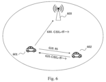
図4は、本開示の幾つかの実施形態による、サイドリンクCSIレポートを処理するシナリオを示している。図4のシナリオにおいて、手順はgNBによってトリガされる。これに関して、gNBは、サイドリンク接続の送信UEに、サイドリンクCSIレポートを送信する様に要求し得る。410で示す様に、gNB403は、サイドリンク接続に関連する送信UE(401として示される)に、サイドリンクCSIレポートの要求を送信し得る。要求に応答して、送信UE401は、420で示す様に、サイドリンクを介して受信UE(402として示される)からのCSIレポートを要求することができる。次に、送信UE401は、430で示す様に、受信UE402からサイドリンクCSIレポートを受信し、440で示す様に、サイドリンクCSIレポートをgNB403に転送することができる。
FIG. 4 illustrates a scenario for processing sidelink CSI reports according to some embodiments of the present disclosure. In the scenario of Figure 4, the procedure is triggered by the gNB. In this regard, the gNB may request transmitting UEs of sidelink connections to transmit sidelink CSI reports. As indicated at 410, the
幾つかの実施形態において、gNB403は、UE401からgNB403へのサイドリンクCSIレポートの送信に使用されるリソースを割り当てることができる。サイドインクCSIレポートのgNB403への送信に使用されるリソースは、PUSCH(物理アップリンク共有チャネル)チャネル又はPUCCH(物理アップリンク制御チャネル)のいずれかである。割り当てられたリソースを示す制御情報は、同じ要求メッセージで要求と一緒に、又は要求とは別に、UE401に送信され得る。制御情報は、アップリンク送信に割り当てられたリソース及び送信パラメータを示し得る。例えば、送信パラメータは、MCS(変調及び符号化方式)、送信電力、適用されるプリコーダ等を含み得るが、これらに限定されない。
In some embodiments,
幾つかの実施形態において、gNB403からの要求は、DCI(ダウンリンク制御情報)、MAC(メディアアクセス制御)CE(制御要素)、又は、RRC(無線リソース制御)メッセージを介して送信され得る。
In some embodiments, requests from
幾つかの実施形態において、gNB403からの要求は、サイドリンク接続ID、つまり、gNB403がCSIレポートを要求しているサイドリンク接続がどれであるかを示し得る。
In some embodiments, the request from
他の実施形態において、gNB403からの要求は、サイドリンク接続IDを含まない。この場合、gNB403は、グラントを発行し、グラントが、アップリンクでgNB403にサイドリンクCSIレポートを送信するためのリソースをスケジュールするために使用されることを(例えば、1ビットによって)示し得る。オプションで、サイドリンクCSIレポートが利用できない場合に、このアップリンクグラントは、他の目的でリソースをスケジューリングするために使用され得る。次に、送信UE401は、総てのサイドリンク接続についてのCSIレポートを取得し、取得したCSIレポートをgNB403に送信し得る。上述した様に、送信UE401と受信UE402との間に複数のサイドリンク接続が存在し得る。さらに、送信UE401と別の端末デバイス(図示せず)との間に確立された1つ又は複数のサイドリンク接続が存在し得る。上記の例において、送信UE401に関連付けられたこれら総てのサイドリンク接続のCSIレポートが取得されて、gNB403に送信され得る。或いは、送信UE401は、CSIレポートをgNB403に送信するために、これらすべてのサイドリンク接続のCSIレポートから幾つかのCSIレポートを選択し得る。一例において、選択は、アップリンクグラントのサイズに従って行われ得る。別の例において、UE401は、優先度の高いトラフィックを伝送する対応するサイドリンク接続のCSIレポートの送信を優先し得る。
In other embodiments, the request from
幾つかの実施形態において、CSIレポートは、関連するサイドリンク接続IDと共にgNB403に送信され得る。
In some embodiments, the CSI report may be sent to
サイドリンクCSIレポートを受信した後、gNB403は、受信したサイドリンクCSIレポートに基づいて、UE401とUE402との間のサイドリンク送信のモード1スケジューリングを実行し得る。これに関して、サイドリンク送信をスケジューリングするためのDCIは、UE401に送信され得る。DCIは、サイドリンク送信に割り当てられたリソース及び送信パラメータを示し得る。例えば、送信パラメータは、MCS(変調及び符号化方式)、送信電力、適用されるプリコーダ等を含み得るが、これらに限定されない。一例において、サイドリンク送信の送信パラメータは、gNB403によって受信されたCSIレポートに基づいて導出される。これにより、gNB403がサイドリンクCSIレポートに基づいて適切な送信パラメータを決定できるため、サイドリンクモード1送信の効率を改善できる。幾つかの実施形態において、DCIは、DCIのスケジューリング情報がどのサイドリンク接続に関連するかを示すサイドリンク接続IDをさらに含み得る。この様にして、gNB503は、送信パラメータを正しいサイドリンク接続に割り当てることができる。
After receiving the sidelink CSI report,
図5は、本開示の別の実施形態による、CSIレポートを処理する別のシナリオを示している。この実施形態において、gNBは、受信UEにサイドリンクCSIレポートを送信することを要求し、受信UEからgNBへのサイドリンクCSIレポートの送信に使用されるリソースを割り当て得る。図5に示す様に、gNB503は、520で、サイドリンクCSIレポートの要求を受信UE502に送信する。要求に応答して、受信UE502は、530で、サイドリンクCSIレポートをgNB503に送信する。サイドリンクCSIレポートは、要求を受信する前にUE502によって取得され得る。例えば、UE502は、UE501からの参照信号(510)に基づいて、UE501からUE502へのサイドリンク送信のCSIレポートを定期的に生成し得る。他の例において、CSIレポートは、要求に応答して生成され得る。
FIG. 5 illustrates another scenario for processing CSI reports according to another embodiment of the present disclosure. In this embodiment, the gNB may request the receiving UE to transmit sidelink CSI reports and allocate resources used for transmitting the sidelink CSI reports from the receiving UE to the gNB. As shown in FIG. 5,
幾つかの実施形態において、gNB503からの要求は、DCI、MAC CE、又は、RRCメッセージを介して送信され得る。幾つかの実施形態において、gNB503は、UE401からgNB503へのサイドリンクCSIの送信に使用されるリソースを割り当て得る。gNB503へのサイドインクCSIレポート送信に使用されるリソースは、PUSCHチャネル又はPUCCHチャネルのいずれかであり得る。割り当てられたリソースを示す制御情報は、同じ要求メッセージで要求と一緒に、又は、要求とは別に、UE502に送信され得る。
In some embodiments, requests from
幾つかの実施形態において、gNB503からの要求は、サイドリンク接続ID、つまり、gNB503がCSIレポートを要求しているサイドリンク接続がどれであるかを示し得る。
In some embodiments, the request from
別の例において、gNB503からの要求は、サイドリンク接続IDを含まない。この場合、gNB503は、グラントを発行し、グラントがアップリンクでgNB503にサイドリンクCSIレポートを送信するためのリソースをスケジュールするために使用されることを(例えば、1ビットによって)示し得る。オプションで、サイドリンクCSIレポートが利用できない場合に、このアップリンクグラントは、他の目的でリソースをスケジューリングするために使用され得る。次に、要求を受信したUE502は、総てのサイドリンク接続についてのCSIレポートを取得し、取得したCSIレポートをgNB503に送信し得る。或いは、UE502は、530で、これら総てのサイドリンク接続のCSIレポートから幾つかのCSIレポートを選択し、当該CSIレポートをgNB503に送信し得る。一例において、選択は、アップリンクグラントのサイズに従って行われ得る。別の例において、UE502は、優先度の高いトラフィックを伝送する対応するサイドリンク接続のCSIレポートの送信を優先し得る。
In another example, the request from
幾つかの実施形態において、サイドリンクCSIレポートは、関連するサイドリンク接続IDと共にgNB503に送信され得る。
In some embodiments, the sidelink CSI report may be sent to
サイドリンクCSIレポートを受信した後、gNB503は、受信したサイドリンクCSIレポートに基づいて、UE501とUE502との間のサイドリンク送信のモード1スケジューリングを実行し得る。これに関して、サイドリンク送信をスケジューリングするためのDCIは、送信UE、つまりUE501に送信され得る。図4に示す実施形態と同様に、DCIは、DCIのスケジューリング情報がどのサイドリンク接続に関連するかを示すサイドリンク接続IDを含み得る。この様にして、gNB403は、送信パラメータを正しいサイドリンク接続に割り当てることができる。
After receiving the sidelink CSI report,
図4及び図5に示す実施形態は、合わせて適用され得る。例えば、gNBは、サイドリンクCSIレポートの要求を送信UEと受信UEの両方に送信することができ、送信UEと受信UEは同じUEであり得る。一実施形態において、UEからgNBに送信されるCSIレポートは、CSIレポートが生成されるサイドリンク接続の方向表示を含み得る。方向表示は、UEがサイドリンク接続の送信UEとして機能するか受信UEとして機能するかを示し得る。 The embodiments shown in FIGS. 4 and 5 can be applied together. For example, the gNB may send sidelink CSI report requests to both the transmitting UE and the receiving UE, which may be the same UE. In one embodiment, the CSI report sent from the UE to the gNB may contain a directional indication of the sidelink connection for which the CSI report is generated. The direction indication may indicate whether the UE functions as a transmitting UE or a receiving UE for the sidelink connection.
一実施形態において、gNBは、1つの特定のサイドリンク接続についての少なくとも1つのサイドリンクCSIレポートを要求し得る。別の実施形態において、gNBは、1つの特定のUEが関与している複数のサイドリンク接続の少なくとも1つのサイドリンクCSIレポートを要求し得る。この場合、1つの特定のUEは、同じ受信UE又は異なる複数の受信UEとの間の複数のサイドリンク接続において送信UEとして動作し得る。追加的又は代替的に、1つの特定のUEは、同じ送信UE又は異なる複数の送信UEとの間の複数のサイドリンク接続において受信UEとして動作し得る。幾つかの実施形態において、UEからのサイドリンク接続のサイドリンクCSIレポートを要求するとき、gNBは、UEがサイドリンク接続において送信UE又は受信UEとして動作することを示し得る。次に、UEは、それに応じてサイドリンクCSIレポートを転送し得る。 In one embodiment, a gNB may request at least one sidelink CSI report for one particular sidelink connection. In another embodiment, a gNB may request at least one sidelink CSI report for multiple sidelink connections involving one particular UE. In this case, one particular UE may act as a transmitting UE in multiple sidelink connections between the same receiving UE or different receiving UEs. Additionally or alternatively, one particular UE may act as a receiving UE in multiple sidelink connections between the same transmitting UE or different transmitting UEs. In some embodiments, when requesting a sidelink CSI report for a sidelink connection from a UE, the gNB may indicate that the UE acts as a transmitting UE or receiving UE on the sidelink connection. The UE may then forward the sidelink CSI report accordingly.
一実施形態において、サイドリンクCSIレポートを要求するとき、gNBは、また、要求しているサイドリンク接続IDを示し得る。図4及び5を参照して説明した様に、要求は、サイドリンク接続IDを含み得る。 In one embodiment, when requesting a sidelink CSI report, the gNB may also indicate the requesting sidelink connection ID. As described with reference to Figures 4 and 5, the request may include a sidelink connection ID.
幾つかの実施形態において、サイドリンク接続IDは、gNBからの要求に含まれ得るが、gNBに送信されるCSIレポートには含まれ得ない。この場合、gNBは、特定のサイドリンク接続のサイドリンクCSIレポートを送信するためにUEが使用すべきアップリンクリソースを示し得る。次に、gNBは、アップリンクリソースとサイドリンク接続との間の対応関係に従って、サイドリンクCSIレポートを区別し得る。 In some embodiments, the sidelink connection ID may be included in requests from gNBs, but may not be included in CSI reports sent to gNBs. In this case, the gNB may indicate uplink resources that the UE should use to transmit sidelink CSI reports for a particular sidelink connection. The gNB may then differentiate sidelink CSI reports according to the correspondence between uplink resources and sidelink connections.
幾つかの実施形態において、gNBは、例えば、gNBがサイドリンクCSIレポートを要求することを決定したとき、サイドリンクCSIのgNBへの送信に使用されるアップリンクリソースのスケジューリングを開始し得る。他の実施形態において、gNBは、UEによるスケジューリング要求に基づいて、サイドリンクCSIレポートの送信に使用されるアップリンクリソースをスケジューリングし得る。これに関して、送信UE又は受信UEは、サイドリンクCSIレポートをgNBに送信することを意図している場合、スケジューリング要求をトリガし得る。例えば、そのようなスケジューリング要求は、UEで利用可能なCSIレポートがあるときにトリガされ得る。一実施形態において、禁止タイマが、UEからの過剰なCSIレポート送信を禁止するために定義され得る。 In some embodiments, a gNB may initiate scheduling of uplink resources used for transmission of sidelink CSI to the gNB, eg, when the gNB decides to request sidelink CSI reports. In other embodiments, the gNB may schedule uplink resources used for sidelink CSI report transmission based on scheduling requests by the UE. In this regard, a transmitting UE or a receiving UE may trigger a scheduling request if it intends to send a sidelink CSI report to the gNB. For example, such a scheduling request may be triggered when there are CSI reports available at the UE. In one embodiment, a prohibit timer may be defined to prohibit excessive CSI report transmissions from the UE.
図4及び5に示される実施形態において、サイドリンクCSIレポートを処理するための手順は、gNBによってトリガされる。これらの実施形態において、サイドリンクCSIレポートは、gNBからの要求に応答してgNBに送信される。本開示はさらに、サイドリンクCSIレポートを処理する手順がUEによってトリガされる解決策を提案する。図6及び図7は、この手順の2つのシナリオを示している。 In the embodiments shown in FIGS. 4 and 5, the procedure for processing sidelink CSI reports is triggered by the gNB. In these embodiments, sidelink CSI reports are sent to gNBs in response to requests from gNBs. The present disclosure further proposes a solution in which the procedure for processing sidelink CSI reports is triggered by the UE. Figures 6 and 7 show two scenarios for this procedure.
図6に示す様に、UE601は、UE601とUE602との間のサイドリンク接続についての少なくとも1つのCSIレポートを取得する。たとえば、CSIレポートは、通常の方法で取得され得る。UE601は、610で示す様に、サイドリンク接続を介して別のUE602に参照信号を送信する。したがって、UE601は、620で示す様に、UE602からCSIレポートを受信する。UE601は、CSIレポートを定期的に取得し得る。
As shown in FIG. 6, UE601 obtains at least one CSI report for the sidelink connection between UE601 and UE602. For example, CSI reports may be obtained in the usual manner. A
620で、UE601は、CSIレポートのgNB603への送信を開始できる。一実施形態において、CSIレポートの送信は、UE601で利用可能なCSIレポートがあるときにトリガされ得る。別の実施形態において、CSIレポートの送信は、UE601によって取得されたCSIレポートが事前定義された条件を満たすときにトリガされ得る。たとえば、禁止タイマが、UEからgNBへの過剰なCSIレポートの送信を禁止するために定義され得る。
At 620,
CSIレポートは、PUSCHチャネル又はPUCCHチャネルで送信され得る。幾つかの実施形態において、UE601は、サイドリンクCSIレポートの送信のために以前に割り当てられたアップリンクリソースを利用し得る。他の実施形態において、UE601は、サイドリンクCSIレポートを送信することを意図するときに、gNB603へのスケジューリング要求をトリガし得る。gNB603は、スケジューリング要求に基づいて、サイドリンクCSIレポートの送信のためのアップリンクリソースをスケジューリングし得る。これに関して、DCIは、スケジュールされたアップリンクリソースを示すためにUE601に送信され得る。
CSI reports may be sent on the PUSCH channel or the PUCCH channel. In some embodiments,
図7は、サイドリンク送信の受信UEがサイドリンクCSIレポートを処理するための手順をトリガし得るという点でのみ図6と異なる。UE702は、710で示す様に、送信UE(701として示される)からの参照信号に基づいてサイドリンクCSIレポートを取得し、720で示す様に、gNB703へのサイドリンクCSIレポートの送信を開始し得る。
FIG. 7 differs from FIG. 6 only in that the receiving UE of the sidelink transmission can trigger the procedure for processing the sidelink CSI report.
上述した様に、幾つかの実施形態において、gNBは、DCIを介してサイドリンク接続のサイドリンクCSIレポートの要求を送信でき、モード1サイドリンクの場合、gNBは、DCIを介してサイドリンク接続のスケジューリング情報を送信できる。サイドリンク接続IDはDCIで示され得る。ただし、既存のDCIフォーマットには、特定のサイドリンクのために、DCIに含めるIDの概念は無い。
As mentioned above, in some embodiments, the gNB can send a sidelink CSI report request for a sidelink connection via DCI, and for
LTEのDCIフォーマット5Aの内容は以下の通りである。
・キャリアインジケータ
・初期送信へのサブチャネル割り当ての最低インデクス
・最初の送信と再送信の周波数リソース位置
・最初の送信と再送信の間の時間ギャップ
・サイドリンクインデクス(時分割複信(TDD)構成0~6の場合)。
・サイドリンクSPS(半永続的スケジューリング)構成(SPSのみ)
・アクティベーション/解放表示(SPSのみ)。
The contents of the LTE DCI format 5A are as follows.
- carrier indicator - lowest index of subchannel assignment to initial transmission - frequency resource location for first transmission and retransmission - time gap between first transmission and retransmission - sidelink index (Time Division Duplex (TDD) configuration) 0 to 6).
- Sidelink SPS (semi-persistent scheduling) configuration (SPS only)
- Activation/release indication (SPS only).
NRのUuインタフェース場合、フォールバックフォーマットとして知られる0-0と、非フォールバックフォーマットとして知られている0-1との2つの基本的なDCIフォーマットが定義されている。DCIフォーマット0-0は、より小さなパラメータセットを設定できる。各フォーマットの内容は以下の表1に要約されている。 For the NR Uu interface, two basic DCI formats are defined: 0-0, known as the fallback format, and 0-1, known as the non-fallback format. DCI format 0-0 can set a smaller set of parameters. The contents of each format are summarized in Table 1 below.

上記の様に、LTEサイドリンクはブロードキャストサービスのみを対象としているため、LTEサイドリンクで使用されるDCI 5AにはIDの概念は含まれていない。一方、gNBはアップリンク送信用の受信機(つまり、gNB自体)を認識しているため、NRのUuインタフェースのDCIにIDの概念は含まれていない。ただし、UEは複数のユニキャストサイドリンク接続に関与している可能性があるため、異なるサイドリンク接続を区別するためにDCIにIDを導入する必要がある。したがって、本開示は、サイドリンク接続IDを搬送する新しいDCIフォーマットを提案する。 As mentioned above, the concept of ID is not included in DCI 5A used in LTE sidelinks, as LTE sidelinks are only intended for broadcast services. On the other hand, since the gNB is aware of the receiver for uplink transmissions (ie the gNB itself), the DCI of the NR's Uu interface does not include the concept of ID. However, since the UE may be involved in multiple unicast sidelink connections, it is necessary to introduce an ID in the DCI to distinguish between different sidelink connections. Therefore, this disclosure proposes a new DCI format to carry the sidelink connection ID.
一実施形態において、サイドリンク接続IDを含む新しいDCIフォーマットは、サイドリンクをスケジューリングするために定義され、IDは、割り当てられたリソース及びDCIに含まれる送信パラメータがどのサイドリンク接続に関連するかを示す。例えば、DCIフォーマット5Aは、サイドリンク接続IDを示す表示を導入する様に拡張され得る。ここで、送信パラメータは、MCS、送信電力、適用されるプリコーダ等を含むが、これらに限定されない。一例において、サイドリンクスケジューリング用の新しいDCIの送信パラメータは、gNBによって受信されたCSIレポートに基づいて導出され、CSIレポートは、サイドリンクスケジューリング用の新しいDCIに含まれているIDと同じサイドリンク接続IDに関連付けられ得る。 In one embodiment, a new DCI format containing a sidelink connection ID is defined for scheduling sidelinks, the ID identifying which sidelink connection the allocated resources and transmission parameters contained in the DCI relate to. show. For example, DCI format 5A can be extended to introduce an indication that indicates the sidelink connection ID. Here, transmission parameters include, but are not limited to, MCS, transmission power, applied precoders, and the like. In one example, the transmission parameters of the new DCI for sidelink scheduling are derived based on the CSI report received by the gNB, the CSI report is the same sidelink connection ID as contained in the new DCI for sidelink scheduling. can be associated with an ID.
一実施形態において、サイドリンク送信UEは、新しいDCIで示される関連するサイドリンク接続IDに基づいて、サイドリンクスケジューリング用の新しいDCIに含まれる送信パラメータを使用するか否かを決定し得る。一例において、送信UEは、関連するサイドリンク接続IDが意図されたサイドリンク送信の接続IDと同じである場合にのみ、示された送信パラメータを採用し得る。別の例において、関連するサイドリンク接続IDが意図されたサイドリンク送信の接続IDと異なる場合でも、送信UEは依然として示された送信パラメータを採用し得る。 In one embodiment, a sidelink transmitting UE may decide whether to use the transmission parameters included in the new DCI for sidelink scheduling based on the associated sidelink connection ID indicated in the new DCI. In one example, a transmitting UE may employ indicated transmission parameters only if the associated sidelink connection ID is the same as the connection ID of the intended sidelink transmission. In another example, the transmitting UE may still employ the indicated transmission parameters even if the associated sidelink connection ID is different from the connection ID of the intended sidelink transmission.
一実施形態において、サイドリンク接続IDを含む新しいDCIフォーマットは、アップリンクでサイドリンクCSIレポートの要求を送信するために定義される。たとえば、NRのUuインタフェースのDCIは、サイドリンク接続IDを示す表示を導入する様に拡張され得る。 In one embodiment, a new DCI format that includes a sidelink connection ID is defined for sending sidelink CSI report requests on the uplink. For example, the DCI of the NR's Uu interface can be extended to introduce an indication that indicates the sidelink connection ID.
上述した様に、受信UEがサイドリンクを介して送信UEにCSIレポートをどの様に送信するかは不明確である。たとえば、サイドリンクCSIレポートがサイドリンクMAC CEとして送信されるのか、PC5-RRCメッセージとして送信されるのかが不明確である。サイドリンクMAC CEはまだ定義されていないことに留意されたい。図8は、アップリンクのMAC PDUの例を示している。MAC PDUは、MAC SDUとMAC CEで構成される。MAC SDUは上位レイヤから配信されるデータであり、MAC CEは、BSR、C-RNTI(セル-無線ネットワーク一時識別子)等のMACレイヤ制御に関連する情報である。 As mentioned above, it is unclear how the receiving UE will send the CSI report to the transmitting UE over the sidelink. For example, it is unclear whether the sidelink CSI report is sent as a sidelink MAC CE or as a PC5-RRC message. Note that the sidelink MAC CE has not yet been defined. FIG. 8 shows an example of an uplink MAC PDU. A MAC PDU is composed of a MAC SDU and a MAC CE. MAC SDU is data delivered from higher layers, and MAC CE is information related to MAC layer control such as BSR, C-RNTI (Cell-Radio Network Temporary Identifier).
本開示は、サイドリンクを介してサイドリンクCSIレポートを搬送する新しいMAC CEを提案する。一実施形態において、受信UEは、サイドリンクを介して送信UEにCSIレポートを送信するとき、430で示す様に、CSIレポートを搬送するサイドリンクMAC CEを生成する。 This disclosure proposes a new MAC CE that carries sidelink CSI reports over the sidelink. In one embodiment, when the receiving UE transmits the CSI report to the transmitting UE over the sidelink, it generates a sidelink MAC CE that carries the CSI report, as shown at 430 .
利用可能なサイドリンクグラントがある場合、CSIレポートを搬送するサイドリンクMAC CEは、MAC PDUに多重化され、現在利用可能なSLグラントを使用して送信され得る。モード1グラントの場合、gNBによってスケジュールされた関連する送信パラメータが適用される。モード2グラントの場合、送信UEはそれ自体で送信パラメータを決定し得る。
If there is a sidelink grant available, the sidelink MAC CE carrying the CSI report may be multiplexed into the MAC PDU and sent using the currently available SL grant. For
別の実施形態において、利用可能なモード1サイドリンクグラントがある場合でさえ、UEは、新しく生成したCSIレポートを送信するためにそれを使用しない。UEは、新しいSR(スケジューリング要求)又はBSR(バッファ状態レポート)をトリガし、CSIレポートがサイドリンクを介して送信されることをgNBに示す。それに応答して、gNBは、サイドリンクCSIレポートの送信に適切な送信パラメータと共に別のモード1サイドリンクグラントをUEに提供し得る。
In another embodiment, even if there is a
別の実施形態において、モード1で利用可能なサイドリンクグラントがない場合、サイドリンク接続の送信UEは、新しいSR/BSRをトリガし、CSIレポートがサイドリンクを介して送信されることをgNBに示す。それに応答して、gNBは、サイドリンクCSIレポートの送信に適切な送信パラメータと共に別のモード1サイドリンクグラントをUEに提供する。
In another embodiment, if there is no sidelink grant available in
一実施形態において、CSIレポートMAC CEは、MAC SDU(上位レイヤからのデータ)と同じMAC PDUに多重化され得る。一例において、CSIレポートを搬送するサイドリンクMAC CEは、常にMAC SDUの前に配置され得る。別の例において、CSIレポートを搬送するサイドリンクMAC CEは、常にMAC SDUの後に配置され得る。 In one embodiment, the CSI report MAC CE may be multiplexed into the same MAC PDU as the MAC SDU (data from higher layers). In one example, the sidelink MAC CE carrying the CSI report may always be placed before the MAC SDU. In another example, the sidelink MAC CE carrying the CSI report may always be placed after the MAC SDU.
NRのUuにおいて、UEがgNBからグラントを取得すると、LCP(論理チャネル優先順位付け)手順を実行して、特定の制限、例えば、許可されたSCS-List及びmaxPUSCH-Durationを満たす論理チャネルからのデータのみをMAC PDUに多重化し、割り当てられたグラントを使用して送信し得る。LTEサイドリンクにおいて、UEがモード1又はモード2のいずれかのグラントを取得すると、UEは、送信に利用可能なデータを有し、ProSe宛先に対応して選択されたものと同じ送信フォーマットを有するサイドリンク論理チャネルの中から、最も優先度の高いサイドリンク論理チャネルを有するProSe宛先を選択する。
In Uu of NR, when the UE gets the grant from the gNB, it performs LCP (Logical Channel Prioritization) procedure to select from logical channels that satisfy certain restrictions, e.g., allowed SCS-List and maxPUSCH-Duration Data only may be multiplexed into MAC PDUs and transmitted using the assigned grant. In the LTE sidelink, once the UE obtains either
本開示は、新しいLCP手順を提案する。一実施形態において、UEが、割り当てられたモード1サイドリンクグラントを使用してサイドリンク送信のための論理チャネルを選択するとき、LCP手順に1つの制限が追加され、その結果、関連する接続(DCIの接続IDによって示される)に関連付けられた論理チャネルからのデータのみが、送信用にMAC PDUに多重化され得る。
This disclosure proposes a new LCP procedure. In one embodiment, one limitation is added to the LCP procedure when a UE selects a logical channel for sidelink transmission using an assigned
別の実施形態において、所与のサイドリンクグラントにより、サイドリンクを介して送信されるデータとCSIレポートの両方が存在する場合、UEは、事前定義されたルールに基づいてデータ送信又はCSIレポート送信に優先順位を付けることができる。たとえば、ルールは、以下の何れかを含み得るが、これらに限定されない。
・UEは、サイドリンクを介したデータ送信よりもCSIレポート送信を常に優先する。
・閾値が設定され、閾値よりも高いLCH(論理チャネル)優先度のデータ送信がCSIレポート送信よりも優先される。
In another embodiment, with a given sidelink grant, if there are both data and CSI reports to be sent over the sidelink, the UE may send data or send CSI reports based on predefined rules. can be prioritized. For example, rules may include, but are not limited to, any of the following.
• The UE always prioritizes CSI report transmission over data transmission over the sidelink.
• A threshold is set, and data transmissions with LCH (Logical Channel) priority higher than the threshold are prioritized over CSI report transmissions.
上記の説明では、実施形態は主にサイドリンクユニキャストに関連して説明されていた。しかしながら、上記の実施形態は、サイドリンクグループキャストにも容易に拡張できることが理解され得る。たとえば、わずかな違いは、サイドリンク接続IDが1対多の通信を示していることである。この場合、サイドリンクの送信UEは、グループ内の複数の受信UEから、同じサイドリンク接続IDを有する複数のCSIレポートを取得し得る。 In the above description, embodiments were primarily described in relation to sidelink unicast. However, it can be appreciated that the above embodiments can be easily extended to sidelink groupcasts. For example, a slight difference is that the sidelink connection ID indicates one-to-many communication. In this case, a sidelink transmitting UE may obtain multiple CSI reports with the same sidelink connection ID from multiple receiving UEs in the group.
上記の説明では、実施形態は主にモード1サイドリンク送信に関連して説明されていた。しかしながら、上記の実施形態は、モード2サイドリンク送信にも容易に拡張できることが理解され得る。モード2の場合、UEによって決定されるリソース上のUE間のサイドリンク送信の状態を示すサイドリンクCSIレポートが生成及び取得され得る。このサイドリンクCSIレポートは、たとえばUEの1つと接続しているgNBに転送することもできる。
In the above description, embodiments were primarily described in relation to
図9は、本開示の幾つかの実施形態に従う方法のフローチャートである。この方法は、基地局内の装置/基地局としての装置によって、又は、基地局に通信可能に結合された装置によって実行され得る。例示的な実施形態によれば、基地局はgNBであり得る。 FIG. 9 is a flowchart of a method according to some embodiments of the disclosure. The method may be performed by a device within/as a base station or by a device communicatively coupled to a base station. According to example embodiments, the base station may be a gNB.
図9に示す例示的な方法900によると、基地局は、ブロック9020で示す様に、第1端末デバイスから、第1端末デバイスに関連付けられた少なくとも1つのサイドリンク接続のチャネル状態情報を示す少なくとも1つのレポートを受信する。サイドリンク接続は、モード1サイドリンクであり得る。基地局は、モード1サイドリンクをサポートするために第1端末デバイスにサービス提供し得る。レポートは、CSIレポートであり得る。
According to the exemplary method 900 shown in FIG. 9, the base station, from the first terminal device, at least Receive one report. A sidelink connection may be a
幾つかの実施形態において、基地局は、第1端末デバイスから基地局への少なくとも1つのレポートの送信に使用されるリソースを示す制御情報をさらに送信し得る。リソースは、第1端末デバイスからのスケジューリング要求に応答して、第1端末デバイスから基地局への少なくとも1つのレポートの送信のために割り当てられ得る。他の実施形態において、基地局は、アップリンクグラントと、アップリンクグラントが第1端末デバイスから基地局への少なくとも1つのレポートの送信に使用されることを示す表示と、を第1端末デバイスに送信し得る。 In some embodiments, the base station may further transmit control information indicating resources used for transmission of the at least one report from the first terminal device to the base station. Resources may be allocated for transmission of at least one report from the first terminal device to the base station in response to a scheduling request from the first terminal device. In another embodiment, the base station transmits to the first terminal device an uplink grant and an indication that the uplink grant will be used to transmit at least one report from the first terminal device to the base station. can send.
幾つかの実施形態において、少なくとも1つのレポートの内の1つのレポートは、少なくとも1つのサイドリンク接続の識別子を示し得る。一例において、識別子は、例えば、レポートに含められるサイドリンク接続IDで明示的に示され得る。別の例において、識別子は、例えば、識別子と他の情報との間に事前定義された対応関係により暗黙的に示され得る。 In some embodiments, one of the at least one reports may indicate an identifier of at least one sidelink connection. In one example, the identifier can be explicitly indicated, for example, in a sidelink connection ID included in the report. In another example, identifiers may be implied by, for example, predefined correspondences between identifiers and other information.
幾つかの実施形態において、基地局は、ブロック9010で示す様に、少なくとも1つのレポートの要求を第1端末デバイスにさらに送信し得る。この要求は、少なくとも1つのレポートの処理をトリガし得る。言い換えると、基地局は、要求に応答して、少なくとも1つのレポートを受信し得る。幾つかの実施形態において、要求は、第1端末デバイスから基地局への少なくとも1つのレポートの送信に使用されるリソースを示す制御情報を含み得る。要求は、少なくとも1つのサイドリンク接続の識別子を示し得る。一例において、識別子は、例えば、レポートに含められるサイドリンク接続IDで明示的に示され得る。別の例において、識別子は、例えば、識別子と他の情報との間に事前定義された対応関係により暗黙的に示され得る。幾つかの実施形態において、要求は、DCI、MAC CE又はRRCメッセージで送信され得る。
In some embodiments, the base station may further transmit at least one report request to the first terminal device, as indicated at
幾つかの実施形態において、基地局は、さらに、受信した少なくとも1つのレポートに基づいてサイドリンクスケジューリング情報を適合させ得る。基地局は、サイドリンクスケジューリング情報を少なくとも1つのサイドリンク接続の送信側にさらに送信し得る。サイドリンクスケジューリング情報は、少なくとも1つのサイドリンク接続の識別子を示し得る。識別子は、明示的又は暗黙的に示され得る。サイドリンクスケジューリング情報は、DCIで搬送され得る。 In some embodiments, the base station may further adapt sidelink scheduling information based on at least one received report. The base station may further transmit sidelink scheduling information to the transmitter of at least one sidelink connection. The sidelink scheduling information may indicate an identifier for at least one sidelink connection. Identifiers may be indicated explicitly or implicitly. Sidelink scheduling information may be carried in DCI.
第1端末デバイスは、少なくとも1つのサイドリンク接続の送信側又は受信側であり得る。幾つかの実施形態において、少なくとも1つのレポートの要求は、第1端末デバイスが少なくとも1つのサイドリンク接続の送信側又は受信側であることを示す表示を含み得る。 The first terminal device may be the sender or receiver of at least one sidelink connection. In some embodiments, the request for at least one report may include an indication that the first terminal device is a sender or receiver of at least one sidelink connection.
幾つかの実施形態において、少なくとも1つのレポートは、PUSCH又はPUCCHで受信される。少なくとも1つのサイドリンク接続は、ユニキャストサイドリンク送信又はグループキャストサイドリンク送信のためのものであり得る。 In some embodiments, at least one report is received on PUSCH or PUCCH. At least one sidelink connection may be for a unicast sidelink transmission or a groupcast sidelink transmission.
幾つかの実施形態において、少なくとも1つのレポートは、少なくとも1つのサイドリンク接続の方向表示を含み得る。 In some embodiments, at least one report may include a directional indication of at least one sidelink connection.
図10は、本開示の幾つかの実施形態に従う方法のフローチャートである。図10に示す方法10000は、端末デバイス内の装置/端末デバイスとしての装置によって、又は、端末デバイスに通信可能に結合された装置によって実行され得る。例示的な実施形態において、端末デバイスは、UE、例えば、移動局であり得る。図10に関する以下の説明において、前の例示的な実施形態と同じ又は類似の部分についての詳細な説明は適切に省略される。
FIG. 10 is a flowchart of a method according to some embodiments of the disclosure. The
図10に示す例示的な方法10000によると、端末デバイスは、ブロック10020で示す様に、端末デバイスに関連付けられた少なくとも1つのサイドリンク接続のチャネル状態情報を示す少なくとも1つのレポートを取得する。次に、端末デバイスは、ブロック10030で示す様に、取得した少なくとも1つのレポートを基地局に送信する。端末デバイスは、少なくとも1つのサイドリンク接続の送信側又は受信側であり得る。
According to the
幾つかの実施形態において、端末デバイスは、端末デバイスから基地局への少なくとも1つのレポートの送信に使用されるリソースを示す制御情報をさらに受信し得る。したがって、取得した少なくとも1つのレポートは、受信した制御情報に基づいて送信され得る。幾つかの実施形態において、制御情報は、スケジューリング要求に応答して受信され得る。この場合、端末デバイスは、端末デバイスから基地局への少なくとも1つのレポートの送信のためのスケジューリング要求を基地局に送信し得る。 In some embodiments, the terminal device may further receive control information indicating resources used for transmission of at least one report from the terminal device to the base station. Accordingly, the obtained at least one report may be transmitted based on the received control information. In some embodiments, control information may be received in response to a scheduling request. In this case, the terminal device may send a scheduling request to the base station for transmission of at least one report from the terminal device to the base station.
別の実施形態において、端末デバイスは、アップリンクグラントと、アップリンクグラントが端末デバイスから基地局への少なくとも1つのレポートの送信に使用されることを示す表示と、を基地局から受信することをさらに含み得る。一例において、端末デバイスは、端末デバイスに関連付けられた複数のサイドリンク接続のチャネル状態情報を示す総てのレポートを送信し得る。別の例において、端末デバイスは、アップリンクグラントのサイズ等、アップリンクグラントに基づいて、総てのレポートのサブセットを選択し得る。したがって、基地局に送信される少なくとも1つのレポートは、端末デバイスに関連付けられたサイドリンク接続に関する総てのレポートのサブセットである。 In another embodiment, the terminal device is configured to receive from the base station an uplink grant and an indication that the uplink grant will be used to transmit at least one report from the terminal device to the base station. It can contain more. In one example, a terminal device may transmit all reports indicating channel state information for multiple sidelink connections associated with the terminal device. In another example, the terminal device may select a subset of all reports based on the uplink grant, such as the size of the uplink grant. Accordingly, the at least one report sent to the base station is a subset of all reports regarding sidelink connections associated with the terminal device.
幾つかの実施形態において、端末デバイスは、ブロック10010で示す様に、少なくとも1つのレポートの要求を基地局からさらに受信し得る。少なくとも1つのレポートは、要求に応答して送信され得る。
In some embodiments, the terminal device may further receive at least one report request from the base station, as indicated at
幾つかの実施形態において、端末デバイスは送信側であり、端末デバイスは、基地局から、少なくとも1つのサイドリンク接続の識別子を示すサイドリンクスケジューリング情報をさらに受信し得る。端末デバイスは、少なくとも1つのサイドリンク接続の識別子に基づいて、サイドリンクスケジューリング情報を使用する否かをさらに決定し得る。 In some embodiments, the terminal device is the transmitting side, and the terminal device may further receive sidelink scheduling information from the base station indicating an identifier for the at least one sidelink connection. The terminal device may further determine whether to use the sidelink scheduling information based on the identifier of the at least one sidelink connection.
幾つかの実施形態において、端末デバイスは、少なくとも1つのサイドリンク接続に関連付けられた別の端末デバイスから少なくとも1つのレポートをさらに受信し得る。端末デバイスは、さらに、別の端末デバイスから端末デバイスへの少なくとも1つのレポートの送信のために、スケジューリング要求を基地局に送信し、基地局から少なくとも1つのレポートの送信のためのサイドリンクグラントを受信し得る。少なくとも1つのレポートは、受信されたサイドリンクグラントに従って、少なくとも1つのサイドリンク接続を介して別の端末デバイスから受信され得る。 In some embodiments, the terminal device may further receive at least one report from another terminal device associated with the at least one sidelink connection. The terminal device further transmits a scheduling request to the base station for transmission of at least one report from another terminal device to the terminal device, and a sidelink grant for transmission of the at least one report from the base station. can receive. At least one report may be received from another terminal device via at least one sidelink connection in accordance with the received sidelink grant.
幾つかの実施形態において、少なくとも1つのレポートは、MACデータと多重化される1つ又は複数のMAC CEで送信され、1つ又は複数のMAC CEは、MACデータの前又は後に配置される。少なくとも1つのレポートを送信するための1つ又は複数のMAC制御要素の内の少なくとも1つは、サイドリンク接続に関連付けられた論理チャネルからのMACデータと多重化され得る。幾つかの実施形態において、端末デバイスは、さらに、少なくとも1つのレポートの送信とサイドリンクデータ送信の優先度付けを行い得る。 In some embodiments, at least one report is sent on one or more MAC CEs multiplexed with MAC data, and one or more MAC CEs are placed before or after the MAC data. At least one of the one or more MAC control elements for transmitting at least one report may be multiplexed with MAC data from logical channels associated with the sidelink connection. In some embodiments, the terminal device may also prioritize transmission of at least one report and transmission of sidelink data.
図9及び図10を参照して説明したステップを実行するための順序は、単なる例として示されていることに留意されたい。幾つかの実装において、幾つかのステップは、逆の順序で又は並行して実行され得る。他の幾つかの実装において、幾つかのステップが省略又は組み合わされ得る。 It should be noted that the order for performing the steps described with reference to Figures 9 and 10 is given as an example only. In some implementations, some steps may be performed in reverse order or in parallel. In some other implementations, some steps may be omitted or combined.
したがって、上記の実施形態によるサイドリンクCSIレポートを処理するための提案された解決策では、サイドリンク送信の効率を改善することに役立つことが分かる。さらに、この解決策により、サイドリンクを介してCSIレポートを効率的に送信できる。 Therefore, it can be seen that the proposed solution for processing sidelink CSI reports according to the above embodiments helps improve the efficiency of sidelink transmission. Furthermore, this solution allows efficient transmission of CSI reports over the sidelink.
図9及び10に示される様々なブロックは、方法ステップとして、及び/又は、コンピュータプログラムコードの動作から生じる動作として、及び/又は、関連する機能を実行する様に構築された複数の結合論理回路要素として見ることができる。上記の概略フローチャート図は、一般に論理フローチャート図として示されている。したがって、示された順序及びラベル付けされたステップは、提示された方法の特定の実施形態を示している。図示された方法の1つ又は複数のステップ又はその一部と機能、論理又は効果が同等である他のステップ及び方法が考えられ得る。さらに、特定の方法での順序は、示されている対応するステップの順序に厳密に従う場合と従わない場合があり得る。 The various blocks shown in FIGS. 9 and 10 may be represented as method steps and/or operations resulting from operation of computer program code and/or multiple combinatorial logic circuits configured to perform associated functions. can be seen as elements. The schematic flow chart diagrams above are generally presented as logical flow chart diagrams. As such, the depicted order and labeled steps are indicative of specific embodiments of the presented method. Other steps and methods may be conceived that are equivalent in function, logic, or effect to one or more steps, or portions thereof, of the illustrated method. Additionally, the order in a particular method may or may not strictly follow the order of the corresponding steps shown.
図11は、本開示の幾つかの実施形態による装置11000のブロック図である。図11に示す様に、装置11000は、プロセッサ11001等の1つ又は複数のプロセッサと、コンピュータプログラムコード11003を格納するメモリ11002等の1つ又は複数のメモリとを備え得る。メモリ11002は、非一時的な機械/プロセッサ/コンピュータ可読記憶媒体であり得る。幾つかの例示的な実施形態によれば、装置11000は、図9に関して説明した様に端末デバイス又は図10に関して説明したネットワークノードにプラグ又はインストールされ得る集積回路チップ又はモジュールとして実装され得る。
FIG. 11 is a block diagram of an
幾つかの実装において、1つ又は複数のメモリ11002及びコンピュータプログラムコード1103は、1つ又は複数のプロセッサ11001を用いて、装置11000に、図9に関して説明した方法の任意の動作を少なくとも実行させる様に構成され得る。そのような実施形態において、装置11000は、上記の様に基地局の少なくとも一部として、又は、基地局に通信可能に結合されて実装され得る。特定の例として、装置11000は、基地局として実装され得る。
In some implementations, one or more of
別の実装において、1つ又は複数のメモリ11002及びコンピュータプログラムコード11003は、1つ又は複数のプロセッサ11001を用いて、装置11000に、図10に関して説明した方法の任意の動作を少なくとも実行させる様に構成され得る。そのような実施形態において、装置11000は、上記の様に端末デバイスの少なくとも一部として、又は、端末デバイスに通信可能に結合されて実装され得る。特定の例として、装置11000は、端末デバイスとして実装され得る。
In another implementation, one or
置換的に又は追加的に、1つ又は複数のメモリ11002及びコンピュータプログラムコード11003は、1つ又は複数のプロセッサ11001を用いて、装置11000に、本開示の例示的な実施形態による提案方法を実行するためのより多くの又はより少ない動作を少なくとも実行させる様に構成され得る。
Alternatively or additionally, the one or
図12は、本開示の幾つかの実施形態による装置12000のブロック図である。図12に示す様に、装置12000は、送信ユニット12001及び受信ユニット12002を含む。例示的な実施形態において、装置12000は、基地局(例えば、gNB)内に実装され得る。受信ユニット12002は、ブロック9020の動作を実行する様に動作可能であり得る。送信ユニット12001は、ブロック9010の動作を実行する様に動作可能であり得る。オプションとして、送信ユニット12001及び/又は受信ユニット12002は、本開示の例示的な実施形態による提案方法を実施するためのより多くの又はより少ない動作を実行する様に動作可能であり得る。
FIG. 12 is a block diagram of an
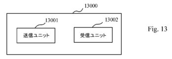
図13は、本開示の幾つかの実施形態による装置13000のブロック図である。図13に示す様に、装置13000は、送信ユニット13001及び受信ユニット13002を含む。例示的な実施形態において、装置1300は、端末デバイス(例えば、UE)内に実装され得る。送信ユニット13001は、ブロック10030の動作を実行する様に動作可能であり得る。受信ユニット13002は、ブロック10020の動作を実行する様に動作可能であり得る。受信ユニット13002は、ブロック10010の動作を実行する様にさらに動作可能であり得る。オプションとして、送信ユニット13001及び/又は受信ユニット13002は、本開示の例示的な実施形態による提案方法を実施するためのより多くの又はより少ない動作を実行する様に動作可能であり得る。
FIG. 13 is a block diagram of
図14は、本開示の幾つかの実施形態による、中間ネットワークを介してホストコンピュータに接続された通信ネットワークを示すブロック図である。 FIG. 14 is a block diagram illustrating a communication network connected to host computers via intermediate networks, according to some embodiments of the present disclosure.
一実施形態に従う図14を参照すると、通信システムは、3GPPタイプのセルラネットワーク等の通信ネットワーク810を含み、通信ネットワーク810は、無線アクセスネットワーク等のアクセスネットワーク811とコアネットワーク814とを含む。アクセスネットワーク811は、NB、eNB、gNB又は他のタイプの無線アクセスポイント等の複数の基地局812a、812b、812cを備え、それぞれが対応するカバレッジエリア813a、813b、813cを定義する。各基地局812a、812b、812cは、有線又は無線接続815を介してコアネットワーク814に接続可能である。カバレッジエリア813cに位置する第1UE891は、対応する基地局812cに無線で接続する、或いは、ページングされる様に構成される。カバレッジエリア813aの第2UE892は、対応する基地局812aに無線で接続可能である。複数のUE891、892がこの例に示されているが、開示された実施形態は、単一UEがカバレッジエリアにある状況、又は、単一UEが対応する基地局812に接続している状況に等しく適用可能である。
Referring to FIG. 14 according to one embodiment, a communication system includes a
通信ネットワーク810自体は、スタンドアロンサーバ、クラウド実装サーバ、分散サーバのハードウェア及び/又はソフトウェアにより、又は、サーバファームの処理リソースとして具現化され得るホストコンピュータ830に接続される。ホストコンピュータ830は、サービスプロバイダの所有権又は管理下にあり得るか、サービスプロバイダによって又はサービスプロバイダに代わって操作され得る。通信ネットワーク810とホストコンピュータ830との間の接続821及び822は、コアネットワーク814からホストコンピュータ830まで直接延長してもよく、オプションの中間ネットワーク820を介してもよい。中間ネットワーク820は、パブリック、プライベート又はホストされたネットワークの1つ又は2つ以上の組み合わせであっても良く、中間ネットワーク820(ある場合)は、バックボーンネットワーク又はインターネットである場合があり、特に、中間ネットワーク820は、2つ以上のサブネットワーク(図示せず)を備えてもよい。
図14の通信システムは全体として、接続されたUE891、892とホストコンピュータ830との間の接続を可能にする。接続性は、オーバーザトップ(OTT)接続850として説明され得る。ホストコンピュータ830及び接続されたUE891、892は、アクセスネットワーク811、コアネットワーク814、任意の中間ネットワーク820及び、仲介者としての可能なさらなるインフラストラクチャ(図示せず)を使用して、OTT接続850を介してデータ及び/又はシグナリングを通信する様に構成される。OTT接続850は、OTT接続850が通過する参加通信デバイスがアップリンク及びダウンリンク通信のルーティングを認識しないという意味で透過的であり得る。例えば、基地局812は、接続されたUE891に転送される(例えば、ハンドオーバ)ホストコンピュータ830から発信されるデータの着信ダウンリンク通信の過去のルーティングについて通知されないか、又は通知される必要はない。同様に、基地局812は、UE891からホストコンピュータ830に向かう発信アップリンク通信の将来のルーティングを認識する必要はない。
The communication system of FIG. 14 as a whole allows connections between connected
図15は、本開示の幾つかの実施形態による、部分的な無線接続を介して、基地局経由でUEと通信するホストコンピュータのブロック図である。 FIG. 15 is a block diagram of a host computer communicating with a UE via a base station over a partial wireless connection, according to some embodiments of the present disclosure.
一実施形態による、前述の段落で説明したUE、基地局及びホストコンピュータの例示的な実装形態を、図15を参照して説明する。通信システム900において、ホストコンピュータ910は、通信システム900の異なる通信デバイスのインタフェースとの有線又は無線接続をセットアップ及び維持する様に構成された通信インタフェース916を含むハードウェア915を備える。ホストコンピュータ910は、記憶及び/又は処理能力を有し得る処理回路918をさらに備える。特に、処理回路918は、命令を実行する様に適合された1つ以上のプログラマブルプロセッサ、特定用途向け集積回路、フィールドプログラマブルゲートアレイ又はこれらの組み合わせ(図示せず)を備え得る。ホストコンピュータ910は、ソフトウェア911をさらに備え、ソフトウェア911は、ホストコンピュータ910に格納されるか、ホストコンピュータ910によってアクセス可能であり、処理回路918によって実行可能である。ソフトウェア911は、ホストアプリケーション912を含む。ホストアプリケーション912は、UE930とホストコンピュータ910で終端されるOTT接続950を介して接続する、UE930の様なリモート・ユーザにサービスを提供する様に動作可能であり得る。リモート・ユーザにサービスを提供する際、ホストアプリケーション912は、OTT接続950を使用して送信されるユーザデータを提供し得る。
An exemplary implementation of the UE, base station and host computer described in the preceding paragraphs, according to one embodiment, will now be described with reference to FIG. In communication system 900 , host computer 910 comprises
通信システム900は、通信システムに設けられ、ホストコンピュータ910及びUE930と通信することを可能にするハードウェア925を備える基地局920をさらに含む。ハードウェア925は、通信システム900の異なる通信デバイスのインタフェースとの有線又は無線接続をセットアップ及び維持するための通信インタフェース926と、少なくとも、基地局920がサービスを提供するカバレッジエリア(図15には示されていない)にあるUE930との少なくとも無線接続970をセットアップ及び維持するための無線インタフェース927と、を含み得る。通信インタフェース926は、ホストコンピュータ910への接続960を促進する様に構成され得る。接続960は直接であってもよいし、通信システムのコアネットワーク(図15には図示せず)及び/又は通信システムの外部の1つ以上の中間ネットワークを通過してもよい。実施形態において、基地局920のハードウェア925は、処理回路928をさらに備え、処理回路928は、命令を実行する様に適合された1つ以上のプログラマブルプロセッサ、特定用途向け集積回路、フィールドプログラマブルゲートアレイ又はこれらの組み合わせ(図示せず)を備え得る。基地局920は、内部に格納されたソフトウェア921又は外部接続を介してアクセス可能なソフトウェア921をさらに有する。
Communication system 900 further includes base station 920 comprising
通信システム900は、既に言及したUE930をさらに含む。そのハードウェア935は、UE930が現在位置するカバレッジエリアにサービスを提供する基地局との無線接続970をセットアップ及び維持する様に構成された無線インタフェース937を含み得る。UE930のハードウェア935は、処理回路938をさらに備え、処理回路3328は、命令を実行する様に適合された1つ以上のプログラマブルプロセッサ、特定用途向け集積回路、フィールドプログラマブルゲートアレイ又はこれらの組み合わせ(図示せず)を備え得る。UE930は、ソフトウェア931をさらに備え、ソフトウェア931は、UE930に格納されるか、UE930によってアクセス可能であり、処理回路938によって実行可能である。ソフトウェア931は、ホストアプリケーション932を含む。クライアントアプリケーション932は、ホストコンピュータ910のサポートにより、UE930を介して人間又は非人間のユーザにサービスを提供する様に動作可能であってもよい。ホストコンピュータ910において、実行中のホストアプリケーション912は、UE930及びホストコンピュータ910で終端するOTT接続950を介して実行中のクライアントアプリケーション932と通信することができる。ユーザにサービスを提供する際、クライアントアプリケーション932は、ホストアプリケーション912からリクエストデータを受信し、リクエストデータに応答してユーザデータを提供してもよい。OTT接続950は、リクエストデータとユーザデータの両方を転送し得る。クライアントアプリケーション932は、ユーザと対話して、提供するユーザデータを生成することができる。
Communication system 900 further includes
図15に示されるホストコンピュータ910、基地局920及びUE930は、それぞれ、図14のホストコンピュータ830、基地局812a、812b、812cのうちの1つ、及び、UE891、892のうちの1つと同一であり得ることに留意されたい。つまり、これらのエンティティの内部動作は図15の様になり、独立して、周囲のネットワークトポロジは図14の様になる。
The host computer 910, base station 920 and
図15において、OTT接続950は、中間デバイス及びこれらのデバイスを介したメッセージの正確なルーティングを明示的に参照することなく、基地局920を介したホストコンピュータ910とUE930との間の通信を示すために抽象的に描かれている。ネットワークインフラストラクチャは、ルーティングを決定してもよく、ルーティングは、UE930又はホストコンピュータ910を操作するサービスプロバイダ又はその両方から隠す様に構成されてもよい。OTT接続950がアクティブである間、ネットワークインフラストラクチャは、ルーティングを動的に変更する決定をさらに行うことができる(たとえば、ネットワークの負荷分散の検討又は再構成に基づいて)。
In FIG. 15,
UE930と基地局920との間の無線接続970は、本開示を通して説明される実施形態の教示に従う。1つ以上の様々な実施形態は、無線接続970が最後のセグメントを形成するOTT接続950を使用して、UE930に提供されるOTTサービスの性能を改善する。より正確には、これらの実施形態の教示は、待ち時間、及び、電力消費を改善し、それにより、低い複雑さ、セルにアクセスするのに必要な時間の短縮、応答性の向上、バッテリ寿命の延長等の利点を提供し得る。
Wireless connection 970 between
測定手順は、データレート、待ち時間及び1つ以上の実施形態が改善される他の要因を監視する目的で提供されてもよい。さらに、測定結果の変動に応じて、ホストコンピュータ910とUE930との間のOTT接続950を再構成するためのオプションのネットワーク機能があり得る。OTT接続950を再構成するための測定手順及び/又はネットワーク機能は、ホストコンピュータ910のソフトウェア911及びハードウェア915、UE930のソフトウェア931及びハードウェア935、或いは、その両方で実装され得る。幾つかの実施形態において、センサ(図示せず)は、OTT接続950が通過する通信デバイス内に又はそれに関連して配置され、センサは、上記で例示した監視量の値を提供するか、ソフトウェア911、931が監視量を計算又は推定できる他の物理量の値を提供することにより、測定手順に参加できる。OTT接続950の再構成には、メッセージ形式、再送信設定、優先ルーティング等が含まれ、再構成は基地局920に影響を与えず、基地局920にとって未知又は感知できない可能性がある。そのような手順及び機能は、当技術分野で知られ実践されている場合がある。特定の実施形態において、測定は、スループット、伝播時間、遅延等のホストコンピュータ910の測定を容易にする独自のUEシグナリングを含み得る。測定は、ソフトウェア911、931が、OTT接続950を使用して、伝播時間、エラー等を監視しながら、メッセージ、特に空又は"ダミー"メッセージを送信する様に実装できる。
Measurement procedures may be provided for the purpose of monitoring data rates, latencies, and other factors for which one or more embodiments improve. Additionally, there may be an optional network function to reconfigure the
図16は、一実施形態による、通信システムで実施される方法を示すフローチャートである。通信システムは、ホストコンピュータ、基地局及びUEを含み、それらは図14及び15を参照して説明されたものであり得る。本開示を単純化するために、図16への参照図面のみがこのセクションに含まれる。ステップ1010では、ホストコンピュータはユーザデータを提供する。ステップ1010のサブステップ1011(オプションであり得る)において、ホストコンピュータはホストアプリケーションを実行することによりユーザデータを提供する。ステップ1020において、ホストコンピュータは、ユーザデータをUEに搬送する送信を開始する。ステップ1030において、基地局は、本開示を通して説明される実施形態の教示に従って、ホストコンピュータが開始した送信で搬送されたユーザデータをUEに送信する。ステップ1040(オプションであり得る)において、UEは、ホストコンピュータによって実行されるホストアプリケーションに関連するクライアントアプリケーションを実行する。
Figure 16 is a flowchart illustrating a method implemented in a communication system, according to one embodiment. The communication system includes host computers, base stations and UEs, which may be described with reference to FIGS. 14 and 15. FIG. To simplify the disclosure, only the drawing reference to FIG. 16 is included in this section. At
図17は、一実施形態による、通信システムで実施される方法を示すフローチャートである。通信システムは、ホストコンピュータ、基地局及びUEを含み、それらは図14及び15を参照して説明されたものであり得る。本開示を単純化するために、図17への参照図面のみがこのセクションに含まれる。この方法のステップ1110において、ホストコンピュータはユーザデータを提供する。オプションのサブステップ(図示せず)では、ホストコンピュータはホストアプリケーションを実行することによりユーザデータを提供する。ステップ1120において、ホストコンピュータは、ユーザデータをUEに搬送する送信を開始する。本開示を通して説明される実施形態の教示に従い、送信は、基地局を通過し得る。ステップ1130(オプションであり得る)において、UEは、送信で搬送されたユーザデータを受信する。
Figure 17 is a flowchart illustrating a method implemented in a communication system, according to one embodiment. The communication system includes host computers, base stations and UEs, which may be described with reference to FIGS. 14 and 15. FIG. To simplify the disclosure, only the drawing reference to FIG. 17 is included in this section. At
図18は、一実施形態による、通信システムで実施される方法を示すフローチャートである。通信システムは、ホストコンピュータ、基地局及びUEを含み、それらは図14及び15を参照して説明されたものであり得る。本開示を単純化するために、図18への参照図面のみがこのセクションに含まれる。ステップ1210(オプションであり得る)において、UEは、ホストコンピュータにより提供されたデータを入力する。追加又は代替として、ステップ1220で、UEはユーザデータを提供する。ステップ1220のサブステップ1221(オプションであり得る)において、UEはクライアントアプリケーションを実行することによりユーザデータを提供する。ステップ1210のサブステップ1211(オプションであり得る)において、UEは、ホストコンピュータによって提供された受信入力データに応答してユーザデータを提供するクライアントアプリケーションを実行する。ユーザデータを提供する際に、実行されたクライアントアプリケーションは、ユーザから受け取ったユーザ入力をさらに考慮し得る。ユーザデータが提供された特定の方法に関係なく、UEは、サブステップ1230(オプションであり得る)において、ホストコンピュータへのユーザデータの送信を開始する。方法のステップ1240において、ホストコンピュータは、本開示を通して説明される実施形態の教示に従って、UEから送信されたユーザデータを受信する。
Figure 18 is a flowchart illustrating a method implemented in a communication system, according to one embodiment. The communication system includes host computers, base stations and UEs, which may be described with reference to FIGS. 14 and 15. FIG. To simplify the disclosure, only the reference drawing to FIG. 18 is included in this section. At step 1210 (which may be optional), the UE inputs data provided by the host computer. Additionally or alternatively, in
図19は、一実施形態による、通信システムで実施される方法を示すフローチャートである。通信システムは、ホストコンピュータ、基地局及びUEを含み、それらは図14及び15を参照して説明されたものであり得る。本開示を単純化するために、図19への参照図面のみがこのセクションに含まれる。ステップ1310(オプションであり得る)において、本開示全体にわたって説明される実施形態の教示に従って、基地局はUEからユーザデータを受信する。ステップ1320(オプションであり得る)において、基地局は、受信したユーザデータのホストコンピュータへの送信を開始する。ステップ1330(オプションであり得る)において、ホストコンピュータは、基地局により開始された送信で搬送されたユーザデータを受信する。 Figure 19 is a flowchart illustrating a method implemented in a communication system, according to one embodiment. The communication system includes host computers, base stations and UEs, which may be described with reference to FIGS. 14 and 15. FIG. To simplify the disclosure, only the reference drawing to FIG. 19 is included in this section. In step 1310 (which may be optional), the base station receives user data from the UE in accordance with the teachings of embodiments described throughout this disclosure. In step 1320 (which may be optional), the base station begins sending the received user data to the host computer. At step 1330 (which may be optional), the host computer receives user data carried in the transmission initiated by the base station.
概して、本開示の様々な実施形態は、ハードウェア、特定目的回路、ソフトウェア、論理回路、又は、それらの組み合わせにより実現され得る。幾つかの側面は、ハードウェアで実現され、他の側面は、コントローラ、マイクロプロセッサ又は他のコンピュータデバイスにより実行され得るファームウェア又はソフトウェアで実現され得るが、本開示はそれらに限定されない。本開示の実施形態の様々な態様を、ブロック図、フローチャート、幾つかの他の図面表現を使用して説明したが、これらのブロック、装置、システム、技術、又は、方法は、限定しない例として、ハードウェア、ソフトウェア、ファームウェア、特定目的回路又は論理回路、汎用目的ハードウェア若しくはコントローラ、他のコンピューティングデバイス、又は、それらの幾つかの組み合わせにより実現され得る。 In general, various embodiments of the present disclosure may be implemented in hardware, special purpose circuitry, software, logic circuitry, or any combination thereof. Although some aspects may be implemented in hardware and other aspects may be implemented in firmware or software that may be executed by a controller, microprocessor or other computing device, the disclosure is not so limited. While various aspects of embodiments of the present disclosure have been described using block diagrams, flowcharts, and several other diagrammatic representations, these blocks, devices, systems, techniques, or methods may be used as non-limiting examples. , hardware, software, firmware, special purpose or logic circuitry, general purpose hardware or controllers, other computing devices, or some combination thereof.
したがって、本開示の例示的な実施形態の少なくとも幾つかの態様は、集積回路チップ及びモジュール等の様々な構成要素で実施され得ることが理解されるべきである。したがって、本開示の例示的な実施形態は、集積回路として具体化される装置で実現でき、集積回路は、本開示の例示的な実施形態に従って動作する様に構成可能なデータプロセッサ、デジタル信号プロセッサ、ベースバンド回路及び無線周波数回路の内の1つ以上を具体化するための回路(及び場合によってはファームウェア)を含み得ることを理解されたい。 Thus, it should be appreciated that at least some aspects of the exemplary embodiments of the present disclosure may be implemented in various components such as integrated circuit chips and modules. Accordingly, exemplary embodiments of the present disclosure can be implemented in devices embodied as integrated circuits, which are data processors, digital signal processors, configurable to operate in accordance with exemplary embodiments of the present disclosure. , baseband circuitry and radio frequency circuitry (and possibly firmware) for implementing one or more of the circuitry.
本開示の例示的な実施形態の少なくとも幾つかの態様は、1つ又は複数のコンピュータ又は他のデバイスによって実行される1つ又は複数のプログラムモジュール等のコンピュータ実行可能命令で具体化できることを理解されたい。一般に、プログラムモジュールは、コンピュータ又は他のデバイスのプロセッサによって実行されたときに特定のタスクを実行したり、特定の抽象データ型を実装したりするルーチン、プログラム、オブジェクト、コンポーネント、データ構造等を含む。コンピュータ実行可能命令は、ハードディスク、光ディスク、リムーバブル記憶媒体、ソリッドステートメモリ、ランダムアクセスメモリ(RAM)等のコンピュータ可読媒体に記憶され得る。当業者によって理解される様に、プログラムモジュールの機能は、様々な実施形態において必要に応じて組み合わせ又は分散させることができる。さらに、この機能は、集積回路、フィールドプログラマブルゲートアレイ(FPGA)等のファームウェア又はハードウェア同等物に全体的又は部分的に具体化され得る。 It will be appreciated that at least some aspects of the exemplary embodiments of the disclosure can be embodied in computer-executable instructions, such as one or more program modules, executed by one or more computers or other devices. sea bream. Generally, program modules include routines, programs, objects, components, data structures, etc. that perform particular tasks or implement particular abstract data types when executed by a processor in a computer or other device. . Computer-executable instructions may be stored in computer-readable media such as hard disks, optical disks, removable storage media, solid state memory, random access memory (RAM), and the like. As those skilled in the art will appreciate, the functionality of the program modules may be combined or distributed as desired in various embodiments. Moreover, this functionality may be embodied in whole or in part in firmware or hardware equivalents such as integrated circuits, field programmable gate arrays (FPGAs).
本開示は、本明細書に明示的に又はその一般化のいずれかで開示される任意の新規の特徴又は特徴の組み合わせを含む。本開示の前述の例示的な実施形態に対する様々な修正及び適合は、添付の図面と併せて読むと、前述の説明を考慮して、関連技術分野の当業者に明らかになり得る。しかしながら、ありとあらゆる修正は、依然として、本開示の非限定的かつ例示的な実施形態の範囲内に含まれるであろう。 The present disclosure includes any novel feature or combination of features disclosed herein either explicitly or by generalization thereof. Various modifications and adaptations to the above-described exemplary embodiments of the disclosure may become apparent to those skilled in the relevant arts in view of the foregoing description when read in conjunction with the accompanying drawings. However, any and all modifications would still fall within the scope of the non-limiting exemplary embodiments of this disclosure.
Claims (14)
前記端末デバイスに関連付けられた少なくとも1つのサイドリンク接続のチャネル状態情報を示す少なくとも1つのレポートの送信ためのスケジューリング要求を基地局に送信することと、
前記基地局から前記少なくとも1つのレポートの前記送信ためのサイドリンクグラントを受信することと、
受信した前記サイドリンクグラントに従って、チャネル状態情報を示す前記少なくとも1つのレポートを、前記少なくとも1つのサイドリンク接続を介して別の端末デバイスに送信することと、
を含み、
前記方法は、さらに、前記少なくとも1つのレポートを前記別の端末デバイスに送信する前に、前記少なくとも1つのサイドリンク接続を介する前記少なくとも1つのレポートの送信又はMACデータの送信のどちらが優先されるかを決定するために、優先順位付けすることを含む、方法。 A method performed by a terminal device, comprising:
transmitting a scheduling request to a base station for transmission of at least one report indicating channel state information for at least one sidelink connection associated with the terminal device;
receiving a sidelink grant for the transmission of the at least one report from the base station;
transmitting the at least one report indicating channel state information to another terminal device via the at least one sidelink connection in accordance with the received sidelink grant;
including
The method further comprises prioritizing transmission of the at least one report or transmission of MAC data over the at least one sidelink connection before transmitting the at least one report to the another terminal device. A method comprising prioritizing to determine .
前記少なくとも1つのレポートを送信することは、少なくとも1つのサイドリンク接続のチャネル状態情報を示す前記少なくとも1つのレポートのためのMAC制御要素を前記別の端末デバイスに送信することを含む、方法。 2. The method of claim 1, wherein
The method, wherein transmitting the at least one report comprises transmitting to the another terminal device a MAC control element for the at least one report indicating channel state information for at least one sidelink connection.
少なくとも1つのサイドリンク接続のチャネル状態情報を示す前記少なくとも1つのレポートのための前記MAC制御要素は、前記少なくとも1つのレポートを1つ以上のMAC PDUに多重化することによって生成される、方法。 3. The method of claim 2, wherein
The method, wherein said MAC control element for said at least one report indicating channel state information for at least one sidelink connection is generated by multiplexing said at least one report into one or more MAC PDUs.
前記少なくとも1つのレポートを1つ以上のMAC PDUに多重化することは、サイドリンク接続に関連付けられた論理チャネルからのMACデータと共に前記少なくとも1つのレポートを1つ以上のMAC PDUに多重化することを含む、方法。 4. The method of claim 3, wherein
Multiplexing the at least one report into one or more MAC PDUs includes multiplexing the at least one report into one or more MAC PDUs with MAC data from logical channels associated with sidelink connections. A method, including
優先順位付けの前記決定が、前記MACデータの論理チャネルよりも前記少なくとも1つのレポートの論理チャネルを優先することであることに応答して、前記別の端末デバイスへの前記少なくとも1つのレポートの前記送信は、前記MACデータの前記送信の前である、方法。 2. The method of claim 1 , wherein
said prioritization of said at least one report to said another terminal device in response to said prioritization prioritizing a logical channel of said at least one report over a logical channel of said MAC data; The method, wherein transmitting is before said transmitting of said MAC data.
前記サイドリンクグラントは、前記少なくとも1つのサイドリンク接続の識別子を含む、方法。 2. The method of claim 1, wherein
The method, wherein the sidelink grant includes an identifier for the at least one sidelink connection.
前記サイドリンクグラントは、ダウンリンク制御情報で搬送される、方法。 2. The method of claim 1, wherein
The method, wherein the sidelink grant is carried in downlink control information.
1つ以上のプロセッサと、
コンピュータプログラムコードを含む1つ以上のメモリと、を備え、
前記1つ以上のメモリ及び前記コンピュータプログラムコードは、前記1つ以上のプロセッサと共に、前記端末デバイスに、
前記端末デバイスに関連付けられた少なくとも1つのサイドリンク接続のチャネル状態情報を示す少なくとも1つのレポートの送信のためのスケジューリング要求を基地局に送信することと、
前記基地局から前記少なくとも1つのレポートの前記送信ためのサイドリンクグラントを受信することと、
受信した前記サイドリンクグラントに従って、チャネル状態情報を示す前記少なくとも1つのレポートを、前記少なくとも1つのサイドリンク接続を介して別の端末デバイスに送信することと、
を実行させる様に構成され、
前記1つ以上のメモリ及び前記コンピュータプログラムコードは、さらに、
前記少なくとも1つのレポートを前記別の端末デバイスに送信する前に、前記少なくとも1つのサイドリンク接続を介する前記少なくとも1つのレポートの送信又はMACデータの送信のどちらが優先されるかを決定するために、優先順位付けする様に構成されている、端末デバイス。 a terminal device,
one or more processors;
one or more memories containing computer program code;
The one or more memories and the computer program code, together with the one or more processors, in the terminal device:
transmitting a scheduling request to a base station for transmission of at least one report indicating channel state information for at least one sidelink connection associated with the terminal device;
receiving a sidelink grant for the transmission of the at least one report from the base station;
transmitting the at least one report indicating channel state information to another terminal device via the at least one sidelink connection in accordance with the received sidelink grant;
is configured to run
The one or more memories and the computer program code further:
for determining whether transmission of the at least one report or transmission of MAC data over the at least one sidelink connection is prioritized prior to transmitting the at least one report to the another terminal device; A terminal device that is configured to prioritize .
前記1つ以上のメモリ及び前記コンピュータプログラムコードは、
少なくとも1つのサイドリンク接続のチャネル状態情報を示す前記少なくとも1つのレポートのためのMAC制御要素を前記別の端末デバイスに送信する様に構成されている、端末デバイス。 A terminal device according to claim 8 ,
The one or more memories and the computer program code are
A terminal device configured to transmit a MAC control element for said at least one report indicating channel state information for at least one sidelink connection to said another terminal device.
前記1つ以上のメモリ及び前記コンピュータプログラムコードは、さらに、
少なくとも1つのサイドリンク接続のチャネル状態情報を示す前記少なくとも1つのレポートのための前記MAC制御要素を、前記少なくとも1つのレポートを1つ以上のMAC PDUに多重化することによって生成する様に構成されている、端末デバイス。 A terminal device according to claim 9 ,
The one or more memories and the computer program code further:
configured to generate the MAC control element for the at least one report indicating channel state information for at least one sidelink connection by multiplexing the at least one report into one or more MAC PDUs; terminal device.
前記1つ以上のメモリ及び前記コンピュータプログラムコードは、
サイドリンク接続に関連付けられた論理チャネルからのMACデータと共に前記少なくとも1つのレポートを1つ以上のMAC PDUに多重化する様に構成されている、端末デバイス。 A terminal device according to claim 10 ,
The one or more memories and the computer program code are
A terminal device configured to multiplex the at least one report into one or more MAC PDUs along with MAC data from logical channels associated with sidelink connections.
前記1つ以上のメモリ及び前記コンピュータプログラムコードは、
優先順位付けの前記決定が、前記MACデータの論理チャネルよりも前記少なくとも1つのレポートの論理チャネルを優先することであることに応答して、前記MACデータの前記送信の前に、前記少なくとも1つのレポートを前記別の端末デバイスに送信する様に構成されている、端末デバイス。 A terminal device according to claim 8 ,
The one or more memories and the computer program code are
in response to the prioritization prioritizing the at least one report logical channel over the MAC data logical channel, prior to the transmission of the MAC data, the at least one A terminal device configured to send a report to said another terminal device.
前記サイドリンクグラントは、前記少なくとも1つのサイドリンク接続の識別子を含む、端末デバイス。 A terminal device according to claim 8 ,
A terminal device, wherein the sidelink grant includes an identifier for the at least one sidelink connection.
前記サイドリンクグラントは、ダウンリンク制御情報で搬送される、端末デバイス。 A terminal device according to claim 8 ,
A terminal device, wherein the sidelink grant is carried in downlink control information.
Applications Claiming Priority (3)
| Application Number | Priority Date | Filing Date | Title |
|---|---|---|---|
| CNPCT/CN2019/085381 | 2019-04-30 | ||
| CN2019085381 | 2019-04-30 | ||
| PCT/CN2020/082416 WO2020220910A1 (en) | 2019-04-30 | 2020-03-31 | Method and apparatus for handling sidelink reports |
Publications (2)
| Publication Number | Publication Date |
|---|---|
| JP2022531050A JP2022531050A (en) | 2022-07-06 |
| JP7301140B2 true JP7301140B2 (en) | 2023-06-30 |
Family
ID=73028598
Family Applications (1)
| Application Number | Title | Priority Date | Filing Date |
|---|---|---|---|
| JP2021545925A Active JP7301140B2 (en) | 2019-04-30 | 2020-03-31 | Method and apparatus for processing sidelink reports |
Country Status (5)
| Country | Link |
|---|---|
| US (1) | US20220225143A1 (en) |
| EP (1) | EP3963993A4 (en) |
| JP (1) | JP7301140B2 (en) |
| CN (1) | CN113647173A (en) |
| WO (1) | WO2020220910A1 (en) |
Families Citing this family (5)
| Publication number | Priority date | Publication date | Assignee | Title |
|---|---|---|---|---|
| US11923941B2 (en) * | 2020-04-16 | 2024-03-05 | Qualcomm Incorporated | Sidelink aperiodic channel state information reporting triggered by a base station |
| US11765736B2 (en) * | 2020-06-08 | 2023-09-19 | Qualcomm Incorporated | Fast feedback for sidelink channels |
| US11700610B2 (en) * | 2021-02-17 | 2023-07-11 | Qualcomm Incorporated | Layer one sidelink channel state information reporting |
| CN116848858A (en) * | 2021-02-18 | 2023-10-03 | 苹果公司 | Systems and methods for UE coordination-based CSI feedback |
| WO2024016882A1 (en) * | 2022-07-20 | 2024-01-25 | Telefonaktiebolaget Lm Ericsson (Publ) | Method and apparatus for sidelink transmission |
Family Cites Families (11)
| Publication number | Priority date | Publication date | Assignee | Title |
|---|---|---|---|---|
| US9295044B2 (en) * | 2012-12-21 | 2016-03-22 | Blackberry Limited | Resource scheduling in direct device to device communications systems |
| US9942917B2 (en) * | 2015-05-14 | 2018-04-10 | Blackberry Limited | Allocating resources for a device-to-device transmission |
| WO2017073944A1 (en) * | 2015-10-27 | 2017-05-04 | Lg Electronics Inc. | Method for triggering a sidelink buffer status reporting in a d2d communication system and device therefor |
| US11089576B2 (en) * | 2016-11-26 | 2021-08-10 | Huawei Technologies Co., Ltd. | Sidelink resource scheduling method, apparatus, and system |
| US10999722B2 (en) * | 2017-02-06 | 2021-05-04 | Lg Electronics Inc. | Method for performing sidelink communication in wireless communication system and device therefor |
| US10912114B2 (en) * | 2017-05-05 | 2021-02-02 | Qualcomm Incorporated | Relaying in a device-to-device communication system |
| US11246147B2 (en) * | 2017-06-15 | 2022-02-08 | Convida Wireless, Llc | Scheduling requests, status reports, and logical channel prioritization |
| KR102647886B1 (en) * | 2018-05-16 | 2024-03-14 | 삼성전자주식회사 | Method and apparatus for configuration of demodulation reference siganl information in vehicle-to-everything system |
| CN110545524B (en) * | 2018-05-28 | 2021-06-22 | 华为技术有限公司 | Resource allocation method and communication device |
| US11910377B2 (en) * | 2018-11-30 | 2024-02-20 | Beijing Xiaomi Mobile Software Co., Ltd. | Method and apparatus for requesting scheduling sidelink resource, and storage medium |
| US20220078818A1 (en) * | 2019-01-08 | 2022-03-10 | Lenovo (Beijing) Limited | Method and apparatus for a sidelink transmission |
-
2020
- 2020-03-31 WO PCT/CN2020/082416 patent/WO2020220910A1/en unknown
- 2020-03-31 US US17/594,786 patent/US20220225143A1/en active Pending
- 2020-03-31 EP EP20798663.9A patent/EP3963993A4/en active Pending
- 2020-03-31 CN CN202080023450.6A patent/CN113647173A/en active Pending
- 2020-03-31 JP JP2021545925A patent/JP7301140B2/en active Active
Non-Patent Citations (3)
| Title |
|---|
| Intel Corporation,Design of physical layer procedures for NR V2X sidelink,3GPP TSG RAN WG1 RAN1#96bis R1 -1904299,2019年04月03日,pp.1-11 |
| NTT DOCOMO, INC.,NR Sidelink Resource Allocation Mechanism Mode 1,3GPP TSG RAN WG1 #96bis R1-1905422,2019年04月03日,pp.1-5 |
| Samsung,Discussion on Uu-based sidelink resource allocation and configuration,3GPP TSG RAN WG1 #95 R1-1812989,2018年11月03日,pp.1-6 |
Also Published As
| Publication number | Publication date |
|---|---|
| CN113647173A (en) | 2021-11-12 |
| JP2022531050A (en) | 2022-07-06 |
| WO2020220910A1 (en) | 2020-11-05 |
| EP3963993A4 (en) | 2023-01-11 |
| US20220225143A1 (en) | 2022-07-14 |
| EP3963993A1 (en) | 2022-03-09 |
Similar Documents
| Publication | Publication Date | Title |
|---|---|---|
| JP7301140B2 (en) | Method and apparatus for processing sidelink reports | |
| EP3628116B1 (en) | Methods, user equipment and base station for sidelink identification | |
| US20200127883A1 (en) | Method and apparatus for beam failure recovery | |
| US11689271B2 (en) | Methods and devices for beam failure recovery | |
| WO2020151751A1 (en) | Method and apparatus for platoon-based communications | |
| US20210360504A1 (en) | Method and apparatus for mobility optimization | |
| CN110050415B (en) | Method and apparatus for uplink transmission | |
| JP2024026239A (en) | Method and apparatus for two-step random access procedure | |
| WO2021027942A1 (en) | Method and apparatus for capability information transfer | |
| US20220022219A1 (en) | Method and apparatus for scheduling uplink transmission | |
| US20230319949A1 (en) | Method and apparatus for sidelink transmission in case of discontinuous reception | |
| JP2022549720A (en) | Method and apparatus for channel state information | |
| JP7458510B2 (en) | Method and apparatus for multicast communication | |
| WO2023072258A1 (en) | Method and apparatus for carrier aggregation | |
| US20240064857A1 (en) | Terminal device, network node, and methods therein for drx configuration | |
| WO2022001789A1 (en) | Method and apparatus for multicast communication | |
| US20230239170A1 (en) | Method and apparatus for multicast communication | |
| US20230327838A1 (en) | Method and apparatus for multicast communication | |
| WO2020057240A1 (en) | Method and apparatus for adaptive priority control between control information and user data | |
| WO2021028194A1 (en) | Methods and apparatuses for sidelink communication |
Legal Events
| Date | Code | Title | Description |
|---|---|---|---|
| A521 | Request for written amendment filed |
Free format text: JAPANESE INTERMEDIATE CODE: A523 Effective date: 20210907 |
|
| A621 | Written request for application examination |
Free format text: JAPANESE INTERMEDIATE CODE: A621 Effective date: 20210907 |
|
| A977 | Report on retrieval |
Free format text: JAPANESE INTERMEDIATE CODE: A971007 Effective date: 20220929 |
|
| A131 | Notification of reasons for refusal |
Free format text: JAPANESE INTERMEDIATE CODE: A131 Effective date: 20221104 |
|
| A521 | Request for written amendment filed |
Free format text: JAPANESE INTERMEDIATE CODE: A523 Effective date: 20230201 |
|
| TRDD | Decision of grant or rejection written | ||
| A01 | Written decision to grant a patent or to grant a registration (utility model) |
Free format text: JAPANESE INTERMEDIATE CODE: A01 Effective date: 20230529 |
|
| A61 | First payment of annual fees (during grant procedure) |
Free format text: JAPANESE INTERMEDIATE CODE: A61 Effective date: 20230620 |
|
| R150 | Certificate of patent or registration of utility model |
Ref document number: 7301140 Country of ref document: JP Free format text: JAPANESE INTERMEDIATE CODE: R150 |