JP7301046B2 - Mapping of virtual resource blocks to physical resource blocks in new radio - Google Patents
Mapping of virtual resource blocks to physical resource blocks in new radio Download PDFInfo
- Publication number
- JP7301046B2 JP7301046B2 JP2020525884A JP2020525884A JP7301046B2 JP 7301046 B2 JP7301046 B2 JP 7301046B2 JP 2020525884 A JP2020525884 A JP 2020525884A JP 2020525884 A JP2020525884 A JP 2020525884A JP 7301046 B2 JP7301046 B2 JP 7301046B2
- Authority
- JP
- Japan
- Prior art keywords
- prb
- interleaving
- consecutive
- prbs
- vrbs
- Prior art date
- Legal status (The legal status is an assumption and is not a legal conclusion. Google has not performed a legal analysis and makes no representation as to the accuracy of the status listed.)
- Active
Links
Images


Classifications
-
- H—ELECTRICITY
- H04—ELECTRIC COMMUNICATION TECHNIQUE
- H04W—WIRELESS COMMUNICATION NETWORKS
- H04W72/00—Local resource management
- H04W72/04—Wireless resource allocation
-
- H—ELECTRICITY
- H04—ELECTRIC COMMUNICATION TECHNIQUE
- H04W—WIRELESS COMMUNICATION NETWORKS
- H04W72/00—Local resource management
- H04W72/04—Wireless resource allocation
- H04W72/044—Wireless resource allocation based on the type of the allocated resource
- H04W72/0453—Resources in frequency domain, e.g. a carrier in FDMA
-
- H—ELECTRICITY
- H04—ELECTRIC COMMUNICATION TECHNIQUE
- H04W—WIRELESS COMMUNICATION NETWORKS
- H04W72/00—Local resource management
- H04W72/04—Wireless resource allocation
- H04W72/044—Wireless resource allocation based on the type of the allocated resource
- H04W72/0446—Resources in time domain, e.g. slots or frames
-
- H—ELECTRICITY
- H04—ELECTRIC COMMUNICATION TECHNIQUE
- H04L—TRANSMISSION OF DIGITAL INFORMATION, e.g. TELEGRAPHIC COMMUNICATION
- H04L1/00—Arrangements for detecting or preventing errors in the information received
- H04L1/0001—Systems modifying transmission characteristics according to link quality, e.g. power backoff
- H04L1/0009—Systems modifying transmission characteristics according to link quality, e.g. power backoff by adapting the channel coding
- H04L1/0013—Rate matching, e.g. puncturing or repetition of code symbols
-
- H—ELECTRICITY
- H04—ELECTRIC COMMUNICATION TECHNIQUE
- H04L—TRANSMISSION OF DIGITAL INFORMATION, e.g. TELEGRAPHIC COMMUNICATION
- H04L1/00—Arrangements for detecting or preventing errors in the information received
- H04L1/004—Arrangements for detecting or preventing errors in the information received by using forward error control
- H04L1/0056—Systems characterized by the type of code used
- H04L1/0071—Use of interleaving
-
- H—ELECTRICITY
- H04—ELECTRIC COMMUNICATION TECHNIQUE
- H04L—TRANSMISSION OF DIGITAL INFORMATION, e.g. TELEGRAPHIC COMMUNICATION
- H04L5/00—Arrangements affording multiple use of the transmission path
- H04L5/003—Arrangements for allocating sub-channels of the transmission path
- H04L5/0044—Arrangements for allocating sub-channels of the transmission path allocation of payload
-
- H—ELECTRICITY
- H04—ELECTRIC COMMUNICATION TECHNIQUE
- H04L—TRANSMISSION OF DIGITAL INFORMATION, e.g. TELEGRAPHIC COMMUNICATION
- H04L5/00—Arrangements affording multiple use of the transmission path
- H04L5/0091—Signaling for the administration of the divided path
- H04L5/0094—Indication of how sub-channels of the path are allocated
-
- H—ELECTRICITY
- H04—ELECTRIC COMMUNICATION TECHNIQUE
- H04W—WIRELESS COMMUNICATION NETWORKS
- H04W72/00—Local resource management
- H04W72/20—Control channels or signalling for resource management
- H04W72/23—Control channels or signalling for resource management in the downlink direction of a wireless link, i.e. towards a terminal
-
- H—ELECTRICITY
- H04—ELECTRIC COMMUNICATION TECHNIQUE
- H04W—WIRELESS COMMUNICATION NETWORKS
- H04W76/00—Connection management
- H04W76/20—Manipulation of established connections
- H04W76/27—Transitions between radio resource control [RRC] states
-
- H—ELECTRICITY
- H04—ELECTRIC COMMUNICATION TECHNIQUE
- H04L—TRANSMISSION OF DIGITAL INFORMATION, e.g. TELEGRAPHIC COMMUNICATION
- H04L5/00—Arrangements affording multiple use of the transmission path
- H04L5/0001—Arrangements for dividing the transmission path
- H04L5/0003—Two-dimensional division
- H04L5/0005—Time-frequency
- H04L5/0007—Time-frequency the frequencies being orthogonal, e.g. OFDM(A), DMT
-
- H—ELECTRICITY
- H04—ELECTRIC COMMUNICATION TECHNIQUE
- H04W—WIRELESS COMMUNICATION NETWORKS
- H04W88/00—Devices specially adapted for wireless communication networks, e.g. terminals, base stations or access point devices
- H04W88/02—Terminal devices
-
- H—ELECTRICITY
- H04—ELECTRIC COMMUNICATION TECHNIQUE
- H04W—WIRELESS COMMUNICATION NETWORKS
- H04W88/00—Devices specially adapted for wireless communication networks, e.g. terminals, base stations or access point devices
- H04W88/08—Access point devices
Description
[0001] 本出願は、2017年11月10日付で出願された米国仮特許出願第62/584,501号の利益および優先権を主張する、2018年11月8日付で出願された、米国特許出願第16/184,771号の利益および優先権を主張するものであり、これら両方が本出願の譲受人に譲渡され、以下に全ての適用目的で完全に記載されているかのようにその全体が参照により本明細書に明示的に組み込まれている。 [0001] This application claims the benefit of and priority to U.S. Provisional Patent Application No. 62/584,501, filed November 10, 2017. and claims the benefit of and priority to application Ser. is expressly incorporated herein by reference.
[0002] 本開示は、一般に通信システムに関し、より具体的には、仮想リソースブロック(VRB)を物理リソースブロック(PRB)にマッピングし、ワイヤレス通信において、例えば、新無線(NR:new radio)技術に従って動作する通信システムにおいて、そのマッピングを使用するための方法および装置に関する。 TECHNICAL FIELD [0002] This disclosure relates generally to communication systems and, more specifically, to mapping virtual resource blocks (VRBs) to physical resource blocks (PRBs) and, in wireless communications, for example, new radio (NR) technologies. to a method and apparatus for using the mapping in a communication system operating according to
[0003] ワイヤレス通信システムは、電話、ビデオ、データ、メッセージング、およびブロードキャストなどの様々な電気通信サービスを提供するために広く展開されている。典型的なワイヤレス通信システムは、利用可能なシステムリソース(例えば、帯域幅、送信電力)を共有することによって複数のユーザとの通信をサポートすることが可能な多元接続技術を採用し得る。そのような多元接続技術の例は、ロングタームエボリューション(LTE(登録商標))システム、符号分割多元接続(CDMA)システム、時分割多元接続(TDMA)システム、周波数分割多元接続(FDMA)システム、直交周波数分割多元接続(OFDMA)システム、シングルキャリア周波数分割多元接続(SC-FDMA)システム、および時分割同期符号分割多元接続(TD-SCDMA)システムを含む。 [0003] Wireless communication systems are widely deployed to provide various telecommunication services such as telephone, video, data, messaging, and broadcast. A typical wireless communication system may employ multiple-access techniques that can support communication with multiple users by sharing available system resources (eg, bandwidth, transmit power). Examples of such multiple-access techniques are Long Term Evolution (LTE) systems, Code Division Multiple Access (CDMA) systems, Time Division Multiple Access (TDMA) systems, Frequency Division Multiple Access (FDMA) systems, Orthogonal It includes frequency division multiple access (OFDMA) systems, single carrier frequency division multiple access (SC-FDMA) systems, and time division synchronous code division multiple access (TD-SCDMA) systems.
[0004] 例として、ワイヤレス多元接続通信システムは、複数の基地局を含み得、各々が、別名ユーザ機器(UE)として知られている複数の通信デバイスのための通信を同時にサポートする。LTEまたはLTE-Aネットワークでは、1つまたは複数の基地局のセットは、eノードB(eNB)を定義し得る。他の例では(例えば、次世代または5Gネットワークでは)、ワイヤレス多元接続通信システムは、いくつかの集中ユニット(CU:central units)(例えば、集中ノード(CN:central nodes)、アクセスノードコントローラ(ANC:access node controllers)など)と通信状態にあるいくつかの分散ユニット(DU:distributed units)(例えば、エッジユニット(EU:edge units)、エッジノード(EN:edge nodes)、無線ヘッド(RH:radio heads)、スマート無線ヘッド(SRH:smart radio heads)、送受信ポイント(TRP:transmission reception points)など)を含み得、ここで、集中ユニットと通信状態にある1つまたは複数の分散ユニットのセットは、アクセスノード(例えば、新無線基地局(NR BS:new radio base station)、新無線ノードB(NR NB:new radio node-B)、ネットワークノード、5G NB、eNB、次世代ノードB(gNB:Next Generation Node B)など)を定義し得る。基地局またはDUは、(例えば、基地局からまたはUEへの送信のための)ダウンリンクチャネルおよび(例えば、UEから基地局または分散ユニットへの送信のための)アップリンクチャネル上でUEのセットと通信し得る。 [0004] By way of example, a wireless multiple-access communication system may include multiple base stations, each simultaneously supporting communication for multiple communication devices, also known as user equipments (UEs). In an LTE or LTE-A network, a set of one or more base stations may define an eNodeB (eNB). In other examples (e.g., in next-generation or 5G networks), a wireless multiple-access communication system consists of several central units (CUs) (e.g., central nodes (CN), access node controllers (ANCs), A number of distributed units (DUs) (e.g. edge units (EU), edge nodes (EN), radio heads (RH heads), smart radio heads (SRH), transmission reception points (TRP), etc.), where a set of one or more distributed units in communication with the centralized unit are: Access nodes (e.g., new radio base station (NR BS), new radio node-B (NR NB), network nodes, 5G NB, eNB, Next Generation Node B (gNB) Generation Node B), etc.). A base station or DU is a set of UEs on downlink channels (eg, for transmission from the base station or to the UE) and uplink channels (eg, for transmission from the UE to the base station or distribution unit). can communicate with
[0005] これらの多元接続技術は、異なるワイヤレスデバイスが都市、国家、地域、さらには地球規模で通信することを可能にする共通プロトコルを提供するために様々な電気通信規格において採用されている。新興の電気通信規格の例は、新無線(NR:new radio)、例えば5G無線アクセスである。NRは、第3世代パートナーシッププロジェクト(3GPP(登録商標))によって公表されたLTEモバイル規格の拡張セットである。それは、ビームフォーミング、多入力多出力(MIMO)アンテナ技術、そしてキャリアアグリゲーションをサポートして、ならびにダウンリンク(DL)上およびアップリンク(UL)上でサイクリックプレフィクス(CP)を用いるOFDMAを使用して、スペクトル効率を向上させること、コストを下げること、サービスを向上させること、新たなスペクトルを利用すること、および他のオープン規格とより良好に統合することによって、モバイルブロードバンドインターネットアクセスをより良好にサポートするように設計されている。 [0005] These multiple access techniques have been adopted in various telecommunication standards to provide a common protocol that allows different wireless devices to communicate on a city, national, regional and even global scale. An example of an emerging telecommunication standard is new radio (NR), eg 5G radio access. NR is a set of extensions to the LTE mobile standard promulgated by the 3rd Generation Partnership Project (3GPP®). It supports beamforming, multiple-input multiple-output (MIMO) antenna technology, and carrier aggregation, and uses OFDMA with cyclic prefixes (CP) on the downlink (DL) and uplink (UL) to improve mobile broadband Internet access by increasing spectral efficiency, lowering costs, improving services, taking advantage of new spectrum, and better integrating with other open standards. designed to support
[0006] しかしながら、モバイルブロードバンドアクセスに対する需要が増加し続けるにつれ、NR技術のさらなる改善の必要性が存在する。好ましくは、これらの改善は、他の多元接続技術と、これらの技術を採用する電気通信規格とに適用可能であるべきである。 [0006] However, as the demand for mobile broadband access continues to increase, there is a need for further improvements in NR technology. Preferably, these improvements should be applicable to other multiple access technologies and telecommunications standards that employ these technologies.
[0007] 本開示のシステム、方法、およびデバイスは各々、いくつかの態様を有し、これらのうちのいずれも、その望ましい属性を単独で担うものではない。下記の特許請求の範囲によって示される本開示の範囲を限定することなく、いくつかの特徴が簡潔に説明されるだろう。この説明を考慮した後、また、特に「詳細な説明」と題するセクションを読んだ後、当業者であれば、本開示の特徴が、ワイヤレスネットワークにおけるアクセスポイントと局の間の改善された通信を含む利点をどのように提供するかを理解するだろう。 [0007] The systems, methods, and devices of the disclosure each have several aspects, no single one of which is solely responsible for its desirable attributes. Without limiting the scope of the disclosure, which is indicated by the following claims, some features will be briefly described. After considering this description, and particularly after reading the section entitled "Detailed Description," it will be appreciated by those skilled in the art that the features of the present disclosure provide improved communications between access points and stations in wireless networks. You will understand how to provide the benefits of inclusion.
[0008] ある特定の態様は、基地局(BS)によるワイヤレス通信のための方法を提供する。本方法は、一般に、N個の連続する第1の仮想リソースブロック(VRBs:virtual resource blocks)の第1のインターリービングユニット(interleaving unit)をN個の連続する第1の物理リソースブロック(PRBs:physical resource blocks)にマッピングする第1のインターリーブマッピング(interleaved mapping)を決定すること、ここにおいて、各第1のPRBは、1期間(a period)中に周波数リソースのセットを備え、と、第1のVRBの第1のインターリービングユニットを第1のユーザ機器(UE)に割り振る第1の許可を送信することと、第1のインターリービングユニットの第1のVRBにマッピングされた第1のPRBを介して第1のUEと通信することと、を含む。 [0008] Certain aspects provide a method for wireless communication by a base station (BS). The method generally converts a first interleaving unit of N consecutive first virtual resource blocks (VRBs) into N consecutive first physical resource blocks (PRBs). determining a first interleaved mapping mapping to physical resource blocks, wherein each first PRB comprises a set of frequency resources during a period; transmitting a first grant allocating the first interleaving unit of the VRB of the first user equipment (UE) to the first PRB mapped to the first VRB of the first interleaving unit communicating with the first UE via.
[0009] ある特定の態様は、ユーザ機器(UE)によるワイヤレス通信のための方法を提供する。本方法は、一般に、N個の連続する仮想リソースブロック(VRB)のインターリービングユニットをN個の連続する物理リソースブロック(PRB)にマッピングするインターリーブマッピングを決定すること、ここにおいて、各PRBは、1期間中に周波数リソースのセットを備える、と、基地局(BS)からVRBのインターリービングユニットを割り振る許可を受信することと、インターリービングユニットのVRBにマッピングされたPRBを介してBSと通信することと、を含む。 [0009] Certain aspects provide a method for wireless communication by a user equipment (UE). The method generally comprises determining an interleaved mapping that maps an interleaving unit of N consecutive virtual resource blocks (VRBs) to N consecutive physical resource blocks (PRBs), where each PRB: providing a set of frequency resources for one time period; receiving permission from a base station (BS) to allocate an interleaving unit of VRBs; and communicating with the BS via PRBs mapped to the VRBs of the interleaving unit. including.
[0010] ある特定の態様は、ワイヤレス通信のための装置を提供する。本装置は、一般に、N個の連続する第1の仮想リソースブロック(VRB)の第1のインターリービングユニットをN個の連続する第1の物理リソースブロック(PRB)にマッピングする第1のインターリーブマッピングを決定すること、ここにおいて、各第1のPRBは、1期間中に周波数リソースのセットを備え、と、第1のVRBの第1のインターリービングユニットを第1のユーザ機器(UE)に割り振る第1の許可を送信することと、第1のインターリービングユニットの第1のVRBにマッピングされた第1のPRBを介して第1のUEと通信することと、を行うように構成されたプロセッサと、プロセッサに結合されたメモリと、を含む。 [0010] Certain aspects provide an apparatus for wireless communication. The apparatus generally provides a first interleave mapping that maps first interleaving units of N consecutive first virtual resource blocks (VRBs) to N consecutive first physical resource blocks (PRBs). wherein each first PRB comprises a set of frequency resources for one time period, and allocating the first interleaving unit of the first VRB to the first user equipment (UE). A processor configured to send a first grant and communicate with a first UE via a first PRB mapped to a first VRB of a first interleaving unit and a memory coupled to the processor.
[0011] ある特定の態様は、ワイヤレス通信のための装置を提供する。本装置は、一般に、N個の連続する仮想リソースブロック(VRB)のインターリービングユニットをN個の連続する物理リソースブロック(PRB)にマッピングするインターリーブマッピングを決定すること、ここにおいて、各第1のPRBは、1期間中に周波数リソースのセットを備え、と、基地局(BS)からVRBのインターリービングユニットを割り振る許可を受信することと、インターリービングユニットのVRBにマッピングされたPRBを介してBSと通信することと、を行うように構成されたプロセッサと、プロセッサと結合されたメモリと、を含む。 [0011] Certain aspects provide an apparatus for wireless communication. The apparatus generally determines an interleaved mapping that maps interleaving units of N consecutive virtual resource blocks (VRBs) to N consecutive physical resource blocks (PRBs), wherein each first A PRB comprises a set of frequency resources for one time period; receiving permission from a base station (BS) to allocate an interleaving unit of the VRB; and a memory coupled to the processor configured to communicate with the processor.
[0012] ある特定の態様は、ワイヤレス通信のための装置を提供する。本装置は、一般に、N個の連続する第1の仮想リソースブロック(VRB)の第1のインターリービングユニットをN個の連続する第1の物理リソースブロック(PRB)にマッピングする第1のインターリーブマッピングを決定するための手段、ここにおいて、各第1のPRBは、1期間中に周波数リソースのセットを備え、と、第1のVRBの第1のインターリービングユニットを第1のユーザ機器(UE)に割り振る第1の許可を送信するための手段と、第1のインターリービングユニットの第1のVRBにマッピングされた第1のPRBを介して第1のUEと通信するための手段と、を含む。 [0012] Certain aspects provide an apparatus for wireless communication. The apparatus generally provides a first interleave mapping that maps first interleaving units of N consecutive first virtual resource blocks (VRBs) to N consecutive first physical resource blocks (PRBs). wherein each first PRB comprises a set of frequency resources during one time period; and a first interleaving unit of the first VRB to a first user equipment (UE). and means for communicating with the first UE via the first PRB mapped to the first VRB of the first interleaving unit. .
[0013] ある特定の態様は、ワイヤレス通信のための装置を提供する。本装置は、一般に、N個の連続する仮想リソースブロック(VRB)のインターリービングユニットをN個の連続する物理リソースブロック(PRB)にマッピングするインターリーブマッピングを決定するための手段、ここにおいて、各PRBは、1期間中に周波数リソースのセットを備え、と、基地局(BS)からVRBのインターリービングユニットを割り振る許可を受信するための手段と、インターリービングユニットのVRBにマッピングされたPRBを介してBSと通信するための手段と、を含む。 [0013] Certain aspects provide an apparatus for wireless communication. The apparatus generally comprises means for determining an interleaved mapping that maps an interleaving unit of N consecutive virtual resource blocks (VRBs) to N consecutive physical resource blocks (PRBs), where each PRB comprises a set of frequency resources in one time period; means for receiving permission from a base station (BS) to allocate interleaving units of VRBs; and means for communicating with the BS.
[0014] ある特定の態様は、ワイヤレス通信のためのコンピュータ可読媒体を提供する。コンピュータ可読媒体は、処理システムによって実行されると、N個の連続する第1の仮想リソースブロック(VRB)の第1のインターリービングユニットをN個の連続する第1の物理リソースブロック(PRB)にマッピングする第1のインターリーブマッピングを決定すること、ここにおいて、各第1のPRBは、1期間中に周波数リソースのセットを備え、と、第1のVRBの第1のインターリービングユニットを第1のユーザ機器(UE)に割り振る第1の許可を送信することと、第1のインターリービングユニットの第1のVRBにマッピングされた第1のPRBを介して第1のUEと通信することと、を一般に含む動作を処理システムに行わせる命令を含む。 [0014] Certain aspects provide a computer-readable medium for wireless communication. The computer readable medium, when executed by the processing system, converts first interleaving units of N consecutive first virtual resource blocks (VRBs) into N consecutive first physical resource blocks (PRBs). Determining a first interleaved mapping to map, wherein each first PRB comprises a set of frequency resources in one time period; and mapping the first interleaving unit of the first VRB to the first transmitting a first grant to allocate to a user equipment (UE); and communicating with the first UE via a first PRB mapped to a first VRB of a first interleaving unit. Contains instructions that cause the processing system to perform actions that generally include:
[0015] ある特定の態様は、ワイヤレス通信のためのコンピュータ可読媒体を提供する。コンピュータ可読媒体は、処理システムによって実行されると、N個の連続する仮想リソースブロック(VRB)のインターリービングユニットをN個の連続する物理リソースブロック(PRB)にマッピングするインターリーブマッピングを決定すること、ここにおいて、各PRBは、ある期間中に周波数リソースのセットを備え、と、基地局(BS)からVRBのインターリービングユニットを割り振る許可を受信することと、インターリービングユニットのVRBにマッピングされたPRBを介してBSと通信することと、を一般に含む動作を処理システムに行わせる命令を含む。 [0015] Certain aspects provide a computer-readable medium for wireless communication. The computer-readable medium, when executed by a processing system, determines an interleave mapping that maps an interleaving unit of N consecutive virtual resource blocks (VRBs) to N consecutive physical resource blocks (PRBs); where each PRB comprises a set of frequency resources for a period of time; receiving permission from a base station (BS) to allocate an interleaving unit of the VRB; and PRBs mapped to the VRB of the interleaving unit and communicating with the BS via .
[0016] これら態様は一般に、添付の図面を参照しておよびそれらによって例示されるようにここに実質的に説明される、方法、装置、システム、コンピュータ可読媒体、および処理システムを含む。 [0016] These aspects generally include methods, apparatus, systems, computer readable media, and processing systems substantially as herein described with reference to and as illustrated by the accompanying drawings.
[0017] 上記および関係する目的を達成するために、1つまたは複数の態様は、以下で十分に説明し、特に特許請求の範囲で指摘する特徴を備える。以下の説明および添付の図面に、1つまたは複数の態様のうちの特定の例示的な特徴を詳細に記載する。しかしながら、これらの特徴は、様々な態様の原理が採用され得る様々な方法のうちのほんのいくつかを示すものであり、この説明は、全てのそのような態様およびそれらの均等物を含むものとする。 [0017] To the accomplishment of the foregoing and related ends, the one or more aspects comprise the features hereinafter fully described and particularly pointed out in the claims. The following description and the annexed drawings set forth in detail certain illustrative features of the one or more aspects. These features are indicative, however, of but a few of the various ways in which the principles of various aspects may be employed, and this description is intended to include all such aspects and their equivalents.
[0018] 本開示の上述された特徴が詳細に理解されることができるように、上記では簡潔に概要を述べたより詳細な説明が、態様を参照して行われ得、そのいくつかは、添付の図面において例示される。しかしながら、添付の図面は、この開示のある特定の典型的な態様のみを例示しており、従って、その範囲を限定すると見なされるべきではなく、説明は、他の等しく有効な態様を認め得ることに留意されたい。 [0018] So that the above-mentioned features of the present disclosure can be understood in detail, a more detailed description, briefly summarized above, can be had with reference to the aspects, some of which are included in the accompanying is illustrated in the drawings of FIG. However, the accompanying drawings illustrate only certain exemplary aspects of this disclosure and are therefore not to be considered limiting of its scope, as the description may admit other equally valid aspects. Please note.
[0034] 理解を容易にするため、可能な場合、図面に共通している同一の要素を指定するために同一の参照番号が使用されている。1つの実施形態で開示された要素は、具体的な説明がなくとも、他の実施形態において効果的に使用され得ることが予期される。 [0034] To facilitate understanding, where possible, identical reference numbers have been used to designate identical elements that are common to the drawings. It is anticipated that elements disclosed in one embodiment can be effectively used on other embodiments without specific recitation.
[0035] 本開示の態様は、新無線(NR)(新無線アクセス技術または第5世代(5G)技術)のための、装置、方法、処理システム、およびコンピュータ可読媒体を提供する。 [0035] Aspects of the present disclosure provide apparatus, methods, processing systems, and computer-readable media for New Radio (NR) (new radio access technology or fifth generation (5G) technology).
[0036] NRは、広帯域幅(例えば、80MHz以上)通信を対象とした拡張型モバイルブロードバンド(eMBB)、高いキャリア周波数(例えば、27GHz以上)通信を対象としたミリメートル波(mmW)、後方互換性のないマシンタイプ通信(MTC)技法を対象とした大量マシンタイプ通信(mMTC:massive machine-type communications)、および/または超高信頼性低レイテンシ通信(URLLC:ultra-reliable low latency communications)を対象としたミッションクリティカルサービスなどの、様々なワイヤレス通信サービスをサポートし得る。これらのサービスは、レイテンシおよび信頼性要求を含み得る。これらのサービスはまた、それぞれのサービス品質(QoS)要件を満たすために、異なる送信時間間隔(TTI)を有し得る。加えて、これらのサービスは、同じサブフレーム中に共存し得る。 [0036] NR stands for Enhanced Mobile Broadband (eMBB) for wide bandwidth (e.g., 80 MHz and above) communications, millimeter wave (mmW) for high carrier frequency (e.g., 27 GHz and above) communications, backward compatibility Massive machine-type communications (mMTC) for machine-type communication (MTC) techniques without It can support various wireless communication services, such as mission critical services. These services may have latency and reliability requirements. These services may also have different transmission time intervals (TTI) to meet their respective quality of service (QoS) requirements. Additionally, these services can coexist in the same subframe.
[0037] 以前から知られている技法(例えば、LTE)では、2つのタイプの仮想リソースブロック(VRB)がサポートされる。(1)各VRBから対応するPRBへの直接マッピングがあるローカライズVRB(例えば、リソース割り当てタイプ0および1)、および(2)連続するVRBが、周波数領域において連続するPRBにマッピングされない分散VRB(例えば、リソース割当タイプ2)。分散VRBは、例えば、低レートサービス(例えば、音声)および高モビリティ、高変調オーダ(order)、高ランク多入力多出力(MIMO)通信で、高周波数ダイバーシティが必要とされ、チャネル依存スケジューリングが適切でないときに使用され得る。
[0037] In previously known techniques (eg, LTE), two types of virtual resource blocks (VRBs) are supported. (1) localized VRBs with direct mapping from each VRB to the corresponding PRB (e.g.
[0038] 本開示の態様によれば、NR通信システムにおいて分散VRBを使用するための技法が提供される。提供される技法は、LTEにおける分散VRBと同様であり、物理ダウンリンク共有チャネル(PDSCH)および物理アップリンク共有チャネル(PUSCH)などの様々な物理チャネルのためのサイクリックプレフィックス直交周波数分割多重(CP-OFDM)波形を使用するNRデータチャネルのために使用され得る。提供される技法は、NR固有のチャネライゼーションパラメータ、帯域幅部分(BWP)、PRBグリッドパラメータ、およびPRBバンドリングパラメータを考慮する。加えて、提供される技法は、データ送信と、同期信号ブロック(SSブロック)ならびに前方および後方互換性のために予約されたリソースなどのNR固有リソースとの間の衝突を解決し得る。 [0038] According to aspects of this disclosure, techniques are provided for using distributed VRB in an NR communication system. The provided technique is similar to distributed VRB in LTE, cyclic prefix orthogonal frequency division multiplexing (CP - OFDM) waveforms may be used for NR data channels. The provided techniques consider NR-specific channelization parameters, bandwidth parts (BWP), PRB grid parameters, and PRB bundling parameters. Additionally, the provided techniques may resolve conflicts between data transmissions and NR-specific resources such as synchronization signal blocks (SS blocks) and resources reserved for forward and backward compatibility.
[0039] 以下の説明は例を提供するものであり、特許請求の範囲で述べられる範囲、適用可能性、または例を限定するものではない。本開示の範囲から逸脱することなく、説明される要素の機能および配列で変更がなされ得る。様々な例は、必要に応じて、様々なプロシージャまたはコンポーネントを省略、代用、あるいは追加し得る。例えば、説明される方法は、説明されるものとは異なる順序で行われ得、また、様々なステップが追加、省略、または組み合わせられ得る。また、いくつかの例に関して説明された特徴は、いくつかの他の例において組み合わせられ得る。例えば、本明細書に記載されている任意の数の態様を使用して、装置が実装され得るか、または方法が実施され得る。加えて、本開示の範囲は、本明細書に記載される開示の様々な態様に加えて、または本開示の様々な態様の他に、他の構造、機能、または構造および機能を使用して実施されるそのような装置または方法をカバーすることを意図している。本明細書に開示された開示のいずれの態様も、特許請求の範囲の1つまたは複数の要素によって具現化され得ることが理解されるべきである。「例示的な」という用語は、本明細書で「例、実例、または例示としての役割を果たす」という意味で用いられる。「例示的な」ものとして本明細書で説明される任意の態様は、必ずしも、他の態様よりも好ましいまたは有利であると解釈されるべきでない。 [0039] The following description provides examples and does not limit the scope, applicability, or examples set forth in the claims. Changes may be made in the function and arrangement of elements described without departing from the scope of the disclosure. Various examples may omit, substitute, or add various procedures or components as appropriate. For example, methods described may be performed in a different order than described, and various steps may be added, omitted, or combined. Also, features described with respect to some examples may be combined in some other examples. For example, an apparatus may be implemented or a method may be practiced using any number of the aspects set forth herein. In addition, the scope of the present disclosure may be determined using other structures, functions, or structures and functions in addition to or in addition to the various aspects of the disclosure described herein. It is intended to cover any such apparatus or method practiced. It should be understood that any aspect of the disclosure disclosed herein may be embodied by one or more elements of a claim. The word "exemplary" is used herein to mean "serving as an example, instance, or illustration." Any aspect described herein as "exemplary" is not necessarily to be construed as preferred or advantageous over other aspects.
[0040] 本明細書で説明する技法は、LTE、CDMA、TDMA、FDMA、OFDMA、SC-FDMAおよび他のネットワークなど、様々なワイヤレス通信ネットワークに使用できる。「ネットワーク」および「システム」という用語は、しばしば互換的に使用される。CDMAネットワークは、UTRA(Universal Terrestrial Radio Access)、cdma2000などの無線技術を実装することができる。UTRAは、ワイドバンドCDMA(WCDMA(登録商標))およびCDMAの他の変形態を含む。CDMA2000は、IS-2000、IS-95、およびIS-856規格をカバーする。TDMAネットワークは、モバイル通信用グローバルシステム(GSM(登録商標))などの無線技術を実装し得る。OFDMAネットワークは、NR(例えば、5G RA)発展型UTRA(E-UTRA)、ウルトラモバイルブロードバンド(UMB)、IEEE802.11(Wi-Fi)、IEEE802.16(WiMAX(登録商標))、IEEE802.20、Flash-OFDMなどといった無線技術を実装し得る。UTRAおよびE-UTRAは、ユニバーサルモバイルテレコミュニケーションシステム(UMTS)の一部である。NRは、5G技術フォーラム(5GTF:5G Technology Forum)とともに開発中の新生のワイヤレス通信技術である。3GPPロングタームエボリューション(LTE)およびLTE-Advanced(LTE-A)は、E-UTRAを使用するUMTSのリリースである。UTRA、E-UTRA、UMTS、LTE、LTE-A、およびGSMは、「第3世代パートナーシッププロジェクト」(3GPP)という名称の組織からの文書に記載されている。CDMA2000およびUMBは、「第3世代パートナーシッププロジェクト2」(3GPP2)という名称の組織からの文書に記載されている。「LTE」は一般に、LTE、LTE-Advanced(LTE-A)、アンライセンススペクトル中のLTE(LTEホワイトスペース)などを指す。本明細書で説明する技法は、上記のワイヤレスネットワークおよび無線技術、ならびに他のワイヤレスネットワークおよび無線技術に使用できる。明確性のために、3Gおよび/または4Gのワイヤレス技術に共通して関連付けられた専門用語を使用して態様が本明細書で説明され得るが、本開示の態様は、NR技術を含む、例えば5G以降などの、他の世代をベースとした通信システムにおいて適用され得る。
[0040] The techniques described herein may be used for various wireless communication networks such as LTE, CDMA, TDMA, FDMA, OFDMA, SC-FDMA and other networks. The terms "network" and "system" are often used interchangeably. A CDMA network may implement a radio technology such as Universal Terrestrial Radio Access (UTRA), cdma2000, and so on. UTRA includes Wideband CDMA (WCDMA®) and other variants of CDMA. CDMA2000 covers IS-2000, IS-95 and IS-856 standards. A TDMA network may implement a radio technology such as Global System for Mobile Communications (GSM). OFDMA networks include NR (eg, 5G RA) Evolved UTRA (E-UTRA), Ultra Mobile Broadband (UMB), IEEE 802.11 (Wi-Fi), IEEE 802.16 (WiMAX), IEEE 802.20 , Flash-OFDM, and the like. UTRA and E-UTRA are part of the Universal Mobile Telecommunications System (UMTS). NR is an emerging wireless communication technology under development with the 5G Technology Forum (5GTF). 3GPP Long Term Evolution (LTE) and LTE-Advanced (LTE-A) are releases of UMTS that use E-UTRA. UTRA, E-UTRA, UMTS, LTE, LTE-A and GSM are described in documents from an organization named "3rd Generation Partnership Project" (3GPP). CDMA2000 and UMB are described in documents from an organization named "3rd
<例示的なワイヤレス通信システム>
[0041] 図1は、新無線(NR)または5Gネットワークなどの、本開示の態様が行われ得る、例示的なワイヤレスネットワーク100を例示する。
<Exemplary Wireless Communication System>
[0041] FIG. 1 illustrates an
[0042] 図1に例示されるように、ワイヤレスネットワーク100は、いくつかのBS110および他のネットワークエンティティを含み得る。BSは、UEと通信する局であり得る。各BS110は、特定の地理的エリアに対して通信カバレッジを提供することができる。3GPPでは、「セル」という用語は、この用語が使用される状況に応じて、ノードB(NB)のカバレッジエリアおよび/またはこのカバレッジエリアにサービスしているノードBサブシステムを指すことができる。NRシステムでは、「セル」という用語と、発展型ノードB(eNB)、ノードB、5G NR、AP、NR BS、NR BS、gNB、またはTRPとは、交換可能であり得る。いくつかの例では、セルは、必ずしも静的である必要はなく、セルの地理的エリアは、モバイル基地局のロケーションに従って移動し得る。いくつかの例では、基地局は、任意の適切なトランスポートネットワークを使用して、直接物理接続、仮想ネットワーク、または同様のものなどの、バックホールインターフェースの様々なタイプを通じて、互いとおよび/またはワイヤレスネットワーク100中の1つまたは複数の他の基地局あるいはネットワークノード(図示せず)と相互接続し得る。
[0042] As illustrated in FIG. 1,
[0043] 一般に、任意の数のワイヤレスネットワークが、所与の地理的エリアに配置され得る。各ワイヤレスネットワークは、特定の無線アクセス技術(RAT)をサポートし得、1つまたは複数の周波数上で動作し得る。RATはまた、無線技術、エアインターフェースなどとも呼ばれ得る。周波数は、キャリア、周波数チャネルなどとも呼ばれ得る。各周波数は、異なるRATのワイヤレスネットワーク間の干渉を避けるために、所与の地理的エリアにおいて単一のRATをサポートし得る。いくつかのケースでは、NRまたは5G RATネットワークが展開され得る。 [0043] In general, any number of wireless networks may be deployed in a given geographic area. Each wireless network may support a particular radio access technology (RAT) and may operate on one or more frequencies. A RAT may also be referred to as a radio technology, air interface, and so on. A frequency may also be called a carrier, a frequency channel, and so on. Each frequency may support a single RAT in a given geographical area to avoid interference between wireless networks of different RATs. In some cases, NR or 5G RAT networks may be deployed.
[0044] BSは、マクロセル、ピコセル、フェムトセル、および/または他のタイプのセルに通信カバレッジを提供し得る。マクロセルは、比較的大きい地理的エリア(例えば、半径数キロメートル)をカバーし、サービスに加入しているUEによる無制限アクセスを可能にする。ピコセルは、比較的小さい地理的エリアをカバーし、サービスに加入しているUEによる無制限アクセスを可能にする。フェムトセルは、比較的小さい地理的エリア(例えば、自宅)をカバーし得、フェムトセルとの関連を有するUE(例えば、限定加入者グループ(CSG:Closed Subscriber Group)中のUE、自宅内のユーザのためのUEなど)による限定アクセスを可能にし得る。マクロセルのためのBSは、マクロBSと呼ばれ得る。ピコセルのためのBSは、ピコBSと呼ばれ得る。フェムトセルのためのBSは、フェムトBSまたはホームBSと呼ばれ得る。図1に示す例では、BS110a、110b、および110cは、それぞれ、マクロセル102a、102b、および102cのためのマクロBSであり得る。BS110xは、ピコセル102xのためのピコBSノードBであり得る。BS110yおよび110zは、それぞれ、フェムトセル102yおよび102zのためのフェムトBSであり得る。1つのBSは、1つまたは複数の(例えば、3つの)セルをサポートし得る。
[0044] A BS may provide communication coverage for macrocells, picocells, femtocells, and/or other types of cells. A macrocell covers a relatively large geographic area (eg, several kilometers in radius) and allows unrestricted access by UEs with service subscription. A picocell covers a relatively small geographical area and allows unrestricted access by UEs with service subscription. A femtocell may cover a relatively small geographical area (e.g., a home), and UEs that have an association with the femtocell (e.g., UEs in a Closed Subscriber Group (CSG), users within a home UE, etc.). A BS for a macro cell may be referred to as a macro BS. A BS for pico cells may be referred to as a pico BS. A BS for a femtocell may be referred to as a Femto BS or Home BS. In the example shown in FIG. 1,
[0045] ワイヤレスネットワーク100はまた、中継局を含み得る。中継局は、上流局(例えば、BSまたはUE)からデータおよび/または他の情報の送信を受信し、そのデータおよび/または他の情報の送信を下流局(例えば、UEまたはBS)に送信する局である。中継局はまた、他のUEに対する送信を中継するUEであり得る。図1に示す例では、中継局110rは、BS110aとUE120rとの間の通信を可能にするために、BS110aおよびUE120rと通信し得る。中継局は、リレーBS、リレーなどと呼ばれ得る。
[0045]
[0046] ワイヤレスネットワーク100は、様々なタイプのBS、例えば、マクロBS、ピコBS、フェムトBS、リレーなどを含む異種ネットワーク(HetNet)であり得る。これらの様々なタイプのBSは、様々な送信電力レベル、様々なカバレッジエリア、およびワイヤレスネットワーク100中の干渉に対する様々な影響を有し得る。例えば、マクロBSは、高い送信電力レベル(例えば、20ワット)を有し得るが、ピコBS、フェムトBS、およびリレーは、より低い送信電力レベル(例えば、1ワット)を有し得る。
[0046]
[0047] ワイヤレスネットワーク100は、同期動作または非同期動作をサポートし得る。同期動作の場合、BSは同様のフレームタイミングを有し得、異なるBSからの送信は近似的に時間的に整合され得る。非同期動作の場合、BSは異なるフレームタイミングを有し得、異なるBSからの送信は時間的に整合されないことがある。本明細書で説明する技法は、同期動作と非同期動作の両方に使用され得る。
[0047]
[0048] ネットワークコントローラ130は、BSのセットに結合され、これらのBSの協調および制御を提供し得る。ネットワークコントローラ130は、バックホールを介してBS110と通信し得る。eNB110はまた、例えば、ワイヤレスバックホールまたはワイヤラインバックホールを介して直接または間接的に互いに通信し得る。
[0048] A
[0049] UE120(例えば、120x、120yなど)は、ワイヤレスネットワーク100にわたって分散され得、各UEは、固定式または移動式であり得る。UEはまた、モバイル局、端末、アクセス端末、加入者ユニット、局、顧客構内機器(CPE:Customer Premises Equipment)、セルラ電話、スマートフォン、携帯情報端末(PDA)、ワイヤレスモデム、ワイヤレス通信デバイス、ハンドヘルドデバイス、ラップトップコンピュータ、コードレス電話、ワイヤレスローカルループ(WLL)局、タブレット、カメラ、ゲーミングデバイス、ネットブック、スマートブック、ウルトラブック、医療デバイスまたは医療機器、ヘルスケアデバイス、生体センサ/デバイス、スマートウォッチ、スマート衣服、スマートグラス、仮想現実ゴーグル、スマートリストバンド、スマートジュエリ(例えば、スマートリング、スマートブレスレットなど)のようなウェアラブルデバイス、エンターテインメントデバイス(例えば、音楽デバイス、ビデオデバイス、衛星ラジオなど)、車両コンポーネントまたはセンサ、スマートメータ/センサ、ロボット、ドローン、工業製造機器、測位デバイス(例えば、GPS、Beidou、地上の)、あるいはワイヤレスまたはワイヤード媒体を介して通信するように構成された任意の他の適したデバイスと呼ばれ得る。いくつかのUEは、基地局、別のリモートデバイス、または何らかの他のエンティティと通信し得るリモートデバイスを含み得る、マシンタイプ通信(MTC)デバイスまたは発展型MTC(eMTC)デバイスであると見なされ得る。マシンタイプ通信(MTC)は、通信の少なくとも一端における少なくとも1つの遠隔デバイスを含む通信を指し、人間の関与(human interaction)を必ずしも必要としない1つまたは複数のエンティティを含む、データ通信の形式を含み得る。MTC UEは、例えば、公衆地上モバイルネットワーク(PLMN:Public Land Mobile Networks)を通してMTCサービスおよび/または他のMTCデバイスとMTC通信することができるUEを含み得る。MTCおよびeMTC UEは、例えば、BS、別のデバイス(例えば、リモートデバイス)、または何らかの他のエンティティと通信し得る、ロボット、ドローン、リモートデバイス、センサ、メータ、モニタ、カメラ、ロケーションタグなどを含む。ワイヤレスノードは、例えば、ワイヤードまたはワイヤレス通信リンクを介した、ネットワーク(例えば、インターネットまたはセルラネットワークのような広域ネットワーク)のための接続、またはネットワークへの接続を提供し得る。MTC UE、ならびに他のUEは、モノのインターネット(IoT)デバイス、例えば、狭帯域IoT(NB-IoT)デバイスとして実装され得る。
[0049] UEs 120 (eg, 120x, 120y, etc.) may be dispersed throughout
[0050] 図1において、両矢印付きの実線は、ダウンリンクおよび/またはアップリンク上での、UEと、そのUEをサービスするように指定されたBSであるサービスを提供するBSとの間の所望の送信を示す。両矢印付きの破線は、UEとBSとの間の干渉する送信を示す。 [0050] In FIG. 1, a solid line with double arrows indicates a line between a UE and a serving BS, which is the BS designated to serve the UE, on the downlink and/or uplink. Indicates desired transmission. Dashed lines with double arrows indicate interfering transmissions between UE and BS.
[0051] 特定のワイヤレスネットワーク(例えば、LTE)は、ダウンリンク上では直交周波数分割多重化(OFDM)を利用し、アップリンク上ではシングルキャリア周波数分割多重化(SC-FDM)を利用する。OFDMおよびSC-FDMは、システム帯域幅を、一般にトーン、ビンなどとも呼ばれる複数(K)個の直交サブキャリアに区分する。各サブキャリアはデータで変調され得る。一般に、変調シンボルは、OFDMでは周波数領域で、SC-FDMでは時間領域で送られる。隣接するサブキャリア間の間隔は固定であり得、サブキャリアの総数(K)はシステム帯域幅に依存し得る。例えば、サブキャリアの間隔は15kHzであり得、(「リソースブロック」と呼ばれる)最小リソース割り振りは12個のサブキャリア(または180kHz)であり得る。従って、公称FFTサイズは、1.25、2.5、5、10、または20メガヘルツ(MHz)のシステム帯域幅に対してそれぞれ128、256、512、1024、または2048に等しくなり得る。システム帯域幅をサブバンドに区分することもできる。例えば、サブバンドは、1.08MHz(すなわち、6リソースブロック)をカバーし得、システム帯域幅の1.25、2.5、5、10、または20MHzに対してそれぞれ、1、2、4、8、または16個のサブバンドが存在し得る。 [0051] Certain wireless networks (eg, LTE) utilize orthogonal frequency division multiplexing (OFDM) on the downlink and single-carrier frequency division multiplexing (SC-FDM) on the uplink. OFDM and SC-FDM partition the system bandwidth into multiple (K) orthogonal subcarriers, which are also commonly called tones, bins, and so on. Each subcarrier may be modulated with data. In general, modulation symbols are sent in the frequency domain with OFDM and in the time domain with SC-FDM. The spacing between adjacent subcarriers may be fixed, and the total number of subcarriers (K) may depend on system bandwidth. For example, the subcarrier spacing may be 15 kHz, and the minimum resource allocation (called "resource blocks") may be 12 subcarriers (or 180 kHz). Therefore, the nominal FFT size can be equal to 128, 256, 512, 1024, or 2048 for system bandwidths of 1.25, 2.5, 5, 10, or 20 megahertz (MHz), respectively. The system bandwidth can also be partitioned into subbands. For example, a subband may cover 1.08 MHz (i.e., 6 resource blocks), with 1, 2, 4, 1, 2, 4, 1, 2, 4, 1, 2, 4, 1.25, 2.5, 5, 10, or 20 MHz of system bandwidth, respectively. There may be 8, or 16 subbands.
[0052] 本明細書で説明される例の態様は、LTE技術に関連付けられ得るが、本開示の態様は、NRなどの他のワイヤレス通信システムに適用可能であり得る。NRは、アップリンクおよびダウンリンク上でCPを用いたOFDMを利用し得、時分割複信(TDD)を使用する半二重動作のためのサポートを含み得る。100MHzの単一のコンポーネントキャリア帯域幅がサポートされ得る。NRリソースブロックは、0.1msの持続期間にわたって75kHzのサブキャリア帯域幅を有する12個のサブキャリアにわたり得る。各無線フレームは、10msの長さを有する2つのハーフフレームからなり、各ハーフフレームは5個のサブフレームからなる。結果として、各サブフレームは、1msの長さを有し得る。各サブフレームは、データ送信のためのリンク方向(例えば、DLまたはUL)を示し得、各サブフレームのためのリンク方向が、動的に切り替えられ得る。各サブフレームは、DL/ULデータ、ならびにDL/UL制御データを含み得る。NRのためのULおよびDLサブフレームは、図6および図7に関連して以下でより詳細に説明され得る。ビームフォーミングがサポートされ得、ビーム方向が動的に構成され得る。プリコードを用いたMIMO送信もまたサポートされ得る。DLにおけるMIMO構成は、UEごとに最大2ストリームおよび最大8ストリームのマルチレイヤDL送信を有する、最大8個の送信アンテナをサポートし得る。UEごとに最大2ストリームを有するマルチレイヤ送信がサポートされ得る。複数のセルのアグリゲーションは、最大8個のサービングセルを用いてサポートされ得る。代替的に、NRは、OFDMベース以外の、異なるエアインターフェースをサポートし得る。NRネットワークは、CUおよび/またはDUのようなエンティティを含み得る。 [0052] Although aspects of the examples described herein may relate to LTE technology, aspects of the disclosure may be applicable to other wireless communication systems, such as NR. NR may utilize OFDM with CP on the uplink and downlink and may include support for half-duplex operation using time division duplex (TDD). A single component carrier bandwidth of 100 MHz may be supported. An NR resource block may span 12 subcarriers with a subcarrier bandwidth of 75 kHz over a duration of 0.1 ms. Each radio frame consists of two half-frames with a length of 10 ms, each half-frame consisting of 5 sub-frames. As a result, each subframe may have a length of 1 ms. Each subframe may indicate a link direction (eg, DL or UL) for data transmission, and the link direction for each subframe may be dynamically switched. Each subframe may contain DL/UL data as well as DL/UL control data. UL and DL subframes for NR may be described in more detail below with respect to FIGS. Beamforming may be supported and beam directions may be dynamically configured. MIMO transmission with precoding may also be supported. A MIMO configuration in DL may support up to 8 transmit antennas with up to 2 streams and up to 8 streams of multi-layer DL transmission per UE. Multi-layer transmission with up to two streams per UE may be supported. Aggregation of multiple cells may be supported with up to 8 serving cells. Alternatively, NR may support different air interfaces other than OFDM-based. An NR network may include entities such as CUs and/or DUs.
[0053] いくつかの例では、エアインターフェースへのアクセスがスケジューリングされ得、ここで、スケジューリングエンティティ(例えば、基地局)は、そのサービスエリアまたはセル内のいくつかまたは全てのデバイスおよび機器間の通信のためにリソースを割り振る。本開示内では、さらに以下で説明されるように、スケジューリングエンティティは、1つまたは複数の下位(subordinate)エンティティのためにリソースをスケジューリング、割り当て、再構成、およびリリースすることを担い得る。すなわち、スケジューリングされた通信について、下位エンティティは、スケジューリングエンティティによって割り振られたリソースを利用する。基地局は、スケジューリングエンティティとして機能し得る唯一のエンティティではない。すなわち、いくつかの例では、UEがスケジューリングエンティティとして機能し得、1つまたは複数の下位エンティティ(例えば、1つまたは複数の他のUE)のためにリソースをスケジューリングする。この例では、UEはスケジューリングエンティティとして機能しており、他のUEは、ワイヤレス通信のためにUEによってスケジューリングされたリソースを利用する。UEは、ピア・ツー・ピア(P2P)ネットワーク中、および/またはメッシュネットワーク中のスケジューリングエンティティとして機能し得る。メッシュネットワークの例では、UEは、スケジューリングエンティティとの通信に加えて、任意で互いと直接通信し得る。 [0053] In some examples, access to an air interface may be scheduled, where a scheduling entity (e.g., a base station) directs communication between some or all devices and equipment within its coverage area or cell. Allocate resources for Within this disclosure, a scheduling entity may be responsible for scheduling, allocating, reconfiguring, and releasing resources for one or more subordinate entities, as described further below. That is, for scheduled communications, subordinate entities utilize resources allocated by the scheduling entity. A base station is not the only entity that can act as a scheduling entity. That is, in some examples, a UE may act as a scheduling entity, scheduling resources for one or more subordinate entities (eg, one or more other UEs). In this example, the UE is acting as a scheduling entity and other UEs utilize resources scheduled by the UE for wireless communication. A UE may act as a scheduling entity in a peer-to-peer (P2P) network and/or in a mesh network. In the mesh network example, the UEs may optionally communicate directly with each other in addition to communicating with the scheduling entity.
[0054] よって、時間-周波数リソースへのスケジューリングされたアクセスを有し、且つセルラ構成、P2P構成、およびメッシュ構成を有するワイヤレス通信ネットワークでは、スケジューリングエンティティおよび1つまたは複数の下位エンティティは、スケジュールされたリソースを利用して通信し得る。 [0054] Thus, in a wireless communication network having scheduled access to time-frequency resources and having cellular, P2P and mesh configurations, the scheduling entity and one or more subordinate entities are scheduled can communicate using the available resources.
[0055] 上述されるように、RANは、CUおよびDUを含み得る。NR BS(例えば、gNB、5GノードB、ノードB、送受信ポイント(TRP)、アクセスポイント(AP))は、1つまたは複数のBSに対応し得る。NRセルは、アクセスセル(ACell)またはデータオンリーセル(DCell)として構成され得る。例えば、RAN(例えば、集中または分散ユニット)は、セルを構成し得る。DCellは、キャリアアグリゲーションまたは二重接続のために使用されるセルであり得るが、初期アクセス、セル選択/再選択、またはハンドオーバのためには使用されない。いくつかのケースでは、DCellは、同期信号を送信しない可能性がある――いくつかのケースではDCellは、SSを送信し得る。NR BSは、セルタイプを示すダウンリンク信号をUEに送信し得る。セルタイプの指示に基づいて、UEは、NR BSと通信し得る。例えば、UEは、示されたセルタイプに基づいて、セル選択、アクセス、ハンドオーバ、および/または測定について考慮するために、NR BSを決定し得る。 [0055] As described above, the RAN may include CUs and DUs. An NR BS (eg, gNB, 5G Node B, Node B, transmit/receive point (TRP), access point (AP)) may correspond to one or more BSs. An NR cell may be configured as an access cell (ACell) or a data only cell (DCell). For example, a RAN (eg, centralized or distributed unit) may constitute a cell. A DCell may be a cell used for carrier aggregation or dual access, but not used for initial access, cell selection/reselection, or handover. In some cases, the DCell may not transmit synchronization signals—in some cases the DCell may transmit SS. The NR BS may send a downlink signal to the UE indicating the cell type. Based on the cell type indication, the UE may communicate with the NR BS. For example, the UE may determine NR BSs to consider for cell selection, access, handover, and/or measurements based on the indicated cell type.
[0056] 図2は、分散された無線アクセスネットワーク(RAN)200の例示的な論理アーキテクチャを例示しており、図1に例示されるワイヤレス通信システム中で実装され得る。5Gアクセスノード206は、アクセスノードコントローラ(ANC:access node controller)202を含み得る。ANCは、分散RAN200の集中ユニット(CU)であり得る。次世代コアネットワーク(NG-CN)204へのバックホールインターフェースは、ANCにおいて終端し得る。隣接する次世代アクセスノード(NG-AN:neighboring next generation access nodes)へのバックホールインターフェースは、ANCにおいて終端し得る。ANCは、(BS、NR BS、ノードB、5G NB、AP、gNBまたは何らかの他の用語でも呼ばれ得る)1つまたは複数のTRP208を含み得る。上述されるように、TRPは、「セル」と互換的に使用され得る。
[0056] FIG. 2 illustrates an exemplary logical architecture of a distributed radio access network (RAN) 200, which may be implemented in the wireless communication system illustrated in FIG. A
[0057] TRP208は、DUであり得る。TRPは、1つのANC(ANC202)または1つ以上のANC(図示せず)に接続され得る。例えば、RAN共有、サービスとしての無線(RaaS:radio as a service)、およびサービス固有のAND展開(service specific AND deployments)について、TRPは、1つ以上のANCに接続され得る。TRPは、1つまたは複数のアンテナポートを含み得る。TRPは、個別に(例えば、動的選択)または共同で(例えば、共同送信)トラフィックUEにサービスするように構成され得る。
[0057]
[0058] ローカルアーキテクチャ200は、フロントホール定義を示すために使用され得る。そのアーキテクチャは、異なる展開タイプにわたってフロントホールソリューションをサポートすることを定義する。例えば、アーキテクチャは、送信ネットワーク能力(例えば、帯域幅、レイテンシ、および/またはジッタ)に基づき得る。
[0058]
[0059] アーキテクチャは、特徴および/またはコンポーネントをLTEと共有し得る。複数の態様によると、次世代AN(NG-AN)210は、NRとの二重接続をサポートし得る。NG-ANは、LTEおよびNRのための共通フロントホールを共有し得る。 [0059] The architecture may share features and/or components with LTE. According to aspects, next generation AN (NG-AN) 210 may support dual connectivity with NR. NG-AN may share a common fronthaul for LTE and NR.
[0060] アーキテクチャは、TRP208間(between and among)の協調を利用可能にし得る。例えば、協調は、ANC202を介して1つのTRP内でおよび/または複数のTRP間でプリセットされ得る。複数の態様によると、TRP間インターフェース(inter-TRP interface)が必要とされ得ない/存在し得ない。
[0060] The architecture may enable coordination between and among
[0061] 複数の態様によると、分割した論理機能の動的構成は、アーキテクチャ200内に存在し得る。図5を参照してより詳細に説明されるように、無線リソース制御(RRC)レイヤ、パケットデータコンバージェンスプロトコル(PDCP)レイヤ、無線リンク制御(RLC)レイヤ、メディアアクセス制御(MAC)レイヤ、および物理(PHY)レイヤは、DUまたはCU(例えば、それぞれ、TRPまたはANC)に適切に配置され得る。ある特定の態様によると、BSは、集中ユニット(CU)(例えば、ANC202)および/または1つまたは複数の分散ユニット(例えば、1つまたは複数のTRP208)を含み得る。
[0061] According to aspects, dynamic configuration of partitioned logic functions may exist within
[0062] 図3は、本開示の態様による、分散RAN300の例示的な物理アーキテクチャを例示する。集中コアネットワークユニット(C-CU:centralized core network unit)302は、コアネットワーク機能をホストし得る。C-CUは、中央に配置され得る。C-CU機能は、ピーク容量を処理しようとして、(例えば、AWS(advanced wireless services)に)オフロードされ得る。
[0062] FIG. 3 illustrates an example physical architecture of distributed
[0063] 集中RANユニット(C-RU)304は、1つまたは複数のANC機能をホストし得る。オプションで、C-RUは、コアネットワーク機能をローカルにホストし得る。C-RUは、分散配置を有し得る。C-RUは、ネットワークエッジに近い可能性がある。 [0063] A centralized RAN unit (C-RU) 304 may host one or more ANC functions. Optionally, the C-RU may host core network functions locally. A C-RU may have a distributed arrangement. A C-RU may be close to the network edge.
[0064] DU306は、1つまたは複数のTRP(エッジノード(EN)、エッジユニット(EU)、無線ヘッド(RH)、スマート無線ヘッド(SRH)など)をホストし得る。DUは、無線周波数(RF)機能を有するネットワークのエッジに位置し得る。
[0064]
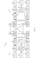
[0065] 図4は、図1に例示されたBS110およびUE120の構成要素の例を例示し、これらは本開示の態様を実装するように使用され得る。上述されるように、BSは、TRPを含み得る。BS110およびUE120の1つまたは複数の構成要素は、本開示の態様を実施するために使用され得る。例えば、UE120のアンテナ452、プロセッサ466、458、464、および/またはコントローラ/プロセッサ480、および/またはBS110のアンテナ434、プロセッサ430、420、438、および/またはコントローラ/プロセッサ440は、ここに説明され、且つ図10および11を参照して例示される動作を行うために使用され得る。
[0065] FIG. 4 illustrates example components of
[0066] 図4は、図1におけるBSのうちの1つおよびUEのうちの1つであり得る、BS110およびUE120の設計のブロック図を示す。制限付き関連付けシナリオの場合、基地局110は図1中のマクロBS110cであり得、UE120はUE120yであり得る。基地局110はまた、何らかの他のタイプの基地局であり得る。基地局110はアンテナ434a~434tを備え得、UE120はアンテナ452a~452rを備え得る。
[0066] FIG. 4 shows a block diagram of a design of
[0067] 基地局110において、送信プロセッサ420は、データソース412からデータを受信し、コントローラ/プロセッサ440から制御情報を受信し得る。制御情報は、物理ブロードキャストチャネル(PBCH)、物理制御フォーマット通知チャネル(PCFICH)、物理ハイブリッドARQインジケータチャネル(PHICH)、物理ダウンリンク制御チャネル(PDCCH)などのためのものであり得る。データは、物理ダウンリンク共有チャネル(PDSCH)などのためのものであり得る。プロセッサ420は、データと制御情報とを処理(例えば、符号化およびシンボルマッピング)し、データシンボルと制御シンボルとをそれぞれ取得し得る。プロセッサ420はまた、例えば、PSS、SSS、およびセル固有基準信号のための基準シンボルを生成し得る。送信(TX)多入力多出力(MIMO)プロセッサ430は、適用可能な場合、データシンボル、制御シンボル、および/または基準シンボルに対して空間処理(例えば、プリコーディング)を行い得、出力シンボルストリームを変調器(MOD)432a~432tに提供し得る。例えば、TX MIMOプロセッサ430は、RS多重化について本明細書で説明されるある特定の態様を行い得る。各変調器432は、(例えば、OFDMなどの)それぞれの出力シンボルストリームを処理して、出力サンプルストリームを取得し得る。各変調器432はさらに、出力サンプルストリームを処理(例えば、アナログへの変換、増幅、フィルタ処理、およびアップコンバート)して、ダウンリンク信号を取得し得る。変調器432a~432tからのダウンリンク信号は、それぞれアンテナ434a~434tを介して送信され得る。
At
[0068] UE120において、アンテナ452a~452rは、基地局110からダウンリンク信号を受信し得、受信信号をそれぞれ復調器(DEMOD)454a~454rに提供し得る。各復調器454は、それぞれの受信信号を調整(例えば、フィルタ処理、増幅、ダウンコンバート、およびデジタル化)して、入力サンプルを取得し得る。各復調器454は、さらに、(例えば、OFDMなどの)入力サンプルを処理して、受信シンボルを取得し得る。MIMO検出器456は、全ての復調器454a~454rから受信シンボルを取得し、適用可能な場合は受信シンボルに対してMIMO検出を行い、検出シンボルを与え得る。例えば、MIMO検出器456は、本明細書で説明される技法を使用して送信された、検出されたRSを提供し得る。受信プロセッサ458は、検出シンボルを処理(例えば、復調、デインターリーブ、および復号)し、UE120の復号されたデータをデータシンク460に提供し、復号された制御情報をコントローラ/プロセッサ480に提供し得る。1つまたは複数のケースによると、CoMPの態様は、それらが分散ユニット内に存在するように、アンテナ、並びにいくつかのTx/Rx機能を提供することを含み得る。例えば、いくつかのTx/Rx処理が中央ユニットで行われ得、一方、他の処理は、分散ユニットにおいて行われ得る。例えば、図に示されるような1つまたは複数の態様によると、BS変調/復調432は、分散ユニットにあり得る。
[0068] At
[0069] アップリンク上では、UE120において、送信プロセッサ464が、データソース462から(例えば、物理アップリンク共有チャネル(PUSCH)のための)データを、コントローラ/プロセッサ480から(例えば、物理アップリンク制御チャネル(PUCCH)のための)制御情報を、受信および処理し得る。送信プロセッサ464はまた、基準信号のための基準シンボルを生成し得る。送信プロセッサ464からのシンボルは、適用可能な場合はTX MIMOプロセッサ466によってプリコードされ、さらに(例えば、SC-FDMなどのために)変調器454a~454rによって処理され、基地局110に送信され得る。BS110において、UE120からのアップリンク信号は、アンテナ434によって受信され、復調器432によって処理され、適用可能な場合はMIMO検出器436によって検出され、さらに受信プロセッサ438によって処理されて、UE120によって送られた復号されたデータおよび制御情報が取得され得る。受信プロセッサ438は、復号されたデータをデータシンク439に提供し、復号された制御情報をコントローラ/プロセッサ440に提供し得る。
[0069] On the uplink, in
[0070] コントローラ/プロセッサ440および480は、それぞれ基地局110およびUE120における動作を指示し得る。基地局110におけるプロセッサ440および/または他のプロセッサおよびモジュールは、ここに説明される技法のためのプロセスを行うか、または指示し得る。UE120におけるプロセッサ480および/または他のプロセッサおよびモジュールは、本明細書で説明される技法のための処理を行うか、または指示し得る。メモリ442および482は、それぞれBS110およびUE120のためのデータおよびプログラムコードを記憶し得る。スケジューラ444は、ダウンリンク上および/またはアップリンク上でのデータ送信のためにUEをスケジュールし得る。
[0070] Controllers/
[0071] 図5は、本開示の態様による、通信プロトコルスタックを実装するための例を示す図500を例示する。例示された通信プロトコルスタックは、5Gシステム(例えば、アップリンクベースのモビリティをサポートするシステム)において動作するデバイスによって実装され得る。図500は、無線リソース制御(RRC)レイヤ510、パケットデータコンバージェンスプロトコル(PDCP)レイヤ515、無線リンク制御(RLC)レイヤ520、メディアアクセス制御(MAC)レイヤ525、および物理(PHY)レイヤ530を含む通信プロトコルスタックを例示する。様々な例では、プロトコルスタックのレイヤは、ソフトウェアの別個のモジュール、プロセッサまたはASICの一部分、通信リンクによって接続された非コロケートデバイスの一部分、またはそれらの様々な組み合わせとして実装され得る。コロケートされたおよびコロケートされていない実装は、例えば、ネットワークアクセスデバイス(例えば、AN、CU、および/またはDU)、あるいはUEのためのプロトコルスタックにおいて使用され得る。
[0071] FIG. 5 illustrates a diagram 500 that shows an example for implementing a communication protocol stack, according to aspects of the present disclosure. The illustrated communication protocol stacks may be implemented by devices operating in 5G systems (eg, systems supporting uplink-based mobility). Diagram 500 includes radio resource control (RRC)
[0072] 第1のオプション505-aは、プロトコルスタックの分割された実装を示し、ここで、そのプロトコルスタックの実装は、集中ネットワークアクセスデバイス(例えば、図2のANC202)と分散ネットワークアクセスデバイス(例えば、図2のDU208)との間で分割される。第1のオプション505-aでは、RRCレイヤ510およびPDCPレイヤ515は、集中ユニットで実装され、RLCレイヤ520、MACレイヤ525、およびPHYレイヤ530は、DUによって実装され得る。CUおよびDUの様々な例では、コロケートされるか、またはコロケートされていない可能性があり得る。第1のオプション505-aは、マクロセル、マイクロセル、またはピコセル配置において有用であり得る。
[0072] A first option 505-a illustrates a split implementation of a protocol stack, where the protocol stack implementation is a centralized network access device (eg,
[0073] 第2のオプション505-bは、プロトコルスタックの統合された実装を示し、ここで、そのプロトコルスタックは、単一のネットワークアクセスデバイス(例えば、アクセスノード(AN)、新無線基地局(NR BS)、新無線ノードB(NR NB)、ネットワークノード(NN)など)において実装される。第2のオプションでは、RRCレイヤ510、PDCPレイヤ515、RLCレイヤ520、MACレイヤ525、およびPHYレイヤ530は、各々ANによって実装される。第2のオプション505-bは、フェムトセルの配置で有用であり得る。
[0073] A second option 505-b shows an integrated implementation of a protocol stack, where the protocol stack is implemented by a single network access device (eg, access node (AN), new radio base station ( NR BS), New Radio Node Bs (NR NB), Network Nodes (NN), etc.). In a second option,
[0074] ネットワークアクセスデバイスがプロトコルスタックの一部を実装するか、または全てを実装するかに関わらず、UEは、全体のプロトコルスタック505-c(例えば、RRCレイヤ510、PDCPレイヤ515、RLCレイヤ520、MACレイヤ525、およびPHYレイヤ530)を実装し得る。
[0074] Regardless of whether the network access device implements part or all of the protocol stack, the UE may implement the entire protocol stack 505-c (eg,
[0075] 図6は、DLセントリックサブフレームの例を示す図600である。DLセントリックサブフレームは、制御部602を含み得る。制御部602は、DLセントリックサブフレームの初期または開始部分に存在し得る。制御部602は、DLセントリックサブフレームの様々な部分に対応する様々なスケジューリング情報および/または制御情報を含み得る。いくつかの構成では、制御部602は、図6で示されるように、物理DL制御チャネル(PDCCH)であり得る。DLセントリックサブフレームはまた、DLデータ部604も含み得る。DLデータ部604は、DLセントリックサブフレームのペイロードと呼ばれることもある。DLデータ部604は、スケジューリングエンティティ(例えば、UEまたはBS)から下位(subordinate)エンティティ(例えば、UE)へDLデータを通信するために利用される通信リソースを含み得る。いくつかの構成では、DLデータ部604は、物理DL共有チャネル(PDSCH)であり得る。
[0075] FIG. 6 is a diagram 600 illustrating an example of a DL-centric subframe. A DL-centric subframe may include a
[0076] DLセントリックサブフレームはまた、共通UL部606を含み得る。共通UL部606は、ULバースト、共通ULバースト、および/または様々な他の適切な用語で呼ばれることもある。共通UL部606は、DLセントリックサブフレームの様々な他の部分に対応するフィードバック情報を含み得る。例えば、共通UL部606は、制御部602に対応するフィードバック情報を含み得る。フィードバック情報の限定されない例は、ACK信号、NACK信号、HARQインジケータ、および/または様々な他の適切なタイプの情報を含み得る。共通UL部606は、ランダムアクセスチャネル(RACH)プロシージャ、スケジューリングリクエスト(SR)、および様々な他の適切なタイプの情報に関連する情報などの、追加的または代替的な情報を含み得る。図6に例示されるように、DLデータ部604の終端は、共通UL部606の始端から時間的に分割され得る。この時間分割は、ギャップ、ガード期間、ガードインターバル、および/または様々な他の適切な用語で呼ばれることもある。この分割は、DL通信(例えば、下位エンティティ(例えば、UE)による受信動作)から、UL通信(例えば、下位エンティティ(例えば、UE)による送信)への切り替えのための時間を提供する。前述のものが単にDLセントリックサブフレームの一例であり、また、同様の特徴を有する代替的構成が、本明細書で説明される態様から必ずしも逸脱せずに存在し得ることを、当業者は理解するだろう。
[0076] A DL-centric subframe may also include a
[0077] 図7は、ULセントリックサブフレームの例を示す図700である。ULセントリックサブフレームは、制御部702を含み得る。制御部702は、ULセントリックサブフレームの初期または開始部分に存在し得る。図7の制御部702は、図6を参照して上述した制御部と同様であり得る。ULセントリックサブフレームはまた、ULデータ部704も含み得る。ULデータ部704は、ULセントリックサブフレームのペイロードと呼ばれることもある。UL部分は、下位エンティティ(例えば、UE)からスケジューリングエンティティ(例えば、UEまたはBS)にULデータを通信するために利用される通信リソースを指し得る。いくつかの構成では、制御部702は、物理DLリンク制御チャネル(PDCCH)であり得る。
[0077] FIG. 7 is a diagram 700 illustrating an example of a UL centric subframe. A UL centric subframe may include a
[0078] 図7に例示されるように、制御部702の終端は、ULデータ部704の始端から時間的に分離され得る。この時間分離は、ギャップ、ガード期間、ガードインターバル、および/または様々な他の適切な用語で呼ばれることもある。この分離は、DL通信(例えば、スケジューリングエンティティによる受信動作)から、UL通信(例えば、スケジューリングエンティティによる送信)への切り替えのための時間を提供する。ULセントリックサブフレームはまた、共通UL部706も含み得る。図7中の共通UL部706は、図7を参照して上述した共通UL部706と同様であり得る。共通UL部706は、追加的にまたは代替的に、チャネル品質インジケータ(CQI)、サウンディング基準信号(SRS)、および様々な他の適切なタイプの情報に関連する情報を含み得る。前述のものが単にULセントリックサブフレームの一例であり、また、同様の特徴を有する代替的構成が、本明細書で説明される態様から必ずしも逸脱せずに存在することを、当業者は理解するだろう。
[0078] As illustrated in FIG. 7, the end of the
[0079] いくつかの状況では、2つ以上の下位エンティティ(例えば、UE)は、サイドリンク信号を使用して互いと通信し得る。このようなサイドリンク通信の現実世界のアプリケーションは、公共安全、近接サービス、UEからネットワークへの中継、車車間(V2V:vehicle-to-vehicle)通信、IoE(Internet of Everything)通信、IoT通信、ミッションクリティカルメッシュ、および/または様々な他の適切なアプリケーションを含み得る。一般に、サイドリンク信号は、スケジューリングエンティティがスケジューリングおよび/または制御目的のために利用され得るとしても、スケジューリングエンティティ(例えば、UEまたはBS)を通してその通信を中継せずに、ある下位エンティティ(例えば、UE1)から別の下位エンティティ(例えば、UE2)に通信された信号を指し得る。いくつかの例では、サイドリンク信号は、(通常アンライセンススペクトルを使用する、ワイヤレスローカルエリアネットワークとは異なる)ライセンススペクトルを使用して通信され得る。 [0079] In some situations, two or more subordinate entities (eg, UEs) may communicate with each other using sidelink signals. Real-world applications of such sidelink communication include public safety, proximity services, UE to network relay, vehicle-to-vehicle (V2V) communication, Internet of Everything (IoE) communication, IoT communication, mission-critical meshes, and/or various other suitable applications. In general, a sidelink signal is a subordinate entity (e.g., UE1 ) to another subordinate entity (eg, UE2). In some examples, sidelink signals may be communicated using licensed spectrum (unlike wireless local area networks, which typically use unlicensed spectrum).
[0080] UEは、リソースの専用セット(例えば、無線リソース制御(RRC)専用の状態など)を使用してパイロットを送信することに関連付けられた構成、またはリソースの共通セット(例えば、RRC共通の状態など)を使用してパイロットを送信することに関連付けられた構成を含む、様々な無線リソースにおいて動作し得る。RRC専用の状態で動作するとき、UEは、ネットワークにパイロット信号を送信するためのリソースの専用セットを選択し得る。RRC共通状態で動作しているとき、UEは、ネットワークにパイロット信号を送信するためにリソースの共通セットを選択し得る。いずれの場合にも、UEによって送信されるパイロット信号は、AN、またはDU、またはそれらの一部分などの、1つまたは複数のアクセスネットワークアクセスデバイスによって受信され得る。各受信ネットワークアクセスデバイスは、リソースの共通セット上で送信されるパイロット信号を受信および測定し、また、ネットワークアクセスデバイスがUEのためのネットワークアクセスデバイスのモニタリングセットのメンバであるUEに割り振られるリソースの専用セット上で送信されるパイロット信号を受信および測定するように構成され得る。受信ネットワークアクセスデバイスのうちの1つまたは複数、または受信ネットワークアクセスデバイスがパイロット信号の測定を送信するCUは、UEのためのサービングセルを識別するために、あるいは、UEの1つまたは複数についてのサービングセルの変更を開始するために測定を使用し得る。 [0080] The UE may use a configuration associated with transmitting pilot using a dedicated set of resources (eg, radio resource control (RRC) dedicated states, etc.) or a common set of resources (eg, RRC common state, etc.) may operate on a variety of radio resources, including configurations associated with transmitting pilots. When operating in RRC dedicated state, the UE may select a dedicated set of resources for transmitting pilot signals to the network. When operating in RRC common state, a UE may select a common set of resources to transmit pilot signals to the network. In any case, pilot signals transmitted by the UE may be received by one or more access network access devices, such as the AN, or DU, or parts thereof. Each receiving network access device receives and measures pilot signals transmitted on a common set of resources and of resources allocated to a UE for which the network access device is a member of a monitoring set of network access devices for the UE. It may be configured to receive and measure pilot signals transmitted on the dedicated set. One or more of the receiving network access devices, or the CUs to which the receiving network access devices transmit measurements of the pilot signals, may be used to identify the serving cell for the UE or the serving cell for one or more of the UEs. Measurements can be used to initiate changes in .
[0081] 本明細書で開示する実施形態の1つまたは複数の態様によれば、様々な信号を多重化することを可能にする、ショートバーストチャネル(例えば、PUCCHおよびPUSCH)のための様々な設計が提供される。 [0081] According to one or more aspects of the embodiments disclosed herein, different signal lengths for short burst channels (eg, PUCCH and PUSCH) allow different signals to be multiplexed. A design is provided.
<例示的な仮想リソースブロックから物理リソースブロックへのマッピング>
[0082] 本開示の態様によれば、NR通信システムにおいて分散VRBを使用するための技法が提供される。提供される技法は、LTEにおける分散VRBと同様であり、物理ダウンリンク共有チャネル(PDSCH)および物理アップリンク共有チャネル(PUSCH)などの様々な物理チャネルのためのサイクリックプレフィックス直交周波数分割多重(CP-OFDM)波形を使用するNRデータチャネルのために使用され得る。提供される技法は、NR固有のチャネライゼーションパラメータ、帯域幅部分(BWP:bandwidth part)、PRBグリッドパラメータ、およびPRBバンドリングパラメータを考慮する。加えて、提供される技法は、データ送信と、同期信号ブロック(SSブロック)ならびに前方および後方互換性のために予約されたリソースなどのNR固有リソースとの間の衝突を解決し得る。
<Exemplary Virtual Resource Block to Physical Resource Block Mapping>
[0082] According to aspects of this disclosure, techniques are provided for using distributed VRB in an NR communication system. The provided technique is similar to distributed VRB in LTE, cyclic prefix orthogonal frequency division multiplexing (CP - OFDM) waveforms may be used for NR data channels. The provided techniques consider NR-specific channelization parameters, bandwidth part (BWP), PRB grid parameters, and PRB bundling parameters. Additionally, the provided techniques may resolve conflicts between data transmissions and NR-specific resources such as synchronization signal blocks (SS blocks) and resources reserved for forward and backward compatibility.
[0083] 本開示の態様では、インターリービングに基づいてVRBをPRBにマッピングする技法が提供される。提供される技法では、VRBからPRBへの1対1マッピングは、インターリーバによって決定される。インターリーバは、N個のRBのインターリービングユニット(例えば、VRBバンドル)に基づいてインターリービングを行うことができる。インターリーバは、N個の連続するVRBのグループ(例えば、VRBバンドル)をN個の連続するPRBのグループ(例えば、PRBバンドル)にマッピングし得る。インターリービングを行う際に、インデックスiを有するVRBユニット(例えば、VRBバンドル)は、インデックスП(i)を有するPRBユニット(例えば、PRBバンドル)にマッピングされ、ここで、П(i)は、VRBのPRBへの1対1マッピングを記述する関数(function)である。 [0083] Aspects of this disclosure provide techniques for mapping VRBs to PRBs based on interleaving. In the provided technique, the one-to-one mapping from VRBs to PRBs is determined by an interleaver. The interleaver may perform interleaving based on an interleaving unit of N RBs (eg, a VRB bundle). An interleaver may map a group of N consecutive VRBs (eg, a VRB bundle) to a group of N consecutive PRBs (eg, a PRB bundle). During interleaving, a VRB unit with index i (eg, a VRB bundle) is mapped to a PRB unit with index Π(i) (eg, a PRB bundle), where Π(i) is the VRB is a function that describes the one-to-one mapping of to PRBs.
[0084] 本開示の態様によれば、インターリーバおよびそのインターリービングユニットは、デバイスおよび/または帯域幅部分(BWP)に固有であり得る。すなわち、インターリーバおよびそのインターリービングユニットは、単一のデバイスへの(例えば、ダウンリンク制御情報(DCI)中の)リソース割り振りのために使用され得、同じ帯域幅中で動作する他のデバイスは、異なるインターリーバおよびインターリービングユニットを使用し得る。同様に、インターリーバおよびそのインターリービングユニットは、BWP上で動作するデバイスへのリソース割り振りのために使用され得、一方、割り振りデバイス(例えば、BS)は、他のBWPのために異なるインターリーバおよびインターリービングユニットを使用する。 [0084] According to aspects of this disclosure, the interleaver and its interleaving units may be device and/or bandwidth part (BWP) specific. That is, the interleaver and its interleaving unit can be used for resource allocation (e.g., in downlink control information (DCI)) to a single device while other devices operating in the same bandwidth , may use different interleavers and interleaving units. Similarly, an interleaver and its interleaving units may be used for resource allocation to devices operating on a BWP, while an allocating device (e.g., a BS) uses different interleavers and interleaving units for other BWPs. Use an interleaving unit.
[0085] 本開示の態様では、上位レイヤシグナリング(例えば、RRCシグナリング)またはDCIシグナリングは、少なくとも半静的な方法で、VRBのPRBへのマッピングに関する情報を用いて(例えば、サービングセルによって)UEを構成または再構成するために使用され得る。 [0085] In aspects of this disclosure, higher-layer signaling (eg, RRC signaling) or DCI signaling is at least semi-static and uses information about the mapping of VRBs to PRBs (eg, by the serving cell) to It can be used to configure or reconfigure.
[0086] 本明細書で使用される場合、「インターリーバ」は、特定のタイプのインターリーバに限定されず、行-列インターリーバ、ランダムインターリーバ、多項式ベースの(polynominal-based)インターリーバなどの、使用され得る任意のタイプのインターリーバを指し得る。 [0086] As used herein, "interleaver" is not limited to any particular type of interleaver, such as row-column interleaver, random interleaver, polynomial-based interleaver, etc. , can refer to any type of interleaver that can be used.
[0087] 図8は、本開示の態様による、例示的な行-列インターリービング技法800を例示する。例示的な技法では、行-列インターリーバ802に基づくマッピングが示されている。例示的な技法では、インターリービングユニットサイズN=2が示されている。すなわち、例示的なマッピングでは、2つの連続的なVRBが、2つの連続的なPRBにマッピングされるインターリービングユニットを形成する。例示するように、VRBのグループ810は、インデックス812を有するインターリービングユニットに編成される。同様に、PRBのグループ820は、インデックス822を有するユニットに編成される。例示的なインターリーバでは、VRBに割り当てられた割り振りは、最初に、矩形マトリックス804に行方向に書き込まれる。すなわち、インターリービングユニット0の割り振りはマトリックスのブロック0に書き込まれ、インターリービングユニット1の割り振りはマトリックスのブロック1に書き込まれ、以下同様である。次いで、インターリーバは、PRBの割り振りを決定するために、列方向にマトリックスから読み取る。すなわち、マトリックスのブロック0における割り振りは、インデックス0を有するユニットにおけるPRBに割り当てられ、一方、マトリックスのブロック3における割り振りは、インデックス1を有するユニットにおけるPRBに割り当てられ、マトリックスのブロック6における割り振りは、インデックス2を有するユニットにおけるPRBに割り当てられ、以下同様である。インデックス822は、括弧内の対応するVRBインターリービングユニットインデックスの上に示されるPRBユニットインデックスを有するユニットのマッピングを示す。同様に、インデックス820は、対応するPRBへのVRBのマッピングを示し、PRBインデックスは、括弧内の対応するVRBインデックスの隣に示される。例示した技法を使用することによって、VRBにおける連続的なRB割り振りは、PRBにおける分散されたRB割り振りをもたらし、一方で、各2(N=2)個の連続するVRBを2つの連続するPRBにマッピングさせる。
[0087] FIG. 8 illustrates an example row-
[0088] 本開示の態様によれば、開示されたインターリービング技法とPRBバンドリングとの間に関係があり得る。開示される技法では、K個の連続するPRBのバンドルは、MIMOプリコーディングおよび復調基準信号(DMRS)ベースのチャネル推定のユニットを定義し得る。PRBバンドリングは、以前から知られている技法に従って、コンポーネントキャリアの絶対PRBグリッドに基づき得る。PRBバンドリングサイズは、プリコーディングおよびDMRSチャネル推定のユニットを定義し得るので、PRBバンドル(PRG)中のRBが、VRB領域とPRB領域の両方において連続的であることが望ましい。 [0088] According to aspects of this disclosure, there may be a relationship between the disclosed interleaving techniques and PRB bundling. In the disclosed techniques, a bundle of K consecutive PRBs may define a unit of MIMO precoding and demodulation reference signal (DMRS)-based channel estimation. PRB bundling may be based on the absolute PRB grid of the component carriers according to previously known techniques. Since the PRB bundling size may define the units of precoding and DMRS channel estimation, it is desirable that the RBs in a PRB bundle (PRG) are contiguous in both VRB and PRB regions.
[0089] 本開示の態様では、単一のインターリービングユニットは、複数のPRGを含み得る。インターリービングユニットサイズは、PRGサイズの整数倍、すなわち、N=α・Kであり、ここで、αは、0よりも大きい整数であり、Kは、PRG中のPRBの数である。 [0089] In aspects of this disclosure, a single interleaving unit may include multiple PRGs. The interleaving unit size is an integer multiple of the PRG size, ie, N=α·K, where α is an integer greater than 0 and K is the number of PRBs in the PRG.
[0090] 本開示の態様によれば、インターリービングユニットとPRGとの境界が揃えられる(aligned)。すなわち、PRB領域中の2つの隣接インターリービングユニット間の境界は、2つのインターリービングユニットがマッピングされる2つのPRG間の境界と一致する。 [0090] According to aspects of this disclosure, the boundaries of the interleaving unit and the PRG are aligned. That is, the boundary between two adjacent interleaving units in the PRB region coincides with the boundary between two PRGs to which the two interleaving units are mapped.
[0091] 本開示の態様では、周波数帯域のエッジ上のインターリービングユニットは、N個よりも少ないRBを有し得る。これは、例えば、BWPの境界がPRGのグリッドの境界と揃えられていないときに起こり得る。 [0091] In aspects of this disclosure, an interleaving unit on an edge of a frequency band may have less than N RBs. This can happen, for example, when the BWP boundaries are not aligned with the PRG grid boundaries.
[0092] 本開示の態様によれば、上記で説明した乗算係数αの単一または複数の値は、RRCシグナリングによって半静的に構成されるか、または複数の値が構成されるとき、構成された値のうちの1つの動的指示のためにDCIシグナリングと組み合わせられ得る。 [0092] According to aspects of this disclosure, the single or multiple values of the multiplication factor α described above may be semi-statically configured by RRC signaling, or configured when multiple values are configured. can be combined with DCI signaling for dynamic indication of one of the specified values.
[0093] 本開示の態様では、同じプリコーディングがBWP全体に適用される広帯域プリコーディングが使用され得る。この場合、BWPの帯域幅(BW)以下の任意のNの値が使用されことができる。以下の表1は、いくつかの例示的なPRGサイズおよび対応するインターリービングユニットサイズを例示する。 [0093] In aspects of this disclosure, wideband precoding may be used where the same precoding is applied to the entire BWP. In this case, any value of N less than or equal to the bandwidth (BW) of the BWP can be used. Table 1 below illustrates some exemplary PRG sizes and corresponding interleaving unit sizes.

[0094] 本開示の態様によれば、PRGサイズがBWPの帯域幅(BW)に等しいとき(すなわち、上記の表1の最後の行に示されるように)、同じMIMOプリコーディングマトリックスがそのBWP中の全てのRBのために使用される。そのような場合、PRGに関係なくPRBをVRBにマッピングする(すなわち、PRGの全てのPRBを、連続するVRBにマッピングされたままにすることなくPRBをVRBにマッピングする)ことは、全てのPRBにおいて同じMIMOプリコーディングマトリックスを使用するため、チャネル推定パフォーマンスを劣化させないので、インターリービングユニットサイズNは、BWP帯域幅以下の任意の整数個のPRBであり得る。 [0094] According to aspects of this disclosure, when the PRG size is equal to the BWP's bandwidth (BW) (i.e., as shown in the last row of Table 1 above), the same MIMO precoding matrix is used for all RBs in In such a case, mapping PRBs to VRBs regardless of PRG (i.e., mapping PRBs to VRBs without leaving all PRBs of a PRG mapped to consecutive VRBs) is equivalent to mapping all PRBs to VRBs. The interleaving unit size N can be any integer number of PRBs less than or equal to the BWP bandwidth, since it uses the same MIMO precoding matrix in , which does not degrade the channel estimation performance.
[0095] 図9は、本開示の態様による、N=4、K=4、およびα=1を使用する、VRBへの20個のPRBのBWPの例示的なマッピング900を例示する。例示的なマッピングでは、BWP910の境界は、PRGグリッド930と一致しない。従って、PRGは、それぞれが4個のPRBを有する4つのPRG912、914、916、および918と、それぞれが2つのPRBを有する2つのPRG922および924とを含む。インターリーバ940は、BWP910の20個のPRBを20個のVRB950にマッピングする。VRBは、各々が4つのVRBを有する4つのインターリービングユニット960、962、964、および966と、各々が2つのVRBを有する2つのインターリーバユニット970および972とに編成される。この例では、α=1であるので、インターリーバ940は、各PRGを、RB(PRG用のPRB、インターリービングユニット用のVRB)において同じサイズを有する対応するインターリービングユニットにマッピングする。従って、インターリーバは、連続的なPRBの各PRGが、同じ数の連続的なVRBを有するインターリービングユニットにマッピングされるように、VRBをPRBにマッピングする。980におけるチャートは、インターリービングユニットインデックス982と、VRBインデックス984と、PRBインデックス986との間の対応関係を示す。
[0095] FIG. 9 illustrates an
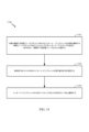
[0096] 図10は、本開示の態様による、図1および図4の基地局110、図2の5Gアクセスノード206、ならびに図3に示されたC-RU304などの基地局によって行われ得るワイヤレス通信のための例示的な動作1000を例示する。
[0096] FIG. 10 illustrates wireless communication that may be performed by a base station, such as
[0097] 動作1000は、ブロック1002において、基地局が、N個の連続する第1の仮想リソースブロック(VRB)の第1のインターリービングユニットをN個の連続する第1の物理リソースブロック(PRB)にマッピングする第1のインターリーブマッピングを決定することから始まり、各第1のPRBは、1期間中に周波数リソースのセットを備える。例えば、図1に示されるBS110aは、4つの連続する第1のVRBの第1のインターリービングユニット(例えば、図9に示されるユニット960)を4つの連続する第1のPRB(例えば、図9に示されるユニット912)にマッピングする第1のインターリーブマッピング(例えば、図9に示されるVRB950とBWP910のPRBとの間に示されるマッピング)を決定し、各第1のPRBは、1期間(例えば、1スロットまたは1サブフレーム)中に周波数リソースのセット(例えば、PRB4、5、6、および7の周波数)を備える。
[0097] At
[0098] ブロック1004において、動作1000は、基地局が、第1のVRBの第1のインターリービングユニットを第1のユーザ機器(UE)に割り振る第1の許可を送信することに続く。上記の例に続き、BS110aは、(ブロック1002からの)第1のVRBの第1のインターリービングユニットを(例えば、PDSCHのために)UE120(図1に示す)に割り振る第1の許可を(例えば、DCI中で)送信する。
[0098] At
[0099] 動作1000は、ブロック1006において、基地局が、第1のインターリービングユニットの第1のVRBにマッピングされた第1のPRBを介して第1のUEと通信することに続く。上記の例に続き、BS110aは、第1のインターリービングユニットの第1のVRBにマッピングされた第1のPRBを介してUE120にPDSCHを送信することによって、UE120と通信する。
[0099]
[0100] 図11は、本開示の態様による、図1および図4に示されたUE120などのユーザ機器(UE)によって行われ得るワイヤレス通信のための例示的な動作1100を例示する。動作1100は、図10を参照して上述した動作1000と相補的(complementary to)と見なされ得る。
[0100] FIG. 11 illustrates
[0101] 動作1100は、ブロック1102において、UEが、N個の連続する仮想リソースブロック(VRB)のインターリービングユニットをN個の連続する物理リソースブロック(PRB)にマッピングするインターリーブマッピングを決定することから始まり、各PRBは、1期間中に周波数リソースのセットを備える。例えば、UE120(図1に示す)は、4つの連続するVRBのインターリービングユニット(例えば、図9に示すユニット960)を4つの連続するPRB(例えば、図9に示すユニット912)にマッピングするインターリーブマッピング(例えば、図9に示すVRB950とBWP910のPRBとの間に示されるマッピング)を決定し、各PRBは、1期間(例えば、1スロットまたは1サブフレーム)中に周波数リソースのセット(例えば、PRB4、5、6、および7の周波数)を備える。
[0101]
[0102] ブロック1104において、動作1100は、UEが、基地局(BS)からVRBのインターリービングユニットを割り振る許可を受信することに続く。上記の例に続き、UE120は、(ブロック1102からの)VRBのインターリービングユニットを(例えば、PDSCHのために)割り振る許可を(例えば、DCIにおいて)BS110a(図1に示す)から受信する。
[0102] At
[0103] 動作1100は、ブロック1106において、UEが、インターリービングユニットのVRBにマッピングされたPRBを介してBSと通信することを続ける。上記の例に続き、UE120は、インターリービングユニットのVRBにマッピングされたPRBを介してBS110aからPDSCHを受信することによって、BS110aと通信する。
[0103]
[0104] 本開示の態様によれば、図10のブロック1006を参照して上述したように、UEと通信することは、UEに信号(例えば、PDSCH)を送信すること、またはUEから信号(例えば、PUSCH)を受信することを含み得る。 [0104] According to aspects of this disclosure, communicating with a UE includes transmitting a signal (eg, PDSCH) to the UE, or a signal (eg, PDSCH) from the UE, as described above with reference to block 1006 of FIG. For example, receiving PUSCH).
[0105] 本開示の態様では、図11のブロック1106を参照して上述したように、BSと通信することは、BSに信号(例えば、PUSCH)を送信すること、またはBSから信号(例えば、PDSCH)を受信することを含み得る。 [0105] In aspects of this disclosure, communicating with the BS includes sending a signal (eg, PUSCH) to the BS or a signal (eg, PDSCH).
[0106] 本開示の態様によれば、インターリービングユニットは、不均一なサイズを有し得、例えば、図9に例示するように、BWPの帯域エッジ上のユニットは、他のユニットとは異なるサイズであり得る。 [0106] According to aspects of this disclosure, interleaving units may have non-uniform sizes, for example, as illustrated in FIG. can be size.
[0107] 本開示の態様では、PRGの不均一なサイズを有することは、いくつかのUEに問題を引き起こし得る。例えば、図9に例示すように、2つのPRG922、924は2つのPRBを有し、一方、他のPRG912、914、916、918は4つのPRBを有する。従って、より小さいPRGサイズに起因して、PRG922もしくは924における割り振り、またはユニット970もしくは972における割り振りは、より低いプリコーディングおよびチャネル推定パフォーマンスを有し得る。
[0107] In aspects of this disclosure, having uneven PRG sizes may cause problems for some UEs. For example, as illustrated in FIG. 9, two
[0108] 本開示の態様によれば、他のPRGよりも小さいサイズを有するいくつかのPRGに関連する問題を低減するために、BWP固有PRGグリッドがBWPのために使用され得る。UEの大きなセットが同じBWPを共有するとき、新しいPRGグリッドは、そのBWPのためにのみ構成され得る。BWP固有PRGグリッドは、BWPのエッジにおける部分ユニットを回避するように構成され得、従って、キャリア固有の絶対PRGグリッドと揃えられないことがある。構成される場合、BWP固有PRGグリッドは、BWP境界と揃えられると仮定され得るか、またはBWP境界もしくは絶対PRGグリッドに対する(RBにおける)オフセット値が構成され得る。 [0108] According to aspects of this disclosure, a BWP-specific PRG grid may be used for the BWP to reduce problems associated with some PRGs having a smaller size than other PRGs. When a large set of UEs share the same BWP, a new PRG grid can only be configured for that BWP. The BWP-specific PRG grid may be configured to avoid partial units at the edges of the BWP and thus may not align with the carrier-specific absolute PRG grid. If configured, the BWP-specific PRG grid may be assumed to be aligned with the BWP boundary, or an offset value (in RBs) to the BWP boundary or absolute PRG grid may be configured.
[0109] 本開示の態様では、許可(例えば、上記のブロック1004で言及された第1の許可または上記のブロック1104で言及された許可)は、(例えば、UEからのPDSCHのために)複数のインターリービングユニットを割り振り得る。
[0109] In aspects of this disclosure, a grant (eg, the first grant mentioned in
[0110] 図12は、本開示の態様による、BWP固有PRGグリッドが構成される例示的なBWP1200を例示する。キャリアの帯域幅内のPRBに対するキャリア固有インデックスが1202に示されている。キャリアの帯域幅内のPRGへのキャリア固有インデックスが1204に示されている。例示的なBWPは、インデックス2を有するPRBから、インデックス21を有するPRBまでの、それらを含めた20個のPRBからなる。例示的なBWPでは、BWP固有PRGグリッドの境界1212が示されており、BWP固有PRGグリッドのインデックス2を有するPRGが1210に示されている。上述のように、境界1222を有するキャリア固有のPRGグリッドは、BWPの帯域幅上に重ねられる。キャリア固有グリッドのインデックス0を有するPRGが1220に示されている。
[0110] FIG. 12 illustrates an
[0111] 本開示の態様によれば、他のPRGよりも小さいサイズを有するいくつかのPRGに関連する問題を低減するために、ヌルRB割り当てがBWPのために使用され得る。UE固有であり得るヌルRBは、データリソースマッピングを回避するために、部分(すなわち、サイズ<N)インターリービングユニット(例えば、図9のユニット970および972)のために半静的に構成され得る。次いで、半静的に構成されたヌルRBは、プリコーディンググリッドとインターリービングユニットとの間の不一致の問題を回避するために、割り振りから除外される。
[0111] According to aspects of this disclosure, null RB allocation may be used for BWPs to reduce problems associated with some PRGs having a smaller size than other PRGs. Null RBs, which may be UE-specific, may be semi-statically configured for partial (i.e., size<N) interleaving units (e.g.,
[0112] 図13Aおよび図13Bは、本開示の態様による、BWPのVRB1300および1350の例示的なセットを例示する。VRBの例示的なセットの各々は、RB#0から始まる連続的な6個のRB割り振りを含む。VRBの第1のセットにおけるVRBのインデックスが1302に示される。VRBの第2のセットにおけるVRBのインデックスが1352に示される。第1の例示的な割り振り1310は、ヌルRBを使用しないBWPのVRBのセット1300中にあり、従って、割り振り1310は、インデックス0~5を有するVRBを含む。第2の例示的な割り振り1360は、インデックス4および5を有するVRB1362および1364中の2つのヌルRBを使用するBWPのVRBのセット1350中にある。従って、6つのRBの割り振り1360は、インデックス0~3およびインデックス6~7を有するVRBを含む。
[0112] FIGS. 13A and 13B illustrate an example set of
[0113] 本開示の態様によれば、図12を参照して上述したようなBWP固有PRGグリッドを使用することと、図13Bを参照して上述したようなヌルRBを使用することとの組み合わせが、いくつかの通信システムにおいて使用され得る。 [0113] According to aspects of this disclosure, a combination of using a BWP-specific PRG grid as described above with reference to FIG. 12 and using null RBs as described above with reference to FIG. 13B may be used in some communication systems.
[0114] 本開示の態様では、小さいRB割り振りを伴う動作の場合、RBはインターリービング後に周波数において十分に広く拡散されないことがあるので、インターリービングユニット(例えば、VoIPトラフィック)のサイズよりも小さいRB割り振りのダイバーシティ利得が影響を受け得る。 [0114] In aspects of this disclosure, for operations with small RB allocations, RBs smaller than the size of an interleaving unit (eg, VoIP traffic) may not be spread widely enough in frequency after interleaving. Allocation diversity gains may be affected.
[0115] 本開示の態様によれば、いくつかのインターリービングユニット中のいくつかのRBは、小さいRB割り振りのために予約され得る。小さいRB割り振りを使用するトラフィックは、予約されたRB上で割り当てられ得、一方、他のトラフィックは、残りのRB上で割り当てられ得る。図13Bを参照して上述したように、ヌルRB構成は、予約を達成するために使用されることができる。すなわち、小さいRB割り振りを有するUEのためにいくつかのRBを予約するために、大きいRB割り振りを有するUEのために、ヌルRBが構成され得る。構成されたヌルRBを有するUEはヌルRBロケーションに割り振られないので、ヌルRB構成を有していない他のUEは、小さいRB割り振りを使用して、トラフィックのためのロケーションを自由に使用することができる。 [0115] According to aspects of this disclosure, some RBs in some interleaving units may be reserved for small RB allocations. Traffic using small RB allocations may be assigned on the reserved RBs, while other traffic may be assigned on the remaining RBs. As described above with reference to FIG. 13B, a null RB configuration can be used to achieve reservation. That is, null RBs may be configured for UEs with large RB allocations to reserve some RBs for UEs with small RB allocations. Since UEs with configured null RBs are not allocated to null RB locations, other UEs that do not have null RB configurations are free to use locations for traffic using smaller RB allocations. can be done.
[0116] 図14Aおよび図14Bは、本開示の態様による、例示的なインターリービングマッピング1400および1450を例示する。例示的なマッピング1400では、1410における2つのVRBが、小さいRB割り振りを使用するトラフィックによる使用のために割り当てられる。2つのVRBが小さいRB割り振りトラフィックに割り振られるとき、1420に示すように、連続するPRBにVRBがマッピングされるので、トラフィックは周波数ダイバーシティから利益を受けない。例示的なマッピング1450では、5つのVRB1460、1462、1464、1466、および1468(例えば、各インターリービングユニット1452、1454、1456、1458、および1459中の1つ)が、小さいRB割り振りトラフィックのために予約される。例示的なマッピングでは、2つの予約されたRB1464および1466が、小さいRBトラフィックに割り振られる。小さいRB割り振りトラフィックに割り当てられたVRBは、PRB1470および1472にマッピングされ、これらは、図14Aに示す1420におけるPRBよりも著しく大きい周波数ダイバーシティを有する。
[0116] FIGS. 14A and 14B illustrate
[0117] 本開示の態様によれば、PRB中のいくつかのリソースは、いくつかの他の目的、例えば、同期信号またはフォワード互換性リソースのために予約され得る。予約は、RBシンボルレベルまたは制限されたリソース要素(RE)レベル(REレベル)で実装され得る。予約されたリソースは、レートマッチングのために半静的および/または動的にUEに示され得る。データリソース(すなわち、PDSCHまたはPUSCHのためのリソース)がVRBにおいて割り振られるため、PRBにおける予約されたリソースは、レートマッチングのためにVRBに変換(例えば、デインターリーブ)されるべきである。 [0117] According to aspects of this disclosure, some resources in a PRB may be reserved for some other purpose, eg, synchronization signals or forward compatibility resources. Reservation may be implemented at the RB symbol level or the restricted resource element (RE) level (RE level). Reserved resources may be semi-statically and/or dynamically indicated to the UE for rate matching. Since data resources (ie, resources for PDSCH or PUSCH) are allocated in VRBs, reserved resources in PRBs should be converted (eg, de-interleaved) to VRBs for rate matching.
[0118] 本開示の態様では、レートマッピングプロシージャは、以下の通りであり得る:1)所与のスロット内のPRB内の予約されたリソース(RBシンボルレベルまたは制限されたREレベル)を決定し、2)PRB内の予約されたリソースのロケーション(例えば、RB、RE、またはシンボル)を、デインターリーバ機能または関数(function)П-1を介したデインターリービングを通じてVRBに変換し、3)開始および/または終了VRBインデックスまたは開始RBおよび割り振りの長さに基づいて連続的なRB割り振りを使用して、データをVRB内のリソース(例えば、PDSCHおよび/またはPUSCHのための)に割り振り、データを割り当てる間、予約されたリソースを回避する(例えば、レートマッチング)、4)VRB対PRBマッピングのためのインターリーブを行う。 [0118] In aspects of this disclosure, the rate mapping procedure may be as follows: 1) determine the reserved resources (RB symbol level or limited RE level) in PRBs in a given slot; , 2) transforming the location of the reserved resource in the PRB (e.g., RB, RE, or symbol) into a VRB through de-interleaving via a de-interleaver function or function П -1 ; 3) Data is allocated to resources (e.g., for PDSCH and/or PUSCH) in the VRB using continuous RB allocation based on the starting and/or ending VRB index or the starting RB and the length of the allocation, and the data 4) do interleaving for VRB to PRB mapping;
[0119] 図15は、本開示の態様による、例示的なインターリービングマッピング1500を例示する。例示的なインターリービングマッピングは、5シンボルスロットを利用し、BWP1510における20個のRBの帯域幅のために構成される。PRB領域におけるシンボルのインデックスは1502で示され、一方、VRB領域におけるシンボルのインデックスは1504で示される。インデックス4を有するRBから始まり、10の割り振り長を有する連続的なVRBの割り振り1520(すなわち、それらを含めたVRB4~VRB13)が示されている。VRBおよびPRBにおける予約されたリソースのロケーションは、インターリービング/デインターリービング機能(function)1530によって関連付けられる。例示的なマッピングは、VRB1522などの、データ送信のために割り振られたRBと、PRB1544などの、予約されたまたは予約されたREを含むRBとを示す。例示的なマッピングでは、データVRB1522はPRB1542に対応する。同様に、予約された、または予約されたREを含むPRB1544は、VRB1524に対応する。VRB1524は、予約された、または予約されたREを含むPRBに対応するので、VRB1524は、その周辺でレートマッチングされる。
[0119] FIG. 15 illustrates an
[0120] 本明細書に開示されている方法は、説明された方法を達成するための1つまたは複数のステップまたはアクションを備える。方法のステップおよび/またはアクションは、特許請求の範囲から逸脱することなく、互いに置き換えられ得る。言い換えると、ステップまたはアクションの特定の順序が指定されない限り、特定のステップおよび/またはアクションの順序および/または使用は、本願の特許請求の範囲から逸脱せずに修正され得る。 [0120] The methods disclosed herein comprise one or more steps or actions for achieving the described method. The method steps and/or actions may be interchanged with one another without departing from the scope of the claims. In other words, unless a specific order of steps or actions is specified, the order and/or use of specific steps and/or actions may be modified without departing from the scope of the claims herein.
[0121] 本明細書で使用される場合、項目のリスト「~のうちの少なくとも1つ」を示すフレーズは、単一の要素を含む、それらの項目の任意の組み合わせを指す。例として、「a、b、またはcのうちの少なくとも1つ」は、a、b、c、a-b、a-c、b-c、およびa-b-c、並びに、同じ要素(例えば、a-a、a-a-a、a-a-b、a-a-c、a-b-b、a-c-c、b-b、b-b-b、b-b-c、c-c、およびc-c-c、あるいは、a、b、およびcの他の順番)の複数との任意の組み合わせをカバーすることが意図される。本明細書で使用される場合、特許請求の範囲に含まれる「および/または」という表現は、2つ以上の項目のリストで使用されるとき、それ自体によって用いられ得るリスト化された項目のうちのいずれか1つ、またはリスト化された項目のうちの2つ以上のいずれかの組み合せが用いられ得ることを意味する。例えば、構成がコンポーネントA、B、および/またはCを含むと説明される場合、その構成は、A単独;B単独;C単独;AおよびBの組合せ;AおよびCの組み合せ;BおよびCの組み合せ;またはA、B、およびCの組み合せを含むことができる。 [0121] As used herein, a phrase indicating "at least one of" a list of items refers to any combination of those items, including single elements. By way of example, "at least one of a, b, or c" refers to a, b, c, ab, ac, bc, and abc, as well as the same elements (e.g. , aa, aaa, aab, aac, abb, acc, bb, bbb, bbc , cc, and cc, or any other order of a, b, and c). As used herein, the term "and/or" included in the claims, when used in a list of more than one item, can be used by itself to refer to the list of items listed. means that any one of, or any combination of two or more of the listed items may be used. For example, if a configuration is described as including components A, B, and/or C, the configuration may be A alone; B alone; C alone; A and B in combination; A and C in combination; combinations; or combinations of A, B, and C.
[0122] 本明細書で使用される場合、「決定すること」という用語は、幅広いアクションを含む。例えば、「決定すること」は、算出すること、計算すること、処理すること、導出すること、調査すること、ルックアップすること(例えば、表、データベース、または別のデータ構造においてルックアップすること)、確認することなどを含み得る。また、「決定すること」は、受信すること(例えば、情報を受信すること)、アクセスすること(例えば、メモリ内のデータにアクセスすること)などを含み得る。また、「決定すること」は、解決すること、選択すること、選ぶこと、確立することなどを含み得る。 [0122] As used herein, the term "determining" includes a wide range of actions. For example, "determining" means calculating, calculating, processing, deriving, examining, looking up (e.g., looking up in a table, database, or another data structure). ), verifying, etc. Also, "determining" can include receiving (eg, receiving information), accessing (eg, accessing data in memory), and the like. Also, "determining" can include resolving, selecting, choosing, establishing and the like.
[0123] 以上の説明は、当業者が本明細書で説明した様々な態様を実行できるようにするために提供したものである。これらの態様に対する様々な変更は当業者には容易に明らかであり、本明細書で定義した一般的原理は他の態様に適用することができる。従って、特許請求の範囲は、本明細書に示された態様に限定されるものではなく、特許請求の範囲の文言に矛盾しない最大限の範囲を与えられるべきであり、単数形の要素への言及は、そのように明記されていない限り、「ただ1つの」を意味するものではなく、「1つまたは複数の」を意味するものである。例えば、「a」や「an」といった冠詞は、本明細書および添付の特許請求の範囲において使用される場合、一般に、別段に明記されていない限り、単数形を指していることが文脈から明らかでない限り、「1つまたは複数」を意味するものと解釈されるべきである。別段に明記されていない限り、「いくつかの」という用語は「1つまたは複数の」を指す。 [0123] The previous description is provided to enable any person skilled in the art to practice the various aspects described herein. Various modifications to these aspects will be readily apparent to those skilled in the art, and the generic principles defined herein may be applied to other aspects. Accordingly, the claims should not be limited to the embodiments shown herein, but are to be accorded the fullest scope consistent with the language of the claims, reverting to elements in the singular. References do not mean "only one," but rather "one or more," unless expressly stated otherwise. For example, the articles "a" and "an," as used in this specification and the appended claims, generally refer to the singular unless otherwise specified, and it is clear from the context that shall be construed to mean "one or more" unless otherwise specified. Unless specified otherwise, the term "some" refers to "one or more."
[0031] さらに、「または」という用語は、排他的な「または」ではなく、包括的な「または」を意味するものとする。すなわち、別段に明記されていない限り、またはコンテキストから明らかでない限り、例えば、「XはAまたはBを用いる」というフレーズは、自然な包括的置換のうちのいずれかを意味することを意図している。すなわち、例えば、「XはAまたはBを用いる」というフレーズは、XがAを用いる場合、XがBを用いる場合、またはXがAとBの両方を用いる場合のいずれによっても満たされる。当業者に知られている、または後に知られることになる、本開示全体にわたって説明した様々な態様の要素の全ての構造的および機能的均等物は、参照により本明細書に明確に組み込まれ、特許請求の範囲に包含されるものである。さらに、本明細書に開示したいかなることも、そのような開示が特許請求の範囲に明示的に記載されているかどうかに関わらず、公共に献呈されるものではない。特許請求の範囲のどの要素も、その要素が明確に「~のための手段」というフレーズを使用して記載されていない限り、または、方法の請求項の場合には、その要素が「~するためのステップ」というフレーズを使用して記載されていない限り、米国特許法第112条6項の規定のもとで解釈されるべきではない。
[0031] Further, the term "or" shall mean an inclusive "or" rather than an exclusive "or." That is, unless stated otherwise, or clear from context, for example, the phrase "X employs A or B" is intended to mean any of the natural inclusive permutations. there is That is, for example, the phrase "X uses A or B" is satisfied whether X uses A, X uses B, or X uses both A and B. All structural and functional equivalents to the elements of the various embodiments described throughout this disclosure that are known, or later become known, to those skilled in the art are expressly incorporated herein by reference, It is within the scope of the claims. Moreover, nothing disclosed herein is a dedication to the public, whether or not such disclosure is expressly recited in the claims. Any element of a claim shall not appear unless that element is explicitly recited using the phrase "means for" or, in the case of a method claim, that element "to Unless stated using the phrase "a step for" should not be construed under the provisions of 35 U.S.C. §112,
[0124] 上述された方法の様々な動作は、対応する機能を実行することができる任意の適切な手段によって行われ得る。手段は、回路、特定用途向け集積回路(ASIC)、またはプロセッサを含むがそれらに限定されない、様々なハードウェアおよび/またはソフトウェアコンポーネントおよび/またはモジュールを含み得る。一般に、図に示す動作がある場合、それらの動作は、同様の番号を有する対応するカウンターパートのミーンズプラスファンクション構成要素を有し得る。 [0124] The various acts of methods described above may be performed by any suitable means capable of performing the corresponding functions. The means may include various hardware and/or software components and/or modules including, but not limited to, circuits, application specific integrated circuits (ASICs), or processors. Generally, where there are operations illustrated in a figure, those operations may have corresponding counterpart means-plus-function components with similar numbering.
[0125] 本開示に関連して説明した様々な例示的な論理ブロック、モジュール、および回路は、汎用プロセッサ、デジタル信号プロセッサ(DSP)、特定用途向け集積回路(ASIC)、フィールドプログラマブルゲートアレイ(FPGA)または他のプログラマブル論理デバイス、個別ゲートまたはトランジスタロジック、個別ハードウェア構成要素、あるいは本明細書に記載の機能を行うように設計されたそれらの任意の組み合せを用いて実施または行われ得る。汎用プロセッサはマイクロプロセッサであり得るが、代替として、プロセッサは、任意の商用に利用可能なプロセッサ、コントローラ、マイクロコントローラ、または状態機械であり得る。プロセッサは、コンピューティングデバイスの組み合せ、例えば、DSPとマイクロプロセッサとの組み合せ、複数のマイクロプロセッサ、DSPコアと連携する1つまたは複数のマイクロプロセッサ、あるいは任意の他のそのような構成としても実装され得る。 [0125] The various exemplary logic blocks, modules, and circuits described in connection with this disclosure may be general purpose processors, digital signal processors (DSPs), application specific integrated circuits (ASICs), field programmable gate arrays (FPGAs), ) or other programmable logic devices, discrete gate or transistor logic, discrete hardware components, or any combination thereof designed to perform the functions described herein. A general-purpose processor may be a microprocessor, but in the alternative, the processor may be any commercially available processor, controller, microcontroller, or state machine. A processor may also be implemented as a combination of computing devices, such as a combination DSP and microprocessor, multiple microprocessors, one or more microprocessors in conjunction with a DSP core, or any other such configuration. obtain.
[0126] ハードウェアで実装される場合、例示的なハードウェア構成は、ワイヤレスノード中の処理システムを備え得る。処理システムは、バスアーキテクチャを用いて実装され得る。バスは、処理システムの特定の用途と全体的な設計の制約に依存して、任意の数の相互接続バスおよびブリッジを含み得る。バスは、プロセッサ、機械可読媒体、およびバスインターフェースを含む様々な回路を共にリンクさせ得る。バスインターフェースは、特に、バスを介してネットワークアダプタを処理システムに接続するために使用され得る。このネットワークアダプタは、PHYレイヤの信号処理機能を実装するために使用され得る。ユーザ端末120(図1を参照)の場合、ユーザインターフェース(例えば、キーパッド、ディスプレイ、マウス、ジョイスティックなど)もまた、バスに接続されることができる。バスはまた、タイミングソース、周辺機器、電圧レギュレータ、電力管理回路などのような様々な他の回路をリンクさせることができるが、これは、当該技術において周知であるため、これ以上説明されない。プロセッサは、1つまたは複数の汎用および/または特殊用途プロセッサで実装され得る。例は、ソフトウェアを実行することができるマイクロプロセッサ、マイクロコントローラ、DSPプロセッサ、および他の回路を含む。当業者は、システム全体に課された特定の用途および全体的な設計の制約に依存して、処理システムについて説明された機能をどのように実装することが最善かを認識するだろう。 [0126] When implemented in hardware, an exemplary hardware configuration may comprise a processing system in a wireless node. A processing system may be implemented using a bus architecture. A bus may include any number of interconnecting buses and bridges, depending on the particular application and overall design constraints of the processing system. A bus may link together various circuits including a processor, a machine-readable medium, and a bus interface. A bus interface may be used, among other things, to connect a network adapter to a processing system via a bus. This network adapter can be used to implement the signal processing functions of the PHY layer. For user terminal 120 (see FIG. 1), a user interface (eg, keypad, display, mouse, joystick, etc.) may also be connected to the bus. The bus may also link various other circuits such as timing sources, peripherals, voltage regulators, power management circuits, etc., but this is well known in the art and will not be described further. A processor may be implemented with one or more general-purpose and/or special-purpose processors. Examples include microprocessors, microcontrollers, DSP processors, and other circuits capable of executing software. Those skilled in the art will recognize how best to implement the described functionality for a processing system depending on the particular application and overall design constraints imposed on the overall system.
[0127] ソフトウェアで実装される場合、これら機能は、コンピュータ可読媒体上で、1つまたは複数の命令またはコードとして送信または記憶され得る。ソフトウェアは、ソフトウェア、ファームウェア、ミドルウェア、マイクロコード、ハードウェア記述言語と呼ばれる場合も、その他の名称で称される場合も、命令、データ、またはそれらの任意の組み合わせを意味するものとして広く解釈されるべきである。コンピュータ可読媒体は、ある場所から別の場所へのコンピュータプログラムの転送を容易にする任意の媒体を含む、コンピュータ記憶媒体とコンピュータ通信媒体の両方を含む。プロセッサは、バスの管理と、機械可読記憶媒体に記憶されたソフトウェアモジュールの実行を含む汎用処理とを担い得る。コンピュータ可読記憶媒体は、プロセッサが記憶媒体から情報を読み取り、記憶媒体に情報を書き込むことができるように、プロセッサに結合され得る。代替として、記憶媒体はプロセッサに一体化することができる。例として、機械可読媒体は、送信線、データによって変調された搬送波、および/またはワイヤレスノードとは別個の命令を記憶したコンピュータ可読記憶媒体を含み得るが、それらは全てバスインターフェースを介してプロセッサによりアクセスされ得る。代替的にまたは加えて、機械可読媒体、またはそのうちの任意の部分は、キャッシュおよび/または汎用レジスタファイルが用いられ得るようなケースに、プロセッサに組み込まれ得る。機械可読媒体の例は、例として、RAM(ランダムアクセスメモリ)、フラッシュメモリ、位相変更メモリ、ROM(読取専用メモリ)、PROM(プログラマブル読取専用メモリ)、EPROM(消去可能なプログラマブル読取専用メモリ)、EEPROM(登録商標)(電気的に消去可能なプログラマブル読取専用メモリ)、レジスタ、磁気ディスク、光ディスク、ハードドライブ、または任意の他の適切な記憶媒体、またはそれらの任意の組み合わせを含み得る。機械可読媒体は、コンピュータプログラム製品に組み込まれ得る。 [0127] If implemented in software, the functions may be transmitted on or stored as one or more instructions or code on a computer-readable medium. Software, whether referred to as software, firmware, middleware, microcode, hardware description language, or otherwise, shall be construed broadly to mean instructions, data, or any combination thereof should. Computer-readable media includes both computer storage media and communication media including any medium that facilitates transfer of a computer program from one place to another. The processor may be responsible for bus management and general-purpose processing, including executing software modules stored on machine-readable storage media. A computer-readable storage medium may be coupled to the processor such that the processor can read information from, and write information to, the storage medium. Alternatively, the storage medium may be integral to the processor. By way of example, a machine-readable medium may include a transmission line, a carrier wave modulated with data, and/or a computer-readable storage medium storing instructions separate from a wireless node, all of which are readable by a processor via a bus interface. can be accessed. Alternatively or additionally, the machine-readable medium, or any portion thereof, may be incorporated into the processor, in which case caches and/or general register files may be used. Examples of machine-readable media include, by way of example, RAM (random access memory), flash memory, phase change memory, ROM (read only memory), PROM (programmable read only memory), EPROM (erasable programmable read only memory), It may include EEPROM (Electrically Erasable Programmable Read Only Memory), registers, magnetic disk, optical disk, hard drive, or any other suitable storage medium, or any combination thereof. A machine-readable medium may be embodied in a computer program product.
[0128] ソフトウェアモジュールは、単一の命令または多数の命令を備えることがあり得、いくつかの異なるコードセグメントにわたって、異なるプログラム間で、および複数の記憶媒体にわたって、分散されることがあり得る。コンピュータ可読媒体は、多数のソフトウェアモジュールを備え得る。ソフトウェアモジュールは、プロセッサなどの装置によって実行されるとき、様々な機能を処理システムに実行させる命令を含む。ソフトウェアモジュールは、送信モジュールと受信モジュールとを含み得る。各ソフトウェアモジュールは、単一の記憶デバイスに存在するか、または複数の記憶デバイスにわたって分散され得る。例として、ソフトウェアモジュールは、トリガイベントが生じたとき、ハードドライブからRAMにロードされ得る。ソフトウェアモジュールの実行中、プロセッサは、アクセススピードを上げるために、命令のうちのいくつかをキャッシュにロードし得る。1つまたは複数のキャッシュラインは次いで、プロセッサによる実行のために、汎用レジスタファイルにロードされ得る。以下でソフトウェアモジュールの機能に言及するとき、そのような機能は、ソフトウェアモジュールからの命令を実行するとき、プロセッサによって実装されることが理解されるだろう。 [0128] A software module may comprise a single instruction, or many instructions, and may be distributed across several different code segments, among different programs, and across multiple storage media. A computer-readable medium may comprise numerous software modules. The software modules contain instructions that, when executed by a device such as a processor, cause the processing system to perform various functions. Software modules may include transmit modules and receive modules. Each software module may reside on a single storage device or be distributed across multiple storage devices. By way of example, software modules may be loaded from the hard drive into RAM when a trigger event occurs. During execution of the software module, the processor may load some of the instructions into cache to speed up access. One or more cache lines may then be loaded into the general register file for execution by the processor. When referring to functionality of software modules below, it will be understood that such functionality is implemented by the processor when executing instructions from the software module.
[0129] また、任意の接続は、厳密にはコンピュータ可読媒体と呼ばれ得る。例えば、ソフトウェアが、同軸ケーブル、光ファイバーケーブル、ツイストペア、デジタル加入者回線(DSL)、または赤外線、無線、およびマイクロ波などのワイヤレス技術を使用して、ウェブサイト、サーバ、または他のリモートソースから送信される場合、同軸ケーブル、光ファイバーケーブル、ツイストペア、DSL、または赤外線、無線、およびマイクロ波などのワイヤレス技術は、媒体の定義に含まれる。本明細書で使用される場合、ディスク(disk)およびディスク(disc)は、コンパクトディスク(CD)、レーザーディスク(登録商標)、光ディスク、デジタル多用途ディスク(DVD)、フロッピー(登録商標)ディスク、およびBlu-ray(登録商標)ディスクを含み、ディスク(disk)は、通常、データを磁気的に再生し、一方、ディスク(disc)は、データをレーザで光学的に再生する。よって、いくつかの態様では、コンピュータ可読媒体は、非一時的なコンピュータ可読媒体(例えば、有形媒体)を備え得る。さらに、他の態様では、コンピュータ可読媒体は、一時的なコンピュータ読取可能な媒体(例えば、信号)を備え得る。上記の組み合せもコンピュータ可読媒体の範囲内に含めるべきである。 [0129] Also, any connection may be properly termed a computer-readable medium. For example, software transmitted from a website, server, or other remote source using coaxial cable, fiber optic cable, twisted pair, digital subscriber line (DSL), or wireless technologies such as infrared, radio, and microwave; Where applicable, coaxial cable, fiber optic cable, twisted pair, DSL, or wireless technologies such as infrared, radio, and microwave are included in the definition of medium. As used herein, disk and disc refer to compact disc (CD), laser disc (registered trademark), optical disc, digital versatile disc (DVD), floppy disk, and Blu-ray® discs, where disks typically reproduce data magnetically, while discs reproduce data optically with a laser. Thus, in some aspects computer readable medium may comprise non-transitory computer readable medium (eg, tangible media). In addition, for other aspects computer readable medium may comprise transitory computer readable medium (eg, a signal). Combinations of the above should also be included within the scope of computer-readable media.
[0130] 従って、ある特定の態様は、本明細書において提示された動作を行うためのコンピュータプログラム製品を備え得る。例えば、このようなコンピュータプログラム製品は、命令を記憶した(および/またはエンコードされた)コンピュータ可読媒体を備えることがあり得、その命令は、ここに記載された動作を行うために1つまたは複数のプロセッサによって実行可能である。例えば、動作を行うための命令がここに説明され、且つ添付の図面に例示される。 [0130] Accordingly, certain aspects may comprise a computer program product for performing the operations presented herein. For example, such a computer program product may comprise a computer-readable medium having (and/or encoded on) instructions stored thereon, the instructions representing one or more instructions for performing the operations described herein. processor. For example, instructions for performing operations are described herein and illustrated in the accompanying drawings.
[0131] さらに、本明細書に説明された方法および技法を行うためのモジュールおよび/または他の適切な手段が、ダウンロードされることができること、および/または、そうでなければ、ユーザ端末および/または基地局によって、適用可能であるように得られることが理解されるべきである。例えば、このようなデバイスは、本明細書で説明される方法を行うための手段の転送を容易にするためにサーバに結合され得る。代替的に、本明細書で説明される様々な方法は、ユーザ端末および/または基地局が、デバイスに記憶手段を結合または提供する際に様々な方法を取得し得るように、記憶手段(例えば、RAM、ROM、コンパクトディスク(CD)またはフロッピーディスクなどの物理記憶媒体など)を介して提供され得る。さらに、本明細書で説明される方法および技法をデバイスに提供するために、任意の他の適切な技法が利用され得る。 [0131] Additionally, modules and/or other suitable means for performing the methods and techniques described herein may be downloaded and/or otherwise stored in a user terminal and/or or obtained by the base station as applicable. For example, such devices may be coupled to servers to facilitate transfer of means for performing the methods described herein. Alternatively, the various methods described herein are stored in a storage means (e.g., storage means) such that the user terminal and/or base station can acquire the various methods upon coupling or providing the storage means to the device. , RAM, ROM, a physical storage medium such as a compact disc (CD) or floppy disk, etc.). In addition, any other suitable technique may be utilized to provide a device with the methods and techniques described herein.
[0132] 特許請求の範囲は、上記に例示されたとおりの構成および構成要素に限定されないことが理解されるべきである。本願の特許請求の範囲から逸脱することなく、様々な修正、変更、および変形が、上述された方法および装置の配置、動作、および細部に対して行われ得る。
以下に本願の出願当初の特許請求の範囲に記載された発明を付記する。
[C1]
基地局(BS)によって行われるワイヤレス通信のための方法であって、
N個の連続する第1の仮想リソースブロック(VRB)の第1のインターリービングユニットをN個の連続する第1の物理リソースブロック(PRB)にマッピングする第1のインターリーブマッピングを決定することと、ここにおいて、各第1のPRBは、1期間中に周波数リソースのセットを備え、
第1のVRBの前記第1のインターリービングユニットを第1のユーザ機器(UE)に割り振る第1の許可を送信することと、
前記第1のインターリービングユニットの前記第1のVRBにマッピングされた前記第1のPRBを介して前記第1のUEと通信することと、
を備える、方法。
[C2]
前記第1のインターリーブマッピングは、複数のインターリービングユニットの各インターリービングユニットを複数のPRBバンドルにマッピングし、
前記複数のPRBバンドルの各PRBバンドルは、同じ数のPRBを有し、
前記許可は、前記複数の前記インターリービングユニットを割り振る、
C1に記載の方法。
[C3]
前記第1のインターリーブマッピングの指示を前記UEに送信すること、
をさらに備える、C1に記載の方法。
[C4]
前記指示を送信することは、
前記第1のインターリーブマッピングの前記指示を備える第1の無線リソース制御(RRC)構成を前記UEに送ること、
を備える、C3に記載の方法。
[C5]
前記第1のインターリーブマッピングの変更を示す第2のRRC構成を前記UEに送ること、
をさらに備える、C4に記載の方法。
[C6]
前記第1のインターリーブマッピングは、第1の帯域幅部分(BWP)に固有であり、前記方法は、
M個の連続する第2のVRBの第2のインターリービングユニットをM個の連続する第2のPRBにマッピングする、前記第1のBWPに固有の第2のインターリーブマッピングを決定することと、
第2のVRBの前記第2のインターリービングユニットを第2のUEに割り振る第2の許可を送信することと、
前記第2のインターリービングユニットの前記第2のVRBにマッピングされた前記第2のPRBを介して前記第2のUEと通信することと、
をさらに備える、C1に記載の方法。
[C7]
MがNに等しくない、C6に記載の方法。
[C8]
前記第1のインターリーブマッピングは、前記第1のインターリービングユニットを複数のPRBバンドルにマッピングする、C1に記載の方法。
[C9]
PRBバンドルは、前記N個の連続する第1のPRBを含み、前記PRBバンドルの高い方の境界および低い方の境界は、キャリア固有PRBバンドルグリッドのPRBバンドルの境界とは異なる、C1に記載の方法。
[C10]
前記第1のインターリーブマッピングは、VRBの複数の第1のインターリービングユニットを複数のPRBバンドルにマッピングし、前記方法は、
前記第1のインターリービングユニットのうちの1つまたは複数のVRBをヌルRBとして半静的に構成することと、
をさらに備える、C1に記載の方法。
[C11]
小さいRB割り振りのために1つまたは複数のPRBを予約することと、
前記予約されたPRBに対応する少なくとも1つのインターリービングユニットをヌルRBとして指定することと、
をさらに備える、C1に記載の方法。
[C12]
前記周波数リソースのうちの1つまたは複数が予約され、前記第1のUEと通信することは、
前記予約された周波数リソースに対応する前記第1のVRBの予約された部分を決定することと、
前記予約された部分を除く前記第1のVRBにデータをレートマッチングすることと、
前記第1のPRBを介して前記データを送信することと、
を備える、C1に記載の方法。
[C13]
前記周波数リソースのうちの1つまたは複数が予約され、前記第1のUEと通信することは、
前記予約された周波数リソースの指示を前記UEにシグナリングすること、
を備える、C1に記載の方法。
[C14]
ユーザ機器(UE)によって行われるワイヤレス通信のための方法であって、
N個の連続する仮想リソースブロック(VRB)のインターリービングユニットをN個の連続する物理リソースブロック(PRB)にマッピングするインターリーブマッピングを決定することと、ここにおいて、各PRBは、1期間中に周波数リソースのセットを備え、
基地局(BS)から、VRBの前記インターリービングユニットを割り振る許可を受信することと、
前記インターリービングユニットの前記VRBにマッピングされた前記PRBを介して前記BSと通信することと、
を備える、方法。
[C15]
前記インターリーブマッピングは、複数のインターリービングユニットの各インターリービングユニットを複数のPRBバンドルにマッピングし、
前記複数のPRBバンドルの各PRBバンドルは、同じ数のPRBを有し、
前記許可は、前記複数の前記インターリービングユニットを割り振る、
C14に記載の方法。
[C16]
前記インターリーブマッピングの指示を前記BSから受信すること、
をさらに備える、C14に記載の方法。
[C17]
前記指示を受信することは、
前記インターリーブマッピングの前記指示を備える第1の無線リソース制御(RRC)構成を前記BSから受信すること、
を備える、C16に記載の方法。
[C18]
前記インターリーブマッピングの変更を示す第2のRRC構成を前記BSから受信すること、
をさらに備える、C17に記載の方法。
[C19]
前記インターリーブマッピングは、前記インターリービングユニットを複数のPRBバンドルにマッピングする、C14に記載の方法。
[C20]
PRBバンドルは、前記N個の連続するPRBを含み、前記PRBバンドルの高い方の境界および低い方の境界は、キャリア固有PRBバンドルグリッドのPRBバンドルの境界とは異なる、C14に記載の方法。
[C21]
前記インターリーブマッピングは、VRBの複数のインターリービングユニットを複数のPRBバンドルにマッピングし、前記方法は、
前記インターリービングユニットのうちの1つまたは複数のVRBをヌルRBとして示す半静的構成を受信すること、
をさらに備える、C14に記載の方法。
[C22]
1つまたは複数のPRBをヌルRBとして指定する指示を受信することと、
前記ヌルRBのうちの1つまたは複数の小さいRB割り振りを受信することと、
前記小さいRB割り振りに従って前記BSと通信することと、
をさらに備える、C14に記載の方法。
[C23]
前記BSと通信することは、
前記周波数リソースのうちの1つまたは複数が予約された周波数リソースであるという指示を受信することと、
前記予約された周波数リソースに対応する前記第1のVRBの予約された部分を決定することと、
前記予約された部分を除く前記第1のVRBにデータをレートマッチングすることと、
前記第1のPRBを介して前記データを送信することと、
を備える、C14に記載の方法。
[C24]
ワイヤレス通信のための装置であって、
N個の連続する第1の仮想リソースブロック(VRB)の第1のインターリービングユニットをN個の連続する第1の物理リソースブロック(PRB)にマッピングする第1のインターリーブマッピングを決定することと、ここにおいて、各第1のPRBは、1期間中に周波数リソースのセットを備え、
第1のVRBの前記第1のインターリービングユニットを第1のユーザ機器(UE)に割り振る第1の許可を送信することと、
前記第1のインターリービングユニットの前記第1のVRBにマッピングされた前記第1のPRBを介して前記第1のUEと通信することと、
を行うように構成されたプロセッサと、
前記プロセッサと結合されたメモリと
を備える、装置。
[C25]
ワイヤレス通信のための装置であって、
N個の連続する仮想リソースブロック(VRB)のインターリービングユニットをN個の連続する物理リソースブロック(PRB)にマッピングするインターリーブマッピングを決定することと、ここにおいて、各PRBは、1期間中に周波数リソースのセットを備え、
基地局(BS)から、VRBの前記インターリービングユニットを割り振る許可を受信することと、
前記インターリービングユニットの前記VRBにマッピングされた前記PRBを介して前記BSと通信することと、
を行うように構成されたプロセッサと、
前記プロセッサと結合されたメモリと、
を備える、装置。
[0132] It is to be understood that the claims are not limited to the exact configuration and components illustrated above. Various modifications, changes and variations may be made in the arrangement, operation and details of the methods and apparatus described above without departing from the scope of the claims of the present application.
The invention described in the scope of claims at the time of filing of the present application will be additionally described below.
[C1]
A method for wireless communication conducted by a base station (BS), comprising:
determining a first interleaving mapping that maps first interleaving units of N consecutive first virtual resource blocks (VRBs) to N consecutive first physical resource blocks (PRBs); wherein each first PRB comprises a set of frequency resources during one period;
transmitting a first grant allocating the first interleaving unit of a first VRB to a first user equipment (UE);
communicating with the first UE via the first PRB mapped to the first VRB of the first interleaving unit;
A method.
[C2]
the first interleaving mapping maps each interleaving unit of a plurality of interleaving units to a plurality of PRB bundles;
each PRB bundle of the plurality of PRB bundles has the same number of PRBs;
the grant allocates the plurality of the interleaving units;
The method described in C1.
[C3]
transmitting an indication of the first interleaved mapping to the UE;
The method of C1, further comprising:
[C4]
Sending the instructions includes:
sending to the UE a first radio resource control (RRC) configuration comprising the indication of the first interleaved mapping;
The method of C3, comprising:
[C5]
Sending to the UE a second RRC configuration indicating a change in the first interleaved mapping;
The method of C4, further comprising:
[C6]
The first interleaved mapping is specific to a first bandwidth portion (BWP), the method comprising:
determining a second interleaving mapping specific to the first BWP that maps second interleaving units of M consecutive second VRBs to M consecutive second PRBs;
sending a second grant allocating the second interleaving unit of a second VRB to a second UE;
communicating with the second UE via the second PRB mapped to the second VRB of the second interleaving unit;
The method of C1, further comprising:
[C7]
The method of C6, wherein M is not equal to N.
[C8]
The method of C1, wherein the first interleaved mapping maps the first interleaved unit to multiple PRB bundles.
[C9]
The method of C1, wherein a PRB bundle includes the N consecutive first PRBs, and a higher boundary and a lower boundary of the PRB bundle are different from PRB bundle boundaries of a carrier-specific PRB bundle grid. Method.
[C10]
The first interleave mapping maps multiple first interleaving units of VRBs to multiple PRB bundles, the method comprising:
semi-statically configuring one or more VRBs of the first interleaving unit as null RBs;
The method of C1, further comprising:
[C11]
reserving one or more PRBs for small RB allocation;
Designating at least one interleaving unit corresponding to the reserved PRB as a null RB;
The method of C1, further comprising:
[C12]
Reserving one or more of the frequency resources and communicating with the first UE includes:
determining a reserved portion of the first VRB corresponding to the reserved frequency resource;
rate matching data to the first VRB excluding the reserved portion;
transmitting the data over the first PRB;
The method of C1, comprising:
[C13]
Reserving one or more of the frequency resources and communicating with the first UE includes:
signaling to the UE an indication of the reserved frequency resources;
The method of C1, comprising:
[C14]
A method for wireless communication conducted by a user equipment (UE), comprising:
Determining an interleaving mapping that maps an interleaving unit of N consecutive virtual resource blocks (VRBs) to N consecutive physical resource blocks (PRBs), wherein each PRB corresponds to a frequency during one period; with a set of resources,
receiving permission from a base station (BS) to allocate the interleaving unit of a VRB;
communicating with the BS via the PRBs mapped to the VRBs of the interleaving unit;
A method.
[C15]
the interleaving mapping maps each interleaving unit of a plurality of interleaving units to a plurality of PRB bundles;
each PRB bundle of the plurality of PRB bundles has the same number of PRBs;
the grant allocates the plurality of the interleaving units;
The method described in C14.
[C16]
receiving an indication of the interleaved mapping from the BS;
The method of C14, further comprising:
[C17]
Receiving the instructions includes:
receiving from the BS a first radio resource control (RRC) configuration comprising the indication of the interleaved mapping;
The method of C16, comprising:
[C18]
receiving a second RRC configuration from the BS indicating a change in the interleaved mapping;
The method of C17, further comprising:
[C19]
The method of C14, wherein the interleaved mapping maps the interleaved unit to multiple PRB bundles.
[C20]
The method of C14, wherein a PRB bundle includes the N consecutive PRBs, and a higher boundary and a lower boundary of the PRB bundle are different from a PRB bundle boundary of a carrier-specific PRB bundle grid.
[C21]
The interleave mapping maps multiple interleaving units of VRBs to multiple PRB bundles, the method comprising:
receiving a semi-static configuration indicating one or more VRBs of the interleaving unit as null RBs;
The method of C14, further comprising:
[C22]
receiving an indication designating one or more PRBs as null RBs;
receiving one or more small RB allocations of the null RBs;
communicating with the BS according to the small RB allocation;
The method of C14, further comprising:
[C23]
Communicating with the BS includes:
receiving an indication that one or more of the frequency resources are reserved frequency resources;
determining a reserved portion of the first VRB corresponding to the reserved frequency resource;
rate matching data to the first VRB excluding the reserved portion;
transmitting the data over the first PRB;
The method of C14, comprising:
[C24]
An apparatus for wireless communication, comprising:
determining a first interleave mapping that maps first interleaving units of N consecutive first virtual resource blocks (VRBs) to N consecutive first physical resource blocks (PRBs); wherein each first PRB comprises a set of frequency resources during one period;
transmitting a first grant allocating the first interleaving unit of a first VRB to a first user equipment (UE);
communicating with the first UE via the first PRB mapped to the first VRB of the first interleaving unit;
a processor configured to perform
a memory coupled to the processor;
A device comprising:
[C25]
An apparatus for wireless communication, comprising:
Determining an interleaving mapping that maps an interleaving unit of N consecutive virtual resource blocks (VRBs) to N consecutive physical resource blocks (PRBs), wherein each PRB corresponds to a frequency during one period; with a set of resources,
receiving permission from a base station (BS) to allocate the interleaving unit of a VRB;
communicating with the BS via the PRBs mapped to the VRBs of the interleaving unit;
a processor configured to perform
a memory coupled to the processor;
A device comprising:
Claims (15)
N個の連続する第1の仮想リソースブロック(VRB)の第1のインターリービングユニットをN個の連続する第1の物理リソースブロック(PRB)にマッピングする第1のインターリーブマッピングを決定することと、ここにおいて、Nは、1よりも大きく、各第1のPRBは、複数のリソース要素を備え、
前記第1のインターリーブマッピングは、複数のインターリービングユニットの各インターリービングユニットを複数のPRBバンドルのうちの対応するPRBバンドルにマッピングし、前記複数のPRBバンドルの各PRBバンドルは、N個の連続するPRBを有し、前記第1のインターリービングユニットの前記N個の連続する第1のVRBは、前記対応するPRBバンドルの前記N個の連続する第1のPRBにマッピングされ、
第1のVRBの前記第1のインターリービングユニットを第1のユーザ機器(UE)に割り振る第1の許可を送信することと、ここにおいて、前記第1の許可は、前記複数の前記インターリービングユニットを割り振り、
前記第1のインターリービングユニットの前記第1のVRBにマッピングされた前記第1のPRBを介して前記第1のUEと通信することと、
を備える、方法。 A method for wireless communication conducted by a base station (BS), comprising:
determining a first interleaving mapping that maps first interleaving units of N consecutive first virtual resource blocks (VRBs) to N consecutive first physical resource blocks (PRBs); wherein N is greater than 1, each first PRB comprises a plurality of resource elements;
The first interleaving mapping maps each interleaving unit of a plurality of interleaving units to a corresponding PRB bundle of a plurality of PRB bundles, each PRB bundle of the plurality of PRB bundles being N consecutive PRBs, wherein the N consecutive first VRBs of the first interleaving unit are mapped to the N consecutive first PRBs of the corresponding PRB bundle;
transmitting a first grant allocating said first interleaving unit of a first VRB to a first user equipment (UE), wherein said first grant comprises said plurality of said interleaving units; to allocate
communicating with the first UE via the first PRB mapped to the first VRB of the first interleaving unit;
A method.
をさらに備え、オプションで、
前記指示を送信することは、
前記第1のインターリーブマッピングの前記指示を備える第1の無線リソース制御(RRC)構成を前記第1のUEに送ること、および/または、
前記第1のインターリーブマッピングの変更を示す第2のRRC構成を前記第1のUEに送ること、
を備える、請求項1に記載の方法。 sending an indication of the first interleaved mapping to the first UE;
and optionally,
Sending the instructions includes:
sending a first radio resource control (RRC) configuration comprising said indication of said first interleaved mapping to said first UE; and/or
Sending to the first UE a second RRC configuration indicating a change in the first interleaved mapping;
2. The method of claim 1, comprising:
M個の連続する第2のVRBの第2のインターリービングユニットをM個の連続する第2のPRBにマッピングする、前記第1のBWPに固有の第2のインターリーブマッピングを決定することと、ここにおいて、Mは、1よりも大きく、
第2のVRBの前記第2のインターリービングユニットを第2のUEに割り振る第2の許可を送信することと、
前記第2のインターリービングユニットの前記第2のVRBにマッピングされた前記第2のPRBを介して前記第2のUEと通信することと、
をさらに備え、オプションで、
MがNに等しくない、請求項1に記載の方法。 The first interleaved mapping is specific to a first bandwidth portion (BWP), the method comprising:
determining a second interleaving mapping specific to said first BWP that maps second interleaving units of M consecutive second VRBs to M consecutive second PRBs; where M is greater than 1,
sending a second grant allocating the second interleaving unit of a second VRB to a second UE;
communicating with the second UE via the second PRB mapped to the second VRB of the second interleaving unit;
and optionally,
2. The method of claim 1, wherein M does not equal N.
をさらに備える、請求項1に記載の方法。 semi-statically configuring one or more VRBs of the first interleaving unit as null RBs;
2. The method of claim 1, further comprising:
前記予約されたPRBに対応する少なくとも1つのインターリービングユニットをヌルRBとして指定することと、
をさらに備える、請求項1に記載の方法。 reserving one or more PRBs for small RB allocation;
Designating at least one interleaving unit corresponding to the reserved PRB as a null RB;
2. The method of claim 1, further comprising:
前記予約された周波数リソースに対応する前記第1のVRBの予約された部分を決定することと、
前記予約された部分を除く前記第1のVRBにデータをレートマッチングすることと、
前記第1のPRBを介して前記データを送信することと、
を備え、および/または、
予約された周波数リソースの指示を前記第1のUEにシグナリングすること、
をさらに備える、請求項1に記載の方法。 one or more frequency resources are reserved and communicating with the first UE;
determining a reserved portion of the first VRB corresponding to the reserved frequency resource;
rate matching data to the first VRB excluding the reserved portion;
transmitting the data over the first PRB;
and/or
signaling to the first UE an indication of reserved frequency resources;
2. The method of claim 1, further comprising:
N個の連続する仮想リソースブロック(VRB)のインターリービングユニットをN個の連続する物理リソースブロック(PRB)にマッピングするインターリーブマッピングを決定することと、ここにおいて、Nは、1よりも大きく、各PRBは、複数のリソース要素を備え、
前記インターリーブマッピングは、複数のインターリービングユニットの各インターリービングユニットを複数のPRBバンドルのうちの対応するPRBバンドルにマッピングし、前記複数のPRBバンドルの各PRBバンドルは、N個の連続するPRBを有し、前記インターリービングユニットの前記N個の連続するVRBは、前記対応するPRBバンドルの前記N個の連続するPRBにマッピングされ、
基地局(BS)から、VRBの前記インターリービングユニットを割り振る許可を受信することと、ここにおいて、前記許可は、前記複数のインターリービングユニットを割り振り、
前記インターリービングユニットの前記VRBにマッピングされた前記PRBを介して前記BSと通信することと、
を備える、方法。 A method for wireless communication conducted by a user equipment (UE), comprising:
Determining an interleaved mapping that maps an interleaving unit of N consecutive virtual resource blocks (VRBs) to N consecutive physical resource blocks (PRBs), where N is greater than 1 and each A PRB comprises a plurality of resource elements,
The interleaving mapping maps each interleaving unit of a plurality of interleaving units to a corresponding PRB bundle of a plurality of PRB bundles, each PRB bundle of the plurality of PRB bundles having N consecutive PRBs. and the N consecutive VRBs of the interleaving unit are mapped to the N consecutive PRBs of the corresponding PRB bundle;
receiving a grant from a base station (BS) to allocate the interleaving unit of a VRB, wherein the grant allocates the plurality of interleaving units;
communicating with the BS via the PRBs mapped to the VRBs of the interleaving unit;
A method.
をさらに備え、オプションで、
前記指示を受信することは、
前記インターリーブマッピングの前記指示を備える第1の無線リソース制御(RRC)構成を前記BSから受信すること、および/または、
前記インターリーブマッピングの変更を示す第2のRRC構成を前記BSから受信すること、
を備える、請求項8に記載の方法。 receiving an indication of the interleaved mapping from the BS;
and optionally,
Receiving the instructions includes:
receiving from the BS a first radio resource control (RRC) configuration comprising the indication of the interleaved mapping; and/or
receiving a second RRC configuration from the BS indicating a change in the interleaved mapping;
9. The method of claim 8, comprising:
をさらに備える、請求項8に記載の方法。 receiving a semi-static configuration indicating one or more VRBs of the interleaving unit as null RBs;
9. The method of claim 8, further comprising:
前記ヌルRBのうちの1つまたは複数の小さいRB割り振りを受信することと、
前記小さいRB割り振りに従って前記BSと通信することと、
をさらに備える、請求項8に記載の方法。 receiving an indication designating one or more PRBs as null RBs;
receiving one or more small RB allocations of the null RBs;
communicating with the BS according to the small RB allocation;
9. The method of claim 8, further comprising:
1つまたは複数の周波数リソースが予約された周波数リソースであるという指示を受信することと、
前記予約された周波数リソースに対応する前記N個の連続するVRBのうちの予約された部分を決定することと、
前記予約された部分を除く前記N個の連続するVRBにデータをレートマッチングすることと、
前記N個の連続するPRBを介して前記データを送信することと、
を備える、請求項8に記載の方法。 Communicating with the BS includes:
receiving an indication that one or more frequency resources are reserved frequency resources;
determining a reserved portion of the N consecutive VRBs corresponding to the reserved frequency resource;
rate matching data to the N consecutive VRBs excluding the reserved portion;
transmitting the data over the N consecutive PRBs;
9. The method of claim 8, comprising:
N個の連続する第1の仮想リソースブロック(VRB)の第1のインターリービングユニットをN個の連続する第1の物理リソースブロック(PRB)にマッピングする第1のインターリーブマッピングを決定することと、ここにおいて、Nは、1よりも大きく、各第1のPRBは、複数のリソース要素を備え、
前記第1のインターリーブマッピングは、複数のインターリービングユニットの各インターリービングユニットを複数のPRBバンドルの対応するPRBバンドルにマッピングし、前記複数のPRBバンドルの各PRBバンドルは、N個の連続するPRBを有し、前記第1のインターリービングユニットの前記N個の連続する第1のVRBは、前記対応するPRBバンドルの前記N個の連続する第1のPRBにマッピングされ、
第1のVRBの前記第1のインターリービングユニットを第1のユーザ機器(UE)に割り振る第1の許可を送信することと、ここにおいて、前記第1の許可は、前記複数の前記インターリービングユニットを割り振り、
前記第1のインターリービングユニットの前記第1のVRBにマッピングされた前記第1のPRBを介して前記第1のUEと通信することと、
を行うように構成されたプロセッサと、
前記プロセッサと結合されたメモリと
を備える、装置。 An apparatus for wireless communication, comprising:
determining a first interleaving mapping that maps first interleaving units of N consecutive first virtual resource blocks (VRBs) to N consecutive first physical resource blocks (PRBs); wherein N is greater than 1, each first PRB comprises a plurality of resource elements;
The first interleaving mapping maps each interleaving unit of the plurality of interleaving units to a corresponding PRB bundle of the plurality of PRB bundles, each PRB bundle of the plurality of PRB bundles comprising N consecutive PRBs. wherein the N consecutive first VRBs of the first interleaving unit are mapped to the N consecutive first PRBs of the corresponding PRB bundle;
transmitting a first grant allocating said first interleaving unit of a first VRB to a first user equipment (UE), wherein said first grant comprises said plurality of said interleaving units; to allocate
communicating with the first UE via the first PRB mapped to the first VRB of the first interleaving unit;
a processor configured to perform
and a memory coupled to said processor.
N個の連続する仮想リソースブロック(VRB)のインターリービングユニットをN個の連続する物理リソースブロック(PRB)にマッピングするインターリーブマッピングを決定することと、ここにおいて、Nは、1よりも大きく、各PRBは、複数のリソース要素を備え、
前記インターリーブマッピングは、複数のインターリービングユニットの各インターリービングユニットを複数のPRBバンドルの対応するPRBバンドルにマッピングし、前記複数のPRBバンドルの各PRBバンドルは、N個の連続するPRBを有し、前記インターリービングユニットの前記N個の連続するVRBは、前記対応するPRBバンドルの前記N個の連続するPRBにマッピングされ、
基地局(BS)から、VRBの前記インターリービングユニットを割り振る許可を受信することと、ここにおいて、前記許可は、前記複数のインターリービングユニットを割り振り、
前記インターリービングユニットの前記VRBにマッピングされた前記PRBを介して前記BSと通信することと、
を行うように構成されたプロセッサと、
前記プロセッサと結合されたメモリと、
を備える、装置。 An apparatus for wireless communication, comprising:
Determining an interleaved mapping that maps an interleaving unit of N consecutive virtual resource blocks (VRBs) to N consecutive physical resource blocks (PRBs), where N is greater than 1 and each A PRB comprises a plurality of resource elements,
the interleaving mapping maps each interleaving unit of a plurality of interleaving units to a corresponding PRB bundle of a plurality of PRB bundles, each PRB bundle of the plurality of PRB bundles having N consecutive PRBs; the N consecutive VRBs of the interleaving unit are mapped to the N consecutive PRBs of the corresponding PRB bundle;
receiving a grant from a base station (BS) to allocate the interleaving unit of a VRB, wherein the grant allocates the plurality of interleaving units;
communicating with the BS via the PRBs mapped to the VRBs of the interleaving unit;
a processor configured to perform
a memory coupled to the processor;
A device comprising:
Applications Claiming Priority (5)
| Application Number | Priority Date | Filing Date | Title |
|---|---|---|---|
| US201762584501P | 2017-11-10 | 2017-11-10 | |
| US62/584,501 | 2017-11-10 | ||
| US16/184,771 US20190150118A1 (en) | 2017-11-10 | 2018-11-08 | Virtual resource block to physical resource block mapping in new radio |
| US16/184,771 | 2018-11-08 | ||
| PCT/US2018/060131 WO2019094796A1 (en) | 2017-11-10 | 2018-11-09 | Virtual resource block to physical resource block mapping in new radio |
Publications (3)
| Publication Number | Publication Date |
|---|---|
| JP2021502760A JP2021502760A (en) | 2021-01-28 |
| JP2021502760A5 JP2021502760A5 (en) | 2021-11-25 |
| JP7301046B2 true JP7301046B2 (en) | 2023-06-30 |
Family
ID=66432631
Family Applications (1)
| Application Number | Title | Priority Date | Filing Date |
|---|---|---|---|
| JP2020525884A Active JP7301046B2 (en) | 2017-11-10 | 2018-11-09 | Mapping of virtual resource blocks to physical resource blocks in new radio |
Country Status (9)
| Country | Link |
|---|---|
| US (1) | US20190150118A1 (en) |
| EP (1) | EP3707947A1 (en) |
| JP (1) | JP7301046B2 (en) |
| KR (1) | KR20200079499A (en) |
| CN (1) | CN111328465B (en) |
| BR (1) | BR112020009185A2 (en) |
| SG (1) | SG11202002639TA (en) |
| TW (1) | TWI805642B (en) |
| WO (1) | WO2019094796A1 (en) |
Families Citing this family (18)
| Publication number | Priority date | Publication date | Assignee | Title |
|---|---|---|---|---|
| GB2446197A (en) | 2007-02-05 | 2008-08-06 | Nec Corp | Frequency-hopping method and mobile communication system |
| KR101784264B1 (en) * | 2010-04-28 | 2017-10-11 | 삼성전자주식회사 | Handover method and apparatus in mobile communication system |
| CN112888073B (en) * | 2017-11-17 | 2022-12-16 | 维沃移动通信有限公司 | Resource mapping method, resource determining method, network side equipment and user terminal |
| US11277246B2 (en) * | 2017-11-17 | 2022-03-15 | Panasonic Intellectual Property Corporation Of America | Base station, user equipment and wireless communication method |
| KR102429264B1 (en) * | 2017-12-06 | 2022-08-03 | 광동 오포 모바일 텔레커뮤니케이션즈 코포레이션 리미티드 | Wireless communication method and device |
| CN109995467B (en) * | 2018-01-03 | 2020-09-01 | 电信科学技术研究院 | Resource mapping method, device and equipment |
| WO2019137403A1 (en) * | 2018-01-09 | 2019-07-18 | Mediatek Singapore Pte. Ltd. | Resource allocation and vrb-to-prb mapping in mobile communications |
| CN110113141B (en) * | 2018-01-12 | 2020-04-03 | 华为技术有限公司 | Wireless communication device, wireless communication method and computer readable storage medium |
| CN110035533B (en) * | 2018-01-12 | 2023-06-06 | 华为技术有限公司 | Resource mapping method and equipment |
| CN112218308A (en) * | 2019-07-11 | 2021-01-12 | 中兴通讯股份有限公司 | Measurement information configuration method and base station |
| CN112399590B (en) * | 2019-08-16 | 2023-11-10 | 华为技术有限公司 | Frequency domain resource allocation method and device |
| TWI724502B (en) | 2019-08-20 | 2021-04-11 | 中磊電子股份有限公司 | Master base station and resourece allocation indicating method |
| US11916671B2 (en) * | 2019-09-18 | 2024-02-27 | Qualcomm Incorporated | Methods for interleaved mapping |
| WO2021168687A1 (en) * | 2020-02-26 | 2021-09-02 | Qualcomm Incorporated | Interleaving techniques for wireless communications systems |
| US20230135832A1 (en) * | 2020-05-05 | 2023-05-04 | Qualcomm Incorporated | Vrb-to-prb allocation for disjoint bwp segments |
| CN114079554A (en) * | 2020-08-21 | 2022-02-22 | 深圳市中兴微电子技术有限公司 | Data transmission method, device, communication node and storage medium |
| CN117397333A (en) * | 2022-05-12 | 2024-01-12 | 北京小米移动软件有限公司 | Resource allocation method, device and equipment and storage medium |
| WO2023226037A1 (en) * | 2022-05-27 | 2023-11-30 | 北京小米移动软件有限公司 | Resource allocation method/apparatus/device in communication system, and storage medium |
Citations (2)
| Publication number | Priority date | Publication date | Assignee | Title |
|---|---|---|---|---|
| JP2011504322A (en) | 2008-01-07 | 2011-02-03 | エルジー エレクトロニクス インコーポレイティド | Scheduling method for distributed virtual resource block |
| JP2011519208A (en) | 2008-06-19 | 2011-06-30 | エルジー エレクトロニクス インコーポレイティド | Resource allocation signaling scheme to adjust the density in cellular multi-carrier systems |
Family Cites Families (13)
| Publication number | Priority date | Publication date | Assignee | Title |
|---|---|---|---|---|
| CA2673930C (en) * | 2006-12-28 | 2013-07-23 | Nokia Corporation | Resource restricted allocation in long term evolution |
| KR100925441B1 (en) * | 2008-01-07 | 2009-11-06 | 엘지전자 주식회사 | A method for scheduling of distributed virtual resource blocks |
| RU2556389C2 (en) * | 2008-01-07 | 2015-07-10 | Оптис Целлулар Течнолоджи,ЛЛС | Method of transmitting/receiving downlink data using resource blocks in wireless mobile communication network system and device therefor |
| US8493835B2 (en) * | 2008-03-26 | 2013-07-23 | Qualcomm, Incorporated | Method and apparatus for mapping virtual resources to physical resources in a wireless communication system |
| US9276710B2 (en) * | 2009-12-21 | 2016-03-01 | Qualcomm Incorporated | Method and apparatus for resource allocation with carrier extension |
| CN102893688B (en) * | 2010-05-14 | 2016-03-09 | Lg电子株式会社 | The method of Resources allocation and device thereof in a wireless communication system |
| TWI437835B (en) * | 2011-08-08 | 2014-05-11 | Ind Tech Res Inst | System and method for controlling a power line network |
| US20130039291A1 (en) * | 2011-08-12 | 2013-02-14 | Research In Motion Limited | Design on Enhanced Control Channel for Wireless System |
| ES2627971T3 (en) * | 2012-08-02 | 2017-08-01 | Huawei Technologies Co., Ltd. | Method of transmission and reception of control channel, base station and user equipment |
| US9380466B2 (en) * | 2013-02-07 | 2016-06-28 | Commscope Technologies Llc | Radio access networks |
| EP2963970B1 (en) * | 2013-03-28 | 2022-01-05 | Huawei Technologies Co., Ltd. | Method and device for allocating bandwidth, user equipment and base station |
| US10219265B2 (en) * | 2014-08-01 | 2019-02-26 | Lg Electronics Inc. | Downlink signal reception method and user equipment, and downlink signal transmission method and base station |
| JP6543341B2 (en) * | 2014-12-08 | 2019-07-10 | エルジー エレクトロニクス インコーポレイティド | Method and apparatus for transmitting uplink control information |
-
2018
- 2018-11-08 US US16/184,771 patent/US20190150118A1/en active Pending
- 2018-11-09 WO PCT/US2018/060131 patent/WO2019094796A1/en unknown
- 2018-11-09 BR BR112020009185-5A patent/BR112020009185A2/en unknown
- 2018-11-09 JP JP2020525884A patent/JP7301046B2/en active Active
- 2018-11-09 TW TW107139835A patent/TWI805642B/en active
- 2018-11-09 KR KR1020207012496A patent/KR20200079499A/en not_active Application Discontinuation
- 2018-11-09 SG SG11202002639TA patent/SG11202002639TA/en unknown
- 2018-11-09 EP EP18839778.0A patent/EP3707947A1/en active Pending
- 2018-11-09 CN CN201880072483.2A patent/CN111328465B/en active Active
Patent Citations (2)
| Publication number | Priority date | Publication date | Assignee | Title |
|---|---|---|---|---|
| JP2011504322A (en) | 2008-01-07 | 2011-02-03 | エルジー エレクトロニクス インコーポレイティド | Scheduling method for distributed virtual resource block |
| JP2011519208A (en) | 2008-06-19 | 2011-06-30 | エルジー エレクトロニクス インコーポレイティド | Resource allocation signaling scheme to adjust the density in cellular multi-carrier systems |
Non-Patent Citations (4)
| Title |
|---|
| Qualcomm Incorporated,DL/UL Resource Allocation[online],3GPP TSG RAN WG1 Meeting #90bis R1-1718568,Internet<URL:http://www.3gpp.org/ftp/tsg_ran/WG1_RL1/TSGR1_90b/Docs/R1-1718568.zip>,2017年10月03日 |
| Qualcomm Incorporated,Remaining Details on DL/UL Resource Allocation[online],3GPP TSG-RAN WG1 Meeting #91 R1-1720687,Internet<URL:http://www.3gpp.org/ftp/tsg_ran/WG1_RL1/TSGR1_91/Docs/R1-1720687.zip>,2017年11月18日 |
| Samsung,DL/UL Resource Allocation[online],3GPP TSG RAN WG1 Meeting 90bis R1-1717662,Internet<URL:http://www.3gpp.org/ftp/tsg_ran/WG1_RL1/TSGR1_90b/Docs/R1-1717662.zip>,2017年10月02日 |
| vivo,Discussion on PRB Bundling for DL[online],3GPP TSG RAN WG1 Meeting #90bis R1-1717469,Internet<URL:http://www.3gpp.org/ftp/tsg_ran/WG1_RL1/TSGR1_90b/Docs/R1-1717469.zip>,2017年10月03日 |
Also Published As
| Publication number | Publication date |
|---|---|
| SG11202002639TA (en) | 2020-05-28 |
| KR20200079499A (en) | 2020-07-03 |
| TWI805642B (en) | 2023-06-21 |
| TW201924253A (en) | 2019-06-16 |
| EP3707947A1 (en) | 2020-09-16 |
| CN111328465A (en) | 2020-06-23 |
| WO2019094796A1 (en) | 2019-05-16 |
| US20190150118A1 (en) | 2019-05-16 |
| BR112020009185A2 (en) | 2020-11-03 |
| CN111328465B (en) | 2023-09-19 |
| JP2021502760A (en) | 2021-01-28 |
Similar Documents
| Publication | Publication Date | Title |
|---|---|---|
| JP7301046B2 (en) | Mapping of virtual resource blocks to physical resource blocks in new radio | |
| JP7333856B2 (en) | Design for Remaining Minimum System Information (RMSI) Control Resource Set (CORESET) and Other System Information (OSI) CORESET | |
| CN110506406B (en) | Coexistence of control resource sets using different waveforms | |
| JP7296403B2 (en) | Pseudo-Collocation Assumption for Aperiodic Channel State Information Reference Signal Triggering | |
| CN110506407B (en) | Control resource set for single carrier waveform | |
| CN110089180B (en) | Transmitting sounding reference signals in a new radio | |
| US11178669B2 (en) | Method for indicating PDSCH/PUSCH resource element mapping | |
| US10856288B2 (en) | Multi-level slot bundling design | |
| JP7419236B2 (en) | Uplink power control configuration | |
| US10771299B2 (en) | Reference signal configurations for doppler support in new radio design | |
| US20210058211A1 (en) | Multiplexing demodulation reference signals and synchronization signals in new radio | |
| US10993252B2 (en) | Scheduling request multiplexing based on reliability and latency objectives | |
| US10965420B2 (en) | Information combining across beams | |
| TWI775962B (en) | Carrier-dependent random access channel (rach) response search space | |
| CN110622590A (en) | Use of multiple paging radio network temporary identifiers (P-RNTIs) for reducing paging collisions | |
| US10790944B2 (en) | Comb interlacing of DFT-spreaded data and reference signals | |
| US10700913B2 (en) | Frequency-hopping in frequency-first mapping for enhanced coverage | |
| CN112889237A (en) | Interference randomization for multiple TCI state transmissions with disjoint resource sets | |
| KR102273488B1 (en) | Uplink Control Information (UCI) to Resource Element (RE) Mapping | |
| WO2019091453A1 (en) | Improved channel state information reference signal generation |
Legal Events
| Date | Code | Title | Description |
|---|---|---|---|
| A521 | Request for written amendment filed |
Free format text: JAPANESE INTERMEDIATE CODE: A523 Effective date: 20211012 |
|
| A621 | Written request for application examination |
Free format text: JAPANESE INTERMEDIATE CODE: A621 Effective date: 20211012 |
|
| A977 | Report on retrieval |
Free format text: JAPANESE INTERMEDIATE CODE: A971007 Effective date: 20221017 |
|
| A131 | Notification of reasons for refusal |
Free format text: JAPANESE INTERMEDIATE CODE: A131 Effective date: 20221101 |
|
| RD02 | Notification of acceptance of power of attorney |
Free format text: JAPANESE INTERMEDIATE CODE: A7422 Effective date: 20230104 |
|
| A521 | Request for written amendment filed |
Free format text: JAPANESE INTERMEDIATE CODE: A523 Effective date: 20230131 |
|
| TRDD | Decision of grant or rejection written | ||
| A01 | Written decision to grant a patent or to grant a registration (utility model) |
Free format text: JAPANESE INTERMEDIATE CODE: A01 Effective date: 20230523 |
|
| A61 | First payment of annual fees (during grant procedure) |
Free format text: JAPANESE INTERMEDIATE CODE: A61 Effective date: 20230620 |
|
| R150 | Certificate of patent or registration of utility model |
Ref document number: 7301046 Country of ref document: JP Free format text: JAPANESE INTERMEDIATE CODE: R150 |