JP7299552B2 - Optical communication system and optical communication method - Google Patents
Optical communication system and optical communication method Download PDFInfo
- Publication number
- JP7299552B2 JP7299552B2 JP2022504829A JP2022504829A JP7299552B2 JP 7299552 B2 JP7299552 B2 JP 7299552B2 JP 2022504829 A JP2022504829 A JP 2022504829A JP 2022504829 A JP2022504829 A JP 2022504829A JP 7299552 B2 JP7299552 B2 JP 7299552B2
- Authority
- JP
- Japan
- Prior art keywords
- optical
- wavelength
- signal
- pumping light
- light
- Prior art date
- Legal status (The legal status is an assumption and is not a legal conclusion. Google has not performed a legal analysis and makes no representation as to the accuracy of the status listed.)
- Active
Links
Images


Classifications
-
- H—ELECTRICITY
- H04—ELECTRIC COMMUNICATION TECHNIQUE
- H04B—TRANSMISSION
- H04B10/00—Transmission systems employing electromagnetic waves other than radio-waves, e.g. infrared, visible or ultraviolet light, or employing corpuscular radiation, e.g. quantum communication
- H04B10/25—Arrangements specific to fibre transmission
- H04B10/2575—Radio-over-fibre, e.g. radio frequency signal modulated onto an optical carrier
- H04B10/25752—Optical arrangements for wireless networks
- H04B10/25753—Distribution optical network, e.g. between a base station and a plurality of remote units
- H04B10/25756—Bus network topology
-
- H—ELECTRICITY
- H04—ELECTRIC COMMUNICATION TECHNIQUE
- H04B—TRANSMISSION
- H04B10/00—Transmission systems employing electromagnetic waves other than radio-waves, e.g. infrared, visible or ultraviolet light, or employing corpuscular radiation, e.g. quantum communication
- H04B10/27—Arrangements for networking
- H04B10/278—Bus-type networks
-
- H—ELECTRICITY
- H04—ELECTRIC COMMUNICATION TECHNIQUE
- H04B—TRANSMISSION
- H04B10/00—Transmission systems employing electromagnetic waves other than radio-waves, e.g. infrared, visible or ultraviolet light, or employing corpuscular radiation, e.g. quantum communication
- H04B10/29—Repeaters
- H04B10/291—Repeaters in which processing or amplification is carried out without conversion of the main signal from optical form
- H04B10/2912—Repeaters in which processing or amplification is carried out without conversion of the main signal from optical form characterised by the medium used for amplification or processing
- H04B10/2916—Repeaters in which processing or amplification is carried out without conversion of the main signal from optical form characterised by the medium used for amplification or processing using Raman or Brillouin amplifiers
-
- H—ELECTRICITY
- H04—ELECTRIC COMMUNICATION TECHNIQUE
- H04B—TRANSMISSION
- H04B10/00—Transmission systems employing electromagnetic waves other than radio-waves, e.g. infrared, visible or ultraviolet light, or employing corpuscular radiation, e.g. quantum communication
- H04B10/29—Repeaters
- H04B10/291—Repeaters in which processing or amplification is carried out without conversion of the main signal from optical form
- H04B10/293—Signal power control
- H04B10/294—Signal power control in a multiwavelength system, e.g. gain equalisation
-
- H—ELECTRICITY
- H04—ELECTRIC COMMUNICATION TECHNIQUE
- H04J—MULTIPLEX COMMUNICATION
- H04J14/00—Optical multiplex systems
- H04J14/02—Wavelength-division multiplex systems
- H04J14/0201—Add-and-drop multiplexing
- H04J14/0202—Arrangements therefor
-
- H—ELECTRICITY
- H04—ELECTRIC COMMUNICATION TECHNIQUE
- H04J—MULTIPLEX COMMUNICATION
- H04J14/00—Optical multiplex systems
- H04J14/02—Wavelength-division multiplex systems
- H04J14/0278—WDM optical network architectures
- H04J14/028—WDM bus architectures
Landscapes
- Engineering & Computer Science (AREA)
- Computer Networks & Wireless Communication (AREA)
- Signal Processing (AREA)
- Physics & Mathematics (AREA)
- Electromagnetism (AREA)
- Computing Systems (AREA)
- Optical Communication System (AREA)
Description
本発明は、光通信システム及び光通信方法に関する。 The present invention relates to an optical communication system and an optical communication method.
PON(Passive Optical Network)方式による光アクセス技術が、IEEE(The Institute of Electrical and Electronics Engineers)及びITU-T(International Telecommunication Union Telecommunication Standardization Sector)によって標準化されている。PON方式による光アクセス技術は、昨今の光アクセスネットワークにおいて広く用いられている。 An optical access technology based on the PON (Passive Optical Network) system is standardized by the IEEE (The Institute of Electrical and Electronics Engineers) and the ITU-T (International Telecommunication Union Telecommunication Standardization Sector). Optical access technology based on the PON system is widely used in recent optical access networks.
図1は、PON方式による光アクセスネットワーク5(以下、「PONシステム5」という。)の構成を示す概略図である。図1に示されるように、PONシステム5では、1つのOLT(Optical Line Terminal)10と、複数のONU(Optical Network Unit)20とが光ファイバ15によって接続され、両者の間で互いに通信が行われる。OLT10は局舎側に設置される光回線終端装置であり、ONU20は加入者側に設置される光回線終端装置である。PON方式では、OLT10に接続された光ファイバ15は、光スプリッタ30(光カプラ)によって複数の通信経路に分岐される。分岐された光ファイバ15は、複数のONU20の一つひとつにそれぞれ接続される。
なお、図1は、一例としてONU20が3つ存在する場合について示したものであるが、ONU20の個数は任意である。FIG. 1 is a schematic diagram showing the configuration of a PON-based optical access network 5 (hereinafter referred to as "
Although FIG. 1 shows a case where there are three
下り通信では、OLT10から送信された光信号(下り信号)を、各ONU20がそれぞれ受信する。PONシステム5における下り通信では、各々のONU20は、予め自装置に割り当てられた時間スロットの下り信号のみを選択して受信する。また、上り通信では、各ONU20から送信された光信号(上り信号)を、OLT10が受信する。PONシステム5における上り通信では、各々のONU20は、予め自装置に割り当てられた時間スロットにのみ上り信号を送信する。このようにして、自己のONU20において送受信される光信号と他のONU20において送受信信される光信号との衝突が回避される。
In downstream communication, each ONU 20 receives an optical signal (downstream signal) transmitted from the
このように、PONシステム5では、複数のONU20(すなわち、複数の加入者)によって、1つのOLT10及び1本の光ファイバ15が共有される。これにより、PONシステム5では、設備コストの増大が抑制され、経済的な高速光アクセスサービスの提供が可能になる。
Thus, in the
従来、PONシステムにおいては、主にダブルスター型のネットワークトポロジーの検討が進められてきた。ダブルスター型のネットワークトポロジーは、例えばFTTH(Fiber To The Home)のように、密集して存在するユーザを効率的に収容することが要求される場合において特に有効なネットワーク構成である。しかしながら、昨今、IoT(Internet of Things)及びモバイルネットワーク等を光アクセスネットワークで収容することが検討されている。この場合、状況に応じてネットワークトポロジーを柔軟に選択することが重要となる。例えば、このような光アクセスネットワークにおいて、バス型のネットワークトポロジーを適用することが考えられる。以下、バス型のネットワークトポロジーが適用された光アクセスネットワークを「バス型光アクセスネットワーク」という。 Conventionally, in the PON system, studies have mainly been made on double-star network topologies. The double-star network topology is a particularly effective network configuration, such as FTTH (Fiber To The Home), when it is required to efficiently accommodate users who are densely present. Recently, however, consideration has been given to accommodating IoT (Internet of Things), mobile networks, and the like in optical access networks. In this case, it is important to flexibly select the network topology according to the situation. For example, it is conceivable to apply a bus-type network topology to such an optical access network. An optical access network to which a bus-type network topology is applied is hereinafter referred to as a "bus-type optical access network."
図2は、バス型光アクセスネットワーク6の構成を示す概略図である。図2に示されるように、バス型光アクセスネットワーク6では、光ファイバ15は、1本の幹線ファイバ16と複数のブランチファイバ17とによって構成される。1本の幹線ファイバ16と複数のブランチファイバ17とによって、OLT10と複数のONU20とがそれぞれ接続される。図2に示されるように、ブランチファイバ17は、ONU20と、幹線ファイバ16上に設置されたドロップ点31とを接続する。
FIG. 2 is a schematic diagram showing the configuration of the bus-type
OLT10から送信された下り信号の通信経路は、ドロップ点31において幹線ファイバ16とブランチファイバ17との2つの通信経路に分岐される。ここで、ドロップ点31が等分岐のパワースプリッタである場合には、これら2つの通信経路へそれぞれ同じ強度の光信号(下り信号)が出力される。この場合、主信号はそれぞれ3[dB](50[%])のドロップ損失を受ける。
A communication path for a downstream signal transmitted from the
バス型光アクセスネットワーク6においては、OLT10から送信された下り信号が、近隣のエリアに存在するONU20に到達する場合には、通信経路において通過するドロップ点31の個数は相対的に少ない。一方、バス型光アクセスネットワーク6においては、OLT10から送信された下り信号が、遠方のエリアに存在するONU20に到達する場合には、通信経路において通過するドロップ点31の個数が相対的に多い。そのため、より遠方のエリアに存在するONU20へ光信号が伝送される場合であるほど、より多くのドロップ点31を通過することになるため、累積するドロップ損失がより増大する。これに伴い、光信号の最大伝送距離が減少する場合があるという課題がある。
In the bus-type
従来、このような課題を解決するため、ドロップ点31として、光信号の分岐比率が最適化された光スプリッタである不等分岐光スプリッタを用いる手法が提案されている(例えば、非特許文献1)。不等分岐光スプリッタとは、各出力ポートにおける透過率が非対称に設定された光スプリッタである。 Conventionally, in order to solve such a problem, a technique has been proposed in which an unequal branching optical splitter, which is an optical splitter with an optimized branching ratio of optical signals, is used as the drop point 31 (see, for example, Non-Patent Document 1 ). A unequal branching optical splitter is an optical splitter in which the transmittance at each output port is set asymmetrically.
図3は、不等分岐光スプリッタ32を用いたバス型光アクセスネットワーク7の構成を示す概略図である。図2に示されるバス型光アクセスネットワーク6と比べて、図3に示される不等分岐光スプリッタを用いたバス型光アクセスネットワーク7では、不等分岐光スプリッタ32(ドロップ点)において、ブランチファイバ17への透過率が減少され、幹線ファイバ16への透過率が増大される。
FIG. 3 is a schematic diagram showing the configuration of the bus-type optical access network 7 using the unequal branching
これにより、図2に示されるバス型光アクセスネットワーク6と比べて、図3に示される不等分岐光スプリッタを用いたバス型光アクセスネットワーク7では、OLT10と遠方のエリアに存在するのONU20とを結ぶ通信経路において、複数のドロップ点を通過することによって累積するドロップ損失がより低減される。これにより、不等分岐光スプリッタ32を用いたバス型光アクセスネットワーク7は、光信号の最大伝送距離を拡大させることができる。
As a result, compared to the bus-type
なお、不等分岐光スプリッタ32を用いたバス型光アクセスネットワーク7では、近隣のエリアに存在するONU20への通信経路にある不等分岐光スプリッタ32(ドロップ点)におけるドロップ損失を増大させ過ぎると、符号誤り率がエラーフリーではなくなる恐れがある。したがって、各不等分岐光スプリッタ32における光信号の分岐比率をそれぞれ最適化することが重要になる(非特許文献1参照)。例えば、前述の通りONU20が局舎側(OLT10側)に近い位置に存在するほど伝送距離が短く、通信経路において通過する不等分岐光スプリッタ32(ドロップ点)の個数が少ない。そのため、この場合には通信経路において累積するドロップ損失は小さく、当該ONU20に直接接続された不等分岐光スプリッタ32(ドロップ点)において、より大きなドロップ損失を許容することができる。
In the bus-type optical access network 7 using the unequal branching
なお、各不等分岐光スプリッタ32における光信号の分岐比率をそれぞれ最適化することが重要であることは、上り通信の場合においても同様である。
It should be noted that the importance of optimizing the splitting ratio of the optical signal in each unequal branching
ところで、光アクセスネットワークにおいて光信号の伝送距離を拡大する技術の一つとして、光増幅技術がある。光増幅技術は、長距離通信によって低下した光信号の信号強度を、受信器が識別できる信号強度にまで増幅させることによって伝送距離を拡大させる技術である。光増幅器による伝送距離の拡大効果は、当該光増幅器が設置される位置によって異なる。これは、光増幅器が設置される位置によって、受信器に入る光雑音の大きさが異なるためである。 By the way, one of the techniques for extending the transmission distance of optical signals in an optical access network is an optical amplification technique. Optical amplification technology is a technology for extending transmission distance by amplifying the signal strength of an optical signal, which has been reduced by long-distance communication, to a signal strength that can be identified by a receiver. The effect of increasing the transmission distance by an optical amplifier differs depending on the position where the optical amplifier is installed. This is because the magnitude of optical noise entering the receiver differs depending on the position where the optical amplifier is installed.
例えば、送信器側に光増幅器が設置される場合、光増幅器が放出する光雑音は伝送損失によって減衰する。そのため、受信器に到達する時点では光雑音の強度が小さく、受信特性の劣化が生じにくい。一方、受信器側に光増幅器が設置される場合、光増幅器が放出する光雑音は伝送損失を受けずに高い強度で受信器に入る。そのため、受信特性の劣化が生じやすい。以上のことから、光アクセスネットワークにおける光信号の伝送距離の拡大において高い効果を得るためには、送信器側に光増幅器を設置することが重要である。 For example, when an optical amplifier is installed on the transmitter side, optical noise emitted by the optical amplifier is attenuated by transmission loss. Therefore, the intensity of the optical noise is low when it reaches the receiver, and deterioration of reception characteristics is less likely to occur. On the other hand, when an optical amplifier is installed on the receiver side, optical noise emitted from the optical amplifier enters the receiver with high intensity without suffering transmission loss. Therefore, reception characteristics are likely to deteriorate. From the above, it is important to install an optical amplifier on the transmitter side in order to obtain a high effect in extending the transmission distance of optical signals in an optical access network.
また、光アクセスネットワークでは、ONU20からOLT10へ送信される上り信号と、OLT10からONU20へ送信される下り信号とが、同一の光ファイバによって伝送される。したがって、伝送距離の拡大を図るためには、上り信号と下り信号とをそれぞれ増幅する必要がある。
In the optical access network, an upstream signal transmitted from the ONU 20 to the
前述の通り、光アクセスネットワークでは、複数の加入者が1つのOLT10及び1つの光ファイバ15を共有する。これにより、設備コストの増大が抑制され、経済的な高速光アクセスサービスの提供が可能になる。したがって、光増幅器による伝送距離の拡大を経済的に行うためには、光増幅器の機能をOLT10側に集約して、当該増幅器の機能を複数のユーザによって共有する構成にすることが重要になる。
As described above, in an optical access network, multiple subscribers share one
図4は、OLT10側に光増幅器40が設置された光アクセスネットワーク8の構成を示す概略図である。図4に示されるように、光アクセスネットワーク8では、2つのWDM(Wavelength Division Multiplexing)光カプラ33によって、上り信号の波長帯が通る通信経路と下り信号の波長帯が通る通信経路とに通信経路が分離され、分離された当該通信経路が再び結合される。WDM光カプラ33は、1つの入力信号を波長ごとに分離し、複数の出力ポートに分岐させることができる
FIG. 4 is a schematic diagram showing the configuration of an
図4に示されるように、集中増幅型の光増幅器40が、上り信号の波長帯が通る通信経路と下り信号の波長帯が通る通信経路とにそれぞれ設置される。集中増幅型の光増幅器40とは、通信路の一点において光信号を集中的に増幅する光増幅器である。図4に示されるように、2つの光増幅器40は、いずれもOLT40側に設置される。
As shown in FIG. 4, a centralized
図4に示されるように、光アクセスネットワーク8では、下り通信においては、送信器側(OLT10側)に光増幅器40が存在することになる。したがって、下り通信においては、前述の通りASE(Amplified Spontaneous Emission)雑音が伝送損失により受信器側(ONU20側)に到達した時点において減少する。そのため、下り通信においては、伝送距離の拡大において高い効果が見込まれる。一方、上り通信においては、受信器側(OLT10側)に光増幅器40が存在することになる。そのため、上り通信においては、受信器側(OLT10側)に入る光雑音が相対的に大きくなる。そのため、上り通信においては、伝送距離の拡大効果が制限される。
As shown in FIG. 4, in the
このように、光アクセスネットワークの伝送距離を拡大させるためには、特に上り通信において雑音を減少させる光増幅技術がOLT10側に備えられる必要がある。昨今、このような光増幅技術として、分布ラマン増幅技術の検討が進められている。分布ラマン増幅技術とは、通信路へ励起光と呼ばれる高いパワーを持つ光を入射させ、非線形光学効果の一つである誘導ラマン散乱の効果によって光信号を増幅させる技術である。分布ラマン増幅技術は、雑音特性が良好な光増幅技術として一般的に知られている。分布ラマン増幅技術においては、励起光の波長は、増幅される光信号の波長に応じて適切に設定される必要がある。
Thus, in order to extend the transmission distance of the optical access network, it is necessary to equip the
図5は、集中型光増幅器と分布ラマン増幅技術とが用いられた光アクセスネットワーク9aの構成を示す概略図である。また、図6は、光アクセスネットワーク9aにおける伝送距離に対する信号強度の変化を示す図である。なお、図6において、一点鎖線は、分布ラマン増幅技術が用いられない場合の信号強度を示したものである。
FIG. 5 is a schematic diagram showing the configuration of an
下り信号は、OLT10から送信された直後に、集中型光増幅器41によって増幅される。その後、増幅された下り信号は、通信路を通過し、ONU20(受信器)に入る。一方、上り信号は、ONU20から送信された直後から伝送損失によって減衰していく。但し、減衰した上り信号は、通信路において励起光の強度が高い領域に入ると、分布ラマン増幅の効果によって徐々に増幅される。分布ラマン増幅では、前述の集中型光増幅器41による増幅とは異なり、通信路が増幅媒体となる。このように、上り信号は、通信路内を伝搬するとともに徐々に増幅利得を得る。このとき、分布ラマン増幅によって発生する光雑音も伝送損失を受けるため、受信器側(OLT10)に到達した時点での光雑音の量も低減される。これにより、良好な雑音特性が得られる。
A downstream signal is amplified by a centralized
このように、OLT10側に光増幅機能が集約された経済的な構成を有する光アクセスネットワークであっても、上り通信において分布ラマン増幅技術が用いられることによって、光雑音の影響を低減させることができる。これにより、伝送距離を拡大することが可能になる。
Thus, even in an optical access network having an economical configuration in which optical amplification functions are concentrated on the
図7は、集中型光増幅器41と分布ラマン増幅技術とが用いられたバス型光アクセスネットワーク9bの構成を示す概略図である。また、図8は、バス型光アクセスネットワーク9bにおける伝送距離に対する励起光強度の変化を示す図である。図7に示されるように、バス型光アクセスネットワーク9bはドロップ点31を有する。バス型光アクセスネットワーク9bにおいて、ドロップ点31は等分岐光スプリッタである。この場合、通信経路においてより多くのドロップ点31を通過して光信号が到達する遠方のエリアにおいては、図8に示されるように励起光の強度が著しく低下するため、ラマン利得の減少が懸念される。このように、従来、バス型光アクセスネットワークにおいて、伝送距離の拡大が困難であるという課題がある。
FIG. 7 is a schematic diagram showing the configuration of a bus-type
本発明は、上記の点を鑑みてなされたものであり、バス型光アクセスネットワークでの伝送距離を拡大することができる技術を提供することを目的とする。 SUMMARY OF THE INVENTION It is an object of the present invention to provide a technology capable of extending the transmission distance in a bus-type optical access network.
本発明の一態様は、局側装置と複数の加入者側装置とがバス型のネットワークトポロジーで構成された光通信システムであって、局側に設置された光増幅部と、光信号及び励起光を分岐させるドロップ部と、を備え、前記光増幅部は、下り信号を増幅する増幅器と、上り信号を増幅させるための前記励起光を通信路へ出力する励起光出力部と、を備え、前記ドロップ部は、幹線ファイバに対する前記励起光の伝送損失を低減させるように、前記光信号の波長に応じて分岐比率を変化させる光通信システムである。 One aspect of the present invention is an optical communication system in which a station-side device and a plurality of subscriber-side devices are configured in a bus-type network topology, and includes an optical amplifier installed on the station side, an optical signal and pumping a drop unit for branching light, wherein the optical amplification unit includes an amplifier for amplifying a downstream signal and a pumping light output unit for outputting the pumping light for amplifying the upstream signal to a communication path, The drop unit is an optical communication system that changes the branch ratio according to the wavelength of the optical signal so as to reduce the transmission loss of the pump light to the trunk fiber.
また、本発明の一態様は、上記の光通信システムであって、前記光信号が複数の波長からなるWDM信号である場合において、前記ドロップ部は、前記WDM信号の波長に応じて周期的に透過率が変化するWDM光カプラを備える。 Further, according to one aspect of the present invention, in the optical communication system described above, in the case where the optical signal is a WDM signal composed of a plurality of wavelengths, the drop unit periodically according to the wavelength of the WDM signal A WDM optical coupler with varying transmittance is provided.
また、本発明の一態様は、上記の光通信システムであって、加入者側に設置されたミラー部をさらに備え、前記光増幅部は、監視光を通信路へ出力する監視光出力部と、前記ミラー部によって反射した前記監視光の強度を検出する強度モニタ部と、前記強度モニタ部によって検出された前記強度に基づいて前記励起光の波長を決定し、決定された前記波長の前記励起光を出力させるように前記励起光出力部を制御する解析部と、をさらに備える。 Further, according to one aspect of the present invention, the optical communication system further includes a mirror unit installed on the subscriber side, wherein the optical amplifier unit is a supervisory light output unit that outputs supervisory light to a communication path. an intensity monitor unit for detecting the intensity of the monitoring light reflected by the mirror unit; determining the wavelength of the excitation light based on the intensity detected by the intensity monitor unit; and an analysis unit that controls the excitation light output unit to output light.
また、本発明の一態様は、上記の光通信システムであって、前記解析部は、前記強度モニタ部によって検出された前記監視光の前記強度が最大になるように前記波長を決定する。 Further, one aspect of the present invention is the optical communication system described above, wherein the analysis unit determines the wavelength so that the intensity of the monitoring light detected by the intensity monitor unit is maximized.
また、本発明の一態様は、上記の光通信システムであって、前記励起光出力部は、前記通信路へ出力される前記励起光の波長をスイープさせ、前記解析部は、前記励起光の前記波長のスイープに応じて変化する前記監視光の前記強度が最大になるように前記波長を決定する。 Further, one aspect of the present invention is the optical communication system described above, wherein the pumping light output unit sweeps the wavelength of the pumping light output to the communication path, and the analysis unit sweeps the pumping light. The wavelength is determined so that the intensity of the monitor light that changes according to the sweep of the wavelength is maximized.
また、本発明の一態様は、上記の光通信システムであって、前記励起光の波長が複数存在する場合において、前記励起光出力部は、前記ドロップ部における幹線ファイバへの透過率が高い波長の光を励起光として用いる。 Further, according to one aspect of the present invention, in the above optical communication system, in the case where the pumping light has a plurality of wavelengths, the pumping light output section includes a wavelength having a high transmittance to the trunk fiber in the drop section. is used as the excitation light.
また、本発明の一態様は、局側装置と複数の加入者側装置とがバス型のネットワークトポロジーで構成された光通信システムによる光通信方法であって、光信号及び励起光を分岐させる分岐ステップと、局側に設置された増幅器によって下り信号を増幅する下り信号増幅ステップと、上り信号を増幅させるための前記励起光を通信路へ出力する励起光出力ステップと、前記分岐ステップにおいて、幹線ファイバに対する前記励起光の伝送損失を低減させるように、前記光信号の波長に応じて分岐比率を変化させる分岐比率変化ステップと、を有する光通信方法である。 Another aspect of the present invention is an optical communication method using an optical communication system in which a station-side device and a plurality of subscriber-side devices are configured in a bus-type network topology. a downstream signal amplification step of amplifying a downstream signal by an amplifier installed on the office side; a pumping light output step of outputting the pumping light for amplifying the upstream signal to a communication path; and a branching ratio changing step of changing the branching ratio according to the wavelength of the optical signal so as to reduce the transmission loss of the pumping light to the fiber.
本発明により、バス型光アクセスネットワークでの伝送距離を拡大することができる。 The present invention can extend the transmission distance in a bus-type optical access network.
<第1の実施形態>
以下、本発明の第1の実施形態について、図面を参照しながら説明する。<First embodiment>
A first embodiment of the present invention will be described below with reference to the drawings.
図9は、本発明の第1の実施形態におけるバス型光アクセスネットワーク1の構成を示す概略図である。図9に示されるように、バス型光アクセスネットワーク1は、局側装置であるOLT10と、加入者側装置である複数のONU20とを備える。OLT10と複数のONU20とは、バス型のネットワークトポロジーで配線された光ファイバ15によって構成された通信路により互いに接続される。
FIG. 9 is a schematic diagram showing the configuration of the bus-type
図9に示されるように、OLT10と通信路との間には、光信号の増幅機能を担う光増幅装置が備えられる。バス型光アクセスネットワーク1では、通信経路が、2つのWDM光カプラ33によって、上り信号の波長帯が通る通信経路と下り信号の波長帯が通る通信経路とに分離され、分離された当該通信経路が再び結合される。
As shown in FIG. 9, an optical amplifying device that performs an optical signal amplifying function is provided between the
図9に示されるように、下り通信においては、OLT10から送信された光信号(下り信号)が光増幅装置に入る。光増幅装置において下り信号は、WDM光カプラ33により分離された通信経路のうち下り信号が通る通信経路を伝搬する。下り信号が通る通信経路には、集中型光増幅器41が設置されている。集中型光増幅器41は、下り信号を増幅する。増幅された下り信号は、通信路を伝搬し、各ONU20によってそれぞれ受信される。
As shown in FIG. 9, in downstream communication, an optical signal (downstream signal) transmitted from the
一方、図9に示されるように、上り通信においては、各ONU20から送信された光信号(上り信号)は、通信路を通過した後、光増幅装置に入る。光増幅装置において上り信号は、WDM光カプラ33により分離された通信経路のうち上り信号が通る通信経路を伝搬する。上り信号は、光増幅装置を通過し、OLT10によって受信される。
On the other hand, as shown in FIG. 9, in upstream communication, an optical signal (upstream signal) transmitted from each
図9に示されるように、光増幅装置は、励起光出力部50を備える。励起光出力部50は、上り信号を増幅させるための励起光を通信路へ入射させる。これにより、上り信号は、通信路において励起光の強度が高い領域に入ると、分布ラマン増幅の効果によって徐々に増幅される。
As shown in FIG. 9, the optical amplifying device has a pumping
本実施形態におけるバス型光アクセスネットワーク1は、ドロップ点31において、励起光が受けるドロップ損失を低減させ、ラマン利得を最大化させる。本実施形態では、ドロップ点31として、WDM光カプラが用いられる。ただし、ここで想定するWDM光カプラは、1つの入力信号を複数の出力ポートに分岐させることができるとともに、分岐比率を波長によって変化させることができるものとする。
The bus-type
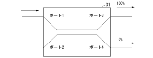
図10は、本発明の第1の実施形態におけるバス型光アクセスネットワーク1のドロップ点31(WDM光カプラ)の構成を示す概略図である。本実施形態では一例として、ドロップ点31は、溶融延伸によるWDM光カプラ(例えば非特許文献2を参照)であるものとする。
FIG. 10 is a schematic diagram showing the configuration of the drop point 31 (WDM optical coupler) of the bus-type
ドロップ点31(WDM光カプラ)は、2本の光ファイバの一部を近接させた状態で融着することによって結合する。ドロップ点31は、一方の光ファイバを伝搬する光信号の一部を、もう一方のファイバに伝搬させる。これにより、入力ポートに入力された光信号を、複数の出力ポートに分配する。例えば、ポート1及びポート2に光信号が入力される場合には、ポート3及びポート4から出力される。また、例えば、ポート3及びポート4に光信号が入力される場合には、ポート1及びポート2から出力される。例えば、下り信号は、ポート1に入力され、ポート3及びポート4から出力される。また、例えば、上り信号は、ポート3及びポート4に入力され、ポート1及びポート2から出力される。
A drop point 31 (WDM optical coupler) couples two optical fibers by fusing portions of them in close proximity. Drop
もしドロップ点が等分岐光スプリッタであるならば、ポート1から入力された光信号の50[%]が、ポート3及びポート4へそれぞれ出力される。これに対し、本実施形態におけるドロップ点31(溶融延伸によるWDM光カプラ)では、光ファイバに熱が加えられて結合部分が引き延ばされることによって、各出力ポートへ光信号の分岐比率が制御される。
If the drop point is an equi-branching optical splitter, 50[%] of the optical signal input from
図11は、本発明の第1の実施形態におけるバス型光アクセスネットワーク1のドロップ点31の透過特性の一例を示す図である。図11において、実線の波形は、ポート1からポート3、又はポート3からポート1に透過する割合を示したものである。また、図11において、破線の波形は、ポート1からポート4、又はポート4からポート1に透過する割合を示したものである。なお、ポート2は用いられないものとする。
FIG. 11 is a diagram showing an example of transmission characteristics of the
本実施形態では、一例として、ドロップ点31における光信号の分岐比率は、(幹線ファイバ方向):(ブランチファイバ方向)=80:20であるものとする。なお、幹線ファイバ方向とは、ポート1からポート3への方向、及びポート3からポート1への方向である。また、ブランチファイバ方向とは、ポート1からポート4への方向、及びポート4からポート1への方向である。
In this embodiment, as an example, the branching ratio of the optical signal at the
一方、励起光は、ドロップ点31において、ブランチファイバ方向には透過せず、全て(100[%])幹線ファイバ方向に透過するように構成される。これにより、遠方のエリアに到達した時点における励起光の光強度が高く保たれるため、ラマン利得を最大化することができる。
On the other hand, at the
なお、本実施形態においては、一例として、ドロップ点31として溶融延伸によるWDM光カプラを用いる構成について説明したが、これに限られるものではない。例えば、PLCが用いられたり、マッハツェンダ型の導波路が用いられた場合であっても、波長に応じて分岐比率を変化させるドロップ点を実現することが可能である。
In this embodiment, as an example, a configuration using a WDM optical coupler by fusion drawing as the
<第2の実施形態>
以下、本発明の第2の実施形態について、図面を参照しながら説明する。本実施形態では、光信号は、複数の波長からなるWDM信号である。<Second embodiment>
A second embodiment of the present invention will be described below with reference to the drawings. In this embodiment, the optical signal is a WDM signal consisting of multiple wavelengths.
図12は、光信号の波長配置とWDM光カプラの透過率の変化の一例を示す図である。光信号が複数の波長からなるWDM信号である場合には、信号によって波長が異なる。そのため、信号によって透過率も変化することになるため、伝送距離にばらつきが生じる。これを解決する方法として、各ポートに対する透過率がWDM信号の波長間隔と同一の周期で周期的に変化するWDM光カプラを活用することが考えられる。 FIG. 12 is a diagram showing an example of wavelength arrangement of optical signals and changes in transmittance of a WDM optical coupler. When the optical signal is a WDM signal composed of multiple wavelengths, the wavelength differs depending on the signal. Therefore, since the transmittance also changes depending on the signal, the transmission distance varies. As a method of solving this problem, it is conceivable to use a WDM optical coupler in which the transmittance for each port changes periodically with the same period as the wavelength interval of the WDM signal.
図13は、各ポートに対する透過率が、WDM信号の波長間隔と同一の周期で変化する様子を示す図である。この場合、すべての信号の透過率を一定に保つことができる。励起光の波長は、前述の通り透過率が100[%]となるように設定される。 FIG. 13 is a diagram showing how the transmittance for each port changes in the same period as the wavelength interval of the WDM signal. In this case, the transmittance of all signals can be kept constant. The wavelength of the excitation light is set so that the transmittance is 100[%] as described above.
一般的に、励起光の波長は、増幅される光信号の波長に合わせて設定される。例えば、標準的なシングルモードファイバが用いられる場合、光信号から約13[THz]程度高い周波数の光が励起光として用いられる。これは、1550[nm]帯において、100[nm]の波長差となる。したがって、1500[nm]の励起光が用いられる場合、1600[nm]付近に増幅利得が生じる。 Generally, the wavelength of pumping light is set to match the wavelength of the optical signal to be amplified. For example, when a standard single-mode fiber is used, light having a frequency about 13 [THz] higher than that of the optical signal is used as excitation light. This results in a wavelength difference of 100 [nm] in the 1550 [nm] band. Therefore, when 1500 [nm] pumping light is used, an amplification gain occurs near 1600 [nm].
図14は、増幅利得が生じる様子を示す図である。図14において、増幅帯域とは、最大の増幅利得が得られる領域を示す。増幅帯域が、分布ラマン増幅によって増幅するWDM信号の帯域よりも十分に大きい場合、増幅するWDM信号が増幅帯域内にあり、かつ、幹線ファイバの透過率が100[%]となる励起光の波長は複数存在し、励起光の波長はこれらのうち、どこに設定されてもよい。 FIG. 14 is a diagram showing how amplification gain is generated. In FIG. 14, the amplification band indicates the region where the maximum amplification gain is obtained. When the amplification band is sufficiently larger than the band of the WDM signal amplified by distributed Raman amplification, the WDM signal to be amplified is within the amplification band, and the wavelength of the pumping light at which the transmittance of the trunk fiber is 100 [%] exists, and the wavelength of the excitation light may be set to any of these.
図15は、励起光の波長を変化させた場合を示す図である。このように、励起光の波長を変化させた場合であっても、WDM信号の波長帯を増幅帯域でカバーすることができる。 FIG. 15 is a diagram showing a case where the wavelength of excitation light is changed. In this way, even when the wavelength of the pumping light is changed, the wavelength band of the WDM signal can be covered by the amplification band.
また、ラマン利得の改善に向けて、複数の励起光を用いて増幅を行うことが考えられる。
図16は、複数の励起光を用いて増幅を行う様子を示す図である。この場合、WDM光カプラの幹線ファイバへの透過率が高い波長の光を励起光として用いればよい。例えば、WDM光カプラの幹線ファイバへの透過率が100[%]となるように、それぞれの励起光の波長を設定することによって、ラマン利得を最大化することができる。Further, in order to improve the Raman gain, it is conceivable to perform amplification using a plurality of pumping lights.
FIG. 16 is a diagram showing how amplification is performed using a plurality of pumping lights. In this case, light having a wavelength with high transmittance to the trunk fiber of the WDM optical coupler may be used as the excitation light. For example, the Raman gain can be maximized by setting the wavelength of each pumping light so that the transmittance to the trunk fiber of the WDM optical coupler is 100[%].
<第3の実施形態>
以下、本発明の第3の実施形態について、図面を参照しながら説明する。
図17は、本発明の第3の実施形態におけるバス型光アクセスネットワーク2の構成を示す概略図である。本実施形態におけるバス型光アクセスネットワーク2は、集中型光増幅器41と分布ラマン増幅技術とが用いられた光アクセスネットワークである。<Third Embodiment>
A third embodiment of the present invention will be described below with reference to the drawings.
FIG. 17 is a schematic diagram showing the configuration of a bus-type
図17に示されるように、バス型光アクセスネットワーク2は、ドロップ点31を有する。本実施形態において、ドロップ点31は、励起光の波長帯で幹線ファイバに対する透過率が100[%]となるように設計される。本実施形態において、ドロップ点31は、WDM光カプラである。
As shown in FIG. 17, the bus-type
しかしながら、厳密にはドロップ点の装置(例えば、WDM光カプラ)の特性は個体によって異なる。そのため、ラマン利得の最大化に向けては、用いられるドロップ点の装置(例えば、WDM光カプラ)に合わせて励起光の波長をそれぞれ最適化する必要がある。 However, strictly speaking, the properties of drop-point devices (eg, WDM optical couplers) vary from individual to individual. Therefore, in order to maximize the Raman gain, it is necessary to optimize the wavelength of the pumping light according to the drop point device (eg, WDM optical coupler) used.
ラマン利得の最大化に向けては、励起光の強度が高い区間を長く保つことが重要である。以下、各ドロップ点31(WDM光カプラ)の幹線ファイバに対する透過率がわずかに100%よりも低い場合の、伝送距離に対する励起光強度の変化を示す。
図18は、ドロップ損失が比較的大きなドロップ点31がOLT10に近い位置に存在する場合の、伝送距離に対する励起光強度の変化を示す図である。また、図19は、ドロップ損失が比較的大きなドロップ点31がONU20に近い位置に存在する場合の、伝送距離に対する励起光強度の変化を示す図である。To maximize the Raman gain, it is important to keep the high-intensity section of the pumping light long. Below, we show the variation of the pumping light intensity with respect to the transmission distance when the transmittance of each drop point 31 (WDM optical coupler) to the trunk fiber is slightly lower than 100%.
FIG. 18 is a diagram showing changes in pumping light intensity with respect to transmission distance when a
図18及び図19に示されるように、両者において、励起光がそれぞれの通信路で受ける伝送損失の合計は同じである。しかしながら、ドロップ損失が比較的大きなドロップ点31がONU20側(加入者側)に存在する場合(図19)のほうが、得られる利得はより大きくなる。これは、ドロップ損失が比較的大きなドロップ点31がONU20側(加入者側)に存在する場合(図19)のほうが、励起光の強度が高い状態でより長い区間を通信できるためである。したがって、励起光の波長帯の決定においては、単にドロップ点31におけるドロップ損失が少ない波長帯に決定するのではなく、各ドロップ点31の位置を考慮して決定することが重要になる。
As shown in FIGS. 18 and 19, in both cases, the total transmission loss that pump light undergoes in each communication path is the same. However, when a
ラマン利得を最大化するための励起光の波長を決定する方法として、例えば、ラマン利得を監視しながら、励起光の波長をスイープする方法が考えられる。
図20は、波長をスイープすることによって励起光の波長を決定するバス型光アクセスネットワーク3の構成を示す概略図である。As a method of determining the wavelength of the pumping light for maximizing the Raman gain, for example, a method of sweeping the wavelength of the pumping light while monitoring the Raman gain can be considered.
FIG. 20 is a schematic diagram showing the configuration of a bus-type
図20に示されるように、バス型光アクセスネットワーク3は、集中型光増幅器41と分布ラマン増幅技術とが用いられた光アクセスネットワークである。図20に示されるように、バス型光アクセスネットワーク3は、ドロップ点31を有する。本実施形態において、ドロップ点31は、WDM光カプラである。
As shown in FIG. 20, the bus-type
バス型光アクセスネットワーク3が備える光増幅装置は、利得監視部と、励起光出力部50と、解析部55とを備える。また、利得監視部は、監視光出力部51と、サーキュレータ52と、強度モニタ部54と、解析部55とを備える。また、図20に示されるように、バス型光アクセスネットワーク3は、ミラー部を備える。ミラー部は、ミラー53を備える。ミラー53は、後述される監視光を反射する。
The optical amplifying device included in the bus-type
利得監視部は、ラマン利得を監視する。
監視光出力部51は、ラマン利得が得られる波長帯の光を、監視光として通信路に入射させる。監視光は、幹線ファイバを伝搬した後、幹線ファイバの末端に設置されたミラー部のミラー53によって反射する。反射した監視光は、再び幹線ファイバを伝搬した後、光増幅装置の強度モニタ部54によって受信される。この際、励起光出力50から出力される励起光がスイープされることによって、強度モニタ部54に入る監視光が受ける利得が変化する。A gain monitor monitors the Raman gain.
The monitor
利得が最大となる励起光の波長を把握するためには、例えば前述の通り、励起光の波長をスイープする方法が有効である。利得を最大化するためには、励起光の波長をスイープして、強度モニタ部54によって検出される監視光の強度が最大となるような励起光の波長を検出すればよい。
In order to grasp the wavelength of the pumping light that maximizes the gain, it is effective, for example, to sweep the wavelength of the pumping light as described above. In order to maximize the gain, it is sufficient to sweep the wavelength of the pumping light and detect the wavelength of the pumping light that maximizes the intensity of the monitor light detected by the
解析部55は、励起光の波長をスイープすることによって変化する、強度モニタ部54によって検出される監視光の強度に基づいて、最適な励起光の波長を検出する。解析部55は、検出結果に基づいて、励起光出力部50から出力される励起光の波長を制御する。
The
なお、ドロップ点31において、幹線ファイバへの監視光の透過率が低い場合には、強度モニタ部54に入る監視光の強度が低くなる。これにより、測定精度が低下することが懸念される。この場合、前述の励起光の波長の設定が行われる前に、監視光の波長をスイープし、強度モニタ部54に入る監視光の強度を十分高く設定しておく必要がある。
At the
以上説明したように、前述の各実施形態におけるバス型光アクセスネットワーク(光通信システム)は、局側装置であるOLT10と加入者側装置である複数のONU20とを含んで構成される。OLT10と複数のONU20とは、バス型トポロジーで配線された光ファイバによってそれぞれ接続される。OLT10と通信路との間には、光信号の増幅機能を担う光増幅装置(光増幅部)が接続される。光増幅装置は,WDM光カプラ33により、上り信号と下り信号とをそれぞれ別の通信経路に分離して、再び結合する。下り信号の通信経路には、集中型光増幅器41が設置される。集中型光増幅器41は、OLT10から送信された下り信号を増幅する。一方、ONU20から送信された上り信号は、通信路を伝搬した後、光増幅装置を通過し、OLT10によって受信される。また、通信路には、光増幅装置から上り信号を増幅させるための励起光が入射される。上り信号は、通信路において励起光の強度が高い領域に入ると、分布ラマン増幅の効果によって徐々に増幅幅される。さらに、ドロップ点31(ドロップ部)において励起光が受けるドロップ損失を低減させ、ラマン利得を最大化するためにWDM光カプラが用いられる。当該WDM光カプラは、1つの入力信号を複数の出力ポートに分岐させ、その分岐比率を光信号の波長に応じて変化させる。
As described above, the bus-type optical access network (optical communication system) in each of the above-described embodiments includes the
このような構成を備えることにより、本発明の各実施形態におけるバス型光アクセスネットワークは、遠方のエリア(すなわち、OLT10からより遠く離れたエリア)においても励起光の強度を高く保つことができるため、ラマン利得を最大化することができる。これにより、本発明によれば、バス型光アクセスネットワークでの伝送距離を拡大することができる。 With such a configuration, the bus-type optical access network in each embodiment of the present invention can keep the intensity of pumping light high even in a distant area (that is, an area farther away from the OLT 10). , the Raman gain can be maximized. Thus, according to the present invention, it is possible to extend the transmission distance in the bus-type optical access network.
上述した各実施形態における光アクセスネットワークの一部をコンピュータで実現するようにしてもよい。その場合、この機能を実現するためのプログラムをコンピュータ読み取り可能な記録媒体に記録して、この記録媒体に記録されたプログラムをコンピュータシステムに読み込ませ、実行することによって実現してもよい。なお、ここでいう「コンピュータシステム」とは、OSや周辺機器のハードウェアを含むものとする。また、「コンピュータ読み取り可能な記録媒体」とは、フレキシブルディスク、光磁気ディスク、ROM、CD-ROM等の可搬媒体、コンピュータシステムに内蔵されるハードディスク等の記録装置のことをいう。さらに「コンピュータ読み取り可能な記録媒体」とは、インターネット等のネットワークや電話回線等の通信回線を介してプログラムを送信する場合の通信線のように、短時間の間、動的にプログラムを保持するもの、その場合のサーバやクライアントとなるコンピュータシステム内部の揮発性メモリのように、一定時間プログラムを保持しているものを含んでもよい。また上記プログラムは、前述した機能の一部を実現するためのものであってもよく、さらに前述した機能をコンピュータシステムにすでに記録されているプログラムとの組み合わせで実現できるものであってもよく、FPGA(Field Programmable Gate Array)等のプログラマブルロジックデバイスを用いて実現されるものであってもよい。 A part of the optical access network in each of the above-described embodiments may be implemented by a computer. In that case, a program for realizing this function may be recorded in a computer-readable recording medium, and the program recorded in this recording medium may be read into a computer system and executed. It should be noted that the "computer system" referred to here includes the OS and hardware of peripheral devices. The term "computer-readable recording medium" refers to portable media such as flexible disks, magneto-optical disks, ROMs and CD-ROMs, and recording devices such as hard disks built into computer systems. Furthermore, "computer-readable recording medium" refers to a program that dynamically retains programs for a short period of time, like a communication line when transmitting a program via a network such as the Internet or a communication line such as a telephone line. It may also include something that retains the program for a certain period of time, such as a volatile memory inside a computer system that serves as a server or client in that case. Further, the program may be for realizing a part of the functions described above, or may be capable of realizing the functions described above in combination with a program already recorded in the computer system. It may be implemented using a programmable logic device such as an FPGA (Field Programmable Gate Array).
以上、この発明の実施形態について図面を参照して詳述してきたが、具体的な構成はこの実施形態に限られるものではなく、この発明の要旨を逸脱しない範囲の設計等も含まれる。 Although the embodiment of the present invention has been described in detail with reference to the drawings, the specific configuration is not limited to this embodiment, and design and the like are included within the scope of the gist of the present invention.
10・・・OLT,15・・・光ファイバ、16・・・幹線ファイバ、17・・・ブランチファイバ、20・・・ONU、30・・・光スプリッタ、31・・・ドロップ点、32・・・不等分岐光スプリッタ、33・・・WDM光カプラ、40・・・光増幅器、41・・・集中型光増幅器、50・・・励起光出力部、51・・・監視光出力部、52・・・サーキュレータ、53・・・ミラー、54・・・強度モニタ部、55・・・解析部
10...OLT, 15...optical fiber, 16...trunk fiber, 17...branch fiber, 20...ONU, 30...optical splitter, 31...drop point, 32... unequal branching
Claims (7)
局側に設置された光増幅部と、
光信号及び励起光を分岐させるドロップ部と、
を備え、
前記光増幅部は、
下り信号を増幅する増幅器と、
上り信号を増幅させるための前記励起光を通信路へ出力する励起光出力部と、
を備え、
前記ドロップ部は、幹線ファイバに対する前記励起光の伝送損失を低減させるように、前記光信号の波長に応じて分岐比率を変化させる
光通信システム。An optical communication system in which a station-side device and a plurality of subscriber-side devices are configured in a bus-type network topology,
an optical amplifier installed on the office side;
a drop unit for branching an optical signal and pumping light;
with
The optical amplification section is
an amplifier that amplifies a downstream signal;
a pumping light output unit that outputs the pumping light for amplifying an upstream signal to a communication path;
with
The optical communication system, wherein the drop unit changes a branching ratio according to the wavelength of the optical signal so as to reduce transmission loss of the pumping light to a trunk fiber.
前記ドロップ部は、
前記WDM信号の波長に応じて周期的に透過率が変化するWDM光カプラ
を備える
請求項1に記載の光通信システム。When the optical signal is a WDM signal consisting of a plurality of wavelengths,
The drop section is
The optical communication system according to claim 1, further comprising a WDM optical coupler whose transmittance changes periodically according to the wavelength of said WDM signal.
をさらに備え、
前記光増幅部は、
監視光を通信路へ出力する監視光出力部と、
前記ミラー部によって反射した前記監視光の強度を検出する強度モニタ部と、
前記強度モニタ部によって検出された前記強度に基づいて前記励起光の波長を決定し、決定された前記波長の前記励起光を出力させるように前記励起光出力部を制御する解析部と、
をさらに備える
請求項1に記載の光通信システム。Further equipped with a mirror unit installed on the subscriber side,
The optical amplification section is
a monitoring light output unit that outputs monitoring light to a communication path;
an intensity monitor unit that detects the intensity of the monitoring light reflected by the mirror unit;
an analysis unit that determines the wavelength of the excitation light based on the intensity detected by the intensity monitor unit and controls the excitation light output unit to output the excitation light of the determined wavelength;
The optical communication system of Claim 1, further comprising:
請求項3に記載の光通信システム。The optical communication system according to claim 3, wherein the analysis unit determines the wavelength so that the intensity of the monitor light detected by the intensity monitor unit is maximized.
前記解析部は、前記励起光の前記波長のスイープに応じて変化する前記監視光の前記強度が最大になるように前記波長を決定する
請求項4に記載の光通信システム。The excitation light output unit sweeps the wavelength of the excitation light output to the communication path,
5. The optical communication system according to claim 4, wherein the analysis unit determines the wavelength so that the intensity of the monitoring light that changes according to the sweep of the wavelength of the pumping light is maximized.
前記励起光出力部は、前記ドロップ部における幹線ファイバへの透過率が高い波長の光を励起光として用いる
請求項1又は請求項2に記載の光通信システム。When there are a plurality of wavelengths of the excitation light,
3. The optical communication system according to claim 1, wherein the pumping light output unit uses, as pumping light, light having a wavelength with high transmittance to the trunk fiber in the drop unit.
光信号及び励起光を分岐させる分岐ステップと、
局側に設置された増幅器によって下り信号を増幅する下り信号増幅ステップと、
上り信号を増幅させるための前記励起光を通信路へ出力する励起光出力ステップと、
前記分岐ステップにおいて、幹線ファイバに対する前記励起光の伝送損失を低減させるように、前記光信号の波長に応じて分岐比率を変化させる分岐比率変化ステップと、
を有する光通信方法。An optical communication method using an optical communication system in which a station-side device and a plurality of subscriber-side devices are configured in a bus-type network topology,
a branching step of branching the optical signal and the pumping light;
a downstream signal amplification step of amplifying a downstream signal by an amplifier installed on the office side;
a pumping light output step of outputting the pumping light to a communication path for amplifying an upstream signal;
a branching ratio changing step of changing the branching ratio according to the wavelength of the optical signal so as to reduce the transmission loss of the pumping light to the trunk fiber in the branching step;
An optical communication method comprising:
Applications Claiming Priority (1)
| Application Number | Priority Date | Filing Date | Title |
|---|---|---|---|
| PCT/JP2020/009025 WO2021176578A1 (en) | 2020-03-04 | 2020-03-04 | Optical communication system and optical communication method |
Publications (2)
| Publication Number | Publication Date |
|---|---|
| JPWO2021176578A1 JPWO2021176578A1 (en) | 2021-09-10 |
| JP7299552B2 true JP7299552B2 (en) | 2023-06-28 |
Family
ID=77613231
Family Applications (1)
| Application Number | Title | Priority Date | Filing Date |
|---|---|---|---|
| JP2022504829A Active JP7299552B2 (en) | 2020-03-04 | 2020-03-04 | Optical communication system and optical communication method |
Country Status (3)
| Country | Link |
|---|---|
| US (1) | US11863211B2 (en) |
| JP (1) | JP7299552B2 (en) |
| WO (1) | WO2021176578A1 (en) |
Citations (3)
| Publication number | Priority date | Publication date | Assignee | Title |
|---|---|---|---|---|
| JP2002176392A (en) | 2000-12-08 | 2002-06-21 | Toshiba Corp | Passive optical network |
| JP2014530523A (en) | 2011-09-08 | 2014-11-17 | オーエフエスファイテル,エルエルシー | Configuration for coexisting GPON and XGPON optical communication systems |
| US20170272197A1 (en) | 2016-03-17 | 2017-09-21 | Telekom Malaysia Berhad | Extender For Optical Access Communication Network |
Family Cites Families (3)
| Publication number | Priority date | Publication date | Assignee | Title |
|---|---|---|---|---|
| JP3229489B2 (en) * | 1994-08-08 | 2001-11-19 | 東京電力株式会社 | Optical network |
| KR100516663B1 (en) * | 2003-01-02 | 2005-09-22 | 삼성전자주식회사 | Passive optical network system for simultaneous transmission of broadcasting service and switched service |
| US20060275037A1 (en) * | 2005-06-02 | 2006-12-07 | Evans Alan F | Methods and apparatus for multiple signal amplification |
-
2020
- 2020-03-04 US US17/908,527 patent/US11863211B2/en active Active
- 2020-03-04 JP JP2022504829A patent/JP7299552B2/en active Active
- 2020-03-04 WO PCT/JP2020/009025 patent/WO2021176578A1/en not_active Ceased
Patent Citations (3)
| Publication number | Priority date | Publication date | Assignee | Title |
|---|---|---|---|---|
| JP2002176392A (en) | 2000-12-08 | 2002-06-21 | Toshiba Corp | Passive optical network |
| JP2014530523A (en) | 2011-09-08 | 2014-11-17 | オーエフエスファイテル,エルエルシー | Configuration for coexisting GPON and XGPON optical communication systems |
| US20170272197A1 (en) | 2016-03-17 | 2017-09-21 | Telekom Malaysia Berhad | Extender For Optical Access Communication Network |
Also Published As
| Publication number | Publication date |
|---|---|
| WO2021176578A1 (en) | 2021-09-10 |
| US20230163852A1 (en) | 2023-05-25 |
| JPWO2021176578A1 (en) | 2021-09-10 |
| US11863211B2 (en) | 2024-01-02 |
Similar Documents
| Publication | Publication Date | Title |
|---|---|---|
| EP1302006B1 (en) | Cascaded pumping system for distributed raman amplification in optical fiber telecommunication systems | |
| JP5805126B2 (en) | Method and apparatus for using distributed Raman amplification and remote pumping in a bidirectional optical communication network | |
| KR101391265B1 (en) | bidirectional optical amplifier | |
| US9634767B2 (en) | Power control in bidirectional WDM optical link | |
| JP7070244B2 (en) | Optical communication system and optical communication method | |
| US7933063B2 (en) | Monitoring method and apparatus of noise light due to Raman amplification and optical communication system using the same | |
| US9641242B2 (en) | Optical communication system, device and method for data processing in an optical network | |
| RU2563801C2 (en) | Method and device for receiving optical input signal and transmitting optical output signal | |
| WO2021001868A1 (en) | Optical receiver, optical transmission system, optical transmission method, and computer program | |
| JP7299552B2 (en) | Optical communication system and optical communication method | |
| US20020167716A1 (en) | Optical amplifier and optical transmission system | |
| JP7332947B2 (en) | OPTICAL COMMUNICATION SYSTEM, OPTICAL CIRCUIT TERMINAL AND OPTICAL COMMUNICATION CONTROL METHOD | |
| Igarashi et al. | Network design for bus-type optical access using distributed Raman amplification with asymmetric power splitter | |
| EP3000195B1 (en) | Adaptive network optimization in an optical communications system | |
| US7869673B2 (en) | Remote larger effective area optical fiber | |
| KR100784115B1 (en) | Passive Optical Subscriber Network System Using Remote Pumping Optical Amplifier | |
| US7535630B2 (en) | Broadband hybrid two-stage optical amplifier | |
| Suzuki et al. | 128× 8 split and 80 km long-reach dual-rate 10G-EPON transmission using ALC hybrid burst-mode optical fiber amplifier and SOA pre-amplifier | |
| US11621778B2 (en) | Optical communication system and optical communication method | |
| US20250110302A1 (en) | High power line system for hollow core fiber and uses thereof | |
| US11689287B2 (en) | Optical communications module link extender including ethernet and PON amplification | |
| CN107534492A (en) | Optical signal amplification | |
| Manaf et al. | FTTH link loss analysis for coexistence of TWDMPON system in Malaysia |
Legal Events
| Date | Code | Title | Description |
|---|---|---|---|
| A621 | Written request for application examination |
Free format text: JAPANESE INTERMEDIATE CODE: A621 Effective date: 20220624 |
|
| TRDD | Decision of grant or rejection written | ||
| A01 | Written decision to grant a patent or to grant a registration (utility model) |
Free format text: JAPANESE INTERMEDIATE CODE: A01 Effective date: 20230516 |
|
| A61 | First payment of annual fees (during grant procedure) |
Free format text: JAPANESE INTERMEDIATE CODE: A61 Effective date: 20230529 |
|
| R150 | Certificate of patent or registration of utility model |
Ref document number: 7299552 Country of ref document: JP Free format text: JAPANESE INTERMEDIATE CODE: R150 |
|
| S533 | Written request for registration of change of name |
Free format text: JAPANESE INTERMEDIATE CODE: R313533 |
|
| R350 | Written notification of registration of transfer |
Free format text: JAPANESE INTERMEDIATE CODE: R350 |