JP7299345B2 - Methods for Output Layerset Modes in Multilayer Video Streams - Google Patents
Methods for Output Layerset Modes in Multilayer Video Streams Download PDFInfo
- Publication number
- JP7299345B2 JP7299345B2 JP2021562788A JP2021562788A JP7299345B2 JP 7299345 B2 JP7299345 B2 JP 7299345B2 JP 2021562788 A JP2021562788 A JP 2021562788A JP 2021562788 A JP2021562788 A JP 2021562788A JP 7299345 B2 JP7299345 B2 JP 7299345B2
- Authority
- JP
- Japan
- Prior art keywords
- picture
- layer
- output
- layers
- vps
- Prior art date
- Legal status (The legal status is an assumption and is not a legal conclusion. Google has not performed a legal analysis and makes no representation as to the accuracy of the status listed.)
- Active
Links
Images


Classifications
-
- H—ELECTRICITY
- H04—ELECTRIC COMMUNICATION TECHNIQUE
- H04N—PICTORIAL COMMUNICATION, e.g. TELEVISION
- H04N19/00—Methods or arrangements for coding, decoding, compressing or decompressing digital video signals
- H04N19/44—Decoders specially adapted therefor, e.g. video decoders which are asymmetric with respect to the encoder
-
- H—ELECTRICITY
- H04—ELECTRIC COMMUNICATION TECHNIQUE
- H04N—PICTORIAL COMMUNICATION, e.g. TELEVISION
- H04N19/00—Methods or arrangements for coding, decoding, compressing or decompressing digital video signals
- H04N19/30—Methods or arrangements for coding, decoding, compressing or decompressing digital video signals using hierarchical techniques, e.g. scalability
-
- H—ELECTRICITY
- H04—ELECTRIC COMMUNICATION TECHNIQUE
- H04N—PICTORIAL COMMUNICATION, e.g. TELEVISION
- H04N7/00—Television systems
- H04N7/14—Systems for two-way working
- H04N7/141—Systems for two-way working between two video terminals, e.g. videophone
- H04N7/147—Communication arrangements, e.g. identifying the communication as a video-communication, intermediate storage of the signals
-
- H—ELECTRICITY
- H04—ELECTRIC COMMUNICATION TECHNIQUE
- H04N—PICTORIAL COMMUNICATION, e.g. TELEVISION
- H04N19/00—Methods or arrangements for coding, decoding, compressing or decompressing digital video signals
- H04N19/10—Methods or arrangements for coding, decoding, compressing or decompressing digital video signals using adaptive coding
- H04N19/134—Methods or arrangements for coding, decoding, compressing or decompressing digital video signals using adaptive coding characterised by the element, parameter or criterion affecting or controlling the adaptive coding
- H04N19/157—Assigned coding mode, i.e. the coding mode being predefined or preselected to be further used for selection of another element or parameter
- H04N19/159—Prediction type, e.g. intra-frame, inter-frame or bidirectional frame prediction
-
- H—ELECTRICITY
- H04—ELECTRIC COMMUNICATION TECHNIQUE
- H04N—PICTORIAL COMMUNICATION, e.g. TELEVISION
- H04N19/00—Methods or arrangements for coding, decoding, compressing or decompressing digital video signals
- H04N19/10—Methods or arrangements for coding, decoding, compressing or decompressing digital video signals using adaptive coding
- H04N19/169—Methods or arrangements for coding, decoding, compressing or decompressing digital video signals using adaptive coding characterised by the coding unit, i.e. the structural portion or semantic portion of the video signal being the object or the subject of the adaptive coding
- H04N19/184—Methods or arrangements for coding, decoding, compressing or decompressing digital video signals using adaptive coding characterised by the coding unit, i.e. the structural portion or semantic portion of the video signal being the object or the subject of the adaptive coding the unit being bits, e.g. of the compressed video stream
-
- H—ELECTRICITY
- H04—ELECTRIC COMMUNICATION TECHNIQUE
- H04N—PICTORIAL COMMUNICATION, e.g. TELEVISION
- H04N19/00—Methods or arrangements for coding, decoding, compressing or decompressing digital video signals
- H04N19/10—Methods or arrangements for coding, decoding, compressing or decompressing digital video signals using adaptive coding
- H04N19/169—Methods or arrangements for coding, decoding, compressing or decompressing digital video signals using adaptive coding characterised by the coding unit, i.e. the structural portion or semantic portion of the video signal being the object or the subject of the adaptive coding
- H04N19/187—Methods or arrangements for coding, decoding, compressing or decompressing digital video signals using adaptive coding characterised by the coding unit, i.e. the structural portion or semantic portion of the video signal being the object or the subject of the adaptive coding the unit being a scalable video layer
-
- H—ELECTRICITY
- H04—ELECTRIC COMMUNICATION TECHNIQUE
- H04N—PICTORIAL COMMUNICATION, e.g. TELEVISION
- H04N19/00—Methods or arrangements for coding, decoding, compressing or decompressing digital video signals
- H04N19/70—Methods or arrangements for coding, decoding, compressing or decompressing digital video signals characterised by syntax aspects related to video coding, e.g. related to compression standards
Landscapes
- Engineering & Computer Science (AREA)
- Multimedia (AREA)
- Signal Processing (AREA)
- Compression Or Coding Systems Of Tv Signals (AREA)
- Image-Pickup Tubes, Image-Amplification Tubes, And Storage Tubes (AREA)
Description
[関連出願]
本願は、参照により全体がここに組み込まれる、2020年3月27日に出願した米国仮出願番号第63/001,045号、及び2020年8月27日に出願した米国特許出願番号第17/000,018号、の優先権を主張する。
[Related Application]
No. 63/001,045, filed March 27, 2020, and U.S. Patent Application Serial No. 17/ 000,018.
[技術分野]
本開示は、高度ビデオコーデックにおけるビデオ圧縮技術及びインター予測及びイントラ予測に関する。特に、本開示は、VVC(Versatile Video Coding (VVC))のような高効率ビデオコーディング(High Efficiency Video Coding (HEVC))以降のビデオコーディング/復号技術を含む次世代ビデオコーディング技術に関する。より具体的には、本開示の態様は、複数のレイヤを有するコーディングビデオストリーム内の高度ビデオコーディング技術により設計される出力レイヤ導出のセットを提供する方法、機器、及びコンピュータ可読媒体を対象とする。
[Technical field]
This disclosure relates to video compression techniques and inter- and intra-prediction in advanced video codecs. In particular, the present disclosure relates to next-generation video coding techniques, including video coding/decoding techniques subsequent to High Efficiency Video Coding (HEVC), such as Versatile Video Coding (VVC). More specifically, aspects of this disclosure are directed to methods, apparatus, and computer-readable media for providing a set of output layer derivations designed by advanced video coding techniques in a coded video stream having multiple layers. .
動き補償と共にインターピクチャ又はイントラピクチャ予測を用いるビデオコーディング及び復号が数十年間、知られている。非圧縮デジタルビデオは、一連のピクチャで構成されることができ、各ピクチャは、例えば1920×1080個のルミナンスサンプル及び関連するクロミナンスサンプルの空間次元を有する。一連のピクチャは、例えば毎秒60ピクチャ又は60Hzの固定又は可変ピクチャレート(略式にフレームレートとしても知られている)を有し得る。非圧縮ビデオは、かなりのビットレート要件を有する。例えば、8ビット/サンプルの1080p60 4:2:0ビデオ(60Hzフレームレートで1920×1080ルミナンスサンプル解像度)は、1.5Gbit/sに近い帯域幅を必要とする。1時間のこのようなビデオは600Gbyteより多くの記憶空間を必要とすることがある。 Video coding and decoding using inter-picture or intra-picture prediction with motion compensation has been known for decades. Uncompressed digital video can consist of a sequence of pictures, each picture having a spatial dimension of, for example, 1920×1080 luminance and associated chrominance samples. A sequence of pictures may have a fixed or variable picture rate (also informally known as frame rate), for example 60 pictures per second or 60 Hz. Uncompressed video has significant bitrate requirements. For example, 8 bits/sample 1080p60 4:2:0 video (1920 x 1080 luminance sample resolution at 60 Hz frame rate) requires a bandwidth approaching 1.5 Gbit/s. An hour of such video may require more than 600 Gbytes of storage space.
ビデオコーディング及び復号の1つの目的は、圧縮を通じて、入力ビデオ信号の中の冗長性の削減であり得る。圧縮は、幾つかの場合には大きさで2桁以上も、前述の帯域幅又は記憶空間要件を軽減するのを助けることができる。損失又は無損失圧縮の両方、及びそれらの組み合わせが利用できる。無損失圧縮は、元の信号の正確なコピーが圧縮された元の信号から再構成可能である技術を表す。損失圧縮を用いると、再構成された信号は、元の信号と同一ではないが、元の信号と再構成された信号との間の歪みは、意図される用途のために有用な再構成された信号を生成するのに十分に小さい。ビデオの場合には、損失圧縮が広く利用される。耐えうる歪みの量は、アプリケーションに依存し、例えば、特定の消費者ストリーミングアプリケーションのユーザは、テレビジョン投稿アプリケーションのユーザよりも高い歪みに耐え得る。達成可能な圧縮比は、許容可能/耐性歪みが高いほど、高い圧縮比を生じ得ることを反映できる。 One goal of video coding and decoding can be the reduction of redundancy in the input video signal through compression. Compression can help alleviate the aforementioned bandwidth or storage space requirements, in some cases by two orders of magnitude or more. Both lossy or lossless compression and combinations thereof are available. Lossless compression refers to techniques in which an exact copy of the original signal can be reconstructed from the compressed original signal. With lossy compression, the reconstructed signal is not identical to the original signal, but the distortion between the original and reconstructed signals makes the reconstructed signal useful for its intended application. small enough to generate a For video, lossy compression is widely used. The amount of distortion that can be tolerated is application dependent, for example, users of certain consumer streaming applications can tolerate higher distortion than users of television posting applications. Achievable compression ratios can reflect that higher allowable/tolerant strains can result in higher compression ratios.
ビデオエンコーダ及びビデオデコーダは、例えば動き補償、変換、量子化、及びエントロピーコーディングを含む幾つかの広い分類からの技術を利用できる。このうちの幾つかが以下に紹介される。 Video encoders and decoders can utilize techniques from several broad categories including motion compensation, transforms, quantization, and entropy coding, for example. Some of these are introduced below.
歴史的に、ビデオエンコーダ及びデコーダは、多くの場合にコーディングビデオシーケンス(coded video sequence (CVS))、グループオブピクチャ(Group of Pictures (GOP))、又は同様のマルチピクチャ時間フレームについて定義され一定のままである所与のピクチャサイズで動作する傾向がある。例えば、動画専門家グループ(Motion Picture Experts Group (MPEG)-2では、システム設計は、イントラフレーム(又はiフレーム、又はiピクチャ)だけでなく、従って標準的にGOPについて、シーンのアクティビティのような要因に依存して水平方向の解像度(従って、ピクチャサイズ)を変更することが知られている。CVSの中の異なる解像度の使用のための参照ピクチャの再サンプリングは、例えばITU-T Rec. H.263 Annex P により知られている。しかしながら、ここで、ピクチャサイズは変化しないので、参照ピクチャのみが再サンプリングされ、結果として(ダウンサンプリングの場合には)ピクチャキャンバスの部分のみが使用され、(アップサンプリングの場合には)シーンの部分のみがキャプチャされる可能性がある。更に、H.263 Annex Qは、上方向又は下方向に、(各次元において)2の倍数で個々のマクロブロックの再サンプリングを許容する。ここでも、ピクチャサイズは同じままである。H.263ではマクロブロックのサイズは固定され、従ってシグナリングされる必要がない。 Historically, video encoders and decoders were often defined in terms of a coded video sequence (CVS), Group of Pictures (GOP), or similar multi-picture time-frame. It tends to work for a given picture size that remains the same. For example, in the Motion Picture Experts Group (MPEG)-2, system design focuses not only on intra-frames (or i-frames, or i-pictures), but also typically on GOPs, such as scene activity. It is known to change the horizontal resolution (and thus the picture size) depending on factors such as resampling of reference pictures for the use of different resolutions in CVS, see ITU-T Rec. .263 Annex P. However, here the picture size does not change, so only the reference picture is resampled, resulting in (in case of downsampling) only part of the picture canvas being used, ( (In the case of upsampling) only parts of the scene may be captured.In addition, H.263 Annex Q specifies that up or down (in each dimension) the number of individual macroblocks is a multiple of 2. Allows resampling, again the picture size remains the same, in H.263 the macroblock size is fixed and therefore does not need to be signaled.
予測ピクチャにおけるピクチャサイズの変更は、近年のビデオコーディングにおいてより主流となっている。例えば、VP9は、参照ピクチャ再サンプリング及びピクチャ全体の解像度の変化を許容する。同様に、Versatile Video Coding (VVC)を対象としている特定の提案(例えば、参照によりここに全体が組み込まれる、Hendry, et. al, “On adaptive resolution change )(ARC) for VVC”, Joint Video Team document JVET-M0135-v1, Jan9-19, 2019を含む)は、異なる-より高い又はより低い-解像度への参照ピクチャ全体の再サンプリングを許容する。Hendryでは、シーケンスパラメータセットの中にコーディングされピクチャパラメータセットの中のピクチャ毎のシンタックス要素により参照されるべき異なる候補解像度が提案される。 Changing the picture size in predicted pictures has become more mainstream in video coding in recent years. For example, VP9 allows reference picture resampling and resolution changes across pictures. Similarly, certain proposals directed to Versatile Video Coding (VVC) (e.g., Hendry, et. al, "On adaptive resolution change (ARC) for VVC", Joint Video Team document JVET-M0135-v1, Jan 9-19, 2019) allows resampling of the entire reference picture to a different - higher or lower - resolution. Hendry proposes different candidate resolutions to be coded in the sequence parameter set and referenced by per-picture syntax elements in the picture parameter set.
種々の実施形態によるビデオビットストリームないの適応型ピクチャサイズのシグナリングのための技術が開示される。 SUMMARY Techniques for adaptive picture size signaling in a video bitstream are disclosed in accordance with various embodiments.
本開示の態様によると、復号の方法は、
圧縮ビデオ/画像データを含むビットストリームを受信するステップであって、前記ビットストリームは複数のレイヤを含む、ステップと、
前記ビットストリームから、ビデオパラメータセット(VPS)内の出力レイヤセットモード指示子をパース又は導出するステップと、
前記出力レイヤセットモード指示子に基づき、出力レイヤセットシグナリングを識別するステップと、前記識別した出力レイヤセットシグナリングに基づき、1つ以上のピクチャ出力レイヤを識別するステップと、
前記識別した1つ以上のピクチャ出力レイヤを復号するステップと、
を含んでよい。
According to aspects of the present disclosure, a method of decoding comprises:
receiving a bitstream comprising compressed video/image data, said bitstream comprising multiple layers;
parsing or deriving an output layer set mode indicator in a video parameter set (VPS) from the bitstream;
identifying output layer set signaling based on the output layer set mode indicator; identifying one or more picture output layers based on the identified output layer set signaling ;
decoding the identified one or more picture output layers;
may contain
前記出力レイヤセットモード指示子に基づき、前記出力レイヤセットシグナリングを識別する前記ステップは、
前記VPS内の前記出力レイヤセットモード指示子が第1値の場合に、前記ビットストリーム内の最高レイヤを前記1つ以上のピクチャ出力レイヤとして識別するステップと、
前記VPS内の前記出力レイヤセットモード指示子が第2値の場合に、前記ビットストリーム内の全部のレイヤを前記1つ以上のピクチャ出力レイヤとして識別するステップと、
前記VPS内の前記出力レイヤセットモード指示子が第3値の場合に、前記VPS内の明示的シグナリングに基づき前記1つ以上のピクチャ出力レイヤを識別するステップと、
を含んでよい。
The step of identifying the output layer set signaling based on the output layer set mode indicator comprises:
identifying the highest layer in the bitstream as the one or more picture output layers when the output layer set mode indicator in the VPS is a first value;
identifying all layers in the bitstream as the one or more picture output layers when the output layer set mode indicator in the VPS is a second value;
identifying the one or more picture output layers based on explicit signaling in the VPS when the output layer set mode indicator in the VPS is a third value;
may contain
前記第1値は、前記第2値と異なり、及び前記第3値と異なってよく、前記第2値は、前記第3値と異なってよい。 The first value may be different from the second value and may be different from the third value, and the second value may be different from the third value.
前記第1値は0であってよく、前記第2値は1であってよく、前記第3値は2であってよい。しかしながら、他の値が使用されてよく、本開示は上述のような0、1、2の使用に限定されない。 The first value may be zero, the second value may be one, and the third value may be two. However, other values may be used and the disclosure is not limited to the use of 0, 1, 2 as described above.
前記VPS内の前記明示的シグナリングにより前記1つ以上のピクチャ出力レイヤを識別する前記ステップは、(i)前記VPSから、出力レイヤフラグをパース又は導出するステップと、(ii)1に等しい前記出力レイヤフラグを有するレイヤを前記1つ以上のピクチャ出力レイヤに設定するステップと、を含んでよい。 The steps of identifying the one or more picture output layers by the explicit signaling in the VPS include: (i) parsing or deriving an output layer flag from the VPS; and (ii) the output equal to 1. and setting layers with layer flags to the one or more picture output layers.
前記出力レイヤセットモード指示子に基づき前記出力レイヤセットシグナリングを識別する前記ステップは、
前記VPS内の前記出力レイヤセットモード指示子が所定値である場合に、前記出力レイヤセットシグナリングは、前記VPS内の明示的シグナリングに基づき前記1つ以上のピクチャ出力レイヤを識別するステップを含んでよい。
The step of identifying the output layer set signaling based on the output layer set mode indicator comprises:
The output layer set signaling includes identifying the one or more picture output layers based on explicit signaling in the VPS when the output layer set mode indicator in the VPS is a predetermined value. OK.
前記VPS内の前記明示的シグナリングに基づき前記1つ以上のピクチャ出力レイヤを識別する前記ステップは、(i)前記VPSから、出力レイヤフラグをパース又は導出するステップと、(ii)1に等しい前記出力レイヤフラグを有するレイヤを前記1つ以上のピクチャ出力レイヤに設定するステップと、を含み、前記複数のレイヤの数は2より大きい。 The step of identifying the one or more picture output layers based on the explicit signaling in the VPS comprises: (i) parsing or deriving an output layer flag from the VPS; and (ii) the and setting a layer with an output layer flag to the one or more picture output layers, wherein the number of the plurality of layers is greater than two.
前記出力レイヤセットシグナリングは、前記出力レイヤセットモード指示子が2に等しく、前記複数のレイヤの数が2より大きいとき、前記VPS内の前記明示的シグナリングに基づき、前記1つ以上のピクチャ出力レイヤを識別するステップを含んでよい。
The output layer set signaling outputs the one or more pictures based on the explicit signaling within the VPS when the output layer set mode indicator is equal to two and the number of layers is greater than two. A step of identifying a layer may be included.
前記出力レイヤセットシグナリングは、前記出力レイヤセットモード指示子が2より小さく、前記複数のレイヤの数が2であるとき、前記ビットストリーム内の最高レイヤ又は前記ビットストリーム内の全部のレイヤを、前記1つ以上のピクチャ出力レイヤとして識別するステップを含んでよく、
前記出力レイヤセットモード指示子は実際に2より小さく、前記複数のレイヤの数は実際に2である。
the output layer set signaling , when the output layer set mode indicator is less than two and the number of layers is two, the highest layer in the bitstream or all layers in the bitstream; identifying as said one or more picture output layers;
The output layer set mode indicator is actually less than two and the number of layers is actually two.
前記VPS内の出力レイヤセット数-1指示子は、前記出力レイヤの数を示す。 The number of output layer sets in the VPS-1 indicator indicates the number of the output layers.
実施形態によると、前記VPS内のVPS最大レイヤ-1指示子は、前記ビットストリーム内のレイヤ数を示す。 According to an embodiment, a VPS maximum layer-1 indicator in said VPS indicates the number of layers in said bitstream.
実施形態によると、VPS内の出力レイヤセットモードフラグ[i][j]は、i番目の出力レイヤセットのj番目のレイヤが出力レイヤであるか否かを示す。 According to an embodiment, the output layer set mode flag [i][j] in the VPS indicates whether the j-th layer of the i-th output layer set is the output layer.
実施形態によると、前記複数のレイヤが独立レイヤであり、前記VPSのVPS全独立レイヤフラグが1に等しい場合、前記出力レイヤセットモード指示子はシグナリングされず、前記出力レイヤセットモード指示子の値は前記第2値であると推定される。 According to an embodiment, if the plurality of layers are independent layers and the VPS all independent layers flag of the VPS is equal to 1, the output layer set mode indicator is not signaled and the value of the output layer set mode indicator is is assumed to be the second value.
実施形態によると、各レイヤが出力レイヤセットである場合、前記出力レイヤセットモード指示子の値に拘わらず、前記VPSのピクチャ出力フラグはピクチャヘッダ内でシグナリングされたピクチャ出力フラグと等しく設定される。 According to an embodiment, if each layer is an output layer set, the picture output flag of said VPS is set equal to the picture output flag signaled in a picture header, regardless of the value of said output layer set mode indicator. .
注:出力レイヤ内のピクチャは、1に等しいPictureOutputFlagを有してよく又は有しなくてよい。非出力レイヤ内のピクチャは、0に等しいPictureOutputFlagを有する。1に等しいPictureOutputFlagを有するピクチャは、表示のために出力される。0に等しいPictureOutputFlagを有するピクチャは、表示のために出力されない。 Note: Pictures in the output layer may or may not have PictureOutputFlag equal to 1. Pictures in non-output layers have PictureOutputFlag equal to zero. Pictures with PictureOutputFlag equal to 1 are output for display. Pictures with PictureOutputFlag equal to 0 are not output for display.
実施形態によると、シーケンスパラメータセット(SPS)VSP識別子が0より大きく、1より多くのレイヤが前記ビットストリーム内に存在することを示すとき、ピクチャ出力フラグは0に等しく設定され、
各レイヤは前記VPSの出力レイヤセットモードフラグが0に等しく、前記ビットストリーム内の前記複数のレイヤが全部独立ではないことを示すとき、前記出力レイヤセットモード指示子は0に等しく、現在アクセスユニットは、以下:1に等しいピクチャ出力フラグを有すること、現在ピクチャのものより大きく前記出力レイヤセットの前記出力レイヤに属するnuhレイヤ識別子を有すること、を含む条件の全部を満たすピクチャを含む。
According to an embodiment, when a sequence parameter set (SPS) VSP identifier is greater than 0, indicating that more than 1 layer is present in said bitstream, a picture output flag is set equal to 0;
When each layer has an output layer set mode flag of the VPS equal to 0 and indicates that the plurality of layers in the bitstream are not all independent, the output layer set mode indicator is equal to 0, and the current access unit contains pictures that satisfy all of the following conditions, including: having a picture output flag equal to 1, having a nuh layer identifier belonging to said output layer of said output layer set greater than that of the current picture.
実施形態によると、前記VPSのシーケンスパラメータセット(SPS)が0より大きいとき、前記VPSのピクチャ出力フラグは0に等しく設定され、各レイヤは出力レイヤセットフラグが0に等しく、前記出力レイヤセットモード指示子は2に等しく、前記出力レイヤセット出力レイヤフラグ[Target OLS Index][General Layer Index [nuh layer identifier]]は0に等しい。 According to an embodiment, when the sequence parameter set (SPS) of the VPS is greater than 0, the picture output flag of the VPS is set equal to 0, each layer has an output layer set flag equal to 0, and the output layer set mode is The indicator is equal to two and the output layer set output layer flag [Target OLS Index] [General Layer Index [nuh layer identifier]] is equal to zero.
実施形態によると、前記方法は、前記復号された1つ以上のピクチャ出力レイヤを表示するようディスプレイを制御するステップ、を更に含んでよい。 According to embodiments, the method may further comprise controlling a display to display the decoded one or more picture output layers.
本開示の態様によると、命令を格納している非一時的コンピュータ可読記憶媒体であって、前記命令は、実行されると、1つ以上のプロセッサを含むシステム又は装置に、
圧縮ビデオ/画像データを含むビットストリームを受信させ、前記ビットストリームは複数のレイヤを含み、
前記ビットストリームから、ビデオパラメータセット(VPS)内の出力レイヤセットモード指示子をパース又は導出させ、
前記出力レイヤセットモード指示子に基づき、出力レイヤセットシグナリングを識別させ、前記識別した出力レイヤセットシグナリングに基づき、1つ以上のピクチャ出力レイヤを識別させ、
前記識別した1つ以上のピクチャ出力レイヤを復号させる、
非一時的コンピュータ可読記憶媒体。
According to aspects of the present disclosure, a non-transitory computer-readable storage medium storing instructions that, when executed, cause a system or device including one or more processors to:
receiving a bitstream comprising compressed video/image data, said bitstream comprising a plurality of layers;
parsing or deriving from the bitstream an output layer set mode indicator in a video parameter set (VPS);
identify output layer set signaling based on the output layer set mode indicator; identify one or more picture output layers based on the identified output layer set signaling ;
decoding the identified one or more picture output layers;
A non-transitory computer-readable storage medium.
実施形態によると、前記命令は、前記1つ以上のプロセッサを含む前記システム又は装置に、前記復号された1つ以上のピクチャ出力レイヤを表示するようディスプレイを制御させるよう更に構成される。 According to embodiments, the instructions are further configured to cause the system or apparatus including the one or more processors to control a display to display the decoded one or more picture output layers.
本開示の態様によると、機器は、コンピュータプログラムコードを記憶する少なくとも1つのメモリと、前記少なくとも1つのメモリにアクセスして前記コンピュータプログラムコードに従い動作するよう構成される少なくとも1つのプロセッサと、を含んでよい。実施形態によると、前記コンピュータプログラムコードは、
前記少なくとも1つのプロセッサに圧縮ビデオ/画像データを含むビットストリームを受信させるよう構成される受信コードであって、前記ビットストリームは複数のレイヤを含む、受信コードと、
前記少なくとも1つのプロセッサに、前記ビットストリームから、ビデオパラメータセット(VPS)内の出力レイヤセットモード指示子をパース又は導出させるよう構成されるパース又は導出コードと、
前記少なくとも1つのプロセッサに、前記出力レイヤセットモード指示子に基づき出力レイヤセットシグナリングを識別させるよう構成される出力レイヤシグナリング識別コードと、
前記少なくとも1つのプロセッサに、前記識別された出力レイヤセットシグナリングに基づき、1つ以上のピクチャ出力レイヤを識別させるよう構成されるピクチャ出力レイヤ識別コードと、
前記少なくとも1つのプロセッサに、前記識別された1つ以上のピクチャ出力レイヤを復号させるよう構成される復号コードと、
を含んでよい。
According to aspects of the present disclosure, an apparatus includes at least one memory storing computer program code and at least one processor configured to access the at least one memory and operate in accordance with the computer program code. OK. According to embodiments, the computer program code comprises:
receiving code configured to cause the at least one processor to receive a bitstream comprising compressed video/image data, the bitstream comprising a plurality of layers;
parsing or derivation code configured to cause the at least one processor to parse or derive an output layer set mode indicator in a video parameter set (VPS) from the bitstream;
an output layer signaling identification code configured to cause the at least one processor to identify output layer set signaling based on the output layer set mode indicator;
a picture output layer identification code configured to cause the at least one processor to identify one or more picture output layers based on the identified output layer set signaling ;
decoding code configured to cause the at least one processor to decode the identified one or more picture output layers;
may contain
実施形態によると、前記コンピュータプログラムコードは、
前記少なくとも1つのプロセッサに、前記1つ以上のピクチャ出力レイヤを表示させる表示制御コードを更に含んでよい。
According to embodiments, the computer program code comprises:
It may further include display control code for causing the at least one processor to display the one or more picture output layers.
本開示の態様によると、ビデオビットストリーム内の適応ピクチャサイズのシグナリングのための方法は、
圧縮ビデオ/画像データで構成されるビットストリームを受信するステップであって、前記ビットストリームは、複数のレイヤを含む、ステップと、
背景領域及び1つ以上の前景サブピクチャを識別するステップと、
特定のサブピクチャ領域が選択されているかどうかを決定するステップと、
特定のサブピクチャ領域が選択されていると決定することに基づき、以下:前記ビットストリームをパースし、エントロピーコーディングされたビットストリームを復号し、及び対応するブロックを逆量子化するこことを含む処理により、前記選択されたサブピクチャ領域に対応する逆量子化済みブロックを生成するステップと、
を含んでよい。
According to aspects of this disclosure, a method for adaptive picture size signaling in a video bitstream comprises:
receiving a bitstream comprising compressed video/image data, said bitstream comprising multiple layers;
identifying a background region and one or more foreground subpictures;
determining whether a particular subpicture region is selected;
Based on determining that a particular sub-picture region is selected, a process comprising: parsing the bitstream, decoding the entropy-coded bitstream, and dequantizing the corresponding block. generating an inverse quantized block corresponding to the selected sub-picture region by:
may contain
前記方法は、前記特定のサブピクチャ領域が選択されていない場合に、前記背景領域を復号し及び表示するステップを更に含んでよい。 The method may further comprise decoding and displaying the background region if the particular sub-picture region is not selected.
前記ビットストリームは、どのレイヤがデコーダ側で出力され得るかを指定するシンタックス要素を含んでよい。 The bitstream may contain syntax elements that specify which layers can be output at the decoder side.
前記シンタックス要素は、可変長のExp-Golombコーディングされたシンタックス要素を含むピクチャのヘッダを含んでよい。 The syntax elements may include picture headers including variable length Exp-Golomb coded syntax elements.
前記方法は、シーケンスパラメータの中のシグナリングに基づき、適応解像度がピクチャ又はその部分について使用されているか否かを決定するステップ、を更に含んでよい。 The method may further comprise determining whether adaptive resolution is being used for the picture or portion thereof based on signaling in the sequence parameters.
適応解像度がピクチャ又はその部分について使用されているか否かを決定する前記ステップは、フラグである第1シンタックス要素が適応解像度の使用を示すかどうかを決定するステップを含んでよい。 Said step of determining whether adaptive resolution is used for a picture or portion thereof may comprise determining whether a flag first syntax element indicates the use of adaptive resolution.
前記方法は、参照ピクチャ寸法の条件付き存在を制御するフラグを用いることにより、サイズが出力ピクチャサイズであると暗示的に想定するのではなく、エンコーダが前記デコーダに、特定の参照ピクチャサイズを使用するよう指示するステップ、を含んでよい。 By using a flag that controls the conditional presence of reference picture dimensions, the method instructs the decoder to use a particular reference picture size rather than implicitly assuming that size is the output picture size. instructing to do so.
前記シンタックス要素は、可能な復号ピクチャ幅及び高さのテーブルを含んでよい。 The syntax element may contain a table of possible decoded picture widths and heights.
実施形態によると、ネットワーク抽象化レイヤ(Network Abstraction Layer (NAL))ユニットヘッダ内の値が、時間だけでなく空間レイヤの示すために使用されてよい。 According to embodiments, values in Network Abstraction Layer (NAL) unit headers may be used to indicate the spatial layer as well as the temporal.
前記NALユニットヘッダ内の値は、時間識別子(Temporal Identifier (ID))フィールドであってよい。 A value in the NAL unit header may be a Temporal Identifier (ID) field.
前記方法は、例えば、拡張可能な環境で、変更無しに、NALユニットヘッダTemporal ID値に基づき時間レイヤ選択フォワーディングのために生成され最適化された既存の選択フォワーディングユニット(Selected Forwarding Units (SFU))を使用するステップを更に含んでよい。 The method is e.g., in an extensible environment, without modification, existing Selected Forwarding Units (SFU) generated and optimized for temporal layer selective forwarding based on NAL unit header Temporal ID values. may further include the step of using
前記方法は、コーディングピクチャサイズとNALユニットヘッダ内のTenporal IDフィールドにより示される時間レイヤとの間でマッピングするステップを更に含んでよい。 The method may further comprise mapping between coding picture sizes and temporal layers indicated by Temporal ID fields in NAL unit headers.
前記方法は、
前記符号化ビデオと共に追加データを受信するステップであって、前記追加データは、前記コーディングビデオシーケンスの部分として含まれる、ステップと、
前記追加データを使用して、前記データを正確に復号し及び/又は元のビデオデータをより正確に再構成するステップと、を更に含んでよい。
The method includes:
receiving additional data with the encoded video, wherein the additional data is included as part of the encoded video sequence;
using the additional data to accurately decode the data and/or more accurately reconstruct the original video data.
前記追加データは:時間的、空間的、又はSNR拡張レイヤ、冗長スライス、冗長ピクチャ、前方誤り訂正符号、のうちの1つ以上の形式であってよい。 The additional data may be in the form of one or more of: temporal, spatial or SNR enhancement layers, redundant slices, redundant pictures, forward error correction codes.
態様によると、命令を格納している非一時的コンピュータ可読記憶媒体であって、前記命令は、実行されると、1つ以上のプロセッサを含むシステム又は装置に、
圧縮ビデオ/画像データで構成されるビットストリームを受信させ、前記ビットストリームは、複数のレイヤを含み、
背景領域及び1つ以上の前景サブピクチャを識別させ、
特定のサブピクチャ領域が選択されているかどうかを決定させ、
特定のサブピクチャ領域が選択されていると決定することに基づき、以下:前記ビットストリームをパースし、エントロピーコーディングされたビットストリームを復号し、及び対応するブロックを逆量子化するこことを含む処理により、前記選択されたサブピクチャ領域に対応する逆量子化済みブロックを生成させる、
非一時的コンピュータ可読記憶媒体。
According to an aspect, a non-transitory computer-readable storage medium storing instructions that, when executed, causes a system or apparatus including one or more processors to:
receiving a bitstream comprising compressed video/image data, said bitstream comprising a plurality of layers;
identify a background region and one or more foreground subpictures;
let it determine whether a particular subpicture region is selected,
Based on determining that a particular sub-picture region is selected, a process comprising: parsing the bitstream, decoding the entropy-coded bitstream, and dequantizing the corresponding block. to generate an inverse quantized block corresponding to the selected sub-picture region;
A non-transitory computer-readable storage medium.
実施形態によると、機器は、コンピュータプログラムコードを格納するよう構成される少なくとも1つのメモリと、前記少なくとも1つのメモリにアクセスし前記コンピュータプログラムコードに従い動作するよう構成される少なくとも1つのプロセッサと、を含み、前記コンピュータプログラムコードは、
前記少なくとも1つ以上のプロセッサに、圧縮ビデオ/画像データで構成されるビットストリームを受信させるよう構成される受信コードであって、前記ビットストリームは複数のレイヤを含む、受信コードと、
前記少なくとも1つ以上のプロセッサに、背景領域及び1つ以上の前景サブピクチャを識別させるよう構成される識別コードと、
前記少なくとも1つ以上のプロセッサに、特定のサブピクチャ領域が選択されたかどうかを決定させるよう構成される決定コードと、
前記少なくとも1つ以上のプロセッサに、特定のサブピクチャ領域が選択されていると決定することに基づき、限定ではないが、以下:前記ビットストリームをパースし、エントロピーコーディングビットストリームを復号し、及び対応するブロックを逆量子化する、ことを含む処理により、前記選択されたサブピクチャに対応する逆量子化済みブロックを生成させるよう構成される生成コードと、
を含む、機器。
According to embodiments, an apparatus comprises at least one memory configured to store computer program code, and at least one processor configured to access said at least one memory and operate in accordance with said computer program code. said computer program code comprising:
receiving code configured to cause the at least one or more processors to receive a bitstream comprising compressed video/image data, the bitstream comprising multiple layers;
an identification code configured to cause the at least one or more processors to identify a background region and one or more foreground subpictures;
decision code configured to cause the at least one or more processors to determine whether a particular subpicture region has been selected;
having the at least one or more processors determine that a particular sub-picture region has been selected, including but not limited to: parsing the bitstream, decoding an entropy-coded bitstream, and corresponding. generating code configured to generate a dequantized block corresponding to the selected sub-picture by a process comprising:
equipment, including
開示の主題の更なる特徴、特性、及び種々の利点は、以下の詳細な説明及び添付の図面から一層明らかになるだろう。 Further features, properties and various advantages of the disclosed subject matter will become more apparent from the following detailed description and accompanying drawings.
ピクチャが、異なる品質を有する複数のレイヤで構成されるビットストリームに符号化されるとき、ビットストリームは、どのレイヤがデコーダ側で出力されてよいかを指定するシンタックス要素を有してよい。出力されるべきレイヤのセットは、出力レイヤセットとして定義される。複数レイヤ及びスケーラビリティをサポートする最新のビデオコーデックでは、1つ以上の出力レイヤセットが、ビデオパラメータセットの中でシグナリングされる。出力レイヤセット及びそれらの依存関係、プロファイル/ティア/レベル及び仮想デコーダ参照モデルパラメータを指定するそれらのシンタックス要素は、パラメータセットの中で効率的にシグナリングされる必要がある。 When a picture is encoded into a bitstream composed of multiple layers with different qualities, the bitstream may have syntax elements that specify which layers may be output at the decoder side. The set of layers to be output is defined as the output layer set. In modern video codecs that support multiple layers and scalability, one or more output layer sets are signaled in the video parameter set. Output layer sets and their dependencies, profiles/tiers/levels and their syntax elements specifying hypothetical decoder reference model parameters need to be efficiently signaled in parameter sets.
本開示の実施形態は、関連技術の1つ以上の問題を解決する。 Embodiments of the present disclosure solve one or more problems of the related art.
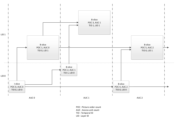
図1は、本開示の実施形態による通信システム(100)の簡易ブロック図を示す。システム(100)は、ネットワーク(150)を介して相互接続される少なくとも2つの端末(110、120)を含んでよい。データの一方向送信では、第1端末(110)は、ネットワーク(150)を介して他の端末(120)へ送信するために、ビデオデータをローカル位置でコーディングしてよい。第2端末(120)は、ネットワーク(150)から他の端末のコーディングビデオデータを受信し、コーディングデータを復号して、復元したビデオデータを表示してよい。単方向データ伝送は、メディアサービングアプリケーション等で共通であってよい。 FIG. 1 shows a simplified block diagram of a communication system (100) according to embodiments of the present disclosure. The system (100) may include at least two terminals (110, 120) interconnected via a network (150). In one-way transmission of data, the first terminal (110) may locally code the video data for transmission over the network (150) to the other terminals (120). A second terminal (120) may receive the coded video data of other terminals from the network (150), decode the coded data, and display the recovered video data. Unidirectional data transmission may be common in media serving applications and the like.
図1は、例えばビデオ会議中に生じ得る、コーディングビデオの双方向送信をサポートするために適用される第2の端末ペア(130、140)を示す。データの双方向送信では、各端末(130、140)は、ネットワーク(150)を介して他の端末へ送信するために、ローカルでキャプチャしたビデオデータをコーディングしてよい。各端末130、140は、また、他の端末により送信されたコーディングビデオデータを受信してよく、コーディングデータを復号してよく、及び復元したビデオデータをローカルディスプレイ装置で表示してよい。 FIG. 1 shows a second terminal pair (130, 140) adapted to support two-way transmission of coded video, which may occur, for example, during a video conference. In bi-directional transmission of data, each terminal (130, 140) may code locally captured video data for transmission over the network (150) to other terminals. Each terminal 130, 140 may also receive coded video data sent by other terminals, decode the coded data, and display the recovered video data on a local display device.
図1では、端末(110~140)は、ラップトップ110、パーソナルコンピュータ(PC)120、及びモバイル端末130及び140として示されるが、端末(110~140)はそのように限定されず、端末(110~140)は、サーバ、パーソナルコンピュータ、モバイル装置、タブレット、スマートフォンのうちの1つ以上又は任意の組合せに対応してよい。本開示の実施形態は、ラップトップコンピュータ、タブレットコンピュータ、メディアプレイヤ、及び/又は専用ビデオ会議設備による適用がある。ネットワーク(150)は、端末(110~140)の間でコーディングビデオデータを運ぶ任意の数のネットワークを表し、例えば有線及び/又は無線通信ネットワークを含む。通信ネットワーク(150)は、回線切り替え及び/又はパケット切り替えチャネルでデータを交換してよい。代表的なネットワークは、電子通信ネットワーク、ローカルエリアネットワーク(LAN)、広域ネットワーク(WAN)及び/又はインターネットを含む。本発明の議論の目的で、ネットワーク(150)のアーキテクチャ及びトポロジは、以下で特に断りの無い限り、本開示の動作にとって重要でないことがある。
In FIG. 1, terminals (110-140) are shown as
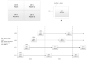
図2は、開示の実施形態の適用の一例として、ストリーミング環境におけるビデオエンコーダ及びビデオデコーダの配置を示す。本開示は、例えばビデオ会議、デジタルテレビジョン(TV)、コンパクトディスク(CD)、デジタルバーサタイルディスク(DVD)、メモリスティック、等を含むデジタル媒体への圧縮ビデオの格納、他のビデオ可能アプリケーション、等に等しく適用可能である。 FIG. 2 illustrates an arrangement of video encoders and video decoders in a streaming environment as an example application of the disclosed embodiments. This disclosure is useful for video conferencing, storing compressed video on digital media including, for example, digital television (TV), compact discs (CD), digital versatile discs (DVD), memory sticks, etc., other video enabled applications, etc. is equally applicable to
ストリーミングシステムは、例えば非圧縮ビデオサンプルストリーム(202)を生成するよう構成されるビデオソース(201)、例えばデジタルカメラを含み得るキャプチャサブシステム()213)を含んでよい。サンプルストリーム(202)は、符号化ビデオビットストリームと比べるとき高データ容量を強調するために図2で太線で示され、カメラ(201)に結合されるエンコーダ(203)により処理できる。エンコーダ(203)は、ハードウェア、ソフトウェア、又はそれらの組み合わせを含み、以下に詳述するように開示の主題の態様を可能にし又は実装することができる。符号化ビデオビットストリーム(204)は、サンプルストリーム(202)と比べたとき、低データ容量を強調するために図2で細線で示され、将来の使用のためにストリーミングサーバ(205)に格納できる。1つ以上のストリーミングクライアント(206、208)は、ストリーミングサーバ(205)にアクセスして、符号化ビデオビットストリーム(204)のコピー(207、209)を読み出すことができる。クライアント(206)は、ビデオデコーダ(210)を含むことができる。ビデオデコーダ(310)は、符号化ビットストリーム(207)の入来するコピーを復号し、ディスプレイ(212)又は他のレンダリング装置においてレンダリング可能な出力ビデオサンプルストリーム(211)を生成する。幾つかのストリーミングシステムでは、ビデオビットストリーム(204、207、209)は、特定のビデオコーディング/圧縮規格に従い符号化できる。これらの規格の例は、ITU-T Recommendation H.265を含む。策定中のビデオコーディング規格は、略式にVVC(Versatile Video Coding)として知られている。開示の主題は、VVCの文脈で使用されてよい。 The streaming system may include a video source (201), eg a capture subsystem (213), which may include a digital camera, for example, configured to generate an uncompressed video sample stream (202). The sample stream (202), shown in bold in FIG. 2 to emphasize its high data capacity when compared to the encoded video bitstream, can be processed by an encoder (203) coupled to the camera (201). The encoder (203) may include hardware, software, or a combination thereof to enable or implement aspects of the disclosed subject matter as detailed below. The encoded video bitstream (204) is shown in thin lines in FIG. 2 to highlight the low data capacity when compared to the sample stream (202) and can be stored on the streaming server (205) for future use. . One or more streaming clients (206, 208) can access the streaming server (205) to read copies (207, 209) of the encoded video bitstream (204). The client (206) may include a video decoder (210). A video decoder (310) decodes an incoming copy of the encoded bitstream (207) and produces an output video sample stream (211) that can be rendered on a display (212) or other rendering device. In some streaming systems, the video bitstreams (204, 207, 209) can be encoded according to a particular video coding/compression standard. Examples of these standards include ITU-T Recommendation H.265. The video coding standard under development is known informally as VVC (Versatile Video Coding). The disclosed subject matter may be used in the context of VVC.
図3は、本開示の実施形態によるビデオデコーダ(210)の機能ブロック図であり得る。 FIG. 3 may be a functional block diagram of a video decoder (210) according to embodiments of the present disclosure.
受信機(310)は、ビデオデコーダ(210)により復号されるべき1つ以上のコーディングビデオシーケンス、同じ又は別の実施形態では、一度に1つのコーディングビデオシーケンスを受信してよい。ここで、各コーディングビデオシーケンスの復号は、他のコーディングビデオシーケンスと独立している。コーディングビデオシーケンスは、符号化ビデオデータを格納する記憶装置へのハードウェア/ソフトウェアリンクであってよいチャネル(312)から受信されてよい。受信機(310)は、他のデータ、例えば、それぞれの使用エンティティ(図示しない)へと転送され得るコーディング音声データ及び/又は補助データストリームと共に、符号化ビデオデータを受信してよい。受信機(310)は、他のデータからコーディングビデオシーケンスを分離してよい。ネットワークジッタを除去するために、バッファメモリ(315)は、受信機(310)とエントロピーデコーダ/パーサ(320)(以後、「パーサ」)との間に接続されてよい。受信機(310)が、十分な帯域幅の記憶/転送装置から制御可能に、又はアイソクロナス(isosynchronous)ネットワークから、データを受信しているとき、バッファ(315)は、必要なくてよく又は小さくできる。インターネットのようなベストエフォート型パケットネットワークで使用する場合、バッファ(315)が必要であってよく、比較的大きくすることができ、有利なことに適応サイズにすることができる。 The receiver (310) may receive one or more coded video sequences, one coded video sequence at a time, to be decoded by the video decoder (210). Here, the decoding of each coded video sequence is independent of other coded video sequences. A coded video sequence may be received from a channel (312), which may be a hardware/software link to a storage device that stores coded video data. The receiver (310) may receive encoded video data along with other data, such as encoded audio data and/or auxiliary data streams, which may be transferred to respective usage entities (not shown). A receiver (310) may separate the coded video sequence from other data. To remove network jitter, a buffer memory (315) may be connected between the receiver (310) and the entropy decoder/parser (320) (hereinafter "parser"). When the receiver (310) is receiving data controllably from a storage/transfer device of sufficient bandwidth or from an isochronous network, the buffer (315) may not be needed or can be small. . For use in a best-effort packet network such as the Internet, a buffer (315) may be required and may be relatively large and advantageously adaptively sized.
ビデオデコーダ(210)は、エントロピーコーディングビデオシーケンスからシンボル(321)を再構成するために、パーサ(320)を含んでよい。これらのシンボルのカテゴリは、ビデオデコーダ210の動作を管理するために使用される情報、および場合によっては図2に示したようにデコーダの統合部分ではないがデコーダに結合され得るディスプレイ212のようなレンダリング装置を制御するための情報を含む。レンダリング装置のための制御情報は、SEI(Supplementary Enhancement Information)メッセージ又はVUI(Video Usability Information)パラメータセットフラグメントの形式であってよい。パーサ(320)は、受信された符号かビデオシーケンスをパース/エントロピー復号してよい。コーディングビデオシーケンスのコーディングは、ビデオコーディング技術又は規格に従うことができ、可変長コーディング、ハフマンコーディング、コンテキスト依存関係を有する又は有しない算術的コーディング、等を含む、当業者によく知られた原理に従うことができる。パーサ320は、符号化ビデオシーケンスから、ビデオデコーダの中のピクセルのサブグループのうちの少なくとも1つについて、該グループに対応する少なくとも1つのパラメータに基づき、サブグループパラメータのセットを抽出してよい。サブグループは、GOP(Groups of Picture)、ピクチャ、タイル、スライス、マクロブロック、符号化ユニット(Coding Units:CU)、ブロック、変換ユニット(Transform Units:TU)、予測ユニット(Prediction Units:PU)、等を含み得る。エントロピーデコーダ/パーサは、コーディングビデオシーケンスから、変換係数、量子化パラメータ値、動きベクトル、等のような情報も抽出してよい。
The video decoder (210) may include a parser (320) to reconstruct symbols (321) from the entropy coded video sequence. These symbol categories include information used to manage the operation of
パーサ(320)は、バッファ(315)から受信したビデオシーケンスに対してエントロピー復号/パース動作を実行して、シンボル(321)を生成してよい。 A parser (320) may perform entropy decoding/parsing operations on the video sequence received from the buffer (315) to generate symbols (321).
シンボル(321)の再構成は、コーディングビデオピクチャ又はその部分の種類(例えば、インター及びイントラピクチャ、インター及びイントラブロック)及び他の要因に依存して、複数の異なるユニットを含み得る。どのユニットがどのように含まれるかは、パーサ(320)によりコーディングビデオシーケンスからパースされたサブグループ制御情報により制御できる。サブグループ制御情報は、パーサ(320)と複数のユニットとの間を流れてよい。 Reconstruction of the symbols (321) may include multiple different units depending on the type of coded video picture or portion thereof (eg, inter and intra pictures, inter and intra blocks) and other factors. Which and how units are included can be controlled by subgroup control information parsed from the coded video sequence by the parser (320). Subgroup control information may flow between the parser (320) and multiple units.
既に言及した機能ブロックを超えて、デコーダ(210)は、後述のように、多数の機能ユニットに概念的に細分化できる。商用的制約の下で動作する実際の実装では、これらのユニットの多くは、互いに密に相互作用し、少なくとも部分的に互いに統合され得る。しかしながら、開示の主題を説明する目的で、機能ユニットへの以下の概念的細分化は適切である。 Beyond the functional blocks already mentioned, the decoder (210) can be conceptually subdivided into a number of functional units, as described below. In a practical implementation operating under commercial constraints, many of these units will interact closely with each other and may be at least partially integrated with each other. However, for purposes of describing the disclosed subject matter, the following conceptual breakdown into functional units is adequate.
第1ユニットは、スケーラ/逆変換ユニット351である。スケーラ/逆変換ユニット(351)は、量子化された変換係数、及び、どの変換が使用されるべきか、ブロックサイズ、量子化係数、量子化スケーリングマトリクス、等を含む制御情報を、パーサ(320)からのシンボル(321)として受信する。これは、アグリゲータ(355)に入力され得るサンプル値を含むブロックを出力できる。
The first unit is the scaler/
幾つかの例では、スケーラ/逆変換ユニット(351)の出力サンプルは、イントラコーディングブロック、つまり、前に再構成されたピクチャからの予測情報を使用しないが現在ピクチャの前に再構成された部分からの予測情報を使用可能なブロック、に属することができる。このような予測情報は、イントラピクチャ予測ユニット(352)により提供できる。幾つかの場合には、イントラピクチャ予測ユニット(352)は、再構成中のブロックと同じサイズ及び形状のブロックを、現在(部分的にさは再構成された)ピクチャ(358)からフェッチした周囲の既に再構成された情報を用いて、生成する。アグリゲータ(355)は、幾つかの場合には、サンプル毎に、イントラ予測ユニット(352)の生成した予測情報を、スケーラ/逆変換ユニット(351)により提供された出力サンプル情報に追加する。 In some examples, the output samples of the scaler/inverse transform unit (351) are the intra-coded blocks, i.e. the previously reconstructed parts of the current picture that do not use the prediction information from the previously reconstructed picture. can belong to a block that can use prediction information from Such prediction information can be provided by an intra-picture prediction unit (352). In some cases, the intra-picture prediction unit (352) fetches blocks of the same size and shape as the block under reconstruction from the current (partially reconstructed) picture (358). is generated using the already reconstructed information of The aggregator (355) adds the prediction information generated by the intra prediction unit (352) to the output sample information provided by the scaler/inverse transform unit (351), on a sample-by-sample basis in some cases.
他の場合には、スケーラ/逆変換ユニット(351)の出力サンプルは、インターコーディングされた、場合によっては動き補償されたブロックに関連し得る。このような場合には、動き補償予測ユニット(353)は、参照ピクチャメモリ(357)にアクセスして、予測のために使用されるサンプルをフェッチできる。ブロックに関連するシンボル(321)に従いフェッチしたサンプルを動き補償した後に、これらのサンプルは、アグリゲータ(355)により、出力サンプル情報を生成するために、スケーラ/逆変換ユニットの出力に追加され得る(この場合、残差サンプル又は残差信号と呼ばれる)。動き補償予測ユニットが予測サンプルをフェッチする参照ピクチャメモリ内のアドレスは、例えばX、Y及び参照ピクチャコンポーネントを有し得るシンボル(321)の形式で、動き補償予測ユニットの利用可能な動きベクトルにより制御できる。動き補償は、サブサンプルの正確な動きベクトルが使用中であるとき参照ピクチャメモリからフェッチされたサンプル値の補間、動きベクトル予測メカニズム、等も含み得る。 In other cases, the output samples of the scaler/inverse transform unit (351) may relate to inter-coded and possibly motion compensated blocks. In such cases, the motion compensated prediction unit (353) can access the reference picture memory (357) to fetch the samples used for prediction. After motion compensating the fetched samples according to the symbols (321) associated with the block, these samples may be added by the aggregator (355) to the output of the scaler/inverse transform unit to generate the output sample information ( in this case called residual samples or residual signals). The address in the reference picture memory from which the motion compensated prediction unit fetches the prediction samples is controlled by the available motion vectors of the motion compensated prediction unit, for example in the form of symbols (321), which may have X, Y and reference picture components. can. Motion compensation may also include interpolation of sample values fetched from reference picture memory when sub-sample accurate motion vectors are in use, motion vector prediction mechanisms, and the like.
アグリゲータ(355)の出力サンプルは、ループフィルタユニット(356)において種々のループフィルタリング技術を受け得る。ビデオ圧縮技術は、コーディングビデオビットストリームに含まれ且つパーサ(320)からのシンボル(321)としてループフィルタユニット(356)に利用可能にされたパラメータにより制御されるが、コーディングピクチャ又はコーディングビデオシーケンスの(復号順序で)前の部分の復号中に取得されたメタ情報にも応答し、前に再構成されループフィルタリングされたサンプル値にも応答し得るインループフィルタ技術を含み得る。 The output samples of aggregator (355) may undergo various loop filtering techniques in loop filter unit (356). The video compression technique is controlled by parameters contained in the coded video bitstream and made available to the loop filter unit (356) as symbols (321) from the parser (320), but not for the coded picture or coded video sequence. It may include an in-loop filtering technique that is also responsive to meta-information obtained during decoding of previous portions (in decoding order) and may also be responsive to previously reconstructed and loop-filtered sample values.
ループフィルタユニット(356)の出力は、レンダー装置(212)へと出力でき及び将来のインターピクチャ予測で使用するために参照ピクチャメモリ(356)に格納され得るサンプルストリームであり得る。 The output of the loop filter unit (356) may be a sample stream that can be output to the render device (212) and stored in the reference picture memory (356) for use in future inter-picture prediction.
特定のコーディングピクチャは、一旦完全に再構成されると、将来の予測のための参照ピクチャとして使用できる。符号化ピクチャが完全に再構成され、符号化ピクチャが(例えばパーサ320により)参照ピクチャとして識別されると、現在参照ピクチャ356は、参照ピクチャメモリ357の一部になることができ、後続の符号化ピクチャの再構成を開始する前に、新鮮な現在ピクチャメモリを再割り当てできる。
A particular coded picture, once fully reconstructed, can be used as a reference picture for future prediction. Once the coded picture has been fully reconstructed and the coded picture has been identified (eg, by parser 320) as a reference picture,
ビデオデコーダ(パーサ)320は、ITU-T Rec H.265のような規格で策定され得る所定のビデオ圧縮技術に従い復号動作を実行してよい。コーディングビデオシーケンスが、ビデオ圧縮技術又は規格で、具体的にはその中のプロファイル文書で指定された、ビデオ圧縮技術又は規格のシンタックスに従うという意味で、コーディングビデオシーケンスは、使用中のビデオ圧縮技術又は規格により指定されたシンタックスに従ってよい。また、遵守のために必要なことは、コーディングビデオシーケンスの複雑さが、ビデオ圧縮技術又は規格のレベルにより定められる限界の範囲内であることであり得る。幾つかの場合には、レベルは、最大ピクチャサイズ、最大フレームレート、最大再構成サンプルレート(例えばメガサンプル/秒で測定される)、最大参照ピクチャサイズ、等を制限する。レベルにより設定される限界は、幾つかの場合には、HDR(Hypothetical Reference Decoder)仕様及びコーディングビデオシーケンスの中でシグナリングされるHDRバッファ管理のためのメタデータを通じて更に制限され得る。 A video decoder (parser) 320 may perform decoding operations according to a predetermined video compression technique, which may be specified in standards such as ITU-T Rec H.265. A coded video sequence conforms to the video compression technology or standard in use, in the sense that the coded video sequence follows the syntax of the video compression technology or standard, specifically specified in the profile document therein. Or it may follow the syntax specified by the standard. A requirement for compliance may also be that the complexity of the coded video sequence is within limits set by the level of video compression technology or standards. In some cases, the level limits the maximum picture size, maximum frame rate, maximum reconstructed sample rate (eg, measured in megasamples/second), maximum reference picture size, and the like. The limit set by the level may in some cases be further restricted through HDR (Hypothetical Reference Decoder) specifications and metadata for HDR buffer management signaled in the coded video sequence.
実施形態では、受信機(310)は、符号化ビデオと共に追加(冗長)データを受信してよい。追加データは、コーディングビデオシーケンスの部分として含まれてよい。追加データは、データを正しく復号するため及び/又は元のビデオデータをより正確に再構成するために、ビデオデコーダ320により使用されてよい。追加データは、例えば、時間的、空間的、又はSNR拡張レイヤ、冗長スライス、冗長ピクチャ、前方誤り訂正符号、等の形式であり得る。
In embodiments, the receiver (310) may receive additional (redundant) data along with the encoded video. Additional data may be included as part of the coding video sequence. The additional data may be used by
図4は、本開示の一実施形態によるビデオエンコーダ(203)の機能ブロック図であり得る。 Figure 4 may be a functional block diagram of a video encoder (203) according to one embodiment of the present disclosure.
エンコーダ(203)は、ビデオサンプルを、エンコーダ(203)によりコーディングされるべきビデオ画像をキャプチャし得るビデオソース(201)(エンコーダの部分ではない)から受信してよい。 The encoder (203) may receive video samples from a video source (201) (not part of the encoder) that may capture video images to be coded by the encoder (203).
ビデオソース(201)は、エンコーダ(203)によりコーディングされるべきソースビデオシーケンスを、任意の適切なビット深さ(例えば、8ビット、10ビット、12ビット、...)、任意の色空間(例えば、BT.601 Y CrCb, RGB,...)、及び任意の適切なサンプリング構造(例えば、Y CrCb 4:2:0, Y CrCb 4:4:4)のデジタルビデオサンプルストリームの形式で、提供してよい。メディア提供システムでは、ビデオソース(201)は、前に準備されたビデオを格納する記憶装置であってよい。ビデオ会議システムでは、ビデオソース(203)は、ビデオシーケンスとしてローカル画像情報をキャプチャするカメラであってよい。ビデオデータは、続けて閲覧されると動きを与える複数の個別ピクチャとして提供されてよい。ピクチャ自体は、ピクセルの空間的配列として組織化されてよい。各ピクセルは、使用中のサンプリング構造、色空間、等に依存して、1つ以上のサンプルを含み得る。当業者は、ピクセルとサンプルとの間の関係を直ちに理解できる。以下の説明はサンプルに焦点を当てる。 The video source (201) encodes the source video sequence to be coded by the encoder (203) into any suitable bit depth (e.g. 8-bit, 10-bit, 12-bit,...), any color space ( BT.601 YCrCb,RGB,...) and any suitable sampling structure (e.g. YCrCb 4:2:0, YCrCb 4:4:4) in the form of a digital video sample stream, may provide. In a media serving system, the video source (201) may be a storage device that stores previously prepared videos. In a videoconferencing system, the video source (203) may be a camera that captures local image information as a video sequence. The video data may be provided as multiple individual pictures that, when viewed in succession, impart motion. The picture itself may be organized as a spatial array of pixels. Each pixel may contain one or more samples, depending on the sampling structure, color space, etc. in use. Those skilled in the art can readily understand the relationship between pixels and samples. The following discussion focuses on samples.
実施形態によると、エンコーダ(203)は、ソースビデオシーケンスのピクチャを、コーディングビデオシーケンス(443)へと、リアルタイムに又はアプリケーションにより要求される任意の他の時間制約の下でコーディングし圧縮してよい。適切なコーディング速度の実施は、制御部(450)の1つの機能である。制御部(450)は、後述するように他の機能ユニットを制御してよく、他の機能ユニットに機能的に結合される。制御部(450)により設定されるパラメータ、レート制御関連パラメータ(ピクチャスキップ、量子化器、レート歪み最適化技術のラムダ値、...)、ピクチャサイズ、GOP(group of pictures)レイアウト、最大動きベクトル探索範囲、等を含んでよい。当業者は、特定のシステム設計のために最適化されたビデオエンコーダ(203)に関連し得るとき、制御部450の他の機能を直ちに識別できる。 According to embodiments, the encoder (203) may code and compress the pictures of the source video sequence into a coded video sequence (443) in real-time or under any other time constraint required by the application. . Enforcing an appropriate coding rate is one function of the control unit (450). The controller (450) may control other functional units as described below and is functionally coupled to the other functional units. Parameters set by the control unit (450), rate control related parameters (picture skip, quantizer, lambda value of rate-distortion optimization techniques, ...), picture size, group of pictures (GOP) layout, maximum motion vector search range, and so on. Those skilled in the art can readily identify other functions of the control unit 450 as they may relate to a video encoder (203) optimized for a particular system design.
幾つかのビデオエンコーダは、当業者が「コーディングループ」として直ちに認識する中で動作する。非常に簡略化した説明として、コーディングループは、エンコーダ(203)(以後、「ソースコーダ」)(コーディングされるべき入力ピクチャと参照ピクチャとに基づき、シンボルを生成する)及びエンコーダ(203)内に組み込まれ、シンボルを再構成して、(シンボルとコーディングビデオビットストリームとの間の任意の圧縮が開示の主題において考慮されるビデオ圧縮技術の中で無損失であるとき)(リモート)デコーダが生成し得るサンプルデータを生成する(ローカル)デコーダ(433)の符号化部分を含むことができる。再構成されたサンプルストリームは、参照ピクチャメモリ434に入力される。シンボルストリームの復号が、デコーダ位置(ローカル又はリモート)と独立にビット正確な結果をもたらすとき、参照ピクチャバッファの内容も、ローカルエンコーダとリモートエンコーダとの間でビット正確である。言い換えると、エンコーダの予測部分が、復号中に予測を用いるときデコーダが「見る」のと正確に同じサンプル値を、参照ピクチャサンプルとして「見る」。参照ピクチャ同期性のこの基本原理(及び、例えばチャネルエラーのために同期性が維持できない場合には、結果として生じるドリフト)は、当業者によく知られている。
Some video encoders operate in what those skilled in the art readily recognize as a "coding loop". As a very simplified description, the coding loop consists of an encoder (203) (hereinafter "source coder") (which generates symbols based on the input picture to be coded and a reference picture) and within encoder (203) generated by a (remote) decoder (when any compression between the symbols and the coded video bitstream is lossless among the video compression techniques considered in the disclosed subject matter), reconstructing the symbols It may include the encoding part of a (local) decoder (433) that generates sample data that can be processed. The reconstructed sample stream is input to reference
「ローカル」デコーダ(433)の動作は、図3と関連して以上に詳述した「リモート」デコーダ(210)のものと同じであり得る。簡単に図3も参照すると、しかしながら、シンボルが利用可能であり、エントロピーコーダ(445)及びパーサ(320)によるコーディングビデオシーケンスへのシンボルの符号化/復号が無損失であり得るので、チャネル(312)、受信機(310)、バッファ(315)、及びパーサ(320)を含むデコーダ(210)のエントロピー復号部分は、ローカルデコーダ(433)に完全に実装されなくてよい。 The operation of the 'local' decoder (433) may be the same as that of the 'remote' decoder (210) detailed above in connection with FIG. Referring also briefly to FIG. 3, however, the channel (312 ), receiver (310), buffer (315), and parser (320) need not be fully implemented in the local decoder (433).
この点で行われる考察は、デコーダ内に存在するパース/エントロピー復号を除く任意のデコーダ技術も、対応するエンコーダ内と実質的に同一の機能形式で存在する必要があるということである。この理由から、開示の主題は、デコーダ動作に焦点を当てる。エンコーダ技術の説明は、それらが包括的に説明されるデコーダ技術の逆であるので、省略できる。特定の領域においてのみ、より詳細な説明が必要であり、以下に提供される。 A consideration made at this point is that any decoder technique other than parse/entropy decoding present in the decoder should be present in substantially the same functional form as in the corresponding encoder. For this reason, the disclosed subject matter will focus on decoder operations. A description of the encoder techniques can be omitted as they are the inverse of the generically described decoder techniques. Only certain areas require more detailed explanation and are provided below.
動作中、幾つかの例では、ソースコーダ(203)は、動き補償された予測コーディングを実行してよい。これは、「参照フレーム」として指定されたビデオシーケンスからの1つ以上の前にコーディングされたフレームを参照して予測的に入力フレームをコーディングする。この方法では、コーディングエンジン(432)は、入力フレームのピクセルブロックと、入力フレームに対する予測基準として選択されてよい参照フレームのピクセルブロックとの間の差分をコーディングする。 During operation, in some examples, the source coder (203) may perform motion compensated predictive coding. It predictively codes an input frame with reference to one or more previously coded frames from a video sequence, designated as "reference frames." In this method, the coding engine (432) codes differences between pixelblocks of an input frame and pixelblocks of a reference frame that may be selected as prediction criteria for the input frame.
ローカルビデオデコーダ(433)は、ソースコーダ(430)により生成されたシンボルに基づき、参照フレームとして指定されてよいフレームのコーディングビデオデータを復号してよい。コーディングエンジン(432)の動作は、有利なことに、損失処理であってよい。コーディングビデオデータがビデオデコーダ(図4に図示されない)において復号され得るとき、再構成ビデオシーケンスは、標準的に、幾つかのエラーを有するソースビデオシーケンスの複製であってよい。ローカルビデオデコーダ(433)は、参照フレームに対してビデオデコーダにより実行され得る復号処理を複製し、参照ピクチャキャッシュ(434)に格納されるべき再構成参照フレームを生じ得る。このように、エンコーダ(203)は、(伝送誤りが無ければ)遠端ビデオデコーダにより取得される再構成参照フレームと共通の内容を有する再構成参照フレームのコピーをローカルに格納してよい。 A local video decoder (433) may decode coded video data for frames, which may be designated as reference frames, based on the symbols generated by the source coder (430). The operation of the coding engine (432) may advantageously be lossy. When the coded video data can be decoded in a video decoder (not shown in FIG. 4), the reconstructed video sequence can typically be a duplicate of the source video sequence with some errors. A local video decoder (433) may replicate decoding processes that may be performed by a video decoder on reference frames, resulting in reconstructed reference frames to be stored in a reference picture cache (434). Thus, the encoder (203) may locally store a copy of a reconstructed reference frame that has content in common with the reconstructed reference frame obtained by the far-end video decoder (barring transmission errors).
予測器(435)は、コーディングエンジン(432)のために予測探索を実行してよい。つまり、コーディングされるべき新しいフレームについて、予測器(435)は、新しいピクチャのための適切な予測基準として機能し得る(候補参照ピクセルブロックのような)サンプルデータ又は参照ピクチャ動きベクトル、ブロック形状、等のような特定のメタデータについて、参照ピクチャメモリ(434)を検索してよい。予測器(435)は、適切な予測基準を見付けるために、サンプルブロック-ピクセルブロック毎に動作してよい。幾つかの例では、予測器(435)により取得された検索結果により決定されるように、入力ピクチャは、参照ピクチャメモリ(434)に格納された複数の参照ピクチャから引き出された予測基準を有してよい。 A predictor (435) may perform a predictive search for the coding engine (432). That is, for a new frame to be coded, the predictor (435) uses sample data (such as candidate reference pixel blocks) or reference picture motion vectors (such as candidate reference pixel blocks), block shapes, The reference picture memory (434) may be searched for specific metadata such as. The predictor (435) may operate on a sample block-pixel block basis to find a suitable prediction criterion. In some examples, the input picture has prediction criteria drawn from multiple reference pictures stored in the reference picture memory (434), as determined by the search results obtained by the predictor (435). You can
制御部(450)は、例えば、ビデオデータの符号化のために使用されるパラメータ及びサブグループパラメータの設定を含む、ビデオコーダ(203)のコーディング動作を管理してよい。 The controller (450) may manage the coding operations of the video coder (203), including, for example, setting parameters and subgroup parameters used for encoding video data.
全ての前述の機能ユニットの出力は、エントロピーコーダ(445)におけるエントロピーコーディングを受けてよい。エントロピーコーダは、ハフマンコーディング、可変長コーディング、算術コーディング、等のような当業者によく知られた技術に従いシンボルを無損失圧縮することにより、種々の機能ユニットにより生成されたシンボルを、コーディングビデオシーケンスへと変換する。 The outputs of all aforementioned functional units may undergo entropy coding in an entropy coder (445). An entropy coder converts the symbols generated by the various functional units into a coding video sequence by losslessly compressing the symbols according to techniques well known to those skilled in the art, such as Huffman coding, variable length coding, arithmetic coding, etc. convert to
送信機(440)は、コーディングビデオデータを格納し得る記憶装置へのハードウェア/ソフトウェアリンクであってよい通信チャネル(460)を介する伝送のために準備するために、エントロピーコーダ(445)により生成されたコーディングビデオシーケンスをバッファリングしてよい。送信機(440)は、ビデオコーダ(430)からのコーディングビデオデータを、送信されるべき他のデータ、例えばコーディング音声データ及び/又は補助データストリーム/ソースとマージ(merge)してよい。 The transmitter (440) outputs the data generated by the entropy coder (445) to prepare for transmission over the communication channel (460), which may be a hardware/software link to a storage device that may store the coded video data. The coded video sequence may be buffered. The transmitter (440) may merge the coded video data from the video coder (430) with other data to be transmitted, such as coded audio data and/or auxiliary data streams/sources.
制御部(450)は、エンコーダ(203)の動作を管理してよい。コーディング中、制御部(450)は、それぞれのピクチャに適用され得るコーディング技術に影響し得る特定のコーディングピクチャタイプを、各コーディングピクチャに割り当ててよい。例えば、ピクチャは、多くの場合、以下のピクチャタイプのうちの1つとして割り当てられてよい。 A controller (450) may manage the operation of the encoder (203). During coding, the controller (450) may assign each coded picture a specific coding picture type, which may affect the coding technique that may be applied to each picture. For example, pictures may often be assigned as one of the following picture types.
イントラピクチャ(Iピクチャ)は、予測のソースとしてシーケンス内の任意の他のフレームを使用せずにコーディング及び復号され得るピクチャであってよい。幾つかのビデオコーデックは、例えばIDR(Independent Decoder Refresh)ピクチャを含む異なる種類のイントラピクチャを許容する。当業者は、Iピクチャの変形、及びそれらの個々の適用及び特徴を認識する。 Intra pictures (I pictures) may be pictures that can be coded and decoded without using any other frame in the sequence as a source of prediction. Some video codecs allow different kinds of intra pictures, including for example Independent Decoder Refresh (IDR) pictures. Those skilled in the art are aware of the variations of I-pictures and their particular applications and characteristics.
予測ピクチャ(Pピクチャ)は、殆どの場合、各ブロックのサンプル値を予測するために1つの動きベクトル及び参照インデックスを用いてイントラ予測又はインター予測を用いてコーディング及び復号され得るピクチャであってよい。 Predicted pictures (P-pictures) are mostly pictures that can be coded and decoded using intra-prediction or inter-prediction using one motion vector and reference indices to predict the sample values of each block. .
双方向予測ピクチャ(Bピクチャ)は、各ブロックのサンプル値を予測するために最大2つの動きベクトル及び参照インデックスを用いてイントラ予測又はインター予測を用いてコーディング及び復号され得るピクチャであってよい。同様に、マルチ予測ピクチャは、単一のブロックの再構成のために、2つより多くの参照ピクチャ及び関連付けられたメタデータを使用できる。 A bi-predictive picture (B-picture) may be a picture that can be coded and decoded using intra-prediction or inter-prediction using up to two motion vectors and reference indices to predict the sample values of each block. Similarly, multi-prediction pictures can use more than two reference pictures and associated metadata for reconstruction of a single block.
ソースピクチャは、共通に、複数のサンプルブロック(例えば、それぞれ4×4、8×8、4×8、又は16×16個のサンプルのブロック)に空間的に細分化され、ブロック毎にコーディングされてよい。ブロックは、ブロックのそれぞれのピクチャに適用されるコーディング割り当てにより決定される他の(既にコーディングされた)ブロックへの参照により予測的にコーディングされてよい。例えば、Iピクチャのブロックは、非予測的にコーディングされてよく、又はそれらは同じピクチャの既にコーディングされたブロックを参照して予測的にコーディングされてよい(空間予測又はイントラ予測)。Pピクチャのピクセルブロックは、1つの前にコーディングされた参照ピクチャを参照して、空間予測を介して又は時間予測を介して、予測的にコーディングされてよい。Bピクチャのブロックは、1つ又は2つの前にコーディングされた参照ピクチャを参照して、空間予測を介して又は時間予測を介して、非予測的にコーディングされてよい。 A source picture is commonly spatially subdivided into multiple sample blocks (e.g., blocks of 4x4, 8x8, 4x8, or 16x16 samples each) and coded block by block. you can A block may be predictively coded with reference to other (already coded) blocks determined by coding assignments applied to each picture of the block. For example, blocks of I pictures may be coded non-predictively, or they may be coded predictively with reference to already coded blocks of the same picture (spatial prediction or intra prediction). Pixel blocks of a P picture may be predictively coded via spatial prediction or via temporal prediction with reference to one previously coded reference picture. Blocks of B pictures may be coded non-predictively via spatial prediction or via temporal prediction with reference to one or two previously coded reference pictures.
ビデオコーダ(203)は、ITU-T Rec. H.265のような所定のビデオコーディング技術又は規格に従いコーディング動作を実行してよい。その動作において、ビデオコーダ(203)は、入力ビデオシーケンスの中の時間的及び空間的冗長性を利用する予測コーディング動作を含む種々の圧縮動作を実行してよい。コーディングビデオデータは、したがって、使用されているビデオコーディング技術又は規格により指定されたシンタックスに従ってよい。 The video coder (203) may perform coding operations according to a given video coding technique or standard, such as ITU-T Rec. H.265. In its operation, the video coder (203) may perform various compression operations, including predictive coding operations that exploit temporal and spatial redundancies in the input video sequence. The coded video data may therefore follow the syntax specified by the video coding technique or standard being used.
一実施形態では、送信機(440)は、符号化ビデオと共に追加データを送信してよい。ビデオコーダ(430)は、このようなデータをコーディングビデオシーケンスの部分として含んでよい。追加データは、時間/空間/SNR拡張レイヤ、冗長ピクチャ及びスライスのような他の形式の冗長データ、SEI(Supplementary Enhancement Information)メッセージ、VUI(Visual Usability Information)パラメータセットフラグメント、等を含んでよい。 In one embodiment, the transmitter (440) may send additional data along with the encoded video. A video coder (430) may include such data as part of a coded video sequence. Additional data may include temporal/spatial/SNR enhancement layers, other forms of redundant data such as redundant pictures and slices, SEI (Supplementary Enhancement Information) messages, VUI (Visual Usability Information) parameter set fragments, and so on.
開示の主題の特定の態様を更に詳細に説明する前に、この記載の残りの部分で参照される幾つかの用語を紹介する必要がある。 Before describing certain aspects of the disclosed subject matter in further detail, it is necessary to introduce some terminology that will be referenced in the remainder of this description.
サブピクチャは、以下では、幾つかの場合には、サンプル、ブロック、マクロブロック、コーディングユニット、又は意味論的にグループ化され変更された解像度で独立にコーディングされてよい同様のエンティティの長方形構成を表してよい。1つ以上のサブピクチャは、ピクチャのためであってよい。1つ以上のコーディングサブピクチャは、コーディングピクチャを形成してよい。1つ以上のサブピクチャは、ピクチャに組み立てられてよく、1つ以上のサブピクチャは、ピクチャから抽出されてよい。特定の環境では、1つ以上のコーディングサブピクチャは、サンプルレベルに変換することなく、圧縮ドメインにおいてコーディングピクチャへと組み立てられてよく、同じ又は特定の他の場合には、1つ以上のコーディングサブピクチャは、圧縮ドメインにおいてコーディングピクチャから抽出されてよい。 Subpictures, hereinafter, are in some cases rectangular arrangements of samples, blocks, macroblocks, coding units, or similar entities that may be semantically grouped and independently coded at varying resolutions. can be expressed. One or more subpictures may be for a picture. One or more coding subpictures may form a coding picture. One or more subpictures may be assembled into a picture and one or more subpictures may be extracted from a picture. In certain circumstances, one or more coded sub-pictures may be assembled into a coded picture in the compressed domain without conversion to the sample level; Pictures may be extracted from the coded pictures in the compressed domain.
適応解像度変更(Adaptive Resolution Change (ARC))は、以下では、例えば参照ピクチャ再サンプリングにより、コーディングビデオシーケンス内のピクチャ又はサブピクチャの解像度の変更を許容するメカニズムを表す。ARCパラメータは、以下では、適応解像度変更を実行するために必要な制御情報を表す。これは、例えば、フィルタパラメータ、スケーリング因子、出力及び/又は参照ピクチャの解像度、種々の制御フラグ、等を含んでよい。 Adaptive Resolution Change (ARC) hereinafter refers to a mechanism that allows changing the resolution of a picture or sub-picture within a coded video sequence, eg by reference picture resampling. The ARC parameters hereinafter represent the control information required to perform adaptive resolution change. This may include, for example, filter parameters, scaling factors, output and/or reference picture resolutions, various control flags, and the like.
上述の説明は、種々の実施形態に従い、単一の意味的に独立したコーディングビデオピクチャをコーディング及び復号することに焦点を当てている。独立したARCパラメータによる複数のサブピクチャのコーディング/復号の意味、及びその暗示される追加の複雑さを説明する前にARCパラメータのシグナリングが説明され得る。 The above description focuses on coding and decoding a single semantically independent coded video picture according to various embodiments. ARC parameter signaling may be explained before explaining the implications of coding/decoding multiple sub-pictures with independent ARC parameters, and the additional complexity that is implied.
図5を参照すると、ARCパラメータをシグナリングする幾つかの新規な選択肢が示される。選択肢の各々と共に記されるように、それらは、コーディング効率、複雑さ、及びアーキテクチャの観点で、特定の利点及び特定の欠点を有するビデオコーディング規格又は技術はARCパラメータをシグナリングするために、これらの選択肢、又は従来技術から分かる選択肢、のうちの1つ以上を選択してよい。選択肢は、相互に排他的でなくてよく、或いは、アプリケーションの必要、技術的に関連する規格、又はエンコーダの選択に基づき、交換されてよい。 Referring to FIG. 5, some novel options for signaling ARC parameters are shown. As noted with each of the options, they have particular advantages and particular drawbacks in terms of coding efficiency, complexity, and architecture. One or more of the options, or options known from the prior art, may be selected. The options may not be mutually exclusive or may be interchangeable based on application needs, technically relevant standards, or encoder choice.
ARCパラメータのクラスは以下を含んでよい: Classes of ARC parameters may include:
-X及びY次元において別個の又は結合された、アップ/ダウンサンプル因子; - separate or combined up/down sample factors in the X and Y dimensions;
-時間次元の追加に伴う、所与の数のピクチャについて一定速度ズームイン/アウトを示す、アップ/ダウンサンプル因子; - an up/down sample factor indicating a constant speed zoom in/out for a given number of pictures with the addition of the temporal dimension;
-上述の2つのうちのいずれかは、因子を含むテーブルを指してよい1つ以上のおそらく短いシンタックス要素のコーディングを含んでよい; - Either of the above two may contain the coding of one or more possibly short syntax elements which may point to a table containing factors;
-X又はY次元における、結合された又は別個の、入力ピクチャ、出力ピクチャ、参照ピクチャ、コーディングピクチの、サンプル、ブロック、マクロブロック、CU、又は任意の他の適切な粒度のユニット内の解像度。1つより多くの解像度がある場合(例えば、入力ピクチャについて1つ、参照ピクチャについて1つ)、特定の場合には、値の1つのセットが、値の別のセットから推定されてよい。これは、例えば、フラグの使用により制御することができる。更に詳細な例については以下を参照する: - Resolution in units of samples, blocks, macroblocks, CUs, or any other suitable granularity of combined or separate input pictures, output pictures, reference pictures, coding pictures in the X or Y dimension. If there is more than one resolution (eg, one for the input picture and one for the reference picture), then in certain cases one set of values may be estimated from another set of values. This can be controlled, for example, through the use of flags. For a more detailed example see:
-「ワーピング(warping)」座標は、ここでも上述のような適切な粒度で、H.263 Annex P で使用されるものを含む。H.263 Annex Pは、このようなワーピング座標をコーディングするための1つの効率的な方法を定義するが、他の更に効率的な可能性のある方法も考案される可能性がある。例えば、Annex Pのワーピング座標の可変長リバーシブルHuffman型コーディングは、適切な長さのバイナリコーディングにより置き換えられる。ここで、バイナリコードワードの長さは、例えば、最大ピクチャサイズから導出され、場合によっては特定の係数により乗算され特定の値によりオフセットされ得、従って、最大ピクチャサイズの境界の外部での「ワーピング」を可能にする。 - "Warping" coordinates include those used in H.263 Annex P, again at the appropriate granularity as described above. H.263 Annex P defines one efficient method for coding such warping coordinates, but other potentially more efficient methods may be devised. For example, the variable-length reversible Huffman-type coding of the warping coordinates in Annex P is replaced by binary coding of appropriate length. Here, the length of the binary codeword can be derived, for example, from the maximum picture size, possibly multiplied by a certain factor and offset by a certain value, thus "warping" outside the bounds of the maximum picture size. ”.
-アップ又はダウンサンプリングフィルタパラメータ。最も簡単な場合には、アップ及び/又はダウンサンプリングのための単一のフィルタのみがあってよい。しかしながら、特定の場合には、フィルタ設計において更なる柔軟性を可能にすることが有利であり、これは、フィルタパラメータのシグナリングを必要とする場合がある。このようなパラメータは、可能なフィルタ設計のリスト内のインデックスを通じて選択されてよい。フィルタは完全に指定されてよく(例えば、フィルタ係数のリストを通じて、適切なエントロピーコーディング技術を用いて)、フィルタは、アップ/ダウンサンプル比を通じて暗示的に選択されてよく、該アップ/ダウンサンプル比に従い上述のメカニズムのうちのいずれかに従いシグナリングされる、等である。 - up or down sampling filter parameters. In the simplest case there may only be a single filter for up and/or downsampling. However, in certain cases it is advantageous to allow more flexibility in filter design, which may require signaling of filter parameters. Such parameters may be selected through an index into a list of possible filter designs. Filters may be fully specified (e.g., through a list of filter coefficients, using an appropriate entropy coding technique), or filters may be selected implicitly through an up/down sample ratio, where the up/down sample ratio , and so on according to any of the mechanisms described above.
以下では、コードワードを通じて示される、アップ/ダウンサンプル因子(X及びY次元の両方で使用されるべき同じ因子)の有限セットのコーディングを想定する。そのコードワードは、有利なことに、例えばH.264及びH.265のようなビデオコーディング仕様における特定のシンタックス要素について共通のExt-Golombコードを使用する可変長コードワードであり得る。 In the following, we assume the coding of a finite set of up/down sample factors (same factors to be used in both the X and Y dimensions) indicated through codewords. The codewords may advantageously be variable length codewords using common Ext-Golomb codes for certain syntax elements in video coding specifications such as H.264 and H.265.
アップ及び/又はダウンサンプル因子への値の1つの適切なマッピングは、例えば表1に従うことができる。
<表1>

<Table 1>
多くの同様のマッピングが、ビデオ圧縮技術又は規格において利用可能なアプリケーションの必要並びにアップ及びダウンスケールメカニズムの能力に従い、考案され得る。表は、より多くの値に拡張され得る。値は、Ext-Bolombコード以外のエントロピーコーディングメカニズムにより、例えばバイナリコーディングを用いて表されてもよい。それは、再サンプリング因子がビデオ処理エンジン(主にエンコーダ及びデコーダ)自体の外部で、例えばMANET(Mobile ad hoc network)により対象とされるとき、特定の利点を有してよい。留意すべきことに、解像度の変化が要求されない(おそらく)最も一般的な状況では、Ext-Golombコードは、短く、上述の表の中では、単一のビットのみになるよう選択できる。それは、最も一般的な場合にバイナリコードを使用することに勝るコーディング効率の利点を有し得る。 Many similar mappings can be devised according to the needs of the application and the capabilities of the up- and down-scaling mechanisms available in the video compression technology or standard. The table can be extended to more values. Values may also be represented by entropy coding mechanisms other than Ext-Bolomb codes, for example using binary coding. It may have particular advantages when the resampling factor is targeted outside the video processing engine (mainly the encoder and decoder) itself, eg by MANET (Mobile ad hoc network). Note that in the (perhaps) most common situation where no resolution change is required, the Ext-Golomb code can be chosen to be short and only a single bit in the table above. It may have coding efficiency advantages over using binary code in the most common case.
表中のエントリの数は、それらの意味と共に、完全に又は部分的に設定可能であってよい。例えば、表の基本的概要は、シーケンス又はデコーダパラメータセットのような「高(high)」パラメータセットの中で伝達されてよい。代替として又は実施形態では、1つ以上のこのような表が、ビデオコーディング技術又は規格の中で定義されてよく、例えばデコーダ又はシーケンスパラメータセットを通じて選択されてよい。 The number of entries in the table along with their meanings may be fully or partially configurable. For example, a basic summary of the table may be conveyed in a "high" parameter set, such as a sequence or decoder parameter set. Alternatively or in embodiments, one or more such tables may be defined within a video coding technique or standard, and may be selected through decoder or sequence parameter sets, for example.
以下では、上述のようにコーディングされたアップサンプリング/ダウンサンプリング因子(ARC情報)がビデオコーディング技術又は規格シンタックスにどのように含まれるかを説明する。同様の検討は、1つ又は幾つかのコードワード制御アップ/ダウンサンプリングフィルタに適用され得る。フィルタ又は他のデータ構造のために比較的に大容量のデータが必要とされるときの議論については以下を参照する。 The following describes how the upsampling/downsampling factors (ARC information) coded as described above are included in a video coding technique or standard syntax. Similar considerations can be applied to one or several codeword controlled up/downsampling filters. See below for a discussion of when relatively large amounts of data are needed for filters or other data structures.
H.263 Annex Pは、ARC情報(502)を4個のワーピング座標の形式で、ピクチャヘッダ(501)に、具体的にはH.263 PLUSPTYPE(503)ヘッダ拡張に含める。これは、(a)利用可能なピクチャヘッダがあるとき、及び(b)ARC情報の頻繁な変更が期待されるとき、賢明な設計選択であり得る。しかしながら、H.263型のシグナリングを使用するときのオーバヘッドは非常に大きくなることがあり、ピクチャヘッダが過渡的特性であり得るので、スケーリング係数がピクチャ境界の間に属しないことがある。 H.263 Annex P includes ARC information (502) in the form of four warping coordinates in the picture header (501), specifically in the H.263 PLUSPTYPE (503) header extension. This may be a wise design choice when (a) there is a picture header available and (b) frequent changes of ARC information are expected. However, the overhead when using H.263 type signaling can be very large, and since picture headers can be of a transient nature, scaling factors may not fall between picture boundaries.
先に引用されたJVCET-M135-v1は、ピクチャパラメータセット(504)内に位置するARC参照情報(505)(インデックス)、シーケンスパラメータセット(SPS)(507)内に位置する目標解像度を含むインデックステーブル(506)、を含む。シーケンスパラメータセット(507)内のテーブル(506)内の可能な解像度の配置は、著者により作成された言葉によると、能力交換中に相互運用交渉点としてSPSを用いて正当性を示すことができる。解像度は、適切なピクチャパラメータセット(504)を参照することにより、ピクチャ毎に、テーブル(506)内の値により設定された限度の範囲内で、変化できる。 JVCET-M135-v1, cited above, contains the ARC reference information (505) (index) located in the picture parameter set (504), the index containing the target resolution located in the sequence parameter set (SPS) (507). Table (506). The arrangement of the possible resolutions in the table (506) within the sequence parameter set (507) can be justified using the SPS as an interoperability negotiation point during capability exchanges, according to the language coined by the author. . The resolution can be varied from picture to picture, within limits set by the values in the table (506), by referencing the appropriate picture parameter set (504).
図5に戻ると、ビデオビットストリームの中でARC情報を運ぶために、以下の追加の選択肢が存在し得る。これらの選択肢の各々は、上述のように、既存技術に勝る特定の利点を有する。選択肢は、同じコーディング技術又は規格の中に同時に存在してよい。 Returning to FIG. 5, the following additional options may exist for carrying ARC information within the video bitstream. Each of these options has certain advantages over existing technology, as described above. Choices may exist simultaneously within the same coding technique or standard.
実施形態では、再サンプリング(ズーム)因子のようなARC情報(509)は、スライスヘッダ、GOB(group of block)ヘッダ、タイルヘッダ、又はタイルグループヘッダ(以後、タイルグループヘッダ)(508)の中に存在してよい。これは、例えば上述のように単一の可変長ue(v)又は数ビットの固定長コードワードのように、ARC情報が小さい場合に十分である。ARC情報をタイルグループヘッダ内に直接有することは、ARC情報が、ピクチャ全体ではなく例えばタイルグループにより表されるサブピクチャに適用可能であるという追加の利点を有する。以下も参照する。更に、ビデオ圧縮技術又は規格がピクチャ全体の適応解像度変化を想定する場合でも(例えば、適応解像度変化に基づくタイルグループとは対照的に)、ARC情報をタイルグループヘッダに入れることは、H.263形式のピクチャヘッダに入れることに対して、誤り回復の観点から特定の利点を有する。 In embodiments, ARC information (509), such as the resampling (zoom) factor, is included in a slice header, group of block (GOB) header, tile header, or tile group header (hereinafter tile group header) (508). may exist in This is sufficient if the ARC information is small, eg a single variable length ue(v) as described above or a fixed length codeword of a few bits. Having the ARC information directly in the tile group header has the additional advantage that the ARC information is applicable to sub-pictures represented by eg the tile group rather than the whole picture. See also Furthermore, even if the video compression technique or standard assumes adaptive resolution changes across pictures (e.g., as opposed to tile groups based on adaptive resolution changes), putting ARC information in the tile group headers is consistent with H.263 It has certain advantages from an error recovery point of view over putting it in the picture header of the form.
同じ又は別の実施形態では、ARC情報(512)自体は、例えばピクチャパラメータセット(PPS)、ヘッダパラメータセット、タイルパラメータセット、適応パラメータセット、等(示された適応パラメータセット)のような適切なパラメータセット(511)内に存在してよい。そのパラメータセットの半は、有利なことに、ピクチャ、例えばタイルグループより大きくない。ARC情報の使用は、関連パラメータセットの活性化を通じて暗に示される。例えば、ビデオコーディング技術又は規格が、ピクチャに基づくARCを想定するとき、ピクチャパラメータセット又は均等物が適切であってよい。 In the same or a different embodiment, the ARC information (512) itself is a suitable may be present in the parameter set (511). Half of the parameter set is advantageously no larger than a picture, eg a tile group. Use of ARC information is implied through activation of the associated parameter set. For example, when a video coding technique or standard assumes picture-based ARC, a picture parameter set or equivalent may be appropriate.
同じ又は別の実施形態では、ARC参照情報(513)は、タイルグループヘッダ(514)又は同様のデータ構造内に存在してよい。該参照情報(513)は、単一のピクチャを超える範囲を有するパラメータセット(516)、例えばシーケンスパラメータセット、又はデコーダパラメータセット、の中で利用可能なARC情報のサブセット(515)を表し得る。 In the same or another embodiment, the ARC reference information (513) may reside within the tile group header (514) or similar data structure. The reference information (513) may represent a subset (515) of the ARC information available in a parameter set (516) with scope beyond a single picture, eg a sequence parameter set or a decoder parameter set.
JVET-M0135-v1で使用されるように、タイルグループヘッダからのPPS、PPS、SPSの間接的に示唆された活性化の追加のレベルは、ピクチャパラメータセットのように、ちょうどシーケンスパラメータセットのように、能力交渉宣言のために使用できる(RFC3984のような特定の規格では有する)ので、不要と思われる。しかしながら、ARC情報が、例えばタイルグループによって表現されるサブピクチャにも適用可能でなければならない場合、適応パラメータセットまたはヘッダパラメータセットのようなタイルグループに限定された活性化範囲を有するパラメータセットは、適切な選択であり得る。また、ARC情報が無視できるより大きなサイズであり、例えば多数のフィルタ係数のようなフィルタ制御情報を含む場合、コーディング効率の観点から、ヘッダ(508)を直接使用するより、パラメータセットが適切な選択であり得る。これらの設定が、同じパラメータセットを参照することにより、将来のピクチャ又はサブピクチャにより再利用できるからである。 As used in JVET-M0135-v1, an additional level of indirectly implied activation of PPS, PPS, SPS from the tile group header, just like the sequence parameter set, like the picture parameter set. Also, it seems unnecessary since it can be used for capability negotiation declarations (which certain standards like RFC3984 have). However, if the ARC information should also be applicable to sub-pictures represented by, for example, a tile group, then a parameter set with an activation range limited to the tile group, such as the adaptation parameter set or the header parameter set, can be a suitable choice. Also, if the ARC information is of a negligible larger size and contains filter control information, e.g. a large number of filter coefficients, then from a coding efficiency point of view the parameter set is a better choice than using the header (508) directly. can be This is because these settings can be reused by future pictures or sub-pictures by referencing the same parameter set.
シーケンスパラメータセット又は複数のピクチャに渡る範囲を有する別の上位パラメータセットを使用するとき、特定の考察が当てはまる: Certain considerations apply when using a sequence parameter set or another high-level parameter set that spans multiple pictures:
1.ARC情報テーブル(516)を格納するパラメータセットは、幾つかの場合には、シーケンスパラメータセットであり得るが、他の場合には、有利なことにデコーダパラメータセットである。デコーダパラメータセットは、複数のCVS、つまりコーディングビデオストリームの活性化範囲、つまり、セッション開始からセッション終了までの全てのコーディングビデオビット、を有することができる。このような範囲は、可能なARC因子が場合によってはハードウェアで実装されるデコーダの特徴であり、ハードウェア特徴はCVSであり、1秒以下の長さ)によって変化しない傾向があるので、より適切であり得る(少なくとも幾つかの娯楽システムでは、グループオブピクチャ(Group of Pictures)。つまり、テーブルをシーケンスパラメータセットに入れることは、ここに、特に以下の2と関連して記載される配置の選択肢に明示的に含まれる。 1. The parameter sets that store the ARC information table (516) may be sequence parameter sets in some cases, but are advantageously decoder parameter sets in other cases. A decoder parameter set can have multiple CVSs, ie activation ranges for a coded video stream, ie all coded video bits from session start to session end. Such a range is more It may be appropriate (at least in some entertainment systems, Group of Pictures. That is, putting the table into the sequence parameter set may be of the arrangement described herein specifically in connection with 2 below. Explicitly included in the selection.
2.ARC情報(513)は、JVCET-M0135-v1におけるようなピクチャパラメータセットにではなく、有利なことに、ピクチャ/スライス/タイル/GOB/タイルグループヘッダ(以下ではタイルグループヘッダ)(514)に直接配置されてよい。理由は以下の通りである:エンコーダが、例えばARC参照情報のような、ピクチャパラメータセット内の単一の値を変更したいとき、エンコーダは新しいPPSを生成し、その新しいPPSを参照しなければならない。ARC参照情報だけが変化し、例えばPPS内の量子化マトリクス情報のような他の情報がそのままであると仮定する。このような情報は、相当なサイズであり、新しいPPSを完成させるために再送信される必要がある場合がある。 2. The ARC information (513) is advantageously not in the picture parameter set as in JVCET-M0135-v1 but directly in the picture/slice/tile/GOB/tile group header (hereafter tile group header) (514). may be placed. The reason is as follows: when the encoder wants to change a single value in the picture parameter set, such as the ARC reference information, the encoder must generate a new PPS and refer to the new PPS. . Assume that only the ARC reference information changes and other information remains the same, such as the quantization matrix information in the PPS. Such information is of considerable size and may need to be retransmitted to complete a new PPS.
ARC参照情報は、テーブル(513)の中のインデックスのように、単一のコードワードであってよく、変化する唯一の値であり得るので、例えば量子化マトリクス情報の全部を再送信することは面倒であり無駄である。従って、コーディング効率の観点から、JVET-M0135-v1とは反対に、PPSを通じる遠回しなことを回避することが、非常に適切であり得る。同様に、ARC参照情報をPPSに入れることは、ピクチャパラメータセット活性化の範囲がピクチャであるので、ARC参照情報(513)により参照されるARC情報が、サブピクチャにではなく必ずピクチャ全体に適用されるという追加の欠点を有する。 The ARC reference information, like the index in the table (513), can be a single codeword and can be the only value that changes, so for example retransmitting all of the quantization matrix information is not possible. cumbersome and wasteful. Therefore, from a coding efficiency point of view, it may be very appropriate to avoid the roundabout way through the PPS, as opposed to JVET-M0135-v1. Similarly, putting the ARC reference information into the PPS ensures that the ARC information referenced by the ARC reference information (513) applies to the whole picture, not to sub-pictures, since the scope of the picture parameter set activation is the picture. has the additional drawback of being
同じ又は別の実施形態では、図6に概要が示されるように、ARCパラメータのシグナリングが以下に詳細に説明される。図6は、少なくとも1993年以来、ビデオコーディング規格で使用されるような表現でシンタックス図を示す。このようなシンタックス図の表記は、C形式のプログラミングにほぼ従う。図6は、太字体の行は、ビットストリーム内に現れるシンタックス要素を示す。太字ではない行は、制御フロー又は変数の設定を示すことがある。 In the same or another embodiment, the signaling of ARC parameters is detailed below, as outlined in FIG. FIG. 6 shows a syntax diagram in terms as used in video coding standards since at least 1993. The notation of such syntax diagrams largely follows C-style programming. In FIG. 6, boldfaced lines indicate syntax elements that appear in the bitstream. Lines that are not bold may indicate control flow or setting of variables.
(場合によっては長方形の)ピクチャ部分に適用可能なヘッダの例示的なシンタックス構造としてのタイルグループヘッダ(601)は、条件付きで、可変長のExt-Golombコーディングされたシンタックス要素dec_pic_size_idx(602)(太字で示される)を含み得る。タイルグループヘッダ内のこのシンタックス要素の存在は、適応解像度(603)、ここでは太字で示されないフラグの値の使用において制御できる。これは、フラグがビットストリーム内に、シンタックスダイアグラム内で生じるポイントで、存在することを意味する。 The tile group header (601), as an exemplary syntactic structure for a header applicable to a (possibly rectangular) picture portion, conditionally replaces the variable length Ext-Golomb coded syntax element dec_pic_size_idx (602 ) (shown in bold). The presence of this syntax element in the tile group header can be controlled in Adaptive Resolution (603), using the value of a flag not shown in bold here. This means that flags are present in the bitstream at points where they occur in the syntax diagram.
このピクチャ又は部分について適応解像度が使用されるか否かは、ビットストリーム内又は外の高レベルシンタックス構造の中でシグナリングできる。図6に示される例では、それは、以下に概説するシーケンスパラメータセットの中でシグナリングされる。 Whether or not adaptive resolution is used for this picture or portion can be signaled in a high-level syntax structure within or outside the bitstream. In the example shown in Figure 6, it is signaled in the sequence parameter set outlined below.
更に図6を参照すると、シーケンスパラメータセット(610)の抜粋も示される。示される最初のシンタックス要素は、adaptive_pic_resolution_change_flag(611)である。真のとき、そのフラグは、適応解像度の使用を示すことができ、それは特定の制御情報を必要とし得る。例では、このような制御情報は、パラメータセット(612)の中のif()文に基づくフラグの値及びタイルグループヘッダ(601)に基づき、条件付きで存在する。 Still referring to FIG. 6, an excerpt of the sequence parameter set (610) is also shown. The first syntax element shown is adaptive_pic_resolution_change_flag (611). When true, the flag can indicate the use of adaptive resolution, which may require specific control information. In the example, such control information exists conditionally based on the value of flags based on if( ) statements in the parameter set (612) and the tile group header (601).
適応解像度が使用されるとき、本例では、サンプルのユニットの中に出力解像度がコーディングされる(613)。参照符号613は、output_pic_width_in_luma_samples及びoutput_pic_height_in_luma_samplesの両方を表し、これらは出力ピクチャの解像度を一緒に定義し得る。その他の場合、ビデオコーディング技術又は規格では、どの値にも特定の制限が定義できる。例えば、レベル定義は、合計の出力サンプルの数を制限してよく、これは、それら2つのシンタックス要素の値の積であり得る。また、特定のビデオコーディング技術又は規格、又は例えばシステム規格のような外部技術又は規格は、番号付けの範囲(例えば、一方又は両方の次元が2のべき乗の数値により除算可能でなければならい)、又はアスペクト比(例えば、幅及び高さが4:3又は16:9のような関係になければならない)を制限してよい。このような制限は、ハードウェア実装を実現するため又は他の理由で導入されてよく、従来良く知られている。
When adaptive resolution is used, the output resolution is coded 613 into units of samples in this example.
特定のアプリケーションでは、エンコーダは、デコーダに、サイズが出力ピクチャサイズであることを暗示的に想定させるのではなく、特定の参照ピクチャサイズを使用するよう指示してよい。本例では、シンタックス要素reference_pic_size_present_flag(614)は、参照ピクチャ次元(615)(ここでも参照符号は幅及び高さの両方を表す)の条件付きの存在を制御する。 In certain applications, the encoder may instruct the decoder to use a particular reference picture size rather than implicitly assume that the size is the output picture size. In this example, the syntax element reference_pic_size_present_flag (614) controls the conditional presence of the reference picture dimension (615) (again the reference sign represents both width and height).
最終的に、図6に、幅及び高さを有する可能な復号ピクチャの表が示される。このような表は、例えば、テーブル指示(num_dec_pic_size_in_luma_samples_minus1)(616)により表現できる。「minus1」は、シンタックス要素の値の解釈を表し得る。例えば、コーディングされた値が0(ゼロ)である場合、1つのテーブルエントリが存在する。値が5である場合、6個のテーブルエントリが存在する。テーブル内の各「行」について、復号ピクチャの幅及び高さがシンタックス(617)に含まれる。 Finally, FIG. 6 shows a table of possible decoded pictures with width and height. Such a table can be represented, for example, by a table directive (num_dec_pic_size_in_luma_samples_minus1) (616). "minus1" may represent an interpretation of the value of the syntax element. For example, if the coded value is 0 (zero), there is one table entry. If the value is 5, there are 6 table entries. For each "row" in the table, the width and height of the decoded picture are included in the syntax (617).
存在するテーブルエントリ(617)は、タイルグループヘッダ内のシンタックス要素dec_pic_size_idx(602)を用いてインデックス付けできる。それにより、タイルグループ毎に異なる復号サイズ、事実上のズーム倍率を可能にする。 The existing table entries (617) can be indexed using the syntax element dec_pic_size_idx (602) in the tile group header. This enables a different decoding size, effectively a zoom factor, for each tile group.
特定のビデオコーディング技術又は規格、例えばVP9は、空間的スケーラビリティを有効にするために、時間スケーラビリティと関連して(開示の主題と全く異なる方法でシグナリングされる)特定の形式の参照ピクチャ再サンプリングを実施することにより、空間的スケーラビリティをサポートする。特に、特定の参照ピクチャは、空間拡張層の基礎を形成するために、ARC型の技術を用いて、より高い解像度へとアップサンプリングされてよい。これらのアップサンプリングされたピクチャは、詳細を追加するために、高解像度における通常の予測メカニズムを使用して、精緻化され得る。 Certain video coding techniques or standards, e.g., VP9, use a particular form of reference picture resampling (signaled in a completely different manner than the disclosed subject matter) in conjunction with temporal scalability to enable spatial scalability. support spatial scalability by implementing In particular, certain reference pictures may be upsampled to a higher resolution using ARC-type techniques to form the basis of the spatial enhancement layer. These upsampled pictures can be refined using normal prediction mechanisms at high resolutions to add detail.
開示の主題は、このような環境で使用できる。特定の場合には、同じ又は別の実施形態で、ネットワーク抽象化層(Network Abstraction Layer (NAL))ユニットヘッダ内の値、例えば時間識別子(Temporal Identifier (ID))フィールドが、時間だけでなく空間レイヤも示すために使用できる。そうすることで、特定のシステム設計に特定の利点がもたらされる可能性がある。例えば、NALユニットヘッダTemporal ID値に基づき時間レイヤ選択フォワーディングのために生成され最適化された既存の選択フォワーディングユニット(Selected Forwarding Units (SFU))は、拡張可能な環境で、変更無しに使用できる。それを有効にするために、コーディングピクチャサイズと時間レイヤとの間のマッピングがNALユニットヘッダ内のTenporal IDフィールドにより示されるという要件が存在し得る。 The disclosed subject matter can be used in such an environment. In certain cases, in the same or another embodiment, a value in a Network Abstraction Layer (NAL) unit header, e.g. It can also be used to indicate layers. Doing so may provide certain advantages for certain system designs. For example, existing Selected Forwarding Units (SFUs) generated and optimized for temporal layer selective forwarding based on NAL unit header Temporal ID values can be used without modification in an extensible environment. To enable it, there may be a requirement that the mapping between coding picture size and temporal layer is indicated by the Temporal ID field in the NAL unit header.
幾つかのビデオコーディング技術では、アクセスユニット(Access Unit (AU))は、コーディングピクチャ、スライス、タイル、NALユニット、等を表すことができ、これらはキャプチャされ、所与の時点でそれぞれのピクチャ/スライス/タイル/NALユニットビットストリームへと構成される。時点は、構成時間であり得る。 In some video coding techniques, Access Units (AUs) can represent coded pictures, slices, tiles, NAL units, etc., which are captured and used to represent each picture/picture at a given time. It is organized into slice/tile/NAL unit bitstreams. The point in time can be the configuration time.
HEVC、及び特定の他のビデオコーディング技術では、ピクチャオーダカウント(picture order count (POC))値は、複合ピクチャバッファ(decoded picture buffer (DPB))に格納された複数の参照ピクチャの中の選択された参照ピクチャを示すために使用できる。アクセスユニット(AU)が1つ以上のピクチャ、スライス、又はタイルを含むとき、同じAUに属する各ピクチャ、スライス、又はタイルは、同じPOC値を運んでよく、その値から、それらが同じ構成時間のコンテンツから生成されたことが導出できる。言い換えると、2つのピクチャ/スライス/タイルが同じ所与のPOC値を運ぶシナリオでは、それは、同じAUに属し同じ構成時間を有する2つのピクチャ/スライス/タイルを示すことができる。反対に、2つのピクチャ/タイル/スライスが異なるPOC値を有することは、それらのピクチャ/スライス/タイルがことなるAUに属し異なる構成時間を有することを示すことができる。 In HEVC, and certain other video coding techniques, a picture order count (POC) value is selected among multiple reference pictures stored in a decoded picture buffer (DPB). can be used to indicate a reference picture. When an access unit (AU) contains one or more pictures, slices, or tiles, each picture, slice, or tile belonging to the same AU may carry the same POC value, from which they are constructed at the same time. It can be derived that it was generated from the content of In other words, in scenarios where two pictures/slices/tiles carry the same given POC value, it can indicate two pictures/slices/tiles belonging to the same AU and having the same composition time. Conversely, two pictures/tiles/slices having different POC values can indicate that the pictures/slices/tiles belong to different AUs and have different construction times.
開示の主題の実施形態では、前述の厳格な関係は緩和でき、アクセスユニットは、異なるPOC値を有するピクチャ、スライス、又はタイルを含むことができる。AU内で異なるPOC値を許容することにより、同一の提示時間を有する場合によっては独立に復号可能なピクチャ/スライス/タイルを識別するためにPOC値を使用することが可能になる。これは、一方で、以下の更に詳述されるように、参照ピクチャ選択シグナリング(例えば、参照ピクチャセットシグナリング、又は参照ピクチャリストシグナリング)の変更を伴わずに、複数のスケーラブルなレイヤのサポートを可能にできる。 In embodiments of the disclosed subject matter, the aforementioned strict relationship can be relaxed, and an access unit can contain pictures, slices, or tiles with different POC values. Allowing different POC values within an AU makes it possible to use POC values to identify potentially independently decodable pictures/slices/tiles that have the same presentation time. This, in turn, enables support for multiple scalable layers without modification of reference picture selection signaling (e.g., reference picture set signaling or reference picture list signaling), as detailed further below. can be done.
しかしながら、POC値だけから、異なるPOC値を有するピクチャ/スライス/タイルに対して、ピクチャ/スライス/タイルが属するAUを識別できることが依然として望ましい。これは、後述するように達成できる。 However, it is still desirable to be able to identify the AU to which a picture/slice/tile belongs, for pictures/slices/tiles with different POC values, from the POC value alone. This can be achieved as described below.
同じ又は他の実施形態では、アクセスユニットカウント(access unit count (AUC))は、NALユニットヘッダ、スライスヘッダ、タイルグループヘッダ、SEIメッセージ、パラメータセット、又はAUデリミタのような上位シンタックス構造の中でシグナリングされてよい。AUCの値は、どのNALユニット、ピクチャ、スライス、又はタイルが所与のAUに属するかを識別するために使用されてよい。AUCの値は、異なる構成時点に対応してよい。AUC値は、POCの値の倍数と等しくてよい。POC値を整数値により除算することにより、AUC値が計算されてよい。特定の場合には、除算演算は、デコーダの実装に特定の負荷をかけ得る。そのような場合には、AUC値の番号付け空間における小さな制約が、除算演算をシフト演算により置き換えることを可能にする。例えば、AUC値は、POC値範囲の最上位ビット(Most Significant Bit (MSB))値に等しくてよい。 In the same or other embodiments, the access unit count (AUC) is measured in higher level syntax structures such as NAL unit headers, slice headers, tile group headers, SEI messages, parameter sets, or AU delimiters. may be signaled with AUC values may be used to identify which NAL units, pictures, slices, or tiles belong to a given AU. AUC values may correspond to different configuration instants. AUC values may be equal to multiples of POC values. An AUC value may be calculated by dividing the POC value by an integer value. In certain cases, the division operation may place a certain burden on the decoder implementation. In such cases, a small constraint on the numbering space of AUC values allows the division operation to be replaced by a shift operation. For example, the AUC value may equal the Most Significant Bit (MSB) value of the POC value range.
同じ実施形態では、AU毎のPOCサイクルの値(poc_cycle_au)は、NALユニットヘッダ、スライスヘッダ、タイルグループヘッダ、SEIメッセージ、パラメータセット、又はAUデリミタのような上位シンタックス構造の中でシグナリングされてよい。poc_cycle_auは、同じAUにどれだけ多くの異なる連続するPOC値が関連付けられ得るかを示してよい。例えば、poc_cycle_auの値が4に等しい場合、両端を含む0~3に等しいPOC値を有するピクチャ、スライス、又はタイルは、0に等しいAUC値を有するAUに関連付けられ、両端を含む4~7に等しいPOC値を有するピクチャ、スライス、又はタイルは、1に等しいAUC値を有するAUに関連付けられる。従って、AUCの値は、poc_cycle_auの値によりPOC値を除算することにより、推定されてよい。 In the same embodiment, the value of POC cycles per AU (poc_cycle_au) is signaled in higher level syntax structures such as NAL unit headers, slice headers, tile group headers, SEI messages, parameter sets, or AU delimiters. good. poc_cycle_au may indicate how many different consecutive POC values can be associated with the same AU. For example, if the value of poc_cycle_au is equal to 4, pictures, slices, or tiles with POC values equal to 0 to 3 inclusive are associated with AUs with AUC values equal to 0, and 4 to 7 inclusive. Pictures, slices or tiles with equal POC values are associated with AUs with AUC values equal to one. Therefore, the value of AUC may be estimated by dividing the POC value by the value of poc_cycle_au.
同じ又は別の実施形態では、poc_cyle_auの値は、例えばビデオパラメータセット(video parameter set (VPS))内に位置する、コーディングビデオシーケンス内の空間又はSNRレイヤの数を識別する情報から導出されてよい。このような可能な関係は、以下に簡単に説明される。上述の様な導出はVPS内の少数のビットを節約することができ、従ってコーディング効率を向上し得るが、ピクチャのようなビットストリームの所与の小さな部分に対してpoc_cycle_auを最小化できるように、poc_cycle_auを、ビデオパラメータセットより階層的に下にある適切な上位シンタックス構造内に明示的にコーディングすることは有利である。この最適化は、POC値(及び/又はPOCを間接的に参照するシンタックス要素の値)が下位のシンタックス構造にコーディングされ得るので、上述の導出処理を通じて節約できるよりも多くのビットを節約できる。 In the same or another embodiment, the value of poc_cyle_au may be derived from information identifying the number of spatial or SNR layers in the coded video sequence, e.g. located in a video parameter set (VPS). . Such possible relationships are briefly described below. A derivation such as the one above can save a small number of bits in the VPS, thus improving coding efficiency, while minimizing poc_cycle_au for a given small portion of a bitstream, such as a picture. , poc_cycle_au in a suitable high-level syntax structure hierarchically below the video parameter set. This optimization saves more bits than could be saved through the derivation process described above, since POC values (and/or values of syntax elements that indirectly reference POCs) can be coded into lower-level syntax structures. can.
同じ又は別の実施形態では、図9は、コーディングビデオシーケンスの中の全部のピクチャ/スライスについて使用されるpoc_cycle_auを示すVPS(又はSPS)の中のvps_poc_cycle_auのシンタックス要素、及びスライスヘッダの中の現在スライスのpoc_cycle_auを示すslice_poc_cycle_auのシンタックス要素をシグナリングするためのシンタックステーブルの例を示す。POC値がAU毎に一様に増大する場合、VPS内のvps_contant_poc_cycle_per_auは1に設定され、vps_poc_cycle_auはVPSの中でシグナリングされる。この場合には、slice_poc_cycle_auは明示的にシグナリングされず、各AUのAUCの値は、POCの値をvps_poc_cycle_auにより除算することにより計算される。POC値がAU毎に一様に増大しない場合、VPS内のvps_contant_poc_cycle_per_auは0に設定される。この場合、vps_access_unit_cntはシグナリングされないが、slice_access_unit_cntは、スライス又はピクチャ毎にスライスヘッダ内でシグナリングされる。各スライス又はピクチャは、slice_access_unit_cnt の異なる値を有してよい。各AUのAUCの値は、POCの値をslice_poc_cycle_auにより除算することにより計算される。図10は、関連するワークフローを示すブロック図を示す。 In the same or another embodiment, FIG. 9 shows the vps_poc_cycle_au syntax element in the VPS (or SPS) indicating the poc_cycle_au used for all pictures/slices in the coded video sequence, and the vps_poc_cycle_au in the slice header. FIG. 10 shows an example syntax table for signaling a slice_poc_cycle_au syntax element that indicates the poc_cycle_au of the current slice. If the POC value increases uniformly per AU, vps_contant_poc_cycle_per_au in the VPS is set to 1 and vps_poc_cycle_au is signaled in the VPS. In this case slice_poc_cycle_au is not explicitly signaled and the AUC value for each AU is calculated by dividing the POC value by vps_poc_cycle_au. vps_contant_poc_cycle_per_au in the VPS is set to 0 if the POC value does not grow uniformly per AU. In this case vps_access_unit_cnt is not signaled, but slice_access_unit_cnt is signaled in the slice header for each slice or picture. Each slice or picture may have a different value of slice_access_unit_cnt. The AUC value for each AU is calculated by dividing the POC value by slice_poc_cycle_au. FIG. 10 shows a block diagram showing the associated workflow.
同じ又は別の実施形態では、ピクチャ、スライス、又はタイルのPOCの値が異なり得る場合でも、同じAUC値を有するAUに対応するピクチャ、スライス、又はタイルは、同じ復号又は出力時点に関連付けられてよい。従って、同じAU内のピクチャ、スライス、又はタイルに渡るインターパーシング/復号依存関係を有しないで、同じAUに関連付けられたピクチャ、スライス、又はタイルの全部又は一部は、並行して復号されてよく、同じ時点で出力されてよい。 In the same or another embodiment, pictures, slices, or tiles corresponding to AUs having the same AUC value are associated with the same decoding or output instant, even though the POC values of the pictures, slices, or tiles may differ. good. Thus, all or some of the pictures, slices or tiles associated with the same AU are decoded in parallel, without interparsing/decoding dependencies across pictures, slices or tiles within the same AU. Well, they can be output at the same point in time.
同じ又は別の実施形態では、ピクチャ、スライス、又はタイルのPOCの値が異なってよい場合でも、同じAUC値を有するAUに対応するピクチャ、スライス、又はタイルは、同じ構成/表示時点に関連付けられてよい。構成時点がコンテナフォーマットに含まれるとき、ピクチャが異なるAUに対応しても、ピクチャが同じ構成時点を有するならば、ピクチャは同じ時点で表示できる。 In the same or another embodiment, pictures, slices, or tiles corresponding to AUs having the same AUC value are associated with the same configuration/display instant, even though the POC values of the pictures, slices, or tiles may differ. you can When the composition instants are included in the container format, even if the pictures correspond to different AUs, the pictures can be displayed at the same instant if they have the same composition instants.
同じ又は他の実施形態では、各ピクチャ、スライス、又はタイルは、同じAU内で同じ一時的識別子(temporal_id)を有してよい。ある時点に対応するピクチャ、スライス、又はタイルの全部又は一部は、同じ一時的サブレイヤに関連付けられてよい。同じ又は他の実施形態では、各ピクチャ、スライス、又はタイルは、同じAU内で異なる空間レイヤ識別子(layer_id)を有してよい。ある時点に対応するピクチャ、スライス、又はタイルの全部又は一部は、同じ又は異なる空間レイヤに関連付けられてよい。 In the same or other embodiments, each picture, slice or tile may have the same temporal_id within the same AU. All or part of a picture, slice, or tile corresponding to a point in time may be associated with the same temporal sublayer. In the same or other embodiments, each picture, slice or tile may have a different spatial layer identifier (layer_id) within the same AU. All or part of a picture, slice, or tile corresponding to a point in time may be associated with the same or different spatial layers.
POC図8は、適応型解像度変化によるtemporal_id、layer_id、POC、及びAUCの組合せを有するビデオシーケンス構造の例を示す。本例では、AUC=0を有する第1AUの中のピクチャ、スライス、又はタイルは、temporal_id=0及びlayer_id=0又は1を有してよく、一方で、AUC=1を有する第2AUの中のピクチャ、スライス、又はタイルは、temporal_id=1及びlayer_id=0又は1をそれぞれ有してよい。POCの値は、temporal_id及びlayer_id.の値と無関係に、ピクチャ当たり1だけ増大する。本例では、poc_cycle_auの値は、2に等しくなる。望ましくは、poc_cycle_auの値は、(空間スケーラビリティ)レイヤの数に等しく設定されてよい。本例では、従って、POCの値は2だけ増大され、AUCの値は1だけ増大される。 POC FIG. 8 shows an example of a video sequence structure with a combination of temporal_id, layer_id, POC and AUC with adaptive resolution change. In this example, a picture, slice or tile in the first AU with AUC=0 may have temporal_id=0 and layer_id=0 or 1, while in the second AU with AUC=1 A picture, slice or tile may have temporal_id=1 and layer_id=0 or 1 respectively. The value of POC increases by 1 per picture, regardless of the values of temporal_id and layer_id. In this example, the value of poc_cycle_au will be equal to two. Preferably, the value of poc_cycle_au may be set equal to the number of (spatial scalability) layers. In this example, the value of POC is therefore increased by two and the value of AUC is increased by one.
上述の実施形態では、参照ピクチャ指示及びインターピクチャ又はインターレイヤ予測構造の全部又は一部は、HEVCにおける既存の参照ピクチャセット(reference picture set (RPS))シグナリング又は参照ピクチャリスト(reference picture list (RPL))を用いてサポートされてよい。RPS又はRPLでは、選択された参照ピクチャが、POCの値又は現在ピクチャと選択された参照ピクチャとの間のPOCのデルタ値をシグナリングすることにより、示される。開示の主題では、RPS及びRPLは、シグナリングを変更せずに、インターピクチャ又はインターレイヤ予測構造を示すために使用できるが、以下の制約を伴う。参照ピクチャのtemporal_idの値が現在ピクチャのtemporal_idの値より大きい場合、現在ピクチャは、動き補償又は他の予測のために参照ピクチャを使用しなくてよい。参照ピクチャのlayer_idの値が現在ピクチャのlayer_idの値より大きい場合、現在ピクチャは、動き補償又は他の予測のために参照ピクチャを使用しなくてよい。 In the above embodiments, all or part of the reference picture indications and inter-picture or inter-layer prediction structures are derived from existing reference picture set (RPS) signaling or reference picture list (RPL) signaling in HEVC. )). In RPS or RPL, the selected reference picture is indicated by signaling the POC value or the POC delta value between the current picture and the selected reference picture. In the disclosed subject matter, RPS and RPL can be used to indicate inter-picture or inter-layer prediction structure without changing the signaling, but with the following restrictions. If the reference picture's temporal_id value is greater than the current picture's temporal_id value, the current picture may not use the reference picture for motion compensation or other prediction. If the layer_id value of the reference picture is greater than the layer_id value of the current picture, the current picture may not use the reference picture for motion compensation or other prediction.
同じ又は他の実施形態では、時間的動きベクトル予測のためのPOC差に基づく動きベクトルスケーリングは、アクセスユニット内の複数のピクチャに渡り無効にされてよい。従って、各ピクチャはアクセスユニット内で異なるPOC値を有してよいが、動きベクトルは、アクセスユニット内の時間的動きベクトル予測のためにスケーリングされ使用されない。これは、同じAU内の異なるPOCを有する参照ピクチャは、同じ時点を有する参照ピクチャと考えられるからである。従って、実施形態では、参照ピクチャが現在ピクチャに関連付けられたAUに属するとき、動きベクトルスケーリング関数は1を返してよい。 In the same or other embodiments, motion vector scaling based on POC differences for temporal motion vector prediction may be disabled across multiple pictures within an access unit. Thus, each picture may have a different POC value within an access unit, but motion vectors are scaled and not used for temporal motion vector prediction within an access unit. This is because reference pictures with different POCs within the same AU are considered reference pictures with the same point in time. Thus, in embodiments, the motion vector scaling function may return 1 when the reference picture belongs to the AU associated with the current picture.
同じ及び他の実施形態では、時間的動きベクトル予測のためのPOC差に基づく動きベクトルスケーリングは、任意的に、参照ピクチャの空間解像度が現在ピクチャの空間解像度と異なるとき、複数のピクチャに渡り無効にされてよい。動きベクトルスケーリングが許可されるとき、動きベクトルは、POC差、及び現在ピクチャと参照ピクチャとの間の空間解像度比に基づきスケーリングされる。 In the same and other embodiments, motion vector scaling based on POC differences for temporal motion vector prediction is optionally disabled across multiple pictures when the spatial resolution of the reference picture differs from the spatial resolution of the current picture. may be made When motion vector scaling is enabled, motion vectors are scaled based on the POC difference and the spatial resolution ratio between the current picture and the reference picture.
同じ又は別の実施形態では、特にpoc_cycle_auが一様でない値を有するとき(vps_contant_poc_cycle_per_au==0のとき)、動きベクトルは、時間的動きベクトル予測のために、POC差の代わりに、AUC差に基づきスケーリングされてよい。その他の場合(vps_contant_poc_cycle_per_au==1のとき)、AUC差に基づく動きベクトルスケーリングは、POC差に基づく動きベクトルスケーリングと同じであってよい。 In the same or another embodiment, especially when poc_cycle_au has non-uniform values (when vps_contant_poc_cycle_per_au==0), motion vectors are based on AUC differences instead of POC differences for temporal motion vector prediction. May be scaled. Otherwise (when vps_contant_poc_cycle_per_au==1), motion vector scaling based on AUC difference may be the same as motion vector scaling based on POC difference.
同じ又は別の実施形態では、動きベクトルがAUC差に基づきスケーリングされるとき、現在ピクチャと同じAU内の(同じAUC値を有する)参照動きベクトルは、動きベクトル予測のためにAUC差に基づきスケーリングされ使用されず、現在ピクチャと参照ピクチャとの間の空間解像度比に基づくスケーリングを伴わないか又は伴う。 In the same or another embodiment, when a motion vector is scaled based on AUC difference, a reference motion vector (with the same AUC value) in the same AU as the current picture is scaled based on AUC difference for motion vector prediction. and not used, with or without scaling based on the spatial resolution ratio between the current picture and the reference picture.
同じ及び他の実施形態では、AUC値は、AUの境界を識別するために使用され、AU粒度の入力及び出力タイミングを必要とする仮説参照デコーダ(hypothetical reference decoder (HDR))動作のために使用される。多くの場合に、AU内で最上位レイヤを有する復号ピクチャが、表示のために出力されてよい。AUC値及びlayer_id値は、出力ピクチャを識別するために使用できる。 In the same and other embodiments, the AUC values are used to identify AU boundaries and are used for hypothetical reference decoder (HDR) operations that require AU-granular input and output timing. be done. In many cases, decoded pictures with the highest layer in the AU may be output for display. The AUC value and layer_id value can be used to identify the output picture.
実施形態では、ピクチャは1つ以上のサブピクチャで構成されてよい。各サブピクチャは、ピクチャの局所領域又は全体領域をカバーしてよい。サブピクチャによりサポートされる領域は、別のサブピクチャによりサポートされる領域と重なり合ってよく又はそうでなくてよい。1つ以上のサブピクチャにより構成される領域は、ピクチャの全体領域をカバーしてよく又はそうでなくてよい。ピクチャがサブピクチャで構成される場合、サブピクチャによりサポートされる領域は、ピクチャによりサポートされる領域と同一である。 In embodiments, a picture may consist of one or more subpictures. Each subpicture may cover a local area or the entire area of the picture. Regions supported by a sub-picture may or may not overlap regions supported by another sub-picture. A region composed of one or more subpictures may or may not cover the entire area of the picture. If a picture is composed of subpictures, the area supported by the subpictures is the same as the area supported by the picture.
同じ実施形態では、サブピクチャは、コーディングピクチャのために使用されたコーディング方法と同様のコーディング方法によりコーディングされてよい。サブピクチャは、独立にコーディングされてよく、又は別のサブピクチャ又はコーディングピクチャに依存してコーディングされてよい。サブピクチャは、別のサブピクチャ又はコーディングピクチャからのパーシング依存関係を有してよく又は有しなくてよい。 In the same embodiment, the sub-pictures may be coded by a coding method similar to the coding method used for the coded pictures. A sub-picture may be coded independently, or may be coded dependent on another sub-picture or coded picture. A subpicture may or may not have a parsing dependency from another subpicture or a coded picture.
同じ実施形態では、コーディングサブピクチャは、1つ以上のレイヤに含まれてよい。レイヤ内のコーディングサブピクチャは、異なる空間解像度を有してよい。元のサブピクチャは、空間的に再サンプリング(アップサンプリング又はダウンサンプリング)され、異なる空間解像度パラメータによりコーディングされ、レイヤに対応するビットストリームに含まれてよい。 In the same embodiment, coding subpictures may be included in one or more layers. Coding subpictures within a layer may have different spatial resolutions. The original sub-pictures may be spatially resampled (upsampled or downsampled), coded with different spatial resolution parameters, and included in the bitstream corresponding to the layer.
同じ又は別の実施形態では、(W,H)を有するサブピクチャは、コーディングされ、レイヤ0に対応するコーディングビットストリームに含まれてよい。ここで、Wはサブピクチャの幅を示し、Hはサブピクチャの高さをそれぞれ示す。一方で、元の空間解像度を有し、(W*Sw,k,H*Sh,k)を有するサブピクチャからアップサンプリング(又はダウンサンプリング)されたサブピクチャは、コーディングされ、レイヤkに対応するコーディングビットストリームに含まれてよい。ここで、Sw,k,Sh,kは、水平及び垂直方向の再サンプリング比を示す。Sw,k,Sh,kの値が1より大きい場合、再サンプリングはアップサンプリングに等しい。一方で、Sw,k,Sh,kの値が1より小さい場合、再サンプリングはダウンサンプリングに等しい。
In the same or another embodiment, the sub-picture with (W, H) may be coded and included in the coded bitstream corresponding to
同じ又は別の実施形態では、レイヤ内のコーディングサブピクチャは、同じサブピクチャ又は異なるサブピクチャ内の別のレイヤ内のコーディングサブピクチャと異なる視覚的品質を有し得る。例えば、レイヤn内のサブピクチャiは、量子化パラメータQi,nによりコーディングされ、レイヤm内のサブピクチャjは、量子化パラメータQj,m.によりコーディングされる。 In the same or another embodiment, a coded sub-picture within a layer may have a different visual quality than a coded sub-picture within another layer within the same sub-picture or a different sub-picture. For example, subpicture i in layer n is coded with quantization parameter Q i,n and subpicture j in layer m is coded with quantization parameter Q j,m .
同じ又別の実施形態では、レイヤ内のコーディングサブピクチャは、独立して復号可能であってよく、同じ局所領域の別のレイヤ内のコーディングサブピクチャからのパーシング又は復号依存関係を有しない。同じ局所領域の別のサブピクチャレイヤを参照することなく独立に復号可能なサブピクチャレイヤは、独立サブピクチャレイヤである。独立したサブピクチャレイヤ内のコーディングサブピクチャは、同じサブピクチャレイヤからの前のコーディングサブピクチャからの復号又はパーシング依存関係を有してよく又は有しなくてよいが、コーディングサブピクチャは、別のサブピクチャレイヤ内のコーディングピクチャからの依存関係を有しなくてよい。 In the same or another embodiment, coded sub-pictures within a layer may be independently decodable and have no parsing or decoding dependencies from coded sub-pictures within another layer of the same local region. A sub-picture layer that can be independently decoded without reference to another sub-picture layer in the same local region is an independent sub-picture layer. A coded sub-picture in an independent sub-picture layer may or may not have a decoding or parsing dependency from a previous coded sub-picture from the same sub-picture layer, but a coded sub-picture may or may not be in another sub-picture layer. It may not have dependencies from coding pictures in sub-picture layers.
同じ又別の実施形態では、レイヤ内のコーディングサブピクチャは、依存して復号可能であってよく、同じ局所領域の別のレイヤ内のコーディングサブピクチャからのパーシング又は復号依存関係を有する。同じ局所領域の別のサブピクチャレイヤを参照して依存して復号可能なサブピクチャレイヤは、依存サブピクチャレイヤである。依存サブピクチャ内のコーディングサブピクチャは、同じサブピクチャに属するコーディングサブピクチャ、同じサブピクチャレイヤ内の前のコーディングサブピクチャ、又は両方の参照サブピクチャを参照してよい。 In the same or another embodiment, a coded sub-picture within a layer may be dependently decodable and have a parsing or decoding dependency from a coded sub-picture within another layer of the same local region. A sub-picture layer that is dependently decodable with reference to another sub-picture layer in the same local region is a dependent sub-picture layer. A coded sub-picture within a dependent sub-picture may refer to a coded sub-picture belonging to the same sub-picture, a previous coded sub-picture in the same sub-picture layer, or both reference sub-pictures.
同じ又別の実施形態では、コーディングサブピクチャは、1つ以上の独立サブピクチャレイヤ及び1つ以上の依存サブピクチャレイヤで構成される。しかしながら、コーディングサブピクチャについて、少なくとも1つの独立サブピクチャレイヤが存在してよい。独立サブピクチャレイヤは、NALユニットヘッダ又は別の上位シンタックス構造内に存在し得る、0に等しいレイヤ識別子(layer_id)の値を有してよい。0に等しいlayer_idを有するサブピクチャレイヤは、基本サブピクチャレイヤである。 In the same or another embodiment, a coding sub-picture is composed of one or more independent sub-picture layers and one or more dependent sub-picture layers. However, there may be at least one independent subpicture layer for coding subpictures. An independent sub-picture layer may have a layer identifier (layer_id) value equal to 0, which may be present in the NAL unit header or another high-level syntax structure. The sub-picture layer with layer_id equal to 0 is the base sub-picture layer.
同じ又別の実施形態では、ピクチャは、1つ以上の前景サブピクチャ及び1つ以上の背景サブピクチャで構成される。背景サブピクチャによりサポートされる領域は、ピクチャの領域と等しくてよい。前景サブピクチャによりサポートされる領域は、背景サブピクチャによりサポートされる領域と重なり合ってよい。背景サブピクチャは、基本サブピクチャレイヤであってよく、一方で、前景サブピクチャは、非基本(拡張)サブピクチャレイヤであってよい。1つ以上の非基本サブピクチャレイヤは、復号のために同じ基本レイヤを参照してよい。aに等しいlayer_idを有する各々の非基本サブピクチャレイヤは、bに等しいlayer_idを有する非基本サブピクチャレイヤを参照してよい。ここで、aはbより大きい。 In the same or another embodiment, a picture is composed of one or more foreground subpictures and one or more background subpictures. The area supported by background subpictures may be equal to the area of the picture. The area supported by foreground subpictures may overlap the area supported by background subpictures. The background sub-picture may be the base sub-picture layer, while the foreground sub-picture may be the non-base (enhanced) sub-picture layer. One or more non-base subpicture layers may reference the same base layer for decoding. Each non-base sub-picture layer with layer_id equal to a may reference a non-base sub-picture layer with layer_id equal to b. where a is greater than b.
同じ又別の実施形態では、ピクチャは、背景サブピクチャを有する又は有しない1つ以上の前景サブピクチャで構成されてよい。各サブピクチャは、それ自体の基本サブピクチャレイヤ及び1つ以上の非基本(拡張)レイヤを有してよい。各基本サブピクチャレイヤは、1つ以上の非基本サブピクチャレイヤにより参照されてよい。aに等しいlayer_idを有する各々の非基本サブピクチャレイヤは、bに等しいlayer_idを有する非基本サブピクチャレイヤを参照してよい。ここで、aはbより大きい。 In the same or another embodiment, a picture may consist of one or more foreground subpictures with or without background subpictures. Each sub-picture may have its own base sub-picture layer and one or more non-base (enhancement) layers. Each base sub-picture layer may be referenced by one or more non-base sub-picture layers. Each non-base sub-picture layer with layer_id equal to a may reference a non-base sub-picture layer with layer_id equal to b. where a is greater than b.
同じ又別の実施形態では、ピクチャは、背景サブピクチャを有する又は有しない1つ以上の前景サブピクチャで構成されてよい。(基本又は非基本)サブピクチャレイヤ内の各コーディングサブピクチャは、同じサブピクチャに属する1つ以上の非基本レイヤのサブピクチャ、及び同じサブピクチャに属さない1つ以上の非基本レイヤのサブピクチャにより参照されてよい。 In the same or another embodiment, a picture may consist of one or more foreground subpictures with or without background subpictures. Each coding sub-picture in a (base or non-base) sub-picture layer consists of one or more non-base layer sub-pictures belonging to the same sub-picture and one or more non-base layer sub-pictures not belonging to the same sub-picture. may be referenced by
同じ又別の実施形態では、ピクチャは、背景サブピクチャを有する又は有しない1つ以上の前景サブピクチャで構成されてよい。レイヤa内のサブピクチャは、同じレイヤ内の複数のサブピクチャに更にパーティションされてよい。レイヤb内の1つ以上のコーディングサブピクチャは、レイヤa内のパーティションされたサブピクチャを参照してよい。 In the same or another embodiment, a picture may consist of one or more foreground subpictures with or without background subpictures. A sub-picture in layer a may be further partitioned into multiple sub-pictures in the same layer. One or more coded sub-pictures in layer b may reference partitioned sub-pictures in layer a.
同じ又は別の実施形態では、コーディングビデオシーケンス(coded video sequence (CVS))は、コーディングピクチャのグループであってよい。CVSは、1つ以上のコーディングサブピクチャシーケンス(coded sub-picture sequences (CSPS))で構成されてよい。ここで、CSPSは、ピクチャの同じ局所領域をカバーするコーディングサブピクチャのグループであってよい。CSPSは、コーディングビデオシーケンスと同じ又は異なる時間解像度を有してよい。 In the same or another embodiment, a coded video sequence (CVS) may be a group of coded pictures. A CVS may consist of one or more coded sub-picture sequences (CSPS). Here, a CSPS may be a group of coded subpictures covering the same local region of a picture. A CSPS may have the same or different temporal resolution as the coding video sequence.
同じ又は別の実施形態では、CSPSは、コーディングされ1つ以上のレイヤに含まれてよい。CSPSは、1つ以上のCSPSレイヤで構成されてよい。CSPSに対応する1つ以上のCSPSレイヤを復号することは、同じ局所領域に対応するサブピクチャのシーケンスを再構成してよい。 In the same or another embodiment, CSPS may be coded and included in one or more layers. A CSPS may consist of one or more CSPS layers. Decoding one or more CSPS layers corresponding to a CSPS may reconstruct a sequence of sub-pictures corresponding to the same local region.
同じ又は別の実施形態では、CSPSに対応するCSPSレイヤの数は、別のCSPSに対応するCSPSレイヤの数と同じ又は異なってよい。 In the same or another embodiment, the number of CSPS layers corresponding to a CSPS may be the same as or different from the number of CSPS layers corresponding to another CSPS.
同じ又は別の実施形態では、CSPSレイヤは、別のCSPSレイヤと異なる時間解像度(例えば、フレームレート)を有してよい。元の(未圧縮)サブピクチャシーケンスは、時間的に再サンプリング(アップサンプリング又はダウンサンプリング)され、異なる時間解像度パラメータによりコーディングされ、レイヤに対応するビットストリームに含まれてよい。 In the same or another embodiment, a CSPS layer may have a different temporal resolution (eg, frame rate) than another CSPS layer. The original (uncompressed) sub-picture sequence may be temporally resampled (upsampled or downsampled), coded with different temporal resolution parameters, and included in the bitstream corresponding to the layer.
同じ又別の実施形態では、フレームレートFを有するサブピクチャシーケンスは、コーディングされ、レイヤ0に対応するコーディングビットストリームに含まれてよい。一方で、F*St,kにより元のサブピクチャシーケンスから時間的にアップサンプリング(又はダウンサンプリング)されたサブピクチャシーケンスは、コーディングされ、レイヤkに対応するコーディングビットストリームに含まれてよい。ここで、St,kはレイヤkの時間サンプリング比を示す。St,kの値が1より大きい場合、時間再サンプリング処理は、フレームレートアップコンバージョンと等しい。一方で、St,kの値が1より小さい場合、時間再サンプリング処理は、フレームレートダウンコンバージョンと等しい。
In the same or another embodiment, a sub-picture sequence with frame rate F may be coded and included in the coded bitstream corresponding to
同じ又は別の実施形態では、動き補償又は任意のインターレイヤ予測のために、CSPSレイヤaを有するサブピクチャがCSPSレイヤbを有するサブピクチャにより参照されるとき、CSPSレイヤaの空間解像度がCSPSレイヤbの空間解像度と異なる場合、CSPSレイヤaの復号ピクセルは、再サンプリングされ、参照のために使用される。再サンプリング処理は、アップサンプリングフィルタリング又はダウンサンプリングフィルタリングを必要としてよい。 In the same or another embodiment, for motion compensation or any inter-layer prediction, when a sub-picture with CSPS layer a is referenced by a sub-picture with CSPS layer b, the spatial resolution of CSPS layer a is the same as the spatial resolution of CSPS layer a. If different from the spatial resolution of b, the decoded pixels of CSPS layer a are resampled and used for reference. The resampling process may require upsampling filtering or downsampling filtering.
図11は、0に等しいlayer_idを有する背景ビデオCSPS及び複数の前景CSPSレイヤを含む例示的なビデオストリームを示す。コーディングサブピクチャは1つ以上のCSPSレイヤで構成されてよいが、いずれの前景CSPSレイヤにも属さない背景領域は、基本レイヤを構成してよい。基本レイヤは、背景領域及び前景領域を含んでよく、拡張CSPSレイヤは前景領域を含んでよい。拡張CSPSレイヤは、同じ領域において、基本レイヤより良好な視覚的品質を有してよい。拡張CSPSレイヤは、同じ領域に対応する、基本レイヤの再構成ピクセル及び動きベクトルを参照してよい。 FIG. 11 shows an exemplary video stream including a background video CSPS with layer_id equal to 0 and multiple foreground CSPS layers. A coding sub-picture may consist of one or more CSPS layers, but background regions that do not belong to any foreground CSPS layer may constitute the base layer. The base layer may contain background and foreground regions, and the enhanced CSPS layer may contain foreground regions. The enhanced CSPS layer may have better visual quality than the base layer in the same area. The enhanced CSPS layer may reference the reconstructed pixels and motion vectors of the base layer corresponding to the same region.
同じ又は別の実施形態では、基本レイヤに対応するビデオビットストリームは、トラックに含まれ、一方で、各サブピクチャに対応するCSPSレイヤは、ビデオファイル内の別のトラックに含まれる。 In the same or another embodiment, the video bitstream corresponding to the base layer is contained in a track, while the CSPS layer corresponding to each sub-picture is contained in another track within the video file.
同じ又は別の実施形態では、基本レイヤに対応するビデオビットストリームは、トラックに含まれ、一方で、同じlayer_idに対応するCSPSレイヤは、別のトラックに含まれる。本例では、レイヤkに対応するトラックは、レイヤkに対応するCSPSレイヤのみを含む。 In the same or another embodiment, the video bitstream corresponding to the base layer is contained in one track, while the CSPS layer corresponding to the same layer_id is contained in another track. In this example, the track corresponding to layer k contains only the CSPS layer corresponding to layer k.
同じ又別の実施形態では、各サブピクチャの各CSPSレイヤは、別のトラックに格納される。各トラックは、1つ以上の他のトラックからのパーシング又は復号依存関係を有してよく又は有しなくてよい。 In the same or another embodiment, each CSPS layer of each sub-picture is stored in a separate track. Each track may or may not have parsing or decoding dependencies from one or more other tracks.
同じ又別の実施形態では、各トラックは、サブピクチャの全部又は一部のCSPSレイヤのレイヤi~レイヤjに対応するビットストリームを含んでよい。ここで、0<i=<j=<k、kはCSPSの最高レイヤである。 In the same or another embodiment, each track may contain a bitstream corresponding to layer i through layer j of the CSPS layers of all or part of the sub-pictures. where 0<i=<j=<k, where k is the highest layer of CSPS.
同じ又は別の実施形態では、ピクチャは、深さマップ、アルファマップ、3Dジオメトリデータ、占有マップ、等を含む1つ以上の関連付けられたメディアデータで構成される。このような関連する時限メディアデータは、1又は複数のデータサブストリームに分割でき、各データサブストリームは、1つのサブピクチャに対応する。 In the same or another embodiment, a picture is composed of one or more associated media data including depth maps, alpha maps, 3D geometry data, occupancy maps, and the like. Such associated timed media data can be divided into one or more data substreams, each data substream corresponding to one subpicture.
同じ又別の実施形態では、図12は、マルチレイヤサブピクチャ方法に基づくビデオ会議の例を示す。ビデオストリームには、背景ピクチャに対応する1つの基本レイヤビデビットストリーム、及び前景サブピクチャに対応する1つ以上の拡張レイヤビデオビットストリームが含まれる。各拡張レイヤビデオビットストリームは、CSPSレイヤに対応してよい。表示において、基本レイヤに対応するピクチャがデフォルトで表示される。それは、ピクチャ内の1つ以上のユーザのピクチャを含む(ピクチャインピクチャ(picture in a picture (PIP)))。特定のユーザがクライアントの制御により選択されると、選択されたユーザに対応する拡張CSPSレイヤが、拡張品質又は空間解像度により、復号され、表示される
図13は、実施形態による、マルチレイヤサブピクチャを含むビデオビットストリームの復号及び表示処理のブロック図を示す。例えば、処理は、以下の動作のうちの1つ以上を含んでよい。例えば、動作1301で、マルチレイヤを有するビデオビットストリームの復号が生じてよい。動作1302は、背景領域と1つ以上の前景サブピクチャとを識別するステップを含んでよい。動作1303は、特定のサブピクチャ領域が選択されているかどうかを決定するステップを含んでよい。動作1304は、特定のサブピクチャ領域が選択されている場合(つまり、1303=Yes)、拡張サブピクチャを復号し表示するステップを含んでよい。動作1305は、特定のサブピクチャ領域が選択されていない場合(つまり、1303=No)、背景領域を復号し及び表示するステップを含んでよい。
In the same or another embodiment, FIG. 12 shows an example of video conferencing based on the multi-layer sub-picture method. The video stream includes one base layer video bitstream corresponding to background pictures and one or more enhancement layer video bitstreams corresponding to foreground subpictures. Each enhancement layer video bitstream may correspond to a CSPS layer. On display, the picture corresponding to the base layer is displayed by default. It contains one or more user pictures within a picture (picture in a picture (PIP)). When a specific user is selected under client control, the enhanced CSPS layer corresponding to the selected user is decoded and displayed with enhanced quality or spatial resolution. 2 shows a block diagram of decoding and display processing of a video bitstream containing . For example, processing may include one or more of the following operations. For example, at operation 1301 decoding of a video bitstream having multiple layers may occur. Act 1302 may include identifying a background region and one or more foreground subpictures.
同じ又別の実施形態では、ネットワーク中間ボックス(例えばルータ)は、帯域幅に依存して、ユーザへ送信すべきレイヤのサブセットを選択してよい。ピクチャ/サブピクチャ編成は、帯域幅適応のために使用されてよい。例えば、ユーザが帯域幅を有しない場合、ルータはレイヤを削除するか、又はそれらの重要性により若しくはユーザ設定に基づき幾つかのサブピクチャを選択してよい。これは、帯域幅に適応するために動的に行うことができる。 In the same or another embodiment, a network middle box (eg router) may select a subset of layers to send to the user depending on bandwidth. Picture/sub-picture organization may be used for bandwidth adaptation. For example, if the user does not have the bandwidth, the router may drop layers or select some subpictures according to their importance or based on user settings. This can be done dynamically to adapt to bandwidth.
図14は、360度ビデオの使用例を示す。球体の360度ピクチャが平面ピクチャに投影されるとき、投影360度ピクチャは、基本レイヤのような複数のサブピクチャにパーティションされてよい。特定のサブピクチャの拡張レイヤは、コーディングされ、クライアントへ送信されてよい。デコーダは、全部のサブピクチャを含む基本レイヤ、及び選択されたサブピクチャの拡張レイヤの両方を復号可能であってよい。現在の視点が選択されたサブピクチャと同じとき、表示されたピクチャは、拡張レイヤを有する復号サブピクチャにより、より高い品質を有してよい。或いは、基本レイヤを有する復号ピクチャは、低品質で表示できる。 FIG. 14 shows an example use of 360 degree video. When a 360-degree picture of a sphere is projected onto a planar picture, the projected 360-degree picture may be partitioned into multiple sub-pictures, such as base layers. An enhancement layer for a particular sub-picture may be coded and sent to the client. A decoder may be able to decode both a base layer containing all sub-pictures and an enhancement layer of selected sub-pictures. When the current view is the same as the selected sub-picture, the displayed picture may have higher quality due to the decoded sub-picture with enhancement layer. Alternatively, the decoded pictures with the base layer can be displayed with lower quality.
同じ又別の実施形態では、表示のためのレイアウト情報は、ファイル内に、補助情報(例えば、SEIメッセージ又はメタデータ)として存在してよい。1つ以上の復号サブピクチャは、シグナリングされたレイアウト情報に従い、再配置され表示されてよい。レイアウト情報は、ストリーミングサーバ又はブロードキャスタによりシグナリングされてよく、又はネットワークエンティティ若しくはクラウドサーバにより再生成されてよく、又はユーザのカスタマイズされた設定により決定されてよい。 In the same or another embodiment, layout information for display may be present in the file as ancillary information (eg, SEI messages or metadata). One or more decoded subpictures may be rearranged and displayed according to the signaled layout information. The layout information may be signaled by the streaming server or broadcaster, regenerated by the network entity or cloud server, or determined by the user's customized settings.
実施形態では、入力ピクチャは、1つ以上の(長方形)サブ領域に分割され、各サブ領域は独立レイヤとしてコーディングされてよい。局所領域に対応する各独立レイヤは、ユニークなlayer_id値を有してよい。独立レイヤ毎に、サブピクチャサイズ及び位置情報がシグナリングされてよい。例えば、ピクチャサイズ(幅、高さ)、左上角のオフセット情報(x_offset,y_offset)である。図15は、分割されたサブピクチャのレイアウト、そのサブピクチャサイズ及び位置情報、及びその対応するピクチャ予測構造の例を示す。サブピクチャサイズ及びサブピクチャ位置を含むレイアウト情報は、パラメータセット、スライス若しくはグループのヘッダ、又はSEIメッセージのような上位シンタックス構造の中でシグナリングされてよい。 In embodiments, an input picture may be partitioned into one or more (rectangular) sub-regions and each sub-region may be coded as an independent layer. Each independent layer corresponding to a local region may have a unique layer_id value. Sub-picture size and position information may be signaled for each independent layer. For example, picture size (width, height) and upper left corner offset information (x_offset, y_offset). FIG. 15 shows an example of a partitioned sub-picture layout, its sub-picture size and position information, and its corresponding picture prediction structure. Layout information, including sub-picture sizes and sub-picture positions, may be signaled in high-level syntax structures such as parameter sets, slice or group headers, or SEI messages.
同じ実施形態で、独立レイヤに対応する各サブピクチャは、AU内の自身のユニークなPOC値を有してよい。DBPに格納されたピクチャの中の参照ピクチャがRPS又はRPL構造内のシンタックス要素を用いて示される場合、レイヤに対応する各サブピクチャのPOC値が使用されてよい。 In the same embodiment, each sub-picture corresponding to an independent layer may have its own unique POC value within the AU. If a reference picture in the picture stored in the DBP is indicated using a syntax element in the RPS or RPL structure, the POC value of each sub-picture corresponding to the layer may be used.
同じ又別の実施形態では、(インターレイヤ)予測構造を示すために、layer_idは使用されなくてよく、POC(デルタ)値が使用されてよい。 In the same or another embodiment, the layer_id may not be used and the POC (delta) value may be used to indicate the (inter-layer) prediction structure.
同じ実施形態では、レイヤ(又は局所領域)に対応するNに等しいPOC値を有するサブピクチャは、動き補償予測のために、同じレイヤ(又は同じ局所領域)に対応する、N+Kに等しいPOC値を有するサブピクチャの参照ピクチャとして使用さてよく又は使用されなくてよい。殆どの場合、数値Kの値は、サブ領域の数に等しくてよい、(独立)レイヤの最大数に等しくてよい。 In the same embodiment, sub-pictures with POC values equal to N corresponding to a layer (or local region) have POC values equal to N+K corresponding to the same layer (or the same local region) for motion compensated prediction. may or may not be used as reference pictures for sub-pictures with In most cases, the value of number K may be equal to the maximum number of (independent) layers, which may be equal to the number of sub-regions.
同じ又別の実施形態では、図16は図15の拡張された場合を示す。入力ピクチャが複数の(例えば4個の)サブ領域に分割されるとき、各局所領域は、1つ以上のレイヤによりコーディングされてよい。この場合、独立レイヤの数は、サブ領域の数に等しくてよく、1つ以上のレイヤがサブ領域に対応してよい。従って、各サブ領域は、1つ以上の独立レイヤ及び0以上の従属レイヤによりコーディングされてよい。 In the same or another embodiment, FIG. 16 shows the expanded case of FIG. When an input picture is divided into multiple (eg, four) sub-regions, each local region may be coded with one or more layers. In this case, the number of independent layers may be equal to the number of sub-regions, and one or more layers may correspond to the sub-regions. Therefore, each sub-region may be coded by one or more independent layers and zero or more dependent layers.
同じ実施形態では、図16において、入力ピクチャは4個のサブ領域に分割されてよい。右上サブ領域は、2つのレイヤ、つまりレイヤ1及びレイヤ4としてコーディングされてよい。一方で、右下サブ領域は、2つのレイヤ、つまりレイヤ3及びレイヤ5としてコーディングされてよい。この場合、レイヤ4は、動き補償予測のためにレイヤ1を参照してよく、レイヤ5は、動き補償のためにレイヤ3を参照してよい。
In the same embodiment, in FIG. 16 the input picture may be divided into four sub-regions. The upper right sub-region may be coded as two layers,
同じ又別の実施形態では、レイヤ境界に跨がるインループフィルタ(例えば、デブロッキングフィルタ、適応型インループフィルタ、リシェーパ、バイラテラルフィルタ、又は任意の深層学習に基づくフィルタ)は、(任意的に)無効にされてよい。 In the same or another embodiment, an in-loop filter that spans layer boundaries (e.g., a deblocking filter, an adaptive in-loop filter, a reshaper, a bilateral filter, or any deep learning-based filter) is (optionally ) may be disabled.
同じ又別の実施形態では、レイヤ境界に跨がる動き補償予測又はイントラブロックコピーは、(任意的に)無効にされてよい。 In the same or another embodiment, motion-compensated prediction or intra-block copying across layer boundaries may be (optionally) disabled.
同じ又別の実施形態では、サブピクチャの境界における動き補償予測又はインループフィルタのための境界パディングは、任意的に処理されてよい。境界パディングが処理されるか否かを示すフラグが、パラメータセット(VPS、SPS、PPS、又はAPS)又はスライス若しくはタイルグループヘッダ、又はSEIメッセージのような上位シンタックス構造の中でシグナリングされてよい。 In the same or another embodiment, boundary padding for motion compensated prediction or in-loop filtering at sub-picture boundaries may optionally be processed. A flag indicating whether boundary padding is processed may be signaled in a parameter set (VPS, SPS, PPS, or APS) or slice or tile group header, or in higher level syntax structures such as SEI messages. .
同じ又別の実施形態では、サブ領域(又はサブピクチャ)のレイアウト情報は、VPS又はMPS内でシグナリングされてよい。図17は、VPS及びSPS内のシンタックス要素の例を示す。本例では、vps_sub_picture_dividing_flagがVPS内でシグナリングされる。フラグは、入力ピクチャが複数のサブ領域に分割されるか否かを示してよい。 In the same or another embodiment, sub-region (or sub-picture) layout information may be signaled within the VPS or MPS. FIG. 17 shows examples of syntax elements in VPS and SPS. In this example, the vps_sub_picture_dividing_flag is signaled within the VPS. A flag may indicate whether the input picture is divided into multiple sub-regions.
vps_sub_picture_dividing_flagの値が0に等しいとき、現在VPSに対応するコーディングビデオシーケンスの中の入力ピクチャは、複数のサブ領域に分割されなくてよい。この場合、入力ピクチャサイズは、SPS内でシグナリングされる、コーディングピクチャサイズ(pic_width_in_luma_samples, pic_height_in_luma_samples)に等しくてよい。 When the value of vps_sub_picture_dividing_flag is equal to 0, the input picture in the coded video sequence corresponding to the current VPS may not be divided into multiple sub-regions. In this case, the input picture size may be equal to the coding picture size (pic_width_in_luma_samples, pic_height_in_luma_samples) signaled in the SPS.
vps_sub_picture_dividing_flagの値が1に等しいとき、入力ピクチャは、複数のサブ領域に分割されてよい。この場合、シンタックス要素vps_full_pic_width_in_luma_samples及びvps_full_pic_height_in_luma_samplesは、VPS内でシグナリングされる。vps_full_pic_width_in_luma_samples及びvps_full_pic_height_in_luma_samplesの値は、それぞれ入力ピクチャの幅及び高さに等しくてよい。 When the value of vps_sub_picture_dividing_flag is equal to 1, the input picture may be divided into multiple sub-regions. In this case, the syntax elements vps_full_pic_width_in_luma_samples and vps_full_pic_height_in_luma_samples are signaled within the VPS. The values of vps_full_pic_width_in_luma_samples and vps_full_pic_height_in_luma_samples may be equal to the width and height of the input picture, respectively.
同じ実施形態で、vps_full_pic_width_in_luma_samples及びvps_full_pic_height_in_luma_samplesの値は、復号のために使用されなくてよいが、構成及び表示のために使用されてよい。 In the same embodiment, the values of vps_full_pic_width_in_luma_samples and vps_full_pic_height_in_luma_samples may not be used for decoding, but may be used for construction and display.
同じ実施形態で、vps_sub_picture_dividing_flagの値が1に等しいとき、シンタックス要素pic_offset_x及びpic_offset_yは、特定のレイヤに対応するSPS内でシグナリングされてよい。この場合、SPS内でシグナリングされるコーディングピクチャサイズ(pic_width_in_luma_samples, pic_height_in_luma_samples)は、特定のレイヤに対応するサブ領域の幅及び高さに等しくてよい。また、サブ領域の左上角の位置(pic_offset_x, pic_offset_y)は、SPS内でシグナリングされてよい。 In the same embodiment, when the value of vps_sub_picture_dividing_flag is equal to 1, the syntax elements pic_offset_x and pic_offset_y may be signaled within the SPS corresponding to a particular layer. In this case, the coding picture size (pic_width_in_luma_samples, pic_height_in_luma_samples) signaled in the SPS may be equal to the width and height of the sub-region corresponding to a particular layer. Also, the position of the upper left corner of the sub-region (pic_offset_x, pic_offset_y) may be signaled within the SPS.
同じ実施形態で、サブ領域の左上角の位置(pic_offset_x, pic_offset_y)は、復号のために使用されなくてよいが、構成及び表示のために使用されてよい。 In the same embodiment, the position of the upper left corner of the subregion (pic_offset_x, pic_offset_y) may not be used for decoding, but may be used for construction and display.
同じ又別の実施形態では、入力ピクチャのサブ領域の全部又は一部のレイアウト情報(サイズ及び位置)、レイヤ間の依存情報は、パラメータセット又はSEIメッセージ内でシグナリングされてよい。 In the same or another embodiment, the layout information (size and position) of all or part of the sub-regions of the input picture, dependency information between layers may be signaled in the parameter set or SEI message.
図18は、サブ領域のレイアウトの情報、レイヤ間の依存関係、及びサブ領域と1つ以上のレイヤとの間の関係を示すためのシンタックス要素の例を示す。本例では、シンタックス要素num_sub_regionは、現在コーディングビデオシーケンス内の(長方形)サブ領域の数を示す。実施形態によると、シンタックス要素num_layersは、現在コーディングビデオシーケンス内のレイヤ数を示してよい。num_layersの値は、num_sub_regionの値に等しいか又はそれより大きくてよい。任意のサブ領域が単一のレイヤとしてコーディングされるとき、num_layersの値はnum_sub_regionの値に等しくてよい。1つ以上のサブ領域が複数のレイヤとしてコーディングされるとき、num_layersの値はnum_sub_regionの値より大きくてよい。シンタックス要素direct_dependency_flag[i][j]は、j番目のレイヤからi番目のレイヤへの依存関係を示す。num_layers_for_region[i]は、i番目のサブ領域に関連付けられたレイヤの数を示す。sub_region_layer_id[i][j]は、i番目のサブ領域に関連付けられたj番目のレイヤのlayer_idを示す。sub_region_offset_x[i]及びsub_region_offset_y[i]は、それぞれi番目のサブ領域の左上角の水平及び垂直位置を示す。sub_region_width[i]及びsub_region_height[i]は、それぞれi番目のサブ領域の幅及び高さを示す。 FIG. 18 shows examples of syntax elements for indicating sub-region layout information, dependencies between layers, and relationships between sub-regions and one or more layers. In this example, the syntax element num_sub_region indicates the number of (rectangular) sub-regions in the current coded video sequence. According to embodiments, the syntax element num_layers may indicate the number of layers in the current coded video sequence. The value of num_layers may be equal to or greater than the value of num_sub_region. When any sub-region is coded as a single layer, the value of num_layers may equal the value of num_sub_region. The value of num_layers may be greater than the value of num_sub_region when one or more sub-regions are coded as multiple layers. The syntax element direct_dependency_flag[i][j] indicates a dependency from the jth layer to the ith layer. num_layers_for_region[i] indicates the number of layers associated with the i-th sub-region. sub_region_layer_id[i][j] indicates the layer_id of the j-th layer associated with the i-th sub-region. sub_region_offset_x[i] and sub_region_offset_y[i] indicate the horizontal and vertical positions of the upper left corner of the i-th sub-region, respectively. sub_region_width[i] and sub_region_height[i] indicate the width and height of the i-th sub-region, respectively.
一実施形態では、1つ以上のレイヤを示すために設定される出力レイヤがプロファイルティアレベル情報と共に又は伴わずに出力されるかを指定する1つ以上のシンタックス要素は、上位シンタックス構造、例えば、VPS、DPS、SPS、PPS、APS、又はSEIメッセージ内でシグナリングされてよい。図19を参照すると、VPSを参照するコーディングビデオシーケンス内の出力レイヤセット(output layer set (OLS))の数を示すシンタックス要素num_output_layer_setsは、VPS内でシグナリングされてよい。出力レイヤセット毎に、output_layer_flagが、出力レイヤの数と同数だけシグナリングされてよい。 In one embodiment, the one or more syntax elements that specify whether output layers set to indicate one or more layers are output with or without profile tier level information are the high-level syntax structure, For example, it may be signaled in VPS, DPS, SPS, PPS, APS, or SEI messages. Referring to FIG. 19, a syntax element num_output_layer_sets indicating the number of output layer sets (OLS) in a coded video sequence referencing the VPS may be signaled within the VPS. For each output layer set, as many output_layer_flags as there are output layers may be signaled.
同じ実施形態では、output_layer_flag[i]が1に等しいことは、i番目のレイヤが出力されることを指定する。0に等しいvps_output_layer_flag[i]は、i番目のレイヤが出力されないことを指定する。 In the same embodiment, output_layer_flag[i] equal to 1 specifies that the i-th layer is output. vps_output_layer_flag[i] equal to 0 specifies that the i th layer is not output.
同じ又別の実施形態では、出力レイヤセット毎のプロファイルティアレベル情報を指定する1つ以上のシンタックス要素は、上位シンタックス構造、例えば、VPS、DPS、SPS、PPS、APS、又はSEIメッセージ内でシグナリングされてよい。更に図19を参照すると、VPSを参照するコーディングビデオシーケンス内のOLS当たりのプロファイルティアレベル情報の数を示すシンタックス要素num_profile_tile_levelは、VPS内でシグナリングされてよい。出力レイヤセット毎に、プロファイルティアレベル情報のシンタックス要素のセット、又はプロファイルティアレベル情報内のエントリの中の特定のプロファイルティアレベル情報を示すインデックスが、出力レイヤの数だけシグナリングされてよい。 In the same or another embodiment, the one or more syntax elements specifying profile tier level information for each output layer set are specified in a higher level syntax structure, e.g., VPS, DPS, SPS, PPS, APS, or may be signaled with Still referring to FIG. 19, a syntax element num_profile_tile_level indicating the number of profile tier level information per OLS in a coded video sequence referencing the VPS may be signaled within the VPS. For each output layer set, a set of profile tier level information syntax elements, or an index indicating a particular profile tier level information in an entry within the profile tier level information, may be signaled for the number of output layers.
同じ実施形態では、profile_tier_level_idx[i][j]は、i番目のOLSのj番目のレイヤに適用されるprofile_tier_level()シンタックス構造のインデックスを、VPS内のprofile_tier_level()シンタックス構造のリストへと指定する。 In the same embodiment, profile_tier_level_idx[i][j] is the index of the profile_tier_level() syntax structure applied to the j-th layer of the i-th OLS into the list of profile_tier_level() syntax structures in the VPS. specify.
同じ又別の実施形態では、図20を参照すると、シンタックス要素num_profile_tile_level及び/又はnum_output_layer_setsは、最大レイヤ数が1より大きいとき(vps_max_layers_minus1>0)、シグナリングされてよい。 In the same or another embodiment, referring to FIG. 20, syntax elements num_profile_tile_level and/or num_output_layer_sets may be signaled when the maximum number of layers is greater than 1 (vps_max_layers_minus1>0).
同じ又別の実施形態では、図20を参照すると、i番目の出力レイヤセットについての出力レイヤシグナリングのモードを示すシンタックス要素vps_output_layers_mode[i]が、VPS内に存在してよい。 In the same or another embodiment, referring to FIG. 20, there may be a syntax element vps_output_layers_mode[i] in the VPS that indicates the mode of output layer signaling for the i-th output layer set.
同じ実施形態では、vps_output_layers_mode[i]が0に等しいことは、i番目の出力レイヤセットと共に最高レイヤのみが出力されることを指定する。1に等しいvps_output_layer_mode[i]は、全部のレイヤが、i番目の出力レイヤセットと共に出力されることを指定する。2に等しいvps_output_layer_mode[i]は、出力されるレイヤが、i番目の出力レイヤセットと共に、1に等しいvps_output_layer_flag[i][j]を有するレイヤであることを指定する。より多くの値が予約されてよい。 In the same embodiment, vps_output_layers_mode[i] equal to 0 specifies that only the highest layer is output with the i-th output layer set. vps_output_layer_mode[i] equal to 1 specifies that all layers are output with the i-th output layer set. vps_output_layer_mode[i] equal to 2 specifies that the layer to be output is the layer with vps_output_layer_flag[i][j] equal to 1 with the i-th output layer set. More values may be reserved.
同じ実施形態で、output_layer_flag[i][j]は、i番目の出力レイヤセットのvps_output_layers_mode[i]の値に依存してシグナリングされてよく又はされなくてよい。 In the same embodiment, output_layer_flag[i][j] may or may not be signaled depending on the value of vps_output_layers_mode[i] of the i-th output layer set.
同じ又別の実施形態では、図20を参照すると、flagvps_ptl_signal_flag[i]がi番目の出力レイヤセットについて存在してよい。vps_ptl_signal_flag[i]の値に依存して、i番目の出力レイヤセットのプロファイルティアレベル情報は、シグナリングされてよく又はされなくてよい。 In the same or another embodiment, referring to FIG. 20, flagvps_ptl_signal_flag[i] may be present for the ith output layer set. Depending on the value of vps_ptl_signal_flag[i], profile tier level information of the i-th output layer set may or may not be signaled.
同じ又別の実施形態では、図21を参照すると、現在CVS内のサブピクチャの数max_subpics_minus1は、上位シンタックス構造、例えば、VPS、DPS、SPS、PPS、APS、又はSEIメッセージ内でシグナリングされてよい。 In the same or another embodiment, referring to FIG. 21, the number of subpictures max_subpics_minus1 in the current CVS is signaled in a higher level syntax structure, e.g., VPS, DPS, SPS, PPS, APS, or SEI message. good.
同じ又別の実施形態では、図21を参照すると、i番目のサブピクチャのサブピクチャ識別子sub_pic_id[i]は、最大レイヤサブピクチャ数が1より大きいとき(max_subpics_minus1>0)、シグナリングされてよい。 In the same or another embodiment, referring to FIG. 21, the sub-picture identifier sub_pic_id[i] of the i-th sub-picture may be signaled when the maximum number of layer sub-pictures is greater than 1 (max_subpics_minus1>0).
同じ又別の実施形態では、各出力レイヤセットの各レイヤに属するサブピクチャ識別子を示す1つ以上のシンタックス要素が、VPS内でシグナリングされてよい。図22を参照すると、k番目のサブピクチャを示すsub_pic_id_layer[i][j][k]は、i番目の出力レイヤセットのj番目のレイヤ内に存在する。これらの情報により、デコーダは、特定の出力レイヤセットの各レイヤについて、どのサブピクチャが復号され出力され得るかを認識してよい。 In the same or another embodiment, one or more syntax elements that indicate sub-picture identifiers belonging to each layer of each output layer set may be signaled within the VPS. Referring to FIG. 22, sub_pic_id_layer[i][j][k] indicating the kth sub-picture exists in the jth layer of the ith output layer set. With this information, the decoder may know which subpictures can be decoded and output for each layer of a particular output layer set.
実施形態では、ピクチャヘッダ(picture header (PH))は、コーディングピクチャの全部のスライスに適用されるシンタックス要素を含むシンタックス構造である。ピクチャユニット(picture unit (PU))は、指定された分類ルールに従い互いに関連付けられた、復号順で連続する、正確に1つのコーディングピクチャを含むNALユニットのセットである。PUは、ピクチャヘッダ(picture header (PH))と、コーディングピクチャに対応する1つ以上のVCL NALユニットとを含んでよい。 In an embodiment, a picture header (PH) is a syntax structure containing syntax elements that apply to all slices of a coded picture. A picture unit (PU) is a set of NAL units containing exactly one coded picture, consecutive in decoding order, associated with each other according to specified classification rules. A PU may include a picture header (PH) and one or more VCL NAL units corresponding to a coded picture.
実施形態では、SPS(RBSP)は、参照され、0に等しいTemporalIdを有する少なくとも1つのAUに含まれ、又は外部手段を通じて提供される前に、復号処理に利用可能であってよい。 In embodiments, the SPS (RBSP) may be referenced and contained in at least one AU with TemporalId equal to 0, or may be available for decoding processing before being provided through external means.
実施形態では、SPS(RBSP)は、参照され、SPSを参照する1つ以上のPPSを含む、CVS内で0に等しいTemporalIdを有する少なくとも1つのAUに含まれ、又は外部手段を通じて提供される前に、復号処理に利用可能であってよい。 In an embodiment, the SPS (RBSP) is referenced and contained in at least one AU with TemporalId equal to 0 in the CVS that contains one or more PPSs that reference the SPS, or before being provided through external means. may be available for the decryption process.
実施形態では、SPS(RBSP)は、1つ以上のPPSにより参照され、SPSを参照する1つ以上のPPSを含む、CVS内でSPS NALユニットの最も低いnuh_layer_id値に等しいnuh_layer_idを有する少なくとも1つのPUに含まれ、又は外部手段を通じて提供される前に、復号処理に利用可能であってよい。 In an embodiment, an SPS (RBSP) is referenced by one or more PPSs and contains at least one PPS that references the SPS and has a nuh_layer_id equal to the lowest nuh_layer_id value of the SPS NAL units in the CVS. It may be available for decoding processing before being included in the PU or provided through external means.
実施形態では、SPS(RBSP)は、1つ以上のPPSにより参照され、0に等しいTemporalId及びSPS NALユニットを参照するPPS NALユニットの最低のnuh_layer_id値に等しいnuh_layer_idを有する1つ以上のPU内に含まれ、又は外部手段を通じて提供される前に、復号処理に利用可能であってよい。 In an embodiment, an SPS (RBSP) is referenced by one or more PPSs in one or more PUs with a TemporalId equal to 0 and a nuh_layer_id equal to the lowest nuh_layer_id value of the PPS NAL units that reference the SPS NAL unit. It may be available for decoding processing before being included or provided through external means.
実施形態では、SPS(RBSP)は、1つ以上のPPSにより参照され、0に等しいTemporalId及びSPSを参照する1つ以上のPPSを含む、CVS内でSPS NALユニットの最も低いnuh_layer_id値に等しいnuh_layer_idを有する少なくとも1つのPUに含まれ、又は外部手段を通じて提供され又は外部手段を通じて提供される前に、復号処理に利用可能であってよい。 In an embodiment, an SPS (RBSP) is referenced by one or more PPSs with nuh_layer_id equal to the lowest nuh_layer_id value of the SPS NAL unit in the CVS containing the TemporalId equal to 0 and one or more PPSs referencing the SPS or provided through external means or available for decoding prior to being provided through external means.
同じ又は別の実施形態では、pps_seq_parameter_set_idは、参照されるSPSのsps_seq_parameter_set_idの値を指定する。pps_seq_parameter_set_idの値は、CLVS内のコーディングピクチャにより参照される全部のPPSの中で同じであってよい。 In the same or another embodiment, pps_seq_parameter_set_id specifies the value of sps_seq_parameter_set_id of the referenced SPS. The value of pps_seq_parameter_set_id may be the same among all PPSs referenced by coding pictures in CLVS.
同じ又別の実施形態では、CVS内で特定の値のsps_seq_parameter_set_idを有する全部のSPS NALユニットは同じコンテンツを有してよい。 In the same or another embodiment, all SPS NAL units with a particular value of sps_seq_parameter_set_id in CVS may have the same content.
同じ又別の実施形態では、nuh_layer_idの値に拘わらず、SPS NALユニットは、sps_seq_parameter_set_idの同じ値空間を共有してよい。 In the same or another embodiment, SPS NAL units may share the same value space of sps_seq_parameter_set_id regardless of the value of nuh_layer_id.
同じ又別の実施形態では、SPS NALユニットのnuh_layer_id値は、SPS NALユニットを参照するPPS NALユニットの最低のnuh_layer_id値に等しくてよい。 In the same or another embodiment, the nuh_layer_id value of the SPS NAL unit may be equal to the lowest nuh_layer_id value of the PPS NAL units that reference the SPS NAL unit.
実施形態では、mに等しいnuh_layer_idを有するSPSが、nに等しいnuh_layer_idを有する1つ以上のPPSにより参照されるとき、mに等しいnuh_layer_idを有するレイヤは、nに等しいnuh_layer_idを有するレイヤ、又はmに等しいnuh_layer_idを有するレイヤの(直接又は間接)参照レイヤと同じであってよい。 In an embodiment, when an SPS with nuh_layer_id equal to m is referenced by one or more PPSs with nuh_layer_id equal to n, the layer with nuh_layer_id equal to m is the layer with nuh_layer_id equal to n, or May be the same as the (direct or indirect) reference layer of the layer with equal nuh_layer_id.
実施形態では、PPS(RBSP)は、参照され、PPS NALユニットのTemporalIdに等しいTemporalIdを有する少なくとも1つのAUに含まれ、又は外部手段を通じて提供される前に、復号処理に利用可能であってよい。 In embodiments, the PPS (RBSP) may be referenced and included in at least one AU having a TemporalId equal to the TemporalId of the PPS NAL unit, or may be available for decoding processing before being provided through external means. .
実施形態では、PPS(RBSP)は、参照され、PPSを参照する1つ以上のPH(又はコーディングスライスNALユニット)を含む、CVS内のPPS NALユニットのTemporalIdに等しいTemporalIdを有する少なくとも1つのAUに含まれ、又は外部手段を通じて提供される前に、復号処理に利用可能であってよい。 In an embodiment, a PPS (RBSP) is referenced to at least one AU with a TemporalId equal to the TemporalId of a PPS NAL unit in the CVS that contains one or more PHs (or coding slice NAL units) that reference the PPS. It may be available for decoding processing before being included or provided through external means.
実施形態では、PPS(RBSP)は、1つ以上のPH(又はコーディングスライスNALユニット)により参照され、PPSを参照する1つ以上のPH(又はコーディングスライスNALユニット)を含む、CVS内のPPS NALユニットを参照するコーディングスライスNALユニットの最も低いnuh_layer_id値に等しいnuh_layer_idを有する少なくとも1つのPUに含まれ、又は外部手段を通じて提供される前に、復号処理に利用可能であってよい。 In an embodiment, a PPS (RBSP) is a PPS NAL in CVS that is referenced by one or more PHs (or coding slice NAL units) and contains one or more PHs (or coding slice NAL units) that reference the PPS. It may be available for decoding processing before being included in at least one PU with nuh_layer_id equal to the lowest nuh_layer_id value of the coding slice NAL units that reference the unit, or provided through external means.
実施形態では、PPS(RBSP)は、1つ以上のPH(又はコーディングスライスNALユニット)により参照され、1つ以上のPH(又はコーディングスライスNALユニット)を含む、CVS内のPPS NALユニットを参照するコーディングスライスNALユニットの最も低いnuh_layer_id値に等しいnuh_layer_id及びPPS NALユニットのTemporalIdに等しいTemporalIdを有する少なくとも1つのPUに含まれ、又は外部手段を通じて提供され又は外部手段を通じて提供される前に、復号処理に利用可能であってよい。 In an embodiment, a PPS (RBSP) is referenced by one or more PHs (or coding slice NAL units) and refers to a PPS NAL unit in CVS that contains one or more PHs (or coding slice NAL units). included in at least one PU with a nuh_layer_id equal to the lowest nuh_layer_id value of the coding slice NAL unit and a TemporalId equal to the TemporalId of the PPS NAL unit, or before being provided through external means, to the decoding process may be available.
同じ又は別の実施形態では、PH内のph_pic_parameter_set_idは、使用中の参照されるPPSのpps_pic_parameter_set_idの値を指定する。pps_seq_parameter_set_idの値は、CLVS内のコーディングピクチャにより参照される全部のPPSの中で同じであってよい。 In the same or another embodiment, ph_pic_parameter_set_id in PH specifies the value of pps_pic_parameter_set_id of the referenced PPS in use. The value of pps_seq_parameter_set_id may be the same among all PPSs referenced by coding pictures in CLVS.
同じ又別の実施形態では、PU内で特定の値のpps_pic_parameter_set_idを有する全部のPPS NALユニットは同じコンテンツを有してよい。 In the same or another embodiment, all PPS NAL units with a particular value of pps_pic_parameter_set_id in the PU may have the same content.
同じ又別の実施形態では、nuh_layer_idの値に拘わらず、PPS NALユニットは、pps_pic_parameter_set_idの同じ値空間を共有してよい。 In the same or another embodiment, PPS NAL units may share the same value space of pps_pic_parameter_set_id regardless of the value of nuh_layer_id.
同じ又別の実施形態では、PPS NALユニットのnuh_layer_id値は、PPS NALユニットを参照するNALユニットを参照するコーディングスライスNALユニットの最低のnuh_layer_id値に等しくてよい。 In the same or another embodiment, the nuh_layer_id value of the PPS NAL unit may be equal to the lowest nuh_layer_id value of the coding slice NAL units that reference the NAL units that reference the PPS NAL unit.
実施形態では、mに等しいnuh_layer_idを有するPPSが、nに等しいnuh_layer_idを有する1つ以上のコーディングスライスNALユニットにより参照されるとき、mに等しいnuh_layer_idを有するレイヤは、nに等しいnuh_layer_idを有するレイヤ、又はmに等しいnuh_layer_idを有するレイヤの(直接又は間接)参照レイヤと同じであってよい。 In an embodiment, when a PPS with nuh_layer_id equal to m is referenced by one or more coding slice NAL units with nuh_layer_id equal to n, the layer with nuh_layer_id equal to m is the layer with nuh_layer_id equal to n, or may be the same as the (direct or indirect) reference layer of the layer with nuh_layer_id equal to m.
実施形態では、PPS(RBSP)は、参照され、PPS NALユニットのTemporalIdに等しいTemporalIdを有する少なくとも1つのAUに含まれ、又は外部手段を通じて提供される前に、復号処理に利用可能であってよい。 In embodiments, the PPS (RBSP) may be referenced and included in at least one AU having a TemporalId equal to the TemporalId of the PPS NAL unit, or may be available for decoding processing before being provided through external means. .
実施形態では、PPS(RBSP)は、参照され、PPSを参照する1つ以上のPH(又はコーディングスライスNALユニット)を含む、CVS内のPPS NALユニットのTemporalIdに等しいTemporalIdを有する少なくとも1つのAUに含まれ、又は外部手段を通じて提供される前に、復号処理に利用可能であってよい。 In an embodiment, a PPS (RBSP) is referenced to at least one AU with a TemporalId equal to the TemporalId of the PPS NAL unit in the CVS that contains one or more PHs (or coding slice NAL units) that reference the PPS. It may be available for decoding processing before being included or provided through external means.
実施形態では、PPS(RBSP)は、1つ以上のPH(又はコーディングスライスNALユニット)により参照され、PPSを参照する1つ以上のPH(又はコーディングスライスNALユニット)を含む、CVS内のPPS NALユニットを参照するコーディングスライスNALユニットの最も低いnuh_layer_id値に等しいnuh_layer_idを有する少なくとも1つのPUに含まれ、又は外部手段を通じて提供される前に、復号処理に利用可能であってよい。 In an embodiment, a PPS (RBSP) is referenced by one or more PHs (or coding slice NAL units) and contains one or more PHs (or coding slice NAL units) that reference the PPS PPS NAL in CVS It may be available for decoding processing before being included in at least one PU with nuh_layer_id equal to the lowest nuh_layer_id value of the coding slice NAL unit that references the unit, or provided through external means.
実施形態では、PPS(RBSP)は、1つ以上のPH(又はコーディングスライスNALユニット)により参照され、1つ以上のPH(又はコーディングスライスNALユニット)を含む、CVS内のPPS NALユニットを参照するコーディングスライスNALユニットの最も低いnuh_layer_id値に等しいnuh_layer_id及びPPS NALユニットのTemporalIdに等しいTemporalIdを有する少なくとも1つのPUに含まれ、又は外部手段を通じて提供され又は外部手段を通じて提供される前に、復号処理に利用可能であってよい。 In embodiments, PPS (RBSP) is referenced by one or more PHs (or coding slice NAL units) and refers to PPS NAL units in CVS that contain one or more PHs (or coding slice NAL units) Included in at least one PU with nuh_layer_id equal to the lowest nuh_layer_id value of the coding slice NAL unit and TemporalId equal to the TemporalId of the PPS NAL unit, or before being provided through external means, to the decoding process may be available.
同じ又は別の実施形態では、PH内のph_pic_parameter_set_idは、使用中の参照されるPPSのpps_pic_parameter_set_idの値を指定する。pps_seq_parameter_set_idの値は、CLVS内のコーディングピクチャにより参照される全部のPPSの中で同じであってよい。 In the same or another embodiment, ph_pic_parameter_set_id in PH specifies the value of pps_pic_parameter_set_id of the referenced PPS in use. The value of pps_seq_parameter_set_id may be the same among all PPSs referenced by coding pictures in CLVS.
同じ又別の実施形態では、PU内で特定の値のpps_pic_parameter_set_idを有する全部のPPS NALユニットは同じコンテンツを有してよい。 In the same or another embodiment, all PPS NAL units with a particular value of pps_pic_parameter_set_id in the PU may have the same content.
同じ又別の実施形態では、nuh_layer_idの値に拘わらず、PPS NALユニットは、pps_pic_parameter_set_idの同じ値空間を共有してよい。 In the same or another embodiment, PPS NAL units may share the same value space of pps_pic_parameter_set_id regardless of the value of nuh_layer_id.
同じ又別の実施形態では、PPS NALユニットのnuh_layer_id値は、PPS NALユニットを参照するNALユニットを参照するコーディングスライスNALユニットの最低のnuh_layer_id値に等しくてよい。 In the same or another embodiment, the nuh_layer_id value of a PPS NAL unit may be equal to the lowest nuh_layer_id value of a coding slice NAL unit that references a NAL unit that references a PPS NAL unit.
実施形態では、mに等しいnuh_layer_idを有するPPSは、nに等しいnuh_layer_idを有する1つ以上のコーディングスライスNALユニットにより参照される。mに等しいnuh_layer_idを有するレイヤは、nに等しいnuh_layer_idを有するレイヤ、又はmに等しいnuh_layer_idを有するレイヤの(直接又は間接)参照レイヤと同じであってよい。 In an embodiment, a PPS with nuh_layer_id equal to m is referenced by one or more coding slice NAL units with nuh_layer_id equal to n. The layer with nuh_layer_id equal to m may be the same as the layer with nuh_layer_id equal to n or the (direct or indirect) reference layer of the layer with nuh_layer_id equal to m.
出力レイヤは、出力される出力レイヤセットのレイヤを示す。出力レイヤセット(output layer set (OLS))は、指定されたレイヤセットで構成されるレイヤセットを示し、レイヤセットの中の1つ以上のレイヤは、出力レイヤとして指定される。出力レイヤセット(output layer set (OLS))レイヤインデックスは、OLS内のレイヤの、OLS内のレイヤのリストへの、インデックスである。 The output layer indicates the layer of the output layer set to be output. An output layer set (OLS) indicates a layer set consisting of a designated layer set, and one or more layers in the layer set are designated as output layers. An output layer set (OLS) layer index is an index of a layer in the OLS into a list of layers in the OLS.
サブレイヤは、特定の値のTemporalId変数及び関連付けられた非VCL NALユニットを有するVCL NALユニットで構成される時間的にスケーラブルなビットストリームの時間的にスケーラブルなレイヤを示す。サブレイヤ表現は、特定のサブレイヤ及び下位のサブレイヤのNALユニットで構成されるビットストリームのサブセットを示す。 A sublayer indicates a temporally scalable layer of a temporally scalable bitstream composed of VCL NAL units with a particular value of the TemporalId variable and associated non-VCL NAL units. A sublayer representation indicates a subset of the bitstream consisting of NAL units of a particular sublayer and lower sublayers.
VPS RBSPは、参照され、0に等しいTemporalIdを有する少なくとも1つのAUに含まれ、又は外部手段を通じて提供される前に、復号処理に利用可能であってよい。CVS内で特定の値のvps_video_parameter_set_idを有する全部のVPS NALユニットは同じコンテンツを有してよい。 The VPS RBSP may be available for the decoding process before being referenced and included in at least one AU with TemporalId equal to 0 or provided through external means. All VPS NAL units with a particular value of vps_video_parameter_set_id in CVS may have the same content.
vps_video_parameter_set_idは、他のシンタックス要素による参照のためにVPSの識別子を提供する。vps_video_parameter_set_idの値は0より大きくてよい。 vps_video_parameter_set_id provides the VPS identifier for reference by other syntax elements. The value of vps_video_parameter_set_id may be greater than 0.
vps_max_sublayers_minus1に1を加えたものは、VPSを参照する各CVS内に存在し得る時間的サブレイヤの最大数を指定する。 vps_max_sublayers_minus1 plus 1 specifies the maximum number of temporal sublayers that can exist in each CVS referencing the VPS.
vps_max_sublayers_minus1に1を加えたものは、VPSを参照する各CVS内に存在し得る時間的サブレイヤの最大数を指定する。vps_max_sublayers_minus1の値は、両端を含む0~6の範囲であってよい。 vps_max_sublayers_minus1 plus 1 specifies the maximum number of temporal sublayers that can exist in each CVS referencing the VPS. The value of vps_max_sublayers_minus1 may range from 0 to 6, inclusive.
1に等しいvps_all_layers_same_num_sublayers_flagは、時間的サブレイヤの数がVPSを参照する各CVS内の全部のレイヤについて同じであることを指定する。 vps_all_layers_same_num_sublayers_flag equal to 1 specifies that the number of temporal sublayers is the same for all layers in each CVS referencing the VPS.
0に等しいvps_all_layers_same_num_sublayers_flagは、VPSを参照する各CVS内のレイヤが、同じ数の時間的サブレイヤを有してよいか又はそうでないかを指定する。存在しないとき、vps_all_layers_same_num_sublayers_flagの値は1に等しいと推定される。 vps_all_layers_same_num_sublayers_flag equal to 0 specifies whether the layers in each CVS that reference the VPS may or may not have the same number of temporal sublayers. When absent, the value of vps_all_layers_same_num_sublayers_flag is assumed to be equal to one.
1に等しいvps_all_independent_layers_flagは、CVS内の全部のレイヤが、インターレイヤ予測を使用しないで独立にコーディングされることを指定する。 vps_all_independent_layers_flag equal to 1 specifies that all layers in the CVS are coded independently without using inter-layer prediction.
0に等しいvps_all_independent_layers_flagは、CVS内のレイヤのうちの1つ以上がインターレイヤ予測を使用してよいことを指定する。存在しないとき、vps_all_independent_layers_flagの値は1に等しいと推定される。 vps_all_independent_layers_flag equal to 0 specifies that one or more of the layers in the CVS may use inter-layer prediction. When absent, the value of vps_all_independent_layers_flag is assumed to be equal to one.
vps_layer_id[i]は、i番目のレイヤのnuh_layer_id値を指定する。m及びnの任意の2つの負ではない整数値について、mがnより小さいとき、vps_layer_id[m]の値はvps_layer_id[n]より小さくてよい。 vps_layer_id[i] specifies the nuh_layer_id value of the i-th layer. For any two non-negative integer values of m and n, the value of vps_layer_id[m] may be less than vps_layer_id[n] when m is less than n.
vps_independent_layer_flag[i]が1に等しいことは、インデックスiを有するレイヤがインターレイヤ予測を使用しないことを指定する。vps_independent_layer_flag[i]が0に等しいことは、インデックスiを有するレイヤがインターレイヤ予測及びシンタックス要素を使用してよいことを指定する。 vps_independent_layer_flag[i] equal to 1 specifies that the layer with index i does not use inter-layer prediction. vps_independent_layer_flag[i] equal to 0 specifies that the layer with index i may use inter-layer prediction and syntax elements.
両端を含む0~i-1の範囲内のjについて、vps_direct_ref_layer_flag[i][j]は、VPS内に存在する。存在しないとき、vps_independent_layer_flag[i]の値は1に等しいと推定される。0に等しいvps_direct_ref_layer_flag[i][j]は、インデックスjを有するレイヤが、インデックスiを有するレイヤの直接参照レイヤではないことを指定する。1に等しいvps_direct_ref_layer_flag[i][j]は、インデックスjを有するレイヤが、インデックスiを有するレイヤの直接参照レイヤであることを指定する。
For j in the
両端を含む0~vps_max_layers_minus1の範囲内のi及びjについてvps_direct_ref_layer_flag[i][j]が存在しないとき、それは0に等しいと推定される。vps_independent_layer_flag[i]が0に等しいとき、両端を含む0~i-1の範囲内のjの少なくとも1つの値が存在してよく、その結果、vps_direct_ref_layer_flag[i][j]の値は1に等しい。
When vps_direct_ref_layer_flag[i][j] does not exist for i and j in the
変数NumDirectRefLayers[i]、DirectRefLayerIdx[i][d]、NumRefLayers[i]、RefLayerIdx[i][r]、及びLayerUsedAsRefLayerFlag[j]は、以下のように導出される:

vps_layer_id[i]に等しいnuh_layer_idを有するレイヤのレイヤインデックスを指定する変数GeneralLayerIdx[i]は、以下のように導出される:

両端を含む0~vps_max_layers_minus1の範囲内のi及びjの両方の任意の2つの異なる値について、dependencyFlag[i][j]が1に等しいとき、i番目のレイヤに適用されるchroma_format_idc及びbit_depth_minus8の値が、それぞれj番目のレイヤに適用されるchroma_format_idc及びbit_depth_minus8の値に等しくなり得ることがビットストリーム規格適合性の要件である。
The value of chroma_format_idc and bit_depth_minus8 that applies to the ith layer when dependencyFlag[i][j] is equal to 1, for any two different values of both i and j in the
1に等しいmax_tid_ref_present_flag[i]は、シンタックス要素max_tid_il_ref_pics_plus1[i]が存在することを指定する。0に等しいmax_tid_ref_present_flag[i]は、シンタックス要素max_tid_il_ref_pics_plus1[i]が存在しないことを指定する。 max_tid_ref_present_flag[i] equal to 1 specifies that the syntax element max_tid_il_ref_pics_plus1[i] is present. max_tid_ref_present_flag[i] equal to 0 specifies that syntax element max_tid_il_ref_pics_plus1[i] is not present.
0に等しいmax_tid_il_ref_pics_plus1[i]は、インターレイヤ予測が、i番目のレイヤの非IRAPピクチャにより使用されないことを指定する。0より大きいmax_tid_il_ref_pics_plus1[i]は、i番目のレイヤのピクチャを復号するために、max_tid_il_ref_pics_plus1[i]-1より大きいTemporalIdを有するピクチャが、ILRPとして使用されないことを指定する。存在しないとき、max_tid_il_ref_pics_plus1[i]の値は7に等しいと推定される。 max_tid_il_ref_pics_plus1[i] equal to 0 specifies that inter-layer prediction is not used by non-IRAP pictures in the i-th layer. max_tid_il_ref_pics_plus1[i] greater than 0 specifies that pictures with TemporalId greater than max_tid_il_ref_pics_plus1[i]−1 are not used as ILRP for decoding the ith layer picture. When absent, the value of max_tid_il_ref_pics_plus1[i] is assumed to be equal to seven.
1に等しいeach_layer_is_an_ols_flagは、各OLSが1つのレイヤのみを含み、VPSを参照するCVS内の各レイヤ自体が、含まれる単一のレイヤが出力レイヤのみであるOLSであることを指定する。0に等しいeach_layer_is_an_ols_flagは、1つより多くのレイヤを含んでよい。vps_max_layers_minus1が0に等しい場合、each_layer_is_an_ols_flagの値は1に等しいと推定される。その他の場合、vps_all_independent_layers_flagが0に等しいとき、each_layer_is_an_ols_flagの値は0に等しいと推定される。 each_layer_is_an_ols_flag equal to 1 specifies that each OLS contains only one layer, and each layer in the CVS that references the VPS is itself an OLS whose only contained single layer is the output layer. each_layer_is_an_ols_flag equal to 0 may contain more than one layer. If vps_max_layers_minus1 is equal to 0, the value of each_layer_is_an_ols_flag is assumed to be equal to 1. Otherwise, the value of each_layer_is_an_ols_flag is assumed to be equal to 0 when vps_all_independent_layers_flag is equal to 0.
0に等しいols_mode_idcは、VPSにより指定されるOLSの合計数がvps_max_layers_minus1+1に等しく、i番目のOLSは両端を含む0~iのレイヤインデックスを有するレイヤを含み、各OLSについて、OLS内の最上位レイヤのみが出力されることを指定する。 ols_mode_idc equal to 0 means that the total number of OLS specified by the VPS is equal to vps_max_layers_minus1+1, the i-th OLS contains layers with layer indices from 0 to i inclusive, and for each OLS, the maximum Specifies that only the upper layer is output.
1に等しいols_mode_idcは、VPSにより指定されるOLSの合計数がvps_max_layers_minus1+1に等しく、i番目のOLSは両端を含む0~iのレイヤインデックスを有するレイヤを含み、各OLSについて、OLS内の全部のレイヤが出力されることを指定する。 ols_mode_idc equal to 1 means that the total number of OLS specified by the VPS is equal to vps_max_layers_minus1+1, the i-th OLS contains layers with layer indices from 0 to i inclusive, and for each OLS, all Specifies that layers of are output.
2に等しいols_mode_idcは、VPSにより指定されるOLSの合計数が明示的にシグナリングされ、各OLSについて、出力レイヤが明示的にシグナリングされ、他のレイヤはOLSの出力レイヤの直接又は間接参照レイヤであるレイヤであることを指定する。 ols_mode_idc equal to 2, the total number of OLS specified by the VPS is explicitly signaled, and for each OLS the output layer is explicitly signaled and the other layer is the direct or indirect reference layer of the output layer of the OLS. Specifies that it is a certain layer.
ols_mode_idcの値は、両端を含む0~2の範囲であってよい。値3のols_mode_idcは、ITU-T/ISO/IECによる将来の使用のために予約されている。 The value of ols_mode_idc may range from 0 to 2, inclusive. A value of 3 ols_mode_idc is reserved for future use by ITU-T/ISO/IEC.
vps_all_independent_layers_flagが1に等しく、each_layer_is_an_ols_flagが0に等しいとき、ols_mode_idcの値は2に等しいと推定される。 The value of ols_mode_idc is assumed to be equal to 2 when vps_all_independent_layers_flag is equal to 1 and each_layer_is_an_ols_flag is equal to 0.
num_output_layer_sets_minus1に1を加えたものは、ols_mode_idcが2に等しいとき、VPSにより指定されるOLSの合計数を指定する。 num_output_layer_sets_minus1 plus 1 specifies the total number of OLS specified by the VPS when ols_mode_idc is equal to 2.
VPSにより指定されるPLSの合計数を指定する変数TotalNumOlssは、以下のように導出される:

0に等しいvps_all_layers_same_num_sublayers_flagは、VPSを参照する各CVS内のレイヤが、同じ数の時間的サブレイヤを有してよいか又はそうでないかを指定する。存在しないとき、vps_all_layers_same_num_sublayers_flagの値は1に等しいと推定される。 vps_all_layers_same_num_sublayers_flag equal to 0 specifies whether the layers in each CVS that reference the VPS may or may not have the same number of temporal sublayers. When absent, the value of vps_all_layers_same_num_sublayers_flag is assumed to be equal to one.
1に等しいvps_all_independent_layers_flagは、CVS内の全部のレイヤが、インターレイヤ予測を使用しないで独立にコーディングされることを指定する。 vps_all_independent_layers_flag equal to 1 specifies that all layers in the CVS are coded independently without using inter-layer prediction.
1に等しいols_output_layer_flag[i][j]は、ols_mode_idcが2に等しいとき、vps_layer_id[j]に等しいnuh_layer_idを有するレイヤがi番目のOLSの出力レイヤであることを指定する。0に等しいols_output_layer_flag[i][j]は、ols_mode_idcが2に等しいとき、vps_layer_id[j]に等しいnuh_layer_idを有するレイヤがi番目のOLSの出力レイヤではないことを指定する。 ols_output_layer_flag[i][j] equal to 1 specifies that the layer with nuh_layer_id equal to vps_layer_id[j] is the output layer of the i-th OLS when ols_mode_idc is equal to 2. ols_output_layer_flag[i][j] equal to 0 specifies that the layer with nuh_layer_id equal to vps_layer_id[j] is not the output layer of the i-th OLS when ols_mode_idc is equal to 2.
i番目のOLS内の出力レイヤの数を指定する変数NumOutputLayersInOls[i]、i番目のOLS内のj番目のレイヤの中のサブレイヤの数を指定する変数NumSubLayersInLayerInOLS[i][j]、i番目のOLSの中のj番目の出力レイヤのnuh_layer_idを指定する変数OutputLayerIdInOls[i][j]、及び、k番目のレイヤが少なくとも1つのOLS内の出力レイヤとして使用されるかどうかを指定する変数LayerUsedAsOutputLayerFlag[k]は、以下のように導出される:


両端を含む0~vps_max_layers_minus1の範囲のiの各値について、LayerUsedAsRefLayerFlag[i]及びLayerUsedAsOutputLayerFlag[i]の値は、両方とも0に等しくなくてよい。言い換えると、少なくとも1つのOLSの出力レイヤでも任意の他のレイヤの直接参照レイヤでもないレイヤは存在しなくてよい。
For each value of i in the
各OLSについて、出力レイヤである少なくとも1つのレイヤが存在してよい。言い換えると、両端を含む0~TotalNumOlss-1の範囲のiの任意の値について、NumOutputLayersInOls[i]の値は1以上であってよい。
For each OLS there may be at least one layer that is an output layer. In other words, the value of NumOutputLayersInOls[i] may be greater than or equal to 1 for any value of i in the
i番目のOLS内のレイヤの数を指定する変数NumLayersInOls[i]、及びi番目のOLS内のj番目のレイヤのnuh_layer_id値を指定する変数LayerIdInOls[i][j]は、以下のように導出される:

LayerIdInOls[i][j]に等しいnuh_layer_idequalを有するレイヤのOLSレイヤインデックスを指定する変数OlsLayerIdx[i][j]は、以下のように導出される:

各OLS内の最下位レイヤは独立レイヤであってよい。言い換えると、両端を含む0~TotalNumOlss-1の範囲のiの各々について、vps_independent_layer_flag[GeneralLayerIdx[LayerIdInOls[i][0]]]の値は1に等しくてよい。
The lowest layer within each OLS may be an independent layer. In other words, the value of vps_independent_layer_flag[GeneralLayerIdx[LayerIdInOls[i][0]]] may equal 1 for each i in the
各レイヤは、VPSにより指定された少なくとも1つのOLSに含まれよい。言い換えると、両端を含む0~vps_max_layers_minus1の範囲のkについてvps_layer_id[k]のうちの1つに等しい特定の値のnuh_layer_idnuhLayerIdを有する各レイヤについて、値i及びjの少なくとも1つのペアが存在してよい。ここで、iは両端を含む0~TotalNumOlss-1の範囲にあり、jは端を含むNumLayersInOls[i]-1の範囲にあり、その結果、LayerIdInOls[i][j]の値はnuhLayerIdに等しい。 Each layer may be included in at least one OLS designated by the VPS. In other words, there may be at least one pair of values i and j for each layer with a particular value nuh_layer_idnuhLayerId equal to one of vps_layer_id[k] for k ranging from 0 to vps_max_layers_minus1, inclusive. . where i ranges from 0 to TotalNumOlss-1, inclusive, and j ranges from NumLayersInOls[i]-1, inclusive, so that the value of LayerIdInOls[i][j] is equal to nuhLayerId. .
実施形態では、復号処理は、現在ピクチャCurrPicについて、以下のように動作する:
(1)PictureOutputFlagが以下のように設定される:
i)以下の条件のうちの1つ以上が真である場合、PictureOutputFlagは0に等しく設定される:
a)現在ピクチャがRASLピクチャであり、関連するIRAPピクチャのNoOutputBeforeRecoveryFlagが1に等しい。
b)gdr_enabled_flagが1に等しく、現在ピクチャが1に等しいNoOutputBeforeRecoveryFlagを有するGDRピクチャである。
d)gdr_enabled_flagが1に等しく、現在ピクチャが1に等しいNoOutputBeforeRecoveryFlagを有するGDRピクチャであり、現在ピクチャのPicOrderCntValが関連するGDRピクチャのRpPicOrderCntValより小さい。
e)sps_video_parameter_set_idが0より大きく、ols_mode_idcが0に等しく、現在AUが以下の条件の全部を満たすピクチャpicAを含む:
・PicAが1に等しいPictureOutputFlagを有する。
・PicAが現在ピクチャのものより大きいnuh_layer_idnuhLidを有する。
・PicAがOLSの出力レイヤに属する(つまり、OutputLayerIdInOls[TargetOlsIdx][0]がnuhLidに等しい)。
f)sps_video_parameter_set_idが0より大きく、ols_mode_idcが2に等しく、ols_output_layer_flag[TargetOlsIdx][GeneralLayerIdx[nuh_layer_id]]が0に等しい。
ii)その他の場合、PictureOutputFlagがpic_output_flagに等しく設定される。
In an embodiment, the decoding process operates as follows for the current picture CurrPic:
(1) PictureOutputFlag is set as follows:
i) PictureOutputFlag is set equal to 0 if one or more of the following conditions are true:
a) The current picture is a RASL picture and the associated IRAP picture's NoOutputBeforeRecoveryFlag is equal to one.
b) GDR pictures with gdr_enabled_flag equal to 1 and the current picture with NoOutputBeforeRecoveryFlag equal to 1;
d) gdr_enabled_flag equal to 1, the current picture is a GDR picture with NoOutputBeforeRecoveryFlag equal to 1, and the current picture's PicOrderCntVal is less than the associated GDR picture's RpPicOrderCntVal.
e) contains pictures picA where sps_video_parameter_set_id is greater than 0, ols_mode_idc is equal to 0, and the current AU satisfies all of the following conditions:
• PicA has a PictureOutputFlag equal to one.
• PicA has a nuh_layer_idnuhLid greater than that of the current picture.
• PicA belongs to the output layer of OLS (ie, OutputLayerIdInOls[TargetOlsIdx][0] equals nuhLid).
f) sps_video_parameter_set_id is greater than 0, ols_mode_idc is equal to 2, and ols_output_layer_flag[TargetOlsIdx][GeneralLayerIdx[nuh_layer_id]] is equal to 0;
ii) Otherwise, PictureOutputFlag is set equal to pic_output_flag.
現在ピクチャの全部のスライスが復号された後に、現在復号ピクチャは、「短期参照のために使用される」としてマークされ、RefPicList[0]又はRefPicList[1]内の各ILRPエントリは、「短期参照のために使用される」としてマークされる。 After all slices of the current picture have been decoded, the current decoded picture is marked as 'used for short-term reference' and each ILRP entry in RefPicList[0] or RefPicList[1] is marked as 'used for short-term reference'. marked as 'used for'.
幾つかの又は別の実施形態では、各レイヤが出力レイヤセットであるとき、valueofols_mode_idcの値に拘わらず、PictureOutputFlagはpic_output_flagに等しく設定される。 In some or other embodiments, when each layer is the output layer set, PictureOutputFlag is set equal to pic_output_flag regardless of the value of valueofols_mode_idc.
同じ又は別の実施形態では、sps_video_parameter_set_idが0より大きく、each_layer_is_an_ols_flagが0に等しく、ols_mode_idcが0に等しく、及び現在AUが以下の条件の全部を満たすピクチャpicAを含むとき、PictureOutputFlagは0に等しく設定される:PicAが1に等しいPictureOutputFlagを有し、PicAが現在ピクチャのものより大きいnuh_layer_idnuhLidを有し、PicAがOLSの出力レイヤに属する(つまり、OutputLayerIdInOls[TargetOlsIdx][0]がnuhLidに等しい)。 In the same or another embodiment, PictureOutputFlag is set equal to 0 when sps_video_parameter_set_id is greater than 0, each_layer_is_an_ols_flag is equal to 0, ols_mode_idc is equal to 0, and the current AU contains a picture picA that satisfies all of the following conditions: : PicA has PictureOutputFlag equal to 1, PicA has nuh_layer_idnuhLid greater than that of the current picture, and PicA belongs to the output layer of OLS (ie, OutputLayerIdInOls[TargetOlsIdx][0] equals nuhLid).
同じ又は別の実施形態では、sps_video_parameter_set_idが0より大きく、each_layer_is_an_ols_flagが0に等しく、ols_mode_idcが2に等しく、及びols_output_layer_flag[TargetOlsIdx][GeneralLayerIdx[nuh_layer_id]]が0に等しいとき、PictureOutputFlagは0に等しく設定される。 In the same or another embodiment, PictureOutputFlag is set equal to 0 when sps_video_parameter_set_id is greater than 0, each_layer_is_an_ols_flag is equal to 0, ols_mode_idc is equal to 2, and ols_output_layer_flag[TargetOlsIdx][GeneralLayerIdx[nuh_layer_id]] is equal to 0. be.
図23は、実施形態による、出力レイヤセットモード指示子を有する出力レイヤセットを示すシンタックステーブルの例を示す。 FIG. 23 shows an example syntax table showing an output layerset with an output layerset mode indicator, according to an embodiment.
図24は、本開示の実施態様による、ビットストリームの復号処理のブロック図を示す。特に、図24は、実施態様による、出力レイヤセットモードを有する出力レイヤセットを示すデコーダ側フローチャートを示す。 FIG. 24 shows a block diagram of a bitstream decoding process, according to an embodiment of the present disclosure. In particular, FIG. 24 shows a decoder-side flowchart illustrating an output layer set with an output layer set mode, according to an embodiment.
本開示の態様によると、復号の方法は、圧縮ビデオ/画像データを含むビットストリームを受信するステップを含んでよい(図24の動作1001)。ビットストリームは複数のレイヤを有してよい。 According to aspects of this disclosure, a method of decoding may include receiving a bitstream containing compressed video/image data (operation 1001 of FIG. 24). A bitstream may have multiple layers.
復号の方法は、ビットストリームから、ビデオパラメータセット(video parameter set (VPS))内の出力レイヤセットモード指示子(例えば、ols_mode_idc)をパースし又は導出する動作1002を更に含んでよい。
The method of decoding may further comprise an
復号の方法は、出力レイヤセットモード指示子に基づく、出力レイヤセットシグナリングを識別する動作1003を更に含んでよい。 The method of decoding may further comprise an act 1003 of identifying output layer set signaling based on the output layer set mode indicator.
復号の方法は、識別された出力レイヤセットシグナリングに基づき1つ以上のピクチャ出力レイヤを識別する動作1004(例えば、動作1004A、1004B、又は1004C)を更に含んでよい。
The method of decoding may further include an act 1004 (eg, acts 1004A, 1004B, or 1004C) of identifying one or more picture output layers based on the identified output layer set signaling.
復号の方法は、識別された1つ以上のピクチャ出力レイヤを復号する動作1005を更に含んでよい。復号された1つ以上のピクチャ出力レイヤが表示されてよい。 The method of decoding may further comprise an act 1005 of decoding the identified one or more picture output layers. One or more decoded picture output layers may be displayed.
出力レイヤセットモード指示子に基づき、出力レイヤセットシグナリングを識別するステップは、VPS内の出力レイヤセットモード指示子が第1値の場合に、ビットストリーム内の最高レイヤを1つ以上のピクチャ出力レイヤとして識別するステップと(例えば図25Aを参照)、VPS内の出力レイヤセットモード指示子が第2値の場合に、ビットストリーム内の全部のレイヤを1つ以上のピクチャ出力レイヤとして識別するステップと(例えば図25Bを参照)、VPS内の出力レイヤセットモード指示子が第3値の場合に、VPS内の明示的シグナリングに基づき1つ以上のピクチャ出力レイヤを識別するステップと(例えば図25Cを参照)、を含んでよい。 The step of identifying output layer set signaling based on the output layer set mode indicator comprises outputting the highest layer in the bitstream to one or more pictures when the output layer set mode indicator in the VPS has a first value. Identifying as layers (see, e.g., FIG. 25A); and identifying all layers in the bitstream as one or more picture output layers if the output layer set mode indicator in the VPS is a second value. and (e.g., see FIG. 25B), identifying one or more picture output layers based on explicit signaling in the VPS when the output layer set mode indicator in the VPS is the third value (e.g., FIG. 25C ), may include
図25A~25Cは、出力ピクチャを下線を付して示す。図25A~25Cに示すように、ビットストリーム内に5個のレイヤがあってよく、特定のレイヤのみがディスプレイに出力される。例えば、レイヤ3が出力され得る(例えば図25Cを参照)。
25A-25C show the output pictures underlined. As shown in Figures 25A-25C, there may be five layers in the bitstream and only certain layers are output to the display. For example,
実施形態によると、VPS内のOls_mode_idcは、出力レイヤセットをシグナリングする方法(メカニズム)を示してよい。例えば、0に等しい場合、ビットストリーム内の最高レイヤが唯一の出力レイヤであってよく、1に等しい場合、ビットストリーム内の全部のレイヤが出力レイヤであってよく、2に等しい場合、1つ以上の出力レイヤがVPS内で明示的にシグナリングされてよい。つまり、ピクチャ出力は、出力レイヤセットシグナリングにより決定されてよい。 According to embodiments, Ols_mode_idc in the VPS may indicate the method (mechanism) to signal the output layer set. For example, if equal to 0, the highest layer in the bitstream may be the only output layer, if equal to 1, all layers in the bitstream may be output layers, and if equal to 2, one These output layers may be explicitly signaled within the VPS. That is, picture outputs may be determined by output layer set signaling.
例えば、各レイヤのピクチャ出力は、出力レイヤセットシグナリングにより決定されてよく、出力レイヤシグナリングの方法はols_mode_idcにより決定されてよい。 For example, the picture output of each layer may be determined by output layer set signaling, and the method of output layer signaling may be determined by ols_mode_idc.
実施形態によると、各ビットストリームは、出力レイヤモードをシグナリングしてよく、出力レイヤモードは時間により変化し得る。 According to embodiments, each bitstream may signal an output layer mode, and the output layer mode may change over time.
実施形態によると、図25Aに示すように、ビットストリーム内に5個のレイヤ(レイヤ4~レイヤ0)が存在してよい。図25Aに示すように、時間=Kで、出力レイヤセットモード指示子(ols_mode_idc)=0であり、最高レイヤが出力されてよい。従って、図25Aに示すように、時間=Kで、レイヤ4の出力ピクチャが出力される。時間=K+1で、最高レイヤであるレイヤ3が出力されよい、等であり、K+2及びK+3も同様である。
According to an embodiment, there may be five layers (
図25Bに示すように、出力レイヤセットモード指示子(ols_mode_idc)が1に等しく、K~K+3の各々におけるように、全部のレイヤが出力されてよい。
As shown in FIG. 25B, if the output layer set mode indicator (ols_mode_idc) is equal to 1, all layers may be output as in each of K through
図25Cに示すように、明示的シグナリングが実行されてよい。例えば、図25Cに示すように、ピクチャレイヤ3(下線により出力として示される)は、例えばK~K+2の時間の間の出力レイヤである。 Explicit signaling may be performed, as shown in FIG. 25C. For example, as shown in FIG. 25C, picture layer 3 (indicated as output by underlining) is the output layer, eg, between times K and K+2.
第1値は第2値と異なってよく、第3値と異なってよく、第2値は第3値と異なってよい。 The first value may be different from the second value, may be different from the third value, and the second value may be different from the third value.
第1値は0であってよく、第2値は1であってよく、第3値は2であってよい。しかしながら、他の値が使用されてよく、本開示は上述のような0、1、2の使用に限定されない。 The first value may be 0, the second value may be 1, and the third value may be 2. However, other values may be used and the disclosure is not limited to the use of 0, 1, 2 as described above.
VPS内の明示的シグナリングにより1つ以上のピクチャ出力レイヤを識別するステップは、以下:(i)VPSから、出力レイヤフラグをパース又は導出するステップと、(ii)1に等しい出力レイヤフラグを有するレイヤを1つ以上のピクチャ出力レイヤに設定するステップと、を含んでよい。 The steps of identifying one or more picture output layers by explicit signaling within the VPS are: (i) parsing or deriving output layer flags from the VPS; and (ii) having output layer flags equal to 1. setting the layer to one or more picture output layers.
出力レイヤセットモード指示子に基づき出力レイヤセットモードシグナリングを識別するステップは、VPS内の出力レイヤセットモード指示子が所定値である場合に、出力レイヤセットモードシグナリングは、VPS内の明示的シグナリングに基づき1つ以上のピクチャ出力レイヤを識別するステップを含んでよい。 The step of identifying output layer set mode signaling based on the output layer set mode indicator is such that when the output layer set mode indicator in the VPS is a predetermined value, the output layer set mode signaling is equal to the explicit signaling in the VPS. identifying one or more picture output layers based on.
VPS内の明示的シグナリングに基づき1つ以上のピクチャ出力レイヤを識別するステップは、(i)VPSから、出力レイヤフラグをパース又は導出するステップと、(ii)1に等しい出力レイヤフラグを有するレイヤを1つ以上のピクチャ出力レイヤに設定するステップと、を含み、複数のレイヤの数は2より大きい。 The steps of identifying one or more picture output layers based on explicit signaling within the VPS include (i) parsing or deriving output layer flags from the VPS; and (ii) layers with output layer flags equal to 1. to one or more picture output layers, wherein the number of layers is greater than two.
出力レイヤセットモードシグナリングは、出力レイヤセットモード指示子が2に等しく、複数のレイヤの数が2より大きいとき、VPS内の前記明示的シグナリングに基づき、1つ以上のピクチャ出力レイヤを識別するステップを含んでよい。 Output layer set mode signaling identifies one or more picture output layers based on the explicit signaling in the VPS when the output layer set mode indicator is equal to two and the number of layers is greater than two. may contain
出力レイヤセットモードシグナリングは、出力レイヤセットモード指示子が2より小さく、複数のレイヤの数が2であるとき、ビットストリーム内の最高レイヤ又はビットストリーム内の全部のレイヤを、1つ以上のピクチャ出力レイヤとして識別するステップを含んでよく、出力レイヤセットモード指示子は実際に2より小さく、複数のレイヤの数は実際に2である。 When the output layer set mode indicator is less than 2 and the number of layers is 2, the output layer set mode signaling is to set the highest layer in the bitstream or all layers in the bitstream to one or more pictures. Identifying as an output layer, where the output layer set mode indicator is actually less than two and the number of layers is actually two.
VPS内の出力レイヤセット数-1指示子は、出力レイヤの数を示す。 The number of output layer sets in the VPS-1 indicator indicates the number of output layers.
実施形態によると、前記VPS内のVPS最大レイヤ-1指示子は、前記ビットストリーム内のレイヤ数を示す。 According to an embodiment, a VPS maximum layer-1 indicator in said VPS indicates the number of layers in said bitstream.
実施形態によると、VPS内の出力レイヤセットモードフラグ[i][j]は、i番目の出力レイヤセットのj番目のレイヤが出力レイヤであるか否かを示す。 According to an embodiment, the output layer set mode flag [i][j] in the VPS indicates whether the j-th layer of the i-th output layer set is the output layer.
実施形態によると、複数のレイヤが独立レイヤであり、VPSのVPS全独立レイヤフラグが1に等しい場合、出力レイヤセットモード指示子はシグナリングされず、出力レイヤセットモード指示子の値は第2値であると推定される。 According to an embodiment, if the multiple layers are independent layers and the VPS all independent layers flag of the VPS is equal to 1, the output layer set mode indicator is not signaled and the value of the output layer set mode indicator is the second value. is estimated to be
実施形態によると、各レイヤが出力レイヤセットである場合、出力レイヤセットモード指示子の値に拘わらず、VPSのピクチャ出力フラグはピクチャヘッダ内でシグナリングされたピクチャ出力フラグと等しく設定される。 According to an embodiment, if each layer is an output layer set, the picture output flag of the VPS is set equal to the picture output flag signaled in the picture header, regardless of the value of the output layer set mode indicator.
注:出力レイヤ内のピクチャは、1に等しいPictureOutputFlagを有してよく又は有しなくてよい。非出力レイヤ内のピクチャは、0に等しいPictureOutputFlagを有する。1に等しいPictureOutputFlagを有するピクチャは、表示のために出力される。0に等しいPictureOutputFlagを有するピクチャは、表示のために出力されない。 Note: Pictures in the output layer may or may not have PictureOutputFlag equal to 1. Pictures in non-output layers have PictureOutputFlag equal to zero. Pictures with PictureOutputFlag equal to 1 are output for display. Pictures with PictureOutputFlag equal to 0 are not output for display.
実施形態によると、シーケンスパラメータセット(SPS)VSP識別子が0より大きく、1より多くのレイヤが前記ビットストリーム内に存在することを示すとき、ピクチャ出力フラグは0に等しく設定され、
各レイヤは前記VPSの出力レイヤセットモードフラグが0に等しく、前記ビットストリーム内の前記複数のレイヤが全部独立ではないことを示すとき、前記出力レイヤセットモード指示子は0に等しく、現在アクセスユニットは、以下:1に等しいピクチャ出力フラグを有すること、現在ピクチャのものより大きく前記出力レイヤセットの前記出力レイヤに属するnuhレイヤ識別子を有すること、を含む条件の全部を満たすピクチャを含む。
According to an embodiment, when a sequence parameter set (SPS) VSP identifier is greater than 0, indicating that more than 1 layer is present in said bitstream, a picture output flag is set equal to 0;
When each layer has an output layer set mode flag of the VPS equal to 0 and indicates that the plurality of layers in the bitstream are not all independent, the output layer set mode indicator is equal to 0, and the current access unit contains pictures that satisfy all of the following conditions, including: having a picture output flag equal to 1, having a nuh layer identifier belonging to said output layer of said output layer set greater than that of the current picture.
実施形態によると、前記VPSのシーケンスパラメータセット(SPS)が0より大きいとき、前記VPSのピクチャ出力フラグは0に等しく設定され、各レイヤは出力レイヤセットフラグが0に等しく、前記出力レイヤセットモード指示子は2に等しく、前記出力レイヤセット出力レイヤフラグ[Target OLS Index][General Layer Index [nuh layer identifier]]は0に等しい。 According to an embodiment, when the sequence parameter set (SPS) of the VPS is greater than 0, the picture output flag of the VPS is set equal to 0, each layer has an output layer set flag equal to 0, and the output layer set mode is The indicator is equal to two and the output layer set output layer flag [Target OLS Index] [General Layer Index [nuh layer identifier]] is equal to zero.
実施形態によると、方法は、復号された1つ以上のピクチャ出力レイヤを表示するようディスプレイを制御するステップ、を更に含んでよい。 According to embodiments, the method may further comprise controlling a display to display one or more decoded picture output layers.
本開示の態様によると、命令を格納している非一時的コンピュータ可読記憶媒体であって、命令は、実行されると、1つ以上のプロセッサを含むシステム又は装置に、圧縮ビデオ/画像データを含むビットストリームを受信させ、ビットストリームは複数のレイヤを含み、ビットストリームから、ビデオパラメータセット(VPS)内の出力レイヤセットモード指示子をパース又は導出させ、出力レイヤセットモード指示子に基づき、出力レイヤセットモードシグナリングを識別させ、識別した出力レイヤセットモードシグナリングに基づき、1つ以上のピクチャ出力レイヤを識別させ、識別した1つ以上のピクチャ出力レイヤを復号させる、非一時的コンピュータ可読記憶媒体。 According to aspects of the present disclosure, a non-transitory computer-readable storage medium storing instructions that, when executed, cause a system or device including one or more processors to output compressed video/image data. receiving a bitstream comprising a plurality of layers, parsing or deriving from the bitstream an output layer-set mode indicator in a video parameter set (VPS), and outputting based on the output layer-set mode indicator A non-transitory computer-readable storage medium that causes identification of layer set mode signaling, identification of one or more picture output layers based on the identified output layer set mode signaling, and decoding of the identified one or more picture output layers.
実施形態によると、命令は、1つ以上のプロセッサを含むシステム又は装置に、復号された1つ以上のピクチャ出力レイヤを表示するようディスプレイを制御させるよう更に構成される。 According to embodiments, the instructions are further configured to cause a system or apparatus including one or more processors to control a display to display one or more decoded picture output layers.
本開示の態様によると、機器は、コンピュータプログラムコードを記憶する少なくとも1つのメモリと、少なくとも1つのメモリにアクセスしてコンピュータプログラムコードに従い動作するよう構成される少なくとも1つのプロセッサと、を含んでよい。実施形態によると、コンピュータプログラムコードは、少なくとも1つのプロセッサに圧縮ビデオ/画像データを含むビットストリームを受信させるよう構成される受信コードであって、ビットストリームは複数のレイヤを含む、受信コードと、少なくとも1つのプロセッサに、ビットストリームから、ビデオパラメータセット(VPS)内の出力レイヤセットモード指示子をパース又は導出させるよう構成されるパース又は導出コードと、少なくとも1つのプロセッサに、出力レイヤセットモード指示子に基づき出力レイヤセットモードシグナリングを識別させるよう構成される出力レイヤシグナリング識別コードと、少なくとも1つのプロセッサに、識別された出力レイヤセットモードシグナリングに基づき、1つ以上のピクチャ出力レイヤを識別させるよう構成されるピクチャ出力レイヤ識別コードと、少なくとも1つのプロセッサに、識別された1つ以上のピクチャ出力レイヤを復号させるよう構成される復号コードと、を含んでよい。 According to aspects of the present disclosure, an apparatus may include at least one memory storing computer program code and at least one processor configured to access the at least one memory and operate in accordance with the computer program code. . According to an embodiment, the computer program code is receiving code configured to cause at least one processor to receive a bitstream comprising compressed video/image data, the bitstream comprising multiple layers; parsing or derivation code configured to cause at least one processor to parse or derive an output layer set mode indicator in a video parameter set (VPS) from a bitstream; and at least one processor comprising an output layer set mode indicator. an output layer signaling identification code configured to identify output layer set mode signaling based on a child; and to cause at least one processor to identify one or more picture output layers based on the identified output layer set mode signaling. A configured picture output layer identification code and decoding code configured to cause at least one processor to decode the identified one or more picture output layers.
実施形態によると、コンピュータプログラムコードは、少なくとも1つのプロセッサに、1つ以上のピクチャ出力レイヤを表示させる表示制御コードを更に含んでよい。 According to embodiments, the computer program code may further include display control code for causing the at least one processor to display one or more picture output layers.
上述の適応解像度パラメータを復号し、表示し、及びシグナリングする技術は、コンピュータ可読命令を用いてコンピュータソフトウェアとして実装でき、1つ以上のコンピュータ可読媒体に物理的に格納できる。例えば、図7は、本開示の主題の特定の実施形態を実装するのに適するコンピュータシステム700を示す。 The techniques for decoding, displaying, and signaling adaptive resolution parameters described above can be implemented as computer software using computer readable instructions and physically stored on one or more computer readable media. For example, FIG. 7 illustrates a computer system 700 suitable for implementing certain embodiments of the disclosed subject matter.
コンピュータソフトウェアは、アセンブリ、コンパイル、リンク等のメカニズムにより処理されて、コンピュータ中央処理ユニット(CPU)、グラフィック処理ユニット(GPU)、等により直接又はインタープリット、マイクロコード実行、等を通じて実行可能な命令を含むコードを生成し得る、任意の適切な機械コード又はコンピュータ言語を用いてコーディングできる。 Computer software is processed by mechanisms such as assembly, compilation, and linking to produce instructions executable by a computer central processing unit (CPU), graphics processing unit (GPU), etc., either directly or through interpretation, microcode execution, etc. can be coded using any suitable machine code or computer language capable of generating code containing
命令は、例えばパーソナルコンピュータ、タブレットコンピュータ、サーバ、スマートフォン、ゲーム装置、モノのインターネット装置、等を含む種々のコンピュータ又はそのコンポーネントで実行できる。 The instructions can be executed by various computers or components thereof including, for example, personal computers, tablet computers, servers, smart phones, gaming devices, Internet of Things devices, and the like.
コンピュータシステム700の図7に示すコンポーネントは、本来例示であり、本開示の実施形態を実装するコンピュータソフトウェアの使用又は機能の範囲に対するようないかなる限定も示唆しない。さらに、コンポーネントの構成も、コンピュータシステム700の例示的な実施形態に示されたコンポーネントのうちのいずれか又は組み合わせに関連する任意の依存関係又は要件を有すると解釈されるべきではない。 The components shown in FIG. 7 of computer system 700 are exemplary in nature and do not suggest any limitation as to the scope of use or functionality of computer software implementing embodiments of the present disclosure. Furthermore, the configuration of components should not be interpreted as having any dependency or requirement relating to any one or combination of components illustrated in the exemplary embodiment of computer system 700.
コンピュータシステム700は、特定のヒューマンインタフェース入力装置を含んでよい。このようなヒューマンインタフェース入力装置は、例えば感覚入力(例えば、キーストローク、スワイプ、データグラブ動作)、音声入力(例えば、音声、クラッピング)、視覚的入力(例えば、ジェスチャ)、嗅覚入力(示されない)を通じた1人以上の人間のユーザによる入力に応答してよい。ヒューマンインタフェース装置は、必ずしも人間による意識的入力に直接関連する必要のない特定の媒体、例えば音声(例えば、会話、音楽、環境音)、画像(例えば、スキャンされた画像、デジタルカメラから取得された写真画像)、ビデオ(例えば、2次元ビデオ、3次元ビデオ、立体ビデオを含む)をキャプチャするためにも使用できる。 Computer system 700 may include certain human interface input devices. Such human interface input devices include, for example, sensory input (e.g. keystrokes, swipes, data grabbing actions), audio input (e.g. voice, clapping), visual input (e.g. gestures), olfactory input (not shown). ) by one or more human users. A human interface device may be a specific medium not necessarily directly related to human conscious input, such as speech (e.g., speech, music, ambient sounds), images (e.g., scanned images, captured from digital cameras, etc.). photographic images), and video (including, for example, two-dimensional video, three-dimensional video, and stereoscopic video).
入力ヒューマンインタフェース装置は、キーボード701、マウス702、トラックパッド703、タッチスクリーン710、データグラブ704、ジョイスティック705、マイクロフォン706、スキャナ707、カメラ708、のうちの1つ以上を含んでよい(そのうちの1つのみが示される)。
Input human interface devices may include one or more of
コンピュータシステム700は、特定のヒューマンインタフェース出力装置も含んでよい。このようなヒューマンインタフェース出力装置は、例えば感覚出力、音声、光、及び匂い/味を通じて1人以上の人間のユーザの感覚を刺激してよい。このようなヒューマンインタフェース出力装置は、感覚出力装置を含んでよい(例えば、タッチスクリーン710、データグラブ704、又はジョイスティック705による感覚フィードバック、しかし入力装置として機能しない感覚フィードバック装置も存在し得る)、音声出力装置(例えば、スピーカ709、ヘッドフォン(図示しない)、視覚的出力装置(例えば、スクリーン710、CRTスクリーン、LCDスクリーン、プラズマスクリーン、OLEDスクリーンを含み、それぞれタッチスクリーン入力能力を有し又は有さず、それぞれ感覚フィードバック能力を有し又は有さず、これらのうちの幾つかは例えば立体出力、仮想現実眼鏡(図示しない)、ホログラフィックディスプレイ、及び発煙剤タンク(図示しない)、及びプリンタ(図示しない)のような手段を通じて2次元視覚出力又は3次元以上の出力を出力可能であってよい))。
Computer system 700 may also include certain human interface output devices. Such human interface output devices may stimulate the senses of one or more human users through sensory output, sound, light, and smell/taste, for example. Such human interface output devices may include sensory output devices (e.g., sensory feedback via
コンピュータシステム700は、人間のアクセス可能な記憶装置、及び、例えばCD/DVD等の媒体721を備えるCD/DVDROM/RW720のような光学媒体、サムドライブ722、取り外し可能ハードドライブ又は個体状態ドライブ723、テープ及びフロッピディスク(図示しない)のようなレガシー磁気媒体、セキュリティドングル(図示しない)等のような専用ROM/ASIC/PLDに基づく装置のような関連する媒体も含み得る。
Computer system 700 includes human accessible storage and optical media such as CD/DVD ROM/
当業者は、本開示の主題と関連して使用される用語「コンピュータ可読媒体」が伝送媒体、搬送波、又は他の一時的信号を包含しないことも理解すべきである。 Those skilled in the art should also understand that the term "computer-readable medium" as used in connection with the subject matter of this disclosure does not encompass transmission media, carrier waves, or other transitory signals.
コンピュータシステム700は、1つ以上の通信ネットワークへのインタフェースも含み得る。ネットワークは、例えば無線、有線、光であり得る。ネットワークへは、更に、ローカル、広域、都市域、車両及び産業、リアルタイム、耐遅延性、等であり得る。ネットワークの例は、イーサネットのようなローカルエリアネットワーク、無線LAN、GSM、3G、4G、5G、LTE等を含むセルラネットワーク、ケーブルTV、衛星TV、地上波放送TVを含むTV有線又は無線広域デジタルネットワーク、CANBusを含む車両及び産業、等を含む。特定のネットワークは、一般に、特定の汎用データポート又は周辺機器バス(749)(例えば、コンピュータシステム700のUSBポート)に取り付けられる外部ネットワークインタフェースを必要とする。他のものは、一般に、後述するようなシステムバスへの取り付けによりコンピュータシステム700のコアに統合される(例えば、イーサネットインタフェースをPCコンピュータシステムへ、又はセルラネットワークインタフェースをスマートフォンコンピュータシステムへ)。これらのネットワークを用いて、コンピュータシステム700は、他のエンティティと通信できる。このような通信は、単方向受信のみ(例えば、放送TV)、単方向送信のみ(例えば、特定のCANBus装置へのCANBus)、又は例えばローカル又は広域デジタルネットワークを用いて他のコンピュータシステムへの双方向であり得る。特定のプロトコル及びプロトコルスタックが、上述のネットワーク及びネットワークインタフェースの各々で使用され得る。 Computer system 700 may also include interfaces to one or more communication networks. Networks can be wireless, wired, optical, for example. To networks can also be local, wide area, metropolitan, vehicle and industrial, real time, delay tolerant, and the like. Examples of networks are local area networks such as Ethernet, cellular networks including wireless LAN, GSM, 3G, 4G, 5G, LTE, etc., cable TV, satellite TV, TV including terrestrial broadcast TV, wired or wireless wide area digital networks. , vehicle and industrial, including CANBus, etc. A particular network generally requires an external network interface attached to a particular general purpose data port or peripheral bus (749) (eg, a USB port of computer system 700). Others are typically integrated into the core of computer system 700 by attachment to a system bus as described below (eg, an Ethernet interface to a PC computer system, or a cellular network interface to a smart phone computer system). Using these networks, computer system 700 can communicate with other entities. Such communication may be unidirectional receive only (e.g. broadcast TV), unidirectional transmit only (e.g. CANBus to a particular CANBus device), or both to other computer systems using, for example, a local or wide area digital network. direction. Specific protocols and protocol stacks may be used in each of the networks and network interfaces mentioned above.
前述のヒューマンインタフェース装置、人間のアクセス可能な記憶装置、及びネットワークインタフェースは、コンピュータシステム700のコア740に取り付け可能である。
The aforementioned human interface devices, human accessible storage devices, and network interfaces are attachable to
コア740は、1つ以上の中央処理ユニット(CPU)741、グラフィック処理ユニット(GPU)742、FPGAの形式の専用プログラマブル処理ユニット743、特定タスクのためのハードウェアアクセラレータ744、等を含み得る。これらの装置は、読み出し専用メモリ(ROM)745、ランダムアクセスメモリ746、内部のユーザアクセス不可能なハードドライブ、SSD、等のような内蔵大容量記憶装置747と共に、システムバス748を通じて接続されてよい。幾つかのコンピュータシステムでは、追加CPU、GPU、等による拡張を可能にするために、システムバス748は、1つ以上の物理プラグの形式でアクセス可能である。周辺機器は、コアのシステムバス748に直接に、又は周辺機器バス749を通じて、取り付け可能である。周辺機器バスのアーキテクチャは、PCI、USB、等を含む。
CPU741、GPU742、FPGA743、及びアクセラレータ744は、結合されて前述のコンピュータコードを生成可能な特定の命令を実行できる。該コンピュータコードは、ROM745又はRAM746に格納できる。一時的データもRAM746に格納でき、一方で、永久的データは例えば内蔵大容量記憶装置747に格納できる。メモリ装置のうちのいずれかへの高速記憶及び読み出しは1つ以上のCPU741、GPU742、大容量記憶装置747、ROM745、RAM746等に密接に関連付けられ得るキャッシュメモリの使用を通じて可能にできる。
コンピュータ可読媒体は、種々のコンピュータにより実施される動作を実行するためのコンピュータコードを有し得る。媒体及びコンピュータコードは、本開示の目的のために特別に設計され構成されたものであり得、又は、コンピュータソフトウェア分野の当業者によく知られ利用可能な種類のものであり得る。 The computer-readable medium can have computer code for performing various computer-implemented operations. The media and computer code may be those specially designed and constructed for the purposes of the present disclosure, or they may be of the kind well known and available to those having skill in the computer software arts.
例として及び限定ではなく、アーキテクチャを有するコンピュータシステム700、及び具体的にはコア740は、プロセッサ(CPU、GPU、FPGA、アクセラレータ、等を含む)が1つ以上の有形コンピュータ可読媒体内に具現化されたソフトウェアを実行した結果として、機能を提供できる。このようなコンピュータ可読媒体は、コア内蔵大容量記憶装置747又はROM745のような非一時的特性のコア740の特定の記憶装置、及び上述のようなユーザアクセス可能な大容量記憶装置と関連付けられた媒体であり得る。本開示の種々の実施形態を実装するソフトウェアは、このような装置に格納されコア740により実行できる。コンピュータ可読媒体は、特定の必要に従い、1つ以上のメモリ装置又はチップを含み得る。ソフトウェアは、コア740及び具体的にはその中のプロセッサ(CPU、GPU、FPGA、等を含む)に、ソフトウェアにより定義された処理に従うRAM746に格納されたデータ構造の定義及び該データ構造の変更を含む、ここに記載した特定の処理又は特定の処理の特定の部分を実行させることができる。追加又は代替として、コンピュータシステムは、ここに記載の特定の処理又は特定の処理の特定の部分を実行するためにソフトウェアと一緒に又はそれに代わって動作可能な論理ハードワイヤド又は他の回路内の実装(例えば、アクセラレータ744)の結果として機能を提供できる。ソフトウェアへの言及は、ロジックを含み、適切な場合にはその逆も同様である。コンピュータ可読媒体への言及は、適切な場合には、実行のためにソフトウェアを格納する(集積回路(IC)のような)回路、実行のためにロジックを実装する回路、又はそれらの両方を含み得る。本開示は、ハードウェア及びソフトウェアの任意の適切な組み合わせを含む。
By way of example and not limitation, architectural computer system 700, and specifically core 740, may include processors (including CPUs, GPUs, FPGAs, accelerators, etc.) embodied in one or more tangible computer-readable media. function can be provided as a result of executing the software that has been developed. Such computer-readable media may be associated with specific storage of
本開示は、幾つかの例示的な実施形態を記載したが、代替、置換、及び種々の代用の均等物が存在し、それらは本開示の範囲に包含される。当業者に明らかなことに、ここに明示的に示され又は説明されないが、本開示の原理を実施し、したがって、本開示の精神及び範囲に含まれる多数のシステム及び方法を考案可能である。 While this disclosure has described several exemplary embodiments, alternatives, permutations, and various substitute equivalents exist and are encompassed within the scope of this disclosure. Those skilled in the art will appreciate that numerous systems and methods, although not explicitly shown or described herein, can be devised that embody the principles of the disclosure and thus fall within the spirit and scope of the disclosure.
Claims (18)
圧縮ビデオ/画像データを含むビットストリームを受信するステップであって、前記ビットストリームは複数のレイヤを含む、ステップと、
前記ビットストリームから、ビデオパラメータセット(VPS)内の出力レイヤセットモード指示子をパース又は導出するステップであって、前記出力レイヤセットモード指示子は時間により変化する、ステップと、
前記出力レイヤセットモード指示子に基づき、出力レイヤセットシグナリングを識別するステップと、
前記識別した出力レイヤセットシグナリングに基づき、1つ以上のピクチャ出力レイヤを識別するステップであって、前記出力レイヤセットモード指示子が2より小さく、前記複数のレイヤの数が2であるとき、前記ビットストリーム内の最高レイヤ又は前記ビットストリーム内の全部のレイヤを、前記1つ以上のピクチャ出力レイヤとして識別する、ステップと、
前記識別した1つ以上のピクチャ出力レイヤを復号するステップと、
を含む方法。 A decoding method performed by a decoder, said method comprising:
receiving a bitstream comprising compressed video/image data, said bitstream comprising multiple layers;
parsing or deriving from the bitstream an output layer set mode indicator in a video parameter set (VPS) , wherein the output layer set mode indicator is time varying;
identifying output layer set signaling based on the output layer set mode indicator;
identifying one or more picture output layers based on the identified output layer set signaling , when the output layer set mode indicator is less than two and the number of layers is two; identifying the highest layer in the bitstream or all layers in the bitstream as the one or more picture output layers;
decoding the identified one or more picture output layers;
method including.
前記VPS内の前記出力レイヤセットモード指示子が第1値の場合に、前記ビットストリーム内の最高レイヤを前記1つ以上のピクチャ出力レイヤとして識別するステップと、
前記VPS内の前記出力レイヤセットモード指示子が第2値の場合に、前記ビットストリーム内の全部のレイヤを前記1つ以上のピクチャ出力レイヤとして識別するステップと、
前記VPS内の前記出力レイヤセットモード指示子が第3値の場合に、前記VPS内の明示的シグナリングに基づき前記1つ以上のピクチャ出力レイヤを識別するステップと、
を含み、
前記第1値は、前記第2値と異なり、及び前記第3値と異なり、
前記第2値は、前記第3値と異なる、請求項1に記載の方法。 The step of identifying the output layer set signaling based on the output layer set mode indicator comprises:
identifying the highest layer in the bitstream as the one or more picture output layers when the output layer set mode indicator in the VPS is a first value;
identifying all layers in the bitstream as the one or more picture output layers when the output layer set mode indicator in the VPS is a second value;
identifying the one or more picture output layers based on explicit signaling in the VPS when the output layer set mode indicator in the VPS is a third value;
including
the first value is different from the second value and different from the third value,
2. The method of claim 1, wherein said second value is different than said third value.
前記VPS内の前記出力レイヤセットモード指示子が所定値である場合に、前記出力レイヤセットシグナリングは、前記VPS内の明示的シグナリングに基づき、前記1つ以上のピクチャ出力レイヤを識別するステップを含む、請求項1~4のいずれか一項に記載の方法。 The step of identifying the output layer set signaling based on the output layer set mode indicator comprises:
the output layer set signaling identifies the one or more picture output layers based on explicit signaling in the VPS when the output layer set mode indicator in the VPS is a predetermined value; A method according to any one of claims 1 to 4, comprising
コンピュータプログラムコードを格納するよう構成される少なくとも1つのメモリと、
前記少なくとも1つのメモリにアクセスし、前記コンピュータプログラムコードに従い動作するよう構成される少なくとも1つのプロセッサと、
を含み、前記コンピュータプログラムコードは、前記少なくとも1つのプロセッサにより実行されると、前記機器に請求項1~15のいずれか一項に記載の方法を実行させる、機器。 a device,
at least one memory configured to store computer program code;
at least one processor configured to access the at least one memory and operate according to the computer program code;
and said computer program code, when executed by said at least one processor, causes said apparatus to perform the method of any one of claims 1-15 .
圧縮ビデオ/画像データを含むビットストリームを符号化するステップであって、前記ビットストリームは複数のレイヤを含む、ステップと、
符号化された前記ビットストリームから、ビデオパラメータセット(VPS)内の出力レイヤセットモード指示子をパース又は導出するステップであって、前記出力レイヤセットモード指示子は時間により変化する、ステップと、
前記出力レイヤセットモード指示子に基づき、出力レイヤセットシグナリングを識別するステップと、
前記識別した出力レイヤセットシグナリングに基づき、1つ以上のピクチャ出力レイヤを識別するステップであって、前記出力レイヤセットモード指示子が2より小さく、前記複数のレイヤの数が2であるとき、前記ビットストリーム内の最高レイヤ又は前記ビットストリーム内の全部のレイヤを、前記1つ以上のピクチャ出力レイヤとして識別する、ステップと、
前記識別した1つ以上のピクチャ出力レイヤを復号するステップと、
を含む方法。
An encoding method performed by an encoder, the method comprising:
encoding a bitstream comprising compressed video/image data, said bitstream comprising multiple layers;
parsing or deriving from the encoded bitstream an output layer set mode indicator in a video parameter set (VPS) , wherein the output layer set mode indicator is time varying;
identifying output layer set signaling based on the output layer set mode indicator;
identifying one or more picture output layers based on the identified output layer set signaling , when the output layer set mode indicator is less than two and the number of layers is two; identifying the highest layer in the bitstream or all layers in the bitstream as the one or more picture output layers;
decoding the identified one or more picture output layers;
method including.
Priority Applications (1)
| Application Number | Priority Date | Filing Date | Title |
|---|---|---|---|
| JP2023098552A JP2023107990A (en) | 2020-03-27 | 2023-06-15 | Method for output layer set mode in multilayered video stream |
Applications Claiming Priority (5)
| Application Number | Priority Date | Filing Date | Title |
|---|---|---|---|
| US202063001045P | 2020-03-27 | 2020-03-27 | |
| US63/001,045 | 2020-03-27 | ||
| US17/000,018 | 2020-08-21 | ||
| US17/000,018 US11228776B1 (en) | 2020-03-27 | 2020-08-21 | Method for output layer set mode in multilayered video stream |
| PCT/US2020/059702 WO2021194558A1 (en) | 2020-03-27 | 2020-11-09 | Method for output layer set mode in multilayered video stream |
Related Child Applications (1)
| Application Number | Title | Priority Date | Filing Date |
|---|---|---|---|
| JP2023098552A Division JP2023107990A (en) | 2020-03-27 | 2023-06-15 | Method for output layer set mode in multilayered video stream |
Publications (2)
| Publication Number | Publication Date |
|---|---|
| JP2022529802A JP2022529802A (en) | 2022-06-24 |
| JP7299345B2 true JP7299345B2 (en) | 2023-06-27 |
Family
ID=77892477
Family Applications (2)
| Application Number | Title | Priority Date | Filing Date |
|---|---|---|---|
| JP2021562788A Active JP7299345B2 (en) | 2020-03-27 | 2020-11-09 | Methods for Output Layerset Modes in Multilayer Video Streams |
| JP2023098552A Pending JP2023107990A (en) | 2020-03-27 | 2023-06-15 | Method for output layer set mode in multilayered video stream |
Family Applications After (1)
| Application Number | Title | Priority Date | Filing Date |
|---|---|---|---|
| JP2023098552A Pending JP2023107990A (en) | 2020-03-27 | 2023-06-15 | Method for output layer set mode in multilayered video stream |
Country Status (9)
| Country | Link |
|---|---|
| US (3) | US11228776B1 (en) |
| EP (1) | EP3977624A4 (en) |
| JP (2) | JP7299345B2 (en) |
| KR (1) | KR20210142737A (en) |
| CN (1) | CN114586364A (en) |
| AU (2) | AU2020437690B2 (en) |
| CA (1) | CA3137353A1 (en) |
| SG (1) | SG11202111529VA (en) |
| WO (1) | WO2021194558A1 (en) |
Families Citing this family (6)
| Publication number | Priority date | Publication date | Assignee | Title |
|---|---|---|---|---|
| KR102669640B1 (en) * | 2019-06-11 | 2024-05-28 | 엘지전자 주식회사 | Chroma quantization parameter data based image decoding method and the apparatus therof |
| EP4030757A4 (en) * | 2019-09-11 | 2022-11-23 | Panasonic Intellectual Property Corporation of America | Coding device, decoding device, coding method, and decoding method |
| US11109069B2 (en) * | 2019-09-20 | 2021-08-31 | Tencent America LLC | Signaling of scalability parameters in video bitstream |
| US11818398B2 (en) * | 2020-05-06 | 2023-11-14 | Sharp Kabushiki Kaisha | Systems and methods for signaling video parameter information in video coding |
| US11451789B2 (en) * | 2020-05-20 | 2022-09-20 | Sharp Kabushiki Kaisha | Systems and methods for signaling buffering period information in video coding |
| US11671627B2 (en) | 2020-09-17 | 2023-06-06 | Lemon Inc. | Operating point entity group signaling in coded video |
Family Cites Families (12)
| Publication number | Priority date | Publication date | Assignee | Title |
|---|---|---|---|---|
| KR100679035B1 (en) * | 2005-01-04 | 2007-02-06 | 삼성전자주식회사 | Deblocking filtering method considering intra BL mode, and video encoder/decoder based on multi-layer using the method |
| EP2642755B1 (en) * | 2012-03-20 | 2018-01-03 | Dolby Laboratories Licensing Corporation | Complexity scalable multilayer video coding |
| US9936196B2 (en) | 2012-10-30 | 2018-04-03 | Qualcomm Incorporated | Target output layers in video coding |
| SG10201913539SA (en) | 2013-04-07 | 2020-02-27 | Dolby Int Ab | Signaling change in output layer sets |
| US9565437B2 (en) * | 2013-04-08 | 2017-02-07 | Qualcomm Incorporated | Parameter set designs for video coding extensions |
| US10187662B2 (en) | 2013-10-13 | 2019-01-22 | Sharp Kabushiki Kaisha | Signaling parameters in video parameter set extension and decoder picture buffer operation |
| US10284858B2 (en) * | 2013-10-15 | 2019-05-07 | Qualcomm Incorporated | Support of multi-mode extraction for multi-layer video codecs |
| JP6329246B2 (en) * | 2014-03-14 | 2018-05-23 | ホアウェイ・テクノロジーズ・カンパニー・リミテッド | Image decoding device |
| US9712871B2 (en) * | 2014-05-01 | 2017-07-18 | Qualcomm Incorporated | Determination bitstream decoding capability in video coding |
| AU2020323624A1 (en) * | 2019-10-07 | 2022-04-28 | Huawei Technologies Co., Ltd. | Avoidance of redundant signaling in multi-layer video bitstreams |
| US11546623B2 (en) * | 2020-03-10 | 2023-01-03 | Qualcomm Incorporated | Coded video sequence start access unit in video coding |
| CN114342371A (en) * | 2020-06-10 | 2022-04-12 | 腾讯美国有限责任公司 | Bit stream extraction techniques for encoding sub-pictures in a video stream |
-
2020
- 2020-08-21 US US17/000,018 patent/US11228776B1/en active Active
- 2020-11-09 CN CN202080070085.4A patent/CN114586364A/en active Pending
- 2020-11-09 SG SG11202111529VA patent/SG11202111529VA/en unknown
- 2020-11-09 WO PCT/US2020/059702 patent/WO2021194558A1/en unknown
- 2020-11-09 EP EP20926565.1A patent/EP3977624A4/en active Pending
- 2020-11-09 KR KR1020217035389A patent/KR20210142737A/en active Search and Examination
- 2020-11-09 JP JP2021562788A patent/JP7299345B2/en active Active
- 2020-11-09 CA CA3137353A patent/CA3137353A1/en active Pending
- 2020-11-09 AU AU2020437690A patent/AU2020437690B2/en active Active
-
2021
- 2021-12-07 US US17/544,164 patent/US11706431B2/en active Active
-
2023
- 2023-04-13 US US18/300,102 patent/US20230308672A1/en active Pending
- 2023-06-01 AU AU2023203449A patent/AU2023203449A1/en active Pending
- 2023-06-15 JP JP2023098552A patent/JP2023107990A/en active Pending
Non-Patent Citations (4)
| Title |
|---|
| Benjamin Bross, Jianle Chen, Shan Liu, and Ye-Kui Wang,Versatile Vi deo Coding (Draft 8),Joint Video Experts Team (JVET) of ITU-T SG 16 WP 3 and ISO/IEC JTC 1/SC 29/WG 11,JVET-Q2001 (version 15),17th Meeting: Brussels, BE,2020年03月12日,pp.37-39,94-99 |
| Byeongdoo Choi, Stephan Wenger, and Shan Liu,AHG8: Output layer set and PTL signaling,Joint Video Experts Team (JVET) of ITU-T SG 16 WP 3 and ISO/IEC JTC 1/SC 29/WG 11,JVET-P0225-v3,6th Meeting: Geneva, CH,2019年10月,pp.1-3 |
| Sachin Deshpande,On VPS and Output Layer Set Signalling,Joint Video Experts Team (JVET) of ITU-T SG 16 WP 3 and ISO/IEC JTC 1/SC 29/WG 11,JVET-Q0220-v1,17th Meeting: Brussels, BE,2020年01月,pp.1-8 |
| Ye-Kui Wang,AHG8: Scalability - general and output layer sets,Joint Video Experts Team (JVET) of ITU-T SG 16 WP 3 and ISO/IEC JTC 1/SC 29/WG 11,JVET-P0115-v2,16th Meeting: Geneva, CH,2019年10月,pp.1-6 |
Also Published As
| Publication number | Publication date |
|---|---|
| US20220094959A1 (en) | 2022-03-24 |
| JP2022529802A (en) | 2022-06-24 |
| US11228776B1 (en) | 2022-01-18 |
| CA3137353A1 (en) | 2021-09-30 |
| AU2020437690B2 (en) | 2023-03-02 |
| AU2023203449A1 (en) | 2023-06-29 |
| EP3977624A1 (en) | 2022-04-06 |
| EP3977624A4 (en) | 2022-09-14 |
| US20230308672A1 (en) | 2023-09-28 |
| JP2023107990A (en) | 2023-08-03 |
| US11706431B2 (en) | 2023-07-18 |
| CN114586364A (en) | 2022-06-03 |
| AU2020437690A1 (en) | 2021-11-25 |
| SG11202111529VA (en) | 2021-11-29 |
| WO2021194558A1 (en) | 2021-09-30 |
| KR20210142737A (en) | 2021-11-25 |
Similar Documents
| Publication | Publication Date | Title |
|---|---|---|
| JP7299345B2 (en) | Methods for Output Layerset Modes in Multilayer Video Streams | |
| JP2023118794A (en) | Method for signaling output layer set in subpicture | |
| JP7297919B2 (en) | A Method for Adaptive Parameter Set Referencing and Constraints in Coded Video Streams | |
| JP2024074922A (en) | Method, system, and computer program for video encoding | |
| JP7358508B2 (en) | Method for layer set output of multi-layer video stream | |
| JP7447147B2 (en) | Techniques for bitstream extraction of sub-images in encoded video streams | |
| JP7223169B2 (en) | Method, computer system, and computer program for alignment between layers in encoded video streams | |
| JP2024023661A (en) | Methods, apparatus and computer programs for decoding/encoding coding video sequences | |
| JP2022526439A (en) | How to decode a coded video stream containing video data partitioned into multiple layers, a system, and a computer program. | |
| JP7522881B2 (en) | Video coding method, device, and computer program | |
| JP2023129535A (en) | Method, apparatus, and computer program for coding video data | |
| JP7322178B2 (en) | Method, apparatus and computer program for indication of sublayer number in multi-layered video stream | |
| RU2787579C1 (en) | Allocation of a random access point and image display in an encoded video stream | |
| JP7536785B2 (en) | Method, device and computer program for decoding an encoded video stream - Patents.com | |
| JP7297929B2 (en) | Method, computer system, and computer program for signaling rectangular slice divisions in an encoded video stream | |
| RU2803890C1 (en) | Layer alignment method in encoded video stream | |
| RU2809562C1 (en) | Induction method based on a set of output layers by sublayer | |
| RU2804274C1 (en) | Image output method with a set of output layers | |
| JPWO2021202001A5 (en) |
Legal Events
| Date | Code | Title | Description |
|---|---|---|---|
| A621 | Written request for application examination |
Free format text: JAPANESE INTERMEDIATE CODE: A621 Effective date: 20211021 |
|
| A131 | Notification of reasons for refusal |
Free format text: JAPANESE INTERMEDIATE CODE: A131 Effective date: 20221101 |
|
| A601 | Written request for extension of time |
Free format text: JAPANESE INTERMEDIATE CODE: A601 Effective date: 20230201 |
|
| A601 | Written request for extension of time |
Free format text: JAPANESE INTERMEDIATE CODE: A601 Effective date: 20230330 |
|
| A521 | Request for written amendment filed |
Free format text: JAPANESE INTERMEDIATE CODE: A523 Effective date: 20230418 |
|
| TRDD | Decision of grant or rejection written | ||
| A01 | Written decision to grant a patent or to grant a registration (utility model) |
Free format text: JAPANESE INTERMEDIATE CODE: A01 Effective date: 20230516 |
|
| A61 | First payment of annual fees (during grant procedure) |
Free format text: JAPANESE INTERMEDIATE CODE: A61 Effective date: 20230615 |
|
| R150 | Certificate of patent or registration of utility model |
Ref document number: 7299345 Country of ref document: JP Free format text: JAPANESE INTERMEDIATE CODE: R150 |