JP7297412B2 - Image processing device, image processing method, and lens device - Google Patents
Image processing device, image processing method, and lens device Download PDFInfo
- Publication number
- JP7297412B2 JP7297412B2 JP2018112753A JP2018112753A JP7297412B2 JP 7297412 B2 JP7297412 B2 JP 7297412B2 JP 2018112753 A JP2018112753 A JP 2018112753A JP 2018112753 A JP2018112753 A JP 2018112753A JP 7297412 B2 JP7297412 B2 JP 7297412B2
- Authority
- JP
- Japan
- Prior art keywords
- information
- distortion
- image
- lens
- focal length
- Prior art date
- Legal status (The legal status is an assumption and is not a legal conclusion. Google has not performed a legal analysis and makes no representation as to the accuracy of the status listed.)
- Active
Links
- 238000012545 processing Methods 0.000 title claims description 112
- 238000003672 processing method Methods 0.000 title claims 3
- 238000012937 correction Methods 0.000 claims description 172
- 230000004075 alteration Effects 0.000 claims description 124
- 238000003384 imaging method Methods 0.000 claims description 85
- 241000226585 Antennaria plantaginifolia Species 0.000 claims description 45
- 230000003287 optical effect Effects 0.000 claims description 32
- 238000000034 method Methods 0.000 claims description 26
- 238000004891 communication Methods 0.000 claims description 18
- 230000008859 change Effects 0.000 claims description 13
- 230000007246 mechanism Effects 0.000 claims description 3
- 238000010586 diagram Methods 0.000 description 15
- 230000008569 process Effects 0.000 description 13
- 238000001514 detection method Methods 0.000 description 12
- 238000011156 evaluation Methods 0.000 description 7
- 230000006870 function Effects 0.000 description 7
- 230000004907 flux Effects 0.000 description 5
- 230000009467 reduction Effects 0.000 description 5
- 238000006243 chemical reaction Methods 0.000 description 2
- 230000006866 deterioration Effects 0.000 description 2
- 230000000694 effects Effects 0.000 description 2
- 230000009466 transformation Effects 0.000 description 2
- 230000015572 biosynthetic process Effects 0.000 description 1
- 230000015556 catabolic process Effects 0.000 description 1
- 238000007796 conventional method Methods 0.000 description 1
- 230000010485 coping Effects 0.000 description 1
- 238000006731 degradation reaction Methods 0.000 description 1
- 238000007429 general method Methods 0.000 description 1
- 239000004973 liquid crystal related substance Substances 0.000 description 1
- ORQBXQOJMQIAOY-UHFFFAOYSA-N nobelium Chemical compound [No] ORQBXQOJMQIAOY-UHFFFAOYSA-N 0.000 description 1
- 238000004091 panning Methods 0.000 description 1
- 230000002093 peripheral effect Effects 0.000 description 1
- 230000004044 response Effects 0.000 description 1
Images


Classifications
-
- H—ELECTRICITY
- H04—ELECTRIC COMMUNICATION TECHNIQUE
- H04N—PICTORIAL COMMUNICATION, e.g. TELEVISION
- H04N23/00—Cameras or camera modules comprising electronic image sensors; Control thereof
- H04N23/60—Control of cameras or camera modules
- H04N23/67—Focus control based on electronic image sensor signals
-
- G—PHYSICS
- G02—OPTICS
- G02B—OPTICAL ELEMENTS, SYSTEMS OR APPARATUS
- G02B7/00—Mountings, adjusting means, or light-tight connections, for optical elements
- G02B7/02—Mountings, adjusting means, or light-tight connections, for optical elements for lenses
- G02B7/04—Mountings, adjusting means, or light-tight connections, for optical elements for lenses with mechanism for focusing or varying magnification
-
- H—ELECTRICITY
- H04—ELECTRIC COMMUNICATION TECHNIQUE
- H04N—PICTORIAL COMMUNICATION, e.g. TELEVISION
- H04N25/00—Circuitry of solid-state image sensors [SSIS]; Control thereof
- H04N25/60—Noise processing, e.g. detecting, correcting, reducing or removing noise
- H04N25/61—Noise processing, e.g. detecting, correcting, reducing or removing noise the noise originating only from the lens unit, e.g. flare, shading, vignetting or "cos4"
- H04N25/611—Correction of chromatic aberration
-
- G06T5/80—
-
- G—PHYSICS
- G02—OPTICS
- G02B—OPTICAL ELEMENTS, SYSTEMS OR APPARATUS
- G02B27/00—Optical systems or apparatus not provided for by any of the groups G02B1/00 - G02B26/00, G02B30/00
- G02B27/0025—Optical systems or apparatus not provided for by any of the groups G02B1/00 - G02B26/00, G02B30/00 for optical correction, e.g. distorsion, aberration
-
- H—ELECTRICITY
- H04—ELECTRIC COMMUNICATION TECHNIQUE
- H04N—PICTORIAL COMMUNICATION, e.g. TELEVISION
- H04N23/00—Cameras or camera modules comprising electronic image sensors; Control thereof
- H04N23/50—Constructional details
- H04N23/55—Optical parts specially adapted for electronic image sensors; Mounting thereof
-
- H—ELECTRICITY
- H04—ELECTRIC COMMUNICATION TECHNIQUE
- H04N—PICTORIAL COMMUNICATION, e.g. TELEVISION
- H04N23/00—Cameras or camera modules comprising electronic image sensors; Control thereof
- H04N23/60—Control of cameras or camera modules
-
- H—ELECTRICITY
- H04—ELECTRIC COMMUNICATION TECHNIQUE
- H04N—PICTORIAL COMMUNICATION, e.g. TELEVISION
- H04N23/00—Cameras or camera modules comprising electronic image sensors; Control thereof
- H04N23/60—Control of cameras or camera modules
- H04N23/667—Camera operation mode switching, e.g. between still and video, sport and normal or high- and low-resolution modes
-
- H—ELECTRICITY
- H04—ELECTRIC COMMUNICATION TECHNIQUE
- H04N—PICTORIAL COMMUNICATION, e.g. TELEVISION
- H04N23/00—Cameras or camera modules comprising electronic image sensors; Control thereof
- H04N23/60—Control of cameras or camera modules
- H04N23/67—Focus control based on electronic image sensor signals
- H04N23/672—Focus control based on electronic image sensor signals based on the phase difference signals
-
- H—ELECTRICITY
- H04—ELECTRIC COMMUNICATION TECHNIQUE
- H04N—PICTORIAL COMMUNICATION, e.g. TELEVISION
- H04N23/00—Cameras or camera modules comprising electronic image sensors; Control thereof
- H04N23/60—Control of cameras or camera modules
- H04N23/67—Focus control based on electronic image sensor signals
- H04N23/673—Focus control based on electronic image sensor signals based on contrast or high frequency components of image signals, e.g. hill climbing method
-
- H—ELECTRICITY
- H04—ELECTRIC COMMUNICATION TECHNIQUE
- H04N—PICTORIAL COMMUNICATION, e.g. TELEVISION
- H04N23/00—Cameras or camera modules comprising electronic image sensors; Control thereof
- H04N23/80—Camera processing pipelines; Components thereof
-
- H—ELECTRICITY
- H04—ELECTRIC COMMUNICATION TECHNIQUE
- H04N—PICTORIAL COMMUNICATION, e.g. TELEVISION
- H04N23/00—Cameras or camera modules comprising electronic image sensors; Control thereof
- H04N23/80—Camera processing pipelines; Components thereof
- H04N23/81—Camera processing pipelines; Components thereof for suppressing or minimising disturbance in the image signal generation
-
- H—ELECTRICITY
- H04—ELECTRIC COMMUNICATION TECHNIQUE
- H04N—PICTORIAL COMMUNICATION, e.g. TELEVISION
- H04N25/00—Circuitry of solid-state image sensors [SSIS]; Control thereof
- H04N25/60—Noise processing, e.g. detecting, correcting, reducing or removing noise
- H04N25/61—Noise processing, e.g. detecting, correcting, reducing or removing noise the noise originating only from the lens unit, e.g. flare, shading, vignetting or "cos4"
Description
本発明は、撮影光学系による画像の収差を補正する技術に関する。 The present invention relates to a technique for correcting image aberration caused by a photographing optical system.
デジタルカメラなどの撮像装置においては、装着された撮影光学系の収差により撮像画像の品質が低下することがある。撮像光学系のレンズには「被写体とレンズによる光学像とは相似形になる」とういう理想条件を満たすことが求められるが、実際にはレンズの歪曲収差により理想条件を満たすことは難しい。歪曲収差とは被写体の光学像が歪んで写るようになる収差であり、例えば光学像が対角線方向に伸びた形に歪む収差は糸巻型歪曲収差と呼ばれ、逆に対角線方向が縮んだ形に歪む収差は樽型歪曲収差と呼ばれる。 2. Description of the Related Art In imaging apparatuses such as digital cameras, the quality of captured images may be degraded due to the aberration of the attached imaging optical system. The lens of the imaging optical system is required to satisfy the ideal condition that "the object and the optical image formed by the lens are similar in shape", but in reality it is difficult to satisfy the ideal condition due to the distortion of the lens. Distortion is an aberration that causes the optical image of the subject to appear distorted. For example, aberration in which the optical image is stretched in the diagonal direction is called pincushion distortion, and conversely the aberration in which the diagonal direction is compressed is called pincushion distortion. The distorting aberration is called barrel distortion.
このような撮像画像における歪曲収差を電子的に補正する技術として、その歪曲収差の歪量に応じて画像を像高ごとに変倍する技術が知られている。その一例として、特許文献1には、幾何変形処理により歪曲収差補正を行う技術が開示されている。特に、特許文献1には、幾何変形処理に必要な参照領域が撮像領域内に収まるか否か判定し、収まらない場合には、収まるように参照領域の変位量に上限値を設定し、その上限値に基づくパラメータを用いて幾何変形処理を行う技術が開示されている。 As a technique for electronically correcting such distortion in a captured image, a technique for changing the magnification of an image for each image height according to the distortion amount of the distortion is known. As an example, Japanese Patent Application Laid-Open No. 2002-200003 discloses a technique for correcting distortion aberration by geometric deformation processing. In particular, Japanese Patent Application Laid-Open No. 2002-200002 determines whether or not a reference area required for geometric deformation processing fits within an imaging area. Techniques for performing geometric deformation processing using parameters based on upper limits have been disclosed.
ところで、撮像装置の出力画像は、予め設定された出力画素数になることが期待されているため、歪曲収差補正後の画像に対しては、撮像装置で設定された出力画素数になるようなリサイズ処理が施されることが多い。一方で、例えば動画像の撮影中にはピント位置が変化することが多く、その変化したピント位置によって歪曲収差量が変動するため、歪曲収差補正後の画像にリサイズ処理を行うと、被写体像の大きさが変化した動画像になることがある。これは、ピント位置を変えながら静止画の連続撮影を行った場合も同様である。この場合、歪曲収差補正後の画像から、常に撮像装置の設定出力画素数の画像を切り出すようにすれば、被写体像の大きさが変化するのを抑制できる。 By the way, since it is expected that the output image of the imaging device will have a preset number of output pixels, the image after the distortion aberration correction will have the number of output pixels set in the imaging device. It is often resized. On the other hand, for example, the focus position often changes during shooting of moving images, and the amount of distortion aberration fluctuates depending on the changed focus position. It may become a moving image whose size has changed. This is the same when still images are continuously shot while changing the focus position. In this case, if an image with the set output pixel number of the imaging device is always cut out from the image after the distortion aberration correction, it is possible to suppress the change in the size of the subject image.
しかしながら、例えば糸巻型歪曲収差補正のように縮小する方向への幾何変換が行われるような場合には、画像データが存在しない(糸巻型歪曲収差補正では対角線方向の四隅にデータが存在しない)ブランク領域が生じた出力画像になってしまうことがある。前述した特許文献1の技術は、幾何変換処理に必要な参照領域が撮像領域内に収まらない場合に、収まる範囲内で補正を行うため、ブランク領域が生ずるのをある程度抑えることは可能である。しかしながら、条件によっては歪曲収差を補正できなくなるケースが頻発することが想定される。このように従来の技術では、歪曲収差が良好に補正された品質の高い画像を得ることができなくなる場合がある。 However, when geometric transformation is performed in the direction of reduction, such as pincushion distortion correction, there is no image data (in pincushion distortion correction, there is no data at the four corners in the diagonal direction). This can result in an output image with regions. When the reference area required for geometric transformation processing does not fit within the imaging area, the technique of Patent Document 1 described above performs correction within the area that fits, so it is possible to suppress the occurrence of blank areas to some extent. However, depending on conditions, it is assumed that there will be frequent cases where distortion cannot be corrected. As described above, with the conventional technique, it may not be possible to obtain a high-quality image in which the distortion aberration is corrected satisfactorily.
そこで、本発明は、例えば動画像の歪曲収差補正を行う場合において高品質の画像を生成可能にすることを目的とする。 SUMMARY OF THE INVENTION Accordingly, it is an object of the present invention to enable generation of a high-quality image, for example, when performing distortion aberration correction on a moving image.
本発明の画像処理装置は、レンズにより形成された光学像を撮像して得られた撮像画像の歪曲収差を補正するための補正値に関する第1の情報と、前記歪曲収差を補正したことによる画角変動を補正するための第2の情報とを取得する取得手段と、前記第1の情報と前記第2の情報とを用いて、前記歪曲収差を補正した画像を生成する処理手段と、を有し、前記第1の情報は、前記レンズの焦点距離およびピント位置の組合せ別に用意された情報であり、前記第2の情報は、前記レンズのピント位置に対応せずに、前記レンズの焦点距離別に用意された情報であることを特徴とする。 An image processing apparatus according to the present invention includes first information about a correction value for correcting distortion of a captured image obtained by capturing an optical image formed by a lens, and an image obtained by correcting the distortion. Acquisition means for acquiring second information for correcting angular fluctuations; and processing means for generating an image in which the distortion is corrected using the first information and the second information. The first information is information prepared for each combination of the focal length and the focus position of the lens, and the second information is the focus of the lens without corresponding to the focus position of the lens. The information is prepared for each distance .
本発明によれば、例えば動画像の歪曲収差補正を行う場合において高品質の動画像を生成することが可能となる。 According to the present invention, it is possible to generate a high-quality moving image, for example, when performing distortion aberration correction on a moving image.
以下に、本発明の好ましい実施形態を、添付の図面に基づいて詳細に説明する。
本発明に係る画像処理装置は、例えば静止画や動画を撮影する撮像装置に適用され、例えば動画撮影時や静止画の連続撮影時のフォーカスレンズ駆動による画角変動を抑制した歪曲収差補正処理を実現可能な装置である。
<第1の実施形態>
Preferred embodiments of the present invention are described in detail below with reference to the accompanying drawings.
The image processing apparatus according to the present invention is applied, for example, to an imaging apparatus that shoots still images and moving images. It is a feasible device.
<First embodiment>
図1は、本発明に係る画像処理装置の適用例である撮像装置100の概略構成を示すブロック図である。本実施形態の撮像装置100は、動画撮影時のフォーカスレンズ駆動による画角変動を抑制する歪曲収差補正機能を搭載した、例えばレンズ交換可能なデジタルカメラであるとする。なお本実施形態では、撮像装置100としてレンズ交換式のデジタルカメラを例に挙げているが、レンズ一体型のデジタルカメラであってもよい。
FIG. 1 is a block diagram showing a schematic configuration of an
本実施形態の撮像装置100はレンズマウント部180を有している。レンズマウント部180にはレンズ装置150を着脱可能とする装着機構が設けられている。図1の例では、撮像装置100のレンズマウント部180にレンズ装置150が装着された状態を示している。
レンズ装置150は、フォーカスレンズ151、ズームレンズ152、絞り153、防振制御レンズ154等で構成された撮影光学系と、撮影光学系の制御や各種情報の送受信制御等を行う制御系とを有して構成されている。レンズ装置150の撮像光学系は、撮像装置100の撮像素子102の撮像面上に、被写体等の光学像を結像させる。なお、フォーカスレンズ151やズームレンズ152、防振制御レンズ154は、複数枚のレンズから構成されるレンズ群でもよい。レンズ装置150が備える撮影光学系や制御系、その他の構成の説明は後述する。
The
The
撮像装置100のミラー制御部111は、システム制御部130からの制御信号に基づいて主ミラー112をミラーアップまたはミラーダウンさせる駆動制御を行う。
主ミラー112は、ミラー制御部111による制御の下で、レンズ装置150から入射した光束を撮像素子102側または光学ファインダー114側へと導く。主ミラー112は、ミラーダウン状態の時、レンズ装置150からの光束を反射させることで光学ファインダー114側に導く。主ミラー112がミラーアップ状態になされた場合、レンズ装置150からの光束は撮像素子102に入射する。また、主ミラー112は、その中央部が光の一部を透過できるようにハーフミラーとなされており、ミラーダウン状態の時に、レンズ装置150からの光束の一部がハーフミラーを透過する。ハーフミラーを透過した光束は、不図示の焦点検出用サブミラーにより反射されて、例えば位相差検出センサーである不図示の焦点検出センサーに導かれる。
ペンタプリズム113は、主ミラー112がミラーダウン状態となされている場合に、レンズ装置150から入射されて主ミラー112により反射された光束を、光学ファインダー114へ導く。
光学ファインダー114は、不図示のピント板や接眼レンズなどを有して構成される。
A mirror control unit 111 of the
The
The
The
シャッター101はフォーカルプレーンシャッターである。
シャッター制御部110は、システム制御部130からの制御信号に基づいて、シャッター101の開閉駆動を制御する。なお、シャッター制御部110は、ミラー制御部111と連携しながらシャッター101の開閉駆動を制御する。
Shutter 101 is a focal plane shutter.
The shutter control unit 110 controls opening/closing driving of the
撮像素子102は、例えばCCDセンサーやCMOSセンサーなどであり、レンズ装置150によって結像された被写体像を電気信号に変換する。撮像素子102は、いわゆる像面位相差検出用の複数の焦点検出画素を有していてもよい。画像生成部103は、撮像素子102から出力されたアナログ撮像信号をデジタルデータに変換することにより、撮像画像データを生成する。画像生成部103により生成された撮像画像データは、メモリ制御部105、画像処理部140へ送られる。
The
タイミング発生部104は、撮像素子102、画像生成部103、メモリ制御部105、システム制御部130および画像処理部140にクロック信号および同期信号を供給する。
メモリ制御部105は、システム制御部130による制御の下、メモリ107の書き込みと読み出し、記録部108の書き込みと読み出し、画像生成部103の画像生成や出力、画像処理部140の画像処理や出力、画像表示部106の画像表示等を制御する。例えば、画像生成部103から出力された画像データは、画像処理部140およびメモリ制御部105を介して、メモリ107や記録部108に書き込まれる。また、メモリ制御部105は、システム制御部130による制御の下でタイミング発生部104を制御して、各部に対するクロック信号や同期信号の出力を制御する。
The
Under the control of the
メモリ107は、撮影した静止画像や動画像のデータを格納する。また、メモリ107は、システム制御部130の作業領域としても使用される。メモリ107には、必要に応じて、画像処理部140の画像処理に必要な情報が予め格納されていてもよい。
記録部108は、撮像装置100の内蔵された不揮発性メモリ、もしくは撮像装置100より取り外しが可能な不揮発性メモリにより構成され、撮影した静止画像や動画像のデータを格納する。
画像表示部106は、液晶ディスプレイ(LCD)などを用いて構成される。画像表示部106が電子ビューファインダー(EVF)として用いられる場合、撮像素子102を用いて撮像した画像データを逐次表示することでEVF機能が実現される。画像再生時には、メモリ107や記録部108に記録された画像が読み出されて画像表示部106に表示される。
The memory 107 stores data of captured still images and moving images. The memory 107 is also used as a work area for the
The
The
シャッタースイッチ115はシャッターボタンのいわゆる半押しでオンになるスイッチSW1であり、シャッタースイッチ116はシャッターボタンのいわゆる全押しでオンになるスイッチSW2である。スイッチSW1がオン状態になると、システム制御部130は、カメラにおけるAF処理、AE処理、AWB処理などの動作制御を開始する。スイッチSW2がオンになると、システム制御部130は、撮像素子102、メモリ制御部105、シャッター制御部110、ミラー制御部111等を制御し、またI/F120を介してレンズ装置150を制御して、撮像装置100における撮像を開始する。さらに、システム制御部130は、画像処理部140における画像処理等を行わせ、メモリ107や記録部108への画像データの記録を行わせる。
The shutter switch 115 is a switch SW1 that is turned on when the shutter button is half-pressed, and the shutter switch 116 is a switch SW2 that is turned on when the shutter button is fully pressed. When the switch SW1 is turned on, the
カメラ操作部117は、各種ボタンやタッチパネル、電源オンオフボタンなどから構成され、ユーザー操作を受け付け、そのユーザー操作による指示をシステム制御部130に出力する。カメラ操作部117を介したユーザー指示を基に、システム制御部130は、撮像装置100に搭載された各種機能、例えばAFモード、AEモードといった動作モードの切り替えなどを実施する。
カメラ電源制御部118は、外部電池や内蔵電池の管理を行う。電池が取り外された場合や電池残量がなくなった場合、カメラ電源制御部118は、カメラ制御の緊急遮断処理を行う。このとき、システム制御部130は、レンズ装置150に供給する電源も遮断する。
The
A camera
I/F120は、レンズ装置150との間で各種情報や制御命令などを送受信するためのインターフェース(以後、I/Fとする)部である。I/F120は、コネクタ190を介して、レンズ装置150のI/F170と接続され、撮像装置100内のシステム制御部130とレンズ装置150内のレンズ制御部160との間で電気信号を用いた通信を実施する。
The I/
システム制御部130は、スイッチSW1、スイッチSW2、メモリ制御部105、カメラ操作部117などからの情報を取得する。そして、システム制御部130は、それらの情報を基に、撮像素子102、メモリ制御部105、シャッター制御部110、ミラー制御部111、I/F120を介してレンズ装置150などを制御することにより、カメラ全体を制御する。
また、システム制御部130は、AF制御部131、レンズ通信制御部133、収差補正制御部132としての各種制御や処理も行う。
The
The
AF制御部131は、撮像装置100におけるAF処理とAF制御を行う。AF制御部131は、ユーザーにより設定されたAFモードに応じたAF処理として、I/F120を介してレンズ装置150から得られるフォーカス位置や焦点距離などのレンズ情報と、後述するAF評価値とを基に、フォーカスレンズ駆動量を演算する。本実施形態の撮像装置100の場合、AFモードとしては、位相差AFモード、コントラストAFモード、像面位相差AFモードが用意されており、ユーザー選択あるいは自動選択によりそれら何れかのAFモードに設定されるようになされている。位相差AFモードの場合、AF制御部131は、不図示の焦点検出センサーが検出した位相差検出信号から不図示の合焦状態判定部が生成した位相差AF評価値を用いてフォーカス駆動量を演算する。コントラストAFモードの場合、AF制御部131は、画像処理部140にて演算されたコントラストAF評価値を用いてフォーカス駆動量を演算する。像面位相差AFモードの場合、AF制御部131は、撮像素子102に設けられた複数の焦点検出画素より出力された撮像面位相差AF評価値を用いてフォーカスレンズ駆動量を演算する。なお本実施形態では、AFモードとして像面位相差AFモードを想定しているが、これに限定されるものではなく、位相差AFモード、コントラストAFモードでもよく、その他にもマニュアルフォーカスが行われてもよい。また本実施形態の撮像装置100は、1点の測距点でAFを行う1点AFモード、多点の測距点でAFを行う多点AFモード、被写体の顔に合わせる顔検出AFモードなどのAF評価モードを、ユーザー選択あるいは自動選択可能となされている。AF制御部131は、設定されたAF評価モードに応じて、評価値を演算するAF枠位置を切り替えるような制御も行う。そして、AF制御部131により演算されたフォーカスレンズ駆動量は、レンズ通信制御部133からI/F120を介してレンズ装置150に送られる。
The
レンズ通信制御部133は、撮像装置100とレンズ装置150との間の通信処理を制御する。レンズ通信制御部133は、I/F120を介してレンズ装置150が装着されたことを検知すると、撮像装置100とレンズ装置150の間の通信を開始し、任意のタイミングでレンズ情報を受信するとともに、カメラ情報、駆動命令などを送信する。例えば撮像装置100がファインダー撮影モードの場合、レンズ通信制御部133は、任意のタイミングでレンズ装置150への通信を行う。またライブビュー撮影モードの場合、レンズ通信制御部133は、任意のタイミング以外に、タイミング発生部104より出力された撮像同期信号に基づいたタイミングで通信してもよい。撮像同期信号に基づいたタイミングで通信を行う場合、レンズ通信制御部133は、タイミング発生部104から撮像同期信号が入力されると、レンズ情報(フォーカスレンズ位置、フォーカスレンズ状態、絞り状態、焦点距離など)をまとめて受信する。
The lens
収差補正制御部132は、レンズ装置150からフォーカス位置や焦点距離位置に応じた収差量を表す情報(以下、収差補正情報とする。)を、I/F120を介しさらにレンズ通信制御部133を経由して取得する。なお、レンズ装置150の収差補正情報がメモリ107に予め保持されている場合、収差補正制御部132は、当該メモリ107からそれらの情報を取得してもよい。なお本実施形態では、レンズ装置150の撮影光学系に起因する収差補正の例として、歪曲収差補正を挙げており、したがって収差補正制御部132は歪曲収差補正情報を取得する。そして、収差補正制御部132は、取得した歪曲収差補正情報に基づいて、撮像モードに応じた補正量を算出し、画像処理部140内のリサイザ141に対して歪曲収差補正量を設定する。
The aberration
画像処理部140は、画像生成部103から画像データあるいはメモリ制御部105からの画像データに対し、所定の画素補完処理や色変換処理を行い、画像データの生成を行う。また画像処理部140は、画像データを用いて他のさまざまな演算処理を行うこともできる。また、画像処理部140は、レンズ装置150から像倍率変化特性情報や歪曲収差特性情報を、I/F120を介しさらにシステム制御部130を経由して取得する。像倍率変化特性情報や歪曲収差特性情報がメモリ107に予め保持されている場合、画像処理部140は、当該メモリ107からそれらの情報を取得してもよい。そして、画像処理部140は、それらの情報に基づく収差補正処理をリサイザ141において実行する。またリサイザ141は、画像の拡大縮小処理をも行い、例えば歪曲収差補正のように像高に応じてリサイズ率が異なるようなケースに対応した拡大縮小処理を行う。なお、画像処理部140による収差補正処理は、レンズ装置150にて形成された光学像から生成した撮像画像に対して行われる場合の他、別途取得されて記録部108等に記録されている撮像画像に対しても行うことができる。本実施形態において、画像処理部140で行われる歪曲収差補正処理の詳細については後述する。
The
次にレンズ装置150が有している撮影光学系と制御系、およびその他の構成について説明する。レンズ装置150の撮影光学系は前述したようにフォーカスレンズ151、ズームレンズ152、絞り153、防振制御レンズ154等を有して構成されている。また、レンズ装置150の制御系は、レンズ制御部160、フォーカス制御部155、ズーム制御部156、絞り制御部157、防振制御部159、およびレンズ操作部161等を有して構成されている。その他、レンズ装置150は、角速度検出部158、メモリ162、I/F170等も有している。
Next, the photographing optical system and control system of the
フォーカスレンズ151は、光軸方向に移動することで撮像光学系における焦点位置を変化させる。ズームレンズ152は、光軸方向に移動することで撮像光学系における焦点距離を変化させる。絞り153は、開口径(絞り値)を可変させる機構を有し、開口径を変化させることにより、撮像装置100への入射光量を変化させる。防振制御レンズ154は、光軸方向に対して直交する方向に移動することで、手振れ等のカメラ振れによる像振れを低減する。
The
フォーカス制御部155は、レンズ制御部160による制御もしくはレンズ操作部161を介して入力されたユーザー指示に応じて、フォーカスレンズ151を駆動させる。またフォーカス制御部155は、フォーカスレンズ151の位置などのフォーカス情報をレンズ制御部160へ出力する。
ズーム制御部156は、レンズ制御部160による制御もしくはレンズ操作部161を介して入力されたユーザー指示に応じて、ズームレンズ152を駆動させる。またズーム制御部156は、焦点距離などのズーム情報をレンズ制御部160へ出力する。
絞り制御部157は、レンズ制御部160による制御もしくはレンズ操作部161を介して入力されたユーザー指示に応じて、絞り153を駆動させる。また、絞り制御部157は、絞り値などの絞り情報をレンズ制御部160へ出力する。
The
The
The aperture control unit 157 drives the
角速度検出部158は、レンズ制御部160による制御の下で、手振れやパンニング、チルティング等によりレンズ装置150が移動する際の角速度(Yaw、Pitch方向の角速度)を検出して、レンズ制御部160へ出力する。
防振制御部159は、レンズ制御部160による制御の下で、防振制御レンズ154を駆動させる。また防振制御部159は、防振可能範囲などの防振情報をレンズ制御部160へ出力する。
Under the control of the
The
レンズ制御部160は、レンズ操作部161からのユーザー指示もしくはI/F170を介した撮像装置100からの命令に基づき、フォーカス制御部155、ズーム制御部156、絞り制御部157、角速度検出部158、防振制御部159などを制御する。例えば、撮像装置100からレンズ情報取得命令が送られてきた場合、レンズ制御部160は、各制御部や検出部などから取得した情報を、I/F170を介して撮像装置100へ送信する。またレンズ制御部160は、フォーカス情報およびズーム情報を基に、フォーカスレンズ151の駆動可能な範囲で取り得る最大焦点距離の演算と、フォーカスレンズ151の現在位置における焦点距離変動率の演算とを行う。そして、レンズ制御部160は、例えば撮像装置100からの要求に対する応答として、それら最大焦点距離および焦点距離変動率の演算結果の情報を、I/F170を介して撮像装置100へ送信する。
The
レンズ操作部161は、例えばフォーカス操作リング、ズーム操作リング、AF/MFスイッチ、IS(防振)オンオフスイッチなどを有し、それらをユーザーが操作したとき操作情報をユーザー指示としてレンズ制御部160に出力する。またこの時のレンズ制御部160は、レンズ操作部161から入力されたユーザー操作情報を、I/F170を介して撮像装置100へ送信する。この場合、撮像装置100のシステム制御部130は、I/F120を介して受信したユーザー操作情報を基に、レンズ装置150に搭載された各種機能についての動作モードの切り替えを実施する。
The
メモリ162は、レンズ装置150の内部メモリであり、制御系における制御に使用される情報や、レンズ装置ごとの個別の情報等が格納されている。レンズ装置ごとの個別の情報としては、様々な情報があるが、一例として、レンズ装置150における像倍率変化特性情報や歪曲収差特性情報を含む各種の光学特性情報等が挙げられる。
I/F170は、レンズ装置150がレンズマウント部180に装着された場合、コネクタ190を介して撮像装置100のI/F120と接続する。そして、I/F170は、コネクタ190およびI/F120を介して、撮像装置100のシステム制御部130とレンズ装置150のレンズ制御部160との間で電気信号を用いた通信を実施する。
A
The I/
<歪曲収差補正のための構成と処理の説明>
本実施形態の撮像装置100は、レンズ装置150に起因する歪曲収差を補正するための補正値に関する第1の情報と、歪曲収差を補正したことによる画角変動を抑制するための第2の情報とを用いて、歪曲収差を補正した画像を生成可能となされている。
図2は、本実施形態の撮像装置100において、焦点位置が変化した時(ピント変動時)に画角変化を抑制した歪曲収差補正を実現する、歪曲収差補正値算出処理の流れを示したフローチャートである。
ここで、図2に示したフローチャートについて説明する前に、本実施形態における歪曲収差補正の理解を容易にするために、以下の図3~図6を用いて、一般的な歪曲収差の補正処理とその問題点について説明する。
<Description of Configuration and Processing for Distortion Aberration Correction>
The
FIG. 2 is a flow chart showing the flow of distortion aberration correction value calculation processing that realizes distortion aberration correction that suppresses changes in the angle of view when the focal position changes (when the focus changes) in the
Here, before describing the flowchart shown in FIG. 2, in order to facilitate understanding of distortion aberration correction in this embodiment, general distortion aberration correction processing will be described using FIGS. 3 to 6 below. and its problems.
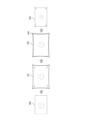
図3は、一般的な樽型歪曲収差の補正処理について説明するための図である。図3の画像300は樽型歪曲収差補正前の画像の一例を表している。なお、図3では、被写体として顔のみが写った例を挙げているため、レンズによる樽型歪曲収差の影響は見え難いが、例えば直線を含む被写体が写っている場合、歪曲収差補正前の画像では、その直線部分が歪んだ状態となって写っている。画像301は、画像300に対してレンズの特性に応じた樽型歪曲収差補正をかけた後の画像を表している。樽型歪曲収差は対角線方向が縮むような歪みが生ずる収差であるため、樽型歪曲収差の補正は、画像を対角線方向に伸ばすような補正となる。また、歪量は一般的に軸上からの距離(以降、像高と呼ぶ。)が長ければ長いほど大きくなる傾向があるので、樽型歪曲収差補正後の画像301は、特に対角線方向の四隅がつままれたような、つまり四隅方向を伸ばしたような画像になる。ただし、この収差補正後の画像301内に写っている被写体は、レンズの樽型歪曲収差による歪みが補正された状態となる。一方、出力する画像は最終的には正方形や長方形等の矩形画像にする必要があるため、歪曲収差補正後の画像301に対しては、可能な限り広い画角の画像302にするような処理(以降、この処理を最大画角演算処理と呼ぶ。)が施される。そして、一般的な撮像装置の出力画素数は予め決められた一定値になることが期待されているため、最大画角演算処理後の画像からは矩形画像304が切り出され、さらに撮像装置の出力画素数(例えば画像300と同じ画素数)に合わせる処理がなされる。すなわち、最終的に出力される画像303は、樽型歪曲収差補正で四隅方向に伸ばされ更に最大画角演算処理が施された画像から切り出した矩形画像304を、元の画像300と同じサイズまで縮小するようになされた画像となる。このような一連の処理が行われることにより、画角の欠損を最小限に抑えた樽型歪曲収差補正後の画像が生成される。 FIG. 3 is a diagram for explaining general barrel distortion correction processing. An image 300 in FIG. 3 represents an example of an image before barrel distortion correction. Note that FIG. 3 shows an example in which only a face is captured as a subject, so the effects of barrel distortion caused by the lens are difficult to see. In the image, the straight line portion is distorted. An image 301 represents an image after applying barrel distortion correction according to lens characteristics to the image 300 . Since the barrel distortion is an aberration that causes distortion that shrinks in the diagonal direction, correction of the barrel distortion is a correction that stretches the image in the diagonal direction. Further, the amount of distortion generally tends to increase as the distance from the on-axis (hereinafter referred to as image height) increases. The image looks as if it were pinched, that is, as if the four corners were stretched. However, the subject captured in the image 301 after the aberration correction is in a state in which the distortion due to the barrel distortion of the lens has been corrected. On the other hand, since the image to be output must ultimately be a rectangular image such as a square or a rectangle, the image 301 after distortion aberration correction is processed to be an image 302 with the widest possible angle of view. (This processing is hereinafter referred to as maximum angle of view calculation processing.) is performed. Since the number of output pixels of a general imaging apparatus is expected to be a predetermined constant value, a rectangular image 304 is cut out from the image after the maximum angle of view calculation processing, and the output of the imaging apparatus is Processing is performed to match the number of pixels (for example, the same number of pixels as the image 300). That is, the image 303 to be finally output is a rectangular image 304 cut out from the image which has been stretched in the four corner directions by barrel distortion aberration correction and further subjected to the maximum angle of view arithmetic processing, and is reduced to the same size as the original image 300. It becomes an image that has been reduced. By performing such a series of processes, an image after barrel distortion correction is generated in which loss of the angle of view is minimized.
次に図4を用いて、一般的な糸巻型の歪曲収差の補正処理について説明する。図4の画像400は糸巻型歪曲収差補正前の画像の一例を表している。なお図4においても図3の例と同様に、被写体として顔のみが写っているため、レンズによる糸巻型歪曲収差の影響は見え難いが、直線を含む被写体の場合、歪曲収差補正前の画像では、その直線部分が歪んだ状態となって写っている。画像401は、画像400に対してレンズの特性に応じた糸巻型歪曲収差補正をかけた後の画像を表している。糸巻型歪曲収差は対角線方向が伸びるような歪みが生ずる収差であるため、糸巻型歪曲収差の補正は、画像を対角線方向に縮めるような補正となる。また糸巻型歪曲収差の場合も、歪量は像高が高くなるほど大きくなる傾向があるので、糸巻型歪曲収差補正後の画像401は、特に対角線方向の四隅が縮められたような画像になる。ただし、収差補正後の画像401内に写っている被写体は、糸巻型歪曲収差による歪みが補正された状態となる。また糸巻型収差補正が行われた場合も前述同様に、出力する画像は最終的には長方形等の矩形画像にする必要があるため、収差補正後の画像401には可能な限り広い画角の画像402にするような最大画角演算処理が施される。そして、最大画角演算処理後の画像からは矩形画像404が切り出され、さらに撮像装置の出力画素数(画像400と同サイズ)に合わせる処理がなされる。すなわち最終的に出力される画像403は、糸巻型歪曲収差補正で四隅方向に縮められ更に最大画角演算処理が施された画像から切り出した矩形画像404を、元の画像400と同じサイズまで拡大するようになされた画像となる。このような一連の処理が行われることにより、画角の欠損を最小限に抑えた糸巻型歪曲収差補正後の画像が生成される。
Next, general pincushion distortion correction processing will be described with reference to FIG. An
以上、一般的な歪曲収差補正の手法を述べたが、例えば動画像が撮影されている場合において、その動画像に歪曲収差補正を行うと、歪曲収差の補正量に応じて、画面中央に映っている被写体の大きさが変化してしまうことがある。前述した図3と図4で説明した歪曲収差補正方法では、最大画角演算処理後の画像から矩形画像を切り出して最終的な出力画像を生成する処理の際に、歪曲収差の補正量に応じて矩形画像を拡大(図3の場合)または縮小(図4の場合)する処理が行われる。このため、動画像の撮影中に、例えばピント位置を動かすと、その動かしたピント位置に応じて歪曲収差量が変化し、その補正のための補正量が変動する。つまり、動画撮影中にピント位置を動かすだけで、最終的な出力画像を得る際の拡大率または縮小率が変化することになり、その結果、画面の中心に映っている被写体の大きさが変わってしまうような低品質の動画になる虞がある。 A general method of correcting distortion aberration has been described above. The size of the subject being photographed may change. In the distortion aberration correction method described above with reference to FIGS. 3 and 4, when the final output image is generated by cutting out a rectangular image from the image after the maximum angle of view calculation process, The rectangular image is enlarged (in the case of FIG. 3) or reduced (in the case of FIG. 4). Therefore, if the focus position is moved during shooting of a moving image, the amount of distortion changes according to the moved focus position, and the correction amount for correcting the distortion changes. In other words, just by moving the focus position during video recording, the magnification or reduction ratio used to obtain the final output image will change, and as a result, the size of the subject in the center of the screen will change. There is a risk that the video will be of such low quality that it will be lost.
このようなことに対処するための一例として、前述した最大画角演算処理を行わないようにする方法が考えられる。この方法について図5を用いて説明する。図5では、樽型歪曲収差補正処理が行われる場合の例である。図5の画像500は図3の画像300と同様の樽型歪曲補正前の画像例であり、画像501は図3の画像301と同様の樽型歪曲収差補正後の画像例である。この例の場合には、樽型歪曲収差補正後の画像501に対し、前述した最大画角演算処理を行わずに、元の画像500と同サイズの矩形画像504が切り出され、その切り出した矩形画像504が最終的に出力される画像503となされる。つまり、出力される画像503は、矩形画像504に対して前述のような縮小するリサイズ処理が行われない画像となされる。この処理によれば、画像の中心に映っている被写体のサイズを変えることなく出力させることが可能となる。したがって、例えば動画像の撮影時にピント位置を変動させて、歪曲収差量が変化しても、被写体中央部の像の倍率が変化することを防ぎつつ、歪曲収差補正を行うことが可能となる。 As an example of coping with such a situation, a method of not performing the above-described maximum angle of view calculation process is conceivable. This method will be described with reference to FIG. FIG. 5 shows an example in which barrel distortion aberration correction processing is performed. An image 500 in FIG. 5 is an example of an image before barrel distortion correction similar to the image 300 in FIG. 3, and an image 501 is an example of an image after barrel distortion correction like the image 301 in FIG. In the case of this example, a rectangular image 504 having the same size as the original image 500 is cut out from the image 501 after correction of the barrel distortion aberration without performing the above-described maximum angle of view calculation processing, and the cut out rectangular image 504 is cut out. The image 504 becomes the image 503 that is finally output. In other words, the output image 503 is an image in which the rectangular image 504 is not subjected to the above-described resizing process. According to this processing, it is possible to output the image without changing the size of the subject appearing in the center of the image. Therefore, for example, even if the amount of distortion is changed by changing the focus position when photographing a moving image, it is possible to correct the distortion while preventing the magnification of the image at the center of the subject from changing.
ところが、この方法では、糸巻型歪曲収差に対する補正が行われる場合に以下のような問題が生ずることがある。これについて図6を用いて説明する。図6の画像600は図4の画像400と同様の糸巻型歪曲補正前の画像例であり、画像601は図4の画像401と同様の糸巻型歪曲収差補正後の画像例である。ここで、糸巻型歪曲収差補正後の画像401に対し、前述した最大画角演算処理を行わずに、元の画像400と同サイズの矩形画像を切り出すとする。しかしながら、糸巻型歪曲収差補正では、前述したように対角線の四隅方向を縮める処理が行われるため、元の画像400と同サイズとして切り出される矩形画像603は、四隅に画像が存在しないブランク領域605が生じた画像となる。このため、糸巻型歪曲収差補正を行う場合には、前述した最大画角演算処理を実施せざるを得ず、これにより例えば動画撮影時にピント位置が変動すると、ピント位置の歪曲特性に応じて像の中心の倍率が変動した低品質の動画になるという問題が残る。
However, in this method, the following problems may occur when pincushion distortion is corrected. This will be described with reference to FIG. An
そこで、本実施形態の撮像装置100では、図2に示すフローチャートの歪曲収差補正値算出処理を行うことにより、焦点位置が変化した時(ピント変動時)に画角変化を抑制した歪曲収差補正を実現可能としている。図2に示すフローチャートの処理は、撮像装置100のシステム制御部130により実行される。なおこのフローチャートの処理は、ハードウェア構成により実行されてもよいし、CPU等が実行するプログラムに基づくソフトウェア構成により実現されてもよく、一部がハードウェア構成で残りがソフトウェア構成により実現されてもよい。CPU等が実行するプログラムは、例えば記録部108の不揮発性メモリ等に格納されていてもよいし、外部メモリから取得されてもよく、或いは不図示のネットワーク等を介して取得されてもよい。以下の説明では、各処理のステップS201~ステップS208をS201~S208と略記する。これらのことは後述する他のフローチャートにおいても同様とする。
Therefore, in the
S201において、システム制御部130のレンズ通信制御部133は、レンズマウント部180に装着されたレンズの歪曲収差補正における特徴情報のフラグを、レンズ装置150からI/F170を介して取得する。ここでいうフラグとは、装着されたレンズ装置150が、動画における歪曲収差補正に対応したレンズであるかどうか判定するための情報である。歪曲収差補正は画角変換が行われる補正であるため、動画のように時間軸で変化する画像に対しては連続した各フレームの画像が滑らかにつながる補正を行う必要がある。一方、レンズ装置150によっては、フォーカス制御値やズーム制御値を十分細かい精度で所持していないものもある。そのようなレンズ装置の場合、撮影されている動画のフレームに対し歪曲収差補正を実施すると、前述したようにズーム制御値やフォーカス制御値の切り替わり時に補正量が急激に変化して動画像が急激に画角変化を起こし、動画の品質が低下してしまう。このため、動画撮影時にも歪曲収差補正が可能なほど十分な精度のズーム・フォーカス制御値を有しているレンズ装置150のみ、当該フラグを立てておく必要がある。このフラグは、予めレンズ装置150のメモリ162に記録しておくことや後述する歪曲収差補正データの中に記録しておくことが望ましい。
In S<b>201 , the lens
次にS202において、システム制御部130の収差補正制御部132は、現在の撮影モードが動画モードか静止画モードかを判定する。静止画の場合、時間軸での微小な画角変化はユーザーにとってさほど気にならないので、収差補正制御部132は、静止画モードであると判定した場合にはS203に処理を進めて図3で説明したような最大画角演算を実施する。ただし、静止画モードであっても、連続撮影により取得される静止画の場合には画角変動を抑える方が望ましいこともあるため、静止画の連続撮影時において画角変動を抑えたい場合には動画モードと判定してもよい。一方、S202において動画モードであると判定した場合、収差補正制御部132は、S204に処理を進める。
Next, in S202, the aberration
S204に進むと、収差補正制御部132は、装着されたレンズ装置150が動画歪曲収差補正に対応可能なレンズか否かを判定する。S204における判定は、S201において取得したフラグの情報を基に行われる。ここで、動画の歪曲収差補正に対応してないレンズ装置150を用いて撮影された動画に対して歪曲収差補正を適用してしまうと、前述したように動画の品質が保証できなくなる虞があるため、そのことをユーザーに通知する必要がある。このため、収差補正制御部132は、レンズ装置150が動画歪曲収差補正に対応していないと判定した場合には、S205に処理を進め、例えば画像表示部106への警告表示によりユーザーに対して動画の品質が保証できなくなる虞があることを通知する。なお、ユーザーへの通知の方法としては、例えば、画像表示部106に歪曲収差補正が適用されてないことを示すアイコンを表示することや、図15に示すように、歪曲収差補正のメニューを選択できないようにするなどが挙げられる。図15は、画像表示部106に画面表示される歪曲収差補正メニューの一例であり、通常は歪曲収差補正を「する(ON)」と「しない(OFF)」のメニュー項目選択が可能であるが、それらニュー項目の選択ができないようにする。そして、収差補正制御部132は、次のS206において、強制的に歪曲収差補正のパラメータを無効化して設定する。
Proceeding to S204, the aberration
また、動画歪曲収差補正に対応可能なレンズであっても、前述したように最大画角演算処理を行うと、ピント変動時のフォーカス位置に応じて画角変化が発生してしまうため、最大画角演算を実施せずに歪曲収差補正値を算出する必要がある。このため、S204でレンズ装置150が動画歪曲収差補正に対応可能なレンズであると判定した場合、収差補正制御部132は、S207において、最大画角演算処理を実施せずに歪曲収差補正値を算出する。ただし、最大画角演算処理を実施しない場合、前述したように、糸巻型の歪曲収差に対する補正が行われると、画素数が元のサイズよりも小さいくなり周辺部分にブランク領域が生じてしまう。
Also, even if the lens is capable of correcting video distortion aberration, if the maximum angle of view calculation process is performed as described above, the angle of view will change according to the focus position when the focus changes. It is necessary to calculate the distortion aberration correction value without performing the angular calculation. Therefore, when it is determined in S204 that the
このため、収差補正制御部132は、レンズ装置150が糸巻型の歪曲収差が発生するレンズである場合には、S208において、画像処理部140に対して拡大処理を行うように指示し、周辺部分にブランク領域が生じないように制御する。すなわち、画像処理部140において拡大処理を行うことで、画像が存在しないブランク領域が前述した矩形画像の外側に移動することになるため、元の画像と同じサイズでかつ、周辺部分にも画像が存在している矩形画像を取得することができるようになる。なお、画像処理部140で拡大処理を行う際の拡大率は、一律の拡大率として設定されていてもよいし、レンズ装置150のメモリ162に予め保持されていてもよい。
For this reason, if the
ただし、焦点距離などの条件によっては糸巻型の歪曲収差が殆ど生じない場合もあり、一律の拡大率を設定すると、糸巻型の歪曲収差が殆ど生じない場合にも一律に拡大処理を行うことになって画像品質が低下してしまうこともある。このため、例えば図7(a)、図7(b)のデータや図8のフローチャートを用いて、焦点距離ごとに拡大率を変更することにより、拡大処理による品質低下を最小限に抑えるようにする。 However, depending on the focal length and other conditions, pincushion distortion may not occur at all, so if a uniform magnification ratio is set, even if pincushion distortion does not occur, the enlargement process will be performed uniformly. As a result, the image quality may deteriorate. For this reason, for example, using the data in FIGS. 7A and 7B and the flow chart in FIG. 8, the enlargement ratio is changed for each focal length so as to minimize the deterioration in quality due to enlargement processing. do.
図7(a)は、焦点距離ごとの拡大率を事前に保持するためのデータフォーマット例を示した図である。図7(a)において、メモリ領域701は歪曲収差補正データそのものが格納される領域である。メモリ領域701の歪曲収差補正データは、動画と静止画で共通に使用されるため、レンズ装置150の光学特性情報を変換せずにそのまま格納しておく。メモリ領域702は、S208で取得する拡大率の情報がテーブルとして格納される領域である。
FIG. 7(a) is a diagram showing an example of a data format for pre-holding magnification ratios for respective focal lengths. In FIG. 7A, a
図7(b)は、メモリ領域702に格納されるテーブルの一例であり、レンズ装置150が取り得る各焦点距離と、焦点距離ごとに対応した拡大率の値との対応関係を示している。図7(b)のテーブルには、焦点距離Z01~Z07に応じた糸巻型歪曲収差補正時に必要な拡大率の値が記録されている。この図7(b)の例の場合、焦点距離Z01~Z03において、拡大率は1倍に設定されている。つまりこのことは、焦点距離Z01~Z03の領域は糸巻型の歪曲収差が殆どないため、拡大する必要がないことを示している。一方、焦点距離Z04~Z07では、拡大率が徐々に大きくなるように設定されている。つまりこのことは、焦点距離Z04~Z07の領域は糸巻型の収差量が徐々に大きくなっていることを示している。なお図7(b)のように、焦点距離に応じて拡大率は可変になるが、一般的に焦点距離変動による画角の変動に比べて、拡大率の変化は微小なものになって焦点距離変動による画角の変動に埋もれるため、焦点距離変更時に拡大率が変わっても問題ない。図7(b)のテーブルデータは、レンズ装置150のメモリ162に記録しておくことが望ましい。また、テーブルデータは、必要に応じて撮像装置100のメモリ107に転送して使用されてもよい。
FIG. 7B is an example of a table stored in the
図8は、図7(b)のテーブルを用いて、撮像装置100の収差補正制御部132が実際の拡大率を算出する処理のフローチャートである。
S801において、収差補正制御部132は、レンズ装置150から送られてくる現在の焦点距離の情報を、レンズ通信制御部133を経由して取得する。
次にS802において、収差補正制御部132は、図7(a)と図7(b)で説明したメモリ領域702のテーブルを用いて、S801で取得した焦点距離に応じた拡大率を参照する。なお、拡大率のデータがレンズ装置150の取り得る全焦点距離分だけ用意されておらず、間引かれた焦点距離ごとのデータとして記録されているような場合、収差補正制御部132は、必要な焦点距離に応じた拡大率を例えば線形補間により算出する。
FIG. 8 is a flow chart of processing for calculating the actual enlargement ratio by the aberration
In S<b>801 , the aberration
Next, in S802, the aberration
そして、収差補正制御部132は、前述のようして取得した拡大率と、図7(a)のメモリ領域701の歪曲収差補正データとに基づく歪曲収差補正および拡大処理を行うように、画像処理部140を制御する。
これにより、本実施形態の撮像装置100によれば、動画時においてピント変動による画角変化を最小限に抑えた歪曲収差補正が可能となる。
Then, the aberration
As a result, according to the
<第2の実施形態>
第2の実施形態の構成は前述した図1と同様であるため、その図示は省略する。第2の実施形態は、図7(b)で説明した焦点距離と拡大率との対応テーブルに代えて、焦点距離と歪曲収差補正量のシフト量との対応テーブルを用いる例である。
<Second embodiment>
Since the configuration of the second embodiment is the same as that of FIG. 1 described above, its illustration is omitted. The second embodiment is an example of using a correspondence table between the focal length and the shift amount of the distortion aberration correction amount instead of the correspondence table between the focal length and the enlargement ratio described with reference to FIG. 7B.
ここで、第1の実施形態で説明した焦点距離に応じた拡大率を用いるようにした場合に生ずる可能性がある問題点について、図9~図11を参照しながら説明する。拡大率を用いる場合に生ずる問題点の一例として、動画モードごとに必要とされる拡大量の違いが挙げられる。具体的には、撮像装置100の動画モードによって、撮像素子102の読み出し領域が可変になる場合があり、その場合に問題が発生することがある。
Here, problems that may occur when the enlargement factor corresponding to the focal length described in the first embodiment is used will be described with reference to FIGS. 9 to 11. FIG. One example of a problem that arises when using an enlargement factor is the difference in the amount of enlargement required for each movie mode. Specifically, depending on the moving image mode of the
例えば図9の領域901は、撮像素子102の撮像可能領域を示している。静止画モードと動画モードの両方が存在する撮像装置の場合、基本的に、静止画モードに必要な領域が、撮像素子の領域901になるように設計されている。撮像装置において動画撮影を行う場合、静止画モードと同様の領域から読み出したデータから動画像を生成することが望ましいが、動画像を生成する際には少なくとも1秒間に30フレームの読み出しを行う必要があるため、処理能力的に難しいことが多い。このため、一般的に、撮像装置の動画モードでは、領域901に対して、例えば水平・垂直に間引き若しくは加算により画素数を減らして動画像を生成することにより、処理負荷を軽減している。ただし、間引きや加算が行われた動画像には、それら間引きや加算の量によってモアレや解像感低下など様々な画質低下が発生してしまうことがある。このため、撮像装置の動画モードには、撮像素子102から読み出す領域を、図9の領域902のように限定し、間引きや加算を行わずに動画像を生成するモード(クロップ読み出しモードと呼ぶ)が用意されている。クロップ読み出しモードによれば、撮像素子102から読み出す領域が限定されることで処理負荷を軽減できるとともに、間引きや加算が行われないためモアレや解像感低下などの画質低下の発生も抑えることができる。
For example, an
しかしながら、クロップ読み出しモードの場合、撮像素子102内における撮像領域が他のモードとは異なるため、例えば陣笠状の歪曲収差補正(陣型歪曲収差補正)で問題が発生する場合がある。その様子について、図10と図11を用いて説明する。
先ず図10を参照しながら、一般的な歪曲収差補正データについて説明する。図10は、像高と歪曲収差の補正値との関係を示すグラフ図である。図10において、縦軸の正の方向は、糸巻型歪曲収差の補正値を示しており、その数値が高いほど、歪み量の大きな糸巻型の歪曲収差を補正することを示している。一方、縦軸の負の方向は、樽型歪曲収差の補正値を示しており、その数値が低いほど、歪み量の大きな樽型歪曲収差を補正することを示している。すなわち、図10の歪曲収差補正では、補正値が正の数値であれば、画像を対角線方向に縮ませる補正が行われることを示し、補正値が負の数値であれば、画像を対角線方向に伸ばす補正が行われることを示している。
However, in the case of the crop readout mode, since the imaging area in the
First, general distortion aberration correction data will be described with reference to FIG. FIG. 10 is a graph showing the relationship between the image height and the distortion aberration correction value. In FIG. 10, the positive direction of the vertical axis indicates the correction value of the pincushion distortion, and the higher the numerical value, the more the pincushion distortion with a larger amount of distortion is corrected. On the other hand, the negative direction of the vertical axis indicates the correction value of barrel distortion, and the lower the numerical value, the more barrel distortion with a larger amount of distortion is corrected. That is, in the distortion aberration correction of FIG. 10, if the correction value is a positive numerical value, it indicates that the image is corrected to shrink in the diagonal direction. This indicates that stretching correction is performed.
次に図11を参照しながら、前述した第1の実施形態において問題になるような歪曲収差補正の形状について説明する。図11では、図10と同様に、縦軸の正の方向が糸巻型歪曲収差の補正値を示し、縦軸の負の方向が樽型歪曲収差の補正値を示している。図11に例示した補正値の場合、低像高では糸巻き型の歪曲収差に対する補正となり、高像高側では樽型の歪曲収差に対する補正となる、いわゆる陣型歪曲収差補正が行われることになる。また、図11において、像高aは図9の領域902の最大像高を示しており、像高bは図9の領域901(撮像可能領域)の最大像高を示している。
Next, referring to FIG. 11, the shape of distortion aberration correction, which is problematic in the first embodiment described above, will be described. In FIG. 11, similarly to FIG. 10, the positive direction of the vertical axis indicates the correction value of pincushion distortion, and the negative direction of the vertical axis indicates the correction value of barrel distortion. In the case of the correction values illustrated in FIG. 11, pincushion distortion is corrected at low image heights, and barrel distortion is corrected at high image heights, so-called field distortion correction. 11, the image height a indicates the maximum image height of the
ここで、前述した第1の実施形態では、糸巻型歪曲収差補正時の拡大率として、図9の領域901の歪曲収差補正を実施した場合の拡大率が、図7(a)のメモリ領域702に格納されることになる。このため、例えば図9の領域902を使用するクロップ読み出しモードで歪曲収差補正を実施した場合、領域901よりも必要な拡大量が大きくなるために、領域901に必要な拡大率が足りず、ブランク領域が生じた画像が出力されてしまう虞がある。一方で、図7(a)のメモリ領域701と702のデータがレンズ装置150のメモリ162に格納されている場合に、それらデータを、当該レンズ装置150が装着される各機種の撮像装置100の全ての動画モードを想定したデータにしておくことは難しい。このため、レンズ装置150のメモリ162に格納されたデータでは、撮像装置において歪曲収差補正後に品質の高い画像を生成できなくなる場合がある。
Here, in the above-described first embodiment, as the enlargement ratio for correcting the pincushion distortion, the enlargement ratio when the distortion aberration correction is performed in the
そこで、第2の実施形態の撮像装置100では、図12に示すフローチャートの歪曲収差補正値算出処理を行う。図12のフローチャートにおいて、S1201~S1207の処理は、図2のS201~S207の処理と同様であるためその説明は省略する。第2の実施形態において、前述の第1の実施形態との差異は、第1の実施形態の拡大率を算出する代わりに、歪曲収差の補正値のシフト量を算出することである。
Therefore, in the
ここで、歪曲収差補正値のシフト量について、図13(a)を参照しながら説明する。図13(a)は、図11で説明したように、第1の実施形態の場合において問題が発生する、陣型歪曲収差補正の特性を示したグラフである。この図11(a)に示した特性の中で、糸巻型の歪曲収差量が最大となる像高をxとし、その像高xに対応した補正値をDistMaxとする。第2の実施形態で説明するところの補正値のシフト量とは、この補正値DistMaxのことを示す。 Here, the shift amount of the distortion correction value will be described with reference to FIG. 13(a). FIG. 13(a) is a graph showing characteristics of field distortion correction, which causes a problem in the case of the first embodiment, as described with reference to FIG. Among the characteristics shown in FIG. 11A, let x be the image height at which the amount of pincushion distortion is maximum, and let DistMax be the correction value corresponding to the image height x. The correction value shift amount described in the second embodiment indicates this correction value DistMax.
図12のS1207において最大画角演算処理を実施せずに歪曲収差補正値を算出した後、収差補正制御部132は、S1208において、レンズ通信制御部133を経由して、レンズ装置150から歪曲収差の補正値のシフト量を取得する。
そして次のS1209において、収差補正制御部132は、歪曲収差の補正値を、S1208で求めたシフト量分だけシフトさせる。この様子を、図13(b)を参照しながら説明する。図13(b)に示すように、収差補正制御部132は、図13(a)に示したシフト量を、歪曲収差の補正値からシフトさせることにより、仮想的に糸巻型の歪曲収差に対する補正がない、つまり歪曲収差補正後に拡大が必要ないパラメータに変換する。図13(a)は、像高が0すなわち原点の被写体像を移動させない基準点とした場合の収差補正の特性を示しており、図13(b)は、像高xの位置にある被写体像を移動させない基準点とした場合の収差補正の特性を示している。
After calculating the distortion aberration correction value without performing the maximum angle of view calculation processing in S1207 of FIG. Get the shift amount of the correction value of .
Then, in next S1209, the aberration
次に、第2の実施形態における焦点距離ごとの補正値のシフト量のデータ保持方法について、図14(a)と図14(b)を参照しながら説明する。
図14(a)は、焦点距離ごとの補正値のシフト量を保持するためのデータフォーマット例を示した図である。図14(a)において、メモリ領域1401は歪曲収差補正データそのものが格納される領域である。図7(a)のメモリ領域702と同様、メモリ領域1401の歪曲収差補正データは、動画と静止画で共通に使用されるため、レンズ装置150の光学特性を変換せずにそのまま格納しておく。メモリ領域1402は、S1408で取得する補正値のシフト量の情報がテーブルとして格納される領域である。図7(a)の場合と同様に、補正値のシフト量に関しても、メモリ領域1401の歪曲収差補正データと紐付けて格納されていることが好ましい。
Next, a data holding method of the shift amount of the correction value for each focal length in the second embodiment will be described with reference to FIGS. 14(a) and 14(b).
FIG. 14A is a diagram showing a data format example for holding the shift amount of the correction value for each focal length. In FIG. 14A, a
図14(b)は、メモリ領域1402に格納されるテーブルの一例であり、レンズ装置150が取り得る各焦点距離と、焦点距離ごとに対応した補正値のシフト量との対応関係を示している。図14(b)のテーブルには、レンズ装置150において設定可能な各焦点距離Z01~Z07において、それぞれ至近から無限遠までピント位置を変化させた場合の最大の補正値のシフト量の値が記録されている。対象の焦点距離の歪曲収差特性が例えば樽型収差である場合、前述した問題は発生しないので、補正値をシフトさせる必要がないため、シフト量の値としては「0」が記録される。つまり、図14(b)の例の場合、焦点距離Z01~Z03では樽型の歪曲収差特性であることを示している。一方、焦点距離Z04~Z07では、補正値のシフト量が徐々に大きくなされている。つまり、焦点距離Z04~Z07の領域では、補正値をシフトさせるために、シフト量の値が徐々に大きな値となされている。
FIG. 14B is an example of a table stored in the
なお、第2の実施形態の場合も第1の実施形態で説明したのと同様に、テーブルデータはレンズ装置150のメモリ162に記録しておき、必要なタイミングでシフト量を読み出して撮像装置100に通知するようにしてもよい。また、レンズ装置150が撮像装置100に装着されたときに、撮像装置100側に送付されてもよい。
また第2の実施形態の場合、シフト量の値(パラメータ)が予め用意されている例を挙げたが、演算時間等に余裕があるのであれば、メモリ領域1401の歪曲収差補正データからその都度、シフト量を算出してもよい。
以上説明したように、第2の実施形態においても、例えば動画の歪曲収差補正において、撮像装置のどのようなモードに対しても、ピント変動時の画角変化を最小限に抑えた歪曲収差補正が可能となる。
In the case of the second embodiment, similarly to the first embodiment, the table data is recorded in the
Further, in the case of the second embodiment, an example in which the value (parameter) of the shift amount is prepared in advance was given. , the shift amount may be calculated.
As described above, in the second embodiment as well, for example, in distortion aberration correction of a moving image, distortion aberration correction that minimizes the change in the angle of view when the focus changes is applied to any mode of the imaging device. becomes possible.
<その他の実施形態>
また前述した実施形態では、撮像装置100の一例としてデジタルカメラ等を挙げたが、この例には限定されず他の撮像装置にも適用可能である。例えば、静止画と動画の撮影が可能なカメラ機能を備えたスマートフォンやタブレット端末などの各種携帯端末、各種の監視カメラ、工業用カメラ、車載カメラ、医療用カメラなどにも本実施形態は適用可能である。
<Other embodiments>
Further, in the above-described embodiment, a digital camera or the like was given as an example of the
本発明は、前述の実施形態の1以上の機能を実現するプログラムを、ネットワーク又は記憶媒体を介してシステム又は装置に供給し、そのシステム又は装置のコンピュータにおける1つ以上のプロセッサーがプログラムを読出し実行する処理でも実現可能である。また、1以上の機能を実現する回路(例えば、ASIC)によっても実現可能である。 The present invention supplies a program that implements one or more functions of the above-described embodiments to a system or device via a network or a storage medium, and one or more processors in the computer of the system or device reads and executes the program. It can also be realized by processing to It can also be implemented by a circuit (for example, ASIC) that implements one or more functions.
前述の実施形態は、何れも本発明を実施するにあたっての具体化の例を示したものに過ぎず、これらによって本発明の技術的範囲が限定的に解釈されてはならないものである。即ち、本発明は、その技術思想、又はその主要な特徴から逸脱することなく、様々な形で実施することができる。 All of the above-described embodiments merely show specific examples for carrying out the present invention, and the technical scope of the present invention should not be construed to be limited by these. That is, the present invention can be embodied in various forms without departing from its technical spirit or main features.
100:撮像装置、102:撮像素子、103:画像生成部、104:タイミング発生部、105:メモリ制御部、107:メモリ、108:記録部、130:システム制御部、132:収差補正制御部、133:レンズ通信制御部、140:画像処理部、150:レンズ装置、155:フォーカス制御部、156:ズーム制御部、160:レンズ制御部、162:メモリ 100: imaging device, 102: imaging device, 103: image generation unit, 104: timing generation unit, 105: memory control unit, 107: memory, 108: recording unit, 130: system control unit, 132: aberration correction control unit, 133: lens communication control section, 140: image processing section, 150: lens device, 155: focus control section, 156: zoom control section, 160: lens control section, 162: memory
Claims (25)
前記第1の情報と前記第2の情報とを用いて、前記歪曲収差を補正した画像を生成する処理手段と、
を有し、
前記第1の情報は、前記レンズの焦点距離およびピント位置の組合せ別に用意された情報であり、
前記第2の情報は、前記レンズのピント位置に対応せずに、前記レンズの焦点距離別に用意された情報であることを特徴とする画像処理装置。 First information about a correction value for correcting distortion aberration of a captured image obtained by capturing an optical image formed by a lens; acquisition means for acquiring the information of 2;
a processing means for generating an image in which the distortion is corrected using the first information and the second information;
has
The first information is information prepared for each combination of the focal length and focus position of the lens,
The image processing apparatus, wherein the second information is information prepared for each focal length of the lens without corresponding to the focal position of the lens.
前記第2の情報のうち、前記歪曲収差を補正する対象となる画像を撮像したときの前記レンズの焦点距離に対応する情報を選択することを特徴とする請求項1または2に記載の画像処理装置。 selecting from among the first information information corresponding to a combination of the focal length and the focus position of the lens when the image to be corrected for the distortion is captured;
3. The image processing according to claim 1, wherein from among the second information, information corresponding to the focal length of the lens when the image to be corrected for the distortion aberration is captured is selected. Device.
前記第1の情報と前記第2の情報とを用いて、前記歪曲収差を補正した画像を生成する処理手段と、
を有し、
前記第1の情報と前記第2の情報は、前記レンズの焦点距離およびピント位置の組合せ別に用意されており、
前記第1の情報のうち、前記歪曲収差を補正する対象となる画像を撮像したときの前記レンズの焦点距離およびピント位置の組合せに対応する情報を選択し、
前記第2の情報のうち、前記歪曲収差を補正する対象となる画像を撮像したときの前記レンズの焦点距離に対応する情報を選択することを特徴とする画像処理装置。 First information about a correction value for correcting distortion aberration of a captured image obtained by capturing an optical image formed by a lens; Acquisition means for acquiring the information of 2;
a processing means for generating an image in which the distortion is corrected using the first information and the second information;
has
The first information and the second information are prepared for each combination of focal length and focus position of the lens,
selecting from among the first information information corresponding to a combination of the focal length and the focus position of the lens when the image to be corrected for the distortion is captured;
An image processing apparatus, wherein, from among the second information, information corresponding to the focal length of the lens when the image for which the distortion aberration is to be corrected is captured is selected.
前記第1の情報を用いて前記撮像画像の歪曲収差を補正し、
前記歪曲収差が補正された画像を前記第2の情報に基づいて拡大処理することを特徴とする請求項1乃至5のいずれか1項に記載の画像処理装置。 The processing means
correcting distortion aberration of the captured image using the first information;
6. The image processing apparatus according to claim 1, wherein the distortion-corrected image is enlarged based on the second information.
前記歪曲収差が樽型の歪曲収差の場合には、前記歪曲収差が補正された画像を拡大処理せず、
前記歪曲収差が糸巻型の歪曲収差の場合には、前記歪曲収差が補正された画像を拡大処理することを特徴とする請求項6に記載の画像処理装置。 The processing means
when the distortion is barrel-shaped distortion, the distortion-corrected image is not enlarged;
7. The image processing apparatus according to claim 6, wherein when the distortion is pincushion distortion, the distortion-corrected image is enlarged.
前記レンズの焦点距離が第1の焦点距離の場合には、前記歪曲収差が補正された画像を拡大処理せず、
前記レンズの焦点距離が前記第1の焦点距離よりも遠く、所定距離以上の第2の焦点距離の場合には、前記歪曲収差が補正された画像を拡大処理することを特徴とする請求項6に記載の画像処理装置。 The processing means
when the focal length of the lens is the first focal length, the distortion-corrected image is not enlarged;
6. When the focal length of said lens is longer than said first focal length and is a second focal length equal to or greater than a predetermined distance, said distortion-corrected image is subjected to enlargement processing. The image processing device according to .
前記処理手段は、前記第1の情報が示す歪曲収差の補正値を、前記第2の情報が示すシフト量だけ変化させて新たな歪曲収差の補正値を求め、前記新たな歪曲収差の補正値を用いて、前記歪曲収差を補正した画像を生成することを特徴とする請求項1乃至5のいずれか1項に記載の画像処理装置。 the first information is a distortion aberration correction value, the second information is information indicating a shift amount of the distortion aberration correction value,
The processing means obtains a new distortion aberration correction value by changing the distortion aberration correction value indicated by the first information by the shift amount indicated by the second information, and calculates the new distortion aberration correction value. 6. The image processing apparatus according to claim 1, wherein the distortion-corrected image is generated by using
前記歪曲収差が糸巻型の歪曲収差を含まない場合には、前記第1の情報が示す歪曲収差の補正値を変化させず、
前記歪曲収差が糸巻型の歪曲収差を含む場合には、前記第1の情報が示す歪曲収差の補正値を前記第2の情報が示すシフト量だけ変化させることを特徴とする請求項9に記載の画像処理装置。 The processing means
when the distortion does not include pincushion distortion, without changing the distortion correction value indicated by the first information;
10. The method according to claim 9, wherein when the distortion includes pincushion distortion, the distortion correction value indicated by the first information is changed by the shift amount indicated by the second information. image processing device.
前記レンズの焦点距離が第1の焦点距離の場合には、前記第1の情報が示す歪曲収差の補正値を変化させず、
前記レンズの焦点距離が前記第1の焦点距離よりも遠く、所定距離以上の第2の焦点距離の場合には、前記第1の情報が示す歪曲収差の補正値を前記第2の情報が示すシフト量だけ変化させることを特徴とする請求項9に記載の画像処理装置。 The processing means
when the focal length of the lens is the first focal length, without changing the distortion correction value indicated by the first information;
When the focal length of the lens is longer than the first focal length and is a second focal length equal to or greater than a predetermined distance, the second information indicates a correction value for distortion aberration indicated by the first information. 10. The image processing apparatus according to claim 9, wherein only the shift amount is changed.
請求項1乃至14のいずれか1項に記載の画像処理装置と、
を有することを特徴とする撮像装置。 imaging means for imaging an optical image formed via the lens device;
An image processing device according to any one of claims 1 to 14 ;
An imaging device characterized by comprising:
前記レンズ装置に起因する歪曲収差を補正するための補正値に関する第1の情報と、前記歪曲収差を補正したことによる画角変動を補正するための第2の情報とを記憶した記憶手段と、
前記第1の情報と前記第2の情報とを、前記撮像装置に通信する通信手段と、
を有し、
前記第1の情報は、レンズの焦点距離およびピント位置の組合せ別に用意された情報であり、
前記第2の情報は、レンズのピント位置に対応せずに、焦点距離別に用意された情報であることを特徴とするレンズ装置。 A lens device detachable from an imaging device,
storage means for storing first information about a correction value for correcting distortion caused by the lens device and second information for correcting a change in angle of view caused by correcting the distortion;
communication means for communicating the first information and the second information to the imaging device;
has
The first information is information prepared for each combination of focal length and focus position of the lens,
The lens device, wherein the second information is information prepared for each focal length without corresponding to the focal position of the lens.
前記第2の情報は、画像の拡大率であることを特徴とする請求項16または17に記載のレンズ装置。 the first information is a correction value for correcting the distortion;
18. The lens device according to claim 16 , wherein said second information is an image magnification.
前記レンズ装置の焦点距離が前記第1の焦点距離よりも遠く、所定距離以上の第2の焦点距離の場合には、前記第2の情報が示す拡大率は1倍よりも大きな倍率であることを特徴とする請求項18に記載のレンズ装置。 when the focal length of the lens device is the first focal length, the magnification of the image indicated by the second information is 1;
When the focal length of the lens device is longer than the first focal length and is a second focal length equal to or greater than a predetermined distance, the magnification indicated by the second information is greater than 1. 19. The lens device according to claim 18 , characterized by:
前記第2の情報は、前記補正値のシフト量であることを特徴とする請求項16または17に記載のレンズ装置。 the first information is a correction value for correcting the distortion;
18. The lens device according to claim 16 , wherein said second information is a shift amount of said correction value.
前記レンズ装置の焦点距離が前記第1の焦点距離よりも遠く、所定距離以上の第2の焦点距離の場合には、前記第2の情報が示す前記シフト量は0を除く値であることを特徴とする請求項20に記載のレンズ装置。 when the focal length of the lens device is the first focal length, the shift amount indicated by the second information is 0;
When the focal length of the lens device is longer than the first focal length and is a second focal length equal to or greater than a predetermined distance, the shift amount indicated by the second information is a value other than zero. 21. A lens device according to claim 20 .
前記第2の焦点距離は、前記レンズ装置に起因する歪曲収差が糸巻型の歪曲収差を含む焦点距離であることを特徴とする請求項21に記載のレンズ装置。 The first focal length is a focal length in which the distortion caused by the lens device does not include pincushion distortion,
22. The lens device according to claim 21 , wherein the second focal length is a focal length in which distortion caused by the lens device includes pincushion distortion.
レンズにより形成された光学像を撮像して得られた撮像画像の歪曲収差を補正するための補正値に関する第1の情報と、前記歪曲収差を補正したことによる画角変動を補正するための第2の情報とを取得する取得工程と、
前記第1の情報と前記第2の情報とを用いて、前記歪曲収差を補正した画像を生成する処理工程と、
を有し、
前記第1の情報は、前記レンズの焦点距離およびピント位置の組合せ別に用意された情報であり、
前記第2の情報は、前記レンズのピント位置に対応せずに、前記レンズの焦点距離別に用意された情報であることを特徴とする画像処理方法。 An image processing method executed by an image processing device,
First information about a correction value for correcting distortion aberration of a captured image obtained by capturing an optical image formed by a lens; an acquisition step of acquiring the information of 2;
a processing step of generating an image with the distortion corrected using the first information and the second information;
has
The first information is information prepared for each combination of the focal length and focus position of the lens,
The image processing method, wherein the second information is information prepared for each focal length of the lens without corresponding to the focal position of the lens.
Priority Applications (5)
| Application Number | Priority Date | Filing Date | Title |
|---|---|---|---|
| JP2018112753A JP7297412B2 (en) | 2018-06-13 | 2018-06-13 | Image processing device, image processing method, and lens device |
| DE102019113802.7A DE102019113802A1 (en) | 2018-06-13 | 2019-05-23 | Image processing device, image processing method, image recording device and lens device |
| KR1020190063550A KR102531256B1 (en) | 2018-06-13 | 2019-05-30 | Image processing apparatus, image processing method, image capturing apparatus, and lens apparatus |
| US16/435,351 US11415773B2 (en) | 2018-06-13 | 2019-06-07 | Apparatus and lens apparatus |
| CN201910509333.XA CN110602350B (en) | 2018-06-13 | 2019-06-13 | Image processing apparatus, image processing method, image capturing apparatus, lens apparatus, and storage medium |
Applications Claiming Priority (1)
| Application Number | Priority Date | Filing Date | Title |
|---|---|---|---|
| JP2018112753A JP7297412B2 (en) | 2018-06-13 | 2018-06-13 | Image processing device, image processing method, and lens device |
Publications (3)
| Publication Number | Publication Date |
|---|---|
| JP2019216365A JP2019216365A (en) | 2019-12-19 |
| JP2019216365A5 JP2019216365A5 (en) | 2021-07-29 |
| JP7297412B2 true JP7297412B2 (en) | 2023-06-26 |
Family
ID=68724874
Family Applications (1)
| Application Number | Title | Priority Date | Filing Date |
|---|---|---|---|
| JP2018112753A Active JP7297412B2 (en) | 2018-06-13 | 2018-06-13 | Image processing device, image processing method, and lens device |
Country Status (5)
| Country | Link |
|---|---|
| US (1) | US11415773B2 (en) |
| JP (1) | JP7297412B2 (en) |
| KR (1) | KR102531256B1 (en) |
| CN (1) | CN110602350B (en) |
| DE (1) | DE102019113802A1 (en) |
Families Citing this family (4)
| Publication number | Priority date | Publication date | Assignee | Title |
|---|---|---|---|---|
| EP3564917B1 (en) * | 2018-05-04 | 2020-07-01 | Axis AB | A method for detecting motion in a video sequence |
| JP7297412B2 (en) * | 2018-06-13 | 2023-06-26 | キヤノン株式会社 | Image processing device, image processing method, and lens device |
| EP3879811B1 (en) * | 2020-03-09 | 2021-12-15 | Axis AB | Determining whether a camera is out-of-focus |
| WO2021195946A1 (en) * | 2020-03-31 | 2021-10-07 | Guangdong Oppo Mobile Telecommunications Corp., Ltd. | Imaging device, electrical device, method of manufacturing imaging device, and method of manufacturing electrical device |
Citations (3)
| Publication number | Priority date | Publication date | Assignee | Title |
|---|---|---|---|---|
| JP2009043060A (en) | 2007-08-09 | 2009-02-26 | Canon Inc | Image processing method for performing distortion correction to image data, program, and recording medium |
| JP2009290863A (en) | 2008-04-28 | 2009-12-10 | Panasonic Corp | Imaging apparatus, and camera body |
| JP2017098631A (en) | 2015-11-18 | 2017-06-01 | オリンパス株式会社 | Image combination processing device |
Family Cites Families (31)
| Publication number | Priority date | Publication date | Assignee | Title |
|---|---|---|---|---|
| US20030141433A1 (en) * | 2002-01-31 | 2003-07-31 | Gordon Gary B. | Solid state image sensor array for correcting curvilinear distortion of a camera lens system and method for fabricating the image sensor array |
| JP2004187111A (en) | 2002-12-05 | 2004-07-02 | Nec Viewtechnology Ltd | Document presentation device |
| US9177368B2 (en) * | 2007-12-17 | 2015-11-03 | Nvidia Corporation | Image distortion correction |
| US20100141852A1 (en) * | 2008-12-05 | 2010-06-10 | Robe Lighting S.R.O. | Distortion Corrected Improved Beam Angle Range, Higher Output Digital Luminaire System |
| JP5523017B2 (en) * | 2009-08-20 | 2014-06-18 | キヤノン株式会社 | Image processing apparatus and image processing method |
| JP5656579B2 (en) * | 2009-11-30 | 2015-01-21 | キヤノン株式会社 | Image pickup apparatus capable of correcting deterioration of image quality caused by optical member, control method for image pickup apparatus, and program |
| US11403739B2 (en) * | 2010-04-12 | 2022-08-02 | Adobe Inc. | Methods and apparatus for retargeting and prioritized interpolation of lens profiles |
| US10800329B2 (en) * | 2010-04-19 | 2020-10-13 | SMR Patents S.à.r.l. | Rear view mirror simulation |
| US8818101B1 (en) * | 2012-01-03 | 2014-08-26 | Google Inc. | Apparatus and method for feature matching in distorted images |
| JP6047008B2 (en) | 2012-12-25 | 2016-12-21 | キヤノン株式会社 | Image processing apparatus, imaging apparatus including the same, and control method of image processing apparatus |
| JP6253280B2 (en) * | 2013-07-04 | 2017-12-27 | キヤノン株式会社 | Imaging apparatus and control method thereof |
| JP6472176B2 (en) | 2014-06-10 | 2019-02-20 | キヤノン株式会社 | Imaging apparatus, image shake correction apparatus, image pickup apparatus control method, and image shake correction method |
| JP5982651B2 (en) | 2014-07-16 | 2016-08-31 | パナソニックIpマネジメント株式会社 | Drum washing machine |
| JP2016025640A (en) | 2014-07-24 | 2016-02-08 | エイオーエフ イメージング テクノロジー リミテッド | Information processor, information processing method and program |
| JP6582644B2 (en) * | 2014-08-11 | 2019-10-02 | セイコーエプソン株式会社 | Imaging device, imaging display device, and vehicle |
| JP6516434B2 (en) * | 2014-10-15 | 2019-05-22 | キヤノン株式会社 | Image processing apparatus, imaging apparatus, image processing method |
| CN104732542B (en) * | 2015-03-27 | 2018-07-13 | 巢湖学院 | The image processing method of panorama Vehicle security system based on multi-cam self-calibration |
| KR102465969B1 (en) * | 2015-06-23 | 2022-11-10 | 삼성전자주식회사 | Apparatus and method for performing graphics pipeline |
| JP5981003B1 (en) * | 2015-08-25 | 2016-08-31 | オリンパス株式会社 | Digital camera system, digital camera, interchangeable lens, distortion correction processing method, distortion aberration correction processing program |
| US9930326B2 (en) * | 2015-09-09 | 2018-03-27 | 6115187 Canada, Inc. | Method for designing an optimization apparatus for a camera having a lens with non-uniform parameters to be imaged as a lens with uniform parameters |
| JP2017116738A (en) * | 2015-12-24 | 2017-06-29 | キヤノン株式会社 | Image correction device, method for controlling image correction device, and program |
| US10140687B1 (en) * | 2016-01-27 | 2018-11-27 | RAPC Systems, Inc. | Real time wide angle video camera system with distortion correction |
| JP6682336B2 (en) * | 2016-04-20 | 2020-04-15 | オリンパス株式会社 | Camera system and camera body |
| JP6701023B2 (en) * | 2016-07-29 | 2020-05-27 | キヤノン株式会社 | Imaging device, image processing method, image processing system, and image processing program |
| JP6752685B2 (en) * | 2016-10-28 | 2020-09-09 | キヤノン株式会社 | Imaging equipment, imaging methods and programs |
| JP6795961B2 (en) * | 2016-12-12 | 2020-12-02 | キヤノン株式会社 | Image processing device, control method of image processing device, and program |
| JP2018182679A (en) * | 2017-04-21 | 2018-11-15 | キヤノン株式会社 | Distortion aberration correction method, distortion aberration correction apparatus, and imaging apparatus using the same |
| KR102382865B1 (en) * | 2017-06-28 | 2022-04-05 | 삼성전자주식회사 | Camera Module, Electronic Device including Camera Module |
| CN107566685B (en) | 2017-09-26 | 2020-10-27 | 联想(北京)有限公司 | Image data processing method and electronic equipment |
| US10572982B2 (en) * | 2017-10-04 | 2020-02-25 | Intel Corporation | Method and system of image distortion correction for images captured by using a wide-angle lens |
| JP7297412B2 (en) * | 2018-06-13 | 2023-06-26 | キヤノン株式会社 | Image processing device, image processing method, and lens device |
-
2018
- 2018-06-13 JP JP2018112753A patent/JP7297412B2/en active Active
-
2019
- 2019-05-23 DE DE102019113802.7A patent/DE102019113802A1/en active Pending
- 2019-05-30 KR KR1020190063550A patent/KR102531256B1/en active IP Right Grant
- 2019-06-07 US US16/435,351 patent/US11415773B2/en active Active
- 2019-06-13 CN CN201910509333.XA patent/CN110602350B/en active Active
Patent Citations (3)
| Publication number | Priority date | Publication date | Assignee | Title |
|---|---|---|---|---|
| JP2009043060A (en) | 2007-08-09 | 2009-02-26 | Canon Inc | Image processing method for performing distortion correction to image data, program, and recording medium |
| JP2009290863A (en) | 2008-04-28 | 2009-12-10 | Panasonic Corp | Imaging apparatus, and camera body |
| JP2017098631A (en) | 2015-11-18 | 2017-06-01 | オリンパス株式会社 | Image combination processing device |
Also Published As
| Publication number | Publication date |
|---|---|
| JP2019216365A (en) | 2019-12-19 |
| US11415773B2 (en) | 2022-08-16 |
| CN110602350B (en) | 2022-10-28 |
| US20190384033A1 (en) | 2019-12-19 |
| KR102531256B1 (en) | 2023-05-11 |
| CN110602350A (en) | 2019-12-20 |
| DE102019113802A1 (en) | 2019-12-19 |
| KR20190141080A (en) | 2019-12-23 |
Similar Documents
| Publication | Publication Date | Title |
|---|---|---|
| JP5864938B2 (en) | Imaging apparatus and control method thereof | |
| JP7297412B2 (en) | Image processing device, image processing method, and lens device | |
| JP5623207B2 (en) | Imaging apparatus and control method thereof | |
| JP5764740B2 (en) | Imaging device | |
| JP5051812B2 (en) | Imaging apparatus, focusing method thereof, and recording medium | |
| JP2006091915A (en) | Imaging apparatus | |
| JP6932531B2 (en) | Image blur correction device, image pickup device, control method of image pickup device | |
| JP5744581B2 (en) | Imaging apparatus and control method thereof | |
| JP2016080918A (en) | Image shake correction device and control method therefor | |
| JP6621027B2 (en) | Imaging device | |
| JP7169773B2 (en) | IMAGING DEVICE, CONTROL METHOD THEREOF, AND PROGRAM | |
| JP5903658B2 (en) | Imaging device | |
| JP2013134470A (en) | Imaging apparatus and its control method | |
| JP2018142983A (en) | Image processing device and method of controlling the same, program, and storage medium | |
| WO2011129036A1 (en) | Image capture device and integrated circuit | |
| WO2017104102A1 (en) | Imaging device | |
| JP2014103489A (en) | Imaging apparatus and control method thereof | |
| WO2014136703A1 (en) | Image-capturing device and image display method | |
| JP2004007303A (en) | Imaging apparatus | |
| JP6539114B2 (en) | Imaging device, control method therefor, and program | |
| JP6104425B2 (en) | IMAGING DEVICE AND IMAGING DEVICE CONTROL METHOD | |
| JP2023070454A (en) | Image processing device and method, and imaging apparatus | |
| JP2015156552A (en) | Imaging apparatus, control method of the same, program, and storage medium | |
| JP5917641B2 (en) | Zoom control device, imaging device, and control method of zoom control device | |
| JP2021082911A (en) | Image processing device, image processing method, and program |
Legal Events
| Date | Code | Title | Description |
|---|---|---|---|
| A521 | Request for written amendment filed |
Free format text: JAPANESE INTERMEDIATE CODE: A523 Effective date: 20210609 |
|
| A621 | Written request for application examination |
Free format text: JAPANESE INTERMEDIATE CODE: A621 Effective date: 20210609 |
|
| A977 | Report on retrieval |
Free format text: JAPANESE INTERMEDIATE CODE: A971007 Effective date: 20220412 |
|
| A131 | Notification of reasons for refusal |
Free format text: JAPANESE INTERMEDIATE CODE: A131 Effective date: 20220607 |
|
| A521 | Request for written amendment filed |
Free format text: JAPANESE INTERMEDIATE CODE: A523 Effective date: 20220725 |
|
| A02 | Decision of refusal |
Free format text: JAPANESE INTERMEDIATE CODE: A02 Effective date: 20221206 |
|
| A521 | Request for written amendment filed |
Free format text: JAPANESE INTERMEDIATE CODE: A523 Effective date: 20230302 |
|
| C60 | Trial request (containing other claim documents, opposition documents) |
Free format text: JAPANESE INTERMEDIATE CODE: C60 Effective date: 20230302 |
|
| A911 | Transfer to examiner for re-examination before appeal (zenchi) |
Free format text: JAPANESE INTERMEDIATE CODE: A911 Effective date: 20230309 |
|
| C21 | Notice of transfer of a case for reconsideration by examiners before appeal proceedings |
Free format text: JAPANESE INTERMEDIATE CODE: C21 Effective date: 20230314 |
|
| TRDD | Decision of grant or rejection written | ||
| A01 | Written decision to grant a patent or to grant a registration (utility model) |
Free format text: JAPANESE INTERMEDIATE CODE: A01 Effective date: 20230516 |
|
| A61 | First payment of annual fees (during grant procedure) |
Free format text: JAPANESE INTERMEDIATE CODE: A61 Effective date: 20230614 |
|
| R151 | Written notification of patent or utility model registration |
Ref document number: 7297412 Country of ref document: JP Free format text: JAPANESE INTERMEDIATE CODE: R151 |