[1.パチンコ機の全体構造]
本発明の一実施形態であるパチンコ機1について、図面を参照して詳細に説明する。まず、図1乃至図12を参照して本実施形態のパチンコ機1の全体構成について説明する。図1は本発明の一実施形態であるパチンコ機の正面図である。図2はパチンコ機の右側面図であり、図3はパチンコ機の左側面図であり、図4はパチンコ機の背面図である。図5はパチンコ機を右前から見た斜視図であり、図6はパチンコ機を左前から見た斜視図であり、図7はパチンコ機を後ろから見た斜視図である。図8は演出操作ユニットの押圧操作部が上昇位置の時のパチンコ機の正面図であり、図9は演出操作ユニットの押圧操作部が上昇位置の時のパチンコ機を右前から見た斜視図である。また、図10は、本体枠から扉枠を開放させると共に、外枠から本体枠を開放させた状態で前から見たパチンコ機の斜視図である。図11はパチンコ機を扉枠、遊技盤、本体枠、及び外枠に分解して前から見た分解斜視図であり、図12はパチンコ機を扉枠、遊技盤、本体枠、及び外枠に分解して後ろから見た分解斜視図である。
[1. Overall Structure of Pachinko Machine]
A pachinko machine 1 that is an embodiment of the present invention will be described in detail with reference to the drawings. First, the overall configuration of a pachinko machine 1 of this embodiment will be described with reference to FIGS. 1 to 12. FIG. FIG. 1 is a front view of a pachinko machine which is one embodiment of the present invention. 2 is a right side view of the pachinko machine, FIG. 3 is a left side view of the pachinko machine, and FIG. 4 is a rear view of the pachinko machine. 5 is a perspective view of the pachinko machine seen from the front right, FIG. 6 is a perspective view of the pachinko machine seen from the front left, and FIG. 7 is a perspective view of the pachinko machine seen from the rear. FIG. 8 is a front view of the pachinko machine when the pressing operation portion of the effect operation unit is in the raised position, and FIG. 9 is a perspective view of the pachinko machine seen from the front right when the pressing operation portion of the effect operation unit is in the raised position. be. FIG. 10 is a perspective view of the pachinko machine seen from the front with the door frame opened from the body frame and the body frame opened from the outer frame. FIG. 11 is an exploded perspective view of the pachinko machine disassembled into the door frame, game board, main body frame and outer frame and viewed from the front. FIG. 1 is an exploded perspective view viewed from the rear after being disassembled into two parts; FIG.
本実施形態のパチンコ機1は、遊技ホールの島設備(図示しない)に設置される枠状の外枠2と、外枠2の前面を開閉可能に閉鎖する扉枠3と、扉枠3を開閉可能に支持していると共に外枠2に開閉可能に取付けられている本体枠4と、本体枠4に前側から着脱可能に取付けられると共に扉枠3を通して遊技者側から視認可能とされ遊技者によって遊技球B(図89を参照)が打込まれる遊技領域5aを有した遊技盤5と、を備えている。
The pachinko machine 1 of this embodiment comprises a frame-shaped outer frame 2 installed on an island facility (not shown) of a game hall, a door frame 3 for closing the front surface of the outer frame 2 so that it can be opened and closed, and a door frame 3. A body frame 4 which is supported so as to be openable and closable and which is attached to the outer frame 2 so as to be openable and closable; and a game board 5 having a game area 5a into which game balls B (see FIG. 89) are driven by.
外枠2は、正面視の形状が上下に延びた四角形の枠に形成されている。外枠2は、左右に離間しており上下に延びている外枠左組立体10及び外枠右組立体20と、外枠左組立体10及び外枠右組立体20の上端同士を連結している外枠上部材30と、外枠左組立体10及び外枠右組立体20の下端同士を連結している外枠下組立体40と、外枠上部材30の上面左端に取付けられている外枠上ヒンジ組立体50と、外枠左組立体10の右側面下部と外枠下組立体40の上面左端に取付けられている外枠下ヒンジ部材60と、を備えている。
The outer frame 2 is formed in a rectangular frame extending vertically when viewed from the front. The outer frame 2 connects the upper ends of the outer frame left assembly 10 and the outer frame right assembly 20, which are spaced apart in the left and right direction and extend vertically, and the outer frame left assembly 10 and the outer frame right assembly 20. a lower outer frame assembly 40 connecting the lower ends of the left outer frame assembly 10 and the right outer frame assembly 20; and a lower outer frame hinge member 60 attached to the lower right side surface of the left outer frame assembly 10 and the left end of the upper surface of the lower outer frame assembly 40 .
外枠2は、パチンコ機1が設置される遊技ホールの島設備に取付けられ、外枠上ヒンジ組立体50と外枠下ヒンジ部材60とによって、本体枠4の本体枠上ヒンジ部材510と本体枠下ヒンジ組立体520とを同軸上で回転可能に支持して、本体枠4を正面視左側を中心にして前方へ開閉可能に取付けるためのものである。
The outer frame 2 is attached to the island facility of the game hall in which the pachinko machine 1 is installed, and the outer frame upper hinge assembly 50 and the outer frame lower hinge member 60 are connected to the main body frame 4 and the main body. It is for coaxially supporting the lower frame hinge assembly 520 so as to be rotatable, and attaching the body frame 4 so as to be openable and closable forward about the left side in front view.
また、扉枠3は、本体枠4を閉じた時に、外枠下組立体40が、本体枠4における基板ユニット620のスピーカユニット620aと協働して、本体枠スピーカ622のエンクロージャ624の一部を形成し、本体枠スピーカ622の後方へ出力されたサウンドを、位相反転させて前方へ放射することで、より重低音のサウンドを遊技者に聴かせることができるものである。
In addition, when the main body frame 4 is closed, the door frame 3 cooperates with the speaker unit 620a of the board unit 620 in the main body frame 4 so that the lower outer frame assembly 40 is part of the enclosure 624 of the main body frame speaker 622. By inverting the phase of the sound output to the rear of the main body frame speaker 622 and radiating it forward, the player can hear a deeper bass sound.
扉枠3は、遊技球Bが打込まれる遊技盤5の遊技領域5aを前側から視認可能に閉鎖し、遊技領域5a内に打込むための遊技球Bを貯留すると共に、貯留している遊技球Bを遊技領域5a内へ打込むために遊技者が操作するハンドル195を備えているものである。また、扉枠3は、パチンコ機1の前面全体を装飾するものである。
The door frame 3 closes the game area 5a of the game board 5 into which the game ball B is hit so as to be visible from the front side, stores the game ball B to be hit in the game area 5a, and stores the game ball B. It has a handle 195 operated by the player to hit the ball B into the game area 5a. Further, the door frame 3 decorates the entire front surface of the pachinko machine 1. - 特許庁
また、扉枠3は、ハンドル195とは別に遊技者が操作可能な演出操作部301を備えており、遊技者参加型演出が実行された際に、遊技者が演出操作部301を操作することで遊技者が演出に参加できるようになり、遊技球Bによる遊技に加えて、演出操作部301の操作によっても遊技者を楽しませることができるようにしている。
In addition, the door frame 3 is provided with a performance operation unit 301 that can be operated by the player separately from the handle 195, and the player can operate the performance operation unit 301 when the player participation type performance is executed. , the player can participate in the performance, and in addition to the game with the game ball B, the player can also be entertained by the operation of the performance operation unit 301.例文帳に追加
本体枠4は、後部が外枠2の枠内に挿入可能とされると共に遊技盤5の外周を支持可能とされた枠状の本体枠ベースユニット500と、本体枠4を外枠2に対して開閉可能に取付けると共に扉枠3を開閉可能に取付けるための本体枠上ヒンジ部材510及び本体枠下ヒンジ組立体520と、本体枠ベースユニット500を補強している本体枠補強フレーム530と、遊技盤5の遊技領域5a内に遊技球Bを打込むための球発射装置540と、遊技ホールの島設備から供給される遊技球Bを受取る払出ベースユニット550と、払出ベースユニット550で受取った遊技球Bを遊技者側へ払出すための払出ユニット560と、パチンコ機1の電源投入を行うことができる電源スイッチ630aを備える電源基板630のほかに払出制御基板633を有している基板ユニット620と、本体枠ベース501に取付けられた遊技盤5の後側を覆う裏カバー640と、外枠2と本体枠4、及び扉枠3と本体枠4の間を施錠する施錠ユニット650と、を備えている。
The body frame 4 has a frame-like body frame base unit 500 whose rear part can be inserted into the frame of the outer frame 2 and can support the outer periphery of the game board 5, and the body frame 4 is attached to the outer frame 2. a main body frame upper hinge member 510 and a main body frame lower hinge assembly 520 for mounting the door frame 3 so that it can be opened and closed, a main body frame reinforcing frame 530 that reinforces the main body frame base unit 500; A ball launching device 540 for hitting a game ball B into the game area 5a of the board 5, a payout base unit 550 for receiving the game ball B supplied from the island facility of the game hall, and a game received by the payout base unit 550. A board unit 620 having a payout control board 633 in addition to a payout unit 560 for paying out balls B to the player side and a power board 630 having a power switch 630a capable of turning on the power of the pachinko machine 1. a back cover 640 that covers the rear side of the game board 5 attached to the main body frame base 501; I have.
本体枠4は、遊技球Bを打込むことで遊技が行われる遊技領域5aを有した遊技盤5を保持すると共に、遊技球Bを遊技者側へ払出したり、遊技に使用された遊技球Bをパチンコ機1の後方(遊技ホールの島設備側)へ排出したり、するためのものである。本体枠4は、前方が開放された箱状に形成されており、内部に前方から遊技盤5が着脱可能に収容される。また、本体枠4は、正面左辺側前端の上下において、遊技ホールの島設備に取付けられる枠状の外枠2に開閉可能に取付けられると共に、開放された前面側が閉鎖されるように扉枠3が開閉可能に取付けられる。
The main body frame 4 holds a game board 5 having a game area 5a where a game is played by hitting a game ball B, and also discharges the game ball B to the player side and stores the game ball B used in the game. is discharged to the rear of the pachinko machine 1 (on the island facility side of the game hall). The body frame 4 is formed in a box shape with an open front, and the game board 5 is detachably accommodated therein from the front. The body frame 4 is attached to a frame-shaped outer frame 2 attached to the island facility of the game hall at the top and bottom of the front left side of the front so that it can be opened and closed. is attached so that it can be opened and closed.
遊技盤5は、遊技者の操作によって遊技球Bが行われる遊技領域5aと、遊技領域5aの外周を区画し外形が正面視略四角形状とされた前構成部材1000と、前構成部材1000の後側に取付けられており遊技領域5aの後端を区画する板状の遊技パネル1100と、遊技パネル1100の後側下部に取付けられている基板ホルダ1200と、基板ホルダ1200の後面に取付けられており主制御基板1310及び設定変更基板を有している主制御ユニット1300と、主制御基板1310からの制御信号に基づいて遊技状況を表示する機能表示ユニット1400と、遊技パネル1100の後側に配置されている周辺制御ユニット1500(図12を参照)と、正面視において遊技領域5aの中央に配置されており所定の演出画像を表示可能な演出表示装置1600と、遊技パネル1100の前面に取付けられる表ユニット2000と、遊技パネル1100の後面に取付けられる裏ユニット3000と、を備えている。裏ユニット3000には、遊技状態に応じて可動演出や発光演出を行うことが可能な各種の演出ユニットを備えている。
The game board 5 includes a game area 5a in which a game ball B is played by a player's operation, a front constituent member 1000 that defines the outer periphery of the game area 5a and has a substantially rectangular outer shape when viewed from the front, and a front constituent member 1000. A plate-shaped game panel 1100 attached to the rear side and defining the rear end of the game area 5a, a substrate holder 1200 attached to the lower rear side of the game panel 1100, and a board holder 1200 attached to the rear surface of the substrate holder 1200. A main control unit 1300 having a cage main control board 1310 and a setting change board, a function display unit 1400 displaying a game situation based on control signals from the main control board 1310, and a game panel 1100 are arranged behind the game panel 1100. a peripheral control unit 1500 (see FIG. 12), an effect display device 1600 arranged in the center of the game area 5a in a front view and capable of displaying a predetermined effect image, and a game panel 1100 attached to the front surface thereof. A front unit 2000 and a back unit 3000 attached to the rear surface of the game panel 1100 are provided. The back unit 3000 is provided with various effect units capable of performing movable effects and light emitting effects according to the game state.
遊技盤5の遊技領域5a内には、遊技球Bと当接し所定のゲージ配列で植設されている複数の障害釘と、遊技球Bの受入れ又は通過により遊技者に対して所定の特典(例えば、所定数の遊技球Bの払出し)を付与する一般入賞口2001、第一下始動口2003、第一上始動口2004、第二始動口2005、第一大入賞口2006、第二大入賞口2007、V入賞口2008、ハズレ口2009と、を備えている。障害釘は、遊技パネル1100の前面に植設されている。一般入賞口2001、ゲート2002、第一下始動口2003、第一上始動口2004、第二始動口2005、第一大入賞口2006、第二大入賞口2007(V入賞口2008、ハズレ口2009)は、表ユニット2000に備えられている。
In the game area 5a of the game board 5, there are a plurality of obstacle nails planted in a predetermined gauge arrangement in contact with the game ball B, and a predetermined privilege ( For example, the payout of a predetermined number of game balls B) general winning opening 2001, first lower starting opening 2003, first upper starting opening 2004, second starting opening 2005, first big winning opening 2006, second big winning An opening 2007, a V winning opening 2008, and a losing opening 2009 are provided. The obstacle nail is planted on the front surface of the game panel 1100. - 特許庁General winning gate 2001, gate 2002, first lower starting gate 2003, first upper starting gate 2004, second starting gate 2005, first big winning gate 2006, second big winning gate 2007 (V winning gate 2008, losing gate 2009 ) are provided in the table unit 2000 .
遊技盤5の遊技領域5a内には、遊技者がハンドルユニット180のハンドル195を操作することで、遊技球Bを打込むことができる。これにより、遊技球Bが、遊技領域5a内の一般入賞口2001、ゲート2002、第一下始動口2003、第一上始動口2004、第二始動口2005、第一大入賞口2006、第二大入賞口2007(V入賞口2008、ハズレ口2009)等に、受入れられたり通過したりするように、遊技者に対してハンドル195の打込操作を楽しませることができる。
A game ball B can be hit into the game area 5a of the game board 5 by operating the handle 195 of the handle unit 180 by the player. As a result, the game ball B is the general winning opening 2001, the gate 2002, the first lower starting opening 2003, the first upper starting opening 2004, the second starting opening 2005, the first big winning opening 2006, the second The player can enjoy the driving operation of the handle 195 so as to be accepted or passed through the big winning opening 2007 (V winning opening 2008, losing opening 2009) or the like.
また、遊技盤5は、遊技領域5a内に遊技球Bを打込むことで変化する遊技状態に応じて、演出表示装置1600に所定の演出画像を表示させたり、始動口表示部2110、裏前上演出ユニット3200、裏前左演出ユニット3300、裏右演出ユニット3400、裏後演出ユニット3600、等により発光演出や可動演出を行わせたりして、遊技者を楽しませることができる。
In addition, the game board 5 causes the effect display device 1600 to display a predetermined effect image, or displays a start opening display portion 2110, a back front display portion 2110, and a back front display portion 2110 according to the game state changed by hitting the game ball B into the game area 5a. A top effect unit 3200, a back front left effect unit 3300, a back right effect unit 3400, a back rear effect unit 3600, etc. can perform light emitting effects and movable effects to entertain the players.
[2.外枠の全体構成]
パチンコ機1の外枠2について、図13乃至図18を参照して説明する。図13はパチンコ機における外枠の正面図であり、図14は外枠の背面図であり、図15は外枠の右側面図である。また、図16は外枠を前から見た斜視図であり、図17は外枠を後ろから見た斜視図である。図18は、外枠を主な部材毎に分解して前から見た分解斜視図である。外枠2は、遊技ホール等のパチンコ機1が設置される島設備(図示は省略)に取付けられるものである。外枠2は、正面視の形状が上下に延びた四角形の枠に形成されている。
[2. Overall configuration of the outer frame]
The outer frame 2 of the pachinko machine 1 will be described with reference to FIGS. 13 to 18. FIG. 13 is a front view of the outer frame of the pachinko machine, FIG. 14 is a rear view of the outer frame, and FIG. 15 is a right side view of the outer frame. 16 is a front perspective view of the outer frame, and FIG. 17 is a rear perspective view of the outer frame. FIG. 18 is an exploded perspective view of the outer frame disassembled into main members and viewed from the front. The outer frame 2 is attached to an island facility (not shown) such as a game hall where the pachinko machine 1 is installed. The outer frame 2 is formed in a rectangular frame extending vertically when viewed from the front.
外枠2は、図示するように、左右に離間しており上下に延びている外枠左組立体10及び外枠右組立体20と、外枠左組立体10及び外枠右組立体20の上端同士を連結している外枠上部材30と、外枠左組立体10及び外枠右組立体20の下端同士を連結している外枠下組立体40と、外枠上部材30の上面左端に取付けられている外枠上ヒンジ組立体50と、外枠左組立体10の右側面下部と外枠下組立体40の上面左端に取付けられている外枠下ヒンジ部材60と、を備えている。
As shown in the figure, the outer frame 2 includes a left outer frame assembly 10 and a right outer frame assembly 20 which are spaced apart in the left and right direction and extend vertically, and a left outer frame assembly 10 and a right outer frame assembly 20. An outer frame upper member 30 connecting the upper ends thereof, an outer frame lower assembly 40 connecting the lower ends of the outer frame left assembly 10 and the outer frame right assembly 20 together, and the upper surface of the outer frame upper member 30 An outer frame upper hinge assembly 50 attached to the left end, and an outer frame lower hinge member 60 attached to the lower right side surface of the outer frame left assembly 10 and the upper left end of the outer frame lower assembly 40. ing.
外枠2は、本体枠4を閉じた時に、外枠下組立体40が、本体枠4における基板ユニット620のスピーカユニット620aと協働して、本体枠スピーカ622のエンクロージャ624の一部を形成していると共に、本体枠スピーカ622の後方へ出力されたサウンドを、位相反転させて前方へ放射することができるものである。
The outer frame 2 forms part of the enclosure 624 of the main body frame speaker 622 when the main body frame 4 is closed. In addition, the sound output to the rear of the main body frame speaker 622 can be phase-inverted and radiated forward.
外枠2は、外枠上ヒンジ組立体50が、本体枠4の本体枠上ヒンジ部材510を着脱可能に支持することができる。外枠2は、外枠上ヒンジ組立体50と外枠下ヒンジ部材60とによって、本体枠4の本体枠上ヒンジ部材510と本体枠下ヒンジ組立体520とを同軸上で回転可能に支持することができ、本体枠4を正面視左側を中心にして前方へ開閉可能に取付けることができる。
In the outer frame 2 , the outer frame upper hinge assembly 50 can detachably support the main body frame upper hinge member 510 of the main body frame 4 . The outer frame 2 coaxially and rotatably supports the main body frame upper hinge member 510 and the main body frame lower hinge assembly 520 of the main body frame 4 by the outer frame upper hinge assembly 50 and the outer frame lower hinge member 60. The body frame 4 can be attached so as to be openable and closable forward with the left side as the center in the front view.
[2-1.外枠左組立体及び外枠右組立体]
外枠2の外枠左組立体10及び外枠右組立体20について、主に図19を参照して詳細に説明する。図19は、外枠の外枠左組立体及び外枠右組立体を夫々分解して前から見た分解斜視図である。外枠2の外枠左組立体10及び外枠右組立体20は、夫々が上下に延びており、互いに左右に離間して配置されている。外枠左組立体10及び外枠右組立体20は、本体枠4の本体枠上ヒンジ部材510及び本体枠下ヒンジ組立体520を同軸上で回転可能に支持して、外枠2に対して本体枠4を開閉可能に取付けるためのものである。
[2-1. Outer frame left assembly and outer frame right assembly]
The outer frame left assembly 10 and the outer frame right assembly 20 of the outer frame 2 will be described in detail mainly with reference to FIG. FIG. 19 is an exploded perspective view of the left outer frame assembly and the right outer frame assembly of the outer frame, viewed from the front. A left outer frame assembly 10 and a right outer frame assembly 20 of the outer frame 2 each extend vertically and are spaced apart from each other in the left and right direction. The outer frame left assembly 10 and the outer frame right assembly 20 coaxially support a main body frame upper hinge member 510 and a main body frame lower hinge assembly 520 of the main body frame 4 so as to be rotatable with respect to the outer frame 2 . It is for attaching the body frame 4 so that it can be opened and closed.
まず、外枠左組立体10は、前後方向が一定の幅(奥行)で上下に延びている外枠左部材11と、外枠左部材11の右側面上端に取付けられている左上連結部材12と、外枠左部材11の右側面下端に取付けられている左下連結部材13と、を備えている。
First, the left outer frame assembly 10 includes a left outer frame member 11 extending vertically with a constant width (depth) in the front-rear direction, and an upper left connecting member 12 attached to the upper end of the right side surface of the left outer frame member 11 . and a lower left connecting member 13 attached to the lower end of the right side surface of the outer frame left member 11 .
外枠左部材11は、一定の断面形状で上下に延びており、アルミ合金の押出型材によって形成されている。外枠左部材11は、左側面における前後方向を三等分したうちの後側の部位において平坦状に右方へ窪んでいる凹部11aと、右側面における凹部11aとは反対側の部位から右方へ膨出している膨出部11bと、膨出部11bを上下に貫通している空洞部11cと、を備えている。外枠左部材11は、凹部11aや膨出部11bによって、強度・剛性が高められていると共に、空洞部11cによって、重量が軽減されている。
The outer frame left member 11 extends vertically with a constant cross-sectional shape, and is formed of an extruded aluminum alloy. The outer frame left member 11 has a concave portion 11a that is flat and concave to the right at the rear portion of the left side surface that is trisected in the front-rear direction, and a portion that is opposite to the concave portion 11a on the right side surface. It has a bulging portion 11b that bulges in the direction and a hollow portion 11c that vertically penetrates the bulging portion 11b. The left outer frame member 11 has increased strength and rigidity due to the concave portion 11a and the bulging portion 11b, and has a reduced weight due to the hollow portion 11c.
また、外枠左部材11は、左右両側面において、上下に延びた複数の溝が形成されている。左側面の複数の溝は、V字状に形成されており、右側面の複数の溝は、半円形状に形成されている。外枠左部材11は、後述する外枠右組立体20の外枠右部材21と左右対称形状に形成されている。
Further, the outer frame left member 11 is formed with a plurality of vertically extending grooves on both left and right side surfaces. The plurality of grooves on the left side are formed in a V shape, and the plurality of grooves on the right side are formed in a semicircular shape. The outer frame left member 11 is formed in a bilaterally symmetrical shape with the outer frame right member 21 of the outer frame right assembly 20 to be described later.
左上連結部材12は、外枠左部材11の上端と外枠上部材30の左端とを連結するためのものである。左上連結部材12は、水平に延びた平板状の水平固定部12aと、水平固定部12aの左辺における前後方向の中間から上方へ延出している平板状の上横固定部12bと、水平固定部12aの左辺における上横固定部12bの前後両側から下方へ延出している平板状の一対の下横固定部12cと、を備えている。左上連結部材12は、平板状の金属板を屈曲させて形成されている。
The upper left connecting member 12 connects the upper end of the outer frame left member 11 and the left end of the outer frame upper member 30 . The upper left connecting member 12 includes a flat plate-like horizontal fixing portion 12a extending horizontally, a flat plate-like upper horizontal fixing portion 12b extending upward from the middle of the left side of the horizontal fixing portion 12a in the front-rear direction, and a horizontal fixing portion. A pair of flat plate-like lower lateral fixing portions 12c extending downward from both front and rear sides of the upper lateral fixing portion 12b on the left side of the portion 12a are provided. The upper left connecting member 12 is formed by bending a flat metal plate.
左上連結部材12は、後側の下横固定部12cを外枠左部材11の空洞部11c内に挿入させると共に、水平固定部12aを外枠左部材11の上端に当接させ、更に、前側及び後側の下横固定部12cを外枠左部材11の右側面に当接させた状態で、外枠左部材11の左側面の外側から下横固定部12cにビスを捩じ込むことで、外枠左部材11に取付けられる。また、左上連結部材12は、水平固定部12aを外枠上部材30の左端側の下面に当接させると共に、上横固定部12bを外枠上部材30の左側面の切欠部30a内に挿入させた状態で、水平固定部12a及び上横固定部12bを通して外枠上部材30にビスを捩じ込むことで、外枠上部材30に取付けられる。
The upper left connecting member 12 inserts the lower horizontal fixing portion 12c on the rear side into the hollow portion 11c of the left outer frame member 11, and the horizontal fixing portion 12a is brought into contact with the upper end of the left outer frame member 11. By screwing a screw into the lower horizontal fixing portion 12c from the outside of the left side surface of the outer frame left member 11 while the rear lower horizontal fixing portion 12c is in contact with the right side surface of the outer frame left member 11. , is attached to the outer frame left member 11 . The upper left connecting member 12 has the horizontal fixing portion 12a in contact with the lower surface of the left end side of the outer frame upper member 30, and the upper horizontal fixing portion 12b is inserted into the left side cutout portion 30a of the outer frame upper member 30. In this state, it is attached to the outer frame upper member 30 by screwing screws into the outer frame upper member 30 through the horizontal fixing portion 12a and the upper horizontal fixing portion 12b.
左下連結部材13は、外枠左部材11の下端と外枠下組立体40(外枠下部材41)の左端とを連結するためのものである。左下連結部材13は、水平に延びた平板状の水平固定部13aと、水平固定部13aの左辺から上方へ延出していると共に水平固定部13aよりも後方へ延出している平板状の上横固定部13bと、上横固定部13bの下辺における水平固定部13aよりも後側の部位から下方へ延出している平板状の下横固定部13cと、上横固定部13bの後辺から右方へ短く延出している平板状の当接部13dと、を備えている。左下連結部材13は、平板状の金属板を屈曲させて形成されている。
The lower left connecting member 13 is for connecting the lower end of the outer frame left member 11 and the left end of the outer frame lower assembly 40 (outer frame lower member 41). The lower left connecting member 13 includes a horizontally extending flat plate-like horizontal fixing portion 13a, and a flat plate-like upper horizontal fixing portion 13a extending upward from the left side of the horizontal fixing portion 13a and extending rearward from the horizontal fixing portion 13a. A fixing portion 13b, a flat plate-like lower horizontal fixing portion 13c extending downward from a portion of the lower side of the upper horizontal fixing portion 13b on the rear side of the horizontal fixing portion 13a, and a right side of the rear side of the upper horizontal fixing portion 13b. and a flat plate-shaped contact portion 13d that extends short in the direction. The lower left connecting member 13 is formed by bending a flat metal plate.
左下連結部材13は、当接部13dの後面を外枠左部材11の膨出部11bの前面に当接させると共に、上横固定部13bの左側面を外枠左部材11の右側面に当接させ、水平固定部13aの下面を外枠左部材11の下端と一致させた状態で、外枠左部材11の左側面の外側から上横固定部13bにビスを捩じ込むことで、外枠左部材11に取付けられる。また、左下連結部材13は、水平固定部13aを外枠下部材41の左端側の上面に当接させると共に、下横固定部13cを外枠下部材41の左側面の切欠部41aに挿入させた状態で、水平固定部13a及び下横固定部13cを通して外枠下部材41にビスを捩じ込むことで、外枠下部材41に取付けられる。
The lower left connecting member 13 abuts the rear surface of the contact portion 13 d against the front surface of the bulging portion 11 b of the left outer frame member 11 and the left side surface of the upper horizontal fixing portion 13 b against the right side surface of the left outer frame member 11 . With the lower surface of the horizontal fixing portion 13a aligned with the lower end of the outer frame left member 11, a screw is screwed into the upper horizontal fixing portion 13b from the outside of the left side surface of the outer frame left member 11, thereby It is attached to the left frame member 11 . The left lower connecting member 13 has the horizontal fixing portion 13a in contact with the upper surface of the left end side of the outer frame lower member 41, and the lower horizontal fixing portion 13c is inserted into the left side cutout portion 41a of the outer frame lower member 41. In this state, it is attached to the outer frame lower member 41 by screwing screws into the outer frame lower member 41 through the horizontal fixing portion 13a and the lower horizontal fixing portion 13c.
次に、外枠右組立体20は、前後方向が一定の幅(奥行)で上下に延びている外枠右部材21と、外枠右部材21の左側面上端に取付けられている右上連結部材22と、外枠右部材21の左側面下端に取付けられている右下連結部材23と、外枠右部材21の左側面上部に取付けられている上鉤掛部材24と、外枠右部材21の左側面下部に取付けられている下鉤掛部材25と、を備えている。
Next, the right outer frame assembly 20 includes a right outer frame member 21 extending vertically with a constant width (depth) in the front-rear direction, and an upper right connecting member attached to the upper end of the left side surface of the right outer frame member 21. 22, a lower right connecting member 23 attached to the lower end of the left side surface of the right outer frame member 21, an upper hooking member 24 attached to the upper left side surface of the right outer frame member 21, and the right outer frame member 21. and a lower hooking member 25 attached to the lower left side surface.
外枠右部材21は、一定の断面形状で上下に延びており、アルミ合金の押出型材によって形成されている。外枠右部材21は、右側面における前後方向を三等分したうちの後側の部位において平坦状に左方へ窪んでいる凹部21aと、左側面における凹部21aとは反対側の部位から左方へ膨出している膨出部21bと、膨出部21bを上下に貫通している空洞部21cと、を備えている。外枠右部材21は、凹部21aや膨出部21bによって、強度・剛性が高められていると共に、空洞部21cによって、重量が軽減されている。
The right outer frame member 21 extends vertically with a constant cross-sectional shape, and is formed of an extruded aluminum alloy. The right outer frame member 21 has a recess 21a that is flat and recessed leftward at the rear portion of the right side surface that is trisected in the front-rear direction, and a recessed portion 21a that is flat and recessed leftward from the portion opposite to the recessed portion 21a on the left side surface. It has a bulging portion 21b that bulges in the direction and a hollow portion 21c that vertically penetrates the bulging portion 21b. The right outer frame member 21 has increased strength and rigidity due to the concave portion 21a and the bulging portion 21b, and has a reduced weight due to the hollow portion 21c.
また、外枠右部材21は、左右両側面において、上下に延びた複数の溝が形成されている。右側面の複数の溝は、V字状に形成されており、左側面の複数の溝は、半円形状に形成されている。外枠右部材21は、外枠左組立体10の外枠左部材11と左右対称形状に形成されている。
Further, the right outer frame member 21 has a plurality of vertically extending grooves formed on both left and right side surfaces thereof. The plurality of grooves on the right side are formed in a V shape, and the plurality of grooves on the left side are formed in a semicircular shape. The right outer frame member 21 and the left outer frame member 11 of the left outer frame assembly 10 are formed in a bilaterally symmetrical shape.
右上連結部材22は、外枠右部材21の上端と外枠上部材30の右端とを連結するためのものである。右上連結部材22は、水平に延びた平板状の水平固定部22aと、水平固定部22aの右辺における前後方向の中間から上方へ延出している平板状の上横固定部22bと、水平固定部22aの右辺における上横固定部22bの前後両側から下方へ延出している平板状の一対の下横固定部22cと、を備えている。右上連結部材22は、平板状の金属板を屈曲させて形成されている。
The upper right connecting member 22 connects the upper end of the outer frame right member 21 and the right end of the outer frame upper member 30 . The upper right connecting member 22 includes a horizontally extending flat plate-like horizontal fixing portion 22a, a flat plate-like upper horizontal fixing portion 22b extending upward from the middle of the right side of the horizontal fixing portion 22a in the front-rear direction, and a horizontal fixing portion. A pair of flat plate-like lower lateral fixing portions 22c extending downward from both front and rear sides of the upper lateral fixing portion 22b on the right side of the portion 22a are provided. The upper right connecting member 22 is formed by bending a flat metal plate.
右上連結部材22は、後側の下横固定部22cを外枠右部材21の空洞部21c内に挿入させると共に、水平固定部22aを外枠右部材21の上端に当接させ、更に、前側及び後側の下横固定部22cを外枠右部材21の左側面に当接させた状態で、外枠右部材21の右側面の外側から下横固定部22cにビスを捩じ込むことで、外枠右部材21に取付けられる。また、右上連結部材22は、水平固定部22aを外枠上部材30の右端側の下面に当接させると共に、上横固定部22bを外枠上部材30の右側面の切欠部30a内に挿入させた状態で、水平固定部22a及び上横固定部22bを通して外枠上部材30にビスを捩じ込むことで、外枠上部材30に取付けられる。
The upper right connecting member 22 inserts the lower horizontal fixing portion 22c on the rear side into the hollow portion 21c of the right outer frame member 21, and the horizontal fixing portion 22a is brought into contact with the upper end of the right outer frame member 21. By screwing a screw into the lower horizontal fixing portion 22c from the outside of the right side surface of the right outer frame member 21 while the lower horizontal fixing portion 22c on the rear side is in contact with the left side surface of the right outer frame member 21. , is attached to the outer frame right member 21 . The upper right connecting member 22 has the horizontal fixing portion 22a in contact with the lower surface of the right end side of the outer frame upper member 30, and the upper horizontal fixing portion 22b is inserted into the notch portion 30a in the right side surface of the outer frame upper member 30. In this state, it is attached to the outer frame upper member 30 by screwing screws into the outer frame upper member 30 through the horizontal fixing portion 22a and the upper horizontal fixing portion 22b.
右下連結部材23は、外枠右部材21の下端と外枠下組立体40(外枠下部材41)の右端とを連結するためのものである。右下連結部材23は、水平に延びた平板状の水平固定部23aと、水平固定部23aの右辺から上方へ延出していると共に水平固定部23aよりも後方へ延出している平板状の上横固定部23bと、上横固定部23bの下辺における水平固定部23aよりも後側の部位から下方へ延出している平板状の下横固定部23cと、上横固定部23bの後辺から左方へ短く延出している平板状の当接部23dと、を備えている。右下連結部材23は、平板状の金属板を屈曲させて形成されている。
The lower right connecting member 23 is for connecting the lower end of the outer frame right member 21 and the right end of the outer frame lower assembly 40 (outer frame lower member 41). The lower right connecting member 23 includes a horizontally extending flat plate-like horizontal fixing portion 23a and a flat plate-like upper portion extending upward from the right side of the horizontal fixing portion 23a and extending rearward from the horizontal fixing portion 23a. Lateral fixing portion 23b, flat plate-shaped lower lateral fixing portion 23c extending downward from a portion of the lower side of upper lateral fixing portion 23b on the rear side of horizontal fixing portion 23a, and from the rear side of upper lateral fixing portion 23b. and a flat plate-shaped contact portion 23d that extends short to the left. The lower right connecting member 23 is formed by bending a flat metal plate.
右下連結部材23は、当接部23dの後面を外枠右部材21の膨出部21bの前面に当接させると共に、上横固定部23bの右側面を外枠右部材21の左側面に当接させ、水平固定部23aの下面を外枠右部材21の下端と一致させた状態で、外枠右部材21の右側面の外側から上横固定部23bにビスを捩じ込むことで、外枠右部材21に取付けられる。また、右下連結部材23は、水平固定部23aを外枠下部材41の右端側の上面に当接させると共に、下横固定部23cを外枠下部材41の右側面の切欠部41aに挿入させた状態で、水平固定部23a及び下横固定部23cを通して外枠下部材41にビスを捩じ込むことで、外枠下部材41に取付けられる。
The lower right connecting member 23 has the rear surface of the abutting portion 23 d in contact with the front surface of the bulging portion 21 b of the right outer frame member 21 and the right side surface of the upper horizontal fixing portion 23 b on the left side surface of the right outer frame member 21 . With the lower surface of the horizontal fixing portion 23a aligned with the lower end of the right outer frame member 21, a screw is screwed into the upper lateral fixing portion 23b from the outside of the right side surface of the right outer frame member 21. It is attached to the outer frame right member 21 . The lower right connecting member 23 has the horizontal fixing portion 23a in contact with the upper surface of the right end side of the lower outer frame member 41, and the lower lateral fixing portion 23c is inserted into the notch portion 41a in the right side surface of the lower outer frame member 41. In this state, it is attached to the outer frame lower member 41 by screwing screws into the outer frame lower member 41 through the horizontal fixing portion 23a and the lower horizontal fixing portion 23c.
上鉤掛部材24及び下鉤掛部材25は、後述する本体枠4における施錠ユニット650の外枠用鉤653が掛止されるものである。上鉤掛部材24は、前後方向に一定の幅で上下に延びており外枠右部材21の左側面に取付けられる平板状の取付部24aと、取付部24aの前辺から左方へ延出しており上側の外枠用鉤653が掛止される平板状の掛止片部24bと、を備えている。
An outer frame hook 653 of a locking unit 650 in the body frame 4 to be described later is hooked to the upper hooking member 24 and the lower hooking member 25 . The upper hooking member 24 has a flat mounting portion 24a that extends vertically with a constant width in the front-rear direction and is attached to the left side surface of the outer frame right member 21, and extends leftward from the front side of the mounting portion 24a. A flat plate-like hooking piece 24b to which the outer frame hook 653 on the upper side of the cage is hooked is provided.
下鉤掛部材25は、前後方向に一定の幅で上下に延びており外枠右部材21の左側面に取付けられる平板状の取付部25aと、取付部25aの前辺から左方へ延出しており下側の外枠用鉤653が掛止される平板状の掛止片部25bと、掛止片部25bを前後に貫通しており下側の外枠用鉤653が挿通可能な挿通口25cと、を備えている。
The lower hooking member 25 has a flat mounting portion 25a that extends vertically with a constant width in the front-rear direction and is attached to the left side surface of the outer frame right member 21, and extends leftward from the front side of the mounting portion 25a. A flat plate-like hooking piece 25b to which the lower outer frame hook 653 is hooked, and an insertion through which the lower outer frame hook 653 can be inserted through the hooking piece 25b in the front-rear direction. and a mouth 25c.
[2-2.外枠上部材]
外枠2の外枠上部材30について、主に図18を参照して詳細に説明する。外枠上部材30は、左右に離間している外枠左組立体10及び外枠右組立体20の上端同士を連結するためのものである。外枠上部材30は、前後方向の幅が、外枠左部材11及び外枠右部材21の前後方向と略同じ幅で、上下方向の厚さが一定で、左右方向に延びており、木材によって形成されている。外枠上部材30は、左右方向の長さが、後述する外枠下組立体40の外枠下部材41の左右方向の長さと同じに形成されている。
[2-2. Outer frame upper member]
The outer frame upper member 30 of the outer frame 2 will be described in detail mainly with reference to FIG. The outer frame upper member 30 is for connecting the upper ends of the outer frame left assembly 10 and the outer frame right assembly 20 which are separated from each other to the left and right. The outer frame upper member 30 has a width in the front-rear direction substantially the same as the width in the front-rear direction of the outer frame left member 11 and the outer frame right member 21, has a constant vertical thickness, and extends in the left-right direction. formed by The outer frame upper member 30 is formed to have the same lateral length as the lateral length of the outer frame lower member 41 of the outer frame lower assembly 40 described later.
外枠上部材30は、左右両側面における前後方向の中央において、上下に貫通した状態で左右方向中央側へ夫々窪んでいる切欠部30aを備えている。これら左右両端の切欠部30aには、左上連結部材12の上横固定部12b及び右上連結部材22の上横固定部22bが夫々挿入された状態で取付けられる。
The outer frame upper member 30 has cutout portions 30a that penetrate vertically and are recessed toward the center in the left and right direction at the center in the front-rear direction on both left and right side surfaces. The upper lateral fixing portion 12b and the upper lateral fixing portion 22b of the upper left connecting member 12 and the upper lateral fixing portion 22b of the upper right connecting member 22 are respectively inserted into the cutout portions 30a on the left and right ends and attached.
また、外枠上部材30は、左側端部において、上面と前面が一般面よりも窪んだ取付段部30bを備えている。この取付段部30bには、後述する外枠上ヒンジ組立体50が取付けられる。
In addition, the outer frame upper member 30 has a mounting stepped portion 30b at the left end portion, the upper surface and the front surface of which are recessed from the general surface. An outer frame upper hinge assembly 50, which will be described later, is attached to the attachment stepped portion 30b.
[2-3.外枠下組立体]
外枠2の外枠下組立体40について、主に図20を参照して詳細に説明する。図20は、外枠の外枠下組立体を分解して前から見た分解斜視図である。外枠下組立体40は、左右に離間している外枠左組立体10及び外枠右組立体20の下端同士を連結すると共に、パチンコ機1において扉枠3よりも下側を閉鎖して装飾するためのものである。
[2-3. Outer frame lower assembly]
The outer frame lower assembly 40 of the outer frame 2 will be described in detail mainly with reference to FIG. FIG. 20 is an exploded front perspective view of the outer frame lower assembly of the outer frame. The outer frame lower assembly 40 connects the lower ends of the outer frame left assembly 10 and the outer frame right assembly 20 which are separated from each other to the left and right, and closes the lower side of the door frame 3 in the pachinko machine 1. It is for decoration.
外枠下組立体40は、左右に離間している外枠左組立体10及び外枠右組立体20の下端同士を連結しており左右に延びている外枠下部材41と、外枠下部材41の前方に配置されており外枠下部材41に沿って左右に延びていると共に後方が開放されている箱状の幕板前部材42と、幕板前部材42の後側に取付けられていると共に外枠下部材41の上面に取付けられており前方が開放されている左右に延びた箱状の幕板後部材43と、幕板後部材43の上面における左端に形成されている球噛防止機構44と、を備えている。
The outer frame lower assembly 40 connects the lower ends of the outer frame left assembly 10 and the outer frame right assembly 20, which are spaced apart in the left and right direction, and extends left and right. A box-shaped curtain plate front member 42 which is arranged in front of the member 41 and extends left and right along the outer frame lower member 41 and whose rear is open is attached to the rear side of the curtain plate front member 42. A box-shaped rear panel member 43 that is attached to the upper surface of the outer frame lower member 41 and extends to the left and right with an open front, and a ball bite prevention formed at the left end on the upper surface of the rear panel member 43 a mechanism 44;
外枠下部材41は、前後方向の幅が、外枠左部材11及び外枠右部材21の前後方向と略同じ幅で、上下方向の厚さが一定で、左右方向に延びており、木材によって形成されている。外枠下部材41は、左右方向の長さが、外枠上部材30の左右方向の長さと同じに形成されている。
The outer frame lower member 41 has a width in the front-rear direction substantially the same as the width in the front-rear direction of the outer frame left member 11 and the outer frame right member 21, has a constant vertical thickness, and extends in the left-right direction. formed by The outer frame lower member 41 is formed to have the same length in the left-right direction as the outer frame upper member 30 in the left-right direction.
外枠下部材41は、左右両側面における前後方向の中央において、上下に貫通した状態で左右方向中央側へ夫々窪んでいる切欠部41aを備えている。これら左右両端の切欠部41aには、左下連結部材13の下横固定部13c及び右下連結部材23の下横固定部23cが夫々挿入された状態で取付けられる。これにより、外枠左部材11及び外枠右部材21の下端同士を連結することができる。
The outer frame lower member 41 has cutout portions 41a that penetrate vertically and are recessed toward the center in the left-right direction at the center in the front-rear direction on both left and right side surfaces. The lower lateral fixing portion 13c of the lower left connecting member 13 and the lower lateral fixing portion 23c of the lower right connecting member 23 are inserted into the cutout portions 41a on both the left and right ends, respectively. Thereby, the lower ends of the outer frame left member 11 and the outer frame right member 21 can be connected.
また、外枠下部材41は、上面から凹んでおり、幕板後部材43の下部が挿入される凹部41bを備えている。凹部41bは、左右に延びていると共に、前後方向中央の後ろ寄りの位置から前端側へ抜けている。この凹部41bにより、幕板前部材42及び幕板後部材43により形成される幕板内部空間40aの容積を可及的に広くしている。
Further, the outer frame lower member 41 is recessed from the upper surface and has a recess 41b into which the lower part of the panel rear member 43 is inserted. The concave portion 41b extends left and right, and extends from a position near the rear in the center in the front-rear direction to the front end side. The concave portion 41b maximizes the volume of the inner space 40a formed by the front panel member 42 and the rear panel member 43. As shown in FIG.
幕板前部材42は、左右方向の長さが外枠下部材41と同じ長さに延びており、高さに対して前後方向の奥行が短い横長の直方体状の箱状に形成されており、後側の全面が開放されている。幕板前部材42は、開放されている後側を、幕板後部材43によって閉鎖することで、幕板後部材43と協働して本体枠スピーカ622のエンクロージャ624の一部となる幕板内部空間40aを形成する。幕板前部材42は、右端付近の前面において、前後に貫通していると共に左右に延びている長孔状の開口部42aを備えている。
The front panel member 42 extends in the left-right direction to the same length as the outer frame lower member 41, and is formed in a horizontally long rectangular parallelepiped box shape with a short depth in the front-rear direction relative to the height. The entire rear side is open. By closing the open rear side of the panel front member 42 with the panel rear member 43, the panel interior becomes a part of the enclosure 624 of the main body frame speaker 622 in cooperation with the panel rear member 43. A space 40a is formed. The curtain plate front member 42 has an elongated opening 42a penetrating in the front-rear direction and extending in the left-right direction on the front surface near the right end.
幕板後部材43は、左右方向の長さが外枠下部材41よりも若干短く延びており、前方が開放された箱状に形成されている。幕板後部材43は、前面に幕板前部材42を取付けることで、幕板前部材42と協働して本体枠スピーカ622のエンクロージャ624の一部となる幕板内部空間40aを形成する。幕板後部材43は、上面における左右方向中央部において、左右に延びていると共に上方へ突出しており幕板内部空間40aと連通している筒状の接続筒部43aを有している。接続筒部43aは、上端が、幕板後部材43の一般的な上面と一致している前端側から後方へ向かうほど上方へ位置するように傾斜している。本実施形態では、接続筒部43aの上端は、45度の角度で傾斜している。
The rear panel member 43 extends in the left-right direction slightly shorter than the outer frame lower member 41, and is formed in a box shape with an open front. By attaching the front panel member 42 to the front surface of the panel rear member 43 , the panel internal space 40 a that forms a part of the enclosure 624 of the main frame speaker 622 is formed in cooperation with the panel front member 42 . The rear panel member 43 has a cylindrical connection tube portion 43a extending in the left-right direction, projecting upward, and communicating with the inner space 40a of the panel at the central portion in the left-right direction of the upper surface. The connecting tube portion 43a has an upper end that is slanted so as to be positioned upward as it goes rearward from the front end side that coincides with the general upper surface of the rear panel member 43 . In this embodiment, the upper end of the connecting tube portion 43a is inclined at an angle of 45 degrees.
この接続筒部43aは、左右方向の長さが、幕板後部材43全体の約1/3の長さに形成されていると共に、前後方向の奥行が、幕板後部材43全体の奥行よりも若干短く形成されている。接続筒部43a内には、前端側と後端側とを結ぶ複数のリブ43bが備えられている。この接続筒部43aの上端には、外枠2に対して本体枠4を閉じた時に、本体枠4における基板ユニット620のスピーカユニット620aにおけるスピーカカバー621の接続部621cが接続されて、スピーカユニット620aの内部空間と連通した状態となり、エンクロージャ624を形成する。
The connecting tube portion 43a is formed so that the length in the left-right direction is approximately 1/3 the length of the entire rear panel member 43, and the depth in the front-rear direction is greater than the depth of the rear panel member 43 as a whole. is also slightly shorter. A plurality of ribs 43b connecting the front end side and the rear end side are provided in the connecting tube portion 43a. When the body frame 4 is closed with respect to the outer frame 2, the connection part 621c of the speaker cover 621 of the speaker unit 620a of the board unit 620 of the body frame 4 is connected to the upper end of the connection tube part 43a, thereby connecting the speaker unit. It communicates with the internal space of 620a to form an enclosure 624. FIG.
球噛防止機構44は、幕板後部材43の上面における左端において、外枠下ヒンジ部材60の部位に遊技球Bが滞留することで、外枠2と本体枠4との間に遊技球Bが挟まれるのを防止するためのものである。
The ball bite prevention mechanism 44 is arranged such that the game ball B stays at the portion of the outer frame lower hinge member 60 at the left end of the upper surface of the rear panel member 43, thereby preventing the game ball B from being held between the outer frame 2 and the main body frame 4. to prevent it from being caught.
球噛防止機構44は、幕板後部材43の上面における左端に形成されており、後述する外枠下ヒンジ部材60が際されるように平坦に形成された載置部44aと、載置部44aの左端において上方へ向かって開口している第一排出口44bと、載置部44aにおける第一排出口44bよりも右方で上方へ向かって開口している第二排出口44cと、載置部44aの後辺及び右辺から上方へ延出している立壁部44dと、立壁部44dの上端から前方へ突出していると共に上面が後方へ向かうに従って上方に位置するように傾斜している上端突出部44eと、を備えている。
The ball bite prevention mechanism 44 is formed at the left end of the upper surface of the rear panel member 43, and includes a mounting portion 44a formed flat so as to face the outer frame lower hinge member 60 described later, and a mounting portion 44a. A first discharge port 44b that opens upward at the left end of the mounting portion 44a, a second discharge port 44c that opens upward to the right of the first discharge port 44b in the mounting portion 44a, An upright wall portion 44d extending upward from the rear and right sides of the placing portion 44a, and an upper end protrusion projecting forward from the upper end of the upright wall portion 44d and having an upper surface inclined upward toward the rear. and a portion 44e.
第一排出口44bは、後述する外枠下ヒンジ部材60の排出孔60dと一致する位置に形成されている。第一排出口44b及び第二排出口44cは、遊技球Bが通過可能な大きさに形成されている。第一排出口44b及び第二排出口44cは、幕板内部空間40aとは連通しておらず、幕板後部材43の後面に開口している。従って、第一排出口44b及び第二排出口44cに進入した遊技球Bを、幕板後部材43の後方へ排出することができる。
The first discharge port 44b is formed at a position coinciding with a discharge hole 60d of the outer frame lower hinge member 60, which will be described later. The first discharge port 44b and the second discharge port 44c are formed in a size through which the game ball B can pass. The first discharge port 44 b and the second discharge port 44 c do not communicate with the inner space 40 a of the curtain plate, and open to the rear surface of the rear panel member 43 . Therefore, the game ball B that has entered the first discharge port 44b and the second discharge port 44c can be discharged behind the curtain plate rear member 43. As shown in FIG.
この球噛防止機構44は、球噛防止機構44は、外枠下ヒンジ部材60と後述する本体枠下ヒンジ組立体520との間の隙間を通して、ピアノ線等の不正な工具が挿入された場合、載置部44aの後端から立上っている立壁部44dにより、不正な工具の侵入を阻止することができる。仮に、不正な工具の先端が立壁部44dに当接することで、上方へ曲がったとしても、立壁部44dの上端に備えられている前方へ突出した上端突出部44eに当接し、これ以上の侵入を阻止することができる。従って、外枠下ヒンジ部材60の部位を介して、不正行為が行われるのを防止することができる。
The ball biting prevention mechanism 44 is designed to prevent an illegal tool such as piano wire from being inserted through a gap between the outer frame lower hinge member 60 and the main body frame lower hinge assembly 520, which will be described later. A standing wall portion 44d rising from the rear end of the mounting portion 44a can prevent an unauthorized tool from entering. Even if the tip of the unauthorized tool abuts against the vertical wall portion 44d and bends upward, it will abut against the upper end projecting portion 44e that protrudes forward provided at the upper end of the vertical wall portion 44d, preventing further intrusion. can be prevented. Therefore, it is possible to prevent fraudulent activity through the portion of the lower outer frame hinge member 60 .
ところで、載置部44aの後端に立壁部44dを備えた場合、外枠2に対して本体枠4を開けた時に、何らかの理由により載置部44a上に落下した遊技球Bが、立壁部44dによって外枠2の後方への移動が阻止されるため、載置部44a上に遊技球Bが滞留し易くなる。そして、載置部44a上に遊技球Bが滞留していると、外枠2に対して本体枠4を閉じる際に、外枠2と本体枠4との間に遊技球Bが挟み込まれてしまい、本体枠4を閉じることができなくなる問題が発生する。
By the way, in the case where the standing wall portion 44d is provided at the rear end of the placing portion 44a, when the main body frame 4 is opened with respect to the outer frame 2, the game ball B that has fallen onto the placing portion 44a for some reason is Since the rearward movement of the outer frame 2 is prevented by 44d, the game ball B tends to stay on the placing portion 44a. When the game ball B remains on the mounting portion 44a, the game ball B is caught between the outer frame 2 and the main body frame 4 when the main body frame 4 is closed with respect to the outer frame 2. As a result, there arises a problem that the body frame 4 cannot be closed.
これに対して、本実施形態の球噛防止機構44では、外枠下ヒンジ部材60上や載置部44a上に落下した遊技球Bを、外枠下ヒンジ部材60の排出孔60dと第一排出口44bを通して、又は、第二排出口44cを通して、遊技球Bを幕板後部材43の後方(外枠2の後方)へ排出することができ、外枠2と本体枠4との間に遊技球Bが挟まれるのを防止することができる。
On the other hand, in the ball biting prevention mechanism 44 of the present embodiment, the game ball B dropped onto the outer frame lower hinge member 60 or the placing portion 44a is discharged from the discharge hole 60d of the outer frame lower hinge member 60 and the first Through the discharge port 44b or through the second discharge port 44c, the game ball B can be discharged behind the curtain board rear member 43 (behind the outer frame 2), and between the outer frame 2 and the main body frame 4 It is possible to prevent the game ball B from being caught.
外枠下組立体40は、幕板前部材42及び幕板後部材43の上面に左右に離間して配置されている一対の案内部材45と、幕板前部材42の開口部42aを後側から閉鎖している平板状のグリル部材46と、グリル部材46を挟んで開口部42aを閉鎖するように幕板前部材42の内部に取付けられており前後に延びた二つの円筒を有したポート部材47と、幕板後部材43の接続筒部43aの上端に配置される枠状のシール部材48と、を備えている。
The lower outer frame assembly 40 includes a pair of guide members 45 arranged on the upper surfaces of the front panel member 42 and the rear panel member 43 with a left-right spacing, and closes the opening 42a of the front panel member 42 from the rear side. and a port member 47 having two cylinders extending back and forth, which is mounted inside the front panel member 42 so as to close the opening 42a with the grill member 46 interposed therebetween. , and a frame-shaped seal member 48 arranged at the upper end of the connecting tube portion 43 a of the rear panel member 43 .
一対の案内部材45は、外枠2に対して本体枠4を閉じた時に、扉枠3の下端が当接するものである。案内部材45は、摩擦抵抗の低い低摩擦材料によって形成されており、本体枠4の下端を滑り易くして、開閉を容易にしている。
The pair of guide members 45 are in contact with the lower end of the door frame 3 when the body frame 4 is closed with respect to the outer frame 2 . The guide member 45 is made of a low-friction material with low frictional resistance, and makes the lower end of the body frame 4 slippery to facilitate opening and closing.
グリル部材46は、左右方向へ延びた帯板状で、上下方向へ間隔をあけて設けられている複数の羽根部46bを有している。羽根部46bは、前端側が後端側よりも高くなるように、傾斜した状態で設けられている(図47を参照)。このグリル部材46は、羽根部46b同士の間の隙間を通して、幕板前部材42の内部(幕板内部空間40a)と外部とを通気可能に連通させている。
The grill member 46 has a strip-like shape extending in the left-right direction, and has a plurality of blade portions 46b that are spaced apart in the up-down direction. The blade portion 46b is provided in an inclined state so that the front end side is higher than the rear end side (see FIG. 47). The grille member 46 communicates the interior of the panel front member 42 (the panel interior space 40a) with the outside through the gaps between the blade portions 46b.
ポート部材47は、二つの円筒により、グリル部材46における羽根部46b同士の間の隙間を介して幕板内部空間40a(エンクロージャ624)と外枠2の前方とを連通させている。ポート部材47は、二つの円筒が、所定の内径で所定の長さに形成されており、ヘルムホルツ共鳴の原理により本体枠スピーカ622から後方(エンクロージャ624内)へ発せられた低音を共振・増幅させて、豊かな低音を外枠2の前方(遊技者側)へ放射することができる。つまり、本実施形態では、本体枠スピーカ622のエンクロージャ624がバスレフ型とされており、遊技者に対して重低音を聞かせることができる。
The port member 47 communicates the interior space 40a (enclosure 624) of the curtain plate with the front of the outer frame 2 through the gap between the blade portions 46b of the grill member 46 by means of two cylinders. The port member 47 is formed of two cylinders having a predetermined inner diameter and a predetermined length, and resonates and amplifies the low-pitched sound emitted from the main body frame speaker 622 to the rear (within the enclosure 624) according to the principle of Helmholtz resonance. , a rich low-pitched sound can be radiated forward of the outer frame 2 (toward the player). In other words, in this embodiment, the enclosure 624 of the main body frame speaker 622 is of a bass reflex type, so that the player can hear deep bass sounds.
シール部材48は、外枠2に対して本体枠4を閉じた時に、接続筒部43aの上端と本体枠4におけるスピーカカバー621の接続部621cの下端との間に挟まれて圧縮されるものであり、接続筒部43aと接続部621cとの間から本体枠スピーカ622のエンクロージャ624内の音が漏れるのを防止するものである。
The seal member 48 is sandwiched and compressed between the upper end of the connection tube portion 43a and the lower end of the connection portion 621c of the speaker cover 621 in the main body frame 4 when the main body frame 4 is closed with respect to the outer frame 2. and prevents the sound in the enclosure 624 of the main frame speaker 622 from leaking from between the connecting tube portion 43a and the connecting portion 621c.
本実施形態のグリル部材46によれば、本体枠スピーカ622により幕板内部空間40aから外部へ放出される空気振動を、傾斜している複数の羽根部46bにより、斜め上前方のハンドルカバーユニット290におけるハンドルカバー295の下側の切欠開口部295bを通してハンドルユニット180が収容されているハンドルカバーベース291の前筒部291a内へ向けさせることができる。これにより、遊技者が、ハンドルカバー295(ハンドルカバーベース291の前筒部291a)の内側に手指を突っ込んで、ハンドル195を回転操作(遊技球Bの打込装置)している時に、本体枠スピーカ622を振動させて前筒部291a内へ風を送ることで、遊技者を驚かせることができ、これまでにない演出を行うことができる。
According to the grill member 46 of the present embodiment, the air vibration emitted from the interior space 40a of the curtain board by the main body frame speaker 622 to the outside is transmitted to the handle cover unit 290 diagonally upward and forward by the plurality of inclined blade portions 46b. can be directed into the front cylindrical portion 291a of the handle cover base 291 in which the handle unit 180 is accommodated through the cutout opening 295b on the lower side of the handle cover 295 at the . As a result, when the player is rotating the handle 195 (striking device for the game ball B) by sticking his or her finger inside the handle cover 295 (the front cylindrical portion 291a of the handle cover base 291), the body frame By vibrating the speaker 622 and blowing air into the front cylindrical portion 291a, the player can be surprised and an unprecedented performance can be performed.
また、ポート部材47を前方へ向かって開口させていることから、グリル部材46の複数の羽根部46bを通ってポート部材47から放出される音圧の一部が、前方へ放出されることとなるため、本パチンコ機1の前方に着座している遊技者や、本パチンコ機1が設置されている遊技ホール内を回遊している他の遊技者に対しても、ポート部材47から放出される演出サウンドが聞えることとなり、演出サウンドによっても遊技者の関心を引付けることができ、遊技者に対する訴求力の高いパチンコ機1を提供することができる。
Further, since the port member 47 is opened forward, part of the sound pressure emitted from the port member 47 through the plurality of vanes 46b of the grill member 46 is emitted forward. Therefore, the balls are discharged from the port member 47 to the player sitting in front of the pachinko machine 1 and other players who are wandering around in the game hall where the pachinko machine 1 is installed. The pachinko machine 1 with high appeal to the player can be provided, since the effect sound can also attract the interest of the player.
また、本体枠4に設けられている本体枠スピーカ622のエンクロージャ624に対して、ポート部材47を外枠2の外枠下組立体40に設けていることから、エンクロージャ624の容積を大きくすることができるため、より重低音の演出サウンドを出力することができ、遊技者を楽しませて興趣の低下を抑制させることができる。
Further, since the port member 47 is provided in the outer frame lower assembly 40 of the outer frame 2 with respect to the enclosure 624 of the main body frame speaker 622 provided in the main body frame 4, the volume of the enclosure 624 can be increased. Therefore, it is possible to output an effect sound with a deeper bass, and it is possible to amuse the player and prevent the player from losing interest in the game.
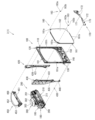
[2-4.外枠上ヒンジ組立体]
外枠2の外枠上ヒンジ組立体50について、主に図21を参照して詳細に説明する。図21(a)は外枠の外枠上ヒンジ組立体を分解して前上から見た分解斜視図であり、(b)は(a)を前下から見た分解斜視図である。外枠上ヒンジ組立体50は、外枠左組立体10の上端と外枠上部材30の左端に取付けられるものであり、外枠2に対して本体枠4をヒンジ回転可能に取付けるためのものである。外枠上ヒンジ組立体50は、外枠左部材11の凹部11aの上端と外枠上部材30の取付段部30bとに取付けられる外枠上ヒンジ部材51と、外枠上ヒンジ部材51に取付けられているロック部材52と、ロック部材52を外枠上ヒンジ部材51に取付けている取付ビス53と、を備えている。
[2-4. Outer frame upper hinge assembly]
The outer frame upper hinge assembly 50 of the outer frame 2 will be described in detail mainly with reference to FIG. FIG. 21(a) is an exploded perspective view of the outer frame upper hinge assembly of the outer frame and viewed from above, and FIG. 21(b) is an exploded perspective view of (a) viewed from below. The outer frame upper hinge assembly 50 is attached to the upper end of the outer frame left assembly 10 and the left end of the outer frame upper member 30, and is used to attach the main body frame 4 to the outer frame 2 so as to be capable of hinge rotation. is. The outer frame upper hinge assembly 50 is attached to the outer frame upper hinge member 51 attached to the upper end of the recessed portion 11a of the outer frame left member 11 and the mounting step portion 30b of the outer frame upper member 30, and the outer frame upper hinge member 51. and a mounting screw 53 for mounting the locking member 52 to the outer frame upper hinge member 51 .
外枠上ヒンジ部材51は、水平に延びた平板状で外枠上部材30の取付段部30bの上面に取付けられる上固定部51aと、上固定部51aの前辺から前方へ延出している平板状の前方延出部51bと、前方延出部51bの右辺の途中から前方へ向かうに従って前方延出部51bの左右中央へ延びており上下に貫通している軸受溝51cと、上固定部51aの左辺から下方へ延びている平板状の横固定部51dと、前方延出部51bの左辺から前辺を周って軸受溝51cが開口している部位までの端縁から下方へ延びており横固定部51dと連続している平板状の端縁壁部51eと、を備えている。外枠上ヒンジ部材51は、金属板をプレス成型により打抜き・屈曲させて形成されている。外枠上ヒンジ部材51は、軸受溝51c内において、本体枠上ヒンジ部材510の後述する本体枠上ヒンジピン512を回転可能に支持することができる。
The outer frame upper hinge member 51 is in the shape of a horizontally extending flat plate and extends forward from an upper fixing portion 51a attached to the upper surface of the mounting step portion 30b of the outer frame upper member 30 and the front side of the upper fixing portion 51a. A flat plate-like forward extending portion 51b, a bearing groove 51c that extends from the middle of the right side of the forward extending portion 51b to the center of the forward extending portion 51b toward the front and penetrates vertically, and an upper fixing portion. A flat plate-like lateral fixing portion 51d extending downward from the left side of 51a, and an end edge extending downward from the left side of the forward extending portion 51b to the portion where the bearing groove 51c opens around the front side. A flat edge wall portion 51e that is continuous with the cage horizontal fixing portion 51d is provided. The outer frame upper hinge member 51 is formed by punching and bending a metal plate by press molding. The outer frame upper hinge member 51 can rotatably support a later-described main body frame upper hinge pin 512 of the main body frame upper hinge member 510 in the bearing groove 51c.
ロック部材52は、前後に延びている帯板状のロック本体52aと、ロック本体52aの後端から右方へ突出している操作片52bと、ロック本体52aの後端から左方へ延びた後に斜め左前方へ延びている弾性変形可能な棒状の弾性部52cと、ロック本体52aの後端付近で上下に貫通している取付孔52dと、を備えている。ロック部材52は、合成樹脂によって形成されている。ロック部材52は、取付ビス53によって、外枠上ヒンジ部材51における前方延出部51bの下面で、軸受溝51cよりも後側の部位に回動可能に取付けられる。
The lock member 52 includes a band plate-like lock body 52a extending back and forth, an operation piece 52b projecting rightward from the rear end of the lock body 52a, and an operation piece 52b extending leftward from the rear end of the lock body 52a. It has an elastically deformable rod-shaped elastic portion 52c extending obliquely to the left front, and a mounting hole 52d penetrating vertically near the rear end of the lock body 52a. The lock member 52 is made of synthetic resin. The locking member 52 is rotatably attached to the lower surface of the forward extending portion 51b of the outer frame upper hinge member 51 by an attaching screw 53, at a portion rearward of the bearing groove 51c.
ロック部材52は、外枠上ヒンジ部材51に取付けた状態で、ロック本体52aが、平面視で軸受溝51cを遮ることができると共に、前端付近の右側面が、外枠上ヒンジ部材51の端縁壁部51eにおける軸受溝51cの開口まで延びている部位と当接可能となるように前方へ延びている。また、ロック本体52aの後端から左方へ延びている弾性部52cの先端は、外枠上ヒンジ部材51における端縁壁部51eの内周面に当接している。このロック部材52は、弾性部52cの付勢力によって取付孔52dを中心に、前端が左方へ回動する方向に付勢されている。従って、通常の状態では、ロック部材52のロック本体52aの前端付近の右側面が、端縁壁部51eに当接している。この状態では、軸受溝51cにおけるロック本体52aよりも前側の部位に、本体枠上ヒンジ部材510の本体枠上ヒンジピン512を収容可能な空間が形成される。
When the lock member 52 is attached to the outer frame upper hinge member 51 , the lock body 52 a can block the bearing groove 51 c in a plan view, and the right side surface near the front end is the edge of the outer frame upper hinge member 51 . It extends forward so as to come into contact with a portion of the edge wall portion 51e extending to the opening of the bearing groove 51c. The tip of the elastic portion 52c extending leftward from the rear end of the lock body 52a abuts the inner peripheral surface of the edge wall portion 51e of the outer frame upper hinge member 51. As shown in FIG. The locking member 52 is biased in a direction in which the front end thereof rotates leftward about the mounting hole 52d by the biasing force of the elastic portion 52c. Therefore, in a normal state, the right side surface of the lock body 52a of the lock member 52 in the vicinity of the front end is in contact with the edge wall portion 51e. In this state, a space capable of accommodating the main body frame upper hinge pin 512 of the main body frame upper hinge member 510 is formed in a portion of the bearing groove 51c on the front side of the lock body 52a.
このロック部材52は、操作片52bを操作することで、弾性部52cの付勢力に抗してロック本体52aを回動させることができる。そして、操作片52bの操作によって、ロック本体52aを、その前端が左方へ移動する方向へ回動させることで、平面視において軸受溝51cからロック本体52aを後退させることができ、軸受溝51cが全通している状態とすることができる。これにより、軸受溝51c内に本体枠上ヒンジピン512を挿入したり、軸受溝51c内から本体枠上ヒンジピン512を外したりすることができる。
By operating the operation piece 52b, the lock member 52 can rotate the lock body 52a against the biasing force of the elastic portion 52c. By operating the operation piece 52b to rotate the lock body 52a in a direction in which the front end thereof moves leftward, the lock body 52a can be retracted from the bearing groove 51c in a plan view. can be in a state in which the As a result, the main body frame upper hinge pin 512 can be inserted into the bearing groove 51c, or the main body frame upper hinge pin 512 can be removed from the bearing groove 51c.
[2-5.外枠下ヒンジ部材]
外枠2の外枠下ヒンジ部材60について、主に図18を参照して詳細に説明する。外枠下ヒンジ部材60は、水平に延びた平板状の水平部60aと、水平部60aの左辺において前後方向中央よりも後側の部位から上方へ立上っている平板状の立上部60bと、水平部60aの前端付近から上方へ突出している外枠下ヒンジピン60cと、水平部60aを上下に貫通しており遊技球Bが一つのみ通過可能な大きさの排出孔60dと、を備えている。この外枠下ヒンジ部材60は、金属板をプレス成型により打抜き・屈曲させて形成されている。
[2-5. Outer frame lower hinge member]
The outer frame lower hinge member 60 of the outer frame 2 will be described in detail mainly with reference to FIG. The outer frame lower hinge member 60 has a flat plate-like horizontal portion 60a that extends horizontally, and a flat plate-like raised portion 60b that rises upward from a portion rearward of the center in the front-rear direction on the left side of the horizontal portion 60a. , an outer frame lower hinge pin 60c protruding upward from near the front end of the horizontal portion 60a; ing. The lower outer frame hinge member 60 is formed by punching and bending a metal plate by press molding.
外枠下ヒンジ部材60の水平部60aは、平面視において、左辺を底辺とした台形に形成されている。外枠下ヒンジピン60cは、円柱状で、上下方向中央よりも上部が、上端が窄まった円錐台状に形成されている。この外枠下ヒンジピン60cは、水平部60aの前端付近における左寄りの位置に取付けられている。排出孔60dは、水平部60aにおいて、立上部60bの前後方向中央の部位と接し、水平部60aの左辺から右方へ逆U字状に延びるように形成されている。この排出孔60dは、外枠下組立体40における球噛防止機構44の第一排出口44bと、略同じ大きさに形成されている。
The horizontal portion 60a of the outer frame lower hinge member 60 is formed in a trapezoidal shape with the left side as the base in plan view. The outer frame lower hinge pin 60c has a columnar shape, and is formed in a truncated cone shape with an upper end narrowed above the center in the vertical direction. The outer frame lower hinge pin 60c is attached to a leftward position near the front end of the horizontal portion 60a. 60 d of discharge holes are formed in the horizontal part 60a so that it may contact|connect the center part of the front-back direction of the rising part 60b, and may extend rightward from the left side of the horizontal part 60a in an inverted U shape. The discharge hole 60 d is formed to have substantially the same size as the first discharge port 44 b of the ball jam prevention mechanism 44 in the outer frame lower assembly 40 .
外枠下ヒンジ部材60は、外枠2に組立てた状態で、水平部60aの後部が、外枠下組立体40における幕板後部材43の載置部44a上に載置され、図示しないビスによって幕板後部材43に固定されている。また、立上部60bが、外枠左部材11の右側面における膨出部11bよりも前側の部位に、図示しないビスによって取付けられている。この外枠下ヒンジ部材60は、外枠下ヒンジピン60cを、本体枠4の本体枠下ヒンジ組立体520における外枠用下ヒンジ孔521aに挿通させることで、外枠上ヒンジ部材51と協働して本体枠4を開閉可能に取付けることができる。
In the outer frame lower hinge member 60 assembled to the outer frame 2, the rear portion of the horizontal portion 60a is placed on the mounting portion 44a of the curtain plate rear member 43 in the outer frame lower assembly 40, and screwed (not shown). It is fixed to the rear panel member 43 by . The raised portion 60b is attached to the right side surface of the outer frame left member 11 on the front side of the bulging portion 11b with a screw (not shown). The outer frame lower hinge member 60 cooperates with the outer frame upper hinge member 51 by inserting the outer frame lower hinge pin 60c into the outer frame lower hinge hole 521a in the main body frame lower hinge assembly 520 of the main body frame 4. Then, the body frame 4 can be attached so that it can be opened and closed.
また、外枠2を組立てた状態では、排出孔60dが、外枠下組立体40における球噛防止機構44の第一排出口44bと一致している。これにより、水平部60a上の遊技球Bを、排出孔60d及び第一排出口44bを通して、外枠2の後方へ落下(排出)させることができる。詳述すると、外枠2に対して本体枠4を閉じる時に、外枠2と本体枠4との間に落下した遊技球Bが、本体枠4が閉じられるのに従って、外枠2と本体枠4との間が徐々に狭くなることから、間隔が広い後方側へ転動とすることとなり、排出孔60dから排出させることができる。この際に、排出孔60dが、パチンコ機1に組立てた状態で、外枠2に対して本体枠4を閉じた時に、本体枠4の後端と略同じとなる位置に形成されているため、外枠2と本体枠4との間に落下した遊技球Bを、排出孔60dから排出させることで本体枠4よりも後側へ転動するのを阻止し易くすることができ、外枠下ヒンジ部材60の部位に遊技球Bが留まり難くすることができる。
Further, in the assembled state of the outer frame 2, the discharge hole 60d coincides with the first discharge port 44b of the ball bite prevention mechanism 44 in the lower outer frame assembly 40. As shown in FIG. Thereby, the game ball B on the horizontal portion 60a can be dropped (discharged) behind the outer frame 2 through the discharge hole 60d and the first discharge port 44b. More specifically, when the main body frame 4 is closed with respect to the outer frame 2, the game ball B that has fallen between the outer frame 2 and the main body frame 4 is separated from the outer frame 2 and the main body frame as the main body frame 4 is closed. 4 gradually narrows, the ball rolls to the rear side where the gap is wide, and can be discharged from the discharge hole 60d. At this time, the discharge hole 60d is formed at a position that is substantially the same as the rear end of the body frame 4 when the body frame 4 is closed with respect to the outer frame 2 in the state assembled to the pachinko machine 1. By ejecting the game ball B dropped between the outer frame 2 and the main body frame 4 from the ejection hole 60d, it is possible to easily prevent the game ball B from rolling to the rear side of the main body frame 4, and the outer frame It is possible to make it difficult for the game ball B to stay at the part of the lower hinge member 60.例文帳に追加
[3.扉枠の全体構成]
パチンコ機1の扉枠3について、主に図22乃至図30を参照して詳細に説明する。図22はパチンコ機における扉枠の正面図であり、図23は扉枠の背面図であり、図24は扉枠の左側面図であり、図25は扉枠の右側面図である。図26は扉枠を右前から見た斜視図であり、図27は扉枠を左前から見た斜視図であり、図28は扉枠を後ろから見た斜視図である。図29は扉枠を主な部材毎に分解して前から見た分解斜視図であり、図30は扉枠を主な部材毎に分解して後ろから見た分解斜視図である。
[3. Overall configuration of door frame]
The door frame 3 of the pachinko machine 1 will be described in detail mainly with reference to FIGS. 22 to 30. FIG. 22 is a front view of a door frame in a pachinko machine, FIG. 23 is a rear view of the door frame, FIG. 24 is a left side view of the door frame, and FIG. 25 is a right side view of the door frame. 26 is a perspective view of the door frame viewed from the front right, FIG. 27 is a perspective view of the door frame viewed from the front left, and FIG. 28 is a perspective view of the door frame viewed from the back. FIG. 29 is an exploded perspective view of the door frame disassembled into main members and viewed from the front, and FIG. 30 is an exploded perspective view of the door frame disassembled into the main members and viewed from the back.
扉枠3は、外枠2の枠内と略同じ大きさで正面視において上下に延びた四角形に形成されており、本体枠4を介して外枠2の枠内を前側から開閉可能に取付けられている。扉枠3は、遊技球Bが打込まれる遊技盤5の遊技領域5aを前側から視認可能に閉鎖し、遊技領域5a内に打込むための遊技球Bを貯留すると共に、貯留している遊技球Bを遊技領域5a内へ打込むために遊技者が操作するハンドル195を備えているものである。また、扉枠3は、パチンコ機1の前面全体を装飾するものである。
The door frame 3 has substantially the same size as the inside of the outer frame 2 and is formed in a rectangular shape extending vertically when viewed from the front. It is The door frame 3 closes the game area 5a of the game board 5 into which the game ball B is hit so as to be visible from the front side, stores the game ball B to be hit in the game area 5a, and stores the game ball B. It has a handle 195 operated by the player to hit the ball B into the game area 5a. Further, the door frame 3 decorates the entire front surface of the pachinko machine 1. - 特許庁
扉枠3は、正面視の外形が上下に延びた四角形で枠状の扉枠ベースユニット100と、扉枠ベースユニット100に着脱可能に取付けられており本体枠4に取付けられた遊技盤5の遊技領域5aを前方から視認可能に閉鎖しているガラスユニット160と、ガラスユニット160の下部を後側から覆うように扉枠ベースユニット100に取付けられている防犯カバー170と、扉枠ベースユニット100の前面右下隅に取付けられているハンドルユニット180と、ハンドルユニット180の外周を覆うハンドルカバーユニット290と、扉枠ベースユニット100の前面下部に取付けられている皿ユニット200と、皿ユニット200の上側で扉枠ベースユニット100の前面左部に取付けられている扉枠左サイドユニット420と、皿ユニットの上側で扉枠ベースユニット100の前面右部に取付けられている扉枠右サイドユニット430と、扉枠左サイドユニット420及び扉枠右サイドユニット430の上側で扉枠ベースユニット100の前面上部に取付けられている扉枠トップユニット450と、を備えている。
The door frame 3 includes a door frame base unit 100 having a rectangular frame shape extending vertically when viewed from the front, and a game board 5 detachably attached to the door frame base unit 100 and attached to the main body frame 4. A glass unit 160 closing the game area 5a so as to be visible from the front, a security cover 170 attached to the door frame base unit 100 so as to cover the lower part of the glass unit 160 from the rear side, and the door frame base unit 100. A handle unit 180 attached to the lower right corner of the front of the door, a handle cover unit 290 covering the outer periphery of the handle unit 180, a tray unit 200 attached to the lower front of the door frame base unit 100, and an upper side of the tray unit 200. A door frame left side unit 420 attached to the front left part of the door frame base unit 100, a door frame right side unit 430 attached to the front right part of the door frame base unit 100 above the dish unit, and a door frame top unit 450 attached to the front upper portion of the door frame base unit 100 above the door frame left side unit 420 and the door frame right side unit 430 .
扉枠ベースユニット100は、正面視の外形が上下に延びた四角形(長方形)に形成されており前後に貫通している扉窓101aを有した扉枠ベース101と、扉枠ベース101の後側で背面視右下隅に取付けられているスピーカダクト103と、扉枠ベース101の後側の下部における背面視右端付近に取付けられている扉枠主中継基板104と、扉枠主中継基板104の背面視左方に取付けられている扉枠副中継基板105と、扉枠副中継基板105の背面視左方に取付けられているハンドル後中継基板106と、扉枠主中継基板104と扉枠副中継基板105の一部とを後側から被覆する扉枠中継基板カバー107と、ハンドル後中継基板106を後側から被覆するハンドル後中継基板カバー108と、配線ケーブルを被覆するケーブルカバー109と、を備えている。
The door frame base unit 100 includes a door frame base 101 having a vertically extending quadrangular (rectangular) outer shape when viewed from the front, and having a door window 101a penetrating in the front and rear directions, and a rear side of the door frame base 101. A speaker duct 103 attached to the lower right corner when viewed from the rear, a door frame main relay board 104 attached near the right end when viewed from the rear on the lower rear side of the door frame base 101, and the rear surface of the door frame main relay board 104. A door frame secondary relay board 105 attached to the left side of the view, a handle rear relay board 106 attached to the rear view left side of the door frame secondary relay board 105, the door frame main relay board 104 and the door frame secondary relay. A door frame relay board cover 107 covering a part of the board 105 from the rear side, a handle rear relay board cover 108 covering the rear handle relay board 106 from the rear side, and a cable cover 109 covering the wiring cable. I have.
また、扉枠ベースユニット100は、扉枠ベース101の後側に取付けられている枠状の扉枠補強ユニット110と、扉枠補強ユニット110に取付けられている扉枠上ヒンジ組立体120及び扉枠下ヒンジ部材125と、扉枠補強ユニット110に取付けられている開閉用のシリンダ錠130と、扉枠ベース101の後側でハンドル後中継基板106の上方に取付けられている球送給ユニット140と、扉枠ベース101の後側の下部における背面視右側に取付けられているファールカバーユニット150と、を備えている。
Further, the door frame base unit 100 includes a frame-shaped door frame reinforcing unit 110 attached to the rear side of the door frame base 101, a door frame upper hinge assembly 120 attached to the door frame reinforcing unit 110, and a door. A frame lower hinge member 125, an opening/closing cylinder lock 130 attached to the door frame reinforcing unit 110, and a ball feeding unit 140 attached above the handle rear relay board 106 on the rear side of the door frame base 101. and a foul cover unit 150 attached to the right side of the lower rear side of the door frame base 101 when viewed from the rear.
扉枠補強ユニット110は、扉枠ベース101の後側に取付けられることで、扉枠ベース101を補強して剛性を付与するものである。扉枠上ヒンジ組立体120及び扉枠下ヒンジ部材125は、扉枠3を本体枠4に対して開閉可能に取付けるためのものである。シリンダ錠130は、本体枠4の施錠ユニット650と協働して、扉枠3と本体枠4との開閉、及び、外枠2と本体枠4との開閉施錠に使用されるものである。
The door frame reinforcing unit 110 is attached to the rear side of the door frame base 101 to reinforce the door frame base 101 and impart rigidity to it. The door frame upper hinge assembly 120 and the door frame lower hinge member 125 are for attaching the door frame 3 to the body frame 4 so as to be openable and closable. The cylinder lock 130 cooperates with the locking unit 650 of the body frame 4 to open and close the door frame 3 and the body frame 4 and to open and close the outer frame 2 and the body frame 4 .
また、球送給ユニット140は、上皿201内の遊技球Bを一つずつ本体枠4の球発射装置540へ供給するためのものである。ファールカバーユニット150は、球発射装置540により発射されて遊技盤5の遊技領域5a内に到達しなかった遊技球B(ファール球)を、下皿202に誘導すると共に、払出装置580から払出された遊技球Bを、上皿201又は下皿202に誘導するためのものである。
Also, the ball feeding unit 140 is for feeding the game balls B in the upper tray 201 to the ball launching device 540 of the body frame 4 one by one. The foul cover unit 150 guides the game ball B (foul ball) that has been shot by the ball launcher 540 and has not reached the game area 5a of the game board 5 to the lower tray 202 and is paid out from the payout device 580. It is for guiding the game ball B to the upper tray 201 or the lower tray 202.例文帳に追加
ガラスユニット160は、透明なガラス板162を有しており扉枠ベース101の扉窓101aを閉鎖している。防犯カバー170は、ガラスユニット160の下部を後方から覆うように扉枠ベース101に取付けられている。ハンドルユニット180は、遊技者が回転操作可能なハンドル195を備えており、ハンドルユニット180は、外周を覆うハンドルカバーユニット290を操作することで、上皿201内の遊技球Bを、球発射装置540によって遊技盤5の遊技領域5a内に打込む遊技を行うためのものである。
The glass unit 160 has a transparent glass plate 162 and closes the door window 101 a of the door frame base 101 . The security cover 170 is attached to the door frame base 101 so as to cover the lower portion of the glass unit 160 from behind. The handle unit 180 has a handle 195 that can be rotated by the player, and the handle unit 180 operates a handle cover unit 290 that covers the outer periphery of the game ball B in the upper tray 201 to release the ball. 540 is used to play a game of hitting the game area 5 a of the game board 5 .
[3-1.扉枠ベースユニットの全体構成]
扉枠3の扉枠ベースユニット100について、主に図31乃至図33を参照して詳細に説明する。図31(a)は扉枠の扉枠ベースユニットを前から見た斜視図であり、(b)は扉枠ベースユニットを後ろから見た斜視図である。図32は扉枠ベースユニットを主な部材毎に分解して前から見た分解斜視図であり、図33は扉枠ベースユニットを主な部材毎に分解して後ろから見た分解斜視図である。
[3-1. Overall configuration of door frame base unit]
The door frame base unit 100 of the door frame 3 will be described in detail mainly with reference to FIGS. 31 to 33. FIG. FIG. 31(a) is a front perspective view of the door frame base unit of the door frame, and FIG. 31(b) is a rear perspective view of the door frame base unit. FIG. 32 is an exploded perspective view of the door frame base unit disassembled for each main member and viewed from the front, and FIG. 33 is an exploded perspective view of the door frame base unit disassembled for each main member and viewed from the back. be.
扉枠ベースユニット100は、正面視左辺側が本体枠4に対してヒンジ回転可能に取付けられ、本体枠4の前面を開閉可能に閉鎖していると共に、本体枠4に取付けられている遊技盤5の遊技領域5aを前方から視認可能としている。扉枠ベースユニット100は、外形が上下に延びた四角形で平板状の扉枠ベース101と、扉枠ベース101の後側で背面視右下隅に取付けられているスピーカダクト103と、を備えている。
The door frame base unit 100 is hinge-rotatably attached to the main body frame 4 at the left side in front view, and closes the front surface of the main body frame 4 so as to be opened and closed. The game area 5a can be visually recognized from the front. The door frame base unit 100 includes a rectangular flat plate door frame base 101 with an outer shape extending vertically, and a speaker duct 103 attached to the rear side of the door frame base 101 at the lower right corner in rear view. .
また、扉枠ベースユニット100は、扉枠ベース101の後側の下部における背面視右端付近に取付けられている扉枠主中継基板104と、扉枠ベース101の後側の下部における扉枠主中継基板104の背面視左方に取付けられている扉枠副中継基板105と、扉枠ベース101の後側の下部における扉枠副中継基板105の背面視左方に取付けられているハンドル後中継基板106と、扉枠ベース101の後側に取付けられており扉枠主中継基板104と扉枠副中継基板105の一部とを後側から被覆する扉枠中継基板カバー107と、扉枠ベース101の後側に取付けられておりハンドル後中継基板106を後側から被覆するハンドル後中継基板カバー108と、扉枠ベース101の後側に取付けられており配線ケーブルを被覆するケーブルカバー109と、を備えている。
The door-frame base unit 100 also includes a door-frame main relay board 104 attached near the right end in the rear view of the lower rear side of the door-frame base 101, and a door-frame main relay board 104 attached to the lower rear side of the door-frame base 101. A door frame secondary relay board 105 attached to the left side of the board 104 in rear view, and a handle rear relay board mounted to the left side of the door frame secondary relay board 105 in the lower rear side of the door frame base 101 in rear view. 106, a door frame relay board cover 107 attached to the rear side of the door frame base 101 and covering the door frame main relay board 104 and part of the door frame sub relay board 105 from the rear side, and the door frame base 101. A rear handle relay board cover 108 attached to the rear side and covering the rear handle relay board 106 from the rear side, and a cable cover 109 attached to the rear side of the door frame base 101 and covering the wiring cable are provided. I have.
更に、扉枠ベースユニット100は、扉枠ベース101の後側に取付けられている枠状の扉枠補強ユニット110と、扉枠補強ユニット110に取付けられている扉枠上ヒンジ組立体120及び扉枠下ヒンジ部材125と、扉枠補強ユニット110に取付けられている開閉用のシリンダ錠130と、扉枠ベース101の後側でハンドル後中継基板106の上方に取付けられている球送給ユニット140と、扉枠ベース101の後側の下部における背面視右側に取付けられているファールカバーユニット150と、を備えている。
Further, the door frame base unit 100 includes a frame-shaped door frame reinforcing unit 110 attached to the rear side of the door frame base 101, a door frame upper hinge assembly 120 attached to the door frame reinforcing unit 110, and a door. A frame lower hinge member 125, an opening/closing cylinder lock 130 attached to the door frame reinforcing unit 110, and a ball feeding unit 140 attached above the handle rear relay board 106 on the rear side of the door frame base 101. and a foul cover unit 150 attached to the right side of the lower rear side of the door frame base 101 when viewed from the rear.
この扉枠ベースユニット100には、前面下隅にハンドルユニット180及びハンドルカバーユニット290が、扉窓101aの下側前面に皿ユニット200が、扉窓101aの左外側前面に扉枠左サイドユニット420が、扉窓101aの右外側前面に扉枠右サイドユニット430が、扉窓101aの上外側前面に扉枠トップユニット450が、夫々取付けられるものである。
The door frame base unit 100 has a handle unit 180 and a handle cover unit 290 at the lower front corner, a tray unit 200 at the lower front of the door window 101a, and a door frame left side unit 420 at the left outer front of the door window 101a. A door frame right side unit 430 is attached to the right outer front surface of the door window 101a, and a door frame top unit 450 is attached to the upper outer front surface of the door window 101a.
また、扉枠ベースユニット100には、扉窓101aを後方から閉鎖するようにガラスユニット160が取付けられると共に、ガラスユニット160の下部を後方から覆うように透明な防犯カバー170が取付けられるものである。
A glass unit 160 is attached to the door frame base unit 100 so as to close the door window 101a from behind, and a transparent security cover 170 is attached to cover the lower part of the glass unit 160 from behind. .
[3-1a.扉枠ベース]
扉枠3における扉枠ベースユニット100の扉枠ベース101について、主に図31乃至図33を参照して詳細に説明する。扉枠ベース101は、正面視の外形が上下に延びた四角形(長方形)に形成されている。扉枠ベース101は、前後に貫通しており、正面視における内周形状が上下に延びた略四角形に形成された扉窓101aを備えている。扉窓101aは、内周を形成している上辺及び左右両辺が、扉枠ベース101の外周辺に夫々接近しており、内周を形成している下辺が、扉枠ベース101の下端から上下方向の約1/3の高さに位置している。このように、扉枠ベース101は、前後に貫通している扉窓101aにより全体が枠状に形成されている。この扉枠ベース101は、合成樹脂により一体成形されている。
[3-1a. door frame base]
The door frame base 101 of the door frame base unit 100 in the door frame 3 will be described in detail mainly with reference to FIGS. 31 to 33. FIG. The door frame base 101 has a quadrangular (rectangular) shape extending vertically when viewed from the front. The door frame base 101 penetrates in the front-rear direction and has a door window 101a formed in a substantially quadrangular shape with an inner peripheral shape extending vertically when viewed from the front. The door window 101a has an upper side and both left and right sides forming the inner periphery thereof, and is close to the outer periphery of the door frame base 101, and a lower side forming the inner periphery extends vertically from the lower end of the door frame base 101. It is located at about 1/3 of the height of the direction. Thus, the door frame base 101 is formed in a frame shape as a whole by the door window 101a penetrating in the front and rear directions. The door frame base 101 is integrally molded of synthetic resin.
扉枠ベース101は、前面における正面視右下隅に形成されており左端側が右端側よりも前方へやや突出するように傾斜しているハンドル取付座面101b(図42等を参照)と、ハンドル取付座面101bと扉窓101aとの間で前後に貫通して扉枠補強ユニット110のシリンダ取付フレーム115が挿入されるシリンダ挿通孔101dと、シリンダ挿通孔101d及びハンドル取付座面101bの正面視左側で前後に貫通しており球送給ユニット140の進入口141a及び球抜口141bを前方に臨ませるための球送給開口101eと、を備えている。
The door frame base 101 has a handle mounting seat surface 101b (see FIG. 42, etc.) which is formed at the lower right corner of the front surface when viewed from the front and is inclined so that the left end side projects slightly forward from the right end side, and a handle mounting seat surface 101b (see FIG. 42). A cylinder insertion hole 101d into which the cylinder mounting frame 115 of the door frame reinforcing unit 110 is inserted through the seat surface 101b and the door window 101a in the front-rear direction, and the left side of the cylinder insertion hole 101d and the handle mounting seat surface 101b in a front view. and a ball feeding opening 101e that penetrates in the front-rear direction and allows the entrance port 141a and the ball extraction port 141b of the ball feeding unit 140 to face forward.
また、扉枠ベース101は、左右方向中央より左寄りで且つハンドル取付座面101bと略同じ高さで前後に貫通しておりファールカバーユニット150の球放出口150dを前方に臨ませる下皿用球通過口101fと、正面視左端付近で扉窓101aの下辺に隣接するように前後に貫通しておりファールカバーユニット150の貫通球通路150aを前方に臨ませる上皿用球通過口101gと、扉窓101aの内周に沿って後面から前方へ向かって窪み、ガラスユニット160のガラス枠161が挿入されるガラスユニット取付部101hと、を備えている。
In addition, the door frame base 101 penetrates in the front and back at a position near the center in the left-right direction and at substantially the same height as the handle mounting seat surface 101b. a passage opening 101f, a ball passage opening 101g for an upper tray that penetrates in the front-rear direction so as to be adjacent to the lower side of the door window 101a in the vicinity of the left end in a front view and faces the through ball passage 150a of the foul cover unit 150 forward, and a door. A glass unit mounting portion 101h recessed forward from the rear surface along the inner circumference of the window 101a and into which the glass frame 161 of the glass unit 160 is inserted is provided.
また、扉枠ベース101は、正面視左下隅(上皿用球通過口101gの下方)に形成されており前後に貫通した縦長の複数のスリット101iを、備えている。複数のスリット101iの後側にスピーカダクト103が取付けられる。また、複数のスリット101iは、パチンコ機1を組立てた状態で、前方に皿ユニット200における皿ユニットベース211のスピーカ口211bが位置していると共に、後方に本体枠4のスピーカユニット620aにおける本体枠スピーカ622が位置しており、本体枠スピーカ622からの音を前方へ放射することができる。
Further, the door frame base 101 is provided with a plurality of longitudinally long slits 101i that are formed in the lower left corner (below the ball passage opening 101g for the upper tray) in a front view and penetrate therethrough in the front-rear direction. A speaker duct 103 is attached to the rear side of the plurality of slits 101i. In addition, in the assembled state of the pachinko machine 1, the plurality of slits 101i are such that the speaker opening 211b of the dish unit base 211 of the dish unit 200 is located in front, and the main body frame of the speaker unit 620a of the main body frame 4 is located in the rear. A speaker 622 is located, and the sound from the main body frame speaker 622 can be radiated forward.
更に、扉枠ベース101は、扉窓101aの下方でハンドル取付座面101bの上方において、前後に貫通している貫通孔101jを備えている。この貫通孔101jは、扉枠ベースユニット100側と皿ユニット200側とを接続する配線ケーブル(図示は省略)が挿通されるものであり、後述する扉枠補強ユニット110における中間補強フレーム114の貫通部114bと一致するように形成されている。
Further, the door frame base 101 is provided with a through hole 101j penetrating back and forth below the door window 101a and above the handle mounting seat surface 101b. A wiring cable (not shown) connecting the door frame base unit 100 side and the tray unit 200 side is inserted through the through hole 101j. It is formed so as to match the portion 114b.
[3-1b.スピーカダクト]
扉枠ベースユニット100のスピーカダクト103について、主に図31乃至図33を参照して詳細に説明する。このスピーカダクト103は、筒状に形成されており、扉枠ベース101の後側において複数のスリット101iが形成されている部位に取付けられる。スピーカダクト103は、パチンコ機1を組立てた状態で、筒状の部位の後端が、本体枠4の本体枠スピーカ622の前方に位置している。これにより、本体枠4の本体枠スピーカ622から放射(出力)された音(サウンド)を、拡散させることなく前方へ誘導することができ、扉枠ベース101の複数のスリット101i及び皿ユニット200の皿ユニットベース211におけるスピーカ口211bを通して、パチンコ機1の前方(遊技者側)へ良好に誘導することができる。
[3-1b. speaker duct]
The speaker duct 103 of the door frame base unit 100 will be described in detail mainly with reference to FIGS. 31 to 33. FIG. This speaker duct 103 is formed in a cylindrical shape and is attached to a portion on the rear side of the door frame base 101 where a plurality of slits 101i are formed. The rear end of the cylindrical portion of the speaker duct 103 is positioned in front of the body frame speaker 622 of the body frame 4 when the pachinko machine 1 is assembled. As a result, the sound radiated (output) from the main body frame speaker 622 of the main body frame 4 can be guided forward without being diffused, and the plurality of slits 101i of the door frame base 101 and the plate unit 200 can be guided forward. Through the speaker port 211b in the dish unit base 211, the pachinko machine 1 can be favorably guided forward (toward the player).
また、スピーカダクト103は、筒状の部位の下方の後面に、接続ケーブル503を保持するケーブルホルダ103aを備えている。ケーブルホルダ103aは、扉枠中継基板カバー107よりも正面視左方に配置されており、扉枠主中継基板104及び扉枠副中継基板105に接続されている接続ケーブル503を、扉枠3の左端側へ延びるように保持している。
Moreover, the speaker duct 103 has a cable holder 103a for holding the connection cable 503 on the rear surface below the tubular portion. The cable holder 103a is arranged to the left of the door frame relay board cover 107 in front view, and connects the connection cable 503 connected to the door frame main relay board 104 and the door frame sub relay board 105 to the door frame 3. It is held so as to extend to the left end side.
[3-1c.扉枠主中継基板・扉枠副中継基板・ハンドル後中継基板]
扉枠ベースユニット100の扉枠主中継基板104、扉枠副中継基板105、ハンドル後中継基板106について、主に図32及び図33等を参照して説明する。扉枠主中継基板104は、外形が上下に延びた四角形に形成されており、扉枠ベース101の後側の下部における背面視右下隅に取付けられる。扉枠主中継基板104は、ハンドル後中継基板106と本体枠4の基板ユニット620におけるインターフェイス基板635との接続を中継するためのものであり、本体枠4から延びている接続ケーブル503(図82及び図83を参照)の一部が接続される。
[3-1c. Door frame main relay board/Door frame secondary relay board/Handle rear relay board]
The door frame main relay board 104, door frame sub relay board 105, and rear handle relay board 106 of the door frame base unit 100 will be described mainly with reference to FIGS. The door frame main relay board 104 has a rectangular outer shape extending vertically, and is attached to the lower right corner of the rear side of the door frame base 101 when viewed from the rear. The door frame main relay board 104 is for relaying the connection between the handle rear relay board 106 and the interface board 635 in the board unit 620 of the body frame 4, and the connection cable 503 extending from the body frame 4 (see FIG. 82). and FIG. 83) are connected.
扉枠副中継基板105は、外形が、上下に延びた四角形の上部の正面視右側に左右に延びた四角形が組み合された逆L字状に形成されており、上下に延びている部位が扉枠主中継基板104の背面視左方に隣接するように、扉枠ベース101の後側に取付けられている。扉枠副中継基板105は、ハンドルユニット180のハンドル装飾基板184、皿ユニット200の皿ユニット中継基板214、扉枠左サイドユニット420の扉枠左サイド上装飾基板422及び扉枠左サイド下装飾基板423、扉枠右サイドユニット430の扉枠右サイド上装飾基板432及び扉枠右サイド下装飾基板433、扉枠トップユニット450の扉枠トップ中継基板等と、本体枠4のインターフェイス基板635との接続を中継するためのものであり、本体枠4から延びている接続ケーブル503の残りが接続される。
The door frame sub-relay board 105 is formed in an inverted L shape by combining a square extending left and right on the right side of the upper part of the square extending vertically when viewed from the front. It is attached to the rear side of the door frame base 101 so as to be adjacent to the left side of the door frame main relay board 104 in rear view. The door frame secondary relay board 105 includes the handle decoration board 184 of the handle unit 180, the plate unit relay board 214 of the plate unit 200, the door frame left side upper decoration board 422 of the door frame left side unit 420, and the door frame left side lower decoration board. 423, the door frame right side upper decorative board 432 and door frame right side lower decorative board 433 of the door frame right side unit 430, the door frame top relay board of the door frame top unit 450, etc., and the interface board 635 of the main body frame 4; It is for relaying the connection, and the rest of the connection cable 503 extending from the body frame 4 is connected.
扉枠主中継基板104及び扉枠副中継基板105は、接続端子が後方へ向かって突出するように、扉枠ベース101に取付けられる。扉枠主中継基板104及び扉枠副中継基板105は、扉枠ベースユニット100を組立てた状態で、扉枠主中継基板104と扉枠副中継基板105の上下に延びている部位とが、扉枠中継基板カバー107によって後側が被覆された状態となり、扉枠副中継基板105の残りの部位が、ファールカバーユニット150によって後側が被覆された状態となる。
The door frame main relay board 104 and the door frame sub relay board 105 are attached to the door frame base 101 so that the connection terminals protrude rearward. When the door-frame base unit 100 is assembled, the door-frame main relay board 104 and the door-frame sub-relay board 105 are arranged so that the vertically extending parts of the door-frame main relay board 104 and the door-frame sub-relay board 105 are connected to the door. The rear side is covered with the frame relay board cover 107 , and the rear side of the remaining part of the door frame sub-relay board 105 is covered with the foul cover unit 150 .
ハンドル後中継基板106は、外形が左右に延びた四角形に形成されており、扉枠ベース101の後側における球送給開口101eの下方でハンドル取付座面101bの後側に取付けられる。ハンドル後中継基板106は、扉枠主中継基板104とハンドルユニット180のハンドル回転検知センサ189、ハンドルタッチセンサ192、単発ボタン操作センサ194、及び球送給ユニット140の球送給ソレノイド145との接続を中継するためのものである。ハンドル後中継基板106は、扉枠ベースユニット100を組立てた状態で、ハンドル後中継基板カバー108によって後側が被覆された状態となる。
The post-handle relay board 106 has a rectangular outer shape extending left and right, and is attached to the rear side of the handle mounting seat surface 101b below the ball feeding opening 101e on the rear side of the door frame base 101. As shown in FIG. The post-handle relay board 106 connects the door frame main relay board 104 to the handle rotation detection sensor 189 of the handle unit 180, the handle touch sensor 192, the single button operation sensor 194, and the ball feed solenoid 145 of the ball feed unit 140. It is for relaying. The rear side of the handle relay board 106 is covered with the rear handle relay board cover 108 when the door frame base unit 100 is assembled.
[3-1d.扉枠中継基板カバー・ハンドル後中継基板カバー・ケーブルカバー]
扉枠ベースユニット100の扉枠中継基板カバー107、ハンドル後中継基板カバー108、及びケーブルカバー109について、主に図31乃至図33を参照して説明する。扉枠中継基板カバー107は、扉枠ベース101の後側に取付けることで、扉枠主中継基板104と扉枠副中継基板105の一部(逆L字状の上下に延びている部位)の後側を被覆するものである。扉枠中継基板カバー107は、前方及び正面視左方が開放された箱状に形成されている。扉枠ベースユニット100に組立てた状態では、後側を被覆している扉枠主中継基板104及び扉枠副中継基板105の接続端子が扉枠中継基板カバー107の内部に露出しており、開放されている左側から接続ケーブル503を内部に挿入して、それら端子に接続することができる。
[3-1d. Door frame relay board cover, rear handle relay board cover, cable cover]
The door frame relay board cover 107, the rear handle relay board cover 108, and the cable cover 109 of the door frame base unit 100 will be described mainly with reference to FIGS. 31 to 33. FIG. By attaching the door frame relay board cover 107 to the rear side of the door frame base 101, the door frame main relay board 104 and a part of the door frame sub relay board 105 (parts extending vertically in an inverted L shape) are covered. It covers the rear side. The door frame relay board cover 107 is formed in a box shape that is open at the front and the left side when viewed from the front. When assembled to the door-frame base unit 100, the connection terminals of the door-frame main relay board 104 and the door-frame sub-relay board 105 covering the rear side are exposed inside the door-frame relay board cover 107 and can be opened. A connection cable 503 can be inserted inside from the left side of the housing and connected to these terminals.
ハンドル後中継基板カバー108は、ハンドル後中継基板106の後側を被覆するように扉枠ベース101の後側に取付けられるものである。ケーブルカバー109は、扉枠補強ユニット110における中間補強フレーム114の後側に取付けられ、扉枠主中継基板104と皿ユニット200の球貸操作ユニット220とを接続する配線ケーブル(図示は省略)を被覆するためのものである。ケーブルカバー109は、左右に延びた箱状に形成されており、前面の左端付近と下面の左右方向中央に、配線ケーブルを通すための開口が形成されている。
The post-handle relay board cover 108 is attached to the rear side of the door frame base 101 so as to cover the rear side of the post-handle relay board 106 . The cable cover 109 is attached to the rear side of the intermediate reinforcing frame 114 in the door frame reinforcing unit 110, and connects the door frame main relay board 104 and the ball lending operation unit 220 of the plate unit 200 with a wiring cable (not shown). It is for covering. The cable cover 109 is formed in a box-like shape extending in the left and right direction, and has openings formed near the left end of the front surface and in the center of the lower surface in the left-right direction for passing the wiring cables.
[3-1e.扉枠補強ユニット]
扉枠ベースユニット100の扉枠補強ユニット110について、主に図31乃至図33を参照して詳細に説明する。扉枠補強ユニット110は、扉枠ベース101の後側に取付けられることで、平板状の扉枠ベース101を補強して、扉枠ベースユニット100に剛性を付与している。扉枠補強ユニット110は、左右に離間して配置されている上下に延びた左補強フレーム111及び右補強フレーム112と、左補強フレーム111及び右補強フレーム112の上端同士を連結している左右に延びた上補強フレーム113と、左補強フレーム111の下端から上寄りの位置に左端側が取付けられており右補強フレーム112付近まで右方へ延びた中間補強フレーム114と、中間補強フレーム114の右端と右補強フレーム112とを連結しているシリンダ取付フレーム115と、右補強フレーム112の後側に上下に離間して複数取付けられており本体枠4の施錠ユニット650の扉枠用鉤652が掛止される鉤掛部材116と、を備えている。
[3-1e. Door frame reinforcement unit]
The door frame reinforcement unit 110 of the door frame base unit 100 will be described in detail mainly with reference to FIGS. 31 to 33. FIG. The door frame reinforcing unit 110 is attached to the rear side of the door frame base 101 to reinforce the flat plate-shaped door frame base 101 and impart rigidity to the door frame base unit 100 . The door frame reinforcing unit 110 includes a vertically extending left reinforcing frame 111 and a right reinforcing frame 112 that are spaced apart in the left and right direction, and a left reinforcing frame 111 and a right reinforcing frame 112 that connect the upper ends of the left reinforcing frame 111 and the right reinforcing frame 112 . An extended upper reinforcing frame 113, an intermediate reinforcing frame 114 whose left end is attached at a position near the upper end of the left reinforcing frame 111 and extends rightward to the vicinity of the right reinforcing frame 112, and the right end of the intermediate reinforcing frame 114. A plurality of cylinder mounting frames 115, which are connected to the right reinforcing frame 112, are mounted on the rear side of the right reinforcing frame 112 with a vertical gap therebetween, and the door frame hooks 652 of the locking unit 650 of the body frame 4 are engaged. and a hooking member 116 that is attached.
左補強フレーム111及び右補強フレーム112は、左右方向が一定の幅で、扉枠ベース101の上下の高さと略同じ長さで上下に延びている。右補強フレーム112には、上下方向に離間しており、前後方向に貫通している複数の挿通孔が形成されている。これら挿通孔は、本体枠4に対して扉枠3を閉めた時に、施錠ユニット650の扉枠用鉤652の先端が挿通される。上補強フレーム113は、上下方向が一定の幅で、扉枠ベース101の左右の幅と略同じ長さで左右に延びている。
The left reinforcing frame 111 and the right reinforcing frame 112 have a constant width in the left-right direction, and extend vertically by a length substantially equal to the vertical height of the door frame base 101 . The right reinforcing frame 112 is formed with a plurality of insertion holes that are spaced apart in the vertical direction and penetrate in the front-rear direction. The tips of the door frame hooks 652 of the locking unit 650 are inserted through these insertion holes when the door frame 3 is closed with respect to the body frame 4 . The upper reinforcing frame 113 has a constant width in the vertical direction, and extends in the left and right direction with substantially the same length as the left and right width of the door frame base 101 .
中間補強フレーム114は、上下方向が上補強フレーム113の上下の幅よりも広い幅で左右に延びている。中間補強フレーム114は、左端付近において上端から下方へ四角く切欠かれた切欠部114aと、右端付近において前後に貫通している貫通部114bと、を有している。切欠部114aは、扉枠ベース101の上皿用球通過口101gと、貫通部114bは、扉枠ベース101の貫通孔101jと、夫々一致する位置に形成されている。
The intermediate reinforcing frame 114 extends laterally with a width that is wider in the vertical direction than the vertical width of the upper reinforcing frame 113 . The intermediate reinforcing frame 114 has a notch portion 114a that is rectangularly cut downward from the upper end in the vicinity of the left end, and a through portion 114b that penetrates in the front-rear direction in the vicinity of the right end. The cut-out portion 114a is formed at the position corresponding to the upper tray ball passage opening 101g of the door frame base 101, and the through portion 114b is formed at the position corresponding to the through hole 101j of the door frame base 101, respectively.
シリンダ取付フレーム115は、左右に離間して配置されており正面視において上下に延びた四角形の平板状に形成されている一対の後片部と、一対の後片部の対面している夫々の辺から前方へ平板状に延出している一対の側片部と、一対の前方延出部の前端の辺同士を連結している平板状の前片部と、を備えている。このシリンダ取付フレーム115は、平面視の形状が前方へ突出した凸形状に形成されている。シリンダ取付フレーム115は、左側の後片部が中間補強フレーム114の右端に取付けられ、右側の後片部が右補強フレーム112に取付けられる。このシリンダ取付フレーム115は、前片部にシリンダ錠130が取付けられる。
The cylinder mounting frame 115 includes a pair of rear piece portions which are spaced apart from each other in the left and right direction and formed in a rectangular flat plate shape extending vertically when viewed from the front, and a pair of rear piece portions facing each other. It has a pair of side pieces extending forward from the sides in a flat plate shape, and a flat front piece portion connecting the front ends of the pair of front extending portions to each other. The cylinder mounting frame 115 is formed in a convex shape that protrudes forward in plan view. The cylinder mounting frame 115 has a left rear piece attached to the right end of the intermediate reinforcing frame 114 and a right rear piece attached to the right reinforcing frame 112 . A cylinder lock 130 is attached to the front piece of the cylinder attachment frame 115 .
鉤掛部材116は、右補強フレーム112の後側において、前後に貫通している挿通孔の部位に取付けられている。これら鉤掛部材116は、施錠ユニット650の扉枠用鉤652が掛止される。
The hooking member 116 is attached to an insertion hole penetrating in the front-rear direction on the rear side of the right reinforcing frame 112 . Door frame hooks 652 of the locking unit 650 are hooked to these hooking members 116 .
扉枠補強ユニット110を構成している左補強フレーム111、右補強フレーム112、上補強フレーム113、中間補強フレーム114、シリンダ取付フレーム115、及び鉤掛部材116は、金属板をプレス成型によって打抜き・屈曲することで形成されている。これらは、リベットによって組立てられている。
The left reinforcing frame 111, the right reinforcing frame 112, the upper reinforcing frame 113, the intermediate reinforcing frame 114, the cylinder mounting frame 115, and the hooking member 116, which constitute the door frame reinforcing unit 110, are made by punching and molding metal plates. It is formed by bending. These are assembled with rivets.
扉枠補強ユニット110は、左補強フレーム111、右補強フレーム112、及び上補強フレーム113が、扉枠ベース101の左辺、右辺、及び上辺に沿うように組立てられていると共に、中間補強フレーム114が、扉枠ベース101の扉窓101aの下方に位置するように組立てられている。
The door frame reinforcing unit 110 includes a left reinforcing frame 111, a right reinforcing frame 112, and an upper reinforcing frame 113 assembled along the left side, right side, and upper side of the door frame base 101, and an intermediate reinforcing frame 114. , is assembled to be located below the door window 101a of the door frame base 101. As shown in FIG.
扉枠補強ユニット110は、図示しない複数のビスにより扉枠ベース101の後側に取付けられる。この扉枠補強ユニット110は、扉枠ベース101に取付けた状態で、中間補強フレーム114の切欠部114a及び貫通部114bが、扉枠ベース101の上皿用球通過口101g及び貫通孔101jと一致した状態となると共に、シリンダ取付フレーム115が、扉枠ベース101のシリンダ挿通孔101dに挿入された状態となる。
The door frame reinforcing unit 110 is attached to the rear side of the door frame base 101 with a plurality of screws (not shown). When the door frame reinforcing unit 110 is attached to the door frame base 101, the notch portion 114a and the through portion 114b of the intermediate reinforcing frame 114 are aligned with the upper tray ball passage opening 101g and the through hole 101j of the door frame base 101. At the same time, the cylinder mounting frame 115 is inserted into the cylinder insertion hole 101 d of the door frame base 101 .
[3-1f.扉枠上ヒンジ組立体]
扉枠ベースユニット100の扉枠上ヒンジ組立体120について、主に図31乃至図33を参照して説明する。扉枠上ヒンジ組立体120は、扉枠補強ユニット110の正面視左上隅に取付けられる。扉枠上ヒンジ組立体120は、扉枠3を、扉枠下ヒンジ部材125と協働して本体枠4に対してヒンジ回転可能に取付けるためのものである。扉枠上ヒンジ組立体120は、扉枠補強ユニット110に取付けられるヒンジブラケット121と、ヒンジブラケット121に上下方向へ移動可能に取付けられる扉枠上ヒンジピン122と、扉枠上ヒンジピン122に取付けられる鍔部材123と、扉枠上ヒンジピン122を上方へ移動するように付勢しているロックバネ124と、を備えている。
[3-1f. Door frame upper hinge assembly]
The door frame upper hinge assembly 120 of the door frame base unit 100 will be described mainly with reference to FIGS. 31-33. The door frame upper hinge assembly 120 is attached to the upper left corner of the door frame reinforcement unit 110 in a front view. The door frame upper hinge assembly 120 is for attaching the door frame 3 to the main body frame 4 in cooperation with the door frame lower hinge member 125 so as to be capable of hinge rotation. The door frame upper hinge assembly 120 includes a hinge bracket 121 attached to the door frame reinforcing unit 110, a door frame upper hinge pin 122 attached to the hinge bracket 121 so as to be movable in the vertical direction, and a flange attached to the door frame upper hinge pin 122. A member 123 and a locking spring 124 biasing the door frame upper hinge pin 122 to move upward.
ヒンジブラケット121は、正面視四角形の平板状の取付片121aと、取付片121aの上辺及び下辺から前方へ延出している平板状の突出片121bと、を備えている。ヒンジブラケット121は、取付片121aが扉枠補強ユニット110に取付けられる。ヒンジブラケット121は、金属板を屈曲させて形成されている。
The hinge bracket 121 includes a flat plate-like attachment piece 121a that is square in front view, and flat plate-like projecting pieces 121b that extend forward from the upper and lower sides of the attachment piece 121a. The hinge bracket 121 is attached to the door frame reinforcing unit 110 at the attachment piece 121a. Hinge bracket 121 is formed by bending a metal plate.
扉枠上ヒンジピン122は、円柱状の金属棒をL字状に屈曲させたものである。扉枠上ヒンジピン122は、扉枠上ヒンジ組立体120に組立てた状態で、上下に延びている部位が、ヒンジブラケット121における一対の突出片121bの前端付近において下方から貫通し、上端が上側の突出片121bよりも上方へ延び出していると共に、水平に延びている部位が下側の突出片121bの下面に当接している。扉枠上ヒンジピン122は、上端が本体枠4の本体枠上ヒンジ部材510における上ヒンジ本体511の扉枠用上ヒンジ孔511aに回転可能に挿通される。
The door frame upper hinge pin 122 is formed by bending a cylindrical metal rod into an L shape. When the door frame upper hinge pin 122 is assembled to the door frame upper hinge assembly 120, the vertically extending portion penetrates from below near the front ends of the pair of protruding pieces 121b of the hinge bracket 121, and the upper end extends upward. The portion extending upward from the protruding piece 121b and extending horizontally contacts the lower surface of the lower protruding piece 121b. The upper end of the door frame upper hinge pin 122 is rotatably inserted into the door frame upper hinge hole 511 a of the upper hinge main body 511 of the main body frame upper hinge member 510 of the main body frame 4 .
鍔部材123は、Eリングとされており、扉枠上ヒンジピン122における一対の突出片121bの間となる部位に取付けられている。ロックバネ124は、コイル状に形成されており、鍔部材123とヒンジブラケット121における下側の突出片121bとの間において扉枠上ヒンジピン122の上下に延びている部位の周りに被せられている。このロックバネ124により、鍔部材123を介して扉枠上ヒンジピン122が上方へ付勢されている。
The flange member 123 is an E-ring and is attached to a portion between the pair of protruding pieces 121b of the hinge pin 122 on the door frame. The lock spring 124 is formed in a coil shape, and covers the vertically extending portion of the door frame upper hinge pin 122 between the flange member 123 and the lower projecting piece 121 b of the hinge bracket 121 . The lock spring 124 urges the door frame upper hinge pin 122 upward via the flange member 123 .
扉枠上ヒンジ組立体120は、扉枠上ヒンジピン122がロックバネ124により上方へ付勢された状態となっており、扉枠上ヒンジピン122における下端の水平に延びている部位が下側の突出片121bの下面に当接することで、これ以上の上方への移動が規制されている。この状態では、扉枠上ヒンジピン122の上端が、上側の突出片121bの上面よりも所定量上方に突出している。
In the door frame upper hinge assembly 120, the door frame upper hinge pin 122 is urged upward by the lock spring 124, and the horizontally extending portion of the lower end of the door frame upper hinge pin 122 is the lower projecting piece. Further upward movement is restricted by abutting on the lower surface of 121b. In this state, the upper end of the door frame upper hinge pin 122 protrudes upward by a predetermined amount from the upper surface of the upper projecting piece 121b.
扉枠上ヒンジ組立体120は、扉枠上ヒンジピン122における下端の水平に延びている部位を、ロックバネ124の付勢力に抗してその部位を下方へ移動させると、扉枠上ヒンジピン122を全体的に下方へ移動させることができ、扉枠上ヒンジピン122の上端を、上側の突出片121bの上面よりも下方へ没入させることができる。従って、扉枠上ヒンジ組立体120は、扉枠上ヒンジピン122の上端を、本体枠上ヒンジ部材510の扉枠用上ヒンジ孔511aに対して下方から挿入させたり、下方へ抜いたりすることができる。これにより、扉枠上ヒンジピン122の上端を、本体枠上ヒンジ部材510の扉枠用上ヒンジ孔511aに挿入させることで、扉枠3の正面視上部左端を、本体枠4に対してヒンジ回転可能に支持させることができる。
In the door frame upper hinge assembly 120, when the horizontally extending portion of the lower end of the door frame upper hinge pin 122 is moved downward against the biasing force of the lock spring 124, the door frame upper hinge pin 122 is fully extended. The upper end of the door frame upper hinge pin 122 can be retracted below the upper surface of the upper projecting piece 121b. Therefore, in the door frame upper hinge assembly 120, the upper end of the door frame upper hinge pin 122 can be inserted from below into the door frame upper hinge hole 511a of the main body frame upper hinge member 510 or removed downward. can. As a result, the upper end of the door frame upper hinge pin 122 is inserted into the door frame upper hinge hole 511 a of the main body frame upper hinge member 510 , so that the upper left end of the door frame 3 when viewed from the front is hinge-rotated with respect to the main body frame 4 . can be supported as much as possible.
また、扉枠上ヒンジ組立体120は、扉枠上ヒンジピン122における上下に延びている部位が、後述する扉枠下ヒンジ部材125の扉枠下ヒンジピン126と同軸上に位置している。これにより、扉枠上ヒンジピン122と扉枠下ヒンジピン126とによって、扉枠3を本体枠4に対して良好な状態でヒンジ回転させることができる。
In the door frame upper hinge assembly 120, the vertically extending portion of the door frame upper hinge pin 122 is positioned coaxially with the door frame lower hinge pin 126 of the door frame lower hinge member 125, which will be described later. As a result, the door frame 3 can be hinge-rotated with respect to the main body frame 4 in a favorable state by the door frame upper hinge pin 122 and the door frame lower hinge pin 126 .
[3-1g.扉枠下ヒンジ部材]
扉枠ベースユニット100の扉枠下ヒンジ部材125について、主に図31乃至図33を参照して説明する。扉枠下ヒンジ部材125は、扉枠補強ユニット110の正面視左下隅に取付けられる。扉枠下ヒンジ部材125は、扉枠3を、扉枠上ヒンジ組立体120と協働して本体枠4に対してヒンジ回転可能に取付けるためのものである。
[3-1g. Door frame lower hinge member]
The door frame lower hinge member 125 of the door frame base unit 100 will be described mainly with reference to FIGS. 31 to 33. FIG. The door frame lower hinge member 125 is attached to the lower left corner of the door frame reinforcing unit 110 when viewed from the front. The door frame lower hinge member 125 is for attaching the door frame 3 to the main body frame 4 in cooperation with the door frame upper hinge assembly 120 so as to be capable of hinge rotation.
扉枠下ヒンジ部材125は、扉枠補強ユニット110に取付けられ正面視四角形で平板状の取付片125aと、取付片125aの下辺から前方へ延出している平板状の突出片125bと、突出片125bの前端付近の下面から下方へ突出している扉枠下ヒンジピン126(図22等を参照)と、を備えている。
The door frame lower hinge member 125 includes a flat mounting piece 125a attached to the door frame reinforcing unit 110 and rectangular in front view, a flat plate-shaped projecting piece 125b extending forward from the lower side of the mounting piece 125a, and a projecting piece. A door frame lower hinge pin 126 (see FIG. 22, etc.) protruding downward from the lower surface near the front end of the door frame 125b.
扉枠下ヒンジ部材125の取付片125a及び突出片125bは、金属板を屈曲させて形成されている。扉枠下ヒンジピン126は、円柱状の金属棒で、下端部の外周にテーパ状の面取りが施されている。この扉枠下ヒンジピン126は、扉枠ベースユニット100に組立てた状態で、突出片125bにおける扉枠上ヒンジ組立体120の扉枠上ヒンジピン122の上下に延びている部位と同軸上となる部位に取付けられている。
The mounting piece 125a and the projecting piece 125b of the lower door frame hinge member 125 are formed by bending a metal plate. The door frame lower hinge pin 126 is a cylindrical metal rod, and the outer circumference of the lower end portion is tapered and chamfered. When the door frame base unit 100 is assembled, the door frame lower hinge pin 126 is positioned coaxially with the vertically extending portion of the door frame upper hinge pin 122 of the door frame upper hinge assembly 120 in the protruding piece 125b. installed.
この扉枠下ヒンジ部材125は、扉枠下ヒンジピン126を本体枠下ヒンジ組立体520の扉枠用下ヒンジ孔522aに挿入することで、扉枠3を本体枠4に対してヒンジ回転可能に支持することができる。
The door frame lower hinge member 125 allows the door frame 3 to rotate with respect to the main body frame 4 by inserting the door frame lower hinge pin 126 into the door frame lower hinge hole 522a of the main body frame lower hinge assembly 520. can support.
[3-1h.シリンダ錠]
扉枠3の扉枠ベースユニット100におけるシリンダ錠130について、主に図34乃至図36を参照して詳細に説明する。図34(a)は扉枠のシリンダ錠を前から見た斜視図であり、(b)は(a)のシリンダ錠を後ろ前から見た斜視図であり、(c)は従来のパチンコ機におけるシリンダ錠を前から見た斜視図であり、(d)は(a)のシリンダ錠を後ろから見た斜視図である。図35(a)は図34(a)のシリンダ錠を分解して前から見た分解斜視図であり、(b)は図34(a)のシリンダ錠を分解して後ろから見た分解斜視図である。図36(a)は図34(a)のシリンダ錠の可動機構を正面から示す説明図であり、(b)は(a)の状態から反時計回りの方向へ90度回転させた状態で示すシリンダ錠の説明図であり、(c)は(a)の状態から時計回りの方向へ90度回転させた状態で示すシリンダ錠の説明図である。
[3-1h. cylinder lock]
The cylinder lock 130 in the door frame base unit 100 of the door frame 3 will be described in detail mainly with reference to FIGS. 34 to 36. FIG. Fig. 34 (a) is a perspective view of the cylinder lock of the door frame as seen from the front, (b) is a perspective view of the cylinder lock of (a) as seen from the back and front, and (c) is a conventional pachinko machine. 2 is a front perspective view of the cylinder lock in FIG. 2, and (d) is a rear perspective view of the cylinder lock in (a). 35(a) is an exploded perspective view of the cylinder lock shown in FIG. 34(a) and viewed from the front, and FIG. 35(b) is an exploded perspective view of the cylinder lock shown in FIG. 34(a) and viewed from the rear. It is a diagram. Fig. 36(a) is an explanatory view showing the movable mechanism of the cylinder lock of Fig. 34(a) from the front, and Fig. 36(b) shows the state rotated counterclockwise by 90 degrees from the state of Fig. 34(a). It is explanatory drawing of a cylinder lock, (c) is explanatory drawing of the cylinder lock shown in the state rotated 90 degrees clockwise from the state of (a).
シリンダ錠130は、扉枠補強ユニット110のシリンダ取付フレーム115に取付けられ、本体枠4の施錠ユニット650と協働して、扉枠3と本体枠4との開閉、及び、外枠2と本体枠4との開閉施錠に使用されるものである。シリンダ錠130は、前後に延びた円柱状のシリンダ本体131と、シリンダ本体131の前端面に形成されている鍵穴132と、シリンダ本体131の後方に設けられており鍵穴132に挿入された正規の鍵を回転させると一緒に回転する回転伝達部材133と、を備えている。
The cylinder lock 130 is attached to the cylinder mounting frame 115 of the door frame reinforcing unit 110, and cooperates with the locking unit 650 of the main body frame 4 to open and close the door frame 3 and the main body frame 4, and to open and close the outer frame 2 and the main body. It is used for opening and closing with the frame 4 . The cylinder lock 130 includes a cylindrical cylinder body 131 extending back and forth, a keyhole 132 formed in the front end face of the cylinder body 131, and a regular keyhole 132 provided behind the cylinder body 131 and inserted into the keyhole 132. and a rotation transmission member 133 that rotates together with the rotation of the key.
シリンダ錠130のシリンダ本体131は、シリンダ取付フレーム115の前片部を後方から貫通して後端が前片部に取付けられている。回転伝達部材133は、後方が開放された円筒状(詳しくは、後方へ向かうに従って直径が大きくなる円錐筒状)に形成されており、中心軸を挟んで対向した位置に後端から前方へ向かって切欠かれた一対の切欠部を有している。回転伝達部材133は、本体枠4における施錠ユニット650の伝達シリンダ654が後方から挿入されるように形成されており、伝達シリンダ654の一対の突起が一対の切欠部内に挿入されることで、回転伝達部材133(鍵穴132に挿入された鍵)の回転を、伝達シリンダ654に伝達させて回転させることができる。
A cylinder body 131 of the cylinder lock 130 penetrates the front piece of the cylinder mounting frame 115 from the rear and the rear end is attached to the front piece. The rotation transmission member 133 is formed in a cylindrical shape (specifically, a conical cylinder shape whose diameter increases toward the rear) with an open rear end, and the rotation transmission member 133 is formed in opposite positions across the central axis from the rear end toward the front. It has a pair of notches that are notched. The rotation transmission member 133 is formed so that the transmission cylinder 654 of the locking unit 650 in the main body frame 4 is inserted from behind. The rotation of the transmission member 133 (the key inserted into the keyhole 132) can be transmitted to the transmission cylinder 654 to rotate.
更に詳述すると、シリンダ錠130は、シリンダ本体131の後端側に設けられており鍵穴132に挿入された正規の鍵を回転させると一緒に回転する第一カム部材134と、シリンダ取付フレーム115におけるシリンダ本体131よりも下方の部位で前後方向の軸周りに対して回転可能に取付けられている第二カム部材135と、上端側が第一カム部材134における回転中心よりも右方の部位で回転可能に取付けられていると共に下端側が第二カム部材135における回転中心よりも右方の部位で回転可能に取付けられている帯板状の第一アーム136と、上端側が第一カム部材134における回転中心よりも下方の部位で回転可能に取付けられていると共に下端側が第二カム部材135における回転中心よりも下方の部位で回転可能に取付けられている帯板状の第二アーム137と、を備えている。
More specifically, the cylinder lock 130 includes a first cam member 134 which is provided on the rear end side of the cylinder main body 131 and rotates together with a regular key inserted into the keyhole 132, and a cylinder mounting frame 115. A second cam member 135 attached rotatably about an axis in the front-rear direction at a portion below the cylinder body 131 in the upper end side rotates at a portion to the right of the rotation center of the first cam member 134 A band plate-shaped first arm 136 that is rotatably attached to the second cam member 135 at the lower end side of the center of rotation of the second cam member 135, and the upper end side is the first cam member 134 that rotates. a strip-shaped second arm 137 which is rotatably attached at a portion below the center and whose lower end side is rotatably attached at a portion below the center of rotation of the second cam member 135; ing.
また、シリンダ錠130は、第二カム部材135(回転伝達部材133)を除いてシリンダ本体131、第一カム部材134、第一アーム136、及び第二アーム137を後方から覆うようにシリンダ取付フレーム115に取付けられている後カバー138と、第一アーム136及び第二アーム137の夫々の上下両端側を、夫々第一カム部材134や第二カム部材135に対して回転可能に取付けているリベット139と、を備えている。
Also, the cylinder lock 130 is mounted on the cylinder mounting frame so as to cover the cylinder main body 131, the first cam member 134, the first arm 136, and the second arm 137 from behind except for the second cam member 135 (rotation transmission member 133). Rivets that rotatably attach the rear cover 138 attached to 115 and the upper and lower end sides of the first arm 136 and the second arm 137 to the first cam member 134 and the second cam member 135, respectively. 139 and .
第一カム部材134は、第一アーム136の上端側が後面側に取付けられていると共に、第二アーム137の上端側が前面側に取付けられている。第二カム部材135は、シリンダ取付フレーム115により後側から回転可能に取付けられており、シリンダ取付フレーム115の前面を挟んだ後側に、回転伝達部材133が一体回転可能に取付けられている。第二カム部材135は、第一アーム136の下端側が前面側に取付けられていると共に、第二アーム137の下端側が第一アーム136よりも前方で前面側に取付けられている。
The first cam member 134 has the upper end side of the first arm 136 attached to the rear side, and the upper end side of the second arm 137 attached to the front side. The second cam member 135 is rotatably attached from the rear side by the cylinder mounting frame 115, and the rotation transmission member 133 is attached to the rear side across the front surface of the cylinder mounting frame 115 so as to be integrally rotatable. The second cam member 135 has the lower end side of the first arm 136 attached to the front side, and the lower end side of the second arm 137 is attached to the front side ahead of the first arm 136 .
第一カム部材134及び第二カム部材135は、夫々において、第一アーム136が取付けられる部位と、第二アーム137が取付けられる部位とが、夫々の回転軸を中心に90度の角度で離隔している。また、第一カム部材134及び第二カム部材135は、夫々において、第一アーム136が取付けられる部位が、第二アーム137が取付けられる部位よりも、回転中心から遠ざかった位置に設けられている。
In each of the first cam member 134 and the second cam member 135, the portion to which the first arm 136 is attached and the portion to which the second arm 137 is attached are spaced apart at an angle of 90 degrees around their respective rotation axes. are doing. In each of the first cam member 134 and the second cam member 135, the portion to which the first arm 136 is attached is located farther from the center of rotation than the portion to which the second arm 137 is attached. .
後カバー138は、左右両側面の下端から外方へ円柱状に突出した軸部138aが、シリンダ取付フレーム115のL字状の係止スリット115bに係止された状態で、上端側が図示しないビスにより、シリンダ取付フレーム115に着脱可能に取付けられている。
The rear cover 138 has a cylindrical shaft portion 138a that protrudes outward from the lower ends of both left and right side surfaces of the rear cover 138. The shaft portion 138a is engaged with the L-shaped engagement slit 115b of the cylinder mounting frame 115. It is detachably attached to the cylinder mounting frame 115 by means of.
このシリンダ錠130は、シリンダ取付フレーム115、シリンダ本体131、回転伝達部材133、第一カム部材134、第二カム部材135、第一アーム136、及び第二アーム137が、金属により形成されている。
In this cylinder lock 130, the cylinder mounting frame 115, the cylinder body 131, the rotation transmission member 133, the first cam member 134, the second cam member 135, the first arm 136 and the second arm 137 are made of metal. .
シリンダ錠130は、扉枠3に組立てた状態で、シリンダ本体131の前端が扉枠右サイドユニット430のシリンダ挿通口440bの前端と略一致した状態となる。
When the cylinder lock 130 is assembled to the door frame 3 , the front end of the cylinder body 131 is substantially aligned with the front end of the cylinder insertion opening 440 b of the door frame right side unit 430 .
ここで、従来のシリンダ錠130Aについて説明する。従来のシリンダ錠130Aは、図34(c)及び(d)に示すように、シリンダ本体131が、シリンダ取付フレーム115Aの前片部を後方から貫通して後端が前片部に取付けられている。このシリンダ錠130Aは、シリンダ本体131の軸芯上に回転伝達部材133が設けられている。
Here, the conventional cylinder lock 130A will be described. As shown in FIGS. 34(c) and 34(d), the conventional cylinder lock 130A has a cylinder main body 131 which penetrates the front piece of the cylinder mounting frame 115A from the rear and the rear end of which is attached to the front piece. there is A rotation transmission member 133 is provided on the axis of a cylinder body 131 of the cylinder lock 130A.
続いて、本実施形態のシリンダ錠130の作動について説明する。従来のシリンダ錠130は、図34(c)及び(d)に示すように、シリンダ本体131の軸芯上に回転伝達部材133が設けられているのに対して、本実施形態のシリンダ錠130は、図34(a)及び(b)等に示すように、シリンダ本体131の軸芯から下方へ離隔した位置に回転伝達部材133が設けられている。
Next, the operation of the cylinder lock 130 of this embodiment will be described. As shown in FIGS. 34(c) and 34(d), the conventional cylinder lock 130 has a rotation transmitting member 133 on the axis of the cylinder body 131. 34(a) and 34(b), etc., a rotation transmission member 133 is provided at a position spaced downward from the axis of the cylinder body 131. As shown in FIGS.
このシリンダ錠130は、通常の状態では、図36(a)に示すように、第一アーム136の上下両端側が、第一カム部材134及び第二カム部材135の夫々において、夫々の回転中心の右方の部位に取付けられていると共に、第二アーム137の上下両端側が、第一カム部材134及び第二カム部材135の夫々において、夫々の回転中心の下方の部位に取付けられている。シリンダ本体131では、正規の鍵によって、通常の状態から、時計回りの方向、及び反時計回りの方向へ、夫々90度の角度で回転することができる。
In the normal state, as shown in FIG. 36(a), the cylinder lock 130 is configured such that the upper and lower end sides of the first arm 136 are aligned with the rotation centers of the first cam member 134 and the second cam member 135, respectively. The upper and lower end sides of the second arm 137 are attached to the lower portions of the rotation centers of the first cam member 134 and the second cam member 135, respectively. The cylinder body 131 can be rotated clockwise and counterclockwise by an angle of 90 degrees from the normal state by using a proper key.
この状態で、鍵穴132に挿入した鍵により、シリンダ本体131のシリンダを介して第一カム部材134を反時計回りの方向へ回転させると、第一アーム136及び第二アーム137が上方へ移動することとなる。この際に、第一アーム136では、上端側が第一カム部材134の回転中心の右方に取付けられているため、第一アーム136により第二カム部材135を反時計回りの方向へ回転させようとする力が大きく作用するのに対して、第二アーム137では、上端側が第一カム部材134の回転中心の下方に取付けられているため、第二アーム137からは第二カム部材135を反時計回りの方向へ回転させようとする力が殆ど作用しない。
In this state, when the first cam member 134 is rotated counterclockwise via the cylinder of the cylinder body 131 by the key inserted into the keyhole 132, the first arm 136 and the second arm 137 move upward. It will happen. At this time, since the upper end side of the first arm 136 is attached to the right of the center of rotation of the first cam member 134, the second cam member 135 should be rotated counterclockwise by the first arm 136. On the other hand, the upper end side of the second arm 137 is attached below the rotation center of the first cam member 134, so that the second cam member 135 is reversed from the second arm 137. Almost no force acts to rotate it in the clockwise direction.
このようにして、第一カム部材134が、通常の状態から反時計回りの方向へ回転すると、主に第一アーム136を介して力が伝達されて、第二カム部材135が反時計回りの方向へ回転し、第二カム部材135と一緒に回転伝達部材133が回転することとなる。この第一カム部材134の反時計回りの方向への回転により上方へ作用する力は、第一アーム136及び第二アーム137が第一カム部材134に取付けられている部位と、第一カム部材134の回転中心との間の左右方向の距離に比例している。そのため、第一カム部材134が、通常の状態から反時計回りの方向へ回転するのに従って、第一アーム136では上方へ作用する力が小さくなるのに対して、第二アーム137では上方へ作用する力が大きくなる。
Thus, when the first cam member 134 rotates counterclockwise from the normal state, force is transmitted mainly through the first arm 136, causing the second cam member 135 to rotate counterclockwise. direction, and the rotation transmission member 133 rotates together with the second cam member 135 . The force that acts upward due to the counterclockwise rotation of the first cam member 134 is generated by the portion where the first arm 136 and the second arm 137 are attached to the first cam member 134 and the portion where the first cam member 134 is attached. 134 is proportional to the horizontal distance from the center of rotation. Therefore, as the first cam member 134 rotates counterclockwise from the normal state, the force acting upward on the first arm 136 decreases, while the force acting upward on the second arm 137 decreases. greater power to do so.
従って、第一カム部材134が、通常の状態から反時計回りの方向への回転角度が45度を越えると、第一アーム136よりも第二アーム137の方が上方へ作用する力が大きくなり、主に第二アーム137を介して、第二カム部材135が反時計回りの方向へ回転することとなる。そして、鍵穴132に挿入した鍵を、通常の状態から、反時計回りの方向へ90度の角度まで回転させることができる(図36(b)を参照)。
Therefore, when the rotation angle of the first cam member 134 in the counterclockwise direction from the normal state exceeds 45 degrees, the upward force acting on the second arm 137 becomes greater than that on the first arm 136 . , mainly via the second arm 137, the second cam member 135 rotates counterclockwise. Then, the key inserted into the keyhole 132 can be rotated counterclockwise by 90 degrees from the normal state (see FIG. 36(b)).
なお、鍵により、通常の状態から反時計回りの方向へ90度回転させた状態から、時計回りの方向へ90度回転させて通常の状態に復帰させる際には、上記とは逆の作用により動作することとなる。
It should be noted that when the key is turned counterclockwise from the normal state by 90 degrees and then rotated clockwise by 90 degrees to return to the normal state, the action opposite to the above is performed. It will work.
一方、通常の状態から、鍵穴132に挿入した鍵により、シリンダ本体131のシリンダを介して第一カム部材134を時計回りの方向へ回転させると、上端側が第一カム部材134の回転中心の右方に取付けられている第一アーム136が下方へ移動すると共に、上端側が第一カム部材134の回転中心の下方に取付けられている第二アーム137が上方へ移動することとなる。この際に、第一アーム136では、上端側が第一カム部材134の回転中心の右方に取付けられているため、第一アーム136により第二カム部材135を時計回りの方向へ回転させようとする力が大きく作用するのに対して、第二アーム137では、上端側が第一カム部材134の回転中心の下方に取付けられているため、第二アーム137からは第二カム部材135を時計回りの方向へ回転させようとする力が殆ど作用しない。
On the other hand, when the key inserted into the keyhole 132 is used to rotate the first cam member 134 clockwise through the cylinder of the cylinder body 131 from the normal state, the upper end side of the first cam member 134 rotates to the right of the center of rotation. As the first arm 136 attached to the side moves downward, the second arm 137 attached to the lower end of the rotation center of the first cam member 134 moves upward. At this time, since the upper end side of the first arm 136 is attached to the right of the center of rotation of the first cam member 134, the second cam member 135 is rotated clockwise by the first arm 136. On the other hand, the upper end of the second arm 137 is attached below the center of rotation of the first cam member 134, so that the second cam member 135 is rotated clockwise from the second arm 137. Almost no force acts to rotate in the direction of .
このようにして、第一カム部材134が、通常の状態から時計回りの方向へ回転すると、主に第一アーム136を介して力が伝達されて、第二カム部材135が時計回りの方向へ回転し、第二カム部材135と一緒に回転伝達部材133が回転することとなる。第一アーム136及び第二アーム137による第一カム部材134の回転を第二カム部材135に伝達する力は、第一アーム136及び第二アーム137が第一カム部材134に取付けられている部位と、第一カム部材134の回転中心との間の左右方向の距離に比例している。そのため、第一カム部材134が、通常の状態から時計回りの方向へ回転するのに従って、第一アーム136では第二カム部材135を回転させようとする力が小さくなるのに対して、第二アーム137では第二カム部材135を回転させようとする力が大きくなる。
Thus, when the first cam member 134 rotates clockwise from the normal state, force is transmitted mainly through the first arm 136, causing the second cam member 135 to rotate clockwise. It rotates, and the rotation transmission member 133 rotates together with the second cam member 135 . The force that transmits the rotation of the first cam member 134 by the first arm 136 and the second arm 137 to the second cam member 135 is the portion where the first arm 136 and the second arm 137 are attached to the first cam member 134. , and the center of rotation of the first cam member 134 in the horizontal direction. Therefore, as the first cam member 134 rotates clockwise from the normal state, the force of the first arm 136 that tends to rotate the second cam member 135 decreases. The arm 137 exerts a greater force to rotate the second cam member 135 .
従って、第一カム部材134が、通常の状態から時計回りの方向への回転角度が45度を越えると、第一アーム136よりも第二アーム137の方が第二カム部材135を回転させようとする力が大きくなり、主に第二アーム137を介して、第二カム部材135が時計回りの方向へ回転することとなる。そして、鍵穴132に挿入した鍵を、通常の状態から、時計回りの方向へ90度の角度まで回転させることができる(図36(c)を参照)。
Therefore, when the rotation angle of the first cam member 134 in the clockwise direction exceeds 45 degrees from the normal state, the second arm 137 will rotate the second cam member 135 more than the first arm 136. As a result, the second cam member 135 rotates clockwise mainly via the second arm 137 . Then, the key inserted into the keyhole 132 can be rotated clockwise by 90 degrees from the normal state (see FIG. 36(c)).
なお、鍵により、通常の状態から時計回りの方向へ90度回転させた状態から、時計回りの方向へ90度回転させて通常の状態に復帰させる際には、上記とは逆の作用により動作することとなる。
It should be noted that when the key is turned clockwise from the normal state by 90 degrees and then rotated clockwise by 90 degrees to return to the normal state, the operation is reversed to that described above. It will be done.
このように、本実施形態のシリンダ錠130によれば、第一カム部材134と第二カム部材135とを、互いに90度の角度で位相させて取付けた第一アーム136と第二アーム137とで連結して、回転を伝達させるようにしているため、第一カム部材134(鍵穴132に挿入された鍵)がどの回転位置にあっても、第一アーム136及び第二アーム137の少なくとも一方により回転を伝達させて、第二カム部材135(回転伝達部材133)を回転させることができ、扉枠3や本体枠4の施錠や開錠を良好なものとすることができる。
As described above, according to the cylinder lock 130 of the present embodiment, the first arm 136 and the second arm 137 in which the first cam member 134 and the second cam member 135 are phased at an angle of 90 degrees to each other. , so that at least one of the first arm 136 and the second arm 137 is engaged regardless of the rotational position of the first cam member 134 (the key inserted into the keyhole 132). , the second cam member 135 (rotation transmission member 133) can be rotated, and the locking and unlocking of the door frame 3 and the body frame 4 can be improved.
また、本実施形態のシリンダ錠130によれば、回転伝達機構としての第一アーム136及び第二アーム137により回転を伝達させることで、シリンダ本体131の軸芯に対して、回転伝達部材133(本体枠4における施錠ユニット650の伝達シリンダ654)の軸芯を、異なる位置に設けることができるため、施錠ユニット650を変更しなくても、扉枠3におけるシリンダ本体131の位置を任意の位置に変更することが可能となり、扉枠3の装飾の邪魔にならない部位にシリンダ本体131(鍵穴132)を設けることができ、扉枠3の装飾性の高いパチンコ機1を提供することができる。
Further, according to the cylinder lock 130 of the present embodiment, rotation is transmitted by the first arm 136 and the second arm 137 as the rotation transmission mechanism, so that the rotation transmission member 133 ( Since the transmission cylinder 654) of the locking unit 650 in the body frame 4 can be provided at a different position, the position of the cylinder body 131 in the door frame 3 can be changed to any position without changing the locking unit 650. The cylinder body 131 (keyhole 132) can be provided in a part that does not interfere with the decoration of the door frame 3, and the pachinko machine 1 with high decorativeness of the door frame 3 can be provided.
また、上述したように、扉枠3においてシリンダ本体131の位置を変更しても、本体枠4における施錠ユニット650を変更する必要がないため、施錠ユニット650を流用することができ、パチンコ機1にかかるコストの増加を抑制させることができる。
Further, as described above, even if the position of the cylinder main body 131 is changed in the door frame 3, there is no need to change the locking unit 650 in the main body frame 4, so that the locking unit 650 can be used. cost increase can be suppressed.
ところで、従来のシリンダ錠130Aでは、シリンダ本体131の後方に回転伝達部材133が設けられているため、当該構成を知見している不正行為者が、前方からシリンダ本体131の後方へ工具を挿入し、当該工具により回転伝達部材133を不正に回転させることで、扉枠3を開けて不正行為を行う恐れがある。これに対して、本実施形態のシリンダ錠130は、シリンダ本体131の軸芯(後方)から離れた位置に回転伝達部材133を設けていることから、シリンダ本体131の後方に工具を挿入して回転伝達部材133を回転させようとしても、当該部位に回転伝達部材133が存在していないため、回転伝達部材133を回転させることができず、扉枠3や本体枠4等を開けた不正行為が行われることを防止することができる。
By the way, in the conventional cylinder lock 130A, since the rotation transmission member 133 is provided behind the cylinder body 131, a fraudulent person who has knowledge of the structure may insert a tool behind the cylinder body 131 from the front. By illegally rotating the rotation transmission member 133 with the tool, the door frame 3 may be opened to commit fraud. On the other hand, in the cylinder lock 130 of the present embodiment, since the rotation transmission member 133 is provided at a position away from the axis (rear) of the cylinder body 131, a tool can be inserted behind the cylinder body 131. Even if an attempt is made to rotate the rotation transmission member 133, the rotation transmission member 133 cannot be rotated because the rotation transmission member 133 does not exist at the relevant portion, and the door frame 3, the body frame 4, etc. are opened. can be prevented from occurring.
更に、シリンダ錠130において、第一アーム136に対して第二アーム137が、第一カム部材134及び第二カム部材135において90度の回転角度で離間した部位同士を連結しているため、第一アーム136又は第二アーム137の一方の第一カム部材134及び第二カム部材135に取付けられている部位が、第一カム部材134の中心と第二カム部材135の中心とを結んだ直線上に位置しても、第一アーム136又は第二アーム137の他方が、第一カム部材134の中心と第二カム部材135の中心とを結んだ直線から最も離れた部位同士を連結している状態となる。従って、第一アーム136又は第二アーム137の一方によって、第一カム部材134及び第二カム部材135の死点に位置することで、第一カム部材134からの回転を第二カム部材135へ伝達させることができなくても、第一アーム136又は第二アーム137の他方によって、第一カム部材134からの回転を第二カム部材135へ伝達させることができるため、第一カム部材134の回転に大きな抵抗がかかることはなく、鍵穴132に挿入されている鍵を滑らかに回転させることができ、開錠・施錠を容易に行うことができると共に、鍵穴に挿入された鍵を無理に回転させられることを回避させることができ、鍵の破損を防止することができる。
Furthermore, in the cylinder lock 130, the second arm 137 connects the first arm 136 and the second arm 137 to the first cam member 134 and the second cam member 135, which are separated by a rotation angle of 90 degrees. A straight line connecting the center of the first cam member 134 and the center of the second cam member 135 at the part attached to one of the first cam member 134 and the second cam member 135 of the one arm 136 or the second arm 137 Even when positioned above, the other of the first arm 136 or the second arm 137 connects the parts farthest from the straight line connecting the center of the first cam member 134 and the center of the second cam member 135. be in a state where Therefore, by positioning the first cam member 134 and the second cam member 135 at the dead center by either the first arm 136 or the second arm 137, the rotation from the first cam member 134 is transferred to the second cam member 135. Even if it cannot be transmitted, the rotation from the first cam member 134 can be transmitted to the second cam member 135 by the other of the first arm 136 or the second arm 137, so the rotation of the first cam member 134 The key inserted in the keyhole 132 can be smoothly rotated without a large resistance to rotation, and unlocking/locking can be easily performed, and the key inserted in the keyhole can be forcibly rotated. Therefore, it is possible to prevent the key from being damaged.
また、第一アーム136と第二アーム137の二つのアームで鍵穴132に挿入された鍵の回転を偏芯した位置に設けられている回転伝達部材133へ伝達させるようにしているため、何らかの理由により一方のアームが破損しても、残りのアームにより回転を伝達させることができ、信頼性の高いシリンダ錠130を有したパチンコ機1を提供することができる。
In addition, since the two arms of the first arm 136 and the second arm 137 transmit the rotation of the key inserted into the keyhole 132 to the rotation transmission member 133 provided at an eccentric position, for some reason Even if one of the arms is damaged, the rotation can be transmitted by the remaining arm, and the pachinko machine 1 having the highly reliable cylinder lock 130 can be provided.
また、滑らかな棒状(帯板状)の第一アーム136及び第二アーム137により、鍵穴132に挿入された鍵の回転を偏芯した位置に設けられている回転伝達部材133へ伝達させるようにしているため、ギアにより回転を伝達させるようにした場合では、工具の先端をギアの歯に引掛けることでギアが回転して回転伝達部材133が回転させられてしまう恐れがあるが、第一アーム136及び第二アーム137を表面が滑らかな棒状としていることで、工具の先端を第一アーム136や第二アーム137に引っ掛かり難くすることができ、第一アーム136や第二アーム137が動かされることで回転伝達部材133が回転させられてしまうことを回避させることができ、施錠ユニット650が不正に操作されて扉枠3や本体枠4が開錠させられてしまうことを確実に防止することができる。
In addition, the rotation of the key inserted into the keyhole 132 is transmitted to the rotation transmission member 133 provided at an eccentric position by the smooth rod-shaped (strip-shaped) first arm 136 and second arm 137. Therefore, if the rotation is transmitted by a gear, the tip of the tool may be hooked on the teeth of the gear, causing the gear to rotate and the rotation transmission member 133 to rotate. Since the arm 136 and the second arm 137 are rod-shaped with smooth surfaces, it is possible to make it difficult for the tip of the tool to get caught on the first arm 136 and the second arm 137, thereby preventing the first arm 136 and the second arm 137 from moving. It is possible to prevent the rotation transmission member 133 from being rotated, and to reliably prevent the door frame 3 and the body frame 4 from being unlocked due to illegal operation of the locking unit 650.例文帳に追加be able to.
なお、本実施形態のシリンダ錠130では、第一カム部材134の回転を第二カム部材135へ伝達させる回転伝達機構として、第一アーム136と第二アーム137とを用いたものを示したが、これに限定するものではなく、例えば、複数の歯車を用いた回転伝達機構、歯車とラックギアを用いた回転伝達機構、スプロケットとチェーンを用いた回転伝達機構、プーリとベルトを用いた回転伝達機構、等としても良い。
In the cylinder lock 130 of this embodiment, the first arm 136 and the second arm 137 are used as the rotation transmission mechanism for transmitting the rotation of the first cam member 134 to the second cam member 135. , but not limited to, for example, a rotation transmission mechanism using a plurality of gears, a rotation transmission mechanism using a gear and a rack gear, a rotation transmission mechanism using a sprocket and a chain, a rotation transmission mechanism using a pulley and a belt , and so on.
[3-1i.球送給ユニット]
扉枠ベースユニット100の球送給ユニット140について、主に図37及び図38を参照して詳細に説明する。図37(a)は扉枠ベースユニットの球送給ユニットを前から見た斜視図であり、(b)は球送給ユニットを後ろから見た斜視図である。図38(a)は球送給ユニットを分解して前から見た分解斜視図であり、(b)は球送給ユニットの後ケースと不正防止部材を外して後から見た分解斜視図である。球送給ユニット140は、皿ユニット200の上皿201から供給される遊技球Bを一つずつ本体枠4の球発射装置540へ供給することができると共に、上皿201内に貯留された遊技球Bを、上皿球抜ボタン222の操作によって下皿202へ抜くことができるものである。
[3-1i. Ball feeding unit]
The ball feeding unit 140 of the door frame base unit 100 will be described in detail mainly with reference to FIGS. 37 and 38. FIG. FIG. 37(a) is a front perspective view of the ball feeding unit of the door frame base unit, and FIG. 37(b) is a rear perspective view of the ball feeding unit. FIG. 38(a) is an exploded perspective view of the ball feeding unit as seen from the front, and (b) is an exploded perspective view of the ball feeding unit as seen from the rear with the rear case and the tamper-proof member removed. be. The ball feeding unit 140 can supply the game balls B supplied from the upper tray 201 of the tray unit 200 one by one to the ball launching device 540 of the main body frame 4, and also the game balls stored in the upper tray 201. The ball B can be pulled out to the lower tray 202 by operating the upper tray ball ejection button 222. - 特許庁
球送給ユニット140は、皿ユニット200の上皿201から遊技球Bが供給され前後方向に貫通している進入口141a、及び進入口141aの下側に開口する球抜口141bを有し後方が開放された箱状の前カバー141と、前カバー141の後端を閉鎖すると共に前方が開放された箱状で、前後方向に貫通している前カバー141の進入口141aから進入した遊技球Bを球発射装置540へ供給するための打球供給口142aを有した後カバー142と、後カバー142及び前カバー141の間で前後方向へ延びた軸周りに回動可能に軸支され前カバー141の後側で進入口141aと球抜口141bとの間を仕切る仕切部143aを有した球抜部材143と、球抜部材143の仕切部143a上の遊技球Bを一つずつ後カバー142の打球供給口142aへ送り、前カバー141と後カバー142との間で上下方向へ延びた軸周りに回動可能に支持された球送給部材144と、球送給部材144を回動させる球送給ソレノイド145と、を備えている。
The ball feeding unit 140 has an inlet 141a through which game balls B are supplied from the upper plate 201 of the plate unit 200 and penetrates in the front-rear direction, and a ball outlet 141b that opens below the inlet 141a. A box-shaped front cover 141 with an open end, and a box-shaped front cover 141 with a closed rear end and an open front, and a game ball entering from an entrance 141a of the front cover 141 penetrating in the front-rear direction. A rear cover 142 having a batted ball supply port 142a for supplying ball B to the ball launching device 540, and a front cover rotatably supported between the rear cover 142 and the front cover 141 about an axis extending in the front-rear direction. A ball extraction member 143 having a partition part 143a partitioning between an entrance port 141a and a ball extraction port 141b on the rear side of 141, and a rear cover 142 for game balls B on the partition part 143a of the ball extraction member 143 one by one. The ball feeding member 144 is rotatably supported about an axis extending vertically between the front cover 141 and the rear cover 142, and the ball feeding member 144 is rotated. A ball feed solenoid 145 is provided.
この球送給ユニット140は、図示するように、正面視で、球送給部材144が進入口141aの右側に配置されており、球送給部材144の左側に球抜部材143が、球送給部材144の右側に球送給ソレノイド145が夫々配置されている。
As shown in the figure, the ball feeding unit 140 has a ball feeding member 144 arranged on the right side of the entry port 141a in a front view, and a ball extracting member 143 on the left side of the ball feeding member 144. A ball feeding solenoid 145 is arranged on the right side of the feeding member 144 .
球送給ユニット140の前カバー141は、正面視で球抜口141bの左側に、球抜部材143の回転中心に対して同心円状に形成された円弧状のスリット141cを備えており、このスリット141cから後述する球抜部材143の作動棹143cが前方へ延びだすようになっている。また、前カバー141は、進入口141aの上縁から上側が上方へ延びだしており、扉枠3を組立てた際に、上皿球抜後ユニット240における後ベース241の球送給誘導路241b及び球抜誘導路241cの上流端側の後方へ開放されている部位を後側から閉鎖するように形成されている。
The front cover 141 of the ball feeding unit 140 has an arcuate slit 141c formed concentrically with respect to the center of rotation of the ball extracting member 143 on the left side of the ball extracting port 141b in front view. An operating rod 143c of a ball extracting member 143, which will be described later, extends forward from 141c. The upper side of the front cover 141 extends upward from the upper edge of the entry port 141a. And, it is formed so as to close from the rear side the portion that is open rearward on the upstream end side of the ball removal guideway 241c.
球抜部材143は、進入口141aよりも下側で進入口141aと球抜口141bとの間を仕切り上面が球送給部材144の方向へ向かって低くなる仕切部143aと、仕切部143aの球送給部材144とは反対側の端部から下方へ延出すると共に上下方向の中間付近から球抜口141bの下側中央へ向かってく字状に屈曲し下端が前後方向へ延びた軸周りに回動可能に支持される回動棹部143bと、回動棹部143bの上端から前方へ向かって突出する棒状の作動棹143cと、作動棹143cよりも下側で回動棹部143bの側面から仕切部143aとは反対側へ突出した錘部143dと、を備えている。球抜部材143の作動棹143cは、前カバー141に形成された円弧状のスリット141cを通して前方へ突出するように形成されている(図37(a)を参照)。作動棹143cは、扉枠ベース101の球送給開口101eを介して皿ユニット200の上皿球抜ボタン222の押圧操作によって下方へ移動する上皿球抜スライダ242の作動伝達部242bの上端(上面)と当接する。
The ball extraction member 143 has a partition portion 143a which partitions between the entrance port 141a and the ball extraction port 141b on the lower side of the entrance port 141a and whose upper surface becomes lower toward the ball feeding member 144, and the partition portion 143a. Extends downward from the end opposite to the ball feeding member 144 and bends in a dogleg shape from near the middle in the vertical direction toward the center of the lower side of the ball outlet 141b. a rod-shaped operating rod 143c protruding forward from the upper end of the rotating rod 143b; and the rotating rod 143b below the operating rod 143c. and a weight portion 143d projecting from the side surface to the side opposite to the partition portion 143a. An operating rod 143c of the ball extracting member 143 is formed to protrude forward through an arcuate slit 141c formed in the front cover 141 (see FIG. 37(a)). The actuating rod 143c is the upper end of the operation transmitting portion 242b of the upper tray ball removal slider 242 that moves downward when the upper tray ball removal button 222 of the tray unit 200 is pressed through the ball feeding opening 101e of the door frame base 101 ( upper surface).
球送給部材144は、進入口141a及び球抜部材143の仕切部143aの方を向き上下方向へ延びた回転軸芯を中心とした平面視が扇状の遮断部144aと、遮断部144aの後端から回転軸芯側へ円弧状に窪んだ球保持部144bと、球保持部144bの後端から下方へ延出する棒状の棹部144cと、を備えている。球送給部材144における遮断部144aと球保持部144bは、夫々回転軸芯を中心とした約180゜の角度範囲内に隣接して形成されている。また、球送給部材144の球保持部144bは、一つの遊技球Bを保持可能な大きさとされている。球送給部材144は、球送給ソレノイド145の駆動によって回転軸芯と偏芯した位置に配置された棹部144cが左右方向へ移動させられることで、回転軸芯周りに回動する。
The ball feeding member 144 has a fan-shaped cut-off portion 144a centered on a rotation axis extending in the vertical direction toward the entrance port 141a and the partition portion 143a of the ball extraction member 143, and a cut-off portion 144a behind the cut-off portion 144a. It has a ball holding portion 144b recessed in an arc shape from the end toward the center of the rotation axis, and a rod-shaped rod portion 144c extending downward from the rear end of the ball holding portion 144b. The blocking portion 144a and the ball holding portion 144b of the ball feeding member 144 are formed adjacent to each other within an angular range of about 180° around the rotation axis. Also, the ball holding portion 144b of the ball feeding member 144 has a size capable of holding one game ball B. As shown in FIG. The ball feeding member 144 rotates about the rotational axis by driving the ball feeding solenoid 145 to move the rod portion 144c, which is arranged at a position eccentric to the rotational axis, in the left-right direction.
この球送給部材144は、遮断部144aが仕切部143aの方向を向くと同時に球保持部144bが打球供給口142aと連通した方向を向いた供給位置と、球保持部144bが仕切部143aの方向へ向いた保持位置との間で回動するようになっている。球送給部材144が供給位置の時には、球保持部144bに保持された遊技球Bが、打球供給口142aから球発射装置540へ供給されると共に、進入口141aから仕切部143a上に進入した遊技球Bが、遮断部144aによって球保持部144b(打球供給口142a)側への移動が遮断されて仕切部143a上に留まった状態となる。一方、球送給部材144が保持位置へ回動すると、球保持部144bが仕切部143aの方向を向くと共に、球保持部144bの棹部144c側の端部が打球供給口142aを閉鎖した状態となり、仕切部143a上の遊技球Bが一つだけ球保持部144b内に保持される。
The ball feeding member 144 has a feed position in which the blocking portion 144a faces the partition portion 143a and the ball holding portion 144b faces the direction in which the ball holding portion 144b communicates with the batted ball supply port 142a. It is adapted to rotate between a holding position facing the direction. When the ball feeding member 144 is at the supply position, the game ball B held by the ball holding portion 144b is supplied from the hit ball supply port 142a to the ball launching device 540 and enters the partition portion 143a from the entry port 141a. The game ball B is blocked from moving toward the ball holding portion 144b (hit ball supply port 142a) by the blocking portion 144a, and remains on the partition portion 143a. On the other hand, when the ball feeding member 144 rotates to the holding position, the ball holding portion 144b faces the partition portion 143a, and the end of the ball holding portion 144b on the rod portion 144c side closes the hit ball supply port 142a. As a result, only one game ball B on the partition portion 143a is held in the ball holding portion 144b.
また、球送給ユニット140は、球送給ソレノイド145の駆動(通電)によって先端が上下方向へ揺動する球送給作動棹146と、球送給作動棹146における上下方向へ揺動する先端の動きによって前後方向へ延びた軸周りに回動すると共に、球送給部材144を上下方向へ延びた軸周りに回動させる球送給クランク147と、を備えている。
Further, the ball feeding unit 140 includes a ball feeding operating rod 146 whose tip swings vertically by driving (energization) of a ball feeding solenoid 145, and a tip of the ball feeding working rod 146 which swings vertically. and a ball feeding crank 147 which rotates around an axis extending in the front-rear direction by movement of the ball feeding member 144 and rotates the ball feeding member 144 around an axis extending in the vertical direction.
球送給作動棹146は、球送給ソレノイド145の下方の部位に鉄板146aを備えている。球送給作動棹146は、左右に延びており、球送給クランク147とは反対側の端部(右端部)が前後に延びた軸周りに回転可能に前カバー141及び後カバー142に取付けられている。球送給作動棹146は、球送給ソレノイド145が駆動されると、発生する磁力によって鉄板146aが球送給ソレノイド145の方(上方)へ引寄せられ、右端部を中心にして球送給クランク147に近い左端部側が上方へ移動するように回動する。その後、球送給ソレノイド145の駆動が解除されると、磁力が消滅することによって鉄板146aの自重が作用して、右端部を中心にして球送給クランク147に近い左端部側が下方へ移動するように回動して初めの状態に復帰する。これにより、球送給作動棹146は、球送給ソレノイド145によって、球送給クランク147に近い左端部(先端)が上下方向に揺動することとなる。
The ball feeding actuation rod 146 has an iron plate 146a below the ball feeding solenoid 145. As shown in FIG. The ball feeding operating rod 146 extends left and right, and the end (right end) opposite to the ball feeding crank 147 is attached to the front cover 141 and the rear cover 142 so as to be rotatable around the longitudinally extending axis. It is When the ball feed solenoid 145 is driven, the ball feed actuation rod 146 draws the iron plate 146a toward (upward) the ball feed solenoid 145 due to the magnetic force generated, thereby feeding the ball around the right end. The left end near the crank 147 rotates so as to move upward. After that, when the driving of the ball feed solenoid 145 is released, the magnetic force disappears and the weight of the iron plate 146a acts, and the left end near the ball feed crank 147 moves downward around the right end. and return to the initial state. As a result, the left end (tip) of the ball feed operating rod 146 near the ball feed crank 147 is vertically swung by the ball feed solenoid 145 .
球送給クランク147は、球送給作動棹146の上下動する先端と係合可能とされ左右方向へ延びた係合部147aと、係合部147aの球送給作動棹146と係合する側とは反対側に配置され前カバー141と後カバー142との間で前後方向へ延びた軸周りに回動可能に軸支される軸部147bと、軸部147bから上方へ延出しており、球送給部材144における回動中心に対して偏芯した位置から下方へ突出する棒状の棹部144c(図38(b)を参照)と係合する伝達部147cと、を備えている。
The ball feeding crank 147 engages with an engaging portion 147a extending in the left-right direction which can be engaged with the tip of the ball feeding operating rod 146 which moves up and down, and the ball feeding operating rod 146 of the engaging portion 147a. A shaft portion 147b is arranged on the opposite side of the front cover 141 and the rear cover 142 and is rotatably supported around an axis extending in the front-rear direction between the front cover 141 and the rear cover 142, and extends upward from the shaft portion 147b. , and a transmission portion 147c that engages with a rod-shaped rod portion 144c (see FIG. 38(b)) projecting downward from a position eccentric to the rotation center of the ball feeding member 144. As shown in FIG.
この球送給ユニット140は、球送給ソレノイド145の駆動により球送給作動棹146の先端(左端)を上方へ移動させることで、球送給作動棹146を介して球送給クランク147を前後に延びた軸周りに回動させることができる。
This ball feeding unit 140 operates a ball feeding crank 147 via the ball feeding operating rod 146 by moving the tip (left end) of the ball feeding operating rod 146 upward by driving the ball feeding solenoid 145. It can be rotated around an axis extending back and forth.
球送給ユニット140は、球送給ソレノイド145の非駆動時(通常時)では、球送給作動棹146が球送給ソレノイド145の下端から離れて先端が下方へ位置した状態となり、この状態では球送給部材144が供給位置に位置した状態となる。また、球送給ソレノイド145の駆動時では、球送給作動棹146が球送給ソレノイド145の下端に吸引されて先端(左端)が上方へ位置した状態となり、球送給部材144が保持位置へ回動する。つまり、球送給ソレノイド145が駆動される(ONの状態)と、球送給部材144が遊技球Bを一つ受入れ、球送給ソレノイド145の駆動が解除される(OFFの状態)と、球送給部材144が受入れた遊技球Bを球発射装置540側へ送る(供給する)ことができる。この球送給ユニット140における球送給ソレノイド145の駆動は、払出制御基板633の発射制御部633b(図203を参照)により発射ソレノイド542の駆動制御と同期して制御される。
In the ball feeding unit 140, when the ball feeding solenoid 145 is not driven (normal time), the ball feeding operating rod 146 is separated from the lower end of the ball feeding solenoid 145 and the tip is positioned downward. Then, the ball feeding member 144 is positioned at the supply position. Further, when the ball feeding solenoid 145 is driven, the ball feeding actuation rod 146 is attracted to the lower end of the ball feeding solenoid 145 so that the tip (left end) is positioned upward, and the ball feeding member 144 is in the holding position. rotate to. That is, when the ball feeding solenoid 145 is driven (ON state), the ball feeding member 144 receives one game ball B, and when the driving of the ball feeding solenoid 145 is released (OFF state), The game ball B received by the ball feeding member 144 can be sent (supplied) to the ball launching device 540 side. The drive of the ball feed solenoid 145 in the ball feed unit 140 is controlled in synchronization with the drive control of the discharge solenoid 542 by the discharge control section 633b (see FIG. 203) of the payout control board 633.
また、球送給ユニット140は、回動可能に軸支されている球抜部材143か、錘部143dによって正面視反時計周りの方向へ回転するようなモーメントがかかるようになっている。しかしながら、球抜部材143の前方へ突出している作動棹143cが、皿ユニット200の上皿球抜ボタン222の押圧操作によって動作する上皿球抜スライダ242の作動伝達部242bの上端と当接することで、その回動が規制されているため、通常の状態では、球抜部材143の仕切部143aが進入口141aと球抜口141bとの間に位置して仕切っており、球抜口141b側へ遊技球Bが侵入することはない。
Also, the ball feeding unit 140 is applied with a moment to rotate counterclockwise when viewed from the front by the rotatably supported ball extraction member 143 or the weight 143d. However, the actuating rod 143c protruding forward of the ball extracting member 143 may contact the upper end of the operation transmission portion 242b of the upper dish ball extracting slider 242 which is operated by pressing the upper dish ball extracting button 222 of the dish unit 200. Since the rotation is restricted, the partition 143a of the ball removal member 143 is positioned between the entrance port 141a and the ball removal port 141b in a normal state to partition the ball removal port 141b side. The game ball B does not enter into.
そして、遊技者が、皿ユニット200の上皿球抜ボタン222を下方へ押圧操作すると、上皿球抜スライダ242が作動伝達部242bと共に下方へスライドし、作動伝達部242bの下方への移動に伴って作動棹143cも相対的に下方へ移動することとなる。作動伝達部242bと共に作動棹143cが下方へ移動すると、球抜部材143が正面視反時計周りの方向へ回動し、仕切部143aが進入口141aと球抜口141bとの間から移動して仕切りが解除される。これにより、進入口141aから進入した遊技球Bが、球抜口141b側へ落下し、球抜口141bから皿ユニット200における上皿球抜後ユニット240の球抜誘導路241cへと排出され、下皿球供給口211cを介して下皿202へ排出(供給)させることができる。
When the player presses downward the upper tray ball release button 222 of the tray unit 200, the upper tray ball release slider 242 slides downward together with the operation transmission portion 242b, and the operation transmission portion 242b moves downward. Accordingly, the operating rod 143c also moves relatively downward. When the operation rod 143c moves downward together with the operation transmission part 242b, the ball removal member 143 rotates counterclockwise in a front view, and the partition part 143a moves from between the inlet 141a and the ball removal opening 141b. partition is removed. As a result, the game ball B entering from the inlet 141a falls to the side of the ball outlet 141b, and is discharged from the ball outlet 141b to the ball removal guideway 241c of the upper tray post-ball removal unit 240 in the plate unit 200, It can be discharged (supplied) to the lower tray 202 through the lower tray ball supply port 211c.
なお、球抜部材143の作動棹143cが当接する作動伝達部242bが形成されている上皿球抜スライダ242は、バネによって上方へ付勢されているので、仕切部143a上に遊技球Bが勢い良く供給されても、その衝撃を、作動棹143cを介してバネによって吸収させることができ、球抜部材143等が破損するのを防止することができると共に、遊技球Bが仕切部143aで跳ね返るのを防止することができる。
In addition, since the upper tray ball extraction slider 242 formed with the operation transmission part 242b with which the operation rod 143c of the ball extraction member 143 abuts is biased upward by the spring, the game ball B is placed on the partition part 143a. Even if the game ball B is supplied vigorously, the impact can be absorbed by the spring via the operating rod 143c, preventing the ball extracting member 143 and the like from being damaged, and the game ball B being caught in the partition portion 143a. You can prevent bouncing.
また、球送給ユニット140は、後カバー142における打球供給口142aの背面視で右上に前方へ窪んだ矩形状の取付凹部142b(図38(b)等を参照)が形成されていると共に、その取付凹部142b内に不正防止部材148が取付けられている。球送給ユニット140の不正防止部材148は、工具鋼やステンレス等の硬質の金属板により形成されており、後カバー142の取付凹部142b内に対して後側から脱着可能に取付けられている。
In addition, the ball feeding unit 140 is formed with a rectangular attachment recess 142b (see FIG. 38(b), etc.) recessed forward and to the upper right when viewed from the back of the batted ball feed port 142a in the rear cover 142. An anti-tampering member 148 is mounted in the mounting recess 142b. The tamper-proof member 148 of the ball feeding unit 140 is made of a hard metal plate such as tool steel or stainless steel, and is detachably attached to the mounting recess 142b of the rear cover 142 from the rear side.
不正防止部材148は、正面視の外形が左右に延びた長方形状に形成されており、右辺から左方へ所定距離の間において、上下方向略中央で上下に分離している上片部148a及び下片部148bと、上片部148a及び下片部148bの互いに対向している辺の先端側(正面視右端側)でC面取り状に夫々形成されている傾斜部148cと、を備えている。不正防止部材148の上片部148aは、不正防止部材148の一般面に対して、正面視右端が後方へ突出するように屈曲させられている。下片部148bは、不正防止部材148の一般面と同一面上に延びている。これにより、平面視において、上片部148aと下片部148bとによって、右方に向かうに従って広がるV字状の溝を形成している。
The tamper-proof member 148 has a rectangular shape extending left and right when viewed from the front. A lower piece portion 148b and an inclined portion 148c formed in a C-chamfered shape on the tip side (right end side in front view) of the sides of the upper piece portion 148a and the lower piece portion 148b facing each other are provided. . The upper piece 148a of the anti-tamper member 148 is bent with respect to the general surface of the anti-tamper member 148 so that the right end in a front view protrudes rearward. The lower piece 148b extends flush with the general surface of the tamper-proof member 148. As shown in FIG. As a result, in plan view, the upper piece 148a and the lower piece 148b form a V-shaped groove that widens toward the right.
不正防止部材148は、後カバー142の取付凹部142bに取付けられることで、上片部148aと下片部148bとで形成されるV字状の溝が、打球供給口142a内と連通した状態となる。
The anti-tampering member 148 is attached to the mounting recess 142b of the rear cover 142, so that the V-shaped groove formed by the upper piece 148a and the lower piece 148b communicates with the ball supply port 142a. Become.
この不正防止部材148によれば、紐を取付けた不正な遊技球Bを、上皿から球送給ユニット140を介して球発射装置540により遊技領域5a内に打込み、不正な遊技球Bに取付けられた紐を操作して、不正な遊技球Bを第一下始動口2003や第一上始動口2004等に出し入れさせるような不正行為が行われる際に、球発射装置540により発射(打球)された不正な遊技球Bの勢いによって、不正な遊技球Bに取付けられた紐を、上片部148aと下片部148bとの間に挿入させた上で、上片部148aと下片部148bとによって形成されたV字状の狭くなった部位により切断させることができ、紐を取付けた不正な遊技球Bを用いた不正行為が行われるのを防止することができる。
According to this tampering prevention member 148, an illicit game ball B to which a string is attached is hit into the game area 5a by the ball launching device 540 from the upper tray via the ball feeding unit 140, and attached to the illicit game ball B. When a fraudulent act is performed such as operating the string that has been set to make an illegal game ball B enter or exit the first lower starting port 2003 or the first upper starting port 2004, etc., the ball launching device 540 shoots (hit ball). The string attached to the illegal game ball B is inserted between the upper piece part 148a and the lower piece part 148b by the momentum of the illegal game ball B, and then the upper piece part 148a and the lower piece part 148b can be cut by the narrowed V-shaped portion formed by 148b, and it is possible to prevent fraudulent acts using an illegal game ball B to which a string is attached.
[3-1j.ファールカバーユニット]
扉枠ベースユニット100のファールカバーユニット150について、主に図39及び図40を参照して詳細に説明する。図39(a)は扉枠ベースユニットのファールカバーユニットを前から見た斜視図であり、(b)はファールカバーユニットを後ろから見た斜視図である。また、図40は、蓋部材を外した状態のファールカバーユニットの正面図である。ファールカバーユニット150は、扉枠ベース101の後側の下部における背面視右側に取付けられている。ファールカバーユニット150は、球発射装置540により発射されて遊技盤5の遊技領域5a内に到達しなかった遊技球B(ファール球)を、下皿202に誘導すると共に、払出装置580から払出された遊技球Bを、上皿201又は下皿202に誘導するためのものである。ファールカバーユニット150は、図示するように、扉枠ベース101の後側に取付けられ前側が開放された浅い箱状のユニット本体151と、ユニット本体151の前面に取付けられている平板状の蓋部材152と、を備えている。
[3-1j. foul cover unit]
The foul cover unit 150 of the door frame base unit 100 will be described in detail mainly with reference to FIGS. 39 and 40. FIG. FIG. 39(a) is a front perspective view of the foul cover unit of the door frame base unit, and FIG. 39(b) is a rear perspective view of the foul cover unit. FIG. 40 is a front view of the foul cover unit with the lid member removed. The foul cover unit 150 is attached to the rear lower portion of the door frame base 101 on the right side in rear view. The foul cover unit 150 guides the game ball B (foul ball) that has been shot by the ball launcher 540 and has not reached the game area 5a of the game board 5 to the lower tray 202 and is paid out from the payout device 580. It is for guiding the game ball B to the upper tray 201 or the lower tray 202.例文帳に追加As shown in the figure, the foul cover unit 150 includes a shallow box-shaped unit body 151 attached to the rear side of the door frame base 101 and having an open front side, and a flat lid member attached to the front side of the unit body 151. 152 and .
ファールカバーユニット150は、正面視左上隅において前後に貫通しており本体枠4の下部満タン球経路ユニット610の下部通常払出通路610aと皿ユニット200の上皿球供給口211aとを連通させる貫通球通路150aと、貫通球通路150aの正面視右下側で後方へ向かって開口しており本体枠4の下部満タン球経路ユニット610の下部満タン払出通路610bと連通可能な満タン球受口150bと、を備えている。
The foul cover unit 150 is penetrated in the front-rear direction at the upper left corner in a front view, and is a penetration that communicates the lower normal dispensing passage 610a of the lower full ball path unit 610 of the main body frame 4 and the upper tray ball supply port 211a of the tray unit 200. A ball passage 150a and a full ball receiver that opens rearward on the lower right side of the through ball passage 150a in a front view and can communicate with a lower full discharge passage 610b of a lower full ball passage unit 610 of the body frame 4. and a mouth 150b.
また、ファールカバーユニット150は、満タン球受口150bの正面視右側で上方へ向かって開口しており本体枠4の球発射装置540により発射されにも関わらず遊技領域5a内へ到達しなかった遊技球B(ファール球)を受けるファール球受口150cと、正面視右下隅付近で前方へ向かって開口しており満タン球受口150b及びファール球受口150cに受入れられた遊技球Bを前方へ放出すると共に皿ユニット200の下皿球供給口211cと連通する球放出口150dと、を備えている。
In addition, the foul cover unit 150 is open upward on the right side of the full ball socket 150b when viewed from the front, and even though the ball is fired by the ball launching device 540 of the body frame 4, it does not reach the game area 5a. A foul ball receiving port 150c for receiving a game ball B (foul ball), and a game ball B received by a full ball receiving port 150b and a foul ball receiving port 150c which are open forward near the lower right corner in front view. and a ball discharge port 150d that discharges the balls forward and communicates with the lower plate ball supply port 211c of the plate unit 200. - 特許庁
更に、ファールカバーユニット150は、ユニット本体151及び蓋部材152によって、満タン球受口150b及びファール球受口150cと球放出口150dとの間に形成されており所定量の遊技球Bを貯留可能な広さを有している貯留通路150eを、備えている。
Further, the foul cover unit 150 is formed by the unit main body 151 and the cover member 152 between the full tank ball receiving port 150b and the foul ball receiving port 150c and the ball discharge port 150d, and stores a predetermined amount of game balls B. A storage passageway 150e having a possible width is provided.
貫通球通路150aは、ユニット本体151と蓋部材152の両方に跨って形成されている。満タン球受口150b及びファール球受口150cは、ユニット本体151に形成されている。球放出口150dは、蓋部材152に形成されている。貯留通路150eは、ユニット本体151と蓋部材152とで形成されている。
The ball-through passage 150a is formed across both the unit main body 151 and the lid member 152 . The full tank ball socket 150b and the foul ball socket 150c are formed in the unit main body 151. As shown in FIG. The ball outlet 150d is formed in the lid member 152. As shown in FIG. A storage passage 150 e is formed by a unit main body 151 and a lid member 152 .
また、ファールカバーユニット150は、貯留通路150eの内壁の一部を構成しており下端が回動可能にユニット本体151及び蓋部材152に取付けられている平板状の可動片153と、可動片153の貯留通路150eから遠ざかる方向への回動を検知する満タン検知センサ154と、可動片153を貯留通路150e側へ付勢しているバネ155と、を備えている。
In addition, the foul cover unit 150 constitutes a part of the inner wall of the storage passage 150e. and a spring 155 that biases the movable piece 153 toward the storage passage 150e.
このファールカバーユニット150は、皿ユニット200の下皿202内が遊技球Bで一杯になって、球放出口150dから遊技球Bが下皿202側へ放出されなくなると、貯留通路150e内にある程度の数の遊技球Bを貯留することができる。そして、貯留通路150e内にある程度の数の遊技球Bが貯留されると、遊技球Bの重さによって可動片153の上端がバネ155の付勢力に抗して貯留通路150eから遠ざかる方向へ移動するように可動片153が回動し、その回動が満タン検知センサ154によって検知される。これにより、下皿202が遊技球Bで満タンになっていると判断することができるため、満タン検知センサ154により満タンが検知されると、これ以上の遊技球Bの払出しを停止させると共に、その旨を遊技者や遊技ホールの係員等に報知して、下皿202の満タンを解消させるように促すことができる。
When the lower plate 202 of the plate unit 200 is filled with the game balls B and the game balls B are no longer discharged from the ball discharge port 150d to the lower plate 202 side, the foul cover unit 150 is kept inside the storage passage 150e to some extent. The number of game balls B can be stored. When a certain number of game balls B are stored in the storage passage 150e, the weight of the game balls B causes the upper end of the movable piece 153 to move away from the storage passage 150e against the biasing force of the spring 155. The movable piece 153 rotates so as to do so, and the rotation is detected by the full-tank detection sensor 154 . As a result, it can be determined that the lower tray 202 is filled with the game balls B, so when the full tank detection sensor 154 detects that the tank is full, the further payout of the game balls B is stopped. At the same time, it is possible to inform the player, the staff of the game hall, etc. to that effect and urge them to eliminate the full tank of the lower tray 202.例文帳に追加
また、ファールカバーユニット150は、ユニット本体151の後側で貫通球通路150aの下側に取付けられており、本体枠4の後述する払出ユニット560における下部満タン球経路ユニット610の払出通路開閉扉613の作動突部613aが当接可能な扉開閉当接部150fを備えている(図90を参照)。扉開閉当接部150fは、後面が下方へ向かうに従って前方へ移動するように傾斜している。この扉開閉当接部150fに払出通路開閉扉613の作動突部613aが当接することで、払出通路開閉扉613を回動させて下部通常払出通路610a及び下部満タン払出通路610bの下流端(前側開口)を開放させることができる。
Further, the foul cover unit 150 is attached to the rear side of the unit main body 151 and below the penetrating ball passage 150a, and serves as a lower full-tank ball path unit 610 in the later-described payout unit 560 of the main body frame 4. A door opening/closing abutting portion 150f with which the operating projection 613a of the door 613 can abut is provided (see FIG. 90). The door opening/closing contact portion 150f is inclined so that the rear surface moves forward as it goes downward. When the operating protrusion 613a of the payout passage opening/closing door 613 abuts against the door opening/closing abutment portion 150f, the payout passage opening/closing door 613 is rotated, and the downstream ends of the lower normal payout passage 610a and the lower full payout passage 610b ( front opening) can be opened.
[3-2.ガラスユニット]
扉枠3におけるガラスユニット160について、主に図29及び図30等を参照して詳細に説明する。ガラスユニット160は、扉枠ベースユニット100における扉枠ベース101の扉窓101aを閉鎖するように、後方からガラスユニット取付部101h内に挿入されて着脱可能に取付けられている。このガラスユニット160は、扉枠3を本体枠4に対して閉めた時に、本体枠4に取付けられている遊技盤5の遊技領域5aを遊技者側(前方)から視認可能とすると共に、遊技領域5aの前方を閉鎖するものである。
[3-2. glass unit]
The glass unit 160 in the door frame 3 will be described in detail mainly with reference to FIGS. 29 and 30 and the like. The glass unit 160 is detachably attached by being inserted into the glass unit attachment portion 101h from the rear so as to close the door window 101a of the door frame base 101 in the door frame base unit 100. As shown in FIG. When the door frame 3 is closed with respect to the main body frame 4, the glass unit 160 makes the game area 5a of the game board 5 attached to the main body frame 4 visible from the player side (front). It closes the front of the area 5a.
ガラスユニット160は、扉枠ベース101の扉窓101aの内周形状よりも大きくガラスユニット取付部101hに取付可能な枠状のガラス枠161と、ガラス枠161の枠内を閉鎖し外周がガラス枠161に取付けられている透明な二つのガラス板162と、扉枠ベースユニット100における扉枠ベース101の後側に回転可能に取付けられガラス枠161を扉枠ベース101に取付けるための一対のガラスユニット取付部材163と、を備えている。
The glass unit 160 includes a frame-shaped glass frame 161 that is larger than the inner peripheral shape of the door window 101a of the door frame base 101 and can be attached to the glass unit attachment portion 101h, and a glass frame that closes the inside of the glass frame 161 and has a glass frame on the outer periphery. 161 and a pair of glass units rotatably attached to the rear side of the door frame base 101 in the door frame base unit 100 for mounting the glass frame 161 to the door frame base 101. and a mounting member 163 .
ガラス枠161は、正面視左右上隅よりも下側の位置から外方へ平板状に延出している一対の取付片161aと、下端から下方へ突出していると共に下辺に沿って延びている帯板状の係止片161bと、を有している。ガラス枠161の取付片161aは、ガラスユニット取付部材163の突出部163bと当接可能とされている。係止片161bは、扉枠ベース101と扉枠補強ユニット110の中間補強フレーム114との間の空間内に挿入可能とされている(図96を参照)。二つのガラス板162は、ガラス枠161の前端側と後端側とに夫々取付けられており、互いの間に空間が形成されるように前後に離間している(図96を参照)。
The glass frame 161 includes a pair of flat mounting pieces 161a extending outward from positions below the left and right upper corners in a front view, and a band projecting downward from the lower end and extending along the lower side. and a plate-shaped locking piece 161b. A mounting piece 161 a of the glass frame 161 can abut on a projecting portion 163 b of the glass unit mounting member 163 . The locking piece 161b can be inserted into the space between the door frame base 101 and the intermediate reinforcing frame 114 of the door frame reinforcing unit 110 (see FIG. 96). The two glass plates 162 are attached to the front end side and the rear end side of the glass frame 161, respectively, and are separated from each other in the front-rear direction so as to form a space between them (see FIG. 96).
ガラスユニット取付部材163は、扉枠ベース101の後側で前後に延びた軸線周りに対して回転可能に取付けられる円盤状の基部163aと、基部163aから回転軸線に対して直角方向へ棒状に突出している突出部163bと、を有している。ガラスユニット取付部材163は、扉枠ベース101の後面における扉窓101aの四隅のうち上側の二つの隅の外側に、夫々回転可能に取付けられる。
The glass unit mounting member 163 has a disk-shaped base portion 163a mounted rotatably about an axis extending back and forth on the rear side of the door frame base 101, and a rod-like member protruding from the base portion 163a in a direction perpendicular to the rotation axis. and a projecting portion 163b. The glass unit mounting members 163 are rotatably mounted outside the upper two corners of the four corners of the door window 101a on the rear surface of the door frame base 101, respectively.
ガラスユニット160を扉枠ベース101に取付けるには、まず、扉枠ベース101に取付けられているガラスユニット取付部材163を、突出部163bが基部163aよりも上方に位置するように回転させた状態とする。そして、扉枠ベース101の後側から、ガラスユニット160のガラス枠161の係止片161bを、扉枠ベース101と扉枠補強ユニット110の中間補強フレーム114との間の隙間に上方から挿入した上で、ガラス枠161の前端を扉枠ベース101のガラスユニット取付部101hの後面に当接させる。その後、ガラスユニット取付部材163を、突出部163bが基部163aよりも下方に位置するように回転させて、突出部163bをガラス枠161の取付片161aの後面と当接させる。これにより、ガラスユニット160が扉枠ベース101に取付けられる。
In order to attach the glass unit 160 to the door frame base 101, first, the glass unit attachment member 163 attached to the door frame base 101 is rotated so that the projecting portion 163b is positioned above the base portion 163a. do. Then, from the rear side of the door frame base 101, the locking piece 161b of the glass frame 161 of the glass unit 160 is inserted from above into the gap between the door frame base 101 and the intermediate reinforcing frame 114 of the door frame reinforcing unit 110. Then, the front end of the glass frame 161 is brought into contact with the rear surface of the glass unit mounting portion 101h of the door frame base 101 . After that, the glass unit mounting member 163 is rotated so that the projecting portion 163b is positioned below the base portion 163a, and the projecting portion 163b is brought into contact with the rear surface of the mounting piece 161a of the glass frame 161. Thereby, the glass unit 160 is attached to the door frame base 101 .
ガラスユニット160を扉枠ベース101から取外す場合は、上記と逆の手順により、取外すことができる。これにより、ガラスユニット160は、扉枠ベース101(扉枠ベースユニット100)に対して着脱可能となっている。
When removing the glass unit 160 from the door frame base 101, the procedure can be reversed. Thereby, the glass unit 160 is detachable with respect to the door frame base 101 (door frame base unit 100).
なお、ガラスユニット160では、ガラスユニット取付部材163の突出部163bが、基部163aよりも下方に位置している回転位置の時に、突出部163bによりガラス枠161の後方への移動を規制しているため、ガラスユニット取付部材163に振動等が作用しても、突出部163bが基部163aよりも上方となるように位置へ回転することはない。従って、ガラス枠161の後方への移動の規制が自然に解除されることはなく、ガラスユニット160が扉枠ベース101から自然に外れることはない。
In addition, in the glass unit 160, the rearward movement of the glass frame 161 is regulated by the projecting portion 163b when the projecting portion 163b of the glass unit mounting member 163 is in the rotational position positioned below the base portion 163a. Therefore, even if vibration or the like acts on the glass unit mounting member 163, the projecting portion 163b does not rotate to a position above the base portion 163a. Therefore, the restriction on the rearward movement of the glass frame 161 is not naturally released, and the glass unit 160 is not naturally removed from the door frame base 101 .
[3-3.防犯カバー]
扉枠3における防犯カバー170について、主に図29及び図30等を参照して詳細に説明する。防犯カバー170は、ガラスユニット160の後面下部を覆うように扉枠ベースユニット100の後側に取付けられ、透明な合成樹脂により形成されている。防犯カバー170は、外周が所定形状に形成された平板状の本体部171と、本体部171の外周縁に沿って後方へ短く突出した平板状の後方突片172と、左右に離間して配置され本体部171よりも前方に突出し、扉枠ベース101の後側に係止可能とされている一対の係止片173と、を備えている。
[3-3. Security cover]
The security cover 170 on the door frame 3 will be described in detail mainly with reference to FIGS. 29 and 30 and the like. The security cover 170 is attached to the rear side of the door frame base unit 100 so as to cover the lower rear surface of the glass unit 160, and is made of transparent synthetic resin. The crime prevention cover 170 includes a flat plate-like body portion 171 having an outer periphery formed in a predetermined shape, and a flat plate-like rear projecting piece 172 projecting short rearward along the outer peripheral edge of the body portion 171, and is spaced apart from the left and right. and a pair of locking pieces 173 that protrude forward from the body portion 171 and can be locked to the rear side of the door frame base 101 .
防犯カバー170の本体部171は、扉枠ベースユニット100に取付けた状態で下端がガラスユニット160の下端よりも下方へ突出するように形成されている。また、本体部171は、上端が、パチンコ機1に組立てた状態で、遊技盤5における遊技領域5aの下端に沿った形状に形成されている。詳述すると、本体部171の上端は、後述する前構成部材1000の内レール1002の一部、アウト誘導部1003、右下レール1004の一部、及び右レール1005に沿った形状に形成されており、パチンコ機1に組立てた状態で遊技領域5a内に突出しないように形成されている。
A main body portion 171 of the crime prevention cover 170 is formed such that its lower end protrudes downward beyond the lower end of the glass unit 160 when attached to the door frame base unit 100 . Further, the upper end of the body portion 171 is formed in a shape along the lower end of the game area 5a on the game board 5 when the pachinko machine 1 is assembled. More specifically, the upper end of the body portion 171 is shaped along a portion of an inner rail 1002, an out guide portion 1003, a portion of a lower right rail 1004, and a right rail 1005 of a front component 1000, which will be described later. It is formed so as not to protrude into the game area 5a when assembled to the pachinko machine 1.例文帳に追加
後方突片172は、本体部171の外周縁の略全周に亘って形成されている。従って、防犯カバー170は、本体部171と後方突片172とによって、後方へ開放された浅い箱状に形成されており、強度・剛性が高くなっている。また、後方突片172は、本体部171の外周縁とは異なる本体部171の後面の一部からも後方に突出している。この本体部171の後面の一部から後方に突出している後方突片172は、パチンコ機1に組立てた状態で遊技盤5の前構成部材1000における外レール1001の一部と沿うように形成されている。
The rear projecting piece 172 is formed over substantially the entire circumference of the outer peripheral edge of the body portion 171 . Therefore, the crime prevention cover 170 is formed into a shallow box-like shape that is opened rearward by the body portion 171 and the rear projecting piece 172, and has high strength and rigidity. The rear projecting piece 172 also protrudes rearward from a portion of the rear surface of the main body portion 171 that is different from the outer peripheral edge of the main body portion 171 . A rear projecting piece 172 protruding rearward from a portion of the rear surface of the main body portion 171 is formed along a portion of the outer rail 1001 of the front structural member 1000 of the game board 5 in the assembled state of the pachinko machine 1. ing.
なお、後方突片172は、パチンコ機1に組立てた状態で、遊技盤5における外レール1001と内レール1002との間に位置する部位には形成されていない。これにより、外レール1001と内レール1002との間を通る遊技球B(球発射装置540により発射された遊技球B)が、防犯カバー170の後方突片172に当接することはなく、遊技領域5a内への遊技球Bの打込みを阻害することはない。
In addition, the rear projecting piece 172 is not formed at a portion positioned between the outer rail 1001 and the inner rail 1002 of the game board 5 in the assembled state of the pachinko machine 1 . As a result, the game ball B passing between the outer rail 1001 and the inner rail 1002 (the game ball B shot by the ball shooting device 540) does not come into contact with the rear projecting piece 172 of the security cover 170, and the game area is It does not hinder the hitting of the game ball B into 5a.
一対の係止片173は、扉枠ベースユニット100(スピーカダクト103及びケーブルカバー109)の後側に弾性係止される。これにより、防犯カバー170は、扉枠ベースユニット100に対して容易に着脱することができる。
A pair of locking pieces 173 are elastically locked to the rear side of the door frame base unit 100 (speaker duct 103 and cable cover 109). Thereby, the security cover 170 can be easily attached to and detached from the door frame base unit 100 .
防犯カバー170は、パチンコ機1に組立てた状態で、本体部171の前面がガラスユニット160の後面(ガラス枠161の後端)と当接し、本体部171の下辺から後方へ突出している部位を除いた後方突片172が、前構成部材1000の防犯凹部1009内に挿入された状態となる。また、防犯カバー170は、本体部171の下辺から後方に突出している後方突片172が、前構成部材1000の下面と接するように前構成部材1000の前面よりも後方へ突出している状態となる。これにより、防犯カバー170と遊技盤5(前構成部材1000)との間が、防犯カバー170の後方突片172と前構成部材1000の防犯凹部1009とによって複雑に屈曲した状態となるため、遊技盤5の前面下方より防犯カバー170と前構成部材1000との間を通してピアノ線等の不正な工具を遊技領域5a内に侵入させようとしても、後方突片172や防犯凹部1009に阻まれることとなり、遊技領域5a内への不正な工具の侵入を阻止することができる。
When the security cover 170 is assembled to the pachinko machine 1, the front surface of the main body 171 abuts the rear surface of the glass unit 160 (the rear end of the glass frame 161), and the part protruding rearward from the lower side of the main body 171 is The removed rear projecting piece 172 is inserted into the security recess 1009 of the front structural member 1000 . Also, the security cover 170 is in a state in which the rear projecting piece 172 projecting rearward from the lower side of the main body portion 171 projects further rearward than the front surface of the front structural member 1000 so as to be in contact with the lower surface of the front structural member 1000 . . As a result, the space between the security cover 170 and the game board 5 (the front component 1000) is in a complicatedly bent state by the rear projecting piece 172 of the security cover 170 and the security recess 1009 of the front component 1000. Even if an illegal tool such as a piano wire tries to enter the game area 5a through between the crime prevention cover 170 and the front component member 1000 from the lower front surface of the board 5, it will be blocked by the rear projecting piece 172 and the crime prevention concave portion 1009. , it is possible to prevent unauthorized tools from entering the game area 5a.
[3-4.ハンドルユニット及びハンドルカバーユニット]
扉枠3におけるハンドルユニット180及びハンドルカバーユニット290について、主に図41乃至図47等を参照して詳細に説明する。図41(a)は扉枠におけるハンドルユニット及びハンドルカバーユニットの部位を示す拡大正面図であり、(b)は扉枠におけるハンドルユニット及びハンドルカバーユニットの部位を示す拡大斜視図である。図42はハンドルカバーユニットを分解して前から見た分解斜視図であり、図43はハンドルカバーユニットを分解して後ろから見た分解斜視図である。図44はハンドルユニットを分解して前から見た分解斜視図であり、図45はハンドルユニットを分解して後ろから見た分解斜視図である。図46は、図41(a)におけるイ-イ線で切断した断面図である。図47は、図1におけるア-ア線で切断した断面図である。なお、図46では、外枠2及び本体枠4を省略した扉枠3のみの断面図としている。
[3-4. Handle unit and handle cover unit]
The handle unit 180 and the handle cover unit 290 in the door frame 3 will be described in detail mainly with reference to FIGS. 41 to 47 and the like. FIG. 41(a) is an enlarged front view showing the portion of the handle unit and the handle cover unit in the door frame, and (b) is an enlarged perspective view showing the portion of the handle unit and the handle cover unit in the door frame. 42 is an exploded perspective view of the handle cover unit viewed from the front, and FIG. 43 is an exploded perspective view of the handle cover unit viewed from the rear. 44 is an exploded perspective view of the handle unit as seen from the front, and FIG. 45 is an exploded perspective view of the handle unit as seen from the rear. FIG. 46 is a cross-sectional view taken along line E--E in FIG. 41(a). FIG. 47 is a cross-sectional view taken along line A--A in FIG. Note that FIG. 46 is a sectional view of only the door frame 3 with the outer frame 2 and the body frame 4 omitted.
本実施形態のハンドルユニット180は、外周を覆うハンドルカバーユニット290と一緒に、扉枠ベースユニット100及び皿ユニット200に取付けられ、遊技者が操作することで、上皿201内の遊技球Bを遊技盤5の遊技領域5a内に打込むことができるものである。
The handle unit 180 of this embodiment is attached to the door frame base unit 100 and the tray unit 200 together with the handle cover unit 290 that covers the outer periphery, and the game ball B in the upper tray 201 is moved by the player's operation. It can be driven into the game area 5 a of the game board 5 .
まず、ハンドルユニット180について説明する。ハンドルユニット180は、後述するハンドルカバーユニット290のハンドルカバーベース291を介して後端が扉枠ベース101のハンドル取付座面101bに取付けられるハンドルベース181と、ハンドルベース181の前端に回転可能に取付けられるハンドル195と、ハンドル195の後側に取付けられ後述するハンドルカバーベース291に案内される複数のハンドルガイド196と、ハンドル195の前端側の中央を覆うようにハンドルベース181に取付けられる円盤状のカバー台座183と、カバー台座183の前側に取付けられており前面に複数のLED184aが実装されているハンドル装飾基板184と、ハンドル装飾基板184の前側を覆うようにカバー台座183に取付けられているハンドル前レンズ185と、を備えている。
First, the handle unit 180 will be described. The handle unit 180 is rotatably attached to the front end of the handle base 181, the rear end of which is attached to the handle mounting seat surface 101b of the door frame base 101 via the handle cover base 291 of the handle cover unit 290, which will be described later. a plurality of handle guides 196 attached to the rear side of the handle 195 and guided by a handle cover base 291 to be described later; A cover pedestal 183, a handle decoration substrate 184 attached to the front side of the cover pedestal 183 and having a plurality of LEDs 184a mounted on the front surface, and a handle attached to the cover pedestal 183 so as to cover the front side of the handle decoration substrate 184. a front lens 185;
また、ハンドルユニット180は、ハンドル195の後側でハンドルベース181の前面に取付けられるインナーベース186と、前端にハンドル195が取付けられると共にインナーベース186とハンドルベース181とによって回転可能に取付けられ外周に駆動ギア部187aを有している軸部材187と、軸部材187の駆動ギア部187aと噛合している伝達ギア188と、伝達ギア188と一体回転する検知軸189aを有しハンドルベース181とインナーベース186との間に挟持されているハンドル回転検知センサ189と、を備えている。
The handle unit 180 has an inner base 186 attached to the front of the handle base 181 on the rear side of the handle 195, and the handle 195 is attached to the front end of the handle unit 180. A shaft member 187 having a drive gear portion 187a, a transmission gear 188 meshing with the drive gear portion 187a of the shaft member 187, and a detection shaft 189a that rotates integrally with the transmission gear 188. and a handle rotation detection sensor 189 sandwiched between the base 186 and the base 186 .
更に、ハンドルユニット180は、一端側がハンドルベース181に取付けられると共に他端側がハンドル195に取付けられハンドル195を初期回転位置(正面視で反時計周りの方向への回転端)へ復帰させるように付勢しているハンドル復帰バネ190と、一端側がインナーベース186に取付けられると共に他端側が伝達ギア188に取付けられ伝達ギア188を介してハンドル回転検知センサ189の検知軸189aを正面視で時計回りの方向へ付勢している補助バネ191と、を備えている。
One end of the handle unit 180 is attached to the handle base 181 and the other end of the handle unit 180 is attached to the handle 195 so that the handle 195 can be returned to the initial rotation position (the rotation end in the counterclockwise direction when viewed from the front). A biasing handle return spring 190, one end of which is attached to an inner base 186 and the other end of which is attached to a transmission gear 188, rotates a detection shaft 189a of a handle rotation detection sensor 189 clockwise when viewed from the front. and an auxiliary spring 191 biasing in the direction.
また、ハンドルユニット180は、インナーベース186の後方でハンドルベース181に取付けられているハンドルタッチセンサ192と、先端側がハンドルベース181の前端外周面の正面視おける左側から外方に突出していると共に基端側がインナーベース186の後方でハンドルベース181に前後に延びた軸周りに回転可能に取付けられている単発ボタン193と、単発ボタン193の押圧操作を検知しハンドルベース181に取付けられている単発ボタン操作センサ194と、を備えている。
The handle unit 180 includes a handle touch sensor 192 attached to the handle base 181 behind the inner base 186, and a front end protruding outward from the left side of the outer peripheral surface of the front end of the handle base 181 when viewed from the front. A single-shot button 193 whose end side is attached to the handle base 181 behind the inner base 186 so as to be rotatable around an axis extending back and forth, and a single-shot button 193 attached to the handle base 181 by detecting the pressing operation of the single-shot button 193. and an operation sensor 194 .
ハンドルユニット180のハンドルベース181は、前後に延びた円筒状の基部181aと、基部181aの前端から半径方向へ突出している円盤状の前端部181bと、円筒状の基部181aの外周面から窪んでいると共に軸方向に延びており周方向へ不等間隔で三つ形成されている溝部181cと、を備えている。ハンドルベース181の基部181aは、外径がハンドルカバーユニット290におけるハンドルカバーベース291の後筒部291cの内径よりも若干小さく形成されている。また、三つの溝部181cは、後述するハンドルカバーベース291の三つの突条291dと対応した位置に形成されている。従って、三つの溝部181cを三つの突条291dと一致させた状態で、基部181aをハンドルカバーベース291の後筒部291c内に挿入させることができると共に、三つの溝部181c内に夫々突条291dが挿入されることで、ハンドルベース181がハンドルカバーベース291に対して相対回転不能な状態となる。
The handle base 181 of the handle unit 180 includes a cylindrical base portion 181a extending back and forth, a disc-shaped front end portion 181b protruding radially from the front end of the base portion 181a, and recessed from the outer peripheral surface of the cylindrical base portion 181a. and three groove portions 181c extending in the axial direction and formed at unequal intervals in the circumferential direction. The base portion 181 a of the handle base 181 has an outer diameter slightly smaller than the inner diameter of the rear cylindrical portion 291 c of the handle cover base 291 in the handle cover unit 290 . Also, the three grooves 181c are formed at positions corresponding to three protrusions 291d of the handle cover base 291, which will be described later. Therefore, the base portion 181a can be inserted into the rear tubular portion 291c of the handle cover base 291 with the three grooves 181c aligned with the three protrusions 291d, and the protrusions 291d can be inserted into the three grooves 181c. is inserted, the handle base 181 is brought into a state in which it cannot rotate relative to the handle cover base 291 .
ハンドル195は、円盤状の中央ハブ部195aと、中央ハブ部195aから周方向へ間隔をあけて放射状に外方へ延出している複数(ここでは三つ)のスポーク部195bと、複数のスポーク部195bの先端同士を連結している円環状の外周リング部195cと、回転軸(軸部材187)を中心として円弧状に延びていると共に中央ハブ部195aを前後方向に貫通している二つのスリット195dと、スリット195dよりも回転中心に対して内側の位置から後方に突出しておりハンドル復帰バネ190の他端側が係止される係止突起195eと、を備えている。中央ハブ部195aの外径は、従来のパチンコ機のハンドル一般外周面の外径と略同じである。
The handle 195 includes a disk-shaped central hub portion 195a, a plurality of (here, three) spoke portions 195b radially extending outward from the central hub portion 195a at intervals in the circumferential direction, and a plurality of spokes. An annular outer ring portion 195c connecting the tips of the portions 195b, and two ring portions extending in an arc around the rotating shaft (shaft member 187) and penetrating the central hub portion 195a in the front-rear direction. A slit 195d and a locking projection 195e projecting rearward from a position inside the rotation center relative to the slit 195d and locking the other end side of the handle return spring 190 are provided. The outer diameter of the central hub portion 195a is substantially the same as the outer diameter of the general outer peripheral surface of the handle of a conventional pachinko machine.
ハンドル195の三つのスポーク部195bは、ハンドル195がフリーの状態(回転させていない状態)で、中央ハブ部195aから水平に左方へ延出した一つのスポーク部195bを中心として、時計回り及び反時計回りの方向へ夫々120度の角度の部位から二つのスポーク部195bが延出している。三つのスポーク部195bは、中央ハブ部195aと外周リング部195cとの間に遊技者の指が挿入可能な隙間が形成されるような長さで延出している。
The three spoke portions 195b of the handle 195 rotate clockwise and clockwise around one spoke portion 195b horizontally extending leftward from the central hub portion 195a when the handle 195 is in a free state (not rotated). Two spokes 195b extend counterclockwise from 120 degree angles. The three spoke portions 195b extend to such a length that a gap is formed between the central hub portion 195a and the outer peripheral ring portion 195c so that a player's finger can be inserted thereinto.
ハンドル195の外周リング部195cは、中央ハブ部195aの中心と同軸上に設けられている。外周リング部195cは、U字のアール側を前方へ向けた一定の断面形状で円環状に形成されている。
An outer ring portion 195c of the handle 195 is provided coaxially with the center of the central hub portion 195a. The outer peripheral ring portion 195c is formed in an annular shape with a constant cross-sectional shape in which the rounded side of the U-shape faces forward.
このハンドル195は、全体が透光性を有するように形成されていると共に、部分的に中央ハブ部195aから外周リング部195cまで電気的に連続したメッキ部が施されている。これにより、外周リング部195cのみに触れた状態でも、ハンドルタッチセンサ192によりハンドル195のタッチが検知されるようになっている。従って、外周リング部195cを回しても、遊技球Bを打込むことができる。
The handle 195 is formed so as to be translucent as a whole, and is partially provided with an electrically continuous plating portion from the central hub portion 195a to the outer peripheral ring portion 195c. As a result, the touch of the handle 195 is detected by the handle touch sensor 192 even when only the outer ring portion 195c is touched. Therefore, the game ball B can be hit by rotating the outer ring portion 195c.
ハンドルガイド196は、ハンドル195の中心側へ向かって開放されたコ字状のガイド部196aと、ガイド部196aの前端から中心側へ延出している平板状の取付ステー196bと、を有している。三つのハンドルガイド196は、ガイド部196aがハンドル195における外周リング部195cの後方に位置するように、取付ステー196bがハンドル195のスポーク部195bの後側に取付けられる。ハンドルガイド196は、ガイド部196aの内部に、後述するハンドルカバーベース291のガイド片291gが挿入されることで、前後方向への移動が規制される。
The handle guide 196 has a U-shaped guide portion 196a that opens toward the center of the handle 195, and a flat mounting stay 196b that extends toward the center from the front end of the guide portion 196a. there is The three handle guides 196 have mounting stays 196 b attached to the rear side of the spokes 195 b of the handle 195 so that the guide portions 196 a are positioned behind the outer ring portion 195 c of the handle 195 . A guide piece 291g of a handle cover base 291, which will be described later, is inserted into the guide portion 196a of the handle guide 196, thereby restricting movement in the front-rear direction.
カバー台座183は、ハンドル195における中央ハブ部195a外径よりも小径の円盤状に形成されており、後面から後方へ突出している三つの取付ボス183aを備えている。三つの取付ボス183aは、ハンドル195のスリット195dを前方から貫通してハンドルベース181の前面に取付けられる。カバー台座183の取付ボス183aが、ハンドル195のスリット195dを貫通していることから、取付ボス183aがスリット195dの周方向端部に当接することとなり、ハンドル195の回転角度を規制している。本例では、ハンドル195を、約120度の回転角度の範囲内で回転させることができる。
The cover pedestal 183 is formed in the shape of a disk having a diameter smaller than the outer diameter of the central hub portion 195a of the handle 195, and has three mounting bosses 183a projecting rearward from the rear surface. The three mounting bosses 183a are mounted on the front surface of the handle base 181 through the slits 195d of the handle 195 from the front. Since the mounting boss 183a of the cover pedestal 183 passes through the slit 195d of the handle 195, the mounting boss 183a comes into contact with the circumferential end of the slit 195d, thereby restricting the rotation angle of the handle 195. In this example, the handle 195 can be rotated within an angle of rotation of approximately 120 degrees.
ハンドル装飾基板184は、中心に1個と、中間の円周上に周方向へ一定の間隔をあけた3個と、外周に沿って周方向へ一定の間隔をあけた6個、の合計10個のLED184a(フルカラーLED)が、三重の同心円状に実装されている。これらのLED184aは、中心の1個と、中間の3個と、及び、外周の左上の2個と、外周の右上の2個と、外周の下側の2個と、の5組に分けられている(図72を参照)。このハンドル装飾基板184には、各LED184aを発光させるための固有のアドレスを有した24ビットのLEDドライバ184bが実装されている。このLEDドライバ184bは、最大で24系統まで制御することができ、5組に分けられた10個のLED184aを夫々フルカラーで発光できるように、1組に対して3系統の合計15系統で制御するようにしている。
The number of handle decoration substrates 184 is 1 in the center, 3 in the middle circumference at regular intervals in the circumferential direction, and 6 at regular intervals in the circumferential direction along the outer circumference, for a total of 10. LEDs 184a (full-color LEDs) are mounted in triple concentric circles. These LEDs 184a are divided into 5 groups: 1 in the center, 3 in the middle, 2 in the upper left corner of the outer circumference, 2 in the upper right corner of the outer circumference, and 2 in the lower part of the outer circumference. (see Figure 72). This handle decoration board 184 is mounted with a 24-bit LED driver 184b having a unique address for causing each LED 184a to emit light. This LED driver 184b can control up to 24 systems, and controls 10 LEDs 184a divided into 5 groups with 3 systems for a total of 15 systems so that each can emit light in full color. I'm trying
このハンドル装飾基板184には、図示は省略するが、LED184a及びLEDドライバ184bを駆動するための電力を供給する2本の電力線(1本はアース線)と、周辺制御基板1510からのコマンド及びアドレス等の信号を受信するための1本の制御信号線と、LEDドライバ184bを周辺制御基板1510と同期させるための1本のクロック線と、の4本の電線からなる配線ケーブルが接続されている。そして、このハンドル装飾基板184のLEDドライバ184bでは、周辺制御基板1510(演出制御基板)から制御信号線を介して当該アドレス宛のコマンドを受信すると、そのコマンドに応じて、5組に分けられた10個のLED184aを、各組毎に適宜の色と強さで発光させることができる。
Although not shown, the handle decoration board 184 has two power lines (one is a ground line) for supplying power to drive the LED 184a and the LED driver 184b, and a command and address line from the peripheral control board 1510. , and a clock line for synchronizing the LED driver 184b with the peripheral control board 1510 are connected. . Then, in the LED driver 184b of the handle decoration board 184, when a command addressed to the address is received via the control signal line from the peripheral control board 1510 (effect control board), it is divided into five groups according to the command. Each set of ten LEDs 184a can be illuminated with an appropriate color and intensity.
このように、このハンドル装飾基板184では、LEDドライバ184bを有していることから、接続される配線ケーブルを構成している電線の数よりも多い数のLED184aの発光を、個別(ここでは組毎)に制御することができるため、電線の数を低減させることができ、電気配線にかかる構成を簡略化することができる。
In this way, since the handle decoration board 184 has the LED driver 184b, the light emission of the LEDs 184a, which is larger in number than the number of electric wires constituting the wiring cable to be connected, can be individually (in this case, assembled). Since it is possible to control each unit, the number of electric wires can be reduced, and the configuration of electric wiring can be simplified.
ハンドル前レンズ185は、前面が前方へ丸く膨出しており、透光性を有している。ハンドル前レンズ185は、内部に、透明な部材で立体的に形成されたレンズ部材が備えられている。このハンドル前レンズ185は、ハンドル装飾基板184の前面のLEDを適宜発光させることで、発光装飾させられる。
The handle front lens 185 has a front surface that bulges forward and is translucent. The handle front lens 185 has a lens member inside which is three-dimensionally formed of a transparent member. The steering wheel front lens 185 is decorated with light emission by appropriately lighting the LED on the front surface of the steering wheel decoration substrate 184 .
ハンドル回転検知センサ189は、可変抵抗器とされており、ハンドル195を回転させると、軸部材187及び伝達ギア188を介してハンドル回転検知センサ189の検知軸189aが回転する。この検知軸189aの回転角度に応じてハンドル回転検知センサ189の内部抵抗が変化する。従って、ハンドル195を回転させてハンドル回転検知センサ189の内部抵抗を変化させると、その内部抵抗に応じて後述する球発射装置540における発射ソレノイド542の駆動力が変化することとなり、ハンドル195の回転角度に応じた強さで、遊技球Bを遊技領域5a内へ打込むことができる。
The handle rotation detection sensor 189 is a variable resistor. When the handle 195 is rotated, the detection shaft 189a of the handle rotation detection sensor 189 rotates via the shaft member 187 and transmission gear 188. FIG. The internal resistance of the steering wheel rotation detection sensor 189 changes according to the rotation angle of the detection shaft 189a. Therefore, when the handle 195 is rotated to change the internal resistance of the handle rotation detection sensor 189, the driving force of the firing solenoid 542 in the ball launcher 540, which will be described later, changes according to the internal resistance, and the handle 195 rotates. The game ball B can be hit into the game area 5a with strength corresponding to the angle.
ハンドルタッチセンサ192は、ハンドルユニット180に作用する静電気を検知するものであり、遊技者がハンドル195に接触することで、遊技者から作用する静電気を検知し、遊技者のハンドル195への接触を検出する。そして、ハンドルタッチセンサ192が遊技者の接触を検出している時に、ハンドル195を回動させると、ハンドル回転検知センサ189の検知が受付けられ、ハンドル195の回転角度に応じた強さで発射ソレノイド542の駆動が制御されて、遊技球Bを打込むことができる。
The handle touch sensor 192 detects static electricity acting on the handle unit 180, detects static electricity acting from the player when the player touches the handle 195, and detects the player's contact with the handle 195. To detect. Then, when the handle 195 is rotated while the handle touch sensor 192 is detecting the contact of the player, the detection of the handle rotation detection sensor 189 is received, and the firing solenoid is fired with the strength corresponding to the rotation angle of the handle 195. The drive of 542 is controlled, and the game ball B can be hit.
従って、遊技者がハンドル195に触れずに、何らかの方法でハンドル195を回転させて遊技球Bを遊技領域5a内に打込もうとしても、ハンドルタッチセンサ192が遊技者の接触を検知していないことから、発射ソレノイド542は駆動されず、遊技球Bを打込むことができないようになっている。これにより、遊技者が本来とは異なる方法でハンドル195を回転させて遊技が行われるのを防止することができ、パチンコ機1を設置する遊技ホールに係る負荷(負担)を軽減させることができる。
Therefore, even if the player tries to hit the game ball B into the game area 5a by rotating the handle 195 in some way without touching the handle 195, the handle touch sensor 192 does not detect the contact of the player. Therefore, the shooting solenoid 542 is not driven, and the game ball B cannot be hit. As a result, it is possible to prevent the player from rotating the handle 195 in a manner different from the original one to play the game, and it is possible to reduce the load (burden) on the game hall where the pachinko machine 1 is installed. .
単発ボタン操作センサ194は、遊技者による単発ボタン193の押圧操作を検知するものである。この単発ボタン操作センサ194が単発ボタンの193の操作を検知すると、払出制御基板633の発射制御部633bによって発射ソレノイド542の駆動が停止させられる。従って、遊技者がハンドル195を回転操作中に単発ボタンの193を押圧操作すると、ハンドル195の回転操作を戻さなくても、遊技球Bの発射を一時的に停止させることができると共に、単発ボタン193の押圧操作を解除することで、単発ボタン193を操作する前の打込強さで再び遊技球Bを遊技領域5a内に打込むことができる。
The one-shot button operation sensor 194 detects the pressing operation of the one-shot button 193 by the player. When the single-shot button operation sensor 194 detects the operation of the single-shot button 193, the ejection control unit 633b of the payout control board 633 stops the driving of the ejection solenoid 542. Therefore, when the player presses the single-shot button 193 while rotating the handle 195, the launch of the game ball B can be temporarily stopped without returning the rotating operation of the handle 195, and the single-shot button can be pressed. By canceling the pressing operation of 193, the game ball B can be hit into the game area 5a again with the hitting strength before the single-shot button 193 is operated.
次に、ハンドルカバーユニット290について説明する。ハンドルカバーユニット290は、ハンドルユニット180におけるハンドル195よりも後側の外周を覆い、後端が扉枠ベース101のハンドル取付座面101bに取付けられるハンドルカバーベース291と、ハンドルカバーベース291の外周を覆い、後端が皿ユニット200の皿ユニット本体252に取付けられるインナー292と、インナー292の前側に設けられており、前面に複数のLED293aが実装されている円環状のハンドルカバー装飾基板293と、ハンドルカバー装飾基板293を前方から覆っている円環状の基板カバー294と、インナー292の外周を覆い、後端が皿ユニット200の皿ユニット本体252に取付けられるハンドルカバー295と、を備えている。
Next, the handle cover unit 290 will be explained. The handle cover unit 290 covers the outer periphery of the handle unit 180 on the rear side of the handle 195, and includes a handle cover base 291 whose rear end is attached to the handle mounting seat surface 101b of the door frame base 101, and the outer periphery of the handle cover base 291. An inner 292 whose rear end is attached to the plate unit main body 252 of the plate unit 200, an annular handle cover decorative substrate 293 provided on the front side of the inner 292 and having a plurality of LEDs 293a mounted on the front surface, An annular board cover 294 covering the handle cover decoration board 293 from the front and a handle cover 295 covering the outer periphery of the inner 292 and having the rear end attached to the plate unit main body 252 of the plate unit 200 are provided.
ハンドルカバーベース291は、ハンドル195の外周リング部195cの内径と略同じ内径で前後に延びた筒状の前筒部291aと、前筒部291aの後端から前方へ向かうに従って内径が小さくなるように延びている中壁部291bと、中壁部291bを貫通しハンドルベース181の基部181aを挿入可能な内径で前後に延びている筒状の後筒部291cと、後筒部291cの内周から内側へ突出していると共に前後に延びており、周方向におけるハンドルベース181の溝部181cと対応した位置に複数(ここでは三つ)設けられている突条291dと、を備えている。
The handle cover base 291 includes a cylindrical front cylindrical portion 291a extending in the front-rear direction with an inner diameter substantially equal to the inner diameter of the outer peripheral ring portion 195c of the handle 195, and a front cylindrical portion 291a whose inner diameter decreases forward from the rear end of the front cylindrical portion 291a. a tubular rear tubular portion 291c penetrating through the intermediate wall portion 291b and extending in the front-rear direction with an inner diameter allowing insertion of the base portion 181a of the handle base 181; and the inner periphery of the rear tubular portion 291c. A plurality of (here, three) projections 291d are provided at positions corresponding to the grooves 181c of the handle base 181 in the circumferential direction.
また、ハンドルカバーベース291は、前筒部291aの外周の前端よりも後側の部位から外方へ延出しているフランジ部291eと、フランジ部291eの途中から前筒部291aの前端と同じ位置まで前方へ突出している円筒状の外筒部291fと、前筒部291aの前端とフランジ部291eとの間の部位において、前筒部291aから外方へ突出しているガイド片291gと、前筒部291aの下部において貫通している開口部291hと、を備えている。
In addition, the handle cover base 291 includes a flange portion 291e extending outward from a portion on the rear side of the front end of the outer circumference of the front cylindrical portion 291a, and a portion extending from the middle of the flange portion 291e to the same position as the front end of the front cylindrical portion 291a. A cylindrical outer cylinder portion 291f projecting forward to the front cylinder portion 291f, a guide piece 291g projecting outward from the front cylinder portion 291a at a portion between the front end of the front cylinder portion 291a and the flange portion 291e, a front cylinder and an opening 291h penetrating at the lower portion of the portion 291a.
ハンドルカバーベース291の中壁部291bは、前筒部291aの後端から前後方向の中央付近まで断面が外方へ膨らんだ円弧状に延びている。後筒部291cは、後端が扉枠ベース101のハンドル取付座面101bに取付けられる。この後筒部291cは、ハンドルベース181の基部181aと同じ長さに形成されており、内部にハンドルベース181の基部181aが挿入される。三つの突条291dは、ハンドルベース181の三つの溝部181cと対応しており、溝部181c内に挿入されることで、ハンドルベース181を相対回転不能とすることができる。外筒部291fは、フランジ部291eの径方向の中央よりも外側の位置から前方へ延出している。このハンドルカバーベース291では、フランジ部291eの前面と外筒部291fの外周面とを繋ぐように三角形状のリブが周方向へ複数設けられている。
The middle wall portion 291b of the handle cover base 291 extends in an arcuate cross section from the rear end of the front cylindrical portion 291a to near the center in the front-rear direction. The rear cylindrical portion 291c is attached to the handle mounting seat surface 101b of the door frame base 101 at its rear end. The rear tubular portion 291c is formed to have the same length as the base portion 181a of the handle base 181, and the base portion 181a of the handle base 181 is inserted therein. The three ridges 291d correspond to the three grooves 181c of the handle base 181, and by being inserted into the grooves 181c, the handle base 181 can be made relatively non-rotatable. The outer cylindrical portion 291f extends forward from a position outside the radial center of the flange portion 291e. In the handle cover base 291, a plurality of triangular ribs are provided in the circumferential direction so as to connect the front surface of the flange portion 291e and the outer peripheral surface of the outer cylindrical portion 291f.
ガイド片291gは、前筒部291aの外周と外筒部291fの内周との間の中央から前筒部291a寄りの位置まで、前筒部291aの外周から突出している。ガイド片291gは、約110度の範囲の長さで周方向へ延びており、10度の角度の間隔をあけて、周方向へ三つ設けられている。このガイド片291g同士の間を通して、ハンドルユニット180におけるハンドルガイド196のガイド部196aの後端側を、ガイド片291gよりも後方へ挿入してハンドル195を回転させることで、コ字状のガイド部196a内にガイド片291gを位置させて、ガイド部196a(ハンドル195)の前後方向への移動を規制することができる。
The guide piece 291g protrudes from the outer circumference of the front tubular portion 291a from the center between the outer circumference of the front tubular portion 291a and the inner circumference of the outer tubular portion 291f to a position near the front tubular portion 291a. The guide pieces 291g extend in the circumferential direction with a length in the range of about 110 degrees, and are provided three in the circumferential direction at intervals of 10 degrees. By inserting the rear end side of the guide portion 196a of the handle guide 196 in the handle unit 180 behind the guide piece 291g through the space between the guide pieces 291g and rotating the handle 195, a U-shaped guide portion is formed. A guide piece 291g can be positioned within 196a to restrict movement of the guide portion 196a (handle 195) in the front-rear direction.
開口部291hは、前後方向が前筒部291aの後端からフランジ部291e付近までの長さで、周方向が約90度の角度の範囲の大きさで、前筒部291aを貫通している。
The opening 291h extends from the rear end of the front cylindrical portion 291a to the vicinity of the flange portion 291e in the front-rear direction, and extends through the front cylindrical portion 291a with a size within an angle range of about 90 degrees in the circumferential direction. .
インナー292は、ハンドルカバーベース291の前筒部291aの外径よりも若干大きい内径でフランジ部291eよりも大きい外径の円環状の基部292aと、基部292aの外周縁から後方へ延出している脚部292bと、脚部292bの後端から基部292a付近まで切欠かれており、周方向へ離隔して設けられている複数(ここでは四つ)の切欠部292cと、を有している。基部292aは、前方からハンドルカバーベース291の前筒部291aが挿入されて、フランジ部291eの後方に位置する。脚部292bは、外側へ膨らむような湾曲状に延出しており、後端が皿ユニット200の皿ユニット本体252に取付けられる。切欠部292cは、脚部292bにおける上下の部位と左右の部位に夫々設けられている。
The inner member 292 has an annular base portion 292a with an inner diameter slightly larger than the outer diameter of the front tubular portion 291a of the handle cover base 291 and an outer diameter larger than the flange portion 291e, and extends rearward from the outer peripheral edge of the base portion 292a. It has a leg portion 292b and a plurality of (here, four) notch portions 292c that are cut from the rear end of the leg portion 292b to the vicinity of the base portion 292a and are spaced apart in the circumferential direction. The base portion 292a is positioned behind the flange portion 291e with the front cylindrical portion 291a of the handle cover base 291 inserted from the front. The leg portion 292 b extends outward in a curved shape, and its rear end is attached to the plate unit main body 252 of the plate unit 200 . The notch portions 292c are provided in the upper and lower portions and the left and right portions of the leg portion 292b, respectively.
ハンドルカバー装飾基板293は、ハンドルカバーベース291の前筒部291aの外径よりも若干大きい内径でフランジ部291eと同じ外径の円環状に形成されている。ハンドルカバー装飾基板293は、12個のLED293aと、各LED293aを発光させるための固有のアドレスを有したLEDドライバ293bと、が実装されている。12個のLED293a(フルカラーLED)は、周方向へ間隔をあけて一列に設けられている。これら12個のLED293aは、中心から左下の2個と、左側の2個と、左上の2個と、右上の2個と、右側の2個と、右下の2個と、の6組に分けられている(図72を参照)。LEDドライバ293bは、最大で24系統まで制御することができ、6組に分けられた10個のLED293aを夫々フルカラーで発光できるように、1組に対して3系統の合計18系統で制御するようにしている。
The handle cover decorative substrate 293 is formed in an annular shape with an inner diameter slightly larger than the outer diameter of the front tubular portion 291a of the handle cover base 291 and the same outer diameter as the flange portion 291e. The steering wheel cover decoration board 293 is mounted with 12 LEDs 293a and an LED driver 293b having a unique address for causing each LED 293a to emit light. The 12 LEDs 293a (full-color LEDs) are arranged in a row at intervals in the circumferential direction. These 12 LEDs 293a are divided into 6 sets of 2 on the lower left, 2 on the left, 2 on the upper left, 2 on the upper right, 2 on the right, and 2 on the lower right from the center. divided (see Figure 72). The LED driver 293b can control up to 24 systems, and controls 10 LEDs 293a divided into 6 groups with 3 systems for a total of 18 systems so that each group can emit light in full color. I have to.
このハンドルカバー装飾基板293には、図示は省略するが、LED293a及びLEDドライバ293bを駆動するための電力を供給する2本の電力線(1本はアース線)と、周辺制御基板1510からのコマンド及びアドレス等の信号を受信するための1本の制御信号線と、LEDドライバ293bを周辺制御基板1510と同期させるための1本のクロック線と、の4本の電線からなる配線ケーブルが接続されている。そして、このハンドルカバー装飾基板293のLEDドライバ293bでは、周辺制御基板1510(演出制御基板)から制御信号線を介して当該アドレス宛のコマンドを受信すると、そのコマンドに応じて、6組に分けられた12個のLED293aを、各組毎に適宜の色と強さで発光させることができる。
Although not shown, the steering wheel cover decoration board 293 has two power lines (one of which is a ground line) for supplying power to drive the LED 293a and the LED driver 293b, commands from the peripheral control board 1510 and A wiring cable made up of four wires, one control signal line for receiving signals such as addresses and one clock line for synchronizing the LED driver 293b with the peripheral control board 1510, is connected. there is Then, when the LED driver 293b of the handle cover decoration board 293 receives a command addressed to the address through the control signal line from the peripheral control board 1510 (effect control board), it is divided into six groups according to the command. The 12 LEDs 293a can be made to emit light in appropriate colors and intensities for each set.
基板カバー294は、ハンドルカバーベース291の前筒部291aの外径よりも若干大きい内径でインナー292の基部292aの外径と略同じ外径の円環状の前板部294aと、前板部294aの外周縁が後方へ短く延出している筒状の側板部294bと、を有している。この基板カバー294は、前板部294aがハンドルカバーベース291のフランジ部291eとハンドルカバー装飾基板293との間に位置し、側板部294bがインナー292の基部292aまで延びている。
The substrate cover 294 includes an annular front plate portion 294a having an inner diameter slightly larger than the outer diameter of the front tubular portion 291a of the handle cover base 291 and having an outer diameter substantially equal to the outer diameter of the base portion 292a of the inner 292, and the front plate portion 294a. and a cylindrical side plate portion 294b with an outer peripheral edge of the cylindrical side plate portion 294b extending short rearward. The substrate cover 294 has a front plate portion 294a located between the flange portion 291e of the handle cover base 291 and the handle cover decorative substrate 293, and a side plate portion 294b extending to the base portion 292a of the inner 292. As shown in FIG.
ハンドルカバー295は、前端にハンドルカバーベース291の外筒部291fの外径と同じ内形の前孔295aを有し、後方へ向かうに従って膨出するような紡錘台(かまくら型、或いは、お椀型、等)の筒状に形成されており、後端から前方へ向かって切欠かれた切欠開口部295bが周方向へ複数(ここでは四つ)設けられている。ハンドルカバー295は、インナー292の外周を覆うように形成されており、複数の切欠開口部295bが切欠部292cと一致するように形成されている。ハンドルカバー295の後端は、インナー292を介して皿ユニット200の皿ユニット本体252に取付けられる。
The handle cover 295 has a front hole 295a having the same inner diameter as the outer cylindrical portion 291f of the handle cover base 291 at its front end, and has a spindle frustum (kamakura type or bowl type) that bulges toward the rear. , etc.), and a plurality of (here, four) notch openings 295b are provided in the circumferential direction by notching forward from the rear end. The handle cover 295 is formed so as to cover the outer periphery of the inner 292, and has a plurality of cutout openings 295b that are aligned with the cutouts 292c. The rear end of the handle cover 295 is attached to the plate unit body 252 of the plate unit 200 via the inner 292 .
ハンドルカバー295は、色や透光性(光の透過率)の異なる合成樹脂により2色成形されている。詳述すると、ハンドルカバー295は、内側層3aと外側層3bとの2種類の樹脂により2色成形されており、内側層3aの一部が外側層3bを貫通して外側面に現れることで、円形や放射状の模様が形成されている。つまり、ハンドルカバー295の表面に表れている円形や放射状の模様は、内側層3aであり、円形や放射状の模様は外側層3bの裏側で繋がっている(図71(a)を参照)。なお、ハンドルカバー295を成形する際に、内側層3aを先に射出成形しても良いし、外側層3bを先に射出成形しても良い。
The handle cover 295 is two-color molded with synthetic resins having different colors and translucency (transmittance of light). More specifically, the handle cover 295 is two-color molded with two types of resin, an inner layer 3a and an outer layer 3b, and a portion of the inner layer 3a penetrates the outer layer 3b to appear on the outer surface. , circular and radial patterns are formed. That is, the circular and radial patterns appearing on the surface of the handle cover 295 are the inner layer 3a, and the circular and radial patterns are connected on the back side of the outer layer 3b (see FIG. 71(a)). When molding the handle cover 295, the inner layer 3a may be injection-molded first, or the outer layer 3b may be injection-molded first.
本実施形態のハンドルユニット180及びハンドルカバーユニット290は、図46等に示すように、パチンコ機1に組立てた状態で、ハンドルカバーベース291の前筒部291aの内部に、ハンドルユニット180におけるハンドル195よりも後側の部位が挿入されていると共に、ハンドルカバーユニット290よりも前方側にハンドル195やハンドル前レンズ185等が位置している。ハンドルユニット180のハンドルベース181の後端は、ハンドルカバーユニット290におけるハンドルカバーベース291の後筒部291cの後端を閉鎖している部位を挟んだ状態で、扉枠ベース101のハンドル取付座面101bに取付けられている。
The handle unit 180 and the handle cover unit 290 of this embodiment are assembled to the pachinko machine 1 as shown in FIG. A portion behind the handle cover unit 290 is inserted, and the handle 195, the handle front lens 185, and the like are positioned on the front side of the handle cover unit 290. As shown in FIG. The rear end of the handle base 181 of the handle unit 180 sandwiches the portion of the handle cover unit 290 that closes the rear cylindrical portion 291c of the handle cover base 291, and the handle mounting seat surface of the door frame base 101 is mounted. 101b.
このハンドルユニット180のハンドル195は、中央の中央ハブ部195aが、ハンドルベース181により回転可能に支持されている。また、ハンドル195は、中央ハブ部195aの外側の外周リング部195cが、その後側に取付けられているハンドルガイド196によりハンドルカバーユニット290により回転可能に支持されている。このハンドルガイド196は、ガイド部196aの後端側が、ハンドルカバーベース291における前筒部291aと外筒部291fとの間で、且つ、フランジ部291eとガイド片291gとの間に挿入(係止)されており、前後方向(軸方向)への移動が規制された状態で、回転可能に支持されている。
A handle 195 of the handle unit 180 is rotatably supported by a handle base 181 at a central hub portion 195a. In addition, the handle 195 is rotatably supported by the handle cover unit 290 by the handle guide 196 attached to the rear side of the outer peripheral ring portion 195c of the central hub portion 195a. The rear end side of the guide portion 196a of the handle guide 196 is inserted (locked) between the front cylindrical portion 291a and the outer cylindrical portion 291f of the handle cover base 291 and between the flange portion 291e and the guide piece 291g. ), and is rotatably supported while its movement in the longitudinal direction (axial direction) is restricted.
ハンドル195、及び、ハンドルカバーユニット290におけるハンドルカバーベース291、インナー292、基板カバー294、ハンドルカバー295は、透光性を有するように形成されており、ハンドルカバー装飾基板293のLED293aを発光させることで、ハンドル195の外周リング部195cを発光装飾させることができる他に、ハンドルカバーベース291(前筒部291a)の内部や、ハンドルカバー295、等も発光装飾させることができる。
The handle 195 and the handle cover base 291, the inner 292, the board cover 294, and the handle cover 295 in the handle cover unit 290 are formed to have translucency, and the LED 293a of the handle cover decoration board 293 is made to emit light. In addition to the outer ring portion 195c of the handle 195 being decorated with light, the interior of the handle cover base 291 (front cylindrical portion 291a), the handle cover 295, etc. can also be decorated with light.
ハンドルカバーユニット290は、ハンドルカバー295及びインナー292に、互いに一致する切欠開口部295b及び切欠部292cを有しているため、外側から見た時に、左右両側と下側に、ハンドルカバーベース291の前筒部291aの内部と連通する穴が開いているように見せることができる。これにより、遊技者に対して、ハンドル195の中央ハブ部195aと外周リング部195cとの間を通してハンドルカバーベース291の前筒部291aの内部に手(指)を突っ込む精神的な不安を和らげることができる。
The handle cover unit 290 has cutout openings 295b and cutouts 292c that match each other in the handle cover 295 and the inner 292, so that when viewed from the outside, the handle cover base 291 is positioned on both the left and right sides and on the lower side. It is possible to make it look as if a hole communicating with the inside of the front tubular portion 291a is open. As a result, the player is relieved from the mental anxiety of sticking his/her hand (fingers) into the front cylindrical portion 291a of the handle cover base 291 through between the central hub portion 195a and the outer ring portion 195c of the handle 195. can be done.
なお、ハンドルカバー295の上側の切欠開口部295b(インナー292の上側の切欠部292c)は、皿右装飾ユニット275と扉枠右サイドユニット430とによって閉鎖されている。
The upper cutout opening 295b of the handle cover 295 (the upper cutout 292c of the inner 292) is closed by the right plate decoration unit 275 and the right side unit 430 of the door frame.
本実施形態のハンドルカバーユニット290は、ハンドルユニット180の後側が挿入されているハンドルカバーベース291の前筒部291aの内部が、開口部291hを通して、インナー292及びハンドルカバー295の夫々の下側の切欠部292c及び切欠開口部295bと連通している(図47を参照)。これにより、ハンドル195の中央ハブ部195aと外周リング部195cとの間の隙間を通して、飲み物等の液体や遊技球B等がハンドルカバーベース291の前筒部291a内へ侵入しても、下側の開口部291h、切欠部292c、及び切欠開口部295bを介してハンドルカバーユニット290の下方へ排出させることができる。
In the handle cover unit 290 of the present embodiment, the inside of the front cylindrical portion 291a of the handle cover base 291 into which the rear side of the handle unit 180 is inserted is positioned below the inner 292 and the handle cover 295 through the opening 291h. It communicates with the notch 292c and the notch opening 295b (see FIG. 47). As a result, even if a liquid such as a drink or a game ball B enters the front cylindrical portion 291a of the handle cover base 291 through the gap between the central hub portion 195a and the outer peripheral ring portion 195c of the handle 195, can be discharged below the handle cover unit 290 through the opening 291h, the notch 292c, and the notch opening 295b.
また、ハンドルカバー295の左右両側の切欠開口部295b内に、液体や遊技球Bが侵入した場合は、前筒部291aとインナー292の脚部292bとの間の隙間を通って、下側の切欠開口部295bから下方へ排出することができる。
In addition, when the liquid or game ball B enters into the cutout openings 295b on both the left and right sides of the handle cover 295, it passes through the gap between the front cylinder portion 291a and the leg portion 292b of the inner 292, It can be discharged downward from the notch opening 295b.
また、ハンドルカバーベース291の開口部291h、インナー292の下側の切欠部292c、及びハンドルカバー295の下側の切欠開口部295bは、図47に示すように、外枠2の外枠下組立体40におけるグリル部材46の羽根部46bの傾斜方向の延長線上に設けられている。これにより、本体枠スピーカ622の振動により羽根部46bを介してグリル部材46から斜め上前方へ放出された風(風圧)を、開口部291h、切欠部292c、及び切欠開口部295bを通して、前筒部291a内へ進入させることができる。従って、遊技者が、ハンドルカバー295(ハンドルカバーベース291の前筒部291a)の内側に手指を突っ込んで、ハンドル195を回転操作(遊技球Bの打込装置)している時に、本体枠スピーカ622を振動させて前筒部291a内へ風を送ることで、遊技者を驚かせることができ、これまでにない演出を行うことができる。
47, the opening 291h of the handle cover base 291, the cutout 292c on the lower side of the inner 292, and the cutout opening 295b on the lower side of the handle cover 295 are formed into the outer frame base assembly of the outer frame 2, as shown in FIG. It is provided on the extension line of the slanting direction of the blade portion 46b of the grill member 46 in the three-dimensional structure 40. As shown in FIG. As a result, the wind (wind pressure) emitted obliquely upward and forward from the grill member 46 via the blade portion 46b due to the vibration of the main body frame speaker 622 passes through the opening portion 291h, the cutout portion 292c, and the cutout opening portion 295b to the front cylinder. It can be made to enter into the portion 291a. Therefore, when the player is rotating the handle 195 (striking device for the game ball B) by sticking his/her fingers into the inside of the handle cover 295 (the front tubular portion 291a of the handle cover base 291), the main body frame speaker By vibrating the 622 and blowing air into the front cylindrical portion 291a, the player can be surprised, and an unprecedented performance can be performed.
更に、ハンドルカバー295に切欠開口部295bを有しているため、扉枠3や本体枠4を開ける際に、右側の切欠開口部295bに指を掛けて引っ張ることができ、扉枠3等を開放する時の取っ手とすることができる。
Furthermore, since the handle cover 295 has a cutout opening 295b, when opening the door frame 3 or the body frame 4, the right cutout opening 295b can be pulled with a finger, and the door frame 3 and the like can be pulled. It can be used as a handle when opening.
また、ハンドル195では、外周リング部195cまでメッキ部が施されているため、ハンドルタッチセンサ192がハンドル195のタッチを検知することができ、外周リング部195cだけに触れた状態でも、遊技球Bを打込むことができる。
In addition, since the handle 195 is plated up to the outer ring portion 195c, the handle touch sensor 192 can detect the touch of the handle 195, and even if only the outer ring portion 195c is touched, the game ball B can be typed.
また、ハンドルカバー295に切欠開口部295bを有しているため、ハンドル195の外周リング部195cと切欠開口部295bとに指を掛けて掴むようにすることで、ハンドル195の回転位置を簡単に固定することができ、手をひねり続けていなくても一定の強さで遊技球Bを遊技領域5a内へ打込み続けることができる。このように、多様な方法でハンドル195を回転させて遊技球Bを打込むことができるため、遊技者に適した打込操作を選択可能なパチンコ機1を提供することができる。
In addition, since the handle cover 295 has a cutout opening 295b, the rotational position of the handle 195 can be easily adjusted by placing a finger on the outer ring portion 195c and the cutout opening 295b of the handle 195. It can be fixed, and the game ball B can be continuously hit into the game area 5a with a constant strength even if the hand is not twisted continuously. As described above, the game ball B can be hit by rotating the handle 195 in various ways, so that the pachinko machine 1 can be provided in which the player can select a hitting operation suitable for the player.
このハンドルユニット180は、扉枠ベース101のハンドル取付座面101bに対して、ハンドルカバーユニット290(ハンドルカバーベース291)を介して取付けられる。この扉枠ベース101のハンドル取付座面101bは、平面視において、右端側が左端側よりも後方に位置するように傾斜しており、外側(開放側)を向いているため、ハンドルカバーベース291を介して取付けられるハンドルユニット180も平面視で外側に傾斜(換言すると、パチンコ機1の前面に直交する線に対してその先端部がパチンコ機1の外側に向かうように傾斜している。)して扉枠3に取付固定される。これにより、遊技者がハンドルユニット180のハンドル195が握り易く、違和感がなく回動操作を行わせることができる。
The handle unit 180 is attached to the handle mounting seat surface 101b of the door frame base 101 via a handle cover unit 290 (handle cover base 291). The handle mounting seat surface 101b of the door frame base 101 is slanted so that the right end side is positioned more rearward than the left end side in plan view, and faces outward (open side). The handle unit 180 attached via the hole is also inclined outward in plan view (in other words, the tip is inclined toward the outside of the pachinko machine 1 with respect to a line perpendicular to the front surface of the pachinko machine 1). is attached and fixed to the door frame 3. As a result, the player can easily grasp the handle 195 of the handle unit 180 and can perform the rotation operation without discomfort.
このように、本実施形態のハンドルユニット180及びハンドルカバーユニット290によれば、左辺側を軸芯にして開閉可能に設けられ、遊技盤5の遊技領域5aを前方から視認可能に閉鎖している扉枠3における右下隅に、円盤状の中央ハブ部195aと、中央ハブ部195aから放射状に突出している複数のスポーク部195bと、複数のスポーク部195bの先端同士を繋いでいる円環状の外周リング部195cと、を有するハンドル195を設けていると共に、外周リング部195cから後方へ延びているような筒状のハンドルカバーユニット290を設けているため、従来のパチンコ機におけるハンドルが設けられている部位に、これまでに見たこともないような形態のハンドル195とハンドルカバーユニット290とが見えることとなり、遊技者に対して強いインパクトを与えることができ、遊技者の関心を強く引付けさせることができると共に、遊技者に対して本パチンコ機1での遊技に対する意欲を高めさせることができ、本パチンコ機1が設置されている遊技ホール内を回遊している遊技者に対し、遊技するパチンコ機として本パチンコ機1を選択させ易くすることができる。
As described above, according to the handle unit 180 and the handle cover unit 290 of the present embodiment, the left side is provided to be openable and closable, and the game area 5a of the game board 5 is closed so as to be visible from the front. At the lower right corner of the door frame 3, there is a disk-shaped central hub portion 195a, a plurality of spoke portions 195b projecting radially from the central hub portion 195a, and an annular outer periphery connecting the tips of the plurality of spoke portions 195b. A handle 195 having a ring portion 195c and a cylindrical handle cover unit 290 extending rearward from the outer ring portion 195c is provided, so that the handle in a conventional pachinko machine is provided. A handle 195 and a handle cover unit 290 in a form never seen before can be seen at the site where the player is, which can give a strong impact to the player and strongly attract the player's interest. At the same time, the player can be motivated to play the game with the pachinko machine 1, and the player who is playing in the game hall where the pachinko machine 1 is installed can play the game. This pachinko machine 1 can be easily selected as the pachinko machine to play.
また、ハンドル195における中央ハブ部195aと外周リング部195cとの間を通して遊技者の指をハンドルカバーユニット290(ハンドルカバーベース291の前筒部291a)内へ挿入可能としていることから、遊技者が遊技領域5aに遊技球Bを打込むためにハンドル195を操作する際に、遊技者がハンドル195の中央ハブ部195aを掴むと、遊技者の指がハンドルカバーユニット290内に挿入された状態となるため、ハンドル195の操作に対して、従来のパチンコ機のハンドルとは異なった感覚を遊技者に付与することができ、新感覚の遊技球Bの打込操作により遊技者を楽しませて興趣の低下を抑制させることができる。
In addition, since the player's fingers can be inserted into the handle cover unit 290 (the front cylindrical portion 291a of the handle cover base 291) through the space between the central hub portion 195a and the outer ring portion 195c of the handle 195, the player can When the player grips the central hub portion 195a of the handle 195 when operating the handle 195 to hit the game ball B into the game area 5a, the player's fingers are inserted into the handle cover unit 290. Therefore, the player can be given a feeling different from the handle of the conventional pachinko machine for the operation of the handle 195, and the player can be entertained and entertained by the operation of hitting the game ball B with a new feeling. can be suppressed.
そして、遊技者がハンドル195を操作している時に、本体枠4の基板ユニット620Aにおけるスピーカユニット620aに設けられている本体枠スピーカ622から演出サウンドを出力させると、本体枠スピーカ622の振動によりスピーカボックス623によるエンクロージャ624内の空気が振動し、エンクロージャ624と連通している外枠2における外枠下組立体40の幕板内部空間40a及びポート部材47を通してエンクロージャ624内の空気の振動が音圧(音風)として前方へ放出される。この際に、ポート部材47の前端に設けられているグリル部材46の複数の羽根部46bにより、本体枠スピーカ622からの音圧(音風)を、ハンドルカバー295の切欠開口部295b及びハンドルカバーベース291の開口部291hを通してハンドルカバーユニット290内(ハンドルカバーベース291の前筒部291a内)へ誘導することができ、中央ハブ部195aと外周リング部195cとの間を通してハンドルカバーユニット290内に指を挿入した状態でハンドル195を操作している遊技者の指に対して、音圧による刺激を付与することができる。従って、遊技領域5a内における遊技状態に応じて、ハンドルカバーユニット290内に挿入されている遊技者の手指に、切欠開口部295b及び開口部291hを通してポート部材47からの音圧を供給することで、遊技者を驚かせたり、チャンスの到来を予感させたり、ハンドル操作の操作量を変更させたり、することができ、遊技者を楽しませることができると共に、遊技者を飽きさせ難くすることができ、遊技に対する興趣の低下を抑制させることができる。
Then, when the player operates the handle 195 and causes the main body frame speaker 622 provided in the speaker unit 620a of the board unit 620A of the main body frame 4 to output the production sound, the vibration of the main body frame speaker 622 causes the speaker to be output. The air inside the enclosure 624 due to the box 623 vibrates, and the vibration of the air inside the enclosure 624 through the inner space 40a and the port member 47 of the outer frame lower assembly 40 in the outer frame 2 communicating with the enclosure 624 causes sound pressure. It is emitted forward as (sound wind). At this time, the sound pressure (sound wind) from the main body frame speaker 622 is transmitted to the cutout opening 295b of the handle cover 295 and the handle cover by the plurality of vanes 46b of the grill member 46 provided at the front end of the port member 47. It can be guided into the handle cover unit 290 (inside the front tubular portion 291a of the handle cover base 291) through the opening 291h of the base 291, and into the handle cover unit 290 through between the central hub portion 195a and the outer peripheral ring portion 195c. Sound pressure stimulation can be applied to the player's finger operating the handle 195 with the finger inserted. Accordingly, sound pressure from the port member 47 is supplied to the player's fingers inserted in the handle cover unit 290 through the notch opening 295b and the opening 291h according to the game state in the game area 5a. , the player can be surprised, the player can feel the arrival of a chance, and the operation amount of the steering wheel operation can be changed, which can entertain the player and prevent the player from getting bored. , it is possible to suppress the decline in interest in the game.
また、切欠開口部295b及び開口部291hを通してハンドルカバーユニット290(ハンドルカバーベース291の前筒部291a)内に本体枠スピーカ622からの音圧(音風)を供給することができるため、ハンドルカバーユニット290内を涼しくすることができ、ハンドル195を操作している遊技者の手指まわりの環境を快適にすることで、遊技者にかかるストレスを緩和させて遊技に対する興趣の低下を抑制させることができる。
In addition, sound pressure (sound wind) from the body frame speaker 622 can be supplied into the handle cover unit 290 (the front cylindrical portion 291a of the handle cover base 291) through the cutout opening 295b and the opening 291h. The inside of the unit 290 can be cooled, and the environment around the fingers of the player operating the handle 195 can be made comfortable, thereby relieving the stress on the player and suppressing the loss of interest in the game. can.
また、上述したように、中央ハブ部195aと外周リング部195cとの間を通してハンドルカバーユニット290内に指を挿入した状態でハンドル195を操作している遊技者の指に対して、ハンドル195やハンドルカバーユニット290が設けられている扉枠3とは異なる外枠2の外枠下組立体40に設けられたポート部材47から前方へ放出される音圧(音風)を、グリル部材46の複数の羽根部46bにより誘導して刺激を付与するようにしているため、ハンドル195に振動装置を設けるようにした場合と比較して、ハンドル195に設けられている各種のセンサ(ハンドル回転検知センサ189、ハンドルタッチセンサ192、単発ボタン操作センサ194、等)や軸受機構等にダメージを与えることはなく、ハンドルユニット180を破損し難くすることが可能となり、ハンドルユニット180の破損により遊技者に不快感を与えてしまうことを回避させることができ、遊技者の遊技に対する興趣の低下を抑制させることができる。
In addition, as described above, the handle 195 and the handle 195 may be pressed against the finger of the player operating the handle 195 while inserting the finger into the handle cover unit 290 through the space between the central hub portion 195a and the outer ring portion 195c. The sound pressure (sound wind) emitted forward from the port member 47 provided in the outer frame lower assembly 40 of the outer frame 2 different from the door frame 3 on which the handle cover unit 290 is provided is applied to the grill member 46. Since stimulation is applied by guiding by a plurality of blades 46b, various sensors (handle rotation detection sensor) provided on the handle 195 are reduced compared to the case where the handle 195 is provided with a vibrating device. 189, handle touch sensor 192, single-shot button operation sensor 194, etc.) and the bearing mechanism, etc., and the handle unit 180 can be made difficult to break. It is possible to avoid giving a pleasant feeling, and to suppress the decrease in the player's interest in the game.
更に、ハンドル195に、中央ハブ部195a、スポーク部195b、及び外周リング部195cを有するようにしていることから、ハンドル195が自動車のステアリングホイールのような外観となるため、従来のパチンコ機のハンドルとは外観が大きく異なっていても、遊技者に対してハンドル195の操作が従来のパチンコ機と同様であることを直感的に認識させることが可能となる。従って、本パチンコ機1を初めて見た遊技者であっても、戸惑わせることなく本パチンコ機1のハンドル195を操作させることができ、遊技者を躊躇させることなく遊技するパチンコ機として本パチンコ機1を選択させ易くすることができる。
Furthermore, since the handle 195 has a central hub portion 195a, spoke portions 195b, and an outer peripheral ring portion 195c, the handle 195 has an appearance similar to that of a steering wheel of an automobile. Although the appearance is greatly different from that of the conventional pachinko machine, the player can intuitively recognize that the operation of the handle 195 is the same as that of the conventional pachinko machine. Therefore, even a player who sees the pachinko machine 1 for the first time can operate the handle 195 of the pachinko machine 1 without being confused, and the pachinko machine can be played without hesitation. It is possible to facilitate the selection of the machine 1.
また、ハンドル195の中央ハブ部195aと外周リング部195cとの間を通して遊技者の指を挿入可能なハンドルカバーユニット290の外周面の下側を向いている部位に切欠開口部295b及び開口部291hを設けていることから、前方からハンドルカバーユニット290(ハンドルカバーベース291の前筒部291a)内を見た時に、開口部291h及び下側の切欠開口部295bを通してハンドルカバーユニット290よりも下方が見えることとなり、筒状のハンドルカバーユニット290に対して開放感を付与することができるため、ハンドルカバーユニット290に指を挿入することに対する遊技者の不安感を軽減させることができ、遊技者を躊躇させることなくハンドル195を操作させることができる。
In addition, a notch opening 295b and an opening 291h are provided at a portion facing downward on the outer peripheral surface of the handle cover unit 290 into which the player's fingers can be inserted through between the central hub portion 195a and the outer peripheral ring portion 195c of the handle 195. is provided, when the inside of the handle cover unit 290 (the front cylindrical portion 291a of the handle cover base 291) is viewed from the front, the area below the handle cover unit 290 is visible through the opening 291h and the lower notch opening 295b. Since it is possible to give a sense of openness to the cylindrical handle cover unit 290, it is possible to reduce the player's anxiety about inserting the finger into the handle cover unit 290, and the player can be relieved. The handle 195 can be operated without hesitation.
また、ハンドルカバーユニット290の外周面における下側を向いている部位に、貫通している切欠開口部295b及び開口部291hを設けていると共に、外枠2(外枠下組立体40)のポート部材47を前方へ向かって開口させているため、ハンドルカバーユニット290内に飲み物等の液体や遊技球B等が入っても、下側の切欠開口部295b及び開口部291hから下方へ排出させることができると共に、切欠開口部295b及び開口部291hから下方へ排出された液体等をポート部材47内に入り難くすることができる。
In addition, a cutout opening 295b and an opening 291h are provided through the portion of the outer peripheral surface of the handle cover unit 290 facing downward, and the port of the outer frame 2 (outer frame lower assembly 40) is provided. Since the member 47 is opened forward, even if a liquid such as a drink or a game ball B or the like enters the handle cover unit 290, it can be discharged downward through the lower notch opening 295b and the opening 291h. In addition, it is possible to make it difficult for the liquid discharged downward from the cutout opening 295 b and the opening 291 h to enter the port member 47 .
更に、ハンドル195に、中央ハブ部195a、スポーク部195b、及び外周リング部195cを有するようにしていると共に、前端の径が外周リング部195cと同じ径のハンドルカバーユニット290のハンドルカバー295に複数の切欠開口部295bを設けるようにしているため、中央ハブ部195aにより従来のパチンコ機のハンドルと同じようなに手で掴んで操作したり、スポーク部195bにより指だけで操作したり、外周リング部195cにより自動車のステアリングホイールのような操作をしたり、外周リング部195cと切欠開口部295bとに指を掛けて掴むような操作をしたり、外周リング部195cを跨ぐようにしてハンドルカバーユニット290の内側と外側とを指で摘むような操作をしたりすることができ、多彩な遊技球Bの打込操作(ハンドル操作)が可能なパチンコ機1を提供することができる。従って、遊技状態や遊技者の状態等に応じて、遊技者が操作し易い方法で遊技球Bを遊技領域5aへ打込むことができ、遊技者を飽きさせ難くすることができると共に、遊技者に遊技球Bの打込操作を楽しませることができ、遊技に対する興趣の低下を抑制させることができる。
Further, the handle 195 has a central hub portion 195a, spoke portions 195b, and an outer ring portion 195c, and the handle cover unit 295 of the handle cover unit 290 has the same diameter at the front end as the outer ring portion 195c. Since the notch opening 295b is provided, the central hub portion 195a can be grasped and operated in the same way as the handle of a conventional pachinko machine, the spoke portion 195b can be operated with only fingers, and the outer ring The portion 195c can be operated like a steering wheel of an automobile, the outer ring portion 195c and the notch opening 295b can be gripped by a finger, or the handle cover unit can be operated by straddling the outer ring portion 195c. It is possible to provide the pachinko machine 1 capable of performing an operation such as pinching the inside and outside of the 290 with fingers and capable of various game ball B hitting operations (handle operation). Therefore, the game ball B can be hit into the game area 5a in a manner that is easy for the player to operate according to the game state, the state of the player, etc., and the player is less likely to get bored. It is possible to enjoy the driving operation of the game ball B, and to suppress the decrease in interest in the game.
また、ハンドル195の外周リング部195cと切欠開口部295bとに指を掛けて掴むようにしたり、外周リング部195cを跨ぐようにしてハンドルカバーユニット290の内側と外側とを指で摘むようにしたりすることで、ハンドル195の操作位置を固定することが可能となる。従って、従来のパチンコ機のハンドルと同様のハンドル操作に加えて、従来のパチンコ機では成し得ないハンドル操作も行うことができるため、遊技者に対して多彩なハンドル操作を提供することができ、ハンドル操作を楽しませて遊技者を飽きさせ難くすることができる。
Alternatively, fingers may be hung between the outer peripheral ring portion 195c and the notch opening 295b of the handle 195 to grasp them, or the inner and outer sides of the handle cover unit 290 may be gripped by fingers while straddling the outer peripheral ring portion 195c. By doing so, the operating position of the handle 195 can be fixed. Therefore, in addition to steering wheel operations similar to those of conventional pachinko machines, steering wheel operations that cannot be performed with conventional pachinko machines can be performed, thereby providing a variety of steering wheel operations to the player. , making it difficult for the player to get bored by entertaining the steering wheel operation.
また、ハンドルカバーユニット290の前端の径を、ハンドル195における外周リング部195cの径と同じとしているため、ハンドルカバーユニット290が外周リング部195cから後方へ延びているような形態となり、ハンドルカバーユニット290がハンドル195と一体となっているような外観とすることができ、見栄えを良くして遊技者の関心を引付けることが可能なパチンコ機1とすることができる。
Also, since the diameter of the front end of the handle cover unit 290 is the same as the diameter of the outer ring portion 195c of the handle 195, the handle cover unit 290 extends rearward from the outer ring portion 195c. The appearance can be such that the 290 is integrated with the handle 195, and the pachinko machine 1 can be improved in appearance to attract the attention of the players.
また、ハンドルカバーユニット290の前端の径が外周リング部195cと同じ径であるため、ハンドルカバーユニット290の上下方向の寸法が必要以上に大きくなることを抑制することが可能となり、ハンドルカバーユニット290により遊技領域5a(扉窓101a)が上方へ圧迫されることを抑制することで、遊技領域5aが狭くなることを回避させることができ、相対的に遊技領域5aを大きくすることができると共に、大きな遊技領域5aにより本パチンコ機1を目立たせることができ、遊技者の関心を強く引付けられる訴求力の高いパチンコ機1とすることができる。
In addition, since the diameter of the front end of the handle cover unit 290 is the same as that of the outer ring portion 195c, it is possible to prevent the vertical dimension of the handle cover unit 290 from increasing more than necessary. By suppressing the game area 5a (door window 101a) from being pressed upward, it is possible to avoid narrowing of the game area 5a, and it is possible to relatively enlarge the game area 5a, The pachinko machine 1 can be made conspicuous by the large game area 5a, and the pachinko machine 1 can be highly appealing to strongly attract the interest of the players.
更に、ハンドルカバー装飾基板293のLED293aを適宜発光させることで、ハンドルカバーユニット290(ハンドルカバーベース291の前筒部291a内やハンドルカバー295)やハンドル195の外周リング部195cを発光装飾させることができるため、遊技者がハンドル195を操作していても、遊技者の手によってハンドルカバー295や外周リング部195cの発光装飾が遮られることはなく、ハンドルカバー295や外周リング部195cを目立たせることができ、遊技者の関心を強く引付けることが可能な訴求力の高いパチンコ機1を提供することができる。
Furthermore, by appropriately lighting the LED 293a of the handle cover decoration substrate 293, the handle cover unit 290 (inside the front cylindrical portion 291a of the handle cover base 291 and the handle cover 295) and the outer peripheral ring portion 195c of the handle 195 can be decorated with light. Therefore, even if the player operates the handle 195, the luminous decoration of the handle cover 295 and the outer ring portion 195c is not blocked by the player's hand, and the handle cover 295 and the outer ring portion 195c are conspicuous. It is possible to provide a highly appealing pachinko machine 1 capable of strongly attracting the interest of players.
また、扉枠3におけるヒンジ側とは反対側の右下隅にハンドル195を設けていると共に、ハンドルカバーユニット290のハンドルカバー295における外周面の右側を向いている部位に切欠開口部295bを設けているため、当該切欠開口部295bを、扉枠3を開閉させる時の取っ手に用いることができる。従って、扉枠3に見栄えが悪くなるような取っ手を設ける必要が無く、扉枠3の見栄えを良くすることができる。
A handle 195 is provided at the lower right corner of the door frame 3 on the side opposite to the hinge side, and a notch opening 295b is provided at a portion of the outer peripheral surface of the handle cover 295 of the handle cover unit 290 facing right. Therefore, the notch opening 295b can be used as a handle for opening and closing the door frame 3. As shown in FIG. Therefore, it is not necessary to provide the door frame 3 with a handle that deteriorates its appearance, and the appearance of the door frame 3 can be improved.
また、ハンドルカバーユニット290(ハンドルカバーベース291)に、ハンドル195の外周リング部195c(ハンドルガイド196)を、周方向へ回転可能に支持すると共に、前後方向への移動を規制するフランジ部291e及びガイド片291gを有するようにしており、ハンドル195の外周リング部195cが前方へ引っ張られても、ガイド片291g等によって外周リング部195cの前方への移動を規制することができるため、外周リング部195cや、外周リング部195cと中央ハブ部195aとを繋いでいるスポーク部195bが変形することはなく、ハンドル195が破損してしまうことを防止することができる。
In addition, the handle cover unit 290 (handle cover base 291) supports an outer peripheral ring portion 195c (handle guide 196) of the handle 195 so as to be rotatable in the circumferential direction, and a flange portion 291e for restricting movement in the front-rear direction, and A guide piece 291g is provided, and even if the outer ring portion 195c of the handle 195 is pulled forward, the forward movement of the outer ring portion 195c can be restricted by the guide piece 291g or the like. 195c and spoke portions 195b connecting the outer ring portion 195c and the central hub portion 195a are not deformed, and the handle 195 can be prevented from being damaged.
また、ハンドルタッチセンサ192により遊技者がハンドル195に触れていることを検知した上で、ハンドル195の操作を受付けて遊技球Bを打込むようにしているため、スポーク部195bや外周リング部195cのみに触れた状態でハンドル195を操作しても遊技球Bを打込むことができ、上述したような多彩な打込操作(ハンドル操作)が可能なパチンコ機1とすることができると共に、遊技者がハンドル195に触れていない状態での遊技球Bの打込みを阻止することができ、道具を用いたハンドル操作が行われることを防止して遊技ホール側の負担を軽減させることができる。
In addition, after detecting that the player is touching the handle 195 by the handle touch sensor 192, since the operation of the handle 195 is received and the game ball B is hit, only the spoke portion 195b and the outer peripheral ring portion 195c are used. The game ball B can be hit even if the handle 195 is operated in a touched state. It is possible to prevent the hitting of the game ball B in a state in which the handle 195 is not touched, prevent the handle operation using a tool, and reduce the burden on the game hall side.
[3-5.皿ユニットの全体構成]
扉枠3における皿ユニット200について、主に図48及び図49を参照して詳細に説明する。図48は扉枠の皿ユニットを見た斜視図であり、図49は皿ユニットを後ろから見た斜視図である。皿ユニット200は、扉枠ベースユニット100の扉枠ベース101の前面における扉窓101aよりも下側の部位に取付けられる。皿ユニット200は、遊技領域5a内に打込むための遊技球Bを貯留する上皿201と、上皿201の下側に配置されており上皿201やファールカバーユニット150から供給される遊技球Bを貯留可能な下皿202と、を備えている。
[3-5. Overall configuration of plate unit]
The plate unit 200 in the door frame 3 will be described in detail mainly with reference to FIGS. 48 and 49. FIG. 48 is a perspective view of the tray unit of the door frame, and FIG. 49 is a perspective view of the tray unit viewed from behind. The plate unit 200 is attached to the front surface of the door frame base 101 of the door frame base unit 100 below the door window 101a. The plate unit 200 includes an upper plate 201 for storing game balls B to be hit into the game area 5a, and the upper plate 201 arranged below the upper plate 201 and game balls supplied from the upper plate 201 and the foul cover unit 150. and a lower tray 202 capable of storing B.
皿ユニット200は、上皿201を有しており扉枠ベースユニット100の扉枠ベース101の前面に取付けられている皿ベースユニット210と、皿ベースユニット210の前面に取付けられており下皿202を有している皿装飾ユニット250と、皿装飾ユニット250及び皿ベースユニット210の前面に取付けられており遊技者が操作可能な演出操作ユニット300と、を備えている。
The tray unit 200 includes an upper tray 201 attached to the front surface of the door frame base 101 of the door frame base unit 100, and a lower tray 202 attached to the front surface of the tray base unit 210. and a performance operation unit 300 attached to the front surface of the plate decoration unit 250 and the plate base unit 210 and operable by the player.
皿ベースユニット210は、左右に延びた平板状の皿ユニットベース211と、皿ユニットベース211の前面上部に取付けられ上皿201を有している上皿本体212と、上皿本体212の右方に取付けられており前方へ突出している取付ベース(図示は省略)と、取付ベースの右方に取付けられている皿ユニット中継基板(図示は省略)と、取付ベースの上面に取付けられている球貸操作ユニット220と、取付ベースの下方に取付けられている上皿球抜前ユニット(図示は省略)と、上皿球抜前ユニットの後方に取付けられている上皿球抜後ユニット240と、を備えている。
The dish base unit 210 includes a plate-like dish unit base 211 extending left and right, an upper dish body 212 attached to the upper front surface of the dish unit base 211 and having the upper dish 201 , and a right side of the upper dish body 212 . Mounting base (illustration omitted) protruding forward attached to the mounting base, Dish unit relay board (illustration omitted) attached to the right of the mounting base, and ball attached to the top surface of the mounting base A rental operation unit 220, an upper tray ball removal pre-unit (not shown) attached below the mounting base, an upper tray post-ball removal unit 240 attached behind the upper tray ball removal pre-unit, It has
皿装飾ユニット250は、皿ユニットベース211の前面下部に取付けられており下皿202を有している下皿本体251と、下皿本体251の外周を覆うように皿ユニットベース211の前面に取付けられる皿ユニット本体252と、下皿本体251の下面に取付けられている下皿球抜ユニット260と、皿ユニット本体252の前面上部に左右に離間して夫々取付けられている皿左装飾ユニット270及び皿右装飾ユニット275と、を備えている。
The dish decoration unit 250 is attached to the front lower part of the dish unit base 211 and is attached to the front surface of the dish unit base 211 so as to cover the lower dish main body 251 having the lower dish 202 and the outer periphery of the lower dish main body 251. a lower plate ball removing unit 260 attached to the lower surface of the lower plate main body 251; a plate left decorative unit 270 attached to the upper front portion of the plate unit main body 252 with a space left and right; A plate right decoration unit 275 is provided.
演出操作ユニット300は、遊技者が操作可能な演出操作部301として、遊技者が接触操作可能な接触操作部302と、遊技者が押圧操作可能な押圧操作部303と、を備えている。演出操作ユニット300は、外面が球形状の演出操作部カバーユニット310と、演出操作部カバーユニット310に内に収容され皿装飾ユニット250の前面に取付けられる操作部ベース315と、操作部ベース315の上面に取付けられている円環状の演出操作部外周装飾基板320と、演出操作部外周装飾基板320の上方を覆っている外周基板カバー325と、操作部ベース315の後側に取付けられている操作部中継基板ユニット330と、を備えている。
The performance operation unit 300 includes, as a performance operation unit 301 operable by the player, a contact operation unit 302 that can be touch-operated by the player and a press operation unit 303 that can be press-operated by the player. The production operation unit 300 includes a production operation part cover unit 310 having a spherical outer surface, an operation part base 315 housed inside the production operation part cover unit 310 and attached to the front surface of the dish decoration unit 250, and an operation part base 315. A ring-shaped effect operation part outer peripheral decoration board 320 attached to the upper surface, an outer periphery board cover 325 covering the upper side of the effect operation part outer periphery decoration board 320, and an operation attached to the rear side of the operation part base 315. and a partial relay board unit 330 .
また、演出操作ユニット300は、演出操作部カバーユニット310から上方へ突出可能とされており演出操作部301が設けられている演出操作部ユニット350と、操作部ベース315に取付けられており演出操作部ユニット350を昇降可能に支持している演出操作部昇降機構360と、演出操作部昇降機構360による演出操作部ユニット350の上方への突出力を調整する突出力調整機構380と、を備えている。
In addition, the effect operation unit 300 is attached to the effect operation unit 350, which can protrude upward from the effect operation unit cover unit 310 and the effect operation unit 301 is provided, and the operation unit base 315, and is attached to the effect operation unit 350. A production operation part elevating mechanism 360 that supports the part unit 350 so that it can be raised and lowered, and a projection force adjustment mechanism 380 that adjusts the upward projection force of the production operation part unit 350 by the production operation part lifting mechanism 360. there is
皿ユニット200は、全体が前方へ膨出しており、左右方向中央において演出操作部301の上面が斜め上前方を向くように演出操作ユニット300が配置されており、上面における演出操作ユニット300の左側に上皿201が演出操作ユニット300の右側に球貸操作ユニット220が配置されていると共に、上皿201の下側で演出操作ユニット300の左側に下皿202が配置されている。
The plate unit 200 bulges forward as a whole, and the production operation unit 300 is arranged so that the upper surface of the production operation unit 301 at the center in the left-right direction faces diagonally upward and forward, and the left side of the production operation unit 300 on the upper surface. An upper plate 201 is arranged on the right side of the production operation unit 300, and a ball renting operation unit 220 is arranged, and a lower plate 202 is arranged on the left side of the production operation unit 300 under the upper plate 201. - 特許庁
[3-5a.上皿]
皿ユニット200の上皿201について、主に図48及び図49等を参照して詳細に説明する。上皿201は、皿ユニットベース211と上皿本体212とによって形成されており、正面視左右の中央より左側の方が大きく前方へ膨出し、上方へ開放された容器状に形成されている。上皿201(上皿本体212)は、扉枠3の左右方向の幅に対して左端から右方へ約1/3の部位が最も前方に膨出している。上皿201は、最も膨出した部位から正面視右方へ向かうに従って、前端が後方へ後退しており、前後方向の奥行が遊技球Bの外径よりも若干大きい誘導通路部201a(図73を参照)を有している。上皿201は、誘導通路部201aを含む底面の全体が、右端側が低くなるように傾斜しており、誘導通路部201aの正面視右端側が、球貸操作ユニット220の下方へ潜り込んでいる。
[3-5a. Fine plate]
The upper plate 201 of the plate unit 200 will be described in detail mainly with reference to FIGS. 48 and 49 and the like. The upper plate 201 is formed by a plate unit base 211 and an upper plate main body 212, and is shaped like a container that bulges forward from the left-right center in a front view and opens upward. The upper tray 201 (upper tray main body 212) bulges most forward at about ⅓ of the width of the door frame 3 in the horizontal direction from the left end to the right. The upper plate 201 has a front end that recedes rearward as it goes to the right in front view from the most bulging part, and the depth in the front-rear direction is slightly larger than the outer diameter of the game ball B. ). The entire bottom surface of the upper plate 201 including the guiding passage portion 201a is inclined so that the right end side is lowered, and the right end side of the guiding passage portion 201a in front view is recessed below the ball lending operation unit 220.例文帳に追加
上皿201は、皿ユニット200に組立てた状態で、その底面が、皿ユニットベース211の上皿球供給口211aよりも下側の位置から上皿球送給口(図示は省略)の上端に対して遊技球Bの外径よりも若干下側の位置へ向かって低くなるように傾斜している。これにより、上皿球供給口211aから前方へ放出された遊技球Bが、上皿201内に受けられて貯留させることができると共に、受けられた遊技球Bを誘導通路部201aの右端側から上皿球送給口を通って球送給ユニット140側へ供給させることができる。
When the upper plate 201 is assembled to the plate unit 200, the bottom surface of the upper plate 201 extends from a position below the upper plate ball supply port 211a of the plate unit base 211 to the upper end of the upper plate ball supply port (not shown). On the other hand, the outer diameter of the game ball B is inclined so as to become lower toward a position slightly below. As a result, the game ball B discharged forward from the upper tray ball supply port 211a can be received and stored in the upper tray 201, and the received game ball B can be discharged from the right end side of the guide passage portion 201a. The ball can be supplied to the ball feeding unit 140 side through the upper dish ball feeding port.
なお、誘導通路部201aには、パチンコ機1において電気的に接地(アース)されている金属製のアース金具が備えられており、遊技球Bが接触(転動)することで、遊技球Bに帯電した静電気を除去させることができる。
In addition, the guiding passage portion 201a is provided with a metal ground fitting that is electrically grounded (grounded) in the pachinko machine 1, and when the game ball B contacts (rolls), the game ball B static electricity can be removed.
[3-5b.下皿]
皿ユニット200の下皿202について、主に図48及び図50等を参照して詳細に説明する。図50(a)は扉枠において下皿球供給口の部位で水平に切断して要部を示す断面図であり、(b)は従来の扉枠において(a)と同じ部位を切断して要部を示す断面図であり、(c)は本実施例品と従来品における下皿での遊技球の貯留数を比較した表である。下皿202は、上皿201の下方で、正面視おいて皿ユニット200(扉枠3)の左右方向中央よりも左側に配置されている。下皿202は、下皿本体251と皿ユニットベース211とで形成されている。下皿202は、遊技球Bを貯留可能な容器状に形成されており、底壁に上下に貫通し遊技球Bを排出可能とされた下皿球抜孔202aを備えている。下皿202の下皿球抜孔202aは、下皿球抜ユニット260の下皿球抜蓋265によって開閉可能に閉鎖されている。
[3-5b. lower plate]
The lower plate 202 of the plate unit 200 will be described in detail mainly with reference to FIGS. 48 and 50 and the like. FIG. 50(a) is a cross-sectional view showing the main part of the door frame cut horizontally at the portion of the lower tray ball supply port, and (b) is a conventional door frame cut at the same portion as (a). It is a cross-sectional view showing the main part, and (c) is a table comparing the number of game balls stored in the lower tray between the product of the present embodiment and the conventional product. The lower tray 202 is arranged below the upper tray 201 and to the left of the center of the tray unit 200 (door frame 3) in the horizontal direction when viewed from the front. The lower plate 202 is formed by a lower plate main body 251 and a plate unit base 211. - 特許庁The lower tray 202 is formed in the shape of a container capable of storing the game balls B, and has a lower tray ball extraction hole 202a through which the game balls B can be discharged through the bottom wall in the vertical direction. The lower tray ball removal hole 202a of the lower tray 202 is closed by a lower tray ball removal lid 265 of the lower tray ball removal unit 260 so as to be openable and closable.
下皿202は、平面視の形状が左右に延びた略四角形に形成されており、左右方向中央より左側の前端が右側よりも前方へ突出している。下皿202は、上下に貫通している下皿球抜孔202aが、右端付近の前端付近に配置されている。この下皿202は、底面が下皿球抜孔202aへ向かって低くなるように傾斜している。下皿202の下皿球抜孔202aは、皿ユニット200に組立てた状態で、下皿球供給口211cの前方に対して左寄りで演出操作ユニット300の下方に位置している。
The lower plate 202 has a substantially quadrangular shape extending leftward and rightward in a plan view, and the front end on the left side of the center in the left-right direction protrudes further forward than on the right side. The lower plate 202 has a lower plate ball extraction hole 202a penetrating vertically, which is arranged near the front end near the right end. The bottom plate 202 is inclined so that its bottom surface becomes lower toward the lower plate ball extraction hole 202a. The lower tray ball extraction hole 202a of the lower tray 202 is positioned below the production operation unit 300 in the left side with respect to the front of the lower tray ball supply port 211c in the assembled state of the tray unit 200. - 特許庁
下皿202は、下皿球抜孔202aを閉鎖している状態で、下皿球供給口211cから前方へ放出された遊技球Bを貯留することができると共に、下皿球抜孔202aを開放することで貯留されている遊技球Bを皿ユニット200の下方(例えば、ドル箱)へ排出させることができる。また、下皿202の下皿球抜孔202aが開放されている状態では、下皿球抜孔202aが下皿球供給口211cの前方に配置されていることから、下皿球供給口211cから前方へ放出された遊技球Bを、最短距離の移動で速やかに下皿球抜孔202aから下方へ排出させることができる。
The lower tray 202 can store the game ball B discharged forward from the lower tray ball supply port 211c in a state where the lower tray ball extraction hole 202a is closed, and the lower tray ball extraction hole 202a can be opened. The stored game balls B can be discharged below the plate unit 200 (for example, a dollar box). Further, when the lower tray ball extraction hole 202a of the lower tray 202 is open, since the lower tray ball extraction hole 202a is arranged in front of the lower tray ball supply port 211c, the ball is moved forward from the lower tray ball supply port 211c. The discharged game ball B can be rapidly discharged downward from the lower tray ball extraction hole 202a by moving the shortest distance.
ここで、従来のパチンコ機では、図50(b)に示すように、ファールカバーユニット150の球放出口150dと連通している皿ベースユニット210における皿ユニットベース211の下皿球供給口211jに対して、その中心軸線上の前方に下皿202の下皿球抜孔202bを設けている。そして、球放出口150dから前方へ放出された遊技球Bが、真直ぐに下皿球抜孔202bへ向かうように、下皿球供給口211jを前方へ真直ぐに延びた筒状としている。これにより、下皿球供給口211jから前方へ放出された遊技球Bを、最短距離の移動で速やかに下皿球抜孔202bから下方へ排出させることができるようにしている。
Here, in the conventional pachinko machine, as shown in FIG. On the other hand, a lower plate ball extraction hole 202b of the lower plate 202 is provided in front of the center axis. The lower tray ball supply port 211j is shaped like a cylinder extending straight forward so that the game ball B discharged forward from the ball outlet 150d goes straight to the lower tray ball extraction hole 202b. As a result, the game ball B discharged forward from the lower dish ball supply port 211j can be quickly discharged downward from the lower dish ball extraction hole 202b by moving the shortest distance.
ところで、下皿球供給口211jにより遊技球Bを下皿球抜孔202bへ向かって真直ぐに誘導させるようにした場合、下皿球抜孔202bが下皿球抜蓋265により閉鎖されていると、下皿球抜孔202bや下皿球供給口211jが下皿202の右端付近に設けられていることから、下皿202内の中央よりも右側の領域において、遊技球Bの貯留が集中してしまう恐れがある。そして、下皿202内の右側の領域に集中した遊技球Bが、下皿球供給口211jの前を塞いでしまうと、ファールカバーユニット150の貯留通路150e内から遊技球Bが下皿202側へ放出されなくなることで、満タン検知センサ154が作動して、下皿202内の左側の領域にまだ余裕があるのにも関わらず、下皿202が満タンであると判定されてしまう恐れがある。
By the way, when the game ball B is guided straight toward the lower tray ball extraction hole 202b by the lower tray ball supply port 211j, if the lower tray ball extraction hole 202b is closed by the lower tray ball extraction lid 265, Since the plate ball extraction hole 202b and the lower plate ball supply port 211j are provided in the vicinity of the right end of the lower plate 202, there is a possibility that the game balls B are concentrated in the region on the right side of the center of the lower plate 202. There is Then, when the game balls B concentrated in the right area in the lower tray 202 block the front of the lower tray ball supply port 211j, the game balls B flow from the storage passage 150e of the foul cover unit 150 toward the lower tray 202 side. As a result, the full-tank detection sensor 154 may be activated and the lower tray 202 may be determined to be full even though there is still room left in the lower tray 202. There is
これに対して、本実施形態では、詳細は後述するが、図50(a)に示すように、下皿球供給口211cの左側の側壁(球誘導部213)を、斜め左前方へ延びるように傾斜させている。詳述すると、下皿球供給口211cにおける左側の側壁を、下皿球抜孔202aの真後ろとなる部位では皿ユニットベース211の前面との間の距離が、少なくとも一つの遊技球Bが流通可能な距離となるように、斜め左前方へ傾斜させている。
On the other hand, in the present embodiment, as shown in FIG. 50(a), the left side wall (ball guiding portion 213) of the lower tray ball supply port 211c is extended obliquely to the left and forward, as shown in FIG. is tilted to More specifically, the distance between the left side wall of the lower tray ball supply port 211c and the front surface of the tray unit base 211 directly behind the lower tray ball extraction hole 202a is such that at least one game ball B can flow. It is tilted diagonally to the left and forward so that it becomes a distance.
また、本実施形態では、図50に示すように、下皿球抜孔202aを、下皿球供給口211cの後端(球放出口150d)の中心軸線(一点鎖線で示す線)よりも左方へ移動させている。
Further, in this embodiment, as shown in FIG. 50, the lower tray ball extraction hole 202a is positioned to the left of the central axis line (the line indicated by the dashed line) of the rear end (ball outlet 150d) of the lower tray ball supply port 211c. are moving to
これにより、下皿球抜孔202aを左方へ移動させることで、下皿202の最も低くなっている部位(下皿球抜孔202aの部位)が、左方へ移動することとなり、下皿球抜孔202aが閉鎖されている状態で、遊技球Bが下皿202内の右側に集中して貯留されることを低減させることができる。そして、下皿202内において、下皿球抜孔202aの部位から複数の遊技球Bが貯留されて、下皿202の後端(皿ユニットベース211の前面)に到達しても、下皿球供給口211cの左側の側壁が斜めに延びて下皿202の後端との間に遊技球Bが流通可能な隙間を形成しているため、ファールカバーユニット150(球放出口150d)や上皿球抜後ユニット240(球抜誘導路241c)から下皿球供給口211c側へ放出された遊技球Bを、斜めに延びた左側の側壁に沿って下皿202内の左側へ誘導して放出させることができ、下皿202内の全体に遊技球Bをきちんと貯留させることができる。
As a result, the lowest portion of the lower plate 202 (the portion of the lower plate ball removal hole 202a) is moved leftward by moving the lower plate ball removal hole 202a to the left. In the state where 202a is closed, it is possible to reduce the concentration of game balls B stored on the right side of the lower tray 202. - 特許庁In the lower tray 202, even if a plurality of game balls B are stored from the portion of the lower tray ball extraction hole 202a and reach the rear end of the lower tray 202 (the front surface of the tray unit base 211), the lower tray balls are supplied. Since the left side wall of the port 211c extends obliquely and forms a gap between it and the rear end of the lower plate 202 through which the game ball B can flow, the foul cover unit 150 (ball discharge port 150d) and the upper plate ball The game ball B released from the post-extraction unit 240 (ball extraction guide path 241c) to the lower tray ball supply port 211c side is guided to the left side in the lower tray 202 along the obliquely extending left side wall and released. , and the game balls B can be properly stored in the entire lower tray 202.例文帳に追加
従って、下皿202内において遊技球Bを貯留できる領域が十分に残っているのにも関わらず、満タン検知センサ154が作動して満タンが報知されてしまうことを防止することができ、下皿202内により多くの遊技球Bを貯留させることができる。
Therefore, it is possible to prevent the full tank detection sensor 154 from operating and notifying that the tank is full even though there is a sufficient area for storing the game balls B in the lower tray 202. More game balls B can be stored in the lower tray 202.例文帳に追加
[3-5c.皿ベースユニット]
皿ユニット200における皿ベースユニット210について、主に図48及び図49を参照して詳細に説明する。皿ベースユニット210は、扉枠ベースユニット100の前面下部に取付けられ左右に延びた平板状の皿ユニットベース211と、皿ユニットベース211の前面上部に取付けられ上皿201を有している上皿本体212と、皿ユニットベース211の後面で右下隅付近に取付けられている皿ユニット中継基板214と、を備えている。
[3-5c. Plate base unit]
The dish base unit 210 in the dish unit 200 will be described in detail mainly with reference to FIGS. 48 and 49. FIG. The dish base unit 210 includes a flat plate-shaped dish unit base 211 attached to the lower front surface of the door frame base unit 100 and extending to the left and right, and an upper dish 201 attached to the upper front surface of the dish unit base 211. It has a main body 212 and a plate unit relay board 214 attached to the rear surface of the plate unit base 211 near the lower right corner.
また、皿ベースユニット210は、皿ユニットベース211の前面の上部に取付けられている球貸操作ユニット220と、球貸操作ユニット220の下方で皿ユニットベース211の前面に取付けられている上皿球抜前ユニット(図示は省略)と、上皿球抜前ユニットの後方で皿ユニットベース211の後側に取付けられている上皿球抜後ユニット240と、を備えている。
In addition, the plate base unit 210 includes a ball rental operation unit 220 attached to the top of the front surface of the plate unit base 211, and an upper plate ball attached to the front surface of the plate unit base 211 below the ball rental operation unit 220. It has a pre-extraction unit (not shown) and an after-extraction upper tray unit 240 attached to the rear side of the tray unit base 211 behind the pre-extraction upper tray unit.
[3-5c-1.皿ユニットベース]
皿ベースユニット210の皿ユニットベース211について、主に図48及び図49を参照して詳細に説明する。皿ユニットベース211は、扉枠ベースユニット100の扉枠ベース101の前面における扉窓101aの下方に取付けられ、扉枠ベース101の全幅に亘って左右に延びた平板状(後方が開放された浅い箱状)に形成されている。
[3-5c-1. Plate unit base]
The dish unit base 211 of the dish base unit 210 will be described in detail mainly with reference to FIGS. 48 and 49. FIG. The plate unit base 211 is attached below the door window 101a on the front surface of the door frame base 101 of the door frame base unit 100, and extends laterally across the entire width of the door frame base 101. box).
皿ユニットベース211は、正面視左上隅付近で前後に貫通していると共に後方へ筒状に延びている上皿球供給口211aと、上皿球供給口211aの下方で前後に貫通しており前側にパンチングメタルが取付けられているスピーカ口211bと、正面視左右中央に対して左寄りの下部において前後に貫通していると共に後方へ筒状に延びている下皿球供給口211cと、下皿球供給口211cの後方へ筒状に延びている部位の右側壁において遊技球Bが通過可能な大きさに切欠かれている切欠部211dと、下皿球供給口211cの正面視右上側で前後に貫通していると共に上下に延びており上部が上皿本体212の右端に位置する上皿球送給口(図示は省略)と、を備えている。
The plate unit base 211 has an upper plate ball supply port 211a that penetrates in the vicinity of the upper left corner in a front view and extends in a cylindrical shape to the rear, and an upper plate ball supply port 211a that penetrates in the front and rear direction below the upper plate ball supply port 211a. A speaker port 211b to which a punching metal is attached on the front side, a lower plate ball supply port 211c penetrating in the front-rear direction and extending rearward in a cylindrical shape at a lower portion on the left side of the left-right center in front view, and a lower plate. A notch portion 211d cut in the right side wall of the portion extending cylindrically to the rear of the ball supply port 211c to a size through which the game ball B can pass, and a front view upper right side of the lower tray ball supply port 211c. and an upper plate ball feeding port (not shown) extending vertically and having an upper portion positioned at the right end of the upper plate main body 212 .
皿ユニットベース211の上皿球供給口211aは、扉枠3に組立てた状態で、前端が上皿201の後壁に開口し、筒状の後端が扉枠ベース101の上皿用球通過口101gを前側から貫通してファールカバーユニット150の貫通球通路150aの前端と接続している。これにより、払出ユニット560の払出装置580から払出された遊技球Bが、上皿球供給口211aを通って上皿201内に供給(払出)される。
The upper tray ball supply port 211a of the tray unit base 211 has a front end opened to the rear wall of the upper tray 201 in a state assembled to the door frame 3, and a tubular rear end of the upper tray ball passage of the door frame base 101. The opening 101g is penetrated from the front side and connected to the front end of the penetrating ball passage 150a of the foul cover unit 150. As shown in FIG. As a result, the game ball B paid out from the payout device 580 of the payout unit 560 is supplied (paid out) into the upper tray 201 through the upper tray ball supply port 211a.
下皿球供給口211cは、扉枠3に組立てた状態で、前端が下皿202の後壁に開口し、筒状の後端が扉枠ベース101の下皿用球通過口101fを前側から貫通してファールカバーユニット150の球放出口150dの前端と接続している。これにより、ファールカバーユニット150の貯留通路150e内を流通する遊技球Bが、下皿球供給口211cを通って下皿202内に供給される。また、下皿球供給口211cの筒状に延びている部位に形成されている切欠部211dには、上皿球抜後ユニット240の後ベース241における球抜誘導路241cの下流端が接続されている。これにより、上皿201に貯留されている遊技球Bが、上皿球抜ボタン222の操作により、上皿球送給口、球送給ユニット140の進入口141a及び球抜口141b、上皿球抜後ユニット240の球送給誘導路241b及び球抜誘導路241c、及び切欠部211dを介して、下皿球供給口211cから下皿202内に排出される。
The lower tray ball supply port 211c has a front end that opens to the rear wall of the lower tray 202 in a state assembled to the door frame 3, and a cylindrical rear end that passes through the lower tray ball passage opening 101f of the door frame base 101 from the front side. It penetrates and connects with the front end of the ball outlet 150 d of the foul cover unit 150 . As a result, the game balls B flowing through the storage passage 150e of the foul cover unit 150 are supplied into the lower tray 202 through the lower tray ball supply port 211c. A notch portion 211d formed in a cylindrically extending portion of the lower tray ball supply port 211c is connected to the downstream end of the ball extraction guide path 241c in the rear base 241 of the upper tray post-ball extraction unit 240. ing. As a result, the game balls B stored in the upper tray 201 are released by operating the upper tray ball ejection button 222, the upper tray ball feed opening, the entrance 141a and the ball ejection opening 141b of the ball feeding unit 140, and the upper tray. The ball is discharged into the lower tray 202 from the lower tray ball supply port 211c through the ball feed guide path 241b and the ball removal guide path 241c of the post-ball extraction unit 240 and the notch 211d.
上皿球送給口211aは、皿ベースユニット210に組立てた状態で、上皿球抜後ユニット240における後ベース241の球受口(図示は省略)の前方に位置しており、上皿201内の遊技球Bが、上皿球抜後ユニット240の球受口から球送給誘導路241bへ供給される。
The upper tray ball feed opening 211a is positioned in front of the ball receiving opening (not shown) of the rear base 241 in the upper tray post-ball removal unit 240 in the state assembled to the tray base unit 210. The game ball B inside is supplied from the ball receiving opening of the unit 240 after removing the upper tray ball to the ball feeding guide path 241b.
また、本実施形態の皿ユニットベース211は、下皿202内へ供給される遊技球Bを、下皿球抜孔202aから遠い位置へ誘導する球誘導部213を有している。球誘導部213は、上皿201から球抜誘導路241cにより誘導されてきた遊技球Bを、下皿202の下皿球抜孔202aから遠い位置(下皿202の左部)へ誘導するものである。この球誘導部213は、図50(a)に示すように、下皿球供給口211cの内壁の一部を形成している。詳述すると、球誘導部213は、筒状に形成されている下皿球供給口211cの内壁における球抜誘導路241cが開口している右側の内壁と対向している左側の内壁を形成しており、後端側から前端側へ向かうに従って左方へ移動するように傾斜している。この左側の内壁の傾斜(球誘導部213)により、下皿球抜孔202aの真後ろとなる部位では皿ユニットベース211の前面(下皿202の後端)との間に、少なくとも一つの遊技球Bが流通可能な距離(隙間)が形成されている。これにより、上皿201から球抜誘導部241cを流通してきた遊技球Bが、右方から球誘導部213に当接すると、球誘導部213の傾斜により左前方へ誘導されることとなり、遊技球Bを、下皿202における下皿球抜孔202aから遠ざかった下皿202内の左端側へ誘導することができる。つまり、球誘導部213により、下皿202内における最も低くなっている部位(下皿球抜孔202a)から遠い位置へ遊技球Bを誘導することができる。
Further, the plate unit base 211 of this embodiment has a ball guiding portion 213 that guides the game ball B supplied into the lower plate 202 to a position far from the lower plate ball extraction hole 202a. The ball guiding portion 213 guides the game ball B guided from the upper tray 201 by the ball extraction guide path 241c to a position far from the lower tray ball extraction hole 202a of the lower tray 202 (left portion of the lower tray 202). be. As shown in FIG. 50(a), the ball guiding portion 213 forms part of the inner wall of the lower tray ball supply port 211c. More specifically, the ball guiding portion 213 forms a left inner wall facing the right inner wall where the ball extraction guide path 241c is opened in the inner wall of the cylindrically formed lower tray ball supply port 211c. , and is inclined to move leftward from the rear end side to the front end side. Due to the inclination of the left inner wall (ball guide portion 213), at least one game ball B is placed between the front surface of the plate unit base 211 (the rear end of the lower plate 202) and the portion immediately behind the lower plate ball extraction hole 202a. A distance (gap) is formed through which the liquid can flow. As a result, when the game ball B, which has flowed through the ball extraction guide portion 241c from the upper tray 201, contacts the ball guide portion 213 from the right side, it is guided left forward by the inclination of the ball guide portion 213, and the game is played. The ball B can be guided to the left end side in the lower plate 202 away from the lower plate ball extraction hole 202a in the lower plate 202. - 特許庁In other words, the ball guiding portion 213 can guide the game ball B to a position far from the lowest portion in the lower tray 202 (lower tray ball extraction hole 202a).
ところで、図50(b)に示すように、従来のパチンコ機(従来品とも称する)における下皿球供給口211jは、前後方向へ真直ぐに延びているため、球抜誘導路241cにより誘導された遊技球Bが、下皿球供給口211jの左側の内壁に当接すると、右方へ跳ね返りながら前方へ転動することとなり、下皿202内における下皿球抜孔202bから遠い位置へ送られることはなく、下皿球抜孔202bが設けられている下皿202内の右側の領域に貯留されることとなる。そのため、従来品では、下皿202内の中央よりも右側の領域において、遊技球B(図50(b)において二点鎖線で示す)の貯留が集中してしまい、下皿202内の右側の領域に集中した遊技球Bが、下皿球供給口211jの前を塞いでしまうと、ファールカバーユニット150の貯留通路150e内から遊技球Bが下皿202側へ放出されなくなることで、満タン検知センサ154が作動して、下皿202内の左側の領域にまだ余裕があるのにも関わらず、下皿202が満タンであると判定されてしまう恐れがある。
By the way, as shown in FIG. 50(b), the lower tray ball supply port 211j in the conventional pachinko machine (also referred to as conventional product) extends straight in the front-rear direction, and thus is guided by the ball extraction guideway 241c. When the game ball B contacts the inner wall on the left side of the lower tray ball supply port 211j, it rolls forward while rebounding to the right, and is sent to a position far from the lower tray ball extraction hole 202b in the lower tray 202. Instead, it is stored in the area on the right side of the bottom plate 202 where the bottom plate ball extraction hole 202b is provided. Therefore, in the conventional product, the accumulation of the game balls B (indicated by the two-dot chain line in FIG. 50(b)) concentrates in the region on the right side of the center of the lower tray 202, and the right side in the lower tray 202 When the game balls B concentrated in the area block the front of the lower tray ball supply port 211j, the game balls B are not released from the storage passage 150e of the foul cover unit 150 to the lower tray 202 side, and the tank is full. There is a risk that the detection sensor 154 will be activated and determine that the lower tray 202 is full even though there is still room in the left area within the lower tray 202 .
これに対して、本実施形態では、上述したように、球誘導部213を有しているため、球抜誘導部241cを流通してきた遊技球Bを、下皿202内の左側の領域へ誘導することができる。また、下皿202内において、下皿球抜孔202aの部位から複数の遊技球Bが貯留されて、下皿202の後端(皿ユニットベース211の前面)に到達しても、下皿球供給口211cの左側の側壁(球誘導部213)と下皿202の後端との間を通して、ファールカバーユニット150(球放出口150d)や上皿球抜後ユニット240(球抜誘導路241c)から下皿球供給口211c側へ放出された遊技球Bを、下皿202内の左側へ誘導することができ、下皿202内の全体に亘って遊技球Bを貯留させることができる。従って、下皿202内において遊技球Bを貯留できる領域が十分に残っているのにも関わらず、満タン検知センサ154が作動して満タンが報知されてしまうことを回避させることができ、下皿202内により多くの遊技球Bを貯留させることができる。
On the other hand, in the present embodiment, as described above, since the ball guide portion 213 is provided, the game ball B flowing through the ball extraction guide portion 241c is guided to the left area in the lower tray 202. can do. Also, in the lower tray 202, even if a plurality of game balls B are stored from the portion of the lower tray ball extraction hole 202a and reach the rear end of the lower tray 202 (the front surface of the tray unit base 211), the lower tray balls are supplied. From the foul cover unit 150 (ball discharge port 150d) and the upper tray post-ball removal unit 240 (ball removal guidance path 241c) The game balls B discharged to the lower tray ball supply port 211c side can be guided to the left side in the lower tray 202, and the game balls B can be accumulated throughout the lower tray 202. - 特許庁Therefore, it is possible to prevent the full tank detection sensor 154 from operating and notifying that the tank is full even though there is a sufficient area for storing the game balls B in the lower tray 202. More game balls B can be stored in the lower tray 202.例文帳に追加
そして、上記のような作用効果を裏付けるものとして、本願発明者等は、本実施形態品と、従来品とで、満タン検知センサ154が作動した時に、夫々の下皿202に貯留されている遊技球Bの数を計数した。遊技球Bの計数は、夫々において10回実施した。その結果は、図50(c)の表に示すように、何れの回においても、本実施例の下皿202(本実施例品)の方が、従来品よりも遊技球Bの貯留数が大きく上回っており、平均で従来品よりも遊技球Bを約40%多く貯留することができることが確認された。
Further, as evidence of the above effects, the inventors of the present application have found that when the full tank detection sensor 154 is activated, the fuel is stored in the respective lower trays 202 in the product of the present embodiment and the conventional product. The number of game balls B was counted. The game ball B was counted 10 times in each case. As a result, as shown in the table of FIG. 50(c), the lower tray 202 of the present embodiment (product of the present embodiment) holds more game balls B than the conventional product at any time. It was confirmed that it was possible to store about 40% more game balls B than the conventional product on average.
[3-5c-2.上皿本体]
皿ベースユニット210の上皿本体212について、主に図48及び図49等を参照して詳細に説明する。上皿本体212は、皿ユニットベース211の前面に取付けられ、皿ユニットベース211と協働して上皿201を形成するものである。上皿本体212は、上方及び後方が開放された容器状(皿状)に形成されている。上皿本体212は、左右に延びており、正面視左右の中央より左側の方が大きく前方へ膨出している。上皿本体212は、最も前方へ膨出した部位から正面視右方へ向かうに従って、前端が後方へ後退しており、前後方向の奥行が遊技球Bの外径よりも若干大きい幅に形成されている。上皿本体212の底面は、右端が最も低くなるように傾斜している。上皿本体212は、右端付近の上方が閉鎖されている。
[3-5c-2. Upper plate body]
The upper plate main body 212 of the plate base unit 210 will be described in detail mainly with reference to FIGS. 48 and 49 and the like. The upper plate main body 212 is attached to the front surface of the plate unit base 211 and forms the upper plate 201 in cooperation with the plate unit base 211 . The upper plate main body 212 is formed in a container shape (dish shape) whose upper and rear sides are open. The upper plate main body 212 extends left and right, and bulges forward to a greater extent on the left side than the center in the left and right direction when viewed from the front. The front end of the upper plate body 212 recedes rearward as it goes rightward in front view from the most forwardly bulging portion, and the depth in the front-rear direction is formed to have a width slightly larger than the outer diameter of the game ball B. ing. The bottom surface of the upper plate main body 212 is inclined so that the right end is the lowest. The top plate main body 212 is closed at the upper part near the right end.
上皿本体212は、皿ユニット200に組立てた状態で、右端付近の上方が閉鎖されている部位が、球貸操作ユニット220の下方に潜り込むように取付けられている。また、上皿本体212は、上部における左右方向の中間部に、演出操作ユニット取付部212aが形成されており、この演出操作ユニット取付部212aに演出操作ユニット300の一部が取付けられる。
The upper plate main body 212 is attached so that the portion near the right end, whose upper part is closed, slips under the ball lending operation unit 220 when assembled to the plate unit 200 . In addition, the upper plate main body 212 is formed with an effect operation unit attachment portion 212a in the middle portion in the left-right direction at the upper portion, and part of the effect operation unit 300 is attached to the effect operation unit attachment portion 212a.
[3-5c-3.皿ユニット中継基板]
皿ベースユニット210の皿ユニット中継基板214は、扉枠ベースユニット100における扉枠副中継基板105と、皿左装飾基板273、皿右装飾基板278、及び操作部中継基板332との接続を中継するためのものである。皿ユニット中継基板214は、皿ユニットベース211の後面における右下隅付近に取付けられる。この皿ユニット中継基板214は、皿ユニットベース211に取付けた状態では、後面が皿ユニットベース211の後側に臨んでいる。
[3-5c-3. Plate unit relay board]
The plate unit relay board 214 of the plate base unit 210 relays the connection between the door frame secondary relay board 105 in the door frame base unit 100, the left plate decorative board 273, the right plate decorative board 278, and the operation part relay board 332. It is for The plate unit relay board 214 is attached near the lower right corner on the rear surface of the plate unit base 211 . The rear surface of the plate unit relay board 214 faces the rear side of the plate unit base 211 when attached to the plate unit base 211 .
[3-5c-4.球貸操作ユニット]
皿ベースユニット210の球貸操作ユニット220について、主に図51を参照して説明する。図51は、扉枠の皿ユニットにおける球貸操作ユニットの部位を拡大して示す平面図である。この球貸操作ユニット220は、上皿201に貯留されている遊技球Bを下皿202へ排出したり、パチンコ機1に隣接して設けられた球貸機(図示は省略)に対して現金やプリペイドカードを投入した上で、所定数の遊技球Bを皿ユニット200の上皿201内へ貸出したり、球貸機に投入された現金やプリペイドカードの残量を表示したり、球貸機に投入された現金やプリペイドカードを貸出された遊技球Bの分を差し引いて返却したり、音量を調節したり、光量を調節したり、するためのものである。
[3-5c-4. Ball rental operation unit]
The ball lending operation unit 220 of the plate base unit 210 will be described mainly with reference to FIG. FIG. 51 is a plan view showing an enlarged portion of the ball rental operation unit in the plate unit of the door frame. This ball lending operation unit 220 discharges game balls B stored in the upper tray 201 to the lower tray 202, and cashes a ball lending machine (not shown) provided adjacent to the pachinko machine 1. or a prepaid card, a predetermined number of game balls B are lent to the upper plate 201 of the plate unit 200, the remaining amount of cash and prepaid cards put into the ball lending machine is displayed, and the ball lending machine This is for returning cash or a prepaid card thrown into the machine after subtracting the amount of the rented game ball B, adjusting the sound volume, and adjusting the amount of light.
球貸操作ユニット220は、皿ユニットベース211の前面の上部に取付けられるベース部221と、ベース部221の上面の左端付近に配置されている上皿球抜ボタン222と、ベース部221の上面における上皿球抜ボタン222の右方に配置されており透光性を有した円盤状の球貸操作ベース223と、球貸操作ベース223の前部左側に配置されている球貸ボタン224と、球貸操作ベース223の前部右側に配置されている返却ボタン225と、球貸操作ベース223の後部下方に配置されている球貸表示部226と、ベース部221の外側で球貸ボタン224の前方に配置されている音量調節ボタン227と、音量調節ボタン227の左側に配置されている光量調節ボタン228と、を備えている。
The ball rental operation unit 220 includes a base portion 221 attached to the top of the front surface of the plate unit base 211, an upper plate ball ejection button 222 located near the left end of the upper surface of the base portion 221, and a button on the upper surface of the base portion 221. A translucent disk-shaped ball rental operation base 223 arranged on the right side of the upper tray ball extraction button 222, a ball rental button 224 arranged on the front left side of the ball rental operation base 223, A return button 225 arranged on the front right side of the ball rental operation base 223, a ball rental display unit 226 arranged in the rear lower part of the ball rental operation base 223, and a ball rental button 224 on the outside of the base unit 221. A volume control button 227 arranged in front and a light amount control button 228 arranged on the left side of the volume control button 227 are provided.
上皿球抜ボタン222は、ベース部221の上面から円柱状に上方へ突出しており、遊技者が押圧操作することで下方へ移動することができる。球貸ボタン224は、円形状に形成されており、上面に「玉」の文字が施されている。返却ボタン225は、三角形状に形成されている。球貸表示部226は、三つの7セグメントLEDと一つの砲弾型LEDにより構成されており、発光している状態で透明な球貸操作ベース223を通して遊技者側から良好に視認することができる。
The upper tray ball ejection button 222 projects upward in a columnar shape from the upper surface of the base portion 221, and can be moved downward by being pressed by the player. The ball lending button 224 is formed in a circular shape, and has the letters "ball" on its upper surface. The return button 225 is formed in a triangular shape. The ball rental display unit 226 is composed of three 7-segment LEDs and one cannonball-shaped LED, and can be visually recognized from the player's side through the transparent ball rental operation base 223 while emitting light.
球貸操作ユニット220は、上皿球抜ボタン222を押圧操作することで、上皿201に貯留されている遊技球Bを下皿へ排出することができる。また、球貸機に現金や残金のあるプリペイドカードを投入した上で、球貸ボタン224を押圧操作すると、所定数の遊技球Bが上皿201に供給される。返却ボタン225を押圧操作すると、球貸機に投入されている現金やプリペイドカードに対して、貸出された遊技球Bの分を差し引いて返却する。球貸表示部226には、球貸機に投入されている現金やプリペイドカードの残量が表示される。また、球貸表示部226には、球貸機が故障した時にエラーコードが表示される。
The ball lending operation unit 220 can discharge the game balls B stored in the upper tray 201 to the lower tray by pressing the upper tray ball ejection button 222 . When the ball lending button 224 is pressed after cash or a prepaid card with a balance is inserted into the ball lending machine, a predetermined number of game balls B are supplied to the upper tray 201 . When a return button 225 is pressed, the rented game ball B is deducted from the cash or prepaid card put into the ball lending machine and returned. A ball lending display section 226 displays the remaining amount of cash and prepaid cards put into the ball lending machine. In addition, an error code is displayed on the ball lending display section 226 when the ball lending machine breaks down.
音量調節ボタン227は、扉枠3のトップ中央スピーカ及びトップサイドスピーカと、本体枠4の低音用の本体枠スピーカ622から出力される音楽、音声、効果音、等の演出用のサウンドの音量を調節するためのものである。この音量調節ボタン227は、二つの円を組合せたような双円形のひょうたん型に形成されている。音量調節ボタン227は、一方(上側)の円の中心に「+」の文字が、他方(下側)の円の中心に「-」の文字が夫々施されていると共に、二つの円の間の部位に、スピーカから音が出ているような絵柄が施されている。音量調節ボタン227は、「+」側の円の直径が、「-」側の円の直径よりも大きく形成されている。この音量調節ボタン227は、「+」側を押圧すると音量が大きくなり、「-」側を押圧すると音量が小さくなる。
The volume control button 227 is used to adjust the volume of sound for presentation such as music, voice, and sound effects output from the top central speaker and top side speaker of the door frame 3 and the main body frame speaker 622 for bass sound of the main body frame 4. It is for adjustment. The volume control button 227 is formed in a bicircular gourd shape that looks like a combination of two circles. The volume control button 227 has a "+" character in the center of one (upper) circle and a "-" character in the center of the other (lower) circle. A pattern is applied to the part of , as if the sound is coming out of the speaker. The volume control button 227 is formed such that the diameter of the circle on the "+" side is larger than the diameter of the circle on the "-" side. Pressing the "+" side of the volume control button 227 increases the volume, and pressing the "-" side decreases the volume.
光量調節ボタン228は、扉枠3や遊技盤5に設けられている各種の装飾基板のLEDの光量や、演出表示装置1600の表示画面の明るさを調節するためのものである。この光量調節ボタン228は、二つの円を組合せたような双円形のひょうたん型に形成されている。光量調節ボタン228は、一方(上側)の円の中心に「+」の文字が、他方(下側)の円の中心に「-」の文字が夫々施されていると共に、二つの円の間の部位に、電球の絵柄が施されている。光量調節ボタン228は、「+」側の円の直径が、「-」側の円の直径よりも大きく形成されている。この光量調節ボタン228は、「+」側を押圧すると明るくなり、「-」側を押圧すると暗くなる。
The light amount adjustment button 228 is for adjusting the light amount of LEDs of various decorative boards provided on the door frame 3 and the game board 5 and the brightness of the display screen of the effect display device 1600 . This light amount adjustment button 228 is formed in a bicircular gourd shape that looks like a combination of two circles. The light amount adjustment button 228 has a "+" character in the center of one (upper) circle and a "-" character in the center of the other (lower) circle. A pattern of a light bulb is applied to the part of . The diameter of the circle on the "+" side of the light amount adjustment button 228 is larger than the diameter of the circle on the "-" side. Pressing the "+" side of the light amount adjustment button 228 brightens the light, and pressing the "-" side darkens it.
音量調節ボタン227と光量調節ボタン228は、互いに異なる色(例えば、音量調節ボタン227を白色、光量調節ボタン228を黒色、)とされており、遊技者が間違え難いようにしている。
The volume control button 227 and the light amount control button 228 are colored in different colors (for example, the volume control button 227 is white and the light amount control button 228 is black) so that the player is unlikely to make a mistake.
ところで、演出操作部301の接触操作部302や押圧操作部303を用いて音量や光量を調節するようにした場合、演出操作部301の操作を必要とする遊技者参加型演出が実行されていない時に、演出操作部301を適宜操作して音量や光量等を調節するための設定用のメニューを演出表示装置1600に表示させて調節する項目を選択した上で、接触操作部302を操作して音量の大きさや光量の明るさ等を変更することとなり、音量や光量を調節するのに手間(時間)がかかることとなる。これに対して、本実施形態によれば、音量調節ボタン227や光量調節ボタン228を操作することで、音量や光量を直接(ダイレクト)に調節することができ、音量や光量の調節にかかる手間を簡略化して短時間で調節することが可能なパチンコ機1を提供することができる。
By the way, when the volume and the amount of light are adjusted by using the contact operation portion 302 and the pressing operation portion 303 of the effect operation portion 301, the player participation type effect requiring the operation of the effect operation portion 301 is not executed. Sometimes, the effect operation unit 301 is appropriately operated to display a setting menu for adjusting the volume, the amount of light, etc. on the effect display device 1600, and after selecting an item to be adjusted, the contact operation unit 302 is operated. Since the volume of the sound and the brightness of the amount of light have to be changed, it takes time and effort to adjust the volume and the amount of light. On the other hand, according to the present embodiment, by operating the volume adjustment button 227 and the light amount adjustment button 228, the volume and the light amount can be directly adjusted. can be simplified and adjusted in a short time.
[3-5c-5.上皿球抜後ユニット]
皿ベースユニット210における上皿球抜前ユニット及び上皿球抜後ユニット240について、主に図49を参照して詳細に説明する。上皿球抜後ユニット240は、球貸操作ユニット220の上皿球抜ボタン222が押圧操作された時に、球送給ユニット140と協働して、上皿201内に貯留されている遊技球Bを下皿202へ排出させるためのものである。
[3-5c-5. Unit after upper plate ball removal]
The unit before ball removal of the upper plate and the unit after removal of upper plate ball 240 in the plate base unit 210 will be described in detail mainly with reference to FIG. The unit 240 after removing the upper tray ball cooperates with the ball feeding unit 140 to operate the game balls stored in the upper tray 201 when the upper tray ball removal button 222 of the ball lending operation unit 220 is pressed. It is for discharging B to the lower tray 202 .
上皿球抜後ユニット240は、上皿球送給口を後方から閉鎖するように皿ユニットベース211の後面に取付けられる後ベース241と、後ベース241の前面に上下方向へスライド可能に取付けられている上皿球抜スライダ242と、上皿球抜スライダ242を上方へ付勢しているバネ(図示は省略)と、後ベース241の後側に取付けられている後カバー244と、を備えている。
The upper tray post-ball removal unit 240 includes a rear base 241 attached to the rear surface of the tray unit base 211 so as to close the upper tray ball feed opening from the rear, and a rear base 241 attached to the front surface of the rear base 241 so as to be vertically slidable. , a spring (not shown) that urges the upper bowl ball extraction slider 242 upward, and a rear cover 244 attached to the rear side of the rear base 241. ing.
後ベース241は、上皿球抜スライダ242をスライド可能に取付ける部位から上方へ突出していると共に前方へ向かって開口しており遊技球Bが通過可能な球受口(図示は省略)と、球受口に受入れられた遊技球Bを後ベース241の後面において下方へ誘導した後に後方へ誘導する球送給誘導路241bと、後ベース241の後面において球送給誘導路241bよりも下側の位置から遊技球Bを下方へ誘導した後に背面視右方へ誘導する球抜誘導路241cと、を備えている。
The rear base 241 protrudes upward from a portion where the upper tray ball removal slider 242 is slidably attached and is open forward, and has a ball socket (not shown) through which the game ball B can pass, and a ball. A ball feeding guideway 241b that guides the game ball B received in the socket downward on the rear surface of the rear base 241 and then guides it backward; A ball removal guidance path 241c for guiding the game ball B downward from the position and then guiding it rightward in rear view is provided.
球受口は、皿ベースユニット210に組立てた状態で、上皿201の誘導通路部201a下流端(正面視右端)において、皿ユニットベース211の上皿球送給口を通して前方へ向かって開口する位置に形成されている。球送給誘導路241bは、扉枠3に組立てた状態で、下部の後方に球送給ユニット140の進入口141aが位置するように形成されている。これにより、上皿201に供給された遊技球Bが、球受口及び球送給誘導路241bを通って球送給ユニット140の進入口141aに進入するようになっている。
The ball receiving port is opened forward through the upper plate ball feeding port of the plate unit base 211 at the downstream end (right end in front view) of the guiding passage portion 201a of the upper plate 201 in the state assembled to the plate base unit 210. formed in position. The ball feeding guide path 241b is formed so that the entry port 141a of the ball feeding unit 140 is positioned at the rear of the lower portion in the assembled state of the door frame 3. As shown in FIG. As a result, the game ball B supplied to the upper tray 201 enters the entrance 141a of the ball feeding unit 140 through the ball receiving port and the ball feeding guide path 241b.
球抜誘導路241cの左右に延びている部位は、上皿球抜スライダ242をスライド可能に取付けている部位よりも背面視右方へ突出していると共に、背面視右端側が低くなるように傾斜しており、背面視右側面に開口している。球抜誘導路241cの左右に延びている部位は、後側が後カバー244によって閉鎖される。球抜誘導路241cは、扉枠3に組立てた状態で、球送給誘導路241bの下方で上下に延びている部位の上部が、球送給ユニット140の球抜口141bの前方に位置すると共に、左右に延びている部位の背面視右端が皿ユニットベース211における下皿球供給口211cの切欠部211dに接続されるように形成されている。これにより、球送給ユニット140の球抜口141bから排出された遊技球Bは、球抜誘導路241c及び切欠部211dを介して下皿球供給口211cから下皿202内へ放出される。
The laterally extending portion of the ball extraction guideway 241c protrudes to the right in rear view from the portion where the upper tray ball extraction slider 242 is slidably attached, and is inclined so that the right end side in rear view is lower. It has an opening on the right side in rear view. A rear cover 244 closes the rear side of the portion of the ball extraction guideway 241c extending to the left and right. The upper portion of the ball extraction guideway 241c that extends vertically below the ball feeding guideway 241b is located in front of the ball extraction opening 141b of the ball feeding unit 140 when assembled to the door frame 3. At the same time, the right end of the laterally extending portion as viewed from the rear is formed so as to be connected to the notch 211d of the lower dish ball supply port 211c of the dish unit base 211 . As a result, the game ball B ejected from the ball outlet 141b of the ball feeding unit 140 is ejected into the lower tray 202 from the lower tray ball supply opening 211c via the ball extraction guide path 241c and the notch 211d.
上皿球抜スライダ242は、正面視の形状が四角形に形成されており、左上隅から前方へ突出している作動受部(図示は省略)と、作動受部の後側となる後面から後方へ突出している作動伝達部242bと、を備えている。作動受部は、上面が平坦に形成されている。また、作動伝達部242bは、上面が後方へ向かうに従って下方へ位置するように傾斜しており、上面の後端と繋がるように下面が水平に延びている。
The upper disk ball removal slider 242 is formed in a rectangular shape when viewed from the front, and includes an operation receiving portion (not shown) projecting forward from the upper left corner and a rear surface on the rear side of the operation receiving portion. and a projecting operation transmission portion 242b. The operation receiving portion has a flat upper surface. Further, the operation transmitting portion 242b has an upper surface that is inclined downward toward the rear, and a lower surface that extends horizontally so as to be connected to the rear end of the upper surface.
上皿球抜スライダ242は、扉枠3に組立てた状態で、作動受部が、皿ユニットベース211を後側から貫通して前方へ突出していると共に、作動受部の上面に上皿球抜ボタン222の下端が当接している。また、上皿球抜スライダ242は、扉枠3に組立てた状態で、作動伝達部242bが、後ベース241の後方に突出していると共に、上面に球送給ユニット140の球抜部材143における作動棹143cが当接している。
When the upper tray ball removal slider 242 is assembled to the door frame 3, the operation receiving portion penetrates the tray unit base 211 from the rear side and protrudes forward. The lower end of button 222 abuts. When the upper tray ball extracting slider 242 is assembled to the door frame 3, the operation transmission part 242b protrudes rearward from the rear base 241, and the operation of the ball extracting member 143 of the ball feeding unit 140 is provided on the upper surface. The rod 143c abuts.
バネは、上端が後ベース241に取付けられていると共に、下端が上皿球抜スライダ242に取付けられており、上皿球抜スライダ242を上方へ付勢している。従って、上皿球抜スライダ242は、バネの付勢力により上方への移動端に位置しており、バネの付勢力に抗することで下方へ移動することができる。
The spring has an upper end attached to the rear base 241 and a lower end attached to the upper disk ball removal slider 242 to urge the upper disk ball removal slider 242 upward. Therefore, the upper bowl ball extracting slider 242 is positioned at the upward movement end by the biasing force of the spring, and can move downward by resisting the biasing force of the spring.
上皿球抜後ユニット240は、バネの付勢力により、上皿球抜スライダ242が上方への移動端に位置させていると共に、上皿球抜スライダ242の作動受部を介して上皿球抜ボタン222を上方への移動端に位置させている。また、バネの付勢力により、上皿球抜スライダ242が上方への移動端に位置させていることから、作動伝達部242bの上面に当接している作動棹143cの下方への移動を阻止しており、球抜部材143の仕切部143aを進入口141aと球抜口141bとの間に位置させて、両者の間を仕切っている。
In the post-upper-disc-ball-extraction unit 240, the upper-disc-ball-extraction slider 242 is positioned at the upper movement end by the biasing force of the spring, and the upper-disc-ball-extraction slider 242 moves through the operation receiving portion of the upper-disc-ball-extraction slider 242. The pull-out button 222 is positioned at the end of upward movement. In addition, since the upper disk ball removal slider 242 is positioned at the upper moving end by the biasing force of the spring, the downward movement of the operating rod 143c in contact with the upper surface of the operation transmitting portion 242b is prevented. A partition portion 143a of the ball removal member 143 is positioned between the entrance port 141a and the ball removal port 141b to separate the two.
従って、上皿球抜ボタン222を押圧していない状態では、球送給ユニット140において進入口141aと球抜口141bとの間が仕切られており、上皿201から球受口へ送られた遊技球Bを、進入口141a及び球送給部材144を介して打球供給口142aから球発射装置540側へ送ることができる。
Therefore, when the upper tray ball ejection button 222 is not pressed, the entrance 141a and the ball ejection opening 141b are partitioned in the ball feeding unit 140, and the ball is sent from the upper tray 201 to the ball receiving opening. The game ball B can be sent to the ball launching device 540 side from the hitting ball supply port 142a via the entrance port 141a and the ball feeding member 144. - 特許庁
一方、上皿球抜ボタン222を、バネの付勢力に抗して下方へ押圧すると、上皿球抜スライダ242が下方へ移動し、上皿球抜スライダ242の作動伝達部242bの上面に当接している球抜部材143の作動棹143cが下方へ移動できるようになり、球抜部材143の錘部143dの荷重により球抜部材143が回動して仕切部143aが進入口141aと球抜口141bとの間から後退する。これにより、上皿201から球受口及び球送給誘導路241bを通って進入口141aに進入した遊技球Bが、進入口141aの下方に開口している球抜口141bから前方へ排出されることとなる。そして、球抜口141bから前方へ排出された遊技球Bは、球抜誘導路241cを通って切欠部211dから下皿球供給口211c内へ誘導された後に、下皿球供給口211cから下皿202内へ放出され、上皿201内の遊技球Bが下皿202内へ排出されることとなる。
On the other hand, when the upper bowl ball ejection button 222 is pressed downward against the biasing force of the spring, the upper bowl ball ejection slider 242 moves downward and hits the upper surface of the operation transmission portion 242b of the upper bowl ball ejection slider 242. The operating rod 143c of the contacting ball extracting member 143 can move downward, and the ball extracting member 143 rotates due to the load of the weight portion 143d of the ball extracting member 143, and the partition portion 143a moves toward the entrance 141a. It retreats from between the mouth 141b. As a result, the game ball B, which has entered the entry port 141a through the ball receiving port and the ball feeding guide path 241b from the upper plate 201, is discharged forward from the ball extraction port 141b opening below the entry port 141a. The Rukoto. Then, the game ball B ejected forward from the ball extraction port 141b passes through the ball extraction guide path 241c and is guided into the lower dish ball supply port 211c from the notch 211d. The game ball B in the upper tray 201 is discharged into the tray 202 and discharged into the lower tray 202 .
上皿球抜ボタン222の下方への押圧を解除すると、バネの付勢力により上皿球抜スライダ242が上方へ移動し、上皿球抜ボタン222が上昇すると共に、作動伝達部242bと当接している作動棹143cにより球抜部材143が回動して進入口141aと球抜口141bとの間に仕切部143aが位置して元の状態に復帰することとなる。
When the downward pressure on the upper tray ball removal button 222 is released, the upper tray ball removal slider 242 moves upward due to the biasing force of the spring, the upper tray ball removal button 222 rises, and comes into contact with the operation transmission part 242b. The ball extraction member 143 is rotated by the operating rod 143c which is engaged, and the partition portion 143a is positioned between the entrance port 141a and the ball extraction port 141b to return to the original state.
このように、上皿球抜後ユニット240によって、上皿201内の遊技球Bを、球送給ユニット140を介して球発射装置540側へ送給したり、下皿202側へ排出したりすることができる。
In this way, the game ball B in the upper tray 201 is fed to the ball launching device 540 side via the ball feeding unit 140 or discharged to the lower tray 202 side by the upper tray ball extraction unit 240. can do.
[3-5d.皿装飾ユニット]
皿ユニット200における皿装飾ユニット250について、主に図22乃至図48等を参照して詳細に説明する。皿装飾ユニット250は、下皿202を有しており皿ベースユニット210の前面に取付けられると共に、左右方向中央に前方から演出操作ユニット300が取付けられるものである。皿装飾ユニット250は、皿ユニット200の略全体を装飾している。
[3-5d. Plate decoration unit]
The dish decoration unit 250 in the dish unit 200 will be described in detail mainly with reference to FIGS. 22 to 48 and the like. The dish decoration unit 250 has a lower dish 202 and is attached to the front surface of the dish base unit 210, and the production operation unit 300 is attached from the front in the center in the horizontal direction. The plate decoration unit 250 decorates substantially the entire plate unit 200. - 特許庁
皿装飾ユニット250は、皿ユニットベース211の前面下部に取付けられ皿ユニットベース211と協働して下皿202を形成する下皿本体251と、下皿本体251の外周を覆うように皿ユニットベース211の前面に取付けられる皿ユニット本体252と、下皿本体251の下面に取付けられている下皿球抜ユニット260と、皿ユニット本体252の前面上部に左右に離間して夫々取付けられている皿左装飾ユニット270及び皿右装飾ユニット275と、を備えている。
The dish decoration unit 250 includes a lower dish main body 251 attached to the front lower portion of the dish unit base 211 and forming the lower dish 202 in cooperation with the dish unit base 211, and a dish unit base covering the outer periphery of the lower dish main body 251. 211, a lower tray ball removal unit 260 attached to the lower surface of the lower tray body 251, and the trays attached to the upper front surface of the tray unit body 252 with a space left and right. A left decoration unit 270 and a plate right decoration unit 275 are provided.
[3-5d-1.下皿本体]
皿装飾ユニット250における下皿本体251について、主に図48及び図50等を参照して詳細に説明する。下皿本体251は、皿ベースユニット210の皿ユニットベース211と協働して下皿202を形成するものである。下皿本体251は、左右に延びていると共に、上方及び後方が開放された容器状(皿状)に形成されている。この下皿本体251は、皿ユニットベース211の前面下部における左右方向中央より左側の部位に、開放されている後方が閉鎖されるように取付けられる。
[3-5d-1. Lower plate body]
The lower plate main body 251 in the plate decoration unit 250 will be described in detail mainly with reference to FIGS. 48 and 50 and the like. The lower plate main body 251 forms the lower plate 202 in cooperation with the plate unit base 211 of the plate base unit 210 . The lower plate main body 251 extends left and right and is formed in a container shape (dish shape) that is open at the top and rear. The lower tray main body 251 is attached to the lower front portion of the tray unit base 211 on the left side of the center in the left-right direction so that the open rear portion is closed.
下皿本体251は、平面視の形状が左右に延びた略四角形に形成されており、左右方向中央より左側の前端が右側よりも前方へ突出している。下皿本体251には、平面視において、右端の前端付近において、上下に貫通している下皿球抜孔202aが形成されている。下皿本体251は、底面が、下皿球抜孔202aへ向かって低くなるように傾斜している。下皿球抜孔202aは、下皿球抜ユニット260の下皿球抜蓋265によって開閉可能に閉鎖される。
The lower plate main body 251 has a substantially quadrangular shape that extends laterally in a plan view, and the front end on the left side of the center in the horizontal direction protrudes further forward than the right side. In the lower plate main body 251, a lower plate ball extraction hole 202a penetrating vertically is formed in the vicinity of the front end of the right end in a plan view. The bottom surface of the lower tray body 251 is inclined so as to become lower toward the lower tray ball extraction hole 202a. The lower tray ball removal hole 202 a is closed by a lower tray ball removal lid 265 of the lower tray ball removal unit 260 so as to be openable and closable.
下皿本体251は、皿装飾ユニット250に組立てた状態で、外周と下面の一部とが皿ユニット本体252に覆われた状態となる。また、下皿本体は、皿ユニット200に組立てた状態で、底面が皿ユニットベース211の下皿球供給口211cよりも下方に位置していると共に、下皿球抜孔202aが下皿球供給口211cの前方に位置している。これにより、下皿球供給口211cから前方へ放出された遊技球Bを、貯留することができる。
When the lower plate main body 251 is assembled to the plate decoration unit 250 , the outer periphery and part of the lower surface are covered with the plate unit main body 252 . In addition, the bottom surface of the lower tray main body is located below the lower tray ball supply port 211c of the tray unit base 211 when assembled with the tray unit 200. 211c. As a result, the game balls B discharged forward from the lower tray ball supply port 211c can be stored.
[3-5d-2.皿ユニット本体]
皿装飾ユニット250における皿ユニット本体252について、主に図48及び図49等を参照して詳細に説明する。皿ユニット本体252は、皿ベースユニット210における皿ユニットベース211の前面に取付けられ、皿ユニット200の前面を装飾するものである。皿ユニット本体252は、上部側では左右方向の中央が前方へ突出するように膨出しており、下部側では左右方向の左側が前方へ突出するように膨出している。また、皿ユニット本体252は、上面が、左右方向の中央が最も低くなるように湾曲している。皿ユニット本体252は、後方へ開放された箱状に形成されている。
[3-5d-2. Dish unit body]
The plate unit main body 252 of the plate decoration unit 250 will be described in detail mainly with reference to FIGS. 48 and 49 and the like. The dish unit main body 252 is attached to the front surface of the dish unit base 211 of the dish base unit 210 and decorates the front surface of the dish unit 200 . The plate unit main body 252 bulges so that the center in the left-right direction protrudes forward on the upper side, and bulges so that the left side in the left-right direction protrudes forward on the lower side. The top surface of the dish unit main body 252 is curved so that the center in the left-right direction is the lowest. The plate unit main body 252 is formed in a box shape that is open rearward.
皿ユニット本体252は、上部において左右両端から左右方向中央へ向かうに従って前方へ膨出していると共に下方へ延びており左右に離間している上部サイド膨出部252aと、下部において左右方向中央より左側が下皿本体251の外周を被覆するように前方へ膨出している下部前面装飾部252bと、を備えている。
The plate unit main body 252 has upper side protrusions 252a which bulge forward from the left and right ends toward the center in the left and right direction at the top and extend downward and are spaced apart from the left and right at the bottom. and a lower front decorative portion 252b that protrudes forward so as to cover the outer periphery of the lower plate main body 251. - 特許庁
左右の上部サイド膨出部252aは、夫々の前面に皿左装飾ユニット270及び皿右装飾ユニット275が取付けられる。
A left plate decoration unit 270 and a right plate decoration unit 275 are attached to the front surfaces of the left and right upper side protrusions 252a, respectively.
皿ユニット本体252は、左側の上部サイド膨出部252aと下部前面装飾部252bとの間で前後に貫通している下皿開口部252dが形成されている。下皿開口部252dは、遊技者の手指が挿入可能な大きさで、左方へ向かうに従って上下が広くなるように形成されている。下皿開口部252dは、下皿本体251と左側の上部サイド膨出部252aの下面とによって、前後に延びた筒状に形成されている。
The plate unit main body 252 is formed with a lower plate opening 252d penetrating back and forth between the left upper side swelling portion 252a and the lower front decorative portion 252b. The lower plate opening 252d has a size that allows the player's fingers to be inserted therein, and is formed so that the upper and lower sides become wider toward the left. The lower tray opening 252d is formed in a tubular shape extending back and forth by the lower tray main body 251 and the lower surface of the left upper side bulge 252a.
更に、図示は省略するが、皿ユニット本体252は、左右方向中央となる一対の上部サイド膨出部252aの間に形成されており演出操作ユニット300が取付けられる演出操作ユニット取付部を備えている。演出操作ユニット取付部は、皿ユニット本体252の左右方向の幅の約1/3の幅に形成されている。
Furthermore, although illustration is omitted, the plate unit main body 252 is formed between a pair of upper side bulges 252a at the center in the left-right direction, and is provided with an effect operation unit attachment portion to which the effect operation unit 300 is attached. . The performance operation unit mounting portion is formed to have a width of about 1/3 of the width of the plate unit main body 252 in the left-right direction.
皿ユニット本体252は、皿ユニット200に組立てた状態で、皿ベースユニット210の前面を全体的に覆うように形成されており、下皿開口部252dを通してスピーカ口211bが前方へ臨んだ状態となる。
The dish unit main body 252 is formed so as to entirely cover the front surface of the dish base unit 210 when assembled with the dish unit 200, and the speaker port 211b faces forward through the lower dish opening 252d. .
[3-5d-3.下皿球抜ユニット]
皿装飾ユニット250における下皿球抜ユニット260について、主に図27及び図50等を参照して詳細に説明する。下皿球抜ユニット260は、下皿本体251の下面に取付けられ、下皿球抜孔202aを開閉させることで、下皿202に遊技球Bを貯留させたり、下皿202から遊技球Bを排出させたりするためのものである。
[3-5d-3. Lower tray ball removal unit]
The lower plate ball removal unit 260 in the plate decoration unit 250 will be described in detail mainly with reference to FIGS. 27 and 50 and the like. The lower tray ball extraction unit 260 is attached to the lower surface of the lower tray main body 251, and by opening and closing the lower tray ball extraction hole 202a, the game ball B is stored in the lower tray 202 and the game ball B is discharged from the lower tray 202. It is intended for
下皿球抜ユニット260は、下皿球抜ボタン263と、下皿球抜ボタン263の操作により貫通孔を開閉する下皿球抜蓋265と、を備えている。
The lower tray ball removal unit 260 includes a lower tray ball removal button 263 and a lower tray ball removal lid 265 that opens and closes the through hole by operating the lower tray ball removal button 263 .
下皿球抜ユニット260は、皿装飾ユニット250に組立てた状態で、下皿球抜ボタン263が、皿ユニット本体252における下部前面装飾部252bの前面と一致していると共に、下皿球抜蓋265が下皿球抜孔202aを閉鎖している。この通常の状態では、下皿球抜孔202aが下皿球抜蓋265によって閉鎖されており、下皿202に遊技球Bを貯留させることができる。
When the lower tray ball removal unit 260 is assembled to the tray decoration unit 250, the lower tray ball removal button 263 is aligned with the front surface of the lower front decoration part 252b of the tray unit main body 252, and the lower tray ball removal lid. 265 closes the lower tray ball extraction hole 202a. In this normal state, the lower tray ball extraction hole 202a is closed by the lower tray ball extraction lid 265, and the game balls B can be stored in the lower tray 202.例文帳に追加
通常の状態において、下皿球抜ボタン263を後方へ押圧すると、下皿球抜蓋265が移動して、下皿球抜孔202aが開いた状態となり、下皿球抜孔202aを通して下皿202内の遊技球Bを皿ユニット200の下方へ排出させることができる。
In a normal state, when the lower tray ball removal button 263 is pushed backward, the lower tray ball removal lid 265 is moved to open the lower tray ball removal hole 202a. The game ball B can be discharged below the plate unit 200. - 特許庁
なお、下皿球抜ボタン263の押圧により下皿球抜蓋265を移動させると、下皿球抜蓋265が移動したままの状態となり、下皿球抜孔202aが開放されたままの状態で維持され、下皿202内の遊技球Bを連続して下方へ排出させることができる。
When the lower tray ball removal button 263 is pressed to move the lower tray ball removal lid 265, the lower tray ball removal lid 265 remains in the moved state, and the lower tray ball removal hole 202a remains open. , and the game balls B in the lower tray 202 can be continuously discharged downward.
この状態から下皿球抜孔202aを閉鎖するには、下部前面装飾部252bの前面よりも後退している下皿球抜ボタン263を後方へ押圧した後に押圧を放すと、下皿球抜蓋265が通常の状態の位置に復帰し、下皿球抜孔202aが閉鎖された状態となる。これにより、下皿202内に遊技球Bを貯留させることができる。
In order to close the lower tray ball removal hole 202a from this state, the lower tray ball removal button 263, which is retracted from the front surface of the lower front decorative portion 252b, is pushed rearward and then released. returns to its normal position, and the lower tray ball extraction hole 202a is closed. Thereby, the game ball B can be stored in the lower tray 202. - 特許庁
[3-5d-4.皿左装飾ユニット及び皿右装飾ユニット]
皿装飾ユニット250における皿左装飾ユニット270及び皿右装飾ユニット275について、主に図48等を参照して詳細に説明する。皿左装飾ユニット270及び皿右装飾ユニット275は、皿ユニット本体252の上部サイド膨出部252aにおける前面の上部に取付けられる。皿左装飾ユニット270及び皿右装飾ユニット275は、皿ユニット200の上部で演出操作ユニット300の左右両側を装飾するものである。
[3-5d-4. Plate left decorative unit and plate right decorative unit]
The left plate decoration unit 270 and the right plate decoration unit 275 in the plate decoration unit 250 will be described in detail mainly with reference to FIG. 48 and the like. The left plate decoration unit 270 and the right plate decoration unit 275 are attached to the upper part of the front surface of the upper side protrusion 252 a of the plate unit main body 252 . The left plate decoration unit 270 and the right plate decoration unit 275 decorate both the left and right sides of the effect operation unit 300 above the plate unit 200 .
皿左装飾ユニット270は、半円筒状で左右に延びており透光性を有している皿左装飾体271と、皿左装飾体271を貫通している透光性を有した皿左装飾レンズ272と、皿左装飾レンズ272の後側に設けられており前面に複数のLEDが実装されている皿左装飾基板273と、を備えている。
The left plate decoration unit 270 includes a left plate decoration body 271 which is semi-cylindrical and extends left and right and which has translucency, and a left plate decoration which has translucency penetrating the left plate decoration body 271. It is provided with a lens 272 and a left plate decorative substrate 273 provided on the rear side of the left plate decorative lens 272 and having a plurality of LEDs mounted on the front surface.
皿左装飾体271は、左端から右端へ向かうに従って、前方へ移動すると共に下方へ移動するように曲線状に延びており、左側の上部サイド膨出部252aの上部に取付けられる。皿左装飾体271は、前方へ膨出した半円弧が、左端では中心軸が斜め左上に延びていると共に、右端では中心軸が左右に延びており、半円筒が捩れているような形状に形成されている。この皿左装飾体271は、乳白色に形成されている。
The plate left decorative body 271 extends in a curved shape so as to move forward and downward from the left end to the right end, and is attached to the upper portion of the left upper side swelling portion 252a. The left plate ornament 271 has a semi-circular arc projecting forward, with the center axis extending obliquely to the upper left at the left end and the center axis extending left and right at the right end, forming a twisted semi-cylindrical shape. formed. The plate left decorative body 271 is formed milky white.
皿左装飾レンズ272は、皿左装飾体271の前面と一致した状態でその長手方向へ延びている。皿左装飾基板273に実装されている複数のLEDは、フルカラーLEDとされており、発光させることで、皿左装飾体271を発光装飾させることができる。
The left plate decorative lens 272 extends in the longitudinal direction of the left plate decorative body 271 while being aligned with the front surface thereof. A plurality of LEDs mounted on the left plate decoration substrate 273 are full-color LEDs, and by emitting light, the left plate decoration body 271 can be decorated with light.
皿左装飾ユニット270は、扉枠3に組立てた状態で、左端が扉枠左サイドユニット420の下端と連続している。皿左装飾ユニット270は、皿左装飾体271において長手方向の途中にリブを有していないことから、皿左装飾基板273の複数のLEDを発光させると、皿左装飾体271の前面全体を略均一に発光装飾させることができ、蛍光灯が埋め込まれているように見せることができる。
The left plate decoration unit 270 is connected to the lower end of the door frame left side unit 420 at its left end when assembled to the door frame 3 . Since the left plate decoration unit 270 does not have a rib in the middle of the longitudinal direction of the left plate decoration 271, when the plurality of LEDs of the left plate decoration substrate 273 are illuminated, the entire front surface of the left plate decoration 271 is illuminated. It can be decorated with substantially uniform light emission, and can look as if a fluorescent lamp is embedded.
皿右装飾ユニット275は、半円筒状で左右に延びており透光性を有している皿右装飾体276と、皿右装飾体276を貫通している透光性を有した皿右装飾レンズ277と、皿右装飾レンズ277の後側に設けられており前面に複数のLEDが実装されている皿右装飾基板278と、を備えている。
The right plate decoration unit 275 includes a right plate decoration body 276 that is semi-cylindrical and extends in the left and right direction and has translucency, and a right plate decoration that has translucency penetrating through the right plate decoration body 276. A lens 277 and a right plate decorative substrate 278 provided behind the right plate decorative lens 277 and having a plurality of LEDs mounted on the front surface are provided.
皿右装飾体276は、右端から左端へ向かうに従って、前方へ移動すると共に下方へ移動するように曲線状に延びており、右側の上部サイド膨出部252aの上部に取付けられる。皿右装飾体276は、前方へ膨出した半円弧が、右端では中心軸が斜め右上に延びていると共に、左端では中心軸が左右に延びており、半円筒が捩れているような形状に形成されている。この皿右装飾体276は、乳白色に形成されている。
The plate right decorative body 276 extends in a curved shape so as to move forward and downward from the right end to the left end, and is attached to the upper portion of the right upper side swelling portion 252a. The right plate ornament 276 has a semi-circular arc that bulges forward, with the center axis extending obliquely to the upper right at the right end and the center axis extending left and right at the left end, forming a twisted semi-cylindrical shape. formed. The right plate decoration 276 is formed in milky white.
皿右装飾レンズ277は、皿右装飾体276の前面と一致した状態でその長手方向へ延びている。皿右装飾基板278に実装されている複数のLEDは、フルカラーLEDとされており、発光させることで、皿右装飾体276を発光装飾させることができる。
The right plate decorative lens 277 extends in the longitudinal direction of the right plate decorative body 276 while being aligned with the front surface thereof. A plurality of LEDs mounted on the right plate decoration substrate 278 are full-color LEDs, and by emitting light, the right plate decoration 276 can be decorated with light.
皿右装飾ユニット275は、扉枠3に組立てた状態で、右端が扉枠右サイドユニット430の下端と連続している。皿右装飾ユニット275は、皿右装飾体276において長手方向の途中にリブを有していないことから、皿右装飾基板278の複数のLEDを発光させると、皿右装飾体276の前面全体を略均一に発光装飾させることができ、蛍光灯が埋め込まれているように見せることができる。
The plate right decorative unit 275 is connected to the lower end of the door frame right side unit 430 at its right end when assembled to the door frame 3 . Since the right plate decoration unit 275 does not have a rib in the middle of the longitudinal direction of the right plate decoration 276, when the plurality of LEDs of the right plate decoration substrate 278 are lit, the entire front surface of the right plate decoration 276 is illuminated. It can be decorated with substantially uniform light emission, and can look as if a fluorescent lamp is embedded.
皿左装飾ユニット270及び皿右装飾ユニット275は、扉枠3に組立てた状態で、皿装飾ユニット250の皿ユニット本体252における上部サイド膨出部252aの前端よりも一部が上方へ突出しており、上部サイド膨出部252aとの間で皿左装飾ユニット270及び皿右装飾ユニット275側が高くなった段差を形成することができる。これにより、皿左装飾ユニット270及び皿右装飾ユニット275と上部サイド膨出部252aとの段差を利用して、遊技者が指を引掛けることができ、上皿201内の遊技球Bを均したり、後述する演出操作部301を操作したり、する際の指掛りとすることができる。また、皿左装飾ユニット270及び皿右装飾ユニット275と上部サイド膨出部252aとの段差により、上部サイド膨出部252a上の遊技球Bが、前方へ流出することを防止することができる。
The left plate decoration unit 270 and the right plate decoration unit 275 partially protrude upward from the front end of the upper side protrusion 252a of the plate unit main body 252 of the plate decoration unit 250 when assembled on the door frame 3. , and the upper side bulging portion 252a, a step can be formed in which the plate left decorative unit 270 and the plate right decorative unit 275 are higher. As a result, the player can hook his finger on the step between the plate left decoration unit 270 and the plate right decoration unit 275 and the upper side swelling portion 252a, and the game ball B in the upper plate 201 is leveled. Alternatively, it can be used as a finger hold when operating an effect operation unit 301, which will be described later. In addition, the step between the left plate decoration unit 270 and the right plate decoration unit 275 and the upper side bulging portion 252a can prevent the game ball B on the upper side bulging portion 252a from flowing forward.
[3-5e.演出操作ユニットの全体構成]
皿ユニット200における演出操作ユニット300の全体構成について、主に図52乃至図56等を参照して詳細に説明する。図52(a)は演出操作ボタンを上方へ向けた状態で演出操作ユニットを前から見た斜視図であり、(b)は(a)の演出操作ユニットを後ろから見た斜視図である。図53は演出操作ユニットを主な部材毎に分解して前上から見た分解斜視図であり、図54は演出操作ユニットを主な部材毎に分解して前下から見た分解斜視図である。図55(a)は演出操作部ユニットが下降位置で昇降バネ下保持部材が上方へ移動端の位置の状態の演出操作ユニットの断面図であり、(b)は(a)の状態から演出操作部ユニットが上昇位置へ移動した状態の演出操作ユニットの断面図である。図56は、演出操作部ユニットが下降位置で昇降バネ下保持部材が下方へ移動端の位置の状態の演出操作ユニットの断面図である。
[3-5e. Overall configuration of production operation unit]
The overall configuration of the effect operation unit 300 in the plate unit 200 will be described in detail mainly with reference to FIGS. 52 to 56 and the like. FIG. 52(a) is a front perspective view of the production operation unit with the production operation button directed upward, and (b) is a rear perspective view of the production operation unit of (a). Fig. 53 is an exploded perspective view of the production operation unit disassembled for each main member and viewed from above, and Fig. 54 is an exploded perspective view of the production operation unit disassembled for each main member and seen from front and below. be. FIG. 55(a) is a cross-sectional view of the effect operation unit in a state where the effect operation unit is in the lowered position and the lifting/lowering unsprung holding member is at the upper movement end position, and (b) is a effect operation from the state of (a). FIG. 10 is a cross-sectional view of the effect operation unit in a state where the part unit has moved to the raised position; FIG. 56 is a cross-sectional view of the effect operation unit in a state where the effect operation unit is in the lowered position and the elevating unsprung holding member is in the downward movement end position.
演出操作ユニット300は、皿ユニット200における左右方向中央に備えられており、皿ユニット200を装飾していると共に、遊技者参加型演出が実行された際に遊技者が操作して演出に参加することができるものである。演出操作ユニット300は、皿ベースユニット210と皿装飾ユニット250とに取付けられている。
The performance operation unit 300 is provided in the center of the plate unit 200 in the horizontal direction, decorates the plate unit 200, and is operated by the player to participate in the performance when the player participation type performance is executed. It is possible. The performance operation unit 300 is attached to the plate base unit 210 and the plate decoration unit 250. - 特許庁
演出操作ユニット300は、遊技者が操作可能な演出操作部301を備えている。演出操作部301は、遊技者が接触操作可能な接触操作部302と、遊技者が押圧操作可能な押圧操作部303と、から構成され、遊技者の操作を受付けたり、演出操作部301を可動(振動)させたりすることができ、遊技者に対して遊技球Bの打込操作だけでなく、遊技中の演出にも参加することができるようにするものである。演出操作部301は、接触操作部302が押圧操作部303の上部に設けられている。演出操作部301は、接触操作部302及び押圧操作部303が、演出操作ユニット300の外径に対して約5/8の大きさの直径の円形状に形成されている。
The performance operation unit 300 includes a performance operation section 301 that can be operated by the player. The effect operation unit 301 is composed of a contact operation unit 302 that can be touch-operated by the player and a pressing operation unit 303 that can be pressed by the player. (vibration) so that the player can participate not only in the operation of hitting the game ball B but also in the performance during the game. The effect operation section 301 has a contact operation section 302 provided above a pressing operation section 303 . In the effect operation unit 301 , the contact operation part 302 and the press operation part 303 are formed in a circular shape with a diameter about 5/8 the outer diameter of the effect operation unit 300 .
演出操作ユニット300は、皿ユニット200の左右方向中央の前面に設けられ外形が球状の演出操作部カバーユニット310と、演出操作部カバーユニット310が外側に取付けられており皿装飾ユニット250の前面に取付けられる操作部ベース315と、操作部ベース315の上面に設けられており演出操作部カバーユニット310の上部(ユニット上カバー312)を発光装飾させるための複数のLED320aが実装されている演出操作部外周装飾基板320と、演出操作部外周装飾基板320を上方から覆うように操作部ベース315に取付けられている外周基板カバー325と、操作部ベース315の後面に取付けられている操作部中継基板ユニット330と、を備えている。
The production operation unit 300 includes a production operation unit cover unit 310 which is provided on the front surface of the plate unit 200 at the center in the left-right direction and has a spherical outer shape, and the production operation unit cover unit 310 is attached to the outside and is attached to the front surface of the plate decoration unit 250. An operation unit base 315 to be attached, and an effect operation unit provided on the upper surface of the operation unit base 315 and mounted with a plurality of LEDs 320a for illuminating and decorating the upper part of the effect operation unit cover unit 310 (unit top cover 312). An outer periphery decoration board 320, an outer periphery board cover 325 attached to the operation part base 315 so as to cover the performance operation part outer periphery decoration board 320 from above, and an operation part relay board unit attached to the rear surface of the operation part base 315. 330 and.
また、演出操作ユニット300は、演出操作部301を有している演出操作部ユニット350と、演出操作部ユニット350を昇降させる演出操作部昇降機構360と、演出操作部ユニット350の突出力を調整する突出力調整機構380と、を備えている。演出操作部ユニット350は、演出操作部昇降機構360により、演出操作部カバーユニット310の上面から上方へ進退可能に設けられている。
In addition, the effect operation unit 300 includes the effect operation unit 350 having the effect operation unit 301, the effect operation unit elevating mechanism 360 for lifting and lowering the effect operation unit 350, and the projection force of the effect operation unit 350. and a projection force adjustment mechanism 380 for adjusting the projection force. The effect operation section unit 350 is provided so as to be able to advance and retreat upward from the upper surface of the effect operation section cover unit 310 by the effect operation section elevating mechanism 360 .
[3-5e-1.演出操作部カバーユニット]
演出操作ユニット300の演出操作部カバーユニット310について、主に図53乃至図56等を参照して詳細に説明する。演出操作部カバーユニット310は、操作部ベース315を介して、皿装飾ユニット250の皿ユニット本体252の演出操作ユニット取付部に取付けられる。演出操作部カバーユニット310は、皿ユニット200の左右方向中央で演出操作ユニット300の外周(演出操作部ユニット350の周囲)を装飾するものである。
[3-5e-1. Production control unit cover unit]
The effect operation section cover unit 310 of the effect operation unit 300 will be described in detail mainly with reference to FIGS. 53 to 56 and the like. The effect operation unit cover unit 310 is attached to the effect operation unit mounting portion of the plate unit main body 252 of the plate decoration unit 250 via the operation portion base 315 . The effect operation section cover unit 310 decorates the outer periphery of the effect operation unit 300 (the periphery of the effect operation section unit 350) at the center of the dish unit 200 in the left-right direction.
演出操作部カバーユニット310は、上方及び後方へ開放された半球状のユニット下カバー311と、ユニット下カバー311の上方に設けられ演出操作部301が挿通される挿通口312aを有した円環状のユニット上カバー312と、を備えている。ユニット下カバー311は、操作部ベース315の前方及び下方を覆うように半球状に形成されている。ユニット上カバー312は、ユニット下カバー311の外面と連続するように形成されている。つまり、演出操作部カバーユニット310は、外面が略球形に形成されている。因みに、本実施形態の演出操作部カバーユニット310は、直径が216mmの球形状である。
The production operation section cover unit 310 has a hemispherical unit lower cover 311 opened upward and rearward, and an annular shape having an insertion opening 312a provided above the unit lower cover 311 and through which the production operation section 301 is inserted. and a unit top cover 312 . The unit lower cover 311 is formed in a hemispherical shape so as to cover the front and lower sides of the operation portion base 315 . The unit upper cover 312 is formed so as to be continuous with the outer surface of the unit lower cover 311 . In other words, the effect operation section cover unit 310 has a substantially spherical outer surface. Incidentally, the effect operation section cover unit 310 of this embodiment has a spherical shape with a diameter of 216 mm.
演出操作部カバーユニット310は、円環状のユニット上カバー312の軸線が、上方へ向かうに従って前方へ位置するように、傾斜した状態で取付けられる。本実施形態では、鉛直線に対して約18度(18.65度)の角度で傾斜している。
The effect operation section cover unit 310 is attached in an inclined state so that the axis of the annular unit upper cover 312 is positioned forward as it goes upward. In this embodiment, it is inclined at an angle of about 18 degrees (18.65 degrees) with respect to the vertical line.
演出操作部カバーユニット310は、扉枠3に組立てた状態で、その前端が扉枠3の前端となっており、扉枠ベース101の前面からユニット下カバー311の前端までの距離が、扉枠ベース101の左右方向の全幅の約1/2の距離となっている。
The front end of the effect operation section cover unit 310 is the front end of the door frame 3 when assembled on the door frame 3, and the distance from the front surface of the door frame base 101 to the front end of the unit lower cover 311 is the door frame The distance is about 1/2 of the full width of the base 101 in the horizontal direction.
演出操作部カバーユニット310は、少なくともユニット上カバー312が透光性を有しており、後述する演出操作部外周装飾基板320の複数のLEDの発光により、発光装飾させることができる。
At least the upper unit cover 312 of the effect operation section cover unit 310 is translucent, and can be decorated with light by emitting light from a plurality of LEDs of the effect operation section peripheral decoration board 320, which will be described later.
演出操作部カバーユニット310は、皿ユニット200に組立てた状態で、前端が、上皿201や下皿202よりも前方へ大きく突出している。また、演出操作部カバーユニット310は、ユニット下カバー311の左右両側から皿左装飾体271及び皿右装飾体276が外方へ延出するように接続されている。これにより、演出操作ユニット300を目立たせていると共に、一体的な装飾により見栄えを良くしている。
The performance operation part cover unit 310 has a front end projecting farther forward than the upper plate 201 and the lower plate 202 in a state assembled to the plate unit 200.例文帳に追加Further, the effect operation section cover unit 310 is connected so that the left plate decoration 271 and the right plate decoration 276 extend outward from both left and right sides of the unit lower cover 311 . As a result, the effect operation unit 300 is conspicuous, and the integral decoration improves the appearance.
[3-5e-2.操作部ベース]
演出操作ユニット300の操作部ベース315について、主に図53乃至図56等を参照して詳細に説明する。操作部ベース315は、後側が皿ベースユニット210における上皿本体212の演出操作ユニット取付部212aに取付けられる。操作部ベース315は、前方と下方がユニット下カバー311により覆われていると共に、上方がユニット上カバー312及び演出操作部301により覆われている。操作部ベース315は、上方が開放された容器状に形成されている。
[3-5e-2. Operation unit base]
The operation section base 315 of the effect operation unit 300 will be described in detail mainly with reference to FIGS. 53 to 56 and the like. The rear side of the operation unit base 315 is attached to the performance operation unit attachment portion 212 a of the upper plate main body 212 of the plate base unit 210 . The operation unit base 315 is covered with the unit lower cover 311 on the front and the bottom, and is covered with the unit upper cover 312 and the effect operation unit 301 on the top. The operation unit base 315 is formed in a container shape with an open top.
操作部ベース315は、上方が開放された略立方体の箱状の本体部315aと、本体部の上端から外方へ延出しており外周が円形状に形成されているフランジ部315bと、を備えている。本体部315aは、内部に演出操作部ユニット350が収容される。また、本体部315aは、底壁に後述する演出操作部ユニット350における演出操作部昇降機構360の一対のガイドシャフト362と中央シャフト366の下端が取付けられる。また、本体部315aは、底壁の上面において、突出力調整機構380の調整スクリュー384の下端側を回転可能に支持している。更に、本体部315aの後壁の後面に、操作部中継基板ユニット330の基板ベース331が取付けられる。
The operation unit base 315 includes a substantially cubic box-shaped body portion 315a with an open top, and a flange portion 315b extending outward from the upper end of the body portion and having a circular outer periphery. ing. The main body portion 315a accommodates the effect operation portion unit 350 therein. In addition, the lower ends of a pair of guide shafts 362 and a central shaft 366 of a production operation section elevating mechanism 360 in the production operation section unit 350, which will be described later, are attached to the bottom wall of the main body section 315a. Further, the main body portion 315a rotatably supports the lower end side of the adjusting screw 384 of the protrusion force adjusting mechanism 380 on the upper surface of the bottom wall. Further, the board base 331 of the operation section relay board unit 330 is attached to the rear wall of the main body section 315a.
フランジ部315bは、上面に演出操作部外周装飾基板320が載置される。また、フランジ部315bは、演出操作部外周装飾基板320を挟むように、円環状の外周基板カバー325が取付けられる。外周基板カバー325にユニット上カバー312が取付けられている。
The effect operation section peripheral decoration board 320 is placed on the upper surface of the flange section 315b. Further, an annular outer peripheral substrate cover 325 is attached to the flange portion 315b so as to sandwich the effect operation portion outer peripheral decorative substrate 320 therebetween. A unit upper cover 312 is attached to the peripheral substrate cover 325 .
操作部ベース315は、演出操作ユニット300に組立てた状態で、フランジ部315bの上面が、ユニット下カバー311の上面に対して略同一面上に位置している。
The upper surface of the flange portion 315 b of the operation portion base 315 is positioned substantially flush with the upper surface of the unit lower cover 311 when assembled to the effect operation unit 300 .
[3-5e-3.操作部中継基板ユニット]
演出操作ユニット300の操作部中継基板ユニット330について、主に図53乃至図56等を参照して詳細に説明する。操作部中継基板ユニット330は、操作部ベース315の後面に取付けられている。操作部中継基板ユニット330は、操作部ベース315における本体部315aの後面に取付けられる基板ベース331と、基板ベース331の後面に取付けられる操作部中継基板332と、操作部中継基板332を後方から覆うように基板ベース331に取付けられる基板カバー333と、を備えている。
[3-5e-3. Operation section relay board unit]
The operation section relay board unit 330 of the effect operation unit 300 will be described in detail mainly with reference to FIGS. 53 to 56 and the like. The operating section relay board unit 330 is attached to the rear surface of the operating section base 315 . The operation part relay board unit 330 covers the board base 331 attached to the rear surface of the main body part 315a of the operation part base 315, the operation part relay board 332 attached to the rear surface of the board base 331, and the operation part relay board 332 from behind. and a board cover 333 attached to the board base 331 as shown.
操作部中継基板332は、演出操作部外周装飾基板320(前装飾基板321及び後装飾基板322)、ボタン外装飾基板355、振動モータ356、接触検知センサ本体358、ボタン中装飾基板364、操作ボタン昇降駆動モータ367、押圧検知センサ373、昇降検知センサ374、突出力検知センサ375、及び突出力調整駆動モータ381と、皿ベースユニット210の皿ユニット中継基板214との接続を中継している。
The operation part relay board 332 includes the effect operation part peripheral decoration board 320 (front decoration board 321 and rear decoration board 322), button outer decoration board 355, vibration motor 356, contact detection sensor main body 358, button middle decoration board 364, and operation buttons. It relays connection between the elevation drive motor 367 , the pressure detection sensor 373 , the elevation detection sensor 374 , the protrusion force detection sensor 375 , the protrusion force adjustment drive motor 381 and the plate unit relay board 214 of the plate base unit 210 .
[3-5e-4.演出操作部ユニット]
演出操作ユニット300における演出操作部ユニット350について、主に図53乃至図56等を参照して詳細に説明する。演出操作部ユニット350は、演出操作部カバーユニット310におけるユニット上カバー312の挿通口312aから外方へ臨むように設けられており、接触操作部302や押圧操作部303として機能することができるものである。
[3-5e-4. Production control unit]
The effect operation section unit 350 in the effect operation unit 300 will be described in detail mainly with reference to FIGS. 53 to 56 and the like. The performance operation section unit 350 is provided so as to face outward from the insertion opening 312a of the unit upper cover 312 in the performance operation section cover unit 310, and can function as the contact operation section 302 and the pressing operation section 303. is.
演出操作部ユニット350は、上端側が閉鎖されている有底筒状のボタン本体351と、ボタン本体351内の上部に取付けられている円盤状の接触検知体352と、下方からボタン本体351内に挿入されている円筒状のボタンスリーブ353と、ボタンスリーブ353の下端に取付けられており演出操作部昇降機構360により昇降可能に支持される円盤状のボタンベース354と、ボタンベース354の上方に配置されており上面に複数のLED355aが実装されている円環状のボタン外装飾基板355と、を備えている。
The effect operation unit 350 includes a bottomed tubular button body 351 whose upper end side is closed, a disk-shaped contact detection body 352 attached to the upper part of the button body 351, and a button body 351 from below. A cylindrical button sleeve 353 inserted, a disk-shaped button base 354 attached to the lower end of the button sleeve 353 and supported so as to be able to move up and down by the effect operation unit elevating mechanism 360, and arranged above the button base 354 and an annular button exterior decoration substrate 355 having a plurality of LEDs 355a mounted on the upper surface thereof.
また、演出操作部ユニット350は、ボタン本体351とボタンスリーブ353との間に配置されている振動モータ356と、振動モータ356をボタンスリーブ353に取付けているモータカバー357と、接触検知体352と接続されておりボタンスリーブ353の外周に取付けられる接触検知センサ本体358と、を備えている。
In addition, the effect operation unit 350 includes a vibration motor 356 arranged between the button body 351 and the button sleeve 353, a motor cover 357 attaching the vibration motor 356 to the button sleeve 353, and a contact detection body 352. a contact sensor body 358 connected to and attached to the outer periphery of the button sleeve 353 .
ボタン本体351は、全体が透明に形成されている。ボタン本体351は、上方へ膨出するように湾曲している円盤状の上面部351aと、上面部351aの外周から下方へ延出している筒状の筒状部351bと、筒状部351bの下端から下方へ突出している係止部351cと、を有している。上面部351aは、演出操作部カバーユニット310の球状の表面と同じ直径の球面の一部を構成する形状に形成されている。この上面部351aには、外径の約1/2の直径に形成されている円形の装飾が施されている。上面部351a(筒状部351b)の外径(直径)は、演出操作部カバーユニット310の直径の約5/8である。筒状部351bの長さ(高さ)は、上面部351aの直径の約5/8である。係止部351cは、筒状部の351bの周方向へ等間隔に四つ設けられている。係止部351cは、ボタンベース354に係止される。因みに、本実施形態のボタン本体351は、直径が約127mmである。
The button body 351 is entirely transparent. The button body 351 includes a disk-shaped upper surface portion 351a that is curved to bulge upward, a tubular portion 351b that extends downward from the outer circumference of the upper surface portion 351a, and a tubular portion 351b. and a locking portion 351c protruding downward from the lower end. The upper surface portion 351 a is formed in a shape that constitutes a part of a spherical surface having the same diameter as the spherical surface of the effect operation section cover unit 310 . The upper surface portion 351a is decorated with a circular shape whose diameter is about half the outer diameter. The outer diameter (diameter) of the upper surface portion 351 a (cylindrical portion 351 b ) is about 5/8 of the diameter of the effect operation portion cover unit 310 . The length (height) of the cylindrical portion 351b is about 5/8 of the diameter of the upper surface portion 351a. Four locking portions 351c are provided at equal intervals in the circumferential direction of the cylindrical portion 351b. The locking portion 351 c is locked to the button base 354 . Incidentally, the button body 351 of this embodiment has a diameter of about 127 mm.
接触検知体352は、外周が円形で、外周から一定の幅の内側が上方へ膨出した皿状に形成されている。接触検知体352は、ボタン本体351の上面部351aにおける円形の装飾の下方の部位で、上方へ斜めに膨出しその内側が平坦に形成されている。これにより、接触検知体352がボタン本体351の装飾の一部のように見えるようになっている。接触検知体352は、外周縁の左右両端と後端から下方へ延出した平板状の下方延出片352aを有している。接触検知体352は、ボタン本体351の上面部351aの下面に取付けられている。接触検知体352は、パンチングメタルにより形成されている。接触検知体352は、パンチングメタルの複数の孔により、全体の面積に対する静電容量が抑制されており、誤検知が防止されている。また、接触検知体352をパンチングメタルとしているため、下方に設けられているボタン中装飾基板364のLED364aからの光を上方へ透過させることができ、ボタン本体351の上面部351aの中央部分を良好な状態で発光装飾させることができる。
The contact detection body 352 has a circular outer periphery and is formed in a dish shape in which the inner side of a certain width bulges upward from the outer periphery. The contact detection member 352 is located below the circular decoration on the upper surface portion 351a of the button body 351, and is formed to bulge upward obliquely and have a flat inner surface. Thereby, the contact detection body 352 looks like a part of decoration of the button body 351 . The contact detection member 352 has flat plate-like downward extending pieces 352a extending downward from the left and right ends and the rear end of the outer peripheral edge. The contact detector 352 is attached to the lower surface of the upper surface portion 351 a of the button body 351 . The contact detection body 352 is made of punching metal. The contact detection body 352 has a plurality of holes in the punching metal to suppress the capacitance with respect to the entire area, thereby preventing erroneous detection. In addition, since the contact detection body 352 is made of punching metal, the light from the LED 364a of the button interior decoration substrate 364 provided below can be transmitted upward, and the central portion of the upper surface portion 351a of the button main body 351 can be satisfactorily controlled. It can be decorated with light emission in a normal state.
接触検知体352は、接触検知センサ本体358における接続コネクタの外部電極端子に接続されている。これにより、接触検知体352が静電容量を検知するためのセンサ電極として機能することができ、ボタン本体351の上面や側面への被検知対象(遊技者の手)接触や接近を検知することができる。つまり、接触検知体352と接触検知センサ本体358とで、ボタン本体351を接触操作部302として機能させることができる。
The contact detection body 352 is connected to the external electrode terminal of the connector in the contact detection sensor main body 358 . As a result, the contact detection body 352 can function as a sensor electrode for detecting capacitance, and can detect the contact or approach of the object to be detected (player's hand) to the upper surface or side surface of the button body 351. can be done. In other words, the contact detection body 352 and the contact detection sensor main body 358 allow the button main body 351 to function as the contact operation section 302 .
ボタンスリーブ353は、上下に延びた筒状のスリーブ本体353aと、スリーブ本体353aの下端から外方へ延出している円環状のフランジ部353bと、を有している。ボタンスリーブ353は、全体が透明に形成されている。スリーブ本体353aは、外径がボタン本体351の内径の約4/7であり、長さがボタン本体351の筒状部351bの長さと略同じである。ボタンスリーブ353は、フランジ部353bを通して、ボタン外装飾基板355の複数のLED355aからの光を上方へ透過させることができる。
The button sleeve 353 has a vertically extending tubular sleeve body 353a and an annular flange portion 353b extending outward from the lower end of the sleeve body 353a. The button sleeve 353 is formed entirely transparent. The outer diameter of the sleeve body 353 a is about 4/7 of the inner diameter of the button body 351 , and the length of the sleeve body 353 a is substantially the same as the length of the tubular portion 351 b of the button body 351 . The button sleeve 353 can upwardly transmit light from the plurality of LEDs 355a of the button external decoration substrate 355 through the flange portion 353b.
ボタンベース354は、ボタン本体351の外径と略同じ直径の円盤状であり、ボタン本体351の開放されている下端側を閉鎖するようにボタン本体351の下端に取付けられている。ボタンベース354は、中心に対して対称となる部位で上下に貫通している一対のガイド孔354aと、中心において上下に貫通している中央孔354bと、中央孔の内面から中心へ向かって突出している一対の案内ピン354cと、を備えている。一対のガイド孔354aは、夫々演出操作部昇降機構360のガイドシャフト362が摺動可能に挿入される。中央孔354bは、昇降カム部材371が通過可能な大きさの内径に形成されている。一対の案内ピン354cは、同一軸芯上で互いに対向していると共に、軸芯周りに回転可能に取付けられている。
The button base 354 is disc-shaped with a diameter approximately equal to the outer diameter of the button body 351, and is attached to the lower end of the button body 351 so as to close the open lower end side of the button body 351. As shown in FIG. The button base 354 has a pair of guide holes 354a vertically penetrating at symmetrical portions with respect to the center, a center hole 354b vertically penetrating at the center, and protruding from the inner surface of the center hole toward the center. and a pair of guide pins 354c. The guide shafts 362 of the effect operation section elevating mechanism 360 are slidably inserted into the pair of guide holes 354a. The central hole 354b is formed with an inner diameter large enough for the elevation cam member 371 to pass through. The pair of guide pins 354c face each other on the same axis and are mounted rotatably around the axis.
ボタンベース354は、下方へ延出しており、演出操作部昇降機構360の押圧検知センサ373により検知される平板状の検知片354dを、更に有している。ボタンベース354は、ボタン本体351の係止部351cが外周面に係止される。ボタンベース354は、一対のガイド孔354aに一対のガイドシャフト362が挿通されることで、上下方向へ昇降可能に案内される。また、ボタンベース354は、一対の案内ピン354cが、昇降カム部材371のカム部371aに案内されることで、上下方向へ移動させられる。ボタンベース354は、下面に、演出操作部昇降機構360の一対の昇降バネ365の上端が当接しており、一対の昇降バネ365により上方へ付勢されている。
The button base 354 extends downward, and further has a flat detection piece 354 d that is detected by the press detection sensor 373 of the effect operation section elevating mechanism 360 . The locking portion 351c of the button body 351 of the button base 354 is locked to the outer peripheral surface. A pair of guide shafts 362 are inserted into a pair of guide holes 354a, and the button base 354 is guided so as to be vertically movable. Further, the button base 354 is vertically moved by guiding the pair of guide pins 354 c to the cam portion 371 a of the elevation cam member 371 . The bottom surface of the button base 354 is in contact with the upper ends of the pair of elevating springs 365 of the effect operation section elevating mechanism 360 and is urged upward by the pair of elevating springs 365 .
ボタン外装飾基板355は、上面に複数のLED355aが実装されている。複数のLED355aは、同心円の二重の円周上に列設されている。詳述すると、複数のLED355aは、ボタンスリーブ353のスリーブ本体353aよりもやや外側の部位と、フランジ部353bの幅の中央付近の部位と、に設けられている。ボタン外装飾基板355のLED355aを適宜発光させることで、ボタン本体351の上面における接触検知体352よりも外側の部位と、ボタン本体351の側面(周面)とを発光装飾させることができる。
A plurality of LEDs 355a are mounted on the upper surface of the external button decoration board 355. As shown in FIG. The plurality of LEDs 355a are arranged in a line on a concentric double circumference. More specifically, the plurality of LEDs 355a are provided at a portion slightly outside the sleeve body 353a of the button sleeve 353 and at a portion near the center of the width of the flange portion 353b. By appropriately lighting the LED 355a of the button exterior decoration substrate 355, the portion of the upper surface of the button body 351 outside the contact detection body 352 and the side surface (peripheral surface) of the button body 351 can be decorated with light.
振動モータ356は、回転軸に偏芯した錘が取付けられており、錘を回転させることで振動を発生させることができるものである。振動モータ356は、回転軸が左右方向へ延びるように配置されている。換言すると、振動モータ356は、演出操作部301の進退方向に対して直交する方向へ回転軸が延びるように配置されている。また、振動モータ356は、演出操作部301(演出操作部ユニット350)を上下方向へ案内する一対のガイドシャフト362を通る直線上の部位に設けられている。これにより、振動モータ356からの振動を演出操作部301へ良好に伝達させることができる。また、振動モータ356による振動により、一対のガイド孔354a(一対のガイドシャフト362)への影響を軽減させることができる。
The vibration motor 356 has an eccentric weight attached to the rotating shaft, and can generate vibration by rotating the weight. Vibration motor 356 is arranged such that its rotating shaft extends in the left-right direction. In other words, the vibration motor 356 is arranged so that the rotation axis extends in a direction orthogonal to the advancing/retreating direction of the effect operation section 301 . Also, the vibration motor 356 is provided at a portion on a straight line passing through a pair of guide shafts 362 that guide the effect operation section 301 (the effect operation section unit 350) in the vertical direction. Thereby, the vibration from the vibration motor 356 can be satisfactorily transmitted to the effect operation section 301 . In addition, the vibration caused by the vibration motor 356 can reduce the influence on the pair of guide holes 354a (the pair of guide shafts 362).
接触検知センサ本体358は、静電容量センサである。接触検知センサ本体358は、詳細な図示は省略するが、サージ保護回路、発信回路、検波平滑回路、及び比較回路等を有したセンサICと、出力回路と、センサICや出力回路に電力を供給する定電圧回路と、センサ電極と、接続コネクタと、を有している。接触検知センサ本体358は、内部に有しているセンサ電極の静電容量を検知することができる。また、接触検知センサ本体358の接続コネクタは、センサ電極と接続されている外部電極端子を有しており、当該外部電極端子が接触検知体352に接続されている。つまり、接触検知センサ本体358は、接触検知体352を外部のセンサ電極として機能させることができるものである。接触検知センサ本体358は、センサ電極で静電容量を検知するとともに、外部抵抗で設定される所定の静電容量を越えたときにON信号を出力するものである。なお、本実施形態では、所定の静電容量を超えたときにON信号を出力するものであるが、静電容量の大小に応じて複数段階の信号を出力するものであっても良い。
The contact detection sensor main body 358 is a capacitance sensor. Although detailed illustration is omitted, the contact detection sensor main body 358 includes a sensor IC having a surge protection circuit, a transmission circuit, a detection smoothing circuit, a comparison circuit, etc., an output circuit, and supplies power to the sensor IC and the output circuit. It has a constant voltage circuit, a sensor electrode, and a connector. The contact detection sensor main body 358 can detect the capacitance of the sensor electrodes that it has inside. The connector of the contact detection sensor main body 358 has an external electrode terminal connected to the sensor electrode, and the external electrode terminal is connected to the contact detection body 352 . That is, the contact detection sensor main body 358 can cause the contact detection body 352 to function as an external sensor electrode. The contact detection sensor main body 358 detects the capacitance with the sensor electrodes and outputs an ON signal when the capacitance exceeds a predetermined capacitance set by the external resistance. In the present embodiment, the ON signal is output when the capacitance exceeds a predetermined value, but signals in multiple stages may be output according to the magnitude of the capacitance.
本実施形態の演出操作部ユニット350は、ボタン本体351の上面部351aの下面に、接触検知センサ本体358により静電容量を検知するためのセンサ電極として機能させられる接触検知体352が設けられているため、接触検知体352を介してボタン本体351の上面への被検知対象(遊技者の手)接触や接近を検知することができる。また、演出操作部ユニット350の接触検知体352は、下方へ延出している複数の下方延出片352aを有しているため、演出操作部ユニット350を上方へ突出させた状態で、ボタン本体351の側面への被検知対象(遊技者の手)接触や接近を検知することができる。このようなことから、演出操作部ユニット350は、接触検知体352と接触検知センサ本体358とで、ボタン本体351を接触操作部302として機能させることができる。
The effect operation unit 350 of the present embodiment is provided with a contact detection body 352 that functions as a sensor electrode for detecting capacitance by a contact detection sensor main body 358 on the lower surface of the upper surface portion 351a of the button main body 351. Therefore, it is possible to detect the contact or approach of the object to be detected (player's hand) to the upper surface of the button body 351 via the contact detection body 352 . In addition, since the contact detection body 352 of the effect operation unit 350 has a plurality of downwardly extending pieces 352a extending downward, the button main body can be detected with the effect operation unit 350 projecting upward. It is possible to detect the contact or approach of the object to be detected (player's hand) to the side surface of 351 . Thus, the effect operation section unit 350 can cause the button body 351 to function as the contact operation section 302 with the contact detection body 352 and the contact detection sensor body 358 .
この演出操作部ユニット350は、演出操作部昇降機構360により上下方向へ昇降可能に支持されている。演出操作部ユニット350は、最も下方へ移動した状態(通常の状態)では、ボタン本体351の上面部351aが、演出操作部カバーユニット310のユニット上カバー312の上面と一致しており、演出操作ユニット300が一つの球体に見えるようになっている。そして、演出操作部ユニット350を、演出操作部昇降機構360により通常の状態から上方へ移動させた状態では、ボタン本体351の上面部351aがユニット上カバー312の上面よりも上方へ突出した状態となり、昇降バネ365の付勢力に抗して下方へ押圧することで、押圧操作部303として機能することができる。
The effect operation unit unit 350 is supported by a effect operation unit elevating mechanism 360 so as to be vertically movable. When the effect operation section unit 350 is moved to the lowest position (normal state), the upper surface portion 351a of the button main body 351 is aligned with the upper surface of the unit upper cover 312 of the effect operation section cover unit 310, and the effect operation is performed. The unit 300 looks like one sphere. When the effect operation unit 350 is moved upward from the normal state by the effect operation unit elevating mechanism 360, the upper surface portion 351a of the button body 351 protrudes upward from the upper surface of the unit upper cover 312. By pressing downward against the urging force of the lifting spring 365, it can function as the pressing operation portion 303. As shown in FIG.
詳述すると、演出操作部ユニット350は、最も下方へ移動した状態(通常の状態)では、押圧してもこれ以上下方へ移動することはなく、押圧操作を行うことができない状態となっている。この通常の状態では、ボタンベース354の検知片354dが、演出操作部昇降機構360の押圧検知センサ373により検知されている。そして、演出操作部昇降機構360により演出操作部ユニット350を通常の状態よりも上方へ移動させた状態にすると、ボタンベース354の検知片354dが押圧検知センサ373から離れ、非検知の状態となる。そして、演出操作部ユニット350の上面を下方へ押圧し、昇降バネ365の付勢力に抗して演出操作部ユニット350を下方の移動端まで下降させると、ボタンベース354の検知片354dが押圧検知センサ373により検知される。これにより、演出操作部ユニット350(押圧操作部303)の押圧操作が検知される。
More specifically, when the effect operation section unit 350 is moved to the lowest position (normal state), it does not move further downward even if it is pressed, and is in a state in which the pressing operation cannot be performed. . In this normal state, the detection piece 354 d of the button base 354 is detected by the press detection sensor 373 of the effect operation section elevating mechanism 360 . Then, when the effect operation unit unit 350 is moved upward from the normal state by the effect operation unit elevating mechanism 360, the detection piece 354d of the button base 354 separates from the press detection sensor 373 and becomes a non-detection state. . Then, when the upper surface of the effect operation unit 350 is pushed downward and the effect operation unit 350 is lowered to the lower movement end against the biasing force of the lifting spring 365, the detection piece 354d of the button base 354 detects the pressing force. It is detected by sensor 373 . Thereby, the pressing operation of the effect operation unit 350 (pressing operation unit 303) is detected.
また、演出操作部ユニット350は、パンチングメタルからなる接触検知体352の上方をボタン本体351で覆っているため、接触操作部302を操作する際に、滑らかな球状のボタン本体351の上面に触れることとなり、複数の孔による凹凸を有したパンチングメタルの表面を遊技者が直接触れることはなく、遊技者に対して接触操作部302を滑らかに操作させることができる。また、接触検知体352をボタン本体351で覆っているため、ボタン本体351の表面(上面)に、微細な凹凸や複数の筋等を形成することで、接触操作部302に対して任意の触感を付与させることが可能となり、接触操作部302に対する設計自由度を高めることができ、より遊技者を楽しませられるパチンコ機1を提供することができる。
In addition, since the effect operation unit 350 covers the upper part of the contact detection body 352 made of punching metal with the button main body 351, when the contact operation unit 302 is operated, the upper surface of the smooth spherical button main body 351 is touched. As a result, the player does not directly touch the surface of the punching metal having unevenness due to the plurality of holes, and the player can smoothly operate the contact operation unit 302 . Further, since the contact detection body 352 is covered with the button body 351 , by forming minute unevenness or a plurality of streaks on the surface (upper surface) of the button body 351 , an arbitrary tactile sensation can be given to the contact operation part 302 . can be provided, the degree of freedom in designing the contact operation unit 302 can be increased, and the pachinko machine 1 that can entertain the player more can be provided.
なお、上記では、ボタン本体351を透明なものとしたが、これに限定するものではなく、ボタン本体351を通して下方側が視認し難い、不透明、又は、半透明なものとしても良い。これにより、ボタン本体351を通してパンチングメタルからなる接触検知体352が見え辛くなるため、演出操作部ユニット350の見栄えを良くすることができる。また、ボタン本体351を不透明なものとした場合、透光性を有するようにすることが望ましい。これにより、下方に設けられているボタン外装飾基板355のLED355aやボタン中装飾基板364のLED364a等からの光により、ボタン本体351を発光装飾させることができ、ボタン本体351の発光演出により遊技者を楽しませることができる。
In the above description, the button body 351 is transparent, but the present invention is not limited to this, and the button body 351 may be made opaque or translucent so that the lower side is difficult to see through the button body 351 . This makes it difficult to see the contact detection body 352 made of punching metal through the button body 351, so that the appearance of the effect operation unit 350 can be improved. Further, when the button body 351 is made opaque, it is desirable to have translucency. As a result, the button main body 351 can be illuminated with light emitted from the LED 355a of the outer button decoration board 355 and the LED 364a of the inner button decoration board 364 provided below. can entertain.
[3-5e-5.演出操作部昇降機構]
演出操作ユニット300における演出操作部昇降機構360について、主に図53乃至図56等を参照して詳細に説明する。演出操作部昇降機構360は、操作部ベース315に取付けられており、演出操作部ユニット350を昇降させることができるものである。演出操作部昇降機構360は、演出操作部ユニット350の下方で操作部ベース315の本体部315a内に取付けられており外周が略円形状の昇降機構ベース361と、昇降機構ベース361の中心軸を対称に配置されており下端が操作部ベース315の本体部315aの底壁に取付けられていると共に上端が操作部ベース315及びボタンベース354を貫通して上方へ延出している円柱状の一対のガイドシャフト362と、一対のガイドシャフト362の上端同士を連結しており外周がボタンスリーブ353の内径よりも小さい円盤状の上部ベース363と、上部ベース363の上面に取付けられており上方へ光を照射可能な複数のLED364aが実装されているボタン中装飾基板364と、を備えている。
[3-5e-5. Production operation unit lifting mechanism]
The effect operation section elevating mechanism 360 in the effect operation unit 300 will be described in detail mainly with reference to FIGS. 53 to 56 and the like. The production operation unit elevating mechanism 360 is attached to the operation unit base 315, and can raise and lower the production operation unit unit 350. As shown in FIG. The effect operation unit elevating mechanism 360 is attached inside the main body 315a of the operation unit base 315 below the effect operation unit 350, and has a substantially circular outer circumference. A pair of cylinders arranged symmetrically, the lower ends of which are attached to the bottom wall of the body portion 315a of the operating portion base 315 and the upper ends of which extend upward through the operating portion base 315 and the button base 354. A guide shaft 362 and a disk-shaped upper base 363 connecting the upper ends of the pair of guide shafts 362 and having an outer circumference smaller than the inner diameter of the button sleeve 353 are attached to the upper surface of the upper base 363 to direct light upward. and a button interior decoration board 364 on which a plurality of irradiable LEDs 364a are mounted.
また、演出操作部昇降機構360は、一対のガイドシャフト362が夫々挿通されておりボタンベース354を上方へ付勢している一対の昇降バネ365と、昇降機構ベース361及びボタンベース354の中心において上下に貫通しており下端が本体部315aの底壁に取付けられていると共に上端が上部ベース363に取付けられている中央シャフト366と、を備えている。
In addition, the effect operation unit elevating mechanism 360 includes a pair of elevating springs 365 through which a pair of guide shafts 362 are respectively inserted and urging the button base 354 upward. and a central shaft 366 that penetrates vertically and has a lower end attached to the bottom wall of the body portion 315 a and an upper end attached to the upper base 363 .
更に、演出操作部昇降機構360は、昇降機構ベース361の下面に回転軸が上方へ突出するように取付けられている操作ボタン昇降駆動モータ367と、操作ボタン昇降駆動モータ367の回転軸に取付けられている平歯車状の昇降駆動ギア368と、昇降駆動ギア368と噛合しており昇降機構ベース361の上側に回転可能に取付けられている平歯車状の従動ギア369と、従動ギア369により回転させられ中央シャフト366が挿通されて回転可能に取付けられている昇降カム駆動ギア部材370と、を備えている。
Furthermore, the effect operation unit elevating mechanism 360 is attached to the operating button elevating drive motor 367 attached to the lower surface of the elevating mechanism base 361 so that the rotating shaft protrudes upward, and the rotating shaft of the operating button elevating drive motor 367. a spur gear-shaped lifting drive gear 368, a spur gear-shaped driven gear 369 that meshes with the lifting drive gear 368 and is rotatably attached to the upper side of the lifting mechanism base 361; and a lift cam drive gear member 370 having a central shaft 366 therethrough and rotatably mounted thereon.
また、演出操作部昇降機構360は、昇降カム駆動ギア部材370と下端が連結されていると共に中央シャフト366が挿通されて回転可能に取付けられており回転することでボタンベース354を昇降させる昇降カム部材371と、昇降駆動ギア368、従動ギア369、及び昇降カム駆動ギア部材370を上方から覆うように昇降機構ベース361の上側に取付けられている円盤状のギアカバー372と、を備えている。
In addition, the effect operation unit elevating mechanism 360 is connected at the lower end to the elevating cam drive gear member 370 and is rotatably attached by inserting the central shaft 366. When rotated, the elevating cam raises and lowers the button base 354. A disk-shaped gear cover 372 is attached to the upper side of the lifting mechanism base 361 so as to cover the lifting drive gear 368, the driven gear 369, and the lifting cam drive gear member 370 from above.
また、演出操作部昇降機構360は、昇降機構ベース361に取付けられており押圧操作部303の押圧操作を検知する押圧検知センサ373と、昇降機構ベース361に取付けられており昇降カム駆動ギア部材370(昇降カム部材371)の回転位置を検知することで演出操作部ユニット350の昇降を検知する昇降検知センサ374と、昇降機構ベース361に取付けられており突出力調整機構380の昇降バネ下保持部材385の昇降を検知することで演出操作部ユニット350の突出力を検知する突出力検知センサ375と、を備えている。
In addition, the effect operation unit elevating mechanism 360 includes a press detection sensor 373 that is attached to the elevating mechanism base 361 and detects the pressing operation of the pressing operation unit 303, and an elevating mechanism base 361 that is attached to the elevation cam drive gear member 370. (Elevation cam member 371) by detecting the rotation position of the elevation detection sensor 374 to detect the elevation of the effect operation unit 350, and the elevation mechanism base 361 attached to the elevation mechanism base 361, the projection force adjustment mechanism 380 of the elevation undersprung holding member A projection force detection sensor 375 that detects the projection force of the effect operation unit 350 by detecting the elevation of the 385 is provided.
昇降機構ベース361は、円盤状に形成されているベース本体361aと、ベース本体361aから下方へ突出している複数の脚部361bと、ベース本体361aを貫通しており一対のガイドシャフト362と共に昇降バネ365が通過可能な一対の貫通孔361cと、を備えている。昇降機構ベース361のベース本体361aは、外径が、操作部ベース315における本体部315aの内周径よりも若干小さい大きさに形成されている。ベース本体361aには、従動ギア369、昇降カム駆動ギア部材370、ギアカバー372、押圧検知センサ373、及び突出力検知センサ375が、上面に取付けられている。また、ベース本体361aには、操作ボタン昇降駆動モータ367、昇降検知センサ374、及び突出力調整駆動モータ381が、下面に取付けられている。昇降機構ベース361は、脚部361bの下端が操作部ベース315における本体部315aの底壁に取付けられる。これにより、操作部ベース315の本体部315aの底壁と昇降機構ベース361のベース本体361aとの間に、突出力調整機構380が配置される空間が形成されている。一対の貫通孔361cは、昇降機構ベース361のベース本体361aにおいて、中心から前方及び後方へ、ベース本体361aの直径の半分の距離の位置に夫々設けられている。
The lifting mechanism base 361 includes a disk-shaped base body 361a, a plurality of legs 361b projecting downward from the base body 361a, and a pair of guide shafts 362 and lifting springs that penetrate the base body 361a. and a pair of through holes 361c through which 365 can pass. The base main body 361 a of the lifting mechanism base 361 is formed to have an outer diameter slightly smaller than the inner peripheral diameter of the main body portion 315 a of the operating portion base 315 . A driven gear 369, an elevation cam drive gear member 370, a gear cover 372, a pressure detection sensor 373, and a projecting force detection sensor 375 are attached to the upper surface of the base body 361a. Further, an operation button elevation drive motor 367, an elevation detection sensor 374, and a projection force adjustment drive motor 381 are attached to the bottom surface of the base body 361a. The lifting mechanism base 361 is attached to the bottom wall of the main body portion 315a of the operating portion base 315 at the lower end of the leg portion 361b. Thus, a space in which the projection force adjustment mechanism 380 is arranged is formed between the bottom wall of the main body portion 315a of the operating portion base 315 and the base main body 361a of the lifting mechanism base 361. As shown in FIG. A pair of through-holes 361c are provided in the base body 361a of the lifting mechanism base 361 at positions half the diameter of the base body 361a forward and rearward from the center.
一対のガイドシャフト362は、昇降機構ベース361のベース本体361aにおいて、中心から前方及び後方へ、ベース本体361aの直径の半分の距離の位置に設けられている一対の貫通孔361cを貫通している。中央シャフト366は、昇降機構ベース361のベース本体361aの中心を貫通している。一対のガイドシャフト362及び中央シャフト366は、夫々の下端が操作部ベース315における本体部315aの底壁に取付けられていると共に、夫々の上端が上部ベース363に取付けられている。一対のガイドシャフト362及び中央シャフト366は、金属棒によって形成されている。
The pair of guide shafts 362 pass through a pair of through-holes 361c provided in the base body 361a of the lifting mechanism base 361, forward and rearward from the center, at positions half the diameter of the base body 361a. . The central shaft 366 passes through the center of the base body 361 a of the lifting mechanism base 361 . The pair of guide shafts 362 and central shaft 366 have their respective lower ends attached to the bottom wall of the main body portion 315 a of the operating portion base 315 and their respective upper ends attached to the upper base 363 . A pair of guide shafts 362 and central shaft 366 are formed by metal rods.
上部ベース363は、外径が昇降機構ベース361のベース本体361aの外径の約1/2の大きさに形成されている。上部ベース363は、下方へ突出している下突部を有している。上部ベース363は、下突部をギアカバー372の上突部に当接させることにより、上部ベース363と昇降機構ベース361との間に、昇降カム部材371を収容可能な空間を形成することができる。
The upper base 363 is formed to have an outer diameter approximately half the outer diameter of the base body 361 a of the lifting mechanism base 361 . The upper base 363 has a lower projection projecting downward. The lower protrusion of the upper base 363 is brought into contact with the upper protrusion of the gear cover 372 to form a space between the upper base 363 and the lifting mechanism base 361 in which the lifting cam member 371 can be accommodated. can.
ボタン中装飾基板364は、上面に実装されている複数のLED364aがフルカラーLEDとされている。ボタン中装飾基板364は、複数のLED364aを適宜発光させることで、ボタン本体351の上面の中央部分を発光装飾させることができる。
A plurality of LEDs 364a mounted on the upper surface of the button middle decoration substrate 364 are full-color LEDs. The button interior decoration substrate 364 can light-embellish the central portion of the upper surface of the button body 351 by appropriately emitting light from a plurality of LEDs 364a.
一対の昇降バネ365は、コイルスプリングとされており、夫々においてガイドシャフト362が挿通されている。一対の昇降バネ365は、下端が突出力調整機構380の昇降バネ下保持部材385に当接していると共に、上端がボタンベース354に当接している。
The pair of lifting springs 365 are coil springs, through which the guide shaft 362 is inserted. The pair of lifting springs 365 have their lower ends in contact with the lower lifting spring holding members 385 of the protrusion force adjusting mechanism 380 and their upper ends in contact with the button base 354 .
昇降カム駆動ギア部材370は、従動ギア369と噛合する平歯車状のギア部370aと、ギア部370aから上方へ突出しており昇降カム部材371の下端が連結される連結部370bと、ギア部370aから下方へ筒状に突出していると共に対向している二箇所が切欠かれており昇降検知センサ374により検知される昇降検知片370cと、を備えている。昇降カム駆動ギア部材370は、ギア部370aの中心に中央シャフト366が挿入されることで、回転可能に取付けられる。
The elevation cam driving gear member 370 includes a spur gear-shaped gear portion 370a that meshes with the driven gear 369, a connecting portion 370b that protrudes upward from the gear portion 370a and is connected to the lower end of the elevation cam member 371, and the gear portion 370a. and an elevation detection piece 370c that protrudes downward in a cylindrical shape from the top and is notched at two opposing locations and is detected by an elevation detection sensor 374. The elevation cam driving gear member 370 is rotatably attached by inserting the central shaft 366 into the center of the gear portion 370a.
昇降カム部材371は、円柱状に形成されており、中心に中央シャフト366が挿通されることで、回転可能に取付けられる。昇降カム部材371は、ギアカバー372を貫通しており、上部ベース363と昇降機構ベース361との間に設けられている。昇降カム部材371は、円柱状の外周面において周方向へ180度離間しており、外方へ突出している一対のカム部371aを備えている。一対のカム部371aは、ボタンベース354の案内ピン354cを案内するものである。
The elevation cam member 371 is formed in a cylindrical shape, and is rotatably attached by inserting the central shaft 366 through the center. The elevation cam member 371 penetrates the gear cover 372 and is provided between the upper base 363 and the elevation mechanism base 361 . The elevating cam member 371 has a pair of cam portions 371a that are spaced apart in the circumferential direction by 180 degrees on the cylindrical outer peripheral surface and protrude outward. The pair of cam portions 371 a guides the guide pin 354 c of the button base 354 .
カム部371aは、下端付近において軸芯に対して直角方向へ延びている第一カム371bと、第一カム371bの中間で上方へ窪んでいる係止部371cと、第一カム371bの一方の端部から軸芯と平行に上方へ延びている第二カム371dと、第一カム371bの第二カム371dとは反対側の端部から螺旋状に上方へ延びている第三カム371eと、を備えている(図55等を参照)。第二カム371dと第三カム371eは、同じ高さまで上方へ延びており、隣接するカム部371a同士の間では、ボタンベース354の案内ピン354cの直径よりも小さい距離で離間している。
The cam portion 371a includes a first cam 371b extending in the direction perpendicular to the axis near the lower end, a locking portion 371c recessed upward in the middle of the first cam 371b, and one of the first cams 371b. a second cam 371d extending upward from the end in parallel with the axis; a third cam 371e spirally extending upward from the end of the first cam 371b opposite to the second cam 371d; (see FIG. 55, etc.). The second cam 371 d and the third cam 371 e extend upward to the same height, and the adjacent cam portions 371 a are spaced apart by a distance smaller than the diameter of the guide pin 354 c of the button base 354 .
また、昇降カム部材371は、下端に昇降カム駆動ギア部材370の連結部370bと連結する被連結部371fを備えている。
Further, the lift cam member 371 has a connected portion 371f that connects with the connecting portion 370b of the lift cam drive gear member 370 at its lower end.
昇降カム部材371は、カム部371aの第二カム371dが、昇降カム部材371の平面視において反時計回りの方向へ回転させた時に、第一カム371bの後端側から上方へ延出するように形成されている。昇降カム部材371は、回転することで、カム部371aによりボタンベース354の案内ピン354cを案内することができ、昇降バネ365により上方へ付勢されているボタンベース354(演出操作部ユニット350)を昇降させることができる。
The lift cam member 371 is configured so that when the second cam 371d of the cam portion 371a is rotated counterclockwise in plan view of the lift cam member 371, it extends upward from the rear end side of the first cam 371b. is formed in The elevation cam member 371 can guide the guide pin 354c of the button base 354 by the cam portion 371a by rotating, and the button base 354 (the effect operation portion unit 350) which is urged upward by the elevation spring 365. can be raised and lowered.
ギアカバー372は、昇降バネ365及び昇降カム部材371が通過可能な貫通孔を有している。また、ギアカバー372は、上部ベース363の下突部と対面する部位に、上方へ突出している上突部を有している。ギアカバー372は、上突部を上部ベース363の下突部の下端に当接させることにより、上部ベース363と昇降機構ベース361との間に、昇降カム部材371を収容可能な空間を形成することができる。
The gear cover 372 has a through hole through which the lifting spring 365 and the lifting cam member 371 can pass. Further, the gear cover 372 has an upper protrusion projecting upward at a portion facing the lower protrusion of the upper base 363 . The gear cover 372 forms a space capable of housing the elevation cam member 371 between the upper base 363 and the elevation mechanism base 361 by bringing the upper projection into contact with the lower end of the lower projection of the upper base 363 . be able to.
押圧検知センサ373は、演出操作部ユニット350におけるボタンベース354の検知片354dを検知することで、演出操作部ユニット350(押圧操作部303)の押圧操作を検知するものである。押圧検知センサ373は、演出操作部ユニット350が最も下方へ移動した状態(通常の状態)では、ボタンベース354の検知片354dを常時検知している。この押圧検知センサ373は、演出操作部昇降機構360により演出操作部ユニット350を通常の状態よりも上方へ移動させると、ボタンベース354の検知片354dが離れるため、非検知の状態となる。そして、押圧検知センサ373は、演出操作部ユニット350の上面が下方へ押圧されて、昇降バネ365の付勢力に抗して演出操作部ユニット350が下方の移動端まで下降させると、ボタンベース354の検知片354dを検知し、演出操作部ユニット350(押圧操作部303)の押圧操作を検知することができる。
The pressing detection sensor 373 detects the pressing operation of the effect operation unit 350 (press operation unit 303) by detecting the detection piece 354d of the button base 354 in the effect operation unit 350. The press detection sensor 373 constantly detects the detection piece 354d of the button base 354 when the effect operation section unit 350 is moved to the lowest position (normal state). This press detection sensor 373 is in a non-detection state because the detection piece 354d of the button base 354 is separated when the effect operation unit unit 350 is moved upward by the effect operation unit elevating mechanism 360 from the normal state. Then, when the upper surface of the effect operation unit 350 is pressed downward and the effect operation unit 350 is lowered to the lower movement end against the biasing force of the lifting spring 365, the press detection sensor 373 detects the button base 354. The detection piece 354d can be detected to detect the pressing operation of the effect operation unit 350 (pressing operation unit 303).
昇降検知センサ374は、昇降カム駆動ギア部材370の昇降検知片370cを検知することで、昇降カム駆動ギア部材370の連結部370bに連結されている被連結部371fを介して、昇降カム部材371の回転位置を検知している。
The elevation detection sensor 374 detects the elevation detection piece 370 c of the elevation cam drive gear member 370 , thereby detecting the elevation cam member 371 via the connected portion 371 f connected to the connection portion 370 b of the elevation cam drive gear member 370 . is detected.
突出力検知センサ375は、突出力調整機構380における昇降バネ下保持部材385の検知片385dを検知するものである。
The projection force detection sensor 375 detects the detection piece 385 d of the lift unsprung holding member 385 in the projection force adjustment mechanism 380 .
演出操作部昇降機構360は、前後に並んだ一対のガイドシャフト362によりボタンベース354を介して演出操作部ユニット350を昇降可能に支持することができると共に、一対の昇降バネ365によりボタンベース354を介して演出操作部ユニット350を上方へ付勢することができる。また、演出操作部昇降機構360は、操作ボタン昇降駆動モータ367により昇降カム部材371を回転させることで、演出操作部ユニット350(演出操作部301)を、演出操作部カバーユニット310に対して昇降させることができる。また、演出操作部昇降機構360は、ボタン中装飾基板364に実装されている複数のLED364aを適宜発光させることで、ボタン本体351の上面の中央部分を発光装飾させることができる。
The effect operation unit elevating mechanism 360 can vertically support the effect operation unit 350 via a button base 354 by a pair of guide shafts 362 arranged in the front-rear direction, and the button base 354 is lifted by a pair of elevating springs 365. The effect operation section unit 350 can be urged upward through it. In addition, the effect operation unit elevating mechanism 360 rotates the elevation cam member 371 by the operation button elevation drive motor 367 to move the effect operation unit 350 (effect operation unit 301) up and down with respect to the effect operation unit cover unit 310. can be made In addition, the effect operation section elevating mechanism 360 can light-embellish the central portion of the upper surface of the button body 351 by appropriately lighting a plurality of LEDs 364a mounted on the button interior decoration substrate 364 .
演出操作部昇降機構360は、通常の状態では、昇降カム部材371の下端側に設けられている係止部371cに、ボタンベース354の案内ピン354cが係止されている(図55(a)を参照)。この通常の状態では、ボタンベース354を介して演出操作部ユニット350が下方への移動端に位置しており、演出操作部ユニット350(押圧操作部303)を下方へ押圧しても、演出操作部ユニット350は下方へ移動することはない。従って、通常の状態では、押圧操作部303の押圧操作が検知されない。また、通常の状態では、演出操作部カバーユニット310におけるユニット上カバー312の表面(上面)と、演出操作部ユニット350におけるボタン本体351の上面とが、一致しており、演出操作部カバーユニット310とボタン本体351とで一つの球体を形成している。
In the normal state, the effect operation section lifting mechanism 360 has the guide pin 354c of the button base 354 locked to the locking part 371c provided on the lower end side of the lifting cam member 371 (FIG. 55(a)). ). In this normal state, the effect operation unit 350 is positioned at the downward movement end via the button base 354, and even if the effect operation unit 350 (pressing operation unit 303) is pressed downward, the effect operation is performed. The part unit 350 does not move downward. Therefore, in a normal state, the pressing operation of the pressing operation portion 303 is not detected. In addition, in a normal state, the surface (upper surface) of the unit upper cover 312 of the effect operation section cover unit 310 and the upper surface of the button main body 351 of the effect operation section unit 350 match, and the effect operation section cover unit 310 and the button body 351 form one sphere.
通常の状態(演出操作部ユニット350が下降位置の状態)で、操作ボタン昇降駆動モータ367により昇降駆動ギア368を平面視において反時計回りの方向へ回転させると、昇降駆動ギア368と噛合している従動ギア369を介して昇降カム駆動ギア部材370が平面視反時計回りの方向へ回転し、昇降カム駆動ギア部材370と連結されている昇降カム部材371も同じ方向へ回転することとなる。この昇降カム部材371が反時計回りの方向へ回転すると、図55(a)において正面に見えているカム部371aが右方へ移動することとなり、ボタンベース354の案内ピン354cが、係止部371cから第一カム371bにおける係止部371cの左方の部位へ転動すると共に、案内ピン354cを介してボタンベース354が昇降バネ365の付勢力に抗して僅かに下方へ移動する。
In a normal state (state in which the effect operation section unit 350 is in the lowered position), when the operation button elevation drive motor 367 rotates the elevation drive gear 368 in a counterclockwise direction in a plan view, the elevation drive gear 368 is engaged. The elevation cam driving gear member 370 rotates counterclockwise in plan view via the driven gear 369, and the elevation cam member 371 connected to the elevation cam driving gear member 370 also rotates in the same direction. When the elevation cam member 371 rotates counterclockwise, the cam portion 371a seen from the front in FIG. The button base 354 moves slightly downward against the urging force of the lifting spring 365 via the guide pin 354c while rolling from the 371c to the left part of the engaging portion 371c of the first cam 371b.
そして、昇降カム部材371の回転に伴って、第一カム371bに沿って相対的に左方へ転動する案内ピン354cが、第一カム371bの左端から第二カム371d側へ位置すると、第二カム371dが第一カム371bに対して垂直に上方へ延びていることから、昇降バネ365の付勢力により案内ピン354cが第二カム371dに沿って上方へ移動することとなり、案内ピン354cと一緒にボタンベース354が上昇して、演出操作部ユニット350が上昇位置の状態となる。この状態では、押圧検知センサ373から検知片354dが離れるため、押圧検知センサ373が非検知の状態となっている。
Then, when the guide pin 354c, which rolls relatively leftward along the first cam 371b as the elevation cam member 371 rotates, is positioned from the left end of the first cam 371b toward the second cam 371d, the second cam member 371 rotates. Since the second cam 371d extends vertically upward with respect to the first cam 371b, the guide pin 354c is moved upward along the second cam 371d by the biasing force of the lift spring 365. At the same time, the button base 354 rises, and the effect operation section unit 350 is in the state of the raised position. In this state, since the detection piece 354d is separated from the pressure detection sensor 373, the pressure detection sensor 373 is in a non-detection state.
なお、昇降バネ365の下端が当接している突出力調整機構380の昇降バネ下保持部材385は、詳細は後述するが、突出力調整駆動モータ381により上下方向の様々な位置に移動させることができる。そして、昇降バネ下保持部材385の上下方向の位置に応じて、昇降バネ365の圧縮量を変化させることができるため、昇降バネ365の圧縮量に応じた突出力で演出操作部ユニット350を上昇位置へ突出させることができる。
The lower lifting spring holding member 385 of the protrusion force adjusting mechanism 380 with which the lower end of the lifting spring 365 abuts can be moved to various positions in the vertical direction by the protrusion force adjusting drive motor 381, although the details will be described later. can. Since the compression amount of the lifting spring 365 can be changed according to the vertical position of the lifting spring lower holding member 385, the effect operation unit 350 is lifted with a projecting force corresponding to the compression amount of the lifting spring 365. Can be protruded into position.
演出操作部ユニット350が上昇位置の状態では、図55(b)に示すように、ボタンベース354の案内ピン354cが、一方のカム部371aの第二カム371dと残りのカム部371aの第三カム371eとに接した状態となっている。この状態で、操作ボタン昇降駆動モータ367の駆動が一旦停止される。
When the effect operating unit 350 is in the raised position, as shown in FIG. 55(b), the guide pin 354c of the button base 354 is positioned between the second cam 371d of one cam portion 371a and the third cam portion 371d of the remaining cam portion 371a. It is in contact with the cam 371e. In this state, the driving of the operation button lifting/lowering drive motor 367 is temporarily stopped.
演出操作部ユニット350が上昇位置の状態では、ボタンベース354の上面が上部ベース363の下面に当接しており、ボタンベース354のこれ以上の上方への移動が規制されている。また、演出操作部ユニット350が上昇位置の状態では、演出操作部ユニット350(演出操作部301)全体が上方へ移動していると共に、ボタン本体351の上面部351aがユニット上カバー312の上面よりも上方へ突出している。
When the effect operation section unit 350 is in the raised position, the upper surface of the button base 354 is in contact with the lower surface of the upper base 363, and further upward movement of the button base 354 is restricted. In addition, when the effect operation unit 350 is in the raised position, the entire effect operation unit 350 (effect operation unit 301) is moved upward, and the upper surface part 351a of the button body 351 is above the upper surface of the unit upper cover 312. also protrudes upwards.
この上昇位置の状態で、演出操作部ユニット350のボタン本体351(押圧操作部303)を、昇降バネ365の付勢力よりも強い力で下方へ押圧した場合、演出操作部ユニット350が昇降バネ365の付勢力に抗して下方へ移動し、ボタンベース354がギアカバー372に当接することとなる。ボタンベース354がギアカバー372に当接することで、ボタンベース354が下降位置の状態となり、ボタンベース354と共に演出操作部ユニット350(押圧操作部303)も下降位置の状態となる。
When the button main body 351 (pressing operation portion 303) of the effect operating unit 350 is pressed downward with a force stronger than the biasing force of the lifting spring 365 in the state of this raised position, the effect operating unit 350 , and the button base 354 comes into contact with the gear cover 372 . When the button base 354 comes into contact with the gear cover 372, the button base 354 is in the lowered position, and the effect operation unit 350 (the pressing operation part 303) is also in the lowered position together with the button base 354.
このように、ボタンベース354がギアカバー372に当接すると、ボタンベース354から下方へ突出している検知片354dが、押圧検知センサ373に検知された状態となり、演出操作部ユニットのボタン本体351(押圧操作部303)の押圧が検知される。
In this way, when the button base 354 contacts the gear cover 372, the detection piece 354d protruding downward from the button base 354 is detected by the pressure detection sensor 373, and the button main body 351 ( Pressing of the pressing operation portion 303) is detected.
演出操作部ユニット350(押圧操作部303)を、上昇位置から下降位置へ戻すには、操作ボタン昇降駆動モータ367により、昇降カム部材371を平面視反時計回りの方向へ回転させると、図55(b)において、ボタンベース354の案内ピン354cの左上と当接している第三カム371eが、右方(案内ピン354cの方向)へ移動することとなるため、第三カム371eによって案内ピン354cが下方へ押圧され、案内ピン354cを介してボタンベース354が昇降バネ365の付勢力に抗して下方へ移動することとなる。
In order to return the effect operation section unit 350 (pressing operation section 303) from the raised position to the lowered position, the operation button elevation drive motor 367 rotates the elevation cam member 371 counterclockwise in plan view. In (b), the third cam 371e, which is in contact with the upper left of the guide pin 354c of the button base 354, moves to the right (in the direction of the guide pin 354c). is pressed downward, and the button base 354 moves downward against the biasing force of the lifting spring 365 via the guide pin 354c.
なお、演出操作部ユニット350を下降位置へ戻す際に、突出力調整機構380の突出力調整駆動モータ381により昇降バネ下保持部材385を下方へ移動させて、昇降バネ365の圧縮量を小さくした状態とする(図56を参照)。これにより、演出操作部ユニット350を上方へ付勢している昇降バネ365の付勢力が弱くなるため、ボタンベース354の案内ピン354cを介して昇降カム部材371の第三カム371eに作用する力も弱くなり、昇降カム部材371を回転させる操作ボタン昇降駆動モータ367にかかる負荷を軽減させることができ、操作ボタン昇降駆動モータ367の破損(故障)を低減させることができる。また、操作ボタン昇降駆動モータ367として、トルクの低い安価なものを用いることができる。
In addition, when returning the effect operation section unit 350 to the lowered position, the protrusion force adjustment drive motor 381 of the protrusion force adjustment mechanism 380 moves the lifting spring lower holding member 385 downward to reduce the compression amount of the lifting spring 365. state (see FIG. 56). As a result, the urging force of the elevation spring 365 that urges the effect operation unit 350 upward is weakened, so that the force acting on the third cam 371e of the elevation cam member 371 via the guide pin 354c of the button base 354 also increases. It is possible to reduce the load applied to the operation button elevation drive motor 367 that rotates the elevation cam member 371, thereby reducing damage (failure) of the operation button elevation drive motor 367. Also, as the operation button lifting/lowering drive motor 367, an inexpensive motor with low torque can be used.
そして、昇降カム部材371の回転に伴って案内ピン354cが第三カム371eの下端から第一カム371b側へ移動すると、ボタンベース354の下方への移動が停止し、案内ピン354cが第一カム371bに沿って転動する。その後、案内ピン354cが第一カム371bの途中の係止部371cの位置に到達すると、昇降バネ365の付勢力により案内ピン354cが上方へ窪んだ係止部371c内に挿入されると共に、操作ボタン昇降駆動モータ367による昇降カム部材371の回転を停止させることで、演出操作部ユニット350が元の下降位置の状態となる。
Then, when the guide pin 354c moves from the lower end of the third cam 371e toward the first cam 371b as the elevation cam member 371 rotates, the downward movement of the button base 354 stops, and the guide pin 354c moves toward the first cam. 371b. After that, when the guide pin 354c reaches the position of the locking portion 371c in the middle of the first cam 371b, the guide pin 354c is inserted into the concave locking portion 371c by the urging force of the lift spring 365, and the operation is performed. By stopping the rotation of the elevation cam member 371 by the button elevation drive motor 367, the effect operation section unit 350 returns to the original lowered position.
なお、上記では、演出操作部昇降機構360において、操作ボタン昇降駆動モータ367により昇降カム部材371を反時計回りの方向へ回転させることにより、ボタンベース354の案内ピン354cを、第一カム371b(係止部371c)から第二カム371dへ移動させて、ボタンベース354(ボタン本体351)を下降位置から上昇位置へ一気に突出させる例を説明したが、ボタンベース354の案内ピン354cが昇降カム部材371の係止部371cに係止されてボタン本体351(演出操作部ユニット350)が下降位置に移動している通常の状態において、操作ボタン昇降駆動モータ367により昇降カム部材371を平面視において時計回りの方向へ回転させるようにしても良い。因みに、本実施形態における演出操作部昇降機構360によるボタン本体351(演出操作部ユニット350)の昇降距離は、約40mmである。
In the above description, in the effect operation section lifting mechanism 360, the operation button lifting drive motor 367 rotates the lifting cam member 371 counterclockwise to move the guide pin 354c of the button base 354 to the first cam 371b ( An example has been described in which the button base 354 (the button main body 351) is projected from the lowered position to the raised position at once by moving from the engaging portion 371c) to the second cam 371d. In a normal state where the button main body 351 (the production operation section unit 350) is locked by the locking portion 371c of the 371 and is moving to the lowered position, the operation button lifting drive motor 367 moves the lifting cam member 371 in a plan view. You may make it rotate in the direction of rotation. Incidentally, the lifting distance of the button body 351 (the effect operation unit unit 350) by the effect operation unit elevating mechanism 360 in this embodiment is about 40 mm.
通常の状態で昇降カム部材371を時計周りの方向へ回転させると、案内ピン354cが第一カム371bから第三カム371eへ移動し、昇降バネ365の付勢力により案内ピン354cが第三カム371eに沿って上方へ移動することとなる。そして、案内ピン354cが第三カム371eの途中の位置の時に、昇降カム部材371の回転を停止させると、ボタン本体351を下降位置と上昇位置との間の任意の位置で上方への突出を停止させることができる。そして、ボタン本体351を下降位置よりも上方の位置へ突出させることで、昇降バネ365の付勢力に抗してボタン本体351を下方へ押圧することが可能となり、ボタン本体351を押圧操作部303として機能させることができる。
When the elevation cam member 371 is rotated clockwise in a normal state, the guide pin 354c moves from the first cam 371b to the third cam 371e. will move upward along the When the guide pin 354c is in the middle position of the third cam 371e, if the rotation of the elevation cam member 371 is stopped, the button body 351 can be protruded upward at any position between the lowered position and the raised position. can be stopped. By protruding the button body 351 to a position above the lowered position, the button body 351 can be pushed downward against the biasing force of the lifting spring 365, and the button body 351 can be pushed downward. can function as
なお、第三カム371eによりボタン本体351を上方へ突出させる際には、突出力調整機構380の昇降バネ下保持部材385を下方へ移動させて、昇降バネ365の付勢力を弱くしておくことが望ましい。これにより、昇降カム部材371(操作ボタン昇降駆動モータ367)の回転にかかる負荷を軽減させることができると共に、ボタン本体351の押圧操作の操作感を軽くすることができる。
When the button body 351 is projected upward by the third cam 371e, the lifting spring lower holding member 385 of the protrusion force adjusting mechanism 380 is moved downward to weaken the biasing force of the lifting spring 365. is desirable. As a result, the load applied to the rotation of the elevation cam member 371 (operation button elevation drive motor 367) can be reduced, and the operational feeling of pressing the button main body 351 can be reduced.
このように、昇降カム部材371の回転位置に応じて、ボタン本体351(演出操作部ユニット350)の突出量を変化させることができるため、遊技状態に応じて(例えば、第一下始動口2003や第一上始動口2004や第二始動口2005への遊技球Bの受入れにより抽選される特別図柄の抽選結果に応じて)、ボタン本体351の突出量を異ならせることで、遊技に対する期待度を遊技者に示唆させることができる。
In this way, the amount of protrusion of the button body 351 (the effect operation section unit 350) can be changed according to the rotational position of the elevation cam member 371. , and the degree of expectation for the game by varying the amount of protrusion of the button body 351 (according to the lottery result of the special symbol drawn by accepting the game ball B into the first upper start port 2004 and the second start port 2005). can be suggested to the player.
なお、昇降カム部材371の第三カム371eの途中に、案内ピン354cを係止可能な浅い凹部を少なくとも一つ設けるようにしても良い。これにより、同じ突出量の位置へ安定してボタン本体351(演出操作部ユニット350)を突出させることができ、突出量のバラツキを防止することができる。また、第三カム371eの途中の少なくとも一か所に凹部を設けるようにした場合、凹部に案内ピン354cが係止されることで、操作ボタン昇降駆動モータ367により昇降カム部材371を回転停止させ続ける必要が無く、操作ボタン昇降駆動モータ367にかかる負荷を軽減させることができる。
At least one shallow concave portion capable of engaging the guide pin 354c may be provided in the middle of the third cam 371e of the elevation cam member 371. As shown in FIG. As a result, the button body 351 (the production operation unit 350) can be stably projected to the position of the same amount of projection, and variations in the amount of projection can be prevented. Further, when a concave portion is provided in at least one place in the middle of the third cam 371e, the guide pin 354c is engaged with the concave portion so that the operation button elevation drive motor 367 stops the elevation cam member 371 from rotating. There is no need to continue, and the load on the operation button lifting drive motor 367 can be reduced.
[3-5e-6.突出力調整機構]
演出操作ユニット300における突出力調整機構380について、主に図53乃至図56等を参照して説明する。突出力調整機構380は、演出操作部ユニット350を上方へ付勢している昇降バネ365の圧縮量を変化させることで、演出操作部ユニット350(押圧操作部303)が上方へ突出する勢い(突出力)を変化させることができるものである。突出力調整機構380は、操作部ベース315における本体部315aの底壁と、昇降機構ベース361のベース本体361aとの間に設けられている。
[3-5e-6. Projection power adjustment mechanism]
The protrusion force adjustment mechanism 380 in the effect operation unit 300 will be described mainly with reference to FIGS. 53 to 56 and the like. The projection force adjustment mechanism 380 changes the amount of compression of the elevation spring 365 that urges the effect operation unit 350 upward, thereby causing the effect operation unit 350 (pressing operation unit 303) to protrude upward ( projection force) can be changed. The projection force adjusting mechanism 380 is provided between the bottom wall of the main body portion 315 a of the operating portion base 315 and the base main body 361 a of the lifting mechanism base 361 .
突出力調整機構380は、昇降機構ベース361のベース本体361aの下面に取付けられている突出力調整駆動モータ381と、突出力調整駆動モータ381の回転軸に取付けられている平歯車状のピニオンギア382と、ピニオンギア382と噛合しておりベース本体361aの下面に回転可能に取付けられている伝達ギア383と、伝達ギア383と噛合している平歯車状のギア部384a、及びギア部384aから下方へ円柱状に延出しており外周にスパイラル状の溝が形成されているスクリュー部384bを有しており、中央シャフト366が挿通されて回転可能に支持されている調整スクリュー384と、調整スクリュー384のスクリュー部384bと噛合しており一対のガイドシャフト362が貫通していると共に一対の昇降バネ365の下端が当接している昇降バネ下保持部材385と、を備えている。
The protrusion force adjustment mechanism 380 includes a protrusion force adjustment drive motor 381 attached to the lower surface of the base body 361a of the lifting mechanism base 361, and a spur gear-shaped pinion gear attached to the rotation shaft of the protrusion force adjustment drive motor 381. 382, a transmission gear 383 that meshes with the pinion gear 382 and is rotatably attached to the lower surface of the base body 361a, a spur gear-shaped gear portion 384a that meshes with the transmission gear 383, and from the gear portion 384a An adjusting screw 384, which has a screw portion 384b extending downward in a cylindrical shape and having a spiral groove formed on its outer periphery, through which a central shaft 366 is inserted and rotatably supported, and an adjusting screw 384, the pair of guide shafts 362 pass therethrough, and the lower ends of the pair of lifting springs 365 are in contact with each other.
突出力調整駆動モータ381は、昇降機構ベース361のベース本体361aの下面との間に隙間が形成されるように、ベース本体361aの下面に取付けられている。突出力調整駆動モータ381は、ベース本体361aとの間の隙間に回転軸が突出している。
The protrusion force adjusting drive motor 381 is attached to the lower surface of the base body 361a of the lifting mechanism base 361 so as to form a gap with the lower surface of the base body 361a. The rotation shaft of the protrusion force adjustment drive motor 381 protrudes into the gap between it and the base body 361a.
調整スクリュー384は、上下が、操作部ベース315における本体部315aの底壁から、昇降機構ベース361のベース本体361aまでに亘る長さに形成されている。調整スクリュー384のスクリュー部384bは、ギア部384aよりも大きい直径の円柱状に形成されている。
The adjusting screw 384 has a length extending from the bottom wall of the main body portion 315 a of the operating portion base 315 to the base main body 361 a of the lifting mechanism base 361 . A screw portion 384b of the adjusting screw 384 is formed in a cylindrical shape with a diameter larger than that of the gear portion 384a.
昇降バネ下保持部材385は、前後に延びている本体部385aと、本体部385aの中央で上下に貫通しておりスクリュー部384bと螺合している螺合孔385bと、本体部385aの前後両端に設けられており昇降バネ365の下端を収容可能な下方へ凹んだバネ保持凹部385cと、本体部385aの前端から上方へ延出している平板状の検知片385dと、を有している。昇降バネ下保持部材385は、一対のバネ保持凹部385cの中央において、ガイドシャフト362が夫々貫通している。検知片385dは、演出操作部昇降機構360の突出力検知センサ375により検知される。
The lower lifting spring holding member 385 includes a main body portion 385a extending in the front-rear direction, a screw hole 385b that penetrates vertically through the center of the main body portion 385a and is screwed with the screw portion 384b, and a front and rear portion of the main body portion 385a. It has spring holding recesses 385c which are provided at both ends and which are recessed downward to accommodate the lower ends of the lifting springs 365, and flat detection pieces 385d which extend upward from the front end of the body portion 385a. . The lift lower spring holding member 385 is penetrated by the guide shafts 362 at the centers of the pair of spring holding recesses 385c. The detection piece 385 d is detected by the projecting force detection sensor 375 of the effect operation section elevating mechanism 360 .
突出力調整機構380は、突出力調整駆動モータ381によりピニオンギア382を回転させると、伝達ギア383及びギア部384aを介して調整スクリュー384を中央シャフト366の周りに回転させることができる。そして、突出力調整機構380は、突出力調整駆動モータ381により調整スクリュー384を回転させることで、スクリュー部384bと噛合している螺合孔385bにより昇降バネ下保持部材385を上下方向へ移動させることができる。
The protrusion force adjusting mechanism 380 can rotate the adjusting screw 384 around the central shaft 366 via the transmission gear 383 and the gear portion 384a when the pinion gear 382 is rotated by the protrusion force adjusting drive motor 381 . The projection force adjustment mechanism 380 rotates the adjustment screw 384 by the projection force adjustment driving motor 381, thereby vertically moving the lifting unsprung holding member 385 through the screw hole 385b that meshes with the screw portion 384b. be able to.
突出力調整機構380は、昇降バネ下保持部材385を上方へ移動させると、バネ保持凹部385cに保持されている昇降バネ365の下端が上方へ移動することとなり、昇降バネ365の圧縮量が大きくなる。一方、昇降バネ下保持部材385を下方へ移動させると、バネ保持凹部385cに保持されている昇降バネ365の下端が下方へ移動することとなり、昇降バネ365の圧縮量が小さくなる(図56を参照)。つまり、昇降バネ下保持部材385を上方へ移動させると、昇降バネ365による演出操作部ユニット350を上方へ付勢する付勢力を大きくすることができ、昇降バネ下保持部材385を下方へ移動させると、昇降バネ365による演出操作部ユニット350を上方へ付勢する付勢力を小さくすることができる。これにより、突出力調整機構380によって、演出操作部ユニット350の上方への突出力を調整することができる。
In the projection force adjustment mechanism 380, when the lift spring lower holding member 385 is moved upward, the lower end of the lift spring 365 held in the spring holding recess 385c is moved upward, and the compression amount of the lift spring 365 is increased. Become. On the other hand, when the lift spring lower holding member 385 is moved downward, the lower end of the lift spring 365 held in the spring holding recess 385c moves downward, and the compression amount of the lift spring 365 becomes smaller (see FIG. 56). reference). That is, when the lifting/lowering unsprung holding member 385 is moved upward, the urging force of the lifting/lowering spring 365 that urges the effect operation section unit 350 upward can be increased, and the lifting/lowering unsprung holding member 385 is moved downward. As a result, the urging force that urges the effect operation section unit 350 upward by the lifting spring 365 can be reduced. As a result, the projection force adjustment mechanism 380 can adjust the upward projection force of the effect operation section unit 350 .
昇降バネ下保持部材385の検知片385dは、昇降バネ下保持部材385を最も上昇させた時に、突出力検知センサ375により検知される。つまり、昇降バネ365の圧縮量が最も大きくなる状態の時に、検知片385dが突出力検知センサ375により検知される。これにより、突出力調整駆動モータ381により昇降バネ下保持部材385を上方へ移動させている時に、突出力検知センサ375が検知片385dを検知すると、突出力調整駆動モータ381による昇降バネ下保持部材385の上方への移動を停止させるようにすることで、昇降バネ365のこれ以上の圧縮を防止することができ、突出力調整機構380の破損を防止することができる。
The detection piece 385d of the lift unsprung holding member 385 is detected by the projecting force detection sensor 375 when the lift unsprung holding member 385 is raised to the maximum. That is, the detection piece 385d is detected by the projecting force detection sensor 375 when the compression amount of the lifting spring 365 is maximized. As a result, when the protrusion force detection sensor 375 detects the detection piece 385d while the protrusion force adjustment drive motor 381 is moving the lift unsprung member 385 upward, the protrusion force adjustment drive motor 381 moves the lift unsprung member 385 upward. By stopping the upward movement of 385, further compression of the lifting spring 365 can be prevented, and damage to the protrusion force adjusting mechanism 380 can be prevented.
また、突出力調整機構380は、上述したように、演出操作部ユニット350の突出力を適宜調整することができるため、演出操作部ユニット350が下降位置の状態で、接触検知体352によりボタン本体351への被検知対象(例えば、遊技者の手指等)の接触又は接近を検知して、演出操作部昇降機構360により演出操作部ユニット350を突出させて被検知対象に当接させるようにした時に、昇降バネ下保持部材385の上下方向の位置を適宜選択してボタン本体351の突出力を異ならせるようにしても良い。これにより、ボタン本体351が上方へ突出した時に、遊技者の手指等にかかる強さを異ならせることができるため、ボタン本体351が強く当接すると、遊技者に対して何か良いことがあるのではないかと思わせることができ、遊技者の遊技に対する期待感を高めさせることができる。従って、突出力調整機構380によれば、遊技状態に応じて(例えば、第一下始動口2003や第一上始動口2004や第二始動口2005への遊技球Bの受入れにより抽選される特別図柄の抽選結果に応じて)、ボタン本体351の突出力を強くしたり弱くしたりすることにより、遊技に対する期待度を遊技者に示唆させることができる。
In addition, as described above, the projection force adjustment mechanism 380 can appropriately adjust the projection force of the effect operation unit 350. Therefore, when the effect operation unit 350 is in the lowered position, the contact detection body 352 detects the button main body. Detecting the contact or approach of an object to be detected (for example, a player's finger, etc.) to 351, the production operation unit unit 350 is protruded by the production operation unit elevating mechanism 360 and brought into contact with the object to be detected. Sometimes, the vertical position of the lifting/lowering unsprung holding member 385 may be appropriately selected to vary the projecting force of the button body 351 . As a result, when the button body 351 protrudes upward, the strength applied to the player's fingers or the like can be varied, so that if the button body 351 strongly abuts, something good will happen to the player. It is possible to make the player think that it is not possible, and it is possible to increase the player's expectation for the game. Therefore, according to the protrusion force adjustment mechanism 380, according to the game state (for example, a special lottery lottery by receiving the game ball B to the first lower starting port 2003, the first upper starting port 2004, and the second starting port 2005) By increasing or decreasing the projecting force of the button body 351 depending on the result of the lottery of the symbols, it is possible to suggest the player's degree of expectation for the game.
ところで、バネの付勢力を変化させる方法として、バネに捩れを加えることにより付勢力を変化させることが考えられる。しかしながら、演出操作部ユニット350を突出させるためには圧縮されたバネ(圧縮コイルバネ)を用いる必要があり、圧縮コイルバネに捩れを加えて付勢力を変化させるようにすると、本来の使用とは異なる無理な応力が圧縮コイルバネに作用することとなり、内部組織が早期に劣化して破損してしまう恐れがある。これに対して、本実施形態の突出力調整機構380では、昇降バネ下保持部材385の上下方向への移動により昇降バネ365の圧縮量を変化させることで、演出操作部ユニット350の突出力(付勢力)を調整するようにしているため、昇降バネ365に無理な応力が作用することはなく、昇降バネ365が早期に劣化してしまうことを低減させることができ、演出操作部ユニット350を長期に亘って安定的に突出させることができる。
By the way, as a method of changing the biasing force of the spring, it is conceivable to change the biasing force by twisting the spring. However, it is necessary to use a compressed spring (compression coil spring) in order to protrude the effect operation section unit 350, and if the compression coil spring is twisted to change the biasing force, a force different from the original use is required. A large amount of stress acts on the compression coil spring, and there is a risk that the internal structure will deteriorate and break at an early stage. On the other hand, in the projection force adjustment mechanism 380 of the present embodiment, by changing the compression amount of the lifting spring 365 by moving the lifting spring lower holding member 385 in the vertical direction, the projection force ( Since the urging force) is adjusted, excessive stress does not act on the lifting spring 365, and early deterioration of the lifting spring 365 can be reduced. It can be made to protrude stably over a long period of time.
[3-5e-7.演出操作ユニットの作用]
次に、演出操作ユニット300の作用について、主に図57及び図58等を参照して詳細に説明する。図57は、演出操作ユニットを押圧操作部の押圧方向から見た平面図において演出操作部外周装飾基板、ボタン外装飾基板、及びボタン内装飾基板の位置関係を示す説明図である。図58(a)は通常の状態で示す皿ユニットの正面図であり、(b)は演出操作部ユニットが上昇位置の時の皿ユニットの正面図である。演出操作ユニット300は、全体が球状に形成されており、上面に遊技者が操作可能な演出操作部301を備えている。演出操作部301は、遊技者の手等の接触や接近による操作が可能な接触操作部302と、押圧操作が可能な押圧操作部303とで構成されている。接触操作部302は、押圧操作部303(ボタン本体351)の上部に設けられている。
[3-5e-7. Action of production operation unit]
Next, the action of the effect operation unit 300 will be described in detail mainly with reference to FIGS. 57 and 58 and the like. FIG. 57 is an explanatory diagram showing the positional relationship of the effect operation section outer peripheral decoration board, button external decoration board, and button internal decoration board in a plan view of the effect operation unit viewed from the pressing direction of the pressing operation section. FIG. 58(a) is a front view of the plate unit shown in a normal state, and FIG. 58(b) is a front view of the plate unit when the effect operation unit is in the raised position. The performance operation unit 300 is formed in a spherical shape as a whole, and has a performance operation section 301 on the upper surface thereof which can be operated by the player. The effect operation section 301 is composed of a contact operation section 302 capable of being operated by contact or approach of the player's hand, etc., and a pressing operation section 303 capable of pressing operation. The contact operation portion 302 is provided above the pressing operation portion 303 (button main body 351).
演出操作ユニット300は、上方へ突出可能な押圧操作部303(演出操作部ユニット350)の突出方向が、鉛直方向に対して上方が前方へ位置するように傾斜した状態で皿ユニット200に組立てられている。つまり、演出操作部301の中央が、球状の演出操作ユニット300の頂点よりも前方に位置している。これにより、本パチンコ機1の前方に着座した遊技者から、演出操作部301が見え易くなっている。
The effect operation unit 300 is assembled to the plate unit 200 in a state in which the projecting direction of the pressing operation part 303 (the effect operation part unit 350) that can project upward is inclined so that the upper part is positioned forward with respect to the vertical direction. ing. In other words, the center of the effect operation section 301 is located forward of the apex of the spherical effect operation unit 300 . As a result, a player seated in front of the pachinko machine 1 can easily see the effect operation section 301.例文帳に追加
演出操作ユニット300は、通常の状態では、押圧操作部303(演出操作部ユニット350)が下降位置の状態となっており、演出操作部ユニット350のボタン本体351の湾曲している上面が、演出操作部カバーユニット310の球面状の表面と一致している。また、通常の状態では、押圧操作部303を下方へ押圧しても、押圧操作部303(演出操作部ユニット350)が下方へ移動することはない。従って、通常の状態では、遊技者に対して演出操作ユニット300が単なる球状の装飾体のように見え、操作可能なものであることを認識させ難くしている。
In the normal state, the effect operation unit 300 has the pressing operation part 303 (the effect operation part unit 350) in the lowered position, and the curved upper surface of the button main body 351 of the effect operation part unit 350 is in the state of the effect. It matches the spherical surface of the operation section cover unit 310 . Further, in a normal state, even if the pressing operation portion 303 is pressed downward, the pressing operation portion 303 (the effect operation portion unit 350) does not move downward. Therefore, in a normal state, the effect operation unit 300 looks like a mere spherical ornament to the player, making it difficult for the player to recognize that it is operable.
演出操作ユニット300は、図57に示すように、押圧操作部303(演出操作部ユニット350)の外周を囲んでいるユニット上カバー312の下方に演出操作部外周装飾基板320が配置されていると共に、押圧操作部303の外縁付近の内側に円環状のボタン外装飾基板355と、更にその内側にボタン中装飾基板364とが配置されている。演出操作ユニット300は、ボタン中装飾基板364を中心にして、ボタン外装飾基板355、演出操作部外周装飾基板320の順に、外方へ配置されている。なお、ボタン中装飾基板364とボタン外装飾基板355の内側のLED355aは、接触検知体352の下方に配置されているが、接触検知体352がパンチングメタルにより形成されていることで透光性を有しているため、それらからの光を上方(遊技者側)へ良好に透過させることができる。
As shown in FIG. 57, the production operation unit 300 has a production operation unit peripheral decoration board 320 arranged below a unit upper cover 312 surrounding the outer circumference of the pressing operation unit 303 (production operation unit unit 350). , an annular button external decoration substrate 355 and an inner button decoration substrate 364 are arranged inside near the outer edge of the pressing operation portion 303 . The effect operation unit 300 is arranged outside in the order of the button outer decoration board 355 and the effect operation part outer periphery decoration board 320 centering on the inside button decoration board 364 . The LEDs 355a inside the button inner decoration substrate 364 and the button outer decoration substrate 355 are arranged below the contact detection body 352, but since the contact detection body 352 is formed of punching metal, it is translucent. Therefore, the light from them can be transmitted upward (toward the player).
演出操作ユニット300は、演出操作部外周装飾基板320のLED320aにより、環状のユニット上カバー312を発光装飾させることができる。また、ボタン外装飾基板355のLED355aにより、ボタン本体351の上面の周縁付近と外周面とを発光装飾させることができる。更に、ボタン中装飾基板364のLED364aにより、ボタン本体351の上面の中央部分を発光装飾させることができる。
The production operation unit 300 can light-embellish the annular unit upper cover 312 by means of the LEDs 320 a of the production operation section peripheral decoration board 320 . In addition, the LEDs 355a of the button external decoration substrate 355 can be used to decorate the vicinity of the peripheral edge of the upper surface of the button body 351 and the outer peripheral surface. Further, the central portion of the upper surface of the button main body 351 can be decorated with light by means of the LED 364a of the button interior decoration substrate 364. FIG.
演出操作部外周装飾基板320の複数のLED320a、ボタン外装飾基板355の複数のLED355a、及びボタン中装飾基板364の複数のLED364aは、夫々において円周上に列設されているため、周方向へ順次発光させることで、押圧操作部303の中央を中心にして光が回転するような発光演出を遊技者に見せることができる。また、複数のLED320a、LED355a、及びLED364aは、同心円状に配置されているため、押圧操作部303の中央から外側へ光が広がるような発光演出や、外側から押圧操作部303の中央へ光が収束するような発光演出を遊技者に見せることができる。
Since the plurality of LEDs 320a of the effect operation section outer peripheral decoration board 320, the plurality of LEDs 355a of the button outer decoration board 355, and the plurality of LEDs 364a of the button inner decoration board 364 are arranged in rows on the circumference, By sequentially emitting light, it is possible to show the player a light-emitting effect in which the light rotates around the center of the pressing operation portion 303 . In addition, since the plurality of LEDs 320a, LEDs 355a, and LEDs 364a are arranged concentrically, light is emitted from the center of the pressing operation unit 303 to the outside, and light is emitted from the outside to the center of the pressing operation unit 303. It is possible to show the player a lighting effect that converges.
演出操作ユニット300は、通常の状態では、図58(a)に示すように、押圧操作部303(演出操作部ユニット350)が、その上面をユニット上カバー312の表面と一致させた下降位置の状態となっている。この状態では、押圧操作部303の押圧操作が不能な状態となっている。一方、接触操作部302では、実行される遊技者参加型演出に応じて、接触操作を可能にすることができる。
In a normal state, the effect operation unit 300 is in a lowered position where the pressing operation part 303 (effect operation part unit 350) is aligned with the surface of the unit top cover 312, as shown in FIG. 58(a). state. In this state, the pressing operation of the pressing operation portion 303 is disabled. On the other hand, the contact operation unit 302 can enable contact operations in accordance with the player-participation type production to be executed.
押圧操作部303(演出操作部ユニット350)を突出させていない通常の状態での演出(遊技者参加型演出)としては、例えば、演出操作ユニット300の上面に触れるように促す演出画像を演出表示装置1600に表示したり、音声や効果音等を出力したりする。そして、接触検知体352によりボタン本体351への接触(又は接近)を検知したら、次の演出段階へ移行させる。なお、接触を検知した時に、ボタン外装飾基板355のLED355aやボタン中装飾基板364のLED364aの発光によりボタン本体351を発光装飾させることで、遊技者に対して接触操作が受付けられたことを認識させることができ、接触操作部302に対する操作感を付与させるようにしても良い。この際に、ボタン本体351の発光色や、発光輝度、発光パターン等により、遊技(例えば、「大当り」遊技のような遊技者が有利となる有利遊技状態の発生)に対する期待度を遊技者に示唆させるようにしても良い。
As an effect (player participatory effect) in a normal state in which the pressing operation part 303 (the effect operation unit 350) is not projected, for example, an effect image prompting the user to touch the upper surface of the effect operation unit 300 is displayed. It displays on the device 1600 and outputs voices, sound effects, and the like. When the contact detection body 352 detects contact (or approach) to the button main body 351, the process proceeds to the next performance stage. When the contact is detected, the LED 355a of the outer button decoration board 355 and the LED 364a of the inner button decoration board 364 emit light to decorate the button body 351, so that the player recognizes that the contact operation has been accepted. The touch operation unit 302 may be given an operational feeling. At this time, the degree of expectation for the game (for example, occurrence of an advantageous game state such as a "jackpot" game in which the player is advantageous) is given to the player by means of the emission color, emission brightness, emission pattern, etc. of the button body 351. You may suggest it.
或いは、接触検知体352によりボタン本体351への接触(又は接近)を検知した時に、振動モータ356の駆動によりボタン本体351を振動させるようにしても良い。これにより、接触操作部302に対する操作感を付与することができ、遊技者に対して接触操作が受付けられたことを強く認識させることができる。なお、この際に、振動モータ356により強い振動を与えたり、弱い振動を与えたり、所定のリズムを有した振動を与えたりすることにより、遊技に対する期待度を遊技者に示唆させるようにしても良い。
Alternatively, when the contact detector 352 detects contact (or approach) to the button body 351 , the vibration motor 356 may be driven to vibrate the button body 351 . As a result, it is possible to impart an operational feeling to the contact operation unit 302, and to make the player strongly recognize that the contact operation has been accepted. At this time, the vibration motor 356 may give a strong vibration, a weak vibration, or a vibration having a predetermined rhythm to suggest the player's degree of expectation for the game. good.
また、通常の状態での演出(遊技者参加型演出)としては、演出操作ユニット300の上面に触れるように促す演出画像を演出表示装置1600に表示したり、音声や効果音等を出力したりした後に、接触検知体352によりボタン本体351の上面に対して遊技者(の手や指)の接触を検知したら、演出操作部昇降機構360によりボタン本体351(演出操作部ユニット350)を、昇降バネ365の付勢力により上方へ突出(ポップアップ)させる。詳述すると、通常の状態で、操作ボタン昇降駆動モータ367により、昇降カム部材371を平面視において反時計回りの方向へ回転させると、ボタンベース354の案内ピン354cがカム部371a(第一カム371b)から外れて、一対の昇降バネ365の付勢力により、ボタンベース354と共に演出操作部ユニット350(ボタン本体351、押圧操作部303)が勢いよく上方へ突出して上昇位置の状態となる(図55(b)を参照)。この上昇位置の状態では、ボタン本体351の上面がユニット上カバー312の上面よりも大きく上方に位置しており、ボタン本体351が上方へ突出している。そして、上記のようにボタン本体351が上方へ突出することにより、ボタン本体351に触れた手指が、ボタン本体351と共に上方へ押上げられるため、遊技者を大いに驚かせることができ、遊技者の関心を強く引付けさせることができる。
In addition, as an effect in the normal state (player participation type effect), an effect image is displayed on the effect display device 1600 to prompt the user to touch the upper surface of the effect operation unit 300, or a voice, sound effect, etc. is output. After that, when the contact detection body 352 detects the contact of the player (hand or finger) with the upper surface of the button body 351, the effect operation unit elevating mechanism 360 raises and lowers the button body 351 (effect operation unit unit 350). The urging force of the spring 365 protrudes (pops up) upward. More specifically, in a normal state, when the operation button elevation drive motor 367 rotates the elevation cam member 371 counterclockwise in plan view, the guide pin 354c of the button base 354 moves to the cam portion 371a (first cam). 371b), the button base 354 and the effect operation unit 350 (the button main body 351 and the pressing operation unit 303) vigorously protrude upward due to the urging force of the pair of lifting springs 365 to reach the raised position (Fig. 55(b)). In this elevated position, the upper surface of the button body 351 is positioned significantly higher than the upper surface of the unit upper cover 312, and the button body 351 protrudes upward. As the button body 351 protrudes upward as described above, the finger touching the button body 351 is pushed upward together with the button body 351, so that the player can be greatly surprised. It can attract a lot of attention.
その後、ボタン本体351(押圧操作部303)を押圧操作させる演出へ移行し、遊技者に対して押圧操作部303の押圧操作を楽しませる。詳述すると、ボタン本体351(押圧操作部303)が上昇位置の状態で、ボタン本体351を昇降バネ365の付勢力に抗して下方へ押圧すると、ボタン本体351(演出操作部ユニット350)が下方へ移動し、ボタン本体351の上面がユニット上カバー312の上面と同一面上となると共に、ボタンベース354の検知片354dが押圧検知センサ373により検知される。これにより、ボタン本体351(押圧操作部303)の押圧操作が検知されることとなり、押圧操作を契機として演出を変化させて、遊技者参加型演出により遊技者を楽しませることができる。
After that, the game shifts to an effect of pressing the button body 351 (pressing operation section 303), and the player is entertained by the pressing operation of the pressing operation section 303. FIG. More specifically, when the button body 351 (press operation unit 303) is in the raised position and is pressed downward against the urging force of the lifting spring 365, the button body 351 (the effect operation unit 350) is activated. When the button body 351 moves downward, the upper surface of the button body 351 becomes flush with the upper surface of the unit upper cover 312 , and the detection piece 354 d of the button base 354 is detected by the pressure detection sensor 373 . As a result, the pressing operation of the button main body 351 (pressing operation unit 303) is detected, and the presentation can be changed with the pressing operation as a trigger, and the player can be entertained by the player participation type presentation.
なお、上記の演出の際に、突出力調整機構380により、ボタン本体351を突出させる突出力(勢い)を強くしたり弱くしたりすることで、突出力の強弱によって遊技に対する期待度を遊技者に示唆させるようにしても良い。また、ボタン本体351のポップアップ時や押圧操作時に、振動モータ356によりボタン本体351を振動させるようにしても良い。
In addition, during the above effects, the protrusion force adjustment mechanism 380 is used to increase or decrease the protrusion force (momentum) that causes the button body 351 to protrude. may be suggested. Further, when the button body 351 is popped up or pressed, the vibration motor 356 may vibrate the button body 351 .
演出操作部ユニット350を突出させる演出において、接触検知体352により、遊技者の手指等が、上方へ突出するボタン本体351の移動範囲内(突出範囲内)に接近したことを検知した時に、ボタン本体351(演出操作部ユニット350)を上方へ突出させるようにしても良い。これにより、遊技者の手指等に、ボタン本体351が当接して衝撃が与えられるため、遊技者をビックリさせることができ、遊技者の関心を強く引付けさせることができる。この場合でも、突出力調整機構380により、ボタン本体351が突出する突出力を強くしたり弱くしたりして、突出力の強弱により遊技に対する期待度を遊技者に示唆させるようにしても良い。
In the effect of projecting the effect operation unit 350, when the contact detection body 352 detects that the player's finger or the like approaches within the moving range (within the projecting range) of the button body 351 projecting upward, the button is activated. The main body 351 (the production operation section unit 350) may be made to protrude upward. As a result, the button main body 351 abuts the player's finger or the like and gives an impact, so that the player can be surprised and the player's interest can be strongly attracted. In this case as well, the protrusion force adjustment mechanism 380 may be used to increase or decrease the protrusion force of the button body 351, so that the player may be prompted to expect a game based on the strength of the protrusion force.
また、演出操作部ユニット350を突出させる演出において、接触検知体352により、遊技者の手指等が、上方へ突出するボタン本体351の突出範囲外で、突出したボタン本体351から所定距離の範囲内に接近したことを検知した時に、ボタン本体351(演出操作部ユニット350)を上方へ突出させるようにしても良い。これにより、遊技者の手指等に、ボタン本体351の突出により発生する風圧を当てることができるため、遊技者を驚かせることができ、遊技者の関心を強く引付けさせることができる。この場合でも、突出力調整機構380により、ボタン本体351が突出する突出力を強くしたり弱くしたりして、遊技者の手指等に当る風圧の強弱により遊技に対する期待度を遊技者に示唆させるようにしても良い。
In addition, in the effect of projecting the effect operation unit 350, the contact detection body 352 detects that the player's finger or the like is outside the projecting range of the upward projecting button body 351 and within a predetermined distance from the projecting button body 351. The button main body 351 (the production operation section unit 350) may be projected upward when it is detected that the player approaches the . As a result, the wind pressure generated by the protrusion of the button body 351 can be applied to the player's fingers or the like, so that the player can be surprised and the player's interest can be strongly attracted. Even in this case, the projecting force of the button body 351 is strengthened or weakened by the projecting force adjusting mechanism 380, and the degree of expectation for the game is suggested to the player by the strength of the wind pressure applied to the player's fingers or the like. You can do it.
更に、演出操作部ユニット350を突出させる演出として、接触検知体352による遊技者の手指等の検知に関わらず、ボタン本体351(演出操作部ユニット350)を上方へ突出させるようにしても良い。この際に、突出力調整機構380により、強い突出力でボタン本体351を突出させると、ボタン本体351が勢い良く突出して音(突出音)が発生するため、突出音により遊技者を驚かせることができる。また、突出力調整機構380により、弱い突出力でボタン本体351を突出させると、ボタン本体351が静かに突出することから、遊技者に対してボタン本体351の突出に気付かせ難くすることができ、いつの間にかボタン本体351が突出していることで遊技者を驚かせることができる。
Further, as an effect of projecting the effect operation unit 350, the button body 351 (effect operation unit 350) may be projected upward regardless of the detection of the player's finger or the like by the contact detection body 352. At this time, when the button body 351 is projected with a strong projection force by the projection force adjustment mechanism 380, the button body 351 projects vigorously and a sound (projection sound) is generated, so that the projection sound surprises the player. can be done. In addition, when the button body 351 is projected with a weak projection force by the projection force adjusting mechanism 380, the button body 351 projects quietly, so that it is difficult for the player to notice the projection of the button body 351. , the player can be surprised by the fact that the button body 351 suddenly protrudes.
演出操作部ユニット350(ボタン本体351)を突出させた後の演出としては、突出力調整機構380により昇降バネ365の付勢力を弱くして、ボタン本体351(押圧操作部303)を、一般的な押圧ボタンと同様の押圧操作させるような演出を実行するようにしても良い。或いは、突出力調整機構380により昇降バネ365の付勢力を強くして、遊技者に対して、強い力でボタン本体351を押圧させるような演出を実行するようにしても良い。
As an effect after projecting the effect operation unit 350 (button main body 351), the pushing force of the lifting spring 365 is weakened by the projection force adjustment mechanism 380, and the button main body 351 (pressing operation part 303) is generally operated. It is also possible to execute an effect such that a pressing operation similar to that of the pressing button is performed. Alternatively, the pushing force of the lifting spring 365 may be strengthened by the protrusion force adjusting mechanism 380, and an effect may be executed in which the player presses the button body 351 with a strong force.
また、演出操作部ユニット350(ボタン本体351)を突出させた後の演出としては、突出しているボタン本体351に対して接触操作させるような演出を実行するようにしても良い。この際に、接触検知体352には、下方へ延出した下方延出片352aを有しているため、ボタン本体351の側面を接触操作させるようにしても良い。また、この際に、突出力調整機構380により昇降バネ365の付勢力を強くしておくことが望ましく、これにより、突出しているボタン本体351を動き難くすることができ、ボタン本体351(接触操作部302)の接触操作を行い易いものとすることができる。
Further, as an effect after the effect operation unit 350 (the button body 351) is projected, an effect such as contacting the projecting button body 351 may be executed. At this time, since the contact detector 352 has a downwardly extending piece 352a extending downward, the side surface of the button body 351 may be touched. Also, at this time, it is desirable to increase the biasing force of the lifting spring 365 by the protrusion force adjustment mechanism 380, so that the protruding button body 351 can be made difficult to move, and the button body 351 (contact operation 302) can be easily operated.
なお、演出操作部ユニット350を突出させる演出として、上記では、演出操作部昇降機構360において、操作ボタン昇降駆動モータ367により昇降カム部材371を反時計回りの方向へ回転させることにより、ボタンベース354の案内ピン354cを、第一カム371b(係止部371c)から第二カム371dへ移動させて、ボタンベース354(ボタン本体351)を下降位置から上昇位置へ一気に突出させる例を示したが、これに限定するものではない。
In addition, as an effect for projecting the effect operation unit 350, in the effect operation unit elevating mechanism 360, the operation button elevating drive motor 367 rotates the elevating cam member 371 in the counterclockwise direction so that the button base 354 The guide pin 354c is moved from the first cam 371b (locking portion 371c) to the second cam 371d to project the button base 354 (button main body 351) from the lowered position to the raised position at once. It is not limited to this.
例えば、ボタンベース354の案内ピン354cが昇降カム部材371の係止部371cに係止されてボタン本体351(演出操作部ユニット350)が下降位置に移動している通常の状態において、操作ボタン昇降駆動モータ367により昇降カム部材371を平面視において時計回りの方向へ回転させることにより、案内ピン354cを第一カム371bから第三カム371eへ移動させ、第三カム371eの途中で昇降カム部材371の回転を停止させて、ボタン本体351を下降位置と上昇位置との間の位置で上方への突出を停止させるようにしても良い。この際に、突出力調整機構380の昇降バネ下保持部材385を下方へ移動させて、昇降バネ365の付勢力を弱くしておく。
For example, in a normal state in which the guide pin 354c of the button base 354 is locked by the locking portion 371c of the elevation cam member 371 and the button main body 351 (the effect operation section unit 350) is moved to the lowered position, the operation button is lifted and lowered. The drive motor 367 rotates the elevation cam member 371 clockwise in plan view, thereby moving the guide pin 354c from the first cam 371b to the third cam 371e, and moving the elevation cam member 371 halfway through the third cam 371e. may be stopped so that the upward projection of the button body 351 is stopped at a position between the lowered position and the raised position. At this time, the lifting spring lower holding member 385 of the protrusion force adjusting mechanism 380 is moved downward to weaken the biasing force of the lifting spring 365 .
このように、昇降カム部材371の第三カム371eによりボタン本体351を途中まで突出させるようにした場合でも、ボタン本体351を押圧操作することができ、ボタン本体351を押圧操作部303として機能させて、遊技者参加型演出を遊技者に楽しませることができる。この場合、昇降カム部材371の回転位置に応じて、ボタン本体351の上方へ突出量を異ならせることができるため、ボタン本体351の突出量に応じて、遊技に対する期待度を示唆させることができ、遊技者を楽しませることができる。
In this way, even when the button body 351 is protruded halfway by the third cam 371e of the elevation cam member 371, the button body 351 can be pressed, and the button body 351 can function as the pressing operation portion 303. Thus, the player can enjoy the player-participation type production. In this case, since the amount of upward protrusion of the button body 351 can be varied according to the rotational position of the elevation cam member 371, the degree of expectation for the game can be suggested according to the amount of protrusion of the button body 351. , can entertain the player.
更に、突出させた演出操作部ユニット350(ボタン本体351)を押圧操作させる演出として、演出操作部ユニット350を突出させた後に、昇降バネ下保持部材385を下方へ移動させて昇降バネ365の圧縮を最小の状態にする。これにより、昇降バネ365の付勢力が最弱の状態となっているため、軽い(弱い)力で演出操作部ユニット350を押圧操作することができ、押圧操作の操作性を高めて押圧操作を楽しませることができる。また、演出操作部ユニット350(ボタン本体351)を押圧操作させる演出として、抽選された特別図柄の抽選結果に応じて、昇降バネ下保持部材385を上下方向の適宜の位置にして昇降バネ365の付勢力を最強から最弱までの何れかの強さとするようにしても良い。これにより、遊技者に演出操作部ユニット350を強く押させたり弱く押させたりすることができるため、演出操作部ユニット350の操作力の違いにより遊技者を楽しませることができると共に、より多彩な演出を提示することができ、遊技者を飽きさせ難くすることができる。
Furthermore, as an effect of pressing the projected effect operation unit 350 (button body 351), after projecting the effect operation unit 350, the lifting spring lower holding member 385 is moved downward to compress the lifting spring 365. be minimized. As a result, since the biasing force of the lifting spring 365 is in the weakest state, the effect operation section unit 350 can be pressed with a light (weak) force, and the operability of the pressing operation is improved. can entertain. In addition, as an effect for pressing the effect operation unit 350 (button main body 351), the lifting spring 365 is moved by moving the lifting spring lower holding member 385 to an appropriate position in the vertical direction according to the lottery result of the selected special symbol. The biasing force may be any strength from the strongest to the weakest. As a result, the player can be made to press the effect operation unit 350 strongly or weakly, so that the player can be entertained by the difference in the operation force of the effect operation unit 350, and more diverse effects can be achieved. It is possible to present an effect and make it difficult for the player to get bored.
また、演出操作ユニット300を用いた演出として、接触操作部302(ボタン本体351)への遊技者の手指等の接触に対して複数の接触段階(接近段階)で検知できるように、接触検知体352の静電容量に応じた複数段階の閾値を設け、各段階に応じて演出を変化させるようにしても良い。つまり、遊技者の手指等がボタン本体351(接触検知体352)へ接近するに従って、接触検知体352の静電容量が大きくなることに着目し、その静電容量の大小に対して複数の閾値を設けることで多段階に検知して、演出に活用するようにしても良い。具体的には、例えば、遊技者の手指等がボタン本体351から所定距離以上離れている段階、遊技者の手指等がボタン本体351から所定距離以内でボタン本体351に接触していない段階、遊技者の手指等がボタン本体351に接触している段階、等に分けて、夫々の段階に応じて演出を変化させることで、一つの接触検知センサ本体358でも多彩な演出を遊技者に提示することができ、遊技者を飽きさせ難くして興趣の低下を抑制させることができる。
In addition, as an effect using the effect operation unit 300, a contact detection body is provided so that the contact of the player's finger or the like to the contact operation unit 302 (button body 351) can be detected at a plurality of contact stages (approach stage). A plurality of stages of threshold values corresponding to the capacitance of 352 may be provided, and the effect may be changed according to each stage. In other words, focusing on the fact that the capacitance of the contact detection body 352 increases as the player's finger or the like approaches the button body 351 (contact detection body 352), a plurality of threshold values are set for the magnitude of the capacitance. may be provided to detect in multiple stages and be utilized for production. Specifically, for example, a stage where the player's fingers or the like are away from the button body 351 by a predetermined distance or more, a stage where the player's fingers or the like are within a predetermined distance from the button body 351 and are not in contact with the button body 351, By dividing the stage into stages in which a player's fingers or the like are in contact with the button body 351, etc., and changing the performance according to each stage, even one contact detection sensor body 358 presents a variety of performances to the player. This makes it difficult for the player to get bored and suppresses the decline in interest.
なお、上記の実施形態では、演出操作ユニット300の通常の状態として、図55(a)に示すように、演出操作部ユニット350(ボタン本体351)を下降位置にすると共に、昇降バネ下保持部材385を上方へ移動させた状態を示したが、これに限定するものではなく、図56(a)に示すように、演出操作部ユニット350を下降位置にすると共に、昇降バネ下保持部材385を下方へ移動させた状態としても良い。これにより、通常の状態において、昇降バネ365が強く圧縮されていないため、昇降バネ365が早期に劣化(疲労)することを抑制させることができる。また、強く圧縮された昇降バネ365の付勢力により、ボタンベース354や昇降バネ下保持部材385が早期に劣化(疲労)することを抑制させることができる。
In the above-described embodiment, as a normal state of the production operation unit 300, as shown in FIG. 385 has been moved upward, but this is not a limitation, and as shown in FIG. It may be in a state of being moved downward. As a result, since the lift spring 365 is not strongly compressed in a normal state, early deterioration (fatigue) of the lift spring 365 can be suppressed. Further, the urging force of the strongly compressed lifting spring 365 can prevent early deterioration (fatigue) of the button base 354 and the lower lifting spring holding member 385 .
このように、本実施形態の演出操作ユニット300によれば、様々なパターンの遊技者参加型演出に用いることができるため、多彩な演出を遊技者に楽しませることができ、遊技者を飽きさせ難くして興趣の低下を抑制させることができる。
As described above, according to the effect operation unit 300 of the present embodiment, since it can be used for various patterns of player-participation type effects, the player can be entertained with various effects, and the player is bored. It is possible to suppress the decrease in interest by making it difficult.
ところで、演出操作ユニット300は、球形状の演出操作部カバーユニット310の上部に、円環状(二つの円弧を合わせた)の演出操作部外周装飾基板320が設けられていると共に、演出操作部外周装飾基板320よりも内側において昇降する演出操作部ユニット350に接触検知センサ本体358が設けられている。また、演出操作部ユニット350のボタンスリーブ353の内部には、位置が固定されているボタン中装飾基板364が設けられている。この接触検知センサ本体358には、静電容量を検知するためのセンサ電極が設けられているため、演出操作部ユニット350を下降位置から上昇位置へ移動させると、接触検知センサ本体358(センサ電極)が演出操作部外周装飾基板320やボタン中装飾基板364に接近することとなり、演出操作部外周装飾基板320やボタン中装飾基板364の接近によりセンサ電極の静電容量が変化して接触検知センサ本体358が誤検知してしまう恐れがある。
By the way, the effect operation unit 300 is provided with an annular (two circular arcs combined) effect operation part outer periphery decoration board 320 on the upper part of the spherical effect operation part cover unit 310, and the effect operation part outer periphery A contact detection sensor main body 358 is provided in the effect operation section unit 350 that moves up and down inside the decoration board 320 . In addition, inside the button sleeve 353 of the effect operation unit 350, a button middle decoration substrate 364 whose position is fixed is provided. Since the contact detection sensor main body 358 is provided with a sensor electrode for detecting capacitance, when the effect operation unit 350 is moved from the lowered position to the raised position, the contact detection sensor main body 358 (sensor electrode ) approaches the production operation section outer peripheral decoration board 320 and the button middle decoration board 364, and the proximity of the production operation section outer circumference decoration board 320 and the button middle decoration board 364 changes the capacitance of the sensor electrode, and the contact detection sensor There is a possibility that the main body 358 may make an erroneous detection.
そこで、演出操作部外周装飾基板320と接触検知センサ本体358との間、及び、ボタン中装飾基板364と接触検知センサ本体358との間に、グランド(GND)に接続された導電性を有するシールド(例えば、パンチングメタル、金属板、エキスパンドメタル、金網、金属線、金属箔、等)を設けるようにしても良い。これにより、演出操作部ユニット350を上下に移動させることで、接触検知センサ本体358と、演出操作部外周装飾基板320やボタン中装飾基板364との距離が変化しても、接触検知センサ本体358と、演出操作部外周装飾基板320やボタン中装飾基板364との間に、接触検知センサ本体358からの距離が変化しないグランド(GND)に接続されたシールドにより、演出操作部外周装飾基板320やボタン中装飾基板364の接近による静電容量の変化の影響を低減させることができ、接触検知センサ本体358における誤検知を防止することができる。
Therefore, a conductive shield connected to the ground (GND) is provided between the effect operation section outer peripheral decoration board 320 and the contact detection sensor main body 358, and between the button inner decoration board 364 and the contact detection sensor main body 358. (For example, punching metal, metal plate, expanded metal, wire mesh, metal wire, metal foil, etc.) may be provided. As a result, even if the distance between the contact detection sensor main body 358 and the production operation section outer peripheral decorative board 320 or the inside button decorative board 364 changes, the contact detection sensor main body 358 can be detected by moving the production operation section unit 350 up and down. , and between the production operation section outer peripheral decoration board 320 and the button inner decoration board 364, a shield connected to a ground (GND) that does not change the distance from the contact detection sensor main body 358 allows the production operation section outer periphery decoration board 320 and the button middle decoration board It is possible to reduce the influence of the change in capacitance due to the approach of the decorative substrate 364 inside the button, and to prevent erroneous detection in the main body 358 of the contact detection sensor.
[3-5f.皿ユニットの別の実施形態]
続いて、上記とは異なる実施形態の皿ユニット200について、主に図59乃至図61等を参照して説明する。図59は、演出操作ユニットの演出操作部ユニットにおいて接触検知体を複数設けた例を示す演出操作部ユニットの平面図である。図60(a)は一つの接触検知センサ本体に複数の接触検知体を接続した例を模式的に示す説明図であり、(b)は(a)において接触検知センサ本体と複数の接触検知体との間に切換部を設けた例を模式的に示す説明図であり、(c)は皿ユニットの皿左装飾ユニット、皿右装飾ユニット、及び演出操作ユニット等を前後方向へ進退可能とし演出操作ユニット等の前側と後側に接触検知体を設けた例を示す説明図である。図61(a)は装飾性を有した接触検知体の一例を示す説明図であり、(b)は演出操作ユニットの別の実施形態を模式的に示す説明図である。なお、図59乃至図61では、上記と同様の構成部分については、同一の符号を付している。
[3-5f. Another embodiment of the plate unit]
Next, a plate unit 200 of an embodiment different from the above will be described mainly with reference to FIGS. 59 to 61 and the like. FIG. 59 is a plan view of an effect operation unit showing an example in which a plurality of contact detectors are provided in the effect operation unit of the effect operation unit. FIG. 60(a) is an explanatory view schematically showing an example in which a plurality of contact detection bodies are connected to one contact detection sensor main body, and (b) shows the contact detection sensor main body and the plurality of contact detection bodies in (a). and (c) is a representation in which the left plate decoration unit, the right plate decoration unit, the effect operation unit, etc. of the plate unit can move forward and backward. FIG. 4 is an explanatory diagram showing an example in which contact detection bodies are provided on the front side and the rear side of an operation unit or the like; FIG. 61(a) is an explanatory diagram showing an example of a decorative touch detector, and FIG. 61(b) is an explanatory diagram schematically showing another embodiment of the effect operation unit. In addition, in FIGS. 59 to 61, the same reference numerals are given to the same components as above.
図59に示す実施形態は、演出操作部ユニット350のボタン本体351の下側において、接触検知体352を、接触検知体左390Lと接触検知体右390Rとの左右に分割したものとしていると共に、接触検知体左390L及び接触検知体右390Rの夫々に対して、接触検知センサ本体左391L及び接触検知センサ本体右391Rを接続するようにしたものである。この実施形態によれば、ボタン本体351の上面において、例えば、遊技者が手指等を左側から右側へ移動させるようにした場合、まず、遊技者の手指等がボタン本体351の左側に位置すると、接触検知体左390Lの静電容量が変化して接触検知センサ本体左391Lが検知となると共に接触検知体右390Rの静電容量は変化することはなく接触検知センサ本体右391Rは非検知のままとなる。そして、遊技者の手指等がボタン本体351の中央に移動すると、接触検知体左390L及び接触検知体右390Rの両方の静電容量が変化することで接触検知センサ本体左391L及び接触検知センサ本体右391Rの両方が検知となる。更に、遊技者の手指等がボタン本体351の右側に移動すると、接触検知体左390Lの静電容量が元に戻り接触検知センサ本体左391Lが非検知となると共に接触検知体右390Rの静電容量が変化しており接触検知センサ本体右391Rが検知したままとなる。
In the embodiment shown in FIG. 59, the contact detection body 352 is divided into left and right contact detection body 390L and right contact detection body 390R on the lower side of the button main body 351 of the effect operation unit 350. A left contact detection sensor main body 391L and a right contact detection sensor main body 391R are connected to the left contact detection body 390L and the right contact detection body 390R, respectively. According to this embodiment, on the top surface of the button body 351, for example, when the player moves his or her finger or the like from the left side to the right side, when the player's finger or the like is positioned on the left side of the button body 351, The capacitance of the left contact detection body 390L changes and the left contact detection sensor main body 391L becomes detection, while the capacitance of the right contact detection body 390R does not change and the right contact detection sensor body 391R remains non-detection. becomes. Then, when the player's finger or the like moves to the center of the button main body 351, the capacitance of both the left contact detection body 390L and the right contact detection body 390R changes, causing the left contact detection sensor body 391L and the contact detection sensor body to change. Both right 391R are detected. Furthermore, when the player's finger or the like moves to the right side of the button body 351, the capacitance of the left contact detection body 390L returns to its original state, and the left contact detection sensor body 391L becomes non-detection, and the electrostatic capacity of the right contact detection body 390R The capacitance has changed and the right contact detection sensor main body 391R continues to detect.
このように、接触検知体左390L及び接触検知体右390Rによる接触検知センサ本体左391L及び接触検知センサ本体右391Rの検知・非検知の組合せとその変化のバターンにより、遊技者の手指等の動きを検知することができる。これにより、より多彩な動きの接触操作を検知することができ、接触操作部302に対して多彩な接触操作を行わせることが可能な遊技者参加型演出を遊技者に提示することができると共に、接触操作部302を操作する遊技者参加型演出をより楽しませることができる。なお、接触検知体を増設すれば、更に複雑な動作を検知できるようになる。
In this way, the combination of detection and non-detection of the left contact detection sensor main body 391L and the right contact detection sensor main body 391R by the left contact detection body 390L and the right contact detection body 390R and the pattern of the change, the movement of the player's fingers etc. can be detected. As a result, it is possible to detect contact operations with more diverse movements, and to present to the player a player-participation-type effect that allows the contact operation unit 302 to perform various contact operations. , the player-participation-type effect that operates the contact operation unit 302 can be more enjoyable. It should be noted that more complicated motions can be detected by increasing the number of contact detection bodies.
図60(a)に示す実施形態は、一つの接触検知センサ本体392に対して、複数の接触検知体393を接続した例である。この実施形態によれば、複数の接触検知体393を、互いに異なる複数の箇所に夫々設けた状態で、一つの接触検知センサ本体392により、何れかの接触検知体393において人体等の接触を検知することができる。
The embodiment shown in FIG. 60( a ) is an example in which a plurality of contact detection bodies 393 are connected to one contact detection sensor body 392 . According to this embodiment, a single contact detection sensor main body 392 detects contact of a human body or the like at any one of the contact detection bodies 393 in a state in which the plurality of contact detection bodies 393 are provided at a plurality of mutually different locations. can do.
例えば、複数の接触検知体393を、ボタン本体351の内側(下側)に分散配置することで、遊技者の手指等がボタン本体351の表面の何れの部位に接触しても、何れかの接触検知体393により接触を検知することができ、接触操作部302への接触に対する検知精度を高めることができる。
For example, by distributing a plurality of contact detection bodies 393 inside (lower side) of the button body 351, even if the player's finger or the like touches any part of the surface of the button body 351, the A contact can be detected by the contact detection body 393, and the accuracy of detecting contact with the contact operation unit 302 can be improved.
また、複数の接触検知体393を、パチンコ機1における遊技者に触れられたくない部位(例えば、遊技者が怪我をする恐れのある部位、他の遊技者に対して迷惑をかけてしまう恐れのある部位、不正行為が行われる恐れのある部位、等)に設けるようにして、何れかの接触検知体393において人体等を検知した時に、注意や警告等を報知するようにしても良い。
In addition, a plurality of contact detection bodies 393 may be used as a part of the pachinko machine 1 that the player does not want to touch (for example, a part where the player may get injured, or where there is a risk of causing annoyance to other players). A certain part, a part where there is a risk of fraudulent conduct, etc.) may be provided so that when any of the contact detectors 393 detects a human body or the like, a caution or warning may be issued.
また、図60(b)に示す実施形態は、一つの接触検知センサ本体392と複数の接触検知体393との間に、何れかの接触検知体393のみを接触検知センサ本体392と接続させる切換部394を設けた例である。この実施形態によれば、切換部394により複数のうちの何れかの接触検知体352に接続を切換えることで、所望の部位(接触検知体352)のみにおける人体等の接触を検知することができる。なお、切換部394としては、「リレーやトランジスタによるスイッチング回路により切換えるもの」、「その他の電子回路により切換えるもの」、「可動部材(例えば、図60(c)に示すような可動する皿左装飾ユニット270、皿右装飾ユニット275、及び演出操作ユニット300)の移動に伴って切換わるもの」、等が挙げられる。
Further, the embodiment shown in FIG. 60(b) is a switching mechanism that connects only one of the contact detection bodies 393 to the contact detection sensor body 392 between one contact detection sensor body 392 and a plurality of contact detection bodies 393. This is an example in which a portion 394 is provided. According to this embodiment, by switching the connection to one of the plurality of contact detection bodies 352 by the switching unit 394, it is possible to detect contact of a human body or the like only at a desired site (contact detection body 352). . The switching unit 394 may be "switched by a switching circuit using relays or transistors", "switched by other electronic circuits", or "a movable member (for example, a movable dish left decoration as shown in FIG. 60(c)." The unit 270, the plate right decoration unit 275, and the effect operation unit 300 are switched along with the movement".
例えば、演出操作部301(接触操作部302)において、複数の接触検知体393を分散配置し、各接触検知体393により検知される部位を順番に触れさせるような遊技者参加型演出を実行した時に、接触検知センサ本体392と接続される接触検知体393を切換部394により触れる順番で切換えて、当該接触検知体393により遊技者の手指等が接触したか否かを検知するようにしても良い。これにより、複数の接触検知体393によるゲーム性の高い遊技者参加型演出を遊技者に提示することができ、遊技者を楽しませて興趣の低下を抑制させることができる。
For example, in the production operation unit 301 (contact operation unit 302), a plurality of contact detection bodies 393 are arranged in a distributed manner, and a player participation type production is executed such that the parts detected by each contact detection body 393 are touched in order. Sometimes, the contact detection body 393 connected to the contact detection sensor main body 392 is switched in the order of touching by the switching part 394, and the contact detection body 393 detects whether or not the player's finger or the like touches. good. As a result, it is possible to present to the player a player-participation-type presentation with a high game quality by the plurality of contact detection bodies 393, and to entertain the player and suppress the decline in interest.
また、図60(c)に示すように、皿左装飾ユニット270、皿右装飾ユニット275、及び演出操作ユニット300を、前方へ進退できるようにした場合、演出操作ユニット300の前面側に第一接触検知体393aを設けると共に、皿左装飾ユニット270、皿右装飾ユニット275、及び演出操作ユニット300の後側に第二接触検知体393bを設け、演出操作ユニット300等を前方へ突出させる時には、切換部394により第一接触検知体393aと接触検知センサ本体392とを接続し、演出操作ユニット300等を後退させる時には、切換部394により第二接触検知体393bと接触検知センサ本体392とを接続するように切換えるようにしても良い。
Further, as shown in FIG. 60(c), when the left plate decoration unit 270, the right plate decoration unit 275, and the effect operation unit 300 are configured to move forward and backward, the front side of the effect operation unit 300 is the first When the contact detection body 393a is provided and the second contact detection body 393b is provided on the rear side of the plate left decoration unit 270, the plate right decoration unit 275, and the effect operation unit 300, and the effect operation unit 300 and the like are projected forward, The first contact detection body 393a and the contact detection sensor main body 392 are connected by the switching part 394, and when the effect operation unit 300 and the like are retracted, the second contact detection body 393b and the contact detection sensor main body 392 are connected by the switching part 394. You may make it switch so that it may carry out.
これにより、演出操作ユニット300等を前方へ突出(移動)させる時に、第一接触検知体393aにより遊技者の接触又は接近を検知して、演出操作ユニット300等の前方への移動を停止させるようにする。これにより、演出操作ユニット300等が本パチンコ機1の前方に着座している遊技者を無用に圧迫してしまうことを防止することができ、遊技者に不快感を与えてしまうことを回避させることができる。
As a result, when the effect operation unit 300 or the like is protruded (moved) forward, the contact or approach of the player is detected by the first contact detection body 393a, and the forward movement of the effect operation unit 300 or the like is stopped. to As a result, it is possible to prevent the effect operation unit 300 or the like from unnecessarily pressing the player seated in front of the pachinko machine 1, thereby avoiding giving the player an unpleasant feeling. be able to.
一方、演出操作ユニット300等を前方へ突出させると、演出操作ユニット300等の後側には隙間が形成される場合があり、その隙間に遊技者の手指等が挿入されている状態で、演出操作ユニット300等を初めの位置へ後退させると、遊技者の手指等が挟まれて怪我をしてしまう恐れがある。そこで、この実施形態では、前方へ移動させた演出操作ユニット300等を後方へ移動させる際に、切換部394により第二接触検知体393bが接触検知センサ本体392に接続されるように切換える。そして、第二接触検知体393bにより遊技者の手指等を検知した場合には、演出操作ユニット300等の後方への移動を停止させ、演出操作ユニット300等の後側から手指等を離させる旨の案内を遊技者に報知し、第二接触検知体393bが非検知の状態でのみ演出操作ユニット300等を後方へ移動させて最初の状態に復帰させる。これにより、演出操作ユニット300等の後側の隙間により、遊技者が怪我をしてしまうことを防止することができ、パチンコ機1の安全性を高めることができる。
On the other hand, if the effect operation unit 300 or the like is projected forward, a gap may be formed behind the effect operation unit 300 or the like. If the operation unit 300 or the like is retracted to the initial position, the player's fingers or the like may be caught and injured. Therefore, in this embodiment, the second contact detection body 393b is switched to be connected to the contact detection sensor main body 392 by the switching portion 394 when the effect operation unit 300 or the like moved forward is moved backward. Then, when the player's finger or the like is detected by the second contact detection body 393b, the rearward movement of the effect operation unit 300 or the like is stopped, and the finger or the like is released from the rear side of the effect operation unit 300 or the like. is notified to the player, and only when the second contact detection body 393b is in a non-detection state, the effect operation unit 300 and the like are moved backward to return to the initial state. As a result, it is possible to prevent the player from being injured due to the gap behind the effect operation unit 300 and the like, and the safety of the pachinko machine 1 can be enhanced.
また、図61(a)に示す実施形態は、遊技者の手指等の接触を検知する接触検知体395の外形を星形として、装飾性(意匠性)を有するようにしたものである。なお、装飾性を有した接触検知体395の形状は、星形に限定するものではなく、円形状、多角形状、幾何学模様の形状、所定のキャラクタを模した形状、所定のアイテムを模した形状、所定のロゴを模した形状、額縁状の形状、等としても良い。これにより、透明なボタン本体351を通して見える接触検知体395が装飾性(意匠性)を有しているため、接触検知体395自身によりボタン本体351ひいてはパチンコ機1の見栄えを良くすることができ、遊技者に対する訴求力の高いパチンコ機1を提供することができる。
Further, in the embodiment shown in FIG. 61(a), the contact detection body 395 for detecting the contact of the player's fingers or the like has a star-shaped outer shape to have decorativeness (design). The shape of the decorative contact detection body 395 is not limited to a star shape, but is circular, polygonal, geometrical, a shape imitating a predetermined character, or a shape imitating a predetermined item. A shape, a shape imitating a predetermined logo, a frame-like shape, or the like may be used. Thereby, the contact detection body 395 which can be seen through the transparent button body 351 has decorativeness (design), so that the appearance of the button body 351 and the pachinko machine 1 can be improved by the contact detection body 395 itself. It is possible to provide a pachinko machine 1 that is highly appealing to players.
更に、上記の実施形態では、接触検知体352をパンチングメタルにより形成したものを示したが、これに限定するものではなく、接触検知体を、金属板、エキスパンドメタル、金網、金属線、メッキ、金属蒸着、箔押し、等により形成するようにしても良く、上記と同様の作用効果を奏することができる。なお、接触検知体は、遊技者の手指等が直接触れないように、透明な表面部材の裏面側に設けることが望ましく、接触検知体の摩耗を回避させることができると共に、表面部材により触感を滑らかなものとすることができる。
Furthermore, in the above embodiment, the contact detection body 352 is formed of punching metal, but the contact detection body is not limited to this. It may be formed by metal vapor deposition, foil stamping, or the like, and the same effect as described above can be obtained. It should be noted that the contact detection body is preferably provided on the back side of the transparent surface member so that the player's fingers do not come into direct contact with it. can be smooth.
更に、上記の実施形態では、接触検知体352の下方にボタン中装飾基板364(LED364a)を設けたものを示したが、これに限定するものではなく、図61(b)に示すように、透明な表面部材396の下側に接触検知体397を設けると共に、その下方に装飾体398を設けるようにしても良い。これにより、表面部材396及び接触検知体397を通して装飾体398が見えることで、表面部材396が設けられている演出操作ユニットの装飾性を高めることができ、パチンコ機1の見栄えを良くすることができる。
Furthermore, in the above-described embodiment, the button interior decoration substrate 364 (LED 364a) is provided below the contact detection body 352, but the present invention is not limited to this, and as shown in FIG. A contact detection body 397 may be provided under the transparent surface member 396, and a decoration body 398 may be provided therebelow. As a result, the decoration body 398 can be seen through the surface member 396 and the contact detection body 397, so that the decorativeness of the performance operation unit provided with the surface member 396 can be enhanced, and the appearance of the pachinko machine 1 can be improved. can.
なお、図61(b)の実施形態において、接触検知体397を金属蒸着により形成し、通常の状態では、接触検知体397の金属光沢により下方に設けられている装飾体398が視認できないようにし、表面部材396への接触の検知等により接触検知体397の下方に設けたLEDにより装飾体398を照明することで、表面部材396及び接触検知体397を通して装飾体398が視認できるようにしても良い。
In the embodiment of FIG. 61(b), the contact detection body 397 is formed by metal vapor deposition, and in a normal state, the metallic luster of the contact detection body 397 prevents the decorative body 398 provided below from being visually recognized. Alternatively, the decoration 398 can be visually recognized through the surface member 396 and the contact detection body 397 by illuminating the decoration 398 with an LED provided below the contact detection body 397 by detecting contact with the surface member 396 or the like. good.
また、接触検知体352を、遊技者から認識不能に形成するようにしても良い。ここで、認識不能な接触検知体としては、「透明な部材により形成したもの」、「ボタン本体等の表面部材の装飾と一体的に見えるように形成したもの」、等が挙げられる。これにより、当該接触検知体352が設けられている演出操作部301では、接触検知体352を認識できないことから、遊技者に対して手指等の接触を検知したり接触操作したりするものではないと錯覚させることができるため、例えば、所定の遊技者参加型演出が実行されて、遊技者の手指等がボタン本体351に接触又は接近した時に、演出操作部昇降機構360によりボタン本体351を上方へ突出させることで、遊技者が初めて接触検知体352(接触操作部302)の存在に気付くこととなり、遊技者を大いに驚かせることができ、遊技者を楽しませて興趣の低下を抑制させることができる。
Also, the contact detection body 352 may be formed so that it cannot be recognized by the player. Here, examples of the unrecognizable contact detection body include "a body formed of a transparent member" and "a body formed so as to be seen integrally with the decoration of the surface member such as the button body". As a result, since the effect operation unit 301 provided with the contact detection body 352 cannot recognize the contact detection body 352, it does not detect the contact of the player's finger or the like or perform a contact operation. For example, when a predetermined player-participation type effect is executed and the player's finger or the like touches or approaches the button body 351, the effect operation unit elevating mechanism 360 moves the button body 351 upward. By causing the player to notice the existence of the contact detection body 352 (contact operation part 302) for the first time, the player can be greatly surprised, and the player can be entertained to suppress the decline in interest. can be done.
[3-6.扉枠左サイドユニット]
扉枠3における扉枠左サイドユニット420について、主に図62乃至図65等を参照して詳細に説明する。図62(a)は扉枠の扉枠左サイドユニットの正面図であり、(b)は扉枠左サイドユニットを前から見た斜視図であり、(c)は扉枠左サイドユニットを後ろから見た斜視図である。図63は扉枠左サイドユニットを分解して前から見た分解斜視図であり、図64は扉枠左サイドユニットを分解して後ろから見た分解斜視図である。図65は、図62(a)においてウ-ウ線で切断した断面図である。扉枠左サイドユニット420は、皿ユニット200の上側で扉枠ベースユニット100の前面左部に取付けられており、正面視において遊技領域5aの左外側を装飾するものである。
[3-6. Door frame left side unit]
The door frame left side unit 420 in the door frame 3 will be described in detail mainly with reference to FIGS. 62 to 65 and the like. Figure 62 (a) is a front view of the door frame left side unit of the door frame, (b) is a perspective view of the door frame left side unit seen from the front, and (c) is a rear view of the door frame left side unit. 1 is a perspective view seen from . FIG. 63 is an exploded perspective view of the door frame left side unit viewed from the front, and FIG. 64 is an exploded perspective view of the door frame left side unit viewed from the back. FIG. 65 is a cross-sectional view taken along line Wu-Wu in FIG. 62(a). The door frame left side unit 420 is attached to the front left portion of the door frame base unit 100 above the plate unit 200, and decorates the left outer side of the game area 5a in front view.
扉枠左サイドユニット420は、扉枠ベースユニット100の扉枠ベース101の前面における扉窓101aの左外側に取付けられる扉枠左サイドベース421と、扉枠左サイドベース421の前面の上部に取付けられており前面に一定の間隔をあけて上下に設設された複数の第一LED422aが実装されている扉枠左サイド上装飾基板422と、扉枠左サイドベース421の前面の下部に取付けられており前面に一定の間隔をあけて上下に設設された複数の第一LED423aが実装されている扉枠左サイド下装飾基板423と、扉枠左サイド上装飾基板422の前側を覆うように扉枠左サイドベース421に取付けられている左サイド上リフレクタ424と、扉枠左サイド下装飾基板423の前側を覆うように扉枠左サイドベース421に取付けられている左サイド下リフレクタ425と、左サイド上リフレクタ424及び左サイド下リフレクタ425の前側を覆うように扉枠左サイドベース421に取付けられている扉枠左サイド装飾体426と、を備えている。
The door frame left side unit 420 is attached to the door frame left side base 421 attached to the left outside of the door window 101a on the front surface of the door frame base 101 of the door frame base unit 100, and to the upper part of the front surface of the door frame left side base 421. A door frame left side upper decorative board 422 on which a plurality of first LEDs 422 a are mounted vertically and arranged at regular intervals on the front surface, and a door frame left side base 421 are attached to the lower front surface of the door frame left side base 421. The front side of the door frame left side lower decoration substrate 423 and the door frame left side upper decoration substrate 422 on which a plurality of first LEDs 423a are mounted vertically at regular intervals on the front surface are covered. A left side upper reflector 424 attached to the door frame left side base 421, a left side lower reflector 425 attached to the door frame left side base 421 so as to cover the front side of the door frame left side lower decorative substrate 423, and a door frame left side decorative body 426 attached to the door frame left side base 421 so as to cover the front side of the left side upper reflector 424 and the left side lower reflector 425 .
また、扉枠左サイドユニット420は、扉枠左サイド上装飾基板422の第一LED422aからの光を前方へ導光する左サイド上導光部材427と、扉枠左サイド下装飾基板423における上下方向の中央よりも上側の第一LED423aからの光を前方へ導光する左サイド中導光部材428と、扉枠左サイド下装飾基板423における上下方向の中央よりも下側の第一LED423aからの光を前方へ導光する左サイド下導光部材429と、を備えている。
In addition, the door frame left side unit 420 includes a left side upper light guide member 427 that guides forward the light from the first LED 422 a of the door frame left side upper decorative board 422 , and upper and lower parts of the door frame left side lower decorative board 423 . From the left side middle light guide member 428 that guides forward the light from the first LED 423a above the center in the direction, and the first LED 423a below the center in the vertical direction on the lower decorative substrate 423 on the left side of the door frame and a left-side lower light guide member 429 that guides the light forward.
扉枠左サイドベース421は、上下に延びており前方へ開放された箱状に形成されている。扉枠左サイドベース421は、色や透光性(光の透過率)の異なる合成樹脂により2色成形されている。詳述すると、扉枠左サイドベース421は、上記のハンドルカバー295と同様に、内側層3aと外側層3bとの2種類の樹脂により2色成形されており、内側層3aの一部が外側層3bを貫通して外側面に現れることで、円形や放射状の模様が形成されている。つまり、扉枠左サイドベース421の表面に表れている円形や放射状の模様は、内側層3aであり、円形や放射状の模様は外側層3bの裏側で繋がっている(図71(a)を参照)。なお、扉枠左サイドベース421を成形する際に、内側層3aを先に射出成形しても良いし、外側層3bを先に射出成形しても良い。
The door frame left side base 421 extends vertically and is shaped like a box that opens forward. The door frame left side base 421 is two-color molded with synthetic resins having different colors and translucency (transmittance of light). More specifically, like the handle cover 295, the door frame left side base 421 is two-color molded with two types of resin, the inner layer 3a and the outer layer 3b, and the inner layer 3a is partly outside. A circular or radial pattern is formed by penetrating the layer 3b and appearing on the outer surface. That is, the circular and radial patterns appearing on the surface of the door frame left side base 421 are the inner layer 3a, and the circular and radial patterns are connected on the back side of the outer layer 3b (see FIG. 71(a). ). When molding the door frame left side base 421, the inner layer 3a may be injection molded first, or the outer layer 3b may be injection molded first.
扉枠左サイド上装飾基板422は、上下に延びた帯板状に形成されている。扉枠左サイド上装飾基板422の前面には、上下方向へ一定の間隔をあけて複数の第一LED422aが実装されていると共に、第一LED422a同士の間に上下に並んで二つずつ第二LED422bが実装されている。また、扉枠左サイド上装飾基板422には、第一LED422a及び第二LED422bを発光させるための固有のアドレスを有した24ビットのLEDドライバ422cが実装されている。
The door frame left side upper decorative substrate 422 is formed in a strip shape extending vertically. A plurality of first LEDs 422a are mounted on the front surface of the upper decorative board 422 on the left side of the door frame at regular intervals in the vertical direction. An LED 422b is mounted. A 24-bit LED driver 422c having a unique address for causing the first LED 422a and the second LED 422b to emit light is mounted on the upper decorative board 422 on the left side of the door frame.
この扉枠左サイド上装飾基板422では、第一LED422aが4個、第二LED422bが8個、の合計12個のフルカラーLEDが実装されている。また、上下両側に第二LED422bが設けられている第一LED422aは、それら第二LED422b同士の中央(間の中心)に設けられている。また、少なくとも第二LED422bは、前面に対して垂直方向の光軸を中心として130度の角度の範囲で光を照射可能な広角のトップビュータイプのLEDである。
A total of 12 full-color LEDs, ie, four first LEDs 422a and eight second LEDs 422b, are mounted on the door frame left side upper decorative board 422. As shown in FIG. Moreover, the first LED 422a having the second LEDs 422b on both upper and lower sides is provided in the center (the center between them) between the second LEDs 422b. Also, at least the second LED 422b is a wide-angle top-view type LED that can irradiate light within an angle range of 130 degrees around the optical axis perpendicular to the front surface.
扉枠左サイド上装飾基板422では、図72に示すように、4個の第一LED422aが、上の2個と残りの2個の2組に分けられている。また、8個の第二LED422bは、上の2個と、上より3個目から5個目までの3個と、上より6個目から8個目までの3個と、の3組に分けられている。LEDドライバ422cは、最大で24系統まで制御することができ、2組に分けられた4個の第一LED422aと、3組に分けられた8個の第二LED422bとを、夫々フルカラーで発光できるように、1組に対して3系統の合計15系統で制御するようにしている。
As shown in FIG. 72, on the door frame left side upper decorative board 422, the four first LEDs 422a are divided into two sets of the upper two and the remaining two. In addition, the eight second LEDs 422b are divided into three sets of two from the top, three from the third to the fifth from the top, and three from the sixth to the eighth from the top. divided. The LED driver 422c can control up to 24 systems, and can emit full-color light from the four first LEDs 422a divided into two groups and the eight second LEDs 422b divided into three groups. Thus, one set is controlled by a total of 15 systems, ie, 3 systems.
この扉枠左サイド上装飾基板422には、図示は省略するが、第一LED422a、第二LED422b、及びLEDドライバ422cを駆動するための電力を供給する2本の電力線(1本はアース線)と、周辺制御基板1510からのコマンド及びアドレス等の信号を受信するための1本の制御信号線と、LEDドライバ422cを周辺制御基板1510と同期させるための1本のクロック線と、の4本の電線からなる配線ケーブルが接続されている。そして、この扉枠左サイド上装飾基板422のLEDドライバ422cでは、周辺制御基板1510(演出制御基板)から制御信号線を介して当該アドレス宛のコマンドを受信すると、そのコマンドに応じて、2組に分けられた4個の第一LED422aと、3組に分けられた8個の第二LED422bとを、各組毎に適宜の色と強さで発光させることができる。
Although not shown, this door frame left side upper decorative board 422 has two power lines (one is a ground line) that supply power for driving the first LED 422a, the second LED 422b, and the LED driver 422c. , one control signal line for receiving signals such as commands and addresses from the peripheral control board 1510, and one clock line for synchronizing the LED driver 422c with the peripheral control board 1510. are connected. Then, in the LED driver 422c of the door frame left side upper decorative board 422, when a command addressed to the address is received via the control signal line from the peripheral control board 1510 (effect control board), two sets of The four first LEDs 422a divided into three groups and the eight second LEDs 422b divided into three groups can be caused to emit light with appropriate color and intensity for each group.
扉枠左サイド下装飾基板423は、上下に延びた帯板状に形成されており、右辺側が凸凹に形成されている。扉枠左サイド下装飾基板423の前面には、上下方向へ一定の間隔をあけて複数の第一LED423aが実装されていると共に、第一LED423a同士の間に上下に並んで二つずつ第二LED423bが実装されている。また、扉枠左サイド下装飾基板423には、第一LED423a及び第二LED423bを発光させるための固有のアドレスを有した24ビットのLEDドライバ423cが実装されている。
The door frame left side lower decorative board 423 is formed in the shape of a strip extending vertically, and the right side thereof is formed unevenly. A plurality of first LEDs 423a are mounted on the front surface of the door frame left side lower decorative board 423 at regular intervals in the vertical direction. An LED 423b is mounted. A 24-bit LED driver 423c having a unique address for causing the first LED 423a and the second LED 423b to emit light is mounted on the door frame left side lower decoration board 423. As shown in FIG.
この扉枠左サイド下装飾基板423では、第一LED423aが6個、第二LED423bが12個、の合計18個のフルカラーLEDが実装されている。また、上下両側に第二LED423bが設けられている第一LED423aは、それら第二LED423b同士の中央(間の中心)に設けられている。また、少なくとも第二LED423bは、前面に対して垂直方向の光軸を中心として130度の角度の範囲で光を照射可能な広角のトップビュータイプのLEDである。
A total of 18 full-color LEDs, ie, 6 first LEDs 423a and 12 second LEDs 423b, are mounted on the door frame left side lower decorative board 423. As shown in FIG. Moreover, the first LED 423a having the second LEDs 423b on both upper and lower sides is provided in the center (the center between them) between the second LEDs 423b. At least the second LED 423b is a wide-angle top-view type LED capable of irradiating light within an angle range of 130 degrees around the optical axis perpendicular to the front surface.
扉枠左サイド下装飾基板423では、図72に示すように、6個の第一LED423aが、上から2個ずつ順番に一組として3組に分けられている。また、12個の第二LED423bは、上より1個目から3個目までの3個と、上より4個目から6個目までの3個と、上より7個目から9個目までの3個と、上より10個目から12個目まで3個と、の4組に分けられている。LEDドライバ423cは、最大で24系統まで制御することができ、3組に分けられた6個の第一LED423aと、4組に分けられた12個の第二LED423bとを、夫々フルカラーで発光できるように、1組に対して3系統の合計21系統で制御するようにしている。
As shown in FIG. 72, on the door frame left side lower decorative board 423, the six first LEDs 423a are divided into three sets of two in order from the top. In addition, the twelve second LEDs 423b are three from the first to third from the top, three from the fourth to sixth from the top, and from the seventh to ninth from the top. , and three from the 10th to 12th from the top. The LED driver 423c can control up to 24 systems, and can emit 6 first LEDs 423a divided into 3 groups and 12 second LEDs 423b divided into 4 groups in full color. Thus, one set is controlled by a total of 21 systems, ie, 3 systems.
この扉枠左サイド下装飾基板423には、図示は省略するが、第一LED423a、第二LED423b、及びLEDドライバ423cを駆動するための電力を供給する2本の電力線(1本はアース線)と、周辺制御基板1510からのコマンド及びアドレス等の信号を受信するための1本の制御信号線と、LEDドライバ423cを周辺制御基板1510と同期させるための1本のクロック線と、の4本の電線からなる配線ケーブルが接続されている。そして、この扉枠左サイド下装飾基板423のLEDドライバ423cでは、周辺制御基板1510(演出制御基板)から制御信号線を介して当該アドレス宛のコマンドを受信すると、そのコマンドに応じて、3組に分けられた6個の第一LED423aと、4組に分けられた12個の第二LED423bとを、各組毎に適宜の色と強さで発光させることができる。
Although not shown, this door frame left side lower decorative board 423 has two power lines (one is a ground line) for supplying power for driving the first LED 423a, the second LED 423b, and the LED driver 423c. , one control signal line for receiving signals such as commands and addresses from the peripheral control board 1510, and one clock line for synchronizing the LED driver 423c with the peripheral control board 1510. are connected. Then, in the LED driver 423c of the door frame left side lower decoration board 423, when a command addressed to the address is received via the control signal line from the peripheral control board 1510 (effect control board), three sets of The six first LEDs 423a divided into four groups and the twelve second LEDs 423b divided into four groups can be caused to emit light in appropriate colors and intensities for each group.
左サイド上リフレクタ424は、扉枠左サイド上装飾基板422に実装されている第二LED422bと対応する位置に前後に貫通している貫通孔424aが形成されていると共に、第一LED422aと対応する位置に前後に延びた筒状の保持筒424bが形成されている。左サイド上リフレクタ424は、貫通孔424a周りの後端が、扉枠左サイド上装飾基板422の前面に当接するように形成されていると共に、貫通孔424aの前面側の周りが、前方へ向かって広がる皿状に形成されている。これにより、第二LED422bからの光を前方へ広く拡散させることができる。
The left side upper reflector 424 has a through hole 424a penetrating back and forth at a position corresponding to the second LED 422b mounted on the door frame left side upper decorative substrate 422, and corresponds to the first LED 422a. A tubular holding tube 424b extending in the front-rear direction is formed at the position. The left side upper reflector 424 is formed so that the rear end around the through hole 424a abuts against the front surface of the door frame left side upper decorative board 422, and the front side around the through hole 424a faces forward. It is shaped like a dish that spreads out. Thereby, the light from the second LED 422b can be widely diffused forward.
左サイド上リフレクタ424の保持筒424bは、後述する左サイド上導光部材427の円柱状の導光軸部427aが挿入されることで、導光軸部427aを前後方向へ真直ぐに保持するものである。この保持筒424bは、貫通孔424a同士の間の中央に設けられている。これにより、保持筒424bを貫通して前方へ突出した左サイド上導光部材427の導光軸部427aにおいて、その上下両側の貫通孔424aより臨んだ扉枠左サイド上装飾基板422の第二LED422bからの光が、導光軸部427aに対して上下両側から均等な光量で照射されることとなり、扉枠左サイド装飾体426の裏側に導光軸部427aの影が写ることを回避させることができる。
A cylindrical light guide shaft portion 427a of a left side upper light guide member 427 described later is inserted into the holding tube 424b of the left side upper reflector 424, thereby holding the light guide shaft portion 427a straight in the front-rear direction. is. This holding cylinder 424b is provided in the center between the through holes 424a. As a result, in the light guide shaft portion 427a of the left upper light guide member 427 projecting forward through the holding cylinder 424b, the second light guide plate 422 of the door frame left upper decorative substrate 422 facing through the through holes 424a on both upper and lower sides thereof is formed. The light from the LED 422b irradiates the light guide shaft portion 427a with a uniform amount of light from both upper and lower sides, so that the shadow of the light guide shaft portion 427a is prevented from appearing on the back side of the door frame left side decorative body 426. be able to.
また、左サイド上リフレクタ424では、貫通孔424a同士の間の中央(中央線上)に、扉枠左サイドベース421に取付けるための取付孔が設けられている。これにより、取付孔に挿通されたビスの頭部の影が、扉枠左サイド装飾体426の裏側に写らないようになっている。
Further, the left side upper reflector 424 is provided with a mounting hole for mounting to the door frame left side base 421 in the center (on the center line) between the through holes 424a. As a result, the shadow of the head of the screw inserted through the mounting hole is prevented from appearing on the back side of the door frame left side decorative body 426 .
左サイド下リフレクタ425は、扉枠左サイド下装飾基板423に実装されている第二LED423bと対応する位置に前後に貫通している貫通孔425aが形成されていると共に、第一LED423aと対応する位置に前後に延びた筒状の保持筒425bが形成されている。左サイド下リフレクタ425は、貫通孔425a周りの後端が、扉枠左サイド下装飾基板423の前面に当接するように形成されていると共に、貫通孔425aの前面側の周りが、前方へ向かって広がる皿状に形成されている。これにより、第二LED423bからの光を前方へ広く拡散させることができる。
The left side lower reflector 425 has a through hole 425a penetrating back and forth at a position corresponding to the second LED 423b mounted on the door frame left side lower decorative substrate 423, and corresponds to the first LED 423a. A cylindrical holding cylinder 425b extending back and forth is formed at the position. The left side lower reflector 425 is formed such that the rear end around the through hole 425a abuts the front surface of the door frame left side lower decorative board 423, and the front side around the through hole 425a faces forward. It is shaped like a dish that spreads out. Thereby, the light from the second LED 423b can be widely diffused forward.
左サイド下リフレクタ425の保持筒425bは、後述する左サイド中導光部材428の円柱状の導光軸部428aや左サイド下導光部材429の円柱状の導光軸部429aが挿入されることで、それら導光軸部428aや導光軸部429aを前後方向へ真直ぐに保持するものである。この保持筒425bは、貫通孔425a同士の間の中央に設けられている。これにより、保持筒425bを貫通して前方へ突出した左サイド中導光部材428の導光軸部428aや左サイド下導光部材429の導光軸部429aにおいて、その上下両側の貫通孔425aより臨んだ扉枠左サイド下装飾基板423の第二LED423bからの光が、導光軸部428aや導光軸部429aに対して上下両側から均等な光量で照射されることとなり、扉枠左サイド装飾体426の裏側に導光軸部428aや導光軸部429aの影が写ることを回避させることができる。
A columnar light guide shaft portion 428a of a left side middle light guide member 428 and a columnar light guide shaft portion 429a of a left side lower light guide member 429, which will be described later, are inserted into the holding tube 425b of the left side lower reflector 425. Thus, the light guide shaft portion 428a and the light guide shaft portion 429a are held straight in the front-rear direction. This holding tube 425b is provided in the center between the through holes 425a. As a result, in the light guide shaft portion 428a of the left side middle light guide member 428 and the light guide shaft portion 429a of the left side lower light guide member 429 that protrude forward through the holding tube 425b, the through holes 425a on both upper and lower sides thereof are formed. The light from the second LED 423b of the lower decorative substrate 423 on the left side of the door frame, which faces the door frame more, irradiates the light guide shaft portion 428a and the light guide shaft portion 429a with a uniform amount of light from both upper and lower sides. It is possible to prevent the shadow of the light guide shaft portion 428a and the light guide shaft portion 429a from appearing on the back side of the side decorative body 426. - 特許庁
また、左サイド下リフレクタ425では、貫通孔425a同士の間の中央(中央線上)に、扉枠左サイドベース421に取付けるための取付孔が設けられている。これにより、取付孔に挿通されたビスの頭部の影が、扉枠左サイド装飾体426の裏側に写らないようになっている。
Further, the left side lower reflector 425 is provided with an attachment hole for attachment to the door frame left side base 421 at the center (on the center line) between the through holes 425a. As a result, the shadow of the head of the screw inserted through the mounting hole is prevented from appearing on the back side of the door frame left side decorative body 426 .
扉枠左サイド装飾体426は、透光性を有した乳白色に形成されている。扉枠左サイド装飾体426は、前方へ膨出した半円弧が上下に延びた形態に形成されている。これにより、扉枠左サイド装飾体426は、後方へ開放された半チューブ状に形成されている。この扉枠左サイド装飾体426は、左右方向の幅の中心に沿って上下方向へ一定の間隔で前後に貫通している複数の開口部426aを有している。複数の開口部426aは、左サイド上リフレクタ424の保持筒424b、及び左サイド下リフレクタ425の保持筒425bと対応した位置に設けられている。これら開口部426aには、左サイド上導光部材427の導光軸部427a、左サイド中導光部材428の導光軸部428a、及び左サイド下導光部材429の導光軸部429a、の夫々の先端が、後方から挿入される。この扉枠左サイド装飾体426は、扉枠左サイドベース421よりも光の透過率の高い合成樹脂により形成されている。また、扉枠左サイド装飾体426は、複数の開口部426aを避けるように、円弧状に窪んだ一定の形状で、左右方向の幅の中心に沿って延びている装飾部426bを、更に有している。
The door frame left side decorative body 426 is formed in translucent milky white. The door frame left side decorative body 426 is formed in a shape in which a forwardly bulging semicircular arc extends vertically. As a result, the door frame left side decorative body 426 is formed in a half-tube shape that is open rearward. The door frame left side decorative body 426 has a plurality of openings 426a penetrating in the front-rear direction at regular intervals in the vertical direction along the center of the width in the horizontal direction. The plurality of openings 426 a are provided at positions corresponding to the holding tube 424 b of the left side upper reflector 424 and the holding tube 425 b of the left side lower reflector 425 . In these openings 426a, the light guide shaft portion 427a of the left upper light guide member 427, the light guide shaft portion 428a of the left middle light guide member 428, the light guide shaft portion 429a of the left lower light guide member 429, are inserted from behind. The door frame left side decoration 426 is made of a synthetic resin having a higher light transmittance than the door frame left side base 421 . In addition, the door frame left side decorative body 426 further has a decorative portion 426b extending along the center of the width in the left-right direction in a certain shape recessed in an arc so as to avoid the plurality of openings 426a. are doing.
左サイド上導光部材427は、円柱状に前後に延びた四つの導光軸部427aと、四つの導光軸部427aの下端同士を連結しているランナー部427bと、を有しており、透明な素材により形成されている。四つの導光軸部427aは、左サイド上リフレクタ424の四つの保持筒424bと対応するように上下に一定の間隔で設けられている。また、導光軸部427aは、保持筒424bの内径と略同じ直径で前後に延びている。各導光軸部427aは、左サイド上リフレクタ424の保持筒424bを後側から貫通して、扉枠左サイド装飾体426の対応している開口部426aに挿入され、先端面が扉枠左サイド装飾体426の表面と一致した状態となる。この左サイド上導光部材427は、導光軸部427aにより、扉枠左サイド上装飾基板422の第一LED422aからの光を前方へ誘導して、先端から外方へ照射することができ、扉枠左サイド装飾体426の開口部426aを明るく発光させることができる。
The left-side upper light guide member 427 has four light guide shaft portions 427a that extend back and forth in a cylindrical shape, and a runner portion 427b that connects the lower ends of the four light guide shaft portions 427a. , made of a transparent material. The four light guide shafts 427a are provided vertically at regular intervals so as to correspond to the four holding cylinders 424b of the left-side upper reflector 424. As shown in FIG. Further, the light guide shaft portion 427a extends back and forth with a diameter substantially equal to the inner diameter of the holding cylinder 424b. Each light guide shaft 427a passes through the holding tube 424b of the left upper reflector 424 from the rear side and is inserted into the corresponding opening 426a of the door frame left side decorative body 426. It will match the surface of the side decoration 426 . The left-side upper light guide member 427 guides the light from the first LED 422a of the door frame left-side upper decorative substrate 422 forward by the light guide shaft portion 427a, and can irradiate the light outward from the tip. The opening 426a of the door frame left side decorative body 426 can be made to emit bright light.
左サイド中導光部材428は、円柱状に前後に延びた三つの導光軸部428aと、三つの導光軸部428aの下端同士を連結しているランナー部428bと、を有しており、透明な素材により形成されている。三つの導光軸部428aは、左サイド下リフレクタ425の上側三つの保持筒425bと対応するように上下に一定の間隔で設けられている。また、導光軸部428aは、保持筒425bの内径と略同じ直径で前後に延びている。各導光軸部428aは、左サイド下リフレクタ425の保持筒425bを後側から貫通して、扉枠左サイド装飾体426の対応している開口部426aに挿入され、先端面が扉枠左サイド装飾体426の表面と一致した状態となる。この左サイド中導光部材428は、導光軸部428aにより、扉枠左サイド下装飾基板423の第一LED423aからの光を前方へ誘導して、先端から外方へ照射することができ、扉枠左サイド装飾体426の開口部426aを明るく発光させることができる。
The left-side center light guide member 428 has three light guide shaft portions 428a that extend back and forth in a cylindrical shape, and a runner portion 428b that connects the lower ends of the three light guide shaft portions 428a. , made of a transparent material. The three light guide shafts 428a are provided vertically at regular intervals so as to correspond to the upper three holding cylinders 425b of the left-side lower reflector 425. As shown in FIG. In addition, the light guide shaft portion 428a extends back and forth with a diameter substantially the same as the inner diameter of the holding cylinder 425b. Each light guide shaft portion 428a passes through the holding cylinder 425b of the left side lower reflector 425 from the rear side and is inserted into the corresponding opening 426a of the door frame left side decorative body 426. It will match the surface of the side decoration 426 . This left side middle light guide member 428 guides the light from the first LED 423a of the door frame left side lower decorative substrate 423 forward by the light guide shaft portion 428a, and can irradiate it outward from the tip. The opening 426a of the door frame left side decorative body 426 can be made to emit bright light.
左サイド下導光部材429は、円柱状に前後に延びた三つの導光軸部429aと、三つの導光軸部429aの下端同士を連結しているランナー部429bと、を有しており、透明な素材により形成されている。三つの導光軸部429aは、左サイド下リフレクタ425の下側の三つの保持筒425bと対応するように上下に一定の間隔で設けられている。また、導光軸部429aは、保持筒425bの内径と略同じ直径で前後に延びている。各導光軸部429aは、左サイド下リフレクタ425の保持筒425bを後側から貫通して、扉枠左サイド装飾体426の対応している開口部426aに挿入され、先端面が扉枠左サイド装飾体426の表面と一致した状態となる。この左サイド下導光部材429は、導光軸部429aにより、扉枠左サイド下装飾基板423の第一LED423aからの光を前方へ誘導して、先端から外方へ照射することができ、扉枠左サイド装飾体426の開口部426aを明るく発光させることができる。
The left-side lower light guide member 429 has three light guide shaft portions 429a extending back and forth in a cylindrical shape, and a runner portion 429b connecting the lower ends of the three light guide shaft portions 429a. , made of a transparent material. The three light guide shafts 429a are vertically spaced at regular intervals so as to correspond to the three holding cylinders 425b on the lower side of the left-side lower reflector 425. As shown in FIG. Further, the light guide shaft portion 429a extends back and forth with a diameter substantially the same as the inner diameter of the holding cylinder 425b. Each light guide shaft portion 429a passes through the holding cylinder 425b of the left side lower reflector 425 from the rear side and is inserted into the corresponding opening portion 426a of the door frame left side decorative body 426. It will match the surface of the side decoration 426 . The left side lower light guide member 429 guides the light from the first LED 423a of the door frame left side lower decorative substrate 423 forward by the light guide shaft portion 429a, and can irradiate it outward from the tip. The opening 426a of the door frame left side decorative body 426 can be brightly illuminated.
本実施形態の扉枠左サイドユニット420は、扉枠左サイドベース421における円形や放射状の模様の部位の色が、ハンドルカバー295における円形や放射状の模様の部位の色と同じ色に形成されていると共に、扉枠左サイドベース421における円形や放射状の模様の外側の部位の色が、ハンドルカバー295における円形や放射状の模様の外側の部位の色と同じ色に形成されている。
In the door frame left side unit 420 of this embodiment, the color of the circular or radial patterned portion of the door frame left side base 421 is the same color as the circular or radial patterned portion of the handle cover 295 . In addition, the color of the portion of the door frame left side base 421 outside the circular or radial pattern is the same as the color of the portion of the handle cover 295 outside the circular or radial pattern.
本実施形態の扉枠左サイドユニット420は、上下方向の中央より上側の部位が、下側の部位よりも前方へやや突出していると共に下端付近が右側に緩く湾曲している。この扉枠左サイドユニット420は、上端が扉窓101aよりも上方で扉枠上ヒンジ組立体120の下側に位置し、下端が扉窓101aよりも下方で皿ベースユニット210の皿ユニットベース211におけるスピーカ口211bの上側に位置している。また、扉枠左サイドユニット420は、上部が扉枠トップユニット450の左外側に位置している。扉枠左サイドユニット420は、扉枠3に組立てた状態で、扉枠ベース101の扉窓101aの左外側を装飾しており、円柱状の蛍光灯が埋め込まれているように見せている。
In the door frame left side unit 420 of this embodiment, the portion above the center in the vertical direction projects slightly forward than the portion below, and the vicinity of the lower end gently curves to the right. The upper end of the door frame left side unit 420 is located above the door window 101a and below the door frame upper hinge assembly 120, and the lower end thereof is below the door window 101a and located on the plate unit base 211 of the plate base unit 210. is located above the speaker mouth 211b in the . The upper part of the door frame left side unit 420 is positioned outside the left side of the door frame top unit 450 . The door frame left side unit 420 decorates the left outer side of the door window 101a of the door frame base 101 in a state assembled to the door frame 3, and looks like a cylindrical fluorescent lamp is embedded.
本実施形態の扉枠左サイドユニット420によれば、扉枠左サイド装飾体426の前面よりも後方へある程度離れた位置に、扉枠左サイド上装飾基板422及び扉枠左サイド下装飾基板423を設けているため、それらに実装されている第二LED422b及び第二LED423bからの光が十分に広がった状態で、扉枠左サイド装飾体426の裏側に照射されることとなるため、扉枠左サイド装飾体426を均一に発光装飾させることができる。
According to the door-frame left-side unit 420 of the present embodiment, the door-frame left-side upper decoration substrate 422 and the door-frame left-side lower decoration substrate 423 are provided at a certain distance rearward from the front surface of the door-frame left-side decoration 426 . is provided, the light from the second LED 422b and the second LED 423b mounted on them is sufficiently spread and is irradiated to the back side of the door frame left side decorative body 426, so that the door frame The left side decoration body 426 can be uniformly decorated with light.
また、扉枠左サイド装飾体426の前面から後方へ離れた位置に設けられている扉枠左サイド上装飾基板422の第一LED422a及び扉枠左サイド下装飾基板423の第一LED423aからの光を、左サイド上導光部材427の導光軸部427a、左サイド中導光部材428の導光軸部428a、及び左サイド下導光部材429の導光軸部429aにより前方へ誘導(導光)して、扉枠左サイド装飾体426の開口部426aの部位を、その他の部位よりも点状に明るく発光させることができる。
In addition, light from the first LED 422a of the door frame left side upper decorative board 422 and the first LED 423a of the door frame left side lower decorative board 423 provided at a position away from the front surface of the door frame left side decorative body 426 rearward. is guided forward by the light guide shaft portion 427a of the left upper light guide member 427, the light guide shaft portion 428a of the left middle light guide member 428, and the light guide shaft portion 429a of the left lower light guide member 429. As a result, the portion of the opening 426a of the door frame left side decorative body 426 can be illuminated more brightly than the other portions.
また、扉枠左サイド上装飾基板422の第一LED422a及び扉枠左サイド下装飾基板423の第一LED423aと、左サイド上導光部材427の導光軸部427a、左サイド中導光部材428の導光軸部428a及び左サイド下導光部材429の導光軸部429aとを、隣接している二つの第二LED422b及び第二LED423b同士の間の中央に設けている。これにより、導光軸部427a、導光軸部428a及び導光軸部429aに対して、両側の第二LED422bや第二LED423bから均等な光量で光が照射されることとなるため、扉枠左サイド装飾体426に後方から導光軸部427a、導光軸部428a及び導光軸部429aの影が投影されても、当該影が見え辛くなり、扉枠左サイド装飾体426をムラなく面状に発光装飾させることができる。
In addition, the first LED 422 a of the door frame left side upper decorative board 422 , the first LED 423 a of the door frame left side lower decorative board 423 , the light guide shaft portion 427 a of the left side upper light guide member 427 , the left side middle light guide member 428 and the light guide shaft portion 429a of the lower left light guide member 429 are provided in the center between the adjacent two second LEDs 422b and 423b. As a result, the second LED 422b and the second LED 423b on both sides of the light guide shaft portion 427a, the light guide shaft portion 428a, and the light guide shaft portion 429a irradiate the light with an even amount of light. Even if the shadows of the light guide shaft portion 427a, the light guide shaft portion 428a, and the light guide shaft portion 429a are projected onto the left side decorative body 426 from behind, the shadows are difficult to see, and the door frame left side decorative body 426 is evenly distributed. It can be decorated with light emission in a plane.
更に、扉枠左サイド装飾体426に、複数の開口部426a同士を繋ぐように左右方向の幅の中心に沿って延びている装飾部426bを有するようにしている。これにより、仮に、第二LED422bや第二LED423bからの光により導光軸部427a、導光軸部428a及び導光軸部429aの影が、扉枠左サイド装飾体426に投影されたとしても、当該影が投影される部位に、装飾部426bを有しているため、導光軸部427a、導光軸部428a及び導光軸部429aの影を判り辛くすることができ、扉枠左サイド装飾体426の発光装飾における見栄えを良くすることができる。
Further, the door frame left side decorative body 426 has a decorative portion 426b extending along the width center in the horizontal direction so as to connect the plurality of openings 426a. As a result, even if the light from the second LED 422b or the second LED 423b projects the shadow of the light guide shaft portion 427a, the light guide shaft portion 428a, and the light guide shaft portion 429a onto the door frame left side decorative body 426, , Since the decorative portion 426b is provided at the portion where the shadow is projected, the shadow of the light guide shaft portion 427a, the light guide shaft portion 428a, and the light guide shaft portion 429a can be made difficult to understand, and the left side of the door frame The appearance of the luminous decoration of the side decorations 426 can be improved.
[3-7.扉枠右サイドユニット]
次に、扉枠3における扉枠右サイドユニット430について、主に図66乃至図70等を参照して詳細に説明する。図66(a)は扉枠の扉枠右サイドユニットの正面図であり、(b)は扉枠右サイドユニットの右側面図であり、(c)は扉枠右サイドユニットを前から見た斜視図であり、(d)は扉枠右サイドユニットを後ろから見た斜視図である。図67は扉枠右サイドユニットを分解して前から見た分解斜視図であり、図68は扉枠右サイドユニットを分解して後ろから見た分解斜視図である。図69は、図66(a)においてエ-エ線で切断した断面図である。図70は、図66(a)においてオ-オ線で切断した断面図である。扉枠右サイドユニット430は、皿ユニット200の上側で扉枠ベースユニット100の前面右部に取付けられており、正面視において遊技領域5aの右外側を装飾するものである。
[3-7. Door frame right side unit]
Next, the door frame right side unit 430 in the door frame 3 will be described in detail mainly with reference to FIGS. 66 to 70 and the like. Figure 66 (a) is a front view of the door frame right side unit of the door frame, (b) is a right side view of the door frame right side unit, and (c) is a front view of the door frame right side unit. It is a perspective view, and (d) is the perspective view which looked at the door-frame right side unit from the back. FIG. 67 is an exploded perspective view of the door-frame right-side unit viewed from the front, and FIG. 68 is an exploded perspective view of the door-frame right-side unit viewed from the back. FIG. 69 is a cross-sectional view taken along line A--E in FIG. 66(a). FIG. 70 is a cross-sectional view taken along line OO in FIG. 66(a). The door frame right side unit 430 is attached to the front right portion of the door frame base unit 100 above the plate unit 200, and decorates the right outer side of the game area 5a in front view.
扉枠右サイドユニット430は、扉枠ベースユニット100の扉枠ベース101の前面における扉窓101aの右外側に取付けられる扉枠右サイドベース431と、扉枠右サイドベース431の前面の上部に取付けられており前面に一定の間隔をあけて上下に設設された複数の第一LED432aが実装されている扉枠右サイド上装飾基板432と、扉枠右サイドベース431の前面の下部に取付けられており前面に一定の間隔をあけて上下に設設された複数の第一LED433aが実装されている扉枠右サイド下装飾基板433と、扉枠右サイド上装飾基板432及び扉枠右サイド下装飾基板433の前側を覆うように扉枠右サイドベース431に取付けられている右サイドリフレクタ434と、右サイドリフレクタ434の前側を覆うように扉枠右サイドベース431に取付けられている扉枠右サイド装飾体435と、を備えている。
The door frame right side unit 430 is attached to the door frame right side base 431 attached to the right outside of the door window 101a on the front surface of the door frame base 101 of the door frame base unit 100, and to the upper part of the front surface of the door frame right side base 431. A door frame right side upper decorative board 432 on which a plurality of first LEDs 432a are mounted on the front surface and arranged vertically at regular intervals, and a door frame right side base 431. A door frame right side lower decorative board 433, a door frame right side upper decorative board 432, and a door frame right side lower A right side reflector 434 attached to the door frame right side base 431 so as to cover the front side of the decorative substrate 433, and a door frame right side attached to the door frame right side base 431 so as to cover the front side of the right side reflector 434. A side decoration 435 is provided.
また、扉枠右サイドユニット430は、扉枠右サイド上装飾基板432の第一LED423aからの光を前方へ導光する右サイド上導光部材436と、扉枠右サイド下装飾基板433の第一LED433aからの光を前方へ導光する右サイド下導光部材437と、を備えている。
The door-frame right-side unit 430 includes a right-side upper light guide member 436 that guides forward the light from the first LED 423a of the door-frame right-side upper decorative board 432, and a right-side lower decorative board 433 of the door-frame right-side lower decorative board. A right-side lower light guide member 437 that guides light from one LED 433a forward is provided.
更に、扉枠右サイドユニット430は、扉枠右サイドベース431の左側面を覆うように覆い取付けられ、所定形状で左右に貫通している複数の装飾孔438aを有している扉枠右サイド左側面装飾体438と、扉枠右サイド左側面装飾体438と扉枠右サイドベース431との間に設けられており、扉枠右サイド左側面装飾体438の装飾孔438aを閉鎖するように嵌合される装飾部439aを有した透光性を有する右サイド左レンズ439と、扉枠右サイドベース431の右側面を覆うように覆い取付けられ、所定形状で左右に貫通している複数の装飾孔440aを有している扉枠右サイド右側面装飾体440と、扉枠右サイド右側面装飾体440と扉枠右サイドベース431との間に設けられており、扉枠右サイド右側面装飾体440の装飾孔440aを閉鎖するように嵌合される装飾部441aを有した透光性を有する右サイド右レンズ441と、を備えている。
Furthermore, the door frame right side unit 430 is attached so as to cover the left side of the door frame right side base 431, and has a plurality of decorative holes 438a penetrating left and right in a predetermined shape. The left side decoration 438 is provided between the door frame right side left side decoration 438 and the door frame right side base 431 so as to close the decoration hole 438a of the door frame right side left side decoration 438. A light-transmitting right side left lens 439 having a fitting decorative portion 439a, and a plurality of light-transmissive right side left lenses 439 and a right side base 431 of the door frame are mounted so as to cover the right side of the door frame right side base 431, and penetrate left and right in a predetermined shape. A door frame right side right side decoration 440 having a decorative hole 440a is provided between the door frame right side right side decoration 440 and the door frame right side base 431. A translucent right-side right lens 441 having a decorative portion 441a fitted to close the decorative hole 440a of the decorative body 440 is provided.
扉枠右サイドベース431は、左右が略一定の幅で上下に延びている。また、扉枠右サイドベース431は、後端側が、全高に亘って垂直に延びており、前端側が、上端から下方へ略真っ直ぐに上下方向の中央付近まで延びたところで、後側へ湾曲して斜め後方へ延びた後に、下部付近で垂直方向へ湾曲して下端まで垂直に延びている。
The door frame right side base 431 extends vertically with a substantially constant width on the left and right. Further, the door frame right side base 431 has a rear end side that extends vertically over the entire height, and a front end side that extends substantially straight downward from the upper end to near the center in the vertical direction, and then curves rearward. After extending diagonally rearward, it curves vertically near the bottom and extends vertically to the bottom end.
扉枠右サイドベース431は、扉枠右サイド左側面装飾体438の装飾孔438a及び扉枠右サイド右側面装飾体440の装飾孔440a(右サイド左レンズ439の装飾部439a及び右サイド右レンズ441の装飾部441a)が設けられている高さの部位に、左右の側面側から窪んでおり前方へ前端まで延びている複数のリフレクタ部431aを有している。これらリフレクタ部431aは、装飾部439a及び装飾部441aの内側となる後端側が側面側へ向かって傾斜していると共に、底面が湾曲している。
The door frame right side base 431 has a decorative hole 438a of the door frame right side left side decorative body 438 and a decorative hole 440a of the door frame right side right side decorative body 440 (the decorative portion 439a of the right side left lens 439 and the right side right lens 439). A plurality of reflector portions 431a recessed from the left and right side surfaces and extending forward to the front end are provided at a portion of the height where the decorative portion 441a) of 441 is provided. These reflector portions 431a have rear end sides that are inside the decorative portions 439a and 441a and are inclined toward the side surfaces, and have curved bottom surfaces.
また、扉枠右サイドベース431は、扉枠右サイド左側面装飾体438及び扉枠右サイド右側面装飾体440において前後方向の中央よりも後側に設けられている装飾孔438a及び装飾孔440a(右サイド左レンズ439の装飾部439a及び右サイド右レンズ441の装飾部441a)と対応しているリフレクタ部431aが、装飾部439a及び装飾部441aの内側となる部位を除いた前側の部位が、左右方向へ貫通している(左右の側面から凹んで互いに繋がっている)。
In addition, the door frame right side base 431 has a decorative hole 438a and a decorative hole 440a which are provided rearwardly of the center in the front-rear direction in the door frame right side left side decoration 438 and the door frame right side right side decoration 440. The reflector part 431a corresponding to (the decoration part 439a of the right side left lens 439 and the decoration part 441a of the right side right lens 441) is a , penetrates in the left and right direction (they are recessed from the left and right sides and connected to each other).
これら、扉枠右サイドベース431のリフレクタ部431aは、後述する扉枠右サイド上装飾基板432の第三LED432c及び扉枠右サイド下装飾基板433の第三LED433cから後方へ照射された光を左右方向へ反射して、右サイド左レンズ439の装飾部439a及び右サイド右レンズ441の装飾部441aを発光装飾させるものである(図70等を参照)。
These reflector portions 431a of the door-frame right-side base 431 reflect light emitted backward from a third LED 432c of a door-frame right-side upper decorative substrate 432 and a third LED 433c of a door-frame right-side lower decorative substrate 433, which will be described later. The light is reflected in the direction, and the decorative portion 439a of the right side left lens 439 and the decorative portion 441a of the right side right lens 441 are decorated with light (see FIG. 70, etc.).
扉枠右サイド上装飾基板432は、上下に延びた帯板状に形成されている。扉枠右サイド上装飾基板432の前面には、上下方向へ一定の間隔をあけて複数の第一LED432aが実装されていると共に、第一LED432a同士の間に上下に並んで二つずつ第二LED432bが実装されている。また、扉枠右サイド上装飾基板432の後面には、上下方向へ間隔をあけて複数の第三LED432cが実装されている。更に、扉枠右サイド上装飾基板432には、第一LED432a、第二LED432b、及び第三LED432cを発光させるための固有のアドレスを有した24ビットのLEDドライバ432dが実装されている。
The door frame right side upper decorative substrate 432 is formed in a strip shape extending vertically. A plurality of first LEDs 432a are mounted on the front surface of the upper decorative board 432 on the right side of the door frame at regular intervals in the vertical direction. An LED 432b is mounted. Further, a plurality of third LEDs 432c are mounted on the rear surface of the upper decorative substrate 432 on the right side of the door frame with a gap in the vertical direction. Further, the door frame right side upper decorative board 432 is mounted with a 24-bit LED driver 432d having a unique address for causing the first LED 432a, the second LED 432b, and the third LED 432c to emit light.
この扉枠右サイド上装飾基板432では、第一LED432aが4個、第二LED432bが8個、第三LED432cが4個、の合計16個のフルカラーLEDが実装されている。また、上下両側に第二LED432bが設けられている第一LED432aは、それら第二LED432b同士の中央(間の中心)に設けられている。また、少なくとも第二LED432b及び第三LED432cは、前面に対して垂直方向の光軸を中心として130度の角度の範囲で光を照射可能な広角のトップビュータイプのLEDである。
On this door frame right side upper decorative board 432, a total of 16 full-color LEDs are mounted, including four first LEDs 432a, eight second LEDs 432b, and four third LEDs 432c. Moreover, the first LED 432a having the second LEDs 432b on both upper and lower sides is provided in the center (the center between them) between the second LEDs 432b. Moreover, at least the second LED 432b and the third LED 432c are wide-angle top-view type LEDs capable of emitting light within an angle range of 130 degrees around the optical axis perpendicular to the front surface.
扉枠右サイド上装飾基板432では、図72に示すように、4個の第一LED432aが、上の2個と残りの2個の2組に分けられている。また、8個の第二LED432bは、上の2個と、上より3個目から5個目までの3個と、上より6個目から8個目までの3個と、の3組に分けられている。更に、4個の第三LED432cは、上の2個と残りの2個の2組に分けられている。
As shown in FIG. 72, on the door frame right side upper decorative board 432, the four first LEDs 432a are divided into two sets of the upper two and the remaining two. In addition, the eight second LEDs 432b are divided into three sets of two from the top, three from the third to the fifth from the top, and three from the sixth to the eighth from the top. divided. Furthermore, the four third LEDs 432c are divided into two sets of the top two and the remaining two.
この扉枠右サイド上装飾基板432は、第一LED432aが2組、第二LED432bが3組、第三LED432cが2組、に夫々分けられていることから、各第一LED432a、第二LED432b、及び第三LED432cを夫々フルカラーで発光させるため、1組に対して3系統の合計21系統である。これに対して、扉枠右サイド上装飾基板432のLEDドライバ432dは、最大で24系統まで制御することができることから、上記の21系統に加えて、後述する扉枠右サイド下装飾基板433における2組に分けられている第三LED433cの上側の1組分3系統の合計24系統を制御するようにしている。
This door frame right side upper decorative board 432 is divided into two sets of first LEDs 432a, three sets of second LEDs 432b, and two sets of third LEDs 432c. and the third LED 432c to emit light in full color, respectively, there are 21 systems in total, 3 systems for one set. On the other hand, the LED driver 432d of the door frame right side upper decorative board 432 can control up to 24 systems. He is trying to control a total of 24 systems|strains of 3 systems|strains for 1 group above the 3rd LED433c divided into 2 groups.
この扉枠右サイド上装飾基板432には、図示は省略するが、第一LED432a、第二LED432b、第三LED432c、扉枠右サイド下装飾基板433の上の2個の第三LED433c、及びLEDドライバ432dを駆動するための電力を供給する2本の電力線(1本はアース線)と、周辺制御基板1510からのコマンド及びアドレス等の信号を受信するための1本の制御信号線と、LEDドライバ432dを周辺制御基板1510と同期させるための1本のクロック線と、の4本の電線からなる配線ケーブルが接続されている。そして、この扉枠右サイド上装飾基板432のLEDドライバ432dでは、周辺制御基板1510(演出制御基板)から制御信号線を介して当該アドレス宛のコマンドを受信すると、そのコマンドに応じて、2組に分けられた4個の第一LED432aと、3組に分けられた8個の第二LED432bと、2組に分けられた4個の第三LED432cと、扉枠右サイド下装飾基板433において2組分けられたうちの上側の組の2個の第三LED433cとを、各組毎に適宜の色と強さで発光させることができる。
Although not shown, this door frame right side upper decorative board 432 includes a first LED 432a, a second LED 432b, a third LED 432c, two third LEDs 433c on the door frame right side lower decorative board 433, and an LED Two power lines (one is a ground line) for supplying power for driving the driver 432d, one control signal line for receiving signals such as commands and addresses from the peripheral control board 1510, and an LED A wiring cable consisting of four electric wires, one clock line for synchronizing the driver 432d with the peripheral control board 1510, is connected. Then, in the LED driver 432d of the door frame right side upper decorative board 432, when a command addressed to the address is received via the control signal line from the peripheral control board 1510 (effect control board), two sets of 4 first LEDs 432a divided into 4, 8 second LEDs 432b divided into 3 groups, 4 third LEDs 432c divided into 2 groups, and 2 The two third LEDs 433c in the upper group out of the grouped groups can be caused to emit light with an appropriate color and intensity for each group.
扉枠右サイド下装飾基板433は、上下に延びた帯板状に形成されている。扉枠右サイド下装飾基板433の前面には、上下方向へ一定の間隔をあけて複数の第一LED433aが実装されていると共に、第一LED433a同士の間に上下に並んで二つずつ第二LED433bが実装されている。また、扉枠右サイド下装飾基板433の後面には、上下に間隔をあけて複数の第三LED433cが実装されている。更に、扉枠右サイド下装飾基板433には、第一LED433a、第二LED433b、及び第三LED433cを発光させるための固有のアドレスを有した24ビットのLEDドライバ433dが実装されている。
The door frame right side lower decorative substrate 433 is formed in a strip shape extending vertically. A plurality of first LEDs 433a are mounted on the front surface of the lower decorative board 433 on the right side of the door frame at regular intervals in the vertical direction. An LED 433b is mounted. Further, a plurality of third LEDs 433c are mounted on the rear surface of the lower decoration board 433 on the right side of the door frame at intervals in the vertical direction. Further, the door frame right side lower decoration board 433 is mounted with a 24-bit LED driver 433d having a unique address for causing the first LED 433a, the second LED 433b, and the third LED 433c to emit light.
この扉枠右サイド下装飾基板433では、第一LED433aが6個、第二LED433bが12個、第三LED433cが4個、の合計22個のフルカラーLEDが実装されている。また、上下両側に第二LED433bが設けられている第一LED433aは、それら第二LED433b同士の中央(間の中心)に設けられている。また、少なくとも第二LED433b及び第三LED433cは、前面に対して垂直方向の光軸を中心として130度の角度の範囲で光を照射可能な広角のトップビュータイプのLEDである。
On this door frame right side lower decorative board 433, a total of 22 full-color LEDs, ie, 6 first LEDs 433a, 12 second LEDs 433b, and 4 third LEDs 433c are mounted. Moreover, 1st LED433a in which 2nd LED433b is provided in both upper-lower sides is provided in the center (center between) of those 2nd LED433b. At least the second LED 433b and the third LED 433c are wide-angle top-view type LEDs capable of emitting light within an angle range of 130 degrees around the optical axis perpendicular to the front surface.
扉枠右サイド下装飾基板433では、図72に示すように、6個の第一LED433aが、上から2個ずつ順番に一組として3組に分けられている。また、12個の第二LED433bは、上より1個目から3個目までの3個と、上より4個目から6個目までの3個と、上より7個目から9個目までの3個と、上より10個目から12個目まで3個と、の4組に分けられている。更に、4個の第三LED433cは、上の2個と残りの2個の2組に分けられている。
As shown in FIG. 72, on the door frame right side lower decorative board 433, the six first LEDs 433a are divided into three sets of two LEDs in order from the top. In addition, the twelve second LEDs 433b are three from the first to third from the top, three from the fourth to the sixth from the top, and from the seventh to the ninth from the top. , and three from the 10th to 12th from the top. Furthermore, the four third LEDs 433c are divided into two sets of the upper two and the remaining two.
この扉枠右サイド下装飾基板433は、第一LED433aが3組、第二LED433bが4組、第三LED433cが2組、に夫々分けられていることから、各第一LED433a、第二LED433b、及び第三LED433cを夫々フルカラーで発光させるため、1組に対して3系統の合計27系統である。これに対して、扉枠右サイド下装飾基板433のLEDドライバ433dは、最大で24系統までしか制御できないため、扉枠右サイド下装飾基板433では、2組に分けられている第三LED433cのうち上側の1組分3系統を、扉枠右サイド上装飾基板432のLEDドライバ432dに制御させ、残りの24系統(前側の第一LED433a及び第二LED433bの全部と、後側の第三LED433cの下側の2個)を、扉枠右サイド下装飾基板433のLEDドライバ433dが制御するようにしている。これにより、LEDドライバの数の増加を抑制することができる。
This door frame right side lower decorative board 433 is divided into three sets of first LEDs 433a, four sets of second LEDs 433b, and two sets of third LEDs 433c. and the third LED 433c to emit light in full color, respectively, there are 27 systems in total, 3 systems for one set. On the other hand, since the LED driver 433d of the door frame right side lower decoration board 433 can control only up to 24 systems at the maximum, the door frame right side lower decoration board 433 has two sets of third LEDs 433c. Among them, the upper one set of 3 systems is controlled by the LED driver 432d of the door frame right side upper decorative board 432, and the remaining 24 systems (all of the front side first LED 433a and second LED 433b, and the rear side third LED 433c ) are controlled by the LED driver 433d of the lower decoration board 433 on the right side of the door frame. This can suppress an increase in the number of LED drivers.
この扉枠右サイド下装飾基板433には、図示は省略するが、第一LED433a、第二LED433b、下の2個の第三LED433c、及びLEDドライバ433dを駆動するための電力を供給する2本の電力線(1本はアース線)と、周辺制御基板1510からのコマンド及びアドレス等の信号を受信するための1本の制御信号線と、LEDドライバ433dを周辺制御基板1510と同期させるための1本のクロック線と、の4本の電線からなる配線ケーブルが接続されている。そして、この扉枠右サイド下装飾基板433のLEDドライバ433dでは、周辺制御基板1510(演出制御基板)から制御信号線を介して当該アドレス宛のコマンドを受信すると、そのコマンドに応じて、3組に分けられた6個の第一LED433aと、4組に分けられた12個の第二LED433bと、2組に分けられたうちの下側の組の2個の第三LED433cとを、各組毎に適宜の色と強さで発光させることができる。
Although illustration is omitted, this door frame right side lower decorative board 433 has two LEDs for supplying electric power for driving a first LED 433a, a second LED 433b, two lower third LEDs 433c, and an LED driver 433d. , one control signal line for receiving signals such as commands and addresses from the peripheral control board 1510, and one for synchronizing the LED driver 433d with the peripheral control board 1510. A clock line and a distribution cable consisting of four electric wires are connected. Then, in the LED driver 433d of the door frame right side lower decoration board 433, when a command addressed to the address is received via the control signal line from the peripheral control board 1510 (effect control board), three sets of Six first LEDs 433a divided into four sets, twelve second LEDs 433b divided into four sets, and two third LEDs 433c in the lower set of the two sets, each set It is possible to emit light with an appropriate color and intensity every time.
右サイドリフレクタ434は、扉枠右サイド上装飾基板432の第二LED432b及び扉枠右サイド下装飾基板433の第二LED433bと対応する位置に前後に貫通している貫通孔434aが形成されていると共に、第一LED432a及び第一LED433aと対応する位置に前後に延びた筒状の保持筒434bが形成されている。右サイドリフレクタ434は、貫通孔434a周りの後端が、扉枠右サイド上装飾基板432や扉枠右サイド下装飾基板433の前面に当接するように形成されていると共に、貫通孔434aの前面側の周りが、前方へ向かって広がる皿状に形成されている。これにより、第二LED432b及び第二LED433bからの光を前方へ広く拡散させることができる。
The right side reflector 434 is formed with through holes 434a penetrating back and forth at positions corresponding to the second LED 432b of the door frame right side upper decorative board 432 and the second LED 433b of the door frame right side lower decorative board 433. In addition, a cylindrical holding tube 434b extending back and forth is formed at a position corresponding to the first LED 432a and the first LED 433a. The right side reflector 434 is formed such that the rear end around the through hole 434a contacts the front surface of the door frame right side upper decorative substrate 432 and the door frame right side lower decorative substrate 433, and the front surface of the through hole 434a. Around the sides it is shaped like a dish widening forward. Thereby, the light from 2nd LED432b and 2nd LED433b can be diffused widely ahead.
右サイドリフレクタ434の保持筒434bは、後述する右サイド上導光部材436の円柱状の導光軸部436aや右サイド下導光部材437の円柱状の導光軸部437aが挿入されることで、導光軸部436aや導光軸部437aを前後方向へ真直ぐに保持するものである。この保持筒434bは、貫通孔434a同士の間の中央に設けられている。これにより、保持筒434bを貫通して前方へ突出した導光軸部436aや導光軸部437aにおいて、その上下両側の貫通孔434aより臨んだ扉枠右サイド上装飾基板432の第二LED432bや扉枠右サイド下装飾基板433の第二LED433bからの光が、導光軸部436aや導光軸部437aに対して上下両側から均等な光量で照射されることとなり、扉枠右サイド装飾体435の裏側に導光軸部436aや導光軸部437aの影が写ることを回避させることができる。
A columnar light guide shaft portion 436a of a right side upper light guide member 436 and a columnar light guide shaft portion 437a of a right side lower light guide member 437, which will be described later, are inserted into the holding tube 434b of the right side reflector 434. , the light guide shaft portion 436a and the light guide shaft portion 437a are held straight in the front-rear direction. This holding cylinder 434b is provided in the center between the through holes 434a. As a result, in the light guide shaft portion 436a and the light guide shaft portion 437a projecting forward through the holding cylinder 434b, the second LED 432b of the door frame right side upper decorative substrate 432 facing through the through holes 434a on both upper and lower sides, The light from the second LED 433b of the lower decorative substrate 433 on the right side of the door frame irradiates the light guide shaft portion 436a and the light guide shaft portion 437a with a uniform amount of light from both upper and lower sides. It is possible to prevent the shadow of the light guide shaft portion 436a and the light guide shaft portion 437a from appearing on the back side of 435.
また、右サイドリフレクタ434では、貫通孔434a同士の間の中央(中央線上)に、扉枠右サイドベース431に取付けるための取付孔が設けられている。これにより、取付孔に挿通されたビスの頭部の影が、扉枠右サイド装飾体435の裏側に写らないようになっている。
Further, the right side reflector 434 is provided with a mounting hole for mounting to the door frame right side base 431 at the center (on the center line) between the through holes 434a. As a result, the shadow of the head of the screw inserted through the mounting hole is prevented from appearing on the back side of the door frame right side decorative body 435 .
扉枠右サイド装飾体435は、透光性を有した乳白色に形成されている。扉枠右サイド装飾体435は、前方へ膨出した半円弧が上下に延びた形態に形成されている。これにより、扉枠右サイド装飾体435は、後方へ開放された半チューブ状に形成されている。この扉枠右サイド装飾体435は、左右方向の幅の中心に沿って上下方向へ一定の間隔で前後に貫通している複数の開口部435aを有している。複数の開口部435aは、右サイドリフレクタ434の保持筒434bと対応した位置に設けられている。これら開口部435aには、右サイド上導光部材436の導光軸部436a、及び右サイド下導光部材437の導光軸部437a、の夫々の先端が、後方から挿入される。この扉枠右サイド装飾体435は、扉枠右サイド左側面装飾体438や扉枠右サイド右側面装飾体440よりも光の透過率の高い合成樹脂により形成されている。扉枠右サイド装飾体435は、扉枠左サイド装飾体426と光の透過率が同じである。また、扉枠右サイド装飾体435は、複数の開口部435aを避けるように、円弧状に窪んだ一定の形状で、左右方向の幅の中心に沿って延びている装飾部435bを、更に有している。
The door frame right side decorative body 435 is formed in translucent milky white. The door frame right side decorative body 435 is formed in a shape in which a forwardly bulging semicircular arc extends vertically. As a result, the door frame right side decorative body 435 is formed in a half-tube shape that is open rearward. This door frame right side decorative body 435 has a plurality of openings 435a penetrating back and forth at regular intervals in the vertical direction along the center of the width in the horizontal direction. The plurality of openings 435a are provided at positions corresponding to the holding cylinders 434b of the right side reflector 434. As shown in FIG. The tip ends of the light guide shaft portion 436a of the right side upper light guide member 436 and the light guide shaft portion 437a of the right side lower light guide member 437 are inserted into these openings 435a from behind. The door frame right side decoration 435 is made of a synthetic resin having a higher light transmittance than the door frame right side left side decoration 438 and the door frame right side right side decoration 440 . The door frame right side decoration 435 has the same light transmittance as the door frame left side decoration 426 . In addition, the door frame right side decorative body 435 further includes a decorative portion 435b extending along the center of the width in the left-right direction in a constant shape recessed in an arc so as to avoid the plurality of openings 435a. are doing.
右サイド上導光部材436は、円柱状に前後に延びた四つの導光軸部436aと、四つの導光軸部436aの下端同士を連結しているランナー部436bと、を有しており、透明な素材により形成されている。四つの導光軸部436aは、右サイドリフレクタ434の上から四つの保持筒434bと対応するように上下に一定の間隔で設けられている。また、導光軸部436aは、保持筒434bの内径と略同じ直径で前後に延びている。各導光軸部436aは、右サイドリフレクタ434の保持筒434bを後側から貫通して、扉枠右サイド装飾体435の対応している開口部435aに挿入され、先端面が扉枠右サイド装飾体435の表面と一致した状態となる。この右サイド上導光部材436は、導光軸部436aにより、扉枠右サイド上装飾基板432の第一LED432aからの光を前方へ誘導して、先端から外方へ照射することができ、扉枠右サイド装飾体435の開口部435aを明るく発光させることができる。
The right-side upper light guide member 436 has four light guide shaft portions 436a extending back and forth in a cylindrical shape, and a runner portion 436b connecting the lower ends of the four light guide shaft portions 436a. , made of a transparent material. The four light guide shafts 436a are provided vertically at regular intervals from above the right side reflector 434 so as to correspond to the four holding cylinders 434b. In addition, the light guide shaft portion 436a extends back and forth with a diameter substantially the same as the inner diameter of the holding cylinder 434b. Each light guide shaft portion 436a passes through the holding tube 434b of the right side reflector 434 from the rear side and is inserted into the corresponding opening 435a of the door frame right side decorative body 435. The surface of the decorative body 435 is matched. This right side upper light guide member 436 guides the light from the first LED 432a of the door frame right side upper decorative substrate 432 forward by the light guide shaft portion 436a, and can irradiate it outward from the tip. The opening 435a of the door frame right side decorative body 435 can be made to emit bright light.
右サイド下導光部材437は、円柱状に前後に延びた六つの導光軸部437aと、六つの導光軸部437aの下端同士を連結しているランナー部437bと、を有しており、透明な素材により形成されている。六つの導光軸部437aは、右サイドリフレクタ434の下から六つの保持筒434bと対応するように上下に一定の間隔で設けられている。また、導光軸部437aは、保持筒434bの内径と略同じ直径で前後に延びている。各導光軸部437aは、右サイドリフレクタ434の保持筒434bを後側から貫通して、扉枠右サイド装飾体435の対応している開口部435aに挿入され、先端面が扉枠右サイド装飾体435の表面と一致した状態となる。この右サイド下導光部材437は、導光軸部437aにより、扉枠右サイド下装飾基板433の第一LED433aからの光を前方へ誘導して、先端から外方へ照射することができ、扉枠右サイド装飾体435の開口部435aを明るく発光させることができる。
The right-side lower light guide member 437 has six light guide shaft portions 437a extending forward and backward in a cylindrical shape, and a runner portion 437b connecting the lower ends of the six light guide shaft portions 437a. , made of a transparent material. The six light guide shafts 437a are vertically spaced apart from the bottom of the right side reflector 434 so as to correspond to the six holding cylinders 434b. In addition, the light guide shaft portion 437a extends back and forth with a diameter substantially the same as the inner diameter of the holding cylinder 434b. Each light guide shaft portion 437a passes through the holding cylinder 434b of the right side reflector 434 from the rear side and is inserted into the corresponding opening 435a of the door frame right side decorative body 435. The surface of the decorative body 435 is matched. This right side lower light guide member 437 guides the light from the first LED 433a of the door frame right side lower decorative substrate 433 forward by the light guide shaft portion 437a, and can irradiate it outward from the tip. The opening 435a of the door frame right side decorative body 435 can be made to emit bright light.
扉枠右サイド左側面装飾体438は、上下に延びた板状に形成されており、所定形状(放射状の模様形状)に左右方向へ貫通した複数の装飾孔438aを有している。扉枠右サイド左側面装飾体438は、前端側が扉枠右サイド装飾体435の後端に沿った形状に形成されている。扉枠右サイド左側面装飾体438は、色や透光性(光の透過率)の異なる合成樹脂により2色成形されている。詳述すると、扉枠右サイド左側面装飾体438は、上記のハンドルカバー295や扉枠左サイドベース421と同様に、内側層3aと外側層3bとの2種類の樹脂により2色成形されており、内側層3aの一部が外側層3bを貫通して外側面に現れることで、円形や放射状の模様が形成されている。つまり、扉枠右サイド左側面装飾体438の表面に表れている円形や放射状の模様の一部は、内側層3aであり、円形や放射状の模様は外側層3bの裏側で繋がっている(図71(a)を参照)。なお、扉枠右サイド左側面装飾体438を成形する際に、内側層3aを先に射出成形しても良いし、外側層3bを先に射出成形しても良い。
The door frame right side left side decoration body 438 is formed in a plate shape extending vertically, and has a plurality of decoration holes 438a penetrating in the left-right direction in a predetermined shape (radial pattern shape). The door frame right side left side decoration 438 has a front end side formed in a shape along the rear end of the door frame right side decoration 435 . The door frame right side left side decorative body 438 is two-color molded with synthetic resins having different colors and translucency (transmittance of light). More specifically, the door-frame right-side left-side decorative body 438 is two-color-molded with two types of resin, the inner layer 3a and the outer layer 3b, in the same manner as the handle cover 295 and the door-frame left-side base 421 described above. A part of the inner layer 3a penetrates the outer layer 3b and appears on the outer surface, thereby forming a circular or radial pattern. In other words, part of the circular or radial pattern appearing on the surface of the door frame right side left side decorative body 438 is the inner layer 3a, and the circular or radial pattern is connected on the back side of the outer layer 3b (Fig. 71(a)). When molding the door frame right side left side decorative body 438, the inner layer 3a may be injection molded first, or the outer layer 3b may be injection molded first.
右サイド左レンズ439は、扉枠右サイド左側面装飾体438の内側(右側)の面に沿った平板状に形成されており、左方へ突出して扉枠右サイド左側面装飾体438の装飾孔438aに内側(右側)から嵌合する装飾部439aを有している。装飾部439aは、装飾孔438aに嵌合させた状態で、表面が扉枠右サイド左側面装飾体438の外側(左側)の面と一致する(図70を参照)。この右サイド左レンズ439は、扉枠右サイド左側面装飾体438よりも光の透過率の高い合成樹脂により形成されている。この右サイド左レンズ439の装飾部439aは、扉枠右サイドベース431におけるリフレクタ部431aの左方に位置しており、扉枠右サイド上装飾基板432の第三LED432cや扉枠右サイド下装飾基板433の第三LED433cからの光により発光装飾することができる。
The right side left lens 439 is formed in a flat plate shape along the inner (right side) surface of the door frame right side left side decoration 438 and protrudes leftward to form the decoration of the door frame right side left side decoration 438 . It has a decorative portion 439a that fits into the hole 438a from the inside (right side). The surface of the decorative portion 439a matches the outer (left) surface of the door frame right side left side decorative body 438 when fitted into the decorative hole 438a (see FIG. 70). The right side left lens 439 is made of a synthetic resin having a higher light transmittance than the door frame right side left side decorative body 438 . The decorative portion 439a of the right-side left lens 439 is positioned to the left of the reflector portion 431a in the door-frame right-side base 431, and the third LED 432c of the door-frame right-side upper decorative substrate 432 and the door-frame right-side lower decoration Light from the third LED 433c of the substrate 433 can be used for decoration.
また、右サイド左レンズ439は、扉枠右サイド左側面装飾体438における内側層3aと同じ色に形成されている。これにより、組立てた状態では、扉枠右サイド左側面装飾体438の装飾孔438aから臨んでいる装飾部439aが、扉枠右サイド左側面装飾体438において2色成形されている放射状の模様の部位と同じように見え、第三LED432cや第三LED433cにより発光装飾される装飾部439aの部位との見分けが付き難くなっている。
Also, the right side left lens 439 is formed in the same color as the inner layer 3 a of the door frame right side left side decoration 438 . As a result, in the assembled state, the decorative portion 439a facing from the decorative hole 438a of the door frame right side left side decoration 438 has a radial pattern molded in two colors on the door frame right side left side decoration 438. It looks the same as the part, and is difficult to distinguish from the part of the decorative part 439a that is decorated with light emission by the third LED 432c and the third LED 433c.
扉枠右サイド右側面装飾体440は、上下に延びた板状に形成されており、所定形状(放射状の模様形状)に左右方向へ貫通した複数の装飾孔440aを有している。また、扉枠右サイド右側面装飾体440は、シリンダ錠130のシリンダ本体131における前端に鍵穴132を有した円筒状の部位が挿入されるシリンダ挿通口440bを有している。この扉枠右サイド右側面装飾体440は、上下方向が扉枠3の全高と略同じに形成されている。また、扉枠右サイド右側面装飾体440は、上端からシリンダ挿通口440bまでの前端側が、扉枠右サイド装飾体435の後端に沿った形状に形成されている。
The door frame right side right side decorative body 440 is formed in a plate shape extending vertically, and has a plurality of decorative holes 440a penetrating in the horizontal direction in a predetermined shape (radial pattern shape). The door frame right side right side decoration 440 has a cylinder insertion opening 440b into which a cylindrical portion having a keyhole 132 is inserted at the front end of the cylinder body 131 of the cylinder lock 130 . The door frame right side right side decoration 440 is formed so that the vertical direction is substantially the same as the total height of the door frame 3 . Further, the door frame right side right side decoration 440 is formed in a shape along the rear end of the door frame right side decoration 435 on the front end side from the upper end to the cylinder insertion opening 440b.
扉枠右サイド右側面装飾体440は、色や透光性(光の透過率)の異なる合成樹脂により2色成形されている。詳述すると、扉枠右サイド右側面装飾体440は、上記のハンドルカバー295や扉枠左サイドベース421、及び扉枠右サイド左側面装飾体438と同様に、内側層3aと外側層3bとの2種類の樹脂により2色成形されており、内側層3aの一部が外側層3bを貫通して外側面に現れることで、円形や放射状の模様が形成されている。つまり、扉枠右サイド右側面装飾体440の表面に表れている円形や放射状の模様の一部は、内側層3aであり、円形や放射状の模様は外側層3bの裏側で繋がっている(図71(a)を参照)。なお、扉枠右サイド右側面装飾体440を成形する際に、内側層3aを先に射出成形しても良いし、外側層3bを先に射出成形しても良い。
The door frame right side right side decorative body 440 is two-color molded with synthetic resins having different colors and translucency (transmittance of light). More specifically, the door frame right side right side decoration 440 includes the inner layer 3a and the outer layer 3b in the same manner as the handle cover 295, the door frame left side base 421, and the door frame right side left side decoration 438. A part of the inner layer 3a penetrates the outer layer 3b and appears on the outer surface to form a circular or radial pattern. In other words, part of the circular or radial pattern appearing on the surface of the door frame right side right side decorative body 440 is the inner layer 3a, and the circular or radial pattern is connected on the back side of the outer layer 3b (Fig. 71(a)). When molding the door frame right side right side decorative body 440, the inner layer 3a may be injection-molded first, or the outer layer 3b may be injection-molded first.
右サイド右レンズ441は、扉枠右サイド右側面装飾体440のシリンダ挿通口440bよりも上側の内側(右側)の面に沿った平板状に形成されており、右方へ突出して扉枠右サイド右側面装飾体440の装飾孔440aに内側(左側)から嵌合する装飾部441aを有している。装飾部441aは、装飾孔440aに嵌合させた状態で、表面が扉枠右サイド右側面装飾体440の外側(右側)の面と一致する(図70を参照)。この右サイド右レンズ441は、扉枠右サイド右側面装飾体440よりも光の透過率の高い合成樹脂により形成されている。この右サイド右レンズ441の装飾部441aは、扉枠右サイドベース431におけるリフレクタ部431aの右方に位置しており、扉枠右サイド上装飾基板432の第三LED432cや扉枠右サイド下装飾基板433の第三LED433cからの光により発光装飾することができる。
The right side right lens 441 is formed in a flat plate shape along the inner (right side) surface above the cylinder insertion opening 440b of the door frame right side right side decorative body 440, and protrudes rightward to the right side of the door frame. It has a decorative portion 441a that fits into the decorative hole 440a of the side right side decorative body 440 from the inside (left side). The surface of the decorative portion 441a matches the outer (right) surface of the door frame right side right side decorative body 440 when fitted into the decorative hole 440a (see FIG. 70). The right side right lens 441 is made of a synthetic resin having a higher light transmittance than the door frame right side right side decorative body 440 . The decorative portion 441a of the right-side right lens 441 is located on the right side of the reflector portion 431a in the door-frame right-side base 431, and the third LED 432c of the door-frame right-side upper decorative substrate 432 and the door-frame right-side lower decoration Light from the third LED 433c of the substrate 433 can be used for decoration.
また、右サイド右レンズ441は、扉枠右サイド右側面装飾体440における内側層3aと同じ色に形成されている。これにより、組立てた状態では、扉枠右サイド右側面装飾体440の装飾孔440aから臨んでいる装飾部441aが、扉枠右サイド右側面装飾体440において2色成形されている放射状の模様の部位と同じように見え、第三LED432cや第三LED433cにより発光装飾される装飾部441aの部位との見分けが付き難くなっている。
Also, the right side right lens 441 is formed in the same color as the inner layer 3 a of the door frame right side right side decoration 440 . As a result, in the assembled state, the decorative portion 441a facing from the decorative hole 440a of the door frame right side right side decoration 440 has a radial pattern molded in two colors on the door frame right side right side decoration 440. It looks the same as the part, and is difficult to distinguish from the part of the decoration part 441a that is decorated with light emission by the third LED 432c and the third LED 433c.
本実施形態の扉枠右サイドユニット430は、扉枠右サイド左側面装飾体438及び扉枠右サイド右側面装飾体440における円形や放射状の模様の部位の色が、ハンドルカバー295や扉枠左サイドベース421における円形や放射状の模様の部位の色と同じ色に形成されていると共に、扉枠右サイド左側面装飾体438及び扉枠右サイド右側面装飾体440における円形や放射状の模様の外側の部位の色が、ハンドルカバー295や扉枠左サイドベース421における円形や放射状の模様の外側の部位の色と同じ色に形成されている。
In the door frame right side unit 430 of the present embodiment, the colors of the circular and radial pattern portions of the door frame right side left side decoration 438 and the door frame right side right side decoration 440 are the same as those of the handle cover 295 and the door frame left side. It is formed in the same color as the circular or radial patterned portion of the side base 421, and is outside the circular or radial patterns of the door frame right side left side decoration 438 and the door frame right side right side decoration 440. is formed in the same color as that of the portion outside the circular or radial pattern on the handle cover 295 and the left side base 421 of the door frame.
本実施形態の扉枠右サイドユニット430は、上下方向の中央より上側の部位が、反対側の扉枠左サイドユニット420における同じ高さの部位よりも前方へ大きく突出している。この扉枠右サイドユニット430は、扉枠3の上端から下端までと略同じ高さに形成されている。扉枠右サイドユニット430は、上部が、扉枠トップユニット450の右外側に位置している。
In the door frame right side unit 430 of the present embodiment, the part above the center in the vertical direction protrudes forward more than the same height part of the door frame left side unit 420 on the opposite side. The door frame right side unit 430 is formed to have substantially the same height as the door frame 3 from its upper end to its lower end. The door frame right side unit 430 has an upper portion positioned outside the right side of the door frame top unit 450 .
扉枠右サイドユニット430は、扉枠3に組立てた状態で、扉枠ベース101の扉窓101aの右外側を装飾しており、扉枠右サイド装飾体435の部位が円柱状の蛍光灯が埋め込まれているように見える。
The door-frame right-side unit 430 decorates the right outer side of the door window 101a of the door-frame base 101 in the state assembled to the door frame 3, and the part of the door-frame right-side decorative body 435 is a cylindrical fluorescent lamp. It looks embedded.
扉枠右サイドユニット430は、上から略半部の高さの部位までが前方へ大きく突出しており、衝立を形成している。これにより、遊技ホールの島設備において、右側に隣接して設けられているパチンコ機の前方に着座している遊技者から、扉窓101a(遊技領域5a)内を視認し辛くしている。従って、扉枠右サイドユニット430を衝立状に形成していることから、近隣に位置している遊技者の視線を遮ることができるため、他の遊技者から遊技領域5aの全体を見え辛くすることができ、他の遊技者から見られているような感じを受け難くすることで他の遊技者に気兼ねすることなく遊技を行わせることができる。
The door-frame right-side unit 430 has a substantially half-height portion that protrudes forward greatly from the top, forming a screen. This makes it difficult for a player seated in front of the pachinko machine provided adjacently on the right side of the island facility of the game hall to see the inside of the door window 101a (game area 5a). Therefore, since the door frame right side unit 430 is formed like a screen, it is possible to block the line of sight of players located nearby, making it difficult for other players to see the entire game area 5a. By making it difficult for the player to feel as if he is being watched by other players, the other players can play without hesitation.
本実施形態の扉枠右サイドユニット430によれば、扉枠右サイド装飾体435の前面よりも後方へある程度離れた位置に、扉枠右サイド上装飾基板432及び扉枠右サイド下装飾基板433を設けているため、それらに実装されている第二LED432b及び第二LED433bからの光が十分に広がった状態で、扉枠右サイド装飾体435の裏側に照射されることとなるため、扉枠右サイド装飾体435を均一に発光装飾させることができる。
According to the door-frame right-side unit 430 of the present embodiment, the door-frame right-side upper decorative substrate 432 and the door-frame right-side lower decorative substrate 433 are provided at positions that are somewhat backward from the front surface of the door-frame right-side decorative body 435 . is provided, the light from the second LED 432b and the second LED 433b mounted on them is sufficiently spread and is irradiated to the back side of the door frame right side decorative body 435, so that the door frame The right side decoration body 435 can be uniformly decorated with light.
また、扉枠右サイドユニット430は、扉枠右サイド装飾体435の前面から後方へ離れた位置に設けられている扉枠右サイド上装飾基板432の第一LED432a及び扉枠右サイド下装飾基板433の第一LED433aからの光を、右サイド上導光部材436の導光軸部436a及び右サイド下導光部材437の導光軸部437aにより前方へ誘導(導光)して、扉枠右サイド装飾体435の開口部435aの部位を、その他の部位よりも点状に明るく発光させることができる。
In addition, the door frame right side unit 430 includes the first LED 432a of the door frame right side upper decoration board 432 and the door frame right side lower decoration board 432 provided at a position away from the front surface of the door frame right side decoration body 435 rearward. The light from the first LED 433a of 433 is guided forward by the light guide shaft portion 436a of the right side upper light guide member 436 and the light guide shaft portion 437a of the right side lower light guide member 437, and the door frame The portion of the opening 435a of the right side decorative body 435 can be illuminated more brightly than the other portions.
更に、扉枠右サイドユニット430は、扉枠右サイド上装飾基板432の第三LED432c及び扉枠右サイド下装飾基板433の第三LED433cを発光させることで、扉枠右サイドベース431のリフレクタ部431aを介して、扉枠右サイド左側面装飾体438の装飾孔438aに嵌め込まれている右サイド左レンズ439の装飾部439a、及び扉枠右サイド右側面装飾体440の装飾孔440aに嵌め込まれている右サイド右レンズ441の装飾部441aを、発光装飾させることができる。また、衝立状の扉枠右サイドユニット430の左右の側面の一部(装飾部439a及び装飾部441aの部位)を発光装飾させることができるため、他の遊技者に対して本パチンコ機1を目立たせることができ、遊技者に対する訴求力の高いパチンコ機1を提供することができる。
Further, the door-frame right-side unit 430 emits light from the third LED 432c of the door-frame right-side upper decorative board 432 and the third LED 433c of the door-frame right-side lower decorative board 433, so that the reflector portion of the door-frame right-side base 431 is illuminated. 431a, the decorative portion 439a of the right side left lens 439 fitted into the decorative hole 438a of the door frame right side left side decorative body 438 and the decorative hole 440a of the door frame right side right side decorative body 440. The decorative portion 441a of the right-side right lens 441 that is attached can be decorated with light emission. In addition, since a part of the right and left sides of the screen-like door frame right side unit 430 (parts of the decorative portion 439a and the decorative portion 441a) can be decorated with light, the pachinko machine 1 can be used by other players. It is possible to provide the pachinko machine 1 which can be conspicuous and which has a high appeal to the players.
また、本実施形態の扉枠右サイドユニット430によれば、扉枠右サイド上装飾基板432の前面側の第一LED432a及び第二LED432bと、扉枠右サイド下装飾基板433の前面側の第一LED433a及び第二LED433bとで、前端側の扉枠右サイド装飾体435を発光装飾させるようにしていると共に、扉枠右サイド上装飾基板432の後面側の第三LED432cと、扉枠右サイド下装飾基板433の後面側の第三LED433cとで、扉枠右サイド装飾体435よりも後側の扉枠右サイド左側面装飾体438及び扉枠右サイド右側面装飾体440を発光装飾させるようにしているため、扉枠右サイド上装飾基板432及び扉枠右サイド下装飾基板433の存在により、第一LED432a、第二LED432b、第一LED433a、第二LED433bからの光が、後側の扉枠右サイド左側面装飾体438及び扉枠右サイド右側面装飾体440を照射して発光装飾させたり、第三LED432c及び第三LED433cからの光が、前側の扉枠右サイド装飾体435を照射して発光装飾させたり、することを防止することができる。これにより、扉枠右サイド装飾体435と、その後側の扉枠右サイド左側面装飾体438及び扉枠右サイド右側面装飾体440とを、完全に独立させて発光装飾させることができるため、より演出効果の高い発光演出を遊技者に提示することが可能なパチンコ機1を提供することができる。
Further, according to the door frame right side unit 430 of the present embodiment, the first LED 432 a and the second LED 432 b on the front side of the door frame right side upper decorative board 432 and the front side of the door frame right side lower decorative board 433 . The first LED 433a and the second LED 433b light-embellish the door frame right side decorative body 435 on the front end side, and the third LED 432c on the rear surface side of the door frame right side upper decorative substrate 432 and the door frame right side. Together with the third LED 433c on the rear side of the lower decorative substrate 433, the door frame right side left side decoration 438 and the door frame right side right side decoration 440 on the rear side of the door frame right side decoration 435 are decorated with light. Therefore, due to the presence of the door frame right side upper decorative board 432 and the door frame right side lower decorative board 433, the light from the first LED 432a, the second LED 432b, the first LED 433a, and the second LED 433b is emitted from the rear door. The frame right side left side decoration 438 and the door frame right side right side decoration 440 are illuminated to be decorated with light, and the light from the third LED 432c and the third LED 433c irradiates the door frame right side decoration 435 on the front side. luminous decoration or prevent it. As a result, the door frame right side decoration 435 and the door frame right side left side decoration 438 and door frame right side right side decoration 440 on the rear side can be made completely independent of each other and decorated with light. It is possible to provide a pachinko machine 1 capable of presenting a player with a light emitting performance with a higher performance effect.
また、扉枠右サイドユニット430は、扉枠右サイド上装飾基板432の第一LED432a及び扉枠右サイド下装飾基板433の第一LED433aと、右サイド上導光部材436の導光軸部436a及び右サイド下導光部材437の導光軸部437aとを、隣接している二つの第二LED432b及び第二LED433b同士の間の中央に設けている。これにより、導光軸部436a及び導光軸部437aに対して、両側の第二LED432bや第二LED433bから均等な光量で光が照射されることとなるため、扉枠右サイド装飾体435に後方から導光軸部436a及び導光軸部437aの影が投影されても、当該影が見え辛くなり、扉枠右サイド装飾体435をムラなく面状に発光装飾させることができる。
The door frame right side unit 430 includes a first LED 432a of the door frame right side upper decorative board 432, a first LED 433a of the door frame right side lower decorative board 433, and a light guide shaft portion 436a of the right side upper light guide member 436. and the light guide shaft portion 437a of the right side lower light guide member 437 are provided in the center between the adjacent two second LEDs 432b and 433b. As a result, the second LED 432b and the second LED 433b on both sides of the light guide shaft portion 436a and the light guide shaft portion 437a are irradiated with a uniform amount of light. Even if the shadows of the light guide shaft portion 436a and the light guide shaft portion 437a are projected from behind, the shadows are difficult to see, and the door frame right side decorative body 435 can be evenly and planarly decorated with light.
更に、扉枠右サイドユニット430は、扉枠右サイド装飾体435に、複数の開口部435a同士を繋ぐように左右方向の幅の中心に沿って延びている装飾部435bを有するようにしている。これにより、仮に、第二LED432bや第二LED433bからの光により導光軸部436a及び導光軸部437aの影が、扉枠右サイド装飾体435に投影されたとしても、当該影が投影される部位に、装飾部435bを有しているため、導光軸部436a及び導光軸部437aの影を判り辛くすることができ、扉枠右サイド装飾体435の発光装飾における見栄えを良くすることができる。
Further, the door-frame right-side unit 430 has a door-frame right-side decoration 435 with a decoration portion 435b extending along the center of the width in the left-right direction so as to connect the plurality of openings 435a. . As a result, even if the light from the second LED 432b and the second LED 433b causes the shadow of the light guide shaft portion 436a and the light guide shaft portion 437a to be projected onto the door frame right side decorative body 435, the shadow is not projected. Since the decorative portion 435b is provided at the portion where the light guide shaft 436a and the light guide shaft 437a are located, the shadow of the light guide shaft 436a and the light guide shaft 437a can be obscured. be able to.
[3-8.扉枠トップユニット]
扉枠3における扉枠トップユニット450について、主に図29及び図30等を参照して説明する。扉枠トップユニット450は、扉枠左サイドユニット420及び扉枠右サイドユニット430の夫々の上部の間に挟まれるように扉枠ベースユニット100の前面上部に取付けられるものである。
[3-8. Door frame top unit]
The door frame top unit 450 in the door frame 3 will be described mainly with reference to FIGS. 29 and 30 and the like. The door frame top unit 450 is attached to the front upper portion of the door frame base unit 100 so as to be sandwiched between the upper portions of the door frame left side unit 420 and the door frame right side unit 430 .
扉枠トップユニット450は、扉枠ベースユニット100の扉枠ベース101の前面における扉窓101aよりも上側に取付けられる扉枠トップベース451と、扉枠トップベース451の左右両側と前面上部を覆うように扉枠トップベース451に取付けられているトップ上カバー452と、トップ上カバー452の前端に取付けられている扉枠トップ装飾体453と、扉枠トップ装飾体453の下端と扉枠トップベース451の下端とを連結している扉枠トップ底板(図示は省略)と、を備えている。
The door frame top unit 450 includes a door frame top base 451 attached above the door window 101a on the front surface of the door frame base 101 of the door frame base unit 100, and covering the left and right sides of the door frame top base 451 and the upper front surface. a top upper cover 452 attached to a door frame top base 451, a door frame top decoration 453 attached to the front end of the top upper cover 452, the lower end of the door frame top decoration 453 and the door frame top base 451. and a door frame top bottom plate (not shown) connecting the bottom end of the.
また、扉枠トップユニット450は、扉枠トップ装飾体453の後方でトップ上カバー452の前面中央に取付けられており前面に複数のLEDが実装されている扉枠トップ中央装飾基板455と、扉枠トップ装飾体453の後方でトップ上カバー452の前面における扉枠トップ中央装飾基板455の左方に取付けられており前面に複数のLEDが実装されている扉枠トップ左装飾基板456と、扉枠トップ装飾体453の後方でトップ上カバー452の前面における扉枠トップ中央装飾基板455の右方に取付けられており前面に複数のLEDが実装されている扉枠トップ右装飾基板457と、を備えている(図72を参照)。
The door frame top unit 450 includes a door frame top center decoration substrate 455 attached to the front center of the top upper cover 452 behind the door frame top decoration 453 and having a plurality of LEDs mounted on the front surface, and a door frame top decoration substrate 455. a door frame top left decorative board 456 mounted on the left side of the door frame top central decorative board 455 in front of the top cover 452 behind the frame top decorative body 453 and having a plurality of LEDs mounted on the front; a door frame top right decoration board 457 attached to the right side of the door frame top central decoration board 455 on the front surface of the top upper cover 452 behind the frame top decoration 453 and having a plurality of LEDs mounted on the front surface; (see Figure 72).
また、扉枠トップユニット450は、扉枠トップベース451の前面に設けられている一対のトップ中央スピーカ(図示は省略)と、一対のトップ中央スピーカの左右両外側に設けられている一対のトップサイドスピーカ(図示は省略)と、トップ中央スピーカ及びトップサイドスピーカを斜め下前方へ向けて取付けている箱状のスピーカボックスと、トップ中央スピーカ及びトップサイドスピーカの前方を覆うように扉枠トップ装飾体453の下側に取付けられているトップ下カバー465と、扉枠トップベース451の前面の右端付近に取付けられている扉枠トップ中継基板(図示は省略)と、扉枠トップベース451の上方を覆うようにトップ上カバー452に取付けられている扉枠トップ天板468と、を備えている。
The door frame top unit 450 includes a pair of top center speakers (not shown) provided on the front surface of the door frame top base 451, and a pair of top speakers provided on both left and right sides of the pair of top center speakers. Side speakers (not shown), a box-shaped speaker box with the top center speaker and top side speakers facing diagonally downward and forward, and a door frame top decoration covering the front of the top center speaker and top side speakers A top lower cover 465 attached to the lower side of the body 453, a door frame top relay board (not shown) attached near the right end of the front surface of the door frame top base 451, and above the door frame top base 451. and a door frame top plate 468 attached to the top upper cover 452 so as to cover the door frame.
扉枠トップベース451は、扉枠左サイドユニット420と扉枠右サイドユニット430との間の距離と略同じ長さで左右に延びている。トップ上カバー452は、平面視において、半円弧状に前方へ突出しており、後端から前方へ向かって大きく切欠かれた開口部452aを有している。この開口部452aは、扉枠トップ天板468によって閉鎖される。
The door-frame top base 451 extends laterally by approximately the same length as the distance between the door-frame left-side unit 420 and the door-frame right-side unit 430 . The top cover 452 protrudes forward in a semicircular arc shape in a plan view, and has an opening 452a that is largely notched forward from the rear end. The opening 452 a is closed by a door frame top plate 468 .
扉枠トップ装飾体453は、透光性を有した乳白色に形成されている。扉枠トップ装飾体453は、平面視おいて、トップ上カバー452の前端に沿うように、半円弧状に左右に延びている。また、扉枠トップ装飾体453は、上下方向の中央が前方へ突出するように前面が半円弧状に形成されている。これにより、扉枠トップ装飾体453は、後方へ開放された半チューブ状に形成されている。
The door frame top decorative body 453 is formed in translucent milky white. The door frame top decoration 453 extends laterally in a semicircular arc along the front end of the top cover 452 in plan view. The front surface of the door frame top decoration 453 is formed in a semicircular shape so that the center in the vertical direction protrudes forward. As a result, the door frame top decorative body 453 is formed in a half-tube shape that is open rearward.
扉枠トップ中央装飾基板455は、左右に延びた帯板状に形成されている。扉枠トップ中央装飾基板455は、前面に実装されている複数のLED455aが、フルカラーLEDとされている。この扉枠トップ中央装飾基板455は、複数のLED455aを適宜発光させることで、扉枠トップ装飾体453の中央部分を発光装飾させることができる。
The door frame top central decorative board 455 is formed in a strip shape extending left and right. A plurality of LEDs 455a mounted on the front surface of the door frame top central decorative board 455 are full-color LEDs. The door frame top center decorative substrate 455 can light-embellish the central portion of the door frame top decorative body 453 by appropriately causing a plurality of LEDs 455a to emit light.
扉枠トップ左装飾基板456は、左右に延びた帯板状に形成されている。扉枠トップ左装飾基板456は、前面に実装されている複数のLED456aが、フルカラーLEDとされている。この扉枠トップ左装飾基板456は、複数のLED456aを適宜発光させることで、扉枠トップ装飾体453の左部分を発光装飾させることができる。
The door frame top left decorative substrate 456 is formed in a strip-like shape extending left and right. A plurality of LEDs 456a mounted on the front surface of the door frame top left decorative board 456 are full-color LEDs. The door-frame top left decoration substrate 456 can light-embellish the left portion of the door-frame top decoration 453 by appropriately causing a plurality of LEDs 456a to emit light.
扉枠トップ右装飾基板457は、左右に延びた帯板状に形成されている。扉枠トップ右装飾基板457は、前面に実装されている複数のLED457aが、フルカラーLEDとされている。この扉枠トップ右装飾基板457は、複数のLED457aを適宜発光させることで、扉枠トップ装飾体453の右部分を発光装飾させることができる。
The door frame top right decorative board 457 is formed in the shape of a strip plate extending left and right. A plurality of LEDs 457a mounted on the front surface of the door frame top right decorative substrate 457 are full-color LEDs. The door frame top right decorative substrate 457 can light-embellish the right portion of the door frame top decorative body 453 by appropriately emitting light from a plurality of LEDs 457a.
一対のトップ中央スピーカは、左右に離隔して設けられている。一対のトップ中央スピーカは、フルレンジスピーカとされており、広い周波数帯域で音声や音楽等のサウンドを出力するものである。一対のトップサイドスピーカは、ツイータとされており、音声や音楽等のサウンドの高音域を出力するものである。
A pair of top center speakers are spaced left and right. The pair of top center speakers are full-range speakers that output sounds such as speech and music over a wide frequency band. The pair of top-side speakers are tweeters and output high-pitched sounds such as voice and music.
トップ下カバー465は、無数の貫通孔を有した金属板からなるパンチングメタルによって形成されている。トップ下カバー465を通して、トップ中央スピーカやトップサイドスピーカから出力されたサウンドが、前方且つ下方へ向けて放射される。
The top lower cover 465 is made of punching metal, which is a metal plate having numerous through holes. Through the top lower cover 465, sounds output from the top center speaker and top side speakers are radiated forward and downward.
扉枠トップ中継基板は、扉枠トップ中央装飾基板455、扉枠トップ左装飾基板456、扉枠トップ右装飾基板457、トップ中央スピーカ、及びトップサイドスピーカと、扉枠ベースユニット100の扉枠副中継基板105との接続を中継するためのものである。
The door frame top relay board includes a door frame top center decorative board 455 , a door frame top left decorative board 456 , a door frame top right decorative board 457 , a top center speaker, a top side speaker, and a door frame secondary of the door frame base unit 100 . It is for relaying the connection with the relay board 105 .
扉枠トップ天板468は、トップ上カバー452の開口部452aを閉鎖するものであり、前端がトップ上カバー452に係止されると共に、後端が扉枠ベースユニット100に取付けられる。
The door frame top plate 468 closes the opening 452 a of the top upper cover 452 , has a front end locked to the top upper cover 452 , and has a rear end attached to the door frame base unit 100 .
扉枠トップユニット450は、扉枠3に組立てた状態で、扉枠ベース101の扉窓101aの上外側を装飾している。扉枠トップユニット450は、扉枠トップ装飾体453の左右両端が、扉枠左サイド装飾体426及び扉枠右サイド装飾体435の上部の内側よりも後方の部位へ前方から沈み込むように接続されている。また、扉枠トップユニット450は、一対のトップ中央スピーカ及び一対のトップサイドスピーカによって、音声や音楽等のサウンドを遊技者側へ出力することができる。
The door frame top unit 450 decorates the upper and outer sides of the door window 101a of the door frame base 101 in a state assembled to the door frame 3. - 特許庁The door frame top unit 450 is connected so that the left and right ends of the door frame top decoration 453 are sunk from the front to the rear portion of the upper inner side of the door frame left side decoration 426 and the door frame right side decoration 435 . It is Further, the door frame top unit 450 can output sounds such as voice and music to the player side through a pair of top center speakers and a pair of top side speakers.
[3-9.扉枠の装飾]
次に、扉枠3の装飾(外装)について、主に図22乃至図28、及び図71等を参照して詳細に説明する。図71(a)は扉枠において2色成形の外側層を不透明にした状態で示す扉枠右サイドユニットの右側面図であり、(b)は(a)において内側層をそのままにして外側層を透明にした状態で示す扉枠右サイドユニットの右側面図である。扉枠3は、図示するように、正面視中央に、ガラスユニット160の透明なガラス板162によって閉鎖されている上下に延びた略四角形の扉窓101aを有している。扉枠3は、皿ユニット200の皿左装飾体271、皿右装飾体276、演出操作ユニット300のユニット上カバー312及びボタン本体351、扉枠左サイドユニット420の扉枠左サイド装飾体426、扉枠右サイドユニット430の扉枠右サイド装飾体435、及び扉枠トップユニット450の扉枠トップ装飾体453によって、扉窓101aの外周が全周に亘って囲まれている。
[3-9. door frame decoration]
Next, the decoration (exterior) of the door frame 3 will be described in detail mainly with reference to FIGS. FIG. 71(a) is a right side view of the door frame right side unit showing a state in which the two-color molded outer layer of the door frame is made opaque, is a right side view of the door frame right side unit shown in a transparent state. The door frame 3 has, as shown in the figure, a substantially rectangular door window 101a extending vertically and closed by a transparent glass plate 162 of a glass unit 160 at the center in front view. The door frame 3 includes the plate left decoration 271 and the plate right decoration 276 of the plate unit 200, the unit upper cover 312 and the button main body 351 of the production operation unit 300, the door frame left side decoration 426 of the door frame left side unit 420, The door frame right side decoration 435 of the door frame right side unit 430 and the door frame top decoration 453 of the door frame top unit 450 surround the entire periphery of the door window 101a.
扉窓101aの外周を囲っている皿左装飾体271、皿右装飾体276、扉枠左サイド装飾体426、扉枠右サイド装飾体435、及び扉枠トップ装飾体453は、半チューブ状に形成されているため、扉窓101aの全周が蛍光灯で囲まれているような装飾を遊技者に見せることができる。
A plate left decoration 271, a plate right decoration 276, a door frame left side decoration 426, a door frame right side decoration 435, and a door frame top decoration 453 surrounding the outer periphery of the door window 101a are formed in a semi-tubular shape. Since it is formed, it is possible to show the player a decoration in which the entire periphery of the door window 101a is surrounded by fluorescent lights.
扉枠3では、扉窓101aの外周を囲っている皿左装飾体271、皿右装飾体276、ユニット上カバー312、扉枠左サイド装飾体426、扉枠右サイド装飾体435、及び扉枠トップ装飾体453の後方又は下方に、皿左装飾基板273、皿右装飾基板278、演出操作部外周装飾基板320、扉枠左サイド上装飾基板422及び扉枠左サイド下装飾基板423、扉枠右サイド上装飾基板432及び扉枠右サイド下装飾基板433、扉枠トップ中央装飾基板455、扉枠トップ左装飾基板456、及び扉枠トップ右装飾基板457が配置されているため、それら装飾基板のLEDを適宜発光させることで、扉窓101aの外周全体を発光装飾させたり、扉窓101aの外周に沿って光が移動するように発光演出を遊技者に見せたり、することができる。
In the door frame 3, a plate left decoration 271, a plate right decoration 276, a unit upper cover 312, a door frame left side decoration 426, a door frame right side decoration 435, and a door frame surround the outer periphery of the door window 101a. Behind or below the top decoration 453 are the left plate decoration board 273, the right plate decoration board 278, the effect operation part outer periphery decoration board 320, the door frame left side upper decoration board 422, the door frame left side lower decoration board 423, and the door frame. Since the right side upper decoration board 432, the door frame right side lower decoration board 433, the door frame top center decoration board 455, the door frame top left decoration board 456, and the door frame top right decoration board 457 are arranged, these decoration boards are arranged. By properly emitting light from the LED, the entire outer periphery of the door window 101a can be decorated with light, or the player can be shown a light emitting performance such that the light moves along the outer periphery of the door window 101a.
扉枠3の皿ユニット200では、左右方向の中央に、上皿201の前後方向の距離よりも直径が大きい球形状の演出操作ユニット300が取付けられている。これにより、皿ユニット200において、大きな球形状の演出操作ユニット300が中央に位置しているため、見た目のインパクトを高めることができ、演出操作ユニット300の演出操作部301(接触操作部302や押圧操作部303)を目立たせることができる。
In the plate unit 200 of the door frame 3, a spherical performance operation unit 300 having a diameter larger than the distance of the upper plate 201 in the front-rear direction is attached to the center in the horizontal direction. As a result, since the large spherical effect operation unit 300 is positioned in the center of the plate unit 200, the visual impact can be enhanced, and the effect operation unit 301 of the effect operation unit 300 (such as the contact operation unit 302 or the pressing operation unit 302) can be The operation unit 303) can be conspicuous.
また、通常の状態では、演出操作部301としてのボタン本体351の上面が、ユニット上カバー312の上面と連続するように一致していることで、一つの球体を形成しているため、遊技者に対して演出操作部301(ボタン本体351)が操作可能であるものと認識させ難くすることができると共に、巨大な球体からなる演出操作ユニット300により、遊技者に対して、一見して他のパチンコ機とは異なるパチンコ機1であることを認識させることができ、遊技者の関心を強く引付けさせることができると共に、遊技者に対する訴求力を高めることができ、遊技するパチンコ機として本パチンコ機1を選択させ易くすることができる。
In addition, in a normal state, the upper surface of the button body 351 as the effect operation section 301 is aligned with the upper surface of the unit upper cover 312 so as to be continuous, thereby forming a single sphere. , the effect operation unit 301 (button body 351) can be made difficult to recognize that the effect operation unit 301 (button body 351) can be operated. This pachinko machine can be made to recognize that it is a pachinko machine 1 different from a pachinko machine, can strongly attract the interest of the player, can enhance the appeal to the player, and can be used as a pachinko machine to play. It is possible to facilitate the selection of the machine 1.
また、皿ユニット200において、演出操作ユニット300の演出操作部301の中央(中心)を、球状の演出操作ユニット300の頂点よりも前方に位置させているため、演出操作部301(接触操作部302や押圧操作部303)の上面が本パチンコ機1の前方に着座した遊技者の頭(顔)の方向を向くこととなる。従って、皿ユニット200の中央に設けられている巨大な球体が演出操作部301であると認識した遊技者に対して、演出操作部301の全容を見え易くすることができ、演出操作部301を大きく見せることができる。また、遊技者に対して巨大な球体状の演出操作部301を操作してみたいと強く思わせることができ、演出操作部301を操作する遊技者参加型演出の実行に対する期待感を高めさせることができると共に、遊技者参加型演出が実行された時に、遊技者に対して能動的に演出操作部301を操作させることができ、演出操作部301の操作により遊技者参加型演出を楽しませて興趣の低下を抑制させることができる。
In addition, in the plate unit 200, since the center (center) of the effect operation section 301 of the effect operation unit 300 is positioned forward of the apex of the spherical effect operation unit 300, the effect operation section 301 (the contact operation section 302 , and the upper surface of the pressing operation portion 303) faces the head (face) of the player seated in front of the pachinko machine 1. Therefore, the player who recognizes that the gigantic sphere provided in the center of the plate unit 200 is the production operation section 301 can easily see the entire production operation section 301, and the production operation section 301 can be easily seen. You can make it look bigger. In addition, it is possible to make the player strongly want to operate the gigantic spherical performance operation section 301, and to heighten expectations for execution of the player-participation type performance by operating the performance operation section 301.例文帳に追加At the same time, when the player participation type performance is executed, the player can be made to actively operate the performance operation unit 301, and the player participation type performance can be enjoyed by the operation of the performance operation unit 301 to increase interest. A decrease can be suppressed.
続いて、本実施形態の扉枠3の外装は、図2乃至図5等に示すように、その外表面に複数の円形や放射状の模様が施されている。図71では、扉枠3の外装の一部として、扉枠右サイドユニット430を例として示している。
Next, as shown in FIGS. 2 to 5, the exterior of the door frame 3 of this embodiment has a plurality of circular or radial patterns on its outer surface. FIG. 71 shows a door frame right side unit 430 as an example of a part of the exterior of the door frame 3 .
詳述すると、扉枠3の外装として、外表面に施されている複数の円形や放射状の模様は、色や透光性(光の透過率)の異なる2種類の合成樹脂を用いて2色成形により形成されている。扉枠3における模様が施されている外装の部位は、内側層3aと外側層3bとの2種類の樹脂により2色成形されており、内側層3aの一部が外側層3bを貫通して外側面に現れることで、円形や放射状の模様が形成されている。
More specifically, as the exterior of the door frame 3, a plurality of circular and radial patterns applied to the outer surface are formed in two colors using two types of synthetic resins with different colors and translucency (light transmittance). It is formed by molding. The patterned exterior portion of the door frame 3 is two-color molded with two types of resin, an inner layer 3a and an outer layer 3b, and a portion of the inner layer 3a penetrates the outer layer 3b. Circular and radial patterns are formed by appearing on the outer surface.
例えば、扉枠右サイドユニット430を例に説明すると、図71(a)に示すように、内側層3aにハニカム状の模様を施し、外側層3bを不透明にすると、円形の模様の部位に内側層3aのハニカム状の模様が見え、模様以外の部位は不透明な外側層3bが見えることとなり、円形や放射状の模様が強調された外観の外装となる。
For example, taking the door frame right side unit 430 as an example, as shown in FIG. The honeycomb pattern of the layer 3a can be seen, and the opaque outer layer 3b can be seen in the part other than the pattern.
これに対して、図71(b)に示すように、外側層3bを透明にすると、外側層3bを通して内側層3aに施されているハニカム状の模様が見えるようになり、相対的に円形や放射状の模様が見え辛くなる。つまり、内側層3aに施されているハニカム状の模様が強調された外観の外装となる。
On the other hand, as shown in FIG. 71(b), when the outer layer 3b is made transparent, the honeycomb-like pattern applied to the inner layer 3a can be seen through the outer layer 3b. Radial patterns become difficult to see. In other words, the exterior has an appearance in which the honeycomb-like pattern applied to the inner layer 3a is emphasized.
なお、図71では、外装の一部として2色成形されている扉枠右サイド右側面装飾体440において、装飾孔440aに嵌め込まれている装飾部441aが右サイド右レンズ441の一部として、扉枠右サイド右側面装飾体440とは異なる別部材としているため、外側層3bを透明にしても、装飾孔440a(装飾部441a)の模様は変化しない。
In FIG. 71, in the door frame right side right side decorative body 440 molded in two colors as part of the exterior, the decorative portion 441a fitted into the decorative hole 440a is a part of the right side right lens 441. Since it is a separate member different from the door frame right side right side decoration body 440, even if the outer layer 3b is made transparent, the pattern of the decoration hole 440a (decoration portion 441a) does not change.
このように、本実施形態によれば、扉枠3の外装を構成している主な部材を、2色成形により形成しているため、内側層3aと外側層3bとに用いられる材料(合成樹脂)の色や光の透過率等を適宜選択して組み合わせることにより、形状はそのままでも見栄えを大きく異ならせることができる。
As described above, according to the present embodiment, the main members constituting the exterior of the door frame 3 are formed by two-color molding. By appropriately selecting and combining the color of resin), light transmittance, etc., it is possible to greatly change the appearance even if the shape remains the same.
従って、例えば、マイナーチェンジ等の時に、外側層3bを透明にして内側層3aの模様を見えるようにすることで、コストをかけることなくパチンコ機1の外装を変更させることができる。
Therefore, for example, when minor changes are made, the exterior of the pachinko machine 1 can be changed without cost by making the outer layer 3b transparent so that the pattern of the inner layer 3a can be seen.
或いは、製造ロット毎に内側層3aと外側層3bの色等を変更し、異なるロットのパチンコ機1を同一の遊技ホールに出荷して島設備に設置させることで、カラフルな感じにして遊技者に対する訴求力を高めさせたりすることができる。
Alternatively, the colors of the inner layer 3a and the outer layer 3b are changed for each production lot, and the pachinko machines 1 of different lots are shipped to the same game hall and installed on the island equipment, thereby providing a colorful feeling to the players. It is possible to enhance the appeal to
なお、上記の実施形態では、2色成形したものを示したが、これに限定するものではなく、3色成形や4色成形等の多色成型としても良い。具体的には、上記の実施形態では、2色成形の扉枠右サイド右側面装飾体440に、右サイド右レンズ441を組み合わせて外装を構成したものを示したが、3色成形として、扉枠右サイド右側面装飾体440と右サイド右レンズ441とを一体に形成するようにしても良い。
Although two-color molding is shown in the above embodiment, the present invention is not limited to this, and multi-color molding such as three-color molding or four-color molding may be used. Specifically, in the above-described embodiment, the exterior is configured by combining the right side right lens 441 with the two-color molded door frame right side right side decorative body 440. The frame right side right side decorative body 440 and the right side right lens 441 may be integrally formed.
また、上記の実施形態では、円形や放射状の模様を形成したものを示したが、これに限定するものではなく、様々な形状の模様を形成するようにしても良い。
Also, in the above-described embodiment, a circular or radial pattern is formed, but the present invention is not limited to this, and patterns of various shapes may be formed.
このように、本実施形態のパチンコ機1によれば、扉枠3における遊技領域5aが前方へ臨む扉窓101aの外側に設けられるハンドルカバー295、扉枠左サイドベース421、扉枠右サイド左側面装飾体438及び扉枠右サイド右側面装飾体440等装飾体を、光透過率の異なる二つの合成樹脂により2色成形(多色成形)すると共に、当該2色成形により水玉模様の装飾を施すようにしていることから、装飾体を所望の形状に形成すると同時に、装飾体に対して所望の装飾が施されることとなるため、従来のパチンコ機の装飾体のように、所望の形状に形成した上で塗装等により所望の装飾を施す必要が無く、装飾にかかる手間を省略してコストの増加を抑制させることができる。
Thus, according to the pachinko machine 1 of the present embodiment, the handle cover 295, the door frame left side base 421, and the door frame right side left side are provided outside the door window 101a facing forward from the game area 5a of the door frame 3. Decorative bodies such as the surface decorative body 438 and the door frame right side right side decorative body 440 are two-color molded (multicolor molding) with two synthetic resins having different light transmittances, and a polka dot decoration is formed by the two-color molding. Since the decoration body is formed into a desired shape, the desired decoration is applied to the decoration body at the same time. There is no need to apply a desired decoration by painting or the like after forming the substrate in a flat shape.
また、装飾体の装飾を2色成形により形成しているため、使用する合成樹脂の色を変更することで、装飾体の見栄え(外観)を簡単に変更することができる。詳述すると、2色成形により水玉模様の装飾を形成する場合、水玉模様の円の内側を構成している内側層3aと、円の外側を構成している外側層3bと、を夫々光透過率の異なる同じ色で形成した場合、内側層3aと外側層3bとが同じ色であることから水玉模様の円が見え辛くなり、水玉模様の装飾が施されていないような外観となる。一方、水玉模様の円の内側を構成している内側層3aを白色に、円の外側を構成している外側層3bを桃色にした場合、内側層3aと外側層3bとの色の違いにより水玉模様の円が明確に見えるようになり、桃色の地に白の水玉模様の装飾が施されている外観となる。このように、装飾体を形成する際に、使用する合成樹脂の光透過率(色を含む)を適宜選択することで、装飾体の外観を容易に変更することができ、外観の変更にかかるコストを抑制させることができる。
In addition, since the decoration of the decorative body is formed by two-color molding, the appearance (appearance) of the decorative body can be easily changed by changing the color of the synthetic resin used. More specifically, when the polka dot decoration is formed by two-color molding, the inner layer 3a forming the inner side of the polka dot circle and the outer layer 3b forming the outer side of the circle are light-transmissive. When the inner layer 3a and the outer layer 3b are formed in the same color with different ratios, since the inner layer 3a and the outer layer 3b have the same color, the polka-dot circles are difficult to see, and the appearance looks as if the polka-dot decoration is not applied. On the other hand, when the inner layer 3a forming the inner side of the polka dot circle is colored white and the outer layer 3b forming the outer side of the circle is colored pink, the color difference between the inner layer 3a and the outer layer 3b causes The polka-dot circles become clearly visible, giving the appearance of a pink background decorated with white polka-dots. Thus, when forming the decoration, by appropriately selecting the light transmittance (including color) of the synthetic resin to be used, the appearance of the decoration can be easily changed. Cost can be suppressed.
また、上述したように、装飾体を形成する際に、使用する合成樹脂の光透過率(色を含む)を適宜選択することで、装飾体の外観を容易に変更することができることから、製造ロット毎に使用する合成樹脂の組合せを変更し、異なるロットの本パチンコ機1を同一の遊技ホールに出荷して島設備において一列に設置させるようにした場合、当該島設備をカラフルな感じにすることができるため、遊技ホール内を回遊している遊技者に対して強いインパクトを与えることができ、遊技者を誘引可能な訴求力の高いパチンコ機1を提供することができる。
In addition, as described above, when forming the decoration, by appropriately selecting the light transmittance (including color) of the synthetic resin used, the appearance of the decoration can be easily changed. When the combination of synthetic resins used is changed for each lot, and the pachinko machines 1 of different lots are shipped to the same game hall and installed in a row on the island equipment, the island equipment is made colorful. Therefore, it is possible to provide a highly appealing pachinko machine 1 capable of exerting a strong impact on the players who are playing in the game hall and attracting the players.
更に、扉枠3における遊技領域5aが前方へ臨む扉窓101aよりも外側の部位に、光透過率の異なる複数の合成樹脂により2色成形された装飾を有するハンドルカバー295、扉枠左サイドベース421、扉枠右サイド左側面装飾体438、及び扉枠右サイド右側面装飾体440等の装飾体を設けているため、当該装飾体により扉窓101aの外側を装飾して見栄えを良くすることができる。
Further, a handle cover 295 having decorations molded in two colors from a plurality of synthetic resins with different light transmittances on a portion of the door frame 3 outside the door window 101a where the game area 5a faces forward, and a door frame left side base. 421, the door frame right side left side decoration 438, and the door frame right side right side decoration 440 are provided, so that the outside of the door window 101a is decorated with the decorations to improve the appearance. can be done.
また、2色成形されている装飾体の外側層3bを、残りの内側層3aよりも光透過率の低い合成樹脂で形成しているため、外側層3bを通して内側層3aを見え難くすることができ、相対的に内側層3aにより構成される装飾(水玉模様)の境界が明確に見えるようになり、装飾をハッキリ見えるようにすることができる。
In addition, since the outer layer 3b of the two-color-molded decorative body is made of a synthetic resin having a lower light transmittance than the remaining inner layer 3a, the inner layer 3a can be made difficult to see through the outer layer 3b. Thus, the boundary of the decoration (polka dot pattern) formed by the inner layer 3a can be clearly seen, and the decoration can be clearly seen.
また、外側層3bの光透過率を残りの内側層3aよりも低くしていることから、外側層3bを通して内側層3aを見え難くすることができるため、初期モデルでは、外側層3bを光透過率の低いものとして内側層3aが外側から透けて見えないようにし、モデルチェンジの際に、外側層3bに光透過率の高い合成樹脂を使用して、内側層3aが透けて見えるようにすることで、装飾体の装飾の見方を大きく変化させることができ、装飾体の形状を変更することなく外観(装飾)を容易に変更することができる。
In addition, since the light transmittance of the outer layer 3b is lower than that of the remaining inner layers 3a, it is possible to make it difficult to see the inner layer 3a through the outer layer 3b. In order to prevent the inner layer 3a from being seen through from the outside, the inner layer 3a can be seen through by using a synthetic resin having a high light transmittance for the outer layer 3b at the time of a model change. Thus, it is possible to greatly change the way of looking at the decoration of the decoration, and it is possible to easily change the appearance (decoration) without changing the shape of the decoration.
また、上述したように、光透過率の低い外側層3bにより、内側層3aを見え難くすることができることから、内側層3aの表面に模様(形状による模様、塗装や印刷やシールの貼り付け等による模様)を施し、初期モデルでは、光透過率の低い不透明な外側層3bにより、外側層3bを通して内側層3aの模様が透けて見えないようにし、モデルチェンジの際に、外側層3bに透明な合成樹脂を使用することで、内側層3aの模様が透けて見えるようにすることができるため、装飾体の形状を変更することなく、装飾体の外観(装飾)を大きく変更することができ、モデルチェンジにかかるコストの増加を抑制させることができる。
In addition, as described above, the outer layer 3b having a low light transmittance makes it difficult to see the inner layer 3a, so that the surface of the inner layer 3a has a pattern (pattern by shape, painting, printing, attaching a sticker, etc.). In the initial model, the opaque outer layer 3b with low light transmittance prevents the pattern of the inner layer 3a from being seen through the outer layer 3b. By using such a synthetic resin, the pattern of the inner layer 3a can be seen through, so the appearance (decoration) of the decoration can be greatly changed without changing the shape of the decoration. , it is possible to suppress the increase in cost for model change.
更に、扉枠右サイド左側面装飾体438及び扉枠右サイド右側面装飾体440の内側に、光を照射可能な扉枠右サイド上装飾基板432の第三LED432c及び扉枠右サイド下装飾基板433の第三LED433cを備えていると共に、内側層3aを他よりも光透過率の高い合成樹脂で形成しているため、扉枠右サイド左側面装飾体438及び扉枠右サイド右側面装飾体440の内側に設けられている第三LED432c及び第三LED433cを発光させると、扉枠右サイド左側面装飾体438及び扉枠右サイド右側面装飾体440の表面に形成されている装飾のうち内側層3aの部位(水玉の部位)を明るく発光装飾させることができ、遊技領域5aが臨む扉窓101aの外側を発光装飾させることで、見栄えを良くすることができると共に、遊技者に扉枠右サイド左側面装飾体438及び扉枠右サイド右側面装飾体440の発光装飾を楽しませることができ、遊技者の興趣の低下を抑制させることができる。
Furthermore, the third LED 432c of the door frame right side upper decorative substrate 432 and the door frame right side lower decorative substrate that can irradiate the inside of the door frame right side left side decoration 438 and the door frame right side right side decoration 440. 433, and the inner layer 3a is formed of a synthetic resin having a higher light transmittance than the others, the door frame right side left side decoration body 438 and the door frame right side right side decoration body When the third LED 432c and the third LED 433c provided inside the door frame 440 emit light, the inner side of the decorations formed on the surface of the door frame right side left side decoration 438 and the door frame right side right side decoration 440 The portion of the layer 3a (portion of polka dots) can be decorated with bright light, and the outer side of the door window 101a facing the game area 5a can be decorated with light, thereby improving the appearance and allowing the player to see the right side of the door frame. The luminous decorations of the side left side decorative body 438 and the door frame right side right side decorative body 440 can be enjoyed, and the decline in interest of the player can be suppressed.
また、外側層3bの光透過率によっては、内側層3aを通して外側層3bに照射された第三LED432c及び第三LED433cからの光によって、外側層3bも発光装飾させることができるため、扉枠右サイド左側面装飾体438及び扉枠右サイド右側面装飾体440全体を発光装飾させることができ、扉枠右サイド左側面装飾体438及び扉枠右サイド右側面装飾体440を綺麗に見せて遊技者の関心を強く引付けることが可能な訴求力の高いパチンコ機1とすることができる。
Depending on the light transmittance of the outer layer 3b, the light from the third LED 432c and the third LED 433c irradiated to the outer layer 3b through the inner layer 3a can also illuminate the outer layer 3b. The entire side left side decoration body 438 and the door frame right side right side decoration body 440 can be decorated with light emission, and the door frame right side left side decoration body 438 and the door frame right side right side decoration body 440 are displayed neatly and the game is played. Thus, the pachinko machine 1 can be highly appealing, capable of strongly attracting the attention of players.
また、上述したように、扉枠右サイド左側面装飾体438及び扉枠右サイド右側面装飾体440等の装飾体の装飾が、光透過率の異なる複数の合成樹脂の2色成形(多色成形)により形成されているため、表面までの層の数や、使用している合成樹脂の光透過率の違い等によって、第三LED432c及び第三LED433c等のLED(発光手段)を発光させていない時に見える装飾と、LEDを発光させている時に見える装飾とを、異ならせることができ、装飾が変化することで、遊技者の関心を強く引付けさせることができる。詳述すると、例えば、多色成形として2色成形を例に説明すると、内側層3aにおいて、外側層3bにより覆われる部位に所定の形状の孔を形成するようにした場合、LEDを発光させていない状態では、内側層3aにおける表面に露出している部位のみが見える。一方、LEDを発光させると、内側層3aにおける孔が形成されている部位では、内側層3aを通さずにLEDからの光が外側層3bに直接照射されるため、外側層3bの表面に内側層3aの孔の形状が見えるようになり、内側層3aにおける表面に露出している部位と孔の部位とが見えることとなり、LEDを発光させていない時とは異なる装飾が見えることとなる。或いは、例えば、内側層3aを黄色に、外側層3bを青色とした場合、LEDを黄色に発光させると、表面の装飾における内側層3aの部位のみが発光装飾される。一方、LEDを緑色(又は白色)に発光させると、表面における内側層3aの部位と外側層3bの部位の両方が発光装飾されるため、LEDにおいて発光させる光の色によって、装飾体における発光装飾される部位を異ならせることができ、発光装飾される装飾を変化させることができる。このように、LEDの発光により、装飾体の装飾を異ならせることができるため、遊技者の関心を強く引付けることができ、遊技者を楽しませることができる。また、遊技状態に応じてLEDを発光させるようにすることで、装飾体の装飾の変化により、遊技者に対して、チャンスの到来や打込操作の変更(例えば、「右打ち」)等を示唆させるようにすることができ、多彩な演出が可能なパチンコ機1を提供することができる。
In addition, as described above, the decoration of the decorative bodies such as the door frame right side left side decorative body 438 and the door frame right side right side decorative body 440 is two-color molding (multicolor molding) of a plurality of synthetic resins having different light transmittances. Since it is formed by molding), the LEDs (light emitting means) such as the third LED 432c and the third LED 433c emit light depending on the number of layers up to the surface and the difference in light transmittance of the synthetic resin used. The decoration that is visible when the LED is not lit can be made different from the decoration that is visible when the LED is illuminated, and the change in the decoration can strongly attract the player's interest. In detail, for example, taking two-color molding as an example of multi-color molding, when a hole of a predetermined shape is formed in a portion of the inner layer 3a covered by the outer layer 3b, the LED is caused to emit light. Without it, only the surface-exposed portions of the inner layer 3a are visible. On the other hand, when the LED emits light, the light from the LED directly irradiates the outer layer 3b without passing through the inner layer 3a at the portion of the inner layer 3a where the hole is formed. The shape of the hole in the layer 3a becomes visible, and the part exposed to the surface and the part of the hole in the inner layer 3a can be seen, and the decoration different from that when the LED is not illuminated can be seen. Alternatively, for example, when the inner layer 3a is yellow and the outer layer 3b is blue, when the LED emits yellow light, only the portion of the inner layer 3a in the surface decoration is illuminated. On the other hand, when the LED emits green (or white) light, both the inner layer 3a portion and the outer layer 3b portion of the surface are luminous decoration. The part to be illuminated can be varied, and the decoration to be illuminated can be changed. In this way, the decoration of the decorative body can be made different by the light emission of the LED, so that the player's interest can be strongly attracted and the player can be entertained. In addition, by causing the LED to emit light according to the game state, the change in the decoration of the decorative body informs the player of the arrival of a chance or the change of the hitting operation (for example, "right hitting"). It is possible to provide the pachinko machine 1 capable of suggesting and capable of various performances.
また、扉窓101a(遊技領域5a)の左右両外側に設けられている扉枠左サイド装飾体426と扉枠右サイド装飾体435の夫々の前後方向の突出量を異ならせていることから、本パチンコ機1を左前方から見た時と右前方から見た時の印象(見え方)を異ならせることができるため、本パチンコ機1が設置されている遊技ホール内において、回遊している遊技者が一旦は本パチンコ機1の前方を通り過ぎても反対側から本パチンコ機1に接近した際に、先の回遊の時とは見え方が異なることで本パチンコ機1への関心を引付けさせることができ、遊技するパチンコ機1を選択するために遊技ホール内を回遊している遊技者を本パチンコ機1へ誘引することが可能な訴求力の高いパチンコ機1とすることができる。
In addition, since the door frame left side decorative body 426 and the door frame right side decorative body 435 provided on the left and right outer sides of the door window 101a (game area 5a) have different projection amounts in the front-rear direction, Since the pachinko machine 1 can give different impressions (appearances) when viewed from the left front and from the right front, the pachinko machine 1 is installed in the game hall where the pachinko machine 1 is installed. Even if the player passes in front of the pachinko machine 1 once, when the player approaches the pachinko machine 1 from the opposite side, the appearance of the pachinko machine 1 is different from that of the previous excursion, thereby attracting interest in the pachinko machine 1.例文帳に追加The pachinko machine 1 can be made to have a high appealing power to attract players who are wandering around the game hall to the pachinko machine 1 to select the pachinko machine 1 to play. .
[3-10.扉枠におけるLEDの配置と系統]
次に、扉枠3に設けられている各LEDの配置と制御の系統について、主に図72及び図73等を参照して詳細に説明する。図72は扉枠の各装飾基板を示す正面図であり、図73は扉枠の演出操作ユニットの部位の装飾基板を示す平面図である。扉枠3は、図72に示すように、正面視において右下隅に、遊技者が回転操作することで遊技球Bを遊技盤5の遊技領域5a内へ打込むハンドル195が設けられている。このハンドル195は、中央ハブ部195aと、中央ハブ部195aが外方へ延出している三つのスポーク部195bと、各スポーク部195bの先端同士を繋いでいる円環状の外周リング部195cと、を有しており、自動車のハンドル(ステアリング)と類似した外観を呈している。
[3-10. Arrangement and system of LEDs in the door frame]
Next, the arrangement of each LED provided on the door frame 3 and the control system will be described in detail mainly with reference to FIGS. 72 and 73 and the like. FIG. 72 is a front view showing each decorative board of the door frame, and FIG. 73 is a plan view showing the decorative board of the portion of the effect operation unit of the door frame. As shown in FIG. 72, the door frame 3 is provided with a handle 195 at the lower right corner in the front view, for driving the game ball B into the game area 5a of the game board 5 by the player's rotating operation. The handle 195 includes a central hub portion 195a, three spoke portions 195b from which the central hub portion 195a extends outward, an annular outer ring portion 195c connecting the tips of the spoke portions 195b, and has an appearance similar to that of an automobile steering wheel.
ハンドル195は、中央ハブ部195aの前側がハンドル前レンズ185により覆われており、ハンドル前レンズ185と中央ハブ部195aとの間に、前面に複数のLED184aが実装されているハンドル装飾基板184が設けられている。また、ハンドル195の外周リング部195cの後方に、前面に複数のLED293aが実装されているハンドルカバー装飾基板293が設けられている。
The handle 195 has a central hub portion 195a whose front side is covered with a handle front lens 185. Between the handle front lens 185 and the central hub portion 195a, a handle decoration substrate 184 having a plurality of LEDs 184a mounted on the front surface is provided. is provided. A handle cover decorative substrate 293 having a plurality of LEDs 293a mounted on its front surface is provided behind the outer ring portion 195c of the handle 195. As shown in FIG.
ハンドル装飾基板184は、中心に1個と、中間の円周上に周方向へ一定の間隔をあけた3個と、外周に沿って周方向へ一定の間隔をあけた6個、の合計10個のLED184a(フルカラーLED)が、三重の同心円状に実装されている。これらのLED184aは、中心の1個と、図72において破線で結ばれている中間の3個と、及び夫々が破線で結ばれている、外周の左上の2個と、外周の右上の2個と、外周の下側の2個と、の5組に分けられている。これら5組に分けられたLED184aは、LEDドライバ184bにより15系統で制御されており、各組のLED184aが、適宜色のフルカラーで発光することができる。
The number of handle decoration substrates 184 is 1 in the center, 3 in the middle circumference at regular intervals in the circumferential direction, and 6 at regular intervals in the circumferential direction along the outer circumference, for a total of 10. LEDs 184a (full-color LEDs) are mounted in triple concentric circles. These LEDs 184a are one in the center, three in the middle connected by dashed lines in FIG. and two on the lower side of the outer circumference. The LEDs 184a divided into these five groups are controlled by 15 systems by an LED driver 184b, and each group of LEDs 184a can emit light in full color as appropriate.
一方、ハンドルカバー装飾基板293には、12個のLED293aが周方向へ間隔をあけて一列に設けられている。これら12個のLED293aは、図72において破線で結んでいるように、中心から左下の2個と、左側の2個と、左上の2個と、右上の2個と、右側の2個と、右下の2個と、の6組に分けられている。これら6組に分けられたLED293aは、LEDドライバ293bにより18系統で制御されており、各組のLED293aが、適宜色のフルカラーで発光することができる。
On the other hand, 12 LEDs 293a are arranged in a row on the handle cover decorative substrate 293 with intervals in the circumferential direction. These 12 LEDs 293a are, as connected by a dashed line in FIG. It is divided into 6 groups, 2 on the bottom right and . The LEDs 293a divided into these six groups are controlled in 18 systems by an LED driver 293b, and the LEDs 293a in each group can emit light in full color as appropriate.
このように、ハンドル195には、ハンドル装飾基板184とハンドルカバー装飾基板293とが設けられているため、ハンドル195を中心にして光が回転するような発光演出や、ハンドル195の中心へ向かって光が集中するような発光演出や、ハンドル195の外側へ向かって光が広がるような発光演出を、遊技者に見せることができる。また、ハンドルカバー装飾基板293のLED293aにより、ハンドルカバー295の外側や内側を発光装飾させることができる。
In this way, the handle 195 is provided with the handle decoration board 184 and the handle cover decoration board 293, so that light is emitted to rotate around the handle 195, and light is emitted toward the center of the handle 195. A player can be shown a light-emitting effect in which light is concentrated and a light-emitting effect in which light spreads toward the outside of the handle 195.例文帳に追加In addition, the outside and inside of the handle cover 295 can be illuminated by the LEDs 293a of the handle cover decoration substrate 293. FIG.
また、扉枠3は、図示するように、正面視中央に、ガラスユニット160の透明なガラス板162によって閉鎖されている上下に延びた略四角形の扉窓101aを有している。扉枠3は、皿ユニット200の皿左装飾体271、皿右装飾体276、演出操作ユニット300、扉枠左サイドユニット420の扉枠左サイド装飾体426、扉枠右サイドユニット430の扉枠右サイド装飾体435、及び扉枠トップユニット450の扉枠トップ装飾体453によって、扉窓101aの外周が全周に亘って囲まれている。
Further, the door frame 3 has, as shown in the figure, a substantially rectangular door window 101a extending vertically and closed by the transparent glass plate 162 of the glass unit 160 at the center in front view. The door frame 3 includes a plate left decoration 271 of the plate unit 200, a plate right decoration 276, an effect operation unit 300, a door frame left side decoration 426 of the door frame left side unit 420, and a door frame of the door frame right side unit 430. The right side decorative body 435 and the door frame top decorative body 453 of the door frame top unit 450 surround the entire outer periphery of the door window 101a.
扉窓101aの外周を囲っている皿左装飾体271、皿右装飾体276、扉枠左サイド装飾体426、扉枠右サイド装飾体435、及び扉枠トップ装飾体453は、半チューブ状に形成されているため、扉窓101aの略全周が蛍光灯で囲まれているような装飾を遊技者に見せることができる。
A plate left decoration 271, a plate right decoration 276, a door frame left side decoration 426, a door frame right side decoration 435, and a door frame top decoration 453 surrounding the outer periphery of the door window 101a are formed in a semi-tubular shape. Since it is formed, it is possible to show the player the decoration that substantially the entire circumference of the door window 101a is surrounded by fluorescent lamps.
この扉枠3では、図72に示すように、扉窓101aの外周を囲っている皿左装飾体271の後方の皿左装飾基板273、皿右装飾体276の後方の皿右装飾基板278、扉枠左サイド装飾体426の後方の扉枠左サイド上装飾基板422及び扉枠左サイド下装飾基板423、扉枠右サイド装飾体435の後方の扉枠右サイド上装飾基板432及び扉枠右サイド下装飾基板433、扉枠トップ装飾体453の後方の扉枠トップ中央装飾基板455及び扉枠トップ左装飾基板456及び扉枠トップ右装飾基板457が、前方へ向けて設けられている。
In this door frame 3, as shown in FIG. 72, a plate left decoration substrate 273 behind the plate left decoration 271 surrounding the outer periphery of the door window 101a, a plate right decoration substrate 278 behind the plate right decoration 276, Door frame left side upper decoration substrate 422 and door frame left side lower decoration substrate 423 behind door frame left side decoration 426, door frame right side upper decoration substrate 432 and door frame right behind door frame right side decoration 435 A side lower decorative board 433, a door frame top central decorative board 455 behind the door frame top decorative body 453, a door frame top left decorative board 456, and a door frame top right decorative board 457 are provided facing forward.
詳述すると、皿左装飾基板273には、左右方向へ一列に並んで前面に実装されている4個のLED273aと、LED273aと後述する皿右装飾基板278のLED273aとを発光させるためのLEDドライバ(図示は省略)と、を備えている。これら4個のLED273aは、図72において破線で結んでいるように、左の2個と、右の2個と、の2組に分けられている。これら2組に分けられたLED273aは、LEDドライバにより6系統で制御されており、各組のLED273aが、適宜色のフルカラーで発光することができる。
More specifically, four LEDs 273a are mounted on the front surface of the plate left decorative substrate 273 in a line in the left-right direction, and an LED driver for causing the LEDs 273a and the LEDs 273a of the plate right decorative substrate 278, which will be described later, to emit light. (illustration is omitted). These four LEDs 273a are divided into two sets, two on the left and two on the right, as connected by a dashed line in FIG. The LEDs 273a divided into these two groups are controlled in six systems by an LED driver, and the LEDs 273a in each group can emit light in full colors as appropriate.
皿右装飾基板278には、左右方向へ一列に並んで前面に実装されている4個のLED278aを備えている。これら4個のLED278aは、図72において破線で結んでいるように、左の2個と、右の2個と、の2組に分けられている。これら2組に分けられたLED278aは、皿左装飾基板273のLEDドライバにより6系統で制御されており、各組のLED278aが、適宜色のフルカラーで発光することができる。
The plate right decorative substrate 278 is provided with four LEDs 278a mounted on the front surface in a row in the left-right direction. These four LEDs 278a are divided into two sets, two on the left and two on the right, as connected by a dashed line in FIG. The LEDs 278a divided into these two groups are controlled in six systems by the LED driver of the plate left decoration board 273, and the LEDs 278a of each group can emit light in full color as appropriate.
扉枠左サイド上装飾基板422には、上下方向へ一定の間隔をあけて実装されている4個の第一LED422aと、第一LED422a同士の間に上下に並んで二つずつ実装されている8個の第二LED422bと、合計12個の第一LED422a及び第二LED422bを発光させるためLEDドライバ422cと、を備えている。第一LED422a及び第二LED422bは、前面に実装されている。扉枠左サイド上装飾基板422の4個の第一LED422aは、図72において二点鎖線で結んでいるように、上の2個と残りの2個の2組に分けられている。また、8個の第二LED422bは、図72において一点鎖線で結んでいるように、上の2個と、上より3個目から5個目までの3個と、上より6個目から8個目までの3個と、の3組に分けられている。2組に分けられた4個の第一LED422aと、3組に分けられた8個の第二LED422bとは、LEDドライバ422cにより15系統で制御されており、各組の第一LED422aや第二LED422bが、適宜色のフルカラーで発光することができる。
On the upper decorative board 422 on the left side of the door frame, four first LEDs 422a are mounted at regular intervals in the vertical direction, and two of each are mounted vertically between the first LEDs 422a. It has eight second LEDs 422b and an LED driver 422c for driving a total of twelve first LEDs 422a and second LEDs 422b. The first LED 422a and the second LED 422b are mounted on the front surface. The four first LEDs 422a of the upper decorative substrate 422 on the left side of the door frame are divided into two sets, the upper two and the remaining two, as connected by a two-dot chain line in FIG. The eight second LEDs 422b are connected by a dashed line in FIG. 72, the upper two, the third to fifth from the top, and the sixth to eight LEDs from the top. It is divided into three sets of three pieces up to the first one. The four first LEDs 422a divided into two groups and the eight second LEDs 422b divided into three groups are controlled by 15 systems by an LED driver 422c. The LED 422b can emit light in full color as appropriate.
扉枠左サイド下装飾基板423には、上下方向へ一定の間隔をあけて実装されている6個の第一LED423aと、第一LED423a同士の間に上下に並んで二つずつ実装されている12個の第二LED423bと、合計18個の第一LED423a及び第二LED423bを発光させるためのLEDドライバ423cと、を備えている。第一LED423a及び第二LED423bは、前面に実装されている。6個の第一LED423aは、図72において二点鎖線で結んでいるように、上から2個ずつ順番に一組として3組に分けられている。また、12個の第二LED423bは、図72において一点鎖線で結んでいるように、上より1個目から3個目までの3個と、上より4個目から6個目までの3個と、上より7個目から9個目までの3個と、上より10個目から12個目まで3個と、の4組に分けられている。3組に分けられた6個の第一LED423aと、4組に分けられた12個の第二LED423bとは、LEDドライバ423cにより21系統で制御されており、各組の第一LED423aや第二LED423bが、適宜色のフルカラーで発光することができる。
On the lower decorative board 423 on the left side of the door frame, six first LEDs 423a are mounted at regular intervals in the vertical direction, and two LEDs 423a are vertically arranged between the first LEDs 423a. It has 12 second LEDs 423b and an LED driver 423c for causing a total of 18 first LEDs 423a and second LEDs 423b to emit light. The first LED 423a and the second LED 423b are mounted on the front surface. The six first LEDs 423a are divided into three sets of two LEDs in order from the top, as indicated by the chain double-dashed lines in FIG. 72, the 12 second LEDs 423b are three LEDs from the first to the third from the top and three from the fourth to the sixth from the top. , 3 from the 7th to 9th from the top and 3 from the 10th to 12th from the top. The six first LEDs 423a divided into three groups and the twelve second LEDs 423b divided into four groups are controlled in 21 systems by an LED driver 423c. The LED 423b can emit light in full color as appropriate.
扉枠右サイド上装飾基板432には、上下方向へ一定の間隔をあけて前面に実装されている4個の第一LED432aと、第一LED432a同士の間に上下に並んで二つずつ前面に実装されている8個の第二LED432bと、上下方向へ間隔をあけて後面に実装されている4個の第三LED432cと、を備えている。また、扉枠右サイド上装飾基板432は、合計16個の第一LED432a、第二LED432b、第三LED432cと、扉枠右サイド下装飾基板433の2個の第三LED433cとを、発光させるためのLEDドライバ432dを備えている。4個の第一LED432aは、図72において二点鎖線で結んでいるように、上の2個と残りの2個の2組に分けられている。また、8個の第二LED432bは、図72において一点鎖線で結んでいるように、上の2個と、上より3個目から5個目までの3個と、上より6個目から8個目までの3個と、の3組に分けられている。更に、4個の第三LED432cは図72において一点鎖線で結んでいるように、上の2個と残りの2個の2組に分けられている。2組に分けられた第一LED432aと、3組に分けられた第二LED432bと、2組に分けられた第三LED432cと、扉枠右サイド下装飾基板433における2組に分けられた第三LED433cのうちの上側の1組の第三LED433cとは、LEDドライバ432dにより24系統で制御されており、各組の第一LED432a、第二LED432b、第三LED432c、第三LED433cが、適宜色のフルカラーで発光することができる。
On the upper decorative board 432 on the right side of the door frame, four first LEDs 432a are mounted on the front surface at regular intervals in the vertical direction, and two LEDs are vertically aligned between the first LEDs 432a on the front surface. It has eight mounted second LEDs 432b and four third LEDs 432c mounted on the rear surface at intervals in the vertical direction. In addition, the door frame right side upper decorative board 432 emits light from a total of 16 first LEDs 432a, second LEDs 432b, third LEDs 432c, and two third LEDs 433c of the door frame right side lower decorative board 433. LED driver 432d. The four first LEDs 432a are divided into two groups, the upper two and the remaining two, as connected by a chain double-dashed line in FIG. In addition, the eight second LEDs 432b are connected by a dashed line in FIG. 72, the upper two, the third to fifth from the top, and the sixth to eight from the top. It is divided into three sets of three pieces up to the first one. Furthermore, the four third LEDs 432c are divided into two sets of the upper two and the remaining two, as connected by a dashed line in FIG. The first LED 432a divided into two groups, the second LED 432b divided into three groups, the third LED 432c divided into two groups, and the third group divided into two groups in the door frame right side lower decorative substrate 433 A set of third LEDs 433c on the upper side of the LEDs 433c is controlled by 24 systems by an LED driver 432d. It can emit light in full color.
扉枠右サイド下装飾基板433には、上下方向へ一定の間隔をあけて前面に実装されている6個の第一LED433aと、第一LED433a同士の間に上下に並んで二つずつ前面に実装されている12個の第二LED433bと、上下方向へ間隔をあけて後面に実装されている4個の第三LED433cと、第一LED433a、第二LED433b、下側の2個の第三LED433cを発光させるためのLEDドライバ433dと、を備えている。6個の第一LED433aは、図72において二点鎖線で結んでいるように、上から2個ずつ順番に一組として3組に分けられている。また、12個の第二LED433bは、図72において一点鎖線で結んでいるように、上より1個目から3個目までの3個と、上より4個目から6個目までの3個と、上より7個目から9個目までの3個と、上より10個目から12個目まで3個と、の4組に分けられている。更に、後側の4個の第三LED433cは、図72において破線で結んでいるように、上の2個と残りの2個の2組に分けられている。3組に分けられた6個の第一LED433aと、4組に分けられた12個の第二LED433bと、2組に分けられたうちの下側の1組の2個の第三LED433cとは、LEDドライバ433dにより24系統で制御されており、各組の第一LED433a、第二LED433b、第三LED433cが、適宜色のフルカラーで発光することができる。
On the door frame right side lower decorative board 433, six first LEDs 433a are mounted on the front surface at regular intervals in the vertical direction, and two LEDs are arranged vertically between the first LEDs 433a on the front surface. Twelve second LEDs 433b mounted, four third LEDs 433c mounted on the rear surface with a gap in the vertical direction, first LED 433a, second LED 433b, and two lower third LEDs 433c and an LED driver 433d for emitting light. The six first LEDs 433a are divided into three sets of two LEDs in order from the top, as shown by the chain double-dashed lines in FIG. 72, the 12 second LEDs 433b are three LEDs from the first to the third from the top and three from the fourth to the sixth from the top. , 3 from the 7th to 9th from the top and 3 from the 10th to 12th from the top. Further, the rear four third LEDs 433c are divided into two sets of the upper two and the remaining two, as connected by the dashed line in FIG. 6 first LEDs 433a divided into 3 groups, 12 second LEDs 433b divided into 4 groups, and 2 third LEDs 433c in the lower group of the 2 groups , LED driver 433d, and the first LED 433a, the second LED 433b, and the third LED 433c of each set can emit light in full color as appropriate.
本実施形態では、扉窓101aの左側に設けられている扉枠左サイド上装飾基板422及び扉枠左サイド下装飾基板423と、扉窓101aの右側に設けられている扉枠右サイド上装飾基板432及び扉枠右サイド下装飾基板433とが、扉窓101aの左右方向中央を境にして、左右非対称の形状に形成されている。また、扉枠左サイド上装飾基板422及び扉枠左サイド下装飾基板423と、扉枠右サイド上装飾基板432及び扉枠右サイド下装飾基板433とは、前後方向の形状も互いに異なっている。
In this embodiment, the door frame left side upper decoration substrate 422 and the door frame left side lower decoration substrate 423 provided on the left side of the door window 101a and the door frame right side upper decoration substrate 423 provided on the right side of the door window 101a are used. The substrate 432 and the door frame right side lower decorative substrate 433 are formed in a shape asymmetrical with respect to the lateral center of the door window 101a. In addition, the door frame left side upper decoration substrate 422 and the door frame left side lower decoration substrate 423 and the door frame right side upper decoration substrate 432 and the door frame right side lower decoration substrate 433 have different shapes in the front-rear direction. .
なお、扉枠左サイド上装飾基板422及び扉枠左サイド下装飾基板423と、扉枠右サイド上装飾基板432及び扉枠右サイド下装飾基板433とは、夫々の前面に実装されている第一LED422a、第二LED422b、第一LED423a、第二LED423bと、第一LED432a、第二LED432b、第一LED433a、第二LED433bとの数が、互いに同じであると共に、配置及び系統(図72において一点鎖線や二点鎖線で結んだ系統)が左右対称に設けられている。これにより、発光演出を行うためのLEDの点灯パターンのデータの作成を容易なものとすることができる。
The door-frame left-side upper decorative board 422 and the door-frame left-side lower decorative board 423, and the door-frame right-side upper decorative board 432 and the door-frame right-side lower decorative board 433 are mounted on the respective front surfaces. While the numbers of one LED 422a, second LED 422b, first LED 423a, second LED 423b and first LED 432a, second LED 432b, first LED 433a, and second LED 433b are the same, the arrangement and system (one point in FIG. 72 A system connected by a chain line or a two-dot chain line) is provided symmetrically. As a result, it is possible to easily create the data of the lighting pattern of the LEDs for performing the lighting effect.
扉枠トップ中央装飾基板455には、左右方向へ間隔をあけて前面に実装されている6個のLED455aと、LED455aと扉枠トップ左装飾基板456のLED456a及び扉枠トップ右装飾基板457のLED457aとを発光させるためのLEDドライバ(図示は省略)と、を備えている。6個のLED455aは、図72において破線で結んでいるように、左から2個ずつの3組に分けられている。3組に分けられた6個のLED455aは、LEDドライバにより9系統で制御されており、各組のLED455aが、適宜色のフルカラーで発光することができる。
On the door frame top center decorative board 455, there are six LEDs 455a mounted on the front surface at intervals in the left-right direction, the LEDs 455a, the LED 456a of the door frame top left decorative board 456, and the LED 457a of the door frame top right decorative board 457. and an LED driver (not shown) for emitting light. The six LEDs 455a are divided into three groups of two from the left, as connected by dashed lines in FIG. The six LEDs 455a divided into three groups are controlled in nine systems by an LED driver, and each group of LEDs 455a can emit light in full color as appropriate.
扉枠トップ左装飾基板456には、左右方向へあけて前面に実装されている4個のLED456aを、備えている。4個のLED456aは、図72において破線で結んでいるように、左側の2個と右側の2個との2組に分けられている。2組に分けられた4個のLED456aは、扉枠トップ中央装飾基板455のLEDドライバにより、6系統で制御されており、各組のLED456aが、適宜色のフルカラーで発光することができる。
The door frame top left decorative board 456 is provided with four LEDs 456a mounted on the front surface with a left-right opening. The four LEDs 456a are divided into two sets, two on the left side and two on the right side, as connected by a dashed line in FIG. The four LEDs 456a divided into two groups are controlled in six systems by the LED driver of the door frame top center decoration board 455, and each group of LEDs 456a can emit light in full color as appropriate.
扉枠トップ右装飾基板457には、左右方向へあけて前面に実装されている4個のLED457aを、備えている。4個のLED457aは、図72において破線で結んでいるように、左側の2個と右側の2個との2組に分けられている。2組に分けられた4個のLED457aは、扉枠トップ中央装飾基板455のLEDドライバにより、6系統で制御されており、各組のLED457aが、適宜色のフルカラーで発光することができる。
The door frame top right decorative board 457 is provided with four LEDs 457a mounted on the front surface with a left-right direction opening. The four LEDs 457a are divided into two sets, two on the left side and two on the right side, as connected by a dashed line in FIG. The four LEDs 457a divided into two groups are controlled in six systems by the LED driver of the door frame top center decoration board 455, and each group of LEDs 457a can emit light in full color as appropriate.
本実施形態の扉枠3によれば、扉枠左サイド上装飾基板422の第一LED422a、扉枠左サイド下装飾基板423の第一LED423a、扉枠右サイド上装飾基板432の第一LED432a、及び扉枠右サイド下装飾基板433の第一LED433aからの光が、左サイド上導光部材427の導光軸部427a、左サイド中導光部材428の導光軸部428a、左サイド下導光部材429の導光軸部429a、右サイド上導光部材436の導光軸部436a、及び右サイド下導光部材437の導光軸部437aにより、扉枠左サイド装飾体426の開口部426aや扉枠右サイド装飾体435の開口部435aまで誘導されて、外方(前方)へ照射される。これにより、扉枠左サイド装飾体426や扉枠右サイド装飾体435の前面において、点状に明るく発光する発光演出を遊技者に見せることができ、これまでのパチンコ機にはない点状にきらりとスポット発光する発光演出により、遊技者を「ハッ」とさせることができる。
According to the door frame 3 of this embodiment, the first LED 422a of the door frame left side upper decorative board 422, the first LED 423a of the door frame left side lower decorative board 423, the first LED 432a of the door frame right side upper decorative board 432, And the light from the first LED 433a of the door frame right side lower decorative substrate 433 passes through the light guide shaft portion 427a of the left side upper light guide member 427, the light guide shaft portion 428a of the left side middle light guide member 428, and the left side lower guide. The light guide shaft portion 429 a of the light member 429 , the light guide shaft portion 436 a of the right side upper light guide member 436 , and the light guide shaft portion 437 a of the right side lower light guide member 437 form the opening of the door frame left side decorative body 426 . The light is guided to 426a and the opening 435a of the door frame right side decorative body 435, and is irradiated outward (forward). As a result, in front of the door frame left side decoration body 426 and the door frame right side decoration body 435, the player can see a light emitting effect of emitting bright light in a dot shape, which has not been seen in conventional pachinko machines. A player can be surprised by a light-emitting effect of flashing spot light.
また、扉枠3では、扉窓101aの外周を囲んでいる皿左装飾基板273のLED273a、皿右装飾基板278のLED278a、扉枠左サイド上装飾基板422の第二LED422b、扉枠左サイド下装飾基板423の第二LED423b、扉枠右サイド上装飾基板432の第二LED432b、扉枠右サイド下装飾基板433の第二LED433b、扉枠トップ中央装飾基板455のLED455a、扉枠トップ左装飾基板456のLED456a、及び扉枠トップ右装飾基板457のLED457aを、適宜発光させることにより、扉窓101aの外周全体を発光装飾させたり、扉窓101aの外周に沿って光が移動するように発光演出を遊技者に見せたり、することができる。
In the door frame 3, the LED 273a of the plate left decorative board 273 surrounding the outer periphery of the door window 101a, the LED 278a of the plate right decorative board 278, the second LED 422b of the door frame left side upper decorative board 422, and the door frame left side lower Second LED 423b of decorative board 423, second LED 432b of door frame right side upper decorative board 432, second LED 433b of door frame right side lower decorative board 433, LED 455a of door frame top center decorative board 455, door frame top left decorative board The LED 456a of 456 and the LED 457a of the door frame top right decorative board 457 are appropriately illuminated to light-embellish the entire outer circumference of the door window 101a, or to make the light move along the outer circumference of the door window 101a. can be shown to or played by the player.
つまり、扉枠3では、図72において二点鎖線で結ばれているLEDの系統により、扉枠左サイド装飾体426や扉枠右サイド装飾体435の前面において、スポット発光する発光演出を実行することができ、図72において一点鎖線で結ばれているLEDの系統により、扉枠左サイド装飾体426や扉枠右サイド装飾体435が面状に発光(面発光)する発光演出を実行することができる。
That is, in the door frame 3, the system of LEDs connected by the two-dot chain line in FIG. In FIG. 72, the system of the LEDs connected by the dashed line allows the door frame left side decorative body 426 and the door frame right side decorative body 435 to perform planar light emission (surface light emission). can be done.
また、扉枠3によれば、第一LED422a、第一LED423a、第一LED432a、及び第一LED433aからの光を、導光軸部427a、導光軸部428a、導光軸部429a、導光軸部436a、及び導光軸部437aにより、扉枠左サイド装飾体426の開口部426aや扉枠右サイド装飾体435の開口部435aに挿入されている前端まで導光して、そこから前方へ照射しているため、扉枠左サイド装飾体426や扉枠右サイド装飾体435の一般面と比較して、開口部426a及び開口部435aの部位を高輝度で明るくスポット発光させることができる。この際に、扉枠左サイド装飾体426及び扉枠右サイド装飾体435が、遊技領域5aが臨む扉窓101aよりも外側に配置されているため、扉枠左サイド装飾体426の開口部426a及び扉枠右サイド装飾体435の開口部435aの部位を高輝度でスポット発光させても、その眩しさにより扉窓101aから臨む遊技領域5a内が見え辛くなることはなく、扉窓101aを通して遊技領域5a内の遊技球Bや演出画像や装飾体等を良好な状態で視認させることができる。
Further, according to the door frame 3, the light from the first LED 422a, the first LED 423a, the first LED 432a, and the first LED 433a is transferred to the light guide shaft portion 427a, the light guide shaft portion 428a, the light guide shaft portion 429a, and the light guide shaft portion 429a. By the shaft portion 436a and the light guide shaft portion 437a, the light is guided to the front end inserted into the opening 426a of the door frame left side decorative body 426 and the opening 435a of the door frame right side decorative body 435, and forward from there. Therefore, compared with the general surface of the door frame left side decorative body 426 and the door frame right side decorative body 435, the parts of the opening 426a and the opening 435a can be illuminated brightly with high brightness. . At this time, since the door frame left side decoration 426 and the door frame right side decoration 435 are arranged outside the door window 101a facing the game area 5a, the opening 426a of the door frame left side decoration 426 And even if the part of the opening 435a of the door frame right side decoration 435 is spot-lighted with high brightness, the inside of the game area 5a facing from the door window 101a is not difficult to see due to the glare, and the game is played through the door window 101a. The game ball B, the performance image, the decorative body, etc. within the area 5a can be visually recognized in good condition.
また、扉枠3によれば、扉枠左サイド装飾体426及び扉枠右サイド装飾体435を、扉窓101a(遊技領域5a)よりも前方へ突出させていると共に、高輝度でスポット発光する開口部426a及び開口部435aを、前方へ突出した扉枠左サイド装飾体426及び扉枠右サイド装飾体435の前端となる尾根の部位(平面視において前方へ円弧状に突出している前端を結んだ上下方向の線上)に設けているため、スポット発光の光が後方側(扉窓101a側)へ照射されることはない。従って、扉枠左サイド装飾体426及び扉枠右サイド装飾体435におけるスポット発光の光が、扉窓101aに設けられているガラス板162により遊技者側へ反射して、扉窓101aの後方の遊技領域5a内が見え辛くなることはないと共に、高輝度でスポット発光させることで他の遊技者の関心を本パチンコ機1へ向けさせることができる。
Further, according to the door frame 3, the door frame left side decorative body 426 and the door frame right side decorative body 435 are projected forward from the door window 101a (game area 5a), and spot light is emitted with high brightness. The opening 426a and the opening 435a are connected to the front ends of the door frame left side decorative body 426 and the door frame right side decorative body 435 projecting forward (connecting the front ends projecting forward in an arc shape in plan view). Since it is provided on a straight line in the vertical direction, the light of the spot emission is not irradiated to the rear side (door window 101a side). Therefore, the spot light emitted from the door frame left side decorative body 426 and the door frame right side decorative body 435 is reflected toward the player side by the glass plate 162 provided in the door window 101a, and is emitted behind the door window 101a. The inside of the game area 5a is not difficult to see, and by emitting spot light with high brightness, the attention of other players can be directed to the pachinko machine 1.例文帳に追加
更に、扉枠3によれば、スポット発光する部位を、扉枠3における扉窓101aよりも外側で前方へ突出している扉枠左サイド装飾体426及び扉枠右サイド装飾体435に設けているため、スポット発光する部位がパチンコ機1の外周付近と略同じ位置となる。そのため、本パチンコ機1の前方に遊技者が着座していても、スポット発光する部位が遊技者よりも外側に位置するため、当該遊技者がスポット発光の光を遮ることはない。これにより、扉枠左サイド装飾体426及び扉枠右サイド装飾体435においてスポット発光させると、本パチンコ機1の前方に着座していない他の遊技者からも高輝度のスポット発光の光が見えることとなるため、他の遊技者に対して本パチンコ機1の存在をアピールすることができ、遊技者の関心を強く引付けることができると共に、遊技するパチンコ機を選択するために遊技ホール内を回遊している遊技者を本パチンコ機1へ誘引することが可能な訴求力の高いパチンコ機1とすることができる。
Further, according to the door frame 3, the parts for spot light emission are provided in the door frame left side decorative body 426 and the door frame right side decorative body 435 which protrude forward outside the door window 101a of the door frame 3. Therefore, the spot light emitting portion is located at substantially the same position as the vicinity of the outer circumference of the pachinko machine 1 . Therefore, even if the player is seated in front of the pachinko machine 1, the player does not block the light of the spot light emission because the spot light emitting portion is located outside the player. As a result, when the door frame left side decorative body 426 and the door frame right side decorative body 435 are spot-lighted, even other players who are not seated in front of the pachinko machine 1 can see the high-intensity spot light. Therefore, the presence of the pachinko machine 1 can be appealed to other players, the interest of the players can be strongly attracted, and the pachinko machine in the game hall can be used to select the pachinko machine to play. It is possible to make the pachinko machine 1 highly appealing, capable of attracting players who are wandering around to the pachinko machine 1.例文帳に追加
なお、扉枠左サイド装飾体426や扉枠右サイド装飾体435の前面をスポット発光させるためのスポット用LED(第一LED422a、第一LED423a、第一LED432a、第一LED433a)を挟んだ両側の面用LED(第二LED422b、第二LED423b、第二LED432b、第二LED433b)は、同一の系統に属するようにすることが望ましい。これにより、スポット用LEDの光を誘導する導光ピン(導光軸部427a、導光軸部428a、導光軸部429a、導光軸部436a、及び導光軸部437a)を挟んだ両側の面用LEDが同一の点灯態様となるため、導光ピンの両側から同じタイミングで同じ光量の光が照射されることとなり、扉枠左サイド装飾体426や扉枠右サイド装飾体435において導光ピンの影をより一層見え難くすることができる。
In addition, on both sides of the spot LED (first LED 422 a, first LED 423 a, first LED 432 a, first LED 433 a) for spot light emission on the front surface of the door frame left side decorative body 426 and the door frame right side decorative body 435 The surface LEDs (second LED 422b, second LED 423b, second LED 432b, second LED 433b) preferably belong to the same system. As a result, both sides sandwiching the light guide pins (the light guide shaft portion 427a, the light guide shaft portion 428a, the light guide shaft portion 429a, the light guide shaft portion 436a, and the light guide shaft portion 437a) that guide the light of the spot LED Since the surface LEDs have the same lighting mode, the same amount of light is emitted from both sides of the light guide pin at the same timing. The shadow of the optical pin can be made even more difficult to see.
更に、扉枠3は、図73に示すように、演出操作ユニット300の演出操作部301における接触操作部302の下方に設けられており、上面に31個のLED320aが実装されている円環状の演出操作部外周装飾基板320を備えている。この演出操作部外周装飾基板320は、31個のLED320aを発光させるための2個のLEDドライバを、備えている。演出操作部外周装飾基板320は、前装飾基板321と後装飾基板322の二つに分割されている。
Further, as shown in FIG. 73, the door frame 3 is provided below the contact operation portion 302 in the effect operation portion 301 of the effect operation unit 300, and has an annular shape with 31 LEDs 320a mounted on the upper surface. It has a performance operation part peripheral decoration board 320. - 特許庁This performance operating section outer peripheral decoration board 320 includes two LED drivers for causing the 31 LEDs 320a to emit light. The effect operation part peripheral decoration board 320 is divided into two parts, a front decoration board 321 and a rear decoration board 322 .
演出操作部外周装飾基板320における前装飾基板321には、31個のLED320aのうち18個のLED320aが実装されている。前装飾基板321の18個のLED320aは、6個が内周に近い円周上で間隔をあけて設けられており、3個が内周と外周との中間の円周上で間隔をあけて設けられており、残りの9個が外周に近い円周上で間隔をあけて設けられている。
18 LEDs 320a out of 31 LEDs 320a are mounted on the front decoration board 321 in the effect operation section peripheral decoration board 320. As shown in FIG. Of the 18 LEDs 320a of the front decorative substrate 321, 6 are spaced apart on the circumference near the inner periphery, and 3 are spaced apart on the circumference between the inner periphery and the outer periphery. , and the remaining nine are spaced on the circumference near the outer circumference.
演出操作部外周装飾基板320における後装飾基板322には、残りの13個のLED320aが実装されている。後装飾基板322の13個のLED320aは、4個が内周に近い円周上で円弧の両端付近で間隔をあけて2個ずつ設けられており、3個が内周と外周との中間の円周上で間隔をあけて設けられており、残りの6個が外周に近い円周上で円弧の両端付近で間隔をあけて3個ずつ設けられている。
The remaining thirteen LEDs 320a are mounted on the rear decoration board 322 in the effect operation section outer periphery decoration board 320. As shown in FIG. Of the thirteen LEDs 320a of the rear decorative substrate 322, four are provided on the circumference near the inner circumference, two at intervals near both ends of the arc, and three are provided midway between the inner circumference and the outer circumference. They are spaced on the circumference, and the remaining six are spaced on the circumference near the outer circumference, three by three near the ends of the arc.
前装飾基板321の18個のLED320aは、図73において一点鎖線で繋いでいるように、内側の円周上の6個が周方向へ2個ずつの3組、中間の円周上の3個が夫々1個ずつの3組、外側の円周上の9個が周方向へ3個ずつの3組、の合計9組に分けられている。また、後装飾基板322の18個のLED320aは、図73において一点鎖線で繋いでいるように、内側の円周上の4個が両端付近の2個ずつの2組、中間の円周上の3個が夫々1個ずつの3組、外側の円周上の9個が両端付近の3個ずつの2組、の合計7組に分けられている。つまり、演出操作部外周装飾基板320では、31個のLED320aが、16組に分けられている。これら16組に分けられたLED320aは、2個のLEDドライバにより48系統で制御されており、各組のLED320aが、適宜色のフルカラーで発光することができる。
The 18 LEDs 320a of the front decoration substrate 321 are connected by a dashed line in FIG. are divided into three sets of one piece each, and three sets of three pieces each of the nine pieces on the outer circumference in the circumferential direction, for a total of nine sets. The 18 LEDs 320a of the rear decoration board 322 are connected by a dashed line in FIG. There are 3 sets of 3 pieces each, and 2 sets of 9 pieces near each end of the outer circumference. That is, on the effect operation section outer peripheral decoration board 320, 31 LEDs 320a are divided into 16 groups. These 16 groups of LEDs 320a are controlled in 48 systems by two LED drivers, and each group of LEDs 320a can emit light in full color as appropriate.
この演出操作部外周装飾基板320によれば、31個、48系統のLED320aを適宜発光させることで、演出操作部301において光が回転するような発光演出や、光が中心へ集中するような発光演出や、光が外側へ広がるような発光演出を遊技者に見せることができる。
According to this effect operation unit outer peripheral decoration board 320, by appropriately emitting light from 31 LEDs 320a of 48 systems, the effect operation unit 301 emits light such that light rotates or light is emitted such that light is concentrated at the center. It is possible to show the player a performance or a light emission performance in which the light spreads outward.
更に、扉枠3によると、遊技領域5aが臨む扉窓101aの左右方向の一方と他方の夫々の外側に、互いに前後方向の突出量が異なるように扉窓101aに沿って上下に延びている扉枠左サイドユニット420の扉枠左サイド装飾体426と扉枠右サイドユニット430の扉枠右サイド装飾体435とが設けられており、扉枠左サイド装飾体426と扉枠右サイド装飾体435の夫々の後方に複数の第一LED422aと第二LED422bとが実装されている扉枠左サイド上装飾基板422と複数の第一LED423aと第二LED423bが実装されている扉枠左サイド下装飾基板423、及び複数の第一LED432aと第二LED432bが実装されている扉枠右サイド上装飾基板432と複数の第一LED433aと第二LED433bが実装されている扉枠右サイド下装飾基板433とが設けられていると共に、第一LED422a、第一LED423a、第一LED432a、第一LED433aからの光を扉枠左サイド装飾体426や扉枠右サイド装飾体435の前面付近まで誘導して前方へ照射する左サイド上導光部材427の導光軸部427a、左サイド中導光部材428の導光軸部428a、左サイド下導光部材429の導光軸部429a、右サイド上導光部材436の導光軸部436a、及び右サイド下導光部材437の導光軸部437aを設けているため、扉枠左サイド上装飾基板422、扉枠左サイド下装飾基板423、扉枠右サイド上装飾基板432、扉枠右サイド下装飾基板433の第二LED422b、第二LED423b、第二LED432b、第二LED433bを発光させることで扉枠左サイド装飾体426及び扉枠右サイド装飾体435を面状に発光装飾(面発光)させることができ、扉枠左サイド上装飾基板422、扉枠左サイド下装飾基板423、扉枠右サイド上装飾基板432、扉枠右サイド下装飾基板433の第一LED422a、第一LED423a、第一LED432a、第一LED433aを発光させると、前方へ照射された光が柱状の導光軸部427a、導光軸部428a、導光軸部429a、導光軸部436a、導光軸部437aにより扉枠左サイド装飾体426及び扉枠右サイド装飾体435の前面付近まで誘導された後に、それらの前端(前端面)から前方へ放射されることとなり、扉枠左サイド装飾体426及び扉枠右サイド装飾体435における導光軸部427a、導光軸部428a、導光軸部429a、導光軸部436a、導光軸部437aの先端と対応している部位を点状に発光装飾(スポット発光)させることができる。
Further, according to the door frame 3, the door frame 3 extends vertically along the door window 101a to the outside of the door window 101a facing the game area 5a on one side and the other in the left-right direction so that the amount of protrusion in the front-rear direction differs from each other. A door frame left side decoration 426 of the door frame left side unit 420 and a door frame right side decoration 435 of the door frame right side unit 430 are provided, and the door frame left side decoration 426 and the door frame right side decoration are provided. Door frame left side upper decoration substrate 422 on which a plurality of first LEDs 422a and second LEDs 422b are mounted and door frame left side lower decorations on which a plurality of first LEDs 423a and second LEDs 423b are mounted behind each of 435 A substrate 423, a door frame right side upper decoration substrate 432 on which a plurality of first LEDs 432a and second LEDs 432b are mounted, and a door frame right side lower decoration substrate 433 on which a plurality of first LEDs 433a and second LEDs 433b are mounted. is provided, and the light from the first LED 422a, the first LED 423a, the first LED 432a, and the first LED 433a is guided to the vicinity of the front surface of the door frame left side decoration 426 and the door frame right side decoration 435 and forward Light guide shaft portion 427a of left side upper light guide member 427, light guide shaft portion 428a of left side middle light guide member 428, light guide shaft portion 429a of left side lower light guide member 429, right side upper light guide member 436 and the light guide shaft portion 437a of the right side lower light guide member 437, the upper decorative substrate 422 on the left side of the door frame, the lower decorative substrate 423 on the left side of the door frame, and the right side of the door frame. The second LED 422b, the second LED 423b, the second LED 432b, and the second LED 433b of the upper decorative substrate 432 and the door frame right side lower decorative substrate 433 are caused to emit light, so that the door frame left side decoration 426 and the door frame right side decoration 435 are illuminated. It is possible to make planar light emitting decoration (surface light emission), and the door frame left side upper decoration substrate 422, the door frame left side lower decoration substrate 423, the door frame right side upper decoration substrate 432, and the door frame right side lower decoration substrate 433. When the first LED 422a, the first LED 423a, the first LED 432a, and the first LED 433a are caused to emit light, the light emitted forward passes through the columnar light guide shaft portion 427a, the light guide shaft portion 428a, the light guide shaft portion 429a, and the light guide shaft. After being guided to the vicinity of the front surface of the door frame left side decorative body 426 and the door frame right side decorative body 435 by the portion 436a and the light guide shaft portion 437a, the light is radiated forward from the front ends (front end surfaces) of the door frame left side decoration body 426 and the door frame right side decoration body 435. Corresponding to the tip of the light guide shaft portion 427a, the light guide shaft portion 428a, the light guide shaft portion 429a, the light guide shaft portion 436a, and the light guide shaft portion 437a in the frame left side decoration 426 and the door frame right side decoration 435 You can make the part where you are in a point-like light-emitting decoration (spot light emission).
従って、扉枠左サイド上装飾基板422、扉枠左サイド下装飾基板423、扉枠右サイド上装飾基板432、扉枠右サイド下装飾基板433の第一LED422aと第二LED422b、第一LED423aと第二LED423b、第一LED432aと第二LED432b、及び第一LED433aと第二LED433b、を適宜発光させることで、遊技領域5a(扉窓101a)よりも外側に設けられている扉枠左サイド装飾体426及び扉枠右サイド装飾体435の全体を面状に発光装飾させたり、扉枠左サイド装飾体426及び扉枠右サイド装飾体435の一部を点状に発光装飾させたり、扉枠左サイド装飾体426及び扉枠右サイド装飾体435の全体を面状に発光装飾させつつ一部を点状に発光装飾させたり、することができるため、多彩な発光演出を遊技者に見せることができ、遊技者を飽きさせ難くすると共に楽しませて遊技に対する興趣の低下を抑制させることができる。
Therefore, the first LED 422a, the second LED 422b, and the first LED 423a of the door frame left side upper decoration substrate 422, the door frame left side lower decoration substrate 423, the door frame right side upper decoration substrate 432, and the door frame right side lower decoration substrate 433 The second LED 423b, the first LED 432a and the second LED 432b, and the first LED 433a and the second LED 433b are caused to emit light appropriately, so that the door frame left side decorative body provided outside the game area 5a (door window 101a) 426 and the door-frame right-side decoration 435 may be light-emitting decorated in a plane, or part of the door-frame left-side decoration 426 and the door-frame right-side decoration 435 may be light-emitting in a point shape, or the left side of the door frame may be decorated. The entire side decoration body 426 and the right side decoration body 435 of the door frame can be decorated with light emission in a planar shape, and at the same time, a part thereof can be decorated with light emission in a dot shape, so that the player can see a variety of light emission effects. This makes it difficult for the player to get tired of the game and keeps the player entertained, thereby suppressing the loss of interest in the game.
この際に、扉枠左サイド上装飾基板422及び扉枠左サイド下装飾基板423の複数の第一LED422a、第二LED422b、第一LED423a、第二LED423bが分けられている系統と、扉枠右サイド上装飾基板432及び扉枠右サイド下装飾基板433の複数の第一LED432a、第二LED432b、第一LED433a、第二LED433bが分けられている系統と、を互いに左右対称としていると共に、夫々において複数の第一LED422a、第一LED423a、第一LED432a、第一LED433aと、複数の第二LED422b、第二LED423b、第二LED432b、第二LED433bと、を互いに異なる系統としているため、扉枠左サイド装飾体426側の第一LED422a、第二LED422b、第一LED423a、第二LED423bと、扉枠右サイド装飾体435側の第一LED432a、第二LED432b、第一LED433a、第二LED433bとの点灯パターンのデータを作成する際に、例えば、扉枠左サイド装飾体426側用のデータを、扉枠右サイド装飾体435側用のデータに流用したり、扉枠左サイド装飾体426側と扉枠右サイド装飾体435側とで同じような流れのデータとしたり、することが可能となることから、点灯パターンのデータの作成にかかる手間を容易なものとすることができ、(同じ作成時間では)より複雑な点灯パターンのデータを構築し易くなり、点灯パターンの多彩な発光演出を遊技者に見せることができると共に、演出効果の高い多彩な発光演出を遊技者に見せることができ、扉窓101aの左右両外側の扉枠左サイド装飾体426及び扉枠右サイド装飾体435における発光演出に対して十分な演出効果を発揮させ得るパチンコ機1を提供することができる。
At this time, a system in which the plurality of first LEDs 422a, second LEDs 422b, first LEDs 423a, and second LEDs 423b of the door frame left side upper decorative board 422 and the door frame left side lower decorative board 423 are divided, and the door frame right side A plurality of first LEDs 432a, second LEDs 432b, first LEDs 433a, and second LEDs 433b of the upper side decoration board 432 and the lower right side decoration board 433 of the door frame are symmetrical to each other. Since the plurality of first LED 422a, first LED 423a, first LED 432a, first LED 433a and the plurality of second LED 422b, second LED 423b, second LED 432b, and second LED 433b are different systems, the left side of the door frame Lighting patterns of the first LED 422a, second LED 422b, first LED 423a, and second LED 423b on the decorative body 426 side and the first LED 432a, second LED 432b, first LED 433a, and second LED 433b on the door frame right side decorative body 435 side. , for example, the data for the left side of the door frame decoration 426 may be diverted to the data for the right side of the door frame 435, or the left side of the door frame decoration 426 and the door frame Since it is possible to create data with the same flow on the right side decorative body 435 side, it is possible to simplify the labor involved in creating lighting pattern data (with the same creation time ) It becomes easier to construct more complicated lighting pattern data, and it is possible to show the player various light emitting effects of the lighting pattern, and at the same time, it is possible to show the player various light emitting effects with high effects. It is possible to provide the pachinko machine 1 capable of exhibiting a sufficient performance effect for the light emission performance of the door frame left side decorative body 426 and the door frame right side decorative body 435 on both the left and right outer sides of 101a.
また、第一LED422a、第一LED423a、第一LED432a、第一LED433aを間にして設けられている二つの第二LED422b、第二LED423b、第二LED432b、第二LED433bを、同じ系統としていることから、第一LED422a、第一LED423a、第一LED432a、第一LED433a(導光軸部427a、導光軸部428a、導光軸部429a、導光軸部436a、導光軸部437a)を挟むように設けられている二つの第二LED422b、第二LED423b、第二LED432b、第二LED433bが必ず同時に点灯することとなるため、導光軸部427a、導光軸部428a、導光軸部429a、導光軸部436a、導光軸部437aの両側から光が照射されることで、夫々の第二LED422b、第二LED423b、第二LED432b、第二LED433bからの光による導光軸部427a、導光軸部428a、導光軸部429a、導光軸部436a、導光軸部437aの影が打ち消されるように薄くなり、扉枠左サイド装飾体426や扉枠右サイド装飾体435に投影される導光軸部427a、導光軸部428a、導光軸部429a、導光軸部436a、導光軸部437aの影を見え辛くすることができ、扉枠左サイド装飾体426や扉枠右サイド装飾体435をムラなく面状に発光装飾させることができる。
Moreover, since the two second LEDs 422b, second LEDs 423b, second LEDs 432b, and second LEDs 433b provided with the first LED 422a, the first LED 423a, the first LED 432a, and the first LED 433a interposed are the same system. , so as to sandwich the first LED 422a, the first LED 423a, the first LED 432a, the first LED 433a (the light guide shaft portion 427a, the light guide shaft portion 428a, the light guide shaft portion 429a, the light guide shaft portion 436a, the light guide shaft portion 437a). Since the two second LEDs 422b, 2nd LEDs 423b, 2nd LEDs 432b, and 2nd LEDs 433b provided in the are always turned on at the same time, the light guide shaft portion 427a, the light guide shaft portion 428a, the light guide shaft portion 429a, By irradiating light from both sides of the light guide shaft portion 436a and the light guide shaft portion 437a, the light from the respective second LED 422b, second LED 423b, second LED 432b, and second LED 433b light guide shaft portion 427a and guide shaft portion 427a. The shadows of the optical axis portion 428a, the light guide shaft portion 429a, the light guide shaft portion 436a, and the light guide shaft portion 437a become thin so as to cancel out, and are projected onto the door frame left side decorative body 426 and the door frame right side decorative body 435. The shadow of the light guide shaft portion 427a, the light guide shaft portion 428a, the light guide shaft portion 429a, the light guide shaft portion 436a, and the light guide shaft portion 437a can be made difficult to see. The right side decorative body 435 can be evenly and planarly decorated with light.
また、第二LED422b、第二LED423b、第二LED432b、第二LED433bにより面状に発光装飾する扉枠左サイド装飾体426及び扉枠右サイド装飾体435が、第一LED422a、第一LED423a、第一LED432a、第一LED433aにより導光軸部427a、導光軸部428a、導光軸部429a、導光軸部436a、導光軸部437aの前端に対応する部位を点状に発光装飾させることができるため、面状に発光しつつ部分的に点状に発光するような、これまでのパチンコ機では見ることができなかった発光演出を遊技者に見せることができ、点状に明るく発光する発光演出等により遊技者の関心を強く引付けさせることができると共に、これまでのパチンコ機にはない点状にきらりとスポット発光する発光演出により、遊技者を「ハッ」とさせることができ、遊技者に対する訴求力の高いパチンコ機1とすることができる。
In addition, the door frame left side decorative body 426 and the door frame right side decorative body 435, which are planarly decorated with light emission by the second LED 422b, the second LED 423b, the second LED 432b, and the second LED 433b, are the first LED 422a, the first LED 423a, and the second LED 433b. The first LED 432a and the first LED 433a light-embellish the portions corresponding to the front ends of the light guide shaft portions 427a, 428a, 429a, 436a, and 437a in a dotted manner. As a result, it is possible to show the player a lighting effect that could not be seen in previous pachinko machines, such as a planar light and a partial light in a dot shape, and the light is bright in a dot shape. The player's interest can be strongly attracted by the light emission effect, etc., and the player can be surprised by the light emission effect, in which the pachinko machine does not have a conventional pachinko machine. The pachinko machine 1 can be highly appealing to players.
更に、左右方向の一方側(左側)の扉枠左サイド上装飾基板422及び扉枠左サイド下装飾基板423と、他方側(右側)の扉枠右サイド上装飾基板432及び扉枠右サイド下装飾基板433とを、互いに左右非対称の形状としていることから、一見して扉枠左サイド上装飾基板422、扉枠左サイド下装飾基板423、扉枠右サイド上装飾基板432、及び扉枠右サイド下装飾基板433を見分けることができるため、パチンコ機1の組立作業において組み付ける扉枠左サイド上装飾基板422、扉枠左サイド下装飾基板423、扉枠右サイド上装飾基板432、及び扉枠右サイド下装飾基板433を間違えてしまうことを回避させることができ、組立ての作業性を向上させてコストの増加を抑制させることができる。
Furthermore, the door frame left side upper decorative board 422 and the door frame left side lower decorative board 423 on one side (left side) in the horizontal direction, and the door frame right side upper decorative board 432 and the door frame right side lower side on the other side (right side). Since the decorative substrates 433 are asymmetrical to each other, at first glance, the left side of the door frame upper decorative substrate 422, the lower left side of the door frame decorative substrate 423, the upper right side of the door frame decorative substrate 432, and the right side of the door frame. Since the side lower decorative board 433 can be identified, the door frame left side upper decorative board 422, the door frame left side lower decorative board 423, the door frame right side upper decorative board 432, and the door frame to be assembled in the assembly work of the pachinko machine 1. It is possible to avoid mistaking the lower right side decorative substrate 433, improve the workability of assembly, and suppress an increase in cost.
[3-11.装飾基板の識別]
続いて、扉枠3を例にして本パチンコ機1におけるLEDが実装されている各種の装飾基板の識別について、主に図74等を参照して詳細に説明する。図74は、扉枠の扉窓の周囲に設けられている各装飾基板を示す背面図である。ここでは、扉枠3における扉窓101aの周囲に設けられている皿左装飾基板273、皿右装飾基板278、扉枠左サイド上装飾基板422、扉枠左サイド下装飾基板423、扉枠右サイド上装飾基板432、扉枠右サイド下装飾基板433、扉枠トップ中央装飾基板455、扉枠トップ左装飾基板456、及び扉枠トップ右装飾基板457、を例にして詳細に説明する。
[3-11. Identification of decorative substrate]
Next, using the door frame 3 as an example, identification of various decorative boards on which LEDs are mounted in the pachinko machine 1 will be described in detail mainly with reference to FIG. 74 and the like. FIG. 74 is a rear view showing each decorative substrate provided around the door window of the door frame. Here, the plate left decoration substrate 273, the plate right decoration substrate 278, the door frame left side upper decoration substrate 422, the door frame left side lower decoration substrate 423, and the door frame right side are provided around the door window 101a in the door frame 3. The upper side decoration board 432, the lower door frame right side decoration board 433, the door frame top center decoration board 455, the door frame top left decoration board 456, and the door frame top right decoration board 457 will be described in detail as examples.
本実施形態のパチンコ機1では、LEDが実装されている装飾基板に、白色の基板を用いており、当該装飾基板に取付けられる白色以外のLEDドライバや接続コネクタ等は、基板の後面側に取付けるようにしている。これにより、装飾基板の前面に実装されているLEDからの光を、前方側へ反射させて前方の装飾体等をより明るく発光装飾させることができるようにしていると共に、前方(遊技者側)から装飾基板を目立ち難いものとしている。
In the pachinko machine 1 of the present embodiment, a white board is used as the decoration board on which the LEDs are mounted, and the LED drivers and connectors of colors other than white that are attached to the decoration board are attached to the rear side of the board. I'm trying As a result, the light from the LEDs mounted on the front surface of the decoration board is reflected forward, so that the decorations in the front can be illuminated brighter, and the light from the front (player side) is reflected. This makes the decorative substrate inconspicuous.
なお、白色の装飾基板は、白色のソルダーレジスト(保護材)がコーティングされているものであっても良いし、基板の板材そのものが白色のものであっても良い。
The white decorative substrate may be coated with a white solder resist (protective material), or the board material itself may be white.
パチンコ機1では、多くの装飾基板を有していることから、夫々の装飾基板を容易に識別できるように、各装飾基板の後面に互いに異なる識別部7が施されている(図74を参照)。この識別部7は、漢字や仮名、アルファベット、記号、数字、型番、等の文字による文字識別部7aと、互いに異なった色(図74において、濃淡の異なる網掛けで示す)による色識別部7bと、を有している。
Since the pachinko machine 1 has a large number of decoration boards, different identification portions 7 are provided on the rear surface of each decoration board so that each decoration board can be easily identified (see FIG. 74). ). The identification unit 7 includes a character identification unit 7a using characters such as kanji, kana, alphabets, symbols, numbers, model numbers, etc., and a color identification unit 7b using different colors (indicated by shades of different shades in FIG. 74). and have
詳述すると、文字識別部7aとして、皿左装飾基板273では「下左」の文字が、皿右装飾基板278では「下右」の文字が、扉枠左サイド上装飾基板422では「左上」の文字が、扉枠左サイド下装飾基板423では「左下」の文字が、扉枠右サイド上装飾基板432では「右上」の文字が、扉枠右サイド下装飾基板433では「右下」の文字が、扉枠トップ中央装飾基板455では「上中」の文字が、扉枠トップ左装飾基板456では「上左」の文字が、扉枠トップ右装飾基板457では「上右」の文字が、夫々施されている。
More specifically, as the character identification portion 7a, the character "bottom left" is displayed on the dish left decorative board 273, the character "bottom right" is displayed on the plate right decorative board 278, and the character "upper left" is displayed on the door frame left side upper decorative board 422. , the letters "lower left" on the door frame left side lower decorative board 423, the letters "upper right" on the door frame right side upper decorative board 432, and the letters "lower right" on the door frame right side lower decorative board 433. The characters are "upper middle" on the door frame top center decorative board 455, "upper left" on the door frame top left decorative board 456, and "upper right" on the door frame top right decorative board 457. , respectively.
また、色識別部7bは、装飾基板毎に異なる色としており、後面の略前面に亘って施されている。なお、本実施形態では、図74に示すように、色識別部7bが、後面の全面ではなく、装飾基板に実装されるLED等のハンダ付けの妨げとならないように部分的に施されている。
Further, the color identification portion 7b has a different color for each decorative substrate, and is applied substantially over the front surface of the rear surface. In this embodiment, as shown in FIG. 74, the color identification portion 7b is not provided on the entire rear surface, but partially so as not to hinder the soldering of LEDs and the like mounted on the decorative substrate. .
識別部7は、印刷(シルク印刷)、シールの貼り付け、塗料の塗布、等によって装飾基板に施されている。
The identification portion 7 is applied to the decorative substrate by printing (silk printing), pasting a sticker, applying paint, or the like.
なお、上記では、扉枠3における扉窓101aの周りに設けられている装飾基板を例に説明したが、ハンドルユニット180、演出操作ユニット300、及び遊技盤5、等に設けられている各種の装飾基板に対しても、文字識別部7aや色識別部7b等の識別部7を設けるようにしても良い。
In the above description, the decoration board provided around the door window 101a in the door frame 3 was explained as an example. The decorative substrate may also be provided with identification portions 7 such as the character identification portion 7a and the color identification portion 7b.
また、上記の実施形態では、識別部7として、文字識別部7aと色識別部7bとの両方を施したものを示したが、これに限定するものではなく、文字識別部7aのみとしても良いし、色識別部7bのみとしても良い。
In the above-described embodiment, the identifying section 7 includes both the character identifying section 7a and the color identifying section 7b. Alternatively, only the color identification section 7b may be provided.
本実施形態のパチンコ機1によれば、LEDが実装されている装飾基板に識別部7(文字識別部7aや色識別部7b)を設けているため、似たような形状の装飾基板を容易に区別することができ、組立作業の際に間違った装飾基板を組み付けてしまうことを防止することができると共に、組立ての作業性を向上させることができる。
According to the pachinko machine 1 of this embodiment, since the identification part 7 (the character identification part 7a and the color identification part 7b) is provided on the decoration board on which the LED is mounted, it is easy to make a decoration board with a similar shape. This makes it possible to prevent the wrong decorative substrate from being assembled during the assembly work and to improve the workability of the assembly.
また、パチンコ機1によれば、識別部7を装飾基板の後面に設けているため、装飾基板の前面側を可能な限り白色とすることができ、装飾基板の前面に実装されているLEDからの光を、装飾基板の前面で前方側へ反射させて前方の装飾体等をより明るく発光装飾させることができると共に、装飾基板を前方(遊技者側)から目立ち難くすることができ、見栄えを良くすることができる。
Further, according to the pachinko machine 1, since the identification part 7 is provided on the rear surface of the decoration board, the front side of the decoration board can be made white as much as possible, and the LED mounted on the front surface of the decoration board The light is reflected forward on the front surface of the decoration board, so that the front decorative body or the like can be decorated with brighter light emission, and the decoration board can be made inconspicuous from the front (player side), thereby improving the appearance. can do better.
更に、パチンコ機1によれば、識別部7としての色識別部7bを、装飾基板の略全体に亘って施すようにしているため、装飾基板の一部を見ただけで所望(所望の色)の装飾基板であるか否かを認識することができる。従って、組立て等の際に、複数種類の装飾基板が重なっているような状態でも、装飾基板の一部が見えていれば、所望の装飾基板を容易に見つけることができ、組立作業にかかる手間を簡略化することができる。
Furthermore, according to the pachinko machine 1, since the color identification portion 7b as the identification portion 7 is provided over substantially the entire decoration board, the desired color can be obtained by just looking at a part of the decoration board. ) can be recognized as a decorative substrate. Therefore, even when a plurality of kinds of decorative substrates are superimposed during assembly, if a part of the decorative substrate is visible, the desired decorative substrate can be easily found. can be simplified.
また、パチンコ機1によれば、装飾基板毎に色識別部7bの色を異ならせているため、組立て時において、一つのパチンコ機1に必要な装飾基板を用意する際に、同じ色の色識別部7bが施された装飾基板がある場合には、同じ装飾基板が重複して用意されていることを簡単に認識することができる。或いは、用意した装飾基板の色識別部7bにおいて色が足りない場合には、用意されていない装飾基板があることを簡単に認識することができる。従って、パチンコ機1の組立てに必要な装飾基板を用意する際に、余分に装飾基板を用意してしまったり、用意した装飾基板が足りなかったり、していることを簡単に認識することができるため、確実に必要な分だけ装飾基板を用意することができ、組立て時における段取りのし易いパチンコ機1とすることができる。従って、パチンコ機1の組立作業をスムーズに行うことができ、組立てにかかる時間を短縮してコストの増加を抑制させることができる。
Further, according to the pachinko machine 1, since the color of the color identification part 7b is different for each decoration board, when preparing the decoration boards required for one pachinko machine 1 at the time of assembly, the same color can be used. When there is a decorative board provided with the identification portion 7b, it can be easily recognized that the same decorative board is prepared redundantly. Alternatively, when the colors are insufficient in the color identification portion 7b of the prepared decorative board, it is possible to easily recognize that there is a decorative board that is not prepared. Therefore, when preparing the decoration substrates necessary for assembling the pachinko machine 1, it is possible to easily recognize that an extra decoration substrate is prepared or the prepared decoration substrate is insufficient. Therefore, it is possible to surely prepare the required number of decorative substrates, and the pachinko machine 1 can be easily set up at the time of assembly. Therefore, the pachinko machine 1 can be assembled smoothly, the time required for assembly can be shortened, and an increase in cost can be suppressed.
また、パチンコ機1によれば、装飾基板の後面に、他の基板と区別するための識別部7としての文字識別部7aが施されているため、作業者が文字識別部7aの文字を読むことで、当該装飾基板がどの部位のものであるのかを容易に知ることができ、上述と同様の作用効果を奏することができる。
Further, according to the pachinko machine 1, since the character identification portion 7a as the identification portion 7 for distinguishing from the other substrates is provided on the rear surface of the decoration board, the operator can read the characters of the character identification portion 7a. Thus, it is possible to easily know which part the decorative substrate belongs to, and the same effect as described above can be obtained.
更に、パチンコ機1によれば、各装飾基板の前面及び後面を白色としていると共に、後面に識別部7を設けているため、装飾基板の前方に設けられている、装飾体の透明度が高くても、前方(遊技者側)から装飾基板を目立ち難いものとすることができ、装飾体の見栄えを良くすることができると共に、装飾基板の白色の前面によりLEDからの光を前方へ反射させることが可能となり、装飾体をより明るく発光装飾させることができ、演出効果の高い発光演出により遊技者を楽しませて興趣の低下を抑制させることができる。
Furthermore, according to the pachinko machine 1, since the front and rear surfaces of each decoration board are white and the identification section 7 is provided on the rear surface, the transparency of the decoration provided in front of the decoration board is high. Also, the decoration board can be made inconspicuous from the front (player side), the appearance of the decoration can be improved, and the light from the LED is reflected forward by the white front surface of the decoration board. is possible, the decorative body can be decorated with brighter light emission, and the player can be entertained by the light emission performance with high performance effect, and the decline in interest can be suppressed.
また、パチンコ機1によれば、LEDドライバ等の機能部品を、装飾基板の後面に設けており、前方(遊技者側)から機能部品を見えないようにしているため、装飾体を通して機能部品が見えることで見栄えが悪くなることを回避させることができ、装飾体(遊技機)の見栄えを良くすることができる。また、装飾基板の後面に設けることで機能部品を見えないようしているため、目立たないように機能部品を白色(又は黄色)に着色する必要が無く、素のままで機能部品を用いることができ、機能部品に着色する手間を省略してパチンコ機1にかかるコストの増加を抑制させることができる。
In addition, according to the pachinko machine 1, the functional parts such as the LED driver are provided on the rear surface of the decoration board so that the functional parts cannot be seen from the front (player side). It is possible to avoid the deterioration of the appearance due to being visible, and improve the appearance of the decoration (game machine). In addition, since the functional parts are hidden from view by being provided on the back surface of the decorative board, there is no need to color the functional parts white (or yellow) to make them inconspicuous, and the functional parts can be used as they are. It is possible to suppress the increase in the cost of the pachinko machine 1 by omitting the labor of coloring the functional parts.
[3-12.扉枠の作用効果]
本実施形態によれば、パチンコ機1において互いに異なる位置に設けられている複数の接触検知体393に対して、遊技者の接近又は接触を検知したい所望の部位に設けられている接触検知体393と接触検知センサ本体392とが接続されるように切換部394により切換えることで、所望の部位の接触検知体393に遊技者が接近又は接触すると、当該接触検知体393の静電容量が変化することとなり、当該接触検知体393と接続されている接触検知センサ本体392により静電容量の変化を検知することができるため、所望の部位への遊技者の接近又は接触を検知することができ、接触検知センサ本体392の検知に応じて主制御基板1310、周辺制御基板1510、周辺制御部1511、及び演出表示制御部1512等の制御手段により所定の制御を実行することができる。一方、切換部394により所望の部位の接触検知体393と接触検知センサ本体392とを接続している状態では、その他の部位に設けられている接触検知体393と接触検知センサ本体392との接続が切断されることとなるため、その他の部位に遊技者が接近又は接触することでその他の部位に設けられている接触検知体393の静電容量が変化しても、当該接触検知体393が切換部394により接続が切断されていることから、当該接触検知体393の静電容量の変化を検知することはなく、所望の部位の接触検知体393の静電容量のみを確実に検知することができ、誤検知を防止することができる。
[3-12. Effects of door frame]
According to this embodiment, with respect to the plurality of contact detection bodies 393 provided at mutually different positions in the pachinko machine 1, the contact detection body 393 provided at a desired portion to detect the player's approach or contact is detected. and the contact detection sensor main body 392 are switched by the switching unit 394, and when the player approaches or touches the contact detection body 393 at a desired portion, the capacitance of the contact detection body 393 changes. Therefore, since the contact detection sensor main body 392 connected to the contact detection body 393 can detect a change in capacitance, it is possible to detect the player's approach or contact with a desired part, Control means such as the main control board 1310 , the peripheral control board 1510 , the peripheral control section 1511 , and the effect display control section 1512 can execute predetermined control according to the detection of the contact detection sensor main body 392 . On the other hand, in a state where the contact detection body 393 and the contact detection sensor main body 392 are connected by the switching portion 394, the connection between the contact detection body 393 and the contact detection sensor main body 392 provided at the other parts is prevented. is cut, even if the capacitance of the contact detection body 393 provided in the other part changes due to the player approaching or touching the other part, the contact detection body 393 is Since the switching unit 394 has disconnected the connection, the change in the capacitance of the contact detection body 393 is not detected, and only the capacitance of the contact detection body 393 at the desired portion can be reliably detected. It is possible to prevent erroneous detection.
このように、互いに異なる位置に設けられている複数の接触検知体393に対して、接触検知センサ本体392と接続する接触検知体393を切換部394により適宜選択して切換えるようにしているため、複数の接触検知体393に対して一つの接触検知センサ本体392で静電容量を検知することが可能となり、主制御基板1310、周辺制御基板1510、周辺制御部1511、及び演出表示制御部1512等の制御手段において遊技者の接近又は接触の検知にかかるチャンネルの数を少なくとすることができ、相対的に演出に使用できるチャンネルの数を多くすることができる。従って、より多くの演出手段(例えば、可動装飾体、発光装飾体、演出表示装置、等)を制御手段によって制御させることが可能となるため、演出手段の増加によりより多彩な演出を遊技者に提示することができ、遊技者を飽きさせ難くすることができると共に、遊技者を十分に楽しませることができ、遊技に対する興趣の低下を抑制させることができる。
As described above, the contact detection body 393 connected to the contact detection sensor main body 392 is appropriately selected and switched by the switching unit 394 among the plurality of contact detection bodies 393 provided at mutually different positions. It is possible to detect capacitance with one contact detection sensor body 392 for a plurality of contact detection bodies 393, and the main control board 1310, peripheral control board 1510, peripheral control section 1511, effect display control section 1512, etc. In the control means of (1), the number of channels involved in detection of the player's approach or contact can be reduced, and the number of channels that can be used for presentation can be relatively increased. Therefore, since it is possible to control more production means (for example, movable decorations, light-emitting decorations, production display devices, etc.) by the control means, the increase in the production means allows the player to enjoy more diverse productions. It is possible to present the game, make it difficult for the player to get bored, sufficiently entertain the player, and suppress the decline in interest in the game.
また、パチンコ機1における遊技者に触れられたくない複数の部位に、夫々接触検知体393を設けるようにし、遊技状態に応じて切換部394により所望の部位に設けられている接触検知体393と接触検知センサ本体392とを接続し、所望の部位への遊技者の接近又は接触を検知して、主制御基板1310、周辺制御基板1510、周辺制御部1511、及び演出表示制御部1512等の制御手段により所定の注意や警報を放置するようにすることが可能となるため、一つの接触検知センサ本体392でパチンコ機1の広い範囲を監視しつつ、演出に使用できるチャンネルの数を相対的に多くすることができ、上記と同様の作用効果を奏することができる。
In addition, the contact detection bodies 393 are provided at a plurality of parts of the pachinko machine 1 that the player does not want to touch, and the contact detection bodies 393 provided at the desired parts by the switching unit 394 according to the game state. Connects to the contact detection sensor main body 392, detects the player's approach or contact with a desired part, and controls the main control board 1310, the peripheral control board 1510, the peripheral control unit 1511, the effect display control unit 1512, etc. Since it is possible to leave a predetermined caution or alarm by the means, while monitoring a wide range of the pachinko machine 1 with one contact detection sensor main body 392, the number of channels that can be used for production can be relatively reduced. The number can be increased, and the same effects as those described above can be obtained.
また、複数の接触検知体393を一つの接触検知センサ本体392で静電容量を検知するようにしていることから、各接触検知体393と接触検知センサ本体392とが離れて設けられていることとなるため、センサICや出力回路のような電子部品等を有しているセンサ本体を遊技者から見え辛い部位に設けることができ、パチンコ機1の見栄えを良くして遊技者に対する訴求力を高めることができる。
Further, since the capacitance of a plurality of contact detection bodies 393 is detected by one contact detection sensor main body 392, each contact detection body 393 and the contact detection sensor main body 392 are provided separately. Therefore, the sensor main body having electronic parts such as a sensor IC and an output circuit can be provided in a portion that is difficult for the player to see, thereby improving the appearance of the pachinko machine 1 and increasing its appeal to the player. can be enhanced.
更に、接触検知センサ本体392に、複数の接触検知体393を電気的に接続するための接続端子を、予め有するようにしていることから、接触検知体393からの配線を、接触検知センサ本体392の接続端子に接続するだけで、接触検知センサ本体392により接触検知体393の静電容量を検知することができるため、パチンコ機1の組立にかかる手間を容易なものとすることができ、パチンコ機1にかかるコストの増加を抑制させることができる。
Further, since the contact detection sensor main body 392 has connection terminals for electrically connecting the plurality of contact detection bodies 393 in advance, the wiring from the contact detection bodies 393 can be connected to the contact detection sensor main body 392. The electrostatic capacity of the contact detection body 393 can be detected by the contact detection sensor main body 392 simply by connecting to the connection terminal of the pachinko machine 1. An increase in the cost of the machine 1 can be suppressed.
また、接触検知センサ本体392に接続端子を予め設けるようにしており、接触検知体393からの配線を接触検知センサ本体392の接続端子に接続するだけで、接触検知センサ本体392と接触検知体393とを接続することができるため、接触検知センサ本体392のセンサ電極に導電部材を接触させて、当該導電部材を介して接触検知体393と接続するようにした場合と比較して、部品点数を少なくすることができ、パチンコ機1にかかるコストを低減させることができると共に、接触検知体393と接続するための導電部材の取り回しの設計を無くすことができ、接触検知体393や接触検知センサ本体392の配置自由度を高めることができ、上述した作用効果を奏するパチンコ機1を具現化し易くすることができる。
Further, the contact detection sensor main body 392 is provided with connection terminals in advance, and the contact detection sensor main body 392 and the contact detection body 393 can be connected by simply connecting the wiring from the contact detection body 393 to the connection terminal of the contact detection sensor main body 392 . can be connected, compared to the case where a conductive member is brought into contact with the sensor electrode of the contact detection sensor main body 392 and connected to the contact detection body 393 via the conductive member, the number of parts can be reduced. can be reduced, the cost of the pachinko machine 1 can be reduced, and the design of the conductive member for connecting to the contact detection body 393 can be eliminated, and the contact detection body 393 and the contact detection sensor body can be eliminated. It is possible to increase the degree of freedom in arranging the 392, and it is possible to facilitate the realization of the pachinko machine 1 having the above-described effects.
また、接触検知センサ本体392に接続する接触検知体393を切換える切換部394を設けており、切換部394により検知したい接触検知体393を選択することができるため、例えば、複数の接触検知体393を分散配置し、分散配置した複数の接触検知体393を所定の順番で触れさせるような遊技者参加型演出を実行した時に、遊技者が順番に触れるタイミングで切換部394により接触検知センサ本体392と接続される接触検知体393を切換えるようにすることで、遊技者が順番通りに接触検知体393を触れたか否かを検知することができ、ゲーム性の高い遊技者参加型演出を一つの接触検知センサ本体392により実現することが可能となり、より遊技者を楽しませられるパチンコ機1を提供することができる。
Further, a switching unit 394 for switching the contact detection body 393 connected to the contact detection sensor main body 392 is provided. are dispersedly arranged, and when a player-participation type performance is executed in which a plurality of dispersedly arranged contact detection bodies 393 are touched in a predetermined order, the contact detection sensor body 392 is operated by the switching unit 394 at the timing when the player touches in order. By switching the contact detection bodies 393 connected to the , it is possible to detect whether or not the player has touched the contact detection bodies 393 in order. This can be realized by the contact detection sensor main body 392, and the pachinko machine 1 that can entertain the players more can be provided.
更に、本実施形態によれば、扉枠3の皿ユニット200における演出操作ユニット300おいて、遊技者が押圧操作可能な演出操作部ユニット350におけるボタン本体351に遊技者の手指等が接近又は接触すると、ボタン本体351により遊技者側が覆われている金属板のパチングメタルからなる接触検知体352に遊技者が接近することとなり、接触検知体352の静電容量が変化する。この接触検知体352の静電容量を接触検知センサ本体358により検知していることから、接触検知体352の静電容量の変化を検知することができるため、接触検知体352を介してボタン本体351(演出操作部ユニット350)への遊技者の接近又は接触を検知することができる。
Further, according to the present embodiment, in the effect operation unit 300 in the plate unit 200 of the door frame 3, the player's finger or the like approaches or touches the button body 351 in the effect operation unit 350 that can be pressed by the player. Then, the player approaches the contact detection body 352 made of patching metal, the player side of which is covered with the button body 351, and the capacitance of the contact detection body 352 changes. Since the capacitance of the contact detection body 352 is detected by the contact detection sensor main body 358, the change in the capacitance of the contact detection body 352 can be detected. It is possible to detect the approach or contact of the player to 351 (the effect operation unit 350).
このようにして接触検知体352及び接触検知センサ本体358を用いて演出操作部ユニット350への遊技者の接近又は接触が検知されると、ボタン外装飾基板355、振動モータ356、演出操作部昇降機構360、ボタン中装飾基板364、及び突出力調整機構380等の演出手段により所定の演出が接触検知体352及びボタン本体351を通して遊技者側へ出力されるため、当該演出により遊技者を楽しませることができ、遊技者の遊技に対する興趣の低下を抑制させることができる。この際に、演出操作部ユニット350に遊技者が接近又は接触すると、所定の演出が出力されることから、接触検知体352及び接触検知センサ本体358により演出操作部ユニット350を非接触操作部や接触操作部として機能させることができる。そして、非接触操作部や接触操作部として機能する演出操作部ユニット350を、突出させた時に遊技者が押圧操作可能としていることから、演出操作部ユニット350により非接触操作、接触操作、及び押圧操作のような多彩な演出操作を行うことができるため、押圧操作のみが可能な操作ボタンを備えた従来のパチンコ機とは異なる外観のパチンコ機1を具現化し易くすることができ、他のパチンコ機との差別化を図ることで遊技者に対する訴求力の高いパチンコ機1を提供することができる。
In this way, when the player's approach or contact with the effect operation section unit 350 is detected using the contact detection body 352 and the contact detection sensor main body 358, the button external decoration board 355, the vibration motor 356, the effect operation section lifting and lowering are performed. A predetermined effect is output to the player side through the contact detection body 352 and the button main body 351 by the effect means such as the mechanism 360, the button middle decoration board 364, and the protrusion force adjusting mechanism 380, so that the player is entertained by the effect. It is possible to prevent the player from losing interest in the game. At this time, when the player approaches or touches the effect operation unit 350, a predetermined effect is output. It can be made to function as a contact operation part. Since the effect operation unit 350, which functions as a non-contact operation unit or a contact operation unit, can be pressed by the player when it is projected, the effect operation unit 350 can perform non-contact operation, contact operation, and pressing operation. Since various performance operations such as operations can be performed, it is possible to easily embody the pachinko machine 1 having an appearance different from that of a conventional pachinko machine having an operation button that can only be operated by pressing, and can be used for other pachinko machines. It is possible to provide the pachinko machine 1 that is highly appealing to players by being differentiated from other machines.
また、接触検知センサ本体358による接触検知体352の静電容量の検知に応じて所定の演出を遊技者側に出力するようにしており、静電容量は、接触検知体352(ボタン本体351)と遊技者との距離に応じて異なるため、静電容量の閾値を複数設けて、夫々の閾値毎に異なる演出を出力することが可能となる。従って、ボタン本体351(演出操作部ユニット350)への遊技者の接近から接触までの間(距離)を多段階に分けて検知することが可能となるため、夫々の段階に応じた演出を出力することで、より多彩な演出を遊技者に提示することができ、遊技者を飽きさせ難くして興趣の低下を抑制させることができる。
In addition, according to the detection of the capacitance of the contact detection body 352 by the contact detection sensor main body 358, a predetermined effect is output to the player side. Since it differs depending on the distance between the player and the player, it is possible to provide a plurality of electrostatic capacity thresholds and output a different effect for each threshold. Therefore, since it is possible to detect the distance (distance) from the approach of the player to the button main body 351 (the production operation unit 350) to the contact thereof in multiple stages, the production corresponding to each stage is output. By doing so, it is possible to present more diverse effects to the player, to make it difficult for the player to get bored, and to suppress the decline in interest.
また、接触検知体352の静電容量を検知する接触検知センサ本体358を、接触検知体352から離れて設けているため、センサICや出力回路のような電子部品等を有している接触検知センサ本体358を、演出操作部ユニット350における遊技者から見え辛い部位に設けることができ、パチンコ機1の見栄えを良くして遊技者に対する訴求力を高めることができる。
In addition, since the contact detection sensor main body 358 that detects the capacitance of the contact detection body 352 is provided away from the contact detection body 352, the contact detection device having electronic components such as a sensor IC and an output circuit can be used. The sensor main body 358 can be provided in a portion of the effect operation unit 350 that is difficult for the player to see, and the appearance of the pachinko machine 1 can be improved to enhance the appeal to the player.
また、上述したように、操作ユニットにより非接触操作、接触操作、及び押圧操作のような多彩な演出操作を行うことができるため、遊技者の演出操作が可能となる遊技者参加型演出を実行することで、多彩な演出操作を楽しませることができ、遊技者を飽きさせ難くすることができると共に、遊技者に遊技者参加型演出を楽しませることができ、遊技者の遊技に対する興趣の低下を抑制させることができる。
In addition, as described above, the operation unit can perform a variety of effect operations such as non-contact operation, contact operation, and pressing operation. By doing so, it is possible to entertain a variety of performance operations, to make it difficult for the player to get bored, to make the player enjoy the player-participation type performance, and to reduce the player's interest in the game. can be suppressed.
更に、接触検知センサ本体358により静電容量が検知される接触検知体352を、複数の孔が形成されている金属板からなるパンチングメタルとしているため、複数の孔により遊技者がボタン本体351に接近又は接触していない状態における接触検知体352の静電容量を小さくすることができ、接触検知センサ本体358による誤検知の発生を回避させることができる。従って、複数の孔の数や大きさや配置等を適宜選択することにより、静電容量の増加を抑制しつつ接触検知体352の面積を大きくすることが可能となるため、接触検知体352によるボタン本体351(演出操作部ユニット350)への遊技者の接近又は接触を検知する範囲を広くすることができる。これにより、接触検知体352を大きくして検知範囲を広くすることができるため、上記の実施形態のように、遊技者が押圧操作可能なボタン本体351(演出操作部ユニット350)を大きくすると共に、接触検知体352をボタン本体351の上面部351aと同じような大きさにした場合、遊技者参加型演出の実行により遊技者が演出操作部ユニット350(ボタン本体351)への接近又は接触を要求された時に、ボタン本体351により覆われている接触検知体352がボタン本体351の上面部351aと同じように大きいことから、演出操作部ユニット350への遊技者の手指等を接近又は接触させる移動距離が短くなり、演出操作部ユニット350を素早く操作することができ、遊技者参加型演出において操作タイミングを逃し難くすることができると共に、遊技者参加型演出に確実に参加させることができ、当該演出により遊技者を楽しませて興趣の低下を抑制させることができる。
Furthermore, since the contact detection body 352 whose capacitance is detected by the contact detection sensor main body 358 is made of a punching metal made of a metal plate having a plurality of holes, the player can easily touch the button main body 351 through the plurality of holes. It is possible to reduce the capacitance of the contact detection body 352 in a state of approach or non-contact, and to avoid erroneous detection by the contact detection sensor main body 358 . Therefore, by appropriately selecting the number, size, arrangement, etc. of the plurality of holes, it is possible to increase the area of the contact detection body 352 while suppressing an increase in the capacitance. It is possible to widen the range for detecting the approach or contact of the player to the main body 351 (the effect operation section unit 350). As a result, the contact detection body 352 can be enlarged to widen the detection range. When the contact detection body 352 is made to have the same size as the upper surface portion 351a of the button body 351, the player can approach or touch the performance operation unit 350 (the button body 351) by executing the player participation type performance. When requested, since the contact detection body 352 covered with the button body 351 is as large as the upper surface portion 351a of the button body 351, the player's finger or the like approaches or touches the effect operation unit 350. The movement distance is shortened, the performance operation unit 350 can be operated quickly, the operation timing in the player participation type performance can be made difficult to miss, and the player can surely participate in the player participation type performance. The effect can entertain the player and suppress the decline in interest.
また、接触検知体352を、パンチングメタルとしているため、接触検知体352に形成されている複数の孔を通して、接触検知体352における遊技者側とは反対側に設けられている演出手段としてのボタン中装飾基板364のLED364aからの発光演出を遊技者側へ出力させることができ、当該発光演出を遊技者に確実に楽しませて興趣の低下を抑制させることができる。
In addition, since the contact detection body 352 is made of punching metal, a button as an effect means provided on the opposite side of the contact detection body 352 from the player side through a plurality of holes formed in the contact detection body 352. The light emitting effect from the LEDs 364a of the middle decoration board 364 can be output to the player side, and the player can surely enjoy the light emitting effect and suppress the decrease in interest.
また、押圧操作が可能な演出操作部ユニット350(ボタン本体351)に、接触検知体352を設けるようにしているため、ある程度の強度・剛性を有した金属板であるパンチングメタルからなる接触検知体352により、演出操作部ユニット350を補強することができ、遊技者が押圧操作をする際に、演出操作部ユニット350(ボタン本体351)を強く押圧したり叩いたりしても、演出操作部ユニット350が変形したり破損したりし難いものとすることができる。従って、接触検知体352により演出操作部ユニット350を破損し難くすることができるため、遊技者に対して演出操作部ユニット350を心置きなく押圧操作させることができ、演出操作部ユニット350を操作する遊技者参加型演出をより楽しませて興趣の低下を抑制させることができる。
In addition, since the effect operation unit 350 (button body 351) that can be pressed is provided with the contact detection body 352, the contact detection body is made of punching metal, which is a metal plate having a certain degree of strength and rigidity. 352 can reinforce the effect operation unit 350, and even if the player strongly presses or hits the effect operation unit 350 (button main body 351) when performing a pressing operation, the effect operation unit unit 350 can be made difficult to be deformed or damaged. Therefore, since the effect operation part unit 350 can be made difficult to be damaged by the contact detection body 352, the effect operation part unit 350 can be operated by pressing the effect operation part unit 350 without worrying about the player. It is possible to make the player participatory performance more enjoyable and suppress the decrease in interest.
更に、接触検知体352を、パンチングメタルとしており、接触検知体352を同じ板厚の金属板から加工したエキスパンドメタルとした場合と比較して、接触検知体352の板厚を薄くすることができるため、接触検知体352を設けるためのスペースを確保し易くすることができ、接触検知体352を設け易くすることができると共に、設計自由度を高めることができ、より遊技者に対する訴求力の高いパチンコ機1を設計し易くすることができる。
Furthermore, the contact detection body 352 is made of punching metal, and the plate thickness of the contact detection body 352 can be made thinner compared to the case where the contact detection body 352 is made of expanded metal processed from a metal plate having the same thickness. Therefore, the space for providing the contact detection body 352 can be easily secured, the contact detection body 352 can be easily provided, the degree of freedom in design can be increased, and the appeal to the player is higher. The pachinko machine 1 can be easily designed.
また、接触検知体352をパンチングメタルとしていることから、エキスパンドメタルと比較して、板厚が一定であるため、プレス加工によって接触検知体352を立体的な所望の形状に容易に加工することが可能となり、ボタン本体351(演出操作部ユニット350)への遊技者の接近又は接触の検知に最適な形状にし易くすることができ、上述した作用効果を確実に具現化することができる。
In addition, since the contact detection body 352 is made of punching metal, the plate thickness is constant compared to expanded metal. The button body 351 (the effect operation unit 350) can be easily made into an optimal shape for detecting the player's approach or contact, and the above-described effects can be reliably realized.
また、演出操作部ユニット350において、接触検知体352の遊技者側をボタン本体351で覆うようにしているため、ボタン本体351により複数の孔が形成されているパンチングメタルからなる接触検知体352を遊技者が直接触れないようにすることができ、複数の孔が形成されている接触検知体352に遊技者が触れることで不快感を与えてしまうことを回避させることができると共に、ボタン本体351を操作部として用いる遊技者参加型演出においてボタン本体351を違和感なく操作させることができ、当該演出を楽しませて興趣の低下を抑制させることができる。
In addition, in the effect operation unit 350, since the player side of the contact detection body 352 is covered with the button body 351, the contact detection body 352 made of punching metal in which a plurality of holes are formed is covered by the button body 351. It is possible to prevent the player from directly touching the contact detection body 352 formed with a plurality of holes, thereby preventing the player from feeling uncomfortable when the contact detection body 352 is formed with a plurality of holes. is used as an operation unit, the button main body 351 can be operated without a sense of incongruity, and the decrease in interest can be suppressed by entertaining the performance.
更に、パンチングメタルからなる接触検知体352の遊技者側をボタン本体351で覆うようにしているため、接触検知体352に形成されている複数の孔に、ほこりや飲食物等の汚れが付着することはなく、清掃にかかる手間を容易なものとすることができ、清掃の容易なパチンコ機1として本パチンコ機1を設置する遊技ホール側の負担を軽減させることができる。
Furthermore, since the player side of the contact detection body 352 made of punching metal is covered with the button body 351, dirt such as dust and food and drink adheres to the plurality of holes formed in the contact detection body 352. Therefore, it is possible to reduce the burden on the game hall side where the pachinko machine 1 is installed as the pachinko machine 1 which is easy to clean.
また、ボタン外装飾基板355、振動モータ356、演出操作部昇降機構360、ボタン中装飾基板364、及び突出力調整機構380等の演出手段を、接触検知体352における遊技者側とは反対側に設け、接触検知体352及びボタン本体351を通して所定の演出を遊技者側に出力可能としており、接触検知センサ本体358によりボタン本体351(演出操作部ユニット350)への遊技者の接近又は接触を検知すると、所定の演出が接触検知体352に形成されている複数の孔及び透明なボタン本体351を通して出力されるため、遊技者の関心を演出操作部ユニット350へ強く引付けさせることができ、演出操作部ユニット350を通して(介して)出力される演出を確実に楽しませて興趣の低下を抑制させることができる。
In addition, the effect means such as the external button decoration board 355, the vibration motor 356, the effect operation part elevating mechanism 360, the internal button decoration board 364, and the projecting force adjustment mechanism 380 are arranged on the opposite side of the contact detection body 352 from the player side. A predetermined effect can be output to the player side through the contact detection body 352 and the button body 351, and the contact detection sensor body 358 detects the player's approach or contact with the button body 351 (effect operation unit 350). Then, a predetermined effect is output through the plurality of holes formed in the contact detection body 352 and the transparent button body 351, so that the player's interest can be strongly attracted to the effect operation unit 350, and the effect is generated. The performance output through (via) the operation section unit 350 can be surely enjoyed, and the decrease in interest can be suppressed.
また、ボタン外装飾基板355、振動モータ356、演出操作部昇降機構360、ボタン中装飾基板364、及び突出力調整機構380等の演出手段を、接触検知体352の遊技者側とは反対側に設けるようにしていることから、接触検知体352により演出手段を覆うような状態となり、接触検知体352(演出操作部ユニット350)と演出手段とをコンパクトに纏めることが可能となるため、上述したような作用効果を奏する演出操作部ユニット350及び演出手段等をパチンコ機1における所望の部位に設け易くすることができ、他のパチンコ機に対して差別化できる訴求力の高いパチンコ機1を提供し易くすることができる。
In addition, the effect means such as the external button decoration board 355, the vibration motor 356, the effect operation part elevating mechanism 360, the internal button decoration board 364, and the projecting force adjustment mechanism 380 are arranged on the opposite side of the contact detection body 352 from the player side. Since it is provided, the effect means is covered by the contact detection body 352, and the contact detection body 352 (the effect operation unit 350) and the effect means can be compactly put together. To provide a highly appealing pachinko machine 1 capable of being easily provided at a desired portion of the pachinko machine 1 with a performance operating unit 350 and a performance means or the like having such functions and effects and capable of being differentiated from other pachinko machines. can be made easier.
更に、本実施形態によれば、扉枠3の皿ユニット200において、上下方向へ進退可能に設けられている演出操作部ユニット350(ボタン本体351)に遊技者が接近又は接触することで、演出操作部ユニット350の接触検知体352の静電容量が変化することから、接触検知センサ本体358により接触検知体352の静電容量を検知することにより、演出操作部ユニット350への遊技者の接近又は接触を検知することができる。そして、接触検知センサ本体358により演出操作部ユニット350への遊技者の接近又は接触が検知されると、演出操作部昇降機構360の昇降バネ365の付勢力により演出操作部ユニット350が上方へ突出するため、遊技者が演出操作部ユニット350に接触していない状態で演出操作部ユニット350が突出すると遊技者に当接(衝突)し、遊技者が演出操作部ユニット350に接触している状態で演出操作部ユニット350が突出すると遊技者を押すような物理的な力による演出を遊技者に提示することができる。従って、これまでのパチンコ機にはない演出により遊技者に対して強いインパクトを与えることができ、遊技者の関心を演出操作部ユニット350へ強く引付けさせることができると共に、遊技者に対して演出操作部ユニット350の突出を確実に気付かせることができる。
Furthermore, according to the present embodiment, the player approaches or touches the effect operation unit 350 (button main body 351) which is provided so as to be able to advance and retreat in the vertical direction in the plate unit 200 of the door frame 3. Since the capacitance of the contact detection body 352 of the operation unit 350 changes, the contact detection sensor main body 358 detects the capacitance of the contact detection body 352, so that the player approaches the effect operation unit 350. Or it can detect contact. Then, when the contact detection sensor main body 358 detects the player's approach or contact with the effect operation unit 350, the effect operation unit 350 protrudes upward due to the biasing force of the lifting spring 365 of the effect operation unit elevating mechanism 360. Therefore, if the effect operation unit 350 protrudes while the player is not in contact with the effect operation unit 350, it contacts (collides) with the player, and the player is in contact with the effect operation unit 350. When the effect operation section unit 350 protrudes in , it is possible to present the player with an effect using a physical force that pushes the player. Therefore, it is possible to give a strong impact to the player by a performance not found in the past pachinko machines, to strongly attract the player's interest to the performance operation unit 350, and to the player. It is possible to reliably make the user notice the projection of the performance operation unit 350. - 特許庁
この演出操作部ユニット350を突出させる際に、突出力調整機構380の昇降バネ下保持部材385を、昇降バネ365の上端部側の方向(上方)へ移動させると、昇降バネ365の圧縮が強くなって付勢力を大きくすることができ、昇降バネ365の上端部側から遠ざかる方向(下方)へ移動させると、昇降バネ365の圧縮が弱くなって付勢力を小さくすることができ、昇降バネ下保持部材385を適宜の位置へ移動させることにより、昇降バネ365による演出操作部ユニット350の付勢力を変更することができる。このように、様々な突出力で演出操作部ユニット350を突出させることができるため、物理的な力による演出のバリエーションを増やすことができ、遊技者を飽きさせ難くすることができると共に、演出操作部ユニット350の突出による演出を楽しませることができ、遊技者の遊技に対する興趣の低下を抑制させることができる。
When the effect operation section unit 350 is projected, if the lifting spring lower holding member 385 of the projection force adjustment mechanism 380 is moved in the direction of the upper end of the lifting spring 365 (upward), the lifting spring 365 is strongly compressed. When the lift spring 365 is moved in a direction (downward) away from the upper end portion side of the lift spring 365, the compression of the lift spring 365 is weakened and the bias force can be reduced. By moving the holding member 385 to an appropriate position, it is possible to change the biasing force of the effect operation section unit 350 by the lifting spring 365 . In this way, since the effect operation section unit 350 can be protruded with various projecting forces, it is possible to increase the variation of effect by physical force, and it is possible to make the player less likely to get tired of the effect operation. It is possible to entertain the performance by the protrusion of the part unit 350, and to suppress the decrease in the player's interest in the game.
また、遊技状態に応じて演出操作部ユニット350の突出力を変更するようにしているため、遊技者が手指等を演出操作部ユニット350に接近又は接触させた時に、強い力で演出操作部ユニット350が当接すると、遊技者に強いインパクトが与えられることで、何か良いこと(例えば、遊技者が有利となる有利遊技状態の発生)があるのではないかと強く思わせることができ、遊技に対する期待感を高めさせて興趣の低下を抑制させることができる。
In addition, since the projecting force of the effect operation unit 350 is changed in accordance with the game state, when the player approaches or touches the effect operation unit 350 with a finger or the like, the effect operation unit 350 is moved with a strong force. When the 350 comes into contact with the player, a strong impact is given to the player, and the player can strongly feel that something good is happening (for example, the occurrence of an advantageous game state in which the player is advantageous), and the game is played. It is possible to suppress the decline in interest by increasing the expectation for.
また、演出操作部ユニット350を、押圧操作が可能な押圧操作部303としているため、遊技者参加型演出を実行した時に、遊技者に対して演出操作部ユニット350を押圧操作させることで、遊技者参加型演出に遊技者を参加させることができ、演出操作部ユニット350の押圧操作を楽しませて興趣の低下を抑制させることができる。
In addition, since the effect operation unit 350 is the pressing operation unit 303 capable of pressing operation, when the player participatory effect is executed, the player can press the effect operation unit 350 to perform the game. It is possible to make the player participate in the player-participation type presentation, and to enjoy the pressing operation of the presentation operation section unit 350, thereby suppressing the decrease in interest.
また、演出操作部ユニット350を押圧操作可能なものとしているため、何時でも押圧操作できるように、演出操作部ユニット350(ボタン本体351の上面)に手指等を置いているような遊技者に対して、演出操作部ユニット350を押圧操作する遊技者参加型演出が実行された時に、演出操作部昇降機構360により演出操作部ユニット350を突出させることで、演出画像やサウンド等により遊技者参加型演出の実行開始を案内しなくても、いち早く遊技者に遊技者参加型演出の実行開始を認識させることができ、演出操作部ユニット350の押圧操作に対する意欲を高めさせて遊技者参加型演出をより一層楽しませることができる。
In addition, since the effect operation unit 350 can be operated by pressing, it is possible to operate the effect operation unit 350 at any time. When the player participatory effect of pressing the effect operating unit 350 is executed, the effect operating unit 350 is protruded by the effect operating unit elevating mechanism 360, so that the player participates in the effect image, sound, etc. The player can be made to quickly recognize the start of execution of the player participation type performance without guiding the execution start of the performance, and the desire for the pressing operation of the performance operation part unit 350 can be increased to perform the player participation type performance. can entertain you even more.
更に、演出操作部昇降機構360における昇降バネ365の付勢力により演出操作部ユニット350を突出させるようにしているため、駆動モータを用いて演出操作部ユニット350を突出させるようにした場合と比較して、演出操作部ユニット350を容易に勢い良く突出させることができ、上述したような作用効果をより奏し易いものとすることができる。
Furthermore, since the effect operation unit 350 is protruded by the biasing force of the lifting spring 365 in the effect operation unit elevating mechanism 360, it is compared with the case where the effect operation unit 350 is projected using a drive motor. As a result, the effect operation section unit 350 can be protruded easily and vigorously, and the effects described above can be more easily achieved.
また、接触検知センサ本体358によって接触検知体352の静電容量を検知することにより、演出操作部ユニット350への遊技者の接近又は接触を検知するようにしており、接触検知体352の静電容量は、演出操作部ユニット350と遊技者との距離に応じて異なるため、静電容量の閾値を複数設けて、夫々の閾値毎に異なる突出力で演出操作部ユニット350を突出させることが可能となる。従って、接触検知センサ本体358により演出操作部ユニット350への遊技者の手指等の接近から接触までの間(距離)を多段階に分けて検知することが可能となるため、夫々の段階に応じた突出力で突出させることで、より多彩な演出を遊技者に提示することができ、遊技者を飽きさせ難くして興趣の低下を抑制させることができる。
Further, by detecting the electrostatic capacitance of the contact detection body 352 by the contact detection sensor main body 358, the approach or contact of the player to the effect operation unit 350 is detected, and the electrostatic capacity of the contact detection body 352 is detected. Since the capacity varies depending on the distance between the effect operation unit 350 and the player, it is possible to set a plurality of electrostatic capacity thresholds and project the effect operation unit 350 with a different protrusion force for each threshold. becomes. Therefore, the contact detection sensor main body 358 can detect the distance (distance) from the approach of the player's finger or the like to the production operation unit 350 to the contact in multiple stages. By projecting with a projecting power, it is possible to present a more diverse performance to the player, and it is possible to prevent the player from getting tired of it and to suppress the decline in interest.
更に、本実施形態によれば、扉枠3の皿ユニット200において、遊技者参加型演出の実行によりポップアップさせることで、遊技者が進退可能に設けられている演出操作部ユニット350に、遊技者が接近又は接触すると、演出操作部ユニット350の遊技者が接触するボタン本体351の裏側に設けられている接触検知体352の静電容量が変化する。一方、演出操作部ユニット350における接触検知体352と離れて設けられている接触検知センサ本体358では、接触検知体352の静電容量を検知していることから、遊技者の接近又は接触による接触検知体352の静電容量の変化を捉えることができるため、演出操作部ユニット350のボタン本体351への遊技者の接近又は接触を検知することができ、接触検知センサ本体358が静電容量により遊技者を検知することができる。そして、接触検知センサ本体358の検知や遊技者による演出操作部ユニット350の進退(押圧)により、演出操作部外周装飾基板320、ボタン外装飾基板355、演出操作部昇降機構360、ボタン中装飾基板364、突出力調整機構380、及び演出表示装置1600等の演出手段によって所定の演出が実行されることとなる。つまり、遊技者が演出操作部ユニット350を進退させたり演出操作部ユニット350に接近又は接触したりすることで、所定の演出が実行されるため、当該演出により遊技者を楽しませることができ、遊技者の遊技に対する興趣の低下を抑制させることができる。
Furthermore, according to the present embodiment, the plate unit 200 of the door frame 3 is popped up by execution of the player participation type effect, so that the player can enter the effect operation unit 350 which is provided so that the player can advance and retreat. approaches or touches, the capacitance of the contact detection body 352 provided on the back side of the button body 351 of the effect operation unit 350 that the player touches changes. On the other hand, since the contact detection sensor main body 358 provided apart from the contact detection body 352 in the effect operation unit 350 detects the electrostatic capacitance of the contact detection body 352, the contact due to the approach or contact of the player is detected. Since the change in the capacitance of the detection body 352 can be captured, it is possible to detect the player's approach or contact with the button body 351 of the effect operation unit 350, and the contact detection sensor body 358 is detected by the capacitance. A player can be detected. Then, the detection of the contact detection sensor main body 358 and the movement (pressing) of the production operation unit 350 by the player causes the production operation unit outer peripheral decoration board 320, the button outer decoration board 355, the production operation part lifting mechanism 360, and the inside button decoration board. 364, the projection force adjusting mechanism 380, and the effect display device 1600 and other effect means execute a predetermined effect. In other words, when the player advances or retreats the effect operation unit 350 or approaches or touches the effect operation unit 350, a predetermined effect is executed, so that the player can be entertained by the effect. It is possible to suppress the decline in the player's interest in the game.
この際に、遊技者が演出操作部ユニット350に接近又は接触すると、演出が実行されるため、演出操作部ユニット350(ボタン本体351)を演出操作部(非接触操作部、接触操作部)のように機能させることができる。一方、遊技者が演出操作部ユニット350を進退(押圧)させると、演出が実行されるため、演出操作部ユニット350を演出操作部(押圧操作部)のように機能させることができる。このようなことから、遊技者が多彩な演出操作を行うことが可能となるため、遊技者の演出操作が可能となる遊技者参加型演出を実行することで、多彩な演出操作を楽しませることができ、遊技者を飽きさせ難くすることができると共に、遊技者に遊技者参加型演出を楽しませることができ、遊技者の遊技に対する興趣の低下を抑制させることができる。
At this time, when the player approaches or touches the effect operation unit 350, the effect is executed. can function as On the other hand, when the player advances and retreats (presses) the effect operation unit 350, the effect is executed, so the effect operation unit 350 can be made to function like a effect operation unit (pressing operation unit). For this reason, since it is possible for the player to perform a variety of performance operations, the player can enjoy various performance operations by executing a player participation type performance that enables the player to perform the performance operation. As a result, it is possible to make it difficult for the player to get bored, and the player can enjoy the player-participation type presentation, thereby suppressing the decline of the player's interest in the game.
また、演出操作部ユニット350におけるボタン本体351の遊技者が接触する部位付近(上面部351aの下側)に設けられている接触検知体352の静電容量により遊技者を検知するようにしており、接触検知体352の静電容量は、接触検知体352(ボタン本体351)と遊技者との距離に応じて異なるため、所定の演出を実行させる静電容量の閾値を複数設けて、夫々の閾値毎に異なる演出を実行させるようにすることが可能となる。従って、演出操作部ユニット350への遊技者の手指等の接近から接触までの間(距離)を多段階に分けて検知することが可能となるため、夫々の段階に応じて演出を提示することで、より多彩な演出を遊技者に提示することができ、遊技者を飽きさせ難くして興趣の低下を抑制させることができる。
In addition, the player is detected by the electrostatic capacity of the contact detection body 352 provided near the portion of the button body 351 in the effect operation unit 350 that the player touches (below the upper surface portion 351a). , the capacitance of the contact detection body 352 varies depending on the distance between the contact detection body 352 (button body 351) and the player. It is possible to execute a different effect for each threshold. Therefore, since it is possible to detect the distance (distance) from the approach of the player's finger or the like to the production operation unit 350 to the contact thereof in multiple stages, the production can be presented according to each stage. Therefore, it is possible to present more diverse effects to the player, to make it difficult for the player to get tired of the game, and to suppress the loss of interest.
また、接触検知体352及び接触検知センサ本体358による遊技者の検知によって所定の演出が実行されるため、当該演出により接触検知体352及び接触検知センサ本体358を用いた演出操作(非接触操作、接触操作)に対して操作感を付与することができ、遊技者に対して演出操作をより楽しませることができる。
In addition, since a predetermined effect is executed by the detection of the player by the contact detection body 352 and the contact detection sensor body 358, the effect operation (non-contact operation, A sense of operation can be given to the contact operation), and the player can enjoy the performance operation more.
更に、遊技者が進退可能(押圧可能)な演出操作部ユニット350と、演出操作部ユニット350への遊技者の接近又は接触を検知可能な接触検知体352及び接触検知センサ本体358とを備えているため、遊技者参加型演出において、遊技者に、演出操作部ユニット350を進退させる操作(押圧操作)や、演出操作部ユニット350に手指等を接近又は接触させる操作(非接触操作、接触操作)等の多彩な操作を要求することが可能となり、多彩な操作により遊技者に対して遊技者参加型演出への参加意欲を高めさせることができ、遊技者参加型演出に参加させ易くすることができる。そして、遊技者が遊技者参加型演出に参加した際に、演出操作部ユニット350や接触検知体352及び接触検知センサ本体358を用いた多彩な操作により、遊技者を飽きさせ難くすることができると共に、遊技者参加型演出を楽しませることができ、遊技者の興趣の低下を抑制させることができる。
Furthermore, the player is provided with a production operation unit 350 that can be advanced and retreated (pressable), and a contact detection body 352 and a contact detection sensor main body 358 that can detect the approach or contact of the player to the production operation unit 350. Therefore, in the player-participating production, the player has an operation (pressing operation) to advance and retreat the production operation unit 350, an operation to approach or touch the production operation unit 350 with a finger or the like (non-contact operation, contact operation). ), etc., and the various operations can increase the player's desire to participate in the player participation type performance and make it easier for the player to participate in the player participation type performance. can be done. When the player participates in the player-participation type production, various operations using the production operation section unit 350, the contact detection body 352, and the contact detection sensor main body 358 can prevent the player from getting bored. At the same time, it is possible to entertain the player participation type production, and to suppress the decline of the player's interest.
また、演出操作部ユニット350のボタンベース354の案内ピン354cを、演出操作部昇降機構360における昇降カム部材371の係止部371cに係止させることにより演出操作部ユニット350を進退不能にロックすることができるため、演出操作部ユニット350を進退させるような演出が実行されるまでは、案内ピン354cと昇降カム部材371とにより演出操作部ユニット350を進退不能としておくことで、演出操作部ユニット350が勝手に動いたり揺れたりすることを防止することができる。従って、演出操作部ユニット350が勝手に動いたり揺れたりすることで、遊技者に不信感や不安感を抱かせてしまうことを回避させることができ、演出操作部ユニット350による演出をより楽しませられるようにすることができる。
In addition, by locking the guide pin 354c of the button base 354 of the effect operation unit 350 to the locking part 371c of the elevation cam member 371 of the effect operation unit elevating mechanism 360, the effect operation unit 350 is locked so as not to advance or retreat. Therefore, by making the effect operating unit 350 unable to move forward and backward by the guide pin 354c and the elevation cam member 371 until the effect to move the effect operating unit 350 forward and backward is executed, the effect operating unit 350 350 can be prevented from moving or shaking without permission. Therefore, it is possible to prevent the player from feeling distrust or anxiety due to the arbitrarily moving or swinging of the performance operating unit 350, thereby making the performance by the performance operating unit 350 more enjoyable. can be made available.
更に、演出操作部ユニット350において、接触検知センサ本体358を接触検知体352から離れた位置に設けるようにしているため、センサICや出力回路のような電子部品等を有している接触検知センサ本体358を遊技者から見え辛い部位に設けることができ、パチンコ機1の見栄えを良くすることができる。
Furthermore, in the effect operation unit 350, since the contact detection sensor main body 358 is provided at a position away from the contact detection body 352, the contact detection sensor having electronic parts such as a sensor IC and an output circuit The main body 358 can be provided in a part that is hard to be seen by a player, and the appearance of the pachinko machine 1 can be improved.
また、静電容量を検知するための接触検知体352と、接触検知体352の静電容量を検知するセンサICや出力回路等を有した接触検知センサ本体358とを、別体としていることから、接触検知センサ本体358とは無関係に接触検知体352の形状や素材等を適宜選択することができるため、接触検知体352を、演出操作部ユニット350のボタン本体351の形状や形態や仕様等に最適に対応したものとすることができ、上述したような作用効果を奏するパチンコ機1を確実に具現化することができる。
In addition, since the contact detection body 352 for detecting the capacitance and the contact detection sensor main body 358 having a sensor IC for detecting the capacitance of the contact detection body 352, an output circuit, etc. are separated, Since the shape, material, etc. of the contact detection body 352 can be appropriately selected regardless of the contact detection sensor main body 358, the contact detection body 352 can be matched with the shape, form, specifications, etc. of the button body 351 of the effect operation unit 350. , and the pachinko machine 1 having the above-described effects can be reliably realized.
更に、本実施形態によれば、扉枠3の演出操作ユニット300において、ボタン外装飾基板355やボタン中装飾基板364、又は装飾体398を被覆しているボタン本体351又は表面部材396に遊技者が手指等を接近又は接触させると、ボタン本体351又は表面部材396とボタン外装飾基板355やボタン中装飾基板364又は装飾体398との間に設けられている接触検知体352又は接触検知体397の静電容量が変化し、その変化に応じてボタン外装飾基板355やボタン中装飾基板364又は装飾体398により遊技者側へ光が照射される所定の演出が実行されるため、遊技者側へ照射される光によって遊技者の関心をボタン外装飾基板355やボタン中装飾基板364又は装飾体398へ強く引付けさせることができ、実行された演出により遊技者を楽しませることができる。この際に、ボタン本体351又は表面部材396とボタン外装飾基板355やボタン中装飾基板364又は装飾体398との間に設けられている接触検知体352又は接触検知体397が、ボタン本体351又は表面部材396に設けられている装飾部に沿うように形成されているため、遊技者に対して接触検知体352又は接触検知体397を装飾部の一部のように錯覚させることができ、遊技者に対して接触検知体352又は接触検知体397が遊技者を検出するためのものであるということ認識不能にすることができる。
Furthermore, according to this embodiment, in the effect operation unit 300 of the door frame 3, the player can attach the outer button decoration substrate 355, the inner button decoration substrate 364, or the button main body 351 or the surface member 396 covering the decoration 398. When a finger or the like approaches or touches the button body 351 or the surface member 396, the contact detection body 352 or the contact detection body 397 provided between the button outer decoration substrate 355, the button inner decoration substrate 364, or the decoration body 398. changes, and according to the change, a predetermined effect is executed in which light is emitted to the player side by the external button decorative board 355, the internal button decorative board 364, or the decorative body 398. Therefore, the player side The player's interest can be strongly attracted to the outside button decoration board 355, the inside button decoration board 364, or the decoration body 398 by the light emitted to the button, and the executed performance can entertain the player. At this time, the contact detection body 352 or the contact detection body 397 provided between the button body 351 or the surface member 396 and the outer button decoration substrate 355, the inner button decoration substrate 364, or the decoration body 398 is detected by the button body 351 or the contact detection body 397. Since it is formed along the decorative portion provided on the surface member 396, it is possible to give the player the illusion that the contact detection body 352 or the contact detection body 397 is a part of the decoration portion. It is possible to make it impossible for the player to recognize that the contact detection body 352 or the contact detection body 397 is for detecting the player.
このように、接触検知体352又は接触検知体397を、遊技者側から認識不能としているため、喩え、接触検知体352又は接触検知体397がボタン外装飾基板355やボタン中装飾基板364又は装飾体398(演出)の一部を遮ったとしても、遊技者は接触検知体352又は接触検知体397が気になることはないと共に、ボタン外装飾基板355やボタン中装飾基板364又は装飾体398の手前に接触検知体352又は接触検知体397が設けられていても、接触検知体352又は接触検知体397の存在により遊技者に違和感を与えてしまうことはない。従って、遊技者に対してボタン外装飾基板355やボタン中装飾基板364又は装飾体398による演出を良好な状態で見せることができ、遊技者を楽しませて興趣の低下を抑制させることができる。
In this way, since the contact detection body 352 or the contact detection body 397 is made unrecognizable from the player side, the contact detection body 352 or the contact detection body 397 can be compared with the button external decoration substrate 355, the button inside decoration substrate 364, or the decoration. Even if a part of the body 398 (effect) is blocked, the player will not be bothered by the contact detection body 352 or the contact detection body 397. Even if the contact detection body 352 or the contact detection body 397 is provided in front of the player, the presence of the contact detection body 352 or the contact detection body 397 does not cause the player to feel uncomfortable. Therefore, it is possible to show the player the effects of the outside button decoration board 355, the inside button decoration board 364, or the decoration body 398 in a good state, so that the player can be entertained and the loss of interest can be suppressed.
また、ボタン本体351又は表面部材396への遊技者の手指等の接近又は接触を接触検知体352又は接触検知体397により検出することにより、ボタン本体351又は表面部材396により被覆されているボタン外装飾基板355やボタン中装飾基板364又は装飾体398において遊技者側へ光が照射される演出が実行されるようにしているため、ボタン本体351又は表面部材396を演出操作部301(接触操作部302)のように機能させることができると共に、遊技者に対して光による操作感を付与することができる。従って、例えば、遊技者参加型演出を実行した時に、遊技者の手指等をボタン本体351又は表面部材396へ接近又は接触させるようにし、接触検知体352又は接触検知体397による手指等の接近又は接触の検出によって、ボタン外装飾基板355やボタン中装飾基板364又は装飾体398により演出が実行されることで、遊技者参加型演出に遊技者を参加させることができ、遊技者に遊技者参加型演出を楽しませることができる。
In addition, by detecting the approach or contact of the player's finger or the like to the button body 351 or the surface member 396 by the contact detection body 352 or the contact detection body 397, the button outside covered by the button body 351 or the surface member 396 is detected. Since the decoration board 355, the inside button decoration board 364, or the decorative body 398 is designed to irradiate the player with light, the button main body 351 or the surface member 396 can be attached to the effect operation section 301 (contact operation section). 302), and the player can be provided with a feeling of light operation. Therefore, for example, when the player participation type production is executed, the player's fingers or the like are made to approach or contact the button main body 351 or the surface member 396, and the contact detection body 352 or the contact detection body 397 approaches or contacts the finger or the like. Upon detection of contact, an effect is executed by the external button decorative board 355, the internal button decorative board 364, or the decorative body 398, thereby allowing the player to participate in the player participation type effect, and allowing the player to participate in the player participation type effect. You can enjoy the type production.
更に、接触検知体352又は接触検知体397によりボタン本体351又は表面部材396への遊技者の接近又は接触を検出するようにしていることから、ボタン本体351又は表面部材396と遊技者の手指等との距離に応じて、ボタン外装飾基板355やボタン中装飾基板364又は装飾体398による演出を異ならせることが可能となるため、遊技者の手指等の動き(位置)によってボタン外装飾基板355やボタン中装飾基板364又は装飾体398による演出を変化させることができ、より多彩な演出を遊技者に見せることができると共に、多彩な演出により遊技者を飽きさせ難くすることができ、遊技者の興趣の低下を抑制させることができる。
Furthermore, since the contact detection body 352 or the contact detection body 397 detects the player's approach or contact with the button body 351 or the surface member 396, the button body 351 or the surface member 396 and the player's finger or the like are detected. Since it is possible to change the effects of the outer button decoration board 355, the inner button decoration board 364, or the decoration 398 according to the distance from the button outer decoration board 355, the movement (position) of the player's fingers, etc. It is possible to change the performance by the decorative board 364 inside the button or the decorative body 398, so that the player can see a more colorful performance, and the colorful performance makes it difficult for the player to get bored. It is possible to suppress the decline in interest in.
また、接触検知体352又は接触検知体397の静電容量の変化を検出するようにしており、遊技者がボタン本体351又は表面部材396へ接近又は接触すると、ボタン本体351又は表面部材396とボタン外装飾基板355やボタン中装飾基板364又は装飾体398との間に設けられている接触検知体352又は接触検知体397の静電容量が変化するため、ボタン本体351又は表面部材396への遊技者の手指等の接近又は接触を容易に検出することができ、上述した作用効果を奏するパチンコ機1を確実に具現化することができる。
In addition, it is designed to detect a change in capacitance of the contact detection body 352 or the contact detection body 397, and when the player approaches or touches the button body 351 or the surface member 396, the button body 351 or the surface member 396 and the button Since the capacitance of the contact detection body 352 or the contact detection body 397 provided between the external decoration board 355, the button interior decoration board 364, or the decoration body 398 changes, the button main body 351 or the surface member 396 is not affected by the game. The pachinko machine 1 that can easily detect the approach or contact of a person's fingers or the like and has the above-described effects can be reliably realized.
また、接触検知体352又は接触検知体397により静電容量の変化を検出させるようにしていることから、接触検知体352又は接触検知体397を導電性の部材とすることができるため、例えば、接触検知体397を金属蒸着膜とした場合、蒸着膜を薄くすることで透明にすることができ、蒸着膜を厚くして金属光沢を有するようにすることで装飾の一部のように見せることができる。或いは、接触検知体352及び接触検知体395を星形やハート形のような意匠性を有する外形のパンチングメタルとした場合、接触検知体352及び接触検知体395を装飾の一部のように見せることができる。このようなことから、遊技者側から認識不能な接触検知体352、接触検知体395、及び接触検知体397とすることができ、上述した作用効果を確実に奏することができる。
In addition, since the contact detection body 352 or the contact detection body 397 is adapted to detect a change in capacitance, the contact detection body 352 or the contact detection body 397 can be a conductive member. When the contact detection body 397 is a metal vapor deposition film, the vapor deposition film can be made transparent by thinning the vapor deposition film, and the vapor deposition film can be thickened to have a metallic luster so that it looks like a part of the decoration. can be done. Alternatively, when the contact detection body 352 and the contact detection body 395 are made of punching metal having a design like a star or a heart, the contact detection body 352 and the contact detection body 395 look like a part of decoration. be able to. For this reason, the contact detection bodies 352, 395, and 397 can be made unrecognizable from the player's side, and the effects described above can be reliably achieved.
更に、本実施形態によれば、扉枠3の演出操作ユニット300において、上面側(表面側)を覆っている透明なボタン本体351への遊技者の手指等の接近又は接触により静電容量が変化し、その変化により、ボタン外装飾基板355、振動モータ356、演出操作部昇降機構360、ボタン中装飾基板364、突出力調整機構380、及び演出表示装置1600等の演出提示手段によって所定の演出を提示させるための接触検知体395等(接触検知体352、接触検知体左390L、接触検知体右390R、接触検知体393、及び接触検知体397、等を含む)を、意匠性を有する所定の外周形状に形成しているため、接触検知体395自身によってパチンコ機1を装飾することができ、見栄えを良くして遊技者に対する訴求力の高いパチンコ機1を提供することができる。また、接触検知体395等の表面側を透明なボタン本体351で覆い、接触検知体395への遊技者の手指等の接近による接触検知体395等の静電容量の変化に応じて、演出提示手段によりボタン本体351及び接触検知体395等を介して所定の演出を提示するようにしているため、ボタン本体351への遊技者の手指等の接近又は接触に応じて、所定の演出が提示されることとなり、ボタン本体351を演出操作部301として機能させることができる。そして、ボタン本体351を通して見える接触検知体395等が意匠性を有していることから、演出操作部301が意匠性を有しているように見えることとなり、これまでのパチンコ機にはない演出操作部301を備えたパチンコ機1であるとして遊技者に強いインパクトを与えることができ、他のパチンコ機との差別化を図ることが可能な訴求力の高いパチンコ機1とすることができる。また、上述したように、意匠性を有した接触検知体395等により、遊技者に強いインパクトを与えることができるため、接触検知体395等(ボタン本体351)への関心を強く抱かせることができ、ボタン本体351(演出操作部301)の操作に対する期待感を高めさせることができると共に、ボタン本体351を操作する遊技者参加型演出が実行された時に、ボタン本体351の操作を楽しませることができ、遊技者の興趣の低下を抑制させることができる。
Furthermore, according to the present embodiment, in the effect operation unit 300 of the door frame 3, the electrostatic capacity is increased by the approach or contact of the player's finger or the like to the transparent button body 351 covering the upper surface side (surface side). Depending on the change, the button external decoration board 355, the vibration motor 356, the effect operation part lifting mechanism 360, the button inside decoration board 364, the projection force adjustment mechanism 380, and the effect presentation means such as the effect display device 1600 produce a predetermined effect. Contact detection body 395 etc. (including contact detection body 352, left contact detection body 390L, right contact detection body 390R, contact detection body 393, and contact detection body 397, etc.) for presenting the , the pachinko machine 1 can be decorated with the contact detection body 395 itself, and the pachinko machine 1 can be provided with a good appearance and high appeal to players. In addition, the surface side of the contact detection body 395 and the like is covered with a transparent button body 351, and an effect is presented according to the change in the electrostatic capacity of the contact detection body 395 and the like due to the approach of the player's finger or the like to the contact detection body 395. Since a predetermined effect is presented via the button body 351 and the contact detection body 395, etc., the predetermined effect is presented in response to the approach or contact of the player's finger or the like to the button body 351. As a result, the button main body 351 can be made to function as the effect operation section 301 . Since the contact detection body 395 or the like that can be seen through the button body 351 has a design property, the effect operation unit 301 looks like it has a design property. The pachinko machine 1 having the operation part 301 can give a strong impact to a player and can be a highly appealing pachinko machine 1 capable of being differentiated from other pachinko machines. In addition, as described above, the contact detection body 395 and the like having a design can give a strong impact to the player, so that the contact detection body 395 and the like (the button main body 351) can strongly arouse interest in the player. It is possible to heighten expectations for the operation of the button body 351 (performance operation section 301), and to entertain the operation of the button body 351 when the player participatory performance for operating the button body 351 is executed. It is possible to suppress the decline in interest of the player.
また、ボタン本体351への遊技者の手指等の接近又は接触を検知する接触検知体395等が、意匠性を有した外周形状に形成しているため、一見した時に、遊技者によっては演出提示手段により演出を提示させるための演出操作部301(ボタン本体351)の存在に気付かせ難くすることができる。従って、演出操作部301を操作する遊技者参加型演出が実行された時に、遊技者に対してボタン本体351への接近又は接触を促すことで、初めてボタン本体351が接触検知体395等による演出操作部301であることに気付かせることができ、遊技者に意外性を付与して遊技者参加型演出をより楽しませることができる。或いは、演出操作部301を操作する遊技者参加型演出が実行させた時に、遊技者が演出操作部301とは知らずにボタン本体351に手指等を接近又は接触すると、接触検知体395等の静電容量が変化して演出提示手段により演出が提示されるため、遊技者をびっくりさせることができ、提示された演出により遊技者を楽しませて興趣の低下を抑制させることができる。
In addition, since the contact detection body 395 or the like for detecting the approach or contact of the player's finger or the like to the button main body 351 is formed in an outer peripheral shape with a design, at first glance, depending on the player, the effect presentation It is possible to make it difficult for the user to notice the existence of the effect operation unit 301 (the button main body 351) for presenting the effect by means. Therefore, when the player-participation-type effect that operates the effect operation unit 301 is executed, the button body 351 is activated by the contact detection body 395 or the like for the first time by urging the player to approach or touch the button body 351. It is possible to make the player notice that it is the operation unit 301, and to give the player unexpectedness to make the player participation type performance more enjoyable. Alternatively, when the player participatory effect that operates the effect operation unit 301 is executed, if the player approaches or touches the button main body 351 without knowing the effect operation unit 301, the contact detection body 395 or the like is stopped. Since the performance is presented by the performance presenting means by changing the electric capacity, the player can be surprised, and the presented performance can amuse the player and suppress the deterioration of interest.
更に、接触検知体395等における静電容量の変化に応じて演出提示手段により演出を提示するようにしているため、接触検知体395等を覆っているボタン本体351への遊技者の手指等の接近や接触を容易に検知することができ、上述した作用効果を奏するパチンコ機1を具現化し易くすることができる。また、接触検知体395等の静電容量の変化に応じて演出を提示するようにしていることから、接触検知体395等を覆っているボタン本体351への遊技者の手指等の接近から接触までの間(距離)を多段階に分けて検知することが可能となるため、夫々の段階に応じて演出を提示することで、より多彩な演出を遊技者に提示することができ、遊技者を飽きさせ難くして興趣の低下を抑制させることができる。
Furthermore, since the effect is presented by the effect presenting means in accordance with the change in the electrostatic capacity of the contact detection body 395 or the like, the player's finger or the like to the button main body 351 covering the contact detection body 395 or the like is presented. Approach and contact can be easily detected, and the pachinko machine 1 having the above-described effects can be easily realized. In addition, since an effect is presented in accordance with a change in the capacitance of the contact detection body 395 or the like, the player's finger or the like approaches the button main body 351 covering the contact detection body 395 or the like and touches the button body 351 . Since it is possible to detect the interval (distance) in multiple stages, by presenting an effect according to each stage, it is possible to present a more colorful effect to the player. It is possible to suppress the decrease in interest by making it difficult to get tired of.
また、接触検知体395等の外周を所定の形状に形成しているため、導電性を有する接触検知体395等として、パンチングメタル、エキスパンドメタル、金網、のような無機質なものを用いても、接触検知体395等に意匠性を付与することができ、接触検知体395等による見栄えの悪化を防止することができると共に、接触検知体395等を目立たせることができ、上記の作用効果を奏するパチンコ機1を具現化し易くすることができる。
In addition, since the outer periphery of the contact detection body 395 and the like is formed in a predetermined shape, even if an inorganic material such as punching metal, expanded metal, or wire mesh is used as the conductive contact detection body 395 or the like, Designability can be imparted to the contact detection body 395 or the like, deterioration in appearance due to the contact detection body 395 or the like can be prevented, and the contact detection body 395 or the like can be made conspicuous, and the above effects can be achieved. The pachinko machine 1 can be easily realized.
また、接触検知体395等の外周形状を、所定の形状に形成しているため、接触検知体395等を立体的な形状に形成しなくても、意匠性を有したものを構築することができる。従って、接触検知体395等を平面形状や単純な立体形状のものとすることができ、接触検知体395等の製造にかかるコストを低減させることができる。
In addition, since the outer peripheral shape of the contact detection body 395 and the like is formed into a predetermined shape, it is possible to construct a device having designability without forming the contact detection body 395 and the like into a three-dimensional shape. can. Therefore, the contact detection body 395 and the like can be formed in a planar shape or a simple three-dimensional shape, and the cost for manufacturing the contact detection body 395 and the like can be reduced.
更に、接触検知体395等の表面側を透明なボタン本体351で覆うようにしているため、接触検知体395等にほこりや飲食物等の汚れが付着することはなく、清掃にかかる手間を容易なものとすることができる。詳述すると、接触検知体395等に、パンチングメタルのような凹凸を有するものを用いていることから、その凹凸内にほこりや飲食物等の汚れが付着し易くなり、その汚れの清掃に手間がかかることとなるが、接触検知体395等の表面側をボタン本体351で覆っているため、接触検知体395等にパンチングメタルのような凹凸を有するようなものを用いても、ボタン本体351により汚れの付着を防止することができ、清掃の容易なものとして本パチンコ機1を設置する遊技ホール側の負担を軽減させることができる。
Furthermore, since the surface side of the contact detection body 395 and the like is covered with the transparent button main body 351, the contact detection body 395 and the like are prevented from being contaminated with dust and dirt such as food and drink, which makes cleaning easier. can be More specifically, since the contact detection member 395 or the like is made of a material having unevenness such as punching metal, dirt such as dust and food and drink easily adheres to the unevenness, and cleaning of the dirt is troublesome. However, since the surface side of the contact detection body 395 and the like is covered with the button main body 351, even if the contact detection body 395 and the like is made of a punching metal having unevenness, the button body 351 This makes it possible to prevent dirt from adhering, and to reduce the burden on the game hall side where the pachinko machine 1 is installed as it is easy to clean.
また、接触検知体395等の表面側を透明なボタン本体351で覆うようにしており、遊技者が接触検知体395等に触れないようにしているため、接触検知体395等として金属蒸着膜や箔押し等のような意匠性を高められるものを用いた場合、遊技者が触れることで早期に摩耗してしまうことを防止することができ、接触検知体395等の耐久性を高めることができる。
In addition, since the surface side of the contact detection bodies 395 and the like is covered with the transparent button main body 351 so that the player does not touch the contact detection bodies 395 and the like, the contact detection bodies 395 and the like are made of a metal vapor deposition film or the like. When a material such as foil stamping that enhances the design is used, it is possible to prevent early wear due to touch by the player, and to increase the durability of the contact detection body 395 and the like.
更に、接触検知体395等の表面側を透明なボタン本体351で覆うようにしており、上述したように、透明なボタン本体351により遊技者が接触検知体395等に直接触れないことから、接触検知体395等として手触りの悪いものや遊技者に不快感を与えてしまうようなものを用いることが可能となるため、接触検知体395等に用いる素材の自由度を高めることができ、ニーズに応じた素材により接触検知体395等を形成することができる。
Furthermore, the surface side of the contact detection body 395 and the like is covered with the transparent button body 351, and as described above, the transparent button body 351 prevents the player from directly touching the contact detection body 395 and the like. Since it is possible to use an object that does not feel good to the touch or an object that gives discomfort to the player as the sensing element 395 or the like, it is possible to increase the degree of freedom in the material used for the contact sensing element 395 or the like, and to meet the needs. The contact detection body 395 and the like can be formed from suitable materials.
また、接触検知体395等を覆っているボタン本体351に遊技者の手指等を接近又は接触させることにより、接触検知体395等の静電容量を変化させると、ボタン本体351及び接触検知体395等を介して所定の演出が遊技者に提示されるため、ボタン本体351及び接触検知体395等を介して提示される演出により、遊技者が手指等をボタン本体351に接近又は接触させたことを直感的に認識させることができ、遊技者に対して手指等の動作を楽しませることができる。
In addition, when the player's finger or the like approaches or touches the button body 351 covering the contact detection body 395 or the like to change the capacitance of the contact detection body 395 or the like, the button body 351 and the contact detection body 395 are changed. Since a predetermined effect is presented to the player via the button main body 351 and the contact detection body 395, etc., the player brings his/her finger or the like closer to or touches the button main body 351. can be intuitively recognized, and the player can enjoy the actions of fingers and the like.
また、ボタン本体351及び接触検知体395等を介して遊技者に演出を提示するようにしており、接触検知体395等を覆っているボタン本体351への遊技者の手指等の接近又は接触により、ボタン本体351及び接触検知体395等を介して遊技者に提示される演出が実行されるため、ボタン本体351を接触操作部のように機能させることができると共に、提示される演出により操作感を付与することができ、ボタン本体351を用いた操作(遊技者参加型演出)を楽しませることができる。
In addition, an effect is presented to the player through the button body 351 and the contact detection body 395, etc., and when the player's finger or the like approaches or touches the button body 351 covering the contact detection body 395, etc. , the button main body 351, the contact detection body 395, and the like are executed, the effect presented to the player is executed. can be provided, and the operation using the button body 351 (player participation type performance) can be enjoyed.
更に、本実施形態によれば、複数の操作が可能な演出操作部ユニット350のボタン本体351を操作するために、遊技者が手指等をボタン本体351に接近又は接触させて、接触検知体352(接触検知センサ本体358)により手指等の検知領域内への進入が検知されると、ボタン外装飾基板355の複数のLED355aやボタン中装飾基板364の複数のLED364aの発光によりボタン本体351を通して遊技者に光が照射される発光演出、振動モータ356によるボタン本体351を通して(介して)接触している遊技者の手指等を振動させる演出、演出操作部昇降機構360によるボタン本体351の上方へ突出によりボタン本体351を通して(介して)遊技者に衝撃や押上げや風圧等を付与する演出、等が実行されるため、ボタン本体351を接触操作部302として機能させることができ、遊技者を楽しませることができる。また、この際に、ボタン本体351を通して光や振動、衝撃や押上げや風圧等の演出が遊技者に付与されるため、当該演出により遊技者を驚かせることができると共に、遊技者を楽しませることができ、ボタン本体351の操作に対する意欲を高めさせることができる。そして、遊技者の手指等がボタン本体351に触れた状態で、手指等を適宜動かしてボタン本体351を下方へ押圧することで、ボタン本体351が押圧操作部303として機能するため、接触検知体352による遊技者の手指等の接近又は接触の検知による接触操作と、ボタン本体351の押圧操作とによって、遊技者に多彩な演出操作を楽しませることができ、遊技者を飽きさせ難くして興趣の低下を抑制させることができる。
Furthermore, according to this embodiment, in order to operate the button body 351 of the effect operation unit 350 capable of performing a plurality of operations, the player approaches or touches the button body 351 with a finger or the like, and touches the contact detection body 352. When the entry of a finger or the like into the detection area is detected by (contact detection sensor main body 358), a plurality of LEDs 355a of button outer decoration board 355 and a plurality of LEDs 364a of button inner decoration board 364 emit light to play through button body 351. A light emission effect in which light is emitted to the player, a effect in which the player's finger or the like that is in contact with the button body 351 is vibrated by the vibration motor 356, and a projection upward of the button body 351 by the effect operation unit elevating mechanism 360. , the button body 351 can be made to function as the contact operation unit 302, and the player can enjoy the game. can let Also, at this time, effects such as light, vibration, impact, push-up, wind pressure, etc. are given to the player through the button body 351, so that the player can be surprised and amused by the effects. , and the willingness to operate the button body 351 can be increased. Then, when the player's finger or the like touches the button body 351 and moves the finger or the like appropriately to press the button body 351 downward, the button body 351 functions as the pressing operation portion 303, so that the contact detection body The player can be entertained with a variety of performance operations by the contact operation by detecting the approach or contact of the player's finger or the like by 352 and the pressing operation of the button body 351, and the player is less likely to get bored and is interesting. can be suppressed.
また、遊技者の手指等の接近又は接触を検知する検知手段を、接触検知体352と接触検知センサ本体358とで構成し、接触検知体352をボタン本体351の上面部351aの裏面付近に設けるようにしているため、検知回路が設けられている接触検知センサ本体358をボタン本体351の上面部351aから離れたボタンスリーブ353のフランジ部353bに配置しても、接触検知体352によりボタン本体351の上面部351aでの遊技者の手指等の接近又は接触を検知することができ、上記と同様の作用効果を奏することができる。
Also, the detection means for detecting the approach or contact of the player's fingers or the like is composed of the contact detection body 352 and the contact detection sensor main body 358, and the contact detection body 352 is provided near the back surface of the upper surface portion 351a of the button body 351. Therefore, even if the contact detection sensor main body 358 provided with the detection circuit is arranged on the flange portion 353b of the button sleeve 353 away from the upper surface portion 351a of the button main body 351, the contact detection body 352 detects the button main body 351. The approach or contact of the player's fingers or the like on the upper surface portion 351a can be detected, and the same effects as above can be achieved.
更に、遊技者の手指等の接近又は接触を検知する検知手段を、接触検知体352と接触検知センサ本体358とで構成するようにしているため、検知回路が設けられている接触検知センサ本体358をボタン本体351の上面部351a(接触検知体352)から離れたボタンスリーブ353のフランジ部353bに配置することができることから、接触検知センサ本体358を目立ち難い部位に配置することができ、パチンコ機1の見栄えを良くすることができる。
Furthermore, since the detection means for detecting the approach or contact of the player's fingers or the like is composed of the contact detection body 352 and the contact detection sensor main body 358, the contact detection sensor main body 358 provided with the detection circuit can be arranged on the flange portion 353b of the button sleeve 353 away from the upper surface portion 351a (contact detection body 352) of the button body 351, so that the contact detection sensor body 358 can be arranged in an inconspicuous portion, and the pachinko machine 1 can be made to look better.
また、ボタン本体351の裏側(下方)に、ボタン外装飾基板355及びボタン中装飾基板364や、演出操作部昇降機構360、を設けているため、それらによりボタン本体351を通して遊技者に、光や振動、衝撃や押上げや風圧等の演出を付与させ易くすることができ、上記と同様の作用効果を奏することができる。
In addition, on the back side (lower side) of the button body 351, the outer button decoration board 355, the inner button decoration board 364, and the effect operation section lifting mechanism 360 are provided, so that the player can receive light and light through the button body 351. Effects such as vibration, impact, push-up, wind pressure, etc. can be easily imparted, and the same effects as those described above can be achieved.
[4.本体枠の全体構成]
パチンコ機1における本体枠4の全体構成について、主に図75乃至図81を参照して詳細に説明する。図75はパチンコ機における本体枠の正面図であり、図76はパチンコ機における本体枠の背面図である。図77は本体枠を右前から見た斜視図であり、図78は本体枠を左前から見た斜視図であり、図79は本体枠を後ろから見た斜視図である。図80は本体枠を主な部材毎に分解して前から見た分解斜視図であり、図81は本体枠を主な部材毎に分解して後ろから見た分解斜視図である。
[4. Overall configuration of main body frame]
The overall structure of the body frame 4 in the pachinko machine 1 will be described in detail mainly with reference to FIGS. 75 to 81. FIG. 75 is a front view of the body frame of the pachinko machine, and FIG. 76 is a rear view of the body frame of the pachinko machine. 77 is a perspective view of the body frame as seen from the front right, FIG. 78 is a perspective view of the body frame as seen from the front left, and FIG. 79 is a perspective view of the body frame as seen from the rear. FIG. 80 is an exploded perspective view of the main body frame disassembled into main members and viewed from the front, and FIG. 81 is an exploded perspective view of the main body frame disassembled into main members and viewed from the back.
本体枠4は、遊技球Bを打込むことで遊技が行われる遊技領域5aを有した遊技盤5を保持すると共に、遊技球Bを遊技者側へ払出したり、遊技に使用された遊技球Bをパチンコ機1の後方(遊技ホールの島設備側)へ排出したり、するためのものである。本体枠4は、図示するように、前方が開放された箱状に形成されており、内部に前方から遊技盤5が着脱可能に収容される。本体枠4は、正面左辺側前端の上下において、遊技ホールの島設備に取付けられる枠状の外枠2に開閉可能に取付けられると共に、開放された前面側が閉鎖されるように扉枠3が開閉可能に取付けられる。
The main body frame 4 holds a game board 5 having a game area 5a where a game is played by hitting a game ball B, and also discharges the game ball B to the player side and stores the game ball B used in the game. is discharged to the rear of the pachinko machine 1 (on the island facility side of the game hall). As shown in the figure, the body frame 4 is formed in a box shape with an open front, and the game board 5 is detachably accommodated therein from the front. The body frame 4 is attached openable and closable to a frame-shaped outer frame 2 attached to the island facility of the game hall at the top and bottom of the front end on the left side of the front, and the door frame 3 is opened and closed so that the open front side is closed. Mounted possible.
本体枠4は、後部が外枠2の枠内に挿入可能とされると共に遊技盤5の外周を支持可能とされた枠状の本体枠ベースユニット500と、本体枠ベースユニット500の正面視左側の上端に取付けられ外枠2の外枠上ヒンジ組立体50に回転可能に取付けられると共に扉枠3の扉枠上ヒンジ組立体120が回転可能に取付けられる本体枠上ヒンジ部材510と、本体枠ベースユニット500の正面視左側の下端に取付けられ外枠2の外枠下ヒンジ部材60に回転可能に取付けられると共に扉枠3の扉枠下ヒンジ部材125が回転可能に取付けられる本体枠下ヒンジ組立体520と、を備えている。
The body frame 4 includes a frame-shaped body frame base unit 500 whose rear part can be inserted into the frame of the outer frame 2 and can support the outer periphery of the game board 5, and the left side of the body frame base unit 500 when viewed from the front. a body frame top hinge member 510 attached to the upper end and rotatably attached to the outer frame top hinge assembly 50 of the outer frame 2 and to which the door frame top hinge assembly 120 of the door frame 3 is rotatably attached; A main body frame hinge assembly attached to the lower end of the left side of the base unit 500 in front view, rotatably attached to the outer frame lower hinge member 60 of the outer frame 2, and rotatably attached to the door frame lower hinge member 125 of the door frame 3. A solid 520 is provided.
また、本体枠4は、本体枠ベースユニット500の正面視左側面に取付けられる本体枠補強フレーム530と、本体枠ベースユニット500の前面下部に取付けられており遊技盤5の遊技領域5a内に遊技球Bを打込むための球発射装置540と、本体枠ベースユニット500の後側における正面視上辺及び左辺に沿って取付けられている逆L字状の払出ベースユニット550と、払出ベースユニット550の後側に取付けられており遊技者側へ遊技球Bを払出すための払出ユニット560と、本体枠ベースユニット500の後面下部に取付けられている基板ユニット620と、本体枠ベースユニット500の後側に開閉可能に取付けられ本体枠ベース501に取付けられた遊技盤5の後側を覆う裏カバー640と、本体枠ベースユニット500の正面視右側面に取付けられており外枠2と本体枠4、及び扉枠3と本体枠4の間を施錠する施錠ユニット650と、を備えている。
The main body frame 4 includes a main body frame reinforcing frame 530 attached to the left side of the main body frame base unit 500 when viewed from the front, and a main body frame reinforcing frame 530 attached to the front lower portion of the main body frame base unit 500, and is positioned within the game area 5a of the game board 5. A ball launcher 540 for hitting a ball B, an inverted L-shaped payout base unit 550 attached along the upper and left sides of the body frame base unit 500 in front view, and the payout base unit 550. A payout unit 560 attached to the rear side for paying out game balls B to the player side, a substrate unit 620 attached to the lower rear surface of the main body frame base unit 500, and the rear side of the main body frame base unit 500. a back cover 640 that covers the rear side of the game board 5 attached to the main body frame base 501 so that it can be opened and closed; and a locking unit 650 for locking between the door frame 3 and the body frame 4. - 特許庁
本体枠ベースユニット500は、正面視の形状が上下に延びた長方形の枠状に形成されている本体枠ベース501と、扉枠3側と接続するための接続ケーブル503を案内する接続ケーブル案内部材502と、遊技盤5を着脱可能に保持するための遊技盤ロック部材505と、を備えている。
The body frame base unit 500 includes a body frame base 501 formed in a rectangular frame shape extending vertically when viewed from the front, and a connection cable guide member for guiding a connection cable 503 for connection to the door frame 3 side. 502, and a game board locking member 505 for detachably holding the game board 5.
払出ベースユニット550は、本体枠ベースユニット500の本体枠ベース501の後側に取付けられる払出ベース551と、払出ベース551に取付けられており左右に延びた箱状で上方へ開放されている球タンク552と、球タンク552の左側に取付けられており上方へ開放された溝状に左方へ延びているタンクレール553と、タンクレール553の上端に取付けられている第一レールカバー554と、第一レールカバー554から正面視左方に離間してタンクレール553の上端に取付けられている第二レールカバー555と、第一レールカバー554と第二レールカバー555の間の位置でタンクレール553の上端に取付けられている球整流部材556と、タンクレール553の下流側端に取付けられている球止部材557と、を備えている。
The payout base unit 550 includes a payout base 551 attached to the rear side of the body frame base 501 of the body frame base unit 500, and a box-shaped ball tank attached to the payout base 551 extending left and right and opening upward. 552, a tank rail 553 attached to the left side of the sphere tank 552 and extending leftward in an upwardly open groove shape, a first rail cover 554 attached to the upper end of the tank rail 553, a second A second rail cover 555 attached to the upper end of the tank rail 553 away from the first rail cover 554 to the left in front view, and a tank rail 553 at a position between the first rail cover 554 and the second rail cover 555. A ball straightening member 556 attached to the upper end and a ball stop member 557 attached to the downstream end of the tank rail 553 are provided.
払出ユニット560は、タンクレール553からの遊技球Bを蛇行状に下方へ誘導する球誘導ユニット570と、球誘導ユニット570により誘導された遊技球Bを払出制御基板633からの指示に基づいて一つずつ払出す払出装置580と、払出装置580を通った遊技球Bを下方へ誘導する上部満タン球経路ユニット600と、上部満タン球経路ユニット600を通った遊技球Bを扉枠3側又は基板ユニット620側へ誘導する下部満タン球経路ユニット610と、を備えている。
The payout unit 560 includes a ball guide unit 570 that guides the game ball B from the tank rail 553 downward in a meandering manner, and the game ball B guided by the ball guide unit 570, based on instructions from the payout control board 633. A payout device 580 that pays out one by one, an upper full ball path unit 600 that guides down the game ball B that has passed through the payout device 580, and a game ball B that has passed through the upper full ball path unit 600 to the door frame 3 side. Alternatively, a lower full ball path unit 610 that guides to the board unit 620 side is provided.
基板ユニット620は、本体枠ベースユニット500の本体枠ベース501に取付けられるスピーカユニット620aと、本体枠ベース501の後面に取付けられるベースユニット620bと、ベースユニット620bの後側に取付けられている電源ユニット620cと、電源ユニット620cの後側に取付けられている払出制御ユニット620dと、スピーカユニット620aの後面に取付けられているインターフェイスユニット620eと、を備えている。
The board unit 620 includes a speaker unit 620a attached to the main body frame base 501 of the main body frame base unit 500, a base unit 620b attached to the rear surface of the main body frame base 501, and a power supply unit attached to the rear side of the base unit 620b. 620c, a payout control unit 620d attached to the rear side of the power supply unit 620c, and an interface unit 620e attached to the rear surface of the speaker unit 620a.
施錠ユニット650は、本体枠ベース501に取付けられるユニットベース651と、ユニットベース651から前方へ突出しており扉枠3と係止可能な複数の扉枠用鉤652と、ユニットベース651から後方へ突出しており外枠2と係止可能な複数の外枠用鉤653と、扉枠用鉤652又は外枠用鉤653を上下方向へ移動させる伝達シリンダ654と、扉枠用鉤652を下方へ付勢していると共に外枠用鉤653を上方へ付勢している錠バネ655と、外枠用鉤653を下方へ移動させる外枠用開錠レバー656と、を備えている。
The locking unit 650 includes a unit base 651 attached to the body frame base 501 , a plurality of door frame hooks 652 projecting forward from the unit base 651 and capable of locking with the door frame 3 , and a unit base 651 projecting backward. A plurality of outer frame hooks 653 that can be engaged with the outer frame 2, a transmission cylinder 654 that vertically moves the door frame hook 652 or the outer frame hook 653, and the door frame hook 652 are attached downward. It has a lock spring 655 that biases the outer frame hook 653 upward and an outer frame unlocking lever 656 that moves the outer frame hook 653 downward.
[4-1.本体枠ベースユニット]
本体枠4における本体枠ベースユニット500について、主に図75乃至図83等を参照して詳細に説明する。図82(a)は本体枠における正面左下隅を示す拡大斜視図であり、(b)は本体枠に対して扉枠を開いた時の本体枠の正面左下隅を示す拡大斜視図である。図83は、本体枠に対する扉枠の開閉時における本体枠の接続ケーブル案内部材の動作を示す説明図である。本体枠ベースユニット500は、前方から後部が外枠2の枠内に挿入されると共に、前方から挿入された遊技盤5の外周を保持するものである。
[4-1. Body frame base unit]
The body frame base unit 500 in the body frame 4 will be described in detail mainly with reference to FIGS. 75 to 83 and the like. FIG. 82(a) is an enlarged perspective view showing the front lower left corner of the body frame, and (b) is an enlarged perspective view showing the front lower left corner of the body frame when the door frame is opened with respect to the body frame. FIG. 83 is an explanatory diagram showing the operation of the connection cable guide member of the body frame when the door frame is opened and closed with respect to the body frame. The main body frame base unit 500 has its rear part inserted into the frame of the outer frame 2 from the front and holds the outer periphery of the game board 5 inserted from the front.
本体枠ベースユニット500は、正面視の形状が上下に延びた長方形の枠状に形成されている本体枠ベース501と、本体枠ベース501の前面における左下隅に取付けられており接続ケーブル503を案内する接続ケーブル案内部材502と、本体枠ベース501の前面下部に前後に延びた軸周りに回転可能に取付けられており遊技盤5を着脱可能に保持するための遊技盤ロック部材505と、を備えている。
The body frame base unit 500 includes a body frame base 501 formed in a rectangular frame shape extending vertically when viewed from the front, and a body frame base 501 attached to the lower left corner of the front surface of the body frame base 501 to guide a connection cable 503 . and a game board lock member 505 for detachably holding the game board 5 which is rotatably attached to the front lower part of the main body frame base 501 around an axis extending back and forth. ing.
本体枠ベースユニット500の本体枠ベース501は、正面視の形状が上下に延びた長方形に形成されているベース本体501aと、ベース本体501aの上端よりやや下側の位置から全高の約3/4の高さの範囲で前後に貫通しており遊技盤5が前側から挿入される遊技盤挿入口501bと、遊技盤挿入口501bの下辺を形成しており遊技盤5が載置される遊技盤載置部501cと、遊技盤載置部501cの左右方向中央から上方へ突出しており遊技盤5の下端の左右及び後方への移動を規制する遊技盤規制部501dと、を備えている。
The body frame base 501 of the body frame base unit 500 includes a base body 501a formed in a rectangular shape extending vertically when viewed from the front, and about 3/4 of the total height from a position slightly below the upper end of the base body 501a. A game board insertion opening 501b through which the game board 5 is inserted from the front side, and a game board on which the game board 5 is placed, which forms the lower side of the game board insertion opening 501b. A placing portion 501c and a game board restricting portion 501d that protrudes upward from the center of the game board placing portion 501c in the left-right direction and restricts the movement of the lower end of the game board 5 to the left, right, and rearward.
また、本体枠ベース501は、ベース本体501aの前面における遊技盤載置部501cの正面視右下側で後方へ窪んでおり球発射装置540を取付けるための発射装置取付部501eと、発射装置取付部501eの正面視右側で前後に貫通しており施錠ユニット650の伝達シリンダ654が挿通されるシリンダ挿通口501fと、遊技盤載置部501cの正面視左下側で前後に貫通しており基板ユニット620におけるスピーカユニット620aの本体枠スピーカ622を前方へ臨ませる円形状のスピーカ用開口部501gと、本体枠ベース501は、スピーカ用開口部501gの下方で後方へ窪んでいると共に左右に延びており接続ケーブル案内部材502が取付けられるケーブル取付凹部501hと、ケーブル取付凹部501hの正面視右端上部において前後に貫通しているケーブル挿通口501iと、を備えている。
In addition, the body frame base 501 is recessed rearward on the lower right side of the game board placing portion 501c in the front view of the base body 501a in front view, and has a launcher attachment portion 501e for attaching the ball launcher 540, and a launcher attachment portion 501e. A cylinder insertion opening 501f through which the transmission cylinder 654 of the locking unit 650 is inserted is inserted in the right side of the portion 501e when viewed from the front. A circular speaker opening 501g for facing forward the main body frame speaker 622 of the speaker unit 620a at 620, and the main body frame base 501 are recessed rearward below the speaker opening 501g and extend to the left and right. It has a cable attachment recess 501h to which the connection cable guide member 502 is attached, and a cable insertion opening 501i penetrating back and forth at the upper right end of the cable attachment recess 501h in front view.
更に、本体枠ベース501は、ベース本体501aにおける遊技盤挿入口501bの正面視右辺から後方へ板状に延出しており、右側面に施錠ユニット650が取付けられると共に、後端に裏カバー640が回動可能に取付けられる後方延出部501jと、ベース本体501aの後面における正面視左端の上下両端部付近に形成されており、本体枠上ヒンジ部材510及び本体枠下ヒンジ組立体520を取付けるための上ヒンジ取付部501k及び下ヒンジ取付部501lと、を備えている。
Further, the body frame base 501 extends rearward in a plate shape from the right side of the game board insertion opening 501b in the base body 501a when viewed from the front. A rotatably attached rearwardly extending portion 501j is formed on the rear surface of the base body 501a near the upper and lower ends of the left end in the front view, for attaching the main body frame upper hinge member 510 and the main body frame lower hinge assembly 520. An upper hinge mounting portion 501k and a lower hinge mounting portion 501l.
また、本体枠ベース501は、ベース本体501aの前面における施錠ユニット650の伝達シリンダ654が挿通されるシリンダ挿通口501fの下方の位置に、本体枠4に対する扉枠3の開放を検出するための扉枠開放スイッチが取り付けられている。扉枠開放スイッチは、本体枠4に対して扉枠3が開かれる(開放される)と、その押圧が解除されて扉枠3の開放を検出することができるようになっている。扉枠開放スイッチからの検出信号は、払出制御基板633を介して、主制御基板1310へ入力されている。また、本体枠ベース501は、扉枠開放スイッチが取り付けられた位置よりも下方のベース本体501aの後面において、外枠2に対する本体枠4の開放を検出するための本体枠開放スイッチが取り付けられている。本体枠開放スイッチは、外枠2に対して本体枠4が開かれる(開放される)と、その押圧が解除されて本体枠4の開放を検出することができるようになっている。本体枠開放スイッチからの検出信号は、払出制御基板633を介して、主制御基板1310へ入力されている。
Further, the body frame base 501 has a door for detecting opening of the door frame 3 with respect to the body frame 4 at a position below the cylinder insertion opening 501f through which the transmission cylinder 654 of the locking unit 650 is inserted on the front surface of the base body 501a. A frame release switch is installed. When the door frame 3 is opened (released) with respect to the body frame 4, the door frame open switch is depressurized and can detect the opening of the door frame 3. A detection signal from the door frame open switch is input to the main control board 1310 via the payout control board 633 . Further, the body frame base 501 has a body frame open switch for detecting the opening of the body frame 4 with respect to the outer frame 2 on the rear surface of the base body 501a below the position where the door frame open switch is attached. there is When the body frame 4 is opened (released) with respect to the outer frame 2, the body frame open switch is depressing and can detect the opening of the body frame 4. As shown in FIG. A detection signal from the body frame opening switch is input to the main control board 1310 via the payout control board 633 .
本体枠ベース501には、前面における遊技盤載置部501cの下方でスピーカ用開口部501gの右方の位置に、遊技盤ロック部材505が前後に延びた軸周りに回転可能に取付けられる。遊技盤ロック部材505は、遊技盤挿入口501bに挿通された遊技盤5の前方への移動を規制可能とすることで、遊技盤挿入口501bに挿入された遊技盤5を着脱可能としている。
A game board lock member 505 is rotatably attached to the main body frame base 501 around a longitudinally extending axis below the game board placing portion 501c on the front surface and to the right of the speaker opening 501g. The game board lock member 505 enables the game board 5 inserted into the game board insertion opening 501b to be detachable by regulating forward movement of the game board 5 inserted into the game board insertion opening 501b.
本体枠ベース501のケーブル取付凹部501hは、下ヒンジ取付部501lの右端側からスピーカ用開口部501gよりも右方で遊技盤ロック部材505が取付けられ部位の下方の位置まで左右方向に延びている。ケーブル取付凹部501hは、接続ケーブル案内部材502を収容可能な大きさに形成されており、接続ケーブル案内部材502の右端側を上下に延びた軸周りに回転可能に取付けることができる。
The cable mounting recess 501h of the main body frame base 501 extends in the left-right direction from the right end of the lower hinge mounting portion 501l to a position to the right of the speaker opening 501g and below the portion where the game board lock member 505 is mounted. . The cable mounting recess 501h is sized to accommodate the connection cable guide member 502, and the right end side of the connection cable guide member 502 can be rotatably mounted around an axis extending vertically.
本体枠ベースユニット500の接続ケーブル案内部材502は、左右に延びた平板状の案内本体502aと、案内本体502aの上下両辺において夫々前方へ突出していると共に案内本体502aの右端よりも右方へ延出している帯板状の一対の枠片502bと、一対の枠片502bの右端同士を連結している円柱状の取付軸502cと、案内本体502aの上下両端において前後に貫通していると共に左右方向へ列設されている複数の貫通孔502dと、を備えている。
The connection cable guide member 502 of the main body frame base unit 500 includes a flat guide body 502a extending left and right, and both upper and lower sides of the guide body 502a projecting forward and extending rightward from the right end of the guide body 502a. A pair of protruding strip-shaped frame pieces 502b, a cylindrical mounting shaft 502c connecting the right ends of the pair of frame pieces 502b, and a guide body 502a are penetrated in the front-rear direction at the upper and lower ends of the guide body 502a, and a plurality of through holes 502d arranged in a row in the direction.
接続ケーブル案内部材502は、左右方向の長さが、本体枠ベース501のケーブル取付凹部501hの左右方向の長さよりも若干短い長さとされており、ケーブル取付凹部501h内に収容可能な大きさに形成されている。接続ケーブル案内部材502は、取付軸502cが、ケーブル取付凹部501h内における右端付近において上下に延びた軸周りに回転可能に取付けられる。これにより、接続ケーブル案内部材502は、左端側が前方へ突出するように回動(ヒンジ回転)することができる。
The connection cable guide member 502 has a length in the left-right direction slightly shorter than the length in the left-right direction of the cable attachment recess 501h of the main body frame base 501, and has a size that can be accommodated in the cable attachment recess 501h. formed. The connection cable guide member 502 is attached such that an attachment shaft 502c is rotatable around an axis extending vertically near the right end of the cable attachment recess 501h. As a result, the connection cable guide member 502 can rotate (hinge rotation) so that the left end side protrudes forward.
この接続ケーブル案内部材502は、接続ケーブル503を案内するためのものである。接続ケーブル503は、複数の配線コードからなり、一方の端部が基板ユニット620のインターフェイス基板635に接続されると共に、反対側の端部が扉枠3の扉枠主中継基板104及び扉枠副中継基板105に接続される。
This connection cable guide member 502 is for guiding the connection cable 503 . The connection cable 503 is composed of a plurality of wiring cords, one end of which is connected to the interface board 635 of the board unit 620 and the other end of which is connected to the door frame main relay board 104 of the door frame 3 and the door frame secondary board. It is connected to the relay board 105 .
続いて、接続ケーブル案内部材502による作用効果について説明する。接続ケーブル案内部材502は、図83等に示すように、本体枠ベース501に対して、左右方向における扉枠3をヒンジ回転可能に取付ける側(左側)とは反対側の端部(右側端部)が、扉枠3のヒンジ軸と平行に延びた軸周りに回転可能に取付けられる。
Next, the effects of the connection cable guide member 502 will be described. As shown in FIG. 83 and the like, the connection cable guide member 502 is attached to the body frame base 501 at the end (right end) opposite to the side (left side) on which the door frame 3 is rotatably attached to the hinge in the left-right direction. ) is mounted rotatably about an axis extending parallel to the hinge axis of the door frame 3 .
そして、本体枠4のインターフェイス基板635と扉枠3の扉枠主中継基板104及び扉枠副中継基板105とを接続する接続ケーブル503は、インターフェイス基板635に接続されている側が、接続ケーブル案内部材502の案内本体502aの右方から左方へ延びるように案内本体502aの前面に当接させた状態で、案内本体502aの上下両端側に形成されている複数の貫通孔502dのうち左右方向が同じ位置の一組の貫通孔502dに挿通した結束バンド504により、案内本体502aと一緒に締付けられることで、案内本体502aに取付けられる。
The connection cable 503 connecting the interface board 635 of the main body frame 4 and the door frame main relay board 104 and the door frame sub relay board 105 of the door frame 3 has a side connected to the interface board 635 connected to the connection cable guide member. 502 is in contact with the front surface of the guide body 502a so as to extend from the right side to the left side of the guide body 502a. It is attached to the guide body 502a by being tightened together with the guide body 502a by a binding band 504 inserted through a set of through holes 502d at the same position.
本体枠4の接続ケーブル案内部材502は、パチンコ機1に組立て扉枠3を本体枠4に対して閉じた状態で、扉枠3の扉枠主中継基板104及び扉枠副中継基板105の後方に位置している(図83(a)を参照)。この状態では、接続ケーブル503が、接続ケーブル案内部材502から左方へ延び出した後、下ヒンジ取付部501lの前方で曲げ返されて扉枠3のケーブルホルダ103aを通って扉枠中継基板カバー107内へ延出している。扉枠3のケーブルホルダ103aは、接続ケーブル案内部材502の左端よりも左方に配置されている。
The connection cable guide member 502 of the main body frame 4 is assembled to the pachinko machine 1, and in a state in which the door frame 3 is closed with respect to the main body frame 4, the door frame main relay board 104 and the door frame sub-relay board 105 of the door frame 3 are installed. (see FIG. 83(a)). In this state, the connection cable 503 extends leftward from the connection cable guide member 502, bends back in front of the lower hinge mounting portion 501l, passes through the cable holder 103a of the door frame 3, and passes through the door frame relay board cover. 107. The cable holder 103 a of the door frame 3 is arranged to the left of the left end of the connection cable guide member 502 .
この状態で、扉枠3を本体枠4に対して開くようにヒンジ回転させると、接続ケーブル案内部材502の左端側が、接続ケーブル503における扉枠3に取付けられている側によって前方へ引っ張られ、接続ケーブル案内部材502が右端の取付軸502cを中心にして回動することとなる。この際に、本実施形態では、扉枠3の開角度αと、接続ケーブル案内部材502の開角度βとの関係が、 α/2≧β (望ましくは、α/3≧β) を満たすように形成されている(図83(b)を参照)。
In this state, when the hinge is rotated to open the door frame 3 with respect to the main body frame 4, the left end side of the connection cable guide member 502 is pulled forward by the side of the connection cable 503 attached to the door frame 3, The connection cable guide member 502 rotates about the mounting shaft 502c at the right end. At this time, in this embodiment, the relationship between the opening angle α of the door frame 3 and the opening angle β of the connection cable guide member 502 satisfies α/2≧β (preferably, α/3≧β). (see FIG. 83(b)).
接続ケーブル案内部材502の開角度βは、扉枠3が閉じている状態(扉枠3の開角度αが0度の状態)では、0度となっている。接続ケーブル案内部材502の開角度βは、扉枠3を開いて開角度αが大きくなるに従って、大きくなるが、開角度αがある程度(例えば、約90度)よりも大きくなると、増加が停止するように推移する。本実施形態では、開角度βの最大角度が、45度未満とされている。
The opening angle β of the connection cable guide member 502 is 0 degrees when the door frame 3 is closed (when the opening angle α of the door frame 3 is 0 degrees). The opening angle β of the connection cable guide member 502 increases as the door frame 3 is opened and the opening angle α increases, but the increase stops when the opening angle α exceeds a certain level (for example, about 90 degrees). transition as follows. In this embodiment, the maximum open angle β is less than 45 degrees.
このように、扉枠3を開けた時に、接続ケーブル案内部材502の左端側が、本体枠ベース501よりも前方へ移動するように接続ケーブル案内部材502が回動するため、接続ケーブル案内部材502に接続ケーブル503が案内されることで、扉枠3と本体枠4との間で接続ケーブル503が垂れ下がってしまうのを防止することができる。
In this manner, when the door frame 3 is opened, the connection cable guide member 502 rotates so that the left end side of the connection cable guide member 502 moves forward from the main body frame base 501 . By guiding the connection cable 503, it is possible to prevent the connection cable 503 from hanging down between the door frame 3 and the body frame 4. - 特許庁
開いた扉枠3を閉める時には、接続ケーブル503における扉枠3に取付けられている部位が相対的に後方へ移動することとなるため、接続ケーブル503によって接続ケーブル案内部材502の左端側が後方へ押圧され、接続ケーブル案内部材502が取付軸502cを中心にして左端側が後方へ移動するように回動することとなる。この際に、接続ケーブル案内部材502が、45度未満の開角度βで開いているため、接続ケーブル案内部材502が扉枠3の閉じる方向への移動を阻害することはなく、扉枠3をスムーズに閉めることができる。また、接続ケーブル503が接続ケーブル案内部材502に案内されているため、扉枠3を閉める際に、接続ケーブル503が扉枠3と本体枠4との間に挟まれることはなく、接続ケーブル503に不具合が生じるのを防止することができる。
When the opened door frame 3 is closed, the portion of the connection cable 503 attached to the door frame 3 moves relatively rearward, so the left end side of the connection cable guide member 502 is pushed rearward by the connection cable 503. As a result, the connection cable guide member 502 rotates about the mounting shaft 502c so that the left end moves rearward. At this time, since the connection cable guide member 502 is opened at an opening angle β of less than 45 degrees, the connection cable guide member 502 does not hinder the movement of the door frame 3 in the closing direction, and the door frame 3 is opened. It can be closed smoothly. Further, since the connection cable 503 is guided by the connection cable guide member 502, the connection cable 503 is not caught between the door frame 3 and the body frame 4 when the door frame 3 is closed. problems can be prevented.
また、本体枠4に対して扉枠3を閉じた時に、接続ケーブル案内部材502に案内されている接続ケーブル503を、180度折返していることから、接続ケーブル503の折返している部位に、折り癖を付けることができる。これにより、扉枠3を開くことで、接続ケーブル503の180度折返されている部位が開くように変化した時に、折り癖により接続ケーブル503に対して閉じようとする力が作用することとなるため、扉枠3を閉じる際に、その折り癖により接続ケーブル503(接続ケーブル案内部材502)が開く方向へ移動するのを阻止することができると共に、接続ケーブル503(接続ケーブル案内部材502)を閉じる方向へ誘導させることができ、扉枠3を円滑に閉じさせることができる。
Further, when the door frame 3 is closed with respect to the main body frame 4, the connection cable 503 guided by the connection cable guide member 502 is folded back 180 degrees. You can get used to it. As a result, when the door frame 3 is opened and the portion of the connection cable 503 folded back 180 degrees is changed to open, a force to close the connection cable 503 is applied due to the fold. Therefore, when the door frame 3 is closed, the crease of the door frame 3 can prevent the connection cable 503 (connection cable guide member 502) from moving in the opening direction, and the connection cable 503 (connection cable guide member 502) can be prevented from moving. It can be guided in the closing direction, and the door frame 3 can be closed smoothly.
更に、扉枠3側において、折返されている接続ケーブル503を接続ケーブル案内部材502の先端よりも扉枠上ヒンジピン122及び扉枠下ヒンジピン126の中心軸(軸芯)に近い位置でケーブルホルダ103aによって保持していることから、本体枠4に対して扉枠3を閉じる際に、ケーブルホルダ103aによって保持されている接続ケーブル503により、接続ケーブル案内部材502の先端側を扉枠上ヒンジピン122及び扉枠下ヒンジピン126の中心軸(軸芯)側へ引寄せることができる。
Further, on the side of the door frame 3, the folded connection cable 503 is attached to the cable holder 103a at a position closer to the central axis (axis) of the upper door frame hinge pin 122 and the lower door frame hinge pin 126 than the tip of the connection cable guide member 502. Therefore, when the door frame 3 is closed with respect to the main body frame 4, the connection cable 503 held by the cable holder 103a guides the leading end of the connection cable guide member 502 to the door frame upper hinge pin 122 and the door frame upper hinge pin 122. It can be pulled toward the central axis (axis) side of the lower door frame hinge pin 126 .
また、本実施形態では、接続ケーブル案内部材502の回転中心を通り、扉枠上ヒンジピン122及び扉枠下ヒンジピン126の中心軸(軸芯)を中心として、スピーカダクト103におけるケーブルホルダ103aよりも扉枠上ヒンジピン122及び扉枠下ヒンジピン126の中心軸(軸芯)側で後方へ突出している部位(押圧部)を通る円に接する接線と、本体枠4の前面と交差する角度が、45度以下となるように構成している。これにより、これにより、本体枠4に対して扉枠3を閉じる時に、押圧部が接続ケーブル503に当接することにより、接続ケーブル503を介して開いている接続ケーブル案内部材502の先端側を閉じる方向へ押圧することができるため、扉枠3の閉方向への移動に伴って接続ケーブル案内部材502をスムーズに閉じさせることができ、扉枠3を確実に閉じることができる。また、扉枠3の開閉に伴って回転(開閉)する接続ケーブル案内部材502の最大開角度βを、45度以下とすることができるため、扉枠3を閉じる際に、接続ケーブル案内部材502を閉じる方向へ確実に回転させることができ、上述と同様の作用効果を奏することができる。
Further, in the present embodiment, the center axis (axis) of the upper door frame hinge pin 122 and the lower door frame hinge pin 126 passes through the rotation center of the connection cable guide member 502, and the door is positioned closer to the speaker duct 103 than the cable holder 103a. The angle between the tangent to the circle passing through the portion (pressing portion) protruding rearward on the central axis (axis) side of the upper frame hinge pin 122 and the lower door frame hinge pin 126 and the front surface of the main body frame 4 is 45 degrees. It is configured as follows. As a result, when the door frame 3 is closed with respect to the main body frame 4, the pressing portion comes into contact with the connection cable 503, thereby closing the tip side of the connection cable guide member 502 that is open through the connection cable 503. Since the connection cable guide member 502 can be smoothly closed as the door frame 3 moves in the closing direction, the door frame 3 can be reliably closed. Further, since the maximum opening angle β of the connection cable guide member 502 that rotates (opens and closes) with the opening and closing of the door frame 3 can be set to 45 degrees or less, when the door frame 3 is closed, the connection cable guide member 502 can be reliably rotated in the closing direction, and effects similar to those described above can be achieved.
[4-2.本体枠上ヒンジ部材]
本体枠4における本体枠上ヒンジ部材510について、主に図80及び図81等を参照して詳細に説明する。本体枠上ヒンジ部材510は、本体枠ベースユニット500の本体枠ベース501における上ヒンジ取付部501kに取付けられ、外枠2の外枠上ヒンジ組立体50に回転可能に取付けられると共に、扉枠3の扉枠上ヒンジ組立体120を回転可能に取付けるものである。
[4-2. Main body frame upper hinge member]
Main body frame upper hinge member 510 in body frame 4 will be described in detail mainly with reference to FIGS. 80 and 81 and the like. The main body frame upper hinge member 510 is attached to the upper hinge attachment portion 501k of the main body frame base 501 of the main body frame base unit 500, is rotatably attached to the outer frame upper hinge assembly 50 of the outer frame 2, and is attached to the door frame 3. is rotatably mounted on the door frame upper hinge assembly 120 of the above.
本体枠上ヒンジ部材510は、水平に延びた平板状の板材の後部が下方へL字状に折り曲げられている上ヒンジ本体511と、上ヒンジ本体511の前端から上方へ円柱状に突出しており外枠上ヒンジ組立体50に軸支される本体枠上ヒンジピン512と、を備えている。上ヒンジ本体511は、水平に延びた部位における本体枠上ヒンジピン512の正面視左側で上下方向に貫通しており扉枠上ヒンジ組立体120を軸支するための扉枠用上ヒンジ孔511aを備えている。
The main body frame upper hinge member 510 includes an upper hinge body 511 in which the rear portion of a horizontally extending plate-like plate is bent downward into an L shape, and a columnar shape protruding upward from the front end of the upper hinge body 511. and a main body frame hinge pin 512 pivotally supported by the outer frame hinge assembly 50 . The upper hinge main body 511 has a door frame upper hinge hole 511 a that penetrates vertically on the left side of the main body frame upper hinge pin 512 in the horizontally extending portion in front view and supports the door frame upper hinge assembly 120 pivotally. I have.
本体枠上ヒンジ部材510は、上ヒンジ本体511における下方へ折り曲げられて上下に延びている部位が、本体枠ベースユニット500の本体枠ベース501における上ヒンジ取付部501kに取付けられる。本体枠上ヒンジ部材510は、本体枠上ヒンジピン512が、外枠上ヒンジ組立体50における外枠上ヒンジ部材51の軸受溝51c内に挿入されて軸支される。上ヒンジ本体511の扉枠用上ヒンジ孔511aには、扉枠3の扉枠上ヒンジ組立体120における扉枠上ヒンジピン122が下方から回転可能に挿入される。
The main body frame upper hinge member 510 is attached to the upper hinge mounting portion 501 k of the main body frame base 501 of the main body frame base unit 500 at a portion of the upper hinge main body 511 that is bent downward and extends vertically. The main body frame hinge member 510 is pivotally supported by inserting the main body frame hinge pin 512 into the bearing groove 51 c of the outer frame upper hinge member 51 in the outer frame upper hinge assembly 50 . The door frame upper hinge pin 122 of the door frame upper hinge assembly 120 of the door frame 3 is rotatably inserted from below into the door frame upper hinge hole 511 a of the upper hinge main body 511 .
この本体枠上ヒンジ部材510は、本体枠下ヒンジ組立体520と協働して、本体枠4を外枠2に対してヒンジ回転可能に取付けることができると共に、本体枠4に対して扉枠3をヒンジ回転可能に取付けることができる。
The main body frame upper hinge member 510 cooperates with the main body frame lower hinge assembly 520 to attach the main body frame 4 to the outer frame 2 so as to be capable of hinge rotation, and to attach the main body frame 4 to the door frame. 3 can be hingedly mounted.
[4-3.本体枠下ヒンジ組立体]
本体枠4における本体枠下ヒンジ組立体520について、主に図80及び図81等を参照して詳細に説明する。本体枠下ヒンジ組立体520は、本体枠ベースユニット500の本体枠ベース501における下ヒンジ取付部501lに取付けられ、外枠2の外枠下ヒンジ部材60に回転可能に取付けられると共に、扉枠3の扉枠下ヒンジ部材125が回転可能に取付けられる。
[4-3. Body frame lower hinge assembly]
The main body frame lower hinge assembly 520 in the main body frame 4 will be described in detail mainly with reference to FIGS. 80 and 81 and the like. The main body frame lower hinge assembly 520 is attached to the lower hinge mounting portion 501l of the main body frame base 501 of the main body frame base unit 500, is rotatably attached to the outer frame lower hinge member 60 of the outer frame 2, and is attached to the door frame 3. A lower door frame hinge member 125 is rotatably mounted.
本体枠下ヒンジ組立体520は、水平に延びた平板状の板材の後部が上方へL字状に折り曲げられている下ヒンジ第一本体521と、下ヒンジ第一本体521の上側に配置されており水平に延びた平板状の板材の後部が上方へL字状に折り曲げられている下ヒンジ第二本体522と、を備えている。本体枠下ヒンジ組立体520は、下ヒンジ第一本体521の水平に延びている部位から上方へ間隔をあけて下ヒンジ第二本体522の水平に延びている部位が配置されていると共に、下ヒンジ第一本体521の垂直に延びている部位の前面に、下ヒンジ第二本体522の垂直に延びている部位が当接している。
The main body frame lower hinge assembly 520 is arranged above the lower hinge first main body 521 and the lower hinge first main body 521. The lower hinge second main body 522 is formed by bending the rear portion of a horizontally extending flat plate member upward into an L shape. The main body frame lower hinge assembly 520 has a horizontally extending portion of the lower hinge second body 522 spaced upward from a horizontally extending portion of the lower hinge first body 521, The vertically extending portion of the lower hinge second body 522 abuts against the front surface of the vertically extending portion of the first hinge body 521 .
下ヒンジ第一本体521は、水平に延びている部位の前端付近で上下に貫通しており外枠2の外枠下ヒンジ部材60における外枠下ヒンジピン60cが下方から挿入される外枠用下ヒンジ孔521aを有している。外枠用下ヒンジ孔521aは、本体枠上ヒンジ部材510の本体枠上ヒンジピン512と同軸上に形成されている。
The lower hinge first main body 521 penetrates vertically near the front end of the horizontally extending portion, and the outer frame lower hinge pin 60c of the outer frame lower hinge member 60 of the outer frame 2 is inserted from below. It has a hinge hole 521a. The outer frame lower hinge hole 521 a is formed coaxially with the main body frame upper hinge pin 512 of the main body frame upper hinge member 510 .
下ヒンジ第二本体522は、水平に延びている部位の前端付近で上下に貫通しており扉枠3の扉枠下ヒンジ部材125の扉枠下ヒンジピン126が上方から挿入される扉枠用下ヒンジ孔522aと、水平に延びている部位の左辺における扉枠用下ヒンジ孔522aよりも後側の位置から上方へ延出しており扉枠3の回動範囲を規制するための規制片522bと、を備えている。扉枠用下ヒンジ孔522aは、本体枠上ヒンジ部材510の上ヒンジ本体511における扉枠用上ヒンジ孔511aと同軸上に形成されている。
The lower hinge second body 522 penetrates vertically near the front end of the horizontally extending portion, and the door frame lower hinge pin 126 of the door frame lower hinge member 125 of the door frame 3 is inserted from above. A hinge hole 522a, and a restricting piece 522b extending upward from a position rearward of the door frame lower hinge hole 522a on the left side of the horizontally extending portion for restricting the rotation range of the door frame 3. , is equipped with The door frame lower hinge hole 522 a is formed coaxially with the door frame upper hinge hole 511 a in the upper hinge main body 511 of the main body frame upper hinge member 510 .
本体枠下ヒンジ組立体520は、下ヒンジ第一本体521と下ヒンジ第二本体522とにおける垂直に延びている部位が、本体枠ベースユニット500の本体枠ベース501における下ヒンジ取付部501lに取付けられる。本体枠下ヒンジ組立体520は、本体枠上ヒンジ部材510と協働して、本体枠4を外枠2に対してヒンジ回転可能に取付けることができると共に、本体枠4に対して扉枠3をヒンジ回転可能に取付けることができる。
In the main body frame lower hinge assembly 520, the vertically extending portions of the lower hinge first body 521 and the lower hinge second body 522 are attached to the lower hinge mounting portion 501l of the main body frame base 501 of the main body frame base unit 500. be done. The main body frame lower hinge assembly 520 cooperates with the main body frame upper hinge member 510 to attach the main body frame 4 to the outer frame 2 so as to be hinge-rotatable, and to attach the door frame 3 to the main body frame 4 . can be hingedly mounted.
[4-4.本体枠補強フレーム]
本体枠4における本体枠補強フレーム530について、主に図80及び図81等を参照して詳細に説明する。本体枠補強フレーム530は、本体枠ベースユニット500における本体枠ベース501の左側面に取付けられる。本体枠補強フレーム530は、平面視の断面形状が、右側が開放されたコ字状に形成されており、一定の断面形状で上下に延びている。本実施形態では、本体枠補強フレーム530が、金属の押出型材によって形成されている。
[4-4. Body frame reinforcing frame]
Main body frame reinforcement frame 530 in body frame 4 will be described in detail mainly with reference to FIGS. 80 and 81 and the like. The body frame reinforcing frame 530 is attached to the left side surface of the body frame base 501 in the body frame base unit 500 . The main body frame reinforcing frame 530 has a cross-sectional shape in plan view that is U-shaped with an open right side, and extends vertically with a constant cross-sectional shape. In this embodiment, the main body frame reinforcement frame 530 is formed of a metal extruded profile.
本体枠補強フレーム530には、前端から右方へ延びている部位の後側に、本体枠ベース501の遊技盤挿入口501bに挿入された遊技盤5が前方及び上下に移動するのを規制する左位置規制部材531が、上下に離間して二つ取付けられている。
The main body frame reinforcing frame 530 has a rear portion extending rightward from the front end thereof, which restricts the forward and vertical movement of the game board 5 inserted into the game board insertion opening 501b of the main body frame base 501. Two left position regulating members 531 are attached with a space therebetween in the vertical direction.
本体枠補強フレーム530は、平面視において右側が開放されたコ字状に形成されている前側に、右方へ開放されていると共に上下に延びている溝部530aを有している。この溝部530aは、本体枠4に対して扉枠3を閉じた時に、扉枠3における扉枠補強ユニット110の左補強フレーム111の後部左端が挿入されるものである。溝部530a内に左補強フレーム111が挿入されることで、平面視において、本体枠補強フレーム530と左補強フレーム111との間の隙間が蛇行した状態となり、パチンコ機1の左側面から不正な工具が内部に挿入されることを防止することができる。本体枠補強フレーム530は、本体枠ベースユニット500の本体枠ベース501の左側(ヒンジ側)を補強していると共に、外枠2と本体枠4の間を通した左側からの本体枠4内(遊技盤5)への不正な工具の差し込みを防止している。
The main body frame reinforcing frame 530 has a groove 530a that opens to the right and extends vertically on the front side that is formed in a U shape with the right side open in a plan view. When the door frame 3 is closed with respect to the main body frame 4, the rear left end of the left reinforcing frame 111 of the door frame reinforcing unit 110 in the door frame 3 is inserted into the groove 530a. By inserting the left reinforcing frame 111 into the groove portion 530a, the gap between the main body frame reinforcing frame 530 and the left reinforcing frame 111 is in a meandering state in plan view, and an unauthorized tool can be inserted from the left side of the pachinko machine 1. can be prevented from being inserted inside. The main body frame reinforcing frame 530 reinforces the left side (hinge side) of the main body frame base 501 of the main body frame base unit 500, and also extends from the left side of the main body frame 4 through between the outer frame 2 and the main body frame 4 ( Prevents unauthorized tools from being inserted into the game board 5).
[4-5.球発射装置]
本体枠4における球発射装置540について、主に図84等を参照して詳細に説明する。図84(a)は本体枠における球発射装置を前から見た斜視図であり、(b)は球発射装置を後ろから見た斜視図である。球発射装置540は、本体枠ベースユニット500の前面下部に取付けられており、扉枠3における皿ユニット200の上皿201に貯留されている遊技球Bを、本体枠4に取付けられた遊技盤5の遊技領域5a内に打込むためのものである。球発射装置540は、扉枠3の前面右下隅のハンドルユニット180のハンドル195の回動角度に応じた強さで遊技球Bを打込むことができる。
[4-5. ball launcher]
The ball launching device 540 in the body frame 4 will be described in detail mainly with reference to FIG. 84 and the like. FIG. 84(a) is a front perspective view of the ball shooting device in the body frame, and FIG. 84(b) is a back perspective view of the ball shooting device. The ball shooting device 540 is attached to the front lower portion of the main body frame base unit 500, and shoots the game balls B stored in the upper tray 201 of the tray unit 200 in the door frame 3 onto the game board attached to the main body frame 4. 5 for hitting into the game area 5a. The ball launching device 540 can hit the game ball B with a force corresponding to the rotation angle of the handle 195 of the handle unit 180 at the front lower right corner of the door frame 3 .
球発射装置540は、本体枠ベースユニット500における本体枠ベース501の発射装置取付部501eに取付けられる平板状の発射ベース541と、発射ベース541の正面視右部の後面に取付けられており回動軸が発射ベース541を貫通して前方へ延出しているロータリーソレノイドからなる発射ソレノイド542と、発射ソレノイド542の回転軸に基端が取付けられている打球槌543と、打球槌543の先端付近から左斜め上方へ延出するように発射ベース541の前面に取付けられており遊技球Bが転動可能な発射レール544と、を備えている。
The ball launching device 540 includes a flat plate-shaped launching base 541 attached to the launching device attachment portion 501e of the body frame base 501 in the body frame base unit 500, and is attached to the rear surface of the right portion of the launching base 541 when viewed from the front, and rotates. A firing solenoid 542 consisting of a rotary solenoid whose shaft extends forward through a firing base 541; A shooting rail 544 is attached to the front surface of the shooting base 541 so as to extend obliquely upward to the left and on which the game ball B can roll.
球発射装置540は、扉枠3の球送給ユニット140から遊技球Bが発射レール544の上面右端に供給されるようになっており、発射レール544の上面右端に遊技球Bが供給されている状態で、ハンドル195を回動操作すると、その回動操作角度に応じた強さで発射ソレノイド542が駆動して、打球槌543により遊技球Bを打球する。そして、打球槌543により打たれた遊技球Bは、発射レール544を通って遊技盤5の外レール1001及び内レール1002に案内されて遊技領域5a内に打込まれる。
The ball launching device 540 is configured such that the game ball B is supplied from the ball feeding unit 140 of the door frame 3 to the right end of the upper surface of the launch rail 544, and the game ball B is supplied to the right end of the upper surface of the launch rail 544. In this state, when the handle 195 is rotated, the firing solenoid 542 is driven with a strength corresponding to the rotation angle, and the game ball B is hit by the ball hitting mallet 543 . Then, the game ball B hit by the ball hitting mallet 543 is guided by the outer rail 1001 and the inner rail 1002 of the game board 5 through the shooting rail 544 and hit into the game area 5a.
なお、遊技球Bの打込強さ等の関係で、打球した遊技球Bが遊技領域5a内に到達しなかった場合は、発射レール544と遊技盤5(外レール1001及び内レール1002)との間から、下方のファールカバーユニット150のファール球受口150cへ落下し、ファールカバーユニット150内を通って下皿202に排出される。
It should be noted that if the hit game ball B does not reach the game area 5a due to the hitting strength of the game ball B, etc., the launch rail 544 and the game board 5 (outer rail 1001 and inner rail 1002) From the gap, the ball drops into the foul ball socket 150c of the foul cover unit 150 below, passes through the inside of the foul cover unit 150, and is discharged to the lower tray 202. - 特許庁
[4-6.払出ベースユニット]
本体枠4における払出ベースユニット550について、主に図85等を参照して詳細に説明する。図85(a)は本体枠の払出ベースユニットを前から見た斜視図であり、(b)は払出ベースユニットを後ろから見た斜視図である。払出ベースユニット550は、逆L字状に形成されており、本体枠ベースユニット500の後側に取付けられる。
[4-6. payout base unit]
The payout base unit 550 in the body frame 4 will be described in detail mainly with reference to FIG. 85 and the like. FIG. 85(a) is a front perspective view of the payout base unit of the body frame, and (b) is a rear perspective view of the payout base unit. The payout base unit 550 is formed in an inverted L shape and attached to the rear side of the body frame base unit 500 .
払出ベースユニット550は、本体枠ベースユニット500における本体枠ベース501の後側に取付けられる払出ベース551を備えている。払出ベース551は、前後方向が略一定の幅で左右に延びている天板部551aと、天板部551aの正面視左辺から前後方向の幅が天板部と略同じ幅で下方へ長く延びている左側板部551bと、天板部551aの正面視右辺から前後方向の幅が天板部551aと略同じ幅で下方へ短く延びている右側板部551cと、天板部551aの後辺から右側板部551cの下辺と同じ位置まで下方へ延びている背板上部551dと、左側板部551bの後辺よりも前方寄りの位置から右方へ略一定の幅で下端付近まで延びている背板左部551eと、背板左部551eの右辺から後方へ左側板部551bの後辺と同じ位置まで延びている内側板部551fと、左側板部551bの下辺の前部から右方へ背板左部551eの右辺と略同じ位置まで延びている底板部551gと、底板部551gの右辺と内側板部551fの下辺とを連結している連結板部551hと、を備えている。払出ベース551は、正面視において逆L字状に形成されており、前方とL字の内方へ開放された箱状に形成されている。
The payout base unit 550 includes a payout base 551 attached to the rear side of the main body frame base 501 in the main body frame base unit 500 . The dispensing base 551 includes a top plate portion 551a extending left and right with a substantially constant width in the front-rear direction, and a front-rear width extending downward from the left side of the top plate portion 551a in a front view with substantially the same width as the top plate portion. a right side plate portion 551c extending short downward from the right side of the top plate portion 551a in the front-rear direction with substantially the same width as the top plate portion 551a; and a rear side of the top plate portion 551a. and a back plate upper portion 551d extending downward to the same position as the lower side of the right side plate portion 551c, and a rear plate portion 551b extending from a position closer to the front than the rear side of the left side plate portion 551b to the vicinity of the lower end with a substantially constant width to the right. A back plate left portion 551e, an inner plate portion 551f extending rearward from the right side of the back plate left portion 551e to the same position as the rear side of the left side plate portion 551b, and rightward from the front portion of the lower side of the left side plate portion 551b. A bottom plate portion 551g extending to substantially the same position as the right side of the back plate left portion 551e, and a connecting plate portion 551h connecting the right side of the bottom plate portion 551g and the lower side of the inner plate portion 551f are provided. The payout base 551 is formed in an inverted L shape when viewed from the front, and is formed in a box shape that is open forward and inward of the L shape.
払出ベース551は、天板部551aが本体枠ベース501の遊技盤挿入口501bの左右方向の幅と略同じ長さで左右に延びていると共に、左側板部551bが遊技盤挿入口501bの上下方向の高さと略同じ長さで上下に延びている。払出ベース551は、天板部551a、左側板部551b、及び右側板部551cの前端が本体枠ベース501の後側に取付けられる。
The payout base 551 has a top plate portion 551a extending in the horizontal direction with a length substantially equal to the horizontal width of the game board insertion opening 501b of the main body frame base 501, and a left side plate portion 551b extending above and below the game board insertion opening 501b. It extends vertically with a length substantially equal to the height of the direction. The dispensing base 551 has front ends of a top plate portion 551a, a left side plate portion 551b, and a right side plate portion 551c attached to the rear side of the body frame base 501. As shown in FIG.
また、払出ベース551は、左側板部551b、背板左部551e、及び内側板部551fによって、後方へ開放されており上下に延びている浅い凹部状の部位を備えており、その部位に払出ユニット560が取付けられる。また、払出ベース551は、内側板部551fの正面視右側面の上部において右方へ突出しており、裏カバー640が取付けられる裏カバー取付部551iを有している。
In addition, the dispensing base 551 has a vertically extending shallow concave portion opened rearward by the left side plate portion 551b, the left side portion 551e of the back plate, and the inner side plate portion 551f. A unit 560 is attached. In addition, the dispensing base 551 protrudes rightward from the upper portion of the right side surface of the inner plate portion 551f when viewed from the front, and has a back cover attachment portion 551i to which the back cover 640 is attached.
払出ベースユニット550は、払出ベース551の天板部551aの上面に取付けられており左右に延びた箱状で上方へ開放されている球タンク552と、払出ベース551の左右に延びている部位の上側における球タンク552の左側に取付けられており上方へ開放された溝状に左方へ延びているタンクレール553と、を備えている。
The payout base unit 550 is attached to the upper surface of the top plate portion 551a of the payout base 551, and includes a box-shaped ball tank 552 that extends left and right and is open upward, and a part that extends left and right of the payout base 551. A tank rail 553 is attached to the left side of the ball tank 552 on the upper side and extends leftward in a groove shape that is open upward.
また、払出ベースユニット550は、タンクレール553の上端における左右方向の途中に取付けられている第一レールカバー554と、第一レールカバー554から正面視左方に離間してタンクレール553の上端に取付けられておりタンクレール553の左端まで延びている第二レールカバー555と、第一レールカバー554と第二レールカバー555の間の位置でタンクレール553の上端に取付けられている球整流部材556と、タンクレール553の下端における正面視左端付近に取付けられている球止部材557と、を備えている。
In addition, the dispensing base unit 550 includes a first rail cover 554 attached to the upper end of the tank rail 553 in the middle in the left-right direction, and a first rail cover 554 separated from the first rail cover 554 to the left in the front view to the upper end of the tank rail 553. A second rail cover 555 attached and extending to the left end of the tank rail 553, and a ball straightening member 556 attached to the upper end of the tank rail 553 at a position between the first rail cover 554 and the second rail cover 555. and a ball stop member 557 attached to the lower end of the tank rail 553 near the left end in front view.
球タンク552は、左右方向が払出ベース551の天板部551aの左右方向の幅の約半分の長さに形成されていると共に、前後方向が天板部551aの前後方向の奥行よりも短い長さに形成されている。球タンク552は、天板部551aの上面において、左右方向の右寄りの位置に取付けられている。球タンク552の底面は、左端側が低くなるように傾斜している。球タンク552は、左端側がタンクレール553と連通している。
The ball tank 552 has a length in the left-right direction that is about half the width in the left-right direction of the top plate portion 551a of the dispensing base 551, and a length in the front-rear direction that is shorter than the depth in the front-rear direction of the top plate portion 551a. It is formed The ball tank 552 is mounted on the upper surface of the top plate portion 551a at a rightward position in the left-right direction. The bottom surface of the sphere tank 552 is inclined so that the left end side is lower. The ball tank 552 communicates with the tank rail 553 on the left end side.
タンクレール553は、払出ベース551の天板部551aの上面における左右方向中央より左側の後端付近に取付けられている。タンクレール553は、平面視の形状が、球タンク552と連通している右端から左方且つ後方へ斜めで前後方向の奥行が遊技球Bの外径の数倍の奥行から略一つ分の奥行になるように延びた後に、前後方向の奥行が遊技球Bの外径よりも若干大きい奥行で左方へ真直ぐに延びた形状に形成されている。タンクレール553は、左端側が低くなるように底面が傾斜しており、底面の左端が遊技球Bの外径よりも若干大きい大きさで下方へ向かって開口している。タンクレール553の底面の左端の開口が、払出ユニット560の球誘導ユニット570における誘導通路570aの上端開口と連通している。
The tank rail 553 is attached to the upper surface of the top plate portion 551a of the dispensing base 551 near the rear end on the left side of the center in the left-right direction. The shape of the tank rail 553 in plan view is oblique to the left and rearward from the right end communicating with the ball tank 552, and the depth in the front-rear direction is approximately one minute from the depth several times the outer diameter of the game ball B. After extending to the depth, the depth in the front-rear direction is slightly larger than the outer diameter of the game ball B, and the shape extends straight to the left. The bottom surface of the tank rail 553 is inclined so that the left end side is lower, and the left end of the bottom surface is slightly larger than the outer diameter of the game ball B and opens downward. The left end opening of the bottom surface of the tank rail 553 communicates with the upper end opening of the guide passage 570a in the ball guide unit 570 of the payout unit 560 .
また、タンクレール553は、左方へ真直ぐに延びている部位の上端が、左端側の高さが遊技球Bの外径よりも若干大きい高さとなるように、底面よりも水平に対して急な角度で左端側が低くなるように傾斜している。タンクレール553は、左方へ真直ぐに延びている部位の後端が、天板部551aの後辺と略一致するように天板部551aの上面に取付けられる。また、タンクレール553は、左方へ真直ぐ延びている部位の上端に、第一レールカバー554、第二レールカバー555、球整流部材556、及び球止部材557が取付けられる。
In addition, the upper end of the tank rail 553 extending straight to the left is steeper than the bottom surface with respect to the horizontal so that the height of the left end side is slightly larger than the outer diameter of the game ball B. It is inclined so that the left end side is lower at an angle. The tank rail 553 is attached to the upper surface of the top plate portion 551a so that the rear end of the portion extending straight to the left substantially coincides with the rear side of the top plate portion 551a. A first rail cover 554, a second rail cover 555, a ball straightening member 556, and a ball stop member 557 are attached to the upper end of the portion of the tank rail 553 that extends straight to the left.
第一レールカバー554及び第二レールカバー555は、タンクレール553における左方へ真直ぐに延びている部位の上端に取付けられる。第一レールカバー554及び第二レールカバー555は、タンクレール553の上端の前後方向の奥行が、タンクレール553内の遊技球Bの圧力によって、広がったり、狭くなったりするのを防止するためのものである。
The first rail cover 554 and the second rail cover 555 are attached to the upper end of a portion of the tank rail 553 that extends straight leftward. The first rail cover 554 and the second rail cover 555 are provided to prevent the depth of the upper end of the tank rail 553 in the front-rear direction from widening or narrowing due to the pressure of the game ball B in the tank rail 553. It is.
球整流部材556は、タンクレール553の上端における第一レールカバー554と第二レールカバー555との間に部位において、第一レールカバー554側の端部が前後方向に延びた軸周りに対して回転可能に取付けられている。球整流部材556は、タンクレール553内へ突出し左右方向に延びている整流片556aを備えている(図91を参照)。この整流片556aによって上下二段になって流通している遊技球Bの上段側の遊技球Bの流れを遅らせて、下流側では一段となって流れるように整流することで、タンクレール553内の高さが低くなっても球詰りしないようにしている。
The ball rectifying member 556 is located between the first rail cover 554 and the second rail cover 555 at the upper end of the tank rail 553, and the end on the side of the first rail cover 554 is arranged around the axis extending in the front-rear direction. rotatably mounted. The ball rectifying member 556 has rectifying pieces 556a projecting into the tank rail 553 and extending in the left-right direction (see FIG. 91). By delaying the flow of the game balls B on the upper side of the game balls B that are circulating in two stages, the rectification pieces 556a rectify the flow of the game balls B so that they flow in one stage on the downstream side. Even if the height is lowered, the balls will not be clogged.
球止部材557は、タンクレール553の下面における正面視左端付近において、左右方向へスライド可能に取付けられており、左方へスライドさせることで、タンクレール553の底面左端の開口を閉鎖して、タンクレール553から下流の払出ユニット側へ遊技球Bが流通しないようにすることができる。
The ball stop member 557 is attached to the lower surface of the tank rail 553 near the left end in a front view so as to be slidable in the left-right direction. It is possible to prevent the game ball B from flowing from the tank rail 553 to the downstream payout unit side.
更に、払出ベースユニット550は、払出ベース551の左右に延びている部位の上面における球タンク552の正面視左方に取付けられている外部端子板558を、更に備えている。外部端子板558は、パチンコ機1とパチンコ機1が設置される遊技ホールの島設備との間で電気的な接続を行うためのものである。外部端子板558は、図示は省略するが、本体枠ベース501の遊技盤挿入口501b側へ臨んだアース接続部を備えている。アース接続部には、遊技盤5側から延びたアース線が接続される。
Furthermore, the payout base unit 550 further includes an external terminal plate 558 attached to the left side of the sphere tank 552 in front view on the top surface of the portion extending left and right of the payout base 551 . The external terminal plate 558 is for electrical connection between the pachinko machine 1 and the island facilities of the game hall in which the pachinko machine 1 is installed. Although not shown, the external terminal plate 558 has a ground connection portion facing the game board insertion opening 501b side of the main body frame base 501 . A ground wire extending from the game board 5 side is connected to the ground connection portion.
[4-7.払出ユニットの全体構成]
本体枠4における払出ユニット560の全体構成について、主に図86及び図87等を参照して詳細に説明する。図86(a)は本体枠における払出ユニットを前から見た斜視図であり、(b)は払出ユニットを後ろから見た斜視図である。図87(a)は払出ユニットを主な構成毎に分解して前から見た分解斜視図であり、(b)は払出ユニットを主な構成毎に分解して後ろから見た分解斜視図である。払出ユニット560は、払出ベースユニット550の払出ベース551の背板左部551eの後面に取付けられるものである。
[4-7. Overall configuration of dispensing unit]
The overall configuration of the payout unit 560 in the body frame 4 will be described in detail mainly with reference to FIGS. 86 and 87 and the like. FIG. 86(a) is a front perspective view of the payout unit in the body frame, and (b) is a rear perspective view of the payout unit. FIG. 87(a) is an exploded perspective view of the payout unit disassembled for each main structure and viewed from the front, and (b) is an exploded perspective view of the payout unit disassembled for each main structure and viewed from the back. be. The payout unit 560 is attached to the rear surface of the back plate left portion 551e of the payout base 551 of the payout base unit 550. As shown in FIG.
払出ユニット560は、タンクレール553からの遊技球Bを蛇行状に下方へ誘導する球誘導ユニット570と、球誘導ユニット570の下側に配置されており球誘導ユニット570により誘導された遊技球Bを払出制御基板633からの指示に基づいて一つずつ払出す払出装置580と、払出装置580を通った遊技球Bを下方へ誘導する上部満タン球経路ユニット600と、上部満タン球経路ユニット600を通った遊技球Bを扉枠3側又は基板ユニット620側へ誘導する下部満タン球経路ユニット610と、を備えている。
The payout unit 560 includes a ball guiding unit 570 that guides the game ball B from the tank rail 553 downward in a meandering manner, and a game ball B that is arranged below the ball guiding unit 570 and guided by the ball guiding unit 570. a payout device 580 that pays out one by one based on instructions from the payout control board 633, an upper full ball path unit 600 that guides down the game ball B that has passed through the payout device 580, and an upper full ball path unit A lower full ball path unit 610 that guides the game ball B passing through 600 to the side of the door frame 3 or the side of the board unit 620 is provided.
球誘導ユニット570は、タンクレール553により一列に整列された遊技球Bを、払出装置580へ供給する。払出装置580は、球誘導ユニット570から供給された遊技球Bが流通可能な払出通路580aと、払出通路580aの途中から分岐している球抜通路580bとを有しており、通常の状態では、払出制御基板633からの指示に基づいて払出通路580aから上部満タン球経路ユニット600側へ遊技球Bを放出し、球抜レバー593が操作される球抜通路580bから上部満タン球経路ユニット600側へ遊技球Bを放出するものである。
The ball guiding unit 570 supplies the game balls B aligned in a line by the tank rail 553 to the payout device 580 . The payout device 580 has a payout passage 580a through which the game balls B supplied from the ball guiding unit 570 can flow, and a ball extraction passage 580b branched from the middle of the payout passage 580a. , Based on the instruction from the payout control board 633, the game ball B is released from the payout passage 580a to the upper full ball path unit 600 side, and the ball pull out lever 593 is operated from the ball pull out passage 580b to the upper full ball path unit A game ball B is released to the 600 side.
上部満タン球経路ユニット600は、払出装置580の払出通路580aから放出された遊技球Bと、球抜通路580bから放出された遊技球Bとを、分けて下方へ誘導するものである。下部満タン球経路ユニット610は、上部満タン球経路ユニット600を介して、払出装置580の払出通路580aから放出された遊技球Bを扉枠3側へ誘導し、球抜通路580bから放出された遊技球Bを基板ユニット620側へ誘導するものである。
The upper full ball path unit 600 separates and guides down the game balls B released from the payout passage 580a of the payout device 580 and the game balls B released from the ball withdrawal passage 580b. The lower full ball path unit 610 guides the game ball B released from the payout passage 580a of the payout device 580 to the side of the door frame 3 via the upper full ball path unit 600, and is released from the ball extraction passage 580b. The game ball B is guided to the board unit 620 side.
[4-7a.球誘導ユニット]
払出ユニット560における球誘導ユニット570について、主に図86及び図87等を参照して詳細に説明する。球誘導ユニット570は、払出ベースユニット550における払出ベース551の背板左部551eの後面上部に後方から取付けられ、タンクレール553からの遊技球Bを受取って払出装置580側へ遊技球Bを誘導するためのものである。
[4-7a. ball guidance unit]
The ball guiding unit 570 in the payout unit 560 will be described in detail mainly with reference to FIGS. 86 and 87 and the like. The ball guide unit 570 is attached from the rear to the upper rear surface of the back plate left portion 551e of the payout base 551 in the payout base unit 550, receives the game ball B from the tank rail 553, and guides the game ball B to the payout device 580 side. It is for
球誘導ユニット570は、遊技球Bが流通可能な蛇行状に延びた誘導通路570aを有しており前方へ開放されている箱状の誘導ユニットベース571と、誘導ユニットベース571の前側を閉鎖している平板状の誘導通路前蓋572と、誘導通路570a内を流通する遊技球Bにより可動する可動片部材573と、可動片部材573の可動を検知することで誘導通路570a内の遊技球Bの有無を検知する球切検知センサ574と、を備えている(図91を参照)。
The ball guide unit 570 has a guide passage 570a extending in a meandering manner through which the game ball B flows, and has a box-shaped guide unit base 571 that is open forward, and the front side of the guide unit base 571 is closed. A flat guide passage front cover 572, a movable piece member 573 that is movable by a game ball B flowing through the guide passage 570a, and a game ball B in the guide passage 570a by detecting the movement of the movable piece member 573. It is provided with a ball cutting detection sensor 574 that detects the presence or absence of (see FIG. 91).
球誘導ユニット570は、誘導ユニットベース571及び誘導通路前蓋572の正面視の形状が、上下に延びた四角形に形成されている。誘導通路570aは、誘導ユニットベース571の上面の左端付近において上方へ開口しており、上端から誘導ユニットベース571の高さ方向中央付近まで垂直に下方へ延びた後に、右方へ屈曲し、誘導ユニットベース571の左右方向の幅の間で折返しを繰返しながら蛇行状に下方へ延びて、誘導ユニットベース571の下面の左端付近において下方へ開口している。
In the sphere guide unit 570, the shape of the guide unit base 571 and the guide passage front cover 572 when viewed from the front is a quadrangle extending vertically. The guide passage 570a opens upward near the left end of the top surface of the guide unit base 571, extends vertically downward from the top end to near the center in the height direction of the guide unit base 571, and then bends rightward to guide The guide unit base 571 extends downward in a meandering manner while being repeatedly folded between the widths of the unit base 571 in the horizontal direction, and opens downward near the left end of the lower surface of the guiding unit base 571 .
誘導通路570aは、遊技球Bが流通する流通方向に対して、前後右方の奥行と、左右方向の幅とが、遊技球Bの外径よりも若干大きく形成されており、遊技球Bを一列で誘導することができる。
The guide passage 570a is formed so that the depth in the front-rear right direction and the width in the left-right direction are slightly larger than the outer diameter of the game ball B with respect to the circulation direction in which the game ball B is circulated. It can be guided in a line.
球誘導ユニット570は、上部付近において、可動片部材573が誘導通路570a内へ進退可能に取付けられている。詳しくは、可動片部材573は、上部が誘導通路570aの正面視右外側の部位で前後に延びた軸周りに回転可能に取付けられており、自重により下端の一部が誘導通路570a内へ突出するように形成されている。この可動片部材573は、誘導通路570a内へ突出している部位に遊技球Bが当接することで、突出している部位が遊技球Bに押されて誘導通路570a内から後退して突出していない状態となる。
The ball guide unit 570 has a movable piece member 573 attached near the top thereof so as to be able to move forward and backward into the guide passage 570a. Specifically, the upper portion of the movable piece member 573 is attached to the right outer side of the guide passage 570a in a front view so as to be rotatable around an axis extending back and forth, and a portion of the lower end protrudes into the guide passage 570a due to its own weight. is formed to This movable piece member 573 is in a state where the game ball B abuts on the part protruding into the guide passage 570a, and the protruding part is pushed by the game ball B and retreats from the guide passage 570a and does not protrude. becomes.
球切検知センサ574は、可動片部材573の一部が誘導通路570a内へ突出している時には、可動片部材573を検知せず、可動片部材573の一部が誘導通路570a内から後退して突出していない時には、可動片部材573を検知する。従って、球切検知センサ574は、誘導通路570a内に遊技球Bが存在している時には検知の状態となり、誘導通路570a内に遊技球Bが存在していない時には非検知の状態となる。
The ball cutting detection sensor 574 does not detect the movable piece member 573 when part of the movable piece member 573 protrudes into the guide passage 570a, and part of the movable piece member 573 retreats from the guide passage 570a. When not protruding, the movable piece member 573 is detected. Therefore, the ball-off detection sensor 574 is in a state of detection when the game ball B exists in the guide path 570a, and is in a non-detection state when the game ball B does not exist in the guide path 570a.
球誘導ユニット570は、本体枠4に組立てた状態で、誘導通路570aの上流端が、タンクレール553の下流端と連通していると共に、誘導通路570aの下流端が、払出装置580の払出通路580aの上流端と連通している。球誘導ユニット570は、遊技球Bを誘導する誘導通路570aが蛇行状に延びていることから、球誘導ユニット570の全高によりも誘導通路570aが長く延びており、誘導通路570a内に多くの遊技球Bを貯留することができる。また、球誘導ユニット570は、球切検知センサ574によって誘導通路570a内の遊技球Bの有無を検知することができるため、誘導通路570aを介して球タンク552内の遊技球Bの有無を検知することができる。
When the ball guiding unit 570 is assembled to the body frame 4, the upstream end of the guiding passage 570a communicates with the downstream end of the tank rail 553, and the downstream end of the guiding passage 570a communicates with the dispensing passage of the dispensing device 580. It communicates with the upstream end of 580a. In the ball guide unit 570, since the guide passage 570a for guiding the game ball B extends in a meandering manner, the guide passage 570a extends longer than the total height of the ball guide unit 570, and many games are played in the guide passage 570a. Ball B can be stored. In addition, since the ball guide unit 570 can detect the presence or absence of the game ball B in the guide passage 570a by the ball end detection sensor 574, the presence or absence of the game ball B in the ball tank 552 is detected via the guide passage 570a. can do.
[4-7b.払出装置]
払出ユニット560における払出装置580について、主に図86乃至図89等を参照して詳細に説明する。図88は、払出ユニットの払出装置を払出羽根の前後方向中央で切断した背面断面図である。図89(a)は球抜可動片が開状態の時に払出装置を払出羽根の前後方向中央で切断した背面断面図であり、(b)は(a)におけるA-A線で切断した断面図である。払出装置580は、払出ベースユニット550の払出ベース551における背板左部551eの後面の球誘導ユニット570の下側に後方から着脱可能に取付けられる。
[4-7b. dispensing device]
The payout device 580 in the payout unit 560 will be described in detail mainly with reference to FIGS. 86 to 89 and the like. FIG. 88 is a rear cross-sectional view of the dispensing device of the dispensing unit cut at the center of the dispensing blade in the longitudinal direction. FIG. 89(a) is a rear cross-sectional view of the dispensing device cut at the center of the dispensing blade in the longitudinal direction when the ball extracting movable piece is in the open state, and (b) is a cross-sectional view cut along line AA in (a). is. The payout device 580 is detachably attached from behind to the lower side of the ball guide unit 570 on the rear surface of the back plate left portion 551e of the payout base 551 of the payout base unit 550 .
払出装置580は、後方へ開放された箱状で遊技球Bが流通可能な払出通路580a及び払出通路580aの途中から分岐している球抜通路580bを有している払出装置本体581と、払出装置本体581を後側から閉鎖している平板状の払出装置後蓋582と、払出装置本体581の前側に取付けられており後方へ開放された浅い箱状の払出装置前蓋583と、を備えている。
The payout device 580 includes a payout device main body 581 having a box-shaped payout passage 580a opened rearward and through which the game balls B can flow, and a ball extraction passage 580b branching from the middle of the payout passage 580a; A flat dispensing device rear lid 582 closing the device main body 581 from the rear side, and a shallow box-shaped dispensing device front lid 583 attached to the front side of the dispensing device main body 581 and opened rearward are provided. ing.
また、払出装置580は、払出装置本体581の後面に取付けられており回転軸が払出装置本体581と払出装置前蓋583との間に突出している払出モータ584と、払出モータ584の回転軸に取付けられている平歯車状の駆動ギア585と、駆動ギア585と噛合しており払出装置本体581と払出装置前蓋583とによって回転可能に取付けられている平歯車状の第一伝達ギア586と、第一伝達ギア586と噛合しており払出装置本体581と払出装置前蓋583とによって回転可能に取付けられている平歯車状の第二伝達ギア587と、第二伝達ギア587と噛合している平歯車状の払出ギア588a及び払出ギア588aよりも外方へ延出している複数の検知片588bを有し払出装置本体581と払出装置前蓋583との間で回転可能に取付けられている払出ギア部材588と、払出装置本体581と払出装置後蓋582との間で払出ギア部材588と一体回転し払出通路580a内に突出している複数の羽根片589aを有した払出羽根589と、払出装置本体581の後側に取付けられており払出ギア部材588の検知片588bを検知する羽根回転検知センサ590と、を備えている。
Dispensing device 580 is attached to the rear surface of dispensing device main body 581 and has a rotating shaft protruding between dispensing device main body 581 and dispensing device front lid 583. A spur-gear-shaped drive gear 585 attached thereto, and a spur-gear-shaped first transmission gear 586 meshing with the drive gear 585 and rotatably attached to the dispensing device main body 581 and the dispensing device front cover 583 , a spur gear-shaped second transmission gear 587 that meshes with the first transmission gear 586 and is rotatably attached to the dispenser main body 581 and the dispensing device front cover 583, and the second transmission gear 587 meshes with the second transmission gear 587. and a plurality of detecting pieces 588b extending outward from the dispensing gear 588a. a payout gear member 588, a payout blade 589 having a plurality of blade pieces 589a rotating integrally with the payout gear member 588 between the payout device main body 581 and the payout device rear lid 582 and protruding into the payout passage 580a; A blade rotation detection sensor 590 that is attached to the rear side of the device main body 581 and detects the detection piece 588b of the dispensing gear member 588 is provided.
更に、払出装置580は、払出通路580aの下流端において払出装置本体581と払出装置後蓋582とによって取付けられており遊技球Bを検知する払出検知センサ591と、払出装置本体581と払出装置後蓋582とによって払出通路580aから分岐する部位で球抜通路580bを開閉可能に取付けられている球抜可動片592と、球抜可動片592が球抜通路580bを閉鎖している位置で保持可能とされており払出装置本体581と払出装置後蓋582とによって上下方向へスライド可能に取付けられている球抜レバー593と、を備えている。
Further, the payout device 580 is attached by a payout device main body 581 and a payout device rear lid 582 at the downstream end of the payout passage 580a. A movable ball removal piece 592 attached to open and close the ball removal passage 580b at a portion branched from the dispensing passage 580a by a lid 582, and the ball removal movable piece 592 can be held at a position where the ball removal passage 580b is closed. and a ball extracting lever 593 attached to the dispensing device main body 581 and the dispensing device rear lid 582 so as to be slidable in the vertical direction.
払出装置580は、平面視の形状が上下に延びた四角形に形成されている。払出装置580は、左右方向の幅が、球誘導ユニット570の左右方向の幅よりも正面視右方へ大きく形成されている。
The dispensing device 580 is formed in a rectangular shape extending vertically in a plan view. Dispensing device 580 has a width in the left-right direction larger than the width in the left-right direction of ball guiding unit 570 toward the right in front view.
払出装置580の払出通路580aは、図88に示すように、背面視において、上流端が左右方向の中央から左寄りの位置で上方へ開口しており、下流端が左右方向の右端付近の位置で下方へ開口している。払出通路580aは、上流端から下方へ向かうに従って少しずつ左方へ移動するように上から全高の約1/3の高さほど下方へ斜めに延び、そこから右方やや斜め下へ折れ曲がった後に、左右の幅の約1/3のところで折れ曲がって払出羽根589の中心(回転軸)へ向かうように下方へ略垂直に延びている。そして、払出羽根589の中心よりも上側において、遊技球Bの外径よりも若干大きい幅で背面視右方へ折れ曲がった後に、払出羽根589の外周との間に遊技球Bよりも若干大きい隙間が形成されるように払出羽根589と同心円の円弧状に下方へ延びた上で、払出羽根589の中心よりも背面視右方の位置で下流端まで下方へ垂直に延びている。
As shown in FIG. 88, the dispensing passage 580a of the dispensing device 580 has an upstream end that opens upward at a position to the left of the center in the left-right direction, and a downstream end that opens at a position near the right end in the left-right direction. It is open downward. The dispensing passage 580a extends obliquely downward from the top to about 1/3 of the total height so as to move leftward little by little as it goes downward from the upstream end, and after bending slightly obliquely downward to the right from there, It bends at about 1/3 of the left and right width and extends substantially vertically downward toward the center (rotational axis) of the delivery blade 589 . Then, above the center of the payout blade 589, after bending to the right in the rear view with a width slightly larger than the outer diameter of the game ball B, a gap slightly larger than the game ball B between the outer circumference of the payout blade 589 is formed, and extends vertically downward to the downstream end at a position on the right side of the center of the delivery blade 589 in the rear view.
払出通路580a内において、払出羽根589よりも下方で下流端の直上に払出検知センサ591が配置されている。
A payout detection sensor 591 is arranged below the payout vane 589 and directly above the downstream end in the payout passage 580a.
球抜通路580bは、払出通路580a内における上流端から斜め下方へ延びて右方へ折れ曲がっている部位で分岐して、背面視左辺に沿って下端まで垂直に延びており、底面の背面視における左端付近で下方へ開口している。
The ball extraction passage 580b extends obliquely downward from the upstream end in the dispensing passage 580a and branches at a portion where it is bent rightward, and extends vertically along the left side of the rear view to the lower end. It opens downward near the left end.
払出装置本体581及び払出装置後蓋582は、払出通路580aと球抜通路580bとが分岐している部位における球抜可動片592が取付けられている側において、互いに対向し遊技球Bの外径よりも狭い隙間を形成するように夫々から後方及び前方へ突出していると共に、夫々が払出通路580aと球抜通路580bの背面視における左側壁と連続するように形成されている本体側ガイド壁581a及び後蓋側ガイド壁582aを備えている。本体側ガイド壁581a及び後蓋側ガイド壁582aは、払出通路580aにおける球抜通路580bと分岐して上から約1/3の高さの位置で背面視右方へ延びている部位の背面視左方の位置に形成されている。本体側ガイド壁581a及び後蓋側ガイド壁582aは、背面視において左斜め上へ窪むように湾曲しており、主に球抜通路580bの側壁を構成するように形成されている。本体側ガイド壁581aと後蓋側ガイド壁582aとの間を通って球抜可動片592が回動する。
The payout device main body 581 and the payout device rear lid 582 are opposed to each other on the side where the ball removal movable piece 592 is attached at the part where the payout passage 580a and the ball removal passage 580b diverge. The body-side guide wall 581a protrudes rearward and forward from each so as to form a narrower gap, and is formed so as to be continuous with the left side walls of the dispensing passage 580a and the ball removal passage 580b in a rear view. and a rear lid side guide wall 582a. The body-side guide wall 581a and the rear lid-side guide wall 582a branch from the ball removal passage 580b in the dispensing passage 580a and extend to the right in the rear view at a position about 1/3 of the height from the top. It is formed in the left position. The main body side guide wall 581a and the rear lid side guide wall 582a are curved so as to be depressed obliquely upward to the left in a rear view, and are formed so as to mainly constitute the side walls of the ball removal passage 580b. The ball removing movable piece 592 rotates through between the main body side guide wall 581a and the rear lid side guide wall 582a.
払出モータ584は、払出装置本体581における払出通路580aが上流端から斜め下方へ延びている部位の背面視右方に取付けられている。駆動ギア585、第一伝達ギア586、第二伝達ギア587、及び払出ギア部材588は、払出装置本体581の前方に配置されており、前側が払出装置前蓋583によって被覆されている。払出ギア部材588は、外方へ延出している平板状の検知片588bが、周方向へ120度の角度の間隔で三つ備えられている。
The payout motor 584 is attached to the right of the portion of the payout device main body 581 where the payout passage 580a extends obliquely downward from the upstream end when viewed from the rear. The drive gear 585 , the first transmission gear 586 , the second transmission gear 587 , and the dispensing gear member 588 are arranged in front of the dispensing device main body 581 and covered with a dispensing device front lid 583 on the front side. The dispensing gear member 588 is provided with three outwardly extending flat detection pieces 588b at angular intervals of 120 degrees in the circumferential direction.
払出羽根589は、払出装置本体581と払出装置後蓋582との間に配置されている。払出羽根589は、外方へ平板状に延出している複数の羽根片589aが、周方向へ120度の角度の間隔で三つ備えられている。羽根片589aは、払出通路580a内における上方から回転軸に向かって延びた後に背面視右方へ延びている部位において、払出通路の側壁との間が遊技球Bの外径よりも狭くなるように、払出通路580a内へ突出している。払出羽根589は、三つの羽根片589aの間に、中心側へ遊技球Bの半径よりも若大きい半径の円弧で窪んだ球収容部589bを備えている。この球収容部589bには、遊技球Bを一つのみ収容可能とされている。これにより、払出羽根589は、羽根片589aによって払出通路580a内の遊技球Bが、払出羽根589よりも下流側へ移動するのを規制することができると共に、背面視時計回りの方向へ回転することで球収容部589bに収容された遊技球Bを下流側へ移動させることができる。
The dispensing blade 589 is arranged between the dispensing device main body 581 and the dispensing device rear lid 582 . The delivery blade 589 has a plurality of blade pieces 589a extending outward in a flat plate shape, and three blade pieces 589a are provided at angular intervals of 120 degrees in the circumferential direction. The wing piece 589a is arranged so that the distance between the wing piece 589a and the side wall of the payout passage is narrower than the outer diameter of the game ball B at the portion extending toward the rotating shaft from above in the payout passage 580a and then extending rightward in rear view. Further, it protrudes into the dispensing passage 580a. The payout blade 589 has a ball housing portion 589b recessed in an arc with a radius slightly larger than the radius of the game ball B toward the center between three blade pieces 589a. Only one game ball B can be accommodated in the ball accommodating portion 589b. As a result, the payout blade 589 can restrict the movement of the game ball B in the payout passage 580a to the downstream side of the payout blade 589 by the blade piece 589a, and rotates clockwise in the rear view. Thus, the game ball B housed in the ball housing portion 589b can be moved downstream.
払出ギア部材588と払出羽根589は、払出装置後蓋582と払出装置前蓋583とによって同軸上で一体回転可能に取付けられている。羽根回転検知センサ590は、背面視において、払出ギア部材588の回転軸の背面視左方に配置されている。羽根回転検知センサ590は、払出羽根589と一体回転する払出ギア部材588の検知片588bを検知することで、払出羽根589の回転を検知するためのものである。
The payout gear member 588 and the payout blade 589 are coaxially attached to the payout device rear cover 582 and the payout device front cover 583 so as to be rotatable together. The blade rotation detection sensor 590 is arranged on the left side of the rotating shaft of the dispensing gear member 588 when viewed from the rear. The blade rotation detection sensor 590 detects the rotation of the delivery blade 589 by detecting the detection piece 588b of the delivery gear member 588 that rotates together with the delivery blade 589 .
球抜可動片592は、上端が、本体側ガイド壁581a及び後蓋側ガイド壁582aの上端において前後に延びた軸周りに回転可能に取付けられている。球抜可動片592は、く字状に屈曲しており、窪んでいる側が払出通路580a内を向くように取付けられている。球抜可動片592は、前後方向の奥行が、本体側ガイド壁581aと後蓋側ガイド壁582aとの間の隙間よりも小さく形成されており、本体側ガイド壁581a及び後蓋側ガイド壁582aの間の隙間を通って、球抜通路580b内へ突出したり球抜通路580b外へ後退したりすることができる。
The upper end of the ball removing movable piece 592 is rotatably attached to the upper ends of the main body side guide wall 581a and the rear cover side guide wall 582a around an axis extending back and forth. The ball removing movable piece 592 is bent in a V-shape, and is attached so that the recessed side faces the inside of the dispensing passage 580a. The ball removing movable piece 592 has a depth in the front-rear direction that is smaller than the gap between the main body side guide wall 581a and the rear lid side guide wall 582a. It can protrude into the ball removal passage 580b or retreat out of the ball removal passage 580b through the gap between them.
球抜レバー593は、球抜可動片592の上端付近の背面視左方において上下方向へスライド可能に、払出装置本体581及び払出装置後蓋582に取付けられている。球抜レバー593は、一部が払出装置後蓋582を貫通して後方へ突出しており、その突出している部位を操作することで、スライドさせることができる。球抜レバー593は、下降端に位置させることで、下部が球抜可動片592と当接可能となり、球抜可動片592の背面視時計回りの方向への回動を規制することができ、球抜可動片592によって球抜通路580bを閉鎖させることができる。また、球抜レバー593は、上昇端に位置させることで、球抜可動片592を球抜通路580bの外側へ回動できるようにすることができ、球抜通路580bを開くことができる(図89を参照)。
The ball removal lever 593 is attached to the dispensing device main body 581 and the dispensing device rear lid 582 so as to be slidable in the vertical direction near the upper end of the ball removal movable piece 592 and to the left in the rear view. A portion of the ball removal lever 593 penetrates the dispensing device rear lid 582 and protrudes rearward, and can be slid by operating the protruding portion. By positioning the ball extracting lever 593 at the lower end, the lower part thereof can come into contact with the ball extracting movable piece 592, and the rotation of the ball extracting movable piece 592 in the clockwise direction in the rear view can be restricted. The ball removal movable piece 592 can close the ball removal passage 580b. Further, by positioning the ball extraction lever 593 at the upper end, the ball extraction movable piece 592 can be turned to the outside of the ball extraction passage 580b, and the ball extraction passage 580b can be opened (Fig. 89).
球抜レバー593を上昇させて球抜可動片592を回動可能な状態とすると、球抜可動片592の上流側で数珠繋ぎのような状態となっていた遊技球Bが、球抜可動片592を越えて球抜通路580b側へ流下することとなる。この際に、球抜通路580bが払出通路580aの上流側から真直ぐに直線状に延びているため、払出通路580aの上流から流下してきた遊技球Bが、真直ぐに球抜通路580b側へ流下すると共に、球抜通路580bの下流側が島設備側に連通していることから、払出羽根589のように遊技球Bの流れを抑制するようなものがないため、遊技球Bが払出通路580a側よりも速く流下することとなる。
When the ball extraction lever 593 is lifted to make the ball extraction movable piece 592 rotatable, the game ball B, which was in a state like a daisy chain on the upstream side of the ball extraction movable piece 592, moves to the ball extraction movable piece 592. and flows down to the ball removal passage 580b side. At this time, since the ball removal passage 580b extends straight from the upstream side of the payout passage 580a, the game ball B flowing down from the upstream side of the payout passage 580a flows straight down to the ball removal passage 580b side. At the same time, since the downstream side of the ball extraction passage 580b communicates with the island facility side, there is no such thing as the payout vane 589 that suppresses the flow of the game ball B, so the game ball B is released from the payout passage 580a side. will flow down faster.
このように、球抜可動片592を回動可能としている状態では、球抜通路580b内を遊技球Bが速い速度で流下することから、球抜通路580b内に突出している球抜可動片592の下端側に遊技球Bが勢い良く当接することとなるが、球抜可動片592が払出装置本体581の本体側ガイド壁581aと払出装置後蓋582の後蓋側ガイド壁582aとの間を通して球抜通路580bの内面よりも外側へ移動することができることから、その当接の力によって球抜可動片592が球抜通路580bの外側へ移動することとなるため、球抜可動片592が球抜通路580bの壁面と遊技球Bとの間に挟まれることはなく、遊技球Bにより球抜可動片592に強い力が作用しないようにすることができ、遊技球Bの衝突による球抜可動片592の耐久性の低下や破損を抑制させることができる。
In this way, in the state in which the ball extraction movable piece 592 is rotatable, the game ball B flows down in the ball extraction passage 580b at a high speed. The game ball B comes into contact with the lower end side of the game ball B vigorously, but the ball removal movable piece 592 passes between the main body side guide wall 581a of the dispensing device main body 581 and the rear lid side guide wall 582a of the dispensing device rear lid 582. Since it can move outward from the inner surface of the ball removal passage 580b, the ball removal movable piece 592 moves to the outside of the ball removal passage 580b by the force of the contact. The game ball B is not sandwiched between the wall surface of the extraction passage 580b and the game ball B, and a strong force can be prevented from acting on the ball extraction movable piece 592 by the game ball B, and the ball extraction movement due to the collision of the game ball B is prevented. It is possible to suppress deterioration in durability and breakage of the piece 592 .
このようなことから、球抜可動片592を破損し難くすることができることから、球抜通路580bの下流側の島設備側へより多くの遊技球Bをより速く排出させることができるため、パチンコ機1の交換やメンテナンス等にかかる時間の増加を抑制させることができ、遊技ホール側の負担を軽減させることができる。
For this reason, since the ball removal movable piece 592 can be made difficult to break, more game balls B can be discharged more quickly to the island facility side on the downstream side of the ball removal passage 580b. It is possible to suppress an increase in the time required for replacement, maintenance, etc. of the machine 1, and to reduce the burden on the game hall side.
また、球抜可動片592が回動可能な状態の時に、球抜可動片592が遊技球Bよりも狭い間隔の本体側ガイド壁581aと後蓋側ガイド壁582aとの間を通して球抜通路580bの外側へ移動するため、球抜通路580b内に突出している球抜可動片592に遊技球Bが当接することで球抜可動片592が本体側ガイド壁581aと後蓋側ガイド壁582aとの間を通して外側へ移動する際に、球抜可動片592と一緒に遊技球Bが本体側ガイド壁581aと後蓋側ガイド壁582aとの間側へ移動しても、遊技球Bよりも間隔の狭い本体側ガイド壁581aと後蓋側ガイド壁582aとの間により、遊技球Bのみが外側への移動を阻止することができる。
Also, when the ball extraction movable piece 592 is in a rotatable state, the ball extraction movable piece 592 passes between the main body side guide wall 581a and the rear lid side guide wall 582a, which are narrower than the game ball B, and the ball extraction passage 580b. , the game ball B comes into contact with the ball removal movable piece 592 projecting into the ball removal passage 580b, so that the ball removal movable piece 592 moves between the main body side guide wall 581a and the rear lid side guide wall 582a. Even if the game ball B moves to the side between the main body side guide wall 581a and the back cover side guide wall 582a together with the ball removal movable piece 592 when moving outward through the gap, the gap is larger than the game ball B. Only the game ball B can be prevented from moving outward by the narrow gap between the main body side guide wall 581a and the rear lid side guide wall 582a.
そして、本体側ガイド壁581aと後蓋側ガイド壁582aとの間によって遊技球Bの外側への移動が阻止されることで、球抜可動片592から遊技球Bが離れることとなり、その後の球抜可動片592の移動が慣性力によることとなるため、球抜可動片592に対して強い力が作用することはなく、球抜可動片592を破損し難くすることができると共に、本体側ガイド壁581aと後蓋側ガイド壁582aとの間から遊技球Bが球抜通路580bの外側へ飛び出すことはなく、遊技球Bを球抜通路580bの下流側へ確実に流通させることができる。
Then, the movement of the game ball B to the outside is blocked by the gap between the main body side guide wall 581a and the rear cover side guide wall 582a, so that the game ball B is separated from the ball removal movable piece 592, and the ball after that is released. Since the movement of the movable ball removal piece 592 is due to inertial force, no strong force acts on the movable ball removal piece 592, making it difficult to damage the movable ball removal piece 592, and the main body side guide. The game ball B does not jump out of the ball extraction passage 580b from between the wall 581a and the rear lid side guide wall 582a, and the game ball B can be reliably circulated downstream of the ball extraction passage 580b.
[4-7c.上部満タン球経路ユニット]
払出ユニット560における上部満タン球経路ユニット600について、主に図86及び図87等を参照して詳細に説明する。上部満タン球経路ユニット600は、払出ベースユニット550における払出ベース551の背板左部551eの後面下部で払出装置580の下側に後方から取付けられる。上部満タン球経路ユニット600は、払出装置580から下方へ放出され遊技球Bを、下部満タン球経路ユニット610へ誘導するためのものである。上部満タン球経路ユニット600は、正面視の形状が上下に延びた四角形に形成されている。
[4-7c. Upper full tank ball path unit]
The upper full ball path unit 600 in the payout unit 560 will be described in detail mainly with reference to FIGS. 86 and 87 and the like. The upper full-tank ball path unit 600 is attached from behind to the lower side of the dispensing device 580 at the lower rear surface of the back plate left portion 551e of the dispensing base 551 in the dispensing base unit 550 . The upper full ball path unit 600 is for guiding the game balls B discharged downward from the payout device 580 to the lower full ball path unit 610 . The upper full-tank ball path unit 600 is formed in a rectangular shape extending vertically when viewed from the front.
上部満タン球経路ユニット600は、払出ベース551に取付けられ後側が開放された箱状の上部満タンベース601と、上部満タンベース601の後側に取付けられており前側が開放された箱状の上部満タンカバー602と、上部満タンカバー602の上端付近に回転可能に取付けられており払出装置580を上方へ押圧可能な払出装置押圧部材603と、を備えている。上部満タンベース601は、正面視右辺から右方へ突出しており、裏カバーを取付けるための裏カバー取付部601aを備えている。
The upper full-tank ball path unit 600 includes a box-shaped upper full-tank base 601 that is attached to the dispensing base 551 and has an open rear side, and a box-shaped upper full-tank base 601 that is attached to the rear side of the upper full-tank base 601 and has an open front side. and a dispensing device pressing member 603 rotatably attached near the upper end of the upper full tank cover 602 and capable of pressing the dispensing device 580 upward. The upper full-tank base 601 protrudes rightward from the right side in a front view, and has a back cover attachment portion 601a for attaching a back cover.
また、上部満タン球経路ユニット600は、上面における正面視左端付近において上方へ開口しており下から全高の約2/3の高さの位置まで左辺に沿って下方へ延出している上部払出球受通路600aと、上部払出球受通路600aと連通しており正面視右方へ全幅の約3/4ほど延びていると共に下から全高の約1/6の高さまで下方へ延出している上部球貯留通路600bと、上部球貯留通路600bの左右方向中央より正面視左側から下方へ延びており下面において下方へ開口している上部通常払出通路600cと、上部通常払出通路600cと隣接し上部球貯留通路600bの左右方向中央より正面視右側から下方へ延びており下面において下方へ開口している上部満タン払出通路600dと、上面における正面視右端付近において上方へ開口して下方へ略垂直に延びた後に下面の右端付近において下方へ開口している上部球抜通路600eと、を備えている(図91を参照)。
In addition, the upper full-tank ball path unit 600 is opened upward near the left end of the upper surface when viewed from the front, and extends downward along the left side from the bottom to a position about 2/3 of the total height. It communicates with the ball receiving passage 600a and the upper delivery ball receiving passage 600a, extends to the right in front view by about 3/4 of the total width, and extends downward from the bottom to about 1/6 of the total height. An upper ball storage passage 600b, an upper normal dispensing passage 600c extending downward from the left-right center of the upper ball storage passage 600b in a front view and opening downward on the lower surface, and an upper portion adjacent to the upper normal dispensing passage 600c. An upper full discharge passage 600d extending downward from the right side of the ball storage passage 600b in the left-right direction and opening downward on the bottom surface, and an upper opening near the right end in the front view on the top surface and substantially perpendicular to the bottom. and an upper ball extraction passage 600e extending downward and opening downward near the right end of the lower surface (see FIG. 91).
上部満タン球経路ユニット600は、下面において、正面視左側から、上部通常払出通路600c、上部満タン払出通路600d、及び上部球抜通路600eが、順に並んで下方へ開口している。上部満タン球経路ユニット600は、払出ユニット560に組立てた状態で、上部払出球受通路600aの上流端が、払出装置580における払出通路580aの下流端の直下で開口しており、上部球抜通路600eの上流端が、払出装置580における球抜通路580bの下流端の直下で開口している。これにより、払出装置580の払出通路580aから放出(払出)された遊技球Bは、上部払出球受通路600a及び上部球貯留通路600bを通って、上部通常払出通路600c又は上部満タン払出通路600dの何れかから下方へ放出される。また、払出装置580の球抜通路580bから下方へ放出された遊技球Bは、上部球抜通路600eを通って下方へ放出される。
On the lower surface of the upper full ball path unit 600, from the left side in front view, an upper normal payout passage 600c, an upper full payout passage 600d, and an upper ball extraction passage 600e are arranged in order and open downward. When the upper full-tank ball path unit 600 is assembled to the payout unit 560, the upstream end of the upper payout ball receiving passage 600a is opened directly below the downstream end of the payout passage 580a in the payout device 580. The upstream end of the passage 600 e opens directly below the downstream end of the ball removal passage 580 b in the dispensing device 580 . As a result, the game ball B released (discharged) from the payout passage 580a of the payout device 580 passes through the upper payout ball receiving passage 600a and the upper ball storage passage 600b, and passes through the upper normal payout passage 600c or the upper full payout passage 600d. is emitted downward from any of the In addition, the game ball B released downward from the ball extraction passage 580b of the payout device 580 is released downward through the upper ball extraction passage 600e.
[4-7d.下部満タン球経路ユニット]
払出ユニット560における下部満タン球経路ユニット610について、主に図86及び図87等を参照して詳細に説明する。下部満タン球経路ユニット610は、払出ベースユニット550における払出ベース551の底板部551gに載置されると共に、上部満タン球経路ユニット600の下部に取付けられる。下部満タン球経路ユニット610は、上部満タン球経路ユニット600から下方へ放出された遊技球Bを、扉枠3側へ誘導したり、基板ユニット620側へ誘導したりするものである。下部満タン球経路ユニット610は、前端側が低くなるように前後方向に延びていると共に、後端が上方へ延びている。
[4-7d. Lower full tank ball route unit]
The lower full ball path unit 610 in the payout unit 560 will be described in detail mainly with reference to FIGS. 86 and 87 and the like. The lower full ball path unit 610 is placed on the bottom plate portion 551g of the payout base 551 of the payout base unit 550 and attached to the lower portion of the upper full ball path unit 600 . The lower full ball path unit 610 guides the game balls B released downward from the upper full ball path unit 600 to the door frame 3 side or the board unit 620 side. The lower full-tank ball path unit 610 extends in the front-rear direction so that the front end side is lower, and the rear end extends upward.
下部満タン球経路ユニット610は、下部通常払出通路610a、下部満タン払出通路610b、及び下部球抜通路610cを有しており前後方向に延びていると共に上方へ開放されている下部満タンベース611と、下部満タンベース611の上側に取付けられている下部満タンカバー612と、下部満タンベース611の前端に前後に延びた軸周りに回動可能に取付けられており下部通常払出通路610a及び下部満タン払出通路610bの下流端開口を開閉可能としている払出通路開閉扉613と、下部通常払出通路610a及び下部満タン払出通路610bの下流端開口を閉鎖する方向へ払出通路開閉扉613を付勢している閉鎖バネ614と、を備えている。
The lower full ball path unit 610 has a lower normal discharge passage 610a, a lower full discharge passage 610b, and a lower ball removal passage 610c. 611, a lower full-tank cover 612 attached to the upper side of the lower full-tank base 611, a lower normal dispensing passage 610a attached to the front end of the lower full-tank base 611 so as to be rotatable about an axis extending back and forth, and A payout passage opening/closing door 613 capable of opening and closing the downstream end opening of the lower full-tank payout passage 610b and a payout passage opening/closing door 613 are attached in a direction to close the downstream end openings of the lower normal payout passage 610a and the lower full-tank payout passage 610b. and a biasing closing spring 614 .
下部満タン球経路ユニット610は、後端の上方へ延びている部位の上面に、正面視左から順に、下部通常払出通路610a、下部満タン払出通路610b、及び下部球抜通路610cが並んだ状態で、夫々の上流端が上方へ向かって開口している。下部通常払出通路610a及び下部満タン払出通路610bは、左右に並んだ状態で前方へ延びた上で、下部満タン球経路ユニット610の前端において前方へ向かって開口している。下部満タン払出通路610bは、下部通常払出通路610aよりも若干低い状態で前方へ延びている。下部球抜通路610cは、下部満タン払出通路610bの正面視右側面に沿って前方へ延びており、前後方向の途中において右方へ向かって開口している。
The lower full-tank ball path unit 610 has a lower normal discharge passage 610a, a lower full-tank discharge passage 610b, and a lower ball removal passage 610c arranged in order from the left in the front view on the upper surface of the part extending upward at the rear end. In this state, each upstream end is open upward. The lower normal payout passage 610a and the lower full payout passage 610b extend forward side by side and open forward at the front end of the lower full ball passage unit 610. As shown in FIG. The lower full-fill dispensing passage 610b extends forward while being slightly lower than the lower normal dispensing passage 610a. The lower ball extraction passage 610c extends forward along the right side surface of the lower full-tank dispensing passage 610b in a front view, and opens rightward in the middle in the front-rear direction.
払出通路開閉扉613は、下部通常払出通路610aと下部満タン払出通路610bとの夫々の前端開口の間の位置で回動可能に取付けられている。この払出通路開閉扉613は、閉鎖バネ614によって正面視時計回りの方向へ付勢されており、通常の状態では、下部通常払出通路610a及び下部満タン払出通路610bの夫々の前端開口(下流端開口)を閉鎖している。払出通路開閉扉613は、前方へ突出している作動突部613aを備えている。作動突部613aは、正面視の形状が、払出通路開閉扉613の回動中心を中心とした短い円弧状に形成されており、前端面が、反時計回りの方向の端部側へ近付くに従って前方へ突出するように傾斜している。この作動突部613aは、本体枠4に対して扉枠3を閉めた時に、扉枠3におけるファールカバーユニット150の扉開閉当接部150fと当接するように形成されている。
The payout passage open/close door 613 is rotatably mounted between the front end openings of the lower normal payout passage 610a and the lower full payout passage 610b. The payout passage opening/closing door 613 is biased clockwise in a front view by a closing spring 614, and in a normal state, the front end openings (downstream ends) of the lower normal payout passage 610a and the lower full payout passage 610b are closed. opening) is closed. The dispensing passage opening/closing door 613 has an operating protrusion 613a protruding forward. The actuating protrusion 613a is formed in a short arc shape centering on the center of rotation of the payout passage opening/closing door 613 when viewed from the front, and the front end surface of the actuating protrusion 613a approaches the end side in the counterclockwise direction. It is slanted to protrude forward. The operating protrusion 613a is formed to contact the door opening/closing contact portion 150f of the foul cover unit 150 in the door frame 3 when the door frame 3 is closed with respect to the body frame 4. As shown in FIG.
下部満タン球経路ユニット610は、払出ユニット560に組立てた状態で、後部上端において上方へ開口している下部通常払出通路610a、下部満タン払出通路610b、下部球抜通路610cが、夫々上部満タン球経路ユニット600の上部通常払出通路600c、上部満タン払出通路600d、及び上部球抜通路600eの下流端の直下に位置している。これにより、上部通常払出通路600cから下方へ放出された遊技球Bは、下部通常払出通路610aを流通し、上部満タン払出通路600dから下方へ放出された遊技球Bは下部満タン払出通路610bを流通し、上部球抜通路600eから下方へ放出された遊技球Bは下部球抜通路610cを流通することとなる。
When the lower full ball path unit 610 is assembled to the payout unit 560, the lower normal payout passage 610a, the lower full payout passage 610b, and the lower ball extraction passage 610c, which are open upward at the upper end of the rear portion, are connected to the upper full ball passage. It is located directly below the downstream ends of the upper normal discharge passage 600c, the upper full tank discharge passage 600d, and the upper ball removal passage 600e of the tank ball path unit 600. As a result, the game ball B released downward from the upper normal payout passage 600c circulates through the lower normal payout passage 610a, and the game ball B released downward from the upper full payout passage 600d passes through the lower full payout passage 610b. , and the game ball B released downward from the upper ball extraction passage 600e flows through the lower ball extraction passage 610c.
また、下部満タン球経路ユニット610は、パチンコ機1に組立てた状態で、下部通常払出通路610a及び下部満タン払出通路610bの前端(下流端)が、扉枠3におけるファールカバーユニット150の貫通球通路150a及び満タン球受口150bの直後で開口している。また、下部球抜通路610cの下流端は、基板ユニット620のベースユニット620bにおける左方へ開口した球抜誘導部627と対向するように開口している。
In addition, when the lower full ball path unit 610 is assembled to the pachinko machine 1, the front ends (downstream ends) of the lower normal payout passage 610a and the lower full payout passage 610b pass through the foul cover unit 150 in the door frame 3. It opens immediately after the ball passage 150a and the full tank ball socket 150b. Further, the downstream end of the lower ball removal passage 610c is opened so as to face the ball removal guide portion 627 opened leftward in the base unit 620b of the board unit 620. As shown in FIG.
下部満タン球経路ユニット610は、通常の状態(本体枠4に対して扉枠3を閉じている状態)では、払出通路開閉扉613の作動突部613aがファールカバーユニット150の扉開閉当接部150fと当接することで、閉鎖バネ614の付勢力に抗して正面視反時計回りの方向へ回動している。これにより、下部通常払出通路610a及び下部満タン払出通路610bの夫々の下流端の開口が開いた状態となっており、ファールカバーユニット150の貫通球通路150a及び満タン球受口150bと連通した状態となっている。
In the normal state (when the door frame 3 is closed with respect to the body frame 4), the lower full-tank ball path unit 610 is such that the actuating projection 613a of the payout passage opening/closing door 613 contacts the door opening/closing of the foul cover unit 150. By coming into contact with the portion 150f, it rotates counterclockwise in front view against the biasing force of the closing spring 614. As shown in FIG. As a result, the openings at the downstream ends of the lower normal payout passage 610a and the lower full payout passage 610b are open, and communicate with the through ball passage 150a and the full ball socket 150b of the foul cover unit 150. state.
一方、本体枠4に対して扉枠3を開いた状態とすると、払出通路開閉扉613の作動突部613aがファールカバーユニット150の扉開閉当接部150fから離れることとなり、払出通路開閉扉613が閉鎖バネ614の付勢力によって正面視時計回りの方向へ回動し、下部通常払出通路610a及び下部満タン払出通路610bの夫々の下流端の開口が閉じられた状態となる。この状態では、下部通常払出通路610a及び下部満タン払出通路610b内の遊技球Bが、夫々の前端開口から前方へ移動することができなくなる。これにより、本体枠4に対して扉枠3を開けても、下部通常払出通路610a及び下部満タン払出通路610bから遊技球Bがこぼれることはない。
On the other hand, when the door frame 3 is opened with respect to the body frame 4, the operating protrusion 613a of the payout passage opening/closing door 613 is separated from the door opening/closing contact portion 150f of the foul cover unit 150, and the payout passage opening/closing door 613 is rotated clockwise in front view by the biasing force of the closing spring 614, and the openings at the downstream ends of the lower normal payout passage 610a and the lower full payout passage 610b are closed. In this state, the game balls B in the lower normal payout passage 610a and the lower full payout passage 610b cannot move forward from the respective front end openings. As a result, even if the door frame 3 is opened with respect to the main body frame 4, the game balls B will not spill from the lower normal payout passage 610a and the lower full payout passage 610b.
[4-7e.払出ユニットにおける遊技球Bの流れ]
続いて、払出ユニット560における遊技球Bの流れについて、主に図91を参照して詳細に説明する。図91は、本体枠における遊技球の流れを示す説明図である。払出ユニット560は、本体枠4に組立てた状態では、払出ベース551の後面に取付けられている。通常の状態では、払出装置580の球抜レバー593が下降端に位置しており、払出通路580aから分岐している球抜通路580bを分岐部分において閉鎖している。また、下部満タン球経路ユニット610では、払出通路開閉扉613が開状態となっている。
[4-7e. Flow of Game Ball B in Payout Unit]
Next, the flow of game balls B in the payout unit 560 will be described in detail mainly with reference to FIG. FIG. 91 is an explanatory diagram showing the flow of game balls in the body frame. The payout unit 560 is attached to the rear surface of the payout base 551 in a state assembled to the body frame 4 . In a normal state, the ball extraction lever 593 of the dispensing device 580 is positioned at the lower end, closing the ball extraction passage 580b branching from the dispensing passage 580a at the branched portion. Further, in the lower full-tank ball path unit 610, the dispensing passage open/close door 613 is in an open state.
上方へ開放されている球タンク552には、パチンコ機1を設置している遊技ホール島設備から、例えば、球誘導ユニット570の球切検知センサ574による球切れの検知に基づいて、所定数の遊技球Bが供給される。球タンク552に供給・貯留された遊技球Bは、タンクレール553によって一列に整列された状態で、球誘導ユニット570の誘導通路570aを通って払出装置580の払出通路580a内へと送られる。払出モータ584が回転していない状態では、遊技球Bが払出羽根589よりも下流側へ移動(流下)することができず、払出羽根589よりも上流側に複数の遊技球Bが滞留した状態となる。
In the ball tank 552 opened upward, a predetermined number of balls are supplied from the game hall island facility in which the pachinko machine 1 is installed, for example, based on the ball-out detection sensor 574 of the ball guidance unit 570. A game ball B is supplied. The game balls B supplied and stored in the ball tank 552 are aligned in a line by the tank rail 553 and sent through the guide passage 570a of the ball guide unit 570 into the payout passage 580a of the payout device 580.例文帳に追加When the payout motor 584 is not rotating, the game ball B cannot move (flow down) downstream of the payout vane 589, and a plurality of game balls B stay upstream of the payout vane 589. becomes.
そして、球誘導ユニット570の誘導通路570a内の遊技球Bが可動片部材573を押圧し、球切検知センサ574が可動片部材573を検知することなる。これにより、少なくとも可動片部材573から払出羽根589までの間の通路内に遊技球Bが貯留されていることが判る。
Then, the game ball B in the guide passage 570 a of the ball guide unit 570 presses the movable piece member 573 , and the ball cutting detection sensor 574 detects the movable piece member 573 . As a result, it can be seen that the game ball B is stored in the passage between at least the movable piece member 573 and the payout blade 589 .
この状態で、払出モータ584により払出羽根589が背面視時計周りの方向へ回転すると、球収容部589bに収容された遊技球Bが背面視時計回りの方向へ移動し、払出通路580aにおける払出羽根589よりも下流側へ放出される。そして、払出羽根589(球収容部589b)から放出された遊技球Bは、払出検知センサ591に検知された後に、上部満タン球経路ユニット600の上部払出球受通路600aへと送られる。
In this state, when the payout vane 589 is rotated clockwise by the payout motor 584, the game ball B accommodated in the ball accommodation portion 589b moves clockwise in the back view, and the payout vane in the payout passage 580a 589 is discharged downstream. After being detected by the payout detection sensor 591, the game ball B released from the payout vane 589 (ball housing portion 589b) is sent to the upper payout ball receiving passage 600a of the upper full ball path unit 600.
上部満タン球経路ユニット600の上部払出球受通路600aへ送られた遊技球Bは、通常の状態では、上部球貯留通路600bを通って、上部払出球受通路600aの直下に配置されている上部通常払出通路600cへと流下する。そして、上部通常払出通路600cへと流下した遊技球Bは、下部満タン球経路ユニット610の下部通常払出通路610a、扉枠3のファールカバーユニット150の貫通球通路150aを通って、皿ユニット200における皿ユニットベース211の上皿球供給口211aから上皿201内へ放出される。
The game balls B sent to the upper paid-out ball receiving passage 600a of the upper full ball path unit 600 pass through the upper ball storage passage 600b in a normal state and are arranged directly under the upper paid-out ball receiving passage 600a. It flows down to the upper normal payout passage 600c. Then, the game ball B flowing down to the upper normal payout passage 600c passes through the lower normal payout passage 610a of the lower full ball path unit 610, the penetrating ball passage 150a of the foul cover unit 150 of the door frame 3, and the plate unit 200. , is discharged into the upper plate 201 from the upper plate ball supply port 211a of the plate unit base 211 at .
払出装置580から多くの遊技球Bが払出されて、上皿201内が遊技球Bで一杯になると、上皿球供給口211aから前方へ遊技球Bを放出することができなくなるため、払出装置580から払出された遊技球Bが、下部満タン球経路ユニット610の下部通常払出通路610a内に滞留するようになり、更に遊技球Bが払出されると、下部通常払出通路610aと上流側で連通している上部満タン球経路ユニット600の上部通常払出通路600c内にも滞留することとなる。そして、上部通常払出通路600c内が遊技球Bで一杯になった状態で、更に遊技球Bが払出されると、上部通常払出通路600cの上流側で連通している上部球貯留通路600b内に遊技球Bが滞留し始める共に、遊技球Bが上部通常払出通路600cと隣接している上部満タン払出通路600d側へ流下し初める。
When many game balls B are paid out from the payout device 580 and the upper tray 201 is filled with the game balls B, the game balls B cannot be discharged forward from the upper tray ball supply port 211a, so the payout device. The game ball B paid out from 580 stays in the lower normal payout passage 610a of the lower full ball path unit 610, and when the game ball B is paid out, the lower normal payout passage 610a and the upstream side It will also stay in the upper normal payout passage 600c of the upper full ball path unit 600 that is in communication. When the upper normal payout passage 600c is filled with the game balls B and the game balls B are further paid out, the upper ball storage passage 600b communicating with the upstream side of the upper normal payout passage 600c is filled with the game balls B. As the game ball B begins to stay, the game ball B begins to flow down toward the upper full payout passage 600d adjacent to the upper normal payout passage 600c.
そして、上部満タン払出通路600d側へ流下した遊技球Bは、下部満タン球経路ユニット610の下部満タン払出通路610bを通って、扉枠3のファールカバーユニット150における満タン球受口150bに受けられる。その後、満タン球受口150bに受けられた遊技球Bは、貯留通路150e、球放出口150d、及び皿ユニットベース211の下皿球供給口211cを通って下皿202内へ放出される。これにより、上皿201が遊技球Bで満タンになった状態で、更に遊技球Bが払出された場合、遊技球Bを自動的に下皿202へ払出させることができる。
Then, the game ball B flowing down to the upper full ball payout passage 600d passes through the lower full ball payout passage 610b of the lower full ball path unit 610, and the full ball receiving opening 150b in the foul cover unit 150 of the door frame 3. can be received. After that, the game ball B received by the full ball socket 150b is discharged into the lower tray 202 through the storage passage 150e, the ball outlet 150d, and the lower tray ball supply opening 211c of the tray unit base 211. Thereby, when the upper tray 201 is filled with the game balls B and the game balls B are put out, the game balls B can be automatically put out to the lower tray 202. - 特許庁
なお、下皿202が遊技球Bで一杯になって、下皿球供給口211cから前方へ遊技球Bを放出することができなくなった状態で、更に遊技球Bが払出されると、下皿球供給口211cの上流側のファールカバーユニット150の貯留通路150e内に遊技球Bが滞留して貯留されることとなる。そして、貯留通路150e内にある程度の数の遊技球Bが貯留されると、可動片153が可動して満タン検知センサ154に検知され、上皿201及び下皿202が遊技球Bで満杯(満タン)になっていることを遊技者に音声(例えば「球を抜いてください!」等)で案内すると共に、払出装置580の払出モータ584を、満タン検知センサ154が非検知の状態となるまで一時的に停止させる。
In addition, when the lower tray 202 is filled with the game balls B, and the game balls B cannot be released forward from the lower tray ball supply port 211c, and the game balls B are further paid out, the lower tray The game ball B stays and is stored in the storage passage 150e of the foul cover unit 150 on the upstream side of the ball supply port 211c. When a certain number of game balls B are stored in the storage passage 150e, the movable piece 153 moves and is detected by the full tank detection sensor 154, and the upper tray 201 and the lower tray 202 are filled with game balls B ( The player is informed that the tank is full by voice (for example, ``Please remove the ball! stop temporarily until
パチンコ機1のメンテナンスや交換等の際に、球タンク552内に貯留されている遊技球Bをパチンコ機1から排出する場合は、払出装置580の球抜レバー593を下降端の位置から上方へスライドさせて上昇端の位置の状態とする。その後、球抜可動片592の下端側が遊技球Bに押されて、背面視時計回りの方向へ回動することとなり、球抜可動片592が本体側ガイド壁581aと後蓋側ガイド壁582aとの間を通って、球抜通路580bの外側へ押し出された状態となる。これにより、払出通路580aから分岐している球抜通路580bへ遊技球Bが進入可能となり、上流側の遊技球Bが球抜通路580bを通って下方へ放出される。
When the game balls B stored in the ball tank 552 are ejected from the pachinko machine 1 during maintenance or replacement of the pachinko machine 1, the ball extraction lever 593 of the payout device 580 is moved upward from the lower end position. Slide it to the state of the rising end position. After that, the lower end side of the ball removing movable piece 592 is pushed by the game ball B and rotates clockwise in the rear view, and the ball removing movable piece 592 moves between the main body side guide wall 581a and the rear lid side guide wall 582a. to the outside of the ball removal passage 580b. As a result, the game ball B can enter the ball extraction passage 580b branched from the payout passage 580a, and the game ball B on the upstream side is discharged downward through the ball extraction passage 580b.
この際に、球抜可動片592の部位では、流下する遊技球Bが、球抜可動片592よりも本体側ガイド壁581a及び後蓋側ガイド壁582aに強く当接するため、球抜可動片592が破損し難くなっている。
At this time, at the position of the ball extraction movable piece 592, the falling game ball B contacts the main body side guide wall 581a and the rear lid side guide wall 582a more strongly than the ball extraction movable piece 592, so that the ball extraction movable piece 592 is less likely to break.
そして、払出装置580の球抜通路580bから下方へ放出された遊技球Bは、上部満タン球経路ユニット600の上部球抜通路600e、及び下部満タン球経路ユニット610の下部球抜通路610cを通って、下部球抜通路610cの下流端開口から基板ユニット620の球抜誘導部627へ放出された後に、排出球受部628及び球排出口629を通ってパチンコ機1の後方外部(遊技ホールの島設備側)に排出される。
Then, the game ball B released downward from the ball extraction passage 580b of the payout device 580 passes through the upper ball extraction passage 600e of the upper full ball path unit 600 and the lower ball extraction passage 610c of the lower full ball path unit 610. After passing through and discharged from the downstream end opening of the lower ball removal passage 610c to the ball removal guide portion 627 of the board unit 620, it passes through the discharge ball receiving portion 628 and the ball discharge port 629 to the rear outside of the pachinko machine 1 (game hall island facility side).
[4-8.基板ユニット]
本体枠4における基板ユニット620について、主に図92乃至図96等を参照して詳細に説明する。図92(a)は本体枠の基板ユニットを前から見た斜視図であり、(b)は基板ユニットを後ろから見た斜視図である。図93は、基板ユニットを後ろ下から見た斜視図である。図94は基板ユニットを主な構成毎に分解して前から見た分解斜視図であり、図95は基板ユニットを主な構成毎に分解して後ろから見た分解斜視図である。図96は、左右方向中央で切断したパチンコ機の下部を示す拡大側面断面図である。基板ユニット620は、本体枠ベースユニット500の後面下部に取付けられている。
[4-8. Substrate unit]
The board unit 620 in the body frame 4 will be described in detail mainly with reference to FIGS. 92 to 96 and the like. FIG. 92(a) is a front perspective view of the board unit of the body frame, and FIG. 92(b) is a rear perspective view of the board unit. FIG. 93 is a perspective view of the board unit as viewed from below. FIG. 94 is an exploded perspective view of the board unit disassembled for each main structure and viewed from the front, and FIG. 95 is an exploded perspective view of the board unit disassembled for each main structure and viewed from the back. FIG. 96 is an enlarged side cross-sectional view showing the lower part of the pachinko machine cut at the center in the left-right direction. The board unit 620 is attached to the lower rear surface of the main body frame base unit 500 .
基板ユニット620は、本体枠ベースユニット500における本体枠ベース501の後面における遊技盤載置部501cよりも下側に取付けられるスピーカユニット620aと、スピーカユニット620aの一部を後方から覆うように本体枠ベース501の後面に取付けられるベースユニット620bと、ベースユニット620bの後側に取付けられている電源ユニット620cと、電源ユニット620cの後側に取付けられている払出制御ユニット620dと、払出制御ユニット620dの一部を後方から覆うようにスピーカユニット620aの後面に取付けられているインターフェイスユニット620eと、を備えている。
The substrate unit 620 includes a speaker unit 620a attached to the rear surface of the main body frame base 501 in the main body frame base unit 500 below the game board mounting portion 501c, and a main body frame so as to cover a part of the speaker unit 620a from the rear. A base unit 620b attached to the rear surface of the base 501, a power supply unit 620c attached to the rear side of the base unit 620b, a payout control unit 620d attached to the rear side of the power supply unit 620c, and a payout control unit 620d. and an interface unit 620e attached to the rear surface of the speaker unit 620a so as to partially cover it from the rear.
スピーカユニット620aは、本体枠ベースユニット500における本体枠ベース501の後面における遊技盤載置部501cよりも下側に取付けられるスピーカカバー621と、スピーカカバー621の後面における正面視左端付近において前方へ向けて取付けられている本体枠スピーカ622と、本体枠スピーカ622の後側を覆うようにスピーカカバー621の後側に取付けられており前方へ開放された容器状のスピーカボックス623と、を備えている。
The speaker unit 620a includes a speaker cover 621 attached to the rear surface of the main body frame base 501 of the main body frame base unit 500 below the game board placing portion 501c, and a speaker cover 621 facing forward near the left end of the rear surface of the speaker cover 621 when viewed from the front. and a container-like speaker box 623 that is attached to the rear side of the speaker cover 621 so as to cover the rear side of the main body frame speaker 622 and that opens forward. .
スピーカカバー621は、左右方向へ延びており、正面視左端付近において前後に貫通しており上下に延びた複数のスリットにより構成されている円形状のスピーカ取付部621aと、スピーカ取付部621aの正面視右方側で後方から前方へ膨出するように窪んでいる空間用前凹部621bと、空間用前凹部621bの下面から下方へ突出していると共に左右方向へ延びており斜め下後へ向けて開口している接続部621cと、を備えている。
The speaker cover 621 extends in the left-right direction and has a circular speaker mounting portion 621a formed of a plurality of vertically extending slits penetrating in the vicinity of the left end in front view, and a front surface of the speaker mounting portion 621a. The space front recess 621b is recessed so as to bulge forward from the rear on the right side of the view, and the space front recess 621b protrudes downward from the lower surface of the space front recess 621b and extends in the left and right direction, obliquely downward and rearward. and an open connecting portion 621c.
スピーカカバー621のスピーカ取付部621aに、後側から本体枠スピーカ622が前方へ向けて取付けられる。また、スピーカカバー621の接続部621cは、下端が外枠2の外枠下組立体40における幕板後部材43の接続筒部43aの上端と一致するように45度の角度で傾斜している。本体枠スピーカ622は、主に低音を出力するコーン型スピーカとされている
The body frame speaker 622 is attached to the speaker attachment portion 621a of the speaker cover 621 from the rear side so as to face forward. The connecting portion 621c of the speaker cover 621 is inclined at an angle of 45 degrees so that the lower end thereof coincides with the upper end of the connecting tube portion 43a of the rear panel member 43 of the lower outer frame assembly 40 of the outer frame 2. . The body frame speaker 622 is a cone-shaped speaker that mainly outputs low frequencies.
スピーカボックス623は、前方へ開放された容器状に形成されており、本体枠スピーカ622の後側となる部位が後方へ最も大きく突出しており、正面視右方へ向かうに従って、階段状に後方への突出が小さくなるように形成されている。これにより、スピーカボックス623の正面視中央より右側の後方の空間を十分に確保することができ、ベースユニット620bや電源ユニット620c等が配置できるようにしている。スピーカボックス623は、スピーカカバー621の接続部621cを除いた後面の全体を被覆する(閉じる)ように形成されている。
The speaker box 623 is formed in the shape of a container that opens forward. is formed so that the protrusion of the As a result, a sufficient space can be secured on the right side of the center of the speaker box 623 when viewed from the front, so that the base unit 620b, the power supply unit 620c, and the like can be arranged. The speaker box 623 is formed so as to cover (close) the entire rear surface of the speaker cover 621 excluding the connecting portion 621c.
スピーカユニット620aは、スピーカカバー621とスピーカボックス623とで本体枠スピーカ622から後方へ出力されるサウンドを封じ込めるエンクロージャ624の一部を形成している。このエンクロージャ624は、スピーカカバー621においてスピーカ取付部621aの正面視右方に前方へ膨出した空間用前凹部621bが形成されていることから、スピーカボックス623が右方へ向かうに従って後方への突出量が小さくなるように階段状に形成されていても、本体枠スピーカ622よりも右方の空間を充分に広く確保されている。
The speaker unit 620 a forms part of an enclosure 624 that encloses the sound output from the main frame speaker 622 to the rear with the speaker cover 621 and the speaker box 623 . In the enclosure 624, the speaker cover 621 is formed with a space front concave portion 621b that bulges forward to the right of the speaker mounting portion 621a when viewed from the front. Even if it is formed stepwise so as to reduce the volume, a sufficiently wide space is ensured on the right side of the body frame speaker 622 .
スピーカユニット620aは、外枠2に対して本体枠4を閉じた状態とすると、スピーカカバー621の接続部621cがシール部材48を挟むように接続筒部43aに接続され、本体枠スピーカ622の後方の空間と、外枠2の幕板内部空間40aとが連通した状態となる。従って、本体枠スピーカ622の後側に、スピーカカバー621、スピーカボックス623、幕板前部材42、及び幕板後部材43によって、広い空間のエンクロージャ624を形成することができ、本体枠スピーカ622の後方へ出力されたサウンドを幕板前部材42の開口部42aから前方へ出力(放射)させることができる。
When the body frame 4 is closed with respect to the outer frame 2, the speaker unit 620a is connected to the connection cylinder part 43a so that the connection part 621c of the speaker cover 621 sandwiches the seal member 48, and the body frame speaker 622 is positioned behind the speaker unit 620a. and the inner space 40a of the curtain plate of the outer frame 2 are in communication. Therefore, on the rear side of the main body frame speaker 622, the speaker cover 621, the speaker box 623, the front panel member 42, and the rear panel member 43 can form a wide enclosure 624. It is possible to output (radiate) the sound forward from the opening 42a of the curtain plate front member 42. As shown in FIG.
詳述すると、上述したように、スピーカユニット620aでは、本体枠スピーカ622の後方の空間(エンクロージャ624の一部)を、比較的広い奥行で正面視右方まで延出させて、接続部621c及び接続筒部43aを介して外枠下組立体40側へ連通させていることから、本体枠スピーカ622から後方へ出力されたサウンドにおいて、特に低音域を減衰させることなく、外枠下組立体40側へ伝達させることができると共に、伝達された低音域を二つのポート部材47を通すことで共振・増幅させて幕板前部材42の開口部42aから前方へ放射することができる。
More specifically, as described above, in the speaker unit 620a, the space behind the body-frame speaker 622 (part of the enclosure 624) extends to the right in a front view with a relatively large depth, and the connection portion 621c and Since it is communicated with the lower outer frame assembly 40 through the connecting tube portion 43a, the lower outer frame assembly 40 can be connected to the lower outer frame assembly 40 without particularly attenuating the low frequency range in the sound output from the main frame speaker 622 to the rear. In addition, the transmitted low frequency range can be resonated and amplified by passing through the two port members 47 and radiated forward from the opening 42 a of the front panel member 42 .
この際に、幕板前部材42の開口部42aから前方へ放射されるサウンドは、位相が反転された状態で、放射されるようにしているため、本体枠スピーカ622の前面から出力されて皿ユニット200のスピーカ口211bから放射されたサウンドに対して、増幅させるように共振することとなり、本体枠スピーカ622の口径が小さくても重低音が響く大きなサウンドを出力することができる。
At this time, since the sound radiated forward from the opening 42a of the curtain plate front member 42 is radiated in a phase-inverted state, it is output from the front surface of the main body frame speaker 622, and the sound is output from the plate unit. The sound radiated from the speaker port 211b of 200 resonates so as to be amplified, and even if the diameter of the body frame speaker 622 is small, it is possible to output a loud sound with deep bass.
つまり、本実施形態では、本体枠スピーカ622のエンクロージャ624がバスレフ型とされており、遊技者に対して重低音を聞かせることができる。これにより、本体枠スピーカ622の前面から出力されて皿ユニット200のスピーカ口211bから放射されるサウンドと、本体枠スピーカ622の後面から出力されて外枠2のグリル部材46から放射されるサウンドとによって、豊かな低音を有したサウンドを遊技者に聴かせることができる。
In other words, in this embodiment, the enclosure 624 of the main body frame speaker 622 is of a bass reflex type, so that the player can hear deep bass sounds. As a result, the sound output from the front surface of the main body frame speaker 622 and radiated from the speaker port 211b of the dish unit 200 and the sound output from the rear surface of the main body frame speaker 622 and radiated from the grill member 46 of the outer frame 2 are produced. This allows the player to listen to sound with rich bass.
また、スピーカユニット620aは、スピーカカバー621に、スピーカ取付部621aの下部と空間用前凹部621bとの間の位置で前後方向に貫通している貫通口621dが形成されていると共に、スピーカボックス623に、貫通口621dと連通して筒状に延びており前後に貫通している貫通筒623aが形成されている。スピーカユニット620aに組立てた状態では、貫通口621dと貫通筒623aが互いに連通し、エンクロージャ624とは独立した状態となる。これら貫通口621d及び貫通筒623aには、接続ケーブル503が挿通される。
In the speaker unit 620a, the speaker cover 621 is formed with a through hole 621d penetrating in the front-rear direction at a position between the lower portion of the speaker mounting portion 621a and the space front recess 621b. A through-cylinder 623a extending in a tubular shape communicating with the through-hole 621d and penetrating back and forth is formed. When assembled into the speaker unit 620a, the through hole 621d and the through tube 623a communicate with each other, and the enclosure 624 is independent. The connection cable 503 is inserted through the through-hole 621d and the through-cylinder 623a.
基板ユニット620のベースユニット620bは、スピーカボックス623の一部を後方から覆うように本体枠ベース501の後面に取付けられる前ベース625と、前ベース625の後側に取付けられており後面に電源ユニット620cが取付けられる後ベース626と、を備えている。
The base unit 620b of the board unit 620 includes a front base 625 attached to the rear surface of the main body frame base 501 so as to cover a part of the speaker box 623 from the rear, and a power supply unit attached to the rear side of the front base 625. and a rear base 626 to which 620c is attached.
また、ベースユニット620bは、前ベース625と後ベース626とで協働して形成しており、下部満タン球経路ユニット610の下部球抜通路610cから放出された遊技球Bを受取って正面視右方へ誘導する球抜誘導部627と、球抜誘導部627の下流側で正面視右方において上方へ開口しており遊技盤5から下方に排出された遊技球Bを受ける排出球受部628と、球抜誘導部627及び排出球受部628を通った遊技球Bを下方へ排出する球排出口629と、を備えている。
In addition, the base unit 620b is formed by a front base 625 and a rear base 626 in cooperation, and receives the game ball B released from the lower ball extraction passage 610c of the lower full ball path unit 610 in a front view. A ball ejection guiding part 627 that guides to the right, and a discharged ball receiving part that opens upward on the right side in front view on the downstream side of the ball ejection guiding part 627 and receives the game ball B discharged downward from the game board 5. 628, and a ball ejection port 629 for ejecting downward the game ball B that has passed through the ball extraction guiding portion 627 and the ejection ball receiving portion 628.
球抜誘導部627は、上流端が正面視において左側面の上部に左方へ向けて開口しており、下流端が排出球受部628の左端側に開口している。球抜誘導部627は、本体枠4に組立てた状態で、上流端の開口が、下部満タン球経路ユニット610の下部球抜通路610cの下流端開口と一致するように対向しており、下部球抜通路610cから放出された遊技球Bを受取って、排出球受部628へ誘導することができる。
The ball ejection guide portion 627 has an upstream end that opens leftward on the upper left side surface in a front view, and a downstream end that opens to the left end side of the ejected ball receiving portion 628 . The ball removal guide part 627 faces the downstream end opening of the lower ball removal passage 610c of the lower full ball path unit 610 in a state where it is assembled to the main body frame 4. The game ball B released from the ball extraction passage 610c can be received and guided to the ejected ball receiving portion 628. - 特許庁
排出球受部628は、上方へ開放されていると共に、左右に長く延びている。排出球受部628の底面は、正面視左端が球抜誘導部627の底面と連続しており、右方へ向かうに従って低くなるように傾斜している。
The ejected ball receiving portion 628 is open upward and extends laterally. The bottom surface of the ejected ball receiving portion 628 is continuous with the bottom surface of the ball extraction guide portion 627 at the left end in front view, and is inclined so as to become lower toward the right.
ベースユニット620bは、球タンク552から抜かれた遊技球Bや、遊技盤5から排出された遊技球Bを、球抜誘導部627や排出球受部628によって正面視右方へ誘導した後に、球排出口629から下方へ排出するようにしているため、正面視において左右方向中央より左側の空間を広く確保し易くすることができる。これにより、スピーカユニット620aのエンクロージャ624の空間を広くすることができ、従来のパチンコ機よりも豊かな低音を有したサウンドを遊技者に聴かせることができる。
The base unit 620b guides the game ball B extracted from the ball tank 552 and the game ball B ejected from the game board 5 to the right in the front view after guiding the ball ejection guide part 627 and the ejected ball receiving part 628. Since the ink is discharged downward from the discharge port 629, it is possible to easily secure a wide space on the left side of the center in the left-right direction in front view. As a result, the space of the enclosure 624 of the speaker unit 620a can be widened, and the player can hear a sound having a richer bass than that of the conventional pachinko machine.
基板ユニット620の電源ユニット620cは、ベースユニット620bの後ベース626の後側に取付けられている電源基板630と、電源基板630の後側を覆うように後ベース626に取付けられている電源基板カバー631と、を備えている。
The power supply unit 620c of the board unit 620 includes a power supply board 630 attached to the rear side of the rear base 626 of the base unit 620b, and a power supply board cover attached to the rear base 626 so as to cover the rear side of the power supply board 630. 631 and .
払出制御ユニット620dは、電源ユニット620cにおける電源基板カバー631の後側に着脱可能に取付けられる箱状の払出制御基板ボックス632と、払出制御基板ボックス632内に収容されている払出制御基板633(図96を参照)と、を備えている。払出制御基板633は、皿ユニット200における球貸操作ユニット220の球貸ボタン224の押圧操作や、遊技盤5の主制御基板1310等からの払出コマンドに応じて、払出装置580の払出モータ584を制御して、指示された数の遊技球Bを遊技者側(上皿201又は下皿202)に払出すためのものである。払出制御基板ボックス632は、開閉の痕跡が残るように形成されている。これにより、払出制御基板633に対する不正な改造を察知することができ、不正行為に対する抑止力を高めている。
The payout control unit 620d includes a box-shaped payout control board box 632 detachably attached to the rear side of the power supply board cover 631 in the power supply unit 620c, and a payout control board 633 housed in the payout control board box 632 (Fig. 96) and The payout control board 633 activates the payout motor 584 of the payout device 580 in response to a pressing operation of the ball lending button 224 of the ball lending operation unit 220 in the plate unit 200 or a payout command from the main control board 1310 of the game board 5 or the like. It is for controlling and paying out the designated number of game balls B to the player side (upper tray 201 or lower tray 202). The payout control board box 632 is formed so that traces of opening and closing remain. This makes it possible to detect unauthorized modification of the payout control board 633, thereby increasing the deterrence against fraud.
インターフェイスユニット620eは、スピーカユニット620aにおけるスピーカボックス623の後側に取付けられている基板ベース634と、基板ベース634の後面に取付けられているインターフェイス基板635と、インターフェイス基板635の後側を覆うように基板ベース634に取付けられているインターフェイス基板カバー636と、を備えている。
The interface unit 620e includes a substrate base 634 attached to the rear side of the speaker box 623 in the speaker unit 620a, an interface substrate 635 attached to the rear surface of the substrate base 634, and a rear side of the interface substrate 635. and an interface board cover 636 attached to the board base 634 .
基板ベース634は、スピーカボックス623の後面における本体枠スピーカ622の後方となる後方へ最も突出している部位に取付けられている。インターフェイス基板635は、接続ケーブル503の一方(本体枠4側)の端部が接続されている。インターフェイス基板635は、電源基板630、払出制御基板633、主制御基板1310、周辺制御基板1510、等が接続されると共に、パチンコ機1の外部に設置されているCRユニットと接続される。インターフェイス基板カバー636は、払出制御ユニット620dの一部を覆うように基板ベース634(インターフェイス基板635)よりも正面視右方へ延出している。
The circuit board base 634 is attached to the rear surface of the speaker box 623 at a portion that protrudes most rearward to the rear of the body-frame speaker 622 . The interface board 635 is connected to one end (body frame 4 side) of the connection cable 503 . The interface board 635 is connected to the power supply board 630, the payout control board 633, the main control board 1310, the peripheral control board 1510, and the like, and is connected to the CR unit installed outside the pachinko machine 1. The interface board cover 636 extends rightward in front view from the board base 634 (interface board 635) so as to cover a part of the payout control unit 620d.
[4-9.裏カバー]
本体枠4における裏カバー640について、主に図75乃至図81を参照して詳細に説明する。裏カバー640は、本体枠ベースユニット500の本体枠ベース501の遊技盤挿入口501b内に前方から挿入されて取付けられた遊技盤5の後側を覆うものである。裏カバー640は、正面視における右辺が、本体枠ベース501の後方延出部501jの上下に延びている後端に、上下に延びた軸周りに回転可能に取付けられ、左辺が、払出ベース551の裏カバー取付部551iと上部満タン球経路ユニット600の裏カバー取付部601aとに取付けられる。
[4-9. back cover]
The back cover 640 of the body frame 4 will be described in detail mainly with reference to FIGS. 75 to 81. FIG. The back cover 640 covers the rear side of the game board 5 inserted from the front into the game board insertion opening 501b of the main body frame base 501 of the main body frame base unit 500 . The back cover 640 has its right side in a front view attached to the rear end of the rear extension portion 501j of the main body frame base 501 extending vertically so as to be rotatable about an axis extending vertically. and the back cover mounting portion 601a of the upper full-tank ball path unit 600. As shown in FIG.
裏カバー640は、上下左右に延びた平板の正面視右辺側が前方へ折り曲げられたような形状に形成されており、本体枠4に組立てた状態で、後面が払出ベース551の背板上部551dの後面と略同一面上に位置するように形成されている。裏カバー640は、前後に貫通し上下に延びている複数のスリット641が形成されている。本実施形態では、裏カバー640は、透明な合成樹脂によって形成されており、パチンコ機1の後側から本体枠4内を視認することができる。
The back cover 640 is formed in such a shape that the right side of a flat plate extending vertically and horizontally is bent forward when viewed from the front. It is formed so as to be positioned substantially on the same plane as the rear surface. The back cover 640 is formed with a plurality of slits 641 penetrating in the front-rear direction and extending vertically. In this embodiment, the back cover 640 is made of transparent synthetic resin, and the inside of the body frame 4 can be seen from the rear side of the pachinko machine 1 .
[4-10.施錠ユニット]
本体枠4における施錠ユニット650について、主に図97を参照して詳細に説明する。図97(a)は本体枠の施錠ユニットを前から見た斜視図であり、(b)は施錠ユニットを後ろから見た斜視図である。施錠ユニット650は、本体枠4の本体枠ベース501に取付けられ、本体枠4と扉枠3、本体枠4と外枠2、との間を施錠するものである。
[4-10. locking unit]
Locking unit 650 in body frame 4 will be described in detail mainly with reference to FIG. FIG. 97(a) is a front perspective view of the locking unit of the body frame, and FIG. 97(b) is a rear perspective view of the locking unit. The locking unit 650 is attached to the main body frame base 501 of the main body frame 4 and locks between the main body frame 4 and the door frame 3 and between the main body frame 4 and the outer frame 2 .
施錠ユニット650は、本体枠ベース501の後方延出部501jの右側面に取付けられ上下に延びているユニットベース651と、ユニットベース651から前方へ突出しており扉枠3と係止可能な複数の扉枠用鉤652と、ユニットベース651から後方へ突出しており外枠2と係止可能な複数の外枠用鉤653と、ユニットベース651の前端下部から前方へ突出しており回転方向によって扉枠用鉤652又は外枠用鉤653を上下方向へ移動させる伝達シリンダ654と、を備えている。
The locking unit 650 includes a unit base 651 that is attached to the right side surface of the rearwardly extending portion 501j of the main body frame base 501 and extends vertically, and a plurality of lock units that protrude forward from the unit base 651 and can be locked with the door frame 3. A door frame hook 652, a plurality of outer frame hooks 653 that protrude backward from the unit base 651 and can be engaged with the outer frame 2, and a door frame that protrudes forward from the lower front end of the unit base 651 and rotates depending on the direction of rotation. and a transmission cylinder 654 for vertically moving the hook 652 or the hook 653 for the outer frame.
また、施錠ユニット650は、扉枠用鉤652を下方へ付勢していると共に外枠用鉤653を上方へ付勢している錠バネ655と、ユニットベース651の前端における伝達シリンダ654よりも上方の位置から前方へ突出しており下方へスライドさせることで、外枠用鉤653を下方へ移動させる外枠用開錠レバー656と、を備えている。
The locking unit 650 also includes a lock spring 655 that biases the door frame hook 652 downward and the outer frame hook 653 upward, and a transmission cylinder 654 at the front end of the unit base 651. An outer frame unlocking lever 656 projects forward from an upper position and slides downward to move the outer frame hook 653 downward.
施錠ユニット650は、本体枠4に組立てた状態で、複数(三つ)の扉枠用鉤652、伝達シリンダ654、及び外枠用開錠レバー656が、本体枠ベース501の前面よりも前方へ突出している。伝達シリンダ654は、本体枠ベース501のシリンダ挿通口501fを通って前方へ突出し、本体枠4に対して扉枠3を閉じた状態とすることで、前端が扉枠3のシリンダ錠130の回転伝達部材133と係合し、鍵穴132に挿入された鍵の回転が伝達されて回転する。
When the locking unit 650 is assembled to the body frame 4 , a plurality (three) of door frame hooks 652 , transmission cylinders 654 , and outer frame unlocking levers 656 are positioned forward of the front surface of the body frame base 501 . Protruding. The transmission cylinder 654 protrudes forward through the cylinder insertion opening 501f of the body frame base 501, and by closing the door frame 3 with respect to the body frame 4, the front end of the cylinder lock 130 of the door frame 3 rotates. Engaged with the transmission member 133, the rotation of the key inserted into the keyhole 132 is transmitted and rotated.
施錠ユニット650は、複数(三つ)の扉枠用鉤652が、扉枠3の扉枠ベースユニット100における扉枠補強ユニット110の鉤掛部材116に係止され、複数(二つ)の外枠用鉤653が、外枠2における外枠右組立体20の上鉤掛部材24と下鉤掛部材25とに係止される。
In the locking unit 650, a plurality (three) of door frame hooks 652 are engaged with the hooking member 116 of the door frame reinforcing unit 110 in the door frame base unit 100 of the door frame 3, and a plurality (two) of the door frame hooks 652 are locked. The frame hook 653 is engaged with the upper hook member 24 and the lower hook member 25 of the outer frame right assembly 20 in the outer frame 2 .
施錠ユニット650は、パチンコ機1に組立てた状態で、シリンダ錠130の鍵穴132に対応している鍵を差し込んで、正面視反時計回りの方向へ回転させると、伝達シリンダ654を介して複数の扉枠用鉤652が上方へ移動し、本体枠4に対して扉枠3が開錠される。一方、鍵を正面視時計回りの方向へ回転させると、伝達シリンダ654を介して複数の外枠用鉤653が下方へ移動し、外枠2に対して本体枠4が開錠される。本体枠4に対して扉枠3を開いた状態では、外枠用開錠レバー656を下方へスライドさせると、複数の外枠用鉤653が下方へ移動し、外枠2に対して本体枠4が開錠される。このようにして、本体枠4と扉枠3との間や、本体枠4と外枠2との間の施錠を、開錠することができる。
When the lock unit 650 is assembled to the pachinko machine 1, a key corresponding to the keyhole 132 of the cylinder lock 130 is inserted and rotated counterclockwise in a front view. The door frame hook 652 moves upward and the door frame 3 is unlocked from the body frame 4 . On the other hand, when the key is rotated clockwise in a front view, the plurality of outer frame hooks 653 move downward via the transmission cylinder 654 to unlock the main body frame 4 from the outer frame 2 . When the door frame 3 is opened with respect to the main body frame 4 , sliding the outer frame unlocking lever 656 downward causes the plurality of outer frame hooks 653 to move downward, thereby opening the main body frame relative to the outer frame 2 . 4 is unlocked. Thus, locking between the main body frame 4 and the door frame 3 and between the main body frame 4 and the outer frame 2 can be unlocked.
本体枠4と扉枠3との間や、本体枠4と外枠2との間を施錠する場合は、扉枠用鉤652及び外枠用鉤653の先端側が細くなるように傾斜しているため、本体枠4に対して扉枠3を閉じたり、外枠2に対して本体枠4を閉じたりすると、扉枠用鉤652や外枠用鉤653が、鉤掛部材116や上鉤掛部材24及び下鉤掛部材25を乗り越えるように下方や上方へ移動した後に、錠バネ655の付勢力によって施錠状態となる。
When locking between the main body frame 4 and the door frame 3 or between the main body frame 4 and the outer frame 2, the front end sides of the door frame hook 652 and the outer frame hook 653 are inclined to be thin. Therefore, when the door frame 3 is closed with respect to the main body frame 4 or the main body frame 4 is closed with respect to the outer frame 2, the door frame hook 652 and the outer frame hook 653 are moved by the hooking member 116 and the upper hooking member. 24 and the lower hooking member 25, it is locked by the biasing force of the lock spring 655. As shown in FIG.
[4-11.本体枠上部の詳細な構成]
続いて、本体枠4の上部の詳細な構成について、主に図98乃至図105を参照して詳細に説明する。図98(a)は本体枠の平面図であり、(b)は(a)におけるB-B線で切断した断面図である。図99は、本体枠を後ろから見た斜視図において上部を拡大して示す拡大図である。図100(a)は球タンクにタンクレール等を組立てた状態で前上から見た斜視図であり、(b)は(a)を前下から見た斜視図である。図101は、図100(a)を分解して前から見た分解斜視図である。図102は、本体枠上部における球タンクから溢れた遊技球が流通する領域を示す説明図である。図103は、本体枠上部における球タンクから溢れた遊技球の流れを示す説明図である。図104は、本体枠上部における迂回通路への遊技球の流れを示す説明図である。図105は、本体枠をヒンジ側の後ろから見た斜視図においてタンクレール付近を拡大して示す拡大図である。
[4-11. Detailed configuration of the upper part of the body frame]
Next, the detailed configuration of the upper portion of the body frame 4 will be described in detail mainly with reference to FIGS. 98 to 105. FIG. FIG. 98(a) is a plan view of the body frame, and (b) is a cross-sectional view taken along line BB in (a). FIG. 99 is an enlarged view showing an enlarged upper portion of the perspective view of the body frame as viewed from behind. FIG. 100(a) is a perspective view of the sphere tank assembled with tank rails, etc., viewed from above, and FIG. 100(b) is a perspective view of FIG. 100(a) viewed from below. FIG. 101 is an exploded perspective view of FIG. 100(a) exploded and viewed from the front. FIG. 102 is an explanatory diagram showing a region in which game balls overflowing from the ball tank in the upper portion of the main body frame circulate. FIG. 103 is an explanatory diagram showing the flow of game balls overflowing from the ball tank in the upper part of the body frame. FIG. 104 is an explanatory diagram showing the flow of game balls to the detour path in the upper part of the body frame. FIG. 105 is an enlarged view of the vicinity of the tank rail in a perspective view of the body frame viewed from behind the hinge side.
本体枠4は、上述したように、後部が外枠2の枠内に挿入可能とされると共に本体枠上ヒンジ部材510及び本体枠下ヒンジ組立体520により外枠2に対して着脱可能且つヒンジ回転可能に取付けられ遊技盤5の外周を支持可能とされた枠状の本体枠ベース501と、本体枠ベース501の後側における正面視上辺及び左辺に沿って取付けられている逆L字状の払出ベース551と、払出ベース551に取付けられており左右に延びた箱状(容器状)で上方へ開放されている球タンク552と、球タンク552の左側に取付けられており上方へ開放された溝状に左方へ延びているタンクレール553と、タンクレール553の上端の一部に取付けられている第一レールカバー554と、第一レールカバー554から正面視左方に離間してタンクレール553の上端に取付けられている第二レールカバー555と、第一レールカバー554と第二レールカバー555の間の位置でタンクレール553の上端に取付けられている球整流部材556と、タンクレール553の下流側端に取付けられている球止部材557と、払出ベース551の後側でタンクレール553の下流側に取付けられており遊技者側へ遊技球Bを払出すための払出装置580と、を備えている。
As described above, the body frame 4 can be inserted into the frame of the outer frame 2 at its rear portion, and can be attached to and detached from the outer frame 2 by means of the body frame upper hinge member 510 and the body frame lower hinge assembly 520. A frame-shaped body frame base 501 that is rotatably attached and capable of supporting the outer circumference of the game board 5, and an inverted L-shaped body that is attached along the upper and left sides of the body frame base 501 in a front view on the rear side. A payout base 551, a sphere tank 552 that is attached to the payout base 551 and has a box shape (container shape) that extends left and right and opens upward, and a ball tank 552 that is attached to the left side of the ball tank 552 and opens upward. A tank rail 553 extending leftward in a groove shape, a first rail cover 554 attached to a part of the upper end of the tank rail 553, and a tank rail separated from the first rail cover 554 leftward in front view. a second rail cover 555 attached to the upper end of the tank rail 553; A ball stop member 557 attached to the downstream end of the payout base 551, a payout device 580 attached to the downstream side of the tank rail 553 behind the payout base 551 and for paying out game balls B to the player side, It has
球タンク552は、平面視の形状が左右方向へ延びた四角形に形成されており正面視において左側が低くなるように傾斜している底壁552aと、底壁552aの前辺及び後辺から夫々上方へ延びている前壁552b及び後壁552cと、底壁552aの左右両辺から夫々上方へ延びている左側壁552d及び右側壁552eと、を有し、上側が開放されている容器状に形成されている。球タンク552には、パチンコ機1が設置される遊技ホール等の島設備から供給される遊技球Bが貯留される。
The sphere tank 552 has a rectangular shape extending in the left-right direction when viewed from above. It has a front wall 552b and a rear wall 552c extending upward, and a left side wall 552d and a right side wall 552e extending upward from both left and right sides of the bottom wall 552a. It is The ball tank 552 stores game balls B supplied from an island facility such as a game hall where the pachinko machine 1 is installed.
また、球タンク552は、前壁552bにおいて上方から切欠いて残りの外周上端縁よりも低く形成されている越流部552fを有している。この越流部552fは、前壁552bにおける左側壁552dの端部側から反対側(右側壁552e側)の端部へ向かって、前壁552bの左右方向の長さの約3/4の長さに亘って形成されている。
Further, the ball tank 552 has an overflow portion 552f which is cut from above in the front wall 552b and is formed lower than the remaining outer peripheral upper edge. The overflow portion 552f extends from the end of the left side wall 552d of the front wall 552b toward the opposite side (right side wall 552e side) of the front wall 552b and has a length of about 3/4 of the length of the front wall 552b in the left-right direction. It is formed over
タンクレール553は、正面視において右端側(上流側)が球タンク552の内部と連通していると共に、球タンク552から遠ざかるように下流側が左右方向の一方側(左方側)へ延びている。タンクレール553は、底部において上流付近から下流端まで延びており遊技球Bの流通方向に直交する幅方向が遊技球Bを一つのみ流通可能に形成されている樋状の主誘導部553aを有している。主誘導部553aは、正面視左方へ向かうほど低くなるように傾斜している。また、主誘導部553aは、平面視において、右端側から左方へ左右方向に延びた軸線に対して平行に右端から左右方向の全長の約1/10の位置まで延びた後に、左方へ向かうに従って後方へ移動するように右端から左右方向の全長の約4/10の位置まで斜めに延び、そこから左右方向に延びた軸線に対して平行に左端まで延びたクランク状に形成されている。タンクレール553は、主誘導部553aにおいて、左端から右方へ左右方向に延びた軸線に対して平行に延びている部位が、同じ幅で上端まで延びており、この部位の上端に第一レールカバー554、第二レールカバー555、及び球整流部材556が取付けられることで上側が閉鎖される。また、タンクレール553は、上側が閉鎖される部位において、遊技球Bが流通する流路の高さが下流端(左端)へ向かうに従って低くなるように形成されており、下流端では遊技球Bが一つのみ流通可能な高さ(遊技球Bの外径よりも若干高い高さ)に形成されている。
The tank rail 553 communicates with the inside of the ball tank 552 on the right end side (upstream side) when viewed from the front, and the downstream side extends to one side (left side) in the left-right direction so as to move away from the ball tank 552 . . The tank rail 553 extends from the vicinity of the upstream to the downstream end at the bottom, and has a gutter-shaped main guiding portion 553a formed so that only one game ball B can flow in the width direction orthogonal to the direction of circulation of the game ball B. have. The main guiding portion 553a is inclined so as to become lower toward the left in front view. In a plan view, the main guiding portion 553a extends leftward from the right end parallel to the axis extending in the leftward and rightward direction from the right end to a position about 1/10 of the total length in the leftward and rightward directions, and then leftward. It is formed in a crank shape extending obliquely from the right end to a position of about 4/10 of the total length in the left-right direction so as to move rearward as it goes, and extending from there to the left end in parallel with the axis extending in the left-right direction. . The main guide portion 553a of the tank rail 553 has a portion extending from the left end to the right in parallel with the axis extending in the left-right direction. The upper side is closed by attaching the cover 554, the second rail cover 555, and the ball straightening member 556. As shown in FIG. In addition, the tank rail 553 is formed so that the height of the passage through which the game ball B flows becomes lower toward the downstream end (left end) at the portion where the upper side is closed, and the game ball B is formed at the downstream end. is formed at a height (slightly higher than the outer diameter of the game ball B) at which only one can be circulated.
また、タンクレール553は、主誘導部553aよりも上方で上流端から上側が閉鎖される部位まで延びており、遊技球Bの流通方向に直交する幅方向へ遊技球Bが複数並ぶように主誘導部553aの幅よりも広く膨出していると共に上流端から下流側へ向かって幅方向が狭くなって主誘導部553aの幅と一致するように変化している膨出部553bを有している。この膨出部553bによって、上流側では幅方向に広がっていた複数の遊技球Bを、下流側へ向かうに従って、幅方向を遊技球B一つ分の幅となるように整列させることができる。また、膨出部553bは、上端側から下方の主誘導部553aへ向かうに従って幅方向が狭くなるように形成されている。このようなことから、タンクレール553は、膨出部553bを流通している複数の遊技球Bを、下流側及び下方側へ向かうに従って、幅方向が一列となるように整列させることができる。
In addition, the tank rail 553 extends above the main guide portion 553a from the upstream end to a portion where the upper side is closed, and the main guide portion 553a is arranged so that a plurality of game balls B are arranged in the width direction orthogonal to the distribution direction of the game balls B. It has a bulging portion 553b that bulges wider than the width of the guide portion 553a and that changes in width direction from the upstream end toward the downstream side so as to match the width of the main guide portion 553a. there is By this bulging portion 553b, a plurality of game balls B spread in the width direction on the upstream side can be aligned so that the width direction becomes the width of one game ball B as it goes downstream. Further, the bulging portion 553b is formed so that the width direction becomes narrower from the upper end toward the main guiding portion 553a downward. Thus, the tank rail 553 can align the plurality of game balls B flowing in the bulging portion 553b so that the width direction is aligned in a row toward the downstream side and downward side.
タンクレール553の膨出部553bは、曲率の中心が内部側に配置されており、三次元的に湾曲した形状に形成されている。膨出部553bは、湾曲している曲率の中心が、主誘導部553aよりも上方に配置されているため、タンクレール553では、主誘導部553aと膨出部553bとの境に、わずかに面取りされた角が形成されている。また、膨出部553bは、上流側よりも下流側の方が、湾曲している曲率が大きく形成されている。このようなことから、三次元的に湾曲している膨出部553bを流通する遊技球Bでは、当接する膨出部553bの位置によって、膨出部553b側からの反力が作用する向きが様々に方向へ変化することとなり、膨出部553b内において球ガミの発生を抑制させることができる。詳述すると、膨出部553bを一定に延びている形状に形成した場合、膨出部553b内を流通する遊技球Bには、膨出部553bの内面から常に一定の方向へ反力が作用することとなり、反力が分散し難くなるため、内部の遊技球Bが常に一定の方向へ押されることで、遊技球Bが逃げ難くなり、球詰り(球ガミ)が発生し易くなる。これに対して、膨出部553bを三次元的な湾曲面としていることから、遊技球Bの位置によって膨出部553bの内面から作用する反力の向きが区々となるため、内部を流通する複数の遊技球Bの押される方向が分散されることで、押された遊技球Bを逃げ易くすることができ、球詰り(球ガミ)を発生し難くすることができる。
The center of curvature of the bulging portion 553b of the tank rail 553 is arranged on the inner side, and the bulging portion 553b is formed in a three-dimensionally curved shape. Since the center of curvature of the bulging portion 553b is located above the main guiding portion 553a, the tank rail 553 has a slight bulge at the boundary between the main guiding portion 553a and the bulging portion 553b. A chamfered corner is formed. Further, the bulging portion 553b is formed to have a larger curvature on the downstream side than on the upstream side. For this reason, in the game ball B flowing through the three-dimensionally curved swelling portion 553b, the direction in which the reaction force from the swelling portion 553b acts depends on the position of the contacting swelling portion 553b. Since the direction changes in various directions, it is possible to suppress the occurrence of spheroids in the bulging portion 553b. More specifically, when the bulging portion 553b is formed in a shape that extends constantly, the game ball B flowing through the bulging portion 553b is always subjected to reaction force in a constant direction from the inner surface of the bulging portion 553b. As a result, the reaction force becomes difficult to disperse, and the game ball B inside is always pushed in a fixed direction, making it difficult for the game ball B to escape and ball clogging (ball jam) is likely to occur. On the other hand, since the bulging portion 553b is a three-dimensional curved surface, the direction of the reaction force acting from the inner surface of the bulging portion 553b varies depending on the position of the game ball B. By dispersing the directions in which the plurality of game balls B to be pushed are dispersed, the pushed game balls B can be easily escaped, and ball clogging (ball jam) can be made difficult to occur.
また、タンクレール553は、透明な素材により形成されており、外側から内部を視認することができるように構成されている。これにより、仮に、タンクレール553内において球詰り(球ガミ)が発生しても、外側からタンクレール553内の遊技球Bの状態を見ることができるため、球詰りしている場所を素早く特定することができる。従って、タンクレール553内での球詰りを、素早く解消させることができるため、球詰りの発生による遊技の中断を可及的に短くすることができ、遊技の中断による遊技者の遊技に対する興趣の低下を抑制させることができる。また、タンクレール553を透明にしていることから、後方からタンクレール553を通して本体枠4に取付けられている遊技盤5の後側(裏ユニット3000)を視認することができるため、遊技盤5の可動演出ユニット等において可動の不具合が発生した時に、遊技盤5を本体枠4に取付けたままの状態で、駆動モータやギアやベルト等の伝達機構の状況を確認することができ、上記と同様の作用効果を奏することができる。
The tank rail 553 is made of a transparent material so that the inside can be seen from the outside. As a result, even if a ball clog (ball jam) occurs in the tank rail 553, the state of the game balls B in the tank rail 553 can be seen from the outside, so the clogged place can be quickly specified. can do. Therefore, since the ball clogging in the tank rail 553 can be quickly eliminated, the interruption of the game due to the occurrence of the clogging of the balls can be shortened as much as possible, and the player's interest in the game due to the interruption of the game can be enhanced. A decrease can be suppressed. In addition, since the tank rail 553 is made transparent, the rear side (back unit 3000) of the game board 5 attached to the main body frame 4 can be seen through the tank rail 553 from the rear. When a problem occurs in the movement of the movable effect unit or the like, the state of the transmission mechanism such as the drive motor, gears, belts, etc. can be checked while the game board 5 is still attached to the main body frame 4, and the same as above. It is possible to achieve the effects of
本体枠4は、球タンク552の前側に備えられ、前後方向へ延びていると共に左右方向におけるタンクレール553の下流側と同じ側(正面視において左側)が球タンク552の左側壁552dよりも外方(左方)へ延びており、球タンク552から前方へ溢れた遊技球Bを球タンク552へ戻すために後端側が越流部552fと同じ高さで前端側が高くなるように傾斜している越流面部501mと、越流面部501mの後端における球タンク552の左側壁552dの外側からタンクレール553における上側が開放されている膨出部553bの上方まで後方へ延び、後端側が低くなるように傾斜していると共に、左右方向において球タンク552から遠ざかっている側(左側)が低くなるように傾斜しており、球タンク552から越流面部501mに溢れた遊技球Bの一部を誘導する迂回通路552gと、を備えている。
The body frame 4 is provided on the front side of the ball tank 552 and extends in the front-rear direction. In order to return the game balls B overflowing forward from the ball tank 552 to the ball tank 552, the rear end side is at the same height as the overflow portion 552f and the front end side is inclined so that the height is higher. and the overflow surface portion 501m extending rearward from the outside of the left side wall 552d of the ball tank 552 at the rear end of the overflow surface portion 501m to the upper side of the bulging portion 553b in which the upper side of the tank rail 553 is open, and the rear end side is low. , and the side (left side) away from the ball tank 552 in the left-right direction is inclined to be lower, and a part of the game ball B overflowing from the ball tank 552 to the overflow surface portion 501m and a detour passage 552g that guides the
また、本体枠4は、迂回通路552gの左右方向両外側のうち球タンク552の左側壁552dとは反対側に備えられており、左右方向の間隔が遊技球Bの外径よりも広く、底面の高さがタンクレール553における上側が開放されている部位よりも低い排出部551jと、排出部551jを間にして迂回通路552gとは反対側で、越流面部501mよりも低い位置に備えられており、後方から電気配線を接続可能とされている複数の電線接続端子558aを有した外部端子板558と、複数の電線接続端子558a(外部端子板558)の上側を覆い、上面が越流面部501mよりも高い位置で水平に延びている端子カバー551kと、を備えている。
In addition, the main body frame 4 is provided on the side opposite to the left side wall 552d of the ball tank 552 among both left and right outer sides of the detour passage 552g. and a discharge portion 551j whose height is lower than the upper open portion of the tank rail 553, and a position lower than the overflow surface portion 501m on the opposite side of the bypass passage 552g across the discharge portion 551j. An external terminal plate 558 having a plurality of wire connection terminals 558a to which electrical wiring can be connected from the rear, and the upper side of the plurality of wire connection terminals 558a (external terminal plate 558) are covered, and the upper surface is overflowed. and a terminal cover 551k extending horizontally at a position higher than the surface portion 501m.
越流面部501mは、本体枠ベース501に形成されている。越流面部501mは、正面視の形状が上下に延びた長方形に形成されているベース本体501aの後面における上辺から遊技球Bの外径の2倍~4倍の距離の低い位置から後方へ平板状に延出している。越流面部501mは、左右方向の長さが、本体枠ベース501の左右方向の長さの約1/3の長さに形成されており、正面視における左端が、本体枠ベース501の左端から左右方向の全長の1/3よりも右方に位置している。越流面部501mは、前端から後端までの高さが、遊技球Bの外径の約1/2の高さに形成されている。この越流面部501mは、本体枠4を外枠2に対して閉じた状態で、外枠上部材30との間に、遊技球Bの外径の約2倍の距離の隙間が形成される。
The overflow surface portion 501m is formed on the body frame base 501 . The overflow surface portion 501m is a flat plate extending backward from a low position two to four times the outer diameter of the game ball B from the upper side of the rear surface of the base body 501a formed in a rectangular shape extending vertically when viewed from the front. It extends in a shape. The overflow surface portion 501m is formed so that the length in the horizontal direction is about 1/3 of the length in the horizontal direction of the main body frame base 501, and the left end in a front view extends from the left end of the main body frame base 501. It is positioned to the right of 1/3 of the total length in the horizontal direction. The overflow surface portion 501m is formed so that the height from the front end to the rear end is about half the outer diameter of the game ball B. This overflow surface portion 501m forms a gap with a distance of about twice the outer diameter of the game ball B between the main body frame 4 and the outer frame upper member 30 in a state where the body frame 4 is closed with respect to the outer frame 2. .
本体枠ベース501は、越流面部501mの左右両側に配置されており、越流面部501mの前端と同じ高さで略水平に延びている平板状の左段部501n及び右段部501oと、左段部501n及び右段部501oの夫々の左右方向両外側において左段部501n及び右段部501oよりも上端が高く前後方向へ帯板状に延びており、左右方向へ遊技球Bの外径よりも狭い間隔で列設されている複数のリブ501pと、を有している。左段部501nは、前後方向の長さに対して、左右方向の長さが短く形成されている。また、左段部501nは、水平面に対して、正面視において後端右隅が僅かに低くなるように傾斜している。右段部501oは、前後方向の長さに対して、左右方向の長さが長く形成されている。また、右段部501oは、水平面に対して、正面視において後端左隅が僅かに低くなるように傾斜している。
The main body frame base 501 is arranged on both left and right sides of the overflow surface portion 501m, and includes a flat left step portion 501n and a right step portion 501o extending substantially horizontally at the same height as the front end of the overflow surface portion 501m, The left step portion 501n and the right step portion 501o have upper ends higher than the left step portion 501n and the right step portion 501o on both left and right outer sides, and extend in the front-rear direction in a band-like shape. and a plurality of ribs 501p arranged at intervals narrower than the diameter. The left step portion 501n is formed so that the length in the left-right direction is shorter than the length in the front-rear direction. In addition, the left step portion 501n is inclined with respect to the horizontal plane so that the rear end right corner is slightly lower when viewed from the front. The right stepped portion 501o is longer in the left-right direction than in the front-rear direction. In addition, the right step portion 501o is inclined with respect to the horizontal plane so that the left corner of the rear end is slightly lower when viewed from the front.
本体枠ベース501の複数のリブ501pは、端子カバー551kの上面よりも高く形成されており、本体枠4を外枠2に対して閉じた状態では、外枠2の外枠上部材30の下面との間の隙間が、遊技球Bの外径よりも狭くなる高さに形成されている。
The plurality of ribs 501p of the main body frame base 501 are formed higher than the upper surface of the terminal cover 551k, and when the main body frame 4 is closed with respect to the outer frame 2, the lower surface of the outer frame upper member 30 of the outer frame 2 is raised. The gap between is formed at a height narrower than the outer diameter of the game ball B.
本体枠ベース501は、本体枠4に組立てた状態で、正面視において、越流面部501mの右端が球タンク552における越流部552fの右端と左右方向が一致していると共に、越流面部501mの左端が迂回通路552gの左端と左右方向が度一致しており、右段部501oの右端が球タンク552の右側壁552eと左右方向が一致している。
When the body frame base 501 is assembled to the body frame 4, the right end of the overflow surface portion 501m is aligned with the right end of the overflow portion 552f of the ball tank 552 in the front view. The right end of the right stepped portion 501o coincides with the right side wall 552e of the ball tank 552 in the left-right direction.
迂回通路552gは、球タンク552と一体に形成されている。なお、以下では、底壁552a、前壁552b、後壁552c、左側壁552d、及び右側壁552eで囲まれた容器状の領域を、単に球タンク552とも称する。迂回通路552gは、球タンク552の左側壁552dの外側から左方へ平板状に延出しており前端が越流部552fと同じ高さで後端が低くなるように傾斜している通路面552hと、通路面552hにおける左側壁552dとは反対側の端辺から上方へ左側壁552dと同じ高さまで延出している堰部と、を有している。迂回通路552gの通路面552hの後端辺は、正面視において後端辺の左端側(堰部552i側)が、球タンク552の後壁552cと同じ位置まで後方に延びており、その左端側から右端側へ向かうに従って前方へ移動するように斜めに延びている。なお、迂回通路552gの通路面552hは、左右方向の傾斜を水平にしてもよい。
The detour passage 552g is formed integrally with the ball tank 552. As shown in FIG. In the following, the container-shaped area surrounded by the bottom wall 552a, the front wall 552b, the rear wall 552c, the left side wall 552d, and the right side wall 552e is simply referred to as the sphere tank 552 as well. The detour passage 552g extends leftward from the outside of the left side wall 552d of the ball tank 552 in a flat plate shape, and has a passage surface 552h whose front end is at the same height as the overflow portion 552f and whose rear end is lower. and a dam portion extending upward from the opposite side of the passage surface 552h to the left side wall 552d to the same height as the left side wall 552d. The rear end side of the passage surface 552h of the detour passage 552g extends rearward to the same position as the rear wall 552c of the ball tank 552 at the left end side (the weir portion 552i side) of the rear end side when viewed from the front. It extends diagonally so as to move forward as it goes from the right end side. In addition, the passage surface 552h of the detour passage 552g may be horizontally inclined in the horizontal direction.
迂回通路552gは、本体枠4に組立てた状態で、後端が、左右方向へクランク状に延びているタンクレール553において、左右方向に対して斜めに延びている部位の前端側と沿うように延びている。つまり、迂回通路552gの後端は、左右方向に対して斜めに延びている。これにより、迂回通路552gにより後方へ誘導された遊技球Bは、斜めになっている後端より、その流通方向が斜めの後端に対して垂直方向となるように変化することとなる。迂回通路552gの斜めに延びている後端は、タンクレール553の斜めに延びている部位と、略平行(タンクレール553内における遊技球Bの流通方向)に延びている。従って、迂回通路552gの後端からは、タンクレール553の流通方向(幅方向)に対して略垂直な方向へ遊技球Bが放出されるため、タンクレール553で幅の広い部位で迂回通路552gからの遊技球Bを受けることができる。また、迂回通路552gからタンクレール553内へは、遊技球Bの流通方向に対して略垂直方向(直角方向)に遊技球Bが供給されるため、迂回通路552gからの遊技球Bによるタンクレール553内での球詰りを発生し難くすることができる。
The detour passage 552g is arranged so that the rear end of the bypass passage 552g is aligned with the front end side of the portion of the tank rail 553 that extends in the left-right direction in a crank-like shape and that extends obliquely in the left-right direction. extended. That is, the rear end of the detour passage 552g extends obliquely with respect to the left-right direction. As a result, the game ball B guided backward by the detour passage 552g changes its circulation direction from the slanted rear end so as to be perpendicular to the slanted rear end. The obliquely extending rear end of the detour passage 552g extends substantially parallel to the obliquely extending portion of the tank rail 553 (distribution direction of the game ball B in the tank rail 553). Therefore, from the rear end of the detour passage 552g, since the game ball B is released in a direction substantially perpendicular to the circulation direction (width direction) of the tank rail 553, the detour passage 552g A game ball B from can be received. In addition, since the game ball B is supplied from the detour passage 552g into the tank rail 553 in a substantially vertical direction (perpendicular direction) to the circulation direction of the game ball B, the tank rail by the game ball B from the detour passage 552g Ball clogging in 553 can be made difficult to occur.
迂回通路552gは、後端が、タンクレール553の下流側へ向かうに従って後方へ移動するように、左右方向に対して斜めに延びているため、迂回通路552gからタンクレール553側へ遊技球Bが放出される際に、斜めに延びている後端により、遊技球Bを、タンクレール553の幅が狭くなっている下流側よりも幅の広くなっている上流側へ放出することができ、幅の広い部位に放出することでタンクレール553内での球ガミの発生を抑制することができる。
Since the rear end of the detour passage 552g extends obliquely with respect to the left-right direction so as to move backward toward the downstream side of the tank rail 553, the game ball B moves from the detour passage 552g to the tank rail 553 side. When released, the obliquely extending rear end allows the game ball B to be released to the upstream side where the width of the tank rail 553 is wider than the downstream side where the width of the tank rail 553 is narrowed. It is possible to suppress the occurrence of ball slugs in the tank rail 553 by releasing it to a wide area of the tank rail 553 .
また、迂回通路552gにより遊技球Bを誘導する部位は、タンクレール553において、球タンク552の左側壁552dの後部と後壁552cの正面視左部の外側に該当している。この部位には、球タンク552内から、球タンク552の案内面部552jの下側(開口部552kの天井側)を潜った遊技球Bが流通する。このようなことから、タンクレール553における迂回通路552gの後方となる部位では、上下方向に積み重なった複数の遊技球Bの高さが、開口部552kの天井の高さ(タンクレール553の壁の高さ)を越えることはない。従って、タンクレール553における球タンク552の下流側、つまり、迂回通路552gの後端側において、上側へ遊技球Bを積み重ねることが可能なスペース(空き)を確保することができるため、迂回通路552gにより後方へ誘導された遊技球Bを、タンクレール553において確実に受取ることができ、タンクレール553から遊技球Bが後方へこぼれることはない。
In addition, the portion where the game ball B is guided by the detour passage 552g corresponds to the rear portion of the left wall 552d of the ball tank 552 and the outer left portion of the rear wall 552c of the tank rail 553 in front view. A game ball B that passes under the guide surface portion 552j of the ball tank 552 (the ceiling side of the opening 552k) from inside the ball tank 552 flows through this portion. For this reason, in the portion behind the detour passage 552g in the tank rail 553, the height of the plurality of game balls B stacked in the vertical direction is the height of the ceiling of the opening 552k (the height of the wall of the tank rail 553). height). Therefore, on the downstream side of the ball tank 552 in the tank rail 553, that is, on the rear end side of the detour passage 552g, a space (empty) in which the game balls B can be stacked upward can be secured, so that the detour passage 552g The tank rail 553 can surely receive the game ball B guided backward by the tank rail 553, and the game ball B does not fall backward from the tank rail 553.例文帳に追加
球タンク552は、前壁552b、後壁552c、及び左側壁552dに囲まれた内側において、左側壁552dにおける越流部552fよりも若干低い位置から右方へ低くなるように延びている平板状の案内面部552jを有している。案内面部552jは、前後方向が前壁552bから後壁552cまで延びている。また、案内面部552jは、正面視において右端辺が、前壁552bにおける左端から前壁552bの左右方向の全長の約1/3の位置から、前壁552bにおける左端から前壁552bの左右方向の全長の約1/9で前壁552bから左側壁552dの前後方向の全長の約1/2付近の位置まで後方へ斜めに延びた後に、左側壁552dと平行に後壁552cの近傍まで延び、そこから後壁552cに平行に前後方向が一定の幅で後壁552cの左端から後壁552cの左右方向の全長の約1/3の位置まで延びた形状に形成されている。
The sphere tank 552 has a flat plate shape extending to the right from a position slightly lower than the overflow portion 552f of the left side wall 552d on the inside surrounded by the front wall 552b, the rear wall 552c, and the left side wall 552d. guide surface portion 552j. The guide surface portion 552j extends in the front-rear direction from the front wall 552b to the rear wall 552c. In addition, the guide surface portion 552j has a right end side extending from the left end of the front wall 552b to the left end of the front wall 552b in the left-right direction from the position about 1/3 of the total length of the front wall 552b in the left-right direction from the left end of the front wall 552b. After extending obliquely rearward from the front wall 552b to about 1/2 of the full length in the front-rear direction of the left side wall 552d at about 1/9 of the full length, it extends in parallel with the left side wall 552d to the vicinity of the rear wall 552c, From there, it extends parallel to the rear wall 552c with a constant width in the front-rear direction from the left end of the rear wall 552c to about 1/3 of the total length in the left-right direction of the rear wall 552c.
球タンク552には、平面視において、上記のような形状に形成されている案内面部552jの右端辺と、当該右端辺の前壁552b側の端と後壁552c側の端とを結んだ直線とで囲まれた領域が、上下方向に貫通するように形成された開口部552kを有している。また、球タンク552は、右側壁552eの前端側と迂回通路552gの堰部552iの前端側に、夫々前壁552bと同一面上で左右方向外方及び上下方向に延びている平板状のフランジ部552lを有している。球タンク552は、前壁552bにおける越流部552fを除いた部位の上端縁と、二つのフランジ部552lの上端縁の高さが、左側壁552dや後壁552cの上端縁(本体枠ベース501の左段部501n及び右段部501oの上面)よりも高く形成されている。
In the spherical tank 552, in plan view, a straight line connecting the right end side of the guide surface portion 552j formed in the above-described shape and the end of the right end side on the front wall 552b side and the end on the rear wall 552c side. and has an opening 552k penetrating in the vertical direction. The ball tank 552 has flat flanges extending laterally outward and vertically on the same plane as the front wall 552b on the front end side of the right side wall 552e and the front end side of the weir portion 552i of the detour passage 552g. It has a portion 552l. In the ball tank 552, the height of the upper edge of the portion of the front wall 552b excluding the overflow portion 552f and the upper edge of the two flange portions 552l is equal to the upper edge of the left wall 552d and the rear wall 552c (body frame base 501). upper surface of the left step portion 501n and the right step portion 501o).
球タンク552とタンクレール553は、互いに組立てた状態では、球タンク552の開口部552kに、タンクレール553の上流端(正面視において右端)が接続されている。また、平面視においてクランク状に左右方向へ延びているタンクレール553の斜めに延びている部位とその左側の左右方向へ真直ぐに延びている部位とは、球タンク552よりも後方に位置(突出)している。そして、球タンク552の左側壁552dの左側の迂回通路552gの後端辺は、クランク状に左右方向へ延びているタンクレール553の斜めに延びている部位の前端に位置している。
When the ball tank 552 and the tank rail 553 are assembled together, the opening 552k of the ball tank 552 is connected to the upstream end (right end in front view) of the tank rail 553 . In addition, the obliquely extending portion of the tank rail 553 extending in the left-right direction in a crank shape in a plan view and the left portion extending straight in the left-right direction are positioned (protruded) behind the ball tank 552 . )are doing. The rear end side of the left detour passage 552g of the left side wall 552d of the ball tank 552 is positioned at the front end of the diagonally extending portion of the tank rail 553 extending in the left-right direction in a crank shape.
排出部551jは、払出ベース551の上面に形成されている。排出部551jは、本体枠4に組立てた状態で、迂回通路552gよりも低い高さから球タンク552の底壁552aと同じ高さまで後方へ向かって階段状に低くなるように、球タンク552における正面視左側のフランジ部552lの後側からタンクレール553まで後方へ延びた後に、タンクレール553に沿って左方へタンクレール553の上端よりも高くなる位置(第二レールカバー555の左右方向中央付近の位置)まで延びた上で、後方へ向かって延びている。
The discharge portion 551j is formed on the upper surface of the payout base 551. As shown in FIG. The discharge part 551j is arranged in the ball tank 552 so that when assembled to the main body frame 4, the height lower than the bypass passage 552g is lowered rearward in a stepwise manner to the same height as the bottom wall 552a of the ball tank 552. After extending rearward from the rear side of the flange portion 552l on the left side in front view to the tank rail 553, it extends leftward along the tank rail 553 to a position higher than the upper end of the tank rail 553 (the center of the second rail cover 555 in the left-right direction). position in the vicinity), and then extends backward.
外部端子板558は、後面に複数の電線接続端子558aが左右方向へ並んだ状態で取付けられている。この電線接続端子558aは、レバーの操作により把持部が開いて電気配線の先端を把持することができワンタッチターミナルである。外部端子板558は、本体枠4に組立てた状態で、タンクレール553における上側が第一レールカバー554、第二レールカバー555、及び球整流部材556により閉鎖される部位の前方に配置されている。外部端子板558(複数の電線接続端子558a)の上側を覆う端子カバー551kは、払出ベース551の上面に形成されている。端子カバー551kの上面は、球タンク552におけるフランジ部552lの上端と略同じ高さに形成されている。
The external terminal plate 558 has a plurality of wire connection terminals 558a arranged in the left-right direction on its rear surface. The electric wire connection terminal 558a is a one-touch terminal in which the gripping portion can be opened by operating a lever to grip the tip of the electric wiring. The external terminal plate 558 is arranged in front of the part where the upper side of the tank rail 553 is closed by the first rail cover 554, the second rail cover 555, and the ball rectifying member 556 in a state assembled to the main body frame 4. . A terminal cover 551k that covers the upper side of the external terminal plate 558 (the plurality of wire connection terminals 558a) is formed on the upper surface of the payout base 551. As shown in FIG. The upper surface of the terminal cover 551k is formed at substantially the same height as the upper end of the flange portion 552l of the ball tank 552. As shown in FIG.
次に、パチンコ機1における本体枠4の上部の作用効果について説明する。まず、越流面部501m、左段部501n、右段部501o、及び迂回通路552gは、図102において白抜きの矢印で示すように、越流面部501mと迂回通路552gは後端側が低くなるように傾斜しており、左段部501nは後端右隅が、右段部501oは後端左隅が、夫々低くなるように傾斜している。また、球タンク552の底壁552a及びタンクレール553(主誘導部553a)は、正面視において、夫々左端側が低くなるように傾斜している。また、球タンク552の案内面部552jは、底壁552aとは逆方向の右端側が低くなるように傾斜している。
Next, the function and effect of the upper portion of the body frame 4 in the pachinko machine 1 will be described. First, the overflow surface portion 501m, the left step portion 501n, the right step portion 501o, and the detour passage 552g are arranged such that the rear end side of the overflow surface portion 501m and the detour passage 552g are lowered as indicated by the white arrows in FIG. The left stepped portion 501n has a rear right corner, and the right stepped portion 501o has a rear left corner. Also, the bottom wall 552a of the ball tank 552 and the tank rail 553 (main guide portion 553a) are inclined so that the left end side thereof becomes lower when viewed from the front. Further, the guide surface portion 552j of the ball tank 552 is inclined so that the right end side in the direction opposite to the bottom wall 552a is lowered.
そして、島設備から供給されることで球タンク552内に貯留されている遊技球Bの量が増えてくると、まず初めに、外周上端縁のうち最も高さの低い越流部552fを越えて球タンク552の外側(前方)へ流出させることができ、球タンク552から溢れた遊技球Bを越流面部501mに逃すことができると共に、球タンク552から前方の越流面部501mへ流出させた遊技球Bを、越流面部501mの傾斜により球タンク552内へ戻すことができる(図103を参照)。従って、球タンク552内でのこれ以上の遊技球Bの増加を防止することができるため、球タンク552内において遊技球B同士が強く押し合うこと(球圧の増加)を抑制させることができ、球タンク552内において遊技球B同士の噛み合いによる詰り(所謂、球ガミ)の発生を防止することができる。
Then, when the amount of game balls B stored in the ball tank 552 increases by being supplied from the island equipment, first, the overflow portion 552f, which is the lowest in the upper edge of the outer periphery, is crossed. The game balls B overflowing from the ball tank 552 can escape to the overflow surface portion 501m, and can be made to flow out from the ball tank 552 to the front overflow surface portion 501m. The game ball B can be returned into the ball tank 552 by the inclination of the overflow surface portion 501m (see FIG. 103). Therefore, since it is possible to prevent the game balls B from increasing further in the ball tank 552, it is possible to suppress the game balls B from strongly pushing each other in the ball tank 552 (increase in ball pressure). , it is possible to prevent the occurrence of clogging (so-called ball jam) due to engagement of the game balls B in the ball tank 552 .
また、迂回通路552gを備えていることから、図104に示すように、球タンク552から越流面部501mに溢れた遊技球Bを、迂回通路552gを介してタンクレール553へ送ることができる。これにより、越流面部501mに溜った遊技球Bにより球タンク552内の遊技球Bに後方への押圧力が強く作用することを回避させることができ、球タンク552内における遊技球Bの詰りを防止することができる。また、迂回通路552gを介して遊技球Bをタンクレール553へ送ることができるため、球タンク552や越流面部501mから溢れた遊技球Bが本体枠4の外側(後側)にこぼれるのを防止することができる。従って、本体枠4の外側にこぼれた遊技球Bが、外枠2と本体枠4との間に挟まれて本体枠4が開閉できなくなるような不具合の発生を回避させることができる。
Further, since the bypass passage 552g is provided, as shown in FIG. 104, the game balls B overflowing the overflow surface portion 501m from the ball tank 552 can be sent to the tank rail 553 via the bypass passage 552g. As a result, it is possible to prevent the game balls B accumulated in the overflow surface portion 501m from exerting a strong backward pressure on the game balls B in the ball tank 552, and clogging of the game balls B in the ball tank 552 can be avoided. can be prevented. In addition, since the game ball B can be sent to the tank rail 553 via the detour passage 552g, the game ball B overflowing from the ball tank 552 or the overflow surface portion 501m can be prevented from spilling outside (rear side) of the body frame 4. can be prevented. Therefore, it is possible to avoid the problem that the game ball B spilled outside the body frame 4 is caught between the outer frame 2 and the body frame 4 and the body frame 4 cannot be opened or closed.
更に、球タンク552から越流面部501mに溢れた遊技球Bの一部を、迂回通路552gによりタンクレール553の下流側へ誘導することができると共に、球タンク552から遠ざかっている左側に沿った一定の位置から遊技球Bをタンクレール553へ送ることができるため、迂回通路552gによってタンクレール553へ送られた遊技球Bによる流れ(圧力)をタンクレール553の下流側へ向けさせることができ、タンクレール553内において遊技球B同士が強く押し合うのを抑制して遊技球Bが詰まるのを防止することができる。
Furthermore, a part of the game ball B overflowing from the ball tank 552 to the overflow surface portion 501m can be guided to the downstream side of the tank rail 553 by the detour passage 552g, and along the left side away from the ball tank 552 Since the game ball B can be sent to the tank rail 553 from a fixed position, the flow (pressure) by the game ball B sent to the tank rail 553 by the bypass passage 552g can be directed to the downstream side of the tank rail 553. , it is possible to suppress the game balls B from strongly pushing each other in the tank rail 553 and prevent the game balls B from being clogged.
また、球タンク552の外周上端縁において、越流部552f以外の残りの上端縁の高さを越流部552fよりも高くしていることから、球タンク552と迂回通路552gとの間の球タンク552における左右方向の一方側の左側壁552dの上端縁が、越流部552f、つまり、越流面部501mの後端よりも高くなっている。これにより、球タンク552から越流部552fを越えて越流面部501mに溢れた上で、越流面部501mから迂回通路552gへ流通している遊技球Bが、球タンク552の一方側の左側壁552dにより遮られることで、迂回通路552gから球タンク552側へ戻ってしまうことを防止することができ、迂回通路552g側の遊技球Bが球タンク552内の遊技球Bを押圧して球タンク552内において遊技球Bの詰りが発生することを防止することができる。
In addition, since the height of the upper edge of the outer periphery of the ball tank 552 other than the overflow portion 552f is higher than the overflow portion 552f, the ball between the ball tank 552 and the detour passage 552g The upper edge of the left side wall 552d on one side in the left-right direction of the tank 552 is higher than the overflow portion 552f, that is, the rear end of the overflow surface portion 501m. As a result, after overflowing from the ball tank 552 to the overflow surface portion 501m over the overflow portion 552f, the game ball B circulating from the overflow surface portion 501m to the bypass passage 552g is on the left side of the ball tank 552. By being blocked by the wall 552d, it is possible to prevent the game ball B from returning from the detour passage 552g to the ball tank 552 side, and the game ball B on the detour passage 552g side presses the game ball B in the ball tank 552 and the ball is released. It is possible to prevent clogging of the game balls B in the tank 552 .
更に、上述したように、球タンク552と迂回通路552gとの間の左側壁552dの上端縁が、越流面部501mの後端(迂回通路552gにおける遊技球Bが転動する通路面552h)よりも高くなっているため、越流面部501mを介することなく遊技球Bが球タンク552から迂回通路552gへ溢れてしまうことを防止することができる。これにより、迂回通路552gに対して横(球タンク552)からの遊技球Bの流入を防止することができるため、迂回通路552gにおける遊技球Bの流れを、前端側の越流面部501mから後端側のタンクレール553へ向かう一定の方向の流れとすることができ、迂回通路552gからタンクレール553へ誘導される遊技球Bの圧力を一定方向とすることができる。従って、タンクレール553内において、遊技球Bにかかる圧力の向きがばらばらとなることで遊技球B同士が押し合って噛み込んでしまうことを防止することができ、遊技球Bの詰りの発生を防止することができる。
Furthermore, as described above, the upper edge of the left side wall 552d between the ball tank 552 and the detour passage 552g is positioned from the rear end of the overflow surface portion 501m (passage surface 552h on which the game ball B rolls in the detour passage 552g). Since the height is also high, it is possible to prevent the game ball B from overflowing from the ball tank 552 to the detour passage 552g without going through the overflow surface portion 501m. As a result, it is possible to prevent the inflow of the game ball B from the side (the ball tank 552) with respect to the detour passage 552g, so that the flow of the game ball B in the detour passage 552g is prevented from the overflow surface portion 501m on the front end side. The flow can be in a constant direction toward the tank rail 553 on the end side, and the pressure of the game ball B guided to the tank rail 553 from the detour passage 552g can be in a constant direction. Therefore, in the tank rail 553, it is possible to prevent the game balls B from pushing each other and getting caught due to the direction of the pressure applied to the game balls B being varied, and the occurrence of clogging of the game balls B can be prevented. can be prevented.
また、タンクレール553の底部に、下流端まで延びている主誘導部553aを備えていることから、タンクレール553内の遊技球Bが主誘導部553aに到達することで、左右方向へ一列に並んだ状態となるため、タンクレール553内の遊技球Bを整列させることができ、遊技球Bを下流側の払出装置580へ確実に誘導することができる。また、タンクレール553における上側が開放されている部位において、複数の遊技球Bが並ぶことが可能な幅の広い膨出部553bを備えているため、迂回通路552gの後端から放出された遊技球Bを確実に受けることができ、上述した作用効果を確実に奏することができる。
In addition, since the bottom of the tank rail 553 is provided with the main guiding portion 553a extending to the downstream end, the game balls B in the tank rail 553 reach the main guiding portion 553a, thereby aligning in the horizontal direction. Since they are aligned, the game balls B in the tank rail 553 can be aligned, and the game balls B can be reliably guided to the payout device 580 on the downstream side. In addition, since the tank rail 553 has a wide bulging portion 553b in which a plurality of game balls B can be arranged in a portion where the upper side of the tank rail 553 is open, the game ball released from the rear end of the detour passage 552g The ball B can be reliably received, and the effects described above can be reliably achieved.
また、タンクレール553の膨出部553bを、上流端から上側が閉鎖されている部位まで延びるようにすると共に、上流端から下流側へ向かって幅方向が狭くなって主誘導部553aの幅と一致するように変化させるようにしているため、複数の遊技球Bが膨出部553b内において下流側へ向かうに従って、それらが幅方向に対して一列となるように整列させられることができる。また、タンクレール553における上側が閉鎖されている部位を、遊技球Bが流通する流路の高さが下流端へ向かうに従って低くなるように形成しているため、上流側(球タンク552側)において高さ方向へ複数段に積み重なっていた複数の遊技球Bを、タンクレール553における上側が閉鎖されている部位を通って下流側へ流通させることで、高さ方向の段数を少なくして一列に整列させることができる。従って、タンクレール553により、複数の遊技球Bを、一列に整列させた状態で下流側(払出装置580側)へ誘導することができる。
In addition, the bulging portion 553b of the tank rail 553 extends from the upstream end to the portion where the upper side is closed, and the width direction becomes narrower from the upstream end toward the downstream side so that the width of the main guiding portion 553a becomes smaller. Since they are changed so as to coincide with each other, a plurality of game balls B can be aligned in a line in the width direction as they go downstream in the bulging portion 553b. In addition, since the part where the upper side of the tank rail 553 is closed is formed so that the height of the flow path through which the game ball B circulates decreases toward the downstream end, the upstream side (the ball tank 552 side) By circulating a plurality of game balls B stacked in multiple stages in the height direction to the downstream side through the portion of the tank rail 553 where the upper side is closed, the number of stages in the height direction is reduced and a row is formed. can be aligned to Therefore, the tank rail 553 can guide a plurality of game balls B to the downstream side (payout device 580 side) in a state of being aligned in a row.
更に、越流面部501m及び迂回通路552gを備えていることから、それらにおいて或る程度の数の遊技球Bを貯留することが可能となると共に、タンクレール553に膨出部553bを備えていることから、タンクレール553内の容積を大きくすることができるため、球タンク552と合わせてより多くの遊技球Bを貯留することができる。
Furthermore, since the overflow surface portion 501m and the detour passage 552g are provided, it is possible to store a certain number of game balls B in them, and the tank rail 553 is provided with a bulging portion 553b. Therefore, since the capacity inside the tank rail 553 can be increased, more game balls B can be stored together with the ball tank 552 .
また、迂回通路552g及び排出部551jを間にして球タンク552とは反対側に、電気配線が接続される複数の電線接続端子558aを備えた外部端子板558と、複数の電線接続端子558a(外部端子板558)の上側を覆う端子カバー551kとを備えているため、島設備から遊技球Bが供給される球タンク552に対して、電線接続端子558a及び端子カバー551kを遠くすることができるため、島設備から供給された遊技球Bが、球タンク552や越流面部501mにおいて跳ねたり勢いよく供給されたりしても、電線接続端子558a等に到達(当接)し難くすることができ、遊技球Bの当接によりショートしたり電気配線が外れたりするような不具合が発生することはない。
In addition, on the side opposite to the ball tank 552 with the bypass passage 552g and the discharge portion 551j in between, an external terminal plate 558 provided with a plurality of wire connection terminals 558a to which electrical wiring is connected, and a plurality of wire connection terminals 558a ( Since it is provided with a terminal cover 551k covering the upper side of the external terminal plate 558), the wire connection terminal 558a and the terminal cover 551k can be distant from the ball tank 552 to which game balls B are supplied from the island facility. Therefore, even if the game ball B supplied from the island facility bounces or is vigorously supplied in the ball tank 552 or the overflow surface portion 501m, it can be made difficult to reach (abut) the wire connection terminal 558a or the like. , there is no problem such as short-circuit or disconnection of electric wiring due to the contact of the game ball B.例文帳に追加
また、複数の電線接続端子558aを後方へ向けると共に、端子カバー551kの上面を、越流面部501mよりも高くしているため、島設備から球タンク552に供給された遊技球Bが球タンク552や越流面部501mで跳ねても、端子カバー551kの上面に乗り難くすることができると共に、端子カバー551kの上面に遊技球Bが乗っても、後側から落下し難くすることができ上述したような不具合の発生を回避させ易くすることができる。
In addition, since the plurality of wire connection terminals 558a are directed backward and the upper surface of the terminal cover 551k is made higher than the overflow surface portion 501m, the game ball B supplied from the island facility to the ball tank 552 is placed in the ball tank 552. Even if it bounces on the overflow surface portion 501m, it can be made difficult to ride on the upper surface of the terminal cover 551k, and even if the game ball B rides on the upper surface of the terminal cover 551k, it can be made difficult to fall from the rear side. It is possible to easily avoid the occurrence of such a problem.
更に、越流面部501mから球タンク552の案内面部552jに戻された遊技球Bは、案内面部552jの傾斜により球タンク552の上流側(図103において右方向)へ送られる。これにより、案内面部552j上の遊技球Bが、球タンク552内の遊技球Bに対して下流方向へ押圧することを防止することができ、球タンク552内において遊技球Bの詰りが発生することを防止することができる。
Further, the game ball B returned from the overflow surface portion 501m to the guide surface portion 552j of the ball tank 552 is sent to the upstream side of the ball tank 552 (to the right in FIG. 103) due to the inclination of the guide surface portion 552j. As a result, it is possible to prevent the game ball B on the guide surface portion 552j from pressing the game ball B in the ball tank 552 in the downstream direction, and clogging of the game ball B occurs in the ball tank 552. can be prevented.
また、島設備から球タンク552に供給された遊技球Bが、球タンク552や越流面部501mで跳ねて、越流面部501mの左右両側にある左段部501nや右段部501oに乗っても、図103に示すように、それらの傾斜により遊技球Bを越流面部501mや迂回通路552gへ誘導することができ、本体枠4の外側に遊技球Bがこぼれることで不具合が発生するのを防止することができる。
In addition, the game ball B supplied from the island facility to the ball tank 552 bounces on the ball tank 552 and the overflow surface portion 501m, and rides on the left step portion 501n and the right step portion 501o on both left and right sides of the overflow surface portion 501m. Also, as shown in FIG. 103, these inclinations can guide the game ball B to the overflow surface portion 501m and the bypass passage 552g, and the game ball B spills outside the main body frame 4, causing a problem. can be prevented.
また、球タンク552からタンクレール553側へ遊技球Bが流通する際に、遊技球Bが案内面部552jの下側を通る構成としているため、案内面部552jによりタンクレール553において上側に積み重なる遊技球Bの量(高さ)を、案内面部552jの下面よりも高くならないように規制することができる。従って、タンクレール553における球タンク552(案内面部552j)の下流側、つまり、迂回通路552gの後端側において、上側へ遊技球Bを積み重ねることが可能なスペース(空き)を確保することができ、迂回通路552gにより誘導された遊技球Bを確実に受取ることができる。
In addition, when the game ball B flows from the ball tank 552 to the tank rail 553 side, the game ball B passes under the guide surface portion 552j, so that the game balls are piled up on the tank rail 553 by the guide surface portion 552j. The amount (height) of B can be regulated so as not to be higher than the lower surface of the guide surface portion 552j. Therefore, on the downstream side of the ball tank 552 (guide surface portion 552j) in the tank rail 553, that is, on the rear end side of the detour passage 552g, a space (empty) capable of stacking the game balls B upward can be secured. , the game ball B guided by the detour passage 552g can be reliably received.
更に、複数の電線接続端子558a及び端子カバー551kを、タンクレール553における上側が閉鎖されている部位の前方に配置しているため、端子カバー551kから後方へ遊技球Bが落下しても、その遊技球Bがタンクレール553に受入れられることはなく、当該遊技球Bがタンクレール553内の遊技球Bに影響を与えて不具合が発生することを防止することができる。
Furthermore, since the plurality of wire connection terminals 558a and the terminal cover 551k are arranged in front of the part where the upper side of the tank rail 553 is closed, even if the game ball B falls backward from the terminal cover 551k, The game ball B is not received by the tank rail 553, and it is possible to prevent the game ball B from affecting the game ball B in the tank rail 553 and causing a problem.
[4-12-1.タンクレール等の第二実施形態]
続いて、本体枠4におけるタンクレール553等の第二実施形態について、主に図106乃至図110等を参照して詳細に説明する。図106は、第二の実施形態のタンクレール等を備えたパチンコ機を後ろから見てタンクレールの部位を拡大して示す斜視図である。図107(a)は図106のタンクレール等を球タンクと共に組立てた状態で示す平面図であり、(b)は(a)のタンクレール等を前から見た斜視図であり、(c)は(a)のタンクレール等を後ろから見た斜視図である。図108(a)は図107のタンクレール等を分解して前から見た分解斜視図であり、(b)は図107のタンクレール等を分解して後ろから見た分解斜視図である。図109は、図107(a)においてカ-カ線で切断したタンクレール等の断面図である。図110は、図107のタンクレール内での遊技球の流れを断面で示す説明図である。上記とは別の第二実施形態のタンクレール553A等は、タンクレール553Aの他に、第一レールカバー554A、第二レールカバー555A、及び球整流部材556Aが、上記の実施形態のタンクレール553、第一レールカバー554、第二レールカバー555、及び球整流部材556とは異なっており、同様の構成については同一の符号を付して説明する。
[4-12-1. Second embodiment of tank rail, etc.]
Next, a second embodiment of the tank rail 553 and the like in the body frame 4 will be described in detail mainly with reference to FIGS. 106 to 110 and the like. FIG. 106 is a perspective view of the pachinko machine provided with the tank rails and the like of the second embodiment, viewed from behind and showing an enlarged portion of the tank rails. Fig. 107(a) is a plan view showing the assembled state of the tank rail etc. of Fig. 106 together with the ball tank, (b) is a perspective view of the tank rail etc. of Fig. 107 as seen from the front, and (c). 2 is a rear perspective view of the tank rail and the like in (a). FIG. Fig. 108(a) is an exploded perspective view of the tank rail and the like in Fig. 107 and viewed from the front, and Fig. 108(b) is an exploded perspective view of the tank rail and the like in Fig. 107 and viewed from the rear. FIG. 109 is a sectional view of the tank rail and the like taken along the carka line in FIG. 107(a). FIG. 110 is an explanatory view showing the flow of game balls in the tank rail of FIG. 107 in cross section. The tank rail 553A of the second embodiment, which is different from the above, has a first rail cover 554A, a second rail cover 555A, and a ball straightening member 556A in addition to the tank rail 553A. , the first rail cover 554, the second rail cover 555, and the ball rectifying member 556, and the same components will be described with the same reference numerals.
本実施形態のタンクレール553Aは、球タンク552に貯留されている遊技球Bを整流して、払出ユニット560の球誘導ユニット570へ受け渡すものである。このタンクレール553Aは、上方へ開放された溝状に左方へ延びている。タンクレール553Aには、上端側を閉鎖するように第一レールカバー554Aと、第一レールカバー554Aの正面視左方に設けられている第二レールカバー555Aと、第二レールカバー555Aの上側に設けられている球整流部材556Aとが取付けられていると共に、タンクレール553Aの下流側端に遊技球Bの流通を阻止可能な球止部材557が取付けられている。
The tank rail 553A of this embodiment rectifies the game balls B stored in the ball tank 552 and delivers them to the ball guidance unit 570 of the payout unit 560 . The tank rail 553A extends leftward in a groove shape that opens upward. The tank rail 553A has a first rail cover 554A so as to close the upper end side, a second rail cover 555A provided to the left of the first rail cover 554A in front view, and a A provided ball straightening member 556A is attached, and a ball stop member 557 capable of blocking the circulation of the game balls B is attached to the downstream end of the tank rail 553A.
タンクレール553Aは、図107(a)等に示すように、膨出部553bよりも下流側に、前後方向へ蛇行している蛇行部553cを有している。この蛇行部553cにより、遊技球Bの流通速度を抑制させることができる。第一レールカバー554Aは、蛇行部553cよりも上流側(球タンク552側)に取付けられている。
As shown in FIG. 107(a) and the like, the tank rail 553A has a meandering portion 553c meandering in the front-rear direction downstream of the bulging portion 553b. The circulation speed of the game ball B can be suppressed by the meandering portion 553c. The first rail cover 554A is attached upstream (on the ball tank 552 side) of the meandering portion 553c.
第二レールカバー555Aは、タンクレール553Aにおける開放されている上端側において、第一レールカバー554Aから蛇行部553cを含んで下流端(正面視において左端)まで覆うように左右方向へ延びている。第二レールカバー555Aは、タンクレール553Aの上端を閉鎖する板状のカバー部555aと、カバー部555aにおける左右方向中央より上流側の前後両端から上方へ延出している一対の保護壁555bと、一対の保護壁555b同士の間でカバー部555aを貫通している開口部555cと、を有している。一対の保護壁555bは、タンクレール553Aの蛇行部553cが設けられている部位では、蛇行部553cに倣って蛇行した形状に形成されている。開口部555cには、後述する球整流部材556Aの整流片556aが上方から貫通するように挿入される。
The second rail cover 555A extends in the left-right direction so as to cover the open upper end of the tank rail 553A from the first rail cover 554A to the downstream end (left end in front view) including the meandering portion 553c. The second rail cover 555A includes a plate-shaped cover portion 555a that closes the upper end of the tank rail 553A; and an opening 555c passing through the cover portion 555a between the pair of protective walls 555b. The pair of protective walls 555b are formed in a meandering shape following the meandering portion 553c at the portion where the meandering portion 553c of the tank rail 553A is provided. Straightening pieces 556a of a ball straightening member 556A, which will be described later, are inserted through the openings 555c from above.
球整流部材556Aは、上流端側が前後に延び軸周りに回転可能に取付けられる。球整流部材556Aは、第二レールカバー555Aにおけるカバー部555aよりも上側で、一対の保護壁555bの間に設けられ、第二レールカバー555Aの開口部555cを貫通してタンクレール553A内へ突出する平板状の整流片556aを有している。この球整流部材556Aは、タンクレール553A内において複数段に積み重なった遊技球Bに対して上から当接することで、遊技球Bの段を崩して一列に整列させ易くしていると共に、最も上側の遊技球Bが下流側へ速く移動することを抑制してタンクレール553Aの下流側において球噛みが発生することを防止するようにしている。
The ball rectifying member 556A extends back and forth at its upstream end side and is attached rotatably around an axis. The ball straightening member 556A is provided above the cover portion 555a of the second rail cover 555A and between the pair of protective walls 555b, penetrates the opening 555c of the second rail cover 555A, and protrudes into the tank rail 553A. It has flat plate-like rectifying pieces 556a. The ball rectifying member 556A abuts on the game balls B stacked in a plurality of stages in the tank rail 553A from above, thereby breaking down the stages of the game balls B and making it easier to line them up in a row. The game ball B is restrained from moving rapidly to the downstream side, thereby preventing the occurrence of ball biting on the downstream side of the tank rail 553A.
本実施形態のタンクレール553A等によれば、組立てた状態で、球整流部材556Aが、第二レールカバー555Aにおける一対の保護壁555b同士の間で、保護壁555bの上端よりも下方に位置している。これにより、タンクレール553Aにおける球整流部材556Aが取付けられている部位の前上側に設けられている外部端子板558の電線接続端子558aに接続されている電線(図106において破線で示す)が、球整流部材556Aに対して上方から接触することを防止することができる。ところで、電線接続端子558aに接続された電線が球整流部材556Aに上から接触すると、その電線の重みによって、球整流部材556Aの整流片556aに遊技球Bが当接しても、球整流部材556Aが上方へ回動することができなくなる恐れがあり、球整流部材556Aによる遊技球Bの整流作用を十分に発揮させることができなくなる恐れがある。これに対して、本実施形態では、第二レールカバー555Aの一対の保護壁555bにより、球整流部材556Aに対して電線接続端子558aに接続された電線の接触を防止することができるため、球整流部材556Aの整流片556aに遊技球Bが当接した時に、球整流部材556Aが上方へ回動することができ、整流作用を十分に発揮させて、タンクレール553A内での球噛みや球詰まりの発生を防止することができる。
According to the tank rail 553A and the like of this embodiment, in the assembled state, the ball straightening member 556A is positioned below the upper end of the protective wall 555b between the pair of protective walls 555b in the second rail cover 555A. ing. As a result, the electric wire (indicated by the dashed line in FIG. 106) connected to the electric wire connection terminal 558a of the external terminal plate 558 provided on the front upper side of the portion of the tank rail 553A to which the ball straightening member 556A is attached is It is possible to prevent contact with the ball rectifying member 556A from above. By the way, when the wire connected to the wire connection terminal 558a contacts the ball rectifying member 556A from above, the weight of the wire causes the game ball B to contact the rectifying piece 556a of the ball rectifying member 556A. may not be able to rotate upward, and there is a risk that the rectifying action of the game ball B by the ball rectifying member 556A may not be sufficiently exhibited. In contrast, in this embodiment, the pair of protective walls 555b of the second rail cover 555A can prevent the electric wire connected to the electric wire connection terminal 558a from contacting the ball rectifying member 556A. When the game ball B comes into contact with the rectifying piece 556a of the rectifying member 556A, the ball rectifying member 556A can be rotated upward, and the rectifying action is sufficiently exerted to prevent ball biting and ball bite in the tank rail 553A. The occurrence of clogging can be prevented.
また、タンクレール553Aに蛇行部553cを設けているため、蛇行部553cにより遊技球Bの流通速度を抑制させることができる。ところで、下流側へ向かって高さが狭くなるタンクレール553A内において、複数段に積み重なった遊技球Bのうち、上側の遊技球Bが先に下流側へ移動すると、球噛みが発生し易くなる。これに対して、本実施形態では、上述したように、蛇行部553cによって遊技球Bの流通速度を抑制させることができるため、上側の遊技球Bが先に下流側へ移動してしまうことを抑制させることができ、球噛みの発生を低減させることができる。
Further, since the meandering portion 553c is provided on the tank rail 553A, the circulation speed of the game ball B can be suppressed by the meandering portion 553c. By the way, in the tank rail 553A whose height becomes narrower toward the downstream side, if the upper game ball B among the game balls B stacked in a plurality of stages moves first to the downstream side, ball jamming is likely to occur. . On the other hand, in the present embodiment, as described above, the circulation speed of the game ball B can be suppressed by the meandering portion 553c, thereby preventing the upper game ball B from moving downstream first. can be suppressed, and the occurrence of ball jamming can be reduced.
また、上述したように、第二レールカバー555Aの保護壁555bによって球整流部材556Aへの電線の当接を阻止して、球詰りの発生を防止することができるため、タンクレール553Aを多くの電線が接続される端子板(例えば、外部端子板558)や制御基板の近くに配置したり、タンクレール553Aの近くに多くの電線が接続される端子板や制御基板を配置したり、することができ、タンクレール553A(球タンク552)や端子板等の配置自由度の高いパチンコ機1を提供することができる。
In addition, as described above, the protective wall 555b of the second rail cover 555A prevents the electric wire from contacting the ball rectifying member 556A, thereby preventing ball clogging. Arranging the terminal board (for example, the external terminal board 558) to which the electric wire is connected and the control board near, or arranging the terminal board and the control board to which many electric wires are connected near the tank rail 553A. Therefore, it is possible to provide the pachinko machine 1 with a high degree of freedom in arranging the tank rail 553A (the ball tank 552), the terminal plate, and the like.
[4-12-2.タンクレール等の第三実施形態]
続いて、本体枠4におけるタンクレール553等の第三実施形態について、主に図111乃至図118等を参照して詳細に説明する。図111は、第三実施形態のタンクレール等を備えた本体枠を右後ろから見てタンクレールの部位を拡大して示す斜視図である。図112は、第三実施形態のタンクレール等を備えた本体枠を左後ろから見てタンクレールの部位を拡大して示す斜視図である。図113(a)は外部端子板の部位を拡大して示す本体枠の背面図であり、(b)は上部を拡大して示す本体枠の左側面図である。図114(a)は図113(b)においてD-D線で切断した断面図であり、(b)は図113(a)においてC-C線で切断した断面図である。図115は、図114(b)においてタンクレール付近を拡大して示す説明図である。図116(a)は第三実施形態のタンクレール等を前から見た斜視図であり、(b)は(a)のタンクレール等を右上後ろから見た斜視図であり、(c)は(a)のタンクレール等を右下後ろから見た斜視図である。図117は図116のタンクレール等を分解して前から見た分解斜視図であり、図118は図116のタンクレール等を分解して後ろから見た分解斜視図である。
[4-12-2. Third embodiment of tank rail etc.]
Next, a third embodiment of the tank rail 553 and the like in the body frame 4 will be described in detail mainly with reference to FIGS. 111 to 118 and the like. FIG. 111 is a perspective view showing the body frame provided with the tank rail and the like of the third embodiment, with the tank rail portion enlarged, as seen from the rear right. FIG. 112 is a perspective view showing the body frame provided with the tank rail and the like of the third embodiment, with the tank rail portion enlarged, as viewed from the rear left. FIG. 113(a) is a rear view of the body frame showing an enlarged portion of the external terminal plate, and FIG. 113(b) is a left side view of the body frame showing an enlarged upper portion. 114(a) is a cross-sectional view taken along line DD in FIG. 113(b), and FIG. 114(b) is a cross-sectional view taken along line CC in FIG. 113(a). FIG. 115 is an explanatory diagram showing an enlarged view of the vicinity of the tank rail in FIG. 114(b). Fig. 116(a) is a perspective view of the tank rail and the like of the third embodiment as seen from the front, (b) is a perspective view of the tank rail and the like of (a) as seen from the upper right rear, and (c) is a It is the perspective view which looked at the tank rail etc. of (a) from the lower right back. FIG. 117 is an exploded perspective view of the tank rail and the like in FIG. 116 and viewed from the front, and FIG. 118 is an exploded perspective view of the tank rail and the like in FIG. 116 and viewed from the rear.
第三実施形態のタンクレール等は、上記の第一実施形態のタンクレール等(球タンク552、タンクレール553、第一レールカバー554、第二レールカバー555、球整流部材556、及び球止部材557)の構成に、球整流部材556を上方から覆う保護カバー559を、加えたものであり、上記と同様の構成については同一の符号を付して説明する。
The tank rail and the like of the third embodiment are similar to the tank rail and the like of the first embodiment (the ball tank 552, the tank rail 553, the first rail cover 554, the second rail cover 555, the ball straightening member 556, and the ball stop member 557), a protective cover 559 for covering the ball rectifying member 556 from above is added.
本実施形態のタンクレール等は、払出ベース551の天板部551aの上面に取付けられており左右に延びた箱状で上方へ開放されている球タンク552と、払出ベース551の左右に延びている部位の上側における球タンク552の左側に取付けられていると共に上方へ開放されており溝状に左方へ延びているタンクレール553と、を備えている。
The tank rails and the like of this embodiment are attached to the upper surface of the top plate portion 551a of the payout base 551 and extend left and right into a box-like ball tank 552 that is open upward. A tank rail 553 is attached to the left side of the sphere tank 552 above the portion where it is located, is open upward, and extends leftward in a groove shape.
球タンク552は、左右方向が払出ベース551の天板部551aの左右方向の幅の約半分の長さに形成されていると共に、前後方向が天板部551aの前後方向の奥行よりも短い長さに形成されている。球タンク552は、天板部551aの上面において、左右方向の右寄りの位置に取付けられている。球タンク552の底面は、左端側が低くなるように傾斜している。球タンク552は、左端側がタンクレール553と連通している。
The ball tank 552 has a length in the left-right direction that is about half the width in the left-right direction of the top plate portion 551a of the dispensing base 551, and a length in the front-rear direction that is shorter than the depth in the front-rear direction of the top plate portion 551a. It is formed The ball tank 552 is mounted on the upper surface of the top plate portion 551a at a rightward position in the left-right direction. The bottom surface of the sphere tank 552 is inclined so that the left end side is lower. The ball tank 552 communicates with the tank rail 553 on the left end side.
タンクレール553は、払出ベース551の天板部551aの上面における左右方向中央より左側の後端付近に取付けられている。タンクレール553は、平面視の形状が、球タンク552と連通している右端から左方且つ後方へ斜めで前後方向の奥行が遊技球Bの外径の数倍の奥行から略一つ分の奥行になるように延びた後に、前後方向の奥行が遊技球Bの外径よりも若干大きい奥行で左方へ真直ぐに延びた形状に形成されている。タンクレール553は、左端側が低くなるように底面が傾斜しており、底面の左端が遊技球Bの外径よりも若干大きい大きさで下方へ向かって開口している。タンクレール553の底面の左端の開口が、払出ユニット560の球誘導ユニット570における誘導通路570aの上端開口と連通している。
The tank rail 553 is attached to the upper surface of the top plate portion 551a of the dispensing base 551 near the rear end on the left side of the center in the left-right direction. The shape of the tank rail 553 in plan view is oblique to the left and rearward from the right end communicating with the ball tank 552, and the depth in the front-rear direction is approximately one minute from the depth several times the outer diameter of the game ball B. After extending to the depth, the depth in the front-rear direction is slightly larger than the outer diameter of the game ball B, and the shape extends straight to the left. The bottom surface of the tank rail 553 is inclined so that the left end side is lower, and the left end of the bottom surface is slightly larger than the outer diameter of the game ball B and opens downward. The left end opening of the bottom surface of the tank rail 553 communicates with the upper end opening of the guide passage 570a in the ball guide unit 570 of the payout unit 560 .
また、タンクレール553は、左方へ真直ぐに延びている部位の上端が、左端側の高さが遊技球Bの外径よりも若干大きい高さとなるように、底面よりも水平に対して急な角度で左端側が低くなるように傾斜している。タンクレール553は、左方へ真直ぐに延びている部位の後端が、天板部551aの後辺と略一致するように天板部551aの上面に取付けられる。
In addition, the upper end of the tank rail 553 extending straight to the left is steeper than the bottom with respect to the horizontal so that the height of the left end side is slightly larger than the outer diameter of the game ball B. It is inclined so that the left end side is lower at an angle. The tank rail 553 is attached to the upper surface of the top plate portion 551a so that the rear end of the portion extending straight to the left substantially coincides with the rear side of the top plate portion 551a.
このタンクレール553は、左方へ真直ぐに延びている部位(下流へ向かうほど高さが低くなっている部位)の底面に、タンクレール553内のゴミや塵等を落下させることが可能な開口部553dが、複数形成されている。これら開口部553dは、後述する第一レールカバー554、第二レールカバー555、及び球整流部材556の夫々の下方となる部位に設けられている。開口部553dは、タンクレール553の下方及び後方へ向かって開口していると共に、左右に延びており、遊技球Bが通過不能な大きさに形成されている。タンクレール553に遊技球Bが存在している状態では、開口部553dを通して後方から遊技球Bの一部を直接視認することができる。また、開口部553dを通して、タンクレール553内の遊技球Bを、作業者の指や細い棒等により触ることができる。これにより、当該部位において発生した球詰りを、開口部553dを通して解消させることができる。また、開口部553dを通して、当該部位の遊技球Bを介して球整流部材556を持上げることができ、球整流部材556の動作を確認することができる。
The tank rail 553 has an opening on the bottom surface of a portion that extends straight to the left (a portion that decreases in height toward the downstream side) so that dirt and dust in the tank rail 553 can drop. A plurality of portions 553d are formed. These openings 553d are provided at portions below a first rail cover 554, a second rail cover 555, and a ball straightening member 556, which will be described later. The opening 553d is opened downward and rearward of the tank rail 553, extends to the left and right, and is formed in a size that the game ball B cannot pass through. When the game ball B exists on the tank rail 553, a part of the game ball B can be directly visually recognized from behind through the opening 553d. Also, the game ball B in the tank rail 553 can be touched by the operator's finger, a thin stick, or the like through the opening 553d. As a result, ball clogging occurring at that portion can be eliminated through the opening 553d. In addition, through the opening 553d, the ball straightening member 556 can be lifted through the game ball B of the relevant portion, and the operation of the ball straightening member 556 can be confirmed.
また、タンクレール等は、球タンク552よりも左方で、タンクレール553における前後方向が略一定の奥行きで左方へ延びている部位の右端から左方へ所定範囲の上方を閉鎖している第一レールカバー554と、タンクレール553における第一レールカバー554との間に間隔をあけた部位から左端までの上方を閉鎖している第二レールカバー555と、タンクレール553の上端における第一レールカバー554と第二レールカバー555との間の部位に設けられている球整流部材556と、タンクレール553の下面の左端付近に設けられている球止部材557と、第一レールカバー554の左右方向の途中から球整流部材556を跨いで第二レールカバー555の左右方向の途中まで上方を覆っている保護カバー559と、を備えている。
Further, the tank rail or the like is located to the left of the ball tank 552 and closes a predetermined range above the right end of the portion of the tank rail 553 that extends leftward with a substantially constant depth in the front-rear direction. A second rail cover 555 that closes the upper part from the part spaced between the first rail cover 554 and the first rail cover 554 of the tank rail 553 to the left end, and the first rail cover 555 at the upper end of the tank rail 553 A ball straightening member 556 provided between the rail cover 554 and the second rail cover 555, a ball stop member 557 provided near the left end of the lower surface of the tank rail 553, and the first rail cover 554. and a protective cover 559 covering the second rail cover 555 from the middle in the left-right direction to the middle in the left-right direction across the ball rectifying member 556 .
第一レールカバー554及び第二レールカバー555は、タンクレール553における左方へ真直ぐに延びている部位の上端に取付けられている。第一レールカバー554及び第二レールカバー555は、タンクレール553の上端の前後方向の奥行が、タンクレール553内の遊技球Bの圧力によって、広がったり、狭くなったりするのを防止している。
The first rail cover 554 and the second rail cover 555 are attached to the upper end of a portion of the tank rail 553 that extends straight leftward. The first rail cover 554 and the second rail cover 555 prevent the depth of the upper end of the tank rail 553 from widening or narrowing due to the pressure of the game ball B in the tank rail 553. .
球整流部材556は、タンクレール553の上端における第一レールカバー554と第二レールカバー555との間に部位において、第一レールカバー554側の端部が前後方向に延びた軸周りに対して回転可能に取付けられている。球整流部材556は、タンクレール553内へ突出し左右方向に延びている整流片556aを備えている(図114(a)等を参照)。
The ball rectifying member 556 is located between the first rail cover 554 and the second rail cover 555 at the upper end of the tank rail 553, and the end on the side of the first rail cover 554 is arranged around the axis extending in the front-rear direction. rotatably mounted. The ball rectifying member 556 has rectifying pieces 556a projecting into the tank rail 553 and extending in the left-right direction (see FIG. 114(a), etc.).
ところで、タンクレール553では、上下に積み重なっている遊技球Bを一段に整列させるようにしているが、積み重なっている遊技球Bが2段から1段に減ったりする時に、上段の遊技球Bが下段の遊技球Bを追い越そうとすると、それらの遊技球Bが互いに噛み合って動かなくなってしまうことがある(所謂、球ガミによる球詰り)。これに対して、本実施形態の球整流部材556は、タンクレール553内を上下二段になって遊技球Bが流通してくると、上段側の遊技球Bが整流片556aに当接し、当該遊技球Bの流れが遅くなることで下側の遊技球Bを追い越そうとすることを防止することができる。これにより、下段側の遊技球Bが先に下流側へ移動し、その後側に上段側の遊技球Bが移動してくることで、遊技球Bを一段に整列させることができる。この際に、上段側の遊技球Bが整流片556aを下方から押圧することとなるため、整流片556aが上方へ移動するように球整流部材556が移動すると共に、その自重により上段側の遊技球Bを下方へ押圧することができ、球整流部材556(整流片556a)の上下方向への揺動により、上段側の遊技球Bの下段側への移動を促すことができると共に、タンクレール553における当該部位(下流へ向かうほど高さが低くなっている部位)での球詰りの発生を抑制することができる。
By the way, in the tank rail 553, the game balls B stacked up and down are arranged in one row. When trying to overtake the game balls B in the lower stage, the game balls B may mesh with each other and become stuck (so-called ball clogging). On the other hand, in the ball rectifying member 556 of the present embodiment, when the game ball B is circulated in the tank rail 553 in two stages, the game ball B on the upper stage comes into contact with the rectifying piece 556a, By slowing down the flow of the game ball B, it is possible to prevent the player from overtaking the game ball B on the lower side. As a result, the game balls B on the lower side first move to the downstream side, and the game balls B on the upper side move after that, so that the game balls B can be aligned in one row. At this time, since the game ball B on the upper side presses the straightening piece 556a from below, the ball straightening member 556 moves so that the straightening piece 556a moves upward, and the game ball on the upper side due to its own weight The ball B can be pushed downward, and the vertical swing of the ball straightening member 556 (straightening piece 556a) can promote the movement of the game ball B on the upper side to the lower side, as well as the tank rail. It is possible to suppress the occurrence of ball clogging at the relevant portion of 553 (the portion whose height decreases toward the downstream).
球止部材557は、タンクレール553の下面における正面視左端付近において、左右方向へスライド可能に取付けられており、左方へスライドさせることで、タンクレール553の底面左端の開口を閉鎖して、タンクレール553から下流の払出ユニット側へ遊技球Bが流通しないようにすることができる。
The ball stop member 557 is attached to the lower surface of the tank rail 553 near the left end in a front view so as to be slidable in the left-right direction. It is possible to prevent the game ball B from flowing from the tank rail 553 to the downstream payout unit side.
保護カバー559は、左右に延びている帯板状の天板部559aと、天板部559aの後辺の一部から下方へ延出している平板状の後板部559bと、天板部559aの前辺と左辺とから下方へ延出している平板状の前板部559cと、前板部559cから前方へ延出している平板状の誘導板部559dと、を有している。天板部559a及び誘導板部559dは、左端側が低くなるように傾斜している。誘導板部559dは、天板部559aの左方側が前方側から左方へ回り込むように形成されており、当該部位の後端が天板部559aの後端と前後方向が一致している。
The protective cover 559 includes a strip plate-like top plate portion 559a extending left and right, a flat plate-like rear plate portion 559b extending downward from a portion of the rear side of the top plate portion 559a, and a top plate portion 559a. It has a flat plate-like front plate portion 559c extending downward from the front side and the left side thereof, and a flat plate-like guide plate portion 559d extending forward from the front plate portion 559c. The top plate portion 559a and the guide plate portion 559d are inclined so that the left end side is lower. The guide plate portion 559d is formed so that the left side of the top plate portion 559a wraps around from the front side to the left, and the rear end of this portion coincides with the rear end of the top plate portion 559a in the front-rear direction.
この保護カバー559は、本体枠4に組立てられた状態で、天板部559aが第一レールカバー554の左右方向の途中から第二レールカバー555の左右方向の途中までの上方を覆うように位置しており、球整流部材556との間に空間を形成して、球整流部材556を上下に揺動可能としている。後板部559bは、球整流部材556の後方を覆うように、タンクレール553の上端よりも下方の位置まで延出している。
The protective cover 559 is positioned so that the top plate portion 559a covers the upper portion from the middle of the first rail cover 554 in the left-right direction to the middle of the second rail cover 555 in the left-right direction when assembled to the main body frame 4. A space is formed between the spherical straightening member 556 and the spherical straightening member 556 so that the spherical straightening member 556 can swing up and down. The rear plate portion 559b extends to a position below the upper end of the tank rail 553 so as to cover the rear of the ball straightening member 556. As shown in FIG.
前板部559cは、右端側が天板部559aよりも右方へ延出しており、タンクレール553に沿って球タンク552まで延びている。誘導板部559dは、天板部559aよりも前側の部位が、前板部559cから遊技球Bの直径よりも大きい長さで前方へ突出しており、遊技球Bを左方へ誘導可能に形成されている。誘導板部559dは、タンクレール553の上端の傾斜よりも緩く傾斜している。誘導板部559dの前端は、払出ベース551の後面との間に、遊技球Bが侵入不能な僅かな隙間を形成している。
The front plate portion 559 c extends rightward from the top plate portion 559 a at its right end, and extends to the ball tank 552 along the tank rail 553 . The guiding plate portion 559d projects forward from the front plate portion 559c at a portion on the front side of the top plate portion 559a with a length larger than the diameter of the game ball B, and is formed to be able to guide the game ball B leftward. It is The guide plate portion 559d is inclined more gently than the upper end of the tank rail 553 is inclined. The front end of the guide plate portion 559d forms a slight gap between the rear surface of the payout base 551 and the game ball B, which cannot enter.
保護カバー559は、パチンコ機1に組立てた状態で、外部から球整流部材556への接触を防止することができる。なお、球整流部材556の動作の確認は、タンクレール553の開口部553dに細い棒を挿入して下方から接触させたり、タンクレール553内の遊技球Bを、開口部553dを通して作業者の指等により上方へ押圧することで、遊技球Bを介して持上げたりすることで、確認することができる。
The protective cover 559 can prevent contact with the ball rectifying member 556 from the outside in a state where the pachinko machine 1 is assembled. The operation of the ball rectifying member 556 can be checked by inserting a thin rod into the opening 553d of the tank rail 553 and contacting it from below, or by inserting the game ball B in the tank rail 553 through the opening 553d. It can be confirmed by pushing it upward by lifting the game ball B, for example.
また、保護カバー559は、誘導板部559dにより、何らかの理由によって外部端子板558の後方に侵入した遊技球Bを、左方へ誘導して本体枠4の左側面より外側へ排出させることができる。
In addition, the protective cover 559 can guide the game ball B, which has entered behind the external terminal plate 558 for some reason, to the left by the guide plate portion 559 d so that it can be discharged to the outside from the left side surface of the body frame 4 . .
本実施形態では、球タンク552、タンクレール553、第一レールカバー554、第二レールカバー555、球整流部材556、及び保護カバー559、等が透明な素材により形成されており、タンクレール553内の遊技球Bを外部から視認することができる。
In this embodiment, the ball tank 552, the tank rail 553, the first rail cover 554, the second rail cover 555, the ball straightening member 556, the protective cover 559, etc. are made of a transparent material. The game ball B can be visually recognized from the outside.
また、タンクレール553の上方を、第一レールカバー554、第二レールカバー555、及び保護カバー559で覆っているため、上方からタンクレール553内に、ゴミや塵等が侵入することを防止することができる。
In addition, since the upper side of the tank rail 553 is covered with the first rail cover 554, the second rail cover 555, and the protective cover 559, it is possible to prevent dirt, dust, etc. from entering the tank rail 553 from above. be able to.
また、第一レールカバー554、第二レールカバー555、及び保護カバー559によりタンクレール553の上方を覆っていることから、上から球整流部材556や遊技球Bに触れることができない。そのため、遊技球B等にゴミや塵等が付着している場合、第一レールカバー554、第二レールカバー555、及び保護カバー559等を取外す必要があるが、本実施形態では、タンクレール553の底部に複数の開口部553dを設けていることに意味がある。詳述すると、球整流部材556やタンクレール553内の遊技球Bにゴミや塵等が付着している場合、開口部553dを通して内部の遊技球Bに触れて遊技球Bや遊技球Bを介して球整流部材556を揺らすことができるため、遊技球B等に付着しているゴミや塵等を落すことができる。そして、遊技球B等から落したゴミや塵等を、開口部553dを通して外部へ排出させることができる。
In addition, since the top of the tank rail 553 is covered by the first rail cover 554, the second rail cover 555, and the protective cover 559, the ball straightening member 556 and the game ball B cannot be touched from above. Therefore, when dirt or dust adheres to the game ball B or the like, it is necessary to remove the first rail cover 554, the second rail cover 555, the protective cover 559, and the like. It is significant that a plurality of openings 553d are provided at the bottom of the . More specifically, when the ball straightening member 556 or the game ball B in the tank rail 553 is covered with dirt or dust, the game ball B inside is touched through the opening 553d, and the game ball B or the game ball B is touched through the opening 553d. Since the ball rectifying member 556 can be shaken by pressing, the dirt, dust, etc. adhering to the game ball B or the like can be dropped. Garbage, dust, etc. dropped from the game ball B or the like can be discharged to the outside through the opening 553d.
ところで、本体枠4では、タンクレール553の前後方向が略一定の奥行きで左方へ延びている部位が、外部端子板558の後方に設けられているため、外部端子板558の電線接続端子558aに接続された電線が球整流部材556に上から接触すると、その電線の重みによって、球整流部材556の整流片556aに遊技球Bが当接しても、球整流部材556が上方へ回動することができなくなる恐れがあり、球整流部材556による遊技球Bの整流作用を十分に発揮させることができなくなる恐れがある。
By the way, in the body frame 4 , the portion where the tank rail 553 extends leftward at a substantially constant depth in the front-rear direction is provided behind the external terminal plate 558 , so that the wire connection terminal 558 a of the external terminal plate 558 is provided. When the electric wire connected to the ball contacts the ball straightening member 556 from above, the ball straightening member 556 rotates upward due to the weight of the wire even if the game ball B contacts the straightening piece 556a of the ball straightening member 556. There is a possibility that the rectifying action of the game ball B by the sphere rectifying member 556 cannot be exhibited sufficiently.
また、外部端子板558の電線接続端子558aは、先端の被覆を剥いた電線が接続されるものであるため、外部端子板558の後方において何らかの理由により遊技球Bが残留した場合、電線接続端子558aへの電線の接続(挿し込み)が不十分であると、残留した遊技球Bによりショートが発生する恐れがある。
In addition, since the wire connection terminal 558a of the external terminal plate 558 is connected to the wire whose tip is stripped of the coating, if the game ball B remains behind the external terminal plate 558 for some reason, the wire connection terminal If the connection (insertion) of the electric wire to 558a is insufficient, there is a possibility that the remaining game ball B may cause a short circuit.
これに対して、本実施形態では、保護カバー559によって球整流部材556の上方を覆っているため、保護カバー559により球整流部材556に対して電線接続端子558aに接続された電線の接触を防止することができる。これにより、球整流部材556の整流片556aに遊技球Bが当接した時に、球整流部材556が上方へ回動することができ、整流作用を十分に発揮させて、タンクレール553内での球噛みや球詰まりの発生を防止することができる。
On the other hand, in this embodiment, since the protective cover 559 covers the upper part of the ball straightening member 556, the protective cover 559 prevents the electric wire connected to the wire connection terminal 558a from contacting the ball straightening member 556. can do. As a result, when the game ball B comes into contact with the rectifying piece 556a of the ball rectifying member 556, the ball rectifying member 556 can be rotated upward, and the rectifying action is sufficiently exerted to allow the ball to move within the tank rail 553. It is possible to prevent the occurrence of ball biting and ball clogging.
ところで、何らかの理由により外部端子板558から電線が抜けて、その先端が外部端子板558の後方に存在している遊技球Bに接触した場合、ショートの発生により必要な情報を遊技ホールのコンピュータが受け取ることができなくなって、遊技ホールでの計数に誤差がでる。これに対して、本実施形態によれば、保護カバー559に誘導板部559dを設けているため、何らかの理由によって外部端子板558の後方に侵入した遊技球Bを、左方へ誘導して本体枠4の左側面より外側へ排出させることができる。これにより、外部端子板558の後方に遊技球Bが残留してしまうことを回避させることができるため、残留した遊技球Bを起因としたショートの発生を防止することができる。従って、電線のショートを回避させることで、必要な情報を遊技ホールのコンピュータ(ホールコン)が確実に受け取れるようにすることができ、遊技ホールでの計数の誤差の発生を抑制することが可能なパチンコ機1を提供することができる。
By the way, if for some reason an electric wire is pulled out of the external terminal plate 558 and the tip of the wire comes into contact with the game ball B existing behind the external terminal plate 558, a short circuit will occur and necessary information will be sent to the game hall computer. It becomes impossible to receive it, and an error occurs in the counting at the game hall. On the other hand, according to this embodiment, since the protective cover 559 is provided with the guide plate portion 559d, the game ball B that has entered the rear of the external terminal plate 558 for some reason is guided to the left and It can be discharged outside from the left side of the frame 4 . As a result, it is possible to prevent the game ball B from remaining behind the external terminal plate 558, thereby preventing the occurrence of a short due to the remaining game ball B. Therefore, by avoiding short-circuiting of electric wires, it is possible to ensure that the computer (hall computer) in the game hall receives the necessary information, and it is possible to suppress the occurrence of counting errors in the game hall. A pachinko machine 1 can be provided.
また、本実施形態によれば、保護カバー559の誘導板部559dにより、遊技球Bを本体枠4の左側面側へ排出させるようにしているため、当該遊技球Bが、本体枠4の後側に設けられている種々の電線や配線に当接して、接続が外れたりショートしたりするような不具合の発生を回避させることができる。
Further, according to this embodiment, since the game ball B is discharged to the left side of the body frame 4 by the guiding plate portion 559 d of the protective cover 559 , the game ball B can be discharged behind the body frame 4 . It is possible to avoid the occurrence of troubles such as disconnection or short-circuit due to contact with various electric wires and wiring provided on the side.
[4-13.基板ユニットの別の実施形態]
続いて、上記とは別の実施形態(第二実施形態)の基板ユニット620Aについて、主に図119乃至図124等を参照して詳細に説明する。図119(a)は別の実施形態の基板ユニットの正面図であり、(b)は(a)の基板ユニットを右前から見た斜視図であり、(c)は(a)の基板ユニットを左前から見た斜視図である。図120(a)は図119(a)の基板ユニットを右上後ろから見た斜視図であり、(b)は図119(a)の基板ユニットを右下後ろから見た斜視図である。図121は図119(a)の基板ユニットを分解して前から見た分解斜視図であり、図122は図119(a)の基板ユニットを分解して後ろから見た分解斜視図である。図123(a)は図119(a)におけるキ-キ線で切断した断面図であり、(b)は(a)におけるク-ク線で切断した断面図であり、(c)は(a)におけるケ-ケ線で切断した断面図である。図124は、図119(a)の基板ユニットを備えたパチンコ機において扉枠よりも後側の部位を示す底面図である。
[4-13. Another Embodiment of Substrate Unit]
Subsequently, a substrate unit 620A of another embodiment (second embodiment) different from the above will be described in detail mainly with reference to FIGS. 119 to 124 and the like. FIG. 119(a) is a front view of a board unit of another embodiment, (b) is a perspective view of the board unit of (a) viewed from the front right, and (c) is a board unit of (a). It is the perspective view seen from the left front. 120(a) is a perspective view of the board unit of FIG. 119(a) viewed from the upper right rear, and (b) is a perspective view of the board unit of FIG. 119(a) viewed from the lower right rear. 121 is an exploded perspective view of the board unit of FIG. 119(a) as seen from the front, and FIG. 122 is an exploded perspective view of the board unit of FIG. 119(a) as seen from the rear. FIG. 123(a) is a cross-sectional view cut along the squiggly line in FIG. 119(a), (b) is a cross-sectional view cut along the Ku-ku line in (a), and (c) is a ) is a cross-sectional view cut along the Keke line. FIG. 124 is a bottom view showing a portion behind the door frame in the pachinko machine having the board unit of FIG. 119(a).
本実施形態の基板ユニット620Aは、上記の基板ユニット620に換えて、本体枠ベースユニット500の後面下部に取付けられるものである。本実施形態の基板ユニット620Aでは、ベースユニット660の構成が、上記の基板ユニット620のベースユニット620bと大きく異なっている。ここでは、上記の基板ユニット620と同様の構成については、同じ符号を付し、詳細な説明は省略する。
The board unit 620A of this embodiment is attached to the lower rear surface of the body frame base unit 500 in place of the board unit 620 described above. In the board unit 620A of this embodiment, the configuration of the base unit 660 is significantly different from the base unit 620b of the board unit 620 described above. Here, the same reference numerals are assigned to the same configurations as those of the board unit 620 described above, and detailed description thereof will be omitted.
基板ユニット620Aは、本体枠ベースユニット500における本体枠ベース501の後面における遊技盤載置部501cよりも下側に取付けられるスピーカユニット620aと、スピーカユニット620aの一部を後方から覆うように本体枠ベース501の後面に取付けられるベースユニット660と、ベースユニット660の後側に取付けられている電源ユニット620cと、電源ユニット620cの後側に取付けられている払出制御ユニット620dと、払出制御ユニット620dの一部を後方から覆うようにスピーカユニット620aの後面に取付けられているインターフェイスユニット620eと、を備えている。
The board unit 620A includes a speaker unit 620a attached to the rear surface of the main body frame base 501 in the main body frame base unit 500 below the game board mounting portion 501c, and a main body frame covering a part of the speaker unit 620a from the rear. A base unit 660 attached to the rear surface of the base 501, a power supply unit 620c attached to the rear side of the base unit 660, a payout control unit 620d attached to the rear side of the power supply unit 620c, and a payout control unit 620d. and an interface unit 620e attached to the rear surface of the speaker unit 620a so as to partially cover it from the rear.
ベースユニット660は、スピーカボックス623の一部を後方から覆うように本体枠ベース501の後面に取付けられる前ベース661と、前ベース661の後側に取付けられており後面に電源ユニット620cが取付けられる後ベース662と、前ベース661と後ベース662との間に設けられており、遊技盤5から下方へ排出された遊技球Bが流通するアウト球通路663と、アウト球通路663を流通する遊技球Bを一つずつ検知するアウトセンサ664と、下部満タン球経路ユニット610の下部球抜通路610cから放出された遊技球Bを受取って正面視右方へ誘導する球抜誘導部627と、球抜誘導部627により誘導された遊技球Bが流通し、後ベース662におけるアウト球通路663よりも後方に設けられている球抜排出通路665と、球抜排出通路665の後側を閉鎖するように後ベース662に取付けられている通路壁部材666と、を備えている。
The base unit 660 includes a front base 661 attached to the rear surface of the main body frame base 501 so as to cover part of the speaker box 623 from the rear, and a power supply unit 620c attached to the rear surface of the front base 661 attached to the rear side. A rear base 662, and an out ball passage 663 provided between the front base 661 and the rear base 662, through which game balls B ejected downward from the game board 5 flow, and a game through which the out ball passage 663 is distributed. An out sensor 664 that detects balls B one by one, a ball extraction guide part 627 that receives and guides the game ball B released from the lower ball extraction passage 610c of the lower full ball path unit 610 to the right in front view, The game ball B guided by the ball removal guide part 627 is circulated, and the ball removal discharge passage 665 provided behind the out ball passage 663 in the rear base 662 and the rear side of the ball removal discharge passage 665 are closed. and a passageway wall member 666 attached to the rear base 662 as shown.
前ベース661は、前方へ開放された左右に長い箱状に形成されている。後ベース662は、上下方向へ略一定の高さで左右に延びた平板状の区画壁部662aを有しており、区画壁部662aの前側にアウト球通路663及び球抜誘導部627が形成されていると共に、区画壁部662aの後側に球抜排出通路665が形成されている。後ベース662は、区画壁部662aよりも後側が、後方へ開放された箱状に形成されている。
The front base 661 is formed in the shape of a box that is open forward and elongated in the left and right direction. The rear base 662 has a flat plate-like partition wall portion 662a that extends left and right at a substantially constant height in the vertical direction, and an out ball passage 663 and a ball extraction guide portion 627 are formed on the front side of the partition wall portion 662a. A ball extraction discharge passage 665 is formed on the rear side of the partition wall portion 662a. The rear base 662 is formed in a box shape that is open rearward on the rear side of the partition wall portion 662a.
ベースユニット660は、前ベース661、後ベース662、及び通路壁部材666が、透明な部材により形成されている。従って、球抜誘導部627、アウト球通路663、及び球抜排出通路665も、透明に形成されている。従って、ベースユニット660の上側や下側から、球抜誘導部627、アウト球通路663、及び球抜排出通路665、の内部を良好に視認することができ、球詰り等を確認し易くなっている。
In the base unit 660, a front base 661, a rear base 662, and a passage wall member 666 are made of transparent members. Accordingly, the ball removal guide portion 627, the out ball passage 663, and the ball removal discharge passage 665 are also formed transparent. Therefore, the inside of the ball removal guiding portion 627, the out ball passage 663, and the ball removal discharge passage 665 can be visually recognized well from the upper side or the lower side of the base unit 660, making it easy to check ball clogging or the like. there is
アウト球通路663は、後ベース662における上下方向へ略一定の高さで左右に延びた平板状の区画壁部662aの前側に、前方が開放された状態で形成されており、開放されている前端が前ベース661により閉鎖されている。
The out-ball passage 663 is formed on the front side of a flat plate-like partition wall portion 662a extending left and right at a substantially constant height in the vertical direction of the rear base 662, and is open at the front. The front end is closed by a front base 661 .
アウト球通路663は、パチンコ機1における左右方向の略中央の位置において上方へ開放されていると共に左右に延びている球排出受部663aと、球排出受部663aに受けられた遊技球Bを左右方向へ大きく蛇行させながら一列に整流するアウト球整流部663bと、アウト球整流部663bにより一列に整流された遊技球Bを下方へ誘導する下方誘導部663cと、下方誘導部663cの下端で下方へ向かって開口しており、ベースユニット660の下面から遊技球Bを下方へ排出するアウト球排出口663dと、を有している。アウト球通路663のアウト球排出口663dは、外枠2よりも後方に設けられている(図124を参照)。
The out-ball passage 663 is open upward at a substantially central position in the left-right direction of the pachinko machine 1 and extends in the left-right direction. Out-ball rectifying portion 663b that rectifies in a row while making it meander in the left-right direction, a downward guiding portion 663c that guides downward the game balls B rectified in a row by the out-ball rectifying portion 663b, and the lower end of the downward guiding portion 663c. It has an out ball discharge port 663d which is open downward and discharges the game ball B downward from the lower surface of the base unit 660. - 特許庁An out-ball discharge port 663d of the out-ball passage 663 is provided behind the outer frame 2 (see FIG. 124).
アウト球通路663の球排出受部663aは、前後方向の奥行きが、遊技球Bの外径の約2.5倍に形成されている。球排出受部663aは、右端側が低くなるように緩い角度で傾斜している。
The ball discharge receiving portion 663a of the out ball passage 663 is formed so that the depth in the front-rear direction is approximately 2.5 times the outer diameter of the game ball B. The ball discharge receiving portion 663a is inclined at a gentle angle so that the right end side is lowered.
アウト球整流部663bは、球排出受部663aの右端よりも右方の位置から球排出受部663aの下方へ向かって左端側が低くなるように緩い角度で傾斜している。また、アウト球整流部663bは、下流側(左方)へ向かうに従って、前後方向の奥行きが狭くなり、球排出受部663aの下方となる下流端付近では、遊技球Bの直径よりも若干大きい奥行となっている。また、アウト球整流部663bにおける球排出受部663aの右端よりも左側となる部位は、下流側(左方)へ向かうに従って、上下の高さが低くなり、下流端付近では、遊技球Bの直径よりも若干大きい高さとなっている。これにより、アウト球整流部663bにおいて、遊技球Bを一列に整列させることができる。
The out-ball straightening portion 663b is inclined at a gentle angle from a position to the right of the right end of the discharged ball receiving portion 663a toward the lower side of the discharged ball receiving portion 663a so that the left end side is lower. In addition, the out-ball straightening portion 663b has a depth in the front-rear direction that narrows toward the downstream side (leftward), and is slightly larger than the diameter of the game ball B in the vicinity of the downstream end below the ball discharge receiving portion 663a. It has depth. In addition, the portion of the out-ball rectifying portion 663b that is left of the right end of the ball discharge receiving portion 663a has a lower vertical height as it goes downstream (leftward), and near the downstream end, the game ball B The height is slightly larger than the diameter. Thereby, the game balls B can be aligned in a row in the out-ball straightening section 663b.
下方誘導部663cは、球排出受部663aの下方となるアウト球整流部663bの下流端から下方へ延びており、上下方向の途中において、前壁が後壁(区画壁部)と同一面上になるように後方へ小さくクランク状に曲線的に屈曲している。これにより、下方誘導部663cの下流端(アウト球排出口663d)は、後ベース662の区画壁部662aの前面よりも後方に位置している。この下方誘導部663cにおけるクランクしている部位よりも上流側に、アウトセンサ664が設けられている。この下方誘導部663cは、クランク状に屈曲している部位が、水平方向へ延びた部分を有しないように曲線状に形成されているため、アウトセンサ664を通過してクランク状に屈曲している部位に遊技球Bが当接しても、上方のアウトセンサ664側へ跳ね上がることはなく、アウトセンサ664により一つの遊技球Bが2回検知されてしまうのを防止することができる。
The downward guide portion 663c extends downward from the downstream end of the out ball straightening portion 663b below the ball discharge receiving portion 663a. It is bent backward in a small crank shape so that it becomes like this. Thereby, the downstream end (out ball discharge port 663 d ) of the downward guiding portion 663 c is located behind the front surface of the partition wall portion 662 a of the rear base 662 . An out-sensor 664 is provided upstream of the cranked portion of the downward guiding portion 663c. Since the downward guide portion 663c is bent in a crank shape and is formed in a curved shape so as not to have a portion extending in the horizontal direction, the downward guide portion 663c passes the out sensor 664 and bends in a crank shape. Even if the game ball B comes into contact with the part where the game ball B is located, it does not bounce upward toward the out-sensor 664 side, and it is possible to prevent one game ball B from being detected twice by the out-sensor 664 .
アウトセンサ664は、遊技球Bが頻繁に通過するため、耐久性が高く寿命の長い非接触タイプの電磁式の近接スイッチを用いている。
The out sensor 664 uses a non-contact type electromagnetic proximity switch with high durability and long life because the game ball B frequently passes through it.
球抜誘導部627は、アウト球通路663における球排出受部663aよりも左方に設けられている。球抜誘導部627は、上流端が正面視において左側面の上部に左方へ向けて開口しており、下流側が後方へ屈曲し後ベース662の区画壁部662aの後側まで延びた上で、球抜排出通路665の上流端に接続されている(図123(a)等を参照)。
The ball discharge guide portion 627 is provided to the left of the ball discharge receiving portion 663 a in the out ball passage 663 . The ball removal guide portion 627 has an upstream end that opens toward the left in the upper part of the left side surface in a front view, and a downstream side that bends rearward and extends to the rear side of the partition wall portion 662a of the rear base 662. , is connected to the upstream end of the ball discharge passage 665 (see FIG. 123(a), etc.).
球抜排出通路665は、後ベース662における区画壁部662aの後側に形成されている。球抜排出通路665は、後方へ開放された状態で後ベース662に形成されており、後端側が通路壁部材666により閉鎖されている。この球抜排出通路665は、後端が、後ベース662の後端よりも遊技球Bの外径の一つ分ほど、前方に位置している。つまり、球抜排出通路665と後ベース662の後側に取付けられる電源ユニット620cの電源基板630との間には、遊技球B一つ分以上の隙間が形成されるようになっている。
The ball extraction discharge passage 665 is formed on the rear side of the partition wall portion 662a in the rear base 662. As shown in FIG. The ball discharge passage 665 is formed in the rear base 662 while being open rearward, and the rear end side is closed by a passage wall member 666 . The rear end of the ball discharge passage 665 is located forward of the rear end of the rear base 662 by about one outer diameter of the game ball B. In other words, between the ball discharge path 665 and the power supply board 630 of the power supply unit 620c attached to the rear side of the rear base 662, a gap corresponding to one game ball B or more is formed.
この球抜排出通路665は、上流端(左端)が球抜誘導部627の下流端と接続されており、アウト球通路663の球排出受部663aと同じ傾斜で、球排出受部663aよりも右方へ延びた横誘導部665aと、横誘導部665aの下流端(右端)から下方へ垂直に後ベース662の下面まで延びている縦誘導部665bと、縦誘導部665bの下流端(下端)において下方へ向かって開口している球抜排出口665cと、を有している。球抜排出口665cは、アウト球通路663のアウト球排出口663dよりも若干後方に設けられている(図124を参照)。
The upstream end (left end) of the ball discharge passage 665 is connected to the downstream end of the ball discharge guide portion 627, and has the same inclination as the ball discharge receiving portion 663a of the out ball passage 663, and is inclined more than the ball discharge receiving portion 663a. A lateral guide portion 665a extending to the right, a vertical guide portion 665b extending vertically downward from the downstream end (right end) of the lateral guide portion 665a to the lower surface of the rear base 662, and the downstream end (lower end) of the vertical guide portion 665b. ) has a ball discharge port 665c that opens downward. The ball discharge port 665c is provided slightly behind the out ball discharge port 663d of the out ball passage 663 (see FIG. 124).
また、球抜排出通路665は、縦誘導部665bの左右の内壁において、上下方向へ一定の間隔をあけて交互に内側へ突出している複数の突起665dを有している。球抜排出通路665は、垂直に下方へ延びている縦誘導部665bを流通する遊技球Bが、複数の突起665dに交互に当接することで、遊技球Bをジグザグ状に流下させてその流通速度の増加を抑制することができ、球抜排出口665cから下方へ排出される遊技球Bの速度を抑制することができる。
In addition, the ball removal passage 665 has a plurality of protrusions 665d that alternately protrude inward at regular intervals in the vertical direction on the left and right inner walls of the vertical guide portion 665b. In the ball discharge passage 665, a game ball B flowing through a vertical guiding portion 665b extending vertically downward contacts with a plurality of projections 665d alternately, thereby causing the game ball B to flow down in a zigzag manner and to flow. An increase in speed can be suppressed, and the speed of the game ball B ejected downward from the ball ejection port 665c can be suppressed.
この球抜排出通路665は、横誘導部665aと縦誘導部665bとにより単純なL字状の通路としているため、球抜レバー593を操作して球タンク552内の遊技球Bを排出する時に、多くの遊技球Bをスムーズに誘導して排出することができる。
This ball discharge passage 665 is a simple L-shaped passage formed by the horizontal guiding portion 665a and the vertical guiding portion 665b. , a large number of game balls B can be smoothly guided and discharged.
この実施形態の基板ユニット620Aによれば、遊技領域5a内に打込まれて遊技盤5から排出された遊技球Bを、アウト球通路663の球排出受部663aで受取った上でアウトセンサ664により検知して遊技ホールの島設備側へ排出するようにしている。一方、球タンク552内等の遊技球Bを排出する(抜く)ために、払出装置580の球抜レバー593を操作して球抜通路580b側へ排出された遊技球Bを、アウト球通路663とは分離独立した球抜誘導部627及び球抜排出通路665を通して、遊技ホールの島設備側へ排出するようにしている。これにより、遊技盤5から排出された遊技球Bのみを、アウト球通路663に設けられているアウトセンサ664により検知することができるため、遊技盤5から排出された遊技球Bのみを正確にカウントすることができる。従って、払出装置580の払出検知センサ591によりカウントされた遊技球B(セーフ球)の数と、アウトセンサ664によりカウントされた遊技球B(アウト球)の数とにより、正確な遊技球Bの払出率(出玉率)を算出することが可能なパチンコ機1とすることができる。
According to the board unit 620A of this embodiment, the game ball B that has been struck into the game area 5a and discharged from the game board 5 is received by the ball discharge receiving portion 663a of the out ball passage 663, and then the out sensor 664 is detected and discharged to the island facility side of the game hall. On the other hand, in order to discharge (remove) the game ball B in the ball tank 552 or the like, the ball discharge lever 593 of the payout device 580 is operated to move the game ball B discharged to the ball discharge passage 580b side to the out ball passage 663. The ball is discharged to the island facility side of the game hall through the ball removal guide part 627 and the ball removal discharge passage 665 which are separated and independent. As a result, only the game ball B discharged from the game board 5 can be detected by the out sensor 664 provided in the out ball passage 663, so that only the game ball B discharged from the game board 5 can be accurately detected. can be counted. Therefore, based on the number of game balls B (safe balls) counted by the payout detection sensor 591 of the payout device 580 and the number of game balls B (out balls) counted by the out sensor 664, the number of game balls B can be accurately counted. The pachinko machine 1 can calculate the payout rate (ball payout rate).
アウトセンサ664によりカウントされる遊技球Bの数(アウト球数)は、遊技領域5a内に打込まれて一般入賞口2001、第一下始動口2003、第一上始動口2004、第二始動口2005、第一大入賞口2006、第二大入賞口2007(V入賞口2008、ハズレ口2009)、等の入賞口に受入れられて遊技盤5から排出された遊技球Bの数と、遊技領域5a内に打込まれた後に何れの入賞口に受入れられることなくアウト口2020やサブアウト口2021に受入れられて遊技盤5から排出された遊技球Bの数と、を足したものであり、遊技領域5a内に打込まれた遊技球Bの数(発射球数)のことである。
The number of game balls B counted by the out sensor 664 (the number of out balls) is driven into the game area 5a, and the general winning opening 2001, the first lower starting opening 2003, the first upper starting opening 2004, the second starting opening The number of game balls B discharged from the game board 5 after being accepted by the winning openings such as the opening 2005, the first big winning opening 2006, the second big winning opening 2007 (V winning opening 2008, losing opening 2009), and the number of game balls B It is the sum of the number of game balls B that are discharged from the game board 5 after being hit into the area 5a and not being accepted in any of the winning openings, and are accepted in the out-opening 2020 or the sub-out-opening 2021. It is the number of game balls B hit into the game area 5a (the number of shot balls).
なお、払出率(出玉率)は、遊技状態に応じて変化するため、所定期間(例えば、単位時間当り、所定時間当り、一日当たり、等)内の払出率として、「所定期間内の払出数÷所定期間内のアウト球数=所定期間内の払出率」のように算出する。
In addition, since the payout rate (ball payout rate) changes according to the gaming state, the payout rate within a predetermined period (for example, per unit time, per predetermined time, per day, etc.) is defined as "payout within a predetermined period number/number of out-balls in a predetermined period=payout rate in a predetermined period".
また、本実施形態によれば、遊技盤5が着脱可能に取付けられる本体枠4の基板ユニット620Aに、遊技盤5から排出された遊技球Bが流通するアウト球通路663を設けると共に、アウト球通路663内を流通する遊技球Bをアウトセンサ664により検知するようにしており、遊技盤5から排出された遊技球Bを検知することができるため、遊技盤5に「アウト球」を検知するアウト球検知ユニットを設ける必要が無く、遊技盤5にかかる構成を簡略化してコストを低減させることができる。
Further, according to the present embodiment, the substrate unit 620A of the main body frame 4 to which the game board 5 is detachably attached is provided with the out ball passage 663 through which the game balls B discharged from the game board 5 flow. The game ball B flowing through the passage 663 is detected by the out sensor 664, and the game ball B ejected from the game board 5 can be detected, so the "out ball" on the game board 5 is detected. There is no need to provide an out-ball detection unit, the configuration of the game board 5 can be simplified, and the cost can be reduced.
更に、本実施形態によれば、球抜排出通路665の後端と、後ベース662の後側に取付けられる電源ユニット620cの電源基板630との間に、遊技球Bの外径よりも大きい隙間を形成するようにしているため、アウト球通路663や球抜排出通路665が電源基板630や払出制御基板633等から遠ざかることとなり、アウト球通路663や球抜排出通路665を多くの遊技球Bが流通することで発生する静電気や誘導電流等による電気的なノイズによる電源基板630や払出制御基板633等への影響を少なくすることができ、遊技球Bの流通による誤作動の少ないパチンコ機1とすることができる。
Furthermore, according to this embodiment, between the rear end of the ball extraction and discharge passage 665 and the power supply board 630 of the power supply unit 620c attached to the rear side of the rear base 662, a gap larger than the outer diameter of the game ball B is provided. , the out-ball passage 663 and the ball discharge passage 665 are kept away from the power supply board 630 and the payout control board 633, etc., and the out-ball passage 663 and the ball discharge passage 665 are used by many game balls B The pachinko machine 1 can reduce the influence on the power supply board 630, the payout control board 633, etc. due to the static electricity, the induced current, etc. generated by the circulation of the game balls B, and the malfunction caused by the circulation of the game balls B is reduced. can be
また、本実施形態によれば、アウト球通路663のアウト球整流部663bにより流通速度が抑制された遊技球Bを、アウトセンサ664により検知するようにしていることから、遊技球Bの流通によりアウトセンサ664にかかる衝撃を弱くすることができるため、アウトセンサ664が早期に消耗して破損してしまうことを低減させることができる。
Further, according to the present embodiment, since the game ball B whose circulation speed is suppressed by the out ball straightening section 663b of the out ball passage 663 is detected by the out sensor 664, the circulation of the game ball B Since the impact applied to the out-sensor 664 can be weakened, it is possible to reduce the possibility that the out-sensor 664 is quickly worn out and damaged.
更に、所定時間当りのセーフ球数と所定時間当りのアウト球数とから算出した所定時間当りの払出率(出玉率)を、遊技者側から視認できるように表示するようにした場合、遊技者としては多くの遊技球Bの払出しを望むことから、表示されている払出率が大きいと、多くの遊技球Bが払出される可能性が高いパチンコ機1であると即座に認識することができ、遊技するパチンコ機1を選択させ易くすることができる。また、払出率を、遊技者側から視認可能に表示するようにした場合、遊技球Bが多く払出されるような不正行為を行うと、表示されている払出率が通常よりも大きくなることから、他の遊技者やパチンコ機1を設置している遊技ホールの係員等が、不正行為に気付き易くなるため、不正行為の実行を躊躇させることができ、不正行為に対する抑止力の高いパチンコ機1とすることができる。
Furthermore, when the payout rate (ball payout rate) per predetermined time calculated from the number of safe balls per predetermined time and the number of out balls per predetermined time is displayed so as to be visible from the player side, Since the player desires to pay out a large number of game balls B, if the displayed payout rate is high, the player can immediately recognize that the pachinko machine 1 is likely to pay out a large number of game balls B. The pachinko machine 1 to be played can be easily selected. In addition, when the payout rate is displayed so that it can be visually recognized from the player side, the displayed payout rate will be larger than usual if a large amount of game balls B are paid out. The pachinko machine 1 having a high deterrence against fraud can make other players, staff members of the game hall where the pachinko machine 1 is installed, etc. easily notice the fraudulent activity, and can make them hesitate to perform the fraudulent activity. can be
また、セーフ球の数とアウト球の数とから算出した払出率を、遊技者側から視認不能な位置に表示するようにした場合、遊技ホールの係員等が見ることで、上記と同様の理由により不正行為を察知することができる。また、パチンコ機1をメンテナンス等する際に、表示されている払出率が通常の値よりも異なる場合は、パチンコ機1内(例えば、障害釘、主制御基板1310、払出制御基板633、中継基板、コネクタ、配線ケーブル、各種センサ、等)での不具合の可能性が考えられるため、不具合に対して早期に対応することが可能となり、遊技ホール側の負担を軽減させることができる。
In addition, if the payout rate calculated from the number of safe balls and the number of out balls is displayed at a position that is invisible to the player, the staff at the game hall can see it for the same reason as above. can detect fraudulent activity. Also, when performing maintenance etc. on the pachinko machine 1, if the displayed payout rate is different from the normal value, the inside of the pachinko machine 1 (for example, the obstacle nail, the main control board 1310, the payout control board 633, the relay board , connectors, wiring cables, various sensors, etc.).
更に、遊技盤5から排出された遊技球Bが流通するアウト球通路663にアウトセンサ664を設けているため、遊技盤5に対して排出される遊技球Bを検知するための構成(例えば、アウト球検知ユニット)を設ける必要が無く、遊技盤5にかかるコストを低減させることができると共に、遊技盤5において、排出される遊技球Bを検知するための構成の分だけスペースを確保することが可能となり、確保したスペースに演出装置を設けるようにすることで、より遊技者を楽しませられるパチンコ機1(遊技盤5)とすることができる。
Furthermore, since an out sensor 664 is provided in the out ball passage 663 through which the game ball B discharged from the game board 5 flows, a configuration for detecting the game ball B discharged to the game board 5 (for example, To reduce the cost of a game board 5 without providing an out-ball detection unit, and to secure a space in the game board 5 for the configuration for detecting the discharged game balls B.例文帳に追加By installing a performance device in the secured space, the pachinko machine 1 (game board 5) can entertain the players more.
また、球抜排出通路665に複数の突起665dが交互に突出している縦誘導部665bを有していることから、当該縦誘導部665bを遊技球Bが流通することで、遊技球Bの流通速度を抑制させることができるため、流通する遊技球Bの衝撃による球抜排出通路665内の破損や、球抜排出通路665から排出された遊技球Bを受取る遊技ホールの島設備側の破損、等を防止することができる。
In addition, since the ball extraction and discharge passage 665 has a vertical guide portion 665b in which a plurality of protrusions 665d protrude alternately, the game ball B circulates through the vertical guide portion 665b. Since the speed can be suppressed, damage in the ball discharge passage 665 due to the impact of the circulating game ball B, damage to the island facility side of the game hall that receives the game ball B discharged from the ball discharge passage 665, etc. can be prevented.
また、アウト球通路663に蛇行しているアウト球整流部663bを設けていると共に、球抜排出通路665に複数の突起665dが突出している縦誘導部665bを設けており、それらにより遊技球Bの流通速度を抑制することができることから、アウト球通路663内や球抜排出通路665内を流通する遊技球Bから放出される電気的なノイズを低減させることができるため、近くに設けられている電源基板630や払出制御基板633等への影響を少なくすることができ、遊技球Bの流通による誤作動の少ないパチンコ機1とすることができる。
In addition, the out-ball passage 663 is provided with a meandering out-ball straightening portion 663b, and the ball extraction and discharge passage 665 is provided with a vertical guide portion 665b having a plurality of projecting projections 665d. Since it is possible to suppress the circulation speed of the ball, it is possible to reduce the electrical noise emitted from the game ball B that circulates in the out ball passage 663 and the ball removal discharge passage 665. It is possible to reduce the influence on the power supply board 630, the payout control board 633, etc., and the pachinko machine 1 with less malfunction due to the circulation of the game balls B.
また、アウト球通路663と球抜排出通路665の夫々のアウト球排出口663dと球抜排出口665cを、下方へ向けて開口させるようにしていることから、アウト球通路663や球抜排出通路665から遊技球Bが下方へ排出されることとなるため、島設備において遊技球Bが当該パチンコ機1の後方に設けられている他のパチンコ機や壁等に衝突し難くなり、他のパチンコ機や壁等が破損してしまうことを回避させることができる。また、アウト球通路663や球抜排出通路665から遊技球Bが下方へ排出されるため、排出された遊技球Bが飛び散り難くなり、島設備側においてアウト球通路663や球抜排出通路665から排出された遊技球Bの回収を容易なものとすることができる。
In addition, since the out ball discharge port 663d and the ball discharge port 665c of the out ball passage 663 and the ball discharge passage 665 are opened downward, the out ball passage 663 and the ball discharge passage Since the game ball B is discharged downward from 665, the game ball B is less likely to collide with other pachinko machines or walls provided behind the pachinko machine 1 in the island facility, and other pachinko machines. It is possible to avoid damage to the machine, walls, etc. In addition, since the game ball B is discharged downward from the out-ball passage 663 and the ball discharge passage 665, the discharged game ball B is less likely to scatter. Collection of discharged game balls B can be facilitated.
更に、本体枠4における遊技盤5が取付けられる部位の下方に、球抜排出通路665とアウト球通路663とが形成されたベースユニット660を設けるようにしていることから、遊技盤5において、遊技領域5a内に打込まれた遊技球Bを下方へ排出するだけで、ベースユニット660のアウト球通路663に受け渡すことが可能となるため、遊技盤5における遊技球Bの排出にかかる構成を、単純(簡単)な構成とすることができ、遊技盤5にかかるコストを低減させることができる。
Furthermore, since the base unit 660 in which the ball discharge passage 665 and the out ball passage 663 are formed is provided below the portion of the main body frame 4 to which the game board 5 is attached, the game board 5 can be Only by discharging the game ball B struck into the area 5a downward, it is possible to deliver it to the out ball passage 663 of the base unit 660, so the configuration for discharging the game ball B on the game board 5 , the configuration can be simple (simple), and the cost of the game board 5 can be reduced.
また、球抜排出通路665の球抜排出口665cやアウト球通路663のアウト球排出口663dを、外枠2よりも後方に設けていることから、球抜排出通路665やアウト球通路663から排出された遊技球Bが外枠2に衝突することを回避させることができるため、球抜排出通路665やアウト球通路663を勢い良く流通する遊技球Bが、外枠2に衝突することで外枠2が破損してしまうことを回避させることができ、破損し難いパチンコ機1を提供することができる。
Further, since the ball discharge port 665c of the ball discharge passage 665 and the out ball discharge port 663d of the out ball passage 663 are provided behind the outer frame 2, the ball discharge passage 665 and the out ball passage 663 Since it is possible to prevent the discharged game ball B from colliding with the outer frame 2, the game ball B vigorously flowing through the ball discharge passage 665 and the out ball passage 663 collides with the outer frame 2. It is possible to prevent the outer frame 2 from being damaged and to provide the pachinko machine 1 which is hard to be damaged.
また、球抜排出通路665の球抜排出口665cやアウト球通路663のアウト球排出口663dを、外枠2よりも後方に設けているため、島設備側の遊技球Bを回収する部位(アウト受部、バケツ、等)を外枠2に重なる位置まで前進させる必要が無く、パチンコ機1の設置の手間と、パチンコ機1の移動の手間とを軽減させることができる。
In addition, since the ball discharge port 665c of the ball discharge passage 665 and the out ball discharge port 663d of the out ball passage 663 are provided behind the outer frame 2, the part for collecting the game balls B on the island facility side ( An out receiving part, a bucket, etc.) need not be advanced to a position superimposed on the outer frame 2, and labor for installing the pachinko machine 1 and labor for moving the pachinko machine 1 can be reduced.
[4-13a.基板ユニットにおける球排出の別の実施形態]
次に、上記の基板ユニット620Aにおける球排出の別の実施形態について、図125及び図126等を参照して詳細に説明する。図125は、アウト球通路のアウト球排出口に誘導片を設けた例を示す説明図である。図126(a)はアウトセンサを着脱可能とした例を示す説明図であり、(b)は(a)においてアウトセンサを取外した状態を示す説明図である。
[4-13a. Another embodiment of ball ejection in the substrate unit]
Next, another embodiment of ball ejection in the substrate unit 620A will be described in detail with reference to FIGS. 125 and 126 and the like. FIG. 125 is an explanatory diagram showing an example in which a guide piece is provided at the out-ball discharge port of the out-ball passage. FIG. 126(a) is an explanatory diagram showing an example in which the out-sensor is detachable, and (b) is an explanatory diagram showing a state in which the out-sensor is removed in (a).
図125に示す実施形態は、ベースユニット660におけるアウト球通路663の下流端のアウト球排出口663dの部位に、遊技球Bを後側へ誘導する誘導片667を設けたものである。詳述すると、この実施形態では、アウト球通路663の下流端付近において、球抜排出通路665と合流する合流部663eを有している。合流部663eは下方へ開口しており、その開口端がアウト球排出口663d(球抜排出口665c)となっている。そして、誘導片667は、アウト球排出口663dにおける前側の壁から短く後方へ突出している。
In the embodiment shown in FIG. 125, a guiding piece 667 for guiding the game ball B rearward is provided at the out ball outlet 663d at the downstream end of the out ball passage 663 in the base unit 660 . More specifically, in this embodiment, in the vicinity of the downstream end of the out ball passage 663, there is a confluence portion 663e that joins the ball removal discharge passage 665. As shown in FIG. The merging portion 663e opens downward, and the opening end serves as an out-ball discharge port 663d (ball removal discharge port 665c). The guide piece 667 protrudes slightly rearward from the front wall of the out-ball outlet 663d.
この図125の実施形態によれば、アウト球排出口663dから下方へ排出された遊技球Bが誘導片667に当接することで、遊技球Bの排出方向を斜め後下方へ向けさせることができる。これにより、本パチンコ機1を遊技ホールの島設備に設置した時に、島設備の前面よりも後側(島設備内)に設けられている遊技球Bを回収する部位(アウト受部、バケツ、等)側へ、遊技球Bを放出させ易くすることができ、島設備側において遊技球Bを確実に回収させることができる。
According to the embodiment of FIG. 125, the game ball B discharged downward from the out ball discharge port 663d abuts against the guide piece 667, so that the discharge direction of the game ball B can be directed obliquely backward and downward. . As a result, when the pachinko machine 1 is installed in the island facility of the game hall, the part (out receiving part, bucket, etc.), and the game balls B can be reliably collected on the island facility side.
また、図125に示す実施形態によれば、誘導片667により遊技球Bの放出方向を斜め後下方へ向けさせることができるため、アウト球通路663のアウト球排出口663dを、本体枠4に取付けられている遊技盤5の遊技領域5aの直下に近い位置(島設備内における前側に近い位置)に設けても、遊技球Bを島設備内のバケツ等へ確実に受取らせることができる。従って、アウト球通路663(アウト球排出口663d)を、可及的に前方の部位に配置することが可能となることから、本体枠4におけるアウト球通路663の後方のスペースを広くすることができるため、アウト球通路663が電源基板630や払出制御基板633等から遠ざかることで、アウト球通路663を多くの遊技球Bが流通することで発生する静電気や誘導電流等による電気的なノイズによる電源基板630や払出制御基板633等への影響を少なくすることができ、遊技球Bの流通による誤作動の少ないパチンコ機1とすることができる。
In addition, according to the embodiment shown in FIG. Even if it is provided at a position close to directly below the game area 5a of the attached game board 5 (a position close to the front side in the island facility), the game ball B can be reliably received by a bucket or the like in the island facility. Therefore, since the out-ball passage 663 (out-ball discharge port 663d) can be arranged as far forward as possible, the space behind the out-ball passage 663 in the body frame 4 can be widened. Therefore, by moving the out-ball passage 663 away from the power supply board 630, the payout control board 633, etc., the static electricity generated by the circulation of many game balls B in the out-ball passage 663, the electric noise caused by the induced current, etc. The influence on the power supply board 630, the payout control board 633 and the like can be reduced, and the pachinko machine 1 with less malfunction due to the circulation of the game balls B can be provided.
続いて、図126に示す実施形態は、アウト球通路663におけるアウト球排出口663dの部位に、アウトセンサ664を下方から着脱可能としたものである。この実施形態では、アウト球通路663における下方誘導部663cの下流端に形成されアウトセンサ664を収容可能に下方へ開放されているセンサ取付凹部663fと、センサ取付凹部663fに収容されているアウトセンサ664の下方への移動を規制するセンサカバー668と、を備えている。
Next, in the embodiment shown in FIG. 126, an out-ball sensor 664 can be attached to and detached from below at a portion of the out-ball discharge port 663d in the out-ball passage 663. As shown in FIG. In this embodiment, a sensor mounting recess 663f that is formed at the downstream end of the downward guide portion 663c in the out ball passage 663 and opens downward to accommodate the out sensor 664, and an out sensor that is housed in the sensor mounting recess 663f. and a sensor cover 668 that restricts the downward movement of 664 .
センサ取付凹部663fは、ベースユニット660のアウト球通路663におけるアウト球整流部663bの下流端に接続されている下方誘導部663cの下端の部位に形成されている。本実施形態においても、ベースユニット660は透明な部材により形成されており、ベースユニット660の上側や下側から、アウト球通路663内を視認することができる。
The sensor mounting recess 663f is formed at the lower end portion of the downward guiding portion 663c connected to the downstream end of the out-ball straightening portion 663b in the out-ball passage 663 of the base unit 660. As shown in FIG. Also in this embodiment, the base unit 660 is formed of a transparent member, and the inside of the out-ball passage 663 can be visually recognized from above or below the base unit 660 .
センサカバー668は、センサ取付凹部663fよりも長く延びており基端側がベースユニット660に回転可能に取付けられる本体部668aと、本体部668aにおけるセンサ取付凹部663fに収容されているアウトセンサ664の検知孔と一致する部位で遊技球Bが通過可能に貫通している貫通孔668bと、本体部668aにおける基端側とは反対側に設けられており弾性変形可能な係止爪部668cと、を有している。
The sensor cover 668 has a body portion 668a that extends longer than the sensor mounting recess 663f and is rotatably mounted on the base unit 660 at the base end side, and detects the out sensor 664 that is housed in the sensor mounting recess 663f in the body portion 668a. A through hole 668b through which the game ball B can pass through at a portion corresponding to the hole, and an elastically deformable locking claw portion 668c provided on the opposite side of the base end side of the main body portion 668a. have.
このセンサカバー668は、ベースユニット660におけるセンサ取付凹部663fに対してアウト球整流部663bとは反対の外側の部位に、基端側が回転可能に取付けられる。センサカバー668の係止爪部668cは、ベースユニット660におけるセンサ取付凹部663fに対してアウト球整流部663b側の外側に設けられている係止部663gに係止される。
The base end of the sensor cover 668 is rotatably attached to the sensor mounting recess 663f of the base unit 660 on the outside of the sensor mounting recess 663f opposite to the out-ball rectifying portion 663b. An engaging claw portion 668c of the sensor cover 668 is engaged with an engaging portion 663g provided outside the sensor mounting recessed portion 663f of the base unit 660 on the out-ball straightening portion 663b side.
センサカバー668は、アウトセンサ664の検知孔がアウト球通路663と一致するように、センサ取付凹部663f内にアウトセンサ664を収容させた状態で、係止爪部668cが上方へ移動するように回転させて、係止爪部668cを係止部663gに係止させて閉じることで、本体部668aがアウトセンサ664の下面に当接し、アウトセンサ664の下方への移動を規制して、アウトセンサ664をベースユニット660に取付けることができる(図126(a)を参照)。この状態では、センサカバー668の貫通孔668bが、アウトセンサ664の検知孔と一致しており、アウト球通路663を流通した遊技球Bが、アウトセンサ664により検知された後に、貫通孔668bを通って下方へ排出される。このセンサカバー668の貫通孔668bは、アウト球通路663のアウト球排出口663dを兼ねている。
The sensor cover 668 accommodates the out-sensor 664 in the sensor mounting recess 663f so that the detection hole of the out-sensor 664 coincides with the out-ball passage 663, and the locking claw portion 668c moves upward. By rotating and closing the locking claw portion 668c by locking it to the locking portion 663g, the main body portion 668a contacts the lower surface of the out sensor 664, restricting the downward movement of the out sensor 664, and the out sensor 664. A sensor 664 can be attached to the base unit 660 (see FIG. 126(a)). In this state, the through-hole 668b of the sensor cover 668 coincides with the detection hole of the out-sensor 664, and after the game ball B circulating in the out-ball passage 663 is detected by the out-sensor 664, the through-hole 668b is detected. discharged downwards. The through-hole 668b of the sensor cover 668 also serves as an out-ball discharge port 663d of the out-ball passage 663. As shown in FIG.
アウトセンサ664を交換(取外す)場合は、センサカバー668の係止爪部668cを操作することで、係止爪部668cを弾性変形させて係止部663gとの係止を解除させる。そして、係止爪部668cが下方へ移動するように、センサカバー668を本体部668aの基端側を中心にして回転させて開くことで、センサカバー668の本体部668aがアウトセンサ664の下面から遠ざかり、アウトセンサ664をセンサ取付凹部663fから取外すことができる(図126(b)を参照)。
When replacing (removing) the out-sensor 664, by operating the locking claw portion 668c of the sensor cover 668, the locking claw portion 668c is elastically deformed to release the locking with the locking portion 663g. Then, the sensor cover 668 is rotated about the base end side of the body portion 668a to open so that the locking claw portion 668c moves downward. , and the out sensor 664 can be removed from the sensor mounting recess 663f (see FIG. 126(b)).
図126(b)に示すように、本実施形態では、センサカバー668を回転させて開いた状態で、センサカバー668の下端と、二点鎖線で示す接触危惧物の上端(例えば、外枠2における外枠下組立体40の上端面、幕板後部材43の接続筒部43aの上端、等)との間、或いは、本体枠4の下端との間、にある程度の隙間ができるようになっている。これにより、センサカバー668が開いている状態で、本体枠4を外枠2に対して開閉させても、センサカバー668が接触危惧物に接触することはなく、センサカバー668の破損を防止することができる。
As shown in FIG. 126(b), in this embodiment, when the sensor cover 668 is rotated and opened, the lower end of the sensor cover 668 and the upper end of the contact-hazardous object indicated by the two-dot chain line (for example, the outer frame 2) , the upper end surface of the lower outer frame assembly 40, the upper end of the connection tube portion 43a of the rear panel member 43, etc.), or the lower end of the main body frame 4. ing. As a result, even if the body frame 4 is opened and closed with respect to the outer frame 2 while the sensor cover 668 is open, the sensor cover 668 will not come into contact with the contact-threatening object, and damage to the sensor cover 668 can be prevented. be able to.
図126に示す実施形態によれば、アウトセンサ664は、遊技盤5の遊技領域5a内に打込まれた全ての遊技球Bを検知するものであることから、多くの遊技球Bが流通することで早期に消耗して破損する虞があるが、上述したように、センサカバー668を開くことでアウトセンサ664を下方から着脱することができるため、アウトセンサ664の交換を容易に行うことができる。
According to the embodiment shown in FIG. 126, the out sensor 664 detects all the game balls B hit into the game area 5a of the game board 5, so many game balls B circulate. However, as described above, the out-sensor 664 can be attached and detached from below by opening the sensor cover 668, so that the out-sensor 664 can be easily replaced. can.
また、この実施形態によれば、センサカバー668が開いている状態で、本体枠4を外枠2に対して開閉させても、センサカバー668が外枠2等の接触危惧物に接触することはなく、センサカバー668の破損を防止することができる。詳述すると、センサカバー668はアウトセンサ664を下方から支持しているものであるが、アウトセンサ664には上方から多くの遊技球Bが接触することとなるため、多くの遊技球Bの接触による振動によってセンサカバー668の係止爪部668cが外れて、センサカバー668が開いてしまう恐れがある。遊技中にセンサカバー668が開いてアウトセンサ664が下方へ脱落してしまうと、遊技領域5a内に遊技球Bが打込まれているのにも関わらず、アウトセンサ664で遊技球Bが検知されなくなるため、主制御基板1310等により異常の発生が報知されることとなる。この異常発生の報知により、遊技ホールの係員等が異常の確認をするために、本体枠4を外枠2に対して開けることとなるが、開いているセンサカバー668の下端と、外枠2等の接触危惧物との間に隙間があるため、センサカバー668が接触危惧物に接触することなく、本体枠4を開けることができ、センサカバー668の破損を防止することができる。
Further, according to this embodiment, even if the body frame 4 is opened and closed with respect to the outer frame 2 while the sensor cover 668 is open, the sensor cover 668 does not come into contact with the outer frame 2 or other objects that may come into contact. Therefore, damage to the sensor cover 668 can be prevented. More specifically, the sensor cover 668 supports the out-sensor 664 from below. There is a possibility that the locking claw portion 668c of the sensor cover 668 may come off due to the vibration caused by the sensor cover 668 and the sensor cover 668 may open. When the sensor cover 668 opens and the out-sensor 664 drops downward during the game, the out-sensor 664 detects the game ball B even though the game ball B is hit in the game area 5a. Therefore, the main control board 1310 or the like notifies the occurrence of the abnormality. Upon notification of the occurrence of this abnormality, the main body frame 4 is opened with respect to the outer frame 2 so that the staff of the game hall can confirm the abnormality. Since there is a gap between the sensor cover 668 and the contact risky substance, the body frame 4 can be opened without the sensor cover 668 coming into contact with the contact risky substance, and damage to the sensor cover 668 can be prevented.
更に、図126の実施形態によれば、センサ取付凹部663fにおけるアウト球整流部663bとは反対の外側の部位で、センサカバー668の基端側をベースユニット660に対して回転可能に取付けていると共に、ベースユニット660を透明としているため、センサカバー668を開いてアウトセンサ664を取外した状態とすることで、下方からアウト球通路663内を良好に視認することができる。従って、アウト球通路663内において遊技球Bが球詰りした時に、外部からアウト球通路663内を視認することができるため、遊技球Bが球詰りしている場所を一見して特定することができ、遊技球Bの球詰りを早期に解消させることができる。
Furthermore, according to the embodiment of FIG. 126, the base end side of the sensor cover 668 is rotatably attached to the base unit 660 at the outside portion opposite to the out-ball straightening portion 663b in the sensor attachment recess 663f. In addition, since the base unit 660 is transparent, the inside of the out-ball passage 663 can be visually recognized from below by opening the sensor cover 668 and removing the out-sensor 664 . Therefore, when the game balls B are jammed in the out-ball passage 663, the inside of the out-ball passage 663 can be visually recognized from the outside, so that the place where the game balls B are jammed can be specified at a glance. It is possible to eliminate the clogging of the game balls B at an early stage.
また、本実施形態のパチンコ機1によれば、扉枠3における扉枠トップユニット450の上面が、外枠2における外枠上部材30の上面と略同一面上となるように形成されているため、本パチンコ機1をひっくり返して逆さまの状態で直立させることができ、センサカバー668の開閉によるアウトセンサ664の交換作業や、透明なベースユニット660を通した底面側からのアウト球通路663内や球抜排出通路665内の確認作業、等を容易に行うことができる。
Further, according to the pachinko machine 1 of the present embodiment, the upper surface of the door frame top unit 450 in the door frame 3 is formed so as to be substantially flush with the upper surface of the outer frame upper member 30 in the outer frame 2. Therefore, the pachinko machine 1 can be turned over to stand upright in an upside-down state, and the replacement of the out-sensor 664 by opening and closing the sensor cover 668 and the out-ball passage 663 from the bottom side through the transparent base unit 660 can be performed. It is possible to easily perform the work of checking the inside and the inside of the ball discharge passage 665 and the like.
また、本実施形態によれば、アウトセンサ664が破損しても、アウトセンサ664を容易に交換することができるため、アウトセンサ664の破損により中断していた遊技を早期に再開させることができ、遊技の中断による遊技者の苛立ちを緩和させて興趣の低下を抑制させることができると共に、本パチンコ機1の稼働率の低下を抑制させることができ、遊技ホール側の負担を軽減させることができる。
Further, according to the present embodiment, even if the out-sensor 664 is damaged, the out-sensor 664 can be easily replaced. Thus, it is possible to alleviate the player's frustration due to the interruption of the game, suppress the decline in interest, suppress the decrease in the operating rate of the pachinko machine 1, and reduce the burden on the game hall side. can.
更に、センサカバー668の一方の端部を、回転可能にベースユニット660に取付けていることから、アウトセンサ664を交換する際に、センサカバー668を開いても、センサカバー668がベースユニット660から吊下がった状態となり脱落することはないため、センサカバー668が紛失することを回避させることができる。
Furthermore, since one end of the sensor cover 668 is rotatably attached to the base unit 660, even if the sensor cover 668 is opened when replacing the out-sensor 664, the sensor cover 668 will not be removed from the base unit 660. Since the sensor cover 668 is in a suspended state and does not fall off, loss of the sensor cover 668 can be avoided.
また、アウトセンサ664を下方から保持しているセンサカバー668において、ベースユニット660における多くの遊技球Bが流通するアウト球通路663に近い外側の部位で、前後方向(水平方向)の軸周りに対して回転可能に取付けるようにしているため、遊技球Bの流通によりアウトセンサ664を介してセンサカバー668にかかる下向きの力の分布が、ベースユニット660に回転可能に取付けられている側(一方の端部側)に大きくかかることとなり、相対的に、ベースユニット660の係止部663gに係止されている係止爪部668c側(他方の端部側)では小さくなる。従って、アウトセンサ664を多くの遊技球Bが通過することで、センサカバー668にアウトセンサ664を介して下向きの力が作用しても、回転可能に取付けられている一方の端部側でその多くを受けることができるため、他方の端部側の係止爪部668cでの係止が解除され難くなり、センサカバー668が開いてアウトセンサ664が脱落してしまうことを低減させることができる。
In addition, in the sensor cover 668 that holds the out sensor 664 from below, at the outer part near the out ball passage 663 in which many game balls B in the base unit 660 circulate, Since it is rotatably attached to the base unit 660, the downward force distribution applied to the sensor cover 668 via the out sensor 664 due to the circulation of the game ball B is rotatably attached to the base unit 660 (one side). ), and is relatively small on the locking claw portion 668c side (the other end side) locked to the locking portion 663g of the base unit 660. Therefore, even if a downward force is applied to the sensor cover 668 via the out sensor 664, the sensor cover 668 is rotatably attached to one end of the game ball B passing through the out sensor 664. Since the sensor cover 668 is opened, it is possible to reduce the possibility that the sensor cover 668 is opened and the out sensor 664 is dropped. .
[4-14.基板ユニットの第三実施形態]
次に、上記とは更に異なる第三実施形態の基板ユニット700について、図127乃至図136等を参照して詳細に説明する。図127(a)は電源ユニット、払出制御ユニット、及びインターフェイスユニットを省略して示す第三実施形態の基板ユニットを右前から見た斜視図であり、(b)は(a)の基板ユニットを左前から見た斜視図である。図128(a)は図127の基板ユニットを右上後ろから見た斜視図であり、(b)は(a)の基板ユニットを右下後ろから見た斜視図である。図129(a)は図127の基板ユニットの平面図であり、(b)は(a)におけるコ-コ線で切断した断面図であり、(c)は(a)におけるサ-サ線で切断した断面図であり、図130は図129(a)におけるシ-シ線で切断した断面図である。
[4-14. Third Embodiment of Substrate Unit]
Next, a board unit 700 of a third embodiment, which is different from the above, will be described in detail with reference to FIGS. 127 to 136 and the like. FIG. 127(a) is a perspective view of the board unit of the third embodiment, omitting the power supply unit, payout control unit, and interface unit, as seen from the front right, and (b) is the board unit of (a) 1 is a perspective view seen from . 128(a) is a perspective view of the board unit of FIG. 127 as seen from the upper right rear, and (b) is a perspective view of the board unit of (a) as seen from the lower right rear. 129(a) is a plan view of the substrate unit of FIG. 127, (b) is a cross-sectional view cut along the corrugated line in (a), and (c) is cut along the Sacer line in (a). FIG. 130 is a cross-sectional view taken along the sea line in FIG. 129(a).
図131は図127の基板ユニットを分解して前から見た分解斜視図であり、図132は図127の基板ユニットを分解して後ろから見た分解斜視図である。図133(a)は図127の基板ユニットの球経路部材を前から見た斜視図であり、(b)は図127の基板ユニットの球経路部材を後ろから見た斜視図である。図134は、図127の基板ユニットにおける球詰りの解消を示す説明図である。図135は、図127の基板ユニットにおける線状の不正工具の侵入の阻止を示す説明図である。図136は、図127の基板ユニットにおけるゴミ落としを示す説明図である。
131 is an exploded front perspective view of the substrate unit of FIG. 127, and FIG. 132 is an exploded rear perspective view of the substrate unit of FIG. 133(a) is a front perspective view of the ball path member of the board unit of FIG. 127, and FIG. 133(b) is a back perspective view of the ball path member of the board unit of FIG. FIG. 134 is an explanatory view showing elimination of ball clogging in the substrate unit of FIG. 127; FIG. 135 is an explanatory view showing prevention of entry of a linear unauthorized tool in the substrate unit of FIG. 127. FIG. 136 is an explanatory diagram showing dust removal in the substrate unit of FIG. 127. FIG.
第三実施形態の基板ユニット700は、上記の基板ユニット620及び基板ユニット620Aとはベースユニット710の構成が異なるのみで、その他の構成については同一であるため、ここでは、上記の基板ユニット620や基板ユニット620Aと同様の構成については、同じ符号を付し、詳細な説明は省略する。また、図127乃至図136では、電源ユニット620c、払出制御ユニット620d、及びインターフェイスユニット620eの図示を省略している。
The substrate unit 700 of the third embodiment differs from the substrate unit 620 and the substrate unit 620A described above only in the configuration of the base unit 710, and the other configurations are the same. Components similar to those of the board unit 620A are denoted by the same reference numerals, and detailed description thereof is omitted. 127 to 136, illustration of the power supply unit 620c, the payout control unit 620d, and the interface unit 620e is omitted.
本実施形態の基板ユニット700は、上記の基板ユニット620又は基板ユニット620Aに換えて、本体枠ベースユニット500の後面下部に取付けられるものである。基板ユニット700は、本体枠ベースユニット500における本体枠ベース501の後面における遊技盤載置部501cよりも下側に取付けられるスピーカユニット620aと、スピーカユニット620aの一部を後方から覆うように本体枠ベース501の後面に取付けられるベースユニット710と、ベースユニット710の後側に取付けられている電源ユニット620cと、電源ユニット620cの後側に取付けられている払出制御ユニット620dと、払出制御ユニット620dの一部を後方から覆うようにスピーカユニット620aの後面に取付けられているインターフェイスユニット620eと、を備えている。
The board unit 700 of this embodiment is attached to the lower rear surface of the body frame base unit 500 in place of the board unit 620 or the board unit 620A. The substrate unit 700 includes a speaker unit 620a attached to the rear surface of the main body frame base 501 in the main body frame base unit 500 below the game board mounting portion 501c, and a main body frame covering a part of the speaker unit 620a from the rear. A base unit 710 attached to the rear surface of the base 501, a power supply unit 620c attached to the rear side of the base unit 710, a payout control unit 620d attached to the rear side of the power supply unit 620c, and a payout control unit 620d. and an interface unit 620e attached to the rear surface of the speaker unit 620a so as to partially cover it from the rear.
この基板ユニット700は、遊技盤5から下方へ放出された遊技球Bが流通可能な第一球経路701と、第一球経路701よりも後方に設けられており遊技盤5から下方へ放出された遊技球Bが流通可能な第二球経路702と、第一球経路701を流通している遊技球Bを検知する第一球センサ703と、第二球経路702を流通している遊技球Bを検知する第二球センサ704と、下部満タン球経路ユニット610の下部球抜通路610cから放出された遊技球Bが流通する球抜通路705と、を備えている。第一球経路701及び第二球経路702は、夫々入口が上方へ向けて開口しており、夫々において第一球センサ703及び第二球センサ704で遊技球Bを一つずつ検知した上で下方へ排出する。
This board unit 700 includes a first ball path 701 through which game balls B released downward from the game board 5 can flow, and a first ball path 701 provided behind the first ball path 701 and released downward from the game board 5. A second ball path 702 through which the game ball B can circulate, a first ball sensor 703 for detecting the game ball B circulating in the first ball path 701, and a game ball circulating in the second ball path 702. A second ball sensor 704 for detecting B and a ball extraction passage 705 through which the game ball B released from the lower ball extraction passage 610c of the lower full ball path unit 610 flows. The entrances of the first ball path 701 and the second ball path 702 are open upward, respectively. Eject downwards.
本実施形態では、遊技盤5において、アウト口2020やサブアウト口2021に受入れられた遊技球Bが、第一球経路701を流通し、遊技盤5において、一般入賞口2001、第一下始動口2003、第一上始動口2004、第二始動口2005、第一大入賞口2006、第二大入賞口2007(V入賞口2008、ハズレ口2009)に受入れられた遊技球Bが、第二球経路702を流通するように構成されている。つまり、アウト球が第一球経路701を流通し、セーフ球が第二球経路702を流通するように構成されており、第一球センサ703により全てのアウト球の数をカウントすることができると共に、第二球センサ704により全てのセーフ球の数をカウントすることができる。これにより、遊技盤5の一般入賞口2001、第一下始動口2003、第一上始動口2004、第二始動口2005、第一大入賞口2006、第二大入賞口2007(V入賞口2008、ハズレ口2009)等の入賞口(入賞口センサ)に対して不正行為が行われた場合、遊技盤5側でのセーフ球の数と、第二球センサ704によりカウントされるセーフ球の数とが異なることとなり、入賞口に対する不正行為を検知することができる。
In this embodiment, in the game board 5, the game ball B received in the out port 2020 or the sub-out port 2021 flows through the first ball path 701, and in the game board 5, the general winning port 2001, the first lower starting port 2003, the game ball B received in the first upper starting hole 2004, the second starting hole 2005, the first big winning hole 2006, the second big winning hole 2007 (V winning hole 2008, losing hole 2009) is the second ball. It is configured to flow through path 702 . In other words, out balls flow through the first ball path 701 and safe balls flow through the second ball path 702, and the number of all out balls can be counted by the first ball sensor 703. At the same time, the number of all safe balls can be counted by the second ball sensor 704 . As a result, the general winning opening 2001 of the game board 5, the first lower starting opening 2003, the first upper starting opening 2004, the second starting opening 2005, the first big winning opening 2006, the second big winning opening 2007 (V winning opening 2008 , loss opening 2009), etc.), the number of safe balls on the game board 5 side and the number of safe balls counted by the second ball sensor 704. are different, it is possible to detect a fraudulent act with respect to the prize winning opening.
更に詳述すると、基板ユニット700のベースユニット710は、スピーカボックス623の一部を後方から覆うようにスピーカカバー621の後側に取付けられる前ベース711と、前ベース711の後側に取付けられていると共に後面に電源ユニット620cが取付けられ球抜通路705を有している後ベース712と、前ベース711と後ベース712との間に設けられており第一球経路701及び第二球経路702を有している球経路部材713と、第一球経路701及び第二球経路702内における遊技球Bの球詰りを解消させると共に不正工具の侵入を防止するために前ベース711及び後ベース712に開閉可能に設けられている防犯カバー714と、後ベース712の後側に取付けられ球抜通路705の後端側を閉鎖している通路壁部材715と、後ベース712の後側に取付けられている枠中継基板716と、を備えている。ベースユニット710において、前ベース711、後ベース712、球経路部材713、及び通路壁部材715は、透明に形成されている。
More specifically, the base unit 710 of the board unit 700 includes a front base 711 attached to the rear side of the speaker cover 621 so as to cover a part of the speaker box 623 from the rear, and a front base 711 attached to the rear side of the front base 711. A rear base 712 having a power supply unit 620c attached to its rear surface and having a ball extraction passage 705, and a first ball path 701 and a second ball path 702 provided between the front base 711 and the rear base 712. and a front base 711 and a rear base 712 to eliminate clogging of game balls B in the first ball path 701 and the second ball path 702 and prevent unauthorized tools from entering. a crime prevention cover 714 provided openable and closable on the rear base 712; and a frame relay board 716 . In the base unit 710, the front base 711, the rear base 712, the ball path member 713, and the passage wall member 715 are transparent.
前ベース711は、後方及び上方に開放された左右に長い箱状に形成されている。前ベース711は、内部に球経路部材713が後方から収容される。前ベース711は、前壁によって球経路部材713の第一球経路701の前端側を閉鎖している。前ベース711は、上側の周壁部において左右方向へ長く開口している球受口711aと、下側の周壁部の左右方向中央から右寄りの位置において開口している解消口711bと、を有している。前ベース711は、内部に球経路部材713を収容した状態で、球受口711aから球経路部材713の第一球経路701及び第二球経路702が上方へ臨んでいる。また、前ベース711は、解消口711bの前端側において、防犯カバー714を左右方向に延びた軸周りに回転可能に支持している。
The front base 711 is formed in the shape of a box that is elongated in the left and right direction and is open rearwardly and upwardly. The ball path member 713 is housed inside the front base 711 from behind. The front base 711 closes the front end side of the first ball path 701 of the ball path member 713 with a front wall. The front base 711 has a ball receiving opening 711a that is long in the left-right direction in the upper peripheral wall, and a release opening 711b that is open in the lower peripheral wall at a position to the right of the center in the left-right direction. ing. The front base 711 accommodates the ball path member 713 therein, and the first ball path 701 and the second ball path 702 of the ball path member 713 face upward from the ball socket 711a. Further, the front base 711 supports the crime prevention cover 714 rotatably about an axis extending in the left-right direction at the front end side of the elimination opening 711b.
後ベース712は、後方に開放された左右に長い箱状に形成されている。後ベース712は、前壁によって球経路部材713の第二球経路702の後端側を閉鎖している。後ベース712は、下部満タン球経路ユニット610の下部球抜通路610cから放出された遊技球Bを受取って正面視右方へ誘導した上で下方へ誘導して排出する球抜通路705を、有している。球抜通路705は、箱状の後ベース712内に設けられており、全体が後方へ開放されている。球抜通路705は、通路壁部材715によって後端側が閉鎖されている。後ベース712の球抜通路705におけるスピーカボックス623よりも上側に位置している部位(正面視左端側の部位)は、前後方向に貫通しており、前端側が前ベース711により閉鎖されていると共に、後側が通路壁部材715により閉鎖されている。
The rear base 712 is formed in the shape of a box that is open rearward and elongated in the left and right directions. The rear base 712 closes the rear end side of the second ball path 702 of the ball path member 713 with a front wall. The rear base 712 receives the game ball B released from the lower ball extraction passage 610c of the lower full ball path unit 610, guides it to the right in the front view, and then guides it downward to discharge the ball extraction passage 705. have. The ball removal passage 705 is provided in a box-shaped rear base 712 and is entirely open rearward. The ball removal passage 705 is closed on the rear end side by a passage wall member 715 . A portion of the ball extraction passage 705 of the rear base 712 located above the speaker box 623 (a portion on the left end side in front view) penetrates in the front-rear direction, and the front end side is closed by the front base 711. , the rear side of which is closed by a passage wall member 715 .
また、後ベース712は、球経路部材713の第一球経路701を流通した遊技球Bを受取って後方へ誘導した後に下方へ排出する第一排出誘導部712aと、球経路部材713の第二球経路702を流通した遊技球Bを受取って後方へ誘導した後に下方へ排出する第二排出誘導部712bと、を有している。第一排出誘導部712a及び第二排出誘導部712bの入口側は、後ベース712の前壁よりも前方へ突出しており、第一排出誘導部712aの入口が前方へ向かって開口していると共に、第二排出誘導部712bの入口が上方へ向かって開口している。第一排出誘導部712a及び第二排出誘導部712bの出口は、前後方向が同じ位置に設けられている。第一排出誘導部712a及び第二排出誘導部712bは、前壁よりも後側が後方へ開放されており、通路壁部材715により後端側が閉鎖されている。
In addition, the rear base 712 includes a first ejection guide portion 712a that receives the game ball B that has circulated through the first ball path 701 of the ball path member 713, guides it backward, and then ejects it downward, and a second ball path member 713. It has a second discharge guide portion 712b that receives the game ball B that has circulated through the ball path 702, guides it backward, and then discharges it downward. The entrance sides of the first ejection guide portion 712a and the second ejection guide portion 712b protrude forward from the front wall of the rear base 712, and the entrance of the first ejection guide portion 712a opens forward. , the inlet of the second discharge guide portion 712b is open upward. The outlets of the first ejection guide portion 712a and the second ejection guide portion 712b are provided at the same position in the front-rear direction. The first ejection guide portion 712 a and the second ejection guide portion 712 b are open rearward from the front wall, and are closed at the rear end side by the passage wall member 715 .
後ベース712は、球抜通路705、第一排出誘導部712a、及び第二排出誘導部712bの夫々の出口が、前ベース711の解消口711bよりも正面視左方に位置しており、左から右へ順番に並んで設けられている。球抜通路705の出口は、第一排出誘導部712a及び第二排出誘導部712bの出口に対して、前端側が前方へ大きく広がっていると共に後端側が後方へ小さく広がっている(図128(b)を参照)。つまり、球抜通路705の出口は、第一排出誘導部712a及び第二排出誘導部712bの出口よりも前後方向が大きく(広く)形成されている。
In the rear base 712, the exits of the ball extraction passage 705, the first discharge guide portion 712a, and the second discharge guide portion 712b are located to the left of the dissolving port 711b of the front base 711 in front view. are arranged in order from the right to the left. The exit of the ball removal passage 705 widens greatly forward at the front end and slightly widens rearward at the rear end with respect to the exits of the first discharge guide portion 712a and the second discharge guide portion 712b (Fig. 128(b) )). That is, the outlet of the ball removal passage 705 is formed larger (broader) in the front-rear direction than the outlets of the first ejection guide portion 712a and the second ejection guide portion 712b.
球経路部材713は、箱状の前ベース711内に後方から挿入されて収容されるものである。球経路部材713は、第一球経路701と第二球経路702とを有している。球経路部材713は、右端において上端から下方へ垂直に延出している左壁部713aと、左壁部713aの下端から右方へ向かって低くなるように傾斜している上左棚部713bと、上左棚部713bの右端から下方へ垂直に延出している段壁部713cと、段壁部713cの下端から右方へ向かって低くなるように傾斜している上右棚部713dと、上右棚部713dの右端から斜め左下へ延出している整流壁部713eと、整流壁部713eの下端に対して右方へ離隔している位置から右方へ向かって高くなると共に上右棚部713dよりも右方に延出している下棚部713fと、下棚部713fの右端から左壁部713aの上端と略同じ高さまで垂直に上方へ延出している右壁部713gと、右壁部713gの上端から上右棚部713dの右端と同じ位置まで左方へ延出している上壁部713hと、上壁部713hの左端に接続されており上方へ開放されたコ字状の溝壁部713iと、を有している。溝壁部713iの左端は、上右棚部713dの左右方向中央に対して右寄りの部位に位置している。
The ball path member 713 is inserted into the box-shaped front base 711 from behind and accommodated therein. The ball path member 713 has a first ball path 701 and a second ball path 702 . The ball path member 713 has a left wall portion 713a extending vertically downward from the upper end at the right end, and an upper left shelf portion 713b inclined downward from the lower end of the left wall portion 713a toward the right. , a stepped wall portion 713c extending vertically downward from the right end of the upper left shelf portion 713b, an upper right shelf portion 713d inclined downward from the lower end of the stepped wall portion 713c toward the right, The straightening wall portion 713e extends obliquely downward to the left from the right end of the upper right shelf portion 713d, and the upper right shelf portion rises rightward from a position separated rightward from the lower end of the straightening wall portion 713e. A lower shelf portion 713f that extends to the right from the portion 713d, a right wall portion 713g that extends vertically upward from the right end of the lower shelf portion 713f to substantially the same height as the upper end of the left wall portion 713a, and a right wall portion 713g. An upper wall portion 713h that extends leftward from the upper end of the wall portion 713g to the same position as the right end of the upper right shelf portion 713d, and a U-shaped opening that is connected to the left end of the upper wall portion 713h and opens upward. and a groove wall portion 713i. The left end of the groove wall portion 713i is positioned on the right side of the center of the upper right shelf portion 713d in the left-right direction.
また、球経路部材713は、整流壁部713eの下端から左方へ延出している下壁部上713jと、下壁部上713jの左端から上左棚部713bの下面まで垂直に上方へ延出している中壁部713kと、中壁部713kの左側面の途中から左方へ向かって低くなるように延出している庇部713lと、下棚部713fの左端付近から下方へ短く垂直に延出している垂下壁部713mと、垂下壁部713mの下端から下壁部上713jと平行に左方へ延出している下壁部下713nと、を有している。下壁部下713nにおける整流壁部713eの下端と下棚部713fの左端との間の下方に位置する部位は、遊技球Bが通過可能な大きさで上下に切欠かれている。
The ball path member 713 includes a lower wall portion upper portion 713j extending leftward from the lower end of the rectifying wall portion 713e, and an upper portion extending vertically upward from the left end of the lower wall portion upper portion 713j to the lower surface of the upper left shelf portion 713b. The protruding middle wall portion 713k, the eaves portion 713l extending downward from the middle of the left side surface of the middle wall portion 713k, and the lower shelf portion 713f near the left end of the lower shelf portion 713f extend vertically and vertically. It has an extending hanging wall portion 713m and a lower wall portion lower portion 713n extending leftward from the lower end of the hanging wall portion 713m in parallel with the lower wall portion upper portion 713j. A portion of the lower wall portion lower 713n located below between the lower end of the rectifying wall portion 713e and the left end of the lower shelf portion 713f is notched vertically to a size through which the game ball B can pass.
更に、球経路部材713は、上左棚部713b、下棚部713f、及び上壁部713hの夫々の下面から下方へ延出しており、左右方向に間隔をあけて設けられている複数の阻害リブ713oを、有している。また、球経路部材713は、左壁部713a、上左棚部713b、段壁部713c、上右棚部713d、整流壁部713e、下棚部713f、右壁部713g、溝壁部713i、下壁部上713j、中壁部713k、垂下壁部713m、下壁部下713nで囲まれている空間を前後に仕切っている平板状の仕切壁部713pを、有している。
Further, the ball path member 713 extends downward from the lower surface of each of the upper left shelf portion 713b, the lower shelf portion 713f, and the upper wall portion 713h, and has a plurality of obstacles spaced apart in the left-right direction. It has a rib 713o. The ball path member 713 includes a left wall portion 713a, an upper left shelf portion 713b, a step wall portion 713c, an upper right shelf portion 713d, a rectifying wall portion 713e, a lower shelf portion 713f, a right wall portion 713g, a groove wall portion 713i, It has a flat partition wall portion 713p that divides the space surrounded by the lower wall portion upper portion 713j, the middle wall portion 713k, the hanging wall portion 713m, and the lower wall portion lower portion 713n into front and rear.
また、球経路部材713は、上左棚部713b、上右棚部713d、及び下棚部713fにおいて、夫々の前端と後端から仕切壁部713p側へ向かって凹むように切欠かれている複数の切欠部713qを、有している。夫々の切欠部713qは、基板ユニット700に組立てた時に、前ベース711や後ベース712との間に、遊技球Bの半径よりも前後方向が小さい隙間が形成されるように設けられており、当該隙間を通して第一球経路701内や第二球経路702内のゴミや塵等を下方へ排出させることができる。
In addition, the ball path member 713 has a plurality of cutouts that are recessed from the front and rear ends of the upper left shelf portion 713b, the upper right shelf portion 713d, and the lower shelf portion 713f toward the partition wall portion 713p. has a notch 713q. Each of the notch portions 713q is provided so that a gap in the front-rear direction smaller than the radius of the game ball B is formed between the front base 711 and the rear base 712 when assembled on the board unit 700. Dirt, dust, etc. in the first ball path 701 and the second ball path 702 can be discharged downward through the gap.
また、球経路部材713は、仕切壁部713pの前面における整流壁部713eと下棚部713fとの間の部位に設けられており、左右に延びている複数の案内突条713rを、有している。
Further, the ball path member 713 is provided at a portion between the straightening wall portion 713e and the lower shelf portion 713f on the front surface of the partition wall portion 713p, and has a plurality of laterally extending guide ribs 713r. ing.
更に、球経路部材713は、仕切壁部713pよりも前側において、下壁部上713j、垂下壁部713m、及び下壁部下713nにより囲まれており、第一球センサ703が収容されるセンサ収容部前713sと、仕切壁部713pよりも後側において、下壁部上713j、垂下壁部713m、及び下壁部下713nにより囲まれており、第二球センサ704が収容されるセンサ収容部後713tと、を有している。
Further, the ball path member 713 is surrounded by a lower wall portion upper portion 713j, a hanging wall portion 713m, and a lower wall portion lower portion 713n on the front side of the partition wall portion 713p. It is surrounded by a lower wall portion upper portion 713j, a hanging wall portion 713m, and a lower wall portion lower portion 713n on the rear side of the front portion 713s and the partition wall portion 713p. 713t and.
センサ収容部前713s及びセンサ収容部後713tには、第一球センサ703及び第二球センサ704の検知孔が、整流壁部713eと下棚部713fとの間に部位の下方に位置するように、つまり、検知孔を右側にした状態で、第一球センサ703及び第二球センサ704が収容される。図示は省略するが、第一球センサ703及び第二球センサ704から延びている配線ケーブルは、センサ収容部前713s及びセンサ収容部後713tから中壁部713kよりも左方へ延出している。
In the front 713s of the sensor housing portion and the rear 713t of the sensor housing portion, the detection holes of the first ball sensor 703 and the second ball sensor 704 are positioned below the portion between the straightening wall portion 713e and the lower shelf portion 713f. In other words, the first sphere sensor 703 and the second sphere sensor 704 are accommodated with the detection hole on the right side. Although not shown, the wiring cables extending from the first sphere sensor 703 and the second sphere sensor 704 extend leftward from the inner wall portion 713k from the front 713s of the sensor housing portion and the rear 713t of the sensor housing portion. .
また、球経路部材713は、下壁部下713nの下面における仕切壁部713pよりも前方の部位に設けられており、下方へ突出していると共に後方へ開放されている第一球誘導部713uを、有している。第一球誘導部713uは、基板ユニット700に組立てた時に、後端側の右半分が後ベース712の前面により閉鎖されると共に、左半分が後ベース712の第一排出誘導部712aの入口側に臨んでいる。第一球誘導部713uは、仕切壁部713pの前方において、整流壁部713eと下棚部713fとの間から下方へ流下した遊技球Bを、右方へ誘導した後に後方へ誘導して、後ベース712の第一排出誘導部712aに受け渡すことができる。
Further, the ball path member 713 is provided at a portion forward of the partition wall portion 713p on the lower surface of the lower wall portion 713n. have. When the first ball guiding portion 713u is assembled to the board unit 700, the right half of the rear end side is closed by the front surface of the rear base 712, and the left half is the entrance side of the first ejection guiding portion 712a of the rear base 712. is coming. In front of the partition wall portion 713p, the first ball guide portion 713u guides the game ball B flowing downward from between the rectifying wall portion 713e and the lower shelf portion 713f to the right and then to the rear, It can be delivered to the first ejection guiding portion 712 a of the rear base 712 .
一方、球経路部材713における仕切壁部713pよりも後側では、下壁部下713nの下方へ開放されている部位(センサ収容部後713tに収容されている第二球センサ704の検知孔の部位)の下方には、後ベース712の第二排出誘導部712bの上方へ向かって開口している入口が位置する。これにより、仕切壁部713pの後方において、整流壁部713eと下棚部713fとの間から下方へ流下した遊技球Bを、後ベース712の第二排出誘導部712bに受け渡すことができる。
On the other hand, on the rear side of the partition wall portion 713p in the ball path member 713, a portion of the lower wall portion lower portion 713n that is open downward (the portion of the detection hole of the second ball sensor 704 housed in the rear sensor housing portion 713t) ) is located below the second discharge guide portion 712 b of the rear base 712 . As a result, the game ball B flowing downward from between the rectifying wall portion 713e and the lower shelf portion 713f behind the partition wall portion 713p can be transferred to the second discharge guiding portion 712b of the rear base 712.
上左棚部713bの右端は、前ベース711における解消口711bの左端よりも若干右寄りに位置している。上右棚部713dの右端は、前ベース711における解消口711bの右端よりも右寄りに位置している。下棚部713fの左端は、前ベース711における解消口711bの左端よりも左方に位置している。従って、前ベース711の解消口711bの直上の上方は、整流壁部713eによって覆われている。上左棚部713b、上右棚部713d、及び下棚部713fは、直線状に傾斜している。一方、整流壁部713eは、曲線状に傾斜しており、左端側が下方へ垂直に向くように湾曲している。整流壁部713eと下棚部713fとの間の距離(高さ)は、左端側が一つの遊技球Bが通過可能な高さとなるように、左方へ向かうに従って狭くなるように傾斜している。この整流壁部713eと下棚部713fとにより複数の遊技球Bを一列に整流して下方へ誘導することができる。
The right end of the upper left shelf portion 713b is located slightly to the right of the left end of the dissolution opening 711b in the front base 711. As shown in FIG. The right end of the upper right shelf portion 713 d is positioned to the right of the right end of the dissolution opening 711 b of the front base 711 . The left end of the lower shelf portion 713f is positioned to the left of the left end of the dissolution opening 711b in the front base 711. As shown in FIG. Accordingly, the portion of the front base 711 immediately above the clearance opening 711b is covered with the rectifying wall portion 713e. The upper left shelf portion 713b, the upper right shelf portion 713d, and the lower shelf portion 713f are linearly inclined. On the other hand, the straightening wall portion 713e is inclined in a curved shape, and the left end side is curved downward vertically. The distance (height) between the rectifying wall portion 713e and the lower shelf portion 713f is inclined so as to become narrower toward the left so that the left end side has a height through which one game ball B can pass. . The rectifying wall portion 713e and the lower shelf portion 713f can straighten a plurality of game balls B in a line and guide them downward.
整流壁部713eと下棚部713fとの間は、上述したように、左方(遊技球Bが流通する下流の方向)へ向かうに従って上下の寸法が狭くなるように形成されているため、遊技球Bの流通量等によっては複数の遊技球Bが整流壁部713eと下棚部713fとの間に噛み込んで、球詰りが発生する恐れがある(図134を参照)。この整流壁部713eは、解消口711bの上方に位置していることから、整流壁部713eと下棚部713fとの間で球詰りが発生した場合、防犯カバー714を開いて解消口711bを開放させた状態とし、下方から解消口711b及び下棚部713fの切欠部713qを通して棒状の工具を整流壁部713eと下棚部713fとの間に挿入し、その工具より噛み込んだ遊技球Bを突くことで球詰りを解消させることができる。
Between the rectifying wall portion 713e and the lower shelf portion 713f, as described above, the vertical dimension is formed to narrow toward the left (downstream direction in which the game ball B circulates). Depending on the amount of balls B distributed, a plurality of game balls B may get caught between the rectifying wall portion 713e and the lower shelf portion 713f, resulting in ball clogging (see FIG. 134). Since the straightening wall portion 713e is located above the clearing port 711b, when ball clogging occurs between the straightening wall portion 713e and the lower shelf portion 713f, the security cover 714 is opened to clear the clearing port 711b. In the opened state, a bar-shaped tool is inserted between the straightening wall portion 713e and the lower shelf portion 713f from below through the dissolution port 711b and the notch portion 713q of the lower shelf portion 713f, and the game ball B is bitten by the tool. You can clear the clogged ball by hitting the .
ところで、下棚部713fには、球詰りを解消させたりゴミや塵を下方へ落下させたりするための切欠部713qが設けられているため、ピアノ線やカテーテル等のような線状の不正工具を下方から切欠部713qを通して下棚部713fの上方(第一球経路701や第二球経路702)へ侵入させ、更に不正工具の先端を、球経路部材713(第一球経路701や第二球経路702)から上方へ延出させて、上方に設けられている遊技盤5に対して不正行為が行われる恐れがある。このような不正工具の挿入は、下棚部713fに限らず、切欠部713qが設けられている上左棚部713bや上右棚部713dにおいても同様の危惧がある。
By the way, since the lower shelf 713f is provided with a notch 713q for eliminating ball clogging and for dropping dirt and dust downward, a wire-shaped unauthorized tool such as a piano wire or a catheter may be used. from below through the notch 713q and into the upper part of the lower shelf 713f (the first ball path 701 and the second ball path 702). There is a risk of cheating on the game board 5 provided above by extending upward from the ball path 702). Insertion of such an unauthorized tool is not limited to the lower shelf portion 713f, and there is a similar concern in the upper left shelf portion 713b and the upper right shelf portion 713d in which the notch portion 713q is provided.
これに対して、本実施形態では、上左棚部713b、下棚部713f、及び上壁部713hの下面には、左右方向に離隔し下方へ延出している複数の平板状の阻害リブ713oを設けているため、線状の不正工具の先端が、上左棚部713b、下棚部713f、及び上壁部713hの下面を伝って移動しようとしても、阻害リブ713oに当接して先端の移動を阻止することができ、これ以上の不正工具の挿入を阻止することができる(図135を参照)。従って、球経路部材713(第一球経路701や第二球経路702)を通した遊技盤5への不正行為の実行を防止することができ、本パチンコ機1を設置する遊技ホール側の負担を軽減させることができると共に、不正行為に対する抑止力の高いパチンコ機1を提供することができる。
On the other hand, in the present embodiment, a plurality of flat plate-like obstruction ribs 713o are provided on the lower surfaces of the upper left shelf portion 713b, the lower shelf portion 713f, and the upper wall portion 713h and are spaced apart in the left-right direction and extending downward. is provided, even if the tip of the linear unauthorized tool tries to move along the lower surfaces of the upper left shelf portion 713b, the lower shelf portion 713f, and the upper wall portion 713h, it abuts against the hindrance rib 713o and the tip ends. Movement can be blocked and further unauthorized tool insertion can be blocked (see FIG. 135). Therefore, it is possible to prevent the execution of fraudulent acts on the game board 5 through the ball path member 713 (the first ball path 701 and the second ball path 702), and the burden on the game hall side where the pachinko machine 1 is installed. can be reduced, and the pachinko machine 1 with a high deterrence against fraud can be provided.
なお、上右棚部713dと上左棚部713bにおける中壁部713kよりも右側の部位では、それらの下方及び左右の側方が、切欠部713qが設けられていない整流壁部713e、下壁部上713j、及び中壁部713kにより閉鎖されているため、上右棚部713dと上左棚部713bの該当部位の切欠部713qを通して下方から不正工具が挿入されることはなく、当該部位の切欠部713qを介して不正行為が行われることはない。
In addition, in the portion of the upper right shelf portion 713d and the upper left shelf portion 713b on the right side of the middle wall portion 713k, the lower part and the left and right sides thereof are the rectifying wall portion 713e in which the notch portion 713q is not provided, and the lower wall. Since it is closed by the upper part 713j and the middle wall part 713k, an unauthorized tool cannot be inserted from below through the corresponding cutout part 713q of the upper right shelf part 713d and the upper left shelf part 713b. No fraudulent act is performed through the notch 713q.
球経路部材713は、上述したように、上左棚部713b、上右棚部713d、及び下棚部713fに複数の切欠部713qが設けられているため、切欠部713qを通してゴミや塵を下方へ排出することができる(図136を参照)。上左棚部713bにおけるセンサ収容部前713s及びセンサ収容部後713tの上方に位置している切欠部713qを通して下方へ排出されたゴミ等は、整流壁部713e、下壁部上713j、及び中壁部713kにより囲まれた空間内に収容される。これにより、センサ収容部前713s及びセンサ収容部後713tに収容されている第一球センサ703及び第二球センサ704に対して、ゴミ等が付着することはない。
As described above, the ball path member 713 is provided with a plurality of notches 713q in the upper left shelf 713b, the upper right shelf 713d, and the lower shelf 713f. (see Figure 136). Dust discharged downward through the notch 713q located above the sensor housing front 713s and the sensor housing rear 713t in the upper left shelf 713b is discharged through the rectifying wall 713e, the lower wall upper 713j, and the middle wall 713j. It is housed in the space surrounded by the wall portion 713k. As a result, dust or the like does not adhere to the first sphere sensor 703 and the second sphere sensor 704 housed in the front sensor housing portion 713s and the rear sensor housing portion 713t.
また、センサ収容部前713s及びセンサ収容部後713tに収容されている第一球センサ703及び第二球センサ704の左端側には、配線ケーブルがコネクタにより接続されており、配線ケーブル及びコネクタがセンサ収容部前713s及びセンサ収容部後713tから左方へ突出している。つまり、第一球センサ703及び第二球センサ704の配線ケーブル及びコネクタが中壁部713kよりも左方に突出している。この中壁部713kでは、左側面におけるセンサ収容部前713s及びセンサ収容部後713tの上方の部位から庇部713lが左方へ延出しているため、上方の上左棚部713bに形成されている切欠部713qを通して下方へ落下したゴミや塵が、庇部713lの傾斜により左方へ誘導され、中壁部713kよりも左方に突出している第一球センサ703及び第二球センサ704の配線ケーブル及びコネクタに落下することを防止することができ、ゴミ等を起因とする不具合の発生を回避させることができる。
Further, wiring cables are connected by connectors to the left end sides of the first ball sensor 703 and the second ball sensor 704 housed in the sensor housing front 713s and the sensor housing rear 713t. It protrudes leftward from the front 713s of the sensor housing portion and the rear 713t of the sensor housing portion. That is, the wiring cables and connectors of the first ball sensor 703 and the second ball sensor 704 protrude leftward from the inner wall portion 713k. In this middle wall portion 713k, since the eaves portion 713l extends leftward from the left side above the sensor housing portion front 713s and the sensor housing portion rear 713t, it is formed on the upper left shelf portion 713b. Dirt and dust that have fallen downward through the cutout portion 713q are guided leftward by the inclination of the eaves portion 713l, and the first sphere sensor 703 and the second sphere sensor 704 protruding leftward from the inner wall portion 713k. It is possible to prevent the product from falling on the wiring cable and the connector, thereby avoiding the occurrence of problems caused by dust or the like.
ベースユニット710は、球経路部材713における仕切壁部713pの前方側の左壁部713a、上左棚部713b、段壁部713c、上右棚部713d、整流壁部713e、下棚部713f、右壁部713g、溝壁部713i、第一球誘導部713u、及び後ベース712の第一排出誘導部712aにより第一球経路701を形成していると共に、球経路部材713における仕切壁部713pの後方側の左壁部713a、上左棚部713b、段壁部713c、上右棚部713d、整流壁部713e、下棚部713f、右壁部713g、溝壁部713i、及び後ベース712の第二排出誘導部712bにより第二球経路702を形成している。
The base unit 710 includes a left wall portion 713a on the front side of the partition wall portion 713p in the ball path member 713, an upper left shelf portion 713b, a stepped wall portion 713c, an upper right shelf portion 713d, a straightening wall portion 713e, a lower shelf portion 713f, The right wall portion 713g, the groove wall portion 713i, the first ball guide portion 713u, and the first discharge guide portion 712a of the rear base 712 form the first ball path 701, and the partition wall portion 713p of the ball path member 713 rear left wall portion 713a, upper left shelf portion 713b, step wall portion 713c, upper right shelf portion 713d, straightening wall portion 713e, lower shelf portion 713f, right wall portion 713g, groove wall portion 713i, and rear base 712 A second ball path 702 is formed by the second discharge guide portion 712b.
防犯カバー714は、平板状に形成されており、前端側が左右方向の軸周りに対して回転可能な状態で前ベース711の解消口711bの前端付近に取付けられている。また、防犯カバー714は、後端側に、後ベース712に係止される弾性係止部714aを有している。図130に示すように、この防犯カバー714は、弾性係止部714aを後ベース712に係止して水平にした状態では、解消口711bを閉鎖しており、弾性係止部714aの係止を解除して後端側が下方へ位置するように回転させて垂直にした状態では、解消口711bを開放している。つまり、防犯カバー714により、解消口711bを開閉させることができる。
The crime prevention cover 714 is formed in a flat plate shape, and is attached near the front end of the release opening 711b of the front base 711 in a state where the front end side can rotate about an axis in the left-right direction. Moreover, the security cover 714 has an elastic locking portion 714a that is locked to the rear base 712 on the rear end side. As shown in FIG. 130, the crime prevention cover 714 closes the release port 711b when the elastic locking portion 714a is locked to the rear base 712 and placed horizontally. is released and rotated so that the rear end side is positioned downward to be vertical, the disengagement opening 711b is open. In other words, the security cover 714 can open and close the dissolution opening 711b.
防犯カバー714は、閉じた状態とすることで前ベース711の解消口711bを閉鎖することができるため、解消口711bから線状の不正工具が球経路部材713内(第一球経路701や第二球経路702)へ挿入されることを防止することができる。また、防犯カバー714は、球経路部材713の整流壁部713eと下棚部713fとの間で球詰りが発生した時に、開いた状態とすることで、前ベース711の解消口711bを開放させることができるため、下方から解消口711b及び下棚部713fの切欠部713qを通して棒状の工具を整流壁部713eと下棚部713fとの間に挿入して遊技球Bの球詰りを解消させることができる。この球詰りの解消作業は、外枠2に対して本体枠4を前方へ開いた状態で実施される。
By closing the security cover 714, the removal opening 711b of the front base 711 can be closed. It can be prevented from being inserted into the two ball path 702). In addition, the security cover 714 opens the clearing port 711b of the front base 711 by opening the clogged ball between the straightening wall portion 713e and the lower shelf portion 713f of the ball path member 713. Therefore, a bar-shaped tool can be inserted between the straightening wall portion 713e and the lower shelf portion 713f through the clearing port 711b and the notch portion 713q of the lower shelf portion 713f from below to clear the clogging of the game balls B. can be done. This ball clogging elimination work is carried out with the body frame 4 opened forward with respect to the outer frame 2 .
この防犯カバー714は、解消口711bを開放させた状態(垂直にした状態)では、下端(弾性係止部714a側の端部)が、接触危惧物(ここでは、外枠2における幕板後部材43の接続筒部43a)の高さ(図130において一点鎖線で示す高さ)よりも下方に位置している。従って、球経路部材713内での遊技球Bの球詰りを解消させるために、外枠2に対して本体枠4を前方へ開いた後に、防犯カバー714を開けたままの状態で本体枠4を外枠2に対して閉じようとしても、開いている防犯カバー714が接触危惧物(幕板後部材43の接続筒部43a)に当接し、本体枠4を閉じることができない。これにより、防犯カバー714の閉め忘れを回避させることができ、防犯カバー714を確実に閉じさせて、防犯カバー714による防犯機能を発揮させることができる。
The security cover 714 has a lower end (an end on the side of the elastic locking portion 714a) in a state in which the release port 711b is opened (in a vertical state). It is positioned below the height of the connection tube portion 43a) of the member 43 (the height indicated by the dashed line in FIG. 130). Therefore, in order to eliminate the clogging of game balls B in the ball path member 713, after opening the body frame 4 forward with respect to the outer frame 2, the body frame 4 is opened with the security cover 714 open. is to be closed against the outer frame 2, the open crime prevention cover 714 comes into contact with the contact-hazardous object (the connecting tube portion 43a of the rear panel member 43), and the body frame 4 cannot be closed. As a result, it is possible to avoid forgetting to close the security cover 714, and to securely close the security cover 714 so that the security cover 714 exhibits its crime prevention function.
また、本実施形態では、外枠2に対して本体枠4を閉じている時に、何らかの理由により防犯カバー714が開いた場合、そのままの状態で本体枠4を外枠2に対して開いても、開いている防犯カバー714に前方から接触危惧物が当接することとなるが、防犯カバー714の前端側が左右方向の軸周りに対して回転可能に取付けられていることから、前方から接触危惧物が当接すると防犯カバー714が閉じる方向へ回転するため、防犯カバー714が接触危惧物に引っ掛かることなく本体枠4を開くことができ、防犯カバー714や接触危惧物の破損を回避させることができる。
Further, in this embodiment, if the security cover 714 is opened for some reason while the body frame 4 is closed with respect to the outer frame 2, even if the body frame 4 is opened with respect to the outer frame 2 as it is. , the open crime prevention cover 714 comes into contact with the object that may come into contact with from the front. Since the crime prevention cover 714 rotates in the direction to close when it contacts, the main body frame 4 can be opened without the crime prevention cover 714 being caught by the contact-threatening object, and damage to the security cover 714 and the contact-threatening object can be avoided. .
なお、本実施形態の防犯カバー714は、整流壁部713eと下棚部713fとの間での遊技球Bの球詰りの発生が稀であり、閉じたままの状態を基本としているため、開き難いように弾性係止部714aによる係止が硬めに設定されている。
It should be noted that the security cover 714 of the present embodiment rarely causes clogging of the game balls B between the rectifying wall portion 713e and the lower shelf portion 713f, and is basically kept closed. The locking by the elastic locking portion 714a is set to be hard so as to make it difficult.
通路壁部材715は、後ベース712の後側に取付けられており、後方へ開放されている球抜通路705の後端側を閉鎖している。また、通路壁部材715は、後ベース712における第一排出誘導部712a及び第二排出誘導部712bの出口側において後方へ開放されている部位を閉鎖しており、第一排出誘導部712a及び第二排出誘導部712bを流通してきた遊技球Bを下方へ排出させることができる。更に、通路壁部材715は、後ベース712とで枠中継基板716を挟持していると共に、枠中継基板716の後側を覆っている。
The passage wall member 715 is attached to the rear side of the rear base 712 and closes the rear end side of the ball removal passage 705 that is open rearward. In addition, the passage wall member 715 closes the portion of the rear base 712 that is open rearward on the exit side of the first discharge guide portion 712a and the second discharge guide portion 712b, and closes the first discharge guide portion 712a and the second discharge guide portion 712b. The game ball B that has flowed through the secondary ejection guide portion 712b can be ejected downward. Furthermore, the passage wall member 715 sandwiches the frame relay board 716 with the rear base 712 and covers the rear side of the frame relay board 716 .
枠中継基板716は、後ベース712と通路壁部材715との間に挟持されている。枠中継基板716は、扉枠3のハンドルタッチセンサ192、単発ボタン操作センサ194、第一球センサ703、及び第二球センサ704と、主制御基板1310との接続を中継するためのものである。
The frame relay board 716 is sandwiched between the rear base 712 and the passage wall member 715 . The frame relay board 716 is for relaying the connection between the handle touch sensor 192 of the door frame 3, the single button operation sensor 194, the first ball sensor 703, and the second ball sensor 704 and the main control board 1310. .
本実施形態のベースユニット710は、図129(a)に示すように、前ベース711の球受口711aから、球経路部材713の上左棚部713bと上右棚部713dの一部とが上方へ臨んでおり、遊技盤5から下方へ放出された全ての遊技球Bを受取ることができる。球受口711aを通して上左棚部713bや上右棚部713dに落下した遊技球Bは、右方へ転動して上右棚部713dの右端から下棚部713f上へ流下する。そして、下棚部713fに流下した遊技球Bは、下棚部713fを左方へ転動する。この際に、下棚部713f上において複数の遊技球Bが上下に積み重なっていると、左方へ向かうほど一列になるように上方の整流壁部713eにより崩される。
As shown in FIG. 129(a), the base unit 710 of this embodiment has an upper left shelf portion 713b and a part of an upper right shelf portion 713d of the ball path member 713 extending from the ball socket 711a of the front base 711. It faces upward and can receive all the game balls B discharged downward from the game board 5.例文帳に追加The game ball B dropped to the upper left shelf portion 713b or the upper right shelf portion 713d through the ball socket 711a rolls to the right and flows down from the right end of the upper right shelf portion 713d to the lower shelf portion 713f. Then, the game ball B that has flowed down to the lower shelf portion 713f rolls leftward on the lower shelf portion 713f. At this time, if a plurality of game balls B are piled up and down on the lower shelf 713f, they are collapsed by the upper rectifying wall 713e so as to form a line toward the left.
下棚部713fを左方へ転動した遊技球Bは、下棚部713fの左端から下方へ落下し、仕切壁部713pよりも前方の場合は、センサ収容部前713sに収容されている第一球センサ703に検知された上で第一球誘導部713uを通った後に、後ベース712の第一排出誘導部712aを通って下方へ排出される。一方、仕切壁部713pよりも後方の場合は、センサ収容部後713tに収容されている第二球センサ704に検知された後に、後ベース712の第二排出誘導部712bを通って下方へ排出される。
The game ball B rolling to the left on the lower shelf portion 713f falls downward from the left end of the lower shelf portion 713f, and if it is in front of the partition wall portion 713p, it is stored in the sensor housing portion front 713s. After being detected by the first ball sensor 703 and passing through the first ball guiding portion 713u, the ball passes through the first discharge guiding portion 712a of the rear base 712 and is discharged downward. On the other hand, in the case behind the partition wall portion 713p, after being detected by the second ball sensor 704 housed in the rear sensor housing portion 713t, the ball is discharged downward through the second discharge guide portion 712b of the rear base 712. be done.
このように、本実施形態のベースユニット710では、球経路部材713の仕切壁部713pの前後で互いに分離した経路を遊技球Bが流通して下方へ排出するようにしており、仕切壁部713pよりも前側を第一球経路701としていると共に、仕切壁部713pよりも後側を第二球経路702としている。従って、遊技盤5から球経路部材713の仕切壁部713pよりも前方へ落下した遊技球Bは、第一球経路701を流通し、第一球センサ703により検知された上で下方へ排出させることができる。一方、遊技盤5から球経路部材713の仕切壁部713pよりも後方へ落下した遊技球Bは、第二球経路702を流通し、第二球センサ704により検知された上で下方へ排出させることができる。
As described above, in the base unit 710 of the present embodiment, the game balls B flow through paths separated from each other before and after the partition wall portion 713p of the ball path member 713 and are discharged downward. A first spherical path 701 is located on the front side of the partition wall portion 713p, and a second spherical path 702 is located on the rear side of the partition wall portion 713p. Therefore, the game ball B dropped forward from the partition wall 713p of the ball path member 713 from the game board 5 flows through the first ball path 701, is detected by the first ball sensor 703, and is discharged downward. be able to. On the other hand, the game ball B that has fallen from the game board 5 behind the partition wall portion 713p of the ball path member 713 flows through the second ball path 702, is detected by the second ball sensor 704, and is discharged downward. be able to.
また、ベースユニット710は、球タンク552内等の遊技球Bを抜くために下部満タン球経路ユニット610の下部球抜通路610cから放出された遊技球Bを、後ベース712の球抜通路705を通して下方へ排出することができる。ベースユニット710の第一排出誘導部712a(第一球経路701)、第二排出誘導部712b(第二球経路702)、及び球抜通路705から下方へ排出された遊技球Bは、島設備側の遊技球Bを回収する部位(アウト受部、バケツ、等)に受渡される。
In addition, the base unit 710 moves the game ball B released from the lower ball extraction passage 610c of the lower full ball path unit 610 in order to extract the game ball B in the ball tank 552 or the like into the ball extraction passage 705 of the rear base 712. can be discharged downward through the The game ball B ejected downward from the first ejection guide portion 712a (first ball path 701), the second ejection guide portion 712b (second ball path 702), and the ball extraction passage 705 of the base unit 710 is It is delivered to the part (out receiving part, bucket, etc.) for collecting the game ball B on the side.
本実施形態の基板ユニット700におけるベースユニット710によれば、上左棚部713b、上右棚部713d、及び下棚部713fに複数の切欠部713qを設けていることから、切欠部713qを通してゴミや塵を落下させて第一球経路701や第二球経路702から排除することができるため、ゴミ等が遊技球Bの流通を妨げることを回避させることができ、球詰り等の発生を抑制させることができる。
According to the base unit 710 of the board unit 700 of this embodiment, since the upper left shelf 713b, the upper right shelf 713d, and the lower shelf 713f are provided with a plurality of cutouts 713q, dust can be collected through the cutouts 713q. Since dust can be dropped and removed from the first ball path 701 and the second ball path 702, it is possible to avoid obstruction of the circulation of the game balls B by dust etc., and suppress the occurrence of clogging etc. can be made
また、前ベース711、後ベース712、球経路部材713、及び通路壁部材715を透明に形成しているため、本体枠4に対して扉枠3を前方へ開くと共に、本体枠4から遊技盤5を取外した状態とすることで、ベースユニット710(基板ユニット700)の上方から、球経路部材713(第一球経路701及び第二球経路702)内での遊技球Bの球詰りの有無を容易に確認することができる。そして、球経路部材713における整流壁部713eと下棚部713fとにより遊技球Bを一列に整列させる部位において、下棚部713fに切欠部713qを設けているため、整流壁部713eと下棚部713fとの間で球詰りが発生した場合、外枠2に対して本体枠4を前方へ開くと共に、防犯カバー714を開くことで、解消口711b及び切欠部713qを通して下方から棒状の工具を整流壁部713eと下棚部713fとの間に挿入することができ、その工具より球詰りを解消させることができる。
Further, since the front base 711, the rear base 712, the ball path member 713, and the passage wall member 715 are formed transparently, the door frame 3 can be opened forward with respect to the main body frame 4, and the game board can be opened from the main body frame 4. 5 is removed, from above the base unit 710 (board unit 700), presence or absence of clogging of game balls B in the ball path member 713 (first ball path 701 and second ball path 702). can be easily verified. In addition, since the notch portion 713q is provided in the lower shelf portion 713f at the portion where the game balls B are aligned in a row by the straightening wall portion 713e and the lower shelf portion 713f in the ball path member 713, the straightening wall portion 713e and the lower shelf portion 713f, the body frame 4 is opened forward with respect to the outer frame 2, and the crime prevention cover 714 is opened to remove a rod-shaped tool from below through the clearing opening 711b and the notch 713q. It can be inserted between the rectifying wall portion 713e and the lower shelf portion 713f, and ball clogging can be eliminated by the tool.
更に、下棚部713fにおける整流壁部713eの下方の部位に、下方へ開放された解消口711bを設けていると共に、解消口711bを閉鎖する防犯カバー714を設けているため、解消口711bを通して上記のように球詰りを解消させることができる上に、通常の状態では防犯カバー714により解消口711bを閉鎖しておくことで、解消口711bから線状の不正工具が第一球経路701や第二球経路702に挿入されることを阻止することができ、不正行為に対する抑止力の高いパチンコ機1を提供することができる。
Furthermore, a dissolution opening 711b that opens downward is provided in a portion below the rectifying wall portion 713e in the lower shelf portion 713f, and a security cover 714 that closes the dissolution opening 711b is provided. In addition to being able to eliminate ball clogging as described above, in a normal state, by closing the elimination opening 711b with the security cover 714, a linear illegal tool can be passed from the elimination opening 711b to the first ball path 701 or the like. The pachinko machine 1 can be prevented from being inserted into the second ball path 702 and has a high deterrent effect against fraud.
また、解消口711bを開閉する防犯カバー714を、前端側において左右方向の軸周りに対して回転させることで開閉するようにしていることから、防犯カバー714を閉め忘れた状態で本体枠4を外枠2に対して閉めようとすると、防犯カバー714が接触危惧物(幕板後部材43の接続筒部43a)に当接して、本体枠4を閉じることができなくなるため、防犯カバー714の閉め忘れに気付かせることができ、防犯カバー714を確実に閉じさせて、防犯カバー714による防犯機能を発揮させることができる。
In addition, since the crime prevention cover 714 for opening and closing the release port 711b is opened and closed by rotating it about the axis in the left-right direction at the front end side, the body frame 4 can be opened and closed while the crime prevention cover 714 is forgotten to be closed. If you try to close the outer frame 2, the security cover 714 will come into contact with the potentially dangerous object (connection cylinder 43a of the rear panel member 43), and the body frame 4 will not be able to be closed. The security cover 714 can be made to notice that it has been forgotten to be closed, and the crime prevention cover 714 can be reliably closed so that the crime prevention function of the crime prevention cover 714 can be exhibited.
更に、上左棚部713b、下棚部713f、及び上壁部713hの下面には、左右方向に離隔し下方へ延出している複数の平板状の阻害リブ713oを設けているため、線状の不正工具の先端が、上左棚部713b、下棚部713f、及び上壁部713hの下面を伝って移動しようとしても、阻害リブ713oに当接して先端の移動を阻止することができ、これ以上の不正工具の挿入を阻止することができる。従って、球経路部材713(第一球経路701や第二球経路702)を通した遊技盤5への不正行為の実行を防止することができ、本パチンコ機1を設置する遊技ホール側の負担を軽減させることができると共に、不正行為に対する抑止力の高いパチンコ機1を提供することができる。
Furthermore, since a plurality of flat plate-like obstruction ribs 713o are provided on the lower surfaces of the upper left shelf portion 713b, the lower shelf portion 713f, and the upper wall portion 713h and are spaced apart in the left-right direction and extend downward, linear Even if the tip of the unauthorized tool attempts to move along the lower surfaces of the upper left shelf portion 713b, the lower shelf portion 713f, and the upper wall portion 713h, it abuts against the inhibition rib 713o to prevent the tip from moving. Further insertion of unauthorized tools can be prevented. Therefore, it is possible to prevent the execution of fraudulent acts on the game board 5 through the ball path member 713 (the first ball path 701 and the second ball path 702), and the burden on the game hall side where the pachinko machine 1 is installed. can be reduced, and the pachinko machine 1 with a high deterrence against fraud can be provided.
また、第一球経路701及び第二球経路702は、上記のように、後ベース712の第一排出誘導部712a及び第二排出誘導部712bや球経路部材713により、蛇行したりクランクしたりする複雑な流通経路を構成するようにしているため、第一排出誘導部712aや第二排出誘導部712bの出口側から線状の不正工具を挿入しても、複雑な経路により侵入を阻むことができ、第一球経路701及び第二球経路702を通した遊技盤5への不正工具の侵入を阻止することができる。
Further, the first ball path 701 and the second ball path 702 meander or crank due to the first discharge guide portion 712a and the second discharge guide portion 712b of the rear base 712 and the ball path member 713 as described above. Therefore, even if an illegal linear tool is inserted from the exit side of the first ejection guide part 712a or the second ejection guide part 712b, the entry can be prevented by the complicated path. It is possible to prevent unauthorized tools from entering the game board 5 through the first ball path 701 and the second ball path 702 .
また、第一球センサ703及び第二球センサ704により、遊技盤5から放出された全ての遊技球Bを検知(カウント)することができるため、遊技盤5に対して排出される遊技球Bを検知するための構成(例えば、アウト球検知ユニット)を設ける必要が無く、遊技盤5にかかるコストを低減させることができると共に、遊技盤5において、排出される遊技球Bを検知するための構成の分だけスペースを確保することが可能となり、確保したスペースに演出装置を設けるようにすることで、より遊技者を楽しませられるパチンコ機1(遊技盤5)とすることができる。
Further, since all the game balls B discharged from the game board 5 can be detected (counted) by the first ball sensor 703 and the second ball sensor 704, the game balls B discharged to the game board 5 can be detected (counted). There is no need to provide a configuration (for example, an out-ball detection unit) for detecting the game ball B, and the cost of the game board 5 can be reduced. A space corresponding to the structure can be secured, and by installing a performance device in the secured space, the pachinko machine 1 (game board 5) can entertain the players more.
また、第一球経路701をアウト球が、第二球経路702をセーフ球が、夫々流通するようにしているため、遊技盤5におけるセーフ球のカウント数と、第二球センサ704によるセーフ球のカウント数とを比較することで、遊技盤5に対して不正行為が行われているか否かを判定することができ、不正行為に対する抑止力の高いパチンコ機1を提供することができる。
In addition, out balls flow through the first ball path 701 and safe balls flow through the second ball path 702, respectively. By comparing with the count number of , it is possible to determine whether or not cheating is being performed on the game board 5, and it is possible to provide the pachinko machine 1 with high deterrence against cheating.
更に、所定時間当りのセーフ球数と所定時間当りのアウト球数とから算出した所定時間当りの払出率(出玉率)を、遊技者側から視認できるように表示するようにした場合、遊技者としては多くの遊技球Bの払出しを望むことから、表示されている払出率が大きいと、多くの遊技球Bが払出される可能性が高いパチンコ機1であると即座に認識することができ、遊技するパチンコ機1を選択させ易くすることができる。また、払出率を、遊技者側から視認可能に表示するようにした場合、遊技球Bが多く払出されるような不正行為を行うと、表示されている払出率が通常よりも大きくなることから、他の遊技者やパチンコ機1を設置している遊技ホールの係員等が、不正行為に気付き易くなるため、不正行為の実行を躊躇させることができ、不正行為に対する抑止力の高いパチンコ機1とすることができる。
Furthermore, when the payout rate (ball payout rate) per predetermined time calculated from the number of safe balls per predetermined time and the number of out balls per predetermined time is displayed so as to be visible from the player side, Since the player desires to pay out a large number of game balls B, if the displayed payout rate is high, the player can immediately recognize that the pachinko machine 1 is likely to pay out a large number of game balls B. The pachinko machine 1 to be played can be easily selected. In addition, when the payout rate is displayed so that it can be visually recognized from the player side, the displayed payout rate will be larger than usual if a large amount of game balls B are paid out. The pachinko machine 1 having a high deterrence against fraud can make other players, staff members of the game hall where the pachinko machine 1 is installed, etc. easily notice the fraudulent activity, and can make them hesitate to perform the fraudulent activity. can be
また、セーフ球の数とアウト球の数とから算出した払出率を、遊技者側から視認不能な位置に表示するようにした場合、遊技ホールの係員等が見ることで、上記と同様の理由により不正行為を察知することができる。また、パチンコ機1をメンテナンス等する際に、表示されている払出率が通常の値よりも異なる場合は、パチンコ機1内(例えば、障害釘、主制御基板1310、払出制御基板633、中継基板、コネクタ、配線ケーブル、各種センサ、等)での不具合の可能性が考えられるため、不具合に対して早期に対応することが可能となり、遊技ホール側の負担を軽減させることができる。
In addition, if the payout rate calculated from the number of safe balls and the number of out balls is displayed at a position where the player cannot see it, the staff of the game hall can see it for the same reason as above. can detect fraudulent activity. Also, when performing maintenance etc. on the pachinko machine 1, if the displayed payout rate is different from the normal value, the inside of the pachinko machine 1 (for example, the obstacle nail, the main control board 1310, the payout control board 633, the relay board , connectors, wiring cables, various sensors, etc.).
また、第一球経路701及び第二球経路702は、球タンク552内の遊技球Bを排出するための球抜通路705と分離しているため、第一球センサ703や第二球センサ704において球抜きの遊技球Bは計数されない。従って、第一球センサ703及び第二球センサ704により、遊技盤5から放出された遊技球Bのみを正確に計数することができる。
Also, since the first ball path 701 and the second ball path 702 are separated from the ball extraction path 705 for discharging the game ball B in the ball tank 552, the first ball sensor 703 and the second ball sensor 704 The game ball B without a ball is not counted. Therefore, only the game balls B released from the game board 5 can be accurately counted by the first ball sensor 703 and the second ball sensor 704 .
なお、上記の実施形態では、第一球経路701をアウト球が、第二球経路702をセーフ球が、夫々流通するものを示したが、これに限定するものではなく、第一球経路701をセーフ球が第二球経路702をアウト球が夫々流通するようにしても良いし、セーフ球及びアウト球に関わらず遊技盤5から排出された遊技球Bが第一球経路701及び第二球経路702の何れかを流通するものとしても良い。
In the above embodiment, the first ball path 701 is the out ball and the second ball path 702 is the safe ball. Alternatively, the game ball B ejected from the game board 5 may pass through the first ball path 701 and the second ball path 701 regardless of the safe ball or the out ball. Any one of the sphere paths 702 may be flowed.
また、上記の実施形態では、防犯カバー714を回転させることにより解消口711bを開閉させるものを示したが、これに限定するものではなく、前後又は左右にスライドさせることで解消口711bを開閉させるものとしても良い。
Further, in the above embodiment, the security cover 714 is rotated to open and close the dissolution opening 711b. However, the security cover 714 is not limited to this. It is good as a thing.
また、上記の実施形態では、一つの仕切壁部713pにより仕切ることで、遊技盤5から下方へ放出された遊技球Bを、第一球経路701及び第二球経路702の前後に別れた二つの球経路の何れかを通って排出させるものを示したが、これに限定するものではなく、複数の仕切壁部により前後に三つ以上に別れた球経路を備え、何れかの球経路を通って遊技盤5から放出された遊技球Bを下方へ排出させるようにしても良い。
In addition, in the above-described embodiment, by partitioning with one partition wall portion 713p, the game ball B released downward from the game board 5 is separated into the first ball path 701 and the second ball path 702 before and after the two paths. Although it is shown that the ball is discharged through one of the three ball paths, it is not limited to this, and the ball path is divided into three or more in the front and back by a plurality of partition walls, and any ball path is provided. The game ball B released from the game board 5 passing through may be ejected downward.
[5.遊技盤の全体構成]
パチンコ機1における遊技盤5の全体構成について、主に図137乃至図145を参照して詳細に説明する。図137は、パチンコ機においてセンター役物等を不透明にした遊技盤の正面図である。図138は図137の遊技盤を右前から見た斜視図であり、図139は図137の遊技盤を左前から見た斜視図であり、図140は図137の遊技盤を後ろから見た斜視図である。図141は、遊技パネルの面と平行に表ユニットを切断して遊技球が流通する遊技領域内を示す遊技盤の正面図である。図142は遊技盤を主な部材毎に分解して前から見た分解斜視図であり、図143は遊技盤を主な部材毎に分解して後ろから見た分解斜視図である。図144は図137におけるス-ス線で切断した断面図であり、図145は図137におけるセ-セ線で切断した断面図である。
[5. Overall configuration of the game board]
The overall configuration of the game board 5 in the pachinko machine 1 will be described in detail mainly with reference to FIGS. 137 to 145. FIG. FIG. 137 is a front view of a game board in a pachinko machine in which the center accessories and the like are made opaque. 138 is a perspective view of the game board of FIG. 137 viewed from the front right, FIG. 139 is a perspective view of the game board of FIG. 137 viewed from the front left, and FIG. 140 is a perspective view of the game board of FIG. 137 viewed from the back. It is a diagram. FIG. 141 is a front view of the game board showing the inside of the game area in which the game balls circulate by cutting the front unit parallel to the surface of the game panel. 142 is an exploded perspective view of the game board disassembled into main members and viewed from the front, and FIG. 143 is an exploded perspective view of the game board disassembled into main members and viewed from the back. 144 is a cross-sectional view cut along the Suse line in FIG. 137, and FIG. 145 is a cross-sectional view cut along the Sese line in FIG.
パチンコ機1の遊技盤5は、遊技者がハンドルユニット180のハンドル195を操作することで遊技球Bが打込まれる遊技領域5aを有している。遊技領域5aには、遊技球Bの受入れ又は通過により遊技者に対して所定の特典(例えば、所定数の遊技球Bの払出し)を付与する一般入賞口2001、ゲート2002、第一下始動口2003、第一上始動口2004、第二始動口2005、第一大入賞口2006、第二大入賞口2007、V入賞口2008、が備えられている。この遊技盤5は、遊技球Bが、遊技領域5a内の一般入賞口2001、ゲート2002、第一下始動口2003、第一上始動口2004、第二始動口2005、第一大入賞口2006、及び第二大入賞口2007等に、受入れられる又は通過するように、ハンドル195の打込操作と遊技領域5a内での遊技球Bの流通とを楽しませる遊技を行うためのものである。
The game board 5 of the pachinko machine 1 has a game area 5a into which game balls B are hit by the player's operation of the handle 195 of the handle unit 180 . In the game area 5a, there are a general prize winning opening 2001, a gate 2002, and a first lower starting opening for giving a predetermined privilege (for example, a predetermined number of game balls B to be paid out) to the player by receiving or passing the game balls B. 2003, a first upper starting opening 2004, a second starting opening 2005, a first big winning opening 2006, a second big winning opening 2007, and a V winning opening 2008 are provided. In this game board 5, the game ball B has a general winning opening 2001, a gate 2002, a first lower starting opening 2003, a first upper starting opening 2004, a second starting opening 2005, and a first big winning opening 2006 in the game area 5a. , and the second big winning opening 2007, etc., so as to be received or passed through, the driving operation of the handle 195 and the circulation of the game ball B within the game area 5a are performed.
遊技盤5は、遊技領域5aの外周を区画し外形が正面視略四角形状とされた前構成部材1000と、前構成部材1000の後側に取付けられており遊技領域5aの後端を区画する板状の遊技パネル1100と、遊技領域5a内において不正に作用する磁気を検知する複数の磁気センサ1030(図203を参照)と、遊技盤5(パチンコ機1)に作用する振動を検知する振動センサ1040(図203等を参照)と、を備えている。遊技パネル1100の前面における遊技領域5a内となる部位には、遊技球Bと当接する複数の障害釘(図示は省略)が所定のゲージ配列で植設されている。
The game board 5 includes a front structural member 1000 which defines the outer periphery of the game area 5a and has a substantially rectangular outer shape when viewed from the front, and is attached to the rear side of the front structural member 1000 to define the rear end of the game area 5a. A plate-shaped game panel 1100, a plurality of magnetic sensors 1030 (see FIG. 203) for detecting magnetism acting illegally in the game area 5a, and vibrations for detecting vibrations acting on the game board 5 (pachinko machine 1). and a sensor 1040 (see FIG. 203, etc.). A plurality of obstructing nails (not shown) that come into contact with the game ball B are planted in a predetermined gauge arrangement in a portion of the front surface of the game panel 1100 that is within the game area 5a.
また、遊技盤5は、透明な遊技パネル1100(パネル板1110)の後方に設けられており遊技領域5a内を装飾する後面セル1130と、後面セル1130をパネル板1110の後面に支持しているセル固定片1140と、遊技パネル1100の後側下部に取付けられている基板ホルダ1200と、基板ホルダ1200の後面に取付けられており遊技球Bを遊技領域5a内へ打込むことで行われる遊技内容を制御する主制御基板1310(図203等を参照)を有している主制御ユニット1300と、を備えている。
In addition, the game board 5 is provided behind a transparent game panel 1100 (panel plate 1110), and supports the rear surface cells 1130 that decorate the inside of the game area 5a, and the rear surface cells 1130 on the rear surface of the panel plate 1110. A cell fixing piece 1140, a substrate holder 1200 attached to the lower rear side of the game panel 1100, and a game ball B attached to the rear surface of the substrate holder 1200 are hit into the game area 5a. and a main control unit 1300 having a main control board 1310 (see FIG. 203, etc.) for controlling the .
また、遊技盤5は、主制御基板1310からの制御信号に基づいて遊技状況を表示し前構成部材1000の左上隅に遊技者側へ視認可能に取付けられている機能表示ユニット1400と、遊技パネル1100の後側に配置されている周辺制御ユニット1500と、正面視において遊技領域5aの中央に配置されており所定の演出画像を表示可能な演出表示装置1600と、遊技パネル1100の後側に配置されており主制御基板1310と周辺制御基板1510との接続を中継しているパネル中継基板(図示は省略)と、遊技パネル1100の前面に取付けられる表ユニット2000と、遊技パネル1100の後面に取付けられる裏ユニット3000と、を更に備えている。
The game board 5 also includes a function display unit 1400 which displays the game status based on control signals from the main control board 1310 and is attached to the upper left corner of the front component 1000 so as to be visible to the player side, and a game panel. A peripheral control unit 1500 arranged on the rear side of 1100, an effect display device 1600 arranged in the center of the game area 5a when viewed from the front and capable of displaying a predetermined effect image, and a game panel 1100 arranged on the rear side. A panel relay board (not shown) that relays the connection between the main control board 1310 and the peripheral control board 1510, a front unit 2000 attached to the front surface of the game panel 1100, and a rear surface of the game panel 1100. and a back unit 3000 to be mounted.
裏ユニット3000の後面に演出表示装置1600が設けられていると共に、演出表示装置1600の後面に周辺制御ユニット1500が設けられている。
A production display device 1600 is provided on the rear surface of the back unit 3000, and a peripheral control unit 1500 is provided on the rear surface of the production display device 1600. - 特許庁
表ユニット2000は、遊技領域5a内に打込まれた遊技球Bを受入可能としており常時開口している複数(ここでは四つ)の一般入賞口2001と、遊技領域5a内の所定位置に設けられており遊技球Bの通過を検知するゲート2002と、遊技領域5a内の所定位置に設けられており遊技球Bを受入可能に常時開口している第一下始動口2003と、上ワープ通路2513を通ってセンター振分ユニット2520により振分けられた遊技球Bが受入れられる第一上始動口2004と、遊技球Bがゲート2002を通過することにより抽選される普通図柄の抽選結果に応じて遊技球Bの受入れが可能となる第二始動口2005と、第一下始動口2003又は第一上始動口2004への遊技球Bの受入れにより抽選される第一特別図柄や第二始動口2005への遊技球Bの受入れにより抽選される第二特別図柄の抽選結果に応じて遊技球Bの受入が可能となる第一大入賞口2006又は第二大入賞口2007と、第二大入賞口2007に受入れられてV振分ユニット2660により振分けられた遊技球Bが受入れられるV入賞口2008と、を備えている。また、遊技盤5は、遊技領域5a内において不正に作用する磁気を検知する複数の磁気センサ1030(図203を参照)を、備えている。
The table unit 2000 is provided at a predetermined position in the game area 5a, with a plurality of (here, four) general winning openings 2001 that are capable of receiving the game ball B hit into the game area 5a and are always open. A gate 2002 that detects the passage of the game ball B, a first lower start port 2003 that is provided at a predetermined position in the game area 5a and is always open to accept the game ball B, and an upper warp passage A first upper starting port 2004 through which the game ball B distributed by the center distribution unit 2520 through 2513 is accepted, and a game according to the lottery result of the normal symbol drawn by passing the game ball B through the gate 2002. To the second start port 2005 that can accept the ball B, the first special symbol drawn by accepting the game ball B to the first lower start port 2003 or the first upper start port 2004 and the second start port 2005 A first big winning hole 2006 or a second big winning hole 2007, and a second big winning hole 2007 that can accept the game ball B according to the lottery result of the second special symbol drawn by accepting the game ball B. and a V winning port 2008 for receiving the game ball B received by the V distribution unit 2660 and distributed by the V distribution unit 2660 . The game board 5 is also provided with a plurality of magnetic sensors 1030 (see FIG. 203) for detecting magnetism acting illegally within the game area 5a.
また、表ユニット2000は、遊技領域5a内における最も下流に設けられており、遊技球Bを受入可能に常時開口していると共に、受入れた遊技球Bを戻すことなく遊技領域5a外に排出するアウト口2020と、遊技領域5a内におけるアウト口2020よりも上流に設けられており、遊技球Bを受入可能に常時開口していると共に、受入れた遊技球Bを戻すことなく遊技領域5a外に排出するサブアウト口2021と、を備えている。アウト口2020は、第一下始動口2003を間にして左アウト口2020a及び右アウト口2020bの二つにより構成されている。また、サブアウト口2021は、遊技領域5aの左右方向中央よりも左方に設けられている左サブアウト口2021aと、遊技領域5aの左右方向中央よりも右方に設けられている右サブアウト口2021bとの二つにより構成されている。
In addition, the front unit 2000 is provided at the most downstream in the game area 5a, is always open to receive the game ball B, and discharges the received game ball B to the outside of the game area 5a without returning it. An out port 2020 is provided upstream of the out port 2020 in the game area 5a, and is always open to receive the game ball B, and the received game ball B is not returned to the outside of the game area 5a. and a sub-out port 2021 for discharging. The out port 2020 is composed of a left out port 2020a and a right out port 2020b with the first lower starting port 2003 interposed therebetween. In addition, the sub-out port 2021 includes a left sub-out port 2021a provided to the left of the center in the left-right direction of the game area 5a, and a right sub-out port 2021b provided to the right of the center in the left-right direction of the game region 5a. It consists of two.
更に、表ユニット2000は、遊技領域5a内の左右方向中央で遊技領域5aの下端の直上に取付けられており第一下始動口2003及びアウト口2020を有している始動口ユニット2100と、始動口ユニット2100の正面視左方で内レール1002に沿うように設けられており三つの一般入賞口2001と左サブアウト口2021aとを有しているサイドユニット2200と、サイドユニット2200の正面視左方のやや上側に設けられているサイド左上ユニット2300と、遊技領域5a内の正面視略中央やや上寄りに設けられており、一つの一般入賞口2001、ゲート2002、第一上始動口2004、第二始動口2005、第一大入賞口2006、第二大入賞口2007、V入賞口2008、及び右サブアウト口2021bを有している枠状のセンター役物2500と、を備えている。
Furthermore, the front unit 2000 is attached directly above the lower end of the game area 5a at the center in the left-right direction in the game area 5a. A side unit 2200 provided along the inner rail 1002 on the left side of the mouth unit 2100 when viewed from the front and having three general winning mouths 2001 and a left sub-out mouth 2021a, and the left side of the side unit 2200 when viewed from the front. A side upper left unit 2300 provided slightly above, and a general prize winning opening 2001, a gate 2002, a first upper start opening 2004, a second A frame-shaped center accessory 2500 having a second starting opening 2005, a first big winning opening 2006, a second big winning opening 2007, a V winning opening 2008, and a right sub-out opening 2021b is provided.
センター役物2500は、ゲート2002及び第一上始動口2004を有している枠状の本体ユニット2510と、本体ユニット2510の右下に設けられており、一つの一般入賞口2001、第二始動口2005、第一大入賞口2006、第二大入賞口2007、V入賞口2008、及び右サブアウト口2021bを有しているアタッカユニット2600と、を備えている。
The center accessory 2500 includes a frame-shaped main unit 2510 having a gate 2002 and a first upper starting opening 2004, and a lower right part of the main unit 2510. One general winning opening 2001 and a second starting opening 2001 are provided. An attacker unit 2600 having an opening 2005, a first big winning opening 2006, a second big winning opening 2007, a V winning opening 2008, and a right sub-out opening 2021b.
裏ユニット3000は、遊技盤5(パチンコ機1)に作用する振動を検知する振動センサ1040と、遊技パネル1100におけるパネルホルダ1120の後面に取付けられ前方が開放されている箱状で後壁に四角い開口部3010aを有している裏箱3010と、裏箱3010の後壁に演出表示装置1600を着脱可能に取付けているロックスライダ3020と、演出表示装置1600の後方に配置されており裏箱3010の後壁に取付けられている裏基板ユニット3040と、を備えている。
The rear unit 3000 includes a vibration sensor 1040 for detecting vibrations acting on the game board 5 (pachinko machine 1), and a box-shaped sensor 1040 attached to the rear surface of the panel holder 1120 of the game panel 1100 and having an open front and a rectangular rear wall. A back box 3010 having an opening 3010a, a lock slider 3020 detachably attaching the effect display device 1600 to the rear wall of the back box 3010, and a back box 3010 arranged behind the effect display device 1600. and a back board unit 3040 attached to the rear wall of the .
また、裏ユニット3000は、裏箱3010内の前端付近の下部に設けられており遊技パネル1100の後方へ誘導された遊技球Bが流通する裏球誘導ユニット3100と、裏箱3010内の前端付近で上辺に沿って設けられている裏前上演出ユニット3200と、裏箱3010内の前端付近で左辺に沿って設けられている裏前左演出ユニット3300と、裏箱3010内に前端からやや後方で右辺に沿って設けられている裏右演出ユニット3400と、裏箱3010内における裏前左演出ユニット3300の後方で裏箱3010内の後端付近における左上隅に設けられている裏後左演出ユニット3500と、裏箱3010内の後端付近に設けられている裏後演出ユニット3600と、を備えている。
In addition, the back unit 3000 is provided in the lower part near the front end in the back box 3010, and the back ball guiding unit 3100 through which the game balls B guided to the rear of the game panel 1100 circulates, and the front end in the back box 3010 A back front upper effect unit 3200 provided along the upper side, a back front left effect unit 3300 provided along the left side near the front end in the back box 3010, and a slightly rearward from the front end in the back box 3010. A back right effect unit 3400 provided along the right side, and a back rear left effect provided at the upper left corner near the rear end in the back box 3010 behind the back front left effect unit 3300 in the back box 3010 It has a unit 3500 and a rear rear effect unit 3600 provided in the vicinity of the rear end in the rear box 3010. - 特許庁
更に、裏ユニット3000は、裏箱3010に裏後演出ユニット3600を取付けるための複数の取付サポータ3050と、裏箱3010に裏右演出ユニット3400を取付けるための取付サポータ3060と、を備えている。
Further, the back unit 3000 includes a plurality of attachment supports 3050 for attaching the back rear effect unit 3600 to the back box 3010 and an attachment supporter 3060 for attaching the back right effect unit 3400 to the back box 3010. - 特許庁
[5-1.前構成部材]
遊技盤5における前構成部材1000について、主に図142及び図143等を参照して詳細に説明する。前構成部材1000は、全体が透明に形成されている。前構成部材1000は、正面視の外形が略正方形とされ、内形が略円形状に前後方向へ貫通しており、内形の内周によって遊技領域5aの外周を区画している。この前構成部材1000は、正面視で左右方向中央から左寄りの下端から時計回りの周方向へ沿って円弧状に延び正面視左右方向中央上端を通り過ぎて右斜め上部まで延びた外レール1001と、外レール1001に略沿って前構成部材1000の内側に配置され正面視左右方向中央下部から正面視左斜め上部まで円弧状に延びた内レール1002と、内レール1002の下端の正面視右側で遊技領域5aの最も低くなった位置に形成されており後方へ向かって低くなるように傾斜しているアウト誘導部1003と、を備えている。
[5-1. Front component]
The front constituent member 1000 of the game board 5 will be described in detail mainly with reference to FIGS. 142 and 143 and the like. The front structural member 1000 is formed transparent as a whole. The front structural member 1000 has a substantially square outer shape when viewed from the front, and an inner shape that penetrates in the front-rear direction in a substantially circular shape. The front component member 1000 includes an outer rail 1001 extending in an arc shape clockwise from the lower end of the center in the left-right direction in a front view, passing through the upper end of the center in the left-right direction in the front view, and extending obliquely upward to the right; The game is played on the inner rail 1002 which is arranged inside the front structural member 1000 substantially along the outer rail 1001 and extends in an arc from the lower center in the horizontal direction when viewed from the front to the oblique upper left when viewed from the front, and the right side of the lower end of the inner rail 1002 when viewed from the front. and an out-guiding portion 1003 formed at the lowest position of the region 5a and inclined so as to become lower toward the rear.
また、前構成部材1000は、アウト誘導部1003の正面視右端から前構成部材1000の右辺付近まで右端側が僅かに高くなるように直線状に傾斜している右下レール1004と、右下レール1004の右端から前構成部材1000の右辺に沿って外レール1001の上端の下側まで延びており上部が前構成部材1000の内側へ湾曲している右レール1005と、右レール1005の上端と外レール1001の上端とを繋いでおり外レール1001に沿って転動して来た遊技球Bが当接する衝止部1006と、を備えている。
The front structural member 1000 includes a lower right rail 1004 which is linearly inclined from the right end of the out-guiding portion 1003 in front view to the vicinity of the right side of the front structural member 1000 so that the right end side is slightly higher, and the lower right rail 1004. from the right end of the front structural member 1000 along the right side of the front structural member 1000 to the lower side of the upper end of the outer rail 1001, the upper portion of which is curved inwardly of the front structural member 1000, and the upper end of the right rail 1005 and the outer rail An impact part 1006 which connects the upper end of the outer rail 1001 and contacts the game ball B rolling along the outer rail 1001 is provided.
また、前構成部材1000は、内レール1002の上端に回動可能に軸支され、外レール1001との間を閉鎖するように内レール1002の上端から上方へ延出した閉鎖位置と正面視時計回りの方向へ回動して外レール1001との間を開放した開放位置との間でのみ回動可能とされると共に閉鎖位置側へ復帰するように図示しないバネによって付勢された逆流防止部材1007を、備えている。
The front structural member 1000 is rotatably supported on the upper end of the inner rail 1002 and extends upward from the upper end of the inner rail 1002 so as to close the space between the front structural member 1000 and the front view clock. The backflow prevention member is rotatable only between the open position where it is rotated in the surrounding direction to open the gap with the outer rail 1001, and is biased by a spring (not shown) so as to return to the closed position side. 1007 is provided.
更に、前構成部材1000は、枠内における正面視左右方向中央下部で、アウト誘導部1003の後端において前後に貫通しているアウト口1008を備えている。このアウト口1008は、始動口ユニット2100によって前方から閉鎖されている。
Furthermore, the front structural member 1000 has an out port 1008 penetrating back and forth at the rear end of the out guide portion 1003 at the lower center in the left-right direction in the front view within the frame. This out port 1008 is closed from the front by the starting port unit 2100 .
また、前構成部材1000は、外レール1001及び内レール1002における下端から略垂直に延びた付近の部位の外側、アウト誘導部1003及び右下レール1004の下側、及び右レール1005の外側、の夫々の部位において、前端から後方へ窪んだ防犯凹部1009を備えている。この防犯凹部1009は、遊技盤5を本体枠4に取付けて、本体枠4に対して扉枠3を閉じた状態とすると、扉枠3における防犯カバー170の後方へ突出した後方突片172が挿入された状態となる。これにより、防犯カバー170と遊技盤5(前構成部材1000)との間が、防犯カバー170の後方突片172と前構成部材1000の防犯凹部1009とによって複雑に屈曲した状態となるため、遊技盤5の前面下方より防犯カバー170と前構成部材1000との間を通してピアノ線等の不正な工具を遊技領域5a内に侵入させようとしても、後方突片172や防犯凹部1009に阻まれることとなり、遊技領域5a内への不正な工具の侵入を阻止することができる。
In addition, the front component member 1000 is provided on the outside of the portion near the outer rail 1001 and the inner rail 1002 extending substantially perpendicularly from the lower ends thereof, the lower side of the out guiding portion 1003 and the lower right rail 1004, and the outside of the right rail 1005. Each part has a security recess 1009 recessed rearward from the front end. When the game board 5 is attached to the main body frame 4 and the door frame 3 is closed with respect to the main body frame 4, the security concave portion 1009 projects backward from the security cover 170 on the door frame 3. inserted. As a result, the space between the security cover 170 and the game board 5 (the front component 1000) is in a complicatedly bent state by the rear projecting piece 172 of the security cover 170 and the security recess 1009 of the front component 1000. Even if an illegal tool such as a piano wire tries to enter the game area 5a through between the crime prevention cover 170 and the front component member 1000 from the lower front surface of the board 5, it will be blocked by the rear projecting piece 172 and the crime prevention concave portion 1009. , it is possible to prevent unauthorized tools from entering the game area 5a.
また、前構成部材1000は、正面視左下隅において下端から上方へ切欠かれている切欠部1010を備えている。この切欠部1010は、遊技パネル1100の切欠部1122と一致しており、遊技盤5を本体枠4に取付けた時に、切欠部1010及び切欠部1122を貫通して下部満タン球経路ユニット610の下部通常払出通路610a及び下部満タン払出通路610bの前端開口が前方へ臨むようになっている。
The front structural member 1000 also has a notch portion 1010 that is cut upward from the lower end at the lower left corner in front view. This notch 1010 is aligned with the notch 1122 of the game panel 1100, and when the game board 5 is attached to the main body frame 4, the notch 1010 and the notch 1122 pass through the lower full ball path unit 610. The front end openings of the lower normal payout passage 610a and the lower full payout passage 610b face forward.
更に、前構成部材1000は、正面視において左上隅に形成されており、機能表示ユニット1400が取付けられる機能表示ユニット取付部1011と、左下隅に形成されている証紙貼付部1012と、を備えている。
Further, the front structural member 1000 includes a function display unit mounting portion 1011 formed in the upper left corner in a front view, to which the function display unit 1400 is mounted, and a certificate stamp pasting portion 1012 formed in the lower left corner. there is
また、前構成部材1000は、略全体が透明に形成されており、後側に配置されている遊技パネル1100や裏ユニット3000等を前方から視認することができる。
In addition, the front structural member 1000 is formed substantially entirely transparent, so that the game panel 1100, the back unit 3000, and the like arranged on the rear side can be visually recognized from the front.
[5-2.遊技パネル]
遊技盤5における遊技パネル1100について、主に図142及び図143等を参照して詳細に説明する。遊技パネル1100は、前構成部材1000の後面に取付けられており、表ユニット2000及び裏ユニット3000が取付けられるものである。遊技パネル1100は、外周が枠状の前構成部材1000の内周よりもやや大きく形成されていると共に透明な合成樹脂で形成されている平板状のパネル板1110と、パネル板1110の外周を保持しており前構成部材1000の後側に取付けられると共に後面に裏ユニット3000が取付けられる枠状のパネルホルダ1120と、を備えている。遊技パネル1100の前面には、所定のゲージ配列で複数の障害釘(図示は省略)が植設されている。
[5-2. Game panel]
The game panel 1100 on the game board 5 will be described in detail mainly with reference to FIGS. 142 and 143 and the like. The game panel 1100 is attached to the rear surface of the front structural member 1000, and the front unit 2000 and the back unit 3000 are attached. The game panel 1100 includes a flat panel plate 1110 whose outer circumference is slightly larger than the inner circumference of the frame-shaped front structural member 1000 and which is made of transparent synthetic resin, and the outer circumference of the panel plate 1110 is held. and a frame-like panel holder 1120 attached to the rear side of the front structural member 1000 and to which the back unit 3000 is attached to the rear surface. A plurality of obstacle nails (not shown) are planted in a predetermined gauge arrangement on the front surface of the game panel 1100 .
遊技パネル1100のパネル板1110は、アクリル樹脂、ポリカーボネイト樹脂、ポリアリレート樹脂、メタクリル樹脂等の合成樹脂板や、ガラスや金属等の無機質板により形成されている。このパネル板1110の板厚は、パネルホルダよりも薄く、障害釘を前面に植設したり表ユニット2000を取付けたりしても十分に保持可能な必要最低限の厚さ(8~10mm)とされている。なお、本実施形態では、透明な合成樹脂板によってパネル板1110が形成されている。
A panel plate 1110 of the game panel 1100 is formed of a synthetic resin plate such as acrylic resin, polycarbonate resin, polyarylate resin, or methacrylic resin, or an inorganic plate such as glass or metal. The thickness of this panel plate 1110 is thinner than that of the panel holder, and is the minimum required thickness (8 to 10 mm) that can be sufficiently held even if obstacle nails are implanted in the front surface or the front unit 2000 is attached. It is In addition, in this embodiment, the panel plate 1110 is formed of a transparent synthetic resin plate.
パネル板1110は、遊技領域5a内において最も低い位置となり前構成部材1000のアウト口1008と対応した位置が、下端から上方へ窪んでいる。また、パネル板1110には、前後に貫通しており表ユニット2000を取付けるための開口部1112が複数形成されている。
The panel plate 1110 is the lowest position in the game area 5a, and the position corresponding to the out port 1008 of the front structural member 1000 is recessed upward from the lower end. In addition, a plurality of openings 1112 are formed through the panel plate 1110 in the front-rear direction for mounting the front unit 2000 thereon.
また、パネル板1110は、図示は省略するが、前後に貫通した丸孔及び短い長孔に形成されている複数の位置決孔と、上縁と下縁とにおいて夫々左右方向へ離隔しており板厚が薄く形成されている複数の係合段部と、を備えている。位置決孔は、パネルホルダ1120の突出ピン(図示は省略)が挿入されることで、パネルホルダ1120との位置決めをするためのものである。係合段部は、パネルホルダ1120の係合爪(図示は省略)や係合片(図示は省略)に係合されることで、パネルホルダ1120に対して着脱可能に取付けられるためのものである。
Although not shown, the panel plate 1110 has a plurality of positioning holes formed in the form of round holes and short elongated holes penetrating in the front-rear direction, and the upper edge and the lower edge thereof are separated in the horizontal direction. and a plurality of engaging stepped portions formed with a thin plate thickness. The positioning holes are for positioning with the panel holder 1120 by inserting projecting pins (not shown) of the panel holder 1120 . The engaging step portion is detachably attached to the panel holder 1120 by being engaged with an engaging claw (not shown) or an engaging piece (not shown) of the panel holder 1120 . be.
パネル板1110は、センター役物2500を取付けるための大きな開口部1112が、正面視において中央よりも上側にオフセットしている。これにより、パネル板1110が枠状となっており、正面視において、遊技球Bの流通方向(枠状の周方向)に対して直交している幅が、中央より上側を除いた、左側及び右側と下側が複数の遊技球Bが並ぶことが可能な広い幅となっており、上側が複数の遊技球Bが並ぶことが不能な狭い幅となっている。
The panel plate 1110 has a large opening 1112 for mounting the center accessory 2500 offset above the center in front view. As a result, the panel plate 1110 has a frame shape, and in a front view, the width perpendicular to the distribution direction of the game ball B (the circumferential direction of the frame shape) is the left side and the left side except for the upper side from the center. The right side and the lower side have a wide width in which a plurality of game balls B can be arranged, and the upper side has a narrow width in which a plurality of game balls B cannot be arranged.
遊技パネル1100のパネルホルダ1120は、パネル板1110を包含する大きさで外形が略四角形状とされ、パネル板1110よりも厚く(本実施形態では、約20mm)形成されている。パネルホルダ1120は、透明な合成樹脂(例えば、熱可塑性合成樹脂)により形成されている。このパネルホルダ1120は、パネル板1110と略同じ大きさで前面側から後方側に向かって凹んでいる保持段部(図示は省略)と、保持段部を略遊技領域5aと同等の大きさで前後方向に貫通している貫通口1121を備えている。
The panel holder 1120 of the game panel 1100 is large enough to include the panel plate 1110 and has a substantially rectangular outer shape, and is thicker than the panel plate 1110 (about 20 mm in this embodiment). The panel holder 1120 is made of transparent synthetic resin (for example, thermoplastic synthetic resin). The panel holder 1120 has a holding stepped portion (not shown) recessed from the front side toward the rear side and having approximately the same size as the panel plate 1110, and the holding stepped portion has a size approximately equal to that of the game area 5a. It has a through hole 1121 penetrating in the front-rear direction.
また、パネルホルダ1120は、正面視左下隅において下端から上方へ切欠かれている切欠部1122を備えている。この切欠部1122は、前構成部材1000の切欠部1010と一致するように形成されており、遊技盤5を本体枠4に取付けた時に、切欠部1010及び切欠部を貫通して貫通して下部満タン球経路ユニット610の下部通常払出通路610a及び下部満タン払出通路610bの前端開口が前方へ臨むようになっている。
In addition, the panel holder 1120 has a notch portion 1122 that is cut upward from the lower end at the lower left corner in front view. This notch portion 1122 is formed to match the notch portion 1010 of the front component member 1000, and when the game board 5 is attached to the main body frame 4, the notch portion 1010 and the notch portion are penetrated to penetrate the lower portion. The front end openings of the lower normal discharge passage 610a and the lower full discharge passage 610b of the full ball path unit 610 face forward.
更に、パネルホルダ1120には、下端からアウト口1008に対応した位置まで上方へ延びており、後面から前方へ向かって窪んでいるアウト凹部1123が形成されている。アウト凹部1123は、上部がアウト口1008と連通している。
Further, the panel holder 1120 is formed with an out recess 1123 extending upward from the lower end to a position corresponding to the out port 1008 and recessed forward from the rear surface. Out recessed portion 1123 communicates with out port 1008 at its upper portion.
また、パネルホルダ1120は、図示は省略するが、保持段部から前方へ突出しておりパネル板1110の複数の位置決孔に夫々が挿入される複数の突出ピンと、保持段部よりも外側に配置されておりパネル板1110の上側と左下の傾斜している部位の係合段部に対して弾性係合する三つの係合爪と、保持段部の下外側から上方へ突出しておりパネル板1110の下辺の二つの係合段部と夫々係合する一対の係合片と、を備えている。パネルホルダ1120は、前方斜め上からパネル板1110の下辺の係合段部を、係合片に係合させた上で、パネル板1110の上部を後方へ移動させて、上側と左下の傾斜している部位の係合段部を係合爪に弾性係合させることで、パネル板1110を保持段部に収容した状態で着脱可能に取付けることができる。この際に、パネル板1110の位置決孔に、パネルホルダ1120の突出ピンが挿入され、パネル板1110がパネルホルダ1120に対して所定の位置に位置決めされる。
Although not shown, the panel holder 1120 includes a plurality of protruding pins protruding forward from the holding stepped portion and inserted into a plurality of positioning holes of the panel plate 1110, and arranged outside the holding stepped portion. The panel plate 1110 has three engaging claws that elastically engage with the engaging stepped portions of the upper and lower left inclined portions of the panel plate 1110, and the panel plate 1110 that protrudes upward from the lower outer side of the holding stepped portion. and a pair of engaging pieces respectively engaged with the two engaging stepped portions on the lower side of the . The panel holder 1120 engages the engaging stepped portion on the lower side of the panel plate 1110 with the engaging piece from diagonally above the front, and then moves the upper portion of the panel plate 1110 rearward to tilt the upper side and the lower left side. The panel plate 1110 can be detachably attached while being accommodated in the holding stepped portion by elastically engaging the engaging stepped portion of the portion where the panel plate 1110 is held with the engaging claw. At this time, the protruding pins of the panel holder 1120 are inserted into the positioning holes of the panel plate 1110 to position the panel plate 1110 at a predetermined position with respect to the panel holder 1120 .
この遊技パネル1100は、前側に取付けられる前構成部材1000と共に透明に形成されているため、遊技盤5に組立てた時に、遊技領域5aの境界が明瞭に見えることを低減させることができ、遊技者に対して開放感を与えることができると共に、実際の遊技領域5aの大きさが変わらないものの、遊技者に対して遊技領域5aを大きく(広く)見せることができる。
Since this game panel 1100 is transparently formed together with the front structural member 1000 attached to the front side, when assembled on the game board 5, it is possible to reduce the boundary of the game area 5a from being clearly visible. It is possible to give a sense of openness to the player, and to make the game area 5a appear larger (wider) to the player, although the actual size of the game area 5a does not change.
また、遊技パネル1100を、前構成部材1000と共に透明としているため、演出表示装置1600、表ユニット2000や裏ユニット3000、等からの光を、前方(遊技者側)へ反射させたり屈折させたりすることで発光しているように見せることができ、遊技盤5の全体の装飾性をより高めることができる。
In addition, since the game panel 1100 is made transparent together with the front structural member 1000, light from the effect display device 1600, the front unit 2000, the back unit 3000, etc. is reflected or refracted forward (toward the player). By doing so, it can be made to appear to emit light, and the overall decorativeness of the game board 5 can be further enhanced.
[5-3.後面セル]
遊技盤5における後面セル1130について、主に図146乃至図148等を参照して詳細に説明する。図146は、遊技盤の正面から後面セルとセル固定片の位置を示す説明図である。図147(a)は前構成部材及び遊技パネルから後面セルとセル固定片とを分解して前から見た分解斜視図であり、(b)は前構成部材及び遊技パネルから後面セルとセル固定片とを分解して後ろから見た分解斜視図である。図148(a)はセル固定片の四面図であり、(b)はセル固定片を前から見た斜視図であり、(c)はセル固定片を後ろから見た斜視図である。後面セル1130は、透明な遊技パネル1100(パネル板1110)を通して前方から視認可能に設けられており、遊技領域5a内を装飾するためのものである。
[5-3. rear cell]
The rear cell 1130 on the game board 5 will be described in detail mainly with reference to FIGS. 146 to 148 and the like. FIG. 146 is an explanatory diagram showing the positions of the rear cells and cell fixing pieces from the front of the game board. Fig. 147(a) is an exploded perspective view of the rear cells and cell fixing pieces disassembled from the front structural members and the game panel, and (b) is the front structural members and the rear cells and the cell fixing from the game panel. FIG. 10 is an exploded perspective view of a piece exploded and viewed from behind; FIG. 148(a) is a four-sided view of the cell fixing piece, (b) is a front perspective view of the cell fixing piece, and (c) is a rear perspective view of the cell fixing piece. The rear cell 1130 is provided so as to be visible from the front through the transparent game panel 1100 (panel plate 1110), and is for decorating the inside of the game area 5a.
本実施形態の遊技盤5は、遊技パネル1100における透明な遊技パネル1100のパネル板1110の後側に設けられており、所定の絵柄が施されているフィルム状の後面セル1130と、後面セル1130をパネル板1110に対して所定範囲内で遊動動可能に支持している(取付けている)セル固定片1140と、を備えている。
The game board 5 of the present embodiment is provided on the rear side of the panel plate 1110 of the transparent game panel 1100 in the game panel 1100, and includes a film-like rear cell 1130 having a predetermined pattern and a rear cell 1130. and a cell fixing piece 1140 that supports (attaches to) the panel plate 1110 so that it can float within a predetermined range.
後面セル1130は、図146において網掛けで示すように、遊技領域5a内(正面視において枠状の前構成部材1000の枠内)において、遊技球Bが流通する領域の後方に設けられている。具体的には、後面セル1130は、内レール1002とセンター役物2500との間の領域、センター役物2500における右上案内通路群2541の上下方向の途中から右下案内通路群2542の上下方向の途中までの領域、センター役物2500におけるアタッカユニット2600の一般入賞口2001の左方から下方にかけての領域、の三つの領域の後方に設けられている。
As shown by shading in FIG. 146, the rear cell 1130 is provided in the game area 5a (within the frame of the frame-shaped front structural member 1000 when viewed from the front) behind the area in which the game balls B circulate. . Specifically, the rear cell 1130 extends from the middle of the upper right guide passage group 2541 in the center accessory 2500 in the vertical direction to the lower right guide passage group 2542 in the region between the inner rail 1002 and the center accessory 2500 . It is provided behind three areas, an area halfway and an area from the left to the bottom of the general winning opening 2001 of the attacker unit 2600 in the center accessory 2500 .
後面セル1130は、一部がパネル板1110における開口部1112内へ突出している部位を有している。具体的には、ゲート2002付近に設けられている後面セル1130は、正面視において、パネル板1110開口部1112内へ突出している部位を有しており、当該部位によりセンター役物2500の右下案内通路群2542を後方から装飾するようにしている。
The rear cell 1130 has a part that protrudes into the opening 1112 in the panel plate 1110 . Specifically, the rear cell 1130 provided near the gate 2002 has a portion protruding into the opening 1112 of the panel plate 1110 when viewed from the front. The guide passage group 2542 is decorated from behind.
後面セル1130は、長手方向の両端が半円弧状の長孔の中央に長孔の幅よりも直径の大きい丸孔を設けたような形状の支持孔1131が複数設けられている。後面セル1130は、後方から支持孔1131を通してセル固定片1140がパネル板1110に取付けられることで、パネル板1110に支持される。また、後面セル1130は、センサや遊技球B等が通過可能な開口1132が、所定の位置に設けられている。
The rear cell 1130 is provided with a plurality of support holes 1131 having a shape in which a round hole having a diameter larger than the width of the long hole is provided in the center of the long hole having semicircular arc-shaped ends in the longitudinal direction. The rear cell 1130 is supported by the panel plate 1110 by attaching the cell fixing piece 1140 to the panel plate 1110 through the support hole 1131 from behind. In addition, the rear cell 1130 is provided with an opening 1132 at a predetermined position through which a sensor, game ball B, etc. can pass.
後面セル1130の支持孔1131は、遊技盤5に組立てた時に、前方から見え難い位置に設けられている。具体的には、センター役物2500の周壁部2511a付近の後方となる部位に設けられている。これにより、パネル板1110やセンター役物2500が透明であっても、周壁部2511a等の存在により後方が見え難くなっているため、支持孔1131やセル固定片1140を見え難くすることができ、遊技領域5a内の見栄えを良くすることができる。
The support hole 1131 of the rear cell 1130 is provided at a position that is difficult to see from the front when the game board 5 is assembled. Specifically, it is provided at a rear portion near the peripheral wall portion 2511a of the center accessory 2500 . As a result, even if the panel plate 1110 and the center accessory 2500 are transparent, it is difficult to see the rear side due to the presence of the peripheral wall portion 2511a and the like. The appearance in the game area 5a can be improved.
セル固定片1140は、図148に示すように、長方形で平板状の本体片1141と、本体片1141の中央において円柱状に短く突出している突部1142と、突部1142及び本体片1141を貫通している取付孔1143と、本体片1141における突部1142を間にした両側から円柱状に突出している一対の位置決ピン1144と、を有している。セル固定片1140は、遊技盤5に組立てた時に目立ち難いように、透明に形成されている。
As shown in FIG. 148, the cell fixing piece 1140 has a rectangular flat body piece 1141, a projection 1142 projecting short in a cylindrical shape from the center of the body piece 1141, and a projection 1142 and the body piece 1141 passing through. and a pair of positioning pins 1144 projecting cylindrically from both sides of the body piece 1141 with the projection 1142 therebetween. The cell fixing piece 1140 is transparent so as not to stand out when assembled on the game board 5 .
セル固定片1140の本体片1141は、後面セル1130の支持孔1131を略覆う大きさに形成されている。突部1142は、後面セル1130の支持孔1131における中央の丸孔の半分の直径で、後面セル1130の厚さよりも若干長く突出している。
The body piece 1141 of the cell fixing piece 1140 is formed in a size that substantially covers the support hole 1131 of the rear cell 1130 . The protrusion 1142 has a half diameter of the central round hole in the support hole 1131 of the rear cell 1130 and protrudes slightly longer than the thickness of the rear cell 1130 .
セル固定片1140の取付孔1143は、突部1142と同軸上に設けられており、突部1142とは反対側に皿座グリが設けられている。この取付孔1143は、セル固定片1140をパネル板1110に取付けるためのものであり、皿頭の取付ビスが挿通される。位置決ピン1144は、本体片1141から突部1142と同じ方向へ、突部1142よりも長く突出している。位置決ピン1144は、遊技パネル1100のパネル板1110の設けられている位置決孔1110bに挿入されることで、セル固定片1140を所定位置に位置決めすることができるものである。
A mounting hole 1143 of the cell fixing piece 1140 is provided coaxially with the protrusion 1142 , and a counterbore is provided on the side opposite to the protrusion 1142 . This attachment hole 1143 is for attaching the cell fixing piece 1140 to the panel plate 1110, and a countersunk head attachment screw is inserted therethrough. The positioning pin 1144 protrudes from the main body piece 1141 in the same direction as the projection 1142 longer than the projection 1142 . The positioning pin 1144 is inserted into the positioning hole 1110b provided in the panel plate 1110 of the game panel 1100 to position the cell fixing piece 1140 at a predetermined position.
後面セル1130は、遊技パネル1100におけるパネル板1110の後面における所定位置に配置されている状態で、後方から支持孔1131を通してセル固定片1140の一対の位置決ピン1144が、パネル板1110の対応している位置決孔1110bに挿入される。これにより、セル固定片1140がパネル板1110の所定位置に位置決めされると共に、セル固定片1140の取付孔1143がパネル板1110の取付孔1110aと同軸上に位置する。この状態で、セル固定片1140の後方から取付孔1143を通して取付ビス(図示は省略)をパネル板1110の取付孔1110aにねじ込んで締付けることにより、セル固定片1140をパネル板1110に取付けることができる。
The rear cell 1130 is arranged at a predetermined position on the rear surface of the panel plate 1110 of the game panel 1100, and a pair of positioning pins 1144 of the cell fixing piece 1140 are inserted through the support holes 1131 from the rear to the panel plate 1110. is inserted into the positioning hole 1110b. As a result, the cell fixing piece 1140 is positioned at a predetermined position on the panel plate 1110, and the mounting hole 1143 of the cell fixing piece 1140 is positioned coaxially with the mounting hole 1110a of the panel plate 1110. As shown in FIG. In this state, the cell fixing piece 1140 can be attached to the panel plate 1110 by screwing a mounting screw (not shown) into the mounting hole 1110a of the panel plate 1110 from behind the cell fixing piece 1140 through the mounting hole 1143 and tightening it. .
後面セル1130は、厚さが0.2mm~0.4mmの合成樹脂のフィルムであり、所定の絵柄が印刷により施されている。なお、後面セル1130の材質としては、「ポリエチレンテレフタレート樹脂」、「ポリカーボネイト樹脂」、「ABS樹脂」、「AES樹脂」、「PMMA(ポリメタクリル酸メチル)樹脂」、「ポリプロピレン樹脂」、「ポリエチレン樹脂」、「ポリスチレン樹脂」、「耐衝撃性ポリスチレン樹脂」、「ポリ塩化ビニル」、等が挙げられる。
The rear cell 1130 is a synthetic resin film having a thickness of 0.2 mm to 0.4 mm, and is printed with a predetermined pattern. The material of the rear cell 1130 includes "polyethylene terephthalate resin", "polycarbonate resin", "ABS resin", "AES resin", "PMMA (polymethyl methacrylate) resin", "polypropylene resin", and "polyethylene resin." ", "polystyrene resin", "impact-resistant polystyrene resin", "polyvinyl chloride", and the like.
セル固定片1140をパネル板1110に取付けた状態では、突部1142により本体片1141とパネル板1110との間に、後面セル1130の厚さよりも大きい隙間が形成されている。また、後面セル1130の支持孔1131の内周と、突部1142及び一対の位置決ピン1144との間にも、隙間が形成されている(図147及び図148等を参照)。従って、後面セル1130は、パネル板1110の後方に、所定の範囲内で遊動可能に支持されている。つまり、後面セル1130は、所定量のガタツキを有した状態でパネル板1110の後面に取付けられている。これにより、パネル板1110の全面に貼り付けるようにした場合と比較して、後面セル1130の取付けにかかる手間を容易なものとすることができると共に、後面セル1130の使用量を低減させることができ、パチンコ機1にかかるコストの増加を抑制させることができる。
When the cell fixing piece 1140 is attached to the panel plate 1110 , a gap larger than the thickness of the rear cell 1130 is formed between the body piece 1141 and the panel plate 1110 by the protrusion 1142 . A gap is also formed between the inner circumference of the support hole 1131 of the rear cell 1130 and the protrusion 1142 and the pair of positioning pins 1144 (see FIGS. 147 and 148, etc.). Therefore, the rear cell 1130 is supported behind the panel plate 1110 so as to be movable within a predetermined range. That is, the rear cell 1130 is attached to the rear surface of the panel plate 1110 with a predetermined amount of backlash. As a result, compared to the case where the panel plate 1110 is attached to the entire surface, the labor required for attaching the rear cell 1130 can be simplified, and the amount of the rear cell 1130 used can be reduced. Therefore, an increase in the cost of the pachinko machine 1 can be suppressed.
また、後面セル1130をパネル板1110の一部に設けるようにしているため、パネル板に貼り付けられる従来のセルと比較して、樹脂シートから取れる後面セル1130の数を多くすることができ、パチンコ機1にかかるコストを低減させることができる。
Also, since the rear cells 1130 are provided on a part of the panel plate 1110, the number of the rear cells 1130 that can be removed from the resin sheet can be increased compared to the conventional cells that are attached to the panel plate. The cost of the pachinko machine 1 can be reduced.
また、後面セル1130を、セル固定片1140を介してガタツキを有した状態でパネル板1110に取付けているため、温度や湿度等の変化によって後面セル1130が伸縮しても、パネル板1110との伸縮差をガタツキにより吸収することができる。これにより、パネル板1110に対して後面セル1130が収縮しても、後面セル1130に皺が寄ったりヒビが入ったりすることを防止することができ、後面セル1130の絵柄による装飾効果を維持させることができる。
In addition, since the rear cell 1130 is attached to the panel plate 1110 with rattling through the cell fixing piece 1140, even if the rear cell 1130 expands and contracts due to changes in temperature, humidity, etc., the panel plate 1110 does not move. The difference in expansion and contraction can be absorbed by rattling. Thus, even if the rear cell 1130 shrinks with respect to the panel plate 1110, the rear cell 1130 can be prevented from wrinkling or cracking, and the decorative effect of the pattern of the rear cell 1130 can be maintained. be able to.
更に、後面セル1130を、セル固定片1140を介して取付ネジによりパネル板1110に取付けていることから、後面セル1130をパネル板1110から容易に着脱させることができるため、絵柄異なる後面セル1130に取替えることで、パチンコ機1のスペック変更、機種変更、或いは、設計変更、等に対して容易に対応することができ、パチンコ機1にかかるコストの増加を抑制させることができると共に、より装飾効果の高い絵柄の後面セル1130に交換することで遊技者に対する訴求力の高いパチンコ機1を提供することができる。
Furthermore, since the rear cell 1130 is attached to the panel plate 1110 with the mounting screws via the cell fixing piece 1140, the rear cell 1130 can be easily attached and detached from the panel plate 1110, so that the rear cell 1130 with different designs can be used. By exchanging, it is possible to easily cope with a change in specifications, model, or design of the pachinko machine 1, suppress an increase in the cost of the pachinko machine 1, and have a more decorative effect. A pachinko machine 1 with high appeal to players can be provided by replacing the rear cells 1130 with high-quality patterns.
また、透明なパネル板1110の後側に後面セル1130を設けるようにしているため、パネル板1110の前面に設けるようにした場合と比較して、遊技者から後面セル1130までの距離が遠くなり、遊技者に対する圧迫感を低減させることができる。
In addition, since the rear cell 1130 is provided on the rear side of the transparent panel plate 1110, the distance from the player to the rear cell 1130 is longer than when it is provided on the front side of the panel plate 1110. , it is possible to reduce the feeling of pressure on the player.
また、後面セル1130に透光性を有するようにすることが望ましく、パネル板1110(後面セル1130)の後方に設けられているLEDからの光により、後面セル1130の絵柄を発光装飾させることができ、遊技領域5a内の見栄えを良くすることができると共に、後面セル1130の発光装飾により遊技者の関心を強く引付けさせることができ、パチンコ機1の訴求力を高めることができる。
In addition, it is desirable that the rear cell 1130 has translucency, and the pattern of the rear cell 1130 can be decorated with light emitted from LEDs provided behind the panel plate 1110 (rear cell 1130). Thus, the appearance of the game area 5a can be improved, and the luminous decoration of the rear cell 1130 can strongly attract the player's interest, and the appeal of the pachinko machine 1 can be enhanced.
なお、上記の実施形態では、セル固定片1140を介して取付ビスを使用して後面セル1130をパネル板1110に取付けたものを示したが、これに限定するものではなく、例えば、後面セル1130を、パネル板1110とパネルホルダ1120との間に挟んで取付けるようにしても良い。
In the above embodiment, the rear cell 1130 is attached to the panel plate 1110 using the mounting screws through the cell fixing piece 1140. However, the present invention is not limited to this. may be sandwiched between the panel plate 1110 and the panel holder 1120 and attached.
[5-4.基板ホルダ]
遊技盤5における基板ホルダ1200について、主に図142及び図143等を参照して詳細に説明する。基板ホルダ1200は、上方及び前方が開放された横長の箱状に形成されており、底面が左右方向中央へ向かって低くなるように傾斜している。基板ホルダ1200は、底面における左右方向中央において、前端から後方へ向かって切欠かれている排出部1201を有している。この基板ホルダ1200は、遊技盤5に組立てた状態で、遊技パネル1100の後側に取付けられている裏ユニット3000の下部を下側及び後側から覆っていると共に、後面に主制御ユニット1300の主制御基板ボックス1320が取付けられている。
[5-4. Substrate holder]
The substrate holder 1200 in the game board 5 will be described in detail mainly with reference to FIGS. 142 and 143 and the like. The substrate holder 1200 is formed in the shape of a horizontally long box that is open at the top and front, and the bottom surface is slanted downward toward the center in the left-right direction. The substrate holder 1200 has a discharge portion 1201 that is notched rearward from the front end at the center of the bottom surface in the left-right direction. This board holder 1200 covers the lower part of the rear unit 3000 attached to the rear side of the game panel 1100 in the state assembled to the game board 5 from the lower side and the rear side, and the main control unit 1300 is attached to the rear side. A main control board box 1320 is attached.
基板ホルダ1200は、パチンコ機1に組立てた状態で、排出部1201が、本体枠4の基板ユニット620におけるベースユニット620bの排出球受部628の直上に位置している。これにより、アウト口2020やサブアウト口2021を通って遊技パネル1100の後側へ排出された遊技球B、及び、表ユニット2000及び裏ユニット3000から下方へ排出された遊技球B、を全て受けることができ、底面に形成された排出部1201から下方の排出球受部628又はアウト球通路663(図123を参照)へ排出させることができる。アウト球通路663へ排出された遊技球Bは、アウトセンサ664により一つずつ検知(カウント)される。
When the substrate holder 1200 is assembled to the pachinko machine 1 , the ejecting portion 1201 is located directly above the ejected ball receiving portion 628 of the base unit 620 b of the substrate unit 620 of the body frame 4 . Thereby, all the game balls B discharged to the rear side of the game panel 1100 through the out port 2020 and the sub-out port 2021 and the game balls B discharged downward from the front unit 2000 and the back unit 3000 are received. can be discharged from the discharge portion 1201 formed on the bottom surface to the discharged ball receiving portion 628 or the out ball passage 663 (see FIG. 123) below. The game balls B discharged to the out ball passage 663 are detected (counted) one by one by the out sensor 664 .
[5-5.主制御基板ユニット]
遊技盤5における主制御ユニット1300について、主に図140、図142及び図143等を参照して詳細に説明する。主制御ユニット1300は、基板ホルダ1200の後面に着脱可能に取付けられている。主制御ユニット1300は、遊技内容及び遊技球Bの払出し等を制御する主制御基板1310(図203を参照)と、主制御基板1310を収容しており基板ホルダ1200に取付けられる主制御基板ボックス1320と、を備えている。
[5-5. Main control board unit]
Main control unit 1300 in game board 5 will be described in detail mainly with reference to FIGS. 140, 142, 143 and the like. The main control unit 1300 is detachably attached to the rear surface of the substrate holder 1200 . The main control unit 1300 includes a main control board 1310 (see FIG. 203) for controlling game content, payout of game balls B, etc., and a main control board box 1320 that houses the main control board 1310 and is attached to the board holder 1200. and has.
主制御基板ボックス1320は、カバー体とベース体とから構成されている。カバー体とベース体とは、ポリカーボネイトの樹脂製であり、透明に成型されている。カバー体とベース体とにより形成される内部空間には、主制御基板1310を収容することができるようになっている。カバー体とベース体とがポリカーボネイトの樹脂製により透明に成型されていることにより、主制御基板1310の表面側や裏面側の状態(不正な改変が行われているか否か、又は不正ICが実装されているか否か)を、主制御基板ボックス1320の外側から確認することができるようになっている。また、主制御基板ボックス1320は、カバー体とベース体とにそれぞれ対応するように複数の封印機構を備えており、一つの封印機構を用いて主制御基板ボックス1320を閉じると、次に、主制御基板ボックス1320を開けるためにはその封印機構を破壊する必要があり、主制御基板ボックス1320の開閉の痕跡を残すことができる。したがって、開閉の痕跡を見ることで、主制御基板ボックス1320の不正な開閉を発見することができ、主制御基板1310への不正行為に対する抑止力が高められている。
The main control board box 1320 is composed of a cover body and a base body. The cover body and the base body are made of polycarbonate resin and molded transparently. A main control board 1310 can be accommodated in the internal space formed by the cover body and the base body. Since the cover body and the base body are molded transparently from polycarbonate resin, the state of the front side and the back side of the main control board 1310 (whether or not unauthorized alteration has been made, or whether or not an unauthorized IC is mounted) ) can be confirmed from the outside of the main control board box 1320 . In addition, the main control board box 1320 has a plurality of sealing mechanisms corresponding to the cover body and the base body, respectively. When the main control board box 1320 is closed using one sealing mechanism, the main In order to open the control board box 1320, its sealing mechanism must be destroyed, and the opening and closing of the main control board box 1320 can be left behind. Therefore, by looking at the traces of opening and closing, it is possible to discover unauthorized opening and closing of the main control board box 1320, and the deterrence against tampering with the main control board 1310 is enhanced.
主制御ユニット1300の主制御基板1310は、インターフェイス基板635、周辺制御基板1510、等と接続されている。また、主制御基板1310は、機能表示ユニット1400、一般入賞口センサ3001、第一下始動口センサ2101、第一上始動口センサ2524、ゲートセンサ2501、第二始動口センサ2601、第一大入賞口センサ3002、第二大入賞口センサ2602、V入賞口センサ2603、ハズレ口センサ2604、始動口ソレノイド2632、第一アタッカソレノイド2642、第二アタッカソレノイド2652、V振分ソレノイド2662、センター振分駆動モータ2525、磁気センサ1030、振動センサ1040、等と接続されている。
A main control board 1310 of the main control unit 1300 is connected to the interface board 635, the peripheral control board 1510, and the like. In addition, the main control board 1310 includes a function display unit 1400, a general winning opening sensor 3001, a first lower starting opening sensor 2101, a first upper starting opening sensor 2524, a gate sensor 2501, a second starting opening sensor 2601, and a first big winning opening. Opening sensor 3002, second prize winning opening sensor 2602, V winning opening sensor 2603, loss opening sensor 2604, starting opening solenoid 2632, first attacker solenoid 2642, second attacker solenoid 2652, V distribution solenoid 2662, center distribution drive It is connected to the motor 2525, the magnetic sensor 1030, the vibration sensor 1040, and the like.
[5-6.機能表示ユニット]
遊技盤5における機能表示ユニット1400について、主に図137等を参照して詳細に説明する。機能表示ユニット1400は、遊技領域5aの外側で前構成部材1000の左上隅に取付けられている。機能表示ユニット1400は、パチンコ機1に組立てた状態で、扉枠3の扉窓101aを通して前方(遊技者側)から視認することができる。この機能表示ユニット1400は、主制御基板1310からの制御信号に基づき複数のLEDを用いて、遊技状態(遊技状況)や、普通図柄の抽選結果や特別図柄の抽選結果等を表示するものである。
[5-6. Function display unit]
The function display unit 1400 on the game board 5 will be described in detail mainly with reference to FIG. 137 and the like. The function display unit 1400 is attached to the upper left corner of the front component 1000 outside the game area 5a. The function display unit 1400 can be visually recognized from the front (player side) through the door window 101a of the door frame 3 in the state assembled to the pachinko machine 1. - 特許庁This function display unit 1400 uses a plurality of LEDs based on control signals from the main control board 1310 to display the game state (game situation), the lottery result of normal symbols, the lottery result of special symbols, and the like. .
機能表示ユニット1400は、詳細な図示は省略するが、遊技状態を表示する三つのLEDからなる状態表示器と、ゲート2002への遊技球Bの受入れにより抽選される普通図柄の抽選結果を表示する二つのLEDからなる普通図柄表示器と、ゲート2002への遊技球Bの受入れに係る保留数を表示する二つのLEDからなる普通保留表示器と、を備えている。
Although detailed illustration is omitted, the function display unit 1400 displays a state indicator consisting of three LEDs for displaying the game state, and the lottery result of the normal symbol drawn by receiving the game ball B into the gate 2002. It is provided with a normal symbol display made up of two LEDs and a normal reservation display made up of two LEDs for displaying the number of reservations related to the reception of game balls B to the gate 2002. - 特許庁
また、機能表示ユニット1400は、第一下始動口2003や第一上始動口2004への遊技球Bの受入れにより抽選された第一特別図柄の抽選結果を表示する八つのLEDからなる第一特別図柄表示器と、第一下始動口2003及び第一上始動口2004への遊技球Bの受入れに係る保留数を表示する二つのLEDからなる第一特別保留数表示器と、第二始動口2005への遊技球Bの受入れにより抽選された第二特別図柄の抽選結果を表示する八つのLEDからなる第二特別図柄表示器と、第二始動口2005への遊技球Bの受入れに係る保留数を表示する二つのLEDからなる第二特別保留数表示器と、を備えている。
In addition, the function display unit 1400 is a first special symbol consisting of eight LEDs for displaying the lottery result of the first special symbol drawn by accepting the game ball B into the first lower starting port 2003 or the first upper starting port 2004. A pattern display, a first special reservation number indicator consisting of two LEDs that display the number of reservations related to the acceptance of the game ball B to the first lower start port 2003 and the first upper start port 2004, and the second start port A second special symbol display device consisting of eight LEDs for displaying the lottery result of the second special symbol drawn by accepting the game ball B to 2005, and a hold related to the acceptance of the game ball B to the second start port 2005 a second special pending number indicator consisting of two LEDs for displaying numbers.
更に、機能表示ユニット1400は、第一特別図柄の抽選結果又は第二特別図柄の抽選結果が「当り」等の時に、第一大入賞口2006や第二大入賞口2007の開閉パターンの繰返し回数(ラウンド数)を表示する五つのLEDからなるラウンド表示器、を備えている。
Furthermore, the function display unit 1400 repeats the opening/closing pattern of the first big winning opening 2006 and the second big winning opening 2007 when the lottery result of the first special symbol or the lottery result of the second special symbol is "hit" or the like. A round indicator consisting of five LEDs displaying (number of rounds) is provided.
この機能表示ユニット1400では、備えられているLEDを、適宜、点灯、消灯、及び、点滅、等させることにより、保留数や図柄等を表示することができる。
In this function display unit 1400, the number of reservations, patterns, etc., can be displayed by lighting, extinguishing, blinking, etc. of the provided LEDs as appropriate.
[5-7.周辺制御ユニット]
遊技盤5における周辺制御ユニット1500について、主に図140等を参照して説明する。周辺制御ユニット1500は、裏ユニット3000の裏箱3010の後側に設けられている演出表示装置1600の後方に設けられている。周辺制御ユニット1500は、主制御基板1310からの制御信号に基づいて遊技者に提示する演出を制御する周辺制御基板1510(図203を参照)と、周辺制御基板1510を収容している周辺制御基板ボックス1520と、を備えている。周辺制御基板1510は、発光演出、サウンド演出、及び可動演出、等を制御するための周辺制御部1511と、演出画像を制御するための演出表示制御部1512と、を備えている。
[5-7. Peripheral control unit]
The peripheral control unit 1500 in the game board 5 will be described mainly with reference to FIG. 140 and the like. The peripheral control unit 1500 is provided behind the performance display device 1600 provided behind the back box 3010 of the back unit 3000 . The peripheral control unit 1500 includes a peripheral control board 1510 (see FIG. 203) that controls the effects presented to the player based on control signals from the main control board 1310, and a peripheral control board that houses the peripheral control board 1510. box 1520; The peripheral control board 1510 includes a peripheral control unit 1511 for controlling lighting effects, sound effects, movable effects, and the like, and an effect display control part 1512 for controlling effect images.
周辺制御ユニット1500の周辺制御基板1510は、主制御基板1310、演出操作ユニット300、扉枠3側の各種装飾基板、演出表示装置1600、等と接続されている(図203を参照)。
The peripheral control board 1510 of the peripheral control unit 1500 is connected to the main control board 1310, the effect operation unit 300, various decorative boards on the side of the door frame 3, the effect display device 1600, etc. (see FIG. 203).
周辺制御ユニット1500は、詳細は後述するが、演出表示装置1600の後側に取付けられている。周辺制御ユニット1500は、遊技盤5に組立てた状態で、周辺制御基板ボックス1520の後面が、配線係止部1603や配線係止部3011に締付けられている結束バンドCTよりも後方へ突出している。
The peripheral control unit 1500 is attached to the rear side of the performance display device 1600, although the details will be described later. When the peripheral control unit 1500 is assembled on the game board 5, the rear surface of the peripheral control board box 1520 protrudes rearward beyond the binding band CT fastened to the wire locking portion 1603 and the wire locking portion 3011. .
[5-8.演出表示装置]
遊技盤5における演出表示装置1600について、主に図142等を参照して説明する。演出表示装置1600は、正面視において遊技領域5aの中央に配置されており、遊技パネル1100の後側に、裏ユニット3000の裏箱3010を介して取付けられている。演出表示装置1600は、詳細は後述するが、裏箱3010の後壁の略中央の後面に対して、着脱可能に取付けられている。演出表示装置1600は、遊技盤5を組立てた状態で、透明な遊技パネル1100や枠状のセンター役物2500の枠内を通して、前側(遊技者側)から視認することができる。
[5-8. Production display device]
The effect display device 1600 on the game board 5 will be described mainly with reference to FIG. 142 and the like. The effect display device 1600 is arranged in the center of the game area 5a when viewed from the front, and is attached to the rear side of the game panel 1100 via the back box 3010 of the back unit 3000. FIG. The effect display device 1600 is detachably attached to the rear surface of the rear wall of the back box 3010 at substantially the center, although the details will be described later. The performance display device 1600 can be visually recognized from the front side (player side) through the frame of the transparent game panel 1100 and the frame-like center accessory 2500 in the assembled state of the game board 5 .
演出表示装置1600は、白色LEDをバックライトとした19inchのフルカラーの液晶表示装置であり、横長の状態で取付けられている。演出表示装置1600は、周辺制御基板1510に接続されており、所定の静止画像や動画を表示することができる。
The effect display device 1600 is a 19-inch full-color liquid crystal display device with a white LED as a backlight, and is installed in a landscape orientation. The effect display device 1600 is connected to the peripheral control board 1510 and can display predetermined still images and moving images.
演出表示装置1600は、上端面から上方へ突出している二つの上固定片1601と、下端面から下方へ突出している一つの下固定片1602と、を備えている。この演出表示装置1600は、液晶画面を前方へ向けた状態で、後述する裏箱3010の開口部3010aの上内周面に開口している二つの固定溝3010cに、裏箱3010の斜め後方から二つの上固定片1601を挿入した上で、下固定片1602側を前方へ移動させて、下固定片1602をロックスライダ3020の開口部内に挿入し、ロックスライダ3020を背面視において左方へスライドさせることにより、裏箱3010に取付けられる。
The performance display device 1600 includes two upper fixed pieces 1601 protruding upward from the upper end surface and one lower fixed piece 1602 protruding downward from the lower end surface. This performance display device 1600 is installed in two fixed grooves 3010c opened in the upper inner peripheral surface of the opening 3010a of the back box 3010, which will be described later, with the liquid crystal screen facing forward. After inserting the two upper fixed pieces 1601, the lower fixed piece 1602 side is moved forward to insert the lower fixed piece 1602 into the opening of the lock slider 3020, and the lock slider 3020 is slid leftward in rear view. It is attached to the back box 3010 by pressing.
また、演出表示装置1600は、後面に設けられている複数の配線係止部1603を、有している。配線係止部1603は、演出表示装置1600の後面を形成している部材(ユニットベース)の後面から後方へ突出した後に、後面に沿って左右方向へ延出しており、L字タイプに形成されている。この配線係止部1603は、先端にユニットベースの後面側へ突出している爪状の鉤部1603aと、長手方向の二辺から夫々前方へ短く突出している突条部1603bと、を有している(図172を参照)。配線係止部1603の先端は、ユニットベースの後面側を向いている面(前面)が、鉤部1603aを含めて先端へ向かうほど後方へ位置するように斜めに形成されている。これにより、配線係止部1603の先端側から配線ECを、配線係止部1603とユニットベースの後面との間へ挿入し易くしている。また、配線係止部1603は、二つの突条部1603bにより断面がコ字状となっており、強度・剛性が高められている。本実施形態では、演出表示装置1600における配線係止部1603が設けられている部材(後ケース)は、透明に形成されている。従って、配線係止部1603等も透明である。
In addition, the effect display device 1600 has a plurality of wire locking portions 1603 provided on the rear surface. After protruding rearward from the rear surface of a member (unit base) forming the rear surface of the effect display device 1600, the wire locking portion 1603 extends in the left-right direction along the rear surface, and is formed in an L shape. ing. The wiring locking portion 1603 has a claw-shaped hook portion 1603a projecting toward the rear surface of the unit base at its tip, and a ridge portion 1603b projecting short forward from each of two sides in the longitudinal direction. (see Figure 172). The front end of the wiring locking portion 1603 is formed obliquely such that the surface (front surface) facing the rear surface of the unit base, including the hook portion 1603a, is located rearward toward the front end. This makes it easier to insert the wire EC from the front end side of the wire locking portion 1603 into between the wire locking portion 1603 and the rear surface of the unit base. In addition, the wire locking portion 1603 has a U-shaped cross section due to the two ridges 1603b, thereby enhancing strength and rigidity. In this embodiment, the member (rear case) provided with the wire locking portion 1603 in the effect display device 1600 is formed transparent. Therefore, the wire locking portion 1603 and the like are also transparent.
演出表示装置1600における複数の配線係止部1603は、周辺制御ユニット1500が取付けられる部位の左右両側に設けられており、左側(背面視で右側)には上下に離間して二つ、右側(背面視で左側)には一つ、夫々設けられている。夫々の配線係止部1603は、左右方向の外方へ向かって延出するように設けられている。
A plurality of wire locking portions 1603 in the effect display device 1600 are provided on both the left and right sides of the portion to which the peripheral control unit 1500 is attached. One is provided on each side (left side in rear view). Each wire locking portion 1603 is provided so as to extend outward in the left-right direction.
また、演出表示装置1600は、ユニットベースにおける配線係止部1603の設けられている部位において前後に貫通している貫通部1604を、有している(図172を参照)。この貫通部1604により、配線係止部1603とユニットベースの後面との間に配線ECを係止させた時に、貫通部1604内に配線ECが屈曲して配線係止部1603から配線ECにかかる圧力を逃がすことができる。
In addition, the effect display device 1600 has a through portion 1604 penetrating back and forth at a portion of the unit base where the wire locking portion 1603 is provided (see FIG. 172). Due to this through portion 1604, when the wire EC is locked between the wire locking portion 1603 and the rear surface of the unit base, the wire EC bends in the through portion 1604 and hangs from the wire locking portion 1603 to the wire EC. pressure can be released.
[5-9.表ユニットの全体構成]
遊技盤5における表ユニット2000について、主に図142及び図143等を参照して詳細に説明する。表ユニット2000は、遊技パネル1100に、前方から取付けられており、前端が遊技パネル1100の前面よりも前方へ突出していると共に、後端の一部が遊技パネル1100の開口部1112内に突出している。
[5-9. Overall configuration of table unit]
The front unit 2000 on the game board 5 will be described in detail mainly with reference to FIGS. 142 and 143 and the like. The front unit 2000 is attached to the game panel 1100 from the front, and the front end projects forward from the front surface of the game panel 1100, and the rear end partially projects into the opening 1112 of the game panel 1100. there is
表ユニット2000は、遊技領域5a内に打込まれた遊技球Bを受入可能に常時開口している複数(ここでは四つ)の一般入賞口2001と、遊技領域5a内の所定位置に設けられており遊技球Bの通過を検知するゲート2002と、遊技領域5a内の所定位置に設けられており遊技球Bを受入可能に常時開口している第一下始動口2003と、センター役物2500の上ワープ通路2513に進入してセンター振分ユニット2520により振分けられた遊技球Bが受入れられる第一上始動口2004と、遊技球Bがゲート2002を通過することにより抽選される普通図柄の抽選結果に応じて遊技球Bの受入れが可能となる第二始動口2005と、第一下始動口2003や第一上始動口2004への遊技球Bの受入れにより抽選される第一特別図柄又は第二始動口2005への遊技球Bの受入れにより抽選される第二特別図柄に応じて遊技球Bの受入れが可能となる第一大入賞口2006や第二大入賞口2007と、第二大入賞口2007に受入れられた遊技球BがV振分ユニット2660により何れかに振分けられて受入れられるV入賞口2008及びハズレ口2009と、を備えている。
The table unit 2000 is provided at a predetermined position in the game area 5a, with a plurality of (here, four) general winning openings 2001 that are always open to accept the game ball B hit into the game area 5a. A gate 2002 for detecting the passage of the game ball B, a first lower starting port 2003 provided at a predetermined position in the game area 5a and always open to accept the game ball B, and a center accessory 2500. A first upper starting port 2004 where the game ball B distributed by the center distribution unit 2520 entering the upper warp passage 2513 is accepted, and a normal symbol lottery drawn by passing the game ball B through the gate 2002 According to the result, the second start port 2005 that enables the acceptance of the game ball B, the first special symbol or the first lottery by accepting the game ball B to the first lower start port 2003 or the first upper start port 2004 A first large prize winning port 2006 and a second large prize winning port 2007 which enable the acceptance of the game ball B according to the second special pattern drawn by accepting the game ball B into the second starting port 2005, and the second large prize winning. It is provided with a V winning opening 2008 and a losing opening 2009 in which a game ball B received in the opening 2007 is distributed and received by a V distribution unit 2660.例文帳に追加
また、表ユニット2000は、遊技領域5a内に打込まれた遊技球Bを遊技領域5a外へ排出するアウト口2020及びサブアウト口2021を、更に備えている。アウト口2020及びサブアウト口2021は、遊技球Bを受入可能に常時開口している。また、アウト口2020は、遊技領域5aの下流端に設けられている。
In addition, the front unit 2000 further includes an out port 2020 and a sub-out port 2021 for discharging the game ball B hit into the game area 5a to the outside of the game area 5a. The out port 2020 and the sub-out port 2021 are always open so that the game ball B can be received. In addition, the out port 2020 is provided at the downstream end of the game area 5a.
また、表ユニット2000は、ゲート2002を通過している遊技球Bを検知するゲートセンサ2501と、第一下始動口2003に受入れられた遊技球Bを検知する第一下始動口センサ2101と、第一上始動口2004に受入れられた遊技球Bを検知する第一上始動口センサ2524と、第二始動口2005に受入れられた遊技球Bを検知する第二始動口センサ2601と、第二大入賞口2007に受入れられた遊技球Bを検知する第二大入賞口センサ2602と、V入賞口2008に受入れられた遊技球Bを検知するV入賞口センサ2603と、ハズレ口2009に受入れられた遊技球Bを検知するハズレ口センサ2604と、遊技領域5a内に作用する不正な磁気を検知する磁気センサ1030と、を備えている。
In addition, the front unit 2000 includes a gate sensor 2501 that detects the game ball B passing through the gate 2002, a first lower start opening sensor 2101 that detects the game ball B received in the first lower start opening 2003, A first upper start opening sensor 2524 that detects the game ball B received in the first upper start opening 2004, a second start opening sensor 2601 that detects the game ball B received in the second start opening 2005, and a second A second big winning hole sensor 2602 for detecting the game ball B accepted in the big winning hole 2007, a V winning hole sensor 2603 for detecting the game ball B accepted in the V winning hole 2008, and a winning hole 2009 It is provided with a loss opening sensor 2604 for detecting the game ball B that has been hit, and a magnetic sensor 1030 for detecting illegal magnetism acting within the game area 5a.
複数(ここでは四つ)の一般入賞口2001は、遊技領域5a内の下部における左右方向中央に対して左側に三つ、右側に一つ、夫々配置されている。ゲート2002は、遊技領域5a内における正面視右端付近で上下方向中央よりも上方に配置されている。第一下始動口2003は、遊技領域5a内の左右方向中央で二つのアウト口2020の間に配置されている。第一上始動口2004は、第一下始動口2003の右上で枠状のセンター役物2500の枠内に配置されている。第二始動口2005は、遊技領域5a内における右端付近で上下方向中央よりも下方に配置されている。第一大入賞口2006は、遊技領域5a内における第一下始動口2003の右方且つ第一上始動口2004の下方に配置されている。第二大入賞口2007は、第一大入賞口2006の右上で第二始動口2005の下方に配置されている。V入賞口2008及びハズレ口2009は第二大入賞口2007の下方に配置されている。V入賞口2008とハズレ口2009は左右に並んでいる。
A plurality of (here, four) general winning holes 2001 are arranged at the lower part of the game area 5a, three on the left side and one on the right side with respect to the center in the horizontal direction. The gate 2002 is arranged above the center in the vertical direction near the right end in the front view in the game area 5a. The first lower starting port 2003 is arranged between the two out ports 2020 at the center in the left-right direction within the game area 5a. The first upper starting port 2004 is arranged in the frame of the frame-shaped center accessory 2500 on the upper right of the first lower starting port 2003 . The second starting port 2005 is arranged below the center in the vertical direction near the right end in the game area 5a. The first big winning opening 2006 is arranged to the right of the first lower starting opening 2003 and below the first upper starting opening 2004 in the game area 5a. The second big prize winning opening 2007 is arranged on the upper right side of the first big winning opening 2006 and below the second start opening 2005 . The V winning opening 2008 and the losing opening 2009 are arranged below the second big winning opening 2007 . The V winning opening 2008 and the losing opening 2009 are arranged side by side.
アウト口2020は、左アウト口2020aと右アウト口2020bの二つにより構成されており、遊技領域5aの下流端で第一下始動口2003の左右両側の下方に配置されている。サブアウト口2021は、左サブアウト口2021aと右サブアウト口2021bの二つにより構成されており、左サブアウト口2021aが左側の三つの一般入賞口2001よりも左方に配置されていると共に、右サブアウト口2021bが右側の一般入賞口2001の右下に配置されている。
The out port 2020 is composed of a left out port 2020a and a right out port 2020b, and is arranged below both left and right sides of the first lower starting port 2003 at the downstream end of the game area 5a. The sub-out port 2021 is composed of a left sub-out port 2021a and a right sub-out port 2021b. The left sub-out port 2021a is arranged to the left of the three general winning ports 2001 on the left side, and the right sub-out port is arranged. 2021b is arranged at the lower right of the general winning opening 2001 on the right side.
表ユニット2000は、遊技領域5a内の左右方向中央で遊技領域5aの下端の直上に取付けられており第一下始動口2003及びアウト口2020を有している始動口ユニット2100と、始動口ユニット2100の正面視左方で内レール1002に沿うように設けられており三つの一般入賞口2001及び左サブアウト口2021aを有しているサイドユニット2200と、サイドユニット2200の正面視左方のやや上側に設けられているサイド左上ユニット2300と、を備えている。
The table unit 2000 is attached directly above the lower end of the game area 5a at the center in the left-right direction in the game area 5a. A side unit 2200 provided along the inner rail 1002 on the left side of 2100 when viewed from the front and having three general prize-winning ports 2001 and a left sub-out port 2021a, and a slightly upper left of the side unit 2200 when viewed from the front. and a side upper left unit 2300 provided in the .
また、表ユニット2000は、遊技領域5a内の正面視略中央やや上寄りに設けられており、ゲート2002、第一上始動口2004、第二始動口2005、第一大入賞口2006、第二大入賞口2007、V入賞口2008、ハズレ口2009、及び右サブアウト口2021bを有している枠状のセンター役物2500を、更に備えている。
In addition, the front unit 2000 is provided slightly above the center in the front view in the game area 5a, and includes a gate 2002, a first upper start opening 2004, a second start opening 2005, a first big winning opening 2006, a second A frame-shaped center accessory 2500 having a big winning opening 2007, a V winning opening 2008, a losing opening 2009, and a right sub-out opening 2021b is further provided.
[5-9a.始動口ユニット]
次に、表ユニット2000の始動口ユニット2100について、主に図137乃至図139、及び図141等を参照して説明する。表ユニット2000の始動口ユニット2100は、遊技領域5a内において、左右方向中央の下端部付近でアウト口1008の直上に配置されており、遊技パネル1100に前方から取付けられている。始動口ユニット2100は、遊技球Bが一つのみ受入可能な幅で上方へ向かって常時開口している第一下始動口2003と、遊技球Bを受入可能に常時開口しており受入れた遊技球Bを戻すことなく遊技領域5a外に排出するアウト口2020と、を有している。また、始動口ユニット2100は、第一下始動口2003に受入れられた遊技球Bを検知する第一下始動口センサ2101を、有している(図203を参照)。
[5-9a. starting unit]
Next, the starting port unit 2100 of the front unit 2000 will be described mainly with reference to FIGS. The starting port unit 2100 of the front unit 2000 is arranged directly above the out port 1008 in the vicinity of the lower end of the center in the left-right direction in the game area 5a, and is attached to the game panel 1100 from the front. The starting port unit 2100 includes a first lower starting port 2003 that is always open upward with a width that allows only one game ball B to be received, and a game ball B that is always open to receive the game ball B. It has an out port 2020 that discharges the ball B to the outside of the game area 5a without returning it. In addition, the starting port unit 2100 has a first lower starting port sensor 2101 for detecting the game ball B received in the first lower starting port 2003 (see FIG. 203).
アウト口2020は、第一下始動口2003よりも低い位置に設けられている。始動口ユニット2100のアウト口2020は、第一下始動口2003の左方に設けられている左アウト口2020aと、第一下始動口2003の右方に設けられている右アウト口2020bと、を有している。左アウト口2020a及び右アウト口2020bは、第一下始動口2003を間にして左右対称の位置に設けられている。第一下始動口2003は、遊技球Bが一つ通過可能な幅で上方へ向かって開口している。左アウト口2020a及び右アウト口2020bは、夫々が遊技球B二つ分の幅で上方へ向かって開口しており、遊技領域5a内の最も低い位置に設けられている。
Out port 2020 is provided at a position lower than first lower starting port 2003 . The out port 2020 of the starting port unit 2100 includes a left out port 2020a provided on the left side of the first lower starting port 2003, a right out port 2020b provided on the right side of the first lower starting port 2003, have. The left out port 2020a and the right out port 2020b are provided at symmetrical positions with the first lower starting port 2003 therebetween. The first lower start opening 2003 is open upward with a width through which one game ball B can pass. The left outlet 2020a and the right outlet 2020b are each open upward with a width of two game balls B, and are provided at the lowest position in the game area 5a.
始動口ユニット2100は、第一下始動口2003とアウト口2020との高低差が、従来のパチンコ機における第一始動口とアウト口との高低差よりも小さく(低く)設けられている。これにより、遊技者に対して第一下始動口2003が、従来の第一始動口よりも下方に設けられているように錯覚させることができ、相対的に遊技領域5a内を広く見せることができる。
The starting port unit 2100 is provided with a difference in height between the first lower starting port 2003 and the out port 2020 smaller (lower) than the difference in height between the first starting port and the out port in the conventional pachinko machine. As a result, the player can be given the illusion that the first lower starting port 2003 is provided below the conventional first starting port, and the inside of the game area 5a can be made to appear relatively wider. can.
始動口ユニット2100は、第一下始動口2003の下方に設けられており所定の絵柄を表示可能な始動口表示部2110を有している。始動口表示部2110は、一つの7セグメントLEDにより構成されている。この始動口表示部2110は、遊技の進行に応じて所定の絵柄(数字を含む)を表示することができる。始動口ユニット2100は、遊技盤5に組立てた状態で、始動口表示部2110によりアウト口1008を前方から閉鎖しており、遊技者側からアウト口1008を視認不能にしている。これにより、アウト口2020が遊技領域5aの最も下端であることを遊技者に認識させることができる。
The starting port unit 2100 is provided below the first lower starting port 2003 and has a starting port display section 2110 capable of displaying a predetermined pattern. The starting opening display section 2110 is composed of one 7-segment LED. This starting point display section 2110 can display a predetermined pattern (including numbers) according to the progress of the game. When the starter unit 2100 is assembled on the game board 5, the starter display part 2110 closes the outlet 1008 from the front, making the outlet 1008 invisible to the player. This allows the player to recognize that the outlet 2020 is the lowest end of the game area 5a.
始動口ユニット2100は、遊技盤5に組立てた状態で、第一下始動口2003がセンター役物2500のステージ2514における中央放出部2514aの直下に位置しており、中央放出部2514aから放出された遊技球Bを高い確率で受入れることができる。この第一下始動口2003に受入れられた遊技球Bは、第一下始動口センサ2101に検知された上で、遊技パネル1100の後方へ誘導されて、裏ユニット3000の裏球誘導ユニット3100に受け渡されて下方へ排出される。
In the starting port unit 2100 assembled on the game board 5, the first lower starting port 2003 is positioned directly below the central release portion 2514a on the stage 2514 of the center accessory 2500, and is released from the central release portion 2514a. A game ball B can be accepted with a high probability. The game ball B received in the first lower starting port 2003 is detected by the first lower starting port sensor 2101, guided to the rear of the game panel 1100, and guided to the back ball guiding unit 3100 of the back unit 3000. It is delivered and discharged downward.
アウト口2020(左アウト口2020a及び右アウト口2020b)に受入れられた遊技球Bは、遊技パネル1100の後方へ誘導されて、裏ユニット3000の裏球誘導ユニット3100に受け渡された後に、裏球誘導ユニット3100から下方へ排出される。
The game ball B received in the out port 2020 (the left out port 2020a and the right out port 2020b) is guided to the rear of the game panel 1100, and after being transferred to the back ball guidance unit 3100 of the back unit 3000, It is discharged downward from the sphere guiding unit 3100 .
[5-9b.サイドユニット]
次に、表ユニット2000のサイドユニット2200について、主に図137乃至図139、及び図141等を参照して説明する。表ユニット2000のサイドユニット2200は、遊技領域5a内において、始動口ユニット2100の左方で内レール1002に沿うように延びており、遊技パネル1100に前方から取付けられている。サイドユニット2200は、遊技球Bを常時受入可能に開口している三つの一般入賞口2001と、遊技球Bを常時受入可能に開口している一つのサブアウト口2021(左サブアウト口2021a)と、を備えている。
[5-9b. side unit]
Next, the side unit 2200 of the front unit 2000 will be described mainly with reference to FIGS. 137 to 139, 141 and the like. The side unit 2200 of the front unit 2000 extends along the inner rail 1002 on the left side of the starting port unit 2100 in the game area 5a and is attached to the game panel 1100 from the front. The side unit 2200 includes three general prize winning openings 2001 which are open to receive the game balls B at all times, one sub-out opening 2021 (left sub-out opening 2021a) which is open to receive the game balls B at all times, It has
サイドユニット2200の三つの一般入賞口2001は、内レール1002に沿うように円弧状に列設されており、左方へ向かうほど高い位置に設けられている。各一般入賞口2001は、遊技球B一つ分の大きさ(幅)で開口している。最も左方の一般入賞口2001の左方に、サブアウト口2021(左サブアウト口2021a)が設けられている。左サブアウト口2021aは、遊技球B一つ分の大きさ(幅)で開口している。
The three general winning holes 2001 of the side unit 2200 are arranged in an arc along the inner rail 1002, and are provided at higher positions toward the left. Each general prize winning opening 2001 is opened with a size (width) corresponding to one game ball B. A sub-out port 2021 (left sub-out port 2021a) is provided to the left of the leftmost general winning port 2001 . The left sub-out port 2021a is open with the size (width) of one game ball B.
また、サイドユニット2200は、最も右方の一般入賞口2001よりも右側に、右方へ向かうに従って低くなるように傾斜している棚部2201を有している。棚部2201は、始動口ユニット2100における左アウト口2020aの右端付近まで、右方へ延出している。つまり、遊技球Bが棚部2201を転動すると、左アウト口2020aに受入れられる。
Also, the side unit 2200 has a shelf 2201 on the right side of the rightmost general prize winning opening 2001, which slopes down toward the right. The shelf 2201 extends rightward to near the right end of the left outlet 2020a in the starter unit 2100. As shown in FIG. That is, when the game ball B rolls on the shelf 2201, it is received by the left out port 2020a.
サイドユニット2200は、遊技盤5に組立てた状態で、三つの一般入賞口2001と左サブアウト口2021aとが、遊技パネル1100の前面よりも前方に突出している。このサイドユニット2200は、一般入賞口2001に受入れられた遊技球Bを、遊技パネル1100の後方に誘導し、裏ユニット3000の裏球誘導ユニット3100に受け渡すことができる。裏ユニット3000の裏球誘導ユニット3100に受渡された遊技球Bは、一般入賞口センサ3001に検知された上で下方へ排出される。
When the side unit 2200 is assembled on the game board 5, the three general prize winning openings 2001 and the left sub-out opening 2021a protrude forward from the front surface of the game panel 1100. - 特許庁This side unit 2200 can guide the game ball B received in the general winning hole 2001 to the rear of the game panel 1100 and deliver it to the back ball guiding unit 3100 of the back unit 3000 . The game ball B delivered to the back ball guiding unit 3100 of the back unit 3000 is detected by the general winning hole sensor 3001 and discharged downward.
また、サイドユニット2200は、左サブアウト口2021aに受入れられた遊技球Bを、遊技パネル1100の後方に誘導して、裏ユニット3000の裏球誘導ユニット3100に受け渡すことができる。裏ユニット3000の裏球誘導ユニット3100に受渡された遊技球Bは、下方へ排出される。
Also, the side unit 2200 can guide the game ball B received in the left sub-out port 2021a to the rear of the game panel 1100 and deliver it to the back ball guiding unit 3100 of the back unit 3000. - 特許庁The game ball B delivered to the back ball guiding unit 3100 of the back unit 3000 is ejected downward.
[5-9c.サイド左上ユニット]
次に、表ユニット2000のサイド左上ユニット2300について、主に図137乃至図139、及び図141等を参照して説明する。表ユニット2000のサイド左上ユニット2300は、遊技領域5a内において、サイドユニット2200の左方で内レール1002に接するように、遊技パネル1100に前方から取付けられている。サイド左上ユニット2300は、右方へ低くなるように傾斜した棚部2301を有している。
[5-9c. Side upper left unit]
Next, the upper left side unit 2300 of the front unit 2000 will be described mainly with reference to FIGS. The side upper left unit 2300 of the front unit 2000 is attached to the game panel 1100 from the front so as to contact the inner rail 1002 on the left side of the side unit 2200 in the game area 5a. The upper left side unit 2300 has a shelf 2301 that slopes down to the right.
サイド左上ユニット2300は、遊技盤5に組立てた状態で、棚部2301が遊技パネル1100の前面よりも前方へ突出している。サイド左上ユニット2300は、センター役物2500の左側を流下してきた遊技球Bを、棚部2301により、センター役物2500の下方となる右方側へ誘導することができる。
When the side upper left unit 2300 is assembled on the game board 5, the shelf 2301 protrudes forward from the front surface of the game panel 1100. - 特許庁The side upper left unit 2300 can guide the game ball B flowing down the left side of the center role 2500 to the right side below the center role 2500 by the shelf part 2301 .
[5-9d.センター役物]
次に、表ユニット2000におけるセンター役物2500について、主に図137乃至図139、図141乃至図145、図149乃至図171を参照して詳細に説明する。図149(a)はセンター役物のセンター振分ユニットにおけるクルーンを前から見た斜視図であり、(b)は(a)のクルーンの平面図であり、(c)は(b)におけるソ-ソ線で切断した断面図である。図150(a)は遊技盤のセンター役物におけるセンター振分ユニットの部位を部分的に斜視図で示す説明図であり、(b)は遊技盤のセンター役物におけるセンター振分ユニットの部位を部分的に平面図で示す説明図である。図151(a)は図149とは異なる実施形態のクルーンを示す説明図であり、(b)は更に異なる実施形態のクルーンを示す説明図であり、(c)は更に異なる実施形態の振分ユニットを示す説明図である。
[5-9d. Center role]
Next, the center role item 2500 in the table unit 2000 will be described in detail mainly with reference to FIGS. Figure 149 (a) is a perspective view of the cloon in the center distribution unit of the center role, (b) is a plan view of the cloon of (a), and (c) is the software of (b). - is a cross-sectional view taken along line S-. FIG. 150(a) is an explanatory view partially showing a perspective view of the center allocation unit in the center accessory of the game board, and (b) shows the center allocation unit in the center accessory of the game board. It is an explanatory view partially shown in a plan view. Figure 151 (a) is an explanatory diagram showing a clone of an embodiment different from that of FIG. 149, (b) is an explanatory diagram showing a clone of a further different embodiment, and (c) is a distribution of a further different embodiment It is an explanatory view showing a unit.
表ユニット2000のセンター役物2500は、遊技領域5a内において、始動口ユニット2100よりも上方で、正面視略中央やや上寄りに配置されており、遊技パネル1100におけるパネル板1110の前面に取付けられている。センター役物2500は、透明な枠状に形成されている。
The center accessory 2500 of the front unit 2000 is arranged above the starter unit 2100 in the game area 5a and slightly above the center when viewed from the front, and is attached to the front surface of the panel plate 1110 of the game panel 1100. ing. The center accessory 2500 is formed in the shape of a transparent frame.
センター役物2500は、詳細は後述するが、遊技球Bを受入可能に常時開口している一つの一般入賞口2001と、遊技球Bが通過可能なゲート2002と、遊技球Bを受入可能に常時開口している第一上始動口2004と、ゲート2002における遊技球Bの通過により抽選された普通図柄の抽選結果に応じて遊技球Bを受入可能に開閉する第二始動口2005と、第一下始動口2003又は第一上始動口2004への遊技球Bの受入れにより抽選された第一特別図柄や第二始動口2005への遊技球Bの受入れにより抽選された第二特別図柄の抽選結果に応じて遊技球Bを受入可能に開閉する第一大入賞口2006及び第二大入賞口2007と、第二大入賞口2007に受入れられた遊技球Bのみが受入可能となるV入賞口2008と、を備えている。
Although the details will be described later, the center accessory 2500 includes one general prize winning opening 2001 that is always open to accept the game ball B, a gate 2002 through which the game ball B can pass, and a gate 2002 that can accept the game ball B. A first upper start port 2004 that is always open, a second start port 2005 that opens and closes to accept the game ball B according to the lottery result of the normal symbol drawn by the passage of the game ball B in the gate 2002, and the second start port 2005. Lottery of the first special symbol drawn by accepting the game ball B to the first lower start port 2003 or the first upper start port 2004 and the second special symbol drawn by receiving the game ball B to the second start port 2005 A first big winning hole 2006 and a second big winning hole 2007 that open and close to accept the game ball B according to the result, and a V winning hole that can accept only the game ball B accepted in the second big winning hole 2007. 2008 and.
また、センター役物2500は、第二大入賞口2007に受入れられた後にV入賞口2008に受入れられなかった遊技球Bが受入れられるハズレ口2009と、遊技領域5a内において遊技球Bを受入可能に常時開口しており遊技球Bの受入れにより所定の特典を付与することなく遊技領域5a外へ排出する右サブアウト口2021b(サブアウト口2021)と、を備えている。
In addition, the center accessory 2500 can receive the game ball B in the game area 5a and the loss opening 2009 for receiving the game ball B which was not received in the V winning opening 2008 after being received in the second big winning opening 2007. and a right sub-out port 2021b (sub-out port 2021) that is always open to receive the game ball B and eject it out of the game area 5a without giving a predetermined privilege.
センター役物2500は、枠状に形成されている本体ユニット2510と、本体ユニット2510の右下外に取付けられているアタッカユニット2600と、を備えている。本体ユニット2510は、ゲート2002及び第一上始動口2004を有している。アタッカユニット2600は、一つの一般入賞口2001、第二始動口2005、第一大入賞口2006、第二大入賞口2007、V入賞口2008、ハズレ口2009、及び右サブアウト口2021bを有している。
The center accessory 2500 includes a frame-shaped body unit 2510 and an attacker unit 2600 attached to the bottom right outside of the body unit 2510 . The main unit 2510 has a gate 2002 and a first upper starting port 2004 . The attacker unit 2600 has one general prize winning port 2001, a second starting gate 2005, a first big winning gate 2006, a second big winning gate 2007, a V winning gate 2008, a losing gate 2009, and a right sub-out gate 2021b. there is
また、センター役物2500は、本体ユニット2510やアタッカユニット2600に取付けられる複数の結束台座2550を、有している。結束台座2550は、詳細は後述するが、結束台座2550は、環状のバンド保持部2552を有しており、バンド保持部2552を通した結束バンドCTにより複数の配線ECを束ねることによって、複数の配線ECを束ねた状態でセンター役物2500に支持(保持)させることができる。
Also, the center accessory 2500 has a plurality of binding bases 2550 attached to the main unit 2510 and the attacker unit 2600 . The binding pedestal 2550 has a ring-shaped band holding portion 2552, which will be described in detail later. The wiring EC can be supported (held) by the center accessory 2500 in a bundled state.
[5-9d-1.本体ユニット]
センター役物2500の本体ユニット2510について詳細に説明する。本体ユニット2510は、ゲート2002及び第一上始動口2004を有している。本体ユニット2510は、遊技パネル1100(パネル板1110)の前面に取付けられる透明枠状のセンターベース2511と、センターベース2511の外側から枠の内側へ遊技球Bを夫々誘導可能な下ワープ通路2512及び上ワープ通路2513と、センターベース2511の枠内における下辺部に設けらており下ワープ通路2512を流通した遊技球Bを左右方向へ転動させた後に遊技領域5a内へ放出させるステージ2514と、センターベース2511の枠内でステージ2514の上方に設けられており上ワープ通路2513を流通した遊技球Bを第一上始動口2004又は振分球排出口2526(図示は省略)の何れかに振分けるセンター振分ユニット2520と、を備えている。
[5-9d-1. main unit]
The main unit 2510 of the center accessory 2500 will be described in detail. The main unit 2510 has a gate 2002 and a first upper starting port 2004 . The main unit 2510 includes a transparent frame-shaped center base 2511 attached to the front surface of the game panel 1100 (panel plate 1110), a lower warp passage 2512 capable of guiding game balls B from the outside of the center base 2511 to the inside of the frame, and an upper warp passage 2513, a stage 2514 which is provided at the lower side of the frame of the center base 2511 and releases the game ball B flowing through the lower warp passage 2512 into the game area 5a after rolling in the left-right direction; The game ball B, which is provided above the stage 2514 within the frame of the center base 2511 and has circulated through the upper warp passage 2513, is swung to either the first upper starting port 2004 or the sorting ball discharge port 2526 (not shown). and a center sorting unit 2520 for sorting.
センターベース2511は、前後方向に延びている枠状の周壁部2511aと、周壁部2511aの外周から突出しており遊技パネル1100のパネル板1110の前面に当接する平板状のフランジ部2511bと、周壁部2511aの内周から突出している平板状のサポート部2511cと、を有している。周壁部2511aは、遊技盤5に組立てた状態で、その後端が遊技パネル1100のパネル板1110の後面と一致する位置まで後方に延出している。また、周壁部2511aは、遊技盤5に組立てた状態で、枠状(環状)の下辺部を除いた前端が、遊技パネル1100のパネル板1110の前面よりも前方に突出している。つまり、センターベース2511は、枠状の下辺部の部位では、周壁部2511aの前端からフランジ部2511bが外方へ延出している。これにより、遊技盤5に組立てた状態で、周壁部2511aによってセンター役物2500の外側から枠内の内側への遊技球Bの侵入を防止することができる。
The center base 2511 includes a frame-shaped peripheral wall portion 2511a extending in the front-rear direction, a flat plate-shaped flange portion 2511b protruding from the outer periphery of the peripheral wall portion 2511a and abutting on the front surface of the panel plate 1110 of the game panel 1100, and the peripheral wall portion. and a flat plate-like support portion 2511c protruding from the inner periphery of 2511a. The peripheral wall portion 2511a extends rearward to a position where its rear end coincides with the rear surface of the panel plate 1110 of the game panel 1100 when assembled to the game board 5 . Moreover, the front end of the peripheral wall portion 2511a except for the frame-like (annular) lower side portion projects forward from the front surface of the panel plate 1110 of the game panel 1100 when assembled to the game board 5 . In other words, the center base 2511 has the flange portion 2511b extending outward from the front end of the peripheral wall portion 2511a at the frame-shaped lower side portion. As a result, when assembled on the game board 5, the peripheral wall portion 2511a can prevent the game ball B from entering from the outside of the center accessory 2500 to the inside of the frame.
フランジ部2511bとサポート部2511cの厚さは、パネル板1110の厚さよりも薄く(パネル板1110の厚さの1/4~1/5の厚さ)形成されている。フランジ部2511bとサポート部2511cは、前後方向の同じ位置で周壁部2511aから突出している。従って、サポート部2511c(フランジ部2511b)の後面から周壁部2511aの後端までの距離が、パネル板1110の厚さと同じである。
The thickness of the flange portion 2511b and the support portion 2511c is formed thinner than the thickness of the panel plate 1110 (1/4 to 1/5 of the thickness of the panel plate 1110). The flange portion 2511b and the support portion 2511c protrude from the peripheral wall portion 2511a at the same position in the front-rear direction. Therefore, the distance from the rear surface of the support portion 2511 c (flange portion 2511 b ) to the rear end of the peripheral wall portion 2511 a is the same as the thickness of the panel plate 1110 .
サポート部2511cは、周壁部2511aの内周において、部分的に複数設けられている。また、サポート部2511cは、周壁部2511aにおけるフランジ部2511bの突出していない部位にも設けられており、周壁部2511aを補強している。また、サポート部2511cは、周壁部2511aから突出した端辺が、周壁部2511aの正面形状に倣った形状、若しくは、直線状に形成されており、サポート部2511cが目立たないようにしている。このサポート部2511cは、周壁部2511aからの突出量を、サポート部2511cの厚さ~パネル板1110の厚さ(1mm~10mm)、の範囲内としており、補強としての効果を発揮させつつ遊技者から目立ち難いようにしている。
A plurality of support portions 2511c are partially provided on the inner periphery of the peripheral wall portion 2511a. The support portion 2511c is also provided at a portion of the peripheral wall portion 2511a where the flange portion 2511b does not protrude, thereby reinforcing the peripheral wall portion 2511a. In addition, the support portion 2511c has an edge protruding from the peripheral wall portion 2511a formed in a shape that follows the front shape of the peripheral wall portion 2511a or in a linear shape, so that the support portion 2511c is not conspicuous. The support portion 2511c has a protrusion amount from the peripheral wall portion 2511a within the range of the thickness of the support portion 2511c to the thickness of the panel plate 1110 (1 mm to 10 mm), and the player can It is made to be inconspicuous from.
下ワープ通路2512は、周壁部2511aにおける正面視左側で遊技パネル1100(パネル板1110)の前面(フランジ部2511b)よりも前側の部位において、遊技領域5a内の遊技球Bが進入可能に開口している。下ワープ通路2512は、進入した遊技球Bを、ステージ2514へ誘導することができる。
The lower warp passage 2512 is located on the left side of the peripheral wall portion 2511a in a front view and is located in front of the front surface (flange portion 2511b) of the game panel 1100 (panel plate 1110). ing. The lower warp passage 2512 can guide the entering game ball B to the stage 2514 .
上ワープ通路2513は、周壁部2511aにおけるフランジ部2511bよりも前側で下ワープ通路2512よりも上方の部位において、遊技領域5a内の遊技球Bが進入可能に開口している。上ワープ通路2513は、進入した遊技球Bをセンター振分ユニット2520へ誘導することができる。
The upper warp passage 2513 is open at a portion on the front side of the flange portion 2511b of the peripheral wall portion 2511a and above the lower warp passage 2512 so that the game ball B in the game area 5a can enter. The upper warp passage 2513 can guide the entering game ball B to the center distribution unit 2520 .
ステージ2514は、左右方向の中央側が窪んだ湾曲状で、始動口ユニット2100の第一下始動口2003の直上と対応した位置、つまり、センター役物2500を遊技パネル1100のパネル板1110に取付けた状態で左右方向の略中央の位置が、その左右両側よりも若干高くなるような波状(W字状)に形成されている。このステージ2514は、左右方向中央の左右両側よりも若干高くなっている部位(中央放出部2514a)と、その左右両側の最も低くなっている部位(サイド放出部2514b)とが、前方へ向かって低くなるように傾斜しており、それらの部位から遊技球Bを遊技領域5a内へ放出させることができる。
The stage 2514 has a curved shape in which the central side in the left-right direction is depressed, and the position corresponding to the position directly above the first lower starting port 2003 of the starting port unit 2100, that is, the center accessory 2500 is attached to the panel plate 1110 of the game panel 1100. It is formed in a wavy shape (W-shape) such that the substantially central position in the left-right direction is slightly higher than the left and right sides thereof. This stage 2514 has a portion (central release portion 2514a) slightly higher than both left and right sides of the center in the left-right direction and the lowest portion (side release portion 2514b) on both left and right sides. It is inclined so that it may become low, and the game ball B can be discharged into the game area 5a from those parts.
ステージ2514は、遊技盤5に組立てた状態で、その左右方向中央の高くなっている部位(中央放出部2514a)が、始動口ユニット2100の第一下始動口2003の直上に位置している。これにより、ステージ2514の中央の中央放出部2514aから遊技球Bが放出されると、極めて高い確率で第一下始動口2003に受入れられる。
When the stage 2514 is assembled on the game board 5 , the raised portion (central release portion 2514 a ) at the center in the left-right direction is located directly above the first lower starting port 2003 of the starting port unit 2100 . As a result, when the game ball B is released from the center release portion 2514a of the stage 2514, it is received in the first lower starting port 2003 with a very high probability.
センター振分ユニット2520は、上ワープ通路2513により誘導された遊技球Bを旋回させた後に下方へ放出させる皿状のクルーン2530と、クルーン2530から放出された遊技球Bを右方へ誘導する第一誘導路2521と、第一誘導路2521の右方において下方へ凹んでいる振分球排出口2526と、振分球排出口2526の右方において遊技球Bを右方へ誘導し右端(下流端)に第一上始動口2004が開口している第二誘導路2522と、振分球排出口2526の上方において前後方向へ進退可能に設けられており前進することで第一誘導路2521から第二誘導路2522へ遊技球Bを誘導可能な平板状のセンター振分片2523と、を有している。
The center distribution unit 2520 includes a dish-shaped croon 2530 that rotates the game ball B guided by the upper warp passage 2513 and then releases it downward, and a third that guides the game ball B released from the croon 2530 to the right. One guideway 2521, a sorting ball discharge port 2526 recessed downward on the right side of the first guideway 2521, and a game ball B is guided to the right on the right side of the sorting ball discharge port 2526, and the right end (downstream A second guideway 2522 in which a first upper starting port 2004 opens at the end) and a sorting ball discharge port 2526 are provided so that they can advance and retreat in the front-rear direction. It has a flat center distribution piece 2523 capable of guiding the game ball B to the second guide path 2522 .
センター振分ユニット2520は、上ワープ通路2513に進入した遊技球Bを、第一上始動口2004又は振分球排出口2526の何れかに振分けることができるものである。
The center distribution unit 2520 can distribute the game ball B that has entered the upper warp passage 2513 to either the first upper starting port 2004 or the distribution ball discharge port 2526 .
また、本体ユニット2510は、図141に示すように、枠状の周壁部2511aの右外側に設けられており、遊技球Bが流通可能な複数(ここでは二つ)の通路からなる右上案内通路群2541と、右上案内通路群2541の下方に設けられており遊技球Bが流通可能な複数の通路(ここでは二つ)からなる右下案内通路群2542と、を有している。右上案内通路群2541と右下案内通路群2542との間には、遊技パネル1100(パネル板1110)が露出している部位を有しており、当該部位に、複数の障害釘(図示は省略)が植設されている。
Further, as shown in FIG. 141, the main unit 2510 is provided on the right outer side of the frame-shaped peripheral wall portion 2511a. It has a group 2541 and a lower right guide passage group 2542 which is provided below the upper right guide passage group 2541 and consists of a plurality of passages (here, two) through which the game ball B can flow. Between the upper right guide passage group 2541 and the lower right guide passage group 2542, there is a portion where the game panel 1100 (panel plate 1110) is exposed, and a plurality of obstacle nails (not shown) are provided in this portion. ) are planted.
右上案内通路群2541は、センター役物2500の右上隅で周壁部2511aの外側に設けられており、周壁部2511aから離れている右上第一案内通路2541aと、右上第一案内通路2541aの右側に設けられている右上第二案内通路2541bと、から構成されている。右上第二案内通路2541bは、周壁部2511aの一部により左側壁が形成されている。右上第一案内通路2541aの入口と右上第二案内通路2541bの入口は、左右に離隔している。また、右上第一案内通路2541aの出口と右上第二案内通路2541bの出口は、同じ高さで左右に隣接している。右上第一案内通路2541a及び右上第二案内通路2541bは、遊技球Bの直径よりも若干広い幅で下方へ延出している。この右上案内通路群2541では、右上第一案内通路2541aよりも右上第二案内通路2541bの方が長く形成されている。
The upper right guide passage group 2541 is provided outside the peripheral wall portion 2511a at the upper right corner of the center accessory 2500, and is located on the right side of the upper right first guide passage 2541a away from the peripheral wall portion 2511a and the upper right first guide passage 2541a. and an upper right second guide passage 2541b provided. A left side wall of the upper right second guide passage 2541b is formed by part of the peripheral wall portion 2511a. The entrance of the upper right first guide passage 2541a and the entrance of the upper right second guide passage 2541b are separated left and right. The exit of the upper right first guide passage 2541a and the exit of the upper right second guide passage 2541b are adjacent to each other at the same height. The upper right first guide passage 2541a and the upper right second guide passage 2541b extend downward with a width slightly wider than the diameter of the game ball B. In the upper right guide passage group 2541, the upper right second guide passage 2541b is longer than the upper right first guide passage 2541a.
右下案内通路群2542は、右上案内通路群2541の下方に設けられており、周壁部2511aから離れている右下第一案内通路2542aと、右下第一案内通路2542aの左側に設けられている右下第二案内通路2542bと、から構成されている。右下第二案内通路2542bは、周壁部2511aの一部により左側壁が形成されている。右下第一案内通路2542aの入口と右下第二案内通路2542bの入口は、左右に隣接して設けられている。
The lower right guide passage group 2542 is provided below the upper right guide passage group 2541, and is provided on the left side of the lower right first guide passage 2542a away from the peripheral wall portion 2511a and the lower right first guide passage 2542a. and a lower right second guide passage 2542b. The left side wall of the lower right second guide passage 2542b is formed by part of the peripheral wall portion 2511a. The entrance of the lower right first guide passage 2542a and the entrance of the lower right second guide passage 2542b are provided adjacent to each other on the left and right.
右下第一案内通路2542aの入口は、左右方向の幅が遊技球Bの直径の2倍以上の大きさに形成されており、左側壁に接するようにゲート2002が設けられている。つまり、右下第一案内通路2542aは、左側のゲート2002を通る入口と、右側のゲート2002を通らない入口の、二つの入口を有しており、右下第一案内通路2542aの一つの入口であるゲート2002は、右上第一案内通路2541aの出口と右上第二案内通路2541bの出口との間の直下に設けられている。右下第一案内通路2542aは、ゲート2002の下方において、左右方向の幅が狭くなり、遊技球Bの直径よりも若干大きい幅となって下方へ延出している。
The entrance of the lower right first guide passage 2542a is formed so that the width in the horizontal direction is at least twice the diameter of the game ball B, and a gate 2002 is provided so as to contact the left wall. That is, the lower right first guide passage 2542a has two entrances, an entrance through the left gate 2002 and an entrance that does not pass through the right gate 2002. One entrance of the lower right first guide passage 2542a The gate 2002 is provided directly below between the exit of the upper right first guide passage 2541a and the exit of the upper right second guide passage 2541b. The lower right first guide passage 2542a narrows in width in the left-right direction below the gate 2002, and extends downward with a width slightly larger than the diameter of the game ball B.
右下第二案内通路2542bの入口は、ゲート2002の左方に隣接して設けられており、左右方向が遊技球Bの直径よりも若干大きい幅に形成されている。右下第二案内通路2542bは、略一定の幅で下方へ延出している。右下第一案内通路2542aの出口と右下第二案内通路2542bの出口は、同じ高さで左右に隣接して設けられている。
The entrance of the lower right second guide passage 2542b is provided adjacent to the left side of the gate 2002, and is formed to have a width slightly larger than the diameter of the game ball B in the left-right direction. The lower right second guide passage 2542b extends downward with a substantially constant width. The exit of the lower right first guide passage 2542a and the exit of the lower right second guide passage 2542b are provided adjacent to each other on the left and right at the same height.
センター役物2500を遊技盤5に組立てた状態で、右上案内通路群2541は、遊技領域5aの上端付近から、遊技領域5aの全高に対して下から約4/5の高さまで下方へ延出している。右下案内通路群2542は、遊技領域5aの全高に対して下から2/3よりもやや高い位置から、遊技領域5aの全高の1/2よりも若干低い位置まで下方へ延出している。右上案内通路群2541及び右下案内通路群2542は、右端側が右レール1005に沿うように形成されている。
With the center accessory 2500 assembled on the game board 5, the upper right guide passage group 2541 extends downward from near the upper end of the game area 5a to a height of about 4/5 of the total height of the game area 5a. ing. The lower right guide passage group 2542 extends downward from a position slightly higher than 2/3 of the total height of the game area 5a to a position slightly lower than 1/2 of the total height of the game area 5a. The upper right guide passage group 2541 and the lower right guide passage group 2542 are formed such that the right end sides thereof are along the right rail 1005 .
右上案内通路群2541の右上第一案内通路2541aは、その入口の右端が前構成部材1000の衝止部1006の下端の直下に位置しており、衝止部1006に当接した遊技球Bの殆どが右上第一案内通路2541aへ進入するように形成されている。右上第一案内通路2541aを流通した遊技球Bは、右上第二案内通路2541bを流通した遊技球Bより、右下案内通路群2542の右下第一案内通路2542aに進入する可能性が高い。
The upper right first guide passage 2541a of the upper right guide passage group 2541 has a right end of its entrance located directly below the lower end of the impingement portion 1006 of the front component member 1000, and the game ball B contacting the impingement portion 1006 does not move. Most of them are formed to enter the upper right first guide passage 2541a. The game ball B that has circulated through the upper right first guide passage 2541a is more likely to enter the lower right first guide passage 2542a of the lower right guide passage group 2542 than the game ball B that has circulated through the upper right second guide passage 2541b.
右下案内通路群2542は、出口が右レール1005よりも左方へオフセットしている。右下案内通路群2542の右下第一案内通路2542aを流通した遊技球Bは、アタッカユニット2600のアタッカ上棚部2612上へ流下する可能性が高い。また、右下案内通路群2542の右下第二案内通路2542bを流通した遊技球Bは、アタッカユニット2600のアタッカ上棚部2612の右方に設けられている中央口2605及び右口2606へ放出される可能性が高い。
The lower right guide passage group 2542 has an exit offset to the left of the right rail 1005 . The game ball B that has circulated through the lower right first guide passage 2542 a of the lower right guide passage group 2542 is highly likely to flow down onto the attacker upper shelf 2612 of the attacker unit 2600 . In addition, the game ball B that has passed through the lower right second guide passage 2542b of the lower right guide passage group 2542 is released to the central opening 2605 and the right opening 2606 provided on the right side of the attacker upper shelf 2612 of the attacker unit 2600. likely to
本体ユニット2510は、詳細は後述するが、センターベース2511の後側に取付けられている一つの結束台座2550を、有している(図166乃至図170等を参照)。結束台座2550は、環状のバンド保持部2552を有しており、バンド保持部2552を通した結束バンドCTにより複数の配線ECを束ねることによって、複数の配線ECを束ねた状態でセンターベース2511に支持させることができる。
The body unit 2510 has one binding pedestal 2550 attached to the rear side of the center base 2511 (see FIGS. 166 to 170, etc.), although the details will be described later. The binding pedestal 2550 has an annular band holding portion 2552, and by binding a plurality of wirings EC with a binding band CT passing through the band holding portion 2552, the plurality of wirings EC can be attached to the center base 2511 in a bundled state. can be supported.
[5-9d-1a.センター振分ユニット]
センター役物2500の本体ユニット2510におけるセンター振分ユニット2520について、主に図149及び図150等を参照して更に詳細に説明する。センター振分ユニット2520は、上ワープ通路2513により誘導された遊技球Bを旋回させた後に下方へ放出させる皿状のクルーン2530と、クルーン2530から放出された遊技球Bを右方へ誘導する第一誘導路2521と、第一誘導路2521の右方において下方へ凹んでいる振分球排出口2526と、振分球排出口2526の右方において遊技球Bを右方へ誘導し右端(下流端)に第一上始動口2004が開口している第二誘導路2522と、振分球排出口2526の上方において前後方向へ進退可能に設けられており前進することで第一誘導路2521から第二誘導路2522へ遊技球Bを誘導可能な平板状のセンター振分片2523と、を有している。
[5-9d-1a. Center distribution unit]
The center distribution unit 2520 in the main body unit 2510 of the center accessory 2500 will be described in more detail mainly with reference to FIGS. 149 and 150 and the like. The center distribution unit 2520 includes a dish-shaped croon 2530 that rotates the game ball B guided by the upper warp passage 2513 and then releases it downward, and a third that guides the game ball B released from the croon 2530 to the right. One guideway 2521, a sorting ball discharge port 2526 recessed downward on the right side of the first guideway 2521, and a game ball B on the right side of the sorting ball discharge port 2526. A second guideway 2522 in which a first upper starting port 2004 opens at the end) and a sorting ball discharge port 2526 are provided so that they can advance and retreat in the front-rear direction. It has a flat center distribution piece 2523 capable of guiding the game ball B to the second guide path 2522 .
センター振分ユニット2520の振分球排出口2526及びセンター振分片2523は、ステージ2514の直上(左右方向の略中央)に位置しており、左右の長さが60mm~70mm(ここでは、65mm)に形成されている。センター振分ユニット2520のセンター振分片2523は、センター振分駆動モータ2525(図203を参照)により所定のパターンで進退している。センター振分片2523は、前端から後方へ所定の幅で、下面が前方へ向かうに従って上方へ移動するように傾斜している。つまり、前端が細くなるようにテーパになっている。これにより、センター振分片2523が前進した時に、センター振分片2523の前端により遊技球Bを噛み難くしており、噛んだとしても摩擦を小さくしているため噛み込みを可及的に少なくしている。
The sorting sphere outlet 2526 and the center sorting piece 2523 of the center sorting unit 2520 are located directly above the stage 2514 (approximately at the center in the left-right direction), and have a length of 60 mm to 70 mm (here, 65 mm). ). The center distribution piece 2523 of the center distribution unit 2520 advances and retreats in a predetermined pattern by a center distribution drive motor 2525 (see FIG. 203). The center distribution piece 2523 is inclined rearward from the front end by a predetermined width so that the lower surface moves upward as it goes forward. That is, it is tapered so that the front end becomes narrower. As a result, when the center distribution piece 2523 moves forward, the front end of the center distribution piece 2523 makes it difficult to bite the game ball B, and even if it does bite, the friction is reduced, so biting is minimized. are doing.
また、センター振分ユニット2520は、図150(b)に示すように、上ワープ通路2513に進入した遊技球Bを検知する振分入球センサ2527と、センター振分片2523により右方へ誘導されて第二誘導路2522を通って第一上始動口2004に受入れられた遊技球Bを検知する第一上始動口センサ2524と、センター振分片2523により第二誘導路2522へ誘導させることができずに振分球排出口2526に受入れられた遊技球Bを検知する振分球排出センサ2528と、を有している。振分入球センサ2527及び振分球排出センサ2528は、周辺制御基板1510に接続されている(図203を参照)。
In addition, as shown in FIG. 150(b), the center distribution unit 2520 is guided to the right by the distribution ball entry sensor 2527 that detects the game ball B that has entered the upper warp passage 2513 and the center distribution piece 2523. The first upper start opening sensor 2524 for detecting the game ball B received in the first upper start opening 2004 through the second guide path 2522 and the center distribution piece 2523 guide it to the second guide path 2522. and a sorting ball discharge sensor 2528 for detecting a game ball B received in a sorting ball discharge port 2526 without being able to do so. The distributed ball sensor 2527 and the distributed ball discharge sensor 2528 are connected to the peripheral control board 1510 (see FIG. 203).
このセンター振分ユニット2520は、上ワープ通路2513を流通し振分入球センサ2527により検知されてクルーン2530から放出された遊技球Bを、所定の確率(例えば、1/2)で第二誘導路2522側へ振分けることができ、第二誘導路2522に振分けられた遊技球Bは、第一上始動口2004に受入れられる。第一上始動口2004に受入れられた遊技球Bは、第一上始動口センサ2524(図150(b)及び図203を参照)により検知された上で、裏ユニット3000の裏球誘導ユニット3100に受け渡され、裏球誘導ユニット3100を介して下方へ排出される。これにより、遊技領域5a内から上ワープ通路2513へ進入した遊技球Bが、一定のリズムで進退するセンター振分片2523により第二誘導路2522(第一上始動口2004)側へ振分けられるか否かによって遊技者をハラハラ・ドキドキさせることができる。この際に、センター振分片2523よりも上流に設けられているクルーン2530において、遊技球Bがある程度旋回してから第一誘導路2521へ放出されるため、前後に進退していることが見えるセンター振分片2523が、前方へ突出して遊技球Bを第一上始動口2004へ誘導できる(振分ける)ことが可能なタイミングで、クルーン2530から遊技球Bが放出されるか否かによっても遊技者をハラハラ・ドキドキさせることができ、遊技者を多段階で楽しませることができる。
This center distribution unit 2520 circulates in the upper warp passage 2513 and is detected by the distribution entrance ball sensor 2527 and released from the croon 2530, the game ball B is secondly guided with a predetermined probability (for example, 1/2). The game ball B that can be distributed to the path 2522 side and distributed to the second guide path 2522 is received by the first upper starting port 2004 . The game ball B received in the first upper starting port 2004 is detected by the first upper starting port sensor 2524 (see FIGS. 150(b) and 203), and then the back ball guiding unit 3100 of the back unit 3000 , and discharged downward through the back ball guiding unit 3100 . As a result, the game ball B that has entered the upper warp passage 2513 from the game area 5a is distributed to the second guideway 2522 (first upper starting port 2004) side by the center distribution piece 2523 that advances and retreats at a constant rhythm. It is possible to make the player nervous and excited depending on whether or not it is possible. At this time, in the cloon 2530 provided upstream of the center distribution piece 2523, since the game ball B is released to the first guideway 2521 after turning to some extent, it can be seen that it advances and retreats back and forth. The center distribution piece 2523 projects forward and can guide (distribute) the game ball B to the first upper starting port 2004. Depending on whether the game ball B is released from the croon 2530 The player can be thrilled and excited, and the player can be entertained in multiple stages.
一方、センター振分ユニット2520において、振分球排出口2526へ落下した遊技球Bは、振分球排出センサ2528により検知された上で、裏ユニット3000の裏球誘導ユニット3100に受け渡され、裏球誘導ユニット3100を介して下方へ排出される。
On the other hand, in the center distribution unit 2520, the game ball B that has fallen to the distribution ball discharge port 2526 is detected by the distribution ball discharge sensor 2528, and transferred to the back ball guidance unit 3100 of the back unit 3000, The ball is discharged downward through the back ball guide unit 3100 .
センター振分ユニット2520のクルーン2530は、透明に形成されている。このクルーン2530は、上ワープ通路2513を流通した遊技球Bが供給され中央が低くなるように窪んでいる皿状の転動面部2531と、転動面部2531の中央において遊技球Bが一つのみ通過可能な大きさで貫通している通過口2532と、転動面部2531の外周縁から上方へ延出している周壁部2533と、を有している。
A clown 2530 of the center distribution unit 2520 is transparent. This croon 2530 is provided with a dish-shaped rolling surface portion 2531 in which the game ball B circulating through the upper warp passage 2513 is supplied and the center is depressed so as to be low, and only one game ball B is placed in the center of the rolling surface portion 2531. It has a passage opening 2532 that is pierced with a size that allows passage, and a peripheral wall portion 2533 that extends upward from the outer peripheral edge of the rolling surface portion 2531 .
クルーン2530の転動面部2531は、中央から外方へ向かって高くなるように延出している中央面部2531aと、中央面部2531aの外周縁から外方へ向かって高くなるように延出していると共に、中央面部2531aよりも水平からの角度が大きい周縁面部2531bと、から構成されている。本実施形態では、転動面部2531の中央面部2531aは、水平に対して4度の角度で傾斜している。一方、周縁面部2531bは、水平に対して20度の角度で傾斜している。
The rolling surface portion 2531 of the croon 2530 includes a central surface portion 2531a that extends outward from the center so as to be higher, and a central surface portion 2531a that extends higher outward from the outer peripheral edge of the central surface portion 2531a. , and a peripheral surface portion 2531b having a larger angle from the horizontal than the central surface portion 2531a. In this embodiment, the central surface portion 2531a of the rolling surface portion 2531 is inclined at an angle of 4 degrees with respect to the horizontal. On the other hand, the peripheral surface portion 2531b is inclined at an angle of 20 degrees with respect to the horizontal.
転動面部2531は、中央面部2531aと周縁面部2531bとの境界が、中央面部2531a及び周縁面部2531bの両方に遊技球Bが接している時に、当該遊技球Bと周壁部2533との間に所定量の隙間が生じるように形成されている(図149(c)を参照)。換言すると、中央面部2531aと周縁面部2531bとの境界が、周壁部2533の内周面から中心へ向かって遊技球Bの半径よりも長い距離の位置となるように設けられている。なお、中央面部2531aと周縁面部2531bとの境界から周壁部2533の内周面までの距離(水平方向の距離)は、遊技球Bの直径の3/5~5/5の範囲内とすることが望ましい。
The rolling surface portion 2531 is located between the game ball B and the peripheral wall portion 2533 when the game ball B is in contact with both the central surface portion 2531a and the peripheral surface portion 2531b. It is formed so that a fixed amount of gap is generated (see FIG. 149(c)). In other words, the boundary between the central surface portion 2531a and the peripheral surface portion 2531b is provided at a position longer than the radius of the game ball B from the inner peripheral surface of the peripheral wall portion 2533 toward the center. The distance (horizontal distance) from the boundary between the central surface portion 2531a and the peripheral surface portion 2531b to the inner peripheral surface of the peripheral wall portion 2533 is within the range of 3/5 to 5/5 of the diameter of the game ball B. is desirable.
クルーン2530の通過口2532は、図149に示すように、内周の形状が正方形、つまり、非円形状に形成されている。この通過口2532は、遊技球Bの直径よりも若干大きい内接円の正方形に貫通している。通過口2532は、その対角線が前後方向へ延出するように設けられている。また、通過口2532は、下方へ向かうほど小さくなるように形成されており、遊技球Bを真下に放出し易くしている。
As shown in FIG. 149, the passage opening 2532 of the croon 2530 has a square inner circumference, that is, a non-circular shape. This passage opening 2532 penetrates a square of an inscribed circle slightly larger than the diameter of the game ball B. Passage opening 2532 is provided such that its diagonal line extends in the front-rear direction. In addition, the passage opening 2532 is formed so as to become smaller toward the bottom, making it easier to release the game ball B directly below.
周壁部2533は、遊技球Bの直径よりも高く上方へ延出している。これにより、転動面部2531に供給された遊技球Bが、転動面部2531から外方へ飛び出してしまうことを防止している。
The peripheral wall portion 2533 is higher than the diameter of the game ball B and extends upward. This prevents the game ball B supplied to the rolling surface portion 2531 from jumping out from the rolling surface portion 2531 .
本実施形態のクルーン2530は、上ワープ通路2513を流通した遊技球Bが、転動面部2531の後部の外周縁付近に左方から右方へ向かって供給される。クルーン2530に供給された遊技球Bは、その勢いにより、転動面部2531の周縁面部2531b上において周壁部2533の内周面に接触しながら時計回りの方向へ旋回することとなり、その転動速度の減衰に伴って、遊技球Bに作用する遠心力が低下してくるため、周縁面部2531bを下るようにその旋回半径が徐々に小さくなると共に、周壁部2533の内周面から中心方向へ遠ざかることとなる。
In the croon 2530 of this embodiment, the game ball B that has circulated through the upper warp passage 2513 is supplied from the left to the right near the outer peripheral edge of the rear portion of the rolling surface portion 2531 . The game ball B supplied to the croon 2530 turns clockwise on the peripheral surface portion 2531b of the rolling surface portion 2531 while contacting the inner peripheral surface of the peripheral wall portion 2533 due to its momentum. Since the centrifugal force acting on the game ball B decreases as the attenuation of It will happen.
そして、旋回している遊技球Bが周縁面部2531bから中央面部2531aに到達すると、中央面部2531aの傾斜角度が周縁面部2531bの傾斜角度よりも十分に緩い(小さい)ため、遊技球Bの転動速度により作用する遠心力の関係で、中央面部2531aと周縁面部2531bとの両方に接した状態で遊技球Bが暫く旋回することとなる。その後、遊技球Bの転動速度が更に減衰してくると、遊技球Bに作用する遠心力が更に低下してくるため、中央面部2531aを下るようにその旋回半径が徐々に小さくなり、中央面部2531aの中央に設けられている通過口2532に進入して、下方の第一誘導路2521へ落下することとなる。
Then, when the turning game ball B reaches the central surface portion 2531a from the peripheral surface portion 2531b, the inclination angle of the central surface portion 2531a is sufficiently looser (smaller) than the inclination angle of the peripheral surface portion 2531b, so the game ball B rolls. Due to the centrifugal force acting according to the speed, the game ball B turns for a while while being in contact with both the central surface portion 2531a and the peripheral edge surface portion 2531b. After that, when the rolling speed of the game ball B is further attenuated, the centrifugal force acting on the game ball B is further reduced. It will enter the passage opening 2532 provided in the center of the surface portion 2531a and drop down into the first guideway 2521 below.
更に詳述すると、クルーン2530に供給された遊技球Bは、周縁面部2531bの傾斜角度が大きく急であることから、周壁部2533の内周面に接した状態で何回も旋回することはなく、多くは周壁部2533の内周面に接することなく中央面部2531aと周縁面部2531bの両方に接した状態で旋回する。この際に、クルーン2530(周壁部2533)を透明にしているため、遊技球Bが恰も周壁部2533に接しながら旋回しているように見せることができ、従来のパチンコ機のクルーンに見慣れた遊技者に対して違和感を与えることはない。
More specifically, the game ball B supplied to the croon 2530 does not turn many times in contact with the inner peripheral surface of the peripheral wall 2533 because the inclination angle of the peripheral surface 2531b is large and steep. Most of them turn while contacting both the central surface portion 2531 a and the peripheral surface portion 2531 b without contacting the inner peripheral surface of the peripheral wall portion 2533 . At this time, since the cloon 2530 (peripheral wall portion 2533) is made transparent, the game ball B can be made to look as if it is turning while being in contact with the circumferential wall portion 2533, and a game familiar to the cloon of the conventional pachinko machine. It does not make people feel uncomfortable.
ところで、従来のパチンコ機におけるクルーンでは、遊技球Bが周壁部に接しながら旋回するため、パチンコ機を叩いて前後方向へ力を作用させると、周壁部を介して遊技球Bの転動方向を旋回方向から中央の通過口の方向へ変更させることが可能であり、所望のタイミング、具体的には、センター振分片2523が前後に進退していることが遊技者に見えていることから、センター振分片2523が前方へ突出して遊技球Bを第一上始動口2004へ振分けることができるタイミングで、遊技球Bを通過口に侵入させる不正行為が行われる問題がある。これに対して、本実施形態のクルーン2530によれば、転動面部2531の周縁面部2531bの傾斜により遊技球Bを周壁部2533から離れた位置で旋回させることができるため、前後に進退していることが見えるセンター振分片2523が、前方へ突出して遊技球Bを第一上始動口2004へ振分けることが可能なタイミングで、パチンコ機1を叩いたり揺すったりして異常振動や衝撃等を作用させても、周壁部2533を介して当該異常振動や衝撃等が遊技球Bに伝達されることはなく、遊技球Bの転動方向が通過口2532の方向へ変更されることを防止することができる。
By the way, in the clun in the conventional pachinko machine, the game ball B turns while being in contact with the peripheral wall. It is possible to change from the turning direction to the direction of the central passage port. At the timing when the center distribution piece 2523 protrudes forward and the game ball B can be distributed to the first upper start opening 2004, there is a problem that the game ball B enters the passage opening. On the other hand, according to the croon 2530 of the present embodiment, the inclination of the peripheral surface portion 2531b of the rolling surface portion 2531 allows the game ball B to turn at a position away from the peripheral wall portion 2533. At the timing when the center distribution piece 2523 which can be seen to be present protrudes forward and the game ball B can be distributed to the first upper starting port 2004, the pachinko machine 1 is hit or shaked to cause abnormal vibration, impact, etc. is applied, the abnormal vibration, impact, etc. are not transmitted to the game ball B through the peripheral wall portion 2533, and the rolling direction of the game ball B is prevented from being changed to the direction of the passage port 2532. can do.
また、パチンコ機1を叩いたり揺すったりした異常振動や衝撃等は、転動面部2531にも作用することとなるが、遊技球Bにおける転動面部2531(周縁面部2531b)との接点が、遊技球Bの重心よりも十分に下方に位置していることから、当該異常振動や衝撃等により作用する力により、周縁面部2531bが遊技球Bの下方に潜り込むように相対移動することとなり、周縁面部2531bを介しても遊技球Bの転動方向が変更されることはない。
In addition, abnormal vibrations and impacts caused by hitting or shaking the pachinko machine 1 also act on the rolling surface portion 2531, but the contact point of the game ball B with the rolling surface portion 2531 (peripheral surface portion 2531b) is Since it is positioned sufficiently below the center of gravity of the ball B, the peripheral surface portion 2531b is relatively displaced under the game ball B by the force acting due to the abnormal vibration, impact, etc., and the peripheral surface portion The rolling direction of the game ball B is not changed even through 2531b.
このようなことから、パチンコ機1を叩いたり揺すったりした異常振動や衝撃等が、周縁面部2531bを介して転動面部2531上を転動している遊技球Bに作用してその転動方向が変更させられてしまうことを回避させることができるため、前後に進退していることが見えるセンター振分片2523が、前方へ突出して遊技球Bを第一上始動口2004へ振分けることが可能なタイミングで、パチンコ機1を叩いたり揺すったりして異常振動や衝撃等を作用させても、当該異常振動や衝撃等により遊技球Bの転動方向が通過口2532の方向へ向けられて、通過口2532へ不正に侵入させられてしまう不正行為を防止することができ、本パチンコ機1を設置している遊技ホール側の負担を軽減させることができる。
For this reason, abnormal vibrations and impacts caused by hitting or shaking the pachinko machine 1 act on the game ball B rolling on the rolling surface portion 2531 via the peripheral surface portion 2531b, and the rolling direction of the game ball B is increased. Since it is possible to avoid that the is changed, the center distribution piece 2523 that can be seen to move back and forth can project forward and distribute the game ball B to the first upper start port 2004. Even if the pachinko machine 1 is struck or shaken at a possible timing to cause abnormal vibration or impact, the abnormal vibration or impact causes the rolling direction of the game ball B to be directed toward the passage opening 2532. , it is possible to prevent fraudulent acts such as unauthorized entry into the passage port 2532, and reduce the burden on the game hall side where the pachinko machine 1 is installed.
また、本実施形態のクルーン2530は、転動面部2531の中央(中心)に設けられている通過口2532の内周形状を、非円形状である正方形にしているため、以下のような優れた作用効果を奏することができる。詳述すると、従来のパチンコ機のように、クルーンにおける通過口の内周形状を円形状にすると、通過口に対する遊技球Bの転動方向と転動速度とによっては、遊技球Bが通過口の縁に沿ってクルクルと必要以上に何回も旋回することがある。そして、遊技球Bが通過口の縁でクルクルと旋回している状態で、パチンコ機を叩いたり揺すったりして異常振動や衝撃等を加えることで、通過口への遊技球Bの侵入を遅らせたり早めたりすることが可能となる。このようなことから、前後に進退していることが見えるセンター振分片2523により遊技球Bが第二誘導路2522(第一上始動口2004)へ誘導されるタイミングで、パチンコ機1を叩いたり揺すったりして異常振動や衝撃等を加えることで、遊技球Bを通過口に侵入させて、不正行為が達成されてしまう恐れがある。なお、パチンコ機1を遊技ホールの島設備に設置している状態では、島設備からパチンコ機1の前面が露出している状態となっているため、パチンコ機1の前方の遊技者側からは、パチンコ機1に対して左右方向や上下方向よりも後方(前後方向)へ力を作用させ易くなっている。従って、遊技機を叩いたり揺すったりする不正な異常振動や衝撃等は、主に前後方向に作用している。
In addition, in the croon 2530 of the present embodiment, the inner peripheral shape of the passage port 2532 provided in the center (center) of the rolling surface portion 2531 is a square, which is a non-circular shape. Operation and effects can be achieved. More specifically, if the inner peripheral shape of the passage opening in the croon is circular, as in a conventional pachinko machine, the game ball B may be pushed into the passage opening depending on the rolling direction and rolling speed of the game ball B with respect to the passage opening. It may twirl along the edge of the frame more times than necessary. Then, in a state in which the game ball B is circling around the edge of the passage opening, the game ball B is hit or shaken to apply abnormal vibration or shock to the passage opening, thereby delaying the entry of the game ball B into the passage opening. It is possible to make it earlier or earlier. For this reason, the pachinko machine 1 is hit at the timing when the game ball B is guided to the second guideway 2522 (the first upper starting port 2004) by the center distribution piece 2523 that can be seen to move back and forth. By applying abnormal vibrations, shocks, etc. by shaking or shaking, the game ball B may enter the passage opening and cheating may be accomplished. When the pachinko machine 1 is installed on the island facility of the game hall, the front surface of the pachinko machine 1 is exposed from the island facility. , force is more likely to act on the pachinko machine 1 in the rearward direction (front-rear direction) than in the left-right direction or the up-down direction. Therefore, unfair abnormal vibrations, shocks, etc. that hit or shake the gaming machine mainly act in the front-rear direction.
上記のような問題に対して、本実施形態では、クルーン2530の通過口2532を、その内周形状を非円形状である正方形としていると共に、対角線の延びている方向が前後方向を向くように設けているため、転動面部2531上において旋回半径を徐々に小さくさせながら旋回している遊技球Bが、まず初めに通過口2532の四つの角の何れかに接触することとなり、角への接触により遊技球Bの転動速度を大きく減衰させることができ、遊技球Bを速やかに通過口2532へ進入させることができる。また、通過口2532の内周形状を正方形としているため、遊技球Bが通過口2532の一辺に沿って転動しても、当該辺の端部において延出方向が90度異なる次の辺に当接するため、遊技球Bに転動方向とは反対方向へ反力が作用し、遊技球Bが通過口2532の縁でクルクルと旋回することはない。このようなことから、前後に進退していることが見えるセンター振分片2523が、前方へ突出して遊技球Bを第一上始動口2004へ振分けることが可能なタイミングで、パチンコ機1を叩いたり揺すったりして異常振動や衝撃等を作用させて通過口2532へ不正に侵入させようとしても、遊技球Bが通過口2532に接すると、直ちに通過口2532に進入してしまうため、不正行為を行うタイミングを取り辛くすることができ、不正行為が行われることを防止することができる。
In order to solve the above problems, in the present embodiment, the passage opening 2532 of the croon 2530 is formed so that the inner peripheral shape thereof is a non-circular square, and the direction in which the diagonal extends is oriented in the front-rear direction. Therefore, the game ball B, which is turning while gradually decreasing the turning radius on the rolling surface portion 2531, first comes into contact with one of the four corners of the passage opening 2532, so that it can reach the corners. The rolling speed of the game ball B can be greatly attenuated by the contact, and the game ball B can enter the passage opening 2532 quickly. In addition, since the inner peripheral shape of the passage opening 2532 is a square, even if the game ball B rolls along one side of the passage opening 2532, the extension direction at the end of the side is different from that of the next side by 90 degrees. Because of the abutment, a reaction force acts on the game ball B in the direction opposite to the rolling direction, and the game ball B does not twirl around the edge of the passage opening 2532 . For this reason, the center distribution piece 2523, which can be seen to move back and forth, protrudes forward and can distribute the game ball B to the first upper start port 2004, and the pachinko machine 1 is started. Even if an attempt is made to illegally enter the passage opening 2532 by hitting or shaking the game ball B to apply abnormal vibration or impact, the game ball B will immediately enter the passage opening 2532 as soon as it touches the passage opening 2532. It is possible to make it difficult to find the timing to perform the act, and to prevent the fraudulent act from being performed.
また、通過口2532の対角線を前後方向へ向けていることから、通過口2532の周縁を構成している各辺を、左右方向に対して交差する方向(斜め方向)へ延出するようにしているため、通過口の縁(辺)が左右方向へ延出している場合と比較して、パチンコ機1を叩いたり揺すったりした前後方向の異常振動や衝撃等による遊技球Bと通過口2532の縁(辺)との間の相対的な移動距離を短くすることができ、異常振動や衝撃等による影響を低減させることができる。従って、遊技球Bが通過口2532に進入しようとする際に、パチンコ機1を叩いたり揺すったりして異常振動や衝撃等を作用させることで、遊技球Bが通過口2532に進入するタイミングを遅らせたり早めたりして調整しようとしても、遊技球Bに与える当該異常振動や衝撃等による影響を低減させることができ、不正行為の達成を阻止することができる。
In addition, since the diagonal line of the passage opening 2532 is oriented in the front-rear direction, each side forming the peripheral edge of the passage opening 2532 extends in a direction (diagonal direction) intersecting the left-right direction. Therefore, compared to the case where the edge (side) of the passage opening extends in the left-right direction, the game ball B and the passage opening 2532 are more likely to be damaged due to abnormal vibration or impact in the front-rear direction caused by hitting or shaking the pachinko machine 1. The relative movement distance between the edges (sides) can be shortened, and the influence of abnormal vibrations, shocks, and the like can be reduced. Therefore, when the game ball B is about to enter the passage opening 2532, the timing of the game ball B entering the passage opening 2532 can be adjusted by hitting or shaking the pachinko machine 1 to apply abnormal vibration or impact. Even if an attempt is made to delay or accelerate the adjustment, the influence of the abnormal vibration or impact on the game ball B can be reduced, and the achievement of fraud can be prevented.
また、クルーン2530において正方形の通過口2532の対角線の延出方向を前後方向へ向けているため、パチンコ機1の前方に着座している遊技者から見た時に、通過口2532の形状をより判り易く見せることができる。従って、これまでのパチンコ機1では見たこともない非円形状である正方形(ここでは、菱形に見える)の通過口2532を有したクルーン2530(転動面部2531)を遊技者に見せることができるため、遊技者に強いインパクトを与えることができ、遊技者に対する訴求力の高いパチンコ機1を提供することができると共に、遊技する遊技機として本パチンコ機1を選択させ易くすることができ、本パチンコ機1での遊技を楽しませて興趣の低下を抑制させることができる。
In addition, since the extending direction of the diagonal line of the square passage opening 2532 in the croon 2530 is oriented in the front-rear direction, the shape of the passage opening 2532 can be understood more clearly when viewed from the player seated in front of the pachinko machine 1. You can make it look easy. Therefore, it is possible to show the player the croon 2530 (rolling surface portion 2531) having the passage opening 2532 of a non-circular square shape (looks like a rhombus here), which has never been seen in the pachinko machine 1 so far. As a result, it is possible to provide a pachinko machine 1 that has a strong impact on the player and is highly appealing to the player, and makes it easier for the player to select this pachinko machine 1 as a game machine to play. The pachinko machine 1 can be enjoyed and the decline in interest can be suppressed.
なお、上記の実施形態では、転動面部2531の周縁面部2531bとして、断面において直線状に傾斜しているものを示したが、これに限定するものではなく、遊技球Bの半径よりも大きい半径の円弧状に傾斜しているものとしても良いし、折れ線状に傾斜しているものとしても良い。これによっても、上記と同様の作用効果を奏することができる。
In the above embodiment, the peripheral surface portion 2531b of the rolling surface portion 2531 is linearly inclined in cross section. , or may be inclined in the form of a polygonal line. Also by this, there can exist an effect similar to the above.
また、上記の実施形態では、転動面部2531において遊技球Bが周壁部2533に接触し難い状態で転動させるようにするために中央面部2531aとは異なる傾斜角度の周縁面部2531bを設けたものを示したが、これに限定するものではなく、転動面部2531から遊技球Bが乗越え可能な高さで突出している突条部を設けるようにしても良いし、転動面部2531において外周側が高くなるように段状に形成されている段部を設けるようにしても良いし、転動面部2531において外周側が高くなるように凹んでいる溝部を設けるようにしても良い。これによっても、上記と同様の作用効果を奏することができる。
Further, in the above-described embodiment, the peripheral edge surface portion 2531b having an inclination angle different from that of the central surface portion 2531a is provided so that the game ball B rolls on the rolling surface portion 2531 in a state where it is difficult to contact the peripheral wall portion 2533. However, it is not limited to this, and it is possible to provide a protrusion that protrudes from the rolling surface portion 2531 at a height that the game ball B can get over, and the outer peripheral side of the rolling surface portion 2531 A stepped portion may be provided so as to be higher, or a recessed groove portion may be provided so that the outer peripheral side of the rolling contact surface portion 2531 is higher. Also by this, there can exist an effect similar to the above.
更に、上記の実施形態では、クルーン2530の非円形状の通過口2532として内周形状が正方形状のものを示したが、これに限定するものではなく、図151(a)に示すように、通過口2532の内周形状を星形状としても良い。これによっても、上記と同様の作用効果を奏することができる他に、遊技者に対して、これまでのパチンコ機では見たこともないような通過口2532が星形のクルーン2530を有した本パチンコ機1を見せることができ、遊技者に強いインパクトを与えることができと共に、クルーン2530を流通する遊技球Bに対する期待感を高めさせることができ、遊技者の遊技に対する興趣の低下を抑制させることができる。また、通過口2532の内周形状としては、「三角形状」、「四角形状」、「五角形状」、「六角形状」、「多角形状」、「楕円形状」、「ダイヤ形状」、「ハート形状」、「クローバ形状」、「スペード形状」、「不定形状」、等の非円形状としても良い。
Furthermore, in the above embodiment, the non-circular passage opening 2532 of the croon 2530 has a square inner peripheral shape, but is not limited to this. The inner peripheral shape of the passage port 2532 may be star-shaped. In addition to the effects similar to those described above, this also provides the player with a book having a star-shaped passage opening 2532 that has never been seen in a pachinko machine. The pachinko machine 1 can be shown, a strong impact can be given to the player, and the player's expectation for the game ball B which circulates the croon 2530 can be heightened, and the decline of the player's interest in the game can be suppressed. be able to. In addition, the shape of the inner circumference of the passage port 2532 includes a “triangular shape”, a “square shape”, a “pentagonal shape”, a “hexagonal shape”, a “polygonal shape”, an “elliptical shape”, a “diamond shape”, and a “heart shape”. ","clover shape","spade shape","irregular shape", and other non-circular shapes.
また、上記の実施形態では、クルーン2530の転動面部2531に通過口2532を一つのみ設けたものを示したが、これに限定するものではなく、図151(b)に示すように、転動面部2531に複数(ここでは四つ)の通過口2532を設けるようにしても良い。複数の通過口2532を設ける場合、遊技球Bが進入する通過口2532によって異なる特典を遊技者に付与するようにしても良い。この図151(b)の実施形態では、四つの通過口2532の内周形状を、ダイヤ形状、ハート形状、クローバ形状、スペード形状、のように互いに異ならせている。これによっても、上記と同様の作用効果を奏することができる他に、所望の形状の通過口2532に遊技球Bが進入するか否かによって、遊技者をハラハラ・ドキドキさせることができ、遊技者を楽しませて興趣の低下を抑制させることができる。
Further, in the above embodiment, only one passage port 2532 is provided in the rolling surface portion 2531 of the rune 2530, but this is not a limitation, and as shown in FIG. A plurality of (here, four) passage openings 2532 may be provided in the moving surface portion 2531 . When a plurality of passage openings 2532 are provided, different benefits may be given to the player depending on the passage opening 2532 into which the game ball B enters. In the embodiment of FIG. 151(b), the inner peripheral shapes of the four passage openings 2532 are different from each other, such as a diamond shape, a heart shape, a clover shape, and a spade shape. In this way, in addition to the effects similar to those described above, it is possible to make the player nervous and excited depending on whether or not the game ball B enters the passage opening 2532 having a desired shape. can be entertained and the decline in interest can be suppressed.
また、上記の実施形態では、センター振分ユニット2520における皿状のクルーン2530に非円形状の通過口2532を設けたものを示したが、これに限定するものではなく、図151(c)に示すような振分ユニット2800における平板状の転動面部に非円形状の入賞口及びハズレ口を設けたものとしても良い。詳述すると、振分ユニット2800は、前方へ低くなるように傾斜しており前端付近において一つの入賞口2801の左右両側にハズレ口2802が設けられている平板面状の転動面部2803と、転動面部2803の前端から前方へ放出された遊技球Bを左右方向何れかの外側へ誘導する誘導面部2804と、誘導面部2804及び転動面部2803の左右両外側に設けられており後端が転動面部2803の後端と一致していると共に前端が誘導面部2804の下流端よりも下方に位置するように傾斜しているサイド面部2805と、転動面部2803の後端付近に設けられている中央回転体2806と、サイド面部2805の前端付近に夫々設けられている横回転体2807と、を有している。
In addition, in the above-described embodiment, the disk-shaped croon 2530 in the center distribution unit 2520 is provided with a non-circular passage opening 2532, but the present invention is not limited to this. A non-circular winning opening and a losing opening may be provided on the flat rolling surface portion of the distribution unit 2800 as shown. More specifically, the sorting unit 2800 has a flat rolling surface portion 2803 which is inclined downward in the forward direction and provided with loss openings 2802 on both left and right sides of one winning opening 2801 in the vicinity of the front end, A guide surface portion 2804 that guides the game ball B released forward from the front end of the rolling surface portion 2803 to the outside in either the left or right direction, and the guide surface portion 2804 and the rolling surface portion 2803 are provided on both left and right outer sides, and the rear end is A side surface portion 2805 that coincides with the rear end of the rolling surface portion 2803 and is inclined so that the front end is located below the downstream end of the guide surface portion 2804, and a side surface portion 2805 provided near the rear end of the rolling surface portion 2803. and lateral rotors 2807 provided in the vicinity of the front ends of the side surface portions 2805, respectively.
また、振分ユニット2800は、転動面部2803の左右両辺から上方へ低く突出している堰部2808と、転動面部2803、誘導面部2804、及び二つのサイド面部2805で構成されている領域の周縁から遊技球Bの直径よりも高く上方へ延出している周壁部2809と、を有している。堰部2808は、転動面部2803の左右両側からの遊技球Bの出入りを抑制している。また、周壁部2809は、振分ユニット2800からの遊技球Bの脱落を防止している。
In addition, the sorting unit 2800 includes a weir portion 2808 protruding low upward from both left and right sides of the rolling surface portion 2803, a rolling surface portion 2803, a guiding surface portion 2804, and two side surface portions 2805. and a peripheral wall portion 2809 that extends upward from the diameter of the game ball B. The weir portion 2808 suppresses the entry and exit of the game ball B from both the left and right sides of the rolling surface portion 2803 . In addition, the peripheral wall portion 2809 prevents the game ball B from falling out of the sorting unit 2800 .
周壁部2809は、平面視の外形形状が、後端側が半円弧状で、前後方向の長さが半円弧の直径と略同じ長さの砲弾状に形成されている。周壁部2809の前後方向の長さは、中央回転体2806の直径の2.5倍である。換言すると、中央回転体2806の直径は、周壁部2809の前後方向の長さの0.4倍である。また、中央回転体2806の直径は遊技球Bの直径(例えば、11mm)の約4倍強であり、周壁部2809の前後方向の長さは遊技球Bの直径の約10.5倍である。また、転動面部2803は、左右方向の長さ(幅)が遊技球Bの直径の約5倍強であり、前後方向の長さ(奥行き)が遊技球Bの直径の5倍~7倍である。
The peripheral wall portion 2809 has a semi-arc shape on the rear end side and a cannonball-like shape with a longitudinal length approximately equal to the diameter of the semi-arc shape when viewed from above. The longitudinal length of the peripheral wall portion 2809 is 2.5 times the diameter of the central rotor 2806 . In other words, the diameter of the central rotor 2806 is 0.4 times the length of the peripheral wall portion 2809 in the front-rear direction. In addition, the diameter of the central rotor 2806 is about four times the diameter of the game ball B (for example, 11 mm), and the length of the peripheral wall 2809 in the front-rear direction is about 10.5 times the diameter of the game ball B. . In addition, the rolling surface portion 2803 has a length (width) in the left-right direction a little over five times the diameter of the game ball B, and a length (depth) in the front-rear direction five to seven times the diameter of the game ball B. is.
転動面部2803は、前後方向の長さが中央回転体2806の直径よりも若干長く、左右方向の長さが前後方向の長さよりも長い略四角形に形成されている。また、転動面部2803は、後端側が、中央回転体2806の中心よりも前方の部位まで延出しており、左右両辺が中央回転体2806へ向かって斜めに屈曲している。転動面部2803は、前後方向が傾斜しているのみで、左右方向は水平である。この転動面部2803の前端付近には、左右方向中央の入賞口2801を間にして、左右両側にハズレ口2802が開口している。入賞口2801とハズレ口2802は、同じ大きさで内周形状が正方形の角孔であり、対角線が延びている方向を前後方向へ向けられている。
The rolling surface portion 2803 is formed in a substantially quadrangular shape with a longitudinal length slightly longer than the diameter of the central rotor 2806 and a lateral length longer than the longitudinal length. Further, the rear end side of the rolling contact surface portion 2803 extends to a portion forward of the center of the central rotating body 2806 , and both left and right sides thereof are obliquely bent toward the central rotating body 2806 . The rolling surface portion 2803 is only inclined in the front-rear direction and horizontal in the left-right direction. In the vicinity of the front end of the rolling surface portion 2803, there are left and right winning openings 2802 with the winning opening 2801 at the center in the left-right direction therebetween. The winning opening 2801 and the losing opening 2802 are rectangular holes having the same size and a square inner peripheral shape, and the direction in which the diagonal line extends is oriented in the front-rear direction.
中央回転体2806は、円盤状で上方へ突出している複数の突起が設けられている。この中央回転体2806は、平面視反時計周りの方向へ一定の速度で常時回転している。
The central rotating body 2806 is provided with a plurality of disk-shaped protrusions protruding upward. This central rotating body 2806 is always rotating at a constant speed counterclockwise in plan view.
横回転体2807は、中央回転体2806よりも速い速度で常時回転している。横回転体2807は、一つの突片が軸方向に対して直角方向へ突出しており、当該突片により遊技球Bをサイド面部2805の後端側へ打込むことができる。左側の横回転体2807は、平面視において反時計回りの方向へ回転させられており、右側の横回転体2807は、平面視において時計回りの方向へ回転させられている。
The lateral rotator 2807 always rotates at a faster speed than the central rotator 2806 . The horizontal rotating body 2807 has one projecting piece projecting in the direction perpendicular to the axial direction, and the game ball B can be driven into the rear end side of the side surface portion 2805 by the projecting piece. The left lateral rotator 2807 is rotated counterclockwise in plan view, and the right lateral rotator 2807 is rotated clockwise in plan view.
本実施形態の振分ユニット2800では、中央回転体2806が16.7rpmの速度で、横回転体2807が中央回転体2806よりもはるかに高速の625rpmの速度で、夫々回転している。このように、横回転体2807の回転速度が速いため、横回転体2807に検知片を設けて回転の有無を検知させるようにしても、検知片を確実にセンサが検知することができない恐れがある。詳述すると、検知片を検知するセンサは、一定の周期毎に作動して検知片を検知させるようにしているため、例えば、検知片と回転周期とセンサの検知周期とを同じにすると、検知片を全く検知することができない場合があるため、センサの検知周期を、検知片の回転周期よりも十分に短くする必要がある。そして、検知片の回転が速く、回転周期が更に短くなると、センサの検知周期も更に短くする必要があるが、センサの検知周期を短くすると、センサと制御部との間で頻繁に信号をやりとりしなければならず、制御部での負荷が高くなって、過負荷による暴走や誤作動のリスクが高くなる。
In the sorting unit 2800 of this embodiment, the central rotating body 2806 rotates at a speed of 16.7 rpm, and the horizontal rotating body 2807 rotates at a speed of 625 rpm, which is much higher than the central rotating body 2806 . As described above, since the rotation speed of the horizontal rotator 2807 is high, even if a detection piece is provided on the horizontal rotator 2807 to detect the presence or absence of rotation, the sensor may not be able to reliably detect the detection piece. be. More specifically, the sensor that detects the detection piece operates at regular intervals to detect the detection piece. Since the piece may not be detected at all, it is necessary to make the detection period of the sensor sufficiently shorter than the rotation period of the detection piece. If the rotation of the detection piece is fast and the rotation cycle is further shortened, the detection cycle of the sensor must be further shortened. This increases the load on the control unit, increasing the risk of runaway or malfunction due to overload.
これに対して、本実施形態では、横回転体2807の回転軸からの回転が減速(例えば、250rpmに減速)して伝達される検知用減速ギア(図示は省略)を有しており、当該検知用減速ギアに検知片を設けてセンサにより回転を検知させている。これにより、横回転体2807の回転を検知するための検知片の回転速度が遅くなるため、センサにより確実に回転を検知することができ、横回転体2807の回転の有無を判断することができる。また、検知片の回転速度を遅くしているため、センサにおける検知周期を無用に短くする必要が無く、適度な検知周期とすることができ、主制御基板1310にかかる負荷の増加を抑制させることができる。
On the other hand, in the present embodiment, a reduction gear for detection (not shown) is provided to transmit the rotation from the rotation shaft of the horizontal rotor 2807 after deceleration (for example, deceleration to 250 rpm). A detection piece is provided on the detection reduction gear, and the rotation is detected by a sensor. As a result, the rotation speed of the detection piece for detecting the rotation of the lateral rotator 2807 is slowed down, so that the sensor can reliably detect the rotation and determine whether the lateral rotator 2807 is rotating. . In addition, since the rotation speed of the detection piece is slowed down, there is no need to shorten the detection period of the sensor unnecessarily. can be done.
この振分ユニット2800は、例えば、所定の可変入賞口に受入れられた遊技球Bが、誘導面部2804の右端付近に供給される。誘導面部2804の右端付近に供給された遊技球Bは、右方のサイド面部2805の前端付近へ転動した後に、サイド面部2805の前端付近において回転している横回転体2807により後方へ弾かれる。そして、後方へ弾かれた遊技球Bは、サイド面部2805の後端側から中央回転体2806を通って転動面部2803に進入し、転動面部2803の傾斜により前方へ転動することとなる。そして、転動面部2803の前端付近に設けられている入賞口2801及びハズレ口2802の何れかに受入れられるか、それらの横を通って誘導面部2804へ進入する。転動面部2803から誘導面部2804へ進入した遊技球Bは、その進入した部位に応じて、左右両側のサイド面部2805の何れかへ転動することとなる。なお、誘導面部2804から左側のサイド面部2805へ転動した遊技球Bは、右記のサイド面部2805での動きと同様に、回転している横回転体2807に弾かれて、サイド面部2805の後端側から中央回転体2806を通って転動面部2803に進入することとなる。
In this sorting unit 2800, for example, a game ball B received in a predetermined variable winning hole is supplied near the right end of the guiding surface portion 2804. FIG. The game ball B supplied to the vicinity of the right end of the guide surface portion 2804 rolls to the vicinity of the front end of the right side surface portion 2805, and then is flipped backward by the horizontal rotating body 2807 rotating near the front end of the side surface portion 2805. . Then, the game ball B flipped backward enters the rolling surface portion 2803 through the central rotating body 2806 from the rear end side of the side surface portion 2805, and rolls forward due to the inclination of the rolling surface portion 2803. . Then, the ball is received in one of the prize winning opening 2801 and the losing opening 2802 provided near the front end of the rolling surface portion 2803, or enters the guiding surface portion 2804 through the sides thereof. The game ball B that has entered the guide surface portion 2804 from the rolling surface portion 2803 rolls to one of the left and right side surface portions 2805 according to the portion where it has entered. In addition, the game ball B that rolls from the guiding surface portion 2804 to the left side surface portion 2805 is repelled by the rotating horizontal rotating body 2807 in the same manner as the movement on the side surface portion 2805 described on the right, and the side surface portion 2805 It will enter the rolling surface portion 2803 through the central rotating body 2806 from the end side.
このように、振分ユニット2800では、転動面部2803に供給された遊技球Bの基本的な流れが、左右何れかのサイド面部2805から、中央回転体2806を通って転動面部2803を転動した後に、誘導面部2804により左右何れかのサイド面部2805へ送られることを、当該遊技球Bが入賞口2801又はハズレ口2802の何れかに受入れられるまで繰返すものである。
Thus, in the sorting unit 2800, the basic flow of the game balls B supplied to the rolling surface portion 2803 rolls on the rolling surface portion 2803 from either the left or right side surface portion 2805 through the central rotating body 2806. After moving, sending to either the left or right side surface portion 2805 by the guiding surface portion 2804 is repeated until the game ball B is received in either the winning opening 2801 or the losing opening 2802 .
ところで、転動面部2803に設けられている通過口としての入賞口2801やハズレ口2802の内形状が円形状の場合、通過口等に対する遊技球Bの転動方向と転動速度とによっては、遊技球Bが通過口に蹴られて(ゴルフ用語におけるリップアウト)通過口から遠ざかる方向へ転動してしまうことがある。そして、通過口(入賞口2801)に蹴られた遊技球Bが別の通過口(ハズレ口2802)に進入してしまうことで、入賞口2801に遊技球Bが入ったと思ったら、入賞口2801に蹴られて隣のハズレ口2802に入ってしまい、遊技者をガッカリさせて興趣を低下させてしまう恐れがある。また、このような現象によって、転動面部2803(振分ユニット2800)における入賞口2801への遊技球Bの受入確率(入賞確率)のバラツキが大きくなり、入賞口2801への受入確率が不安定になることで、遊技者に対して不信感を与えてしまったり、同じ性能のパチンコ機を提供することが困難となってしまったり、する恐れがある。
By the way, when the inner shape of the winning opening 2801 or the losing opening 2802 as the passing opening provided on the rolling surface portion 2803 is circular, depending on the rolling direction and rolling speed of the game ball B with respect to the passing opening, etc., The game ball B may be kicked by the passage (ripped out in golf terminology) and roll away from the passage. Then, when the game ball B kicked into the passing hole (winning hole 2801) enters another passing hole (losing hole 2802), the game ball B enters the winning hole 2801, and the winning hole 2801 There is a risk that the player will be kicked by the player and enter the adjacent failing hole 2802, disappointing the player and reducing his interest. In addition, due to such a phenomenon, variation in the acceptance probability (winning probability) of the game ball B to the winning opening 2801 in the rolling surface portion 2803 (distribution unit 2800) increases, and the acceptance probability to the winning opening 2801 becomes unstable. As a result, there is a risk that the player will be distrusted and that it will be difficult to provide a pachinko machine with the same performance.
本実施形態では、入賞口2801やハズレ口2802の内周形状を非円形状である正方形にしているため、入賞口2801やハズレ口2802の縁に遊技球Bが接触すると、速やかに遊技球Bが接触した入賞口2801やハズレ口2802へ受入れられることとなり、遊技球Bが入賞口2801やハズレ口2802に蹴られて別のハズレ口2802や入賞口2801に受入れられてしまうことはない。従って、遊技球Bが蹴られて隣接している入賞口2801やハズレ口2802に受入れられてしまうことを防止することができるため、ハズレ口2802へ遊技球Bが無用に進入して、遊技者をガッカリさせてしまうことを低減させることができ、遊技者の遊技に対する興趣の低下を抑制させることができる。また、予定外の入賞口2801への遊技球Bの受入れを防止して、入賞口2801への遊技球Bの受入確率のバラツキを低減させることができるため、遊技者に不信感を与えてしまうことを回避させることができると共に、入賞口2801への受入確率が同じ性能のパチンコ機1を確実に提供することができる。
In this embodiment, since the inner peripheral shape of the winning opening 2801 and the losing opening 2802 is a non-circular square shape, when the game ball B contacts the edges of the winning opening 2801 and the losing opening 2802, the game ball B is received in the winning opening 2801 or the losing opening 2802 with which the game ball B is in contact, and the game ball B is not kicked by the winning opening 2801 or the losing opening 2802 and received in another losing opening 2802 or the winning opening 2801.例文帳に追加Therefore, since it is possible to prevent the game ball B from being kicked and accepted by the adjacent winning opening 2801 or the losing opening 2802, the game ball B unnecessarily enters the losing opening 2802, causing the player to It is possible to reduce the disappointment of the player and suppress the decline in the player's interest in the game. In addition, since it is possible to prevent the game ball B from being unplanned to be accepted into the prize winning opening 2801 and to reduce the variation in the acceptance probability of the game ball B to the winning prize opening 2801, the player is distrusted. This can be avoided, and the pachinko machine 1 with the same performance as the probability of acceptance into the prize winning opening 2801 can be reliably provided.
また、入賞口2801やハズレ口2802の内周形状を非円形状である正方形にしていると共に、その対角線が前後方向へ延びるように設けていることから、入賞口2801やハズレ口2802の周縁を構成している各辺を、左右方向に対して交差する方向(斜め方向)へ延出するようにしているため、入賞口2801やハズレ口2802の縁(辺)が左右方向へ延出している場合と比較して、パチンコ機1を叩いたり揺すったりした前後方向の異常振動や衝撃等による遊技球Bと入賞口2801やハズレ口2802の縁(辺)との間の相対的な移動距離を短くすることができ、異常振動や衝撃等による影響を低減させることができる。従って、遊技球Bが入賞口2801に進入する際に、パチンコ機1を叩いたり揺すったりして異常振動や衝撃等を作用させても、当該異常振動や衝撃等による影響を低減させることができ、遊技球Bを入賞口2801へ不正に入賞させる不正行為の達成を阻止することができる。
In addition, since the inner peripheral shape of the winning opening 2801 and the losing opening 2802 is square, which is a non-circular shape, and the diagonal line thereof extends in the front-rear direction, the peripheral edges of the winning opening 2801 and the losing opening 2802 Since each of the constituent sides extends in a direction (diagonal direction) intersecting the horizontal direction, the edges (sides) of the winning opening 2801 and the losing opening 2802 extend in the horizontal direction. Compared to the case, the relative movement distance between the game ball B and the edge (side) of the winning opening 2801 or the losing opening 2802 due to abnormal vibration or impact in the front-rear direction caused by hitting or shaking the pachinko machine 1 is reduced. It can be shortened, and the influence of abnormal vibration, impact, etc. can be reduced. Therefore, when the game ball B enters the winning hole 2801, even if the pachinko machine 1 is struck or shaken to cause abnormal vibration or shock, the influence of the abnormal vibration or shock can be reduced. , it is possible to prevent the achievement of the fraudulent act of illegally winning the game ball B into the winning opening 2801.例文帳に追加
更に、転動面部2803の左右両辺に沿って設けられている堰部2808を、遊技球Bの半径よりも短く上方へ突出させているため、転動面部2803上において遊技球Bが堰部2808に接している時に、パチンコ機1を叩いたり揺すったりして左右方向へ異常振動や衝撃等を作用させても、遊技球Bにおける堰部2808との接点が、遊技球Bの重心よりも十分に下方に位置していることから、当該異常振動や衝撃等により作用する力により、堰部2808が遊技球Bの下方に潜り込むように相対移動することとなり、堰部2808を介して遊技球Bの転動方向が前方向から左右方向へ変更されることはない。従って、パチンコ機1を叩いたり揺すったりした異常振動や衝撃等が、堰部2808を介して転動面部2803上を転動している遊技球Bに作用してその転動方向が変更させられてしまうことを回避させることができるため、当該異常振動や衝撃等により遊技球Bの転動方向が入賞口2801の方向へ向けられて、入賞口2801へ不正に受入れられてしまう不正行為を防止することができ、本パチンコ機1を設置している遊技ホール側の負担を軽減させることができる。
Furthermore, since the dams 2808 provided along the left and right sides of the rolling surface 2803 are protruded upward shorter than the radius of the game ball B, the dams 2808 are projected on the rolling surface 2803. , even if the pachinko machine 1 is struck or shaken to apply abnormal vibrations or shocks in the left-right direction, the contact point of the game ball B with the weir portion 2808 is sufficiently above the center of gravity of the game ball B. Therefore, due to the force acting due to the abnormal vibration, impact, etc., the weir portion 2808 moves relative to the game ball B so as to slip under the game ball B, and the game ball B The rolling direction of is not changed from the forward direction to the left-right direction. Therefore, abnormal vibrations and impacts caused by hitting or shaking the pachinko machine 1 act on the game ball B rolling on the rolling surface portion 2803 via the weir portion 2808 to change the rolling direction. Therefore, it is possible to prevent fraudulent behavior in which the rolling direction of the game ball B is directed in the direction of the winning opening 2801 due to the abnormal vibration, impact, etc., and is illegally accepted into the winning opening 2801. It is possible to reduce the burden on the game hall side where the pachinko machine 1 is installed.
また、入賞口2801やハズレ口2802の正方形の対角線の延出方向を前後方向へ向けているため、パチンコ機1の前方に着座している遊技者から見た時に、入賞口2801やハズレ口2802の形状をより判り易く見せることができる。従って、これまでのパチンコ機1では見たこともない非円形状である正方形(ここでは、菱形に見える)の入賞口2801やハズレ口2802が設けられている転動面部2803を有した振分ユニット2800を遊技者に見せることができるため、遊技者に強いインパクトを与えることができ、遊技者に対する訴求力の高いパチンコ機1を提供することができると共に、遊技する遊技機として本パチンコ機1を選択させ易くすることができ、本パチンコ機1での遊技を楽しませて興趣の低下を抑制させることができる。
In addition, since the extending direction of the diagonal line of the square of the winning opening 2801 and the losing opening 2802 is oriented in the front-rear direction, the winning opening 2801 and the losing opening 2802 can be seen from the player seated in front of the pachinko machine 1. can make the shape of . Therefore, a distribution having a rolling surface portion 2803 provided with a square winning opening 2801 and a losing opening 2802 having a non-circular shape (here, it looks like a rhombus) which has never been seen in the pachinko machine 1 so far. Since the unit 2800 can be shown to the player, a strong impact can be given to the player, and the pachinko machine 1 highly appealing to the player can be provided, and the pachinko machine 1 can be used as a game machine to play. can be made easy to select, and the game on the pachinko machine 1 can be enjoyed and the decline in interest can be suppressed.
なお、上記の実施形態では、非円形状の入賞口2801及びハズレ口2802を同じ形状としたものを示したが、これに限定するものではなく、入賞口2801とハズレ口2802との内周形状を互いに異なる形状としても良く、入賞口2801をより目立たせることができる。
In the above-described embodiment, the non-circular winning opening 2801 and the losing opening 2802 have the same shape. may have different shapes to make the winning opening 2801 more conspicuous.
[5-9d-2.アタッカユニット]
センター役物2500のアタッカユニット2600について、主に図152乃至図164等を参照して詳細に説明する。図152(a)はセンター役物のアタッカユニットの一部を分解して前から見た分解斜視図であり、(b)はアタッカユニットの一部を分解して後ろから見た分解斜視図である。図153はセンター役物のアタッカユニットを分解して前から見た分解斜視図であり、図154はセンター役物のアタッカユニットを分解して後ろから見た分解斜視図である。図155(a)はアタッカユニットにおける第二始動口開閉ユニット、第一大入賞口開閉ユニット、第二大入賞口開閉ユニット、V振分ユニットを前から見た斜視図であり、(b)はアタッカユニットにおける第二始動口開閉ユニット、第一大入賞口開閉ユニット、第二大入賞口開閉ユニット、V振分ユニットを後ろから見た斜視図である。
[5-9d-2. Attacker unit]
The attacker unit 2600 of the center role item 2500 will be described in detail mainly with reference to FIGS. 152 to 164 and the like. FIG. 152(a) is an exploded perspective view of a part of the attacker unit of the center role, seen from the front, and FIG. 152(b) is an exploded perspective view of a part of the attacker unit, seen from behind. be. FIG. 153 is an exploded perspective view of the attacker unit of the center role viewed from the front, and FIG. 154 is an exploded perspective view of the attacker unit of the center role viewed from the rear. Figure 155 (a) is a front perspective view of the second starting opening opening/closing unit, the first big winning opening opening/closing unit, the second big winning opening opening/closing unit, and the V sorting unit in the attacker unit, and (b) is a front perspective view. It is the perspective view which looked at the second starting opening opening/closing unit, the first big winning opening opening/closing unit, the second big winning opening opening/closing unit, and the V sorting unit in the attacker unit from behind.
図156(a)はセンター役物のアタッカユニットにおける第二始動口開閉ユニットを分解して前から見た分解斜視図であり、(b)は第二始動口開閉ユニットを分解して後ろから見た分解斜視図である。図157(a)は第二始動口を閉鎖している時の第二始動口開閉ユニットの斜視図であり、(b)は第二始動口を開放している時の第二始動口開閉ユニットの斜視図であり、(c)は第二始動口を閉鎖している時の第二始動口開閉ユニットの各構成の状態を示す説明図であり、(d)は第二始動口を開放している時の第二始動口開閉ユニットの各構成の状態を示す説明図である。
Fig. 156(a) is an exploded perspective view of the second starter opening/closing unit in the attacker unit of the center accessory and viewed from the front, and (b) is an exploded perspective view of the second starter opening/closing unit as seen from the rear. 1 is an exploded perspective view; FIG. Figure 157 (a) is a perspective view of the second starting port opening/closing unit when the second starting port is closed, and (b) is the second starting port opening/closing unit when the second starting port is open. (c) is an explanatory diagram showing the state of each configuration of the second starter port opening/closing unit when the second starter port is closed, and (d) is an explanatory view showing the state of each configuration when the second starter port is opened FIG. 10 is an explanatory diagram showing the state of each configuration of the second starting port opening/closing unit when it is on;
図158(a)はセンター役物のアタッカユニットにおける第一大入賞口開閉ユニットを分解して前から見た分解斜視図であり、(b)は第一大入賞口開閉ユニットを分解して後ろから見た分解斜視図である。図159(a)は第一大入賞口を閉鎖している時の第一大入賞口開閉ユニットの各構成の状態を示す説明図であり、(b)は第一大入賞口を開放している時の第一大入賞口開閉ユニットの各構成の状態を示す説明図である。
Figure 158 (a) is an exploded perspective view of the first grand prize opening opening/closing unit in the attacker unit of the center role, and (b) is an exploded perspective view of the first prize opening opening/closing unit from the rear. 1 is an exploded perspective view seen from above; FIG. FIG. 159(a) is an explanatory diagram showing the state of each configuration of the first big prize winning opening opening/closing unit when the first big prize winning opening is closed, and It is an explanatory view showing the state of each configuration of the first big winning opening opening and closing unit when it is.
図160(a)はセンター役物のアタッカユニットにおける第二大入賞口開閉ユニットを分解して前から見た分解斜視図であり、(b)は第二大入賞口開閉ユニットを分解して後ろから見た分解斜視図である。図161(a)はセンター役物のアタッカユニットにおけるV振分ユニットを分解して前から見た分解斜視図であり、(b)はV振分ユニットを分解して後ろから見た分解斜視図である。図162(a)はV振分ユニット、V入賞口センサ、ハズレ口センサ、及びセンター右下球経路の関係を示す斜視図であり、(b)は(a)を分解して示す分解斜視図である。図163(a)は異なる実施形態の開閉ユニットの取付状態を示す斜視図であり、(b)は(a)を分解して示す分解斜視図である。
Figure 160 (a) is an exploded perspective view of the second large winning opening opening/closing unit in the attacker unit of the center role, and (b) is an exploded front view of the second large winning opening opening/closing unit. 1 is an exploded perspective view seen from above; FIG. Figure 161 (a) is an exploded perspective view of the V distribution unit in the attacker unit of the center role and viewed from the front, and (b) is an exploded perspective view of the V distribution unit viewed from the rear. is. FIG. 162(a) is a perspective view showing the relationship between the V sorting unit, the V winning slot sensor, the losing slot sensor, and the center right ball path, and (b) is an exploded perspective view showing (a) exploded. is. FIG. 163(a) is a perspective view showing a mounting state of an opening/closing unit of a different embodiment, and (b) is an exploded perspective view showing (a) exploded.
センター役物2500のアタッカユニット2600は、一つの一般入賞口2001、第二始動口2005、第一大入賞口2006、第二大入賞口2007、V入賞口2008、ハズレ口2009、及び右サブアウト口2021bを有している。アタッカユニット2600は、第二始動口2005に受入れられた遊技球Bを検知する第二始動口センサ2601と、第二大入賞口2007に受入れられた遊技球Bを検知する第二大入賞口センサ2602と、V入賞口2008に受入れられた遊技球Bを検知するV入賞口センサ2603と、ハズレ口2009に受入れられた遊技球Bを検知するハズレ口センサ2604と、を有している。
The attacker unit 2600 of the center accessory 2500 includes one general winning opening 2001, second starting opening 2005, first big winning opening 2006, second big winning opening 2007, V winning opening 2008, losing opening 2009, and right sub-out opening. 2021b. The attacker unit 2600 includes a second starting opening sensor 2601 that detects the game ball B received in the second starting opening 2005, and a second big winning opening sensor that detects the game ball B received in the second big winning opening 2007. 2602, a V winning opening sensor 2603 for detecting the game ball B received in the V winning opening 2008, and a loss opening sensor 2604 for detecting the game ball B received in the losing opening 2009.
アタッカユニット2600は、本体ユニット2510のセンターベース2511に取付けられると共に、遊技パネル1100のパネル板1110の前面に取付けられる平板状のアタッカ台板2610と、アタッカ台板2610の前側に設けられており第二始動口2005、第一大入賞口2006、第二大入賞口2007、V入賞口2008、ハズレ口2009、右サブアウト口2021b、及び遊技球Bの流路を形成していると共に、第二始動口センサ2601、第二大入賞口センサ2602、V入賞口センサ2603、及びハズレ口センサ2604の前端側を保持しているアタッカ前板2620と、を備えている。
The attacker unit 2600 is attached to the center base 2511 of the main unit 2510, and is attached to the front of the panel plate 1110 of the game panel 1100. The attacker base plate 2610 is a flat plate, and the attacker base plate 2610 is provided on the front side of the base plate 2610. Second starting port 2005, first big winning port 2006, second big winning port 2007, V winning port 2008, losing port 2009, right sub-out port 2021b, and flow path of game ball B, second starting An attacker front plate 2620 holding the front end sides of the mouth sensor 2601, the second big winning mouth sensor 2602, the V winning mouth sensor 2603, and the losing mouth sensor 2604 is provided.
また、アタッカユニット2600は、夫々がアタッカ台板2610の後側に取付けられており、第二始動口2005を開閉させる第二始動口開閉ユニット2630と、第一大入賞口2006を開閉させる第一大入賞口開閉ユニット2640と、第二大入賞口2007を開閉させる第二大入賞口開閉ユニット2650と、第二大入賞口2007に受入れられた遊技球BをV入賞口2008又はハズレ口2009の何れかに振分けるV振分ユニット2660と、を備えている。
In addition, the attacker units 2600 are attached to the rear side of the attacker base plate 2610, respectively. A large winning opening opening/closing unit 2640, a second large winning opening opening/closing unit 2650 for opening and closing the second large winning opening 2007, and a game ball B received in the second large winning opening 2007 of the V winning opening 2008 or the losing opening 2009. and a V distribution unit 2660 for distributing to any one.
また、アタッカユニット2600は、アタッカ台板2610の前方においてアタッカ前板2620の後側に夫々が保持されており、第二始動口2005を発光装飾させるための複数のLEDが上面に実装されている第二始動口装飾基板2671と、第一大入賞口2006を発光装飾させるための複数のLEDが上面に実装されている第一大入賞口装飾基板2672と、第二大入賞口2007を発光装飾させるための複数のLEDが上面に実装されている第二大入賞口装飾基板2673と、V入賞口2008及びハズレ口2009を発光装飾させるための複数のLEDが上面に実装されているV入賞口装飾基板2674と、を備えている。
In addition, the attacker units 2600 are respectively held in front of the attacker base plate 2610 and behind the attacker front plate 2620, and a plurality of LEDs for decorating the second starting port 2005 with light are mounted on the upper surface. A second starting opening decoration board 2671, a first big winning opening decoration board 2672 having a plurality of LEDs mounted on the upper surface for decorating the first big winning opening 2006, and a second big winning opening 2007 are decorated with light. A second large prize winning opening decoration substrate 2673 having a plurality of LEDs mounted on the upper surface for making the V winning opening 2673 and a V winning opening having a plurality of LEDs mounted on the upper surface for decorating the V winning opening 2008 and the losing opening 2009 with light emission. and a decorative substrate 2674 .
更に、アタッカユニット2600は、アタッカ台板2610の後側に取付けられており第二始動口2005に受入れられた遊技球Bを下方へ誘導するセンター右上球経路2675と、アタッカ台板2610の後側に取付けられておりV入賞口2008及びハズレ口2009に受入れられた遊技球Bを後方へ誘導すると共にV入賞口センサ2603及びハズレ口センサ2604の後端側を保持するセンター右下球経路2676と、を備えている。
Furthermore, the attacker unit 2600 is attached to the rear side of the attacker base plate 2610, and the center right ball path 2675 that guides downward the game ball B received in the second start port 2005 and the rear side of the attacker base plate 2610 A center right ball path 2676 that guides the game ball B received in the V winning opening 2008 and the losing opening 2009 backward and holds the rear end sides of the V winning opening sensor 2603 and the losing opening sensor 2604. , is equipped with
アタッカユニット2600のセンター右上球経路2675は、第二始動口2005に受入れられてアタッカ台板2610の前面において第二始動口センサ2601に検知された後に、アタッカ前板2620により後方へ誘導されてアタッカ台板2610の第一開口2611aを通過した遊技球Bが進入する。センター右上球経路2675に進入した遊技球Bは、下方へ誘導された後に、アタッカ台板2610の第一樋部2615により後方へ誘導されて裏ユニット3000の裏球誘導ユニット3100に受け渡され、当該裏球誘導ユニット3100から下方へ排出される。
After being received by the second starting port 2005 and detected by the second starting port sensor 2601 on the front surface of the attacker base plate 2610, the center upper right ball path 2675 of the attacker unit 2600 is guided rearward by the attacker front plate 2620 and the attacker A game ball B that has passed through the first opening 2611a of the base plate 2610 enters. After entering the center right ball path 2675, the game ball B is guided downward, then guided backward by the first gutter portion 2615 of the attacker base plate 2610, and delivered to the back ball guiding unit 3100 of the back unit 3000, The back ball guidance unit 3100 is discharged downward.
アタッカユニット2600のセンター右下球経路2676は、前後方向へ延出しており左右に隣接している二つの通路部2676aと、二つの通路部2676aの上方に設けられておりV入賞口センサ2603及びハズレ口センサ2604が当接可能なセンサ当接部2676bと、を有している。二つの通路部2676aは、後端側が低くなるように傾斜している。センサ当接部2676bは、V入賞口センサ2603及びハズレ口センサ2604の夫々の後部に当接させることで、V入賞口センサ2603及びハズレ口センサ2604の左右方向、下方、及び後方への移動を規制することができる。
The center right ball path 2676 of the attacker unit 2600 extends in the front-rear direction and is provided in two passages 2676a adjacent to each other in the left and right direction, and is provided above the two passages 2676a. and a sensor contact portion 2676b with which the failure opening sensor 2604 can contact. The two passage portions 2676a are inclined so that the rear end sides thereof are lowered. The sensor contact portion 2676b is brought into contact with the rear portions of the V winning opening sensor 2603 and the losing opening sensor 2604, thereby controlling the movement of the V winning opening sensor 2603 and the losing opening sensor 2604 in the left-right direction, downward, and rearward. can be regulated.
また、センター右下球経路2676は、センサ当接部2676bよりも後方に、結束バンドCTを挿通可能に後方へ突出している環状のバンド保持部2676c、を更に有している。このバンド保持部2676cと結束バンドCTとを使用することで、V入賞口センサ2603やハズレ口センサ2604等に接続されている複数の配線ECを束ねて保持することができる。
Further, the center right ball path 2676 further has an annular band holding portion 2676c that protrudes rearward behind the sensor contact portion 2676b so that the binding band CT can be inserted therethrough. By using the band holding portion 2676c and the binding band CT, it is possible to bundle and hold a plurality of wires EC connected to the V winning opening sensor 2603, the losing opening sensor 2604, and the like.
センター右下球経路2676は、V振分ユニット2660のユニットケース2665と協働して、V入賞口センサ2603及びハズレ口センサ2604を上下から挟むことができる(図162を参照)。センター右下球経路2676は、遊技盤5に組立てた状態で、アタッカ台板2610の後側に取付けられており、二つの通路部2676aの前端が、アタッカ台板2610の第七開口2611gに臨んでいる。このセンター右下球経路2676の通路部2676aには、第二大入賞口2007に受入れられてV振分ユニット2660によりV入賞口2008又はハズレ口2009の何れかに振分けられて、アタッカ前板2620により後方へ誘導されてアタッカ台板2610の第七開口2611gを通過した遊技球Bが進入する。通路部2676aに進入した遊技球Bは、その傾斜により後方へ誘導され、後端から裏ユニット3000の裏球誘導ユニット3100に受け渡されて下方へ排出される。
The center right ball path 2676 cooperates with the unit case 2665 of the V distribution unit 2660 to sandwich the V winning opening sensor 2603 and the losing opening sensor 2604 from above and below (see FIG. 162). The center right ball path 2676 is attached to the rear side of the attacker base plate 2610 in the assembled state on the game board 5, and the front ends of the two passage portions 2676a face the seventh opening 2611g of the attacker base plate 2610. I'm in. In the passage portion 2676 a of the center right ball path 2676 , the ball is received in the second big winning opening 2007 and is distributed by the V distribution unit 2660 to either the V winning opening 2008 or the losing opening 2009 , and the attacker front plate 2620 The game ball B that is guided backward by and passes through the seventh opening 2611g of the attacker base plate 2610 enters. The game ball B that has entered the passage portion 2676a is guided backward by its inclination, delivered from the rear end to the back ball guiding unit 3100 of the back unit 3000, and discharged downward.
また、アタッカユニットは、第二始動口開閉ユニット2630の後側に取付けられている基板ベース2677と、基板ベース2677の後側に取付けられているアタッカ中継基板2678と、アタッカ中継基板2678の後側を覆うように基板ベース2677に取付けられている基板カバー2679と、アタッカ台板2610の後側に取付けられており磁気センサ1030を保持するための磁気センサホルダ2680と、を備えている。
In addition, the attacker unit consists of a substrate base 2677 attached to the rear side of the second starting port opening/closing unit 2630, an attacker relay substrate 2678 attached to the rear side of the substrate base 2677, and an attacker relay substrate 2678 attached to the rear side of the attacker relay substrate 2678. and a magnetic sensor holder 2680 attached to the rear side of the attacker base plate 2610 to hold the magnetic sensor 1030 .
また、アタッカユニット2600は、詳細は後述するが、アタッカ台板2610の後側に取付けられている一つの結束台座2550を、有している(図166乃至図170等を参照)。結束台座2550は、環状のバンド保持部2552を有しており、バンド保持部2552を通した結束バンドCTにより複数の配線ECを束ねることによって、複数の配線ECを束ねた状態でアタッカ台板2610に支持させることができる。
In addition, the attacker unit 2600 has one binding pedestal 2550 attached to the rear side of the attacker base plate 2610 (see FIGS. 166 to 170, etc.), although the details will be described later. The binding pedestal 2550 has an annular band holding portion 2552, and by binding a plurality of wirings EC with a binding band CT passing through the band holding portion 2552, the attacker base plate 2610 can be attached to the attacker base plate 2610 in a state where the plurality of wirings EC are bundled. can be supported by
[5-9b-2a.アタッカ台板]
アタッカ台板2610は、図152乃至図154に示すように、平板状の台板本体2611を有している。台板本体2611は、上部において前後に貫通しており第二始動口センサ2601及び第二始動口2005を開閉する第二始動口扉体2631が挿通されると共に第二始動口2005に受入れられた遊技球Bが通過する第一開口2611aと、第一開口2611aの下方において前後に貫通しており第二始動口装飾基板2671に接続される配線が挿通される第二開口2611bと、第二開口2611bの下方において前後に貫通しており第二大入賞口2007を開閉する第二大入賞口扉体2651が挿通される第三開口2611cと、第三開口2611cの下方において前後に貫通しており第二大入賞口装飾基板2673に接続される配線が挿通される第四開口2611dと、第四開口2611dの左方且つ下方において前後に貫通しておりV入賞口2008を開閉するV入賞口扉体2661が挿通される第五開口2611eと、第五開口2611eの左方において前後に貫通しており一般入賞口2001に受入れられた遊技球Bが通過する第六開口2611fと、第五開口2611eの下方において前後に貫通しておりV入賞口センサ2603及びハズレ口センサ2604が挿通されると共にV入賞口2008やハズレ口2009に受入れられた遊技球Bが通過する第七開口2611gと、第七開口2611gの下方において前後に貫通しておりV入賞口装飾基板2674に接続される配線が挿通される第八開口2611hと、第八開口2611h及び第七開口2611gの左方において前後に貫通しており右サブアウト口2021bに受入れられた遊技球Bが通過する第九開口2611iと、第九開口2611iの左方において前後に貫通しており第一大入賞口装飾基板2672に接続される配線が挿通される第十開口2611jと、第十開口2611jの上方且つ左方において前後に貫通しており第一大入賞口2006を開閉する第一大入賞口扉体2641が挿通される第十一開口2611kと、第十一開口2611kの下方において前後に貫通しており第一大入賞口2006に受入れられた遊技球Bが通過する第十二開口2611lと、を有している。
[5-9b-2a. Attacker base plate]
The attacker base plate 2610 has a flat base plate main body 2611 as shown in FIGS. 152 to 154 . The base plate main body 2611 penetrates in the front and rear at the upper part, and the second starting opening sensor 2601 and the second starting opening door body 2631 for opening and closing the second starting opening 2005 are inserted and received in the second starting opening 2005. The first opening 2611a through which the game ball B passes, the second opening 2611b through which the wiring connected to the second starting opening decoration board 2671 is inserted, which penetrates back and forth below the first opening 2611a, and the second opening A third opening 2611c through which the second big prize winning opening door body 2651 for opening and closing the second big prize winning opening 2007 is penetrated in the front and rear direction below the third opening 2611b and the third opening 2611c. A fourth opening 2611d through which wiring connected to the second grand prize winning opening decoration board 2673 is inserted, and a V winning opening door that penetrates back and forth on the left and below the fourth opening 2611d and opens and closes the V winning opening 2008. A fifth opening 2611e through which the body 2661 is inserted, and a sixth opening 2611f through which the game ball B received in the general prize winning opening 2001 passes through on the left side of the fifth opening 2611e, and a fifth opening 2611e. a seventh opening 2611g through which the V winning opening sensor 2603 and the losing opening sensor 2604 are inserted and the game ball B received in the V winning opening 2008 and the losing opening 2009 passes; An eighth opening 2611h through which the wiring connected to the V winning opening decoration board 2674 is inserted, which penetrates back and forth below the opening 2611g, and which penetrates back and forth to the left of the eighth opening 2611h and the seventh opening 2611g. A ninth opening 2611i through which the game ball B received in the cage right sub-out opening 2021b passes, and a wiring connected to the first prize winning opening decoration board 2672 which penetrates in the left side of the ninth opening 2611i and is inserted through. and a eleventh opening 2611k through which a first big prize winning opening door 2641 that opens and closes the first big winning opening 2006 penetrates back and forth above and to the left of the tenth opening 2611j. And, below the eleventh opening 2611k, there is a twelfth opening 2611l through which the game ball B received in the first big winning opening 2006 passes.
また、アタッカ台板2610は、台板本体2611の前面における第一開口2611aの上方において左端が低くなるように左右に延出していると共に前方へ突出している平板状のアタッカ上棚部2612と、台板本体2611の前面における第三開口2611cの下方で第四開口2611dの左方において後方へ凹んでおり第二大入賞口センサ2602の後端が挿入されるセンサ保持凹部2613と、を有している。
In addition, the attacker base plate 2610 has a flat plate-like attacker upper shelf 2612 that extends left and right so that the left end is lowered above the first opening 2611a in the front surface of the base plate body 2611 and that protrudes forward. A sensor holding recess 2613 recessed rearward on the left side of the fourth opening 2611d below the third opening 2611c in the front surface of the plate body 2611 and into which the rear end of the second prize winning opening sensor 2602 is inserted. there is
更に、アタッカ台板2610は、台板本体2611の後面から後方へ円柱状に突出している複数の取付ボス2614と、第二始動口2005に受入れられた後に第一開口2611aを通過してセンター右上球経路2675により誘導された遊技球Bを後方へ誘導する第一樋部2615と、一般入賞口2001に受入れられた後に第六開口2611fを通過した遊技球Bを後方へ誘導する第二樋部2616と、右サブアウト口2021bに受入れられた後に第九開口2611iを通過した遊技球Bを後方へ誘導する第三樋部2617と、を有している。
Furthermore, the attacker base plate 2610 passes through a plurality of mounting bosses 2614 projecting rearward from the rear surface of the base plate main body 2611 in a columnar shape, and after being received in the second starting port 2005, passes through the first opening 2611a to the upper right of the center. A first gutter portion 2615 that guides backward the game ball B guided by the ball path 2675, and a second gutter portion that guides backward the game ball B that has passed through the sixth opening 2611f after being accepted in the general winning opening 2001. 2616, and a third gutter portion 2617 that guides backward the game ball B that has passed through the ninth opening 2611i after being received in the right sub-out port 2021b.
[5-9d-2b.アタッカ前板]
アタッカ前板2620は、透明に形成されている。アタッカ前板2620は、平板状の前板本体2621と、前板本体2621の後面から板状に後方へ延出している壁形成部2622と、を有している。アタッカ前板2620の壁形成部2622により、中央口2605及び右口2606が形成されている。
[5-9d-2b. Attacker front plate]
Attacker front plate 2620 is formed transparent. The attacker front plate 2620 has a flat front plate main body 2621 and a wall forming portion 2622 extending rearward in a plate shape from the rear surface of the front plate main body 2621 . A central opening 2605 and a right opening 2606 are formed by the wall forming portion 2622 of the attacker front plate 2620 .
また、アタッカ前板2620の壁形成部2622は、一般入賞口2001、第一大入賞口2006、第二大入賞口2007、V入賞口2008、ハズレ口2009、右サブアウト口2021b、遊技球Bの通路等の他に、第二始動口センサ2601、第二大入賞口センサ2602、V入賞口センサ2603、ハズレ口センサ2604の前端側を保持するセンサ保持部2623、第二始動口装飾基板2671、第一大入賞口装飾基板2672、第二大入賞口装飾基板2673、V入賞口装飾基板2674、等を保持する基板保持部2624、等を形成している。
In addition, the wall forming part 2622 of the attacker front plate 2620 includes the general winning opening 2001, the first big winning opening 2006, the second big winning opening 2007, the V winning opening 2008, the losing opening 2009, the right sub-out opening 2021b, and the game ball B In addition to the passage etc., the sensor holding part 2623 that holds the front end side of the second starting opening sensor 2601, the second big winning opening sensor 2602, the V winning opening sensor 2603, the losing opening sensor 2604, the second starting opening decoration board 2671, A substrate holding portion 2624 for holding the first big winning opening decoration board 2672, the second big winning opening decoration board 2673, the V winning opening decoration board 2674, and the like are formed.
更に、アタッカ前板2620は、アタッカ上棚部2612により誘導された遊技球Bを誘導するアタッカ右誘導通路2625を、有している。このアタッカ右誘導通路2625により遊技球Bを、第二始動口2005及び第二大入賞口2007よりも左方へ誘導することができる。
Furthermore, the attacker's front plate 2620 has an attacker's right guide passage 2625 that guides the game ball B guided by the attacker's upper shelf 2612 . The game ball B can be guided to the left side of the second starting opening 2005 and the second big winning opening 2007 by this attacker right guide passage 2625 .
[5-9d-2c.第二始動口開閉ユニット]
アタッカユニット2600の第二始動口開閉ユニット2630は、図156及び図157等に示すように、アタッカ台板2610を貫通して前方へ進退可能に設けられている平板状の第二始動口扉体2631と、第二始動口扉体2631をゲート2002での遊技球Bの通過により抽選された普通図柄に応じて進退させるための始動口ソレノイド2632(図203を参照)と、第二始動口扉体2631と始動口ソレノイド2632とを保持しており第一ケース部2633と第二ケース部2634との二つにより構成されているユニットケース2635と、を有している。第二始動口2005は、右方へ向かって開口しており、平板状の第二始動口扉体2631が第二始動口2005(第二始動口センサ2601)の右方において前後及び上下に延出した状態で設けられている。
[5-9d-2c. Second start gate opening/closing unit]
As shown in FIGS. 156 and 157, the second starting opening opening/closing unit 2630 of the attacker unit 2600 is a flat plate-like second starting opening door body provided so as to be able to advance and retreat forward through the attacker base plate 2610. 2631, a starting opening solenoid 2632 (see FIG. 203) for advancing and retreating the second starting opening door body 2631 according to the normal pattern drawn by the passage of the game ball B at the gate 2002, and the second starting opening door It has a unit case 2635 that holds the body 2631 and the starting solenoid 2632 and is composed of a first case portion 2633 and a second case portion 2634 . The second starting port 2005 is open to the right, and a flat plate-like second starting port door body 2631 extends forward and backward and up and down on the right side of the second starting port 2005 (second starting port sensor 2601). It is installed in the extended state.
また、第二始動口開閉ユニット2630は、第二始動口扉体2631の前後の進退に対して逆の動きで前後に進退し、アタッカ台板2610を貫通して前方へ突出することで遊技球Bを第二始動口2005(第二始動口センサ2601)へ誘導可能な平板状の案内片2636を、有している。案内片2636は、ユニットケース2635により前後方向へ進退可能に保持(支持)されている。平板状の案内片2636は、第二始動口扉体2631の下方付近から右方へ延出している。案内片2636は、右端側が低くなるように傾斜している。図155では、第二始動口開閉ユニット2630の第二始動口扉体2631が前方へ突出(前進)しているので、逆の動きをする案内片2636は後退しており、第二始動口2005を閉鎖している時の状態を示す図である。
In addition, the second starting opening opening and closing unit 2630 advances and retreats in the opposite direction to the front and rear movement of the second starting opening door body 2631, penetrates the attacker base plate 2610 and protrudes forward, so that the game ball It has a flat guide piece 2636 capable of guiding B to the second starting port 2005 (second starting port sensor 2601). The guide piece 2636 is held (supported) by the unit case 2635 so as to be able to move forward and backward. A flat plate-shaped guide piece 2636 extends rightward from near the bottom of the second starting port door body 2631 . The guide piece 2636 is inclined so that the right end side is lower. In FIG. 155, since the second starter door body 2631 of the second starter door opening/closing unit 2630 protrudes (advances) forward, the guide piece 2636 that moves in the opposite direction is retracted, and the second starter door 2005 It is a figure which shows the state when closing.
また、第二始動口開閉ユニット2630は、図示は省略するが、ユニットケース2635の内部において上下方向の軸芯周りに対して回動可能に設けられており、始動口ソレノイド2632のプランジャ2632aの進退を第二始動口扉体2631及び案内片2636に伝達させて、第二始動口扉体2631及び案内片2636を進退させる開閉リンク2637を、有している。
Although not shown, the second start opening/closing unit 2630 is rotatable about a vertical axis inside the unit case 2635. is transmitted to the second start opening door body 2631 and the guide piece 2636, and the opening/closing link 2637 moves the second start opening door body 2631 and the guide piece 2636 forward and backward.
第二始動口開閉ユニット2630の第二始動口扉体2631は、前後に長い平板状でその板面を左右方向へ向けて設けられている扉片2631aと、扉片2631aの下端の後部から後方へ延出している平板状の基部2631bと、基部2631bから上方へ円柱状に突出している開閉ピン2631cと、を有している。第二始動口扉体2631の扉片2631aは、その前端辺が下方へ向かうほど後方へ移動するように傾斜している。また、扉片2631aは、右側面の前端付近が、前方へ向かうほど左方へ移動するように傾斜していおり、その厚さが前方へ向かうほど薄くなっている。
The second starter opening door body 2631 of the second starter opening opening/closing unit 2630 includes a door piece 2631a which is in the shape of a flat plate elongated in the front-rear direction and is provided with its plate surface directed in the left-right direction. It has a flat plate-like base portion 2631b extending upward, and an opening/closing pin 2631c projecting upward from the base portion 2631b in a cylindrical shape. The door piece 2631a of the second start opening door body 2631 is inclined so that the front end side thereof moves rearward as it goes downward. Further, the door piece 2631a is inclined such that the vicinity of the front end of the right side face moves leftward as it goes forward, and its thickness becomes thinner as it goes forward.
第二始動口扉体2631は、前端から後方へ所定の幅で、右側面が前方へ向かうに従って左方へ移動するように傾斜している。つまり、前端が細くなるようにテーパになっている。これにより、第二始動口扉体2631が前進した時に、アタッカ前板2620の前板本体2621と第二始動口扉体2631の前端との間で遊技球Bを噛み難くしており、噛んだとしても摩擦を小さくしているため噛み込みを可及的に少なくしている。
The second starting opening door body 2631 is inclined rearward from the front end by a predetermined width so that the right side thereof moves leftward as it goes forward. That is, it is tapered so that the front end becomes narrower. As a result, when the second starting opening door body 2631 moves forward, it is difficult to bite the game ball B between the front plate main body 2621 of the attacker front plate 2620 and the front end of the second starting opening door body 2631. However, since the friction is reduced, biting is reduced as much as possible.
第二始動口扉体2631は、基部2631bが第二ケース部2644の扉体支持部によって前後方向へスライド可能に支持され、扉片2631aが第二ケース部2644の扉体スリット2634cを通して前方へ突出することができる。第二始動口扉体2631の開閉ピン2631cは、開閉リンク2637の第一スリット2637e内に摺動可能に挿入される。
The base 2631b of the second starting door door 2631 is supported by the door supporting portion of the second case portion 2644 so as to be slidable in the front-rear direction, and the door piece 2631a protrudes forward through the door slit 2634c of the second case portion 2644. can do. The opening/closing pin 2631c of the second starting port door member 2631 is slidably inserted into the first slit 2637e of the opening/closing link 2637. As shown in FIG.
始動口ソレノイド2632は、プランジャ2632aが左右方向(右方)へ進退するように、ユニットケース2635内に保持されている。始動口ソレノイド2632は、第二始動口扉体2631や案内片2636に対して、上下に(平面視において)重なるように設けられている。始動口ソレノイド2632は、進退するプランジャ2632aが、図示しないバネにより、突出する方向へ付勢されている。従って、始動口ソレノイド2632に通電されていない状態では、バネの付勢力によりプランジャ2632aが突出しており、プランジャ2632aの進退を伝達する開閉リンク2637によって、第二始動口扉体2631が前方へ突出して第二始動口2005を閉鎖していると共に、案内片2636がユニットケース2635内に後退して、遊技球Bを第二始動口2005側へ案内不能としている。
The starting solenoid 2632 is held in the unit case 2635 so that the plunger 2632a advances and retreats in the left-right direction (rightward). The starting opening solenoid 2632 is provided so as to overlap vertically (in plan view) with respect to the second starting opening door body 2631 and the guide piece 2636 . A plunger 2632a that advances and retreats in the starting port solenoid 2632 is urged in a projecting direction by a spring (not shown). Therefore, when the starting port solenoid 2632 is not energized, the plunger 2632a protrudes due to the biasing force of the spring, and the second starting port door body 2631 protrudes forward due to the open/close link 2637 that transmits the advance and retraction of the plunger 2632a. While the second starting port 2005 is closed, the guide piece 2636 retreats into the unit case 2635, making it impossible to guide the game ball B to the second starting port 2005 side.
ユニットケース2635は、第一ケース部2633と第二ケース部2634との二つの部材により構成されている。第一ケース部2633は、前方、左右両方向、及び下方が開放された箱状に形成されている。一方、第二ケース部2634は、上方及び後方が開放された箱状に形成されている。これにより、第一ケース部2633と第二ケース部2634とを互いに組み合わせることで、夫々の開放されている部位が閉鎖されるようになっている。第一ケース部2633は、下方へ円柱状に突出しており開閉リンク2637を回転可能に支持するための軸部2633aを有している。
The unit case 2635 is composed of two members, a first case portion 2633 and a second case portion 2634 . The first case portion 2633 is formed in a box shape that is open forward, left and right, and downward. On the other hand, the second case portion 2634 is formed in a box shape with an open top and a rear. Thus, by combining the first case portion 2633 and the second case portion 2634 with each other, the respective open portions are closed. The first case portion 2633 has a shaft portion 2633a that protrudes downward in a columnar shape and supports the opening/closing link 2637 in a rotatable manner.
ユニットケース2635の第二ケース部2634は、前後方向へ延出しており第二始動口扉体2631を前後方向へスライド可能に支持するための扉体支持部2634aと、前後方向へ延出しており案内片2636を前後方向へスライド可能に支持するための案内片支持部2634bと、第二始動口扉体2631の扉片2631aが挿通可能な前後方向に貫通している扉体スリット2634cと、案内片2636の案内片本体2636aが挿通可能な前後方向に貫通している案内片スリット2634dと、を有している。
A second case portion 2634 of the unit case 2635 extends in the front-rear direction and extends in the front-rear direction along with a door support portion 2634a for supporting the second starting port door 2631 so as to be slidable in the front-rear direction. A guide piece support portion 2634b for supporting the guide piece 2636 so as to be slidable in the front-rear direction, a door body slit 2634c penetrating in the front-rear direction through which the door piece 2631a of the second start opening door body 2631 can be inserted, and a guide. It has a guide piece slit 2634d penetrating in the front-rear direction through which the guide piece main body 2636a of the piece 2636 can be inserted.
第二ケース部2634の扉体支持部2634aは、断面が上方へ開放されたコ字状に形成されており、その内部に第二始動口扉体2631の基部2631bが前後方向へ摺動可能に挿入される。案内片支持部2634bは、断面がコ字状に形成されており、その開放されている部位が互いに対向するように、左右方向に離間して一対設けられている。一対の案内片支持部2634bには、夫々案内片2636の案内片本体2636aの左右両側端が前後方向へ摺動可能に挿入される。
The door supporting portion 2634a of the second case portion 2634 has a U-shaped cross section that opens upward, and the base portion 2631b of the second starting port door 2631 is slidable in the front-rear direction. inserted. The guide piece support portions 2634b are formed to have a U-shaped cross section, and a pair of the guide piece support portions 2634b are provided so as to be spaced apart in the left-right direction so that the open portions thereof face each other. Left and right side ends of the guide piece body 2636a of the guide piece 2636 are inserted into the pair of guide piece support portions 2634b so as to be slidable in the front-rear direction.
案内片2636は、左右及び前後に長い平板状の案内片本体2636aと、案内片本体2636aの後辺から前方へ向かって切欠かれている切欠部2636bと、案内片本体2636aにおける切欠部2636bよりも右方の部位から上方へ円柱状に突出している開閉ピン2636cと、を有している。案内片2636の案内片本体2636aは、左右両端辺の後部が第二ケース部2634の一対の案内片支持部2634bに挿入されて前後方向へスライド可能に支持される。また、案内片本体2636aの前端側は、第二ケース部2634の案内片スリット2634dを通し前方へ突出することができる。
The guide piece 2636 includes a flat guide piece main body 2636a that is long in the left-right and front-rear directions, a notch portion 2636b cut forward from the rear side of the guide piece main body 2636a, and a notch portion 2636b in the guide piece main body 2636a. and an opening/closing pin 2636c projecting upward in a columnar shape from the right portion. A guide piece main body 2636a of the guide piece 2636 is supported so as to be slidable in the front-rear direction by inserting the rear portions of both left and right edges into a pair of guide piece support portions 2634b of the second case portion 2634 . Further, the front end side of the guide piece main body 2636a can pass through the guide piece slit 2634d of the second case portion 2634 and protrude forward.
案内片2636は、前端から後方へ所定の幅で、下面が前方へ向かうに従って上方へ移動するように傾斜している。つまり、前端が細くなるようにテーパになっている。これにより、案内片2636が前進した時に、アタッカ前板2620の前板本体2621と案内片2636との間で遊技球Bを噛み難くしており、噛んだとしても摩擦を小さくしているため噛み込みを可及的に少なくしている。
The guide piece 2636 is inclined rearward from the front end by a predetermined width so that the lower surface moves upward as it goes forward. That is, it is tapered so that the front end becomes narrower. As a result, when the guide piece 2636 moves forward, it is difficult to bite the game ball B between the front plate main body 2621 of the attacker front plate 2620 and the guide piece 2636. Minimize inclusions as much as possible.
案内片2636の切欠部2636bは、図157等に示すように、後辺から前方へU字状に切欠かれている。この切欠部2636bは、第二始動口開閉ユニット2630を組立てた時に、その内部に開閉リンク2637が位置すると共に、開閉リンク2637と接触しないように形成されている。詳細は後述するが、案内片2636の切欠部2636bの存在によって、小型の第二始動口開閉ユニット2630を実現している。案内片2636の開閉ピン2636cは、開閉リンク2637の第二スリット2637g内に摺動可能に挿入される。
A cutout portion 2636b of the guide piece 2636 is cut out in a U shape forward from the rear side as shown in FIG. 157 and the like. The notch 2636b is formed so that the opening/closing link 2637 is positioned inside and does not come into contact with the opening/closing link 2637 when the second starting port opening/closing unit 2630 is assembled. Although the details will be described later, the existence of the notch portion 2636b of the guide piece 2636 realizes a compact second starting port opening/closing unit 2630. As shown in FIG. The opening/closing pin 2636c of the guide piece 2636 is slidably inserted into the second slit 2637g of the opening/closing link 2637. As shown in FIG.
開閉リンク2637は、ユニットケース2635により上下方向の軸芯周りに対して回動可能に支持される上下に延びた円筒状の基部2637aと、基部2637aの下端から外方へ延出している下アーム2637bと、下アームの先端から所定の間隔をあけて円柱状に下方へ延出している一対の伝達ピン2637cと、基部2637aの上端から下アーム2637bとは直交する方向へ延出している第一アーム2637dと、第一アーム2637dの先端から基部2637aへ向かって切欠かれている第一スリット2637eと、基部2637aの上端から第一アーム2637dとは反対方向へ延出している第二アーム2637fと、第二アーム2637fの先端から基部2637aへ向かって切欠かれている第二スリット2637gと、を有している。
The opening/closing link 2637 includes a vertically extending cylindrical base portion 2637a supported by the unit case 2635 so as to be rotatable about the vertical axis, and a lower arm extending outward from the lower end of the base portion 2637a. 2637b, a pair of transmission pins 2637c extending downward in a columnar shape from the tip of the lower arm at a predetermined interval, and a first pin extending from the upper end of the base portion 2637a in a direction orthogonal to the lower arm 2637b. an arm 2637d, a first slit 2637e cut from the tip of the first arm 2637d toward the base 2637a, a second arm 2637f extending from the upper end of the base 2637a in the opposite direction to the first arm 2637d, and a second slit 2637g cut from the tip of the second arm 2637f toward the base 2637a.
円筒状の基部2637aは、第一ケース部2633の軸部2633aを挿入させることで、上下方向の軸芯周りに対して回動可能に保持される。下アーム2637bは、基部2637aの下端から平板状に前方へ延出している。一対の伝達ピン2637cは、その間に始動口ソレノイド2632における円盤状のプランジャ2632aの先端が挿入される。第一アーム2637dは、基部2637aの上端から左方へ下アーム2637bよりも長く延出している。第一スリット2637eは、第一アーム2637dの先端から第一アーム2637dの長手方向の中央付近まで延出しており、第二始動口扉体2631の開閉ピン2631cが摺動可能に挿入される。第二アーム2637fは、基部2637aの上端から右方へ第一アーム2637dと同じ長さで延出している。第二スリット2637gは、第二アーム2637fの先端から第二アーム2637fの長手方向の中央付近まで延出しており、案内片2636の開閉ピン2636cが摺動可能に挿入される。
By inserting the shaft portion 2633a of the first case portion 2633, the cylindrical base portion 2637a is held so as to be rotatable about the axis in the vertical direction. The lower arm 2637b extends forward in a flat plate shape from the lower end of the base 2637a. A tip of a disk-shaped plunger 2632a of the starting solenoid 2632 is inserted between the pair of transmission pins 2637c. The first arm 2637d extends leftward from the upper end of the base portion 2637a longer than the lower arm 2637b. The first slit 2637e extends from the tip of the first arm 2637d to near the center in the longitudinal direction of the first arm 2637d, and the opening/closing pin 2631c of the second starting port door body 2631 is slidably inserted. The second arm 2637f extends rightward from the upper end of the base 2637a with the same length as the first arm 2637d. The second slit 2637g extends from the tip of the second arm 2637f to near the longitudinal center of the second arm 2637f, and the open/close pin 2636c of the guide piece 2636 is slidably inserted.
この第二始動口開閉ユニット2630は、遊技盤5に組立てた状態では、ユニットケース2635がアタッカ台板2610の後側に取付けられており、台板本体2611の第一開口2611aを通して第二始動口扉体2631と案内片2636とがアタッカ台板2610の前面よりも前方へ進退可能に構成されている。また、第二始動口開閉ユニット2630は、第二始動口扉体2631及び案内片2636が、所定の色(例えば、赤色、黒色、青色、等)に着色されており、目立つように構成されている。また、第二始動口開閉ユニット2630は、ユニットケース2635が透明に形成されており、外から内部を視認することができると共に、光を透過させることができる。
In this second starting opening opening/closing unit 2630, in the state assembled to the game board 5, the unit case 2635 is attached to the rear side of the attacker base plate 2610, and the second starting opening is passed through the first opening 2611a of the base plate main body 2611. The door 2631 and the guide piece 2636 are configured to be able to move forward and backward from the front surface of the attacker base plate 2610 . In addition, the second starting port opening/closing unit 2630 is configured such that the second starting port door body 2631 and the guide piece 2636 are colored in a predetermined color (for example, red, black, blue, etc.) to stand out. there is In addition, the unit case 2635 of the second starting port opening/closing unit 2630 is formed transparent, so that the inside can be visually recognized from the outside and the light can be transmitted.
第二始動口開閉ユニット2630は、図157(c)及び(d)に示すように、組立てた状態では、プランジャ2632aが右方へ突出するように始動口ソレノイド2632が左右方向へ向けられている。第二始動口扉体2631は、始動口ソレノイド2632の上方に設けられている。案内片2636は、第二始動口扉体2631と始動口ソレノイド2632との間に設けられている。開閉リンク2637は、基部2637aの下端が案内片2636よりも下方に位置すると共に、基部2637aの上端が第二始動口扉体2631の基部2631bの上方に位置するように設けられている。
As shown in FIGS. 157(c) and 157(d), the second starting port opening/closing unit 2630 has the starting port solenoid 2632 oriented in the horizontal direction so that the plunger 2632a projects rightward in the assembled state. . The second starting port door body 2631 is provided above the starting port solenoid 2632 . The guide piece 2636 is provided between the second starting port door body 2631 and the starting port solenoid 2632 . The opening/closing link 2637 is provided such that the lower end of the base portion 2637a is positioned below the guide piece 2636 and the upper end of the base portion 2637a is positioned above the base portion 2631b of the second starting port door body 2631.
また、開閉リンク2637は、その中心軸が、始動口ソレノイド2632におけるプランジャ2632aの先端が進退する範囲内で、始動口ソレノイド2632の後端よりもやや前方に位置するように設けられている。そして、開閉リンク2637の基部2637aよりも左方に第二始動口扉体2631が設けられていると共に、開閉リンク2637の基部2637aが切欠部2636b内に挿入されるように案内片2636が設けられている。この切欠部2636bは、開閉リンク2637(基部2637a)が接触しないように形成されている。
Further, the opening/closing link 2637 is provided such that its central axis is positioned slightly forward of the rear end of the starting solenoid 2632 within the range where the tip of the plunger 2632a of the starting solenoid 2632 advances and retreats. A second starting opening door body 2631 is provided to the left of the base portion 2637a of the opening/closing link 2637, and a guide piece 2636 is provided so that the base portion 2637a of the opening/closing link 2637 is inserted into the notch portion 2636b. ing. The notch 2636b is formed so that the opening/closing link 2637 (base 2637a) does not come into contact with it.
第二始動口扉体2631は、その基部2631bが第二ケース部2634の上方へ開放されている扉体支持部2634aに挿入されていると共に、基部2631bの上方に開閉リンク2637の第一アーム2637dが位置しており、開閉ピン2631cが第一スリット2637e内に挿入されている。これにより、第二始動口扉体2631は、扉体支持部2634aと第一アーム2637dとによって上下方向及び左右方向の移動が規制されている。
The base 2631b of the second starting port door 2631 is inserted into the door supporting portion 2634a that is open to the upper side of the second case portion 2634, and the first arm 2637d of the opening/closing link 2637 is positioned above the base 2631b. is positioned, and the open/close pin 2631c is inserted into the first slit 2637e. As a result, the second starting opening door body 2631 is restricted from moving vertically and horizontally by the door body supporting portion 2634a and the first arm 2637d.
案内片2636は、案内片本体2636aの左右両端が第二ケース部2634の案内片支持部2634bに挿入されており、案内片支持部2634bにより上下方向及び左右方向の移動が規制されている。案内片2636は、開閉ピン2636cが開閉リンク2637の第二スリット2637gに挿入されている。
The left and right ends of the guide piece body 2636a of the guide piece 2636 are inserted into the guide piece support portions 2634b of the second case portion 2634, and movement in the vertical and horizontal directions is restricted by the guide piece support portions 2634b. The opening/closing pin 2636 c of the guide piece 2636 is inserted into the second slit 2637 g of the opening/closing link 2637 .
第二始動口開閉ユニット2630は、通常の状態(始動口ソレノイド2632に通電されていない状態)では、図157(a)及び(c)に示すように、始動口ソレノイド2632の図示しないバネの付勢力により、そのプランジャ2632aが右方へ突出している。この状態では、プランジャ2632aの先端が開閉リンク2637の基部2637aの中心軸よりも右方に位置しているため、プランジャ2632aの先端の円盤状の部位が間に挿入されている一対の伝達ピン2637cにより、下アーム2637bが基部2637aの中心軸に対して右前方へ延出している。従って、下アーム2637bと直角に延出している第一アーム2637dの先端が、基部2637aの中心軸よりも前方に位置していると共に、第二アーム2637fの先端が基部2637aの中心軸よりも後方に位置している。そして、第一アーム2637dの第一スリット2637eには第二始動口扉体2631の開閉ピン2631cが挿入されていると共に、第二アーム2637fの第二スリット2637gには案内片2636の開閉ピン2636cが挿入されているため、第二始動口扉体2631が前進していると共に、案内片2636が後退している。
The second starting port opening/closing unit 2630 has a spring (not shown) attached to the starting port solenoid 2632, as shown in FIGS. The force causes the plunger 2632a to protrude to the right. In this state, the tip of the plunger 2632a is positioned to the right of the central axis of the base 2637a of the opening/closing link 2637, so that the disk-shaped portion of the tip of the plunger 2632a is inserted between the pair of transmission pins 2637c. As a result, the lower arm 2637b extends forward and to the right with respect to the central axis of the base portion 2637a. Therefore, the tip of the first arm 2637d extending perpendicularly to the lower arm 2637b is positioned forward of the central axis of the base 2637a, and the tip of the second arm 2637f is positioned rearward of the central axis of the base 2637a. located in The opening/closing pin 2631c of the second starting door 2631 is inserted into the first slit 2637e of the first arm 2637d, and the opening/closing pin 2636c of the guide piece 2636 is inserted into the second slit 2637g of the second arm 2637f. Since it is inserted, the second starting port door body 2631 advances and the guide piece 2636 retreats.
これにより、第二始動口扉体2631の前端がアタッカ台板2610の前面よりも前方に突出していると共に、案内片2636の前端がアタッカ台板2610の前面よりも後方に位置している。この状態では、案内片2636により遊技球Bが第二始動口2005へ向かって案内されることはないと共に、何らかの理由により遊技球Bが第二始動口2005へ向かっても第二始動口扉体2631により阻止されて、第二始動口2005に受入れられることはない。
As a result, the front end of the second starting opening door body 2631 protrudes forward from the front surface of the attacker base plate 2610 , and the front end of the guide piece 2636 is positioned rearward from the front surface of the attacker base plate 2610 . In this state, the guide piece 2636 does not guide the game ball B toward the second start opening 2005, and for some reason even if the game ball B goes to the second start opening 2005, the second start opening door body 2631 prevents it from being accepted by the second starting port 2005 .
一方、ゲート2002を遊技球Bが通過することで抽選された普通図柄に応じて(普通図柄が「普通当り」)、始動口ソレノイド2632に所定のパターンで通電されると、バネの付勢力に抗してプランジャ2632aが没入するようにその先端が左方へ移動する。この状態では、プランジャ2632aの先端が、開閉リンク2637の基部2637aの中心軸よりも左方に位置している。従って、始動口ソレノイド2632に通電されて、プランジャ2632aが没入すると、プランジャ2632aの先端の円盤状の部位が間に挿入されている一対の伝達ピン2637cを介して、開閉リンク2637が基部2637aの中心軸に対して時計回りの方向へ回動する。この回動により、開閉リンク2637の第一アーム2637dの先端が、基部2637aの中心軸よりも後方に位置すると共に、第二アーム2637fの先端が基部2637aの中心軸よりも前方に位置することとなる。そして、第一アーム2637dの第一スリット2637eには第二始動口扉体2631の開閉ピン2631cが挿入されていると共に、第二アーム2637fの第二スリット2637gには案内片2636の開閉ピン2636cが挿入されているため、第二始動口扉体2631が後退すると共に、案内片2636が前進することとなる。
On the other hand, when the game ball B passes through the gate 2002 and according to the normal symbol drawn (the normal symbol is "normal hit"), when the starting solenoid 2632 is energized in a predetermined pattern, the biasing force of the spring is applied. Its tip moves to the left so that plunger 2632a retracts against it. In this state, the tip of plunger 2632a is positioned to the left of the center axis of base 2637a of opening/closing link 2637. As shown in FIG. Therefore, when the starting port solenoid 2632 is energized and the plunger 2632a is retracted, the opening/closing link 2637 is moved to the center of the base portion 2637a via a pair of transmission pins 2637c between which the disk-shaped portion of the tip of the plunger 2632a is inserted. Rotate clockwise about the axis. By this rotation, the tip of the first arm 2637d of the opening/closing link 2637 is positioned rearward of the central axis of the base portion 2637a, and the tip of the second arm 2637f is positioned forward of the central axis of the base portion 2637a. Become. The opening/closing pin 2631c of the second starting door 2631 is inserted into the first slit 2637e of the first arm 2637d, and the opening/closing pin 2636c of the guide piece 2636 is inserted into the second slit 2637g of the second arm 2637f. Since it is inserted, the guide piece 2636 moves forward while the second starting port door body 2631 moves backward.
これにより、第二始動口扉体2631の前端がアタッカ台板2610の前面よりも後方に位置すると共に、案内片2636の前端がアタッカ台板2610の前面よりも前方に突出した状態となる。この状態で案内片2636の上面に遊技球Bが流下すると、当該遊技球Bが案内片2636に案内されて左方へ転動し、案内片2636の左方に設けられている第二始動口2005に受入れられる。
As a result, the front end of the second starting opening door body 2631 is positioned rearward from the front surface of the attacker base plate 2610 , and the front end of the guide piece 2636 protrudes forward from the front surface of the attacker base plate 2610 . In this state, when the game ball B flows down on the upper surface of the guide piece 2636, the game ball B is guided by the guide piece 2636 and rolls leftward, and the second start opening provided on the left side of the guide piece 2636 Accepted in 2005.
第二始動口2005に受入れられた遊技球Bは、第二始動口センサ2601に検知された後に、アタッカ前板2620により後方へ誘導されて、センター右上球経路2675に進入する。そして、センター右上球経路2675に進入した遊技球Bは、アタッカ台板2610の第一樋部2615により後方へ誘導されて、裏ユニット3000の裏球誘導ユニット3100に受け渡された上で、裏球誘導ユニット3100から下方へ排出される。
After being detected by the second starting hole sensor 2601 , the game ball B received in the second starting hole 2005 is guided backward by the attacker front plate 2620 and enters the center upper right ball path 2675 . Then, the game ball B that has entered the center right ball path 2675 is guided backward by the first gutter portion 2615 of the attacker base plate 2610, and after being delivered to the back ball guidance unit 3100 of the back unit 3000, It is discharged downward from the sphere guiding unit 3100 .
なお、第二始動口開閉ユニット2630では、案内片2636を前方へ突出させた状態では、案内片2636の切欠部2636bの前端がユニットケース2635の前面よりも後方に位置しており、切欠部2636bが遊技球Bの流通を妨げることはないと共に、遊技者から切欠部2636bが見え難くなっている。
In the second starting port opening/closing unit 2630, when the guide piece 2636 is protruding forward, the front end of the notch 2636b of the guide piece 2636 is located behind the front surface of the unit case 2635, and the notch 2636b does not hinder the circulation of the game ball B, and the notch 2636b is difficult for the player to see.
更に、第二始動口開閉ユニット2630は、ユニットケース2635において、前面から後方へ凹んでおり第二始動口センサ2601の後部を保持可能なセンサ保持凹部2635aと、磁気センサ1030を着脱可能に保持することができる磁気センサ保持部2635bと、後面から後方へ環状に突出しており結束バンドCTのバンド部CTaを挿通可能なバンド保持部2635cと、後面におけるバンド保持部2635cの下方に設けられている配線係止部2635dと、配線係止部2635dの部位においてユニットケース2635を貫通している貫通部2635eと、を有している。センサ保持凹部2635aは、第二始動口扉体2631よりも左方に設けられている。
Further, the second starting opening/closing unit 2630 detachably holds a sensor holding recess 2635a which is recessed rearward from the front surface of the unit case 2635 and can hold the rear portion of the second starting opening sensor 2601, and the magnetic sensor 1030. a magnetic sensor holding portion 2635b that can hold a magnetic sensor, a band holding portion 2635c that annularly protrudes rearward from the rear surface and through which the band portion CTa of the binding band CT can be inserted, and wiring provided below the band holding portion 2635c on the rear surface It has an engaging portion 2635d and a penetrating portion 2635e that penetrates the unit case 2635 at the wire engaging portion 2635d. The sensor holding recessed portion 2635a is provided to the left of the second starting port door member 2631. As shown in FIG.
ユニットケース2635のセンサ保持凹部2635aは、第二始動口センサ2601を、その検知孔が左右方向を向くように保持することができると共に、検知孔の軸芯が左方へ低くなるように傾斜した状態で保持することができる。ユニットケース2635は、センサ保持凹部2635aにより第二始動口センサ2601の後部を外部から着脱可能に保持することができる。また、センサ保持凹部2635aは、第二始動口センサ2601を、その検知孔の下端が案内片2636の上面の延長線よりも若干下方となるように保持することができる。これにより、案内片2636により案内された遊技球Bを、確実に第二始動口センサ2601の検知孔を通過させて検知させることができる。
The sensor holding recess 2635a of the unit case 2635 can hold the second starting opening sensor 2601 so that the detection hole faces the left-right direction, and the axis of the detection hole is inclined to the left. state can be maintained. The unit case 2635 can detachably hold the rear part of the second start opening sensor 2601 from the outside by means of the sensor holding recess 2635a. Further, the sensor holding recess 2635 a can hold the second starting opening sensor 2601 so that the lower end of the detection hole is slightly below the extension line of the upper surface of the guide piece 2636 . As a result, the game ball B guided by the guide piece 2636 can be reliably passed through the detection hole of the second starting opening sensor 2601 and detected.
ユニットケース2635のバンド保持部2635cは、環状の開口を左右方向へ向けて設けられている。これにより、バンド保持部2635cに結束バンドCTのバンド部CTaを通して配線ECと共に締付けた(結束した)時に、配線ECを上下方向へ延ばすことが可能となる。
A band holding portion 2635c of the unit case 2635 is provided with an annular opening directed in the left-right direction. Thus, when the band portion CTa of the binding band CT is passed through the band holding portion 2635c and fastened (bound) together with the wiring EC, the wiring EC can be extended in the vertical direction.
配線係止部2635dは、ユニットケース2635の後面から後方へ突出した後に、後面に沿って背面視において右方へ延出しており、L字タイプに形成されている。この配線係止部2635dは、その先端がユニットケース2635の後面側へ鉤状に形成されており、鉤状の部位を含むユニットケース2635側を向いている面が、先端へ向かうほどユニットケース2635から遠ざかるように傾斜している。これにより、配線係止部2635dは、背面視において右方から上下に延びている配線ECを挿入することができ、先端の鉤状の部位により配線ECの外れ(脱落)を抑制させることができる。
After protruding rearward from the rear surface of the unit case 2635, the wire locking portion 2635d extends rightward along the rear surface in a rear view, and is formed in an L shape. The wire locking portion 2635d has a hook-like tip formed on the rear surface side of the unit case 2635, and the surface facing the unit case 2635 including the hook-like portion gradually tapers toward the unit case 2635 toward the tip. sloping away from As a result, the wiring EC extending vertically from the right side in a rear view can be inserted into the wiring locking portion 2635d, and the hook-shaped portion at the tip thereof can prevent the wiring EC from coming off (falling off). .
貫通部2635eは、ユニットケース2635の内外の間で配線ECを通すことができると共に、配線係止部2635dとユニットケース2635の外側面との間に配線ECを挿入して係止させた時に、貫通部2635e内に配線ECが屈曲して配線係止部2635dから配線ECにかかる圧力を逃がすことができる。
The penetrating portion 2635e allows the wiring EC to pass between the inside and outside of the unit case 2635, and when the wiring EC is inserted and locked between the wiring locking portion 2635d and the outer surface of the unit case 2635, The wire EC bends into the penetrating portion 2635e, and the pressure applied to the wire EC from the wire locking portion 2635d can be released.
このユニットケース2635のバンド保持部2635cと配線係止部2635dとによれば、結束バンドCTによりバンド保持部2635cに保持させた配線ECの下方を、配線係止部2635dに係止させることで、当該配線ECをユニットケース2635の後面に沿うようにすることができる。
According to the band holding portion 2635c and the wire locking portion 2635d of the unit case 2635, the lower portion of the wire EC held by the band holding portion 2635c by the binding band CT is locked by the wire locking portion 2635d. The wiring EC can be arranged along the rear surface of the unit case 2635 .
バンド保持部2635cや配線係止部2635dに保持される配線ECとしては、磁気センサ保持部2635bに保持された磁気センサ、第二始動口センサ2601、始動口ソレノイド2632、及び第二始動口装飾基板2671、等に接続される配線ECを挙げることができるが、その他の配線ECを保持させても良い。
The wiring EC held by the band holding portion 2635c and the wire locking portion 2635d includes the magnetic sensor held by the magnetic sensor holding portion 2635b, the second starting opening sensor 2601, the starting opening solenoid 2632, and the second starting opening decoration board. 2671, etc., but other wirings EC may be held.
本実施形態の第二始動口開閉ユニット2630によれば、始動口ソレノイド2632を、プランジャ2632aが左右方向へ進退するように設けていると共に、第二始動口扉体2631及び案内片2636に対して上下に(平面視において)重なるように設けているため、第二始動口開閉ユニット2630の前後方向の寸法を可及的に小さくすることができる。また、第二始動口扉体2631及び案内片2636を進退させるための開閉リンク2637の一部が挿入される切欠部2636bを案内片2636に設けているため、平面視における案内片2636と開閉リンク2637とで構成される領域の面積を可及的に小さくすることができ、第二始動口開閉ユニット2630の小型化を実現することができる。従って、第二始動口開閉ユニット2630が小さくなることで、後方のスペースを確保し易くすることができるため、後方の役物や装飾体をより大きくしたり、後方に新たな役物や装飾体を配置したり、することでパチンコ機1をより目立たせることができ、遊技者の関心を強く引付けさせることができると共に、後方の役物等によって遊技者をより楽しませることができ、遊技者の遊技に対する興趣の低下を抑制させることができる。
According to the second starting port opening/closing unit 2630 of the present embodiment, the starting port solenoid 2632 is provided so that the plunger 2632a advances and retreats in the left-right direction, and the second starting port door body 2631 and the guide piece 2636 Since they are provided so as to overlap vertically (in a plan view), the dimension in the front-rear direction of the second starting port opening/closing unit 2630 can be reduced as much as possible. In addition, since the guide piece 2636 is provided with a notch portion 2636b into which a part of the opening/closing link 2637 for advancing and retreating the second starting opening door body 2631 and the guide piece 2636 is inserted, the guide piece 2636 and the opening/closing link in a plan view are 2637 can be made as small as possible, and the miniaturization of the second starting port opening/closing unit 2630 can be realized. Therefore, by making the second starting opening opening/closing unit 2630 smaller, it is possible to easily secure a space behind, so that the accessories and decorations in the rear can be made larger, and new accessories and decorations can be added in the rear. The pachinko machine 1 can be made more conspicuous by arranging or arranging, and the player's interest can be strongly attracted, and the player can be more entertained by the rear accessory etc., and the game can be played. It is possible to suppress the decline in interest in the game of the player.
また、第二始動口開閉ユニット2630のユニットケース2635を、アタッカ台板2610の後に取付けるようにしているため、アタッカ台板2610によりユニットケース2635(始動口ソレノイド2632)を遊技者側から見え難くすることが可能となり、始動口ソレノイド2632が見えることによる見栄えの低下を抑制させることができ、見栄えの良いパチンコ機1を提供することができる。
In addition, since the unit case 2635 of the second starting port opening/closing unit 2630 is attached behind the attacker base plate 2610, the unit case 2635 (starting port solenoid 2632) is made difficult to see from the player side by the attacker base plate 2610. Therefore, it is possible to suppress deterioration in appearance due to the starter solenoid 2632 being visible, and to provide a pachinko machine 1 with a good appearance.
更に、第二始動口扉体2631及び始動口ソレノイド2632を保持しているユニットケース2635を、第一ケース部2633と第二ケース部2634との二つにより構成しているため、第二始動口開閉ユニット2630の部品点数の増加を抑制させることができ、パチンコ機1にかかるコストの増加を抑制させることができる。
Furthermore, since the unit case 2635 holding the second starting port door 2631 and the starting port solenoid 2632 is composed of the first case portion 2633 and the second case portion 2634, the second starting port An increase in the number of parts of the opening/closing unit 2630 can be suppressed, and an increase in the cost of the pachinko machine 1 can be suppressed.
また、ユニットケース2635を、第一ケース部2633と第二ケース部2634との二つで構成しているため、第二始動口扉体2631や始動口ソレノイド2632を第一ケース部2633と第二ケース部2634とで挟むようにして保持することが可能となり、組立てにかかる手間を簡略化することができる。
In addition, since the unit case 2635 is composed of the first case portion 2633 and the second case portion 2634, the second start opening door body 2631 and the start opening solenoid 2632 are arranged in the first case portion 2633 and the second case portion 2634. It is possible to hold it by sandwiching it with the case portion 2634, and it is possible to simplify the labor required for assembly.
また、第二始動口開閉ユニット2630のユニットケース2635に、第二始動口センサ2601の後端側が挿入されるセンサ保持凹部2635aを設けており、ユニットケース2635の外側面に第二始動口センサ2601が接するようにしているため、ユニットケース2635により第二始動口センサ2601の所定方向への移動を規制することができ、第二始動口センサ2601の所定位置への位置決めを可能とすることができる。また、遊技盤5を組立てる際に、ユニットケース2635のセンサ保持凹部2635aによって第二始動口センサ2601をガイドすることができ、組立て作業のし易いものとすることができる。
In addition, the unit case 2635 of the second starting opening/closing unit 2630 is provided with a sensor holding recess 2635a into which the rear end side of the second starting opening sensor 2601 is inserted. are in contact with each other, the unit case 2635 can restrict the movement of the second starting port sensor 2601 in a predetermined direction, and it is possible to position the second starting port sensor 2601 at a predetermined position. . Further, when assembling the game board 5, the second starting opening sensor 2601 can be guided by the sensor holding recess 2635a of the unit case 2635, so that the assembling work can be facilitated.
[5-9d-2d.第一大入賞口開閉ユニット]
アタッカユニット2600の第一大入賞口開閉ユニット2640は、図158及び図159等に示すように、アタッカ台板2610を貫通して前方へ進退可能に設けられている平板状の第一大入賞口扉体2641と、第一大入賞口扉体2641を第一下始動口2003又は第一上始動口2004への遊技球Bの受入れや第二始動口2005への遊技球Bの受入れにより抽選された第一特別図柄や第二特別図柄に応じて(例えば、「大当り」、「中当り」、「小当り」、等)又はV入賞口2008への遊技球Bの受入れに応じて進退させるための第一アタッカソレノイド2642と、第一大入賞口扉体2641と第一アタッカソレノイド2642とを保持しており第一ケース部2643と第二ケース部2644との二つにより構成されているユニットケース2645と、を有している。
[5-9d-2d. First Grand Prize Opening Opening/Closing Unit]
As shown in FIGS. 158 and 159, etc., the first big prize winning opening opening/closing unit 2640 of the attacker unit 2600 is a flat first big prize winning opening which is provided so as to be able to advance and retreat forward through the attacker base plate 2610. The door body 2641 and the first big prize opening door body 2641 are drawn by accepting the game ball B to the first lower start opening 2003 or the first upper start opening 2004 or accepting the game ball B to the second start opening 2005 According to the first special symbol or second special symbol (for example, "big hit", "middle hit", "small hit", etc.) or according to the acceptance of the game ball B into the V winning opening 2008 A unit case that holds a first attacker solenoid 2642, a first big prize opening door 2641 and a first attacker solenoid 2642, and is composed of a first case part 2643 and a second case part 2644 2645 and .
平板状の第一大入賞口扉体2641は、上方へ向かって開口している第一大入賞口2006の上方において、左端側が低くなるように左右方向へ延出している。
The flat plate-like first big prize winning port door body 2641 extends in the left-right direction above the first big prize winning port 2006 that opens upward, so that the left end side is lower.
また、第一大入賞口開閉ユニット2640は、第一アタッカソレノイド2642の進退するプランジャ2642aに取付けられているプランジャヘッド2646と、ユニットケース2645により上下方向の軸芯周りに対して回動可能に支持されておりプランジャヘッド2646の進退により回動することで第一大入賞口扉体2641を進退させる開閉リンク2647と、を有している。
In addition, the first big prize winning opening opening/closing unit 2640 is rotatably supported around the vertical axis by a plunger head 2646 attached to a plunger 2642a of the first attacker solenoid 2642 and a unit case 2645. It has an opening and closing link 2647 that advances and retreats the first big winning opening door body 2641 by rotating with the advance and retreat of the plunger head 2646 .
第一大入賞口開閉ユニット2640の第一大入賞口扉体2641は、左右に長い平板状で左端側が低くなるように傾斜している扉片2641aと、扉片2641aの後辺から前方へ向かって切欠かれている切欠部2641bと、切欠部2641bよりも右方で扉片2641aの後端付近において上下に貫通しており左右に長いリンクスリット2641cと、を有している。扉片2641aは、前辺が中央よりも右側の部位が後方へ位置するように階段状に屈曲していると共に、後辺が中央よりも左側の部位が前方へ位置するように階段状に屈曲している。換言すると、扉片2641aは、平面視の形状が、左右に長い長方形の右上隅に左右に長い別の長方形を重ねたような形状に形成されている。
The first big prize winning opening door body 2641 of the first big winning opening opening/closing unit 2640 includes a door piece 2641a that is in the shape of a flat plate that is long in the left and right direction and that is inclined so that the left end side is low, and a door piece 2641a that extends forward from the rear side of the door piece 2641a. and a link slit 2641c that penetrates vertically near the rear end of the door piece 2641a to the right of the notch 2641b and is long in the left and right direction. The front side of the door piece 2641a is bent stepwise so that the portion on the right side of the center is positioned backward, and the rear side is bent in a stepped shape so that the portion on the left side of the center is positioned forward. are doing. In other words, the shape of the door piece 2641a in plan view is formed such that another rectangle that is long left and right is superimposed on the upper right corner of a rectangle that is long left and right.
第一大入賞口扉体2641は、前端から後方へ所定の幅で、下面が前方へ向かうに従って上方へ移動するように傾斜している。つまり、前端が細くなるようにテーパになっている。これにより、第一大入賞口扉体2641が前進した時に、アタッカ前板2620の前板本体2621と第一大入賞口扉体2641の前端との間で遊技球Bを噛み難くしており、噛んだとしても摩擦を小さくしているため噛み込みを可及的に少なくしている。
The first big prize winning opening door body 2641 is inclined rearward from the front end by a predetermined width so that the lower surface moves upward as it goes forward. That is, it is tapered so that the front end becomes narrower. Thereby, when the first big prize winning opening door body 2641 moves forward, it is difficult to bite the game ball B between the front plate main body 2621 of the attacker front plate 2620 and the front end of the first big winning prize opening door body 2641, Even if it bites, it reduces friction as much as possible because it reduces friction.
第一大入賞口扉体2641の切欠部2641bは、図159に示すように、扉片2641aの後辺のうち中央よりも左側の前方へ位置している部位に設けられている。切欠部2641bは、前方へ窄まった台形状に切欠かれており、その右縁が、扉片2641aにおける後辺の中央付近において前後方向へ延びている部位が前方へ延長されるように前後方向へ真直ぐに延出している。リンクスリット2641cは、開閉リンク2647の開閉ピン2647dが摺動可能に挿入される。この第一大入賞口扉体2641は、ユニットケース2645により前後方向へスライド可能に支持される。
As shown in FIG. 159, the notch portion 2641b of the first big prize winning opening door body 2641 is provided at a portion located forward and to the left of the center of the rear side of the door piece 2641a. The cutout portion 2641b has a trapezoidal shape that tapers forward, and the right edge of the cutout portion 2641b extends forward and backward in the vicinity of the center of the rear side of the door piece 2641a. It extends straight to The opening/closing pin 2647d of the opening/closing link 2647 is slidably inserted into the link slit 2641c. The first big prize winning opening door 2641 is supported by a unit case 2645 so as to be slidable in the front-rear direction.
第一アタッカソレノイド2642は、プランジャ2642aが左右方向(左方)へ進退するように、ユニットケース2645内に保持されている。第一アタッカソレノイド2642は、第一大入賞口扉体2641に対して上下に(平面視において)重なるように設けられている。第一アタッカソレノイド2642は、進退するプランジャ2642aが、図示しないバネにより、突出する方向へ付勢されている。従って、第一アタッカソレノイド2642に通電されていない状態では、バネの付勢力によりプランジャ2642aが突出しており、プランジャ2642aに取付けられているプランジャヘッド2646及び開閉リンク2647を介して、第一大入賞口扉体2641が前方へ突出している。この第一大入賞口扉体2641が前方へ突出することで、第一大入賞口2006の上方を閉鎖して遊技球Bを受入不能とすることができる。
The first attacker solenoid 2642 is held in the unit case 2645 so that the plunger 2642a advances and retreats in the horizontal direction (leftward). The first attacker solenoid 2642 is provided so as to overlap vertically (in a plan view) with respect to the first big winning opening door body 2641 . The plunger 2642a that advances and retreats from the first attacker solenoid 2642 is urged in a direction in which it protrudes by a spring (not shown). Therefore, when the first attacker solenoid 2642 is not energized, the plunger 2642a protrudes due to the biasing force of the spring. A door 2641 protrudes forward. By projecting forward the first big winning opening door body 2641, the top of the first big winning opening 2006 can be closed and the game ball B cannot be accepted.
ユニットケース2645は、第一ケース部2643と第二ケース部2644とが上下に分離するように設けられている。第一ケース部2643と第二ケース部2644との間において、第一大入賞口扉体2641が前後方向へスライド可能に保持されている。ユニットケース2645は、遊技球Bが流通可能な球通路2645aを有している。球通路2645aは、上流端側が第一大入賞口扉体2641よりも下方でユニットケース2645の前面において前方へ向かって開口しており、下流端側がユニットケース2645の後部において下方へ向かって開口している。本実施形態の球通路2645aは、第一大入賞口2006に受入れられた遊技球Bが流通する。また、第一ケース部2643は、円柱状に下方へ延出しており、開閉リンク2647を回転可能に支持する軸部(図示は省略)を有している。
The unit case 2645 is provided so that the first case portion 2643 and the second case portion 2644 are vertically separated. Between the first case portion 2643 and the second case portion 2644, the first big winning opening door body 2641 is held so as to be slidable in the front-rear direction. The unit case 2645 has a ball passage 2645a through which game balls B can flow. The ball passage 2645a has an upstream end that opens forward on the front surface of the unit case 2645 below the first big prize opening door 2641, and a downstream end that opens downward at the rear of the unit case 2645. ing. The ball passage 2645a of this embodiment circulates the game ball B received in the first big winning hole 2006. FIG. The first case portion 2643 extends downward in a cylindrical shape and has a shaft portion (not shown) that rotatably supports the opening/closing link 2647 .
プランジャヘッド2646は、第一アタッカソレノイド2642のプランジャ2642aの先端の円盤状の部位が挿入されることでプランジャ2642aに取付けられる接続部2646aと、接続部2646aの上端から上方へ突出していると共に左方へ突出している突出部2646bと、突出部2646bを上下に貫通しており前後に長い伝達スリット2646cと、を有している。伝達スリット2646cは、内部に開閉リンク2647の伝達ピンが摺動可能に挿入される。このプランジャヘッド2646は、接続部2646aがプランジャ2642aに取付けられることで、プランジャ2642aと一体となって左右方向へ進退する。
The plunger head 2646 includes a connecting portion 2646a attached to the plunger 2642a by inserting the disc-shaped portion at the tip of the plunger 2642a of the first attacker solenoid 2642, and a connecting portion 2646a protruding upward from the upper end of the connecting portion 2646a and extending leftward. and a transmission slit 2646c penetrating vertically through the projecting portion 2646b and extending in the front-rear direction. The transmission pin of the opening/closing link 2647 is slidably inserted into the transmission slit 2646c. The plunger head 2646 advances and retreats in the left-right direction together with the plunger 2642a by attaching the connecting portion 2646a to the plunger 2642a.
開閉リンク2647は、ユニットケース2645により上下方向の軸芯周りに対して回動可能に支持される上下に延びた円筒状の基部2647aと、基部2647aから外方へ広がるように三角形状に延出している平板状の延出片2647bと、延出片2647bの一つの先端から円柱状に下方へ延出している伝達ピン2647cと、延出片2647bの残りの先端から円柱状に下方へ延出している開閉ピン2647dと、を有している。
The opening/closing link 2647 has a vertically extending cylindrical base portion 2647a supported by the unit case 2645 so as to be rotatable about the axis in the vertical direction, and a triangular shape extending outward from the base portion 2647a. a flat plate-like extension piece 2647b, a transmission pin 2647c that extends downward in a cylindrical shape from one tip of the extension piece 2647b, and a transmission pin 2647c that extends downward in a column shape from the remaining tip of the extension piece 2647b. and an open/close pin 2647d.
円筒状の基部2647aは、第一ケース部2643の図示しない軸部を挿入させることで、上下方向の軸芯周りに対して回動可能に保持される。延出片2647bは、基部2647aの下端付近から三角形状に広がるように前方へ延出している。延出片2647bは、基部2647aを一つの頂点として三角形状に形成されており、一つの先端となる頂点が基部2647aの中心軸よりも左方で基部2647aに近く位置していると共に、残りの先端となる頂点が基部2647aの中心軸よりも右方で基部2647aから遠くに位置している。伝達ピン2647cは、延出片2647bにおける基部2647aに近い頂点(先端)から下方へ延出しており、プランジャヘッド2646の伝達スリット2646cに摺動可能に挿入される。開閉ピン2647dは、延出片2647bにおける基部2647aから遠い頂点(先端)から下方へ延出しており、第一大入賞口扉体2641のリンクスリット2641cに摺動可能に挿入される。
The cylindrical base portion 2647a is held so as to be rotatable about the axis in the vertical direction by inserting the shaft portion (not shown) of the first case portion 2643 . The extension piece 2647b extends forward from the vicinity of the lower end of the base portion 2647a so as to widen in a triangular shape. The extension piece 2647b is formed in a triangular shape with the base portion 2647a as one vertex, and one tip vertex is located to the left of the central axis of the base portion 2647a and close to the base portion 2647a. The apex serving as the tip is positioned to the right of the center axis of the base 2647a and far from the base 2647a. The transmission pin 2647c extends downward from the vertex (tip) of the extension piece 2647b near the base 2647a, and is slidably inserted into the transmission slit 2646c of the plunger head 2646. As shown in FIG. The opening/closing pin 2647d extends downward from the vertex (tip) of the extending piece 2647b far from the base 2647a, and is slidably inserted into the link slit 2641c of the first grand prize winning opening door 2641.
この第一大入賞口開閉ユニット2640は、遊技盤5に組立てた状態では、ユニットケース2645がアタッカ台板2610の後側に取付けられており、台板本体2611の第十一開口2611kを通して第一大入賞口扉体2641がアタッカ台板2610の前面よりも前方へ進退可能に構成されている。また、ユニットケース2645の球通路2645aの上流端が、アタッカ台板2610の第十二開口2611lの後方に位置している。また、第一大入賞口開閉ユニット2640は、第一大入賞口扉体2641が、所定の色(例えば、赤色、黒色、青色、等)に着色されており、目立つように構成されている。また、第一大入賞口開閉ユニット2640は、ユニットケース2645が透明に形成されており、外から内部を視認することができると共に、光を透過させることができる。
When the first big winning opening opening/closing unit 2640 is assembled on the game board 5, the unit case 2645 is attached to the rear side of the attacker base plate 2610. A special winning opening door body 2641 is configured to be able to move forward and backward from the front surface of the attacker base plate 2610 . Also, the upstream end of the ball passage 2645a of the unit case 2645 is located behind the twelfth opening 2611l of the attacker base plate 2610. As shown in FIG. In addition, the first big prize winning opening opening/closing unit 2640 is configured such that the first big winning opening door body 2641 is colored in a predetermined color (for example, red, black, blue, etc.) to stand out. In addition, the unit case 2645 of the first big prize winning opening opening/closing unit 2640 is formed transparent, so that the inside can be visually recognized from the outside and the light can be transmitted.
第一大入賞口開閉ユニット2640は、図159(a)等に示すように、組立てた状態では、プランジャ2642aが左方へ突出するように第一アタッカソレノイド2642が左右方向へ向けられている。第一アタッカソレノイド2642のプランジャ2642aの先端に、プランジャヘッド2646が上方へ延出するように取付けられている。そして、プランジャヘッド2646の突出部2646bが、切欠部2641b内に位置するように、第一アタッカソレノイド2642の上方に第一大入賞口扉体2641が設けられており、プランジャヘッド2646の突出部2646bの上端が、第一大入賞口扉体2641の扉片2641a(切欠部2641b)よりも上方に突出している。切欠部2641bは、プランジャヘッド2646(突出部2646b)が接触しないように形成されている。また、第一大入賞口扉体2641は、扉片2641aの左右両端辺がユニットケース2645により前後方向へスライド可能に支持されている。
As shown in FIG. 159(a) and the like, in the assembled state, the first attacker solenoid 2642 of the first big winning opening opening/closing unit 2640 is oriented in the horizontal direction so that the plunger 2642a protrudes leftward. A plunger head 2646 is attached to the tip of the plunger 2642a of the first attacker solenoid 2642 so as to extend upward. The first big winning opening door body 2641 is provided above the first attacker solenoid 2642 so that the protruding portion 2646b of the plunger head 2646 is located in the notch portion 2641b, and the protruding portion 2646b of the plunger head 2646 The upper end of the protrudes upward from the door piece 2641a (notch 2641b) of the first big prize opening door body 2641. The notch 2641b is formed so that the plunger head 2646 (projection 2646b) does not come into contact with it. In addition, the first big prize winning opening door body 2641 is supported by a unit case 2645 at both left and right edges of a door piece 2641a so as to be slidable in the front-rear direction.
開閉リンク2637は、基部2637aが第一大入賞口扉体2641の扉片2641a(切欠部2641b)よりも上方に位置している。この開閉リンク2647は、その中心軸が、第一アタッカソレノイド2642におけるプランジャ2642aと一緒に進退するプランジャヘッド2646の伝達スリット2646cが進退する範囲内で、第一アタッカソレノイド2642の後端よりもやや前方に位置するように設けられている。開閉リンク2647の伝達ピン2647cがプランジャヘッド2646の伝達スリット2646cに挿入されていると共に、開閉ピン2647dが第一大入賞口扉体2641のリンクスリット2641cに挿入されている。
The opening/closing link 2637 has a base portion 2637a located above the door piece 2641a (notch portion 2641b) of the first big prize winning opening door body 2641. As shown in FIG. The center axis of the open/close link 2647 is slightly forward of the rear end of the first attacker solenoid 2642 within the range where the transmission slit 2646c of the plunger head 2646 that advances and retreats together with the plunger 2642a of the first attacker solenoid 2642 advances and retreats. It is provided to be located in The transmission pin 2647c of the opening/closing link 2647 is inserted into the transmission slit 2646c of the plunger head 2646, and the opening/closing pin 2647d is inserted into the link slit 2641c of the first big prize opening door body 2641.
第一大入賞口開閉ユニット2640は、通常の状態では、第一アタッカソレノイド2642の図示しないバネの付勢力により、そのプランジャ2642aが左方へ突出しており、プランジャ2642aと一緒に進退するプランジャヘッド2646が左方の移動端に位置している。この状態では、プランジャヘッド2646の伝達スリット2646cが開閉リンク2647の基部2647aの中心軸よりも左方に位置していることから、開閉リンク2647の伝達ピン2647cも基部2647aの中心軸よりも左方に位置している。また、この状態では、開閉リンク2647の開閉ピン2647dが、基部2647aの中心軸よりも前方に位置している。そして、開閉リンク2647の開閉ピン2647dが挿入されているリンクスリット2641cを有する第一大入賞口扉体2641は、その前端が、アタッカ台板2610の前面よりも前方に突出しており、第一大入賞口2006への遊技球Bの受入を不能としている。つまり、第一大入賞口2006を閉鎖している。
In the normal state, the plunger 2642a of the first big winning opening opening/closing unit 2640 protrudes leftward due to the biasing force of the spring (not shown) of the first attacker solenoid 2642, and the plunger head 2646 advances and retreats together with the plunger 2642a. is located at the left end of travel. In this state, since the transmission slit 2646c of the plunger head 2646 is positioned to the left of the central axis of the base 2647a of the opening/closing link 2647, the transmission pin 2647c of the opening/closing link 2647 is also to the left of the central axis of the base 2647a. located in Also, in this state, the opening/closing pin 2647d of the opening/closing link 2647 is positioned forward of the central axis of the base portion 2647a. The front end of the first big winning opening door body 2641 having the link slit 2641c into which the opening/closing pin 2647d of the opening/closing link 2647 is inserted protrudes forward from the front surface of the attacker base plate 2610. Acceptance of the game ball B into the winning opening 2006 is disabled. That is, the first big prize winning opening 2006 is closed.
一方、第一下始動口2003又は第一上始動口2004への遊技球Bの受入れや第二始動口2005への遊技球Bの受入れにより抽選された第一特別図柄や第二特別図柄に応じて(例えば、「大当り」、「中当り」、「小当り」、等)又は、V入賞口2008への遊技球Bの受入れに応じて、第一アタッカソレノイド2642に所定のパターンで通電されると、バネの付勢力に抗してプランジャ2642aが没入するようにその先端が右方へ移動し、プランジャ2642aと一緒にプランジャヘッド2646も右方へ移動する。このプランジャヘッド2646が右方へ移動すると、その伝達スリット2646cが開閉リンク2647の基部2647aの中心軸よりも右方へ移動することとなるため、伝達スリット2646cに挿入されている伝達ピン2647cを介して、開閉リンク2647が反時計回りの方向へ回動する。この回動により、開閉リンク2647の開閉ピン2647dが、基部2647aの中心軸よりも後方へ移動することとなり、開閉ピン2647dが挿入されているリンクスリット2641cを介して第一大入賞口扉体2641が後方へスライドすることとなる。
On the other hand, according to the first special symbol or the second special symbol drawn by accepting the game ball B to the first lower start port 2003 or the first upper start port 2004 or accepting the game ball B to the second start port 2005 (for example, "big hit", "medium hit", "small hit", etc.) Or, in response to the reception of the game ball B into the V winning opening 2008, the first attacker solenoid 2642 is energized in a predetermined pattern. Then, the tip of the plunger 2642a moves rightward against the urging force of the spring so that the plunger 2642a is retracted, and the plunger head 2646 moves rightward together with the plunger 2642a. When the plunger head 2646 moves to the right, the transmission slit 2646c moves to the right of the center axis of the base 2647a of the open/close link 2647, so that the transmission pin 2647c inserted in the transmission slit 2646c As a result, the open/close link 2647 rotates counterclockwise. Due to this rotation, the opening/closing pin 2647d of the opening/closing link 2647 moves rearward from the center axis of the base portion 2647a, and the opening/closing pin 2647d is inserted through the link slit 2641c, and the first big prize opening door body 2641 moves. will slide backwards.
これにより、第一大入賞口扉体2641の前端がアタッカ台板2610の前面よりも後方に位置した状態となり、第一大入賞口2006が開放されて遊技球Bを受入可能な状態となる。この状態では、図152(a)に示すように、第一大入賞口扉体2641の切欠部2641bの前端がアタッカ台板2610の前面よりも前方に位置しており、前方から視認可能な状態となっている。この際に、第一大入賞口扉体2641の切欠部2641bは、アタッカ台板2610の前面から遊技球Bの半径よりも短い距離で突出しているため、切欠部2641bの遊技球Bが接触することはなく、遊技球Bの流通を妨げることはない。
As a result, the front end of the first big winning opening door body 2641 is located behind the front surface of the attacker base plate 2610, and the first big winning opening 2006 is opened so that the game ball B can be received. In this state, as shown in FIG. 152(a), the front end of the notch 2641b of the first big prize opening door 2641 is located forward of the front surface of the attacker base plate 2610, and is visible from the front. It has become. At this time, the cutout portion 2641b of the first big winning opening door body 2641 protrudes from the front surface of the attacker base plate 2610 at a distance shorter than the radius of the game ball B, so the game ball B of the cutout portion 2641b contacts. Therefore, the circulation of game balls B is not hindered.
第一大入賞口2006に受入れられた遊技球Bは、アタッカ前板2620により後方へ誘導されて、アタッカ台板2610の第十二開口2611lを通り、ユニットケース2645の球通路2645aに進入する。そして、球通路2645aに進入した遊技球Bは、下流端から裏ユニット3000の裏球誘導ユニット3100に受け渡され、第一大入賞口センサ3002(図203を参照)により検知された上で下方へ排出される。
The game ball B received in the first big winning hole 2006 is guided backward by the attacker front plate 2620, passes through the twelfth opening 2611l of the attacker base plate 2610, and enters the ball passage 2645a of the unit case 2645. Then, the game ball B that has entered the ball passage 2645a is transferred from the downstream end to the back ball guiding unit 3100 of the back unit 3000, and after being detected by the first big winning hole sensor 3002 (see FIG. 203), is discharged to
本実施形態の第一大入賞口開閉ユニット2640によれば、第一アタッカソレノイド2642を、プランジャが左右方向へ進退するように設けていると共に、第一大入賞口扉体2641に対して上下に(平面視において)重なるように設けているため、第一大入賞口開閉ユニット2640の前後方向の寸法を可及的に小さくすることができる。また、第一大入賞口扉体2641を進退させるためのプランジャヘッド2646の一部が挿入される切欠部2641bを第一大入賞口扉体2641に設けているため、平面視における第一大入賞口扉体2641とプランジャヘッド2646及び開閉リンク2647とで構成される領域の面積を可及的に小さくすることができ、第一大入賞口開閉ユニット2640の小型化を実現することができる。従って、第一大入賞口開閉ユニット2640が小さくなることで、後方のスペースを確保し易くすることができるため、後方の役物や装飾体をより大きくしたり、後方に新たな役物や装飾体を配置したり、することでパチンコ機1をより目立たせることができ、遊技者の関心を強く引付けさせることができると共に、後方の役物等によって遊技者をより楽しませることができ、遊技者の遊技に対する興趣の低下を抑制させることができる。
According to the first big prize winning opening opening/closing unit 2640 of the present embodiment, the first attacker solenoid 2642 is provided so that the plunger advances and retreats in the left and right direction, and the first big prize winning opening door body 2641 moves up and down. Since they are provided so as to overlap (in a plan view), the front-rear dimension of the first big winning opening opening/closing unit 2640 can be made as small as possible. In addition, since the notch portion 2641b into which a part of the plunger head 2646 for advancing and retracting the first big prize winning port door 2641 is inserted is provided in the first big prize winning port door 2641, the first big prize winning in plan view is provided. The area of the region composed of the gate body 2641, the plunger head 2646 and the opening/closing link 2647 can be made as small as possible, and the miniaturization of the first prize winning opening opening/closing unit 2640 can be realized. Therefore, by making the first big prize opening opening/closing unit 2640 smaller, it is possible to make it easier to secure a space behind, so that the accessories and decorations in the back can be made larger, and new accessories and decorations can be added in the back. The pachinko machine 1 can be made more conspicuous by arranging and doing the body, and the interest of the player can be strongly attracted, and the player can be more entertained by the accessories in the back. It is possible to suppress the decline in the player's interest in the game.
また、第一大入賞口開閉ユニット2640のユニットケース2645を、アタッカ台板2610の後に取付けるようにしているため、アタッカ台板2610によりユニットケース2645(第一アタッカソレノイド2642)を遊技者側から見え難くすることが可能となり、第一アタッカソレノイド2642が見えることによる見栄えの低下を抑制させることができ、見栄えの良いパチンコ機1を提供することができる。
In addition, since the unit case 2645 of the first big winning opening opening/closing unit 2640 is attached behind the attacker base plate 2610, the unit case 2645 (first attacker solenoid 2642) can be seen from the player side by the attacker base plate 2610. It is possible to make it difficult, suppress deterioration in appearance due to the first attacker solenoid 2642 being visible, and provide a pachinko machine 1 with a good appearance.
更に、第一大入賞口扉体2641及び第一アタッカソレノイド2642を保持しているユニットケース2645を、第一ケース部2643と第二ケース部2644との二つにより構成しているため、第一大入賞口開閉ユニット2640の部品点数の増加を抑制させることができ、パチンコ機1にかかるコストの増加を抑制させることができる。
Furthermore, since the unit case 2645 holding the first big prize opening door 2641 and the first attacker solenoid 2642 is composed of the first case portion 2643 and the second case portion 2644, the first An increase in the number of parts of the big winning opening opening/closing unit 2640 can be suppressed, and an increase in the cost of the pachinko machine 1 can be suppressed.
また、ユニットケース2645を、第一ケース部2643と第二ケース部2644との二つで構成しているため、第一大入賞口扉体2641や第一アタッカソレノイド2642を第一ケース部2643と第二ケース部2644とで挟むようにして保持することが可能となり、組立てにかかる手間を簡略化することができる。
In addition, since the unit case 2645 is composed of the first case portion 2643 and the second case portion 2644, the first big winning opening door 2641 and the first attacker solenoid 2642 are combined with the first case portion 2643. It is possible to hold it by sandwiching it with the second case portion 2644, and it is possible to simplify the labor required for assembly.
また、第一大入賞口開閉ユニット2640では、第一大入賞口扉体2641により第一大入賞口2006を閉鎖している状態の時に、第一大入賞口扉体2641の切欠部2641bの一部をアタッカ台板2610の前面よりも前方へ突出させていると共に、第一大入賞口2006の上方へ光を照射可能なLEDが実装されている第一大入賞口装飾基板2672を設けているため、第一大入賞口装飾基板2672のLEDの発光により、切欠部2641bを通して第一大入賞口扉体2641上を転動している遊技球Bを下から照らすことができる。これにより、これまでのパチンコ機では見たこともないような、第一大入賞口扉体2641上を転動している遊技球Bが照らし出される演出を遊技者に見せることができ、遊技者の関心を強く引付けることができると共に、遊技者を楽しませることができ、遊技に対する興趣の低下を抑制させることができる。
Further, in the first big winning gate opening/closing unit 2640, when the first big winning gate 2006 is closed by the first big winning gate door body 2641, one of the notches 2641b of the first big winning gate door body 2641 is opened. A first big prize winning opening decoration board 2672 is provided, which protrudes forward from the front surface of the attacker base plate 2610 and has an LED capable of irradiating light upward to the first big winning opening 2006. Therefore, the light emitted from the LED of the first big prize winning opening decoration board 2672 can illuminate the game ball B rolling on the first big winning opening door body 2641 through the notch 2641b from below. As a result, the player can see an effect in which the game ball B rolling on the first big prize opening door body 2641 is illuminated, which has never been seen in a pachinko machine so far. The player's interest can be strongly attracted, the player can be entertained, and the loss of interest in the game can be suppressed.
[5-9d-2e.第二大入賞口開閉ユニット]
アタッカユニット2600の第二大入賞口開閉ユニット2650は、図160に示すように、アタッカ台板2610を貫通して前方へ進退可能に設けられている平板状の第二大入賞口扉体2651と、第二大入賞口扉体2651を第一下始動口2003、第一上始動口2004、及び第二始動口2005での遊技球Bの受入により抽選された第一特別図柄又は第二特別図柄に応じて進退させるための第二アタッカソレノイド2652と、第二大入賞口扉体2651と第二アタッカソレノイド2652とを保持しており第一ケース部2653と第二ケース部2654との二つにより構成されているユニットケース2655と、第二アタッカソレノイド2652の進退するプランジャ2652aに取付けられているプランジャヘッド2656と、ユニットケース2655により上下方向の軸芯に対して回動可能に支持されておりプランジャヘッド2656の進退により回動することで第二大入賞口扉体2651を進退させる開閉リンク2657と、を有している。
[5-9d-2e. Second Grand Prize Opening/Closing Unit]
As shown in FIG. 160, the second large winning opening opening/closing unit 2650 of the attacker unit 2600 includes a flat plate-like second large winning opening door body 2651 provided so as to be able to advance and retreat forward through the attacker base plate 2610. , The second special winning opening door body 2651 is selected by receiving the game ball B at the first lower starting opening 2003, the first upper starting opening 2004, and the second starting opening 2005. The second attacker solenoid 2652 for advancing and retreating according to the second large winning opening door body 2651 and the second attacker solenoid 2652 are held and the first case part 2653 and the second case part 2654 The unit case 2655, the plunger head 2656 attached to the advancing and retracting plunger 2652a of the second attacker solenoid 2652, and the unit case 2655 rotatably support the plunger about the axis in the vertical direction. It has an open/close link 2657 that advances and retreats the second big winning opening door body 2651 by rotating with the advance and retreat of the head 2656 .
第二大入賞口開閉ユニット2650の第二大入賞口扉体2651は、左右に長い平板状で左端側が低くなるように傾斜している扉片2651aと、扉片2651aの後端における左右方向中央から後方へ延出している基部2651bと、基部2651bを上下に貫通しており左右に長いリンクスリット2651cと、を有している。この第二大入賞口扉体2651は、ユニットケース2655(第一ケース部2653)の上面において前後方向へスライド可能に支持される。リンクスリット2651cには、開閉リンク2657の開閉ピン2657eが摺動可能に挿入される。
The second big prize winning opening door body 2651 of the second big winning opening opening/closing unit 2650 includes a door piece 2651a that is in the shape of a flat plate that is long in the left and right direction and that is inclined so that the left end side is low, and a left-right center at the rear end of the door piece 2651a. and a link slit 2651c penetrating vertically through the base 2651b and extending horizontally. The second big winning opening door 2651 is supported on the upper surface of the unit case 2655 (first case portion 2653) so as to be slidable in the front-rear direction. An opening/closing pin 2657e of the opening/closing link 2657 is slidably inserted into the link slit 2651c.
第二大入賞口扉体2651は、前端から後方へ所定の幅で、下面が前方へ向かうに従って上方へ移動するように傾斜している。つまり、前端が細くなるようにテーパになっている。これにより、第二大入賞口扉体2651が前進した時に、アタッカ前板2620の前板本体2621と第二大入賞口扉体2651の前端との間で遊技球Bを噛み難くしており、噛んだとしても摩擦を小さくしているため噛み込みを可及的に少なくしている。
The second big prize winning opening door body 2651 is slanted from the front end to the rear by a predetermined width so that the lower surface moves upward as it goes forward. That is, it is tapered so that the front end becomes narrower. Thereby, when the second big winning opening door body 2651 moves forward, it is difficult to bite the game ball B between the front plate main body 2621 of the attacker front plate 2620 and the front end of the second big winning opening door body 2651, Even if it bites, it reduces friction as much as possible because it reduces friction.
第二アタッカソレノイド2652は、通電により進退するプランジャ2652aが左方へ突出する向きで、ユニットケース2655内に保持される。第二アタッカソレノイド2652は、第二大入賞口扉体2651に対して上下に(平面視において)重なるように設けられている。第二アタッカソレノイド2652は、図示しないバネを有しており、当該バネによりプランジャ2652aが突出する方向へ付勢されている。プランジャ2652aは、先端が円盤状に形成されている。
The second attacker solenoid 2652 is held in the unit case 2655 in such a direction that a plunger 2652a that advances and retracts when energized protrudes leftward. The second attacker solenoid 2652 is provided so as to overlap vertically (in a plan view) with respect to the second prize winning opening door body 2651 . The second attacker solenoid 2652 has a spring (not shown) and is biased by the spring in a direction in which the plunger 2652a protrudes. The plunger 2652a has a disk-shaped tip.
ユニットケース2655は、アタッカ台板2610の後側に取付けられるものである。ユニットケース2655は、互いが上下に分れる第一ケース部2653と第二ケース部2654との二つにより構成されている。ユニットケース2655は、上面において第二大入賞口扉体2651を前後方向へスライド可能に保持(支持)している。また、ユニットケース2655は、第二アタッカソレノイド2652、プランジャヘッド2656、及び開閉リンク2657を内部に保持している。
The unit case 2655 is attached to the rear side of the attacker base plate 2610 . The unit case 2655 is composed of a first case portion 2653 and a second case portion 2654 which are vertically separated from each other. The unit case 2655 holds (supports) the second big winning opening door 2651 on its upper surface so as to be slidable in the front-rear direction. Also, the unit case 2655 holds the second attacker solenoid 2652, the plunger head 2656, and the open/close link 2657 inside.
ユニットケース2655の第一ケース部2653は、上面から逆L字状に上方へ突出している四つのスライド保持片2653aを有している。二つのスライド保持片2653aは、第一ケース部2653の左右両端において、上端の水平に延びている部位の先端同士が対向するように設けられている。この二つのスライド保持片2653aにより、第二大入賞口扉体2651における扉片2651aの左右両端をスライド可能に保持(支持)することができる。残りの二つのスライド保持片2653aは、第一ケース部2653の上面における左右方向中央付近の後部において、上端の水平に延びている部位の先端同士が対向するように左右に離間して設けられている。この二つのスライド保持片2653aにより、第二大入賞口扉体2651における基部2651bの左右両端をスライド可能に保持(支持)することができる。
A first case portion 2653 of the unit case 2655 has four slide holding pieces 2653a protruding upward in an inverted L shape from the upper surface. The two slide holding pieces 2653a are provided at the left and right ends of the first case portion 2653 so that the top ends of the horizontally extending portions of the upper ends face each other. The two sliding holding pieces 2653a can hold (support) the left and right ends of the door piece 2651a of the second big winning opening door body 2651 so as to be slidable. The remaining two slide holding pieces 2653a are provided on the upper surface of the first case portion 2653 at the rear portion near the center in the left-right direction so that the tips of the horizontally extending portions of the upper ends face each other and are spaced apart from each other in the left and right direction. there is The two slide holding pieces 2653a can hold (support) the left and right ends of the base portion 2651b of the second big prize opening door body 2651 in a slidable manner.
また、ユニットケース2655の第一ケース部2653は、左右方向の中央の二つのスライド保持片2653aの間の部位において、上下に貫通している内周形状が扇状の貫通口2653bを有している。この貫通口2653bには、下方から開閉リンク2657の開閉ピン2657eが挿通される。
In addition, the first case portion 2653 of the unit case 2655 has a fan-shaped through-hole 2653b penetrating vertically between two slide holding pieces 2653a in the center in the left-right direction. . An opening/closing pin 2657e of the opening/closing link 2657 is inserted through the through hole 2653b from below.
ユニットケース2655の第二ケース部2654は、上方に開放された左右に長い箱状に形成されており、底壁の左端付近から円柱状に上方へ延出している軸部2654aを有している。第二ケース部2654の軸部2654aは、開閉リンク2657を回動可能に支持するためのものである。
The second case portion 2654 of the unit case 2655 is formed in a box-like shape that is open upward and elongated in the left and right directions, and has a shaft portion 2654a that extends upward in a cylindrical shape from near the left end of the bottom wall. . A shaft portion 2654a of the second case portion 2654 is for rotatably supporting the opening/closing link 2657. As shown in FIG.
プランジャヘッド2656は、第二アタッカソレノイド2652のプランジャ2652aの先端の円盤状の部位が挿入されることでプランジャ2652aに取付けられる接続部2656aと、接続部2656aから左方へ延出している延出部2656bと、延出部2656bの先端に設けられている伝達部2656cと、を有している。伝達部2656cは、平面視の形状が前方へ開放されたU字状に形成されており、その内部に開閉リンク2657の伝達ピン2657cが摺動可能に挿入される。このプランジャヘッド2656は、接続部2656aがプランジャ2652aに取付けられることで、プランジャ2652aと一体となって左右方向へ進退する。
The plunger head 2656 has a connection portion 2656a attached to the plunger 2652a by inserting the disc-shaped portion at the tip of the plunger 2652a of the second attacker solenoid 2652, and an extension portion extending leftward from the connection portion 2656a. 2656b and a transmission portion 2656c provided at the tip of the extension portion 2656b. The transmission portion 2656c is formed in a U-shape that opens forward in plan view, and the transmission pin 2657c of the opening/closing link 2657 is slidably inserted therein. The plunger head 2656 advances and retreats in the left-right direction together with the plunger 2652a by attaching the connecting portion 2656a to the plunger 2652a.
開閉リンク2657は、ユニットケース2655により上下方向の軸芯周りに対して回動可能に支持される上下に延びた円筒状の基部2657aと、基部2657aから外方へ延出している第一アーム2657bと、第一アーム2657bの先端から円柱状に上方へ延出している伝達ピン2657cと、基部2657aから第一アーム2657bとは異なる方向へ第一アーム2657bよりも長く外方へ延出している第二アーム2657dと、第二アーム2657dの先端から円柱状に上方へ延出している開閉ピン2657eと、を有している。
The opening/closing link 2657 includes a vertically extending cylindrical base portion 2657a supported by the unit case 2655 so as to be rotatable about the axis in the vertical direction, and a first arm 2657b extending outward from the base portion 2657a. , a transmission pin 2657c that extends upward in a cylindrical shape from the tip of the first arm 2657b, and a second pin that extends outward from the base portion 2657a in a direction different from that of the first arm 2657b longer than the first arm 2657b. It has a second arm 2657d and an opening/closing pin 2657e that extends upward in a cylindrical shape from the tip of the second arm 2657d.
円筒状の基部2657aは、第二ケース部2654の軸部2654aを挿入させることで、上下方向の軸芯周りに対して回動可能に保持される。第一アーム2657bは、基部2657aの下端から前方へ延出している。伝達ピン2657cは、プランジャヘッド2656におけるU字状の伝達部2656cに摺動可能に挿入される。第二アーム2657dは、基部2657aの上端から右方へ延出している。第二アーム2657dは、第一アーム2657bに対して延出方向が90度異なっていると共に、第一アーム2657bの2倍の長さで延出している。開閉ピン2657eは、ユニットケース2655の第一ケース部2653の貫通口2653bを通して第二大入賞口扉体2651のリンクスリット2651c内に摺動可能に挿入される。
By inserting the shaft portion 2654a of the second case portion 2654, the cylindrical base portion 2657a is held so as to be rotatable about the axis in the vertical direction. The first arm 2657b extends forward from the lower end of the base 2657a. The transmission pin 2657 c is slidably inserted into the U-shaped transmission portion 2656 c of the plunger head 2656 . The second arm 2657d extends rightward from the upper end of the base 2657a. The second arm 2657d has an extending direction different from that of the first arm 2657b by 90 degrees, and extends twice as long as the first arm 2657b. The opening/closing pin 2657e is slidably inserted into the link slit 2651c of the second big winning opening door body 2651 through the through hole 2653b of the first case portion 2653 of the unit case 2655.
この第二大入賞口開閉ユニット2650は、遊技盤5に組立てた状態では、ユニットケース2655がアタッカ台板2610の後側に取付けられており、台板本体2611の第三開口2611cを通して第二大入賞口扉体2651がアタッカ台板2610の前面よりも前方へ進退可能に構成されている。また、第二大入賞口開閉ユニット2650は、第二大入賞口扉体2651が、所定の色(例えば、赤色、黒色、青色、等)に着色されており、目立つように構成されている。また、第二大入賞口開閉ユニット2650は、ユニットケース2655が透明に形成されており、外から内部を視認することができると共に、光を透過させることができる。
The unit case 2655 of the second large winning opening opening/closing unit 2650 is attached to the rear side of the attacker base plate 2610 in the state assembled to the game board 5, and the second large winning opening opening/closing unit 2650 passes through the third opening 2611c of the base plate main body 2611. A winning opening door body 2651 is configured to be able to move forward and backward from the front surface of the attacker base plate 2610 . In addition, the second big prize opening opening/closing unit 2650 is configured so that the second big prize opening door body 2651 is colored in a predetermined color (for example, red, black, blue, etc.) to stand out. In addition, the unit case 2655 of the second prize winning opening opening/closing unit 2650 is formed transparent, so that the inside can be visually recognized from the outside and the light can be transmitted.
第二大入賞口開閉ユニット2650は、通常の状態では、第二アタッカソレノイド2652のバネの付勢力により、第二大入賞口扉体2651が前進して前端がアタッカ台板2610の前面よりも前方に突出しており、第二大入賞口2007への遊技球Bの受入を不能としている。つまり、第二大入賞口2007を閉鎖している。
In the normal state, the second large winning opening opening/closing unit 2650 advances the second large winning opening door body 2651 by the biasing force of the spring of the second attacker solenoid 2652 so that the front end of the second large winning opening opening/closing unit 2650 is ahead of the front surface of the attacker base plate 2610. , making it impossible to accept the game ball B into the second big winning hole 2007 . That is, the second big prize winning opening 2007 is closed.
一方、第一下始動口2003又は第一上始動口2004への遊技球Bの受入れや第二始動口2005への遊技球Bの受入れにより抽選された第一特別図柄や第二特別図柄に応じて(例えば、抽選された特別図柄が、「大当り」、「中当り」、「小当り」、等)、第二アタッカソレノイド2652に所定のパターンで通電されると、バネの付勢力に抗してプランジャ2652aが没入し、プランジャ2652aの先端に取付けられているプランジャヘッド2656を介して開閉リンク2657が回動する。この開閉リンク2657の回動により第二大入賞口扉体2651が後退して前端がアタッカ台板2610の前面よりも後方に位置した状態となる。これにより、第二大入賞口2007が開放されて遊技球Bを受入可能な状態となる。
On the other hand, according to the first special symbol or the second special symbol drawn by accepting the game ball B to the first lower start port 2003 or the first upper start port 2004 or accepting the game ball B to the second start port 2005 (For example, the lottery special symbols are "big win", "medium win", "minor win", etc.), and when the second attacker solenoid 2652 is energized in a predetermined pattern, it resists the biasing force of the spring. As a result, the plunger 2652a is retracted, and the opening/closing link 2657 is rotated via the plunger head 2656 attached to the tip of the plunger 2652a. Due to the rotation of the open/close link 2657 , the second big winning opening door body 2651 retreats and the front end is positioned behind the front surface of the attacker base plate 2610 . As a result, the second big winning hole 2007 is opened and the game ball B can be received.
第二大入賞口2007に受入れられた遊技球Bは、第二大入賞口2007の下方でアタッカ台板2610の前方に設けられている第二大入賞口センサ2602により検知された上で、アタッカ前板2620により更に下方へ誘導される。第二大入賞口センサ2602の下方(下流)にはV入賞口2008及びハズレ口2009が設けられており、第二大入賞口センサ2602に検知された遊技球Bは、V振分ユニット2660によりV入賞口2008又はハズレ口2009の何れかに振分けられることとなる。
The game ball B received in the second large winning opening 2007 is detected by the second large winning opening sensor 2602 provided in front of the attacker base plate 2610 below the second large winning opening 2007, and then the attacker It is further guided downward by the front plate 2620 . A V winning opening 2008 and a losing opening 2009 are provided below (downstream) the second large winning opening sensor 2602, and the game ball B detected by the second large winning opening sensor 2602 It will be distributed to either the V winning opening 2008 or the losing opening 2009 .
V入賞口2008に振分けられた遊技球Bは、アタッカ台板2610の前面においてV入賞口センサ2603に検知された後に、アタッカ前板2620により後方へ誘導され、アタッカ台板2610の第七開口2611gを通ってセンター右下球経路2676に進入する。一方、ハズレ口2009に振分けられた遊技球Bは、アタッカ台板2610の前面においてハズレ口センサ2604に検知された後に、アタッカ前板2620により後方へ誘導され、アタッカ台板2610の第七開口2611gを通ってセンター右下球経路2676の通路部2676aに進入する。そして、センター右下球経路2676の通路部2676aに進入した遊技球Bは、その下流端(後端)から裏ユニット3000の裏球誘導ユニット3100に受け渡され、裏球誘導ユニット3100から下方へ排出される。
After being detected by the V winning opening sensor 2603 on the front surface of the attacker base plate 2610, the game ball B distributed to the V winning opening 2008 is guided backward by the attacker front plate 2620, and passes through the seventh opening 2611g of the attacker base plate 2610. Enter center right ball path 2676 through . On the other hand, the game ball B distributed to the losing hole 2009 is detected by the losing hole sensor 2604 on the front surface of the attacker base plate 2610, and then guided backward by the attacker front plate 2620, and the seventh opening 2611g of the attacker base plate 2610. , and enters passage portion 2676a of center right lower ball path 2676. Then, the game ball B that has entered the passage portion 2676a of the center right ball path 2676 is transferred from its downstream end (rear end) to the back ball guiding unit 3100 of the back unit 3000, and from the back ball guiding unit 3100 downward. Ejected.
本実施形態の第二大入賞口開閉ユニット2650によれば、第二アタッカソレノイド2652を、プランジャ2652aが左右方向へ進退するように設けていると共に、第二大入賞口扉体2651に対して上下に(平面視において)重なるように設けているため、第二大入賞口開閉ユニット2650の前後方向の寸法を可及的に小さくすることができる。従って、第二大入賞口開閉ユニット2650が小さくなることで、後方のスペースを確保し易くすることができるため、後方の役物や装飾体をより大きくしたり、後方に新たな役物や装飾体を配置したり、することでパチンコ機1をより目立たせることができ、遊技者の関心を強く引付けさせることができると共に、後方の役物等によって遊技者をより楽しませることができ、遊技者の遊技に対する興趣の低下を抑制させることができる。
According to the second big winning gate opening/closing unit 2650 of the present embodiment, the second attacker solenoid 2652 is provided so that the plunger 2652a advances and retreats in the horizontal direction, and the vertical movement of the second big winning gate door body 2651 is performed. (in a plan view), the dimension of the second big prize opening opening/closing unit 2650 in the front-rear direction can be reduced as much as possible. Therefore, by making the second big prize opening opening/closing unit 2650 smaller, it is possible to make it easier to secure the space behind, so that the accessories and decorations in the back can be made larger, and new accessories and decorations can be added in the back. The pachinko machine 1 can be made more conspicuous by arranging and doing the body, and the interest of the player can be strongly attracted, and the player can be more entertained by the accessories in the back. It is possible to suppress the decline in the player's interest in the game.
また、第二大入賞口開閉ユニット2650のユニットケース2655を、アタッカ台板2610の後に取付けるようにしているため、アタッカ台板2610によりユニットケース2655(第二アタッカソレノイド2652)を遊技者側から見え難くすることが可能となり、第二アタッカソレノイド2652が見えることによる見栄えの低下を抑制させることができ、見栄えの良いパチンコ機1を提供することができる。
In addition, since the unit case 2655 of the second big winning opening opening/closing unit 2650 is attached behind the attacker base plate 2610, the unit case 2655 (second attacker solenoid 2652) can be seen from the player side by the attacker base plate 2610. It is possible to make it difficult, suppress deterioration in appearance due to the second attacker solenoid 2652 being visible, and provide a pachinko machine 1 with a good appearance.
更に、第二大入賞口扉体2651及び第二アタッカソレノイド2652を保持しているユニットケース2655を、第一ケース部2653と第二ケース部2654との二つにより構成しているため、第二大入賞口開閉ユニット2650の部品点数の増加を抑制させることができ、パチンコ機1にかかるコストの増加を抑制させることができる。
Furthermore, since the unit case 2655 holding the second big prize opening door 2651 and the second attacker solenoid 2652 is composed of the first case portion 2653 and the second case portion 2654, the second An increase in the number of parts of the big winning opening opening/closing unit 2650 can be suppressed, and an increase in the cost of the pachinko machine 1 can be suppressed.
また、ユニットケース2655を、第一ケース部2653と第二ケース部2654との二つで構成しているため、第二アタッカソレノイド2652を第一ケース部2653と第二ケース部2654とで挟むようにして保持することが可能となり、組立てにかかる手間を簡略化することができる。
In addition, since the unit case 2655 is composed of the first case portion 2653 and the second case portion 2654, the second attacker solenoid 2652 is sandwiched between the first case portion 2653 and the second case portion 2654. It becomes possible to hold it, and the labor required for assembly can be simplified.
[5-9d-2f.V振分ユニット]
アタッカユニット2600のV振分ユニット2660は、図161に示すように、アタッカ台板2610を貫通して前方へ進退可能に設けられている平板状のV入賞口扉体2661と、V入賞口扉体2661を進退させるためのV振分ソレノイド2662と、V入賞口扉体2661とV振分ソレノイド2662とを保持しており第一ケース部2663と第二ケース部2664との二つにより構成されているユニットケース2665と、V振分ソレノイド2662の進退するプランジャ2662aに取付けられているプランジャヘッド2666と、ユニットケース2665により上下方向の軸芯に対して回動可能に支持されておりプランジャヘッド2666の進退により回動することでV入賞口扉体2661を進退させる開閉リンク2667と、を有している。
[5-9d-2f. V distribution unit]
The V distribution unit 2660 of the attacker unit 2600 includes, as shown in FIG. It holds a V distribution solenoid 2662 for advancing and retreating the body 2661, a V winning opening door body 2661 and a V distribution solenoid 2662, and is composed of a first case portion 2663 and a second case portion 2664. a plunger head 2666 attached to a plunger 2662a that advances and retreats of the V distribution solenoid 2662; It has an open/close link 2667 that advances and retreats the V winning opening door body 2661 by rotating by advancing and retreating.
V振分ユニット2660のV入賞口扉体2661は、左右が遊技球B一つ分よりも若干長い平板状で右端側が低くなるように傾斜している扉片2661aと、扉片2661aの後端から後方へ延出している基部2661bと、基部2661bの後端に設けられており上下に貫通していると共に左右に長いリンクスリット2661cと、を有している。このV入賞口扉体2661は、ユニットケース2665内において前後方向へスライド可能に支持されている。リンクスリット2661cには、開閉リンク2667の開閉ピン2667eが摺動可能に挿入される。
The V prize opening door body 2661 of the V distribution unit 2660 has a flat plate shape slightly longer than one game ball B on the left and right sides, and a door piece 2661a inclined so that the right end side is lower, and the rear end of the door piece 2661a. and a link slit 2661c provided at the rear end of the base portion 2661b and penetrating vertically and extending left and right. The V winning opening door 2661 is supported in the unit case 2665 so as to be slidable in the front-rear direction. An opening/closing pin 2667e of the opening/closing link 2667 is slidably inserted into the link slit 2661c.
V入賞口扉体2661は、前端から後方へ所定の幅で、下面が前方へ向かうに従って上方へ移動するように傾斜している。つまり、前端が細くなるようにテーパになっている。これにより、V入賞口扉体2661が前進した時に、アタッカ前板2620の前板本体2621とV入賞口扉体2661の前端との間で遊技球Bを噛み難くしており、噛んだとしても摩擦を小さくしているため噛み込みを可及的に少なくしている。
The V winning opening door body 2661 is slanted with a predetermined width rearward from the front end so that the lower surface moves upward as it goes forward. That is, it is tapered so that the front end becomes narrower. As a result, when the V winning opening door 2661 moves forward, it is difficult to bite the game ball B between the front plate body 2621 of the attacker front plate 2620 and the front end of the V winning opening door 2661. Since friction is reduced, biting is reduced as much as possible.
V振分ソレノイド2662は、通電により進退するプランジャ2662aが左方へ突出する向きで、ユニットケース2665内に保持されている。V振分ソレノイド2662は、V入賞口扉体2661に対して上下に(平面視において)重なるように設けられている。V振分ソレノイド2662は、図示しないバネを有しており、当該バネによりプランジャ2662aが突出する方向へ付勢されている。プランジャ2662aは、先端が円盤状に形成されている。
The V distribution solenoid 2662 is held in the unit case 2665 in such a direction that a plunger 2662a that advances and retracts when energized protrudes leftward. The V distribution solenoid 2662 is provided so as to overlap vertically (in a plan view) with respect to the V winning opening door 2661 . The V distribution solenoid 2662 has a spring (not shown) and is biased by the spring in a direction in which the plunger 2662a protrudes. The plunger 2662a has a disk-shaped tip.
ユニットケース2665は、アタッカ台板2610の後側に取付けられるものである。ユニットケース2665は、互いが上下に分れる第一ケース部2663と第二ケース部2664との二つにより構成されている。ユニットケース2665は、内部となる第二ケース部2664の上面においてV入賞口扉体2661を前後方向へスライド可能に保持(支持)している。また、ユニットケース2665は、V振分ソレノイド2662、プランジャヘッド2666、及び開閉リンク2667を内部に保持している。
The unit case 2665 is attached to the rear side of the attacker base plate 2610 . The unit case 2665 is composed of a first case portion 2663 and a second case portion 2664 which are vertically separated from each other. The unit case 2665 holds (supports) the V winning opening door 2661 slidably in the front-rear direction on the upper surface of the second case portion 2664 inside. Also, the unit case 2665 holds the V distribution solenoid 2662, the plunger head 2666, and the open/close link 2667 inside.
ユニットケース2665の第一ケース部2663は、下方に開放された左右に長い箱状に形成されている。第二ケース部2664は、上方に開放された左右に長い箱状に形成されている。第二ケース部2664は、底壁の上面から逆L字状に上方へ突出している二つのスライド保持片2664aを有している。二つのスライド保持片2664aは、第一ケース部2663の左右方向中央に対してやや左寄りの部位を中心として、上端の水平に延びている部位の先端同士が互いに対向するように設けられている。この二つのスライド保持片2653aにより、V入賞口扉体2661における基部2661bの左右両端をスライド可能に保持(支持)することができる。
A first case portion 2663 of the unit case 2665 is shaped like a box that is open downward and elongates in the left and right directions. The second case portion 2664 is formed in a box-like shape that is open upward and elongated in the left and right direction. The second case portion 2664 has two slide holding pieces 2664a protruding upward in an inverted L shape from the upper surface of the bottom wall. The two slide holding pieces 2664a are provided so that the top ends of the horizontally extending portions of the first case portion 2663 face each other, centered on a portion slightly leftward with respect to the center in the left-right direction. The two slide holding pieces 2653a can hold (support) the left and right ends of the base portion 2661b of the V winning opening door body 2661 so as to be slidable.
また、第二ケース部2664は、底壁における二つのスライド保持片2664aよりも左方で後端付近から円柱状に上方へ延出している軸部2664bを有している。第二ケース部2664の軸部2664bは、開閉リンク2667を回動可能に支持するためのものである。
The second case portion 2664 also has a shaft portion 2664b extending upward in a columnar shape from near the rear end to the left of the two slide holding pieces 2664a on the bottom wall. A shaft portion 2664b of the second case portion 2664 is for rotatably supporting the opening/closing link 2667. As shown in FIG.
このユニットケース2665は、外側面における下面に、V入賞口センサ2603やハズレ口センサ2604の一部が当接するセンサ当接部2665aを有している。センサ当接部2665aにV入賞口センサ2603やハズレ口センサ2604を当接させることで、V入賞口センサ2603やハズレ口センサ2604の所定方向への移動を規制することができる。更に詳述すると、センサ当接部2665aは、左側に対して右側が高い階段状に形成されており、V入賞口センサ2603では上方への移動を規制することができると共に、ハズレ口センサ2604では上方及び左方への移動を規制することができる。
The unit case 2665 has a sensor abutting portion 2665a on the lower surface of the outer surface, with which a part of the V winning opening sensor 2603 or the losing opening sensor 2604 abuts. By bringing the V winning opening sensor 2603 and the losing opening sensor 2604 into contact with the sensor contact portion 2665a, movement of the V winning opening sensor 2603 and the losing opening sensor 2604 in a predetermined direction can be restricted. More specifically, the sensor contact portion 2665a is formed in a stepped shape with the right side being higher than the left side. Upward and leftward movement can be restricted.
プランジャヘッド2666は、V振分ソレノイド2662のプランジャ2662aの先端の円盤状の部位が挿入されることでプランジャ2662aに取付けられる接続部2666aと、接続部2666aから左方へ延出している延出部2666bと、延出部2666bの先端から下方へ円柱状に突出している伝達ピン2666cと、を有している。伝達ピン2666cは、開閉リンク2667の伝達スリット2667c内に対して摺動可能に挿入される。このプランジャヘッド2666は、接続部2666aがプランジャ2662aに取付けられることで、プランジャ2662aと一体となって左右方向へ進退する。
The plunger head 2666 has a connection portion 2666a attached to the plunger 2662a by inserting the disc-shaped portion at the tip of the plunger 2662a of the V distribution solenoid 2662, and an extension portion extending leftward from the connection portion 2666a. 2666b, and a transmission pin 2666c projecting downward from the tip of the extending portion 2666b in a cylindrical shape. The transmission pin 2666c is slidably inserted into the transmission slit 2667c of the opening/closing link 2667. As shown in FIG. The plunger head 2666 advances and retreats in the left-right direction together with the plunger 2662a by attaching the connecting portion 2666a to the plunger 2662a.
開閉リンク2667は、ユニットケース2665により上下方向の軸芯周りに対して回動可能に支持される上下に延びた円筒状の基部2667aと、基部2667aから外方へ延出している第一アーム2667bと、第一アーム2667bを上下に貫通していると共に第一アーム2667bの長手方向へ延出している長孔状の伝達スリット2667cと、基部2667aから第一アーム2667bとは異なる方向へ第一アーム2667bよりも長く外方へ延出している第二アーム2667dと、第二アーム2667dの先端から円柱状に下方へ延出している開閉ピン2667eと、を有している。
The opening/closing link 2667 includes a vertically extending cylindrical base portion 2667a supported by the unit case 2665 so as to be rotatable about the vertical axis, and a first arm 2667b extending outward from the base portion 2667a. , an elongated hole-shaped transmission slit 2667c penetrating vertically through the first arm 2667b and extending in the longitudinal direction of the first arm 2667b, and the first arm 2667b from the base portion 2667a in a direction different from that of the first arm 2667b. It has a second arm 2667d extending outward longer than 2667b, and an opening/closing pin 2667e extending downward in a cylindrical shape from the tip of the second arm 2667d.
円筒状の基部2667aは、第二ケース部2664の軸部2664bを挿入させることで、上下方向の軸芯周りに対して回動可能に保持される。第一アーム2667bは、基部2667aの上端から前方へ延出している。伝達スリット2667cには、プランジャヘッド2666の伝達ピン2666cが摺動可能に挿入される。第二アーム2667dは、基部2667aの上端から右方へ延出している。第二アーム2667dは、第一アーム2667bに対して延出方向が90度異なっていると共に、第一アーム2667bの2倍の長さで延出している。開閉ピン2667eは、V入賞口扉体2661のリンクスリット2661c内に摺動可能に挿入される。
By inserting the shaft portion 2664b of the second case portion 2664, the cylindrical base portion 2667a is held so as to be rotatable about the axis in the vertical direction. The first arm 2667b extends forward from the upper end of the base 2667a. A transmission pin 2666c of the plunger head 2666 is slidably inserted into the transmission slit 2667c. The second arm 2667d extends rightward from the upper end of the base 2667a. The extension direction of the second arm 2667d differs from that of the first arm 2667b by 90 degrees, and it extends twice as long as the first arm 2667b. The opening/closing pin 2667e is slidably inserted into the link slit 2661c of the V winning opening door 2661. As shown in FIG.
このV振分ユニット2660は、遊技盤5に組立てた状態では、ユニットケース2665がアタッカ台板2610の後側に取付けられており、台板本体2611の第五開口2611eを通してV入賞口扉体2661がアタッカ台板2610の前面よりも前方へ進退可能に構成されている。また、V振分ユニット2660は、V入賞口扉体2661が、所定の色(例えば、赤色、黒色、青色、等)に着色されており、目立つように構成されている。また、V振分ユニット2660は、ユニットケース2665が透明に形成されており、外から内部を視認することができると共に、光を透過させることができる。
This V distribution unit 2660 has a unit case 2665 attached to the rear side of the attacker base plate 2610 in the state assembled on the game board 5, and the V winning opening door 2661 through the fifth opening 2611e of the base plate main body 2611. is configured to be able to move forward and backward from the front surface of the attacker base plate 2610 . In addition, the V distribution unit 2660 is configured such that the V winning opening door 2661 is colored in a predetermined color (eg, red, black, blue, etc.) to stand out. In addition, the V distribution unit 2660 has a transparent unit case 2665 so that the inside can be visually recognized from the outside and light can be transmitted.
更に、V振分ユニット2660は、ユニットケース2665の下面のセンサ当接部2665aに、V入賞口センサ2603とハズレ口センサ2604とが当接している。これらV入賞口センサ2603及びハズレ口センサ2604には、左右方向、下方及び後方からセンター右下球経路2676のセンサ当接部2676bが当接している。つまり、V入賞口センサ2603とハズレ口センサ2604とは、V振分ユニット2660とセンター右下球経路2676とにより挟まれており、上下、後方及び左右への移動が規制されている(図162を参照)。
Furthermore, in the V allocation unit 2660 , the V winning opening sensor 2603 and the losing opening sensor 2604 are in contact with the sensor contact portion 2665 a on the lower surface of the unit case 2665 . A sensor contact portion 2676b of a center right ball path 2676 is in contact with the V winning hole sensor 2603 and the losing hole sensor 2604 from the left, right, downward, and rearward directions. In other words, the V winning opening sensor 2603 and the losing opening sensor 2604 are sandwiched between the V sorting unit 2660 and the center right ball path 2676, and their vertical, rearward, and horizontal movements are restricted (see FIG. 162). ).
V振分ユニット2660は、V振分ソレノイド2662に対して通電していない状態では、V振分ソレノイド2662のバネの付勢力により、V入賞口扉体2661が前進して前端がアタッカ台板2610の前面よりも前方に突出しており、V入賞口2008への遊技球Bの受入を不能としている。つまり、V入賞口2008を閉鎖している。これにより、第二大入賞口2007に受入れられてV入賞口2008へ向かって流下してきた遊技球Bを、V入賞口扉体2661の傾斜により右方のハズレ口2009へ誘導することができ、当該遊技球Bをハズレ口2009に振分けることができる。
In the V distribution unit 2660, when the V distribution solenoid 2662 is not energized, the V prize opening door body 2661 advances due to the biasing force of the spring of the V distribution solenoid 2662, and the front end is the attacker base plate 2610. It protrudes forward from the front surface of , making it impossible to accept the game ball B into the V winning opening 2008. That is, the V winning opening 2008 is closed. As a result, the game ball B received in the second big winning opening 2007 and flowing down toward the V winning opening 2008 can be guided to the losing opening 2009 on the right side by the inclination of the V winning opening door body 2661. The game ball B can be distributed to the loss opening 2009. - 特許庁
そして、ハズレ口2009に振分けられた(受入れられた)遊技球Bは、アタッカ台板2610の前面においてハズレ口センサ2604により検知された上で、アタッカ前板2620により後方へ誘導され、アタッカ台板2610の第七開口2611gを通ってセンター右下球経路2676の通路部2676aに進入する。そして、センター右下球経路2676の通路部2676aに進入した遊技球Bは、その下流端(後端)から裏ユニット3000の裏球誘導ユニット3100に受け渡され、裏球誘導ユニット3100から下方へ排出される。
Then, the game ball B distributed (accepted) to the losing port 2009 is detected by the losing port sensor 2604 on the front surface of the attacker base plate 2610, and then guided backward by the attacker front plate 2620, and the attacker base plate 2610 through the seventh opening 2611g to enter the passage portion 2676a of the center right lower ball path 2676; Then, the game ball B that has entered the passage portion 2676a of the center right ball path 2676 is transferred from its downstream end (rear end) to the back ball guiding unit 3100 of the back unit 3000, and from the back ball guiding unit 3100 downward. Ejected.
一方、V振分ソレノイド2662に通電されると、バネの付勢力に抗してプランジャ2662aが没入し、プランジャ2662aの先端に取付けられているプランジャヘッド2666を介して開閉リンク2667が回動する。この開閉リンク2667の回動によりV入賞口扉体2661が後退して前端がアタッカ台板2610の前面よりも後方に位置した状態となる。これにより、V入賞口2008が開放されて遊技球Bを受入可能な状態となる。この状態で、第二大入賞口2007に受入れられた遊技球Bが流下してくると、V入賞口2008に受入れられることとなる。つまり、V入賞口2008へ振分けられることとなる。
On the other hand, when the V distribution solenoid 2662 is energized, the plunger 2662a is retracted against the biasing force of the spring, and the opening/closing link 2667 is rotated via the plunger head 2666 attached to the tip of the plunger 2662a. Due to the rotation of the open/close link 2667 , the V winning opening door body 2661 retreats and the front end is positioned behind the front surface of the attacker base plate 2610 . As a result, the V winning opening 2008 is opened and the game ball B can be received. In this state, when the game ball B received in the second big winning opening 2007 flows down, it is received in the V winning opening 2008 . In other words, it is distributed to the V winning opening 2008 .
なお、V振分ソレノイド2662への通電は、遊技の進行に関わらず一定の周期で通電させるようにしても良いし、第一下始動口2003又は第一上始動口2004への遊技球Bの受入れや第二始動口2005への遊技球Bの受入れにより抽選された第一特別図柄や第二特別図柄に応じて所定のパターンで通電させるようにしても良い。
In addition, the energization of the V distribution solenoid 2662 may be energized at a constant cycle regardless of the progress of the game, or the game ball B to the first lower start port 2003 or the first upper start port 2004 It may be energized in a predetermined pattern according to the first special symbol or the second special symbol drawn by acceptance or acceptance of the game ball B to the second starting port 2005. - 特許庁
V入賞口2008に振分けられた(受入れられた)遊技球Bは、アタッカ台板2610の前面においてV入賞口センサ2603に検知された後に、アタッカ前板2620により後方へ誘導され、アタッカ台板2610の第七開口2611gを通ってセンター右下球経路2676の通路部2676aに進入する。そして、センター右下球経路2676の通路部2676aに進入した遊技球Bは、その下流端(後端)から裏ユニット3000の裏球誘導ユニット3100に受け渡され、裏球誘導ユニット3100から下方へ排出される。
After being detected by the V winning hole sensor 2603 in front of the attacker base plate 2610, the game ball B distributed (accepted) to the V winning hole 2008 is guided backward by the attacker front plate 2620, and is guided backward by the attacker base plate 2610. through the seventh opening 2611g of the center right hemispherical path 2676. Then, the game ball B that has entered the passage portion 2676a of the center right ball path 2676 is transferred from its downstream end (rear end) to the back ball guiding unit 3100 of the back unit 3000, and from the back ball guiding unit 3100 downward. Ejected.
本実施形態のV振分ユニット2660によれば、V振分ソレノイド2662を、プランジャ2662aが左右方向へ進退するように設けていると共に、V入賞口扉体2661に対して上下に(平面視において)重なるように設けているため、V振分ユニット2660の前後方向の寸法を可及的に小さくすることができる。従って、V振分ユニット2660が小さくなることで、後方のスペースを確保し易くすることができるため、後方の役物や装飾体をより大きくしたり、後方に新たな役物や装飾体を配置したり、することでパチンコ機1をより目立たせることができ、遊技者の関心を強く引付けさせることができると共に、後方の役物等によって遊技者をより楽しませることができ、遊技者の遊技に対する興趣の低下を抑制させることができる。
According to the V distribution unit 2660 of the present embodiment, the V distribution solenoid 2662 is provided so that the plunger 2662a advances and retreats in the left-right direction, and the V prize opening door body 2661 vertically (in plan view) ) Since the V distribution unit 2660 is provided so as to overlap, the dimension in the front-rear direction of the V distribution unit 2660 can be reduced as much as possible. Therefore, by making the V distribution unit 2660 smaller, it is possible to easily secure a space behind, so that the accessories and decorations in the back can be made larger, and new accessories and decorations can be arranged in the back. By doing so, the pachinko machine 1 can be made more conspicuous, the player's interest can be strongly attracted, and the player can be more entertained by the rear accessories, etc., and the player's It is possible to suppress the decrease in interest in the game.
また、V振分ユニット2660のユニットケース2665を、アタッカ台板2610の後に取付けるようにしているため、アタッカ台板2610によりユニットケース2665(V振分ソレノイド2662)を遊技者側から見え難くすることが可能となり、V振分ソレノイド2662が見えることによる見栄えの低下を抑制させることができ、見栄えの良いパチンコ機1を提供することができる。
Also, since the unit case 2665 of the V distribution unit 2660 is attached behind the attacker base plate 2610, the unit case 2665 (V distribution solenoid 2662) is made difficult to see from the player side by the attacker base plate 2610. is possible, it is possible to suppress deterioration in appearance due to the V distribution solenoid 2662 being visible, and it is possible to provide a pachinko machine 1 with a good appearance.
更に、V入賞口扉体2661及びV振分ソレノイド2662を保持しているユニットケース2665を、第一ケース部2663と第二ケース部2664との二つにより構成しているため、V振分ユニット2660の部品点数の増加を抑制させることができ、パチンコ機1にかかるコストの増加を抑制させることができる。
Furthermore, since the unit case 2665 holding the V winning opening door 2661 and the V distribution solenoid 2662 is composed of the first case portion 2663 and the second case portion 2664, the V distribution unit An increase in the number of parts of the 2660 can be suppressed, and an increase in the cost of the pachinko machine 1 can be suppressed.
また、ユニットケース2665を、第一ケース部2663と第二ケース部2664との二つで構成しているため、V入賞口扉体2661やV振分ソレノイド2662を第一ケース部2663と第二ケース部2664とで挟むようにして保持することが可能となり、組立てにかかる手間を簡略化することができる。
In addition, since the unit case 2665 is composed of the first case portion 2663 and the second case portion 2664, the V winning opening door 2661 and the V distribution solenoid 2662 are arranged in the first case portion 2663 and the second case portion 2664. It is possible to hold it by sandwiching it with the case portion 2664, and it is possible to simplify the labor required for assembly.
また、V振分ユニット2660のユニットケース2665の外側面にセンサ当接部2665aを設けており、ユニットケース2665の外側面にV入賞口センサ2603やハズレ口センサ2604が当接するようにしているため、ユニットケース2665によりV入賞口センサ2603やハズレ口センサ2604の所定方向への移動を規制することができ、V入賞口センサ2603やハズレ口センサ2604の所定位置への位置決めを可能とすることができる。また、遊技盤5を組立てる際に、ユニットケース2665のセンサ当接部2665aによってV入賞口センサ2603やハズレ口センサ2604をガイドすることができ、組立て作業のし易いものとすることができる。
In addition, a sensor contact portion 2665a is provided on the outer surface of the unit case 2665 of the V distribution unit 2660, and the V winning opening sensor 2603 and the losing opening sensor 2604 are in contact with the outer surface of the unit case 2665. The unit case 2665 can restrict the movement of the V winning opening sensor 2603 and the losing opening sensor 2604 in a predetermined direction, and the V winning opening sensor 2603 and the losing opening sensor 2604 can be positioned at predetermined positions. can. Further, when assembling the game board 5, the sensor contact portion 2665a of the unit case 2665 can guide the V winning opening sensor 2603 and the losing opening sensor 2604, thereby facilitating the assembly work.
[5-9d-2g.開閉ユニットの第二実施形態]
次に、上記の第二始動口開閉ユニット2630、第一大入賞口開閉ユニット2640、第二大入賞口開閉ユニット2650、及びV振分ユニット2660、とは異なる実施形態の開閉ユニット2700について、図163を参照して詳細に説明する。図163は、下後ろから見た斜視図である。この開閉ユニット2700は、平板状の台板2710の後側に取付けられるものである。
[5-9d-2g. Second Embodiment of Opening/Closing Unit]
Next, the opening/closing unit 2700 of an embodiment different from the second starting opening opening/closing unit 2630, the first big winning opening opening/closing unit 2640, the second big winning opening opening/closing unit 2650, and the V sorting unit 2660 is shown in FIG. 163 for a detailed description. FIG. 163 is a perspective view from the bottom rear. This opening/closing unit 2700 is attached to the rear side of a flat base plate 2710 .
開閉ユニット2700は、台板2710を貫通して前後に進退可能に設けられている平板状の扉体2701と、扉体2701を進退させる駆動手段としてのソレノイド2702と、扉体2701及びソレノイド2702とを保持しており第一ケース部2703及び第二ケース部2704の二つにより構成されているユニットケース2705と、を備えている。
The opening/closing unit 2700 includes a flat plate-like door 2701 which penetrates a base plate 2710 and is provided so as to be able to move back and forth; a solenoid 2702 as a driving means for moving the door 2701 forward and backward; and a unit case 2705 configured by two of a first case portion 2703 and a second case portion 2704 .
開閉ユニット2700の扉体2701は、前端から後方へ所定の幅で、下面が前方へ向かうに従って上方へ移動するように傾斜している。つまり、前端が細くなるようにテーパになっている。これにより、扉体2701が前進した時に、図示しない前板と扉体2701の前端との間で遊技球Bを噛み難くしており、噛んだとしても摩擦を小さくしているため噛み込みを可及的に少なくしている。
A door 2701 of the opening/closing unit 2700 is inclined rearward from the front end by a predetermined width so that the lower surface moves upward as it goes forward. That is, it is tapered so that the front end becomes narrower. As a result, when the door body 2701 moves forward, it is difficult to bite the game ball B between the front plate (not shown) and the front end of the door body 2701. It's getting less and less.
ソレノイド2702は、通電により進退するプランジャ2702aが右方へ突出する向きで、ユニットケース2705内に保持されている。ソレノイド2702は、図示しないバネを有しており、当該バネによりプランジャ2702aが突出する方向へ付勢されている。プランジャ2702aは、先端が円盤状に形成されている。
The solenoid 2702 is held in the unit case 2705 in such a direction that a plunger 2702a that advances and retracts when energized projects rightward. The solenoid 2702 has a spring (not shown) and is biased by the spring in a direction in which the plunger 2702a protrudes. The plunger 2702a has a disk-shaped tip.
この開閉ユニット2700は、ソレノイド2702に通電していない状態では、バネの付勢力によりプランジャ2702aが突出しており、プランジャ2702aに接続されている図示しない開閉リンクにより扉体2701が、その前端が台板2710の前面よりも後方へ位置するように後退している。これにより、扉体2701によって遊技球Bを図示しない受入口へ誘導することができず、当該受入口への遊技球Bの受入れを不能としている。
In this opening/closing unit 2700, when the solenoid 2702 is not energized, the plunger 2702a protrudes due to the biasing force of the spring. It retreats so that it may be located behind the front of 2710 . As a result, the game ball B cannot be guided to a reception opening (not shown) by the door 2701, and reception of the game ball B to the reception opening is disabled.
開閉ユニット2700は、ソレノイド2702への通電によりプランジャ2702aをバネの付勢力に抗して没入させると、図示しない開閉リンクにより扉体2701が前進して、その前端が台板2710の第一開口2710aを通して前面よりも前方へ突出した状態となる。この扉体2701は、左端側が低くなるように傾斜しているため、扉体2701の左方において検知孔が第二開口2710bを通して台板2710の前面よりも前方に突出している球センサ2711の方へ遊技球Bを誘導することができる。従って、扉体2701が突出している状態で遊技球Bが扉体2701上へ流下すると、その遊技球Bを扉体2701の上面により球センサ2711の方へ誘導することができ、遊技球Bを球センサ2711の検知孔に通過させて検知させることができる。つまり、受入口への遊技球Bの受入れを可能とすることができる。
In the opening/closing unit 2700, when the solenoid 2702 is energized and the plunger 2702a is retracted against the biasing force of the spring, the opening/closing link (not shown) advances the door body 2701, and the front end of the door body 2701 moves toward the first opening 2710a of the base plate 2710. It will be in a state of protruding forward from the front through. Since the door 2701 is inclined so that the left end side is lower, the ball sensor 2711 whose detection hole protrudes forward from the front surface of the base plate 2710 through the second opening 2710b on the left side of the door 2701 The game ball B can be guided to. Therefore, when the game ball B flows down onto the door 2701 while the door 2701 is protruding, the game ball B can be guided toward the ball sensor 2711 by the upper surface of the door 2701, and the game ball B can be moved. It can be detected by passing through the detection hole of the ball sensor 2711 . That is, it is possible to accept the game ball B into the acceptance port.
また、開閉ユニット2700は、ユニットケース2705の外側面に設けられている環状のバンド保持部2706と、ユニットケース2705に設けられており開閉ユニット2700を台板2710の取付ボス2710cに取付けるための取付部2707と、ユニットケース2705に設けられており台板2710のセンサ保持部2710dに保持されている球センサ2711と当接可能なセンサ当接部2708と、を有している。
The opening/closing unit 2700 includes an annular band holding portion 2706 provided on the outer surface of the unit case 2705, and a mounting member provided in the unit case 2705 for attaching the opening/closing unit 2700 to the mounting boss 2710c of the base plate 2710. and a sensor abutting portion 2708 which is provided in the unit case 2705 and can abut against the ball sensor 2711 held by the sensor holding portion 2710d of the base plate 2710 .
バンド保持部2706は、図示するように、ユニットケース2705の外側面において互いに異なる位置に複数設けられている。具体的には、バンド保持部2706は、ユニットケース2705の左側面2705Lに二つ設けられていると共に、ユニットケース2705の右側面に一つ設けられている。各バンド保持部2706は、環状の開口が上下方向へ向けて設けられている。バンド保持部2706は、環状の部位に結束バンドCTのバンド部CTaを通した状態で、ソレノイド2702や球センサ2711等に接続されている配線ECと共に締付ける(結束する)ことで、それら配線ECをユニットケース2705に保持させるためのものである。
As illustrated, a plurality of band holding portions 2706 are provided at different positions on the outer surface of the unit case 2705 . Specifically, two band holding portions 2706 are provided on the left side surface 2705L of the unit case 2705 and one band holding portion 2706 is provided on the right side surface of the unit case 2705 . Each band holding portion 2706 has an annular opening directed vertically. The band holding part 2706 tightens (bundles) together with the wiring EC connected to the solenoid 2702, the ball sensor 2711, etc. in a state where the band part CTa of the binding band CT is passed through the annular part, thereby binding the wiring EC. It is for holding in the unit case 2705 .
取付部2707は、二つ設けられており、ユニットケース2705の左右の側面から夫々外方へフランジ状に突出している。センサ保持部2710dは、ユニットケース2705の左側面2705Lから突出している取付部2707と一体的に設けられている。このセンサ保持部2710dは、台板2710における球センサ2711の一部を収容可能なコ字状のセンサ保持部2710dにおいて、後方へ開放されている部位の一部を閉鎖するものである。これにより、センサ保持部2710dに保持されている球センサ2711の後方への移動を規制することができる。なお、センサ保持部2710dは、コ字状の開放されている部位が、右方(ユニットケース2705側)を向いている。
Two mounting portions 2707 are provided, and project outward from the left and right side surfaces of the unit case 2705 in a flange shape. The sensor holding portion 2710d is provided integrally with the mounting portion 2707 protruding from the left side surface 2705L of the unit case 2705. As shown in FIG. The sensor holding portion 2710d closes a portion of the rearwardly open portion of the U-shaped sensor holding portion 2710d that can accommodate a portion of the ball sensor 2711 in the base plate 2710 . Thereby, the rearward movement of the ball sensor 2711 held by the sensor holding portion 2710d can be restricted. The open U-shaped portion of the sensor holding portion 2710d faces rightward (toward the unit case 2705).
本実施形態の開閉ユニット2700では、遊技盤5に組立てた状態で、二つの取付部2707が、その前面が台板2710の取付ボス2710cの後端に当接した状態で取付けられている。球センサ2711は、台板2710の後方から第二開口2710bを通して検知孔が設けられている前部が、台板2710の前面よりも前方へ突出しており、後部がコ字状のセンサ保持部2710d内に収容されている。そして、球センサ2711の後端の一部がセンサ当接部2708に当接していると共に、球センサ2711の後部の周側面の一部がユニットケース2705の左側面2705Lに当接している。
In the opening/closing unit 2700 of this embodiment, when assembled on the game board 5, the two mounting portions 2707 are mounted with their front surfaces in contact with the rear ends of the mounting bosses 2710c of the base plate 2710. As shown in FIG. The ball sensor 2711 has a front portion provided with a detection hole through the second opening 2710b from the rear of the base plate 2710 and protrudes forward from the front surface of the base plate 2710, and a U-shaped sensor holding portion 2710d at the rear. housed inside. A portion of the rear end of the ball sensor 2711 contacts the sensor contact portion 2708 , and a portion of the peripheral side surface of the rear portion of the ball sensor 2711 contacts the left side surface 2705 L of the unit case 2705 .
なお、球センサ2711の前端には、台板2710の前方に設けられている前板(図示は省略)が当接している。これにより、球センサ2711は所定位置に位置決めされている。また、上述したように、ユニットケース2705の外側面における左側面2705Lが球センサ2711の一部に当接していることから、ユニットケース2705は、当該部位により球センサ2711の所定方向への移動を規制する機能を有している。
A front plate (not shown) provided in front of the base plate 2710 is in contact with the front end of the ball sensor 2711 . Thereby, the ball sensor 2711 is positioned at a predetermined position. In addition, as described above, since the left side surface 2705L of the outer side surface of the unit case 2705 is in contact with a part of the ball sensor 2711, the unit case 2705 prevents the ball sensor 2711 from moving in a predetermined direction. It has a regulatory function.
本実施形態では、ユニットケース2705の左側面2705Lの後部からソレノイド2702に接続されている配線ECが外部に延出していると共に、ユニットケース2705の左方に設けられている球センサ2711の後端に接続されている配線ECが後方へ延出している。そして、それら配線ECをユニットケース2705の下面に沿うように右方へ延出させ、ユニットケース2705の右側面における後端下部に設けられているバンド保持部2706に、結束バンドCTによって締付けられている。結束バンドCTの詳細については、後述の[5-9a-1.配線係止部]の章に記載している。
In this embodiment, the wiring EC connected to the solenoid 2702 extends outside from the rear portion of the left side surface 2705L of the unit case 2705, and the rear end of the ball sensor 2711 provided on the left side of the unit case 2705 The wiring EC connected to extends backward. The wires EC extend rightward along the lower surface of the unit case 2705, and are fastened by a binding band CT to a band holding portion 2706 provided at the lower rear end of the right side surface of the unit case 2705. there is For details of the binding band CT, refer to [5-9a-1. wiring locking part].
この際に、ソレノイド2702に接続されている配線ECは余裕の少ない状態で締付けられており、球センサ2711に接続されている配線ECは余裕の多い状態で締付けられている。これにより、ユニットケース2705を台板2710から取外した時に、ユニットケース2705が台板2710からある程度離れるまでは配線ECにより球センサ2711が後方へ引っ張られることはない。つまり、球センサ2711をセンサ保持部2710dに保持させたままの状態で、開閉ユニット2700を台板2710からある程度離すことができ、開閉ユニット2700を確認(メンテナンス)することができる。
At this time, the wire EC connected to the solenoid 2702 is tightened with little slack, and the wire EC connected to the ball sensor 2711 is tightened with a large slack. Accordingly, when the unit case 2705 is removed from the base plate 2710, the ball sensor 2711 is not pulled backward by the wiring EC until the unit case 2705 is separated from the base plate 2710 to some extent. That is, the opening/closing unit 2700 can be separated from the base plate 2710 to some extent while the ball sensor 2711 is held by the sensor holding portion 2710d, and the opening/closing unit 2700 can be checked (maintained).
また、球センサ2711に接続されている配線ECを、結束バンドCTによりバンド保持部2706に保持させているため、開閉ユニット2700を球センサ2711と一緒に台板2710から取外しても、配線ECにより開閉ユニット2700と球センサ2711とが繋がれており、球センサ2711の紛失を防止することができる。
In addition, since the wiring EC connected to the ball sensor 2711 is held by the band holding portion 2706 by the binding band CT, even if the opening/closing unit 2700 is removed from the base plate 2710 together with the ball sensor 2711, the wiring EC The opening/closing unit 2700 and the sphere sensor 2711 are connected, and loss of the sphere sensor 2711 can be prevented.
本実施形態の開閉ユニット2700によれば、ソレノイド2702を、プランジャ2702aが左右方向へ進退するように設けているため、開閉ユニット2700の前後方向の寸法を可及的に小さくすることができる。従って、開閉ユニット2700が小さくなることで、後方のスペースを確保し易くすることができるため、後方の役物や装飾体をより大きくしたり、後方に新たな役物や装飾体を配置したり、することでパチンコ機1をより目立たせることができ、遊技者の関心を強く引付けさせることができると共に、後方の役物等によって遊技者をより楽しませることができ、遊技者の遊技に対する興趣の低下を抑制させることができる。
According to the opening/closing unit 2700 of this embodiment, the solenoid 2702 is provided so that the plunger 2702a advances and retreats in the left-right direction, so the front-rear dimension of the opening/closing unit 2700 can be reduced as much as possible. Therefore, by making the opening/closing unit 2700 smaller, it is possible to easily secure a space in the rear. By doing so, the pachinko machine 1 can be made more conspicuous, the player's interest can be strongly attracted, and the player can be more entertained by the rear accessories, etc., and the player's interest in the game can be improved. A decrease in interest can be suppressed.
また、開閉ユニット2700のユニットケース2705を、台板2710の後に取付けるようにしているため、台板2710によりユニットケース2705(ソレノイド2702)を遊技者側から見え難くすることが可能となり、ソレノイド2702が見えることによる見栄えの低下を抑制させることができ、見栄えの良いパチンコ機1を提供することができる。
In addition, since the unit case 2705 of the opening/closing unit 2700 is attached behind the base plate 2710, the unit case 2705 (solenoid 2702) can be made difficult to see from the player side by the base plate 2710, and the solenoid 2702 can be A pachinko machine 1 with a good appearance can be provided by suppressing deterioration in the appearance due to being visible.
更に、扉体2701及びソレノイド2702を保持しているユニットケース2705を、第一ケース部2703と第二ケース部2704との二つにより構成しているため、開閉ユニット2700の部品点数の増加を抑制させることができ、パチンコ機1にかかるコストの増加を抑制させることができる。
Furthermore, since the unit case 2705 holding the door 2701 and the solenoid 2702 is composed of the first case portion 2703 and the second case portion 2704, an increase in the number of parts of the opening/closing unit 2700 is suppressed. It is possible to suppress an increase in the cost of the pachinko machine 1.
また、ユニットケース2705を、第一ケース部2703と第二ケース部2704との二つで構成しているため、扉体2701やソレノイド2702を第一ケース部2703と第二ケース部2704とで挟むようにして保持することが可能となり、組立てにかかる手間を簡略化することができる。
Since the unit case 2705 is composed of the first case portion 2703 and the second case portion 2704, the door 2701 and the solenoid 2702 are sandwiched between the first case portion 2703 and the second case portion 2704. It becomes possible to hold it in such a way that it is squeezed, and it is possible to simplify the labor required for assembly.
また、開閉ユニット2700のユニットケース2705の外側面にセンサ当接部2708を設けており、ユニットケース2705の外側面に球センサ2711が当接するようにしているため、ユニットケース2705により球センサ2711の所定方向への移動を規制することができ、球センサ2711の所定位置への位置決めを可能とすることができる。また、遊技盤5を組立てる際に、ユニットケース2705のセンサ当接部2708によって球センサ2711をガイドすることができ、組立て作業のし易いものとすることができる。
In addition, since the sensor contact portion 2708 is provided on the outer surface of the unit case 2705 of the opening/closing unit 2700 and the ball sensor 2711 contacts the outer surface of the unit case 2705, the unit case 2705 prevents the ball sensor 2711 from Movement in a predetermined direction can be restricted, and the ball sensor 2711 can be positioned at a predetermined position. Further, when assembling the game board 5, the ball sensor 2711 can be guided by the sensor contact portion 2708 of the unit case 2705, so that the assembling work can be facilitated.
更に、開閉ユニット2700のユニットケース2705に、環状の複数のバンド保持部2706を設けているため、バンド保持部2706に結束バンドCTのバンド部CTaを通して配線ECと共に締付けることにより、当該配線ECをユニットケース2705に保持させることができ、配線ECを纏めることで遊技者側から配線ECを見え難くすることができる。
Further, since the unit case 2705 of the opening/closing unit 2700 is provided with a plurality of ring-shaped band holding portions 2706, the band portions CTa of the binding band CT are passed through the band holding portions 2706 and tightened together with the wiring EC, whereby the wiring EC can be connected to the unit. It can be held in the case 2705, and the wiring EC can be made difficult to see from the player side by collecting the wiring EC.
また、複数のバンド保持部2706を設けているため、配線ECの取回方向に応じて、必要なバンド保持部2706を使用することができる。従って、機種や設計変更等により開閉ユニット2700の取付位置を変更することで、配線ECの取回方向が変化しても、何れかのバンド保持部2706を使用することで対応することができるため、汎用性の高い開閉ユニット2700とすることができ、開閉ユニット2700を流用できることでパチンコ機1にかかるコストの増加を抑制させることができる。
In addition, since a plurality of band holding portions 2706 are provided, a required band holding portion 2706 can be used according to the routing direction of the wiring EC. Therefore, even if the installation position of the opening/closing unit 2700 is changed due to model or design change, etc., even if the winding direction of the wiring EC is changed, it can be dealt with by using one of the band holding portions 2706. , the opening/closing unit 2700 can be highly versatile, and the opening/closing unit 2700 can be reused, so that an increase in the cost of the pachinko machine 1 can be suppressed.
また、ユニットケース2705にバンド保持部2706を設けているため、遊技盤5を組立てる前に、開閉ユニット2700とは別体とされている球センサ2711の配線ECを結束バンドCTによりバンド保持部2706に保持させておくことで、組立ての際に球センサ2711の取付け忘れを防止することができる。
In addition, since the unit case 2705 is provided with the band holding portion 2706, before the game board 5 is assembled, the wiring EC of the ball sensor 2711, which is separate from the opening/closing unit 2700, is connected to the band holding portion 2706 by the binding band CT. It is possible to prevent the sphere sensor 2711 from being left unattached during assembly.
更に、ユニットケース2705に、球センサ2711の後端に当接するセンサ当接部2708を設けているため、球センサ2711を台板2710のセンサ保持部2710dに保持させた状態で、開閉ユニット2700を台板2710に取付けると、センサ当接部2708により球センサ2711の後方への移動を規制して球センサ2711を取付けることができる。従って、球センサ2711を開閉ユニット2700とは別に取付ける必要がなく、遊技盤5の組立てを容易なものとすることができる。
Furthermore, since the unit case 2705 is provided with the sensor contact portion 2708 that contacts the rear end of the ball sensor 2711, the opening/closing unit 2700 can be opened while the ball sensor 2711 is held by the sensor holding portion 2710d of the base plate 2710. When attached to the base plate 2710 , the ball sensor 2711 can be attached with the sensor contact portion 2708 restricting the rearward movement of the ball sensor 2711 . Therefore, it is not necessary to attach the ball sensor 2711 separately from the opening/closing unit 2700, and the assembly of the game board 5 can be facilitated.
[5-9d-2h.アタッカユニットにおけるセンサの取付け]
次に、センター役物2500のアタッカユニット2600におけるセンサ(ここでは、第二始動口センサ2601、第二大入賞口センサ2602、V入賞口センサ2603、及びハズレ口センサ2604)の取付けについて、図152乃至図154、図162、及び図164等を参照して詳細に説明する。図164は、センター役物のアタッカユニットにおいて、アタッカ前板、第二始動口センサ、第二大入賞口センサ、V入賞口センサ、ハズレ口センサ、アタッカ台板、センター右下球通路、の関係を斜視図で示す説明図である。なお、図153では、V入賞口センサ2603及びハズレ口センサ2604の取付状態を判り易くするために、それらとセンター右下球経路2676との位置関係を分解していない状態で記載している。
[5-9d-2h. Attachment of the sensor in the attacker unit]
Next, regarding the attachment of the sensors (here, the second starting opening sensor 2601, the second winning opening sensor 2602, the V winning opening sensor 2603, and the losing opening sensor 2604) in the attacker unit 2600 of the center accessory 2500, see FIG. 154, 162, 164, etc., will be described in detail. Figure 164 shows the relationship between the attacker front plate, the second starting opening sensor, the second large winning opening sensor, the V winning opening sensor, the losing opening sensor, the attacker base plate, and the center lower right ball passage in the attacker unit of the center role. is an explanatory view showing the in perspective view. In addition, in FIG. 153, in order to make it easier to understand the mounting state of the V winning opening sensor 2603 and the losing opening sensor 2604, the positional relationship between them and the center right ball path 2676 is not disassembled.
まず、第二始動口センサ2601、第二大入賞口センサ2602、V入賞口センサ2603、及びハズレ口センサ2604、等のセンサ(球センサ)の外形形状について説明する。球センサは、遊技球Bを検知するための、遊技球Bが通過可能な検知孔を有している。球センサは、遊技球Bを検知するための検知孔の軸芯方向から見ると、外形が正方形を二つ並べたような大きさの長方形に形成されており、その長方形の長手方向の中央よりも一方側に検知孔が設けられている。また、長方形の四隅のうちの検知孔に近い一つの隅に、C面取りが設けられている。また、球センサは、検知孔の軸芯方向が、検知孔の直径の約半分の厚さに形成されている。従って、球センサは、薄い平板状で長手方向の中央よりも一方側に検知孔が設けられている形状に形成されている。そして、球センサは、長手方向の中央に対して検知孔とは反対側の内部には、基板及びコネクタが収容されている。従って、球センサにおける長手方向の両端面のうち検知孔から遠い端面に、外部からの配線ECが接続されるコネクタが設けられている。以下では、球センサにおける長手方向の中央よりも検知孔が設けられている側を検知側と称すると共に、その反対側をコネクタ側と称して説明する。
First, the external shapes of the sensors (sphere sensors) such as the second starting opening sensor 2601, the second big winning opening sensor 2602, the V winning opening sensor 2603, and the losing opening sensor 2604 will be described. The ball sensor has a detection hole for detecting the game ball B through which the game ball B can pass. When viewed from the axial direction of the detection hole for detecting the game ball B, the ball sensor is formed in a rectangular shape with the size of two squares arranged side by side. A detection hole is also provided on one side. Also, one of the four corners of the rectangle that is close to the detection hole is chamfered. Further, the ball sensor is formed so that the thickness in the axial direction of the detection hole is approximately half the diameter of the detection hole. Therefore, the sphere sensor is formed in a shape of a thin flat plate having a detection hole provided on one side of the center in the longitudinal direction. The sphere sensor accommodates a substrate and a connector in the interior on the side opposite to the detection hole with respect to the center in the longitudinal direction. Therefore, a connector to which the wiring EC from the outside is connected is provided on one of the longitudinal end faces of the sphere sensor which is farther from the detection hole. Hereinafter, the side of the sphere sensor where the detection hole is provided with respect to the center in the longitudinal direction will be referred to as the detection side, and the opposite side will be referred to as the connector side.
アタッカユニット2600における第二始動口センサ2601の取付けについて説明する。第二始動口センサ2601は、第二始動口2005に受入れられた遊技球Bを検知するためのものである。第二始動口センサ2601は、検知側が長手方向の中央よりも前方へ位置するように向けられている。この第二始動口センサ2601は、検知側がアタッカ前板2620における後方へ開放されたセンサ保持部2623に収容されている。これにより、第二始動口センサ2601は、アタッカ前板2620により、前方、上下方向及び左右方向への移動が規制されている。また、第二始動口センサ2601は、アタッカ前板2620のセンサ保持部2623により、検知孔の軸芯が水平方向に対して正面視右方が高くなるように傾斜した状態で保持されている。つまり、第二始動口センサ2601は、アタッカ前板2620により検知孔の軸芯が傾斜した状態で位置決めされている。
Attachment of the second starting opening sensor 2601 in the attacker unit 2600 will be described. The second starting hole sensor 2601 is for detecting the game ball B received in the second starting hole 2005 . The second starting port sensor 2601 is oriented so that the detection side is located forward from the center in the longitudinal direction. The detection side of the second starting opening sensor 2601 is housed in a sensor holding portion 2623 of the attacker front plate 2620 that is open rearward. As a result, the movement of the second starting opening sensor 2601 in the forward, vertical and horizontal directions is restricted by the attacker front plate 2620 . Further, the second starting opening sensor 2601 is held by the sensor holding portion 2623 of the attacker front plate 2620 in a state in which the axis of the detection hole is tilted so that the right side in the front view is higher than the horizontal direction. That is, the second starting opening sensor 2601 is positioned by the attacker front plate 2620 in a state in which the axis of the detection hole is inclined.
この第二始動口センサ2601は、左方へ流通する遊技球Bを検知するものであり、検知孔の軸芯方向の位置決めには特に精度を良くしなくてはならないため、第二始動口センサ2601の前端側(検知側)を収容するアタッカ前板2620のセンサ保持部2623が、第二始動口センサ2601の検知側の周縁を囲むようにコ字状に形成されている。これにより、第二始動口センサ2601を所望の位置に高精度で位置決めすることができるため、第二始動口開閉ユニット2630の案内片2636により左方へ案内された遊技球Bを、スムーズに検知孔を通過させて検知させることができ、案内片2636上での遊技球Bの停滞や滞りを抑制させることができる。
This second starting hole sensor 2601 detects the game ball B that circulates to the left, and since the positioning of the detection hole in the axial direction must be particularly accurate, the second starting hole sensor A sensor holding portion 2623 of an attacker front plate 2620 that accommodates the front end side (detection side) of the sensor 2601 is formed in a U shape so as to surround the peripheral edge of the second start opening sensor 2601 on the detection side. As a result, the second starting opening sensor 2601 can be positioned at a desired position with high accuracy, so that the game ball B guided leftward by the guide piece 2636 of the second starting opening opening/closing unit 2630 can be detected smoothly. It can be detected by passing through the hole, and the stagnation and stagnation of the game ball B on the guide piece 2636 can be suppressed.
また、第二始動口センサ2601は、コネクタ側がアタッカ台板2610の第一開口2611aを前方から通過して、台板本体2611の後方へ突出している。この第二始動口センサ2601のコネクタ側は、第二始動口開閉ユニット2630におけるユニットケース2635の外側面に設けられているセンサ保持凹部2635a内に挿入されている。これにより、第二始動口センサ2601のコネクタ側は、センサ保持凹部2635aにより後方、上下方向及び左右方向への移動が規制されている。従って、第二始動口センサ2601は、アタッカ前板2620と第二始動口開閉ユニット2630(ユニットケース2635)とで前後に挟まれた状態で取付けられている。
The connector side of the second starting port sensor 2601 protrudes rearward from the base plate main body 2611 by passing through the first opening 2611 a of the attacker base plate 2610 from the front. The connector side of the second starting port sensor 2601 is inserted into a sensor holding recess 2635 a provided on the outer surface of the unit case 2635 of the second starting port opening/closing unit 2630 . As a result, the connector side of the second starting port sensor 2601 is restricted from moving rearward, vertically, and horizontally by the sensor holding recess 2635a. Therefore, the second starting opening sensor 2601 is mounted in a state sandwiched between the front attacker plate 2620 and the second starting opening opening/closing unit 2630 (unit case 2635).
次に、アタッカユニット2600における第二大入賞口センサ2602の取付けについて説明する。第二大入賞口センサ2602は、第二大入賞口2007に受入れられた遊技球Bを検知するためのものである。第二大入賞口センサ2602は、検知側とコネクタ側とが左右方向へ並んだ状態で検知孔を上下方向へ向けて配置されている。具体的には、第二大入賞口センサ2602は、検知側の正面視右方にコネクタ側が位置するように、長手方向を左右方向へ向けて水平に配置されている。この第二大入賞口センサ2602は、その殆どがアタッカ前板2620のセンサ保持部2623内に収容されている。これにより、第二大入賞口センサ2602は、アタッカ前板2620(センサ保持部2623)によって、前方、上下方向及び左右方向への移動が規制されている。
Next, the attachment of the second big winning opening sensor 2602 in the attacker unit 2600 will be described. The second big winning hole sensor 2602 is for detecting the game ball B received in the second big winning hole 2007 . The second prize winning opening sensor 2602 is arranged with the detection hole facing up and down while the detection side and the connector side are aligned in the left-right direction. Specifically, the second prize winning opening sensor 2602 is arranged horizontally with its longitudinal direction oriented in the left-right direction so that the connector side is located on the right side of the detection side in a front view. Most of this second prize winning opening sensor 2602 is accommodated in the sensor holding portion 2623 of the attacker front plate 2620 . As a result, the movement of the second big prize opening sensor 2602 in the forward, vertical and horizontal directions is restricted by the attacker front plate 2620 (sensor holding portion 2623).
また、第二大入賞口センサ2602は、アタッカ前板2620のセンサ保持部2623よりも後方へ突出している部位(後端)が、アタッカ台板2610のセンサ保持凹部2613に収容されている。つまり、第二大入賞口センサ2602は、後端がアタッカ台板2610の前面に当接しており、アタッカ台板2610によって後方への移動が規制されている。従って、第二大入賞口センサ2602は、アタッカ台板2610の台板本体2611の前方に設けられており、アタッカ台板2610とアタッカ前板2620とで挟まれた状態で取付けられている。
A portion (rear end) of the second prize winning opening sensor 2602 protruding rearward from the sensor holding portion 2623 of the attacker front plate 2620 is accommodated in the sensor holding recess 2613 of the attacker base plate 2610 . That is, the rear end of the second prize winning opening sensor 2602 is in contact with the front surface of the attacker base plate 2610 , and the rearward movement thereof is restricted by the attacker base plate 2610 . Therefore, the second prize winning opening sensor 2602 is provided in front of the base plate main body 2611 of the attacker base plate 2610 and is mounted in a state sandwiched between the attacker base plate 2610 and the attacker front plate 2620 .
この第二大入賞口センサ2602の取付けでは、その大部分がアタッカ前板2620のセンサ保持部2623に収容されているため、二つの部材で半分ずつ保持する場合と比較して、二つの部材における夫々の製造誤差や組立誤差等の影響を受け難くすることができ、第二大入賞口センサ2602を所望の位置に位置決めし易くすることができる。従って、第二大入賞口センサ2602の検知孔の位置をズレ難くすることができるため、第二大入賞口2007に受入れられた遊技球Bを確実に検知孔に通すことができ、遊技球Bの停滞、滞り、球詰り、等を発生し難くすることができる。
In the installation of this second big winning opening sensor 2602, since most of it is accommodated in the sensor holding portion 2623 of the attacker front plate 2620, compared to the case where two members hold each half, It is possible to make it difficult to be affected by each manufacturing error, assembly error, etc., and it is possible to easily position the second big winning hole sensor 2602 at a desired position. Therefore, since the position of the detection hole of the second big winning hole sensor 2602 can be made difficult to shift, the game ball B received in the second big winning hole 2007 can be surely passed through the detection hole, and the game ball B stagnation, stagnation, ball clogging, etc. can be made difficult to occur.
続いて、アタッカユニット2600のV入賞口センサ2603及びハズレ口センサ2604の取付けについて説明する。V入賞口センサ2603は、V入賞口2008に受入れられた(振分けられた)遊技球Bを検知するためのものであり、ハズレ口センサ2604は、ハズレ口2009に受入れられた遊技球Bを検知するためのものである。V入賞口センサ2603及びハズレ口センサ2604は、検知孔を上下方向へ向けた水平な状態で、検知側が長手方向の中央よりも前方へ位置するように向けられている。このV入賞口センサ2603及びハズレ口センサ2604は、検知側がアタッカ前板2620における後方へ開放されたセンサ保持部2623に収容されている。これにより、V入賞口センサ2603及びハズレ口センサ2604は、アタッカ前板2620により、前方、上下方向及び左右方向への移動が規制されている。
Next, the attachment of the V winning opening sensor 2603 and the losing opening sensor 2604 of the attacker unit 2600 will be described. The V winning opening sensor 2603 is for detecting the game ball B accepted (distributed) in the V winning opening 2008, and the loss opening sensor 2604 detects the game ball B accepted in the losing opening 2009. It is for The V winning opening sensor 2603 and the losing opening sensor 2604 are oriented so that the detection side is located forward from the center in the longitudinal direction in a horizontal state in which the detection holes are oriented vertically. The detection side of the V winning opening sensor 2603 and the losing opening sensor 2604 is housed in a sensor holding portion 2623 of the attacker front plate 2620 which is open rearward. As a result, the V winning opening sensor 2603 and the losing opening sensor 2604 are restricted from moving forward, vertically, and horizontally by the attacker front plate 2620 .
また、V入賞口センサ2603及びハズレ口センサ2604は、コネクタ側がアタッカ台板2610の第七開口2611gを前方から通過して、台板本体2611の後方へ突出している。このV入賞口センサ2603及びハズレ口センサ2604のコネクタ側は、V振分ユニット2660のユニットケース2665とセンター右下球経路2676とによって挟まれている。V振分ユニット2660のユニットケース2665の下面には、V入賞口センサ2603及びハズレ口センサ2604と当接可能なセンサ当接部2665aが設けられている。センター右下球経路2676には、前方及び上方に開放されており、V入賞口センサ2603及びハズレ口センサ2604と当接可能(一部を収容可能)なセンサ当接部2676bが設けられている。
In addition, the connector side of the V winning opening sensor 2603 and the losing opening sensor 2604 protrudes rearward of the base plate main body 2611 through the seventh opening 2611g of the attacker base plate 2610 from the front. The connector sides of the V winning opening sensor 2603 and the losing opening sensor 2604 are sandwiched between the unit case 2665 of the V distribution unit 2660 and the center right ball path 2676 . The lower surface of the unit case 2665 of the V distribution unit 2660 is provided with a sensor contact portion 2665a capable of coming into contact with the V winning opening sensor 2603 and the losing opening sensor 2604 . The center right ball path 2676 is provided with a sensor abutting portion 2676b which is open forward and upward and can abut (partially accommodate) the V winning opening sensor 2603 and the losing opening sensor 2604. .
詳述すると、V入賞口センサ2603のコネクタ側は、上面がV振分ユニット2660のユニットケース2665のセンサ当接部2665aにおける段になっている部位よりも左側の部位に当接している。また、V入賞口センサ2603のコネクタ側の左側面、下面、及び後面は、センター右下球経路2676のセンサ当接部2676bに当接している。これにより、V入賞口センサ2603のコネクタ側は、ユニットケース2665のセンサ当接部2665aによって上方へ移動が規制されていると共に、センター右下球経路2676のセンサ当接部2676bによって左方、下方、及び後方への移動が規制されている。このV入賞口センサ2603は、コネクタ側では右方への移動が規制されていないが、検知側においてセンサ保持部2623により右方への移動が規制されているため、所望の位置に対して十分に位置決めすることができる。
More specifically, the connector side of the V prize opening sensor 2603 is in contact with the portion on the left side of the stepped portion of the sensor contact portion 2665a of the unit case 2665 of the V sorting unit 2660 . Also, the left side surface, the bottom surface, and the rear surface of the V winning hole sensor 2603 on the connector side are in contact with the sensor contact portion 2676 b of the center right ball path 2676 . As a result, the connector side of the V winning hole sensor 2603 is restricted from moving upward by the sensor contact portion 2665a of the unit case 2665, and is moved leftward and downward by the sensor contact portion 2676b of the center right ball path 2676. , and backward movement are restricted. The V-winning opening sensor 2603 is not restricted from moving rightward on the connector side, but is restricted from moving rightward by the sensor holder 2623 on the detection side. can be positioned.
一方、ハズレ口センサ2604のコネクタ側は、上面がV振分ユニット2660のユニットケース2665のセンサ当接部2665aにおける段になっている部位よりも右側の部位に当接していると共に、左側面がセンサ当接部2665aにおける段になっている部位(垂直に延びている部位)に当接している。また、ハズレ口センサ2604のコネクタ側の右側面、下面、及び後面は、センター右下球経路2676のセンサ当接部2676bに当接している。これにより、ハズレ口センサ2604のコネクタ側は、ユニットケース2665のセンサ当接部2665aによって上方及び左方への移動が規制されていると共に、センター右下球経路2676のセンサ当接部2676bによって右方、下方、及び後方への移動が規制されている。
On the other hand, the connector side of the unsuccessful sensor 2604 has its upper surface in contact with the portion on the right side of the stepped portion of the sensor contact portion 2665a of the unit case 2665 of the V distribution unit 2660, and its left side surface. It is in contact with the stepped portion (vertically extending portion) of the sensor contact portion 2665a. In addition, the right side surface, the lower surface, and the rear surface of the failure opening sensor 2604 on the connector side are in contact with the sensor contact portion 2676 b of the center right lower ball path 2676 . As a result, the connector side of the failure opening sensor 2604 is restricted from moving upward and to the left by the sensor contact portion 2665a of the unit case 2665, and is moved to the right by the sensor contact portion 2676b of the center right ball path 2676. Forward, downward, and rearward movement is restricted.
このように、V入賞口センサ2603及びハズレ口センサ2604の取付けでは、アタッカ前板2620、V振分ユニット2660(ユニットケース2665)、及びセンター右下球経路2676、の三つの部材により挟まれた状態で取付けられており、前端の検知側がアタッカ前板2620のセンサ保持部2623に収容されているため、上記と同様に検知孔を所望の位置に高精度で位置決めすることができ、上記と同様の作用効果を奏することができる。
In this way, when attaching the V winning opening sensor 2603 and the losing opening sensor 2604, it is sandwiched by three members: the attacker front plate 2620, the V distribution unit 2660 (unit case 2665), and the center right ball path 2676. The detection side of the front end is housed in the sensor holding portion 2623 of the attacker front plate 2620, so that the detection hole can be positioned at a desired position with high precision in the same manner as described above. It is possible to achieve the effects of
なお、センター右下球経路2676には、環状のバンド保持部2676cが設けられているため、バンド保持部2676cと結束バンドCTとを使用して、V入賞口センサ2603及びハズレ口センサ2604に接続されている複数の配線ECを束ねて保持させるようにしても良い。
In addition, since an annular band holding portion 2676c is provided in the center right ball path 2676, the band holding portion 2676c and the binding band CT are used to connect to the V winning opening sensor 2603 and the losing opening sensor 2604. A plurality of wirings EC may be bundled and held.
[5-9d-2i.開閉ユニットにおける扉体の第二実施形態]
次に、上記の第二始動口開閉ユニット2630の案内片2636、第一大入賞口開閉ユニット2640の第一大入賞口扉体2641、第二大入賞口開閉ユニット2650の第二大入賞口扉体2651、V振分ユニット2660のV入賞口扉体2661、及び開閉ユニット2700の扉体2701、とは異なる実施形態の扉体2720について、主に図165を参照して詳細に説明する。図165(a)は異なる実施形態の扉体をセンター役物のアタッカユニットにおいて第一大入賞口開閉ユニットに適用して側面断面で示す説明図であり、(b)は(a)を平面図で示す説明図である。ここでは、扉体2701を、アタッカユニット2600における第一大入賞口開閉ユニット2640に適用して(第一大入賞口扉体2641と置き換えて)説明し、同じ構成の部位については同じ符号を付すと共に、詳細な説明は省略する。
[5-9d-2i. Second Embodiment of Door in Opening/Closing Unit]
Next, the guide piece 2636 of the second starting opening opening/closing unit 2630, the first large winning opening door body 2641 of the first large winning opening opening/closing unit 2640, and the second large winning opening door of the second large winning opening opening/closing unit 2650 A door 2720 of an embodiment different from the body 2651, the V prize opening door 2661 of the V sorting unit 2660, and the door 2701 of the opening/closing unit 2700 will be described in detail mainly with reference to FIG. FIG. 165(a) is an explanatory view showing a side sectional view of a door body of a different embodiment applied to the first grand prize opening opening/closing unit in the attacker unit of the center accessory, and (b) is a plan view of (a). It is an explanatory diagram shown in . Here, the door body 2701 is applied to the first big winning opening opening/closing unit 2640 in the attacker unit 2600 (replaced with the first big winning opening door body 2641) and explained, and the parts having the same configuration are given the same reference numerals. Also, detailed description is omitted.
開閉ユニットとしての第一大入賞口開閉ユニット2640は、アタッカ台板2610を貫通して前方へ進退可能に設けられている平板状の平板状の扉体2720を有している。この扉体2720は、アタッカ台板2610の台板本体2611とアタッカ前板2620の前板本体2621との間に設けられており、上方へ開口している第一大入賞口2006を、前後に進退することで閉鎖可能としているものである。扉体2720は、第一下始動口2003又は第一上始動口2004への遊技球Bの受入れや第二始動口2005への遊技球Bの受入れにより抽選された第一特別図柄や第二特別図柄に応じて(例えば、「大当り」、「中当り」、「小当り」、等)、又はV入賞口2008への遊技球Bの受入れに応じて、後方へスライドすることにより第一大入賞口2006を開放するものである。
The first big winning opening opening/closing unit 2640 as an opening/closing unit has a flat plate-like door body 2720 that penetrates through the attacker base plate 2610 and is provided so as to advance and retreat forward. The door body 2720 is provided between the base plate main body 2611 of the attacker base plate 2610 and the front plate main body 2621 of the attacker front plate 2620. It can be closed by advancing and retreating. The door body 2720 is the first special symbol drawn by accepting the game ball B to the first lower start port 2003 or the first upper start port 2004 or the acceptance of the game ball B to the second start port 2005 and the second special First big prize by sliding backward according to the pattern (for example, "big win", "medium win", "small win", etc.) or according to the reception of the game ball B into the V winning opening 2008 It opens the mouth 2006 .
アタッカユニット2600では、第一大入賞口2006の下方に、上方へ光を照射可能なLEDが実装されている第一大入賞口装飾基板2672が設けられている。この第一大入賞口装飾基板2672のLEDにより、第一大入賞口2006を発光装飾させることができる。
In the attacker unit 2600, below the first big winning hole 2006, there is provided a first big winning hole decoration substrate 2672 on which an LED capable of emitting light upward is mounted. With the LED of the first big prize winning opening decoration board 2672, the first big winning prize opening 2006 can be decorated with light.
扉体2720は、不透明で、所定の色(例えば、赤色、黒色、青色、等)に着色されており、目立つように構成されている。この扉体2720は、図165に示すように、アタッカ台板2610の前面よりも前方へ突出する部位に、上下に貫通している複数の開口部2721を有している。開口部2721は、第一大入賞口2006を閉鎖している状態で、図165(b)においてクロスハッチで示している遊技球Bの転動領域2722から離れた部位に設けられている。これにより、複数の開口部2721が遊技球Bに接触することはなく、遊技球Bの流通を阻害することはない。
The door 2720 is opaque and colored in a predetermined color (eg, red, black, blue, etc.), and configured to stand out. As shown in FIG. 165, the door 2720 has a plurality of openings 2721 penetrating vertically at a portion projecting forward from the front surface of the attacker base plate 2610 . The opening 2721 is provided at a portion away from the rolling area 2722 of the game ball B indicated by cross hatching in FIG. As a result, the plurality of openings 2721 do not come into contact with the game ball B, and the circulation of the game ball B is not hindered.
ところで、大入賞口や役物入賞口を前後に進退することで開閉する扉体が設けられている従来のパチンコ機では、扉体上を多くの遊技球Bが流通することから、耐摩耗性を高める等の理由により添加剤が加えられており、当該添加剤により略不透明になっている。そのため、大入賞口等が閉鎖されている状態で下方から光を照射しても、その光が扉体によって遮られてしまうため、扉体上を転動している遊技球Bが暗く見える問題がある。これに対して、扉体の上方且つ後方に前方へ光を照射するLEDを設けて、扉体上の遊技球Bを後方から照らすようにしたものが提案されている。しかしながら、扉体の上方且つ後方にLEDを設けるようにする場合、当該LEDからの光では扉体の下方の大入賞口内を明るく照らすことが困難であるため、当該LEDとは別に大入賞口内を照らすLEDを設ける必要があり、パチンコ機にかかるコストが増加する問題がある。
By the way, in a conventional pachinko machine provided with a door body that opens and closes by advancing and retreating the big prize winning opening and the accessory winning opening, since many game balls B circulate on the door body, wear resistance is required. Additives are added for reasons such as increasing Therefore, even if light is emitted from below while the big prize opening is closed, the light is blocked by the door body, and the game ball B rolling on the door body looks dark. There is On the other hand, it has been proposed to illuminate the game ball B on the door from behind by providing an LED for emitting light forward above and behind the door. However, when LEDs are provided above and behind the door, it is difficult to brightly illuminate the inside of the large prize winning opening below the door with the light from the LED. There is a problem that the cost of the pachinko machine increases because it is necessary to provide an LED to illuminate the pachinko machine.
これに対して、本実施形態では、前後に進退することで第一大入賞口2006を開閉可能としている平板状の扉体2720に、上下に貫通している複数の開口部2721を設けているため、扉体2720を前進させて第一大入賞口2006を閉鎖している状態の時に、第一大入賞口2006の下方に設けられている第一大入賞口装飾基板2672のLEDを発光させると、そのLEDから上方へ照射された光により、第一大入賞口2006内を発光装飾させることができると共に、開口部2721を通して扉体2720上を転動している遊技球Bを下から照らすことができる。これにより、これまでのパチンコ機では見たこともないような、扉体2720上を転動している遊技球Bが下から照らし出される発光演出を遊技者に見せることができ、遊技者の関心を強く引付けることができると共に、遊技者を楽しませることができ、遊技に対する興趣の低下を抑制させることができる。
On the other hand, in the present embodiment, a flat plate-like door 2720 that can open and close the first grand prize opening 2006 by moving back and forth is provided with a plurality of openings 2721 penetrating vertically. Therefore, when the door body 2720 is moved forward to close the first large prize winning port 2006, the LED of the first large prize winning port decorative board 2672 provided below the first large prize winning port 2006 is illuminated. Then, the light emitted upward from the LED can light-embellish the interior of the first prize winning opening 2006, and illuminate the game ball B rolling on the door 2720 through the opening 2721 from below. be able to. As a result, the player can see a light emitting effect in which the game ball B rolling on the door 2720 is illuminated from below, which has never been seen in a pachinko machine so far. The interest of the player can be strongly attracted, the player can be entertained, and the loss of interest in the game can be suppressed.
また、扉体2720の複数の開口部2721により、第一大入賞口2006の下方に設けられた第一大入賞口装飾基板2672のLEDからの光によって扉体2720上の遊技球Bを照らすことができるため、従来のパチンコ機のように、扉体よりも上方と下方に夫々LED(装飾基板)を設ける必要がなく、一つの第一大入賞口装飾基板2672によって第一大入賞口2006内と、扉体2720上の遊技球Bと、を発光装飾させることができ、パチンコ機1にかかるコストの増加を抑制させることができる。
In addition, the plurality of openings 2721 of the door body 2720 illuminate the game ball B on the door body 2720 with the light from the LED of the first big winning mouth decoration board 2672 provided below the first big winning mouth 2006. Unlike conventional pachinko machines, LEDs (decorative boards) need not be provided above and below the door body. , and the game ball B on the door 2720 can be decorated with light emission, and an increase in the cost of the pachinko machine 1 can be suppressed.
また、第一大入賞口装飾基板2672のLEDからの光を、扉体2720の複数の開口部2721を通して下方から遊技球Bに照らすようにしているため、従来のパチンコ機のように遊技球Bを後方から照らすようにする場合と比較して、LEDからの光が直接遊技者の目に届き難くすることができ、眩しく見えてしまうことを低減させることができる。また、LEDからの光が直接遊技者の目に届くことで眩しく見えて、かえって遊技球Bが見え辛くなることを防止することができ、遊技球Bを見え易くすることができる。
In addition, since the light from the LED of the first big prize winning opening decoration board 2672 is illuminating the game ball B from below through the plurality of openings 2721 of the door body 2720, the game ball B can be played like a conventional pachinko machine. As compared with the case of illuminating from behind, it is possible to make it difficult for the light from the LEDs to reach the player's eyes directly, and to reduce the glare. In addition, it is possible to prevent the game ball B from becoming difficult to see because the light from the LED directly reaches the player's eyes and makes the game ball B more visible.
更に、扉体2720に上下に貫通している複数の開口部2721を設けているため、扉体2720上に落下した塵やゴミ等を、開口部2721を通して下方へ排出することができ、扉体2720上の塵やゴミ等が遊技球Bの流通や扉体2720の進退等を阻害してしまうことを回避させることができる。
Further, since a plurality of openings 2721 penetrating vertically through the door 2720 are provided, the dust and dirt falling on the door 2720 can be discharged downward through the openings 2721. It is possible to prevent dust, garbage, etc. on 2720 from interfering with the circulation of the game ball B and the movement of the door body 2720, for example.
なお、上記の実施形態では、第一大入賞口2006を開閉する扉体2720に複数の開口部2721を設けたものを示したが、これに限定するものではなく、第二始動口2005、第二大入賞口2007、V入賞口2008、等を開閉する扉体に開口部を設けるようにしても良い。
In the above-described embodiment, the door body 2720 for opening and closing the first big prize opening 2006 is provided with a plurality of openings 2721. However, the present invention is not limited to this. Openings may be provided in door bodies for opening and closing the second prize winning opening 2007, the V winning opening 2008, and the like.
[5-9d-3.結束台座]
次に、センター役物2500における結束台座2550について、主に図166乃至図171等を参照して詳細に説明する。図166(a)はセンター役物におけるアタッカユニット付近において配線を省略した状態で後方から見た斜視図であり、(b)は(a)において結束台座を分解して示す分解斜視図である。図167は、センター役物における本体ユニットのセンターベース及びアタッカユニットのアタッカ台板と結束台座との関係を示す説明図である。図168は、結束台座の六面図である。図169(a)は結束台座を上前から見た斜視図であり、(b)は結束台座を上後から見た斜視図であり、(c)は結束台座を下前から見た斜視図である。図170(a)は複数の配線を結束バンドにより結束台座に束ねた状態でセンター役物の要部を拡大して示す斜視図であり、(b)は(a)において結束台座を分離させた状態で示す分解斜視図である。図171(a)は図168の結束台座とは異なる実施形態の結束台座を示す斜視図であり、(b)は更に異なる実施形態の結束台座を示す斜視図である。
[5-9d-3. Binding pedestal]
Next, the binding pedestal 2550 in the center accessory 2500 will be described in detail mainly with reference to FIGS. 166 to 171 and the like. FIG. 166(a) is a perspective view of the vicinity of the attacker unit in the center accessory as viewed from the rear with wiring omitted, and (b) is an exploded perspective view showing the binding pedestal exploded in (a). FIG. 167 is an explanatory diagram showing the relationship between the center base of the main unit and the attacker base plate of the attacker unit and the binding pedestal in the center accessory. FIG. 168 is a six-sided view of the binding pedestal. FIG. 169(a) is a perspective view of the binding pedestal seen from above, (b) is a perspective view of the binding pedestal seen from above and rear, and (c) is a perspective view of the binding pedestal seen from below. is. FIG. 170(a) is an enlarged perspective view showing a main part of the center accessory in a state in which a plurality of wires are bundled on the binding pedestal with a binding band, and (b) shows the binding pedestal separated in (a). It is an exploded perspective view shown in a state. 171(a) is a perspective view showing a binding pedestal of an embodiment different from the binding pedestal of FIG. 168, and (b) is a perspective view showing a binding pedestal of a further different embodiment.
センター役物2500の結束台座2550は、結束バンドCTを使用することで、複数の配線ECを束ねた状態でセンター役物2500に保持(支持)させるためのものである。結束台座2550は、センターベース2511やアタッカ台板2610に取付けられる平板状の本体部2551と、本体部2551から突出している環状のバンド保持部2552と、本体部2551を貫通している取付孔2553と、を有している。
The binding pedestal 2550 of the center accessory 2500 is for holding (supporting) the center accessory 2500 in a state in which a plurality of wires EC are bundled by using a binding band CT. The binding pedestal 2550 includes a flat plate-like body portion 2551 attached to the center base 2511 and the attacker base plate 2610, an annular band holding portion 2552 projecting from the body portion 2551, and an attachment hole 2553 penetrating the body portion 2551. and have
結束台座2550は、図168に示すように、正面視において、本体部2551の形状が、上下に長い長方形の右上隅が45度の角度で面取り(C面取り)された形状に形成されており、本体部2551の中央に対して左上の部位にバンド保持部2552が設けられていると共に、バンド保持部2552よりも下方で左右方向の中央において取付孔2553が設けられている。環状のバンド保持部2552は、環状の開口が本体部2551に対して左右方向を向くように設けられている。バンド保持部2552の環状の開口は、側面視において上下に長い長方形状に形成されている。
As shown in FIG. 168, the binding pedestal 2550 has a body portion 2551 formed in a shape in which the upper right corner of a vertically long rectangle is chamfered (C-chamfered) at an angle of 45 degrees when viewed from the front. A band holding portion 2552 is provided at the upper left portion of the body portion 2551 with respect to the center, and a mounting hole 2553 is provided below the band holding portion 2552 and at the center in the left-right direction. The ring-shaped band holding portion 2552 is provided such that the ring-shaped opening faces the left-right direction with respect to the body portion 2551 . The ring-shaped opening of the band holding portion 2552 is formed in a rectangular shape elongated vertically in a side view.
結束台座2550は、本体部2551からバンド保持部2552とは反対方向へ突出している周壁部2554を、有している。周壁部2554は、本体部2551の左辺に沿って延出している左壁部2554aと、左壁部2554aと連続しており本体部2551の上辺に沿って延出している上壁部2554bと、上壁部2554bと連続しており本体部2551のC面取辺に沿って延出しているC面取壁部2554cと、C面取壁部2554cと連続しており本体部2551の右辺から一定幅離れた位置で右辺に沿って延出している右壁部2554dと、右壁部2554d及び左壁部2554aと連続しており本体部2551の下辺から一定幅離れた位置で下辺に沿って延出している下壁部2554eと、下壁部2554eにおいて取付孔2553の軸芯を中心として半円筒状に凹んでいる凹曲壁部2554fと、を有している。
The binding pedestal 2550 has a peripheral wall portion 2554 protruding from the body portion 2551 in the direction opposite to the band holding portion 2552 . The peripheral wall portion 2554 includes a left wall portion 2554a that extends along the left side of the main body portion 2551, an upper wall portion 2554b that is continuous with the left wall portion 2554a and extends along the upper side of the main body portion 2551, A C-chamfered wall portion 2554c that is continuous with the upper wall portion 2554b and extends along the C-chamfered side of the body portion 2551, and a C-chamfered wall portion 2554c that is continuous with the C-chamfered wall portion 2554c and is constant The right wall portion 2554d extending along the right side at a distance from the main body portion 2551 is continuous with the right wall portion 2554d and the left wall portion 2554a. It has a protruding lower wall portion 2554e and a concave curved wall portion 2554f that is recessed in a semi-cylindrical shape around the axial center of the mounting hole 2553 in the lower wall portion 2554e.
周壁部2554の左壁部2554aは、下壁部2554eと接続している部位の付近が、本体部2551の左辺から一定幅離れるように凹んでいる。この左壁部2554aにおける本体部2551の左辺から凹んでいる距離は、右壁部2554dにおける本体部2551の右辺から一定幅離れている距離(本体部2551の右辺から右壁部2554dまでの距離)と同じである。下壁部2554eは、本体部2551の下辺から一定幅離れている距離が、本体部2551の右辺から右壁部2554dまでの距離よりも長い。更に詳述すると、下壁部2554eは、本体部2551の下辺から一定幅離れている距離が、本体部2551の下辺から取付孔2553における本体部2551の下辺に近い側と接する位置までの距離と略同じである。
A left wall portion 2554a of the peripheral wall portion 2554 is recessed such that the vicinity of the portion connected to the lower wall portion 2554e is separated from the left side of the main body portion 2551 by a certain width. The distance that the left wall portion 2554a is recessed from the left side of the main body portion 2551 is the distance that the right wall portion 2554d is separated from the right side of the main body portion 2551 by a certain width (the distance from the right side of the main body portion 2551 to the right wall portion 2554d). is the same as The distance of the lower wall portion 2554e from the lower side of the main body portion 2551 by a certain width is longer than the distance from the right side of the main body portion 2551 to the right wall portion 2554d. More specifically, the distance of the lower wall portion 2554e from the lower side of the main body portion 2551 by a certain width is equal to the distance from the lower side of the main body portion 2551 to the position where the mounting hole 2553 contacts the side closer to the lower side of the main body portion 2551. They are almost the same.
結束台座2550の左壁部2554aにおける凹んでいる部位、右壁部2554d、及び、下壁部2554eは、直線状に延出している壁状又はリブ状の側面に当接可能とされている。左壁部2554aにおける凹んでいる部位、右壁部2554d、及び、下壁部2554eに、壁状又はリブ状の側面を当接させることで、結束台座2550を回転不能に取付けることができる。また、結束台座2550の凹曲壁部2554fにより形成される空間内には、円柱状又は半円柱状の取付ボスが挿入される。
The recessed portion of the left wall portion 2554a of the binding base 2550, the right wall portion 2554d, and the lower wall portion 2554e can come into contact with the linearly extending wall-like or rib-like side surface. The binding pedestal 2550 can be non-rotatably attached by bringing the wall-like or rib-like side surfaces into contact with the concave portion of the left wall portion 2554a, the right wall portion 2554d, and the lower wall portion 2554e. In addition, a cylindrical or semi-cylindrical mounting boss is inserted into the space formed by the concave curved wall portion 2554f of the binding pedestal 2550. As shown in FIG.
本実施形態の結束台座2550は、センター役物2500の本体ユニット2510では、センターベース2511の後面から円柱状に突出している取付ボス2515に取付けられる。結束台座2550が取付けられる取付ボス2515は、センターベース2511から後方へ突出していると共に、左右方向へ直線状に延出しているリブ2516と一部が重なるように設けられている。従って、結束台座2550は、取付ボス2515の外周が凹曲壁部2554fにより囲まれると共に、下壁部2554eがリブ2516の上側面に沿った状態で、センターベース2511に取付けられる。詳細な図示は省略するが、下壁部2554eとリブ2516との間には、ある程度の隙間を有しているため、当該隙間の範囲内において、結束台座2550が取付孔2553の軸芯を中心として回動可能である。センターベース2511の取付ボス2515は、予め各所に余分に設けられている。従って、複数の取付ボス2515は、機種等に応じて使用されるところと使用されないところが混在している。
The binding pedestal 2550 of this embodiment is attached to a mounting boss 2515 projecting cylindrically from the rear surface of the center base 2511 in the main unit 2510 of the center accessory 2500 . A mounting boss 2515 to which the binding pedestal 2550 is mounted protrudes rearward from the center base 2511 and is provided so as to partially overlap with a rib 2516 linearly extending in the left-right direction. Accordingly, the binding pedestal 2550 is attached to the center base 2511 with the outer periphery of the attachment boss 2515 surrounded by the concavely curved wall portion 2554f and the lower wall portion 2554e along the upper side surfaces of the ribs 2516 . Although detailed illustration is omitted, since there is a certain amount of gap between the lower wall portion 2554e and the rib 2516, the binding pedestal 2550 can move around the axial center of the mounting hole 2553 within the range of the gap. can be rotated as The mounting bosses 2515 of the center base 2511 are preliminarily provided at various locations. Therefore, the plurality of mounting bosses 2515 are used and unused depending on the model.
また、アタッカユニット2600では、アタッカ台板2610の後面から円柱状に突出している取付ボス2614に取付けられる。結束台座2550が取付けられる取付ボス2614は、アタッカ台板2610から後方へ突出していると共に、左右方向へ直線状に延出しているリブ2618と一部が重なるように設けられている。従って、結束台座2550は、取付ボス2614の外周が凹曲壁部2554fにより囲まれると共に、下壁部2554eがリブ2618の上側面に当接した状態で、アタッカ台板2610に取付けられる。アタッカユニット2600の取付ボス2614は、予め各所に余分に設けられている。従って、複数の取付ボス2614は、機種等に応じて使用されるところと使用されないところが混在している。
Also, in the attacker unit 2600 , it is attached to an attachment boss 2614 that protrudes in a cylindrical shape from the rear surface of the attacker base plate 2610 . A mounting boss 2614 to which the binding pedestal 2550 is mounted protrudes rearward from the attacker base plate 2610 and is provided so as to partially overlap with a rib 2618 linearly extending in the left-right direction. Therefore, the binding pedestal 2550 is attached to the attacker base plate 2610 in a state in which the outer circumference of the attachment boss 2614 is surrounded by the concave curved wall portion 2554f and the lower wall portion 2554e is in contact with the upper surface of the rib 2618. Mounting bosses 2614 of the attacker unit 2600 are preliminarily provided at various locations. Therefore, the plurality of mounting bosses 2614 are mixed depending on the model and the like.
センター役物2500の二つの結束台座2550は、本体ユニット2510とアタッカユニット2600との境の部位で、枠状のセンターベース2511の枠の内周に近い位置に設けられている。二つの結束台座2550は、比較的近い位置に設けられており、夫々のバンド保持部2552が、環状の開口を左右方向へ向けて取付けられている。
The two binding pedestals 2550 of the center accessory 2500 are provided near the inner circumference of the frame of the frame-shaped center base 2511 at the boundary between the main unit 2510 and the attacker unit 2600 . The two binding pedestals 2550 are provided relatively close to each other, and the respective band holding portions 2552 are attached with the annular openings directed in the left-right direction.
また、センター役物2500の二つの結束台座2550は、本体ユニット2510のセンターベース2511及びアタッカユニット2600のアタッカ台板2610と同じ色(ここでは透明)に形成されている。これにより、遊技盤5に組立てた時に、結束台座2550を目立ち難くしている。
Also, the two binding pedestals 2550 of the center accessory 2500 are formed in the same color (here, transparent) as the center base 2511 of the main unit 2510 and the attacker base plate 2610 of the attacker unit 2600 . This makes the binding pedestal 2550 inconspicuous when assembled on the game board 5.例文帳に追加
本実施形態の結束台座2550は、図170に示すように、環状のバンド保持部2552に結束バンドCTのバンド部CTaを通した状態で、複数の配線ECと共に締付けることにより、複数の配線ECを束ねた状態でセンター役物2500(センターベース2511及びアタッカ台板2610)に取付けることができる。これにより、複数の配線ECがばらけることでセンター役物2500の枠内にはみ出してしまい、遊技者側から配線ECが見えることで見栄えが悪くなってしまうことを防止することができる。
As shown in FIG. 170, the binding pedestal 2550 of the present embodiment holds the plurality of wires EC by tightening them together with the plurality of wires EC in a state where the band portion CTa of the binding band CT is passed through the annular band holding portion 2552. It can be attached to the center accessory 2500 (the center base 2511 and the attacker base plate 2610) in a bundled state. As a result, it is possible to prevent the plurality of wires EC from being separated and protruding into the frame of the center accessory 2500, and the wires EC being seen from the player's side and becoming unattractive.
また、本実施形態の結束台座2550によれば、結束バンドCTで束ねた配線ECを、結束台座2550を介してセンター役物2500のセンターベース2511及びアタッカ台板2610に取付けているため、センターベース2511やアタッカ台板2610にバンド保持部を直接設ける場合と比較して、機種変更や設計変更に対応し易くすることができ、パチンコ機1にかかるコストの増加を抑制させることができる。また、メンテナンス等により配線ECをセンター役物2500から遠ざけたい時に、結束バンドCTを切断しなくても、結束台座2550を取外すことで複数の配線ECを束ねたまま遠ざけることができ、メンテナンス等の作業性を向上させることができる。
Further, according to the binding pedestal 2550 of the present embodiment, since the wiring EC bundled with the binding band CT is attached to the center base 2511 and the attacker base plate 2610 of the center accessory 2500 via the binding pedestal 2550, the center base Compared to the case where the band holding part is directly provided on the 2511 or the attacker base plate 2610, it is possible to easily respond to model changes and design changes, and the increase in the cost of the pachinko machine 1 can be suppressed. Also, when it is desired to move the wiring EC away from the center accessory 2500 for maintenance or the like, a plurality of wiring EC can be kept bundled together by removing the binding pedestal 2550 without cutting the binding band CT. Workability can be improved.
詳述すると、結束バンドCTによる複数の配線ECの結束状態を保ったまま、結束台座2550を離脱させることで、複数の配線ECを束にしたままで固定位置(結束台座2550の取付位置)からズラすことが可能である。これによって次のような効果を奏することができる。すなわち、従来は、複数の配線ECの後方の部品の設置状況等を確認する場合に、固定位置において結束バンドCTで結束していた複数の配線ECを、結束バンドCTを切断して1本ずつ非結束状態にすることと、確認後に1本ずつバラした非結束状態の配線ECを固定位置において新たな結束バンドCTで結束するように戻すことが必要であったところ、本実施形態によれば、結束台座2550の着脱のみで前述した手間が生じることがなくなり、複数の配線ECの後方の部品の設置状況等の確認が容易になる。
More specifically, by removing the binding pedestal 2550 while maintaining the binding state of the plurality of wirings EC by the binding band CT, the plurality of wirings EC can be removed from the fixed position (attachment position of the binding pedestal 2550) while the plurality of wirings EC are bundled. It is possible to shift. This can provide the following effects. That is, conventionally, when confirming the installation status of components behind a plurality of wirings EC, the plurality of wirings EC, which were bound with a binding band CT at a fixed position, are cut one by one by cutting the binding band CT. It was necessary to unbind the wires EC and to bind the unbound wires EC, which were separated one by one after confirmation, with a new binding band CT at the fixed position, but according to the present embodiment, , the trouble described above is eliminated only by attaching and detaching the bundling pedestal 2550, and confirmation of the installation status of the components behind the plurality of wirings EC can be facilitated.
更に、遊技盤5を組立てる際に、予め複数の配線ECをバンド保持部2552と共に結束バンドCTで束ねて結束台座2550に保持させておくことで、配線ECが組立ての邪魔になり難くすることができるため、組立作業を行い易いものとすることができ、コストの増加を抑制させることができる。
Furthermore, when assembling the game board 5, by bundling a plurality of wires EC together with the band holding portion 2552 with the binding band CT in advance and holding them on the binding pedestal 2550, the wires EC can be prevented from interfering with the assembly. Therefore, the assembly work can be facilitated, and an increase in cost can be suppressed.
また、複数の結束台座2550を比較的接近させて取付けるようにしていると共に、夫々のバンド保持部2552が、環状の開口に対して直角方向の軸線上に互いが位置しないように設けているため、複数(一連)の結束台座2550に保持されている複数の配線ECが、二つの結束台座2550の間ではS字状に曲がった状態となる。これにより、二つの結束台座2550の間で、複数の配線ECが直線状に保持されようにする場合と比較して、複数の配線ECに長さの余裕が付与されるため、温度や湿度等の環境の変化により配線ECが伸縮しても、当該長さ余裕により配線ECの伸縮を吸収することができ、断線等の不具合の発生を抑制させることができる。
In addition, since the plurality of binding pedestals 2550 are mounted relatively close to each other, and the respective band holding portions 2552 are provided so as not to be positioned on the axis perpendicular to the annular opening. , a plurality of wirings EC held by a plurality of (a series of) binding pedestals 2550 are bent in an S shape between two binding pedestals 2550 . As a result, compared to the case where the plurality of wirings EC are held in a straight line between the two binding pedestals 2550, the plurality of wirings EC is provided with a margin of length, so that the temperature, humidity, etc. Even if the wiring EC expands and contracts due to a change in the environment, the expansion and contraction of the wiring EC can be absorbed by the length allowance, and the occurrence of problems such as disconnection can be suppressed.
また、二つの結束台座2550の間で配線ECをS字状に曲がった状態とすることで配線ECの長さに余裕を持たせることができるため、メンテナンス等の際に、全ての結束台座2550を取外さなくても、一つの結束台座2550を取外すことで配線ECが接続されている部材をセンター役物2500からある程度遠ざけることができ、メンテナンス等にかかる手間を容易なものとすることができる。
In addition, since the wiring EC is bent in an S shape between the two binding pedestals 2550, the length of the wiring EC can be given a margin. By removing one bundling pedestal 2550 without removing it, the member to which the wiring EC is connected can be kept away from the center accessory 2500 to some extent, and the labor required for maintenance etc. can be simplified. .
更に、周壁部2554にセンターベース2511のリブ2516やアタッカ台板2610のリブ2618が当接するように結束台座2550を取付けることで、結束台座2550が取付孔2553の軸芯を中心として回転してしまうことを防止することができ、バンド保持部2552において結束バンドCTにより保持されている配線ECの取回方向が変化してしまうことを防止することができると共に、配線ECを所望の位置に維持し続けることができ、配線ECを遊技者側から見え難くして見栄えを良くすることができる。
Furthermore, by attaching the binding pedestal 2550 so that the rib 2516 of the center base 2511 and the rib 2618 of the attacker base plate 2610 are in contact with the peripheral wall portion 2554, the binding pedestal 2550 rotates around the axis of the mounting hole 2553. In addition, it is possible to prevent the wire EC held by the binding band CT in the band holding portion 2552 from changing in the wiring direction, and to maintain the wire EC at a desired position. It can be continued, and the appearance can be improved by making the wiring EC hard to be seen from the player side.
なお、本実施形態では、結束台座2550をセンター役物2500に取付けるものを示したが、これに限定するものではなく、遊技パネル1100や裏ユニット3000、アタッカ、等に結束台座2550を取付けて、結束バンドCTを介して配線ECを保持させるようにしても良い。
In this embodiment, the binding pedestal 2550 is attached to the center accessory 2500. However, the present invention is not limited to this. The wiring EC may be held via the binding band CT.
[5-9d-3a.結束台座の別の実施形態]
次に、上記の結束台座2550とは異なる実施形態の結束台座2560及び結束台座2570について、図171を参照して詳細に説明する。まず、図171(a)に示す結束台座2560は、正面の形状が上下に長い長方形の本体部2561と、本体部2561から環状に突出している複数のバンド保持部2562と、本体部2561を貫通している取付孔2563と、を有している。
[5-9d-3a. Another embodiment of the binding pedestal]
Next, a binding pedestal 2560 and a binding pedestal 2570 of an embodiment different from the binding pedestal 2550 described above will be described in detail with reference to FIG. First, the binding pedestal 2560 shown in FIG. 171(a) includes a main body portion 2561 having a rectangular front shape elongated vertically, a plurality of band holding portions 2562 annularly protruding from the main body portion 2561, and a band holding portion 2562 extending through the main body portion 2561. and a mounting hole 2563 that is provided.
本体部2561は、前後方向が所定の厚さを有したブロック状に形成されている。複数のバンド保持部2562は、正面となる本体部2561の前面に二つ設けられていると共に、本体部2561の左右両側面に夫々一つずつ設けられている。更に詳述すると、本体部2561の前面の二つのバンド保持部2562は、一つが上部において環状の開口を上下方向へ向けて設けられており、残りの一つがその下方に環状の開口を左右方向へ向けて設けられている。これら二つのバンド保持部2562は、その中心が本体部2561の前面における左右方向の中央を通る軸線上に設けられている。左右両側面のバンド保持部2562は、本体部2561の前面における下側のバンド保持部2562と同じ高さで、環状の開口を前後方向へ向けて設けられている。取付孔2563は、本体部2561の前面における下側のバンド保持部2562の下方において、本体部2561の前面の左右方向中央に設けられている。
The body portion 2561 is formed in a block shape having a predetermined thickness in the front-rear direction. The plurality of band holding portions 2562 are provided two on the front surface of the main body portion 2561, which is the front surface, and are provided on both left and right side surfaces of the main body portion 2561 one by one. More specifically, two band holding portions 2562 on the front surface of the main body portion 2561 are provided, one of which has an annular opening directed in the vertical direction, and the other of which has an annular opening downward in the horizontal direction. is set towards. The centers of these two band holding portions 2562 are provided on an axis passing through the center of the front surface of the body portion 2561 in the left-right direction. The band holding portions 2562 on the left and right side surfaces are provided at the same height as the lower band holding portion 2562 on the front surface of the main body portion 2561, and have annular openings directed in the front-rear direction. The mounting hole 2563 is provided in the center of the front surface of the body portion 2561 in the left-right direction below the lower band holding portion 2562 on the front surface of the body portion 2561 .
この結束台座2560は、詳細な図示は省略するが、ブロック状の本体部2561の下面が、前面より後方へ所定距離を残した後側が上方へ一定の高さで凹んでいると共に、その左右方向の中央が取付孔2563の軸芯を中心として半円筒状に上方へ凹んでいる。つまり、第一実施形態の結束台座2550の下壁部2554e及び凹曲壁部2554fと同様の形状に形成されている。
Although not shown in detail, the binding pedestal 2560 has a lower surface of a block-shaped main body 2561 that is recessed upward at a constant height on the rear side leaving a predetermined distance rearward from the front surface. is recessed upward in a semi-cylindrical shape around the axial center of the mounting hole 2563 . That is, they are formed in the same shape as the lower wall portion 2554e and the concave curved wall portion 2554f of the binding base 2550 of the first embodiment.
この結束台座2560は、前面における下側のバンド保持部2562、及び左右両側面のバンド保持部2562に、結束バンドCTのバンド部CTaを通して当該バンド保持部2562と共に配線ECを締付けて束ねると、当該配線ECを上下方向へ延出させた状態で保持させることができる。一方、前面における上側のバンド保持部2562に、結束バンドCTのバンド部CTaを通して当該バンド保持部2562と共に配線ECを締付けて束ねると、当該配線ECを左右方向へ延出させた状態で保持させることができる。
This binding pedestal 2560 has a lower band holding portion 2562 on the front surface and band holding portions 2562 on both left and right side surfaces. The wiring EC can be held in a vertically extending state. On the other hand, when the band holding portion 2562 on the upper side of the front surface passes the band portion CTa of the binding band CT and bundles the wiring EC together with the band holding portion 2562, the wiring EC is held in a state of extending in the left-right direction. can be done.
本実施形態の結束台座2560によれば、上述の結束台座2550と同様の作用効果に加えて、一つの本体部2561に向きや位置の異なる複数のバンド保持部2562を有しているため、配線ECの取回位置や取回方向に応じたバンド保持部2562を使用すれば良く、結束台座2560の汎用性をより高めることができ、様々な場面で使用することができる。
According to the binding pedestal 2560 of the present embodiment, in addition to the same effect as the binding pedestal 2550 described above, since one main body 2561 has a plurality of band holding portions 2562 with different orientations and positions, wiring The band holding portion 2562 may be used according to the handling position and the handling direction of the EC, and the versatility of the binding base 2560 can be further enhanced, and it can be used in various situations.
次に、図171(b)に示す結束台座2570は、所定方向へ長く延出している本体部2571と、本体部2571の長手方向の両端付近において同じ方向へ環状に突出している二つのバンド保持部2572と、本体部2571の長手方向の両端付近でバンド保持部2572よりも長手方向外側において本体部2571を貫通している二つの取付孔2573と、を有している。
Next, the binding pedestal 2570 shown in FIG. 171(b) includes a main body portion 2571 extending long in a predetermined direction and two band holding members annularly protruding in the same direction near both ends of the main body portion 2571 in the longitudinal direction. 2572 and two mounting holes 2573 penetrating through the body portion 2571 in the vicinity of both ends of the body portion 2571 in the longitudinal direction and outside the band holding portion 2572 in the longitudinal direction.
この結束台座2570は、二つのバンド保持部2572が、環状の開口を本体部2571の長手方向に対して直角方向を向くように設けられている。これにより、夫々のバンド保持部2572に、同じ配線ECを結束バンドCTにより締付けることで、当該配線ECを本体部2571に沿って配置することができる。
The binding pedestal 2570 is provided with two band holding portions 2572 such that the ring-shaped openings are oriented perpendicularly to the longitudinal direction of the body portion 2571 . As a result, the same wiring EC can be arranged along the body portion 2571 by fastening the same wiring EC to each of the band holding portions 2572 with the binding band CT.
本実施形態の結束台座2570によっても、上記の結束台座2550や結束台座2560と同様の作用効果を奏する他に、本体部2571に沿って配線ECを保持することができ、本体部2571により配線ECを隠すようにすることで、遊技者側から配線ECをより見え難くすることができる。
The binding pedestal 2570 of the present embodiment also has the same effects as those of the binding pedestal 2550 and the binding pedestal 2560 described above. By hiding the wiring EC, it is possible to make it more difficult for the player to see the wiring EC.
なお、上記の実施形態では、本体部2571の長手方向の両端付近にバンド保持部2572を設けたものを示したが、これに限定するものではなく、本体部2571の長手方向の両端付近に加えて、長手方向の途中の部位にもバンド保持部2572を設けるようにしても良い。
In the above-described embodiment, the band holding portions 2572 are provided near both longitudinal ends of the main body portion 2571. However, the present invention is not limited to this. Alternatively, the band holding portion 2572 may be provided at an intermediate portion in the longitudinal direction.
また、上記の実施形態では、直線状に延出している本体部2571を示したが、これに限定するものではなく、L字状や曲線状に延出している本体部2571としても良い。
Further, in the above-described embodiment, the main body portion 2571 extending linearly is shown, but the main body portion 2571 is not limited to this, and the main body portion 2571 may be extended in an L shape or a curved shape.
また、上記の実施形態では、バンド保持部2552、バンド保持部2562、バンド保持部2572、バンド保持部2635c、バンド保持部2676c、バンド保持部2706、等のバンド保持部の形状を閉じた環状のものを示したが、これに限定するものではなく、配線係止部1603のように開放された形状としても良い。バンド保持部を閉じた形状とする場合、結束バンドCT等で固定する必要があるが、結束バンドCTがバンド保持部から抜けることはなく、配線ECの結束を確実に行うことができる。一方、バンド保持部を開放された形状とする場合、開放された部位から結束バンドCTを容易に挿入することができ、作業性を向上させることができる。
Further, in the above-described embodiments, the band holding portions such as the band holding portion 2552, the band holding portion 2562, the band holding portion 2572, the band holding portion 2635c, the band holding portion 2676c, the band holding portion 2706, and the like have a closed annular shape. However, the shape is not limited to this, and an open shape such as the wire locking portion 1603 may be used. When the band holding portion has a closed shape, it is necessary to fix it with a binding band CT or the like. On the other hand, when the band holding portion is formed in an open shape, the binding band CT can be easily inserted through the opened portion, and workability can be improved.
[5-9e.遊技領域内での遊技球の流れ]
次に、遊技領域5a内での遊技球Bの流れについて、主に図141等を参照して詳細に説明する。遊技盤5に組立てた状態では、センター役物2500が遊技領域5aの略中央に設けられている。遊技領域5a内において、センター役物2500の左右両外側の部位と下側の部位に、複数の障害釘が所定のゲージ配列で植設されている。また、センター役物2500の左側でサイド左上ユニット2300の上方に、遊技球Bの当接により回転する風車が設けられている。
[5-9e. Flow of game balls within the game area]
Next, the flow of the game ball B within the game area 5a will be described in detail mainly with reference to FIG. 141 and the like. In the state assembled on the game board 5, the center accessory 2500 is provided substantially in the center of the game area 5a. In the game area 5a, a plurality of obstacle nails are planted in a predetermined gauge arrangement in both the right and left outer portions and the lower portion of the center accessory 2500. As shown in FIG. In addition, a pinwheel that rotates when the game ball B comes into contact is provided on the left side of the center accessory 2500 and above the side upper left unit 2300 .
センター役物2500の左側には、内レール1002との間に所定のゲージ配列で植設されている複数の障害釘が設けられている。遊技領域5a内におけるセンター役物2500の左側において、センターベース2511の周壁部2511aにおける上下方向の中央付近で、左上方を向けて上ワープ通路2513の入口が開口している。また、上ワープ通路2513の入口の下方且つ右方において、左方からやや上方を向けて下ワープ通路2512の入口が開口している。そして、下ワープ通路2512とサイド左上ユニット2300の棚部2301との間に風車が設けられている。
On the left side of the center accessory 2500, a plurality of obstacle nails are installed between the inner rail 1002 and the inner rail 1002 in a predetermined gauge arrangement. On the left side of the center accessory 2500 in the game area 5a, near the center in the vertical direction of the peripheral wall portion 2511a of the center base 2511, the entrance of the upper warp passage 2513 opens toward the upper left. Also, below and to the right of the entrance of the upper warp passage 2513, the entrance of the lower warp passage 2512 opens slightly upward from the left. A windmill is provided between the lower warp passage 2512 and the shelf 2301 of the side upper left unit 2300 .
センター役物2500の左側へ打込まれた遊技球Bは、或る程度の確率で上ワープ通路2513や下ワープ通路2512に進入する。上ワープ通路2513に進入した遊技球Bは、センター役物2500の枠内に設けられているセンター振分ユニット2520のクルーン2530に供給される。クルーン2530に供給された遊技球Bは、皿状のクルーン2530内において旋回した後に下方の第一誘導路2521へ放出され、第一誘導路2521の傾斜に沿って右方へ転動し、所定のリズムで進退しているセンター振分片2523により、第一上始動口2004又は振分球排出口2526の何れかに振分けられる。センター振分ユニット2520では、上ワープ通路2513を流通した遊技球Bが、所定の確率(例えば、1/2)で第一上始動口2004へ振分けられる。
The game ball B hit to the left side of the center accessory 2500 enters the upper warp passage 2513 and the lower warp passage 2512 with a certain probability. The game ball B that has entered the upper warp passage 2513 is supplied to the crew 2530 of the center distribution unit 2520 provided within the frame of the center accessory 2500 . The game ball B supplied to the croon 2530 is released to the first guideway 2521 below after turning in the dish-shaped croon 2530, rolls to the right along the slope of the first guideway 2521, and reaches a predetermined By the center sorting piece 2523 advancing and retreating at the rhythm of , the ball is sorted to either the first upper starting port 2004 or the sorting ball discharge port 2526 . In the center distribution unit 2520, the game ball B that has circulated through the upper warp passage 2513 is distributed to the first upper starting port 2004 with a predetermined probability (eg, 1/2).
第一上始動口2004に受入れられた遊技球Bは、下流に設けられている第一上始動口センサ2524により検知された後に、裏ユニット3000の裏球誘導ユニット3100に受け渡され、裏球誘導ユニット3100を介して下方へ排出される。第一上始動口センサ2524により遊技球Bが検知されると、所定数の遊技球Bが払出される特典が付与されると共に、所定条件を充足している状態(例えば、第一特別図柄の保留数が4未満の状態)で、遊技者に有利となる有利遊技状態の発生を可能としている第一特別図柄の抽選が実行される。
After being detected by the first upper starting hole sensor 2524 provided downstream, the game ball B received in the first upper starting hole 2004 is delivered to the back ball guiding unit 3100 of the back unit 3000, and the back ball is played. It is discharged downward through the induction unit 3100 . When the game ball B is detected by the first upper starting opening sensor 2524, the privilege that a predetermined number of game balls B are paid out is given, and a state in which a predetermined condition is satisfied (for example, the first special symbol In a state where the number of reservations is less than 4), a lottery for the first special symbol that enables the occurrence of an advantageous gaming state that is advantageous to the player is executed.
下ワープ通路2512に進入した遊技球Bは、センター役物2500の枠内に設けられているステージ2514に供給され、ステージ2514上を左右方向へ転動し、中央放出部2514a又はサイド放出部2514bの何れかから遊技領域5a内へ還流するように放出される。ステージ2514の中央放出部2514aは、遊技領域5a内の左右方向中央で第一下始動口2003の直上に設けられているため、中央放出部2514aから放出された遊技球Bは、高い確率で第一下始動口2003に受入れられる。中央放出部2514aの左右両側のサイド放出部2514bから放出された遊技球Bは、或る程度の確率で第一下始動口2003に受入れられる。
The game ball B that has entered the lower warp passage 2512 is supplied to the stage 2514 provided within the frame of the center accessory 2500, rolls on the stage 2514 in the left-right direction, and exits from the central release portion 2514a or the side release portion 2514b. is released so as to flow back into the game area 5a. Since the center release portion 2514a of the stage 2514 is provided directly above the first lower starting port 2003 at the center in the left-right direction within the game area 5a, the game ball B released from the center release portion 2514a has a high probability. It is received in the lower starting port 2003 . The game ball B released from the side release portions 2514b on both the left and right sides of the central release portion 2514a is received in the first lower starting port 2003 with a certain degree of probability.
第一下始動口2003に受入れられた遊技球Bは、始動口ユニット2100の第一下始動口センサ2101に検知された後に遊技パネル1100の後方へ誘導されて、裏ユニット3000の裏球誘導ユニット3100に受け渡されて裏球誘導ユニット3100から下方へ排出される。第一下始動口センサ2101により遊技球Bが検知されると、所定数の遊技球Bが払出される特典が付与されると共に、所定条件を充足している状態(例えば、第一特別図柄の保留数が4未満の状態)で、遊技者に有利となる有利遊技状態の発生を可能としている第一特別図柄の抽選が実行される。
The game ball B received in the first lower starting port 2003 is guided to the rear of the game panel 1100 after being detected by the first lower starting port sensor 2101 of the starting port unit 2100, and is guided to the back ball guiding unit of the back unit 3000. 3100 and discharged downward from the back ball guiding unit 3100 . When the game ball B is detected by the first lower starting opening sensor 2101, the privilege that a predetermined number of game balls B are paid out is given, and the state satisfying the predetermined condition (for example, the first special symbol In a state where the number of reservations is less than 4), a lottery for the first special symbol that enables the occurrence of an advantageous gaming state that is advantageous to the player is executed.
ステージ2514から放出されて第一下始動口2003に受入れられなかった遊技球Bは、アウト口2020(左アウト口2020a及び右アウト口2020b)に受入れられて遊技領域5a外へ排出される。アウト口2020に受入れられた遊技球Bは、遊技パネル1100の後方へ誘導されて、裏ユニット3000の裏球誘導ユニット3100に受け渡された後に、裏球誘導ユニット3100から下方へ排出される。
The game ball B released from the stage 2514 and not received in the first lower starting port 2003 is received in the out port 2020 (left out port 2020a and right out port 2020b) and discharged out of the game area 5a. The game ball B received in the out port 2020 is guided to the rear of the game panel 1100, delivered to the back ball guiding unit 3100 of the back unit 3000, and discharged downward from the back ball guiding unit 3100. - 特許庁
センター役物2500の左外側へ打込まれ、上ワープ通路2513や下ワープ通路2512に進入しなかった遊技球Bは、風車の中心よりも右側を流通した場合では、高い確率で、センター役物2500の下辺に沿って斜めに列設されている複数の障害釘に沿うように右方へ流下する。風車の中心よりも右側を流通した遊技球Bは、第一下始動口2003やサイドユニット2200に設けられている一般入賞口2001に受入れられる可能性がある。第一下始動口2003及び一般入賞口2001に受入れられなかった遊技球Bは、アウト口2020(左アウト口2020a及び右アウト口2020b)に受入れられて遊技領域5a外へ排出される。
A game ball B that has been hit to the left outside of the center role 2500 and has not entered the upper warp passage 2513 or the lower warp passage 2512 has a high probability when it circulates on the right side of the center of the windmill. It flows rightward along a plurality of obstructing nails arranged obliquely along the lower side of 2500 . A game ball B that has circulated on the right side of the center of the windmill may be received by the first lower starting opening 2003 or the general winning opening 2001 provided in the side unit 2200 . The game ball B that has not been received by the first lower starting port 2003 and the general prize winning port 2001 is received by the out port 2020 (left out port 2020a and right out port 2020b) and discharged out of the game area 5a.
一般入賞口2001に受入れられた遊技球Bは、遊技パネル1100の後方へ誘導された上で裏ユニット3000の裏球誘導ユニット3100に受け渡され、一般入賞口センサ3001に検知された上で下方へ排出される。一般入賞口センサ3001に遊技球Bが検知されると、所定数の遊技球Bを払出される特典が付与される。
The game ball B received in the general winning opening 2001 is guided to the rear of the game panel 1100, passed to the back ball guidance unit 3100 of the back unit 3000, detected by the general winning opening sensor 3001, and downward. is discharged to When the game ball B is detected by the general winning hole sensor 3001, a privilege of paying out a predetermined number of game balls B is provided.
一方、風車の中心よりも左側を流通した場合では、サイド左上ユニット2300の棚部2301上に流下し、棚部2301を右方へ流下する。風車の中心よりも左側を流通した遊技球Bは、サイドユニット2200に設けられている一般入賞口2001及び左サブアウト口2021aに受入れられる可能性がある。左サブアウト口2021aに受入れられた遊技球Bは、遊技パネル1100の後方に誘導された後に、裏ユニット3000の裏球誘導ユニット3100に受け渡され、裏球誘導ユニット3100から下方へ排出される。一般入賞口2001及び左サブアウト口2021aに受入れられなかった遊技球Bは、左アウト口2020aに受入れられて遊技領域5a外へ排出される。
On the other hand, when the water flows leftward from the center of the windmill, it flows down onto the shelf 2301 of the side upper left unit 2300 and flows down the shelf 2301 to the right. A game ball B that circulates on the left side of the center of the windmill may be received by the general prize winning opening 2001 and the left sub-out opening 2021 a provided in the side unit 2200 . The game ball B received in the left sub-out port 2021a is guided to the rear of the game panel 1100, then transferred to the back ball guiding unit 3100 of the back unit 3000, and discharged downward from the back ball guiding unit 3100. - 特許庁The game ball B that has not been received by the general winning hole 2001 and the left sub-out hole 2021a is received by the left out hole 2020a and discharged out of the game area 5a.
続いて、センター役物2500の右側には、右上案内通路群2541、ゲート2002、右下案内通路群2542、第二始動口2005、第二大入賞口2007、一般入賞口2001、第一大入賞口2006、及び、右サブアウト口2021b、が上から順に設けられている。右上案内通路群2541と右下案内通路群2542との間、一般入賞口2001の左方で第二大入賞口2007と第一大入賞口2006との間、に夫々複数の障害釘が植設されている。
Next, on the right side of the center accessory 2500, there are an upper right guide passage group 2541, a gate 2002, a lower right guide passage group 2542, a second start gate 2005, a second grand prize gate 2007, a general prize gate 2001, and a first grand prize. An opening 2006 and a right sub-out opening 2021b are provided in this order from the top. A plurality of obstacle nails are planted between the upper right guide passage group 2541 and the lower right guide passage group 2542, and between the second grand prize winning port 2007 and the first grand prize winning port 2006 on the left side of the general prize winning port 2001. It is
本実施形態の遊技盤5では、センター役物2500の周壁部2511aの上辺における左右方向中央付近から右方へ向かって低くなる部位の上方に、遊技球Bが進入する強さで遊技球Bを打込むと、右上案内通路群2541の右上第一案内通路2541a又は右上第二案内通路2541bの何れかを遊技球Bが流通する。
In the game board 5 of the present embodiment, the game ball B is placed above the portion of the upper side of the peripheral wall portion 2511a of the center accessory 2500 that is lowered toward the right from the vicinity of the center in the left-right direction with the strength that the game ball B enters. When struck, the game ball B circulates through either the upper right first guide passage 2541 a or the upper right second guide passage 2541 b of the upper right guide passage group 2541 .
センター役物2500の右側を狙って比較的強く打込まれた遊技球Bは、衝止部1006に当接して右上案内通路群2541の右上第一案内通路2541aに進入する。一方、センター役物2500の右側を狙って比較的弱く打込まれた遊技球Bは、センター役物2500の周壁部2511aにおける上端部の上面を右方へ転動して右上案内通路群2541の右上第二案内通路2541bに進入する。
The game ball B hit relatively strongly aiming at the right side of the center accessory 2500 touches the impinging portion 1006 and enters the upper right first guide passage 2541 a of the upper right guide passage group 2541 . On the other hand, the game ball B, which is hit relatively weakly aiming at the right side of the center accessory 2500, rolls rightward on the upper surface of the upper end portion of the peripheral wall portion 2511a of the center accessory 2500, and moves to the upper right guide passage group 2541. Enter the upper right second guide passage 2541b.
右上案内通路群2541を流通した遊技球Bは、或る程度の確率でゲート2002を通過する。ゲート2002には遊技球Bの通過を検知するゲートセンサ2501が設けられており、ゲートセンサ2501により遊技球Bの通過が検知されると、第二始動口2005を開閉させる普通図柄の抽選が実行される。
A game ball B that has circulated through the upper right guide passage group 2541 passes through the gate 2002 with a certain degree of probability. The gate 2002 is provided with a gate sensor 2501 for detecting the passage of the game ball B, and when the passage of the game ball B is detected by the gate sensor 2501, a lottery of normal symbols for opening and closing the second starting port 2005 is executed. be done.
右上案内通路群2541を流通した遊技球Bは、その下流に設けられている右下案内通路群2542の右下第一案内通路2542a又は右下第二案内通路2542bの何れかを流通する。右下第二案内通路2542bを流通した遊技球Bは、アタッカユニット2600のアタッカ上棚部2612上に流下し、アタッカ上棚部2612からアタッカ右誘導通路2625に進入し、当該アタッカ右誘導通路2625により第二始動口2005及び第二大入賞口2007よりも下流へ誘導される。つまり、右下第二案内通路2542bを流通した遊技球Bは、第二始動口2005や第二大入賞口2007が開放されていても、それらに受入れられることはない。
The game ball B that has circulated through the upper right guide passage group 2541 circulates through either the lower right first guide passage 2542a or the lower right second guide passage 2542b of the lower right guide passage group 2542 provided downstream thereof. The game ball B that has circulated through the lower right second guide passage 2542b flows down onto the attacker upper shelf portion 2612 of the attacker unit 2600, enters the attacker right guide passage 2625 from the attacker upper shelf portion 2612, and is guided by the attacker right guide passage 2625. It is guided downstream from the second starting port 2005 and the second big prize winning port 2007 . In other words, the game ball B that has circulated through the lower right second guide passage 2542b is not received by the second starting port 2005 or the second big prize winning port 2007 even if they are open.
なお、右下第二案内通路2542bを流通した遊技球Bが、アタッカ上棚部2612上に流下しないことがある。また、逆に、右下第一案内通路2542aを流通した遊技球Bが、アタッカ上棚部2612上に流下することがある。
It should be noted that the game ball B that has circulated through the lower right second guide passage 2542b may not flow down onto the attacker upper shelf portion 2612 . Conversely, the game ball B that has circulated through the lower right first guide passage 2542a may flow down onto the attacker upper shelf portion 2612 .
右下第一案内通路2542aを流通した遊技球B(アタッカ上棚部2612上に流下しなかった遊技球B)は、或る程度の確率で、アタッカ上棚部2612の右方に設けられている中央口2605に進入して第二始動口開閉ユニット2630における後退している案内片2636の前方を通過する。従って、ゲート2002における遊技球Bの通過により抽選された普通図柄に応じて(普通図柄が「普通当り」)、案内片2636が前進していると共に第二始動口扉体2631が後退している時に、案内片2636上に遊技球Bが流下すると、案内片2636により左方へ誘導されて、第二始動口2005に受入れられる。
The game ball B that has circulated through the lower right first guide passage 2542a (the game ball B that has not flowed down onto the attacker upper shelf 2612) has a certain degree of probability. It enters the port 2605 and passes in front of the retracted guide piece 2636 in the second starting port opening/closing unit 2630 . Therefore, according to the normal pattern drawn by the passage of the game ball B in the gate 2002 (the normal pattern is "normal win"), the guide piece 2636 advances and the second starting port door body 2631 retreats. When the game ball B flows down on the guide piece 2636, it is guided to the left by the guide piece 2636 and is received by the second starting port 2005. - 特許庁
第二始動口2005に受入れられた遊技球Bは、第二始動口センサ2601に検知された後に、アタッカ前板2620により後方へ誘導されて、センター右上球経路2675に進入する。そして、センター右上球経路2675に進入した遊技球Bは、アタッカ台板2610の第一樋部2615により後方へ誘導されて、裏ユニット3000の裏球誘導ユニット3100に受け渡された上で、裏球誘導ユニット3100から下方へ排出される。第二始動口センサ2601により遊技球Bが検知されると、所定数の遊技球Bが払出される特典が付与されると共に、所定条件を充足している状態(例えば、第二特別図柄の保留数が4未満の状態)で、遊技者に有利となる有利遊技状態の発生を可能としている第二特別図柄の抽選が実行される。
After being detected by the second starting hole sensor 2601 , the game ball B received in the second starting hole 2005 is guided backward by the attacker front plate 2620 and enters the center upper right ball path 2675 . Then, the game ball B that has entered the center right ball path 2675 is guided backward by the first gutter portion 2615 of the attacker base plate 2610, and after being delivered to the back ball guidance unit 3100 of the back unit 3000, It is discharged downward from the sphere guiding unit 3100 . When the game ball B is detected by the second starting opening sensor 2601, the privilege that a predetermined number of game balls B are paid out is given, and a state in which a predetermined condition is satisfied (for example, the second special symbol is held In a state where the number is less than 4), a lottery for the second special symbol that enables the generation of an advantageous game state that is advantageous to the player is executed.
右下案内通路群2542を流通し、中央口2605に進入して第二始動口2005に受入れられなかった遊技球B及び右口2606に進入した遊技球Bは、第二大入賞口2007を閉鎖している第二大入賞口扉体2651上に流下する。第二大入賞口扉体2651上に流下した遊技球Bは、その傾斜により左方へ転動し、左端から左方へ放出される。従って、第一下始動口2003及び第一上始動口2004への遊技球Bの受入れにより抽選された第一特別図柄、第二始動口2005への遊技球Bの受入れにより抽選された第二特別図柄、に応じて(例えば、抽選された特別図柄が、「大当り」、「中当り」、「小当り」、等の時)、第二大入賞口扉体2651が後退して第二大入賞口2007が開放されている時に、第二大入賞口扉体2651の前方を遊技球Bが通過すると、当該遊技球Bが第二大入賞口2007に受入れられる。
The game ball B that circulates through the lower right guide passage group 2542, enters the central opening 2605 and is not accepted by the second start opening 2005, and the game ball B that enters the right opening 2606 closes the second big winning opening 2007. It flows down on the second big winning a prize mouth door body 2651 which is doing. The game ball B that has flowed down onto the second big winning opening door 2651 rolls leftward due to its inclination and is released leftward from the left end. Therefore, the first special symbol drawn by accepting the game ball B to the first lower start port 2003 and the first upper start port 2004, the second special lottery drawn by accepting the game ball B to the second start port 2005 Depending on the pattern (for example, when the drawn special pattern is a "big hit", "middle hit", "small hit", etc.), the second big prize opening door body 2651 retreats and the second big prize is won. When the game ball B passes in front of the second big winning opening door body 2651 while the opening 2007 is open, the game ball B is received in the second big winning opening 2007 .
第二大入賞口2007受入れられた遊技球Bは、下流に設けられている第二大入賞口センサ2602により検知された後に、下方へ誘導されてV振分ユニット2660によりV入賞口2008又はハズレ口2009に何れかに振分けられてV入賞口センサ2603又はハズレ口センサ2604に検知された上で、遊技パネル1100の後方へ誘導され、裏ユニット3000の裏球誘導ユニット3100に受け渡されて下方へ排出される。
The game ball B received in the second large winning opening 2007 is detected by the second large winning opening sensor 2602 provided downstream, and then guided downward to be guided downward by the V sorting unit 2660 to reach the V winning opening 2008 or lose. After being sorted to one of the openings 2009 and detected by the V winning opening sensor 2603 or the losing opening sensor 2604, it is guided to the rear of the game panel 1100, transferred to the back ball guidance unit 3100 of the back unit 3000, and downward. is discharged to
第二大入賞口センサ2602により遊技球Bが検知されると、所定数の遊技球Bが払出される特典が付与される。V入賞口センサ2603に遊技球Bが検知されると、第一大入賞口2006が所定の開閉パターンで開閉することで遊技者が有利となる有利遊技状態(例えば、「大当り」遊技)が発生する特典が付与される。ハズレ口センサ2604に遊技球Bが検知されると、所定数の遊技球Bの払出しのような特典は付与されない。なお、ハズレ口センサ2604により遊技球Bが検知された場合、V入賞口センサ2603により遊技球Bを検知した場合とは異なる特典を付与するようにしても良い。本実施形態では、また、V入賞口センサ2603とハズレ口センサ2604とで検知した遊技球Bの個数の和が、第二大入賞口センサ2602で検知した遊技球Bの個数と一致しているか否かの整合性をチェックして、不正行為を監視している。
When the game balls B are detected by the second big winning hole sensor 2602, the privilege of paying out a predetermined number of game balls B is provided. When the game ball B is detected by the V winning opening sensor 2603, the first big winning opening 2006 opens and closes in a predetermined opening/closing pattern, thereby generating an advantageous gaming state (for example, "jackpot" game) in which the player has an advantage. You will be given a privilege to When the game ball B is detected by the loss opening sensor 2604, a privilege such as the payout of the game ball B of a predetermined number is not provided. In addition, when the game ball B is detected by the loss opening sensor 2604, a different privilege from the case when the game ball B is detected by the V winning opening sensor 2603 may be given. In the present embodiment, the sum of the number of game balls B detected by the V winning opening sensor 2603 and the losing opening sensor 2604 matches the number of game balls B detected by the second big winning opening sensor 2602. It checks for integrity and monitors fraudulent activity.
右下案内通路群2542からアタッカ上棚部2612に流下してアタッカ右誘導通路2625を流通した遊技球B、又は、中央口2605又は右口2606に進入して第二大入賞口扉体2651上から左方へ放出された遊技球Bは、アタッカユニット2600の一般入賞口2001の左方に植設されている複数の障害釘に当接しながら下方へ流下する。そして、アタッカユニット2600の一般入賞口2001や右サブアウト口2021bに受入れられる可能性がある。
A game ball B that flows down from the lower right guide passage group 2542 to the attacker upper shelf 2612 and circulates through the attacker right guide passage 2625, or enters the central opening 2605 or the right opening 2606 and from the second big winning opening door body 2651 The game ball B released to the left flows downward while coming into contact with a plurality of obstacle nails planted on the left side of the general winning opening 2001 of the attacker unit 2600 . Then, there is a possibility that it will be accepted in the general prize winning opening 2001 of the attacker unit 2600 or the right sub-out opening 2021b.
一般入賞口2001に受入れられた遊技球Bは、遊技パネル1100の後方へ誘導された上で裏ユニット3000の裏球誘導ユニット3100に受け渡され、一般入賞口センサ3001に検知された上で下方へ排出される。一般入賞口センサ3001に遊技球Bが検知されると、所定数の遊技球Bを払出される特典が付与される。また、右サブアウト口2021bに受入れられた遊技球Bは、遊技パネル1100の後方に誘導された後に、裏ユニット3000の裏球誘導ユニット3100に受け渡され、裏球誘導ユニット3100から下方へ排出される。
The game ball B received in the general winning opening 2001 is guided to the rear of the game panel 1100, passed to the back ball guidance unit 3100 of the back unit 3000, detected by the general winning opening sensor 3001, and downward. is discharged to When the game ball B is detected by the general winning hole sensor 3001, a privilege of paying out a predetermined number of game balls B is provided. In addition, the game ball B received in the right sub-out port 2021b is guided to the rear of the game panel 1100, passed to the back ball guiding unit 3100 of the back unit 3000, and discharged downward from the back ball guiding unit 3100. be.
アタッカユニット2600の一般入賞口2001及び右サブアウト口2021bに受入れられなかった遊技球Bは、左方に設けられている第一大入賞口2006を閉鎖している第一大入賞口扉体2641の上面を左方へ転動し、その左端から左方に設けられている右アウト口2020bに受入れられて遊技領域5a外へ排出される。
The game ball B that has not been received by the general winning opening 2001 and the right sub-out opening 2021b of the attacker unit 2600 is closed by the first big winning opening door body 2641 closing the first big winning opening 2006 provided on the left side. It rolls on the upper surface to the left, is received by the right outlet 2020b provided on the left from the left end, and is discharged out of the game area 5a.
この際に、第一下始動口2003及び第一上始動口2004への遊技球Bの受入れにより抽選された第一特別図柄、第二始動口2005への遊技球Bの受入れにより抽選された第二特別図柄、に応じて(例えば、抽選された特別図柄が、「大当り」、「中当り」、「小当り」、等の時)、第一大入賞口扉体2641が後退して第一大入賞口2006が開放されている時に、第一大入賞口2006上へ遊技球Bが流下してくると、当該遊技球Bが第一大入賞口2006に受入れられる。
At this time, the first special symbol drawn by accepting the game ball B to the first lower start port 2003 and the first upper start port 2004, the second lottery drawn by accepting the game ball B to the second start port 2005 According to the two special symbols (for example, when the drawn special symbols are "big win", "medium win", "minor win", etc.), the first big winning port door body 2641 retreats to the first When the game ball B flows down onto the first big winning hole 2006 while the big winning hole 2006 is open, the game ball B is received in the first big winning hole 2006.例文帳に追加
第一大入賞口2006に受入れられた遊技球Bは、遊技パネル1100の後方へ誘導されて裏ユニット3000の裏球誘導ユニット3100に受け渡された後に、第一大入賞口センサ3002により検知された上で下方へ排出される。第一大入賞口センサ3002により遊技球Bが検知されると、所定数の遊技球Bが払出される特典が付与される。
The game ball B received in the first big winning hole 2006 is guided to the rear of the game panel 1100 and delivered to the back ball guiding unit 3100 of the back unit 3000, and then detected by the first big winning hole sensor 3002. and discharged downwards. When the game ball B is detected by the first big winning hole sensor 3002, a privilege that a predetermined number of game balls B are paid out is provided.
本実施形態では、遊技者が有利となる有利遊技状態が発生する第一特別図柄や第二特別図柄の特別図柄の抽選において、第一下始動口2003及び第一上始動口2004が遊技球Bを受入可能に常時開口しているのに対して、第二始動口2005がゲート2002の遊技球Bの通過により抽選される普通抽選が「普通当り」の時のみ所定パターンで遊技球Bを受入可能にしている。これにより、第二始動口2005よりも第一下始動口2003や第一上始動口2004の方が、遊技球Bが受入れられる可能性が高くなっている。
In this embodiment, in the lottery of the first special symbol and the second special symbol in which an advantageous gaming state in which the player is advantageous occurs, the first lower starting port 2003 and the first upper starting port 2004 are the game ball B while the second starting port 2005 receives the game ball B in a predetermined pattern only when the normal lottery drawn by passing the game ball B through the gate 2002 is "ordinary hit". making it possible. As a result, the first lower starting port 2003 and the first upper starting port 2004 are more likely than the second starting port 2005 to accept the game ball B.
このようなことから、通常の状態では、遊技者に対して、第一下始動口2003や第一上始動口2004に遊技球Bが受入れられるように、センター役物2500の左側を遊技球Bが流下するように、遊技球Bの打込操作を行わせることができ、複数の障害釘により案内される遊技球Bの動きを見せて、遊技球Bによるパチンコ機1本来の遊技を楽しませることができると共に、第一下始動口2003や第一上始動口2004への遊技球Bの受入れに対する期待感を高めさせることができる。
For this reason, in a normal state, the game ball B is placed on the left side of the center accessory 2500 so that the game ball B can be received by the first lower start port 2003 or the first upper start port 2004 for the player. The game ball B can be hit so as to flow down, and the original game of the pachinko machine 1 by the game ball B can be enjoyed by showing the movement of the game ball B guided by a plurality of obstacle nails. Along with being able to do so, it is possible to heighten expectations for acceptance of the game ball B to the first lower starting port 2003 and the first upper starting port 2004.例文帳に追加
この第一下始動口2003や第一上始動口2004を狙った遊技において、第一上始動口2004(上ワープ通路2513)を狙った遊技では、上ワープ通路2513に進入した遊技球Bが、センター振分ユニット2520のクルーン2530及びセンター振分片2523を介して第一上始動口2004に受入れられるため、クルーン2530での遊技球Bの動きを楽しませることができると共に、センター振分片2523により遊技球Bが第一上始動口2004へ振分けられるタイミングでクルーン2530から遊技球Bが放出されるか否かによっても遊技者を楽しませることができる。
In the game aiming at the first lower starting port 2003 or the first upper starting port 2004, in the game aiming at the first upper starting port 2004 (upper warp passage 2513), the game ball B entering the upper warp passage 2513 is Since it is received in the first upper starting port 2004 via the cloon 2530 and the center distributing piece 2523 of the center distributing unit 2520, the movement of the game ball B in the croon 2530 can be enjoyed, and the center distributing piece 2523 The player can also be entertained by whether or not the game ball B is released from the croon 2530 at the timing when the game ball B is distributed to the first upper starting port 2004 by .
そして、第一下始動口2003や第一上始動口2004へ遊技球Bが受入れられることで、第一特別図柄の抽選結果として「当り」(例えば、「小当り」、「中当り」、「大当り」、等)が抽選されると、第一大入賞口2006又は第二大入賞口2007が開閉するため、第一大入賞口2006又は第二大入賞口2007に遊技球Bが受入れられるように、センター役物2500の右側を狙った遊技球Bの打込操作(所謂、「右打ち」)を楽しませることができる共に、第一大入賞口2006又は第二大入賞口2007への遊技球Bの受入れに対する期待感を高めさせることができる。
Then, by receiving the game ball B into the first lower start port 2003 or the first upper start port 2004, the lottery result of the first special symbol is "hit" (for example, "small hit", "middle hit", " etc.) is drawn, the first big prize opening 2006 or the second big prize opening 2007 opens and closes, so that the game ball B is accepted in the first big prize opening 2006 or the second big prize opening 2007. In addition, it is possible to enjoy the hitting operation of the game ball B aimed at the right side of the center accessory 2500 (so-called "right hitting"), and the game to the first big winning hole 2006 or the second big winning hole 2007 It is possible to heighten expectations for acceptance of the ball B.
センター役物2500の右側へ遊技球Bを打込む際に、センター役物2500の右側には、右上第一案内通路2541aと右上第二案内通路2541bとからなる右上案内通路群2541と、ゲート2002と、右下第一案内通路2542aと右下第二案内通路2542bとからなる右下案内通路群2542と、が設けられており、多様な流路を有しているため、所望の流路を遊技球Bが流通するように、遊技球Bの打込強さを調整させることができ、遊技者に対して遊技球Bの打込操作を楽しませることができる。
When hitting the game ball B to the right side of the center role 2500, on the right side of the center role 2500, there is an upper right guide passage group 2541 consisting of an upper right first guide passage 2541a and an upper right second guide passage 2541b, and a gate 2002. and a lower right guide passage group 2542 consisting of a lower right first guide passage 2542a and a lower right second guide passage 2542b. The hitting strength of the game ball B can be adjusted so that the game ball B circulates, and the player can enjoy the hitting operation of the game ball B.例文帳に追加
また。センター役物2500の右側には、ゲート2002が設けられており、ゲート2002を通過することで第二始動口2005が受入可能となる普通抽選の抽選が行われるため、右側に打込んだ遊技球Bがゲート2002を通過するか否かによって遊技者を楽しませることができると共に、第二始動口2005が受入可能となった時に、第二始動口2005に遊技球Bが受入れられるか否かによっても遊技者を楽しませることができる。
again. A gate 2002 is provided on the right side of the center accessory 2500, and a normal lottery lottery is performed so that the second start port 2005 can be accepted by passing through the gate 2002, so the game ball hit on the right side. The player can be entertained depending on whether or not B passes through the gate 2002, and it depends on whether or not the game ball B can be accepted into the second starting port 2005 when the second starting port 2005 becomes acceptable. can also entertain players.
更に、第二大入賞口2007では、受入れられた遊技球BがV入賞口2008又はハズレ口2009の何れかに振分けられるため、第二大入賞口2007に受入れられた遊技球Bが、V入賞口2008へ振分けられるか否かによって遊技者をハラハラ・ドキドキさせることができ、遊技者をより楽しませることができる。
Furthermore, in the second big winning hole 2007, the game ball B received in the second big winning hole 2007 is distributed to either the V winning hole 2008 or the losing hole 2009, so that the game ball B received in the second big winning hole 2007 is V winning. Depending on whether or not it is sorted to the mouth 2008, the player can be thrilled and excited, and the player can be more entertained.
[5-10.裏ユニットの全体構成]
次に、遊技盤5における裏ユニット3000の全体構成について、主に図142及び図143等を参照して詳細に説明する。裏ユニット3000は、遊技盤5(パチンコ機1)に作用する振動を検知する振動センサ1040(図173及び図174等を参照)と、一般入賞口2001に受入れられて遊技パネル1100の後方に誘導された遊技球Bを検知する一般入賞口センサ3001と、第一大入賞口2006に受入れられて遊技パネル1100の後方に誘導された遊技球Bを検知する第一大入賞口センサ3002と、を備えている。一般入賞口センサ3001及び第一大入賞口センサ3002は、裏球誘導ユニット3100に設けられている。
[5-10. Overall configuration of the back unit]
Next, the overall configuration of the back unit 3000 on the game board 5 will be described in detail mainly with reference to FIGS. 142 and 143 and the like. The back unit 3000 includes a vibration sensor 1040 (see FIGS. 173 and 174, etc.) for detecting vibration acting on the game board 5 (pachinko machine 1), and a general winning slot 2001 for guiding the game panel 1100 to the rear. A general winning hole sensor 3001 for detecting the game ball B that has been received, and a first big winning hole sensor 3002 for detecting the game ball B received by the first big winning hole 2006 and guided to the rear of the game panel 1100. I have it. The general winning hole sensor 3001 and the first big winning hole sensor 3002 are provided in the back ball guiding unit 3100 .
裏ユニット3000は、遊技パネル1100におけるパネルホルダ1120の後面に取付けられ前方が開放されている箱状で後壁に四角い開口部3010aを有している裏箱3010と、裏箱3010の後壁に左右方向へスライド可能に設けられており演出表示装置1600を着脱させるためのロックスライダ3020と、裏箱3010の後壁にヒンジ回転可能に取付けられている裏基板ユニット3040と、を備えている。
The back unit 3000 is attached to the rear surface of the panel holder 1120 in the game panel 1100 and is open at the front. It has a lock slider 3020 which is slidable in the left-right direction for attaching and detaching the performance display device 1600, and a back substrate unit 3040 attached to the rear wall of the back box 3010 so as to be hinge-rotatable.
裏基板ユニット3040は、正面視の形状がL字型で前後に薄い箱状の基板ボックス3041と、基板ボックス3041内に収容されているパネル中継基板及び演出駆動基板(図示は省略)と、を備えている。基板ボックス3041は、L字型の上下に延びている部位の外側辺に、裏箱3010の軸支部3010fに回転可能に支持される二つの軸部3041aを有している。また、基板ボックス3041は、L字型の左右に延びている部位の先端に、裏箱3010の係止部3010gに係止される係止爪3041bを有している。
The back board unit 3040 includes a box-shaped board box 3041 that is L-shaped when viewed from the front and is thin in the front and rear, and a panel relay board and effect drive board (not shown) housed in the board box 3041. I have. The board box 3041 has two shafts 3041a rotatably supported by the shaft support 3010f of the back box 3010 on the outer sides of the vertically extending L-shaped portion. Further, the circuit board box 3041 has locking claws 3041b that are locked to the locking portions 3010g of the back box 3010 at the ends of the L-shaped portions extending to the left and right.
また、裏ユニット3000(裏箱3010)は、パチンコ機1(遊技盤5)の組立て等の際に用いることが可能な機能面部3015を有している。機能面部3015は、裏箱3010に設けられており、裏箱3010への演出ユニット(ここでは、裏球誘導ユニット3100、裏前上演出ユニット3200、裏前左演出ユニット3300、裏右演出ユニット3400、等)のような他の部材の取付け、裏ユニット3000の前側を下方へ向けた状態の伏せ置き、裏ユニット3000の後側を上方へ向けた状態の仰向け置き、等に用いることができるものである。
In addition, the back unit 3000 (back box 3010) has a functional surface portion 3015 that can be used when assembling the pachinko machine 1 (game board 5). The functional surface part 3015 is provided in the back box 3010, and the effect units to the back box 3010 (here, the back ball induction unit 3100, the back front upper effect unit 3200, the back front left effect unit 3300, the back right effect unit 3400 , etc.), placing the rear unit 3000 face down with the front side facing downward, placing the rear unit 3000 face down with the rear side facing upward, etc. is.
また、裏ユニット3000は、詳細は後述するが、裏箱3010に裏後演出ユニット3600を取付けるための複数の取付サポータ3050と、裏箱3010に裏右演出ユニット3400を取付けるための取付サポータ3060と、を備えている。
In addition, the back unit 3000 includes a plurality of attachment supports 3050 for attaching the back rear effect unit 3600 to the back box 3010, and an attachment supporter 3060 for attaching the back right effect unit 3400 to the back box 3010, although the details will be described later. , is equipped with
更に、裏ユニット3000は、裏箱3010内の前端付近の下部に設けられており遊技パネル1100の後方へ誘導された遊技球Bが流通する裏球誘導ユニット3100と、裏箱3010内の前端付近で上辺に沿って設けられている裏前上演出ユニット3200と、裏箱3010内の前端付近で左辺に沿って設けられている裏前左演出ユニット3300と、裏箱3010内に前端からやや後方で右辺に沿って設けられている裏右演出ユニット3400と、裏前左演出ユニット3300の後方で裏箱3010内の後端付近における左上隅に設けられている裏後左演出ユニット3500と、裏後左演出ユニット3500が取付けられており裏箱3010内の後端付近に設けられている裏後演出ユニット3600と、を備えている。
Further, the back unit 3000 includes a back ball guide unit 3100, which is provided in the lower part near the front end in the back box 3010 and through which the game balls B guided to the rear of the game panel 1100 circulate, A back front upper effect unit 3200 provided along the upper side, a back front left effect unit 3300 provided along the left side near the front end in the back box 3010, and a slightly rearward from the front end in the back box 3010. , the back right effect unit 3400 provided along the right side, the back rear left effect unit 3500 provided in the upper left corner near the rear end in the back box 3010 behind the back front left effect unit 3300, and the back A rear rear effect unit 3600 is provided near the rear end in the back box 3010 to which the rear left effect unit 3500 is attached.
裏球誘導ユニット3100、裏前上演出ユニット3200、及び裏前左演出ユニット3300は、裏箱3010に直接取付けられている。裏右演出ユニット3400は、裏後演出ユニット3600の前面に取付けられていると共に、一部が取付サポータ3060を介して裏箱3010に取付けられている。裏後演出ユニット3600は、裏箱3010に取付けられており、一部が取付サポータ3050を介して裏箱3010に取付けられている。
The back ball induction unit 3100 , the back front up effect unit 3200 and the back front left effect unit 3300 are directly attached to the back box 3010 . The back right effect unit 3400 is attached to the front surface of the back rear effect unit 3600 and partly attached to the back box 3010 via the attachment supporter 3060 . The back post effect unit 3600 is attached to the back box 3010 and partly attached to the back box 3010 via the attachment supporter 3050 .
裏ユニット3000における裏前上演出ユニット3200、裏前左演出ユニット3300、裏右演出ユニット3400、裏後左演出ユニット3500、及び、裏後演出ユニット3600は、遊技の進行に応じで、所定の可動演出や発光演出を遊技者に見せることができるものである。
The back front upper effect unit 3200, the back front left effect unit 3300, the back right effect unit 3400, the back rear left effect unit 3500, and the back rear effect unit 3600 in the back unit 3000 are movable in accordance with the progress of the game. It is possible to show a performance or a light-emitting performance to a player.
[5-10a.裏箱]
次に、裏ユニット3000における裏箱3010について、主に図172乃至図174等を参照して詳細に説明する。図172は、遊技盤の後面における配線係止部の使用状態を斜視図で示す説明図である。図173は遊技盤の裏ユニットを演出ユニット及び取付サポータ及び裏箱に分解して前から見た分解斜視図であり、図174は遊技盤の裏ユニットを演出ユニット及び取付サポータ及び裏箱に分解して後ろから見た分解斜視図である。
[5-10a. back box]
Next, the back case 3010 in the back unit 3000 will be described in detail mainly with reference to FIGS. 172 to 174 and the like. FIG. 172 is an explanatory diagram showing a use state of the wire locking portion on the rear surface of the game board in a perspective view. Fig. 173 is an exploded perspective view of the back unit of the game board disassembled into the effect unit, mounting supporter and back box seen from the front, and Fig. 174 is a disassembled view of the back unit of the game board into the effect unit, mounting supporter and back box. and is an exploded perspective view seen from behind.
裏箱3010は、遊技パネル1100(パネルホルダ1120)の後側に取付けられるものであり、箱状の内部に演出ユニットが取付けられると共に、後面に演出表示装置1600や裏基板ユニット3040が取付けられるものである。裏箱3010は、透明に形成されている。これにより、遊技盤5に組立てた状態でも外側から内部を視認することができる。
The back box 3010 is attached to the rear side of the game panel 1100 (panel holder 1120), and the effect unit is attached to the inside of the box shape, and the effect display device 1600 and the back board unit 3040 are attached to the rear surface. is. The back box 3010 is formed transparent. As a result, the inside can be visually recognized from the outside even when assembled on the game board 5.例文帳に追加
裏箱3010は、前方が開放されている箱状で後壁に四角く貫通している開口部3010aと、開口部3010aの下辺に設けられており演出表示装置1600が載置される載置面部3010bと、開口部3010aの上辺において枠内の内側から上方へ向かって窪んでいる二つの固定溝3010cと、載置面部3010bの左右方向中央付近の下側に設けられておりロックスライダ3020が左右へスライド可能に取付けられるロック機構部3010dと、を備えている。
The back box 3010 has a box-like shape with an open front and a rectangular opening 3010a penetrating through the rear wall, and a placement surface 3010b provided at the lower side of the opening 3010a on which the effect display device 1600 is placed. , two fixing grooves 3010c recessed upward from the inside of the frame on the upper side of the opening 3010a, and a lock slider 3020 provided below the center of the mounting surface 3010b in the left-right direction. and a lock mechanism portion 3010d slidably attached.
裏箱3010の開口部3010aは、正面視において縦横の比が、3:4の四角形に形成されている。開口部3010aは、左右方向が、裏箱3010の後壁の左右方向と略同じ大きさに形成されている。また、開口部3010aは、上下方向が、裏箱3010の上下方向の中心に対して上方にオフセット(偏芯)した位置に設けられている。開口部3010aは、19インチの液晶表示装置(演出表示装置1600)と同じ大きさに形成されている。
The opening 3010a of the back box 3010 is formed in a quadrangular shape with an aspect ratio of 3:4 when viewed from the front. The opening 3010a is formed to have substantially the same size in the left-right direction as the rear wall of the back box 3010 in the left-right direction. In addition, the opening 3010a is provided at a position that is vertically offset (eccentric) with respect to the center of the back box 3010 in the vertical direction. The opening 3010a is formed to have the same size as the 19-inch liquid crystal display device (effect display device 1600).
裏箱3010の二つの固定溝3010cには、下方から演出表示装置1600の上固定片1601が挿入される。また、裏箱3010のロック機構部3010dには、ロックスライダ3020を背面視において左方へスライドさせた状態で、演出表示装置1600の下固定片1602を後方から挿入させることができる。ロック機構部3010dに演出表示装置1600の下固定片1602を挿入させた状態で、ロックスライダ3020を背面視において右方へスライドさせると、ロックスライダ3020により下固定片1602の後方への移動を阻止して演出表示装置1600を取付けることができる。
The upper fixed pieces 1601 of the performance display device 1600 are inserted into the two fixed grooves 3010c of the back box 3010 from below. Further, the lower fixed piece 1602 of the effect display device 1600 can be inserted from behind into the lock mechanism portion 3010d of the back box 3010 while the lock slider 3020 is slid leftward in rear view. When the lock slider 3020 is slid to the right in a rear view with the lower fixed piece 1602 of the effect display device 1600 inserted into the lock mechanism portion 3010d, the lock slider 3020 blocks the rearward movement of the lower fixed piece 1602. Effect display device 1600 can be attached.
また、裏箱3010は、前端から外方へ延出している平板状の固定片部3010eを備えている。この固定片部3010eは、前面が遊技パネル1100の後面に当接した状態で、遊技パネル1100に取付けられる。
In addition, the back box 3010 has a flat fixing piece 3010e extending outward from the front end. The fixing piece 3010e is attached to the game panel 1100 with its front surface in contact with the rear surface of the game panel 1100. As shown in FIG.
更に、裏箱3010は、後面に裏基板ユニット3040の軸部3041aを上下方向に延びた軸周りに対して回転可能に支持することが可能な一対の軸支部3010fと、一対の軸支部3010fとは左右方向の反対側の後面に設けられており裏基板ユニット3040の係止爪3041bが係止される係止部3010gと、を備えている。
Further, the back box 3010 has a pair of shaft support portions 3010f capable of supporting the shaft portion 3041a of the back substrate unit 3040 rotatably around the axis extending in the vertical direction on the rear surface, and a pair of shaft support portions 3010f. is provided on the rear surface on the opposite side in the left-right direction, and has an engaging portion 3010g to which the engaging claw 3041b of the rear substrate unit 3040 is engaged.
裏箱3010は、一対の軸支部3010fと係止部3010gとにより、開口部3010a(演出表示装置1600)を跨いで裏基板ユニット3040を後側に取付けることができる。遊技盤5に組立てた時に、裏基板ユニット3040におけるL字型の上下に延びている部位が、背面視において周辺制御ユニット1500の左方に位置している。また、裏基板ユニット3040におけるL字型の左右に延びている部位は、周辺制御ユニット1500の下方に位置している。
The back box 3010 can mount the back board unit 3040 on the rear side across the opening 3010a (effect display device 1600) by means of a pair of shaft support portions 3010f and locking portions 3010g. When assembled to the game board 5, the vertically extending L-shaped portion of the back board unit 3040 is positioned to the left of the peripheral control unit 1500 in rear view. In addition, the L-shaped portion of the rear substrate unit 3040 extending to the left and right is located below the peripheral control unit 1500 .
裏箱3010は、遊技盤5に組立てた状態で、係止部3010gに係止されている裏基板ユニット3040の係止爪3041bを解除して、軸部3041aを中心として係止爪3041bが後方へ移動するように回動させることで、裏箱3010に取付けられている演出表示装置1600の後方を開放させることができ、裏箱3010から裏基板ユニット3040を取外すことなく、演出表示装置1600を着脱させることができる。
In the state where the back box 3010 is assembled to the game board 5, the locking claws 3041b of the back board unit 3040 locked to the locking portion 3010g are released, and the locking claws 3041b are moved backward around the shaft portion 3041a. By rotating so as to move to , the rear of the effect display device 1600 attached to the back box 3010 can be opened, and the effect display device 1600 can be opened without removing the back board unit 3040 from the back box 3010. It can be put on and taken off.
また、裏箱3010は、後面に設けられており配線ECを係止するための複数の配線係止部3011と、配線係止部3011の設けられている部位において前後に貫通している貫通部3012と、を有している。裏箱3010の貫通部3012は、裏箱3010の内外の間で配線ECを通すことができると共に、配線係止部3011と裏箱3010の後面との間に配線ECを係止させた時に、貫通部3012内に配線ECが屈曲して配線係止部3011から配線ECにかかる圧力を逃がすことができる。
In addition, the back box 3010 includes a plurality of wire locking portions 3011 provided on the rear surface for locking the wiring EC, and a through portion penetrating back and forth at the portion where the wire locking portion 3011 is provided. 3012 and . The through portion 3012 of the back box 3010 allows the wiring EC to pass between the inside and the outside of the back box 3010, and when the wire EC is locked between the wiring locking portion 3011 and the rear surface of the back box 3010, The wire EC bends into the through portion 3012 to release the pressure applied to the wire EC from the wire locking portion 3011 .
また、裏箱3010は、固定片部3010eを除いた前後方向を向いている面に設けられており上下又は左右に並んでいる二つの貫通孔を一組とした複数の機能孔部3013と、パチンコ機1(遊技盤5)の組立て等の際に用いることが可能な機能面部3015と、を有している。機能孔部3013の二つの貫通孔は、同じ直径である。機能孔部3013は、演出ユニットを直接、又は、取付サポータ3050や取付サポータ3060を介して、裏箱3010に取付けるためのものである。
In addition, the back box 3010 is provided on the surface facing the front-rear direction except for the fixing piece portion 3010e, and has a plurality of function holes 3013, each of which is a set of two through-holes arranged vertically or horizontally. and a functional surface portion 3015 that can be used when assembling the pachinko machine 1 (game board 5). The two through holes of the functional hole 3013 have the same diameter. The functional hole portion 3013 is for attaching the production unit to the back box 3010 directly or via the attachment supporter 3050 or the attachment supporter 3060 .
[5-10a-1.配線係止部]
続いて、裏箱3010の配線係止部3011について詳細に説明する。裏箱3010の後面には、複数の配線係止部3011が設けられている。配線係止部3011は、図174等に示すように、配線係止部3011は、前方に配線ECが通過可能な隙間を有し裏箱3010の後面と同一面上に延出している直線タイプの配線係止部3011A、裏箱3010の後面から短く後方へ突出した後に裏箱3010の面と平行に延出しているL字タイプの配線係止部3011B、裏箱3010の後面から短く後方へ突出した後に裏箱3010の後面と平行に延出し途中で裏箱3010の裏面に接近する方向へ一段屈曲しているクランクタイプの配線係止部3011Cと、裏箱3010の後面から短く後方へ突出した後に裏箱3010の面と平行に延出し先端が裏箱3010の後面に接近して離反するように屈曲しているM字タイプの配線係止部3011D、L字タイプの配線係止部が互いに向き合わせたように設けられている対向タイプの配線係止部3011、等がある。
[5-10a-1. Wire locking part]
Next, the wire locking portion 3011 of the back case 3010 will be described in detail. A plurality of wire locking portions 3011 are provided on the rear surface of the back box 3010 . As shown in FIG. 174 and the like, the wire locking portion 3011 is of a straight line type having a gap in the front through which the wiring EC can pass and extending on the same plane as the rear surface of the back box 3010. L-shaped wire locking portion 3011A that protrudes short backward from the rear surface of the back box 3010 and then extends parallel to the surface of the back box 3010; A crank-type wiring locking part 3011C that extends parallel to the rear surface of the back box 3010 after protruding and is bent in a direction approaching the back surface of the back box 3010 on the way, and a short rearward projection from the rear surface of the back box 3010. After that, an M-shaped wire locking portion 3011D extending parallel to the surface of the back box 3010 and bent so that the tip thereof approaches and separates from the rear surface of the back box 3010, and an L-shaped wire locking portion are formed. There is an opposing type wiring locking portion 3011 provided so as to face each other, and the like.
直線タイプの配線係止部3011Aは、裏箱3010の後面における開口部3010aの上方の部位の左右両端付近と、開口部3010aの下方でロック機構部3010dの背面視左方の部位と、に設けられている。開口部3010aの上方の配線係止部3011Aは、左右方向の中央側へ先端が延出するように設けられている。開口部3010aの下方の配線係止部3011Aは、左右に並んで三つ設けられており、夫々の先端が、左右両端の二つの配線係止部3011Aでは上方へ、中央の配線係止部3011Aでは下方へ延出するように設けられている。
The linear type wire locking portions 3011A are provided near the left and right ends of the portion above the opening 3010a on the rear surface of the back box 3010 and at the portion below the opening 3010a and to the left of the lock mechanism portion 3010d in rear view. It is A wire locking portion 3011A above the opening 3010a is provided so that its tip extends toward the center in the left-right direction. Three wire locking portions 3011A below the opening 3010a are arranged side by side. is provided so as to extend downward.
L字タイプの配線係止部3011Bは、開口部3010aの下方で左右両端付近に設けられており、背面視左側に一つと右側に二つ、夫々設けられている。背面視左側の配線係止部3011Bは、先端が右方へ延出するように設けられている。背面視右側に設けられている二つの配線係止部3011Bは、一つの配線係止部3011Bは先端が右方へ延出するように設けられており、残りの配線係止部3011Bは先端が右方へ延出している配線係止部3011Bの左方において先端が下方へ延出するように設けられている。
The L-shaped wire locking portions 3011B are provided near the left and right ends below the opening 3010a, one on the left side and two on the right side in rear view. The wire locking portion 3011B on the left side in rear view is provided so that the tip thereof extends rightward. Of the two wire locking portions 3011B provided on the right side of the rear view, one wire locking portion 3011B has a tip extending rightward, and the other wire locking portion 3011B has a tip extending to the right. The tip is provided so as to extend downward on the left side of the wire locking portion 3011B extending to the right.
クランクタイプの配線係止部3011Cは、開口部3010aの下方で左右方向中央から背面視で左寄りの位置に設けられている。この配線係止部3011Cは、先端が下方へ延出するように設けられている。
The crank-type wire locking portion 3011C is provided below the opening 3010a at a position leftward from the center in the left-right direction when viewed from the back. The wire locking portion 3011C is provided so that the tip thereof extends downward.
M字タイプの配線係止部3011Dは、開口部3010aの下方でクランクタイプの配線係止部3011Cを間にして左右両側に夫々二つずつ、合計四つ設けられている。各配線係止部3011Dは、配線係止部3011Cと同じ高さで、先端が下方へ延出するように設けられている。四つの配線係止部3011Dと一つの配線係止部3011Cは、左右方向へ一定の間隔で設けられている。
A total of four M-shaped wire locking portions 3011D are provided below the opening 3010a, two on each of the left and right sides with a crank-type wire locking portion 3011C interposed therebetween. Each wire locking portion 3011D has the same height as the wire locking portion 3011C, and is provided so that the tip thereof extends downward. The four wire locking portions 3011D and one wire locking portion 3011C are provided at regular intervals in the horizontal direction.
対向タイプの配線係止部3011Eは、互いに対向するように設けられている先端同士の間の隙間が、長手方向に対して傾斜するように設けられている。この配線係止部3011Eは、開口部3010aの上方で背面視左端付近に設けられている直線タイプの配線係止部3011Aの下方に設けられている。配線係止部3011Eは、長手方向が左右方向へ向けて設けられている。
The opposed-type wire locking portion 3011E is provided so that the gap between the tips facing each other is inclined with respect to the longitudinal direction. The wire locking portion 3011E is provided below the linear type wire locking portion 3011A which is provided above the opening 3010a and near the left end in the rear view. The wire locking portion 3011E is provided so that its longitudinal direction extends in the left-right direction.
配線係止部3011は、先端に裏箱3010の後面側(前方)へ突出している爪状の鉤部3011aと、長手方向の二辺から夫々後面側(前方)へ短く突出している突条部3011bと、を有している。配線係止部3011の先端は、裏箱3010の後面側を向いている面(前面)が、鉤部3011aを含めて先端へ向かうほど後方へ位置するように斜めに形成されている。これにより、配線係止部3011の先端側から配線ECを、配線係止部3011と裏箱3010の後面との間へ挿入し易くしている。また、配線係止部3011は、二つの突条部3011bにより断面がコ字状となっており、強度・剛性が高められている。
The wire locking portion 3011 has a claw-shaped hook portion 3011a protruding toward the rear surface side (forward) of the back case 3010 at the tip, and a ridge portion projecting short toward the rear surface side (forward) from each of the two sides in the longitudinal direction. 3011b and . The front end of the wiring locking portion 3011 is formed obliquely so that the surface (front face) facing the rear side of the back box 3010 including the hook portion 3011a is located rearward toward the front end. This makes it easy to insert the wire EC from the front end side of the wire locking portion 3011 into the space between the wire locking portion 3011 and the rear surface of the back box 3010 . In addition, the wire locking portion 3011 has a U-shaped cross section due to the two ridges 3011b, and has increased strength and rigidity.
これら配線係止部3011は、先端が延出している方向を、配線ECを係止させて配線ECを取回した状態で、当該配線ECを引っ張った時に配線ECが移動しようとする方向とは反対方向としている。これにより、遊技盤5の組立て時やメンテナンス等の際に、配線ECが引っ張られたり引っ張ったりしても、配線係止部3011において配線ECが先端とは反対方向へ移動するため、配線係止部3011から配線ECが抜けることはない。
The direction in which the ends of these wiring locking portions 3011 extend is different from the direction in which the wiring EC tends to move when the wiring EC is pulled in a state where the wiring EC is laid by locking the wiring EC. It is in the opposite direction. As a result, even if the wire EC is pulled or pulled during assembly or maintenance of the game board 5, the wire EC moves in the direction opposite to the leading end in the wire locking portion 3011, so that the wire locking can be performed. The wiring EC does not come off from the portion 3011 .
次に、配線係止部3011の使用方法の一例について、図172を参照して詳細に説明する。図示するように、遊技盤5に組立てた状態では、周辺制御ユニット1500(周辺制御基板1510)に接続されている複数の配線ECからなるハーネスWH1が、演出表示装置1600の後面に設けられている背面視右上の配線係止部1603に係止された上で、裏箱3010の後面における開口部3010aの上方の背面視右側の配線係止部3011に係止されて上方へ延出している。
Next, an example of how to use the wire locking portion 3011 will be described in detail with reference to FIG. As shown in the figure, in the state assembled to the game board 5, a harness WH1 composed of a plurality of wirings EC connected to the peripheral control unit 1500 (peripheral control board 1510) is provided on the rear surface of the effect display device 1600. After being locked by the wire locking portion 1603 on the upper right in the rear view, it is locked by the wire locking portion 3011 on the right side in the rear view above the opening 3010a on the rear surface of the back box 3010 and extends upward.
裏箱3010の配線係止部3011は、演出表示装置1600の配線係止部1603よりも背面視左方に設けられている。また、裏箱3010の配線係止部3011は、先端が背面視において左方へ延出しているのに対して、演出表示装置1600の配線係止部1603は、先端が背面視において右方へ延出している。従って、配線係止部3011と配線係止部1603とに係止されたハーネスWH1(複数の配線EC)の両端側(コネクタ側)を引っ張った場合、ハーネスWH1が配線係止部1603や配線係止部3011の先端が延出している方向とは反対方向へ移動することなり、ハーネスWH1が配線係止部1603や配線係止部3011から抜けることはない。
The wiring locking portion 3011 of the back box 3010 is provided to the left of the wiring locking portion 1603 of the effect display device 1600 in rear view. In addition, the tip of the wire locking portion 3011 of the back box 3010 extends leftward in rear view, while the wire locking portion 1603 of the effect display device 1600 extends rightward in rear view. procrastinating. Therefore, when both ends (connector sides) of the harness WH1 (plurality of wires EC) locked by the wire locking portion 3011 and the wire locking portion 1603 are pulled, the harness WH1 is pulled from the wire locking portion 1603 and the wire locking portion 1603. Since the tip of the stop portion 3011 moves in the direction opposite to the extending direction, the harness WH1 does not come off from the wire locking portion 1603 or the wire locking portion 3011 .
また、図172に示すように、周辺制御ユニット1500には本数の少ない配線EC(ここでは2本の配線EC)からなるハーネスWH2が下方へ延出するように接続されている。このハーネスWH2は、演出表示装置1600の後面における背面視右下の配線係止部1603に係止されているが、二つの配線係止部1603の間で上方へ屈曲しているハーネスWH1を潜るように取回されている。これにより、下方へ延出しているハーネスWH2に対して、長さに余裕を付与させつつ、垂れ下がりを防止している。
As shown in FIG. 172, the peripheral control unit 1500 is connected to a harness WH2 consisting of a small number of wirings EC (here, two wirings EC) so as to extend downward. This harness WH2 is locked by the wire locking portion 1603 on the rear surface of the effect display device 1600 at the bottom right in the rear view, but passes through the harness WH1 that is bent upward between the two wire locking portions 1603. It is handled like this. As a result, the harness WH2 extending downward is prevented from sagging while providing a length allowance.
更に、図172に示すように、配線係止部1603及び配線係止部3011に係止されているハーネスWH1やハーネスWH2は、配線係止部1603や配線係止部3011と共に結束バンドCTにより締付けて束ねられている。この際に、ハーネスWH1やハーネスWH2は、配線係止部1603や配線係止部3011が延出している長手方向に対して結束バンドCTと一緒にスライドできる強さで締付けられている。なお、配線係止部1603や配線係止部3011の先端には鉤部1603aや鉤部3011aが設けられているため、結束バンドCTがハーネスWH1やハーネスWH2と一緒に配線係止部1603や配線係止部3011の先端から抜けることはない。
Further, as shown in FIG. 172, the harness WH1 and the harness WH2 locked by the wire locking portion 1603 and the wire locking portion 3011 are tightened together with the wire locking portion 1603 and the wire locking portion 3011 by the binding band CT. bundled together. At this time, the harness WH1 and the harness WH2 are fastened with such a strength that they can be slid together with the binding band CT in the longitudinal direction in which the wire locking portion 1603 and the wire locking portion 3011 extend. Incidentally, since the hook portion 1603a and the hook portion 3011a are provided at the ends of the wire locking portion 1603 and the wire locking portion 3011, the binding band CT is attached to the wiring locking portion 1603 and the wiring together with the harness WH1 and the harness WH2. It does not come off from the tip of the locking portion 3011 .
ここで、結束バンドCTは、帯状で長手方向に一定の間隔で複数の突条又は溝が設けられているバンド部CTaと、バンド部CTaの基端が接続されていると共にバンド部CTaの先端側を挿通可能としており突条を利用してバンド部CTaの後退を不能としているブロック状のロック部CTbと、を有している。結束バンドCTは、ロック部CTbにおけるバンド部CTaの基端が接続されている部位に近い下面からバンド部CTaの先端を内部に挿入することで、バンド部CTaをループ状(環状)にすることができ、ロック部CTbの上面から突出したバンド部CTaの先端を引っ張ることで、バンド部CTaによるループの径を小さくすることができる。この際に、図示は省略するが、ロック部CTbの内部には、バンド部CTaがロック部CTbから抜ける方向への移動を阻止するロック機構が設けられており、ロック部CTbを挿通させたバンド部CTaが戻る(後退する)ことはない。
Here, the binding band CT has a band portion CTa, which is strip-shaped and provided with a plurality of ridges or grooves at regular intervals in the longitudinal direction, and a proximal end of the band portion CTa, which is connected to a distal end of the band portion CTa. and a block-shaped lock portion CTb that allows the band portion CTa to be inserted through the side and prevents the band portion CTa from retreating by using a ridge. The banding band CT is formed by inserting the front end of the band portion CTa from the lower surface of the lock portion CTb near the portion where the base end of the band portion CTa is connected, thereby making the band portion CTa loop-shaped (annular). By pulling the end of the band portion CTa projecting from the upper surface of the lock portion CTb, the diameter of the loop formed by the band portion CTa can be reduced. At this time, although not shown, a lock mechanism is provided inside the lock portion CTb to prevent the band portion CTa from moving in a direction in which the band portion CTa is pulled out of the lock portion CTb. The part CTa never returns (retreats).
従って、バンド部CTaのループ内にバンド保持部2706及び配線ECが位置するように、バンド部CTaの先端をロック部CTbに挿入して引っ張ることで、バンド部CTaによりバンド保持部2706及び配線ECを締付けて結束させたままの状態で維持することができる。結束バンドCTによって締付けた後には、バンド部CTaにおけるロック部CTbから突出している部位を、ロック部CTbから適宜(例えば、0.5mm~2mm)の長さで切断する。これにより、何らかの理由によりバンド部CTaがロック部CTbから抜ける方向へ移動しても、直ちにロック部CTaから抜けてしまうことを回避させて不具合の発生を抑制させることができる。
Therefore, by inserting the tip of the band part CTa into the lock part CTb and pulling it so that the band holding part 2706 and the wire EC are positioned inside the loop of the band part CTa, the band part CTa holds the band holding part 2706 and the wire EC. can be maintained in the state of being tightened and bundled. After tightening with the binding band CT, the portion of the band portion CTa protruding from the lock portion CTb is cut to an appropriate length (for example, 0.5 mm to 2 mm) from the lock portion CTb. As a result, even if the band portion CTa moves in the direction of coming out of the lock portion CTb for some reason, it is possible to prevent the band portion CTa from coming out of the lock portion CTa immediately, thereby suppressing the occurrence of problems.
本実施形態の結束バンドCTは、光透過性を有する乳白色に形成されている。結束バンドCTは、取付ける部位や作業者等に応じて色を異ならせるようにしても良い。例えば、作業者や協力企業毎に結束バンドCTの色を変えると、後工程で作業漏れ等を発見し易くすることができる。
The cable ties CT of the present embodiment are formed in a milky white color that is light transmissive. The color of the binding band CT may be changed according to the site where it is attached, the operator, and the like. For example, by changing the color of the cable tie CT for each worker or cooperating company, it is possible to easily discover work omissions in the post-process.
なお、結束バンドCTとして、ロック部CTbに対してバンド部CTaが着脱不能のものを示したが、これに限定するものではなく、バンド部CTaが着脱可能なものであっても良い。結束バンドCTを、着脱可能なものとすると、取外した後にも再使用することができるため、廃棄物の量を低減させることができる。
As the binding band CT, the band part CTa is not detachable from the lock part CTb, but it is not limited to this, and the band part CTa may be detachable. If the binding band CT is detachable, it can be reused even after it is removed, so the amount of waste can be reduced.
遊技盤5の後側では、図172に示すように、結束バンドCTは、ロック部CTbが、配線係止部1603や配線係止部3011と接触している状態で取付けられている。結束バンドCTのロック部CTbは、配線係止部1603や配線係止部3011におけるハーネスWH1又はハーネスWH2とは反対側の部位に当接している。換言すると、結束バンドCTは、ハーネスWH1又はハーネスWH2とロック部CTbとの間に、配線係止部1603や配線係止部3011が位置するように取付けられている。これにより、ロック部CTbが後方を向いているため、結束バンドCTによる結束作業や結束の確認、等を容易にすることができる。また、結束バンドCTの切断作業を容易にすることができる。更に、詳細は後述するが、ハーネスWH1又はハーネスWH2へのロック部CTbの接触を回避させることができるため、結束バンドCTで結束されたハーネスWH1又はハーネスWH2を、配線係止部1603や配線係止部3011で保護することができる。
On the rear side of the game board 5, as shown in FIG. 172, the binding band CT is attached such that the lock portion CTb is in contact with the wire locking portion 1603 and the wire locking portion 3011. As shown in FIG. The lock portion CTb of the binding band CT is in contact with the portion of the wire locking portion 1603 or the wire locking portion 3011 opposite to the harness WH1 or the harness WH2. In other words, the binding band CT is attached so that the wire locking portion 1603 and the wire locking portion 3011 are positioned between the harness WH1 or the harness WH2 and the lock portion CTb. As a result, since the lock portion CTb faces rearward, it is possible to easily perform the binding work with the binding band CT, confirm the binding, and the like. Moreover, the work of cutting the binding band CT can be facilitated. Furthermore, although the details will be described later, since the contact of the lock portion CTb with the harness WH1 or the harness WH2 can be avoided, the harness WH1 or the harness WH2 bound by the binding band CT can be attached to the wire locking portion 1603 or the wire hook. It can be protected by the stop portion 3011 .
また、図172に示すように、演出表示装置1600の配線係止部1603が形成されている部材(後ケース)、及び、裏箱3010は、透明に形成されているため、配線係止部1603や配線係止部3011における配線係止部1603や配線係止部3011により支持されている部位を、配線係止部1603や配線係止部3011を通して外部(後方)から視認することができる。これにより、ハーネスWH1やハーネスWH2を構成している全ての配線ECが、結束バンドCTにより束ねられているか否かを容易に確認することができると共に、結束バンドCTによる結束作業を容易なものとすることができる。
Further, as shown in FIG. 172, since the member (rear case) in which the wire locking portion 1603 of the effect display device 1600 is formed and the back box 3010 are formed transparent, the wire locking portion 1603 A portion of the wire locking portion 3011 supported by the wire locking portion 1603 or the wire locking portion 3011 can be visually recognized from the outside (rear side) through the wire locking portion 1603 or the wire locking portion 3011 . As a result, it is possible to easily confirm whether or not all the wires EC constituting the harness WH1 and the harness WH2 are bundled with the binding band CT, and the binding work with the binding band CT is facilitated. can do.
更に、図示するように、ハーネスWH1又はハーネスWH2に対して、結束バンドCT(のバンド部CTa)が斜めに接触するように、結束バンドCTが取付けられている。これにより、結束バンドCTを、ハーネスWH1やハーネスWH2の長手方向と直交する方向へ接触させる場合と比較して、接触面積を広くすることができ、摩擦抵抗を大きくして移動(スライド)し難くすることができる。
Further, as shown in the figure, the binding band CT is attached to the harness WH1 or the harness WH2 so that (the band portion CTa of) the binding band CT is in oblique contact. As a result, compared to the case where the binding band CT is brought into contact with the harness WH1 or the harness WH2 in a direction orthogonal to the longitudinal direction, the contact area can be increased, and the frictional resistance is increased to make movement (sliding) difficult. can do.
また、図示するように、ハーネスWH1を配線係止部1603や配線係止部3011に束ねている結束バンドCTは、バンド部CTaの長手方向が、配線係止部1603や配線係止部3011の長手方向と直交する方向に対して斜めに延出するように取付けられている。換言すると、結束バンドCTが、たすき掛け状に取付けられている。これにより、結束バンドCTによりハーネスWH1を配線係止部1603や配線係止部3011に束ねている状態で、結束バンドCTのバンド部CTaの長手方向が、配線係止部1603や配線係止部3011の長手方向と直交する方向へ近付くように、結束バンドCTを傾斜させると、バンド部CTaによる締付けを緩めることができ、結束バンドCTと一緒にハーネスWH1を配線係止部1603や配線係止部3011の長手方向へスライドさせ易くすることができる。また、スライドさせた後に、結束バンドCTを、傾斜している状態に戻すと、配線係止部1603や配線係止部3011を締付けて元のスライドし難い状態に戻すことができる。
Further, as shown in the figure, the binding band CT for bundling the harness WH1 with the wire locking portion 1603 and the wire locking portion 3011 is such that the longitudinal direction of the band portion CTa is the wire locking portion 1603 and the wire locking portion 3011. It is attached so as to extend obliquely with respect to the direction orthogonal to the longitudinal direction. In other words, the binding band CT is attached crosswise. As a result, in a state in which the harness WH1 is bundled with the wire locking portion 1603 or the wire locking portion 3011 by the binding band CT, the longitudinal direction of the band portion CTa of the binding band CT is aligned with the wire locking portion 1603 or the wire locking portion. By inclining the binding band CT so as to approach the direction orthogonal to the longitudinal direction of 3011, the tightening by the band portion CTa can be loosened, and the harness WH1 can be attached to the wiring locking portion 1603 or the wiring locking portion together with the binding band CT. The portion 3011 can be easily slid in the longitudinal direction. Further, when the binding band CT is returned to the inclined state after being slid, the wire locking portion 1603 and the wire locking portion 3011 can be tightened to return to the original state in which it is difficult to slide.
ところで、詳細な図示は省略するが、周辺制御ユニット1500の周辺制御基板ボックス1520の後面が、ハーネスWH1やハーネスWH2を配線係止部1603や配線係止部3011に束ねている結束バンドCTのロック部CTbよりも後方へ突出している。これにより、遊技盤5の組立作業の際に、遊技盤5の後面を下にして作業台に載置しても、周辺制御基板ボックス1520が作業台に当接するため、結束バンドCTのロック部CTbに作業台が当接することはない。或いは、遊技盤5の搬送作業の際に、複数の遊技盤5を重ねて搬送しても、他の遊技盤5が周辺制御基板ボックス1520に当接するため、ロック部CTbに他の遊技盤5が当接することはない。このようなことから、周辺制御基板ボックス1520の存在により、結束バンドCTのロック部CTbに作業台や遊技盤5のような他の部材が当接して潰れてしまうことを回避させることができ、ロック部CTbの破損により配線係止部1603や配線係止部3011からハーネスWH1やハーネスWH2がはずれて不具合が発生することを防止することができる。
By the way, although detailed illustration is omitted, the rear surface of the peripheral control board box 1520 of the peripheral control unit 1500 locks the binding band CT that binds the harness WH1 and the harness WH2 to the wiring locking portion 1603 and the wiring locking portion 3011. It protrudes rearward from the portion CTb. As a result, when the game board 5 is assembled, even if the game board 5 is placed on the workbench with its rear surface facing down, the peripheral control board box 1520 is in contact with the workbench. The workbench does not come into contact with CTb. Alternatively, even if a plurality of game boards 5 are stacked and transported during the transport operation of the game boards 5, the other game boards 5 come into contact with the peripheral control board box 1520, so that the other game boards 5 are locked in the lock part CTb. does not abut. As such, the existence of the peripheral control board box 1520 can prevent other members such as the workbench and the game board 5 from coming into contact with the lock portion CTb of the binding band CT and being crushed. It is possible to prevent the harness WH1 and the harness WH2 from being detached from the wire locking portion 1603 and the wire locking portion 3011 due to breakage of the lock portion CTb.
また、図示は省略するが、本実施形態の遊技盤5を、パチンコ機1に組立てた状態では、遊技盤5の後方が本体枠4の裏カバー640によって覆われた状態となる。これにより、遊技ホールの島設備において、他の部材、本パチンコ機1と遊技ホール側とを接続している配線EC、遊技球B、等の他の部材が、結束バンドCTのロック部CTbに接触(当接)することを裏カバー640により回避させることができ、他の部材等が接触することでロック部CTbによるバンド部CTaの締付けが解除されてハーネスWH1やハーネスWH2が配線係止部1603や配線係止部3011からはずれてしまうことを防止することができ、結束バンドCTを起因とする不具合の発生を防止することができる。また、裏カバー640によりロック部CTbへの他の部材の接触による締付けの緩みや解除を防止することができるため、ロック部CTbからバンド部CTaが着脱可能なタイプの結束バンドCTを使用することができる。
Also, although illustration is omitted, when the game board 5 of the present embodiment is assembled to the pachinko machine 1 , the rear side of the game board 5 is covered with the back cover 640 of the body frame 4 . As a result, in the island facility of the game hall, other members such as the wiring EC connecting the pachinko machine 1 and the game hall side, the game ball B, and the like are connected to the lock portion CTb of the binding band CT. Contact (abutment) can be avoided by the back cover 640, and the tightening of the band portion CTa by the lock portion CTb is released by the contact of another member or the like, so that the harness WH1 or the harness WH2 becomes the wire locking portion. It is possible to prevent detachment from 1603 and wire locking portion 3011, and it is possible to prevent the occurrence of problems caused by the binding band CT. In addition, since the back cover 640 can prevent loosening and release of tightening due to contact of other members with the lock portion CTb, it is possible to use a binding band CT of a type in which the band portion CTa can be detached from the lock portion CTb. can be done.
なお、上記の実施形態では、配線係止部1603や配線係止部3011を透明としたものを示したが、これに限定するものではなく、半透明や不透明であっても配線ECが透けて見えるような光透過性を有するものとしても良い。或いは、配線係止部1603や配線係止部3011を、不透明な光透過性を有しないものとしても良い。
In the above-described embodiment, the wire locking portion 1603 and the wire locking portion 3011 are made transparent, but the present invention is not limited to this. It may be a material having a visible light transmittance. Alternatively, the wire locking portion 1603 and the wire locking portion 3011 may be opaque and non-light transmissive.
また、図示は省略するが、ハーネスWH1における配線係止部1603や配線係止部3011から離れた部位(例えば、配線係止部1603と配線係止部3011との間の部位)を、特定結束バンドで束ねるようにしても良い。これにより、ハーネスWH1における配線係止部1603と配線係止部3011との間の部位であっても、ハーネスWH1を特定結束バンドで束ねているため、ハーネスWH1を構成している複数の配線ECが一本ずつにばらけてしまうことを、ハーネスWH1の全長に亘って抑制することができる。ここでは、特定結束バンドは、上記の結束バンドCTとは異なる名称であるが、用途の違いを明確にしているものであり、結束バンドCTと同じ構成(構造)のものである。
Although illustration is omitted, a portion of the harness WH1 distant from the wire locking portion 1603 and the wire locking portion 3011 (for example, a portion between the wire locking portion 1603 and the wire locking portion 3011) is bound by a specific binding method. You can bundle them with a band. As a result, since the harness WH1 is bundled with the specific binding band even at a portion between the wiring locking portion 1603 and the wiring locking portion 3011 in the harness WH1, the plurality of wirings EC constituting the harness WH1 can be connected. can be suppressed over the entire length of the harness WH1. Here, the specific cable tie is a different name from the cable tie CT described above, but it clarifies the difference in usage and has the same configuration (structure) as the cable tie CT.
このように、本実施形態の配線係止部1603、配線係止部3011、及び結束バンドCTによれば、以下のような優れた作用効果を奏することができる。詳述すると、まず、従来のパチンコ機では、裏箱の後面において複数の配線ECからなるハーネスが、むき出しの状態となっている。そして、むき出しのハーネスが他の部材と接触することで不具合が発生する恐れがあるため、ハーネスが裏箱の後面に沿うようにハーネスを支持するための複数のハーネス支持部を設けるようにしている。このような従来のパチンコ機のハーネス支持部は、裏箱の後面に沿って延出し一方の端部が自由端とされた棒状又は帯板状のものとされており、自由端側から裏箱とハーネス支持部との間にハーネスを挿入することで支持するようにしている。しかしながら、従来のハーネス支持部では、ハーネス又はハーネスを構成している配線ECがはずれてしまうことがあり、不具合が発生する恐れがあった。
Thus, according to the wire locking portion 1603, the wire locking portion 3011, and the binding band CT of this embodiment, the following excellent effects can be obtained. Specifically, first, in a conventional pachinko machine, a harness made up of a plurality of wires EC is exposed on the rear surface of the back box. Since there is a risk that the exposed harness may come into contact with other members and cause problems, a plurality of harness support portions are provided to support the harness so that the harness follows the rear surface of the back box. . The harness supporting portion of such a conventional pachinko machine has a rod-like or strip-like shape extending along the rear surface of the back box and having one end as a free end. and the harness support portion. However, in the conventional harness support portion, the harness or the wiring EC constituting the harness may come off, which may cause a problem.
このような問題に対して、本実施形態では、配線係止部1603及び配線係止部3011において、複数の配線ECからなるハーネスWH1やハーネスWH2と一緒に結束バンドCTで締付けて束ねているため、配線係止部1603及び配線係止部3011においてハーネスWH1やハーネスWH2から一本ずつ配線ECがばらけてしまうことはなく、一部のばらけた配線ECが配線係止部1603や配線係止部3011からはずれてしまうことを防止することができると共に、配線係止部1603や配線係止部3011から配線ECがはずれることで断線し易くなることを回避させることができる。
In order to solve such a problem, in the present embodiment, the wire locking portion 1603 and the wire locking portion 3011 are bundled together with the harness WH1 and the harness WH2 made up of a plurality of wires EC by tightening them with the binding band CT. , the wires EC are not separated one by one from the harness WH1 and the harness WH2 at the wire locking portion 1603 and the wire locking portion 3011, and some of the loose wires EC are It is possible to prevent disconnection from the portion 3011 , and avoid disconnection of the wire EC from the wire locking portion 1603 and the wire locking portion 3011 .
また、複数の配線ECからなるハーネスWH1やハーネスWH2を、結束バンドCTで束ねたまま配線係止部1603及び配線係止部3011の長手方向へスライド可能としているため、ハーネスWH1やハーネスWH2により隠れている部材を確認したい時に、結束バンドCTにより束ねていない従来ではハーネスから配線ECを一本ずつ移動(スライド)させて作業していたのに対して、一度に複数の配線EC(ハーネスWH1やハーネスWH2)をスライドさせることができ、確認作業を容易なものとすることができ、本パチンコ機1を設置している遊技ホール側の負担を軽減させることができる。
In addition, since the harness WH1 and the harness WH2 made up of a plurality of wires EC can be slid in the longitudinal direction of the wire locking portion 1603 and the wire locking portion 3011 while being bundled with the binding band CT, the wiring is hidden by the harness WH1 and the harness WH2. When you want to check the members that are tied up, you have to move (slide) the wiring EC one by one from the harness in the conventional case where it is not bundled with the tying band CT. The harness WH2) can be slid, the confirmation work can be facilitated, and the burden on the game hall side where the pachinko machine 1 is installed can be reduced.
更に、ハーネスWH1を支持するための配線係止部1603及び配線係止部3011の先端を自由端としているため、配線係止部1603及び配線係止部3011の開放されている自由端側からハーネスWH1やハーネスWH2を容易に挿入することができ、作業性を向上させることができる。この際に、配線係止部1603及び配線係止部3011の先端に、演出表示装置1600及び裏箱3010へ向かって突出している鉤部1603a及び鉤部3011aを設けているため、結束バンドCTにより配線係止部1603及び配線係止部3011と一緒にハーネスWH1やハーネスWH2を締付けて束ねた状態にすると、結束バンドCTがハーネスWH1やハーネスWH2と一緒に配線係止部1603及び配線係止部3011の自由端の方向へスライドしても、鉤部1603a及び鉤部3011aに当接することでそれ以上のスライドが阻止され、結束バンドCTと一緒にハーネスWH1やハーネスWH2が配線係止部1603及び配線係止部3011の先端から抜けてしまうことを防止することができ、上述した作用効果を確実に奏することが可能なパチンコ機1を提供することができる。
Furthermore, since the ends of the wire locking portion 1603 and the wire locking portion 3011 for supporting the harness WH1 are free ends, the wire locking portion 1603 and the wire locking portion 3011 are connected to the harness from the open free end side. WH1 and harness WH2 can be easily inserted, and workability can be improved. At this time, since hook portions 1603a and hook portions 3011a projecting toward the effect display device 1600 and the back box 3010 are provided at the ends of the wire locking portion 1603 and the wire locking portion 3011, the binding band CT When the harness WH1 and the harness WH2 are tightened and bundled together with the wiring locking portion 1603 and the wiring locking portion 3011, the tying band CT together with the harness WH1 and the harness WH2 is connected to the wiring locking portion 1603 and the wiring locking portion. 3011, it abuts against the hook 1603a and the hook 3011a to prevent further sliding. It is possible to provide the pachinko machine 1 that can prevent the wire from slipping off from the tip of the wire locking portion 3011 and can reliably achieve the above-described effects.
また、結束バンドCTを、バンド部CTaと、バンド部CTaを後退不能、つまり、一方向へのみ挿通可能なロック部CTbとで、構成されているものとしているため、配線係止部1603や配線係止部3011、及びハーネスWH1やハーネスWH2に巻き付けたバンド部CTaの先端をロック部CTbに挿通して引っ張るだけで、配線係止部1603や配線係止部3011及びハーネスWH1やハーネスWH2を締付けた状態でロックすることができ、ハーネスWH1やハーネスWH2の結束作業の作業性を高めることができる。この際に、結束バンドCTのロック部CTbを配線係止部1603や配線係止部3011に当接させているため、何らかの理由により結束バンドCTに対してハーネスWH1やハーネスWH2の軸芯周りに回転するような力が作用しても、結束バンドCTのロック部CTbが配線係止部1603や配線係止部3011に当接していることで、結束バンドCTがハーネスWH1やハーネスWH2の軸芯周りに回転してしまうことを阻止することができ、結束バンドCTのロック部CTbやロック部CTbから延出しているバンド部CTaの先端が他の部材に接触することを回避させて、不具合の原因となることを防止することができる。
In addition, since the binding band CT is composed of the band portion CTa and the lock portion CTb that cannot retract the band portion CTa, that is, allows the band portion CTa to be inserted only in one direction, the wire locking portion 1603 and the wire The wire locking portion 1603, the wire locking portion 3011, the harness WH1 and the harness WH2 are tightened simply by inserting the locking portion 3011 and the tip of the band portion CTa wound around the harness WH1 and the harness WH2 into the locking portion CTb and pulling. It is possible to lock the harness WH1 and the harness WH2 in the folded state, and the workability of the binding operation of the harness WH1 and the harness WH2 can be improved. At this time, since the lock portion CTb of the binding band CT is brought into contact with the wiring locking portion 1603 and the wiring locking portion 3011, for some reason, the harness WH1 and the harness WH2 are not moved around the axis of the binding band CT. Even if a rotating force acts, the lock portion CTb of the binding band CT abuts on the wiring locking portion 1603 and the wiring locking portion 3011, so that the binding band CT is aligned with the axis of the harness WH1 and the harness WH2. It is possible to prevent it from rotating around, and it is possible to prevent the lock portion CTb of the binding band CT and the tip of the band portion CTa extending from the lock portion CTb from contacting other members, thereby preventing problems. You can prevent it from happening.
更に、結束バンドCTのロック部CTbを、配線係止部1603や配線係止部3011におけるハーネスWH1やハーネスWH2とは反対側の部位に当接させるようにしているため、以下のような優れた作用効果を奏することができる。詳述すると、結束バンドCTのロック部CTbを、配線係止部1603や配線係止部3011におけるハーネスWH1やハーネスWH2と接している側に当接させるようにすると、ロック部CTbから突出しているバンド部CTaの先端を、演出表示装置1600や裏箱3010の方向へ引っ張る必要があり、演出表示装置1600や裏箱3010が邪魔になって結束作業がし辛くなる。これに対して、配線係止部1603や配線係止部3011におけるハーネスWH1やハーネスWH2とは反対側にロック部CTbを当接させるようにしているため、結束バンドCTによりハーネスWH1やハーネスWH2を束ねる時に、ロック部CTbが作業者側を向くこととなり、ロック部CTbから突出しているバンド部CTaの先端を、演出表示装置1600や裏箱3010から遠ざかる方向へ引っ張れば、配線係止部1603や配線係止部3011及びハーネスWH1やハーネスWH2を締付けることができ、作業性をより向上させることができる。
Furthermore, since the lock portion CTb of the binding band CT is brought into contact with the portion of the wire locking portion 1603 and the wire locking portion 3011 opposite to the harness WH1 and the harness WH2, the following excellent Operation and effects can be achieved. More specifically, when the lock portion CTb of the binding band CT is brought into contact with the side of the wire locking portion 1603 or the wire locking portion 3011 that is in contact with the harness WH1 or the harness WH2, the lock portion CTb protrudes from the lock portion CTb. It is necessary to pull the end of the band part CTa toward the effect display device 1600 and the back box 3010, and the effect display device 1600 and the back box 3010 become an obstacle, making it difficult to perform the binding work. On the other hand, since the lock portion CTb is brought into contact with the wiring locking portion 1603 and the wiring locking portion 3011 on the side opposite to the harness WH1 and the harness WH2, the harness WH1 and the harness WH2 are connected by the binding band CT. When bundling, the lock part CTb faces the operator side, and if the tip of the band part CTa protruding from the lock part CTb is pulled in a direction away from the effect display device 1600 and the back box 3010, the wire locking part 1603 and the back box 3010 are pulled. The wiring locking portion 3011 and the harness WH1 and harness WH2 can be tightened, and workability can be further improved.
また、結束バンドCTのロック部CTbを、配線係止部1603や配線係止部3011におけるハーネスWH1やハーネスWH2とは反対側の部位に当接さていることから、上述したように、ロック部CTbが作業者側を向くため、ロック部CTbにバンド部CTaの先端が挿通されているか否かを簡単に確認することができ、作業チェックのし易いパチンコ機1を提供することができる。
In addition, since the lock portion CTb of the binding band CT is in contact with the portion of the wire locking portion 1603 and the wire locking portion 3011 opposite to the harness WH1 and the harness WH2, as described above, the lock portion CTb faces the operator side, it is possible to easily confirm whether or not the front end of the band part CTa is inserted into the lock part CTb, and to provide the pachinko machine 1 which facilitates work check.
更に、結束バンドCTのロック部CTbを、配線係止部1603や配線係止部3011におけるハーネスWH1やハーネスWH2とは反対側の部位に当接させることから、ハーネスWH1やハーネスWH2とロック部CTbとの間に配線係止部1603や配線係止部3011が介在することとなるため、配線係止部1603や配線係止部3011を結束バンドCTのロック部CTbがハーネスWH1やハーネスWH2に接触してしまうことを遮断する遮断壁とすることができる。これにより、以下のような優れた作用効果を奏することができる。詳述すると、結束バンドCTのロック部CTbにバンド部CTaの先端を挿入し、そのバンド部CTaの先端を引っ張って束ねる際に、ロック部CTbにハーネスWH1やハーネスWH2の配線ECが当接していると、配線ECの一部が引っ張られているバンド部CTaと一緒にロック部CTb内へ引っ張られてしまい、配線ECの絶縁被膜が破れてしまう恐れがある。これに対して、配線係止部1603や配線係止部3011におけるハーネスWH1やハーネスWH2とは反対側にロック部CTbを当接させている、つまり、ハーネスWH1やハーネスWH2とロック部CTbとの間に配線係止部1603や配線係止部3011を介在させていることから、ロック部CTbにハーネスWH1やハーネスWH2(配線EC)が当接していないため、ロック部CTbを挿通させたバンド部CTaの先端を引っ張っても、バンド部CTaと一緒に配線ECの一部がロック部CTb内へ引っ張られることはなく、配線ECの絶縁被膜の破れを防止することができ、結束バンドCTで結束されたハーネスWH1やハーネスWH2を保護することができる。
Furthermore, since the lock portion CTb of the binding band CT is brought into contact with the portion of the wire locking portion 1603 or the wire locking portion 3011 opposite to the harness WH1 or the harness WH2, the harness WH1 or the harness WH2 and the lock portion CTb are brought into contact with each other. Since the wire locking portion 1603 and the wire locking portion 3011 are interposed between the wire locking portion 1603 and the wire locking portion 3011, the lock portion CTb of the binding band CT contacts the harness WH1 and the harness WH2. It can be a blocking wall that blocks the possibility of Thereby, there can exist the following outstanding effects. More specifically, when inserting the tip of the band portion CTa into the lock portion CTb of the binding band CT and pulling the tip of the band portion CTa to bundle it, the wires EC of the harness WH1 and the harness WH2 come into contact with the lock portion CTb. If this happens, part of the wire EC will be pulled into the lock part CTb together with the pulled band part CTa, and the insulating coating of the wire EC may be broken. On the other hand, the lock portion CTb is brought into contact with the wiring locking portion 1603 and the wiring locking portion 3011 on the side opposite to the harness WH1 and the harness WH2. Since the wire locking portion 1603 and the wire locking portion 3011 are interposed therebetween, the harness WH1 and the harness WH2 (wiring EC) are not in contact with the lock portion CTb. Even if the tip of CTa is pulled, a part of the wire EC is not pulled into the lock part CTb together with the band part CTa, so that the insulating coating of the wire EC can be prevented from being broken, and the wire EC can be bound with the binding band CT. It is possible to protect the harness WH1 and harness WH2.
また、結束バンドCTのロック部CTbを、配線係止部1603や配線係止部3011におけるハーネスWH1やハーネスWH2とは反対側の部位に当接させているため、パチンコ機1のメンテナンスや分解のために配線係止部1603や配線係止部3011からハーネスWH1やハーネスWH2を外す際に、結束バンドCT(バンド部CTa)の切断作業を容易にすることができる。詳述すると、上述したように、ブロック状のロック部CTbが作業者側を向いているため、ニッパーのような切断工具をロック部CTbに沿わせてガイドさせることで、他の部位を傷付けることなくバンド部CTaを簡単に切断することができる。
In addition, since the lock portion CTb of the binding band CT is brought into contact with the portion of the wiring locking portion 1603 and the wiring locking portion 3011 opposite to the harness WH1 and the harness WH2, maintenance and disassembly of the pachinko machine 1 are reduced. Therefore, when removing the harness WH1 or the harness WH2 from the wire locking portion 1603 or the wire locking portion 3011, the work of cutting the binding band CT (band portion CTa) can be facilitated. More specifically, as described above, since the block-shaped lock portion CTb faces the operator, a cutting tool such as a nipper can be guided along the lock portion CTb to prevent damage to other parts. The band portion CTa can be easily cut without cutting.
また、結束バンドCTを保護する保護部として、本体枠4の裏カバー640や、結束バンドCTよりも後方へ突出している周辺制御基板ボックス1520を設けていることから、結束バンドCTのロック部CTbを保護することができるため、パチンコ機1(遊技盤5)の組立て、搬送、設置、遊技ホールに設置した後、等の様々な状況下において、何らかの理由により結束バンドCTに他の部材が当接してしまうことを保護することができ、結束バンドCT(ロック部CTb)の破損を防止して配線係止部1603や配線係止部3011からハーネスWH1やハーネスWH2がはずれてしまうことを回避させることができる。また、本体枠4の裏カバー640や周辺制御基板ボックス1520により結束バンドCTに他の部材が当接してしまうことを保護することができるため、結束バンドCTの当接による他の部材の破損を回避させることができ、不具合の発生を低減させることができる。
In addition, since the back cover 640 of the body frame 4 and the peripheral control board box 1520 protruding rearward from the binding band CT are provided as protective portions for protecting the binding band CT, the locking portion CTb of the binding band CT is provided. Therefore, under various circumstances such as after the pachinko machine 1 (game board 5) is assembled, transported, installed, installed in the game hall, etc., for some reason, other members will not hit the binding band CT. It is possible to protect the harness WH1 and the harness WH2 from coming into contact with each other, prevent the cable tie CT (lock part CTb) from being damaged, and prevent the harness WH1 and the harness WH2 from coming off the wire locking part 1603 and the wire locking part 3011. be able to. In addition, since the back cover 640 of the main body frame 4 and the peripheral control board box 1520 can protect other members from coming into contact with the binding band CT, damage to other members due to contact with the binding band CT can be prevented. can be avoided, and the occurrence of defects can be reduced.
更に、本体枠4の裏カバー640によって、他の部材の結束バンドCTへの当接を確実に回避させることができるため、何らかの理由により結束バンドCT(ロック部CTb)に他の部材が当接して破損してしまうことを防止することができ、ロック部CTbの破損により配線係止部1603や配線係止部3011からハーネスWH1やハーネスWH2がはずれてしまうことを回避させることができる。また、本体枠4の裏カバー640により結束バンドCTに他の部材が当接してしまうことを防止することができるため、結束バンドCTの当接により他の部材が破損してしまうことを回避させることができ、不具合の発生を低減させることができる。
Furthermore, since the rear cover 640 of the body frame 4 can reliably prevent other members from coming into contact with the binding band CT, the binding band CT (lock portion CTb) may not come into contact with another member for some reason. It is possible to prevent the harness WH1 and the harness WH2 from being detached from the wire locking portion 1603 and the wire locking portion 3011 due to the breakage of the lock portion CTb. In addition, since the back cover 640 of the body frame 4 can prevent other members from coming into contact with the binding band CT, damage to other members due to contact with the binding band CT can be avoided. It is possible to reduce the occurrence of defects.
また、遊技盤5を、パチンコ機1に組立てた状態では、遊技盤5の後方が本体枠4の裏カバー640によって覆われた状態となるため、遊技ホールの島設備において、他の部材、本パチンコ機1と遊技ホール側とを接続している配線EC、遊技球B、等の他の部材が、結束バンドCTのロック部CTbに接触(当接)することを裏カバー640により回避させることができ、他の部材等が接触することでロック部CTbによるバンド部CTaの締付けが解除されてハーネスWH1やハーネスWH2が配線係止部1603や配線係止部3011からはずれてしまうことを防止することができ、結束バンドCTを起因とする不具合の発生を防止することができる。また、裏カバー640によりロック部CTbへの他の部材の接触による締付けの緩みや解除を防止することができるため、ロック部CTbからバンド部CTaが着脱可能なタイプの結束バンドCTを使用することができる。
In addition, when the game board 5 is assembled to the pachinko machine 1, the rear of the game board 5 is covered by the back cover 640 of the main body frame 4, so that other members, books, etc. To prevent other members such as a wiring EC and a game ball B connecting a pachinko machine 1 and a game hall from contacting (abutting) a lock part CTb of a binding band CT by a back cover 640.例文帳に追加This prevents the harness WH1 and the harness WH2 from coming off the wire locking portion 1603 and the wire locking portion 3011 due to the release of the tightening of the band portion CTa by the lock portion CTb due to contact with other members. It is possible to prevent the occurrence of problems caused by the binding band CT. In addition, since the back cover 640 can prevent loosening and release of tightening due to contact of other members with the lock portion CTb, it is possible to use a binding band CT of a type in which the band portion CTa can be detached from the lock portion CTb. can be done.
また、結束バンドCTを保護する保護部として、結束バンドCTよりも突出している周辺制御基板ボックス1520を設けているため、配線係止部1603や配線係止部3011が設けられている裏箱3010へ向かって後方から他の部材が移動すると、当該他の部材が結束バンドCTに接触する前に、保護部としての周辺制御基板ボックス1520に当接することとなり、他の部材がこれ以上結束バンドCTへ向かって移動することを阻止することができ、結束バンドCTへの他の部材の接触を防止することができる。従って、結束バンドCT(ロック部CTb)への他の部材の接触(当接)を回避させることができるため、他の部材等が接触することで結束バンドCTによるハーネスWH1やハーネスWH2の移動の規制が解除されてしまうことはなく、結束バンドCTを起因とする不具合の発生を防止することができる。また、結束バンドCTを保護する保護部としての周辺制御基板ボックス1520を設けているため、何らかの理由により後方から他の部材が本体枠4の裏カバー640を越えて遊技盤5へ接近しても、上述したように、結束バンドCTを保護する周辺制御基板ボックス1520が更に存在しているため、結束バンドCTを二重に保護することができる。
In addition, since the peripheral control board box 1520 protruding from the binding band CT is provided as a protective portion for protecting the binding band CT, the back box 3010 provided with the wiring locking portion 1603 and the wiring locking portion 3011 is provided. When another member moves from the rear toward the tying band CT, the other member comes into contact with the peripheral control board box 1520 as a protection part before the other member contacts the tying band CT, and the other member moves further away from the tying band CT. can be prevented from moving toward the binding band CT, and other members can be prevented from coming into contact with the binding band CT. Therefore, it is possible to avoid contact (abutment) of other members with the binding band CT (lock portion CTb). It is possible to prevent the occurrence of problems caused by the binding band CT without the restriction being lifted. In addition, since the peripheral control board box 1520 is provided as a protection part for protecting the binding band CT, even if for some reason other members go over the back cover 640 of the body frame 4 and approach the game board 5 from behind, , As described above, since the peripheral control board box 1520 that protects the cable ties CT is further present, the cable ties CT can be doubly protected.
また、結束バンドCTを保護する保護部として、パチンコ機1における遊技領域5aが設けられている遊技盤5の後面に、結束バンドCTよりも後方へ突出している周辺制御基板ボックス1520を設けていることから、遊技盤5の組立作業の際に、遊技盤5の後面を下にして作業台に載置しても、周辺制御基板ボックス1520が作業台に当接するため、結束バンドCTのロック部CTbに作業台が当接することはない。或いは、遊技盤5の搬送作業の際に、複数の遊技盤5を重ねて搬送しても、他の遊技盤5が周辺制御基板ボックス1520に当接するため、ロック部CTbに他の遊技盤5が当接することはない。このようなことから、周辺制御基板ボックス1520の存在により、結束バンドCTのロック部CTbに作業台や遊技盤5のような他の部材が当接して潰れてしまうことを回避させることができ、ロック部CTbの破損により配線係止部1603や配線係止部3011からハーネスWH1やハーネスWH2がはずれて不具合が発生することを防止することができる。
In addition, as a protective portion for protecting the binding band CT, a peripheral control board box 1520 is provided on the rear surface of the game board 5 where the game area 5a of the pachinko machine 1 is provided, and projects backward beyond the binding band CT. Therefore, even if the game board 5 is placed on the workbench with its rear surface facing downward during the assembly work of the game board 5, the peripheral control board box 1520 abuts on the workbench. The workbench does not come into contact with CTb. Alternatively, even if a plurality of game boards 5 are stacked and transported during the transport operation of the game boards 5, the other game boards 5 come into contact with the peripheral control board box 1520, so that the other game boards 5 are locked in the lock part CTb. does not abut. As such, the existence of the peripheral control board box 1520 can prevent other members such as the workbench and the game board 5 from coming into contact with the lock portion CTb of the binding band CT and being crushed. It is possible to prevent the harness WH1 and the harness WH2 from being detached from the wire locking portion 1603 and the wire locking portion 3011 due to breakage of the lock portion CTb.
更に、演出表示装置1600の後面や裏箱3010を透明にして、配線係止部1603や配線係止部3011によりハーネスWH1やハーネスWH2を視認可能に支持させていることから、外部から配線係止部1603や配線係止部3011を通して支持しているハーネスWH1やハーネスWH2を視認することができるため、ハーネスWH1やハーネスWH2を構成している全ての配線ECが結束バンドCTにより束ねられてその移動が規制されているか否かを容易に確認することができ、一部の配線ECがはずれた不具合品の出荷を防止することができると共に、メンテナンス等において結束バンドCTの確認作業を容易なものとすることができる。
Furthermore, since the rear surface of the effect display device 1600 and the back box 3010 are made transparent, and the wiring locking portion 1603 and the wiring locking portion 3011 support the harness WH1 and the harness WH2 so as to be visible, the wiring can be locked from the outside. Since the harness WH1 and the harness WH2 supported through the portion 1603 and the wire locking portion 3011 can be visually recognized, all the wires EC constituting the harness WH1 and the harness WH2 are bundled by the binding band CT and cannot be moved. It is possible to easily check whether or not the wiring EC is regulated, and it is possible to prevent the shipment of defective products in which a part of the wiring EC is disconnected. can do.
また、配線係止部1603や配線係止部3011を通してハーネスWH1やハーネスWH2を視認することができるため、結束バンドCTによりハーネスWH1やハーネスWH2の束ねる結束作業を行い易いものとすることができ、作業性を向上させることができる。
In addition, since the harness WH1 and the harness WH2 can be visually recognized through the wiring locking portion 1603 and the wiring locking portion 3011, the binding work of binding the harness WH1 and the harness WH2 can be easily performed by the binding band CT. Workability can be improved.
また、透明な配線係止部1603や配線係止部3011を通してハーネスWH1やハーネスWH2を視認可能としていると共に、結束バンドCTを、光透過性の低い乳白色のものとすると共に、ハーネスWH1やハーネスWH2を構成している複数の配線ECとは異なる色(例えば、灰色、黄色、白色、黒色、青色、赤色、緑色、等)としているため、配線係止部1603や配線係止部3011を通してハーネスWH1やハーネスWH2(複数の配線EC)及び結束バンドCTのバンド部CTaを見た時に、バンド部CTaがハーネスWH1やハーネスWH2に跨っていることを明確に視認することができる。これにより、結束バンドCTによるハーネスWH1やハーネスWH2の結束を確実に確認することができると共に、結束バンドCTによる配線係止部1603や配線係止部3011及びハーネスWH1やハーネスWH2の結束作業を行い易いものとすることができる。
In addition, the harness WH1 and the harness WH2 can be visually recognized through the transparent wiring locking portion 1603 and the wiring locking portion 3011, and the binding band CT is milky white with low light transmittance. are colored (e.g., gray, yellow, white, black, blue, red, green, etc.) from the plurality of wires EC constituting the harness WH1 through the wire locking portion 1603 and the wire locking portion 3011. When looking at the harness WH2 (a plurality of wires EC) and the band portion CTa of the binding band CT, it is possible to clearly visually recognize that the band portion CTa straddles the harness WH1 and the harness WH2. As a result, the binding of the harness WH1 and the harness WH2 by the binding band CT can be reliably confirmed, and the wiring locking portion 1603, the wiring locking portion 3011, the harness WH1 and the harness WH2 are bound by the binding band CT. can be made easier.
更に、結束バンドCTを、そのバンド部CTaがハーネスWH1やハーネスWH2の長手方向に対して斜めに接触するようにしているため、ハーネスWH1やハーネスWH2の長手方向と直交する方向へ接触させる場合と比較して、接触面積を広くすることができ、結束バンドCT(バンド部CTa)とハーネスWH1やハーネスWH2との間の摩擦抵抗を大きくすることができる。従って、結束バンドCTによるハーネスWH1やハーネスWH2の移動を十分に規制することができ、配線係止部1603や配線係止部3011からハーネスWH1やハーネスWH2や配線ECがはずれることを防止して不具合の発生を回避させることができる。
Furthermore, since the band portion CTa of the binding band CT is made to contact obliquely with respect to the longitudinal direction of the harness WH1 or the harness WH2, it is possible to make contact in a direction orthogonal to the longitudinal direction of the harness WH1 or the harness WH2. In comparison, the contact area can be widened, and the frictional resistance between the binding band CT (band portion CTa) and the harness WH1 or harness WH2 can be increased. Therefore, it is possible to sufficiently restrict the movement of the harness WH1 and the harness WH2 by the binding band CT, thereby preventing the harness WH1, the harness WH2, and the wiring EC from coming off from the wiring locking portion 1603 and the wiring locking portion 3011. can be avoided.
また、結束バンドCTのバンド部CTaを、ハーネスWH1やハーネスWH2に対して斜めに接触させているため、以下のような優れた作用効果を奏することができる。詳述すると、結束バンドCTによりハーネスWH1やハーネスWH2を締付けて結束させると、結束バンドCTのバンド部CTaからハーネスWH1やハーネスWH2(配線EC)に力が作用することとなるため、その力の強さによっては配線ECを被覆している絶縁被覆膜が早期に劣化してしまい、漏電やショートのような不具合が発生し易くなる恐れがある。これに対して、結束バンドCTのバンド部CTaをハーネスWH1やハーネスWH2に対して斜めに接触するようにすると、バンド部CTaをハーネスWH1やハーネスWH2の長手方向と直交する方向に巻き付けて接触させるようにする場合と比較して、バンド部CTaとハーネスWH1やハーネスWH2(配線EC)との接触面積を広くすることができる。従って、結束バンドCTにより同じ強さで締付けても、斜めに接触させて接触面積を広くすることで、締付けにより作用する力を広く分散させて相対的に小さくすることができるため、絶縁被膜の早期の劣化を抑制することができ、漏電やショートのような不具合の発生を抑制することができる。
In addition, since the band portion CTa of the binding band CT is in oblique contact with the harness WH1 and the harness WH2, the following excellent effects can be obtained. More specifically, when the harness WH1 and the harness WH2 are tightened and bound by the binding band CT, a force acts on the harness WH1 and the harness WH2 (wiring EC) from the band portion CTa of the binding band CT. Depending on the strength, the insulating coating film covering the wiring EC may deteriorate early, and problems such as electric leakage and short circuit may easily occur. On the other hand, if the band portion CTa of the binding band CT is brought into contact with the harness WH1 or the harness WH2 obliquely, the band portion CTa is wound in a direction orthogonal to the longitudinal direction of the harness WH1 or the harness WH2 to bring it into contact. The contact area between the band portion CTa and the harness WH1 or the harness WH2 (wiring EC) can be increased as compared with the case where the wiring EC is formed. Therefore, even if they are tightened with the same strength by the binding band CT, by making them contact obliquely to widen the contact area, the force acting upon tightening can be widely dispersed and made relatively small, so that the insulation film is not affected by the insulation coating. Early deterioration can be suppressed, and problems such as electrical leakage and short circuits can be suppressed.
また、配線係止部1603や配線係止部3011を、帯板状に延出しているものとしているため、結束バンドCTにより配線係止部1603や配線係止部3011と一緒にハーネスWH1やハーネスWH2を束ねると、配線係止部1603や配線係止部3011が幅を有していることから、結束バンドCTのバンド部CTaがハーネスWH1やハーネスWH2に対して自動的に斜めに接触した状態とすることができ、上述したような作用効果を奏するパチンコ機1を確実に提供することができる。
In addition, since the wiring locking portion 1603 and the wiring locking portion 3011 are extended in a strip shape, the harness WH1 and the harness can be secured together with the wiring locking portion 1603 and the wiring locking portion 3011 by the binding band CT. When WH2 is bundled, the band portion CTa of the binding band CT is automatically in diagonal contact with the harness WH1 and the harness WH2 because the wire locking portion 1603 and the wire locking portion 3011 have widths. As a result, it is possible to reliably provide the pachinko machine 1 that exhibits the above-described effects.
更に、複数の配線ECからなるハーネスWH1やハーネスWH2を、配線係止部1603や配線係止部3011から離れた部位で特定結束バンドにより単体で束ねるようにしているため、ハーネスWH1やハーネスWH2を構成している複数の配線ECが一本ずつにばらけてしまうことを、ハーネスWH1やハーネスWH2の全長に亘って抑制することができ、ばらけた配線ECの他の部材への接触を回避させて不具合の発生を防止することができる。
Furthermore, since the harness WH1 and the harness WH2 made up of a plurality of wirings EC are individually bundled with a specific binding band at a portion away from the wiring locking portion 1603 and the wiring locking portion 3011, the harness WH1 and the harness WH2 can be It is possible to suppress the plurality of wirings EC constituting the wiring EC from being separated one by one over the entire length of the harness WH1 and the harness WH2, thereby avoiding the contact of the separated wirings EC with other members. It is possible to prevent the occurrence of defects.
また、特定結束バンドによりハーネスWH1やハーネスWH2を、配線係止部1603や配線係止部3011から離れた部位で束ねて結束させているため、何らかの理由によりハーネスWH1やハーネスWH2がその長手方向へ引っ張られた場合、ハーネスWH1やハーネスWH2の移動に伴って特定結束バンドのロック部が配線係止部1603や配線係止部3011及び結束バンドCTに当接することとなり、特定結束バンドによってそれ以上のハーネスWH1やハーネスWH2の移動を阻止することができる。
In addition, since the harness WH1 and the harness WH2 are bundled and bound by the specific binding band at a portion away from the wire locking portion 1603 and the wire locking portion 3011, the harness WH1 and the harness WH2 may be moved in the longitudinal direction for some reason. When pulled, the lock portion of the specific binding band comes into contact with the wiring locking portion 1603, the wiring locking portion 3011, and the binding band CT as the harness WH1 and the harness WH2 move, and the specific binding band pulls the lock further. Movement of the harness WH1 and the harness WH2 can be prevented.
更に、複数の配線ECからなるハーネスWH1やハーネスWH2を、配線係止部1603や配線係止部3011から離れた部位で特定結束バンドにより結束しているため、ハーネスWH1やハーネスWH2の外周が円形に近付くように複数の配線ECが集まり、特定結束バンドのバンド部がハーネスWH1やハーネスWH2の長手方向と直交する方向へ延出している状態となる。これにより、特定結束バンドの部位では、ハーネスWH1やハーネスWH2をコンパクトに纏めることができるため、ハーネスWH1やハーネスWH2の後方に設けられている部品を確認し易くすることができる。
Furthermore, since the harness WH1 and the harness WH2 made up of a plurality of wiring ECs are bound by the specific binding band at a portion away from the wiring locking portion 1603 and the wiring locking portion 3011, the outer circumferences of the harness WH1 and the harness WH2 are circular. , and the band portion of the specific binding band extends in a direction perpendicular to the longitudinal direction of the harness WH1 and the harness WH2. As a result, the harness WH1 and the harness WH2 can be compactly bundled at the portion of the specific binding band, so that it is possible to easily check the parts provided behind the harness WH1 and the harness WH2.
また、配線係止部1603や配線係止部3011から離れた部位に設けられている特定結束バンドの部位では、特定結束バンドのバンド部がハーネスWH1やハーネスWH2(の長手方向)と直交する方向へ延出している。一方、配線係止部1603や配線係止部3011において結束バンドCTのバンド部CTaをハーネスWH1やハーネスWH2に対して斜めに接触させるようにしており、配線係止部1603や配線係止部3011の部位と結束部の部位とで、ハーネスWH1やハーネスWH2に対するバンド部CTaやバンド部が延出している方向を異ならせることができる。これにより、ハーネスWH1やハーネスWH2を束ねる作業において、バンド部CTaやバンド部の延出している方向の位置や数等を確認することで、作業書通りに作業が実施されているか否かを容易に確認することができる。なお、この場合、配線係止部1603や配線係止部3011の結束バンドCTと、特定結束バンドとで、色を異ならせるようにしても良く、結束作業の確認をし易いものとすることができる。
In addition, at the portion of the specific binding band provided at a portion away from the wiring locking portion 1603 and the wiring locking portion 3011, the band portion of the specific binding band is aligned in a direction orthogonal to the harness WH1 and the harness WH2 (longitudinal direction). extended to On the other hand, the band portion CTa of the binding band CT is obliquely brought into contact with the harness WH1 and the harness WH2 at the wire locking portion 1603 and the wire locking portion 3011. The direction in which the band portion CTa and the band portion extend with respect to the harness WH1 and the harness WH2 can be made different between the portion of (1) and the portion of the binding portion. As a result, in the work of bundling the harness WH1 and the harness WH2, by checking the position and number of the band part CTa and the extending direction of the band part, it is easy to determine whether the work is being performed according to the work manual. can be verified. In this case, the color of the binding band CT of the wire locking portion 1603 or the wire locking portion 3011 and the specific binding band may be different so that the binding work can be easily confirmed. can.
また、配線係止部1603や配線係止部3011を、平板状又は帯板状に延出しているものとしているため、配線係止部1603や配線係止部3011を棒状のものとする場合と比較して、配線係止部1603や配線係止部3011とハーネスWH1やハーネスWH2との接触面積を広くすることができるため、摩擦抵抗を大きくすることができる。これにより、移動規制手段としての結束バンドCTによる作用効果をより発揮させ易くすることができ、ハーネスWH1やハーネスWH2の移動を確実に規制して不具合の発生をより回避させることができる。
In addition, since the wire locking portion 1603 and the wire locking portion 3011 extend in the shape of a flat plate or a band plate, the wire locking portion 1603 and the wire locking portion 3011 are formed in a rod shape. In comparison, since the contact area between the wire locking portion 1603 or the wire locking portion 3011 and the harness WH1 or the harness WH2 can be increased, the frictional resistance can be increased. As a result, the action and effect of the binding band CT as the movement restricting means can be exhibited more easily, and the movement of the harness WH1 and the harness WH2 can be reliably restricted to further avoid problems.
更に、配線係止部1603や配線係止部3011を、平板状又は帯板状に延出しているものとしていることから、配線係止部1603や配線係止部3011においてハーネスWH1やハーネスWH2を構成している複数の配線ECが配線係止部1603や配線係止部3011の面に沿って並ぶように広がり易くなるため、配線ECからの放熱し易くすることができる。この際に、配線係止部1603や配線係止部3011を通してハーネスWH1やハーネスWH2を視認することができるため、ハーネスWH1やハーネスWH2を構成している複数の配線ECを、配線係止部1603や配線係止部3011を通して1本1本確認し易くすることができる。
Furthermore, since the wiring locking portion 1603 and the wiring locking portion 3011 are extended in the shape of a flat plate or a band plate, the wiring locking portion 1603 and the wiring locking portion 3011 can hold the harness WH1 and the harness WH2. Since the plurality of wirings EC constituting the wirings EC can be easily spread along the surfaces of the wiring locking portion 1603 and the wiring locking portion 3011, heat can be easily released from the wirings EC. At this time, since the harness WH1 and the harness WH2 can be visually recognized through the wiring locking portion 1603 and the wiring locking portion 3011, the plurality of wires EC constituting the harness WH1 and the harness WH2 are connected to the wiring locking portion 1603. It is possible to easily check each wire through the wire locking portion 3011 .
また、図172の要部拡大断面図に示すように、配線係止部1603や配線係止部3011に、その長手方向に延出している二辺から前方へ突出している突条部1603bや突条部3011bを設けているため、ハーネスWH1やハーネスWH2を、突条部1603bや突条部3011bに接触させるようにしている。換言すると、配線係止部1603や配線係止部3011に、ハーネスWH1やハーネスWH2との接触を回避させる凹部を設けている。これにより、結束バンドCTで締付けて結束させた時に、結束バンドCTのバンド部CTaから配線係止部1603や配線係止部3011の全幅に亘ってハーネスWH1やハーネスWH2に力が作用することを回避させることができるため、ハーネスWH1やハーネスWH2に作用する力を調節することができ、配線ECにおける絶縁被膜の早期の劣化を抑制させることができる。
Further, as shown in the enlarged cross-sectional view of the essential part in FIG. Since the ridge portion 3011b is provided, the harness WH1 and the harness WH2 are brought into contact with the ridge portion 1603b and the ridge portion 3011b. In other words, the wire locking portion 1603 and the wire locking portion 3011 are provided with recesses for avoiding contact with the harness WH1 and the harness WH2. As a result, when the binding band CT is tightened and bundled, force is applied to the harness WH1 and the harness WH2 from the band portion CTa of the binding band CT over the entire width of the wiring locking portion 1603 and the wiring locking portion 3011. Since it can be avoided, the force acting on the harness WH1 and the harness WH2 can be adjusted, and early deterioration of the insulating coating in the wiring EC can be suppressed.
また、配線係止部1603や配線係止部3011に、突条部1603bや突条部3011bを設けているため、結束バンドCTでハーネスWH1やハーネスWH2を締付けると、ハーネスWH1やハーネスWH2を構成している配線ECの絶縁被膜が、突条部1603bや突条部3011bの角辺に食い込み易くなる。これにより、ハーネスWH1やハーネスWH2の長手方向の移動に対して、抵抗を付与することができ、ハーネスWH1やハーネスWH2をその長手方向へ移動し難くすることができる。
Further, since the wire locking portion 1603 and the wire locking portion 3011 are provided with the ridge portion 1603b and the ridge portion 3011b, when the harness WH1 and the harness WH2 are tightened with the binding band CT, the harness WH1 and the harness WH2 are formed. The insulating coating of the wiring EC that is attached is likely to bite into the corners of the protruding portion 1603b and the protruding portion 3011b. Thereby, resistance can be applied to the movement of the harness WH1 and the harness WH2 in the longitudinal direction, and the movement of the harness WH1 and the harness WH2 in the longitudinal direction can be made difficult.
更に、本実施形態では、演出表示装置1600の後面における配線係止部1603と対向している部位にその後面を貫通している貫通部1604、及び、裏箱3010における配線係止部3011と対向している部位に前後に貫通している貫通部3012、が夫々設けられている。換言すると、配線係止部1603や配線係止部3011のような配線ECやハーネスWH1等を係止させるためのハーネス支持部が設けられている本体部(ここでは、演出表示装置1600や裏箱3010)において、本体部におけるハーネス支持部の本体部の面に沿って延出している部位と対向している部位に、ハーネス支持部と一緒に配線ECやハーネスWH1等を束ねている結束バンドCTが、本体部に当接することを回避させる当接回避部(本実施形態では、貫通部1604や貫通部3012に相当している)が設けられている。
Furthermore, in the present embodiment, a penetrating portion 1604 penetrating through the rear surface of the production display device 1600 facing the wire locking portion 1603 and the wiring locking portion 3011 of the back box 3010 are provided. Penetrating portions 3012 penetrating back and forth are respectively provided in the portions where they are. In other words, the main body portion (here, the effect display device 1600 and the back box) provided with a harness support portion for locking the wiring EC such as the wiring locking portion 1603 and the wiring locking portion 3011, the harness WH1, etc. 3010), a binding band CT for bundling the wiring EC, the harness WH1, etc. together with the harness support is provided at a portion of the main body that faces the portion of the harness support that extends along the surface of the main body. However, a contact avoiding portion (corresponding to the penetrating portion 1604 and the penetrating portion 3012 in this embodiment) is provided to avoid contact with the main body portion.
このように、配線係止部1603や配線係止部3011のようなハーネス支持部と対向している本体部の部位に、結束バンドCTとの当接を回避させる当接回避部を設けているため、本体部とハーネス支持部との間に複数の配線ECやハーネスWH1や結束バンドCTの挿入を容易なものとすることができ、作業性を向上させることができる。また、ハーネス支持部にハーネスWH1等を結束している結束バンドCTが、本体部の面に当接することを回避させている、つまり、結束バンドCTが本体部に当接していないため、ハーネスWH1やハーネス支持部に対する不具合を低減させることができる。
In this way, contact avoidance portions for avoiding contact with the binding band CT are provided at portions of the main body facing the harness support portion such as the wire locking portion 1603 and the wire locking portion 3011 . Therefore, it is possible to easily insert a plurality of wires EC, harnesses WH1, and binding bands CT between the main body portion and the harness support portion, and workability can be improved. In addition, the binding band CT that binds the harness WH1 and the like to the harness support portion is prevented from coming into contact with the surface of the main body. It is possible to reduce troubles with respect to the harness and the harness support.
詳述すると、結束バンドCTが本体部に当接すると、配線ECやハーネスWH1等と結束バンドCTとを介してハーネス支持部に本体部から遠ざかる方向へ力が常時作用することとなる。従って、本体部からハーネス支持部に作用する力により、ハーネス支持部が早期に疲労して破損してしまう恐れがある。また、本体部からハーネス支持部に作用する力は、配線ECやハーネスWH1等にも作用するため、配線ECの絶縁被膜に常時力が作用することで、絶縁被膜が早期に劣化してしまい、漏電やショートが発生する恐れがある。このような問題に対して、本実施形態では、本体部に当接回避部を設けているため、本体部からハーネス支持部や結束バンドCTにより束ねられているハーネスWH1等に力が作用することはない。従って、ハーネス支持部が早期に破損したり、ハーネスWH1等において漏電やショートが発生したりするような不具合を低減させることができる。
More specifically, when the binding band CT comes into contact with the main body, a force is always applied to the harness supporting part through the wiring EC, the harness WH1, etc. and the binding band CT in a direction away from the main body. Therefore, the force acting on the harness support from the main body may prematurely fatigue and damage the harness support. In addition, since the force acting on the harness support portion from the main body portion also acts on the wiring EC, the harness WH1, etc., the force constantly acts on the insulation coating of the wiring EC, and the insulation coating deteriorates early. Leakage or short circuit may occur. In order to solve such a problem, in the present embodiment, since the main body is provided with the contact avoiding portion, force is applied from the main body to the harness supporting portion and the harness WH1 and the like bundled by the binding band CT. no. Therefore, it is possible to reduce problems such as early breakage of the harness support portion and occurrence of electrical leakage or short circuit in the harness WH1 or the like.
なお、当接回避部として、本実施形態では、本体部の面(演出表示装置1600の後面や裏箱3010の後面)を貫通しているものを示したが、これに限定するものではなく、本体部の面から凹んでいるものであっても良い。
In addition, in the present embodiment, the contact avoiding part is shown as penetrating the surface of the main body (the rear surface of the effect display device 1600 and the rear surface of the back box 3010), but it is not limited to this. It may be recessed from the surface of the main body.
上記の実施形態では、演出表示装置1600の後カバーに設けられている配線係止部1603、裏箱3010の配線係止部3011、において、ハーネスWH1やハーネスWH2を結束バンドCTで一緒に結束させたものを示したが、これに限定するものではなく、装飾体や可動装飾体を有する演出ユニットに設けられている配線係止部において、配線ECやハーネスを結束バンドCTで一緒に結束させても良い。
In the above-described embodiment, the harness WH1 and the harness WH2 are bound together with the binding band CT at the wiring locking portion 1603 provided on the rear cover of the effect display device 1600 and the wiring locking portion 3011 of the back box 3010. However, it is not limited to this, and the wiring EC and the harness are bound together with the binding band CT at the wiring locking portion provided in the production unit having the decorative body and the movable decorative body. Also good.
また、上記の実施形態では、配線係止部1603や配線係止部3011のようなハーネス支持部に、ハーネスWH1やハーネスWH2のようなハーネスと一緒に結束バンドCTを巻き付けて締付ける(結束する)ことにより、ハーネス支持部からハーネスがはずれてしまうことを防止するものを示したが、これに限定するものではなく、面ファスナー型バンドを使用しても良いし、ビニタイを使用しても良いし、ハーネスクリップを使用しても良いし、スパイラルチューブを使用しても良いし、ハーネス支持部に高摩擦抵抗部を設けるようにしても良いし、ハーネス支持部に粘着部を設けるようにしても良い。
Further, in the above embodiment, the binding band CT is wrapped around the harness supporting portion such as the wiring locking portion 1603 and the wiring locking portion 3011 together with the harnesses such as the harness WH1 and the harness WH2 and tightened (bound). Although the harness is prevented from being detached from the harness support portion by using a hook-and-loop fastener type band or a vinyl tie, the present invention is not limited to this. A harness clip may be used, a spiral tube may be used, a high friction resistance portion may be provided on the harness support portion, or an adhesive portion may be provided on the harness support portion. good.
[5-10a-2.機能面部]
次に、裏箱3010の機能面部3015について詳細に説明する。機能面部3015は、パチンコ機1(遊技盤5)の組立て等の際にも用いられるものである。機能面部3015は、裏箱3010の外周縁よりも内側で、裏箱3010を遊技パネル1100(パネルホルダ1120)の後側に取付けるための固定片部3010eよりも後方の部位に設けられている。機能面部3015は、前面側と後面側とが遊技パネル1100の面と平行な面に形成されている。機能面部3015は、正面視において裏ユニット3000の重心を囲むように設けられている。
[5-10a-2. Functional side]
Next, the functional surface portion 3015 of the back box 3010 will be described in detail. The functional surface portion 3015 is also used when assembling the pachinko machine 1 (game board 5). The functional surface portion 3015 is provided inside the outer peripheral edge of the back box 3010 and behind the fixing piece portion 3010e for attaching the back box 3010 to the rear side of the game panel 1100 (panel holder 1120). The functional surface portion 3015 is formed so that its front side and rear side are parallel to the surface of the game panel 1100 . The functional surface portion 3015 is provided so as to surround the center of gravity of the back unit 3000 when viewed from the front.
この機能面部3015は、前面側や後面側に所定の部材を当接させることができることから、例えば、機能面部3015の前面側に作業台や載置台等のような所定部材から突出している中間部材の上端を当接させるようにしても良い。この際に、中間部材は、機能面部3015から裏ユニット3000(ここでは、裏球誘導ユニット3100、裏前上演出ユニット3200、裏前左演出ユニット3300)の前面までの距離よりも長く(高く)突出している。これにより、遊技盤5の組立ての際に、裏ユニット3000を、前面側を下方にして所定部材上に載置(伏せ置き)したい場合、裏ユニット3000を、前面を下方へ向けた状態で、機能面部3015の前面に、所定部材から突出している中間部材の上端を当接させることで、裏ユニット3000の前面が所定部材から上方へ離れている状態で、裏ユニット3000を所定部材上に載置することができる。
Since a predetermined member can be brought into contact with the front side or the rear side of the functional surface portion 3015, for example, an intermediate member protruding from a predetermined member, such as a workbench or a mounting table, can be attached to the front side of the functional surface portion 3015. You may make it contact|abut the upper end of . At this time, the intermediate member is longer (higher) than the distance from the functional surface portion 3015 to the front surface of the back unit 3000 (here, the back ball guiding unit 3100, the back front upper effect unit 3200, and the back front left effect unit 3300). Protruding. As a result, when the back unit 3000 is to be placed (face down) on a predetermined member with the front side facing downward when assembling the game board 5, the back unit 3000 is placed with the front side facing downward. By bringing the upper end of the intermediate member protruding from the predetermined member into contact with the front surface of the functional surface portion 3015, the rear unit 3000 is placed on the predetermined member while the front surface of the rear unit 3000 is separated from the predetermined member. can be placed.
従って、所定部材の接触による裏ユニット3000の前面への傷付きを防止することができ、裏ユニット3000を良好な状態に維持することができると共に、傷付きによる不良品(不具合品)の発生を防止することができ、パチンコ機1にかかるコストの増加を抑制させることができる。なお、中間部材は、所定部材とは分離している別部材としても良い。
Therefore, it is possible to prevent the front surface of the rear unit 3000 from being damaged due to the contact of a predetermined member, thereby maintaining the rear unit 3000 in a good condition and preventing defective products (defective products) due to scratches. This can be prevented, and an increase in the cost of the pachinko machine 1 can be suppressed. Note that the intermediate member may be a separate member separated from the predetermined member.
また、上述したように、機能面部3015により裏ユニット3000の前面と所定部材との接触を回避させることができるため、演出ユニットを保持している裏ユニット3000(裏箱3010)を伏せ置いた状態で、裏箱3010の後側に対して演出表示装置1600や裏基板ユニット3040等の他の部材の取付作業や配線作業を行うことができる。
Further, as described above, the functional surface portion 3015 can prevent the front surface of the back unit 3000 from coming into contact with a predetermined member, so that the back unit 3000 (back box 3010) holding the effect unit is placed face down. Then, the mounting work and wiring work of other members such as the performance display device 1600 and the back substrate unit 3040 can be performed on the rear side of the back box 3010 .
更に、裏箱3010に機能面部3015を設けているため、裏前上演出ユニット3200や裏前左演出ユニット3300等のような演出ユニットに機能面部3015を設けるようにする場合と比較して、演出ユニットを保持していない状態でも裏箱3010を伏せ置くことができる。従って、組立ての途中でも裏箱3010(裏ユニット3000)を伏せ置くことができ、様々な作業状態(作業態様)に対応することができる。
Furthermore, since the back box 3010 is provided with the functional surface portion 3015, the effect is much higher than when the functional surface portion 3015 is provided in the effect unit such as the back front upper effect unit 3200 and the back front left effect unit 3300. The back box 3010 can be placed face down even when the unit is not held. Therefore, the back box 3010 (back unit 3000) can be placed face down even during assembly, and various work conditions (work modes) can be handled.
また、機能面部3015は、前面側や後面側に所定の部材を当接させることができることから、例えば、機能面部3015の後面側に作業台や載置台等のような所定部材から突出している中間部材の上端を当接させるようにしても良い。この際に、中間部材は、機能面部3015から裏ユニット3000の後面までの距離よりも長く(高く)突出している。これにより、遊技盤5の組立ての際に、裏ユニット3000を、後面側を下方にして所定部材上に載置(仰向け置き)したい場合、裏ユニット3000を、後面を下方へ向けた状態で、機能面部3015の後面に、所定部材から突出している中間部材の上端を当接させることで、裏ユニット3000の後面が所定部材から上方へ離れている状態で、裏ユニット3000を所定部材上に載置することができる。
Further, since the functional surface portion 3015 can be brought into contact with a predetermined member on the front surface side or the rear surface side, for example, an intermediate member protruding from a predetermined member such as a workbench or a mounting table can be provided on the rear surface side of the functional surface portion 3015 . You may make it contact|abut the upper end of a member. At this time, the intermediate member protrudes longer (higher) than the distance from the functional surface portion 3015 to the rear surface of the back unit 3000 . As a result, when the back unit 3000 is to be placed on a predetermined member with the rear side facing downward (placed on one's back) when assembling the game board 5, the back unit 3000 is placed with the rear side facing downward. By bringing the upper end of the intermediate member protruding from the predetermined member into contact with the rear surface of the functional surface portion 3015, the rear unit 3000 is placed on the predetermined member while the rear surface of the rear unit 3000 is separated from the predetermined member. can be placed.
従って、機能面部3015の後面に中間部材の上面を当接させることにより、裏ユニット3000の後面への所定部材の接触を回避させた状態で、裏ユニット3000を仰向けに所定部材上に載置することができるため、組立て等の際に、裏ユニット3000(裏箱3010)を仰向けにした状態で安定させることができ、裏箱3010の前端側からの組立作業等を行い易いものとすることができる。
Therefore, the rear unit 3000 is placed face up on a predetermined member in a state in which contact of the predetermined member with the rear surface of the rear unit 3000 is avoided by bringing the upper surface of the intermediate member into contact with the rear surface of the functional surface portion 3015. Therefore, the back unit 3000 (back box 3010) can be stabilized in a supine position during assembly, etc., and the assembly work, etc., from the front end side of the back box 3010 can be facilitated. can.
また、機能面部3015を、裏箱3010の前面から後方へ凹んでいる部位に設けていることから、機能面部3015の周縁の少なくとも一部に、前方や後方へ突出している部位(例えば、裏箱3010の側壁)を有しているため、当該部位により機能面部3015と中間部材や中間部材の上面との、所定部材の面に沿った方向への相対的な移動を規制することができる。これにより、機能面部3015を介して伏せ置きしたり仰向け置きしたりした時に、裏ユニット3000(裏箱3010)を動き難くすることができ、組立作業等をより行い易いものとすることができる。
In addition, since the functional surface portion 3015 is provided in a portion that is recessed rearward from the front surface of the back box 3010, at least a part of the peripheral edge of the functional surface portion 3015 is provided with a portion that protrudes forward or backward (for example, the back box 3010), relative movement of the functional surface portion 3015 and the intermediate member or the upper surface of the intermediate member in the direction along the surface of the predetermined member can be restricted by this portion. This makes it difficult for the back unit 3000 (back box 3010) to move when placed face down or on one's back via the functional surface portion 3015, making assembly work easier.
更に、機能面部3015には複数の機能孔部3013の一部が設けられているため、中間部材に、機能孔部3013の貫通孔内に挿入可能な位置決ピンを設けることで、当該位置決ピンにより機能面部3015を介して伏せ置き又は仰向け置きした裏ユニット3000(裏箱3010)を、所定部材の面に沿った方向への移動を規制することができ、上記と同様の作用効果を奏することができる。
Furthermore, since a part of the plurality of functional holes 3013 is provided on the functional surface portion 3015, the intermediate member is provided with positioning pins that can be inserted into the through holes of the functional holes 3013. The back unit 3000 (back box 3010), which is placed face down or face up, can be restricted from moving in the direction along the surface of the predetermined member by means of the pin, and the same effect as described above can be achieved. be able to.
また、機能面部3015を、正面視において裏ユニット3000の重心を囲むように設けているため、裏ユニット3000を、中間部材を介して作業台や載置台のような所定部材に伏せ置き又は仰向け置きした時に、裏ユニット3000を安定した状態とすることができ、裏ユニット3000が傾いて演出ユニットの前面等が所定部材に接触してしまうことを回避させることができる。
In addition, since the functional surface portion 3015 is provided so as to surround the center of gravity of the rear unit 3000 when viewed from the front, the rear unit 3000 can be placed face down or face up on a predetermined member such as a workbench or a mounting table via an intermediate member. When this is done, the back unit 3000 can be kept in a stable state, and the tilting of the back unit 3000 and the contact of the front surface of the performance unit with a predetermined member can be avoided.
更に、機能面部3015を、裏箱3010の前面よりも後方に設けているため、遊技パネル1100(パネルホルダ1120)の後側に裏箱3010を取付ける際に、機能面部3015が遊技パネル1100に当接することはなく、裏箱3010(裏ユニット3000)を問題なく遊技パネル1100の後側に取付けることができる。
Furthermore, since the functional surface portion 3015 is provided behind the front surface of the back box 3010, the functional surface portion 3015 hits the game panel 1100 when the back box 3010 is attached to the rear side of the game panel 1100 (panel holder 1120). The back box 3010 (back unit 3000) can be attached to the rear side of the game panel 1100 without any contact.
なお、上記の実施形態では、機能面部3015として、遊技パネル1100の面と平行な平面状のものを示したが、これに限定するものではなく、例えば、機能面部を、「後方へ円錐状又は円錐台状に凹んでいる曲面部」、「後方へ多角錘状又は多角錘台状に凹んでいる多面部」、「前方へ円錐状又は円錐台状に突出している曲面部」、「前方へ多角錘状又は多角錘台状に突出している多面部」、等としても良い。機能面部を、上記のような曲面部や多面部とする場合、中間部材の上端面を機能面部に倣った形状とすることが望ましい。これにより、機能面部(裏箱3010)と中間部材との所定部材の面に沿った方向への相対的な移動を規制することができる。
In the above embodiment, the functional surface portion 3015 has a planar shape parallel to the surface of the game panel 1100, but is not limited to this. Curved surface portion recessed in a truncated cone shape”, “polyhedral portion recessed in the shape of a polygonal pyramid or a truncated polygonal pyramid”, “curved surface portion protruding forward in the shape of a cone or a truncated cone”, “forward Polyhedral portions that protrude in the shape of a polygonal pyramid or a truncated polygonal pyramid. When the functional surface portion is a curved surface portion or a multi-surface portion as described above, it is desirable that the upper end surface of the intermediate member has a shape that follows the functional surface portion. Thereby, the relative movement of the functional surface portion (back box 3010) and the intermediate member in the direction along the surface of the predetermined member can be restricted.
また、上記の実施形態では、裏箱3010に機能面部3015を設けたものを示したが、これに限定するものではなく、裏箱3010に取付けられる演出ユニットや遊技球Bを誘導する球誘導部材等に設けるようにしても良い。例えば、演出ユニットの駆動モータやソレノイドの端面、球誘導部材の先端面、等を機能面部としても良い。
In addition, in the above-described embodiment, the back box 3010 is provided with the functional surface portion 3015, but the present invention is not limited to this. etc. may be provided. For example, the drive motor of the effect unit, the end surface of the solenoid, the tip surface of the ball guiding member, and the like may be used as the functional surface portion.
[5-10b.取付サポータ]
次に、裏ユニット3000における取付サポータ3050及び取付サポータ3060について、主に図173乃至図177を参照して詳細に説明する。図175(a)は裏ユニットにおける取付サポータの六面図であり、(b)は(a)の取付サポータを前から見た斜視図であり、(c)は(a)の取付サポータを後ろから見た斜視図である。図176は、(a)は図175の取付サポータとは異なる実施形態の取付サポータを示す斜視図であり、(b)は(a)の取付サポータにおいて本体部の形状が異なる取付サポータの要部を斜視図で示す説明図であり、(c)は(a)の取付サポータとは異なる実施形態の取付サポータの要部を後ろから見た斜視図で示す説明図である。図177(a)は図175の取付サポータとは異なる形態の取付サポータを左前から見た斜視図であり、(b)は(a)の取付サポータの正面図であり、(c)は(a)の取付サポータを右前から見た斜視図であり、(d)は(a)の取付サポータを後ろから見た斜視図である。
[5-10b. Mounting supporter]
Next, the mounting supporter 3050 and the mounting supporter 3060 in the rear unit 3000 will be described in detail mainly with reference to FIGS. 173 to 177. FIG. FIG. 175(a) is a six-sided view of the mounting supporter in the back unit, (b) is a perspective view of the mounting supporter in (a) viewed from the front, and (c) is the mounting supporter in (a) viewed from the rear. 1 is a perspective view seen from . 176, (a) is a perspective view showing a mounting supporter of an embodiment different from the mounting supporter of FIG. 175, and (b) is a main part of the mounting supporter having a different body shape from the mounting supporter of (a). (c) is an explanatory view showing a perspective view from behind of a main part of a mounting supporter of an embodiment different from the mounting supporter of (a). 177(a) is a perspective view of a mounting supporter having a different form from the mounting supporter of FIG. 175 as viewed from the front left, (b) is a front view of the mounting supporter of (a), and (c) is a front view of the mounting supporter of (a). ) is a perspective view of the mounting supporter of (a) as seen from the front right, and (d) is a perspective view of the mounting supporter of (a) as seen from the back.
図178は、裏箱を透明にした状態で要部としての取付サポータの部位を拡大して示すと共に裏ユニットを後ろから見た斜視図である。図179(a)は裏ユニットにおける図175の取付サポータの部位を後ろから見た写真であり、(b)は裏ユニットにおける図177の取付サポータの部位を後ろから見た写真である。図178では、裏箱3010を破線で示すと共に、要部の拡大において取付サポータ3050や取付サポータ3060に網掛けを付している。
FIG. 178 is a perspective view of the back unit as seen from the back, showing an enlarged portion of the mounting supporter as a main part with the back box made transparent. FIG. 179(a) is a rearward photograph of the mounting supporter portion of FIG. 175 in the rear unit, and FIG. 179(b) is a rearward photograph of the mounting supporter portion of FIG. 177 in the rear unit. In FIG. 178, the back box 3010 is indicated by broken lines, and the attachment supporters 3050 and 3060 are shaded in the enlargement of the main part.
本実施形態では、取付サポータ3050により裏後演出ユニット3600を裏箱3010に取付けていると共に、取付サポータ3060により裏右演出ユニット3400を裏箱3010に取付けている。
In this embodiment, the back rear effect unit 3600 is attached to the back box 3010 by the attachment supporter 3050 , and the back right effect unit 3400 is attached to the back box 3010 by the attachment supporter 3060 .
まず、取付サポータ3050について説明する。取付サポータ3050は、図175等に示すように、ブロック状の本体部3051と、本体部3051を貫通している第一取付孔3052と、第一取付孔3052と離間して設けられており本体部3051から後方へ円柱状に突出している突出ピン3053と、本体部3051から前方へ円柱状に突出しているボス部3054と、ボス部3054を貫通している第二取付孔3055と、を有している。この取付サポータ3050は、裏箱3010とは異なる色(ここでは黒色)に着色されている。
First, the mounting supporter 3050 will be described. As shown in FIG. 175 and the like, the mounting supporter 3050 is provided with a block-shaped body portion 3051, a first mounting hole 3052 penetrating the body portion 3051, and the first mounting hole 3052. A projecting pin 3053 projecting rearward in a cylindrical shape from the portion 3051 , a boss portion 3054 projecting forward in a cylindrical shape from the body portion 3051 , and a second mounting hole 3055 passing through the boss portion 3054 . are doing. This mounting supporter 3050 is colored in a different color (here, black) from the back box 3010 .
取付サポータ3050の本体部3051は、正面視の形状が、左右に長い長方形の左辺を上辺及び下辺に接する半円弧とした形状に形成されている。本体部3051は、左右方向中央付近から右側が、その左側よりも前後方向の長さが短く形成されている。本体部3051は、後面が平坦に形成されているのに対して、前面が左右方向の中央付近から右側が後方へ凹むように段状に形成されている。この本体部3051は、左右方向の中央よりも右側に左側よりも厚さの薄い片部3051aを有している。また、本体部3051における突出ピン3053の根元の部位は、突出ピン3053の外周を囲むように凹んでいる(環状の溝部を有している)。
A main body portion 3051 of the attachment supporter 3050 is formed in a shape of a semi-circular arc in which the left side of a rectangle elongated in the left-right direction is in contact with the upper side and the lower side when viewed from the front. The main body portion 3051 is formed such that the right side of the center in the left-right direction is shorter than the left side in the front-rear direction. The body portion 3051 has a flat rear surface, and a front surface formed in a stepped shape so that the right side thereof is recessed rearward from the vicinity of the center in the left-right direction. The body portion 3051 has a piece portion 3051a on the right side of the center in the left-right direction, the thickness of which is thinner than that on the left side. Further, the base portion of the protruding pin 3053 in the main body portion 3051 is recessed so as to surround the outer periphery of the protruding pin 3053 (having an annular groove).
第一取付孔3052は、本体部3051における正面視において左辺の半円弧の中心と同軸上に設けられており、本体部3051を前後方向に貫通している。この第一取付孔3052は、裏箱3010における機能孔部3013の孔の直径よりも若干小さい直径で設けられている。
The first attachment hole 3052 is provided coaxially with the center of the semi-circular arc on the left side of the body portion 3051 when viewed from the front, and penetrates the body portion 3051 in the front-rear direction. This first attachment hole 3052 is provided with a diameter slightly smaller than the diameter of the hole of the functional hole portion 3013 in the back case 3010 .
突出ピン3053は、本体部3051における片部3051aの後方となる部位において後方へ円柱状に突出している。突出ピン3053は、先端が半球状に形成されている。突出ピン3053は、その軸芯と第一取付孔3052の軸芯との距離が、裏箱3010における二つの貫通孔の互いの軸芯同士の距離と同じである。また、突出ピン3053は、円柱の直径が、裏箱3010における機能孔部3013の孔の直径と同じであり、機能孔部3013内に挿入(又は圧入)することができる。
The protruding pin 3053 protrudes rearward in a cylindrical shape from a portion of the body portion 3051 that is behind the piece portion 3051a. The projecting pin 3053 has a hemispherical tip. The protruding pin 3053 has the same distance between its axis and the axis of the first mounting hole 3052 as the distance between the axes of the two through holes in the back case 3010 . The protruding pin 3053 has the same diameter as the hole of the functional hole 3013 in the back box 3010 and can be inserted (or press-fitted) into the functional hole 3013 .
ボス部3054は、本体部3051における左右方向の中央から右寄りの部位(突出ピン3053側へ寄った部位)から円柱状に前方へ突出(延出)している。ボス部3054は、その前面がボス部3054の直径よりも短く本体部3051の前面よりも前方へ突出している。ボス部3054の円柱の直径は、本体部3051の上辺から下辺までの距離と同じである。従って、ボス部3054は、本体部3051の上辺と下辺とに接している。
The boss portion 3054 protrudes (extends) forward in a columnar shape from a portion of the main body portion 3051 on the right side of the center in the left-right direction (a portion closer to the protruding pin 3053 side). The front surface of the boss portion 3054 is shorter than the diameter of the boss portion 3054 and protrudes forward from the front surface of the main body portion 3051 . The diameter of the cylinder of boss portion 3054 is the same as the distance from the upper side to the lower side of main body portion 3051 . Therefore, the boss portion 3054 is in contact with the upper side and the lower side of the body portion 3051 .
第二取付孔3055は、ボス部3054の円柱の中心において、ボス部3054及び本体部3051まで前後に貫通している。第二取付孔3055の直径は、第一取付孔3052の直径と同じである。
The second mounting hole 3055 extends through the boss portion 3054 and the body portion 3051 in the front-rear direction at the center of the cylinder of the boss portion 3054 . The diameter of the second mounting hole 3055 is the same as the diameter of the first mounting hole 3052 .
この取付サポータ3050は、裏箱3010の機能孔部3013を構成している二つの貫通孔の一つに前方から突出ピン3053を挿入させると共に、第一取付孔3052を残りの貫通孔と同軸上に位置させた状態で、裏箱3010の後方から貫通孔を通して第一取付孔3052に取付ビスをねじ込んで締付けることにより、裏箱3010に取付けられる。なお、取付サポータ3050の本体部3051には、突出ピン3053の前方となる部位に平坦な片部3051aを有しているため、取付サポータ3050の突出ピン3053を機能孔部3013に挿入する際に、作業者が指等で片部3051aを押圧することで、突出ピン3053を容易に機能孔部3013へ挿入することができる。
This mounting supporter 3050 inserts a protruding pin 3053 from the front into one of the two through holes forming the functional hole 3013 of the back box 3010, and the first mounting hole 3052 is coaxial with the remaining through holes. In the state of being positioned at , it is attached to the back case 3010 by screwing the attachment screw into the first attachment hole 3052 through the through hole from the rear of the back case 3010 and tightening. In addition, since the main body portion 3051 of the mounting supporter 3050 has a flat piece portion 3051a in front of the protruding pin 3053, when the protruding pin 3053 of the mounting supporter 3050 is inserted into the functional hole portion 3013, The protruding pin 3053 can be easily inserted into the functional hole 3013 by pressing the piece 3051a with a finger or the like.
そして、裏箱3010に取付けられている取付サポータ3050のボス部3054の先端に演出ユニットのベースを当接させると共に、前方からベースを通して第二取付孔3055に取付ビスをねじ込むことで、取付サポータ3050を介して演出ユニットを裏箱3010内に取付けることができる。
Then, the mounting supporter 3050 is attached to the back box 3010 by bringing the base of the production unit into contact with the tip of the boss portion 3054 of the mounting supporter 3050 and screwing the mounting screw into the second mounting hole 3055 through the base from the front. A production unit can be attached in the back box 3010 via.
具体的には、裏箱3010には、二つの貫通孔からなる機能孔部3013が複数設けられている。また、裏箱3010内に取付けられる裏後演出ユニット3600は、四角い枠状のユニットベース3601を有しており、枠状のユニットベース3601の上辺と下辺の部位に取付孔が設けられている。そして、裏箱3010に設けられている複数の機能孔部3013のうち、ユニットベース3601の取付孔と対応している位置の機能孔部3013に、前方から取付サポータ3050を取付ける。
Specifically, the back box 3010 is provided with a plurality of functional holes 3013 each having two through holes. The back effect unit 3600 mounted in the back box 3010 has a square frame-shaped unit base 3601, and the frame-shaped unit base 3601 is provided with mounting holes at the upper and lower sides thereof. Then, the attachment supporter 3050 is attached from the front to the functional holes 3013 at positions corresponding to the attachment holes of the unit base 3601 among the plurality of functional holes 3013 provided in the back case 3010 .
裏箱3010に取付サポータ3050を取付けたら、裏後演出ユニット3600を裏箱3010内に挿入し、ユニットベース3601の取付孔と、取付サポータ3050の第二取付孔3055とを一致させる。本実施形態では、ユニットベース3601における取付サポータ3050に取付けられる取付孔の部位において、取付サポータ3050のボス部3054の先端を挿入可能な凹部が形成されており、当該凹部にボス部3054の先端を挿入させることで、ユニットベース3601の取付孔と取付サポータ3050の第二取付孔3055とを簡単に一致させることができる。
After the attachment supporter 3050 is attached to the back box 3010, the back effect unit 3600 is inserted into the back box 3010, and the attachment hole of the unit base 3601 and the second attachment hole 3055 of the attachment supporter 3050 are aligned. In this embodiment, a concave portion into which the tip of the boss portion 3054 of the mounting supporter 3050 can be inserted is formed in the portion of the mounting hole to which the mounting supporter 3050 is attached in the unit base 3601, and the tip of the boss portion 3054 is inserted into the concave portion. By inserting it, the mounting hole of the unit base 3601 and the second mounting hole 3055 of the mounting supporter 3050 can be easily aligned.
裏後演出ユニット3600のユニットベース3601の取付孔と、取付サポータ3050の第二取付孔3055とを一致させたら、ユニットベース3601の前方から取付ビスを第二取付孔3055にねじ込んで締付ける。これにより、裏箱3010内に裏後演出ユニット3600を取付けることができる。
After aligning the mounting hole of the unit base 3601 of the back effect unit 3600 with the second mounting hole 3055 of the mounting supporter 3050, the mounting screw is screwed into the second mounting hole 3055 from the front of the unit base 3601 and tightened. Thereby, the back post effect unit 3600 can be attached in the back box 3010. - 特許庁
なお、上記では、取付サポータ3050を裏箱3010に取付けてから、取付サポータ3050に裏後演出ユニット3600を取付ける例を示したが、これに限定するものではなく、裏後演出ユニット3600のユニットベース3601に取付サポータ3050を取付けてから、当該取付サポータ3050を裏箱3010に取付けるようにしても良い。
In the above description, an example is shown in which the mounting supporter 3050 is attached to the back box 3010 and then the back effect unit 3600 is attached to the mounting supporter 3050. However, the unit base of the back effect unit 3600 is not limited to this. The mounting supporter 3050 may be mounted on the back box 3010 after the mounting supporter 3050 is mounted on 3601 .
また、上記の実施形態では、取付サポータ3050を裏箱3010に予め設けられている機能孔部3013に取付けて使用する例を示したが、これに限定するものではなく、遊技盤5を組立てる際に、裏箱3010の所定位置に取付サポータ3050を取付けるための二つの貫通孔を穿設して、当該貫通孔に取付サポータ3050を取付けるようにしても良い。
In addition, in the above-described embodiment, an example in which the mounting supporter 3050 is attached to the functional hole 3013 provided in advance in the back box 3010 is shown. Alternatively, two through holes for mounting the mounting supporters 3050 may be drilled at predetermined positions of the back box 3010, and the mounting supporters 3050 may be mounted to the through holes.
更に、上記の実施形態では、取付サポータ3050のボス部3054が、本体部3051の前面からボス部3054の直径よりも短く突出しているものを示したが、これに限定するものではなく、図176に示す取付サポータ3050ように、ボス部3054が前方へ長く突出(延出)しているものとしても良い。これにより、様々な長さのボス部3054を有した取付サポータ3050を予め用意しておくことで、様々な設計変更や機種変更に対応することができると共に、裏箱3010の前端付近に設けられる演出ユニット等も取付サポータ3050を介して裏箱3010に取付けることができる。
Furthermore, in the above embodiment, the boss portion 3054 of the mounting supporter 3050 protrudes from the front surface of the main body portion 3051 shorter than the diameter of the boss portion 3054, but the present invention is not limited to this. The boss portion 3054 may protrude (extend) forward as long as the mounting supporter 3050 shown in FIG. Accordingly, by preparing mounting supporters 3050 having boss portions 3054 of various lengths in advance, it is possible to cope with various design changes and model changes. A performance unit or the like can also be attached to the back box 3010 via the attachment supporter 3050 .
また、取付サポータ3050としては、図176(b)に示すように、本体部3051を大きくして裏箱3010(機能孔部3013)との接触面積を大きくするようにしても良い。或いは、図176(c)に示すように、突出ピン3053の替りに第一取付孔3052をもう一つ増やして、二つの第一取付孔3052を使用して裏箱3010(機能孔部3013)に取付けるようにしても良い。これらによれば、重い演出ユニット等を取付けたりボス部3054を長く突出させたりすることで、取付サポータ3050における裏箱3010(機能孔部3013)との取付け部分に作用する力が大きくなっても、演出ユニット等を良好な状態で取付けることができる。つまり、重い演出ユニット等や、機能孔部3013から離れた位置に設けられることで長いボス部3054を必要とする演出ユニット等に、対応することができる。
Further, as the mounting supporter 3050, as shown in FIG. 176(b), the body portion 3051 may be enlarged to increase the contact area with the back case 3010 (function hole portion 3013). Alternatively, as shown in FIG. 176(c), one more first mounting hole 3052 is added instead of the protruding pin 3053, and the two first mounting holes 3052 are used to attach the back box 3010 (functional hole portion 3013). You may make it attach to. According to these, by attaching a heavy production unit or the like or protruding the boss portion 3054 long, even if the force acting on the attachment portion of the attachment supporter 3050 to the back box 3010 (functional hole portion 3013) increases. , production units, etc. can be installed in good condition. That is, it is possible to deal with a heavy effect unit or the like, or a effect unit or the like that requires a long boss portion 3054 by being provided at a position away from the functional hole portion 3013 .
また、上記の実施形態では、取付サポータ3050を裏箱3010に取付けたものを示したが、これに限定するものではなく、遊技パネル1100、表ユニット2000、等に取付けるようにしても良い。
Also, in the above embodiment, the attachment supporter 3050 is attached to the back box 3010, but it is not limited to this, and may be attached to the game panel 1100, front unit 2000, or the like.
このように、本実施形態の取付サポータ3050によれば、裏箱3010に裏後演出ユニット3600のような演出ユニットを取付けるための取付ボスを設けていなくても、取付サポータ3050を取付けるだけで、裏箱3010の所望の位置に演出ユニット等を取付けるための取付ボスを設けることができる。換言すると、裏箱3010に、二つの貫通孔からなる機能孔部3013を、予め複数設けておき、裏後演出ユニット3600のような演出ユニットの取付孔と対応する部位の機能孔部3013に取付サポータ3050を取付けることで、当該演出ユニットを取付けるための取付ボスを裏箱3010に設けることができる。従って、設計変更や機種変更により裏箱3010における演出ユニット等を取付ける部位が変化しても、裏箱3010を新たに作り直さなくても取付サポータ3050を取付ける位置を変更するだけで、演出ユニット等を取付けることができるため、設計変更や機種変更に容易に対応することができると共に、裏箱3010を流用することが可能となり、パチンコ機1にかかるコストの増加を抑制させることができる。
Thus, according to the mounting supporter 3050 of this embodiment, even if the back box 3010 is not provided with a mounting boss for mounting a production unit such as the back-side production unit 3600, just by mounting the mounting supporter 3050, A mounting boss for mounting a production unit or the like can be provided at a desired position of the back box 3010 . In other words, the back box 3010 is provided with a plurality of functional holes 3013 consisting of two through holes in advance, and attached to the functional holes 3013 corresponding to the attachment holes of the production unit such as the rear rear production unit 3600. By attaching the supporter 3050, the back box 3010 can be provided with an attachment boss for attaching the effect unit. Therefore, even if the parts of the back box 3010 where the production unit etc. are attached change due to design changes or model changes, the production unit etc. can be installed simply by changing the position where the mounting supporter 3050 is installed without remaking the back box 3010. Since it can be attached, it is possible to easily cope with design changes and model changes, and the back box 3010 can be diverted, and an increase in the cost of the pachinko machine 1 can be suppressed.
また、本実施形態の取付サポータ3050は、裏箱3010とは異なる色に着色されていることから、裏箱3010に取付けると目立つようになるため、遊技盤5を組立てる際に、裏箱3010内での取付サポータ3050の位置を作業者に容易に認識させることができ、取付サポータ3050(取付ボス)の位置が判り易くなることで、裏後演出ユニット3600のような演出ユニット等の取付作業を行い易いものとすることができる。本実施形態では、裏箱3010が透明であるため、取付サポータ3050が裏箱3010の外側からも視認することができる(図178及び図179(a)を参照)。
In addition, since the mounting supporter 3050 of the present embodiment is colored in a different color from the back box 3010, it becomes conspicuous when attached to the back box 3010. The operator can easily recognize the position of the mounting supporter 3050 at the rear side, and the position of the mounting supporter 3050 (mounting boss) can be easily recognized, so that the mounting work of the effect unit such as the back side effect unit 3600 can be easily performed. It can be made easy. In this embodiment, since the back box 3010 is transparent, the attachment supporter 3050 can be seen from the outside of the back box 3010 (see FIGS. 178 and 179(a)).
また、取付サポータ3050を介して裏後演出ユニット3600のような演出ユニット等を裏箱3010内に取付けるようにしているため、演出ユニット等と裏箱3010との間にある程度の隙間を形成することができ、当該隙間により熱等を逃し易くすることができる。また、取付サポータ3050を介して演出ユニット等を裏箱3010に取付けているため、取付サポータ3050により、演出ユニット等側と裏箱3010側との間での振動の伝達を低減させることが可能となる。
In addition, since a production unit such as the rear rear production unit 3600 is mounted in the back box 3010 via the mounting supporter 3050, a certain amount of clearance is formed between the production unit and the back box 3010. , and heat and the like can be easily released by the gap. In addition, since the effect unit etc. are attached to the back box 3010 via the mounting supporter 3050, the mounting supporter 3050 can reduce the transmission of vibration between the effect unit etc. side and the back box 3010 side. Become.
更に、ボス部3054を有する取付サポータ3050を介して裏後演出ユニット3600のような演出ユニット等を裏箱3010に取付けるようにしているため、演出ユニット等のユニットベースに裏箱3010に取付けるための後方へ突出した取付ボスを設ける必要がなく、ユニットベースの前後方向の厚さを相対的に薄くすることが可能となり、ユニットベースを成形するための金型の彫りの深さを浅くすることができ、ユニットベースにかかるコストを低減させることができる。
Furthermore, since the production unit such as the back rear production unit 3600 is attached to the back box 3010 via the attachment supporter 3050 having the boss portion 3054, the unit base of the production unit etc. is attached to the back box 3010. There is no need to provide a mounting boss projecting rearward, the thickness of the unit base in the front-rear direction can be made relatively thin, and the depth of engraving of the mold for forming the unit base can be made shallow. It is possible to reduce the cost of the unit base.
ところで、本実施形態の取付サポータ3050を射出成形等により形成すると、突出ピン3053の根元にRが付き易くなり、当該Rにより突出ピン3053の根元が太くなる。そして、突出ピン3053の根元にRが付いている状態で、裏箱3010の機能孔部3013に挿入しようとすると、根元の太くなっている部分が機能孔部3013に入ることができず、突出ピン3053の挿入が途中で止まってしまい、突出ピン3053の挿入が不完全な状態で取付サポータ3050が裏箱3010に取付けられてしまう恐れがある。そして、突出ピン3053の挿入が不完全な場合、取付サポータ3050により取付けられる裏後演出ユニット3600の位置決効果を十分に発揮することができなくなることで、上述したような作用効果が得られなくなる恐れがある。
By the way, if the mounting supporter 3050 of this embodiment is formed by injection molding or the like, the base of the protruding pin 3053 is likely to be rounded, and the base of the protruding pin 3053 is thickened by the R. Then, when an attempt is made to insert the projecting pin 3053 with the R at the base thereof into the functional hole 3013 of the back box 3010, the thickened portion at the base cannot enter the functional hole 3013 and protrudes. The insertion of the pin 3053 may stop halfway, and the mounting supporter 3050 may be attached to the back case 3010 in a state in which the protruding pin 3053 is incompletely inserted. If the insertion of the protruding pin 3053 is incomplete, the positioning effect of the back-side effect unit 3600 attached by the attachment supporter 3050 cannot be fully exhibited, and the above-described effects cannot be obtained. There is fear.
これに対して、本実施形態では、取付サポータ3050の本体部3051における突出ピン3053の根元の外周に溝部を設けているため、突出ピン3053の根元が本体部3051の後面よりも前方の溝部の底部となり、突出ピン3053の根元にRが付いていても、突出ピン3053における本体部3051の後面よりも後方の部位が太くなることはなく、突出ピン3053の有効範囲の太さ(直径)を均一にすることができ、本体部3051の後面に裏箱3010の前面が当接するまで、機能孔部3013に対して突出ピン3053を完全に挿入することができる。また、裏箱3010の機能孔部3013の前端縁にバリが生じていても、当該バリが溝部内に収容されることで、裏箱3010と本体部3051との間にバリが挟まれてしまうことを回避させることができ、機能孔部3013に対して突出ピン3053を完全に挿入することができる。このようなことから、突出ピン3053による裏後演出ユニット3600を取付けた時の位置決効果を確実に発揮させることができ、上述した作用効果を確実に奏するパチンコ機1を提供することができる。
On the other hand, in this embodiment, since the groove is provided on the outer periphery of the base of the protruding pin 3053 in the main body 3051 of the mounting supporter 3050, the base of the protruding pin 3053 is located in the groove ahead of the rear surface of the main body 3051. Even if the protruding pin 3053 has an R at the base of the protruding pin 3053, the portion of the protruding pin 3053 behind the rear surface of the main body portion 3051 does not become thicker, and the thickness (diameter) of the effective range of the protruding pin 3053 is not increased. The protruding pin 3053 can be fully inserted into the functional hole 3013 until the front surface of the back box 3010 abuts the rear surface of the body portion 3051 . Also, even if a burr occurs at the front edge of the functional hole portion 3013 of the back box 3010, the burr will be caught between the back box 3010 and the main body portion 3051 by being accommodated in the groove. can be avoided, and the protruding pin 3053 can be completely inserted into the functional hole 3013 . As described above, the positioning effect of the protruding pin 3053 when the back effect unit 3600 is attached can be reliably exhibited, and the pachinko machine 1 that reliably exhibits the above-described effects can be provided.
また、突出ピン3053の根元にRが付いていても、Rにより太くなっている部分を溝部の存在によって本体部3051の後面よりも前方へ移動させることができるため、突出ピン3053の根元の太くなっている部位により機能孔部3013への挿入が不完全になることで、裏箱3010と本体部3051との間に隙間が生じることはない。また、機能孔部3013の前端縁に生じているバリを溝部に収容させることができるため、本体部3051の第一取付孔3052の部位において、当該バリにより裏箱3010と本体部3051との間に隙間が生じることもない。従って、裏箱3010と本体部3051との間に隙間が生じた状態で、取付サポータ3050が裏箱3010に取付けられてしまうことはなく、取付サポータ3050を介して裏箱3010に取付けられている裏後演出ユニット3600等の演出ユニットがガタツクことはない。
In addition, even if the base of the protruding pin 3053 is rounded, the portion thickened by the rounded radius can be moved forward from the rear surface of the main body 3051 due to the existence of the groove. Incomplete insertion into the functional hole portion 3013 due to such a portion does not create a gap between the back box 3010 and the main body portion 3051 . In addition, since the burr generated at the front edge of the functional hole portion 3013 can be accommodated in the groove portion, the burr formed between the back box 3010 and the main body portion 3051 at the portion of the first attachment hole 3052 of the main body portion 3051 . There is no gap between them. Therefore, the mounting supporter 3050 is attached to the back box 3010 via the mounting supporter 3050 without being attached to the back box 3010 with a gap between the back box 3010 and the main body 3051. The effect units such as the back effect unit 3600 do not rattle.
更に、本体部3051の後面における突出ピン3053の根元の外周に溝部を設けているため、取付サポータ3050の射出成形時において、本体部3051における突出ピン3053の存在による板厚の違いにより、溶融樹脂が硬化する際に、本体部3051の前面側が凹むヒケの発生を抑制することができる。
Further, since a groove is provided on the outer periphery of the base of the protruding pin 3053 on the rear surface of the main body 3051, during the injection molding of the mounting supporter 3050, the difference in plate thickness due to the presence of the protruding pin 3053 in the main body 3051 causes the molten resin It is possible to suppress the occurrence of a sink mark that dents the front side of the main body portion 3051 when the resin hardens.
次に、取付サポータ3060について説明する。取付サポータ3060は、図177等に示すように、所定長さの本体部3061と、本体部3061の長手方向の両端付近において前後に貫通している第一取付孔3062と、本体部3061の長手方向へ離間して本体部3061の後面から後方へ円柱状に突出している二つの突出ピン3063と、本体部3061の長手方向の両端付近において前後に貫通している第二取付孔3064と、を有している。この取付サポータ3060は、裏箱3010とは異なる色(ここでは黒色)に着色されている。
Next, the attachment supporter 3060 will be described. As shown in FIG. 177 and the like, the mounting supporter 3060 includes a main body portion 3061 having a predetermined length, first mounting holes 3062 penetrating back and forth near both ends of the main body portion 3061 in the longitudinal direction, and Two protruding pins 3063 protruding rearward from the rear surface of the main body 3061 in a cylindrical shape spaced apart in the direction, and second mounting holes 3064 penetrating back and forth near both ends of the main body 3061 in the longitudinal direction. have. This mounting supporter 3060 is colored in a different color (here, black) from the back box 3010 .
取付サポータ3060の本体部3061は、長手方向の両端に設けられているブロック状の二つのヘッド部3061aと、二つのヘッド部3061aの後端同士を連結している帯板状のバック連結片3061bと、バック連結片3061bの一方の長辺に沿って前方へ延出していると共に二つのヘッド部3061a同士を連結している帯板状のサイド連結片3061cと、バック連結片3061bとサイド連結片3061cとを繋いでおり長手方向へ間隔をあけて複数(ここでは四つ)設けられている三角形状のリブ片3061dと、を有している。サイド連結片3061cは、正面視においてバック連結片3061bの左辺に沿って設けられている。この本体部3061は、バック連結片3061bとサイド連結片3061cとにより、長手方向と直交する断面の形状がL字状に形成されていると共に、複数の三角形のリブ片3061dを有していることから、強度・剛性が高められており、曲がり難いものとなっている。
The main body portion 3061 of the mounting supporter 3060 includes two block-shaped head portions 3061a provided at both ends in the longitudinal direction, and a strip-shaped back connecting piece 3061b connecting the rear ends of the two head portions 3061a. a strip-shaped side connecting piece 3061c extending forward along one long side of the back connecting piece 3061b and connecting the two head portions 3061a together; the back connecting piece 3061b and the side connecting piece; 3061c and a plurality of (here, four) triangular rib pieces 3061d provided at intervals in the longitudinal direction. The side connecting piece 3061c is provided along the left side of the back connecting piece 3061b in front view. The body portion 3061 has an L-shaped cross section perpendicular to the longitudinal direction formed by the back connecting piece 3061b and the side connecting piece 3061c, and has a plurality of triangular rib pieces 3061d. Therefore, the strength and rigidity are enhanced, making it difficult to bend.
二つの第一取付孔3062は、本体部3061の長手方向の両端に設けられているヘッド部3061aのバック連結片3061b側の端部付近で、正面視において左右方向中央に対してサイド連結片3061c寄り(右寄り)の部位に設けられている。二つの第一取付孔3062は、本体部3061の長手方向の軸線と平行な同一直線上に設けられている。第一取付孔3062は、裏箱3010における機能孔部3013の孔の直径よりも若干小さい直径で設けられている。二つの第一取付孔3062同士の間隔は、裏箱3010において、本体部3061が跨り二つの貫通孔が離間している方向へ等間隔で列設されている四つの機能孔部3013に対して、両外側の二つの機能孔部3013において互いに近い側の貫通孔同士の間隔と同じである。
The two first mounting holes 3062 are formed near the ends of the head portion 3061a provided at both ends in the longitudinal direction of the main body portion 3061 on the side of the back connecting piece 3061b, and the side connecting pieces 3061c with respect to the center in the left-right direction in front view. It is provided in the part nearer (toward the right). The two first mounting holes 3062 are provided on the same straight line parallel to the longitudinal axis of the body portion 3061 . The first attachment hole 3062 is provided with a diameter slightly smaller than the diameter of the hole of the functional hole portion 3013 in the back case 3010 . The distance between the two first attachment holes 3062 is the same as that of the four functional holes 3013 arranged in a row at equal intervals in the direction in which the main body 3061 straddles the two through-holes in the back case 3010. , is the same as the interval between the through holes on the side closer to each other in the two functional holes 3013 on both outer sides.
二つの突出ピン3063は、本体部3061におけるバック連結片3061bの後面から後方へ円柱状に突出している。突出ピン3063は、先端が円錐台状に形成されている。また、突出ピン3063は、円柱の直径が、裏箱3010における機能孔部3013の孔の直径と同じであり、機能孔部3013内に挿入(又は圧入)することができる。二つの突出ピン3063は、二つの第一取付孔3062を結んだ同一直線上に設けられている。二つの突出ピン3063同士の間隔は、裏箱3010における本体部3061が跨る四つの機能孔部3013のうち、中心に近い二つの機能孔部3013において互いに遠い側の貫通孔同士の間隔と同じである。
The two protruding pins 3063 protrude rearward in a columnar shape from the rear surface of the back connecting piece 3061b of the body portion 3061 . The protruding pin 3063 has a truncated conical tip. The protruding pin 3063 has the same diameter as the hole of the functional hole 3013 in the back box 3010 and can be inserted (or press-fitted) into the functional hole 3013 . The two projecting pins 3063 are provided on the same straight line connecting the two first mounting holes 3062 . The interval between the two protruding pins 3063 is the same as the interval between the through-holes on the far side of the two functional holes 3013 near the center of the four functional holes 3013 that the main body 3061 of the back box 3010 straddles. be.
二つの第二取付孔3064は、本体部3061の長手方向の両端において第一取付孔3062よりも外側の部位に設けられており、正面視左右方向の中央に設けられている。第二取付孔3064は、本体部3061のヘッド部3061aにおいて前後方向に貫通している。第二取付孔3064の直径は、第一取付孔3062の直径と同じである。
The two second mounting holes 3064 are provided outside the first mounting holes 3062 at both ends in the longitudinal direction of the main body 3061, and are provided in the center in the left-right direction when viewed from the front. The second attachment hole 3064 extends through the head portion 3061a of the body portion 3061 in the front-rear direction. The diameter of second mounting hole 3064 is the same as the diameter of first mounting hole 3062 .
この取付サポータ3060は、裏箱3010に設けられている複数の機能孔部3013のうち、二つの貫通孔が離間している方向へ等間隔で四つ以上列設されている部位の機能孔部3013に取付けられるものである。
This mounting supporter 3060 is a functional hole in a portion of a plurality of functional holes 3013 provided in the back case 3010, in which four or more are arranged in a row at equal intervals in the direction in which two through holes are spaced apart. 3013.
取付サポータ3060は、裏箱3010において列設されている四つの機能孔部3013のうち中心に近い二つの機能孔部3013における互いに離れている側の二つの貫通孔に、前方から二つの突出ピン3063を夫々挿入させる。この際に、取付サポータ3060の本体部3061には、突出ピン3063の前方となる部位に平坦なバック連結片3061bを有しているため、取付サポータ3060の突出ピン3063を機能孔部3013に挿入する際に、作業者が指等でバック連結片3061bを押圧することで、突出ピン3063を容易に機能孔部3013へ挿入することができる。
The mounting supporter 3060 has two protruding pins from the front in two through-holes on the side apart from each other in the two functional holes 3013 near the center of the four functional holes 3013 arranged in a row in the back box 3010. 3063 are inserted respectively. At this time, since the main body portion 3061 of the mounting supporter 3060 has a flat back connecting piece 3061b in front of the protruding pin 3063, the protruding pin 3063 of the mounting supporter 3060 is inserted into the functional hole portion 3013. At this time, the worker can easily insert the projecting pin 3063 into the functional hole 3013 by pressing the back connecting piece 3061b with a finger or the like.
この取付サポータ3060は、二つの突出ピン3063を二つの機能孔部3013の貫通孔に挿入すると、二つの第一取付孔3062が、四つの機能孔部3013における両端の機能孔部3013の貫通孔と一致した状態となる。従って、裏箱3010の後方から、貫通孔と一致している第一取付孔3062に取付ビスをねじ込んで締付けることにより、裏箱3010に取付サポータ3060を取付けることができる。
In this mounting supporter 3060, when two projecting pins 3063 are inserted into the through holes of the two function hole portions 3013, the two first mounting holes 3062 become the through holes of the function hole portions 3013 at both ends of the four function hole portions 3013. is consistent with Therefore, the mounting supporter 3060 can be attached to the back box 3010 by screwing the mounting screw into the first mounting hole 3062 matching the through hole from the rear of the back box 3010 and tightening.
そして、裏箱3010に取付けられている取付サポータ3060における本体部3061のヘッド部3061aの前端に演出ユニットのベースを当接させると共に、前方からベースを通して第二取付孔3064に取付ビスをねじ込むことで、取付サポータ3060を介して演出ユニットを裏箱3010内に取付けることができる。
Then, the base of the production unit is brought into contact with the front end of the head portion 3061a of the main body portion 3061 of the mounting supporter 3060 attached to the back box 3010, and the mounting screw is screwed into the second mounting hole 3064 through the base from the front. , the production unit can be attached in the back box 3010 via the attachment supporter 3060.
具体的には、裏箱3010には、二つの貫通孔からなる機能孔部3013が複数設けられており、左右の両端付近では、二つの貫通孔が上下に離間していると共に、二つの貫通孔が離間している方向(上下方向)へ等間隔で複数(ここでは四つ以上)の機能孔部3013が設けられている。また、裏右演出ユニット3400は、金属板からなるユニットベース3401を有している。このユニットベース3401には、左辺から前方へ屈曲した後に前端側が右方へ屈曲しているフランジ部3401aを、有しており、フランジ部3401aに前後に貫通している取付孔が設けられている。そして、裏箱3010における正面視において右辺に沿って上下に列設されている四つの機能孔部3013に、前方から取付サポータ3060を取付ける。
Specifically, the back box 3010 is provided with a plurality of functional hole portions 3013 consisting of two through holes. A plurality of (here, four or more) functional holes 3013 are provided at equal intervals in the direction in which the holes are spaced apart (vertical direction). In addition, the back-right effect unit 3400 has a unit base 3401 made of a metal plate. The unit base 3401 has a flange portion 3401a that bends forward from the left side and then bends rightward at the front end side, and a mounting hole penetrating back and forth is provided in the flange portion 3401a. . Attachment supporters 3060 are attached from the front to the four functional holes 3013 vertically arranged along the right side of the back box 3010 when viewed from the front.
裏箱3010に取付サポータ3060を取付けたら、裏右演出ユニット3400のユニットベース3401のフランジ部3401aを、前方から取付サポータ3060(本体部3061)の前面に当接させる。そして、フランジ部3401aの取付孔を、取付サポータ3060の第二取付孔3064と一致させた状態で、前方から取付孔を通して第二取付孔3064に取付ビスをねじ込んで締付ける。これにより、裏右演出ユニット3400におけるユニットベース3401のフランジ部3401aを裏箱3010に取付けることができる。
After the attachment supporter 3060 is attached to the back box 3010, the flange portion 3401a of the unit base 3401 of the back right effect unit 3400 is brought into contact with the front surface of the attachment supporter 3060 (body portion 3061) from the front. Then, with the mounting hole of the flange portion 3401a aligned with the second mounting hole 3064 of the mounting supporter 3060, the mounting screw is screwed into the second mounting hole 3064 through the mounting hole from the front and tightened. As a result, the flange portion 3401 a of the unit base 3401 in the back right effect unit 3400 can be attached to the back box 3010 .
なお、上記では、取付サポータ3060を裏箱3010に取付けてから、取付サポータ3060に裏右演出ユニット3400におけるユニットベース3401のフランジ部3401aを取付ける例を示したが、これに限定するものではなく、裏右演出ユニット3400のユニットベース3401のフランジ部3401aに取付サポータ3060を取付けてから、当該取付サポータ3060を裏箱3010に取付けるようにしても良い。
In the above description, an example is shown in which the mounting supporter 3060 is attached to the back box 3010 and then the flange portion 3401a of the unit base 3401 of the back-right effect unit 3400 is attached to the mounting supporter 3060. However, the present invention is not limited to this. After attaching the attachment supporter 3060 to the flange portion 3401 a of the unit base 3401 of the back right effect unit 3400 , the attachment supporter 3060 may be attached to the back box 3010 .
また、上記の実施形態では、取付サポータ3060を裏箱3010に予め設けられている機能孔部3013に取付けて使用する例を示したが、これに限定するものではなく、遊技盤5を組立てる際に、裏箱3010の所定位置に取付サポータ3060を取付けるための貫通孔を穿設して、当該貫通孔に取付サポータ3060を取付けるようにしても良い。
Further, in the above-described embodiment, an example in which the mounting supporter 3060 is attached to the function hole 3013 provided in advance in the back box 3010 and used is shown, but the present invention is not limited to this, and when the game board 5 is assembled, Alternatively, a through hole for mounting the mounting supporter 3060 may be drilled at a predetermined position of the back box 3010, and the mounting supporter 3060 may be mounted to the through hole.
更に、上記の実施形態では、取付サポータ3060として、本体部3061が直線状に延出しているものを示したが、これに限定するものではなく、本体部3061がL字状、枠状、円弧状、曲線状、等の形状に延出しているものとしても良い。
Furthermore, in the above-described embodiment, the attachment supporter 3060 has the main body portion 3061 extending linearly, but the main body portion 3061 is not limited to this, and the main body portion 3061 may be L-shaped, frame-shaped, or circular. It is good also as what has extended in shape, such as arc shape and curvilinear shape.
本実施形態では、取付サポータ3060を、夫々が二つの貫通孔からなる複数の機能孔部3013を使用して裏箱3010に取付けていると共に、使用している各機能孔部3013では、二つの貫通孔のうち一つのみを使用している。つまり、二つの貫通孔からなる機能孔部3013において、一つの貫通孔を使用しないものとしている。このようなことから、上記の実施形態では、機能孔部3013を二つの貫通孔からなるものを示したが、これに限定するものではなく、一つの貫通孔からなる機能孔部3013としても良い。
In this embodiment, the mounting supporter 3060 is attached to the back case 3010 using a plurality of functional holes 3013 each having two through holes, and each functional hole 3013 used has two holes. Only one of the through holes is used. That is, one through-hole is not used in the functional hole portion 3013 consisting of two through-holes. For this reason, in the above-described embodiment, the functional hole portion 3013 has two through holes. However, the functional hole portion 3013 may have one through hole. .
このように、本実施形態の取付サポータ3060によれば、裏箱3010に裏右演出ユッニト3400のような演出ユニットを取付けるための取付ボスを設けていなくても、取付サポータ3060を取付けるだけで、裏箱3010の所望の位置に演出ユニット等を取付けるための取付ボスを設けることができる。換言すると、裏箱3010に、二つの貫通孔からなる機能孔部3013を、予め複数設けておき、裏右演出ユニット3400のような演出ユニットの取付孔と対応する部位の複数の機能孔部3013に取付サポータ3060を取付けることで、当該演出ユニットを取付けるための取付ボスを裏箱3010に設けることができる。従って、設計変更や機種変更により裏箱3010における演出ユニット等を取付ける部位が変化しても、裏箱3010を新たに作り直さなくても取付サポータ3060を取付ける位置を変更するだけで、演出ユニット等を取付けることができるため、設計変更や機種変更に容易に対応することができると共に、裏箱3010を流用することが可能となり、パチンコ機1にかかるコストの増加を抑制させることができる。
Thus, according to the mounting supporter 3060 of this embodiment, even if the back box 3010 is not provided with a mounting boss for mounting a production unit such as the back-right production unit 3400, just by installing the mounting supporter 3060, A mounting boss for mounting a production unit or the like can be provided at a desired position of the back box 3010 . In other words, a plurality of functional holes 3013 consisting of two through holes are provided in advance in the back box 3010, and the plurality of functional holes 3013 at portions corresponding to the attachment holes of the production unit such as the rear right production unit 3400 are provided. By attaching the attachment supporter 3060 to the back box 3010, an attachment boss for attaching the effect unit can be provided. Therefore, even if the parts of the back box 3010 where the effect unit etc. are attached change due to design changes or model changes, the effect unit etc. can be replaced by simply changing the position where the attachment supporter 3060 is attached without remaking the back box 3010. Since it can be attached, it is possible to easily cope with design changes and model changes, and the back box 3010 can be diverted, and an increase in the cost of the pachinko machine 1 can be suppressed.
また、本実施形態の取付サポータ3060は、裏箱3010とは異なる色に着色されていることから、裏箱3010に取付けると目立つようになるため、遊技盤5を組立てる際に、裏箱3010内での取付サポータ3060の位置を作業者に容易に認識させることができ、取付サポータ3060(取付ボス)の位置が判り易くなることで、裏右演出ユニット3400のような演出ユニット等の取付作業を行い易いものとすることができる。本実施形態では、裏箱3010が透明であるため、取付サポータ3060が裏箱3010の外側からも視認することができる(図178及び図179(b)を参照)。
In addition, since the mounting supporter 3060 of this embodiment is colored in a different color from the back box 3010, it becomes conspicuous when attached to the back box 3010. The operator can easily recognize the position of the mounting supporter 3060 at the bottom, and the position of the mounting supporter 3060 (mounting boss) can be easily understood, so that the installation work of the production unit such as the back right production unit 3400 can be easily performed. can be made easier. In this embodiment, since the back box 3010 is transparent, the mounting supporter 3060 can be visually recognized from the outside of the back box 3010 (see FIGS. 178 and 179(b)).
また、取付サポータ3060を介して裏右演出ユニット3400のような演出ユニット等を裏箱3010内に取付けるようにしているため、演出ユニット等と裏箱3010との間にある程度の隙間を形成することができ、当該隙間により熱等を逃し易くすることができる。また、取付サポータ3060を介して演出ユニット等を裏箱3010に取付けているため、取付サポータ3060により、演出ユニット等側と裏箱3010側との間での振動の伝達を低減させることが可能となる。
In addition, since the effect unit such as the back right effect unit 3400 is mounted inside the back box 3010 via the mounting supporter 3060, a certain amount of gap is formed between the effect unit etc. and the back box 3010. , and heat and the like can be easily released by the gap. In addition, since the effect unit etc. are attached to the back box 3010 via the mounting supporter 3060, the mounting supporter 3060 can reduce the transmission of vibration between the effect unit etc. side and the back box 3010 side. Become.
更に、複数の機能孔部3013に跨るように取付サポータ3060を裏箱3010に取付けているため、取付サポータ3060により裏箱3010(或いは裏右演出ユニット3400のユニットベース3401)を補強することができる。
Furthermore, since the attachment supporter 3060 is attached to the back box 3010 so as to straddle the plurality of functional holes 3013, the attachment supporter 3060 can reinforce the back box 3010 (or the unit base 3401 of the back right effect unit 3400). .
なお、上記の取付サポータ3050及び取付サポータ3060に、配線ECを保持するための、環状に突出しているバンド保持部や、棒状又は帯板状に延出している配線係止部、を設けるようにしても良い。この場合、上述したように、取付サポータ3050や取付サポータ3060により演出ユニットと裏箱3010との間にある程度の隙間が形成されるため、当該隙間に配線ECを配置することで、配線ECを良好に取回すことが可能となる。
In addition, the mounting supporter 3050 and the mounting supporter 3060 are provided with a band holding portion protruding in an annular shape and a wire locking portion extending in a rod-like or strip-like shape for holding the wiring EC. can be In this case, as described above, since a certain amount of gap is formed between the production unit and the back box 3010 by the attachment supporter 3050 and the attachment supporter 3060, the wiring EC can be arranged in the gap to improve the wiring EC. It becomes possible to handle it.
また、上記の実施形態の取付サポータ3050及び取付サポータ3060では、第一取付孔3052及び第二取付孔3055、第一取付孔3062及び第二取付孔3064、を互いに異なる位置に設けたものを示したが、これに限定するものではなく、第一取付孔3052及び第二取付孔3055、第一取付孔3062及び第二取付孔3064、夫々同軸上に設けるようにしても良い。これにより、取付サポータ3050及び取付サポータ3060を、より小型化したり簡素なものとしたりすることができる。
Further, in the mounting supporter 3050 and the mounting supporter 3060 of the above embodiment, the first mounting hole 3052 and the second mounting hole 3055, and the first mounting hole 3062 and the second mounting hole 3064 are provided at different positions. However, it is not limited to this, and the first mounting hole 3052 and the second mounting hole 3055, and the first mounting hole 3062 and the second mounting hole 3064 may be provided coaxially. Accordingly, the mounting supporter 3050 and the mounting supporter 3060 can be made smaller and simpler.
また、上記の実施形態の取付サポータ3050及び取付サポータ3060では、第一取付孔3052の軸芯と第二取付孔3055の軸芯、第一取付孔3062の軸芯と第二取付孔3064の軸芯、とが夫々同じ方向(平行)へ延出しているものを示したが、これに限定するものではなく、第一取付孔の軸芯に対して第二取付孔の軸芯が異なる方向を向いているものとしても良い。これにより、演出ユニットの取付けをより多彩な方向から取付サポータに取付けることが可能となる。
Further, in the mounting supporter 3050 and the mounting supporter 3060 of the above embodiment, the axis of the first mounting hole 3052 and the axis of the second mounting hole 3055, the axis of the first mounting hole 3062 and the axis of the second mounting hole 3064 Although the cores and cores are shown extending in the same direction (parallel), it is not limited to this, and the direction in which the axis of the second mounting hole differs from the axis of the first mounting hole is shown. It can be whatever suits you. This makes it possible to attach the performance unit to the attachment supporter from various directions.
[5-10c.裏前上演出ユニット]
続いて、裏ユニット3000における裏前上演出ユニット3200について、主に図180及び図181等を参照して説明する。図180は遊技盤の裏ユニットを各ユニット毎に分解して前から見た分解斜視図であり、図181は遊技盤の裏ユニットを各ユニット毎に分解して後ろから見た分解斜視図である。裏前上演出ユニット3200は、裏箱3010内の前端付近で上辺に沿って設けられている。裏前上演出ユニット3200は、前後方向に間隔をあけて配置されている裏前上第一装飾板3201、裏前上第二装飾板3202、裏前上第三装飾板3203、の三つの透明な装飾板を有している(図144を参照)。三つの装飾板は、後述する裏後演出ユニット3600における退避位置の裏後上装飾体3650の前方に設けられており、各装飾板を通して裏後上装飾体3650を前方から視認可能としている。
[5-10c. Back front performance unit]
Next, the back front effect effect unit 3200 in the back unit 3000 will be described mainly with reference to FIGS. 180 and 181 and the like. FIG. 180 is an exploded perspective view of the back unit of the game board disassembled for each unit and viewed from the front. FIG. 181 is an exploded perspective view of the back unit of the game board disassembled for each unit and viewed from the back. be. The back front up effect unit 3200 is provided near the front end inside the back box 3010 along the upper side. The back front upper effect unit 3200 includes three transparent upper back front upper first decorative plates 3201, back front upper second decorative plates 3202, and back front upper third decorative plates 3203, which are arranged at intervals in the front-rear direction. It has a decorative plate (see Figure 144). The three decorative plates are provided in front of the rear upper decorative body 3650 at the retracted position in the rear rear effect unit 3600 described later, and the upper rear decorative body 3650 is visible from the front through the respective decorative plates.
裏前上第一装飾板3201、裏前上第二装飾板3202、裏前上第三装飾板3203、の三つの装飾板は、左右に長い平板状で、板面を前後方向へ向けて設けられている。各装飾板の後面には、パチンコ機1(遊技盤5)のコンセプトに沿った同じロゴが筋彫り状に施されている。当該ロゴは、裏後演出ユニット3600の裏後上装飾体にも設けられており、裏前上第三装飾板3203には、裏後上装飾体3650のロゴと同じ大きさのロゴが施されている。裏前上第二装飾板3202には、裏前上第三装飾板3203のロゴよりも大きいロゴが施されている。更に、裏前上第一装飾板3201には、裏前上第二装飾板3202のロゴよりも大きいロゴが施されている。これにより、後方から前方へ向かってロゴの文字が大きくなるような遠近感のある立体的な装飾を遊技者に見せることができる(図197を参照)。
The three decorative plates, a back front upper first decorative plate 3201, a back front upper second decorative plate 3202, and a back front upper third decorative plate 3203, are flat plates elongated in the left and right direction, and are provided with their plate surfaces facing forward and backward. It is The same logo along the concept of the pachinko machine 1 (game board 5) is carved on the rear surface of each decorative plate. The logo is also provided on the back rear upper decoration of the back rear effect unit 3600, and the logo of the same size as the logo of the back rear upper decoration 3650 is applied to the back front upper third decoration plate 3203. ing. The back front upper second decorative plate 3202 has a logo that is larger than the logo of the back front upper third decorative plate 3203 . Further, the back front upper first decorative plate 3201 is provided with a logo that is larger than the logo of the back front upper second decorative plate 3202 . As a result, the player can see a three-dimensional decoration with a sense of perspective such that the characters of the logo become larger from the rear to the front (see FIG. 197).
裏前上演出ユニット3200は、裏前上第一装飾板3201、裏前上第二装飾板3202、及び裏前上第三装飾板3203、を支持しており裏箱3010に取付けられるユニットベース3204と、ユニットベース3204に設けられており、裏前上第一装飾板3201、裏前上第二装飾板3202、及び裏前上第三装飾板3203、の夫々の上端面へ向かって光を照射可能な複数のLEDが実装されている裏前上装飾基板3205と、を更に有している。
The back front upper effect unit 3200 supports a back front upper first decoration plate 3201, a back front upper second decoration plate 3202, and a back front upper third decoration plate 3203, and has a unit base 3204 attached to the back box 3010. , which are provided on the unit base 3204, and irradiate light toward the upper end surfaces of each of the back front upper first decoration plate 3201, the back front upper second decoration plate 3202, and the back front upper third decoration plate 3203. and a back front top decorative substrate 3205 on which a possible plurality of LEDs are mounted.
裏前上演出ユニット3200は、裏前上装飾基板3205に実装されている複数のLEDを適宜発光させることで、裏前上第一装飾板3201、裏前上第二装飾板3202、及び裏前上第三装飾板3203、の夫々の上端面から内部に入射された光が、夫々施されている筋彫り状のロゴの部位において乱反射することで、当該ロゴを発光させることができる。
The back front upper effect unit 3200 appropriately emits light from a plurality of LEDs mounted on the back front upper decorative substrate 3205, so that the back front upper first decoration plate 3201, the back front upper second decoration plate 3202, and the back front upper decoration plate 3202 are displayed. The light incident inside from the upper end surface of each of the upper third decorative plates 3203 is diffusely reflected at the portions of the engraved logos, so that the logos can be illuminated.
なお、図示は省略するが、裏前上第一装飾板3201、裏前上第二装飾板3202、及び裏前上第三装飾板3203、に夫々施されているロゴのうち、特定の文字を形成している筋彫りの部位に、後方からインクジェット印刷機により色彩が施されており、裏前上装飾基板3205のLEDからの光により光沢感のある輝きを放つことができる。
Although illustration is omitted, specific characters among the logos applied to the back front upper first decorative plate 3201, the back front upper second decorative plate 3202, and the back front upper third decorative plate 3203, respectively The formed streaks are colored from the back by an inkjet printer, and the light from the LEDs of the back front upper decorative substrate 3205 can give off a lustrous shine.
[5-10d.裏前左演出ユニット]
続いて、裏ユニット3000における裏前左演出ユニット3300について、主に図180乃至図184等を参照して詳細に説明する。図182(a)は裏ユニットにおける裏前左演出ユニットの正面図であり、(b)は裏前左演出ユニットを前から見た斜視図であり、(c)は裏前左演出ユニットを後ろから見た斜視図であり、(d)は(a)においてサ-サ線で切断した裏前左演出ユニットの断面図である。図183は、裏ユニットにおける裏前左演出ユニットを分解して前から見た分解斜視図であり、図184は、裏ユニットにおける裏前左演出ユニットを分解して後ろから見た分解斜視図である。裏ユニット3000の裏前左演出ユニット3300は、裏箱3010内における前端付近で左辺に沿って設けられている。
[5-10d. Back front left production unit]
Next, the back front left effect unit 3300 in the back unit 3000 will be described in detail mainly with reference to FIGS. 180 to 184 and the like. Figure 182(a) is a front view of the back front left effect unit in the back unit, (b) is a perspective view of the back front left effect unit seen from the front, and (c) is a rear front left effect unit. (d) is a cross-sectional view of the back front left effect unit cut along the sacer line in (a). FIG. 183 is an exploded perspective view of the back front left effect unit in the back unit and viewed from the front, and FIG. 184 is an exploded perspective view of the back front left effect unit in the back unit and viewed from the back. be. The back front left effect unit 3300 of the back unit 3000 is provided along the left side near the front end inside the back box 3010 .
裏前左演出ユニット3300は、遊技盤5のコンセプトに沿った所定のキャラクタの絵柄が施されているシート状の素材を立体的に形成した裏前左装飾体3301と、裏前左装飾体3301の前方に設けられており裏前左装飾体3301の表面に沿うように形成されている透明な装飾体カバー3302と、裏前左装飾体3301の後方に設けられており裏前左装飾体3301の表面に沿うように形成されている透明な内レンズ3303と、裏前左装飾体3301、装飾体カバー3302、及び内レンズ3303を支持しており裏箱3010に取付けられるユニットベース3304と、ユニットベース3304と内レンズ3303との間に設けられており前方へ光を照射可能な複数のLEDが実装されている裏前左メイン装飾基板3305と、装飾体カバー3302の左方に設けられており装飾体カバー3302の左側面に光を照射可能な複数のLEDが実装されている裏前左サブ装飾基板3306と、裏前左サブ装飾基板3306をユニットベース3304に取付けている基板ベース3307と、ユニットベース3304の後面に貼り付けられており後面に所定のキャラクタが施されているシート状の裏前左裏装飾シート3308と、ユニットベース3304に取付けられている磁気センサ1030と、を有している。裏前左演出ユニット3300の磁気センサ1030は、センター役物2500における下ワープ通路2512や上ワープ通路2513の入口付近に作用する不正な磁気を検知するためのものである。
A back front left effect unit 3300 includes a back front left decoration body 3301 and a back front left decoration body 3301 which are three-dimensionally formed of a sheet-like material having a predetermined character pattern according to the concept of the game board 5.例文帳に追加and a transparent decorative body cover 3302 formed along the surface of the back front left decorative body 3301 provided in front of and formed behind the back front left decorative body 3301 and formed behind the back front left decorative body 3301. A unit base 3304 that supports the transparent inner lens 3303 formed along the surface of the back front left decorative body 3301, the decorative body cover 3302, and the inner lens 3303 and is attached to the back box 3010, and the unit It is provided between the base 3304 and the inner lens 3303 and is provided on the left side of the back front left main decorative board 3305 and the decorative body cover 3302 on which a plurality of LEDs capable of emitting light forward are mounted. A back front left sub-decorative board 3306 on which a plurality of LEDs capable of emitting light are mounted on the left side surface of the decorative body cover 3302, a board base 3307 mounting the back front left sub-decorative board 3306 to the unit base 3304, It has a sheet-like back front left back decoration sheet 3308 attached to the back surface of the unit base 3304 and having a predetermined character on the back surface, and a magnetic sensor 1030 attached to the unit base 3304. there is The magnetic sensor 1030 of the back front left effect unit 3300 is for detecting an illegal magnetism acting near the entrances of the lower warp passage 2512 and the upper warp passage 2513 in the center accessory 2500 .
裏前左装飾体3301は、透光性を有している。裏前左装飾体3301は、ポリエチレンテレフタレート樹脂、ポリカーボネイト樹脂、ABS樹脂、AES樹脂、PMMA(ポリメタクリル酸メチル)樹脂、ポリプロピレン樹脂、ポリエチレン樹脂、ポリスチレン樹脂、耐衝撃性ポリスチレン樹脂、ポリ塩化ビニル、のような熱可塑性樹脂のシートに、所定のキャラクタからなるカラーの絵柄を、シルク印刷、オフセット印刷、インクジェット印刷、等により施したものを、圧空成形や真空成形により立体的に形成したものである。
The back front left decorative body 3301 has translucency. The back front left decorative body 3301 is made of polyethylene terephthalate resin, polycarbonate resin, ABS resin, AES resin, PMMA (polymethyl methacrylate) resin, polypropylene resin, polyethylene resin, polystyrene resin, impact-resistant polystyrene resin, polyvinyl chloride. A color pattern consisting of a predetermined character is printed on a thermoplastic resin sheet by silk printing, offset printing, ink jet printing, etc., and is three-dimensionally formed by pressure molding or vacuum molding.
装飾体カバー3302は、後面に、裏前左装飾体3301におけるキャラクタの輪郭に沿った位置に筋彫り状の溝3302aが形成されている。装飾体カバー3302は、裏前左サブ装飾基板3306の複数のLEDからの光が左側面に照射されて内部に入射すると、内部で導光された光を溝3302aの部位において前方等へ乱反射させることができ、溝3302aを発光させることができる。これにより、裏前左装飾体3301における所定のキャラクタの輪郭部分が発光する発光演出を遊技者に見せることができる。この装飾体カバー3302は、裏前左装飾体3301の素材(シート)よりも厚く、透明な合成樹脂を射出成形により形成したものである。
The decorative body cover 3302 has a groove 3302a formed along the contour of the character on the back front left decorative body 3301 on the rear surface. When the light from the plurality of LEDs of the back front left sub-decorative substrate 3306 is irradiated to the left side of the decorative body cover 3302 and enters the interior, the light guided inside is irregularly reflected forward or the like at the portion of the groove 3302a. , and the groove 3302a can be illuminated. As a result, the player can see a light emitting effect in which the contour portion of the predetermined character in the back front left decorative body 3301 emits light. This decorative body cover 3302 is thicker than the material (sheet) of the back front left decorative body 3301 and is formed by injection molding a transparent synthetic resin.
内レンズ3303は、所定の厚さを有する状態で、裏前左装飾体3301の立体形状に沿うように形成されている。従って、後方に設けられている裏前左メイン装飾基板3305に実装されている複数のLEDからの光を、その形状に応じて適宜の方向へ屈折させることができるため、裏前左装飾体3301の後面にそのキャラクタに対応するように濃淡(陰影)を有した光を照射させることができる。これにより、後方の裏前左メイン装飾基板3305の複数のLEDによって裏前左装飾体3301を発光装飾させた時に、内レンズ3303により陰影のある光が照射されることとなるため、裏前左装飾体3301の絵柄(キャラクタ)の立体感をより高めることができる。また、裏前左メイン装飾基板3305のLEDの発光の有無による裏前左装飾体3301の見え方のギャップを大きくすることができ、発光演出による演出効果をより高めることができると共に、遊技者の関心を強く引き付けさせることができ、遊技に対する興趣の低下を抑制させることができる。この内レンズ3303は、装飾体カバー3302と同じように、透明な合成樹脂を射出成形により形成したものである。
The inner lens 3303 is formed along the three-dimensional shape of the back front left decorative body 3301 with a predetermined thickness. Therefore, the light from the plurality of LEDs mounted on the back front left main decorative substrate 3305 provided on the rear side can be refracted in an appropriate direction according to its shape. It is possible to irradiate the back surface of the character with light having a density (shading) corresponding to the character. As a result, when the back front left decoration body 3301 is illuminated by the plurality of LEDs of the rear back front left main decoration substrate 3305, the inner lens 3303 irradiates shaded light. The three-dimensional effect of the pattern (character) of the decorative body 3301 can be further enhanced. In addition, it is possible to increase the gap in the appearance of the back front left decoration body 3301 depending on whether or not the LED of the back front left main decoration board 3305 emits light, so that the performance effect of the light emission performance can be further enhanced and the player can enjoy. The interest can be strongly attracted, and the decrease in interest in the game can be suppressed. The inner lens 3303 is formed by injection molding a transparent synthetic resin, like the decorative body cover 3302 .
ユニットベース3304は、後面が平坦に形成されており、前後に貫通している開口部3304aを有している。この開口部3304aは、後面に貼り付けられている裏前左裏装飾シート3308を剥がす際に、前方から開口部3304aを通して作業者の指等により裏前左裏装飾シート3308を後方へ押圧することを可能としており、工具を使用しなくても裏前左裏装飾シート3308を剥がし易くしている。また、開口部3304aは、機種等の違いによって、裏前左裏装飾シート3308が貼り付けられていない時には、裏前左メイン装飾基板3305からの熱を後方へ逃がすことができる。このユニットベース3304は、透明な合成樹脂により形成されている。
The unit base 3304 has a flat rear surface and an opening 3304a penetrating in the front-rear direction. This opening 3304a is used to press the back front left back decoration sheet 3308 backward from the front with a finger or the like of an operator through the opening 3304a when peeling off the back front left back decoration sheet 3308 attached to the rear surface. , making it easy to peel off the back front left back decorative sheet 3308 without using a tool. In addition, the opening 3304a allows heat from the front-left main decorative substrate 3305 to escape rearward when the front-left rear decorative sheet 3308 is not attached due to the difference in model. The unit base 3304 is made of transparent synthetic resin.
裏前左メイン装飾基板3305は、第一基板3305aと第二基板3305bの二つの基板により構成されている。第一基板3305a及び第二基板3305bの夫々の前面に、複数のフルカラーLEDが実装されている。裏前左メイン装飾基板3305に実装されている複数のLEDを発光させると、内レンズ3303を通して裏前左装飾体3301を発光装飾させることができる。
The back front left main decorative board 3305 is composed of two boards, a first board 3305a and a second board 3305b. A plurality of full-color LEDs are mounted on the front surface of each of the first substrate 3305a and the second substrate 3305b. When a plurality of LEDs mounted on the back front left main decoration substrate 3305 are caused to emit light, the back front left decoration body 3301 can be decorated with light emission through the inner lens 3303 .
裏前左サブ装飾基板3306は、上基板3306a、中基板3306b、及び下基板3306c、の三つの基板により構成されている。上基板3306a、中基板3306b、及び下基板3306c、の夫々に右方へ光を照射可能な複数のフルカラーLEDが実装されている。裏前左サブ装飾基板3306の複数のLEDを発光させると、装飾体カバー3302の溝3302aを発光させることができ、溝3302aと対応している裏前左装飾体3301におけるキャラクタの輪郭を発光装飾させることができる。
The back front left sub-decorative substrate 3306 is composed of three substrates, an upper substrate 3306a, a middle substrate 3306b, and a lower substrate 3306c. A plurality of full-color LEDs capable of emitting rightward light are mounted on each of the upper substrate 3306a, middle substrate 3306b, and lower substrate 3306c. When a plurality of LEDs of the back front left sub-decorative substrate 3306 are illuminated, the groove 3302a of the decoration cover 3302 can be illuminated, and the outline of the character in the back front left decoration 3301 corresponding to the groove 3302a is illuminated. can be made
裏前左裏装飾シート3308は、後面に、裏前左装飾体3301の絵柄とは異なる絵柄が印刷により施されている。つまり、裏前左裏装飾シート3308の絵柄は、後方へ向けて設けられており、正面視において、裏前左演出ユニット3300の投影範囲内では視認不能に設けられている。
The back front left back decoration sheet 3308 has a pattern different from the back front left decoration body 3301 printed on the rear surface. In other words, the pattern of the back front left back decoration sheet 3308 is provided toward the rear, and is provided so as not to be visually recognized within the projection range of the back front left effect unit 3300 in a front view.
本実施形態の裏前左演出ユニット3300(裏前左裏装飾シート3308)は、遊技盤5に組立てた状態で、後面が、演出表示装置1600の表示画面における左端付近において前方へ所定距離離れた部位に位置している(図145及び図197等を参照)。従って、前方から見た時に、裏前左裏装飾シート3308の後面の絵柄が、演出表示装置1600の表示画面で反射して、映って見える(反射絵柄3310が見える)こととなるが、演出表示装置1600の表示画面に所定の演出画像が表示されて表示画面が明るくなっていると、その明るさにより絵柄の映りが打ち消されて、反射絵柄3310が見えることは殆どない。そして、演出表示装置1600の表示画面を、ブラックアウトのようにある程度暗くすると、演出表示装置1600の表示画面に裏前左裏装飾シート3308の後面の絵柄が映って反射絵柄3310が見えるようになる(図197を参照)。これにより、演出表示装置1600による演出画像を用いた演出の実行中において、暗転させたり意図的に表示画面を暗くしたりすることで、裏前左裏装飾シート3308の後面の絵柄が表示画面に映って反射絵柄3310が見える演出を遊技者に見せることができるため、ほのかに見える反射絵柄3310により遊技者を驚かせることができ、遊技者の関心を強く引き付けさせることができると共に、何か良いことがあるのではないかと思わせることができ、遊技に対する期待感を高めさせて興趣の低下を抑制させることができる。
The back front left effect unit 3300 (back front left back decorative sheet 3308) of the present embodiment is assembled on the game board 5, and the rear surface is separated forward by a predetermined distance near the left end of the display screen of the effect display device 1600. It is located at the site (see FIGS. 145 and 197, etc.). Therefore, when viewed from the front, the pattern on the rear surface of the back front left back decorative sheet 3308 is reflected on the display screen of the effect display device 1600 and appears (the reflected pattern 3310 is visible), but the effect is displayed. When a predetermined effect image is displayed on the display screen of the device 1600 and the display screen is bright, the reflection of the pattern is canceled by the brightness, and the reflected pattern 3310 is hardly seen. When the display screen of the production display device 1600 is darkened to some extent like blackout, the pattern on the rear surface of the front-back-left-back decoration sheet 3308 is reflected on the display screen of the production display device 1600, and the reflection pattern 3310 becomes visible. (See Figure 197). As a result, during execution of the effect using the effect image by the effect display device 1600, by turning the display screen dark or intentionally darkening the display screen, the pattern on the rear surface of the back front left back decorative sheet 3308 appears on the display screen. Since it is possible to show the player the effect in which the reflected pattern 3310 is reflected, the player can be surprised by the faintly visible reflected pattern 3310, the player's interest can be strongly attracted, and there is something good. It is possible to make the player think that there is something happening, to increase the expectation for the game, and to suppress the deterioration of the interest.
また、裏前左裏装飾シート3308の後面の絵柄を、裏前左装飾体3301の絵柄とは異ならせているため、以下のような演出効果を発揮させることができる。詳述すると、演出表示装置1600の表示画面に演出画像を表示している通常の状態では裏前左装飾体3301の所定の表情をしたキャラクタ(絵柄)のみが見え、裏前左装飾体3301の右方に裏前左裏装飾シート3308の異なる表情をしたキャラクタ(絵柄)が表示画面に映った反射絵柄3310が見えることはない。そして、ブラックアウト等により表示画面を暗くすると、裏前左装飾体3301の右方に、裏前左装飾体3301の表情とは異なる表情の裏前左裏装飾シート3308のキャラクタが映って反射絵柄3310が見えるため、当該キャラクタの裏の顔が見えるような演出を遊技者に提示することができ、キャラクタの表情のギャップを遊技者に楽しませることができる。この演出を、例えば、大当り遊技が実行される前に実施すると、当該演出により、遊技者に対して「ハズレ」かもと強く思わせることができ、その後に「大当り」となることで、遊技者を驚かせて興趣をより高めさせることができる。
In addition, since the pattern on the rear surface of the back front left back decoration sheet 3308 is different from the pattern on the back front left decoration body 3301, the following effect can be exhibited. More specifically, in a normal state in which an effect image is displayed on the display screen of the effect display device 1600, only the character (picture) with a predetermined facial expression on the back front left ornament 3301 is visible. A reflected pattern 3310 in which characters (pictures) with different facial expressions on the back front and left back decorative sheets 3308 are reflected on the display screen on the right side is not visible. When the display screen is darkened by blackout or the like, a character on the back front left back decoration sheet 3308 with an expression different from that of the back front left decoration 3301 is reflected on the right side of the back front left decoration 3301 to form a reflected pattern. Since 3310 can be seen, it is possible to present to the player an effect in which the character's back face can be seen, and the gap between the character's facial expressions can be enjoyed by the player. For example, if this effect is performed before a big win game is executed, the effect can strongly make the player think that it may be a "losing", and after that, a "big win" will occur. can surprise you and make you more interested.
更に、裏前左演出ユニット3300を、遊技パネル1100の後方に設けていることから、裏前左演出ユニット3300と演出表示装置1600との間から、演出表示装置1600の表示画面(前面)に光が入り難くすることができるため、演出表示装置1600の表示画面を暗くした時に、演出表示装置1600の前面を十分に暗くすることができ、裏前左演出ユニット3300の裏前左裏装飾シート3308の絵柄を映り込み易くすることができると共に、映り込んだ裏前左裏装飾シート3308の絵柄(反射絵柄3310)を遊技者側から見え易くすることができ、上述した作用効果を確実に奏することが可能なパチンコ機1を提供することができる。
Furthermore, since the back front left effect unit 3300 is provided behind the game panel 1100, the display screen (front) of the effect display device 1600 is illuminated from between the back front left effect unit 3300 and the effect display device 1600. When the display screen of the effect display device 1600 is darkened, the front surface of the effect display device 1600 can be sufficiently darkened, and the back front left back decoration sheet 3308 of the back front left effect unit 3300 can be made difficult to enter. to make it easy to reflect the pattern of the back, and to make the reflected pattern (reflected pattern 3310) of the back front left back decorative sheet 3308 easy to see from the player's side, and to surely achieve the above-mentioned effects. It is possible to provide the pachinko machine 1 capable of
また、上述したように、演出表示装置1600の表示画面を暗くすると、当該表示画面に映り込む裏前左演出ユニット3300の裏前左裏装飾シート3308の反射絵柄3310がほのかに見えるため、例えば、表示画面を暗くする時間を短くすると、遊技者に対して表示画面に裏前左裏装飾シート3308の絵柄が映り込んでいることを気付かせ難くすることができる。換言すると、遊技者によっては、表示画面に映り込んだ裏前左裏装飾シート3308の反射絵柄3310に気付かせることができる。これにより、遊技者が表示画面に裏前左裏装飾シート3308の絵柄が映り込んでいることに気付くことで、遊技者をニヤリとさせたりハッとさせたりすることができ、得した気分にさせて遊技者を楽しませることができる。
Further, as described above, when the display screen of the effect display device 1600 is darkened, the reflected pattern 3310 of the back front left back decoration sheet 3308 of the back front left effect unit 3300 reflected on the display screen is faintly visible. By shortening the time for which the display screen is darkened, it is possible to make it difficult for the player to notice that the design of the back front left back decorative sheet 3308 is reflected on the display screen. In other words, some players can notice the reflective design 3310 of the back front left back decorative sheet 3308 reflected on the display screen. As a result, the player notices that the pattern of the front-left-back decoration sheet 3308 is reflected on the display screen, so that the player can be made to grin or startle, thereby making the player feel good. to entertain the player.
更に、上述したように、演出表示装置1600の表示画面を暗くすると、裏前左演出ユニット3300の後面に設けられている裏前左裏装飾シート3308の絵柄が表示画面に映り込むことで、パチンコ機1の前方から裏前左裏装飾シート3308の反射絵柄3310(装飾)が見えるようになるため、演出表示装置1600と裏前左演出ユニット3300(裏前左裏装飾シート3308)との位置関係によっては、本パチンコ機1の前方に着座している遊技者からは映り込んだ裏前左裏装飾シート3308を見え難くし、隣のパチンコ機の前方に着座している遊技者や本パチンコ機1の付近にいる遊技者からは映り込んだ裏前左裏装飾シート3308の絵柄を見え易くすることが可能となる。これにより、他の遊技者に対して本パチンコ機1をアピールすることができ、遊技者に対する訴求力の高いパチンコ機1を提供することができると共に、遊技するパチンコ機として本パチンコ機1を選択させ易くすることができ、本パチンコ機1での遊技を楽しませて興趣の低下を抑制させることができる。
Furthermore, as described above, when the display screen of the effect display device 1600 is darkened, the pattern of the back front left back decoration sheet 3308 provided on the rear surface of the back front left effect unit 3300 is reflected on the display screen, thereby realizing pachinko. Since the reflected pattern 3310 (decoration) of the back front left back decorative sheet 3308 can be seen from the front of the machine 1, the positional relationship between the effect display device 1600 and the back front left effect unit 3300 (back front left back decorative sheet 3308). Depending on the situation, it is difficult for the player seated in front of the pachinko machine 1 to see the back front left rear decorative sheet 3308 reflected therefrom, so that the player seated in front of the adjacent pachinko machine or the pachinko machine can be made difficult to see. It is possible for a player near 1 to easily see the pattern of the back front left back decorative sheet 3308 reflected. As a result, the pachinko machine 1 can be appealed to other players, the pachinko machine 1 with high appeal to the players can be provided, and the pachinko machine 1 can be selected as the pachinko machine to be played. The pachinko machine 1 can be enjoyed, and the decrease in interest can be suppressed.
また、演出表示装置1600の中央から左方へ離れた位置に裏前左演出ユニット3300を設けていることから、前方に着座している遊技者の左右の目のうち右目でしか表示画面に映り込んだ裏前左裏装飾シート3308の絵柄が見えないようにすることが可能となる。これにより、演出表示装置1600の表示画面を暗くした時に、右目でしか表示画面に映り込んだ裏前左裏装飾シート3308の絵柄が見えないため、映り込んだ裏前左裏装飾シート3308の絵柄を不確かな状態に見せることができ、幻が見えるような演出を遊技者に提示することができると共に、当該演出による不気味感を増幅させることができ、遊技者を楽しませて興趣の低下を抑制させることができる。
In addition, since the back front left effect unit 3300 is provided at a position away from the center of the effect display device 1600 to the left, only the right eye out of the left and right eyes of the player seated in front is reflected on the display screen. It is possible to make the pattern of the intricate back front left back decorative sheet 3308 invisible. As a result, when the display screen of the effect display device 1600 is darkened, the pattern of the front-left-back decoration sheet 3308 reflected on the display screen can only be seen with the right eye, so the pattern of the front-left-back decoration sheet 3308 reflected on the display screen can be seen only with the right eye. can be shown in an uncertain state, the player can be presented with an illusionary effect, and the eerie feeling due to the effect can be amplified to entertain the player and suppress the decline in interest. can be made
また、裏前左演出ユニット3300を裏箱3000の前端付近に設けると共に、演出表示装置1600を裏箱3000の後に設けていることから、裏前左演出ユニット3300の後面(裏前左裏装飾シート3308)と演出表示装置1600の表示画面との間の前後方向の間隔を可及的に長くすることができるため、本パチンコ機1の正面から表示画面に映り込んでいる裏前左裏装飾シート3308の絵柄を見え易くすることができる。従って、本パチンコ機1の前方に着座している遊技者に対して、上述したような作用効果を奏する演出を十分に楽しませることができ、遊技者の遊技に対する興趣の低下を抑制させることができる。
In addition, since the back front left effect unit 3300 is provided near the front end of the back box 3000 and the effect display device 1600 is provided behind the back box 3000, the rear surface of the back front left effect unit 3300 (back front left back decorative sheet 3308) and the display screen of the effect display device 1600 can be made as long as possible, the back front left back decoration sheet reflected on the display screen from the front of the pachinko machine 1 The pattern of 3308 can be made easy to see. Therefore, the player seated in front of the pachinko machine 1 can be sufficiently entertained with the above-described effect, and the player's interest in the game can be suppressed. can.
なお、上記の実施形態では、演出表示装置1600の表示画面に、裏前左演出ユニット3300における裏前左裏装飾シート3308の絵柄を映り込ませて前方の遊技者に見せるものを示したが、これに限定するものではなく、例えば、演出表示装置1600の前面に、透明シート、透明板、マジックミラー、等からなる反射板を設けるようにしても良い。これにより、上述と同様に演出表示装置1600の表示画面を暗くすると、裏前左演出ユニット3300の後面に設けられている裏前左裏装飾シート3308を反射板に映り込み易くすることができ、上述した作用効果をより奏し易くすることができる。この場合、反射板を傾斜させたり湾曲させたりして、パチンコ機1の前方に着座している遊技者から反射板に映り込んだ裏前左裏装飾シート3308を見え易くするようにしても良い。
In the above-described embodiment, the display screen of the effect display device 1600 shows the pattern of the back front left back decoration sheet 3308 in the back front left effect unit 3300 to be shown to the player in front. For example, a reflector made of a transparent sheet, a transparent plate, a magic mirror, or the like may be provided on the front surface of the effect display device 1600 . As a result, when the display screen of the effect display device 1600 is darkened in the same manner as described above, the back front left back decorative sheet 3308 provided on the rear surface of the back front left effect unit 3300 can be easily reflected on the reflector. It is possible to make it easier to achieve the effects described above. In this case, the reflector may be inclined or curved so that the player seated in front of the pachinko machine 1 can easily see the back front left rear decorative sheet 3308 reflected on the reflector. .
また、上記の実施形態では、裏前左演出ユニット3300の後面の裏前左裏装飾シート3308を、演出表示装置1600の表示画面に対してそのまま映り込ませるようにしたものを示したが、これに限定するものではなく、裏前左演出ユニット3300の後面に設けられている裏前左裏装飾シート3308に対して後方から光を照射可能なLEDのような発光手段3320を設けるようにしても良い(図197(bを参照))。これにより、演出表示装置1600の表示画面を暗くした時に、発光手段3320を発光させて裏前左裏装飾シート3308を明るくすることで、表示画面に対して裏前左裏装飾シート3308をより明るく映り込ませることができるため、表示画面に映り込んだ裏前左裏装飾シート3308をより見え易くすることができ、上述した作用効果をより奏することが可能なパチンコ機1を提供することができる。
Further, in the above embodiment, the back front left back decoration sheet 3308 on the rear surface of the back front left effect unit 3300 is shown as it is on the display screen of the effect display device 1600, but this is the case. Alternatively, a light emitting means 3320 such as an LED capable of irradiating light from behind may be provided to the back front left back decoration sheet 3308 provided on the rear surface of the back front left effect unit 3300. Good (see Figure 197(b)). As a result, when the display screen of the production display device 1600 is darkened, the light emitting means 3320 is caused to emit light to brighten the front-left-back decorative sheet 3308, thereby making the front-left-back decorative sheet 3308 brighter than the display screen. Since it can be reflected, the front-back left-back decoration sheet 3308 reflected on the display screen can be made more visible, and the pachinko machine 1 capable of exhibiting the above-described effects can be provided. .
なお、本実施形態のように演出表示手段として液晶表示装置1600を用いる場合、ノングレア液晶よりも、光沢液晶の方が望ましい。光沢液晶を用いることで、反射絵柄3310をより見え易くすることができ、上述した作用効果を奏し易いパチンコ機1を提供することができる。
Note that when the liquid crystal display device 1600 is used as the effect display means as in the present embodiment, glossy liquid crystal is preferable to non-glare liquid crystal. By using glossy liquid crystal, it is possible to make the reflective pattern 3310 more visible, and it is possible to provide the pachinko machine 1 that easily exhibits the above-described effects.
[5-10e.裏右演出ユニット]
続いて、裏ユニット3000における裏右演出ユニット3400について、主に図180及び図181等を参照して説明する。裏右演出ユニット3400は、裏後演出ユニット3600の前面に取付けられていると共に、一部が取付サポータ3060を介して裏箱3010に取付けられている。裏右演出ユニット3400は、上下に長い金属板からなるユニットベース3401と、ユニットベース3401に取付けられており提灯を模した三つの裏右上装飾体3402、裏右中装飾体3403、及び裏右下装飾体3404と、ユニットベース3401の上端付近に取付けられており裏右上装飾体3402、裏右中装飾体3403、及び裏右下装飾体3404を可動させるための裏右駆動モータ3405と、を有している。
[5-10e. Back right production unit]
Next, the back right effect unit 3400 in the back unit 3000 will be described mainly with reference to FIGS. 180 and 181 and the like. The back right effect unit 3400 is attached to the front surface of the back rear effect unit 3600 and partly attached to the back box 3010 via the attachment supporter 3060 . The back right effect unit 3400 includes a unit base 3401 made of a vertically long metal plate, three back upper right decorations 3402 imitating lanterns attached to the unit base 3401, a back right middle decoration 3403, and a back right bottom. It has a decoration body 3404 and a back right drive motor 3405 for moving the back upper right decoration body 3402, the back right middle decoration body 3403, and the back lower right decoration body 3404 attached near the upper end of the unit base 3401. are doing.
ユニットベース3401は、右辺の上下方向中央部において前方へ延出した後に先端が右方へ屈曲されているフランジ部3401aを有している。ユニットベース3401は、上端と下端とが夫々裏後演出ユニット3600の前面に取付けられ、フランジ部3401aが取付サポータ3060を介して裏箱3010に取付けられる。
The unit base 3401 has a flange portion 3401a extending forward at the center portion in the vertical direction of the right side and having a tip bent rightward. The upper end and lower end of the unit base 3401 are attached to the front surface of the back effecting unit 3600 , and the flange portion 3401 a is attached to the back box 3010 via the attachment supporter 3060 .
裏右上装飾体3402、裏右中装飾体3403、及び裏右下装飾体3404は、上下方向へ列設されており、提灯を模すように立体的に形成されており、夫々が同じ大きさに形成されている。裏右中装飾体3403は、左右方向の中央を境にして裏右中左装飾体3403aと裏右中右装飾体3403bとの二つにより構成されている。裏右上装飾体3402、裏右中装飾体3403の裏右中左装飾体3403a及び裏右中右装飾体3403b、裏右下装飾体3404、の夫々の後方には前面の複数のLEDが実装されている装飾基板が設けられている。
The back upper right decorative body 3402, the back right middle decorative body 3403, and the back lower right decorative body 3404 are arranged in a row in the vertical direction, are three-dimensionally formed to imitate a lantern, and are the same size. is formed in The back-right center decoration 3403 is composed of two back-right-center-left decorations 3403a and back-right-center-right decorations 3403b with the center in the left-right direction as a boundary. A plurality of front LEDs are mounted behind each of the back upper right decoration 3402, the back right center left decoration 3403a, the back right middle right decoration 3403b, and the back right middle decoration 3404. A decorative substrate is provided.
裏右演出ユニット3400は、詳細な図示は省略するが、ユニットベース3401の上下方向の中央付近において下端が前後方向の軸周りに回動可能に支持されており上方へ延出している上右アームと、上右アームの上端において前後方向の軸周りに回動可能に支持されている上連結ベースと、上連結ベースにおける上右アームの上端よりも左方の部位において上端が前後方向の軸周りに回動可能に支持されており下方へ延出している上左アームと、上右アームの下方において上端が前後方向の軸周りに回動可能に支持されており下方へ延出している下右アームと、下右アームの下端において前後方向の軸周りに回動可能に支持されている下連結ベースと、下連結ベースにおける下右アームの下端よりも左方の部位において下端が前後方向の軸周りに回動可能に支持されており上方へ延出している下左アームと、上左アームの下端と下左アームの下端とを夫々上下に離隔している状態で夫々を前後方向の軸周りに回動可能に支持している中連結ベースと、を有している。
Although not shown in detail, the back right effect unit 3400 has an upper right arm that is supported at its lower end near the center of the unit base 3401 in the vertical direction so as to be rotatable about an axis in the front-rear direction and that extends upward. an upper connecting base which is supported at the upper end of the upper right arm so as to be rotatable about the longitudinal axis; and an upper end of the upper connecting base located to the left of the upper end of the upper right arm, the upper end of which rotates about the longitudinal axis. an upper left arm that is rotatably supported by the upper arm and extends downward; an arm, a lower connection base supported at the lower end of the lower right arm so as to be rotatable about a longitudinal axis, and a portion of the lower connection base to the left of the lower end of the lower right arm, the lower end of which is the longitudinal axis A lower left arm that is rotatably supported around and extends upward, and a lower end of the upper left arm and a lower end of the lower left arm are vertically separated from each other, and each is rotated around an axis in the front-rear direction. and a middle connecting base pivotally supporting the body.
上右アームは、下端に設けられている上右下ギアと、上端に設けられている上右上ギアと、を有している。上左アームは、上端に設けられており上右アームの上右上ギアと噛合している上左上ギアと、下端に設けられている上左下ギアと、を有している。下右アームは、上端に設けられており上右アームの上右下ギアと噛合している下右上ギアと、下端に設けられている下右下ギアと、を有している。下左アームは、下端に設けられており下右アームの下右下ギアと噛合している下左下ギアと、上端に設けられており上左アームの上左下ギアと噛合している下左上ギアと、を有している。これにより、ユニットベース3401、上右アーム、上左アーム、下右アーム、下左アーム、上連結ベース、下連結ベース、及び中連結ベース、によって、パンタグラフのようなリンクを形成している。
The upper right arm has an upper right lower gear provided at the lower end and an upper upper right gear provided at the upper end. The upper left arm has an upper left gear provided at the upper end and meshing with the upper right gear of the upper right arm, and an upper left lower gear provided at the lower end. The lower right arm has a lower right gear provided at its upper end and meshing with the upper right gear of the upper right arm, and a lower right gear provided at its lower end. The lower left arm has a lower left lower gear provided at the lower end and meshing with the lower right gear of the lower right arm, and a lower left gear provided at the upper end and meshing with the upper left lower gear of the upper left arm. and have Thus, the unit base 3401, the upper right arm, the upper left arm, the lower right arm, the lower left arm, the upper connection base, the lower connection base, and the middle connection base form a pantograph-like link.
裏右上装飾体3402は、上連結ベースの前面に取付けられており、裏右下装飾体3404は、下連結ベースの前面に取付けられている。裏右中装飾体3403の裏右中左装飾体3403aは、中連結ベースの前面に取付けられており、裏右中右装飾体3403bは、上右下ギア及び下右上ギアを前方から覆うようにユニットベース3401の前面に取付けられている。
The back upper right decorative body 3402 is attached to the front surface of the upper connecting base, and the back lower right decorative body 3404 is attached to the front surface of the lower connecting base. The back right middle left decoration 3403a of the back right middle decoration 3403 is attached to the front surface of the middle connecting base, and the back right middle right decoration 3403b covers the upper right gear and the lower right gear from the front. It is attached to the front surface of the unit base 3401 .
この裏右演出ユニット3400は、通常の状態では、ユニットベース3401の前方において、裏右中左装飾体3403aと裏右中右装飾体3403bとが互いに接していると共に、裏右上装飾体3402、裏右中装飾体3403、及び裏右下装飾体3404が上下方向へ直線状に並んだ状態となっている。
In the normal state of the back right effect unit 3400, in front of the unit base 3401, the back right middle left decorative body 3403a and the back right middle right decorative body 3403b are in contact with each other. The middle right decorative body 3403 and the lower right back decorative body 3404 are aligned vertically in a straight line.
裏右演出ユニット3400は、通常の状態から、裏右駆動モータ3405により下右アームの上端側を正面視において時計回りの方向へ回動させると、中連結ベースが左方へ移動すると共に、上連結ベースと下連結ベースとが夫々左方へ移動しつつ互いに接近するように上下方向へ移動する。これにより、裏右中装飾体3403の裏右中左装飾体3403aが裏右中右装飾体3403bから離れて左方へ移動し、裏右上装飾体3402が裏右中左装飾体3403aよりも短く左方へ移動すると共に少し下方へ移動し、裏右下装飾体3404が裏右上装飾体3402と同じように左方へ移動すると共に少し上方へ移動する。
In the back right effect unit 3400, when the back right drive motor 3405 rotates the upper end side of the lower right arm clockwise in a front view from the normal state, the middle connection base moves leftward and moves upward. The connecting base and the lower connecting base move leftward and vertically so as to approach each other. As a result, the back-right-center-left decoration 3403a of the back-right-middle decoration 3403 moves leftward away from the back-right-middle-right decoration 3403b, and the back-upper-right decoration 3402 becomes shorter than the back-right-center-left decoration 3403a. As it moves leftward, it moves slightly downward, and the back lower right decorative body 3404 moves leftward and slightly upward like the back right upper decorative body 3402 .
この状態では、上右アーム、上左アーム、下右アーム、及び下左アームが、夫々を各辺とした菱形の形態となり、当該菱形の上下の頂点に裏右上装飾体3402及び裏右下装飾体3404が位置していると共に、当該菱形の左右の頂点に裏右中左装飾体3403a及び裏右中右装飾体3403bが位置している。これにより、裏右上装飾体3402、裏右中左装飾体3403a、及び裏右下装飾体3404が、遊技領域5a(演出表示装置1600)の中央側へ接近した出現位置の状態となる(図198を参照)。
In this state, the upper right arm, the upper left arm, the lower right arm, and the lower left arm take the form of a rhombus with each side forming a rhombus. A body 3404 is positioned, and a back-right-center-left decorative body 3403a and a back-right-center-right decorative body 3403b are positioned at the left and right vertices of the rhombus. As a result, the back upper right decorative body 3402, the back right middle left decorative body 3403a, and the back right lower decorative body 3404 are brought into a state of appearing positions approaching the center side of the game area 5a (effect display device 1600) (FIG. 198). ).
この裏右演出ユニット3400によれば、裏右上装飾体3402、裏右中装飾体3403、及び裏右下装飾体3404、を通常の退避位置から出現位置へ移動させると、それら装飾体が中央付近に移動(出現)する。この際に、上下に直線状に列設されていた裏右上装飾体3402、裏右中装飾体3403、及び裏右下装飾体3404が、裏右中装飾体3403が裏右中左装飾体3403aと裏右中右装飾体3403bとの二つに左右に分裂し、裏右上装飾体3402、裏右中左装飾体3403a、裏右中右装飾体3403b、及び裏右下装飾体3404、が菱形の頂点に配置された形態に変形するため、遊技者を驚かせることができ、遊技者の関心をそれら装飾体に強く引き付けさせることができると共に、装飾体の出現により何か良いことがあるのではないかと思わせることができ、遊技に対する期待感を高めさせて興趣の低下を抑制させることができる。
According to this back right effect unit 3400, when the back upper right decorative body 3402, the back right middle decorative body 3403, and the back lower right decorative body 3404 are moved from the normal retracted position to the appearing position, these decorative bodies are moved to the vicinity of the center. Move (appear) to At this time, the back upper right decorative body 3402, the back right middle decorative body 3403, and the back right lower decorative body 3404, which were arranged in a straight line in the vertical direction, are replaced by the back right middle decorative body 3403 and the back right middle left decorative body 3403a. and the back right middle right decoration 3403b. Since it transforms into a form placed at the top of the decoration, it can surprise the player, attract the player's attention to the decoration, and at the same time, the appearance of the decoration can bring about something good. It is possible to make the player think that the player is not interested in the game, thereby raising expectations for the game and suppressing a decline in interest.
[5-10f.裏後左演出ユニット]
続いて、裏ユニット3000における裏後演出ユニット3600の裏後左演出ユニット3500について、主に図180乃至図181等を参照して説明する。裏後左演出ユニット3500は、裏後演出ユニット3600の枠状のユニットベース3601の左辺を構成している部位の上部付近に取付けられている。裏後左演出ユニット3500は、ナタの刃先を模した透光性を有する裏後左装飾体3501と、裏後演出ユニット3600の枠状のユニットベース3601に取付けられ、裏後左装飾体3501を支持している裏後左ベース3502と、裏後左ベース3502に取付けられており裏後左装飾体3501を可動させるための裏後左駆動モータ3503と、を有している。
[5-10f. Back left production unit]
Next, the back-left effect unit 3500 of the back-side effect unit 3600 in the back unit 3000 will be described mainly with reference to FIGS. 180 to 181 and the like. The back-left effect unit 3500 is attached near the upper part of the left side of the frame-shaped unit base 3601 of the back-back effect unit 3600 . The back left effect unit 3500 is attached to a back rear left decorative body 3501 having translucency imitating the cutting edge of a machete and a frame-shaped unit base 3601 of the back rear effect unit 3600, and the back rear left decorative body 3501 is attached. It has a back rear left base 3502 that supports it, and a back rear left driving motor 3503 attached to the back rear left base 3502 and for moving the back rear left decorative body 3501 .
また、裏後左演出ユニット3500は、詳細な図示は省略するが、裏後左ベースに基端側が前後方向の軸周りに回動可能に取付けられている回動ベースと、回動ベースとは異なる位置で回動ベースに基端側が前後方向の軸周りに回動可能に取付けられていると共に先端側が回動ベースにその長手方向へ摺動可能に取付けられているリンクアームと、リンクアームの先端の摺動により回動ベースの先端から外方へ突出するように回動ベースにスライド可能に取付けられており先端に裏後左装飾体が回動ベースの回動面と平行な第二軸周りに対して回動可能に取付けられているスライドベースと、回動ベースに基端側が第二軸と平行な軸周りに回動可能に取付けられていると共に先端側が裏後左装飾体3501に第二軸と平行な軸周りに回動可能に取付けられている傾斜アームと、裏後左装飾体3501を回動ベースに接近する方向へ付勢している復帰バネと、を有している。
In addition, although detailed illustration is omitted, the back rear left effect unit 3500 has a rotation base attached to the back rear left base so that the base end side can rotate about an axis in the front-rear direction, and the rotation base. a link arm having a proximal end attached to a rotating base at different positions so as to be rotatable about an axis in the front-rear direction and a distal end attached to the rotating base so as to be slidable in the longitudinal direction; It is slidably attached to the rotation base so as to protrude outward from the tip of the rotation base by sliding the tip, and the back rear left decoration on the tip is the second shaft parallel to the rotation surface of the rotation base. A slide base attached rotatably about the surroundings, a base end side attached to the rotation base rotatably about an axis parallel to the second axis, and a tip side attached to the back rear left ornament 3501 It has an inclined arm rotatably mounted around an axis parallel to the second axis, and a return spring urging the back rear left decorative body 3501 in a direction to approach the rotation base. .
回動ベースは、く字状に屈曲しており、基端側が裏後左駆動モータ3503によって回動させられる。回動ベースは、その形状に沿うようにく字状に屈曲している屈曲スリットを有している。屈曲スリットには、リンクアームの先端側が摺動可能に挿入されている。スライドベースは、屈曲スリットにおける基端側に近い直線部分と平行に延出している直線スリットを有している。直線スリットには、リンクアームの先端側が摺動可能に挿入されている。スライドベースは、ナタの刃先を模している裏後左装飾体3501において刃先とは反対側の端部(正面視において右端付近)を、第二軸周りに回動可能に取付けている。傾斜アームは、基端側を間にして先端側がスライドベースの先端から遠ざかる方向へ延出するように設けられており、回動アームの基端側へ延出している。復帰バネは、コイルバネであり、基端側が回動アームにおける傾斜アームを回動可能に取付けている部位よりも基端側に取付けられており、先端側が回動アームの先端側へ延出するように裏後左装飾体3501に取付けられている。
The rotation base is bent in a V-shape, and the base end side thereof is rotated by a rear rear left driving motor 3503 . The rotating base has a bending slit bent in a V-shape along its shape. A tip side of the link arm is slidably inserted into the bending slit. The slide base has a straight slit extending parallel to the straight portion of the bending slit near the proximal end. The tip side of the link arm is slidably inserted into the linear slit. The slide base attaches the end (near the right end in front view) of the back rear left decoration body 3501 imitating the cutting edge of a hatchet on the opposite side to the cutting edge so as to be rotatable around the second axis. The inclined arm is provided so that the distal end side extends in a direction away from the distal end of the slide base with the proximal end side in between, and extends toward the proximal end side of the rotating arm. The return spring is a coil spring, and the base end side is attached to the base end side of the portion of the rotating arm where the tilt arm is rotatably attached, and the tip end side extends to the tip side of the rotating arm. It is attached to the rear left decoration body 3501 on the rear side.
この裏後左演出ユニット3500は、通常の状態では、回動ベースが上方へ延出するように位置しており、回動ベースの先端側に取付けられている裏後左装飾体3501が、その刃先が下方を向いた状態になっている。この通常の状態(退避位置の状態)では、裏後左装飾体3501が、裏前左演出ユニット3300の裏前左装飾体3301、及び裏後演出ユニット3600の退避位置の裏後上装飾体3650、の夫々の後方に位置しており、前方から視認不能となっている。また、裏後左装飾体3501は、その前面が、演出表示装置1600の表示画面と平行である。
In a normal state, the back left effect unit 3500 is positioned so that the rotation base extends upward, and the back rear left decorative body 3501 attached to the tip side of the rotation base is attached to the back left decoration. The cutting edge is pointing downwards. In this normal state (retracted position state), the back left decoration 3501 is the back front left decoration 3301 of the back front left effect unit 3300 and the back rear top decoration 3650 of the back rear effect unit 3600 at the retracted position. , and is invisible from the front. In addition, the front surface of the back rear left decorative body 3501 is parallel to the display screen of the effect display device 1600 .
通常の状態において、裏後左駆動モータ3503により回動ベースを、基端側を中心として時計回りの方向へ回動させると、先端側の裏後左装飾体3501が、右方且つ下方へ移動するように回動する。また、回動ベースの時計回りの方向への回動により、リンクアームの先端が屈曲スリット及び直線スリットを先端側へ向かって、屈曲スリットの屈曲している部位まで摺動する。この状態(第一出現位置の状態)では、裏後左装飾体3501の略全体が裏前左装飾体3301よりも右方及び裏後上装飾体3650の下方に位置して遊技者から視認可能な状態となっているが、模している刃先の一部が裏前左装飾体3301の後方及び裏後上装飾体3650の下方に位置しており、全体の形状が不明瞭な状態となっている(図199を参照)。つまり、裏後左装飾体3501が、ナタの刃先であると認識し辛くなっている。この第一出現位置の状態でも、裏後左装飾体3501は、前面が演出表示装置1600の表示画面と平行であり、全体が裏後上装飾体3650よりも後方に位置している。
In a normal state, when the back left drive motor 3503 rotates the rotating base clockwise around the proximal side, the back left ornament 3501 on the tip side moves rightward and downward. Rotate so that Further, by rotating the rotating base in the clockwise direction, the tip of the link arm slides toward the tip side of the bending slit and the linear slit to the bent portion of the bending slit. In this state (the state of the first appearance position), substantially the entire rear left decorative body 3501 is positioned to the right of the left front rear decorative body 3301 and below the upper rear rear decorative body 3650 and is visible to the player. However, part of the simulated cutting edge is located behind the back front left decoration 3301 and below the back rear upper decoration 3650, and the overall shape is unclear. (see Figure 199). In other words, it is difficult to recognize that the back rear left decoration 3501 is the cutting edge of the hatchet. Even in this state of the first appearance position, the back left decoration 3501 has a front surface parallel to the display screen of the effect display device 1600 and is positioned behind the back top decoration 3650 as a whole.
そして、回動ベースを更に時計回りの方向へ回動させると、リンクアームの先端が屈曲スリットの曲がっている先端側へ進入することとなるが、同じくリンクアームの先端が挿入されているスライドベースの直線スリットでは、当該直線スリットが屈曲していないため、リンクアームの先端が、直線スリットを介してスライドベースを屈曲スリットの屈曲している先端側が延出している方向へ押圧する。これにより、スライドベースが、回動ベースに対してその先端が外方へ突出するようにスライドすることとなる。
When the rotation base is further rotated clockwise, the tip of the link arm enters the bent tip side of the bending slit. Since the straight slit is not bent, the tip of the link arm presses the slide base through the straight slit in the direction in which the bent tip side of the bent slit extends. As a result, the slide base slides with respect to the rotation base so that its tip protrudes outward.
このスライドベースが回動ベースの先端から外方へ突出するように移動すると、スライドベースには裏後左装飾体3501が第二軸周りに回転可能に取付けられているため、スライドベースと一緒に裏後左装飾体3501が回動ベースの先端から外方(ここでは右方)へ移動することとなる。この際に、裏後左装飾体3501は、回動ベースとの間で傾斜アームにより連結されているため、スライドベースと一緒に裏後左装飾体3501が右方へ移動すると、裏後左装飾体3501の右端側(第二軸)が傾斜アームの基端側から遠ざかることとなるため、傾斜アームの先端側及び裏後左装飾体3501の左端側が、復帰バネの付勢力に抗して前方へ移動するように、裏後左装飾体3501が第二軸周りに回動することとなる。これにより、裏後左装飾体3501の左端側が裏後上装飾体3650よりも前方の裏前左装飾体3301と略同じ位置まで前方へ突出した状態となり、その全体が遊技者側から視認可能な第二出現位置の状態となる(図200を参照)。
When this slide base moves so as to protrude outward from the tip of the rotating base, since the back rear left decorative body 3501 is attached to the slide base so as to be rotatable around the second axis, it moves together with the slide base. The back rear left decorative body 3501 moves outward (to the right in this case) from the tip of the rotating base. At this time, since the back left ornament 3501 is connected to the rotating base by the inclined arm, when the back left ornament 3501 moves rightward together with the slide base, the back left ornament 3501 moves to the right. Since the right end side (second axis) of the body 3501 moves away from the base end side of the tilting arm, the tip side of the tilting arm and the left end side of the back rear left decorative body 3501 move forward against the biasing force of the return spring. , the rear left decorative body 3501 rotates about the second axis. As a result, the left end side of the back rear left decoration 3501 protrudes forward to substantially the same position as the back front left decoration 3301 ahead of the back rear upper decoration 3650, and the whole thereof is visible from the player side. It will be in the state of the second appearance position (see Figure 200).
この第二出現位置の状態では、裏後左装飾体3501の前面が、演出表示装置1600の表示画面に対して斜めになっており、裏後左装飾体3501が模しているナタの刃先が、恰も演出表示装置1600の表示画面から斜め前方へ飛び出しているように見える。
In this state of the second appearance position, the front surface of the back left ornament 3501 is slanted with respect to the display screen of the effect display device 1600, and the edge of the machete that the back left ornament 3501 imitates is .
この裏後左演出ユニット3500によれば、通常の状態では視認不能な裏後左装飾体3501が二段階で視認可能となるため、裏後左装飾体3501がどの段階まで出現するか否かによって遊技者をハラハラ・ドキドキさせることができ、遊技者を楽しませることができる。そして、第二出現位置へ移動すると、演出表示装置1600の表示画面に平行に移動(回動)していた裏後左装飾体3501が、その刃先の先端(左端)が前方へ突出するように移動するため、これまでのパチンコ機では見たこともないような可動演出を遊技者に見せることができ、遊技者に強いインパクトを与えることができると共に、何か良いことがあるのではないかと強く思わせることができ、遊技に対する期待感を高めさせて興趣の低下を抑制させることができる。
According to the rear left effect unit 3500, the rear left decorative body 3501, which is invisible in a normal state, becomes visible in two stages. The player can be thrilled and excited, and the player can be entertained. Then, when it moves to the second appearance position, the back left ornament 3501 that has moved (rotated) parallel to the display screen of the effect display device 1600 moves forward so that the tip (left end) of its cutting edge protrudes forward. Because it moves, it is possible to show the player a moving effect that has never been seen before in a pachinko machine, and it is possible to give a strong impact to the player. It is possible to make the player think strongly, heighten expectations for the game, and suppress a decline in interest.
[5-10g.裏後演出ユニット]
続いて、裏ユニット3000における裏後演出ユニット3600について、主に図185乃至図196等を参照して詳細に説明する。図185は、裏ユニットにおける裏後演出ユニットの正面図である。図186(a)は裏後演出ユニットを前から見た斜視図であり、(b)は裏後演出ユニットを後ろから見た斜視図である。図187は裏後演出ユニットにおいてユニットベース側と裏後上装飾体及び裏後下装飾体とを分解して前から示す分解斜視図であり、図188は裏後演出ユニットにおいてユニットベース側と裏後上装飾体及び裏後下装飾体とを分解して後ろから示す分解斜視図である。図189(a)は裏後演出ユニットにおける裏後上装飾体のロック機構を分解して前から見た分解斜視図であり、(b)は裏後上装飾体のロック機構を分解して後ろから見た分解斜視図である。図190(a)は裏後上装飾体においてロック位置の状態のロック機構を斜視図で示す説明図であり、(b)は裏後上装飾体においてロック解除位置の状態のロック機構を斜視図で示す説明図である。
[5-10 g. Behind-the-scenes production unit]
Next, the back effect unit 3600 in the back unit 3000 will be described in detail mainly with reference to FIGS. 185 to 196 and the like. FIG. 185 is a front view of a back effect unit in the back unit. FIG. 186(a) is a perspective view of the back effect unit seen from the front, and FIG. 186(b) is a perspective view of the back effect unit seen from the back. Fig. 187 is an exploded perspective view showing the unit base side, the upper rear decoration body and the lower rear decoration body in the rear rear effect unit from the front, and Fig. 188 is an exploded perspective view showing the unit base side and the rear rear production unit. FIG. 4 is an exploded perspective view showing the rear upper decorative body and the rear lower decorative body exploded from the rear; FIG. 189(a) is an exploded perspective view of the locking mechanism of the back upper decoration in the back rear effect unit and viewed from the front. 1 is an exploded perspective view seen from above; FIG. FIG. 190(a) is a perspective view of the lock mechanism in the locked position of the back upper decoration, and (b) is a perspective view of the lock mechanism in the unlocked position of the back upper decoration. It is an explanatory diagram shown in .
図191は裏後演出ユニットの裏後下装飾体を分解して前から見た分解斜視図であり、図192は裏後演出ユニットの裏後下装飾体を分解して後ろから見た分解斜視図である。図193は、裏後演出ユニットの裏後下装飾体の後面における配線の取回しを示す説明図である。図194(a)は裏後下装飾体における第一回転装飾体を分解して前から見た分解斜視図であり、(b)は裏後下装飾体における第一回転装飾体を分解して後ろから見た分解斜視図である。図195は、裏後上装飾体を落下位置へ移動させた状態で示す裏後演出ユニットの正面図である。図196は、裏後上装飾体及び裏後下装飾体を中央位置へ移動させた状態で示す裏後演出ユニットの正面図である。
FIG. 191 is an exploded perspective view of the back-rear lower decoration of the back-back effect unit and viewed from the front, and FIG. It is a diagram. FIG. 193 is an explanatory diagram showing the routing of wiring on the rear surface of the back-back lower decorative body of the back-back effect unit. Figure 194 (a) is an exploded perspective view of the first rotary decoration in the back rear lower decoration and viewed from the front, and (b) is an exploded view of the first rotary decoration in the back rear lower decoration. It is the exploded perspective view seen from the back. FIG. 195 is a front view of the back-back effect unit shown in a state in which the back-back upper decorative body is moved to the drop position. FIG. 196 is a front view of the back-back effect unit showing a state in which the back-upper decorative body and the back-back lower decorative body are moved to the center position.
裏ユニット3000の裏後演出ユニット3600は、裏箱3010内の後端付近に取付サポータ3050を介して取付けられている。裏後演出ユニット3600は、裏箱3010の内周形状よりも若干小さい角枠状のユニットベース3601と、ユニットベース3601の前方で左右両端付近に夫々設けられており上下に長い円柱状の一対のガイドシャフト3602と、一対のガイドシャフト3602により左右両端が夫々昇降可能に支持されている裏後上装飾体3650と、裏後上装飾体3650の下方において一対のガイドシャフト3602により左右両端が夫々昇降可能に支持されている裏後下装飾体3700と、を有している。
The back effect unit 3600 of the back unit 3000 is attached to the vicinity of the rear end inside the back box 3010 via the attachment supporter 3050 . The rear back effect unit 3600 includes a square frame-shaped unit base 3601 slightly smaller than the inner peripheral shape of the back box 3010, and a pair of vertically elongated columnar units provided near the left and right ends in front of the unit base 3601. A guide shaft 3602, a back upper decoration 3650 whose left and right ends are supported by a pair of guide shafts 3602 so that they can be raised and lowered respectively, and a pair of guide shafts 3602 below the back upper decoration 3650 that raises and lowers both left and right ends. and a back and bottom ornament 3700 that is releasably supported.
また、裏後演出ユニット3600は、角枠状のユニットベース3601における上辺の右端付近に、裏後上装飾体3650のロック機構3660におけるロックラッチ3661の上ロック爪3661bが係止されるロック溝3603を有している。このロック溝3603は、正面視の形状が四角形で前面から後方へ凹むように設けられている。ロック溝3603は、右側のガイドシャフト3602(ユニットベース3601の右辺)よりも左方に設けられている。更に、裏後演出ユニット3600は、遊技盤5に作用する振動を検知するための振動センサ1040を有している。振動センサ1040は、ユニットベース3601における上辺の左右方向中央から右寄りの部位に設けられている。
In addition, the rear rear effect unit 3600 has a lock groove 3603 in which the upper lock claw 3661b of the lock latch 3661 of the lock mechanism 3660 of the rear upper decorative body 3650 is locked in the vicinity of the right end of the upper side of the square frame-shaped unit base 3601. have. The lock groove 3603 has a rectangular shape when viewed from the front and is recessed rearward from the front surface. The lock groove 3603 is provided to the left of the right guide shaft 3602 (right side of the unit base 3601). Furthermore, the back effect unit 3600 has a vibration sensor 1040 for detecting vibration acting on the game board 5 . The vibration sensor 1040 is provided on the upper side of the unit base 3601 at a portion to the right of the center in the left-right direction.
更に、裏後演出ユニット3600は、角枠状のユニットベース3601における下辺の左右方向中央付近において前後方向に貫通していると共に左右方向に長く延出している回転用スリット3604を有している。この回転用スリット3604には、後述する裏後下装飾体3700におけるユニットアーム3788の他端側が摺動可能に挿入される。
Further, the back-side effect unit 3600 has a rotation slit 3604 penetrating in the front-rear direction and extending long in the left-right direction near the center in the left-right direction of the lower side of the rectangular frame-shaped unit base 3601 . The other end side of the unit arm 3788 of the back/rear lower decorative body 3700 to be described later is slidably inserted into the rotation slit 3604 .
また、裏後演出ユニット3600は、ユニットベース3601の右端側に設けられており裏後上装飾体3650を昇降させるための右昇降機構3610と、ユニットベース3601の左端側に設けられており裏後下装飾体3700を昇降させるための左昇降機構3630と、を有している。
In addition, the back rear effect unit 3600 is provided on the right end side of the unit base 3601 and is provided with a right lifting mechanism 3610 for lifting and lowering the back rear upper decorative body 3650, and is provided on the left end side of the unit base 3601. and a left elevating mechanism 3630 for elevating the lower decorative body 3700 .
右昇降機構3610は、ユニットベース3601の略全高に亘って上下に延出しており螺旋状の溝が形成されている右スパイラルシャフト3611と、右スパイラルシャフト3611に螺合されており右スパイラルシャフト3611の回転により昇降する右昇降スライダ3612と、ユニットベース3601の右下隅に設けられており右スパイラルシャフト3611をその軸芯周りに回転させる裏後右下駆動モータ3613と、ユニットベース3601の右上隅付近において上下方向の所定範囲内でスライド可能に設けられている補助上スライダ3614と、補助上スライダ3614の下方においてユニットベース3601により上下方向へスライド可能に設けられている補助下スライダ3615と、補助上スライダ3614と補助下スライダ3615とに上下両端が係止されており補助上スライダ3614と補助下スライダ3615とが互いに接近する方向へ付勢している補助バネ3616と、ユニットベース3601に上下に離間して設けられており右昇降スライダ3612の昇降位置を検知する右昇降第一センサ3617及び右昇降第二センサ3618と、を有している。
The right elevating mechanism 3610 includes a right spiral shaft 3611 extending vertically over substantially the entire height of the unit base 3601 and formed with a spiral groove, and a right spiral shaft 3611 screwed to the right spiral shaft 3611 . a right elevation slider 3612 that moves up and down by the rotation of the unit base 3601; a rear bottom right drive motor 3613 that is provided at the bottom right corner of the unit base 3601 and rotates the right spiral shaft 3611 around its axis; an auxiliary upper slider 3614 provided slidably within a predetermined range in the vertical direction; an auxiliary lower slider 3615 provided slidably in the vertical direction by the unit base 3601 below the auxiliary upper slider 3614; The upper and lower ends of the slider 3614 and the auxiliary lower slider 3615 are engaged with the auxiliary spring 3616 that biases the auxiliary upper slider 3614 and the auxiliary lower slider 3615 in the direction of approaching each other, and the unit base 3601 is vertically separated from the unit base 3601. A right elevation first sensor 3617 and a right elevation second sensor 3618 are provided to detect the elevation position of the right elevation slider 3612 .
右昇降機構3610の右昇降スライダ3612は、裏後上装飾体3650の装飾体ベース3652における右スライド支持部3652cに対して下方から当接可能とされていると共に、補助下スライダ3615に上方から当接可能されている。この右昇降スライダ3612により裏後上装飾体3650を上下方向へ移動(昇降)させることができる。補助上スライダ3614は、裏後上装飾体3650の右スライド支持部3652cに対して上方から当接可能とされている。補助下スライダ3615は、補助上スライダ3614の下端に当接可能とされていると共に、裏後上装飾体3650の右スライド支持部3652cに対して下方から当接可能とされている。補助下スライダ3615は、裏後上装飾体3650の右スライド支持部3652cの下方の移動端よりも下方へ移動可能に設けられている。補助バネ3616は、補助上スライダ3614を介して裏後上装飾体3650の右スライド支持部3652cを下方へ付勢可能としていると共に、補助下スライダ3615を介して裏後上装飾体3650の右スライド支持部3652cを上方へ付勢可能としている。
The right elevating slider 3612 of the right elevating mechanism 3610 can contact the right slide support portion 3652c of the decoration base 3652 of the back upper decoration 3650 from below, and can contact the auxiliary lower slider 3615 from above. is accessible. The right elevating slider 3612 can move (elevate) the rear upper decorative body 3650 in the vertical direction. The auxiliary upper slider 3614 can abut against the right slide support portion 3652c of the back upper decoration 3650 from above. The auxiliary lower slider 3615 can contact the lower end of the auxiliary upper slider 3614 and can contact the right slide support portion 3652c of the back upper decoration 3650 from below. The auxiliary lower slider 3615 is provided so as to be movable below the lower moving end of the right slide support portion 3652c of the back upper decoration 3650 . The auxiliary spring 3616 can urge the right sliding support portion 3652c of the back upper decoration 3650 downward via the auxiliary upper slider 3614, and the right slide of the back upper decoration 3650 via the auxiliary lower slider 3615. The support portion 3652c can be biased upward.
右昇降機構3610の右昇降第一センサ3617は、右昇降スライダ3612を介して裏後上装飾体3650が退避位置に移動したことを検知するためのものであり、右昇降第二センサ3618は、右昇降スライダ3612を介して裏後上装飾体3650が中央位置に移動したことを検知するためのものである。
The right elevation first sensor 3617 of the right elevation mechanism 3610 is for detecting that the back rear upper decoration 3650 has moved to the retracted position via the right elevation slider 3612, and the right elevation second sensor 3618 is This is for detecting that the rear upper decorative body 3650 has moved to the central position via the right elevating slider 3612 .
左昇降機構3630は、ユニットベース3601の下端付近から上下方向の中央付近まで上下に延出しており螺旋状の溝が形成されている左スパイラルシャフト3631と、
左スパイラルシャフト3631に螺合されており左スパイラルシャフト3631の回転により昇降する左昇降スライダ3632と、ユニットベース3601の左下隅に設けられており左スパイラルシャフト3631をその軸芯周りに回転させる裏後左下駆動モータ3633と、ユニットベース3601に設けられており左昇降スライダ3632の昇降位置を検知する左昇降センサ3634と、ユニットベース3601に設けられており左スパイラルシャフト3631に沿って上下に延出している左ラックギア3635と、を有している。
The left elevating mechanism 3630 includes a left spiral shaft 3631 extending vertically from the vicinity of the lower end of the unit base 3601 to the vicinity of the center in the vertical direction, and having a spiral groove formed thereon.
A left lifting slider 3632 that is screwed to the left spiral shaft 3631 and moves up and down by the rotation of the left spiral shaft 3631, and a rear rear that is provided at the lower left corner of the unit base 3601 and rotates the left spiral shaft 3631 around its axis. A left lower drive motor 3633, a left elevation sensor 3634 provided on the unit base 3601 for detecting the elevation position of the left elevation slider 3632, and a left spiral shaft 3631 provided on the unit base 3601 and extending vertically along the left spiral shaft 3631. and a left rack gear 3635 that
左昇降機構3630の左昇降スライダ3632は、その前面に裏後下装飾体3700における左ユニット3760の左スライドベース3761の後面が取付けられている。この左昇降スライダ3632により、裏後下装飾体3700を上下方向へ移動(昇降)させることができる。左昇降センサ3634は、左昇降スライダ3632を介して裏後下装飾体3700が退避位置に移動したことを検知するためのものである。左ラックギア3635は、そのギア歯の先端を右方へ向けて設けられており、裏後下装飾体3700における左ユニット3760のピニオンギア3768が噛合する。この左ラックギア3635により、ピニオンギア3768を介して裏後下装飾体3700の第一回転装飾体3710を回転させることができる。
The left lifting slider 3632 of the left lifting mechanism 3630 has the rear surface of the left slide base 3761 of the left unit 3760 of the rear lower decoration 3700 attached to its front surface. The left elevating slider 3632 can move (elevate) the back rear lower decoration body 3700 in the vertical direction. The left elevating sensor 3634 is for detecting that the back rear lower decoration body 3700 has moved to the retracted position via the left elevating slider 3632 . The left rack gear 3635 is provided with the tip of its gear teeth directed rightward, and the pinion gear 3768 of the left unit 3760 in the rear lower decoration body 3700 meshes. The left rack gear 3635 can rotate the first rotating decorative body 3710 of the back rear lower decorative body 3700 via the pinion gear 3768 .
[5-10g-1.裏後上装飾体]
続いて、裏後演出ユニット3600の裏後上装飾体3650について、主に図189及び図190等を参照して詳細に説明する。裏後演出ユニット3600の裏後上装飾体3650は、裏後下装飾体3700の上方において一対のガイドシャフト3602により上下方向へ移動可能に支持されている。また、裏後上装飾体3650は、右昇降機構3610によって上下方向へ移動可能とされている。この裏後上装飾体3650は、下方へ移動する(落下する)ことで、裏後下装飾体3700と合体して一つの大きな装飾体を形成することが可能である。
[5-10g-1. Back back upper decoration]
Next, the back-back upper decorative body 3650 of the back-back effect unit 3600 will be described in detail mainly with reference to FIGS. 189 and 190 and the like. The back-upper decoration 3650 of the back-back effect unit 3600 is supported above the back-back lower decoration 3700 by a pair of guide shafts 3602 so as to be vertically movable. In addition, the rear upper decorative body 3650 can be vertically moved by a right elevating mechanism 3610 . By moving (falling) downward, the back upper decoration 3650 can be combined with the back lower decoration 3700 to form one large decoration.
裏後上装飾体3650は、左右方向へ延出している裏後上装飾レンズ3651と、裏後上装飾レンズ3651の後側に取付けられている装飾体ベース3652と、裏後上装飾レンズ3651と装飾体ベース3652との間に設けられており複数のLEDが実装されている裏後上装飾基板3653と、裏後上装飾レンズ3651と裏後上装飾基板3653との間に設けられており裏後上装飾基板3653の前面に実装されている複数のLEDからの光を拡散させて前方へ照射させる透明平板状の拡散レンズ(図示は省略)と、装飾体ベース3652の後面に設けられているロック機構3660と、を有している。
The rear upper decorative body 3650 includes a rear upper decorative lens 3651 extending in the left-right direction, a decorative body base 3652 attached to the rear side of the rear upper decorative lens 3651, and the rear upper decorative lens 3651. A rear upper decoration substrate 3653 provided between the decoration body base 3652 and mounted with a plurality of LEDs, and a rear upper decoration substrate 3653 provided between the rear upper decorative lens 3651 and the rear upper decoration substrate 3653. A transparent plate-shaped diffuser lens (not shown) that diffuses the light from the plurality of LEDs mounted on the front surface of the rear upper decoration substrate 3653 and irradiates it forward, and is provided on the rear surface of the decoration base 3652. and a locking mechanism 3660 .
裏後上装飾レンズ3651は、一対のガイドシャフト3602の間隔よりも若干短い長さで左右方向へ延出しており、透光性を有している。裏後上装飾レンズ3651は、ナタを模した形状に形成されており、遊技盤5のコンセプトに沿った所定のロゴがレリーフ状に設けられている。
The rear upper decorative lens 3651 extends in the left-right direction with a length slightly shorter than the interval between the pair of guide shafts 3602, and has translucency. The back rear upper decorative lens 3651 is formed in a shape that imitates a machete, and a predetermined logo in accordance with the concept of the game board 5 is provided in relief.
装飾体ベース3652は、裏後上装飾レンズ3651の後側を覆うと共に下縁が裏後上装飾レンズ3651よりも下方へ延出している透明平板状のベース本体3652aと、ベース本体3652aの左右両端から裏後上装飾レンズ3651よりも左右方向の外方へ突出しガイドシャフト3602が摺動可能に挿入される左スライド支持部3652b及び右スライド支持部3652cと、を有している。装飾体ベース3652の右スライド支持部3652cは、上方から補助上スライダ3614が当接可能とされていると共に、下方から右昇降スライダ3612が当接可能とされている。
The decorative body base 3652 includes a transparent plate-like base body 3652a that covers the rear side of the rear upper decorative lens 3651 and whose lower edge extends below the rear upper decorative lens 3651, and both left and right ends of the base main body 3652a. It has a left slide support portion 3652b and a right slide support portion 3652c that protrude outward in the horizontal direction from the rear upper decorative lens 3651 and into which the guide shaft 3602 is slidably inserted. The right slide support portion 3652c of the decoration base 3652 can be contacted by the auxiliary upper slider 3614 from above and can be contacted by the right elevating slider 3612 from below.
また、装飾体ベース3652は、下端縁の左右方向中央付近における左右方向へ所定の長さの部位から後方へ平板状に延出している受部3652dと、受部3652dの上面とベース本体3652aの後面とを接続している複数のリブ3652eと、後面における右スライド支持部3652cに隣接して設けられておりロック機構3660が取付けられるロック機構取付部3652fと、を有している。この受部3652dは、裏後上装飾体3650が退避位置から落下した時に、裏後下装飾体3700の右ユニット3780における右スライドベース3781の上面に設けられている衝撃吸収部3781fと当接する。
The decorative body base 3652 includes a receiving portion 3652d extending rearward in a flat plate shape from a portion of a predetermined length in the left-right direction near the center of the lower edge in the left-right direction. It has a plurality of ribs 3652e connecting to the rear surface, and a lock mechanism attachment portion 3652f provided adjacent to the right slide support portion 3652c on the rear surface and to which the lock mechanism 3660 is attached. The receiving portion 3652d abuts on a shock absorbing portion 3781f provided on the upper surface of the right slide base 3781 of the right unit 3780 of the back lower decoration 3700 when the back upper decoration 3650 falls from the retracted position.
また、装飾体ベース3652は、ベース本体3652aを前後に貫通しており裏後上装飾基板3653の後面に実装されている複数のLEDが挿入される複数の導光口3652gを、有している。導光口3652gは、内周面におけるベース本体3652aの外縁に近い側の内面が円弧状に形成されている。この導光口3652gは、裏後上装飾体3650に組立てた時に、円弧状の内周面に裏後上装飾基板3653の後面に実装されているLEDから光が照射されるように形成されており、当該内周面から光がベース本体3652a内に入射される。ベース本体3652a内に入射された光は、ベース本体3652aの外縁において前方へ反射されてベース本体3652aの前面から前方へ放射される。これにより、裏後上装飾基板3653の後面に実装されている複数のLEDを発光させると、裏後上装飾体3650(裏後上装飾レンズ3651)の外周縁を発光装飾させることができる。
In addition, the decoration base 3652 has a plurality of light guide openings 3652g that pass through the base body 3652a in the front and rear direction and into which the plurality of LEDs mounted on the rear surface of the rear upper decoration substrate 3653 are inserted. . The light guide port 3652g has an arcuate inner surface on the side closer to the outer edge of the base body 3652a in the inner peripheral surface. The light guide port 3652g is formed so that light is emitted from the LED mounted on the rear surface of the rear upper decoration substrate 3653 to the arcuate inner peripheral surface when the rear upper decoration body 3650 is assembled. light enters the base body 3652a from the inner peripheral surface. The light that has entered the base body 3652a is reflected forward at the outer edge of the base body 3652a and emitted forward from the front surface of the base body 3652a. As a result, when a plurality of LEDs mounted on the rear surface of the rear upper decorative substrate 3653 are caused to emit light, the outer peripheral edge of the rear upper decorative body 3650 (back upper decorative lens 3651) can be decorated with light.
更に、装飾体ベース3652は、ベース本体3652aを前後に貫通している複数の開口部3652hを、有している。複数の開口部3652hは、装飾体ベース3652の上下方向の中央付近で左右方向へ列設されている。開口部3652hは、導光口3652gよりも大きい四角形に形成されており、裏後上装飾基板3653からの熱を後方へ放出させることができる。
Furthermore, the decoration base 3652 has a plurality of openings 3652h that penetrate the base body 3652a in the front-rear direction. The plurality of openings 3652h are arranged in rows in the horizontal direction near the center of the decoration base 3652 in the vertical direction. The opening 3652h is formed in a rectangular shape larger than the light guide port 3652g, and can release heat from the rear upper decoration substrate 3653 to the rear.
裏後上装飾基板3653は、前面と後面にサイドビュータイプのフルカラーLEDが複数実装されている。裏後上装飾基板3653は、前面と後面に白色のソルダーレジストが施されていると共に、黄色のシルク印刷で素子の名称や基板の識別番号が印字されている。これにより、光を反射させて裏後上装飾レンズ3651をより明るく発光装飾させることができると共に、前方から裏後上装飾基板3653を見え難くしている。拡散レンズは、裏後上装飾基板3653の前面に実装されている複数のLEDが挿入される複数の導光口と、後面の略全面に亘って形成されている複数の四角錘状の拡散部と、を有している。この拡散レンズは、導光口の内周面から内部に光が入射されると、複数の拡散部により乱反射させて前面から前方へ放射させることができ、前方に設けられている裏後上装飾レンズ3651を均一な明るさで発光装飾させることができる。
A plurality of side-view type full-color LEDs are mounted on the front and rear surfaces of the rear upper decorative substrate 3653 . The rear upper decorative substrate 3653 has white solder resist applied to the front and rear surfaces thereof, and the name of the element and the identification number of the substrate are printed by yellow silk printing. As a result, the rear upper decorative lens 3651 can be decorated brighter by reflecting light, and the rear upper decorative substrate 3653 is difficult to see from the front. The diffuser lens consists of a plurality of light guide openings into which a plurality of LEDs are mounted on the front surface of the rear upper decorative substrate 3653, and a plurality of quadrangular pyramid-shaped diffusing portions formed over substantially the entire rear surface. and have When light enters the interior from the inner peripheral surface of the light guide port, this diffuser lens diffusely reflects the light by a plurality of diffusers and emits it forward from the front. The lens 3651 can be illuminated with uniform brightness.
裏後上装飾体3650のロック機構3660は、装飾体ベース3652のロック機構取付部3652fにおいて前後方向へ進退可能に設けられているロックラッチ3661と、ロックラッチ3661を後方へ付勢しているロックバネ3662と、装飾体ベース3652のロック機構取付部3652fに取付けられておりロックバネ3662の付勢力に抗してロックラッチ3661によるロックを解除させるためのロック解除ソレノイド3663と、ロック解除ソレノイド3663を後方から覆うように装飾体ベース3652のロック機構取付部3652fに取付けられている後カバー3664と、後カバー3664に上下方向の軸周りに対して回動可能に支持されておりロックラッチ3661の後方から当接しているロックリンク3665と、ロック解除ソレノイド3663のプランジャ3663aの先端に取付けられておりプランジャ3663aの進退によりロックリンク3665を回動させるプランジャヘッド3666と、を有している。
The lock mechanism 3660 of the rear upper ornamental body 3650 includes a lock latch 3661 which is provided so as to be able to move forward and backward in the lock mechanism mounting portion 3652f of the ornamental body base 3652, and a lock spring which biases the lock latch 3661 backward. 3662, a lock release solenoid 3663 attached to the lock mechanism attachment portion 3652f of the decorative body base 3652 and for releasing the lock by the lock latch 3661 against the biasing force of the lock spring 3662, and the lock release solenoid 3663 from behind. The rear cover 3664 is attached to the lock mechanism attachment portion 3652f of the decoration base 3652 so as to cover it, and the rear cover 3664 is supported to be rotatable about the vertical axis and hits the lock latch 3661 from behind. It has a lock link 3665 in contact therewith, and a plunger head 3666 attached to the tip of the plunger 3663a of the lock release solenoid 3663 and rotating the lock link 3665 by advancing and retracting the plunger 3663a.
ロック機構3660のロックラッチ3661は、右スライド支持部3652cの左方に隣接して設けられている。ロックラッチ3661は、上下に延出している本体部3661aと、本体部3661aの上下両端から夫々後方へ延出している上ロック爪3661b及び下ロック爪3661cと、を有している。ロックラッチ3661は、上ロック爪3661bの上面が後方へ向かうに従って低くなるように傾斜しており、下ロック爪3661cの下面が後方へ向かうに従って高くなるように傾斜している。上ロック爪3661bは、ユニットベース3601のロック溝3603に挿入可能とされており、下ロック爪3661cは、裏後下装飾体3700の右ユニット3780における右スライドベース3781のロック溝3781eに挿入可能とされている。
A lock latch 3661 of the lock mechanism 3660 is provided adjacent to the left side of the right slide support portion 3652c. The lock latch 3661 has a body portion 3661a extending vertically, and an upper locking claw 3661b and a lower locking claw 3661c extending rearward from both upper and lower ends of the body portion 3661a. The lock latch 3661 is inclined so that the upper surface of the upper lock claw 3661b becomes lower toward the rear, and the lower surface of the lower lock claw 3661c becomes higher toward the rear. The upper lock claw 3661b can be inserted into the lock groove 3603 of the unit base 3601, and the lower lock claw 3661c can be inserted into the lock groove 3781e of the right slide base 3781 of the right unit 3780 of the rear lower decoration 3700. It is
ロック解除ソレノイド3663は、ロックラッチ3661よりも左方において、進退するプランジャ3663aが、右方へ(ロックラッチ3661の方向へ向かって)突出するように設けられている。ロックリンク3665は、後カバー3664により上下方向の軸周りに回動可能に支持される軸部3665aと、軸部3665aから前方へ延出しており先端がプランジャヘッド3666に摺動可能に連結される伝達部3665bと、軸部3665aから右方へ延出しておりロックラッチ3661の本体部3661aの後面に当接可能な押圧部3665cと、を有している。ロックリンク3665は、平面視の形状がL字状に形成されている。
The lock release solenoid 3663 is provided to the left of the lock latch 3661 so that a retractable plunger 3663a projects rightward (toward the lock latch 3661). The lock link 3665 has a shaft portion 3665a supported by the rear cover 3664 so as to be rotatable around a vertical axis, and extends forward from the shaft portion 3665a, and the tip thereof is slidably connected to the plunger head 3666. It has a transmission portion 3665b and a pressing portion 3665c extending rightward from the shaft portion 3665a and capable of coming into contact with the rear surface of the body portion 3661a of the lock latch 3661 . The lock link 3665 is L-shaped in plan view.
ロック機構3660は、ロック解除ソレノイド3663に通電されていない通常の状態では、ロック解除ソレノイド3663の右方へ突出するように進退するプランジャ3663aが右方への移動端まで突出している。この状態では、プランジャ3663aの先端に取付けられているプランジャヘッド3666を介してロックリンク3665の伝達部3665bが前後方向へ延出していると共に、押圧部3665cが左右方向へ延出している。このロックリンク3665の押圧部3665cには、ロックバネ3662の付勢力により前方からロックラッチ3661の本体部3661aが当接している。これにより、ロックラッチ3661の上ロック爪3661bと下ロック爪3661cが、後方へ突出した状態となっており、ロック可能な状態となっている(図190(a)を参照)。
In the lock mechanism 3660, when the lock release solenoid 3663 is not energized in a normal state, a plunger 3663a that advances and retreats so as to protrude to the right of the lock release solenoid 3663 protrudes to the rightward movement end. In this state, the transmission portion 3665b of the lock link 3665 extends longitudinally through the plunger head 3666 attached to the tip of the plunger 3663a, and the pressing portion 3665c extends laterally. The pressing portion 3665c of the lock link 3665 is in contact with the body portion 3661a of the lock latch 3661 from the front due to the biasing force of the lock spring 3662. As shown in FIG. As a result, the upper lock claw 3661b and the lower lock claw 3661c of the lock latch 3661 protrude rearward and are in a lockable state (see FIG. 190(a)).
ロック可能な状態において、ロックラッチ3661の上ロック爪3661bに、相対的に上方からユニットベース3601が当接すると、その傾斜している上面により上ロック爪3661bが前方へ押圧されることとなり、ロックラッチ3661がロックバネ3662の付勢力に抗して前方へ移動する。そして、上ロック爪3661bがユニットベース3601のロック溝3603に到達すると、前方への押圧がなくなり、ロックバネ3662の付勢力によりロックラッチ3661が後方へ移動する。これにより、上ロック爪3661bがロック溝3603内に挿入された状態となり、上ロック爪3661b(裏後上装飾体3650)の下方への移動が規制された状態となる。
In the lockable state, when the unit base 3601 abuts the upper lock claw 3661b of the lock latch 3661 from above, the upper lock claw 3661b is pushed forward by the inclined upper surface of the unit base 3601, thereby locking. The latch 3661 moves forward against the biasing force of the lock spring 3662 . Then, when the upper lock claw 3661b reaches the lock groove 3603 of the unit base 3601, the forward pressure is released and the lock latch 3661 is moved backward by the biasing force of the lock spring 3662. As a result, the upper lock claw 3661b is inserted into the lock groove 3603, and downward movement of the upper lock claw 3661b (back upper decoration 3650) is restricted.
ロック可能な状態において、一方、ロックラッチ3661の下ロック爪3661cに、相対的に下方から裏後下装飾体3700の右ユニット3780における右スライドベース3781が当接すると、その傾斜している下面により下ロック爪3661cが前方へ押圧されることとなり、ロックラッチ3661がロックバネ3662の付勢力に抗して前方へ移動する。そして、下ロック爪3661cがら裏後下装飾体3700の右ユニット3780における右スライドベース3781のロック溝3781eに到達すると、前方への押圧がなくなり、ロックバネ3662の付勢力によりロックラッチ3661が後方へ移動する。これにより、下ロック爪3661cがロック溝3781e内に挿入された状態となり、裏後下装飾体3700から下ロック爪3661c(裏後上装飾体3650)の上方への移動が規制された状態となる。
In the lockable state, on the other hand, when the right slide base 3781 of the right unit 3780 of the back rear lower decorative body 3700 contacts the lower lock claw 3661c of the lock latch 3661 relatively from below, the inclined lower surface The lower lock claw 3661c is pushed forward, and the lock latch 3661 moves forward against the biasing force of the lock spring 3662. As shown in FIG. Then, when the lower lock claw 3661c reaches the lock groove 3781e of the right slide base 3781 in the right unit 3780 of the back rear lower decoration 3700, the forward pressure is released and the lock latch 3661 moves rearward due to the biasing force of the lock spring 3662. do. As a result, the lower lock claw 3661c is inserted into the lock groove 3781e, and the upward movement of the lower lock claw 3661c (the upper rear decoration 3650) from the rear lower decoration 3700 is restricted. .
この状態で、ロック解除ソレノイド3663に通電すると、プランジャ3663aが没入するように左方へ移動することとなり、プランジャ3663aの先端に取付けられているプランジャヘッド3666が左方へ移動する。このプランジャヘッド3666が左方へ移動すると、プランジャヘッド3666に連結されている伝達部3665bを介してロックリンク3665が、軸部3665aを中心として平面視において時計回りの方向へ回動することとなる。そして、ロックリンク3665が時計回りの方向へ回動すると、ロックリンク3665の押圧部3665cの先端が前方へ移動するように回動することとなるため、押圧部3665cの前方への移動によりロックラッチ3661がロックバネ3662の付勢力に抗して前方へ移動することとなる。これにより、ロックラッチ3661の上ロック爪3661bと下ロック爪3661cが、前方へ没入(後退)した状態となり、ロックが解除された状態となる(図190(b)を参照)。このロック解除の状態では、上ロック爪3661b及び下ロック爪3661cが、ユニットベース3601のロック溝3603や、裏後下装飾体3700のロック溝3781e、から前方へ離れて抜けた状態となるため、裏後上装飾体3650がロック溝3603やロック溝3781eに対して相対的に上下方向へ移動可能な状態となる。
In this state, when the unlocking solenoid 3663 is energized, the plunger 3663a moves leftward so as to retract, and the plunger head 3666 attached to the tip of the plunger 3663a moves leftward. When the plunger head 3666 moves to the left, the lock link 3665 rotates clockwise around the shaft portion 3665a via the transmission portion 3665b connected to the plunger head 3666. . When the lock link 3665 rotates clockwise, the tip of the pressing portion 3665c of the lock link 3665 rotates to move forward. 3661 moves forward against the biasing force of the lock spring 3662 . As a result, the upper lock claw 3661b and the lower lock claw 3661c of the lock latch 3661 are retracted (retracted) forward, and the lock is released (see FIG. 190(b)). In this unlocked state, the upper lock claw 3661b and the lower lock claw 3661c are separated forward from the lock groove 3603 of the unit base 3601 and the lock groove 3781e of the back rear lower decoration 3700. The back upper decorative body 3650 becomes movable in the vertical direction relative to the lock groove 3603 and the lock groove 3781e.
この裏後上装飾体3650は、ロック解除ソレノイド3663を有するロック機構3660が設けられているため、その分、裏後上装飾体3650が重くなっている。これにより、裏後上装飾体3650を退避位置から落下させた時に、重量感のある落下演出(可動演出)を遊技者に見せることができ、遊技者に強いインパクトを与えることができる。
Since the back upper decoration 3650 is provided with a lock mechanism 3660 having an unlocking solenoid 3663, the back upper decoration 3650 is correspondingly heavier. As a result, when the back rear upper decorative body 3650 is dropped from the retracted position, the player can be shown a heavy falling performance (movable performance), and a strong impact can be given to the player.
[5-10g-2.裏後下装飾体]
続いて、裏後演出ユニット3600における裏後下装飾体3700について、主に図191乃至図194等を参照して詳細に説明する。裏後演出ユニット3600の裏後下装飾体3700は、裏後上装飾体3650の下方において、一対のガイドシャフト3602により上下方向へ移動可能に支持されている。また、裏後下装飾体3700は、左昇降機構3630によって上下方向へ移動可能とされている。この裏後下装飾体3700は、上方から落下してきた裏後上装飾体3650を受け止めることができると共に、落下してきた裏後上装飾体3650と合体して一つの大きな装飾体を形成することが可能である。
[5-10g-2. Back rear lower decoration]
Next, the back-back lower decorative body 3700 in the back-back effect unit 3600 will be described in detail mainly with reference to FIGS. 191 to 194 and the like. The back-back lower decoration 3700 of the back-back effect unit 3600 is supported below the back-back upper decoration 3650 by a pair of guide shafts 3602 so as to be vertically movable. In addition, the back rear lower decoration body 3700 can be vertically moved by a left elevating mechanism 3630 . The lower rear decoration body 3700 can receive the upper rear decoration body 3650 that has fallen from above, and can combine with the upper rear decoration body 3650 that has fallen to form one large decoration body. It is possible.
裏後下装飾体3700は、前後方向の軸周りに対して回転可能に設けられており、夫々が左右方向に列設されている第一回転装飾体3710、第二回転装飾体3720、第三回転装飾体3730、及び第四回転装飾体3740と、第一回転装飾体3710、第二回転装飾体3720、第三回転装飾体3730、及び第四回転装飾体3740の後方に設けられている左右に長い後装飾体3750と、を有している。
The back and bottom decorations 3700 are provided rotatably about an axis in the front-rear direction. Left and right provided behind the rotary decoration 3730 and the fourth rotary decoration 3740, the first rotary decoration 3710, the second rotary decoration 3720, the third rotary decoration 3730, and the fourth rotary decoration 3740 and a long rear ornament 3750 .
また、裏後下装飾体3700は、第一回転装飾体3710を支持しており左昇降機構3630により左側のガイドシャフト3602に沿って上下方向へ移動する左ユニット3760と、第二回転装飾体3720、第三回転装飾体3730、第四回転装飾体3740、及び後装飾体3750、を支持しており右側のガイドシャフト3602に沿って上下方向へ移動可能な右ユニット3780と、左ユニット3760と右ユニット3780とを連結している連結ガイド3790と、を有している。
In addition, the back rear lower decoration 3700 supports the first rotary decoration 3710, and the left unit 3760 moves vertically along the left guide shaft 3602 by the left lifting mechanism 3630, and the second rotary decoration 3720. , a third rotary decoration 3730, a fourth rotary decoration 3740, and a rear decoration 3750. A right unit 3780, a left unit 3760, and a right unit 3760 are vertically movable along a right guide shaft 3602. and a connecting guide 3790 connecting with the unit 3780 .
裏後下装飾体3700の第一回転装飾体3710は、所定の文字(例えば、「惨」の文字)を模した透光性を有する第一装飾レンズ3711と、第一装飾レンズ3711の後側に取付けられている第一ベース3712と、第一装飾レンズ3711と第一ベース3712との間に設けられており複数のLEDが実装されている第一回転装飾体装飾基板3713と、第一装飾レンズ3711と第一回転装飾体装飾基板3713との間に設けられており第一回転装飾体装飾基板3713に実装されている複数のLEDからの光を前方へ拡散させて照射させる透明平板状の拡散レンズ(図示は省略)と、を有している。
The first rotating decorative body 3710 of the back rear lower decorative body 3700 includes a translucent first decorative lens 3711 that imitates a predetermined character (for example, the character of “miserable”), and the rear side of the first decorative lens 3711. a first base 3712 attached to the first decorative lens 3711 and the first base 3712; Provided between the lens 3711 and the first rotary decorative body decoration substrate 3713, a transparent flat plate-shaped light from a plurality of LEDs mounted on the first rotary decorative body decoration substrate 3713 is diffused forward and irradiated. and a diffusing lens (not shown).
第一回転装飾体3710の第一ベース3712は、後方へ突出している円筒状の軸筒部3712aを有している。軸筒部3712aは、左ユニット3760における左スライドベース3761の軸支部3761c内に挿入されることで前後方向の軸周りに回転可能に支持される。また、軸筒部3712aの後端には左ユニット3760の第一装飾体ギア3762が取付けられる。この軸筒部3712a内を通して後方から第一回転装飾体装飾基板3713に配線ECが接続される。第一ベース3712の軸筒部3712aは、第一装飾レンズ3711における「惨」の文字の略中央に設けられている。
The first base 3712 of the first rotating decorative body 3710 has a cylindrical axial tube portion 3712a protruding rearward. The shaft cylinder portion 3712a is inserted into the shaft support portion 3761c of the left slide base 3761 of the left unit 3760, and is rotatably supported around the longitudinal axis. A first decoration gear 3762 of the left unit 3760 is attached to the rear end of the shaft tube portion 3712a. A wiring EC is connected to the first rotary ornament decoration substrate 3713 from behind through the inside of the shaft tube portion 3712a. The shaft tube portion 3712a of the first base 3712 is provided substantially in the center of the character "severe" on the first decorative lens 3711. As shown in FIG.
第一回転装飾体装飾基板3713は、前面にサイドビュータイプのフルカラーLEDが複数実装されている。第一回転装飾体装飾基板3713は、表面に白色のソルダーレジストが施されていると共に、黄色のシルク印刷で素子の名称や基板の識別番号が印字されている。これにより、光を反射させて第一装飾レンズ3711をより明るく発光装飾させることができると共に、前方から第一回転装飾体装飾基板3713を見え難くしている。拡散レンズは、第一回転装飾体装飾基板3713の前面に実装されている複数のLEDが挿入される複数の導光口と、後面の略全面に亘って形成されている複数の四角錘状の拡散部と、を有している。この拡散レンズは、導光口の内周面から内部に光が入射されると、複数の拡散部により乱反射させて前面から前方へ放射させることができ、前方に設けられている第一装飾レンズ3711を均一な明るさで発光装飾させることができる。
A plurality of side-view type full-color LEDs are mounted on the front surface of the first rotary ornament decoration board 3713 . The surface of the first rotary ornament decoration board 3713 is applied with a white solder resist, and the name of the element and the identification number of the board are printed by yellow silk printing. As a result, the first decorative lens 3711 can be decorated brighter by reflecting light, and the first rotary decorative body decoration substrate 3713 is difficult to see from the front. The diffuser lens has a plurality of light guide openings into which a plurality of LEDs mounted on the front surface of the first rotary decorative body decoration substrate 3713 are inserted, and a plurality of quadrangular pyramid-shaped lenses formed over substantially the entire rear surface. and a diffusing portion. When light enters the inside from the inner peripheral surface of the light guide port, the diffuser lens diffusely reflects the light by the plurality of diffusers and emits the light forward from the front surface. 3711 can be illuminated with uniform brightness.
第二回転装飾体3720は、所定の文字(例えば、「劇」の文字)を模した透光性を有する第二装飾レンズ3721と、第二装飾レンズ3721の後側に取付けられている第二ベース3722と、第二装飾レンズ3721と第二ベース3722との間に設けられており複数のLEDが実装されている第二回転装飾体装飾基板3723と、第二装飾レンズ3721と第二回転装飾体装飾基板3723との間に設けられており第二回転装飾体装飾基板3723に実装されている複数のLEDからの光を前方へ拡散させて照射させる透明平板状の拡散レンズ(図示は省略)と、を有している。
The second rotating decorative body 3720 includes a translucent second decorative lens 3721 imitating a predetermined character (for example, the character “drama”), and a second decorative lens 3721 attached to the rear side of the second decorative lens 3721. A base 3722, a second rotary decorative body decoration substrate 3723 provided between the second decorative lens 3721 and the second base 3722 and having a plurality of LEDs mounted thereon, the second decorative lens 3721 and the second rotary decoration A transparent plate-shaped diffuser lens (not shown) that is provided between the body decoration board 3723 and diffuses forward the light from the plurality of LEDs mounted on the second rotary decoration body decoration board 3723 for irradiation. and have
第二回転装飾体3720の第二ベース3722は、後方へ長く突出している円筒状の軸筒部3722aを有している。軸筒部3722aは、後装飾体3750を貫通して右ユニット3780の右スライドベース3781における三つの軸支筒3781dのうち左側の軸支筒3781d内に挿入されることで前後方向の軸周りに回転可能に支持される。また、軸筒部3722aの後端には右ユニット3780の第二装飾体ギア3784が取付けられる。この軸筒部3722a内を通して後方から第二回転装飾体装飾基板3723に配線ECが接続される。第二ベース3722の軸筒部3722aは、第二装飾レンズ3721における「劇」の文字の中央よりも下方に設けられている。
The second base 3722 of the second rotating decorative body 3720 has a cylindrical shaft tube portion 3722a that protrudes long rearward. The shaft tube portion 3722a penetrates the rear decoration 3750 and is inserted into the left side shaft support tube 3781d of the three shaft support tubes 3781d of the right slide base 3781 of the right unit 3780, so that it rotates around the longitudinal axis. It is rotatably supported. A second decoration gear 3784 of the right unit 3780 is attached to the rear end of the shaft tube portion 3722a. A wiring EC is connected to the second rotary ornament decoration substrate 3723 from the rear through the inside of the shaft tube portion 3722a. The shaft tube portion 3722a of the second base 3722 is provided below the center of the characters “drama” on the second decorative lens 3721 .
第二回転装飾体装飾基板3723は、前面にサイドビュータイプのフルカラーLEDが複数実装されている。第二回転装飾体装飾基板3723は、表面に白色のソルダーレジストが施されていると共に、黄色のシルク印刷で素子の名称や基板の識別番号が印字されている。これにより、光を反射させて第二装飾レンズ3721をより明るく発光装飾させることができると共に、前方から第二回転装飾体装飾基板3723を見え難くしている。拡散レンズは、第二回転装飾体装飾基板3723の前面に実装されている複数のLEDが挿入される複数の導光口と、後面の略全面に亘って形成されている複数の四角錘状の拡散部と、を有している。この拡散レンズは、導光口の内周面から内部に光が入射されると、複数の拡散部により乱反射させて前面から前方へ放射させることができ、前方に設けられている第二装飾レンズ3721を均一な明るさで発光装飾させることができる。
A plurality of side-view type full-color LEDs are mounted on the front surface of the second rotary ornament decoration board 3723 . The surface of the second rotary ornament decoration board 3723 is applied with white solder resist, and the name of the element and the identification number of the board are printed by yellow silk printing. As a result, the second decorative lens 3721 can be decorated brighter by reflecting light, and the second rotary decorative body decorative substrate 3723 is difficult to see from the front. The diffuser lens has a plurality of light guide openings into which a plurality of LEDs mounted on the front surface of the second rotary decorative body decoration substrate 3723 are inserted, and a plurality of quadrangular pyramid shaped lenses formed over substantially the entire rear surface. and a diffusing portion. When light is incident on the interior from the inner peripheral surface of the light guide port, the diffuser lens diffusely reflects the light by the plurality of diffusers and radiates the light forward from the front surface. 3721 can be illuminated with uniform brightness.
第三回転装飾体3730は、所定の文字(例えば、「回」の文字)を模した透光性を有する第三装飾レンズ3731と、第三装飾レンズ3731の後側に取付けられている第三ベース3732と、第三装飾レンズ3731と第三ベース3732との間に設けられており複数のLEDが実装されている第三回転装飾体装飾基板3733と、第三装飾レンズ3731と第三回転装飾体装飾基板3733との間に設けられており第三回転装飾体装飾基板3733に実装されている複数のLEDからの光を前方へ拡散させて照射させる透明平板状の拡散レンズ(図示は省略)と、を有している。
The third rotating decorative body 3730 includes a translucent third decorative lens 3731 that imitates a predetermined character (for example, the character “回”) and a third decorative lens 3731 attached to the rear side of the third decorative lens 3731. A base 3732, a third rotary decorative body decoration substrate 3733 provided between the third decorative lens 3731 and the third base 3732 and having a plurality of LEDs mounted thereon, the third decorative lens 3731 and the third rotary decoration A transparent plate-like diffuser lens (not shown) that is provided between the body decoration board 3733 and diffuses and irradiates the light from the plurality of LEDs mounted on the third rotary decoration body decoration board 3733 forward. and have
第三回転装飾体3730の第三ベース3732は、後方へ長く突出している円筒状の軸筒部3732aを有している。軸筒部3732aは、後装飾体3750を貫通して右ユニット3780の右スライドベース3781における三つの軸支筒3781dのうち中央の軸支筒3781d内に挿入されることで前後方向の軸周りに回転可能に支持される。また、軸筒部3732aの後端には右ユニット3780の第三装飾体ギア3785が取付けられる。この軸筒部3732a内を通して後方から第三回転装飾体装飾基板3733に配線ECが接続される。第三ベース3732の軸筒部3732aは、第三装飾レンズ3731における「回」の文字の中央よりも下方に設けられている。
The third base 3732 of the third rotating decorative body 3730 has a cylindrical shaft tube portion 3732a protruding rearward. The shaft tube portion 3732a penetrates the rear decoration 3750 and is inserted into the central shaft support tube 3781d of the three shaft support tubes 3781d of the right slide base 3781 of the right unit 3780, thereby rotating around the longitudinal axis. It is rotatably supported. A third decoration gear 3785 of the right unit 3780 is attached to the rear end of the shaft tube portion 3732a. A wiring EC is connected to the third rotary ornament decoration substrate 3733 from the rear through the inside of the shaft tube portion 3732a. The shaft tube portion 3732a of the third base 3732 is provided below the center of the letter "turn" on the third decorative lens 3731. As shown in FIG.
第三回転装飾体装飾基板3733は、前面にサイドビュータイプのフルカラーLEDが複数実装されている。第三回転装飾体装飾基板3733は、表面に白色のソルダーレジストが施されていると共に、黄色のシルク印刷で素子の名称や基板の識別番号が印字されている。これにより、光を反射させて第三装飾レンズ3731をより明るく発光装飾させることができると共に、前方から第三回転装飾体装飾基板3733を見え難くしている。拡散レンズは、拡散レンズは、第三回転装飾体装飾基板3733の前面に実装されている複数のLEDが挿入される複数の導光口と、後面の略全面に亘って形成されている複数の四角錘状の拡散部と、を有している。この拡散レンズは、導光口の内周面から内部に光が入射されると、複数の拡散部により乱反射させて前面から前方へ放射させることができ、前方に設けられている第三装飾レンズ3731を均一な明るさで発光装飾させることができる。
A plurality of side-view type full-color LEDs are mounted on the front surface of the third rotary ornament decoration board 3733 . The surface of the third rotary ornament decoration board 3733 is applied with white solder resist, and the name of the element and the identification number of the board are printed by yellow silk printing. As a result, the third decorative lens 3731 can be decorated brighter by reflecting light, and the third rotary decorative body decorative substrate 3733 is difficult to see from the front. The diffuser lens has a plurality of light guide openings into which a plurality of LEDs mounted on the front surface of the third rotary decorative body decoration substrate 3733 are inserted, and a plurality of light guide openings formed over substantially the entire rear surface. and a quadrangular pyramid-shaped diffusing portion. When light is incident on the interior from the inner peripheral surface of the light guide port, the diffuser lens diffusely reflects the light by the plurality of diffusers and radiates the light forward from the front surface. 3731 can be illuminated with uniform brightness.
第四回転装飾体3740は、所定の文字(例えば、「避」の文字)を模した透光性を有する第四装飾レンズ3741と、第四装飾レンズ3741の後側に取付けられている第四ベース3742と、第四装飾レンズ3741と第四ベース3742との間に設けられており複数のLEDが実装されている第四回転装飾体装飾基板3743と、第四装飾レンズ3741と第四回転装飾体装飾基板3743との間に設けられており第四回転装飾体装飾基板3743に実装されている複数のLEDからの光を前方へ拡散させて照射させる透明平板状の拡散レンズ(図示は省略)と、を有している。
The fourth rotating decorative body 3740 includes a translucent fourth decorative lens 3741 imitating a predetermined character (for example, the character “avoid”) and a fourth decorative lens 3741 attached to the rear side of the fourth decorative lens 3741 . A base 3742, a fourth rotary decorative body decoration substrate 3743 provided between the fourth decorative lens 3741 and the fourth base 3742 and having a plurality of LEDs mounted thereon, the fourth decorative lens 3741 and the fourth rotary decoration A transparent plate-shaped diffuser lens (not shown) that is provided between the body decoration board 3743 and diffuses the light from the plurality of LEDs mounted on the fourth rotary decoration body decoration board 3743 forward for irradiation. and have
第四回転装飾体3740の第四ベース3742は、後方へ長く突出している円筒状の軸筒部3742aを有している。軸筒部3742aは、後装飾体3750を貫通して右ユニット3780の右スライドベース3781における三つの軸支筒3781dのうち右側の軸支筒3781d内に挿入されることで前後方向の軸周りに回転可能に支持される。また、軸筒部3732aの後端には右ユニット3780の第四装飾体ギア3786が取付けられる。この軸筒部3732a内を通して後方から第四回転装飾体装飾基板3743に配線ECが接続される。第四ベース3742の軸筒部3742aは、第四装飾レンズ3741における「避」の文字の中央よりも下方に設けられている。
The fourth base 3742 of the fourth rotating decorative body 3740 has a cylindrical shaft tube portion 3742a protruding rearward. The shaft tube portion 3742a passes through the rear decoration 3750 and is inserted into the right shaft support tube 3781d of the three shaft support tubes 3781d of the right slide base 3781 of the right unit 3780, thereby rotating around the longitudinal axis. It is rotatably supported. A fourth decoration gear 3786 of the right unit 3780 is attached to the rear end of the shaft tube portion 3732a. A wiring EC is connected to the fourth rotary decorative body decoration substrate 3743 from behind through the inside of the shaft tube portion 3732a. The shaft tube portion 3742a of the fourth base 3742 is provided below the center of the letter "Avoid" on the fourth decorative lens 3741. As shown in FIG.
第四回転装飾体装飾基板3743は、前面にサイドビュータイプのフルカラーLEDが複数実装されている。第四回転装飾体装飾基板3743は、表面に白色のソルダーレジストが施されていると共に、黄色のシルク印刷で素子の名称や基板の識別番号が印字されている。これにより、光を反射させて第四装飾レンズ3741をより明るく発光装飾させることができると共に、前方から第四回転装飾体装飾基板3743を見え難くしている。拡散レンズは、拡散レンズは、第四回転装飾体装飾基板3743の前面に実装されている複数のLEDが挿入される複数の導光口と、後面の略全面に亘って形成されている複数の四角錘状の拡散部と、を有している。この拡散レンズは、導光口の内周面から内部に光が入射されると、複数の拡散部により乱反射させて前面から前方へ放射させることができ、前方に設けられている第四装飾レンズ3741を均一な明るさで発光装飾させることができる。
A plurality of side-view type full-color LEDs are mounted on the front surface of the fourth rotary ornament decoration board 3743 . The surface of the fourth rotary ornament decoration substrate 3743 is applied with a white solder resist, and the name of the element and the identification number of the substrate are printed by yellow silk printing. As a result, the fourth decorative lens 3741 can be decorated brighter by reflecting light, and the fourth rotary decorative body decorative substrate 3743 is difficult to see from the front. The diffuser lens has a plurality of light guide openings into which a plurality of LEDs are inserted mounted on the front surface of the fourth rotary decorative body decoration substrate 3743, and a plurality of light guide openings formed over substantially the entire rear surface. and a quadrangular pyramid-shaped diffusing portion. When light enters the inside from the inner peripheral surface of the light guide port, this diffuser lens can diffusely reflect the light by the plurality of diffusion parts and radiate it forward from the front surface. 3741 can be illuminated with uniform brightness.
後装飾体3750は、左右方向に間隔をあけて前後に貫通している三つの円形の通過口3750aを有している。これら通過口3750aには、後述する右ユニット3780における右スライドベース3781の軸支筒3781dが後方から挿入される。後装飾体3750は、左右方向へ延出している後装飾レンズ3751と、後装飾レンズ3751の後側に取付けられている後ベース3752と、後装飾レンズ3751と後ベース3752との間に設けられており後面に複数のLEDが実装されている後装飾体装飾基板3753と、を有している。
The rear decorative body 3750 has three circular passage openings 3750a penetrating in the front-rear direction at intervals in the left-right direction. A shaft support cylinder 3781d of a right slide base 3781 in a right unit 3780, which will be described later, is inserted from behind into these passage openings 3750a. The rear decorative body 3750 includes a rear decorative lens 3751 extending in the horizontal direction, a rear base 3752 attached to the rear side of the rear decorative lens 3751, and provided between the rear decorative lens 3751 and the rear base 3752. and a rear decoration decoration board 3753 having a rear surface on which a plurality of LEDs are mounted.
後装飾体3750の後装飾レンズ3751(後装飾体3750)は、左右に長いナタを模した形状に形成されている。この後装飾レンズ3751は、裏後上装飾体3650の裏後上装飾レンズ3651と左右方向の長さが略同じであり、上縁の形状が裏後上装飾レンズ3651の下縁の形状と沿うように形成されている。これにより、裏後上装飾体3650と裏後下装飾体3700とが合体した時に、裏後上装飾レンズ3651と後装飾レンズ3751との間に僅かな隙間が形成されると共に、裏後上装飾レンズ3651と後装飾レンズ3751とで一つの大きなナタの装飾体を形成することができる。
A rear decorative lens 3751 (rear decorative body 3750) of the rear decorative body 3750 is formed in a shape imitating a hatchet that is long in the left and right direction. The rear decorative lens 3751 has substantially the same length in the horizontal direction as the rear upper decorative lens 3651 of the rear upper decorative body 3650, and the shape of the upper edge conforms to the shape of the lower edge of the rear upper decorative lens 3651. is formed as As a result, when the rear upper decorative body 3650 and the rear lower decorative body 3700 are combined, a slight gap is formed between the rear upper decorative lens 3651 and the rear decorative lens 3751, and the rear upper decorative body is formed. The lens 3651 and the rear decorative lens 3751 can form one large hatchet decoration.
後ベース3752は、後装飾レンズ3751と同じ大きさに形成されている。後ベース3752は、前後に貫通しており後装飾体装飾基板3753の後面に実装されている複数のLEDが挿入される複数の導光口と、複数の導光口よりも下方で前面における下縁から上方の所定範囲内において四角錘状に凹んでいる複数の拡散部と、を有している。複数の導光口は、後ベース3752における上下方向の中央よりも上方を通る水平線を間にするように上下に二列で左右方向へ複数設けられており、上側の列では上縁に近い内周面が、下側の列では下縁に近い内周面が、夫々円弧状に形成されている。この導光口は、円弧状の内周面に後装飾体装飾基板3753の後面に実装されているLEDから光が照射されるように形成されており、当該内周面から光が後ベース3752内に入射される。後ベース3752内に入射された光は、後ベース3752の上縁及び複数の拡散部により前方へ反射されて後ベース3752の前面から前方へ放射される。これにより、後装飾体装飾基板3753に実装されている複数のLEDを発光させると、後装飾体3750(後装飾レンズ3751)の上縁、及び下縁から上方へ所定幅の範囲、を発光装飾させることができる。
The rear base 3752 is formed to have the same size as the rear decorative lens 3751 . The rear base 3752 has a plurality of light guide openings through which a plurality of LEDs mounted on the rear surface of the rear decorative body decoration board 3753 are inserted, and a lower front surface lower than the plurality of light guide openings. and a plurality of diffusing portions recessed in a quadrangular pyramid shape within a predetermined range above the edge. A plurality of light guide openings are provided in two rows vertically with a horizontal line passing above the center of the rear base 3752 in the vertical direction between them. The peripheral surfaces, and in the lower row the inner peripheral surface close to the lower edge, are each formed in the shape of a circular arc. This light guide port is formed so that light is emitted from the LED mounted on the rear surface of the rear decorative body decoration substrate 3753 to the arc-shaped inner peripheral surface, and the light is emitted from the inner peripheral surface to the rear base 3752. is injected into the The light incident on the rear base 3752 is forwardly reflected by the upper edge of the rear base 3752 and the plurality of diffusers and emitted forward from the front surface of the rear base 3752 . As a result, when a plurality of LEDs mounted on the rear decorative body decoration substrate 3753 are caused to emit light, the upper edge and the lower edge of the rear decorative body 3750 (rear decorative lens 3751) and a predetermined width range upward from the light emitting decoration. can be made
後装飾体装飾基板3753は、後面にサイドビュータイプのフルカラーLEDが複数実装されている。後装飾体装飾基板3753は、表面に白色のソルダーレジストが施されていると共に、黄色のシルク印刷で素子の名称や基板の識別番号が印字されている。これにより、光を反射させて後装飾レンズ3751をより明るく発光装飾させることができると共に、前方から後装飾体装飾基板3753を見え難くしている。後装飾体装飾基板3753は、実装されている複数のLEDを発光させると、後装飾レンズ3751を発光装飾させることができる。
A plurality of side-view type full-color LEDs are mounted on the rear surface of the rear decoration body decoration board 3753 . A white solder resist is applied to the surface of the post-decorative body decoration substrate 3753, and the name of the element and the identification number of the substrate are printed by yellow silk printing. As a result, the rear decorative lens 3751 can be decorated brighter by reflecting light, and the rear decorative body decoration substrate 3753 is difficult to see from the front. The rear decorative body decoration substrate 3753 can light-embellish the rear decorative lens 3751 by causing a plurality of mounted LEDs to emit light.
左ユニット3760は、左側のガイドシャフト3602によって上下方向へスライド可能に支持されると共に、第一回転装飾体3710を回転可能に支持するものである。また、左ユニット3760は、上下方向のスライドに伴って左昇降機構3630の左ラックギア3635と協働して第一回転装飾体3710を前後方向の軸周りに回転させるものである。更に、左ユニット3760は、連結ガイド3790を介して右ユニット3780の左端側を上方へ吊り上げ可能としている。
The left unit 3760 is vertically slidably supported by the left guide shaft 3602 and rotatably supports the first rotary decoration 3710 . In addition, the left unit 3760 rotates the first rotating decorative body 3710 around the longitudinal axis in cooperation with the left rack gear 3635 of the left elevating mechanism 3630 as it slides in the vertical direction. Furthermore, the left unit 3760 enables the left end side of the right unit 3780 to be lifted upward via the connection guide 3790 .
左ユニット3760は、図194に示すように、左側のガイドシャフト3602により上下方向へスライド可能に支持され第一回転装飾体3710における第一ベース3712の軸筒部3712aを回転可能に支持する左スライドベース3761と、左スライドベース3761の後方に設けられており左スライドベース3761を貫通した第一ベース3712の軸筒部3712aの後端に取付けられる平歯車状の第一装飾体ギア3762と、第一装飾体ギア3762に左方から噛合しており左スライドベース3761に回転可能に支持されている第一伝達ギア3763と、第一伝達ギア3763に左方から噛合している平歯車状の小径ギア3764a、及び小径ギア3764aと一体回転する平歯車状の大径ギア3764bを有し左スライドベース3761に回転可能に支持されている変速ギア3764と、変速ギア3764の大径ギア3764bに左方から噛合しており左スライドベース3761に回転可能に支持されている平歯車状の第二伝達ギア3765と、第二伝達ギア3765に左方から噛合しており左スライドベース3761に回転可能に支持されている平歯車状の第三伝達ギア3766と、第三伝達ギア3766に左方から噛合しており左スライドベース3761に回転可能に支持されている平歯車状の第四伝達ギア3767と、第四伝達ギア3767に左方から噛合していると共に左昇降機構3630の左ラックギア3635に右方から噛合し左スライドベース3761に回転可能に支持されている平歯車状のピニオンギア3768と、を有している。
As shown in FIG. 194, the left unit 3760 is vertically slidably supported by the left guide shaft 3602, and is a left slide that rotatably supports the shaft tube portion 3712a of the first base 3712 of the first rotary ornament 3710. a base 3761, a spur-gear-shaped first ornamental gear 3762 attached to the rear end of the shaft tube portion 3712a of the first base 3712 that is provided behind the left slide base 3761 and passes through the left slide base 3761; A first transmission gear 3763 that meshes with the decoration gear 3762 from the left and is rotatably supported by the left slide base 3761, and a small diameter spur gear that meshes with the first transmission gear 3763 from the left A gear 3764a and a large-diameter gear 3764b in the form of a spur gear that rotates integrally with the small-diameter gear 3764a. A spur gear-shaped second transmission gear 3765 meshed from the left and rotatably supported by the left slide base 3761, and a second transmission gear 3765 meshed from the left and rotatably supported by the left slide base 3761. a spur gear-shaped third transmission gear 3766, a spur gear-shaped fourth transmission gear 3767 that meshes with the third transmission gear 3766 from the left side and is rotatably supported by the left slide base 3761; a spur gear-shaped pinion gear 3768 that meshes with the fourth transmission gear 3767 from the left side, meshes with the left rack gear 3635 of the left lifting mechanism 3630 from the right side, and is rotatably supported by the left slide base 3761; have.
また、左ユニット3760は、第一装飾体ギア3762、第一伝達ギア3763、変速ギア3764、第二伝達ギア3765、第三伝達ギア3766、第四伝達ギア3767、及びピニオンギア3768、の後方を覆うように左スライドベース3761の後側に取付けられているギアカバー3769と、ギアカバー3769の後側に取付けられており第一回転装飾体3710の第一回転装飾体装飾基板3713に接続される配線ECの一部を後方から覆う配線カバー3770と、を有している。
In addition, the left unit 3760 moves behind the first decoration gear 3762, the first transmission gear 3763, the transmission gear 3764, the second transmission gear 3765, the third transmission gear 3766, the fourth transmission gear 3767, and the pinion gear 3768. A gear cover 3769 attached to the rear side of the left slide base 3761 so as to cover it, and a gear cover 3769 attached to the rear side of the gear cover 3769 and connected to the first rotary ornament decoration base plate 3713 of the first rotary ornament 3710. and a wiring cover 3770 that covers part of the wiring EC from the rear.
左スライドベース3761は、後方が解放された前後方向が浅い箱状に形成されているベース本体3761aと、ベース本体3761aの左辺に設けられており左側のガイドシャフト3602が摺動可能に挿通される左スライド支持部3761bと、ベース本体3761aを前後に貫通しており第一回転装飾体3710における第一ベース3712の軸筒部3712aを回転可能に支持する軸支部3761cと、を有している。左スライドベース3761は、軸支部3761cに第一ベース3712の軸筒部3712aを挿入させることで、第一回転装飾体3710を前後方向の軸周りに対して回転可能に支持することができる。左スライドベース3761は、左スライド支持部3761bの後側が左昇降機構3630の左昇降スライダ3632に取付けられる。
The left slide base 3761 includes a base body 3761a formed in a box-like shape with an open rear end and a shallow front-rear direction, and a left side of the base body 3761a through which the left guide shaft 3602 is slidably inserted. It has a left slide support portion 3761b and a shaft support portion 3761c that penetrates the base main body 3761a in the front-rear direction and rotatably supports the shaft tube portion 3712a of the first base 3712 of the first rotary decoration 3710. The left slide base 3761 can support the first rotating decorative body 3710 rotatably about the longitudinal axis by inserting the shaft tube portion 3712a of the first base 3712 into the shaft support portion 3761c. The left slide base 3761 is attached to the left elevating slider 3632 of the left elevating mechanism 3630 at the rear side of the left slide support portion 3761b.
第一装飾体ギア3762は、第一回転装飾体3710の第一ベース3712における円筒状の軸筒部3712aの後端に取付けられており、中心部に前後に貫通している貫通孔を有している。第一装飾体ギア3762の貫通孔及び円筒状の軸筒部3712aを通して、第一回転装飾体3710の第一回転装飾体装飾基板3713に複数の配線ECを接続させることができる。ピニオンギア3768は、左ラックギア3635に噛合するように左側が左スライドベース3761の左端よりも左方へ突出するように設けられている。
The first decoration gear 3762 is attached to the rear end of the cylindrical shaft tube portion 3712a of the first base 3712 of the first rotary decoration 3710, and has a through hole extending back and forth at the center. ing. A plurality of wirings EC can be connected to the first rotary ornament decoration substrate 3713 of the first rotary ornament 3710 through the through hole of the first ornament gear 3762 and the cylindrical shaft tube portion 3712a. The pinion gear 3768 is provided such that its left side protrudes leftward beyond the left end of the left slide base 3761 so as to mesh with the left rack gear 3635 .
ギアカバー3769は、左端付近から後方へ円柱状に突出している左ユニットピン3769aを、有している。この左ユニットピン3769aは、連結ガイド3790の連結スリット3791に摺動可能に挿入される。
The gear cover 3769 has a left unit pin 3769a projecting rearward in a cylindrical shape from near the left end. The left unit pin 3769a is slidably inserted into the connecting slit 3791 of the connecting guide 3790. As shown in FIG.
この左ユニット3760は、遊技盤5に組立てた状態で、左スライドベース3761が左昇降機構3630の左昇降スライダ3632に取付けられており、裏後左下駆動モータ3633により左スパイラルシャフト3631を適宜方向へ回転させると、左昇降スライダ3632と一緒に上下方向へスライドする。左ユニット3760は、左スライドベース3761の左端から外方へ突出しているピニオンギア3768が左ラックギア3635と噛合しているため、左ユニット3760が上下方向へスライドすると、ピニオンギア3768が回転する。このピニオンギア3768が回転すると、その回転が、第四伝達ギア3767、第三伝達ギア3766、第二伝達ギア3765、変速ギア3764、及び第一伝達ギア3763、を介して第一装飾体ギア3762に伝達され、第一装飾体ギア3762と一緒に第一回転装飾体3710が回転することとなる。本実施形態では、左ユニット3760が、下方の移動端から上方の移動端までスライドすると、第一回転装飾体3710が360度回転する。
This left unit 3760 is assembled on the game board 5, and the left slide base 3761 is attached to the left elevating slider 3632 of the left elevating mechanism 3630, and the left spiral shaft 3631 is moved in an appropriate direction by the rear rear left lower driving motor 3633. When rotated, it slides vertically together with the left elevation slider 3632 . In the left unit 3760, a pinion gear 3768 projecting outward from the left end of the left slide base 3761 meshes with the left rack gear 3635, so that when the left unit 3760 slides vertically, the pinion gear 3768 rotates. When this pinion gear 3768 rotates, the rotation is transmitted through the fourth transmission gear 3767, the third transmission gear 3766, the second transmission gear 3765, the transmission gear 3764, and the first transmission gear 3763 to the first decoration gear 3762. , and the first rotary ornament 3710 rotates together with the first ornament gear 3762 . In this embodiment, when the left unit 3760 slides from the lower movement end to the upper movement end, the first rotary decoration 3710 rotates 360 degrees.
また、左ユニット3760は、左ユニットピン3769aが連結ガイド3790の連結スリット3791内に摺動可能に挿入されているため、左ユニット3760を上下方向へスライドさせると、左ユニットピン3769aが連結スリット3791の移動端にスライドした後に、左ユニットピン3769aを介して連結ガイド3790を同じ方向へスライドさせることができる。
In addition, since the left unit pin 3769a of the left unit 3760 is slidably inserted into the connecting slit 3791 of the connecting guide 3790, when the left unit 3760 is slid vertically, the left unit pin 3769a moves toward the connecting slit 3791. , the connecting guide 3790 can be slid in the same direction via the left unit pin 3769a.
左ユニット3760では、第一装飾体ギア3762の貫通孔を通して複数の配線ECが、第一回転装飾体3710の第一回転装飾体装飾基板3713に接続されている。第一回転装飾体3710は、上述したように、前後方向の軸周りに対して360度回転するため、第一装飾体ギア3762の貫通孔を通る複数の配線ECが、予め回転方向とは反対方向へ180度捩られている。これにより、第一回転装飾体3710を回転(回動)させても、複数の配線ECが必要以上に捩れないようにしている。
In the left unit 3760 , a plurality of wirings EC are connected to the first rotary ornament decoration substrate 3713 of the first rotary ornament 3710 through through holes of the first ornament gear 3762 . As described above, since the first rotary decoration 3710 rotates 360 degrees about the axis in the front-rear direction, a plurality of wires EC passing through the through holes of the first decoration gear 3762 are arranged in advance in the direction opposite to the rotation direction. It is twisted 180 degrees in the direction. This prevents the plurality of wirings EC from being twisted more than necessary even when the first rotary decoration 3710 is rotated (pivoted).
右ユニット3780は、右側のガイドシャフト3602によって上下方向へスライド可能に支持されると共に、第二回転装飾体3720、第三回転装飾体3730、及び第四回転装飾体3740を夫々回転可能に支持するものである。また、右ユニット3780は、上下方向へのスライドに伴って、第二回転装飾体3720、第三回転装飾体3730、及び第四回転装飾体3740、を夫々前後方向の軸周りに回転させることができる。
The right unit 3780 is vertically slidably supported by the right guide shaft 3602, and rotatably supports the second rotary decoration 3720, the third rotary decoration 3730, and the fourth rotary decoration 3740. It is a thing. In addition, the right unit 3780 can rotate the second rotating decorative body 3720, the third rotating decorative body 3730, and the fourth rotating decorative body 3740 around the axis in the front-rear direction as it slides in the vertical direction. can.
右ユニット3780は、図191及び図192等に示すように、左右に長く右端側が右側のガイドシャフト3602によって上下方向へスライド可能に支持される右スライドベース3781と、右スライドベース3781の後側において左右方向へ所定の範囲内でスライド可能に支持されているスライドラック3782と、左右両端が右スライドベース3781とスライドラック3782とに夫々取付けられておりスライドラック3782を左方へ付勢しているラックバネ3783と、を有している。
As shown in FIGS. 191 and 192, the right unit 3780 includes a right slide base 3781 which is long in the left and right direction and whose right end is supported by a right guide shaft 3602 so as to be vertically slidable. A slide rack 3782 is supported so as to be slidable in the left-right direction within a predetermined range, and both left and right ends are attached to a right slide base 3781 and the slide rack 3782, respectively, and bias the slide rack 3782 leftward. and a rack spring 3783 .
また、右ユニット3780は、第二回転装飾体3720における第二ベース3722の軸筒部3722aの後端に取付けられスライドラック3782のスライドにより回転する平歯車状の第二装飾体ギア3784と、第三回転装飾体3730における第三ベース3732の軸筒部3732aの後端に取付けられスライドラック3782のスライドにより回転する平歯車状の第三装飾体ギア3785と、第四回転装飾体3740における第四ベース3742の軸筒部3742aの後端に取付けられスライドラック3782のスライドにより回転する平歯車状の第四装飾体ギア3786と、を有している。
In addition, the right unit 3780 includes a spur gear-shaped second decoration gear 3784 that is attached to the rear end of the shaft cylinder portion 3722a of the second base 3722 in the second rotary decoration 3720 and that rotates when the slide rack 3782 slides; A spur-gear-shaped third decoration gear 3785 that is attached to the rear end of the shaft cylinder portion 3732a of the third base 3732 in the three-rotation decoration 3730 and rotates by sliding the slide rack 3782, and the fourth decoration in the fourth rotation decoration 3740. and a spur-gear-shaped fourth decoration gear 3786 that is attached to the rear end of the shaft tube portion 3742a of the base 3742 and rotates when the slide rack 3782 slides.
更に、右ユニット3780は、スライドラック3782を後方から覆うように右スライドベース3781の後側に取付けられているギアカバー3787と、一端側がギアカバー3787により回動可能に支持されており他端側がギアカバー3787よりも外方へ延出してユニットベース3601の回転用スリット3604に摺動可能に支持されるユニットアーム3788と、ギアカバー3787により回動可能に支持されておりユニットアーム3788における一端側を中心とした回動を伝達してスライドラック3782を左右方向へスライドさせる伝達ギア3789と、を有している。
Further, the right unit 3780 includes a gear cover 3787 attached to the rear side of the right slide base 3781 so as to cover the slide rack 3782 from behind, and one end side is rotatably supported by the gear cover 3787, and the other end side is A unit arm 3788 that extends outward from the gear cover 3787 and is slidably supported in the rotation slit 3604 of the unit base 3601, and one end side of the unit arm 3788 that is rotatably supported by the gear cover 3787. and a transmission gear 3789 that transmits the rotation about to slide the slide rack 3782 in the left-right direction.
右スライドベース3781は、左右に長く後方へ開放された箱状のベース本体3781aと、ベース本体3781aの右端に設けられており右側のガイドシャフト3602が摺動可能に挿通される右スライド支持部3781bと、ベース本体3781aの左端において前後に貫通していると共に上下に延出しており連結ガイド3790の連結ピン3792が摺動可能に挿入される一対の右ユニットスリット3781cと、ベース本体3781aから円筒状に前方へ突出しており筒内が前後に貫通している三つの軸支筒3781dと、を有している。
The right slide base 3781 includes a box-shaped base body 3781a that is long in the left and right direction and that opens rearward, and a right slide support portion 3781b that is provided at the right end of the base body 3781a and through which the right guide shaft 3602 is slidably inserted. and a pair of right unit slits 3781c extending vertically through the left end of the base main body 3781a and into which the connecting pin 3792 of the connecting guide 3790 is slidably inserted; and three shaft support cylinders 3781d projecting forward and through which the inside of the cylinder penetrates in the front-rear direction.
右スライドベース3781は、ベース本体3781aの前面に後装飾体3750が取付けられる。ベース本体3781aの三つの軸支筒3781dは、夫々が後装飾体3750の通過口3750aに後方から挿入される。また、三つの軸支筒3781d内には、第二回転装飾体3720の第二ベース3722における軸筒部3722a、第三回転装飾体3730の第三ベース3732における軸筒部3732a、及び第四回転装飾体3740の第四ベース3742における軸筒部3742a、が夫々挿入され、夫々の軸筒部3722a、軸筒部3732a、及び軸筒部3742aを回転可能に支持することができる。
The right slide base 3781 has a rear decoration 3750 attached to the front surface of the base body 3781a. The three shaft support cylinders 3781d of the base body 3781a are respectively inserted into the passage openings 3750a of the rear decoration 3750 from behind. In addition, in the three shaft support cylinders 3781d, there are the shaft tube portion 3722a of the second base 3722 of the second rotary decoration 3720, the shaft tube portion 3732a of the third base 3732 of the third rotary decoration 3730, and the fourth rotary The shaft tube portions 3742a of the fourth base 3742 of the decorative body 3740 are inserted, respectively, and can rotatably support the shaft tube portions 3722a, 3732a, and 3742a.
また、右スライドベース3781は、ベース本体3781aにおける右スライド支持部3781bの左近傍から上方へ突出するように設けられており、裏後上装飾体3650のロック機構3660におけるロックラッチ3661の下ロック爪3661cが係止されるロック溝3781eを有している。このロック溝3781eは、正面視の形状が四角形で前面から後方へ凹むように設けられている。
In addition, the right slide base 3781 is provided so as to protrude upward from the vicinity of the left side of the right slide support portion 3781b in the base main body 3781a. It has a locking groove 3781e in which the 3661c is locked. The lock groove 3781e has a rectangular shape when viewed from the front and is recessed rearward from the front surface.
更に、右スライドベース3781は、ベース本体3781aの上面に設けられており裏後上装飾体3650における装飾体ベース3652の受部3652dの下面と当接可能な複数の衝撃吸収部3781fを、有している。衝撃吸収部3781fは、高粘度のエラストマーにより形成されている。
Furthermore, the right slide base 3781 has a plurality of shock absorbing portions 3781f provided on the upper surface of the base main body 3781a and capable of coming into contact with the lower surface of the receiving portion 3652d of the decoration base 3652 of the rear upper decoration 3650. ing. The impact absorbing portion 3781f is made of high-viscosity elastomer.
スライドラック3782は、左端付近に設けられており歯先を上方へ向けた左ラックギア3782aと、左ラックギア3782aの右方且つ上方に設けられており歯先を下方へ向けた中ラックギア3782bと、中ラックギア3782bの右方且つ下方に設けられており歯先を上方へ向けた右ラックギア3782cと、中ラックギア3782bと右ラックギア3782cとの間における後方且つ下方に設けられており歯先を上方へ向けた後ラックギア3782dと、を有している。スライドラック3782の左ラックギア3782a、中ラックギア3782b、及び右ラックギア3782cは、前後方向が同じ位置に設けられており、左右方向へ同じ長さで延出している。
The slide rack 3782 includes a left rack gear 3782a provided near the left end with its tooth tip directed upward, a middle rack gear 3782b provided to the right and above the left rack gear 3782a with its tooth tip directed downward, and a middle rack gear 3782b with its tooth tip directed downward. A right rack gear 3782c, which is provided to the right and below the rack gear 3782b and has an upward tooth tip, and a right rack gear 3782c, which is provided rearward and downward between the middle rack gear 3782b and the right rack gear 3782c and has an upward tooth tip. and a rear rack gear 3782d. The left rack gear 3782a, the middle rack gear 3782b, and the right rack gear 3782c of the slide rack 3782 are provided at the same position in the front-back direction and extend in the left-right direction with the same length.
スライドラック3782の左ラックギア3782aには、第二装飾体ギア3784が上方から噛合している。中ラックギア3782bには、第三装飾体ギア3785が下方から噛合している。右ラックギア3782cには、第四装飾体ギア3786が上方から噛合している。後ラックギア3782dには、伝達ギア3789の大径ギア3789bが上方から噛合している。これにより、スライドラック3782が左右方向へスライドすると、第二装飾体ギア3784、第四装飾体ギア3786、及び伝達ギア3789、が同じ方向へ回転し、第三装飾体ギア3785がそれらとは逆方向に回転する。
A second decoration gear 3784 is engaged with the left rack gear 3782a of the slide rack 3782 from above. A third ornamental gear 3785 meshes with the middle rack gear 3782b from below. A fourth decoration gear 3786 meshes with the right rack gear 3782c from above. A large-diameter gear 3789b of a transmission gear 3789 meshes with the rear rack gear 3782d from above. Thus, when the slide rack 3782 slides in the horizontal direction, the second decoration gear 3784, the fourth decoration gear 3786, and the transmission gear 3789 rotate in the same direction, and the third decoration gear 3785 rotates in the opposite direction. rotate in the direction
第二装飾体ギア3784、第三装飾体ギア3785、及び第四装飾体ギア3786は、夫々に前後方向に貫通している貫通孔を有している。この貫通孔を通して、右ユニット3780側から第二回転装飾体3720の第二回転装飾体装飾基板3723、第三回転装飾体3730の第三回転装飾体装飾基板3733、及び第四回転装飾体3740の第四回転装飾体装飾基板3743に対して複数の配線ECを接続させることができる。
The second decoration gear 3784, the third decoration gear 3785, and the fourth decoration gear 3786 each have a through-hole penetrating in the front-rear direction. Through this through-hole, from the right unit 3780 side, the second rotary decoration decoration substrate 3723 of the second rotary decoration 3720, the third rotary decoration decoration substrate 3733 of the third rotary decoration 3730, and the fourth rotary decoration 3740 A plurality of wirings EC can be connected to the fourth rotary ornament decoration substrate 3743 .
ギアカバー3787は、後面に第一回転装飾体3710の第一回転装飾体装飾基板3713、に接続される複数の配線ECを支持するための対向タイプの複数の配線係止部3787aと、直線タイプの配線係止部3787bと、L字タイプの複数の配線係止部3787cと、を有している。対向タイプの複数の配線係止部3787aは、ギアカバー3787の上縁付近において左右方向へ間隔をあけて設けられている。直線タイプの配線係止部3787bは、ユニットアーム3788の一端側を回動可能に支持している部位よりも左方に設けられており、自由端(先端)を上方へ向けた状態で設けられている。L字タイプの複数の配線係止部3787cは、直線タイプの配線係止部3787bの左方で、上方へ延出した後に前方へ延出している状態で左右方向へ間隔をあけて設けられている。
The gear cover 3787 has, on the rear surface thereof, a plurality of facing type wiring locking portions 3787a for supporting a plurality of wirings EC connected to the first rotary decoration base plate 3713 of the first rotary decoration 3710, and a linear type. and a plurality of L-shaped wire locking portions 3787c. A plurality of opposed-type wire locking portions 3787a are provided in the vicinity of the upper edge of the gear cover 3787 at intervals in the left-right direction. The linear type wire locking portion 3787b is provided to the left of the portion that rotatably supports one end of the unit arm 3788, and is provided with the free end (tip) facing upward. ing. A plurality of L-shaped wire locking portions 3787c are provided on the left side of the straight wire locking portion 3787b at intervals in the left-right direction while extending upward and then forward. there is
ユニットアーム3788は、ギアカバー3787に回動可能に支持されている一端側に、その回動軸と同軸上に設けられている扇状のギア部3788aを有している。このギア部3788aは、伝達ギア3789の小径ギア3789aが噛合している。ユニットアーム3788は、他端側が一端側から左方へ延出しており、ユニットベース3601の下辺に設けられている左右方向へ長い回転用スリット3604内に摺動可能に挿入される。また、ユニットアーム3788は、一端と他端との間の部位が筒状に形成されており、内部に複数の配線ECが挿通される。
The unit arm 3788 has a fan-shaped gear portion 3788a provided coaxially with the rotation axis on one end side that is rotatably supported by the gear cover 3787 . A small-diameter gear 3789a of the transmission gear 3789 meshes with the gear portion 3788a. The other end of the unit arm 3788 extends leftward from the one end, and is slidably inserted into a horizontally elongated rotation slit 3604 provided on the lower side of the unit base 3601 . Also, the unit arm 3788 has a cylindrical portion between one end and the other end, and a plurality of wirings EC are inserted therein.
伝達ギア3789は、ユニットアーム3788のギア部3788aと噛合する平歯車状の小径ギア3789aと、小径ギア3789aの前方で一体回転する平歯車状の大径ギア3789bと、を有している。伝達ギア3789の大径ギア3789bは、スライドラック3782の後ラックギア3782dに上方から噛合している。
The transmission gear 3789 has a spur-shaped small-diameter gear 3789a that meshes with the gear portion 3788a of the unit arm 3788, and a spur-shaped large-diameter gear 3789b that rotates integrally in front of the small-diameter gear 3789a. A large-diameter gear 3789b of the transmission gear 3789 meshes with a rear rack gear 3782d of the slide rack 3782 from above.
この右ユニット3780は、右スライドベース3781のロック溝3781eに、裏後上装飾体3650のロック機構3660におけるロックラッチ3661の下ロック爪3661cを係止させることで、裏後上装飾体3650と一体となることができ、裏後上装飾体3650により吊り上げられるように一緒に上方へスライドすることができる。
The right unit 3780 is integrated with the rear upper decoration 3650 by engaging the lower lock claw 3661c of the lock latch 3661 of the lock mechanism 3660 of the rear upper decoration 3650 with the lock groove 3781e of the right slide base 3781. and can slide upward together so as to be lifted by the back upper ornament 3650 .
右ユニット3780は、通常の状態では、ユニットアーム3788が右スライドベース3781と平行に左方へ延出している。この状態で、右ユニット3780が上方へスライドすると、ユニットアーム3788の他端側がユニットベース3601の回転用スリット3604に挿入されていることから、ユニットアーム3788は、その他端側が回転用スリット3604に沿って右方へ移動すると共に、一端側を中心として正面視において反時計回りの方向へ回動することとなる。そして、ユニットアーム3788のギア部3788aが反時計回りの方向へ回動することで、ギア部3788aと噛合している小径ギア3789aを介して伝達ギア3789が時計回りの方向へ回転し、伝達ギア3789の大径ギア3789bと噛合している後ラックギア3782dを介してスライドラック3782が左方へスライドすることとなる。この際に、スライドラック3782には、ラックバネ3783により左方へ付勢されているため、スライドラック3782が抵抗なく軽やかに左方へスライドする。
In the normal state, the right unit 3780 has a unit arm 3788 extending leftward in parallel with the right slide base 3781 . In this state, when the right unit 3780 slides upward, since the other end of the unit arm 3788 is inserted into the rotation slit 3604 of the unit base 3601, the other end of the unit arm 3788 slides along the rotation slit 3604. As it moves to the right, it rotates counterclockwise about the one end as viewed from the front. When the gear portion 3788a of the unit arm 3788 rotates counterclockwise, the transmission gear 3789 rotates clockwise through the small-diameter gear 3789a that meshes with the gear portion 3788a. The slide rack 3782 slides to the left through the rear rack gear 3782d that meshes with the large diameter gear 3789b of the 3789. At this time, since the slide rack 3782 is biased leftward by the rack spring 3783, the slide rack 3782 slides lightly leftward without resistance.
このスライドラック3782が左方へスライドすると、左ラックギア3782aと噛合している第二装飾体ギア3784と、右ラックギア3782cと噛合している第四装飾体ギア3786とが、夫々時計回りの方向へ回転すると共に、中ラックギア3782bと噛合している第三装飾体ギア3785が反時計回りの方向へ回転する。右ユニット3780を上方へスライドさせると、第二回転装飾体3720及び第四回転装飾体3740を時計回りの方向へ、第三回転装飾体3730を反時計回りの方向へ、夫々を回転させながら、夫々を上方へ移動させることができる。スライドラック3782が右方の移動端から左方の移動端までスライドすると、第二回転装飾体3720、第三回転装飾体3730、及び第四回転装飾体3740が、夫々180度回転する。
When the slide rack 3782 slides leftward, the second decoration gear 3784 meshing with the left rack gear 3782a and the fourth decoration gear 3786 meshing with the right rack gear 3782c move clockwise. As it rotates, the third decoration gear 3785 meshing with the middle rack gear 3782b rotates counterclockwise. When the right unit 3780 is slid upward, the second rotary decoration 3720 and the fourth rotary decoration 3740 are rotated clockwise, and the third rotary decoration 3730 is rotated counterclockwise. Each can be moved upwards. When the slide rack 3782 slides from the right movement end to the left movement end, the second rotary decoration 3720, the third rotary decoration 3730, and the fourth rotary decoration 3740 rotate 180 degrees.
右ユニット3780は、ユニットアーム3788の他端側がユニットベース3601の回転用スリット3604に摺動可能に連結されていることから、裏後下装飾体3700の第一回転装飾体装飾基板3713、第二回転装飾体装飾基板3723、第三回転装飾体装飾基板3733、第四回転装飾体装飾基板3743、及び後装飾体装飾基板3753、と周辺制御基板1510とを接続している複数の配線ECが、ユニットアーム3788の後側に沿わせて設けられている。これにより、右ユニット3780(裏後下装飾体3700)に接続されている複数の配線ECを前方から見え難くしている。
Since the other end of the unit arm 3788 of the right unit 3780 is slidably connected to the rotation slit 3604 of the unit base 3601, the right unit 3780 has the first rotary decorative body decoration base plate 3713 of the back rear lower decoration body 3700, the second A plurality of wirings EC connecting the rotary decoration decoration board 3723, the third rotary decoration decoration board 3733, the fourth rotary decoration decoration board 3743, the rear decoration decoration board 3753, and the peripheral control board 1510, It is provided along the rear side of the unit arm 3788 . This makes it difficult to see from the front a plurality of wirings EC connected to the right unit 3780 (back lower decoration 3700).
この右ユニット3780では、第二装飾体ギア3784、第三装飾体ギア3785、及び第四装飾体ギア3786、の夫々の貫通孔を通して配線ECが後方から第二回転装飾体3720、第三回転装飾体3730、及び第四回転装飾体3740へ延出している。これら第二回転装飾体3720、第三回転装飾体3730、及び第四回転装飾体3740は、上述したように、前後方向の軸周りに180度回転するため、第二装飾体ギア3784、第三装飾体ギア3785、及び第四装飾体ギア3786、の夫々の貫通孔を通る配線ECが、予め回転方向とは反対方向へ90度捩られている。これにより、第二回転装飾体3720、第三回転装飾体3730、及び第四回転装飾体3740、を回転(回動)させても、配線ECが必要以上に捩れないようにしている。
In this right unit 3780, the wiring EC passes through the through-holes of the second decoration gear 3784, the third decoration gear 3785, and the fourth decoration gear 3786. It extends to the body 3730 and the fourth rotary ornamental body 3740 . As described above, the second rotary decoration 3720, the third rotary decoration 3730, and the fourth rotary decoration 3740 rotate 180 degrees around the axis in the front-rear direction. The wiring EC passing through the through-holes of the decoration gear 3785 and the fourth decoration gear 3786 is pre-twisted 90 degrees in the direction opposite to the direction of rotation. As a result, even if the second rotary decoration 3720, the third rotary decoration 3730, and the fourth rotary decoration 3740 are rotated (turned), the wires EC are prevented from being twisted more than necessary.
また、右ユニット3780では、図193に示すように、ユニットアーム3788の他端側から一端側へ向かって添わせた複数の配線EC(ハーネスWH3)を、一端側付近において右方(正面視では左方)へ曲げてギアカバー3787に沿うように右方へ延出させている。このハーネスWH3は、直線タイプの配線係止部3787bやL字タイプの配線係止部3787cとギアカバー3787の後面との間に挿入されている。この右ユニット3780では、ユニットアーム3788の回動軸(ハーネスWH3の曲がっている部位)に最も近い位置に設けられている配線係止部3787bにおいて、ハーネスWH3が配線係止部3787bと一緒に結束バンドCTにより締付けて束ねられている。この際に、ハーネスWH3は、配線係止部3787bが延出している長手方向に対して結束バンドCTと一緒にスライドできる強さで締付けられている。なお、配線係止部3787bの先端には前方へ突出した鉤部(図示は省略)が設けられているため、結束バンドCTがハーネスWH3と一緒に配線係止部3787bの先端から抜けることはない。
In the right unit 3780, as shown in FIG. 193, a plurality of wirings EC (harnesses WH3) arranged from the other end side of the unit arm 3788 toward the one end side are connected to the right side (when viewed from the front) near the one end side. left) and extends rightward along the gear cover 3787 . The harness WH3 is inserted between the straight wire locking portion 3787b or the L-shaped wire locking portion 3787c and the rear surface of the gear cover 3787. As shown in FIG. In the right unit 3780, the harness WH3 is bound together with the wire locking portion 3787b at the wire locking portion 3787b provided closest to the turning shaft of the unit arm 3788 (the portion where the harness WH3 is bent). It is tightened and bundled by a band CT. At this time, the harness WH3 is fastened with such a strength that it can slide together with the binding band CT in the longitudinal direction in which the wire locking portion 3787b extends. In addition, since a hook portion (not shown) projecting forward is provided at the tip of the wiring locking portion 3787b, the binding band CT will not come off from the tip of the wiring locking portion 3787b together with the harness WH3. .
このように、ハーネスWH3におけるユニットアーム3788の回動軸(ハーネスWH3の曲がっている部位)に最も近い配線係止部3787bにおいて、配線係止部3787bと一緒に結束バンドCTで締付けているため、右ユニット3780(裏後下装飾体3700)の上下方向のスライドによりユニットアーム3788が回動することで、ユニットアーム3788を介してハーネスWH3に、移動させようとする力が作用しても、結束バンドCTによりハーネスWH3が配線係止部3787bから抜けることはなく、ハーネスWH3の抜けによる不具合の発生を確実に防止することができる。
In this way, since the wire locking portion 3787b closest to the turning shaft of the unit arm 3788 (the bent portion of the harness WH3) in the harness WH3 is tightened together with the wiring locking portion 3787b by the binding band CT, When the unit arm 3788 rotates due to the vertical sliding of the right unit 3780 (rear lower decorative body 3700), even if a force to move the harness WH3 is applied via the unit arm 3788, the binding will not occur. The band CT prevents the harness WH3 from slipping out of the wire locking portion 3787b, thereby reliably preventing problems caused by the slipping of the harness WH3.
この右ユニット3780において、結束バンドCTによりハーネスWH3及び配線係止部3787bを結束している部位では、上述の配線係止部1603や配線係止部3011と同様に、結束バンドCTのロック部CTbが、配線係止部3787bと接触している状態で取付けられている。結束バンドCTのロック部CTbは、配線係止部3787bにおけるハーネスWH3とは反対側の部位に当接している。換言すると、結束バンドCTは、ハーネスWH3とロック部CTbとの間に、配線係止部3787bが位置するように取付けられている。これにより、ロック部CTbが後方を向いているため、結束バンドCTによる結束作業や結束の確認、等を容易にすることができる。また、結束バンドCTの切断作業を容易にすることができる。更に、ハーネスWH3へのロック部CTbの接触を回避させることができるため、結束バンドCTで結束されたハーネスWH3を、配線係止部3787bで保護することができる。
In the right unit 3780, at the portion where the harness WH3 and the wire locking portion 3787b are bound by the binding band CT, the locking portion CTb of the binding band CT is provided in the same manner as the wire locking portion 1603 and the wire locking portion 3011 described above. is attached in contact with the wire locking portion 3787b. The lock portion CTb of the binding band CT is in contact with a portion of the wire locking portion 3787b opposite to the harness WH3. In other words, the binding band CT is attached so that the wire locking portion 3787b is positioned between the harness WH3 and the lock portion CTb. As a result, since the lock portion CTb faces rearward, it is possible to easily perform the binding work with the binding band CT, confirm the binding, and the like. Moreover, the work of cutting the binding band CT can be facilitated. Furthermore, since contact of the lock portion CTb with the harness WH3 can be avoided, the harness WH3 bound with the binding band CT can be protected by the wire locking portion 3787b.
また、配線係止部3787bが形成されているギアカバー3787を透明としているため、ハーネスWH3における配線係止部3787bにより支持されている部位を、配線係止部3787bを通して外部(後方)から視認することができる。これにより、ハーネスWH3を構成している全ての配線ECが、結束バンドCTにより束ねられているか否かを容易に確認することができると共に、結束バンドCTによる結束作業を容易なものとすることができる。
Further, since the gear cover 3787 in which the wiring locking portion 3787b is formed is transparent, the portion of the harness WH3 supported by the wiring locking portion 3787b can be visually recognized from the outside (rear side) through the wiring locking portion 3787b. be able to. As a result, it is possible to easily check whether or not all the wires EC constituting the harness WH3 are bundled with the binding band CT, and the binding work with the binding band CT can be facilitated. can.
更に、図示するように、ハーネスWH3に対して、結束バンドCT(のバンド部CTa)が斜めに接触するように、結束バンドCTが取付けられている。これにより、結束バンドCTを、ハーネスWH3の長手方向と直交する方向へ接触させる場合と比較して、接触面積を広くすることができ、摩擦抵抗を大きくして移動(スライド)し難くすることができる。
Further, as shown in the figure, the binding band CT is attached to the harness WH3 so that (the band portion CTa of) the binding band CT is in oblique contact. As a result, compared with the case where the binding band CT is brought into contact with the harness WH3 in a direction orthogonal to the longitudinal direction, the contact area can be increased, and the frictional resistance can be increased to make movement (sliding) difficult. can.
また、図示するように、ハーネスWH3を配線係止部3787bに束ねている結束バンドCTは、バンド部CTaの長手方向が、配線係止部3787bの長手方向と直交する方向に対して斜めに延出するように取付けられている。換言すると、結束バンドCTが、たすき掛け状に取付けられている。これにより、結束バンドCTによりハーネスWH3を配線係止部3787bに束ねている状態で、結束バンドCTのバンド部CTaの長手方向が、配線係止部3787bの長手方向と直交する方向へ近付くように、結束バンドCTを傾斜させると、バンド部CTaによる締付けを緩めることができ、結束バンドCTと一緒にハーネスWH3を配線係止部3787bの長手方向へスライドさせ易くすることができる。また、スライドさせた後に、結束バンドCTを、傾斜している状態に戻すと、配線係止部3787bを締付けて元のスライドし難い状態に戻すことができる。
Further, as shown in the figure, the binding band CT that binds the harness WH3 to the wire locking portion 3787b has a longitudinal direction of the band portion CTa that extends obliquely to a direction orthogonal to the longitudinal direction of the wire locking portion 3787b. installed to eject. In other words, the binding band CT is attached crosswise. As a result, in a state in which the harness WH3 is bundled with the wire locking portion 3787b by the binding band CT, the longitudinal direction of the band portion CTa of the binding band CT approaches the direction orthogonal to the longitudinal direction of the wire locking portion 3787b. When the binding band CT is inclined, the tightening by the band portion CTa can be loosened, and the harness WH3 can be easily slid in the longitudinal direction of the wiring locking portion 3787b together with the binding band CT. Further, when the binding band CT is returned to the inclined state after being slid, the wire locking portion 3787b can be tightened to return to the original state in which it is difficult to slide.
また、図193に示すように、ハーネスWH3における水平方向からユニットアーム3788へ沿うように曲がっている部位を、全体的に捩っているため、右ユニット3780(裏後下装飾体3700)の上下方向のスライドによりユニットアーム3788が回動することで、ユニットアーム3788を介してハーネスWH3に力が作用しても、ハーネスWH3を構成している複数の配線ECがばらけることはない。
In addition, as shown in FIG. 193, since the portion of the harness WH3 that is bent from the horizontal direction along the unit arm 3788 is twisted as a whole, the right unit 3780 (rear rear lower decoration 3700) is vertically bent. Since the unit arm 3788 rotates due to the sliding in the direction, even if a force acts on the harness WH3 via the unit arm 3788, the plurality of wirings EC constituting the harness WH3 will not come apart.
連結ガイド3790は、左ユニット3760と右ユニット3780とを、上下方向へ相対的に移動可能に連結するものである。連結ガイド3790は、前後に貫通していると共に上下に長く延出しており左ユニット3760におけるギアカバー3769の左ユニットピン3769aが摺動可能に挿入される連結スリット3791と、連結スリット3791の右方において後方へ円柱状に突出しており右ユニット3780における右スライドベース3781の右ユニットスリット3781cに摺動可能に挿入される連結ピン3792と、を有している。
The connection guide 3790 connects the left unit 3760 and the right unit 3780 so as to be relatively movable in the vertical direction. The connection guide 3790 penetrates in the front-rear direction and extends vertically. and a connecting pin 3792 that protrudes rearward in a cylindrical shape and is slidably inserted into the right unit slit 3781c of the right slide base 3781 of the right unit 3780 .
[5-10g-3.裏後演出ユニットの動作]
次に、裏ユニット3000における裏後演出ユニット3600の動作(可動演出)について、主に図185、図195及び図196等を参照して説明する。裏後演出ユニット3600は、上述したように、左右に離隔している一対のガイドシャフト3602により上下方向へスライド可能に支持されている裏後上装飾体3650と裏後下装飾体3700とを有している。裏後演出ユニット3600は、通常の状態では、図185に示すように、裏後上装飾体3650は、上方への移動端である退避位置に位置している。裏後上装飾体3650が退避位置の状態では、ロック機構3660におけるロックラッチ3661の上ロック爪3661bがユニットベース3601のロック溝3603に挿入されており、裏後上装飾体3650の下方への移動が規制(ロック)されている。また、裏後上装飾体3650の装飾体ベース3652の右スライド支持部3652cには、下方から右スパイラルシャフト3611に螺合されている右昇降スライダ3612が当接しており、この右昇降スライダ3612によっても裏後上装飾体3650は、下方への移動が規制されている。つまり、ロック機構3660と右昇降スライダ3612とにより、裏後上装飾体3650の落下が阻止されている。
[5-10g-3. Operation of back-stage production unit]
Next, the operation (movable effect) of the back effect unit 3600 in the back unit 3000 will be described mainly with reference to FIGS. 185, 195, 196 and the like. As described above, the back rear effect unit 3600 has the back upper upper decorative body 3650 and the back lower lower decorative body 3700 which are slidably supported in the vertical direction by a pair of guide shafts 3602 separated in the left and right directions. are doing. In the normal state of the rear back effect unit 3600, as shown in FIG. 185, the back rear upper decorative body 3650 is positioned at the retracted position which is the end of upward movement. When the back upper decoration 3650 is in the retracted position, the upper lock claw 3661b of the lock latch 3661 in the lock mechanism 3660 is inserted into the lock groove 3603 of the unit base 3601, and the rear upper decoration 3650 moves downward. is restricted (locked). A right elevating slider 3612 screwed onto the right spiral shaft 3611 from below is in contact with the right slide support portion 3652c of the decoration base 3652 of the back upper decoration 3650. The back upper decoration 3650 is restricted from moving downward. In other words, the lock mechanism 3660 and the right elevating slider 3612 prevent the rear upper decorative body 3650 from falling.
また、裏後上装飾体3650では、装飾体ベース3652の右スライド支持部3652cに上方から補助上スライダ3614が当接していると共に、補助バネ3616の付勢力によって補助上スライダ3614に補助下スライダ3615が当接している。また、右昇降機構3610では、右昇降第一センサ3617が右昇降スライダ3612を検知している。
In addition, in the back rear upper decoration 3650, the auxiliary upper slider 3614 is in contact with the right slide support portion 3652c of the decoration base 3652 from above, and the auxiliary upper slider 3614 is moved to the auxiliary lower slider 3615 by the biasing force of the auxiliary spring 3616. abuts. Also, in the right elevation mechanism 3610 , the right elevation first sensor 3617 detects the right elevation slider 3612 .
一方、裏後下装飾体3700は、通常の状態では、図185に示すように、下方への移動端である退避位置に位置している。裏後下装飾体3700が退避位置の状態では、第一回転装飾体3710の「惨」の文字が斜め左に傾いていると共に、第二回転装飾体3720の「劇」の文字、第三回転装飾体3730の「回」の文字、及び第四回転装飾体3740の「避」の文字が、夫々180度回転している。第一回転装飾体3710と第三回転装飾体3730とが、夫々前後方向が同じ位置に設けられている。第二回転装飾体3720と第四回転装飾体3740と左ユニット3760が夫々前後方向が同じ位置に設けられていると共に、第一回転装飾体3710及び第三回転装飾体3730の後方に設けられている。更に、第二回転装飾体3720、第四回転装飾体3740、及び左ユニット3760の後方に、後装飾体3750と右ユニット3780とが設けられている。この後装飾体3750及び右ユニット3780の上方に、裏後上装飾体3650が設けられている。
On the other hand, in a normal state, the rear lower decoration body 3700 is positioned at the retracted position, which is the end of downward movement, as shown in FIG. When the back and bottom decorations 3700 are in the retracted position, the character "miserable" on the first rotating decoration 3710 is tilted to the left, and the character "drama" on the second rotating decoration 3720 is in the third rotation. The character "turn" of the decoration 3730 and the character "avoid" of the fourth rotation decoration 3740 are each rotated 180 degrees. The first rotary decoration 3710 and the third rotary decoration 3730 are provided at the same position in the front-rear direction. The second rotary decoration 3720, the fourth rotary decoration 3740, and the left unit 3760 are provided at the same position in the front-rear direction, and are provided behind the first rotary decoration 3710 and the third rotary decoration 3730. there is Furthermore, behind the second rotary decoration 3720, the fourth rotary decoration 3740, and the left unit 3760, a rear decoration 3750 and a right unit 3780 are provided. A rear upper decoration 3650 is provided above the rear decoration 3750 and the right unit 3780 .
裏後下装飾体3700が退避位置の状態では、左ユニット3760におけるギアカバー3769の左ユニットピン3769aが、連結ガイド3790の連結スリット3791の下方への移動端(下端)に位置している。また、連結ガイド3790の連結ピン3792は、右ユニット3780の右スライドベース3781における右ユニットスリット3781cの下方への移動端(下端)に位置している。
When the back rear lower decoration 3700 is in the retracted position, the left unit pin 3769a of the gear cover 3769 of the left unit 3760 is positioned at the downward movement end (lower end) of the connection slit 3791 of the connection guide 3790 . Also, the connecting pin 3792 of the connecting guide 3790 is positioned at the downward movement end (lower end) of the right unit slit 3781c in the right slide base 3781 of the right unit 3780 .
また、裏後下装飾体3700が退避位置の状態では、左ユニット3760から一部が左方へ突出しているピニオンギア3768が、左昇降機構3630の左ラックギア3635に噛合している。また、右ユニット3780のスライドラック3782が右方への移動端に位置していると共に、ユニットアーム3788が略水平に左右方向へ延出している。スライドラック3782は、ラックバネ3783により左方へ付勢されている。また、左昇降機構3630では、左昇降センサ3634が左昇降スライダ3632を検知している。
Further, when the back rear lower decoration body 3700 is in the retracted position, a pinion gear 3768 partly protruding leftward from the left unit 3760 meshes with the left rack gear 3635 of the left elevating mechanism 3630 . Further, the slide rack 3782 of the right unit 3780 is positioned at the rightward movement end, and the unit arm 3788 extends substantially horizontally in the left-right direction. The slide rack 3782 is biased leftward by a rack spring 3783 . Also, in the left elevation mechanism 3630 , the left elevation sensor 3634 detects the left elevation slider 3632 .
この通常の状態から裏後上装飾体3650を落下させる可動演出を実施する場合は、まず、右昇降機構3610において裏後右下駆動モータ3613により右スパイラルシャフト3611を回転させて右昇降スライダ3612を下方の移動端(裏後下装飾体3700における右ユニット3780の右スライドベース3781の右スライド支持部3781b付近の位置)まで移動させる。この右昇降スライダ3612が下方へ移動すると、途中で補助下スライダ3615に当接し、補助バネ3616の付勢力に抗して、補助下スライダ3615と一緒に下方の移動端まで移動する。これにより、補助バネ3616が長く引き伸ばされることでその付勢力が増大し、補助上スライダ3614を介して装飾体ベース3652の右スライド支持部3652cに強い付勢力が下方へ作用している。この状態(落下可能な状態)でも、ロック機構3660のロックラッチ3661の上ロック爪3661bがユニットベース3601のロック溝3603に挿入されて係止されているため、裏後上装飾体3650が落下することはない。
In the case of performing the movable effect of dropping the rear upper decorative body 3650 from this normal state, first, in the right lifting mechanism 3610, the right spiral shaft 3611 is rotated by the rear lower right driving motor 3613 to move the right lifting slider 3612. It is moved to the lower movement end (the position near the right slide support portion 3781b of the right slide base 3781 of the right unit 3780 in the back rear lower decoration 3700). When the right elevating slider 3612 moves downward, it abuts on the auxiliary lower slider 3615 in the middle, resists the biasing force of the auxiliary spring 3616, and moves together with the auxiliary lower slider 3615 to the lower movement end. As a result, the auxiliary spring 3616 is elongated and its urging force increases, and a strong urging force acts downward on the right slide support portion 3652c of the decoration base 3652 via the auxiliary upper slider 3614 . Even in this state (droppable state), the upper lock claw 3661b of the lock latch 3661 of the lock mechanism 3660 is inserted and locked into the lock groove 3603 of the unit base 3601, so the back upper decoration 3650 falls. never.
そして、ロック機構3660のロック解除ソレノイド3663に通電すると、ロックラッチ3661がロックバネ3662の付勢力に抗して前方へ移動し、上ロック爪3661bがロック溝3603から抜けてロックが解除される。これにより、裏後上装飾体3650が退避位置から落下する。この際に、裏後上装飾体3650には、装飾体ベース3652の右スライド支持部3652cに、補助上スライダ3614を介して下方へ強く付勢している補助バネ3616の付勢力が作用しているため、裏後上装飾体3650が自由落下よりも速い初速度で落下する。補助上スライダ3614は、補助バネ3616の付勢力により右スライド支持部3652cを下方へ押圧した後に、ある程度下方への位置で移動が停止する。従って、補助下スライダ3615は、補助バネ3616により上方へ付勢された状態となっている。
When the lock release solenoid 3663 of the lock mechanism 3660 is energized, the lock latch 3661 moves forward against the biasing force of the lock spring 3662, and the upper lock claw 3661b comes out of the lock groove 3603 to release the lock. As a result, the back rear upper decoration body 3650 falls from the retracted position. At this time, the biasing force of the auxiliary spring 3616 that strongly biases the right slide support portion 3652c of the decoration base 3652 downward via the auxiliary upper slider 3614 acts on the rear upper decoration 3650. Therefore, the rear upper decorative body 3650 falls at an initial speed faster than the free fall. After pressing the right slide support portion 3652c downward by the biasing force of the auxiliary spring 3616, the auxiliary upper slider 3614 stops moving at a certain downward position. Therefore, the auxiliary lower slider 3615 is biased upward by the auxiliary spring 3616 .
裏後上装飾体3650が下方に設けられている裏後下装飾体3700の右ユニット3780上に落下すると(出現位置に移動すると)、装飾体ベース3652の受部3652dの下面が、右スライドベース3781の上面の複数の衝撃吸収部3781fに当接して落下の衝撃が吸収されると共に、ロック機構3660のロックラッチ3661の下ロック爪3661cが、右スライドベース3781のロック溝3781eに係止され、右スライドベース3781の上面で上方へ跳ね返ることはない。
When the back upper decoration 3650 is dropped onto the right unit 3780 of the lower back decoration 3700 provided below (when it moves to the appearance position), the lower surface of the receiving portion 3652d of the decoration base 3652 moves to the right slide base. The impact of the drop is absorbed by coming into contact with a plurality of impact absorbing portions 3781f on the upper surface of the 3781, and the lower lock claw 3661c of the lock latch 3661 of the lock mechanism 3660 is engaged with the lock groove 3781e of the right slide base 3781, The upper surface of the right slide base 3781 does not bounce upward.
これにより、裏後上装飾体3650が自由落下よりも速い速度で落下すると共に、落下した後に上方へ跳ね返ってくることはないため、ズシンと落ちてくるような重量感のある可動演出(落下演出)を遊技者に見せることができ、遊技者に対して強いインパクトを与えることができる。
As a result, the rear upper decorative body 3650 falls at a speed faster than the free fall, and does not bounce upward after falling, so that a movable effect with a heavy feeling of falling (falling effect) ) can be shown to the player, and a strong impact can be given to the player.
裏後上装飾体3650を落下させて出現位置へ移動させた状態では、図195に示すように、裏後上装飾体3650と裏後下装飾体3700の後装飾体3750とが互いに接するように位置しており、一つの大きなナタを模した装飾体を形成している。また、この状態では、第一回転装飾体3710の一部が裏後上装飾体3650の前方に位置しているのみで、第二回転装飾体3720、第三回転装飾体3730、及び第四回転装飾体3740は、裏後上装飾体3650の前方に位置していない。
When the back upper decoration 3650 is dropped and moved to the appearance position, as shown in FIG. They are positioned to form a decoration that imitates a single large hatchet. Also, in this state, only a part of the first rotary decoration 3710 is positioned in front of the back and top decoration 3650, and the second rotary decoration 3720, the third rotary decoration 3730, and the fourth rotary decoration The decorative body 3740 is not located in front of the back upper decorative body 3650 .
裏後上装飾体3650を退避位置から落下させて出現位置へ移動させた状態で、左昇降機構3630において、裏後左下駆動モータ3633により左スパイラルシャフト3631を回転させて、左スパイラルシャフト3631に螺合されている左昇降スライダ3632を上方へスライドさせると、左昇降スライダ3632に取付けられている裏後下装飾体3700の左ユニット3760の左スライドベース3761を介して、左ユニット3760が第一回転装飾体3710と一緒に上方へスライドする。この際に、左ユニット3760のピニオンギア3768が左ラックギア3635に噛合しているため、左ユニット3760の上昇に伴ってピニオンギア3768が回転し、第一回転装飾体3710が反時計回りの方向へ回転することとなる。また、ギアカバー3769の左ユニットピン3769aが、連結ガイド3790の連結スリット3791内を上方へ摺動する。
In the state where the rear upper decoration body 3650 is dropped from the retracted position and moved to the appearing position, the left spiral shaft 3631 is rotated by the rear rear lower left driving motor 3633 in the left lifting mechanism 3630, and the left spiral shaft 3631 is screwed. When the combined left elevating slider 3632 is slid upward, the left unit 3760 rotates first through the left slide base 3761 of the left unit 3760 of the back-rear lower decoration 3700 attached to the left elevating slider 3632. It slides upward together with the decoration 3710 . At this time, since the pinion gear 3768 of the left unit 3760 is in mesh with the left rack gear 3635, the pinion gear 3768 rotates as the left unit 3760 rises, and the first rotary decorative body 3710 rotates counterclockwise. It will rotate. Also, the left unit pin 3769a of the gear cover 3769 slides upward inside the connection slit 3791 of the connection guide 3790 .
左昇降スライダ3632を介して左ユニット3760を上昇させた当初では、左ユニット3760(第一回転装飾体3710)のみが上昇し、右ユニット3780(第二回転装飾体3720、第三回転装飾体3730、第四回転装飾体3740、及び後装飾体3750)は上昇しない。
At the beginning when the left unit 3760 is lifted via the left lifting slider 3632, only the left unit 3760 (first rotary decoration 3710) is lifted, and the right unit 3780 (second rotary decoration 3720, third rotary decoration 3730 , fourth rotary ornament 3740, and rear ornament 3750) do not rise.
そして、左ユニット3760が上昇してギアカバー3769の左ユニットピン3769aが、連結ガイド3790の連結スリット3791の上方への移動端(上端)に到達すると、左ユニットピン3769aが連結スリット3791を介して連結ガイド3790を上方へ吊り上げ、連結ガイド3790が上昇を開始する。この際でも、ピニオンギア3768が左ラックギア3635に噛合しているため、第一回転装飾体3710が反時計回りの方向へ更に回転する。左ユニット3760の左ユニットピン3769aによって連結ガイド3790が上昇を開始すると、連結ガイド3790の連結ピン3792が右ユニット3780における右スライドベース3781の右ユニットスリット3781c内を上方へ摺動する。
When the left unit pin 3769a of the gear cover 3769 reaches the upward moving end (upper end) of the connecting slit 3791 of the connecting guide 3790, the left unit pin 3769a moves through the connecting slit 3791. The connection guide 3790 is lifted upward, and the connection guide 3790 starts to rise. Even at this time, since the pinion gear 3768 is meshing with the left rack gear 3635, the first rotary decorative body 3710 further rotates in the counterclockwise direction. When the left unit pin 3769 a of the left unit 3760 starts to lift the connection guide 3790 , the connection pin 3792 of the connection guide 3790 slides upward inside the right unit slit 3781 c of the right slide base 3781 of the right unit 3780 .
これにより、上昇する左ユニット3760の左ユニットピン3769aにより連結ガイド3790が上昇を開始した当初では、左ユニット3760(第一回転装飾体3710)及び連結ガイド3790のみが上昇し、右ユニット3780(第二回転装飾体3720、第三回転装飾体3730、第四回転装飾体3740、及び後装飾体3750)は上昇しない。
As a result, when the connecting guide 3790 starts to rise by the left unit pin 3769a of the rising left unit 3760, only the left unit 3760 (first rotary decorative body 3710) and the connecting guide 3790 rise, and the right unit 3780 (second The second rotary decoration 3720, the third rotary decoration 3730, the fourth rotary decoration 3740, and the rear decoration 3750) do not rise.
左昇降スライダ3632により左ユニット3760が連結ガイド3790を吊り上げながら更に上昇し、連結ガイド3790の連結ピン3792が、右ユニット3780における右スライドベース3781の右ユニットスリット3781cの上方への移動端(上端)に到達すると、連結ピン3792及び右ユニットスリット3781cを介して、右ユニット3780の左端側に上方へ吊り上げようとする力が作用する。この際でも、ピニオンギア3768が左ラックギア3635に噛合しているため、第一回転装飾体3710が反時計回りの方向へ更に回転する。
The left unit 3760 further rises while lifting the connection guide 3790 by the left elevating slider 3632, and the connection pin 3792 of the connection guide 3790 moves the upper end (upper end) of the right unit slit 3781c of the right slide base 3781 in the right unit 3780. , a force acts to lift the left end of the right unit 3780 upward via the connecting pin 3792 and the right unit slit 3781c. Even at this time, since the pinion gear 3768 is meshing with the left rack gear 3635, the first rotary decorative body 3710 further rotates in the counterclockwise direction.
これと同時に、右昇降機構3610では、裏後右下駆動モータ3613により右スパイラルシャフト3611を回転させて噛合している右昇降スライダ3612を上昇させ、右昇降スライダ3612を裏後上装飾体3650の装飾体ベース3652の右スライド支持部3652cに下方から当接させて、右スライド支持部3652cを上方へ移動させる。この際に、右昇降スライダ3612は、下方から当接している補助下スライダ3615を介して補助バネ3616による上方への付勢力が作用しているため、上昇にかかる負荷が軽減されている。
At the same time, in the right elevating mechanism 3610, the right spiral shaft 3611 is rotated by the rear lower right driving motor 3613 to raise the engaged right elevating slider 3612, and the right elevating slider 3612 is moved to the rear upper decoration body 3650. The right slide support portion 3652c of the decoration base 3652 is brought into contact with from below, and the right slide support portion 3652c is moved upward. At this time, since the upward biasing force of the auxiliary spring 3616 acts on the right elevation slider 3612 via the auxiliary lower slider 3615 that is in contact with it from below, the lifting load is reduced.
右昇降スライダ3612により右スライド支持部3652cを介して装飾体ベース3652(裏後上装飾体3650)が上昇すると、裏後上装飾体3650のロック機構3660の下ロック爪3661cが、裏後下装飾体3700の右ユニット3780における右スライドベース3781のロック溝3781eに係止されているため、下ロック爪3661c及びロック溝3781eを介して右ユニット3780の右端側に上方へ吊り上げようとする力が作用する。
When the decoration base 3652 (upper rear decoration 3650) is lifted by the right elevating slider 3612 via the right slide support portion 3652c, the lower lock claw 3661c of the lock mechanism 3660 of the upper rear decoration 3650 is engaged with the lower rear decoration. Since it is engaged with the lock groove 3781e of the right slide base 3781 in the right unit 3780 of the body 3700, a force to lift the right end of the right unit 3780 upward is applied via the lower lock claw 3661c and the lock groove 3781e. do.
このように、右ユニット3780の左端側では連結ガイド3790の連結ピン3792から、右ユニット3780の右端側では裏後上装飾体3650のロック機構3660の下ロック爪3661cから、夫々上方へ吊り上げようとする力が作用するため、右ユニット3780がここで初めて上昇を開始することとなる。この状態では、裏後上装飾体3650により右ユニット3780が吊り上げられており、裏後上装飾体3650と裏後下装飾体3700とが合体した状態で上昇する。
In this way, the left end side of the right unit 3780 is lifted upward from the connecting pin 3792 of the connecting guide 3790, and the right end side of the right unit 3780 is lifted upward from the lower locking claw 3661c of the locking mechanism 3660 of the rear upper decorative body 3650. The right unit 3780 starts to rise here for the first time because the force acting on it acts. In this state, the right unit 3780 is lifted by the upper back decoration 3650, and the upper back decoration 3650 and the lower back decoration 3700 are lifted together.
右ユニット3780が上昇を開始すると、右ユニット3780に支持されている第二回転装飾体3720、第三回転装飾体3730、第四回転装飾体3740、及び後装飾体3750、が一緒に上昇する。この際に、右ユニット3780の下部において左方へ延出しているユニットアーム3788の他端側がユニットベース3601の回転用スリット3604に摺動可能に挿入されているため、ユニットアーム3788が、その一端側を中心として反時計回りの方向へ回動すると共に、他端側が回転用スリット3604内を右方へ摺動する。
When the right unit 3780 starts to rise, the second rotary decoration 3720, the third rotary decoration 3730, the fourth rotary decoration 3740, and the rear decoration 3750 supported by the right unit 3780 rise together. At this time, since the other end side of the unit arm 3788 extending leftward from the lower portion of the right unit 3780 is slidably inserted into the rotation slit 3604 of the unit base 3601, the unit arm 3788 side, and the other end side slides to the right in the slit 3604 for rotation.
右ユニット3780のユニットアーム3788が反時計回りの方向へ回動すると、スライドラック3782が右方の移動端から左方へスライドすることとなり、スライドラック3782のスライドにより第二回転装飾体3720及び第四回転装飾体3740が時計回りの方向へ回転すると共に、第三回転装飾体3730が反時計回りの方向へ回転することとなる。この際も、左ユニット3760は上昇しているため、ピニオンギア3768と左ラックギア3635との噛合により第一回転装飾体3710が反時計回りの方向へ更に回転する。
When the unit arm 3788 of the right unit 3780 rotates counterclockwise, the slide rack 3782 slides leftward from the right movement end. The quadruple rotary decoration 3740 rotates clockwise, and the third rotary decoration 3730 rotates counterclockwise. Also at this time, since the left unit 3760 is raised, the engagement between the pinion gear 3768 and the left rack gear 3635 further rotates the first rotary decorative body 3710 in the counterclockwise direction.
この際に、スライドラック3782がラックバネ3783により左方へ付勢されているため、ユニットアーム3788の反時計回りの方向への回動にかかる負荷を軽減させていると共に、第二回転装飾体3720、第三回転装飾体3730、及び第四回転装飾体3740の回転にかかる負荷を軽減させている。
At this time, since the slide rack 3782 is biased leftward by the rack spring 3783, the load applied to the counterclockwise rotation of the unit arm 3788 is reduced, and the second rotating decorative body 3720 , the third rotating decoration 3730 and the fourth rotating decoration 3740 are reduced.
そして、右昇降機構3610において、右昇降第二センサ3618が右昇降スライダ3612を検知すると、裏後右下駆動モータ3613及び裏後左下駆動モータ3633による右スパイラルシャフト3611及び左スパイラルシャフト3631の回転が停止して、右昇降スライダ3612及び左昇降スライダ3632の上昇が停止する。この状態では、裏後上装飾体3650と裏後下装飾体3700とが、上下方向の略中央の中央位置に位置している。また、左昇降機構3630の左昇降スライダ3632(左ユニット3760)は、上方への移動端に位置している。
In the right elevating mechanism 3610, when the right elevating second sensor 3618 detects the right elevating slider 3612, the right spiral shaft 3611 and the left spiral shaft 3631 are rotated by the back rear lower right driving motor 3613 and the rear rear lower left driving motor 3633. It stops, and the right elevation slider 3612 and the left elevation slider 3632 stop rising. In this state, the back top upper decorative body 3650 and the back back lower decorative body 3700 are positioned at substantially the center position in the vertical direction. Also, the left elevating slider 3632 (left unit 3760) of the left elevating mechanism 3630 is positioned at the end of upward movement.
この中央位置の状態では、図196に示すように、第一回転装飾体3710の「惨」の文字が360度回転して退避位置と同じように左斜めに傾いているが、上下方向の半分以上が裏後上装飾体3650の前方に位置するように上昇している。また、第二回転装飾体3720の「劇」の文字、第三回転装飾体3730の「回」の文字、及び第四回転装飾体の「避」の文字、が夫々180度回転して上下方向が正しくなっていると共に、それらの上下方向の半分近くが裏後上装飾体3650の前方に位置している。これにより、裏後上装飾体3650と後装飾体3750とで構成されている左右に長い大きなナタの上下方向の中央に、「惨劇回避」の文字が設けられた装飾体を形成している。
In this central position, as shown in FIG. 196, the character "savage" on the first rotating decorative body 3710 is rotated 360 degrees and tilted to the left in the same way as in the retracted position. The above are raised so as to be positioned in front of the back upper decoration body 3650 . In addition, the character "drama" of the second rotary decoration 3720, the character "kai" of the third rotary decoration 3730, and the character "avoid" of the fourth rotary decoration are each rotated by 180 degrees in the vertical direction. are correct, and nearly half of them in the vertical direction are located in front of the back upper decoration body 3650 . As a result, a decorative body is formed in which the characters "Avoid Tragedy" are provided at the center in the vertical direction of a large hatchet which is long in the left and right direction and which is composed of the back rear upper decorative body 3650 and the rear decorative body 3750.例文帳に追加
この中央位置からは、裏後上装飾体3650のロック機構3660において、ロック解除ソレノイド3663に通電して、ロックラッチ3661を前方へスライドさせ、下ロック爪3661cを右ユニット3780の右スライドベース3781のロック溝3781eから抜いてロックを解除する。そして、右昇降機構3610の裏後右下駆動モータ3613により右昇降スライダ3612が上昇するように右スパイラルシャフト3611を回転させ、右昇降スライダ3612を介して裏後上装飾体3650を上方へ移動させる。ロック機構3660によるロックを解除した状態で、裏後上装飾体3650を上方へ移動させることで、裏後上装飾体3650が裏後下装飾体3700から分離して、裏後上装飾体3650のみが上昇することとなる。
From this central position, the lock release solenoid 3663 in the lock mechanism 3660 of the back upper decoration 3650 is energized to slide the lock latch 3661 forward, and the lower lock claw 3661c is moved to the right slide base 3781 of the right unit 3780. It is pulled out from the lock groove 3781e to release the lock. Then, the right spiral shaft 3611 is rotated so that the right elevating slider 3612 is lifted by the rear lower right drive motor 3613 of the right elevating mechanism 3610, and the rear upper decoration body 3650 is moved upward via the right elevating slider 3612. . By moving the upper back decoration body 3650 upward while the locking mechanism 3660 is unlocked, the upper back decoration body 3650 is separated from the lower back decoration body 3700, and only the upper back decoration body 3650 is separated. will rise.
この際に、右昇降スライダ3612は、下方から当接している補助下スライダ3615を介して補助バネ3616により上方へ付勢されているため、上昇にかかる負荷が軽減されている。また、裏後上装飾体3650では、右側のガイドシャフト3602により支持される右スライド支持部3652cの近傍にロック機構3660(ロック解除ソレノイド3663)を設けているため、右スライド支持部3652cからガイドシャフト3602にかかる回転モーメントが抑制されており、裏後上装飾体3650がスムーズに上昇することができる。
At this time, the right elevating slider 3612 is urged upward by the auxiliary spring 3616 via the auxiliary lower slider 3615 in contact with it from below, so that the load applied to the upward movement is reduced. In addition, in the back rear upper decoration 3650, since the lock mechanism 3660 (unlocking solenoid 3663) is provided in the vicinity of the right slide support portion 3652c supported by the right guide shaft 3602, the right slide support portion 3652c is connected to the guide shaft. The rotational moment applied to 3602 is suppressed, and the rear upper decorative body 3650 can rise smoothly.
右昇降スライダ3612により裏後上装飾体3650が上昇して、右昇降スライダ3612が右昇降第一センサ3617に検知されると、裏後右下駆動モータ3613による右スパイラルシャフト3611の回転が停止して、右昇降スライダ3612(裏後上装飾体3650)の上昇が停止する。これにより、裏後上装飾体3650が、通常の状態である退避位置の状態に復帰することとなる。
When the rear upper decorative body 3650 is lifted by the right elevating slider 3612 and the right elevating slider 3612 is detected by the right elevating first sensor 3617, the rotation of the right spiral shaft 3611 by the rear lower right driving motor 3613 stops. As a result, the right elevating slider 3612 (back upper decoration 3650) stops rising. As a result, the rear upper decorative body 3650 returns to the retracted position, which is the normal state.
一方、退避位置から上昇した中央位置の裏後下装飾体3700では、左昇降機構3630の左昇降スライダ3632が、これ以上、上昇しないため、ロック機構3660によるロックが解除されると、左昇降機構3630において、左昇降スライダ3632が下降するように左スパイラルシャフト3631が逆回転し、裏後下装飾体3700が下降する。この際に、第一回転装飾体3710、第二回転装飾体3720、第三回転装飾体3730、及び第四回転装飾体3740は、上昇する時とは反対方向に回転しながら下降する。
On the other hand, since the left lifting slider 3632 of the left lifting mechanism 3630 does not rise any further in the back rear lower decoration body 3700 at the central position which has been lifted from the retracted position, when the lock by the locking mechanism 3660 is released, the left lifting mechanism At 3630, the left spiral shaft 3631 reversely rotates so that the left elevating slider 3632 descends, and the back rear lower decoration body 3700 descends. At this time, the first rotary decoration 3710, the second rotary decoration 3720, the third rotary decoration 3730, and the fourth rotary decoration 3740 descend while rotating in the opposite direction to the upward movement.
そして、左昇降スライダ3632が、左昇降センサ3634により検知されると、裏後左下駆動モータ3633による左スパイラルシャフト3631の回転が停止して、左昇降スライダ3632(裏後下装飾体3700)の下降が停止する。これにより、裏後下装飾体3700が、通常の状態である退避位置の状態に復帰する。
When the left elevating slider 3632 is detected by the left elevating sensor 3634, the rotation of the left spiral shaft 3631 by the rear rear lower left driving motor 3633 is stopped, and the left elevating slider 3632 (back rear lower decoration 3700) descends. stops. As a result, the back rear lower decoration body 3700 returns to the retracted position, which is the normal state.
[5-11.遊技盤による演出]
続いて、遊技盤5による演出について、主に図197乃至図202等を参照して詳細に説明する。図197(a)は演出表示装置の表示画面をブラックアウトさせた状態で示す遊技盤の正面図であり、(b)は演出表示装置の表示画面と裏ユニットにおける裏前左演出ユニットの裏前左裏装飾シートとの関係を模式的に示す説明図である。図198は、裏ユニットにおける裏右演出ユニットの裏右上装飾体、裏右中装飾体、及び裏右下装飾体を出現位置へ移動させた状態で示す遊技盤の正面図である。図199は裏ユニットにおける裏後左演出ユニットの裏後左装飾体を第一出現位置へ移動させた状態で示す遊技盤の正面図であり、図200は裏ユニットにおける裏後左演出ユニットの裏後左装飾体を第二出現位置へ移動させた状態で示す遊技盤の正面図の正面図である。図201は裏ユニットにおける裏後演出ユニットの裏後上装飾体を退避位置から出現位置へ落下させた状態で示す遊技盤の正面図であり、図202は裏ユニットにおける裏後演出ユニットの裏後上装飾体と裏後下装飾体とを中央位置へ移動させた状態で示す遊技盤の正面図である。
[5-11. Production with a game board]
Next, the effects of the game board 5 will be described in detail mainly with reference to FIGS. 197 to 202 and the like. Figure 197(a) is a front view of the game board showing the display screen of the effect display device in a blacked out state, and (b) is the display screen of the effect display device and the back front of the back front left effect unit in the back unit. FIG. 4 is an explanatory diagram schematically showing the relationship with the left back decorative sheet; FIG. 198 is a front view of a game board showing a state in which the back upper right decoration, the back right middle decoration, and the back lower right decoration of the back right effect unit in the back unit are moved to the appearance position. Figure 199 is a front view of the game board showing the state in which the back left ornament of the back left effect unit in the back unit is moved to the first appearance position, and Figure 200 is the back of the back left effect unit in the back unit. It is a front view of a front view of the game board shown in a state in which the rear left ornament is moved to the second appearing position. FIG. 201 is a front view of the game board showing the state in which the upper back decorative body of the back rear effect unit in the back unit is dropped from the retracted position to the appearing position, and FIG. FIG. 10 is a front view of the game board showing a state in which the upper decoration and the rear lower decoration are moved to the center position;
本実施形態の遊技盤5は、図137等に示すように、前方に遊技領域5aが設けられている遊技パネル1100のパネル板1110が透明ではあるが、パネル板1110の後方に所定の絵柄が施された後面セル1130(図146を参照)が設けられているため、主にセンター役物2500の枠内を通して、後方に設けられている裏ユニット3000や演出表示装置1600の表示画面等が視認可能となっている。
In the game board 5 of the present embodiment, as shown in FIG. 137 and the like, the panel plate 1110 of the game panel 1100 provided with the game area 5a in front is transparent, but the panel plate 1110 has a predetermined pattern behind it. Since the rear cell 1130 (see FIG. 146) is provided, the back unit 3000 provided behind and the display screen of the effect display device 1600 can be visually recognized mainly through the frame of the center accessory 2500. It is possible.
この遊技盤5は、通常の状態では、センター役物2500の枠内における上辺付近に、裏ユニット3000における裏前上演出ユニット3200の裏前上第一装飾板3201、裏前上第二装飾板3203、裏前上第三装飾板3203、及び裏後演出ユニット3600における退避位置の裏後上装飾体3650、が視認可能に設けられている。裏前上第一装飾板3201、裏前上第二装飾板3202、裏前上第三装飾板3203、及び裏後上装飾体3650は、前後方向に間隔をあけて設けられており、夫々に遊技盤5のコンセプトに沿った同じロゴが施されている。裏前上第一装飾板3201、裏前上第二装飾板3202、裏前上第三装飾板3203、に施されているロゴは、後方の装飾板ほど文字が小さくなるように筋彫り状に施されており、裏前上第三装飾板3203のロゴと裏後上装飾体3650のロゴとが同じ大きさに設けられている。これにより、後方から前方へ向かってロゴの文字が大きくなるような遠近感のある立体的な装飾を遊技者に見せることができる(図197を参照)。
In a normal state, the game board 5 has a front upper first decoration plate 3201 and a rear upper second decoration plate of the rear front upper effect unit 3200 in the rear unit 3000 near the upper side in the frame of the center accessory 2500. 3203, the back front upper third decorative plate 3203, and the back rear upper decoration body 3650 at the retracted position in the back rear effect unit 3600 are provided so as to be visible. The back front upper first decoration plate 3201, the back front upper second decoration plate 3202, the back front upper third decoration plate 3203, and the back rear upper decoration body 3650 are spaced apart in the front-rear direction. The same logo that follows the concept of the game board 5 is applied. The logos applied to the back front upper first decorative plate 3201, the back front upper second decorative plate 3202, and the back front upper third decorative plate 3203 are streak-carved so that the letter becomes smaller toward the rear decorative plate. The logo on the back front upper third decoration plate 3203 and the logo on the back rear upper decoration body 3650 are provided in the same size. As a result, the player can see a three-dimensional decoration with a sense of perspective such that the characters of the logo become larger from the rear to the front (see FIG. 197).
この通常の状態では、裏後演出ユニット3600における退避位置の裏後上装飾体3650の前方に、裏前上第一装飾板3201、裏前上第二装飾板3202、裏前上第三装飾板3203、三つの装飾板が設けられているため、それらを通して裏後上装飾体3650を視認することができるものの、裏後上装飾体3650が三つの装飾板にかかる装飾であると錯覚させことができ、裏後上装飾体3650が可動するものであると認識させ辛くしている。
In this normal state, in front of the back upper upper decoration body 3650 at the retracted position in the back rear effect unit 3600, there are the upper front upper first decoration plate 3201, the second upper front upper decoration plate 3202, and the third upper front back decoration plate. 3203. Since the three decorative plates are provided, although the rear upper decorative body 3650 can be visually recognized through them, the illusion that the rear upper decorative body 3650 is a decoration applied to the three decorative plates may be given. This makes it difficult for the user to recognize that the rear upper decorative body 3650 is movable.
また、通常の状態では、センター役物2500の枠内における左辺に沿って、裏前左演出ユニット3300の立体的に形成されている裏前左装飾体3301が見えると共に、センター役物2500の枠内における右辺に沿って、裏右演出ユニット3400の裏右上装飾体3402、裏右中装飾体3403、及び裏右下装飾体3404、が上下に並んで見える。
In a normal state, along the left side of the frame of the center role 2500, the back front left decorative body 3301 of the back front left effect unit 3300 can be seen, and the center role 2500 frame can be seen. Along the right side in the inside, the back upper right decorative body 3402, the back right middle decorative body 3403, and the back lower right decorative body 3404 of the back right effect unit 3400 can be seen to be aligned vertically.
また、通常の状態では、裏後左演出ユニット3500の裏後左装飾体3501が、裏前左演出ユニット3300の裏前左装飾体3301、及び裏後演出ユニット3600の退避位置の裏後上装飾体3650、の夫々の後方に位置しており、前方から視認不能となっている。
In addition, in the normal state, the back left decorative body 3501 of the back rear left effect unit 3500 is the back front left decorative body 3301 of the back front left effect unit 3300 and the back rear upper decoration of the retracted position of the back rear effect unit 3600. , and are not visible from the front.
更に、通常の状態では、センター役物2500の枠内における下辺には、センター振分ユニット2520が見える。このセンター振分ユニット2520の後方に、裏後演出ユニット3600における退避位置の裏後下装飾体3700が位置しており、裏後下装飾体3700が前方から殆ど見えない。
Furthermore, in a normal state, a center sorting unit 2520 can be seen on the lower side of the frame of the center accessory 2500 . Behind the center distribution unit 2520, the rear lower decoration body 3700 at the retracted position in the rear rear effect unit 3600 is positioned, and the lower rear decoration body 3700 is hardly visible from the front.
本実施形態の遊技盤5における裏ユニット3000の裏前左演出ユニット3300を用いて図197に示すような演出を実行することができる。裏前左演出ユニット3300では、図197(b)に示すように、裏前左演出ユニット3300の裏前左裏装飾シート3308と演出表示装置1600との間にある程度の距離が設けられているため、通常の状態から、例えば、演出表示装置1600の表示画面をブラックアウトさせると、演出表示装置1600の表示画面に裏前左裏装飾シート3308の後面の絵柄が映って反射絵柄3310が見えるようになる(図197(a)を参照)。これにより、演出表示装置1600による演出画像を用いた演出の実行中において、暗転させたり意図的に表示画面を暗くしたりすることで、裏前左裏装飾シート3308の後面の絵柄が表示画面に映って反射絵柄3310が見える演出を遊技者に見せることができるため、ほのかに見える反射絵柄3310により遊技者を驚かせることができ、遊技者の関心を強く引き付けさせることができると共に、何か良いことがあるのではないかと思わせることができ、遊技に対する期待感を高めさせて興趣の低下を抑制させることができる。
Using the back front left effect unit 3300 of the back unit 3000 in the game board 5 of this embodiment, the effect shown in FIG. 197 can be executed. In the back front left effect unit 3300, as shown in FIG. 197(b), a certain distance is provided between the back front left back decoration sheet 3308 of the back front left effect unit 3300 and the effect display device 1600. For example, when the display screen of the effect display device 1600 is blacked out from the normal state, the pattern on the rear surface of the back front left back decorative sheet 3308 is reflected on the display screen of the effect display device 1600 so that the reflective pattern 3310 can be seen. becomes (see FIG. 197(a)). As a result, during execution of the effect using the effect image by the effect display device 1600, by turning the display screen dark or intentionally darkening the display screen, the pattern on the rear surface of the back front left back decorative sheet 3308 appears on the display screen. Since it is possible to show the player the effect in which the reflected pattern 3310 is reflected, the player can be surprised by the faintly visible reflected pattern 3310, the player's interest can be strongly attracted, and there is something good. It is possible to make the player think that there is something happening, to increase the expectation for the game, and to suppress the deterioration of the interest.
また、裏前左裏装飾シート3308の後面の絵柄を、裏前左装飾体3301の絵柄とは異ならせているため、以下のような演出効果を発揮させることができる。詳述すると、演出表示装置1600の表示画面に演出画像を表示している通常の状態では裏前左装飾体3301の所定の表情をしたキャラクタ(絵柄)のみが見え、裏前左装飾体3301の右方に裏前左裏装飾シート3308の異なる表情をしたキャラクタ(絵柄)が表示画面に映った反射絵柄3310が見えることはない。そして、ブラックアウト等により表示画面を暗くすると、裏前左装飾体3301の右方に、裏前左装飾体3301の表情とは異なる表情の裏前左裏装飾シート3308のキャラクタが映って反射絵柄3310が見えるため、当該キャラクタの裏の顔が見えるような演出を遊技者に提示することができ、キャラクタの表情のギャップを遊技者に楽しませることができる。この演出を、例えば、大当り遊技が実行される前に実施すると、当該演出により、遊技者に対して「ハズレ」かもと強く思わせることができ、その後に「大当り」となることで、遊技者を驚かせて興趣をより高めさせることができる。
In addition, since the pattern on the rear surface of the back front left back decoration sheet 3308 is different from the pattern on the back front left decoration body 3301, the following effect can be exhibited. More specifically, in a normal state in which an effect image is displayed on the display screen of the effect display device 1600, only the character (picture) with a predetermined facial expression on the back front left ornament 3301 is visible. A reflected pattern 3310 in which characters (pictures) with different facial expressions on the back front and left back decorative sheets 3308 are reflected on the display screen on the right side is not visible. When the display screen is darkened by blackout or the like, a character on the back front left back decoration sheet 3308 with an expression different from that of the back front left decoration 3301 is reflected on the right side of the back front left decoration 3301 to form a reflected pattern. Since 3310 can be seen, it is possible to present to the player an effect in which the character's back face can be seen, and the gap between the character's facial expressions can be enjoyed by the player. For example, if this effect is performed before a big win game is executed, the effect can strongly make the player think that it may be a "losing", and after that, a "big win" will occur. can surprise you and make you more interested.
なお、図197(b)において破線で示すように、後方から裏前左裏装飾シート3308へ向かって光を照射可能なLEDのような発光手段3320を設けるようにしても良い。これにより、ブラックアウト等により演出表示装置1600の表示画面を暗くした時に、発光手段3320を発光させることで、裏前左裏装飾シート3308の絵柄が明るくなるため、当該絵柄を演出表示装置1600の表示画面により映り易くすることができ、反射絵柄3310を見え易くすることができる。
In addition, as indicated by the dashed line in FIG. 197(b), a light emitting means 3320 such as an LED capable of irradiating light from the back toward the back front left back decorative sheet 3308 may be provided. As a result, when the display screen of the effect display device 1600 is darkened due to a blackout or the like, the pattern of the back front left back decorative sheet 3308 is brightened by causing the light emitting means 3320 to emit light. It can be made easier to be reflected on the display screen, and the reflected pattern 3310 can be made easier to see.
或いは、図示は省略するが、裏前左メイン装飾基板3305の後面に後方へ向かって光を照射可能なLEDを実装し、ブラックアウト等により演出表示装置1600の表示画面を暗くした時に、裏前左メイン装飾基板3305の後面のLEDを発光させることで、裏前左裏装飾シート3308の絵柄が明るくなるため、当該絵柄を演出表示装置1600の表示画面により映り易くすることができる。
Alternatively, although not shown, an LED capable of emitting light backward is mounted on the rear surface of the back front left main decorative board 3305, and when the display screen of the effect display device 1600 is darkened by blackout or the like, the back front By causing the LED on the rear surface of the left main decorative board 3305 to emit light, the design of the back front left rear decorative sheet 3308 becomes brighter, so that the design can be more easily reflected on the display screen of the effect display device 1600. - 特許庁
次に、遊技盤5の裏ユニット3000における裏右演出ユニット3400を用いて図198に示すような演出を実行することができる。裏右演出ユニット3400において、裏右上装飾体3402、裏右中装飾体3403、及び裏右下装飾体3404、が上下に並んでいる通常の状態から、裏右駆動モータ3405の駆動により出現位置へ移動させると、裏右中装飾体3403が裏右中左装飾体3403aと裏右中右装飾体3403bとの二つに左右に分裂し、裏右上装飾体3402、裏右中左装飾体3403a、裏右中右装飾体3403b、及び裏右下装飾体3404、が菱形の頂点に配置された形態に変形する。これにより、裏右上装飾体3402、裏右中左装飾体3403a、及び裏右下装飾体3404、が遊技領域5a(演出表示装置1600)の中央側へ接近した状態となるため、遊技者を驚かせることができ、遊技者の関心をそれら装飾体に強く引き付けさせることができると共に、装飾体の出現により何か良いことがあるのではないかと思わせることができ、遊技に対する期待感を高めさせて興趣の低下を抑制させることができる。
Next, using the back right effect unit 3400 in the back unit 3000 of the game board 5, the effect shown in FIG. 198 can be executed. In the back-right effect unit 3400, the back-right driving motor 3405 drives the back-right driving motor 3405 from the normal state in which the back-right upper decorative body 3402, the back-right middle decorative body 3403, and the back-right lower decorative body 3404 are vertically aligned to the appearing position. When moved, the back right center decoration 3403 splits into two left and right back right center left decorations 3403a and back right center right decorations 3403b. The back-right middle-right decoration 3403b and the back-right bottom decoration 3404 are transformed into a form arranged at the vertex of the rhombus. As a result, the back upper right decorative body 3402, the back right middle left decorative body 3403a, and the back right lower decorative body 3404 are brought closer to the center side of the game area 5a (the effect display device 1600), thereby surprising the player. It is possible to strongly attract the interest of the player to the decorations, and to make the player think that the appearance of the decorations may bring about something good, thereby increasing the player's expectation for the game. It is possible to suppress the decline of interest.
次に、遊技盤5の裏ユニット3000における裏後左演出ユニット3500を用いて、図199及び図200に示すような演出を実行することができる。裏後左演出ユニット3500において、裏後左装飾体3501が前方から視認不能となっている通常の状態から、裏後左駆動モータ3503の駆動により裏後左装飾体3501を右方且つ下方の方向(時計回りの方向)へ回動させて第一出現位置へ移動させると、図199に示すように、裏後左装飾体3501の略全体が裏前左装飾体3301よりも右方及び裏後上装飾体3650の下方に位置して遊技者から視認可能な状態となっているが、模している刃先の一部が裏前左装飾体3301の後方及び裏後上装飾体3650の下方に位置しており、全体の形状が不明瞭な状態となっている。
Next, using the back-left effect unit 3500 in the back unit 3000 of the game board 5, effects as shown in FIGS. 199 and 200 can be executed. In the back-left effect unit 3500, the back-left decoration 3501 is driven in the right and downward direction by driving the back-left driving motor 3503 from the normal state in which the back-left decoration 3501 is invisible from the front. When it is rotated (clockwise) and moved to the first appearance position, substantially the entire rear left ornament 3501 is positioned to the right and rear of the front left ornament 3301, as shown in FIG. Although it is positioned below the upper decoration 3650 and is visible to the player, part of the simulated cutting edge is behind the back front left decoration 3301 and below the back rear upper decoration 3650. It is located, and the overall shape is unclear.
これにより、裏後左装飾体3501が退避位置から第一出現位置へ移動すると、裏後左装飾体3501が視認可能となるため、遊技者の関心を裏後左装飾体3501に引付けさせることができる。この際に、裏後左装飾体3301の一部が隠れており、全体の形状が不明瞭であることから、裏後左装飾体3501が、ナタの刃先であると認識し辛くなっているため、裏後左装飾体3501が、その全体が見える位置まで移動するか否かによって遊技者をドキドキさせることができる。そして、裏後左駆動モータ3503により裏後左装飾体3501を更に時計回りの方向へ回動させて第二出現位置へ移動させると、図200に示すように、裏後左装飾体3501が、その全体が見えるようになると共に、左端側が前方へ突出するように傾斜した状態となる。これにより、裏後左装飾体3501の前面が、演出表示装置1600の表示画面に対して斜めになっており、裏後左装飾体3501が模しているナタの刃先が、恰も演出表示装置1600の表示画面から斜め前方へ飛び出しているように見えるため、遊技者に対して強いインパクトを与えることができ、何か良いことがあるのではないかと思わせて遊技に対する期待感を高めさせることができる。
As a result, when the back-left decoration 3501 moves from the retracted position to the first appearing position, the back-left decoration 3501 becomes visible, so that the player's attention is attracted to the back-left decoration 3501.例文帳に追加can be done. At this time, since a part of the back left decoration 3301 is hidden and the overall shape is unclear, it is difficult to recognize that the back left decoration 3501 is the cutting edge of the hatchet. , back left decorative body 3501 can make the player's heart beat faster depending on whether or not it moves to a position where the whole can be seen. Then, when the back left decorative body 3501 is further rotated clockwise by the back left driving motor 3503 to move to the second appearance position, as shown in FIG. 200, the back left decorative body 3501 is The whole can be seen, and the left end side is inclined so as to protrude forward. As a result, the front surface of the back left ornament 3501 is slanted with respect to the display screen of the effect display device 1600, and the cutting edge of the machete that the back left ornament 3501 imitates resembles the effect display device 1600. Since it looks like it is projected diagonally forward from the display screen, it can have a strong impact on the player, making them think that something good is happening and increasing their expectations for the game. can.
このように、裏後左演出ユニット3500によれば、通常の状態では視認不能な裏後左装飾体3501が二段階で視認可能となるため、裏後左装飾体3501がどの段階まで出現するか否かによって遊技者をハラハラ・ドキドキさせることができ、遊技者を楽しませることができる。そして、第二出現位置へ移動すると、演出表示装置1600の表示画面に平行に移動(回動)していた裏後左装飾体3501が、その刃先の先端(左端)が前方へ突出するように移動するため、これまでのパチンコ機では見たこともないような可動演出を遊技者に見せることができ、遊技者に強いインパクトを与えることができると共に、何か良いことがあるのではないかと強く思わせることができ、遊技に対する期待感を高めさせて興趣の低下を抑制させることができる。
In this way, according to the rear-left effect unit 3500, the rear-left decorative body 3501, which is invisible in a normal state, becomes visible in two stages. Depending on whether or not the game is played, the player can be thrilled and excited, and the player can be entertained. Then, when it moves to the second appearance position, the back left ornament 3501 that has moved (rotated) parallel to the display screen of the effect display device 1600 moves forward so that the tip (left end) of its cutting edge protrudes forward. Because it moves, it is possible to show the player a moving effect that has never been seen before in a pachinko machine, and it is possible to give a strong impact to the player. It is possible to make the player think strongly, heighten expectations for the game, and suppress a decline in interest.
次に、遊技盤5における裏ユニット3000の裏後演出ユニット3600を用いて、図201及び図202に示すような演出を実行することができる。裏後演出ユニット3600において、右昇降機構3610の裏後右下駆動モータ3613の駆動により右昇降スライダ3612を下方の移動端へ移動させた後に、裏後上装飾体3650におけるロック機構3660のロック解除ソレノイド3663に通電すると、ロックラッチ3661の上ロック爪3661bによるロックが解除されて、裏後上装飾体3650が落下して下方に設けられている裏後下装飾体3700に上方から当接する(図201を参照)。この際に、裏後上装飾体3650には、補助バネ3616により下方へ付勢されているため、裏後上装飾体3650が自由落下よりも速い初速度で落下する。また、裏後上装飾体3650が落下して下方の退避位置の裏後下装飾体3700に当接すると、衝撃吸収部3781fにより衝撃が吸収されると共に、ロックラッチ3661の下ロック爪3661cがロック溝3781eに係止されて上方への跳ね返りが阻止される。
201 and 202 can be executed by using the back effect unit 3600 of the back unit 3000 on the game board 5. FIG. In the rear rear effect unit 3600, after the right lifting slider 3612 is moved to the lower movement end by driving the rear lower right driving motor 3613 of the right lifting mechanism 3610, the locking mechanism 3660 of the rear rear upper decorative body 3650 is unlocked. When the solenoid 3663 is energized, the lock by the upper lock claw 3661b of the lock latch 3661 is released, and the rear upper decoration 3650 drops and contacts the lower rear decoration 3700 provided below from above (Fig. 201). At this time, since the back top decoration 3650 is biased downward by the auxiliary spring 3616, the back top decoration 3650 falls at an initial speed faster than the free fall. Further, when the back upper decoration 3650 falls and contacts the back lower decoration 3700 at the retracted position, the impact is absorbed by the impact absorbing portion 3781f, and the lower lock claw 3661c of the lock latch 3661 is locked. It is locked in the groove 3781e and prevented from rebounding upward.
これにより、裏後上装飾体3650が自由落下よりも速い速度で落下すると共に、落下した後に上方へ跳ね返ってくることはないため、ズシンと落ちてくるような重量感のある可動演出(落下演出)を遊技者に見せることができ、遊技者に対して強いインパクトを与えることができる。
As a result, the rear upper decorative body 3650 falls at a speed faster than the free fall, and does not bounce upward after falling, so that a movable effect with a heavy feeling like falling (falling effect) ) can be shown to the player, and a strong impact can be given to the player.
そして、裏後上装飾体3650が落下して出現位置へ移動した後に、右昇降機構3610の裏後右下駆動モータ3613により右昇降スライダ3612と、左昇降機構3630の裏後左下駆動モータ3633により左昇降スライダ3632と、を夫々上昇させると、裏後上装飾体3650と裏後下装飾体3700とが上下に合体した状態で一緒に中央位置まで上昇する。この際に、裏後下装飾体3700の第一回転装飾体3710、第二回転装飾体3720、第三回転装飾た3730、及び第四回転装飾体3740、が前後方向の軸周りに対して回転しながら上昇し、中央位置に到達すると、図202に示すように、裏後上装飾体3650と後装飾体3750とで構成されている左右に長い大きなナタの上下方向の中央に、第一回転装飾体3710による「惨」、第二回転装飾体3720による「劇」、第三回転装飾体3730による「回」、及び第四回転装飾体3740による「避」、の夫々の文字が左右に並んだ大きな装飾体が、演出表示装置1600の表示画面の中央に出現することとなる。
After the back top decoration 3650 falls and moves to the appearance position, the right lift slider 3612 is driven by the back bottom right drive motor 3613 of the right lift mechanism 3610, and the back rear left bottom drive motor 3633 of the left lift mechanism 3630 is driven. When the left elevating slider 3632 is lifted, the rear upper decorative body 3650 and the rear lower decorative body 3700 are vertically combined and lifted together to the central position. At this time, the first rotary decoration 3710, the second rotary decoration 3720, the third rotary decoration 3730, and the fourth rotary decoration 3740 of the back and rear lower decoration 3700 rotate about the axis in the front-rear direction. When it reaches the central position, as shown in FIG. The letters "miserable" by the decorative body 3710, "play" by the second rotating decorative body 3720, "kai" by the third rotating decorative body 3730, and "avoidance" by the fourth rotating decorative body 3740 are arranged side by side. A large decorative body will appear in the center of the display screen of the effect display device 1600 .
これにより、遊技者に対して強いインパクトを与えることができると共に、第一回転装飾体3710、第二回転装飾体3720、第三回転装飾た3730、及び第四回転装飾体3740、による「惨劇回避」の文字により、「大当り」のような遊技者が有利となる有利遊技状態が発生すると強く思わせることができ、遊技に対する期待感を高めさせて興趣の低下を抑制させることができる。
As a result, a strong impact can be given to the player, and the tragedy avoidance by the first rotary decoration 3710, the second rotary decoration 3720, the third rotary decoration 3730, and the fourth rotary decoration 3740 can be achieved. ' can strongly make the player think that an advantageous game state such as 'jackpot' will occur in which the player is advantageous, and the expectation for the game can be heightened to suppress the decline in interest.
なお、裏後演出ユニット3600を用いた演出として、裏後上装飾体3650を出現位置へ落下させた後に、ロック機構3660により裏後下装飾体3700のロック溝3781eとのロックを解除し、左昇降機構3630の裏後左下駆動モータ3633を駆動させずに、右昇降機構3610の裏後右下駆動モータ3613のみを駆動させて、裏後上装飾体3650のみを上昇させるようにしても良い。これにより、裏後上装飾体3650が落下した後に、裏後上装飾体3650が裏後下装飾体3700と合体した状態で上昇するか否かによって遊技者をハラハラ・ドキドキさせることができ、遊技者を楽しませることができると共に、多彩な組合せの演出を遊技者に提示することができ、遊技者を飽きさせ難くして興趣の低下を抑制させることができる。
As an effect using the back rear effect unit 3600, after the back rear upper decoration 3650 is dropped to the appearance position, the locking mechanism 3660 releases the lock of the back rear lower decoration 3700 from the lock groove 3781e, and the left side is moved. Only the rear lower right driving motor 3613 of the right lifting mechanism 3610 may be driven without driving the rear lower left driving motor 3633 of the lifting mechanism 3630 to lift only the upper rear decorative body 3650 . As a result, after the back upper decoration body 3650 falls, the player can feel nervous and excited depending on whether or not the back upper decoration body 3650 rises in a combined state with the back rear lower decoration body 3700, and the game is played. As well as being able to entertain players, it is possible to present various combinations of performances to the player, to make it difficult for the player to get tired of the game, and to suppress the loss of interest.
[6.制御構成]
次に、パチンコ機1の各種制御を行う制御構成について、図203等を参照して説明する。図203は、パチンコ機の制御構成を概略で示すブロック図である。パチンコ機1の主な制御構成は、図示するように、遊技盤5に取付けられる主制御基板1310及び周辺制御基板1510と、本体枠4に取付けられる払出制御基板633と、から構成されており、夫々の制御が分担されている。主制御基板1310は、遊技動作(遊技の進行)を制御する。周辺制御基板1510は、主制御基板1310からのコマンドに基づいて遊技中の各種演出を制御する周辺制御部1511と、周辺制御部1511からのコマンドに基づいて演出表示装置1600での演出画像の表示を制御する演出表示制御部1512と、を備えている。払出制御基板633は、遊技球Bの払出し等を制御する払出制御部633aと、ハンドル195の回転操作による遊技球Bの発射を制御する発射制御部633bと、を備えている。
[6. control configuration]
Next, a control configuration for performing various controls of the pachinko machine 1 will be described with reference to FIG. 203 and the like. FIG. 203 is a block diagram schematically showing the control configuration of the pachinko machine. The main control configuration of the pachinko machine 1, as shown, is composed of a main control board 1310 and a peripheral control board 1510 attached to the game board 5, and a payout control board 633 attached to the main body frame 4. Each control is shared. The main control board 1310 controls game operations (game progress). The peripheral control board 1510 controls various effects during the game based on commands from the main control board 1310, and displays an effect image on the effect display device 1600 based on the command from the peripheral control part 1511. and an effect display control unit 1512 that controls the . The payout control board 633 includes a payout control unit 633a that controls payout of the game ball B, and a launch control unit 633b that controls launch of the game ball B by rotating the handle 195. FIG.
[6-1.主制御基板]
遊技の進行を制御する主制御基板1310は、詳細な図示は省略するが、各種処理プログラムや各種コマンドを記憶するROMや一時的にデータを記憶するRAM等が内蔵されるマイクロプロセッサである主制御MPUと、入出力デバイス(I/Oデバイス)としての主制御I/Oポートと、各種検出スイッチからの検出信号が入力される主制御入力回路と、各種ソレノイドを駆動するための主制御ソレノイド駆動回路と、主制御MPUに内蔵されているRAMに記憶された情報を完全に消去するためのRAMクリアスイッチと、設定値の表示やエラー表示を行うための設定表示器、遊技盤5に区画形成される遊技領域5aに設けられるアウト口2020及びサブアウト口2021により回収された遊技球Bの球数を表示するためのベースモニタと、を備えている。主制御MPUは、その内蔵されたROMやRAMのほかに、その動作(システム)を監視するウォッチドックタイマや不正を防止するための機能等も内蔵されている。
[6-1. Main control board]
Although not shown in detail, the main control board 1310 that controls the progress of the game is a main control board that is a microprocessor that contains a ROM that stores various processing programs and various commands, a RAM that temporarily stores data, and the like. An MPU, a main control I/O port as an input/output device (I/O device), a main control input circuit to which detection signals from various detection switches are input, and a main control solenoid drive for driving various solenoids. A circuit, a RAM clear switch for completely erasing the information stored in the RAM built in the main control MPU, a setting display for displaying set values and errors, and partitioning on the game board 5 and a base monitor for displaying the number of game balls B collected by an out port 2020 and a sub-out port 2021 provided in the game area 5a. The main control MPU has built-in ROM and RAM, as well as a watchdog timer for monitoring its operation (system), a function for preventing fraud, and the like.
主制御MPUには、その内蔵されているRAM(以下、「主制御内蔵RAM」と記載する。)や、その内蔵されているROM(以下、「主制御内蔵ROM」と記載する。)のほかに、その動作(システム)を監視するウォッチドックタイマ(以下、「主制御内蔵WDT」と記載する。)や不正を防止するための機能等も内蔵されている。
The main control MPU includes a built-in RAM (hereinafter referred to as "main control built-in RAM") and a built-in ROM (hereinafter referred to as "main control built-in ROM"). In addition, a watchdog timer (hereinafter referred to as "main control built-in WDT") for monitoring the operation (system) and a function for preventing fraud are also built-in.
また、主制御MPUは、不揮発性のRAMが内蔵されている。この不揮発性のRAMには、主制御MPUを製造したメーカによって個体を識別するためのユニークな符号(世界で1つしか存在しない符号)が付された固有のIDコードが予め記憶されている。この一度付されたIDコードは、不揮発性のRAMに記憶されるため、外部装置を用いても書き換えることができない。主制御MPUは、不揮発性のRAMからIDコードを取り出して参照することができるようになっている。
In addition, the main control MPU has a built-in non-volatile RAM. This non-volatile RAM pre-stores a unique ID code assigned by the manufacturer of the main control MPU to identify the individual (there is only one code in the world). Since the ID code assigned once is stored in a non-volatile RAM, it cannot be rewritten using an external device. The main control MPU can retrieve the ID code from the non-volatile RAM and refer to it.
また、主制御MPUは、電気的なノイズの影響を受けると、ハードウェアによって強制的にリセットがかかる回路も内蔵されている(以下、「内蔵リセット回路」と記載する)。内蔵リセット回路は、主制御MPUの所定のレジスタの内容を監視して、つじつまの合わない内容にレジスタが変化した場合に、電気的なノイズの影響を受けたとして、主制御MPUを強制的にリセットする回路である。このような内蔵リセット回路による強制リセットは、ユーザプログラムによって制御して無効化することができない仕組みとなっている。このため、主制御MPUは、内蔵リセット回路による強制リセットがかかると、後述する主制御側電源断時処理を実行することなく、リセットがかかり、再び、後述する主制御側電源投入時処理を実行することとなる。この場合、主制御側電源断時処理が実行されていないため、後述するように、必ず主制御内蔵RAMのチェックサム(サム値)エラーとなるため、主制御内蔵RAMの内容が完全に消去(クリア)されることとなる。なお、主制御MPUが内蔵リセット回路により強制リセットがかかったとしても、主制御MPUの内蔵リセット回路から払出制御基板633に対してリセット信号を出力することがないため、主制御基板1310(主制御MPU)のみが再起動することとなり、払出制御基板633は起動した状態が維持されている。
The main control MPU also incorporates a circuit that is forcibly reset by hardware when affected by electrical noise (hereinafter referred to as "internal reset circuit"). The built-in reset circuit monitors the contents of a predetermined register of the main control MPU, and if the contents of the register change to inconsistent contents, the main control MPU is forcibly affected by electrical noise. This is the reset circuit. Such a forced reset by the built-in reset circuit cannot be controlled and disabled by a user program. Therefore, when the main control MPU is forcibly reset by the built-in reset circuit, the main control MPU is reset without executing the main control side power failure processing described later, and the main control side power ON processing described later is executed again. It will be done. In this case, since the main control side power failure processing has not been executed, as will be described later, a checksum (sum value) error will always occur in the main control built-in RAM, so the contents of the main control built-in RAM will be completely erased ( cleared). In addition, even if the main control MPU is forcibly reset by the built-in reset circuit, the main control board 1310 (main control MPU) will be restarted, and the payout control board 633 is maintained in a started state.
また、主制御MPUは、遊技に関する各種乱数のうち、大当り遊技状態を発生させるか否かの決定に用いるための大当り判定用乱数をハードウェアにより更新するハード乱数回路(以下、「主制御内蔵ハード乱数回路」と記載する。)が内蔵されている。この主制御内蔵ハード乱数回路は、予め定めた数値範囲(本実施形態では、最小値として値0~最大値として値65535という数値範囲が予め設定されている。)内において乱数を生成し、初期値として予め定めた値が固定されず(つまり、初期値が固定されず)、主制御MPUがリセットされるごとに異なる値がセットされるように回路構成されている。具体的には、主制御内蔵ハード乱数回路は、主制御MPUがリセットされると、まず、予め定めた数値範囲内における一の値を初期値として、主制御MPUに入力されるクロック信号(主制御MPUと別体に設けた図示しない水晶発振器から出力されるクロック信号)に基づいて高速に予め定めた数値範囲内における他の値を重複することなく次々に抽出し、予め定めた数値範囲内におけるすべての値を抽出し終えると、再び、予め定めた数値範囲内における一の値を抽出して、主制御MPUに入力されるクロック信号に基づいて高速に予め定めた数値範囲内における他の値を重複することなく次々に抽出する。このような高速な抽選を主制御内蔵ハード乱数回路が繰返し行い、主制御MPUは、主制御内蔵ハード乱数回路から値を取得する時点における主制御内蔵ハード乱数回路が抽出した値を大当り判定用乱数としてセットするようになっている。
In addition, the main control MPU is a hardware random number circuit (hereinafter referred to as "main control built-in hardware Random number circuit”) is built in. This main control built-in hard random number circuit generates a random number within a predetermined numerical range (in this embodiment, a numerical range of 0 as the minimum value and 65535 as the maximum value is preset), The circuit is configured such that a predetermined value is not fixed (that is, the initial value is not fixed) and a different value is set each time the main control MPU is reset. Specifically, when the main control MPU is reset, the main control built-in hard random number circuit first sets one value within a predetermined numerical range as an initial value, and the clock signal (main Based on a clock signal output from a crystal oscillator (not shown) provided separately from the control MPU), other values within a predetermined numerical range are extracted one after another without duplication, and the values within the predetermined numerical range are extracted at high speed. When all the values of are extracted, one value within the predetermined numerical range is extracted again, and another value within the predetermined numerical range is extracted at high speed based on the clock signal input to the main control MPU. Extract values one after another without duplication. Such a high-speed lottery is repeatedly performed by the main control built-in hard random number circuit, and the main control MPU selects the value extracted by the main control built-in hard random number circuit at the time of obtaining the value from the main control built-in hard random number circuit as a jackpot judgment random number. is set as
主制御入力回路は、その各種入力端子に各種センサからの検出信号がそれぞれ入力された情報を強制的にリセットするためのリセット端子が設けられず、リセット機能を有していない。このため、主制御入力回路は、図示しない主制御システムリセットからのシステムリセット信号が入力されない回路として構成されている。つまり、主制御入力回路は、その各種入力端子に入力されている各種センサからの検出信号に基づく情報が主制御システムリセットによりリセットされないことによって、その情報に基づく各種信号がその各種出力端子から出力される回路として構成されている。
The main control input circuit is not provided with a reset terminal for forcibly resetting information to which detection signals from various sensors are input to its various input terminals, and does not have a reset function. Therefore, the main control input circuit is configured as a circuit to which a system reset signal from a main control system reset (not shown) is not input. In other words, the main control input circuit outputs various signals based on the information from the various output terminals because the information based on the detection signals from the various sensors input to the various input terminals is not reset by the main control system reset. It is configured as a circuit that
主制御基板1310の主制御MPUは、第一下始動口2003に受入れられた遊技球Bを検出する第一下始動口センサ2101、第一上始動口2004に受入れられた遊技球Bを検知する第一上始動口センサ2524、第二始動口2005に受入れられた遊技球Bを検出する第二始動口センサ2601、一般入賞口2001に受入れられた遊技球Bを検出する一般入賞口センサ3001、ゲート2002を通過した遊技球Bを検知するゲートセンサ2501、第一大入賞口2006に受入れられた遊技球Bを検知する第一大入賞口センサ3002、第二大入賞口2007に受入れられた遊技球Bを検知する第二大入賞口センサ2602、V入賞口2008に受入れられた遊技球Bを検知するV入賞口センサ2603、ハズレ口2009に受入れられた遊技球Bを検知するハズレ口センサ2604、遊技盤5から排出された遊技球Bを検知するアウトセンサ664、遊技領域5a内における不正な磁気を検知する磁気センサ1030、及び遊技盤5に作用する振動を検知する振動センサ1040、等からの検出信号は、主制御入力回路を介して主制御MPUの所定の入力ポートの入力端子に入力されている。
The main control MPU of the main control board 1310 detects the game ball B received in the first lower start opening sensor 2101 and the first upper start opening 2004 that detect the game ball B received in the first lower start opening 2003. First upper starting hole sensor 2524, second starting hole sensor 2601 for detecting game ball B received in second starting hole 2005, general winning hole sensor 3001 for detecting game ball B received in general winning hole 2001, A gate sensor 2501 for detecting the game ball B that has passed through the gate 2002, a first big prize winning hole sensor 3002 for detecting the game ball B received in the first big winning hole 2006, and a game received in the second big winning hole 2007 A second big winning hole sensor 2602 for detecting the ball B, a V winning hole sensor 2603 for detecting the game ball B received in the V winning hole 2008, and a losing hole sensor 2604 for detecting the game ball B received in the losing hole 2009. , the out sensor 664 that detects the game ball B discharged from the game board 5, the magnetic sensor 1030 that detects illegal magnetism in the game area 5a, and the vibration sensor 1040 that detects vibration acting on the game board 5, etc. A detection signal is input to an input terminal of a predetermined input port of the main control MPU via the main control input circuit.
また、設定変更基板に備える設定キースイッチ、設定切替ボタンからのそれぞれの検出信号は、主制御入力回路を介して主制御MPUの所定の入力ポートの入力端子に入力されている。
Further, respective detection signals from the setting key switches and setting switching buttons provided on the setting change board are input to input terminals of predetermined input ports of the main control MPU via the main control input circuit.
また、扉枠開放スイッチからの検出信号と本体枠開放スイッチからの検出信号とは、払出制御基板633を介して(経由して、つまり、後述する、払出制御入力回路、そして払出制御出力回路を介すことなく、そのまま)、主制御基板1310へそれぞれ入力されると、主制御入力回路を介して、主制御MPUの所定の入力ポートの入力端子にそれぞれ入力されている。
In addition, the detection signal from the door frame open switch and the detection signal from the main body frame open switch are transmitted via the payout control board 633 (i.e., through the payout control input circuit and the payout control output circuit, which will be described later). When input to the main control board 1310 as they are), they are input to input terminals of predetermined input ports of the main control MPU via the main control input circuit.
なお、アウトセンサ664、第一下始動口センサ2101、第一上始動口センサ2524、及び第二始動口センサ2601からのそれぞれの検出信号は、他の基板を介すことなく、つまり直接、主制御基板1310に入力され、主制御入力回路を介して主制御MPUの所定の入力ポートの入力端子に入力されている。これに対して、一般入賞口センサ3001、ゲートセンサ2501、第一大入賞口センサ3002、第二大入賞口センサ2602、V入賞口センサ2603、ハズレ口センサ2604、磁気センサ1030、及び振動センサ1040からのそれぞれの検出信号は、パネル中継基板を介して、つまり間接的に、主制御基板1310に入力され、主制御入力回路を介して主制御MPUの所定の入力ポートの入力端子に入力されている。
It should be noted that detection signals from the out sensor 664, the first lower starting port sensor 2101, the first upper starting port sensor 2524, and the second starting port sensor 2601 are directly transmitted to the main It is input to the control board 1310 and input to the input terminal of a predetermined input port of the main control MPU via the main control input circuit. On the other hand, the general winning opening sensor 3001, the gate sensor 2501, the first big winning opening sensor 3002, the second big winning opening sensor 2602, the V winning opening sensor 2603, the losing opening sensor 2604, the magnetic sensor 1030, and the vibration sensor 1040 Each detection signal from is input to the main control board 1310 via the panel relay board, that is, indirectly, and is input to the input terminal of a predetermined input port of the main control MPU via the main control input circuit. there is
主制御MPUは、これらの検出信号に基づいて、その所定の出力ポートの出力端子から主制御ソレノイド駆動回路に制御信号を出力することにより、主制御ソレノイド駆動回路から始動口ソレノイド2632、第一アタッカソレノイド2642、第二アタッカソレノイド2652、V振分ソレノイド2662、及びセンター振分駆動モータ2525、へそれぞれの駆動信号を、パネル中継基板を介して、つまり間接的に、出力したり、その所定の出力ポートの出力端子から機能表示ユニット1400の状態表示器、普通図柄表示器、普通保留表示器、第一特別図柄表示器、第一特別保留数表示器、第二特別図柄表示器、第二特別保留数表示器、ラウンド表示器、へそれぞれの駆動信号を、他の基板を介すことなく、つまり直接、出力したり、する。また、主制御MPUは、これらの検出信号に基づいて、その所定の出力ポートの出力端子から駆動信号を出力することにより、設定変更基板の設定変更許可ランプへ駆動信号を出力する。
Based on these detection signals, the main control MPU outputs a control signal from the output terminal of the predetermined output port to the main control solenoid drive circuit, thereby causing the main control solenoid drive circuit to output the starting solenoid 2632 and the first attacker. Each drive signal to the solenoid 2642, the second attacker solenoid 2652, the V distribution solenoid 2662, and the center distribution drive motor 2525 is output via the panel relay board, that is, indirectly, or its predetermined output From the output terminal of the port to the function display unit 1400 status indicator, normal symbol indicator, normal pending indicator, first special symbol indicator, first special pending number indicator, second special symbol indicator, second special pending Drive signals to the number indicator and the round indicator are directly output without going through other substrates. Further, the main control MPU outputs a drive signal to the setting change permission lamp of the setting change board by outputting the drive signal from the output terminal of the predetermined output port based on these detection signals.
また、主制御MPUは、その所定の出力ポートの出力端子から遊技に関する各種情報(遊技情報)を出力することにより、払出制御基板633に対して遊技に関する各種情報(遊技情報)を出力したり、その所定の出力ポートの出力端子から信号(停電クリア信号)を出力することにより、停電監視回路に対して信号(停電クリア信号)を出力したり、その所定の出力ポートの出力端子から遊技球Bの発射を許可する旨を伝える発射許可信号を出力することにより、払出制御基板633に対して遊技球Bの発射を許可する旨を伝える発射許可信号を出力したりする。この発射を許可する旨を伝える発射許可信号の論理は、発射を許可するときには発射許可論理に設定される一方、発射を許可しないときには発射許可論理を反転させた発射停止論理(発射非許可論理)に設定される。なお、発射許可信号の論理は、初期値(デフォルト)として、パチンコ機1が電源投入されてから(復電してから)後述する主制御側タイマ割り込み処理における発射許可信号設定処理が開始されるまでに亘って、発射許可論理を反転させた発射停止論理(発射非許可論理)に設定されるようにリセット機能付き主制御出力回路を含むハードウェアにより構成されている。
In addition, the main control MPU outputs various information (game information) about the game to the payout control board 633 by outputting various information (game information) about the game from the output terminal of the predetermined output port, By outputting a signal (power failure clear signal) from the output terminal of the predetermined output port, a signal (power failure clear signal) is output to the power failure monitoring circuit, or the game ball B is output from the output terminal of the predetermined output port. By outputting a launch permission signal for permitting the launch of the game ball B, a launch permission signal for permitting the launch of the game ball B is output to the payout control board 633 . The logic of the launch permission signal that conveys permission to launch is set to the launch permission logic when launch is permitted, while the launch stop logic (fire non-permission logic) inverts the launch permission logic when launch is not permitted. is set to As for the logic of the firing permission signal, as an initial value (default), after the pachinko machine 1 is powered on (after the power is restored), firing permission signal setting processing in the main control side timer interrupt processing described later is started. Until then, it is configured by hardware including a main control output circuit with a reset function so that the firing stop logic (fire non-permission logic) is set by inverting the firing permission logic.
なお、本実施形態において、第一下始動口センサ2101、第一上始動口センサ2524、第二始動口センサ2601、ゲートセンサ2501、第一大入賞口センサ3002、第二大入賞口センサ2602、V入賞口センサ2603、ハズレ口センサ2604、アウトセンサ664には、非接触タイプの電磁式の近接スイッチを用いているのに対して、一般入賞口センサ3001には、接触タイプのON/OFF動作式のメカニカルスイッチを用いている。これは、遊技球Bが、第一下始動口2003及び第一上始動口2004や第二始動口2005、ゲート2002には頻繁に入球又は通過するため、第一下始動口センサ2101、第二始動口センサ2601、及びゲートセンサ2501による遊技球Bの検出も頻繁に発生する。このため、第一下始動口センサ2101、第二始動口センサ2601、第一上始動口センサ2524、及びゲートセンサ2501には、耐久性が高く寿命の長い近接スイッチを用いている。
In addition, in this embodiment, the first lower starting opening sensor 2101, the first upper starting opening sensor 2524, the second starting opening sensor 2601, the gate sensor 2501, the first big winning opening sensor 3002, the second big winning opening sensor 2602, Non-contact type electromagnetic proximity switches are used for the V winning opening sensor 2603, the losing opening sensor 2604, and the out sensor 664, whereas the general winning opening sensor 3001 uses a contact type ON/OFF operation. A mechanical switch of the type is used. This is because the game ball B frequently enters or passes through the first lower starting port 2003, the first upper starting port 2004, the second starting port 2005, and the gate 2002, so that the first lower starting port sensor 2101, the second The detection of the game ball B by the two start sensor 2601 and the gate sensor 2501 also occurs frequently. For this reason, proximity switches with high durability and long life are used for the first lower starter sensor 2101, the second starter sensor 2601, the first upper starter sensor 2524, and the gate sensor 2501. FIG.
また、遊技者にとって有利となる有利遊技状態(「大当り」遊技、等)が発生すると、第一大入賞口2006が開放されて遊技球Bが頻繁に入球するため、第一大入賞口センサ3002による遊技球Bの検出も頻繁に発生する。このため、第一大入賞口センサ3002にも、耐久性が高く寿命の長い近接スイッチを用いている。また、遊技領域5aに発射された遊技球Bは、遊技盤5に区画形成される遊技領域5aに設けられるアウト口1008により多量に回収されるため、アウトセンサ664による遊技球Bの検出も頻繁に発生する。このため、アウトセンサ664に対しても、耐久性が高く寿命の長い近接スイッチを用いている。これに対して、遊技球Bが頻繁に入球しない一般入賞口2001には、一般入賞口センサ3001による検出も頻繁に発生しない。このため、一般入賞口センサ3001には、近接スイッチより寿命が短いメカニカルスイッチを用いている。なお、一般入賞口2001に遊技球Bが頻繁に入球するしないに関係なく、耐久性が高く寿命の長い近接スイッチを用いてもよい。
Also, when an advantageous gaming state (such as a "jackpot" game) that is advantageous to the player occurs, the first big winning hole 2006 is opened and the game ball B enters frequently, so that the first big winning hole sensor Detection of game ball B by 3002 also occurs frequently. For this reason, the proximity switch with high durability and long life is also used for the first prize winning opening sensor 3002 . In addition, since a large amount of the game balls B launched into the game area 5a are collected by the out port 1008 provided in the game area 5a that is partitioned and formed on the game board 5, the game balls B are frequently detected by the out sensor 664. occurs in For this reason, a proximity switch with high durability and long life is used for the out sensor 664 as well. On the other hand, detection by the general winning hole sensor 3001 does not occur frequently in the general winning hole 2001 into which the game ball B does not enter frequently. For this reason, a mechanical switch whose life is shorter than that of the proximity switch is used for the general winning hole sensor 3001 . It should be noted that regardless of whether or not the game ball B enters the general winning hole 2001 frequently, a proximity switch with high durability and long life may be used.
また、主制御MPUは、遊技に関する各種情報(遊技情報)及び払出しに関する各種コマンド等を払出制御基板633に送信したり、この払出制御基板633からのパチンコ機1の状態に関する各種コマンド等を受信したりする。更に、主制御MPUは、遊技演出の制御に関する各種コマンド及びパチンコ機1の状態に関する各種コマンドを、主制御I/Oポートを介して周辺制御基板1510の周辺制御部1511に送信したりする。なお、主制御MPUは、その詳細な説明は後述するが、払出制御基板633からパチンコ機1の状態に関する各種コマンドを受信すると、これらの各種コマンドを整形して周辺制御部1511に送信する。
In addition, the main control MPU transmits various information (game information) related to the game and various commands related to payout to the payout control board 633, and receives various commands related to the state of the pachinko machine 1 from the payout control board 633. or Further, the main control MPU transmits various commands related to the control of game effects and various commands related to the state of the pachinko machine 1 to the peripheral control section 1511 of the peripheral control board 1510 via the main control I/O port. In addition, the main control MPU, which will be described later in detail, receives various commands relating to the state of the pachinko machine 1 from the payout control board 633 , shapes these various commands and transmits them to the peripheral control unit 1511 .
主制御基板1310には、詳細な説明は後述するが、基板ユニット620の電源基板630から各種電圧が供給されている。この主制御基板1310に各種電圧を供給する電源基板630は、電源遮断時にでも所定時間、主制御基板1310に電力を供給するためのバックアップ電源としての電気二重層キャパシタ(以下、単に「キャパシタ」と記載する。)を備えている。このキャパシタにより主制御MPUは、電源遮断時にでも電源断時処理において各種情報をRAMに記憶することができる。この記憶した各種情報は、電源投入時に主制御基板1310のRAMクリアスイッチが操作されると、RAMから完全に消去(クリア)される。このRAMクリアスイッチの操作信号(検出信号)は、払出制御基板633にも出力される。
Various voltages are supplied to the main control board 1310 from the power supply board 630 of the board unit 620, although detailed description will be given later. A power supply board 630 that supplies various voltages to the main control board 1310 is an electric double layer capacitor (hereinafter simply referred to as a "capacitor") as a backup power supply for supplying power to the main control board 1310 for a predetermined period of time even when power is cut off. described.). This capacitor allows the main control MPU to store various information in the RAM during power-off processing even when the power is off. The stored various information is completely erased (cleared) from the RAM when the RAM clear switch on the main control board 1310 is operated when the power is turned on. The operation signal (detection signal) of this RAM clear switch is also output to the payout control board 633 .
また、主制御基板1310には、停電監視回路が設けられている。この停電監視回路は、電源基板630から供給される各種電圧の低下を監視しており、それらの電圧が停電予告電圧以下となると、停電予告として停電予告信号を出力する。この停電予告信号は、主制御I/Oポートを介して主制御MPUに入力される他に、払出制御基板633等にも出力されている。
Further, the main control board 1310 is provided with a power failure monitoring circuit. This power failure monitoring circuit monitors the drop of various voltages supplied from the power supply substrate 630, and outputs a power failure warning signal as a power failure warning when those voltages become equal to or lower than the power failure warning voltage. This blackout warning signal is input to the main control MPU via the main control I/O port, and is also output to the payout control board 633 and the like.
[6-2.払出制御基板]
遊技球Bの払出し等を制御する払出制御基板633は、払出しに関する各種制御を行う払出制御部633aと、発射ソレノイド542による発射制御を行うとともに、球送給ソレノイド145による球送給制御を行う発射制御部633bと、パチンコ機1の状態を表示するエラーLED表示器と、エラーLED表示器に表示されているエラーを解除するための押圧操作部を有するエラー解除スイッチと、メンテナンスの際に、球タンク552、タンクレール553、球誘導ユニット570、及び払出装置580内の遊技球Bを、パチンコ機1の外部(上皿201)に排出して、球抜き動作を開始するための球抜スイッチと、を備えている。
[6-2. Payout control board]
A payout control board 633 that controls the payout of game balls B includes a payout control unit 633a that performs various controls related to payout, and a launching control unit that performs shooting control by a shooting solenoid 542 and ball feeding control by a ball feeding solenoid 145. A control unit 633b, an error LED indicator for displaying the state of the pachinko machine 1, an error release switch having a pressing operation unit for releasing the error displayed on the error LED indicator, and a ball A ball extracting switch for discharging the game balls B in the tank 552, the tank rail 553, the ball guiding unit 570, and the payout device 580 to the outside of the pachinko machine 1 (upper tray 201) and starting the ball extracting operation. , is equipped with
[6-2a.払出制御部]
払出制御基板633における払出しに関する各種制御を行う払出制御部633aは、詳細な図示は省略するが、各種処理プログラムや各種コマンドを記憶するROMや一時的にデータを記憶するRAM等が内蔵されるマイクロプロセッサである払出制御MPUと、I/Oデバイスとしての払出制御I/Oポートと、払出制御MPUが正常に動作しているか否かを監視するための外部WDT(外部ウォッチドックタイマ)と、払出装置580の払出モータ584に駆動信号を出力するための払出モータ駆動回路と、払出しに関する各種検出スイッチからの検出信号が入力される払出制御入力回路と、を備えている。払出制御MPUには、その内蔵されたROMやRAMのほかに、不正を防止するため機能等も内蔵されている。
[6-2a. Payout control unit]
The payout control unit 633a, which performs various controls related to payout in the payout control board 633, is a microcontroller that includes a ROM that stores various processing programs and various commands, a RAM that temporarily stores data, etc., although detailed illustration is omitted. A payout control MPU as a processor, a payout control I/O port as an I/O device, an external WDT (external watchdog timer) for monitoring whether the payout control MPU is operating normally, and a payout It has a payout motor drive circuit for outputting a drive signal to the payout motor 584 of the device 580 and a payout control input circuit into which detection signals from various detection switches relating to payout are input. The payout control MPU has built-in ROM and RAM as well as functions for preventing fraud.
払出制御部633aの払出制御MPUは、主制御基板1310からの遊技に関する各種情報(遊技情報)及び払い出しに関する各種コマンドを払出制御I/Oポートを介してシリアル方式で受信したり、主制御基板1310からのRAMクリアスイッチの操作信号(検出信号)が払出制御I/Oポートを介して入力されたりする他に、満タン検知センサ154からの検出信号が入力されたり、球切検知センサ574、払出検知センサ591、及び羽根回転検知センサ590からの検出信号が入力される。
The payout control MPU of the payout control unit 633a receives various information (game information) on the game from the main control board 1310 and various commands on payout in a serial manner via the payout control I/O port. In addition to inputting the operation signal (detection signal) of the RAM clear switch from the payout control I / O port, the detection signal from the full tank detection sensor 154 is input, the ball cut detection sensor 574, payout Detection signals from the detection sensor 591 and the blade rotation detection sensor 590 are input.
球誘導ユニット570の球切検知センサ574、払出装置580の払出検知センサ591及び羽根回転検知センサ590からの検出信号は、払出制御入力回路に入力され、払出制御I/Oポートを介して払出制御MPUに入力される。
Detection signals from the ball cutting detection sensor 574 of the ball guiding unit 570, the payout detection sensor 591 of the payout device 580, and the blade rotation detection sensor 590 are input to the payout control input circuit, and payout control is performed via the payout control I/O port. input to the MPU.
また、本体枠4に対する扉枠3の開放を検出する扉枠開放スイッチ、及び外枠2に対する本体枠4の開放を検出する本体枠開放スイッチからの検出信号は、払出制御入力回路に入力され、払出制御I/Oポートを介して払出制御MPUに入力される。
Detection signals from the door frame open switch for detecting the opening of the door frame 3 with respect to the main body frame 4 and the main body frame open switch for detecting the opening of the main body frame 4 with respect to the outer frame 2 are input to the payout control input circuit, It is input to the payout control MPU via the payout control I/O port.
また、ファールカバーユニット150の満タン検知センサ154からの検出信号、払出装置580の羽根回転検知センサ590からの検出信号、払出装置580の払出検知センサ591からの検出信号、主制御基板1310の停電監視回路からの停電予告信号、エラー解除スイッチからのエラー解除信号は、払出制御入力回路を介して、払出制御MPUの所定の入力ポートへ入力されている。
Further, a detection signal from the full tank detection sensor 154 of the foul cover unit 150, a detection signal from the blade rotation detection sensor 590 of the dispensing device 580, a detection signal from the dispensing detection sensor 591 of the dispensing device 580, and a power failure of the main control board 1310. A power failure warning signal from the monitoring circuit and an error cancellation signal from the error cancellation switch are input to a predetermined input port of the payout control MPU via the payout control input circuit.
払出制御MPUは、払出モータ584を駆動するための駆動信号を、払出制御I/Oを介して払出モータ584に出力したり、パチンコ機1の状態をエラーLED表示器に表示するための信号を、払出制御I/Oポートを介してエラーLED表示器に出力したり、パチンコ機1の状態を示すためのコマンドを、払出制御I/Oポートを介して主制御基板1310にシリアル方式で送信したり、実際に払出した遊技球Bの球数を払出制御I/Oポートを介して外部端子板558に出力したりする。この外部端子板558は、遊技ホール側に設置されたホールコンピュータに接続されている。このホールコンピュータは、パチンコ機1が払出した遊技球Bの球数やパチンコ機1の遊技情報等を把握することにより遊技者の遊技を監視している。
The payout control MPU outputs a drive signal for driving the payout motor 584 to the payout motor 584 via the payout control I/O, and outputs a signal for displaying the state of the pachinko machine 1 on the error LED indicator. , Output to the error LED indicator through the payout control I / O port, and send a command for indicating the state of the pachinko machine 1 to the main control board 1310 through the payout control I / O port in a serial manner. Also, the number of game balls B actually put out is output to the external terminal plate 558 via the payout control I/O port. This external terminal board 558 is connected to a hall computer installed on the game hall side. This hall computer monitors the game played by the player by grasping the number of game balls B paid out by the pachinko machine 1, the game information of the pachinko machine 1, and the like.
エラーLED表示器(図示は省略)は、セグメント表示器であり、英数字や図形等を表示してパチンコ機1の状態を表示している。エラーLED表示器が表示して報知する内容としては、次のようなものがある。例えば、図形「-」が表示されているときには「正常」である旨を報知し、数字「0」が表示されているときには「接続異常」である旨(具体的には、主制御基板1310と払出制御基板633との基板間の電気的な接続に異常が生じている旨)を報知し、数字「1」が表示されているときには「球切れ」である旨(具体的には、球切検知センサ574からの検出信号に基づいて払出装置580内に遊技球Bがない旨)を報知し、数字「2」が表示されているときには「球がみ」である旨(具体的には、羽根回転検知センサ590からの検出信号に基づいて払出装置580の払出通路580aと払出羽根589との間に遊技球Bがかみ込んで払出羽根589が回転困難となっている旨)を報知し、数字「3」が表示されているときには「計数スイッチエラー」である旨(具体的には、払出検知センサ591からの検出信号に基づいて払出検知センサ591に不具合が生じている旨)を報知し、数字「5」が表示されているときには「リトライエラー」である旨(具体的には、払出し動作のリトライ回数が予め設定された上限値に達した旨)を報知し、数字「6」が表示されているときには「満タン」である旨(具体的には、満タン検知センサ154からの検出信号に基づいてファールカバーユニット150内に貯留された遊技球Bで満タンである旨)を報知し、数字「7」が表示されているときには「CR未接続」である旨(払出制御基板633からCRユニットまでに亘るいずれかにおいて電気的な接続が切断されている旨)を報知し、数字「9」が表示されているときには「ストック中」である旨(具体的には、まだ払出していない遊技球Bの球数が予め定めた球数に達している旨)を報知している。
An error LED indicator (not shown) is a segment indicator, and displays the status of the pachinko machine 1 by displaying alphanumeric characters, graphics, and the like. Contents displayed and notified by the error LED indicator include the following. For example, when the figure "-" is displayed, it is notified that it is "normal", and when the number "0" is displayed, it is notified that it is "abnormal connection" (specifically, the main control board 1310 and It informs that an abnormality has occurred in the electrical connection between the boards with the payout control board 633), and when the number "1" is displayed, it means that the ball is out (specifically, the ball is cut Based on the detection signal from the detection sensor 574, it informs that there is no game ball B in the payout device 580), and when the number "2" is displayed, it means that "ball is caught" (specifically, Based on the detection signal from the blade rotation detection sensor 590, the game ball B is caught between the payout passage 580a of the payout device 580 and the payout blade 589, and the payout blade 589 is difficult to rotate). When the number "3" is displayed, it is notified that there is a "counting switch error" (specifically, that the payout detection sensor 591 has malfunctioned based on the detection signal from the payout detection sensor 591). , when the number "5" is displayed, it informs that a "retry error" has occurred (specifically, that the number of retries for the dispensing operation has reached a preset upper limit), and the number "6" is displayed. When displayed, it indicates that the tank is "full" (specifically, the tank is full with game balls B stored in the foul cover unit 150 based on the detection signal from the full tank detection sensor 154). Notifies that when the number "7" is displayed, it is "CR unconnected" (that the electrical connection is cut off anywhere from the payout control board 633 to the CR unit), When the number "9" is displayed, it is notified that the game is "in stock" (specifically, the number of game balls B that have not yet been paid out has reached a predetermined number). .
球貸ボタン224からの遊技球Bの球貸要求信号、及び返却ボタン225からのプリペイドカードの返却要求信号は、CRユニットに入力される。CRユニットは、球貸要求信号に従って貸し出す遊技球Bの球数を指定した信号を、払出制御基板633にシリアル方式で送信し、この信号が払出制御I/Oポートで受信されて払出制御MPUに入力される。またCRユニットは、貸出した遊技球Bの球数に応じて挿入されたプリペイドカードの残度を更新するとともに、その残度の表示信号を球貸操作ユニット220へ出力し、この信号が球貸操作ユニット220の球貸表示部226に入力されて表示される。
A ball lending request signal for the game ball B from the ball lending button 224 and a return requesting signal for the prepaid card from the return button 225 are input to the CR unit. The CR unit transmits a signal designating the number of game balls B to be lent according to the ball lending request signal to the payout control board 633 in a serial manner. is entered. In addition, the CR unit updates the remaining amount of the inserted prepaid card according to the number of rented game balls B, and outputs a signal indicating the remaining amount to the ball lending operation unit 220. It is input to and displayed on the ball rental display section 226 of the operation unit 220 .
[6-2b.発射制御部]
発射制御部633bは、発射ソレノイド542による発射制御と、球送給ソレノイド145による球送給制御と、を行う。発射制御部633bは、詳細に図示は省略するが、発射に関する各種検出スイッチからの検出信号が入力される発射制御入力回路と、定時間毎にクロック信号を出力する発振回路と、このクロック信号に基づいて遊技球Bを遊技領域5aに向かって打ち出すための発射基準パルスを出力する発射タイミング制御回路と、この発射基準パルスに基づいて発射ソレノイド542に駆動信号を出力する発射ソレノイド駆動回路と、発射基準パルスに基づいて球送給ソレノイド145に駆動信号を出力する球送給ソレノイド駆動回路と、を備えている。発射タイミング制御回路は、発振回路からのクロック信号に基づいて、1分当たり100個の遊技球Bが遊技領域5aに向かって打ち出されるよう発射基準パルスを生成して発射ソレノイド駆動回路に出力するとともに、発射基準パルスを所定数倍した球送基準パルスを生成して球送給ソレノイド駆動回路に出力する。
[6-2b. Launch control section]
The shooting control unit 633b performs shooting control by the shooting solenoid 542 and ball feeding control by the ball feeding solenoid 145. Although not shown in detail, the firing control unit 633b includes a firing control input circuit that receives detection signals from various detection switches related to firing, an oscillation circuit that outputs a clock signal at regular intervals, and an oscillation circuit that outputs a clock signal at regular intervals. A firing timing control circuit that outputs a firing reference pulse for firing the game ball B toward the game area 5a based on the firing timing control circuit, a firing solenoid drive circuit that outputs a drive signal to the firing solenoid 542 based on the firing reference pulse, and a firing and a ball feed solenoid drive circuit that outputs a drive signal to the ball feed solenoid 145 based on the reference pulse. Based on the clock signal from the oscillation circuit, the launch timing control circuit generates a launch reference pulse so that 100 game balls B are launched toward the game area 5a per minute, and outputs the pulse to the launch solenoid drive circuit. , to generate a ball-feeding reference pulse obtained by multiplying the firing reference pulse by a predetermined number and output it to the ball-feeding solenoid drive circuit.
ハンドルユニット180の関係では、ハンドル195に手のひらや指が触れているか否かを検出するハンドルタッチセンサ192、及び遊技者の意志によって遊技球Bの打ち出しを強制的に停止するか否かを検出する単発ボタン操作センサ194からの検出信号は、発射制御入力回路に入力された後に、発射タイミング制御回路に入力される。またCRユニットとCRユニット接続端子板とが電気的に接続されると、CR接続信号として発射制御入力回路に入力され、発射タイミング制御回路に入力される。遊技球Bの発射を許可する旨を伝える主制御基板1310からの発射許可信号は、発射制御入力回路に入力された後に、発射タイミング制御回路に入力される。ハンドル195の回転位置に応じて遊技球Bを遊技領域5aに向かって打ち出す強度を電気的に調節するハンドル回転検知センサ189からの信号は、発射ソレノイド駆動回路に入力され。
In relation to the handle unit 180, a handle touch sensor 192 detects whether or not the palm or fingers are in contact with the handle 195, and detects whether or not the launch of the game ball B is forcibly stopped by the will of the player. A detection signal from the single-shot button operation sensor 194 is input to the firing timing control circuit after being input to the firing control input circuit. When the CR unit and the CR unit connection terminal plate are electrically connected, the CR connection signal is input to the firing control input circuit and the firing timing control circuit. A launch permission signal from the main control board 1310 for permitting launch of the game ball B is input to the launch timing control circuit after being input to the launch control input circuit. A signal from a handle rotation detection sensor 189, which electrically adjusts the intensity of hitting the game ball B toward the game area 5a according to the rotation position of the handle 195, is input to a launch solenoid drive circuit.
発射タイミング制御回路は、ハンドルタッチセンサ192からの検出信号に基づいてハンドル195に手のひらや指が触れているという発射条件1が成立し、CR接続信号に基づいてCRユニットとCRユニット接続端子板とが電気的に接続されるという発射条件2が成立し、主制御基板1310からの発射許可信号に基づいて遊技球Bの発射が許可されているという発射条件3が成立しなければ、遊技球Bを遊技領域5aに向かって打ち出すための発射基準パルスを出力しないため、例えば、発射ソレノイド駆動回路が発射ソレノイド542に駆動信号を出力せず遊技球Bを発射することができない。
Based on the detection signal from the handle touch sensor 192, the firing timing control circuit satisfies the firing condition 1 that the palm or finger is touching the handle 195, and based on the CR connection signal, connects the CR unit and the CR unit connection terminal plate. are electrically connected to each other, and the shooting condition 3 that game ball B is permitted to be shot based on a launch permission signal from main control board 1310 is not satisfied. , for example, the firing solenoid drive circuit does not output a drive signal to the firing solenoid 542 and the game ball B cannot be fired.
この発射ソレノイド駆動回路は、ハンドル回転検知センサ189からの信号に基づいて、ハンドル195の回転位置に見合う打ち出し強度で遊技球Bを遊技領域5aに向かって打ち出すための駆動電流を、発射基準パルスが入力されたことを契機として、発射ソレノイド542に出力する。一方、球送給ソレノイド駆動回路は、球送基準パルスが入力されたことを契機として、球送給ソレノイド145に一定電流を出力することにより、皿ユニット200の上皿201に貯留された遊技球Bを球送給ユニット140内に1球受入れ、その球送基準パルスの入力が終了したことを契機として、その一定電流の出力を停止することにより受入れた遊技球Bを球発射装置540側へ送る。このように、発射ソレノイド駆動回路から発射ソレノイド542に出力される駆動電流は可変に制御されるのに対して、球送給ソレノイド駆動回路から球送給ソレノイド145に出力される駆動電流は一定に制御されている。
Based on the signal from the handle rotation detection sensor 189, this firing solenoid drive circuit applies a drive current for launching the game ball B toward the game area 5a with a launching strength corresponding to the rotational position of the handle 195. Triggered by the input, it is output to the firing solenoid 542 . On the other hand, the ball feed solenoid drive circuit outputs a constant current to the ball feed solenoid 145 in response to the input of the ball feed reference pulse, thereby causing the game balls stored in the upper plate 201 of the plate unit 200 to move. One ball of B is received in the ball feeding unit 140, and when the input of the ball feeding reference pulse ends, the output of the constant current is stopped, and the received game ball B is sent to the ball launching device 540 side. send. In this way, the drive current output from the firing solenoid drive circuit to the firing solenoid 542 is variably controlled, while the drive current output from the ball feed solenoid drive circuit to the ball feed solenoid 145 is constant. controlled.
なお、本実施形態では、発射ソレノイド542による発射制御を行うと共に球送給ソレノイド145による球送給制御を行う発射制御部633bを、払出制御基板633に備えたが、電源基板630に備えるように構成してもよい。この場合、主制御基板1310からの発射許可信号は、電源基板630に直接入力されるように構成してもよいし、払出制御基板633を介して電源基板630へ入力されてもよいし、図示しない中継基板を介して電源基板630へ入力されてもよい。
In addition, in this embodiment, the discharge control board 633 is equipped with a firing control section 633b that performs firing control by the firing solenoid 542 and ball feeding control by the ball feeding solenoid 145. may be configured. In this case, the firing permission signal from the main control board 1310 may be configured to be directly input to the power supply board 630, or may be input to the power supply board 630 via the payout control board 633. It may be input to the power supply board 630 via a relay board that does not.
[6-3.周辺制御基板]
周辺制御基板1510は、図203に示すように、主制御基板1310からのコマンドに基づいて演出制御を行う周辺制御部1511と、この周辺制御部1511からの制御データに基づいて、演出表示装置1600の描画制御を行う演出表示制御部1512と、を備えている。
[6-3. Peripheral control board]
Peripheral control board 1510, as shown in FIG. and an effect display control unit 1512 that controls the drawing of
[6-3a.周辺制御部]
周辺制御基板1510における演出制御を行う周辺制御部1511は、詳細な図示は省略するが、CPU、RAM、VDP、VRAM、音源、SATAコントローラ、そして各種I/Oインターフェイス等が1つの半導体チップ上に集積された周辺制御ICと、各種処理プログラムや各種コマンドを記憶する周辺制御ROMと、高音質の演奏を行う音源ICと、この音源ICが参照する音楽、音声、及び効果音等の音情報が記憶されている音ROMと、を備えている。
[6-3a. Peripheral control section]
The peripheral control unit 1511, which controls the effects in the peripheral control board 1510, has a CPU, RAM, VDP, VRAM, sound source, SATA controller, various I/O interfaces, etc. on one semiconductor chip, although detailed illustration is omitted. An integrated peripheral control IC, a peripheral control ROM that stores various processing programs and various commands, a sound source IC that performs high-quality sound performance, and sound information such as music, voice, and sound effects that the sound source IC refers to. and a stored sound ROM.
周辺制御ICには、1つの半導体チップ上にパラレルI/Oポート、シリアルI/Oポート等を複数集積されており、主制御基板1310から各種コマンドを受信すると、この各種コマンドに基づいて、周辺制御ICのCPUは遊技盤5の各装飾基板に設けられたカラーLED等への点灯信号、点滅信号又は階調点灯信号を出力するための遊技盤側発光データをランプ駆動基板用シリアルI/Oポートから遊技盤5の各装飾基板に送信したり、遊技盤5に設けられた各種演出ユニットを作動させる駆動モータへの駆動信号を出力するための遊技盤側駆動データを遊技盤装飾駆動基板用シリアルI/Oポートから遊技盤5の駆動モータ或いは駆動ソレノイドに送信したり、扉枠3に設けられた振動モータ356、操作ボタン昇降駆動モータ367、及び突出力調整駆動モータ381等への駆動信号を出力するための扉側駆動データと、扉枠3の各装飾基板に設けられたカラーLED等への点灯信号、点滅信号又は階調点灯信号を出力するための扉側発光データと、から構成される扉側駆動発光データを枠装飾駆動基板用シリアルI/Oポートから扉枠3側に送信したり、演出表示装置1600に表示させる画面を示す制御データ(表示コマンド)を表示制御部用シリアルI/Oポートから演出表示制御部1512に送信したり、するほかに、音ROMから音情報を抽出するための制御信号(音コマンド)を音源ICに出力したりする。
The peripheral control IC has a plurality of parallel I/O ports, serial I/O ports, etc. integrated on one semiconductor chip. The CPU of the control IC receives game board side emission data for outputting a lighting signal, a blinking signal or a gradation lighting signal to the color LED or the like provided on each decoration board of the game board 5 through the serial I/O for the lamp drive board. Game board side drive data for transmitting from the port to each decoration board of the game board 5 and for outputting a drive signal to the drive motor for actuating various effect units provided on the game board 5 is provided for the game board decoration drive board. Transmission from the serial I/O port to the drive motor or drive solenoid of the game board 5, drive signals to the vibration motor 356 provided on the door frame 3, the operation button lifting drive motor 367, the projecting force adjustment drive motor 381, etc. and door-side light emission data for outputting a lighting signal, a blinking signal, or a gradation lighting signal to the color LED or the like provided on each decorative substrate of the door frame 3. The door side driving light emission data to be transmitted to the door frame 3 side from the frame decoration driving board serial I/O port, and the control data (display command) indicating the screen to be displayed on the effect display device 1600 are transmitted to the display control unit serial In addition to transmitting from the I/O port to the effect display control unit 1512, a control signal (sound command) for extracting sound information from the sound ROM is output to the sound source IC.
扉枠3に設けられた演出操作ユニット300の接触検知センサ本体358、押圧検知センサ373、昇降検知センサ374及び突出力検知センサ375からの検知信号は、周辺制御ICに入力されている。
Detection signals from the contact detection sensor main body 358, the pressure detection sensor 373, the elevation detection sensor 374, and the projecting force detection sensor 375 of the effect operation unit 300 provided on the door frame 3 are input to the peripheral control IC.
また周辺制御ICのCPUは、演出表示制御部1512が正常に動作している旨を伝える信号(動作信号)が演出表示制御部1512から入力されており、この動作信号に基づいて演出表示制御部1512の動作を監視している。
Further, the CPU of the peripheral control IC receives a signal (operation signal) from the performance display control unit 1512 to inform that the performance display control unit 1512 is operating normally, and based on this operation signal, the performance display control unit 1512 activity is monitored.
音源ICは、周辺制御ICのCPUからの制御データ(音コマンド)に基づいて音ROMから音情報を抽出し、扉枠3や本体枠4等に設けられた、トップ中央スピーカ、トップサイドスピーカや、本体枠4の本体枠スピーカ622等から各種演出に合せた音楽及び効果音等のサウンドが流れるように制御を行う。なお、周辺制御基板1510が収容された周辺制御基板ボックスから後方へ突出している音量調整スイッチを回転操作することで、音量を調整することができるようになっている。本実施形態では、扉枠3側のトップ中央スピーカ、トップサイドスピーカと、本体枠4の低音用の本体枠スピーカ622とに、音情報としての音響信号(例えば、2chステレオ信号、4chステレオ信号、2.1chサラウンド信号、或いは、4.1chサラウンド信号、等)を送ることで、従来よりも臨場感のある音響効果(音響演出)を提示することができる。
The sound source IC extracts sound information from the sound ROM based on the control data (sound command) from the CPU of the peripheral control IC, and outputs the sound information to the top center speaker, top side speaker, etc. , the main body frame speaker 622 of the main body frame 4 and the like are controlled so that sounds such as music and sound effects in accordance with various presentations are played. The volume can be adjusted by rotating a volume control switch protruding rearward from the peripheral control board box in which the peripheral control board 1510 is housed. In this embodiment, acoustic signals as sound information (for example, 2ch stereo signal, 4ch stereo signal, By transmitting a 2.1ch surround signal, a 4.1ch surround signal, etc.), it is possible to present a sound effect (sound performance) with a more realistic feeling than before.
なお、周辺制御部1511は、周辺制御ICのCPUに内蔵された内蔵WDT(ウォッチドックタイマ)のほかに、図示しない、外部WDT(ウォッチドックタイマ)も備えており、周辺制御ICのCPUは、内蔵WDTと外部WDTとを併用して自身のシステムが暴走しているか否かを診断している。
The peripheral control unit 1511 includes an external WDT (watchdog timer) (not shown) in addition to a built-in WDT (watchdog timer) built into the CPU of the peripheral control IC. The built-in WDT and the external WDT are used together to diagnose whether or not the own system is running out of control.
この周辺制御ICのCPUから演出表示制御部1512に出力される表示コマンドはシリアル入出力ポートにより行われ、本実施形態では、ビットレート(単位時間あたりに送信できるデータの大きさ)として19.2キロ(k)ビーピーエス(bits per second、以下、「bps」と記載する)が設定されている。一方、周辺制御ICのCPUから遊技盤5側に出力される、初期データ、扉枠側点灯点滅コマンド、遊技盤側点灯点滅コマンド、可動体駆動コマンド等は、表示コマンドと異なる複数のシリアル入出力ポートにより行われ、本実施形態では、ビットレートとして250kbpsが設定されている。
A display command output from the CPU of the peripheral control IC to the effect display control unit 1512 is performed by a serial input/output port. Kilo (k) bps (bits per second, hereinafter referred to as "bps") is set. On the other hand, the initial data, the door frame side lighting and blinking command, the game board side lighting and blinking command, the movable body driving command, etc., which are output from the CPU of the peripheral control IC to the game board 5 side, are multiple serial input/output signals different from the display commands. It is performed by the port, and 250 kbps is set as the bit rate in this embodiment.
[6-3b.演出表示制御部]
演出表示制御部1512は、演出表示装置1600の描画制御を行うものである。演出表示制御部1512は、詳細な図示は省略するが、マイクロプロセッサとしての表示制御MPUと、各種処理プログラム、各種コマンド及び各種データを記憶する表示制御ROMと、演出表示装置1600を表示制御するVDP(Video Display Processorの略)と、演出表示装置1600に表示される画面の各種データを記憶する画像ROMと、この画像ROMに記憶されている各種データが転送されてコピーされる画像RAMと、を備えている。
[6-3b. Effect display control unit]
The effect display control unit 1512 controls drawing of the effect display device 1600 . Although not shown in detail, the effect display control unit 1512 includes a display control MPU as a microprocessor, a display control ROM that stores various processing programs, various commands and various data, and a VDP that controls the display of the effect display device 1600. (abbreviation of Video Display Processor), an image ROM for storing various data of the screen displayed on the effect display device 1600, and an image RAM to which the various data stored in the image ROM are transferred and copied. I have.
この表示制御MPUは、パラレルI/Oポート、シリアルI/Oポート等を内蔵しており、周辺制御部1511からの制御データ(表示コマンド)に基づいてVDPを制御して演出表示装置1600の描画制御を行っている。なお、表示制御MPUは、正常に動作していると、その旨を伝える動作信号を周辺制御部1511に出力する。また表示制御MPUは、VDPから実行中信号が入力されており、この実行中信号の出力が16msごとに停止されたことを契機として、割り込み処理を行っている。
This display control MPU incorporates a parallel I/O port, a serial I/O port, etc., and controls the VDP based on control data (display commands) from the peripheral control unit 1511 to render the effect display device 1600 . are controlling. When the display control MPU is operating normally, the display control MPU outputs an operation signal to the peripheral control unit 1511 to that effect. Further, the display control MPU receives an in-execution signal from the VDP, and performs interrupt processing when the output of the in-execution signal is stopped every 16 ms.
表示制御ROMは、演出表示装置1600に描画する画面を生成するための各種プログラムのほかに、周辺制御部1511からの制御データ(表示コマンド)と対応するスケジュールデータ、その制御データ(表示コマンド)と対応する非常駐領域転送スケジュールデータ等を複数記憶している。スケジュールデータは、画面の構成を規定する画面データが時系列に配列されて構成されており、演出表示装置1600に描画する画面の順序が規定されている。非常駐領域転送スケジュールデータは、画像ROMに記憶されている各種データを画像RAMの非常駐領域に転送する際に、その順序を規定する非常駐領域転送データが時系列に配列されて構成されている。この非常駐領域転送データは、スケジュールデータの進行に従って演出表示装置1600に描画される画面データを、前もって、画像ROMから画像RAMの非常駐領域に各種データを転送する順序が規定されている。
The display control ROM stores not only various programs for generating screens to be drawn on the effect display device 1600, but also control data (display commands) from the peripheral control unit 1511, corresponding schedule data, the control data (display commands) and A plurality of corresponding nonresident area transfer schedule data and the like are stored. The schedule data is configured by arranging screen data that defines the structure of the screen in time series, and defines the order of the screens to be drawn on the effect display device 1600 . The non-resident area transfer schedule data is configured by arranging non-resident area transfer data in chronological order, which defines the order when various data stored in the image ROM are transferred to the non-resident area of the image RAM. The non-resident area transfer data defines in advance the order of transferring various data from the image ROM to the non-resident area of the image RAM for the screen data to be drawn on the effect display device 1600 according to the progress of the schedule data.
表示制御MPUは、周辺制御部1511からの制御データ(表示コマンド)と対応するスケジュールデータの先頭の画面データを表示制御ROMから抽出してVDPに出力した後に、先頭の画面データに続く画面データを表示制御ROMから抽出してVDPに出力する。このように、表示制御MPUは、スケジュールデータに時系列に配列された画面データを、先頭の画面データから1つずつ表示制御ROMから抽出してVDPに出力する。
The display control MPU extracts the top screen data of the schedule data corresponding to the control data (display command) from the peripheral control unit 1511 from the display control ROM and outputs the screen data following the top screen data to the VDP. It extracts from the display control ROM and outputs it to the VDP. Thus, the display control MPU extracts the screen data arranged in time series in the schedule data one by one from the top screen data from the display control ROM and outputs the extracted data to the VDP.
VDPは、表示制御MPUから出力された画面データが入力されると、この入力された画面データに基づいて画像RAMからスプライトデータを抽出して演出表示装置1600に表示する描画データを生成し、この生成した描画データを、演出表示装置1600に出力する。またVDPは、演出表示装置1600が、表示制御MPUからの画面データを受入れないときに、その旨を伝える実行中信号を表示制御MPUに出力する。なお、VDPは、ラインバッファ方式が採用されている。この「ラインバッファ方式」とは、演出表示装置1600の左右方向を描画する1ライン分の描画データをラインバッファに保持し、このラインバッファに保持した1ライン分の描画データを、演出表示装置1600に出力する方式である。
When the screen data output from the display control MPU is input, the VDP extracts sprite data from the image RAM based on the input screen data, generates drawing data to be displayed on the effect display device 1600, and extracts the sprite data from the image RAM based on the input screen data. The generated drawing data is output to the effect display device 1600 . Also, when the effect display device 1600 does not accept the screen data from the display control MPU, the VDP outputs an execution signal to the display control MPU to notify that effect. Note that the VDP employs a line buffer method. The "line buffer method" is to hold the drawing data for one line drawn in the horizontal direction of the effect display device 1600 in a line buffer, and transfer the drawing data for one line held in the line buffer to the effect display device 1600. It is a method to output to
画像ROMには、極めて多くのスプライトデータが記憶されており、その容量が大きくなっている。画像ROMの容量が大きくなると、つまり、演出表示装置1600に描画するスプライトの数が多くなると、画像ROMのアクセス速度が無視できなくなり、演出表示装置1600に描画する速度に影響することとなる。そこで、本実施形態では、アクセス速度の速い画像RAMに、画像ROMに記憶されているスプライトデータを転送してコピーし、この画像RAMからスプライトデータを抽出している。なお、スプライトデータは、スプライトをビットマップ形式に展開する前のデータである基データであり、圧縮された状態で画像ROMに記憶されている。
The image ROM stores an extremely large amount of sprite data and has a large capacity. When the capacity of the image ROM increases, that is, when the number of sprites drawn on the effect display device 1600 increases, the access speed of the image ROM cannot be ignored, and the speed of drawing on the effect display device 1600 is affected. Therefore, in this embodiment, the sprite data stored in the image ROM is transferred and copied to the image RAM having a high access speed, and the sprite data is extracted from this image RAM. The sprite data is base data, which is data before the sprite is developed into a bitmap format, and is stored in the image ROM in a compressed state.
ここで、「スプライト」について説明すると、「スプライト」とは、演出表示装置1600に、纏まった単位として表示されるイメージである。例えば、演出表示装置1600に、種々の人物(キャラクタ)を表示させる場合には、夫々の人物を描くためのデータを「スプライト」と呼ぶ。これにより、演出表示装置1600に複数人の人物を表示させる場合には、複数のスプライトを用いることとなる。また人物のほかに、背景を構成する家、山、道路等もスプライトであり、背景全体を1つのスプライトとすることもできる。これらのスプライトは、画面に配置される位置やスプライト同士が重なる場合の上下関係(以下、「スプライトの重ね合わせの順序」と記載する。)が設定されて演出表示装置1600に描画される。
A “sprite” is an image displayed as a unit on the effect display device 1600 . For example, when displaying various persons (characters) on the effect display device 1600, the data for drawing each person is called a "sprite". As a result, when displaying a plurality of persons on the effect display device 1600, a plurality of sprites are used. In addition to the person, the houses, mountains, roads, etc. that make up the background are also sprites, and the entire background can be made into one sprite. These sprites are drawn on the effect display device 1600 after setting the position to be arranged on the screen and the vertical relationship when the sprites are superimposed (hereinafter referred to as "sprite superimposition order").
なお、スプライトは縦横それぞれ64画素の矩形領域を複数張り合わせて構成されている。この矩形領域を描くためのデータを「スプライトキャラクタ」と呼ぶ。小さなスプライトの場合には1つのスプライトキャラクタを用いて表現することができるし、人物など比較的大きいスプライトの場合には、例えば横2×縦3などで配置した合計6個のスプライトキャラクタを用いて表現することができる。背景のように更に大きいスプライトの場合には更に多数のスプライトキャラクタを用いて表現することができる。このように、スプライトキャラクタの数及び配置は、スプライトごとに任意に指定することができるようになっている。
Note that the sprite is constructed by gluing together a plurality of rectangular areas of 64 pixels each in length and width. The data for drawing this rectangular area is called a "sprite character". A small sprite can be expressed using one sprite character, and a relatively large sprite such as a person can be expressed using a total of 6 sprite characters, for example, arranged horizontally by 2×vertically 3. can be expressed. Larger sprites such as backgrounds can be represented using more sprite characters. In this way, the number and arrangement of sprite characters can be arbitrarily specified for each sprite.
演出表示装置1600は、その正面から見て左から右に向かって順次、画素に沿った一方向に画素ごとの表示状態を設定する主走査と、その一方向と交差する方向に主走査を繰返し行う副走査と、によって駆動される。演出表示装置1600は、演出表示制御部1512から出力された1ライン分の描画データが入力されると、主走査として演出表示装置1600の正面から見て左から右に向かって順次、1ライン分の画素にそれぞれ出力する。そして1ライン分の出力が完了すると、演出表示装置1600は、副走査として直下のラインに移行し、同様に次ライン分の描画データが入力されると、この次ライン分の描画データに基づいて主走査として演出表示装置1600の正面から見て左から右に向かって順次、1ライン分の画素にそれぞれ出力する。
The effect display device 1600 sequentially repeats the main scanning for setting the display state of each pixel in one direction along the pixels from left to right when viewed from the front and the main scanning in the direction crossing the one direction. It is driven by the sub-scan to be performed. When drawing data for one line output from the effect display control unit 1512 is input, the effect display device 1600 sequentially scans one line from left to right as viewed from the front of the effect display device 1600 as main scanning. are output to each pixel. When the output for one line is completed, the effect display device 1600 shifts to the line immediately below as sub-scanning, and similarly, when drawing data for the next line is input, based on the drawing data for the next line. As main scanning, the pixels are sequentially output from left to right when viewed from the front of the effect display device 1600, respectively, to pixels for one line.
[6-3c.振動発報処理]
周辺制御基板1510による振動発報処理について、主に図204を参照して説明する。図204は、遊技盤における振動発報処理のフローチャートである。「振動発報処理」は、役物としてのセンター役物2500の上ワープ通路2513を通してセンター振分ユニット2520内に遊技球Bが進入して所定条件を充足している時に、振動センサ1040により不正な振動が検知されると、警報を発報して不正行為が行われていることを報知する処理である。
[6-3c. Vibration alarm processing]
Vibration alarm processing by the peripheral control board 1510 will be described mainly with reference to FIG. FIG. 204 is a flowchart of vibration alarm processing on the game board. In the "vibration alarm processing", when the game ball B enters the center distribution unit 2520 through the upper warp passage 2513 of the center role 2500 as a role and satisfies a predetermined condition, the vibration sensor 1040 detects an error. This is a process of issuing an alarm to notify that an illegal act is being carried out when an unacceptable vibration is detected.
詳述すると、「振動発報処理」では、まずステップS101の「遊技球役物内フラグ」は、別の省略したフローチャートであり、役物としてのセンター振分ユニット2520にIN側となる振分入球センサ2527による遊技球Bの検知と、OUT側となる第一上始動口センサ2524及び振分球排出センサ2528による遊技球Bの検知との整合性を判断してフラグを立てるものである。具体的には、
IN側の個数>OUT側の個数・・・・フラグON
IN側の個数=OUT側の個数・・・・フラグOFF
IN側の個数<OUT側の個数・・・・不整合の報知を実行
のようにフラグが立てられる。
More specifically, in the "vibration alarm process", the "flag inside the game ball role" in step S101 is another omitted flow chart, and the center distribution unit 2520 as the role is distributed to the IN side. A flag is set by judging the consistency between the detection of the game ball B by the entering ball sensor 2527 and the detection of the game ball B by the first upper start opening sensor 2524 and the sorting ball discharge sensor 2528 on the OUT side. . in particular,
Number on the IN side > Number on the OUT side・・・Flag ON
Number on the IN side = Number on the OUT side ··· Flag OFF
Number of IN side < Number of OUT side . . . .
このステップS101において役物内フラグがONでない(フラグOFF)の時には、ステップS101を繰り返す。ステップS101において役物内フラグがONであれば、次のステップS102において「裏後上装飾体作動中フラグ」のON/OFFを判定する。裏後上装飾体3650の動作(落下)の際に作動中フラグがONになる。ステップS102において作動中フラグがONの時には、ステップS101に戻る。ステップS102において、作動中フラグがOFFの時には、次のステップS103へ進む。
In step S101, when the inside-accessory item flag is not ON (flag OFF), step S101 is repeated. If the internal accessory flag is ON in step S101, then in the next step S102, ON/OFF of the "back rear upper decorative body operating flag" is determined. When the rear upper decorative body 3650 moves (drops), the operating flag is turned ON. When the operating flag is ON in step S102, the process returns to step S101. In step S102, when the operating flag is OFF, the process proceeds to the next step S103.
ステップS103では、「押圧操作演出中フラグ」のON/OFFを判定する。扉枠3の演出操作ユニット300における押圧操作部303の押圧操作による演出の際に演出中フラグがONになる。ステップS103において、演出中フラグがONの時には、ステップS101に戻り、演出中フラグがOFFの時には、次のステップS104に進む。
In step S103, ON/OFF of the "pressing operation rendering flag" is determined. During the production by the pressing operation of the pressing operation part 303 in the production operation unit 300 of the door frame 3, the production flag is turned ON. In step S103, when the effecting flag is ON, the process returns to step S101, and when the effecting flag is OFF, the process proceeds to the next step S104.
ステップS104では、「振動発報中フラグ」のON/OFFを判定する。振動発報の実行の際に発報中フラグがONになる。ステップS104において、発報中フラグがONの時には、ステップS101に戻り、発報中フラグがOFFの時には、次のステップS105に進む。
In step S104, ON/OFF of the "vibration alerting flag" is determined. The in-warning flag is turned ON when the vibration warning is executed. In step S104, when the in-reporting flag is ON, the process returns to step S101, and when the in-reporting flag is OFF, the process proceeds to the next step S105.
ステップS105では、「主制御基板からの振動検知コマンド」の有無を判定する。主制御基板1310では、振動センサ1040により振動を検知すると、周辺制御基板1510へ振動検知コマンドを送信する。このステップS105において、振動検知コマンドが無い時には、ステップS101に戻り、振動検知コマンドが有る時には、次のステップS106に進む。
In step S105, it is determined whether or not there is a "vibration detection command from the main control board". When the vibration sensor 1040 detects vibration, the main control board 1310 transmits a vibration detection command to the peripheral control board 1510 . In this step S105, when there is no vibration detection command, the process returns to step S101, and when there is a vibration detection command, the process proceeds to the next step S106.
ステップS106では、「発報処理」が所定期間実行された後に、通常の状態に復帰する。ステップS106の「発報処理」は、周辺制御基板1510において実行される。具体的には、例えば、演出表示装置1600の表示画面の中央に、「振動検出」の文字を所定期間(例えば、5分間)表示する。また、報知の効果音(サイレン)と「振動を検出しました」の音声とを所定期間(例えば、90秒間)繰り返し扉枠トップユニット450に設けられているトップ中央スピーカ及びトップサイドスピーカや、本体枠4に設けられている本体枠スピーカ622等から出力する。この際に、ボリュームを最大にする。更に、扉枠3において、演出操作ユニット300の演出操作部301を赤色で発光させると共に、扉枠左サイドユニット420の扉枠左サイド装飾体426、扉枠右サイドユニット430の扉枠右サイド装飾体435、及び扉枠トップユニット450の扉枠トップ装飾体453を、赤色と白色とに点滅発光させる。そして、所定期間(例えば、5分間)の経過、又は、遊技ホールの係員によるリセット、により通常の状態に復帰する。
In step S106, after the "alarm processing" is executed for a predetermined period, the normal state is restored. The “notification processing” of step S106 is executed in the peripheral control board 1510. FIG. Specifically, for example, the characters "Vibration Detected" are displayed in the center of the display screen of the effect display device 1600 for a predetermined period (for example, 5 minutes). In addition, the notification sound effect (siren) and the voice of "vibration detected" are repeated for a predetermined period (for example, 90 seconds). The sound is output from the body frame speaker 622 or the like provided in the frame 4 . At this time, maximize the volume. Furthermore, in the door frame 3, the effect operation unit 301 of the effect operation unit 300 is illuminated in red, and the door frame left side decoration 426 of the door frame left side unit 420 and the door frame right side decoration of the door frame right side unit 430 are displayed. The body 435 and the door frame top decorative body 453 of the door frame top unit 450 are caused to blink in red and white. Then, after a predetermined period of time (for example, 5 minutes) elapses or reset by the game hall staff, the normal state is restored.
このように、センター役物2500におけるセンター振分ユニット2520において、遊技球Bが第一上始動口2004へ振分けられるように、パチンコ機1を叩いたり揺すったりして振動を作用させると、振動発報処理により警報が発報されるため、不正行為の実行を躊躇させることができ、不正行為に対する抑止力の高いパチンコ機1を提供することができる。
Thus, in the center distribution unit 2520 in the center accessory 2500, when the pachinko machine 1 is struck or shaken so as to distribute the game ball B to the first upper starting port 2004, vibration is generated. Since the alarm is issued by the information processing, it is possible to make the player hesitate to commit fraud, and the pachinko machine 1 with high deterrence against fraud can be provided.
この際に、ステップS102において裏後上装飾体3650の作動中フラグを見ていると共に、ステップS103において押圧操作部303を使用する演出中フラグを見ているため、裏後上装飾体3650の落下による振動や、押圧操作部303を押圧操作する振動を、誤検知して警告を報知してしまうことを回避させることができ、誤発報により遊技者を不快にさせて、遊技に対する興趣を低下させてしまうことを防止することができる。
At this time, since the operation flag of the back upper decoration 3650 is seen in step S102 and the effect flag using the pressing operation unit 303 is seen in step S103, the back upper decoration 3650 falls. It is possible to avoid erroneously detecting the vibration caused by pressing the pressing operation unit 303 and issuing a warning. You can prevent it from happening.
また、センター振分ユニット2520では、上述したように、クルーン2530の通過口2532を非円形状としていると共に、転動面部2531に角度の異なる周縁面部2531bを設けて遊技球Bを周壁部2533に接触し難くしており、パチンコ機1を叩いたり揺すったりして異常な振動を作用させても、当該異常振動により遊技球Bの転動方向が変更されて不正に通過口2532へ侵入させられることを防止していることから、振動発報処理と合わせて、不正行為に対して二重に防御することができるため、不正行為の達成を確実に防止することができ、不正行為に対するより抑止力の高いパチンコ機1を提供することができる。
In addition, in the center distribution unit 2520, as described above, the passage opening 2532 of the croon 2530 is formed in a non-circular shape, and the rolling surface portion 2531 is provided with a peripheral edge surface portion 2531b having a different angle so that the game ball B is placed on the peripheral wall portion 2533. Even if the pachinko machine 1 is struck or shaken to cause abnormal vibration, the abnormal vibration changes the rolling direction of the game ball B and makes it enter the passage opening 2532 illegally. Since this is prevented, it is possible to doublely defend against fraudulent activity in combination with vibration alarm processing. A pachinko machine 1 with high power can be provided.
[7.遊技内容]
本実施形態のパチンコ機1による遊技内容について、図141等を参照して説明する。本実施形態のパチンコ機1は、扉枠3の前面右下隅に配置されたハンドルユニット180のハンドル195を遊技者が回転操作することで、皿ユニット200の上皿201に貯留された遊技球Bが、遊技盤5における外レール1001と内レール1002との間を通って遊技領域5a内の上部へと打込まれて、遊技球Bによる遊技が開始される。遊技領域5a内の上部へ打込まれた遊技球Bは、その打込強さによってセンター役物2500の左側、或いは、右側の何れかを流下する。なお、遊技球Bの打込強さは、ハンドル195の回転量によって調整することができ、時計回りの方向へ回転させるほど強く打込むことができ、連続で一分間に最大100個の遊技球B、つまり、0.6秒間隔で遊技球Bを打込むことができる。
[7. Game content]
Game contents by the pachinko machine 1 of this embodiment will be described with reference to FIG. 141 and the like. In the pachinko machine 1 of the present embodiment, the player rotates the handle 195 of the handle unit 180 arranged at the lower right corner of the front surface of the door frame 3, and the game balls B stored in the upper plate 201 of the plate unit 200 are played. is hit into the upper part of the game area 5a through the space between the outer rail 1001 and the inner rail 1002 of the game board 5, and the game with the game ball B is started. The game ball B hit to the upper part of the game area 5a flows down either the left side or the right side of the center accessory 2500 depending on the hitting strength. The hitting strength of the game ball B can be adjusted by the amount of rotation of the handle 195, and the more the handle 195 is rotated in the clockwise direction, the stronger the ball can be hit. B, that is, game balls B can be hit at intervals of 0.6 seconds.
また、遊技領域5a内には、適宜位置に所定のゲージ配列で複数の障害釘が遊技パネル1100の前面に植設されており、遊技球Bが障害釘に当接することで、遊技球Bの流下速度が抑制されると共に、遊技球Bに様々な動きが付与されて、その動きを楽しませられるようになっている。また、遊技領域5a内には、障害釘の他に、遊技球Bの当接により回転する風車がサイド左上ユニット2300の上方でセンター役物2500の左方に設けられている。
In addition, in the game area 5a, a plurality of obstacle nails are planted on the front surface of the game panel 1100 in a predetermined gauge arrangement at appropriate positions. The flowing speed is suppressed, and various motions are given to the game ball B so that the motions can be enjoyed. Further, in the game area 5a, in addition to the obstacle nail, a windmill that rotates when the game ball B comes into contact is provided above the side upper left unit 2300 and to the left of the center accessory 2500. As shown in FIG.
センター役物2500の上部へ打込まれた遊技球Bは、センター役物2500の外周面のうち、最も高くなった部位よりも正面視左側へ進入すると、センター役物2500の左側、つまり、内レール1002とセンター役物2500との間を、複数の障害釘に当接しながら流通することとなる。センター役物2500の左側には、上ワープ通路2513の入口及び下ワープ通路2512の入口が、遊技球Bを受入可能に常時開口している。
The game ball B hit to the upper part of the center role 2500 enters the left side of the outer peripheral surface of the center role 2500 from the highest part in front view, the left side of the center role 2500, that is, the inner side. It flows between the rail 1002 and the center accessory 2500 while coming into contact with a plurality of obstacle nails. On the left side of the center accessory 2500, the entrance of the upper warp passage 2513 and the entrance of the lower warp passage 2512 are always open so that the game ball B can be received.
上ワープ通路2513に進入した遊技球Bは、センター役物2500の枠内に設けられているセンター振分ユニット2520のクルーン2530に供給される。クルーン2530に供給された遊技球Bは、皿状のクルーン2530内において旋回した後に下方の第一誘導路2521へ放出され、第一誘導路2521の傾斜に沿って右方へ転動し、所定のリズムで進退しているセンター振分片2523により、所定の確率(例えば、1/2)で第一上始動口2004又は振分球排出口2526の何れかに振分けられる。第一上始動口2004に振分けられた遊技球Bは、第一上始動口2004に受入れられる。
The game ball B that has entered the upper warp passage 2513 is supplied to the crew 2530 of the center distribution unit 2520 provided within the frame of the center accessory 2500 . The game ball B supplied to the croon 2530 is released to the first guideway 2521 below after turning in the dish-shaped croon 2530, rolls to the right along the slope of the first guideway 2521, and reaches a predetermined The center sorting piece 2523 advances and retreats at the rhythm of . The game ball B distributed to the first upper starting port 2004 is received by the first upper starting port 2004.例文帳に追加
一方、下ワープ通路2512に進入した遊技球Bは、センター役物2500の枠内に設けられているステージ2514に供給され、ステージ2514上を左右方向へ転動し、中央放出部2514a又はサイド放出部2514bの何れかから遊技領域5a内へ還流するように放出される。ステージ2514の中央放出部2514aは、遊技領域5a内の左右方向中央で第一下始動口2003の直上に設けられているため、中央放出部2514aから放出された遊技球Bは、高い確率で第一下始動口2003に受入れられる。中央放出部2514aの左右両側のサイド放出部2514bから放出された遊技球Bは、或る程度の確率で第一下始動口2003に受入れられる可能性がある。
On the other hand, the game ball B that has entered the lower warp passage 2512 is supplied to the stage 2514 provided within the frame of the center accessory 2500, rolls on the stage 2514 in the left-right direction, and is discharged from the central release portion 2514a or the side release. It is released so as to flow back into the game area 5a from any of the portions 2514b. Since the center release portion 2514a of the stage 2514 is provided directly above the first lower starting port 2003 at the center in the left-right direction within the game area 5a, the game ball B released from the center release portion 2514a has a high probability. It is received in the lower starting port 2003 . The game ball B released from the side release portions 2514b on both the left and right sides of the central release portion 2514a may be received in the first lower starting port 2003 with a certain degree of probability.
第一下始動口2003や第一上始動口2004に遊技球Bが受入れられると、主制御基板1310及び払出制御基板633を介して払出装置580から所定数(例えば、3個)の遊技球Bが、上皿201に払出されると共に、主制御基板1310において、第一特別図柄(例えば、「ハズレ」、「小当り」、「2R大当り」、「5R大当り」、「15R大当り」、「確変(確率変更)当り」、「時短(時間短縮)当り」、「確変時短当り」、「確変時短無し当り」、「第二大当り」、等)の抽選が行われる。抽選された第一特別図柄の抽選結果が、「ハズレ」以外であると、遊技者が有利な有利遊技状態が発生する。そして、抽選された第一特別図柄の抽選結果は、所定時間(例えば、0.1~360秒、特別変動時間とも称す)かけて遊技者に示唆される。
When the game ball B is received in the first lower starting port 2003 or the first upper starting port 2004, a predetermined number (for example, three) of the game balls B from the payout device 580 via the main control board 1310 and the payout control board 633 is paid out to the upper tray 201, and on the main control board 1310, the first special symbols (for example, "loss", "minor win", "2R big win", "5R big win", "15R big win", "probability variable (Probability change) hit", "time reduction (time reduction) hit", "probability change time reduction hit", "probability change time reduction no hit", "second big hit", etc.) lottery is performed. If the lottery result of the lottered first special symbol is other than "losing", an advantageous game state in which the player is advantageous occurs. Then, the lottery result of the first special symbol that has been drawn is suggested to the player over a predetermined period of time (for example, 0.1 to 360 seconds, also called special fluctuation time).
本実施形態では、第一下始動口2003や第一上始動口2004への遊技球Bの受入れにより特別抽選の開始から抽選された第一特別図柄の抽選結果が示唆されるまで(特別変動時間)の間に、第一下始動口2003や第一上始動口2004に遊技球Bが受入れられると、第一特別図柄の抽選結果の示唆を開始することができないため、先に抽選された第一特別図柄の抽選結果の示唆が完了するまで、第一特別図柄の抽選結果の示唆の開始が保留される。この保留される第一特別図柄の抽選結果の保留数は、第一下始動口2003や第一上始動口2004に対して、夫々4つまでを上限とし、それ以上については、第一下始動口2003や第一上始動口2004に遊技球Bが受入れられても第一特別図柄の抽選結果を保留せずに、破棄している。これにより、保留が貯まることで遊技ホール側の負担の増加を抑制している。
In this embodiment, from the start of the special lottery by the acceptance of the game ball B to the first lower start port 2003 and the first upper start port 2004 until the lottery result of the first special symbol drawn is suggested (special fluctuation time ), when the game ball B is accepted in the first lower starting port 2003 or the first upper starting port 2004, it is not possible to start suggesting the lottery result of the first special symbol, so the first lottery The start of the suggestion of the lottery result of the first special symbol is suspended until the suggestion of the lottery result of the one special symbol is completed. The number of pending lottery results of the first special symbol to be held is up to four for each of the first lower start port 2003 and the first upper start port 2004, and for more than that, the first lower start Even if the game ball B is accepted in the opening 2003 or the first upper starting opening 2004, the lottery result of the first special symbol is discarded without being reserved. As a result, an increase in the burden on the game hall side is suppressed by accumulating the holdings.
ところで、センター役物2500の左側へ流下した遊技球Bが、上ワープ通路2513や下ワープ通路2512に進入しなかった場合、サイド左上ユニット2300の棚部2301や障害釘により左右方向中央側へ寄せられ、サイドユニット2200の一般入賞口2001やサブアウト口2021(左サブアウト口2021a)、或いは、始動口ユニット2100の第一下始動口2003等、に受入れられる可能性がある。そして、一般入賞口2001に遊技球Bが受入れられると、主制御基板1310及び払出制御基板633を介して払出装置580から所定数(例えば、10個)の遊技球Bが、上皿201に払出される。
By the way, when the game ball B that has flowed down to the left side of the center accessory 2500 does not enter the upper warp passage 2513 or the lower warp passage 2512, it is moved to the center in the left-right direction by the shelf 2301 of the side upper left unit 2300 and the obstacle nail. There is a possibility that it will be accepted in the general prize winning opening 2001 of the side unit 2200, the sub-out opening 2021 (left sub-out opening 2021a), or the first lower starting opening 2003 of the starting opening unit 2100, or the like. Then, when the game balls B are received in the general winning hole 2001, a predetermined number (for example, 10) of the game balls B are paid out to the upper tray 201 from the payout device 580 via the main control board 1310 and the payout control board 633. be done.
一方、遊技領域5a内においてセンター役物2500の上部に打込まれた遊技球Bが、センター役物2500の周壁部2511aの最も高くなった部位よりも右側に進入すると、センター役物2500の右上案内通路群2541の右上第一案内通路2541a又は右上第二案内通路2541bの何れかを通る。右上案内通路群2541を流通した遊技球Bは、下方へ間隔をあけて設けられている右下案内通路群2542の右下第一案内通路2542a又は右下第二案内通路2542bの何れかを流通してアタッカユニット2600の上方に放出される。
On the other hand, when the game ball B hit to the upper part of the center role 2500 in the game area 5a enters the right side of the highest part of the peripheral wall 2511a of the center role 2500, the upper right of the center role 2500 It passes through either the upper right first guide passage 2541 a or the upper right second guide passage 2541 b of the guide passage group 2541 . The game ball B that has circulated through the upper right guide passage group 2541 circulates through either the lower right first guide passage 2542a or the lower right second guide passage 2542b of the lower right guide passage group 2542 provided with an interval downward. and released above the attacker unit 2600 .
右上案内通路群2541と右下案内通路群2542との間には、複数の障害釘が植設されている。また、右下案内通路群2542の右下第一案内通路2542aは、入口が大きく形成されており、当該入口の一部にゲート2002が設けられている。従って、右上案内通路群2541を流通した遊技球Bは、複数の障害釘に当接した上で、ある程度の確率でゲート2002を通過する。また、ゲート2002を通過した遊技球Bは、右下第一案内通路2542aを流通する。
A plurality of obstacle nails are implanted between the upper right guide passage group 2541 and the lower right guide passage group 2542 . A lower right first guide passage 2542a of the lower right guide passage group 2542 has a large entrance, and a gate 2002 is provided at a part of the entrance. Therefore, the game ball B that has flowed through the upper right guide path group 2541 passes through the gate 2002 with a certain degree of probability after coming into contact with a plurality of obstructing nails. Also, the game ball B that has passed through the gate 2002 flows through the lower right first guide passage 2542a.
このゲート2002を遊技球Bが通過してゲートセンサ2501により検知されると、主制御基板1310において普通抽選が行われ、抽選された普通図柄の抽選結果が「普通当り」の場合、第二始動口扉体2631により閉鎖されている第二始動口2005が所定時間(例えば、0.3~10秒)の間、開状態となり、第二始動口2005への遊技球Bの受入れが可能となる。
When the game ball B passes through the gate 2002 and is detected by the gate sensor 2501, a normal lottery is performed in the main control board 1310, and when the lottery result of the lottery normal symbol is "normal win", the second start. The second starting port 2005 closed by the door body 2631 is in an open state for a predetermined time (for example, 0.3 to 10 seconds), and the reception of the game ball B to the second starting port 2005 becomes possible. .
本実施形態では、ゲート2002を遊技球Bが通過することで行われる普通抽選において、普通抽選を開始してから普通図柄の抽選結果を示唆するまでにある程度の時間を設定している(例えば、0.01~60秒、普通変動時間とも称す)。この普通図柄の抽選結果の示唆は、遊技盤5の機能表示ユニット1400に表示される。第二始動口2005では、普通変動時間の経過後に開状態となる。
In the present embodiment, in the ordinary lottery performed by the game ball B passing through the gate 2002, a certain amount of time is set from the start of the ordinary lottery to the indication of the lottery result of the ordinary symbol (for example, 0.01 to 60 seconds, also referred to as normal fluctuation time). The suggestion of the lottery result of this normal symbol is displayed on the function display unit 1400 of the game board 5 . The second starting port 2005 is opened after the normal fluctuation time has elapsed.
なお、遊技球Bがゲート2002を通過してから普通図柄の抽選結果が示唆されるまでの間に、遊技球Bがゲート2002を通過すると、普通図柄の抽選結果の示唆を開始することができないため、普通図柄の抽選結果の示唆の開始を、先の普通図柄の抽選結果の示唆が終了するまで保留するようにしている。また、普通図柄の抽選結果の保留数は、4つまでを上限とし、それ以上については、ゲート2002に遊技球Bが通過しても、保留せずに破棄している。これにより、保留が貯まることで遊技ホール側の負担の増加を抑制している。
If the game ball B passes through the gate 2002 during the period from when the game ball B passes through the gate 2002 to when the normal symbol lottery result is suggested, the normal symbol lottery result cannot be suggested. Therefore, the start of the suggestion of the lottery result of the normal symbol is suspended until the suggestion of the lottery result of the previous normal symbol ends. In addition, the upper limit of the number of reserved lottery results of normal symbols is up to four, and even if the game ball B passes through the gate 2002, it is discarded without being reserved. As a result, an increase in the burden on the game hall side is suppressed by accumulating reservations.
右下案内通路群2542を流通した遊技球Bは、アタッカユニット2600におけるアタッカ上棚部2612、中央口2605、右口2606、の何れかに流下する。アタッカ上棚部2612に流下した遊技球Bは左方へ誘導されてアタッカ右誘導通路2625を通って第二大入賞口2007よりも左方に放出される。従って、アタッカ上棚部2612上に流下した遊技球Bは、第二始動口2005及び第二大入賞口2007に受入れられることはない。
The game ball B having circulated through the lower right guide passage group 2542 flows down to any of the attacker upper shelf 2612 , the central opening 2605 and the right opening 2606 in the attacker unit 2600 . The game ball B that has flowed down to the attacker upper shelf portion 2612 is guided to the left, passes through the attacker right guide passage 2625, and is released to the left of the second big winning opening 2007.例文帳に追加Therefore, the game ball B that has flowed down onto the attacker's upper shelf 2612 will not be accepted by the second starting hole 2005 and the second big winning hole 2007 .
アタッカユニット2600の中央口2605の下流(下方)には、第二大入賞口2007が設けられていると共に、第二大入賞口2007との間に第二始動口開閉ユニット2630の案内片2636が進退可能に設けられている。つまり、中央口2605の下流には第二始動口2005と第二大入賞口2007とが設けられている。一方、右口2606の下流は、第二始動口2005よりも下方の部位で中央口2605側と合流しており、第二大入賞口2007のみが設けられている。従って、従って、中央口2605へ流下した遊技球Bは、第二始動口2005又は第二大入賞口2007に受入れられる可能性があり、右口2606へ流下した遊技球Bは、第二大入賞口2007に受入れられる可能性がある。
A second large winning opening 2007 is provided downstream (lower) of the central opening 2605 of the attacker unit 2600, and a guide piece 2636 of the second starting opening opening/closing unit 2630 is provided between the second large winning opening 2007 and the second large winning opening 2007. It is provided so that it can advance and retreat. That is, downstream of the central opening 2605, the second starting opening 2005 and the second big winning opening 2007 are provided. On the other hand, downstream of the right opening 2606 merges with the central opening 2605 side at a portion below the second starting opening 2005, and only the second big winning opening 2007 is provided. Accordingly, there is a possibility that the game ball B that has flowed down to the central opening 2605 will be accepted in the second starting opening 2005 or the second big winning opening 2007, and the gaming ball B that has flowed down to the right opening 2606 will be the second big winning. It may be received in mouth 2007 .
また、右下案内通路群2542の右下第一案内通路2542a及び右下第二案内通路2542bのうち、右下第一案内通路2542aの下方にアタッカユニット2600の中央口2605が設けられているため、右下第二案内通路2542bよりも右下第一案内通路2542aを流通させた方が、中央口2605、つまり、第二始動口2005に受入れられる可能性が高い。
Further, of the lower right first guide passage 2542a and the lower right second guide passage 2542b of the lower right guide passage group 2542, the central opening 2605 of the attacker unit 2600 is provided below the lower right first guide passage 2542a. , the lower right first guide passage 2542a is more likely to be accepted by the central port 2605, that is, the second starting port 2005, than the lower right second guide passage 2542b.
アタッカユニット2600の第二始動口2005に遊技球Bが受入れられると、主制御基板1310及び払出制御基板633を介して払出装置580から所定数(例えば、1個)の遊技球Bが、上皿201に払出されると共に、主制御基板1310において、第二特別図柄(例えば、「ハズレ」、「小当り」、「2R大当り」、「5R大当り」、「15R大当り」、「確変(確率変更)当り」、「時短(時間短縮)当り」、「確変時短当り」、「確変時短無し当り」、「第二大当り」、等)の抽選が行われる。抽選された第二特別図柄の抽選結果が、「ハズレ」以外であると、遊技者が有利な有利遊技状態が発生する。そして、抽選された第二特別図柄の抽選結果は、第一特別図柄の抽選結果の特別変動時間よりも長い所定時間(例えば、0.1~360秒、特別変動時間とも称す)かけて遊技者に示唆される。
When the game ball B is received in the second starting port 2005 of the attacker unit 2600, a predetermined number (for example, one) of the game ball B from the payout device 580 via the main control board 1310 and the payout control board 633, the upper tray 201, and in the main control board 1310, the second special symbol (for example, "loss", "small hit", "2R big hit", "5R big hit", "15R big hit", "probability change (probability change) A lottery of "hit", "time saving (time reduction) hit", "probable variable time short hit", "probable variable time short hit", "second big hit", etc.) will be held. If the lottery result of the lottered second special symbol is other than "losing", an advantageous game state in which the player is advantageous occurs. Then, the lottery result of the drawn second special symbol takes a predetermined time (for example, 0.1 to 360 seconds, also called special variation time) longer than the special variation time of the lottery result of the first special symbol. suggested.
本実施形態では、第二始動口2005への遊技球Bの受入れにより特別抽選の開始から抽選された第二特別図柄の抽選結果が示唆されるまで(特別変動時間)の間に、第二始動口2005に遊技球Bが受入れられると、第二特別図柄の抽選結果の示唆を開始することができないため、先に抽選された第二特別図柄の抽選結果の示唆が完了するまで、第二特別図柄の抽選結果の示唆の開始が保留される。この保留される第二特別図柄の抽選結果の保留数は、第二始動口2005に対して、夫々4つまでを上限とし、それ以上については、第二始動口2005に遊技球Bが受入れられても第二特別図柄の抽選結果を保留せずに、破棄している。これにより、保留が貯まることで遊技ホール側の負担の増加を抑制している。
In this embodiment, from the start of the special lottery by the acceptance of the game ball B to the second start port 2005 until the lottery result of the second special symbol drawn is suggested (special fluctuation time), the second start When the game ball B is received in the mouth 2005, the suggestion of the lottery result of the second special symbol cannot be started. The start of suggesting the lottery result of the symbol is suspended. The number of retained lottery results of the second special symbol to be retained is up to 4 for each of the second start ports 2005, and for more than that, the game balls B are accepted by the second start ports 2005. However, the lottery result of the second special symbol is discarded without being reserved. As a result, an increase in the burden on the game hall side is suppressed by accumulating reservations.
第二始動口2005への遊技球Bの受入れにより抽選された第二特別図柄の抽選結果の特別変動時間は、第一下始動口2003や第一上始動口2004への遊技球Bの受入れにより抽選された第一特別図柄の抽選結果の特別変動時間よりも長く設定されている。これにより、第二特別図柄の抽選結果の方が保留数の消費に時間がかかるため、第一下始動口2003や第一上始動口2004及び第二始動口2005に対する単位時間当たりの遊技球Bの受入数が同じであっても、第二始動口2005の方が実行される第二特別図柄の抽選結果の数が少なくなる。従って、通常の状態において、センター役物2500の右側へ遊技球Bを打込んでも、第二始動口2005しか受入れられる可能性がなく、第二特別図柄の抽選結果が実行される頻度が低いため、遊技者に対して遊技球Bがセンター役物2500の左側を流通するような打込操作を積極的に行わせることができる
The special fluctuation time of the lottery result of the second special symbol drawn by accepting the game ball B to the second start port 2005 is the acceptance of the game ball B to the first lower start port 2003 or the first upper start port 2004 It is set longer than the special fluctuation time of the lottery result of the lottery first special symbol. As a result, since the second special symbol lottery result takes more time to consume the number of reservations, the game ball B per unit time for the first lower start port 2003, the first upper start port 2004 and the second start port 2005 Even if the number of acceptances is the same, the number of lottery results of the second special symbol to be executed in the second start port 2005 is smaller. Therefore, in the normal state, even if the game ball B is hit to the right side of the center accessory 2500, there is a possibility that only the second starting port 2005 will be accepted, and the frequency with which the lottery result of the second special symbol is executed is low. , the player can be made to positively perform a hitting operation such that the game ball B circulates on the left side of the center accessory 2500.
上記のように、第一下始動口2003又は第一上始動口2004又は第二始動口2005に遊技球Bが受入れられることで抽選された第一特別図柄の抽選結果又は第二特別図柄の抽選結果により、第一大入賞口2006や第二大入賞口2007が、所定の開閉パターンで開閉して、遊技球Bを受入可能な状態となる。
As described above, the lottery result of the first special symbol drawn by receiving the game ball B in the first lower starting port 2003 or the first upper starting port 2004 or the second starting port 2005 or the lottery of the second special symbol As a result, the first big winning hole 2006 and the second big winning hole 2007 are opened and closed in a predetermined opening/closing pattern, and the game ball B can be received.
アタッカユニット2600の中央口2605又は右口2606へ流下し第二始動口2005に受入れられなかった遊技球Bは、第二大入賞口2007を閉鎖している第二大入賞口扉体2651上に流下し、第二大入賞口扉体2651により左方へ誘導されてアタッカ右誘導通路2625の下流となる領域へ放出される。
The game ball B that has flowed down to the central opening 2605 or the right opening 2606 of the attacker unit 2600 and has not been received by the second starting opening 2005 is placed on the second large winning opening door body 2651 that closes the second large winning opening 2007. It flows down, is guided to the left by the second big winning opening door body 2651, and is discharged to the downstream area of the attacker's right guiding passage 2625. - 特許庁
そして、第一特別図柄の抽選結果や第二特別図柄の抽選結果に応じて第二大入賞口2007が受入可能となっているタイミングで遊技球Bが流下してくると、当該遊技球Bが第二大入賞口2007に受入れられる。遊技球Bが第二大入賞口2007に受入れられると、主制御基板1310及び払出制御基板633によって払出装置580から所定数(例えば、10個、又は、13個)の遊技球Bが、上皿201に払出される。
Then, when the game ball B flows down at the timing when the second big prize opening 2007 can be accepted according to the lottery result of the first special symbol or the lottery result of the second special symbol, the game ball B is dropped. It is accepted in the second grand prize opening 2007 . When the game ball B is received in the second big winning hole 2007, a predetermined number (for example, 10 or 13) of the game balls B from the payout device 580 by the main control board 1310 and the payout control board 633, is placed on the upper tray. 201 is paid out.
また、第二大入賞口2007に受入れられた遊技球Bは、下流に設けられているV振分ユニット2660によりV入賞口2008又はハズレ口2009の何れかに振分けられる。そして、V入賞口2008に遊技球Bが振分けられると、第一大入賞口2006が所定の開閉パターンで開閉する「大当り」遊技が実行される。
Also, the game ball B received in the second big winning opening 2007 is distributed to either the V winning opening 2008 or the losing opening 2009 by the V distribution unit 2660 provided downstream. Then, when the game ball B is distributed to the V winning opening 2008, a "jackpot" game is executed in which the first big winning opening 2006 opens and closes in a predetermined opening/closing pattern.
アタッカユニット2600に流下してアタッカ右誘導通路2625を流通した遊技球B、及び、第二始動口2005と第二大入賞口2007の何れにも受入れられなかった遊技球Bは、高い確率で第一大入賞口2006を閉鎖している第一大入賞口扉体2641上へ流下する。その途中には、アタッカユニット2600の一般入賞口2001が設けられており、当該一般入賞口2001に受入れられる可能性がある。また、第一大入賞口2006の右方には、サブアウト口2021(右サブアウト口2021b)が設けられており、一般入賞口2001に受入れられずに第一大入賞口2006(第一大入賞口扉体2641)上に流下しなかった遊技球Bが受入れられる。更に、第一大入賞口扉体2641上へ流下した遊技球Bは、第一大入賞口扉体2641の左端側から放出されてアウト口2020(右アウト口2020b)に受入れられる。
The game ball B that flows down to the attacker unit 2600 and circulates through the attacker's right guide passage 2625, and the game ball B that is not accepted in either the second starting port 2005 or the second big winning port 2007, has a high probability. It flows down onto the first big prize winning opening door body 2641 that closes the first big winning opening 2006 . A general prize winning port 2001 of the attacker unit 2600 is provided in the middle of the path, and there is a possibility that the general prize winning port 2001 is accepted. In addition, a sub-out port 2021 (right sub-out port 2021b) is provided on the right side of the first major prize-winning port 2006. The game ball B that did not flow down onto the door 2641) is accepted. Further, the game ball B that has flowed down onto the first big winning gate door 2641 is released from the left end side of the first big winning gate door 2641 and is received by the out port 2020 (right out port 2020b).
そして、第一特別図柄の抽選結果や第二特別図柄の抽選結果に応じて第一大入賞口2006が受入可能となっているタイミングで遊技球Bが流下してくると、当該遊技球Bが第一大入賞口2006に受入れられる。遊技球Bが第二大入賞口2007に受入れられると、主制御基板1310及び払出制御基板633によって払出装置580から所定数(例えば、10個、又は、13個)の遊技球Bが、上皿201に払出される。
Then, when the game ball B flows down at the timing when the first big prize opening 2006 can be received according to the lottery result of the first special symbol or the lottery result of the second special symbol, the game ball B is dropped. It is accepted in the first grand prize opening 2006 . When the game ball B is received in the second big winning hole 2007, a predetermined number (for example, 10 or 13) of the game balls B from the payout device 580 by the main control board 1310 and the payout control board 633, is placed on the upper tray. 201 is paid out.
抽選された第一特別図柄の抽選結果や第二特別図柄の抽選結果が「大当り」の場合、又は、V入賞口2008に遊技球Bが受入れられた場合、第一大入賞口2006が、遊技球Bを受入可能な開状態となった後に、所定時間(例えば、20秒~40秒)経過、或いは、第一大入賞口2006への所定個数(例えば、10個)の遊技球Bの受入れ、の何れかの条件が充足すると、遊技球Bを受入不能な閉状態とする開閉パターン(一回の開閉パターンを1ラウンドと称す)を、所定回数(所定ラウンド数)繰返す。例えば、「2R大当り」であれば2ラウンド、「5R大当り」であれば5ラウンド、「15R大当り」であれば15ラウンド、夫々繰返して、遊技者に有利な有利遊技状態を発生させる。
When the lottery result of the first special symbol drawn or the lottery result of the second special symbol is "big hit", or when the game ball B is accepted in the V winning opening 2008, the first big winning opening 2006 is the game. A predetermined time (for example, 20 seconds to 40 seconds) has elapsed after the ball B is opened to be accepted, or a predetermined number (for example, 10) of game balls B are received into the first big winning hole 2006. , is satisfied, the opening/closing pattern (one opening/closing pattern is called one round) in which the game ball B is in a closed state that cannot be received is repeated a predetermined number of times (a predetermined number of rounds). For example, 2 rounds for "2R big win", 5 rounds for "5R big win", and 15 rounds for "15R big win" are repeated to generate an advantageous game state advantageous to the player.
なお、「大当り」では、大当り遊技の終了後に、「大当り」等の第一特別図柄や第二特別図柄が抽選される確率を変更(「確変当り」)したり、第一特別図柄の抽選結果や第二特別図柄の抽選結果を示唆する演出画像の表示時間を変更(「時短当り」)したりする「当り」がある。
In addition, in the "jackpot", after the end of the jackpot game, change the probability that the first special pattern such as "jackpot" and the second special pattern are drawn ("probability hit"), or change the lottery result of the first special pattern And there is a "hit" that changes the display time of the effect image that suggests the lottery result of the second special pattern ("time saving hit").
第一特別図柄の抽選結果や第二特別図柄の抽選結果(例えば、第二特別図柄の抽選結果)が「第二大当り」の場合、第一大入賞口2006又は第二大入賞口2007が、所定のパターンで遊技球Bを受入可能とした後に、有利遊技状態としてST(スペシャル・タイム)を発生させる。このSTとは、予め決められた特定の変動回数の間、確変や時短の状態を維持するものである。
When the lottery result of the first special symbol or the lottery result of the second special symbol (for example, the lottery result of the second special symbol) is the "second big hit", the first big winning port 2006 or the second big winning port 2007 After making it possible to accept game balls B in a predetermined pattern, ST (special time) is generated as an advantageous game state. This ST maintains the state of probability variation and time saving during a predetermined specific number of variations.
このように、第一大入賞口2006や第二大入賞口2007が遊技球Bを受入可能な時に、第一大入賞口2006や第二大入賞口2007に遊技球Bを受入れさせることで、多くの遊技球Bを払出させることができるため、遊技者を楽しませることができ、遊技に対する興趣の低下を抑制させることができる。
In this way, when the first big winning hole 2006 and the second big winning hole 2007 can accept the game ball B, by allowing the first big winning hole 2006 and the second big winning hole 2007 to accept the game ball B, Since a large number of game balls B can be paid out, the player can be entertained and the loss of interest in the game can be suppressed.
本実施形態では、第一特別図柄の抽選結果や第二特別図柄の抽選結果の示唆を、機能表示ユニット1400と演出表示装置1600とで行っている。機能表示ユニット1400では、主制御基板1310によって直接制御されて特別図柄の抽選結果(第一特別図柄の抽選結果及び第二特別図柄の抽選結果)の示唆が行われる。機能表示ユニット1400での特別図柄の抽選結果の示唆は、複数のLEDを、点灯・消灯を繰返して所定時間点滅させ、その後に、点灯しているLEDの組合せによって特別図柄の抽選結果を示唆する。
In this embodiment, the function display unit 1400 and the effect display device 1600 suggest the lottery result of the first special symbol and the lottery result of the second special symbol. The function display unit 1400 is directly controlled by the main control board 1310 to suggest the special symbol lottery results (the first special symbol lottery result and the second special symbol lottery result). Suggestion of the lottery result of the special pattern in the function display unit 1400 is performed by repeatedly lighting and extinguishing a plurality of LEDs, blinking for a predetermined time, and thereafter suggesting the lottery result of the special pattern by the combination of the lit LEDs. .
一方、演出表示装置1600では、主制御基板1310からの制御信号に基づいて、周辺制御基板1510によって間接的に制御され演出画像として特別図柄の抽選結果の示唆が行われる。演出表示装置1600での特別図柄の抽選結果を示唆する演出画像は、複数の絵柄からなる絵柄列を、左右方向へ三つ並べて表示した状態で、各絵柄列を変動させ、変動表示されている絵柄列を順次停止表示させ、停止表示される三つの絵柄列の絵柄が、特別図柄の抽選結果と対応した組合せとなるように夫々の絵柄列が停止表示される。特別図柄の抽選結果が「ハズレ」以外の場合は、三つの絵柄列が停止して各絵柄が停止表示された後に、特別図柄の抽選結果を示唆する確定画像が演出表示装置1600に表示されて、抽選された特別図柄の抽選結果に応じた有利遊技状態(例えば、「小当り」遊技、「大当り」遊技、等)が発生する。
On the other hand, the effect display device 1600 is indirectly controlled by the peripheral control board 1510 based on the control signal from the main control board 1310, and the result of the lottery of the special symbol is suggested as the effect image. The effect image suggesting the lottery result of the special pattern on the effect display device 1600 is displayed by changing each pattern row in a state in which three pattern rows consisting of a plurality of patterns are arranged in the horizontal direction and displayed. The pattern rows are successively stopped and displayed, and the respective pattern rows are stop-displayed so that the patterns of the three stopped-displayed pattern rows are combined corresponding to the lottery result of the special pattern. When the lottery result of the special pattern is other than "losing", after the three pattern rows are stopped and each pattern is stopped and displayed, a finalized image suggesting the lottery result of the special pattern is displayed on the effect display device 1600. - 特許庁, an advantageous game state (for example, a "small hit" game, a "big hit" game, etc.) occurs according to the lottery result of the drawn special symbols.
なお、機能表示ユニット1400での特別図柄の抽選結果を示唆する時間(LEDの点滅時間(特別変動時間))と、演出表示装置1600での特別図柄の抽選結果を示唆する時間(絵柄列が変動して確定画像が表示されるまでの時間)とは、異なっており、機能表示ユニット1400の方が長い時間に設定されている。
It should be noted that the time to suggest the lottery result of the special pattern in the function display unit 1400 (blinking time of the LED (special fluctuation time)) and the time to suggest the lottery result of the special pattern in the effect display device 1600 (the pattern row fluctuates and the time until the finalized image is displayed), and the function display unit 1400 is set to a longer time.
また、周辺制御基板1510では、演出表示装置1600による特別図柄の抽選結果を示唆するための演出画像の表示の他に、抽選された特別図柄の抽選結果に応じて、扉枠3における演出操作ユニット300における演出操作部301の接触操作部302や押圧操作部303を操作させる遊技者参加型演出を行うことができる。遊技者参加型演出では、操作ボタン昇降駆動モータ367により押圧操作部303を上昇させて目立たせることができ、演出操作部301の操作により遊技者参加型演出を楽しませることができる。
In addition, in the peripheral control board 1510, in addition to the display of the effect image for suggesting the lottery result of the special symbol by the effect display device 1600, according to the lottery result of the special symbol drawn, the effect operation unit in the door frame 3 A player-participation type effect can be performed in which the contact operation part 302 and the pressing operation part 303 of the effect operation part 301 in 300 are operated. In the player participatory effect, the pressing operation part 303 can be raised by the operation button lifting drive motor 367 to make it stand out, and the player participatory effect can be enjoyed by operating the effect operation part 301 .
また、周辺制御基板1510では、扉枠3に備えられている各装飾基板や、遊技盤5に備えられている各装飾基板、演出表示装置1600、始動口表示部2110、裏前上演出ユニット3200、裏前左演出ユニット3300、裏右演出ユニット3400、裏後左演出ユニット3500、裏後演出ユニット3600、等を適宜用いて、発光演出や表示演出等を行うことが可能であり、各種の演出によっても遊技者を楽しませることができ、遊技者の遊技に対する興趣が低下するのを抑制することができる。
In addition, in the peripheral control board 1510, each decorative board provided on the door frame 3, each decorative board provided on the game board 5, an effect display device 1600, a start opening display section 2110, and a back front upper effect unit 3200 , the back front left effect unit 3300, the back right effect unit 3400, the back rear left effect unit 3500, the back rear effect unit 3600, etc., can be used as appropriate to perform light emission effect, display effect, etc., and various effects can be performed. Also, the player can be entertained, and the decline in the player's interest in the game can be suppressed.
更に、周辺制御基板1510では、接触操作部302や押圧操作部303を操作する遊技者参加型演出において、遊技者が操作すべき操作を間違えたり、行わなかったりした時に、正しい操作を行わせるように遊技者にその旨を告知する。
Furthermore, the peripheral control board 1510 is designed to allow the player to perform the correct operation when the player makes a mistake in performing the operation to be performed or does not perform the operation in the player participation type presentation in which the contact operation unit 302 or the pressing operation unit 303 is operated. to notify the player to that effect.
[8.扉枠の第二実施形態]
続いて、パチンコ機1における扉枠3の第二実施形態について、主に図205乃至図213等を参照して詳細に説明する。図205は第二実施形態の扉枠の正面図であり、図206は第二実施形態の扉枠の背面図であり、図207は第二実施形態の扉枠を右前から見た斜視図であり、図208は第二実施形態の扉枠を左前から見た斜視図であり、図209は第二実施形態の扉枠を後ろから見た斜視図である。図210(a)は第二実施形態の扉枠を扉枠トップアドユニットとその他とに分解して前から見た分解斜視図であり、(b)は(a)を後ろから見た分解斜視図である。図211(a)は扉枠トップアドユニットを分解して前から見た分解斜視図であり、(b)は扉枠トップアドユニットを分解して後ろから見た分解斜視図である。図212(a)は第二実施形態の扉枠の上部の側面断面図であり、(b)は(a)において扉枠トップアドユニットとその他とに分解して示す分解側面断面図である。図213(a)は第二実施形態の扉枠において扉枠右サイドユニットから右サイドパネル及び右サイド装飾シートを分解して後ろから見た要部の分解斜視図であり、(b)は右サイドパネルを左後ろから見た斜視図である。
[8. Second Embodiment of Door Frame]
Next, a second embodiment of the door frame 3 in the pachinko machine 1 will be described in detail mainly with reference to FIGS. 205 to 213 and the like. 205 is a front view of the door frame of the second embodiment, FIG. 206 is a rear view of the door frame of the second embodiment, and FIG. 207 is a perspective view of the door frame of the second embodiment seen from the front right. 208 is a front left perspective view of the door frame of the second embodiment, and FIG. 209 is a rear perspective view of the door frame of the second embodiment. Fig. 210(a) is an exploded perspective view of the door frame of the second embodiment disassembled into a door frame top add unit and others, viewed from the front, and Fig. 210(b) is an exploded perspective view of (a) viewed from the rear. It is a diagram. FIG. 211(a) is an exploded perspective view of the door frame top add unit as seen from the front, and FIG. 211(b) is an exploded perspective view of the door frame top add unit as seen from the rear. FIG. 212(a) is a side sectional view of the upper portion of the door frame of the second embodiment, and (b) is an exploded side sectional view showing the door frame top add unit and others in (a). FIG. 213(a) is an exploded perspective view of the essential parts of the door frame of the second embodiment, which is viewed from behind by disassembling the right side panel and the right side decorative sheet from the right side unit of the door frame, and (b) is an exploded perspective view of the main part. It is the perspective view which looked at the side panel from the left back.
第二実施形態の扉枠3は、上記(第一実施形態)の扉枠3に対して、扉枠トップユニット450に、新たに扉枠トップアドユニット490が設けられている。また、第二実施形態の扉枠3は、扉枠右サイドユニット430の扉枠右サイドベース431及び扉枠右サイド右側面装飾体440の形状を変更し、右サイド右レンズ441を無くした上で、新たに右サイドパネル442及び右サイド装飾シート443を追加している。また、第二実施形態の扉枠3は、扉枠ベースユニット100に、右サイドパネル442を着脱可能とするためのロックレバー444を新たに追加している。その他の部位については、第一実施形態の扉枠3と同じであり、同じ構成の部位については同じ符号を付して詳細な説明は省略する。
In the door frame 3 of the second embodiment, a door frame top add unit 490 is newly provided in the door frame top unit 450 of the door frame 3 of the first embodiment. In addition, the door frame 3 of the second embodiment has the door frame right side base 431 of the door frame right side unit 430 and the door frame right side right side decoration body 440 changed in shape, and the right side right lens 441 is eliminated. , a right side panel 442 and a right side decorative sheet 443 are newly added. In addition, the door frame 3 of the second embodiment newly adds a lock lever 444 to the door frame base unit 100 to make the right side panel 442 detachable. Other parts are the same as those of the door frame 3 of the first embodiment, and parts having the same configuration are denoted by the same reference numerals, and detailed description thereof is omitted.
第二実施形態の扉枠3は、扉枠トップユニット450を取外すことなく扉枠トップユニット450を覆うように取付けることで扉枠3の上部の装飾を変更可能な扉枠トップアドユニット490と、扉枠右サイドユニット430の扉枠右サイドベース431の右方に着脱可能に設けられている透明な右サイドパネル442と、右サイドパネル442と扉枠右サイドベース431との間に設けられており所定の絵柄が施されている右サイド装飾シート443と、扉枠ベースユニット100に設けられており右サイドパネル442を着脱不能にロック可能なロックレバー444と、を有している。
The door frame 3 of the second embodiment includes a door frame top add unit 490 that can change the decoration of the upper part of the door frame 3 by attaching the door frame top unit 450 so as to cover the door frame top unit 450 without removing the door frame top unit 450, A transparent right side panel 442 detachably provided on the right side of the door frame right side base 431 of the door frame right side unit 430, and a transparent right side panel 442 provided between the right side panel 442 and the door frame right side base 431. It has a right side decorative sheet 443 on which a predetermined pattern is applied, and a lock lever 444 which is provided on the door frame base unit 100 and can lock the right side panel 442 so that it cannot be detached.
[8-1.扉枠トップアドユニット]
第二実施形態の扉枠3における扉枠トップアドユニット490について、主に図210乃至図212を参照して詳細に説明する。扉枠トップアドユニット490は、扉枠トップユニット450を取外すことなく扉枠3の上部の装飾を変更可能とするものである。扉枠トップアドユニット490は、扉枠トップユニット450の扉枠トップ装飾体453を前方及び上方から覆うように形成されている扉枠トップアド装飾体491と、扉枠トップアド装飾体491の上下方向に貫通している開口部491dを閉鎖可能な平板状の天板支持板492と、天板支持板492により前後方向へスライド可能に設けられており後端が扉枠ベースユニット100に着脱可能に取付けられるトップアド天板493と、トップアド天板493を天板支持板492にスライド可能に取付けている二つの取付ビス494と、トップアド天板493の後端側を扉枠ベースユニット100に取付けるための複数の手回ネジ495と、を有している。
[8-1. Door frame top ad unit]
The door frame top add unit 490 in the door frame 3 of the second embodiment will be described in detail mainly with reference to FIGS. 210 to 212. FIG. The door frame top add unit 490 makes it possible to change the decoration of the upper part of the door frame 3 without removing the door frame top unit 450 . The door frame top add unit 490 includes a door frame top add decoration 491 formed to cover the door frame top decoration 453 of the door frame top unit 450 from the front and above, and the top and bottom of the door frame top add decoration 491. A flat plate-shaped top plate support plate 492 capable of closing an opening 491d penetrating in the direction of the door frame and the top plate support plate 492 are provided so as to be slidable in the front-rear direction, and the rear end is detachable from the door frame base unit 100. two mounting screws 494 that slidably attach the top add top plate 493 to the top plate support plate 492; and a plurality of hand screws 495 for attachment to the .
トップアド装飾体491は、扉枠トップ装飾体453を前方から被覆可能に形成されており、上下方向の中央が前方へ膨出するように半円弧状に湾曲していると共に、左右方向の中央が前方へ膨出するように湾曲しており、後方へ開放されている半チューブ状の装飾体本体491aと、装飾体本体491aの左右方向中央の前面に設けられており所定形状(ここでは、ナタを模した形状)に形成されている中央装飾体491bと、装飾体本体491aの上端辺から後方へ平板状に延出している蓋部491cと、蓋部491cの中央付近において上下に貫通している開口部491dと、蓋部491cにおける開口部491dの左右両外側に設けられておりトップアド天板493の係止爪493cと係止可能な被係止部491eと、を有している。
The top ad decoration 491 is formed so as to be able to cover the door frame top decoration 453 from the front. A semi-tube-shaped decoration body 491a that is curved so as to bulge forward and is open to the rear, and a predetermined shape (here, A central decorative body 491b formed in a shape resembling a hatchet), a lid portion 491c extending rearward from the upper end side of the decorative body main body 491a in a flat plate shape, and vertically penetrating near the center of the lid portion 491c. and locked portions 491e provided on both left and right outer sides of the opening 491d in the lid portion 491c and capable of being locked with the locking claws 493c of the top add top plate 493. .
トップアド装飾体491の装飾体本体491aは、前面側にガラスが割れているような前方へ突出した立体的な装飾が施されており、透光性を有している。中央装飾体491bは、ナタを模した形状に形成されており、柄を斜め右上へ延出させた状態で刃が装飾体本体491aに突き刺さっているように形成されている。開口部491dは、左右に長い四角形に設けられている。
A decorative body main body 491a of the top ad decorative body 491 has a forward-projecting three-dimensional decoration such that the glass is broken on the front side, and has translucency. The central ornamental body 491b is formed in a shape that imitates a hatchet, and is formed such that the blade is stuck into the ornamental body main body 491a in a state in which the handle extends obliquely to the upper right. The opening 491d is provided in a rectangular shape elongated in the left and right direction.
天板支持板492は、トップアド装飾体491の開口部491dを上方から閉鎖可能に形成されている。天板支持板492は、開口部491dを閉鎖した時に下方へ落下しないように形成されている。天板支持板492は、下面から下方へ円柱状に突出しており左右に離間している一対のボス部(図示は省略)を有している。このボス部をトップアド天板493のスリット493bに挿入することで、トップアド天板493を前後方向へスライド可能に支持することができる。また、このボス部は、下端に取付ビス494がねじ込まれ、当該取付ビス494により天板支持板492からのトップアド天板493の落下を防止している。
The top support plate 492 is formed so as to be able to close the opening 491d of the top ad decoration 491 from above. The top support plate 492 is formed so as not to fall downward when the opening 491d is closed. The top plate support plate 492 has a pair of boss portions (not shown) projecting downward from the bottom surface in a cylindrical shape and spaced apart from each other to the left and right. By inserting this boss portion into the slit 493b of the top add table 493, the top add table 493 can be slidably supported in the front-rear direction. A mounting screw 494 is screwed into the lower end of this boss portion, and the mounting screw 494 prevents the top plate 493 from falling from the top plate support plate 492 .
トップアド天板493は、扉枠トップユニット450の扉枠トップ天板468と同じ大きさに形成されており、トップ上カバー452の開口部452aを閉鎖することが可能な平板状の天板本体493aと、天板本体493aにおいて上下方向へ貫通していると共に前後方向へ延出しており天板支持板492のボス部が摺動可能に挿入される一対のスリット493bと、一対のスリット493bよりも左右方向の外方に設けられておりトップアド装飾体491の被係止部491eと係止可能な係止爪493cと、天板本体493aの後辺から後方へ突出しており左右方向に間隔をあけて複数(ここでは三つ)設けられている取付片部493dと、を有している。
The top add top plate 493 is formed to have the same size as the door frame top top plate 468 of the door frame top unit 450, and is a flat top plate body capable of closing the opening 452a of the top upper cover 452. 493a, a pair of slits 493b extending vertically through the top plate main body 493a and extending in the front-rear direction into which the boss portions of the top plate support plate 492 are slidably inserted, and the pair of slits 493b. are provided outside in the left-right direction, and an engaging claw 493c that can be engaged with the engaged portion 491e of the top ad decoration 491 protrudes rearward from the rear side of the top plate main body 493a and is spaced in the left-right direction. and a plurality (here, three) of mounting pieces 493d provided with a gap between them.
トップアド天板493の三つの取付片部493dは、扉枠トップユニット450においてスピーカボックス464の後面に設けられている溝部464a内に、上方から挿入されるものである。スピーカボックス464は、扉枠トップベース451と扉枠トップ装飾体453との間に設けられており、扉枠トップベース451の前面に取付けられている。このスピーカボックスには、一対のトップ中央スピーカと一対のトップサイドスピーカとが、斜め下前方へ向けて取付けられており、内部がサウンドを増幅可能なエンクロージャとなっている。スピーカボックス464の溝部464aは、上方及び後方へ開放されるように後面から凹んでおり、扉枠3に組立てた時に、扉枠ベースユニット100との間で取付片部493dを挿入可能な空間を形成する。
The three mounting pieces 493d of the top add table 493 are inserted from above into grooves 464a provided on the rear surface of the speaker box 464 in the door frame top unit 450. As shown in FIG. The speaker box 464 is provided between the door frame top base 451 and the door frame top decorative body 453 and attached to the front surface of the door frame top base 451 . A pair of top center speakers and a pair of top side speakers are attached to the speaker box so as to face obliquely downward and forward, and the inside serves as an enclosure capable of amplifying sound. The groove portion 464a of the speaker box 464 is recessed from the rear surface so as to open upward and rearward, and when assembled to the door frame 3, a space is provided between the door frame base unit 100 and the mounting piece portion 493d into which the mounting piece portion 493d can be inserted. Form.
トップアド天板493は、扉枠3に扉枠トップアドユニット490を取付ける際に、既存の扉枠トップ天板468と交換するような形でトップ上カバー452の開口部452aに取付けられる。取付片部493dは、扉枠ベースユニット100の後方から手回ネジ495のネジ部495bがねじ込まれる。
The top add top plate 493 is attached to the opening 452 a of the top cover 452 in such a manner as to replace the existing door frame top top plate 468 when attaching the door frame top add unit 490 to the door frame 3 . A screw portion 495b of a hand screw 495 is screwed into the mounting piece portion 493d from the rear of the door frame base unit 100. As shown in FIG.
また、トップアド天板493は、天板本体493aの後端辺における左右方向中央付近に設けられており、前方へ湾曲状に切欠かれている凹部493eを、更に有している。この凹部493eは、扉枠トップアドユニット490(トップアド天板493)を扉枠3から着脱する際の指掛りとなるものであり、着脱の作業性を向上させている。
The top add top plate 493 is provided near the center in the left-right direction on the rear edge of the top plate main body 493a, and further has a concave portion 493e that is notched forward in a curved shape. This concave portion 493e serves as a finger hook when the door frame top add unit 490 (top add top plate 493) is attached to or detached from the door frame 3, thereby improving the attachment/detachment workability.
手回ネジ495は、作業者の指で摘むことが可能な頭部495aと、頭部495aから突出しているネジ部495bと、を有している。手回ネジ495の頭部495aには、十字状の溝が設けられており、+のドライバによっても回すことができる。
The hand screw 495 has a head 495a that can be picked up by the operator's fingers, and a threaded portion 495b protruding from the head 495a. The head 495a of the hand screw 495 is provided with a cross-shaped groove and can be turned by a + screwdriver.
本実施形態の扉枠トップアドユニット490は、トップアド装飾体491における蓋部491cの下方にトップアド天板493が位置している。つまり、天板支持板492とトップアド天板493との間にトップアド装飾体491の蓋部491cが位置している。扉枠トップアドユニット490は、トップアド装飾体491の蓋部491cの後端よりも、トップアド天板493の後端が後方に位置するように設けられている。トップアド天板493のスリット493bの後端に天板支持板492のボス部が位置している状態(天板支持板492に対するトップアド天板493の前方への移動端に位置している状態)では、トップアド装飾体491の被係止部491eに、トップアド天板493の係止爪493cが係止された状態となっている。これにより、ボス部とスリット493bとにより、トップアド天板493の前方への相対移動が規制されていると共に、被係止部491eと係止爪493cとにより、トップアド天板493の後方への相対移動が規制されている。従って、被係止部491eと係止爪493cとの係止を解除すると、スリット493bの長さの範囲内でトップアド天板493を後方へ引き出すことができる。
In the door frame top add unit 490 of the present embodiment, the top add table 493 is positioned below the lid portion 491c of the top add decorative body 491 . In other words, the lid portion 491 c of the top add decoration 491 is positioned between the top plate support plate 492 and the top add top plate 493 . The door frame top add unit 490 is provided so that the rear end of the top add top plate 493 is located behind the rear end of the lid portion 491 c of the top add decoration 491 . The state where the boss portion of the top plate support plate 492 is located at the rear end of the slit 493b of the top add top plate 493 (the state where the top add top plate 493 is positioned at the forward movement end with respect to the top plate support plate 492) ), the engaging portion 491e of the top ad decorative body 491 is engaged with the engaging claw 493c of the top plate 493. As shown in FIG. As a result, relative forward movement of the top add table 493 is restricted by the boss portion and the slit 493b, and rearward movement of the top add table 493 is made possible by the locked portion 491e and the locking claw 493c. relative movement is regulated. Therefore, when the engagement between the engaged portion 491e and the engagement claw 493c is released, the top add table 493 can be pulled out rearward within the range of the length of the slit 493b.
次に、扉枠トップアドユニット490の取付けについて説明する。まず、扉枠3における扉枠トップユニット450の扉枠トップ天板468(図210(a)を参照)は、後端辺から後方へ突出しており左右方向に間隔をあけて設けられている三つの取付片部(図示は省略)を有している。扉枠トップ天板468の三つの取付片部は、トップアド天板493の三つの取付片部493dと同じ位置に設けられている。この扉枠トップ天板468は、前端がトップ上カバー452の開口部452aの前端に係止されると共に、後端の取付片部がスピーカボックス464の後面の溝部464aに挿入され状態で、扉枠ベースユニット100を後方から貫通した手回ネジ495のネジ部495bがねじ込まれることで、取付けられている。
Next, the attachment of the door frame top add unit 490 will be described. First, the door frame top plate 468 (see FIG. 210(a)) of the door frame top unit 450 in the door frame 3 protrudes rearward from the rear edge and is spaced in the left-right direction. It has two mounting pieces (not shown). The three mounting pieces of the door frame top plate 468 are provided at the same positions as the three mounting pieces 493 d of the top add table 493 . The front end of the door frame top plate 468 is engaged with the front end of the opening 452a of the top cover 452, and the mounting piece at the rear end is inserted into the groove 464a on the rear surface of the speaker box 464. The screw portion 495b of the hand screw 495 passing through the frame base unit 100 from the rear is screwed in to attach.
従って、扉枠3の扉枠トップユニット450は、トップ上カバー452の開口部452aを閉鎖している扉枠トップ天板468が、扉枠ベースユニット100の上部において後方からねじ込まれている複数の手回ネジ495を外すことで、扉枠トップ天板468のみを簡単に取外すことができる。この扉枠トップ天板468を取外すことで、トップ上カバー452の開口部452aを通して、扉枠トップユニット450の内部に設けられている扉枠トップ中央装飾基板455、扉枠トップ左装飾基板456、扉枠トップ右装飾基板457、一対のトップ中央スピーカ、一対のトップサイドスピーカ、扉枠トップ中継基板、及びそれらに接続されている配線ECやコネクタ、等を確認することができる。つまり、扉枠トップ天板468は、点検口の蓋である。なお、図210等では、内部に設けられているスピーカボックス464等を不透明に図示しているが、実際には透明であり内部を良好に視認することができる。
Therefore, the door frame top unit 450 of the door frame 3 has a plurality of door frame top plates 468 that close the opening 452a of the top cover 452 and are screwed from behind on the upper part of the door frame base unit 100. By removing the hand screw 495, only the door frame top plate 468 can be easily removed. By removing the door frame top plate 468, the door frame top central decorative board 455, the door frame top left decorative board 456, and the door frame top left decorative board 456 provided inside the door frame top unit 450 can be passed through the opening 452a of the top upper cover 452. The door frame top right decorative board 457, the pair of top center speakers, the pair of top side speakers, the door frame top relay board, and the wiring EC and connectors connected to them can be confirmed. In other words, the door frame top plate 468 is the lid of the inspection door. In FIG. 210 and the like, the speaker box 464 and the like provided inside are illustrated as opaque, but they are actually transparent and the inside can be visually recognized well.
扉枠トップアドユニット490の取付は、まず、扉枠3の後方から手回ネジ495を取外した後に、後端側を上方へ持ち上げるようにして扉枠トップ天板468の上方へ取外す。この際に、扉枠ベースユニット100における扉枠ベース101の扉枠トップ天板468の後端辺と対向している部位の左右方向中央付近に、湾曲状に後方へ凹んでいる凹部101kが形成されているため、凹部101kを指掛りとすることで扉枠トップ天板468を簡単に取外すことができる。
To install the door frame top add unit 490 , first remove the hand screw 495 from the rear of the door frame 3 , then lift the rear end side upward to remove it above the door frame top plate 468 . At this time, a concave portion 101k curved backward is formed near the center in the left-right direction of the portion of the door-frame base unit 100 facing the rear end side of the door-frame top plate 468 of the door-frame base 101. Therefore, the door frame top plate 468 can be easily removed by using the concave portion 101k as a finger hook.
扉枠トップ天板468を取外したら、扉枠トップアドユニット490を扉枠トップユニット450の前方に位置させ、後端側が上方に位置するように斜めにした状態で、トップアド装飾体491の装飾体本体491aを、扉枠トップユニット450の扉枠トップ装飾体453に前方から被せた後に、後端側を下方へ移動させて、三つの取付片部493dをスピーカボックス464の後面の溝部464aに挿入する。これにより、トップアド天板493が、トップ上カバー452の開口部452aを閉鎖している状態となる。そして、扉枠ベースユニット100の後方から、手回ネジ495のネジ部495bを前方へ貫通させてトップアド天板493の取付片部493dにねじ込んで締付ける。これにより、扉枠トップアドユニット490が扉枠3に取付けられた状態となる。
After the door frame top plate 468 is removed, the door frame top add unit 490 is positioned in front of the door frame top unit 450, and the top add decoration body 491 is decorated in a state in which the rear end side is tilted upward. After covering the door frame top decorative body 453 of the door frame top unit 450 with the main body 491a from the front, the rear end side is moved downward, and the three mounting pieces 493d are fitted into the grooves 464a on the rear surface of the speaker box 464. insert. As a result, the top add table 493 closes the opening 452 a of the top cover 452 . Then, from the rear of the door frame base unit 100, the screw portion 495b of the hand screw 495 is passed forward and screwed into the attachment piece portion 493d of the top add top plate 493 and tightened. As a result, the door frame top add unit 490 is attached to the door frame 3 .
扉枠トップアドユニット490を取付けた状態で、扉枠トップ中央装飾基板455、扉枠トップ左装飾基板456、及び扉枠トップ右装飾基板457、に夫々実装されているLEDを発光させて、扉枠トップ装飾体453を発光装飾させたり導光軸部469(図212を参照)により前方へ光を照射させたりすることで、その光によって透光性を有するトップアド装飾体491の装飾体本体491aを発光装飾させることができ、所定の発光演出を遊技者に見せることができる。
With the door frame top add unit 490 attached, the LEDs mounted on the door frame top central decorative board 455, the door frame top left decorative board 456, and the door frame top right decorative board 457 are made to emit light, and the door is opened. The decorative body of the top ad decorative body 491 is translucent by the light emitted from the frame top decorative body 453 or by radiating light forward from the light guide shaft portion 469 (see FIG. 212). 491a can be decorated with light emission, and a predetermined light emission effect can be shown to the player.
また、トップアド装飾体491の装飾体本体491aは、半チューブ状の扉枠トップ装飾体453を覆っているが、トップ下カバー465を覆っていないため、トップ下カバー465を通して内部のスピーカボックス464に取付けられているトップ中央スピーカやトップサイドスピーカからの音(サウンド)を減衰させることなく外部へ出力することができる。
Also, the decoration main body 491a of the top ad decoration 491 covers the semi-tubular door frame top decoration 453, but does not cover the top lower cover 465. The sound from the top center speaker and the top side speaker attached to the device can be output to the outside without being attenuated.
本実施形態の扉枠トップアドユニット490によれば、扉枠トップユニット450のメンテナンス用の蓋である扉枠トップ天板468を取外して、扉枠トップ天板468と交換するようにして扉枠トップアドユニット490を取付けることができるため、扉枠トップユニット450を取外すことなく扉枠トップアドユニット490を取付けることができる。この際に、扉枠トップアドユニット490には、扉枠トップユニット450の扉枠トップ装飾体453を前方から被覆するトップアド装飾体491を有しているため、扉枠トップ装飾体453の装飾を隠して新たにトップアド装飾体491の装飾を遊技者に見せることができる。このようなことから、扉枠トップユニット450を扉枠3の扉枠ベースユニット100から取外さなくても、扉枠トップアドユニット490を取付けることで、扉枠3の上部の装飾を変更することができ、扉枠3の上部の装飾の変更にかかるコストを低減させることができる。つまり、扉枠トップアドユニット490により、低コストで扉枠3の上部の装飾を変更することができる。
According to the door frame top add unit 490 of this embodiment, the door frame top plate 468, which is a cover for maintenance of the door frame top unit 450, is removed and replaced with the door frame top plate 468. Since the top add unit 490 can be attached, the door frame top add unit 490 can be attached without removing the door frame top unit 450 . At this time, since the door frame top add unit 490 has the top add decoration 491 covering the door frame top decoration 453 of the door frame top unit 450 from the front, the door frame top decoration 453 is decorated. can be hidden and the decoration of the top ad decoration body 491 can be newly shown to the player. Therefore, the decoration of the upper part of the door frame 3 can be changed by attaching the door frame top add unit 490 without removing the door frame top unit 450 from the door frame base unit 100 of the door frame 3. Therefore, the cost for changing the decoration of the upper part of the door frame 3 can be reduced. That is, the door frame top add unit 490 can change the decoration of the upper part of the door frame 3 at low cost.
また、上述したように、扉枠トップアドユニット490を取付けることで、扉枠3の上部の装飾を簡単に変更することができるため、パチンコ機1において仕様変更や機種変更等により遊技盤5を交換する際に、当該遊技盤5の装飾(コンセプト)と対応している扉枠トップアドユニット490を取付けることが可能となる。これにより、低コストでパチンコ機1の見栄えを大きく変更することができ、遊技者に対する訴求力の高いパチンコ機1を提供することができる。
Further, as described above, by attaching the door frame top add unit 490, the decoration of the upper part of the door frame 3 can be easily changed. When exchanging, it is possible to attach the door frame top add unit 490 corresponding to the decoration (concept) of the game board 5.例文帳に追加As a result, the appearance of the pachinko machine 1 can be greatly changed at low cost, and the pachinko machine 1 highly appealing to players can be provided.
更に、扉枠トップアドユニット490や扉枠トップ天板468を、手回ネジ495により取付けているため、ドライバ等の工具が無くても扉枠トップアドユニット490や扉枠トップ天板468の取付け取外しを簡単に行うことができる。従って、パチンコ機1を設置している遊技ホールにおいても、簡単に扉枠トップアドユニット490を取付けることができ、遊技ホール側の負担を軽減させることができる。
Furthermore, since the door frame top add unit 490 and the door frame top plate 468 are attached by hand screws 495, the door frame top add unit 490 and the door frame top plate 468 can be attached without tools such as a screwdriver. Easy to remove. Therefore, even in the game hall where the pachinko machine 1 is installed, the door frame top add unit 490 can be easily attached, and the burden on the game hall side can be reduced.
また、扉枠トップアドユニット490では、装飾基板等のような電子部品を有していないため、扉枠3に取付ける際に、配線ECを接続する必用がなく、取付にかかる手間を容易なものとすることができる。また、扉枠トップアドユニット490には、電子部品を有していないため、何らかの理由により破損してトップアド装飾体491等が外れたりしても、配線ECやトップアド装飾体491等が垂れ下がることはない。
Further, since the door frame top add unit 490 does not have an electronic component such as a decorative board, it is not necessary to connect the wiring EC when installing it to the door frame 3, which makes the installation easy. can be Further, since the door frame top ad unit 490 has no electronic parts, even if the top ad decoration 491 or the like is removed due to damage for some reason, the wiring EC or the top ad decoration 491 or the like hangs down. never.
また、扉枠トップアドユニット490は、扉枠トップ装飾体453を前方から覆うトップアド装飾体491が透光性を有しているため、扉枠トップ装飾体453を発光装飾させることで、トップアド装飾体491を発光装飾させることができる。従って、扉枠トップアドユニット490を取付ける前の、扉枠トップユニット450での発光演出をそのまま流用することができ、取付ける前と同様の発光演出を遊技者に楽しませることができる。また、発光演出するためのプログラムを変更する必用がなく、パチンコ機1にかかるコストの増加を抑制させることができる。
In the door frame top ad unit 490, the top ad decoration 491 covering the door frame top adornment 453 from the front is translucent. The advertisement decoration body 491 can be decorated with light emission. Therefore, the light emission effect of the door frame top unit 450 before the door frame top ad unit 490 is installed can be used as it is, and the player can enjoy the same light effect as before the installation. In addition, there is no need to change the program for emitting light, and the increase in the cost of the pachinko machine 1 can be suppressed.
更に、扉枠3の後側から手回ネジ495により扉枠トップアドユニット490を取付けているため、扉枠3を本体枠4に対して閉じた状態にすると、外部から手回ネジ495を操作することはできず、不正に扉枠トップアドユニット490が取外されてしまうことを防止することができる。また、扉枠3を本体枠4に対して閉じた状態にすると、手回ネジ495の後方に本体枠ベース501の前面が位置するため、パチンコ機1に作用する振動等により手回ネジ495が緩んでも、後方へ脱落するように抜けてしまうことはなく、扉枠トップアドユニット490の取付けを維持することができる。
Furthermore, since the door frame top add unit 490 is attached from the rear side of the door frame 3 with the hand screw 495, when the door frame 3 is closed with respect to the main body frame 4, the hand screw 495 is operated from the outside. Therefore, it is possible to prevent the door frame top add unit 490 from being illegally removed. Further, when the door frame 3 is closed with respect to the main body frame 4, the front face of the main body frame base 501 is positioned behind the hand screw 495, so that the hand screw 495 may be disengaged due to vibration or the like acting on the pachinko machine 1. Even if the door frame top add unit 490 is loosened, it does not fall off backward, and the attachment of the door frame top add unit 490 can be maintained.
なお、図示は省略するが、本体枠4の本体枠ベース501には、扉枠3を閉じた時に手回ネジ495が挿入される凹部が形成されている。この本体枠ベース501の凹部を、手回ネジ495の頭部495aの外周に当接するようにしても良い。これにより、手回ネジ495に対して、回転方向へ抵抗を付与することができるため、手回ネジ495を緩み難くすることができる。
Although not shown, the body frame base 501 of the body frame 4 is formed with a recess into which the hand screw 495 is inserted when the door frame 3 is closed. The concave portion of the body frame base 501 may be brought into contact with the outer circumference of the head portion 495 a of the hand screw 495 . As a result, resistance can be applied to the hand screw 495 in the rotational direction, making it difficult for the hand screw 495 to loosen.
また、図示は省略するが、扉枠トップアドユニット490において、導光軸部469と対応する位置に、前後に貫通している貫通孔を設けるようにしても良い。これにより、導光軸部469の先端が貫通孔を通して直接前方へ露出することとなるため、扉枠トップアドユニット490を取付けても、導光軸部469を使用した輝度の高い発光演出を遊技者に見せることができる。また、扉枠トップアドユニット490に、導光軸部469等からの光を誘導する導光部を設け、当該導光部により扉枠トップアドユニット490の任意の位置(例えば、ナタを模した中央装飾体491b)を発光装飾できるようにしても良い。
Although not shown, the door frame top add unit 490 may be provided with a through hole penetrating back and forth at a position corresponding to the light guide shaft portion 469 . As a result, the tip of the light guide shaft portion 469 is directly exposed forward through the through hole, so even if the door frame top add unit 490 is attached, the light emission effect with high luminance using the light guide shaft portion 469 can be achieved. can show people. Further, the door frame top add unit 490 is provided with a light guide portion that guides the light from the light guide shaft portion 469 or the like, and the light guide portion allows the door frame top add unit 490 to be placed at an arbitrary position (for example, like a hatchet). The central decoration body 491b) may be made to be luminous decoration.
また、図示は省略するが、扉枠トップアドユニット490におけるトップアド装飾体491の中央装飾体491bを、ナタを模した形状としていることから、中央装飾体491bにおけるナタの刃の部分を鏡のように形成し、本パチンコ機1の前方に着座している遊技者が、下から中央装飾体491b(ナタ)を覗き込んだ時に、中央装飾体491bの鏡状の部位(ナタの刃を模している部位)に、遊技盤5が映り込むようにしても良い。具体的には、例えば、裏前上演出ユニット3200における裏前上第一装飾体3201等の導光板の絵柄や、演出表示装置1600の表示画面における特定の部位に表示されている演出画像、等が映り込んで見えるようにしても良い。演出表示装置1600の表示画面の演出画像を映り込ませる際に、表示画面には鏡文字を表示し、中央装飾体491bのナタの刃の部位に映り込むことで正しく読めるようにしても良い。これにより、遊技者を驚かせることができ、遊技者を楽しませて興趣の低下を抑制させることができる。なお、遊技者に対して、中央装飾体491bを下から覗き込ませるために、下から覗き込ませるような案内を、表示したり報知したりしても良い。
Also, although not shown, the center decoration 491b of the top add decoration 491 in the door frame top add unit 490 has a shape that imitates a hatchet. When a player sitting in front of the pachinko machine 1 looks into the central decorative body 491b (machete) from below, the mirror-like portion of the central decorative body 491b (imitation of the blade of a machete) is displayed. The game board 5 may be reflected in the portion where the game board 5 is shown. Specifically, for example, the pattern of the light guide plate such as the back front upper first decorative body 3201 in the back front upper effect unit 3200, the effect image displayed in a specific part on the display screen of the effect display device 1600, etc. may be reflected and visible. When the effect image on the display screen of the effect display device 1600 is reflected, mirrored characters may be displayed on the display screen so that they can be read correctly by being reflected in the machete blade portion of the central decoration 491b. As a result, the player can be surprised, the player can be entertained, and the loss of interest can be suppressed. In addition, in order to make the player look into the central decorative body 491b from below, it is possible to display or inform the player of guidance to make the player look into it from below.
更に、図示は省略するが、扉枠トップアドユニット490におけるトップアド装飾体491の中央装飾体491bにおいて、ナタの刃を模している部位の下面に、印刷やシールの貼り付け等によって所定の絵柄を施すようにしても良い。具体的には、例えば、裏前上第一装飾体3201等の導光板に表示される絵柄が、中央装飾体491bにおけるナタの刃を模している部位に反射して映り込んでいるような絵柄を施すようにしても良い。これにより、遊技盤5の導光板では絵柄が表示されていないのに、中央装飾体491bを見上げると、導光板の絵柄が刃を模している部位に映っているように見せることができるため、遊技者を驚かせることができると共に、不思議がらせることができ、遊技者を楽しませることができる。
Furthermore, although illustration is omitted, in the central decorative body 491b of the top ad decorative body 491 in the door frame top ad unit 490, on the lower surface of the part imitating the blade of a machete, a predetermined shape is printed or pasted with a sticker. A pattern may be applied. Specifically, for example, the pattern displayed on the light guide plate of the back front upper first decorative body 3201 or the like is reflected and reflected on the part of the central decorative body 491b imitating a machete blade. A pattern may be applied. As a result, even though the pattern is not displayed on the light guide plate of the game board 5, when looking up at the central decorative body 491b, it is possible to make it appear as if the pattern of the light guide plate is reflected in the part imitating the blade. , can surprise and wonder the player, and entertain the player.
また、中央装飾体491bにおけるナタの刃を模している部位の下面に、遊技盤5のコンセプトに沿った所定のキャラクタの目(顔)の絵柄を施すようにしても良い。これにより、本パチンコ機1において遊技している遊技者が、中央装飾体491bの下面に施されている目の絵柄に気付くと、いつも所定のキャラクタに見られているような感じにさせることができる。
In addition, the lower surface of the part of the central decorative body 491b imitating the blade of a machete may be provided with a pattern of the eyes (face) of a predetermined character in line with the concept of the game board 5. FIG. As a result, when a player playing in the pachinko machine 1 notices the pattern of the eyes on the lower surface of the central decorative body 491b, he/she can always feel as if he or she is being watched by a predetermined character. can.
また、図示は省略するが、扉枠トップユニット450の扉枠トップ中央装飾基板455に実装されているLEDからの光を導光して、中央装飾体491bにおけるナタの刃を模している部位の下面の絵柄を、発光可能とするようにしても良い。
Also, although illustration is omitted, light from an LED mounted on the door frame top central decorative substrate 455 of the door frame top unit 450 is guided, and a portion of the central decorative body 491b imitating a machete blade is provided. The pattern on the bottom surface of the can be made to emit light.
更に、中央装飾体491bにおけるナタの刃を模している部位の下面に、遊技盤5側や扉枠右サイドユニット430側から、プロジェクタのように所定の絵柄(或いは、動画)を投映させるようにしても良い。この際に、中央装飾体491bにおけるナタの刃を模している部位を鏡のようにして、中央装飾体491bに投影された絵柄を反射させて、遊技者の手や足、上皿201や演出操作部301等に投影させるようにしても良い。
Furthermore, a predetermined pattern (or moving image) is projected like a projector from the game board 5 side or the door frame right side unit 430 side on the lower surface of the part of the central decorative body 491b imitating the blade of a machete. You can do it. At this time, the part imitating the blade of the machete in the central decoration 491b is used like a mirror to reflect the pattern projected on the central decoration 491b, thereby reflecting the player's hands, feet, upper plate 201, and so on. You may make it project on the production|presentation operation parts 301 grade|etc.,.
また、本実施形態の扉枠トップアドユニット490は、トップアド装飾体491の中央装飾体491cが大きく前方へ突出していることから、遊技者が視認可能な部位に、「頭上注意」を喚起する案内表示(例えば、シール)を設けたり、ナタの刃を模した中央装飾体491cに触れないように注意する注意書き(例えば、シール)を設けたり、することが望ましい。
In addition, in the door frame top ad unit 490 of the present embodiment, the central decoration 491c of the top ad decoration 491 protrudes greatly forward, so that the player can be visually recognized at a portion visible to the player. It is desirable to provide a guide display (for example, a sticker) or provide a cautionary note (for example, a sticker) not to touch the central decorative body 491c imitating a machete blade.
[8-2.扉枠右サイドユニット]
次に、第二実施形態の扉枠3における扉枠右サイドユニット430について、主に図
213等を参照して詳細に説明する。扉枠右サイドユニット430は、上記(第一実施形態)と同様に、皿ユニット200の上側で扉枠ベースユニット100の前面右部に取付けられており、正面視において遊技領域5aの右外側を装飾するものである。第二実施形態の扉枠3における扉枠右サイドユニット430では、扉枠右サイドベース431の右側面がリフレクタ部431aを有しない平坦面に形成されている。なお、図示は省略するが、扉枠右サイドベース431の左側面には前方及び左方へ開放されるように凹んでいるリフレクタ部431aが設けられている。また、二色成形等により水玉模様の装飾が施されている扉枠右サイド右側面装飾体440は、扉枠右サイドユニット430における下端から所定の高さまでの下部付近にのみ設けられている。
[8-2. Door frame right side unit]
Next, the door frame right side unit 430 in the door frame 3 of the second embodiment will be described in detail mainly with reference to FIG. 213 and the like. The door frame right side unit 430 is attached to the front right portion of the door frame base unit 100 on the upper side of the plate unit 200 in the same manner as in the above (first embodiment). It is for decoration. In the door frame right side unit 430 in the door frame 3 of the second embodiment, the right side surface of the door frame right side base 431 is formed as a flat surface without the reflector portion 431a. Although not shown, the left side surface of the door frame right side base 431 is provided with a reflector portion 431a that is recessed so as to open forward and leftward. The door frame right side right side decoration 440, which is decorated with polka dots by two-color molding or the like, is provided only in the vicinity of the lower part of the door frame right side unit 430 from the lower end to a predetermined height.
この扉枠右サイドユニット430は、チューブ状の扉枠右サイド装飾体435の後方で扉枠右サイドベース431の右方に着脱可能に設けられている透明な右サイドパネル442と、右サイドパネル442と扉枠右サイドベース431との間に設けられており所定の絵柄が施されている右サイド装飾シート443と、扉枠ベースユニット100に設けられており右サイドパネル442を着脱不能にロックするロックレバー444と、を有している。
This door frame right side unit 430 includes a transparent right side panel 442 detachably provided on the right side of a door frame right side base 431 behind a tubular door frame right side decorative body 435, and a right side panel. A right side decorative sheet 443 provided between 442 and a door frame right side base 431 and having a predetermined pattern and a right side panel 442 provided in the door frame base unit 100 are locked so as not to be detachable. and a lock lever 444 that
扉枠右サイドユニット430の扉枠右サイドベース431は、前端縁と後端縁に上下方向へ間隔をあけて設けられている複数の係止溝431bと、扉枠右サイドベース431の上面から突出している二つの突片431cと、を有している。扉枠右サイドベース431の係止溝431bには、右サイドパネル442のロック片442b及び係止片442cが挿入される。また、扉枠右サイドベース431の突片431cは、右サイドパネル442のスリット442eに挿入される。
The door-frame right-side base 431 of the door-frame right-side unit 430 has a plurality of locking grooves 431b provided at intervals in the vertical direction on the front edge and the rear edge. and two protruding pieces 431c. The locking piece 442b and the locking piece 442c of the right side panel 442 are inserted into the locking groove 431b of the right side base 431 of the door frame. Also, the projecting piece 431 c of the door frame right side base 431 is inserted into the slit 442 e of the right side panel 442 .
右サイドパネル442は、平板状のパネル本体442aと、パネル本体442aの後端辺の上部から左方へ平板状に延出しているロック片442bと、パネル本体442aの後端辺におけるロック片442bよりも下方の部位と前端辺とにおいて上下方向へ間隔をあけて設けられており左方へ平板状にロック片442bよりも短く延出している係止片442cと、パネル本体442aの上端辺から左方へ平板状に延出している上壁部442dと、上壁部442dを貫通している二つのスリット442eと、を有している。
The right side panel 442 includes a flat panel main body 442a, a flat lock piece 442b extending leftward from the top of the rear edge of the panel main body 442a, and a lock piece 442b on the rear edge of the panel main body 442a. A locking piece 442c extending leftward in a flat plate shape shorter than the locking piece 442b and an upper end side of the panel main body 442a It has an upper wall portion 442d extending leftward in a flat plate shape and two slits 442e penetrating through the upper wall portion 442d.
右サイドパネル442のパネル本体442aは、上下に長く形成されている。パネル本体442aは、前端辺が扉枠右サイド装飾体435の後端縁に沿った形状に形成されており、後端辺が扉枠ベースユニット100の前面に沿うように上下方向へ直前状に形成されている。ロック片442b及び複数の係止片442cは、扉枠右サイドベース431の係止溝431bと対応している部位に設けられている。複数の係止片442cは、先端が下方へ屈曲している逆L字状に形成されている。
A panel body 442a of the right side panel 442 is formed to be elongated vertically. The front edge of the panel main body 442a is formed along the rear edge of the door frame right side decorative body 435, and the rear edge of the panel main body 442a is vertically straightened along the front surface of the door frame base unit 100. formed. The locking piece 442b and the plurality of locking pieces 442c are provided at portions corresponding to the locking grooves 431b of the right side base 431 of the door frame. The plurality of locking pieces 442c are formed in an inverted L shape with their ends bent downward.
右サイドパネル442は、上壁部442dを扉枠右サイドベース431の突片431cよりも若干上方に位置させた状態で、複数の係止片442cを扉枠右サイドベース431の係止溝431bに挿入して、パネル本体442aを、右サイド装飾シート443を介して扉枠右サイドベース431の右側面に当接させた後に、スリット442eに突片431cが挿入されるように下方へスライドさせることで、複数の係止片442cを係止溝431bに係止させることができる。
The right side panel 442 is arranged such that the upper wall portion 442d is positioned slightly above the projecting piece 431c of the door frame right side base 431, and the plurality of locking pieces 442c are inserted into the locking groove 431b of the door frame right side base 431. so that the panel main body 442a contacts the right side surface of the door frame right side base 431 through the right side decorative sheet 443, and then slides downward so that the projecting piece 431c is inserted into the slit 442e. Thus, the plurality of locking pieces 442c can be locked to the locking grooves 431b.
右サイド装飾シート443は、厚さが0.2mm~0.4mmの合成樹脂のフィルムであり、所定の絵柄が印刷により施されている。なお、右サイド装飾シート443の材質としては、「ポリエチレンテレフタレート樹脂」、「ポリカーボネイト樹脂」、「ABS樹脂」、「AES樹脂」、「PMMA(ポリメタクリル酸メチル)樹脂」、「ポリプロピレン樹脂」、「ポリエチレン樹脂」、「ポリスチレン樹脂」、「耐衝撃性ポリスチレン樹脂」、「ポリ塩化ビニル」、等が挙げられる。
The right side decorative sheet 443 is a synthetic resin film having a thickness of 0.2 mm to 0.4 mm, and is printed with a predetermined pattern. The materials of the right side decorative sheet 443 include "polyethylene terephthalate resin", "polycarbonate resin", "ABS resin", "AES resin", "PMMA (polymethyl methacrylate) resin", "polypropylene resin", " polyethylene resin", "polystyrene resin", "impact-resistant polystyrene resin", "polyvinyl chloride", and the like.
ロックレバー444は、扉枠ベースユニット100における扉枠ベース101の後面における右上隅(背面視では左上隅)に設けられており、下端側が左右方向の軸周りに回動可能に支持されている。このロックレバー444は、図213(a)に示すように、ロック状態では、後面が垂直に立ち上がっており、上端側が後方へ移動するように回動させることでロックを解除することができる。ロックレバー444は、図示は省略するが、上端付近から前方へ突出するロック突起を有しており、ロック状態にすると、ロック突起が右サイドパネル442のロック片442bに上方から当接し、ロック片442b(右サイドパネル442)の上方へのスライドが規制されて、右サイドパネル442の着脱を不能に(ロック)することができる。
The lock lever 444 is provided at the upper right corner (upper left corner in the rear view) on the rear surface of the door frame base 101 in the door frame base unit 100, and the lower end side is supported so as to be rotatable about the horizontal axis. As shown in FIG. 213(a), the lock lever 444 has its rear face upright in the locked state, and can be unlocked by rotating the upper end to move rearward. Although not shown, the lock lever 444 has a lock projection projecting forward from near its upper end. The upward sliding of 442b (right side panel 442) is restricted, and attachment and detachment of the right side panel 442 can be disabled (locked).
本実施形態の扉枠右サイドユニット430は、扉枠3に組立てられている状態では、右サイドパネル442の複数の係止片442cが、扉枠右サイドベース431の係止溝431bに係止されていると共に、スリット442e内に扉枠右サイドベース431の突片431cが挿入されており、右方への移動が規制されている。また、右サイドパネル442のロック片442bには、ロック位置のロックレバー444のロック突起が上方から当接しており、上方への移動が規制されている。これにより、右サイドパネル442が着脱不能な状態になっている。
When the door frame right side unit 430 of this embodiment is assembled to the door frame 3, the locking pieces 442c of the right side panel 442 are locked to the locking grooves 431b of the door frame right side base 431. In addition, the projecting piece 431c of the right side base 431 of the door frame is inserted into the slit 442e to restrict its rightward movement. Further, the lock protrusion of the lock lever 444 in the lock position is in contact with the lock piece 442b of the right side panel 442 from above, thereby restricting upward movement. As a result, the right side panel 442 is in a non-detachable state.
右サイドパネル442を取外す時は、扉枠3の後側において、ロックレバー444の上端を後方へ引いて、ロックレバー444を傾けた状態にする。これにより、図示しないロック突起が右サイドパネル442のロック片442bの上方から遠ざかり、右サイドパネル442の上方への移動の規制(ロック)が解除された状態となる。この状態で、右サイドパネル442を上方へスライドさせて、上壁部442dのスリット442eから扉枠右サイドベース431の突片431cを抜くと共に、複数の係止片442cと係止溝431bとの係止を解除する。そして、右サイドパネル442を右方へ移動させると、係止溝431bから係止片442c及びロック片442bが抜け、右サイドパネル442が扉枠右サイドベース431から外れる。この右サイドパネル442が外れることで、右サイド装飾シート443も取外すことができる。
When removing the right side panel 442, on the rear side of the door frame 3, the upper end of the lock lever 444 is pulled rearward so that the lock lever 444 is tilted. As a result, the lock protrusion (not shown) moves away from above the lock piece 442b of the right side panel 442, and the restriction (lock) of upward movement of the right side panel 442 is released. In this state, the right side panel 442 is slid upward to pull out the projecting piece 431c of the door frame right side base 431 from the slit 442e of the upper wall portion 442d. Release the lock. Then, when the right side panel 442 is moved rightward, the locking piece 442c and the locking piece 442b are removed from the locking groove 431b, and the right side panel 442 is removed from the door frame right side base 431. By removing the right side panel 442, the right side decorative sheet 443 can also be removed.
このように、本実施形態によれば、扉枠3の後側のロックレバー444を操作することで、扉枠右サイドユニット430の右サイドパネル442及び右サイド装飾シート443を取外すことができるため、パチンコ機1において仕様変更や機種変更等により遊技盤5を交換する際に、当該遊技盤5の装飾(コンセプト)と対応している装飾が施されている右サイドパネル442や絵柄が施されている右サイド装飾シート443に交換することで、扉枠3の扉枠右サイドユニット430においても機種変更等に容易に対応することができ、遊技者に対する訴求力の高いパチンコ機1を提供し易くすることができる。
Thus, according to this embodiment, by operating the lock lever 444 on the rear side of the door frame 3, the right side panel 442 and the right side decorative sheet 443 of the door frame right side unit 430 can be removed. When the game board 5 is replaced due to a specification change or a model change in the pachinko machine 1, the right side panel 442 decorated with a decoration (concept) corresponding to the decoration (concept) of the game board 5 or a pattern is applied. To provide a pachinko machine 1 which is highly appealing to players, by replacing the right side decoration sheet 443 with the right side decorative sheet 443 which is installed in the door frame 3, so that the right side unit 430 of the door frame 3 can be easily changed. can be made easier.
また、扉枠右サイドユニット430における右側面の大部分を構成している右サイドパネル442及び右サイド装飾シート443を容易に交換可能としているため、扉枠右サイドユニット430全体を交換しなくても、絵柄の異なる右サイド装飾シート443に交換するだけで、パチンコ機1の見栄えを大きく変更することができ、低コストで訴求力の高いパチンコ機1を提供することができる。
In addition, since the right side panel 442 and the right side decorative sheet 443, which constitute most of the right side surface of the door frame right side unit 430, can be easily replaced, the entire door frame right side unit 430 does not have to be replaced. Also, the appearance of the pachinko machine 1 can be greatly changed only by replacing it with a right side decorative sheet 443 having a different pattern, and the pachinko machine 1 with high appeal at a low cost can be provided.
また、本体枠4に対して扉枠3を開いて、扉枠3の後側のロックレバー444を操作するだけで、右サイドパネル442や右サイド装飾シート443を簡単に取外すことができるため、本パチンコ機1を設置している遊技ホール側での作業性を高めることができ、遊技ホール側の負担を軽減させることができる。
Further, the right side panel 442 and the right side decorative sheet 443 can be easily removed simply by opening the door frame 3 with respect to the main body frame 4 and operating the lock lever 444 on the rear side of the door frame 3. The workability on the game hall side where the pachinko machine 1 is installed can be improved, and the burden on the game hall side can be reduced.
更に、ロックレバー444を扉枠3の後側における右上隅に設けているため、扉枠3を本体枠4に対して閉じた状態にすると、ロックレバー444の後方に本体枠ベース501の前面が位置してロックレバー444が回動不能な状態となる。これにより、パチンコ機1に作用する振動等によってロックレバー444によるロックが勝手に解除されてしまったり、ロックレバー444が不正に操作されてロックが解除されてしまったり、することはない。
Furthermore, since the lock lever 444 is provided at the upper right corner on the rear side of the door frame 3, when the door frame 3 is closed with respect to the body frame 4, the front surface of the body frame base 501 is positioned behind the lock lever 444. It is positioned so that the lock lever 444 cannot rotate. As a result, the locking by the lock lever 444 is not arbitrarily released due to vibration or the like acting on the pachinko machine 1, and the lock is not released due to illegal operation of the lock lever 444.例文帳に追加
[9.本発明と実施形態との関係]
本実施形態のパチンコ機1における扉枠3は本発明の扉体に、本実施形態における本体枠4は本発明の本体ユニットに、本実施形態における扉枠ベース101の扉窓101aは本発明の遊技窓に、本実施形態における皿ユニット200、皿装飾ユニット250、演出操作ユニット300、扉枠左サイドユニット420、扉枠右サイドユニット430、及び扉枠トップユニット450は本発明の扉周縁装飾体に、本実施形態における右サイドパネル442及び扉枠トップ天板468は本発明の蓋体に、本実施形態における扉枠トップ中央装飾基板455、扉枠トップ左装飾基板456、及び扉枠トップ右装飾基板457に夫々実装されている複数のLEDは本発明の発光手段に、本実施形態における扉枠トップアドユニット490は本発明の追加装飾体に、本実施形態におけるトップアド天板493は本発明の追加蓋体に、本実施形態における手回ネジ495は本発明のネジ部材に、夫々相当している。
[9. Relationship between the present invention and the embodiment]
The door frame 3 in the pachinko machine 1 of the present embodiment is the door body of the present invention, the main body frame 4 of the present embodiment is the main unit of the present invention, and the door window 101a of the door frame base 101 of the present embodiment is the door frame of the present invention. The plate unit 200, the plate decoration unit 250, the effect operation unit 300, the door frame left side unit 420, the door frame right side unit 430, and the door frame top unit 450 in this embodiment are the door periphery decorations of the present invention in the game window. In addition, the right side panel 442 and the door frame top plate 468 in this embodiment are the lid body of the present invention, the door frame top center decorative substrate 455, the door frame top left decorative substrate 456, and the door frame top right substrate 455 in this embodiment. The plurality of LEDs mounted on the decorative substrate 457 are the light emitting means of the present invention, the door frame top add unit 490 of the present embodiment is the additional decoration of the present invention, and the top add top plate 493 of the present embodiment is the present invention. The additional lid body of the invention and the hand screw 495 in this embodiment respectively correspond to the screw member of the invention.
[10.本実施形態の特徴的な作用効果]
本実施形態のパチンコ機1によれば、本パチンコ機1を遊技ホールに設置した当初は、扉枠3における扉枠ベース101の扉窓101aの外周の上部に設けられている扉枠トップユニット450の全体が見える状態で使用する。つまり、扉枠トップアドユニット490を取付けていない状態で使用する。この当初の状態で扉枠トップ中央装飾基板455、扉枠トップ左装飾基板456、及び扉枠トップ右装飾基板457に夫々実装されている複数のLEDを適宜発光させると、扉枠トップユニット450の扉枠トップ装飾体453を発光装飾させることができ、扉枠トップユニット450の発光演出によって遊技者を楽しませることができる。そして、例えば、本体枠4に設けられている遊技盤5の変更(機種変更)、フルモデルチェンジやマイナーチェンジ、本パチンコ機1の稼働率の低下、遊技ホールでの催し物の開催、等を契機して扉枠トップユニット450に扉枠トップアドユニット490の取付けを実施する。具体的には、扉枠3を本体枠4から開いた後に、扉枠3の後方から手回ネジ495を回転操作して扉枠トップユニット450の扉枠トップ天板468を取外してトップ上カバー452の開口部452aが見えるようにする。次に、その開口部452aに扉枠トップアドユニット490のトップアド天板493を嵌め込んだ上で、扉枠3の後方から手回ネジ495を回転操作してトップアド天板493の取付片部493dにねじ込んでトップアド天板493を取付ける(固定する)。その後、扉枠3を本体枠4に対して閉じることで、扉枠トップアドユニット490が取付けられたパチンコ機1とすることができる。なお、トップアド天板493を取外す場合は、上記とは逆の手順により取外した後に、開口部452aに扉枠トップ天板468を取付けることで最初の状態に戻すことができる。このようにして扉枠トップユニット450に扉枠トップアドユニット490を取付けると、扉枠トップアドユニット490を取付けた部位の装飾を変更することができるため、パチンコ機1の外観を大きく変更することができ、変更した外観により遊技者の関心を強く引付けせて遊技者に対する訴求力を高めることができる。また、扉枠トップアドユニット490を取付けた状態で、扉枠トップユニット450の扉枠トップ中央装飾基板455、扉枠トップ左装飾基板456、及び扉枠トップ右装飾基板457に夫々実装されている複数のLEDを適宜発光させると、扉枠トップユニット450を介して扉枠トップアドユニット490を発光装飾させることができ、扉枠トップアドユニット490の発光演出によって遊技者を楽しませて興趣の低下を抑制させることができる。
[10. Characteristic effects of the present embodiment]
According to the pachinko machine 1 of this embodiment, when the pachinko machine 1 is installed in the game hall, the door frame top unit 450 is provided on the upper part of the outer periphery of the door window 101a of the door frame base 101 in the door frame 3. be used in a state in which the whole is visible. In other words, it is used without the door frame top add unit 490 attached. In this initial state, when a plurality of LEDs respectively mounted on the door frame top center decorative board 455, the door frame top left decorative board 456, and the door frame top right decorative board 457 are appropriately lighted, the door frame top unit 450 The door frame top decoration 453 can be decorated with light emission, and the player can be entertained by the light emission performance of the door frame top unit 450.例文帳に追加Then, for example, a change (model change) of the game board 5 provided in the main body frame 4, a full model change or a minor change, a decrease in the operating rate of the pachinko machine 1, an event in the game hall, etc. Then, the door frame top add unit 490 is attached to the door frame top unit 450 . Specifically, after the door frame 3 is opened from the main body frame 4, the hand screw 495 is rotated from the rear of the door frame 3 to remove the door frame top plate 468 of the door frame top unit 450 and remove the top upper cover. The opening 452a of 452 is made visible. Next, after the top add top plate 493 of the door frame top add unit 490 is fitted into the opening 452a, the hand screw 495 is rotated from the rear of the door frame 3 to open the mounting piece of the top add top plate 493. The top plate 493 is attached (fixed) by screwing it into the portion 493d. After that, by closing the door frame 3 with respect to the body frame 4, the pachinko machine 1 to which the door frame top add unit 490 is attached can be obtained. When removing the top add table 493, the initial state can be restored by attaching the door frame top table 468 to the opening 452a after removing the top add table 493 by reversing the procedure described above. When the door frame top add unit 490 is attached to the door frame top unit 450 in this way, the decoration of the part where the door frame top add unit 490 is attached can be changed, so that the appearance of the pachinko machine 1 can be greatly changed. The changed appearance can strongly attract the interest of the player and enhance the appeal to the player. In addition, with the door frame top add unit 490 attached, they are mounted on the door frame top center decorative board 455, the door frame top left decorative board 456, and the door frame top right decorative board 457 of the door frame top unit 450, respectively. When a plurality of LEDs are appropriately lighted, the door frame top ad unit 490 can be decorated with light emission through the door frame top unit 450, and the light emission performance of the door frame top ad unit 490 amuses the player and reduces interest. can be suppressed.
また、扉枠3や扉枠トップユニット450をそのままの状態で、前方から扉枠トップユニット450の扉枠トップ装飾体453を覆うように扉枠トップアドユニット490を取付けるだけで、パチンコ機1の外観を大きく変更することができるため、扉枠3や扉枠トップユニット450を取外して別のものに交換する必要はなく、パチンコ機1の変更にかかるコストを低減させることができる。従って、扉枠トップアドユニット490を取付けることにより、低コストで遊技者に対する訴求力を高めることが可能なパチンコ機1を提供することができる。
In addition, the pachinko machine 1 can be installed by simply attaching the door frame top add unit 490 so as to cover the door frame top decorative body 453 of the door frame top unit 450 from the front while keeping the door frame 3 and the door frame top unit 450 as they are. Since the appearance can be greatly changed, it is not necessary to remove the door frame 3 and the door frame top unit 450 and replace them with other ones, and the cost for changing the pachinko machine 1 can be reduced. Therefore, by attaching the door frame top add unit 490, it is possible to provide the pachinko machine 1 capable of increasing the appeal to the players at a low cost.
更に、扉枠トップユニット450におけるトップ上カバー452の開口部452aを、扉枠トップユニット450の周面における扉窓101aの中央側とは反対側、つまり、扉枠トップユニット450の上面に設けるようにしていることから、本パチンコ機1の前方に着座している遊技者から扉枠トップユニット450の開口部452a(扉枠トップ天板468やトップアド天板493)を見え難くすることができるため、扉枠トップ天板468やトップアド天板493として装飾が施されていないものを使用しても、見栄えの悪化を防止することができ、扉枠トップアドユニット490による装飾効果を発揮させることができると共に、装飾が施されていない安価な扉枠トップ天板468やトップアド天板493を使用することができ、パチンコ機1にかかるコストの増加を抑制させることができる。
Further, the opening 452a of the top upper cover 452 in the door frame top unit 450 is provided on the side opposite to the central side of the door window 101a on the peripheral surface of the door frame top unit 450, that is, on the upper surface of the door frame top unit 450. As a result, the opening 452a of the door frame top unit 450 (the door frame top plate 468 and the top ad plate 493) can be made difficult to see from the player seated in front of the pachinko machine 1. Therefore, even if the door frame top plate 468 and the top add top plate 493 are not decorated, deterioration of appearance can be prevented, and the decorative effect of the door frame top add unit 490 can be exhibited. In addition, an inexpensive door frame top plate 468 and a top add plate 493 with no decoration can be used, and an increase in the cost of the pachinko machine 1 can be suppressed.
また、扉枠トップユニット450におけるトップ上カバー452の開口部452aから扉枠トップ天板468を取外した後に、開口部452aにトップアド天板493を嵌め込んで取付けるようにしていることから、扉枠トップユニット450と扉枠3とを前後から挟持して扉枠トップアドユニット490を取付ける場合と比較して、扉枠トップアドユニット490の後端が扉枠3の外周よりも飛び出してしまうようなことはないため、扉枠トップアドユニット490が、後から取って付けたものではなく初めからパチンコ機1に付いていたように見せることができ、遊技者を残念な気分にさせてしまうことを回避させることができると共に、扉枠トップアドユニット490の取付状態の見栄えを良くすることができ、扉枠トップアドユニット490による装飾効果を十分に発揮させて遊技者に対する訴求力を高めさせることができる。
Further, after the door frame top plate 468 is removed from the opening 452a of the top cover 452 of the door frame top unit 450, the top add plate 493 is fitted into the opening 452a. The rear end of the door frame top add unit 490 is prevented from protruding from the outer periphery of the door frame 3, compared to the case where the frame top unit 450 and the door frame 3 are sandwiched from the front and back and the door frame top add unit 490 is attached. Therefore, the door frame top add unit 490 can be made to look like it was attached to the pachinko machine 1 from the beginning rather than being attached later, which makes the player feel disappointed. can be avoided, the appearance of the mounting state of the door frame top add unit 490 can be improved, and the decorative effect of the door frame top add unit 490 can be fully exhibited to enhance the appeal to a player. can be done.
また、扉枠トップアドユニット490を、扉枠トップユニット450の扉枠トップ装飾体453を覆うように取付けていると共に、扉枠トップユニット450を介して扉枠トップアドユニット490を発光装飾させるようにしていることから、扉枠トップアドユニット490に発光装飾させるためのLED(装飾基板)を設けておらず、扉枠トップアドユニット490に配線ECを接続する必用がないため、何らかの理由により扉枠トップアドユニット490が扉枠トップユニット450から外れても、配線ECにより扉枠トップアドユニット490が垂れ下がったような状態になることはなく、扉枠トップユニット450における扉枠トップアドユニット490により覆われていた扉枠トップ装飾体453の装飾が見えるようになるだけであり、パチンコ機1の見栄えが悪くなることはなく、本パチンコ機1の使用を問題なく継続することができる。
In addition, the door frame top add unit 490 is attached so as to cover the door frame top decorative body 453 of the door frame top unit 450, and the door frame top add unit 490 is decorated with light through the door frame top unit 450. Since the door frame top add unit 490 is not provided with an LED (decoration board) for decorating the door frame top add unit 490, there is no need to connect the wiring EC to the door frame top add unit 490. Even if the frame top add unit 490 is detached from the door frame top unit 450, the wiring EC prevents the door frame top add unit 490 from hanging down. Only the decoration of the covered door frame top decoration body 453 becomes visible, and the appearance of the pachinko machine 1 does not deteriorate, and the use of the pachinko machine 1 can be continued without problems.
更に、扉枠3の後方から手回ネジ495を回転操作することで扉枠トップアドユニット490を取付けたり取外したりして着脱することができるようにしているため、扉枠3が本体枠4に対して閉じられている状態では、扉枠トップユニット450の扉枠トップ天板468や扉枠トップアドユニット490を取外すことはできず、扉枠トップ天板468や扉枠トップアドユニット490が取外されるようなイタズラや、扉枠トップ天板468や扉枠トップアドユニット490を取外すことで現れるトップ上カバー452の開口部452aを通した不正行為、等を回避させることができる。
Furthermore, since the door frame top add unit 490 can be attached and detached by rotating the hand screw 495 from behind the door frame 3, the door frame 3 can be attached to the main body frame 4. On the other hand, in the closed state, the door frame top plate 468 and the door frame top add unit 490 of the door frame top unit 450 cannot be removed, and the door frame top plate 468 and the door frame top add unit 490 cannot be removed. It is possible to avoid mischief such as being removed, fraudulent acts through the opening 452a of the top upper cover 452 that appear when the door frame top plate 468 and the door frame top add unit 490 are removed, and the like.
また、扉枠3の後方から手回ネジ495を回転操作することによって扉枠トップ天板468やトップアド天板493を取外すことができるようにしており、前方や上下左右方向からは扉枠トップ天板468やトップアド天板493を取外せないようにしているため、トップアド天板493に何らかの力が作用しても、扉枠トップユニット450から外れ難くすることができる。また、手回ネジ495によって扉枠トップ天板468やトップアド天板493を取付けているため、係止させて取付けるようにする場合と比較して、扉枠トップアドユニット490の取付強度を高めることができる。従って、トップアド天板493に何らかの力が作用しても、扉枠トップユニット450から外れ難くすることができるため、遊技中に扉枠トップ天板468や扉枠トップアドユニット490が外れることで、遊技が中断して遊技者の興趣を低下させてしまうことを確実に防止することができ、遊技者に本パチンコ機1での遊技を良好な状態で楽しませて興趣の低下を抑制させることができる。
Further, the door frame top plate 468 and the top add plate 493 can be removed by rotating the hand screw 495 from behind the door frame 3. Since the top plate 468 and the top add top plate 493 cannot be removed, even if some force acts on the top add top plate 493, it can be made difficult to come off from the door frame top unit 450.例文帳に追加In addition, since the door frame top plate 468 and the top add top plate 493 are attached with the hand screw 495, the attachment strength of the door frame top add unit 490 is increased compared to the case where the door frame top add unit 490 is attached by locking. be able to. Therefore, even if some force is applied to the top add panel 493, it is possible to make it difficult for the door frame top panel 468 or the door frame top add unit 490 to come off. To surely prevent the game from being interrupted and the interest of the player to be lowered, and to allow the player to enjoy the game on the pachinko machine 1 in a good condition and suppress the decline of the interest. can be done.
また、扉枠トップユニット450を介して扉枠トップアドユニット490を発光装飾させるようにしているため、扉枠トップユニット450に発光演出を行わせるための演出用のプログラムを、扉枠トップアドユニット490を取付けた時にもそのまま使用することができ、パチンコ機1の外観の変更にかかるコストの増加を抑制させることができる。
In addition, since the door frame top ad unit 490 is designed to be decorated with light emission through the door frame top unit 450, the program for effecting the light emission effect by the door frame top unit 450 is provided in the door frame top ad unit. The pachinko machine 1 can be used as it is even when the 490 is attached, and an increase in cost required for changing the appearance of the pachinko machine 1 can be suppressed.
更に、扉枠トップユニット450を介して扉枠トップアドユニット490を発光装飾させていることから、扉枠トップアドユニット490に発光装飾させるためのLED(装飾基板)を設けていないため、その分、扉枠トップアドユニット490にかかるコストを低減させることができ、低コストで遊技者に対する訴求力を高めることが可能なパチンコ機1を提供することができる。また、扉枠トップアドユニット490にLED(装飾基板)を設けていないため、扉枠トップアドユニット490を取付ける際に配線ECを接続する必用がなく、扉枠トップアドユニット490の着脱にかかる手間を容易なものとすることができる。
Furthermore, since the door frame top add unit 490 is decorated with light through the door frame top unit 450, an LED (decoration board) for decorating the door frame top add unit 490 with light is not provided. Therefore, the cost of the door frame top add unit 490 can be reduced, and the pachinko machine 1 capable of increasing the appeal to the players can be provided at a low cost. In addition, since the door frame top add unit 490 is not provided with an LED (decorative board), it is not necessary to connect the wiring EC when installing the door frame top add unit 490, and it takes time and effort to attach and detach the door frame top add unit 490. can be made easier.
また、手回ネジ495によって扉枠トップ天板468やトップアド天板493を取付けるようにしていることから、ドライバやレンチ等の工具を使用しなくても、扉枠トップ天板468やトップアド天板493を簡単に着脱させることができるため、扉枠トップアドユニット490の取付作業にかかる手間を容易なものとすることができ、パチンコ機1における装飾の変更にかかるコストを低減させることができる。
In addition, since the door frame top plate 468 and the top add plate 493 are attached by hand screws 495, the door frame top plate 468 and the top add plate 468 and the top add plate can be installed without using tools such as screwdrivers and wrenches. Since the top plate 493 can be easily attached and detached, it is possible to reduce the labor involved in attaching the door frame top add unit 490, and reduce the cost required for changing the decoration of the pachinko machine 1.例文帳に追加can.
更に、手回ネジ495によって扉枠トップ天板468やトップアド天板493を取付けるようにしていると共に、本体枠4に、扉枠3を閉じた時に、手回ネジ495の頭部495aを収容可能な凹部を設けていることから、扉枠3を本体枠4に対して閉じているパチンコ機1の使用状態では、外部からピアノ線のような不正工具を侵入させて手回ネジ495を回転させようとしても、手回ネジ495の頭部が本体枠4の溝部に収容されているため、手回ネジ495の頭部への不正工具の到達を阻止することができ、手回ネジ495が回されて扉枠トップ天板468やトップアド天板493が取外されてしまうことを防止することができると共に、扉枠トップ天板468やトップアド天板493が取外された開口部452aを通した不正行為が行われることを防止することができる。
Further, the hand screw 495 is used to attach the door frame top plate 468 and the top add top plate 493, and the head 495a of the hand screw 495 is accommodated in the body frame 4 when the door frame 3 is closed. Therefore, when the pachinko machine 1 is used with the door frame 3 closed with respect to the main body frame 4, an unauthorized tool such as a piano wire may enter from the outside to rotate the hand screw 495. Even if an attempt is made to turn the hand screw 495, since the head of the hand screw 495 is accommodated in the groove portion of the main body frame 4, it is possible to prevent an unauthorized tool from reaching the head of the hand screw 495. It is possible to prevent the door frame top plate 468 and the top add plate 493 from being removed by being turned, and the opening 452a from which the door frame top plate 468 and the top add plate 493 are removed. It is possible to prevent fraudulent activities through
なお、扉枠トップ天板468やトップアド天板493を着脱する際に、手回ネジ495が扉枠3から外れないようすることが望ましい。これにより、扉枠トップ天板468やトップアド天板493を着脱する際に、扉枠3から外れた手回ネジ495が紛失してしまったり、本体枠4内に侵入して不具合発生の原因となったり、することを回避させることができる。
It is desirable that the hand screw 495 does not come off the door frame 3 when the door frame top plate 468 or the top add plate 493 is attached or detached. As a result, when the door frame top plate 468 or the top add plate 493 is attached or detached, the hand screw 495 detached from the door frame 3 may be lost, or it may enter the body frame 4 and cause a problem. and can be avoided.
また、本体枠4に、扉枠3を閉じた時に、手回ネジ495の頭部495aに接触する接触部、を設けるようにすることが望ましい。これにより、扉枠3を本体枠4に対して閉じているパチンコ機1の使用状態において、パチンコ機1に作用している振動や不正工具の接触等により、手回ネジ495に回転させようとする力が作用しても、頭部495aに接触部が接触していることで手回ネジ495の回転に対して抵抗を付与することができるため、手回ネジ495が回転してしまうことを抑制することができ、手回ネジ495が勝手に外れたり、手回ネジ495を回そうとする不正行為に抵抗したり、することができる。
Further, it is desirable to provide the body frame 4 with a contact portion that contacts the head 495a of the hand screw 495 when the door frame 3 is closed. As a result, when the pachinko machine 1 is in use with the door frame 3 closed to the main body frame 4, the hand screw 495 may be rotated due to vibration acting on the pachinko machine 1 or contact with an unauthorized tool. Even if a force acts, the contact portion is in contact with the head portion 495a so that resistance can be applied to the rotation of the hand screw 495, thereby preventing the hand screw 495 from rotating. It can be restrained and the hand screw 495 can be unintentionally dislodged or tampered with trying to turn the hand screw 495 can be resisted.
また、扉枠トップアドユニット490に、扉枠トップユニット450を介した光又は扉枠トップ中央装飾基板455、扉枠トップ左装飾基板456、及び扉枠トップ右装飾基板457に夫々実装されている複数のLEDからの直接の光を誘導可能な導光手段を設けるようにして、当該導光手段により扉枠トップアドユニット490における扉枠トップユニット450が発光装飾される部位の前方のトップアド装飾体491の装飾体本体491aとは異なる部位(例えば、中央装飾体491b)を発光装飾可能とするようにしても良い。これにより、扉枠トップアドユニット490に発光装飾させるためのLEDを設けていなくても、導光手段により扉枠トップユニット450からの光を誘導して装飾効果を高められる任意の部位を発光装飾させることができるため、遊技者をより楽しませることが可能な発光演出を提示することができ、遊技者の関心を強く引付けることが可能な訴求力の高いパチンコ機1を提供することができる。
In the door frame top add unit 490, the light through the door frame top unit 450 is mounted on the door frame top center decoration board 455, the door frame top left decoration board 456, and the door frame top right decoration board 457, respectively. A top add decoration in front of a portion of the door frame top add unit 490 where the door frame top unit 450 is decorated with light emission by providing a light guide means capable of guiding the direct light from a plurality of LEDs. A part of the body 491 different from the decoration main body 491a (for example, the central decoration 491b) may be made to be luminous decoration. As a result, even if the door frame top add unit 490 is not provided with an LED for decorating the door frame 490, the light from the door frame top unit 450 can be guided by the light guide means to enhance the decorative effect. Therefore, the pachinko machine 1 can be provided with a highly appealing pachinko machine 1 capable of presenting a light-emitting effect that can more amuse the player and strongly attracting the interest of the player. .
また、扉枠トップユニット450の扉枠トップ天板468を、扉枠3の後方から手回ネジ495を回転操作することで取外すことができるようにしているため、例えば、異なる装飾が施されている別の扉枠トップ天板468を用意し、当該扉枠トップ天板468に交換することで、扉枠トップユニット450における扉枠トップ天板468の部位の装飾を簡単に変更することができる。これによっても、低コストでパチンコ機1の外観を変更することができ、外観の変更により遊技者の関心を強く引付けることが可能な訴求力の高いパチンコ機1を提供することができる。
In addition, since the door frame top plate 468 of the door frame top unit 450 can be removed from the rear of the door frame 3 by rotating the hand screw 495, for example, different decorations can be applied. By preparing another door frame top plate 468 and replacing it with the door frame top plate 468, the decoration of the portion of the door frame top plate 468 in the door frame top unit 450 can be easily changed. . This also makes it possible to change the appearance of the pachinko machine 1 at a low cost, and to provide the pachinko machine 1 with high appeal that can strongly attract the attention of the players by changing the appearance.
更に、本実施形態のパチンコ機1によれば、遊技盤5における遊技パネル1100(パネル板1110)の後方に設けられている後面セル1130において、遊技パネル1100の前面に取付けられている表ユニット2000におけるセンター役物2500等の後方の部位に設けられている後面セル1130の支持孔1131を通してセル固定片1140を取付けると、後面セル1130が遊技パネル1100とセル固定片1140における平板状の本体片1141との間に位置し、本体片1141によって後方への移動が規制される。この際に、本体片1141から前方へ突出している突部1142の外形を、後面セル1130の支持孔1131の内形よりも小さくしていることから、支持孔1131の内周と突部1142の外周との間に隙間が形成されるため、当該隙間の範囲内で後面セル1130を遊技パネル1100の後面に沿った方向(上下方向及び左右方向)へ移動可能とすることができ、温度や湿度等の環境による後面セル1130の遊技パネル1100に対する相対的な収縮差を吸収することができる。また、本体片1141から前方へ突出している突部1142が、後面セル1130の厚さよりも長く突出していることから、遊技パネル1100と本体片1141との間には後面セル1130の厚さよりも大きい隙間が形成されるため、当該隙間の範囲内において後面セル1130を前後方向へ移動可能とすることができ、温度や湿度等の環境により後面セル1130が前後方向へ波打っても、当該隙間によりその波打ちを吸収することができる。このようなことから、温度や湿度等の環境の変化によって、透明の遊技パネル1100の後方に設けられているシート状の後面セル1130が、遊技パネル1100よりも伸縮しても、当該後面セル1130が、支持孔1131を通して遊技パネル1100の後面に取付けられているセル固定片1140により、上下方向、左右方向、及び前後方向、に対してある程度の範囲内で移動可能に支持されており、遊技パネル1100に対して伸縮可能な状態で支持されているため、後面セル1130が自由に伸縮することができる。従って、温度や湿度等の環境が変化しても、後面セル1130に皺や亀裂が生ずることはなく、後面セル1130による装飾効果を維持させることができるため、透明な遊技パネル1100を通して見える後面セル1130の絵柄により遊技領域5a内の見栄えを良くすることができ、遊技者を楽しませて興趣の低下を抑制させることができる。
Further, according to the pachinko machine 1 of the present embodiment, the front unit 2000 attached to the front surface of the game panel 1100 in the rear cell 1130 provided behind the game panel 1100 (panel plate 1110) on the game board 5 When the cell fixing piece 1140 is attached through the support hole 1131 of the rear cell 1130 provided in the rear part of the center accessory 2500 etc., the rear cell 1130 is connected to the game panel 1100 and the flat plate-like body piece 1141 of the cell fixing piece 1140 , and the body piece 1141 restricts the rearward movement. At this time, since the outer shape of the protrusion 1142 protruding forward from the body piece 1141 is smaller than the inner shape of the support hole 1131 of the rear cell 1130, the inner circumference of the support hole 1131 and the protrusion 1142 Since a gap is formed between the outer circumference and the rear cell 1130, it is possible to move the rear cell 1130 in the direction along the rear surface of the game panel 1100 (vertical direction and horizontal direction) within the range of the gap. The relative shrinkage difference of the rear cell 1130 with respect to the game panel 1100 due to the environment can be absorbed. In addition, since the protrusion 1142 protruding forward from the main body piece 1141 protrudes longer than the thickness of the rear cell 1130, the space between the game panel 1100 and the main body piece 1141 is larger than the thickness of the rear cell 1130. Since the gap is formed, the rear cell 1130 can be moved in the front-rear direction within the range of the gap. It can absorb the waves. For this reason, even if the sheet-like rear cell 1130 provided behind the transparent game panel 1100 expands or contracts more than the game panel 1100 due to changes in the environment such as temperature and humidity, the rear cell 1130 does not move. is supported by a cell fixing piece 1140 attached to the rear surface of the game panel 1100 through a support hole 1131 so as to be movable within a certain range in the vertical, horizontal, and longitudinal directions. Since it is supported in a stretchable state with respect to 1100, the rear cell 1130 can freely stretch and contract. Therefore, even if the environment such as temperature and humidity changes, wrinkles and cracks do not occur in the rear cell 1130, and the decorative effect of the rear cell 1130 can be maintained. The pattern of 1130 can improve the appearance of the game area 5a, and can entertain the player and prevent the player from losing interest in the game.
また、後面セル1130における支持孔1131(セル固定片1140)を、遊技パネル1100の前面に設けられているセンター役物2500等の後方となる部位に設けているため、所定の絵柄が抜き取られている支持孔1131を、前方のセンター役物2500等によって見え難くすることができ、支持孔1131(セル固定片1140)が見えることによる見栄えの悪化を抑制することができると共に、遊技領域5a内の見栄えを良くすることができ、遊技者に対する訴求力を高められるパチンコ機1を提供することができる。
In addition, since the support hole 1131 (cell fixing piece 1140) in the rear cell 1130 is provided behind the center accessory 2500 or the like provided on the front surface of the game panel 1100, a predetermined pattern is removed. The support hole 1131 can be made difficult to see by the front center accessory 2500 or the like, and deterioration of the appearance due to the view of the support hole 1131 (cell fixing piece 1140) can be suppressed. It is possible to provide the pachinko machine 1 which can improve its appearance and enhance its appeal to players.
また、セル固定片1140を使用して後面セル1130を伸縮可能な状態で遊技パネル1100に設けており、従来の技術のように遊技パネル1100に貼り付けていないため、透明な遊技パネル1100の装飾に対する手間を容易なものとすることができ、パチンコ機1にかかるコストの増加を抑制させることができる。詳述すると、切削加工する遊技パネル1100では、切削加工後にセル固定片1140を使用して後面セル1130を取付けることができるため、遊技パネル1100の切削加工時に、後面セル1130に傷が付くことはない。また、遊技パネル1100と後面セル1130との材質等に違いによって切削加工面が荒れることはなく、切削加工後の仕上工程を省くことができる。一方、切削加工や射出成形により開口部1112を有するように形成された遊技パネル1100では、後面セル1130を貼り付けていないため、貼り付けにかかる手間を無くすことができる。従って、従来の技術よりも簡単に透明な遊技パネル1100の後方に後面セル1130を設けることができ、パチンコ機1にかかるコストの増加を抑制させることができる。
In addition, since the rear cell 1130 is provided on the game panel 1100 in a stretchable state using the cell fixing piece 1140 and is not attached to the game panel 1100 as in the prior art, the transparent game panel 1100 can be decorated. It is possible to simplify the labor for the pachinko machine 1 and suppress the increase in the cost of the pachinko machine 1.例文帳に追加More specifically, in the game panel 1100 to be cut, the rear cells 1130 can be attached using the cell fixing pieces 1140 after cutting, so the rear cells 1130 are not damaged during the cutting of the game panel 1100. do not have. In addition, the machined surface is not roughened due to the difference in material between the game panel 1100 and the rear cell 1130, and a finishing process after the machined process can be omitted. On the other hand, in the game panel 1100 formed by cutting or injection molding so as to have the opening 1112, since the rear cell 1130 is not attached, the labor required for attachment can be eliminated. Therefore, the rear cell 1130 can be provided behind the transparent game panel 1100 more easily than in the prior art, and an increase in the cost of the pachinko machine 1 can be suppressed.
更に、後面セル1130を、遊技パネル1100の一部の後方に設けるようにしているため、遊技パネル1100の全面に後面セル1130を設けるようにする場合と比較して、後面セル1130の使用量を低減させることができ、パチンコ機1にかかるコストを低減させることができる。
Furthermore, since the rear cells 1130 are provided behind a part of the game panel 1100, the usage of the rear cells 1130 can be reduced compared to the case where the rear cells 1130 are provided on the entire surface of the game panel 1100. can be reduced, and the cost of the pachinko machine 1 can be reduced.
ところで、遊技パネル1100が透明の場合、遊技者からは遊技パネル1100が見え難くなることから、遊技領域5a内を見た時に、遊技パネル1100の後方に設けられている裏ユニット3000の装飾体等に対して焦点が合うこととなるため、遊技者によっては、遊技パネル1100の前方を流通する遊技球Bに焦点が合い難くなり、遊技球Bが見え辛くなることで遊技に対する興趣を低下させてしまう恐れがある。これに対して、本実施形態では、透明な遊技パネル1100の一部の後方に、所定の絵柄が施されている後面セル1130を設けるようにしていることから、遊技者が遊技領域5a内を見た時に、後面セル1130の絵柄に焦点が合い易くなるため、遊技パネル1100を見るだけで自然と遊技領域5a内を流通している遊技球Bに焦点が合うこととなり、遊技領域5a内を流通している遊技球Bを視認し易くすることができ、遊技球Bの動きを楽しませて興趣の低下を抑制させることができる。
By the way, if the game panel 1100 is transparent, the game panel 1100 is difficult for the player to see. Therefore, depending on the player, it becomes difficult for the player to focus on the game ball B flowing in front of the game panel 1100, and the game ball B becomes difficult to see, thereby reducing interest in the game. There is a risk that it will be lost. On the other hand, in the present embodiment, a rear cell 1130 having a predetermined pattern is provided behind a part of the transparent game panel 1100, so that the player can move inside the game area 5a. Since the pattern of the rear cell 1130 is easily focused when viewed, the game ball B circulating in the game area 5a is naturally focused just by looking at the game panel 1100, and the game ball B circulating in the game area 5a is focused. The circulating game balls B can be easily visually recognized, and the movement of the game balls B can be enjoyed to suppress the deterioration of interest.
また、透明な遊技パネル1100(パネル板1110)の後方の一部に、所定の絵柄が施されている後面セル1130を設けるようにしているため、後面セル1130の絵柄によって後方に設けられている装飾体を遊技者側から隠すことができる。従って、後面セル1130の後方に発光装飾可能な装飾体を設けるようにすると、装飾体を発光装飾させていない状態では、後面セル1130の絵柄により遊技者に対して装飾体の存在に気付かせないようにすることができる。そして、当該装飾体を遊技の進行に応じて発光装飾させると、後面セル1130が後方の装飾体からの光により発光装飾されることとなるため、遊技者に対して存在を予見できなかった装飾体の存在に気付かせることが可能となり、遊技者を大いに驚かせることができ、遊技者にチャンスが到来したと強く思わせることができると共に、より演出効果の高い発光演出を遊技者に見せることができ、遊技者を楽しませて興趣の低下を抑制させることができる。
In addition, since the rear cell 1130 having a predetermined pattern is provided in a part of the rear of the transparent game panel 1100 (panel plate 1110), the rear cell 1130 is provided in the rear due to the pattern of the rear cell 1130. The ornament can be hidden from the player side. Therefore, if a decoration capable of emitting light is provided behind the rear cell 1130, the pattern of the rear cell 1130 prevents the player from noticing the existence of the decoration when the decoration is not decorated with light. can be made Then, when the decoration body is decorated with light emission according to the progress of the game, the rear cell 1130 is decorated with light emission from the light from the rear decoration body. To make a player aware of the presence of a body, greatly startle the player, make the player strongly think that a chance has arrived, and show the player a luminous performance with a higher performance effect. It is possible to entertain the player and suppress the decline in interest.
また、上述したように、後面セル1130により後方に設けられている装飾体を遊技者側から見えないように隠すことができることから、装飾体として、後面セル1130によって視認不能な状態から、遊技パネル1100の前後に貫通している開口部1112を通して視認可能となる状態へ、遊技の進行に応じて可動装飾体を移動させるようにすると、遊技の進行に応じて可動装飾体が出現する可動演出を見せることができる。従って、可動装飾体が出現することにより、遊技者に対してチャンスの到来を示唆させることができるため、遊技者に対して遊技者が有利となる有利遊技状態(例えば、「大当り」の遊技状態)が発生するのではないかと強く思わせることができ、遊技に対する期待感を高めさせて興趣の低下を抑制させることができる。
In addition, as described above, since the rear cell 1130 can hide the decorative body provided in the rear so that it cannot be seen from the player side, the decorative body can be hidden by the rear cell 1130 from a state in which the game panel is invisible. When the movable ornament is moved in accordance with the progress of the game to a state in which it becomes visible through the opening 1112 penetrating in the front and rear of 1100, a movable effect is produced in which the movable ornament appears in accordance with the progress of the game. I can show you. Therefore, by the appearance of the movable decoration, it is possible to suggest the arrival of a chance to the player, so that an advantageous game state in which the player has an advantage over the player (for example, a "big win" game state). ) is likely to occur, heightening the sense of anticipation for the game and suppressing the loss of interest.
更に、後面セル1130をセル固定片1140により遊技パネル1100の後面に支持するようにしていることから、セル固定片1140を遊技パネル1100から取外すことで、後面セル1130を遊技パネル1100から簡単に着脱させることができる。これにより、遊技パネル1100からセル固定片1140を取外すことで、遊技パネル1100に対して、絵柄の異なる後面セル1130を取付けたり交換したりすることができるため、パチンコ機1の仕様変更や機種変更に対して容易に対応することができ、パチンコ機1にかかるコストの増加を抑制させることができる。
Further, since the rear cell 1130 is supported on the rear surface of the game panel 1100 by the cell fixing piece 1140, the rear cell 1130 can be easily attached and detached from the game panel 1100 by removing the cell fixing piece 1140 from the game panel 1100. can be made As a result, by removing the cell fixing piece 1140 from the game panel 1100, the rear cell 1130 with a different pattern can be attached or replaced with respect to the game panel 1100, so that the pachinko machine 1 can be changed in specification or model. can be easily dealt with, and an increase in the cost of the pachinko machine 1 can be suppressed.
また、遊技パネル1100と後面セル1130とを別々にしているため、以下のような優れた作用効果を奏することができる。詳述すると、従来の技術ように、遊技パネルに装飾フィルムを貼り付ける場合、遊技パネルに開口部を設けると、装飾フィルムにおける当該開口部の部位が切り取られてしまうため、装飾フィルムにより開口部内を装飾させることはできなかった。これに対して、本実施形態では、遊技パネル1100と後面セル1130とを別々にしているため、遊技パネル1100に開口部1112が設けられていても、後面セル1130の一部を当該開口部1112内へ延出させることで、開口部1112内を装飾することができ、従来とは異なる見栄えのパチンコ機1とすることが可能となり、遊技者に対する訴求力高いパチンコ機1を提供し易くすることができる。この際に、遊技パネル1100の開口部1112に取付けられるセンター役物2500等において、開口部1112の周縁よりも中心側の部位の後方に、後面セル1130の一部を延出させているため、センター役物2500における当該部位を、後面セル1130の絵柄によって後方から装飾することができ、遊技領域5a内の見栄えを良くすることができる。
Also, since the game panel 1100 and the rear cell 1130 are separated, the following excellent effects can be obtained. More specifically, when a decorative film is attached to a game panel as in the prior art, if an opening is provided in the game panel, the portion of the decorative film corresponding to the opening is cut off. I couldn't decorate it. On the other hand, in this embodiment, since the game panel 1100 and the rear cell 1130 are separated, even if the game panel 1100 is provided with the opening 1112, a part of the rear cell 1130 is replaced by the opening 1112. To easily provide a pachinko machine 1 with high appeal to a player by making it possible to decorate the inside of the opening 1112 by extending it inward, to make it possible to make the pachinko machine 1 different in appearance from the conventional ones. can be done. At this time, in the center accessory 2500 or the like attached to the opening 1112 of the game panel 1100, a part of the rear surface cell 1130 extends behind the portion closer to the center than the peripheral edge of the opening 1112. The corresponding portion of the center accessory 2500 can be decorated from behind with the pattern of the rear cell 1130, and the appearance within the game area 5a can be improved.
更に、セル固定片1140を、透明なものとしているため、後面セル1130の支持孔1131を通して前方からセル固定片1140を見え難くすることができ、遊技領域5a内での見栄えの悪化を抑制させることができる。
Furthermore, since the cell fixing piece 1140 is made transparent, the cell fixing piece 1140 can be made difficult to see from the front through the support hole 1131 of the rear cell 1130, thereby suppressing deterioration of the appearance in the game area 5a. can be done.
また、セル固定片1140に、本体片1141における突部1142とは異なる位置から前方へ突出し、遊技パネル1100におけるパネル板1110の位置決孔1110bに挿入される位置決ピン1144を設けていることから、取付孔1143を通して遊技パネル1100におけるパネル板1110の取付孔1110aにねじ込まれる取付ビスと位置決ピン1144とによって、セル固定片1140を前後方向の軸芯周りに対して回転不能とすることができるため、何らかの理由によりセル固定片1140が回転した場合、セル固定片1140が他の部材に接触して不具合が発生したり、セル固定片1140が遊技者から見え易くなることで遊技領域5a内の見栄えが悪くなったり、することを防止することができる。
In addition, since the cell fixing piece 1140 is provided with a positioning pin 1144 that protrudes forward from a position different from the protrusion 1142 on the body piece 1141 and is inserted into the positioning hole 1110b of the panel plate 1110 of the game panel 1100. A mounting screw screwed into a mounting hole 1110a of a panel plate 1110 of the game panel 1100 through a mounting hole 1143 and a positioning pin 1144 can make the cell fixing piece 1140 non-rotatable about the longitudinal axis. Therefore, if the cell fixing piece 1140 rotates for some reason, the cell fixing piece 1140 may come into contact with another member, causing a problem, or the cell fixing piece 1140 may become easily visible to the player, causing damage to the game area 5a. You can prevent it from looking bad or doing it.
また、後面セル1130の支持孔1131を、センター役物2500のセンターベース2511における前方へ壁状に突出している周壁部2511aの後方に設けているため、センター役物2500が透明に形成されていても、前方へ壁状に突出している周壁部2511aにより光が乱屈折することで後方の支持孔1131をより見え難くすることができ、支持孔1131(セル固定片1140)が見えることによる見栄えの悪化を抑制することができると共に、遊技領域5a内の見栄えを良くすることができ、遊技者に対する訴求力を高められるパチンコ機1を提供することができる。
In addition, since the support hole 1131 of the rear cell 1130 is provided behind the peripheral wall portion 2511a projecting forward like a wall in the center base 2511 of the center accessory 2500, the center accessory 2500 is formed transparent. Also, the peripheral wall portion 2511a protruding forward like a wall refracts light irregularly, so that the rear support hole 1131 can be made more difficult to see. It is possible to provide the pachinko machine 1 capable of suppressing the deterioration, improving the appearance of the game area 5a, and increasing the appeal to the players.
更に、本実施形態のパチンコ機1によれば、遊技盤5のセンター役物2500におけるアタッカユニット2600に設けられている第二始動口開閉ユニット2630や第一大入賞口開閉ユニット2640において、平板状の案内片2636や第一大入賞口扉体2641を、平面視において始動口ソレノイド2632や第一アタッカソレノイド2642及び開閉リンク2637や開閉リンク2647に対して少なくとも一部が重なるように設けているため、第二始動口開閉ユニット2630や第一大入賞口開閉ユニット2640における前後方向及び左右方向の寸法を小さくすることが可能となる。また、平板状の案内片2636や第一大入賞口扉体2641を、正面視において開閉リンク2637や開閉リンク2647と交差するように設けているため、第二始動口開閉ユニット2630や第一大入賞口開閉ユニット2640における上下方向の寸法を小さくすることが可能となる。また、平板状の案内片2636や第一大入賞口扉体2641を、始動口ソレノイド2632や第一アタッカソレノイド2642の上方又は下方に設けているため、平面視において案内片2636や第一大入賞口扉体2641と始動口ソレノイド2632や第一アタッカソレノイド2642とが重なるように設けることが可能となり、第二始動口開閉ユニット2630や第一大入賞口開閉ユニット2640の前後方向の寸法を小さくすることが可能となる。更に、平板状の案内片2636や第一大入賞口扉体2641に、開閉リンク2637や開閉リンク2647との接触を回避する切欠部2636bや切欠部2641bを設けているため、平面視において開閉リンク2637や開閉リンク2647と案内片2636や第一大入賞口扉体2641とを可及的に接近させることができる。そして、第二始動口開閉ユニット2630や第一大入賞口開閉ユニット2640を従来よりも小型化することができることから、パチンコ機1内における他の部材(装飾体)の配置スペースを相対的に広くすることができ、当該スペースにより装飾体を大きくしたり新たな装飾体を設けたりすることができる。また、上述したように、第二始動口開閉ユニット2630や第一大入賞口開閉ユニット2640を従来よりも小型化することができるため、第二始動口開閉ユニット2630や第一大入賞口開閉ユニット2640の配置自由度を高めることができ、従来のパチンコ機とは異なる位置に第二始動口開閉ユニット2630や第一大入賞口開閉ユニット2640を設けることが可能となる。このようなことから、これまでにない見た目のパチンコ機1とすることができ、遊技者に対する訴求力の高いパチンコ機1を提供することができる。
Furthermore, according to the pachinko machine 1 of the present embodiment, the second starting opening opening/closing unit 2630 and the first grand winning opening opening/closing unit 2640 provided in the attacker unit 2600 in the center accessory 2500 of the game board 5 have a flat plate shape. The guide piece 2636 and the first big prize opening door 2641 are provided so that at least a part overlaps with the starting opening solenoid 2632, the first attacker solenoid 2642, the opening and closing link 2637, and the opening and closing link 2647 in plan view. , the dimensions of the second starting opening opening/closing unit 2630 and the first big winning opening opening/closing unit 2640 in the front-rear direction and the left-right direction can be reduced. In addition, since the plate-like guide piece 2636 and the first grand prize opening door body 2641 are provided so as to intersect with the opening/closing link 2637 and the opening/closing link 2647 when viewed from the front, It is possible to reduce the vertical dimension of the winning opening opening/closing unit 2640 . In addition, since the flat plate-shaped guide piece 2636 and the first big prize opening door body 2641 are provided above or below the starting solenoid 2632 and the first attacker solenoid 2642, the guide piece 2636 and the first big prize in plan view The opening door body 2641, the starting opening solenoid 2632, and the first attacker solenoid 2642 can be provided so as to overlap each other, and the dimensions of the second starting opening opening/closing unit 2630 and the first prize winning opening opening/closing unit 2640 in the front-rear direction are reduced. becomes possible. Furthermore, since the flat guide piece 2636 and the first big prize door 2641 are provided with cutouts 2636b and 2641b for avoiding contact with the opening/closing links 2637 and 2647, the opening/closing links 2637 and opening/closing link 2647 can be brought as close as possible to guide piece 2636 and first big prize winning opening door body 2641 . Since the second starting opening opening/closing unit 2630 and the first big winning opening opening/closing unit 2640 can be made smaller than before, the space for arranging other members (decorations) in the pachinko machine 1 can be relatively widened. The space can be used to enlarge the decoration or provide a new decoration. Further, as described above, since the second starting opening opening/closing unit 2630 and the first big winning opening opening/closing unit 2640 can be made smaller than before, the second starting opening opening/closing unit 2630 and the first big winning opening opening/closing unit 2640 can be arranged more freely, and the second starting opening opening/closing unit 2630 and the first big winning opening opening/closing unit 2640 can be provided at positions different from those of the conventional pachinko machine. As such, the pachinko machine 1 can be provided with an unprecedented appearance, and the pachinko machine 1 highly appealing to the players can be provided.
また、案内片2636や第一大入賞口扉体2641に、開閉リンク2637や開閉リンク2647との接触を回避させる切欠部2636bや切欠部2641bを設けていることから、第二始動口開閉ユニット2630や第一大入賞口開閉ユニット2640を小型化するために、始動口ソレノイド2632や第一アタッカソレノイド2642、開閉リンク2637や開閉リンク2647、及び案内片2636や第一大入賞口扉体2641を密に配置した時に、切欠部2636bや切欠部2641bにより開閉リンク2637や開閉リンク2647が案内片2636や第一大入賞口扉体2641に接触することを回避させることができるため、始動口ソレノイド2632や第一アタッカソレノイド2642により案内片2636や第一大入賞口扉体2641を問題なく進退させることができ、第二始動口開閉ユニット2630や第一大入賞口開閉ユニット2640による機能を確実に発揮させることができる。
In addition, since the guide piece 2636 and the first big prize opening door body 2641 are provided with a notch portion 2636b and a notch portion 2641b for avoiding contact with the opening and closing link 2637 and the opening and closing link 2647, the second starting opening opening and closing unit 2630 Also, in order to downsize the first big prize winning opening opening/closing unit 2640, the starter solenoid 2632, the first attacker solenoid 2642, the opening/closing link 2637, the opening/closing link 2647, the guide piece 2636, and the first big prize winning opening door body 2641 are tightly packed. , opening and closing link 2637 and opening and closing link 2647 can be avoided from contacting the guide piece 2636 and the first big winning opening door body 2641 by the notch 2636b and the notch 2641b, so that the starting opening solenoid 2632 and The first attacker solenoid 2642 can move the guide piece 2636 and the first big prize gate door body 2641 back and forth without any problem, and the functions of the second starting gate opening/closing unit 2630 and the first big prize winning gate opening/closing unit 2640 are exhibited reliably. be able to.
更に、第二始動口開閉ユニット2630や第一大入賞口開閉ユニット2640では、第一ケース部2633や第一ケース部2643及び第二ケース部2634や第二ケース部2644からなる容器状のユニットケース2635やユニットケース2645に、始動口ソレノイド2632や第一アタッカソレノイド2642、開閉リンク2637や開閉リンク2647、及び案内片2636や第一大入賞口扉体2641を収容支持するようにしているため、遊技球Bを検知するためのセンサやLEDのような発光手段が実装されている装飾基板を内蔵していないものとしており、第二始動口開閉ユニット2630や第一大入賞口開閉ユニット2640をより小型化することができる。また、センサや装飾基板等を内蔵していないことから、第二始動口開閉ユニット2630や第一大入賞口開閉ユニット2640とは別に、センサや装飾基板を独立して配置できるので、遊技球Bの流通経路の設計自由度を増加させることができると共に、流通経路(流路)の変更に伴う設計工数を節約することができ、パチンコ機1のコスト削減や短納期に対応することができる。
Furthermore, in the second starting opening opening/closing unit 2630 and the first big winning opening opening/closing unit 2640, a container-shaped unit case consisting of a first case portion 2633, a first case portion 2643, a second case portion 2634, and a second case portion 2644 2635 and unit case 2645 accommodate and support the starting solenoid 2632, the first attacker solenoid 2642, the opening/closing link 2637, the opening/closing link 2647, the guide piece 2636, and the first prize winning opening door body 2641. It does not have a built-in decoration board on which a sensor for detecting the ball B or a light emitting means such as an LED is mounted, and the second starting opening opening/closing unit 2630 and the first prize winning opening opening/closing unit 2640 are made smaller. can be In addition, since no sensor, decoration board, etc. are built in, the sensor and the decoration board can be arranged independently of the second starting opening opening/closing unit 2630 and the first big winning opening opening/closing unit 2640. The degree of freedom in designing the distribution route can be increased, and design man-hours associated with changing the distribution route (flow path) can be saved, and the cost of the pachinko machine 1 can be reduced and the delivery time can be shortened.
ところで、従来技術のようなケース内にセンサを内蔵しているユニットにおいて、ユニットの配置自由度を高めるために、使用機種に応じて、ケース内からセンサを取外してセンサが内蔵されていないユニットを使用することが考えられる。しかしながら、この場合、当該ユニットを複数の機種において流用することで量産効果を得ようとすると、同一のユニットにおいて、センサが取付けられているユニットと、センサが取外されているユニットの両方を製造する必要があり、ユニットの製造にかかる手間が煩雑なものとなり、十分な量産効果を得ることが困難となる。また、同一のユニットにおいて、センサが取外されているユニットが混在していると、パチンコ機の組立ての際に、誤ってセンサの無いユニットを組付けてしまう恐れがあり、不具合の原因となると共に、組立ての際にユニットを確認する必要があり、手間がかかることでコストが増加する問題がある。これに対して、本実施形態では、上述したように、第二始動口開閉ユニット2630や第一大入賞口開閉ユニット2640にセンサ等を設けていない(内蔵していない)ことから、使用機種に関わらず同一の第二始動口開閉ユニット2630や第一大入賞口開閉ユニット2640を使用することができるため、同じ第二始動口開閉ユニット2630や第一大入賞口開閉ユニット2640のみを製造すれば良く、十分な量産効果を得ることができる。また、同一の第二始動口開閉ユニット2630や第一大入賞口開閉ユニット2640において機能の異なるものが存在しないため、パチンコ機1の組立ての際に、第二始動口開閉ユニット2630や第一大入賞口開閉ユニット2640を確認する必要はなく、組付け間違いによる不具合の発生を防止することができると共に、組立てにかかる手間を簡略化して、パチンコ機1にかかるコストを低減させることができる。
By the way, in order to increase the degree of freedom in arranging the unit, the sensor is removed from the case and the unit without the built-in sensor is used depending on the model used. It is conceivable to use However, in this case, if you try to obtain a mass production effect by using the same unit in multiple models, you will have to manufacture both a unit with the sensor attached and a unit with the sensor removed from the same unit. This complicates the production of the unit and makes it difficult to achieve a sufficient effect of mass production. Also, if there are units without sensors in the same unit, there is a risk of erroneously assembling units without sensors when assembling the pachinko machine, causing problems. At the same time, it is necessary to check the unit when assembling it, which is troublesome and increases the cost. On the other hand, in the present embodiment, as described above, the second starting opening opening and closing unit 2630 and the first big winning opening opening and closing unit 2640 are not provided with sensors or the like (not built in). Regardless, the same second starting opening opening/closing unit 2630 and first big winning opening opening/closing unit 2640 can be used, so if only the same second starting opening opening/closing unit 2630 and first big winning opening opening/closing unit 2640 are manufactured Good and sufficient mass production effect can be obtained. In addition, since there is no identical second starting opening opening/closing unit 2630 or first large winning opening opening/closing unit 2640 with different functions, when the pachinko machine 1 is assembled, the second starting opening opening/closing unit 2630 or the first large winning opening opening/closing unit 2630 and the first large winning opening opening/closing unit 2640 do not have different functions. It is not necessary to check the prize winning opening opening/closing unit 2640, and it is possible to prevent the occurrence of defects due to erroneous assembly, simplify the labor required for assembly, and reduce the cost of the pachinko machine 1.例文帳に追加
また、第二始動口開閉ユニット2630や第一大入賞口開閉ユニット2640において、案内片2636や第一大入賞口扉体2641を進退させる始動口ソレノイド2632や第一アタッカソレノイド2642をソレノイドとしているため、始動口ソレノイド2632や第一アタッカソレノイド2642を駆動モータとする場合と比較して、案内片2636や第一大入賞口扉体2641が進退するレスポンスを速くすることができる。また、始動口ソレノイド2632や第一アタッカソレノイド2642としてのソレノイドを、プランジャが左右方向へ出没するようにしているため、第二始動口開閉ユニット2630や第一大入賞口開閉ユニット2640の前後方向の寸法を小さくすることができ、第二始動口開閉ユニット2630や第一大入賞口開閉ユニット2640の後方のスペースを確保し易くすることができる。従って、第二始動口開閉ユニット2630や第一大入賞口開閉ユニット2640の後方の役物や装飾体をより大きくしたり、後方に新たな役物や装飾体を配置したり、することができるため、それらによりパチンコ機1をより目立たせることができ、遊技者の関心を強く引付けさせることができると共に、後方の役物等によって遊技者をより楽しませることができ、遊技者の遊技に対する興趣の低下を抑制させることができる。
In addition, in the second starting opening opening/closing unit 2630 and the first big winning opening opening/closing unit 2640, the guide piece 2636 and the first big winning opening opening/closing unit 2641 are moved forward and backward, and the starting opening solenoid 2632 and the first attacker solenoid 2642 are solenoids. , Compared to the case where the starter solenoid 2632 and the first attacker solenoid 2642 are used as drive motors, the response of the guide piece 2636 and the first big prize winning opening door body 2641 to advance and retreat can be made faster. In addition, since the plungers of the solenoids as the starting opening solenoid 2632 and the first attacker solenoid 2642 are configured to move in and out in the left and right direction, the front and back direction of the second starting opening opening/closing unit 2630 and the first big winning opening opening/closing unit 2640 The size can be reduced, and the space behind the second starting opening opening/closing unit 2630 and the first big winning opening opening/closing unit 2640 can be easily secured. Therefore, it is possible to make the accessories and decorations behind the second starting opening opening/closing unit 2630 and the first big winning opening opening/closing unit 2640 larger, or arrange new accessories and decorations behind them. Therefore, the pachinko machine 1 can be made more conspicuous by them, the player's interest can be strongly attracted, and the player can be more entertained by the accessories in the back, and the player's interest in the game can be improved. A decrease in interest can be suppressed.
また、第二始動口開閉ユニット2630や第一大入賞口開閉ユニット2640において、案内片2636や第一大入賞口扉体2641の切欠部2636bや切欠部2641bに対して、遊技球Bを接触不能に設けていることから、始動口ソレノイド2632や第一アタッカソレノイド2642により案内片2636や第一大入賞口扉体2641を前方へ突出させている時に、遊技球Bが案内片2636や第一大入賞口扉体2641上を流通しても、当該遊技球Bが案内片2636や第一大入賞口扉体2641を上下方向へ貫通している切欠部2636bや切欠部2641bに接触することはないため、案内片2636や第一大入賞口扉体2641上を流通している遊技球Bの流通方向が変化したり、案内片2636や第一大入賞口扉体2641上で遊技球Bが停止してしまったり、するような不具合の発生を阻止することができ、不具合の発生により遊技者に不信感を与えて興趣を低下させてしまうことを防止することができる。
In addition, in the second starting opening opening and closing unit 2630 and the first big winning opening opening and closing unit 2640, the game ball B cannot be brought into contact with the notch 2636b and the notch 2641b of the guide piece 2636 and the first big winning opening door body 2641. When the guide piece 2636 and the first big prize winning opening door body 2641 are protruded forward by the starter solenoid 2632 and the first attacker solenoid 2642, the game ball B is pushed through the guide piece 2636 and the first large prize winning opening door body 2641. Even if the game ball B circulates on the winning opening door body 2641, the game ball B does not come into contact with the guide piece 2636 or the notch part 2636b or the notch part 2641b penetrating the first big winning opening door body 2641 in the vertical direction. Therefore, the direction of circulation of the game ball B circulating on the guide piece 2636 or the first big prize gate door 2641 changes, or the game ball B stops on the guide piece 2636 or the first big prize gate door 2641. It is possible to prevent the occurrence of troubles such as playing games, and to prevent the players from losing their interest due to distrust caused by the occurrence of troubles.
更に、第二始動口開閉ユニット2630や第一大入賞口開閉ユニット2640において、案内片2636や第一大入賞口扉体2641の切欠部2636bや切欠部2641bを、後端辺から前方へ向かって凹むように切欠き状に設けていることから、案内片2636や第一大入賞口扉体2641における切欠部2636bや切欠部2641bの後端側を後方へ開放させているため、案内片2636や第一大入賞口扉体2641の後端辺側から開閉リンク2637や開閉リンク2647を切欠部2636bや切欠部2641b内へ簡単に挿通させることが可能となり、第二始動口開閉ユニット2630や第一大入賞口開閉ユニット2640の組立てにかかる手間を容易なものとすることができ、パチンコ機1にかかるコストの増加を抑制させることができる。
Furthermore, in the second starting opening opening/closing unit 2630 and the first big winning opening opening/closing unit 2640, the notch 2636b and the notch 2641b of the guide piece 2636 and the first big winning opening door body 2641 are moved forward from the rear end side. Since it is provided in a notch shape so as to be recessed, the rear end side of the guide piece 2636 and the notch portion 2636b and the notch portion 2641b of the first big prize opening door body 2641 is opened backward. It is possible to easily insert the opening/closing link 2637 or the opening/closing link 2647 into the cutout portion 2636b or the cutout portion 2641b from the rear end side of the first grand prize opening door body 2641, and the second starting opening opening/closing unit 2630 or the first The labor involved in assembling the big winning opening opening/closing unit 2640 can be simplified, and an increase in the cost of the pachinko machine 1 can be suppressed.
また、上記のように、案内片2636や第一大入賞口扉体2641の切欠部2636bや切欠部2641bを、後方へ開放されている切欠き状としているため、案内片2636や第一大入賞口扉体2641を前方へ突出させた時に、開閉リンク2637や開閉リンク2647の一部を案内片2636や第一大入賞口扉体2641の後端辺よりも後方へ突出させるようにすることが可能となる。つまり、案内片2636や第一大入賞口扉体2641の後端辺を、開閉リンク2637や開閉リンク2647の後端よりも前方に位置させることが可能となる。これにより、案内片2636や第一大入賞口扉体2641の前後方向の寸法を小さくすることができるため、第二始動口開閉ユニット2630や第一大入賞口開閉ユニット2640をより小型化することができ、上述した作用効果を奏するパチンコ機1を確実に提供することができる。
Further, as described above, since the guide piece 2636 and the notch portion 2636b and the notch portion 2641b of the first big prize opening door body 2641 are formed in a notch shape that is opened rearward, the guide piece 2636 and the first big prize win When the opening door body 2641 is projected forward, the opening/closing link 2637 or part of the opening/closing link 2647 can be made to project backward beyond the guide piece 2636 or the rear end side of the first prize winning opening door body 2641. It becomes possible. That is, it is possible to position the rear end sides of the guide piece 2636 and the first big prize gate door body 2641 forward of the rear ends of the opening/closing links 2637 and 2647 . As a result, it is possible to reduce the size of the guide piece 2636 and the first big prize opening door body 2641 in the front-rear direction, so that the size of the second starting opening opening/closing unit 2630 and the first big prize opening opening/closing unit 2640 can be reduced. Therefore, it is possible to reliably provide the pachinko machine 1 that exhibits the above-described effects.
また、第二始動口開閉ユニット2630や第一大入賞口開閉ユニット2640において、始動口ソレノイド2632や第一アタッカソレノイド2642、開閉リンク2637や開閉リンク2647、及び案内片2636や第一大入賞口扉体2641を収容支持している容器状のユニットケース2635やユニットケース2645を、第一ケース部2633や第一ケース部2643と第二ケース部2634や第二ケース部2644との二つにより構成しているため、第二始動口開閉ユニット2630や第一大入賞口開閉ユニット2640の部品点数の増加を抑制させることができ、パチンコ機1にかかるコストの増加を抑制させることができる。また、この場合、ユニットケース2635やユニットケース2645を、第一ケース部2633や第一ケース部2643と第二ケース部2634や第二ケース部2644との二つで構成しているため、始動口ソレノイド2632や第一アタッカソレノイド2642や開閉リンク2637や開閉リンク2647や案内片2636や第一大入賞口扉体2641第一ケース部2633や第一ケース部2643と第二ケース部2634や第二ケース部2644とで挟むことができ、組立にかかる手間を簡略化することができる。
In addition, in the second starting opening opening and closing unit 2630 and the first big winning opening opening and closing unit 2640, the starting opening solenoid 2632, the first attacker solenoid 2642, the opening and closing link 2637 and the opening and closing link 2647, and the guide piece 2636 and the first big winning opening door A container-like unit case 2635 or unit case 2645 that accommodates and supports the body 2641 is composed of a first case portion 2633 or a first case portion 2643 and a second case portion 2634 or a second case portion 2644. Therefore, an increase in the number of parts of the second starting opening opening/closing unit 2630 and the first big winning opening opening/closing unit 2640 can be suppressed, and an increase in the cost of the pachinko machine 1 can be suppressed. Further, in this case, since the unit case 2635 and the unit case 2645 are composed of the first case portion 2633 and the first case portion 2643 and the second case portion 2634 and the second case portion 2644, the starting port Solenoid 2632, first attacker solenoid 2642, opening/closing link 2637, opening/closing link 2647, guide piece 2636, first grand prize opening door 2641, first case portion 2633, first case portion 2643, second case portion 2634, and second case It can be sandwiched with the portion 2644, and the labor required for assembly can be simplified.
更に、第二始動口開閉ユニット2630では、第二始動口センサ2601における遊技球Bが通過して検知する部位(検知部)をユニットケース2635よりも前方に設けているため、第二始動口センサ2601の検知部が前方に位置することとなり、案内片2636(第二始動口2005)から第二始動口センサ2601までの距離を可及的に短くすることができ、入賞した遊技球Bを速やかに検知することができると共に、第二始動口センサ2601による遊技球Bの検知を遊技者側から見え易くすることができ、遊技球Bの検知を目視させることで遊技者の遊技に対する期待感を高めさせて楽しませることができる。
Furthermore, in the second starting opening opening and closing unit 2630, since the part (detection part) that detects the passing game ball B in the second starting opening sensor 2601 is provided in front of the unit case 2635, the second starting opening sensor 2601 is positioned in front, the distance from the guide piece 2636 (second starting port 2005) to the second starting port sensor 2601 can be shortened as much as possible, and the winning game ball B can be quickly released. In addition, the detection of the game ball B by the second starting opening sensor 2601 can be easily seen from the player side, and by making the detection of the game ball B visible, the player's expectation for the game can be increased. It can elevate and entertain.
また、上方へ光を照射可能な複数のLEDが実装されている第一大入賞口装飾基板2672を前方へ突出している第一大入賞口扉体2641の下方に設けると共に、第一大入賞口装飾基板2672のLEDからの光が第一大入賞口扉体2641の切欠部2641bを通して第一大入賞口扉体2641上の遊技球Bに下方から照射されるようにしている。これにより、第一大入賞口装飾基板2672のLEDからの光を、切欠部2641bを通して第一大入賞口扉体2641上を流通している遊技球Bに照射させることができるため、これまでのパチンコ機では見たこともないような、第一大入賞口扉体2641上を流通している遊技球Bが下方から照らし出される演出を遊技者に見せることができ、遊技者の関心を強く引付けることができると共に、遊技者を楽しませることができ、遊技に対する興趣の低下を抑制させることができる。
In addition, a first big prize winning opening decorative substrate 2672 on which a plurality of LEDs capable of irradiating light upward is mounted is provided below the first big winning opening door body 2641 protruding forward, and the first big winning opening The light from the LED of the decoration board 2672 is made to irradiate the game ball B on the first big prize winning port door 2641 from below through the notch 2641b of the first big prize winning port door 2641 . As a result, the light from the LED of the first large winning opening decorative substrate 2672 can be irradiated to the game ball B circulating on the first large winning opening door body 2641 through the notch portion 2641b. The player can see the performance that the game ball B circulating on the first big winning port door body 2641 is illuminated from below, which has never been seen in the pachinko machine, and the player's interest is strongly enhanced. As well as being able to attract the player, the player can be entertained, and the decline in interest in the game can be suppressed.
更に、本実施形態のパチンコ機1によれば、遊技盤5の裏ユニット3000における裏後演出ユニット3600において、前面に所定の装飾が施されている裏後上装飾レンズ3651を有する裏後上装飾体3650が上方の退避位置の時には、裏後上装飾体3650が演出表示装置1600の表示画面の上部前方で左右方向に跨るように位置しており、演出表示装置1600の表示画面に表示されている演出画像を、良好な状態で遊技者に見せて楽しませることができる。この状態で、遊技の進行に応じてロック機構3660のロック解除ソレノイド3663を作動させてロックラッチ3661の上ロック爪3661bによる落下の規制を解除すると、裏後上装飾体3650が下方の出現位置へ落下する。この裏後上装飾体3650には、ロック解除ソレノイド3663を有するロック機構3660が設けられていると共に、裏後上装飾レンズ3651や複数のLEDが実装されている裏後上装飾基板3653を有し演出表示装置1600を左右に跨ぐような大きさに形成していることから、裏後上装飾体3650の重量が、従来のパチンコ機に設けられている昇降装飾体よりも増大していると共に、補助バネ3616により裏後上装飾体3650が下方へ付勢されている。そのため、遊技の進行に応じてロック機構3660のロックラッチ3661の上ロック爪3661bによる落下の規制を解除すると、補助バネ3616の付勢力により裏後上装飾体3650が自由落下よりも速い速度で落下し、従来よりも速い速度で落下する裏後上装飾体3650を遊技者に見せることができる。この際に、左右に大きな裏後上装飾体3650が演出表示装置1600の表示画面に表示されている演出画像を遮りながら落下することとなるため、演出画像を見ていた遊技者に対して裏後上装飾体3650の落下(可動演出)を確実に気付かせることができ、裏後上装飾体3650の可動演出を楽しませることができる。
Further, according to the pachinko machine 1 of the present embodiment, the rear rear effect unit 3600 in the rear unit 3000 of the game board 5 has the rear rear upper decorative lens 3651 having a predetermined decoration on the front surface. When the body 3650 is in the upper retracted position, the rear upper decorative body 3650 is located in the upper front of the display screen of the effect display device 1600 so as to straddle the left and right direction, and is displayed on the display screen of the effect display device 1600. It is possible to entertain the player by showing the effect image in good condition to the player. In this state, when the lock release solenoid 3663 of the lock mechanism 3660 is operated in accordance with the progress of the game to release the restriction of the fall by the upper lock claw 3661b of the lock latch 3661, the back rear upper ornament 3650 moves to the lower appearing position. Fall. The rear upper decorative body 3650 is provided with a lock mechanism 3660 having an unlocking solenoid 3663, and has a rear upper decorative lens 3651 and a rear upper decorative substrate 3653 on which a plurality of LEDs are mounted. Since the effect display device 1600 is formed in a size that straddles the left and right sides, the weight of the back rear upper decoration body 3650 is larger than that of the lifting decoration body provided in the conventional pachinko machine, An auxiliary spring 3616 urges the rear upper decorative body 3650 downward. Therefore, when the regulation of the fall by the upper lock claw 3661b of the lock latch 3661 of the lock mechanism 3660 is released according to the progress of the game, the urging force of the auxiliary spring 3616 causes the rear upper ornament 3650 to fall at a speed faster than the free fall. Then, the player can see the back-upper decorative body 3650 falling at a faster speed than before. At this time, since the left and right large back and upper decorations 3650 fall while blocking the effect image displayed on the display screen of the effect display device 1600, the player who is watching the effect image can see the back side. The dropping of the upper rear decoration 3650 (movable presentation) can be surely noticed, and the movable presentation of the upper rear decoration 3650 can be enjoyed.
そして、退避位置から落下した裏後上装飾体3650が出現位置に設けられている裏後下装飾体3700における右ユニット3780の右スライドベース3781の衝撃吸収部3781fに当接すると、衝撃吸収部3781fにより落下による衝撃が吸収されるため、出現位置に落下した裏後上装飾体3650が上方へ跳ね返り難くい。また、裏後上装飾体3650が出現位置へ到達すると同時にロックラッチ3661の下ロック爪3661cにより上昇が規制されるようにすると、落下した裏後上装飾体3650が出現位置において上方へ跳ね返ることを防止することができる。このようなことから、裏後上装飾体3650を退避位置から落下させると、当該裏後上装飾体3650が出現位置において跳ね返りもせずに停止することとなるため、裏後上装飾体3650がドスンと或いはズシンと落ちてきたように見せることが可能となり、重量感を有する迫力のある落下演出を遊技者に見せることができ、遊技者に対して強いインパクトを与えることができる。また、裏後上装飾体3650により重量感を有する迫力のあるインパクトの高い落下演出を遊技者に見せることができるため、裏後上装飾体3650の落下演出により遊技者に対して何か良いことがあるのではないかと強く思わせることができ、遊技に対する期待感を高めさせることができると共に、遊技者を楽しませることができ、興趣の低下を抑制させることができる。
Then, when the rear upper decoration body 3650 dropped from the retracted position contacts the shock absorbing portion 3781f of the right slide base 3781 of the right unit 3780 in the rear lower decoration body 3700 provided at the appearing position, the shock absorbing portion 3781f. , the back-upper decoration 3650 that has fallen to the emergence position is less likely to rebound upward. In addition, when the back upper decoration 3650 reaches the appearing position and the lower lock claw 3661c of the lock latch 3661 restricts the upward movement, the falling back upper ornament 3650 can be prevented from rebounding upward at the appearing position. can be prevented. For this reason, when the back upper decorative body 3650 is dropped from the retracted position, the upper back decorative body 3650 stops at the appearing position without rebounding. It is possible to make it look as if the ball is falling with a thud, so that the player can see a powerful falling performance with a sense of weight, and a strong impact can be given to the player. In addition, since the back upper decorative body 3650 can show the player a powerful and high-impact falling effect with a sense of weight, the falling effect of the back upper decorative body 3650 is good for the player. It is possible to make the player strongly think that there is something to be expected, to increase the expectation for the game, to entertain the player, and to suppress the decline in interest.
また、遊技の進行に応じて裏後上装飾基板3653に実装されている複数のLEDを発光させることで、裏後上装飾体3650の前面の裏後上装飾レンズ3651を明るく発光装飾させることができ、遊技者の関心を裏後上装飾体3650に強く引付けさせることができる。
In addition, by causing a plurality of LEDs mounted on the rear upper decorative substrate 3653 to emit light according to the progress of the game, the rear upper decorative lens 3651 on the front surface of the rear upper decorative body 3650 can be brightly decorated with light emission. It is possible to make the player's attention strongly attracted to the rear upper decorative body 3650 .
更に、裏後上装飾体3650の落下演出(可動演出)と、発光装飾による発光演出と、演出表示装置1600による演出画像と、を適宜組合せることで、多彩な演出を遊技者に提示することができ、遊技者を飽きさせ難くして興趣の低下を抑制させることができる。
Furthermore, by appropriately combining the falling effect (movable effect) of the back rear upper decorative body 3650, the light emitting effect by the light emitting decoration, and the effect image by the effect display device 1600, various effects can be presented to the player. This makes it difficult for the player to get bored and suppresses the loss of interest.
また、衝撃吸収部3781fにより裏後上装飾体3650の落下による衝撃を吸収させることができるため、落下による衝撃によって裏後上装飾体3650や出現位置に設けられている裏後下装飾体3700等が破損してしまうことを回避させることができ、裏後上装飾体3650等の破損による遊技の中断によって遊技者に不快感を与えてしまうことを防止することができると共に、裏後上装飾体3650による落下演出(可動演出)を良好な状態で遊技者に楽しませることができ、遊技者の興趣の低下を抑制させることができる。
In addition, since the shock absorbing portion 3781f can absorb the shock caused by the fall of the upper back decoration 3650, the shock caused by the drop can be applied to the upper back decoration 3650 and the lower back decoration 3700 provided at the appearing position. It is possible to prevent the player from feeling uncomfortable due to the interruption of the game due to the breakage of the back upper decoration body 3650, etc., and the back rear upper decoration body. A player can be entertained in a good state with the falling effect (movable effect) by the 3650, and the decline in interest of the player can be suppressed.
更に、ロックラッチ3661を、ロックバネ3662の付勢力により突出することで裏後上装飾体3650の落下や上昇を規制するように構成すると共に、ロックラッチ3661における上昇を規制する上ロック爪3661bの下面を先端へ向かって高くなるように傾斜させると共に、落下を規制する下ロック爪3661cの上面を辺端へ向かって低くなるように傾斜させていることにより、裏後上装飾体3650を退避位置から落下させた時に、ロックラッチ3661の下ロック爪3661cの下面の傾斜により、ロックラッチ3661がロックバネ3662の付勢力に抗して自動的に後退し、裏後上装飾体3650が出現位置に到達すると、後退したロックラッチ3661がロックバネ3662の付勢力によって突出し、下ロック爪3661cがロック溝3781eに挿入されて上昇を即座に規制することができ、裏後上装飾体3650が出現位置において上方へ跳ね返ることを防止することができる。一方、裏後上装飾体3650を出現位置から退避位置へ上昇させた時に、上ロック爪3661bの傾斜している上面により突出しているロックラッチ3661をロックバネ3662の付勢力に抗して後退させることができ、裏後上装飾体3650が退避位置に到達すると、後退したロックラッチ3661がロックバネ3662の付勢力によって突出し、上ロック爪3661bがロック溝3603に挿入されて落下を規制することができる。このように、ロック解除ソレノイド3663を駆動させなくても、裏後上装飾体3650の昇降によって落下や上昇を自動的に規制(ロック)することができ、上述したような作用効果を奏するパチンコ機1を確実に具現化することができる。
Furthermore, the lock latch 3661 is configured to restrict the fall and rise of the back rear upper decorative body 3650 by protruding with the biasing force of the lock spring 3662, and the lower surface of the upper lock claw 3661b that restricts the lift of the lock latch 3661 , and the upper surface of the lower lock claw 3661c, which regulates the fall, is inclined lower toward the edge, so that the rear upper decorative body 3650 can be moved from the retracted position. When dropped, the lock latch 3661 automatically retracts against the biasing force of the lock spring 3662 due to the inclination of the lower surface of the lower lock claw 3661c of the lock latch 3661, and when the rear upper decoration body 3650 reaches the appearing position. , the retracted lock latch 3661 protrudes by the urging force of the lock spring 3662, the lower lock claw 3661c is inserted into the lock groove 3781e to immediately restrict the upward movement, and the back upper decoration 3650 rebounds upward at the appearing position. can be prevented. On the other hand, when the rear upper decorative body 3650 is raised from the appearance position to the retracted position, the protruding lock latch 3661 is retracted against the biasing force of the lock spring 3662 by the inclined upper surface of the upper lock claw 3661b. When the back upper ornament 3650 reaches the retracted position, the retracted lock latch 3661 projects by the biasing force of the lock spring 3662, and the upper lock claw 3661b is inserted into the lock groove 3603 to restrict the fall. In this way, even without driving the lock release solenoid 3663, the fall and rise can be automatically restricted (locked) by lifting and lowering the rear upper decorative body 3650, and the pachinko machine having the above-described effects. 1 can be realized with certainty.
また、ロックラッチ3661の下ロック爪3661cによって出現位置からの上昇を規制可能としていると共に、出現位置において裏後上装飾体3650と当接し上方へ移動可能な裏後下装飾体3700を設けるようにしていることから、裏後上装飾体3650を出現位置へ落下させた後に、ロックラッチ3661の下ロック爪3661cにより上方への移動を規制したままの状態で裏後上装飾体3650を上昇させると、ロックラッチ3661の下ロック爪3661cにより裏後下装飾体3700に対して上方へ吊り上げる力が作用することとなるため、裏後上装飾体3650と裏後下装飾体3700とが一緒に上昇することとなる。従って、裏後上装飾体3650を落下させた後に上昇させると、裏後下装飾体3700と一緒に上昇することとなり、裏後上装飾体3650と裏後下装飾体3700とが合体したような大きな装飾体が上昇するため、遊技者を大いに驚かせることができ、極めて強いインパクトを与えることができると共に、遊技者に対して何か良いことがあるのではないかと強く思わせて遊技に対する期待感を高めさせることができ、遊技者を楽しませて興趣の低下を抑制させることができる。
In addition, the lower lock claw 3661c of the lock latch 3661 can regulate the upward movement from the appearance position, and the rear lower decoration body 3700 which contacts the rear upper decoration body 3650 at the appearance position and can move upward is provided. Therefore, after the back upper decoration 3650 is dropped to the appearance position, if the upper rear decoration 3650 is lifted while its upward movement is restricted by the lower lock claw 3661c of the lock latch 3661, Since the lower lock claw 3661c of the lock latch 3661 exerts a force to lift the back lower decoration 3700 upward, the upper back decoration 3650 and the lower back decoration 3700 are lifted together. It will happen. Therefore, when the back top decoration 3650 is dropped and then lifted, it rises together with the back bottom bottom decoration 3700, and the back top top decoration 3650 and the back bottom bottom decoration 3700 seem to be united. Since the large decorative body rises, it can greatly surprise the player and give an extremely strong impact, and at the same time, make the player strongly think that something good will happen and expect the game. It is possible to enhance the feeling of the game, entertain the player, and prevent the player from losing interest.
また、出現位置から裏後上装飾体3650を上昇させる際に、補助バネ3616により裏後上装飾体3650を上方へ付勢させるようにしているため、裏後上装飾体3650の上昇にかかる負荷を軽減させることができる。
In addition, when the back upper decoration 3650 is lifted from the appearance position, the auxiliary spring 3616 urges the back upper decoration 3650 upward. can be reduced.
更に、本実施形態のパチンコ機1によれば、遊技盤5において、遊技パネル1100の後方、つまり、遊技が行われる遊技領域5aの後方に演出画像を表示可能な演出表示装置1600を設けているため、演出表示装置1600が設けられている従来のパチンコ機と似たような外観のパチンコ機1とすることができるため、従来のパチンコ機に見慣れた遊技者に対して躊躇させ難くすることができ、遊技するパチンコ機として本パチンコ機1を選択させ易くすることができる。また、遊技パネル1100の後方において、演出表示装置1600の中央から離れた左方の位置に裏ユニット3000の裏前左演出ユニット3300を設けているため、裏前左演出ユニット3300が演出表示装置1600の表示画面に表示されている演出画像を妨げ難くすることができ、遊技者に演出画像を十分に楽しませることができる。この裏前左演出ユニット3300には、前面に裏前左装飾体3301が設けられているため、当該裏前左装飾体3301によって演出表示装置1600の前方及び遊技領域5a内を装飾することができ、パチンコ機1の見栄えを良くすることができる。また、裏前左演出ユニット3300には、後面に後方へ向けた裏前左裏装飾シート3308が設けられているが、前方の遊技者側からは裏前左演出ユニット3300(裏前左装飾体3301)を通して裏前左裏装飾シート3308が見えることはない。一方、裏前左演出ユニット3300の後方には演出表示装置1600が設けられているため、演出表示装置1600の表示画面により、裏前左演出ユニット3300の後面に設けられている裏前左裏装飾シート3308の装飾を前方へ反射させることができる。つまり、演出表示装置1600の表示画面に、裏前左演出ユニット3300の裏前左裏装飾シート3308を映り込ませることができる。しかしながら、演出表示装置1600に演出画像を表示させている状態(通常の状態)では、表示画面が明るくなっているため、その明るさにより裏前左裏装飾シート3308の絵柄の映り込みが打ち消されて、表示画面に映り込む裏前左裏装飾シート3308の絵柄が見えることは殆どない。
Furthermore, according to the pachinko machine 1 of the present embodiment, the game board 5 is provided with an effect display device 1600 capable of displaying an effect image behind the game panel 1100, that is, behind the game area 5a where the game is played. Therefore, the appearance of the pachinko machine 1 provided with the performance display device 1600 can be similar to that of the conventional pachinko machine, so that it is difficult for the player familiar with the conventional pachinko machine to hesitate. This pachinko machine 1 can be easily selected as the pachinko machine to be played. In addition, since the back front left effect unit 3300 of the back unit 3000 is provided at the left position away from the center of the effect display device 1600 behind the game panel 1100, the back front left effect unit 3300 is placed on the effect display device 1600. The effect image displayed on the display screen can be made difficult to be disturbed, and the player can be sufficiently entertained with the effect image. Since the back front left effect unit 3300 is provided with the back front left ornament 3301 on the front surface, the back front left ornament 3301 can decorate the front of the effect display device 1600 and the inside of the game area 5a. , the appearance of the pachinko machine 1 can be improved. In addition, the back front left effect unit 3300 is provided with a back front left back decorative sheet 3308 facing backward on the rear surface, but the back front left effect unit 3300 (back front left decoration body) is provided from the front player side. 3301), the back front left back decorative sheet 3308 is not visible. On the other hand, since the effect display device 1600 is provided behind the back front left effect unit 3300, the display screen of the effect display device 1600 can be used to display the back front left back decoration provided on the rear surface of the back front left effect unit 3300. The decoration of sheet 3308 can be reflected forward. That is, the display screen of the effect display device 1600 can reflect the back-front-left-back decoration sheet 3308 of the back-front-left effect unit 3300 . However, in the state where the effect image is displayed on the effect display device 1600 (normal state), the display screen is bright, and the brightness cancels out the reflection of the pattern on the back front left back decorative sheet 3308. Therefore, the pattern of the back front left back decorative sheet 3308 reflected on the display screen is hardly visible.
この状態で、演出表示装置1600の表示画面を意図的に暗くする(例えば、ブラックアウトする)と、表示画面に対して裏前左裏装飾シート3308の絵柄の映り込みが相対的に明るくなるため、表示画面に裏前左裏装飾シート3308の絵柄が写って見えるようになる。つまり、演出表示装置1600において表示画面を暗くすると、裏前左演出ユニット3300の後面に設けられている裏前左裏装飾シート3308の絵柄が表示画面に映り込むため、表示画面に表示される演出画像と比較して、表示画面に映り込む裏前左裏装飾シート3308の絵柄(反射絵柄3310)がほのかに見えることとなる(図197を参照)。この際に、裏前左演出ユニット3300を演出表示装置1600の中央から左方へ離れた位置に設けているため、演出表示装置1600の表示画面を暗くした時に、表示画面に映り込んでいる裏前左裏装飾シート3308を遊技者から見え易くすることができる。このようなことから、演出表示装置1600による演出画像を用いた演出の実行中において、暗転させたり意図的に表示画面を暗くしたりすることで、裏前左演出ユニット3300の後面の裏前左裏装飾シート3308の絵柄(装飾)が表示画面に映って見える演出を遊技者に見せることができるため、外観上は従来のパチンコ機と似ていても、表示画面に裏前左裏装飾シート3308の絵柄が映り込むようなこれまでのパチンコ機では見たこともない演出を遊技者に見せることができ、遊技者の関心を強く引き付けさせて強いインパクトを与えることができると共に、何か良いことがあるのではないかと思わせることができ、遊技に対する期待感を高めさせて興趣の低下を抑制させることができる。
In this state, if the display screen of the effect display device 1600 is intentionally darkened (for example, blacked out), the reflection of the pattern on the front-back left-back decorative sheet 3308 becomes relatively bright with respect to the display screen. , the design of the back-front-left-back decoration sheet 3308 can be seen on the display screen. That is, when the display screen of the effect display device 1600 is darkened, the design of the back front left back decorative sheet 3308 provided on the rear surface of the back front left effect unit 3300 is reflected on the display screen. Compared with the image, the design (reflected design 3310) of the back-front-left-back decorative sheet 3308 reflected on the display screen is faintly visible (see FIG. 197). At this time, since the back front left effect unit 3300 is provided at a position away from the center of the effect display device 1600 to the left, when the display screen of the effect display device 1600 is darkened, the back side is reflected on the display screen. The front left back decorative sheet 3308 can be easily seen by the player. For this reason, during the execution of the effect using the effect image by the effect display device 1600, by turning the display screen dark or intentionally darkening the display screen, the rear front left effect unit 3300 can be displayed. Since the pattern (decoration) of the back decoration sheet 3308 can be seen on the display screen, the player can see the effect, so even if the appearance is similar to that of a conventional pachinko machine, the back front left back decoration sheet 3308 can be displayed on the display screen. It is possible to show the player a performance that has never been seen in a pachinko machine until now, such as the pattern of the image being reflected. It is possible to make the player think that there is something wrong with the game, increase the expectation for the game, and suppress the decrease in interest.
また、裏前左演出ユニット3300の裏前左裏装飾シート3308の絵柄を、裏前左装飾体3301の絵柄とは異なる装飾(絵柄)としているため、演出表示装置1600の表示画面を暗くして映り込んでいる裏前左裏装飾シート3308の絵柄が見えるようにすると、遊技者に対して暗い表示画面に、明らかに裏前左装飾体3301とは異なる装飾(裏前左裏装飾シート3308)が映り込んでいることを認識させることができ、遊技者に対して強いインパクトを与えることができる。詳述すると、演出表示装置1600の表示画面に演出画像を表示している通常の状態では、裏前左演出ユニット3300の前面に設けられている裏前左装飾体3301として、所定の表情をしたキャラクタのみが見え、裏前左裏装飾シート3308として異なる表情をしたキャラクタが、表示画面に映り込んで見えることはない。そして、ブラックアウト等により表示画面を暗くすると、裏前左演出ユニット3300の隣接するように、裏前左装飾体3301の表情とは異なる表情の裏前左裏装飾シート3308のキャラクタが表示画面に映り込んで見えるため、当該キャラクタの裏(別)の顔が見えるような演出を遊技者に提示することができ、キャラクタの表情のギャップを遊技者に楽しませることができる。この演出を、例えば、大当り遊技のような遊技者が有利な有利遊技状態が発生する前に実行すると、当該演出により、遊技者に対して有利遊技状態が発生しない「ハズレ」かもと強く思わせることができ、その後に有利遊技状態(「大当り」)となることで、遊技者を驚かせて興趣をより高めさせることができる。
In addition, since the design of the back front left decoration sheet 3308 of the back front left effect unit 3300 is different from the pattern of the back front left decorative body 3301, the display screen of the effect display device 1600 is darkened. When the pattern of the back front left back decorative sheet 3308 reflected is made visible, a decoration clearly different from the back front left decorative body 3301 (back front left back decorative sheet 3308) appears on the display screen which is dark for the player. It is possible to make the player recognize that the image is reflected, and it is possible to give a strong impact to the player. More specifically, in a normal state in which an effect image is displayed on the display screen of the effect display device 1600, the back front left decorative body 3301 provided on the front surface of the back front left effect unit 3300 has a predetermined facial expression. Only the characters are visible, and the characters with different facial expressions on the back front left back decorative sheet 3308 are not reflected on the display screen. When the display screen is darkened by blackout or the like, a character on the back front left back decoration sheet 3308 with an expression different from that of the back front left decoration body 3301 appears on the display screen so as to be adjacent to the back front left effect unit 3300 . Since it is reflected, it is possible to present the player with an effect in which the character's back (another) face can be seen, and the player can enjoy the gap between the character's facial expressions. If this performance is executed before the occurrence of an advantageous game state such as a jackpot game that is advantageous to the player, the performance makes the player strongly think that the advantageous game state may not occur. After that, an advantageous game state (“jackpot”) is achieved, thereby surprising the player and making him/her more interested.
更に、裏前左演出ユニット3300を、遊技パネル1100の後方に設けていることから、裏前左演出ユニット3300と演出表示装置1600との間から、演出表示装置1600の表示画面(前面)に光が入り難くすることができるため、演出表示装置1600の表示画面を暗くした時に、演出表示装置1600の前面を十分に暗くすることができ、裏前左演出ユニット3300の裏前左裏装飾シート3308の絵柄を映り込み易くすることができると共に、映り込んだ裏前左裏装飾シート3308の絵柄(反射絵柄3310)を遊技者側から見え易くすることができ、上述した作用効果を確実に奏することが可能なパチンコ機1を提供することができる。
Furthermore, since the back front left effect unit 3300 is provided behind the game panel 1100, the display screen (front) of the effect display device 1600 is illuminated from between the back front left effect unit 3300 and the effect display device 1600. When the display screen of the effect display device 1600 is darkened, the front surface of the effect display device 1600 can be sufficiently darkened, and the back front left back decoration sheet 3308 of the back front left effect unit 3300 can be made difficult to enter. to make it easier to reflect the pattern of the back, and to make the reflected pattern (reflected pattern 3310) of the back front left back decorative sheet 3308 easy to see from the player's side, and to surely exhibit the above-mentioned effects. It is possible to provide the pachinko machine 1 capable of
また、上述したように、演出表示装置1600の表示画面を暗くすると、当該表示画面に映り込む裏前左演出ユニット3300の裏前左裏装飾シート3308の反射絵柄3310がほのかに見えるため、例えば、表示画面を暗くする時間を短くすると、遊技者に対して表示画面に裏前左裏装飾シート3308の絵柄が映り込んでいることを気付かせ難くすることができる。換言すると、遊技者によっては、表示画面に映り込んだ裏前左裏装飾シート3308の反射絵柄3310に気付かせることができる。これにより、遊技者が表示画面に裏前左裏装飾シート3308の絵柄が映り込んでいることに気付くことで、遊技者をニヤリとさせたりハッとさせたりすることができ、得した気分にさせて遊技者を楽しませることができる。
Further, as described above, when the display screen of the effect display device 1600 is darkened, the reflected pattern 3310 of the back front left back decoration sheet 3308 of the back front left effect unit 3300 reflected on the display screen is faintly visible. By shortening the time for which the display screen is darkened, it is possible to make it difficult for the player to notice that the design of the back front left back decorative sheet 3308 is reflected on the display screen. In other words, some players can notice the reflective design 3310 of the back front left back decorative sheet 3308 reflected on the display screen. As a result, the player notices that the pattern of the front-left-back decoration sheet 3308 is reflected on the display screen, so that the player can be made to grin or startle, thereby making the player feel good. to entertain the player.
更に、上述したように、演出表示装置1600の表示画面を暗くすると、裏前左演出ユニット3300の後面に設けられている裏前左裏装飾シート3308の絵柄が表示画面に映り込むことで、パチンコ機1の前方から裏前左裏装飾シート3308の反射絵柄3310(装飾)が見えるようになるため、演出表示装置1600と裏前左演出ユニット3300(裏前左裏装飾シート3308)との位置関係によっては、本パチンコ機1の前方に着座している遊技者からは映り込んだ裏前左裏装飾シート3308を見え難くし、隣のパチンコ機の前方に着座している遊技者や本パチンコ機1の付近にいる遊技者からは映り込んだ裏前左裏装飾シート3308の絵柄を見え易くすることが可能となる。これにより、他の遊技者に対して本パチンコ機1をアピールすることができ、遊技者に対する訴求力の高いパチンコ機1を提供することができると共に、遊技するパチンコ機として本パチンコ機1を選択させ易くすることができ、本パチンコ機1での遊技を楽しませて興趣の低下を抑制させることができる。
Furthermore, as described above, when the display screen of the effect display device 1600 is darkened, the pattern of the back front left back decoration sheet 3308 provided on the rear surface of the back front left effect unit 3300 is reflected on the display screen, thereby realizing pachinko. Since the reflected pattern 3310 (decoration) of the back front left back decorative sheet 3308 can be seen from the front of the machine 1, the positional relationship between the effect display device 1600 and the back front left effect unit 3300 (back front left back decorative sheet 3308). Depending on the situation, it is difficult for the player seated in front of the pachinko machine 1 to see the back front left rear decorative sheet 3308 reflected therefrom, so that the player seated in front of the adjacent pachinko machine or the pachinko machine can be made difficult to see. It is possible for a player near 1 to easily see the pattern of the back front left back decorative sheet 3308 reflected. As a result, the pachinko machine 1 can be appealed to other players, the pachinko machine 1 with high appeal to the players can be provided, and the pachinko machine 1 can be selected as the pachinko machine to be played. The pachinko machine 1 can be enjoyed, and the decrease in interest can be suppressed.
また、演出表示装置1600の中央から左方へ離れた位置に裏前左演出ユニット3300を設けていることから、前方に着座している遊技者の左右の目のうち右目でしか表示画面に映り込んだ裏前左裏装飾シート3308の絵柄が見えないようにすることが可能となる。これにより、演出表示装置1600の表示画面を暗くした時に、右目でしか表示画面に映り込んだ裏前左裏装飾シート3308の絵柄が見えないため、映り込んだ裏前左裏装飾シート3308の絵柄を不確かな状態に見せることができ、幻が見えるような演出を遊技者に提示することができると共に、当該演出による不気味感を増幅させることができ、遊技者を楽しませて興趣の低下を抑制させることができる。
In addition, since the back front left effect unit 3300 is provided at a position away from the center of the effect display device 1600 to the left, only the right eye out of the left and right eyes of the player seated in front is reflected on the display screen. It is possible to make the pattern of the intricate back front left back decorative sheet 3308 invisible. As a result, when the display screen of the effect display device 1600 is darkened, the pattern of the front-left-back decoration sheet 3308 reflected on the display screen can only be seen with the right eye, so the pattern of the front-left-back decoration sheet 3308 reflected on the display screen can be seen only with the right eye. can be shown in an uncertain state, the player can be presented with an illusionary effect, and the eerie feeling due to the effect can be amplified to entertain the player and suppress the decline in interest. can be made
また、裏前左演出ユニット3300を裏箱3000の前端付近に設けると共に、演出表示装置1600を裏箱3000の後に設けていることから、裏前左演出ユニット3300の後面(裏前左裏装飾シート3308)と演出表示装置1600の表示画面との間の前後方向の間隔を可及的に長くすることができるため、本パチンコ機1の正面から表示画面に映り込んでいる裏前左裏装飾シート3308の絵柄を見え易くすることができる。従って、本パチンコ機1の前方に着座している遊技者に対して、上述したような作用効果を奏する演出を十分に楽しませることができ、遊技者の遊技に対する興趣の低下を抑制させることができる。
In addition, since the back front left effect unit 3300 is provided near the front end of the back box 3000 and the effect display device 1600 is provided behind the back box 3000, the rear surface of the back front left effect unit 3300 (back front left back decorative sheet 3308) and the display screen of the effect display device 1600 can be made as long as possible, the back front left back decoration sheet reflected on the display screen from the front of the pachinko machine 1 The pattern of 3308 can be made easy to see. Therefore, the player seated in front of the pachinko machine 1 can be sufficiently entertained with the above-described effects, and the player's interest in the game can be suppressed. can.
更に、本実施形態のパチンコ機1によれば、遊技盤5のセンター役物2500におけるセンター振分ユニット2520において、上ワープ通路2513を通って、外周縁に遊技球Bの半径よりも高い周壁部2533が設けられているクルーン2530の転動面部2531の外周付近に供給された遊技球Bは、周縁面部2531bの傾斜により周壁部2533への接触を抑制されつつ転動面部2531の中央面部2531a上を転動して通過口2532に進入することとなる。この際に、転動面部2531に設けられている通過口2532の形状を、中心を通り互いに対向している二つの部位を結んだ最も長い対向線が前後方向へ延出するように向けた非円形状(ここでは正方形)としているため、遊技球Bが通過口2532の縁でクルクルと旋回することを防止したり、遊技球Bが通過口2532に蹴られたりすることを抑制したり、することができ、遊技球Bを速やかに通過口2532へ進入させることができる。従って、クルーン2530の下流に設けられているセンター振分片2523が前後に進退していることが遊技者に見えていることから、パチンコ機1を叩いたり揺すったりして、センター振分片2523により遊技球Bを第一上始動口2004へ振分けることができる所望のタイミングで遊技球Bを通過口2532へ侵入させようとしても、そのタイミングを計っている間に遊技球Bが通過口2532に進入することとなるため、不正行為の達成を阻止することができ、不正行為による遊技ホール側の負担を軽減させることができる。
Furthermore, according to the pachinko machine 1 of the present embodiment, in the center allocation unit 2520 in the center accessory 2500 of the game board 5, the upper warp passage 2513 passes through the peripheral wall portion higher than the radius of the game ball B on the outer peripheral edge. The game ball B supplied to the vicinity of the outer periphery of the rolling surface portion 2531 of the croon 2530 provided with 2533 is suppressed from contacting the peripheral wall portion 2533 by the inclination of the peripheral edge surface portion 2531b. to enter the passage opening 2532 . At this time, the passage opening 2532 provided in the rolling contact surface portion 2531 is shaped so that the longest opposing line connecting two portions facing each other through the center extends in the front-rear direction. Since it is circular (square in this case), the game ball B is prevented from turning round and round at the edge of the passage opening 2532, and the game ball B is prevented from being kicked by the passage opening 2532. , and the game ball B can enter the passage opening 2532 quickly. Therefore, since the player can see that the center distribution piece 2523 provided downstream of the croon 2530 is moving back and forth, the pachinko machine 1 can be hit or shaken to cause the center distribution piece 2523 to move forward and backward. Even if you try to enter the game ball B into the passage port 2532 at a desired timing that can distribute the game ball B to the first upper start port 2004, the game ball B will enter the passage port 2532 while measuring the timing. Therefore, the achievement of fraud can be prevented, and the burden on the game hall side due to fraud can be reduced.
また、通過口2532を非円形状としていることから、遊技球Bが通過口2532に蹴られて別の通過口2532に進入してしまうことを抑制(又は防止)することができるため、通過口2532に対する遊技球Bの進入確率(受入確率)を安定させることができ、通過口2532への受入確率が同じ性能のパチンコ機1を確実に提供することができる。
In addition, since the passage opening 2532 has a non-circular shape, it is possible to suppress (or prevent) the game ball B from being kicked by the passage opening 2532 and entering another passage opening 2532. The entry probability (acceptance probability) of the game ball B to the 2532 can be stabilized, and the pachinko machine 1 having the same performance as the acceptance probability to the passage opening 2532 can be reliably provided.
具体的には、クルーン2530では、転動面部2531を中心が低い皿状としていると共に、転動面部2531の中心に一つの通過口2532を設けている。このクルーン2530では、転動面部2531の外周付近に供給された遊技球Bが、中央面部2531aよりも角度が急な周縁面部2531bにより周壁部2533への接触を抑制されつつ転動面部2531の外周付近からその旋回半径を徐々に小さくさせながら円形に転動し、中心の通過口2532に進入することとなる。この際に、遊技球Bが旋回を開始すると周縁面部2531bにより周壁部2533と接触しないように転動することとなるため、パチンコ機1を叩いたり揺すったりした異常振動が周壁部2533を介して遊技球Bに作用することを回避させることができ、異常振動により遊技球Bの転動方向が通過口2532の方向へ向けられて、通過口2532へ不正に侵入させられてしまう不正行為を防止することができる。また、遊技球Bが円形状に転動しているのに対して、通過口2532が非円形状の正方形状としているため、遊技球Bの旋回半径が徐々に小さくなると、やがて通過口2532における内接円よりも外側の四隅の部位の何れかに接触し、速やかに遊技球Bが通過口2532へ向かって進入(転落)することとなり、遊技球Bが通過口2532の縁でクルクルと旋回することはない。従って、パチンコ機1を叩いたり揺すったりして、前後に進退していることが見えているセンター振分片2523により遊技球Bが第一上始動口2004へ振分けられるように、クルーン2530から遊技球Bが落下するタイミングをコントロールしようとしても、そのタイミングを計っている間に遊技球Bが通過口2532に進入することとなるため、不正行為の達成を阻止することができ、不正行為による遊技ホール側の負担を軽減させることができる。
Specifically, in the croon 2530 , the rolling surface portion 2531 is shaped like a dish whose center is low, and one passage opening 2532 is provided at the center of the rolling surface portion 2531 . In this croon 2530, the game ball B supplied to the vicinity of the outer periphery of the rolling surface portion 2531 is suppressed from contacting the peripheral wall portion 2533 by the peripheral edge surface portion 2531b having a steeper angle than the central surface portion 2531a. It rolls circularly while gradually decreasing its turning radius from the vicinity and enters the central passage opening 2532 . At this time, when the game ball B starts turning, it rolls so as not to come into contact with the peripheral wall portion 2533 by the peripheral surface portion 2531b. Acting on the game ball B can be avoided, and the rolling direction of the game ball B is directed to the direction of the passage port 2532 due to the abnormal vibration, thereby preventing the fraudulent act of illegally entering the passage port 2532.例文帳に追加can do. In addition, while the game ball B rolls in a circular shape, the passage opening 2532 has a non-circular square shape. The game ball B comes into contact with any of the four corners outside the inscribed circle and quickly enters (falls) toward the passage opening 2532, and the game ball B circles around the edge of the passage opening 2532. never do. Therefore, by hitting or shaking the pachinko machine 1, the game ball B is distributed to the first upper starting port 2004 by the center distribution piece 2523 that can be seen to move back and forth, so that the game is played from the cloon 2530. Even if an attempt is made to control the timing at which the ball B falls, the game ball B will enter the passage opening 2532 while the timing is being measured, so that the achievement of the fraudulent act can be prevented and the game by the fraudulent act can be prevented. The burden on the hall side can be reduced.
また、図151(b)に示すように、転動面部2531を中心が低い皿状とすると共に、転動面部2531の中心付近に所定の特典が付与される特定通過口2532を含む複数の通過口2532を設ける場合、転動面部2531の外周付近に供給された遊技球Bが、周縁面部2531bにより周壁部2533への接触を抑制されつつ転動面部2531の外周付近からその旋回半径を徐々に小さくさせながら円形に転動し、中心付近に設けられている複数の通過口2532の何れか一つに進入することとなり、特定通過口2532に遊技球Bが進入すると所定の特典が付与されることとなる。この際に、遊技球Bが旋回を開始すると周縁面部2531bにより周壁部2533と接触しないように転動することとなるため、パチンコ機1を叩いたり揺すったりした異常振動が周壁部2533を介して遊技球Bに作用することを回避させることができ、異常振動により遊技球Bの転動方向が通過口2532の方向へ向けられて、通過口2532へ不正に侵入させられてしまう不正行為を防止することができる。また、複数の通過口2532を同一の円周上に配置しても、各通過口2532が非円形状であるため、円形状に旋回転動している遊技球Bの旋回半径が徐々に小さくなると、やがて、複数の通過口2532の夫々の内接円に接する外接円よりも外側に位置している夫々の通過口2532の部位の何れかに接触し、速やかに遊技球Bが接触した通過口2532へ向かって進入(転落)することとなり、遊技球Bが通過口2532の縁でクルクルと旋回したり、遊技球Bが通過口2532に蹴られて別の通過口2532に進入してしまったり、することはない。従って、パチンコ機1を叩いたり揺すったりして所望の通過口2532(特定通過口2532)へ侵入させようとしても、所望の通過口2532に接近する前に別の通過口2532に遊技球Bが接触すると、その通過口2532に進入してしまうため、不正行為の達成を阻止することができる。また、遊技球Bが通過口2532に接触すると、その通過口2532に進入し、遊技球Bが通過口2532により蹴られることはないため、通過口2532に対する遊技球Bの進入確率(受入確率)を安定させることができ、通過口2532への受入確率が同じ性能のパチンコ機1を確実に提供することができる。また、上述したように、遊技球Bが特定通過口2532で蹴られることはなく、特定通過口2532に接触した遊技球Bを当該特定通過口2532に進入させることができるため、遊技者を残念な気分にさせてしまうことを回避させることができ、遊技者を楽しませて興趣の低下を抑制させることができる。
Further, as shown in FIG. 151(b), the rolling surface portion 2531 has a dish shape with a low center, and a plurality of passages including a specific passage opening 2532 to which a predetermined privilege is given near the center of the rolling surface portion 2531. When the mouth 2532 is provided, the game ball B supplied to the vicinity of the outer periphery of the rolling surface portion 2531 is suppressed from contacting the peripheral wall portion 2533 by the peripheral surface portion 2531b, and the turning radius is gradually increased from the vicinity of the outer periphery of the rolling surface portion 2531. It rolls circularly while being made smaller, and enters one of a plurality of passage holes 2532 provided near the center, and when the game ball B enters the specific passage hole 2532, a predetermined privilege is given. It will happen. At this time, when the game ball B starts turning, it rolls so as not to come into contact with the peripheral wall portion 2533 by the peripheral surface portion 2531b. Acting on the game ball B can be avoided, and the rolling direction of the game ball B is directed to the direction of the passage port 2532 due to the abnormal vibration, thereby preventing the fraudulent act of illegally entering the passage port 2532.例文帳に追加can do. In addition, even if a plurality of passage holes 2532 are arranged on the same circumference, since each passage hole 2532 is non-circular, the turning radius of the game ball B rotating in a circular shape gradually becomes smaller. Then, soon, it comes into contact with any part of each of the passage openings 2532 located outside the circumscribed circle that contacts the inscribed circle of each of the plurality of passage openings 2532, and the game ball B quickly contacts and passes through. The game ball B will enter (fall) toward the opening 2532, and the game ball B will turn round and round on the edge of the passage opening 2532, or the game ball B will be kicked by the passage opening 2532 and enter another passage opening 2532. There is nothing to do. Therefore, even if the pachinko machine 1 is struck or shaken to enter the desired passage opening 2532 (the specific passage opening 2532), the game ball B will enter another passage opening 2532 before approaching the desired passage opening 2532. If it touches, it will enter the passage 2532, and thus the achievement of fraud can be prevented. Also, when the game ball B contacts the passage opening 2532, it enters the passage opening 2532, and since the game ball B is not kicked by the passage opening 2532, the entry probability (acceptance probability) of the game ball B to the passage opening 2532 is can be stabilized, and the pachinko machine 1 having the same performance as the acceptance probability to the passage port 2532 can be reliably provided. In addition, as described above, the game ball B is not kicked at the specific passage opening 2532, and the game ball B that has come into contact with the specific passage opening 2532 can enter the specific passage opening 2532. It is possible to avoid making the player feel uncomfortable, and it is possible to entertain the player and suppress the decline in interest.
更に、図151(c)に示す振分ユニット2800のように、転動面部2803を所定方向へ低くなるように傾斜している平板状とすると共に、転動面部2803の下流端付近に通過口としての入賞口2801とハズレ口2802とを設ける場合、堰部2808により周壁部2809への接触を抑制されつつ、転動面部2803を上流側から下流側へ向かって転動する遊技球Bが、入賞口2801やハズレ口2802に進入する可能性がある。この堰部2808は、遊技球Bの周壁部2809への接触を抑制していることから、遊技球Bが堰部2808を越えて周壁部2809に接触することがあるようにしており、堰部2808を遊技球Bが乗越え可能な低い高さとしている。これにより、遊技球Bが堰部2808に接触している状態で、パチンコ機1を叩いたり揺すったりして異常振動を作用させることで、堰部2808によって遊技球Bの転動方向を入賞口2801の方向へ変更させようとしても、堰部2808が遊技球Bの下方へ潜り込むように相対移動することとなり、遊技球Bに対して入賞口2801の方向へ力が作用することを可及的に低減させることができ、入賞口2801に遊技球Bが不正に侵入させられてしまう不正行為を防止することができる。そして、遊技球Bが入賞口2801やハズレ口2802に進入しようとする際に、入賞口2801及びハズレ口2802を非円形状としているため、入賞口2801やハズレ口2802の縁に遊技球Bが接触すると、速やかに遊技球Bが接触した入賞口2801やハズレ口2802へ向かって進入(転落)することとなり、遊技球Bが入賞口2801やハズレ口2802の縁でクルクルと旋回したり、遊技球Bが入賞口2801やハズレ口2802に蹴られて別のハズレ口2802や入賞口2801に進入してしまったり、することはない。従って、パチンコ機1を叩いたり揺すったりして、所望のタイミングで遊技球Bを入賞口2801へ侵入させようとしても、入賞口2801やハズレ口2802に遊技球Bが接触すると、その入賞口2801やハズレ口2802に進入してしまうため、不正行為の達成を阻止することができる。また、遊技球Bが入賞口2801やハズレ口2802に接触すると、その入賞口2801やハズレ口2802に進入し、遊技球Bが入賞口2801やハズレ口2802により蹴られることはないため、入賞口2801に対する遊技球Bの進入確率(受入確率)を安定させることができ、入賞口2801への受入確率が同じ性能のパチンコ機1を確実に提供することができる。また、所定の特典が付与される入賞口2801を設けていることから、上述したように、遊技球Bが入賞口2801で蹴られることはなく、入賞口2801に接触した遊技球Bをそのまま入賞口2801に進入させることができるため、遊技者を残念な気分にさせてしまうことを回避させることができ、遊技者を楽しませて興趣の低下を抑制させることができる。
Further, as in a sorting unit 2800 shown in FIG. 151(c), the rolling surface portion 2803 is formed in a flat plate shape inclined so as to be lowered in a predetermined direction, and a passage opening is provided near the downstream end of the rolling surface portion 2803. When the winning opening 2801 and the losing opening 2802 are provided, the game ball B that rolls on the rolling surface portion 2803 from the upstream side toward the downstream side while being suppressed from contacting the peripheral wall portion 2809 by the weir portion 2808, There is a possibility of entering the winning opening 2801 or the losing opening 2802 . Since the dam 2808 suppresses the contact of the game ball B with the peripheral wall 2809, the game ball B may cross the dam 2808 and come into contact with the peripheral wall 2809. 2808 is a low height that the game ball B can climb over. As a result, while the game ball B is in contact with the dam 2808, the pachinko machine 1 is struck or shaken to cause abnormal vibration, and the dam 2808 changes the rolling direction of the game ball B to the winning opening. Even if an attempt is made to change the direction of 2801, the weir portion 2808 will relatively move so as to slip under the game ball B, and the force acting on the game ball B in the direction of the winning opening 2801 can be prevented as much as possible. can be reduced to 2801, and a fraudulent act in which the game ball B is illegally entered into the prize winning opening 2801 can be prevented. When the game ball B tries to enter the winning opening 2801 or the losing opening 2802, the winning opening 2801 and the losing opening 2802 are formed in a non-circular shape, so that the game ball B does not reach the edge of the winning opening 2801 or the losing opening 2802. Upon contact, the game ball B quickly enters (falls) toward the winning opening 2801 or the losing opening 2802, and the game ball B circles around the edges of the winning opening 2801 or the losing opening 2802, The ball B is not kicked by a winning opening 2801 or a losing opening 2802 and enters another losing opening 2802 or winning opening 2801. - 特許庁Therefore, even if the pachinko machine 1 is hit or shaken to cause the game ball B to enter the winning hole 2801 at a desired timing, if the game ball B contacts the winning hole 2801 or the losing hole 2802, the winning hole 2801 Since it will enter the wrong opening 2802, it is possible to prevent the achievement of the fraudulent act. Further, when the game ball B contacts the winning opening 2801 or the losing opening 2802, it enters the winning opening 2801 or the losing opening 2802, and the game ball B is not kicked by the winning opening 2801 or the losing opening 2802. The entry probability (acceptance probability) of the game ball B to the 2801 can be stabilized, and the pachinko machine 1 having the same performance as the acceptance probability to the winning opening 2801 can be reliably provided. In addition, since the winning opening 2801 to which a predetermined privilege is given is provided, the game ball B is not kicked at the winning opening 2801 as described above, and the game ball B that touches the winning opening 2801 wins the prize as it is. Since it can be made to enter the mouth 2801, it is possible to prevent the player from feeling disappointed, and to entertain the player and suppress the loss of interest.
また、本実施形態によれば、上述したように、不正行為の達成を阻止することができるため、不正行為を実行しても無駄であると認識させることができ、不正行為に対する抑止力の高いパチンコ機1を提供することができる。この際に、パチンコ機1では振動センサ1040が設けられており、振動発報処理により異常振動に対して警報を報知することができるため、不正行為に対する抑止力をより高めることができる。
In addition, according to the present embodiment, as described above, it is possible to prevent the achievement of a fraudulent act, so that it is possible to make the person recognize that the fraudulent act is useless, and the deterrence against the fraudulent act is high. A pachinko machine 1 can be provided. At this time, the vibration sensor 1040 is provided in the pachinko machine 1, and an alarm can be issued against abnormal vibration by the vibration alarm processing, so that deterrence against fraud can be further enhanced.
また、上述したように、通過口2532の形状によって、パチンコ機1を叩いたり揺すったりするような異常振動による不正行為の達成を阻止することができるため、異常振動を検知するための振動センサ1040を省くことが可能となり、パチンコ機1の制御にかかる負荷を軽減させることができる。
In addition, as described above, the shape of the passage opening 2532 can prevent the achievement of fraud due to abnormal vibrations such as hitting or shaking the pachinko machine 1. Therefore, the vibration sensor 1040 for detecting abnormal vibrations is used to detect abnormal vibrations. can be omitted, and the load on the control of the pachinko machine 1 can be reduced.
更に、転動面部2531の通過口2532を非円形状としているため、以下のような優れた作用効果を奏することができる。詳述すると、従来のパチンコ機では、転動面部としてのクルーンの貫通孔が円形状であるため、多くの遊技者が貫通孔(通過口)は円形状であると認識している。これに対して、本実施形態は、クルーン2530における転動面部2531の通過口2532を非円形状としているため、従来のパチンコ機における貫通孔の形状に見慣れた遊技者に対して、これまでのパチンコ機では見たこともない形状の通過口2532により強いインパクトを与えることができ、遊技者の関心を転動面部2531の通過口2532へ強く引付けさせることができる。従って、遊技者に対して、クルーン2530の通過口2532に遊技球Bが進入すると何か良いことがあるのではないかと強く思わせることができるため、転動面部2531(クルーン2530)に遊技球Bが供給されると、当該遊技球Bが所望の通過口2532に進入するか否かによって遊技者をハラハラ・ドキドキさせることができ、遊技者を楽しませて興趣の低下を抑制させることができる。
Furthermore, since the passage opening 2532 of the rolling contact surface portion 2531 is formed in a non-circular shape, the following excellent effects can be obtained. Specifically, in the conventional pachinko machine, since the through hole of the croon as the rolling surface portion is circular, many players recognize that the through hole (passage opening) is circular. On the other hand, in the present embodiment, since the passage opening 2532 of the rolling surface portion 2531 in the croon 2530 is non-circular, it is possible for a player who is familiar with the shape of the through hole in the conventional pachinko machine to The passage opening 2532 having a shape that has never been seen in a pachinko machine can give a strong impact, and the player's attention can be strongly attracted to the passage opening 2532 of the rolling surface portion 2531 . Therefore, since it is possible to make the player strongly think that something good will happen if the game ball B enters the passage port 2532 of the croon 2530, the game ball is placed on the rolling surface portion 2531 (croon 2530). When B is supplied, it is possible to make the player nervous and excited depending on whether or not the game ball B enters the desired passage opening 2532, and it is possible to entertain the player and suppress the decline in interest. .
また、クルーン2530において、非円形状の通過口2532における最も長い対向線(対角線)の延出方向が、前後方向を向くように通過口2532を設けているため、通過口2532の周縁における左右方向へ直線状又は曲率の小さい曲線状に延出している部分を、無くしたり少なくしたりすることができる。つまり、通過口2532の周縁を構成している各辺の部分が、左右方向に対して交差する方向(斜め方向)へ延出するようにしている。このように、通過口2532の縁(構成している辺)を斜め方向へ延出するようにしているため、通過口2532の縁(辺)が左右方向へ延出している場合と比較して、前後方向の異常振動による遊技球Bと通過口2532の縁(辺)との間の相対的な移動距離を短くすることができ、異常振動による影響を低減させることができる。従って、遊技球Bが通過口2532に進入しようとする際に、パチンコ機1を叩いたり揺すったりして前後方向へ異常振動や衝撃等を作用させて、遊技球Bが通過口2532に進入するタイミングを遅らせたり早めたりしてコントロールしようとしても、遊技球Bに与える当該異常振動や衝撃等による影響を低減させることができ、遊技球Bを直ちに通過口2532へ進入させて、不正行為の達成を確実に阻止することができる。
In addition, in the croon 2530, the passage opening 2532 is provided so that the extending direction of the longest opposing line (diagonal line) in the non-circular passage opening 2532 faces the front-rear direction. It is possible to eliminate or reduce the portion extending linearly or curvedly with a small curvature. In other words, each side portion forming the peripheral edge of the passage opening 2532 extends in a direction (diagonal direction) intersecting the left-right direction. In this way, since the edges (sides forming) of the passage opening 2532 extend obliquely, compared to the case where the edges (sides) of the passage opening 2532 extend in the left-right direction. , the relative movement distance between the game ball B and the edge (side) of the passage opening 2532 due to abnormal vibration in the front-rear direction can be shortened, and the influence of the abnormal vibration can be reduced. Therefore, when the game ball B is about to enter the passage opening 2532, the pachinko machine 1 is struck or shaken to apply abnormal vibration or impact in the front-rear direction, and the game ball B enters the passage opening 2532. Even if an attempt is made to control the game ball B by delaying or advancing the timing, the effect of the abnormal vibration or shock given to the game ball B can be reduced, and the game ball B can be immediately entered into the passage port 2532 to complete the cheating. can be reliably prevented.
また、通過口2532の対角線の延出方向を前後方向へ向けるようにしているため、パチンコ機1の前方に着座している遊技者から見た時に、通過口2532の形状をより判り易く見せることができる。従って、これまでのパチンコ機では見たこともない非円形状の通過口2532を有した転動面部2531を遊技者に見せることができるため、遊技者に強いインパクトを与えることができ、遊技者に対する訴求力の高いパチンコ機1を提供することができると共に、遊技するパチンコ機として本パチンコ機1を選択させ易くすることができ、本パチンコ機1での遊技を楽しませて興趣の低下を抑制させることができる。
In addition, since the extending direction of the diagonal line of the passage opening 2532 is oriented in the front-rear direction, the shape of the passage opening 2532 can be seen more clearly when viewed from the player seated in front of the pachinko machine 1.例文帳に追加can be done. Therefore, since the rolling surface portion 2531 having the non-circular passage opening 2532, which has never been seen in a pachinko machine so far, can be shown to the player, a strong impact can be given to the player, and the player can It is possible to provide a pachinko machine 1 highly appealing to players, to make it easier for players to select the pachinko machine 1 as a pachinko machine to play, to entertain the game on the pachinko machine 1, and to suppress the decline in interest. can be made
更に、上述したように、クルーン2530における転動面部2531の周縁面部2531bや、振分ユニット2800の堰部2808、を遊技球Bが乗越え可能な低い高さとしているため、遊技球Bが周縁面部2531bや堰部2808に接触している状態で、パチンコ機1を叩いたり揺すったりして異常振動を作用させることで、周縁面部2531bや堰部2808によって遊技球Bの転動方向を通過口2532の方向へ変更させようとしても、周縁面部2531bや堰部2808が遊技球Bの下方へ潜り込むように相対移動することとなり、遊技球Bに対して通過口2532や入賞口2801の方向へ力が作用することを可及的に低減させることができる。従って、不正な異常振動により遊技球Bの転動方向が通過口2532や入賞口2801の方向へ向けられてしまうことを回避させることができ、通過口2532や入賞口2801に遊技球Bが不正に侵入させられてしまう不正行為を防止することができる。
Furthermore, as described above, since the peripheral surface portion 2531b of the rolling surface portion 2531 in the croon 2530 and the weir portion 2808 of the distribution unit 2800 are set to a low height that the game ball B can get over, the game ball B can pass through the peripheral surface portion 2531b and the dam 2808, the pachinko machine 1 is struck or shaken to cause abnormal vibration, and the peripheral surface 2531b and the dam 2808 move the game ball B in the rolling direction to the passage opening 2532. , the peripheral surface portion 2531b and the weir portion 2808 move relative to the game ball B so as to slip under the game ball B, and a force is applied to the game ball B in the direction of the passage port 2532 and the prize winning port 2801. can be reduced as much as possible. Therefore, it is possible to prevent the rolling direction of the game ball B from being directed toward the passage port 2532 or the prize winning port 2801 due to illegal abnormal vibration, and the game ball B illegally enters the passing port 2532 or the prize winning port 2801. It is possible to prevent fraudulent acts that allow intrusion into the
また、転動面部2531の外周縁から遊技球Bの半径よりも高く上方へ延出している周壁部2533を設けているため、周壁部2533によって転動面部2531から遊技球Bが外方へ脱落することを防止することができ、転動面部2531及び通過口2532による遊技球Bの動きを楽しませて興趣の低下を抑制させることができる。
In addition, since the peripheral wall portion 2533 extending upward from the outer peripheral edge of the rolling surface portion 2531 is higher than the radius of the game ball B, the peripheral wall portion 2533 causes the game ball B to fall outward from the rolling surface portion 2531. The movement of the game ball B by the rolling surface portion 2531 and the passage opening 2532 can be enjoyed, and the decrease in interest can be suppressed.
また、転動面部2531の外周縁に周壁部2533を設けているため、外部から転動面部2531及び通過口2532へピアノ線のような不正工具を侵入させて不正行為を行おうとしても、周壁部2533により不正工具の侵入を阻止することができ、不正行為に対する抑止力をより高めることができる。
In addition, since the peripheral wall portion 2533 is provided on the outer peripheral edge of the rolling surface portion 2531, even if an unauthorized tool such as a piano wire is made to enter the rolling surface portion 2531 and the passage opening 2532 from the outside to commit fraud, the peripheral wall portion 2533 can be The portion 2533 can prevent unauthorized tools from entering, and can further enhance the deterrence against unauthorized actions.
更に、転動面部2531の外周縁に周壁部2533を設けていても、周縁面部2531bにより遊技球Bが周壁部2533に接触することを抑制することができるため、パチンコ機1を叩いたり揺すったりした異常振動が周壁部2533を介して遊技球Bに作用することを回避させることができ、異常振動により遊技球Bの転動方向が通過口2532の方向へ向けられて、通過口2532へ不正に侵入させられてしまう不正行為を防止することができる。
Furthermore, even if the peripheral wall portion 2533 is provided on the outer peripheral edge of the rolling surface portion 2531, the peripheral edge surface portion 2531b can suppress the game ball B from coming into contact with the peripheral wall portion 2533, so that the pachinko machine 1 can be hit or shaken. It is possible to avoid the abnormal vibration that has occurred acting on the game ball B through the peripheral wall part 2533, and the abnormal vibration causes the rolling direction of the game ball B to be directed to the direction of the passage opening 2532. It is possible to prevent fraudulent acts that allow intrusion into the
また、転動面部2531や転動面部2803の外周付近に遊技球Bが供給されるようにしていることから、遊技球Bが転動面部2531や転動面部2803に供給されてから通過口2532や入賞口2801又はハズレ口2802に進入するまでの転動距離を、長くし易くすることが可能となるため、転動面部2531や転動面部2803を転動する遊技球Bの動きを、より長い時間、遊技者に楽しませることができ、遊技者の遊技に対する興趣の低下を抑制させることができる。
In addition, since the game ball B is supplied to the vicinity of the outer periphery of the rolling surface portion 2531 and the rolling surface portion 2803, the game ball B is supplied to the rolling surface portion 2531 and the rolling surface portion 2803, and then the passage opening 2532 Since it is possible to easily increase the rolling distance until it enters the winning opening 2801 or the losing opening 2802, the movement of the game ball B rolling on the rolling surface portion 2531 and the rolling surface portion 2803 can be further increased. The player can be entertained for a long time, and the decline of the player's interest in the game can be suppressed.
また、転動面部2531の外周付近に遊技球Bを供給するようにしており、上述したように、転動面部2531における遊技球Bの転動時間を長くすることが可能となるため、例えば、転動面部2531での転動時間により通過口2532よりも下流側での遊技球Bの流通タイミングを、可動装飾体や演出表示装置等の演出装置による所定の演出を実行する実行タイミングと、合せ易くすることができる。従って、遊技球Bの流通と演出装置とによる合同演出の演出効果を充分に発揮させることができ、遊技者を楽しませて興趣の低下を抑制させることができる。
In addition, since the game ball B is supplied to the vicinity of the outer periphery of the rolling surface portion 2531, as described above, it is possible to lengthen the rolling time of the game ball B on the rolling surface portion 2531. For example, The timing of the circulation of the game ball B on the downstream side of the passage port 2532 by the rolling time on the rolling surface portion 2531 is matched with the execution timing of executing a predetermined effect by the effect device such as the movable decorative body and the effect display device. can be made easier. Therefore, the effect of the joint performance by the circulation of the game ball B and the performance device can be fully exhibited, and the player can be entertained and the decline in interest can be suppressed.
更に、本実施形態のパチンコ機1によれば、遊技盤5の裏ユニット3000における裏後演出ユニット3600において、遊技の進行に応じて移動する裏後下装飾体3700では、裏後下装飾体3700に設けられている裏後装飾体装飾基板3753等に接続されている複数の配線ECからなるハーネスWH3を、右ユニット3780のギアカバー3787の後面に設けられている配線係止部3787bに支持させた上で、ギアカバー3787から外方へ延出するように一端側がギアカバー3787に連結されているユニットアーム3788に沿わせ、当該ユニットアーム3788の他端側からユニットベース3601側へ誘導するようにしている。そして、遊技の進行に応じて裏後下装飾体3700を移動させると、裏後下装飾体3700の移動によりユニットアーム3788が相対的に変位(回動)することから、ハーネスWH3におけるユニットアーム3788の一端側に近い部位が、裏後下装飾体3700の移動により最も動くこととなり、ユニットアーム3788の一端側に近い配線係止部3787bにおいてハーネスWH3が外れ易くなる。この際に、当該配線係止部3787bにおいて結束バンドCTにより束ねてハーネスWH3の移動を規制しているため、遊技の進行に応じて裏後下装飾体3700を移動させることで、ハーネスWH3に張力等が作用して、ハーネスWH3が配線係止部3787bから外れる方向へ動こうとしても、結束バンドCTによりハーネスWH3が配線係止部3787bに沿って移動することを抑制することができ、配線係止部3787bからハーネスWH3を外れることを防止することができる。また、複数の配線ECからなるハーネスWH3を、結束バンドCTにより配線係止部3787b内での移動を規制しているため、配線係止部3787bにおいてハーネスWH3から一本ずつ配線ECがばらけてしまうことはなく、一部のばらけた配線ECが配線係止部3787bから外れてしまうことを防止することができると共に、配線係止部3787bから配線ECが外れることで断線し易くなることを回避させることができる。従って、裏後下装飾体3700からハーネスWH3が外れることで不具合が発生して遊技が中断してしまうことを回避させることができるため、遊技者に対して不快感を与えてしまうことはなく、裏後下装飾体3700による演出(可動演出)を確実に楽しませることができ、遊技者の遊技に対する興趣の低下を抑制させることができる。
Furthermore, according to the pachinko machine 1 of the present embodiment, in the back rear effect unit 3600 in the back unit 3000 of the game board 5, the back rear bottom decoration body 3700 that moves according to the progress of the game is replaced with the back back bottom decoration body 3700 A harness WH3 consisting of a plurality of wirings EC connected to the rear decorative body decoration substrate 3753 and the like provided in the right unit 3780 is supported by the wiring locking portion 3787b provided on the rear surface of the gear cover 3787 of the right unit 3780. Then, along the unit arm 3788 whose one end side is connected to the gear cover 3787 so as to extend outward from the gear cover 3787, the other end side of the unit arm 3788 is guided toward the unit base 3601 side. I have to. When the rear lower decoration 3700 is moved as the game progresses, the unit arm 3788 is relatively displaced (rotated) due to the movement of the lower rear decoration 3700. Therefore, the unit arm 3788 of the harness WH3 is moved. A portion near one end side moves the most due to the movement of the rear lower decoration body 3700, and the harness WH3 is easily detached at the wire locking portion 3787b near the one end side of the unit arm 3788. At this time, since the movement of the harness WH3 is restricted by bundling it with the binding band CT at the wire locking portion 3787b, the tension on the harness WH3 is increased by moving the back rear lower decoration body 3700 according to the progress of the game. Even if the harness WH3 tries to move in the direction of being detached from the wire locking portion 3787b due to the action of the above elements, the binding band CT can suppress the movement of the harness WH3 along the wire locking portion 3787b. It is possible to prevent the harness WH3 from coming off the stop portion 3787b. Further, since the harness WH3 made up of a plurality of wires EC is restricted from moving within the wire locking portion 3787b by the binding band CT, the wires EC are separated one by one from the harness WH3 at the wire locking portion 3787b. Therefore, it is possible to prevent some of the loose wires EC from coming off the wire locking portion 3787b, and to avoid disconnection of the wires EC from the wire locking portion 3787b. can be made Therefore, it is possible to prevent the game from being interrupted due to the trouble caused by the harness WH3 being detached from the back rear lower decoration body 3700, thereby preventing the player from feeling uncomfortable. The production (movable production) by the back rear lower decorative body 3700 can be surely enjoyed, and the player's interest in the game can be suppressed.
また、上述したように、裏後下装飾体3700の移動によりハーネスWH3が最も動き易いユニットアーム3788の一端側に近い配線係止部3787bにおいて、結束バンドCTによりハーネスWH3の移動を規制しているため、裏後下装飾体3700の移動による配線係止部3787bからのハーネスWH3の外れを効果的に阻止することができ、ハーネスWH3が配線係止部3787bから外れることを確実に防止して、上述した作用効果を確実に奏することが可能なパチンコ機1を提供することができる。
Further, as described above, the movement of the harness WH3 is regulated by the binding band CT at the wiring locking portion 3787b near one end of the unit arm 3788 where the harness WH3 is most likely to move due to the movement of the back rear lower decoration 3700. Therefore, it is possible to effectively prevent the harness WH3 from coming off from the wire locking portion 3787b due to the movement of the back rear lower decoration body 3700. It is possible to provide the pachinko machine 1 that can reliably achieve the above-described effects.
また、裏後下装飾体3700の移動によりハーネスWH3が最も動き易いユニットアーム3788の一端側に近い配線係止部3787bにおいて、結束バンドCTによりハーネスWH3の移動を規制しているため、裏後下装飾体3700の移動によりハーネスWH3を動かそうとする力が作用しても、結束バンドCTが設けられている配線係止部3787bの部位で、当該力を遮断して裏後装飾体装飾基板3753等側へ作用することを回避させることができる。これにより、裏後下装飾体3700を移動させた時に、ハーネスWH3が裏後装飾体装飾基板3753等から外れてしまうことを回避させることができるため、裏後装飾体装飾基板3753等を確実に作動させることができ、裏後下装飾体3700による演出を良好な状態で遊技者に楽しませて興趣の低下環抑制させることができる。
In addition, at the wiring locking portion 3787b near one end side of the unit arm 3788 where the harness WH3 is most likely to move due to the movement of the back rear lower decoration body 3700, the binding band CT restricts the movement of the harness WH3. Even if a force acting to move the harness WH3 due to the movement of the decoration 3700 acts, the force is interrupted at the wire locking portion 3787b where the binding band CT is provided, and the rear decoration decoration substrate 3753 is formed. It is possible to avoid acting on the isolateral side. As a result, it is possible to prevent the harness WH3 from coming off the back-rear decorative body decoration board 3753 or the like when the back-rear lower decoration body 3700 is moved, so that the back-rear decorative body decoration board 3753 or the like can be securely attached. It can be operated, and the player can be entertained in a good state with the performance by the rear-back and lower decorative body 3700, and the decline in interest can be suppressed.
また、上述したように、ユニットアーム3788の一端側に近い配線係止部3787bにおいて結束バンドCTにより、ハーネスWH3を移動させようとする力を遮断することができるため、ハーネスWH3における当該配線係止部3787bと裏後装飾体装飾基板3753等との間の部位を動き難くすることができる。これにより、結束バンドCTが設けられている配線係止部3787bと裏後装飾体装飾基板3753等との間に設けられている配線係止部3787cでは、結束バンドCTを設けることを省略することが可能となるため、パチンコ機1の製造にかかる手間を簡略化することができ、コストの増加を抑制させることができる。
In addition, as described above, since the binding band CT at the wire locking portion 3787b near one end of the unit arm 3788 can block the force to move the harness WH3, the wire locking in the harness WH3 can be prevented. A portion between the portion 3787b and the rear decoration body decoration substrate 3753 or the like can be made difficult to move. As a result, in the wiring locking portion 3787c provided between the wiring locking portion 3787b in which the binding band CT is provided and the rear decorative body decoration substrate 3753 or the like, the provision of the binding band CT can be omitted. is possible, the labor involved in manufacturing the pachinko machine 1 can be simplified, and an increase in cost can be suppressed.
更に、裏後下装飾体3700において、ギアカバー3787の後面に配線係止部3787bを設けてハーネスWH3を沿わせるようにしていると共に、ギアカバー3787から外方へ延出しているハーネスWH3をユニットアーム3788に沿わせてユニットベース3601側へ誘導しているため、前方の遊技者側から裏後下装飾体3700の裏後装飾体装飾基板3753等に接続されているハーネスWH3を、ギアカバー3787やユニットアーム3788等で隠して見え難くすることができ、裏後下装飾体3700の見栄えを良くして遊技者を楽しませることができる。
Further, in the back rear lower decoration body 3700, a wire locking portion 3787b is provided on the rear surface of the gear cover 3787 so that the harness WH3 can be routed along, and the harness WH3 extending outward from the gear cover 3787 can be connected to the unit. Since it is guided along the arm 3788 to the unit base 3601 side, the harness WH3 connected to the back rear decoration body decoration board 3753 of the back rear lower decoration body 3700 and the like is connected to the gear cover 3787 from the front side of the player. , the unit arm 3788 or the like to make it difficult to see, and the appearance of the back and bottom decorative body 3700 can be improved to entertain the player.
また、ハーネスWH3を支持するための配線係止部3787bの先端を自由端としているため、配線係止部3787bの開放されている自由端側からハーネスWH3を容易に挿入することができ、作業性を向上させることができる。この際に、配線係止部3787bの先端に、ギアカバー3787へ向かって突出している鉤部(図示は省略)を設けているため、結束バンドCTにより配線係止部3787bと一緒にハーネスWH3を締付けて束ねた状態にすると、結束バンドCTがハーネスWH3と一緒に配線係止部3787bの自由端の方向へスライドしても、鉤部に当接することでそれ以上のスライドが阻止され、結束バンドCTと一緒にハーネスWH3が配線係止部3787bの先端から抜けてしまうことを防止することができ、上述した作用効果を確実に奏することが可能なパチンコ機1を提供することができる。
In addition, since the tip of the wiring locking portion 3787b for supporting the harness WH3 is a free end, the harness WH3 can be easily inserted from the open free end side of the wiring locking portion 3787b. can be improved. At this time, since a hook (not shown) protruding toward the gear cover 3787 is provided at the tip of the wiring locking portion 3787b, the harness WH3 is attached together with the wiring locking portion 3787b by the binding band CT. When the binding band CT is tightened and bundled, even if the binding band CT slides together with the harness WH3 in the direction of the free end of the wiring locking portion 3787b, the binding band CT abuts on the hook portion to prevent further sliding. It is possible to provide the pachinko machine 1 that can prevent the harness WH3 from slipping off from the tip of the wire locking portion 3787b together with the CT, and can reliably achieve the above-described effects.
更に、複数の配線ECからなるハーネスWH3を、裏後下装飾体3700におけるギアカバー3787の後面から延出している配線係止部3787bに、当該配線係止部3787bと一緒に結束バンドCTで締付けて束ねているため、結束バンドCTによる締付けによってハーネスWH3と配線係止部3787bとの間の摺動抵抗を高めることができ、配線係止部3787bからハーネスWH3を外れ難くすることができる。また、複数の配線ECからなるハーネスWH3を、配線係止部3787bと一緒に結束バンドCTで締付けて束ねているため、配線係止部3787bにおいてハーネスWH3から一本ずつ配線ECがばらけてしまうことはなく、一部のばらけた配線ECが配線係止部3787bから外れてしまうことを防止することができると共に、配線係止部3787bから配線ECが外れることで断線し易くなることを回避させることができる。
Furthermore, the harness WH3 made up of a plurality of wires EC is fastened together with the wire locking portion 3787b to the wire locking portion 3787b extending from the rear surface of the gear cover 3787 in the back rear lower decorative body 3700 with a binding band CT. Since the wires are bundled together, the sliding resistance between the harness WH3 and the wiring locking portion 3787b can be increased by tightening with the binding band CT, and the harness WH3 can be made difficult to come off from the wiring locking portion 3787b. In addition, since the harness WH3 made up of a plurality of wires EC is bundled together with the wire locking portion 3787b by tightening with the binding band CT, the wires EC are separated one by one from the harness WH3 at the wire locking portion 3787b. Therefore, it is possible to prevent a part of the scattered wiring EC from coming off the wiring locking portion 3787b, and to avoid disconnection of the wiring EC from the wiring locking portion 3787b. be able to.
また、複数の配線ECからなるハーネスWH3を、配線係止部3787bと一緒に結束バンドCTで締付けて束ねているため、結束バンドCTによる締付け力によっては結束バンドCTで束ねたままハーネスWH3を配線係止部3787bの長手方向へスライドさせることができる。これにより、裏後下装飾体3700のメンテナンス等の際に、ハーネスWH3によって隠れているギアカバー3787やギアカバー3787の前方の部材を確認したい時に、結束バンドCTにより束ねていない従来の技術ではハーネスWH3から配線ECを一本ずつ移動(スライド)させて作業していたのに対して、本実施形態では、一度に複数の配線EC(ハーネスWH3)をスライドさせることができ、確認作業を容易なものとすることができ、本パチンコ機1を設置している遊技ホール側の負担を軽減させることができる。
In addition, since the harness WH3 made up of a plurality of wires EC is bundled together with the wire locking portion 3787b by being tightened by the binding band CT, depending on the tightening force of the binding band CT, the wiring of the harness WH3 while being bound by the binding band CT may occur. The locking portion 3787b can be slid in the longitudinal direction. As a result, when it is desired to check the gear cover 3787 hidden by the harness WH3 and the members in front of the gear cover 3787 during maintenance of the back rear lower decoration body 3700 or the like, the harness is not bundled with the binding band CT in the prior art. Whereas the wiring EC was moved (slid) one by one from WH3, in the present embodiment, a plurality of wiring ECs (harnesses WH3) can be slid at once, which facilitates the confirmation work. It is possible to reduce the burden on the game hall side where the pachinko machine 1 is installed.
また、結束バンドCTを、ハーネスWH3を束ねるためのバンド部CTaと、バンド部CTaを後退不能、つまり、一方向へのみ挿通可能なロック部CTbとで、構成しているため、配線係止部3787b及びハーネスWH3に巻き付けたバンド部CTaの先端をロック部CTbに挿通して引っ張るだけで、配線係止部3787b及びハーネスWH3を締付けた状態でロックすることができ、ハーネスWH3の結束作業の作業性を高めることができる。この際に、結束バンドCTのロック部CTbを配線係止部3787bに当接させているため、何らかの理由により結束バンドCTに対してハーネスWH3の軸芯周りに回転するような力が作用しても、結束バンドCTのロック部CTbが配線係止部3787bに当接していることで、結束バンドCTがハーネスWH3の軸芯周りに回転してしまうことを阻止することができ、結束バンドCTのロック部CTbやロック部CTbから延出しているバンド部CTaの先端が他の部材に接触することを回避させて、不具合の原因となることを防止することができる。
In addition, since the binding band CT is composed of the band portion CTa for binding the harness WH3 and the lock portion CTb that cannot retract the band portion CTa, that is, the band portion CTa can be inserted only in one direction, the wire locking portion 3787b and the harness WH3, the end of the band portion CTa wound around the harness WH3 is inserted into the lock portion CTb and pulled, the wire locking portion 3787b and the harness WH3 can be locked in a tightened state, and the binding work of the harness WH3 can be performed. can enhance sexuality. At this time, since the lock portion CTb of the binding band CT is brought into contact with the wire locking portion 3787b, for some reason, a force is applied to the binding band CT to rotate it about the axis of the harness WH3. Also, since the lock portion CTb of the binding band CT is in contact with the wire locking portion 3787b, it is possible to prevent the binding band CT from rotating around the axis of the harness WH3. It is possible to prevent the lock portion CTb and the tip of the band portion CTa extending from the lock portion CTb from coming into contact with other members, thereby preventing troubles.
更に、裏後下装飾体3700の後方から配線係止部3787bを通して支持しているハーネスWH3を視認することができるため、ハーネスWH3を構成している全ての配線ECが結束バンドCTによりその移動が規制されているか否かを容易に確認することができ、一部の配線ECが外れた不具合品の出荷を防止することができると共に、メンテナンス等において結束バンドCTの確認作業を容易なものとすることができる。
Furthermore, since the harness WH3 supported through the wire locking portion 3787b can be visually recognized from behind the back rear lower decoration body 3700, all the wires EC constituting the harness WH3 can be prevented from moving by the binding band CT. To easily confirm whether or not a regulation is imposed, to prevent shipment of a defective product in which a part of wiring EC is disconnected, and to facilitate confirmation work of a binding band CT in maintenance or the like.例文帳に追加be able to.
また、配線係止部3787bを通してハーネスWH3を視認することができるため、結束バンドCTによりハーネスWH3の移動を規制させる作業(結束バンドCTによる結束作業)を行い易いものとすることができ、作業性を向上させることができる。
In addition, since the harness WH3 can be visually recognized through the wire locking portion 3787b, it is possible to easily perform the work of restricting the movement of the harness WH3 with the binding band CT (binding work with the binding band CT). can be improved.
更に、配線係止部3787bを通してハーネスWH3を視認可能としているため、例えば、結束バンドCTを、光透過性の低いものとすると共に、ハーネスWH3を構成している複数の配線ECとは異なる色とすると、配線係止部3787bを通してハーネスWH3(複数の配線EC)及びバンド部CTaを見た時に、バンド部CTaがハーネスWH3に跨っていることを明確に視認することができるため、結束バンドCTによるハーネスWH3の結束を確実に確認することができると共に、結束バンドCTによる配線係止部3787b及びハーネスWH3の結束作業を行い易いものとすることができる。
Furthermore, since the harness WH3 is visible through the wiring locking portion 3787b, for example, the binding band CT is made to have low light transmittance and a color different from that of the plurality of wirings EC constituting the harness WH3. Then, when the harness WH3 (a plurality of wires EC) and the band portion CTa are seen through the wire locking portion 3787b, it is possible to clearly visually recognize that the band portion CTa straddles the harness WH3. The bundling of the harness WH3 can be reliably confirmed, and the work of bundling the wire locking portion 3787b and the harness WH3 with the bundling band CT can be facilitated.
また、結束バンドCTのバンド部CTaを、ハーネスWH3に対して斜めに接触させるようにしているため、ハーネスWH3の長手方向と直交する方向へ接触させる場合と比較して、接触面積を広くすることができ、バンド部CTaとハーネスWH3との間の摩擦抵抗を大きくすることができる。従って、結束バンドCTによるハーネスWH3の移動を十分に規制することができ、配線係止部3787bからハーネスWH3や配線ECが外れることを防止して不具合の発生を回避させることができる。
In addition, since the band portion CTa of the binding band CT is made to contact the harness WH3 obliquely, the contact area can be widened compared to the case of contact in the direction orthogonal to the longitudinal direction of the harness WH3. , and the frictional resistance between the band portion CTa and the harness WH3 can be increased. Therefore, the movement of the harness WH3 can be sufficiently restricted by the binding band CT, and it is possible to prevent the harness WH3 and the wiring EC from being detached from the wiring locking portion 3787b, thereby avoiding problems.
また、結束バンドCTのバンド部CTaを、ハーネスWH3に対して斜めに接触させているため、以下のような優れた作用効果を奏することができる。詳述すると、結束バンドCTによりハーネスWH3を締付けて結束させると、結束バンドCTのバンド部CTaからハーネスWH3(配線EC)に力が作用することとなるため、その力の強さによっては配線ECを被覆している絶縁被覆膜が早期に劣化してしまい、漏電やショートのような不具合が発生し易くなる恐れがある。これに対して、結束バンドCTのバンド部CTaをハーネスWH3に対して斜めに接触するようにすると、バンド部CTaをハーネスWH3の長手方向と直交する方向に巻き付けて接触させるようにする場合と比較して、バンド部CTaとハーネスWH3(配線EC)との接触面積を広くすることができる。従って、結束バンドCTにより同じ強さで締付けても、斜めに接触させて接触面積を広くすることで、締付けにより作用する力を広く分散させて相対的に小さくすることができるため、絶縁被膜の早期の劣化を抑制することができ、漏電やショートのような不具合の発生を抑制することができる。
In addition, since the band portion CTa of the binding band CT is obliquely contacted with the harness WH3, the following excellent effects can be obtained. More specifically, when the harness WH3 is tightened and bound by the binding band CT, a force acts on the harness WH3 (wiring EC) from the band portion CTa of the binding band CT. There is a risk that the insulating coating film that covers the will deteriorate in an early stage, and problems such as electric leakage and short circuits will easily occur. On the other hand, when the band portion CTa of the binding band CT is brought into contact with the harness WH3 obliquely, it is compared with the case where the band portion CTa is wound in a direction orthogonal to the longitudinal direction of the harness WH3. Thus, the contact area between the band portion CTa and the harness WH3 (wiring EC) can be widened. Therefore, even if they are tightened with the same strength by the binding band CT, by making them contact obliquely to widen the contact area, the force acting upon tightening can be widely dispersed and made relatively small, so that the insulation film is not affected by the insulation coating. Early deterioration can be suppressed, and problems such as electrical leakage and short circuits can be suppressed.
また、配線係止部3787bを、ハーネスWH3に張力が作用した時にハーネスWH3の長手方向に対して交差する方向へのハーネスWH3の移動方向とは反対方向へギアカバー3787から延出させるようにしているため、遊技の進行に応じて裏後下装飾体3700を移動、パチンコ機1の組立て、メンテナンス、等の際に、ハーネスWH3が引っ張られたりハーネスWH3を引っ張ったりしても、配線係止部3787bにおいてハーネスWH3が先端とは反対方向へ移動することとなり、配線係止部3787bからハーネスWH3が抜けることはなく、上述した作用効果を確実に奏することが可能なパチンコ機1を提供することができる。
Also, the wire locking portion 3787b is made to extend from the gear cover 3787 in the direction opposite to the moving direction of the harness WH3 in the direction intersecting the longitudinal direction of the harness WH3 when tension is applied to the harness WH3. Therefore, even if the harness WH3 is pulled or the harness WH3 is pulled during the movement of the back rear lower decoration body 3700 according to the progress of the game, the assembly of the pachinko machine 1, maintenance, etc., the wire locking portion At 3787b, the harness WH3 moves in the direction opposite to the tip, so that the harness WH3 does not come off from the wire locking portion 3787b, and the pachinko machine 1 can reliably achieve the above-described effects. can.
更に、裏後下装飾体3700の裏後装飾体装飾基板3753等に接続されている複数の配線EC(絶縁被覆)を、白色や灰色のような明るくも目立ち難い色とすると、裏後下装飾体3700による可動演出を実行した時に、ハーネスWH3における配線係止部3787bにより支持されていない部位が裏後下装飾体3700の正面投影範囲よりも外方へ突出しても、遊技者に対して配線EC(ハーネスWH3)の突出に気付かせ難くすることができ、裏後下装飾体3700による可動演出の演出効果の低下を抑制させることができる。
Furthermore, if a plurality of wirings EC (insulating coating) connected to the back-rear decoration decoration substrate 3753 of the back-rear bottom decoration 3700 and the like are made of a bright but inconspicuous color such as white or gray, the back-rear bottom decoration can be used. Even if the portion of the harness WH3 that is not supported by the wiring locking portion 3787b protrudes outward from the front projection range of the back rear lower decoration 3700 when the movable effect by the body 3700 is executed, the wiring is not provided to the player. It is possible to make it difficult for the player to notice the protrusion of the EC (harness WH3), and it is possible to suppress the deterioration of the performance effect of the movable performance by the back rear lower decoration body 3700.例文帳に追加
また、配線係止部3787bを、平板状又は帯板状に延出させていることから、配線係止部3787bを棒状のものとする場合と比較して、配線係止部3787bとハーネスWH3との接触面積を広くすることができるため、摩擦抵抗を大きくすることができる。これにより、結束バンドCTによる作用効果をより発揮させ易くすることができ、ハーネスWH3の移動を確実に規制して不具合の発生をより回避させることができる。
In addition, since the wire locking portion 3787b extends in the shape of a flat plate or a band plate, the wire locking portion 3787b and the harness WH3 are more easily separated than when the wire locking portion 3787b is in the shape of a rod. Since the contact area can be widened, the frictional resistance can be increased. As a result, the action and effect of the binding band CT can be exhibited more easily, and the movement of the harness WH3 can be reliably restricted to further avoid problems.
また、配線係止部3787bを、平板状又は帯板状に延出させているため、配線係止部3787bにおいてハーネスWH3を構成している複数の配線ECが配線係止部3787bの面に沿って並ぶように広がり易くなる。これにより、配線ECからの放熱し易くすることができる。また、この場合、配線係止部3787bを通してハーネスWH3を視認できるため、ハーネスWH3を構成している複数の配線ECを、配線係止部3787bを通して1本1本確認し易くすることができる。
In addition, since the wire locking portion 3787b extends in a flat plate shape or a band plate shape, the plurality of wires EC constituting the harness WH3 in the wire locking portion 3787b extend along the surface of the wire locking portion 3787b. It becomes easier to spread so that it lines up. This makes it easier to radiate heat from the wiring EC. Further, in this case, since the harness WH3 can be visually recognized through the wire locking portion 3787b, it is possible to easily check the plurality of wires EC constituting the harness WH3 one by one through the wire locking portion 3787b.
更に、結束バンドCTのロック部CTbを、配線係止部3787bにおけるハーネスWH3とは反対側の部位(ギアカバー3787から遠い側の部位)に当接させるようにしているため、以下のような優れた作用効果を奏することができる。詳述すると、結束バンドCTのロック部CTbを、配線係止部3787bにおけるハーネスWH3と接している側に当接させるようにすると、ロック部CTbから突出しているバンド部CTaの先端をギアカバー3787の方向へ引っ張る必要があり、ギアカバー3787が邪魔になって結束作業がし辛くなる。これに対して、本実施形態では、配線係止部3787bにおけるハーネスWH3とは反対側にロック部CTbを当接させるようにしていることから、結束バンドCTによりハーネスWH3を束ねる時に、ロック部CTbが作業者側を向くこととなるため、ロック部CTbから突出しているバンド部CTaの先端をギアカバー3787から遠ざかる方向へ引っ張れば、配線係止部3787b及びハーネスWH3を締付けることができ、作業性をより向上させることができる。
Furthermore, since the lock portion CTb of the binding band CT is brought into contact with the portion of the wire locking portion 3787b opposite to the harness WH3 (the portion far from the gear cover 3787), the following advantages can be obtained. It is possible to obtain the function and effect. More specifically, when the lock portion CTb of the binding band CT is brought into contact with the side of the wire locking portion 3787b that is in contact with the harness WH3, the tip of the band portion CTa protruding from the lock portion CTb is attached to the gear cover 3787. Since the gear cover 3787 becomes an obstacle, it becomes difficult to perform the binding work. On the other hand, in the present embodiment, since the lock portion CTb is brought into contact with the wire locking portion 3787b on the side opposite to the harness WH3, when the harness WH3 is bundled with the binding band CT, the lock portion CTb faces the operator side, the wire locking portion 3787b and the harness WH3 can be tightened by pulling the tip of the band portion CTa protruding from the lock portion CTb in a direction away from the gear cover 3787, thereby improving workability. can be further improved.
また、結束バンドCTのロック部CTbを、配線係止部3787bにおけるハーネスWH3とは反対側の部位に当接させるようにしていることから、上述したように、ロック部CTbが作業者側を向いているため、ロック部CTbにバンド部CTaの先端が挿通されているか否かを簡単に確認することができ、作業チェックのし易いパチンコ機1を提供することができる。
In addition, since the lock portion CTb of the binding band CT is brought into contact with the portion of the wire locking portion 3787b opposite to the harness WH3, the lock portion CTb faces the operator as described above. Therefore, it is possible to easily confirm whether or not the front end of the band portion CTa is inserted through the lock portion CTb, and it is possible to provide the pachinko machine 1 which facilitates operation check.
更に、結束バンドCTのロック部CTbを、配線係止部3787bにおけるハーネスWH3とは反対側の部位に当接させていることから、ハーネスWH3とロック部CTbとの間に配線係止部3787bが介在することとなるため、配線係止部3787bを結束バンドCTのロック部CTbがハーネスWH3に接触してしまうことを遮断する遮断壁とすることができる。これにより、以下のような優れた作用効果を奏することができる。詳述すると、結束バンドCTのロック部CTbにバンド部CTaの先端を挿入し、そのバンド部CTaの先端を引っ張って束ねる際に、ロック部CTbにハーネスWH3の配線ECが接触していると、配線ECの一部が引っ張られているバンド部CTaと一緒にロック部CTb内へ引っ張られてしまい、配線ECの絶縁被膜が破れてしまう恐れがある。これに対して、本実施形態では、配線係止部3787bにおけるハーネスWH3とは反対側にロック部CTbを当接させている、つまり、ハーネスWH3とロック部CTbとの間に配線係止部3787bを介在させるようにしており、ロック部CTbにハーネスWH3(配線EC)が接触していないため、ロック部CTbを挿通させたバンド部CTaの先端を引っ張っても、バンド部CTaと一緒に配線ECの一部がロック部CTb内へ引っ張られることはなく、配線ECの絶縁被膜の破れを防止することができ、結束バンドCTで結束されたハーネスWH3を保護することができる。
Furthermore, since the lock portion CTb of the binding band CT is brought into contact with the portion of the wire lock portion 3787b opposite to the harness WH3, the wire lock portion 3787b is formed between the harness WH3 and the lock portion CTb. Since the wire locking portion 3787b is interposed, the wire locking portion 3787b can be used as a blocking wall for blocking the contact of the locking portion CTb of the binding band CT with the harness WH3. Thereby, there can exist the following outstanding effects. More specifically, when the tip of the band portion CTa is inserted into the lock portion CTb of the binding band CT and the tip of the band portion CTa is pulled to bundle, if the wire EC of the harness WH3 is in contact with the lock portion CTb, A part of the wire EC may be pulled into the lock portion CTb together with the pulled band portion CTa, and the insulating coating of the wire EC may be broken. On the other hand, in the present embodiment, the lock portion CTb is brought into contact with the wire locking portion 3787b on the side opposite to the harness WH3. is interposed, and the harness WH3 (wiring EC) is not in contact with the lock portion CTb. is not pulled into the lock portion CTb, the insulation coating of the wiring EC can be prevented from being broken, and the harness WH3 bound with the binding band CT can be protected.
また、結束バンドCTのロック部CTbを、配線係止部3787bにおけるハーネスWH3とは反対側の部位に当接させているため、パチンコ機1のメンテナンスや分解のために配線係止部3787bからハーネスWH3を外す際に、結束バンドCT(バンド部CTa)の切断作業を容易にすることができる。詳述すると、上述したように、ブロック状のロック部CTbが作業者側を向いているため、ニッパーのような切断工具をロック部CTbに沿わせてガイドさせることで、他の部位を傷付けることなくバンド部CTaを簡単に切断することができる。
In addition, since the lock portion CTb of the binding band CT is brought into contact with the portion of the wiring locking portion 3787b opposite to the harness WH3, the wiring locking portion 3787b can be removed from the wiring locking portion 3787b for maintenance or disassembly of the pachinko machine 1. When removing the WH3, the work of cutting the binding band CT (band portion CTa) can be facilitated. More specifically, as described above, since the block-shaped lock portion CTb faces the operator, a cutting tool such as a nipper is guided along the lock portion CTb to prevent damage to other parts. The band portion CTa can be easily cut without cutting.
また、結束バンドCTのバンド部CTaを、ハーネスWH3に対して斜めに接触させていることから、平板状又は帯板状の配線係止部3787bを結束バンドCTにより配線係止部3787bと一緒にハーネスWH3を束ねると、配線係止部3787bが幅を有しているため、結束バンドCTのバンド部CTaがハーネスWH3に対して自動的に斜めに接触した状態とすることができ、上述したような作用効果を奏するパチンコ機1を確実に提供することができる。
In addition, since the band portion CTa of the binding band CT is in contact with the harness WH3 obliquely, the flat plate-like or band plate-like wiring locking portion 3787b is connected with the wiring locking portion 3787b by the binding band CT. When the harness WH3 is bundled, since the wiring locking portion 3787b has a width, the band portion CTa of the binding band CT can be automatically brought into oblique contact with the harness WH3, as described above. It is possible to reliably provide the pachinko machine 1 that exhibits a wide range of functions and effects.
また、配線係止部3787bの先端に鉤部を設けることから、配線係止部3787bの先端を、鉤部を含めて先端へ向かうに従ってギアカバー3787から遠ざかるように斜めに形成すると、配線係止部3787bの先端側から配線係止部3787bとギアカバー3787との間に、ハーネスWH3や結束バンドCTを挿入し易くすることができ、作業性を向上させることができる。
In addition, since the hook is provided at the tip of the wire locking portion 3787b, if the tip of the wire locking portion 3787b including the hook is formed obliquely so as to move away from the gear cover 3787 toward the tip, the wire can be locked. The harness WH3 and the binding band CT can be easily inserted between the wire locking portion 3787b and the gear cover 3787 from the distal end side of the portion 3787b, and workability can be improved.
更に、本実施形態のパチンコ機1によれば、遊技盤5のセンター役物2500において、結束台座2550の凹曲壁部2554fに所定部材としての本体ユニット2510におけるセンターベース2511の取付ボス2515やアタッカユニット2600におけるアタッカ台板2610の取付ボス2614の一部を収容させると共に、結束台座2550の周壁部2554をセンターベース2511のリブ2516やアタッカ台板2610のリブ2618に当接させることにより、結束台座2550をセンターベース2511やアタッカ台板2610の所定位置において回転不能に位置決めすることができ、この状態で、結束台座2550の本体部2551を貫通している取付孔2553を通して取付ビスを取付ボス2515や取付ボス2614にねじ込むことで、結束台座2550をセンターベース2511やアタッカ台板2610に取付けることができる。一方、結束台座2560や結束台座2570では、夫々の取付孔2563や取付孔2573を通して取付ビスを所定部材にねじ込むことで、所定部材に取付けることができる。
Furthermore, according to the pachinko machine 1 of the present embodiment, in the center accessory 2500 of the game board 5, the mounting boss 2515 of the center base 2511 of the main unit 2510 as a predetermined member and the attacker are attached to the concave curved wall portion 2554f of the binding pedestal 2550. A part of the mounting boss 2614 of the attacker base plate 2610 in the unit 2600 is accommodated, and the peripheral wall portion 2554 of the binding base 2550 is brought into contact with the rib 2516 of the center base 2511 and the rib 2618 of the attacker base plate 2610, thereby forming a binding base. 2550 can be non-rotatably positioned at a predetermined position of the center base 2511 or the attacker base plate 2610, and in this state, the mounting screws are inserted through the mounting holes 2553 penetrating the body portion 2551 of the binding pedestal 2550 and the mounting bosses 2515 and 2550. The binding pedestal 2550 can be attached to the center base 2511 or the attacker base plate 2610 by screwing it into the attachment boss 2614 . On the other hand, the binding pedestal 2560 and the binding pedestal 2570 can be attached to a predetermined member by screwing the mounting screw into the predetermined member through the mounting hole 2563 and the mounting hole 2573, respectively.
そして、結束台座2550、結束台座2560、及び結束台座2570の環状のバンド保持部2552、バンド保持部2562、及びバンド保持部2572に結束バンドCTを挿通し、バンド保持部2552、バンド保持部2562、及びバンド保持部2572と一緒に周辺制御基板1510等に接続されている配線ECを締付けることにより、配線ECを結束させて束ねた状態で保持することができる。この際に、結束バンドCTを環状のバンド保持部2552、バンド保持部2562、及びバンド保持部2572に挿通されているため、結束バンドCTが環状のバンド保持部2552、バンド保持部2562、及びバンド保持部2572から抜けることはなく、複数の配線ECの結束を確実に行うことができる。このようなことから、所定部材(センターベース2511やアタッカ台板2610)における所望の位置(取付ボス2515や取付ボス2614の設けられている位置)に結束台座2550、結束台座2560、及び結束台座2570を取付けることで、当該所望の位置に配線ECを保持するためのバンド保持部2552、バンド保持部2562、及びバンド保持部2572を設けることができる。つまり、結束台座2550、結束台座2560、及び結束台座2570の取付けによって所定部材(センターベース2511やアタッカ台板2610)の任意の位置にバンド保持部2552、バンド保持部2562、及びバンド保持部2572を設けることができる。
Then, the binding band CT is inserted through the ring-shaped band holding portions 2552, 2562, and 2572 of the binding pedestal 2550, the binding pedestal 2560, and the binding pedestal 2570, and the band holding portion 2552, the band holding portion 2562, By tightening the wiring EC connected to the peripheral control board 1510 and the like together with the band holding portion 2572, the wiring EC can be bound and held in a bundled state. At this time, since the binding band CT is inserted through the ring-shaped band holding portions 2552, 2562, and 2572, the binding band CT passes through the ring-shaped band holding portions 2552, 2562, and 2572. A plurality of wires EC can be reliably bound without coming off from the holding portion 2572 . For this reason, the binding pedestals 2550, 2560, and 2570 can be mounted at desired positions (positions where the mounting bosses 2515 and 2614 are provided) on predetermined members (the center base 2511 and the attacker base plate 2610). By attaching , a band holding portion 2552, a band holding portion 2562, and a band holding portion 2572 for holding the wiring EC at the desired position can be provided. That is, by attaching the binding pedestal 2550, the binding pedestal 2560, and the binding pedestal 2570, the band holding portion 2552, the band holding portion 2562, and the band holding portion 2572 can be placed at arbitrary positions of the predetermined members (the center base 2511 and the attacker base plate 2610). can be provided.
詳述すると、所定部材(センターベース2511やアタッカ台板2610)における複数の配線ECの通り道(ルート上)において、大きさや形状等の理由により所定部材自体に配線ECを保持するためのハーネス支持部(バンド保持部に相当)を形成することができない位置であっても、取付ビスにより結束台座2550、結束台座2560、及び結束台座2570を取付けるための取付ボスを設けるスペースを確保することは容易であるため、結束台座2550、結束台座2560、及び結束台座2570を取付けることができる。そして、所定部材(センターベース2511やアタッカ台板2610)における配線ECの通り道上(ルート上)に複数の結束台座2550、結束台座2560、及び結束台座2570を取付けて、それら結束台座2550、結束台座2560、及び結束台座2570のバンド保持部2552、バンド保持部2562、及びバンド保持部2572に配線ECを保持させることで、所望のルート上に配線ECを保持することができる。従って、メンテナンスや振動等の何らかの理由により配線ECが動こうとしても、結束台座2550、結束台座2560、及び結束台座2570を介して当該配線ECを所望のルート上に維持(保持)することができるため、配線ECが所望のルート上からはずれることはなく、配線ECが他の部材と接触して断線してしまうことを防止することができると共に、遊技者側から見え難いように配線ECを所望のルート上に確実に保持させることができ、見栄えを良くすることが可能なパチンコ機1を提供することができる。
More specifically, in the path (on the route) of a plurality of wirings EC on a predetermined member (the center base 2511 and the attacker base plate 2610), the harness support portion for holding the wiring EC on the predetermined member itself due to reasons such as size and shape. (corresponding to the band holding portion), it is easy to secure a space for mounting bosses for mounting the binding bases 2550, 2560, and 2570 with mounting screws. Therefore, the binding pedestal 2550, the binding pedestal 2560, and the binding pedestal 2570 can be attached. Then, a plurality of binding pedestals 2550, 2560, and 2570 are attached on the path (on the route) of the wiring EC in a predetermined member (the center base 2511 and the attacker base plate 2610), and the binding pedestals 2550 and 2570 are attached. 2560 and the band holding portions 2552, 2562, and 2572 of the binding pedestal 2570 to hold the wiring EC, the wiring EC can be held on a desired route. Therefore, even if the wiring EC moves for some reason such as maintenance or vibration, the wiring EC can be maintained (held) on a desired route via the binding pedestal 2550, the binding pedestal 2560, and the binding pedestal 2570. Therefore, the wiring EC does not deviate from the desired route, and it is possible to prevent the wiring EC from coming into contact with other members and breaking the wiring. To provide a pachinko machine 1 which can be surely held on the route of the ball and which can be improved in appearance.
また、結束台座2550、結束台座2560、及び結束台座2570を取付けることで所定部材(センターベース2511やアタッカ台板2610)にバンド保持部2552、バンド保持部2562、及びバンド保持部2572を設けることができるため、所定部材自体にバンド保持部を形成する場合と比較して、所定部材にかかるコストを低減させることができると共に、設計変更や機種変更に対応し易くすることができ、パチンコ機1にかかるコストの増加を抑制させることができる。
Also, by attaching the binding pedestal 2550, the binding pedestal 2560, and the binding pedestal 2570, it is possible to provide the band holding portion 2552, the band holding portion 2562, and the band holding portion 2572 on predetermined members (the center base 2511 and the attacker base plate 2610). Therefore, compared with the case where the band holding part is formed in the predetermined member itself, the cost of the predetermined member can be reduced, and design change and model change can be easily handled, and the pachinko machine 1 can be equipped with the device. This cost increase can be suppressed.
更に、取付孔を通して取付ビスを所定部材(センターベース2511やアタッカ台板2610)にねじ込むことで、結束台座2550、結束台座2560、及び結束台座2570を所定部材に取付けるようにしており、取付ビスにより結束台座2550、結束台座2560、及び結束台座2570を脱着可能に取付けているため、結束台座2550、結束台座2560、及び結束台座2570のバンド保持部2552、バンド保持部2562、及びバンド保持部2572に複数の配線ECを保持させたまま、結束台座2550、結束台座2560、及び結束台座2570を所定部材から取外すと、複数の配線ECを束ねたまま所望のルート上から離すことができる。このことから、例えば、メンテナンス等において、複数の配線EC(ルート上)の奥に設けられている部品の設置状況等を確認する場合、従来の技術ではハーネス支持部による隙間に挿入されていた複数の配線ECを一本ずつ隙間から外した後に、再び当該隙間に一本ずつ挿入して元に戻しており手間がかかるものであったが、本構成によれば、結束台座2550、結束台座2560、及び結束台座2570を取外すだけで一度に複数の配線ECを遠ざけることができるため、上記のような手間がなくなり、複数の配線ECの奥の部品の設置状況等の確認を容易にすることができ、本パチンコ機1を設置している遊技ホール側の負担を軽減させることができる。
Furthermore, by screwing mounting screws into predetermined members (the center base 2511 and the attacker base plate 2610) through the mounting holes, the binding pedestal 2550, the binding pedestal 2560, and the binding pedestal 2570 are mounted to the predetermined members. Since the binding pedestal 2550, the binding pedestal 2560, and the binding pedestal 2570 are detachably attached, the band holding portions 2552, the band holding portions 2562, and the band holding portions 2572 of the binding pedestal 2550, the binding pedestal 2560, and the binding pedestal 2570 By removing the binding pedestal 2550, the binding pedestal 2560, and the binding pedestal 2570 from the predetermined member while holding the plurality of wires EC, the plurality of wires EC can be separated from the desired route while being bundled. For this reason, for example, when checking the installation status of parts provided in the back of a plurality of wiring ECs (on the route) in maintenance etc., in the conventional technology, multiple After removing the wires EC one by one from the gaps, the wires EC are inserted into the gaps one by one and returned to the original position, which is time-consuming. , and by simply removing the bundling pedestal 2570, the plurality of wiring ECs can be moved away at once, eliminating the above-mentioned trouble and facilitating confirmation of the installation status of components behind the plurality of wiring ECs. It is possible to reduce the burden on the game hall side where the pachinko machine 1 is installed.
また、上述したように、結束台座2550、結束台座2560、及び結束台座2570を介して配線ECを所定部材(センターベース2511やアタッカ台板2610)に取付けているため、パチンコ機1を組立てる際に、予め結束台座2550、結束台座2560、及び結束台座2570のバンド保持部2552、バンド保持部2562、及びバンド保持部2572に複数の配線ECを保持させてから、当該結束台座2550、結束台座2560、及び結束台座2570を所定部材に取付けるようにすることもできる。これにより、パチンコ機1を組立てる際に、結束台座2550、結束台座2560、及び結束台座2570のバンド保持部2552、バンド保持部2562、及びバンド保持部2572によって複数の配線ECが保持されて束ねられているため、複数の配線ECが組立ての邪魔になり難くすることができ、組立作業を行い易いものとすることでパチンコ機1にかかるコストの増加を抑制させることができる。
In addition, as described above, since the wiring EC is attached to predetermined members (the center base 2511 and the attacker base plate 2610) via the binding pedestal 2550, the binding pedestal 2560, and the binding pedestal 2570, when the pachinko machine 1 is assembled, , the band holding portions 2552, the band holding portions 2562, and the band holding portions 2572 of the binding pedestal 2550, the binding pedestal 2560, and the band holding portion 2570 are held in advance, and then the binding pedestal 2550, the binding pedestal 2560, And the binding pedestal 2570 can also be attached to a predetermined member. Thus, when assembling the pachinko machine 1, the plurality of wires EC are held and bundled by the band holding portions 2552, 2562, and 2572 of the binding pedestal 2550, the binding pedestal 2560, and the band holding portion 2572 of the binding pedestal 2570. Therefore, it is possible to prevent the plurality of wirings EC from interfering with the assembly, and the increase in the cost of the pachinko machine 1 can be suppressed by facilitating the assembly work.
また、所定部材(センターベース2511やアタッカ台板2610)の取付ボス(取付ボス2515や取付ボス2614)に結束台座2550、結束台座2560、及び結束台座2570を取付けるだけで、所定部材に配線ECを保持するためのバンド保持部2552、バンド保持部2562、及びバンド保持部2572を設けることができることから、所定部材にバンド保持部を直接設ける場合と比較して、取付ボスでは成形型(金型)の構造が複雑化することなく形成することができるため、所定部材を成形するための成形型(金型)の構造を単純なものとすることができ、パチンコ機1にかかるコストの増加を抑制させることができる。
Also, the wiring EC can be attached to the predetermined member by simply attaching the binding pedestal 2550, the binding pedestal 2560, and the binding pedestal 2570 to the mounting boss (mounting boss 2515 and mounting boss 2614) of the predetermined member (the center base 2511 and the attacker base plate 2610). Since the band holding portion 2552, the band holding portion 2562, and the band holding portion 2572 can be provided for holding the band holding portion 2552, the band holding portion 2562, and the band holding portion 2572 can be provided. Since the structure of the pachinko machine 1 can be formed without complicating the structure, the structure of the molding die (mold) for molding the predetermined member can be simplified, and an increase in the cost of the pachinko machine 1 can be suppressed. can be made
更に、結束台座2550の凹曲壁部2554fに、所定部材(センターベース2511やアタッカ台板2610)の取付ボス2515や取付ボス2614を収容させると共に、結束台座2550の周壁部2554を所定部材に当接させることで、結束台座2550の回転を規制することができることから、所定部材に対して結束台座2550を位置決めすることができるため、結束台座2550の取付けにかかる作業性を向上させることができる。
Further, the mounting bosses 2515 and 2614 of the predetermined members (the center base 2511 and the attacker base plate 2610) are accommodated in the recessed curved wall portion 2554f of the binding pedestal 2550, and the peripheral wall portion 2554 of the binding pedestal 2550 is brought into contact with the predetermined members. Since the rotation of the binding pedestal 2550 can be restricted by the contact, the binding pedestal 2550 can be positioned with respect to a predetermined member, so that the workability of mounting the binding pedestal 2550 can be improved.
また、結束台座2550の周壁部2554を所定部材(センターベース2511やアタッカ台板2610)に当接させることで、結束台座2550の回転を規制することができるため、所定部材に結束台座2550を取付けてバンド保持部2552に配線ECを保持させた後に、メンテナンス等により配線ECが引っ張られても、結束台座2550が回転することはなく、結束台座2550の回転によりバンド保持部2552に保持されている配線ECの方向(取回方向)が変化してしまうことを防止することができると共に、配線ECを所望の位置に位置し続けることができ、配線ECを遊技者側から見え難くして見栄えの良いパチンコ機1を提供することができる。
Further, by bringing the peripheral wall portion 2554 of the binding pedestal 2550 into contact with a predetermined member (the center base 2511 or the attacker base plate 2610), the rotation of the binding pedestal 2550 can be restricted. After the wire EC is held by the band holding portion 2552 by using the band holding portion 2552, even if the wire EC is pulled due to maintenance or the like, the binding base 2550 does not rotate and is held by the band holding portion 2552 due to the rotation of the binding base 2550. It is possible to prevent the direction (routing direction) of the wiring EC from changing, to keep the wiring EC at a desired position, and to make the wiring EC difficult to see from the player's side, thereby improving the appearance. A good pachinko machine 1 can be provided.
更に、結束台座2550、結束台座2560、及び結束台座2570を所定部材(センターベース2511やアタッカ台板2610)と同じ色(本実施形態では、透明)に形成しているため、所定部材に結束台座2550、結束台座2560、及び結束台座2570を取付けた時に結束台座2550、結束台座2560、及び結束台座2570を目立ち難くすることができ、見栄えが悪くなるのを防止することができる。
Furthermore, since the binding pedestal 2550, the binding pedestal 2560, and the binding pedestal 2570 are formed in the same color (transparent in this embodiment) as the predetermined member (the center base 2511 and the attacker base plate 2610), the binding pedestal can be attached to the predetermined member. 2550, the binding pedestal 2560, and the binding pedestal 2570 are attached, the binding pedestal 2550, the binding pedestal 2560, and the binding pedestal 2570 can be made inconspicuous, and deterioration of appearance can be prevented.
また、所定部材(センターベース2511やアタッカ台板2610)の取付ボス2515や取付ボス2614に結束台座2550、結束台座2560、及び結束台座2570を取付けるようにしているため、所定部材に予め複数の取付ボスを設けておくことで、設計変更や機種変更等に伴って配線ECの通る道(ルート)が変更されても、変更されたルート上(又はルートに近い)の取付ボスに結束台座2550、結束台座2560、及び結束台座2570を取付けることで、設計変更等に容易に対応することができ、パチンコ機1にかかるコストの増加を抑制させることができる。また、上述したように、所定部材(センターベース2511やアタッカ台板2610)に予め複数の取付ボスを設けておいて、所望のルート上の取付ボスに結束台座2550、結束台座2560、及び結束台座2570を取付けるようにすることで、設計変更等に容易に対応することができるため、所定部材の汎用性を高めることができ、所定部材(部品)の共通化を促すことができる。更に、本実施形態の結束台座2550、結束台座2560、及び結束台座2570を使用すれば、配線ECを保持するための部位を所定部材(センターベース2511やアタッカ台板2610)に予め余分に設けておくよりも、所定部材に取付ボスを予め余分に設けるだけなので、所定部材を成形するための金型を単純化することができる。
In addition, since the binding bases 2550, 2560, and 2570 are attached to the mounting bosses 2515 and 2614 of the predetermined members (the center base 2511 and the attacker base plate 2610), a plurality of attachments to the predetermined members can be performed in advance. By providing a boss, even if the path (route) along which the wiring EC passes is changed due to design change, model change, etc., the binding pedestal 2550, By attaching the binding pedestal 2560 and the binding pedestal 2570, it is possible to easily respond to design changes, etc., and to suppress an increase in the cost of the pachinko machine 1. Further, as described above, a plurality of mounting bosses are provided in advance on predetermined members (the center base 2511 and the attacker base plate 2610), and the binding bases 2550, 2560, and binding bases are attached to the mounting bosses on desired routes. By attaching the 2570, it is possible to easily respond to design changes, etc., so that the versatility of the predetermined members can be enhanced, and the common use of the predetermined members (parts) can be promoted. Furthermore, if the binding pedestal 2550, the binding pedestal 2560, and the binding pedestal 2570 of the present embodiment are used, an extra portion for holding the wiring EC is provided in advance on a predetermined member (the center base 2511 or the attacker base plate 2610). Rather than placing an additional mounting boss on the predetermined member, the mold for molding the predetermined member can be simplified.
また、一つの結束台座2560に、互いに異なる向きに複数のバンド保持部2562を設けており、所定部材(センターベース2511やアタッカ台板2610)に結束台座2560を取付けた時に、結束台座2560を付け直して向きを変えなくても、当該部位を通る配線ECの方向と対応している向きのバンド保持部2562を使用して配線ECを保持させることができるため、結束台座2560の汎用性を高めることができ、パチンコ機1にかかるコストの増加を抑制させることができる。
In addition, a plurality of band holding portions 2562 are provided on one binding pedestal 2560 in different directions, and when the binding pedestal 2560 is attached to a predetermined member (the center base 2511 or the attacker base plate 2610), the binding pedestal 2560 is attached. Since the wiring EC can be held by using the band holding portion 2562 having a direction corresponding to the direction of the wiring EC passing through the relevant portion without changing the orientation, the versatility of the binding pedestal 2560 is enhanced. It is possible to suppress an increase in the cost of the pachinko machine 1.
更に、本実施形態のパチンコ機1によれば、遊技盤5において、複数の配線ECからなるハーネスWH1を、演出表示装置1600及び裏箱3010から延出している配線係止部1603及び配線係止部3011に、当該配線係止部1603及び配線係止部3011と一緒に結束バンドCTで締付けて束ねているため、結束バンドCTによる締付けによってハーネスWH1と配線係止部1603及び配線係止部3011との間の摺動抵抗を高めることができ、配線係止部1603及び配線係止部3011からハーネスWH1をはずれ難くすることができる。また、複数の配線ECからなるハーネスWH1を、配線係止部1603及び配線係止部3011と一緒に結束バンドCTで締付けて束ねているため、配線係止部1603及び配線係止部3011においてハーネスWH1から一本ずつ配線ECがばらけてしまうことはなく、一部のばらけた配線ECが配線係止部1603及び配線係止部3011からはずれてしまうことを防止することができると共に、配線係止部1603及び配線係止部3011から配線ECがはずれることで断線し易くなることを回避させることができる。
Furthermore, according to the pachinko machine 1 of the present embodiment, in the game board 5, the harness WH1 made up of a plurality of wires EC is connected to the wire locking portion 1603 extending from the effect display device 1600 and the back box 3010 and the wire locking portion 1603 extending from the back box 3010. Since the wire locking portion 1603 and the wire locking portion 3011 are bundled together with the wire locking portion 1603 and the wire locking portion 3011 by tightening with the binding band CT, the harness WH1, the wire locking portion 1603 and the wire locking portion 3011 are bundled by tightening with the binding band CT. It is possible to increase the sliding resistance between the wiring harness WH1 and the wire locking portion 1603 and the wiring locking portion 3011, thereby making it difficult for the harness WH1 to come off. In addition, since the harness WH1 composed of a plurality of wires EC is bundled together with the wire locking portion 1603 and the wire locking portion 3011 by tightening with the binding band CT, the wiring locking portion 1603 and the wire locking portion 3011 are bundled together. The wires EC are not separated from WH1 one by one, and it is possible to prevent some of the separated wires EC from being detached from the wire locking portion 1603 and the wire locking portion 3011. It is possible to avoid disconnection of the wiring EC from the stopping portion 1603 and the wiring locking portion 3011 .
また、複数の配線ECからなるハーネスWH1を、配線係止部1603及び配線係止部3011と一緒に結束バンドCTで締付けて束ねているため、結束バンドCTによる締付け力によっては結束バンドCTで束ねたままハーネスWH1を配線係止部1603及び配線係止部3011の長手方向へスライドさせることができる。これにより、メンテナンス等の際に、ハーネスWH1によって隠れている部材を確認したい時に、結束バンドCTにより束ねていない従来の技術ではハーネスWH1から配線ECを一本ずつ移動(スライド)させて作業していたのに対して、本実施形態では、一度に複数の配線EC(ハーネスWH1)をスライドさせることができるため、確認作業を容易なものとすることができ、本パチンコ機1を設置している遊技ホール側の負担を軽減させることができる。
In addition, since the harness WH1 composed of a plurality of wires EC is bundled together with the wire locking portion 1603 and the wire locking portion 3011 by tightening with the binding band CT, depending on the tightening force of the binding band CT, The harness WH1 can be slid in the longitudinal direction of the wire locking portion 1603 and the wire locking portion 3011 while the harness WH1 is held. As a result, when it is desired to check the members hidden by the harness WH1 during maintenance or the like, in the conventional technology that is not bundled with the binding band CT, the wiring EC is moved (slid) one by one from the harness WH1. On the other hand, in the present embodiment, since a plurality of wiring EC (harness WH1) can be slid at once, confirmation work can be facilitated, and this pachinko machine 1 is installed. The burden on the game hall side can be reduced.
更に、ハーネスWH1を支持するための配線係止部1603及び配線係止部3011の先端を自由端としているため、配線係止部1603及び配線係止部3011の開放されている自由端側からハーネスWH1を容易に挿入することができ、作業性を向上させることができる。この際に、配線係止部1603及び配線係止部3011の先端に、演出表示装置1600及び裏箱3010へ向かって突出している鉤部1603a及び鉤部3011aを設けているため、結束バンドCTにより配線係止部1603及び配線係止部3011と一緒にハーネスWH1を締付けて束ねた状態にすると、結束バンドCTがハーネスWH1と一緒に配線係止部1603及び配線係止部3011の自由端の方向へスライドしても、鉤部1603a及び鉤部3011aに当接することでそれ以上のスライドが阻止され、結束バンドCTと一緒にハーネスWH1が配線係止部1603及び配線係止部3011の先端から抜けてしまうことを防止することができ、上述した作用効果を確実に奏することが可能なパチンコ機1を提供することができる。
Furthermore, since the ends of the wire locking portion 1603 and the wire locking portion 3011 for supporting the harness WH1 are free ends, the wire locking portion 1603 and the wire locking portion 3011 are connected to the harness from the open free end side. WH1 can be easily inserted, and workability can be improved. At this time, since hook portions 1603a and hook portions 3011a protruding toward the effect display device 1600 and the back box 3010 are provided at the ends of the wire locking portion 1603 and the wire locking portion 3011, the binding band CT When the harness WH1 is tightened and bundled together with the wire locking portion 1603 and the wire locking portion 3011, the binding band CT moves together with the harness WH1 in the direction of the free ends of the wire locking portion 1603 and the wire locking portion 3011. Even if it slides to the right, further sliding is prevented by abutting the hook portion 1603a and the hook portion 3011a, and the harness WH1 is pulled out from the tip of the wire locking portion 1603 and the wire locking portion 3011 together with the binding band CT. It is possible to provide the pachinko machine 1 that can prevent the game from being lost and can reliably achieve the above-described effects.
また、結束バンドCTを、バンド部CTaと、バンド部CTaを後退不能、つまり、一方向へのみ挿通可能なロック部CTbとで、構成されているものとしているため、配線係止部1603や配線係止部3011、及びハーネスWH1やハーネスWH2に巻き付けたバンド部CTaの先端をロック部CTbに挿通して引っ張るだけで、配線係止部1603や配線係止部3011及びハーネスWH1やハーネスWH2を締付けた状態でロックすることができ、ハーネスWH1やハーネスWH2の結束作業の作業性を高めることができる。この際に、結束バンドCTのロック部CTbを配線係止部1603や配線係止部3011に当接させているため、何らかの理由により結束バンドCTに対してハーネスWH1やハーネスWH2の軸芯周りに回転するような力が作用しても、結束バンドCTのロック部CTbが配線係止部1603や配線係止部3011に当接していることで、結束バンドCTがハーネスWH1やハーネスWH2の軸芯周りに回転してしまうことを阻止することができ、結束バンドCTのロック部CTbやロック部CTbから延出しているバンド部CTaの先端が他の部材に接触することを回避させて、不具合の原因となることを防止することができる。
In addition, since the binding band CT is composed of the band portion CTa and the lock portion CTb that cannot retract the band portion CTa, that is, allows the band portion CTa to be inserted only in one direction, the wire locking portion 1603 and the wire The wire locking portion 1603, the wire locking portion 3011, the harness WH1 and the harness WH2 are tightened simply by inserting the locking portion 3011 and the tip of the band portion CTa wound around the harness WH1 and the harness WH2 into the locking portion CTb and pulling. It is possible to lock the harness WH1 and the harness WH2 in the folded state, and the workability of the binding operation of the harness WH1 and the harness WH2 can be improved. At this time, since the lock portion CTb of the binding band CT is brought into contact with the wiring locking portion 1603 and the wiring locking portion 3011, for some reason, the harness WH1 and the harness WH2 are not moved around the axis of the binding band CT. Even if a rotating force acts, the lock portion CTb of the binding band CT abuts on the wiring locking portion 1603 and the wiring locking portion 3011, so that the binding band CT is aligned with the axis of the harness WH1 and the harness WH2. It is possible to prevent it from rotating around, and it is possible to prevent the lock portion CTb of the binding band CT and the tip of the band portion CTa extending from the lock portion CTb from contacting other members, thereby preventing problems. You can prevent it from happening.
更に、結束バンドCTのロック部CTbを、配線係止部1603や配線係止部3011におけるハーネスWH1やハーネスWH2とは反対側の部位に当接させるようにしているため、以下のような優れた作用効果を奏することができる。詳述すると、結束バンドCTのロック部CTbを、配線係止部1603や配線係止部3011におけるハーネスWH1やハーネスWH2と接している側に当接させるようにすると、ロック部CTbから突出しているバンド部CTaの先端を、演出表示装置1600や裏箱3010の方向へ引っ張る必要があり、演出表示装置1600や裏箱3010が邪魔になって結束作業がし辛くなる。これに対して、配線係止部1603や配線係止部3011におけるハーネスWH1やハーネスWH2とは反対側にロック部CTbを当接させるようにしているため、結束バンドCTによりハーネスWH1やハーネスWH2を束ねる時に、ロック部CTbが作業者側を向くこととなり、ロック部CTbから突出しているバンド部CTaの先端を、演出表示装置1600や裏箱3010から遠ざかる方向へ引っ張れば、配線係止部1603や配線係止部3011及びハーネスWH1やハーネスWH2を締付けることができ、作業性をより向上させることができる。
Furthermore, since the lock portion CTb of the binding band CT is brought into contact with the portion of the wire locking portion 1603 and the wire locking portion 3011 opposite to the harness WH1 and the harness WH2, the following excellent Operation and effects can be achieved. More specifically, when the lock portion CTb of the binding band CT is brought into contact with the side of the wire locking portion 1603 or the wire locking portion 3011 that is in contact with the harness WH1 or the harness WH2, the lock portion CTb protrudes from the lock portion CTb. It is necessary to pull the end of the band part CTa toward the effect display device 1600 and the back box 3010, and the effect display device 1600 and the back box 3010 become an obstacle, making it difficult to perform the binding work. On the other hand, since the lock portion CTb is brought into contact with the wiring locking portion 1603 and the wiring locking portion 3011 on the side opposite to the harness WH1 and the harness WH2, the harness WH1 and the harness WH2 are connected by the binding band CT. When bundling, the lock part CTb faces the operator side, and if the tip of the band part CTa protruding from the lock part CTb is pulled in a direction away from the effect display device 1600 and the back box 3010, the wire locking part 1603 and the back box 3010 are pulled. The wiring locking portion 3011 and the harness WH1 and harness WH2 can be tightened, and workability can be further improved.
また、結束バンドCTのロック部CTbを、配線係止部1603や配線係止部3011におけるハーネスWH1やハーネスWH2とは反対側の部位に当接さていることから、上述したように、ロック部CTbが作業者側を向くため、ロック部CTbにバンド部CTaの先端が挿通されているか否かを簡単に確認することができ、作業チェックのし易いパチンコ機1を提供することができる。
In addition, since the lock portion CTb of the binding band CT is in contact with the portion of the wire locking portion 1603 and the wire locking portion 3011 opposite to the harness WH1 and the harness WH2, as described above, the lock portion CTb faces the operator side, it is possible to easily confirm whether or not the front end of the band part CTa is inserted into the lock part CTb, and to provide the pachinko machine 1 which facilitates work check.
更に、結束バンドCTのロック部CTbを、配線係止部1603や配線係止部3011におけるハーネスWH1やハーネスWH2とは反対側の部位に当接させることから、ハーネスWH1やハーネスWH2とロック部CTbとの間に配線係止部1603や配線係止部3011が介在することとなるため、配線係止部1603や配線係止部3011を結束バンドCTのロック部CTbがハーネスWH1やハーネスWH2に接触してしまうことを遮断する遮断壁とすることができる。これにより、以下のような優れた作用効果を奏することができる。詳述すると、結束バンドCTのロック部CTbにバンド部CTaの先端を挿入し、そのバンド部CTaの先端を引っ張って束ねる際に、ロック部CTbにハーネスWH1やハーネスWH2の配線ECが当接していると、配線ECの一部が引っ張られているバンド部CTaと一緒にロック部CTb内へ引っ張られてしまい、配線ECの絶縁被膜が破れてしまう恐れがある。これに対して、配線係止部1603や配線係止部3011におけるハーネスWH1やハーネスWH2とは反対側にロック部CTbを当接させている、つまり、ハーネスWH1やハーネスWH2とロック部CTbとの間に配線係止部1603や配線係止部3011を介在させていることから、ロック部CTbにハーネスWH1やハーネスWH2(配線EC)が当接していないため、ロック部CTbを挿通させたバンド部CTaの先端を引っ張っても、バンド部CTaと一緒に配線ECの一部がロック部CTb内へ引っ張られることはなく、配線ECの絶縁被膜の破れを防止することができ、結束バンドCTで結束されたハーネスWH1やハーネスWH2を保護することができる。
Furthermore, since the lock portion CTb of the binding band CT is brought into contact with the portion of the wire locking portion 1603 or the wire locking portion 3011 opposite to the harness WH1 or the harness WH2, the harness WH1 or the harness WH2 and the lock portion CTb are brought into contact with each other. Since the wire locking portion 1603 and the wire locking portion 3011 are interposed between the wire locking portion 1603 and the wire locking portion 3011, the lock portion CTb of the binding band CT contacts the harness WH1 and the harness WH2. It can be a blocking wall that blocks the Thereby, there can exist the following outstanding effects. More specifically, when inserting the tip of the band portion CTa into the lock portion CTb of the binding band CT and pulling the tip of the band portion CTa to bundle it, the wires EC of the harness WH1 and the harness WH2 come into contact with the lock portion CTb. If this happens, part of the wire EC will be pulled into the lock part CTb together with the pulled band part CTa, and the insulating coating of the wire EC may be broken. On the other hand, the lock portion CTb is brought into contact with the wiring locking portion 1603 and the wiring locking portion 3011 on the side opposite to the harness WH1 and the harness WH2. Since the wire locking portion 1603 and the wire locking portion 3011 are interposed therebetween, the harness WH1 and the harness WH2 (wiring EC) are not in contact with the lock portion CTb. Even if the tip of CTa is pulled, a part of the wire EC is not pulled into the lock part CTb together with the band part CTa, so that the insulating coating of the wire EC can be prevented from being broken, and the wire EC can be bound with the binding band CT. It is possible to protect the harness WH1 and harness WH2.
また、結束バンドCTのロック部CTbを、配線係止部1603や配線係止部3011におけるハーネスWH1やハーネスWH2とは反対側の部位に当接させているため、パチンコ機1のメンテナンスや分解のために配線係止部1603や配線係止部3011からハーネスWH1やハーネスWH2を外す際に、結束バンドCT(バンド部CTa)の切断作業を容易にすることができる。詳述すると、上述したように、ブロック状のロック部CTbが作業者側を向いているため、ニッパーのような切断工具をロック部CTbに沿わせてガイドさせることで、他の部位を傷付けることなくバンド部CTaを簡単に切断することができる。
In addition, since the lock portion CTb of the binding band CT is brought into contact with the portion of the wiring locking portion 1603 and the wiring locking portion 3011 opposite to the harness WH1 and the harness WH2, maintenance and disassembly of the pachinko machine 1 are reduced. Therefore, when removing the harness WH1 or the harness WH2 from the wire locking portion 1603 or the wire locking portion 3011, the work of cutting the binding band CT (band portion CTa) can be facilitated. More specifically, as described above, since the block-shaped lock portion CTb faces the operator, a cutting tool such as a nipper can be guided along the lock portion CTb to prevent damage to other parts. The band portion CTa can be easily cut without cutting.
また、結束バンドCTを保護する保護部として、本体枠4の裏カバー640や、結束バンドCTよりも後方へ突出している周辺制御基板ボックス1520を設けていることから、結束バンドCTのロック部CTbを保護することができるため、パチンコ機1(遊技盤5)の組立て、搬送、設置、遊技ホールに設置した後、等の様々な状況下において、何らかの理由により結束バンドCTに他の部材が当接してしまうことを保護することができ、結束バンドCT(ロック部CTb)の破損を防止して配線係止部1603や配線係止部3011からハーネスWH1やハーネスWH2がはずれてしまうことを回避させることができる。また、本体枠4の裏カバー640や周辺制御基板ボックス1520により結束バンドCTに他の部材が当接してしまうことを保護することができるため、結束バンドCTの当接による他の部材の破損を回避させることができ、不具合の発生を低減させることができる。
In addition, since the back cover 640 of the body frame 4 and the peripheral control board box 1520 protruding rearward from the binding band CT are provided as protective portions for protecting the binding band CT, the locking portion CTb of the binding band CT is provided. Therefore, under various circumstances such as after the pachinko machine 1 (game board 5) is assembled, transported, installed, installed in the game hall, etc., for some reason, other members will not hit the binding band CT. It is possible to protect the harness WH1 and the harness WH2 from coming into contact with each other, prevent the cable tie CT (lock part CTb) from being damaged, and prevent the harness WH1 and the harness WH2 from coming off the wire locking part 1603 and the wire locking part 3011. be able to. In addition, since the back cover 640 of the main body frame 4 and the peripheral control board box 1520 can protect other members from coming into contact with the binding band CT, damage to other members due to contact with the binding band CT can be prevented. This can be avoided, and the occurrence of problems can be reduced.
更に、本体枠4の裏カバー640によって、他の部材の結束バンドCTへの当接を確実に回避させることができるため、何らかの理由により結束バンドCT(ロック部CTb)に他の部材が当接して破損してしまうことを防止することができ、ロック部CTbの破損により配線係止部1603や配線係止部3011からハーネスWH1やハーネスWH2がはずれてしまうことを回避させることができる。また、本体枠4の裏カバー640により結束バンドCTに他の部材が当接してしまうことを防止することができるため、結束バンドCTの当接により他の部材が破損してしまうことを回避させることができ、不具合の発生を低減させることができる。
Furthermore, since the back cover 640 of the body frame 4 can reliably prevent other members from coming into contact with the binding band CT, the binding band CT (lock portion CTb) may not come into contact with another member for some reason. It is possible to prevent the harness WH1 and the harness WH2 from being detached from the wire locking portion 1603 and the wire locking portion 3011 due to the breakage of the lock portion CTb. In addition, since the back cover 640 of the body frame 4 can prevent other members from coming into contact with the binding band CT, damage to other members due to contact with the binding band CT can be avoided. It is possible to reduce the occurrence of defects.
また、遊技盤5を、パチンコ機1に組立てた状態では、遊技盤5の後方が本体枠4の裏カバー640によって覆われた状態となるため、遊技ホールの島設備において、他の部材、本パチンコ機1と遊技ホール側とを接続している配線EC、遊技球B、等の他の部材が、結束バンドCTのロック部CTbに接触(当接)することを裏カバー640により回避させることができ、他の部材等が接触することでロック部CTbによるバンド部CTaの締付けが解除されてハーネスWH1やハーネスWH2が配線係止部1603や配線係止部3011からはずれてしまうことを防止することができ、結束バンドCTを起因とする不具合の発生を防止することができる。また、裏カバー640によりロック部CTbへの他の部材の接触による締付けの緩みや解除を防止することができるため、ロック部CTbからバンド部CTaが着脱可能なタイプの結束バンドCTを使用することができる。
In addition, when the game board 5 is assembled to the pachinko machine 1, the rear of the game board 5 is covered by the back cover 640 of the main body frame 4, so that other members, books, etc. To prevent other members such as a wiring EC and a game ball B connecting a pachinko machine 1 and a game hall from contacting (abutting) a lock part CTb of a binding band CT by a back cover 640.例文帳に追加This prevents the harness WH1 and the harness WH2 from coming off the wire locking portion 1603 and the wire locking portion 3011 due to the release of the tightening of the band portion CTa by the lock portion CTb due to contact with other members. It is possible to prevent the occurrence of problems caused by the binding band CT. In addition, since the back cover 640 can prevent loosening and release of tightening due to contact of other members with the lock portion CTb, it is possible to use a binding band CT of a type in which the band portion CTa can be detached from the lock portion CTb. can be done.
また、結束バンドCTを保護する保護部として、結束バンドCTよりも突出している周辺制御基板ボックス1520を設けているため、配線係止部1603や配線係止部3011が設けられている裏箱3010へ向かって後方から他の部材が移動すると、当該他の部材が結束バンドCTに接触する前に、保護部としての周辺制御基板ボックス1520に当接することとなり、他の部材がこれ以上結束バンドCTへ向かって移動することを阻止することができ、結束バンドCTへの他の部材の接触を防止することができる。従って、結束バンドCT(ロック部CTb)への他の部材の接触(当接)を回避させることができるため、他の部材等が接触することで結束バンドCTによるハーネスWH1やハーネスWH2の移動の規制が解除されてしまうことはなく、結束バンドCTを起因とする不具合の発生を防止することができる。また、結束バンドCTを保護する保護部としての周辺制御基板ボックス1520を設けているため、何らかの理由により後方から他の部材が本体枠4の裏カバー640を越えて遊技盤5へ接近しても、上述したように、結束バンドCTを保護する周辺制御基板ボックス1520が更に存在しているため、結束バンドCTを二重に保護することができる。
In addition, since the peripheral control board box 1520 protruding from the binding band CT is provided as a protective portion for protecting the binding band CT, the back box 3010 provided with the wiring locking portion 1603 and the wiring locking portion 3011 is provided. When another member moves from the rear toward the tying band CT, the other member comes into contact with the peripheral control board box 1520 as a protection part before the other member contacts the tying band CT, and the other member moves further away from the tying band CT. can be prevented from moving toward the binding band CT, and other members can be prevented from coming into contact with the binding band CT. Therefore, it is possible to avoid contact (abutment) of other members with the binding band CT (lock portion CTb). It is possible to prevent the occurrence of problems caused by the binding band CT without the restriction being lifted. In addition, since the peripheral control board box 1520 is provided as a protection part for protecting the binding band CT, even if for some reason other members go over the back cover 640 of the body frame 4 and approach the game board 5 from behind, , As described above, since the peripheral control board box 1520 that protects the cable ties CT is further present, the cable ties CT can be doubly protected.
また、結束バンドCTを保護する保護部として、パチンコ機1における遊技領域5aが設けられている遊技盤5の後面に、結束バンドCTよりも後方へ突出している周辺制御基板ボックス1520を設けていることから、遊技盤5の組立作業の際に、遊技盤5の後面を下にして作業台に載置しても、周辺制御基板ボックス1520が作業台に当接するため、結束バンドCTのロック部CTbに作業台が当接することはない。或いは、遊技盤5の搬送作業の際に、複数の遊技盤5を重ねて搬送しても、他の遊技盤5が周辺制御基板ボックス1520に当接するため、ロック部CTbに他の遊技盤5が当接することはない。このようなことから、周辺制御基板ボックス1520の存在により、結束バンドCTのロック部CTbに作業台や遊技盤5のような他の部材が当接して潰れてしまうことを回避させることができ、ロック部CTbの破損により配線係止部1603や配線係止部3011からハーネスWH1やハーネスWH2がはずれて不具合が発生することを防止することができる。
In addition, as a protective portion for protecting the binding band CT, a peripheral control board box 1520 is provided on the rear surface of the game board 5 where the game area 5a of the pachinko machine 1 is provided, and projects backward beyond the binding band CT. Therefore, even if the game board 5 is placed on the workbench with the rear surface facing downward during the assembly work of the game board 5, the peripheral control board box 1520 abuts on the workbench. The workbench does not come into contact with CTb. Alternatively, even if a plurality of game boards 5 are stacked and transported during the transport operation of the game boards 5, the other game boards 5 come into contact with the peripheral control board box 1520. does not abut. As such, the presence of the peripheral control board box 1520 can prevent other members such as the workbench and the game board 5 from coming into contact with the lock portion CTb of the binding band CT and being crushed. It is possible to prevent the harness WH1 and the harness WH2 from being detached from the wire locking portion 1603 and the wire locking portion 3011 due to breakage of the lock portion CTb.
更に、演出表示装置1600の後面や裏箱3010を透明にして、配線係止部1603や配線係止部3011によりハーネスWH1やハーネスWH2を視認可能に支持させていることから、外部から配線係止部1603や配線係止部3011を通して支持しているハーネスWH1やハーネスWH2を視認することができるため、ハーネスWH1やハーネスWH2を構成している全ての配線ECが結束バンドCTにより束ねられてその移動が規制されているか否かを容易に確認することができ、一部の配線ECがはずれた不具合品の出荷を防止することができると共に、メンテナンス等において結束バンドCTの確認作業を容易なものとすることができる。
Furthermore, since the rear surface of the effect display device 1600 and the back box 3010 are made transparent, and the wiring locking portion 1603 and the wiring locking portion 3011 support the harness WH1 and the harness WH2 so as to be visible, the wiring can be locked from the outside. Since the harness WH1 and the harness WH2 supported through the portion 1603 and the wire locking portion 3011 can be visually recognized, all the wires EC constituting the harness WH1 and the harness WH2 are bundled by the binding band CT and cannot be moved. It is possible to easily check whether or not the wiring EC is regulated, and it is possible to prevent the shipment of defective products in which a part of the wiring EC is disconnected. can do.
また、配線係止部1603や配線係止部3011を通してハーネスWH1やハーネスWH2を視認することができるため、結束バンドCTによりハーネスWH1やハーネスWH2の束ねる結束作業を行い易いものとすることができ、作業性を向上させることができる。
In addition, since the harness WH1 and the harness WH2 can be visually recognized through the wiring locking portion 1603 and the wiring locking portion 3011, the binding work of binding the harness WH1 and the harness WH2 can be easily performed by the binding band CT. Workability can be improved.
また、透明な配線係止部1603や配線係止部3011を通してハーネスWH1やハーネスWH2を視認可能としていると共に、結束バンドCTを、光透過性の低い乳白色のものとすると共に、ハーネスWH1やハーネスWH2を構成している複数の配線ECとは異なる色(例えば、灰色、黄色、白色、黒色、青色、赤色、緑色、等)としているため、配線係止部1603や配線係止部3011を通してハーネスWH1やハーネスWH2(複数の配線EC)及び結束バンドCTのバンド部CTaを見た時に、バンド部CTaがハーネスWH1やハーネスWH2に跨っていることを明確に視認することができる。これにより、結束バンドCTによるハーネスWH1やハーネスWH2の結束を確実に確認することができると共に、結束バンドCTによる配線係止部1603や配線係止部3011及びハーネスWH1やハーネスWH2の結束作業を行い易いものとすることができる。
In addition, the harness WH1 and the harness WH2 can be visually recognized through the transparent wiring locking portion 1603 and the wiring locking portion 3011, and the binding band CT is milky white with low light transmittance. are colored (e.g., gray, yellow, white, black, blue, red, green, etc.) from the plurality of wires EC constituting the harness WH1 through the wire locking portion 1603 and the wire locking portion 3011. When looking at the harness WH2 (a plurality of wires EC) and the band portion CTa of the binding band CT, it is possible to clearly visually recognize that the band portion CTa straddles the harness WH1 and the harness WH2. As a result, the binding of the harness WH1 and the harness WH2 by the binding band CT can be reliably confirmed, and the wiring locking portion 1603, the wiring locking portion 3011, the harness WH1 and the harness WH2 are bound by the binding band CT. can be made easier.
更に、結束バンドCTを、そのバンド部CTaがハーネスWH1やハーネスWH2の長手方向に対して斜めに接触するようにしているため、ハーネスWH1やハーネスWH2の長手方向と直交する方向へ接触させる場合と比較して、接触面積を広くすることができ、結束バンドCT(バンド部CTa)とハーネスWH1やハーネスWH2との間の摩擦抵抗を大きくすることができる。従って、結束バンドCTによるハーネスWH1やハーネスWH2の移動を十分に規制することができ、配線係止部1603や配線係止部3011からハーネスWH1やハーネスWH2や配線ECがはずれることを防止して不具合の発生を回避させることができる。
Furthermore, since the band portion CTa of the binding band CT is made to contact obliquely with respect to the longitudinal direction of the harness WH1 or the harness WH2, it is possible to make contact in a direction orthogonal to the longitudinal direction of the harness WH1 or the harness WH2. In comparison, the contact area can be widened, and the frictional resistance between the binding band CT (band portion CTa) and the harness WH1 or harness WH2 can be increased. Therefore, it is possible to sufficiently restrict the movement of the harness WH1 and the harness WH2 by the binding band CT, thereby preventing the harness WH1, the harness WH2, and the wiring EC from coming off from the wiring locking portion 1603 and the wiring locking portion 3011. can be avoided.
また、結束バンドCTのバンド部CTaを、ハーネスWH1やハーネスWH2に対して斜めに接触させているため、以下のような優れた作用効果を奏することができる。詳述すると、結束バンドCTによりハーネスWH1やハーネスWH2を締付けて結束させると、結束バンドCTのバンド部CTaからハーネスWH1やハーネスWH2(配線EC)に力が作用することとなるため、その力の強さによっては配線ECを被覆している絶縁被覆膜が早期に劣化してしまい、漏電やショートのような不具合が発生し易くなる恐れがある。これに対して、結束バンドCTのバンド部CTaをハーネスWH1やハーネスWH2に対して斜めに接触するようにすると、バンド部CTaをハーネスWH1やハーネスWH2の長手方向と直交する方向に巻き付けて接触させるようにする場合と比較して、バンド部CTaとハーネスWH1やハーネスWH2(配線EC)との接触面積を広くすることができる。従って、結束バンドCTにより同じ強さで締付けても、斜めに接触させて接触面積を広くすることで、締付けにより作用する力を広く分散させて相対的に小さくすることができるため、絶縁被膜の早期の劣化を抑制することができ、漏電やショートのような不具合の発生を抑制することができる。
In addition, since the band portion CTa of the binding band CT is in oblique contact with the harness WH1 and the harness WH2, the following excellent effects can be obtained. More specifically, when the harness WH1 and the harness WH2 are tightened and bound by the binding band CT, a force acts on the harness WH1 and the harness WH2 (wiring EC) from the band portion CTa of the binding band CT. Depending on the strength, the insulating coating film covering the wiring EC may deteriorate early, and problems such as electric leakage and short circuit may easily occur. On the other hand, if the band portion CTa of the binding band CT is brought into contact with the harness WH1 or the harness WH2 obliquely, the band portion CTa is wound in a direction orthogonal to the longitudinal direction of the harness WH1 or the harness WH2 to bring it into contact. The contact area between the band portion CTa and the harness WH1 or the harness WH2 (wiring EC) can be increased as compared with the case where the wiring EC is formed. Therefore, even if they are tightened with the same strength by the binding band CT, by making them contact obliquely to widen the contact area, the force acting upon tightening can be widely dispersed and made relatively small, so that the insulation film is not affected by the insulation coating. Early deterioration can be suppressed, and problems such as electrical leakage and short circuits can be suppressed.
また、配線係止部1603や配線係止部3011を、帯板状に延出しているものとしているため、結束バンドCTにより配線係止部1603や配線係止部3011と一緒にハーネスWH1やハーネスWH2を束ねると、配線係止部1603や配線係止部3011が幅を有していることから、結束バンドCTのバンド部CTaがハーネスWH1やハーネスWH2に対して自動的に斜めに接触した状態とすることができ、上述したような作用効果を奏するパチンコ機1を確実に提供することができる。
In addition, since the wiring locking portion 1603 and the wiring locking portion 3011 are extended in a strip shape, the harness WH1 and the harness can be secured together with the wiring locking portion 1603 and the wiring locking portion 3011 by the binding band CT. When WH2 is bundled, the band portion CTa of the binding band CT is automatically in diagonal contact with the harness WH1 and the harness WH2 because the wire locking portion 1603 and the wire locking portion 3011 have widths. As a result, it is possible to reliably provide the pachinko machine 1 that achieves the effects described above.
更に、複数の配線ECからなるハーネスWH1やハーネスWH2を、配線係止部1603や配線係止部3011から離れた部位で特定結束バンドにより単体で束ねるようにしているため、ハーネスWH1やハーネスWH2を構成している複数の配線ECが一本ずつにばらけてしまうことを、ハーネスWH1やハーネスWH2の全長に亘って抑制することができ、ばらけた配線ECの他の部材への接触を回避させて不具合の発生を防止することができる。
Furthermore, since the harness WH1 and the harness WH2 made up of a plurality of wirings EC are individually bundled with a specific binding band at a portion away from the wiring locking portion 1603 and the wiring locking portion 3011, the harness WH1 and the harness WH2 can be It is possible to suppress the plurality of wirings EC constituting the wiring EC from being separated one by one over the entire length of the harness WH1 and the harness WH2, thereby avoiding the contact of the separated wirings EC with other members. It is possible to prevent the occurrence of defects.
また、特定結束バンドによりハーネスWH1やハーネスWH2を、配線係止部1603や配線係止部3011から離れた部位で束ねて結束させているため、何らかの理由によりハーネスWH1やハーネスWH2がその長手方向へ引っ張られた場合、ハーネスWH1やハーネスWH2の移動に伴って特定結束バンドのロック部が配線係止部1603や配線係止部3011及び結束バンドCTに当接することとなり、特定結束バンドによってそれ以上のハーネスWH1やハーネスWH2の移動を阻止することができる。
In addition, since the harness WH1 and the harness WH2 are bundled with the specific binding band at a portion away from the wiring locking portion 1603 and the wiring locking portion 3011, the harness WH1 and the harness WH2 may be moved in the longitudinal direction for some reason. When pulled, the lock portion of the specific binding band comes into contact with the wiring locking portion 1603, the wiring locking portion 3011, and the binding band CT as the harness WH1 and the harness WH2 move, and the specific binding band pulls the lock further. Movement of the harness WH1 and the harness WH2 can be prevented.
更に、複数の配線ECからなるハーネスWH1やハーネスWH2を、配線係止部1603や配線係止部3011から離れた部位で特定結束バンドにより結束しているため、ハーネスWH1やハーネスWH2の外周が円形に近付くように複数の配線ECが集まり、特定結束バンドのバンド部がハーネスWH1やハーネスWH2の長手方向と直交する方向へ延出している状態となる。これにより、特定結束バンドの部位では、ハーネスWH1やハーネスWH2をコンパクトに纏めることができるため、ハーネスWH1やハーネスWH2の後方に設けられている部品を確認し易くすることができる。
Furthermore, since the harness WH1 and the harness WH2 made up of a plurality of wiring ECs are bound by the specific binding band at a portion away from the wiring locking portion 1603 and the wiring locking portion 3011, the outer circumferences of the harness WH1 and the harness WH2 are circular. , and the band portion of the specific binding band extends in a direction perpendicular to the longitudinal direction of the harness WH1 and the harness WH2. As a result, the harness WH1 and the harness WH2 can be compactly bundled at the portion of the specific binding band, so that it is possible to easily check the parts provided behind the harness WH1 and the harness WH2.
また、配線係止部1603や配線係止部3011から離れた部位に設けられている特定結束バンドの部位では、特定結束バンドのバンド部がハーネスWH1やハーネスWH2(の長手方向)と直交する方向へ延出している。一方、配線係止部1603や配線係止部3011において結束バンドCTのバンド部CTaをハーネスWH1やハーネスWH2に対して斜めに接触させるようにしており、配線係止部1603や配線係止部3011の部位と結束部の部位とで、ハーネスWH1やハーネスWH2に対するバンド部CTaやバンド部が延出している方向を異ならせることができる。これにより、ハーネスWH1やハーネスWH2を束ねる作業において、バンド部CTaやバンド部の延出している方向の位置や数等を確認することで、作業書通りに作業が実施されているか否かを容易に確認することができる。なお、この場合、配線係止部1603や配線係止部3011の結束バンドCTと、特定結束バンドとで、色を異ならせるようにしても良く、結束作業の確認をし易いものとすることができる。
In addition, at the portion of the specific binding band provided at a portion away from the wiring locking portion 1603 and the wiring locking portion 3011, the band portion of the specific binding band is aligned in a direction orthogonal to the harness WH1 and the harness WH2 (longitudinal direction). extended to On the other hand, the band portion CTa of the binding band CT is obliquely brought into contact with the harness WH1 and the harness WH2 at the wire locking portion 1603 and the wire locking portion 3011. The direction in which the band portion CTa and the band portion extend with respect to the harness WH1 and the harness WH2 can be made different between the portion of (1) and the portion of the binding portion. As a result, in the work of bundling the harness WH1 and the harness WH2, by checking the position and number of the band part CTa and the extending direction of the band part, it is easy to determine whether the work is being performed according to the work manual. can be verified. In this case, the color of the binding band CT of the wire locking portion 1603 or the wire locking portion 3011 and the specific binding band may be different so that the binding work can be easily confirmed. can.
また、配線係止部1603や配線係止部3011を、平板状又は帯板状に延出しているものとしているため、配線係止部1603や配線係止部3011を棒状のものとする場合と比較して、配線係止部1603や配線係止部3011とハーネスWH1やハーネスWH2との接触面積を広くすることができるため、摩擦抵抗を大きくすることができる。これにより、移動規制手段としての結束バンドCTによる作用効果をより発揮させ易くすることができ、ハーネスWH1やハーネスWH2の移動を確実に規制して不具合の発生をより回避させることができる。
In addition, since the wire locking portion 1603 and the wire locking portion 3011 extend in the shape of a flat plate or a band plate, the wire locking portion 1603 and the wire locking portion 3011 are formed in a rod shape. In comparison, since the contact area between the wire locking portion 1603 or the wire locking portion 3011 and the harness WH1 or the harness WH2 can be increased, the frictional resistance can be increased. As a result, the action and effect of the binding band CT as the movement restricting means can be exhibited more easily, and the movement of the harness WH1 and the harness WH2 can be reliably restricted to further avoid problems.
更に、配線係止部1603や配線係止部3011を、平板状又は帯板状に延出しているものとしていることから、配線係止部1603や配線係止部3011においてハーネスWH1やハーネスWH2を構成している複数の配線ECが配線係止部1603や配線係止部3011の面に沿って並ぶように広がり易くなるため、配線ECからの放熱し易くすることができる。この際に、配線係止部1603や配線係止部3011を通してハーネスWH1やハーネスWH2を視認することができるため、ハーネスWH1やハーネスWH2を構成している複数の配線ECを、配線係止部1603や配線係止部3011を通して1本1本確認し易くすることができる。
Furthermore, since the wiring locking portion 1603 and the wiring locking portion 3011 are extended in the shape of a flat plate or a band plate, the wiring locking portion 1603 and the wiring locking portion 3011 can hold the harness WH1 and the harness WH2. Since the plurality of wirings EC constituting the wirings EC can be easily spread along the surfaces of the wiring locking portion 1603 and the wiring locking portion 3011, heat can be easily released from the wirings EC. At this time, since the harness WH1 and the harness WH2 can be visually recognized through the wiring locking portion 1603 and the wiring locking portion 3011, the plurality of wires EC constituting the harness WH1 and the harness WH2 are connected to the wiring locking portion 1603. It is possible to easily check each wire through the wire locking portion 3011 .
また、配線係止部1603及び配線係止部3011を、ハーネスWH1に張力が作用した時にハーネスWH1の長手方向に対して交差する方向へのハーネスWH1の移動方向とは反対方向へ、演出表示装置1600及び裏箱3010から延出させるようにしており、パチンコ機1の組立て時やメンテナンス等の際に、ハーネスWH1が引っ張られたりハーネスWH1を引っ張ったりしても、配線係止部1603及び配線係止部3011においてハーネスWH1が先端とは反対方向へ移動するため、配線係止部1603及び配線係止部3011からハーネスWH1が抜けることはなく、上述した作用効果を確実に奏することが可能なパチンコ機1を提供することができる。
In addition, the wiring locking portion 1603 and the wiring locking portion 3011 are moved in the direction opposite to the moving direction of the harness WH1 in the direction crossing the longitudinal direction of the harness WH1 when tension is applied to the harness WH1. 1600 and the back box 3010, so that even if the harness WH1 is pulled or the harness WH1 is pulled during assembly or maintenance of the pachinko machine 1, the wiring locking portion 1603 and the wiring locking portion 1603 are extended. Since the harness WH1 moves in the direction opposite to the distal end at the stopping portion 3011, the harness WH1 does not come off from the wire locking portion 1603 and the wire locking portion 3011, and the above-described effects can be reliably achieved. Machine 1 can be provided.
また、配線係止部1603及び配線係止部3011の先端を、鉤部1603a及び鉤部3011aを含めて先端へ向かうに従って演出表示装置1600及び裏箱3010から遠ざかるように斜めに形成しているため、配線係止部1603及び配線係止部3011の先端側から配線係止部1603及び配線係止部3011と演出表示装置1600及び裏箱3010との間に、ハーネスWH1を挿入し易くすることができ、作業性を向上させることができる。
In addition, since the ends of the wire locking portion 1603 and the wire locking portion 3011 including the hook portion 1603a and the hook portion 3011a are formed obliquely so as to move away from the effect display device 1600 and the back box 3010 toward the tip. , the harness WH1 can be easily inserted between the wire locking portion 1603 and the wire locking portion 3011 and the effect display device 1600 and the back box 3010 from the tip side of the wire locking portion 1603 and the wire locking portion 3011. and workability can be improved.
更に、本実施形態のパチンコ機1によれば、遊技盤5の裏ユニット3000において、取付サポータ3060の突出ピン3063を、裏箱3010における本体部3061が跨る位置に設けられている複数の機能孔部3013の貫通孔に挿入した上で、本体部3061が跨る位置に設けられている複数の機能孔部3013のうち複数の第一取付孔3062と対応している機能孔部3013の貫通孔に、裏箱3010における取付サポータ3060とは反対側から取付ビス挿通させて第一取付孔3062にねじ込んで締付けることにより、裏箱3010に対して取付サポータ3060を取付けることができる。この状態では、取付サポータ3060は、突出ピン3063が機能孔部3013の貫通孔に挿入されているため、裏箱3010に対して回転不能に取付けられている。そして、裏箱3010に取付けられている取付サポータ3060の本体部3061に設けられている複数の第二取付孔3064を使用して裏右演出ユニット3400を取付サポータ3060に取付けることで、裏右演出ユニット3400を、取付サポータ3060を介して裏箱3010に固定する(取付ける)ことができる。なお、取付サポータ3060を裏右演出ユニット3400に取付けてから、当該取付サポータ3060を裏箱3010に取付けるようにしても良い。この際に、上述したように、取付サポータ3060の突出ピン3063が貫通孔に挿入されており、取付サポータ3060を介して裏箱3010に取付けられる裏右演出ユニット3400の位置決め精度を高めることができるため、裏右演出ユニット3400を所望の位置に確実に取付けることができ、裏右演出ユニット3400による作用効果を発揮させ易くすることができる。
Furthermore, according to the pachinko machine 1 of the present embodiment, in the back unit 3000 of the game board 5, the protruding pins 3063 of the mounting supporter 3060 are arranged in a plurality of functional holes provided at positions where the body portion 3061 of the back box 3010 straddles. After inserting it into the through hole of the portion 3013, it is inserted into the through hole of the functional hole portion 3013 corresponding to the plurality of first mounting holes 3062 among the plurality of functional hole portions 3013 provided at the position where the main body portion 3061 straddles. The mounting supporter 3060 can be attached to the back box 3010 by inserting the mounting screw from the opposite side of the back box 3010 to the mounting supporter 3060 and screwing it into the first mounting hole 3062 and tightening. In this state, the mounting supporter 3060 is non-rotatably mounted on the back case 3010 because the projecting pin 3063 is inserted into the through hole of the functional hole portion 3013 . Then, by attaching the back right effect unit 3400 to the mounting supporter 3060 using a plurality of second mounting holes 3064 provided in the main body portion 3061 of the mounting supporter 3060 attached to the back box 3010, the back right effect Unit 3400 can be fixed (attached) to back box 3010 via attachment supporter 3060 . Note that the attachment supporter 3060 may be attached to the back box 3010 after the attachment supporter 3060 is attached to the back right effect unit 3400 . At this time, as described above, the protruding pin 3063 of the mounting supporter 3060 is inserted into the through hole, and the positioning accuracy of the back-right effect unit 3400 attached to the back box 3010 via the mounting supporter 3060 can be increased. Therefore, the back right effect unit 3400 can be securely mounted at a desired position, and the effect of the back right effect unit 3400 can be easily exhibited.
そして、裏箱3010には機能孔部3013が複数設けられているため、裏右演出ユニット3400を取付けたい所望の位置に設けられている複数の機能孔部3013に取付サポータ3060を取付けることで、所望の位置に裏右演出ユニット3400を取付けることができる。従って、設計変更や機種変更等により裏右演出ユニット3400の位置を変更したい時に、裏箱3010を作り直さなくても、取付サポータ3060を所望の位置に設けられている複数の機能孔部3013に取付けるだけで、裏右演出ユニット3400の位置を容易に変更することができるため、裏右演出ユニット3400の配置自由度をより高めることができ、設計変更や機種変更等に対して容易に対応することが可能となることで、パチンコ機1にかかるコストの増加を抑制させることができる。
Since the back box 3010 is provided with a plurality of functional holes 3013, by attaching the mounting supporter 3060 to the plurality of functional holes 3013 provided at desired positions where the back right effect unit 3400 is to be mounted, The back right effect unit 3400 can be attached at a desired position. Therefore, when it is desired to change the position of the back right effect unit 3400 due to design change, model change, etc., the attachment supporter 3060 can be attached to a plurality of functional holes 3013 provided at desired positions without remaking the back box 3010. Since the position of the back-right effect unit 3400 can be easily changed with just a touch, the degree of freedom of arrangement of the back-right effect unit 3400 can be increased, and design change, model change, etc. can be easily dealt with. is possible, the increase in the cost of the pachinko machine 1 can be suppressed.
また、上述したように、裏箱3010における複数の機能孔部3013のうち所望の位置の複数の機能孔部3013に取付サポータ3060を取付けることで裏右演出ユニット3400を所望の位置に取付けることができることから、裏右演出ユニット3400の配置自由度を高めることができるため、より効果的な位置に裏右演出ユニット3400を配置することができ、これまでのパチンコ機1では見られなかった位置に裏右演出ユニット3400を取付けることで遊技者の関心を強く引付けさせることができ、遊技者に対する訴求力の高いパチンコ機1を提供することができる。
In addition, as described above, by attaching the mounting supporter 3060 to a plurality of functional holes 3013 at desired positions among the plurality of functional holes 3013 in the back box 3010, the back right effect unit 3400 can be mounted at a desired position. Since the rear right effect unit 3400 can be placed at a more effective position, the rear right effect unit 3400 can be placed at a position not seen in the conventional pachinko machine 1. By attaching the back right effect unit 3400, the player's interest can be strongly attracted, and the pachinko machine 1 with high appeal to the player can be provided.
また、取付サポータ3060(本体部3061)を、裏箱3010における複数の機能孔部3013に跨る大きさとしていることから、一つの取付サポータ3060に複数の裏右演出ユニット3400等の演出ユニットを取付けることが可能となるため、一つの取付サポータ3060に複数の演出ユニットを取付けるようにすることで、取付サポータ3060により複数の演出ユニットを纏めてユニット化することができる。従って、取付サポータ3060に複数の演出ユニットを取付けてから、当該取付サポータ3060を裏箱3010に取付けるようにすることで、複数の演出ユニットを一度に裏箱3010に取付けることができ、パチンコ機1の組立てにかかる手間を簡略化してコストの増加を抑制させることができる。
In addition, since the mounting supporter 3060 (main body portion 3061) is sized to span the plurality of functional holes 3013 in the back box 3010, a plurality of production units such as the back right production unit 3400 are attached to one mounting supporter 3060. Therefore, by attaching a plurality of effect units to one attachment supporter 3060, the attachment supporter 3060 can collectively unitize the plurality of effect units. Therefore, by attaching a plurality of effect units to the mounting supporter 3060 and then mounting the mounting supporter 3060 to the back box 3010, the plurality of effect units can be attached to the back box 3010 at once, and the pachinko machine 1 It is possible to simplify the time and effort required for assembling and suppress an increase in cost.
更に、取付サポータ3060を裏箱3010に対して複数の機能孔部3013に跨って取付けるようにしているため、取付サポータ3060により裏箱3010を補強することができ、裏箱3010の耐久性を高めて破損し難くすることができる。また、取付サポータ3060により裏箱3010を補強することができるため、裏右演出ユニット3400からの荷重や可動演出による振動や慣性力等が作用しても裏箱3010を変形し難くすることができ、裏右演出ユニット3400を位置不動に固定することができる。従って、裏右演出ユニット3400が無用に揺れたり動いたりすることを防止することができるため、裏右演出ユニット3400による装飾効果や演出効果を確実に発揮させることができ、遊技者を楽しませて興趣の低下を抑制させることが可能なパチンコ機1を提供することができる。
Furthermore, since the mounting supporter 3060 is attached to the back box 3010 across the plurality of functional holes 3013, the mounting supporter 3060 can reinforce the back box 3010, thereby increasing the durability of the back box 3010. can be made difficult to break. In addition, since the back box 3010 can be reinforced by the mounting supporter 3060, the back box 3010 can be made difficult to deform even if the load from the back right effect unit 3400 or the vibration or inertial force due to the movable effect acts. , the back right effect unit 3400 can be fixed in a fixed position. Therefore, it is possible to prevent the back right effect unit 3400 from swinging or moving unnecessarily, so that the decoration effect and the effect of the back right effect unit 3400 can be surely exerted, and the player can be entertained. It is possible to provide a pachinko machine 1 capable of suppressing a decline in interest.
また、取付サポータ3060を介して裏箱3010に裏右演出ユニット3400を取付けているため、裏右演出ユニット3400と裏箱3010との間に取付サポータ3060の本体部3061と同じ厚さの隙間を形成することができ、当該隙間を通して裏右演出ユニット3400や裏箱3010等からの熱を逃がし易くすることができる。また、裏箱3010に設けられている複数の機能孔部3013には、夫々に貫通孔を有していると共に、上述したように、取付サポータ3060の取付位置を適宜選択することができることから、取付サポータ3060が取付けられていない機能孔部3013が存在しているため、取付サポータ3060が取付けられていない機能孔部3013の貫通孔を通して裏右演出ユニット3400側からの熱を換気して逃すことができる。このようなことから、裏箱3010の複数の機能孔部3013と取付サポータ3060とによる構成によって、裏右演出ユニット3400や裏箱3010等において熱による影響を低減させることができ、裏右演出ユニット3400等による装飾効果や演出効果を確実に発揮させることができる。
In addition, since the back right effect unit 3400 is attached to the back box 3010 via the attachment supporter 3060, a gap having the same thickness as the main body portion 3061 of the attachment supporter 3060 is provided between the back right effect unit 3400 and the back box 3010. Through the gap, heat from the back-right effect unit 3400, the back box 3010, and the like can be easily released. In addition, since the plurality of functional holes 3013 provided in the back box 3010 each have a through hole and the mounting position of the mounting supporter 3060 can be appropriately selected as described above, Since there is a functional hole 3013 to which the mounting supporter 3060 is not attached, the heat from the back right effect unit 3400 side is ventilated and escaped through the through hole of the functional hole 3013 to which the mounting supporter 3060 is not attached. can be done. For this reason, the configuration of the plurality of functional holes 3013 of the back box 3010 and the mounting supporter 3060 can reduce the influence of heat on the back right effect unit 3400, the back box 3010, etc., and the back right effect unit It is possible to reliably exhibit the decorative effect and presentation effect of the 3400 or the like.
更に、取付サポータ3060を介して裏箱3010に裏右演出ユニット3400を取付けているため、取付サポータ3060により裏箱3010と裏右演出ユニット3400との間での振動の伝達を低減させることができる。これにより、裏箱3010や裏右演出ユニット3400が無用に揺れたり動いたりすることを防止することができるため、裏箱3010や裏右演出ユニット3400による装飾効果や演出効果を確実に発揮させることができ、遊技者を楽しませて興趣の低下を抑制させることが可能なパチンコ機1を提供することができる。
Furthermore, since the back right effect unit 3400 is attached to the back box 3010 via the attachment supporter 3060, the attachment supporter 3060 can reduce the transmission of vibration between the back box 3010 and the back right effect unit 3400. . As a result, the back box 3010 and the back right direction unit 3400 can be prevented from swinging or moving unnecessarily, so that the decoration effect and the direction effect of the back box 3010 and the back right direction unit 3400 can be surely exhibited. It is possible to provide a pachinko machine 1 capable of entertaining a player and suppressing a decline in interest.
また、上述したように、裏箱3010に設けられている複数の機能孔部3013に対して、取付サポータ3060を取付ける複数の機能孔部3013を適宜選択することで、裏箱3010を作り直さなくても裏右演出ユニット3400の位置を容易に変更することができるため、機種に関わらず裏箱3010を同じものとして流用することが可能となり、パチンコ機1にかかるコストを低減させることができる。
In addition, as described above, by appropriately selecting a plurality of functional holes 3013 for attaching the mounting supporter 3060 to the plurality of functional holes 3013 provided in the back box 3010, the back box 3010 does not have to be remade. Since the position of the back right performance unit 3400 can be easily changed, the same back box 3010 can be used regardless of the model, and the cost of the pachinko machine 1 can be reduced.
更に、取付サポータ3060を介して裏右演出ユニット3400を裏箱3010に取付けているため、取付サポータ3060として本体部3061の大きさや形状の異なるものを予め複数用意しておくことで、裏箱3010の複数の機能孔部3013が設けられている面に沿った方向への位置変更に加えて、当該面に対して垂直方向への位置変更も容易に対応することができ、裏右演出ユニット3400の配置自由度をより高めることができる。
Furthermore, since the back right effect unit 3400 is attached to the back box 3010 via the attachment supporter 3060, by preparing in advance a plurality of mounting supporters 3060 having different sizes and shapes of the main body part 3061, the back box 3010 In addition to the positional change in the direction along the surface on which the plurality of functional holes 3013 are provided, the positional change in the direction perpendicular to the surface can be easily handled, and the back right effect unit 3400 can be arranged more freely.
また、取付サポータ3060を介して裏右演出ユニット3400を裏箱3010に設けているため、従来の技術のように裏箱3010に演出ユニットを取付けるための取付ボスを設ける必要が無いと共に、取付サポータ3060を取付けるための複数の機能孔部3013において貫通孔を設けているため、従来よりも裏箱3010を軽量化することができ、パチンコ機1の組立て等において裏箱3010の取回し(運搬)や取り扱い等を容易なものとすることができる。
In addition, since the back right effect unit 3400 is provided on the back box 3010 via the mounting supporter 3060, there is no need to provide a mounting boss for mounting the effect unit on the back box 3010 as in the prior art, and the mounting supporter 3060 is provided. Since through holes are provided in a plurality of functional holes 3013 for attaching the 3060, the back box 3010 can be made lighter than before, and handling (transportation) of the back box 3010 in the assembly of the pachinko machine 1, etc. ) and handling can be made easier.
また、上記のように、取付サポータ3060の突出ピン3063を機能孔部3013の貫通孔に挿入することで、取付サポータ3060を位置決めすることができるため、取付サポータ3060を介して裏右演出ユニット3400を動き難くすることができる。これにより、可動演出中に裏右演出ユニット3400が無用に動いたり揺れたりすることを防止することができるため、所望の動きをする可動演出を遊技者に確実に見せることができ、所望の演出効果を確実に発揮させることができると共に、遊技者を楽しませることができ、遊技に対する興趣の低下を抑制させることができる。
Further, as described above, by inserting the protruding pin 3063 of the mounting supporter 3060 into the through hole of the functional hole portion 3013, the mounting supporter 3060 can be positioned. can be made difficult to move. As a result, it is possible to prevent the back right effect unit 3400 from moving or swinging unnecessarily during the movable effect, so that the player can surely see the movable effect with the desired movement, and the desired effect can be achieved. The effect can be reliably exhibited, the player can be entertained, and the decrease in interest in the game can be suppressed.
また、取付サポータ3060の本体部3061を、第一取付孔3062及び第二取付孔3064が設けられているブロック状の複数のヘッド部3061aと、複数のヘッド部3061a同士を繋いでいる板状のバック連結片3061b及びサイド連結片3061cと、で構成するようにしており、取付サポータ3060の本体部3061を、全長に亘って一定の厚さで形成する場合と比較して、バック連結片3061b及びサイド連結片3061cの部位の材料を少なくすることができるため、取付サポータ3060のコストと重量を低減させることができ、パチンコ機1にかかるコストの増加を抑制させることができる。
In addition, the body portion 3061 of the mounting supporter 3060 is composed of a plurality of block-shaped head portions 3061a provided with a first mounting hole 3062 and a second mounting hole 3064, and a plate-shaped head portion 3061a connecting the plurality of head portions 3061a. The back connecting piece 3061b and the side connecting piece 3061c, compared to the case where the body portion 3061 of the mounting supporter 3060 is formed with a constant thickness over the entire length, the back connecting piece 3061b and the side connecting piece 3061c Since the material for the portion of the side connecting piece 3061c can be reduced, the cost and weight of the mounting supporter 3060 can be reduced, and an increase in the cost of the pachinko machine 1 can be suppressed.
更に、本実施形態のパチンコ機1によれば、遊技盤5の裏ユニット3000において、取付サポータ3050の突出ピン3053を、箱枠状の裏箱3010における機能孔部3013の二つの貫通孔の一方に挿入した上で、第一取付孔3052を当該機能孔部3013における残りの貫通孔と一致させた状態で、取付サポータ3050とは反対側の裏箱3010の後方から貫通孔を通して取付ビスを第一取付孔3052にねじ込んで締付けることにより、裏箱3010に対して取付サポータ3050を取付けることができる。この状態では、取付サポータ3050は、突出ピン3053が二つの貫通孔の一つに挿入されているため、裏箱3010に対して回転不能に取付けられている。そして、裏箱3010に取付けられている取付サポータ3050の本体部3051から突出しているボス部3054の先端の第二取付孔3055を使用して裏後演出ユニット3500を取付サポータ3050に取付けることで、裏後演出ユニット3500を、取付サポータ3050を介して裏箱3010に固定する(取付ける)ことができる。なお、取付サポータ3050を裏後演出ユニット3500に取付けてから、当該取付サポータ3050を裏箱3010に取付けるようにしても良い。この際に、上述したように、取付サポータ3050の突出ピン3053が機能孔部3013における二つの貫通孔の一つに挿入されており、取付サポータ3050を介して裏箱3010に取付けられる裏後演出ユニット3500の位置決め精度を高めることができるため、裏後演出ユニット3500を所望の位置に確実に取付けることができ、裏後演出ユニット3500による作用効果を発揮させ易くすることができる。
Furthermore, according to the pachinko machine 1 of the present embodiment, in the back unit 3000 of the game board 5, the protruding pin 3053 of the mounting supporter 3050 is attached to one of the two through holes of the functional hole portion 3013 in the box-frame-shaped back box 3010. , and with the first mounting holes 3052 aligned with the remaining through holes in the functional hole portion 3013, the mounting screws are inserted through the through holes from the rear of the back box 3010 on the side opposite to the mounting supporter 3050. The attachment supporter 3050 can be attached to the back box 3010 by screwing it into one attachment hole 3052 and tightening it. In this state, the mounting supporter 3050 is non-rotatably mounted on the back case 3010 because the protruding pin 3053 is inserted into one of the two through holes. By attaching the back effect unit 3500 to the mounting supporter 3050 using the second mounting hole 3055 at the tip of the boss portion 3054 protruding from the main body portion 3051 of the mounting supporter 3050 attached to the back box 3010, The back post effect unit 3500 can be fixed (attached) to the back box 3010 via the attachment supporter 3050 . Note that the attachment supporter 3050 may be attached to the back box 3010 after the attachment supporter 3050 is attached to the back effect unit 3500 . At this time, as described above, the protruding pin 3053 of the mounting supporter 3050 is inserted into one of the two through holes in the functional hole portion 3013, and the mounting supporter 3050 is attached to the back box 3010. Since the positioning accuracy of the unit 3500 can be improved, the after-behind effect unit 3500 can be reliably mounted at a desired position, and the effect of the after-behind effect unit 3500 can be easily exhibited.
そして、裏箱3010には機能孔部3013が複数設けられているため、裏後演出ユニット3500を取付けたい所望の位置に設けられている機能孔部3013に取付サポータ3050を取付けることで、所望の位置に裏後演出ユニット3500を取付けることができる。また、取付サポータ3050では、先端に第二取付孔3055が設けられているボス部3054を本体部3051から所定方向(前方)へ延出(突出)させているため、突出しているボス部3054の長さが異なる取付サポータ3050を、予め複数用意しておくことで、裏箱3010の機能孔部3013が設けられている面に対して、ボス部3054が所望の長さの取付サポータ3050を使用することで、当該面から所望の距離離れた位置に裏後演出ユニット3500を取付けることができる。このようなことから、設計変更や機種変更等により裏後演出ユニット3500の位置を変更したい時に、裏箱3010を作り直さなくても、取付サポータ3050を所望の位置に設けられている機能孔部3013に取付けたり、ボス部3054が所望の長さの取付サポータ3050を取付けたりするだけで、機能孔部3013が設けられている面に沿った方向や当該面に対して垂直方向へ裏後演出ユニット3500の位置を容易に変更することができるため、裏後演出ユニット3500の配置自由度をより高めることができ、設計変更や機種変更等に対して容易に対応することが可能となることで、パチンコ機1にかかるコストの増加を抑制させることができる。
Since the back box 3010 is provided with a plurality of functional holes 3013, by attaching the mounting supporter 3050 to the functional hole 3013 provided at the desired position where the back effect unit 3500 is to be mounted, the desired A rear effect unit 3500 can be attached to the position. In addition, in the mounting supporter 3050, the boss portion 3054 having the second mounting hole 3055 at its tip extends (protrudes) from the main body portion 3051 in a predetermined direction (forward). By preparing a plurality of mounting supporters 3050 having different lengths in advance, the mounting supporters 3050 having a desired length of the boss portion 3054 can be used for the surface of the back box 3010 on which the functional hole portion 3013 is provided. By doing so, the back effect unit 3500 can be attached at a desired distance from the surface. For this reason, when it is desired to change the position of the back effect unit 3500 due to design change, model change, etc., the mounting supporter 3050 can be attached to the desired position without remaking the back box 3010. or mounting the mounting supporter 3050 with the desired length of the boss portion 3054, the back effect unit can be moved in the direction along the surface on which the functional hole portion 3013 is provided or in the direction perpendicular to the surface. Since the position of 3500 can be easily changed, it is possible to increase the degree of freedom in arranging the behind-the-scenes effect unit 3500, and it is possible to easily respond to design changes, model changes, etc. An increase in the cost of the pachinko machine 1 can be suppressed.
また、上述したように、裏箱3010に複数の機能孔部3013のうち所望の位置の機能孔部3013に取付サポータ3050を取付けたり、ボス部3054が所望の長さの取付サポータ3050を取付けたりすることで裏後演出ユニット3500を所望の位置に取付けることができることから、裏後演出ユニット3500の配置自由度を高めることができるため、より効果的な位置に裏後演出ユニット3500を配置することができ、これまでのパチンコ機では見られなかった位置に裏後演出ユニット3500を取付けることで遊技者の関心を強く引付けさせることができ、遊技者に対する訴求力の高いパチンコ機1を提供することができる。
In addition, as described above, the mounting supporter 3050 can be attached to the function hole 3013 at a desired position among the plurality of function holes 3013 of the back box 3010, or the mounting supporter 3050 having the desired length of the boss portion 3054 can be attached. By doing so, the rear back effect unit 3500 can be mounted at a desired position, and the degree of freedom of arrangement of the back rear effect unit 3500 can be increased, so that the rear back effect unit 3500 can be arranged at a more effective position. To provide a pachinko machine 1 capable of strongly attracting a player's interest and having a high appealing power to the player by mounting a rear back performance unit 3500 at a position not seen in the past pachinko machines. be able to.
また、上述したように、裏箱3010に設けられている複数の機能孔部3013に対して、取付サポータ3050を取付ける機能孔部3013や、ボス部3054の長さが異なる取付サポータ3050を適宜選択することで、裏箱3010を作り直さなくても裏後演出ユニット3500の位置を容易に変更することができるため、機種に関わらず裏箱3010を同じものとして流用することが可能となり、パチンコ機1にかかるコストを低減させることができる。
In addition, as described above, the functional holes 3013 for mounting the mounting supporters 3050 and the mounting supporters 3050 having different lengths of the boss portions 3054 are appropriately selected from the plurality of functional holes 3013 provided in the back box 3010. As a result, the position of the back effect unit 3500 can be easily changed without remaking the back box 3010, so that the back box 3010 can be used as the same regardless of the model, and the pachinko machine 1. cost can be reduced.
更に、取付サポータ3050の先端に第二取付孔3055が設けられているボス部3054を、第一取付孔3052と突出ピン3053との間に設けているため、第二取付孔3055に取付けられている裏後演出ユニット3500からの荷重を、第一取付孔3052(取付ビス)と突出ピン3053とから均等に裏箱3010へ作用させることができ、取付サポータ3050を破損し難くすることができると共に、裏後演出ユニット3500の取付けを良好な状態で維持し続けることができ、上述した作用効果を確実に奏することが可能なパチンコ機1を提供することができる。
Furthermore, since a boss portion 3054 having a second mounting hole 3055 provided at the tip of the mounting supporter 3050 is provided between the first mounting hole 3052 and the protruding pin 3053, the mounting supporter 3050 can be attached to the second mounting hole 3055. The load from the back effecting unit 3500 can be applied to the back box 3010 evenly from the first mounting hole 3052 (mounting screw) and the protruding pin 3053, and the mounting supporter 3050 can be hardly damaged. It is possible to provide the pachinko machine 1 capable of maintaining the attachment of the rear effect unit 3500 in a good condition and reliably achieving the above-described effects.
また、取付サポータ3050の本体部3051における突出ピン3053が突出している面とは反対側の面に、平坦な片部3051aを設けているため、取付サポータ3050の突出ピン3053を、裏箱3010の機能孔部3013における貫通孔に挿入するために本体部3051を裏箱3010側へ押圧する際に、当該片部3051aを押圧することで、本体部3051を裏箱3010側へ押圧し易くすることができ、突出ピン3053を貫通孔へ確実に挿入させることができる。また、片部3051aを平坦にしているため、指等により押圧し易いため、取付サポータ3050の取付作業を容易なものとすることができ、パチンコ機1の組立てにかかる手間を低減させることができる。
In addition, since a flat piece portion 3051a is provided on the surface of the main body portion 3051 of the mounting supporter 3050 opposite to the surface from which the protruding pin 3053 protrudes, the protruding pin 3053 of the mounting supporter 3050 can be attached to the rear box 3010. When pressing the body portion 3051 toward the back case 3010 in order to insert it into the through hole of the functional hole portion 3013, the piece portion 3051a is pressed to make it easier to press the body portion 3051 toward the back case 3010. and the projecting pin 3053 can be reliably inserted into the through hole. In addition, since the piece 3051a is flat, it is easy to press with a finger or the like. .
また、上述したように、取付サポータ3050の突出ピン3053を機能孔部3013における二つの固定孔の一つに挿入することで、取付サポータ3050を位置決めすることができるため、取付サポータ3050を介して裏後演出ユニット3500を動き難くすることができる。従って、裏後演出ユニット3500を、可動演出が実行可能な演出装置(可動装飾体)としても、可動演出中に裏後演出ユニット3500が無用に動いたり揺れたりすることを防止することができるため、所望の動きをする可動演出を遊技者に確実に見せることができ、所望の演出効果を確実に発揮させることができると共に、遊技者を楽しませることができ、遊技に対する興趣の低下を抑制させることができる。
Further, as described above, by inserting the protruding pin 3053 of the mounting supporter 3050 into one of the two fixing holes in the functional hole portion 3013, the mounting supporter 3050 can be positioned. It is possible to make it difficult to move the behind-the-scenes effect unit 3500.例文帳に追加Therefore, even if the back-side production unit 3500 is used as a production device (movable decorative body) capable of executing a movable production, it is possible to prevent the back-side production unit 3500 from moving or swinging unnecessarily during the movable production. To make it possible to surely show a player a movable performance of desired movement, to surely exhibit a desired performance effect, to amuse the player, and to suppress the decrease in interest in the game. be able to.
また、取付サポータ3050を介して裏箱3010に裏後演出ユニット3500を取付けているため、裏後演出ユニット3500と裏箱3010との間に取付サポータ3050の本体部3051と同じ厚さの隙間を形成することができ、当該隙間を通して裏後演出ユニット3500や裏箱3010等からの熱を逃がし易くすることができる。また、裏箱3010に設けられている複数の機能孔部3013には、夫々に貫通孔を有していると共に、上述したように、取付サポータ3050の取付位置を適宜選択することができることから、取付サポータ3050が取付けられていない機能孔部3013が存在しているため、取付サポータ3050が取付けられていない機能孔部3013の貫通孔を通して裏後演出ユニット3500側からの熱を換気して逃すことができる。このようなことから、裏箱3010の複数の機能孔部3013と取付サポータ3050とによる構成によって、裏後演出ユニット3500や裏箱3010等において熱による影響を低減させることができ、裏後演出ユニット3500等による装飾効果や演出効果を確実に発揮させることができる。
In addition, since the rear back effect unit 3500 is attached to the back box 3010 via the mounting supporter 3050, a gap having the same thickness as the main body portion 3051 of the mounting supporter 3050 is provided between the back rear effect unit 3500 and the back box 3010. Through the gap, heat from the back effect unit 3500, the back box 3010 and the like can be easily released. In addition, since the plurality of functional holes 3013 provided in the back case 3010 each have a through hole and the mounting position of the mounting supporter 3050 can be appropriately selected as described above, Since there is a functional hole 3013 to which the mounting supporter 3050 is not attached, the heat from the rear effect unit 3500 side is ventilated and escaped through the through hole of the functional hole 3013 to which the mounting supporter 3050 is not attached. can be done. For this reason, the configuration of the plurality of functional holes 3013 of the back box 3010 and the mounting supporter 3050 can reduce the influence of heat in the back back effect unit 3500, the back box 3010, etc., and the back back effect unit It is possible to reliably exhibit the decorative effect and presentation effect of the 3500 or the like.
更に、取付サポータ3050を介して裏箱3010に裏後演出ユニット3500を取付けているため、取付サポータ3050により裏箱3010と裏後演出ユニット3500との間での振動の伝達を低減させることができる。これにより、裏箱3010や裏後演出ユニット3500が無用に揺れたり動いたりすることを防止することができるため、裏箱3010や裏後演出ユニット3500による装飾効果や演出効果を確実に発揮させることができ、遊技者を楽しませて興趣の低下を抑制させることが可能なパチンコ機1を提供することができる。
Furthermore, since the back post effect unit 3500 is attached to the back box 3010 via the attachment supporter 3050, the attachment supporter 3050 can reduce transmission of vibration between the back box 3010 and the back post effect unit 3500. . As a result, the back box 3010 and the rear rear effect unit 3500 can be prevented from swinging or moving unnecessarily, so that the decorative effect and the performance effect of the back box 3010 and the rear rear effect unit 3500 can be surely exhibited. It is possible to provide a pachinko machine 1 capable of entertaining a player and suppressing a decline in interest.
また、取付サポータ3050を介して裏後演出ユニット3500を裏箱3010に設けているため、従来の技術のように裏箱3010に裏後演出ユニット3500を取付けるための取付ボスを設ける必要が無いと共に、取付サポータ3050を取付けるための複数の機能孔部3013において貫通孔を設けているため、従来よりも裏箱3010を軽量化することができ、パチンコ機1の組立て等において裏箱3010の取回し(運搬)や取り扱い等を容易なものとすることができる。
In addition, since the back-side effect unit 3500 is provided in the back box 3010 via the mounting supporter 3050, there is no need to provide a mounting boss for mounting the back-side effect unit 3500 to the back box 3010 unlike the conventional art. Since through holes are provided in a plurality of functional holes 3013 for mounting the mounting supporters 3050, the back box 3010 can be made lighter than before, and the back box 3010 can be handled in assembling the pachinko machine 1 or the like. (transportation) and handling can be facilitated.
また、取付サポータ3050や取付サポータ3060の色を、裏箱3010の色と異ならせるようにしていることから、取付サポータ3050や取付サポータ3060を裏箱3010に取付けた時に、取付サポータ3050や取付サポータ3060を識別し易くすることができるため、パチンコ機1の組立てや分解等の際に、取付サポータ3050や取付サポータ3060の位置が判り易いことで作業をスムーズに進行させることができ、組立て等にかかる手間を容易なものとすることでパチンコ機1にかかるコストの増加を抑制させることができる。
In addition, since the color of the mounting supporters 3050 and 3060 is made different from the color of the back box 3010, when the mounting supporters 3050 and 3060 are attached to the back box 3010, the mounting supports 3050 and 3060 are Since the 3060 can be easily identified, when assembling or disassembling the pachinko machine 1, the positions of the mounting supporter 3050 and the mounting supporter 3060 can be easily recognized, and the work can proceed smoothly. By simplifying the time and effort involved, an increase in the cost of the pachinko machine 1 can be suppressed.
更に、本実施形態のパチンコ機1によれば、センター役物2500のアタッカユニット2600において、扉ユニット(第二始動口開閉ユニット2630、及び開閉ユニット2700)のケース(ユニットケース2635、及びユニットケース2705)に、駆動手段(始動口ソレノイド2632、及びソレノイド2702)から延出している配線ECとセンサ(第二始動口センサ2601、及び球センサ2711)から延出している配線ECとを支持するための複数の配線支持部(バンド保持部2635cと配線係止部2635d、及びバンド保持部2706)を設けているため、それらの配線ECを配線支持部に支持させることで、複数の配線ECを纏めることができ、扉ユニットから配線ECが区々の方向へ延出することを防止することができる。この際に、配線ECを結束バンドCTにより配線支持部に締付けて支持させているため、自由端を有するように棒状又は帯板状に延出している配線支持部とケースとの間に配線ECを挿入して支持させるようにする場合と比較して、配線支持部から配線ECがばらけたり抜けたりすることを防止することができる。従って、パチンコ機1を組立てる際に、扉ユニットのケースから延出している配線ECが組立ての邪魔になったり他の部材に引っ掛かったりすることを抑制させて作業性を良くすることができ、組立作業が煩雑になることを低減させてコストの増加を抑制させることができる。また、配線支持部により複数の配線ECを纏めることで、ケースから延出している配線ECを、他の部材に引っ掛かり難くすることができるため、配線ECが傷付いたり配線ECが駆動手段やセンサから抜けたりしている状態で組立てられてしまうことを防止することができ、配線ECに起因する不具合の発生を回避させ易くすることができる。
Furthermore, according to the pachinko machine 1 of the present embodiment, in the attacker unit 2600 of the center accessory 2500, the case (unit case 2635 and unit case 2705) of the door unit (second start opening opening/closing unit 2630 and opening/closing unit 2700) ) for supporting the wiring EC extending from the driving means (starting port solenoid 2632 and solenoid 2702) and the wiring EC extending from the sensor (second starting port sensor 2601 and ball sensor 2711) Since a plurality of wiring support portions (the band holding portion 2635c, the wiring locking portion 2635d, and the band holding portion 2706) are provided, the plurality of wiring ECs can be collected by supporting the wiring ECs on the wiring support portion. , and the wiring EC can be prevented from extending in different directions from the door unit. At this time, since the wiring EC is supported by being fastened to the wiring supporting portion by the binding band CT, the wiring EC is not separated between the wiring supporting portion extending like a bar or strip having a free end and the case. As compared with the case of inserting and supporting the wiring EC, it is possible to prevent the wiring EC from being loosened or coming off from the wiring supporting portion. Therefore, when the pachinko machine 1 is assembled, the wiring EC extending from the case of the door unit can be prevented from interfering with the assembly or being caught by other members, thereby improving workability. It is possible to suppress the increase in cost by reducing the complexity of the work. In addition, by collecting a plurality of wirings EC by the wiring supporting portion, it is possible to prevent the wirings EC extending from the case from being caught by other members. It is possible to prevent the wiring EC from being assembled in a state where the wiring EC is detached from the wiring EC.
また、ケース(ユニットケース2635、及びユニットケース2705)に保持されている駆動手段(始動口ソレノイド2632、及びソレノイド2702)に接続されている配線ECと、扉ユニット(第二始動口扉体2631、及び開閉ユニット2700の扉体2701)付近に設けられ扉ユニットにより流通が変化させられた遊技球Bを検知するセンサ(第二始動口センサ2601、及び球センサ2711)に接続されている配線ECとを、一緒に配線支持部(バンド保持部2635cと配線係止部2635d、及びバンド保持部2706)に支持させているため、パチンコ機1を組立てる際に、扉ユニットを使用する部位(例えば、第二始動口2005、第一大入賞口2006、第二大入賞口2007、V入賞口2008、等)と対応している種類のセンサを、配線EC及び配線支持部を介して予めセットにしておくことで、当該扉ユニットと対応している種類のセンサを確実に組付けることができ、異なる種類のセンサを組付けてしまうことを防止することができる。また、メンテナンス等により扉ユニットやセンサを取外して再び組立てる時に、センサの紛失を防止することができると共に、種類の異なるセンサを取付けてしまうことを防止することができる。
In addition, the wiring EC connected to the driving means (starting opening solenoid 2632 and solenoid 2702) held in the case (unit case 2635 and unit case 2705), the door unit (second starting opening door body 2631, and the wiring EC connected to the sensor (the second starting opening sensor 2601 and the ball sensor 2711) provided near the door 2701) of the opening/closing unit 2700 and detecting the game ball B whose circulation is changed by the door unit; are supported together by the wire support portion (the band holding portion 2635c, the wire locking portion 2635d, and the band holding portion 2706). 2nd starting gate 2005, first big prize gate 2006, second big prize gate 2007, V prize gate 2008, etc.) are set in advance via wiring EC and wiring support part. As a result, it is possible to reliably assemble a sensor of a type corresponding to the door unit, and to prevent assembling a different type of sensor. In addition, when the door unit and the sensor are removed for maintenance and then reassembled, the sensor can be prevented from being lost, and a sensor of a different type can be prevented from being installed.
更に、扉ユニット(第二始動口開閉ユニット2630、及び開閉ユニット2700)のケース(ユニットケース2635、及びユニットケース2705)に配線ECを支持する配線支持部(バンド保持部2635cと配線係止部2635d、及びバンド保持部2706)を設けているため、駆動手段(始動口ソレノイド2632、及びソレノイド2702)及びセンサ(第二始動口センサ2601、及び球センサ2711)から延出している配線ECを配線支持部に支持させることで、当該配線ECをケースに沿わせることができ、遊技者側から配線ECを見え辛くして見栄えを良くすることができる。
Further, the wiring supporting portions (the band holding portion 2635c and the wiring locking portion 2635d) that support the wiring EC to the case (the unit case 2635 and the unit case 2705) of the door unit (the second opening opening/closing unit 2630 and the opening/closing unit 2700) , and band holding portion 2706) are provided, the wiring EC extending from the drive means (starting opening solenoid 2632 and solenoid 2702) and sensor (second starting opening sensor 2601 and ball sensor 2711) is supported by wiring. By supporting the wiring EC on the part, the wiring EC can be made to run along the case, and the wiring EC can be hard to be seen from the player's side, and the appearance can be improved.
また、扉ユニット(第二始動口開閉ユニット2630、及び開閉ユニット2700)のケース(ユニットケース2635、及びユニットケース2705)により、扉ユニットの外部に設けられているセンサ(第二始動口センサ2601、及び球センサ2711)の移動を規制可能としていることから、パチンコ機1の組立ての際に、扉ユニットを台板(アタッカ台板2610、及び台板2710)のような所定の部材に取付けると、当該扉ユニットによりセンサの移動を規制することができるため、扉ユニットによりセンサを取付けることができ、組立てにかかる手間を簡略化してパチンコ機1のコストを低減させることができる。
In addition, the case (unit case 2635 and unit case 2705) of the door unit (second start opening/closing unit 2630 and opening/closing unit 2700) allows sensors (second start opening sensor 2601, and ball sensor 2711). Since the movement of the sensor can be regulated by the door unit, the sensor can be attached by the door unit, the labor required for assembly can be simplified, and the cost of the pachinko machine 1 can be reduced.
また、扉ユニット(第二始動口開閉ユニット2630、及び開閉ユニット2700)によりセンサ(第二始動口センサ2601、及び球センサ2711)の移動を規制するようにしているため、メンテナンス等の際に扉ユニットを取外すだけでセンサも取外すことができ、取外しにかかる手間を簡略化して本パチンコ機1を設置している遊技ホール側の負担を軽減させることができる。
In addition, since the movement of the sensor (the second starting opening sensor 2601 and the ball sensor 2711) is regulated by the door unit (the second starting opening opening/closing unit 2630 and the opening/closing unit 2700), the door can be opened during maintenance or the like. The sensor can also be removed only by removing the unit, and the labor required for removal can be simplified, and the burden on the game hall side where the pachinko machine 1 is installed can be reduced.
また、扉ユニット(第二始動口開閉ユニット2630、及び開閉ユニット2700)の外部に設けられているセンサ(第二始動口センサ2601、及び球センサ2711)からの配線ECに対して、長さに余裕を持たせて配線支持部(バンド保持部2635cと配線係止部2635d、及びバンド保持部2706)に支持させているため、その長さの余裕の範囲内で扉ユニットに対してセンサを相対的に離すことができる。従って、パチンコ機1を組立てる際に、予め扉ユニットの配線支持部にセンサに接続されている配線ECを支持させた状態で、扉ユニットを取付けた後にセンサを取付けたりセンサを取付けた後に扉ユニットを取付けたりしてもセンサからの配線ECが無用に引っ張られることはなく、取付作業(組立作業)をスムーズに行うことができる。
In addition, the length of the wiring EC from the sensor (second start opening sensor 2601 and ball sensor 2711) provided outside the door unit (second start opening opening/closing unit 2630 and opening/closing unit 2700) Since the wire support portions (the band holding portion 2635c, the wire locking portion 2635d, and the band holding portion 2706) are supported with a margin, the sensor can be positioned relative to the door unit within the length margin. can be separated. Therefore, when the pachinko machine 1 is assembled, the wiring EC connected to the sensor is supported by the wiring supporting portion of the door unit in advance, and the sensor is mounted after the door unit is mounted, or the door unit is mounted after the sensor is mounted. is attached, the wiring EC from the sensor is not unnecessarily pulled, and the attachment work (assembly work) can be performed smoothly.
更に、センサ(第二始動口センサ2601、及び球センサ2711)に接続されている配線ECを、センサから配線支持部(バンド保持部2635cと配線係止部2635d、及びバンド保持部2706)までの最短の長さよりも長い長さで支持しているため、メンテナンス等により所定の部材(アタッカ台板2610、及び台板2710)から扉ユニット(第二始動口開閉ユニット2630、及び開閉ユニット2700)を取外す際に、センサからの配線ECの長さに余裕があるため、所定の部材から扉ユニットをある程度離すことが可能となり、メンテナンス等を良好に実施することができ、本パチンコ機1を設置している遊技ホール側の負担の増加を抑制させることができる。
Furthermore, the wiring EC connected to the sensor (second starting opening sensor 2601 and ball sensor 2711) is routed from the sensor to the wiring support portion (band holding portion 2635c, wire locking portion 2635d, and band holding portion 2706). Since it is supported by a length longer than the shortest length, the door unit (second start opening opening/closing unit 2630 and opening/closing unit 2700) can be removed from predetermined members (attacker base plate 2610 and base plate 2710) due to maintenance or the like. Since there is a margin in the length of the wiring EC from the sensor when removing, it is possible to separate the door unit from the predetermined member to some extent, maintenance can be carried out satisfactorily, and the pachinko machine 1 can be installed. It is possible to suppress an increase in the burden on the game hall side.
また、扉ユニット(第二始動口開閉ユニット2630、及び開閉ユニット2700)に配線支持部(バンド保持部2635cと配線係止部2635d、及びバンド保持部2706)を複数設けているため、設計変更や機種変更等により配線ECを取回す方向を変更した時に、当該配線ECが通る最適な位置に設けられている配線支持部を選択して配線ECを支持させることができる。従って、ケース(ユニットケース2635、及びユニットケース2705)を作り変えなくても設計変更や機種変更等に対応することができ、パチンコ機1にかかるコストの増加を抑制させることができる。
In addition, since a plurality of wiring support portions (band holding portion 2635c, wire locking portion 2635d, and band holding portion 2706) are provided in the door unit (second start opening opening/closing unit 2630 and opening/closing unit 2700), design changes and When the direction in which the wiring EC is routed is changed due to model change or the like, the wiring EC can be supported by selecting the wiring support portion provided at the optimum position where the wiring EC passes. Therefore, design changes and model changes can be handled without changing the case (unit case 2635 and unit case 2705), and an increase in the cost of the pachinko machine 1 can be suppressed.
更に、扉ユニット(第二始動口開閉ユニット2630、及び開閉ユニット2700)に複数の配線支持部(バンド保持部2635cと配線係止部2635d、及びバンド保持部2706)を設けているため、扉ユニットを組付けた後で、駆動手段(始動口ソレノイド2632、及びソレノイド2702)及びセンサ(第二始動口センサ2601、及び球センサ2711)からの配線ECを支持していない空いている配線支持部に、他の部材からの配線ECを支持させて束ねることができ、パチンコ機1内における配線ECの取回しを良くすることができる。
Furthermore, since the door unit (the second opening opening/closing unit 2630 and the opening/closing unit 2700) is provided with a plurality of wiring support portions (the band holding portion 2635c, the wiring locking portion 2635d, and the band holding portion 2706), the door unit After assembling, the wiring EC from the driving means (starting port solenoid 2632 and solenoid 2702) and sensor (second starting port sensor 2601 and ball sensor 2711) , the wiring EC from other members can be supported and bundled, and the routing of the wiring EC in the pachinko machine 1 can be improved.
また、配線ECを結束バンドCTにより締付けて支持させており、扉ユニット(第二始動口開閉ユニット2630、及び開閉ユニット2700)やセンサ(第二始動口センサ2601、及び球センサ2711)に対して不正行為を行おうとすると、結束バンドCTを切断する必要があり不正行為の痕跡が残り易いため、不正行為の実行を躊躇させることができ、不正行為に対する抑止力の高いパチンコ機1を提供することができる。
In addition, the wiring EC is tightened and supported by the binding band CT, and the door unit (second start opening opening/closing unit 2630 and opening/closing unit 2700) and sensor (second start opening sensor 2601 and ball sensor 2711) To provide a pachinko machine 1 capable of making a player hesitate to commit a fraudulent act because it is necessary to cut a banding band CT when attempting to commit a fraudulent act, and a trace of the fraudulent act is likely to remain, and has a high deterrence power against the fraudulent act. can be done.
更に、本実施形態のパチンコ機1によれば、センター役物2500のアタッカユニット2600において、遊技の進行に応じて駆動手段としてのソレノイド(始動口ソレノイド2632、第二アタッカソレノイド2652、V振分ソレノイド2662、及びソレノイド2702)により扉体(第二始動口扉体2631、第二大入賞口扉体2651、V入賞口扉体2661、及び扉体2701)が進退することで遊技球Bが通過して当該遊技球Bを検知するセンサ(第二始動口センサ2601、第二大入賞口センサ2602、V入賞口センサ2603、ハズレ口センサ2604、及び球センサ2711)を、扉ユニット(第二始動口開閉ユニット2630、第二大入賞口開閉ユニット2650、V振分ユニット2660、及び開閉ユニット2700)のケース(ユニットケース2635、ユニットケース2655、ユニットケース2665、及びユニットケース2705)外に設けていることから、ケース内にセンサを設けていないため、従来の技術と比較して、扉体を有するユニット(扉ユニット)を相対的に小さくすることができ、扉ユニットを小型化することができる。従って、扉ユニットを小型化することができることから、扉ユニットの配置自由度を高めることができるため、従来のパチンコ機1とは異なる位置に扉ユニットを設けることで、これまでにない見た目のパチンコ機1とすることができ、遊技者に対する訴求力の高いパチンコ機1を提供することができる。
Furthermore, according to the pachinko machine 1 of the present embodiment, in the attacker unit 2600 of the center accessory 2500, solenoids (starting opening solenoid 2632, second attacker solenoid 2652, V distribution solenoid 2662, and solenoid 2702), the door body (second starting door body 2631, second big winning mouth door body 2651, V winning mouth door body 2661, and door body 2701) advances and retreats, and the game ball B passes. Sensors (second starting opening sensor 2601, second big winning opening sensor 2602, V winning opening sensor 2603, losing opening sensor 2604, and ball sensor 2711) for detecting the game ball B are connected to the door unit (second starting opening Provided outside the case (unit case 2635, unit case 2655, unit case 2665, and unit case 2705) of the opening/closing unit 2630, the second grand prize opening opening/closing unit 2650, the V sorting unit 2660, and the opening/closing unit 2700) Therefore, since no sensor is provided in the case, the unit having the door body (door unit) can be made relatively smaller than the conventional technology, and the size of the door unit can be reduced. Therefore, since the door unit can be miniaturized, the degree of freedom in arranging the door unit can be increased. It is possible to provide a pachinko machine 1 that is highly appealing to players.
また、センサ(第二始動口センサ2601、第二大入賞口センサ2602、V入賞口センサ2603、ハズレ口センサ2604、及び球センサ2711)の少なくとも一部を扉ユニット(第二始動口開閉ユニット2630、第二大入賞口開閉ユニット2650、V振分ユニット2660、開閉ユニット2700)のケース(ユニットケース2635、ユニットケース2655、ユニットケース2665、及びユニットケース2705)よりも前方に設けているため、従来の技術のように、ケース内にセンサを設けるようにした場合と比較して、遊技球Bの検知にかかる前後方向の寸法を小さくすることができ、後方のスペースを確保し易くすることができる。従って、上述したように扉ユニットを小型化することができると共に、後方のスペースを確保し易くすることができるため、後方の役物や装飾体をより大きくしたり、後方に新たな役物や装飾体を配置したり、することでパチンコ機1をより目立たせることができ、遊技者の関心を強く引付けさせることができると共に、後方の役物等によって遊技者をより楽しませることができ、遊技者の遊技に対する興趣の低下を抑制させることができる。
In addition, at least a part of the sensors (second starting opening sensor 2601, second big winning opening sensor 2602, V winning opening sensor 2603, losing opening sensor 2604, and ball sensor 2711) is replaced with a door unit (second starting opening opening/closing unit 2630 , Second big winning opening opening and closing unit 2650, V distribution unit 2660, opening and closing unit 2700) case (unit case 2635, unit case 2655, unit case 2665, and unit case 2705) Because it is provided in front, conventional Compared to the case where the sensor is provided in the case as in the technique of (1), it is possible to reduce the dimension in the front-rear direction required for detecting the game ball B, and it is possible to easily secure the rear space. . Therefore, as described above, the door unit can be made smaller, and the rear space can be easily secured. The pachinko machine 1 can be made more conspicuous by arranging the ornaments, the player's interest can be strongly attracted, and the player can be more entertained by the rear accessories. , it is possible to suppress the decline in the player's interest in the game.
また、遊技球Bを検知するセンサ(第二始動口センサ2601、第二大入賞口センサ2602、V入賞口センサ2603、ハズレ口センサ2604、及び球センサ2711)を扉ユニット(第二始動口開閉ユニット2630、第二大入賞口開閉ユニット2650、V振分ユニット2660、及び開閉ユニット2700)のケース(ユニットケース2635、ユニットケース2655、ユニットケース2665、及びユニットケース2705)外に設けているため、使用機種に関わらず同一の扉ユニットを使用することができ、同じ扉ユニットのみを製造することで十分な量産効果を得ることができると共に、同一の扉ユニットを使用することで、組付け間違いによる不具合の発生を防止することができ、組立てにかかる手間を簡略化してパチンコ機1にかかるコストを低減させることができる。
In addition, the sensor for detecting the game ball B (the second starting opening sensor 2601, the second big winning opening sensor 2602, the V winning opening sensor 2603, the losing opening sensor 2604, and the ball sensor 2711) is connected to the door unit (the opening and closing of the second starting opening Since it is provided outside the case (unit case 2635, unit case 2655, unit case 2665, and unit case 2705) of the unit 2630, the second grand prize opening opening/closing unit 2650, the V sorting unit 2660, and the opening/closing unit 2700, The same door unit can be used regardless of the model used, and by manufacturing only the same door unit, a sufficient mass production effect can be obtained. It is possible to prevent the occurrence of defects, simplify the labor required for assembly, and reduce the cost of the pachinko machine 1.例文帳に追加
詳述すると、例えば、従来の技術によるケース内にセンサを内蔵しているユニットにおいて、ユニットの配置自由度を高めるために、使用機種に応じて、ケース内からセンサを取外してセンサが内蔵されていないユニットを使用することが考えられる。しかしながら、この場合、当該ユニットを複数の機種において流用することで量産効果を得ようとすると、同一のユニットにおいて、センサが取付けられているユニットと、センサが取外されているユニットの両方を製造する必要があり、ユニットの製造にかかる手間が煩雑なものとなり、十分な量産効果を得ることが困難となる。また、同一のユニットにおいて、センサが取外されているユニットが存在していると、パチンコ機の組立ての際に、誤ってセンサの無いユニットを組付けてしまう恐れがあり、不具合の原因となると共に、組立ての際にユニットを確認する必要があり、手間がかかることでコストが増加する問題がある。
To be more specific, for example, in a conventional unit with a built-in sensor inside a case, in order to increase the degree of freedom in arranging the unit, depending on the model used, the sensor is removed from the case and the sensor is built in. It is conceivable to use a unit that does not have However, in this case, if you try to obtain a mass production effect by using the same unit in multiple models, you will have to manufacture both a unit with the sensor attached and a unit with the sensor removed from the same unit. This complicates the production of the unit and makes it difficult to achieve a sufficient effect of mass production. In addition, if there is a unit with the sensor removed from the same unit, there is a risk of erroneously assembling a unit without the sensor when assembling the pachinko machine, which can cause problems. At the same time, it is necessary to check the unit when assembling it, which is troublesome and increases the cost.
これに対して、本実施形態では、上述したように、扉ユニット(第二始動口開閉ユニット2630、第二大入賞口開閉ユニット2650、V振分ユニット2660、及び開閉ユニット2700)にセンサ(第二始動口センサ2601、第二大入賞口センサ2602、V入賞口センサ2603、ハズレ口センサ2604、及び球センサ2711)を設けていない(内蔵していない)ことから、複数の機種においてセンサの位置が異なっていても、使用機種に関わらず同一の扉ユニットを使用することができるため、同じ扉ユニットのみを製造すれば良く、十分な量産効果を得ることができる。また、同一の扉ユニットにおいて機能の異なるものが存在しないため、パチンコ機1の組立ての際に、扉ユニットを確認する必要はなく、組付け間違いによる不具合の発生を防止することができると共に、組立てにかかる手間を簡略化して、パチンコ機1にかかるコストを低減させることができる。
On the other hand, in the present embodiment, as described above, the sensor (second 2 starting opening sensor 2601, second winning opening sensor 2602, V winning opening sensor 2603, loss opening sensor 2604, and ball sensor 2711) are not provided (not built in), so the position of the sensor in multiple models Since the same door unit can be used irrespective of the model to be used even if the .DELTA. In addition, since there are no door units with different functions in the same door unit, it is not necessary to check the door unit when assembling the pachinko machine 1, and it is possible to prevent the occurrence of defects due to assembling errors, and to assemble the pachinko machine 1. The cost of the pachinko machine 1 can be reduced by simplifying the labor involved in the above.
更に、センサ(第二始動口センサ2601、第二大入賞口センサ2602、V入賞口センサ2603、ハズレ口センサ2604、及び球センサ2711)の少なくとも一部を扉ユニット(第二始動口開閉ユニット2630、第二大入賞口開閉ユニット2650、V振分ユニット2660、及び開閉ユニット2700)のケース(ユニットケース2635、ユニットケース2655、ユニットケース2665、ユニットケース2705)よりも前方に設けているため、センサにおける遊技球Bが通過して検知する部位(検知孔)をケースよりも前方に設けることで、センサの検知孔が前方に位置することとなり、センサによる遊技球Bの検知を遊技者側から見え易くすることができ、遊技球Bの検知を目視させることで遊技者の遊技に対する期待感を高めさせて楽しませることができる。
Furthermore, at least a part of the sensors (second starting opening sensor 2601, second big winning opening sensor 2602, V winning opening sensor 2603, losing opening sensor 2604, and ball sensor 2711) is replaced with a door unit (second starting opening opening/closing unit 2630 , second prize winning opening opening/closing unit 2650, V sorting unit 2660, and opening/closing unit 2700). By providing the part (detection hole) where the game ball B passes and is detected in front of the case, the detection hole of the sensor is positioned in front, and the detection of the game ball B by the sensor is visible from the player side. By visually observing the detection of the game ball B, the player's expectation for the game can be heightened and enjoyed.
また、平板状のアタッカ台板2610や台板2710を貫通して扉体(第二始動口扉体2631、第二大入賞口扉体2651、V入賞口扉体2661、及び扉体2701)を前方へ進退させるようにしているため、アタッカ台板2610やアタッカ前板2620に遊技球Bを受入れるための受入口(第二始動口2005、第二大入賞口2007、V入賞口2008、ハズレ口2009、等)や遊技球Bの通路等が設けられることとなる。従って、機種や設計等を変更する際に、アタッカ台板2610側を変更するだけで受入口や通路の態様を容易に変更することができるため、遊技者の関心を強く引き付けることが可能な訴求力の高いパチンコ機1を提供し易くすることができると共に、扉ユニット(第二始動口開閉ユニット2630、第二大入賞口開閉ユニット2650、V振分ユニット2660、及び開閉ユニット2700)を変更することなく流用することができるため、パチンコ機1にかかるコストの増加を抑制させることができる。
In addition, through the plate-shaped attacker base plate 2610 and the base plate 2710, the door body (second start gate door body 2631, second prize winning gate door body 2651, V winning gate door body 2661, and door body 2701) Since it is made to advance and retreat forward, the receiving port for receiving the game ball B on the attacker base plate 2610 and the attacker front plate 2620 (second starting port 2005, second big winning port 2007, V winning port 2008, loss port 2009, etc.) and passages for game balls B are provided. Therefore, when changing the model, design, etc., it is possible to easily change the mode of the reception port and the passage only by changing the side of the attacker base plate 2610, so it is possible to strongly attract the player's interest. A pachinko machine 1 with high power can be easily provided, and a door unit (a second starting opening opening/closing unit 2630, a second prize winning opening opening/closing unit 2650, a V sorting unit 2660, and an opening/closing unit 2700) can be changed. Therefore, the increase in the cost of the pachinko machine 1 can be suppressed.
また、扉ユニット(第二始動口開閉ユニット2630、第二大入賞口開閉ユニット2650、V振分ユニット2660、及び開閉ユニット2700)のケース(ユニットケース2635、ユニットケース2655、ユニットケース2665、及びユニットケース2705)をアタッカ台板2610の後に取付けるようにしているため、アタッカ台板2610によりケースを遊技者側から見え難くすることが可能となり、ケース(駆動手段(始動口ソレノイド2632、第二アタッカソレノイド2652、V振分ソレノイド2662、及びソレノイド2702))による見栄えの低下を抑制させることができ、見栄えの良いパチンコ機1を提供することができる。
In addition, the case (unit case 2635, unit case 2655, unit case 2665, and unit Since the case 2705) is attached behind the attacker base plate 2610, it is possible to make the case difficult to see from the player side by the attacker base plate 2610, and the case (driving means (starting opening solenoid 2632, second attacker solenoid 2652, the V distribution solenoid 2662, and the solenoid 2702)) can be suppressed, and the pachinko machine 1 with a good appearance can be provided.
更に、駆動手段(始動口ソレノイド2632、第二アタッカソレノイド2652、V振分ソレノイド2662、及びソレノイド2702)及び扉体(第二始動口扉体2631、第二大入賞口扉体2651、V入賞口扉体2661、及び扉体2701)を保持しているケース(ユニットケース2635、ユニットケース2655、ユニットケース2665、及びユニットケース2705)を、第一ケース部と第二ケース部(第一ケース部2633と第二ケース部2634、第一ケース部2653と第二ケース部2654、第一ケース部2663と第二ケース部2664、及び第一ケース部2703と第二ケース部2704)との二つにより構成しているため、扉ユニット(第二始動口開閉ユニット2630、第二大入賞口開閉ユニット2650、V振分ユニット2660、及び開閉ユニット2700)の部品点数の増加を抑制させることができ、パチンコ機1にかかるコストの増加を抑制させることができる。
Furthermore, driving means (starting opening solenoid 2632, second attacker solenoid 2652, V distribution solenoid 2662, and solenoid 2702) and door body (second starting opening door body 2631, second big winning opening door body 2651, V winning opening The cases (unit case 2635, unit case 2655, unit case 2665, and unit case 2705) holding the door 2661 and door 2701) are separated into a first case portion and a second case portion (first case portion 2633). and second case portion 2634, first case portion 2653 and second case portion 2654, first case portion 2663 and second case portion 2664, and first case portion 2703 and second case portion 2704). Therefore, it is possible to suppress the increase in the number of parts of the door unit (the second start opening opening and closing unit 2630, the second big winning opening opening and closing unit 2650, the V distribution unit 2660, and the opening and closing unit 2700), and the pachinko machine 1 can be suppressed.
また、ケースを、第一ケース部と第二ケース部(第一ケース部2633と第二ケース部2634、第一ケース部2653と第二ケース部2654、第一ケース部2663と第二ケース部2664、及び第一ケース部2703と第二ケース部2704)との二つで構成しているため、駆動手段(始動口ソレノイド2632、第二アタッカソレノイド2652、V振分ソレノイド2662、及びソレノイド2702)や扉体(第二始動口扉体2631、第二大入賞口扉体2651、V入賞口扉体2661、及び扉体2701)を第一ケースと第二ケースとで挟むようにして保持することが可能となり、組立てにかかる手間を簡略化することができる。
Moreover, the case is divided into the first case portion and the second case portion (the first case portion 2633 and the second case portion 2634, the first case portion 2653 and the second case portion 2654, the first case portion 2663 and the second case portion 2664). , and the first case portion 2703 and the second case portion 2704). It is possible to hold the doors (the second start door door 2631, the second grand prize door door 2651, the V prize door door 2661, and the door 2701) sandwiched between the first case and the second case. , the labor required for assembly can be simplified.
更に、少なくとも一部がケース(ユニットケース2635、ユニットケース2655、ユニットケース2665、ユニットケース2705)よりも前方に設けられているセンサ(第二始動口センサ2601、第二大入賞口センサ2602、V入賞口センサ2603、ハズレ口センサ2604、及び球センサ2711)に、ケース(アタッカ台板2610、台板2710)よりも前方に設けられているアタッカ前板2620が接するようにしているため、アタッカ前板2620によりセンサの所定方向への移動を規制することができ、センサの所定位置への位置決めを可能とすることができる。
Furthermore, sensors (second starting opening sensor 2601, second big winning opening sensor 2602, V Since the attacker front plate 2620 provided in front of the case (attacker base plate 2610, base plate 2710) is in contact with the winning opening sensor 2603, the losing opening sensor 2604, and the ball sensor 2711), The plate 2620 can restrict movement of the sensor in a predetermined direction, and can position the sensor at a predetermined position.
また、センサ(第二始動口センサ2601、V入賞口センサ2603、ハズレ口センサ2604、及び球センサ2711)に、ケース(ユニットケース2635、ユニットケース2665、及びユニットケース2705)の外側面が接するようにしているため、ケースによりセンサの所定方向への移動を規制することができ、センサの所定位置への位置決めを可能とすることができる。また、パチンコ機1を組立てる際に、接するケースによってセンサをガイドすることができ、組立て作業のし易いものとすることができる。
In addition, the outer surface of the case (unit case 2635, unit case 2665, and unit case 2705) is in contact with the sensor (second starting opening sensor 2601, V winning opening sensor 2603, losing opening sensor 2604, and ball sensor 2711). Therefore, the movement of the sensor in a predetermined direction can be restricted by the case, and the sensor can be positioned at a predetermined position. Further, when the pachinko machine 1 is assembled, the sensor can be guided by the case in contact with the sensor, which facilitates the assembly work.
以上、本発明について好適な実施形態を挙げて説明したが、本発明はこれらの実施形態に限定されるものではなく、以下に示すように、本発明の要旨を逸脱しない範囲において、種々の改良及び設計の変更が可能である。
Although the present invention has been described above with reference to preferred embodiments, the present invention is not limited to these embodiments. and design changes are possible.
すなわち、上記の実施形態では、遊技機としてパチンコ機1やスロットマシンに適用したものを示したが、これに限定するものではなく、パチスロ機や、パチンコ機とパチスロ機とを融合させてなる遊技機に、適用しても良く、この場合でも、上記と同様の作用効果を奏することができる。また、所謂、遊技者が遊技球Bに触れることのない、封入式遊技機や、管理遊技機と呼ばれる遊技機にも、応用可能である。
That is, in the above-described embodiment, the game machine is applied to the pachinko machine 1 or the slot machine, but the game machine is not limited to this, and the game is a pachislot machine or a game combining a pachinko machine and a pachislot machine. In this case, the same effects as those described above can be obtained. Also, the present invention can be applied to a so-called enclosed type game machine in which the player never touches the game ball B, or a game machine called a management game machine.
また、上記の実施形態では、結束台座2550の本体部2551や結束台座2560の本体部2561として平板状やブロック状のものを示したが、これに限定するものではなく、結束台座の本体部を、入賞口を開閉したり遊技球Bを振分けたりする進退可能な扉体を有する開閉ユニットのユニットケースとしたり、演出ユニットのユニットベースとしたり、しても良い。
In the above-described embodiment, the body portion 2551 of the binding pedestal 2550 and the body portion 2561 of the binding pedestal 2560 are flat plate-shaped or block-shaped. It may be used as a unit case for an opening/closing unit having a retractable door for opening/closing a prize winning slot or distributing game balls B, or as a unit base for an effect unit.