JP7295709B2 - Wireless communication unit and wireless network system using it - Google Patents
Wireless communication unit and wireless network system using it Download PDFInfo
- Publication number
- JP7295709B2 JP7295709B2 JP2019105705A JP2019105705A JP7295709B2 JP 7295709 B2 JP7295709 B2 JP 7295709B2 JP 2019105705 A JP2019105705 A JP 2019105705A JP 2019105705 A JP2019105705 A JP 2019105705A JP 7295709 B2 JP7295709 B2 JP 7295709B2
- Authority
- JP
- Japan
- Prior art keywords
- unit
- upstream
- wireless communication
- radio
- base station
- Prior art date
- Legal status (The legal status is an assumption and is not a legal conclusion. Google has not performed a legal analysis and makes no representation as to the accuracy of the status listed.)
- Active
Links
Images


Description
この発明は、無線ネットワーク通信を移動端末との間で行なうための無線通信ユニットに関するものであり、複数ユニット間の連携動作を容易に実現でき、広域エリアのカバーリング対応にも好適に使用可能な無線通信ユニットと、それを用いた無線ネットワークシステムに関する。 TECHNICAL FIELD The present invention relates to a wireless communication unit for performing wireless network communication with a mobile terminal, which can easily realize cooperative operation between a plurality of units, and can be suitably used for covering a wide area. The present invention relates to a wireless communication unit and a wireless network system using it.
例えば、3GPP仕様に基づく高速通信規格(例えば、LTE(Long Term Evolution)あるいはWiMAX(Worldwide Interoperability for Microwave Access)の無線通信ネットワークにおいては、無線通信アクセス網を収容するEPC(Evolved Packet Core)をエリア内に構築することが必須であり、移動端末が接続する無線基地局は該EPCを介してIPパケットの送受信制御を受ける。一方、携帯電話、スマートフォンあるいはタブレットPCなどの移動端末の普及に伴い、海上や過疎地域、あるいは災害等により通信機能が喪失した地域など、EPCや無線基地局がインフラ的に整備されていない地域(以下、「無線非整備地域」と称する)においても、移動端末を利用したいという要望が高まっている。 For example, in a wireless communication network of a high-speed communication standard based on 3GPP specifications (for example, LTE (Long Term Evolution) or WiMAX (Worldwide Interoperability for Microwave Access), an EPC (Evolved Packet Core) that accommodates the wireless communication access network is placed within the area. The wireless base station to which the mobile terminal connects receives IP packet transmission/reception control via the EPC.On the other hand, with the spread of mobile terminals such as mobile phones, smart phones and tablet PCs, maritime I want to use mobile terminals even in areas where EPC and wireless base stations are not developed as infrastructure (hereinafter referred to as "wireless areas") such as depopulated areas, areas where communication functions have been lost due to disasters, etc. There is a growing demand for
こうした要望に応えるべく、例えば特許文献1には、無線基地局とEPC機能部とを一体化した複合型の無線通信ユニットが提案されている。このような無線通信ユニットを上記のような無線非整備地域に設置することで、該ユニットに含まれる無線基地局部により小規模ながら通信可能エリアが構築され、ユニット内のEPC機能部が通信制御を行なう形で、前記無線基地局部に接続する複数の移動端末間で無線通信を行なうことが可能となる。しかし、無線通信ユニット1台でカバーできる通信エリアは狭く、また、通信容量も限られている。この場合、無線非整備地域内に無線通信ユニットを複数台配置することも考えられるが、ユニット間での通信連携が考慮されておらず、異なる複合装置に接続された移動端末同士の通信ができない、という欠点がある。また、移動端末の接続台数が増えたり、動画データなどの大容量データの送受信がなされたりした場合など、エリア内の通信トラフィックが過剰となった場合は輻輳などの問題を生じやすい問題がある。
In order to meet such a demand,
そこで、特許文献2~7には、複数の無線通信ユニットを連携させ、移動端末からの通信トラフィックを各無線通信ユニットに分散して転送処理する構成が開示されている。具体的には、特許文献5の図6に、移動端末との通信をオフロードさせるための無線通信ユニット同士の連携経路として、衛星装置を経由する形態が開示されている。
Therefore,
特許文献2~7においては、複数の無線通信ユニットが相互接続されている様子が図示されている(例えば、特許文献2の図1等)。上述した衛星装置を経由したオフロード形態を除くと、この接続がいかなる実体にて構成されものかにつき、具体的な開示は文献中にてなされていない。しかし、仮に無線通信ユニット間が有線接続されていると考えた場合、無線非整備地域内の相応に広い通信エリア内に無線通信ユニットを分散配置しようとすれば、装置間を接続する通信ケーブルが非常に長くなる。その結果、信号品質及び通信容量の低下を招き、これを防止するための中継装置が必要となるなど、接続インフラ構築のためのコストが高騰する問題がある。さらに、列車や自動車、船舶など、無線通信ユニットが移動体に搭載される用途にあっては、各無線通信ユニットをケーブル接続することは物理的に不可能である。また、仮に無線通信ユニット同士も無線接続されていると考えた場合、新たな無線通信ユニットの組み込み・離脱や、無線通信ユニットの接続順序等が変化する場合の対応についての考慮は全くなされていない。
本発明の課題は、複数の無線通信ユニットを簡便な構造により無線連携させることが可能であり、ひいては複数ユニット間の連携動作を容易に実現できるとともに、無線通信ユニットの新たな組み込み又は離脱、接続順序等の変更に対しても柔軟に対応可能な無線通信ユニットと、それを用いた無線ネットワークシステムとを提供することにある。 An object of the present invention is to make it possible to wirelessly link a plurality of wireless communication units with a simple structure. To provide a wireless communication unit capable of flexibly coping with changes in the order, etc., and a wireless network system using the unit.
上記の課題を解決するために、本発明の無線通信ユニットは、移動体上に搭載可能に構成され、無線ネットワーク通信を移動端末との間で行なうための無線通信ユニットであって、移動端末が端末用無線ベアラを介して接続可能な無線基地局部と、無線基地局部に有線接続され、該無線基地局部に対する上位ネットワーク制御部として機能するEPC(Evolved Packet Core)機能部と、EPC機能部に有線接続されるとともに、第一の別の無線通信ユニットである上流ユニットの無線基地局部(以下、上流無線基地局部という)と上流側のユニット間無線ベアラ(以下、上流ユニット間無線ベアラという)を介して接続可能な中継無線通信部とを備え、無線基地局部は、第二の別の無線通信ユニットである下流ユニットの中継無線通信部(以下、下流中継無線通信部という)と下流側のユニット間無線ベアラ(以下、下流ユニット間無線ベアラという)を介して接続可能とされ、EPC機能部は下流ユニット間無線ベアラ設定要求を無線基地局部に送信する一方、無線基地局部は下流ユニット間無線ベアラ設定要求を受けて下流中継無線通信部とともに下流ユニット間無線ベアラを構築するものであり、EPC機能部は端末用無線ベアラ設定要求を無線基地局部に送信する一方、無線基地局部は端末用無線ベアラ設定要求を受けて移動端末とともに端末用無線ベアラを構築するものであり、中継無線通信部は、上流ユニットのEPC機能部(以下、上流EPC機能部という)が発行する上流ユニット間無線ベアラ設定要求を受信し、該上流ユニット間無線ベアラ設定要求を受けて上流無線基地局部とともに上流ユニット間無線ベアラを構築するものであり、EPC機能部は端末用無線ベアラ設定要求を無線基地局部に送信する一方、無線基地局部は端末用無線ベアラ設定要求を受けて移動端末とともに端末用無線ベアラを構築するものであり、さらに、中継無線通信部は、上流ユニットが非接続の状態において新たな接続先となる上流ユニットの候補を検出した場合に、該上流ユニットの候補の無線基地局部に対し上流ユニット間無線ベアラを構築するためのアタッチ要求を送信することにより、上流ユニットの候補から上流ユニット間無線ベアラ設定要求を受信して上流ユニット間無線ベアラを構築する制御を行なう上流ユニット間無線ベアラ構築制御部を備える一方、無線基地局部は、下流ユニットが非接続の状態において新たに接続される下流ユニットの候補からのアタッチ要求を受信した場合に、該アタッチ要求をEPC機能部に通知するとともに、該EPC機能部からの端末用無線ベアラ設定要求を受信して下流ユニット間無線ベアラを構築する制御を行なう下流ユニット間無線ベアラ構築制御部を備えるものであり、
中継無線通信部は、上流ユニットとは別の無線通信ユニットであって上流ユニットよりも高品質にて無線接続可能な切替候補ユニットが存在する場合に、新たな上流ユニットとして該切替候補ユニットに接続切り替えする上流ユニット接続切替制御部を有するものであり、EPC機能部は無線基地局部に対し、下流ユニットとの間の下流ユニット間無線ベアラを一時的かつ強制的に切断する指示を行なう下流ユニット間無線ベアラ強制切断指示部を備える一方、無線基地局部は指示を受けて下流ユニット間無線ベアラの切断制御を行なう下流ユニット間無線ベアラ切断制御部を備え、上流ユニット接続切替制御部は、上流ユニット間無線ベアラが切断されるに伴い、該上流ユニット間無線ベアラにより上流ユニットとして接続されていた無線通信ユニットである旧上流ユニットと、切替候補ユニットとのそれぞれに対する通信品質評価を行ない、通信品質評価の結果に基づいて新たな上流ユニットとして接続するべき無線通信ユニットを決定するものであり、上流ユニット接続切替制御部は、各無線通信ユニットからCQI参照信号を受信し、該CQI参照信号を用いてCQI情報を生成し、該CQI情報の内容に基づいて通信品質評価を行なうことを特徴とする。
In order to solve the above problems, a wireless communication unit according to the present invention is configured to be mountable on a mobile body and is a wireless communication unit for performing wireless network communication with a mobile terminal, the mobile terminal comprising: A radio base station unit connectable via a terminal radio bearer, an EPC (Evolved Packet Core) function unit connected by wire to the radio base station unit and functioning as an upper network control unit for the radio base station unit, and a wire connection to the EPC function unit While being connected, via the radio base station section of the upstream unit (hereinafter referred to as the upstream radio base station section), which is a first separate radio communication unit, and the upstream inter-unit radio bearer (hereinafter referred to as the upstream inter-unit radio bearer) and a relay wireless communication unit that can be connected via a wireless communication unit, and the wireless base station unit is a relay wireless communication unit of a downstream unit that is a second separate wireless communication unit (hereinafter referred to as a downstream relay wireless communication unit) and a unit on the downstream side. A connection is possible via a radio bearer (hereinafter referred to as a radio bearer between downstream units), and the EPC function part transmits a radio bearer setting request between downstream units to the radio base station part, while the radio base station part performs radio bearer setting between downstream units. In response to the request, a radio bearer between downstream units is constructed together with the downstream relay radio communication section. Upon receipt of the request, a terminal radio bearer is constructed together with the mobile terminal. receiving the upstream unit radio bearer setting request, constructing a radio bearer between upstream units together with the upstream radio base station section, while the EPC function section transmits a terminal radio bearer setting request to the radio base station section The radio base station receives a terminal radio bearer setting request and constructs a terminal radio bearer together with the mobile terminal. When a unit candidate is detected, an attach request for establishing a radio bearer between upstream units is transmitted to the radio base station section of the candidate for the upstream unit, thereby making a radio bearer setting request between the upstream units from the candidate for the upstream unit. and constructing a radio bearer between upstream units. When receiving the attach request, the downstream unit notifies the EPC function unit of the attach request, receives the terminal radio bearer setting request from the EPC function unit, and controls the construction of the radio bearer between downstream units. is provided with an inter-radio bearer construction control unit,
When there is a switching candidate unit which is a wireless communication unit different from the upstream unit and is wirelessly connectable with higher quality than the upstream unit, the relay wireless communication unit connects to the switching candidate unit as a new upstream unit. The EPC function unit instructs the wireless base station unit to temporarily and forcibly disconnect the downstream unit wireless bearer between the downstream unit and the downstream unit. A radio bearer forced disconnection instruction section is provided, while the radio base station section is provided with an inter-downstream unit radio bearer disconnection control section that performs control for disconnection of radio bearers between downstream units in response to the instruction. As the radio bearer is disconnected, communication quality evaluation is performed for each of the old upstream unit, which is a radio communication unit connected as an upstream unit by the inter-upstream unit radio bearer, and the switching candidate unit, and evaluation of communication quality is performed. Based on the result, a radio communication unit to be connected as a new upstream unit is determined. The upstream unit connection switching control section receives a CQI reference signal from each radio communication unit, Information is generated, and communication quality is evaluated based on the contents of the CQI information .
また、本発明の無線ネットワークシステムは、移動体上に搭載可能に構成され、無線ネットワーク通信を移動端末との間で行なうための無線通信ユニットであって、移動端末が端末用無線ベアラを介して接続可能な無線基地局部と、無線基地局部に有線接続され、該無線基地局部に対する上位ネットワーク制御部として機能するEPC(Evolved Packet Core)機能部と、EPC機能部に有線接続されるとともに、第一の別の無線通信ユニットである上流ユニットの無線基地局部(以下、上流無線基地局部という)と上流側のユニット間無線ベアラ(以下、上流ユニット間無線ベアラという)を介して接続可能な中継無線通信部とを備え、無線基地局部は、第二の別の無線通信ユニットである下流ユニットの中継無線通信部(以下、下流中継無線通信部という)と下流側のユニット間無線ベアラ(以下、下流ユニット間無線ベアラという)を介して接続可能とされ、EPC機能部は下流ユニット間無線ベアラ設定要求を無線基地局部に送信する一方、無線基地局部は下流ユニット間無線ベアラ設定要求を受けて下流中継無線通信部とともに下流ユニット間無線ベアラを構築するものであり、EPC機能部は端末用無線ベアラ設定要求を無線基地局部に送信する一方、無線基地局部は端末用無線ベアラ設定要求を受けて移動端末とともに端末用無線ベアラを構築するものであり、中継無線通信部は、上流ユニットのEPC機能部(以下、上流EPC機能部という)が発行する上流ユニット間無線ベアラ設定要求を受信し、該上流ユニット間無線ベアラ設定要求を受けて上流無線基地局部とともに上流ユニット間無線ベアラを構築するものであり、EPC機能部は端末用無線ベアラ設定要求を無線基地局部に送信する一方、無線基地局部は端末用無線ベアラ設定要求を受けて移動端末とともに端末用無線ベアラを構築するものであり、さらに、中継無線通信部は、上流ユニットが非接続の状態において新たな接続先となる上流ユニットの候補を検出した場合に、該上流ユニットの候補の無線基地局部に対し上流ユニット間無線ベアラを構築するためのアタッチ要求を送信することにより、上流ユニットの候補から上流ユニット間無線ベアラ設定要求を受信して上流ユニット間無線ベアラを構築する制御を行なう上流ユニット間無線ベアラ構築制御部を備える一方、無線基地局部は、下流ユニットが非接続の状態において新たに接続される下流ユニットの候補からのアタッチ要求を受信した場合に、該アタッチ要求をEPC機能部に通知するとともに、該EPC機能部からの端末用無線ベアラ設定要求を受信して下流ユニット間無線ベアラを構築する制御を行なう下流ユニット間無線ベアラ構築制御部を備える無線通信ユニットが複数配置された無線通信ユニット群からなり、該無線通信ユニット群は、互いに隣接する無線通信ユニット対の基地局セルが一部重なる位置関係でユニット間無線ベアラにより接続されるとともに、無線通信ユニット対の一方に接続された移動端末と他方に接続された移動端末とが、無線通信ユニット対及び該無線通信ユニット対を接続するユニット間無線ベアラを介してIPパケットの送受信を行なうものであり、中継無線通信部は、上流ユニットとは別の無線通信ユニットであって上流ユニットよりも高品質にて無線接続可能な切替候補ユニットが存在する場合に、新たな上流ユニットとして該切替候補ユニットに接続切り替えする上流ユニット接続切替制御部を有するものであり、各無線通信ユニットにおいて、EPC機能部は無線基地局部に対し、下流ユニットとの間の下流ユニット間無線ベアラを一時的かつ強制的に切断する指示を行なう下流ユニット間無線ベアラ強制切断指示部を備える一方、無線基地局部は指示を受けて下流ユニット間無線ベアラの切断制御を行なう下流ユニット間無線ベアラ切断制御部を備え、上流ユニット接続切替制御部は、上流ユニット間無線ベアラが切断されるに伴い、該上流ユニット間無線ベアラにより上流ユニットとして接続されていた無線通信ユニットである旧上流ユニットと、切替候補ユニットとのそれぞれに対する通信品質評価を行ない、通信品質評価の結果に基づいて新たな上流ユニットとして接続するべき無線通信ユニットを決定するものであり、上流ユニット接続切替制御部は、各無線通信ユニットからCQI参照信号を受信し、該CQI参照信号を用いてCQI情報を生成し、該CQI情報の内容に基づいて通信品質評価を行なうことを特徴とする。なお、上流ユニット間無線ベアラと下流ユニット間無線ベアラは、着目している無線通信ユニットの上流側に構築されるか、下流側に構築されるかの違いのみであり、隣接する無線通信ユニット対の中継無線通信部と無線基地局部とを相互に接続する無線ベアラとしての機能的実体は同じであり、以下、これらを総称する場合は単に「ユニット間無線ベアラ」と称するものとする。
Further, the radio network system of the present invention is a radio communication unit configured to be mountable on a mobile object and for performing radio network communication with a mobile terminal, wherein the mobile terminal communicates with the mobile terminal via a terminal radio bearer. A connectable wireless base station unit, an EPC (Evolved Packet Core) functional unit wired to the wireless base station unit and functioning as an upper network control unit for the wireless base station unit, and a wired connection to the EPC functional unit, a first A relay wireless communication that can be connected via a wireless base station section of an upstream unit (hereinafter referred to as an upstream wireless base station section), which is another wireless communication unit of the upstream unit, and an upstream inter-unit wireless bearer (hereinafter referred to as an upstream inter-unit wireless bearer). and the wireless base station unit includes a relay wireless communication unit of a downstream unit that is a second separate wireless communication unit (hereinafter referred to as a downstream relay wireless communication unit) and a downstream inter-unit wireless bearer (hereinafter referred to as a downstream unit The EPC function unit transmits a request for setting a wireless bearer between downstream units to the wireless base station unit, while the wireless base station unit receives the request for setting a wireless bearer between downstream units and relays the downstream relay wireless. The EPC function unit constructs a radio bearer between downstream units together with the communication unit. While the EPC function unit transmits a terminal radio bearer setting request to the radio base station unit, the radio base station unit receives the terminal radio bearer setting request and communicates with the mobile terminal. A relay wireless communication section receives a wireless bearer setting request between upstream units issued by an EPC function section of an upstream unit (hereinafter referred to as an upstream EPC function section), and establishes a wireless bearer for a terminal. Upon receiving a radio bearer setting request, a radio bearer between upstream units is constructed together with the upstream radio base station section. In response to the bearer setting request, the terminal radio bearer is constructed together with the mobile terminal. Further, when the relay radio communication section detects a candidate for an upstream unit to be a new connection destination while the upstream unit is not connected, Then, by transmitting an attach request for constructing a radio bearer between upstream units to the radio base station section of the candidate for the upstream unit, receiving a radio bearer setting request between the upstream units from the candidate for the upstream unit, and performing communication between the upstream units When the radio base station section receives an attach request from a downstream unit candidate to be newly connected while the downstream unit is in a state of non-connection a radio bearer construction control section between downstream units for notifying the attach request to the EPC function section, receiving a terminal radio bearer setting request from the EPC function section, and performing control for constructing a radio bearer between downstream units; The wireless communication unit group is composed of a wireless communication unit group in which a plurality of wireless communication units are arranged, and the wireless communication unit group is connected by an inter-unit wireless bearer in a positional relationship in which the base station cells of pairs of wireless communication units adjacent to each other partially overlap. , the mobile terminal connected to one of the wireless communication unit pairs and the mobile terminal connected to the other perform transmission and reception of IP packets via the wireless communication unit pair and the unit-to-unit wireless bearer connecting the wireless communication unit pair.When there is a switching candidate unit that is a wireless communication unit different from the upstream unit and that can be wirelessly connected with higher quality than the upstream unit, the relay wireless communication unit selects the switching candidate unit as a new upstream unit. It has an upstream unit connection switching control section that switches connection to a candidate unit, and in each wireless communication unit, the EPC function section temporarily and forcibly establishes a wireless bearer between downstream units with respect to the wireless base station section. A downstream inter-unit radio bearer forcible disconnection instruction section is provided for instructing a forced disconnection of the radio bearer between downstream units, while the radio base station section is provided with a downstream inter-unit radio bearer disconnection control section for controlling disconnection of the radio bearer between downstream units in response to the instruction. The unit connection switching control unit, when the upstream unit-to-unit wireless bearer is disconnected, changes the connection between the old upstream unit, which is a wireless communication unit connected as an upstream unit by the upstream unit-to-unit wireless bearer, and the switching candidate unit. A communication quality evaluation is performed, and a wireless communication unit to be connected as a new upstream unit is determined based on the result of the communication quality evaluation, and the upstream unit connection switching control section receives the CQI reference signal from each wireless communication unit. and generate CQI information using the CQI reference signal, and perform communication quality evaluation based on the content of the CQI information.Characterized by The difference between the wireless bearer between upstream units and the wireless bearer between downstream units is only whether it is built upstream or downstream of the wireless communication unit of interest. The functional entity of the radio bearer that interconnects the relay radio communication section and the radio base station section is the same, and hereinafter, when collectively referred to, they are simply referred to as "inter-unit radio bearer".
上記本発明の無線通信ユニット(及び無線ネットワークシステム)は、その下位概念において、中継無線通信部が、上流ユニットとは別の無線通信ユニットであって上流ユニットよりも高品質にて無線接続可能な切替候補ユニットが存在する場合に、新たな上流ユニットとして該切替候補ユニットに接続切り替えする上流ユニット接続切替制御部を有するように構成できる。 In the wireless communication unit (and wireless network system) of the present invention, in its subordinate concept, the relay wireless communication unit is a wireless communication unit different from the upstream unit and can be wirelessly connected with higher quality than the upstream unit. If there is a switching candidate unit, it can be configured to have an upstream unit connection switching control section that switches connection to the switching candidate unit as a new upstream unit.
また、上流ユニット接続切替制御部が、上流ユニットとの間の通信品質の低下により該上流ユニットとの接続が切断されるに伴い、切替候補ユニットに接続切り替えするように構成できる。 Further, the upstream unit connection switching control section can be configured to switch the connection to the switching candidate unit as the connection with the upstream unit is cut due to deterioration of the communication quality with the upstream unit.
EPC機能部は無線基地局部に対し、下流ユニットとの間の下流ユニット間無線ベアラを一時的かつ強制的に切断する指示を行なう下流ユニット間無線ベアラ強制切断指示部を備える一方、無線基地局部は指示を受けて下流ユニット間無線ベアラの切断制御を行なう下流ユニット間無線ベアラ切断制御部を備え、上流ユニット接続切替制御部は、上流ユニット間無線ベアラが切断されるに伴い、該上流ユニット間無線ベアラにより上流ユニットとして接続されていた無線通信ユニットである旧上流ユニットと、切替候補ユニットとのそれぞれに対する通信品質評価を行ない、通信品質評価の結果に基づいて新たな上流ユニットとして接続するべき無線通信ユニットを決定するように構成できる。この場合、より具体的には上流ユニット接続切替制御部は、各無線通信ユニットからCQI参照信号を受信し、該CQI参照信号を用いてCQI情報を生成し、該CQI情報の内容に基づいて通信品質評価を行なうように構成できる。 The EPC function unit includes a downstream inter-unit radio bearer forced disconnection instruction unit that instructs the radio base station unit to temporarily and forcibly disconnect the radio bearer between downstream units with the downstream unit. a downstream unit connection switching control unit configured to perform disconnection control of a wireless bearer between downstream units in response to an instruction; Perform communication quality evaluation on each of the old upstream unit, which is a wireless communication unit connected as an upstream unit by a bearer, and the switching candidate unit, and wireless communication to be connected as a new upstream unit based on the result of the communication quality evaluation. Can be configured to determine the unit. In this case, more specifically, the upstream unit connection switching control section receives a CQI reference signal from each wireless communication unit, generates CQI information using the CQI reference signal, and communicates based on the content of the CQI information. It can be configured to do a quality assessment.
また、下流ユニット間無線ベアラ強制切断指示部は、接続中の下流ユニットとの距離を反映した下流ユニット距離情報を取得する下流ユニット距離情報取得部と、切替候補ユニットとの距離を反映した切替候補ユニット距離情報を取得する切替候補ユニット距離情報取得部と、取得された切替候補ユニット距離情報に反映される切替候補ユニットとの距離d1が、取得された下流ユニット距離情報に反映される下流ユニットとの距離dcよりも小さくなった場合に、下流ユニット間無線ベアラを一時的かつ強制的に切断する指示を行なうように構成できる。 Further, the downstream unit wireless bearer forced disconnection instruction unit includes a downstream unit distance information acquisition unit that acquires downstream unit distance information that reflects the distance to the currently connected downstream unit, and a switching candidate unit that reflects the distance to the switching candidate unit. The distance d1 between the switching candidate unit distance information acquisition unit that acquires the unit distance information and the switching candidate unit reflected in the acquired switching candidate unit distance information is the downstream unit that is reflected in the acquired downstream unit distance information. can be configured to issue an instruction to temporarily and forcibly disconnect the wireless bearer between downstream units when the distance dc becomes smaller than the distance dc.
無線通信ユニットの現在位置を取得する現在位置取得部が設けられ、下流ユニット距離情報取得部及び切替候補ユニット距離情報取得部は、下流ユニット及び切替候補ユニットからそれぞれの現在位置を取得し、それらの現在位置の情報に基づいて前下流ユニットとの距離及び切替候補ユニットとの距離を各々算出するものとして構成できる。 A current position obtaining section for obtaining the current position of the wireless communication unit is provided, and the downstream unit distance information obtaining section and the switching candidate unit distance information obtaining section obtain the respective current positions from the downstream unit and the switching candidate unit, and The distance to the upstream/downstream unit and the distance to the switching candidate unit can be calculated based on the current position information.
また、下流ユニット間無線ベアラ強制切断指示部は、下流ユニット間無線ベアラを切断する指示を予め定められた時間間隔にて周期的に出力するものとして構成できる。 Further, the downstream inter-unit radio bearer forced disconnection instruction section can be configured to periodically output an instruction to disconnect the downstream inter-unit radio bearer at predetermined time intervals.
さらに、EPC機能部は、無線基地局部の通信エリア内にて該無線基地局に端末用無線ベアラを介して接続中の複数の移動端末及び他の無線通信ユニットの中継無線通信部について、それら接続中の移動端末のノード特定情報を登録する接続中ノード登録部を備え、無線基地局部から転送されてくるIPパケットの送信先ノードを接続中ノード登録部の登録内容と照合し、送信先ノードが、接続中ノード登録部に登録されたノード特定情報のいずれかに対応する移動端末を示す場合には、IPパケットを該移動端末に無線基地局部にて折り返す形で転送する一方、送信先ノードが接続中ノード登録部に登録されていないノードを示す場合にはIPパケットを中継無線通信部及び無線基地局部の少なくともいずれかから無線通信ユニット外の送信先に転送する制御を行なうように構成できる。 In addition, the EPC function unit is configured to connect relay radio communication units of a plurality of mobile terminals and other radio communication units connected to the radio base station via terminal radio bearers within the communication area of the radio base station unit. a connected node registration unit for registering node identification information of a mobile terminal inside the mobile terminal unit; , when indicating a mobile terminal corresponding to any of the node identification information registered in the connected node registration section, the IP packet is forwarded to the mobile terminal in a form of being looped back by the radio base station section, while the destination node is When a node not registered in the connected node registration unit is indicated, control can be performed to transfer the IP packet from at least one of the relay wireless communication unit and the wireless base station unit to a destination outside the wireless communication unit.
この場合、EPC機能部は、共有化された中継無線通信部のノード特定情報に基づき、IPパケットの転送テーブルを作成し、該転送テーブルを参照してIPパケットの転送制御を行なうとともに、無線ネットワークシステムに含まれる無線通信ユニットの数の増加、減少、及び接続順序の変更がなされた場合に、転送テーブルの内容を更新するように構成することができる。 In this case, the EPC function unit creates an IP packet forwarding table based on the shared node identification information of the relay wireless communication unit, and refers to the forwarding table to perform IP packet forwarding control. It can be configured to update the contents of the forwarding table when the number of wireless communication units included in the system is increased, decreased, and the connection order is changed.
本発明の無線通信ユニット及びこれを用いた無線ネットワークシステムにおいては、上流側の別の無線通信ユニットである上流ユニット(上流無線基地局部)と上流ユニット間無線ベアラを介して接続可能な中継無線通信部が設けられる。また、無線基地局部は、下流側の別の無線通信ユニットである下流ユニット(下流中継無線通信部)と下流ユニット間無線ベアラを介して接続可能とされる。その結果、複数の無線通信ユニットをユニット間無線ベアラにより接続することが可能となり、複数台の無線通信ユニットにより、より広いエリアをカバーする無線ネットワークシステムを容易に構築できる。そして、その中継無線通信部は、上流ユニットが非接続の状態において(つまり、ネットワークのエッジを構成している場合である)、新たな接続先となる上流ユニットの候補を検出した場合に、該上流ユニットの候補の無線基地局部に対し上流ユニット間無線ベアラを構築するためのアタッチ要求を送信することにより、上流ユニットの候補から上流ユニット間無線ベアラ設定要求を受信して上流ユニット間無線ベアラを構築できる。また、無線基地局部は、下流ユニットが非接続の状態において新たに接続される下流ユニットの候補からのアタッチ要求を受信した場合に、該アタッチ要求をEPC機能部に通知するとともに、該EPC機能部からの端末用無線ベアラ設定要求を受信して下流ユニット間無線ベアラを構築できる。これにより、無線ネットワークシステムへの新たな無線通信ユニットの組み込みを容易に図ることができる。 In the radio communication unit of the present invention and the radio network system using the same, relay radio communication that can be connected to an upstream unit (upstream radio base station section), which is another radio communication unit on the upstream side, via a radio bearer between upstream units. Department is provided. Also, the radio base station section is connectable to a downstream unit (downstream relay radio communication section), which is another radio communication unit on the downstream side, via a downstream inter-unit radio bearer. As a result, a plurality of wireless communication units can be connected by inter-unit wireless bearers, and a wireless network system covering a wider area can be easily constructed with a plurality of wireless communication units. Then, when the relay wireless communication unit detects a candidate for an upstream unit to be a new connection destination while the upstream unit is in a non-connected state (that is, when forming an edge of the network), By transmitting an attach request for constructing a radio bearer between upstream units to a radio base station section of a candidate upstream unit, a radio bearer setting request between upstream units is received from the candidate upstream unit and a radio bearer between upstream units is established. can build. Further, when the radio base station receives an attach request from a downstream unit candidate to be newly connected while the downstream unit is not connected, the radio base station notifies the EPC function unit of the attach request, can receive a terminal radio bearer setup request from and establish a radio bearer between downstream units. This makes it possible to easily incorporate a new wireless communication unit into the wireless network system.
また、その下位概念発明においては、中継無線通信部に、上流ユニットとは別の無線通信ユニットであって上流ユニットよりも高品質にて無線接続可能な切替候補ユニットが存在する場合に、新たな上流ユニットとして該切替候補ユニットに接続切り替えする上流ユニット接続切替制御部を設けるようにした。これにより、無線ネットワークシステムを構築中の複数の無線通信ユニット間の距離や相対的な位置関係が変化したり、あるいは外部から新たな無線通信ユニットが接近し、より高品質な接続状態が確保できる可能性が生じたりした場合に、接続先となる上流ユニットを、より高品質にて無線接続可能な切替候補ユニットに切り替える制御がなされるので、無線ネットワークシステム全体の接続トポロジーの適正化を容易に図ることができ、ひいては通信品質(特に、ユーザスループットおよびセル当りのスループット)を向上させることが可能である。 Further, in the subordinate concept invention, when there is a switching candidate unit which is a wireless communication unit different from the upstream unit and which can be wirelessly connected with higher quality than the upstream unit in the relay wireless communication unit, a new As an upstream unit, an upstream unit connection switching control section for switching connection to the switching candidate unit is provided. As a result, the distance and relative positional relationship between multiple wireless communication units that are constructing a wireless network system change, or a new wireless communication unit approaches from the outside, making it possible to secure a higher quality connection state. If a possibility arises, control is performed to switch the upstream unit to be connected to a switching candidate unit that can be wirelessly connected with higher quality, making it easy to optimize the connection topology of the entire wireless network system. It is possible to improve communication quality (in particular, user throughput and throughput per cell).
また、別の下位概念発明においてEPC機能部は、無線基地局部の通信エリア内にて該無線基地局に端末用無線ベアラを介して接続中の複数の移動端末について、それら接続中の移動端末のノード特定情報を登録する接続中ノード登録部を備え、無線基地局部から転送されてくるIPパケットの送信先ノードを接続中ノード登録部の登録内容と照合し、送信先ノードが、接続中ノード登録部に登録されたノード特定情報のいずれかに対応する移動端末を示す場合には、IPパケットを該移動端末に無線基地局部にて折り返す形で転送する一方、送信先ノードが接続中ノード登録部に登録されていないノードを示す場合にはIPパケットを中継無線通信部及び無線基地局部の少なくともいずれかから無線通信ユニット外の送信先に転送する制御を行なう。移動端末の接続が生じるごとにノード特定情報を取得して接続中ノード登録部に登録することで、伝送対象のIPパケットの送信先が配下の移動端末であるか、ユニット外の移動端末であるかを容易に把握できる。その結果、EPC機能部は、外部ネットワークから通信経路情報を取得しなくとも、複数ユニット間のIPパケットの伝送制御を実行可能となる。 In another subordinate concept invention, the EPC function unit is configured to, for a plurality of mobile terminals connected to a radio base station via a terminal radio bearer within a communication area of the radio base station unit, A connected node registration part for registering node identification information is provided, and the destination node of the IP packet transferred from the radio base station part is collated with the registered contents of the connected node registration part, and the destination node registers the connected node. When a mobile terminal corresponding to any of the node identification information registered in the unit is indicated, the IP packet is forwarded to the mobile terminal in the form of being looped back by the radio base station unit, while the destination node is connected to the node registration unit. If the node indicates a node not registered in the wireless communication unit, control is performed to transfer the IP packet from at least one of the relay wireless communication unit and the wireless base station unit to a destination outside the wireless communication unit. Each time a mobile terminal is connected, the node identification information is acquired and registered in the connected node registration unit, so that the destination of the IP packet to be transmitted is a subordinate mobile terminal or a mobile terminal outside the unit. It is easy to grasp whether As a result, the EPC function section can execute IP packet transmission control between a plurality of units without obtaining communication path information from the external network.
以下、本発明を実施するための形態を添付の図面に基づいて説明する。
図1は、本発明の無線ネットワークシステムの構成単位となる無線通信ユニット対の概念を一実施形態として示す模式図である。無線通信ユニット対は本発明の一実施形態である同一構成の無線通信ユニット1(A),1(B)からなり(以下、無線通信ユニット対1(A),1(B)ともいう)、それぞれ3GPPで規定された方式(本実施形態では、LTEとするが、WiMAXなど他の方式であってもよい)の通信プロトコルスタックに従い、UE(移動端末)5との間で無線通信を行なうものとして構成されている。
BEST MODE FOR CARRYING OUT THE INVENTION Hereinafter, embodiments for carrying out the present invention will be described with reference to the accompanying drawings.
FIG. 1 is a schematic diagram showing, as an embodiment, the concept of a wireless communication unit pair, which is a constituent unit of the wireless network system of the present invention. The wireless communication unit pair consists of wireless communication units 1(A) and 1(B) having the same configuration, which is an embodiment of the present invention (hereinafter also referred to as wireless communication unit pair 1(A) and 1(B)), Each performs wireless communication with UE (mobile terminal) 5 in accordance with the communication protocol stack of the method specified by 3GPP (in this embodiment, LTE is used, but other methods such as WiMAX may be used). is configured as
無線通信ユニット1(A),1(B)は、それぞれ移動体である大型船舶WS(A),WS(B)に設置され、後に詳述するユニット間無線ベアラ55により無線接続されている。各無線通信ユニット1(A),1(B)は、それぞれUE(移動端末)5が接続可能となるセル50(A),50(B)を形成する。また、大型船舶WS(A),WA(B)(例えば漁業母船、タンカーなど)の周囲では小船舶FB(例えば、漁船、タグボートなど)が操業をおこなっており、セル50(A)又はセル50(B)内の小船舶FBの乗員がUE5を携行している。それらUE5は、それぞれ最も近い無線通信ユニット1(A),1(B)に対し端末用無線ベアラ57により無線接続されている。なお、UE5は大型船舶WS(A),WA(B)の乗員が携行するものであってもよい。また、無線通信ユニット1(A),1(B)の設置先は船舶以外の移動体(車両など)であってもよいし、例えば陸上の所望の設置先に固定配置してもよい。
The wireless communication units 1(A) and 1(B) are installed on the large ships WS(A) and WS(B), which are mobile bodies, respectively, and are wirelessly connected by an
図2は、無線通信ユニット1(A),1(B)の機能ブロック構成を示すものである。無線通信ユニット1(A),1(B)は電気的にはいずれも同一の構成を有する。そして、本明細書において複数の無線通信ユニット及びその構成要素を互いに区別して示す場合は、対応する構成要素に同一の番号を付与しつつ、該番号に続く形で括弧付きの大文字アルファベットを付与して示す。一方、無線通信ユニット間の区別を行なわずに各構成要素を示す場合は、括弧付きの大文字アルファベットを省略する場合がある。以下、無線通信ユニット1(A)側の符号を主体的に用いて説明するが、必要に応じて無線通信ユニット1(B)側についても、対応する符号を援用しつつ説明する。また、本明細書に添付の図面において無線ベアラを示す矢印線を破線にて示し、有線のベアラないし電気的な接続線は実線又は一点鎖線の矢印線で示している。 FIG. 2 shows the functional block configuration of the wireless communication units 1(A) and 1(B). The wireless communication units 1(A) and 1(B) electrically have the same configuration. In this specification, when a plurality of wireless communication units and their constituent elements are distinguished from each other, the same numbers are given to the corresponding constituent elements, followed by parenthesized capital letters. is shown. On the other hand, when each component is indicated without distinguishing between wireless communication units, parenthesized capital letters may be omitted. In the following, the description will be made mainly using the codes on the wireless communication unit 1(A) side, but the corresponding codes on the wireless communication unit 1(B) side will also be used when necessary. Also, in the drawings attached to this specification, arrow lines indicating radio bearers are indicated by dashed lines, and wired bearers or electrical connection lines are indicated by solid or dashed-dotted arrow lines.
無線通信ユニット1(A)は、UE(移動端末)5が端末用無線ベアラ57を介して接続可能な無線基地局部4(A)(eNodeB(evolved NodeB))と、無線基地局部4(A)に有線接続され、該無線基地局部4(A)に対する上位ネットワーク制御部として機能するEPC(Evolved Packet Core)機能部3(A)とを有する。また、該EPC機能部3(A)には、上流側の無線通信ユニット1(B)(上流ユニット)の無線基地局部4(B)(上流無線基地局部)に対し上流側のユニット間無線ベアラ55(上流ユニット間無線ベアラ)を介して接続可能な中継無線通信部9(A)が有線接続されている。
A radio communication unit 1 (A) includes a radio base station section 4 (A) (eNodeB (evolved NodeB)) to which a UE (mobile terminal) 5 can connect via a
一方、無線通信ユニット1(B)は、同様の無線基地局部4(B)と、無線基地局部4(B)に有線接続され、該無線基地局部4(B)に対する上位ネットワーク制御部として機能するEPC機能部3(B)と、EPC機能部3(B)に有線接続される中継無線通信部9(B)を備える。該中継無線通信部9(B)は、無線通信ユニット1(B)の上流側にさらに別の無線通信ユニットが配置されていれば、その無線通信ユニットの無線基地局部に対しユニット間無線ベアラを介して接続可能である(図11参照)。また、無線基地局部4(B)は、下流側の無線通信ユニット1(A)(下流ユニット)の中継無線通信部9(A)(下流中継無線通信部)に対し、下流側のユニット間無線ベアラ55(下流ユニット間無線ベアラ)を介して接続可能とされている。つまり、ユニット間無線ベアラ55は、無線通信ユニット1(A)から見たときは上流ユニット間無線ベアラとなり、無線通信ユニット1(B)から見たときは下流ユニット間無線ベアラとなる。そして、ユニット間無線ベアラ55(下流ユニット間無線ベアラと上流ユニット間無線ベアラ)は、端末側無線ベア57ラと同一方式の無線プロトコルスタック、本実施形態においてはいずれもLTEの無線プロトコルスタックに従って構築される。
On the other hand, the radio communication unit 1(B) is wired to a similar radio base station section 4(B) and the radio base station section 4(B), and functions as a higher network control section for the radio base station section 4(B). An EPC function unit 3(B) and a relay wireless communication unit 9(B) connected to the EPC function unit 3(B) by wire are provided. If another wireless communication unit is arranged on the upstream side of the wireless communication unit 1(B), the relay wireless communication unit 9(B) provides an inter-unit wireless bearer to the wireless base station unit of that wireless communication unit. (See FIG. 11). In addition, the wireless base station section 4 (B) provides a downstream inter-unit wireless communication to the relay wireless communication section 9 (A) (downstream relay wireless communication section) of the wireless communication unit 1 (A) (downstream unit) on the downstream side. It is connectable via a bearer 55 (radio bearer between downstream units). That is, the
次に、いずれの無線通信ユニット1(A),1(B)(以下、総称する場合は無線通信ユニット1という)においても、EPC機能部3は、コントロールプレーン側のゲートウェイとなるMME(Mobility Management Entity)2、ユーザプレーン側のゲートウェイとなるS-GW(Serving Gateway)6、EPC機能部3、及び該EPC機能部3の上流側ネットワーク要素(ここで、ルータ8(後述)及び中継無線通信部9)の結節点に位置し、上流側ネットワーク要素側(つまり、上流ユニット側)に向けたIPアドレス管理を行なうP-GW(PDN (Packet Data Network) Gateway)7を有する。また、無線基地局部4には複数のUE5が端末用無線ベアラ57を介して無線接続される。
Next, in any of the wireless communication units 1(A) and 1(B) (hereinafter collectively referred to as the wireless communication unit 1), the
コントロールプレーン側において無線基地局部(eNodeB)4は、S1-MMEインターフェースを介してMME2に接続される。また、ユーザプレーン側において無線基地局部4は、S1-Uインターフェースを介してS-GW6に接続される。また、S-GW6はS5インターフェースを介してP-GW7と接続される。一方、一般的なLTEネットワークにおいては、複数の無線基地局は共通のコアネットワークに接続され、隣接する無線基地局のセル間をUEが移動する場合、コントロールプレーン側にて無線基地局同士を接続するX2インターフェースあるいはコアネットワーク側のS1インターフェースを介してハンドオーバ制御がなされる。しかし、本実施形態においては、無線通信ユニット1(A),1(B)のセル50(A),50(B)間をUEが移動する場合、両無線通信ユニット1(A),1(B)の無線基地局部4(A),4(B)はX2インターフェースにより接続されておらず、また、コアネットワークに相当するEPC機能部3(A),3(B)が互いに独立しているため、上記従来の形態のハンドオーバ制御がなされない。これに代わって、特有の簡易ハンドオーバ処理がなされるが、詳細については後述する。
On the control plane side, the radio base station unit (eNodeB) 4 is connected to the
図3は、無線通信ユニット1の電気的構成を示すブロック図である。EPC機能部3はマイコンハードウェアを主体に構成されており、CPU301、プログラム実行領域となるRAM302、マスクROM303(恒久的に書換えが不要なマイコンハードウェア周辺制御用等のファームウェアを格納している;以下、同様)及びそれらを相互に接続するバス306等からなる。また、バス306にはフラッシュメモリ305が接続され、ここにEPC用のLTEプロトコルスタックを含む通信ファームウェア305aと、前記LTEプロトコルスタックをプラットフォームとして、図2のMME2、S-GW6及びP-GW7の各機能を仮想的に実現するMMEエンティティ305b、S-GWエンティティ305c及びPーGWエンティティ305dの各プログラムがインストールされている。さらに、フラッシュメモリ305には、IPパケットの転送ルーティングを行なうための転送テーブル305e、接続中ノード登録部305f及びチャネルマップ305gも格納されている。
FIG. 3 is a block diagram showing the electrical configuration of the
さらに、フラッシュメモリ305には、ネットワーク調整プログラム305hが格納されている。該プログラム305hは、無線基地局部4に対し、下流ユニットとの間の下流ユニット間無線ベアラを一時的かつ強制的に切断する指示を行なう機能を担うものである(その具体的な処理の流れは、図34~図35にて詳述する)。
Furthermore, the flash memory 305 stores a network adjustment program 305h. The program 305h has a function of instructing the radio
また、バス306には上流側通信インターフェース304A及び下流側通信インターフェース304Bが接続されている。P-GW用のIPパケットの入出力ポートは上流側通信インターフェース304Aに、S-GW用のIPパケットの入出力ポートは下流側通信インターフェース304Bにそれぞれ確保される。なお、上記の構成では、図2のMME2、S-GW6及びP-GW7をコンピュータハードウェア上での仮想機能ブロックとして構成しているが、各々独立したハードウェアロジックにより構成してもよい。
The
無線基地局部4はマイコンハードウェアを主体に構成されており、CPU401、プログラム実行領域となるRAM402、マスクROM403及びそれらを相互に接続するバス406等からなる。バス406にはフラッシュメモリ405が接続され、ここに無線基地局用のLTEプロトコルスタックを含む通信ファームウェア405aが格納されている。また、バス406には端末用無線ベアラの構築によりUEと無線接続するための無線通信部412と、通信インターフェース404が接続されている。通信インターフェース404はEPC機能部3の下流側通信インターフェース304Bと有線の通信バス31により接続されている。
The wireless
中継無線通信部9はマイコンハードウェアを主体に構成されており、CPU901、プログラム実行領域となるRAM902、マスクROM903及びそれらを相互に接続するバス906等からなる。バス906にはフラッシュメモリ905が接続され、ここに中継無線通信部用のLTEプロトコルスタックを含む通信ファームウェア905a、及び上流ユニット接続切替制御プログラム905bが格納されている。また、バス906にはユニット間無線ベアラの構築により上流無線基地局部と無線接続するための無線通信部912と、通信インターフェース904が接続されている。通信インターフェース904はEPC機能部3の上流側通信インターフェース304Aと有線の通信バス30により接続されている。
The relay
中継無線通信部9において、通信ファームウェア905aに組み込まれている中継無線通信部用のLTEプロトコルスタックは、後述するUE(移動端末)用のプロトコルスタックと同一のものが使用される。換言すれば、中継無線通信部9の上流無線基地局部への接続手順は、UE(移動端末)の接続手順であるアタッチシーケンスと方式的には同一である。また、上流ユニット接続切替制御プログラム905bは、中継無線通信部9が上流ユニットの無線基地局部へアタッチする際に、その接続先候補として2つ以上の無線通信ユニットが存在する場合、より高品質にて接続できる無線通信ユニットを最終的に接続すべき上流ユニットとして選択する処理、あるいは、上流ユニットとは別の無線通信ユニットであって上流ユニットよりも高品質にて無線接続可能な切替候補ユニットが存在する場合に、新たな上流ユニットとして該切替候補ユニットに接続切り替えする処理を担うものである。
In the relay
また、通信バス30には、EPC機能部3とインターネット等の外部ネットワーク60との間のIPパケットの送受信を中継するルータ8が接続されている(すなわち、EPC機能部3と中継無線通信部9との間にルータ8が設けられている)。
Also, the
次に、無線通信ユニット1は、着脱式の二次電池モジュール21(例えば、リチウムイオン二次電池モジュールやニッケル水素二次電池モジュールなど)と、無線基地局部4、EPC機能部3、ルータ8及び中継無線通信部9の各機能回路ブロックと、二次電池モジュール21からの入力電圧を各機能回路ブロックの駆動電圧に変換して出力する電源回路部22とが可搬型筐体23に一体的に組付けられた構造を有する。これにより、無線通信ユニット1は、二次電池モジュール21から駆動電源電圧を自律的に調達でき、商用交流などの外部電源電圧が使用不能な設置場所(例えば海上など)においても問題なく使用可能である。可搬型筐体23は金属ないし強化型樹脂製の箱型であり、図3に示す例では、搬送ないし移動の便宜を図るため、可搬型筐体23の底部にキャスター24Cを、同じく背面に手押し用の取手24を設けている。
Next, the
放電により二次電池モジュール21の出力電圧が下がった場合は、可搬型筐体23から二次電池モジュール21を取り外し、例えば図示しない商用交流電源や自家発電装置に接続された専用の充電器に装着して充電することが可能である。また、電源回路部22は、上記商用交流や移動体に設けられた集中電源部などの外部電源電圧も受電できるようになっており、上記駆動電源電圧に変換出力が可能である。さらに、当該外部電源電圧により二次電池モジュール21の充電を実行できるように構成することもできる。例えば電源回路部22が商用交流等から受電している状態で、停電により該受電が途絶えた場合は二次電池モジュール21からの受電に切り替えることで、無線通信ユニット1の動作が継続可能となるように構成することもできる。
When the output voltage of the
次に、図4は、UE(移動端末)5の電気的構成の一例を示すブロック図である。UE5はマイコン100を処理主体として備えたスマートフォンとして構成されている。マイコン100は、CPU101、プログラム実行領域となるRAM102、ROM103、入出力部104及びそれらを相互に接続するバス106等からなる。また、バス106にはフラッシュメモリ105が接続され、ここにUE5の動作環境を構築するためのOS(図示せず)と、端末アプリ105b等がインストールされている。
Next, FIG. 4 is a block diagram showing an example of the electrical configuration of the UE (mobile terminal) 5. As shown in FIG. UE5 is comprised as the smart phone provided with the
また、入出力部104にはグラフィックコントローラ1091を介してモニタ109が接続されている。モニタ109には入力部をなすタッチパネル110が重ね合わされ、モニタ109に表示形成される種々のソフト操作部(ボタンやアイコンなど:図13~図17参照)と協働して、UE5の動作制御に必要な種々の情報入力がなされるようになっている。タッチパネル110はタッチパネルコントローラ1101を介して入出力部104に接続されている。入出力部104には静止画ないし動画を撮影するためのカメラ111が接続されている。さらに、バス106には無線通信部112が接続されている。UE5は該無線通信部112にて、図2の無線通信ユニット1の無線基地局部4と端末用無線ベアラ57を介して無線接続される。
A
図5は、UE5と無線通信ユニット1との間のデータ伝送に使用するIPパケットの構造を示す模式図である。IPパケット1300はIPヘッダ1301とペイロード1302とからなり、IPヘッダ1301にはPDU識別番号、データの送信元アドレス1301a、送信先アドレス1301bなどが書き込まれる。
FIG. 5 is a schematic diagram showing the structure of an IP packet used for data transmission between
図6及び図7は、LTEシステムにおける無線プロトコルスタックを示し、図6はユーザプレーンのプロトコルスタックを、図7はコントロールプレーンのプロトコルスタックを示している。該無線プロトコルスタックは、OSI参照モデルのレイヤ1~レイヤ3に区分されており、レイヤ1はPHY(物理)層である。レイヤ2は、MAC(Medium Access Control:メディアアクセス制御)層、RLC(Radio Link Control:無線リンク制御)層、及びPDCP(Packet Data Convergence Protocol:パケットデータ暗号化)層を含む。レイヤ3は、RRC(Radio Resource Control:無線リソース制御)層及びNAS(Non-Access Stratum:非アクセス)層を含む。
6 and 7 show radio protocol stacks in the LTE system, with FIG. 6 showing a user plane protocol stack and FIG. 7 showing a control plane protocol stack. The wireless protocol stack is partitioned into
各層の役割は以下の通りである。
・PHY層:符号化・復号、変調・復調、アンテナマッピング・デマッピング、及びリソースマッピング・デマッピングを行なう。UE5及び中継無線通信部9のPHY層と無線基地局部(eNodeB)4のPHY層との間では、物理チャネルを介してデータ及び制御信号が伝送される。
・MAC層:データの優先制御、HARQによる再送制御処理、及びランダムアクセス手順等を行なう。UE5及び中継無線通信部9のMAC層と無線基地局部4のMAC層との間では、トランスポートチャネルを介してデータ及び制御信号が伝送される。無線基地局部4のMAC層は、上下リンクのトランスポートフォーマット(トランスポートブロックサイズ、変調・符号化方式(MCS))及びUE5への割当リソースブロックを決定するスケジューラを含む。
The role of each layer is as follows.
PHY layer: Performs encoding/decoding, modulation/demodulation, antenna mapping/demapping, and resource mapping/demapping. Data and control signals are transmitted via physical channels between the PHY layer of the
MAC layer: Performs data priority control, retransmission control processing by HARQ, random access procedure, and the like. Data and control signals are transmitted between the MAC layer of the
・RLC層:MAC層及びPHY層の機能を利用してデータを受信側のRLC層に伝送する。UE5のRLC層と無線基地局部4のRLC層との間では、論理チャネルを介してデータ及び制御信号が伝送される。
・PDCP層:PDUのヘッダ圧縮・伸張、及び暗号化・復号化を行なう。
・RRC層:制御信号を取り扱う制御プレーンでのみ定義される。UE5のRRC層と無線基地局部4のRRC層との間では、各種設定のためのメッセージ(RRCメッセージ)が伝送される。RRC層は、無線ベアラの確立、再確立及び解放に応じて、論理チャネル、トランスポートチャネル及び物理チャネルを制御する。UE5のRRCと無線基地局部4のRRCとの間に接続(RRC接続)がある場合、UE5はRRCコネクティッドモードとなり、そうでない場合はRRCアイドルモードとなる。
• RLC layer: uses functions of the MAC layer and the PHY layer to transmit data to the RLC layer of the receiving side. Data and control signals are transmitted between the RLC layer of the
- PDCP layer: Performs header compression/decompression and encryption/decryption of PDUs.
• RRC layer: defined only in the control plane that handles control signaling. A message (RRC message) for various settings is transmitted between the RRC layer of the
以上の層はコントロールプレーン及びユーザプレーンの双方にて使用される。一方、コントロールプレーンのみ、UE5、中継無線通信部9及びMME2には、RRC層よりさらに上位にセッション管理及びモビリティ管理等を行なうNAS層が設けられる。また、無線基地局部4のEPC機能部3側とのユーザデータ伝送インターフェースには、GTP-U(GPRS(General Packet Radio Service)Tunneling Protocol for User Plane)層が設けられている。GTP-U層は、接続先のUE5ないし中継無線通信部9の識別や、使用する無線ベアラの識別を行なうためのものである。
These layers are used in both the control plane and the user plane. On the other hand, only the control plane, the
次に、図8は、LTEシステムにおける下りリンクのチャネルマッピングを示す。ここでは、論理チャネル(Downlink Logical Channel)、トランスポートチャネル(Downlink Transport Channel)及び物理チャネル(Downlink Physical Channel)相互間のマッピング関係を示している。以下、順に説明する。
・DTCH(Dedicated Traffic Channel:専用トラフィックチャネル)は、データの送信のための個別論理チャネルである。DTCHは、トランスポートチャネルであるDLSCH(Downlink Shared Channel:下りシェアドチャネル)にマッピングされる。
Next, FIG. 8 shows downlink channel mapping in the LTE system. Here, the mapping relationship among logical channels (Downlink Logical Channels), transport channels (Downlink Transport Channels) and physical channels (Downlink Physical Channels) is shown. They will be described in order below.
- DTCH (Dedicated Traffic Channel) is a dedicated logical channel for the transmission of data. The DTCH is mapped to a DLSCH (Downlink Shared Channel), which is a transport channel.
・DCCH(Dedicated Control Channel:専用制御チャネル):UE5とネットワークとの間の個別制御情報を送信するための論理チャネルである。DCCHは、UE5及び中継無線通信部9が無線基地局部4とRRC接続を有する場合に用いられる。DCCHは、DLSCHにマッピングされる。
・CCCH(Common Control Channel:共通制御チャネル):UE5及び中継無線通信部9と無線基地局部4との間の送信制御情報のための論理チャネルである。CCCHは、UE5及び中継無線通信部9が無線基地局部4との間でRRC接続を有していない場合に用いられる。CCCHは、DLSCHにマッピングされる。
DCCH (Dedicated Control Channel): A logical channel for transmitting dedicated control information between the
• CCCH (Common Control Channel): a logical channel for transmission control information between the
・BCCH(Broadcast Control Channel:放送制御チャネル):システム情報配信のための論理チャネルである。BCCHは、トランスポートチャネルであるBCH(Broadcast Channel、放送チャネル)又はDLSCHにマッピングされる。
・PCCH(Paging Control Channel:ページング制御チャネル):ページング情報、及びシステム情報変更を通知するための論理チャネルである。PCCHは、トランスポートチャネルであるPCH(Paging Channel:ページングチャネル)にマッピングされる。
BCCH (Broadcast Control Channel): Logical channel for system information distribution. The BCCH is mapped to a transport channel BCH (Broadcast Channel) or DLSCH.
PCCH (Paging Control Channel): A logical channel for notifying paging information and system information changes. PCCH is mapped to PCH (Paging Channel) which is a transport channel.
また、トランスポートチャネルと物理チャネルとの間のマッピング関係は以下の通りである。
・DLSCH及びPCH:PDSCH(Physical Downlink Shared Channel:物理下りシェアドチャネル)にマッピングされる。DLSCHは、HARQ、リンクアダプテーション、及び動的リソース割当をサポートする。
・BCH:PBCH(Physical Broadcast Channel:物理ブロードキャストチャネル)にマッピングされる。
Also, the mapping relationship between transport channels and physical channels is as follows.
DLSCH and PCH: mapped to PDSCH (Physical Downlink Shared Channel). DLSCH supports HARQ, link adaptation and dynamic resource allocation.
BCH: Mapped to PBCH (Physical Broadcast Channel).
次に、図9は、LTEシステムにおける上りリンクのチャネルマッピングを示す。図8と同様に、論理チャネル(Downlink Logical Channel)、トランスポートチャネル(Downlink Transport Channel)及び物理チャネル(Downlink Physical Channel)相互間のマッピング関係を示している。以下、順に説明する。 Next, FIG. 9 shows uplink channel mapping in the LTE system. Similar to FIG. 8, it shows the mapping relationship between logical channels (Downlink Logical Channels), transport channels (Downlink Transport Channels) and physical channels (Downlink Physical Channels). They will be described in order below.
・CCCH(Common Control Channel:共通制御チャネル):UE5及び中継無線通信部9とEPC機能部3との間の制御情報を送信するために使用される論理チャネルであり、EPC機能部3と無線リソース制御(RRC:Radio Resource Control)接続を有していないUE5によって使用される。
・DCCH(Dedicated Control Channel:専用制御チャネル):1対1(point-to-point)の双方向の論理チャネルであり、UE5及び中継無線通信部9とEPC機能部3と間で個別の制御情報を送信するために利用するチャネルである。専用制御チャネルDCCHは、RRC接続を有しているUE5によって使用される。
・DTCH(Dedicated Traffic Channel:専用トラフィックチャネル):1対1の双方向論理チャネルであり、特定のUE又は中継無線通信部専用のチャネルであって、ユーザ情報の転送のために利用される。
CCCH (Common Control Channel): A logical channel used for transmitting control information between the
DCCH (Dedicated Control Channel): A one-to-one (point-to-point) two-way logical channel, individual control information between
• DTCH (Dedicated Traffic Channel): A one-to-one bi-directional logical channel, dedicated to a particular UE or relay radio, used for the transfer of user information.
・ULSCH(Uplink Shared Channel:上りリンク共用チャネル):HARQ)、動的適応無線リンク制御、間欠送信(DTX:Discontinuous Transmission)がサポートされるトランスポートチャネルである。
・RACH(Random Access Channel:ランダムアクセスチャネル):制限された制御情報が送信されるトランスポートチャネルである。
ULSCH (Uplink Shared Channel: HARQ), dynamic adaptive radio link control, and discontinuous transmission (DTX: Discontinuous Transmission) are supported transport channels.
RACH (Random Access Channel): transport channel in which limited control information is transmitted.
・PUCCH(Physical Uplink Control Channel:物理上りリンク制御チャネル):下りリンクデータに対する応答情報(ACK(Acknowledge)/NACK(Negative acknowledge))、下りリンクの無線品質情報(CQI:channel Quality Indiacator)、および、上りリンクデータの送信要求(スケジューリングリクエスト:Scheduling Request:SR)を無線基地局部4に通知するために使用される物理チャネルである。
・PUSCH(Physical Uplink Shared Channel:物理上りリンク共用チャネル):上りリンクデータを送信するために使用される物理チャネルである。
・PRACH(Physical Random Access Channel:物理ランダムアクセスチャネル):主にUE5から無線基地局部4への送信タイミング情報(送信タイミングコマンド)を取得するためのランダムアクセスプリアンブル送信に使用される物理チャネルである。ランダムアクセスプリアンブル送信はランダムアクセス手順の中で行なわれる。
PUCCH (Physical Uplink Control Channel): Response information for downlink data (ACK (Acknowledge) / NACK (Negative acknowledge)), downlink radio quality information (CQI: channel Quality Indicator), and, It is a physical channel used to notify the radio
- PUSCH (Physical Uplink Shared Channel): A physical channel used to transmit uplink data.
PRACH (Physical Random Access Channel): A physical channel mainly used for random access preamble transmission for acquiring transmission timing information (transmission timing command) from the
図9に示すように、上りリンクでは、次のようにトランスポートチャネルと物理チャネルのマッピングが行われる。上りリンク共用チャネルULSCHは、物理上りリンク共用チャネルPUSCHにマッピングされる。ランダムアクセスチャネルRACHは、物理ランダムアクセスチャネルPRACHにマッピングされる。物理上りリンク制御チャネルPUCCHは、物理チャネル単独で使用される。また、共通制御チャネルCCCH、専用制御チャネルDCCH、専用トラフィックチャネルDTCHは、上りリンク共用チャネルULSCHにマッピングされる。 As shown in FIG. 9, in the uplink, mapping of transport channels and physical channels is performed as follows. The uplink shared channel ULSCH is mapped to the physical uplink shared channel PUSCH. A random access channel RACH is mapped to a physical random access channel PRACH. A physical uplink control channel PUCCH is used as a physical channel alone. Also, the common control channel CCCH, the dedicated control channel DCCH, and the dedicated traffic channel DTCH are mapped to the uplink shared channel ULSCH.
次に、LTEシステムの下りリンクにおいては、UE5及び中継無線通信部9は無線基地局部4に対してOFDM(Orthogonal Frequency-Division Multiplexing、直交周波数分割多重)アクセス(OFDMA)により無線接続する。OFDMA方式は、周波数分割多重と時間分割多重とを複合させた二次元の多重化アクセス方式として特徴づけられる。具体的には、直交する周波数軸と時間軸のサブキャリアを分割してUE5に割り振り、各サブキャリアの信号がゼロ(0点)になるように、周波数軸上で直交するサブキャリアを分割する。サブキャリアを分割して周波数軸上に割り当てることにより、あるサブキャリアがフェージングの影響を受けても影響のない別のサブキャリアを選択することができるので、ユーザは無線環境に応じてより良好なサブキャリアを使用でき、無線品質を維持できる利点が生ずる。
Next, in the downlink of the LTE system, the
そして、OFDMA方式においては、周波数軸と時間軸とが張る仮想平面上で定義されるリソースブロック(Resource Block:以下、RBともいう)が無線リソースとして採用される。RBは図10に示すように、上記平面を180kHz/0.5msecでマトリックスに区切ったブロックとして定義され、各ブロックは周波数軸上では15kHz間隔で隣接する12個のサブキャリアを、時間軸上ではフレームの1スロット分(7シンボル)を含む。このRBは時間軸上で隣接する2つ(1msec)を1組としてUE5及び中継無線通信部9に割り当てられる。他方、LTEシステムの上りリンクにおいても、SC-FDM(Single Career Frequency-Division Multiplexing)アクセス(SC-FDMA)が採用される点を除き、同様の概念のリソースブロックが無線リソースとして用いられる。OFDMAでは1つのリソースブロックが周波数軸上で12のサブキャリア(帯域幅:15kHz)に分割されるのに対し、SC-FDMAはサブキャリアへの分割がなされないシングルキャリア方式である。
In the OFDMA system, a resource block (hereinafter also referred to as RB) defined on a virtual plane defined by a frequency axis and a time axis is adopted as a radio resource. As shown in FIG. 10, RB is defined as a block in which the above plane is divided into a matrix of 180 kHz/0.5 msec. It contains one slot (7 symbols) of the frame. These RBs are assigned to the
例えば下りリンクへのリソースブロックの割当については、通常のLTEプロトコルにおいて次のような手順にて決定されている。UE5及び中継無線通信部9は、定められた周波数単位ごとに、eNodeB4より送信されるCQI参照信号を受信し、下りチャネルの受信品質を示す指示子であるCQIを測定してCQI情報を作成する。CQI情報は、図32に示すごとく、測定により得られる受信品質を変調方式毎に符号化率と周波数利用効率の2つのパラメータにて表したもので、上りリンクの制御チャネル(前述のPUCCH)を用いてUE5からeNodeB4にCQIインデクスを用いて報告される。eNodeB4は、複数のUE5又は中継無線通信部9から通知されたCQI情報を基に、個々のUE5又は中継無線通信部9との無線ベアラに割り当てる。各UE5及び中継無線通信部9のCQI情報の内容に応じて受信信号レベルの高い周波数ブロックを各々のUE5及び中継無線通信部9に対して最適に割当てを行うことにより、UE5及び中継無線通信部9のダイバーシチ効果(マルチユーザダイバーシチ)を得ることができ、ユーザスループットおよびセル当りのスループットを向上できる。
For example, allocation of resource blocks to the downlink is determined by the following procedure in a normal LTE protocol. The
本実施形態においては、図2に示すように、個々の無線通信ユニット1の中継無線通信部9がアタッチ可能な、つまり(上流)ユニット間無線ベアラ55を構築可能な(隣接)eNodeB4の数が1つのみに定められている。また、eNodeB4に接続可能な中継無線通信部9の数も1つのみに定められている。
In this embodiment, as shown in FIG. 2, the number of (adjacent) eNodeBs 4 to which the relay
図11は、上記の構成の無線通信ユニット1を採用した場合の、本発明の無線ネットワークシステムの構成例を示すものである。該無線ネットワークシステムにおいて無線通信ユニット群1(A)~1(D)は、互いに隣接する無線通信ユニット対(1(A)と1(B)、1(B)と1(C)、1(C)と1(D))の基地局セル(50(A)と50(B)、50(B)と50(C)、50(C)と50(D))が一部重なる位置関係で、ユニット間無線ベアラ55(A),55(B),55(C)によりカスケード接続されている。該構成により、無線通信ユニット1同士の接続トポロジーが極めて簡略化されていることが容易に把握できる。この場合、例えば無線通信ユニット対1(A),1(B)の一方に接続されたUE5(A)(移動端末)と他方に接続されたUE5(B)(移動端末)とが、無線通信ユニット対1(A),1(B)及び該無線通信ユニット対1(A),1(B)を接続するユニット間無線ベアラ55(A)を介してIPパケットの送受信を行なうことができる。無線通信ユニット群1(A)~1(D)は、例えば全てが前述の船舶や車両などの移動体上に搭載されていてもよいし、一部のもののみを移動体上に搭載し、残余のものを建物内などに固定設置するようにしてもよい。
FIG. 11 shows a configuration example of the wireless network system of the present invention when the
また、図11においては、ユニット間無線ベアラ55(A),55(B),55(C)によりカスケード接続された無線通信ユニットが3以上(図11では、4つ)となっている。この場合、無線通信ユニット群1(A)~1(D)の1つの無線通信ユニットをなす第一の無線通信ユニット1(A)に接続されたUE(移動端末)5(A)と、無線通信ユニット群1(A)~1(D)において第一の無線通信ユニット1(A)に対し1以上の中間の無線通信ユニット1(B),1(C)を隔てて配置される第二の無線通信ユニット1(C),1(D)に接続されたUE(移動端末)5(C),5(D)とが、第一の無線通信ユニット1(A)、中間の無線通信ユニット1(B),1(C)及び第二の無線通信ユニット1(C),1(D)と、それら無線通信ユニット1(A)~1(D)を接続するユニット間無線ベアラ55(A),55(B),55(C)とを介してIPパケットを送受信できるようになっている。このように、カスケード接続される無線通信ユニットの数を容易に増やすことができ、より広大なエリアにてUE5同士の無線通信によるIPパケットの送受信が可能となる。
Also, in FIG. 11, the number of wireless communication units cascade-connected by inter-unit wireless bearers 55(A), 55(B), and 55(C) is three or more (four in FIG. 11). In this case, a UE (mobile terminal) 5(A) connected to a first wireless communication unit 1(A) constituting one wireless communication unit of the wireless communication unit groups 1(A) to 1(D) and a wireless In the communication unit group 1 (A) to 1 (D), the second radio communication unit 1 (B), 1 (C) arranged with one or more intermediate radio communication units 1 (B) and 1 (C) apart from the first radio communication unit 1 (A) UEs (mobile terminals) 5(C), 5(D) connected to the wireless communication units 1(C), 1(D) of the first wireless communication unit 1(A), an intermediate wireless communication unit 1 (B), 1 (C) and second wireless communication units 1 (C), 1 (D), and inter-unit wireless bearer 55 (A ), 55(B), and 55(C). In this way, the number of cascade-connected wireless communication units can be easily increased, and IP packets can be transmitted and received by wireless communication between
3GPP仕様の無線通信方式においては、該3GPPに規定された複数の周波数バンドのいずれが割り当てられる。この割り当てられる周波数バンドは、通信方式によって相違し、例えばLTEバンドとしてはバンド1、3、6、8、11、18、19、21、26、28、41及び42が使用されている。いずれのバンドも、予め定められた帯域幅の複数の周波数チャネルに分割され、EPC機能部3は、図2のユニット間無線ベアラ55及び端末用無線ベアラ57を、予め定められた周波数チャネルを選択して構築することとなる。すなわち、下流ユニット間チャネル、上流ユニット間チャネル及び端末側チャネルは、各々3GPPに規定される複数のバンドのいずれかに属する周波数チャネルとして設定される。
In the wireless communication system of the 3GPP specifications, any one of a plurality of frequency bands defined by the 3GPP is assigned. The assigned frequency band differs depending on the communication system. For example,
本実施形態において、EPC機能部3は、(下流)ユニット間無線ベアラ55の設定周波数チャネルを、予め定められた特定の1つの周波数チャネルである(下流)ユニット間チャネルに固定設定する。また、端末用無線ベアラ57の設定周波数チャネルである端末側チャネルについては、(下流)ユニット間チャネルと同一の周波数チャネルに設定される。つまり、EPC機能部3は、直下の無線基地局部4に対し、下流側の無線通信ユニット1の中継無線通信部9と移動端末5に対し同一の周波数チャネルを設定する。
In this embodiment, the
端末用無線ベアラ57は、無線基地局部4に接続するUE5の台数や、伝送されるデータの容量に起因した通信トラフィックの混雑状況に応じて、同一バンド内で使用する周波数チャネルの数は適宜変更する必要がある。また、隣接する無線通信ユニットの重なりを有するセル間でUEが移動する場合、移動前のセルと移動後のセルとで各無線基地局部に接続する際の端末用無線ベアラ57の使用周波数チャネルが同一であるとセル間干渉の問題を生ずる。よって、UE(移動端末)5は、下流側のセルに移動したときは、移動先のセルの無線通信ユニット1の無線基地局部4に対し、その無線基地局部4から見た(下流)ユニット間無線ベアラ55の設定周波数チャネル((下流)ユニット間チャネル)に切り替える形で後述のハンドオーバ処理がなされる。他方、UE(移動端末)5が上流側のセルに移動したときは、移動先のセルの無線通信ユニット1の無線基地局部4に対し、その無線基地局部4から見た(上流)ユニット間無線ベアラ55の設定周波数チャネル((上流)ユニット間チャネル)に切り替える形で後述のハンドオーバ処理がなされる。つまり、UE(移動端末)5がセル間を移動するに伴い、端末側チャネルを逐次切り替える形で端末用無線ベアラ57が構築される。しかし、ユニット間無線ベアラ55については、多数のUE5が接続される各通信ユニット1からのIPパケットの伝送が集約されて通信トラフィック量が非常に大きくなるため、IPパケット伝送処理を可能な限りスムーズに行うことが求められる。このとき、個々のセル内のUE5の接続状況に応じて、ユニット間無線ベアラ55の周波数チャネル設定が頻繁に変更されてしまう状況が生じると、複数の無線通信ユニット1を横断するIPパケット伝送を行なおうとする際に、ユニット間無線ベアラ5での通信途絶等の問題が生じやすくなる。
The
図11のような、複数の無線通信ユニット1(A)~1(D)をカスケード接続する無線ネットワークシステムの構成においては、ユニット間無線ベアラ55による隣接ユニットの無線基地局部4との接続トポロジーが大きく変化しなければ、個々の無線通信ユニット1の中継無線通信部9の接続先となる無線基地局部4は固定されており、中継無線通信部9に対して周波数チャネル切替えを伴うハンドオーバ処理は不要となる。そこで、ユニット間無線ベアラ55について、予め定められた特定の1つの周波数チャネルであるユニット間チャネルに固定設定することで、ユニット間無線ベアラ55のチャネル切替えに伴う通信途絶等を効果的に防止でき、複数の無線通信ユニット1を横断する際のIPパケット伝送の安定性を大幅に向上することができる。
In the configuration of a wireless network system in which a plurality of wireless communication units 1(A) to 1(D) are cascade-connected as shown in FIG. If there is no significant change, the wireless
次に、図11において、無線通信ユニット1(A)のセル50(A)、無線通信ユニット1(B)のセル50(B)及び無線通信ユニット1(C)のセル50(C)とは互いに重なりを生じている。この場合、例えば無線通信ユニット1(B)から見て上流及び下流の無線通信ユニット1(A),1(C)を接続するユニット間無線ベアラ55(A),(B)のユニット間チャネルは、これを互いに異なる周波数チャネルに設定することで、ユニット間無線ベアラ55(A),(B)の構築に際して、これに関与する、互いに一部重なる複数のセル50(A)~50(C)の間で電波干渉を効果的に防止することができる。 Next, in FIG. 11, what is the cell 50(A) of the wireless communication unit 1(A), the cell 50(B) of the wireless communication unit 1(B), and the cell 50(C) of the wireless communication unit 1(C)? overlap each other. In this case, for example, the unit-to-unit channel of the unit-to-unit radio bearers 55(A) and 55(B) connecting the upstream and downstream radio communication units 1(A) and 1(C) from the radio communication unit 1(B) is , by setting them to frequency channels different from each other, when building inter-unit radio bearers 55 (A) and (B), a plurality of cells 50 (A) to 50 (C) that partially overlap each other participate in this can effectively prevent radio wave interference between
より具体的には、無線通信ユニット1(A)~1(D)の各EPC機能部3は、(上流)ユニット間無線ベアラが構築される際に、下流ユニット間チャネルを、上流ユニット間無線ベアラに対して設定される上流ユニット間チャネルと異なる周波数チャネルに設定する一方、端末用チャネル群については、下流ユニット間チャネル及び上流ユニット間チャネルとのいずれとも異なる周波数チャネル群として設定している。例えば、無線通信ユニット1(B)に着目してみた場合、無線通信ユニット1(B)のEPC機能部3は、上流ユニット間無線ベアラ55(B)に対して設定される上流ユニット間チャネルを例えばCH2に設定する。一方、無線通信ユニット1(A)のEPC機能部3は、該無線通信ユニット1(A)から見た上流ユニット間無線ベアラ55(A)(無線通信ユニット1(B)から見れば下流ユニット間無線ベアラである)に対して設定される上流ユニット間チャネル(無線通信ユニット1(B)から見れば下流ユニット間チャネルである)を、上記CH2と相違するCH1に設定するのである。このとき、下流ユニット間チャネルCH1と上流ユニット間チャネルCH2とを同一バンド内の互いに異なる周波数チャネルとして設定することで、ユニット間無線ベアラを構築するための無線基地局部4及び中継無線通信部9のハードウェアを、単一バンド仕様にて簡便に構成できる利点が生ずる。
More specifically, each of the
また、端末側チャネルについては、上記同一バンドに属する周波数チャネルのうち、下流ユニット間チャネルと同一のチャネルに設定される。例えば、図11の無線ネットワークシステム全体に1つのバンドのみが割り当てられている場合、端末側チャネルは、同一バンドに属する周波数チャネルのうち、下流ユニット間チャネルと同一のチャネルを設定することで、端末用無線ベアラ構築も含めて無線基地局部4及び中継無線通信部9のハードウェアの単一バンド仕様化を図ることができ、装置構成の簡略化に寄与する。なお、端末側チャネルは、下流ユニット間チャネル及び上流ユニット間チャネルとして設定されるもの以外の残余の周波数チャネルから切り替え可能に選択してもよい。
Further, the terminal-side channel is set to the same channel as the channel between downstream units among the frequency channels belonging to the same band. For example, when only one band is assigned to the entire radio network system of FIG. The hardware of the radio
この場合、図11のように順次カスケード接続される複数の無線通信ユニット1の列において、セル間の重なりが生じないように定められた限界距離L内に接続経路長が収まっている複数の無線通信ユニット1(A)~1(D)について、これらを接続するユニット間無線ベアラ55(A)~55(C)のユニット間チャネルを、全て異なる周波数チャネルに設定することが望ましいといえる。他方、限界距離L内に接続経路長が収まっている無線通信ユニット1(A)~1(D)に対し、さらにその上流又は下流に別の無線通信ユニットが接続される場合は、該別の無線通信ユニットを接続するユニット間無線ベアラのユニット間チャネルを、上記限界距離L内の無線通信ユニットに割り振られたユニット間チャネルのいずれかと同じ周波数チャネルに設定することも可能である。例えば、図11において、無線通信ユニット1(A)のさらに上流側に新たな無線通信ユニットを接続する場合、該新たな無線通信ユニットからみて最も遠い無線通信ユニット1(A)の上流側ユニット間チャネルと同じ周波数チャネルCH1を、該新たな無線通信ユニットの下流側ユニット間チャネルとして設定することができる。
In this case, in a row of a plurality of
また、本実施形態では、上記の同一バンドとして、3GPPに規定されたバンド28が採用されている。バンド28は、地上波アナログテレビ放送の停波にともない空きを生じたVHF帯(700MHz帯)に設定されている。バンド28は低周波数帯のため通信速度が幾分遅い関係上、都市部など端末加入者の多いエリア等での採用が積極的に進められておらず、電波リソースの利用状況がそれほどひっ迫していないためスムーズな接続が期待できる。また、低周波数帯であるということは、電波の遠方到達性に優れ、1つの無線通信ユニットがカバーできるエリア(セル)の拡大を図ることができる。また、地下や障害物があっても繋がりやすい特性を有し、例えば海上や鉱山などで本発明の無線ネットワークシステムを構築する上でも好適であるといえる。 Further, in this embodiment, the band 28 defined by 3GPP is adopted as the same band. Band 28 is set to the VHF band (700 MHz band) that has become available due to the termination of terrestrial analog television broadcasting. Since band 28 is a low-frequency band, the communication speed is somewhat slow, so it has not been actively adopted in areas such as urban areas where there are many terminal subscribers, and the utilization of radio wave resources is so tight. A smooth connection can be expected. In addition, the low frequency band has excellent long-distance reachability of radio waves, and it is possible to expand the area (cell) that can be covered by one wireless communication unit. In addition, it has a characteristic that it is easy to connect even if there is an underground or obstacle, and it can be said that it is suitable for constructing the wireless network system of the present invention, for example, on the sea or in a mine.
次に、本発明の無線ネットワークシステムにおいて、図11のごとく隣接するユニット間無線ベアラ55(A)~55(C)のユニット間チャネル設定を互いに異ならせるための具体的な手法としては、例えばユニット間無線ベアラ55(A)~55(C)を経由して、各無線通信ユニット1(A)~1(D)がユニット間チャネル情報を共有化することにより行なうことができる。 Next, in the wireless network system of the present invention, as a specific method for differentiating the inter-unit channel settings of the adjacent inter-unit radio bearers 55(A) to 55(C) as shown in FIG. The wireless communication units 1(A) to 1(D) can share inter-unit channel information via inter-radio bearers 55(A) to 55(C).
また、無線ネットワークシステムに参加する無線通信ユニットの上限数が定められている場合には、図11において個々の無線通信ユニット1(A)~1(D)に付与されるノードアドレスの組み合わせに応じて、割り振るべきユニット間チャネルの種別をチャネルマップの形で一律に定め、このチャネルマップを個々の無線通信ユニットのEPC機能部3に組み込んでおくことが、処理のさらなる簡略化を図るうえで有効である。各EPC機能部3は他の無線通信ユニットのEPC機能部3とチャネル設定情報を共有しなくとも、組み込まれたチャネルマップを参照することで、隣接するユニット間無線ベアラのユニット間チャネルが異なるものとなるように設定とすることが可能となる。この場合、EPC機能部1は、下流ユニット間チャネルとして選択可能な周波数チャネル群と、接続先となる下流中継無線通信部のノードアドレスとの対応関係を示すチャネルマップを記憶するチャネルマップ記憶部を有し、下流中継無線通信部からのアタッチ要求を受けるに伴い、該下流中継無線通信部のノードアドレスを取得するとともに、取得したノードアドレスに対応する周波数チャネルをチャネルマップ上にて特定し、特定された該周波数チャネルを下流ユニット間チャネルとして設定するように動作する。
Further, when the upper limit of the number of wireless communication units participating in the wireless network system is defined, in FIG. Therefore, it is effective to uniformly determine the type of inter-unit channel to be allocated in the form of a channel map and incorporate this channel map into the
図12は、チャネルマップ305gの一例を示す。該チャネルマップ305gにおいては、システム構築に参加する無線通信ユニット1の数が4つであり、それぞれノードアドレスMID01~MID04が付与されている。そして、それらノードアドレスの組み合わせに応じ、対応する無線通信ユニットの間に設定するユニット間チャネルのチャネル番号が重複を生じないように定められている。このチャネルマップ305gは、無線通信ユニット1の数の増減及び配列変更に伴い、随時更新される。
FIG. 12 shows an example of a
図13は、EPC機能部3による上記チャネルマップ305gを用いたチャネル設定処理の流れを示すフローチャートである。B101では、下流側の無線通信ユニットのノードアドレスから、チャネルマップ305gを参照して下流側ユニット間チャネルのチャネル番号Ch#Mを取得する。B102では、上流側のユニット間チャネルのチャネル番号Ch#B(このチャネル番号Ch#Bは複数であってもよい)を上流側の無線通信ユニットから取得する。B103では、Ch#M/Ch#B以外の残余のチャネル番号からUE用のチャネル番号Ch#U1、Ch#U2・・・を選択する。そして、B104では、使用可能なチャネル番号(Ch#U1、Ch#U2・・・)を無線基地局部及びUEに通知する。この通知は、無線基地局部及びUEのアタッチシーケンスにて実行される。
FIG. 13 is a flow chart showing the flow of channel setting processing by the
以下、中継無線通信部9とUE5のアタッチシーケンスの流れについて、図14及び図15を用いて説明する。図14は中継無線通信部9のアタッチシーケンスを示す。TS1では中継無線通信部9から無線基地局部(eNodeB)4を経由してMME2に対し、アタッチ要求が出される。中継無線通信部9は、eNodeB4から定期的に出力される報知信号を受信することにより、eNodeB4のセル内(つまり、圏内)に入ったことを認識でき、アタッチ要求をeNodeB4に向けて出力する。このとき、要求元に無線通信ユニットのIPアドレスを送信する。MME2はこれを受け、TS2にてS-GW6に対しベアラ設定要求を送信する。S-GW6はTS3にて、P-GW7との間でS5インターフェース上に物理回線のベアラ設定処理を実行する。ベアラが設定されればS-GW6はTS4にてMME2に、ベアラ設定応答を送信する。
The flow of the attach sequence between the relay
MME2は、TS5にて要求元ユニットのIPアドレスに対応する無線通信チャネルをチャネルマップ305g(図12)上で検索する。そして、TS6で、無線ベアラ設定要求(アタッチ受入れ)を無線基地局部4に設定チャネル番号とともに通知する。これを受けた無線基地局部4はTS7にて設定するべき無線ベアラ(ユニット間無線ベアラ)の設定チャネル番号を含むMIB(Master Information Block)を中継無線通信部9に送信する。TS8にて中継無線通信部9はユニット間チャネルを、受信したMIBに含まれる設定チャネル番号に固定設定し、設定完了を返信する。これを受け、TS9にて無線基地局部4はセッション開始要求(タッチ受入れ)を中継無線通信部9に通知する。TS10にて中継無線通信部9はユニット間無線ベアラを設定し、セッション開始応答を無線基地局部4に返す。TS11にて、無線基地局部4は、セッション開始応答をMME2に通知する。
At TS5, the
一方、図15はUE5(移動端末)のアタッチシーケンスを示す。TS11ではUE5から無線基地局部(eNodeB)4を経由してMME2に対し、アタッチ要求が出される。このとき、要求元に無線通信ユニットのIPアドレスを送信する。MME2はこれを受け、TS12にてS-GW6に対しベアラ設定要求を送信する。S-GW6はTS13にて、P-GW7との間でS5インターフェース上に物理回線のベアラ設定処理を実行する。ベアラが設定されればS-GW6はTS14にてMME2に、ベアラ設定応答を送信する。MME2は、図13の処理に従い、端末用無線ベアラ群として使用可能な設定チャネル番号を決定する。そして、TS16で、無線ベアラ設定要求(アタッチ受入れ)を無線基地局部4に決定した設定チャネル番号とともに通知する。これを受けた無線基地局部4はTS17にて設定するべき無線ベアラ(ユニット間無線ベアラ)の設定チャネル番号を含むMIB(Master Information Block)をUE5に送信する。
On the other hand, FIG. 15 shows the attach sequence of UE5 (mobile terminal). At TS11, the UE5 issues an attach request to the MME2 via the radio base station unit (eNodeB)4. At this time, the IP address of the wireless communication unit is transmitted to the request source. MME2 receives this and transmits a bearer setup request to S-GW6 in TS12. At TS13, S-GW6 executes bearer setting processing of a physical line on the S5 interface with P-GW7. When the bearer is set, S-GW6 transmits a bearer setting response to MME2 in TS14. The
TS18にてUE5は端末側チャネルを、受信したMIBに含まれる設定チャネル番号に設定し、設定完了を返信する。これを受け、TS19にて無線基地局部4はセッション開始要求(アタッチ受入れ)をUE5に通知する。TS20にてUE5は端末用無線ベアラを設定し、セッション開始応答を無線基地局部4に返す。TS21にて、無線基地局部4は、セッション開始応答をMME2に通知する。上記のように、UE5のアタッチシーケンスと中継無線通信部9のアタッチシーケンスとは、周波数チャネル設定の内容を除き、基本的に同一の手順に従い実行されている。
At TS18, the
LTEシステムにおいては、上記設定チャネル番号などの報知情報の送信量を運用・環境ごとに柔軟に変更するために、PBCHを用いた固定的な報知情報リソースと、PDSCHを用いた可変的に使用できる無線リソースとが組み合わせて使用される。ここで固定的なリソースであるPBCHを用いるのは、UE5(中継無線通信部9)が最初に取得する情報として報知情報が定められており、UE5(中継無線通信部9)が無線基地局部(eNodeB)4からの通知を受けることなしに受信できる必要があるためである。UE5は固定的なリソースであるPBCHを最初に受信し、PBCHからPDSCHを受信するための最低限の情報を得て、その情報をもとにPDSCHにて送られる報知情報を読むようにしている。PDSCHはRB単位で割り当て可能な可変リソースであるため、PDSCHにて送信する報知情報の量は可変である。これにより報知情報に使用するリソース量の変更が実現され、ネットワーク運用や環境により異なる報知情報量に応じた無線リソースの割り当てが可能となる。
In the LTE system, fixed broadcast information resources using PBCH and variably using PDSCH can be used in order to flexibly change the transmission amount of broadcast information such as the set channel number for each operation/environment. are used in combination with radio resources. The PBCH, which is a fixed resource, is used here because the broadcast information is defined as the information that the UE 5 (relay wireless communication unit 9) acquires first, and the UE 5 (relay wireless communication unit 9) uses the wireless base station unit ( This is because it needs to be able to receive without being notified by the eNodeB) 4. The
そして、このPBCHにより送信される報知情報のうち上記のMIBは、無線フレームの先頭(すなわち、サブフレーム番号=0)で送信されるものであり、時間リソース及び周波数リソースが常に固定された形で割り当てられる。その送信情報は、通常は、例えばPDSCHにより他の報知情報(例えばSIB(System Information Block))を受信するための情報、及び無線フレーム番号(SFN : System Frame Number)などである。しかし、本実施形態では、このMIBを利用して、無線基地局部4はUE5(中継無線通信部9)に対し、端末用無線ベアラあるいはユニット間無線ベアラのチャネル情報を配信する。MIBのサイズは24ビットに固定されているが、そのうちの10ビットは予備領域となっているので、例えばこの予備領域を利用して上記無線ベアラの設定チャネル情報を組み込むことが可能である。
Of the broadcast information transmitted by this PBCH, the above MIB is transmitted at the beginning of a radio frame (that is, subframe number = 0), and the time resources and frequency resources are always fixed. assigned. The transmission information is usually, for example, information for receiving other broadcast information (for example, SIB (System Information Block)) by PDSCH, a radio frame number (SFN: System Frame Number), and the like. However, in this embodiment, using this MIB, the radio
次に、図11のごとく、ユニット間無線ベアラ55によりカスケード接続された2以上の無線通信ユニット1(A)~1(D)の各EPC機能部3は、個々の無線通信ユニット1(A)~1(D)の無線基地局部4に接続中のUE5(A)~5(D)(移動端末)のノードアドレス(ノード特定情報)を、ユニット間無線ベアラ55(A)~55(C)を経由して他の無線通信ユニットに転送できるようになっている。これにより、2以上の無線通信ユニット1(A)~1(D)間にて接続中のUE5(A)~5(D)のノードアドレスの無線通信ユニット1(A)~1(D)間での共有化が可能となる。そして、EPC機能部3は共有化されたノードアドレス(ノード特定情報)に基づいてIPパケットの転送テーブルを作成し、該転送テーブルを参照してIPパケットの転送制御を行なう。
Next, as shown in FIG. 11, each
図16は転送テーブルの一例を示すものである。転送テーブルは、個々の無線通信ユニット(MAD01~MAD04はそれらのノードアドレスを示す)において、接続中のUEのノードアドレス(UEAD11,12・・・、UEAD21,22・・・)がリスト化された形で登録される接続中ノード登録部305fと、受け取ったパケットの最終的な転送先となる無線通信ユニットのアドレスと、受け取ったパケットの次の転送先となる無線通信ユニットのアドレス(いわゆる、ネクストホッピング)とを対応付けて記憶した、ルーティングテーブル305ertとを含む。ネクストホッピングの情報は、本実施形態の無線ネットワークシステムにおいて、最終的なパケット送信先となるUEが接続された無線通信ユニットが、自身の下位側に隣接する無線通信ユニットに対しネクストホッピングが自ノードであることを報知し、これを受けた下位側の無線通信ユニットがさらに下位の無線通信ユニットに同様の報知を行なうことで、個々の無線通信ユニットに対するネクストホッピング情報がパケット送信元の無線通信ユニットに至るまで順次伝達されてゆく。各無線通信ユニットは、報知されたネクストホッピング情報をルーティングテーブル305ertに書き込み、以降、同じ宛先のパケットが送信される場合に、このルーティングテーブル305ertを参照することで、次の無線通信ユニットへのパケット転送がスムーズに実行される(いわゆる、ダイナミックルーティング方式)。本実施形態においてルーティングテーブル305ertには、ネクストホッピングだけでなく、途中経路上の無線通信ユニットのアドレスも合わせて共有・記憶されているが、これは省略してもよい。 FIG. 16 shows an example of the transfer table. The forwarding table lists node addresses (UEAD11, 12 . . . UEAD21, 22 . the address of the wireless communication unit that is the final transfer destination of the received packet, and the address of the wireless communication unit that is the next transfer destination of the received packet (so-called next hopping) are stored in association with each other. In the wireless network system of the present embodiment, the next hopping information indicates that the wireless communication unit to which the UE that is the final packet transmission destination is connected performs next hopping to the adjacent wireless communication unit on the lower side of itself. , and the lower-level wireless communication unit receiving this notifies the lower-level wireless communication units in the same way, so that the next hopping information for each wireless communication unit is the packet transmission source wireless communication unit. is transmitted sequentially until Each wireless communication unit writes the notified next hopping information to the routing table 305ert, and thereafter, when a packet to the same destination is transmitted, this routing table 305ert is referred to so that the next packet to the wireless communication unit Transfer is performed smoothly (so-called dynamic routing method). In this embodiment, the routing table 305ert shares and stores not only the next hopping but also the addresses of the wireless communication units on the intermediate route, but this may be omitted.
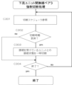
図17は、各EPC機能部3にてなされる該転送テーブルの更新処理の流れを示すものであり、A201で処理が開始されると、A202では無線通信ユニットの配列(順序や数)が変化したか否かを確認する。具体的には、後述の接続変更により、上流ユニット又は下流ユニットのノードアドレスが変化したかを確認し、変化していればA203に進み、ルーティングテーブル305ert上にて、パケット送信先となる無線通信ユニットのノードアドレス毎に、ネクストホッピングとなる無線通信ユニットのノードアドレスを変更する。一方、変化していなければA203をスキップする。A204では自ノードに接続中のUEのIPアドレスを取得する。A205では、取得したIPアドレスにより、接続中ノード登録部305fの内容が更新される。A206では、処理を終了するか否かを判断し、終了でなければA207で一定期間待機した後A202に戻り、以下の処理を繰り返す。
FIG. 17 shows the flow of the forwarding table update process performed by each
図18は、同じ無線通信ユニット1に接続するUE5(UE(I)及びUE(II))間のIPパケットの伝送処理の流れを示すものである。U1及びU2は図15により説明済みのアタッチシーケンスであり、端末用無線ベアラが構築される。U3でUE(I)からIPパケットが無線基地局部4に向け上りパケットとして送出される。無線基地局部4がこれをEPC機能部3に転送する。EPC機能部3では、図16の接続中ノード登録部305fを参照し、自身が属する無線通信ユニットに接続中のいずれかのUEのIPアドレスが、受け取ったIPパケットのヘッダに記録されている送信先アドレスと一致しているか否かを確認する。図18の場合、UE(II)のIPアドレスがこれに該当することとなり、D1にて該IPパケットを下りパケットとして配下の無線基地局部4に折り返し転送する。無線基地局部4はこれを受け取ってUE(II)に転送し、処理は完了する。
FIG. 18 shows the flow of IP packet transmission processing between UEs 5 (UE(I) and UE(II)) connected to the same
図19は、図11において、無線通信ユニット1(A)に接続中のUE5(A)と、隣接する無線通信ユニット1(A)に接続中のUE5(B)と間のIPパケットの伝送処理の流れを示すものである。U1~U3までの処理は図18と同じである。U3において無線通信ユニット1(A)のEPC機能部3は接続中ノード登録部305fを参照し、受け取ったIPパケットの送信先アドレスが、自身が属する無線通信ユニット1(A)に接続中のいずれのUEのIPアドレスとも一致せず、かつルーティングテーブル305ertの参照により、ネクストホッピングが上流側の無線通信ユニット1(B)であることを確認する。そして、U4にてそのIPパケットを、ユニット間無線ベアラ55(A)により上流側の無線通信ユニット1(B)に転送する。無線通信ユニット1(B)では、このIPパケットを受け取り、同様に接続中ノード登録部305fを参照し、UE5(B)のIPアドレスが送信先のIPアドレスと一致することを確認する。そして、D2にて該IPパケットを下りパケットとして配下の無線基地局部4に転送する。無線基地局部4はこれを受け取ってUE5(B)に転送し、処理は完了する。
FIG. 19 shows IP packet transmission processing between UE 5 (A) connected to wireless communication unit 1 (A) and UE 5 (B) connected to adjacent wireless communication unit 1 (A) in FIG. It shows the flow of The processing from U1 to U3 is the same as in FIG. In U3, the
たとえば、IPパケットの送信元のUEが、カスケード接続された無線通信ユニット群の中間のものに接続されており、送信先のUEが該無線通信ユニットよりも下流側の無線通信ユニットに接続中のUEである場合は、上記UEにてEPC機能部3は接続中ノード登録部305fを参照し、受け取ったIPパケットの送信先アドレスが、自身が属する無線通信ユニットに接続中のいずれのUEのIPアドレスとも一致せず、かつルーティングテーブル305ertの参照により、ネクストホッピングが下流側の無線通信ユニットであることを確認する。そして、該IPパケットは下りパケットとして無線基地局部4に転送され、さらに送信先となるUEが接続される無線通信ユニットに下流側のユニット間無線ベアラを用いて転送される。
For example, the IP packet transmission source UE is connected to an intermediate group of cascaded wireless communication units, and the transmission destination UE is connected to a wireless communication unit downstream of the wireless communication unit. If it is a UE, the
図20は、図11において、無線通信ユニット1(A)に接続中のUE5(A)と、2つ先の無線通信ユニット1(C)に接続中のUE5(C)と間のIPパケットの伝送処理の流れを示すものである。U1~U4までの処理は図19と同じである。U5において無線通信ユニット1(B)のEPC機能部3は接続中ノード登録部305fを参照し、受け取ったIPパケットのヘッダに記録されている送信先アドレスが、自身が属する無線通信ユニット1(B)に接続中のいずれのUEのIPアドレスとも一致しないことを確認し、U5にてそのIPパケットを、ユニット間無線ベアラ55(B)により上流側の無線通信ユニット1(C)に転送する。無線通信ユニット1(C)では、このIPパケットを受け取り、同様に接続中ノード登録部305fを参照し、UE5(C)のIPアドレスが送信先のIPアドレスと一致することを確認する。そして、D3にて該IPパケットを下りパケットとして配下の無線基地局部4に転送する。無線基地局部4はこれを受け取ってUE5(C)に転送し、処理は完了する。
FIG. 20 shows IP packets between UE 5 (A) connected to wireless communication unit 1 (A) and UE 5 (C) connected to wireless communication unit 1 (C) two ahead in FIG. It shows the flow of transmission processing. The processing from U1 to U4 is the same as in FIG. In U5, the
図21は、無線通信ユニット1(A)に接続中のUE5(A)からのIPパケットが、無線ネットワークシステム外の送信先アドレスを有している場合の処理を示す。U1~U5までの処理は図20と同じである。U5において無線通信ユニット1(C)のEPC機能部3は接続中ノード登録部305fを参照し、受け取ったIPパケットのヘッダに記録されている送信先アドレスが、自身が属する無線通信ユニット1(C)に接続中のいずれのUEのIPアドレスとも一致しないことを確認し、U6にてそのIPパケットをルータ8に転送する。すなわち、ルータ8が設けられた無線通信ユニット1(C)のEPC機能部3は、転送されてくるIPパケットの送信先ノードが接続中ノード登録部305fに含まれていないノードを示す場合は、ルータ8を介してIPパケットを外部ネットワーク60に転送する。
FIG. 21 shows processing when an IP packet from UE 5(A) connecting to wireless communication unit 1(A) has a destination address outside the wireless network system. The processing from U1 to U5 is the same as in FIG. In U5, the
図11の無線通信ユニット1(A)~1(D)はいずれもルータ8を内蔵しており、例えば衛星通信回線61等により外部ネットワーク60(例えばグローバル公共ネットワーク(インターネット))と接続可能である。該構成により、本発明の無線ネットワークシステム外のネットワークを送信先とするIPパケットの転送処理を、簡単なアルゴリズムにより実現できていることがわかる。
Each of the wireless communication units 1(A) to 1(D) in FIG. 11 has a built-in
なお、各無線通信ユニットにおけるIPパケットの転送制御処理については、図16に示す転送テーブルに代え、より簡便な接続中ノード登録部を用いた方式とすることも可能である。図23はその一例を示すものであり、該接続中ノード登録部305fが設けられている無線通信ユニット1に接続中のUE5のノード特定情報のみをリストとして記憶している。ノード特定情報は、接続中のUEのIPアドレス(UEIP01,UEIP02,・・・)であるが、UE5を接続ノードとして特定できる情報であればこれに限らず、例えばUE5に組み込まれたSIM(subscriber identity module)カードのID(=UE5の端末加入者情報:SIMID01,SIMID02,・・・)や装置のMACアドレス(MAD01,MAD02,・・・)なども使用可能である。
It should be noted that the IP packet transfer control process in each wireless communication unit may employ a simpler method using a connected node registration unit instead of the transfer table shown in FIG. FIG. 23 shows an example of this, and only the node identification information of
すなわち、図11において、各無線通信ユニット1(A)~1(D)のEPC機能部3には、無線基地局部4のセル(通信エリア)内にて該無線基地局部4に端末用無線ベアラ57(A)~57(D)を介して接続中の複数のUE5(A)~5(D)(移動端末)について、それら接続中のUE5(A)~5(D)のノード特定情報を登録する接続中ノード登録部305fを設けておく。EPC機能部3は、無線基地局部4から転送されてくるIPパケットの送信先ノード(送信先アドレス)を接続中ノード登録部305fの登録内容と照合し、送信先ノードが、接続中ノード登録部305fに登録されたノード特定情報のいずれかに対応するUE(移動端末)を示す場合には、IPパケットを該UEに対し無線基地局部4にて折り返す形で転送する。
That is, in FIG. 11, the
他方、送信先ノードが接続中ノード登録部305に登録されていないノードを示す場合にはIPパケットを中継無線通信部9及び無線基地局部4の双方に転送する。つまり、この方式では、外部の送信先を示すIPパケットを受け取ったEPC機能部3は、接続中ノード登録部305の内容のみでは送信先ノードが上流側と下流側のいずれに存在するかの判別ができない。そこで、外部の送信先を示すIPパケットについては、送信方向を特に限定せず、上流側と下流側の両方に転送を行なうことでこの問題を解決する。
On the other hand, when the destination node indicates a node not registered in the connected node registration section 305 , the IP packet is transferred to both the relay
接続中ノード登録部305fを用いる方式は、図16の転送テーブルを用いる方式と異なり、ダイナミックルーティングのために他の無線通信ユニットとの間で連携する通信処理が不要となる利点を有する。つまり、個々の無線通信ユニットは、自身の接続中UEの状態を把握する処理に専念すればよいのである。図24はその処理の流れを示すものであり、A101で処理が開始されると、A102で新たなUEからアタッチ要求があるか否かを確認する。アタッチ要求があればA103に進み、該当するUEのノード特定情報を新規登録する一方、アタッチ要求がなければA103をスキップする。次に、A104では、接続切断したUEがあるか否かを確認する。接続切断したUEがあればA105に進み、該当するUEのノード特定情報を削除する一方、接続切断したUEがなければA105をスキップする。
Unlike the method using the forwarding table of FIG. 16, the method using the connected
例えば図11において無線通信ユニット1(B)に着目した場合、その中継無線通信部9は、EPC機能部3から転送されるIPパケットを、上流ユニット間無線ベアラ55(B)を介して上流側の無線通信ユニット1(C)の無線基地局部4(上流無線基地局部)に上りパケットとして転送する。他方、無線通信ユニット1(B)の無線基地局部4はEPC機能部3から転送されるIPパケットを、下流ユニット間無線ベアラ55(A)を介して下流側の無線通信ユニット1(A)の無線基地局部4(下流無線基地局部)に下りパケットとして転送する。この処理が各無線通信ユニット1(A)~1(D)にて実施されることで、送信先のUEが無線ネットワークシステム内に存在する場合は、伝送対象のIPパケットの送信先は、上りリンクと下りリンクのいずれかにて必ず特定できる。なお、上りリンクと下りリンクのうち、伝送対象のIPパケットの送信先が存在しなかった側では、IPパケットはリンク末端の無線通信ユニットまでたどり着くこととなるが、該末端の無線通信ユニットでも送信先のUEが見いだせなかった場合は、その無線通信ユニットでIPパケットを無効化する処理(例えば破棄する処理)を行なえばよい。
For example, when focusing on the wireless communication unit 1 (B) in FIG. 11, the relay
そして、伝送対象のIPパケットが、無線ネットワークシステムの外部の送信先アドレスを示すものの場合の処理を考慮した場合、図11のようにカスケード接続された無線通信ユニット1(A)~1(D)の一方の終端に位置するユニット(図11では無線通信ユニット1(A)とする)を、上記IPパケットを破棄する処理を実行するユニットとして定め、他方の終端に位置するユニット(図11では無線通信ユニット1(D)とする)は、ルータ8を介して外部ネットワーク60に接続できるように構成する。例えば中間の無線通信ユニット1(B)に接続されたUEが送信元となり、外部ネットワーク60に向けて送信先が指定されたIPパケットは、本方式において下りリンク側に転送されたものについては無線通信ユニット1(A)で破棄されるので、結局上りリンク側に送信されたIPパケットだけが生き残り、最終的に無線通信ユニット1(D)にたどり着くこととなる。無線通信ユニット1(D)では、図19を援用して説明すれば、受け取ったIPパケットのヘッダに記録されている送信先アドレスが、接続中ノード登録部305f内のいずれのUEのIPアドレスとも一致しないことを確認し、U6にてそのIPパケットをルータ8に転送する。該IPパケットは、ルータ8を介して外部ネットワーク60に送出される。
Considering the processing in the case where the IP packet to be transmitted indicates a destination address outside the wireless network system, the wireless communication units 1(A) to 1(D) cascaded as shown in FIG. A unit (wireless communication unit 1 (A) in FIG. 11) located at one end of the is defined as a unit that executes the process of discarding the IP packet, and a unit located at the other end (wireless communication unit 1 (A) in FIG. 11) Communication unit 1 (D)) is configured to be connectable to
次に、前述の簡易ハンドオーバ処理について説明する。
図2を用いてすでに説明したごとく、本実施形態においては、無線通信ユニット対をなす一方の無線通信ユニット1(A)と他方の無線通信ユニット1(B)とがユニット間無線ベアラ55によってのみ通信接続される構成となっている。すなわち、無線通信ユニット対1(A),1(B)の無線基地局部4,4間は、これらを直接接続する制御インターフェースが省略されている(すなわち、従来のX2インターフェースが設けられない構成)。よって、図11において無線通信ユニット1(A)に接続された移動端末5(A)が無線通信ユニット1(B)の通信セル50B内に移動した場合に、X2インターフェースを用いた通常のハンドオーバ処理を実施することができない。そこで、本実施形態では、図20に示すシーケンスに従って、下記の簡易ハンドオーバ処理が実行される。すなわち、UE5(A)が無線通信ユニット1(A)に対し、U1及びU2において図15に示すアタッチシーケンスを実行し、無線通信ユニット1(A)との間に端末用無線ベアラを構築する。これにより、UE5(A)は無線通信ユニット1(A)との間で上りパケット(U3)及び下りパケット(D1)の送受信が可能となる。
Next, the aforementioned simple handover processing will be described.
As already explained using FIG. 2, in this embodiment, one wireless communication unit 1 (A) and the other wireless communication unit 1 (B) forming a wireless communication unit pair are connected only by the unit-to-
そして、S101において、無線通信ユニット1(A)の無線基地局部4とUE5(移動端末)とを接続する端末用無線ベアラの切断をUE5(移動端末)が検出し、さらにS102で移動先の無線通信ユニット1(B)をUE5が検出することで、UE5はU1’において無線通信ユニット1(B)に対して新たなアタッチ要求を行なう。無線通信ユニット1(B)はこのアタッチ要求を受けることにより、U2と同様の処理に基づきUE5との間に新たな端末用無線ベアラを確立する。すなわち、無線通信ユニット1(B)のEPC機能部3からの指令に基づき、無線通信ユニット1(B)の無線基地局部4と、移動後のUE5(A)(移動端末)との間に端末用無線ベアラが再構築される。以上の処理により、基地局間インターフェースが存在しない環境であるにも関わらず、UE5のセル間移動に伴う実質的なハンドオーバ処理が実現できていることがわかる。
Then, in S101, the UE5 (mobile terminal) detects disconnection of the terminal radio bearer that connects the radio
以下、図11のごとく複数の無線通信ユニット1(A)~1(D)がユニット間無線ベアラ55(A)~55(B)により接続され、本発明の無線ネットワークシステムが構築されている状態において、システム内の無線通信ユニット接続のトポロジー変更が行われる具体例について説明する。 Hereinafter, as shown in FIG. 11, a plurality of wireless communication units 1(A) to 1(D) are connected by inter-unit wireless bearers 55(A) to 55(B) to construct the wireless network system of the present invention. , a specific example of changing the topology of the wireless communication unit connection in the system will be described.
図25の状態A1では、3つの無線通信ユニット1(B)~1(D)がユニット間無線ベアラ55(B),55(C)により接続されており、その先頭の無線通信ユニット1(B)に向け、新たな無線通信ユニット1(A)が接近しつつある。そして、その中継無線通信部(BTC)9が、無線通信ユニット1(B)のeNodeB4の圏内に入ると、中継無線通信部(BTC)9はアタッチ要求を無線通信ユニット1(B)のeNodeB4に向けて出力する。以下は、図14にして説明済みのアタッチシーケンスが実行され、状態A2のごとく、無線通信ユニット1(A)と無線通信ユニット1(B)との間にユニット間無線ベアラ55(A)が構築されて、無線ネットワークシステムに無線通信ユニット1(A)が取り込まれる。
In state A1 of FIG. 25, three wireless communication units 1(B) to 1(D) are connected by inter-unit wireless bearers 55(B) and 55(C), and the leading wireless communication unit 1(B) ), a new wireless communication unit 1(A) is approaching. When the relay wireless communication unit (BTC) 9 enters the range of the
図26の状態B1では、3つの無線通信ユニット1(A)~1(C)がユニット間無線ベアラ55(A)~55(B)により接続されており、その末端の無線通信ユニット1(C)に向け、新たな無線通信ユニット1(D)が接近しつつある。そして、無線通信ユニット1(C)の中継無線通信部(BTC)9が、接近中の無線通信ユニット1(D)のeNodeB4の圏内に入ると、無線通信ユニット1(C)の中継無線通信部9はアタッチ要求を無線通信ユニット1(D)のeNodeB4に向けて出力する。以下は、図14にして説明済みのアタッチシーケンスが実行され、状態B2のごとく、無線通信ユニット1(C)と無線通信ユニット1(D)との間にユニット間無線ベアラ55(C)が構築されて、無線ネットワークシステムに無線通信ユニット1(D)が取り込まれる。
In state B1 of FIG. 26, three wireless communication units 1(A) to 1(C) are connected by inter-unit wireless bearers 55(A) to 55(B), and the terminal wireless communication unit 1(C) ), a new wireless communication unit 1(D) is approaching. Then, when the relay wireless communication unit (BTC) 9 of the wireless communication unit 1(C) enters the range of the
図25及び図26のいずれにおいても、新たに付加される無線通信ユニットは、構築済みの無線通信ネットワークシステムの先頭または末端、つまり、ネットワークのエッジを構成している無線通信ユニット(図25では符号1(B),図26では符号1(C))にのみ接続が許されている実施形態を示している。この方式は、無線通信ユニットの付加が、既存ネットワーク内の無線通信ユニットの接続順序に影響を及ぼさず、簡易である利点がある。しかし、付加対象の無線通信ユニットが、エッジを構成する無線通信ユニットに接近した場合にのみアタッチ・接続がなされるため、無線通信ユニットの新規付加に対する柔軟性にやや乏しい欠点がある。 In both FIGS. 25 and 26, the newly added radio communication unit is the head or end of the constructed radio communication network system, that is, the radio communication unit that constitutes the edge of the network. 1(B), and FIG. 26 shows an embodiment in which connection is permitted only to reference numeral 1(C)). This method has the advantage that the addition of the wireless communication unit does not affect the connection order of the wireless communication units in the existing network and is simple. However, since the wireless communication unit to be added is attached and connected only when it approaches the wireless communication unit that constitutes the edge, there is a drawback that the flexibility for adding a new wireless communication unit is rather poor.
一方、中継無線通信部は、上流ユニットとは別の無線通信ユニットであって上流ユニットよりも高品質にて無線接続可能な切替候補ユニットが存在する場合に、新たな上流ユニットとして該切替候補ユニットに接続切り替えするように構成することもできる。図27は、その最も単純な場合として、状態C1のごとく、複数の無線通信ユニット1(A)~1(D)からなる無線通信ネットワークシステムの中間に位置する無線通信ユニット1(C)が、状態C2のように移動により離間し、状態C3のようにネットワークシステムより離脱する場合(あるいは、故障等により通信不能となる場合:これも一種の「離脱」であるといえる)の、残余の無線通信ユニット1(A),1(B),1(D)の再接続プロセスを示すものである。 On the other hand, when there is a switching candidate unit that is a wireless communication unit different from the upstream unit and that can be wirelessly connected with higher quality than the upstream unit, the relay wireless communication unit selects the switching candidate unit as a new upstream unit. It can also be configured to switch the connection to FIG. 27 shows, as the simplest case, a wireless communication unit 1(C) positioned in the middle of a wireless communication network system consisting of a plurality of wireless communication units 1(A) to 1(D), as in state C1. In the case of moving apart as in state C2 and leaving the network system as in state C3 (or when communication becomes impossible due to a failure or the like: this can also be said to be a kind of "leaving"), the remaining wireless It shows the reconnection process of communication units 1(A), 1(B), 1(D).
上記のような無線通信ユニット1(C)の離脱が生じると、その上流ユニット(図27では無線通信ユニット1(D))と、無線通信ユニット1(C)との間の通信品質の低下によりユニット間無線ベアラ55(C)の接続が切断される。その結果、無線ネットワークシステムは、離脱した無線通信ユニット1(C)に接続していた2つの無線通信ユニット1(B)、1(D)を各々新たにエッジとする2つのネットワーククラスタCR1,CR2に分解する。また、その切断により一旦孤立した無線通信ユニット1(D)は、これに最も近い残余の無線通信ユニット1(B)からみた場合に切替候補ユニットとなる。この場合、状態C3のように、一方のネットワーククラスタCR1のエッジをなす無線通信ユニット1(B)が、他方のネットワーククラスタCR2のエッジをなす無線通信ユニット1(D)にアタッチ要求することにより、状態C4のように無線通信ユニット1(B)と無線通信ユニット1(D)との間に新たにユニット間無線ベアラ55(B’)が構築され、2つのネットワーククラスタCR1,CR2の再接続が完了する。 When the wireless communication unit 1(C) is separated as described above, the quality of communication between the upstream unit (wireless communication unit 1(D) in FIG. 27) and the wireless communication unit 1(C) deteriorates. The connection of the inter-unit radio bearer 55(C) is disconnected. As a result, the wireless network system is divided into two network clusters CR1 and CR2 each having two new edges, the two wireless communication units 1(B) and 1(D) connected to the disconnected wireless communication unit 1(C). decompose into Also, the wireless communication unit 1(D) once isolated due to the disconnection becomes a switching candidate unit when viewed from the nearest remaining wireless communication unit 1(B). In this case, as in state C3, the wireless communication unit 1 (B) that forms the edge of one network cluster CR1 issues an attach request to the wireless communication unit 1 (D) that forms the edge of the other network cluster CR2. As in state C4, a new inter-unit radio bearer 55 (B') is constructed between the radio communication unit 1 (B) and the radio communication unit 1 (D), and the two network clusters CR1 and CR2 are reconnected. complete.
図27は、無線通信ユニット1(C)の離脱により生じる切替候補ユニットが無線通信ユニット1(B)の1つだけである単純な事例を示していたが、実際には残余の無線通信ユニット1(A),1(B),1(D)の移動により、例えばネットワーククラスタCR1,CR2のいずれかのエッジをなす無線通信ユニットから見た切替候補ユニットが複数生じる場合もある。また、無線通信ネットワークシステムの中間に無線通信ユニットに対し、ネットワーク外の別の無線通信ユニットが接近した場合、その接近先に位置する無線通信ユニットの2つ以上のものが切替候補ユニットとなることもある。 FIG. 27 shows a simple case in which the wireless communication unit 1 (B) is the only switching candidate unit resulting from the withdrawal of the wireless communication unit 1 (C). Due to the movement of (A), 1(B), and 1(D), for example, a plurality of switching candidate units seen from the wireless communication unit forming the edge of either network cluster CR1 or CR2 may occur. Further, when another wireless communication unit outside the network approaches a wireless communication unit in the middle of the wireless communication network system, two or more of the wireless communication units located at the approaching point become switching candidate units. There is also
ここで、中継無線通信部の接続先となる無線基地局部を、別の無線通信ユニットの無線基地局部に接続変更するには、すでに構築されているユニット間無線ベアラを一旦切断して、変更先となる無線通信ユニットの無線基地局部と間に新たにユニット間無線ベアラを構築しなおさなければならない。このユニット間無線ベアラの切断を、状況に応じて上流側の無線通信ユニットの側からEPC機能部の指示により強制的に実行できるようにしておくと、ユニット間無線ベアラの再構築による無線通信ユニット間の接続トポロジーの最適化を容易に図ることができる。具体的にはEPC機能部が無線基地局部に対し、下流ユニットとの間の下流ユニット間無線ベアラを一時的かつ強制的に切断する指示を行ない(図3:ネットワーク調整プログラム305hの機能)、無線基地局部は指示を受けて下流ユニット間無線ベアラの切断制御を行なうようにする。この場合、上流ユニット接続切替制御部は、上流ユニット間無線ベアラが切断されるに伴い、該上流ユニット間無線ベアラにより上流ユニットとして接続されていた無線通信ユニットである旧上流ユニットと、切替候補ユニットとのそれぞれに対する通信品質評価を行ない、通信品質評価の結果に基づいて新たな上流ユニットとして接続するべき無線通信ユニットを決定するように構成しておく(上流ユニット接続切替制御プログラム905bの機能)。 Here, in order to change the connection from the radio base station section that is the connection destination of the relay radio communication section to the radio base station section of another radio communication unit, the inter-unit radio bearer that has already been established is once disconnected, and A new inter-unit radio bearer must be re-established between the radio base station section of the radio communication unit to be used. If this inter-unit radio bearer disconnection can be forcibly executed by an instruction from the EPC function section from the upstream radio communication unit side according to the situation, the radio communication unit can It is possible to easily optimize the connection topology between them. Specifically, the EPC function section instructs the radio base station section to temporarily and forcibly disconnect the radio bearer between the downstream units (FIG. 3: function of the network adjustment program 305h). Upon receipt of the instruction, the base station section performs disconnection control of the radio bearer between downstream units. In this case, the upstream unit connection switching control section, along with the disconnection of the upstream unit wireless bearer, controls the former upstream unit, which is a wireless communication unit connected as an upstream unit by the upstream unit wireless bearer, and the switching candidate unit. , and a wireless communication unit to be connected as a new upstream unit is determined based on the result of the communication quality evaluation (function of the upstream unit connection switching control program 905b).
図28及び図29にその一例を示している。図28の状態D1では、3つの無線通信ユニット1(A)~1(C)がユニット間無線ベアラ5(A),55(B)により接続されており、無線通信ユニット1(B),1(C)の中間に向け、新たな無線通信ユニット1(D)が接近しつつある。この状況で、例えば無線通信ユニット1(C)の下流ユニット間無線ベアラ強制切断指示部は、接続中の下流ユニット1(B)との距離d1を反映した下流ユニット距離情報を取得し(下流ユニット距離情報取得部)、切替候補ユニットとなる無線通信ユニット1(D)との距離dcを反映した切替候補ユニット距離情報を取得する(切替候補ユニット距離情報取得部)。状態D1においてはd1>dcである。 An example is shown in FIGS. 28 and 29. FIG. In state D1 of FIG. 28, three wireless communication units 1(A) to 1(C) are connected by inter-unit wireless bearers 5(A) and 55(B). Towards the middle of (C), a new wireless communication unit 1 (D) is approaching. In this situation, for example, the downstream unit wireless bearer forced disconnection instruction unit of the wireless communication unit 1(C) acquires downstream unit distance information reflecting the distance d1 to the downstream unit 1(B) being connected (downstream unit distance information acquisition unit), and acquires switching candidate unit distance information reflecting the distance dc from the wireless communication unit 1(D) that is a switching candidate unit (switching candidate unit distance information acquisition unit). In state D1, d1>dc.
そして、状態D2のように、取得された切替候補ユニット距離情報に反映される切替候補ユニットとの距離d1が、取得された下流ユニット距離情報に反映される下流ユニットとの距離dcよりも小さくなった場合に、無線通信ユニット1(C)のEPC機能部3は無線基地局部4に対し、下流ユニット間無線ベアラ(55(B))を一時的かつ強制的に切断する指示を行なう。これにより、状態D3のごとく、すでに接続中の下流ユニット(1(C))よりも近くなるように切替候補ユニット(1(D))が接近してきた場合、上記距離判定により下流ユニット間無線ベアラが強制切断され、図29の状態D4のように、より近い切替候補ユニット(1(D))との接続が新たに生じるようユニット間無線ベアラ55(B’)が再構築され、ユニット間無線ベアラの通信品質及び通信密度を大幅に高めることができる。
Then, as in state D2, the distance d1 to the switching candidate unit reflected in the acquired switching candidate unit distance information becomes smaller than the distance dc to the downstream unit reflected in the acquired downstream unit distance information. In this case, the
下流ユニット距離情報及び切替候補ユニット距離情報の取得方式は種々の形態から選んで採用可能であるが、例えば最も簡便な方法としては、無線通信ユニットに該無線通信ユニットの現在位置を取得する現在位置取得部を設け、下流ユニット距離情報取得部及び切替候補ユニット距離情報取得部を、下流ユニット及び切替候補ユニットからそれぞれの現在位置を取得し、それらの現在位置の情報に基づいて下流ユニットとの距離及び切替候補ユニットとの距離を各々算出する方式を例示できる。本実施形態では、図3に示すように、各無線通信ユニット1の無線基地局部4に現在位置取得部をなすGPS413(バス405に接続されている)を設けており、例えば図28において無線通信ユニット1(D)は、下流ユニット1(C)の位置情報を下流ユニット間無線ベアラ(55(B))を経由してGPS情報として取得可能である。また、ユニット間無線ベアラが構築されていない切替候補ユニット(1(D))の位置情報については、図3においてルータ8に衛星通信回線61を介して接続された外部ネットワーク60を経由してGPS情報として取得可能である。
The method of acquiring the downstream unit distance information and the switching candidate unit distance information can be selected from various forms and adopted. An acquisition unit is provided, and the downstream unit distance information acquisition unit and the switching candidate unit distance information acquisition unit acquire the respective current positions from the downstream unit and the switching candidate unit, and determine the distance from the downstream unit based on the information of their current positions. and the distance to the switching candidate unit can be exemplified. In this embodiment, as shown in FIG. 3, the radio
図34は、前述のネットワーク調整プログラム305hによる、この場合の下流ユニット間無線ベアラ強制切断処理の流れの一例を示すものである。図28(状態D1)において該処理を行なうのは、無線通信ユニット1(D)のEPC機能部3である。C201では、自身の位置情報をGPS413(図3)から取得する。なお、この位置情報は他の無線通信ユニットが距離算出にて使用できるようにするため、外部ネットワーク60(図3)にアップロードされる。C202では、接続を受けている下流ユニット1(B)(図28)の位置情報を、ユニット間無線ベアラ55(B)を介して取得するとともに、上記自身の位置情報とに基いて距離dcを演算する。
FIG. 34 shows an example of the flow of processing for forcibly disconnecting the wireless bearer between downstream units in this case by the network adjustment program 305h. In FIG. 28 (state D1), it is the
そして、C203では、周辺の切替候補ユニット(図23では無線通信ユニット1(D))の位置情報を、外部ネットワーク60(図3)を経由して取得する。C204では、各切替候補ユニットまでの距離を演算し、最も近いものをd1として特定する。そして、C205にて、d1<dcの場合にC206に進み、接続を受けている下流ユニット1(B)(図28)とのユニット間無線ベアラ55(B)を一時切断する(図28:状態D2)。また、C205にて、d1<dcでない場合はC206をスキップする。そして、C207にて終了でなければC201へ戻り、以下の処理を繰り返す。 Then, in C203, the position information of the surrounding switching candidate unit (wireless communication unit 1(D) in FIG. 23) is acquired via the external network 60 (FIG. 3). In C204, the distance to each switching candidate unit is calculated, and the closest one is identified as d1. Then, in C205, if d1<dc, the process proceeds to C206 to temporarily disconnect the unit-to-unit wireless bearer 55(B) with the connected downstream unit 1(B) (FIG. 28) (FIG. 28: State D2). In C205, if d1<dc, C206 is skipped. Then, if the process is not finished in C207, the process returns to C201, and the following processes are repeated.
図28の状態D2にように、上記のようなユニット間無線ベアラの切断が生じると、これによりエッジ化した旧下流ユニット1(B)の中継無線通信部9は、上流ユニット接続切替制御プログラム905b(図3:上流ユニット接続切替制御部)により、状態D3のように、上流ユニット間無線ベアラ55(B)により上流ユニットとして接続されていた無線通信ユニットである旧上流ユニット1(C)と、切替候補ユニット1(D)とのそれぞれに対する通信品質評価を行ない、通信品質評価の結果に基づいて新たな上流ユニットとして接続するべき無線通信ユニットを決定する処理を行なう。これにより、再接続後の無線通信ユニットとの通信品質や無線通信ユニット間の通信のスループットをより高めることが可能となる。
As in the state D2 of FIG. 28, when the inter-unit wireless bearer is disconnected as described above, the relay
本実施形態では、各無線通信ユニット1(C)、1(D)からCQI参照信号を受信し、該CQI参照信号を用いてCQI情報(図32)を生成し、該CQI情報の内容に基づいて通信品質評価を行なうようにしている。CQI情報の測定・生成処理機能は、LTE端末(UE及び中継無線通信部)の場合、前述の通りリソースブロックのスケジューリングアルゴリズムに不可欠であり、3GPPのプロトコルにも標準仕様として組み込まれているので、これを流用できる利点がある。ただし、LTEプロトコルにおいてCQIの測定がなされるのは、端末が無線基地局部にアタッチした後であり、本発明への適用を図るには、アタッチ前にCQI測定が実行されるよう、標準プロトコル外の処理を工夫する必要がある。 In this embodiment, a CQI reference signal is received from each wireless communication unit 1 (C) and 1 (D), CQI information (FIG. 32) is generated using the CQI reference signal, and based on the content of the CQI information, communication quality evaluation. In the case of LTE terminals (UE and relay radio communication unit), the CQI information measurement and generation processing function is indispensable for the resource block scheduling algorithm as described above, and is also incorporated in the 3GPP protocol as a standard specification. There is an advantage that this can be diverted. However, in the LTE protocol, the CQI is measured after the terminal attaches to the radio base station. It is necessary to devise the processing of
図33は、上流ユニット接続切替制御処理の流れの一例を示すものである。図28(状態D3)において該処理を行なうのは、旧下流ユニットを構成していた無線通信ユニット1(B)の中継無線通信部9である。C101では、上流側ユニット間無線ベアラの切断を検出し、検出があればC102に進む。接続候補となる無線通信ユニット1(C)、1(D)の無線基地局部4は、LTEプロトコルに従い、それぞれUE5ないし中継無線通信部9のアタッチを受け付けるための報知情報を出力する。そして、本実施形態においては、標準プロトコル外の処理として、この報知情報に続く形でCQI測定用の参照信号を送信するようにしている。この参照信号は、図10のリソースブロックマトリックスにおいて、時間軸上における各スロット内の特定のシンボル(例えばシンボル「0」と「4」)にて、予め定められた周波数のサブキャリアを用いる形で挿入されている。そこで、報知情報の中に、参照信号を取得するためのスロット内のシンボル番号と、周波数サブキャリア特定情報とを組み込んでおけば、無線通信ユニット1(B)の中継無線通信部9は、これを読み取ってCQI測定用の参照信号の受信設定処理を行なうことができる。
FIG. 33 shows an example of the flow of upstream unit connection switching control processing. In FIG. 28 (state D3), it is the relay
図33に戻り、C102では、CQI参照信号が受信しているか否かを確認する。受信している場合はC103に進み、CQI参照信号を複数ノードから受けているか否かを判定する。受けている場合はC104に進み、各CQI参照信号についてCQI測定を実施する。そして、C105に進み、図29の状態D4のように、複数ユニット(1(C), 1(D))のうち、測定したCQIが示す通信品質が最も良好な無線通信ユニット、例えば図29では、例えば無線通信ユニット1(B)に最も近くなることで、CQI情報(図32参照)に反映された符号化率及び周波数利用効率が最も良好となる無線通信ユニット1(D)にアタッチ要求することで、該無線通信ユニット1(D)との間にユニット間無線ベアラ55(B’)が構築される。一方、C103で、CQI参照信号を複数ノードから受けていない場合、つまり、1つのノード(無線通信ユニット)からしか受けていない場合は、C106に進み、CQI測定結果とは無関係に当該ユニットへのアタッチ要求を行なう。C107で終了でなければC101に戻り、以下の処理を繰り返す。 Returning to FIG. 33, at C102, it is confirmed whether or not the CQI reference signal is received. If received, the process proceeds to C103 to determine whether or not CQI reference signals are received from a plurality of nodes. If so, proceed to C104 and perform CQI measurements for each CQI reference signal. Then, proceeding to C105, as in state D4 in FIG. 29, the wireless communication unit with the best communication quality indicated by the measured CQI among the plurality of units (1(C), 1(D)), for example, in FIG. For example, by being closest to the wireless communication unit 1(B), an attach request is made to the wireless communication unit 1(D) that has the best coding rate and frequency utilization efficiency reflected in the CQI information (see FIG. 32). Thus, an inter-unit radio bearer 55 (B') is established with the radio communication unit 1 (D). On the other hand, if the CQI reference signal is not received from multiple nodes in C103, that is, if the CQI reference signal is received only from one node (radio communication unit), proceed to C106, regardless of the CQI measurement result. Make an attach request. If the process is not finished in C107, the process returns to C101, and the following processes are repeated.
図29の状態D5では、無線通信ユニット1(D)は同様のアルゴリズムにより、自身に最も近接する無線通信ユニット1(C)に対しアタッチし、ユニット間無線ベアラ55(C’)が構築され、再接続が完了する。 In the state D5 of FIG. 29, the wireless communication unit 1 (D) uses the same algorithm to attach to the wireless communication unit 1 (C) closest to itself, and an inter-unit wireless bearer 55 (C') is constructed. Reconnection is completed.
以上、本発明の実施の形態について説明したが、あくまで例示であって、本発明はこれに限定されるものではない。例えば、下流ユニット間無線ベアラ強制切断処理の内容は上記のものに限らず、例えば図30の状態E1及び状態E2に示すように、上流ユニットのEPC機能部が下流ユニット間無線ベアラを切断する指示を予め定められた時間間隔にて周期的に出力するように構成できる。無線基地局部が下流ユニット間無線ベアラを周期的(例えば通信品質への影響が少なくて済むように、1時間から1年に一度、望ましくは3時間から3か月に一度など)に切断する。下流ユニット間無線ベアラが切断された後の処理の流れは、すでに説明したものと同様である。なお、図30においては、全ての下流ユニット間無線ベアラ(55(A),55(B))を一斉に切断するようにしていたが、図31に示すように、下流ユニット間無線ベアラを切断する周期を無線通信ユニットごとにずらせて実施することも可能である。図31にて、状態F0はどの下流ユニット間無線ベアラも切断されていない状態を示し、状態F1~F3は、いずれかの下流ユニット間無線ベアラが切断されている状態を示す。状態F1~F3において、切断される下流ユニット間無線ベアラは互いに相違している。 Although the embodiment of the present invention has been described above, it is merely an example, and the present invention is not limited to this. For example, the content of the downstream unit-to-unit wireless bearer forced disconnection processing is not limited to the above. For example, as shown in states E1 and E2 in FIG. can be configured to be periodically output at predetermined time intervals. The radio base station section periodically disconnects the radio bearer between the downstream units (for example, once every hour to a year, preferably every three hours to three months, etc., so as to minimize the impact on communication quality). The flow of processing after the downstream inter-unit radio bearer is disconnected is the same as that already described. In FIG. 30, all the downstream unit-to-unit wireless bearers (55(A), 55(B)) are disconnected all at once, but as shown in FIG. It is also possible to shift the cycle for each wireless communication unit. In FIG. 31, state F0 indicates a state in which no downstream unit-to-unit radio bearer is disconnected, and states F1 to F3 indicate states in which any downstream unit-to-unit radio bearer is disconnected. In states F1-F3, the downstream inter-unit radio bearers to be disconnected are different from each other.
図35は、その場合の処理の流れの一例を示すものであり、C301では、例えばネットワーク調整プログラム305hに組み込まれている切断スケジューラの計時情報を参照する。C302では、予め定められている切断時期が到来したかどうかを確認する。到来していればC303に進み、接続を受けている無線通信ユニットとの接続状態を一時切断
する処理を行なう。また、C302で切断時期が到来していなければC303をスキップする。C304で終了でなければC301に戻り、以下の処理を繰り返す。
FIG. 35 shows an example of the flow of processing in that case. At C301, for example, the clock information of the disconnection scheduler incorporated in the network adjustment program 305h is referred to. In C302, it is checked whether or not a predetermined disconnection time has come. If it has arrived, the process advances to C303 to perform processing for temporarily disconnecting from the connected wireless communication unit. If the disconnection time has not come in C302, C303 is skipped. If the process is not finished in C304, the process returns to C301, and the following processes are repeated.
1(A),1(B) 無線通信ユニット
WS(A),WS(B) 大型船舶
2 MME
3 EPC機能部
301 CPU
302 RAM
303 マスクROM
304A 上流側通信インターフェース
304B 下流側通信インターフェース
305 フラッシュメモリ
305a 通信ファームウェア
305b MMEエンティティ
305c S-GWエンティティ
305d PーGWエンティティ
305e 転送テーブル
305ert ルーティングテーブル
305f,305f’ 接続中ノード登録部
305g チャネルマップ
306 バス
21 二次電池モジュール
22 電源回路部
23 可搬型筐体
30,31 通信バス
4 無線基地局部
401 CPU
402 RAM
403 マスクROM
404 通信インターフェース
405 フラッシュメモリ
405a 通信ファームウェア
406 バス
412 無線通信部
5 UE(移動端末)
6 S-GW
7 P-GW
8 ルータ
9 中継無線通信部
901 CPU
902 RAM
903 マスクROM
905 フラッシュメモリ
905a 通信ファームウェア
906 バス
912 無線通信部
50(A),50(B) 通信エリア
55 ユニット間無線ベアラ
57 端末用無線ベアラ
1(A), 1(B) Wireless communication unit WS(A), WS(B)
3
302 RAMs
303 Mask ROM
304A upstream
402 RAMs
403 Mask ROM
404
6 S-GW
7 P-GW
8
902 RAM
903 Mask ROM
905 Flash memory
Claims (9)
前記移動端末が端末用無線ベアラを介して接続可能な無線基地局部と、
前記無線基地局部に有線接続され、該無線基地局部に対する上位ネットワーク制御部として機能するEPC(Evolved Packet Core)機能部と、
前記EPC機能部に有線接続されるとともに、第一の別の無線通信ユニットである上流ユニットの無線基地局部(以下、上流無線基地局部という)と上流側のユニット間無線ベアラ(以下、上流ユニット間無線ベアラという)を介して接続可能な中継無線通信部とを備え、
前記無線基地局部は、第二の別の無線通信ユニットである下流ユニットの中継無線通信部(以下、下流中継無線通信部という)と下流側のユニット間無線ベアラ(以下、下流ユニット間無線ベアラという)を介して接続可能とされ、
前記EPC機能部は下流ユニット間無線ベアラ設定要求を前記無線基地局部に送信する一方、前記無線基地局部は前記下流ユニット間無線ベアラ設定要求を受けて前記下流中継無線通信部とともに前記下流ユニット間無線ベアラを構築するものであり、
前記EPC機能部は端末用無線ベアラ設定要求を前記無線基地局部に送信する一方、前記無線基地局部は前記端末用無線ベアラ設定要求を受けて前記移動端末とともに前記端末用無線ベアラを構築するものであり、
前記中継無線通信部は、前記上流ユニットのEPC機能部(以下、上流EPC機能部という)が発行する上流ユニット間無線ベアラ設定要求を受信し、該上流ユニット間無線ベアラ設定要求を受けて前記上流無線基地局部とともに前記上流ユニット間無線ベアラを構築するものであり、
前記EPC機能部は端末用無線ベアラ設定要求を前記無線基地局部に送信する一方、前記無線基地局部は前記端末用無線ベアラ設定要求を受けて前記移動端末とともに前記端末用無線ベアラを構築するものであり、さらに、
前記中継無線通信部は、上流ユニットが非接続の状態において新たな接続先となる上流ユニットの候補を検出した場合に、該上流ユニットの候補の無線基地局部に対し前記上流ユニット間無線ベアラを構築するためのアタッチ要求を送信することにより、前記上流ユニットの候補から前記上流ユニット間無線ベアラ設定要求を受信して前記上流ユニット間無線ベアラを構築する制御を行なう上流ユニット間無線ベアラ構築制御部を備える一方、
前記無線基地局部は、前記下流ユニットが非接続の状態において新たに接続される下流ユニットの候補からのアタッチ要求を受信した場合に、該アタッチ要求を前記EPC機能部に通知するとともに、該EPC機能部からの前記端末用無線ベアラ設定要求を受信して前記下流ユニット間無線ベアラを構築する制御を行なう下流ユニット間無線ベアラ構築制御部を備えるものであり、
前記中継無線通信部は、前記上流ユニットとは別の無線通信ユニットであって前記上流ユニットよりも高品質にて無線接続可能な切替候補ユニットが存在する場合に、新たな上流ユニットとして該切替候補ユニットに接続切り替えする上流ユニット接続切替制御部を有するものであり、
前記EPC機能部は前記無線基地局部に対し、前記下流ユニットとの間の前記下流ユニット間無線ベアラを一時的かつ強制的に切断する指示を行なう下流ユニット間無線ベアラ強制切断指示部を備える一方、前記無線基地局部は前記指示を受けて前記下流ユニット間無線ベアラの切断制御を行なう下流ユニット間無線ベアラ切断制御部を備え、
前記上流ユニット接続切替制御部は、前記上流ユニット間無線ベアラが切断されるに伴い、該上流ユニット間無線ベアラにより前記上流ユニットとして接続されていた無線通信ユニットである旧上流ユニットと、前記切替候補ユニットとのそれぞれに対する通信品質評価を行ない、前記通信品質評価の結果に基づいて新たな上流ユニットとして接続するべき無線通信ユニットを決定するものであり、
前記上流ユニット接続切替制御部は、各前記無線通信ユニットからCQI参照信号を受信し、該CQI参照信号を用いてCQI情報を生成し、該CQI情報の内容に基づいて前記通信品質評価を行なうことを特徴とする無線通信ユニット。 A wireless communication unit configured to be mountable on a mobile object and for performing wireless network communication with a mobile terminal,
a radio base station unit to which the mobile terminal can connect via a terminal radio bearer;
an EPC (Evolved Packet Core) functional unit connected by wire to the radio base station unit and functioning as an upper network control unit for the radio base station unit;
The wireless base station section of the upstream unit (hereinafter referred to as the upstream wireless base station section) and the upstream inter-unit wireless bearer (hereinafter referred to as the upstream unit a relay radio communication unit connectable via a radio bearer);
The radio base station section includes a relay radio communication section of a downstream unit, which is a second separate radio communication unit (hereinafter referred to as a downstream relay radio communication section) and a downstream inter-unit radio bearer (hereinafter referred to as a downstream inter-unit radio bearer). ) and can be connected via
The EPC function unit transmits a wireless bearer setting request between downstream units to the wireless base station unit, while the wireless base station unit receives the wireless bearer setting request between downstream units and performs wireless communication between downstream units together with the downstream relay wireless communication unit. which constructs the bearer,
The EPC function unit transmits a terminal radio bearer setting request to the radio base station unit, and the radio base station unit receives the terminal radio bearer setting request and constructs the terminal radio bearer together with the mobile terminal. can be,
The relay wireless communication unit receives an upstream unit-to-unit wireless bearer setting request issued by an EPC function unit (hereinafter referred to as an upstream EPC function unit) of the upstream unit, receives the upstream unit-to-unit wireless bearer setting request, and receives the upstream unit-to-unit wireless bearer setting request. builds a radio bearer between the upstream units together with the radio base station,
The EPC function unit transmits a terminal radio bearer setting request to the radio base station unit, and the radio base station unit receives the terminal radio bearer setting request and constructs the terminal radio bearer together with the mobile terminal. Yes, and
The relay wireless communication unit constructs the upstream unit-to-unit wireless bearer for the wireless base station unit of the upstream unit candidate when detecting a candidate for the upstream unit to be a new connection destination while the upstream unit is not connected. By transmitting an attach request to establish a radio bearer between upstream units, the upstream unit radio bearer construction control section receives the radio bearer setting request between upstream units from the upstream unit candidate and controls construction of the radio bearer between upstream units. while being prepared,
When the wireless base station section receives an attach request from a downstream unit candidate to be newly connected while the downstream unit is not connected, the wireless base station section notifies the EPC function section of the attach request. an inter-downstream unit radio bearer construction control unit that receives the terminal radio bearer setting request from the unit and performs control for constructing the inter-downstream unit radio bearer ,
When there is a switching candidate unit which is a wireless communication unit different from the upstream unit and which can be wirelessly connected with higher quality than the upstream unit, the relay wireless communication unit selects the switching candidate as a new upstream unit. It has an upstream unit connection switching control unit that switches connection to the unit,
The EPC function unit includes a downstream inter-unit radio bearer forced disconnect instruction unit that instructs the radio base station unit to temporarily and forcibly disconnect the inter-downstream unit radio bearer with the downstream unit; The radio base station section includes a downstream unit radio bearer disconnection control section that receives the instruction and performs control to disconnect the radio bearer between downstream units,
The upstream unit connection switching control unit, when the upstream unit-to-unit wireless bearer is disconnected, controls the former upstream unit, which is a wireless communication unit connected as the upstream unit by the upstream unit-to-unit wireless bearer, and the switching candidate. performing communication quality evaluation for each unit, and determining a wireless communication unit to be connected as a new upstream unit based on the result of the communication quality evaluation;
The upstream unit connection switching control section receives a CQI reference signal from each wireless communication unit, generates CQI information using the CQI reference signal, and performs the communication quality evaluation based on the content of the CQI information. A wireless communication unit characterized by:
該無線通信ユニット群は、互いに隣接する無線通信ユニット対の基地局セルが一部重なる位置関係で前記ユニット間無線ベアラにより接続されるとともに、
前記無線通信ユニット対の一方に接続された移動端末と他方に接続された移動端末とが、前記無線通信ユニット対及び該無線通信ユニット対を接続する前記ユニット間無線ベアラを介してIPパケットの送受信を行なうものであり、
前記中継無線通信部は、前記上流ユニットとは別の無線通信ユニットであって前記上流ユニットよりも高品質にて無線接続可能な切替候補ユニットが存在する場合に、新たな上流ユニットとして該切替候補ユニットに接続切り替えする上流ユニット接続切替制御部を有するものであり、
各前記無線通信ユニットにおいて、
前記EPC機能部は前記無線基地局部に対し、前記下流ユニットとの間の前記下流ユニット間無線ベアラを一時的かつ強制的に切断する指示を行なう下流ユニット間無線ベアラ強制切断指示部を備える一方、前記無線基地局部は前記指示を受けて前記下流ユニット間無線ベアラの切断制御を行なう下流ユニット間無線ベアラ切断制御部を備え、
前記上流ユニット接続切替制御部は、前記上流ユニット間無線ベアラが切断されるに伴い、該上流ユニット間無線ベアラにより前記上流ユニットとして接続されていた無線通信ユニットである旧上流ユニットと、前記切替候補ユニットとのそれぞれに対する通信品質評価を行ない、前記通信品質評価の結果に基づいて新たな上流ユニットとして接続するべき無線通信ユニットを決定するものであり、
前記上流ユニット接続切替制御部は、各前記無線通信ユニットからCQI参照信号を受信し、該CQI参照信号を用いてCQI情報を生成し、該CQI情報の内容に基づいて前記通信品質評価を行なうことを特徴とする無線ネットワークシステム。 A radio base station unit configured to be mountable on a mobile body and for performing radio network communication with a mobile terminal, the radio base station section to which the mobile terminal can be connected via a terminal radio bearer; an EPC (Evolved Packet Core) function unit connected by wire to a radio base station unit and functioning as an upper network control unit for the radio base station unit; and a first separate radio communication unit connected by wire to the EPC function unit a radio base station section of an upstream unit (hereinafter referred to as an upstream radio base station section) and a relay radio communication section connectable via an upstream inter-unit radio bearer (hereinafter referred to as an upstream inter-unit radio bearer); The base station section connects the relay wireless communication section of the downstream unit, which is a second separate wireless communication unit (hereinafter referred to as the downstream relay wireless communication section), and the downstream inter-unit wireless bearer (hereinafter referred to as the downstream inter-unit wireless bearer). The EPC function unit transmits a wireless bearer setting request between downstream units to the wireless base station unit, while the wireless base station unit receives the wireless bearer setting request between downstream units and performs the downstream relay wireless communication. The EPC function unit transmits a terminal radio bearer setting request to the radio base station unit, while the radio base station unit receives the terminal radio bearer setting request. The relay wireless communication unit receives an upstream unit-to-unit wireless bearer setting request issued by an EPC function unit of the upstream unit (hereinafter referred to as an upstream EPC function unit). and constructs the upstream inter-unit radio bearer together with the upstream radio base station section in response to the upstream unit radio bearer setting request, and the EPC function section transmits the terminal radio bearer setting request to the radio base station section , the radio base station section receives the terminal radio bearer setup request and constructs the terminal radio bearer together with the mobile terminal, and further, the relay radio communication section receives the terminal radio bearer setting request, and further, the relay radio communication section receives the terminal radio bearer setting request, When a candidate for an upstream unit to be a new connection destination is detected in the state of (1), by transmitting an attach request for constructing the radio bearer between the upstream units to the radio base station section of the candidate for the upstream unit, and an upstream unit-to-unit radio bearer construction control section that receives the upstream unit-to-unit radio bearer setup request from the upstream unit candidate and controls to construct the upstream unit-to-unit radio bearer. receives an attach request from a downstream unit candidate to be newly connected in a non-connected state, notifies the attach request to the EPC function unit, and sets the radio bearer for the terminal from the EPC function unit. comprising a wireless communication unit group in which a plurality of wireless communication units having an inter-downstream unit radio bearer construction control section that receives a request and controls construction of the inter-downstream unit radio bearer;
The radio communication unit group is connected by the inter-unit radio bearer in a positional relationship in which base station cells of pairs of radio communication units adjacent to each other partially overlap,
A mobile terminal connected to one of the wireless communication unit pair and a mobile terminal connected to the other wireless communication unit pair transmit and receive IP packets via the wireless communication unit pair and the unit-to-unit wireless bearer connecting the wireless communication unit pair. and
When there is a switching candidate unit which is a wireless communication unit different from the upstream unit and which can be wirelessly connected with higher quality than the upstream unit, the relay wireless communication unit selects the switching candidate as a new upstream unit. It has an upstream unit connection switching control unit that switches connection to the unit,
In each said wireless communication unit,
The EPC function unit includes a downstream inter-unit radio bearer forced disconnect instruction unit that instructs the radio base station unit to temporarily and forcibly disconnect the inter-downstream unit radio bearer with the downstream unit; The radio base station section includes a downstream unit radio bearer disconnection control section that receives the instruction and performs control to disconnect the radio bearer between downstream units,
The upstream unit connection switching control unit, when the upstream unit-to-unit wireless bearer is disconnected, controls the former upstream unit, which is a wireless communication unit connected as the upstream unit by the upstream unit-to-unit wireless bearer, and the switching candidate. performing communication quality evaluation for each unit, and determining a wireless communication unit to be connected as a new upstream unit based on the result of the communication quality evaluation;
The upstream unit connection switching control section receives a CQI reference signal from each wireless communication unit, generates CQI information using the CQI reference signal, and performs the communication quality evaluation based on the content of the CQI information. A wireless network system characterized by :
Priority Applications (2)
| Application Number | Priority Date | Filing Date | Title |
|---|---|---|---|
| JP2019105705A JP7295709B2 (en) | 2019-06-05 | 2019-06-05 | Wireless communication unit and wireless network system using it |
| JP2023079657A JP2023106476A (en) | 2019-06-05 | 2023-05-12 | Wireless communication unit and wireless network system using the same |
Applications Claiming Priority (1)
| Application Number | Priority Date | Filing Date | Title |
|---|---|---|---|
| JP2019105705A JP7295709B2 (en) | 2019-06-05 | 2019-06-05 | Wireless communication unit and wireless network system using it |
Related Child Applications (1)
| Application Number | Title | Priority Date | Filing Date |
|---|---|---|---|
| JP2023079657A Division JP2023106476A (en) | 2019-06-05 | 2023-05-12 | Wireless communication unit and wireless network system using the same |
Publications (2)
| Publication Number | Publication Date |
|---|---|
| JP2020202414A JP2020202414A (en) | 2020-12-17 |
| JP7295709B2 true JP7295709B2 (en) | 2023-06-21 |
Family
ID=73744071
Family Applications (2)
| Application Number | Title | Priority Date | Filing Date |
|---|---|---|---|
| JP2019105705A Active JP7295709B2 (en) | 2019-06-05 | 2019-06-05 | Wireless communication unit and wireless network system using it |
| JP2023079657A Pending JP2023106476A (en) | 2019-06-05 | 2023-05-12 | Wireless communication unit and wireless network system using the same |
Family Applications After (1)
| Application Number | Title | Priority Date | Filing Date |
|---|---|---|---|
| JP2023079657A Pending JP2023106476A (en) | 2019-06-05 | 2023-05-12 | Wireless communication unit and wireless network system using the same |
Country Status (1)
| Country | Link |
|---|---|
| JP (2) | JP7295709B2 (en) |
Citations (4)
| Publication number | Priority date | Publication date | Assignee | Title |
|---|---|---|---|---|
| WO2011105371A1 (en) | 2010-02-23 | 2011-09-01 | 国立大学法人九州大学 | Communications system, slave node, route building method, and program |
| US20140323137A1 (en) | 2013-04-29 | 2014-10-30 | Oceus Networks Inc. | Mobile cellular network backhaul |
| US20180063827A1 (en) | 2016-08-29 | 2018-03-01 | Argela Yazilim ve Bilisim Teknolojileri San. ve Tic. A.S. | Routing and interference coordination in self-backhauling wireless mesh networks |
| US20190141561A1 (en) | 2017-11-08 | 2019-05-09 | Argela Yazilim ve Bilisim Teknolojileri San. ve Tic. A.S. | Dynamic topology management in self-backhauling wireless mesh networks |
-
2019
- 2019-06-05 JP JP2019105705A patent/JP7295709B2/en active Active
-
2023
- 2023-05-12 JP JP2023079657A patent/JP2023106476A/en active Pending
Patent Citations (4)
| Publication number | Priority date | Publication date | Assignee | Title |
|---|---|---|---|---|
| WO2011105371A1 (en) | 2010-02-23 | 2011-09-01 | 国立大学法人九州大学 | Communications system, slave node, route building method, and program |
| US20140323137A1 (en) | 2013-04-29 | 2014-10-30 | Oceus Networks Inc. | Mobile cellular network backhaul |
| US20180063827A1 (en) | 2016-08-29 | 2018-03-01 | Argela Yazilim ve Bilisim Teknolojileri San. ve Tic. A.S. | Routing and interference coordination in self-backhauling wireless mesh networks |
| US20190141561A1 (en) | 2017-11-08 | 2019-05-09 | Argela Yazilim ve Bilisim Teknolojileri San. ve Tic. A.S. | Dynamic topology management in self-backhauling wireless mesh networks |
Non-Patent Citations (1)
| Title |
|---|
| Nokia, Nokia Shanghai Bell,Measurements with IAB[online],3GPP TSG RAN WG1 #94 R1-1808581,Internet<URL:http://www.3gpp.org/ftp/tsg_ran/WG1_RL1/TSGR1_94/Docs/R1-1808581.zip>,2018年08月10日 |
Also Published As
| Publication number | Publication date |
|---|---|
| JP2020202414A (en) | 2020-12-17 |
| JP2023106476A (en) | 2023-08-01 |
Similar Documents
| Publication | Publication Date | Title |
|---|---|---|
| KR102187281B1 (en) | A method for a resource usage of node in a wireless communication systemand apparatus using the same | |
| JP6475885B2 (en) | Radio base station, user terminal and processor | |
| US11064400B2 (en) | Wireless telecommunications system, terminal device, infrastructure equipment, integrated circuitry and methods | |
| US10652954B2 (en) | Telecommunications apparatuses and methods | |
| CN110383866B (en) | Method, device and system for directly connecting link resource configuration and readable storage medium | |
| JP7439763B2 (en) | Communication equipment and control equipment | |
| US20210329498A1 (en) | Communication apparatus, control apparatus, and communication system | |
| CN112822778A (en) | Method and user equipment for sidelink transmission | |
| KR20220116211A (en) | A method of operating an IAB node in a wireless communication system and an apparatus using the method | |
| KR20230008165A (en) | Method for UE to perform cooperative communication in a wireless communication system supporting sidelink and apparatus therefor | |
| US8855640B2 (en) | Partitioning resources on a target side of a handover of a user equipment based on data traffic indication | |
| KR20220119073A (en) | A method of operating an IAB node in a wireless communication system and an apparatus using the method | |
| JP7271301B2 (en) | Wireless communication unit and wireless network system using it | |
| JP7295709B2 (en) | Wireless communication unit and wireless network system using it | |
| JP7277300B2 (en) | Wireless communication unit and wireless network system using it | |
| JP7341735B2 (en) | Wireless communication unit and wireless network system using it | |
| JP7386621B2 (en) | Wireless communication unit and wireless network system using it | |
| JP7385485B2 (en) | Wireless communication unit and wireless network system using it | |
| CN115088321A (en) | Communication method and apparatus for IAB node having a plurality of timings set therein | |
| JP7461749B2 (en) | Wireless communication unit and wireless network system using the same | |
| KR102083024B1 (en) | Method and apparatus of small cell autonomous configuration to avoid inter-cell interference | |
| JP7385767B2 (en) | Method and apparatus for operating an IAB node in a situation where multiple parent nodes and one IAB node are connected | |
| JP2022017102A (en) | Wireless communication unit and wireless network system using the same | |
| JP2022017101A (en) | Radio communication unit and radio network system using the same |
Legal Events
| Date | Code | Title | Description |
|---|---|---|---|
| A621 | Written request for application examination |
Free format text: JAPANESE INTERMEDIATE CODE: A621 Effective date: 20220525 |
|
| A977 | Report on retrieval |
Free format text: JAPANESE INTERMEDIATE CODE: A971007 Effective date: 20230309 |
|
| A131 | Notification of reasons for refusal |
Free format text: JAPANESE INTERMEDIATE CODE: A131 Effective date: 20230314 |
|
| A521 | Request for written amendment filed |
Free format text: JAPANESE INTERMEDIATE CODE: A523 Effective date: 20230512 |
|
| TRDD | Decision of grant or rejection written | ||
| A01 | Written decision to grant a patent or to grant a registration (utility model) |
Free format text: JAPANESE INTERMEDIATE CODE: A01 Effective date: 20230530 |
|
| A61 | First payment of annual fees (during grant procedure) |
Free format text: JAPANESE INTERMEDIATE CODE: A61 Effective date: 20230609 |
|
| R150 | Certificate of patent or registration of utility model |
Ref document number: 7295709 Country of ref document: JP Free format text: JAPANESE INTERMEDIATE CODE: R150 |