JP7293227B2 - Combining near-infrared and visible light imaging in a short microscope tube - Google Patents
Combining near-infrared and visible light imaging in a short microscope tube Download PDFInfo
- Publication number
- JP7293227B2 JP7293227B2 JP2020531485A JP2020531485A JP7293227B2 JP 7293227 B2 JP7293227 B2 JP 7293227B2 JP 2020531485 A JP2020531485 A JP 2020531485A JP 2020531485 A JP2020531485 A JP 2020531485A JP 7293227 B2 JP7293227 B2 JP 7293227B2
- Authority
- JP
- Japan
- Prior art keywords
- visible light
- light
- display
- camera
- eyepiece
- Prior art date
- Legal status (The legal status is an assumption and is not a legal conclusion. Google has not performed a legal analysis and makes no representation as to the accuracy of the status listed.)
- Active
Links
- 238000003384 imaging method Methods 0.000 title claims description 135
- 230000003287 optical effect Effects 0.000 claims description 143
- 238000012014 optical coherence tomography Methods 0.000 claims description 94
- 238000001356 surgical procedure Methods 0.000 claims description 39
- 238000000034 method Methods 0.000 description 31
- 238000005259 measurement Methods 0.000 description 20
- 210000001519 tissue Anatomy 0.000 description 19
- 238000010586 diagram Methods 0.000 description 16
- 239000000523 sample Substances 0.000 description 13
- 230000000875 corresponding effect Effects 0.000 description 8
- 230000002093 peripheral effect Effects 0.000 description 7
- 208000002177 Cataract Diseases 0.000 description 6
- 210000004087 cornea Anatomy 0.000 description 5
- 230000002207 retinal effect Effects 0.000 description 4
- 230000006870 function Effects 0.000 description 3
- 239000012528 membrane Substances 0.000 description 3
- 210000004379 membrane Anatomy 0.000 description 3
- 238000000386 microscopy Methods 0.000 description 3
- 210000001525 retina Anatomy 0.000 description 3
- 210000003786 sclera Anatomy 0.000 description 3
- 238000000926 separation method Methods 0.000 description 3
- 230000004304 visual acuity Effects 0.000 description 3
- 230000000007 visual effect Effects 0.000 description 3
- 229910000530 Gallium indium arsenide Inorganic materials 0.000 description 2
- 238000002679 ablation Methods 0.000 description 2
- 239000002775 capsule Substances 0.000 description 2
- 238000004891 communication Methods 0.000 description 2
- 230000002596 correlated effect Effects 0.000 description 2
- 238000001514 detection method Methods 0.000 description 2
- 230000010354 integration Effects 0.000 description 2
- 229910052451 lead zirconate titanate Inorganic materials 0.000 description 2
- 239000004973 liquid crystal related substance Substances 0.000 description 2
- 238000012986 modification Methods 0.000 description 2
- 230000004048 modification Effects 0.000 description 2
- 238000012545 processing Methods 0.000 description 2
- 239000004065 semiconductor Substances 0.000 description 2
- 206010012689 Diabetic retinopathy Diseases 0.000 description 1
- 208000001351 Epiretinal Membrane Diseases 0.000 description 1
- 208000031471 Macular fibrosis Diseases 0.000 description 1
- 206010025421 Macule Diseases 0.000 description 1
- 208000002367 Retinal Perforations Diseases 0.000 description 1
- 206010038848 Retinal detachment Diseases 0.000 description 1
- XUIMIQQOPSSXEZ-UHFFFAOYSA-N Silicon Chemical compound [Si] XUIMIQQOPSSXEZ-UHFFFAOYSA-N 0.000 description 1
- 208000034698 Vitreous haemorrhage Diseases 0.000 description 1
- 238000007792 addition Methods 0.000 description 1
- 210000003484 anatomy Anatomy 0.000 description 1
- 238000003491 array Methods 0.000 description 1
- 210000004204 blood vessel Anatomy 0.000 description 1
- 238000000576 coating method Methods 0.000 description 1
- 230000000295 complement effect Effects 0.000 description 1
- 230000008030 elimination Effects 0.000 description 1
- 238000003379 elimination reaction Methods 0.000 description 1
- 208000030533 eye disease Diseases 0.000 description 1
- 210000000744 eyelid Anatomy 0.000 description 1
- 230000004438 eyesight Effects 0.000 description 1
- 239000012530 fluid Substances 0.000 description 1
- 238000011010 flushing procedure Methods 0.000 description 1
- 238000005286 illumination Methods 0.000 description 1
- 238000002513 implantation Methods 0.000 description 1
- 238000001802 infusion Methods 0.000 description 1
- 230000002452 interceptive effect Effects 0.000 description 1
- HFGPZNIAWCZYJU-UHFFFAOYSA-N lead zirconate titanate Chemical compound [O-2].[O-2].[O-2].[O-2].[O-2].[Ti+4].[Zr+4].[Pb+2] HFGPZNIAWCZYJU-UHFFFAOYSA-N 0.000 description 1
- 208000029233 macular holes Diseases 0.000 description 1
- 229910044991 metal oxide Inorganic materials 0.000 description 1
- 150000004706 metal oxides Chemical class 0.000 description 1
- 238000003333 near-infrared imaging Methods 0.000 description 1
- 210000004126 nerve fiber Anatomy 0.000 description 1
- 230000001537 neural effect Effects 0.000 description 1
- 210000002445 nipple Anatomy 0.000 description 1
- 210000001328 optic nerve Anatomy 0.000 description 1
- 230000002085 persistent effect Effects 0.000 description 1
- 230000002980 postoperative effect Effects 0.000 description 1
- 230000001902 propagating effect Effects 0.000 description 1
- 230000004264 retinal detachment Effects 0.000 description 1
- 210000003583 retinal pigment epithelium Anatomy 0.000 description 1
- 230000035945 sensitivity Effects 0.000 description 1
- 229910052710 silicon Inorganic materials 0.000 description 1
- 239000010703 silicon Substances 0.000 description 1
- 230000003595 spectral effect Effects 0.000 description 1
- 238000011477 surgical intervention Methods 0.000 description 1
- 238000012800 visualization Methods 0.000 description 1
- 210000004127 vitreous body Anatomy 0.000 description 1
Images


Classifications
-
- A—HUMAN NECESSITIES
- A61—MEDICAL OR VETERINARY SCIENCE; HYGIENE
- A61F—FILTERS IMPLANTABLE INTO BLOOD VESSELS; PROSTHESES; DEVICES PROVIDING PATENCY TO, OR PREVENTING COLLAPSING OF, TUBULAR STRUCTURES OF THE BODY, e.g. STENTS; ORTHOPAEDIC, NURSING OR CONTRACEPTIVE DEVICES; FOMENTATION; TREATMENT OR PROTECTION OF EYES OR EARS; BANDAGES, DRESSINGS OR ABSORBENT PADS; FIRST-AID KITS
- A61F9/00—Methods or devices for treatment of the eyes; Devices for putting-in contact lenses; Devices to correct squinting; Apparatus to guide the blind; Protective devices for the eyes, carried on the body or in the hand
- A61F9/007—Methods or devices for eye surgery
- A61F9/00736—Instruments for removal of intra-ocular material or intra-ocular injection, e.g. cataract instruments
-
- A—HUMAN NECESSITIES
- A61—MEDICAL OR VETERINARY SCIENCE; HYGIENE
- A61B—DIAGNOSIS; SURGERY; IDENTIFICATION
- A61B3/00—Apparatus for testing the eyes; Instruments for examining the eyes
- A61B3/0008—Apparatus for testing the eyes; Instruments for examining the eyes provided with illuminating means
-
- A—HUMAN NECESSITIES
- A61—MEDICAL OR VETERINARY SCIENCE; HYGIENE
- A61B—DIAGNOSIS; SURGERY; IDENTIFICATION
- A61B3/00—Apparatus for testing the eyes; Instruments for examining the eyes
- A61B3/0016—Operational features thereof
-
- A—HUMAN NECESSITIES
- A61—MEDICAL OR VETERINARY SCIENCE; HYGIENE
- A61B—DIAGNOSIS; SURGERY; IDENTIFICATION
- A61B3/00—Apparatus for testing the eyes; Instruments for examining the eyes
- A61B3/0016—Operational features thereof
- A61B3/0025—Operational features thereof characterised by electronic signal processing, e.g. eye models
-
- A—HUMAN NECESSITIES
- A61—MEDICAL OR VETERINARY SCIENCE; HYGIENE
- A61B—DIAGNOSIS; SURGERY; IDENTIFICATION
- A61B3/00—Apparatus for testing the eyes; Instruments for examining the eyes
- A61B3/0075—Apparatus for testing the eyes; Instruments for examining the eyes provided with adjusting devices, e.g. operated by control lever
-
- A—HUMAN NECESSITIES
- A61—MEDICAL OR VETERINARY SCIENCE; HYGIENE
- A61B—DIAGNOSIS; SURGERY; IDENTIFICATION
- A61B3/00—Apparatus for testing the eyes; Instruments for examining the eyes
- A61B3/10—Objective types, i.e. instruments for examining the eyes independent of the patients' perceptions or reactions
- A61B3/102—Objective types, i.e. instruments for examining the eyes independent of the patients' perceptions or reactions for optical coherence tomography [OCT]
-
- A—HUMAN NECESSITIES
- A61—MEDICAL OR VETERINARY SCIENCE; HYGIENE
- A61B—DIAGNOSIS; SURGERY; IDENTIFICATION
- A61B3/00—Apparatus for testing the eyes; Instruments for examining the eyes
- A61B3/10—Objective types, i.e. instruments for examining the eyes independent of the patients' perceptions or reactions
- A61B3/12—Objective types, i.e. instruments for examining the eyes independent of the patients' perceptions or reactions for looking at the eye fundus, e.g. ophthalmoscopes
-
- A—HUMAN NECESSITIES
- A61—MEDICAL OR VETERINARY SCIENCE; HYGIENE
- A61B—DIAGNOSIS; SURGERY; IDENTIFICATION
- A61B3/00—Apparatus for testing the eyes; Instruments for examining the eyes
- A61B3/10—Objective types, i.e. instruments for examining the eyes independent of the patients' perceptions or reactions
- A61B3/13—Ophthalmic microscopes
-
- A—HUMAN NECESSITIES
- A61—MEDICAL OR VETERINARY SCIENCE; HYGIENE
- A61B—DIAGNOSIS; SURGERY; IDENTIFICATION
- A61B3/00—Apparatus for testing the eyes; Instruments for examining the eyes
- A61B3/10—Objective types, i.e. instruments for examining the eyes independent of the patients' perceptions or reactions
- A61B3/14—Arrangements specially adapted for eye photography
-
- A—HUMAN NECESSITIES
- A61—MEDICAL OR VETERINARY SCIENCE; HYGIENE
- A61B—DIAGNOSIS; SURGERY; IDENTIFICATION
- A61B90/00—Instruments, implements or accessories specially adapted for surgery or diagnosis and not covered by any of the groups A61B1/00 - A61B50/00, e.g. for luxation treatment or for protecting wound edges
- A61B90/20—Surgical microscopes characterised by non-optical aspects
-
- A—HUMAN NECESSITIES
- A61—MEDICAL OR VETERINARY SCIENCE; HYGIENE
- A61B—DIAGNOSIS; SURGERY; IDENTIFICATION
- A61B90/00—Instruments, implements or accessories specially adapted for surgery or diagnosis and not covered by any of the groups A61B1/00 - A61B50/00, e.g. for luxation treatment or for protecting wound edges
- A61B90/36—Image-producing devices or illumination devices not otherwise provided for
- A61B90/37—Surgical systems with images on a monitor during operation
-
- A—HUMAN NECESSITIES
- A61—MEDICAL OR VETERINARY SCIENCE; HYGIENE
- A61F—FILTERS IMPLANTABLE INTO BLOOD VESSELS; PROSTHESES; DEVICES PROVIDING PATENCY TO, OR PREVENTING COLLAPSING OF, TUBULAR STRUCTURES OF THE BODY, e.g. STENTS; ORTHOPAEDIC, NURSING OR CONTRACEPTIVE DEVICES; FOMENTATION; TREATMENT OR PROTECTION OF EYES OR EARS; BANDAGES, DRESSINGS OR ABSORBENT PADS; FIRST-AID KITS
- A61F9/00—Methods or devices for treatment of the eyes; Devices for putting-in contact lenses; Devices to correct squinting; Apparatus to guide the blind; Protective devices for the eyes, carried on the body or in the hand
- A61F9/007—Methods or devices for eye surgery
- A61F9/008—Methods or devices for eye surgery using laser
- A61F9/00802—Methods or devices for eye surgery using laser for photoablation
- A61F9/00812—Inlays; Onlays; Intraocular lenses [IOL]
-
- G—PHYSICS
- G02—OPTICS
- G02B—OPTICAL ELEMENTS, SYSTEMS OR APPARATUS
- G02B21/00—Microscopes
- G02B21/0004—Microscopes specially adapted for specific applications
- G02B21/0012—Surgical microscopes
-
- G—PHYSICS
- G02—OPTICS
- G02B—OPTICAL ELEMENTS, SYSTEMS OR APPARATUS
- G02B21/00—Microscopes
- G02B21/18—Arrangements with more than one light path, e.g. for comparing two specimens
- G02B21/20—Binocular arrangements
-
- G—PHYSICS
- G02—OPTICS
- G02B—OPTICAL ELEMENTS, SYSTEMS OR APPARATUS
- G02B21/00—Microscopes
- G02B21/18—Arrangements with more than one light path, e.g. for comparing two specimens
- G02B21/20—Binocular arrangements
- G02B21/22—Stereoscopic arrangements
-
- G—PHYSICS
- G02—OPTICS
- G02B—OPTICAL ELEMENTS, SYSTEMS OR APPARATUS
- G02B21/00—Microscopes
- G02B21/36—Microscopes arranged for photographic purposes or projection purposes or digital imaging or video purposes including associated control and data processing arrangements
- G02B21/361—Optical details, e.g. image relay to the camera or image sensor
-
- A—HUMAN NECESSITIES
- A61—MEDICAL OR VETERINARY SCIENCE; HYGIENE
- A61B—DIAGNOSIS; SURGERY; IDENTIFICATION
- A61B90/00—Instruments, implements or accessories specially adapted for surgery or diagnosis and not covered by any of the groups A61B1/00 - A61B50/00, e.g. for luxation treatment or for protecting wound edges
- A61B90/36—Image-producing devices or illumination devices not otherwise provided for
- A61B90/37—Surgical systems with images on a monitor during operation
- A61B2090/371—Surgical systems with images on a monitor during operation with simultaneous use of two cameras
-
- A—HUMAN NECESSITIES
- A61—MEDICAL OR VETERINARY SCIENCE; HYGIENE
- A61B—DIAGNOSIS; SURGERY; IDENTIFICATION
- A61B90/00—Instruments, implements or accessories specially adapted for surgery or diagnosis and not covered by any of the groups A61B1/00 - A61B50/00, e.g. for luxation treatment or for protecting wound edges
- A61B90/36—Image-producing devices or illumination devices not otherwise provided for
- A61B90/37—Surgical systems with images on a monitor during operation
- A61B2090/373—Surgical systems with images on a monitor during operation using light, e.g. by using optical scanners
- A61B2090/3735—Optical coherence tomography [OCT]
-
- A—HUMAN NECESSITIES
- A61—MEDICAL OR VETERINARY SCIENCE; HYGIENE
- A61F—FILTERS IMPLANTABLE INTO BLOOD VESSELS; PROSTHESES; DEVICES PROVIDING PATENCY TO, OR PREVENTING COLLAPSING OF, TUBULAR STRUCTURES OF THE BODY, e.g. STENTS; ORTHOPAEDIC, NURSING OR CONTRACEPTIVE DEVICES; FOMENTATION; TREATMENT OR PROTECTION OF EYES OR EARS; BANDAGES, DRESSINGS OR ABSORBENT PADS; FIRST-AID KITS
- A61F9/00—Methods or devices for treatment of the eyes; Devices for putting-in contact lenses; Devices to correct squinting; Apparatus to guide the blind; Protective devices for the eyes, carried on the body or in the hand
- A61F9/007—Methods or devices for eye surgery
- A61F9/008—Methods or devices for eye surgery using laser
- A61F2009/00844—Feedback systems
- A61F2009/00851—Optical coherence topography [OCT]
-
- A—HUMAN NECESSITIES
- A61—MEDICAL OR VETERINARY SCIENCE; HYGIENE
- A61F—FILTERS IMPLANTABLE INTO BLOOD VESSELS; PROSTHESES; DEVICES PROVIDING PATENCY TO, OR PREVENTING COLLAPSING OF, TUBULAR STRUCTURES OF THE BODY, e.g. STENTS; ORTHOPAEDIC, NURSING OR CONTRACEPTIVE DEVICES; FOMENTATION; TREATMENT OR PROTECTION OF EYES OR EARS; BANDAGES, DRESSINGS OR ABSORBENT PADS; FIRST-AID KITS
- A61F9/00—Methods or devices for treatment of the eyes; Devices for putting-in contact lenses; Devices to correct squinting; Apparatus to guide the blind; Protective devices for the eyes, carried on the body or in the hand
- A61F9/007—Methods or devices for eye surgery
- A61F9/008—Methods or devices for eye surgery using laser
- A61F2009/00861—Methods or devices for eye surgery using laser adapted for treatment at a particular location
- A61F2009/0087—Lens
-
- A—HUMAN NECESSITIES
- A61—MEDICAL OR VETERINARY SCIENCE; HYGIENE
- A61F—FILTERS IMPLANTABLE INTO BLOOD VESSELS; PROSTHESES; DEVICES PROVIDING PATENCY TO, OR PREVENTING COLLAPSING OF, TUBULAR STRUCTURES OF THE BODY, e.g. STENTS; ORTHOPAEDIC, NURSING OR CONTRACEPTIVE DEVICES; FOMENTATION; TREATMENT OR PROTECTION OF EYES OR EARS; BANDAGES, DRESSINGS OR ABSORBENT PADS; FIRST-AID KITS
- A61F9/00—Methods or devices for treatment of the eyes; Devices for putting-in contact lenses; Devices to correct squinting; Apparatus to guide the blind; Protective devices for the eyes, carried on the body or in the hand
- A61F9/007—Methods or devices for eye surgery
- A61F9/008—Methods or devices for eye surgery using laser
- A61F2009/00885—Methods or devices for eye surgery using laser for treating a particular disease
- A61F2009/00887—Cataract
-
- A—HUMAN NECESSITIES
- A61—MEDICAL OR VETERINARY SCIENCE; HYGIENE
- A61F—FILTERS IMPLANTABLE INTO BLOOD VESSELS; PROSTHESES; DEVICES PROVIDING PATENCY TO, OR PREVENTING COLLAPSING OF, TUBULAR STRUCTURES OF THE BODY, e.g. STENTS; ORTHOPAEDIC, NURSING OR CONTRACEPTIVE DEVICES; FOMENTATION; TREATMENT OR PROTECTION OF EYES OR EARS; BANDAGES, DRESSINGS OR ABSORBENT PADS; FIRST-AID KITS
- A61F9/00—Methods or devices for treatment of the eyes; Devices for putting-in contact lenses; Devices to correct squinting; Apparatus to guide the blind; Protective devices for the eyes, carried on the body or in the hand
- A61F9/007—Methods or devices for eye surgery
- A61F9/008—Methods or devices for eye surgery using laser
- A61F2009/00897—Scanning mechanisms or algorithms
Landscapes
- Health & Medical Sciences (AREA)
- Life Sciences & Earth Sciences (AREA)
- Physics & Mathematics (AREA)
- Surgery (AREA)
- General Health & Medical Sciences (AREA)
- Engineering & Computer Science (AREA)
- Animal Behavior & Ethology (AREA)
- Veterinary Medicine (AREA)
- Biomedical Technology (AREA)
- Heart & Thoracic Surgery (AREA)
- Public Health (AREA)
- Ophthalmology & Optometry (AREA)
- Molecular Biology (AREA)
- Medical Informatics (AREA)
- Biophysics (AREA)
- Nuclear Medicine, Radiotherapy & Molecular Imaging (AREA)
- Optics & Photonics (AREA)
- Chemical & Material Sciences (AREA)
- Analytical Chemistry (AREA)
- General Physics & Mathematics (AREA)
- Oral & Maxillofacial Surgery (AREA)
- Radiology & Medical Imaging (AREA)
- Pathology (AREA)
- Vascular Medicine (AREA)
- Multimedia (AREA)
- Signal Processing (AREA)
- Gynecology & Obstetrics (AREA)
- Microscoopes, Condenser (AREA)
- Eye Examination Apparatus (AREA)
Description
本開示は眼科手術に関し、より詳しくは、顕微鏡の短小鏡筒内での近赤外光イメージングと可視光イメージングの結合に関する。 FIELD OF THE DISCLOSURE The present disclosure relates to ophthalmic surgery and, more particularly, to combining near-infrared and visible light imaging within a short tube of a microscope.
眼科において、目の手術、すなわち眼科手術は、毎年何万人もの患者の視力を保存し、改善している。しかしながら、視力が眼内のわずかな変化にも影響を受けやすいことや、多くの眼構造が微細で繊細な性質であることから、眼科手術は施行が難しく、些細な、又は稀な手術のエラーをなくすか、手技の精度を多少高めるだけでも術後の患者の視力には大きな差が生じる可能性がある。 In ophthalmology, eye surgery, or ophthalmic surgery, preserves and improves vision in tens of thousands of patients each year. However, the sensitivity of visual acuity to subtle changes in the eye and the fine and delicate nature of many ocular structures make ophthalmic surgery difficult to perform and subject to minor or rare surgical errors. Elimination of visual acuity or even a modest increase in the precision of the procedure can make a large difference in a patient's postoperative visual acuity.
眼科手術は、眼及び付属の視覚構造に対して行われ、それには網膜硝子体手術や白内障手術等が含まれていてよい。具体的には、網膜硝子体手術は、眼の内部、例えば硝子体液及び網膜が関わる様々な繊細な処置を含む。黄斑上膜、糖尿病網膜症、硝子体出血、黄斑円孔、網膜剥離、及び白内障手術の合併症その他をはじめとする多くの眼病の治療において視力による知覚のパフォーマンスを向上させるために、様々な網膜硝子体手術の処置が、時としてレーザを用いて採用される。網膜硝子体手術中、眼科医は典型的に、手術用顕微鏡を使って角膜を通して眼底を見ながら、強膜を貫通する手術器具を挿入して各種の処置の何れかを行う。手術用顕微鏡は、画像化及び、任意選択により眼科手術中の眼底の照明を提供する。患者は典型的に、手術中に手術用顕微鏡の下に仰臥位で横たわり、開瞼器を使って眼が露出した状態に保たれる。使用される光学系の種類に応じて、眼科医は眼底のある視野を得るが、これは狭視野から、眼底の周辺領域にまで及び得る広視野まで様々であってよい。 Ophthalmic surgery is performed on the eye and attached visual structures and may include vitreoretinal surgery, cataract surgery, and the like. Specifically, vitreoretinal surgery involves a variety of delicate procedures involving the interior of the eye, such as the vitreous humor and retina. Various retinas to improve visual perceptual performance in the treatment of many eye diseases including the epimacular membrane, diabetic retinopathy, vitreous hemorrhage, macular hole, retinal detachment, and complications of cataract surgery, among others. Vitrectomy procedures are sometimes employed using lasers. During vitreoretinal surgery, an ophthalmologist typically uses an operating microscope to view the fundus through the cornea while inserting surgical instruments through the sclera to perform any of a variety of procedures. A surgical microscope provides imaging and, optionally, illumination of the fundus during ophthalmic surgery. During surgery, the patient typically lies supine under an operating microscope and the eye is kept exposed using an eyelid speculum. Depending on the type of optics used, the ophthalmologist obtains a field of view with the fundus, which can vary from narrow to wide, which can extend to the peripheral areas of the fundus.
外から見える前眼部に行われる白内障手術中、病変水晶体が水晶体嚢から除去され、眼内レンズ(IOL:interocular lens)等の人工レンズと置換される。白内障手術中、角膜と虹彩は手術用顕微鏡を使って観察され得、それによって角膜の切開創から人工レンズを移植することのほか、新しい人工レンズを位置調整し、適正に設置することが可能となる。 During cataract surgery performed on the externally visible anterior segment of the eye, the diseased lens is removed from the lens capsule and replaced with an artificial lens, such as an intraocular lens (IOL). During cataract surgery, the cornea and iris can be viewed using an operating microscope, allowing the implantation of an artificial lens through a corneal incision, as well as the alignment and proper placement of a new artificial lens. Become.
可視光を使って眼を見ることに加えて、手術用顕微鏡は、眼科手術に関わる眼組織の見えない部分に関する追加情報を提供するために光干渉断層撮影(OCT:optical coherence tomography)システムを備えていてよい。OCTシステムによれば、眼の、そうでない場合に手術用顕微鏡を使って可視光の下で光学的に区別することが難しい部分の画像化も可能となり得る。OCTシステムにより提供されるOCT画像は、眼科手術処置中に外科医を案内し得るが、OCTは典型的に近赤外(NIR:near-infrared)光等の不可視光で動作するため、OCT測定ビームの位置を手術用顕微鏡で観察中の眼の実際の位置と相関させることは困難であり得る。 In addition to viewing the eye using visible light, surgical microscopes are equipped with optical coherence tomography (OCT) systems to provide additional information about the invisible portion of eye tissue involved in eye surgery. It's okay. OCT systems may also allow imaging of parts of the eye that are otherwise difficult to optically distinguish under visible light using an operating microscope. OCT images provided by an OCT system can guide a surgeon during an ophthalmic surgical procedure, but because OCT typically operates in invisible light, such as near-infrared (NIR) light, the OCT measurement beam It can be difficult to correlate the position of the eye with the actual position of the eye under observation with an operating microscope.
1つの態様において、開示される方法は、手術用顕微鏡を使って眼科手術を行うためのものである。方法は、手術用顕微鏡に連結されたOCTスキャニングシステムを使って術野をスキャンするステップを含んでいてよく、手術用顕微鏡は術野からの可視光を見るために使用される。方法において、OCTスキャニングシステムは、術野のスキャニングのためにNIR光を術野に投射し得る。方法は、手術用顕微鏡の第一の接眼レンズに可視光を透過させる光路内のマルチビームスプリッタを使って、NIR光の第一の部分と可視光の第二の部分を手術用顕微鏡の結像光路へと偏向させるステップをさらに含んでいてよい。方法において、結像光路は光路に垂直な平面内にあってよい。方法はまた、結像光路内のダイクロイックミラーを使って、NIR光の第一の部分を可視光の第二の部分から分離するステップと、IRカメラを使ってNIR光の第一の部分から術野のIR像を生成するステップと、をさらに含んでいてよく、IR像は、術野の中の術野スキャン位置を示す。方法はまた、可視光カメラを使って可視光の第二の部分から術野の可視光像を生成するステップも含んでいてよく、可視光カメラとIRカメラは同一平面内に位置付けられる。 In one aspect, the disclosed method is for performing ophthalmic surgery using an operating microscope. The method may include scanning the surgical field using an OCT scanning system coupled to an operating microscope, which is used to view visible light from the surgical field. In the method, an OCT scanning system can project NIR light onto the surgical field for scanning of the surgical field. The method focuses a first portion of NIR light and a second portion of visible light onto an operating microscope using multiple beam splitters in the optical path that transmit the visible light to a first eyepiece of the operating microscope. The step of deflecting into the optical path may be further included. In the method, the imaging optical path may lie in a plane perpendicular to the optical path. The method also includes separating a first portion of NIR light from a second portion of visible light using a dichroic mirror in the imaging optical path; generating an IR image of the field, the IR image indicating the operative field scan location within the operative field. The method may also include generating a visible light image of the surgical field from the second portion of the visible light using a visible light camera, the visible light camera and the IR camera being positioned in the same plane.
開示される実施例の何れかにおいて、方法は、IRカメラからIR像を取得するステップと、IR像をコントローラに送信して、手術用顕微鏡の第二の接眼レンズで見るための表示光を生成するステップと、を含んでいてよい。方法において、表示光の少なくとも一部は、第二の接眼レンズへと透過される可視光の光路を辿ってよい。 In any of the disclosed embodiments, the method includes acquiring an IR image from an IR camera and transmitting the IR image to a controller to generate display light for viewing with a second eyepiece of a surgical microscope. and . In the method, at least part of the display light may follow a visible light path that is transmitted to the second eyepiece.
開示される実施例の何れかにおいて、方法は、可視光カメラから可視光像を取得するステップと、可視光像をコントローラに送信して、表示光を生成するステップを含んでいてよい。方法において、表示光の少なくとも一部は、第二の接眼レンズへと透過される可視光の光路を辿ってよい。 In any of the disclosed embodiments, the method may include acquiring a visible light image from a visible light camera and transmitting the visible light image to a controller to generate display light. In the method, at least part of the display light may follow a visible light path that is transmitted to the second eyepiece.
開示される実施例の何れかにおいて、第一の接眼レンズと第二の接眼レンズは同じ接眼レンズであり、表示光はマルチビームスプリッタにより光路へと反射されてよい。 In any of the disclosed embodiments, the first eyepiece and the second eyepiece may be the same eyepiece, and the display light may be reflected into the optical path by multiple beam splitters.
開示される実施例の何れかにおいて、第一の接眼レンズと第二の接眼レンズは異なる接眼レンズであり、表示光はビームコンバイナにより第二の接眼レンズへと透過される可視光へと反射される。 In any of the disclosed embodiments, the first eyepiece and the second eyepiece are different eyepieces, and the display light is reflected by a beam combiner into visible light that is transmitted to the second eyepiece. be.
開示される実施例の何れかにおいて、方法は、第一のビームスプリッタを使って表示光を第一の表示ビームと第二の表示ビームに分離するステップと、マルチビームスプリッタを使って第一の表示ビームを第一の接眼レンズに向けるステップと、ビームコンバイナを使って第二の表示ビームを第二の接眼レンズに向けるステップと、を含んでいてよい。 In any of the disclosed embodiments, the method comprises the steps of separating the display light into a first display beam and a second display beam using a first beam splitter; Directing a display beam to a first eyepiece and directing a second display beam to a second eyepiece using a beam combiner may be included.
開示される実施例の何れかにおいて、第一の部分はNIR光の少なくとも90%であってよく、第二の部分は可視光の30%以下であってよい。 In any of the disclosed embodiments, the first portion may be at least 90% of NIR light and the second portion may be 30% or less of visible light.
開示される実施例の何れかにおいて、可視光カメラとIRカメラは相互に垂直に向けられてよい。 In any of the disclosed embodiments, the visible light camera and the IR camera may be oriented perpendicular to each other.
開示される実施例の何れかにおいて、方法は、可視光を手術用顕微鏡の、第一の接眼レンズとは異なる第二の接眼レンズへと透過させる第二の光路内の第二のマルチビームスプリッタを使って、NIR光の第三の部分と可視光の第四の部分を手術用顕微鏡の第二の結像光路へと偏向させるステップと、を含んでいてよく、結像光路と第二の結像光路が同一平面内にある。方法は、第二の結像光路内の第二のダイクロイックミラーを使って、NIR光の第三の部分を可視光の第四の部分から分離するステップと、第二のIRカメラを使って、NIR光の第三の部分からの術野の第二のIR像を生成するステップであって、第二のIR像は術野の、術野スキャン位置を示すようなステップと、第二の可視光カメラを使って可視光の第四の部分からの術野の第二の可視光像を生成するステップであって、第二の可視光カメラと第二のIRカメラは同一平面内に位置付けられるステップと、をさらに含んでいてよい。 In any of the disclosed embodiments, the method comprises a second multibeam splitter in a second optical path for transmitting visible light to a second eyepiece different from the first eyepiece of a surgical microscope. and deflecting the third portion of the NIR light and the fourth portion of the visible light into a second imaging optical path of the surgical microscope using a The imaging optical paths are in the same plane. The method includes separating a third portion of NIR light from a fourth portion of visible light using a second dichroic mirror in a second imaging optical path; using a second IR camera to: generating a second IR image of the operative field from the third portion of the NIR light, the second IR image of the operative field indicating the operative field scan position; generating a second visible light image of the operative field from a fourth portion of visible light using a light camera, wherein the second visible light camera and the second IR camera are positioned in the same plane; and a step.
開示される実施例の何れかにおいて、方法は、第二のIRカメラから第二のIR像を取得するステップと、第二のIR像をコントローラに送信して、第二の接眼レンズで見るための第二の表示光を生成するステップと、をさらに含んでいてよい。方法において、第二のIR像を含む第二の表示光の少なくとも一部は、第二の接眼レンズへと透過される可視光の光路を辿ってよい。方法は、第二の可視光カメラから第二の可視光像を取得するステップと、第二の可視光像をコントローラに送信して、第二の表示光を生成するステップと、をさらに含んでいてよい。方法において、第二の可視光像を含む表示光の少なくとも一部は、第二の接眼レンズへと透過される可視光の光路を辿ってよい。 In any of the disclosed embodiments, the method includes acquiring a second IR image from a second IR camera; transmitting the second IR image to the controller for viewing with a second eyepiece. and generating a second display light of. In the method, at least a portion of the second display light comprising the second IR image may follow a visible light path that is transmitted to the second eyepiece. The method further includes acquiring a second visible light image from a second visible light camera and transmitting the second visible light image to a controller to generate a second display light. you can stay In the method, at least a portion of the display light comprising the second visible light image may follow a visible light path that is transmitted to the second eyepiece.
他の態様において、眼科手術を実行するための手術用顕微鏡が開示される。手術用顕微鏡は、手術用顕微鏡に連結され、術野をスキャンするためのOCTスキャニングシステムを含み、手術用顕微鏡は術野からの可視光を見るために使用される。手術用顕微鏡において、OCTスキャニングシステムは、NIR光を術野のスキャニングのために術野に投射してよい。手術用顕微鏡は、可視光を手術用顕微鏡の第一の接眼レンズへと透過させる光路内のマルチビームスプリッタをさらに含んでいてよく、マルチビームスプリッタは、NIR光の第一の部分と可視光の第二の部分を手術用顕微鏡の結像光路へと偏向させるために使用され、結像光路は光路に垂直な平面内にある。手術用顕微鏡は、NIR光の第一の部分を可視光の第二の部分から分離するために使用される結像光路内のダイクロイックミラーと、NIR光の第一の部分から術野のIR像を生成するために使用されるIRカメラであって、IR像は、術野の中の術野のスキャニングの位置を示すIRカメラと、可視光の第二の部分から術野の可視光像を生成するために使用される可視光カメラと、をさらに含んでいてよく、可視光カメラとIRカメラは同一平面内に位置付けられる。 In another aspect, a surgical microscope for performing ophthalmic surgery is disclosed. A surgical microscope includes an OCT scanning system for scanning the surgical field coupled to the surgical microscope, and the surgical microscope is used to view visible light from the surgical field. In a surgical microscope, an OCT scanning system may project NIR light onto the surgical field for scanning of the surgical field. The surgical microscope may further include a multi-beam splitter in the optical path for transmitting the visible light to a first eyepiece of the surgical microscope, the multi-beam splitter separating the first portion of the NIR light and the visible light. It is used to deflect the second portion into the imaging beam path of the surgical microscope, which lies in a plane perpendicular to the beam path. The surgical microscope includes a dichroic mirror in the imaging optical path used to separate a first portion of NIR light from a second portion of visible light, and an IR image of the surgical field from the first portion of NIR light. wherein the IR image is a visible light image of the operative field from the IR camera indicating the position of the scanning of the operative field within the operative field and a second portion of the visible light. and a visible light camera used to generate the image, wherein the visible light camera and the IR camera are positioned in the same plane.
開示される実施例の何れかにおいて、手術用顕微鏡は、IR像をIRカメラから取得し、オーバレイ情報を生成するために使用されるコントローラと、コントローラからのオーバレイ画像を受信するディスプレイであって、手術用顕微鏡の第二の接眼レンズで見るための表示光を出力するために使用されるディスプレイと、をさらに含んでいてよい。手術用顕微鏡において、表示光の少なくとも一部は、第二の接眼レンズへと透過される可視光の光路を辿ってよい。 In any of the disclosed embodiments, the surgical microscope is a controller used to acquire IR images from an IR camera and generate overlay information, and a display to receive the overlay images from the controller, comprising: a display used to output display light for viewing with a second eyepiece of the surgical microscope. In a surgical microscope, at least part of the display light may follow a visible light path that is transmitted to a second eyepiece.
開示される実施例の何れかにおいて、手術用顕微鏡は、可視光カメラから可視光像を取得するために使用されるコントローラと、コントローラから可視光像を受信するディスプレイと、を含んでいてよい。手術用顕微鏡において、可視光像を含む表示光の少なくとも一部は、第二の接眼レンズへと透過される可視光の光路を辿ってよい。 In any of the disclosed embodiments, a surgical microscope can include a controller used to acquire a visible light image from a visible light camera, and a display that receives the visible light image from the controller. In a surgical microscope, at least part of the display light, including the visible light image, may follow a visible light path that is transmitted to the second eyepiece.
開示される実施例の何れかにおいて、第一の接眼レンズと第二の接眼レンズは同じ接眼レンズであってよく、表示光はマルチビームスプリッタにより光路へと反射されてよい。 In any of the disclosed embodiments, the first eyepiece and the second eyepiece may be the same eyepiece, and the display light may be reflected into the optical path by multiple beam splitters.
開示される実施例の何れかにおいて、第一の接眼レンズと第二の接眼レンズは異なる接眼レンズであってよく、手術用顕微鏡は、表示光を、第二の接眼レンズへと透過される可視光へと反射させるために使用されるビームコンバイナをさらに含んでいてよい。 In any of the disclosed embodiments, the first eyepiece and the second eyepiece may be different eyepieces, and the surgical microscope directs the display light to a visible light that is transmitted to the second eyepiece. It may further include a beam combiner that is used to reflect light.
開示される実施例の何れかにおいて、手術用顕微鏡は、表示光を第一の表示ビームと第二の表示ビームに分離するために使用される第一のビームスプリッタと、第一の表示ビームを第一の接眼レンズに向けるために使用されるマルチビームスプリッタと、第二の表示ビームを第二の接眼レンズに向けるために使用されるビームコンバイナと、を含んでいてよい。 In any of the disclosed embodiments, the surgical microscope includes a first beam splitter used to split display light into a first display beam and a second display beam; A multi-beam splitter used to direct the first eyepiece and a beam combiner used to direct the second display beam to the second eyepiece may be included.
開示される実施例の何れかにおいて、第一の部分はNIR光の少なくとも90%であってよく、第二の部分は可視光の30%以下であってよい。 In any of the disclosed embodiments, the first portion may be at least 90% of NIR light and the second portion may be 30% or less of visible light.
開示される実施例の何れかにおいて、可視光カメラとIRカメラは相互に垂直に向けられてよい。 In any of the disclosed embodiments, the visible light camera and the IR camera may be oriented perpendicular to each other.
開示される実施例の何れかにおいて、手術用顕微鏡は、手術用顕微鏡の、第一の接眼レンズとは異なる第二の接眼レンズへと可視光を透過させる第二の光路内の第二のマルチビームスプリッタを含んでいてよく、第二のビームスプリッタは、NIR光の第三の部分と可視光の第四の部分を手術用顕微鏡の第二の結像光路へと偏向させるために使用され、結像光路と第二の結像光路は同一平面内にある。手術用顕微鏡は、第二の結像光路内の第二のダイクロイックミラーであって、NIR光の第三の部分を可視光の第四の部分から偏向させるために使用される第二のダイクロイックミラーと、NIR光の第三の部分から術野の第二のIR像を生成するために使用される第二のIRカメラであって、第二のIR像は術野の中の術野のスキャニングの位置を示す第二のIRカメラと、可視光の第四の部分から術野の第二の可視光像を生成するために使用される第二の可視光カメラと、をさらに含んでいてよく、第二の可視光カメラと第二のIRカメラは同一平面内に位置付けられる。 In any of the disclosed embodiments, the surgical microscope includes a second multiplexer in a second optical path that transmits visible light to a second eyepiece different from the first eyepiece of the surgical microscope. a beamsplitter may be included, the second beamsplitter being used to deflect the third portion of the NIR light and the fourth portion of the visible light into a second imaging optical path of the operating microscope; The imaging optical path and the second imaging optical path are in the same plane. The operating microscope has a second dichroic mirror in the second imaging optical path, the second dichroic mirror used to deflect the third portion of NIR light from the fourth portion of visible light. and a second IR camera used to generate a second IR image of the surgical field from a third portion of the NIR light, the second IR image being a scanning of the surgical field within the surgical field. and a second visible light camera used to generate a second visible light image of the operative field from the fourth portion of the visible light. , the second visible light camera and the second IR camera are positioned in the same plane.
開示される実施例の何れかにおいて、手術用顕微鏡は、第二のIRカメラから第二のIR像を取得して、オーバレイ情報を生成するために使用されるコントローラと、コントローラからオーバレイ情報を受信する第二のディスプレイであって、第二の接眼レンズで見るための第二の表示光を出力するために使用される第二のディスプレイと、を含んでいてよい。手術用顕微鏡において、第二の表示光の少なくとも一部は、第二の接眼レンズへと透過される可視光の光路を辿ってよい。手術用顕微鏡は、第二の可視光カメラから第二の可視光像を取得して、オーバレイ情報を生成するために使用されるコントローラと、コントローラからオーバレイ情報を受信する第二のディスプレイと、をさらに含んでいてよい。手術用顕微鏡において、第二の表示光の少なくとも一部は第二の接眼レンズへと透過される可視光の光路を辿ってよい。 In any of the disclosed embodiments, the surgical microscope has a controller used to acquire a second IR image from a second IR camera and generate overlay information, and receives overlay information from the controller. a second display used to output a second display light for viewing with a second eyepiece. In the surgical microscope, at least part of the second display light may follow the optical path of visible light transmitted to the second eyepiece. The surgical microscope includes a controller used to acquire a second visible light image from a second visible light camera and generate overlay information, and a second display to receive the overlay information from the controller. It may contain more. In the surgical microscope, at least part of the second display light may follow a visible light path that is transmitted to the second eyepiece.
本開示をより完全に理解するために、ここで、下記のような添付の図面と共に以下の説明を参照する。 For a more complete understanding of the present disclosure, reference will now be made to the following description in conjunction with the accompanying drawings as follows.
以下の説明において、開示される主題を説明しやすくするために詳細が示されている。しかしながら、当業者にとっては、開示されている実施例は例であり、考え得るすべての実施例を網羅しているとはかぎらないことが明らかであるはずである。 In the following description, details are set forth to facilitate explanation of the disclosed subject matter. However, it should be apparent to those skilled in the art that the disclosed embodiments are examples and are not exhaustive of all possible embodiments.
本明細書において使用されるかぎり、参照番号の枝番の形態は、ある要素の具体的な個別例を指し、参照番号の枝番ではない形態は、集合的な要素を示す。それゆえ、例えば、装置「12-1」は、ある装置分類の1つの個別例を指し、ある装置の分類はまとめて装置「12」と示され得、その中の何れも、装置「12」と概して呼ばれてよい。 As used herein, the secondary forms of a reference number refer to specific instances of an element and the non-subscript forms of the reference numbers refer to the element collectively. Thus, for example, device "12-1" refers to one individual instance of a device class, and a class of devices may be collectively denoted device "12", any of which may be device "12". may generally be called
前述のように、網膜水晶体手術や白内障手術等の眼科手術中、外科医は、手術用顕微鏡を使って患者の眼の一部を観察し得る。例えば、網膜水晶体手術中、眼底は、角膜を通じて観察するための眼科レンズ、例えば接触又は非接触レンズに関連して観察されてよい。白内障手術中、前眼部が手術用顕微鏡を使って角膜を通して観察されてよい。様々な外科的処置の何れかを実行するために、外科医は、例えばOCTシステムを使って眼組織をスキャンし、そこからOCT画像を生成する等、眼の特定の部分を光学的にスキャンして、対応する眼組織の断層深さスキャン(profile depth scans)を生成したいと望み得る。断層深さスキャンは、手術用顕微鏡により生成される光学画像からでは見えにくい眼組織に関する情報を明らかにし得る。断層深さスキャンは、点スキャン(Aスキャン)、線スキャン(Bスキャン)、又は面スキャン(Cスキャン)であってよい。Bスキャンからの画像は、眼組織の線に沿った深さを画像化し、他方で、Cスキャンでは3次元(3D)データが得られ、これを切断して光学的視点からの正面像(en face view)を含む各種の画像を提供できるが、これらは様々な深さで、選択された組織層について生成できる。 As mentioned above, during ophthalmic surgery, such as retinal lens surgery and cataract surgery, a surgeon may use an operating microscope to view a portion of a patient's eye. For example, during retinal lens surgery, the fundus may be viewed in conjunction with an ophthalmic lens, such as a contact or non-contact lens, for viewing through the cornea. During cataract surgery, the anterior segment of the eye may be viewed through the cornea using an operating microscope. To perform any of a variety of surgical procedures, a surgeon optically scans a particular portion of the eye, such as using an OCT system to scan eye tissue and generate an OCT image therefrom. , to generate profile depth scans of the corresponding ocular tissue. A tomographic depth scan can reveal information about ocular tissue that is difficult to see from optical images produced by surgical microscopes. A tomographic depth scan may be a point scan (A-scan), a line scan (B-scan), or a plane scan (C-scan). Images from B-scans image depth along lines of ocular tissue, while C-scans provide three-dimensional (3D) data, which are cut into en-face views from an optical perspective (en A variety of images can be provided, including face views, which can be generated for selected tissue layers at various depths.
OCTシステムは手術用顕微鏡の光学系と統合されているが、OCTシステム(スキャナ及びスキャニングコントローラを含む)は典型的に、手術用顕微鏡により提供される術野の可視光像と本来的に相関されていない。それゆえ、可視光を使って観察されている術野内の目に見えないOCT測定ビームの位置を相関させるために、追加の方法とシステムが使用される。可視光のエイミングレーザビーム等の位置インディケータが知られており、これは術野の可視光像上のOCT測定ビームの術中位置を示す。しかしながら、このような位置インディケータは、異なる光学ズーム又は倍率を有する様々な顕微鏡設計を通じて広く有益でないこともあり得、用途において非柔軟的に制約され得、これは望ましくない。 Although OCT systems are integrated with the optics of an operating microscope, OCT systems (including scanners and scanning controllers) typically are inherently correlated with the visible light image of the operative field provided by the operating microscope. not Therefore, additional methods and systems are used to correlate the position of the invisible OCT measurement beam within the surgical field being viewed using visible light. Position indicators, such as an aiming laser beam of visible light, are known that indicate the intraoperative position of the OCT measurement beam on a visible light image of the operative field. However, such a position indicator may not be widely useful across a variety of microscope designs having different optical zooms or magnifications, and may be inflexibly constrained in application, which is undesirable.
後でより詳しく説明するように、顕微鏡の短小鏡筒内での近赤外光イメージングと可視光イメージングの結合が開示され、これは手術用顕微鏡により観察される術野内のNIR OCT測定ビームのIR像を直接撮影する赤外光(IR)カメラを提供する。IRカメラは可視光カメラに追加して提供され、画像コンテンツのデジタル可視化、可視光イメージング、及びNIRイメージングを可能にし、その際、手術用顕微鏡の接眼レンズと対物レンズとの間の鏡筒の長さは、鏡筒の長さが増すと手術用顕微鏡の人間工学的使用可能性が低下する可能性があるため、増大されない。本明細書で開示される顕微鏡の短小鏡筒内での近赤外光イメージングと可視光イメージングの結合では、IRカメラを用いたOCT測定ビームの直接撮影により、多様な顕微鏡設計、対物レンズ、及び倍率レベルでの柔軟で制約のない動作が可能となる。本明細書で開示される顕微鏡の短小鏡筒内での近赤外光イメージングと可視光イメージングの結合では、IRカメラと可視光カメラは、鏡筒の長さに垂直な光の結像光路を使って統合され、したがって鏡筒の長さを増大させない。本明細書で開示される顕微鏡の短小鏡筒内での近赤外光イメージングと可視光イメージングの結合により、外科医はOCT測定ビームの術野内での位置を素早く正確に特定して、OCT測定ビームを外科的介入を受ける眼組織の位置と相関させることができる。OCT測定ビームの位置と眼組織の位置を手作業で相関させることに関わる、やりにくく、時間のかかる作業を回避することにより、本明細書で開示される顕微鏡の短小鏡筒内での近赤外光イメージングと可視光イメージングの結合は、手術のワークフローを改善し、患者の安全性にプラスの影響を与え得る。 As will be described in more detail later, a combination of near-infrared and visible light imaging within a short microscope tube is disclosed, which is the IR of the NIR OCT measurement beam within the surgical field viewed by the surgical microscope. An infrared (IR) camera is provided that captures images directly. IR cameras are provided in addition to visible light cameras to enable digital visualization of image content, visible light imaging, and NIR imaging, where the length of the tube between the eyepiece and objective of a surgical microscope is The depth is not increased because increasing the length of the tube can reduce the ergonomic usability of the surgical microscope. The combination of near-infrared and visible light imaging within the short barrel of the microscope disclosed herein allows for direct imaging of the OCT measurement beam with an IR camera to accommodate a wide variety of microscope designs, objectives, and Flexible and unrestricted operation at magnification levels is possible. In the combination of near-infrared and visible light imaging within the short barrel of the microscope disclosed herein, the IR camera and the visible light camera direct the imaging optical path of the light perpendicular to the length of the barrel. , thus not increasing the length of the tube. The combination of near-infrared and visible light imaging within the short barrel of the microscope disclosed herein allows the surgeon to quickly and accurately locate the OCT measurement beam within the surgical field and can be correlated with the location of ocular tissue undergoing surgical intervention. By avoiding the cumbersome and time-consuming task involved in manually correlating the position of the OCT measurement beam and the position of the ocular tissue, near-infrared imaging within the short tube of the microscope disclosed herein. Combining external and visible light imaging can improve surgical workflow and have a positive impact on patient safety.
ここで、図面を参照すると、図1は手術用顕微鏡検査法のためのスキャニング機器100の図である。機器100は、正確な縮尺又は遠近法にしたがって描かれてはおらず、図式的表現である。後でより詳しく説明するように、機器100は、網膜水晶体手術等の眼科手術中に、患者の眼110を観察し、分析するために使用されてよい。図のように、機器100は、手術用顕微鏡120と、OCTシステム160と、コントローラ162と、を含む。同じく図1には、可視光/NIRイメージングシステム130、ディスプレイ136、眼科レンズ140のほか、手術用具116及び照明器114も示されている。顕微鏡検査法のためのスキャニング機器100は、様々な実施例において、異なる要素で実装されてもよい。
Referring now to the drawings, FIG. 1 is a diagram of a
図1に示されるように、手術用顕微鏡120は、表示されているような光学的及び電気的機能を説明するために概略的な形態で描かれている。手術用顕微鏡120は、異なる実施例では、他の電子的及び機械的構成部品を含んでいてもよいと理解されたい。したがって、対物レンズ124は、眼110の眼底の所望の倍率での拡大又は視野を提供するための選択可能な対物レンズを表していてよい。対物レンズ124は眼110の眼底からの光を、眼110の角膜上に載せられた眼科レンズ140を介して受け取ってよい。留意すべき点として、眼科レンズ140は説明のために接触レンズとして示されているが、手術用顕微鏡120と共に様々な種類の眼科レンズが使用されてよく、これには接触レンズ及び非接触レンズが含まれる。網膜水晶体手術を行うために、各種の用具及び機器が使用されてよく、これには、手術用具116により示される、強膜を貫通する器具が含まれる。照明器114は、使用してよい光源の中で、眼110の眼底内からの光源を提供する特殊な用具であってよい。
As shown in FIG. 1,
図1において、手術用顕微鏡120は双眼形式で示されており、別々であるが実質的に同じ2つの光路154を有し、これによって左側接眼レンズ126-Lと右側接眼レンズ126-Rを含む双眼式接眼レンズ126での観察が可能となる。機器100の使用者(図示せず)、例えば外科医又はその他の医療従事者は、手術用顕微鏡120の視野に対応する術野を可視化できる。眼科手術中、手術用具116が眼110内に挿入され得る。例えば、網膜硝子体手術中、手術用具116は、強膜の毛様体扁平部に作られた切開創を介して水晶体嚢の中に挿入されてよい。手術用具116は、切除プローブ、硝子体切除プローブ、レーザプローブ、アブレーションプローブ、バキュームプローブ、フラッシングプローブ、鋏、鉗子、その他の適当な眼科器具、又はそれらの様々な組合せであってよい。他の様々な手術用具、例えば照明器114又はインフュージョンカニューレ等も眼科手術中に眼110内に挿入されてよい。使用者は手術用具116を使って、術野において眼科手術を実行してもよい。術野には、眼110内の各種の生物学的組織が含まれていてよく、これには水晶体液、透明膜、血管、網膜、黄斑、中心小窩、傍中心窩、周中心窩、視神経乳頭、眼盃、又は眼110のその他の部分が含まれる。生物学的組織にはまた、内境界膜、神経線維層、神経細胞層、内網状層、内顆粒層、外顆粒層、外境界膜、杆体錐体層、又は網膜色素上皮を含む、網膜の様々な層が含まれていてよい。
In FIG. 1,
前述のように、手術用顕微鏡120は眼科手術中に術野を画像化するために使用される。手術用顕微鏡120は眼科手術中に使用するように構成された何れの適当な手術用顕微鏡であってもよい。手術用顕微鏡は、アナログ又はデジタル光学構成部品又はそれらの組合せを含んでいてよい。したがって、手術用顕微鏡120は対物レンズ124と共に、焦点レンズ、ズームレンズ等の様々な内部レンズ(図示せず)を含んでいてよい。手術用顕微鏡120は、光学トレインを含む各種のミラー、格子、又はその他の光学構成部品をさらに含んでいてよい。可視光による動作では、手術用顕微鏡120は可視光を受け取ってよく、これは、術野から反射され、使用者の眼で観察できるようにする少なくとも1つの接眼レンズ126を使って、可視光に対応する可視光像を見るために使用される。可視光像は、術野の正面眼底画像を含んでいてよい。図1に示される立体構成では、手術用顕微鏡120は対物レンズ124から接眼レンズ126までの2つの光路154を有するように示されている。具体的には、左側光路154-Lは光を左側接眼レンズ126-Lに透過させ、他方で、右側光路154-Rは光を右側接眼レンズ126-Rに透過させる。本明細書で述べるように、光路156は、術野の対物レンズ124からの画像とディスプレイ136により生成される術野のデジタル画像を直接透過させるために使用されてよい。術野のデジタル画像は術野の可視光像とIR像をさらに含んでいてよく、これらはそれぞれ、可視光/NIRイメージングシステム130に含まれる可視光カメラとIRカメラにより生成され、これについては本明細書でさらに詳しく説明する。左右という指定は、本明細書で使用されるかぎり、任意選択的であってよく、互換的であってよく、本明細書において、図1に関する説明のために明示され得る点に留意されたい。
As previously mentioned,
図1において、OCTシステム160は様々な構成要素を含んでいてよく、これにはOCTビーム源、コリメータ、スキャナ並びに、参照アームとサンプルアームに関連付けられたレンズ、ミラー、フィルタ、及び格子を含む光学系が含まれる。OCTビーム源はOCT測定ビーム156を出力してよく、これはスキャナにより、手術用顕微鏡120の術野内の解剖学的構造をスキャンするように方向付けられる。スキャナは、スキャニングミラー、マイクロミラー装置、微細電気機械システム(MEMS)機器、変形可能プラットフォーム、ガルバノメータに基づくスキャナ、ポリゴンスキャナ、又はレゾナント圧電チタン酸ジルコン酸鉛(PZT)スキャナのうちの1つ又は複数を含んでいてよい。スキャナは、OCT画像ビーム156を眼組織の何れの適当なスキャンパターンで方向付けるためにも使用されてよい。OCT測定ビーム156は、NIR範囲内の波長、例えば0.2~1.8マイクロメートルの範囲、0.7~1.4マイクロメートルの範囲、又は0.9~1.1マイクロメートルの範囲の光を含んでいてよい。OCT測定ビーム156がNIR光を利用する場合、OCT測定ビーム156が眼組織をスキャンする位置は裸眼では見えず、これは手術用顕微鏡120の使用者にとって不利である。
In FIG. 1,
OCTシステム160は、OCTサンプルビーム158の光路長の差に基づく干渉パターンを検出するように構成される検出器をさらに含む。検出器としては、バランストフォトディテクタ、InGaAs PIN検出器、InGaAs検出器アレイ、Si PIN検出器、電荷結合素子(CCD)センサ、相補型金属酸化膜半導体(CMOS)センサ、ピクセル、又は検出された光に基づいて電気信号を生成する他の何れの種類のセンサのアレイが含まれていてもよい。さらに、検出器としては、2次元センサアレイ又は検出カメラが含まれていてもよい。
図1において、OCTシステム160はフーリエドメインシステム(特にスペクトルドメイン、波長掃引光源)又は時間ドメインシステムであってよい。時間ドメインOCTシステムでは、参照アームはOCTビーム源から異なる距離に移動され、それによって標的となる生物学的組織の異なる深さでの画像化が可能となる。周波数ドメインOCTシステム、空間符号化周波数ドメイン(SEFD)システム、スペクトルドメインシステム、又はフーリエドメインシステムでは、標的となる生物学的組織の深さスキャンは、光の波長に基づく干渉信号を分析することによって得られる。周波数ドメインOCTシステムは物理的構成部品の移動を含まない(時間ドメインOCTシステムでの参照アームと対照的)ため、周波数ドメインOCTシステムのスキャニング速度は時間ドメインシステムより速くなり得る。SEFDシステムはOCTビームを異なる波長の光に細分するための分散型検出器を利用できる。波長掃引光源(SS-OCT)システムのOCTビーム源は、異なる波長間で高速掃引するチューナブルレーザを利用でき、毎秒100,000までのAスキャンを取得するために使用できる。
In FIG. 1,
OCTシステム160は、各種の方法を使って手術用顕微鏡120に光学的に統合されてよい。図1に示されるように、部分透過ミラー129は、入射するOCTシステム160からのOCT測定ビーム156を右側光路154-Rへと偏向させるために使用され、そこでOCT測定ビーム156は対物レンズ124及び眼科レンズ140により眼110の内部へと向けられる。部分透過ミラー129は、ダイクロイックであってよく、NIR光を選択的に反射する一方で、可視光を選択的に透過させ得る。それゆえ、眼110から出て、右側光路154-Rに沿って伝搬される可視光は、部分透過ミラー129によって右側接眼レンズ126-Rに向かって透過させられてよく、その一方で、OCT測定ビーム156から反射したNIR光は反射によりOCTシステム160へとOCTサンプルビーム158として戻されてよく、これはOCT測定ビーム156からの光子を含む。OCTシステム160(及び特にOCTシステム160と共に含められるOCTスキャナ)は固定された配置で取り付けられるため、OCT測定ビーム156がスキャンされると、術野の中の異なる位置がスキャンされて、OCTサンプルビーム158を反射により、検出及び画像化のためにOCTシステム160へと戻す。
それゆえ、OCTシステム160は、術野内の標的となる生物学的組織から反射されOCTサンプルビーム158を受け取り、OCT像を生成するために使用される。OCTシステム160は、術野をスキャンすることに基づいてOCT画像を生成してもよい。具体的には、OCT画像は、術野の1点において組織の特定の深さを画像化する個々のAスキャンから構成されてよい。隣接する複数のAスキャンを結合して、複数のAスキャンの線スキャンとしてのBスキャンを形成できる。Bスキャンは、線スキャンと組織の深さの2次元OCT画像を生成してよい。Cスキャンは、隣接する複数のBスキャンから3次元OCT画像を生成してよい。
Thus, the
先に説明したように、OCTシステム160は、手術用顕微鏡120と統合されて、術野をスキャンし、OCT画像を生成するために使用されてよい。特に、OCTシステム182は、眼科手術中、非接触の高解像度深さ分解画像化能力を提供し得る。コントローラ162はさらに、接眼レンズ154で見られる可視光像の中にOCT画像の少なくとも一部を重ね、又は「注入」するために使用されてよい。例えば、コントローラ162は、OCTシステム160からOCT画像を受け取り得、OCT画像がディスプレイ136により出力されるようにしてよい。すると、オーバレイ情報(例えば、OCT NIR光の位置等)を表す画像が、後でより詳しく説明するような各種の機能を有するマルチビームスプリッタ128に出力され得、そこで画像は左側光路154-Lへと反射され、使用者が見るために左側接眼レンズ154-Lへと透過させられる。この画像は断面OCT画像であってよく、これは手術用顕微鏡120の視野(術野)の上に重ねられ、それによって使用者(外科医)は断面OCT画像のほか、対物レンズ124から術野の可視光像を正面眼底画像として見ることができる。断面OCT画像は、正面眼底画像の中に見え得る眼の組織内の解剖学的特徴を示し得る。
As previously described,
上述の断面OCT画像のオーバレイに加えて、可視光/NIRイメージングシステム130は、術野の可視光像及びIR像をデジタル的に生成するために使用されてよい。特に、IR像は、術野の中の眼110の所望の内部をスキャンするOCT測定ビーム156の実際の位置を示すために使用されてよい。具体的には、OCT測定ビーム156からの反射NIR光134はマルチビームスプリッタ128に、OCTサンプルビーム158が部分透過ミラー129に到達するのと実質的に同様の方法で到達する。しかしながら、(OCTサンプルビーム158の場合のように、)組織のある深さのOCTイメージングのためにNIR光134を使用する代わりに、NIR光134は可視光/NIRイメージングシステム130に含められるIRカメラにより取得されて、術野の中のOCT測定ビーム156の実際の位置を示すIR像を作成するために使用されてよい。IR像は別々のIRカメラを使って、手術用顕微鏡120の光学系を用いて生成されるため、図1に示される配置は、異なる種類の手術用顕微鏡及び何れの倍率レベルでも使用されてよい。
In addition to the cross-sectional OCT image overlays described above, the visible/
具体的には図1において、対物レンズ124から、可視光132とNIR光134は眼110の内部からマルチビームスプリッタ128に到達してよい。マルチビームスプリッタ128は、対物レンズ124から左側光路154-Lに沿って到達したNIR光134の大部分を選択的に反射させ、それによってNIR光134を可視光/NIRイメージングシステム130へと偏向させるように構成されてよい。それと同時に、マルチビームスプリッタ128は、対物レンズ124から左側光路154-Lに沿って到達した可視光132のわずかな部分を選択的に反射させ、他方で、可視光132の大部分を左側接眼レンズ126-Lに向かって透過させるように構成されてよい。幾つかの実施例において、マルチビームスプリッタ128から反射されるNIR光134は入射NIR光の90%より多くてよく、マルチビームスプリッタ128から反射される可視光134は入可視光の約30%であってよい。前述のように、マルチビームスプリッタ128は追加的に、ディスプレイ136から反対面に到達した可視光に対しては反射性を有し、ディスプレイ136からの可視光を左側光路125-Lに沿って左側接眼レンズ126-Lに向かって反射してよい。異なる強度の可視光が左側光路154-Lと右側光路154-Rにより透過させられたときに、左側接眼レンズ126-Lと右側接眼レンズ126-Rとの間で観察される可視光レベルのバランスを取り、バランスのとれた立体ビューを提供するために、各種のフィルタが使用されてよい点に留意されたい。図1に示される光学配置は例であり、他の実施形態では異なっていてもよい点に留意されたい。
Specifically, in FIG. 1 , from
すると、可視光/NIRイメージングシステム130は、マルチビームスプリッタ128からのNIR光134と可視光132を受け取ってよい。可視光/NIRイメージングシステム130は、内部でNIR光134をIRカメラに向けて、術野のIR像を生成してよく、可視光132を可視光カメラへと向けて、術野の可視光像を生成してよい。コントローラ162は、前述のOCTシステム160からのOCT像と同様に、又はそれに関連して、可視光/NIRイメージングシステム130からの可視光及びIR像をディスプレイ136で表示するために使用されてよい。可視光/NIRイメージングシステム130の異なる実施例のその他の様々な詳細を図2A~2D、3及び4に関して後述する。
Visible/
図1において、コントローラ162は、例えば表示データを出力するために、ディスプレイ136との電気的インタフェースを有していてよい(図6も参照のこと)。コントローラ162は、マルチビームスプリッタ128を使用して、双眼式接眼レンズ126で見られる表示画像をディスプレイ136に出力してよい。コントローラ162との電気的インタフェースはデジタル画像データをサポートしてよいため、コントローラ162は比較的高いフレームリフレッシュレートで画像処理をリアルタイムで実行してよく、それによって手術用顕微鏡120の使用者は、眼110の表示された画像を制御するため、及びその他の動作のための使用者の入力に対する実質的に瞬時のフィードバックを経験し得る。ディスプレイ104は、液晶表示スクリーン(LCD)、有機LED(OLED)等の発光ダイオード(LED)ディスプレイ、コンピュータのモニタ、テレビ等、プロジェクタ、LDP(digital light processing)エンジン、又はLCoS(liquid crystal on silicon)デバイス及びその他の種類のディスプレイデバイスとして実装されてよい。ディスプレイ136は、対応するディスプレイの種類のためのディスプレイ標準、例えばVGA(video graphics array)、XGA(extended graphics array)、DVI(digital visual interface)、HDMI(登録商標)(high-definition multimedia interface)及びその他の標準に適合していてよい。特定の実施例において、ディスプレイ136は、一般的な光学デバイス等、可視光/NIRイメージングシステム130と統合される小型デバイスであってもよい。
In FIG. 1,
図1に示されるように、機器100は可視光/NIRイメージングシステム130を含み、これは手術用顕微鏡120と、対物レンズ124と双眼式接眼レンズ126との間の距離により与えられる手術用顕微鏡120の鏡筒の長さを増大させずに統合される。手術用顕微鏡120の鏡筒の長さは、使用者にとって重要な人間工学的要素であり得る。例えば、手術用顕微鏡120の人間工学的望ましさは鏡筒の長さが長すぎると大きく低下し、それによって、特定の身長より低いか、又は特定の腕の長さを有する使用者にとって、手術用顕微鏡120の操作が難しくなる。機器100において、可視光/NIRイメージングシステム130に関連付けられる鏡筒の長さは増大されず、これは少なくとも一部に、先に説明したようなマルチビームスプリッタ128の機能による。さらに、可視光/NIRイメージングシステム130と共に含められる光学構成部品は、ディスプレイ136と共に、以下の図面において詳しく説明するように、光路154に垂直(図1に示される)、鏡筒の長さに垂直、対物レンズ124の光軸に垂直、又は眼110の光軸に垂直な平面内に配置されてよい。以下の図面の中で詳しく説明するように、可視光/NIRイメージングシステム130を同一平面内に配置することにより、図1に示されるように、比較的短い鏡筒の長さを有する顕微鏡の短小鏡筒が可能となり得、これは望ましいことである。
As shown in FIG. 1,
手術用顕微鏡スキャニング機器100には、本開示の範囲から逸脱することなく変更、追加、又は削除を行ってもよい。手術用顕微鏡スキャニング機器100の構成部品と要素は、本明細書に記載するように、特定の用途に応じて統合されても分離されてもよい。手術用顕微鏡スキャニング機器100は、これより多い、少ない、又はこれとは異なる構成部品を使って実装されてもよい。
Modifications, additions, or omissions may be made to surgical
次に、図2A~2D、3、及び4を参照すると、可視光/NIRイメージングシステム130の特定の実施例の様々な図が示されている。図2A~2D、3、及び4の可視光/NIRイメージングシステム130は例示的な実施例であり、説明のために概略的に描かれ、必ずしも正しい縮尺又は正確な遠近法で描かれているとはかぎらない。図2A~2D、3、及び4の可視光/NIRイメージングシステム130は、各種の構成部品の3次元光学配置を示すために斜視図で示され、説明される。図2A~2D、3、及び4の可視光/NIRイメージングシステム130は、示されているものより多い、少ない、又はそれとは異なる構成要素を使って実装されてもよい。図2A~2D、3、及び4において、可視光/NIRイメージングシステム130は、手術用顕微鏡120との統合及び使用を可能にするための光路、ビーム、及び光学構成部品(図1参照)に関して示され、説明されている。説明を明瞭にするために、手術用顕微鏡120及び手術用顕微鏡スキャニング機器100の特定の要素は、図2A~2D、3、及び4から省略されているが、可視光/NIRイメージングシステム130は、本明細書に記載されているように、手術用顕微鏡スキャニング機器100で使用されてよいと理解されたい。さらに、図2A~2D、3、及び4において、ディスプレイ136、接眼レンズ126、及び光路154は、光学的統合の説明を明瞭にするために様々な図に含められており、このような要素は何れかの特定の可視光/NIRイメージングシステム130の外部にあってもよいことがわかるであろう。図2A~2D、3、及び4において、結像光路202は、可視光/NIRイメージングシステム130と共に含められる光路の平面的光学構成を示し、表示光路204はディスプレイ136に関連付けられる光路の平面的光学構成を示す。各種の実施例において、結像光路202と表示光路204は同一平面に整列されてよい。
2A-2D, 3, and 4, various views of specific embodiments of visible light/
図2Aにおいて、可視光/NIRイメージングシステム130-1が左チャネル構成で示されており、その中で結像光路202と表示光路204は、任意選択により左側光路154-Lを有する左側接眼レンズ154-Lとして示されている1つの接眼レンズと統合される。具体的には、可視光/NIRイメージングシステム130-1の結像光路202において、対物レンズ124(図1参照)から左側光路154-Lに沿ってマルチビームスプリッタ128に到達した可視光132-1の第一の部分は、左側光路154-Lに沿って左側接眼レンズ154-Lに透過される。可視光132-1の第二の部分は、マルチビームスプリッタ128によりダイクロイックミラー210への結像光路202へと反射される。ダイクロイックミラー210は、可視光132-1の第二の部分(術野の可視光像を搬送する)を、デジタルカメラであってよい可視光カメラ232へと透過させるために使用されてよい。可視光132-1の第一の部分は、特定の実施例において、可視光132-1の第二の部分の強度の約2倍であってよい。それと同時に、可視光/NIRイメージングシステム130-1において、対物レンズ124から左側光路154-Lに沿ってマルチビームスプリッタ128へと到達したNIR光134(術野のIR像を搬送する)は、ダイクロイックミラー210により、デジタルカメラであってよいIRカメラ234へと反射される。各種の実施例において、可視光カメラ232は、IRカメラ234に垂直に向けられてよい。ダイクロイックミラー210のダイクロイック動作は逆転されてもよく、それによって可視光カメラ232とIRカメラ234はダイクロイックミラー210に関する位置において入れ替えられてもよいと理解されたい。可視光/NIRイメージングシステム130-1の表示光路204において、ディスプレイ136は表示光132-2(ディスプレイ136により生成された可視光表示画像を搬送する)をマルチビームスプリッタ128の、結像光路202とは反対の面へと出力してよい。マルチビームスプリッタ128は、表示光132-2の実質的部分又は実質的に全部を左側光路154-Lに沿って左側接眼レンズ126-Lに向けて反射させるように特に構成されてよい。
In FIG. 2A, visible light/NIR imaging system 130-1 is shown in a left channel configuration, in which imaging
図2Bにおいて、可視光/NIRイメージングシステム130-2が別の左チャネル構成で示されており、その中で結像光路202と表示光路204は、任意選択により左側光路154-Lを有する左側接眼レンズ154-Lとして示されている1つの接眼レンズと統合される。具体的には、可視光/NIRイメージングシステム130-2の結像光路202において、対物レンズ124(図1参照)から左側光路154-Lに沿ってマルチビームスプリッタ128に到達した可視光132-1の第一の部分は、左側光路154-Lに沿って左側接眼レンズ154-Lに透過される。可視光132-1の第二の部分は、マルチビームスプリッタ128により結像光路202へと反射され、そこで第一のミラー208-1と第二のミラー208-2が可視光132-1の第二の部分をダイクロイックミラー210へと偏向させるために使用される。ダイクロイックミラー210は、可視光132-1の第二の部分(術野の可視光像を搬送する)を、可視光カメラ232へと透過させるために使用されてよい。可視光132-1の第一の部分は、特定の実施例において、可視光132-1の第二の部分の強度の約2倍であってよい。それと同時に、可視光/NIRイメージングシステム130-2において、NIR光134(術野のIR像を搬送する)は、結像光路202に沿って(ミラー208-1、208-2により偏向されて)可視光132-1の第二の部分と共にダイクロイックミラー210へと伝わる。すると、NIR光134はダイクロイックミラー210によりIRカメラ234へと反射される。各種の実施例において、可視光カメラ232は、IRカメラ234に垂直に向けられてよい。ダイクロイックミラー210のダイクロイック動作は逆転されてもよく、それによって可視光カメラ232とIRカメラ234はダイクロイックミラー210に関する位置において入れ替えられてもよいと理解されたい。可視光/NIRイメージングシステム130-2の表示光路204において、ディスプレイ136は表示光132-2(ディスプレイ136により生成された可視光表示画像を搬送する)をマルチビームスプリッタ128の、結像光路202とは反対の面へと出力してよい。マルチビームスプリッタ128は、表示光132-2の実質的部分又は実質的に全部を左側光路154-Lに沿って左側接眼レンズ126-Lに向けて反射させるように特に構成されてよい。
In FIG. 2B, visible light/NIR imaging system 130-2 is shown in another left channel configuration, in which imaging
図2Cにおいて、可視光/NIRイメージングシステム130-3が図1に示される構成に対応する双眼式接眼レンズ型の構成で示されており、その中で結像光路202と表示光路204は各々、異なる接眼レンズに統合される。具体的には、可視光/NIRイメージングシステム130-3の結像光路202において、対物レンズ124(図1参照)から右側光路154-Rに沿ってマルチビームスプリッタ128に到達した可視光132-1の第一の部分は、右側光路154-Rに沿って右側接眼レンズ154-Rに透過される。可視光132-1の第二の部分は、マルチビームスプリッタ128によりダイクロイックミラー210への結像光路202へと反射される。ダイクロイックミラー210は、可視光132-1の第二の部分(術野の可視光像を搬送する)を可視光カメラ232へと透過させるために使用されてよい。可視光132-1の第一の部分は、特定の実施例において、可視光132-1の第二の部分の強度の約2倍であってよい。それと同時に、可視光/NIRイメージングシステム130-3において、NIR光134(術野のIR像を搬送する)は、結像光路202に沿って可視光132-1の第二の部分と共にダイクロイックミラー210へと伝わる。すると、NIR光134はダイクロイックミラー210により、IRカメラ234へと反射される。各種の実施例において、可視光カメラ232は、IRカメラ234に垂直に向けられてよい。ダイクロイックミラー210のダイクロイック動作は逆転されてもよく、それによって可視光カメラ232とIRカメラ234はダイクロイックミラー210に関する位置において入れ替えられてもよいと理解されたい。可視光/NIRイメージングシステム130-3の表示光路204において、ディスプレイ136は表示光132-2(ディスプレイ136により生成された可視光表示画像を搬送する)を部分透過ミラー229へと出力してよく、これは表示光132-2の実質的部分又は実質的に全部を左側光路154-Lに沿って左側接眼レンズ126-Lに向けて反射させる。それと同時に、図2Cにおいて、部分透過ミラー229は可視光132-1を左側光路154-Lに沿って左側接眼レンズ126-Lに向かって透過させる。
In FIG. 2C, visible/NIR imaging system 130-3 is shown in a binocular eyepiece-type configuration corresponding to the configuration shown in FIG. Integrated into different eyepieces. Specifically, in the imaging
図2Dにおいて、可視光/NIRイメージングシステム130-4が図1に示される構成に対応する、別の平面視構成で示されており、その中で結像光路202と表示光路204は各々、異なる接眼レンズと統合される。具体的には、可視光/NIRイメージングシステム130-4の結像光路202において、対物レンズ124(図1参照)から左側光路154-Lに沿ってマルチビームスプリッタ128に到達した可視光132-1の第一の部分は、左側光路154-Lに沿って左側接眼レンズ154-Lに透過される。可視光132-1の第二の部分は、マルチビームスプリッタ128により結像光路202へと反射され、そこで第一のミラー208-1と第二のミラー208-2が可視光132-1の第二の部分をダイクロイックミラー210へと偏向させるために使用される。ダイクロイックミラー210は、可視光132-1の第二の部分(術野の可視光像を搬送する)を、可視光カメラ232へと透過させるために使用されてよい。可視光132-1の第一の部分は、特定の実施例において、可視光132-1の第二の部分の強度の約2倍であってよい。それと同時に、可視光/NIRイメージングシステム130-4において、NIR光134(術野のIR像を搬送する)は、結像光路202に沿って可視光132-1の第二の部分と共にダイクロイックミラー210へと伝わる。すると、NIR光134はダイクロイックミラー210によりIRカメラ234へと反射される。各種の実施例において、可視光カメラ232は、IRカメラ234に垂直に向けられてよい。ダイクロイックミラー210のダイクロイック動作は逆転されてもよく、それによって可視光カメラ232とIRカメラ234はダイクロイックミラー210に関する位置において入れ替えられてもよいと理解されたい。可視光/NIRイメージングシステム130-4の表示光路204において、ディスプレイ136は表示光132-2(ディスプレイ136により生成された可視光表示画像を搬送する)を部分透過ミラー229へと出力してよく、これは、表示光132-2の実質的部分又は実質的に全部を右側光路154-Rに沿って右側接眼レンズ126-Rに向けて反射させる。それと同時に、図2Dにおいて、部分透過ミラー229は可視光132-1を右側光路154-Rに沿って右側接眼レンズ126-Rに向かって透過させる。
In FIG. 2D, visible light/NIR imaging system 130-4 is shown in another planar view configuration corresponding to the configuration shown in FIG. Integrated with eyepiece. Specifically, in the imaging
図3Aにおいて、可視光/NIRイメージングシステム130-5が立体構成で示されており、その中では表示光路204が表示画像を両方の接眼レンズに出力し、他方で結像光路202は1つの接眼レンズに統合される。図3Aにおいて、ディスプレイ136は3D表示に対応してよい。具体的には、可視光/NIRイメージングシステム130-5の結像光路202において、対物レンズ124(図1参照)から右側光路154-Rに沿ってマルチビームスプリッタ128に到達した可視光132-1の第一の部分は、右側光路154-Lに沿って右側接眼レンズ154-Rに透過される。可視光132-1の第二の部分は、マルチビームスプリッタ128により結像光路202へと反射され、そこで第一のミラー208-1と第二のミラー208-2が可視光132-1の第二の部分をダイクロイックミラー210へと偏向させるために使用される。ダイクロイックミラー210は、可視光132-1の第二の部分(術野の可視光像を搬送する)を、可視光カメラ232へと透過させるために使用されてよい。可視光132-1の第一の部分は、特定の実施例において、可視光132-1の第二の部分の強度の約2倍であってよい。それと同時に、可視光/NIRイメージングシステム130-5において、NIR光134(術野のIR像を搬送する)は、結像光路202に沿って可視光132-1の第二の部分と共にダイクロイックミラー210へと伝わる。すると、NIR光134はダイクロイックミラー210によりIRカメラ234へと反射される。各種の実施例において、可視光カメラ232は、IRカメラ234に垂直に向けられてよい。ダイクロイックミラー210のダイクロイック動作は逆転されてもよく、それによって可視光カメラ232とIRカメラ234はダイクロイックミラー210に関する位置において入れ替えられてもよいと理解されたい。可視光/NIRイメージングシステム130-5の表示光路204において、ディスプレイ136は表示光132-2(ディスプレイ136により生成された可視光表示画像を搬送する)をビームスプリッタ328へと出力してよく、これは、表示光132-2を左右部分に分離する。表示光132-2の左部分は部分透過ミラー229に出力され、それが表示光132-2の左部分の実質的部分又は実質的に全部を左側光路154-Lに沿って左側接眼レンズ126-Lに向けて反射させる。図3Aにおいて、表示光132-2の右部分は、ミラー208-3によりマルチビームスプリッタ128に向けて反射され、右側光路154-Rに沿って右側接眼レンズ126-Rへと反射される。
In FIG. 3A, visible light/NIR imaging system 130-5 is shown in a stereo configuration, in which display
図3Bにおいて、可視光/NIRイメージングシステム130-6が立体構成で示されており、その中では表示光路204が表示画像を両方の接眼レンズに出力し、他方で結像光路202は1つの接眼レンズに統合される。図3Bにおいて、ディスプレイ136は3D表示に対応してよい。具体的には、可視光/NIRイメージングシステム130-6の結像光路202において、対物レンズ124(図1参照)から左側光路154-Lに沿ってマルチビームスプリッタ128に到達した可視光132-1の第一の部分は、左側光路154-Lに沿って左側接眼レンズ154-Lに透過される。可視光132-1の第二の部分は、マルチビームスプリッタ128により結像光路202へと反射され、そこで第一のミラー208-1と第二のミラー208-2が可視光132-1の第二の部分をダイクロイックミラー210へと偏向させるために使用される。ダイクロイックミラー210は、可視光132-1の第二の部分(術野の可視光像を搬送する)を、可視光カメラ232へと透過させるために使用されてよい。可視光132-1の第一の部分は、特定の実施例において、可視光132-1の第二の部分の強度の約2倍であってよい。それと同時に、可視光/NIRイメージングシステム130-6において、NIR光134(術野のIR像を搬送する)は、結像光路202に沿って可視光132-1の第二の部分と共にダイクロイックミラー210へと伝わる。すると、NIR光134はダイクロイックミラー210によりIRカメラ234へと反射される。各種の実施例において、可視光カメラ232は、IRカメラ234に垂直に向けられてよい。ダイクロイックミラー210のダイクロイック動作は逆転されてもよく、それによって可視光カメラ232とIRカメラ234はダイクロイックミラー210に関する位置において入れ替えられてもよいと理解されたい。可視光/NIRイメージングシステム130-6の表示光路204において、ディスプレイ136は表示光132-2(ディスプレイ136により生成された可視光表示画像を搬送する)をビームスプリッタ328へと出力してよく、これは、表示光132-2を左右部分に分離する。表示光132-2の右部分はミラー208-3により部分透過ミラー229へと反射され、それが表示光132-2の右部分の実質的部分又は実質的に全部を右側光路154-Rに沿って右側接眼レンズ126-Rに向けて反射させる。図3Bにおいて、表示光132-2の左部分は、マルチビームスプリッタ128に出力され、左側光路154-Lに沿って左側接眼レンズ126-Lへと反射される。
In FIG. 3B, visible light/NIR imaging system 130-6 is shown in a stereo configuration, in which display
図4において、可視光/NIRイメージングシステム130-7が完全立体構成で示され、その中で、表示光路204は表示画像を両方の接眼レンズに出力し、2つの別々の結像光路202-L及び202-Rはそれぞれの接眼レンズに統合される。図4において、ディスプレイ136は3D表示に対応してよい。
In FIG. 4, visible light/NIR imaging system 130-7 is shown in full stereo configuration, in which display
具体的には、可視光/NIRイメージングシステム130-7の結像光路202-Lにおいて、対物レンズ124(図1参照)から左側光路154-Lに沿って左側マルチビームスプリッタ128-Lに到達した可視光132-1の第一の部分は、左側光路154-Lに沿って左側接眼レンズ154-Lに透過される。可視光132-1の第二の部分は、左側マルチビームスプリッタ128-Lにより左側結像光路202-Lへと反射され、そこで第一のミラー208-1と第二のミラー208-2が可視光132-1の第二の部分を左側結像光路202-L内のダイクロイックミラー210へと偏向させるために使用される。ダイクロイックミラー210は、可視光132-1の第二の部分(術野の可視光像を搬送する)を、左側可視光カメラ232-Lへと透過させるために使用されてよい。可視光132-1の第一の部分は、特定の実施例において、可視光132-1の第二の部分の強度の約2倍であってよい。それと同時に、可視光/NIRイメージングシステム130-7において、NIR光134(術野のIR像を搬送する)は、結像光路202-Lに沿って可視光132-1の第二の部分と共に結像光路202-L内のダイクロイックミラー210へと伝わる。すると、NIR光134はダイクロイックミラー210により左側IRカメラ234-Lへと反射される。各種の実施例において、可視光カメラ232は、左側IRカメラ234に垂直に向けられてよい。ダイクロイックミラー210のダイクロイック動作は逆転されてもよく、それによって左側可視光カメラ232-Lと右側IRカメラ234-Lは結像光路202-L内のダイクロイックミラー210に関する位置において入れ替えられてもよいと理解されたい。
Specifically, in the imaging optical path 202-L of the visible light/NIR imaging system 130-7, from the objective lens 124 (see FIG. 1) along the left optical path 154-L to the left multi-beam splitter 128-L A first portion of visible light 132-1 is transmitted to left eyepiece 154-L along left optical path 154-L. A second portion of visible light 132-1 is reflected by left multibeam splitter 128-L into left imaging path 202-L, where first mirror 208-1 and second mirror 208-2 are visible. It is used to deflect a second portion of light 132-1 onto
可視光/NIRイメージングシステム130-7の表示光路204において、ディスプレイ136は表示光132-2(ディスプレイ136により生成された可視光表示画像を搬送する)をビームスプリッタ328へと出力してよく、これは、表示光132-2を左右部分に分離する。表示光132-2の右部分は第三のミラー208-3により部分透過ミラー229へと反射され、それが表示光132-2の右部分の実質的部分又は実質的に全部を右側光路154-Rに沿って右側接眼レンズ126-Rに向けて反射させる。図4において、表示光132-2の左部分は、マルチビームスプリッタ128に出力され、左側光路154-Lに沿って左側接眼レンズ126-Lへと反射される。
In display
図4において、可視光/NIRイメージングシステム130-6の右側結像光路202-Rにおいて、対物レンズ124(図1参照)から右側光路154-Rに沿って右側マルチビームスプリッタ128-Rに到達した可視光132-1の第一の部分は、右側光路154-Lに沿って右側接眼レンズ154-Rに透過される。可視光132-1の第二の部分は、右側マルチビームスプリッタ128-Rにより右側結像光路202-Rへと反射され、そこで第四のミラー208-4と第五のミラー208-5が可視光132-1の第二の部分を右側結像光路202-R内のダイクロイックミラー210へと偏向させるために使用される。ダイクロイックミラー210は、可視光132-1の第二の部分(術野の可視光像を搬送する)を、右側可視光カメラ232-Rへと透過させるために使用されてよい。可視光132-1の第一の部分は、特定の実施例において、可視光132-1の第二の部分の強度の約2倍であってよい。それと同時に、可視光/NIRイメージングシステム130-7において、NIR光134(術野のIR像を搬送する)は、右側結像光路202-Rに沿って可視光132-1の第二の部分と共にダイクロイックミラー210へと伝わる。すると、NIR光134はダイクロイックミラー210により右側IRカメラ234-Rへと反射される。各種の実施例において、右側可視光カメラ232-Rは、右側IRカメラ234-Rに垂直に向けられてよい。ダイクロイックミラー210のダイクロイック動作は右側結像光路202-R内で逆転されてもよく、それによって右側可視光カメラ232-Rと右側IRカメラ234-Rはダイクロイックミラー210に関する位置において入れ替えられてもよいと理解されたい。
In FIG. 4, in the right imaging optical path 202-R of the visible light/NIR imaging system 130-6, from the objective lens 124 (see FIG. 1) along the right optical path 154-R to the right multi-beam splitter 128-R. A first portion of visible light 132-1 is transmitted to right eyepiece 154-R along right optical path 154-L. A second portion of visible light 132-1 is reflected by right multibeam splitter 128-R into right imaging path 202-R, where fourth mirror 208-4 and fifth mirror 208-5 are visible. It is used to deflect a second portion of light 132-1 onto
次に図5を参照すると、本明細書に記載されている、眼科手術の施行方法500のうちの選択された要素のフローチャートがフローチャートの形態で示されている。方法500は、使用者が手術用顕微鏡スキャニング機器100を操作して眼の眼底を観察し、眼底のビューに基づいて外科的処置を実行する間にコントローラ162が行ってよいステップと処置を説明する。例えば、方法500は、可視光/NIRイメージングコントロール614(図6参照)により実行されてよい。特定の実施例において、OCTシステム160は方法500の中で後述する少なくとも幾つかの動作を実行してよい。方法500で説明される特定の動作は任意選択によるものであってよく、又は異なる実施例では順序が変更されてもよい点に留意されたい。
Referring now to FIG. 5, a flowchart of selected elements of a
方法500はステップ502で、手術用顕微鏡に連結されたOCTスキャニングシステムを使って術野をスキャニングすることから始まってよく、手術用顕微鏡は、術野からの可視光を見るために使用され、OCTスキャニングシステムは、術野のスキャニングのためにNIR光を術野に投射する。ステップ504で、可視光を手術用顕微鏡の第一の接眼レンズに透過させる光路内のマルチビームスプリッタを使って、NIR光の第一の部分と可視光の第二の部分が手術用顕微鏡の結像光路へと偏向され、結像光路は光路に垂直な平面内にある。ステップ506で、結像光路内のダイクロイックミラーを使用し、NIR光の第一の部分が可視光の第二の部分から分離される。ステップ508で、術野のIR像がNIR光の第一の部分からIRカメラを使って生成され、IR像は術野の中の術野のスキャニングの位置を示す。ステップ510で、術野の可視光像が可視光の第二の部分から可視光カメラを使って生成され、可視光カメラとIRカメラは同一平面内に位置付けられる。ステップ512で、取得されたIR像がコントローラに送信され、これは、手術用顕微鏡の第二の接眼レンズで見るための表示光を生成するために使用され、表示光の少なくとも一部は、第二の接眼レンズへと透過される可視光の光路を辿る。ステップ514で、取得した可視光像がコントローラに送信され、そこで表示光の少なくとも一部は第二の接眼レンズへと透過される可視光の光路を辿る。ステップ512及び514の表示光は、術野のビューに上に重ねるためのオーバレイ情報を含むか、それを表してよい。
The
次に図6を参照すると、図1に関して上で説明したコントローラ162のうちの選択された要素の図が示されている。図6に示される実施例では、コントローラ162は、共有バス602を介して、メモリ610としてまとめて識別されるメモリ媒体に連結されたプロセッサ601を含む。
Referring now to FIG. 6, a diagram of selected elements of the
コントローラ162は、図6に示されているように、通信インタフェース620をさらに含み、これはコントローラ162を各種の外部実体、例えばOCTシステム160、可視光/NIRイメージングシステム130、及びディスプレイ136、並びにその他の機器とインタフェースさせることができる。幾つかの実施例において、通信インタフェース620は、コントローラ162がネットワーク(図6では示されず)に接続できるように動作可能である。顕微鏡の短小鏡筒内での近赤外光イメージングと可視光イメージングの結合に適した幾つかの実施例において、コントローラ162は、図6に示されるように、表示インタフェース604を含み、これは共有バス602又はその他のバスを、ディスプレイ136又は外付けディスプレイ等の1つ又は複数のディスプレイのための出力ポートと接続する。
図6において、メモリ610は持続性及び揮発性媒体、固定及びリムーバブル媒体、並びに磁気及び半導体媒体を含む。メモリ610は、命令、データ、又はそれらの両方を記憶するように動作可能である。メモリ610は図のように、命令セット又はシーケンス、すなわちオペレーティングシステム312及び可視光/NIRイメージングコントロールアプリケーション614を含む。オペレーティングシステム612は、UNIX若しくはUNIX系オペレーティングシステム、Windows(登録商標)ファミリオペレーティングシステム、又は他の適当なオペレーティングシステムであってよい。
In FIG. 6,
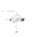
次に、図7を参照すると、空間ビーム分離を用いたマルチビームスプリッティングのためのマルチビームスプリッタ128-1の図が示されている。マルチビームスプリッタ128-1は、正しい縮尺又は遠近法で描かれておらず、概略的表現である。図7において、前述のマルチビームスプリッタ128の動作を説明する内部の詳細を説明する。マルチビームスプリッタ128の各種の実施例と構成は、本願と同時に出願された“MULTI-BEAM SPLITTING USING SPATIAL BEAM SEPARATION”と題する米国特許出願に記載されている。マルチビームスプリッタ128-1は、第一の光源A、第二の光源D、第一の出力B、及び第二の出力Cを有する一般的な構成で示されている。例えば、図1の機器100と比較して、第一の光源Aは手術用顕微鏡120を使って観察されている物体、例えば眼110であってよく、第一の出力Bは顕微鏡の観察ポート、例えば接眼レンズ126であってよい。さらに、幾つかの実施例において、第二の光源Dはオーバレイコンテンツの供給源、例えばディスプレイ136であってよく、第二の出力Cは第一の光源Aにおいて物体の画像を取得するためのセンサポート、例えばOCTシステム160又は可視光/NIRイメージングシステム130であってよい。
Referring now to FIG. 7, a diagram of multi-beam splitter 128-1 for multi-beam splitting with spatial beam separation is shown. Multi-beam splitter 128-1 is not drawn to scale or perspective and is a schematic representation. Referring to FIG. 7, the internal details describing the operation of the
図7において、第一のビーム710は第一の光源Aから部分透過ミラー706の第一の面706-1に到達する。部分透過ミラー706は第一の面706-1での入射光を部分的に反射させ、部分的に透過させるように構成されるため、部分透過ミラー706は第一のビーム710からの第一の部分的ビーム716を透過させ、第一のビーム710からの第二の部分的ビーム712を反射させる。具体的には、第一の面706-1から反射した第二の部分的ビーム712は、第二の出力Cに設置されたアパーチャフィルタ704に対応する面積にわたるビーム712-1、712-2、712-3を含むように示されている。アパーチャフィルタ704は、透明で第二の出力Cに到達した第二の部分的ビーム712-2のためのアパーチャとしての役割を果たす第二の半径(r2)を有する円形の開口を有する不透明フィールドを含み、第二の部分的ビーム712-1、712-2は、アパーチャフィルタ704の、開口の外側の周辺部分に到達するため、アパーチャフィルタ704でブロックされる。その一方で、第一の部分的ビーム716は第一の出力Bへと透過される。
In FIG. 7, first beam 710 reaches first surface 706-1 of partially transmitting
図7ではまた、ビーム714-1、714-2、714-3として示される第二のビーム714が、第一の光源Dからスポットフィルタ702に到達する。スポットフィルタ702は、アパーチャフィルタ704の第二の半径(r2)と同等であってよい第一の半径(r1)を有する円形の不透明スポットを有する透明フィールドを含む。特に、第一の半径(r1)は第二の半径(r2)より大きいか、それと等しくてよい。したがって、第二のビーム714の周辺部分714-1、714-3は部分透過ミラー706の第二の面706-2に到達し、他方で中央部分714-2はスポットフィルタ702によりブロックされる。部分透過ミラー706は第二の面706-2での入射光を部分的に反射させ、部分的に透過させるように構成されるため、部分透過ミラー706は、周辺部分718-1、718-3として示される第三の部分的ビーム718を第一の出力Bに向かって反射させ、第三の部分的ビーム718は第一の部分的ビーム716と同軸的に重ねられ、それによって第二の光源Dからのオーバレイコンテンツ(すなわち、オーバレイ情報)を第一の出力Bにおいて第一の光源Aからのコンテンツと重ねることができる。それと同時に、第二の面706-2はまた、第二のビーム714(周辺部分714-1、714-3)からの第四の部分的ビーム720を透過させ、それによってスポットフィルタ702の透明フィールドに対応する第四の部分的ビームの周辺部分720-1、720-3だけが第二の出力Cへと透過される。第一の半径(r1)が少なくとも第二の半径(r2)と同じ大きさ、すなわち等しい場合、第四の部分的ビーム720はしたがって、アパーチャフィルタ704の不透明フィールドがスポットフィルタ702の透明フィールドに空間的に対応するため、アパーチャフィルタ704でブロックされる。それゆえ、第四の部分的ビームの周辺部分720-1、720-3はアパーチャフィルタ704によりブロックされ、第四の部分的ビーム720はマルチビームスプリッタ128-1によりブロックされる。アパーチャフィルタ704の開口では第二の部分的ビーム712-2だけが到達し、これは、第二の部分的ビーム712-2の中央部分がスポットフィルタ702でブロックされるからであり、それによって第四の部分的ビーム720の中央部分が第二の部分的ビーム712-2を干渉するのが防止される。
Also in FIG. 7, a second beam 714, shown as beams 714-1, 714-2, 714-3, reaches
半径r1及びr2の絶対値は、フィルタ702、704の大きさに関して、第二の出力C及び第一の出力Bに結合される光の比を定めるように選択されてよい点に留意されたい。半径r1及びr2は自由に選択できるため、この分離比は希望に応じて連続的に変化させることができる。さらに、幾つかの実施例において、スポットフィルタ702とアパーチャフィルタ704は位置を入れ替えてよい点にも留意されたい。スポットフィルタ702とアパーチャフィルタ704は、機械的構成部品又は不透明コーティングを使って実装されてよく、スポット又は開口は図7に示され、上述した円形の形状の代替案として、異なる形状で様々に形成されてもよい。
Note that the absolute values of radii r1 and r2 may be selected with respect to the size of
図7において、反射及び透過されたビーム経路はマルチビームスプリッタ128の異なる実施例では異なる幾何学形状を有していてよい。図のように、第一の光軸に沿った第一の光源Aから第一の出力Bまでの第一のビーム710は、第二の光軸に沿った第二の光源Dから第二の出力Cへの第二のビーム714に垂直であってよく、部分透過ミラー706は、第一の光軸に沿った第一のビーム710と第二の光軸に沿った第二のビーム714の両方に関して45度に向けられてもよい。
In FIG. 7, the reflected and transmitted beam paths may have different geometries in different embodiments of
次に、図8を参照すると、本明細書で説明する、空間ビーム分離を使用するマルチビームスプリッティングのためのマルチビームスプリッタ128-2の図が示されている。マルチビームスプリッタ128-2は、正確な縮尺又は遠近法で描かれておらず、見やすいようにスキュー角で示される概略的表現である。図8において、マルチビームスプリッタ128-2のキューブ形光学素子としての例示的な実装が示されている。マルチビームスプリッタ128-2の1つの面にスポットフィルタ702が形成され、他方で、アパーチャフィルタ704が反対の面に形成される。図8ではまた、部分透過ミラー706も見ることができ、これは2つの三角形のプリズム間の接合面を使用して形成されてよい。特定の実施例では、部分透過ミラー706はダイクロイック特性を有していてよい。
Referring now to FIG. 8, a diagram of a multi-beam splitter 128-2 for multi-beam splitting using spatial beam splitting as described herein is shown. Multi-beam splitter 128-2 is a schematic representation not drawn to scale or perspective, but shown at skew angles for ease of viewing. In FIG. 8, an exemplary implementation of multi-beam splitter 128-2 as a cube-shaped optical element is shown. A
本明細書で開示するように、可視光及びIRカメラの両方が、眼科手術に使用される手術用顕微鏡の光学的鏡筒の長さを増大させずに統合されてよい。スキャニングOCT測定ビームを直接、術中に捕捉するためにIRカメラが使用されてよく、これは人間の目には見えないNIR光を使用する。手術用顕微鏡の使用者に対して術中に表示されるものと同じ術野で撮影されたIRカメラからのIR像は、接眼レンズの中で使用者に対して表示されてよく、それによってOCTスキャンの位置を術野の実際の可視光像と共に可視化できる。 As disclosed herein, both visible light and IR cameras may be integrated without increasing the length of the optical tube of surgical microscopes used in ophthalmic surgery. An IR camera may be used to capture the scanning OCT measurement beam directly intraoperatively, which uses NIR light that is invisible to the human eye. An IR image from the IR camera, taken in the same operative field as is intraoperatively displayed to the surgical microscope user, may be displayed to the user in the eyepiece, thereby providing an OCT scan. can be visualized with the actual visible light image of the surgical field.
上で開示した主題は例示的であり、限定的ではないと考えるものとし、付属の特許請求の範囲は、本開示の実際の主旨と範囲内に含まれるすべての変更、改良、及びその他の実施例を含むものとする。それゆえ、法の下で可能なかぎり、本開示の範囲は後述の特許請求の範囲及びそれらの等価物の許容される最も広い解釈により特定され、上記の詳細な説明によって制約又は限定されないものとする。 The subject matter disclosed above is to be considered illustrative and not limiting, and the appended claims cover all modifications, improvements and other implementations coming within the true spirit and scope of this disclosure. Shall include examples. Therefore, to the extent possible under law, the scope of the disclosure is to be defined by the broadest permissible interpretation of the following claims and their equivalents, and not to be restricted or limited by the above detailed description. do.
Claims (10)
前記手術用顕微鏡に連結され、術野をスキャンするために使用される光干渉断層撮影(OCT)スキャニングシステムであって、前記手術用顕微鏡は前記術野からの可視光を見るために使用され、前記OCTスキャニングシステムは前記術野の前記スキャニングのために近赤外(NIR)光を前記術野に投射するOCTスキャニングシステムと、
前記可視光を前記手術用顕微鏡の第一の接眼レンズへと透過させる光路内のマルチビームスプリッタであって、前記NIR光の第一の部分と前記可視光の第二の部分を前記手術用顕微鏡の結像光路へと偏向させるために使用されるマルチビームスプリッタと、
前記NIR光の前記第一の部分を前記可視光の前記第二の部分から分離するために使用される前記結像光路内のダイクロイックミラーと、
前記NIR光の前記第一の部分から前記術野のIR像を生成するために使用される赤外光(IR)カメラであって、前記IR像は、前記術野の中の、前記術野の前記スキャニングの位置を示す赤外光(IR)カメラと、
前記可視光の前記第二の部分から前記術野の可視光像を生成するために使用される可視光カメラであって、前記可視光カメラと前記IRカメラは同一平面内に位置付けられる可視光カメラと、
を含む手術用顕微鏡。 An operating microscope for performing ophthalmic surgery, comprising:
an optical coherence tomography (OCT) scanning system coupled to the surgical microscope and used to scan a surgical field, wherein the surgical microscope is used to view visible light from the surgical field; an OCT scanning system that projects near-infrared (NIR) light onto the operative field for the scanning of the operative field;
A multi-beam splitter in the optical path for transmitting the visible light to a first eyepiece of the surgical microscope, wherein the first portion of the NIR light and the second portion of the visible light are transmitted to the surgical microscope. a multi-beam splitter used to deflect into the imaging optical path of
a dichroic mirror in the imaging optical path used to separate the first portion of the NIR light from the second portion of the visible light;
An infrared (IR) camera used to generate an IR image of the operative field from the first portion of the NIR light, the IR image being an image of the operative field within the operative field. an infrared (IR) camera indicating the location of said scanning of
A visible light camera used to generate a visible light image of the surgical field from the second portion of the visible light, wherein the visible light camera and the IR camera are positioned in the same plane. and,
Operating microscope including.
前記コントローラからオーバレイ情報を受信するディスプレイであって、前記手術用顕微鏡の第二の接眼レンズで見るための表示光を出力するために使用され、前記表示光の少なくとも一部は、前記第二の接眼レンズへと透過される可視光の光路を辿るディスプレイと、
をさらに含む、請求項1に記載の手術用顕微鏡。 a controller used to acquire the IR image from the IR camera and generate overlay information;
A display that receives overlay information from the controller and is used to output display light for viewing with a second eyepiece of the surgical microscope, at least a portion of the display light a display that follows the optical path of visible light transmitted to the eyepiece;
The surgical microscope of Claim 1 , further comprising:
前記コントローラから前記可視光像を受信する前記ディスプレイであって、前記可視光像を含む前記表示光の少なくとも一部は前記第二の接眼レンズへと透過される可視光の前記光路を辿る前記ディスプレイと、
をさらに含む、請求項2に記載の手術用顕微鏡。 the controller used to acquire the visible light image from the visible light camera;
The display receiving the visible light image from the controller, wherein at least a portion of the display light containing the visible light image follows the optical path of visible light transmitted to the second eyepiece. and,
3. The surgical microscope of claim 2 , further comprising:
前記表示光を、前記第二の接眼レンズへと透過される前記可視光へと反射させるために使用されるビームコンバイナをさらに含む、
請求項3に記載の手術用顕微鏡。 the first eyepiece and the second eyepiece are different eyepieces;
further comprising a beam combiner used to reflect the display light into the visible light transmitted to the second eyepiece;
A surgical microscope according to claim 3 .
前記第一の表示ビームを前記第一の接眼レンズに向けるために使用される前記マルチビームスプリッタと、
前記第二の表示ビームを前記第二の接眼レンズに向けるために使用されるビームコンバイナと、
をさらに含む、請求項3に記載の手術用顕微鏡。 a first beam splitter used to split the display light into a first display beam and a second display beam;
the multi-beam splitter used to direct the first display beam to the first eyepiece;
a beam combiner used to direct the second display beam to the second eyepiece;
4. The surgical microscope of claim 3 , further comprising:
前記第二の結像光路内の第二のダイクロイックミラーであって、前記NIR光の前記第三の部分を前記可視光の前記第四の部分から偏向させるために使用される第二のダイクロイックミラーと、
前記NIR光の前記第三の部分から前記術野の第二のIR像を生成するために使用される第二のIRカメラであって、前記第二のIR像は前記術野の中の、前記術野の前記スキャニングの前記位置を示す第二のIRカメラと、
前記可視光の前記第四の部分から前記術野の第二の可視光像を生成するために使用される第二の可視光カメラであって、前記第二の可視光カメラと前記第二のIRカメラは同一平面内に位置付けられる第二の可視光カメラと、
をさらに含む、請求項1に記載の手術用顕微鏡。 a second multibeam splitter in a second optical path for transmitting visible light to a second eyepiece different from the first eyepiece of the surgical microscope, wherein the third beam splitter of the NIR light is and a fourth portion of said visible light into a second imaging optical path of said operating microscope, said imaging optical path and said second imaging optical path being co-planar. two multi-beam splitters; and
A second dichroic mirror in the second imaging optical path used to deflect the third portion of the NIR light from the fourth portion of the visible light. and,
a second IR camera used to generate a second IR image of the surgical field from the third portion of the NIR light, wherein the second IR image is of the surgical field; a second IR camera indicating the position of the scanning of the operative field;
a second visible light camera used to generate a second visible light image of the surgical field from the fourth portion of the visible light, comprising: the second visible light camera and the second visible light camera; a second visible light camera, wherein the IR camera is positioned in the same plane;
The surgical microscope of Claim 1 , further comprising:
前記コントローラから前記オーバレイ情報を受信する第二のディスプレイであって、前記第二の接眼レンズで見るための第二の表示光を出力するために使用され、前記第二の表示光の少なくとも一部は、前記第二の接眼レンズへと透過される前記可視光の光路を辿る、第二のディスプレイと、
前記第二の可視光カメラから第二の可視光像を取得して、前記オーバレイ情報を生成するために使用される前記コントローラと、
前記コントローラから前記オーバレイ情報を受信する第二のディスプレイであって、前記第二の表示光の少なくとも一部は前記第二の接眼レンズへと透過される前記可視光の前記光路を辿る第二のディスプレイと、
をさらに含む、請求項9に記載の手術用顕微鏡。 a controller used to acquire the second IR image from the second IR camera and generate overlay information;
a second display that receives the overlay information from the controller and is used to output a second display light for viewing with the second eyepiece, at least a portion of the second display light a second display that follows the optical path of the visible light transmitted to the second eyepiece;
the controller used to acquire a second visible light image from the second visible light camera to generate the overlay information;
a second display receiving the overlay information from the controller, wherein at least a portion of the second display light follows the optical path of the visible light transmitted to the second eyepiece; a display;
10. The surgical microscope of claim 9 , further comprising:
Applications Claiming Priority (3)
| Application Number | Priority Date | Filing Date | Title |
|---|---|---|---|
| US201762597630P | 2017-12-12 | 2017-12-12 | |
| US62/597,630 | 2017-12-12 | ||
| PCT/IB2018/059642 WO2019116165A1 (en) | 2017-12-12 | 2018-12-04 | Combined near infrared imaging and visible imaging in a compact microscope stack |
Publications (2)
| Publication Number | Publication Date |
|---|---|
| JP2021505284A JP2021505284A (en) | 2021-02-18 |
| JP7293227B2 true JP7293227B2 (en) | 2023-06-19 |
Family
ID=65013737
Family Applications (1)
| Application Number | Title | Priority Date | Filing Date |
|---|---|---|---|
| JP2020531485A Active JP7293227B2 (en) | 2017-12-12 | 2018-12-04 | Combining near-infrared and visible light imaging in a short microscope tube |
Country Status (8)
| Country | Link |
|---|---|
| US (1) | US10888458B2 (en) |
| EP (1) | EP3678531B1 (en) |
| JP (1) | JP7293227B2 (en) |
| CN (2) | CN111465343B (en) |
| AU (1) | AU2018384025B2 (en) |
| CA (1) | CA3079936A1 (en) |
| ES (1) | ES2934374T3 (en) |
| WO (1) | WO2019116165A1 (en) |
Families Citing this family (9)
| Publication number | Priority date | Publication date | Assignee | Title |
|---|---|---|---|---|
| US10786389B2 (en) * | 2016-10-26 | 2020-09-29 | Amo Development, Llc | Ophthalmic laser delivery apparatus using MEMS micromirror arrays for scanning and focusing laser beam |
| US10993614B2 (en) | 2017-10-16 | 2021-05-04 | Alcon Inc. | OCT-enabled injection for vitreoretinal surgery |
| CA3074066A1 (en) * | 2017-10-27 | 2019-05-02 | Alcon Inc. | Foot pedal controlled oct-display for vitreoretinal surgery |
| CA3100584A1 (en) * | 2018-06-20 | 2019-12-26 | Alcon Inc. | Auxiliary surgical field visualization system |
| CN110638527B (en) * | 2019-07-01 | 2021-06-01 | 中国科学院苏州生物医学工程技术研究所 | Operation microscopic imaging system based on optical coherence tomography augmented reality |
| EP3991633A1 (en) * | 2020-11-03 | 2022-05-04 | Leica Instruments (Singapore) Pte. Ltd. | Microscope system for use in eye surgery and corresponding system, methods and computer programs |
| CN112587304B (en) * | 2021-03-04 | 2021-06-18 | 季华实验室 | Femtosecond laser guiding system and method based on dual-mode image |
| DE112021007958T5 (en) * | 2021-07-13 | 2024-04-25 | Haag-Streit Ag | Ophthalmic or surgical microscope with display device and camera |
| WO2024110796A1 (en) * | 2022-11-22 | 2024-05-30 | Alcon Inc. | Ophthalmic visualization using spectrum-independent imagers, edge detection, and visible-ir image merging |
Citations (4)
| Publication number | Priority date | Publication date | Assignee | Title |
|---|---|---|---|---|
| JP2004113322A (en) | 2002-09-25 | 2004-04-15 | Canon Inc | Ophthalmological therapy instrument |
| US20120184846A1 (en) | 2011-01-19 | 2012-07-19 | Duke University | Imaging and visualization systems, instruments, and methods using optical coherence tomography |
| WO2017029561A1 (en) | 2015-08-17 | 2017-02-23 | Novartis Ag | Surgical microscope with integrated optical coherence tomography and display systems |
| WO2017093851A1 (en) | 2015-12-02 | 2017-06-08 | Novartis Ag | Location indicator for optical coherence tomography in ophthalmic visualization |
Family Cites Families (18)
| Publication number | Priority date | Publication date | Assignee | Title |
|---|---|---|---|---|
| CA2127426C (en) * | 1994-07-05 | 2006-05-16 | Richard K. Snook | Ophthalmic pachymeter and method of making ophthalmic determinations |
| CA2390072C (en) * | 2002-06-28 | 2018-02-27 | Adrian Gh Podoleanu | Optical mapping apparatus with adjustable depth resolution and multiple functionality |
| US7621636B2 (en) * | 2007-01-10 | 2009-11-24 | Clarity Medical Systems, Inc. | Working distance and alignment sensor for a fundus camera |
| EP2194903B1 (en) | 2007-09-06 | 2017-10-25 | Alcon LenSx, Inc. | Precise targeting of surgical photodisruption |
| DE102008062650B9 (en) | 2008-12-17 | 2021-10-28 | Carl Zeiss Meditec Ag | Surgical microscope for observing infrared fluorescence and methods for this |
| DE102009037708B4 (en) * | 2009-08-17 | 2019-02-21 | Carl Zeiss Meditec Ag | Product for use in an OCT method and intraocular lens |
| DE102010013830A1 (en) | 2010-03-26 | 2011-09-29 | Carl Zeiss Microlmaging Gmbh | Microscope e.g. stimulated Raman scattering microscopy for observing biological specimen, has detector for detecting fluorescence produced in sample, and thermal image camera for reading detection signal of detector |
| EP2446812B1 (en) * | 2010-10-26 | 2016-12-28 | Haag-Streit Ag | Device for examining eyes with digital imaging |
| DE102010055350A1 (en) * | 2010-12-20 | 2012-06-21 | Carl Zeiss Meditec Ag | Apparatus for the interferometric measurement of the eye length and the anterior eye portion |
| AU2015202839B2 (en) * | 2011-06-06 | 2017-02-23 | Clarity Medical Systems, Inc. | A compact wavefront sensor module and its attachment to or integration with an ophthalmic instrument |
| WO2014066598A1 (en) * | 2012-10-24 | 2014-05-01 | The Uab Research Foundation | Imaging retinal intrinsic optical signals |
| US9164297B2 (en) * | 2013-03-15 | 2015-10-20 | Johnson & Johnson Vision Care, Inc. | Ophthalmic devices with stabilization features |
| US9538911B2 (en) * | 2013-09-19 | 2017-01-10 | Novartis Ag | Integrated OCT-refractometer system for ocular biometry |
| JP2016050990A (en) * | 2014-08-29 | 2016-04-11 | 富士フイルム株式会社 | Projection zoom lens and projection display device |
| JP2016083240A (en) * | 2014-10-27 | 2016-05-19 | 株式会社トーメーコーポレーション | Ophthalmologic apparatus |
| US20160278983A1 (en) * | 2015-03-23 | 2016-09-29 | Novartis Ag | Systems, apparatuses, and methods for the optimization of laser photocoagulation |
| JP7075178B2 (en) * | 2015-08-05 | 2022-05-25 | フェニックス テクノロジー グループ インコーポレイテッド | Wide-field retinal imager and how it works |
| AU2017257258B2 (en) | 2016-04-28 | 2021-07-22 | Alex Artsyukhovich | Detachable miniature microscope mounted keratometer for cataract surgery |
-
2018
- 2018-12-04 CA CA3079936A patent/CA3079936A1/en active Pending
- 2018-12-04 US US16/209,502 patent/US10888458B2/en active Active
- 2018-12-04 AU AU2018384025A patent/AU2018384025B2/en active Active
- 2018-12-04 CN CN201880080588.2A patent/CN111465343B/en active Active
- 2018-12-04 ES ES18833509T patent/ES2934374T3/en active Active
- 2018-12-04 EP EP18833509.5A patent/EP3678531B1/en active Active
- 2018-12-04 JP JP2020531485A patent/JP7293227B2/en active Active
- 2018-12-04 CN CN202310675125.3A patent/CN116671862A/en active Pending
- 2018-12-04 WO PCT/IB2018/059642 patent/WO2019116165A1/en unknown
Patent Citations (4)
| Publication number | Priority date | Publication date | Assignee | Title |
|---|---|---|---|---|
| JP2004113322A (en) | 2002-09-25 | 2004-04-15 | Canon Inc | Ophthalmological therapy instrument |
| US20120184846A1 (en) | 2011-01-19 | 2012-07-19 | Duke University | Imaging and visualization systems, instruments, and methods using optical coherence tomography |
| WO2017029561A1 (en) | 2015-08-17 | 2017-02-23 | Novartis Ag | Surgical microscope with integrated optical coherence tomography and display systems |
| WO2017093851A1 (en) | 2015-12-02 | 2017-06-08 | Novartis Ag | Location indicator for optical coherence tomography in ophthalmic visualization |
Also Published As
| Publication number | Publication date |
|---|---|
| CN111465343B (en) | 2023-06-20 |
| US10888458B2 (en) | 2021-01-12 |
| CN111465343A (en) | 2020-07-28 |
| AU2018384025B2 (en) | 2024-06-13 |
| JP2021505284A (en) | 2021-02-18 |
| CN116671862A (en) | 2023-09-01 |
| US20190175402A1 (en) | 2019-06-13 |
| WO2019116165A1 (en) | 2019-06-20 |
| EP3678531A1 (en) | 2020-07-15 |
| AU2018384025A1 (en) | 2020-04-23 |
| CA3079936A1 (en) | 2019-06-20 |
| ES2934374T3 (en) | 2023-02-21 |
| EP3678531B1 (en) | 2022-11-09 |
Similar Documents
| Publication | Publication Date | Title |
|---|---|---|
| JP7293227B2 (en) | Combining near-infrared and visible light imaging in a short microscope tube | |
| US7140730B2 (en) | Optical apparatus and method for comprehensive eye diagnosis | |
| US11253148B2 (en) | Ophthalmological device and ophthalmological inspection system | |
| US10888457B2 (en) | Detachable miniature microscope mounted keratometer for cataract surgery | |
| US8192025B2 (en) | Non-contact optical coherence tomography imaging of the central and peripheral retina | |
| JP6616704B2 (en) | Ophthalmic apparatus and ophthalmic examination system | |
| US10456034B2 (en) | Ophthalmic microscope system | |
| JP6899632B2 (en) | Ophthalmologic imaging equipment | |
| US11911103B2 (en) | Personalized patient interface for ophthalmic devices | |
| JP6915968B2 (en) | Ophthalmic Surgical Microscope | |
| JP2018033717A (en) | Ophthalmological device | |
| KR101922609B1 (en) | Potable Slit Lamp Camera for Ophthalmology | |
| JP7349807B2 (en) | ophthalmology equipment | |
| JP2023025820A (en) | microscope | |
| JP2017113134A (en) | Microscope system for ophthalmology | |
| JP7292072B2 (en) | ophthalmic equipment | |
| JP7103813B2 (en) | Ophthalmic equipment | |
| JP2023102006A (en) | Ophthalmologic apparatus | |
| CN118401163A (en) | System and method for assisting in alignment of an object with an ophthalmic device |
Legal Events
| Date | Code | Title | Description |
|---|---|---|---|
| A621 | Written request for application examination |
Free format text: JAPANESE INTERMEDIATE CODE: A621 Effective date: 20211116 |
|
| A977 | Report on retrieval |
Free format text: JAPANESE INTERMEDIATE CODE: A971007 Effective date: 20221216 |
|
| A131 | Notification of reasons for refusal |
Free format text: JAPANESE INTERMEDIATE CODE: A131 Effective date: 20230110 |
|
| A521 | Request for written amendment filed |
Free format text: JAPANESE INTERMEDIATE CODE: A523 Effective date: 20230406 |
|
| TRDD | Decision of grant or rejection written | ||
| A01 | Written decision to grant a patent or to grant a registration (utility model) |
Free format text: JAPANESE INTERMEDIATE CODE: A01 Effective date: 20230509 |
|
| A61 | First payment of annual fees (during grant procedure) |
Free format text: JAPANESE INTERMEDIATE CODE: A61 Effective date: 20230607 |
|
| R150 | Certificate of patent or registration of utility model |
Ref document number: 7293227 Country of ref document: JP Free format text: JAPANESE INTERMEDIATE CODE: R150 |