(第1実施形態)
以下に、本発明を具体化した美容器の第1実施形態を図面に従って説明する。
図1~図3に示すように、本実施形態の美容器は、全体として左右対称形状に形成されている。ここで、図2における左右を本実施形態の美容器の左右とし、図2における上部を美容器の前部とし、図2の紙面と直交する方向を美容器の表裏の方向とする。
(First embodiment)
DESCRIPTION OF THE PREFERRED EMBODIMENTS A first embodiment of a beauty device embodying the present invention will be described below with reference to the drawings.
As shown in FIGS. 1 to 3, the beauty device of this embodiment is formed in a bilaterally symmetrical shape as a whole. Here, the left and right in FIG. 2 are the left and right of the beauty device of this embodiment, the upper portion in FIG. 2 is the front portion of the beauty device, and the direction perpendicular to the paper surface of FIG.
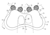
図1~図3に示すように、美容器は、カッサ本体部11の周縁部にマッサージ部として機能する押圧施術部としてのカッサ部12を一体に有する押圧施術部材としてのカッサ部材13と、カッサ本体部11に取り付けられて結合されたホルダ部材14とを備えている。そして、カッサ部材13は、美容器の外形とほぼ相似形をなしている。美容器は、カッサ部12を露出させた状態でホルダ部材14及びカッサ部材13を覆うカバー部材15を備えている。図1~図5に示すように、このカッサ部材13,ホルダ部材14及びカバー部材15により全体として扁平形状をなす合成樹脂製の美容器本体10が構成されている。この美容器本体10は、図2,図21及び図22に示すように、使用者の指先によって把持される。カッサ部12は、左右両端部に位置する曲線状の一対の膨らみ部19と、両膨らみ部19間の後部側において膨らみ部19と連続する曲線状の窪み部20とを備えている。カッサ部12の周縁部は、図18に示す断面形状においてほぼ円弧状に膨らんだ形状を有している。
As shown in FIGS. 1 to 3, the beauty device includes a Gussa member 13 as a pressure treatment member integrally having a Gussa part 12 as a pressure treatment part functioning as a massage part on the peripheral edge of the Gussa body part 11; and a holder member 14 attached and coupled to the body portion 11 . The Gussa member 13 has a shape substantially similar to the outer shape of the beauty device. The beauty device includes a cover member 15 that covers the holder member 14 and the guide member 13 with the guide member 12 exposed. As shown in FIGS. 1 to 5, the umbrella member 13, the holder member 14, and the cover member 15 constitute a beauty device main body 10 made of synthetic resin and having a flat shape as a whole. This beauty device body 10 is gripped by the user's fingertips, as shown in FIGS. The cussa portion 12 has a pair of curved bulges 19 positioned at both left and right ends, and a curved dent 20 continuous with the bulges 19 on the rear side between the bulges 19 . The peripheral portion of the guide portion 12 has a substantially arcuate bulging shape in the cross-sectional shape shown in FIG. 18 .
図6~図9に示すように、ホルダ部材14には、その左右においてそれぞれ交差状態で対をなす合計4本の支持軸16が支持されている。この支持軸16は、高強度で耐食性(耐薬品性を含む)に優れた金属、例えばステンレススチールから構成されている。支持軸16は、ステンレススチール以外に、真鍮,アルミニウム合金,チタン合金など、ステンレススチール以外の金属を用いたり、ポリカーボネートなどの高強度合成樹脂を用いたりすることができる。なお、支持軸16として、ステンレススチール以外の金属を用いた場合は、その支持軸16にクローム,ニッケル,金,銀,銅,プラチナなどのメッキを施すことができる。
As shown in FIGS. 6 to 9, the holder member 14 supports a total of four support shafts 16 that are paired in an intersecting state on the left and right sides thereof. The support shaft 16 is made of a metal having high strength and excellent corrosion resistance (including chemical resistance), such as stainless steel. The support shaft 16 may be made of metal other than stainless steel, such as brass, aluminum alloy, or titanium alloy, or may be made of high-strength synthetic resin such as polycarbonate. When a metal other than stainless steel is used as the support shaft 16, the support shaft 16 can be plated with chrome, nickel, gold, silver, copper, platinum, or the like.
図10及び図18に示すように、支持軸16はカバー部材15の挿通孔17から外部に突出されており、この突出部にはそれぞれ球状をなすマッサージ部としての回転体18が回転可能に支持されている。従って、回転体18は美容器本体10の周縁部から外方に突出している。前記カッサ部12は擦りマッサージであるカッサマッサージに用いられ、回転体18は転がりマッサージに用いられる。回転体18は、良好な外観を得るとともに、耐食性を得るために、ABS樹脂によって構成される。回転体18の表面は、肌に対するアレルギー防止のために、全体に対して化学的に安定した金属,例えばクロムメッキが施されている。クロムメッキに代えて、パラジウム,プラチナ,金や、それらの合金の金属メッキを用いることもできる。回転体18は亜鉛などの金属によって構成してもよい。この構成の場合、回転体18は削り出しによって製造しても、あるいはダイキャスト成形してもよい。この場合、回転体18の表面は研磨される。
As shown in FIGS. 10 and 18, the support shaft 16 protrudes from an insertion hole 17 of the cover member 15, and the protruding portion rotatably supports a rotating body 18 serving as a spherical massaging portion. It is Therefore, the rotating body 18 protrudes outward from the peripheral portion of the beauty device main body 10 . The Guasha part 12 is used for a Guasha massage, which is a rubbing massage, and the rotating body 18 is used for a rolling massage. The rotating body 18 is made of ABS resin in order to obtain good appearance and corrosion resistance. The surface of the rotor 18 is plated with a chemically stable metal such as chromium to prevent skin allergies. Metal plating of palladium, platinum, gold, or alloys thereof can be used instead of chrome plating. The rotor 18 may be made of metal such as zinc. In the case of this configuration, the rotating body 18 may be manufactured by cutting or may be die-cast. In this case, the surface of the rotor 18 is polished.
以下に、各部の構成を詳細に説明する。
カッサ部材13は、ABS樹脂などの良好な外観と耐食性を得るための合成樹脂によって構成されている。カッサ部材13には、肌に対するアレルギー防止のために、カッサ部12を含む全体に対して化学的に安定した金属,例えばメッキクロムメッキが施されている。クロムメッキに代えて、パラジウム,プラチナ,金,銀,銅,ニッケルや、それらの合金の金属メッキを用いることもできる。このため、カッサ部12の表面は、カバー部材15の表面と比較して摩擦係数が小さく、滑りやすくなっている。なお、カッサ部材13は、亜鉛などの金属をダイキャスト成形することによって構成してもよい。この場合、少なくともカッサ部12は研磨される。
The configuration of each part will be described in detail below.
The glass member 13 is made of synthetic resin, such as ABS resin, for obtaining good appearance and corrosion resistance. In order to prevent allergy to the skin, the entire Gussa member 13 including the Gussa part 12 is plated with a chemically stable metal such as chrome plating. Metal plating of palladium, platinum, gold, silver, copper, nickel, or alloys thereof can be used instead of chrome plating. Therefore, the surface of the umbrella portion 12 has a smaller coefficient of friction than the surface of the cover member 15 and is slippery. Note that the glass member 13 may be configured by die-casting a metal such as zinc. In this case, at least the Gussa portion 12 is ground.
図8~図10に示すように、全体として板状をなすカッサ本体部11の外周部の表裏両面には突起状の複数のスペーサ21が一体形成されている。カッサ本体部11の前部側には左右幅の広い第1凹部22が形成されており、その第1凹部22の左右両端部には一対の第2凹部23が形成されている。両第2凹部23間の突出部24の表裏両面にはそれぞれ一対の突条25,26が形成されている。カッサ本体部11の左右両端部にはボス部27が形成されている。
As shown in FIGS. 8 to 10, a plurality of protruding spacers 21 are integrally formed on both front and back surfaces of the outer peripheral portion of the main body portion 11 having a plate shape as a whole. A wide first concave portion 22 is formed on the front side of the camera main body 11 , and a pair of second concave portions 23 are formed at both left and right ends of the first concave portion 22 . A pair of ridges 25 and 26 are formed on both front and back surfaces of the projecting portion 24 between the two second recesses 23 . Boss portions 27 are formed at both left and right end portions of the main body portion 11 .
図8及び図9に示すように、カッサ部12の表裏内周縁にはカッサ部12のほぼ全長に沿って延びる段差部28が形成されている。
図10及び図11に示すように、ホルダ部材14は、POM(ポリアセタール)などの強度を確保できる合成樹脂によって構成されている。ホルダ部材14は、ほぼ板状をなし、その全体がカッサ本体部11の第1凹部22内に嵌合されている。図8~図10に示すように、ホルダ部材14の後部側には第1凹部22内の第2凹部23内に嵌合される一対の凸部31が形成されている。ホルダ部材14の左右両側縁には、第1凹部22の内側縁に係合される第1係合部32,33が突出されている。凸部31の先端には第2凹部23の内縁部の一側面に係合される第2係合部34が形成されている。両凸部31の側縁には突条25に係合する第3係合部35が形成されている。ホルダ部材14の左右両端にはカッサ部材13のカッサ本体部11の上面に係合される一対の第4係合部37が形成されている。凸部31間には架設部39が形成されており、この架設部39は突条26に係合される。なお、ホルダ部材14は、POM以外の合成樹脂、例えば、PC(ポリカーボネイト)、ABS,PE(ポリエチレン),PP(ポリプロピレン),PBT(ポリブチレンテレフタレート),PA6(6ナイロン)などによって構成してもよい。
As shown in FIGS. 8 and 9 , stepped portions 28 are formed on the front and back inner peripheral edges of the cutting portion 12 so as to extend substantially along the entire length of the cutting portion 12 .
As shown in FIGS. 10 and 11, the holder member 14 is made of a synthetic resin such as POM (polyacetal) capable of ensuring strength. The holder member 14 has a substantially plate-like shape, and the entirety of the holder member 14 is fitted in the first concave portion 22 of the camera body portion 11 . As shown in FIGS. 8 to 10, a pair of protrusions 31 are formed on the rear side of the holder member 14 so as to be fitted into the second recesses 23 inside the first recesses 22 . First engagement portions 32 and 33 that engage with the inner edges of the first recess 22 protrude from the left and right side edges of the holder member 14 . A second engaging portion 34 that engages with one side surface of the inner edge portion of the second concave portion 23 is formed at the tip of the convex portion 31 . A third engaging portion 35 that engages with the ridge 25 is formed on the side edge of both convex portions 31 . A pair of fourth engaging portions 37 that are engaged with the upper surface of the gripper main body portion 11 of the gripper member 13 are formed on the left and right ends of the holder member 14 . A bridging portion 39 is formed between the convex portions 31 , and the bridging portion 39 is engaged with the ridge 26 . The holder member 14 may be made of a synthetic resin other than POM, such as PC (polycarbonate), ABS, PE (polyethylene), PP (polypropylene), PBT (polybutylene terephthalate), PA6 (nylon 6), or the like. good.
図10及び図11に示すように、ホルダ部材14の左右両端部には挿通孔41が透設されている。そして、この挿通孔41を通るタップネジ42がボス部27のボス孔43にネジ込まれており、このタップネジ42によってホルダ部材14とカッサ部材13とが固定されている。なお、ホルダ部材14の挿通孔41の部分は厚くなっている。また、タップネジ42に代えて、挿通孔41内及びボス孔43内に圧入されるピンであってもよい。このピンはホルダ部材14と一体であってもよい。
As shown in FIGS. 10 and 11 , insertion holes 41 are provided through both left and right end portions of the holder member 14 . A tap screw 42 passing through this insertion hole 41 is screwed into a boss hole 43 of the boss portion 27 , and the holder member 14 and the gripper member 13 are fixed by this tap screw 42 . A portion of the insertion hole 41 of the holder member 14 is thickened. Also, instead of the tap screw 42, a pin press-fitted into the insertion hole 41 and the boss hole 43 may be used. This pin may be integral with the holder member 14 .
図10,図12及び図13に示すように、カバー部材15は、ABSやPCなどの塗装に適した合成樹脂によって構成されて、その表面に塗装が施されるとともに、その塗装の上にトップコートが施されている。カバー部材15は、美容器本体10の両側面を形成する一対の側面部51と、その両側面部51の前端部間に位置する端面部52とにより全体としてほぼ2枚貝形状をなすように一体構成されており、端面部52の両端には短い延長部53が形成されている。延長部53の縁部にはほぼ円弧凹状の応力回避部54が凹設されており、この応力回避部54は側面部51に対して開放方向の力が作用した場合における応力集中を回避するためのものである。図3~図5に示すように、カバー部材15の側面部51の外側面は前後方向及び左右方向において中央部を含む全体が凸曲面になっているとともに、側面部51の外側面の中央部が前後方向において凸曲面を維持しながら緩やかに落ち込む窪み部30になっている。
As shown in FIGS. 10, 12 and 13, the cover member 15 is made of a synthetic resin suitable for painting such as ABS or PC. It has a coat. The cover member 15 is integrally formed with a pair of side surface portions 51 forming both side surfaces of the beauty device body 10 and an end surface portion 52 positioned between the front end portions of the both side surface portions 51 so as to form an almost bivalve shape as a whole. A short extension 53 is formed at each end of the end surface 52 . A substantially circular arc-shaped stress avoidance portion 54 is recessed in the edge portion of the extension portion 53. The stress avoidance portion 54 avoids stress concentration when a force acts on the side portion 51 in the opening direction. belongs to. As shown in FIGS. 3 to 5, the outer surface of the side surface portion 51 of the cover member 15 has a convex curved surface as a whole including the central portion in the front-rear direction and the left-right direction. is a recessed portion 30 that gently drops while maintaining a convex curved surface in the front-rear direction.
そして、図18に示すように、側面部51の外周縁がカッサ部材13の段差部28に弾性係合されて、カバー部材15によってカッサ部材13がカッサ部12を露出させた状態で把持されている。この状態で両側面部51間にカッサ部材13のカッサ部12を除く部分及びホルダ部材14が収容されている。従って、両側面部51によってカッサ部12及び回転体18の部分を除いてカッサ部材13及びホルダ部材14が覆われている。両側面部51の内側面にカッサ部材13のスペーサ21が当接または近接対向しており、このスペーサ21により、側面部51のホルダ部材14側への凹み変形が抑えられている。
Then, as shown in FIG. 18, the outer peripheral edge of the side surface portion 51 is elastically engaged with the stepped portion 28 of the gripper member 13, and the gripper member 13 is gripped by the cover member 15 with the gripper portion 12 exposed. there is In this state, the portion of the gripper member 13 excluding the gripper portion 12 and the holder member 14 are accommodated between the side surfaces 51 . Therefore, the gripper member 13 and the holder member 14 are covered by the side surfaces 51 except for the gripper portion 12 and the rotor 18 . The spacers 21 of the gripper member 13 are in contact with or closely opposed to the inner side surfaces of the side surfaces 51 , and the spacers 21 prevent the side surfaces 51 from being dented toward the holder member 14 .
図10,図18及び図19に示すように、支持軸16が挿通される前述した挿通孔17は端面部52に透設されている。
次に、支持軸16及び回転体18と、それらの関連構成とについて詳細に説明する。
As shown in FIGS. 10, 18 and 19, the aforementioned insertion hole 17 through which the support shaft 16 is inserted is provided through the end surface portion 52. As shown in FIG.
Next, the support shaft 16 and the rotating body 18 and their related structures will be described in detail.
図10及び図11に示すように、ホルダ部材14の左右両側部の表裏両面には、それぞれ断面半円状をなす各一対の軸支持部61,62が凹設されている。各対の表裏の軸支持部61,62は連通し、それらの軸線は平面視において前後方向に対して傾斜するとともに、交差している。軸支持部61,62の内底部は、それぞれ3箇所の架設部63によって形成されている。3箇所の架設部63のうち、中間に位置する1箇所の架設部63には、先端に爪部64を有する抜止め部65が突出されている。図18に示すように、爪部64の内側には案内斜面87が形成されている。
As shown in FIGS. 10 and 11 , a pair of shaft support portions 61 and 62 each having a semicircular cross-section are recessed on both the front and back surfaces of the left and right sides of the holder member 14 . The front and back shaft support portions 61 and 62 of each pair communicate with each other, and their axes are slanted with respect to the front-rear direction and cross each other in a plan view. The inner bottom portions of the shaft support portions 61 and 62 are each formed by three bridging portions 63 . A locking portion 65 having a claw portion 64 at its tip protrudes from one of the three bridging portions 63 located in the middle. As shown in FIG. 18, a guide slope 87 is formed inside the claw portion 64 .
図6及び図7,図8~図10に示すように、各対の軸支持部61,62にはそれぞれ支持軸16が収容されている。このため、各対の支持軸16は、それらの先端間が開くように傾斜状態で交差されている。図10,図14及び図15に示すように、各支持軸16は、大径部66と小径部67とを有しており、大径部66の一端には先細状のテーパ部68が形成されるとともに、大径部66の他端にはフランジ69が形成されている。テーパ部68の近傍の大径部66には小径段差状の掛止め部70が凹設されている。小径部67の先端部には、さらに小径にした段差状の保持部71が凹設されている。大径部66のフランジ側の端部を除く部分は支持軸16の直径線上において切除されたDカット形状である平面部72となっている。大径部66にはフランジ69と接する位置にO(オー)リング73が嵌められている。
As shown in FIGS. 6, 7, and 8 to 10, each pair of shaft support portions 61 and 62 accommodates the support shaft 16. As shown in FIGS. For this reason, each pair of support shafts 16 intersects in an inclined state so that the tips thereof are open. As shown in FIGS. 10, 14 and 15, each support shaft 16 has a large diameter portion 66 and a small diameter portion 67. At one end of the large diameter portion 66, a tapered portion 68 is formed. A flange 69 is formed at the other end of the large diameter portion 66 . The large diameter portion 66 near the tapered portion 68 is recessed with a small diameter stepped latching portion 70 . At the tip of the small diameter portion 67, a stepped holding portion 71 having a smaller diameter is recessed. A portion of the large-diameter portion 66 excluding the end portion on the flange side is a flat portion 72 having a D-shaped cutout along the diameter line of the support shaft 16 . An O-ring 73 is fitted to the large-diameter portion 66 at a position in contact with the flange 69 .
図10に示すように、支持軸16は平面部72を軸支持部61,62の開放側に位置させた状態で収容されている。また、抜止め部65の爪部64が同抜止め部65の弾性力が付与された下において掛止め部70に掛止されて、軸支持部61,62内に抜止め状態で保持されている。そして、支持軸16に対して軸支持部61,62からの引き抜き力が作用した場合、その引き抜きトルクが所定値以上の際に、爪部64が破断されて、支持軸16を引き抜くことができる。この所定値の引き抜きトルクを第1トルクとする。支持軸16は、平面部72を相互に対面させた状態で交差配置されており、各支持軸16の軸線は同一平面上に配置されている。従って、図3に示すように、回転体18も同一平面α上に配置されている。図6に示すように、各対の支持軸16及び回転体18は開き傾斜角度θ1の軸線ζ上に位置するとともに、各対の支持軸16及び回転体18のうち、内側の隣接する2本の支持軸16及び回転体18は先窄まり傾斜角度θ2の軸線ζ上に位置している。
As shown in FIG. 10, the support shaft 16 is accommodated with the flat portion 72 positioned on the open side of the shaft support portions 61 and 62 . In addition, the claw portion 64 of the retaining portion 65 is retained by the retaining portion 70 under the elastic force of the retaining portion 65, and is retained in the shaft support portions 61 and 62 in a retained state. there is When a pull-out force from the shaft support portions 61 and 62 acts on the support shaft 16 and the pull-out torque is equal to or greater than a predetermined value, the claw portion 64 is broken and the support shaft 16 can be pulled out. . This predetermined pull-out torque is defined as the first torque. The support shafts 16 are arranged to cross each other with the flat portions 72 facing each other, and the axes of the support shafts 16 are arranged on the same plane. Therefore, as shown in FIG. 3, the rotor 18 is also arranged on the same plane α. As shown in FIG. 6, each pair of support shafts 16 and rotors 18 are positioned on the axis ζ of the opening inclination angle θ1, and two adjacent inner sides of each pair of support shafts 16 and rotors 18 The support shaft 16 and the rotating body 18 are positioned on the axis .zeta.
そして、図6及び図7に示すように、本実施形態においては、左右の各一対の支持軸16及び回転体18の軸線ζの開き傾斜角度θ1が70.5度になっている。また、各対の支持軸16及び回転体18において、隣接する内側の支持軸16及び回転体18の軸線ζの先窄まり傾斜角度θ2は95.6度である。また、支持軸16の大径部66がカバー部材15の挿通孔17を外側から挿通しており、フランジ69及び小径部67が端面部52の外側に位置している。このため、フランジ69及びOリング73がカバー部材15の端面部52の外側面に位置していて、このフランジ69及びOリング73によりカバー部材15のカッサ部材13の段差部28から離れる方向への移動が抑えられている。Oリング73は、変形のしやすさと強度を得るためにシリコーン樹脂によって構成されるが、それ以外に、NBR(ニトリルゴム),PPなどによって構成することもできる。
As shown in FIGS. 6 and 7, in this embodiment, the opening inclination angle θ1 of the axis ζ of each pair of left and right support shafts 16 and rotating body 18 is 70.5 degrees. In addition, in each pair of support shaft 16 and rotor 18, the converging inclination angle θ2 of the axis ζ of the adjacent inner support shaft 16 and rotor 18 is 95.6 degrees. Also, the large diameter portion 66 of the support shaft 16 is inserted through the insertion hole 17 of the cover member 15 from the outside, and the flange 69 and the small diameter portion 67 are positioned outside the end face portion 52 . For this reason, the flange 69 and the O-ring 73 are positioned on the outer surface of the end face portion 52 of the cover member 15 , and the flange 69 and the O-ring 73 move the cover member 15 away from the stepped portion 28 of the gripper member 13 . movement is suppressed. The O-ring 73 is made of silicone resin in order to obtain ease of deformation and strength, but it can also be made of NBR (nitrile rubber), PP, or the like.
図18及び図19に示すように、各支持軸16のフランジ69は、カバー部材15の端面部52にカーブに沿って配置されており、配列方向の両外側の2本の支持軸16のフランジ69が内側の2本の支持軸16のフランジ69より外方に位置している。従って、配列方向の両外側に位置する2個の回転体18が前方に突出し、中央に位置する2個の回転体18は、平面に直交する方向から見て配列方向の外側の2個の回転体18の外周同士を結び外側の2個の回転体18間で交差しない2本の仮想線のうち美容器本体10から離間した側の仮想線よりも美容器本体10に近い位置となる奥側に位置しており、図7に示すように、本実施形態において、回転体18の前後の高さの差εは、4.0mm(ミリメートル)である。また、本実施形態において、各対の回転体18間の間隔δは、5.0mmであり、各対の回転体18のうち、奥側の隣接する2個の回転体18間の間隔γは、8.4mmである。
As shown in FIGS. 18 and 19, the flanges 69 of each support shaft 16 are arranged along the curve on the end face portion 52 of the cover member 15, and the flanges of the two support shafts 16 on both outer sides in the arrangement direction are arranged. 69 are located outside the flanges 69 of the inner two support shafts 16 . Therefore, the two rotating bodies 18 located on both outer sides in the arrangement direction protrude forward, and the two rotating bodies 18 located in the center project two rotating bodies 18 on the outside in the arrangement direction when viewed from the direction orthogonal to the plane. Of two virtual lines that connect the outer peripheries of the bodies 18 and do not intersect between the two outer rotating bodies 18, the far side is closer to the beauty device body 10 than the virtual line on the side spaced from the beauty device body 10. As shown in FIG. 7, in this embodiment, the height difference ε between the front and rear sides of the rotor 18 is 4.0 mm (millimeters). Further, in the present embodiment, the interval δ between each pair of rotating bodies 18 is 5.0 mm, and the interval γ between two adjacent rotating bodies 18 on the far side of each pair of rotating bodies 18 is , 8.4 mm.
図15及び図18に示すように、小径部67には、ほぼ四角柱状の外形を有するベアリング74が回転可能に支持されており、このベアリング74は支持軸16の保持部71に嵌合したCリング形状の止めリング75によって抜止めされている。ベアリング74は、回転に適した材料として、POMによって構成されるが、それ以外に、ABS,PC,PE,PBT,PA6,PP(ポリプロピレン)などによって構成することもできる。止めリング75は、引っ張り強度と耐食性を得るために、POMによって構成されるが、それ以外に、ABS,PC,PE,PBT,PA6,PP(ポリプロピレン)などによって構成することもできる。ベアリング74には回転体18が外嵌されている。従って、回転体18はベアリング74とともに支持軸16上において回転される。ベアリング74は摩擦係数の小さな合成樹脂材料によって構成されている。止めリング75の外径は、回転体18の内腔部84において止めリング75と対向する部分の内径とほぼ等しくなっている。つまり、ベアリング74に対して回転体18を外嵌した状態において、止めリング75を広げようとした場合、止めリング75が、内腔部84の内径面と干渉するようになっている。
As shown in FIGS. 15 and 18, the small diameter portion 67 rotatably supports a bearing 74 having a substantially quadrangular prism shape. It is retained by a ring-shaped retaining ring 75 . The bearing 74 is made of POM as a material suitable for rotation, but can also be made of ABS, PC, PE, PBT, PA6, PP (polypropylene), or the like. The stop ring 75 is made of POM for tensile strength and corrosion resistance, but it can also be made of ABS, PC, PE, PBT, PA6, PP (polypropylene), or the like. The rotating body 18 is fitted around the bearing 74 . Therefore, the rotor 18 is rotated on the support shaft 16 together with the bearing 74 . The bearing 74 is made of a synthetic resin material with a small coefficient of friction. The outer diameter of the retaining ring 75 is approximately equal to the inner diameter of the portion of the bore 84 of the rotor 18 that faces the retaining ring 75 . In other words, if the retaining ring 75 is to be expanded while the rotating body 18 is fitted onto the bearing 74 , the retaining ring 75 interferes with the inner diameter surface of the bore portion 84 .
図16~図18に示すように、ベアリング74の両側面の軸方向の両端部には位置決め突条78,79が形成されている。位置決め突条78,79のうちフランジ69側の位置決め突条78が止めリング75側の位置決め突条79より高くなっている。そして、高い方の位置決め突条78が回転体18の内側の位置決め溝80に係合して、ベアリング74と回転体18とが位置決めされている。低い方の位置決め突条79は回転体18の内側面に圧接されて、回転体18とベアリング74との間のガタつきが防止されている。
As shown in FIGS. 16 to 18, positioning protrusions 78 and 79 are formed at both axial ends of both side surfaces of the bearing 74 . Of the positioning protrusions 78 and 79, the positioning protrusion 78 on the flange 69 side is higher than the positioning protrusion 79 on the stop ring 75 side. The higher positioning protrusion 78 is engaged with the positioning groove 80 inside the rotating body 18 to position the bearing 74 and the rotating body 18 . The lower positioning ridge 79 is pressed against the inner surface of the rotating body 18 to prevent rattling between the rotating body 18 and the bearing 74 .
ベアリング74の周壁のほぼ半部には開放部82が形成されている。この開放部82の軸方向の縁部には、開放部82内に向かって突片77が突出されており、その先端には回転体18の取付けを案内するための案内斜面87を有する爪部76が形成されている。この爪部76は、回転体18の内側の凹部86に係合されて、回転体18が抜止めされている。爪部76は破壊に対する脆弱部を構成しており、回転体18から、その回転体18及び支持軸16に対して所定値以上の引き抜きトルクが作用した場合、爪部76が破断されて、回転体18が引き抜かれるようになっている。この引き抜きトルクを第2トルクとし、この第2トルクは支持軸16を引き抜くための第1トルクを下回る値である。また、爪部76が引き抜きトルクによって破断された場合、爪部76の基部には、図16に2点鎖線で示す残留突起89が形成されるように、爪部76の形状及び大きさが設定されている。
An open portion 82 is formed in approximately half of the peripheral wall of the bearing 74 . A protruding piece 77 protrudes into the open portion 82 from the edge portion in the axial direction of the open portion 82, and a claw portion having a guide slope 87 at the tip thereof for guiding the mounting of the rotating body 18. 76 is formed. The claw portion 76 is engaged with a concave portion 86 inside the rotating body 18 to prevent the rotating body 18 from coming off. The claw portion 76 constitutes a fragile portion against destruction, and when a pull-out torque of a predetermined value or more is applied from the rotating body 18 to the rotating body 18 and the support shaft 16, the claw portion 76 is broken and rotates. The body 18 is adapted to be withdrawn. This pull-out torque is referred to as a second torque, and this second torque is a value lower than the first torque for pulling out the support shaft 16 . Further, the shape and size of the claw portion 76 are set so that when the claw portion 76 is broken by the pull-out torque, a residual protrusion 89 indicated by a two-dot chain line in FIG. 16 is formed at the base portion of the claw portion 76. It is
以上のように構成された美容器は、以下の手順で組み立てられる。
すなわち、図6及び図7に示すように、カッサ部材13のカッサ本体部11の第1凹部22内にホルダ部材14が嵌合されて、第2凹部23内に凸部31が嵌合されるとともに、第1~第4係合部32,33,34,35,37がカッサ本体部11の周縁に係合される。このことにより、カッサ部材13に対してホルダ部材14が位置決めされる。そして、この状態で、タップネジ42によってカッサ部材13とホルダ部材14とが固定される。次いで、カバー部材15がカッサ部材13及びホルダ部材14を覆うようにカッサ部材13に組付けられ、カバー部材15の端面部52の内側面がホルダ部材14に当接するとともに、カバー部材15の周縁部がカッサ部材13の段差部28に係合されて、カバー部材15が位置決めされる。
The beauty device configured as described above is assembled in the following procedure.
That is, as shown in FIGS. 6 and 7, the holder member 14 is fitted in the first recess 22 of the gripper main body 11 of the gripper member 13, and the projection 31 is fitted in the second recess 23. At the same time, the first to fourth engaging portions 32 , 33 , 34 , 35 and 37 are engaged with the peripheral edge of the armature portion 11 . As a result, the holder member 14 is positioned with respect to the cutter member 13 . In this state, the gripper member 13 and the holder member 14 are fixed by the tap screw 42 . Next, the cover member 15 is assembled to the holder member 13 so as to cover the holder member 13 and the holder member 14 . is engaged with the stepped portion 28 of the cutter member 13 to position the cover member 15 .
一方、図15及び図18に示すように、支持軸16の大径部66のフランジ69部分にOリング73が取付けられる。また、支持軸16の小径部67にベアリング74が取付けられるとともに、止めリング75が小径部67の保持部71に取付けられて、ベアリング74が保持される。さらに、ベアリング74の外周に回転体18が外嵌される。なお、Oリング73の取付け及びベアリング74の取付けは、相前後してもよい。このベアリング74の外嵌状態においては、図19に示すように、位置決め突条78と位置決め溝80との嵌合によって、ベアリング74と回転体18とが位置決めされる。また、爪部76と凹部86との係合によりベアリング74に対して回転体18が固定される。このようにして、支持軸16,ベアリング74及び回転体18の組立て体が構成される。
On the other hand, as shown in FIGS. 15 and 18, an O-ring 73 is attached to the flange 69 portion of the large diameter portion 66 of the support shaft 16 . A bearing 74 is attached to the small diameter portion 67 of the support shaft 16, and a retaining ring 75 is attached to the holding portion 71 of the small diameter portion 67 to hold the bearing 74. As shown in FIG. Furthermore, the rotor 18 is fitted around the outer circumference of the bearing 74 . It should be noted that the attachment of the O-ring 73 and the attachment of the bearing 74 may be done in succession. 19, the bearing 74 and the rotor 18 are positioned by fitting the positioning protrusion 78 into the positioning groove 80. As shown in FIG. Further, the rotating body 18 is fixed to the bearing 74 by the engagement between the pawl portion 76 and the concave portion 86 . Thus, an assembly of the support shaft 16, the bearing 74 and the rotor 18 is constructed.
そして、回転体18が組付けられた支持軸16がカバー部材15の挿通孔17からホルダ部材14の軸支持部61,62内に挿入される。支持軸16の軸支持部61,62内への挿入にともない、支持軸16のテーパ部68が抜止め部65の爪部64の斜面87に係合して、抜止め部65をその弾性に抗して後退させた後に、爪部64が支持軸16の掛止め部70に掛止めされて、支持軸16が抜止めされる。この場合、支持軸16の軸方向の挿入深さを規定する軸支持部61,62の内端位置が挿入状態の支持軸16の先端と当接しない奥側の位置にあるため、支持軸16が軸支持部61,62内に収容された状態において軸支持部61,62の内端と支持軸16の先端との間にクリアランスが形成される。このため、支持軸16を爪部64が掛止め部70に適切に掛止めされるまで押し込んで、支持軸16を爪部64によって適切に掛止めできる。
Then, the support shaft 16 to which the rotating body 18 is assembled is inserted into the shaft support portions 61 and 62 of the holder member 14 through the insertion hole 17 of the cover member 15 . As the support shaft 16 is inserted into the shaft support portions 61 and 62, the tapered portion 68 of the support shaft 16 engages with the slope 87 of the claw portion 64 of the retaining portion 65, and the retaining portion 65 is elastically retained. After being retracted against resistance, the claw portion 64 is engaged with the engaging portion 70 of the support shaft 16 to prevent the support shaft 16 from coming off. In this case, since the inner end positions of the shaft support portions 61 and 62 that define the insertion depth of the support shaft 16 in the axial direction are located on the far side where they do not come into contact with the tip of the support shaft 16 in the inserted state, the support shaft 16 are accommodated in the shaft support portions 61 and 62, a clearance is formed between the inner ends of the shaft support portions 61 and 62 and the tip of the support shaft 16. As shown in FIG. Therefore, the support shaft 16 can be properly latched by the claw portion 64 by pushing the support shaft 16 until the claw portion 64 is appropriately latched by the latch portion 70 .
そして、この場合、軸支持部61,62が各対の支持軸16の径方向の半部を収容する深さであるため、支持軸16の平面部72が対接されるように支持軸16の軸線を中心とした方向の向きが設定される。このようにすれば、支持軸16の平面部72どうしが接合して、支持軸16の回転が阻止される。そして、この状態においては、Oリング73とカバー部材15の端面部52との係合により、支持軸16の軸支持部61,62の奥部への移動が阻止される。また、爪部64と掛止め部70との係合により、支持軸16の軸支持部61,62からの抜出し方向への移動が阻止される。従って、各回転体18は図6に示す位置関係に配置され、支持軸16の軸方向のガタ付きを防止できる。
In this case, since the shaft support portions 61 and 62 are deep enough to accommodate the radial halves of each pair of support shafts 16, the support shafts 16 are positioned so that the flat portions 72 of the support shafts 16 are in contact with each other. The orientation of the direction about the axis of is set. By doing so, the flat portions 72 of the support shaft 16 are joined together, and the rotation of the support shaft 16 is prevented. In this state, the engagement between the O-ring 73 and the end face portion 52 of the cover member 15 prevents the support shaft 16 from moving toward the inner portion of the shaft support portions 61 and 62 . Further, the engagement between the pawl portion 64 and the latching portion 70 prevents the support shaft 16 from moving in the extraction direction from the shaft support portions 61 and 62 . Therefore, the rotating bodies 18 are arranged in the positional relationship shown in FIG. 6, and the axial play of the support shaft 16 can be prevented.
以上のようにして実施形態の美容器を組立てることができる。
そして、本実施形態の美容器は以下のようにして使用される。
この美容器は、図2,21及び図22に示すように、通常、使用者の親指と人差指及び中指とによって摘まれるようにして把持される。そして、カッサ部12によって主として顔の表面部が擦られて、カッサマッサージが行われる。この場合、図20に示すように、カッサ部12の膨らみ部19によって顔の頬や目尻などの部位をマッサージすることができる。また、カッサ部12の窪み部20によって顎などの突出部をマッサージできる。
The beauty device of the embodiment can be assembled as described above.
And the beauty device of this embodiment is used as follows.
As shown in FIGS. 2, 21 and 22, this beauty device is usually gripped by the user's thumb, index finger and middle finger. Then, the Guasha part 12 mainly rubs the surface of the face to perform a Guasha massage. In this case, as shown in FIG. 20, the swollen portion 19 of the Gussa portion 12 can be used to massage portions such as the cheeks and the corners of the eyes. In addition, the protruding portion such as the chin can be massaged by the concave portion 20 of the Gussa portion 12. - 特許庁
さらに、図21及び図22に示すように、回転体18によって顔などの表面部を転がりマッサージできる。この場合、4個の回転体18のうち、両外側に位置する2個の回転体18が前方に突出するとともに、その内側の2個の回転体18が奥側に位置する。このため、顔などの表面部の膨らみに沿って4個の回転体18を同時に転がりマッサージに関与させることができる。また、配列端部の回転体18と一方の膨らみ部19とを顔などの表面部に同時に当てることにより、回転体18による転がりマッサージと膨らみ部19によるカッサマサージとを同時に行うことができる。
Furthermore, as shown in FIGS. 21 and 22, the rotating body 18 can roll and massage the surface of the face or the like. In this case, among the four rotating bodies 18, the two rotating bodies 18 positioned on both outer sides protrude forward, and the two inner rotating bodies 18 are positioned on the back side. Therefore, the four rotating bodies 18 can simultaneously roll along the bulge of the surface of the face, etc., and participate in the massage. Also, by simultaneously applying the rotary body 18 at the end of the arrangement and the swelling part 19 on one side to the surface of the face or the like, the rolling massage by the rotary body 18 and the massage by the swelling part 19 can be performed at the same time.
そして、この転がりマッサージに際しては、左右2対の回転体18が先広がりに傾斜配置された支持軸16上に支持されている。このため、美容器を回転体18の転がり方向に移動させれば、図20に2点鎖線で示すように、回転体18の一方向の転がり進行において、左右の2対の回転体18によって顔の表面部が押圧されるとともに、各対の回転体18間の肌が引っ張られる。また、回転体18の逆方向の転がり進行において、図2に2点鎖線で示すように、各対の回転体18によって、顔などの表面部100の2箇所が同時に摘み上げられる。
During this rolling massage, two pairs of left and right rotors 18 are supported on support shafts 16 which are arranged at an angle so as to spread out. Therefore, if the beauty device is moved in the rolling direction of the rotating body 18, as shown by the two-dot chain line in FIG. are pressed, and the skin between each pair of rotating bodies 18 is pulled. When the rotating bodies 18 roll in the opposite direction, each pair of rotating bodies 18 simultaneously picks up two portions of the surface portion 100 such as the face, as indicated by the chain double-dashed lines in FIG.
一方、左右2対の回転体18のうち、内側に位置して隣接する2個の回転体18は先窄まりに傾斜配置された支持軸16に支持されている。このため、前記と同様にして、美容器を回転体18の転がり方向に移動傾斜させれば、図20に2点鎖線で示すように、回転体18の一方向の転がり進行において、隣接する2個の2対の回転体18によって顔の表面部が摘み上げられる。また、回転体18の逆方向の転がり進行において、図2に2点鎖線で示すように、隣接する2個の回転体18によって、両回転体18間の肌が押圧されるとともに、引っ張られる。
On the other hand, of the two pairs of right and left rotating bodies 18, the two adjacent rotating bodies 18 located inside are supported by support shafts 16 which are arranged in an inclined manner so as to taper. Therefore, if the beauty device is moved and tilted in the rolling direction of the rotating body 18 in the same manner as described above, as shown by the two-dot chain line in FIG. The surface of the face is picked up by two pairs of rotating bodies 18 . When the rotating bodies 18 roll in the opposite direction, the skin between the rotating bodies 18 is pressed and pulled by two adjacent rotating bodies 18, as indicated by the chain double-dashed lines in FIG.
従って、美容器を往復移動させれば、各対の回転体18と、隣接する2個の回転体18とによって、摘み上げと、押圧及び引っ張りとを同時に、かつ交互に行うことができて、身体表面部100を回転体18によって連続して満遍なくマッサージできて、有効な美容効果を得ることができる。
Therefore, by reciprocating the beauty device, each pair of rotating bodies 18 and two adjacent rotating bodies 18 can simultaneously and alternately perform picking up, pressing, and pulling. The body surface part 100 can be continuously and evenly massaged by the rotating body 18, and an effective cosmetic effect can be obtained.
本実施形態においては、以下の効果がある。
(1)美容器には、回転体18を支持するホルダ部材14と、カッサのためのカッサ部12を有するカッサ部材13と、外観機能を担持するカバー部材15とが設けられている。従って、使用者は、カッサ部12によるカッサマッサージと、回転体18による転がりマッサージと、カッサ部12によるカッサマッサージ及び回転体18による転がりマッサージの同時マッサージを必要に応じて自在に選択して実行できて、使用者に適した美容マッサージが可能になる。つまり、美容器のカッサ部12において、図20に2点鎖線で示すように、目の下や目尻の擦りマッサージを行うことができるとともに、回転体18により転がりマッサージを行うことができて、さらに、擦りと転がりの同時マッサージにより、有効な美容効果を得ることができる。加えて、ホルダ部材14,カッサ部材13及びカバー部材15によって美容器本体10を構成しているため、部品点数が少なくできる。従って、構成を簡素化できて、美容器の組付けが容易になる。
This embodiment has the following effects.
(1) The beauty device is provided with a holder member 14 that supports a rotating body 18, a scissors member 13 that has a scissors portion 12 for scissors, and a cover member 15 that carries appearance functions. Therefore, the user can freely select and perform the simultaneous massage of the Gussa massage by the Gussa part 12, the Rolling massage by the rotating body 18, and the Gussa massage by the Gussa part 12 and the rolling massage by the Rotating body 18 as required. Therefore, it is possible to perform a beauty massage suitable for the user. That is, in the Gussa portion 12 of the beauty device, as shown by the two-dot chain line in FIG. Simultaneous massage of rolling and rolling can provide an effective beauty effect. In addition, since the holder member 14, the gripper member 13 and the cover member 15 constitute the beauty device main body 10, the number of parts can be reduced. Therefore, the configuration can be simplified, and the beauty device can be easily assembled.
(2)美容器本体10がカッサ部12を有するカッサ部材13と、回転体18を支持するホルダ部材14と、カッサ部材13及びホルダ部材14を覆うカバー部材15とにより構成されている。従って、カッサ部材13として、カッサマッサージに適した滑りやすい低摩擦係数のものを選択でき、ホルダ部材14として回転体18の支持に適した高靭性のものを選択でき、カバー部材15として装飾及び使用のための把持に適した材質のものを選択できる。よって、カッサ部材13,ホルダ部材14及びカバー部材15として、製造上の制約やデザイン上の制約を受けることを回避できる。このため、美容器として、高機能で、かつ外観に優れたものとすることができる。
(2) The beauty device main body 10 is composed of the gripper member 13 having the gripper portion 12 , the holder member 14 supporting the rotating body 18 , and the cover member 15 covering the gripper member 13 and the holder member 14 . Therefore, as the Guasha member 13, one having a slippery low friction coefficient suitable for Guasha massage can be selected, and as the holder member 14, one having high toughness suitable for supporting the rotating body 18 can be selected, and the cover member 15 can be decorated and used. A material suitable for gripping can be selected. Therefore, the gripper member 13, the holder member 14, and the cover member 15 can be prevented from being subject to manufacturing restrictions and design restrictions. Therefore, the beauty device can be highly functional and excellent in appearance.
(3)カッサ部12に金属メッキが施されているため、そのカッサ部12の表面の摩擦係数が小さくなって、滑りやすくなる。このように、カッサ部12の摩擦係数を小さくすることにより、身体表面部100のカッサマッサージに際して肌が引っ張られることがほとんどなく、快適に使用することができる。
(3) Since the gripper portion 12 is plated with a metal, the coefficient of friction of the surface of the gripper portion 12 is reduced, making it slippery. By reducing the coefficient of friction of the Gussa portion 12 in this manner, the skin is hardly pulled during the Gussa massage of the body surface portion 100, and the user can use the Gussa portion 12 comfortably.
(4)カバー部材15の両側面部51及び端面部52により、マッサージに用いられるカッサ部12及び回転体18を除く部分が覆われて、支持軸16やホルダ部材14などが露出されることなく隠蔽されるため、美容器全体として外観の優れたものとすることができる。そして、カバー部材15として、カッサ部材13やホルダ部材14と別の材質や色を選択できるため、多様な加飾が可能になる。
(4) The side surfaces 51 and the end surfaces 52 of the cover member 15 cover the portion other than the gripper portion 12 and the rotating body 18 used for massage, so that the support shaft 16 and the holder member 14 are hidden without being exposed. Therefore, the beauty device as a whole can have an excellent appearance. Since the material and color of the cover member 15 can be selected separately from those of the holder member 13 and the holder member 14, various decorations are possible.
(5)回転体18が球状であるため、身体表面部が点接触に近い状態で押圧されて、強い圧力で有効なマッサージを行うことができる。
(6)2対で合計4個の回転体18が先広がり状の支持軸16に支持されているため、美容器を一方向に移動させることにより、各対の回転体18により身体表面部100の2箇所がつまみ上げられ、他方向に移動されることにより、身体表面部100の2箇所が引っ張られる。また、4個の回転体18のうち奥部の隣接する2個の回転体18は、先窄まりの支持軸16に支持されているため、美容器を一方向に移動させることにより、隣接する一対の回転体18により、各対の回転体18とは逆のタイミングで、身体表面部100がつまみ上げられ、他方向に移動されることにより引っ張られる。このように、身体表面部100が交互にかつ逆のタイミングで、摘み上げ及び引っ張り作用を受けて、有効な美容マッサージを行うことができる。そして、身体表面部100が摘み上げられて引っ張られることにより、肌の毛穴が広げられて、毛穴内の汚れや老廃物などを毛穴から出しやすくなる。
(5) Since the rotating body 18 is spherical, the surface of the body is pressed in a state close to point contact, and effective massage can be performed with strong pressure.
(6) Since two pairs of rotating bodies 18 in total of four are supported on the support shaft 16 with a flared shape, by moving the beauty device in one direction, each pair of rotating bodies 18 can rotate the body surface portion 100. are picked up and moved in the other direction, the body surface portion 100 is pulled at two locations. In addition, since two of the four rotating bodies 18 adjacent to each other at the back are supported by the support shaft 16 that narrows toward the end, the beauty device can be moved in one direction so that the adjacent two rotating bodies 18 The body surface portion 100 is picked up by the pair of rotors 18 at the timing opposite to that of each pair of rotors 18 and pulled by being moved in the other direction. In this manner, the body surface portion 100 is alternately and inversely subjected to a picking and pulling action to provide effective cosmetic massage. By picking up and pulling the body surface portion 100, the pores of the skin are widened, and dirt and wastes in the pores are easily removed from the pores.
(7)カッサ部材13のカッサ本体部11に対してホルダ部材14が位置決め状態で組付けられるとともに、カッサ部材13の段差部28にカバー部材15が位置決め状態で組付けられる。このように、カッサ部材13を基準にしてホルダ部材14及びカバー部材15が組付けられるため、高い組付け精度を得ることができるとともに、組付けを容易に行うことができる。
(7) The holder member 14 is attached to the armature body 11 of the armature member 13 in a positioned state, and the cover member 15 is attached to the stepped portion 28 of the armature member 13 in a positioned state. In this way, since the holder member 14 and the cover member 15 are assembled with the gripper member 13 as a reference, high assembly accuracy can be obtained and the assembly can be easily performed.
(8)カバー部材15がカッサ部材13のカッサ部12を除く部分を覆う一対の側面部51と、その両側面部51間に位置するとともに、両側面部51と一体の端面部52とによって一体構成されている。従って、カバー部材15を1部品で構成できて、カバー部材15の構成を簡素化できる。また、カバー部材15がカッサ部材13の段差部28によって位置決めされた状態で、挿通孔17に支持軸16が挿通されるとともに、ホルダ部材14の端面が端面部52の内側面に位置し、支持軸16上のOリング73が端面部52の外側面に位置している。このようにして、カバー部材15の端面部52がホルダ部材14と、カッサ部材13と、Oリング73とによって保持されるため、カッサ部材13やホルダ部材14に対するカバー部材15のネジ止めが不要になる。従って、カバー部材15の組付けが容易になるとともに、ネジがないために外観が向上する。また、美容器の使用に際しては、ネジの頭部が身体表面部100に当たることがないため、良好な使用感を得ることができる。
(8) The cover member 15 is integrally constituted by a pair of side surface portions 51 covering the portion of the gripper member 13 excluding the gripper portion 12 and an end surface portion 52 positioned between the side surface portions 51 and integrated with the side surface portions 51. ing. Therefore, the cover member 15 can be configured by one component, and the configuration of the cover member 15 can be simplified. In addition, while the cover member 15 is positioned by the stepped portion 28 of the cutter member 13, the support shaft 16 is inserted into the insertion hole 17, and the end face of the holder member 14 is positioned on the inner side face of the end face portion 52 to support the cover member 15. An O-ring 73 on the shaft 16 is located on the outer surface of the end face portion 52 . In this way, since the end face portion 52 of the cover member 15 is held by the holder member 14, the cutter member 13, and the O-ring 73, it is unnecessary to screw the cover member 15 to the cutter member 13 and the holder member 14. Become. Accordingly, the assembly of the cover member 15 is facilitated, and the appearance is improved because there are no screws. Moreover, since the head of the screw does not hit the body surface portion 100 when using the beauty device, a good feeling of use can be obtained.
(9)カバー部材15は、両側面部51と端面部52とが一体形成されているため、例えば、両側面部51と端面部52が別体となった複数の部品を組み合わせた構成と比較して、カバー部材15の組付けが容易になる。また、部品間の合わせ目が存在しないために、外観に優れるだけではなく、その合わせ目に異物や化粧品の残留物などが詰まることはなく、清潔性を維持できるとともに、外観の低下を防止できる。
(9) Since the cover member 15 has the side surface portions 51 and the end surface portions 52 integrally formed, for example, the side surface portions 51 and the end surface portions 52 are different from each other, and compared to a configuration in which a plurality of parts are combined. , the assembly of the cover member 15 is facilitated. In addition, since there is no seam between parts, not only is the appearance excellent, but the seam is not clogged with foreign matter or cosmetic residue, etc., so that cleanliness can be maintained and deterioration of the appearance can be prevented. .
(10)美容器が左右対称形状に形成されているとともに、回転体18が同一平面α上に配置されているため、美容器の使用に際して左右方向において方向性がない。従って、美容器を左右の向きや表裏の向きにとらわれることなく、どちらの向きでも同じように使用できて、使いやすいものとなる。
(10) Since the beauty device is bilaterally symmetrical and the rotator 18 is arranged on the same plane α, there is no directivity in the horizontal direction when using the beauty device. Therefore, the beauty device can be used in the same way regardless of the left-right orientation or the front-back orientation, making it easy to use.
(11)カバー部材15の両側面部51の外側面の中央部にそれぞれ窪み部30が形成されているため、美容器を指先で摘むようにして把持する場合に、安定して把持できる。従って、カッサ部12による擦りマッサージや回転体18による転がりマッサージを簡単かつ適切に行うことができる。
(11) Since the recessed portion 30 is formed in the central portion of the outer side surface of the both side portions 51 of the cover member 15, the beauty device can be stably grasped when it is grasped by pinching it with the fingertips. Therefore, the rubbing massage by the Gussa portion 12 and the rolling massage by the rotating body 18 can be performed easily and appropriately.
(12)カバー部材15の側面部51の外側面に円弧状に膨らむ凸曲面が形成されている。従って、美容器を指先で摘むように把持した状態においては、手首をあまり動かすことなく、指先の動きによって、カッサ部12及び回転体18の肌に対する当たり角度を自在かつ微妙に変更することが可能になって、使いやすいものとなる。
(12) The outer surface of the side surface portion 51 of the cover member 15 is formed with an arc-shaped convex curved surface. Therefore, when the beauty device is gripped with the fingertips, it is possible to freely and subtly change the angle of contact between the guide part 12 and the rotating body 18 with respect to the skin by the movement of the fingertips without moving the wrist much. It becomes easy to use.
(13)図20に2点鎖線で示すように、カッサ部12の一方の膨らみ部19と、配列端部の1個の回転体18とを同時に肌に当てることができるため、擦りマッサージと転がりマッサージとを同時遂行可能になり、効率的なマッサージを行うことができる。例えば、皮膚の薄い目元に対しては回転体18を、皮膚の厚い頬に対してはカッサ部12を用いることで、皮膚の厚さの違う箇所に対して適切な強さで同時にマッサージすることが可能になる。しかも、この場合、図2に示すように、カッサ部12とカバー部材15との間の境界29がカッサ部12の頂部と、配列端部の回転体18の外周面とを結ぶ線βの内側に位置しているため、この境界29が肌に接触することを回避できて、違和感のない良好な使用感を維持できる。さらに、図2に2点鎖線で示すように、回転体18と、カバー部材15の側面部51とを同時に身体表面部100の肌に当てることができるため、転がりマッサージと広い面積による擦りマッサージとを同時遂行でき、有効なマッサージを行うことができる。
(13) As shown by the two-dot chain line in FIG. 20, one bulging portion 19 of the Gussa portion 12 and one rotating body 18 at the end of the arrangement can be applied to the skin at the same time. It becomes possible to perform massage and massage at the same time, and efficient massage can be performed. For example, by using the rotator 18 for the eyes with thin skin and the Gussa part 12 for the cheeks with thick skin, areas with different skin thicknesses can be simultaneously massaged with appropriate strength. becomes possible. Moreover, in this case, as shown in FIG. 2, the boundary 29 between the umbrella portion 12 and the cover member 15 is inside the line .beta. , the boundary 29 can be prevented from coming into contact with the skin, and a comfortable feeling of use can be maintained. Furthermore, as shown by the two-dot chain line in FIG. 2, the rotary body 18 and the side surface portion 51 of the cover member 15 can be applied to the skin of the body surface portion 100 at the same time. can be performed at the same time and effective massage can be performed.
(14)4個の回転体18が同一平面α上に配置されているため、各対の回転体18による表面部のつまみ上げを自然に、かつ快適に行うことができる。これとは異なり、回転体18が同一平面α上に配置されていない場合は、回転体18のつまみ上げや引っ張りにねじり方向への力が作用するため、使用感が低下するおそれがある。
(14) Since the four rotating bodies 18 are arranged on the same plane α, each pair of rotating bodies 18 can pick up the surface part naturally and comfortably. On the other hand, if the rotating body 18 is not arranged on the same plane α, a torsional force acts when the rotating body 18 is picked up or pulled, which may deteriorate the usability.
(15)4個の回転体18のうち、内側の2個の回転体18が奥部に配置されているため、顎部のような顔などの凸部分を4個の回転体18によって広い範囲にわたって同時にマッサージできる。
(15) Of the four rotating bodies 18, since the inner two rotating bodies 18 are arranged in the inner part, the four rotating bodies 18 can cover a wide range of convex parts such as the face such as the jaw. can be massaged at the same time.
(16)各対の支持軸16が交差されているため、支持軸16を長くすることができて、支持軸16のガタ付きを防止できるとともに、軸間の角度θ1,θ2を高精度に設定できる。従って、軸強度及び軸精度を向上して使用感や高級感を得ることができる。また、カバー部材15の挿通孔17を挿通する各対の支持軸16がそれぞれ傾斜され、加えて各対の支持軸16が交差されているため、これらの支持軸16により、カバー部材15がカッサ部材13に対して位置ずれしたり、外れたりすることなく、保持される。従って、ネジなどの固定手段を設けなくても、カバー部材15の組付け強度を高めることができる。
(16) Since each pair of support shafts 16 intersect, it is possible to lengthen the support shafts 16, prevent the support shafts 16 from rattling, and set the angles θ1 and θ2 between the shafts with high accuracy. can. Therefore, it is possible to improve the shaft strength and the shaft accuracy and obtain a sense of use and a high-class feeling. In addition, since each pair of support shafts 16 passing through the insertion hole 17 of the cover member 15 is inclined and each pair of support shafts 16 intersects, these support shafts 16 allow the cover member 15 to move toward the camera. It is held without being misaligned with respect to the member 13 or coming off. Therefore, the mounting strength of the cover member 15 can be increased without providing fixing means such as screws.
(17)支持軸16にDカット状の平面部72が形成されるとともに、各対の支持軸16が平面部72を対接させているため、美容器の厚さを薄くできる。また、対接された平面部72によって相手側の支持軸16の軸支持部61,62からの浮き上がりを抑えることができるため、支持軸16を抑えるための専用部品が不要になって、支持軸16を抑える構造を簡素化できる。さらに、ホルダ部材14に支持軸16を支持するための孔状の閉じられた環状構成が不要になって、ホルダ部材14の成形における型抜きが容易になる。その結果、金型の成形が簡単になる。また、平面部72の対接により、支持軸16の回転が阻止される。このため、ホルダ部材14の軸支持部61,62の部分の支持軸16の回転による摩耗を防止でき、その結果、支持軸16のガタ付きを防止して、高級な使用感を維持できる。
(17) Since the support shafts 16 are formed with the D-cut plane portions 72 and the plane portions 72 of each pair of the support shafts 16 are in contact with each other, the thickness of the cosmetic device can be reduced. Further, since the mating support shaft 16 can be prevented from rising from the shaft support portions 61 and 62 by the flat portions 72 that are in contact with each other, there is no need for a dedicated component for holding the support shaft 16 in place. 16 can be simplified. Further, the holder member 14 does not need a hole-shaped closed annular structure for supporting the support shaft 16, so that the holder member 14 can be easily removed from the mold. As a result, molding of the mold is simplified. Further, the rotation of the support shaft 16 is prevented by the abutment of the flat portion 72 . Therefore, it is possible to prevent wear of the shaft support portions 61 and 62 of the holder member 14 due to the rotation of the support shaft 16. As a result, the support shaft 16 is prevented from rattling, and a high-class usability can be maintained.
(18)支持軸16の先端にテーパ部68を形成するとともに、ホルダ部材14側の爪部64に斜面87を設けて、支持軸16を美容器全体組み付けの最後に軸支持部61,62に差し込み、掛止め部70と爪部64との掛止めにより支持軸16を固定するように構成されている。すなわち、回転体18を組付ける場合に、回転体18がベアリング74を介して支持軸16に組付けられ、その状態の支持軸16をカバー部材15の挿通孔17を介して軸支持部61,62に挿入することができる。もちろん、支持軸16を単体でホルダ部材14に組み付けて、その後に回転体18を支持軸16に組み付けてもよい。この場合、支持軸16の先端にテーパ部68が形成されているため、支持軸16の先端が挿通孔17や軸支持部61,62の入り口などと干渉することなく、支持軸16を軸支持部61,62にスムーズに挿入できる。そして、支持軸16が軸支持部61,62内に収容された状態において軸支持部61,62の内端と支持軸16の先端との間にクリアランスが形成される。このため、支持軸16が所定位置に達すると、カバー部材15の端面部52と支持軸16のフランジ69との間のOリング73の圧縮変形や端面部52の湾曲変形をともないながら爪部64が後退した後、掛止め部70に嵌合状態で掛止めされる。そして、爪部64が掛止め部70に掛止めされると、Oリング73の圧縮変形や端面部52の湾曲変形が復元して、支持軸16がガタ付きなく強固に固定される。従って、支持軸16の組付けが容易で、組付け後は支持軸16が抜けることはなく、回転体18を肌に当てて、使用者の意に従う動きによるマッサージを行うことができる。
(18) A tapered portion 68 is formed at the tip of the support shaft 16, and a sloped surface 87 is provided on the claw portion 64 on the holder member 14 side, so that the support shaft 16 is attached to the shaft support portions 61 and 62 at the end of assembling the entire beauty device. It is configured to fix the support shaft 16 by inserting and engaging the engaging portion 70 and the claw portion 64 . That is, when assembling the rotating body 18 , the rotating body 18 is assembled to the support shaft 16 via the bearing 74 , and the support shaft 16 in this state is inserted through the insertion hole 17 of the cover member 15 into the shaft support portions 61 and 61 . 62 can be inserted. Of course, the support shaft 16 alone may be assembled to the holder member 14 and then the rotor 18 may be assembled to the support shaft 16 . In this case, since the tip of the support shaft 16 is formed with the tapered portion 68 , the tip of the support shaft 16 does not interfere with the insertion hole 17 or the entrances of the shaft support portions 61 and 62 , so that the support shaft 16 can be axially supported. It can be smoothly inserted into the parts 61 and 62. - 特許庁A clearance is formed between the inner ends of the shaft support portions 61 and 62 and the tip of the support shaft 16 when the support shaft 16 is accommodated in the shaft support portions 61 and 62 . Therefore, when the support shaft 16 reaches a predetermined position, the claw portion 64 is compressed and deformed along with the compression deformation of the O-ring 73 between the end surface portion 52 of the cover member 15 and the flange 69 of the support shaft 16 and the bending deformation of the end surface portion 52 . After retreating, it is latched on the latching portion 70 in a fitted state. When the claw portion 64 is hooked to the hook portion 70, the compressive deformation of the O-ring 73 and the curved deformation of the end face portion 52 are restored, and the support shaft 16 is firmly fixed without rattling. Therefore, the support shaft 16 can be easily assembled, the support shaft 16 will not come off after assembly, and the rotating body 18 can be brought into contact with the user's skin and massaged according to the user's wishes.
(19)摩擦係数の小さな合成樹脂材料のベアリング74が支持軸16に対して回転可能に外嵌され、そのベアリング74が合成樹脂製の止めリング75によって支持軸16に抜止め状態で保持されている。従って、回転体18として、ガタつきのない円滑な回転を得ることができて、使用感に優れた美容器を実現できる。
(19) A bearing 74 made of a synthetic resin material having a small coefficient of friction is rotatably fitted on the support shaft 16, and the bearing 74 is retained on the support shaft 16 by a stop ring 75 made of synthetic resin. there is Therefore, the rotating body 18 can be smoothly rotated without rattling, and a beauty device with excellent usability can be realized.
(20)例えば、ベアリング74が原因となって、回転体18の回転不良が生じたような場合において、回転体18に対して支持軸16の軸方向に力を加えて第2のトルクにより回転体18を支持軸16から引き抜こうとした際には、ベアリング74の脆弱部としての爪部76の部分において突片77が破壊される。つまり、支持軸16上のベアリング74に回転体18を外嵌した状態において、止めリング75の外径が回転体18の内腔部84の内径とほぼ等しくなっているため、止めリング75を広げようとすると、止めリング75の外周面が内腔部84の内径面と干渉する。このため、止めリング75によって保持されたベアリング74は支持軸16から外れることができない。従って、回転体18に対する引き抜き力が爪部76に集中して爪部76の部分が破壊される。その結果、ベアリング74が支持軸16上に残された状態で、回転体18を単独で支持軸16から取外すことができて、ベアリング74を容易に交換できる。このため、回転体18内にベアリング74が残留することはなく、ベアリング74は支持軸16の小径部67に装着された状態を維持する。これに対し、回転体18内にベアリング74が残ったままであると、回転体18の再使用が困難である。つまり、このような場合は、回転体18の再利用のために、回転体18の内部からベアリング74を除去する作業が必要であるが、本実施形態の構成においては、このような手間を省くことができる。
(20) For example, in the case where the bearing 74 causes the rotating body 18 to rotate poorly, a force is applied to the rotating body 18 in the axial direction of the support shaft 16 to rotate the rotating body 18 by the second torque. When the body 18 is to be pulled out from the support shaft 16 , the protruding piece 77 is broken at the pawl portion 76 as the fragile portion of the bearing 74 . That is, when the rotating body 18 is fitted onto the bearing 74 on the support shaft 16, the outer diameter of the stop ring 75 is substantially equal to the inner diameter of the inner cavity 84 of the rotating body 18, so the stop ring 75 is widened. If you try, the outer peripheral surface of the stop ring 75 will interfere with the inner diameter surface of the bore portion 84 . For this reason, the bearing 74 held by the stop ring 75 cannot come off from the support shaft 16 . Therefore, the pullout force with respect to the rotating body 18 concentrates on the claw portion 76, and the portion of the claw portion 76 is destroyed. As a result, the rotor 18 can be removed independently from the support shaft 16 while the bearing 74 remains on the support shaft 16, and the bearing 74 can be easily replaced. Therefore, the bearing 74 does not remain in the rotating body 18, and the bearing 74 is kept attached to the small-diameter portion 67 of the support shaft 16. As shown in FIG. On the other hand, if the bearing 74 remains inside the rotating body 18, it is difficult to reuse the rotating body 18. In other words, in such a case, it is necessary to remove the bearing 74 from the inside of the rotating body 18 in order to reuse the rotating body 18. However, in the configuration of the present embodiment, such labor is saved. be able to.
(21)回転体18を支持軸16から引き外した場合、ベアリング74の爪部76が破断されるが、爪部76の部分において突片77の先端部に小さな残留突起89が形成される。従って、回転体18を引き外した後、回転体18を再度組み付ける何らかの必要性が生じた場合、再組付け状態の回転体18を残留突起89により保持できるため、爪部76の破断前と比較して、多少ガタ付きが存在はするが、転がりマッサージを行うことができる。
(21) When the rotating body 18 is removed from the support shaft 16, the claw portion 76 of the bearing 74 is broken, but a small residual projection 89 is formed at the tip of the projecting piece 77 in the claw portion 76 portion. Therefore, when it becomes necessary to reassemble the rotating body 18 after the rotating body 18 has been detached, the reassembled rotating body 18 can be held by the residual protrusions 89. Then, a rolling massage can be performed although there is some backlash.
(22)支持軸16に対するOリング73の組付けが行われない組付けミスが生じた場合は、Oリング73を組付けるために、支持軸16がホルダ部材14から引き抜かれる。この場合、ホルダ部材14の突片77の爪部76が破壊されて、支持軸16の引き抜きが可能になる。従って、金属よりなる高価な支持軸16の破損を回避できる。そして、ホルダ部材14を新たなものと交換すれば、支持軸16の再利用が可能となる。
(22) If an assembly error occurs in which the O-ring 73 is not assembled to the support shaft 16 , the support shaft 16 is pulled out from the holder member 14 in order to assemble the O-ring 73 . In this case, the claw portion 76 of the projecting piece 77 of the holder member 14 is destroyed, and the support shaft 16 can be pulled out. Therefore, breakage of the expensive support shaft 16 made of metal can be avoided. By replacing the holder member 14 with a new one, the support shaft 16 can be reused.
(23)支持軸16がステンレススチールによって構成されているため、耐食性に優れ、高い靭性を有する。従って、支持軸16が化粧品の溶剤によって腐食されたり、表面が酸化されたりすることを回避できる。その結果、支持軸16に支持されたベアリング74の円滑な回転を維持できるとともに、支持軸16の破損や変形のおそれがほとんどないため、良好な使用感を長期にわたって保つことができる。
(23) Since the support shaft 16 is made of stainless steel, it has excellent corrosion resistance and high toughness. Therefore, it is possible to prevent the support shaft 16 from being corroded by the cosmetic solvent and the surface from being oxidized. As a result, the smooth rotation of the bearing 74 supported by the support shaft 16 can be maintained, and the support shaft 16 is hardly damaged or deformed.
(第2実施形態)
次に、本発明の第2実施形態を図23~図27の図面に基づいて第1実施形態と異なる部分を中心に説明する。
(Second embodiment)
Next, a second embodiment of the present invention will be described with reference to FIGS. 23 to 27, focusing on portions different from the first embodiment.
図23及び図24に示すように、本実施形態の美容器は、前記第1実施形態とは異なり、ホルダ部材14がカッサ部材の機能を兼ねている。すなわち、ホルダ部材14は周縁部にカッサ部12を一体に有する。カバー部材15は、前記第1実施形態と同じ構成であって、カッサ部12を周縁から露出させた状態でホルダ部材14を覆っている。このホルダ部材14及びカバー部材15により全体として第1実施形態の図1~図5に示す形状と同じ扁平形状をなす合成樹脂製の美容器本体10が構成されている。
As shown in FIGS. 23 and 24, in the beauty device of this embodiment, unlike the first embodiment, the holder member 14 also functions as a guide member. That is, the holder member 14 integrally has the grip portion 12 on the peripheral portion thereof. The cover member 15 has the same configuration as that of the first embodiment, and covers the holder member 14 with the guide portion 12 exposed from the peripheral edge. The holder member 14 and the cover member 15 constitute a beauty device main body 10 made of synthetic resin and having the same flat shape as the shape shown in FIGS. 1 to 5 of the first embodiment as a whole.
図27に示すように、カバー部材15は、その側面部51の周縁部がカッサ部12の段差部28に係合するとともに、端面部52がホルダ部材14とOリング73とによって挟持されて、ホルダ部材14とカバー部材15とが固定されている。
As shown in FIG. 27, the cover member 15 has a peripheral portion of the side surface portion 51 that engages with the step portion 28 of the umbrella portion 12, and an end surface portion 52 that is sandwiched between the holder member 14 and the O-ring 73. The holder member 14 and the cover member 15 are fixed.
以上のように、第1実施形態においては、カッサ部材とホルダ部材とが別部材によって構成されていたが、図25及び図26に示すように、この第2実施形態においては、それらがホルダ部材14として一体形成されている。従って、ホルダ部材14には、カッサ部材とホルダ部材とを連結する構成は設けられていないが、カバー部材15の変形を抑制するスペーサ21は設けられている。その他の構成,組立手順及び使用方法は第1実施形態と同様である。
As described above, in the first embodiment, the gripper member and the holder member are separate members. However, in the second embodiment, as shown in FIGS. 14 is integrally formed. Accordingly, the holder member 14 is not provided with a structure for connecting the gripper member and the holder member, but is provided with the spacer 21 for suppressing deformation of the cover member 15 . Other configurations, assembly procedures, and usage methods are the same as those of the first embodiment.
従って、第2実施形態においては、ホルダ部材14及びカバー部材15の2部材によって美容器本体10を構成しているため、部品点数が少なくできる。このため、構成を簡素化できて、美容器の組付けが容易になる。
Therefore, in the second embodiment, the beauty device main body 10 is composed of two members, the holder member 14 and the cover member 15, so that the number of parts can be reduced. Therefore, the configuration can be simplified, and the beauty device can be easily assembled.
(第3実施形態)
次に、本発明を具体化した第3実施形態を図28~図34の図面に基づいて第1実施形態及び第2実施形態と異なる部分を中心に説明する。
(Third embodiment)
Next, a third embodiment embodying the present invention will be described with reference to the drawings of FIGS. 28 to 34, focusing on the differences from the first and second embodiments.
本実施形態の美容器211においては、図28に記載の美容器の上下を実施形態の美容器211の上下とする。
図28~図30に示すように、本実施形態の美容器211は、下部側に1箇所のコーナが位置するほぼ扁平な逆三角形状の美容器本体(以下、本体という)212と、その本体212の上部側の一辺に配列された第1~第4回転体131~134よりなる回転体群213とを備えている。第1~第4回転体131~134は、頂部側が球形で、本体212側が曲率半径が大きくなる球状あるいは楕円球をなして、全体としてほぼ球状に形成されている(図32参照)。ただし、第1~第4回転体131~134は、この形状に限定されるものではなく、全体形状が真球形状,ラグビーボール形状,円筒形状などの形状を採用できる。それだけではなく、バルーン形状あるいは頂部側が球形状で本体212側が円筒状、さらには頂部側がフラットで本体212側が円筒状(この場合、頂部側と本体212側との間の境界部分は断面円弧状にする)など各種の形状を採用できる。バルーン形状の第1~第4回転体131~134は、具体的には第1~第4回転体131~134の外周面の本体212側の曲率が頂部側の曲率よりも小さく形成される。そして、このバルーン形状の第1~第4回転体131~134は後述の第1~第4支持軸106~109に対して直交する面を基準として、面対称にならない特徴がある。本体212の別の一辺(以下、腹部という)には凹状に湾曲するクレセント形状のカッサ部214が形成されている。この回転体131~134は身体表面部300の転がりマッサージに用いられ、カッサ部214は身体表面部300に対する擦りマッサージであるカッサマッサージに用いられる。本体212の別の一辺(以下、背部という)は凸状に湾曲されており、この背部の上部にはソーラー発電ユニット(以下、発電ユニットという)215が配置されている。
In the beauty device 211 of this embodiment, the top and bottom of the beauty device shown in FIG. 28 are the top and bottom of the beauty device 211 of the embodiment.
As shown in FIGS. 28 to 30, a beauty device 211 of this embodiment includes a substantially flat inverted triangular beauty device main body (hereinafter referred to as main body) 212 having one corner located on the lower side, and a main body. A rotor group 213 composed of first to fourth rotors 131 to 134 arranged along one side of the upper part of the rotor 212 is provided. The first to fourth rotors 131 to 134 are spherical on the top side and spherical or ellipsoidal with a large radius of curvature on the main body 212 side, and are generally formed in a substantially spherical shape as a whole (see FIG. 32). However, the first to fourth rotors 131 to 134 are not limited to this shape, and the overall shape may be spherical, rugby ball, cylindrical, or the like. Not only that, it may have a balloon shape, or a spherical shape on the top side and a cylindrical shape on the main body 212 side, or a flat top side and a cylindrical shape on the main body 212 side (in this case, the boundary portion between the top side and the main body 212 side has an arcuate cross section). ) and various other shapes can be adopted. Specifically, the balloon-shaped first to fourth rotating bodies 131 to 134 are formed such that the curvature of the outer peripheral surface of the first to fourth rotating bodies 131 to 134 on the main body 212 side is smaller than the curvature on the top portion side. The balloon-shaped first to fourth rotors 131 to 134 have a feature that they are not symmetrical with respect to a plane perpendicular to first to fourth support shafts 106 to 109, which will be described later. Another side (hereinafter referred to as abdomen) of the main body 212 is formed with a concavely curved crescent-shaped Gussa portion 214 . The rotating bodies 131 to 134 are used for rolling massage of the body surface portion 300 , and the Gussa portion 214 is used for the Gussa massage, which is rubbing massage on the body surface portion 300 . Another side (hereinafter referred to as the back portion) of the main body 212 is curved in a convex shape, and a solar power generation unit (hereinafter referred to as the power generation unit) 215 is arranged on the upper portion of the back portion.
図31に示すように、前記本体212は、ホルダ部材216を備えており、そのホルダ部材216の外側には外表面を凹凸にした2枚貝形状のメインシェル217,クレセント形状のカッサ側シェル218及び回転体側シェル219よりなるカバー220(図1~図3参照)が被せられている。メインシェル217,カッサ側シェル218,回転体側シェル219及び第1~第4回転体131~134の表面には金属メッキが施されている。
As shown in FIG. 31, the main body 212 is provided with a holder member 216. On the outside of the holder member 216, a clam-shaped main shell 217 having an uneven outer surface and a crescent-shaped capsa-side shell 218 are provided. and a cover 220 (see FIGS. 1 to 3) made of a rotor-side shell 219 is covered. Metal plating is applied to the surfaces of the main shell 217, the cutter-side shell 218, the rotor-side shell 219, and the first to fourth rotors 131-134.
発電ユニット215は内部に発電パネル(図示しない)を有している。この発電パネルは発電ユニット215の外表面のレンズ部材265により集光された外部光を受けて発電するようになっている。
The power generation unit 215 has a power generation panel (not shown) inside. This power generation panel receives external light condensed by the lens member 265 on the outer surface of the power generation unit 215 and generates power.
図31に示すように、前記ホルダ部材216に突出形成した各保持筒276~279には前記第1~第4回転体131~134の第1~第4支持軸106~109がそれぞれ挿通支持されている。第1~第4支持軸106~109には前記回転体131~134が回転可能に支持されている。そして、前記発電ユニット215によって発電された一方の極性の電流が第1,第3支持軸106,108を介して第1,第3回転体131,133の外周面の金属メッキ,カッサ側シェル218及び回転体側シェル219の外表面の金属メッキに供給される。また、前記発電ユニット215によって発電された他方の極性の電流が第2,第4支持軸107,109を介して第2,第4回転体132,134の外周面の金属メッキに供給される。
As shown in FIG. 31, the first to fourth support shafts 106 to 109 of the first to fourth rotors 131 to 134 are inserted through and supported by holding cylinders 276 to 279 projecting from the holder member 216, respectively. ing. The rotating bodies 131-134 are rotatably supported by the first to fourth support shafts 106-109. Then, the electric current of one polarity generated by the power generation unit 215 passes through the first and third support shafts 106 and 108 to the metal plating of the outer peripheral surfaces of the first and third rotating bodies 131 and 133 and the cassette side shell 218 . and the metal plating of the outer surface of the rotor-side shell 219 . Also, the current of the other polarity generated by the power generation unit 215 is supplied to the metal plating of the outer peripheral surfaces of the second and fourth rotors 132 and 134 via the second and fourth support shafts 107 and 109 .
本実施形態においては、図30に示すように、前記各保持筒276~279及び各回転体131~134の各支持軸106~109の中心が同一平面α上に配列されている。そして、図32に示すように、第1支持軸106及び保持筒276の軸線ζ1と第2支持軸107及び保持筒277の軸線ζ2とが相互に平行状に同方向を向くとともに、第3支持軸108及び保持筒278の軸線ζ3と第4支持軸109及び保持筒279の軸線ζ4とが相互に平行状に同方向を向いている。ここで、「平行状」とは、支持軸106~109が平行または同方向に向いた状態をいい、各々の支持軸106~109の平行状に関する位置関係は、本発明の効果を奏するものであれば、特に限定されない。この場合、隣接する軸線ζ1,ζ2の平行状に関する位置関係及び隣接する軸線ζ3,ζ4の平行状に関する位置関係は、それぞれ平行を示す0度からプラスマイナス方向である外側方向及び内側方向に20度の範囲内が好ましい。また、第2支持軸107及び保持筒277の軸線ζ2と第3支持軸108及び保持筒278の軸線ζ3との間には傾斜した外開き角度θ3が形成される。当該角度θ3は、発明の効果を奏するものであれば、特に限定されないが、好ましくは30~120度、さらに好ましくは60~80度であり、最も好ましい範囲は45~55度である。本実施形態の角度θ3は53度である。さらに、第1支持軸106及び保持筒276の軸線ζ1と第4支持軸109及び保持筒279の軸線ζ4との間には傾斜した外開き角度θ4が形成される。当該角度θ4は、発明の効果を奏するものであれば特に限定されないが、好ましくは30~120度、さらに好ましくは60~80度であり、最も好ましい範囲は45~55度である。本実施形態の角度θ4は46度である。
In this embodiment, as shown in FIG. 30, the centers of the support shafts 106-109 of the holding cylinders 276-279 and the rotating bodies 131-134 are arranged on the same plane α. Then, as shown in FIG. 32, the axis .zeta.1 of the first support shaft 106 and the holding cylinder 276 and the axis .zeta.2 of the second support shaft 107 and the holding cylinder 277 are oriented parallel to each other in the same direction. The axis .zeta.3 of the shaft 108 and the holding tube 278 and the axis .zeta.4 of the fourth support shaft 109 and the holding tube 279 are parallel to each other and face in the same direction. Here, "parallel" means a state in which the support shafts 106 to 109 are parallel or oriented in the same direction, and the positional relationship regarding the parallel state of each of the support shafts 106 to 109 is the effect of the present invention. If there is, it is not particularly limited. In this case, the parallel positional relationship between the adjacent axes .zeta.1 and .zeta.2 and the parallel positional relationship between the adjacent axes .zeta.3 and .zeta.4 are 20 degrees in the plus and minus directions outward and inward, respectively, from 0 degrees indicating parallelism. is preferably within the range of Further, an inclined outward opening angle θ3 is formed between the axis ζ2 of the second support shaft 107 and the holding cylinder 277 and the axis ζ3 of the third support shaft 108 and the holding cylinder 278. As shown in FIG. The angle θ3 is not particularly limited as long as the effect of the invention is achieved, but is preferably 30 to 120 degrees, more preferably 60 to 80 degrees, and most preferably 45 to 55 degrees. The angle θ3 in this embodiment is 53 degrees. Furthermore, an inclined outward opening angle θ4 is formed between the axis ζ 1 of the first support shaft 106 and the holding cylinder 276 and the axis ζ 4 of the fourth support shaft 109 and the holding cylinder 279 . The angle θ4 is not particularly limited as long as the effect of the invention is achieved, but is preferably 30 to 120 degrees, more preferably 60 to 80 degrees, and most preferably 45 to 55 degrees. The angle θ4 in this embodiment is 46 degrees.
図28に示すように、第2,第3支持軸107,108間の中心線ηと直交する方向において、第1,第2回転体131,132の頂部間には高低差ε1が設けられ、第3,第4回転体133,134の頂部間には高低差ε2が設けられ、本実施形態において、高低差ε1は15mm(ミリメートル),ε2は20mmである。これらの高低差ε1,ε2は、発明の効果を奏するものであれば、特に限定されないが、下限は好ましくは0mm以上、さらに好ましくは5mm以上、最良は10mm以上であり、上限は好ましくは60mm以下、さらに好ましくは40mm以下、最良は30mm以下である。ここで、第1,第2回転体131,132の頂部間の高低差ε1とは以下のとおりである。すなわち、第1回転体131の支持軸106の軸線の延長線上における第1回転体131の外周面の接線κ1と、第2回転体132の支持軸107の軸線の延長線上における第2回転体132の外周面の接線κ2との間の距離をε1とする。また、第3,第4回転体133,134の頂部間の高低差ε2とは以下のとおりである。すなわち、第3回転体133の支持軸108の軸線の延長線上における第3回転体133の外周面の接線κ3と、第4回転体134の支持軸109の軸線の延長線上における第4回転体134の外周面の接線κ4との間の距離をε2とする。
As shown in FIG. 28, a height difference ε1 is provided between the tops of the first and second rotating bodies 131 and 132 in the direction orthogonal to the center line η between the second and third support shafts 107 and 108, A height difference ε2 is provided between the tops of the third and fourth rotating bodies 133 and 134. In this embodiment, the height difference ε1 is 15 mm (millimeters) and ε2 is 20 mm. These height differences ε1 and ε2 are not particularly limited as long as the effect of the invention is exhibited, but the lower limit is preferably 0 mm or more, more preferably 5 mm or more, the best is 10 mm or more, and the upper limit is preferably 60 mm or less. , more preferably 40 mm or less, and best 30 mm or less. Here, the height difference ε1 between the tops of the first and second rotating bodies 131 and 132 is as follows. That is, the tangent κ1 of the outer peripheral surface of the first rotating body 131 on the extension of the axis of the support shaft 106 of the first rotating body 131 and the second rotating body 132 on the extension of the axis of the support shaft 107 of the second rotating body 132 Let ε1 be the distance between the tangent line κ2 of the outer peripheral surface of the . Also, the height difference ε2 between the tops of the third and fourth rotors 133 and 134 is as follows. That is, the tangent κ3 of the outer peripheral surface of the third rotating body 133 on the extension of the axis of the support shaft 108 of the third rotating body 133 and the fourth rotating body 134 on the extension of the axis of the support shaft 109 of the fourth rotating body 134 Let ε2 be the distance between the tangent line κ4 of the outer peripheral surface of the .
以上のように構成された美容器211の使用方法を説明する。
本実施形態の美容器211を用いれば、回転体群213や、カッサ部214によって顔の頬,額,目尻,顎,フェイスライン、ネックなどの身体表面部300の部位をマッサージすることができる。すなわち、この美容器は、図33に示すように、本体212が使用者によって把持される。そして、回転体131~134によって顔などの身体表面部300を転がりマッサージできる。この場合、4個の回転体131~134のうち、両外側に位置する2個の回転体131,134が前方に突出するとともに、その内側の2個の回転体132,133が奥側、すなわち回転体131及び回転体134に対して本体212側に位置する。このため、このため、顔などの表面部の膨らみに沿って4個の回転体131~134を同時に転がりマッサージに関与させることができて、広い範囲を同時にマッサージできる。
A method of using the beauty device 211 configured as described above will be described.
By using the beauty device 211 of the present embodiment, it is possible to massage parts of the body surface part 300 such as cheeks, forehead, corners of the eyes, chin, face line, and neck by means of the rotator group 213 and the gauze part 214 . That is, as shown in FIG. 33, the main body 212 of this beauty device is held by the user. Then, the body surface portion 300 such as the face can be rolled and massaged by the rotating bodies 131 to 134 . In this case, of the four rotating bodies 131 to 134, the two rotating bodies 131 and 134 located on both outer sides protrude forward, and the inner two rotating bodies 132 and 133 are on the far side, that is, It is positioned on the main body 212 side with respect to the rotors 131 and 134 . Therefore, the four rotating bodies 131 to 134 can simultaneously roll along the bulge of the surface of the face, etc., and can simultaneously massage a wide range.
そして、この転がりマッサージに際しては、中央部の2個の回転体132,133が先広がりに傾斜配置された支持軸107,108上に支持されている。このため、美容器211を回転体131~134の転がり方向に移動させれば、図28に示すように、回転体131~134の一方向の転がり進行において、中央部の2個の回転体132,133によって身体表面部300がつまみ上げられる。また、回転体132,133の逆方向の転がり進行において、2個の回転体132,133によって、身体表面部300が押圧されるとともに、その身体表面部300の肌が引っ張られる。
During this rolling massage, the two rotating bodies 132 and 133 in the central portion are supported on support shafts 107 and 108 which are arranged at an angle so as to spread out. Therefore, if the beauty device 211 is moved in the rolling direction of the rotating bodies 131 to 134, as shown in FIG. , 133 pick up the body surface 300 . In addition, when the rotating bodies 132 and 133 roll in opposite directions, the two rotating bodies 132 and 133 press the body surface portion 300 and pull the skin of the body surface portion 300 .
従って、美容器を往復移動させれば、回転体131~134によって身体表面部300の広い範囲を押圧をともないながら転がりマッサージできるとともに、隣接する2個の回転体132,133によって、摘み上げと、押圧及び引っ張りとを交互に行うことができる。このため、身体表面部300を回転体131~134によって連続して満遍なくマッサージできて、有効な美容効果を得ることができる。
Therefore, when the beauty device is reciprocated, a wide range of the body surface portion 300 can be massaged while being pressed by the rotating bodies 131 to 134, and the two adjacent rotating bodies 132 and 133 can pick up and The pressing and pulling can be alternated. Therefore, the body surface portion 300 can be continuously and evenly massaged by the rotating bodies 131 to 134, and an effective cosmetic effect can be obtained.
また、図34に示すように、配列端部の回転体134とカッサ部214とを顔などの表面部に同時に当てることにより、回転体134による転がりマッサージとカッサ部214によるカッサマサージとを同時に行うことができる。
Further, as shown in FIG. 34, by simultaneously applying the rotary body 134 at the end of the arrangement and the Gussa portion 214 to the surface such as the face, rolling massage by the rotary body 134 and Gussa massage by the Gussa portion 214 are performed at the same time. be able to.
これらのマッサージの場合、一方の極性の微弱電流が第2回転体132,第4回転体134に供給される。また、他方の極性の微弱電流が第1回転体131,第3回転体133,回転体側シェル219及びカッサ側シェル218の表面メッキに供給される。つまり、身体表面部300の肌に当接する部分における隣接部分の極性が逆になるため、その隣接部分間の肌に微弱電流が流れて電気的刺激による美容効果も発揮することができる。
In the case of these massages, weak current of one polarity is supplied to the second rotating body 132 and the fourth rotating body 134 . A weak current of the other polarity is supplied to the surface plating of the first rotor 131 , the third rotor 133 , the rotor-side shell 219 and the cutter-side shell 218 . In other words, since the polarities of the adjacent parts of the body surface part 300 contacting the skin are reversed, a weak electric current flows through the skin between the adjacent parts, and a cosmetic effect can be exhibited by electrical stimulation.
本実施形態においては、以下の効果がある。
(24)第1~第4回転体131~134が同一平面α上において配列されているため、身体表面部300の広い範囲を同時にマッサージできるとともに、第1~第4回転体131~134が球状であるため、身体表面部300を点接触に近い状態で押圧できて、有効なマッサージを行うことができる。また、第1及び第2回転体131,132、第3及び第4回転体133,134がそれぞれ平行な支持軸106~109上に位置し、中央部の回転体132,133が奥側に位置するように軸方向に変位して配置されている。このため、身体表面部300のカーブに従って適切にマッサージできる。そして、第2,第3回転体132,133が先広がりに傾斜した第2,第3支持軸107,108上に支持されているため、この両回転体132,133によって、身体表面部300の摘み上げと、押圧及び引っ張りとを行うことができて、効果的なマッサージを行うことができる。このように、回転体131~134の転がりによる押圧や、つまみ上げ、引っ張りが身体表面部300に作用するため、有効なマッサージを行うことができる。そして、つまみ上げ及び引っ張りが肌に作用するため、肌の毛穴が広げられて、毛穴内の汚れや老廃物などを毛穴から出しやすくなる。
This embodiment has the following effects.
(24) Since the first to fourth rotating bodies 131 to 134 are arranged on the same plane α, a wide range of the body surface portion 300 can be massaged simultaneously, and the first to fourth rotating bodies 131 to 134 are spherical. Therefore, the body surface portion 300 can be pressed in a state close to point contact, and effective massage can be performed. Also, the first and second rotating bodies 131, 132 and the third and fourth rotating bodies 133, 134 are positioned on the parallel support shafts 106 to 109, respectively, and the central rotating bodies 132, 133 are positioned on the far side. It is displaced in the axial direction so as to Therefore, it is possible to appropriately massage according to the curve of the body surface portion 300 . Further, since the second and third rotating bodies 132 and 133 are supported on the second and third support shafts 107 and 108 that are slanted toward the ends, the body surface portion 300 is It can be picked up, pressed and pulled, and an effective massage can be performed. In this way, since the pressing, picking up, and pulling caused by the rolling of the rotating bodies 131 to 134 act on the body surface portion 300, effective massage can be performed. Since the pinching and pulling act on the skin, the pores of the skin are widened, making it easier to remove dirt and waste from the pores.
ちなみに、本実施形態の美容器211において、回転体群213及びカッサ部214により身体表面部300をマッサージしたところ、肌水分量,血流量,肌弾力,肌の柔らかさがそれぞれ改善され、特に、回転体群213のみによるマッサージにおいて顕著な効果を得ることができた。
Incidentally, in the beauty device 211 of this embodiment, when the body surface portion 300 is massaged by the rotating body group 213 and the Gussa portion 214, the skin moisture content, blood flow, skin elasticity, and skin softness are improved. A remarkable effect could be obtained in the massage only by the rotating body group 213 .
(25)中央部の第2,第3回転体132,133が奥側に位置するように軸方向に変位して配置されるとともに、第2,第3回転体132,133が先広がりに傾斜した第2,第3支持軸107,108上に支持されているため、身体表面部において美容器211を安定して移動できる。すなわち、回転体131~134が身体表面部300に立体的に接触するとともに、中央部の回転体132,133が身体表面部300を把持するため、美容器211の移動方向性が確保される。このため、使用者の意図した範囲を適切にマッサージできて、使いやすいものとなる。
(25) The second and third rotating bodies 132 and 133 in the central portion are displaced in the axial direction so as to be positioned on the far side, and the second and third rotating bodies 132 and 133 are inclined so as to spread forward. Since it is supported on the second and third support shafts 107 and 108, the beauty device 211 can be stably moved on the body surface portion. That is, since the rotating bodies 131 to 134 are in three-dimensional contact with the body surface portion 300 and the central rotating bodies 132 and 133 grip the body surface portion 300, the movement directionality of the beauty device 211 is ensured. Therefore, the range intended by the user can be properly massaged, making it easy to use.
(26)4個の回転体131~134が同一平面α上に配置されているため、回転体132,133による身体表面部300のつまみ上げを自然に、かつ快適に行うことができる。
(26) Since the four rotating bodies 131 to 134 are arranged on the same plane α, the body surface portion 300 can be picked up by the rotating bodies 132 and 133 naturally and comfortably.
(27)4個の回転体131~134のうち、内側の2個の回転体132~133が奥部に配置されているため、顎部のような顔などの凸部分に対して4個の回転体131~134を同時に使用できて、広い範囲にわたって同時にマッサージできる。
(27) Of the four rotating bodies 131 to 134, the inner two rotating bodies 132 to 133 are arranged in the inner part, so that the four rotating bodies 132 to 133 are arranged in the back part, so that the four rotating bodies 131 to 134 are arranged on the convex part of the face such as the jaw. Rotating bodies 131-134 can be used at the same time, and a wide range can be massaged at the same time.
(28)第1~第4支持軸106~109の長さや、保持筒276~279からの突出量を異ならせることにより、第1~第4回転体131~134の高低差を自在に調節できる。このため、顔のカーブなどに応じて、第1~第4回転体131~134間において適切な位置関係を設定できて、有効なマッサージが可能となる。
(28) By varying the length of the first to fourth support shafts 106 to 109 and the amount of protrusion from the holding cylinders 276 to 279, the difference in height of the first to fourth rotors 131 to 134 can be freely adjusted. . Therefore, an appropriate positional relationship can be set between the first to fourth rotors 131 to 134 according to the curve of the face, etc., and effective massage is possible.
(29)図34に示すように、カッサ部214と、配列端部の1個の回転体134とを同時に肌に当てることができるため、擦りマッサージと転がりマッサージとを同時遂行可能になり、効率的なマッサージを行うことができる。例えば、皮膚の薄い目元に対しては回転体134を、皮膚の厚い頬に対してはカッサ部214を用いることで、皮膚の厚さの違う箇所に対して適切な強さで同時にマッサージすることが可能になる。
(29) As shown in FIG. 34, since the gully portion 214 and one rotating body 134 at the end of the array can be applied to the skin at the same time, rubbing massage and rolling massage can be performed at the same time. You can give a gentle massage. For example, by using the rotator 134 for the eyes with thin skin and the Gussa part 214 for the cheeks with thick skin, areas with different skin thicknesses can be simultaneously massaged with appropriate strength. becomes possible.
(30)メインシェル217の外表面に凹凸が形成されているため、美容器211全体が金属メッキされて、表面平滑であるにも関わらず、美容器211を滑らず、安定して把持できる。従って、カッサ部214による擦りマッサージや回転体群213による転がりマッサージを簡単かつ適切に行うことができる。
(30) Since the outer surface of the main shell 217 is uneven, the entire beauty device 211 is metal-plated, and despite the smooth surface, the beauty device 211 can be held stably without slipping. Therefore, the rubbing massage by the Gussa portion 214 and the rolling massage by the rotating body group 213 can be easily and appropriately performed.
(変更例)
第1,第2実施形態は、以下のような態様で具体化することも可能である。
・カバー部材15を2分割以上の分割構造とすること。例えば、カバー部材15の側面部51と端面部52とを分割して、3分割構造としたり、端面部52の幅方向の中央部において分割して2分割構造としたりすること。
(Change example)
The first and second embodiments can also be embodied in the following aspects.
- The cover member 15 should be split into two or more. For example, the side surface portion 51 and the end surface portion 52 of the cover member 15 may be divided to form a three-partition structure, or the end surface portion 52 may be divided at the central portion in the width direction to form a two-part structure.
・ホルダ部材14を左右に分割したり、前後に分割したりすること。
・カッサ部材13とホルダ部材14とが結合されることなく分離した状態で、カッサ部材13及びホルダ部材14がカバー部材15内に配置されるように構成すること。この構成においては、カッサ部材13及びホルダ部材14はカバー部材15に対して位置決め状態で組付けられる。この構成においては、カバー部材15がカッサ部材13とホルダ部材14とを連結する連結部材としての機能を有する。
- Dividing the holder member 14 into right and left or front and rear.
- The gripper member 13 and the holder member 14 are arranged in the cover member 15 in a state in which the gripper member 13 and the holder member 14 are separated without being joined. In this configuration, the cutter member 13 and the holder member 14 are assembled to the cover member 15 in a positioned state. In this configuration, the cover member 15 functions as a connecting member that connects the gripper member 13 and the holder member 14 .
・カッサ部材13としてカバー部材15より比熱が大きなものを用いること。このようにすれば、カッサマッサージに際して、カッサ部材13のカッサ部12が冷たく感じられることを回避できる。
• Use a member having a larger specific heat than the cover member 15 as the glass member 13 . By doing so, it is possible to prevent the Gussa portion 12 of the Gussa member 13 from feeling cold during the Gussa massage.
・カッサ部材13とホルダ部材14とが結合されることなく分離した状態で、カッサ部材13及びホルダ部材14がカバー部材15内に配置されるように構成すること。この構成においては、カッサ部材13及びホルダ部材14はカバー部材15に対して位置決め状態で組付けられる。
- The gripper member 13 and the holder member 14 are arranged in the cover member 15 in a state in which the gripper member 13 and the holder member 14 are separated without being joined. In this configuration, the cutter member 13 and the holder member 14 are assembled to the cover member 15 in a positioned state.
・カッサ部材13のカッサ本体部11とカッサ部12とを別部材によって構成すること。例えば、カッサ本体部11を合成樹脂製とし、カッサ部12を金属製とすれば、カッサ部12の摩擦係数を小さくすることができる。
- The gripper main body portion 11 and the gripper portion 12 of the gripper member 13 are composed of separate members. For example, if the gripper main body 11 is made of synthetic resin and the gripper portion 12 is made of metal, the coefficient of friction of the gripper portion 12 can be reduced.
・回転体18の数を3個以下あるいは5個以上とする。
・各回転体18を同じ高さにすること。従って、カバー部材15の端面部52を湾曲させることなく、直線状にすることができる。
- The number of rotating bodies 18 is set to 3 or less or 5 or more.
- Make each rotating body 18 the same height. Therefore, the end surface portion 52 of the cover member 15 can be straightened without being curved.
・回転体18の大きさを異ならせること。例えば、複数の回転体18のうち、配列方向の両端の回転体18を他の回転体18より大きくすること。
・回転体18の形状をラクビーボール形状,円錐台形状など、種々変更すること。
- The size of the rotating body 18 can be varied. For example, among the plurality of rotating bodies 18, the rotating bodies 18 at both ends in the arrangement direction are made larger than the other rotating bodies 18.
- The shape of the rotating body 18 can be changed in various ways, such as a rugby ball shape and a truncated cone shape.
・回転体18に対して引き抜きトルクが作用したときに破断される破断部を爪部76以外の部分に設けること。例えば、突片77の付け根部を細くして、その部分を破断しやすい破断部とすること。
• A breaking portion that breaks when a pull-out torque acts on the rotating body 18 is provided in a portion other than the claw portion 76 . For example, the root portion of the protruding piece 77 may be thinned so that the portion can be easily broken.
・支持軸16をホルダ部材14と一体にすること。すなわち、ホルダ部材14の周縁から支持軸16を突出させること。
・支持軸16を短くして交差させないように構成すること。
Integrating the support shaft 16 with the holder member 14; That is, to project the support shaft 16 from the peripheral edge of the holder member 14 .
- The support shafts 16 should be shortened so as not to cross each other.
・抜止め部65の撓み強度を弱くしたりすること等によって支持軸16の軸支持部61,62からの抜け強度を回転体18の支持軸16からの抜け強度より弱くすること。
・支持軸16をカバー部材15によって押さえるようにすること。
The strength of the support shaft 16 to be removed from the shaft support portions 61 and 62 is made weaker than the strength of the rotating body 18 to be removed from the support shaft 16 by, for example, weakening the bending strength of the retaining portion 65 .
- The support shaft 16 should be held down by the cover member 15 .
・ベアリング74を回転体18側に支持すること。
・ベアリング74を設けることなく、回転体18を支持軸16に対して直接回転可能に取り付けること。
- Support the bearing 74 on the rotating body 18 side.
- The rotor 18 can be directly rotatably mounted on the support shaft 16 without providing the bearing 74 .
・回転体18を同一方向に傾斜した支持軸16に支持すること。つまり、支持軸16が長いものであっても、交差させることなく、ホルダ部材14に支持すること。このような構成においても、支持軸16がカバー部材15の挿通孔17を挿通することにより、傾斜した支持軸16により、カバー部材15を位置ずれすることなく、組付け状態に維持できる。
- Support the rotating body 18 on the support shaft 16 inclined in the same direction. That is, even if the support shaft 16 is long, it should be supported by the holder member 14 without crossing. Even in such a configuration, by inserting the support shaft 16 through the insertion hole 17 of the cover member 15 , the cover member 15 can be maintained in the assembled state without being displaced by the inclined support shaft 16 .
・カバー部材15に対して、象嵌,コーティング,シート貼着などの加飾構成を設けること。
・カバー部材15に香料を含浸させること。
- The cover member 15 is provided with a decorative structure such as inlay, coating, or sheet attachment.
- impregnating the cover member 15 with perfume;
・カバー部材15に窓孔を設けるとともに、その窓孔内に光発電パネルを設け、その光発電パネルの出力端子をカッサ部12や回転体18の表面のメッキに電気接続すること。従って、光発電パネルによって発電された微弱電流を身体表面部100に供給することができ、微弱電流を利用した美容効果を得ることができる。
- A window hole is provided in the cover member 15 , a photovoltaic panel is provided in the window hole, and the output terminal of the photovoltaic panel is electrically connected to the plating on the surface of the glass part 12 and the rotating body 18 . Therefore, a weak current generated by the photovoltaic panel can be supplied to the body surface portion 100, and a cosmetic effect using the weak current can be obtained.
・美容器の内部に電池を設け、その電池の出力端子をカッサ部12や回転体18の表面のメッキに電気接続すること。このように構成すれば、前記と同様に、マイクロカレントを利用した美容効果を得ることができる。
- A battery is provided inside the cosmetic device, and the output terminal of the battery is electrically connected to the plating on the surface of the Gussa part 12 and the rotating body 18 . With this configuration, similar to the above, it is possible to obtain cosmetic effects using microcurrent.
・美容器の内部に例えば20Hz(ヘルツ)程度の低周波電流発生機構を設け、その機構の出力端子をカッサ部12や回転体18の表面のメッキに電気接続すること。このように構成すれば、実施形態の美容器を筋肉に刺激を与えるためのEMS(Electrical Muscle Stimulation)として使用することができる。
- A low-frequency current generating mechanism of, for example, about 20 Hz (Hertz) is provided inside the beauty device, and the output terminals of the mechanism are electrically connected to the plating on the surfaces of the finger part 12 and the rotating body 18 . With this configuration, the cosmetic device of the embodiment can be used as EMS (Electrical Muscle Stimulation) for stimulating muscles.
・美容器の内部にバイブレータを設けて、マッサージ用の物理的振動を付与できるようにすること。
また、前記第3実施形態は、以下のような態様で具体化することも可能である。
- A vibrator is provided inside the beauty device so that physical vibration for massage can be imparted.
Also, the third embodiment can be embodied in the following aspects.
・回転体を支持する支持軸を3本または5本以上にすること。つまり、回転体を3個または5個以上とすること。この構成においては、配列方向の中央部の回転体を配列方向の両端部の回転体の奥部に配置する。
・The number of support shafts supporting the rotating body should be 3 or 5 or more. In other words, the number of rotating bodies should be 3 or 5 or more. In this configuration, the rotator at the center in the arrangement direction is arranged behind the rotators at both ends in the arrangement direction.
・外開き状に傾斜させた隣接する一対の支持軸を、同支持軸の配列方向の端部に設けること。
(他の技術的思想)
前記各実施形態及び変更例から把握される技術的思想は以下の通りである。
- A pair of adjacent support shafts that are inclined outward are provided at the ends of the support shafts in the arrangement direction.
(Other technical ideas)
The technical ideas understood from the above embodiments and modifications are as follows.
(A)美容器本体の周縁部にカッサ部を形成するとともに、同美容器本体の周縁にマッサージ用の回転体を設けた美容器において、
前記美容器本体が、前記カッサ部を外周に一体形成するとともに、前記回転体を支持するホルダ部材と、そのホルダ部材を覆うカバー部材とを備えた美容器。
(A) A beauty device in which a Gussa portion is formed on the peripheral edge of the beauty device main body, and a rotating body for massage is provided on the peripheral edge of the beauty device main body,
The beauty device main body includes a holder member for supporting the rotating body, and a cover member for covering the holder member.
以上の構成においては、回転体を支持するとともに、カッサ部を有するホルダ部材と、外観機能を担持するカバー部材とが分担して設けられている。従って、カバー部材として、ホルダ部材と別の材質や色を選択できるため、多様な装飾が可能になる。
In the above configuration, the holder member that supports the rotating body and has the umbrella portion and the cover member that carries the appearance function are provided in a shared manner. Therefore, a material and color different from those of the holder member can be selected for the cover member, so that various decorations are possible.
(B)前記カバー部材が、美容器本体の両側面を構成する一対の側面部と、その側面部間に位置する端面部とを一体形成し、前記カッサ部を前記カバー部材の周縁部から突出させた前記技術的思想(A)項に記載の美容器。
(B) The cover member integrally forms a pair of side surface portions constituting both side surfaces of the beauty device main body and an end surface portion located between the side surface portions, and the guide portion protrudes from the peripheral edge portion of the cover member. The beauty device according to the above technical concept (A).
(C)把持可能にした美容器本体の周縁部から外方に突出したマッサージ用の少なくとも3個の回転体を一平面内に配列した美容器において、前記支持軸を前記一平面内において傾斜させ、配列方向の内側の回転体を配列方向の外側に配置された前記回転体より奥部に配置し、隣接する前記支持軸を先広がり状に傾斜させ、先広がり状に傾斜する支持軸の配列方向の外側にその支持軸と平行な支持軸を設けた美容器。
(C) A beauty device in which at least three massaging rotors protruding outward from the peripheral edge of a grippable beauty device body are arranged in one plane, wherein the support shaft is inclined in the one plane. arranging the rotating bodies on the inner side in the arrangement direction deeper than the rotating bodies arranged on the outer side in the arrangement direction, and slanting the adjacent supporting shafts in a widening manner; A beauty device provided with a support shaft parallel to the support shaft on the outside of the direction.