JP7285703B2 - robot control system - Google Patents
robot control system Download PDFInfo
- Publication number
- JP7285703B2 JP7285703B2 JP2019112101A JP2019112101A JP7285703B2 JP 7285703 B2 JP7285703 B2 JP 7285703B2 JP 2019112101 A JP2019112101 A JP 2019112101A JP 2019112101 A JP2019112101 A JP 2019112101A JP 7285703 B2 JP7285703 B2 JP 7285703B2
- Authority
- JP
- Japan
- Prior art keywords
- posture
- joint
- robot device
- robot
- target
- Prior art date
- Legal status (The legal status is an assumption and is not a legal conclusion. Google has not performed a legal analysis and makes no representation as to the accuracy of the status listed.)
- Active
Links
- 230000033001 locomotion Effects 0.000 claims description 119
- 210000000323 shoulder joint Anatomy 0.000 claims description 28
- 210000001503 joint Anatomy 0.000 claims description 24
- 210000002310 elbow joint Anatomy 0.000 claims description 15
- 239000013598 vector Substances 0.000 claims description 9
- 230000014509 gene expression Effects 0.000 claims description 8
- 230000036544 posture Effects 0.000 description 156
- 238000003384 imaging method Methods 0.000 description 28
- 210000001624 hip Anatomy 0.000 description 26
- 210000000988 bone and bone Anatomy 0.000 description 20
- 210000002414 leg Anatomy 0.000 description 20
- 238000012545 processing Methods 0.000 description 19
- 238000012937 correction Methods 0.000 description 18
- 230000006870 function Effects 0.000 description 18
- 230000001360 synchronised effect Effects 0.000 description 18
- 210000004394 hip joint Anatomy 0.000 description 14
- 238000004891 communication Methods 0.000 description 12
- 210000003857 wrist joint Anatomy 0.000 description 11
- 210000000544 articulatio talocruralis Anatomy 0.000 description 10
- 210000000629 knee joint Anatomy 0.000 description 8
- 230000008859 change Effects 0.000 description 7
- 230000006641 stabilisation Effects 0.000 description 7
- 238000011105 stabilization Methods 0.000 description 7
- 230000009471 action Effects 0.000 description 6
- 238000001514 detection method Methods 0.000 description 6
- 238000010586 diagram Methods 0.000 description 6
- 238000000034 method Methods 0.000 description 6
- 238000004364 calculation method Methods 0.000 description 5
- 230000036461 convulsion Effects 0.000 description 5
- 210000000245 forearm Anatomy 0.000 description 5
- 230000010365 information processing Effects 0.000 description 4
- 230000007246 mechanism Effects 0.000 description 4
- 210000000689 upper leg Anatomy 0.000 description 4
- 210000000707 wrist Anatomy 0.000 description 4
- 210000003127 knee Anatomy 0.000 description 3
- 230000008569 process Effects 0.000 description 3
- 230000001133 acceleration Effects 0.000 description 2
- 238000013459 approach Methods 0.000 description 2
- 238000013528 artificial neural network Methods 0.000 description 2
- 238000004590 computer program Methods 0.000 description 2
- 210000000454 fifth toe Anatomy 0.000 description 2
- 210000002683 foot Anatomy 0.000 description 2
- 210000001255 hallux Anatomy 0.000 description 2
- 238000012986 modification Methods 0.000 description 2
- 230000004048 modification Effects 0.000 description 2
- 241000282412 Homo Species 0.000 description 1
- 241001465754 Metazoa Species 0.000 description 1
- 206010044565 Tremor Diseases 0.000 description 1
- 238000009825 accumulation Methods 0.000 description 1
- 238000004458 analytical method Methods 0.000 description 1
- 210000003423 ankle Anatomy 0.000 description 1
- 210000000617 arm Anatomy 0.000 description 1
- 230000006399 behavior Effects 0.000 description 1
- 238000005452 bending Methods 0.000 description 1
- 230000005540 biological transmission Effects 0.000 description 1
- 238000006243 chemical reaction Methods 0.000 description 1
- 230000001427 coherent effect Effects 0.000 description 1
- 239000000470 constituent Substances 0.000 description 1
- 238000013135 deep learning Methods 0.000 description 1
- 238000005516 engineering process Methods 0.000 description 1
- 238000002474 experimental method Methods 0.000 description 1
- 210000004247 hand Anatomy 0.000 description 1
- 238000010191 image analysis Methods 0.000 description 1
- 230000003278 mimic effect Effects 0.000 description 1
- 238000012544 monitoring process Methods 0.000 description 1
- 230000002265 prevention Effects 0.000 description 1
- 238000004904 shortening Methods 0.000 description 1
- 230000000087 stabilizing effect Effects 0.000 description 1
- 210000005010 torso Anatomy 0.000 description 1
Images


Classifications
-
- G—PHYSICS
- G06—COMPUTING; CALCULATING OR COUNTING
- G06T—IMAGE DATA PROCESSING OR GENERATION, IN GENERAL
- G06T7/00—Image analysis
- G06T7/70—Determining position or orientation of objects or cameras
- G06T7/73—Determining position or orientation of objects or cameras using feature-based methods
- G06T7/75—Determining position or orientation of objects or cameras using feature-based methods involving models
-
- A—HUMAN NECESSITIES
- A63—SPORTS; GAMES; AMUSEMENTS
- A63H—TOYS, e.g. TOPS, DOLLS, HOOPS OR BUILDING BLOCKS
- A63H11/00—Self-movable toy figures
- A63H11/18—Figure toys which perform a realistic walking motion
-
- B—PERFORMING OPERATIONS; TRANSPORTING
- B25—HAND TOOLS; PORTABLE POWER-DRIVEN TOOLS; MANIPULATORS
- B25J—MANIPULATORS; CHAMBERS PROVIDED WITH MANIPULATION DEVICES
- B25J19/00—Accessories fitted to manipulators, e.g. for monitoring, for viewing; Safety devices combined with or specially adapted for use in connection with manipulators
- B25J19/02—Sensing devices
- B25J19/021—Optical sensing devices
- B25J19/023—Optical sensing devices including video camera means
-
- B—PERFORMING OPERATIONS; TRANSPORTING
- B25—HAND TOOLS; PORTABLE POWER-DRIVEN TOOLS; MANIPULATORS
- B25J—MANIPULATORS; CHAMBERS PROVIDED WITH MANIPULATION DEVICES
- B25J9/00—Programme-controlled manipulators
- B25J9/16—Programme controls
- B25J9/1656—Programme controls characterised by programming, planning systems for manipulators
- B25J9/1664—Programme controls characterised by programming, planning systems for manipulators characterised by motion, path, trajectory planning
-
- B—PERFORMING OPERATIONS; TRANSPORTING
- B25—HAND TOOLS; PORTABLE POWER-DRIVEN TOOLS; MANIPULATORS
- B25J—MANIPULATORS; CHAMBERS PROVIDED WITH MANIPULATION DEVICES
- B25J9/00—Programme-controlled manipulators
- B25J9/16—Programme controls
- B25J9/1694—Programme controls characterised by use of sensors other than normal servo-feedback from position, speed or acceleration sensors, perception control, multi-sensor controlled systems, sensor fusion
- B25J9/1697—Vision controlled systems
-
- B—PERFORMING OPERATIONS; TRANSPORTING
- B62—LAND VEHICLES FOR TRAVELLING OTHERWISE THAN ON RAILS
- B62D—MOTOR VEHICLES; TRAILERS
- B62D57/00—Vehicles characterised by having other propulsion or other ground- engaging means than wheels or endless track, alone or in addition to wheels or endless track
- B62D57/02—Vehicles characterised by having other propulsion or other ground- engaging means than wheels or endless track, alone or in addition to wheels or endless track with ground-engaging propulsion means, e.g. walking members
- B62D57/032—Vehicles characterised by having other propulsion or other ground- engaging means than wheels or endless track, alone or in addition to wheels or endless track with ground-engaging propulsion means, e.g. walking members with alternately or sequentially lifted supporting base and legs; with alternately or sequentially lifted feet or skid
-
- G—PHYSICS
- G01—MEASURING; TESTING
- G01B—MEASURING LENGTH, THICKNESS OR SIMILAR LINEAR DIMENSIONS; MEASURING ANGLES; MEASURING AREAS; MEASURING IRREGULARITIES OF SURFACES OR CONTOURS
- G01B11/00—Measuring arrangements characterised by the use of optical techniques
- G01B11/24—Measuring arrangements characterised by the use of optical techniques for measuring contours or curvatures
-
- G—PHYSICS
- G05—CONTROLLING; REGULATING
- G05B—CONTROL OR REGULATING SYSTEMS IN GENERAL; FUNCTIONAL ELEMENTS OF SUCH SYSTEMS; MONITORING OR TESTING ARRANGEMENTS FOR SUCH SYSTEMS OR ELEMENTS
- G05B2219/00—Program-control systems
- G05B2219/30—Nc systems
- G05B2219/40—Robotics, robotics mapping to robotics vision
- G05B2219/40264—Human like, type robot arm
-
- G—PHYSICS
- G06—COMPUTING; CALCULATING OR COUNTING
- G06T—IMAGE DATA PROCESSING OR GENERATION, IN GENERAL
- G06T2207/00—Indexing scheme for image analysis or image enhancement
- G06T2207/20—Special algorithmic details
- G06T2207/20084—Artificial neural networks [ANN]
-
- G—PHYSICS
- G06—COMPUTING; CALCULATING OR COUNTING
- G06T—IMAGE DATA PROCESSING OR GENERATION, IN GENERAL
- G06T2207/00—Indexing scheme for image analysis or image enhancement
- G06T2207/30—Subject of image; Context of image processing
- G06T2207/30196—Human being; Person
Description
本発明は、ロボット装置の運動を制御する技術に関する。 The present invention relates to technology for controlling motion of a robot device.
様々なタイプのロボットの研究、開発が行われている。特許文献1は、カメラ画像入力器を介して入力されたユーザの画像に応じて、ユーザの動作と同調した動作を生成するモジュールを備えたロボット装置を開示する。 Various types of robots are being researched and developed. Patent Literature 1 discloses a robot device provided with a module that generates a motion synchronized with a user's motion according to a user's image input via a camera image input device.
4足歩行する動物の身体メカニズムや動作を模した「ペット型」ロボットや、2足直立歩行する人間の身体メカニズムや動作を模した「人間型」ロボットが実用化されている。エンターテインメント性を重視した動作を行うロボット装置は「エンターテインメントロボット」と称され、市販されている。 "Pet-type" robots imitating the physical mechanisms and movements of animals walking on four legs and "human-type" robots imitating the physical mechanisms and movements of humans walking upright on two legs have been put to practical use. A robot device that performs actions with an emphasis on entertainment is called an "entertainment robot" and is commercially available.
エンターテインメントロボットは、その性質上、ユーザを楽しませるアクションを提供する。そのようなアクションの一つとして、特許文献1では、ユーザの動作を真似する同調動作を実現するモジュールをロボット装置に持たせている。本発明者は、ユーザの動作に同調する機能をもつエンターテインメントロボットの可能性に注目し、同調動作を効果的に実現するための仕組みを考案した。 Entertainment robots, by their very nature, provide actions that entertain the user. As one of such actions, in Japanese Unexamined Patent Application Publication No. 2002-100002, a robot device is provided with a module that realizes a synchronized action that imitates a user's action. The inventor of the present invention focused on the possibility of an entertainment robot having a function of synchronizing with the user's motion, and devised a mechanism for effectively realizing the synchronizing motion.
上記課題を解決するために、本発明のある態様は、上半身と、腰部および複数の可動脚をもつ下半身とを有するロボット装置を制御するシステムであって、人の画像が記録された画像データを取得して、人の姿勢を推定する姿勢推定部と、姿勢推定部の推定結果にもとづいて、ロボット装置の運動を制御する運動制御部とを備える。運動制御部は、姿勢推定部により推定された人の上半身の姿勢に、ロボット装置の上半身の姿勢を同調させる第1運動制御部と、ロボット装置の下半身を安定化制御する第2運動制御部とを有する。 In order to solve the above problems, one aspect of the present invention is a system for controlling a robot device having an upper body and a lower body having a waist and a plurality of movable legs, wherein image data in which an image of a person is recorded is provided. A posture estimation unit acquires and estimates the posture of a person, and a motion control unit controls the motion of the robot device based on the estimation result of the posture estimation unit. The motion control unit includes a first motion control unit that synchronizes the posture of the upper body of the robot device with the posture of the upper body of the person estimated by the posture estimation unit, and a second motion control unit that controls the stabilization of the lower body of the robot device. have
なお、以上の構成要素の任意の組合せ、本発明の表現を方法、装置、システム、コンピュータプログラム、コンピュータプログラムを読み取り可能に記録した記録媒体、データ構造などの間で変換したものもまた、本発明の態様として有効である。 Any combination of the above constituent elements, and any conversion of the expression of the present invention between a method, an apparatus, a system, a computer program, a recording medium on which the computer program is readable, a data structure, etc. are also included in the present invention. It is effective as an aspect of
図1は、実施例の情報処理システム1の概略構成を示す。情報処理システム1は、ロボット装置20およびサーバ装置10を備える。ロボット装置20は自律運動可能な移動体であって、アクセスポイント(AP)3を介して、インターネットなどのネットワーク2経由でサーバ装置10と通信可能に接続する。
FIG. 1 shows a schematic configuration of an information processing system 1 of an embodiment. The information processing system 1 includes a
ロボット装置20は、上半身と、腰部および複数の可動脚をもつ下半身とを有するロボットであり、オーナであるユーザにより所有される。実施例でロボット装置20は2本の可動脚をもち、ユーザの動きをカメラで撮影して、ユーザの動きを真似する同調機能をもつ。ロボット装置20はユーザを、画像解析による顔認証や音声解析による声紋認証などによって認識できることが好ましい。ロボット装置20がユーザを認識することで、たとえばユーザからの指示を受け付け、またユーザの動きのみを真似するように動作できる。
The
ロボット装置20は、転倒を防止する機能、歩く機能などを含む基本機能を、複数の関節を構成する関節モータの制御手法を記述した基本アプリケーションプログラム(以下、「基本アプリケーション」とも呼ぶ)により実現する。ロボット装置20が運動する上で最も重要なことは転倒しないことであり、基本アプリケーションは、Cart-Tableモデルや倒立振子モデルを利用して姿勢を安定化する安定化制御アプリケーションを含む。基本アプリケーションはロボット装置20の基本機能を担当することから、ロボット装置20にプリインストールされていることが好ましく、たとえばミドルウェアに組み込まれていてよい。
The
基本アプリケーション以外のアプリケーションプログラムは、応用アプリケーションプログラム(以下、「応用アプリケーション」とも呼ぶ)であり、応用アプリケーションはたとえばダンス機能などの付加的な機能を実現する。応用アプリケーションは、サーバ装置10から必要に応じて供給されて、ロボット装置20にインストールされる。ロボット装置20は、新しい応用アプリケーションをダウンロードしてインストールすることで、新しい機能を獲得する。実施例のロボット装置20は、応用アプリケーションの一つとして、ユーザの動きに同調して運動する同調アプリケーションをインストールしている。同調アプリケーションが実行されると、ロボット装置20はユーザの動きを真似するように同調運動する。実施例において同調運動は、ロボット装置20が、推定したユーザの姿勢と同じまたは似た姿勢をとる運動を意味する。
Application programs other than the basic application are applied application programs (hereinafter also referred to as "applied applications"), and the applied applications implement additional functions such as a dance function. Application applications are supplied from the
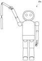
図2は、ロボット装置20の外観を示す。ロボット装置20は人間と同じような部位および関節を持ち、人間の姿勢と同じまたは似た姿勢をとることのできる構造を有することが好ましい。ロボット装置20は上半身および下半身を有して構成される。下半身は、腰部30、および腰部30より下の部位である右大腿31a、左大腿31b、右下腿32a、左下腿32b、右足33a、左足33bを含む。上半身は、腰部30より上の部位で構成され、頭部21、首22、胴体23、右肩24a、左肩24b、右上腕25a、左上腕25b、右前腕26a、左前腕26b、右手27a、左手27bを含む。隣り合う部位間には関節部分を構成する関節モータが配置され、関節モータ間はリンク機構で連結される。
FIG. 2 shows the appearance of the
図3は、ロボット装置20が備える関節構造を模式的に示す。ロボット装置20がユーザと同じまたは似た姿勢をとるためには、ロボット装置20の関節構造が、人間の関節構造と同じまたは近似していることが好ましい。胴体23に対して頭部21を支持する首関節は、首関節ヨー軸用モータ41、首関節ピッチ軸用モータ42、首関節ロール軸用モータ43を備える。
FIG. 3 schematically shows a joint structure included in the
胴体23と右手27aの間には、右肩関節を構成する肩関節ピッチ軸用モータ51a、肩関節ロール軸用モータ52a、肩関節ヨー軸用モータ53a、右肘関節を構成する肘関節ピッチ軸用モータ54a、右手首関節を構成する手首関節ピッチ軸用モータ55aが設けられる。胴体23と左手27bの間には、左肩関節を構成する肩関節ピッチ軸用モータ51b、肩関節ロール軸用モータ52b、肩関節ヨー軸用モータ53b、左肘関節を構成する肘関節ピッチ軸用モータ54b、左手首関節を構成する手首関節ピッチ軸用モータ55bが設けられる。なお人間の関節構造に近づけるために、手首関節には、さらにロール軸用モータが設けられてよい。
Between the
胴体23と腰部30の間には、体幹関節を構成する体幹ロール軸用モータ61、体幹ピッチ軸用モータ62、体幹ヨー軸用モータ63が設けられる。図3において、体幹ヨー軸用モータ63は、下半身である腰部30に配置されているが、実施例の姿勢制御において、体幹ヨー軸用モータ63は、上半身の姿勢を制御するための関節モータとして取り扱われる。
A trunk
腰部30から右足33a、左足33bまでの間のモータは、下半身の姿勢を制御するための関節モータである。腰部30と右足33aの間には、右股関節を構成する股関節ヨー軸用モータ71a、股関節ロール軸用モータ72a、股関節ピッチ軸用モータ73a、右膝関節を構成する膝関節ピッチ軸用モータ74a、右足首関節を構成する足首関節ピッチ軸用モータ75a、足首関節ロール軸用モータ76aが設けられる。腰部30と左足33bの間には、左股関節を構成する股関節ヨー軸用モータ71b、股関節ロール軸用モータ72b、股関節ピッチ軸用モータ73b、左膝関節を構成する膝関節ピッチ軸用モータ74b、左足首関節を構成する足首関節ピッチ軸用モータ75b、足首関節ロール軸用モータ76bが設けられる。
The motors from the
図4は、ロボット装置20を制御するロボット制御システム100のハードウェア構成を示す。ロボット制御システム100はロボット装置20の筐体内に設けられ、モーションセンサ102、通信部104、撮像部106、第1プロセッサ90および第2プロセッサ92を備える。第1プロセッサ90は、姿勢推定機能を実現する姿勢推定部108を有する。第2プロセッサ92は、ロボット装置20の運動制御機能を実現する運動制御部110を有する。運動制御部110は、第1運動制御部120、第2運動制御部140およびモード設定部142を備え、第1運動制御部120は、同調制御部122、補正処理部124、パターン判定部126および姿勢履歴記憶部128を有する。
FIG. 4 shows the hardware configuration of a
ロボット制御システム100の構成は、ハードウエアコンポーネントでいえば、任意のコンピュータのCPU、メモリ、メモリにロードされたプログラム、ストレージなどによって実現される。第1プロセッサ90および第2プロセッサ92は図示する機能ブロックを有し、これらの機能ブロックがハードウエアのみ、ソフトウエアのみ、またはそれらの組合せによっていろいろな形で実現できることは、当業者には理解されるところである。
The configuration of the
通信部104は無線LANでAP3に接続し、AP3を介してサーバ装置10と通信する。通信部104は、サーバ装置10から応用アプリケーションやパッチファイルをダウンロードできる。通信部104はアドホック通信機能を有し、複数のロボット装置20が存在する空間では、ロボット装置20同士がアドホック通信により接続できる。
The
モーションセンサ102は、3軸加速度センサおよび3軸ジャイロセンサを有する。モーションセンサ102は腰部30に設けられて、3次元空間における位置および姿勢を示すセンサデータおよび/または位置および姿勢の変化を示すセンサデータを運動制御部110に提供する。さらにモーションセンサ102は各関節部分に設けられて、センサデータを運動制御部110に提供してよい。
撮像部106は、RGBカラーセンサであって、所定の周期(たとえば1/60秒)で撮影したRGB画像データを姿勢推定部108に供給する。実施例のRGB画像データは、深度情報をもたない2次元画像データである。なお撮像部106は他の種類のイメージセンサであってもよい。撮像部106は頭部21に設けられて、ロボット装置20の顔が向いている方向を撮影する。なお顔が向いている方向のみならず、顔の横方向、後ろ方向を撮影するために、複数の撮像部106が頭部21に設けられてもよい。ロボット装置20において同調アプリケーションが実行されると、ロボット装置20は、撮像部106により撮影されたユーザの動きを真似する同調運動を行う。
The
同調アプリケーションの一つの動作モードでは、ロボット装置20がユーザと向かい合い、撮像部106で撮影したユーザの動作を、ユーザと向き合った状態で真似する。このときロボット装置20は、ユーザの動作を左右対称にコピーし、たとえばユーザが右手を上げると、ロボット装置20は左手を上げ、ユーザが右手を左右に振ると、ロボット装置20は左手を右左に振る。ユーザからロボット装置20を見ると、ロボット装置20が鏡に映るユーザのように運動することから、この動作モードを「ミラーリングモード」と呼ぶ。
In one operation mode of the tuning application, the
同調アプリケーションの別の動作モードでは、ロボット装置20が、ユーザの動作と基本的には同じように運動する。この動作モードでは、ユーザが右手を上げると、ロボット装置20は右手を上げ、ユーザが右手を左右に振ると、ロボット装置20は右手を左右に振る。この動作モードは、2人のユーザが、それぞれのロボット装置20を操作して、ロボット装置20同士を対戦させるようなシーンで利用される。たとえば2台のロボット装置20がボクシングをする場合、ユーザが右ストレートを出すと、ロボット装置20は対戦相手のロボット装置20に対して右ストレートを出し、ユーザが左フックを出すと、ロボット装置20は対戦相手のロボット装置20に対して左フックを出す。またロボット装置20の右手27aに物体(刀などの武器)を持たせた状態で、ユーザが体を中心として水平面で右腕を反時計回りに回すと、ロボット装置20が体を中心として水平面で物体を反時計回りに回して、対戦相手のロボット装置20に物体の先端をぶつけるように運動する。このような動作モードを「バトルモード」と呼ぶ。
In another mode of operation for tuning applications, the
このように同調アプリケーションでは、複数の動作モードが用意されている。ユーザは利用シーンに応じて動作モードを選択した後、ロボット装置20に同調運動をさせる。動作モードを選択するための手段は何でもよい。たとえばロボット装置20に動作モードを選択するためのボタンが設けられていてもよいし、音声認識機能を有するロボット装置20がユーザによる動作モードの発話を音声認識して、発話された動作モードを特定してもよい。また他のアプリケーション、たとえばゲームなどによって、動作モードが自動的に選択されてもよい。モード設定部142が、選択された動作モードを受け付けると、第1運動制御部120および第2運動制御部140が、選択された動作モードでロボット装置20の運動を制御する。
A tuning application thus provides a plurality of modes of operation. After the user selects an operation mode according to the usage scene, the
同調アプリケーションを実施する前提として、ロボット装置20は、ユーザの姿勢を認識する必要がある。そのため姿勢推定部108は、ユーザの画像が記録されたRGB画像データを取得して、ユーザの姿勢を推定する。なお姿勢推定部108は、RGB画像データに限らず、ユーザの画像が記録された別の種類の画像データから、ユーザの姿勢を推定してもよい。姿勢推定部108は、機械学習されたモデルを用いて人の姿勢を推定するニューラルネットワークを有してよい。
As a prerequisite for executing the tuning application, the
近年、人の姿勢を推定するためのライブラリがオープンソースで公開されている。このライブラリは、ディープラーニングを実施したニューラルネットワークを用いて2次元画像から人の関節位置などの特徴点を検出し、特徴点を繋ぎ合わせることで人の姿勢を推定する。ある姿勢推定モデルでは、一人につき25個の特徴点の位置が推定される。25個の特徴点は、鼻、首、右肩、右肘、右手首、左肩、左肘、左手首、中央腰、右腰、右膝、右足、左腰、左膝、左足、右目、左目、右耳、左耳、左足親指、左足小指、左かかと、右足親指、右足小指、右かかとである。実施例の姿勢推定部108は、このような姿勢推定モデルを利用して、撮影された人の姿勢を推定する。
In recent years, a library for estimating a person's posture has been published as an open source. This library uses a deep-learning neural network to detect feature points such as the joint positions of a person from a two-dimensional image, and connects the feature points to estimate a person's posture. One pose estimation model estimates the positions of 25 feature points per person. The 25 feature points are nose, neck, right shoulder, right elbow, right wrist, left shoulder, left elbow, left wrist, center waist, right waist, right knee, right leg, left waist, left knee, left leg, right eye, left eye. , right ear, left ear, left big toe, left little toe, left heel, right big toe, right little toe, right heel. The
実施例の姿勢推定部108は、人の画像が記録された2次元画像データから25個の特徴点の位置を推定し、これらの特徴点を用いて人の姿勢を推定する。具体的に姿勢推定部108は、3次元空間における人の胴体、脚、腕、手などの各部位の位置や向きを推定し、推定した人の姿勢を表現する姿勢情報を運動制御部110に供給する。
The
姿勢推定部108は、人の姿勢を表現する姿勢情報として、人の関節の角度情報および体の向きを示す情報を運動制御部110に供給するが、3次元空間における特徴点の相対的な位置情報(3次元座標)を姿勢情報として供給してもよい。また姿勢推定部108は、最初に2次元画像における25個の特徴点の位置情報を推定するが、これらの特徴点の位置情報(2次元座標)も人の姿勢を表現する姿勢情報であり、これらの特徴点の位置情報を姿勢情報として運動制御部110に供給してもよい。この場合、運動制御部110は、複数の特徴点の2次元座標から、3次元空間における人の姿勢を推定する機能をもつ必要がある。
The
図5(a)は、姿勢推定部108により検出される特徴点の例を示す。姿勢推定部108は、25個の特徴点の位置を推定し、撮影されたユーザの姿勢を推定する。実施例で撮像部106は、ロボット装置20のオーナであるユーザを撮影する。同調運動の開始前、ユーザは図5(a)に示す基準姿勢で撮影され、姿勢推定部108は、基準姿勢をとるユーザに関して検出した特徴点から、体の各パーツの長さを算出して保持する。各パーツは2つの特徴点を連結した直線で表現され、この直線を「ボーン」と呼ぶ。基準姿勢は、ユーザが撮像部106に対して正対した直立姿勢であり、各パーツを表現するボーンの長さは、基本的には正対姿勢で最大となる。姿勢推定部108は、基準姿勢で検出した各ボーンの長さを「最大ボーン長」として保持する。なおユーザが撮像部106に近付くと、検出されるボーン長は、最大ボーン長を超え、その場合は、検出されるボーン長を最大ボーン長として更新する処理を行う。このときボーン長の相対比を事前に定めておき、その相対比にしたがって最大ボーン長を更新してもよい。以下の説明では、便宜上、ユーザと撮像部106の間の距離が変化せず、最大ボーン長が固定であることを前提とする。
FIG. 5A shows an example of feature points detected by
図5(b)は、姿勢推定部108により検出される特徴点の別の例を示す。図5(b)に示す撮影画像では、基準姿勢から、ユーザが右手を上に振り上げる状態が撮影されている。図5(a)と比較して、右肘、右手の検出位置が大きく変化し、したがって右手上腕のボーン長と、右手前腕のボーン長が、基準姿勢と比較して短くなっている。姿勢推定部108は、ボーン長にもとづいて人の関節の角度を推定する。
FIG. 5B shows another example of feature points detected by
姿勢推定部108は、以下の式より、深度を算出する。
![]()
・肘関節は肩関節よりも前
・手首関節は肘関節よりも前
・膝関節は股関節よりも前
・膝関節は足首関節よりも前
・膝関節はかかとよりも前
ここで「前」は、撮像部106により近い位置であることを意味する。
![]()
・The elbow joint is before the shoulder joint ・The wrist joint is before the elbow joint ・The knee joint is before the hip joint ・The knee joint is before the ankle joint ・The knee joint is before the heel It means a position closer to the
姿勢推定部108は、この前後関係の基準および算出した深度を用いて、3次元空間における特徴点の位置を推定し、3次元空間における特徴点を連結したベクトル(ボーンベクトル)を推定する。姿勢推定部108は、3次元空間のボーンベクトルを2次元平面に射影することで、ユーザの各関節の角度、つまりユーザの各関節のピッチ角度、ロール角度、ヨー角度をそれぞれ推定する。
このとき姿勢推定部108は、ロボット装置20の関節構造に対応するユーザの関節角度を推定することが好ましい。たとえばロボット装置20の肩関節は、ピッチ軸、ロール軸、ヨー軸のそれぞれに関節モータを有するため、姿勢推定部108は、人の肩関節のピッチ角度、ロール角度、ヨー角度をそれぞれ推定する。またロボット装置20の肘関節はピッチ軸に関節モータを有するため、姿勢推定部108は、人の肘関節のピッチ角度を推定する。いずれにしても姿勢推定部108は、運動制御部110による同調制御で使用する姿勢情報を生成することが好ましい。
At this time, the
なお人の胴体が撮像部106に対して右側を向いているか、または左側を向いているかは、以下のように導出する。
図6は、ユーザを撮影した画像から検出される特徴点を示す。なお、いくつかの特徴点については図示を省略している。図6(a)は、ユーザが撮像部106に対して右側を向いた状態を、図6(b)は、ユーザが撮像部106に対して左側を向いた状態を示している。
It should be noted that whether the person's torso faces the right side or the left side with respect to the
FIG. 6 shows feature points detected from an image of a user. It should be noted that illustration of some characteristic points is omitted. 6A shows a state in which the user faces the
姿勢推定部108は、ユーザの顔の特徴点Aと、顔より下方に位置する特徴点Bと、特徴点Bより下方に位置する特徴点Cにもとづいて、胴体の向きを推定する。ここで特徴点A、B、Cは、基準姿勢(撮像部106に対して正対した直立姿勢)で、上から下に向けて直線的に並ぶ特徴点であり、ここでは特徴点Aが鼻、特徴点Bが首、特徴点Cが中央腰である。姿勢推定部108は、特徴点A、B、Cを繋いだ線から、胴体が右側を向いているか、左側を向いているかを判断する。
The
具体的に姿勢推定部108は、特徴点Bと特徴点Aを連結する2次元のボーンベクトルと、特徴点Bと特徴点Cを連結する2次元のボーンベクトルの外積にもとづいて、人の胴体の向きを推定してよい。2つのボーンベクトルの外積が正である場合、胴体の向きは撮像部106に対して右向きであり、外積が負である場合、胴体の向きは撮像部106に対して左向きと判定される。
Specifically, the
実施例の姿勢推定部108は、人の姿勢を表現する姿勢情報として、少なくとも人の関節の角度情報を運動制御部110に供給する。姿勢推定部108は、姿勢情報として、胴体の向きを示す情報および特徴点の3次元座標を運動制御部110に供給してもよい。また姿勢推定部108は、姿勢情報として、特徴点の2次元座標を姿勢情報として運動制御部110に供給してもよい。
The
運動制御部110は、姿勢推定部108の推定結果にもとづいて、ロボット装置20の運動を制御する。運動制御部110は、各関節モータの回転速度を導出し、各関節モータに対応するマイコンに回転指示を供給する。
The
第1運動制御部120における同調制御部122は、推定したユーザの上半身の姿勢にロボット装置20の上半身の姿勢を同調させる。ユーザの上半身は、腰より上の部位である。図3に示す関節構造において、ロボット装置20の上半身の関節を構成するモータは、首関節ヨー軸用モータ41、首関節ピッチ軸用モータ42、首関節ロール軸用モータ43、肩関節ピッチ軸用モータ51a、肩関節ロール軸用モータ52a、肩関節ヨー軸用モータ53a、肘関節ピッチ軸用モータ54a、手首関節ピッチ軸用モータ55a、肩関節ピッチ軸用モータ51b、肩関節ロール軸用モータ52b、肩関節ヨー軸用モータ53b、肘関節ピッチ軸用モータ54b、手首関節ピッチ軸用モータ55b、体幹ロール軸用モータ61、体幹ピッチ軸用モータ62、体幹ヨー軸用モータ63である。
The
第1運動制御部120の機能は、同調アプリケーションを実行することで実現される。同調制御部122は、推定したユーザの上半身の姿勢にもとづいて、ロボット装置20の上半身の関節モータを制御して、ロボット装置20の上半身の姿勢をユーザの上半身の姿勢に同調させる。同調した姿勢は、ユーザがロボット装置20の姿勢を見て、自分の動きを真似していることが分かる程度に似た姿勢であればよい。
The function of the first
ロボット装置20の姿勢をユーザの姿勢に同調させるために、同調制御部122は、人体の姿勢情報を用いてロボット装置20の複数の関節のそれぞれの目標角度を演算する演算式を定義した演算規則を保持する。同調制御部122は、演算規則に定義された演算式にもとづいて、姿勢推定部108により推定された人の姿勢情報を用いてロボット装置20の複数の関節のそれぞれの目標角度を決定し、目標角度にしたがって関節モータを駆動する。これによりロボット装置20の姿勢がユーザの姿勢に同調する。
In order to synchronize the posture of the
演算式は、人の姿勢情報を入力されると、ロボット装置20の関節の目標角度を出力するように構成される。最も単純な例で説明すると、人の右肘の関節角度情報を演算式に入力すると、演算式は、ロボット装置20の右肘の関節の目標角度を出力する。目標角度が、推定した人の関節角度と等しく、または近似した値となることで、ロボット装置20の同調運動が実現される。
The arithmetic expression is configured to output the target angle of the joint of the
一方、第2運動制御部140は、ロボット装置20の下半身を安定化制御し、上記演算式にもとづいた同調制御を実施しない。つまり第2運動制御部140は、ロボット装置20の下半身の姿勢を、ユーザの下半身の姿勢に同調させない。図3に示す関節構造において、下半身の関節を構成するモータは、股関節ヨー軸用モータ71a、股関節ロール軸用モータ72a、股関節ピッチ軸用モータ73a、膝関節ピッチ軸用モータ74a、足首関節ピッチ軸用モータ75a、足首関節ロール軸用モータ76a、股関節ヨー軸用モータ71b、股関節ロール軸用モータ72b、股関節ピッチ軸用モータ73b、膝関節ピッチ軸用モータ74b、足首関節ピッチ軸用モータ75b、足首関節ロール軸用モータ76bである。第2運動制御部140の機能は、安定化制御アプリケーションを実行することで実現され、モーションセンサ102のセンサデータを常時監視して、ロボット装置20が転倒しないように姿勢を安定化させる。なお第2運動制御部140の機能は、同調アプリケーションに組み込まれていてもよい。第2運動制御部140は、姿勢安定化制御において、上半身の運動による負荷を外乱要素として処理することになる。
On the other hand, the second
この安定化制御で第2運動制御部140は、姿勢推定部108により推定された人の腰の位置情報から、3次元空間におけるロボット装置20の腰部30の目標高さを決定する。また第2運動制御部140は、人の両足の位置情報から、ロボット装置20の右足33aと左足33bの目標位置を決定してもよい。人の両足の位置情報は、たとえば右かかと、左かかとの位置情報を利用する。第2運動制御部140は、基準姿勢における人の腰の位置情報と、現在の腰の位置情報の差分から、ロボット装置20の腰部30の目標高さを決定してよい。なお第2運動制御部140は、基準姿勢と現在の姿勢とで、両足の位置を結ぶ直線に対して中央腰から垂線を下ろした長さを算出し、その長さの比から、ロボット装置20の腰部30の目標高さを決定してもよい。
In this stabilization control, the second
上記したように第2運動制御部140は、ロボット装置20の下半身の姿勢を、ユーザの下半身の姿勢に同調させるものではないが、右足33a、左足33bの位置と、腰部30の高さに関してはユーザの姿勢に合わせることで、ユーザの下半身に近似した姿勢を作り出せる。第2運動制御部140は、右足33a、左足33bの目標位置と、腰部30の目標高さを決定した後、インバースキネマティクス演算を行って下半身に含まれる複数の関節モータを制御してよい。
As described above, the second
図7は、ロボット装置20がミラーリングモードで同調動作をする様子を示す。図7に示す例では、ユーザが膝を曲げた状態で右手を上げている。このユーザの姿勢に対してロボット装置20の上半身は、同調制御部122によってユーザの上半身の姿勢に同調し、ロボット装置20の下半身は、ユーザの下半身の姿勢に同調することなく、第2運動制御部140によって転倒しないように姿勢制御される。ロボット装置20の腰部30の高さは、ユーザの腰の高さに応じた高さに設定されている。
FIG. 7 shows how the
なお本発明者が、姿勢推定部108の検出値を使用してロボット装置20の動作実験を行ったところ、実際の撮影環境では被写体である人が動かなくても、姿勢推定部108の検出値に揺れが発生することが分かった。そのため姿勢推定部108の検出値をそのまま利用して運動制御部110が関節モータを回転制御すると、検出値の揺れ頻度が大きいほど、各関節が忙しなく動き続けるようになる。そこで同調制御部122は、躍度最小(Minimum Jerk)モデルを用いて、各関節のモータの回転速度を決定する。
When the present inventor conducted an operation experiment of the
図8は、関節角度を表現する躍度最小モデル軌道の例を示す。躍度最小モデルは、加速度の変化率が小さくなる軌道を求める手法であり、姿勢推定部108の検出値に基づいた関節角度軌道と比べると、目標角度に対して軌道を滑らかにできることが分かる。同調制御部122が、躍度最小モデルを用いてモータの回転速度を決定することで、姿勢推定部108の検出値に揺れが生じても関節の回転を緩やかにできる。
FIG. 8 shows an example of a minimum jerk model trajectory that expresses joint angles. The minimum jerk model is a method of obtaining a trajectory that reduces the rate of change in acceleration, and it can be seen that the trajectory can be made smoother with respect to the target angle than the joint angle trajectory based on the detection values of the
なお姿勢推定部108においては、特徴点位置の検出誤差、深度の算出誤差、関節角度の推定誤差など、姿勢に関する様々な誤差が発生する。ロボット装置20の上半身では、体幹関節を起点として、肩関節、肘関節、手首関節と角度変化が伝達されるため、姿勢推定部108において発生する姿勢推定誤差は、体幹関節から手首関節の間で次第に累積される。そのため全ての関節を同じように動かすと、先端となる右手27a、左手27bは、姿勢推定誤差が最大に累積されて、暴れるような挙動をとることがある。このような挙動を回避するために、同調制御部122は、少なくとも1つの関節の目標角度を決定し、決定した目標角度への目標到達時間をもとに、関節を構成するモータの回転速度を決定する制御を行う。
In the
姿勢推定部108は、人の各関節の角度情報を、所定の周期T1(たとえば20m秒)で推定し、運動制御部110に供給する。したがって同調制御部122は、同じ周期T1で、供給された推定角度情報から、ロボット装置20の上半身の各関節の目標角度を決定する。つまり同調制御部122は、周期T1(20m秒)ごとに、各関節の新たな目標角度を決定する。この目標角度は姿勢推定誤差を含んでいるため、周期T1ごとに決定される目標角度は、姿勢推定誤差に揺れが生じている場合には、離散的な値となることもある。
このとき同調制御部122が、周期T1で各関節が目標角度となるように関節モータの回転速度を決定すると、上半身先端に近付くにつれて関節が発振する(暴れる)ような挙動となる。そこで同調制御部122は、決定した目標角度への目標到達時間T2を、目標角度の決定周期T1より長く設定して、関節の急峻な回転を回避し、関節の回転を緩やかにさせる。
At this time, if the
たとえば、現在角度と目標角度との差がαであったとする。同調制御部122は、時間T2後に関節がα度回転するためのモータの回転速度を決定し、その回転速度で時間T1だけ回転させる。時間T1の間に回転する角度は(α×T1/T2)であり、そのためT2=10×T1とした場合、時間T1後の回転量は、α/10となる。時間T1後、同調制御部122は、姿勢推定部108から供給される推定角度情報にもとづいて、新たな目標角度を決定し、その時点から時間T2後に関節が目標角度となるためのモータの回転速度を決定する。
For example, assume that the difference between the current angle and the target angle is α. The
目標角度への目標到達時間T2を、目標角度の決定周期T1よりも長くすることで、同調運動に遅延は発生するものの、ロボット装置20がユーザの動きに滑らかに追従できるようになる。なお目標到達時間T2を決定周期T1よりも長くするほど、ロボット装置20の動きは滑らかになるが、一方で、目標到達時間T2を決定周期T1よりも長くしすぎると、同調運動の遅延は大きくなる。
By setting the target reaching time T2 to the target angle longer than the determination period T1 of the target angle, the
同調運動の遅延をユーザに小さく見せるために、目標角度の目標到達時間T2は、関節ごとに設定されることが好ましい。具体的に上半身の先端側の関節に設定される目標到達時間は、体幹側の関節に設定される目標到達時間よりも短くされる。先端側の関節、つまり手首関節に連結する右手27a、左手27bの動きや、肘関節に連結する右前腕26a、左前腕26bの動きは、胴体23から離れて動くため、ユーザの目につきやすい。そのため先端側の関節における目標到達時間T2を短く設定することで、同調運動の遅延をできるだけ小さく見せることが可能となる。
The target angle T2 is preferably set for each joint in order to make the delay in synchronized motion appear small to the user. Specifically, the target reaching time set for the joint on the tip side of the upper body is set shorter than the target reaching time set for the joint on the trunk side. The joints on the distal side, that is, the movements of the
一方で、体幹側の関節については、目標到達時間T2を相対的に長く設定することで、姿勢推定誤差が先端側に累積する影響を低減する。これにより、ロボット装置20の全体の動きが滑らかに制御される。たとえば手首関節、肘関節の目標到達時間T2を80m秒、より体幹側の肩関節の目標到達時間T2を100~200m秒、体幹関節の目標到達時間T2を250m秒と設定して、同調運動の低遅延と滑らかさとを実現してよい。
On the other hand, for the joints on the trunk side, by setting the target arrival time T2 to be relatively long, the influence of posture estimation errors accumulating on the tip side is reduced. As a result, the overall motion of the
なお肩関節内でも、より先端側である関節モータの目標到達時間T2を相対的に短く設定することが好ましく、肩関節ヨー軸用モータ53aの目標到達時間T2を100m秒、肩関節ロール軸用モータ52aの目標到達時間T2を160m秒、肩関節ピッチ軸用モータ51aの目標到達時間T2を200m秒と設定してよい。つまり体幹側から先端(手先)の間に配置された1つの関節モータの目標到達時間T2は、当該関節モータよりも先端側の関節モータの目標到達時間T2以上であり、当該関節モータよりも体幹側の関節モータの目標到達時間T2以下に設定される。なお首関節の速い動きは違和感を生じさせるため、首関節の目標到達時間T2は最大値(たとえば400m秒)に設定されてよい。
In the shoulder joint, it is preferable to set the target reaching time T2 of the joint motor closer to the distal end to be relatively short. The target reaching time T2 of the
図9は、複数のロボット装置を、それぞれのユーザが操作して対戦させるロボットシステムを示す。このロボットシステム200では、ユーザAがロボット装置20aを操作し、ユーザBがロボット装置20bを操作して、ロボット装置20aとロボット装置20bとをボクシングで対戦させる。各ロボット装置20a、20bにおいては、動作モードとして「バトルモード」が設定され、さらに「バトルモード」の中の「ボクシングモード」が選択される。「ボクシングモード」でロボット装置20は、ユーザの動きと基本的には同じように運動し、ユーザが右ストレートを出すと、ロボット装置20も右ストレートを出し、ユーザが左フックを出すと、ロボット装置20も左フックを出す。
FIG. 9 shows a robot system in which each user operates a plurality of robot devices to compete against each other. In this
対戦型のロボットシステム200では、ロボット装置20同士が向かい合い、それぞれのユーザは、ロボット装置20の顔の正面には立たない。ロボット装置20の頭部21に全方位を撮影する複数の撮像部106が設けられている場合、姿勢推定部108は、撮像部106がユーザを撮影した画像データを取得して、撮影されたユーザの姿勢を推定する。
In the battle-
この例では、ロボット装置20aにおいて、姿勢推定部108が、撮像部106で撮影した画像データからユーザAの姿勢を推定し、同調制御部122が、ユーザAの姿勢にロボット装置20aの姿勢を同調させる制御を行う。またロボット装置20bにおいて、姿勢推定部108が、撮像部106で撮影した画像データからユーザBの姿勢を推定し、同調制御部122が、ユーザBの姿勢にロボット装置20bの姿勢を同調させる制御を行う。このようにロボットシステム200では、ユーザA、Bが、ボクシングの動きをすることで、ロボット装置20a、20bが、それぞれユーザA、Bの動きを真似して運動する。それぞれのユーザにとって、ロボット装置20が自分の分身のように動くため、ロボット装置20を利用した、これまでにないエンタテインメント性を実現できる。
In this example, in the
なおロボット装置20は、ユーザを撮影した画像データを、別の外部装置から供給されてもよい。ユーザは、ロボット装置20とは離れた場所にいながら、自身を撮影した画像データを外部装置からロボット装置20に送信する。ロボット装置20において姿勢推定部108が、受信した画像データからユーザの姿勢を推定し、同調制御部122が、ユーザの姿勢にロボット装置20の姿勢を同調させる制御を行う。この場合、ユーザは、ロボット装置20とは別の場所にいながら、ロボット装置20同士の対戦を実現できる。
Note that the
なおロボット装置20が、顔が向いている方向を撮影する単一の撮像部106のみを有する場合、体は相手のロボット装置20に向いたまま、顔をユーザに向けさせて、撮像部106でユーザを撮影してもよい。しかしながらロボット装置20同士の対戦では、それぞれのロボット装置20の顔が相手のロボット装置20の方向を向いてない状況となり、違和感が生じる。そのためロボット装置20が、相手のロボット装置20のユーザの姿勢を推定し、推定した姿勢を当該相手のロボット装置20に送信してもよい。
Note that if the
つまりロボット装置20aにおいては、撮像部106がユーザBを撮影し、姿勢推定部108が、ユーザBの姿勢を推定して、通信部104がユーザBの姿勢情報をロボット装置20bに送信する。この送信は、アドホック通信を用いてよい。ロボット装置20bでは、通信部104がユーザBの姿勢情報を受信し、運動制御部110が、ユーザBの姿勢情報にもとづいて、ロボット装置20bの運動制御を実施する。
That is, in the
同様にロボット装置20bにおいては、撮像部106がユーザAを撮影し、姿勢推定部108が、ユーザAの姿勢を推定して、通信部104がユーザAの姿勢情報をロボット装置20aに送信する。ロボット装置20aでは、通信部104がユーザAの姿勢情報を受信し、運動制御部110が、ユーザAの姿勢情報にもとづいて、ロボット装置20aの運動制御を実施する。このようにロボット装置20が対戦相手のユーザの姿勢を推定して、対戦相手のロボット装置20に送信することで、互いに画像データを送信するよりも、処理時間を短縮できる。
Similarly, in the
「バトルモード」には、シンプルにパンチを繰り出して「ボクシングモード」だけでなく、武器を装着して戦うモードがあり、たとえば三節棍を武器とする「三節棍対戦モード」や、刀を武器とする「刀対戦モード」がある。このような武器対戦モードでは、武器の種類によって、ロボット装置20の同調運動を補正する方がよいことがある。そこでバトルモードで動作させる際、ユーザはロボット装置20に装着する武器に応じた動作モードを選択し、モード設定部142は、装着する武器に応じた動作モードを設定する。なおロボット装置20が、装着される武器を自動認識する機能を有していれば、モード設定部142が、自動認識した武器に応じた動作モードを設定してよい。補正処理部124は、設定された動作モードに応じて、ロボット装置20の同調運動を補正する。
In "Battle Mode", there is not only "Boxing Mode" where you simply throw a punch, but also a mode where you fight by wearing weapons, for example, "Three-section club battle mode" where you use a three-section club as a weapon, and "Battle mode" where you use a sword as a weapon. There is a "sword battle mode" to do. In such a weapon battle mode, it may be better to correct the synchronization movement of the
(a)「三節棍対戦モード」
三節棍は、3本の棒を紐や鎖で一直線になるように連結した武器である。三節棍をロボット装置20aの右手27aに持たせる場合、ユーザAが右腕を振らない状態だと、把持した棒以外の2本の棒は、だらんと垂れ下がり、床面に付いてしまう。そこで補正処理部124は、「三節棍対戦モード」においては、右肩関節のピッチ角に下限を設定して、ロボット装置20aが、三節棍を高く上げた状態を維持して、棒が床面に付かないようにする。なお左手27bに三節棍を持たせる場合には、補正処理部124は、左肩関節のピッチ角に下限を設定すればよい。
(a) “Three-section club battle mode”
A three-section staff is a weapon that connects three sticks in a straight line with a string or chain. When the three-bar staff is held by the
図10は、肩関節のピッチ角に下限を設定した状態を示す。下限角度は、三節棍の長さに依存して定められてよい。肩関節のピッチ角に下限を設定しない場合、ユーザAの腕が下がった状態では、三節棍も垂れ下がった状態となり、脚部に絡まることがある。また、ユーザAが腕を十分に上げない状態でぐるぐると回すと、三節棍がロボット装置20aの胴体に巻き付くような状況も発生しうる。そこで「三節棍対戦モード」では、補正処理部124が肩関節のピッチ角に下限を設定し、ユーザAがそれほど腕を上げずにぐるぐると回しても、ロボット装置20aが三節棍を自然にぐるぐると回して、相手のロボット装置20bを攻撃できる。
FIG. 10 shows a state in which the lower limit is set for the pitch angle of the shoulder joint. The lower angle may be determined depending on the length of the three-bar staff. If the pitch angle of the shoulder joint does not have a lower limit, when the arm of the user A is lowered, the three-bar staff also hangs down and may get entangled with the leg. In addition, if the user A rotates the arm without raising the arm sufficiently, a situation may occur in which the three-bar staff is wrapped around the body of the
(b)「刀対戦モード」
刀をロボット装置20aの右手27aに持たせる場合、ロボット装置20aは、低い位置よりも高い位置に刀を構えた方が見映えがよい。ユーザAが右上腕を高い位置まで上げれば、同調制御部122によりロボット装置20aは、高い位置に刀を構えることができる。しかしながら実際に試したところ、ユーザAは刀を持っていないため、その感覚が分かりづらく、「刀対戦モード」においてユーザAは上腕を高い位置に上げないことが判明した。そこでユーザAが右上腕を高い位置まで上げなくても、ロボット装置20aの右上腕25aを高く上げられるように、補正処理部124がロボット装置20aの同調運動を補正する。
(b) "Sword battle mode"
When the sword is held in the
図11(a)は、姿勢推定部108により検出される特徴点の例を示す。特徴点Dが首、特徴点Eが右肩、特徴点Fが右肘、特徴点Gが右手首である。同調制御部122は、人体の姿勢情報を用いてロボット装置20の複数の関節のそれぞれの目標角度を演算する演算式を定義した演算規則を用いて、ロボット装置20の関節の目標角度を決定している。したがって、たとえば「ボクシングモード」における同調制御においてロボット装置20の右肩の目標関節角度は、特徴点D、特徴点E、特徴点Fの位置関係から定まる姿勢情報を用いて決定される。
FIG. 11( a ) shows an example of feature points detected by
一方で「刀対戦モード」では、補正処理部124は、同調制御における演算式の少なくとも一部を変更して、同調運動を補正する。
図11(b)は、補正処理部124による補正処理の例を示す。この補正処理では、ロボット装置20の右肩の目標関節角度が、特徴点D、特徴点E、特徴点Gの位置関係から定まる姿勢情報を用いて決定される。なおロボット装置20の右手首は、図11(a)に示す特徴点Fから特徴点Gに向かうボーンベクトルを、特徴点Gを起点に設定したときの終点Hを基準に算出される。
On the other hand, in the "sword fighting mode", the
FIG. 11B shows an example of correction processing by the
このように補正処理部124が、同調制御における演算規則の少なくとも一部を変更して、ロボット装置20の関節の目標角度を補正することで、演算規則をそのまま適用した同調制御を実施するよりも、エンターテイメント性に優れたロボット運動を実現できる。
In this manner, the
なおロボット装置20aの補正処理部124は、対戦相手であるロボット装置20bの運動にもとづいて、ロボット装置20aの同調運動を補正してもよい。補正処理部124は、対戦相手を撮影した画像を撮像部106から取得し、たとえば対戦相手の攻撃が自分に当たりそうであることを判断すると、同調制御部122による同調運動を強制中止して、攻撃を回避する行動をとってもよい。
The
なお人とロボット装置20の関節構造は完全には同じではないため、ロボット装置20は人の動きを正確に真似できないことがある。また人の動きを撮像部106で捉えきれないこともある。そのような状況に対応するべく、補正処理部124は、ロボット装置20の姿勢の変化が所定のパターンを示す場合に、その後のロボット装置20を、当該パターンに対応付けられた運動パターンで運動させてよい。
Since the joint structures of the human and the
姿勢履歴記憶部128は、現在から所定時間過去までのロボット装置20の姿勢を記憶する。姿勢履歴記憶部128は、たとえば十数秒程度前までのロボット装置20の姿勢を記憶できればよい。パターン判定部126は、姿勢履歴記憶部128に記憶された姿勢を参照して、現在に至るロボット装置20の姿勢の変化が所定のパターンを示すか判定する。ロボット装置20の姿勢の変化が所定のパターンを示す場合、補正処理部124は、その後のロボット装置20を、当該パターンに対応付けられた運動パターンで運動させる。たとえばミラーリングモードにおいて、ユーザが物を右手で掴み、右腕を右肩ピッチ軸回りに回して右手を右肩越しに背中まで持っていき、背後に物を落とす、という動作を行うとする。このとき撮像部106は、ユーザが右手を右肩越しに背後に持っていった様子を撮影できない。そこで姿勢履歴記憶部128に、ロボット装置20が、手に物を把持した状態で腕を耳よりも後ろに動かしたことを示す姿勢の変化が記憶されると、パターン判定部126が、現在に至る姿勢の変化が所定のパターンであることを判定して、補正処理部124が、手を開いて、物を背中に落とす動作をさせてよい。
The posture
本発明を実施例をもとに説明した。実施例は例示であり、それらの各構成要素や各処理プロセスの組合せにいろいろな変形例が可能なこと、またそうした変形例も本発明の範囲にあることは当業者に理解されるところである。実施例では、運動制御部110が上半身のみを同調制御したが、全身を同調制御してもよい。
The invention has been described on the basis of examples. Those skilled in the art will understand that the embodiments are illustrative, and that various modifications can be made to combinations of each component and each treatment process, and such modifications are also within the scope of the present invention. In the embodiment, the
また実施例では上半身の同調制御において、同調制御部122が、決定した目標角度への目標到達時間T2を、目標角度の決定周期T1より長く設定して、関節の急峻な回転を回避することを説明したが、下半身の姿勢安定化制御において、第2運動制御部140が、同様に目標角度への目標到達時間T2を、目標角度の決定周期T1より長く設定する制御を行ってよい。下半身の急な動きは上半身に伝達されることから、目標到達時間T2は、上半身における最大の目標到達時間、つまり体幹関節の目標到達時間よりも長く設定されることが好ましい。
Further, in the embodiment, in the synchronization control of the upper body, the
1・・・情報処理システム、10・・・サーバ装置、20,20a,20b・・・ロボット装置、100・・・ロボット制御システム、102・・・モーションセンサ、104・・・通信部、106・・・撮像部、108・・・姿勢推定部、110・・・運動制御部、120・・・第1運動制御部、122・・・同調制御部、124・・・補正処理部、126・・・パターン判定部、128・・・姿勢履歴記憶部、140・・・第2運動制御部、142・・・モード設定部、200・・・ロボットシステム。
Reference Signs List 1
Claims (13)
人の画像が記録された画像データを取得して、前記人の姿勢を推定する姿勢推定部と、
前記姿勢推定部の推定結果にもとづいて、前記ロボット装置の運動を制御する運動制御部と、を備え、
前記運動制御部は、
前記姿勢推定部により推定された前記人の上半身の姿勢に、前記ロボット装置の上半身の姿勢を同調させる第1運動制御部と、
前記姿勢推定部により推定された前記人の下半身の姿勢に、前記ロボット装置の下半身の姿勢を同調させず、前記ロボット装置の下半身を安定化制御する第2運動制御部と、を有する、
ロボット制御システム。 A system for controlling a robotic device having an upper body and a lower body having a waist and a plurality of movable legs,
a posture estimation unit that acquires image data in which an image of a person is recorded and estimates the posture of the person;
a motion control unit that controls the motion of the robot device based on the estimation result of the posture estimation unit;
The motion control unit
a first motion control unit that synchronizes the posture of the upper body of the robot device with the posture of the upper body of the person estimated by the posture estimation unit;
a second motion control unit that stabilizes and controls the lower body of the robot device without synchronizing the posture of the lower body of the robot device with the posture of the lower body of the person estimated by the posture estimation unit;
robot control system.
請求項1に記載のロボット制御システム。 The upper body of the robot device is a portion above the waist of the robot device,
The robot control system according to claim 1.
請求項1または2に記載のロボット制御システム。 The second motion control unit determines a target height of the waist of the robot device in a three-dimensional space from the position information of the person's waist estimated by the posture estimation unit.
The robot control system according to claim 1 or 2.
請求項1から3のいずれかに記載のロボット制御システム。 The posture estimation unit estimates position information of a plurality of feature points of the person from the image data, and estimates joint angles of the person based on the position information of the plurality of feature points.
The robot control system according to any one of claims 1 to 3.
請求項4に記載のロボット制御システム。 The posture estimating unit estimates angles of joints of the person based on lengths of straight lines connecting the plurality of feature points.
The robot control system according to claim 4.
請求項1から5のいずれかに記載のロボット制御システム。 The posture estimating unit determines the orientation of the body of the person based on a first feature point of the face, a second feature point located below the face, and a third feature point located below the second feature point. to estimate
The robot control system according to any one of claims 1 to 5.
請求項6に記載のロボット制御システム。 The posture estimating unit calculates the orientation of the torso of the person based on an outer product of a vector connecting the second feature points and the first feature points and a vector connecting the second feature points and the third feature points. to estimate
The robot control system according to claim 6.
請求項1から7のいずれかに記載のロボット制御システム。 The motion control unit determines a target angle of at least one joint of the robot device, and performs control to determine the rotation speed of a motor that constitutes the joint based on the target arrival time to the determined target angle. ,
The robot control system according to any one of claims 1 to 7.
請求項8に記載のロボット制御システム。 The robot device includes a plurality of joints, and a target time to reach a target angle is set for each joint.
The robot control system according to claim 8.
請求項9に記載のロボット制御システム。 One joint is composed of multiple motors, and the target arrival time to the target angle is set for each motor.
A robot control system according to claim 9 .
請求項9または10に記載のロボット制御システム。 The target reaching time set for the joints on the tip side of the upper body is shorter than the target reaching time set for the joints on the trunk side,
The robot control system according to claim 9 or 10.
請求項11に記載のロボット制御システム。 The target reaching time set for the elbow joint is shorter than the target reaching time set for the shoulder joint.
The robot control system according to claim 11.
請求項1から12のいずれかに記載のロボット制御システム。 The first motion control unit uses the posture information of the human body estimated by the posture estimation unit based on an arithmetic expression for calculating target angles of each of a plurality of joints of the robot device using the posture information of the human body. determining target angles of a plurality of joints of the robot device by using
A robot control system according to any one of claims 1 to 12.
Priority Applications (4)
| Application Number | Priority Date | Filing Date | Title |
|---|---|---|---|
| JP2019112101A JP7285703B2 (en) | 2019-06-17 | 2019-06-17 | robot control system |
| EP20825874.9A EP3984709A4 (en) | 2019-06-17 | 2020-06-10 | Robot control system |
| PCT/JP2020/022802 WO2020255813A1 (en) | 2019-06-17 | 2020-06-10 | Robot control system |
| US17/614,770 US20220226996A1 (en) | 2019-06-17 | 2020-06-10 | Robot control system |
Applications Claiming Priority (1)
| Application Number | Priority Date | Filing Date | Title |
|---|---|---|---|
| JP2019112101A JP7285703B2 (en) | 2019-06-17 | 2019-06-17 | robot control system |
Publications (3)
| Publication Number | Publication Date |
|---|---|
| JP2020204889A JP2020204889A (en) | 2020-12-24 |
| JP2020204889A5 JP2020204889A5 (en) | 2022-06-17 |
| JP7285703B2 true JP7285703B2 (en) | 2023-06-02 |
Family
ID=73837024
Family Applications (1)
| Application Number | Title | Priority Date | Filing Date |
|---|---|---|---|
| JP2019112101A Active JP7285703B2 (en) | 2019-06-17 | 2019-06-17 | robot control system |
Country Status (4)
| Country | Link |
|---|---|
| US (1) | US20220226996A1 (en) |
| EP (1) | EP3984709A4 (en) |
| JP (1) | JP7285703B2 (en) |
| WO (1) | WO2020255813A1 (en) |
Families Citing this family (2)
| Publication number | Priority date | Publication date | Assignee | Title |
|---|---|---|---|---|
| CN112894828B (en) * | 2021-03-02 | 2022-05-20 | 乐聚(深圳)机器人技术有限公司 | Robot motion simulation method, device, equipment and storage medium |
| CN114227679B (en) * | 2021-12-17 | 2023-07-25 | 深圳市金大智能创新科技有限公司 | Remote robot control method and system based on digital virtual person driving |
Citations (2)
| Publication number | Priority date | Publication date | Assignee | Title |
|---|---|---|---|---|
| JP2003117858A (en) | 1999-09-20 | 2003-04-23 | Sony Corp | Method and device for control of robot walk |
| WO2017086364A1 (en) | 2015-11-16 | 2017-05-26 | 直広 早石 | Link-sequence mapping device, link-sequence mapping method, and program |
Family Cites Families (16)
| Publication number | Priority date | Publication date | Assignee | Title |
|---|---|---|---|---|
| US9177387B2 (en) * | 2003-02-11 | 2015-11-03 | Sony Computer Entertainment Inc. | Method and apparatus for real time motion capture |
| JP4179230B2 (en) * | 2004-06-07 | 2008-11-12 | ソニー株式会社 | Robot apparatus and operation control method thereof |
| JP3927994B2 (en) * | 2004-10-19 | 2007-06-13 | 松下電器産業株式会社 | Robot device |
| US8803888B2 (en) * | 2010-06-02 | 2014-08-12 | Microsoft Corporation | Recognition system for sharing information |
| US9047507B2 (en) * | 2012-05-02 | 2015-06-02 | Apple Inc. | Upper-body skeleton extraction from depth maps |
| EP2674914B1 (en) * | 2012-06-11 | 2018-08-08 | Volvo Car Corporation | Method for determining a body parameter of a person |
| EP2674913B1 (en) * | 2012-06-14 | 2014-07-23 | Softkinetic Software | Three-dimensional object modelling fitting & tracking. |
| WO2014112632A1 (en) * | 2013-01-18 | 2014-07-24 | 株式会社東芝 | Movement-information processing device and method |
| JP5962679B2 (en) * | 2014-01-20 | 2016-08-03 | トヨタ自動車株式会社 | Biped walking robot control method and biped walking robot control system |
| US10518409B2 (en) * | 2014-09-02 | 2019-12-31 | Mark Oleynik | Robotic manipulation methods and systems for executing a domain-specific application in an instrumented environment with electronic minimanipulation libraries |
| CN106078752B (en) * | 2016-06-27 | 2019-03-19 | 西安电子科技大学 | A kind of anthropomorphic robot human body behavior imitation method based on Kinect |
| US20210387346A1 (en) * | 2016-10-22 | 2021-12-16 | Carla R. Gillett | Humanoid robot for performing maneuvers like humans |
| US10777006B2 (en) * | 2017-10-23 | 2020-09-15 | Sony Interactive Entertainment Inc. | VR body tracking without external sensors |
| JP2020203341A (en) * | 2019-06-17 | 2020-12-24 | 株式会社ソニー・インタラクティブエンタテインメント | Robot control system |
| CN113043267A (en) * | 2019-12-26 | 2021-06-29 | 深圳市优必选科技股份有限公司 | Robot control method, device, robot and computer readable storage medium |
| WO2022123618A1 (en) * | 2020-12-07 | 2022-06-16 | 株式会社ソニー・インタラクティブエンタテインメント | Information processing device, system, information processing method, and program |
-
2019
- 2019-06-17 JP JP2019112101A patent/JP7285703B2/en active Active
-
2020
- 2020-06-10 EP EP20825874.9A patent/EP3984709A4/en active Pending
- 2020-06-10 US US17/614,770 patent/US20220226996A1/en active Pending
- 2020-06-10 WO PCT/JP2020/022802 patent/WO2020255813A1/en unknown
Patent Citations (2)
| Publication number | Priority date | Publication date | Assignee | Title |
|---|---|---|---|---|
| JP2003117858A (en) | 1999-09-20 | 2003-04-23 | Sony Corp | Method and device for control of robot walk |
| WO2017086364A1 (en) | 2015-11-16 | 2017-05-26 | 直広 早石 | Link-sequence mapping device, link-sequence mapping method, and program |
Also Published As
| Publication number | Publication date |
|---|---|
| WO2020255813A1 (en) | 2020-12-24 |
| US20220226996A1 (en) | 2022-07-21 |
| EP3984709A4 (en) | 2023-07-26 |
| JP2020204889A (en) | 2020-12-24 |
| EP3984709A1 (en) | 2022-04-20 |
Similar Documents
| Publication | Publication Date | Title |
|---|---|---|
| US10657696B2 (en) | Virtual reality system using multiple force arrays for a solver | |
| JP2022503776A (en) | Systems and methods for generating complementary data for visual displays | |
| US6741911B2 (en) | Natural robot control | |
| Zuher et al. | Recognition of human motions for imitation and control of a humanoid robot | |
| JP7285703B2 (en) | robot control system | |
| WO2020255814A1 (en) | Robot control system | |
| JP5118220B2 (en) | Motion modeling apparatus and method, and program | |
| CA2439326A1 (en) | Artificial multiped and motion controller therefor | |
| CN112405504B (en) | Exoskeleton robot | |
| US20230023609A1 (en) | Systems and methods for animating a simulated full limb for an amputee in virtual reality | |
| JP7382743B2 (en) | robot system | |
| WO2020203870A1 (en) | Information processing device, information processing method, and program | |
| US20200035073A1 (en) | Robot interaction system and method | |
| JP7309371B2 (en) | robot control system | |
| JP2015204091A (en) | vector data output system and video display system | |
| Xiang et al. | Comparing real-time human motion capture system using inertial sensors with microsoft kinect | |
| JP5491971B2 (en) | Program, recording medium recording the program, and computer executing the program | |
| JP2018110672A (en) | Display control device and display control program | |
| Liu et al. | Symmetric Kullback-Leibler metric based tracking behaviors for bioinspired robotic eyes | |
| JP6855561B1 (en) | Dialysis patient exercise support system and dialysis patient exercise support device and their methods and programs | |
| GB2572213A (en) | Second user avatar method and system | |
| JP5676030B2 (en) | Program and game device for executing the program | |
| WO2023163104A1 (en) | Joint angle learning estimation system, joint angle learning system, joint angle estimation device, joint angle learning method, and computer program | |
| JP6318202B2 (en) | Game program and game system | |
| JP5378027B2 (en) | GAME PROGRAM, STORAGE MEDIUM, AND COMPUTER DEVICE |
Legal Events
| Date | Code | Title | Description |
|---|---|---|---|
| A521 | Request for written amendment filed |
Free format text: JAPANESE INTERMEDIATE CODE: A523 Effective date: 20220609 |
|
| A621 | Written request for application examination |
Free format text: JAPANESE INTERMEDIATE CODE: A621 Effective date: 20220609 |
|
| TRDD | Decision of grant or rejection written | ||
| A01 | Written decision to grant a patent or to grant a registration (utility model) |
Free format text: JAPANESE INTERMEDIATE CODE: A01 Effective date: 20230425 |
|
| A61 | First payment of annual fees (during grant procedure) |
Free format text: JAPANESE INTERMEDIATE CODE: A61 Effective date: 20230523 |
|
| R150 | Certificate of patent or registration of utility model |
Ref document number: 7285703 Country of ref document: JP Free format text: JAPANESE INTERMEDIATE CODE: R150 |