JP7285576B2 - Door stop device with infinite holding position - Google Patents
Door stop device with infinite holding position Download PDFInfo
- Publication number
- JP7285576B2 JP7285576B2 JP2020533090A JP2020533090A JP7285576B2 JP 7285576 B2 JP7285576 B2 JP 7285576B2 JP 2020533090 A JP2020533090 A JP 2020533090A JP 2020533090 A JP2020533090 A JP 2020533090A JP 7285576 B2 JP7285576 B2 JP 7285576B2
- Authority
- JP
- Japan
- Prior art keywords
- link arm
- locking mechanism
- door
- return means
- notch
- Prior art date
- Legal status (The legal status is an assumption and is not a legal conclusion. Google has not performed a legal analysis and makes no representation as to the accuracy of the status listed.)
- Active
Links
Images


Classifications
-
- E—FIXED CONSTRUCTIONS
- E05—LOCKS; KEYS; WINDOW OR DOOR FITTINGS; SAFES
- E05C—BOLTS OR FASTENING DEVICES FOR WINGS, SPECIALLY FOR DOORS OR WINDOWS
- E05C17/00—Devices for holding wings open; Devices for limiting opening of wings or for holding wings open by a movable member extending between frame and wing; Braking devices, stops or buffers, combined therewith
- E05C17/02—Devices for holding wings open; Devices for limiting opening of wings or for holding wings open by a movable member extending between frame and wing; Braking devices, stops or buffers, combined therewith by mechanical means
- E05C17/04—Devices for holding wings open; Devices for limiting opening of wings or for holding wings open by a movable member extending between frame and wing; Braking devices, stops or buffers, combined therewith by mechanical means with a movable bar or equivalent member extending between frame and wing
- E05C17/12—Devices for holding wings open; Devices for limiting opening of wings or for holding wings open by a movable member extending between frame and wing; Braking devices, stops or buffers, combined therewith by mechanical means with a movable bar or equivalent member extending between frame and wing consisting of a single rod
- E05C17/20—Devices for holding wings open; Devices for limiting opening of wings or for holding wings open by a movable member extending between frame and wing; Braking devices, stops or buffers, combined therewith by mechanical means with a movable bar or equivalent member extending between frame and wing consisting of a single rod sliding through a guide
- E05C17/203—Devices for holding wings open; Devices for limiting opening of wings or for holding wings open by a movable member extending between frame and wing; Braking devices, stops or buffers, combined therewith by mechanical means with a movable bar or equivalent member extending between frame and wing consisting of a single rod sliding through a guide concealed, e.g. for vehicles
-
- E—FIXED CONSTRUCTIONS
- E05—LOCKS; KEYS; WINDOW OR DOOR FITTINGS; SAFES
- E05C—BOLTS OR FASTENING DEVICES FOR WINGS, SPECIALLY FOR DOORS OR WINDOWS
- E05C17/00—Devices for holding wings open; Devices for limiting opening of wings or for holding wings open by a movable member extending between frame and wing; Braking devices, stops or buffers, combined therewith
- E05C17/02—Devices for holding wings open; Devices for limiting opening of wings or for holding wings open by a movable member extending between frame and wing; Braking devices, stops or buffers, combined therewith by mechanical means
- E05C17/04—Devices for holding wings open; Devices for limiting opening of wings or for holding wings open by a movable member extending between frame and wing; Braking devices, stops or buffers, combined therewith by mechanical means with a movable bar or equivalent member extending between frame and wing
- E05C17/12—Devices for holding wings open; Devices for limiting opening of wings or for holding wings open by a movable member extending between frame and wing; Braking devices, stops or buffers, combined therewith by mechanical means with a movable bar or equivalent member extending between frame and wing consisting of a single rod
- E05C17/20—Devices for holding wings open; Devices for limiting opening of wings or for holding wings open by a movable member extending between frame and wing; Braking devices, stops or buffers, combined therewith by mechanical means with a movable bar or equivalent member extending between frame and wing consisting of a single rod sliding through a guide
- E05C17/22—Devices for holding wings open; Devices for limiting opening of wings or for holding wings open by a movable member extending between frame and wing; Braking devices, stops or buffers, combined therewith by mechanical means with a movable bar or equivalent member extending between frame and wing consisting of a single rod sliding through a guide with braking, clamping or securing means in the guide
Description
本発明は、一方がドア扉に、他方がフレームにリンクされているロック機構およびリンクアームを備えるドア停止装置に関し、当該リンクアームは、リンクアームの当該面に対して押し付けられるブレーキ要素と協働することを意図した少なくとも1つの面を有し、当該ブレーキ要素は、ブレーキ要素上に提供されたノッチ内に係合するブロック要素により制御され、当該ブロック要素は、ブレーキ要素上に、ブロック要素の圧力を加えることを意図した弾性リターン手段と協働し、それにより、閉じられた位置と、完全に開かれた位置の間の任意の所与の位置で、ドアを開いた位置に相対的に保持するのを可能にする。 The present invention relates to a door stop device comprising a locking mechanism and a link arm linked on the one hand to the door leaf and on the other hand to the frame, the link arm cooperating with a braking element pressed against the surface of the link arm. The braking element is controlled by a blocking element that engages in a notch provided on the braking element, the blocking element having at least one surface intended to Cooperating with elastic return means intended to apply pressure so that the door is in any given position between the closed and fully open positions relative to the open position. allow to hold.
本発明は、複数の用途のドア停止装置の分野、より具体的には、自動車、建築部門および家庭用電化製品のドアの分野の範囲内である。 The present invention is within the field of multi-application door stops, and more particularly in the field of automotive, building sector and consumer electronics doors.
本出願人が提出した文書「FR 3 046 193」から、ドアを開閉するために必要な力が遮断されるとすぐに、スイングドアまたはスライドドアを、連結アーム上に位置付けられた保持ノッチによって画定された複数の位置の1つに停止させ、保持できる、特に自動車のドアのために可能な用途のドア停止装置は既知である。
From
したがって、「FR 3 046 193」に記載されている複数の保持位置を有するドア停止装置は、実質的に、
-各々が、ブロック要素を保持し得、それにより、ドア停止装置が複数の位置でロックされるのを確実にする複数のノッチを有する連結アームと、
-移動に対してある程度の抵抗性を与えながら、それが取り付けられている連結アームに沿ってスライドし、それにより、当該可動台の一部分であるいくつかの傾斜路に押し付けられている間に、ブロック要素をロック解除位置に保持するのを可能にし、連結アームとブロック機構の間で相対動作が起きる時にはいつも、この場合では、ドア停止装置は、ロック解除モードになる可動台と、で構成されている。連結アームと可動台との間の動作に対する相対的な抵抗性は、それぞれ、これら2つの要素の各々に属する2つの接触面の間に単純に発生するいくらかの摩擦によって得られ、また、可動台にリンクされ、連結アームに属する面に対して弾性手段によって押し付けられるブレーキパッドと、
-連結アーム上に提供されたノッチのいずれかの内部にあるいくつかの伸縮自在リコール手段によって押され、当該ブロック要素が、この一つを解放するために、当該連結アームのノッチからそれが取り外せるようにして、連結アームに対して全体的に垂直な構成要素を有する方向で、ブロック機構に相対的な移動性をもって、それ自体が取り付けられているブロック要素と、
-ブロック機構に取り付けられ、連結アームに対して全体的に垂直な構成要素を含む方向で、ブロック要素と直接的または間接的に協働する伸縮自在リコール手段と、からなるブレーキ装置を加えることによっても得られることもある。伸縮自在リコール手段は、金属またはプラスチックの対からなるか、またはこれらの材料の混合物、例えばコイルばねまたは弾性ブレードを含む対、またはエラストマーブロックなどの変形可能な要素からなることもある。
Thus, the door stop device with multiple holding positions described in
- articulated arms each having a plurality of notches that can hold a blocking element, thereby ensuring that the door stop is locked in a plurality of positions;
- while providing some resistance to movement, it slides along the articulated arm to which it is attached and is thereby pressed against some ramps that are part of the carriage; a carriage which enables the blocking element to be held in the unlocked position and in which case the door stop is put into the unlocked mode whenever relative movement occurs between the connecting arm and the blocking mechanism. ing. The relative resistance to motion between the connecting arm and the carriage, respectively, is obtained simply by some friction occurring between the two contact surfaces belonging to each of these two elements, and by the carriage a brake pad linked to and pressed by elastic means against a surface belonging to the connecting arm;
- Pushed by some telescopic recall means inside one of the notches provided on the linking arm, the blocking element allows it to be removed from the notch of the linking arm in order to release this one. Thus, a blocking element mounted on itself with mobility relative to the blocking mechanism in an orientation having the component generally perpendicular to the connecting arm;
- by adding a braking device consisting of telescopic recall means attached to the blocking mechanism and cooperating directly or indirectly with the blocking element in an orientation including the component generally perpendicular to the connecting arm; can also be obtained. The telescopic recall means may consist of metal or plastic pairs, or a mixture of these materials, for example pairs containing coil springs or elastic blades, or deformable elements such as elastomeric blocks.
ただし、このドア停止装置は、複数の、しかしそれにも関わらず事前画定された保持位置を介在させることが知られているため、ドアは任意の位置には保持できず、事前定義された位置の1つにしか保持できないため、ドアの開放および保持を実際に可能にする全体の移動の使用を制限する。 However, this door stop is known to interpose multiple, but nonetheless predefined holding positions, so that the door cannot be held in any position, but in one of the predefined positions. Being able to hold only one limits the use of the whole movement that actually allows opening and holding the door.
本発明は、ドア停止装置の設計を大幅に強固にし、この欠点を克服する解決策を提案するが、本発明は、ブロック要素が、リンクアームの少なくとも1つの面に対して、いくらかの摩擦で押し付けられ、この目的のために設計されたブレーキ要素を介して、間接的に作用することを提供し、それが取り付けられるリンクアームに対して長手移動方向に、また当該ロック機構の本体に対しての移動が制限されて、スライドできる可動台には、ドア停止装置がロック解除位置にある場合に、当該ブロック要素の保持を確実にするように設計された傾斜路が提供され、当該ブロック要素はそれからもはや、当該ブレーキ要素に作用しない。 Although the present invention significantly strengthens the design of the door stop and proposes a solution to overcome this drawback, the present invention provides that the blocking element must be held against at least one surface of the link arm with some friction. pressed and provided to act indirectly through a braking element designed for this purpose, longitudinally to the link arm on which it is mounted and to the body of the locking mechanism in question. The movement of the carriage is limited and the slidable carriage is provided with a ramp designed to ensure retention of the blocking element when the door stop is in the unlocked position, the blocking element being It then no longer acts on the braking element in question.
この目的のために、本発明は、一方がドア扉に連結され、他方がフレームに連結されたロック機構およびリンクアームを備えるドア停止装置に関し、ドアの枠およびフレームとのリンクが関節連結されているのが好ましい。当該リンクアームは、この目的のために、リンクアームの当該面に対して押し付けられるブレーキ要素を備える当該ロック機構と協働することを意図した少なくとも1つの面を備え、当該ブレーキ要素が、リンクアームに対して全体的に垂直な方向で、当該ロック機構上の相対的移動性をもって、それ自体が取り付けられたブロック要素によって制御され、また、当該ブロック要素が、当該ブレーキ要素上に提供されたノッチ内に係合し、当該ブロック要素を介して、ブレーキ要素にいくらかの圧力を加え、それにより、閉じられた位置と、完全に開かれた位置の間の任意の位置で、ドアを開いたままで相対的に保持することができるようにするために、当該ブロック要素は、当該ブロック要素に直接的に、または間接的に作用する弾性リターン手段と協働するが、注目すべきは、
-当該リンクアームが、下述されるブレーキ要素と協働することを意図し、またリンクアームの当該面に対して押し付けられる少なくとも1つの面を有し、リンクアームのその面は、その特性により、リンクアームの当該ブレーキ要素と当該面との間の良好な摩擦グリップを可能にする表面粗さを有し、それにより、ドアが閉じられた位置と完全に開かれた位置の間の任意の位置で、ドア停止装置をロックするのを確実にする面を備えることと、
-当該ロック機構が、
-1つのブレーキ要素であって、ブレーキ要素の当該面に面する当該リンクアームの一方の面に良好なグリップで押さえ付けられる面を有し、当該ブレーキ要素が、下述されるブロック要素を受容するように意図され、ドア停止装置がロックモードにある場合、当該ブレーキ要素の上にいくらかの圧力を加える少なくとも1つのノッチを有し、ドア停止装置がロック解除モードにある時に、当該ブロック要素の当該ブレーキ要素への圧力がなくなるとすぐに、ブレーキ要素の当該ノッチが当該ブロック要素に面する位置に当該ブレーキ要素を戻すために、当該ブレーキ要素が、当該リンクアームに対して平行な方向で、ロック機構と協働する伸縮自在リコール手段によって移動が制限されて、ブロック機構に対して可動式に取り付けられている少なくとも1つのブレーキ要素と、
-1つのブロック要素であって、下述される弾性リターン手段の効果の下で、この目的のために、当該ブレーキ要素上に提供されたノッチに、いくらかの圧力を加えることにより、当該ブレーキ要素を制御し、当該ブロック要素が、当該リンクアームに対して全体的に垂直な方向で、ロック機構上にそれ自体が可動式に取り付けられ、その結果、ブレーキ要素を解放するために、当該ブロック要素を当該ブレーキ要素のノッチから取り外し得る、少なくとも1つのブロック要素と、
-弾性リターン手段であって、ロック機構に、またはブロック要素にリンクされ、それが、当該リンクアームに対して全体的に垂直な方向で、当該ロック機構と当該ブロック要素の間に、直接的、または間接的に作用する弾性リターン手段と、を含むことである。弾性リターン手段は、金属またはプラスチックの対からなるか、またはこれらの材料の混合物、例えばコイルばねまたは弾性ブレードを含む対からなるか、またはエラストマーブロックなどの変形可能な要素と、
-可動台であって、動作に対してある程度の抵抗性を与えながら、それが取り付けられている当該リンクアームに沿って、当該ロック機構の本体に対して、移動が制限されて、スライドすることができ、それにより、当該可動台上に提供された傾斜路に寄りかかることによって、当該ブロック要素が、ブレーキ要素上に提供された当該ノッチの外側に保持したままにすることができ、リンクアームとロック機構との間に、相対的動作が現れた場合、ドア停止装置がロック解除モードになる可動台からなり得る。当該リンクアームと当該可動台との間の相対的なスライド抵抗は、それぞれ、これらの2つの要素の各々に属する2つの接触面の間の単純な摩擦によって、また、当該可動台に固定され、弾性手段によって、当該リンクアームに属する面に向かって押し付けられるブレーキパッドで作製し得るブレーキ装置の追加によっても達成し得る。
To this end, the invention relates to a door stop device comprising a locking mechanism and a link arm connected on the one hand to the door leaf and on the other hand to the frame, the links with the door frame and the frame being articulated. It is preferable to be The link arm comprises for this purpose at least one surface intended to cooperate with the locking mechanism comprising a braking element pressed against the surface of the link arm, the braking element relative mobility on the locking mechanism in a direction generally perpendicular to the through the blocking element to apply some pressure to the braking element, thereby keeping the door open in any position between the closed and fully open positions. In order to be able to hold relative, said blocking elements co-operate with elastic return means acting directly or indirectly on said blocking elements, notably:
- said link arm is intended to cooperate with the braking element described below and has at least one surface pressed against said surface of said link arm, said surface of said link arm owing to its properties , has a surface roughness that allows a good frictional grip between said braking element and said surface of the link arm, so that any door between the closed and fully open positions providing a surface ensuring locking of the door stop in position;
- the locking mechanism is
- a braking element having a surface that rests with good grip on one side of the link arm facing that side of the braking element, said braking element receiving a block element as described below; and having at least one notch that applies some pressure on the braking element when the door stop is in the locking mode and on the blocking element when the door stop is in the unlocking mode. so that as soon as the pressure on the braking element is relieved, the braking element returns to a position in which the notch of the braking element faces the block element, in a direction parallel to the link arm: at least one braking element movably mounted to the blocking mechanism, the movement of which is limited by telescoping recall means cooperating with the locking mechanism;
- one blocking element, under the effect of elastic return means described below, by applying some pressure to notches provided on the braking element for this purpose; and the blocking element is itself movably mounted on the locking mechanism in a direction generally perpendicular to the link arm, so that the blocking element releases the braking element from the notch of the braking element;
- elastic return means linked to the locking mechanism or to the blocking element so that it is directly between the locking mechanism and the blocking element in a direction generally perpendicular to the link arm; or elastic return means acting indirectly. The elastic return means consist of pairs of metal or plastic, or of mixtures of these materials, for example pairs comprising coil springs or elastic blades, or deformable elements such as elastomeric blocks,
- a movable platform that slides along the link arm to which it is mounted, with limited movement relative to the body of the locking mechanism, while providing some resistance to movement; so that by leaning against the ramp provided on the carriage, the blocking element can remain held outside the notch provided on the braking element, link arm and It may consist of a carriage which, when relative motion is encountered with the locking mechanism, causes the door stop to enter an unlocked mode. The relative sliding resistance between the link arm and the carriage is respectively fixed to the carriage by simple friction between two contact surfaces belonging to each of these two elements, It can also be achieved by the addition of a braking device, which can be made of a brake pad which is pressed against a surface belonging to the link arm by elastic means.
ブレーキ要素および可動台の変形、好ましい実施形態では、単一部品を形成するために、ブレーキ要素および可動台を一緒に固定することができる。 A variant of the braking element and the carriage, in a preferred embodiment the braking element and the carriage can be fixed together to form a single part.
次に、ブレーキ要素上に提供され、ブロック要素を受容することを意図したノッチは、傾斜路によって各側に延伸され、その傾斜は、ブレーキ要素上に提供された当該ノッチの壁の傾斜未満であることが好ましい。当該傾斜路は、ドア停止装置がロック解除モードにある場合、当該ブロック要素によって加えられる力に反応するために、当該リンクアームに属する面に寄りかかるであろう。ブレーキ要素と可動台を一緒に組み合わせることによって得られる対は、いくらかの抵抗性を動作に与えながら、それが取り付けられている当該リンクアームに沿って、当該ロック機構の本体に対して移動が制限されて、スライドし得るが、したがって、組み合わされたブレーキ要素と可動台からなる当該対に提供された傾斜路に寄りかかることによって、組み合わされたブレーキ要素および可動台からなる当該対に提供されたノッチの外側に当該ブロック要素を保持することができ、リンクアームとロック機構の間に相対的動作が現れた場合、ドア停止装置がそれからロック解除モードになる。リンクアームと、組み合わされたブレーキ要素および可動台からなる当該対との間の相対的なスライド抵抗は、それぞれ、これらの2つの要素の各々に属する2つの接触面の間の単純な摩擦によって得ることができる。 The notch provided on the braking element and intended to receive the blocking element is then extended on each side by a ramp, the inclination of which is less than the inclination of the walls of the notch provided on the braking element. Preferably. The ramp will rest against a surface belonging to the link arm in order to react to the force exerted by the blocking element when the door stop is in the unlocking mode. The pair obtained by combining the braking element and the carriage together provides some resistance to movement while limiting travel relative to the body of the locking mechanism along the link arm to which it is attached. and slide so that by leaning against the ramp provided on the pair of combined braking element and carriage, the notch provided on the pair of combined braking element and carriage The blocking element can then be held on the outside of the door stop and the door stop will then go into the unlock mode if there is relative movement between the link arm and the locking mechanism. Relative sliding resistance between the link arm and the pair of combined braking element and carriage is obtained by simple friction between the two contact surfaces belonging to each of these two elements, respectively. be able to.
弾性リターン手段の変形、好ましい実施形態では、弾性リターン手段の変形は、一方の弾性リターン手段と、他方のブロック要素またはロック機構との間に提供された伝達手段の追加で形成されることもあり、当該伝達手段は、少なくとも2つの面要素で形成され、その少なくとも1つは、湾曲形状であり、当該面要素は、互いに対して全体的に垂直である2つの方向での相対的動作で互いに協働する。当該面要素は、弾性リターン手段によって与えられる負荷を伝達するようにして、また当該面要素の間の接触点で伝達される接触力の方向が、弾性リターン手段が圧縮されるにつれて変化するようにして協働する。したがって、弾性リターン手段の圧縮方向に対して、接触点で伝達される接触力の方向によって画定される角度が小さい場合、当該ブロック要素に作用する垂直成分は小さく、これは、ロック解除モードで利点を有する。逆に、弾性リターン手段の圧縮方向に対して、接触点で伝達される接触力の方向によって画定される角度が90°に近い場合、ブロック要素に作用する垂直成分は大きく、これはロックモードで利点を有する。意図された目的は、ドア停止装置がロック解除モードにある場合、ロックモードで大きな保持力を得て、可動台の傾斜路に対する当該ブロック要素の負荷を減らし、それにより、ロック解除モードで可動台が加えられる力を均衡するために必要な、リンクアームと可動台の間の相対的スライド抵抗を減らすことを可能にすることである。ロック解除モードでドアを移動することが、少ない労力で済む。 The deformation of the elastic return means, in a preferred embodiment the deformation of the elastic return means, may also be formed by the addition of transmission means provided between the elastic return means on the one hand and the blocking element or locking mechanism on the other hand. , said transmission means is formed by at least two surface elements, at least one of which is of curved shape, said surface elements moving towards each other in relative motion in two directions which are generally perpendicular to each other; collaborate. The surface elements are adapted to transmit the load imparted by the elastic return means and the direction of the contact force transmitted at the contact points between the surface elements changes as the elastic return means are compressed. work together. Therefore, when the angle defined by the direction of the contact force transmitted at the contact point is small with respect to the compression direction of the elastic return means, the normal component acting on the blocking element is small, which is advantageous in unlocking mode. have Conversely, if the angle defined by the direction of the contact force transmitted at the point of contact is close to 90° with respect to the direction of compression of the elastic return means, the vertical component acting on the blocking element is large, which is the locking mode. have advantages. The intended purpose is to obtain a greater holding force in locked mode when the door stop is in unlocked mode, thus reducing the loading of the blocking element against the ramp of the cradle, thereby allowing the cradle to remain in unlocked mode. to make it possible to reduce the relative sliding resistance between the link arm and the carriage required to balance the forces applied by the . Moving the door in unlocked mode requires less effort.
弾性リターン手段の別の変形、本発明によれば、弾性リターン手段は、ロック機構に、またはブロック要素に固定され、リンク機構に対して全体的に垂直な方向で、当該ロック機構と当該ブロック要素との間で、直接的または間接的に作用する。弾性リターン手段の実施形態の1つによれば、本発明は、当該ロック機構の傾斜に応じて、ロックモードで保持力を調節できるようにするために、ロック機構の傾斜に応じて、当該弾性リターン手段によって加えられる力の値を調節することを提案する。この目的のために、本発明は、下述される機械的リンクが、単純に重力の影響下で、当該別個弾性リターン手段の間に、または、別個弾性リターン手段のうち1つと、ロック機構との間に、入るようになると、それらが与える負荷が、同じ方向で累積するようにして位置付けられた、少なくとも2つの別個弾性リターン手段の効果を重ねることによって、弾性リターン手段を形成することを提案する。単純な重力の影響下で作用する機械的リンクは、抵抗性円錐状面に収容された球形ボールで有利に形成されることもあり、当該抵抗性円錐状面は、別個弾性リターン手段の1つに固定されるか、またはロック機構に固定され、当該抵抗性円錐状面はまた、他の別個弾性リターン手段上に位置付けられた剛性面に対して中央にあるか、またはロック機構上に位置付けられた剛性面に対して中央にあり、当該剛性面は、その中央に、球形ボールを受容することもある空洞をその中央に備え、上述された抵抗性円錐状面および剛性面が、上述されたブロック要素の動作の結果として、互いに向かって動くと、球形ボールは、重力の影響下で、抵抗性円錐状面の中央に留まり、ドア停止装置はこの瞬間には傾斜されていない。この場合、ブロック要素の動作中に、関与しない別個弾性リターン手段のそれぞれは、圧縮されず、したがって、ブロック要素に伝達される負荷に寄与しない。逆に、重力の影響下で、球形ボールが当該抵抗性円錐状面の中央を離れると、ドア停止装置の所定の閾値を超える傾斜のため、当該球形ボールは、上述された当該抵抗性円錐状面と当該剛性面の間にそれ自体を介在させるようになり、それにより、対応する弾性リターン手段が、当該ブロック要素の動作によって圧縮されることを可能にする機械的リンクを構成し、したがって、別個弾性リターン手段の両方によって提供される累積負荷を引き起こす。したがって、ドア停止装置の傾斜が、特定の所定の閾値未満に留まる場合、弾性リターン手段の1つは、ブロック要素の動作により影響を受けず、当該ブロック要素へ結果として生じる負荷はより低くなる。逆に、ドア停止装置の傾斜が所定の閾値を超えると、別個弾性リターン手段が、ブロック要素の動作によって同時に動作され、その結果、当該ブロック要素にかかる負荷がより大きくなる。 Another variant of the elastic return means, according to the invention, is fixed to the locking mechanism or to the blocking element, and in a direction generally perpendicular to the linkage, the locking mechanism and the blocking element. acts directly or indirectly between According to one embodiment of the elastic return means, the invention provides for adjusting the holding force in the locking mode according to the inclination of the locking mechanism by adjusting the elastic return means according to the inclination of the locking mechanism. We propose to adjust the value of the force exerted by the return means. To this end, the invention provides that the mechanical link described below is simply under the influence of gravity between said separate elastic return means or one of said separate elastic return means and a locking mechanism. It is proposed to form the elastic return means by superimposing the effect of at least two separate elastic return means positioned such that the loads they impart accumulate in the same direction as they come into between do. A mechanical link acting under the influence of simple gravity may advantageously be formed of a spherical ball housed in a resistive conical surface, said resistive conical surface being one of the separate resilient return means. or to a locking mechanism, said resistive conical surface also being centered with respect to a rigid surface positioned on another separate elastic return means or positioned on the locking mechanism. centered against a rigid surface, said rigid surface having a cavity in its center which may receive a spherical ball, the resistive conical surface described above and the rigid surface described above As a result of the action of the blocking elements, when moving towards each other, the spherical balls remain in the center of the resistive conical surface under the influence of gravity and the door stop is not tilted at this moment. In this case, during operation of the block element, each of the non-involved separate elastic return means is not compressed and thus does not contribute to the load transmitted to the block element. Conversely, when the spherical ball leaves the center of the resistive conical surface under the influence of gravity, the tilt of the door stopper beyond a predetermined threshold causes the spherical ball to move into the resistive conical surface described above. comes to interpose itself between the surface and said rigid surface, thereby constituting a mechanical link enabling the corresponding elastic return means to be compressed by the movement of said blocking element; This causes a cumulative load provided by both separate elastic return means. Therefore, if the tilt of the door stop remains below a certain predetermined threshold, one of the elastic return means will not be affected by the movement of the blocking element and the resulting load on that blocking element will be lower. Conversely, when the tilt of the door stop exceeds a predetermined threshold, the separate elastic return means are simultaneously operated by the movement of the blocking element, resulting in a greater load on that blocking element.
本発明の他の目的および利点は、本発明によって提案される装置の実施形態に関連し、非限定的な例と見なされ、添付された図面に基づいてその理解が容易になり、それらが、本発明によって提案される装置の概略表現を構成する記述が以降に示される。 Other objects and advantages of the invention relate to embodiments of the device proposed by the invention, which are considered as non-limiting examples and are facilitated in their understanding on the basis of the accompanying drawings, in which: A description will be given hereinafter which constitutes a schematic representation of the device proposed by the invention.
本発明によって提案されるドア停止装置の実施形態の例は、
-リンクアーム(1)であって、一端に優先的に関節で繋がれ、ドアフレームまたはドア扉にリンクされ、機械的部品の設計で使用される金属またはプラスチックなどの耐久性材料で作られた、細長く、優先的に直線形状の板で有利に形成され、下述されるブレーキ要素(21)と協働することを意図した少なくとも1つの面(11)を備え、リンクアーム(1)の当該面(11)に向かって押し付けられ、リンクアーム(1)のその面(11)は、その特性が、ブレーキ要素(21)と、リンクアーム(1)の当該面(11)との間の良好な摩擦グリップを可能にする表面粗さを有し、したがって、当該ドアの閉じられた位置と完全に開かれた位置の間の任意の位置で、ドア停止装置をロックするのを確実にするリンクアーム(1)で形成される(図1)。リンクアーム(1)は、リンク機構(1)に対する当該可動台(3)の長手方向のスライドを可能にしながら、リンクアーム(1)に対する当該可動台(3)の保持を可能にするために、下述される可動台(3)に属する少なくとも1つの、または優先的には2つのリブ(33)を受容するために、その面の1つ以上の上に、少なくとも1つ、または優先的に2つの溝(12)を有することもある(図3)。本発明は、リンクアーム(1)と可動台(3)との間の溝およびリブの配置が逆であっても変更されないが、これは当業者には明らかであると理解されよう。最後に、本発明は、下述されるロック機構(2)に対して可動であるリンクアーム(1)は、好ましい実施形態では、下述されるブロック要素(23)によって間接的に加えられる負荷をリンクアーム(1)に反応させるために、当該可動台(3)にリンクされた、支持ゾーン(34)と接触してスライドし得る(図4)。当該支持ゾーン(34)は、リンクアーム(1)上の当該ブロック要素(23)によって間接的に伝達された力によって負荷が加えられた場合、リンクアーム(1)と接触している領域のその表面粗さが、当該リンクアーム(1)と当該可動台(3)との間の相対的摩擦減速を可能にするであろう、平坦な形状のエラストマー部分からなることもある。本発明はまた、当該リンクアーム(1)に対して、ブロック要素(23)によって間接的に加えられる負荷に反応するために、リンクアーム(1)は、ロック機構(2)にリンクされ、優先的に平坦で、直線形状である少なくとも1つの支持領域(25)と接触してスライドでき、ロック機構(2)がロックモードまたはロック解除モードにある場合、ロック機構(2)に対して、当該リンクアーム(1)の相対的な案内を可能にすることを提供する(図1)。当該支持領域(25)は、当業者が困難なく、達成可能な、単純に、ロック機構(2)の壁にリンクされた1つ以上のリブからなることもある。
Examples of embodiments of the door stop device proposed by the present invention are:
- A link arm (1), articulated preferentially at one end and linked to the door frame or door leaf, made of a durable material such as metal or plastic used in the design of the mechanical parts. , with at least one surface (11) advantageously formed by an elongated, preferentially rectilinear plate and intended to cooperate with a braking element (21) described below, the corresponding plate of the link arm (1) pressed against the surface (11) of the link arm (1), the characteristics of which are good between the braking element (21) and the surface (11) of the link arm (1). A link that has a surface roughness that allows for a smooth frictional grip and thus ensures locking of the door stop in any position between the closed and fully open positions of the door in question. It is formed by an arm (1) (Fig. 1). The link arm (1) allows the movable table (3) to be held with respect to the link arm (1) while allowing longitudinal sliding of the movable table (3) with respect to the link mechanism (1). at least one, or preferentially, on one or more of its faces to receive at least one, or preferentially two ribs (33) belonging to the carriage (3) described below It may have two grooves (12) (Fig. 3). It will be understood that the present invention would not change if the arrangement of the grooves and ribs between the link arm (1) and the carriage (3) were reversed, which would be obvious to those skilled in the art. Finally, the present invention provides that the link arm (1), which is movable with respect to the locking mechanism (2) described below, is in a preferred embodiment a load exerted indirectly by a blocking element (23) described below. to the link arm (1), it can slide in contact with a support zone (34) linked to the carriage (3) (Fig. 4). Said support zone (34), when loaded by forces indirectly transmitted by said blocking element (23) on the link arm (1), is that of the area in contact with the link arm (1). The surface roughness may consist of a flat shaped elastomer part that will allow relative frictional deceleration between the link arm (1) and the carriage (3). The present invention also provides that the link arm (1) is linked to the locking mechanism (2) to react loads indirectly applied to the link arm (1) by the blocking element (23). slidable in contact with at least one support area (25) which is generally flat and of linear shape and which, when the locking mechanism (2) is in the locking or unlocking mode, against the locking mechanism (2); It is provided to allow relative guidance of the link arms (1) (Fig. 1). Said support area (25) may simply consist of one or more ribs linked to the walls of the locking mechanism (2), achievable without difficulty by those skilled in the art.
-ロック機構(2)(図1)は、リンクアーム(1)に対して可動であり、ブラケット(28)(図1)によって概略化された、リンクアーム(1)の長手方向軸に対して垂直な軸を有する、優先的に関節で連結されたリンクによって、ドアの扉またはフレームのいずれかにリンクされるように設計されていて、ドアに、事前定義されたロック解除力より大きな力が加えられていない場合、リンクアーム(1)を任意の位置にロックするために、当該ロック機構(2)が、当該リンクアーム(1)と協働することが意図されている。 - the locking mechanism (2) (Fig. 1) is movable relative to the link arm (1), relative to the longitudinal axis of the link arm (1), schematically illustrated by the bracket (28) (Fig. 1); Designed to be linked to either the door leaf or the frame of a door by a preferentially articulated link with a vertical axis so that the door is subjected to a force greater than a predefined unlocking force. If not added, the locking mechanism (2) is intended to cooperate with the link arm (1) to lock it in any position.
当該ロック機構(2)は、
-ブレーキ要素(21)の面(211)に面した、リンクアーム(1)の面(11)上に良好なグリップで押し付けることができる面(211)を有するブレーキ要素(21)を備え(図3)、ドア停止装置がロックモードにある時に、当該ブレーキ要素(21)が、当該ブレーキ要素(21)にいくらかの圧力を加える、下述されるブロック要素(23)を受容することを意図したノッチ(212)を備える(図5)。当該ブレーキ要素(21)はまた、ドア停止装置がロック解除モードにある時に起きる、当該ブロック要素(23)のブレーキ要素(21)への圧力がなくなるとすぐに、当該ブレーキ要素(21)のノッチ(212)がブロック要素(23)に面する、中央位置に当該ブレーキ要素(21)を戻すために、リンクアーム(1)に平行な方向で、ロック機構(2)と協働する伸縮自在リコール手段(22)によって移動が制限されて、ロック機構(2)に対して可動式に取り付けられる(図5)。ブレーキ要素(21)は、この非限定的な例に提示される実施形態において、V字形が提供されるであろうノッチ(212)を実装するのに十分な剛性がある、例えば平行六面体のエラストマーブロックで構成されてもよい。さらに、ブレーキ要素(21)のエラストマー材料は、この例では、それ自体が金属またはプラスチックで提供されるリンクアーム(1)に使用される材料との良好なグリップを可能にする。さらに、リンクアーム(1)とブレーキ要素(21)との間のグリップはまた、本発明を変更することなく、非限定的例として、接触面に提供されるとげ、ノッチ、縞または溝などを追加することなどの、当業者に周知の任意の解決策によって得ることができる。最後に、伸縮自在リコール手段(22)は、この例では、ロック機構(2)の壁に押し付けられ、ブレーキ要素(21)の両側に対称的に配置された単純なコイルばね(図3)と、
-下述される弾性リターン手段(24)の効果の下で、ブレーキ要素(21)上に提供されたノッチ(212)にいくらかの圧力を加えることもあり(図4)、当該ブロック要素(23)が、リンクアーム(1)に対して全体的に垂直な方向で、ロック機構(2)にそれ自体が可動式に取り付けられ、その結果、後者を解放するために、ブレーキ要素(21)上に提供された当該ノッチ(212)から当該ブロック要素(23)を取り外すことができる、ブロック要素(23)と、で構成される(図3)。本発明によって提案される実施形態の例では、ブロック要素(23)には、ブレーキ要素(21)上に提供されたノッチ(212)のVセクションに嵌合するのを意図した三角形の先端(231)(図5)と、
-図1に概略が示され、当業者によって容易に達成され得る、単純なコイルばねの形態で即座に表現されるような、ロック機構(2)の本体の固定部分に押し付けられ、またはアンカー結合されることによって、あるいは、ブロック要素(23)に押し付けられ、またはアンカー結合されることによって、ロック機構(2)に、またはブロック要素(23)にリンクされた弾性リターン手段(24)と、が備えられている。本発明は、当該弾性リターン手段(24)が、リンクアーム(1)に対して全体的に垂直な方向で、当該ロック機構(2)と当該ブロック要素(23)との間で、直接的または間接的に作用することがあることと、
-長手方向移動案内が、それが取り付けられるリンクアーム(1)に沿って、ロック機構(2)の本体に対して移動が制限されて、スライドすることができ、当該可動台(3)(図3)の長手方向移動案内は、リンクアーム(1)に提供された少なくとも1つ、好ましくは2つの溝(12)にスライドするように取り付けられた、少なくとも1つ、好ましくは2つのリブ(33)によって得られる場合があり、当該可動台(3)とリンクアーム(1)との間での相対的な動作に対していくらかの抵抗を加え、したがって、可動台(3)に提供された、下述される傾斜路(32)に、当該ブロック要素(23)を寄りかからせることによって、ブロック要素(23)を、ブレーキ要素(21)上に提供されたノッチ(212)の外側に保持することができ、リンクアーム(1)とロック機構(2)の間に相対的動作が現れた場合に、ドア停止装置がそれからロック解除モードになる、可動台(3)を提供する(図4)。リンクアーム(1)と可動台(3)との間の相対的なスライド抵抗は、それぞれが、これらの2つの要素の各々に属する2つの接触面の間の単純な摩擦によって達成できるが、本明細書には記述されていない、可動台(3)に固定され、リンクアーム(1)に属する面に対して弾性手段によって押し戻される少なくとも1つのブレーキパッドでできており、当業者によって困難なく達成が可能であるブレーキ装置を追加することによっても達成できる。また、リンクアーム(1)と可動台(3)との間の相対的なスライド抵抗は、本明細書に記述されていない、リンクアーム(1)の面の1つに位置付けられ、可動台(3)に属するエンボスに対して押し付けられ、そうでなければ、当該変形部品に面する可動台(3)の一部分上に位置付けられた半円筒状空洞に位置付けられながら、自由に旋回し得る円筒状ローラーに押し付けられる変形可能部分を変形することによって、達成され得る。当該変形可能部品は、例えば、エラストマー材料で作られてもよい。上述された、リンクアーム(1)と可動台(3)との間の相対的なスライド抵抗を得るためのモードは、網羅的ではなく、当業者は、本発明変更することなく、先行技術で可能な他の解決策を使用できる。また、可動台(3)は、本発明によれば、少なくとも1つ、好ましくは2つのノッチ(31)を備え、その形状は、ブレーキ要素(21)上に提供されたノッチ(212)と全体的または部分的に類似し、また、当該ノッチ(31)の各側に位置付けられた少なくとも2つの傾斜路(32)を備える(図4)。本発明はまた、可動台(3)に属する当該傾斜路(32)が、当該傾斜路(32)上のブロック要素(23)によって伝達される負荷からの、リンクアーム(1)の長手方向軸に平行な力成分を制限するために、優先的に、当該可動台(3)のノッチ(31)の壁の傾斜未満である、リンクアーム(1)の長手方向軸に対する傾斜を有することを提供する。本発明によれば、可動台(3)のノッチ(31)は、ブロック要素(23)の先端(231)の一部分を受容するように設計され、当該ノッチ(31)は、この目的のために、好ましくは、ブロック要素(23)が、ロック位置にある当該ノッチ(212)に完全に押し付けられた場合、可動台(3)のノッチ(31)が、ブレーキ要素(21)のノッチ(212)の上に、また可動台(3)のノッチ(31)の上に同時に、ブロック要素(23)によって加えられた負荷によって、ノッチ(212)に並置され、またそれに整列されるようにして、ブレーキ要素(21)のノッチ(212)と並んで位置付けられるだろう。
The lock mechanism (2) is
- comprising a braking element (21) with a surface (211) that can be pressed with good grip onto the surface (11) of the link arm (1), facing the surface (211) of the braking element (21) (Fig. 3), intended to receive a blocking element (23), described below, which applies some pressure to the braking element (21) when the door stop is in locking mode; A notch (212) is provided (Fig. 5). Said braking element (21) also has a notch in said braking element (21) as soon as the pressure on said blocking element (23) on said braking element (21) is released, which occurs when the door stop is in unlock mode. telescopic recall cooperating with the locking mechanism (2) in a direction parallel to the link arm (1) to return said braking element (21) to the central position (212) facing the block element (23); It is movably mounted to the locking mechanism (2), limited in movement by means (22) (Fig. 5). The braking element (21) is rigid enough to implement the notch (212), which in the embodiment presented in this non-limiting example would be provided with a V-shape, for example a parallelepiped elastomer It may consist of blocks. Furthermore, the elastomeric material of the braking element (21) allows a good grip with the material used for the link arm (1), which itself is provided in metal or plastic in this example. Furthermore, the grip between the link arm (1) and the braking element (21) may also be provided with thorns, notches, stripes or grooves etc. provided on the contact surface, as non-limiting examples, without changing the invention. It can be obtained by any solution known to those skilled in the art, such as adding. Finally, the telescopic recall means (22) are in this example simple coil springs (Fig. 3) pressed against the walls of the locking mechanism (2) and placed symmetrically on both sides of the braking element (21). ,
- Under the effect of the elastic return means (24) described below, the notch (212) provided on the braking element (21) may exert some pressure (Fig. 4) and the blocking element (23 ) is itself movably attached to the locking mechanism (2) in an orientation generally perpendicular to the link arm (1), so that, in order to release the latter, on the braking element (21) a blocking element (23) through which said blocking element (23) can be removed from said notch (212) provided in (Fig. 3). In the example of embodiment proposed by the invention, the blocking element (23) has a triangular tip (231) intended to fit into the V-section of the notch (212) provided on the braking element (21). ) (FIG. 5) and
- Compressed or anchored to a fixed part of the body of the locking mechanism (2), such as is readily represented in the form of a simple coil spring, schematically shown in Figure 1 and easily achievable by a person skilled in the art. a resilient return means (24) linked to the locking mechanism (2) or to the blocking element (23) by being pressed or anchored to the blocking element (23); are provided. The present invention provides that said elastic return means (24) are in a direction generally perpendicular to the link arm (1), between said locking mechanism (2) and said blocking element (23), directly or that it may act indirectly; and
- the longitudinal movement guide is able to slide along the link arm (1) to which it is attached, with limited movement relative to the body of the locking mechanism (2), the carriage (3) (Fig. 3) the longitudinal displacement guide comprises at least one, preferably two ribs (33) slidably mounted in at least one, preferably two grooves (12) provided in the link arm (1); ), which adds some resistance to relative movement between the carriage (3) and the link arm (1), and thus provided to the carriage (3), Retaining the blocking element (23) outside a notch (212) provided on the braking element (21) by leaning the blocking element (23) against the ramp (32) described below and provides a carriage (3) from which the door stop goes into unlock mode when relative motion appears between the link arm (1) and the locking mechanism (2) (Fig. 4 ). The relative sliding resistance between the link arm (1) and the carriage (3) can be achieved by simple friction between two contact surfaces belonging to each of these two elements, respectively, but this made of at least one brake pad fixed to the carriage (3) and pushed back by elastic means against the surface belonging to the link arm (1), not described in the specification, and achieved without difficulty by a person skilled in the art can also be achieved by adding a braking device that allows Also, the relative sliding resistance between the link arm (1) and the carriage (3) is located on one of the faces of the link arm (1), not described herein, and the carriage ( 3), otherwise it can pivot freely while being positioned in a semi-cylindrical cavity positioned on the part of the mobile platform (3) facing the deformation part in question. It can be achieved by deforming a deformable portion that is pressed against a roller. The deformable part may for example be made of an elastomeric material. The modes for obtaining the relative sliding resistance between the link arm (1) and the carriage (3) described above are not exhaustive, and those skilled in the art will be able to follow the prior art without modifying the present invention. Other possible solutions can be used. The carriage (3) also comprises according to the invention at least one, preferably two notches (31), the shape of which is similar to that of the notches (212) provided on the braking element (21). substantially or partially similar and comprising at least two ramps (32) positioned on each side of said notch (31) (Fig. 4). The invention also provides that the ramp (32) belonging to the carriage (3) is free from loads transmitted by the block elements (23) on the ramp (32) in the longitudinal axis of the link arm (1). preferentially having an inclination with respect to the longitudinal axis of the link arm (1) that is less than the inclination of the wall of the notch (31) of the carriage (3) in order to limit the force component parallel to do. According to the invention, the notch (31) of the carriage (3) is designed to receive a portion of the tip (231) of the blocking element (23), said notch (31) being for this purpose Preferably, the notch (31) of the carriage (3) aligns with the notch (212) of the braking element (21) when the blocking element (23) is fully pressed against the corresponding notch (212) in the locked position. above and at the same time above the notch (31) of the carriage (3), juxtaposed and aligned with the notch (212) by the load exerted by the block element (23), the brake It will be positioned alongside notch (212) of element (21).
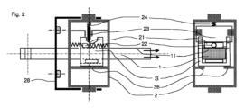
所定の閾値を超える力がリンクアーム(1)上に現れると、ロック位置にある間、ブロック要素(23)が、ノッチ(212)およびノッチ(31)で構成される対から離隔するように、ブロック要素(23)が、ブレーキ要素(21)のノッチ(212)ともはや接触しなくなる点まで移動され、それにより、当該ブロック要素(23)が、この点から、可動台(3)のノッチ(31)に面していて、またこの後、可動台(3)の傾斜路(32)の上に寄りかかる、当該ブロック要素(23)の先端(231)の部品により保持されるのみである(図4および図5)。この位置において、リンクアーム(1)はもはやブレーキ要素(21)によって移動が遮断されなくなり、そしてドア停止装置がロック解除モードになる。このフェーズにおいて、可動台(3)は主に、リンクアーム(1)の長手方向軸に平行な方向にあり、釣り合った2つの反対方向の力を受ける。これらの力のうちの1つは、可動台(3)の傾斜路(32)上にブロック要素(23)によって加えられた負荷から生じ、負荷の、リンクアーム(1)の長手方向軸に平行な成分は、可動台(3)とリンクアーム(1)との間に現れるスライド抵抗によって平衡され、リンクアーム(1)に対するその相対的な動作の間、当該スライド抵抗は、可動台(3)に加えられた摩擦力に応じる。リンクアーム(1)の動作がロック機構(2)に対して停止するとすぐに、ドアが任意の位置で開いたままになると、当該スライド抵抗がなくなり、それにより力の平衡が崩れ、弾性リターン手段(24)の効果の下で、ブロック要素(23)が、可動台(3)のノッチ(31)をブレーキ要素(21)のノッチ(212)と整列させると、ブロック要素(23)の先端(231)が当該ノッチ(212)に押し込まれる。その後、ドア停止装置は再びロック位置になる。可動台(3)のノッチ(31)は、ブレーキ要素(21)のノッチ(212)のすぐ横に位置付けられるだけでなく、使用できるスペースが限られているため、本発明を修正することなく、例えば、わずかに異なる位置に位置付けられ得ることに注意すべきである。この場合、ブロック要素(23)の末端(231)の代わりになり、可動台(3)のノッチ(31)と協働し得る1つの要素を提供することによって、ブロック要素(23)を適切に取り付ける必要がある。最後に、本発明は、好ましい実施形態では、ロック機構(2)のロックモードまたはロック解除モードにおいて、当該可動台(3)上のブロック要素(23)によって、直接的に、または間接的に加えられた負荷に反応するために、可動台(3)が、ロック機構(2)上に提供され、優先的に平坦で直線形状である(図2)少なくとも1つの支持ゾーン(26)と接触して寄りかかるか、またはスライドする。当該支持ゾーン(26)は、単純に、ロック機構(2)の壁に提供された1つ以上のリブからなってもよく、当業者は、困難なくこれを達成することができる。 so that when a force exceeding a predetermined threshold appears on the link arm (1), the blocking element (23) moves away from the pair consisting of the notch (212) and the notch (31) while in the locked position; The blocking element (23) is moved to the point where it is no longer in contact with the notch (212) of the braking element (21) so that it moves from this point to the notch (212) of the carriage (3). 31) and, after this, resting on the ramp (32) of the carriage (3), it is only held by the part of the tip (231) of said block element (23) (Fig. 4 and Fig. 5). In this position the link arm (1) is no longer blocked from movement by the braking element (21) and the door stop is in unlock mode. In this phase, the carriage (3) is mainly in a direction parallel to the longitudinal axis of the link arm (1) and is subjected to two balanced and opposite forces. One of these forces arises from the load exerted by the blocking element (23) on the ramp (32) of the carriage (3), parallel to the longitudinal axis of the link arm (1). component is balanced by the sliding resistance that appears between the carriage (3) and the link arm (1), and during its relative motion with respect to the linkage arm (1), the sliding resistance is equal to that of the carriage (3) responds to the frictional force applied to As soon as the movement of the link arm (1) stops relative to the locking mechanism (2), if the door is left open in any position, the sliding resistance disappears, thereby unbalancing the forces and restoring the elastic return means. Under the effect of (24), when the block element (23) aligns the notch (31) of the carriage (3) with the notch (212) of the brake element (21), the tip of the block element (23) ( 231) is pushed into the notch (212). The door stop is then again in the locked position. Not only is the notch (31) of the carriage (3) positioned immediately next to the notch (212) of the braking element (21), but due to the limited space available, without modifying the invention: For example, it should be noted that they could be positioned in slightly different positions. In this case, the block element (23) is properly formed by providing one element that can take the place of the end (231) of the block element (23) and cooperate with the notch (31) of the carriage (3). need to be installed. Finally, the present invention, in a preferred embodiment, applies directly or indirectly by blocking element (23) on said carriage (3) in locked or unlocked mode of locking mechanism (2). In order to react to the applied load, the carriage (3) is provided on the locking mechanism (2) and is in contact with at least one support zone (26) which is preferentially flat and rectilinear (Fig. 2). lean against or slide. Said support zone (26) may simply consist of one or more ribs provided on the wall of the locking mechanism (2) and a person skilled in the art can achieve this without difficulty.
-ブレーキ要素(21)および可動台(3)の変形(図15)、好ましい実施形態では、ブレーキ要素(21)および可動台(3)は、単一の部品を形成するために、一緒に固定され得る。次に、ブレーキ要素(21)上に提供され、ブロック要素(23)を受容することを意図したノッチ(212)は、それから傾斜路(32)によって各側に延伸され、その傾斜は、好ましくは、ブレーキ要素(21)上に提供された当該ノッチ(212)の壁の傾斜未満である。当該傾斜路(32)は、ドア停止装置がロック解除モードにある場合、当該ブロック要素(23)によって加えられる力に反応するために、当該リンクアーム(1)に属する面(111)に寄りかかるだろう。次に、ブレーキ要素(21)と可動台(3)を一緒に組み合わせることによって得られる対は、それが取り付けられている当該リンクアーム(1)に沿って、当該ロック機構(2)の本体に対して移動が制限されて、動作に対していくらかの抵抗を与えながら、スライドでき、それにより、組み合わされたブレーキ要素(21)および可動台(3)からなる当該対の上に提供された傾斜路(32)の上に寄りかかることによって、当該ブロック要素(23)を組み合わされたブレーキ要素(21)および可動台(3)からなる当該対を備えるノッチ(212)の外側に、保持しておくのを可能にし、リンクアーム(1)とロック機構(2)との間に、相対的動作が現れると、ドア停止装置はそれからロック解除モードになる。リンクアーム(1)と、組み合わされたブレーキ要素(21)および可動台(3)からなる当該対との間の相対的なスライド抵抗は、それぞれ、これら2つの要素の各々に属する2つの接触面の間の単純な摩擦によって達成できる。本明細書で提示される非限定的な例では、有利に傾斜路(32)の下に位置付けられた、組み合わされたブレーキ要素(21)および可動台(3)からなる対に属する面(2111)が、この目的のために、リンクアーム(1)上に留保された面(111)の部品と接触するようになり、したがって、面(2111)と面(111)との間に生成された摩擦力によって生じる移動に対する抵抗性を生む。組み合わされたブレーキ要素(21)および可動台(3)からなる対は、ノッチ(212)および傾斜路(32)を実装できるのに十分な剛性のあるエラストマー材料で製作することができる。さらに、選択されたエラストマー材料は、例えば金属またはプラスチックで提供されるリンクアーム(1)を構成する材料との良好なグリップを有するだろう。 - a variant of the braking element (21) and the carriage (3) (Fig. 15), in a preferred embodiment the braking element (21) and the carriage (3) are fixed together to form a single part; can be The notches (212) provided on the braking elements (21) and intended to receive the blocking elements (23) are then extended on each side by ramps (32), the slopes of which are preferably , less than the slope of the wall of the notch (212) provided on the braking element (21). Said ramp (32) only rests against a surface (111) belonging to said link arm (1) in order to react to the force exerted by said blocking element (23) when the door stop is in unlocking mode. deaf. The pair obtained by combining the braking element (21) and the carriage (3) together is then attached to the body of the locking mechanism (2) along the link arm (1) to which it is attached. The tilt provided on the pair of combined braking element (21) and carriage (3) is limited to allow it to slide while providing some resistance to movement. By leaning over the channel (32), the blocking element (23) is kept outside the notch (212) with the pair of combined braking element (21) and carriage (3). and when there is relative movement between the link arm (1) and the locking mechanism (2), the door stop device is then in unlock mode. The relative sliding resistance between the link arm (1) and the pair of combined braking element (21) and carriage (3) is determined by the two contact surfaces belonging to each of these two elements, respectively. can be achieved by simple friction between In the non-limiting example presented here, the surface (2111 ) come into contact with parts of surface (111) reserved on link arm (1) for this purpose, thus creating between surface (2111) and surface (111) Creates resistance to movement caused by frictional forces. The combined braking element (21) and carriage (3) pair can be made of sufficiently rigid elastomeric material to allow the notch (212) and ramp (32) to be implemented. Furthermore, the selected elastomeric material will have a good grip with the material making up the link arm (1), for example provided in metal or plastic.
-弾性リターン手段(24)の変形(図6および図7)、好ましい実施形態では、弾性リターン手段(24)の変形は、一方の弾性リターン手段(24)と、他方のブロック要素(23)またはロック機構(2)との間に提供された伝達手段(241)を追加することによっても形成でき、当該伝達手段(241)は、少なくとも2つの面要素(2411)および(2412)で形成され、そのうちの少なくとも1つは湾曲した形状であり、当該面要素(2411)および(2412)は、互いに対して全体的に垂直である2つの方向での相対動作で互いに協働し、当該面要素(2411)および(2412)のうちの1つは、ブロック要素(23)にリンクされ、これらの当該面要素(2411)または(2412)のもう一方は、それが提示される弾性リターン手段(24)を介してロック機構(2)にリンクされている。当該面要素(2411)および(2412)は、図6および図7に示され、当該面要素(2411)と(2412)との間の接触点で伝達される力F(a)の方向が、弾性リターン手段(24)が圧縮された時に変化するようにして、弾性リターン手段(24)によって提供された負荷を伝達するために協働する。したがって、弾性リターン手段(24)の圧縮方向に対して、当該面要素(2411)と(2412)の間の接触点で伝達される力F(a)の方向によって画定される角度が小さい場合、当該ブロック要素(23)に作用する、図6および図7に示される垂直成分F(p)は小さく、これはロック解除モードにおいて有利である(図7)。逆に、上記で定義された接触点で伝達される力F(a)の方向によって画定され、弾性リターン手段(24)の圧縮方向に対する角度が90°に近い場合、ブロック要素(23)に作用する垂直成分F(p)は大きく、それはロックモードで有利である(図6)。本明細書の目的は、ドア停止装置がロック解除モードにある時にはいつでも、可動台(3)の傾斜路(32)上の当該ブロック要素(23)の負荷を減らし、それにより、当該ロック解除モードで可動台(3)に加えられる力を平衡するために必要な、リンクアーム(1)と可動台(3)との間の相対的なスライド抵抗を減らすことができることである。ドアがロック解除モードにある時にドアを移動すると、少ない労力で済む。好ましい実施形態では、本発明を変更することなく、例えば、弾性リターン要素(24)が、先行技術で既知の、湾曲した先端を有する弾性ブレードでできている場合、面要素(2411)および(2412)はそれぞれ、面要素(2411)の場合にはエンボスとしてブロック要素(23)に統合され、また面要素(2412)の場合には、弾性リターン手段(24)に統合され得ることに注目されたい。 - Deformation of the elastic return means (24) (Figs. 6 and 7), in a preferred embodiment the deformation of the elastic return means (24) consists of elastic return means (24) on the one hand and blocking element (23) on the other or may also be formed by the addition of transmission means (241) provided between the locking mechanism (2), said transmission means (241) being formed by at least two surface elements (2411) and (2412), At least one of which is of curved shape, said surface elements (2411) and (2412) cooperate with each other in relative motion in two directions which are generally perpendicular to each other, and said surface elements ( 2411) and (2412) is linked to the block element (23) and the other of these said surface elements (2411) or (2412) is the elastic return means (24) on which it is presented to the locking mechanism (2) via. Said surface elements (2411) and (2412) are shown in Figures 6 and 7 and the direction of the force F(a) transmitted at the point of contact between said surface elements (2411) and (2412) is They cooperate to transfer the load provided by the elastic return means (24) in such a way that it changes when the elastic return means (24) is compressed. Therefore, if the angle defined by the direction of the force F(a) transmitted at the point of contact between said surface elements (2411) and (2412) is small with respect to the compression direction of the elastic return means (24), The vertical component F(p) shown in FIGS. 6 and 7 acting on the block element (23) is small, which is advantageous in unlocked mode (FIG. 7). Conversely, if the angle defined by the direction of the force F(a) transmitted at the point of contact defined above, with respect to the direction of compression of the elastic return means (24) is close to 90°, then the blocking element (23) has a large vertical component F(p), which is advantageous in lock mode (Fig. 6). The purpose of this specification is to reduce the loading of the blocking element (23) on the ramp (32) of the carriage (3) whenever the door stop is in the unlocked mode, so that the unlocked mode It is possible to reduce the relative sliding resistance between the link arm (1) and the carriage (3) required to balance the forces applied to the carriage (3) at . Less effort is required to move the door when it is in the unlocked mode. In a preferred embodiment, without modifying the invention, the face elements (2411) and (2412 ) can each be integrated into the block element (23) as an embossment in the case of the surface element (2411) and into the elastic return means (24) in the case of the surface element (2412). .
-弾性リターン手段(24)の別の変形(図8~図13)。
本発明によれば、弾性リターン手段(24)は、ロック機構(2)に、またはブロック要素(23)に固定され、また、当該ロック機構(2)と当該ブロック要素(23)との間で、リンクアーム(1)に対して全体的に垂直な方向で、直接的または間接的に作用する。弾性リターン手段(24)の実施形態のうちの1つによれば、本発明は、当該ロック機構(2)の傾斜に応じて、保持力がロックモードで調整できるようにするために、ロック機構(2)の傾斜に応じて、当該弾性リターン手段(24)によって加えられた負荷の値を調整することを提案する。この目的のために、本発明は、下述される機械的リンク(291)が、当該別個弾性リターン手段(24)および(29)との間で、または、別個弾性リターン手段(24)または(29)のうちの1つと、ロック機構(2)との間で、重力の影響下で介在するようになると、それらが加える負荷が同じ方向で累積されるようにして配置された少なくとも2つの別個弾性リターン手段(24)および(29)の効果を重ねることによって、弾性リターン手段(24)を置き換えることを提案する(図8)。本発明によって提案される実施形態例では、アウトラインが上述された第1の変形によって作製された弾性リターン手段(29)とロック機構(2)との間に機械的リンク(291)を挿入することを選択するだろう。単純な重力の影響下で作用する機械的リンク(291)は、抵抗性円錐状面(292)内に収納された(図8)球形ボール(291)で有利に形成でき、当該抵抗性円錐状面(292)は機械的に、先行技術で既知の任意の手段によって、または本発明を変更することなく、弾性リターン手段(29)に機械的にリンクされ(図8)、当該抵抗円錐状面(292)は、この場合には、図8に示される図に対して逆位置(「上下逆」)でのドア停止装置の取り付けで、ロック機構(2)にリンクされている(図11)。当該抵抗性円錐状面(292)はまた、抵抗性円錐状面(292)自体が、ロック機構(2)にリンクされている場合、ロック機構(2)上に位置付けられるか(図8)、そうでなければ弾性リターン手段(29)にリンクされる(図11)部品上に位置付けられた剛性面(293)に対して中央に位置付けられている。当該剛性面(293)は、その中央に空洞(2931)を備え、それは、ブロック要素(23)の動作の結果として、抵抗性円錐状面(292)および剛性面(293)が互いに向かって移動する場合(図9および図12)、球形ボール(291)を受容することができ、重力の影響下で、球形ボール(291)は、抵抗性円錐状面(292)の中央に留まっている。この場合、弾性リターン手段(29)は、ブロック要素(23)の動作によって圧縮されず、したがって、ブロック要素(23)に加えられる負荷に寄与しない。逆に、抵抗性円錐状面(292)によって形成されたコーンの角度によって事前に決定された閾値を超えるドア停止装置の傾斜によって、重力の影響下で、球形ボール(291)が抵抗性円錐状面(292)を離れると、当該球形ボール(291)は、抵抗性円錐状面(292)と剛性面(293)との間に自体を挿入するようになり、したがって、弾性リターン手段(29)が、ブロック要素(23)の動作によって圧縮されるのを可能にし、したがって、別個弾性リターン手段(24)および(29)によって加えられた累積負荷を生じる機械的リンクを構成する(図10および図13)。したがって、ドア停止装置の傾斜が、特定の所定の閾値未満に留まる場合、弾性リターン手段(29)は、ブロック要素(23)の動作によって影響を受けず、また当該ブロック要素(23)に生じる負荷はより小さい。逆に、ドア停止装置の傾斜が特定の所定の閾値を超えると、弾性リターン手段(29)は、当該弾性リターン手段(24)と同時に、ブロック要素(23)の移動によって動作され、当該ブロック要素(23)に結果として生じる負荷はより大きい。
- Another variant of the elastic return means (24) (Figs. 8-13).
According to the invention, the elastic return means (24) are fixed to the locking mechanism (2) or to the blocking element (23) and between said locking mechanism (2) and said blocking element (23) , acting directly or indirectly in a direction generally perpendicular to the link arm (1). According to one of the embodiments of the elastic return means (24), the invention provides a locking mechanism (24) in order to allow the holding force to be adjusted in locking mode, depending on the inclination of said locking mechanism (2). It is proposed to adjust the value of the load applied by said elastic return means (24) according to the slope of (2). To this end, the present invention provides that the mechanical link (291) described below is between said separate elastic return means (24) and (29) or separate elastic return means (24) or ( 29) and the locking mechanism (2), arranged in such a way that when they come to intervene under the influence of gravity, the loads they apply are accumulated in the same direction. It is proposed to replace the elastic return means (24) by superimposing the effects of the elastic return means (24) and (29) (Fig. 8). In the example embodiment proposed by the invention, inserting a mechanical link (291) between the elastic return means (29) made according to the first variant outlined above and the locking mechanism (2) would choose A mechanical link (291) acting under the influence of simple gravity can advantageously be formed of a spherical ball (291) housed (FIG. 8) within a resistive conical surface (292), the resistive conical surface (292) The surface (292) is mechanically linked to the resilient return means (29) (Fig. 8) by any means known in the prior art or without modification of the invention, and the resistance conical surface (292) is linked to the locking mechanism (2), in this case mounting the door stop in the reversed position ("upside down") relative to the view shown in FIG. 8 (FIG. 11) . Said resistance cone (292) is also positioned on the locking mechanism (2) if the resistance cone (292) itself is linked to the locking mechanism (2) (Fig. 8); It is centrally located with respect to a rigid surface (293) located on the part otherwise linked to the elastic return means (29) (Fig. 11). Said rigid surface (293) comprises a cavity (2931) in its center which, as a result of movement of the blocking element (23), causes the resistance conical surface (292) and the rigid surface (293) to move towards each other. When it does (FIGS. 9 and 12), a spherical ball (291) can be received and, under the influence of gravity, the spherical ball (291) remains centered on the resistive conical surface (292). In this case, the elastic return means (29) are not compressed by the movement of the blocking element (23) and therefore do not contribute to the load applied to the blocking element (23). Conversely, tilting of the door stop beyond a threshold predetermined by the angle of the cone formed by resistive conical surface (292) causes spherical ball (291) to form a resistive cone under the influence of gravity. Leaving the surface (292), the spherical ball (291) will insert itself between the resistive conical surface (292) and the rigid surface (293), thus allowing the elastic return means (29) to constitutes a mechanical link that allows to be compressed by the action of the block element (23), thus creating a cumulative load applied by the separate elastic return means (24) and (29) (Fig. 10 and Fig. 13). Therefore, if the inclination of the door stop remains below a certain predetermined threshold, the elastic return means (29) are unaffected by the movement of the blocking element (23) and the load caused on said blocking element (23). is smaller than Conversely, when the inclination of the door stop exceeds a certain predetermined threshold, the elastic return means (29) are operated simultaneously with the elastic return means (24) by the movement of the blocking element (23) to The resulting load on (23) is higher.
リンクアームの変形(1)(図14)。
上述されたリンクアーム(1)は、リンクアーム(1)がドア扉に取り付けられると、ドアのフレームとロック機構(2)との間のリンクを提供する。逆に、ロック機構(2)がドアのフレームに取り付けられるように設計されていると、リンクアーム(1)は、ドア扉とロック機構(2)との間のリンクを提供する。
どちらの場合でも、ドアの開閉中、リンクアーム(1)は、ドアの相対的な動作から生じる力を伝達し、ロック機構(2)はそれからロック解除モードになる。さらに、リンクアーム(1)は、ロック機構(2)がロック位置にある場合、ドアを固定位置で開いたままにするのに必要な保持力を伝達する。また、ドアが完全に開いた位置に達する場合に、先行技術で既知のドア停止装置のほとんどがそうであるように、リンクアーム(1)が、そうしなければ、ドアに、また自動車の本体にも損傷を与える、完全に開いた点を超えないようにドアを止めるのを確実にするように設計された、いわゆる「端部停止」装置を提供することは興味深い。先行技術で既知の端部停止装置は、一般にハード停止として設計されており、ドアが乱暴に開かれた時の衝撃を減らすために、弾性材料で作られたパッドが時には取り付けられていることがある。また、本発明は、リンクアーム(1)が、当該リンクアーム(1)の側に置かれ、優先的に、面(11)と反対側に位置付けられた円筒部(15)をその自由端に含み得、その面(11)は、ブレーキ要素(21)と協働することを意図し、当該円筒部(15)の軸は、リンクアーム(1)の長手方向軸に優先的に並行である。当該円筒部(15)は、ロック機構(2)に取り付けられた円筒状空洞(27)の中に進入するように設計され、当該円筒状空洞(27)は、その断面の径が、円筒部(15)の断面の径よりわずかに大きくなるだけであるので、その結果、円筒状空洞(27)内へのこの円筒部(15)の進入が行われ、ドアが完全に開かれると、これらの2つの部品の壁の間の隙間が小さくなる。本目的は、ピストンのように作用する円筒部(15)の進入の結果として、円筒状空洞(27)内に大量の圧縮空気を閉じ込め、それにより、リンクアーム(1)のストロークの終わりを弱めることである。また、リンクアーム(1)がストロークの終わり位置に固定された直後に、円筒部(15)の壁と円筒状空洞(27)との間での可能性のある漏れにより、円筒状空洞(27)内に閉じ込められた空気の圧力低下を素早く生じさせるであろう。本発明はまた、円筒状空洞(27)が、当該円筒状空洞(27)の断面の寸法が、円筒部(15)の断面の寸法よりわずかに小さくなるようにし、その結果、円筒部(15)の進入の間、円筒状空洞(27)を形成するエラストマー材料の変形によって、ブレーキ効果をもって、当該円筒状空洞(27)内への当該円筒部(15)の進入が起きるようにして、いくつかのエラストマー材料で作製され得ることを提供する。最後に、本発明は、後の円筒状空洞(27)の中への進入の場合に、円筒部(15)による弾性要素(271)の圧縮によって、リンクアーム(1)のストロークの終わりを弱めるのを助けるために、弾性要素(271)が、円筒状空洞(27)内に置かれ得ることを提供する。弾性要素(271)は本明細書では記述されないであろうが、非限定的な例として、コイルばね、エラストマーブロック、または先行技術で既知の他の任意の弾性変形可能な要素によって構成され得る。
Deformation of the link arm (1) (Fig. 14).
The link arm (1) described above provides the link between the frame of the door and the locking mechanism (2) when the link arm (1) is attached to the door leaf. Conversely, if the locking mechanism (2) is designed to be attached to the door frame, the link arm (1) provides the link between the door leaf and the locking mechanism (2).
In either case, during opening and closing of the door, the link arm (1) transfers the force resulting from the relative motion of the door and the locking mechanism (2) is then in unlock mode. Additionally, the link arm (1) transfers the holding force necessary to keep the door open in a fixed position when the locking mechanism (2) is in the locked position. Also, when the door reaches its fully open position, as is the case with most of the door stop devices known in the prior art, the link arm (1) is otherwise forced into the door and into the body of the vehicle. It would be interesting to provide a so-called "end stop" device designed to ensure that the door stops beyond the fully open point, which would also damage the door. End stops known in the prior art are generally designed as hard stops and are sometimes fitted with pads made of resilient material to reduce the impact when the door is violently opened. be. The invention also provides that the link arm (1) is placed on the side of said link arm (1) and preferentially has at its free end a cylinder (15) located opposite the surface (11). the surface (11) of which is intended to cooperate with the braking element (21), the axis of said cylinder (15) being preferentially parallel to the longitudinal axis of the link arm (1) . Said cylindrical portion (15) is designed to enter into a cylindrical cavity (27) attached to the locking mechanism (2), said cylindrical cavity (27) having a cross-sectional diameter equal to that of the cylindrical portion. Only slightly larger than the diameter of the cross-section of (15) so that the entry of this cylinder (15) into the cylindrical cavity (27) takes place and when the door is fully opened these The gap between the walls of the two parts of the is reduced. The purpose is to trap a large amount of compressed air in the cylindrical cavity (27) as a result of the entry of the cylinder (15) acting like a piston, thereby weakening the end of the stroke of the link arm (1). That is. Also, immediately after the link arm (1) is fixed in the end-of-stroke position, a possible leakage between the wall of the cylinder (15) and the cylindrical cavity (27) causes ) will quickly cause a pressure drop in the trapped air. The present invention also provides that the cylindrical cavity (27) has a cross-sectional dimension slightly smaller than that of the cylindrical part (15), so that the cylindrical part (15 ) so that the deformation of the elastomeric material forming the cylindrical cavity (27) causes the entry of the cylinder (15) into the cylindrical cavity (27) with a braking effect. provided that it can be made of any elastomeric material. Finally, the invention weakens the end of stroke of the link arm (1) by compression of the elastic element (271) by the cylinder (15) in case of subsequent entry into the cylindrical cavity (27). In order to assist in this, an elastic element (271) is provided that can be placed within the cylindrical cavity (27). Elastic element (271) will not be described herein, but may be constituted by a coil spring, an elastomeric block, or any other elastically deformable element known in the prior art, as non-limiting examples.
Claims (7)
前記リンクアーム(1)の面(11)が、前記ブレーキ要素(21)と前記リンクアーム(1)の面(11)との間の良好な摩擦グリップを可能にする特性を有する表面粗さを有することと、
前記ブレーキ要素(21)が、前記リンクアーム(1)の面(11)にある程度のグリップで押し付けることができる面(211)を有することと、
前記ブレーキ要素(21)が、前記リンクアーム(1)に対して平行な方向で、前記ロック機構(2)に対して可動式に取り付けられており、前記ブレーキ要素(21)は、前記ドア停止装置がロック解除モードにある間、前記ブロック要素(23)が前記ブレーキ要素(21)に圧力をかけなくなったら、前記ブレーキ要素(21)を、前記ブレーキ要素(21)のノッチ(212)が、前記ブロック要素(23)に対向する位置に戻すために、前記ロック機構(2)と協働する伸縮自在リコール手段(22)によって移動を制限されていることと、
前記ブロック要素(23)が、前記ブレーキ要素(21)を解放するために、前記ブレーキ要素(21)上に提供されたノッチ(212)から取り外せることと、
前記ロック機構(2)または前記ブロック要素(23)にリンクされた弾性リターン手段(24)が、前記リンクアーム(1)に対して全体的に垂直な方向に沿って、前記ロック機構(2)と前記ブロック要素(23)との間で、直接的または間接的に作用することと、
可動台(3)が、前記可動台(3)と前記リンクアーム(1)との間の相対的な移動にある程度の抵抗を与えながら、それが取り付けられているリンクアーム(1)に沿って、前記ロック機構(2)の本体に対して、移動が制限されてスライドすることと、
前記可動台(3)が、前記ブレーキ要素(21)上に提供されたノッチ(212)に全部または一部が類似した形状を有する少なくとも1つのノッチ(31)、および、前記可動台(3)のノッチ(31)の各側に配置され、前記ドア停止装置が前記ロック解除モードにある時にはいつも、前記ブロック要素(23)を保持するように意図される、少なくとも2つの傾斜路(32)を備え、前記可動台(3)のノッチ(31)は、前記ブロック要素(23)の先端(231)の一部を受容するように設計され、また、前記ブロック要素(23)が、ロックモードにおいて前記ノッチ(212)に完全に押し込まれると、前記ブロック要素(23)により加えられる負荷の結果として、前記可動台(3)のノッチ(31)が、前記ブレーキ要素(21)のノッチ(212)に並置かつ整列されるようにして、前記可動台(3)のノッチ(31)が、前記ブレーキ要素(21)のノッチ(212)と並んで優先的に位置付けられることと、
前記リンクアーム(1)上に所定の閾値より大きい力が発生すると、前記ブロック要素(23)は、前記ブレーキ要素(21)のノッチ(212)および前記可動台(3)のノッチ(31)からなる対から離隔するように、前記ブロック要素(23)が前記ブレーキ要素(21)のノッチ(212)と接触しなくなる点まで移動され、それにより、前記ブロック要素(23)はこの時点から、前記可動台(3)のノッチ(31)に面していた、また、これから前記可動台(3)の傾斜路(32)に寄りかかる、前記ブロック要素(23)の先端(231)の部分によってのみ保持され、前記リンクアーム(1)は、もはや前記ブレーキ要素(21)によって移動を遮断されず、前記ドア停止装置は、その時点で前記ロック解除モードにあることと、
を特徴とする、ドア停止装置。 A door stop device for a door having a door leaf and a door frame, said door stop device comprising a link arm (1) and a locking mechanism (2), one at said door leaf and the other at said door Intended to be linked to a frame, said link arm (1) has at least one surface (11) intended to cooperate with said locking mechanism (2), said locking mechanism (2) ) has for this cooperation a braking element (21) pressed against the surface (11) of said link arm (1), said braking element (21) being movably attached to said locking mechanism (2). Controlled along a direction generally perpendicular to said link arm (1) by an attached blocking element (23), said blocking element (23) provided on said braking element (21) engaging in a notch (212) and said blocking element (23) cooperating with elastic return means (24) acting directly or indirectly on said blocking element (23), said braking element (21) apply pressure through said blocking element (23) and thus the relative position of said door in any open position between a closed position and a fully open position; enable retention,
The surface (11) of said link arm (1) has a surface roughness that has the property of allowing a good frictional grip between said braking element (21) and the surface (11) of said link arm (1). having and
said braking element (21) has a surface (211) that can be pressed against the surface (11) of said link arm (1) with a certain amount of grip;
Said braking element (21) is movably mounted with respect to said locking mechanism (2) in a direction parallel to said link arm (1), said braking element (21) acting on said door stop. When said blocking element (23) no longer exerts pressure on said braking element (21) while the device is in unlocking mode, said braking element (21) is pushed into the notch (212) of said braking element (21). is restricted in movement by telescopic recall means (22) cooperating with said locking mechanism (2) for returning to a position opposite said blocking element (23);
said blocking element (23) is removable from a notch (212) provided on said braking element (21) to release said braking element (21);
A resilient return means (24) linked to said locking mechanism (2) or to said blocking element (23) moves said locking mechanism (2) along a direction generally perpendicular to said link arm (1). ) and said blocking element (23), directly or indirectly,
A carriage (3) moves along the link arm (1) to which it is attached while providing some resistance to relative movement between said carriage (3) and said link arm (1). , sliding with limited movement relative to the body of the locking mechanism (2);
The carriage (3) has at least one notch (31) having a shape similar in whole or in part to the notch (212) provided on the braking element (21), and the carriage ( 3) at least two ramps arranged on each side of the notch (31) of 3) and intended to hold said blocking element (23) whenever said door stop is in said unlocking mode . (32), the notch (31) of said carriage (3) is designed to receive part of the tip (231) of said block element (23), and said block element (23 ) is fully pushed into said notch (212) in locking mode , as a result of the load exerted by said blocking element (23), said notch (31) of said carriage (3) pushes against said braking element The notch (31) of said carriage (3) is aligned with the notch (212) of said braking element (21) such that it is juxtaposed and aligned with the notch (212) of (21). be prioritized in
When a force greater than a predetermined threshold occurs on said link arm (1), said blocking element (23) is released from notch (212 ) of said braking element (21) and notch (31) of said carriage (3). pair, the blocking element (23) is moved out of contact with the notch (212) of the braking element (21), whereby the blocking element (23) is moved away from this point. , a tip (231) of said block element (23) which faced a notch (31) of said carriage (3) and which now leans against a ramp (32) of said carriage (3). said link arm (1) is no longer blocked from movement by said braking element (21) and said door stopping device is now in said unlocking mode;
A door stop device, characterized by:
Applications Claiming Priority (3)
| Application Number | Priority Date | Filing Date | Title |
|---|---|---|---|
| FR1701303A FR3074829A1 (en) | 2017-12-13 | 2017-12-13 | DEVICE FOR STOPPING DOOR WITH INFINITE HOLDING POSITIONS |
| FR1701303 | 2017-12-13 | ||
| PCT/FR2018/053266 WO2019115957A1 (en) | 2017-12-13 | 2018-12-13 | Door-stopping device with infinite holding positions |
Publications (2)
| Publication Number | Publication Date |
|---|---|
| JP2021507147A JP2021507147A (en) | 2021-02-22 |
| JP7285576B2 true JP7285576B2 (en) | 2023-06-02 |
Family
ID=63405242
Family Applications (1)
| Application Number | Title | Priority Date | Filing Date |
|---|---|---|---|
| JP2020533090A Active JP7285576B2 (en) | 2017-12-13 | 2018-12-13 | Door stop device with infinite holding position |
Country Status (6)
| Country | Link |
|---|---|
| US (1) | US11236535B2 (en) |
| EP (1) | EP3724432B1 (en) |
| JP (1) | JP7285576B2 (en) |
| CN (1) | CN111601940A (en) |
| FR (1) | FR3074829A1 (en) |
| WO (1) | WO2019115957A1 (en) |
Families Citing this family (2)
| Publication number | Priority date | Publication date | Assignee | Title |
|---|---|---|---|---|
| JP2020111135A (en) * | 2019-01-10 | 2020-07-27 | アイシン精機株式会社 | Vehicular door device |
| CN113335036A (en) * | 2021-07-14 | 2021-09-03 | 泰州劲松股份有限公司 | Positioning device for mounting interior trim part of automobile door and mounting method thereof |
Citations (3)
| Publication number | Priority date | Publication date | Assignee | Title |
|---|---|---|---|---|
| WO2007012729A1 (en) | 2005-07-27 | 2007-02-01 | Prieur Andre | Door stop with indeterminate retaining positions |
| JP2014531547A (en) | 2011-10-11 | 2014-11-27 | プリュール,アンドレ | Door stop device |
| JP2019505702A (en) | 2015-12-24 | 2019-02-28 | プリュール,アンドレ | Door stop device with multiple holding positions |
Family Cites Families (21)
| Publication number | Priority date | Publication date | Assignee | Title |
|---|---|---|---|---|
| US2268976A (en) * | 1940-04-26 | 1942-01-06 | Reconstruction Finance Corp | Door check |
| US7438346B1 (en) * | 1997-03-17 | 2008-10-21 | Automotive Technologies International, Inc. | Method and apparatus for controlling a vehicle door |
| US6681444B2 (en) * | 1997-03-17 | 2004-01-27 | Automotive Technologies International, Inc. | Apparatus for controlling a door |
| US6065185A (en) * | 1998-03-17 | 2000-05-23 | Automotive Technologies International Inc. | Vehicle infinite door check |
| US20040055110A1 (en) * | 1997-03-17 | 2004-03-25 | Breed David S. | Method and apparatus for controlling a vehicle door |
| FR2777934A1 (en) * | 1998-04-23 | 1999-10-29 | Coutier Moulage Gen Ind | DOOR STOP WITH UNDEFINED STOP POSITION FOR VEHICLE DOOR |
| US6513193B1 (en) * | 2000-07-21 | 2003-02-04 | Daimlerchrysler Corporation | Door check mechanism providing an infinite number of stable positions |
| US6467126B1 (en) * | 2000-07-21 | 2002-10-22 | Daimlerchrysler Corporation | Door check mechanism providing an infinite number of stable positions |
| US6370732B1 (en) * | 2000-09-06 | 2002-04-16 | Daimlerchrysler Corporation | Door check mechanism providing an infinite number of stable positions |
| US6711778B2 (en) * | 2002-02-26 | 2004-03-30 | Benny W. Sparkman | Door stop apparatus |
| JP2004316299A (en) * | 2003-04-17 | 2004-11-11 | Riken Kaki Kogyo Kk | Door checker for automobile |
| FR2874051B1 (en) * | 2004-08-05 | 2006-09-08 | Andre Prieur | DOOR STOP WITH INDETERMINED HOLDING POSITIONS |
| DE602004025523D1 (en) * | 2004-11-04 | 2010-03-25 | Volvo Lastvagnar Ab | DOOR BRAKE DEVICE |
| CN102561870A (en) * | 2010-12-08 | 2012-07-11 | 曾文昌 | Safety brake device of door |
| KR101256990B1 (en) * | 2011-05-25 | 2013-04-26 | 주식회사 광진 | Door checker for vehicle |
| US8733818B2 (en) * | 2012-06-14 | 2014-05-27 | GM Global Technology Operations LLC | Two-stage hybrid check link assembly |
| WO2015072137A1 (en) * | 2013-11-13 | 2015-05-21 | アイシン精機株式会社 | Opening adjusting block, opening adjusting device, and door checking mechanism for vehicle doors |
| US10053895B2 (en) * | 2015-03-10 | 2018-08-21 | Ramon Cervantes, JR. | Door holding device |
| EP3103945B1 (en) * | 2015-06-10 | 2018-09-12 | HELLA GmbH & Co. KGaA | Vehicle door check |
| US9598890B1 (en) * | 2015-12-01 | 2017-03-21 | GM Global Technology Operations LLC | Infinite check link system |
| US9822570B2 (en) * | 2016-03-29 | 2017-11-21 | Ford Global Technologies, Llc | Automatically closing vehicle door |
-
2017
- 2017-12-13 FR FR1701303A patent/FR3074829A1/en not_active Withdrawn
-
2018
- 2018-12-13 US US16/771,767 patent/US11236535B2/en active Active
- 2018-12-13 CN CN201880077933.7A patent/CN111601940A/en active Pending
- 2018-12-13 JP JP2020533090A patent/JP7285576B2/en active Active
- 2018-12-13 WO PCT/FR2018/053266 patent/WO2019115957A1/en unknown
- 2018-12-13 EP EP18833100.3A patent/EP3724432B1/en active Active
Patent Citations (3)
| Publication number | Priority date | Publication date | Assignee | Title |
|---|---|---|---|---|
| WO2007012729A1 (en) | 2005-07-27 | 2007-02-01 | Prieur Andre | Door stop with indeterminate retaining positions |
| JP2014531547A (en) | 2011-10-11 | 2014-11-27 | プリュール,アンドレ | Door stop device |
| JP2019505702A (en) | 2015-12-24 | 2019-02-28 | プリュール,アンドレ | Door stop device with multiple holding positions |
Also Published As
| Publication number | Publication date |
|---|---|
| CN111601940A (en) | 2020-08-28 |
| US20210172223A1 (en) | 2021-06-10 |
| EP3724432B1 (en) | 2021-09-08 |
| FR3074829A1 (en) | 2019-06-14 |
| WO2019115957A1 (en) | 2019-06-20 |
| EP3724432A1 (en) | 2020-10-21 |
| JP2021507147A (en) | 2021-02-22 |
| US11236535B2 (en) | 2022-02-01 |
Similar Documents
| Publication | Publication Date | Title |
|---|---|---|
| JP6959651B2 (en) | Door stop device with multiple holding positions | |
| JP7285576B2 (en) | Door stop device with infinite holding position | |
| KR100831102B1 (en) | Damping device | |
| US6813811B2 (en) | Door checker for automobile | |
| KR101860622B1 (en) | Drive device for a movable furniture part | |
| US20130145580A1 (en) | Damping device for furniture parts | |
| CN110168181B (en) | Sliding door fitting | |
| US9777513B2 (en) | Pull-out device for at least two pull-out furniture parts | |
| US9611682B2 (en) | Device for a movable furniture part, and piece of furniture | |
| US9579775B2 (en) | Detachable blocking device, in particular on a clamping tool | |
| CN108367773B (en) | Steering column for a motor vehicle | |
| US9567787B2 (en) | Door stop device | |
| CN108005504B (en) | Sliding door stop device | |
| CN102765334A (en) | Vehicle seat fold mechanism | |
| US7832051B2 (en) | Door stop with indeterminate retaining positions | |
| JP2568275Y2 (en) | Door horizontal holding device for flap door | |
| JP7094011B2 (en) | Sliding door bounce prevention device | |
| EP2761118B1 (en) | Safety device to prevent the sudden closing of a movable element | |
| EP2986183B1 (en) | A chair adjustment device | |
| JP6891573B2 (en) | Brake device for sliding door shoji | |
| JP6730210B2 (en) | Sliding door stop device | |
| JP3966624B2 (en) | Seismic isolation devices such as storage fixtures | |
| JP4126581B2 (en) | Vanity with slide mechanism | |
| KR200492717Y1 (en) | Sliding door-lock apparatus | |
| GB2258886A (en) | Vehicle door check. |
Legal Events
| Date | Code | Title | Description |
|---|---|---|---|
| A621 | Written request for application examination |
Free format text: JAPANESE INTERMEDIATE CODE: A621 Effective date: 20211014 |
|
| A131 | Notification of reasons for refusal |
Free format text: JAPANESE INTERMEDIATE CODE: A131 Effective date: 20220906 |
|
| A601 | Written request for extension of time |
Free format text: JAPANESE INTERMEDIATE CODE: A601 Effective date: 20221202 |
|
| A521 | Request for written amendment filed |
Free format text: JAPANESE INTERMEDIATE CODE: A523 Effective date: 20230203 |
|
| TRDD | Decision of grant or rejection written | ||
| A01 | Written decision to grant a patent or to grant a registration (utility model) |
Free format text: JAPANESE INTERMEDIATE CODE: A01 Effective date: 20230418 |
|
| A61 | First payment of annual fees (during grant procedure) |
Free format text: JAPANESE INTERMEDIATE CODE: A61 Effective date: 20230516 |
|
| R150 | Certificate of patent or registration of utility model |
Ref document number: 7285576 Country of ref document: JP Free format text: JAPANESE INTERMEDIATE CODE: R150 |