JP7284178B2 - Cathode flow field distribution for fuel cell stack - Google Patents
Cathode flow field distribution for fuel cell stack Download PDFInfo
- Publication number
- JP7284178B2 JP7284178B2 JP2020539290A JP2020539290A JP7284178B2 JP 7284178 B2 JP7284178 B2 JP 7284178B2 JP 2020539290 A JP2020539290 A JP 2020539290A JP 2020539290 A JP2020539290 A JP 2020539290A JP 7284178 B2 JP7284178 B2 JP 7284178B2
- Authority
- JP
- Japan
- Prior art keywords
- electrochemical cell
- porous structure
- cathode
- cell stack
- electrochemical
- Prior art date
- Legal status (The legal status is an assumption and is not a legal conclusion. Google has not performed a legal analysis and makes no representation as to the accuracy of the status listed.)
- Active
Links
Images


Classifications
-
- H—ELECTRICITY
- H01—ELECTRIC ELEMENTS
- H01M—PROCESSES OR MEANS, e.g. BATTERIES, FOR THE DIRECT CONVERSION OF CHEMICAL ENERGY INTO ELECTRICAL ENERGY
- H01M8/00—Fuel cells; Manufacture thereof
- H01M8/02—Details
- H01M8/0202—Collectors; Separators, e.g. bipolar separators; Interconnectors
- H01M8/0258—Collectors; Separators, e.g. bipolar separators; Interconnectors characterised by the configuration of channels, e.g. by the flow field of the reactant or coolant
-
- H—ELECTRICITY
- H01—ELECTRIC ELEMENTS
- H01M—PROCESSES OR MEANS, e.g. BATTERIES, FOR THE DIRECT CONVERSION OF CHEMICAL ENERGY INTO ELECTRICAL ENERGY
- H01M8/00—Fuel cells; Manufacture thereof
- H01M8/02—Details
- H01M8/0202—Collectors; Separators, e.g. bipolar separators; Interconnectors
- H01M8/0204—Non-porous and characterised by the material
- H01M8/0223—Composites
- H01M8/0228—Composites in the form of layered or coated products
-
- H—ELECTRICITY
- H01—ELECTRIC ELEMENTS
- H01M—PROCESSES OR MEANS, e.g. BATTERIES, FOR THE DIRECT CONVERSION OF CHEMICAL ENERGY INTO ELECTRICAL ENERGY
- H01M8/00—Fuel cells; Manufacture thereof
- H01M8/02—Details
- H01M8/0202—Collectors; Separators, e.g. bipolar separators; Interconnectors
- H01M8/023—Porous and characterised by the material
- H01M8/0232—Metals or alloys
-
- H—ELECTRICITY
- H01—ELECTRIC ELEMENTS
- H01M—PROCESSES OR MEANS, e.g. BATTERIES, FOR THE DIRECT CONVERSION OF CHEMICAL ENERGY INTO ELECTRICAL ENERGY
- H01M8/00—Fuel cells; Manufacture thereof
- H01M8/10—Fuel cells with solid electrolytes
- H01M8/1004—Fuel cells with solid electrolytes characterised by membrane-electrode assemblies [MEA]
-
- H—ELECTRICITY
- H01—ELECTRIC ELEMENTS
- H01M—PROCESSES OR MEANS, e.g. BATTERIES, FOR THE DIRECT CONVERSION OF CHEMICAL ENERGY INTO ELECTRICAL ENERGY
- H01M8/00—Fuel cells; Manufacture thereof
- H01M8/10—Fuel cells with solid electrolytes
- H01M2008/1095—Fuel cells with polymeric electrolytes
-
- H—ELECTRICITY
- H01—ELECTRIC ELEMENTS
- H01M—PROCESSES OR MEANS, e.g. BATTERIES, FOR THE DIRECT CONVERSION OF CHEMICAL ENERGY INTO ELECTRICAL ENERGY
- H01M8/00—Fuel cells; Manufacture thereof
- H01M8/24—Grouping of fuel cells, e.g. stacking of fuel cells
- H01M8/241—Grouping of fuel cells, e.g. stacking of fuel cells with solid or matrix-supported electrolytes
-
- Y—GENERAL TAGGING OF NEW TECHNOLOGICAL DEVELOPMENTS; GENERAL TAGGING OF CROSS-SECTIONAL TECHNOLOGIES SPANNING OVER SEVERAL SECTIONS OF THE IPC; TECHNICAL SUBJECTS COVERED BY FORMER USPC CROSS-REFERENCE ART COLLECTIONS [XRACs] AND DIGESTS
- Y02—TECHNOLOGIES OR APPLICATIONS FOR MITIGATION OR ADAPTATION AGAINST CLIMATE CHANGE
- Y02E—REDUCTION OF GREENHOUSE GAS [GHG] EMISSIONS, RELATED TO ENERGY GENERATION, TRANSMISSION OR DISTRIBUTION
- Y02E60/00—Enabling technologies; Technologies with a potential or indirect contribution to GHG emissions mitigation
- Y02E60/30—Hydrogen technology
- Y02E60/50—Fuel cells
Landscapes
- Chemical & Material Sciences (AREA)
- Life Sciences & Earth Sciences (AREA)
- Engineering & Computer Science (AREA)
- Manufacturing & Machinery (AREA)
- Sustainable Development (AREA)
- Sustainable Energy (AREA)
- Chemical Kinetics & Catalysis (AREA)
- Electrochemistry (AREA)
- General Chemical & Material Sciences (AREA)
- Composite Materials (AREA)
- Fuel Cell (AREA)
- Inert Electrodes (AREA)
Description
[001]本出願は、2018年1月17日に出願された、米国仮出願第62/618,146号、および、2018年1月17日に出願された、米国仮出願第62/618,228号に対する優先権の利益を主張するものであり、それらの米国仮出願の各々は、その全体が参照により本明細書に組み込まれている。 [001] This application is filed on January 17, 2018, U.S. Provisional Application No. 62/618,146, and U.S. Provisional Application No. 62/618, filed on January 17, 2018. 228, each of which is incorporated herein by reference in its entirety.
[002]本開示は、電気化学セルおよび電気化学セルスタック、より詳細には、電気化学セルスタックに対するカソード流れ場分配を対象とする。 [002] This disclosure is directed to electrochemical cells and electrochemical cell stacks, and more particularly to cathode flow field distribution for electrochemical cell stacks.
[003]普通は燃料セルまたは電解セルと分類される電気化学セルは、化学反応から電流を発生させる、または、電流の流れを使用して化学反応を誘導するために使用されるデバイスである。例えば、燃料セルは、燃料(例えば、水素、天然ガス、メタノール、ガソリン、その他)および酸化剤(空気または酸素)の化学エネルギーを、電気、ならびに、熱および水の廃棄生成物へと変換する。基本的な燃料セルは、負帯電アノードと、正帯電カソードと、電解質と呼ばれるイオン伝導材料とを備える。 [003] Electrochemical cells, commonly classified as fuel cells or electrolysis cells, are devices used to generate electrical current from chemical reactions or to induce chemical reactions using the flow of electrical current. For example, fuel cells convert the chemical energy of a fuel (eg, hydrogen, natural gas, methanol, gasoline, etc.) and an oxidant (air or oxygen) into electricity and waste products of heat and water. A basic fuel cell comprises a negatively charged anode, a positively charged cathode, and an ionically conductive material called the electrolyte.
[004]異なる燃料セル技術は、異なる電解質材料を利用する。プロトン交換膜(PEM)燃料セルは、例えば、電解質として高分子イオン伝導膜を利用する。水素PEM燃料セルにおいて、水素原子が、アノードにおいて電子およびプロトン(水素イオン)へと電気化学的に分けられる。電子は、次いで、回路を通ってカソードに流れ、電気を発生させ、一方で、プロトンは、電解質膜を通ってカソードに拡散する。カソードにおいて、水素プロトンは、電子および酸素(カソードに供給される)と組み合わさって、水および熱を生成する。 [004] Different fuel cell technologies utilize different electrolyte materials. A proton exchange membrane (PEM) fuel cell, for example, utilizes a polyionic conducting membrane as the electrolyte. In a hydrogen PEM fuel cell, hydrogen atoms are electrochemically split into electrons and protons (hydrogen ions) at the anode. The electrons then flow through the circuit to the cathode, generating electricity, while the protons diffuse through the electrolyte membrane to the cathode. At the cathode, hydrogen protons combine with electrons and oxygen (supplied to the cathode) to produce water and heat.
[005]電解セルは、逆に動作させられる燃料セルを表す。基本的な電解セルは、外部電位が付与されるときに、水を水素および酸素ガスへと分解することにより、水素発生器として機能する。水素燃料セルまたは電解セルの基本的な技術は、電気化学的水素圧縮、精製、または膨張などの電気化学的水素操作に応用され得る。電気化学的水素操作は、水素管理に対して従前から使用される機械的システムに対する存立可能な代替案として出現した。エネルギー担体としての水素の成功裏の商業化、および、「水素経済」の長期の持続可能性は、主として、燃料セル、電解セル、および他の水素操作/管理システムの、効率およびコスト有効度に依存する。 [005] Electrolytic cells represent fuel cells that are operated in reverse. A basic electrolytic cell functions as a hydrogen generator by splitting water into hydrogen and oxygen gases when an external potential is applied. The basic technology of hydrogen fuel cells or electrolysis cells can be applied to electrochemical hydrogen manipulations such as electrochemical hydrogen compression, purification, or expansion. Electrochemical hydrogen manipulation has emerged as a viable alternative to the mechanical systems traditionally used for hydrogen management. The successful commercialization of hydrogen as an energy carrier and the long-term sustainability of the "hydrogen economy" will depend primarily on the efficiency and cost effectiveness of fuel cells, electrolysis cells, and other hydrogen operation/management systems. Dependent.
[006]動作において、単一の燃料セルは、一般的には、約1ボルトを発生させることができる。所望される量の電力を得るために、個々の燃料セルは、燃料セルスタックを形成するために組み合わされ、燃料セルは、順次的に一体に積層される。各々の燃料セルは、カソードと、電解質膜と、アノードとを含み得る。カソード/膜/アノード接合体は、典型的にはバイポーラプレートにより両方の側で支持される、「膜電極接合体」すなわち「MEA」の構成物である。反応物ガス、すなわち、燃料(例えば、水素)および酸化剤(例えば、空気または酸素)が、流れ場を通してMEAの電極に供給される。機械的支持を提供することに加えて、バイポーラプレート(さらには流れ場プレートまたはセパレータプレートとして知られている)は、スタック内の個々のセルを物理的に分離し、一方で、それらのセルを電気的に接続する。典型的な燃料セルスタックは、燃料および酸化剤を、アノードおよびカソード流れ場それぞれに導くための、マニホールドおよび入口ポートを含む。燃料セルスタックは、さらには、過剰燃料および酸化剤を駆逐するための、排気マニホールドおよび出口ポートを含む。燃料セルスタックは、さらには、燃料セルスタックにより発生させられる熱を駆逐する助けとなる冷却剤流体を循環させるためのマニホールドを含み得る。 [006] In operation, a single fuel cell can typically generate about 1 volt. To obtain the desired amount of power, individual fuel cells are combined to form a fuel cell stack, the fuel cells being stacked together in sequence. Each fuel cell may include a cathode, an electrolyte membrane, and an anode. The cathode/membrane/anode assembly is typically a "membrane electrode assembly" or "MEA" construction supported on both sides by bipolar plates. Reactant gases, ie, fuel (eg, hydrogen) and oxidant (eg, air or oxygen) are supplied to the electrodes of the MEA through a flow field. In addition to providing mechanical support, bipolar plates (also known as flow field plates or separator plates) physically separate individual cells in a stack while separating those cells from each other. Connect electrically. A typical fuel cell stack includes manifolds and inlet ports for directing fuel and oxidant to the anode and cathode flow fields, respectively. The fuel cell stack also includes an exhaust manifold and outlet ports for expelling excess fuel and oxidant. The fuel cell stack may further include manifolds for circulating a coolant fluid that helps dissipate heat generated by the fuel cell stack.
[007]上記で説明されたように、水が、電気への燃料および酸化剤の変換の副生成物としてカソードにおいて発生させられる。この水は、典型的には、反応物ガス、例えば、酸素の流れによって、電気化学セルから除去される。水の非効率的な除去は、電気化学セルのフラッディングを招き得る。電気化学セルのフラッディングは、反応物ガス流れの低減または完全な停止を招き得る。水の過剰蓄積は、個々の電気化学セルの故障を招くことがあり、そのことは、次いで、電気化学セルスタックの不安定性および/または故障を招くことがある。 [007] As explained above, water is generated at the cathode as a by-product of the conversion of fuel and oxidant to electricity. This water is typically removed from the electrochemical cell by a stream of reactant gases, such as oxygen. Inefficient removal of water can lead to flooding of the electrochemical cell. Flooding of an electrochemical cell can result in reduced or complete shutdown of reactant gas flow. Excessive accumulation of water can lead to failure of individual electrochemical cells, which in turn can lead to instability and/or failure of the electrochemical cell stack.
[008]典型的な電気化学セルスタックにおいて、端部電気化学セルは、中間に配置される電気化学セルとは異なる動作温度を有し得る。典型的には、これらの端部電気化学セルの動作温度は、端部電気化学セルの中間に配置される電気化学セルの動作温度より小であり、そのことは、端部電気化学セルは、1つの熱生成近隣電気化学セルを有するのみであり、しかるに、中間に配置される電気化学セルは、2つの熱生成近隣電気化学セルからの熱に遭遇するという事実によるものである。端部セルが1つの熱生成近隣電気化学セルのみからの熱にまさに遭遇するのみではなく、それらの端部セルは、さらには、電気化学セルスタックを収容する、電流抽出プレートおよび端部プレートなどの、電気化学セルスタック接合体の端部構成要素を通して雰囲気とより直接的に接触し、かくして、伝導性冷却を受けさせられる。 [008] In a typical electrochemical cell stack, the end electrochemical cells may have different operating temperatures than the electrochemical cells located in the middle. Typically, the operating temperature of these end electrochemical cells is less than the operating temperature of the electrochemical cells located in the middle of the end electrochemical cells, which means that the end electrochemical cells This is due to the fact that it only has one heat-producing neighboring electrochemical cell, whereas an electrochemical cell placed in between sees heat from two heat-producing neighboring electrochemical cells. Not only do end cells see heat only from one heat-producing neighboring electrochemical cell, they also contain electrochemical cell stacks, current extraction plates and end plates, etc. are in more direct contact with the atmosphere through the end components of the electrochemical cell stack assembly, and are thus subjected to conductive cooling.
[009]いかなる個別の理論にも束縛されることなく、端部セルの増大される冷却は、水の蓄積を招き得るものであり、そのことは、個々のセルおよび電気化学セルスタックの性能に有害に影響を及ぼし得る。この問題点に対処する試行は、電気化学セルのすべての全体を通して均一な動作温度を維持するための取り組みで、端部セルに隣接して配置されるヒータを追加することを含む。しかしながら、そのようなヒータの追加は、電気化学セルスタック接合体に、不必要な複雑さ、重量、寄生エネルギー、および空間消費を加える。よって、電気化学セル内の、特に端部電気化学セル内の水蓄積の量を制御する、改善された電気化学セルスタック設計に対する必要性が実在する。 [009] Without being bound by any particular theory, increased cooling of end cells can lead to water accumulation, which affects the performance of individual cells and electrochemical cell stacks. can have detrimental effects. Attempts to address this issue have included adding heaters located adjacent to the end cells in an effort to maintain a uniform operating temperature throughout all of the electrochemical cells. However, the addition of such heaters adds unnecessary complexity, weight, parasitic energy, and space consumption to the electrochemical cell stack assembly. Thus, a need exists for improved electrochemical cell stack designs that control the amount of water accumulation in electrochemical cells, particularly in edge electrochemical cells.
[010]前に述べられた電気化学セルスタック設計考慮事項を考慮して、本開示は、上記のことに対して定められる問題、および/または、既存の技術に関する他の問題のうちの、1つまたは複数を克服することを対象とする、電気化学セルスタックを対象とする。 [010] In view of the electrochemical cell stack design considerations discussed previously, the present disclosure addresses one of the problems addressed above and/or other problems with existing technology. An electrochemical cell stack is directed to overcoming one or more.
[011]1つの態様において、本開示は、電気化学セルスタックを対象とする。電気化学セルスタックは、複数の電気化学セルを含み得る。各々の電気化学セルは、カソード触媒層、アノード触媒層、およびカソード触媒層とアノード触媒層との間に介在させられる高分子膜を備える膜電極接合体を含み得る。各々の電気化学セルは、さらには、アノードプレートおよびカソードプレートであって、膜電極接合体が、それらのアノードプレートとカソードプレートとの間に介在させられる、アノードプレートおよびカソードプレートと、カソードプレートとカソード触媒層との間に配置されるカソード流れ場であって、平均孔サイズを有する複数の孔を有する多孔質構造を含む、カソード流れ場とを含み得る。一部の実施形態において、複数の電気化学セルは、スタックの第1の端部において配置される第1の電気化学セルを含み得る。一部の実施形態において、第1の電気化学セルの多孔質構造は、複数の電気化学セルの多孔質構造の平均孔サイズより大である平均孔サイズを有し得る。一部の実施形態において、第1の電気化学セルの多孔質構造は、複数の電気化学セルの多孔質構造の平均流れ抵抗より小である流れ抵抗を有し得る。一部の実施形態において、第1の電気化学セルの多孔質構造は、複数の電気化学セルの多孔質構造のものより大である流れ寸法(すなわち、厚さ)を有し得る。 [011] In one aspect, the present disclosure is directed to an electrochemical cell stack. An electrochemical cell stack may include multiple electrochemical cells. Each electrochemical cell can include a membrane electrode assembly comprising a cathode catalyst layer, an anode catalyst layer, and a polymer membrane interposed between the cathode catalyst layer and the anode catalyst layer. Each electrochemical cell further comprises an anode plate and a cathode plate, a membrane electrode assembly interposed between the anode plate and the cathode plate, and a cathode plate. a cathode flow field disposed between the cathode catalyst layer, the cathode flow field comprising a porous structure having a plurality of pores having an average pore size; In some embodiments, the plurality of electrochemical cells can include a first electrochemical cell positioned at a first end of the stack. In some embodiments, the porous structure of the first electrochemical cell can have an average pore size that is greater than the average pore size of the porous structures of the plurality of electrochemical cells. In some embodiments, the porous structure of the first electrochemical cell can have a flow resistance that is less than the average flow resistance of the porous structures of the plurality of electrochemical cells. In some embodiments, the porous structure of the first electrochemical cell can have a flow dimension (ie, thickness) that is greater than that of the porous structures of the plurality of electrochemical cells.
[012]一部の実施形態において、第1の電気化学セルの多孔質構造の平均孔サイズは、複数の電気化学セルの多孔質構造の平均孔サイズより約5%から約50%大である。他の実施形態において、第1の電気化学セルの多孔質構造の流れ抵抗は、複数の電気化学セルの多孔質構造の平均流れ抵抗より約5%から約50%小である。なおも他の実施形態において、第1の電気化学セルの多孔質構造の流れ抵抗は、複数の電気化学セルの多孔質構造の平均流れ抵抗より約15%小である。 [012] In some embodiments, the average pore size of the porous structure of the first electrochemical cell is about 5% to about 50% larger than the average pore size of the porous structure of the plurality of electrochemical cells. . In other embodiments, the flow resistance of the porous structure of the first electrochemical cell is about 5% to about 50% less than the average flow resistance of the porous structure of the plurality of electrochemical cells. In still other embodiments, the flow resistance of the porous structure of the first electrochemical cell is about 15% less than the average flow resistance of the porous structures of the plurality of electrochemical cells.
[013]一部の実施形態において、複数の電気化学セルは、第1の電気化学セルに対してスタックの反対の端部において配置される最後の電気化学セルを含み、最後の電気化学セルの多孔質構造は、複数の電気化学セルの多孔質構造の平均孔サイズより大である平均孔サイズを有する。一部の実施形態において、最後の電気化学セルの多孔質構造の平均孔サイズは、複数の電気化学セルの多孔質構造の平均孔サイズより約5%から約50%大である。一部の実施形態において、最後の電気化学セルの多孔質構造の流れ抵抗は、複数の電気化学セルの多孔質構造の平均流れ抵抗より約5%から約50%小である。一部の実施形態において、最後の電気化学セルの多孔質構造の流れ抵抗は、複数の電気化学セルの多孔質構造の平均流れ抵抗より約15%小である。 [013] In some embodiments, the plurality of electrochemical cells includes a last electrochemical cell disposed at an opposite end of the stack relative to the first electrochemical cell, and The porous structure has an average pore size that is greater than the average pore size of the porous structures of the plurality of electrochemical cells. In some embodiments, the average pore size of the porous structure of the last electrochemical cell is about 5% to about 50% larger than the average pore size of the porous structure of the plurality of electrochemical cells. In some embodiments, the flow resistance of the porous structure of the last electrochemical cell is about 5% to about 50% less than the average flow resistance of the porous structure of the plurality of electrochemical cells. In some embodiments, the flow resistance of the porous structure of the last electrochemical cell is about 15% less than the average flow resistance of the porous structures of the plurality of electrochemical cells.
[014]一部の実施形態において、複数の電気化学セルは、第1の電気化学セルに隣接して配置される第2の電気化学セルを含み、第1の電気化学セルに隣接して配置される第2の電気化学セルの多孔質構造は、複数の電気化学セルの多孔質構造の平均孔サイズより大である平均孔サイズを有する。一部の実施形態において、第2の電気化学セルの多孔質構造の平均孔サイズは、複数の電気化学セルの多孔質構造の平均孔サイズより約5%から約50%大である。一部の実施形態において、第2の電気化学セルの多孔質構造の流れ抵抗は、複数の電気化学セルの多孔質構造の平均流れ抵抗より約5%から約50%小である。一部の実施形態において、最後の電気化学セルの多孔質構造の流れ抵抗は、複数の電気化学セルの多孔質構造の平均流れ抵抗より約15%小である。 [014] In some embodiments, the plurality of electrochemical cells includes a second electrochemical cell positioned adjacent to the first electrochemical cell and positioned adjacent to the first electrochemical cell. The porous structure of the second electrochemical cell to be applied has an average pore size that is greater than the average pore size of the porous structures of the plurality of electrochemical cells. In some embodiments, the average pore size of the porous structure of the second electrochemical cell is about 5% to about 50% larger than the average pore size of the porous structure of the plurality of electrochemical cells. In some embodiments, the flow resistance of the porous structure of the second electrochemical cell is about 5% to about 50% less than the average flow resistance of the porous structure of the plurality of electrochemical cells. In some embodiments, the flow resistance of the porous structure of the last electrochemical cell is about 15% less than the average flow resistance of the porous structures of the plurality of electrochemical cells.
[015]一部の実施形態において、複数の電気化学セルは、最後の電気化学セルに隣接して配置される第3の電気化学セルを含み、最後の電気化学セルに隣接して配置される第3の電気化学セルの多孔質構造は、複数の電気化学セルの多孔質構造の平均孔サイズより大である平均孔サイズを有する。一部の実施形態において、第3の電気化学セルの多孔質構造の平均孔サイズは、複数の電気化学セルの多孔質構造の平均孔サイズより約5%から約50%大である。一部の実施形態において、第3の電気化学セルの多孔質構造の流れ抵抗は、複数の電気化学セルの多孔質構造の平均流れ抵抗より約5%から約50%小である。一部の実施形態において、第3の電気化学セルの多孔質構造の流れ抵抗は、複数の電気化学セルの多孔質構造の平均流れ抵抗より約5%小である。 [015] In some embodiments, the plurality of electrochemical cells includes a third electrochemical cell positioned adjacent to the last electrochemical cell, positioned adjacent to the last electrochemical cell The porous structure of the third electrochemical cell has an average pore size that is greater than the average pore size of the porous structures of the plurality of electrochemical cells. In some embodiments, the average pore size of the porous structure of the third electrochemical cell is about 5% to about 50% larger than the average pore size of the porous structure of the plurality of electrochemical cells. In some embodiments, the flow resistance of the porous structure of the third electrochemical cell is about 5% to about 50% less than the average flow resistance of the porous structure of the plurality of electrochemical cells. In some embodiments, the flow resistance of the porous structure of the third electrochemical cell is about 5% less than the average flow resistance of the porous structures of the plurality of electrochemical cells.
[016]一部の実施形態において、複数の電気化学セルのうちの少なくとも1つの多孔質構造は、ニッケルおよびクロムを含む。一部の実施形態において、ニッケル濃度は、約60質量%から約80質量%の範囲に及び、クロム濃度は、約20質量%から約40質量%の範囲に及ぶ。一部の実施形態において、少なくとも1つの電気化学セルの多孔質構造は、反対の第2の表面より高いクロム濃度を伴う第1の表面を有する。一部の実施形態において、第1の表面のクロム濃度は、約3質量%から約50質量%の範囲に及ぶ。一部の実施形態において、反対の第2の表面は、約3質量%未満のクロム濃度を有する。一部の実施形態において、クロム濃度は、約3質量%から約6質量%の範囲に及び、ニッケル濃度は、約74質量%から約87質量%の範囲に及ぶ。 [016] In some embodiments, the porous structure of at least one of the plurality of electrochemical cells comprises nickel and chromium. In some embodiments, the nickel concentration ranges from about 60% to about 80% by weight and the chromium concentration ranges from about 20% to about 40% by weight. In some embodiments, the porous structure of at least one electrochemical cell has a first surface with a higher chromium concentration than an opposing second surface. In some embodiments, the chromium concentration of the first surface ranges from about 3% to about 50% by weight. In some embodiments, the opposing second surface has a chromium concentration of less than about 3% by weight. In some embodiments, the chromium concentration ranges from about 3% to about 6% by weight and the nickel concentration ranges from about 74% to about 87% by weight.
[017]一部の実施形態において、複数の電気化学セルのうちの少なくとも1つの多孔質構造は、スズをさらに含む。一部の実施形態において、スズ濃度は、約10質量%から約20質量%の範囲に及ぶ。 [017] In some embodiments, the porous structure of at least one of the plurality of electrochemical cells further comprises tin. In some embodiments, the tin concentration ranges from about 10% to about 20% by weight.
[018]一部の実施形態において、多孔質構造は、カソードプレートに面する多孔質構造の表面内へとスタンピングされた、複数の相互嵌合させられたフィードチャネルおよび排出チャネルを有し、フィードチャネルは、第1のカソード分配チャネルにおいて開始し、第1のカソード分配チャネルと流体連通し、第2のカソード分配チャネルの方に延び、排出チャネルは、第2のカソード分配チャネルにおいて終了し、第2のカソード分配チャネルと流体連通し、第1のカソード分配チャネルの方に延びる。一部の実施形態において、フィードチャネルおよび排出チャネルの、幅および/または深さは、多孔質構造の長さに沿って変動する。一部の実施形態において、フィードチャネルの幅は、第1のカソード分配チャネルから離れて第2のカソード分配チャネルの方に延びると狭くなり、排出チャネルの幅は、第1のカソード分配チャネルから離れて第2のカソード分配チャネルの方に延びると広くなる。一部の実施形態において、フィードチャネルの深さは、第1のカソード分配チャネルから離れて第2のカソード分配チャネルの方に延びると減少し、排出チャネルの深さは、第1のカソード分配チャネルから離れて第2のカソード分配チャネルの方に延びると増大する。 [018] In some embodiments, the porous structure has a plurality of interdigitated feed and exhaust channels stamped into the surface of the porous structure facing the cathode plate, the feed The channel starts at the first cathode distribution channel, is in fluid communication with the first cathode distribution channel, extends toward the second cathode distribution channel, and the exhaust channel terminates at the second cathode distribution channel, and the second cathode distribution channel. 2 cathode distribution channels and extends toward the first cathode distribution channel. In some embodiments, the width and/or depth of the feed and exhaust channels vary along the length of the porous structure. In some embodiments, the width of the feed channel narrows as it extends away from the first cathode distribution channel toward the second cathode distribution channel, and the width of the exhaust channel narrows as it extends away from the first cathode distribution channel. widens as it extends toward the second cathode distribution channel. In some embodiments, the depth of the feed channel decreases as it extends away from the first cathode distribution channel and toward the second cathode distribution channel, and the depth of the exhaust channel is less than the depth of the first cathode distribution channel. increases when extending away from the second cathode distribution channel.
[019]一部の実施形態において、フィードチャネルの断面積は、第1のカソード分配チャネルから離れて第2のカソード分配チャネルの方に延びると減少し、排出チャネルの断面積は、第1のカソード分配チャネルから離れて第2のカソード分配チャネルの方に延びると増大する。一部の実施形態において、フィードチャネルの断面積は、酸化剤が、フィードチャネルの外に流れ、多孔質構造内へと拡散するレートにほぼ等しいレートで減少し、排出チャネルの断面積は、酸化剤が、排出チャネル内へと、多孔質構造の外に流れるレートにほぼ等しいレートで増大し、以て、フィードチャネルおよび排出チャネルを通る、酸化剤のほぼ一定の速度を維持する。 [019] In some embodiments, the cross-sectional area of the feed channel decreases as it extends away from the first cathode distribution channel and toward the second cathode distribution channel, and the cross-sectional area of the exhaust channel It increases as it extends away from the cathode distribution channel and toward the second cathode distribution channel. In some embodiments, the cross-sectional area of the feed channel decreases at a rate approximately equal to the rate at which the oxidant flows out of the feed channel and diffuses into the porous structure, and the cross-sectional area of the exhaust channel The agent increases into the exhaust channel at a rate approximately equal to the rate at which it flows out of the porous structure, thus maintaining a nearly constant velocity of oxidant through the feed and exhaust channels.
[020]一部の実施形態において、多孔質構造は、フィードチャネルと排出チャネルとの間に形成される、1つまたは複数のランドセクションを含み、1つまたは複数のランドセクションの厚さは、多孔質構造の長さに沿って変動する。 [020] In some embodiments, the porous structure includes one or more land sections formed between the feed channel and the exhaust channel, wherein the thickness of the one or more land sections is Varies along the length of the porous structure.
[021]別の態様において、本開示は、電気化学セルスタックを対象とする。電気化学セルスタックは、複数の電気化学セルを含み得る。各々の電気化学セルは、カソード触媒層、アノード触媒層、およびカソード触媒層とアノード触媒層との間に介在させられる高分子膜を備える膜電極接合体を含み得る。各々の電気化学セルは、アノードプレートおよびカソードプレートであって、膜電極接合体が、それらのアノードプレートとカソードプレートとの間に介在させられ、アノードプレートが、アノード触媒層に面するアノード流れ場を形成する複数のチャネルを規定する、アノードプレートおよびカソードプレートも含み得る。各々の電気化学セルは、さらには、カソードプレートとカソード触媒層との間に配置されるカソード流れ場であって、多孔質構造を含む、カソード流れ場を含み得る。一部の実施形態において、アノード流れ場を形成する複数のチャネルは、概して正方形の形状の、波形にされたチャネルであり、複数のチャネルは、アノード触媒層を横断する燃料の流れを導くように構成される、アノード側に対し開放のアノードチャネルを含み、複数のチャネルは、さらには、冷却剤流れを導くように構成される、逆の側に対し開放の冷却剤チャネルを含む。一部の実施形態において、複数の電気化学セルは、電気化学セルスタックの第1の端部において配置される第1の電気化学セルを含む。一部の実施形態において、第1の電気化学セルの多孔質構造は、複数の電気化学セルの多孔質構造の平均孔サイズより大である平均孔サイズを有する。一部の実施形態において、第1の電気化学セルの多孔質構造は、複数の電気化学セルの多孔質構造の平均流れ抵抗より小である流れ抵抗を有する。 [021] In another aspect, the present disclosure is directed to an electrochemical cell stack. An electrochemical cell stack may include multiple electrochemical cells. Each electrochemical cell can include a membrane electrode assembly comprising a cathode catalyst layer, an anode catalyst layer, and a polymer membrane interposed between the cathode catalyst layer and the anode catalyst layer. Each electrochemical cell has an anode plate and a cathode plate with a membrane electrode assembly interposed between the anode and cathode plates, the anode flow field facing the anode catalyst layer. An anode plate and a cathode plate may also be included that define a plurality of channels that form a . Each electrochemical cell may further include a cathode flow field disposed between the cathode plate and the cathode catalyst layer, the cathode flow field comprising a porous structure. In some embodiments, the plurality of channels that form the anode flow field are generally square-shaped, corrugated channels, the plurality of channels to direct fuel flow across the anode catalyst layer. The plurality of channels further includes a coolant channel open to the opposite side configured to direct coolant flow. In some embodiments, the plurality of electrochemical cells includes a first electrochemical cell arranged at a first end of an electrochemical cell stack. In some embodiments, the porous structure of the first electrochemical cell has an average pore size that is greater than the average pore size of the porous structures of the plurality of electrochemical cells. In some embodiments, the porous structure of the first electrochemical cell has a flow resistance that is less than the average flow resistance of the porous structures of the plurality of electrochemical cells.
[022]一部の実施形態において、冷却剤チャネルは、各々、Aの冷却剤チャネル幅を有し、アノードチャネルは、各々、Bのアノードチャネル幅を有し、アノードチャネル幅Bに対する冷却剤チャネル幅Aの比率は、約1より大であり、約6未満である。 [022] In some embodiments, the coolant channels each have a coolant channel width of A and the anode channels each have an anode channel width of B, with coolant channel to anode channel width B The width A ratio is greater than about 1 and less than about 6.
[023]上述の全体的な説明、および、後に続く詳細な説明の両方は、請求される際、本開示について、単に例示的および解説的であり、限定的ではないということが理解されるべきである。 [023] It is to be understood that both the foregoing general description and the detailed description that follows are merely exemplary and explanatory, and are not restrictive of the present disclosure as claimed. is.
[024]本明細書に組み込まれ、本明細書の部分の構成物である、添付図面は、本開示の実施形態を例解し、説明とともに、本開示の原理を解説するように働く。 [024] The accompanying drawings, which are incorporated in and constitute a part of this specification, illustrate embodiments of the disclosure and, together with the description, serve to explain the principles of the disclosure.
[037]本開示の本例示的な実施形態に対する言及が、今から詳細に為されることになり、それらの実施形態の例が、添付図面において例解される。可能である場合はいつでも、同じ参照番号が、同じまたは類する部分を指すために、図面の全体を通して使用されることになる。電気化学セル、特に、水素、酸素、および水を用いる燃料セルとの関係において説明されるが、本開示のデバイスおよび方法は、電解セル、水素精製器、水素エキスパンダ、および水素圧縮器を含むが、それらに制限されない、様々なタイプの燃料セルおよび電気化学セルによって用いられ得るということが理解される。 [037] Reference will now be made in detail to the present exemplary embodiments of the disclosure, examples of which are illustrated in the accompanying drawings. Wherever possible, the same reference numbers will be used throughout the drawings to refer to the same or like parts. Although described in the context of electrochemical cells, particularly fuel cells using hydrogen, oxygen, and water, the devices and methods of the present disclosure include electrolytic cells, hydrogen purifiers, hydrogen expanders, and hydrogen compressors. can be used with, but not limited to, various types of fuel cells and electrochemical cells.
[038]図1は、例示的な実施形態による、燃料セルスタック11の少なくとも一部分を形成するために、長手方向軸5に沿って一体に積層される複数の電気化学セル、例えば、燃料セル10の側面概略側面図である。燃料セル10は、一括して膜電極接合体(MEA)18と呼称され得る、さらには本明細書においてカソードと呼称され得るカソード触媒層12と、さらには本明細書においてアノードと呼称され得るアノード触媒層14と、カソード触媒層12とアノード触媒層14との間に配設されるプロトン交換膜(PEM)16とを備えることができる。PEM16は、純粋な高分子膜、または、他の材料を伴う複合膜を含むことができ、例えば、シリカ、ヘテロポリ酸、層状金属リン酸塩、リン酸塩、およびリン酸ジルコニウムが、高分子マトリクス内に埋め込まれ得る。PEM16は、プロトンに対して透過性であり得るものであり、一方で、電子を伝導しない。カソード触媒層12およびアノード触媒層14は、触媒を内包する多孔質炭素電極を含むことができる。触媒材料、例えば白金、白金コバルト合金、または非白金族金属(非PGM)が、酸素および燃料の反応を増大し得る。一部の実施形態において、カソード触媒層12およびアノード触媒層14は、約1μmの平均孔サイズを有し得る。
[038] FIG. 1 illustrates a plurality of electrochemical cells, such as
[039]燃料セル10は、2つのバイポーラプレート、例えば、カソードプレート20およびアノードプレート22を備えることができる。カソードプレート20は、カソード触媒層12に隣接して配置され得るものであり、アノードプレート22は、アノード触媒層14に隣接して配置され得る。MEA18は、カソードプレート20とアノードプレート22との間に介在させられ、それらのプレートの間で囲繞され得る。カソード区画19が、MEA18とカソードプレート20との間に形成され得るものであり、アノード区画21が、MEA18とアノードプレート22との間に形成され得る。カソードプレート20およびアノードプレート22は、電流コレクタの役割を果たし、それぞれの電極表面(例えば、アノード触媒層14およびカソード触媒層12)への燃料および酸化剤に対するアクセス流れ通路を提供し、燃料セル10の動作の間に形成される水の除去のための流れ通路を提供することができる。カソードプレート20およびアノードプレート22は、さらには、冷却剤流体(例えば、水、グリコール、または、水グリコール混合物)に対する流れ通路を規定することができる。例えば、隣接する燃料セル10のカソードプレート20とアノードプレート22との間に、冷却剤区画23が形成され得るものであり、その冷却剤区画23は、隣接する燃料セル10の間で冷却剤流体を循環させるように構成される。燃料セル10により発生させられる熱は、冷却剤流体に伝達され、冷却剤流体の循環により別のところに搬送され得る。カソードプレート20およびアノードプレート22は、例えば、アルミニウム、鋼、ステンレス鋼、チタン、銅、Ni-Cr合金、グラファイト、または、任意の他の適した電気伝導性材料から作製され得る。
[039] The
[040]一部の実施形態において、例えば、図1において例解されるように、燃料セル10は、さらには、MEA18の各々の側で、燃料セル10の中に、電気伝導性ガス拡散層(例えば、カソードガス拡散層24およびアノードガス拡散層26)を含み得る。ガス拡散層24、26は、セルの中でのガスおよび液体の輸送を可能にする拡散媒体として働き、電気的にカソードプレート20、アノードプレート22と、MEA18との間の伝導を提供し、燃料セル10からの熱およびプロセス水の除去において助力となり、一部の事例において、PEM16に対する機械的支持を提供し得る。ガス拡散層24、26は、PEM16に面する側にコーティングされるカソード触媒層12およびアノード触媒層14を伴う、織布または不織布の炭素布を含むことができる。一部の実施形態において、カソード触媒層12およびアノード触媒層14は、隣接するGDL24、26またはPEM16のいずれか上へとコーティングされ得る。一部の実施形態において、ガス拡散層24、26は、約10μmの平均孔サイズを有し得る。
[040] In some embodiments, for example, as illustrated in FIG. (eg, a cathode
[041]燃料セル10は、MEA18の各々の側に配置される流れ場をさらに含み得る。例えば、燃料セル10は、本明細書においてさらに説明されるように、カソードプレート20とGDL24との間に配置される多孔質構造を含み得るカソード流れ場28と、アノードプレート22により形成され得るアノード流れ場30とを含み得る。流れ場は、MEA18の各々の側の燃料および酸化剤が、MEA18を通って流れる、および、MEA18に達することを可能にするように構成され得る。これらの流れ場は、カソードおよびアノード触媒層12、14への、燃料および酸化剤の均一な分配を手助けし得る。触媒層12、14への、燃料および酸化剤の均一な分配は、燃料セル10の性能を増大し得る。GDL24は、カソード流れ場28からのカソード触媒層12の機械的保護を提供し得る。
[041]
[042]図1においての1つの燃料セル10のみが、カソード触媒層12、アノード触媒層14、プロトン交換膜16、膜電極接合体(MEA)18、カソード区画19、カソードプレート20、アノード区画21、アノードプレート22、冷却剤区画23、ガス拡散層24、ガス拡散層26、カソード流れ場28、およびアノード流れ場30に対する参照番号を含むが、スタック11の他の燃料セル10は、同じ要素を含み得るということが理解されるべきである。
[042] Only one
[043]燃料セルスタック11は、さらには、燃料セル10の積層されるカソードプレート20およびアノードプレート22の系列により規定される長手方向軸5に沿って延びる複数の流体マニホールド31A、31Bを含み得る。流体マニホールド31A、31Bは、燃料(例えば、水素)および酸化剤(例えば、酸素)を各々の燃料セル10のMEA18にフィードし、反応物生成物(例えば、未反応の燃料、未反応の酸化剤、および水)を各々の燃料セルのMEA18から排出するために構成され得る。流体マニホールド31A、31Bは、さらには、冷却剤流体を、冷却剤区画23を通してフィードおよび排出するために構成され得る。流体マニホールド31A、31B、カソード区画19、アノード区画21、および冷却剤区画23を通る流れの方向は変動し得る。例えば、一部の実施形態において、マニホールドおよび区画を通る流れは並流であり得るものであり、一方で、他の実施形態において、流れ経路のうちの1つまたは複数は向流であり得る。例えば、一部の実施形態において、アノード区画21を通る燃料の流れは、カソード区画19を通る酸化剤の流れに対して向流であり得る。流体マニホールド31A、31Bは、通路およびポートを介してMEA18に流体接続し得る。特定のマニホールド、通路、およびポートが、本明細書において「フィード」または「排出」、および、「入口」または「出口」として識別されることがあるが、これらの名称は、流れの方向に基づいて決定され得るものであり、流れの方向は、切り替えられ得るということが理解されるべきである。流れの方向を変化させることは、これらの名称を変化させ得る。
[043] The fuel cell stack 11 may further include a plurality of
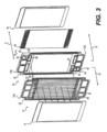
[044]図2は、隣接する燃料セル10の一部分の部分的に分解された側面斜視図を示す。例えば、図2は、1つの燃料セル10のMEA18、GDL24、およびアノードプレート22、ならびにさらには、隣接する燃料セル10のカソードプレート20、カソード流れ場28、MEA18、およびGDL24を示す。アノード区画21は、隣接するMEA18とアノードプレート22との間に形成され得る。冷却剤区画23は、隣接するアノードプレート22とカソードプレート20との間に形成され得る。カソード区画19は、隣接するカソードプレート20とMEA18との間に形成され得る。カソード区画19は、カソード流れ場28を内包し得る。図2において示されるように、燃料セル10は、さらには上部および下部流体マニホールドと呼称され得る、流体マニホールド31A、31Bを含み得る。流体マニホールド31A、31Bは、図2において示されるように、長手方向軸5に沿って延び得る。
[044] FIG. 2 shows a partially exploded side perspective view of a portion of an
[045]図3~5は、1つの例解的な実施形態による、燃料セル10を通る燃料、酸化剤、および冷却流体の流れ経路を例解する。しかし、他の実施形態に対して、流れ経路のうちの1つまたは複数の方向は、例えば、流れの方向を逆にすることにより切り替えられ得るということが理解されるべきである。図3は、燃料セル10のMEA18のアノード側を通して循環させられる燃料に対する流れ経路を例解し、図4は、燃料セル10のMEA18のカソード側を通して循環させられる酸化剤に対する流れ経路を例解し、図5は、隣接する燃料セル10の間で循環させられる冷却剤流体に対する流れ経路を例解する。
[045] Figures 3-5 illustrate flow paths of fuel, oxidant, and cooling fluid through the
[046]今から図3を参照すると、第1の流体マニホールド31Aは、少なくとも1つのアノードフィードマニホールド32を含み得るものであり、そのアノードフィードマニホールド32は、流体接続し、燃料を、少なくとも1つのアノード入口通路34を通し、少なくとも1つのアノード入口ポート36を通し、アノード区画21内へと導き得る。アノード区画21からの燃料(例えば、未反応の燃料)は、アノード区画21から、少なくとも1つのアノード出口ポート38を通り、少なくとも1つのアノード出口通路40を通り、少なくとも1つのアノード排出マニホールド42内へと導かれ得る。アノード入口通路34およびアノード出口通路40は、隣接する燃料セル10のアノードプレート22とカソードプレート20との間に位置し得る。アノード入口通路34およびアノード出口通路40、ならびに、アノードフィードマニホールド32およびアノード排出マニホールド42の周辺部は、図3において例解されるように、表面ガスケット43により封止され得る。
[046] Referring now to Figure 3, the
[047]図4において示されるように、第2の流体マニホールド31Bは、少なくとも1つのカソードフィードマニホールド44を含み得るものであり、そのカソードフィードマニホールド44は、流体接続し、酸化剤を、少なくとも1つのカソード入口通路46を通し、少なくとも1つのカソード入口ポート48を通し、カソード区画19内へと導き得る。カソード区画19からの酸化剤は、カソード区画19から、少なくとも1つのカソード出口ポート50を通り、少なくとも1つのカソード出口通路52を通り、少なくとも1つのカソード排出マニホールド54内へと導かれ得る。カソード入口通路46およびカソード出口通路52は、隣接する燃料セル10のアノードプレート22とカソードプレート20との間に位置し得る。カソード入口通路46およびカソード出口通路52、ならびに、カソードフィードマニホールド44およびカソード排出マニホールド54の周辺部は、図4において例解されるように、表面ガスケット43により封止され得る。
[047] As shown in FIG. 4, the
[048]図5において示されるように、第1の流体マニホールド31Aは、少なくとも1つの冷却剤フィードマニホールド56を含み得るものであり、その冷却剤フィードマニホールド56は、流体接続し、冷却剤流体を、少なくとも1つの冷却剤入口通路58を通し、冷却剤区画23の中の冷却剤流れ場86に導き得る。冷却剤区画23の中で、冷却剤流体は、本明細書においてさらに説明されることになるように、アノードプレート22により規定される複数の冷却剤チャネルから成り立つ冷却剤流れ場86を通って、アノードプレート22とカソードプレート20との間で流れ得る。隣接する燃料セル10により発生させられる熱は、冷却剤流体に伝達され、冷却剤流体の循環により燃料セル10から除去され得る。冷却剤区画23からの冷却剤流体は、少なくとも1つの冷却剤出口通路60を通り、少なくとも1つの冷却剤排出マニホールド62内へと導かれ得る。冷却剤入口通路58および冷却剤出口通路60は、隣接する燃料セル10のアノードプレート22とカソードプレート20との間に位置し得る。冷却剤入口通路58および冷却剤出口通路60、ならびに、冷却剤フィードマニホールド56および冷却剤排出マニホールド62の周辺部は、図5において例解されるように、表面ガスケット43により封止され得る。
[048] As shown in FIG. 5, the
[049]図6Aは、例示的な実施形態による、カソード流れ場28の正面図である。図6Aにおいて可視の側は、隣接するカソードプレート20に面するように構成される側である(図2を確認されたい)。カソード流れ場28は、多孔質構造、例えば、一部の実施形態において、多孔質3次元ネットワーク構造を有する多孔質金属製発泡体構造を含み得る。一部の実施形態において、多孔質構造は、スクリーン、エキスパンデッドメタルメッシュ、および、3次元的に形成され穴あけ加工された金属シートから選定され得る。一部の実施形態において、多孔質構造は、ステンレス鋼、NiCr、NiSnCr、およびチタンから選定される材料から作製され得る。多孔質構造は、2つの反対向きの表面を伴うシート形状のものであり得る。一部の実施形態において、多孔質金属製発泡体構造は、約50μmから約500μmの範囲に及ぶ平均孔サイズを有し得る。一部の実施形態において、多孔質金属製発泡体構造は、約100μmの平均孔サイズを有し得る。カソード流れ場28は、カソードプレート20に面する多孔質金属製発泡体構造の表面内の凹所に据えられる、第1のカソード分配チャネル90と、第2のカソード分配チャネル92とを含み得る。カソード流れ場28は、約0.2mmから約1.5mmの範囲に及ぶ厚さを有し得、第1のカソード分配チャネル90および/または第2のカソード分配チャネル92は、厚さの約10%から約75%の間の深さで、カソード流れ場内の凹所に据えられ得る。
[049] Figure 6A is a front view of a
[050]第1のカソード分配チャネル90は、カソード流れ場28の底部縁部に沿って、カソード流れ場28の一方の側から他方の側に概して延び得る。第2のカソード分配チャネル92は、カソード流れ場28の頂部縁部に沿って、カソード流れ場28の一方の側から他方の側に概して延び得る。カソード流れ場28がカソードプレート20に隣接して配置されるとき、カソード入口ポート48は、第1のカソード分配チャネル90と位置合わせされ得るものであり、カソード出口ポート50は、第2のカソード分配チャネル92と位置合わせされ得る。
[050] The first
[051]カソード流れ場28は、第1のカソード分配チャネル90および/または第2のカソード分配チャネル92の全体を通して形成される複数の支持特徴部94を含み得る。支持特徴部94は、概して円柱形、ディンプル形状のもの、または、他の適した形状であり得る。1つまたは複数の支持特徴部94の高さは、第1のカソード分配チャネル90および/または第2のカソード分配チャネル92の凹所深さにほぼ等しくあり得る。第1のカソード分配チャネル90、第2のカソード分配チャネル92、および支持特徴部94は、カソード流れ場28を形成する多孔質金属製発泡体構造を、スタンピングする、圧延加工する、または、他の形で塑性変形させることにより形成され得る。
[051]
[052]第1のカソード分配チャネル90および第2のカソード分配チャネル92は、酸化剤が多孔質金属製発泡体構造の孔内へと流れる前に沿って流れるための開放流れ経路を提供することにより、カソード流れ場28の幅に沿った酸化剤の一様な流れ分配を助長するように構成され得る。支持特徴部94は、第1のカソード分配チャネル90および第2のカソード分配チャネル92内へのカソードプレート20の変形またはたわみを、防止または低減することにより、燃料セル10が圧縮されるときに、第1のカソード分配チャネル90および第2のカソード分配チャネル92により提供される開放流れ経路を維持するために、機械的圧縮の間の、およびさらには、動作の間の適切な支持を提供するように構成され得る。
[052] The first
[053]図6B、6C、および6Fは、カソード流れ場28’、28’’、28’’’の追加的な実施形態の正面図である。一部の実施形態において、カソード流れ場28’、28’’、28’’’は、カソード流れ場28に代えて燃料セル10内で利用され得る。カソード流れ場28’、28’’、28’’’は、本明細書において説明されるようなカソード流れ場28のすべての特徴部、および、下記で説明されるような追加的な特徴部を含み得る。図6B、6C、および6Fにおいて可視の側は、隣接するカソードプレート20に面するように構成される側、または、隣接するMEA18に面するように構成される側であり得る。
[053] Figures 6B, 6C, and 6F are front views of additional embodiments of cathode flow fields 28', 28'', 28'''. In some embodiments, cathode flow fields 28 ′, 28 ″, 28 ′″ may be utilized within
[054]カソード流れ場28’、28’’は、複数のフィード(または第1の)チャネル101と、複数の排出(または第2の)チャネル102とを含み得る。フィードチャネル101および排出チャネル102は、カソードプレート20に面する表面上で、カソード流れ場28’内で、スタンピングされ、切り込み加工され、成形され、または、他の形で形成され得る。図6Bおよび6Cにおいて示されるように、フィードチャネル101は、第1のカソード分配チャネル90において開始し、第1のカソード分配チャネル90と流体連通し、第2のカソード分配チャネル92の方に延び得る。排出チャネル102は、第2のカソード分配チャネル92において終了し、第2のカソード分配チャネル92と流体連通し、第1のカソード分配チャネル90の方に延び得る。フィードチャネル101および排出チャネル102は、図6Bにおいて示されるように、相互嵌合させられ得るものであり、そのことによって、排出チャネル102は、隣接するフィードチャネル101の間に配置され得る。一部の実施形態において、フィードチャネル101および排出チャネル102は、改善された酸化剤分配を可能にするために、流体流れに対する障害物が実質的にないことがある。一部の実施形態において、フィードチャネル101および排出チャネル102は、第1および第2のカソード分配チャネル90、92において見出されるディンプル94と同様のディンプル(図示せず)を含み得る。
[054] The cathode flow field 28', 28'' may include multiple feed (or first)
[055]所定の実施形態において、複数のフィードチャネル101および排出チャネル102は、異なる配置構成、形状、および/または断面積を有し得るということが思索される。例えば、図6Bにおいて、フィードおよび排出チャネル101、102の幅は、カソード流れ場28’の長さに沿って変動し得る。図6Bにおいて、フィードチャネル101は、第1のカソード分配チャネル90において、または、第1のカソード分配チャネル90の付近で広く開始し、第2のカソード分配チャネル92の方に延びると狭くなって点になり、一方で、排出チャネルは、点において開始し、第2のカソード分配チャネル92の方に延びると広くなる。一部の実施形態において、フィードチャネル101の遠位端は、図6Bにおいて示されるような点よりむしろ平坦であり得る。同様に、一部の実施形態において、排出チャネル102の近位端は、図6Bにおいて示されるような点よりむしろ平坦であり得る。この配置構成によって、フィードチャネル101と排出チャネル102との間の直接的な流体連通は存しない。むしろ、第1のカソード分配チャネル90によりフィードチャネル101に分配される酸化剤は、複数のフィードチャネル101を通って流れ得るものであり、カソード流れ場28’の多孔質構造を通って、隣接する排出チャネル102に拡散することを強制され得る。
[055] It is contemplated that in certain embodiments, the plurality of
[056]図6Cは、カソード流れ場28’’に対するフィードチャネル101および排出チャネル102の別の配置構成を示し、フィードおよび排出チャネル101、102の幅は、カソード流れ場28’’の長さに沿ってほぼ同じままである。フィードおよび排出チャネル101、102の幅はほぼ同じままであるが、フィードおよび排出チャネル101、102の深さは、カソード流れ場28’’の長さに沿って変動し得る。例えば、図6Dは、フィードチャネル101を通る断面A-Aに沿ったカソード流れ場28’’の断面図を示す。図6Dにおいて示されるように、フィードチャネル101は、第1のカソード分配チャネル90において、または、第1のカソード分配チャネル90の付近で最も深く(すなわち、最大深さfd1)開始し得るものであり、深さは、第2のカソード分配チャネル92の方に延びると減少し得る。図6Dにおいて示されるように、深さは、一定のレートで(例えば、線形に)減少し得るものであり、または、一部の実施形態において、深さは、可変のレートで(例えば、非線形に、指数関数的に)減少し得る。図6Dにおいて示されるように、フィードチャネル101は、最小深さ(fd2)を伴う遠位端において平坦に行き止まり得る。他の実施形態において、フィードチャネル101は、ゼロ最小深さfd2を伴う遠位端において行き止まり得る。
[056] Figure 6C shows an alternative arrangement of the
[057]図6Eは、排出チャネル102を通る断面B-Bに沿ったカソード流れ場28’’の断面を示す。図6Eにおいて示されるように、排出チャネル102は、第1のカソード分配チャネル90において、または、第1のカソード分配チャネル90の付近で最も浅く(すなわち、最小深さdd1)開始し得るものであり、深さは、第2のカソード分配チャネル92の方に延びると増大し得る。排出チャネル102は、第2のカソード分配チャネル92において、または、第2のカソード分配チャネル92の付近で最も深くあり得る(すなわち、最大深さdd2)。図6Eにおいて示されるように、深さは、一定のレートで(例えば、線形に)増大し得るものであり、または、一部の実施形態において、深さは、可変のレートで(例えば、非線形に、指数関数的に)増大し得る。図6Eにおいて示されるように、排出チャネル102は、最小深さ(dd1)を伴う近位端において平坦に開始し得る。他の実施形態において、排出チャネル101は、ゼロ最小深さdd1を伴う近位端において開始し得る。
[057] FIG. 6E shows a cross-section of cathode flow field 28'' along cross-section BB through
[058]フィードおよび排出チャネル101、102の、幅を変動させること(例えば、図6Bを確認されたい)、または、深さを変動させること(例えば、図6C~Eを確認されたい)により、カソード流れ場28’、28’’に沿った酸化剤の流れに対して利用可能な断面積は変動(例えば、排出チャネル102において増大、または、フィードチャネル101において減少)し得る。カソード流れ場28’、28’’の長さに沿ったフィードおよび排出チャネル101、102においての利用可能な流れ面積の増大または減少は、フィードチャネル101および排出チャネル102に沿った酸化剤の流れ速度がほぼ一定のままであるように、フィードチャネル101から多孔質構造内へと拡散し、多孔質構造から排出チャネル102内へと拡散した酸化剤の体積と対応するように構成され得る。換言すれば、フィードチャネル101の断面積は、酸化剤の速度がほぼ一定のままであるように、酸化剤が、フィードチャネル101の外に流れ、多孔質構造内へと拡散するレートに等しいレートで減少し得る。同様に、排出チャネル102の断面積は、酸化剤の速度がほぼ一定のままであるように、酸化剤が、排出チャネル102内へと、多孔質構造の外に流れるレートに等しいレートで増大し得る。一部の実施形態において、フィードおよび排出チャネル101、102の、幅および深さは、両方が変動し得る。例えば、一部の実施形態において、図6Dおよび6Eは、図6Cに加えて、図6Bの断面を表し得る。
[058] By varying the width (see, for example, Fig. 6B) or the depth (see, for example, Figs. 6C-E) of the feed and
[059]図6Bおよび6Cにおいて示されるように、ランドセクション104と呼称され得る、フィードチャネル101と排出チャネル102との間に形成される分離セクションが存し得る。フィードチャネル101と排出チャネル102との間のランドセクション104の厚さは固定され得るものであり、または、一部の実施形態において、厚さは変動し得る。例えば、厚さは、第1のカソード分配チャネル90に最も近いと(例えば、フィードチャネル101の近位端と、排出チャネルの遠位端との間で)最も大であり得るものであり、厚さは、第2のカソード分配チャネル92の方で減少し得る。他の実施形態において、厚さは、第1のカソード分配チャネル90に最も近いと最も薄くあり得るものであり、厚さは、第2のカソード分配チャネル92の方で増大し得る。他の実施形態において、ランドセクション104の厚さは、第1のカソード分配チャネル90と、第2のカソード分配チャネル92との間のほぼ中程で、最も厚く、または、最も薄くあり得る。
[059] As shown in FIGS. 6B and 6C, there may be a separation section formed between
[060]一部の実施形態において、複数のマイクロチャネル106が、ランドセクション104内に、カソード流れ場28’、28’’内に形成され得る。マイクロチャネル106は、ランドセクション104の全体長さ、または、一部分だけに沿って形成され得る。マイクロチャネル106は、カソード流れ場28’、28’’により提供される多孔質ネットワークと比較して、酸化剤に対する好まれる流れ経路を生み出すために、フィードチャネル101を排出チャネル102と流体接続するように構成され得る。これらの実施形態に対して、拡散することと連関して、または、拡散することよりむしろ、酸化剤は、マイクロチャネルを通ってフィードチャネル101から排出チャネル102に流れ得る。マイクロチャネル106は、他の形ではカソード流れ場28’、28’’のランドセクションにより陰にされることになる、触媒サイトの大部分に対する酸化剤利用可能性を提供するような手立てで、サイズ設定および隔置され得る。
[060] In some embodiments, a plurality of
[061]フィードおよび排出チャネル101、102の数は、例えば、カソード流れ場28’、28’’の幅、フィードチャネル101の幅、排出チャネル102の幅、燃料セル10の用途、酸化剤に対する意図もしくは設計される動作圧力、酸化剤に対する意図もしくは設計される動作流れレート、燃料セル10に対する意図もしくは設計されるパワー出力、または、これらのパラメータの任意の組合せを含む、1つまたは複数の異なるパラメータに基づいて調整され得る。
[061] The number of feed and
[062]カソード流れ場28’、28’’は、いくつかの利益を提示し得る。例えば、フィードチャネル101および排出チャネル102は、酸化剤が通って流れることができる、より大きい断面積を提供し、そのことは、他の多孔質流れ場構造と比較して、多孔質流れ場にわたる圧力降下を低減することができる。フィードチャネル101および排出チャネル102に加えて、マイクロチャネルが、さらには、酸化剤ガスがフィードチャネル101と排出チャネル102との間で通って流れることができる、増大された断面積を提供し得るものであり、そのことは、多孔質流れ場にわたる圧力降下をさらに低減することができる。圧力降下を低減することにより、酸化剤を加圧するために要されるエネルギー(例えば、ブロワパワー)の量が低減され得るものであり、そのことが今度は、燃料セル10の総体的な性能および効率を改善する(例えば、パワー密度を改善し、寄生負荷を低減する)ことができる。加えて、カソード流れ場28’、28’’の特徴部は、カソード流れ場の出口の付近で酸素濃度を増大するために、多孔質流れ場の中で新鮮な酸化剤を、より一様に分配し得る。(例えば、フィードチャネル101、排出チャネル102、およびマイクロチャネル)。このことは、酸化剤の入来する流れが、例えば、流れが多孔質体を通して分配されるまで、酸素に富んだままであることを可能にすることができ、そのことは、より良好なセル電圧、および、潜在的には、より高い電流密度を結果的に生じさせることができる。
[062] The cathode flow fields 28', 28'' may present several benefits. For example,
[063]カソード流れ場28’’’は、図6Fにおいて示されるように、その表面内へと形成される(例えば、プレス加工される、エンボス加工される、または、切り込み加工される)複数のチャネル110を含み得る。複数のチャネル110は、第1のカソード分配チャネル90において始まり、第2のカソード分配チャネル92の方にほぼ中途まで延びる、第1のセットのチャネル110Aを含み得る。第1のセットのチャネル110Aは、新鮮な酸化剤(例えば、まだ消費されていない酸化剤)が、より低い酸素濃度を酸化剤がしばしば有することがあるカソード流れ場28’’’の第2の半分体まで直接的に進行することを可能にするように構成される。第1のセットのチャネル110Aは、それらがランドセクションの頂部上にあるように寸法設定され得る。他のチャネル110は、総体的な圧力降下を低減し、混合、および/または、一様な分配を手助けするように構成され得る。一部の実施形態に対して、カソード流れ場28’’’に対して使用される、ありふれた材料は、非一様な圧力降下および流れ特性を結果的に生じさせることになる非一様性を伴い得る。チャネル110は、より一様な圧力降下および流れ特性を可能にすることにより、この問題点に対処する助けとなるように設計される。第1のセットのチャネル110Aは、さらには、活性区域の前縁部においての流れレート、およびかくして流れ速度を低減する助けとなり、そのことが今度は、その領域内の水分の除去を低減して、乾燥状況においてのより良好な動作および性能を提供する。このことは、さらには、カソード流れ場28’’’の流れ経路に沿って湿度および酸素濃度分布のバランスをとる助けとなり、そのことは、電気化学反応の結果として、活性区域にわたって電流および温度分布のバランスをとる。このことは、燃料セルおよびスタックの、耐久性および信頼性を改善する。一部の実施形態において、第1のセットのチャネル110Aは、強め合って干渉し、セルが潜在的にドライアウトすることのリスクを増大する、高速度効果に対する潜在的可能性を回避するために、燃料セルのアノードまたは冷却剤側の任意の流れチャネルの反対に配置され得る。
[063] Cathode flow field 28''' is formed (e.g., stamped, embossed, or notched) into its surface as shown in Figure 6F. A
[064]カソード流れ場28(または28’’または28’’’)を作り上げる多孔質構造は、1つまたは複数の、金属および/または合金を含み得る。例えば、多孔質構造は、少なくとも、ニッケル(Ni)およびクロム(Cr)(例えば、NiCr)、または、ニッケル、スズ(Sn)、およびクロム(例えば、NiSnCr)の組合せを含み得る。多孔質構造のNiCr実施形態に対して、クロムの質量による濃縮物は、約20質量%から約40質量%の範囲に及ぶことができ、一方で、ニッケルは、残りの残量 - 約60質量%から約80質量%を占め得る。多孔質構造のNiSnCr実施形態に対して、クロムの濃度は、約3質量%から約6質量%の範囲に及ぶことができ、スズの濃度は、約10質量%から約20質量%の範囲に及ぶことができ、一方で、ニッケルは、残量 - 約74%から約87%を占め得る。 [064] The porous structure that makes up the cathode flow field 28 (or 28'' or 28''') may include one or more metals and/or alloys. For example, the porous structure can include at least nickel (Ni) and chromium (Cr) (eg, NiCr), or a combination of nickel, tin (Sn), and chromium (eg, NiSnCr). For NiCr embodiments of porous structures, the concentration by weight of chromium can range from about 20% to about 40% by weight, while nickel accounts for the remaining balance - about 60% by weight. % to about 80% by weight. For NiSnCr embodiments of the porous structure, the chromium concentration can range from about 3 wt% to about 6 wt%, and the tin concentration can range from about 10 wt% to about 20 wt%. can range, while nickel can make up the balance—about 74% to about 87%.
[065]一部の実施形態において、多孔質構造の少なくとも1つの表面は、約3質量%から約50質量%の範囲に及ぶクロム濃度を含み得る。例えば、カソード流れ場28を形成する多孔質構造の、1つまたは両方の表面のクロム濃度は、約3質量%から約50質量%、約5質量%から約40質量%、または、約7質量%から約40質量%の範囲に及び得る。多孔質金属体の表面のクロム濃度を増大することは有利であり得るものであり、なぜならば、そのことは、酸性環境において多孔質構造の耐食性を増大するからである。例えば、カソード流れ場を形成する多孔質構造の表面のうちの少なくとも1つが、約3質量%から約50質量%の範囲に及ぶクロム濃度を有するとき、多孔質構造を含むバイポーラプレートは、有利には、カソードにおいての実質的に酸性の環境において高耐食性であり得る。本明細書において説明されるような多孔質構造により提供される、改善された耐食性は、有利には、カソードプレートが、コーティングされたステンレス鋼よりむしろ、コーティングされないステンレス鋼から形成されることを可能にし得るものであり、そのコーティングされたステンレス鋼は、その耐食性特質のために従前から使用されてきたものである。
[065] In some embodiments, at least one surface of the porous structure may comprise a chromium concentration ranging from about 3% to about 50% by weight. For example, the chromium concentration of one or both surfaces of the porous structure forming the
[066]一部の実施形態において、多孔質構造の一方の表面は、多孔質構造の他方の表面より高いクロム濃度を有し得る。そのような実例において、より高いクロム濃度を有する表面は、有利には、より高耐食性であり得る。より高いクロム濃度を有する表面は、MEA18に面するように配置構成され得る。一部の実施形態において、多孔質構造の、より高耐食性の表面は、約3質量%から約50質量%の範囲に及ぶクロム濃度を有し得るものであり、一方で、金属多孔質構造の、より少ない耐食性表面は、約3質量%クロム未満のクロム濃度を有し得る。
[066] In some embodiments, one surface of the porous structure may have a higher chromium concentration than the other surface of the porous structure. In such instances, surfaces with higher chromium concentrations may advantageously be more corrosion resistant. A surface with a higher chromium concentration may be arranged to face
[067]本明細書において説明される多孔質構造の様々な実施形態は、1つまたは複数の電気めっきプロセスにより形成され得る。例えば、一部の実施形態において、樹脂成形体が、初期に、3次元ネットワーク構造に対する基板として使用され得る。樹脂成形体は、ポリウレタン、メラミン、ポリプロピレン、ポリエチレン、または類するもののうちの、1つまたは複数を含み得る。樹脂成形体は、その3次元ネットワーク構造内に孔を含み得る。一部の実施形態において、樹脂成形体は、約80%から約98%の範囲に及ぶ空隙率を有し得るものであり、約50μmから約500μmの孔サイズを有し得る。一部の実施形態において、樹脂成形体は、約150μmから約5,000μm、約200μmから2,000μm、または、約300μmから約1,200μmの厚さを有し得る。 [067] Various embodiments of the porous structures described herein may be formed by one or more electroplating processes. For example, in some embodiments, a resin compact may initially be used as a substrate for the three-dimensional network structure. Resin moldings may comprise one or more of polyurethane, melamine, polypropylene, polyethylene, or the like. The resin molding may contain pores within its three-dimensional network structure. In some embodiments, the resin compact can have a porosity ranging from about 80% to about 98% and can have a pore size of about 50 μm to about 500 μm. In some embodiments, the resin compact can have a thickness of about 150 μm to about 5,000 μm, about 200 μm to 2,000 μm, or about 300 μm to about 1,200 μm.
[068]多孔質構造を形成するために、金属層が、樹脂成形体上へとめっきされ得る。多孔質構造のNiCr実施形態に対して、例えば、ニッケル層およびクロム層が、樹脂成形体上へとめっきされ得る。多孔質構造のNiSnCr実施形態に対して、例えば、ニッケル層、スズ層、およびクロム層が、樹脂成形体上へとめっきされ得る。樹脂成形体は、ニッケル粒子、スズ粒子、および/または炭素粒子などの伝導性金属の、無電解めっき(自己触媒めっき)、蒸気堆積、スパッタリング、および/または塗布などの電気的伝導処置を受けさせられ得る。次いで、ニッケル層および/またはスズ層が、処置された樹脂成形体の3次元構造またはスケルトンの表面上に電気的にめっきされ得る。例えば、樹脂成形体が伝導性層によってコーティングされるとき、ニッケル層が、引き続いて、電気めっきプロセスによって、樹脂成形体のスケルトン上に形成され得る。ニッケル層が形成される後、スズ層が、引き続いて、別の電気めっきプロセスによって、樹脂成形体のスケルトン上に形成され得る。代替的には、樹脂成形体が伝導性層によってコーティングされるとき、スズ層が最初に電気めっきされ、ニッケル層の電気めっきが後に続き得る。一部の実施形態において、化学蒸気堆積が、クロムを実質的にニッケルの構造に付加するために使用され得る。例えば、一部の実施形態において、クロムは、実質的にニッケルの構造に、約15質量%から約50質量%の範囲に及ぶ濃度で、化学蒸気堆積によって付加され得る。 [068] A metal layer may be plated onto the resin compact to form a porous structure. For porous structure NiCr embodiments, for example, a nickel layer and a chromium layer can be plated onto the resin compact. For porous structure NiSnCr embodiments, for example, a nickel layer, a tin layer, and a chromium layer can be plated onto the resin compact. The resin compact is subjected to an electrically conductive treatment such as electroless plating (autocatalytic plating), vapor deposition, sputtering, and/or painting of conductive metals such as nickel particles, tin particles, and/or carbon particles. can be A layer of nickel and/or a layer of tin may then be electroplated onto the surface of the three-dimensional structure or skeleton of the treated resin compact. For example, when the resin compact is coated with a conductive layer, a nickel layer may subsequently be formed on the skeleton of the resin compact by an electroplating process. After the nickel layer is formed, a tin layer may subsequently be formed on the skeleton of the resin compact by another electroplating process. Alternatively, when the resin compact is coated with a conductive layer, the tin layer can be electroplated first, followed by the electroplating of the nickel layer. In some embodiments, chemical vapor deposition may be used to add chromium to a substantially nickel structure. For example, in some embodiments, chromium can be added to a substantially nickel structure by chemical vapor deposition at concentrations ranging from about 15% to about 50% by weight.
[069]一部の実施形態において、ニッケル層および/またはスズ層などの、1つまたは複数の金属層が、樹脂成形体のスケルトン上へとめっきされる後、クロム層が、電気めっきプロセスによって付加され得る。一部の実施形態において、クロムめっき層は、多孔質構造の少なくとも1つの表面のクロム濃度が、約3質量%から約50質量%の範囲に及ぶように形成され得る。クロムめっき層がめっきされた後、または、ニッケルおよび/もしくはスズめっき層がめっきされる後、多孔質構造は、熱処置により初期の樹脂成形体を除去することにより形成され得る。例えば、多孔質構造は、約900℃から約1300℃の範囲内の温度で、不活性雰囲気、または、還元される雰囲気内で加熱され得る。 [069] In some embodiments, after one or more metal layers, such as a nickel layer and/or a tin layer, are plated onto the skeleton of the resin compact, a chromium layer is applied by an electroplating process. can be added. In some embodiments, the chromium-plated layer can be formed such that at least one surface of the porous structure has a chromium concentration ranging from about 3% to about 50% by weight. After the chromium plating layer is plated, or after the nickel and/or tin plating layer is plated, the porous structure can be formed by removing the initial resin molding by heat treatment. For example, the porous structure can be heated in an inert or reducing atmosphere at a temperature within the range of about 900°C to about 1300°C.
[070]図7に関して、その図において描写されるのが、本開示の例示的な実施形態による、複数の電気化学セルを含み得る電気化学セルスタック接合体11である。長手方向軸5に沿って配置構成され得るのが、登場の順に、第1の端部112、第1の電気化学セル116、第1の電気化学燃料セルに隣接して配置される第2の電気化学セル120、1つまたは複数の電気化学セル124、最後の電気化学セル118に隣接して配置される第3の電気化学セル122、および、反対の端部114である。上記で説明されたように、図7において説明される複数の電気化学セル(例えば、セル116、118、120、122、および124)の各々は、すべてが膜電極接合体18を協働的に作り上げる、カソード触媒層12と、アノード触媒層14と、プロトン交換膜16と、カソードガス拡散層24と、アノード拡散層28とを含み得る。電気化学セルの各々は、カソード流れ場28と、カソードプレート20と、アノードプレート22とをさらに含み得る。電気化学セルスタック接合体11の中の電気化学セルのうちの1つまたは複数のカソード流れ場28は、多孔質構造であり得るものであり、各々の多孔質構造は、平均孔サイズを有し得るものであり、電気化学セルスタック接合体11の中の複数の電気化学セルは、ともに、平均孔サイズを有し得る。
[070] With respect to FIG. 7, depicted in that figure is an electrochemical cell stack assembly 11 that may include a plurality of electrochemical cells, according to an exemplary embodiment of the present disclosure. Arranged along the
[071]一部の実施形態において、第1の電気化学セル116の多孔質構造は、複数の電気化学セルの多孔質構造の平均孔サイズより大である平均孔サイズを有し得る。一部の実施形態において、第1の電気化学セル116の多孔質構造の平均孔サイズは、複数の電気化学セルの多孔質構造の平均孔サイズより約5%から約50%大であり得る。
[071] In some embodiments, the porous structure of the first
[072]一部の実施形態において、第1の電気化学セル116の多孔質構造は、複数の電気化学セルの多孔質構造の平均流れ抵抗より小である流れ抵抗を有し得る。一部の実施形態において、第1の電気化学セル116の多孔質構造の流れ抵抗は、複数の電気化学セルの多孔質構造の平均流れ抵抗より約5%から約50%小であり得る。一部の実施形態において、第1の電気化学セル116の多孔質構造の流れ抵抗は、複数の電気化学セルの多孔質構造の平均流れ抵抗より約5%、6%、7%、8%、9%、10%、15%、20%、25%、30%、40%、または50%小であり得る。例えば、一部の実施形態において、平均より小である流れ抵抗は、例えば、図6B~6Fにおいて示されるような、カソード流れ場28’、28’’、または28’’’などの、多孔質流れ場にわたる低減された酸化剤圧力降下を結果的に生じさせる、相互嵌合させられたチャネルを有するカソード流れ場を用いることにより達成され得る。
[072] In some embodiments, the porous structure of the first
[073]一部の実施形態において、第1の電気化学セル116に隣接して配置される第2の電気化学セル120の多孔質構造の平均孔サイズは、複数の電気化学セルの多孔質構造の平均孔サイズとほぼ同じであり得る。一部の実施形態において、第2の電気化学セル120の多孔質構造は、複数の電気化学セルの多孔質構造の平均孔サイズより大である平均孔サイズを有し得る。一部の実施形態において、第2の電気化学セル120の多孔質構造は、複数の電気化学セルの多孔質構造の平均孔サイズより大である、ただし、第1の電気化学セル116の多孔質構造の平均孔サイズより小である平均孔サイズを有し得る。一部の実施形態において、第2の電気化学セル120の多孔質構造の平均孔サイズは、複数の電気化学セルの多孔質構造の平均孔サイズより約5%から約50%大であり得る。
[073] In some embodiments, the average pore size of the porous structure of the second
[074]一部の実施形態において、第2の電気化学セル120の多孔質構造は、複数の電気化学セルの多孔質構造の平均流れ抵抗より小である流れ抵抗を有し得る。一部の実施形態において、第2の電気化学セル120の多孔質構造は、複数の電気化学セルの多孔質構造の平均流れ抵抗より小である、ただし、第1の電気化学セル116の多孔質構造の流れ抵抗より大である流れ抵抗を有し得る。一部の実施形態において、第2の電気化学セル120の多孔質構造の流れ抵抗は、複数の電気化学セルの多孔質構造の平均流れ抵抗より約5%から約50%小であり得る。一部の実施形態において、第2の電気化学セル120の多孔質構造の流れ抵抗は、複数の電気化学セルの多孔質構造の平均流れ抵抗より約5%、6%、7%、8%、9%、10%、15%、20%、25%、30%、40%、または50%小であり得る。例えば、一部の実施形態において、平均より小である流れ抵抗は、例えば、図6B~6Fにおいて示されるような、カソード流れ場28’、28’’、または28’’’などの、多孔質流れ場にわたる低減された酸化剤圧力降下を結果的に生じさせる、相互嵌合させられたチャネルを有するカソード流れ場を用いることにより達成され得る。
[074] In some embodiments, the porous structure of the second
[075]一部の実施形態において、最後の電気化学セル118の多孔質構造の平均孔サイズは、複数の電気化学セルの多孔質構造の平均サイズとほぼ同じである。一部の実施形態において、最後の電気化学セル118の多孔質構造は、複数の電気化学セルの多孔質構造の平均孔サイズより大である平均孔サイズを有し得る。一部の実施形態において、最後の電気化学セル118の多孔質構造は、第1の電気化学セル116および/または第2の電気化学セル120の多孔質構造の平均孔サイズとほぼ同じ平均孔サイズを有し得る。一部の実施形態において、最後の電気化学セル118の多孔質構造の平均孔サイズは、複数の電気化学セルの多孔質構造の平均孔サイズより約5%から約50%大であり得る。
[075] In some embodiments, the average pore size of the porous structure of the last
[076]一部の実施形態において、最後の電気化学セル118の多孔質構造は、複数の電気化学セルの多孔質構造の平均流れ抵抗より小である流れ抵抗を有し得る。一部の実施形態において、最後の電気化学セル118の多孔質構造の流れ抵抗は、複数の電気化学セルの多孔質構造の平均流れ抵抗より約5%から約50%小であり得る。一部の実施形態において、最後の電気化学セル118の多孔質構造の流れ抵抗は、複数の電気化学セルの多孔質構造の平均流れ抵抗より約5%、6%、7%、8%、9%、10%、15%、20%、25%、30%、40%、または50%小であり得る。例えば、一部の実施形態において、平均より小である流れ抵抗は、例えば、図6B~6Fにおいて示されるような、カソード流れ場28’、28’’、または28’’’などの、多孔質流れ場にわたる低減された酸化剤圧力降下を結果的に生じさせる、相互嵌合させられたチャネルを有するカソード流れ場を用いることにより達成され得る。
[076] In some embodiments, the porous structure of the last
[077]一部の実施形態において、第3の電気化学セル122の多孔質構造の平均孔サイズは、複数の電気化学セルの多孔質構造の平均孔サイズとほぼ同じであり得る。一部の実施形態において、第3の電気化学セル122の多孔質構造は、複数の電気化学セルの多孔質構造の平均孔サイズより大である平均孔サイズを有し得る。一部の実施形態において、第3の電気化学セル122の多孔質構造は、複数の電気化学セルの多孔質構造の平均孔サイズより大である、ただし、最後の電気化学セル118の多孔質構造の平均孔サイズより小である平均孔サイズを有し得る。一部の実施形態において、第3の電気化学セル122の多孔質構造の平均孔サイズは、複数の電気化学セルの多孔質構造の平均孔サイズより約5%から約50%大であり得る。
[077] In some embodiments, the average pore size of the porous structure of the third
[078]一部の実施形態において、第3の電気化学セル122の多孔質構造は、複数の電気化学セルの多孔質構造の平均流れ抵抗より小である流れ抵抗を有し得る。一部の実施形態において、第3の電気化学セル122の多孔質構造は、複数の電気化学セルの多孔質構造の平均流れ抵抗より小である、ただし、最後の電気化学セル122の多孔質構造の流れ抵抗より大である流れ抵抗を有し得る。一部の実施形態において、第3の電気化学セル122の多孔質構造の流れ抵抗は、複数の電気化学セルの多孔質構造の平均流れ抵抗より約5%から約20%小であり得る。一部の実施形態において、第3の電気化学セル122の多孔質構造の流れ抵抗は、複数の電気化学セルの多孔質構造の平均流れ抵抗より約5%、6%、7%、8%、9%、10%、15%、20%、25%、30%、40%、または50%小であり得る。例えば、一部の実施形態において、平均より小である流れ抵抗は、例えば、図6B~6Fにおいて示されるような、カソード流れ場28’、28’’、または28’’’などの、多孔質流れ場にわたる低減された酸化剤圧力降下を結果的に生じさせる、相互嵌合させられたチャネルを有するカソード流れ場を用いることにより達成され得る。
[078] In some embodiments, the porous structure of the third
[079]複数のセル(例えば、第1の電気化学セル116、第2の電気化学セル120、第3の電気化学セル122、および/または、最後の電気化学セル118)のうちの1つまたは複数の多孔質構造の増大される平均孔サイズは、複数の電気化学セルの多孔質構造の平均流れ抵抗より約5%から約20%小の、これらの多孔質構造の中の流れ抵抗を結果的に生じさせ得る。流れ抵抗においてのこの差が、今度は、反応物ガス(例えば、酸素)に対する、これらの多孔質構造を通る、より好都合な流れ経路を結果的に生じさせ得るものであり、そのことは、より高い流れレートを結果的に生じさせ得る。複数のセル(例えば、第1の電気化学セル116、第2の電気化学セル120、第3の電気化学セル122、および/または、最後の電気化学セル118)のうちの1つまたは複数を通る、このより高い反応物ガス流れレートは、有利には、これらのセルにおいての、スタック接合体11の端部においてのそれらのセルの配置から結果的に生じる、それらのセルのより低い動作温度により引き起こされるフラッディングの現出を防止または最小化し得る。これらのセルにおいてのフラッディングの現出を防止または最小化することは、これらの電気化学セル、および、全体としての電気化学セルスタックの安定性を改善し、それらの電気化学セルおよび電気化学セルスタックの寿命を長くすることができる。
[079] One of the plurality of cells (eg, first
[080]当業者により察知されることになるように、本明細書において説明される平均孔サイズおよび流れ抵抗においての差は、例示的にすぎず、電気化学セルスタックが設計される対象の個別の用途に基づいて最適化され得る。例えば、高い電流密度が要される用途は、より多くの流れを提供するために、端部セルにおいて、より低い流れ抵抗を要し得るものであり、なぜならば、より高い電流密度は、端部電気化学セルと、中間の複数の電気化学セルとの間の、温度においてのより大きい差を、およびかくして、フラッディングのより高い現出を結果的に生じさせる水のより大である蓄積を招き得るからである。加えて、当業者は、図7において説明される電気化学セルスタック接合体11は、例示的にすぎず、複数の電気化学セルの多孔質構造の平均孔サイズより大である平均孔サイズ、および、複数の電気化学セルの平均流れ抵抗より小である流れ抵抗を伴う、複数の電気化学セルの中の追加的な電気化学セルが存し得るということに気付くであろう。
例1:電気化学セル流れ抵抗の測定
[081]接合された電気化学燃料セルは、カソードフィードマニホールドを介して、反応物ガス、例えば、酸素に接続され得る。酸素の流れは、電気化学セルが典型的な電気化学セルスタック接合体において遭遇することになる流れレートをシミュレートするために、生起させられ、増大され、測定され得る。例えば、カソードフィードマニホールドおよびカソード排出マニホールドにおいての圧力は、例えば、マノメータを使用して測定され得るものであり、フィードおよび排出においての圧力においての差が、セルに関するカソード流れ場の多孔質構造の圧力降下を提供し得る。測定量流れレートに対する測定された圧力降下の比率が、次いで、動作においてセルから予測される流れ抵抗を表す。
[080] As will be appreciated by those skilled in the art, the differences in average pore sizes and flow resistances described herein are exemplary only and are specific to the individual for which the electrochemical cell stack is designed. can be optimized based on the application. For example, applications requiring high current densities may require lower flow resistance in the end cells to provide more flow, because higher current densities A larger difference in temperature between the electrochemical cell and the electrochemical cells in between and thus can lead to a larger accumulation of water resulting in a higher manifestation of flooding. It is from. Additionally, those skilled in the art will appreciate that the electrochemical cell stack assembly 11 illustrated in FIG. 7 is merely exemplary and has an average pore size that is greater than the average pore size of the porous structure of the plurality of electrochemical cells, and , there may be additional electrochemical cells in the plurality of electrochemical cells with flow resistances that are less than the average flow resistance of the plurality of electrochemical cells.
Example 1: Measurement of electrochemical cell flow resistance
[081] A joined electrochemical fuel cell may be connected to a reactant gas, such as oxygen, through a cathode feed manifold. Oxygen flow can be induced, increased, and measured to simulate flow rates that an electrochemical cell would encounter in a typical electrochemical cell stack assembly. For example, the pressures at the cathode feed manifold and the cathode exhaust manifold can be measured using, for example, manometers, and the difference in pressure at the feed and exhaust is the pressure in the porous structure of the cathode flow field for the cell. can provide descent. The ratio of the measured pressure drop to the measured flow rate then represents the flow resistance expected from the cell in operation.
[082]上述の説明は、例解の目的のために提示されたものである。その説明は、網羅的ではなく、開示される寸分違わない形式または実施形態に限定されない。実施形態の修正、適合、および他の応用が、本明細書の考察、および、開示される実施形態の実践から明白であろう。例えば、燃料セル10の説明された実施形態は、種々の電気化学セルによって使用されるために適合させられ得る。例えば、本開示は、主に、アノードチャネル流れ場およびカソード多孔質流れ場を伴う燃料セルに着目するが、これらの特徴部のうちの一部は、アノードおよびカソード流れ場を利用する燃料セル、または、アノードおよびカソード多孔質流れ場を利用する燃料セルにおいて利用され得るということが思索される。同様に、本明細書において説明されるセルおよび電気化学スタックの配置構成は、例示的にすぎず、他の燃料セル構成の範囲に適用され得る。
[082] The foregoing description has been presented for purposes of illustration. The description is not exhaustive and is not limited to the exact forms or embodiments disclosed. Modifications, adaptations, and other applications of the embodiments will be apparent from consideration of the specification and practice of the disclosed embodiments. For example, the described embodiment of
[083]なおまた、例解的な実施形態が本明細書において説明されたが、範囲は、本開示に基づく均等な要素、修正、省略、組合せ(例えば、様々な実施形態にわたる態様の)、適合、および/または改変を有する一切の実施形態を含む。特許請求の範囲においての要素は、特許請求の範囲において用いられる文言に基づいて広範に解釈されるべきであり、本明細書において、または、本出願の手続処理の間に説明される例に限定されるべきではなく、それらの例は、非排他的と解されるべきである。さらに、開示される方法のステップは、ステップを並べ替えること、および/または、ステップを挿入もしくは削除することを含む、任意の様式で修正され得る。 [083] It should also be noted that although illustrative embodiments have been described herein, the scope includes equivalent elements, modifications, omissions, combinations (e.g., of aspects across various embodiments), based on this disclosure, Includes any embodiment with adaptations and/or modifications. Elements in the claims are to be interpreted broadly based on the language used in the claims and are limited to the examples set forth herein or during prosecution of this application. should not be used, and those examples should be construed as non-exclusive. Additionally, the steps of the disclosed methods may be modified in any manner, including reordering steps and/or inserting or deleting steps.
[084]本開示の特徴部および利点は、詳細な明細書から明白であり、かくして、添付される特許請求の範囲は、本開示の真の趣旨および範囲の中に収まる、すべてのセルおよびセルスタックを包含するということが意図される。本明細書において使用される際、不定冠詞「a」および「an」は、「1つまたは複数の」を意味する。同様に、複数形用語の使用は、その用語が所与の文脈において曖昧さのないものでない限り、必ずしも複数を表象するとは限らない。「および」または「または」などの単語は、別段に具体的に指図されない限り、「および/または」を意味する。さらに、数多くの修正および変更が、本開示を考究することから、たやすく浮かぶことになるので、本開示を、例解および説明される、そのままの構築物および動作に限定することは所望されず、よって、本開示の範囲の中に収まる、すべての適した修正および均等物が、頼むところにされることがある。 [084] The features and advantages of the present disclosure will be apparent from the detailed specification, and thus the appended claims will cover all cells and cells falling within the true spirit and scope of the disclosure. It is intended to encompass stacks. As used herein, the indefinite articles "a" and "an" mean "one or more." Similarly, the use of plural terms does not necessarily imply a plurality unless the terms are unambiguous in a given context. Words such as "and" or "or" mean "and/or" unless specifically stated otherwise. Furthermore, since numerous modifications and variations will readily emerge from a consideration of this disclosure, it is not desired to limit this disclosure to the precise construction and operation illustrated and described; Accordingly, all suitable modifications and equivalents that fall within the scope of this disclosure are relied upon.
[085]本明細書の全体を通して、用語「概して平行な」および「概して垂直な」は、軸、平面、または、他の構成要素との関係において、1つまたは複数の構成要素の配置構成を説明するために使用され得る。「概して平行な」または「概して垂直な」と配置構成を説明するときに許容され得る、平行および垂直からのずれの度は変動し得る。許されるずれは、例えば、約10度未満のずれ、約5度未満のずれ、および、約3度未満のずれ、約2度未満のずれ、および、約1度未満のずれなど、約20度未満の外れであり得る。 [085] Throughout this specification, the terms "generally parallel" and "generally perpendicular" refer to the arrangement of one or more components in relation to an axis, plane, or other component. can be used for explanation. The degree of deviation from parallel and perpendicular that may be tolerated when describing an arrangement as "generally parallel" or "generally perpendicular" may vary. Permissible deviations are, for example, about 20 degrees, such as less than about 10 degrees, less than about 5 degrees, and less than about 3 degrees, less than about 2 degrees, and less than about 1 degree. can be out of less than
[086]本明細書において使用される際、用語「約」は、数値的な値を、20%、10%、5%、または1%の相違だけ、説述される値より上および下に緩和するために使用される。一部の実施形態において、用語「約」は、数値的な値を、10%の相違だけ、説述される値より上および下に緩和するために使用される。一部の実施形態において、用語「約」は、数値的な値を、5%の相違だけ、説述される値より上および下に緩和するために使用される。一部の実施形態において、用語「約」は、数値的な値を、1%の相違だけ、説述される値より上および下に緩和するために使用される。 [086] As used herein, the term "about" refers to a numerical value above and below the stated value by a difference of 20%, 10%, 5%, or 1%. used for mitigation. In some embodiments, the term "about" is used to relax numerical values above and below the stated value by a difference of 10%. In some embodiments, the term "about" is used to relax numerical values above and below the stated value by a difference of 5%. In some embodiments, the term "about" is used to relax numerical values above and below the stated value by 1% difference.
[087]本明細書において使用される際、用語「隣接する(toを伴わない)」および「隣接する(toを伴う)」は、互換的に使用され、2つ以上の物体の相対的位置を、隣にある、または隣接すると説明する。例えば、一部の実施形態において、電気化学セル燃料スタックにおいて、2つの電気化学燃料セルが、「隣接する」または「互いに隣接する」と説明されるならば、そのことは、前記電気化学燃料セルの中間に電気化学燃料セルは存しないということを意味すると理解されるべきである。 [087] As used herein, the terms "adjacent (without to)" and "adjacent (with to)" are used interchangeably to refer to the relative positions of two or more bodies. are described as being next to or adjacent to each other. For example, in some embodiments, if two electrochemical fuel cells are described as being "adjacent" or "adjacent to each other" in an electrochemical cell fuel stack, it means that the electrochemical fuel cells should be understood to mean that there is no electrochemical fuel cell in between.
[088]本明細書において使用される際、用語「燃料セル」および「電気化学燃料セル」、ならびに、それらの用語の複数形異形は、互換的に使用され得るものであり、意味合いにおいて同一であると理解される。 [088] As used herein, the terms "fuel cell" and "electrochemical fuel cell" and plural variations of those terms may be used interchangeably and are identical in meaning. It is understood that there are
[089]本開示の他の実施形態が、本明細書の考察、および、本明細書においての本開示の実践から、当業者には明白であろう。本明細書および例は、単に例示的と考えられ、本開示の真の範囲および趣旨は、後に続く特許請求の範囲により指示されるということが意図される。
[089] Other embodiments of the disclosure will be apparent to those skilled in the art from consideration of the specification and practice of the disclosure herein. It is intended that the specification and examples be considered as exemplary only, with a true scope and spirit of the disclosure being indicated by the following claims.
Claims (33)
カソード触媒層、アノード触媒層、および、前記カソード触媒層と前記アノード触媒層との間に介在させられる高分子膜を備える膜電極接合体と、
アノードプレートおよびカソードプレートであって、前記膜電極接合体は、前記アノードプレートと前記カソードプレートとの間に介在させられる、アノードプレートおよびカソードプレートと、
前記カソードプレートと前記カソード触媒層との間に配置されるカソード流れ場であって、平均孔サイズを有する複数の孔を有する多孔質構造を備えたカソード流れ場と
を備え、
前記複数の電気化学セルは、前記電気化学セルスタックの第1の端部において配置される第1の電気化学セルを含み、
前記第1の電気化学セルの前記多孔質構造は、前記複数の電気化学セルの前記多孔質構造の平均孔サイズより大である平均孔サイズを有し、
前記第1の電気化学セルの前記多孔質構造は、前記複数の電気化学セルの前記多孔質構造の平均流れ抵抗より小である流れ抵抗を有する、
電気化学セルスタック。 An electrochemical cell stack comprising a plurality of electrochemical cells, each electrochemical cell comprising:
a membrane electrode assembly comprising a cathode catalyst layer, an anode catalyst layer, and a polymer membrane interposed between the cathode catalyst layer and the anode catalyst layer;
an anode plate and a cathode plate, wherein the membrane electrode assembly is interposed between the anode plate and the cathode plate;
a cathode flow field disposed between the cathode plate and the cathode catalyst layer, the cathode flow field comprising a porous structure having a plurality of pores having an average pore size;
the plurality of electrochemical cells includes a first electrochemical cell disposed at a first end of the electrochemical cell stack;
the porous structure of the first electrochemical cell has an average pore size that is greater than the average pore size of the porous structure of the plurality of electrochemical cells;
the porous structure of the first electrochemical cell has a flow resistance that is less than an average flow resistance of the porous structures of the plurality of electrochemical cells;
Electrochemical cell stack.
カソード触媒層、アノード触媒層、および、前記カソード触媒層と前記アノード触媒層との間に介在させられる高分子膜を備えた膜電極接合体と、
アノードプレートおよびカソードプレートであって、前記膜電極接合体は、前記アノードプレートと前記カソードプレートとの間に介在させられ、前記アノードプレートは、前記アノード触媒層に面するアノード流れ場を形成する複数のチャネルを規定する、アノードプレートおよびカソードプレートと、
前記カソードプレートと前記カソード触媒層との間に配置されるカソード流れ場であって、多孔質構造を備えたカソード流れ場と
を備え、
前記アノード流れ場を形成する前記複数のチャネルは、概して正方形の形状の、波形にされたチャネルであり、前記複数のチャネルは、前記アノード触媒層を横断する燃料の流れを導くように構成された、アノード側に対し開放のアノードチャネルを含み、前記複数のチャネルは、さらには、冷却剤流れを導くように構成された、逆の側に対し開放の冷却剤チャネルを含み、
前記複数の電気化学セルは、前記電気化学セルスタックの第1の端部において配置される第1の電気化学セルを含み、
前記第1の電気化学セルの前記多孔質構造は、前記複数の電気化学セルの前記多孔質構造の平均孔サイズより大である平均孔サイズを有し、
前記第1の電気化学セルの前記多孔質構造は、前記複数の電気化学セルの前記多孔質構造の平均流れ抵抗より小である流れ抵抗を有する、
電気化学セルスタック。 An electrochemical cell stack comprising a plurality of electrochemical cells stacked along a longitudinal axis, each electrochemical cell comprising:
a membrane electrode assembly comprising a cathode catalyst layer, an anode catalyst layer, and a polymer membrane interposed between the cathode catalyst layer and the anode catalyst layer;
an anode plate and a cathode plate, wherein the membrane electrode assembly is interposed between the anode plate and the cathode plate, the anode plates forming an anode flow field facing the anode catalyst layer; an anode plate and a cathode plate defining channels of
a cathode flow field disposed between the cathode plate and the cathode catalyst layer, the cathode flow field comprising a porous structure;
The plurality of channels forming the anode flow field were generally square-shaped, corrugated channels, the plurality of channels configured to direct fuel flow across the anode catalyst layer. , comprising an anode channel open to the anode side, the plurality of channels further comprising a coolant channel open to the opposite side configured to direct coolant flow;
the plurality of electrochemical cells includes a first electrochemical cell disposed at a first end of the electrochemical cell stack;
the porous structure of the first electrochemical cell has an average pore size that is greater than the average pore size of the porous structure of the plurality of electrochemical cells;
the porous structure of the first electrochemical cell has a flow resistance that is less than an average flow resistance of the porous structures of the plurality of electrochemical cells;
Electrochemical cell stack.
Applications Claiming Priority (5)
| Application Number | Priority Date | Filing Date | Title |
|---|---|---|---|
| US201862618228P | 2018-01-17 | 2018-01-17 | |
| US201862618146P | 2018-01-17 | 2018-01-17 | |
| US62/618,146 | 2018-01-17 | ||
| US62/618,228 | 2018-01-17 | ||
| PCT/US2019/014004 WO2019143811A1 (en) | 2018-01-17 | 2019-01-17 | Cathode flow field distribution for fuel cell stacks |
Publications (2)
| Publication Number | Publication Date |
|---|---|
| JP2021511635A JP2021511635A (en) | 2021-05-06 |
| JP7284178B2 true JP7284178B2 (en) | 2023-05-30 |
Family
ID=65279769
Family Applications (1)
| Application Number | Title | Priority Date | Filing Date |
|---|---|---|---|
| JP2020539290A Active JP7284178B2 (en) | 2018-01-17 | 2019-01-17 | Cathode flow field distribution for fuel cell stack |
Country Status (7)
| Country | Link |
|---|---|
| US (1) | US11387470B2 (en) |
| EP (1) | EP3740989A1 (en) |
| JP (1) | JP7284178B2 (en) |
| KR (1) | KR20200106948A (en) |
| CN (1) | CN111971831B (en) |
| AU (1) | AU2019209555B2 (en) |
| WO (1) | WO2019143811A1 (en) |
Families Citing this family (1)
| Publication number | Priority date | Publication date | Assignee | Title |
|---|---|---|---|---|
| US20230134415A1 (en) | 2020-03-26 | 2023-05-04 | Eh Group Engineering Ag | Fuel cell |
Citations (4)
| Publication number | Priority date | Publication date | Assignee | Title |
|---|---|---|---|---|
| JP2003092121A (en) | 2001-09-14 | 2003-03-28 | Toyota Motor Corp | Fuel cell |
| JP2007165257A (en) | 2005-12-16 | 2007-06-28 | Toyota Motor Corp | Separator for fuel cell |
| JP2015164133A (en) | 2008-06-23 | 2015-09-10 | ヌヴェラ・フュエル・セルズ・インコーポレーテッド | Design of fuel cell based on bipolar plate with frame |
| JP2017016942A (en) | 2015-07-03 | 2017-01-19 | 国立大学法人山梨大学 | Separator for fuel battery, cell structure and cell stack |
Family Cites Families (9)
| Publication number | Priority date | Publication date | Assignee | Title |
|---|---|---|---|---|
| US6329094B1 (en) * | 1997-05-14 | 2001-12-11 | Sanyo Electric Co., Ltd. | Polymer electrolyte fuel cell showing stable and outstanding electric-power generating characteristics |
| JP2006526271A (en) * | 2003-05-15 | 2006-11-16 | 日産自動車株式会社 | Fuel cell system |
| JP2007200674A (en) * | 2006-01-26 | 2007-08-09 | Toyota Motor Corp | Fuel cell stack |
| US8889314B2 (en) * | 2009-01-13 | 2014-11-18 | GM Global Technology Operations LLC | Bipolar plate for a fuel cell stack |
| WO2013188568A1 (en) * | 2012-06-13 | 2013-12-19 | Nuvera Fuel Cells, Inc. | Flow structures for use with an electrochemical cell |
| JP6055379B2 (en) * | 2013-06-27 | 2016-12-27 | 住友電気工業株式会社 | Porous metal body, method for producing porous metal body, and fuel cell |
| WO2015175664A1 (en) * | 2014-05-15 | 2015-11-19 | Nuvera Fuel Cells, Inc. | Flow fields for use with an electrochemical cell |
| DE102015213950A1 (en) | 2015-07-23 | 2017-01-26 | Volkswagen Ag | Fuel cell and fuel cell stack |
| JP6701601B2 (en) * | 2015-09-10 | 2020-05-27 | 住友電気工業株式会社 | Metal porous body, fuel cell, and method for producing metal porous body |
-
2019
- 2019-01-17 EP EP19703557.9A patent/EP3740989A1/en active Pending
- 2019-01-17 JP JP2020539290A patent/JP7284178B2/en active Active
- 2019-01-17 AU AU2019209555A patent/AU2019209555B2/en active Active
- 2019-01-17 CN CN201980019821.0A patent/CN111971831B/en active Active
- 2019-01-17 US US16/249,946 patent/US11387470B2/en active Active
- 2019-01-17 KR KR1020207023643A patent/KR20200106948A/en not_active Application Discontinuation
- 2019-01-17 WO PCT/US2019/014004 patent/WO2019143811A1/en unknown
Patent Citations (4)
| Publication number | Priority date | Publication date | Assignee | Title |
|---|---|---|---|---|
| JP2003092121A (en) | 2001-09-14 | 2003-03-28 | Toyota Motor Corp | Fuel cell |
| JP2007165257A (en) | 2005-12-16 | 2007-06-28 | Toyota Motor Corp | Separator for fuel cell |
| JP2015164133A (en) | 2008-06-23 | 2015-09-10 | ヌヴェラ・フュエル・セルズ・インコーポレーテッド | Design of fuel cell based on bipolar plate with frame |
| JP2017016942A (en) | 2015-07-03 | 2017-01-19 | 国立大学法人山梨大学 | Separator for fuel battery, cell structure and cell stack |
Also Published As
| Publication number | Publication date |
|---|---|
| US11387470B2 (en) | 2022-07-12 |
| JP2021511635A (en) | 2021-05-06 |
| AU2019209555B2 (en) | 2024-09-19 |
| WO2019143811A1 (en) | 2019-07-25 |
| US20190221868A1 (en) | 2019-07-18 |
| KR20200106948A (en) | 2020-09-15 |
| AU2019209555A1 (en) | 2020-08-06 |
| EP3740989A1 (en) | 2020-11-25 |
| WO2019143811A8 (en) | 2019-08-22 |
| CN111971831B (en) | 2024-01-05 |
| CN111971831A (en) | 2020-11-20 |
Similar Documents
| Publication | Publication Date | Title |
|---|---|---|
| JP7308208B2 (en) | Electrochemical cell with improved fluid flow design | |
| JP7449228B2 (en) | PEM fuel cell with improved fluid flow design | |
| US11387469B2 (en) | Electrochemical cells with improved fluid flow design | |
| JP2017516284A (en) | Flow field for use with electrochemical cells | |
| JP7284178B2 (en) | Cathode flow field distribution for fuel cell stack | |
| US20190221865A1 (en) | Fuel-cell plate and flow structure designs | |
| JP2008218201A (en) | Fuel cell |
Legal Events
| Date | Code | Title | Description |
|---|---|---|---|
| A621 | Written request for application examination |
Free format text: JAPANESE INTERMEDIATE CODE: A621 Effective date: 20220111 |
|
| A131 | Notification of reasons for refusal |
Free format text: JAPANESE INTERMEDIATE CODE: A131 Effective date: 20221028 |
|
| A977 | Report on retrieval |
Free format text: JAPANESE INTERMEDIATE CODE: A971007 Effective date: 20221031 |
|
| A521 | Request for written amendment filed |
Free format text: JAPANESE INTERMEDIATE CODE: A523 Effective date: 20230127 |
|
| TRDD | Decision of grant or rejection written | ||
| A01 | Written decision to grant a patent or to grant a registration (utility model) |
Free format text: JAPANESE INTERMEDIATE CODE: A01 Effective date: 20230424 |
|
| A61 | First payment of annual fees (during grant procedure) |
Free format text: JAPANESE INTERMEDIATE CODE: A61 Effective date: 20230518 |
|
| R150 | Certificate of patent or registration of utility model |
Ref document number: 7284178 Country of ref document: JP Free format text: JAPANESE INTERMEDIATE CODE: R150 |