JP7284166B2 - sprinkler head - Google Patents
sprinkler head Download PDFInfo
- Publication number
- JP7284166B2 JP7284166B2 JP2020528695A JP2020528695A JP7284166B2 JP 7284166 B2 JP7284166 B2 JP 7284166B2 JP 2020528695 A JP2020528695 A JP 2020528695A JP 2020528695 A JP2020528695 A JP 2020528695A JP 7284166 B2 JP7284166 B2 JP 7284166B2
- Authority
- JP
- Japan
- Prior art keywords
- sprinkler head
- deflector
- slit
- convex portion
- head according
- Prior art date
- Legal status (The legal status is an assumption and is not a legal conclusion. Google has not performed a legal analysis and makes no representation as to the accuracy of the status listed.)
- Active
Links
- XLYOFNOQVPJJNP-UHFFFAOYSA-N water Substances O XLYOFNOQVPJJNP-UHFFFAOYSA-N 0.000 claims description 49
- 238000005979 thermal decomposition reaction Methods 0.000 claims description 13
- 230000002093 peripheral effect Effects 0.000 claims description 9
- 230000006835 compression Effects 0.000 description 7
- 238000007906 compression Methods 0.000 description 7
- 239000000956 alloy Substances 0.000 description 3
- 229910045601 alloy Inorganic materials 0.000 description 3
- 230000008018 melting Effects 0.000 description 3
- 238000002844 melting Methods 0.000 description 3
- 239000007921 spray Substances 0.000 description 3
- 230000007423 decrease Effects 0.000 description 2
- 238000007789 sealing Methods 0.000 description 2
- 238000005507 spraying Methods 0.000 description 2
- 238000010276 construction Methods 0.000 description 1
- 238000000354 decomposition reaction Methods 0.000 description 1
- 230000003111 delayed effect Effects 0.000 description 1
- 239000011521 glass Substances 0.000 description 1
- 238000009434 installation Methods 0.000 description 1
- 239000000155 melt Substances 0.000 description 1
- 239000002184 metal Substances 0.000 description 1
- 239000003595 mist Substances 0.000 description 1
- 238000009736 wetting Methods 0.000 description 1
Images


Classifications
-
- A—HUMAN NECESSITIES
- A62—LIFE-SAVING; FIRE-FIGHTING
- A62C—FIRE-FIGHTING
- A62C31/00—Delivery of fire-extinguishing material
- A62C31/02—Nozzles specially adapted for fire-extinguishing
-
- A—HUMAN NECESSITIES
- A62—LIFE-SAVING; FIRE-FIGHTING
- A62C—FIRE-FIGHTING
- A62C37/00—Control of fire-fighting equipment
- A62C37/08—Control of fire-fighting equipment comprising an outlet device containing a sensor, or itself being the sensor, i.e. self-contained sprinklers
- A62C37/09—Control of fire-fighting equipment comprising an outlet device containing a sensor, or itself being the sensor, i.e. self-contained sprinklers telescopic or adjustable
-
- A—HUMAN NECESSITIES
- A62—LIFE-SAVING; FIRE-FIGHTING
- A62C—FIRE-FIGHTING
- A62C37/00—Control of fire-fighting equipment
- A62C37/08—Control of fire-fighting equipment comprising an outlet device containing a sensor, or itself being the sensor, i.e. self-contained sprinklers
- A62C37/10—Releasing means, e.g. electrically released
- A62C37/11—Releasing means, e.g. electrically released heat-sensitive
- A62C37/12—Releasing means, e.g. electrically released heat-sensitive with fusible links
-
- B—PERFORMING OPERATIONS; TRANSPORTING
- B05—SPRAYING OR ATOMISING IN GENERAL; APPLYING FLUENT MATERIALS TO SURFACES, IN GENERAL
- B05B—SPRAYING APPARATUS; ATOMISING APPARATUS; NOZZLES
- B05B1/00—Nozzles, spray heads or other outlets, with or without auxiliary devices such as valves, heating means
- B05B1/26—Nozzles, spray heads or other outlets, with or without auxiliary devices such as valves, heating means with means for mechanically breaking-up or deflecting the jet after discharge, e.g. with fixed deflectors; Breaking-up the discharged liquid or other fluent material by impinging jets
- B05B1/262—Nozzles, spray heads or other outlets, with or without auxiliary devices such as valves, heating means with means for mechanically breaking-up or deflecting the jet after discharge, e.g. with fixed deflectors; Breaking-up the discharged liquid or other fluent material by impinging jets with fixed deflectors
- B05B1/265—Nozzles, spray heads or other outlets, with or without auxiliary devices such as valves, heating means with means for mechanically breaking-up or deflecting the jet after discharge, e.g. with fixed deflectors; Breaking-up the discharged liquid or other fluent material by impinging jets with fixed deflectors the liquid or other fluent material being symmetrically deflected about the axis of the nozzle
Landscapes
- Health & Medical Sciences (AREA)
- Public Health (AREA)
- Business, Economics & Management (AREA)
- Emergency Management (AREA)
- Fire-Extinguishing By Fire Departments, And Fire-Extinguishing Equipment And Control Thereof (AREA)
- Nozzles (AREA)
Description
本発明は、消火用のスプリンクラーヘッドに関するものである。 The present invention relates to a sprinkler head for fire fighting.
スプリンクラーヘッドは、天井や壁面に設置され、火災の際に作動して水を散布し消火を行うものである。スプリンクラーヘッドの一例として、作動時にデフレクターが天井から室内側に突出して水を散布するものがある。 A sprinkler head is installed on a ceiling or a wall and is activated in the event of a fire to spray water and extinguish the fire. An example of a sprinkler head is one in which a deflector protrudes from the ceiling into the room when activated to sprinkle water.
上記のスプリンクラーヘッドは、複数の支柱で吊設されたデフレクターが、平時は円筒形のフレーム内に収納されている。火災が発生すると分解部分が分解して、該分解部分で支えていたデフレクターが一定距離だけ落下して停止し、本体の放水口から噴出してきた水がこのデフレクターに当たって四方に散布される。 In the above sprinkler head, deflectors suspended by a plurality of struts are housed in a cylindrical frame in normal times. When a fire breaks out, the disassembled part is disassembled, the deflector supported by the disassembled part drops by a certain distance and stops, and the water jetted from the water outlet of the main body hits the deflector and is sprayed in all directions.
一方アメリカでは、スプリンクラーヘッドの設置や施工の基準がthe National Fire Protection Association standardsによりNFPA 13として定められおり、建物の用途に応じたスプリンクラー設備の設計および設置のための基準が定められている。住宅用スプリンクラー設備の基準はNFPA 13D、13Rがある。また住宅用スプリンクラーヘッドの基準としてUnderwriters Laboratories(UL LLC)によりUL 1626が規定されている。 On the other hand, in the United States, the National Fire Protection Association standards for the installation and construction of sprinkler heads are stipulated as NFPA 13, which stipulates the standards for designing and installing sprinkler equipment according to the purpose of the building. Standards for residential sprinkler systems are NFPA 13D and 13R. In addition, UL 1626 is specified by Underwriters Laboratories (UL LLC) as a standard for residential sprinkler heads.
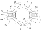
特許文献1のスプリンクラーヘッドは上記の住宅用スプリンクラーヘッドであり、該スプリンクラーヘッドは、デフレクターを吊設するピンが本体の外部に設置されている。図7に示すようにデフレクター5の外形は略円形をしているが、ピン5Cが設置された箇所の凸部H1は外方に延出した形状となっている。 The sprinkler head of
デフレクター5の縁には複数のスリット5Aが設置されており、スリット5Aの形状(長さ、幅、角度、等)によって散水パターンをコントロールしている。一般的にスリット5Aを設置した方向ではスプリンクラーヘッドの直下や近距離領域の床面の散水量が多くなる傾向にあり、2つのスリット5A、5Aの間に形成された凸部の方向おいては、スプリンクラーヘッドから離れた遠距離領域の床面の散水量が多くなる傾向がある。 A plurality of
住宅用スプリンクラーヘッドは、床面への散水に加えて壁面にも散水を行うようにUL 1626に定められている。壁面への散水の条件の一つとして、壁面の濡れが天井面から床面に向かって所定の距離以下を濡らさなければならない事が規定されている。 Residential sprinkler heads are specified in UL 1626 to spray walls as well as floors. As one of the conditions for spraying water on the wall surface, it is stipulated that the wall surface must be wetted within a predetermined distance from the ceiling surface to the floor surface.
そのため、床面だけでなく壁面にもある程度の水が向かうようにスリットや凸部の形状を構成しているが、ピンが設置された位置からデフレクターの中心を起点に90度回転した方向にはピンのような散水の妨げとなるものが無く、水が飛び過ぎる傾向があった。 Therefore, the shape of the slits and protrusions is configured so that a certain amount of water is directed not only to the floor surface but also to the wall surface. There was no impediment to watering, such as a pin, and there was a tendency for water to fly too much.
また、散水しているスプリンクラーヘッドの周囲に設置されているスプリンクラーヘッドは、散水によって感熱分解部が水で冷やされると作動が遅れるおそれがある。このため、周囲に設置されているスプリンクラーヘッドを濡らさないように水平よりも下方に向けて水を飛散させなければならないが、前述の壁面の濡れ条件も満たさなければならない。 In addition, the sprinkler head installed around the sprinkler head that is spraying water may be delayed in operation if the heat-sensitive decomposition section is cooled by the water spray. For this reason, the water must be sprayed downward from the horizontal so as not to wet the sprinkler heads installed around it, but the wall surface wetting conditions mentioned above must also be met.
そこで本発明では、上記問題に鑑み、壁面を適度に濡らすことができ、周囲のスプリンクラーヘッドの作動に影響を及ぼさない散水パターンが得られるスプリンクラーヘッドを提供することを目的としている。 Therefore, in view of the above problems, an object of the present invention is to provide a sprinkler head that can moderately wet the wall surface and obtain a watering pattern that does not affect the operation of surrounding sprinkler heads.
上記の目的を達成するために、本発明は以下のスプリンクラーヘッドを提供する。
すなわち、給水配管と接続されたノズルを内部に備えた本体と、円盤状で縁部に複数のスリットを有しておりノズルの中心軸に交差して設置されたデフレクターと、本体とデフレクターとを連結する支持部材と、を備えたスプリンクラーヘッドであり、デフレクターの中心を起点として支持部材の位置から90度回転した方向に円弧状の第1凸部が設置されており、該凸部の両隣には円弧状の第1スリットが設置され、一方の第1スリットから第1凸部、他方の第1スリットまでの形状が波型であるスプリンクラーヘッドである。In order to achieve the above objects, the present invention provides the following sprinkler head.
That is, a main body internally provided with a nozzle connected to a water supply pipe, a disk-shaped deflector having a plurality of slits at the edge and installed across the central axis of the nozzle, and the main body and the deflector. A sprinkler head comprising a connecting support member, and arc-shaped first protrusions are installed in a direction rotated 90 degrees from the position of the support member with the center of the deflector as the starting point, and on both sides of the protrusions is a sprinkler head in which arc-shaped first slits are installed and the shape from one first slit to the first convex portion and the other first slit is wave-shaped.
上記スプリンクラーヘッドにおいて、ノズルから放出されデフレクターに衝突して第1凸部に流れた水は第1凸部の縁から霧状の水が放射方向に飛散される。一方、第1スリットから飛散する水流はまとまった水流となり、このまとまった水流により周囲の空気が動いて気流が生じる。第1凸部から飛散した霧状の水は気流の影響を受けてスプリンクラーヘッドから離れた床面の遠距離領域や壁面まで到達する。 In the above sprinkler head, the water that is discharged from the nozzles, collides with the deflector, and flows to the first projections is sprayed radially from the edges of the first projections. On the other hand, the water flow that scatters from the first slit becomes a stream of water, and this stream of water moves the surrounding air to generate an air flow. The misty water scattered from the first projections is affected by air currents and reaches a long-distance area on the floor surface away from the sprinkler head and the wall surface.
第1凸部と、第1スリットに隣接した第2凸部は、デフレクターの外周径よりも内側に設置されており、ノズルから放出された水流は、その勢いを保った状態で第1スリットを通過してスプリンクラーヘッドの真下やその周囲の近距離領域に均一に散布される。これにより、床面の近距離領域と遠距離領域、壁面に対して必要な散水量が得られる。
The first protrusion and the second protrusion adjacent to the first slit are installed inside the outer diameter of the deflector, and the water flow discharged from the nozzle passes through the first slit while maintaining its momentum. It passes through and spreads evenly over the short range area directly under and around the sprinkler head. As a result, the required amount of sprinkled water can be obtained for the near-field area and the far-field area of the floor surface and for the wall surface.
以上、説明したように本発明によれば、第1凸部から飛散する水が霧状となり、第1スリットのまとまった水流により発生する気流によって、霧状の水を壁面や遠距離方向に到達させることができる。これにより、周囲に設置されたスプリンクラーヘッドが被水することを抑制して作動に影響を及ぼさないようにしたスプリンクラーヘッドを実現できる。
As described above, according to the present invention, the water that scatters from the first convex portion becomes a mist, and the air current generated by the concentrated water flow in the first slit reaches the wall surface or a long distance direction. can be made As a result, it is possible to realize a sprinkler head that prevents the sprinkler head installed around it from being exposed to water and does not affect its operation.
本発明について図1~図6を参照して説明する。本発明のスプリンクラーヘッドSは、本体1、弁体2、感熱分解部3、デフレクター4等から構成される。 The present invention will be described with reference to FIGS. 1 to 6. FIG. A sprinkler head S of the present invention is composed of a
本体1は図1~図2に示すように中空状であり内部にノズル11を有する。本体1の一端は給水配管Pと接続可能な牡ネジ12を有しており、他端には弁体2が設置されており常時ノズル11が閉塞されている。 As shown in FIGS. 1 and 2, the
本体1の中間部分には外側に拡張した平面13を有している。平面13の外周部からノズル11の放水方向に向かって円筒状の周壁部14が設置されている。周壁部14の下端の内側には段部15が設置されており、段部15には感熱分解部3のレバー31、31が係合される。段部15には欠如部16、16を有しており、欠如部16は対向して設置されている。欠如部16から周壁部14の内部にレバー31、31を通過可能となっている。 The middle part of the
周壁部14の外周にはデフレクター4を吊設するための突起17が2箇所設置されている。突起17は欠如部16から離れて設置されており、図中において突起17は欠如部16から90度回転した位置に設置されている。突起17にはノズル11の中心軸10と平行に穿設された穴18を有している。穴18はテーパー穴となっており、ノズル11側の端の穴径のほうが大きく形成されている。 Two
周壁部14の外周には円筒形状をしたサポートカップ19が設置されており、サポートカップ19の内側に本体1が配置されている。サポートカップ19の上端面は平面13との係合面となっており、サポートカップ19は本体1に取付られている。サポートカップ19の下方にはカバープレート20が設置されており、図1に示すようにデフレクター4はカバープレート20に載置された状態にある。 A
カバープレート20は円筒状のリテーナー20aの下端と低融点合金によって接合しており、火災の熱により低融点合金が溶融するとカバープレート20はリテーナー20aから分離して脱落する。リテーナー20aの上部はサポートカップ19の内側に挿通される。サポートカップ19の側面とリテーナー20aの側面は接続構造を有しており、リテーナー20aをサポートカップ19に係合可能となっている。 The
弁体2は円盤形状をしており、前述のとおりノズル11の出口端を閉塞している。弁体2において
ノズル11側の面にはシール部材21が設置されている。本実施形態ではシール部材21としてフッ素樹脂シートを弁体2に貼付している。弁体2のシール部材21が設置された面と反対側の面の中央には半球型の突起を有している。該突起はコンプレッションスクリュー22の端と接しており、コンプレッションスクリュー22によって弁体2がノズル11の方向に押圧されている。The
弁体2と感熱分解部3の間にはコンプレッションスクリュー22とサドル23が設置されている。コンプレッションスクリュー22は外周に牡ネジ24が刻設されており、サドル23に設置された牝ネジ25と螺合している。サドル23は金属製であり矩形の平面を有している。該平面の中央には牝ネジ25が設置されている。図中においてサドル23の平面の両端は、下面が感熱分解部3のレバー31、31と接触している。これにより、段部15に係止されたレバー31、31とサドル23、コンプレッションスクリュー22によって弁体2はノズル11の出口端と接触した構成になる。この状態にてコンプレッションスクリュー22を回転させて、その先端を弁体2の方向に移動させると弁体2がノズル11の出口端に押圧される。 A
このとき、コンプレッションスクリュー22を回転させても弁体2によりノズル11側への移動が妨げられるので、サドル23が図中下方に移動する。しかしながらサドル23の両端はレバー31、31と係合しており下方への移動が妨げられているため、サドル23の平面が弓状に湾曲して弾性変形され、牝ネジ25が設置された中央付近が下方に凹んで湾曲した状態となる。このためサドル23の両端に接しているレバー31、31にもサドル23の弾性による力が作用している。 At this time, even if the
感熱分解部3は、前述の段部15に係合され通常時は弁2を支持しており、火災時には火災の熱によって分解作動して弁体2を解放する。感熱分解部3は、図3に示すように一対のレバー31、支持板32、バランサー33、シリンダー34、プランジャー35、低融点合金36、セットスクリュー37から構成される。感熱分解部3の構成は公知であるので詳細な説明は省略する。 The
感熱分解部3は図3に示すようなユニット部品として構成され、ユニット部品として保管、運搬が可能である。スプリンクラーヘッドSの組立時においても図3で示すユニット部品の状態で本体1に組み込まれる。 The
デフレクター4は、円盤形状をしておりノズル11の中心軸10に対して垂直に交差している。図1においてデフレクター4は2本のピン41、41によって本体1に摺動可能に設置されている。より具体的には、ピン41が本体1の穴18に摺動可能に挿通されており、ピン41の下端がデフレクター4に固定設置されている。ピン41の上端は穴18との係合部42となっており、上端に向かうに従い拡径している。上記のピン41と本体の穴18は本体1とデフレクター4を連結する支持部材として機能する。 The
図4および図5においてデフレクター4の中心にはノズル11の方向に突出したボタン43が設置されている。デフレクター4にはノズル中心軸10と交差しており、デフレクター4の平面に沿った直線L1上に2本のピン41、41が設置される。デフレクター4には縁部から中心に向かって線状に欠如されたスリットを複数有している。スリットはデフレクター4の中心側の端が円弧状をした円弧端となっている。また、一つのスリットと該スリットに隣接するスリットの間は凸部となっている。尚、図5に示すデフレクター4のスリット及び凸部の形状は直線L1に対して対称である。 4 and 5, a
図5において、デフレクター4の中心(ノズル11の中心軸10と直線L1の交点)を起点としてピン41、41の位置から90度回転した方向に円弧状の第1凸部44が設置されている。第1凸部44の両隣には円弧状の第1スリット45、45が設置されている。より具体的には、一方の第1スリット45から第1凸部44を通過して他方の第1スリット45までのデフレクター4の外形は波型をしている。また第1凸部44と、第1スリット45に隣接した第2凸部46は、デフレクター4の外周円C1よりも内側に設置されている。 In FIG. 5, an arcuate
上記構成において、第1凸部44と第2凸部46は周囲の凸部よりも短く形成され、一方の第1スリット45から他方の第1スリット45までの間は波型形状となっている。ノズル11から放出された水はボタン43に衝突してデフレクター4の外周に向かって流れ、波型をした第1凸部44から第2凸部46の方向へ流れた水の一部は、第1スリット55を通過してスプリンクラーヘッドSの直下やその周囲の近距離領域へ均一に散布される。このとき第1スリット45、45の方向(矢印Bの方向)にまとまった水流が生じる。 In the above configuration, the first
一方、第1凸部44から飛散した水流は図6において第1凸部44の周囲に図示された矢印のように第1凸部44の縁から放射方向に飛散される。そのため矢印A方向の水流は霧状の水流となる。しかしながら第1スリット45、45の方向にまとまった水流が生じていることから、この水流によって生じる気流により矢印A方向に飛散した霧状の水流が遠くまで運ばれてA方向の延長上にある壁面を濡らす。第2凸部46の先端と、隣の第1スリット45および第2スリット47の間の角は、丸みを帯びた円弧状となっており、この円弧状の部分から飛散する水は第1凸部44の縁から飛散する水と同じように放射方向に飛散される。 On the other hand, the water flow splashed from the first
図6に示すように、第1凸部44の先端と第1スリットの円弧端までの距離aは、1~2mmにするのが好ましい。距離aが大きくなり過ぎると、矢印B方向への水流が増して矢印A方向への水流が減る傾向となる。 As shown in FIG. 6, the distance a between the tip of the
第2凸部46の長さbは、それと隣接する凸部4aの長さよりも短い。凸部4aの長さから第2凸部46の長さbを差し引いた寸法cは、第2凸部46の長さと略同じか僅かに寸法cの方が長く構成されている。第2凸部46の長さbを調整することでデフレクター4の中心から第2凸部46に向かう方向(矢印Cの方向)への水流をコントロールできる。より具体的には、第2凸部46の長さbを短くすると矢印Cの方向に飛散する水流が矢印Bで示す水流の方に引き寄せられる傾向があり、矢印C方向の散水量が減少する。
The length b of the
第3凸部48は直線L1上に配置されておりピン41が設置されている。ピン41はデフレクター4の外周円C1よりも外側に設置されており、また第3凸部48の先端はデフレクター4の外周円C1よりも外側に延出している。第3凸部48の両隣には、直線L1に沿って第4凸部49が設置され、第4凸部49の先端と第3凸部48の先端は直線L1と垂直に交わる直線L2上にある。 The third
第3凸部48の先端は第4凸部49の平面よりもノズル11から離れる方向に屈曲され、段50が設置されている。段50にはピン41の下端が挿通される穴が穿設されており、ピン41を該穴に挿通した後、ピン41を段50に固定設置する。第3凸部48上において段50の近傍に斜面51を有しており、斜面51はデフレクター4の外周円C1よりも外側に設置されている。 The tip of the
第3凸部48と第4凸部49の間の第3スリット52は、直線L1に対して僅かに傾いて設置されている。このため第3凸部48は先端に向かうに従って幅が細くなっている。 The
第4凸部49に隣接した第4スリット53と第1スリット45、第2スリット47の円弧端は、デフレクター4の外周円C1と同芯である円C2に接している。円C2はデフレクター4の外周円C1よりも小径である。 The arc ends of the
ピン41が設置された直線L1の方向への水の飛距離はピン41が水の流れの妨げとなる。そのため第3凸部48と第4凸部49の先端はデフレクター4の外周円C1よりも外側に設けられ、ボタン43からピン41の方向に流れる水の滑走距離を長くして水流の勢いを増加させている。
The
第3スリット52に到達した水は、第3スリットを通過して下方に流れるが、第3凸部48の表面を流れた水は斜面51に到達するまで水流の勢いを維持して滑走する。そのためL1方向の延長上に設けられた壁面を十分濡らす程度の流量を確保できる。 The water that has reached the
以上、説明した本発明のスプリンクラーヘッドSの構成は上記に限定されるものではなく、例えば感熱分解部3としてグラスバルブやリンクを用いることができる。また、本体とデフレクターとを連結する支持部材を、本体からノズルの放水方向に延出したフレームアームとして構成することも可能であり、フレームアームの先端に本発明のデフレクターを設置してもよい。 The structure of the sprinkler head S of the present invention described above is not limited to the above. For example, a glass bulb or a link can be used as the
1 本体
2 弁体
3 感熱分解部
4 デフレクター
11 ノズル
41 ピン
43 ボタン
44 第1凸部
45 第1スリット
46 第2凸部
47 第2スリット
48 第3凸部
49 第4凸部
50 段
1 body
2 valve body
3 Thermal decomposition unit
4 deflector
11 nozzle
41 pins
43 button
44 first projection
45 first slit
46 second projection
47 second slit
48 third projection
49 fourth projection
50 steps
Claims (13)
円盤状であり縁部から中心に向かって線状に欠如された複数のスリットを有しており前記ノズルの中心軸に交差して設置されたデフレクターと、
前記本体と前記デフレクターとを連結する支持部材と、
を備えたスプリンクラーヘッドであり、
前記デフレクターの中心を起点として前記支持部材の位置から90度回転した方向に円弧状の第1凸部が設置されており、前記第1凸部の両隣には円弧状の第1スリットが設置され、一方の前記第1スリットから前記第1凸部、他方の前記第1スリットまでの形状が波型であり、前記ノズルから放出された水を前記第1凸部の縁から放射方向に飛散し、
前記第1凸部と、前記第1スリットに隣接した第2凸部は、前記デフレクターの外周径よりも内側に設置され、
前記第1凸部の幅は、前記デフレクターの外周側から前記デフレクターの中心側に向かって拡がっており、
前記第2凸部は、その先端の角が丸みを帯びた円弧状であることを特徴とするスプリンクラーヘッド。 a main body internally provided with a nozzle connected to a water supply pipe;
a disc-shaped deflector having a plurality of slits linearly cut from the edge toward the center and installed to intersect the central axis of the nozzle;
a support member that connects the main body and the deflector;
a sprinkler head with
An arc-shaped first protrusion is installed in a direction rotated 90 degrees from the position of the support member with the center of the deflector as a starting point, and arc-shaped first slits are installed on both sides of the first protrusion. , the shape from the first slit on one side to the first convex portion and the first slit on the other side is corrugated, and the water discharged from the nozzle is scattered in the radial direction from the edge of the first convex portion. ,
The first convex portion and the second convex portion adjacent to the first slit are installed inside the outer peripheral diameter of the deflector ,
The width of the first convex portion expands from the outer peripheral side of the deflector toward the center side of the deflector,
The sprinkler head , wherein the second projection has an arcuate shape with rounded corners .
Applications Claiming Priority (3)
| Application Number | Priority Date | Filing Date | Title |
|---|---|---|---|
| JP2018128127 | 2018-07-05 | ||
| JP2018128127 | 2018-07-05 | ||
| PCT/JP2019/016949 WO2020008707A1 (en) | 2018-07-05 | 2019-04-22 | Sprinkler head |
Publications (3)
| Publication Number | Publication Date |
|---|---|
| JPWO2020008707A1 JPWO2020008707A1 (en) | 2021-08-02 |
| JPWO2020008707A5 JPWO2020008707A5 (en) | 2022-03-10 |
| JP7284166B2 true JP7284166B2 (en) | 2023-05-30 |
Family
ID=69059446
Family Applications (1)
| Application Number | Title | Priority Date | Filing Date |
|---|---|---|---|
| JP2020528695A Active JP7284166B2 (en) | 2018-07-05 | 2019-04-22 | sprinkler head |
Country Status (4)
| Country | Link |
|---|---|
| US (1) | US11511144B2 (en) |
| JP (1) | JP7284166B2 (en) |
| TW (1) | TWM589058U (en) |
| WO (1) | WO2020008707A1 (en) |
Citations (3)
| Publication number | Priority date | Publication date | Assignee | Title |
|---|---|---|---|---|
| US20090126950A1 (en) | 2005-06-03 | 2009-05-21 | Tyco Fire Products Lp | Residential Flat Plate Concealed Sprinkler |
| JP2012040165A (en) | 2010-08-19 | 2012-03-01 | Senju Sprinkler Kk | Sprinkler head |
| JP2012080961A (en) | 2010-10-07 | 2012-04-26 | Senju Sprinkler Kk | Sprinkler head |
Family Cites Families (11)
| Publication number | Priority date | Publication date | Assignee | Title |
|---|---|---|---|---|
| US3061016A (en) * | 1959-12-14 | 1962-10-30 | Hodgman Mfg Co Inc | Fusible link |
| US3010521A (en) * | 1960-05-03 | 1961-11-28 | Safety First Products Corp | Cantilever sprinkler head for dry powder |
| US4616710A (en) * | 1984-12-27 | 1986-10-14 | Pilant Frank J | Heat-released plug |
| US5152344A (en) | 1991-03-25 | 1992-10-06 | Grinnell Corporation | Fire protection sprinkler |
| JP3413630B2 (en) * | 1996-07-10 | 2003-06-03 | 能美防災株式会社 | Foam solution spray head |
| US6962208B2 (en) * | 2000-05-17 | 2005-11-08 | The Viking Corporation | Compact pendant sprinkler head |
| JP2003325695A (en) * | 2002-03-06 | 2003-11-18 | Senju Sprinkler Kk | Sprinkler head cover |
| US20040134670A1 (en) * | 2002-12-27 | 2004-07-15 | Orr Shawn Gregory | Sprinkler cover |
| US7275603B2 (en) * | 2004-10-26 | 2007-10-02 | The Reliable Automatic Sprinkler Co., Inc. | Concealed pendent fire protection sprinkler with drop-down deflector |
| US9086180B2 (en) * | 2011-07-11 | 2015-07-21 | Frank T. Porta | Quick connect fire and dust suppression system |
| JP2013056084A (en) * | 2011-09-09 | 2013-03-28 | Senju Sprinkler Kk | Sprinkler head |
-
2019
- 2019-04-22 US US17/256,747 patent/US11511144B2/en active Active
- 2019-04-22 JP JP2020528695A patent/JP7284166B2/en active Active
- 2019-04-22 WO PCT/JP2019/016949 patent/WO2020008707A1/en active Application Filing
- 2019-06-24 TW TW108208040U patent/TWM589058U/en unknown
Patent Citations (3)
| Publication number | Priority date | Publication date | Assignee | Title |
|---|---|---|---|---|
| US20090126950A1 (en) | 2005-06-03 | 2009-05-21 | Tyco Fire Products Lp | Residential Flat Plate Concealed Sprinkler |
| JP2012040165A (en) | 2010-08-19 | 2012-03-01 | Senju Sprinkler Kk | Sprinkler head |
| JP2012080961A (en) | 2010-10-07 | 2012-04-26 | Senju Sprinkler Kk | Sprinkler head |
Also Published As
| Publication number | Publication date |
|---|---|
| JPWO2020008707A1 (en) | 2021-08-02 |
| US20210260423A1 (en) | 2021-08-26 |
| WO2020008707A1 (en) | 2020-01-09 |
| TWM589058U (en) | 2020-01-11 |
| US11511144B2 (en) | 2022-11-29 |
Similar Documents
| Publication | Publication Date | Title |
|---|---|---|
| EP2012881B1 (en) | Extended coverage horizontal sidewall sprinkler | |
| KR102153208B1 (en) | House concealed sprinkler | |
| US20210094051A1 (en) | Sprinkler Head | |
| CN111699025A (en) | Sprinkler head | |
| JP7284166B2 (en) | sprinkler head | |
| KR20180107343A (en) | Dry type sprinklers pendent | |
| JP2006263217A (en) | Fire-fighting method and fire extinguishing head | |
| CN111386141B (en) | Sprinkler head | |
| EP2219742B1 (en) | Anti-skipping sprinkler | |
| JP4302125B2 (en) | Sprinkler head fitting | |
| US20240001183A1 (en) | Sprinkler frame support bridge | |
| JP3012031U (en) | Sprinkler head | |
| JP2000153005A (en) | Sprinkler head mounting implement | |
| JP2651854B2 (en) | Sprinkler head | |
| KR102703885B1 (en) | Sprinkler head to prevent micro-flow of fire water | |
| WO2022220132A1 (en) | Sprinkler head | |
| JP3846591B2 (en) | Sprinkler head | |
| JP2852638B2 (en) | Flash sprinkler head | |
| JP2019170479A (en) | Sprinkler head | |
| AU2021471757A1 (en) | Sprinkler frame support bridge | |
| TW202128252A (en) | Sprinkler head including a main body, a deflector unit, a closing member, a heat-sensitive actuating part, a heat collector and a shield | |
| JPH0871174A (en) | Sprinkler head |
Legal Events
| Date | Code | Title | Description |
|---|---|---|---|
| A521 | Request for written amendment filed |
Free format text: JAPANESE INTERMEDIATE CODE: A523 Effective date: 20220301 |
|
| A621 | Written request for application examination |
Free format text: JAPANESE INTERMEDIATE CODE: A621 Effective date: 20220301 |
|
| A131 | Notification of reasons for refusal |
Free format text: JAPANESE INTERMEDIATE CODE: A131 Effective date: 20230131 |
|
| A521 | Request for written amendment filed |
Free format text: JAPANESE INTERMEDIATE CODE: A523 Effective date: 20230302 |
|
| TRDD | Decision of grant or rejection written | ||
| A01 | Written decision to grant a patent or to grant a registration (utility model) |
Free format text: JAPANESE INTERMEDIATE CODE: A01 Effective date: 20230516 |
|
| A61 | First payment of annual fees (during grant procedure) |
Free format text: JAPANESE INTERMEDIATE CODE: A61 Effective date: 20230518 |
|
| R150 | Certificate of patent or registration of utility model |
Ref document number: 7284166 Country of ref document: JP Free format text: JAPANESE INTERMEDIATE CODE: R150 |