JP7282532B2 - Information processing device, information processing method, data structure, and program - Google Patents
Information processing device, information processing method, data structure, and program Download PDFInfo
- Publication number
- JP7282532B2 JP7282532B2 JP2019010058A JP2019010058A JP7282532B2 JP 7282532 B2 JP7282532 B2 JP 7282532B2 JP 2019010058 A JP2019010058 A JP 2019010058A JP 2019010058 A JP2019010058 A JP 2019010058A JP 7282532 B2 JP7282532 B2 JP 7282532B2
- Authority
- JP
- Japan
- Prior art keywords
- polygon mesh
- topology
- mesh
- geometry
- data
- Prior art date
- Legal status (The legal status is an assumption and is not a legal conclusion. Google has not performed a legal analysis and makes no representation as to the accuracy of the status listed.)
- Active
Links
Images


Classifications
-
- G—PHYSICS
- G06—COMPUTING; CALCULATING OR COUNTING
- G06T—IMAGE DATA PROCESSING OR GENERATION, IN GENERAL
- G06T17/00—Three dimensional [3D] modelling, e.g. data description of 3D objects
- G06T17/20—Finite element generation, e.g. wire-frame surface description, tesselation
- G06T17/205—Re-meshing
-
- G—PHYSICS
- G06—COMPUTING; CALCULATING OR COUNTING
- G06T—IMAGE DATA PROCESSING OR GENERATION, IN GENERAL
- G06T2210/00—Indexing scheme for image generation or computer graphics
- G06T2210/08—Bandwidth reduction
-
- G—PHYSICS
- G06—COMPUTING; CALCULATING OR COUNTING
- G06T—IMAGE DATA PROCESSING OR GENERATION, IN GENERAL
- G06T2210/00—Indexing scheme for image generation or computer graphics
- G06T2210/36—Level of detail
Description
本発明は、情報処理装置、情報処理方法、データ構造、及びプログラムに関する。 The present invention relates to an information processing device, an information processing method, a data structure, and a program.
従来、三次元情報のデータ表現の方法として、ポリゴンメッシュによるサーフェイスモデル(メッシュモデル)を用いる方法が知られている。但し、この方法において、例えば、ウェブブラウザを用いてポリゴンメッシュの描画を行う場合等、描画リソースが限られる場合がある。 Conventionally, a method of using a surface model (mesh model) based on a polygon mesh is known as a method of expressing data of three-dimensional information. However, in this method, drawing resources may be limited, for example, when a web browser is used to draw a polygon mesh.
そこで、低解像度から高解像度までポリゴンメッシュを段階的に復号可能なプログレッシブ符号化方式を適用し、先に低解像度のメッシュデータを転送して描画し、後から追加の詳細情報を転送して高解像度のメッシュデータを描画することが行われている。 Therefore, we apply a progressive coding method that can decode polygon meshes step by step from low resolution to high resolution. Rendering resolution mesh data is done.
特許文献1には、符号化時にメッシュの2頂点を1頂点に統合する処理を繰り返すことで簡略化したメッシュとその手順を管理する木構造を生成し、復号時にその簡略化したメッシュから木構造を逆に辿ることで元のメッシュを復元する方法が開示されている。
In
本発明に係る情報処理装置は、ポリゴンメッシュの符号化データを出力する情報処理装置であって、第1のポリゴンメッシュを取得する取得手段と、前記取得手段により取得された第1のポリゴンメッシュに基づいて、前記第1のポリゴンメッシュより解像度が高い第2のポリゴンメッシュのジオメトリに関するジオメトリデータを生成する生成手段と、前記第1のポリゴンメッシュのトポロジに関するトポロジデータと前記生成手段により生成されたジオメトリデータとを含む前記符号化データを出力する出力手段とを有し、前記トポロジデータは、前記第1のポリゴンメッシュの頂点間の接続関係を示すエッジの情報及び前記第1のポリゴンメッシュの構成単位に関する情報を含み、前記第1のポリゴンメッシュの構成単位は、当該構成単位を形成するエッジを用いて記述される、ことを特徴とする。 An information processing apparatus according to the present invention is an information processing apparatus for outputting coded data of polygon meshes, comprising an obtaining means for obtaining a first polygon mesh , and the first polygon mesh obtained by the obtaining means. generating means for generating geometry data relating to the geometry of a second polygon mesh having a resolution higher than that of said first polygon mesh, and topology data relating to the topology of said first polygon mesh and generated by said generating means and output means for outputting the encoded data including geometry data, wherein the topology data includes edge information indicating connection relationships between vertices of the first polygon mesh and the configuration of the first polygon mesh. It is characterized in that it includes information about units, and the constituent units of the first polygon mesh are described using edges that form the constituent units.
本発明は、前記従来の課題に鑑みてなされたものであって、その目的は、ポリゴンメッシュの解像度を段階的に復号可能なように符号化するプログレッシブ符号化方式において、復号に係る処理量を削減する。 SUMMARY OF THE INVENTION The present invention has been made in view of the above-mentioned problems of the prior art. Reduce.
本発明は、ポリゴンメッシュの解像度を段階的に復号可能な符号化データを出力する情報処理装置であって、第1のポリゴンメッシュを表すメッシュデータを取得する取得手段と、前記取得手段により取得されたメッシュデータに基づいて、前記第1のポリゴンメッシュより解像度が高い第2のポリゴンメッシュのジオメトリに関するジオメトリデータを生成する生成手段と、前記第1のポリゴンメッシュのトポロジに関するトポロジデータと前記生成手段により生成されたジオメトリデータとを含む前記符号化データを出力する出力手段とを有し、前記トポロジデータは、前記第1のポリゴンメッシュの頂点間の接続関係を示すエッジの情報を含むことを特徴とする。 The present invention is an information processing apparatus for outputting coded data capable of decoding the resolution of a polygon mesh step by step, comprising obtaining means for obtaining mesh data representing a first polygon mesh, and mesh data obtained by the obtaining means. generating means for generating geometry data relating to the geometry of a second polygon mesh having a resolution higher than that of the first polygon mesh based on the mesh data obtained; and topology data relating to the topology of the first polygon mesh and the generating means and output means for outputting the encoded data including the generated geometry data, wherein the topology data includes edge information indicating a connection relationship between vertices of the first polygon mesh. do.
本発明によれば、ポリゴンメッシュの解像度を段階的に復号可能なように符号化するプログレッシブ符号化方式において、復号に係る処理量を削減することができる。 According to the present invention, it is possible to reduce the amount of processing involved in decoding in a progressive encoding method that encodes the resolution of a polygon mesh so that it can be decoded step by step.
以下、本発明の実施形態について、図面を参照して説明する。なお、以下の実施形態は、本発明を限定するものではなく、本実施形態で説明されている特徴の組み合わせの全てが本発明の解決手段に必須のものとは限らない。加えて、本発明の要旨を逸脱しない範囲の様々な形態も本発明に含まれ、また、以下の実施形態の一部を適宜組み合わせることもできる。その他、以下の実施形態において、その装置構成として、符号化部と復号部の双方の機能を有するものとして説明するが、符号化部と復号部のいずれか一方の機能を有するものでもよい。 BEST MODE FOR CARRYING OUT THE INVENTION Hereinafter, embodiments of the present invention will be described with reference to the drawings. It should be noted that the following embodiments do not limit the present invention, and not all combinations of features described in the present embodiments are essential to the solution of the present invention. In addition, the present invention includes various modes within the scope of the present invention, and some of the following embodiments can be combined as appropriate. In addition, in the following embodiments, the device configuration is described as having the functions of both the encoding unit and the decoding unit, but it may have the function of either the encoding unit or the decoding unit.
(実施形態1)
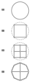
はじめに、本実施形態について説明する前に、本実施形態で用いるメッシュのデータ記述方法(データ記述形式)との対比のため、既存のメッシュのデータ記述方法について、図1を用いて説明する。図1は、既存のデータ記述形式で記述されたメッシュデータを示す図である。
(Embodiment 1)
First, before describing this embodiment, an existing mesh data description method will be described with reference to FIG. 1 for comparison with the mesh data description method (data description format) used in this embodiment. FIG. 1 is a diagram showing mesh data described in an existing data description format.
図1(A)は、頂点V0、頂点V2、頂点V3によって構成される三角形T0と頂点V0、頂点V3、頂点V1によって構成される三角形T1から成るメッシュを表したものである。このようなメッシュは、図1(B)に示される各頂点の頂点座標と、図1(C)に示される各三角形を構成する頂点の参照を記述することで定義される。 FIG. 1A shows a mesh consisting of a triangle T0 composed of vertices V0, V2 and V3 and a triangle T1 composed of vertices V0, V3 and V1. Such a mesh is defined by describing the vertex coordinates of each vertex shown in FIG. 1(B) and the references of the vertices forming each triangle shown in FIG. 1(C).
なお、頂点の参照はデータ上の頂点の順位(インデックス)を示すものであるが(記述するものであるが)、各要素間の接続関係は、頂点座標にアクセス可能な手段で示されればよく、その他、メモリ上のアドレス等で記述されることもある。また、図1(B)に示されるような三次元空間における位置を表現する情報をジオメトリ、図1(C)に示されるような各要素間の接続関係を表現する情報をトポロジと称する。加えて、以下において、上述のデータ記述形式を、既存のデータ記述形式と称する。 The reference to the vertex indicates the order (index) of the vertex on the data (although it describes it). In addition, it is often described by an address on the memory or the like. Information expressing positions in a three-dimensional space as shown in FIG. 1(B) is called geometry, and information expressing connection relationships between elements as shown in FIG. 1(C) is called topology. In addition, hereinafter, the data description format described above is referred to as an existing data description format.
次に、本実施形態に係る情報処理装置(符号化装置)として、メッシュを高速に復号することが可能なプログレッシブ符号化装置、併せて、そのプログレッシブ符号化装置により生成されるメッシュのデータ記述形式について説明する。 Next, as an information processing device (encoding device) according to the present embodiment, a progressive encoding device capable of decoding meshes at high speed, and a data description format of meshes generated by the progressive encoding device will be explained.
図2は、プログレッシブ符号化装置の機能構成を示す図である。なお、図2において、図2(A)は符号化部、図2(B)は復号部を示している。以下、順に説明する。図2(A)に示される符号化部は、上述の図1で示した既存のデータ記述形式で表現されたメッシュを、段階的に解像度を制御することができるようにプログレッシブ符号化する。本実施形態におけるプログレッシブ符号化は、ポリゴンメッシュの3次元メッシュモデルを複数の解像度(精細度)で復号可能なように(複数の解像度のうち、いずれかの解像度(各々の解像度)を選択して復号可能なように)符号化する符号化方式である。即ち、本実施形態における符号化装置は、ポリゴンメッシュを複数の解像度で復号可能な符号化データ(プログレッシブメッシュデータ)を出力する情報処理装置として機能する。 FIG. 2 is a diagram showing the functional configuration of a progressive encoding device. In FIG. 2, FIG. 2(A) shows an encoding section, and FIG. 2(B) shows a decoding section. They will be described in order below. The encoding unit shown in FIG. 2(A) progressively encodes the mesh expressed in the existing data description format shown in FIG. 1 so that the resolution can be controlled step by step. The progressive encoding in this embodiment is performed so that the three-dimensional mesh model of the polygon mesh can be decoded at a plurality of resolutions (definition) (one of the plurality of resolutions is selected (each resolution) It is an encoding scheme that encodes (so that it can be decoded). That is, the encoding device in this embodiment functions as an information processing device that outputs encoded data (progressive mesh data) capable of decoding polygon meshes at a plurality of resolutions.
符号化部は、図2(A)に示されるように、メッシュ入力部201、メッシュ簡略化部202、トポロジ変換部203、メッシュ細分化部204、メッシュ出力部207を備える。さらに、メッシュ細分化部204は、トポロジ細分化部205、ジオメトリ算出部206を有する。
The encoding unit includes a
メッシュ入力部201は、既存のデータ記述形式(具体的には、図1(B)、図1(C)に示されるデータ記述形式)で記述されたポリゴンメッシュを表すメッシュデータを受信(取得)し、プログレッシブ符号化装置内に入力する。メッシュ簡略化部202は、入力されたメッシュデータのメッシュを簡略化する。なお、以下において、この簡略化したメッシュをベースメッシュと称する。
The
トポロジ変換部203は、ベースメッシュをプログレッシブ表現に変換する。なお、プログレッシブ表現については、図4を用いて後述する。メッシュ細分化部204は、プログレッシブ表現に変換されたベースメッシュのトポロジの細分化、及び頂点座標の入力されたメッシュ(以下、入力メッシュと称する)へのフィッティングを繰り返し実行する。これにより、メッシュ細分化部204は、最終階層のメッシュ(以下、フルメッシュと称する)を生成する。メッシュ出力部207は、トポロジ変換部203で生成されたプログレッシブ表現のベースメッシュのトポロジ、及びメッシュ細分化部204で生成されたフルメッシュのジオメトリを、プログレッシブ表現されたメッシュとして出力する。なお、以下において、メッシュ出力部207により出力されるプログレッシブ表現されたメッシュデータをプログレッシブメッシュデータと称する。
A
次に、図2(A)に示されるプログレッシブ符号化装置の符号化部において実行される処理の概要及び手順を、図3(A)のフローチャートを用いて説明する。なお、フローチャートの説明における記号「S」は、ステップを表すものとする。また、この点、以降のフローチャートの説明においても同様とする。 Next, an overview and procedure of processing executed in the encoding unit of the progressive encoding device shown in FIG. 2A will be described using the flowchart of FIG. 3A. Note that the symbol "S" in the description of the flowchart represents a step. In addition, this point is the same in the description of the subsequent flowcharts.
S301において、メッシュ入力部201は、プログレッシブ符号化装置内にメッシュデータを入力する。S302において、メッシュ簡略化部202は、入力されたメッシュデータにおけるメッシュを簡略化して、より面数の少ないメッシュ(即ち、ベースメッシュ)で入力されたメッシュデータにおけるメッシュを近似的に表現する。なお、メッシュの簡略化に関して、本実施形態では、上述の特許文献1で開示されている方法を用いるが、必ずしもこの方法に限定されず、形状の構造を保った状態で面数を削減できる方法であれば任意の方法でよい。
In S301, the
S303において、トポロジ変換部203は、ベースメッシュをプログレッシブ表現に変換する。なお、プログレッシブ表現に変換するときの解像度の段階数をPD(Progressive Depth)とする。例えば、PD=3の場合、ベースメッシュから2回の細分化が行われ、1階層目のベースメッシュと3階層目のフルメッシュとその間に2階層目の中間メッシュが存在することになる。中間メッシュはベースメッシュより解像度が高く、フルメッシュは中間メッシュより解像度が高くなる。
In S303, the
S304において、トポロジ細分化部205は、メッシュの正則分割を実行する。なお、メッシュの正則分割については、図5を用いて後述する。また、正則分割では面数や頂点数が増えるだけで形状は変化しないため、S305において、ジオメトリ算出部206は、頂点座標が入力メッシュに近づくように、位置合わせを実行する。ここでは、位置合わせを実行する頂点により近い入力メッシュの頂点を探索し、その位置合わせを実行する頂点の座標をその探索した頂点の座標と一致させる。その他、位置合わせに関して、入力メッシュとの差を最小化するようなエネルギー最小化問題として実行してもよく、その方法は任意である。
In S304, the
ここで、補足として、S302~S305の一連の処理によって、メッシュが変化する様子を、図5を用いて説明する。図5(A)は入力メッシュであり、表現したい理想的な形状であり、図示されていない多数の微小な三角形によって形成されているものとする。この図5(A)に示されるメッシュを入力メッシュとして、S302においてメッシュを簡略化することで、図5(B)に示されるように2つの三角形で近似的に表現する。そして、S304においてメッシュの正則分割を実行することで、図5(C)に示されるように、各々の三角形が4分割される。最後に、S305において頂点の位置合わせを実行することで、図5(D)に示されるように、メッシュの形状を入力メッシュに近付ける。 Here, as a supplement, how the mesh is changed by the series of processes from S302 to S305 will be described with reference to FIG. FIG. 5A is an input mesh, which has an ideal shape to be expressed and is formed by a large number of minute triangles (not shown). By using the mesh shown in FIG. 5A as an input mesh and simplifying the mesh in S302, the mesh is approximated by two triangles as shown in FIG. 5B. Then, by performing regular division of the mesh in S304, each triangle is divided into four as shown in FIG. 5(C). Finally, vertex alignment is performed in S305 to bring the shape of the mesh closer to the input mesh, as shown in FIG. 5(D).
S306において、メッシュ細分化部204は、上述のS304、S305の処理がPD-1回、繰り返し実行されたか否かを判定する。メッシュ細分化部204は、上述のS304、S305の処理をPD-1回、繰り返し実行することで(S306 Yes)、解像度の段階数がPDであるプログレッシブ表現されたメッシュ(即ち、フルメッシュ)を生成することができる。S307において、メッシュ出力部207が出力するプログレッシブメッシュデータは、少なくともベースメッシュのトポロジに関するトポロジデータ及びフルメッシュのジオメトリに関するジオメトリデータを含む。
In S306, the
次に、プログレッシブ表現されたメッシュのデータ記述形式を、図4を用いて説明する。図4(A)はメッシュのデータ記述形式の概略を示したものであり、また、メッシュデータは、V(V0、V1、V2、V3)で示される頂点、E(E0、E1、E2、E3、E4)で示されるエッジ、T(T0、T1)で示される三角形を含むように構成される。図4(B)は、頂点座標を記述したものであり、図1(B)と同様である。 Next, the data description format of the progressively expressed mesh will be described with reference to FIG. FIG. 4A shows an outline of the mesh data description format, and the mesh data consists of vertices indicated by V (V 0 , V 1 , V 2 , V 3 ), E (E 0 , E 1 , E 2 , E 3 , E 4 ), a triangle denoted T(T 0 , T 1 ). FIG. 4(B) describes vertex coordinates and is the same as FIG. 1(B).
図4(C)は、メッシュ上の頂点間の接続関係を示すエッジを記述したものであり、ここでは、エッジ両端の頂点の参照を記述している。また、図4(C)では、頂点の参照を、図4(B)に示される頂点の順位(番号)のうち、順位の低い(小さい)ものから順に記述している(即ち、順位が低いものが先に記述される)。なお、頂点の参照に関して、順位の高い(大きい)ものから順に記述してもよい。 FIG. 4(C) describes an edge that indicates the connection relationship between vertices on the mesh, and here describes references to vertices at both ends of the edge. Also, in FIG. 4C, reference to vertices is described in order from the lowest (smallest) order of the vertex ranks (numbers) shown in FIG. are described first). Note that vertex references may be described in descending order of order.
図4(D)は、メッシュの構成単位である三角形のメッシュを記述したものであり、ここでは、その三角形を構成する3つのエッジの参照を記述する。なお、エッジの参照は、三角形を構成する頂点の順位のうち、最も順位が低い頂点を基点として、対辺に向かって、右側のエッジ、左側のエッジ、対辺のエッジの順に記述される。補足として、この順番は、三角形の表方向をエッジの記述順序によって一意に表現できればよく、例えば、逆順やずれ等、その他の順序で記述されていてもよい。以下、このデータ記述形式をプログレッシブ形式と称する。 FIG. 4(D) describes a triangular mesh, which is a constituent unit of the mesh, and here describes references to three edges that constitute the triangle. Edge references are described in the order of the right edge, the left edge, and the edge of the opposite side, starting from the vertex with the lowest order among the vertices forming the triangle as a base point. As a supplement, this order only needs to be able to uniquely express the front directions of the triangles by the description order of the edges. This data description format is hereinafter referred to as a progressive format.
次に、プログレッシブ符号化装置の符号化部のメッシュ出力部207より出力されるファイルの構成を、図8を用いて説明する。出力されるファイルは、図8に示されるように、header領域、base mesh領域、subband mesh領域を含む。header領域には、解像度の段階数(progressive_depth)、各階層におけるメッシュの頂点数(num_vertices)、エッジ数(num_edges)、三角形数(num_triangles)が記述されている。
Next, the configuration of the file output from the
base mesh領域には、ベースメッシュのエッジedges、三角形triangles、頂点座標coordsが記述されている。subband mesh領域には、ベースメッシュよりも解像度の高い階層で必要とされる追加の詳細情報が記述されており、ここでは、各階層において、解像度の低い階層からの細分化処理で新たに生じた頂点の頂点座標coordsが記述されている。即ち、同一の階層において、header領域に記述されている頂点数とsubband mesh領域に記述される頂点数が異なることに留意する。 The base mesh area describes edges edges, triangle triangles, and vertex coordinates coords of the base mesh. The subband mesh region describes the additional detail required by the higher resolution layers than the base mesh, where at each layer the new Vertex coordinates coords of vertices are described. That is, it should be noted that the number of vertices described in the header area differs from the number of vertices described in the subband mesh area in the same layer.
続いて、図3(B)のフローチャートを用いて、上述のプログレッシブメッシュの正則分割処理について説明する。ここで、分割前のメッシュの頂点数をNV、エッジ数をNE、三角形数をNTとし、以下、各要素の参照番号を(n)で示すものとする。なお、頂点に関して、分割後の頂点も分割前の頂点を利用するため、分割の前後において参照番号は維持されるが、エッジ及び三角形に関して、分割の前後において独立(固有)の参照番号が付与される。図6に細分化前後におけるプログレッシブ形式で記述されたメッシュデータの変化(即ち、頂点V、エッジE、三角形Tの参照番号の関係)を示し、図7に細分化前後における各要素数の変動を示す。 Next, the regular division processing of the progressive mesh described above will be described with reference to the flowchart of FIG. 3(B). Here, the number of vertices of the mesh before division is NV, the number of edges is NE, the number of triangles is NT, and the reference number of each element is hereinafter denoted by (n). Regarding vertices, since the vertices after division also use the vertices before division, reference numbers are maintained before and after division, but independent (unique) reference numbers are given to edges and triangles before and after division. be. FIG. 6 shows changes in mesh data described in a progressive format before and after subdivision (that is, the relationship between the reference numbers of vertices V, edges E, and triangles T), and FIG. 7 shows changes in the number of elements before and after subdivision. show.
S308において、トポロジ細分化部205は、例えば、着目するエッジをEdとして、そのエッジEdの両端の2頂点(Va、Vb)の平均座標である新頂点VNV+dを生成する。S309において、トポロジ細分化部205は、分割により生成された新頂点とその両端の2頂点の各々とを結ぶエッジE2d、E2d+1を新エッジとして生成する。S310において、トポロジ細分化部205は、全てのエッジに対して分割処理を実行したか否かを判定する。
In S308, the
このように、S308~S310では、トポロジ細分化部205は、分割前のエッジの1つ1つに順に着目して分割処理を実行する。また、図13を用いて補足すると、図13(A)と図13(B)の関係に示されるようになる。即ち、エッジE0、エッジE1、エッジE2から新頂点VNV+0、VNV+1、VNV+2を生成し、さらに新エッジE20及びE20+1、新エッジE21及びE21+1、新エッジE22及びE22+1を生成する。
In this way, in S308 to S310, the
S311において、トポロジ細分化部205は、三角形Tgを構成するエッジEd、Ee、Efを分割して生成された3つの新頂点VNV+d、VNV+e、VNV+fを互いに接続する。これにより、トポロジ細分化部205は、3つの新エッジE2NE+3g、E2NE+3g+1、E2NE+3g+2を生成する。S312において、三角形Tgを分割して生成された9つの新エッジE2d、E2d+1、E2e、E2e+1、E2f、E2f+1、E2NE+3g~E2NE+3g+2により構成される4つの新三角形T4g~T4g+3を生成(定義)する。S313において、トポロジ細分化部205は、全ての三角形に対して分割処理を実行したか否かを判定する。
In S311, the
このように、S311~S313では、新エッジを生成し、さらに、新三角形を定義(生成)する。また、図13を用いて補足すると、図13(B)と図13(C)の関係に示されるように、図13(B)において生成された新頂点VNV+0、VNV+1、VNV+2を互いに結ぶことにより、図13(C)に示されるように4つの新三角形を生成(定義)する。これにより、トポロジ(即ち、各要素間の接続関係を表現する情報)が生成される。 Thus, in steps S311 to S313, new edges are generated, and new triangles are defined (generated). 13(B) and 13(C), new vertices V NV+0 , V NV+1 , V NV+1 generated in FIG. 13(B) By joining V NV+2 together, four new triangles are generated (defined) as shown in FIG. 13(C). As a result, a topology (that is, information expressing connection relationships between elements) is generated.
その他、図7に、細分化前後における頂点、エッジ、三角形の要素数の変動を示す。図7において、S308で生成される新頂点は符号701の領域、S309で生成される新エッジは符号702の領域、S311で生成される新エッジは符号703の領域、S312で生成される新三角形は符号704の領域に記述される。
In addition, FIG. 7 shows changes in the numbers of vertices, edges, and triangle elements before and after subdivision. In FIG. 7, the new vertex generated in S308 is the
次に、図2(B)に示される復号部について説明する。復号部は、図2(A)の符号化部により生成されたプログレッシブメッシュデータを復号し、所望の解像度のメッシュ(設定された階層のメッシュ)を取得する。復号部は、例えば、PD(解像度の段階数)=3で生成されたプログレッシブメッシュデータに対して、解像度の段階数として2階層目のメッシュを指定すると、ベースメッシュの4倍の面数のメッシュを取得する。なお、本実施形態では、復号時に設定された階層のメッシュのみを出力する仕様としているが、復号の過程で取得される全ての階層のトポロジを出力するようにしてもよい。 Next, the decoding unit shown in FIG. 2B will be described. The decoding unit decodes the progressive mesh data generated by the encoding unit in FIG. 2(A), and obtains meshes of desired resolution (set hierarchical meshes). For example, for progressive mesh data generated with PD (number of stages of resolution)=3, if a mesh of the second layer is specified as the number of stages of resolution, a mesh with four times the number of faces of the base mesh to get In this embodiment, only the meshes of the hierarchy set at the time of decoding are output, but the topology of all the hierarchies acquired in the process of decoding may be output.
復号部は、図2(B)に示されるように、メッシュ入力部208、トポロジ格納部209、トポロジ細分化部210、ジオメトリ格納部211、ジオメトリ取得部212、メッシュ復元部213、メッシュ出力部214を備える。
As shown in FIG. 2B, the decoding unit includes a
メッシュ入力部208は、プログレッシブ符号化装置内にプログレッシブメッシュデータを入力し、トポロジ格納部209にトポロジを格納(設定)し、ジオメトリ格納部211に頂点座標情報を格納する。
The
トポロジ細分化部210は、トポロジ格納部209に格納されたトポロジを細分化し、設定された階層のメッシュのトポロジを生成する。ジオメトリ取得部212は、ジオメトリ格納部211に格納された頂点座標のうち、設定された階層に必要な部分(頂点座標データ)を取得する。
The
メッシュ復元部213は、細分化されたメッシュのトポロジを変換して既存のデータ記述形式のトポロジを取得すると共に、ジオメトリ取得部212から取得した頂点座標データと併せて、設定された階層におけるメッシュの表現を取得する。メッシュ出力部214は、生成したメッシュを出力する。
The
次に、図2(B)に示されるプログレッシブ符号化装置の復号部において実行される処理の概要及び手順を、図9(A)のフローチャートを用いて説明する。S901において、メッシュ入力部208は、プログレッシブ符号化装置内にプログレッシブメッシュデータを入力する。
Next, the outline and procedure of the processing executed in the decoding section of the progressive encoding device shown in FIG. 2(B) will be described using the flowchart of FIG. 9(A). In S901, the
S902において、トポロジ細分化部210は、ベースメッシュのトポロジの正則分割を実行する。S903において、トポロジ細分化部210は、解像度の段階数がN階層のメッシュを取得する場合、N-1回、S902における正則分割を実行したか否かを判定する。
At S902, the
S904において、メッシュ復元部213は、プログレッシブ表現された三角形を既存のメッシュ表現のメッシュデータ(即ち、既存のデータ記述形式のメッシュデータ)に変換する。なお、この場合、上述の図4のデータ記述形式(即ち、三角形におけるエッジの参照の記述順序、エッジにおける頂点の参照の記述順序)に従うことで、メッシュの面の表裏を誤ることなく、頂点を取得することができる。具体的には、例えば、三角形を構成する3つのエッジのうち、1番目に記述されたエッジの1番目に記述された頂点、1番目に記述されたエッジの2番目に記述された頂点、2番目に記述されたエッジの2番目に記述された頂点を取り出せばよい。S905において、メッシュ出力部214は、生成したメッシュを出力する。
In S904, the
続いて、図9(B)のフローチャートを用いて、S902において実行されるベースメッシュのトポロジの正則分割処理について説明する。なお、図9(B)において、上述の図3(B)との変更点は、図3(B)のS308を実行しないことである(即ち、図9(B)では、頂点座標の算出は行わず、入力された頂点座標情報を利用する)。 Next, the regular division processing of the topology of the base mesh executed in S902 will be described with reference to the flowchart of FIG. 9B. In FIG. 9B, the difference from the above-described FIG. 3B is that S308 in FIG. 3B is not executed (that is, in FIG. instead, use the input vertex coordinate information).
上述の構成により、メッシュのトポロジをエッジで管理することで、上位階層で生じるトポロジの生成ルールが簡易になり、高速に復号可能な三次元メッシュのプログレッシブ符号化を実現することができる。なお、本実施形態において説明した内容は、二次元メッシュにも同様に適用することができる。 With the above-described configuration, managing the mesh topology at the edge simplifies the rules for generating the topology generated in the upper layers, and realizes progressive coding of the three-dimensional mesh that can be decoded at high speed. Note that the contents described in this embodiment can be similarly applied to a two-dimensional mesh.
図10は、符号化装置のハードウェア構成を示す図である。本実施形態に係る符号化装置は、CPU1001、RAM1002、ROM1003、キーボード1004、マウス1005、表示装置1006、外部記憶装置1007、記憶媒体ドライブ1008、I/F1009を備える。
FIG. 10 is a diagram showing the hardware configuration of an encoding device. The encoding device according to this embodiment includes a
CPU(Central Processing Unit)1001は、RAM1002又はROM1003に格納されているコンピュータプログラム又はデータを用いて、コンピュータ全体の制御を行う。また、CPU1001は、符号化装置が実行するものとして説明した上述の各処理を実行する。RAM(Random Access Memory)1002は、コンピュータ読み取り可能な記憶媒体の一例である。RAM1002は、外部記憶装置1007、記憶媒体ドライブ1008、又はネットワークI/F(インタフェース)1009からロードされたコンピュータプログラムやデータを一時的に記憶するための記憶エリアを備える。また、RAM1002は、CPU1001が各種の処理を実行するときに用いるワークエリアを備える。即ち、RAM1002は、各種のエリアを適宜提供することができる。ROM(Read Only Memory)1003は、コンピュータ読み取り可能な記憶媒体の一例であり、例えば、コンピュータの設定データ、ブートプログラム等を格納する。
A CPU (Central Processing Unit) 1001 controls the entire computer using computer programs or data stored in a
本実施形態に係る符号化装置のCPU1001は、図2に示されるブロックの一部の機能を実現する。即ち、CPU1001は、図2に示されるブロックの一部として、メッシュ簡略化部202、トポロジ変換部203、メッシュ細分化部204、トポロジ細分化部210、ジオメトリ取得部212、メッシュ復元部213の機能を実現する。また、CPU1001がRAM1002にロードされたプログラムを実行することで、上述の図2に示されるブロックの一部は、CPU1001が実行するソフトウェア(コンピュータプログラム)として実装できる。この場合、このソフトウェアは、PC(Personal Computer)等のコンピュータのRAM1002にインストールされることになる。そして、このコンピュータのCPU1001がこのインストールされたソフトウェアを実行することで、このコンピュータは上述の符号化装置の機能を実現することになる。
The
なお、CPU1001とは異なる専用の1又は複数のハードウェア或いはGPU(Graphics Processing Unit)を備え、CPU1001による処理の少なくとも一部を専用のハードウェア又はGPUが行うようにしてもよい。また、専用のハードウェアとしては、例えば、ASIC(特定用途向け集積回路)、FPGA(Field-Programmable Gate Array)、及びDSP(デジタルシグナルプロセッサ)等がある。その他、補足として、図2のトポロジ格納部209及びジオメトリ格納部211は、例えば、RAM1002、外部記憶装置1007等に対応する。
Note that one or a plurality of dedicated hardware or a GPU (Graphics Processing Unit) different from the
キーボード1004及びマウス1005は、コンピュータの操作者が操作するものであり、これを用いることで、各種の指示やデータをCPU1001に対して入力することができる。表示装置1006は、CRTや液晶画面等により構成されており、CPU1001による処理結果を画像や文字等で表示することができる。
A
外部記憶装置1007は、コンピュータ読み取り記憶媒体の一例であり、ハードディスクドライブ装置に代表される大容量情報記憶装置である。外部記憶装置1007には、例えば、OS(オペレーティングシステム)、図3(A)及び(B)に示される各処理をCPU1001に実現させるためのコンピュータプログラムやデータ、上述の各種テーブル、データベース等が記憶される。外部記憶装置1007に記憶されるコンピュータプログラムやデータは、CPU1001による制御に従って、適宜RAM1002にロードされる。
The
記憶媒体ドライブ1008は、CD-ROMやDVD-ROM等の記憶媒体に記憶されているコンピュータプログラムやデータを読み出し、その読み出したコンピュータプログラムやデータをRAM1002や外部記憶装置1007に出力する。なお、外部記憶装置1007に記憶されているものとして説明した情報の一部又は全部を上述のCD-ROMやDVD-ROM等の記憶媒体に記憶させておき、この記憶媒体ドライブ1008に読み取らせてもよい。
The
ネットワークI/F1009は、外部装置から頂点インデックス等を入力したり、外部装置に符号データを出力したりするためのインタフェースであり、例えば、USB(Universal Serial Bus)である。バス1010は、プログレッシブ符号化装置内の各部を接続するバスである。
A network I/
以上のようなハードウェア構成において、コンピュータの電源がオンになると、CPU1001は、ROM1003に格納されているブートプログラムに従って、外部記憶装置1007からOSをRAM1002にロードする。この結果、キーボード1004及びマウス1005を介した入力操作が可能となり、また、表示装置1006にGUI(Graphical User Interface)を表示することが可能となる。さらに、ユーザが、マウス1005等を操作し、外部記憶装置1007に格納されたテクスチャマッピングアプリケーションの起動を指示すると、CPU1001は、このテクスチャマッピングアプリケーションをRAM1002にロードし、各種処理を実行する。これにより、上述のコンピュータが符号化装置として機能することになる。
In the hardware configuration as described above, when the computer is powered on, the
なお、CPU1001により実行される、プログレッシブ符号化のアプリケーションプログラムは、メッシュ簡略化部202、メッシュ細分化部204、トポロジ細分化部210、メッシュ復元部213に相当する関数を備えることになる。また、ここでの処理結果は、外部記憶装置1007に保存される。以上のように、上述のコンピュータは、本実施形態に係る符号化装置に適用することができる。
The progressive coding application program executed by the
(実施形態2)
上述の実施形態1では、高速に復号する上でエッジデータをデータ構造内に埋め込む例について説明した。但し、実施形態1では、メッシュを高速に復号できる反面、エッジ数は頂点数に対して約3倍程度であり、要素数が多くなることから、結果、データ量が大きくなる傾向がある。
(Embodiment 2)
In the first embodiment described above, an example of embedding edge data in a data structure for high-speed decoding has been described. However, in
そこで、本実施形態では、データ量を低減することを目的として、出力するデータのデータ構造内にエッジデータを埋め込まずに、プログレッシブ符号化を実現する方法について説明する。なお、本実施形態に係る符号化装置に関して、上述の図2に示される符号化装置と同様に、後述する各ブロックの機能を、各ブロックの機能を有する関数群から成るプログラムにより実現してもよい。また、上述の実施形態1では、メッシュの構成単位として、三角形のメッシュを例に説明したが、本実施形態では四角形のメッシュを例に説明する。 Therefore, in the present embodiment, a method of realizing progressive encoding without embedding edge data in the data structure of output data for the purpose of reducing the amount of data will be described. As for the encoding device according to the present embodiment, similarly to the encoding device shown in FIG. 2, the function of each block described later may be implemented by a program consisting of a function group having the function of each block. good. Further, in the above-described first embodiment, a triangular mesh is used as an example of a mesh constituent unit, but in this embodiment, a quadrilateral mesh is used as an example.
図12は、プログレッシブ符号化装置の機能構成を示す図である。なお、図12において、図12(A)は符号化部、図12(B)は復号部を示している。符号化部は、図12(A)に示されるように、メッシュ入力部1201、メッシュ簡略化部1202、トポロジ変換部1203、メッシュ細分化部1204、メッシュ出力部1207を備える。さらに、メッシュ細分化部1204は、トポロジ細分化部1205、ジオメトリ算出部1206を有する。また、復号部は、図12(B)に示されるように、以下を備える。即ち、メッシュ入力部1208、トポロジ格納部1209、トポロジ変換部1210、トポロジ細分化部1211、ジオメトリ格納部1212、ジオメトリ取得部1213、メッシュ復元部1214、メッシュ出力部1215を備える。
FIG. 12 is a diagram showing the functional configuration of a progressive encoding device. In FIG. 12, FIG. 12(A) shows an encoding section, and FIG. 12(B) shows a decoding section. The encoding unit includes a
以下、主に、実施形態1と共通する内容については、その説明を省略し、実施形態1と異なる部分に着目して説明する。符号化部のメッシュ簡略化部1202は、実施形態1と同様に、入力されたメッシュデータのメッシュを簡略化し、それにより得られた既存のデータ記述形式のベースメッシュのトポロジをメッシュ出力部1207に出力する。メッシュ出力部1207は、プログレッシブ表現されたメッシュのトポロジではなく、一般的なデータ記述形式のベースメッシュのトポロジを出力する。
In the following, the description of the contents common to the first embodiment will be omitted, and the description will focus on the parts different from the first embodiment. The
復号部のメッシュ入力部1208は、符号化部のメッシュ出力部1207から既存のデータ記述形式のベースメッシュを受信する。メッシュ入力部1208は、その受信したベースメッシュのトポロジをトポロジ格納部1209に格納し、そのベースメッシュのジオメトリをジオメトリ格納部1212に格納する。
The
トポロジ変換部1210は、そのベースメッシュのトポロジをプログレッシブ表現に変換する。
なお、ここで、トポロジ変換部1210における入出力は、トポロジ変換部1203における入出力と一致するものとする。即ち、このように、復号部において、ベースメッシュをプログレッシブ表現に変換する。その後、トポロジ細分化部1211は、トポロジ変換部1210においてプログレッシブ表現に変換されたベースメッシュのトポロジを細分化し、設定された階層のメッシュのトポロジを生成する。
The
It is assumed here that the input/output in the
また、本実施形態では、上述のように、四角形のメッシュをメッシュの構成単位として取り扱うため、メッシュ細分化(分割)の行程は、基本的に図5と同様であるが、図11に示されるようにトポロジが図5と異なる。具体的には、三角形のメッシュに対して四角形のメッシュは、エッジの分割において、図13(D)のエッジが図13(E)のように分割され、実施形態1と同様であるが、図13(F)に示されるように、四角形の内部に新たな頂点が生成される点で異なる。 In addition, in this embodiment, as described above, since the quadrilateral mesh is treated as a mesh constituent unit, the process of mesh subdivision (division) is basically the same as in FIG. 5, but shown in FIG. The topology is different from that shown in FIG. Specifically, for a triangular mesh and a quadrilateral mesh, the edges in FIG. 13D are divided as shown in FIG. The difference is that new vertices are generated inside the square, as shown in 13(F).
以上、本実施形態では、既存のデータ記述形式のベースメッシュのトポロジを出力して、プログレッシブ符号化を実現する構成について説明した。本実施形態に係る符号化装置は、この構成により、実施形態1に係る符号化装置と比較して、トポロジに要するデータ量を低減することができる。
<その他の実施形態>
本発明は、上述の実施形態の1以上の機能を実現するプログラムを、ネットワーク又は記憶媒体を介してシステム又は装置に供給し、そのシステム又は装置のコンピュータにおける1つ以上のプロセッサがプログラムを読出し実行する処理でも実現可能である。また、1以上の機能を実現する回路(例えば、ASIC)によっても実現可能である。
As described above, in the present embodiment, the configuration for outputting the topology of the base mesh in the existing data description format and realizing progressive coding has been described. With this configuration, the encoding device according to the present embodiment can reduce the amount of data required for the topology compared to the encoding device according to the first embodiment.
<Other embodiments>
The present invention supplies a program that implements one or more functions of the above-described embodiments to a system or apparatus via a network or a storage medium, and one or more processors in the computer of the system or apparatus reads and executes the program. It can also be realized by processing to It can also be implemented by a circuit (for example, ASIC) that implements one or more functions.
203 トポロジ変換部
204 メッシュ細分化部
207 メッシュ出力部
203
Claims (13)
第1のポリゴンメッシュを取得する取得手段と、
前記取得手段により取得された第1のポリゴンメッシュに基づいて、前記第1のポリゴンメッシュより解像度が高い第2のポリゴンメッシュのジオメトリに関するジオメトリデータを生成する生成手段と、
前記第1のポリゴンメッシュのトポロジに関するトポロジデータと前記生成手段により生成されたジオメトリデータとを含む前記符号化データを出力する出力手段と
を有し、
前記トポロジデータは、前記第1のポリゴンメッシュの頂点間の接続関係を示すエッジの情報及び前記第1のポリゴンメッシュの構成単位に関する情報を含み、
前記第1のポリゴンメッシュの構成単位は、当該構成単位を形成するエッジを用いて記述される、
ことを特徴とする情報処理装置。 An information processing device that outputs encoded data of a polygon mesh,
obtaining means for obtaining a first polygon mesh ;
generation means for generating, based on the first polygon mesh acquired by the acquisition means, geometry data relating to the geometry of a second polygon mesh having a resolution higher than that of the first polygon mesh;
output means for outputting the coded data including topology data relating to the topology of the first polygon mesh and the geometry data generated by the generating means;
The topology data includes edge information indicating a connection relationship between vertices of the first polygon mesh and information on the constituent units of the first polygon mesh,
the unit of the first polygon mesh is described using edges forming the unit;
An information processing device characterized by:
前記頂点の参照は、前記ポリゴンメッシュにおける頂点の順位を示すものであり、前記順位の低い順又は高い順に記述されることを特徴とする請求項1に記載の情報処理装置。 The edge is defined by describing references to vertices at both ends of the edge,
2. The information processing apparatus according to claim 1 , wherein the references to the vertices indicate the order of the vertices in the polygon mesh, and are described in ascending or descending order of the order.
前記細分化手段は、
前記三角形を構成するエッジの各々に対して、2つのエッジに分割し、当該分割した2つのエッジを接続する頂点を生成し、
当該生成された頂点を互いに接続するエッジを生成することで、前記三角形を4つの三角形に分割することを特徴とする請求項3又は4に記載の情報処理装置。 a subdivision means for subdividing the first polygon mesh into second polygon meshes;
The subdivision means are
dividing each of the edges forming the triangle into two edges and generating a vertex connecting the two divided edges;
5. The information processing apparatus according to claim 3 , wherein the triangle is divided into four triangles by generating edges connecting the generated vertices to each other.
第1のポリゴンメッシュを取得する取得手段と、
前記取得手段により取得された第1のポリゴンメッシュに基づいて、前記第1のポリゴンメッシュより解像度が高い第2のポリゴンメッシュのジオメトリに関するジオメトリデータを生成する生成手段と、
前記第1のポリゴンメッシュのトポロジに関するトポロジデータであって前記第1のポリゴンメッシュの頂点間の接続関係を示すエッジの情報を含むトポロジデータと前記生成手段により生成されたジオメトリデータとを含む前記符号化データを出力する出力手段と、
前記第1のポリゴンメッシュのトポロジを細分化して、第3のポリゴンメッシュのトポロジを生成する生成手段と、
前記第2のポリゴンメッシュのジオメトリのうち、前記第3のポリゴンメッシュのトポロジから参照される、前記第3のポリゴンメッシュのジオメトリを取得する第2の取得手段と、
前記第3のポリゴンメッシュのトポロジ及びジオメトリから、前記第3のポリゴンメッシュを復元する復元手段と、
を有することを特徴とする情報処理装置。 An information processing device that outputs encoded data of a polygon mesh,
obtaining means for obtaining a first polygon mesh ;
generation means for generating, based on the first polygon mesh acquired by the acquisition means, geometry data relating to the geometry of a second polygon mesh having a resolution higher than that of the first polygon mesh;
said code including topology data relating to the topology of said first polygon mesh, said topological data including edge information indicating a connection relationship between vertices of said first polygon mesh, and geometry data generated by said generating means; output means for outputting converted data;
generation means for subdividing the topology of the first polygon mesh to generate a topology of a third polygon mesh;
a second acquisition means for acquiring the geometry of the third polygon mesh, which is referenced from the topology of the third polygon mesh, among the geometries of the second polygon mesh;
restoration means for restoring the third polygon mesh from the topology and geometry of the third polygon mesh;
An information processing device comprising:
前記第1のトポロジを、当該第1のトポロジから形成される第2のポリゴンメッシュの頂点間の接続関係を示すエッジを用いたデータ記述形式に変換する変換手段と、
前記変換された前記第1のトポロジを第2のトポロジに細分化する細分化手段と、
前記第1のジオメトリのうち、前記第2のトポロジから参照されるジオメトリを第2のジオメトリとして取得する第2の取得手段と、
前記第2のトポロジ及び前記第2のジオメトリから前記第1のポリゴンメッシュを復元する復元手段と
を備えることを特徴とする情報処理装置。 a first obtaining means for obtaining data including a first topology and a first geometry defining a first polygon mesh;
conversion means for converting the first topology into a data description format using edges indicating connection relationships between vertices of a second polygon mesh formed from the first topology;
a subdivision means for subdividing the transformed first topology into second topologies;
a second obtaining means for obtaining, as a second geometry, one of the first geometries that is referenced from the second topology;
and restoring means for restoring the first polygon mesh from the second topology and the second geometry.
前記第1のポリゴンメッシュを出力する出力手段と、
を備え、
前記出力手段は、少なくとも前記第2のポリゴンメッシュのトポロジ及び前記第1のポリゴンメッシュのジオメトリを含むデータを出力し、
前記トポロジは、前記エッジを用いることなく記述されることを特徴とする請求項8に記載の情報処理装置。 subdivision means for subdividing the second polygon mesh into the first polygon mesh;
output means for outputting the first polygon mesh ;
with
the output means outputs data including at least the topology of the second polygon mesh and the geometry of the first polygon mesh;
9. The information processing apparatus according to claim 8 , wherein said topology is described without using said edges.
第1のポリゴンメッシュを取得する取得ステップと、
前記取得ステップにて取得された第1のポリゴンメッシュに基づいて、前記第1のポリゴンメッシュより解像度が高い第2のポリゴンメッシュのジオメトリに関するジオメトリデータを生成する生成ステップと、
前記第1のポリゴンメッシュのトポロジに関するトポロジデータと前記生成ステップにて生成されたジオメトリデータとを含む前記符号化データを出力する出力ステップと、
を有し、
前記トポロジデータは、前記第1のポリゴンメッシュの頂点間の接続関係を示すエッジの情報及び前記第1のポリゴンメッシュの構成単位に関する情報を含み、
前記第1のポリゴンメッシュの構成単位は、当該構成単位を形成するエッジを用いて記述される、
ことを特徴とする情報処理方法。 An information processing method in an information processing device that outputs coded data of a polygon mesh, comprising:
an obtaining step of obtaining a first polygon mesh;
a generation step of generating geometry data related to the geometry of a second polygon mesh having a resolution higher than that of the first polygon mesh, based on the first polygon mesh obtained in the obtaining step;
an output step of outputting the coded data including topology data relating to the topology of the first polygon mesh and the geometry data generated in the generating step;
has
The topology data includes edge information indicating a connection relationship between vertices of the first polygon mesh and information on the constituent units of the first polygon mesh,
the unit of the first polygon mesh is described using edges forming the unit;
An information processing method characterized by:
第1のポリゴンメッシュを取得する取得ステップと、
前記取得ステップにて取得された第1のポリゴンメッシュに基づいて、前記第1のポリゴンメッシュより解像度が高い第2のポリゴンメッシュのジオメトリに関するジオメトリデータを生成する生成ステップと、
前記第1のポリゴンメッシュのトポロジに関するトポロジデータであって前記第1のポリゴンメッシュの頂点間の接続関係を示すエッジの情報を含むトポロジデータと前記生成ステップにて生成されたジオメトリデータとを含む前記符号化データを出力する出力ステップと、
前記第1のポリゴンメッシュのトポロジを細分化して、第3のポリゴンメッシュのトポロジを生成する生成ステップと、
前記第2のポリゴンメッシュのジオメトリのうち、前記第3のポリゴンメッシュのトポロジから参照される、前記第3のポリゴンメッシュのジオメトリを取得する第2の取得ステップと、
前記第3のポリゴンメッシュのトポロジ及びジオメトリから、前記第3のポリゴンメッシュを復元する復元ステップと、
を含む、
ことを特徴とする情報処理方法。 An information processing method in an information processing device that outputs coded data of a polygon mesh, comprising:
an obtaining step of obtaining a first polygon mesh ;
a generation step of generating geometry data related to the geometry of a second polygon mesh having a resolution higher than that of the first polygon mesh, based on the first polygon mesh obtained in the obtaining step;
said topological data relating to the topology of said first polygon mesh , said topological data including edge information indicating a connection relationship between vertices of said first polygon mesh, and said geometry data generated in said generating step; an output step that outputs encoded data;
a generation step of subdividing the first polygon mesh topology to generate a third polygon mesh topology;
a second acquiring step of acquiring the geometry of the third polygon mesh referenced from the topology of the third polygon mesh among the geometries of the second polygon mesh;
a restoration step of restoring the third polygon mesh from the topology and geometry of the third polygon mesh;
including,
An information processing method characterized by:
前記第1のトポロジを、当該第1のトポロジから形成される第2のポリゴンメッシュの頂点間の接続関係を示すエッジを用いたデータ記述形式に変換する変換ステップと、
前記変換された前記第1のトポロジを第2のトポロジに細分化する細分化ステップと、
前記第1のジオメトリのうち、前記第2のトポロジから参照されるジオメトリを第2のジオメトリとして取得する第2の取得ステップと、
前記第2のトポロジ及び前記第2のジオメトリから前記第1のポリゴンメッシュを復元する復元ステップと
を有することを特徴とする情報処理方法。 a first obtaining step of obtaining data including a first topology and a first geometry defining a first polygon mesh;
a conversion step of converting the first topology into a data description format using edges indicating connection relationships between vertices of a second polygon mesh formed from the first topology;
a subdivision step of subdividing the transformed first topology into a second topology;
a second obtaining step of obtaining, as a second geometry, one of the first geometries that is referenced from the second topology;
and a restoring step of restoring the first polygon mesh from the second topology and the second geometry.
Priority Applications (4)
| Application Number | Priority Date | Filing Date | Title |
|---|---|---|---|
| JP2019010058A JP7282532B2 (en) | 2019-01-24 | 2019-01-24 | Information processing device, information processing method, data structure, and program |
| US16/740,982 US11527041B2 (en) | 2019-01-24 | 2020-01-13 | Information processing apparatus, information processing method and storage medium |
| US17/963,346 US20230034516A1 (en) | 2019-01-24 | 2022-10-11 | Information processing apparatus, information processing method and storage medium |
| JP2023082299A JP2023101015A (en) | 2019-01-24 | 2023-05-18 | Information processing device, information processing method, data structure, and program |
Applications Claiming Priority (1)
| Application Number | Priority Date | Filing Date | Title |
|---|---|---|---|
| JP2019010058A JP7282532B2 (en) | 2019-01-24 | 2019-01-24 | Information processing device, information processing method, data structure, and program |
Related Child Applications (1)
| Application Number | Title | Priority Date | Filing Date |
|---|---|---|---|
| JP2023082299A Division JP2023101015A (en) | 2019-01-24 | 2023-05-18 | Information processing device, information processing method, data structure, and program |
Publications (2)
| Publication Number | Publication Date |
|---|---|
| JP2020119292A JP2020119292A (en) | 2020-08-06 |
| JP7282532B2 true JP7282532B2 (en) | 2023-05-29 |
Family
ID=71732725
Family Applications (2)
| Application Number | Title | Priority Date | Filing Date |
|---|---|---|---|
| JP2019010058A Active JP7282532B2 (en) | 2019-01-24 | 2019-01-24 | Information processing device, information processing method, data structure, and program |
| JP2023082299A Pending JP2023101015A (en) | 2019-01-24 | 2023-05-18 | Information processing device, information processing method, data structure, and program |
Family Applications After (1)
| Application Number | Title | Priority Date | Filing Date |
|---|---|---|---|
| JP2023082299A Pending JP2023101015A (en) | 2019-01-24 | 2023-05-18 | Information processing device, information processing method, data structure, and program |
Country Status (2)
| Country | Link |
|---|---|
| US (2) | US11527041B2 (en) |
| JP (2) | JP7282532B2 (en) |
Families Citing this family (8)
| Publication number | Priority date | Publication date | Assignee | Title |
|---|---|---|---|---|
| JP7278795B2 (en) | 2019-02-21 | 2023-05-22 | キヤノン株式会社 | Image processing device, image processing method and program |
| USD959477S1 (en) | 2019-12-20 | 2022-08-02 | Sap Se | Display system or portion thereof with a virtual three-dimensional animated graphical user interface |
| USD959476S1 (en) | 2019-12-20 | 2022-08-02 | Sap Se | Display system or portion thereof with a virtual three-dimensional animated graphical user interface |
| USD959447S1 (en) | 2019-12-20 | 2022-08-02 | Sap Se | Display system or portion thereof with a virtual three-dimensional animated graphical user interface |
| US11205296B2 (en) * | 2019-12-20 | 2021-12-21 | Sap Se | 3D data exploration using interactive cuboids |
| WO2023181875A1 (en) * | 2022-03-24 | 2023-09-28 | ソニーグループ株式会社 | Information processing device and method |
| WO2023228289A1 (en) * | 2022-05-24 | 2023-11-30 | 日本電信電話株式会社 | Video correction device, video correction method, and program |
| JP2024008746A (en) * | 2022-07-09 | 2024-01-19 | Kddi株式会社 | Mesh decoder, mesh encoder, method for decoding mesh, and program |
Citations (1)
| Publication number | Priority date | Publication date | Assignee | Title |
|---|---|---|---|---|
| JP2000092487A (en) | 1998-08-29 | 2000-03-31 | Samsung Electronics Co Ltd | Progressive coding/decoding method for three- dimensional mesh information and its system |
Family Cites Families (15)
| Publication number | Priority date | Publication date | Assignee | Title |
|---|---|---|---|---|
| US5963209A (en) * | 1996-01-11 | 1999-10-05 | Microsoft Corporation | Encoding and progressive transmission of progressive meshes |
| US6108006A (en) | 1997-04-03 | 2000-08-22 | Microsoft Corporation | Method and system for view-dependent refinement of progressive meshes |
| US6191796B1 (en) * | 1998-01-21 | 2001-02-20 | Sensable Technologies, Inc. | Method and apparatus for generating and interfacing with rigid and deformable surfaces in a haptic virtual reality environment |
| US6262737B1 (en) * | 1998-01-30 | 2001-07-17 | University Of Southern California | 3D mesh compression and coding |
| JP4384813B2 (en) * | 1998-06-08 | 2009-12-16 | マイクロソフト コーポレーション | Time-dependent geometry compression |
| US6879324B1 (en) * | 1998-07-14 | 2005-04-12 | Microsoft Corporation | Regional progressive meshes |
| US6356263B2 (en) * | 1999-01-27 | 2002-03-12 | Viewpoint Corporation | Adaptive subdivision of mesh models |
| TW493142B (en) * | 2001-03-14 | 2002-07-01 | Ind Tech Res Inst | Method for building progressive mesh |
| US20040249617A1 (en) * | 2003-06-03 | 2004-12-09 | Pccw-Hkt Datacom Services Limited | Selective, pregressive transmission of 3D geometry models with the pre-ordered hierarchical meshes |
| US20060132488A1 (en) * | 2004-12-17 | 2006-06-22 | Electronics And Telecommunications Research Institute | Apparatus and method for representing multi-level LOD three-dimensional image |
| US9165403B2 (en) * | 2011-01-14 | 2015-10-20 | Intel Corporation | Planetary scale object rendering |
| US8970590B1 (en) * | 2012-11-27 | 2015-03-03 | Msc.Software Corporation | Surface mesh generation systems and methods |
| EP3007448A1 (en) | 2014-10-07 | 2016-04-13 | Canon Kabushiki Kaisha | Disparity data encoding apparatus and method of controlling the same for |
| GB2533443B (en) * | 2015-06-05 | 2018-06-06 | Imagination Tech Ltd | Tessellation method using recursive sub-division of triangles |
| US10657675B2 (en) * | 2018-03-06 | 2020-05-19 | Google Llc | Techniques for improved progressive mesh compression |
-
2019
- 2019-01-24 JP JP2019010058A patent/JP7282532B2/en active Active
-
2020
- 2020-01-13 US US16/740,982 patent/US11527041B2/en active Active
-
2022
- 2022-10-11 US US17/963,346 patent/US20230034516A1/en active Pending
-
2023
- 2023-05-18 JP JP2023082299A patent/JP2023101015A/en active Pending
Patent Citations (1)
| Publication number | Priority date | Publication date | Assignee | Title |
|---|---|---|---|---|
| JP2000092487A (en) | 1998-08-29 | 2000-03-31 | Samsung Electronics Co Ltd | Progressive coding/decoding method for three- dimensional mesh information and its system |
Also Published As
| Publication number | Publication date |
|---|---|
| US20200242837A1 (en) | 2020-07-30 |
| JP2020119292A (en) | 2020-08-06 |
| US11527041B2 (en) | 2022-12-13 |
| US20230034516A1 (en) | 2023-02-02 |
| JP2023101015A (en) | 2023-07-19 |
Similar Documents
| Publication | Publication Date | Title |
|---|---|---|
| JP7282532B2 (en) | Information processing device, information processing method, data structure, and program | |
| JP6826368B2 (en) | Encoding device and its control method | |
| Valette et al. | Wavelet-based progressive compression scheme for triangle meshes: Wavemesh | |
| JP4759284B2 (en) | Method and apparatus for encoding / decoding three-dimensional volume data | |
| JP7442993B2 (en) | Information processing device, information processing method, data structure, and program | |
| US20070206007A1 (en) | Bi-level iso-surface compression | |
| US8040345B2 (en) | Systems for hybrid geometric/volumetric representation of 3D objects | |
| CN108352082B (en) | Techniques to crowd 3D objects into a plane | |
| JP2004259270A (en) | Color gradient path | |
| US20090184957A1 (en) | Method and system for compressing and decoding mesh data with random accessibility in three-dimensional mesh model | |
| KR20160049031A (en) | Tessellation in tile-based rendering | |
| JP2011070326A (en) | Image processing apparatus, and image processing method | |
| KR20080022551A (en) | Triangulating procedural geometric objects | |
| JP2004185628A (en) | Coding and decoding methods for three-dimensional object data, and device for the methods | |
| US9858708B2 (en) | Convex polygon clipping during rendering | |
| Pajarola et al. | Implant sprays: Compression of progressive tetrahedral mesh connectivity | |
| US20060202991A1 (en) | System and a method for drawing development figures and a computer readable medium thereof | |
| US9275487B1 (en) | System and method for performing non-affine deformations | |
| CN103150749A (en) | Floating volume-of-interest in multilayer volume ray casting | |
| JP5798357B2 (en) | Image processing apparatus and image processing method | |
| JP2007322810A (en) | Font database generating program and font data structure | |
| CN1099643C (en) | Font generating method and computor medium | |
| JP2023515602A (en) | Method and apparatus for point cloud coding | |
| JP7052450B2 (en) | Encoding device, decoding device and program | |
| JP2006302188A (en) | Device of compressing triangle mesh data, device of expanding triangle mesh data, data structure of triangle mesh data, program and recording medium |
Legal Events
| Date | Code | Title | Description |
|---|---|---|---|
| A621 | Written request for application examination |
Free format text: JAPANESE INTERMEDIATE CODE: A621 Effective date: 20220121 |
|
| A977 | Report on retrieval |
Free format text: JAPANESE INTERMEDIATE CODE: A971007 Effective date: 20221011 |
|
| A131 | Notification of reasons for refusal |
Free format text: JAPANESE INTERMEDIATE CODE: A131 Effective date: 20221101 |
|
| A521 | Request for written amendment filed |
Free format text: JAPANESE INTERMEDIATE CODE: A523 Effective date: 20221219 |
|
| TRDD | Decision of grant or rejection written | ||
| A01 | Written decision to grant a patent or to grant a registration (utility model) |
Free format text: JAPANESE INTERMEDIATE CODE: A01 Effective date: 20230418 |
|
| A61 | First payment of annual fees (during grant procedure) |
Free format text: JAPANESE INTERMEDIATE CODE: A61 Effective date: 20230517 |
|
| R151 | Written notification of patent or utility model registration |
Ref document number: 7282532 Country of ref document: JP Free format text: JAPANESE INTERMEDIATE CODE: R151 |