JP7282381B2 - ablation probe - Google Patents
ablation probe Download PDFInfo
- Publication number
- JP7282381B2 JP7282381B2 JP2019554411A JP2019554411A JP7282381B2 JP 7282381 B2 JP7282381 B2 JP 7282381B2 JP 2019554411 A JP2019554411 A JP 2019554411A JP 2019554411 A JP2019554411 A JP 2019554411A JP 7282381 B2 JP7282381 B2 JP 7282381B2
- Authority
- JP
- Japan
- Prior art keywords
- applicator
- coolant
- ablation probe
- tube
- deformable member
- Prior art date
- Legal status (The legal status is an assumption and is not a legal conclusion. Google has not performed a legal analysis and makes no representation as to the accuracy of the status listed.)
- Active
Links
- 238000002679 ablation Methods 0.000 title claims description 260
- 239000000523 sample Substances 0.000 title claims description 238
- 239000002826 coolant Substances 0.000 claims description 220
- 239000004020 conductor Substances 0.000 claims description 77
- 238000003780 insertion Methods 0.000 claims description 51
- 230000037431 insertion Effects 0.000 claims description 51
- 239000000463 material Substances 0.000 claims description 51
- 230000008878 coupling Effects 0.000 claims description 43
- 238000010168 coupling process Methods 0.000 claims description 43
- 238000005859 coupling reaction Methods 0.000 claims description 43
- 239000003507 refrigerant Substances 0.000 claims description 19
- 230000007704 transition Effects 0.000 claims description 19
- 239000012528 membrane Substances 0.000 claims description 16
- 230000037361 pathway Effects 0.000 claims description 8
- 238000007789 sealing Methods 0.000 claims description 8
- 239000013013 elastic material Substances 0.000 claims description 7
- 230000005855 radiation Effects 0.000 claims description 7
- 239000011248 coating agent Substances 0.000 claims description 6
- 238000000576 coating method Methods 0.000 claims description 6
- 230000002685 pulmonary effect Effects 0.000 claims description 6
- 239000012530 fluid Substances 0.000 claims description 5
- 239000007769 metal material Substances 0.000 claims description 5
- 239000000203 mixture Substances 0.000 claims description 4
- 239000000919 ceramic Substances 0.000 claims description 3
- 239000012777 electrically insulating material Substances 0.000 claims description 3
- 238000004891 communication Methods 0.000 claims description 2
- 210000001519 tissue Anatomy 0.000 description 39
- 238000001816 cooling Methods 0.000 description 17
- 239000012809 cooling fluid Substances 0.000 description 16
- 238000010438 heat treatment Methods 0.000 description 10
- 230000003902 lesion Effects 0.000 description 7
- 239000002184 metal Substances 0.000 description 7
- 238000000034 method Methods 0.000 description 7
- 238000005452 bending Methods 0.000 description 6
- 238000005304 joining Methods 0.000 description 6
- 210000004072 lung Anatomy 0.000 description 6
- 230000000451 tissue damage Effects 0.000 description 6
- 231100000827 tissue damage Toxicity 0.000 description 6
- 230000000694 effects Effects 0.000 description 5
- 239000004642 Polyimide Substances 0.000 description 4
- 238000010276 construction Methods 0.000 description 4
- 230000006378 damage Effects 0.000 description 4
- 239000003779 heat-resistant material Substances 0.000 description 4
- 230000003211 malignant effect Effects 0.000 description 4
- 229920001721 polyimide Polymers 0.000 description 4
- 229920000642 polymer Polymers 0.000 description 4
- 239000004952 Polyamide Substances 0.000 description 3
- 229910001000 nickel titanium Inorganic materials 0.000 description 3
- 210000000496 pancreas Anatomy 0.000 description 3
- 229920002647 polyamide Polymers 0.000 description 3
- 230000008467 tissue growth Effects 0.000 description 3
- 230000037317 transdermal delivery Effects 0.000 description 3
- XLYOFNOQVPJJNP-UHFFFAOYSA-N water Substances O XLYOFNOQVPJJNP-UHFFFAOYSA-N 0.000 description 3
- MCMNRKCIXSYSNV-UHFFFAOYSA-N Zirconium dioxide Chemical compound O=[Zr]=O MCMNRKCIXSYSNV-UHFFFAOYSA-N 0.000 description 2
- 239000000853 adhesive Substances 0.000 description 2
- 230000001070 adhesive effect Effects 0.000 description 2
- 230000005540 biological transmission Effects 0.000 description 2
- 210000004027 cell Anatomy 0.000 description 2
- 230000008859 change Effects 0.000 description 2
- 238000006243 chemical reaction Methods 0.000 description 2
- 239000003989 dielectric material Substances 0.000 description 2
- 238000009558 endoscopic ultrasound Methods 0.000 description 2
- 230000002349 favourable effect Effects 0.000 description 2
- 210000001035 gastrointestinal tract Anatomy 0.000 description 2
- 238000007373 indentation Methods 0.000 description 2
- 230000007246 mechanism Effects 0.000 description 2
- 238000012544 monitoring process Methods 0.000 description 2
- HLXZNVUGXRDIFK-UHFFFAOYSA-N nickel titanium Chemical compound [Ti].[Ti].[Ti].[Ti].[Ti].[Ti].[Ti].[Ti].[Ti].[Ti].[Ti].[Ni].[Ni].[Ni].[Ni].[Ni].[Ni].[Ni].[Ni].[Ni].[Ni].[Ni].[Ni].[Ni].[Ni] HLXZNVUGXRDIFK-UHFFFAOYSA-N 0.000 description 2
- 238000013021 overheating Methods 0.000 description 2
- 238000002604 ultrasonography Methods 0.000 description 2
- 210000001835 viscera Anatomy 0.000 description 2
- FAPWRFPIFSIZLT-UHFFFAOYSA-M Sodium chloride Chemical compound [Na+].[Cl-] FAPWRFPIFSIZLT-UHFFFAOYSA-M 0.000 description 1
- 238000010317 ablation therapy Methods 0.000 description 1
- 230000002411 adverse Effects 0.000 description 1
- 229910045601 alloy Inorganic materials 0.000 description 1
- 239000000956 alloy Substances 0.000 description 1
- 210000003484 anatomy Anatomy 0.000 description 1
- 210000003445 biliary tract Anatomy 0.000 description 1
- 238000001574 biopsy Methods 0.000 description 1
- 210000004204 blood vessel Anatomy 0.000 description 1
- 238000000071 blow moulding Methods 0.000 description 1
- 230000015556 catabolic process Effects 0.000 description 1
- 229910010293 ceramic material Inorganic materials 0.000 description 1
- 239000002131 composite material Substances 0.000 description 1
- 150000001875 compounds Chemical class 0.000 description 1
- 230000006835 compression Effects 0.000 description 1
- 238000007906 compression Methods 0.000 description 1
- 230000001010 compromised effect Effects 0.000 description 1
- 238000006731 degradation reaction Methods 0.000 description 1
- 238000010586 diagram Methods 0.000 description 1
- 238000006073 displacement reaction Methods 0.000 description 1
- 238000010292 electrical insulation Methods 0.000 description 1
- 210000003238 esophagus Anatomy 0.000 description 1
- 208000014674 injury Diseases 0.000 description 1
- 210000004185 liver Anatomy 0.000 description 1
- 239000000314 lubricant Substances 0.000 description 1
- 210000001165 lymph node Anatomy 0.000 description 1
- 238000004519 manufacturing process Methods 0.000 description 1
- 238000001465 metallisation Methods 0.000 description 1
- 238000012986 modification Methods 0.000 description 1
- 230000004048 modification Effects 0.000 description 1
- 230000002093 peripheral effect Effects 0.000 description 1
- 239000004033 plastic Substances 0.000 description 1
- 201000003144 pneumothorax Diseases 0.000 description 1
- 229920000052 poly(p-xylylene) Polymers 0.000 description 1
- 239000004810 polytetrafluoroethylene Substances 0.000 description 1
- 229920001343 polytetrafluoroethylene Polymers 0.000 description 1
- 238000011160 research Methods 0.000 description 1
- 239000012858 resilient material Substances 0.000 description 1
- 230000029058 respiratory gaseous exchange Effects 0.000 description 1
- 238000006748 scratching Methods 0.000 description 1
- 230000002393 scratching effect Effects 0.000 description 1
- 238000000926 separation method Methods 0.000 description 1
- 239000011780 sodium chloride Substances 0.000 description 1
- 238000005476 soldering Methods 0.000 description 1
- 239000007787 solid Substances 0.000 description 1
- 239000010935 stainless steel Substances 0.000 description 1
- 229910001220 stainless steel Inorganic materials 0.000 description 1
- 239000000126 substance Substances 0.000 description 1
- 230000001225 therapeutic effect Effects 0.000 description 1
- 238000002560 therapeutic procedure Methods 0.000 description 1
- 229920001169 thermoplastic Polymers 0.000 description 1
- 239000012815 thermoplastic material Substances 0.000 description 1
- 229920001187 thermosetting polymer Polymers 0.000 description 1
- 239000004416 thermosoftening plastic Substances 0.000 description 1
- 210000003437 trachea Anatomy 0.000 description 1
- 238000012546 transfer Methods 0.000 description 1
- 230000008733 trauma Effects 0.000 description 1
- 238000012285 ultrasound imaging Methods 0.000 description 1
- 238000009827 uniform distribution Methods 0.000 description 1
Images


Classifications
-
- A—HUMAN NECESSITIES
- A61—MEDICAL OR VETERINARY SCIENCE; HYGIENE
- A61B—DIAGNOSIS; SURGERY; IDENTIFICATION
- A61B18/00—Surgical instruments, devices or methods for transferring non-mechanical forms of energy to or from the body
- A61B18/04—Surgical instruments, devices or methods for transferring non-mechanical forms of energy to or from the body by heating
- A61B18/12—Surgical instruments, devices or methods for transferring non-mechanical forms of energy to or from the body by heating by passing a current through the tissue to be heated, e.g. high-frequency current
- A61B18/14—Probes or electrodes therefor
- A61B18/1477—Needle-like probes
-
- A—HUMAN NECESSITIES
- A61—MEDICAL OR VETERINARY SCIENCE; HYGIENE
- A61B—DIAGNOSIS; SURGERY; IDENTIFICATION
- A61B1/00—Instruments for performing medical examinations of the interior of cavities or tubes of the body by visual or photographical inspection, e.g. endoscopes; Illuminating arrangements therefor
- A61B1/00064—Constructional details of the endoscope body
- A61B1/00071—Insertion part of the endoscope body
- A61B1/0008—Insertion part of the endoscope body characterised by distal tip features
- A61B1/00087—Tools
-
- A—HUMAN NECESSITIES
- A61—MEDICAL OR VETERINARY SCIENCE; HYGIENE
- A61B—DIAGNOSIS; SURGERY; IDENTIFICATION
- A61B1/00—Instruments for performing medical examinations of the interior of cavities or tubes of the body by visual or photographical inspection, e.g. endoscopes; Illuminating arrangements therefor
- A61B1/012—Instruments for performing medical examinations of the interior of cavities or tubes of the body by visual or photographical inspection, e.g. endoscopes; Illuminating arrangements therefor characterised by internal passages or accessories therefor
- A61B1/018—Instruments for performing medical examinations of the interior of cavities or tubes of the body by visual or photographical inspection, e.g. endoscopes; Illuminating arrangements therefor characterised by internal passages or accessories therefor for receiving instruments
-
- A—HUMAN NECESSITIES
- A61—MEDICAL OR VETERINARY SCIENCE; HYGIENE
- A61B—DIAGNOSIS; SURGERY; IDENTIFICATION
- A61B1/00—Instruments for performing medical examinations of the interior of cavities or tubes of the body by visual or photographical inspection, e.g. endoscopes; Illuminating arrangements therefor
- A61B1/267—Instruments for performing medical examinations of the interior of cavities or tubes of the body by visual or photographical inspection, e.g. endoscopes; Illuminating arrangements therefor for the respiratory tract, e.g. laryngoscopes, bronchoscopes
- A61B1/2676—Bronchoscopes
-
- A—HUMAN NECESSITIES
- A61—MEDICAL OR VETERINARY SCIENCE; HYGIENE
- A61B—DIAGNOSIS; SURGERY; IDENTIFICATION
- A61B18/00—Surgical instruments, devices or methods for transferring non-mechanical forms of energy to or from the body
- A61B18/04—Surgical instruments, devices or methods for transferring non-mechanical forms of energy to or from the body by heating
- A61B18/12—Surgical instruments, devices or methods for transferring non-mechanical forms of energy to or from the body by heating by passing a current through the tissue to be heated, e.g. high-frequency current
- A61B18/14—Probes or electrodes therefor
- A61B18/1492—Probes or electrodes therefor having a flexible, catheter-like structure, e.g. for heart ablation
-
- A—HUMAN NECESSITIES
- A61—MEDICAL OR VETERINARY SCIENCE; HYGIENE
- A61B—DIAGNOSIS; SURGERY; IDENTIFICATION
- A61B18/00—Surgical instruments, devices or methods for transferring non-mechanical forms of energy to or from the body
- A61B18/18—Surgical instruments, devices or methods for transferring non-mechanical forms of energy to or from the body by applying electromagnetic radiation, e.g. microwaves
- A61B18/1815—Surgical instruments, devices or methods for transferring non-mechanical forms of energy to or from the body by applying electromagnetic radiation, e.g. microwaves using microwaves
-
- A—HUMAN NECESSITIES
- A61—MEDICAL OR VETERINARY SCIENCE; HYGIENE
- A61B—DIAGNOSIS; SURGERY; IDENTIFICATION
- A61B17/00—Surgical instruments, devices or methods, e.g. tourniquets
- A61B2017/00477—Coupling
-
- A—HUMAN NECESSITIES
- A61—MEDICAL OR VETERINARY SCIENCE; HYGIENE
- A61B—DIAGNOSIS; SURGERY; IDENTIFICATION
- A61B17/00—Surgical instruments, devices or methods, e.g. tourniquets
- A61B2017/00831—Material properties
- A61B2017/00862—Material properties elastic or resilient
-
- A—HUMAN NECESSITIES
- A61—MEDICAL OR VETERINARY SCIENCE; HYGIENE
- A61B—DIAGNOSIS; SURGERY; IDENTIFICATION
- A61B17/00—Surgical instruments, devices or methods, e.g. tourniquets
- A61B2017/00831—Material properties
- A61B2017/00867—Material properties shape memory effect
-
- A—HUMAN NECESSITIES
- A61—MEDICAL OR VETERINARY SCIENCE; HYGIENE
- A61B—DIAGNOSIS; SURGERY; IDENTIFICATION
- A61B18/00—Surgical instruments, devices or methods for transferring non-mechanical forms of energy to or from the body
- A61B2018/00005—Cooling or heating of the probe or tissue immediately surrounding the probe
- A61B2018/00011—Cooling or heating of the probe or tissue immediately surrounding the probe with fluids
- A61B2018/00023—Cooling or heating of the probe or tissue immediately surrounding the probe with fluids closed, i.e. without wound contact by the fluid
-
- A—HUMAN NECESSITIES
- A61—MEDICAL OR VETERINARY SCIENCE; HYGIENE
- A61B—DIAGNOSIS; SURGERY; IDENTIFICATION
- A61B18/00—Surgical instruments, devices or methods for transferring non-mechanical forms of energy to or from the body
- A61B2018/00053—Mechanical features of the instrument of device
- A61B2018/00059—Material properties
- A61B2018/00071—Electrical conductivity
- A61B2018/00077—Electrical conductivity high, i.e. electrically conducting
-
- A—HUMAN NECESSITIES
- A61—MEDICAL OR VETERINARY SCIENCE; HYGIENE
- A61B—DIAGNOSIS; SURGERY; IDENTIFICATION
- A61B18/00—Surgical instruments, devices or methods for transferring non-mechanical forms of energy to or from the body
- A61B2018/00053—Mechanical features of the instrument of device
- A61B2018/00059—Material properties
- A61B2018/00071—Electrical conductivity
- A61B2018/00083—Electrical conductivity low, i.e. electrically insulating
-
- A—HUMAN NECESSITIES
- A61—MEDICAL OR VETERINARY SCIENCE; HYGIENE
- A61B—DIAGNOSIS; SURGERY; IDENTIFICATION
- A61B18/00—Surgical instruments, devices or methods for transferring non-mechanical forms of energy to or from the body
- A61B2018/00053—Mechanical features of the instrument of device
- A61B2018/00273—Anchoring means for temporary attachment of a device to tissue
- A61B2018/00279—Anchoring means for temporary attachment of a device to tissue deployable
- A61B2018/00285—Balloons
-
- A—HUMAN NECESSITIES
- A61—MEDICAL OR VETERINARY SCIENCE; HYGIENE
- A61B—DIAGNOSIS; SURGERY; IDENTIFICATION
- A61B18/00—Surgical instruments, devices or methods for transferring non-mechanical forms of energy to or from the body
- A61B2018/00571—Surgical instruments, devices or methods for transferring non-mechanical forms of energy to or from the body for achieving a particular surgical effect
- A61B2018/00577—Ablation
-
- A—HUMAN NECESSITIES
- A61—MEDICAL OR VETERINARY SCIENCE; HYGIENE
- A61B—DIAGNOSIS; SURGERY; IDENTIFICATION
- A61B18/00—Surgical instruments, devices or methods for transferring non-mechanical forms of energy to or from the body
- A61B2018/00636—Sensing and controlling the application of energy
- A61B2018/00773—Sensed parameters
- A61B2018/00791—Temperature
-
- A—HUMAN NECESSITIES
- A61—MEDICAL OR VETERINARY SCIENCE; HYGIENE
- A61B—DIAGNOSIS; SURGERY; IDENTIFICATION
- A61B18/00—Surgical instruments, devices or methods for transferring non-mechanical forms of energy to or from the body
- A61B2018/00636—Sensing and controlling the application of energy
- A61B2018/00773—Sensed parameters
- A61B2018/00875—Resistance or impedance
-
- A—HUMAN NECESSITIES
- A61—MEDICAL OR VETERINARY SCIENCE; HYGIENE
- A61B—DIAGNOSIS; SURGERY; IDENTIFICATION
- A61B18/00—Surgical instruments, devices or methods for transferring non-mechanical forms of energy to or from the body
- A61B2018/00982—Surgical instruments, devices or methods for transferring non-mechanical forms of energy to or from the body combined with or comprising means for visual or photographic inspections inside the body, e.g. endoscopes
-
- A—HUMAN NECESSITIES
- A61—MEDICAL OR VETERINARY SCIENCE; HYGIENE
- A61B—DIAGNOSIS; SURGERY; IDENTIFICATION
- A61B18/00—Surgical instruments, devices or methods for transferring non-mechanical forms of energy to or from the body
- A61B18/18—Surgical instruments, devices or methods for transferring non-mechanical forms of energy to or from the body by applying electromagnetic radiation, e.g. microwaves
- A61B18/1815—Surgical instruments, devices or methods for transferring non-mechanical forms of energy to or from the body by applying electromagnetic radiation, e.g. microwaves using microwaves
- A61B2018/1861—Surgical instruments, devices or methods for transferring non-mechanical forms of energy to or from the body by applying electromagnetic radiation, e.g. microwaves using microwaves with an instrument inserted into a body lumen or cavity, e.g. a catheter
-
- A—HUMAN NECESSITIES
- A61—MEDICAL OR VETERINARY SCIENCE; HYGIENE
- A61B—DIAGNOSIS; SURGERY; IDENTIFICATION
- A61B18/00—Surgical instruments, devices or methods for transferring non-mechanical forms of energy to or from the body
- A61B18/18—Surgical instruments, devices or methods for transferring non-mechanical forms of energy to or from the body by applying electromagnetic radiation, e.g. microwaves
- A61B18/1815—Surgical instruments, devices or methods for transferring non-mechanical forms of energy to or from the body by applying electromagnetic radiation, e.g. microwaves using microwaves
- A61B2018/1869—Surgical instruments, devices or methods for transferring non-mechanical forms of energy to or from the body by applying electromagnetic radiation, e.g. microwaves using microwaves with an instrument interstitially inserted into the body, e.g. needles
Landscapes
- Health & Medical Sciences (AREA)
- Life Sciences & Earth Sciences (AREA)
- Surgery (AREA)
- Engineering & Computer Science (AREA)
- Public Health (AREA)
- Nuclear Medicine, Radiotherapy & Molecular Imaging (AREA)
- General Health & Medical Sciences (AREA)
- Physics & Mathematics (AREA)
- Veterinary Medicine (AREA)
- Biomedical Technology (AREA)
- Heart & Thoracic Surgery (AREA)
- Medical Informatics (AREA)
- Molecular Biology (AREA)
- Animal Behavior & Ethology (AREA)
- Otolaryngology (AREA)
- Biophysics (AREA)
- Optics & Photonics (AREA)
- Pathology (AREA)
- Radiology & Medical Imaging (AREA)
- Plasma & Fusion (AREA)
- Pulmonology (AREA)
- Cardiology (AREA)
- Electromagnetism (AREA)
- Physiology (AREA)
- Surgical Instruments (AREA)
Description
本開示は、アブレーションプローブに関する。特に、本開示は組織成長を阻害するため、組織内に熱を生成するように使用され得るアブレーションプローブに関する。 The present disclosure relates to ablation probes. In particular, the present disclosure relates to ablation probes that can be used to generate heat within tissue to inhibit tissue growth.
熱アブレーションにより、体内の悪性となり得る組織成長を阻害できる。現行のアブレーションシステムは、高周波(RF)エネルギー(またはマイクロ波エネルギー)を、アプリケータ先端周囲の組織に送り込むアプリケータを使用する。これにより、局地的加熱と、悪性細胞の破壊を実現する。このようなアプリケータは、経皮的送達用に設計されており、比較的短く、大径である。しかし、経皮的送達では、多くの病変部位に安全かつ容易に到達することはできない。例えば、肝臓の裏の膵臓の位置は経皮的送達が困難である。同様に、胸板を通じて肺に到達しようとすると、気胸が生じかねない。大径アプリケータの場合、挿入時に不慮の組織損傷も生じかねない。したがって、既存の経皮的アプリケータが適切に熱アブレーション処置到達可能な適応症の範囲は限られている。 Thermal ablation can inhibit potentially malignant tissue growth in the body. Current ablation systems use an applicator that delivers radio frequency (RF) energy (or microwave energy) into the tissue around the applicator tip. This achieves localized heating and destruction of malignant cells. Such applicators are designed for transdermal delivery and are relatively short and large diameter. However, transdermal delivery does not allow safe and easy access to many lesion sites. For example, the location of the pancreas behind the liver is difficult for transdermal delivery. Similarly, attempting to reach the lungs through the chest plate can result in pneumothorax. Large diameter applicators can also cause inadvertent tissue damage during insertion. Therefore, the range of indications that existing percutaneous applicators can adequately reach for thermal ablation procedures is limited.
内視鏡は、消化管に接する数多くの病変部位に到達可能である。当該部位としては、膵臓、胆道、リンパ節、そして多数の重要な血管が挙げられる。さらに、超音波内視鏡(EUS)システムは、内視鏡内に一体化された超音波撮像システムにより、消化管に隣接した組織病変を特定する手段を提供する。生検針を、EUSシステムを通じて送り込んで、超音波誘導で対象箇所に誘導してもよい。同様の内視鏡を、超音波と、ナビゲーションシステムの両方を使用して、肺内の病変部位を評価するように利用可能である。この技術は、長いワーキングチャネルまたは誘導可能カテーテルを病変部位へと誘導するのに利用できる。公知のアプリケータ設計は通常、断面積が大きすぎ、長さも弾性も不十分で、特に内視鏡のワーキングチャネルまたは肺ナビゲーションシステムに不向きである。 Endoscopes can reach many lesion sites bordering the digestive tract. Such sites include the pancreas, biliary tract, lymph nodes, and many important blood vessels. In addition, endoscopic ultrasound (EUS) systems provide a means of identifying tissue lesions adjacent to the gastrointestinal tract through an ultrasound imaging system integrated within the endoscope. A biopsy needle may be delivered through the EUS system and guided to the target site by ultrasound guidance. Similar endoscopes are available to assess lesions within the lung using both ultrasound and navigation systems. This technique can be used to guide long working channels or steerable catheters to the lesion site. Known applicator designs typically have too large a cross-sectional area, insufficient length and insufficient resilience, making them particularly unsuitable for endoscopic working channels or pulmonary navigation systems.
アブレーションアプリケータ(特にマイクロ波アプリケータ)をより小さく、より長くして、内視鏡送達に適するようにするには、多くの課題がある。デバイスをより小さくすると、エネルギーをアプリケータ先端に供給するのに使用される電源ケーブルの電力損失により、送れる電力が限られてしまう可能性がある。即ち、電力損失により、アプリケータ先端に届く電力が低減する。したがって先端で生成される熱が少なくなり、治療送達に時間がかかってしまう。このような損失は、ケーブルの長さ方向に沿った熱となるので、ケーブルまたは内視鏡の損傷または患者の外傷を防止するため、冷却システムにより制御される必要がある。細いケーブルの長さ方向に沿って冷却を維持するには、高圧冷却流体が必要である。公知の冷媒流専用の導管は、アブレーションプローブの全体断面を大きくし、弾性を損なってしまう。したがって、内視鏡的な利用には即さない。さらに、アプリケータは、内臓に突き刺さり、対象病変に到達するため、最小限の外形と、好ましい機械的特性を有する必要がある。 There are many challenges in making ablation applicators (particularly microwave applicators) smaller and longer and suitable for endoscopic delivery. With smaller devices, the power that can be delivered can be limited by power losses in the power cable used to deliver energy to the applicator tip. That is, the power loss reduces the power reaching the applicator tip. Therefore, less heat is generated at the tip and treatment delivery takes longer. Such losses result in heat along the length of the cable and must be controlled by a cooling system to prevent cable or endoscope damage or patient trauma. High pressure cooling fluid is required to maintain cooling along the length of thin cables. Known conduits dedicated to coolant flow increase the overall cross-section of the ablation probe and impair its resilience. Therefore, it is not suitable for endoscopic use. Furthermore, the applicator should have minimal profile and favorable mechanical properties in order to penetrate internal organs and reach target lesions.
一態様において、本開示は
腔内送達デバイスのワーキングチャネルを通じた挿入に適したアブレーションプローブであって、
周辺組織に放射線を当てて加熱するように構成されたアプリケータと、
アプリケータに電磁エネルギーを供給するように構成された給電ケーブルと、
冷媒が流れることができる第1冷媒流経路と、
プローブが挿入しやすい挿入形態と、展開形態との間で遷移するように構成された変形可能部材と、を備え、
変形可能部材が展開形態において冷媒が流れることを可能とする第2冷媒路が設けられ、
アブレーションプローブが、
給電ケーブルの先端を収容するように構成されたチューブをさらに有し、
変形可能部材はチューブの少なくとも一部を囲い、
チューブは弾性材料から形成される、アブレーションプローブを提供する。
In one aspect, the present disclosure provides an ablation probe suitable for insertion through a working channel of an intraluminal delivery device comprising:
an applicator configured to irradiate and heat surrounding tissue;
a power cable configured to supply electromagnetic energy to the applicator;
a first coolant flow path through which coolant can flow;
a deformable member configured to transition between an insertion configuration to facilitate insertion of the probe and a deployed configuration;
a second coolant passage is provided through which the deformable member allows coolant to flow in the deployed configuration;
the ablation probe
further comprising a tube configured to house the tip of the power supply cable;
the deformable member surrounds at least a portion of the tube;
A tube is formed from an elastic material to provide an ablation probe.
弾性材料製のチューブを設けることで、アブレーションプローブは患者の体内の蛇行経路に沿ってワーキングチャネルを通じて送達された後にも、永久的に変形することが防止され得る。これにより、アブレーションプローブが当該ワーキングチャネルを出た後に、屈曲して、想定外の経路を辿ることが防止されることができ、所望のアブレーション部位に送達されやすくなる。 By providing a tube of resilient material, the ablation probe may be prevented from permanently deforming after being delivered through the working channel along a tortuous path within the patient's body. This can prevent the ablation probe from bending and following an unexpected path after exiting the working channel, facilitating delivery to the desired ablation site.
本発明の別の態様では、周辺組織に放射線を当てて加熱するように構成されたアプリケータと、アプリケータに電磁エネルギーを供給するように構成された給電ケーブルと、冷媒が流れることができる第1冷媒流経路と、プローブが挿入しやすい挿入形態と、展開形態との間で遷移するように構成された変形可能部材と、を備え、前記変形可能部材は、前記展開形態において冷媒が流れることを可能とする第2冷媒路を実現するアブレーションプローブが提供される。 In another aspect of the invention, an applicator configured to irradiate and heat surrounding tissue, a power cable configured to supply electromagnetic energy to the applicator, and a third device through which a coolant can flow. a coolant flow path, an insertion configuration to facilitate insertion of the probe, and a deformable member configured to transition between a deployed configuration, wherein the deformable member permits coolant flow in the deployed configuration. An ablation probe is provided that provides a second coolant path that allows for
変形可能部材が挿入形態の際に、アブレーションプローブは挿入しやすい外径を有してもよい。即ち、小さくコンパクトな外形、または適切な形状または形態であってもよい。挿入形態において、アブレーションプローブは、不慮の組織損傷を生じる可能性を抑えながら組織内に挿入され得る。挿入形状は、アブレーションプローブを内視鏡または肺ナビゲーションシステムを介して、送達しやすくし得る。所望位置に到達すると、変形可能部材は展開形態に遷移して、戻り冷媒路を実現してもよい。したがって、アブレーションプローブは冷却不要の挿入時に、小さな形状を有し得る。所望位置に到達すると、変形可能部材を展開して、アブレーションプローブの使用時に冷却を実現してもよい。 The ablation probe may have an outer diameter that facilitates insertion when the deformable member is in the insertion configuration. That is, it may have a small, compact profile, or any suitable shape or form. In the insertion configuration, the ablation probe can be inserted into tissue while reducing the potential for inadvertent tissue damage. The insertion geometry may facilitate delivery of the ablation probe via an endoscope or pulmonary navigation system. Upon reaching the desired location, the deformable member may transition to a deployed configuration to provide a return coolant path. Therefore, the ablation probe can have a small profile during insertion without cooling. Once the desired location is reached, the deformable member may be deployed to provide cooling during use of the ablation probe.
あるいは、チューブは超弾性材料により形成されてもよい。例えば、大きなひずみ(例えば5%)から弾性回復可能な合金(例えば、NiTiいわゆるニチノール)である。任意で、チューブは、少なくとも部分的に導電材料で形成されてもよい。 Alternatively, the tube may be formed from a superelastic material. For example, alloys (eg NiTi, so-called nitinol) that are elastically recoverable from large strains (eg 5%). Optionally, the tube may be at least partially formed of an electrically conductive material.
以下の内容を、第1態様または第2態様と組み合わせて適宜利用可能である。また、以下の内容同士も任意で組み合わせることができる。 The following contents can be appropriately used in combination with the first aspect or the second aspect. Moreover, the following contents can also be combined arbitrarily.
あるいは、第2冷媒路は、変形可能部材のみにより、プローブの長さ方向に沿った少なくとも一部に設けられる。 Alternatively, the second coolant path is provided at least partially along the length of the probe by the deformable member alone.
あるいは、変形可能部材は、第1冷媒路の先端に流体接続される Alternatively, the deformable member is fluidly connected to the tip of the first coolant passage
あるいは、給電ケーブルの先端部は先端断面サイズであり、給電ケーブルの基部は基端断面サイズであり、先端断面サイズは基端断面サイズよりも小さい。 Alternatively, the distal end of the feeding cable has the distal cross-sectional size, the proximal portion of the feeding cable has the proximal cross-sectional size, and the distal cross-sectional size is smaller than the proximal cross-sectional size.
あるいは、プローブは、a)変形可能部材と、アプリケータと、給電ケーブルの先端部と、第1冷媒路の先端部とを含む針部と、b)給電ケーブルの基部と、第1冷媒路の基部と、(好ましくは変形不能な)冷媒導管とを含むカテーテル部とを備え、変形可能部材は、針部とカテーテル部との間の境界で冷媒導管に流体接続される。 Alternatively, the probe includes: a) a needle portion including a deformable member, an applicator, a tip of a power supply cable, and a tip of a first refrigerant passage; b) a base of the power supply cable and the first refrigerant passage; A base portion and a catheter portion including a (preferably non-deformable) refrigerant conduit, the deformable member being fluidly connected to the refrigerant conduit at an interface between the needle portion and the catheter portion.
あるいは、針部の最大断面サイズは、カテーテル部の最大断面サイズよりも小さい。これにより、針部は、あらゆる組織損傷のリスクを抑えながら、アブレーション部位に到達可能となり得る。 Alternatively, the maximum cross-sectional size of the needle portion is smaller than the maximum cross-sectional size of the catheter portion. This may allow the needle to reach the ablation site while reducing the risk of any tissue damage.
あるいは、給電ケーブルの先端部は先端断面サイズであり、給電ケーブルの基部は基端断面サイズであり、先端断面サイズは基端断面サイズよりも小さい。 Alternatively, the distal end of the feeding cable has the distal cross-sectional size, the proximal portion of the feeding cable has the proximal cross-sectional size, and the distal cross-sectional size is smaller than the proximal cross-sectional size.
針部とカテーテル部の組合せにより、アブレーションプローブはワーキングチャネルの長さ方向に沿ってアプリケータに適切なレベルの電磁エネルギーを送り込むことと、アブレーション部位に対して最低限の侵襲性で到達することとの間で有利なバランスが実現される。給電ケーブルの断面が比較的小さい針部と、冷却を実現するため展開可能な変形可能部材を設けることで、装置の当該部位における全体断面を低減できる。したがって、アプリケータを配置して、アブレーション処置を実行する際に、組織への損傷を抑えることができる。カテーテル部が比較的厚いことで、給電ケーブルはエネルギーを適切にアプリケータに届けることができる。したがって、カテーテル部は、長いワーキングチャネルにエネルギーを送るように最適化され、一方で針部はアブレーション部位に対して最低限の侵襲性で到達するように最適化される。 The needle and catheter combination allows the ablation probe to deliver adequate levels of electromagnetic energy to the applicator along the length of the working channel and to reach the ablation site in a minimally invasive manner. A favorable balance is achieved between Providing a relatively small cross-section needle for the power cable and deployable deformable members to provide cooling can reduce the overall cross-section of the device at that location. Thus, the applicator can be positioned to limit tissue damage when performing an ablation procedure. The relatively thick catheter section allows the power cable to adequately deliver the energy to the applicator. Therefore, the catheter section is optimized to deliver energy to a long working channel, while the needle section is optimized to reach the ablation site with minimal invasiveness.
あるいは、アブレーションプローブは、給電ケーブルの先端部を、給電ケーブルの基部に機械的および電気的に結合するように構成されたコネクタをさらに備える。 Alternatively, the ablation probe further comprises a connector configured to mechanically and electrically couple the distal end of the feed cable to the base of the feed cable.
あるいは、コネクタは、給電ケーブルの先端部を給電ケーブルの基部に機械的および電気的に結合するように構成された接合部材を備えてもよく、接合部材は、給電ケーブルの基部を収容するような形状基端を有し、給電ケーブルの先端部を収容するような形状先端を有する。これにより、給電ケーブルの異なる部位間で、確実でコンパクトな機械的および電気的結合が可能となり得る。 Alternatively, the connector may comprise a joint member configured to mechanically and electrically couple the distal end of the feed cable to the base of the feed cable, the joint member accommodating the base of the feed cable. It has a shaped proximal end and has a shaped distal end to accommodate the distal end of the power supply cable. This may allow a secure and compact mechanical and electrical coupling between different parts of the feeder cable.
あるいは、コネクタの一部は、給電ケーブルの先端部を収容するチューブ内に延在することで、それら要素間に機械的結合を形成するように構成されてもよい。これにより、コネクタと、給電ケーブルの先端部との間の接合が補強され得る。 Alternatively, a portion of the connector may be configured to extend into a tube that houses the tip of the feed cable, thereby forming a mechanical bond between those elements. This may reinforce the joint between the connector and the tip of the power supply cable.
あるいは、コネクタは誘電部材を有し、誘電部材は、給電ケーブルの基部および/または先端部と、給電ケーブルの基部および/または先端部のそれぞれの外側導体との間の領域を少なくとも一部埋めるように構成されてもよい。誘電部材は、内側導体からの熱伝達を促進し得る。 Alternatively, the connector has a dielectric member that at least partially fills the area between the base and/or tip of the feed cable and the respective outer conductor of the base and/or tip of the feed cable. may be configured to A dielectric member may facilitate heat transfer from the inner conductor.
あるいは、コネクタは封止部材を有し、封止部材は、コネクタと、給電ケーブルの先端部および給電ケーブルの基部の一方または両方との間の接続領域を少なくとも一部囲んでもよい。封止部材は、給電ケーブルの部位間の接合部への冷媒侵入(例えば水の侵入)のリスクを低減するような防水封止を実現し得る。 Alternatively, the connector may have a sealing member that at least partially surrounds the connection area between the connector and one or both of the distal end of the power supply cable and the base of the power supply cable. The sealing member may provide a waterproof seal that reduces the risk of refrigerant ingress (eg, water ingress) into the joint between sections of the power cable.
あるいは、カテーテル冷媒導管は変形可能部材に結合されたカテーテルチューブから形成され、アプリケータと、給電ケーブルの先端部を収容するチューブと、給電ケーブルとは、カテーテルチューブに対して、変形可能部材がアプリケータの先端を覆う被覆状態と、変形可能部材がアプリケータの先端を覆わない非被覆状態との間で遷移するように移動可能であってもよい。 Alternatively, the catheter coolant conduit is formed from a catheter tube coupled to the deformable member, the applicator, the tube containing the tip of the feed cable, and the feed cable being arranged relative to the catheter tube so that the deformable member is applied. It may be movable to transition between a covered state covering the tip of the applicator and an uncovered state in which the deformable member does not cover the tip of the applicator.
あるいは、被覆状態においてアプリケータの先端はカテーテルチューブ内に存在し、非被覆状態において、アプリケータの先端はカテーテルチューブ内に存在しない。アプリケータと、給電ケーブルは、カテーテルチューブに対して移動可能で、これにより、アプリケータ先端と、変形部材とがカテーテルチューブに出入りする。 Alternatively, in the coated state the applicator tip resides within the catheter tube and in the uncoated state the applicator tip does not reside within the catheter tube. The applicator and power cable are movable with respect to the catheter tube to move the applicator tip and deformable member into and out of the catheter tube.
あるいは、変形可能部材は展開形態において、アプリケータを少なくとも部分的に囲うように構成される。これにより、製造が困難で、アプリケータ性能低下につながり得る専用冷却経路が、アプリケータ内に不要となり得る。 Alternatively, the deformable member is configured to at least partially enclose the applicator in the deployed configuration. This can eliminate the need for dedicated cooling paths within the applicator that can be difficult to manufacture and lead to poor applicator performance.
あるいは、展開形態において、変形可能部材は、アブレーションプローブを周辺組織に対して固定するような形状を有する。 Alternatively, in the deployed configuration, the deformable member has a shape to secure the ablation probe against surrounding tissue.
あるいは、アブレーションプローブはさらに、アプリケータを、給電ケーブルの先端部を収容するチューブに結合するように構成された繋ぎ部材をさらに備え、繋ぎ部材は、チューブの一部とアプリケータの一部とを囲うことで、これらの間の接続を繋ぎする繋ぎチューブを有してもよい。 Alternatively, the ablation probe further comprises a tether member configured to couple the applicator to the tube containing the tip of the feed cable, the tether member connecting a portion of the tube and a portion of the applicator. The enclosure may have a tether tube bridging the connection between them.
あるいは、繋ぎチューブと、チューブとアプリケータとが固く嵌合することで、それらの間に摩擦嵌合が実現されてもよい。 Alternatively, a tight fit between the tether tube and the tube and applicator may provide a friction fit between them.
あるいは、変形可能部材は、アブレーションプローブの長さ方向に沿って延在する、1つ以上の細長変形可能経路を含む。 Alternatively, the deformable member includes one or more elongate deformable paths extending along the length of the ablation probe.
あるいは、1つ以上の変形可能経路は、アブレーションプローブの外周の周りに等間隔で配置された複数の経路を含む。 Alternatively, the one or more deformable paths comprise multiple paths evenly spaced around the circumference of the ablation probe.
あるいは、変形可能部材は、展開形態において最大閾値サイズまで拡張するように構成される。 Alternatively, the deformable member is configured to expand to a maximum threshold size in the deployed configuration.
あるいは、変形可能部材は、a)挿入形態と、展開形態との間で遷移するように、サイズが拡張または収縮するように構成されたコンプライアントまたはセミコンプライアント材料、および/またはb)挿入形態と、展開形態との間で遷移するように、畳まれる、または開くように構成された非コンプライアント材料を備える。 Alternatively, the deformable member is a) a compliant or semi-compliant material configured to expand or contract in size to transition between an inserted configuration and a deployed configuration, and/or b) an inserted configuration. , comprises a non-compliant material configured to collapse or unfold to transition between the deployed configuration.
あるいは、アブレーションプローブはさらに結合部材を有し、結合部材は、変形可能部材をアプリケータに結合するように構成される。 Alternatively, the ablation probe further comprises a coupling member configured to couple the deformable member to the applicator.
あるいは結合部材は、アプリケータとは異なる材料から形成されていてよく、結合部材は、変形可能部材が接合される接合部位を形成するように構成される。アプリケータとは異なる材料で結合部材を形成することで、変形可能部材の接合により適した材料が使用され得る。例えば、変形可能部材と同じ材料で形成して、接合性を向上してもよい。 Alternatively, the coupling member may be formed from a different material than the applicator, the coupling member being configured to form a joint site to which the deformable member is joined. By forming the connecting member from a different material than the applicator, a more suitable material for joining the deformable members can be used. For example, it may be made of the same material as the deformable member to improve bondability.
あるいは、結合部材は、アプリケータとの機械的結合を実現するような形状を有してもよい。好ましくは、結合部材は、アプリケータを囲う結合チューブから形成され、結合チューブは、アプリケータの外面と固く嵌合することで、その間に摩擦嵌合が実現されてもよい。これにより、変形可能部材をアプリケータに直接接合することなく、変形可能部材とアプリケータとの間の確実な結合が実現され得る。 Alternatively, the coupling member may have a shape to provide a mechanical coupling with the applicator. Preferably, the coupling member is formed from a coupling tube that surrounds the applicator, and the coupling tube may fit tightly with the outer surface of the applicator to provide a friction fit therebetween. Thereby, a secure coupling between the deformable member and the applicator can be achieved without directly joining the deformable member to the applicator.
あるいは、結合部材は電気絶縁材から形成されてもよい。 Alternatively, the coupling member may be formed from an electrically insulating material.
あるいは、第1冷媒路は、給電ケーブルを囲うチューブの内面と、給電ケーブルの外面との間に形成された冷媒経路を有する。 Alternatively, the first refrigerant path has a refrigerant path formed between the inner surface of the tube surrounding the power supply cable and the outer surface of the power supply cable.
あるいは、第1冷媒路は、給電ケーブルを収容するチューブの本体内に形成された1つ以上の冷媒経路を含む。 Alternatively, the first coolant path includes one or more coolant paths formed within the body of the tube that houses the power supply cable.
任意で、給電ケーブルは、アプリケータに信号を送信するように構成された内側導体と、内側導体を遮蔽するように構成された外側導体とを有し、第1冷媒路は、外側導体内に形成された1つ以上の冷媒経路を含む。 Optionally, the feeder cable has an inner conductor configured to transmit a signal to the applicator and an outer conductor configured to shield the inner conductor, the first coolant path being within the outer conductor. Including one or more coolant paths formed therein.
あるいは、1つ以上の冷媒経路は、チューブの外面または外側導体の外面に1つ以上のスロットを含み、アブレーションプローブはさらに、チューブまたは外側導体の周りに設けられた膜をさらに含み、膜は、第1冷媒路を第2冷媒路から分離するように構成される。 Alternatively, the one or more coolant paths comprise one or more slots in the outer surface of the tube or the outer surface of the outer conductor, the ablation probe further comprising a membrane provided around the tube or the outer conductor, the membrane comprising: It is configured to separate the first coolant path from the second coolant path.
あるいは、1つ以上の冷媒経路は、チューブの外側導体の長さ方向に沿って、または給電ケーブルを囲むチューブに沿って配置される。 Alternatively, one or more refrigerant paths are arranged along the length of the outer conductor of the tube or along the tube surrounding the feeder cable.
任意で、1つ以上の冷媒経路は、外側導体または給電ケーブルを囲うチューブの外周上に等間隔に配置された複数の経路を含む。任意で、複数の経路は、外側導体またはチューブの外周上に等間隔に配置された4つの経路を含む。 Optionally, the one or more refrigerant paths comprise a plurality of equally spaced paths around the circumference of the tube surrounding the outer conductor or feed cable. Optionally, the plurality of paths includes four equally spaced paths around the circumference of the outer conductor or tube.
あるいは、アプリケータは、第1冷媒路に流体接続される1つ以上のアプリケータ冷媒経路をさらに含む。 Alternatively, the applicator further includes one or more applicator coolant paths fluidly connected to the first coolant path.
あるいは、1つ以上のアプリケータ冷媒経路は、アプリケータの本体の外面の1つ以上の凹部により形成される。これは、アプリケータの冷却に寄与し得る。 Alternatively, the one or more applicator coolant paths are formed by one or more recesses in the outer surface of the body of the applicator. This may contribute to cooling the applicator.
あるいは、変形可能部材は、アプリケータを少なくとも部分的に囲い、アブレーションプローブは、変形可能部材と、アプリケータとの間に設けられた絶縁部材をさらに含んでもよい。これは、アプリケータが発する高熱に対する、変形可能部材の防護に寄与し得る。 Alternatively, the deformable member may at least partially enclose the applicator and the ablation probe may further include an insulating member provided between the deformable member and the applicator. This may help protect the deformable member against the high heat generated by the applicator.
あるいは、アプリケータは、給電ケーブルの先端部を収容するチューブ内に延在するように構成された挿入領域を含み、挿入領域は、第1冷媒路をアプリケータ冷媒経路に流体接続するように構成された1つ以上の経路を含む。これにより、アプリケータの確実でコンパクトな結合を実現し、アプリケータ冷媒経路への冷媒供給を可能とし得る。 Alternatively, the applicator includes an insertion region configured to extend into a tube housing the distal end of the feed cable, the insertion region configured to fluidly connect the first coolant path to the applicator coolant path. contains one or more paths defined by This may provide a secure and compact coupling of the applicator and allow coolant supply to the applicator coolant path.
あるいは、アブレーションプローブは、変形可能部材が展開形態に遷移したかを検知するように構成されたセンサをさらに有する。 Alternatively, the ablation probe further comprises a sensor configured to detect if the deformable member has transitioned to the deployed configuration.
あるいは、センサは、変形可能部材の構成を判定するために、アプリケータの1つ以上の特性または周辺組織に印加されるエネルギーを検知するように構成される。 Alternatively, the sensor is configured to sense one or more properties of the applicator or energy applied to surrounding tissue to determine the configuration of the deformable member.
あるいは、変形可能部材内に、1つ以上のセンサが設けられる。 Alternatively, one or more sensors are provided within the deformable member.
あるいは、1つ以上のセンサは、1つ以上の温度センサおよび/または1つ以上のインピーダンスセンサを含む。 Alternatively, the one or more sensors include one or more temperature sensors and/or one or more impedance sensors.
あるいは、プローブは、アプリケータの基端に設けられたチョーク要素をさらに有する。 Alternatively, the probe further comprises a choke element provided at the proximal end of the applicator.
あるいは、チョーク要素は、セラミックと金属材料との混合物で形成される。 Alternatively, the choke element is formed from a mixture of ceramic and metal materials.
あるいは、チョーク要素は、第1冷媒路を介して流れる冷媒により冷却される。あるいは、チョーク要素は、給電ケーブルを収容するチューブに一体化される。あるいは、チョーク要素は、給電ケーブルの外側導体と、給電ケーブルを収容するチューブとの間に延在し、好ましくはアプリケータにより印加された放射線の1/4波長に等しい距離だけ延在するアプリケータの一部を含む。チューブ内に存在するアプリケータ材料を金属として、給電ケーブルと金属チューブとの間に電気的接続を実現することで、金属ポケット、即ちチョークが形成される場合、金属チューブ内に存在するアプリケータの一部に経路が存在し、形成されたチョークを通じて冷媒が流れることが可能になる。 Alternatively, the choke element is cooled by coolant flowing through the first coolant passage. Alternatively, the choke element is integrated into the tube containing the feed cable. Alternatively, the choke element extends between the outer conductor of the feed cable and the tube containing the feed cable, preferably by a distance equal to a quarter wavelength of the radiation applied by the applicator. including part of If the applicator material present in the tube is metal and the electrical connection between the power supply cable and the metal tube is achieved to form a metal pocket or choke, the applicator material present in the metal tube is A passage exists in part, allowing coolant to flow through the formed choke.
あるいは、変形可能部材は、第2変形可能部材で、アブレーションプローブは、プローブが挿入しやすい挿入形態と、展開形態との間で遷移可能なように構成された第1変形可能部材をさらに備え、展開形態において、第1冷媒路は、第1変形可能部材により少なくとも部分的に実現されてもよい。これにより、冷媒流用に追加の空間が形成され得る。 Alternatively, the deformable member is a second deformable member, and the ablation probe further comprises a first deformable member configured to be transitionable between an insertion configuration in which the probe is easily inserted and a deployment configuration, In the deployed configuration, the first coolant passageway may be at least partially realized by the first deformable member. This may create additional space for coolant diversion.
あるいは、第1変形可能部材は、給電ケーブルチューブの先端部を収容するチューブと、アプリケータの少なくとも一部の一方または両方を少なくとも部分的に囲んでもよい。 Alternatively, the first deformable member may at least partially surround one or both of the tube containing the distal end of the feed cable tube and at least a portion of the applicator.
あるいは、第1冷媒流路は、給電ケーブルの先端部と、チューブとの間に形成された導管と、チューブおよび第1変形可能部材との間に形成された導管の一方または両方により形成されてもよい。 Alternatively, the first coolant channel is formed by one or both of a conduit formed between the tip of the power supply cable and the tube, and a conduit formed between the tube and the first deformable member. good too.
あるいは、針部は、使用時に組織を突き刺すように構成された尖った先端を有してもよい。 Alternatively, the needle may have a sharp tip configured to pierce tissue when in use.
あるいは、針部は、シース部材をさらに有してもよい。シース部材は、尖った先端を囲う第1位置と、尖った先端が露出する第2位置との間で移動可能に構成される。 Alternatively, the needle portion may further have a sheath member. The sheath member is configured to be movable between a first position enclosing the sharp tip and a second position exposing the sharp tip.
あるいは、腔内送達デバイスは、内視鏡、気管支鏡または肺ナビゲーションシステムの内の1つであってもよい。 Alternatively, the intraluminal delivery device may be one of an endoscope, bronchoscope or pulmonary navigation system.
本発明の実施形態を以下の添付の図を参照に、あくまで例示的に説明する。
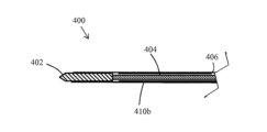
図1aおよび1bに、一実施形態に係るアブレーションプローブ100を概略的に示す。本開示のアブレーションプローブ100は、悪性組織成長のような、所望の治療部位に到達するために、体内に挿入されるのに適し得る。所望の治療部位に到達するため、アブレーションプローブは体内部位送達デバイスのワーキングチャネルを通じた挿入に適してもよい。体内部位送達デバイスとは、患者の体内の部位に送り込める任意のデバイスを意味する。このデバイスは、器具を体内の所望位置に挿入するためのワーキングチャネルを有する。体内部位送達デバイスは、患者の体内腔(例えば、気管と、肺または食道の気管支経路)に沿って送達されるように構成された腔内送達デバイスであってもよい。例えば、アブレーションプローブ100は体内の様々な病変部位に到達するために、内視鏡として利用されてもよい。したがって、アブレーションプローブは全体的に弾性を有してもよい。これにより内視鏡のワーキングチャネルを通じて挿入可能になる。別の実施形態では、アブレーションプローブは、特定の種類の内視鏡(例えば気管支鏡)または肺ナビゲーションシステム等のその他種類の腔内送達デバイスと使用してもよい。アブレーションプローブ100は経皮的に利用されてもよい。あるいは、その他適切な技術を利用してもよい。例えば、体孔を通じて挿入されてもよい。経皮的使用の場合、アブレーションプローブは挿入可能となるよう、全体的に剛性があってもよい。
1a and 1b schematically illustrate an
アブレーションプローブ100は、放射線を当てて周辺組織を加熱するように構成されたアプリケータ102を有する。放射線を当てることで、アプリケータ102の周囲または近傍の悪性細胞を加熱、破壊するように局所加熱を生じてもよい。アプリケータ102は、所望の加熱が生じるように、周辺組織に任意の適切な形態の放射線を当てるように構成されてもよい。アプリケータ102は、例えばマイクロ波または高周波、或いはその他適切な放射線を照射することで加熱を生じるように構成されてもよい。アプリケータ102は、処置する組織に対して所望の位置に配置可能となるように、アブレーションプローブ100の先端またはその近傍に配置されてもよい。以下の説明では、「先端」、「基端」とは、使用時のアブレーションプローブの配置に関して、アブレーションプローブを操作するユーザ側と、治療部位側とに対応する。即ち、アブレーションプローブ100の先端は治療部位に最も近く、基端はユーザに最も近い。ハンドルのような制御手段(不図示)が、アブレーションプローブ100の基端に設けられてもよい。これにより、ユーザはアブレーションプローブ100を操作、配置できる。
アブレーションプローブ100はさらに、電磁エネルギーをアプリケータ102に供給するように構成された給電ケーブル104を有する。給電ケーブルは、アプリケータへの電磁エネルギー供給に適した任意の細長部材であってもよい(例えば導体)。給電ケーブル104は、アプリケータ102にエネルギー供給するため、アブレーションプローブ100の長さ方向の少なくとも一部に沿って延在してもよい。記載の実施形態では、給電ケーブル104の先端はアプリケータ102の基端に結合され、給電ケーブル104の基端は、アプリケータ102へのエネルギー供給用に、所望の信号を生成するのに適した生成手段(不図示)に結合される。
アブレーションプローブ100はさらに、第1冷媒路を有する。記載の実施形態では、第1冷媒路は冷媒送り路106であって、アプリケータ102に向かって冷媒が流れることを可能にする。例えば、冷媒送り路106は、アブレーションプローブ100の基端における冷媒送り路106に結合された冷媒供給手段(不図示)からの冷媒流をアブレーションプローブ100の先端に送り得る。冷媒流は、使用時のアブレーションプローブ100の温度制御に寄与し得る。これにより、アブレーションプローブ100が過熱損傷する、あるいは健常組織を破損することなく、長期間にわたって周辺組織にエネルギーを送ることが可能となる。冷媒送り路は、後述のように1つ以上の冷媒経路により形成されてもよい。冷媒は流体であってもよく、水、生理食塩水、極低温ガスまたは当該技術で公知のその他適切な冷媒であってもよい。
アブレーションプローブ100はさらに、第2冷媒路を有する。記載の実施形態では、第2冷媒路は、冷媒がアプリケータから戻ることを可能にする冷媒戻り路108である。即ち、冷媒戻り路108は、供給された冷媒をアブレーションプローブ100の先端から基端に戻し得る。アブレーションプローブ100はさらに、変形可能部材110を有する。変形可能部材110は、アブレーションプローブ100が挿入しやすい挿入形態(図1a参照)と、展開形態(図1b参照)との間で遷移するように構成される。変形可能部材110が展開形態となると、冷媒戻り路108が設けられる。いくつかの実施形態では、変形可能部材が挿入形態となると、冷媒戻り路は一切設けられない。これにより、アブレーションプローブの形状を最小化でき得る。別の実施形態では、変形可能部材が挿入形態となると、戻り路が一切存在しなくてもよい。したがって、挿入形態によると、アブレーションプローブ100を体内の所望位置に送るのに適し得る構成が実現される。挿入形態は例えば、不慮の組織損傷のリスクを抑えた挿入を可能にするような、適切なサイズおよび/または形状に対応してもよい。挿入形態において、アブレーションプローブは例えば、損傷を生じずに組織内に挿入しやすいように、または内視鏡のワーキングチャネルを通じて挿入しやすいように、細形状(例えば、小断面サイズ)となってもよい。
別の実施形態では、第1冷媒路は冷媒戻り路として作用する。この実施形態では、第1冷媒路は、アプリケータから冷媒流を運ぶように構成される。この実施形態では、第2冷媒路は、冷媒流をアプリケータに運ぶように構成された冷媒送り路としても構成され得る。したがって、第1および第2冷媒路の組合せにより、アプリケータから、そしてアプリケータに向かって冷媒流を送り込むことができるように構成され、冷媒がこの両方向に流れることができる冷媒循環路が形成される。図示の実施形態では、冷媒送り路として作用する第1冷媒路は、給電ケーブルの近傍に、より低温の冷媒を送り込むことが可能であり得る。これはアブレーションプローブの冷却に寄与し得る。給電ケーブルでは大量の熱が発生し得るためである。別の実施形態では、アプリケータの冷却を優先するため、第2冷媒路が冷媒送り路として作用してアプリケータに、より低温の冷媒を送り込んでもよい。 In another embodiment, the first coolant path acts as a coolant return path. In this embodiment, the first coolant path is configured to carry coolant flow from the applicator. In this embodiment, the second coolant channel may also be configured as a coolant channel configured to carry coolant flow to the applicator. Thus, the combination of the first and second coolant paths form a coolant circuit configured to direct coolant flow from and towards the applicator, allowing coolant to flow in both directions. be. In the illustrated embodiment, the first coolant path, acting as coolant channel, may be able to deliver cooler coolant in the vicinity of the power supply cable. This may contribute to cooling the ablation probe. This is because power cables can generate a large amount of heat. In another embodiment, to prioritize cooling of the applicator, the second coolant path may act as a coolant channel to deliver cooler coolant to the applicator.
したがってアブレーションプローブ100は、変形可能部材110が挿入形態にある状態で、所望の位置に到達し得る。所望の位置に到達すると、変形可能部材110を展開形態にして、アプリケータ102から冷媒が流れることを可能にしてもよい。したがって、冷媒が、使用中のアブレーションプローブ100を冷却するよう、冷媒送り路および冷媒戻り路を通じて流れることができるようになる。このため、変形可能部材110は、冷媒流が不要な場合に、アブレーション部位への送達に適した挿入形態を実現できる。アブレーションプローブが所望位置に到達すると、変形可能部材110を、アプリケータ102からのエネルギー送達中に必要な冷媒流を実現するのに適した構成にしてもよい。変形可能部材が挿入形態となると、アブレーションプローブ全体の直径は、約13から約25ゲージ(約2.5から0.5mm)の間であってもよい。これにより、挿入が容易になり得る。
図1aおよび1bに示すように、冷媒戻り路110は、アブレーションプローブ100の長さの少なくとも一部に沿って延在する変形可能部材のみによって提供できる。例えば、アブレーションプローブ100の長さ方向に沿った少なくとも一部では、変形可能部材110により形成された冷媒戻り路108以外には、戻り冷媒を運ぶ経路または導管が一切存在しなくてもよい。これにより、変形可能部材が挿入形態にある場合に、アブレーションプローブ100を小断面サイズにでき得る。任意の冷媒戻り路を追加する場合、アブレーションプローブ100の本体に追加の空間が必要となり、細形状とならなくなってしまう。
As shown in FIGS. 1a and 1b,
図1aおよび1bの実施形態では、変形可能部材110は、冷媒送り路106の先端に流体接続される(例えば、冷媒送り路の先端が、流体戻り路の先端に接続されて、アプリケータから、そしてアプリケータへの(両方向に)流れることができる、単一の経路が形成されてもよい)。したがって、変形可能部材110が展開形態となると、冷媒送り路106は、冷媒戻り路108内に延在する。この構成により、変形可能部材110が挿入形態となると、アブレーションプローブ100を全体的に小型化できる。
In the embodiment of FIGS. 1a and 1b, the
図2から8aに、本開示に係るアブレーションプローブ200の実施形態の例をより詳細に示す。図示の実施形態は、単に一例である。
An example embodiment of an
図2に示すように、この実施形態では、アブレーションプローブ200は、主に2つの部位、具体的には針部212およびカテーテル部214を備える。針部212はアブレーションプローブ200の先端に配置されてよく、所望のアブレーション位置に到達するように、使用時に組織内に挿入されるように構成される。カテーテル部214は、アブレーションプローブ200の基端に設けられ、針部212との間で電磁エネルギーまたは冷媒流を送り合うように配置される。図示の実施形態では、アブレーションプローブ200はハンドル部216をさらに備える。ハンドル部216を介して、使用時にアブレーションプローブを操作および位置決めできる。図2に示すように、カテーテル部は、内視鏡として利用できるように、長く弾性を有してもよい。請求項に記載のない別の実施形態では、経皮的利用できるように、短くて硬いカテーテル部が設けられてもよい。
As shown in FIG. 2, in this embodiment,
いくつかの実施形態では、針部はアブレーションプローブの全体長さ方向に対して小部位であってもよい。例えば、針部は、長さ5mmから2000mm、好ましくは長さ約70mmであってもよい。針部の長さは、対象の生体組織に応じて選択され得る。例えば、針部は、膵臓、肺等の内臓に到達する場合、長さ10から100mmであってもよい。あるいは、経皮的処置用の送達の場合より長くてもよい(例えば、長さ100から400mm)。針部が長いほど、例えば肺の部位送達に適し得る。カテーテル部は、長さ約1000mmから2000mmであってもよく、好ましくは長さ約1400mmである。カテーテル部の長さは、到達する必要のあるアブレーション部位の位置に応じて選択されてもよい。別の実施形態では、アブレーションプローブ(例えば、変形可能部材を有するもの)の針部は、アブレーションプローブの長さ方向においてより大きな割合であってもよい。いくつかの実施形態では、針部はアブレーションプローブの長さ全体で形成されてもよい。そのような実施形態では、変形可能部材はアブレーションプローブ全体の長さの大部分または全体を通じて延在してもよい。そのような実施形態では、カテーテル部は不要であってもよい。例えば、アブレーションプローブが経皮的に利用される場合、カテーテル部は、内視鏡的利用の場合よりも短くてもよいし、あるいは存在しなくてもよい。 In some embodiments, the needle may be a small segment relative to the overall length of the ablation probe. For example, the needle may be 5 mm to 2000 mm long, preferably about 70 mm long. The length of the needle can be selected according to the target living tissue. For example, the needle may be 10 to 100 mm long when reaching internal organs such as the pancreas, lungs, and the like. Alternatively, it may be longer (eg, 100 to 400 mm in length) for transdermal therapeutic delivery. Longer needles may be suitable for, for example, pulmonary site delivery. The catheter section may be about 1000mm to 2000mm long, preferably about 1400mm long. The length of the catheter section may be selected depending on the location of the ablation site that needs to be reached. In another embodiment, the needle portion of an ablation probe (eg, one with a deformable member) may be a greater proportion of the length of the ablation probe. In some embodiments, the needle may be formed the entire length of the ablation probe. In such embodiments, the deformable member may extend through most or all of the length of the entire ablation probe. In such embodiments, a catheter portion may not be required. For example, if the ablation probe is used percutaneously, the catheter section may be shorter than for endoscopic use or may be absent.
図3は、針部の展開図である。針部212は、変形可能部材210と、アプリケータ202と、給電ケーブル204aの先端部と、冷媒送り路の先端部とを含んでもよい。図4はカテーテル部の展開図を示す。この実施形態では、カテーテル部214は、給電ケーブル204bの基部と、冷媒送り路の基部と、冷媒戻り導管(変形不能であってもよい)とを含む。冷媒送り路の基部は、給電ケーブル204bの基部を収容するチューブ218と、周囲の冷媒送達導管220との間の空間により形成されてもよい。冷媒戻り路は、冷媒送達導管220と、周辺冷媒戻りチューブ222との間の空間により形成されてもよい。別の実施形態では、カテーテル部214内で、冷媒戻り路および冷媒送り路から、その他適切な経路または導管の構成が設けられてもよい。
FIG. 3 is an exploded view of the needle. The
針部の最大断面サイズは、カテーテル部の最大断面サイズよりも小さくてもよい。言い換えると、針部の最大部における断面サイズ(例えば直径)は、カテーテル部の最大部における断面サイズ(例えば直径)よりも小さくてもよい。これにより、針部は組織損傷を生じ得るあらゆるリスクを抑えながら、アブレーション部位に到達でき得る。一方、カテーテル部は、使用時に、共に使用されるデバイスのワーキングチャネル内に嵌るようなサイズであってもよい。 The maximum cross-sectional size of the needle portion may be smaller than the maximum cross-sectional size of the catheter portion. In other words, the cross-sectional size (eg, diameter) at the largest portion of the needle portion may be smaller than the cross-sectional size (eg, diameter) at the largest portion of the catheter portion. This allows the needle to reach the ablation site with reduced risk of any possible tissue damage. On the other hand, the catheter portion may be sized such that, in use, it fits within the working channel of the device with which it is used.
図5aから5cは、冷媒戻り路および冷媒送り路を形成する適切な経路構成の例を示す断面図である。図5aでは、カテーテル部は、それぞれ冷媒戻り路および冷媒送り路の一方を形成する2つの空洞を含む。図5bでは、カテーテル部は、冷媒戻り路および冷媒送り路を形成する4つの空洞を含む。内2つの空洞が、冷媒戻り路を形成してもよく、内2つの空洞が冷媒送り路を形成してもよい。この実施形態では、ねじれ抵抗と強度が向上し得る。空洞は、図5aおよび5bに示すような同じ大きさに設計されなくてもよい。図5cはその例を示す。当図では、空洞は3つ存在する。第1および第2空洞により冷媒戻り路および冷媒送り路が形成され、第3空洞は、センサ等のその他要素を含むように設けられてもよい。第3空洞は、第1および第2空洞よりも小さく、冷媒流用に適切な空間を提供するようにしてもよい。 Figures 5a to 5c are cross-sectional views showing examples of suitable path configurations for forming coolant return and coolant feed paths. In Figure 5a, the catheter section includes two cavities forming one of the coolant return and coolant feed paths, respectively. In FIG. 5b, the catheter section includes four cavities forming coolant return and coolant feed paths. Two of the cavities may form a coolant return path and two of the cavities may form a coolant feed path. This embodiment may provide improved kink resistance and strength. The cavities do not have to be designed to the same size as shown in Figures 5a and 5b. FIG. 5c shows an example. In this figure, there are three cavities. The first and second cavities form a coolant return path and a coolant feed path, and the third cavity may be provided to contain other elements such as sensors. The third cavity may be smaller than the first and second cavities to provide adequate space for coolant flow.
別の実施形態では、カテーテル部内で冷媒戻り路および冷媒送り路を形成する経路は、給電ケーブルの基部の外側導体内の1つ以上の経路により形成されてもよい。これにより、弾性が向上し、コンパクトな構成が実現され得る。 In another embodiment, the pathways forming the coolant return and coolant delivery channels within the catheter section may be formed by one or more pathways within the outer conductor of the base of the feed cable. This allows for improved resilience and a compact construction.
記載の実施形態では、給電ケーブルは、針部212とカテーテル部214との間の境界で繋がった、ケーブルの長さ方向に沿った2つの部分(先端204aおよび基部204b)により形成される(図6の拡大図により詳細に示す)。給電ケーブルは、同軸ケーブルの長さ方向に沿った2つ部位から形成されて、アプリケータ202に電磁エネルギーを送る電気循環路を形成してもよい。別の実施形態では、厚さの異なる複数の領域を含む単一の給電ケーブルを利用して、基端部および先端部を形成してもよい。別の実施形態では、適切な電磁エネルギーをアプリケータ202に供給するため、その他任意の導体を設けてもよい。アブレーションプローブ200はさらに、給電ケーブル204bの基部に給電ケーブル204aの先端部を機械的および電気的に結合するために構成されたコネクタ224を有してもよい。コネクタ224は、有効なインピーダンスマッチを維持し、電気損失を最小限に抑え、アブレーションプローブ200のコンパクトな構成を保証しつつ、給電ケーブル204a、204bの異なる部位同士を接続しもよい。給電ケーブルの異なる部位を接続するために使用されるコネクタの例を図21により詳細に示し、後述する。
In the described embodiment, the feed cable is formed by two sections (
記載の実施形態では、給電ケーブル204aの先端部は対応する先端断面サイズであり、給電ケーブル204bの基端は対応する基端断面サイズである。したがって、導体の大きさ(例えば直径)は、アブレーションプローブ200内のその位置に基づいて最適化される。断面サイズは、給電ケーブルの電力操作を最適化(例えば最大化)し、さらに電気損失を抑えてアブレーションプローブ200の機械的強度を最適化するように選択されてもよい。即ち、給電ケーブルの小断面部は、針部212外のアブレーション200の一部に対する、より断面積が大きい給電ケーブル(例えば、より効率的なケーブル)に接続することで、長さを短くできる。アブレーションプローブ200のこの部分は、組織内に挿入する必要がないので、細さは重要ではない。したがって、カテーテル部212における給電ケーブルの断面を、小断面であることが要されない箇所で大きくし、電力損失が抑えられる。
In the described embodiment, the distal end of
したがって、アブレーションプローブの針部は、カテーテル部よりも全体的に断面サイズが小さくなる。即ち、針部が組織への挿入のために最適化され、カテーテル部は、挿入されるデバイスワーキングチャネルの長い距離にわたって電力を送るように最適化される。使用時に針部は、アブレーションプローブが挿入されるワーキングチャネルからはみ出してもよい。そのため、組織を傷つけないように、針部が比較的小さな断面サイズを有することが重要となる。カテーテル部に対しては、比較的大きな断面サイズを使用してもよい。針部と異なり、カテーテル部はワーキングチャネルの長さ方向にわたって電力を送るように最適化される。一例において、変形可能部材が挿入形態にあるとき、針部は、最大部で全体直径が1mmであってもよい。カテーテル部は、最大部で全体直径が3mmであってもよい。 Therefore, the needle portion of the ablation probe has an overall smaller cross-sectional size than the catheter portion. That is, the needle portion is optimized for insertion into tissue and the catheter portion is optimized to deliver power over long distances of the device working channel into which it is inserted. In use, the needle may protrude from the working channel into which the ablation probe is inserted. Therefore, it is important that the needle has a relatively small cross-sectional size so as not to damage tissue. A relatively large cross-sectional size may be used for the catheter portion. Unlike the needle portion, the catheter portion is optimized to deliver power along the length of the working channel. In one example, the needle may have an overall diameter of 1 mm at its widest point when the deformable member is in the inserted configuration. The catheter section may have an overall diameter of 3 mm at its widest point.
別の実施形態では、給電ケーブルの先端部と基端部で、断面サイズが同じであってもよい。この場合でも、変形可能部材を使用することで、カテーテル部よりも針部の全体サイズを小さくできる。 In another embodiment, the cross-sectional size may be the same at the distal and proximal ends of the feed cable. Again, the use of deformable members allows the overall size of the needle portion to be smaller than the catheter portion.
針部212はさらに、給電ケーブル204aの先端部を収容するチューブ226(例えばハイポチューブ)を有してもよい。チューブ226は、針部212が組織内に挿入できるように十分な強度を誇る金属材料で形成されてもよい。別の実施形態では、チューブ226は、その他任意の材料で形成されてもよく、例えばニチノール等の超弾性材料で形成されてもよい。
別の実施形態では、チューブ226は弾性材料(必ずしも超弾性材料ではない)により形成されてもよい。チューブを弾性(または超弾性)材料により形成することで、蛇行したワーキングチャネルの経路を通じて送られた場合でも永久変形しなくなり得る。したがって、アブレーションプローブは、ワーキングチャネルから出た後、ワーキングチャネルの形状によって材料変形が起きてしまい湾曲して延在するのではなく、真直ぐ進み得る。これにより、アブレーションプローブの先端を所望の位置により誘導しやすく成り得る。
In another embodiment,
この例を、図6bおよび6cに示す。図6bは、挿入されたワーキングチャネル201の端から延在する弾性材料から形成されるチューブを有するアブレーションプローブ200の例を示す。アブレーションプローブの、ワーキングチャネルから延在する部分は、直線状に延びるように示されている。図6cは、非弾性チューブを有するアブレーションプローブの例を示す。この図では、そのようなアブレーションプローブの、ワーキングチャネル201から延びる部位が、湾曲して延在しやすいことを示す。
An example of this is shown in Figures 6b and 6c. FIG. 6b shows an example of an
いくつかの実施形態では、チューブは弾性(または超弾性)導電材料から形成されてもよい。これにより、後述のようにチューブはチョークの一部を形成する。チューブは、所要の弾性を実現可能とするように、適宜固形材またはメッシュ材(例えば、編組またはコイル強化ポリマーチューブ)により形成されてもよい。 In some embodiments, the tube may be formed from an elastic (or superelastic) conductive material. The tube thereby forms part of the choke, as described below. The tube may be formed from any suitable solid or mesh material (eg, braided or coil reinforced polymer tubing) so as to allow the desired elasticity to be achieved.
一実施形態では、給電ケーブルとチューブ226の内壁との間に形成された経路により、冷媒送り経路が設けられる。例えば、給電ケーブルとチューブ226の内壁との間の間隙により、冷媒が流れる空間を実現してもよい。別の実施形態では、チューブ226の内壁にスロットを切り込んで、冷媒が流れる空間を実現してもよい。給電ケーブルの送電能を最大化し、適切な冷却流を保証するように、間隙の量を指定してもよい。
In one embodiment, a path formed between the feed cable and the inner wall of
図示の実施形態では、冷媒送り路は、チューブ226の本体に形成された1つ以上の冷媒経路を含む。したがって、冷媒は給電ケーブルを部分的に囲んで、冷却に寄与してもよい。経路の幅および数は、アブレーションプローブ100の機械的強度と、冷却能を最適化(例えば最大化)するように選択されてもよい。
In the illustrated embodiment, the coolant feed path includes one or more coolant passages formed in the body of
チューブ226の壁に、1つ以上の経路を切り込んで、給電ケーブル204aの先端部に隣接して冷却流体が流れることを可能としてもよい。記載の実施形態では、1つ以上の経路が、チューブ226の外面に形成された1つ以上のスロットにより形成されてもよい。この実施形態では、アブレーションプローブ200は、チューブ226の周りに配置された膜228をさらに有してもよい。膜228は、冷媒送り路を冷媒戻り路から分離するように配置されてもよい(例えば、それらの間の境界となる)。いくつかの実施形態では、1つ以上の経路から、変形可能部材210に冷媒が流れることができるように、膜228の先端から遠位方向に延在してもよい。別の実施形態では、膜228に1つ以上の開口を設けて、1つ以上の経路を変形可能部材210と流体接続してもよい。膜228は、冷却流体用の密閉導管が形成されるように、チューブ226に被せた薄層材(例えば、ポリマー熱収縮材)により形成されてもよい。別の実施形態では、チューブ226の壁内に経路を設けてもよく、この場合、膜228は不要となり得る。
One or more passages may be cut into the wall of
別の実施形態では(不図示)、給電ケーブル204aの先端部は、アプリケータ202に信号を送信するように構成された内側導体と、内側導体を遮蔽するように構成された外側導体とを有してもよい(例えば同軸ケーブルであってもよい)。冷媒送り路は、外側導体内に形成された1つ以上の冷媒経路を有してもよい。例えば、冷媒経路は、外側導体の外面の1つ以上のスロットにより形成されてもよい。したがって、冷媒と、別個の外側導体とにより、電気絶縁材を遮蔽するように構成された、媒体混在外側導体を形成する。膜は、外側導体周囲に形成されて、冷却流体用の導管を形成してもよい。いくつかの実施形態では、給電ケーブルは、外側導体が針部の堅固な本体を形成するように頑丈な素材(例えばステンレス鋼)で形成された、同軸ケーブルにより形成されてもよい。この実施形態では、冷媒送り路は、チューブ228ではなく外側導体内の経路により形成されてもよい。したがって、そのような実施形態では、チューブは不要となり、省スペースとなる。別の実施形態では、チューブも設けてもよい。冷却経路は、アプリケータ202に冷媒を届けるとともに、効率的に給電ケーブルを冷却してもよい。いくつかの実施形態では、外側導体内に形成された1つ以上の経路は、給電ケーブルの中心軸に対して揃えられてもよい。経路の幅と数は、電気損失を最低限に抑え、給電ケーブルの、外側導体内に経路を有する部位と、給電ケーブルの、外側導体内に経路を有さない部位(例えば、カテーテル部)との間のインピーダンスマッチングを保証しながら、給電ケーブルの機械的強度と、冷却能を最適化するように選択されてもよい。
In another embodiment (not shown), the distal end of
図7のチューブ226の拡大図に示すように、冷媒送り路を形成する上述の1つ以上の冷媒経路は、アブレーションプローブの長さ方向に沿って配置されてもよい。いくつかの実施形態では、給電ケーブルを収容するチューブ226または外側導体の外周に沿って等間隔に複数の経路が設けられてもよい。図7では、同経路の内に1つのみが示されている(参照符号230)。いくつかの実施形態では、複数の経路は、給電ケーブルを収容するチューブ226または外側導体の外周に沿って等間隔に設けられた4つの経路を含んでもよい。別の実施形態では、アブレーションプローブの冷却要件および機械的強度要件に応じて、経路の数または配置を変えてもよい。
As shown in the enlarged view of
図8aの詳細図に示すように、給電ケーブル204aの先端部の内側導体は、アプリケータ202に接続される。この実施形態では、給電ケーブル204aの先端部の内側導体は、アプリケータ202の基端に接続される。給電ケーブルが内側および外側導体で形成される場合、内側導体はアプリケータ202に接続されて、アプリケータ材料への電磁エネルギーの効率的伝達を保証してもよい。アプリケータ202は、印加するエネルギーに応じて、十分な誘電特性を有するセラミック材料(例えばジルコニア)から形成されてもよい。アプリケータ202には、内側導体の一部を挿入する内部孔をアプリケータ202に設けてもよい。これにより、接着で位置決めされ得る、強固な機械的結合部が保証される。給電ケーブルを収容するチューブ226が設けられる場合、アプリケータ202をチューブ226に結合してもよい。そのような実施形態では、アプリケータ202の基端は、チューブを挿入する孔、または連動指を介して、チューブ226に接続されてもよい。これにより、その間の結合の機械的強度を最大化できる。別の実施形態では、チューブ226とアプリケータ202との間または給電ケーブル204aの先端部とアプリケータ202との間のその他任意の適切な接続手段を設けてもよい。
The inner conductor at the distal end of
一実施形態では、チューブ226とアプリケータ202との間の結合のために、繋ぎ部材を設けてもよい。図8bに示す例では、繋ぎ部材はチューブ226およびアプリケータ202の一部を囲繞し、これらの間を繋ぐ繋ぎチューブ226bを含む。繋ぎチューブ226bと、チューブ226およびアプリケータ202のそれぞれとの間は、それらを互いに固定するように、締まり嵌めされてもよい。これは、チューブ226とアプリケータ202との間の接合の機械的強度の向上に寄与し得る。これは、患者の体内部位を通じた、蛇行経路を有するワーキングチャネルを介してアブレーションプローブが送られる場合に有利である。繋ぎチューブ226aは、ポリイミド(PI)材料等の耐熱材料により形成されてもよい。これにより、繋ぎチューブ226aの、アプリケータ202から発生した熱に対する耐性の向上に寄与し得る。別の実施形態では、その他任意の適切な材料が使用されてもよい。繋ぎチューブ226aは薄壁チューブであってもよい。これにより、針部の全体断面サイズが最小限に抑えられる。例えば、繋ぎチューブ226aの壁の厚さは、例えば、0.01から0.15mmの範囲内であってもよい。いくつかの実施形態では、繋ぎチューブは、熱可塑性材料またはポリアミドのような耐熱材料から構成されてもよい。
In one embodiment, a tether may be provided for coupling between
いくつかの実施形態では、アプリケータ202はさらに、冷媒送り路に流体接続された1つ以上の冷媒経路232を含んでもよい。この実施形態では、図9のアプリケータ202の拡大図に示すように、経路をアプリケータ202内に設けてもよい。経路232は、冷却流体を、アプリケータ表面を超えて、アプリケータ202の先端(例えば、アプリケータ202の長さ方向に沿った全体または一部)に向かって流れることを可能とし得る。薄層材(例えばポリマー熱収縮材)は、アプリケータ上に設けられて、経路230を密閉し、冷却流体用の導管を形成してもよい。この構成により、アンテナ面での組織の炭化およびそれに関連した熱性能の劣化のリスクが抑えられ得る。いくつかの実施形態では、アプリケータ内の1つ以上の経路232は、冷却流体を対象とするように、図9に示すように基端からアプリケータの長さの一部に沿って延在してもよい。これにより、制御されたアブレーション加熱領域を生成することが可能になる。
In some embodiments, the
図10aは、アプリケータ冷媒経路の別の例を示す。1つ以上のアプリケータ冷媒経路は、アプリケータ202の本体外面の1つ以上の凹みにより形成されてもよい。この例を図10aに示す。図では、冷媒経路232aがアプリケータ202内に示されている。この例では、冷媒経路232aは、アプリケータ202外面の外周全体に延在する冷媒経路232aにより形成される。これは、冷却を促進するように、アプリケータ202の周りに適切な冷媒流を提供することに寄与する。別の実施形態では、冷媒経路の形状および数は異なっていてもよい。図10aに示す実施形態では、アプリケータ202は、変形可能部材210により部分的に囲まれている。アプリケータ冷媒経路(複数可)232aは、冷媒戻り路に冷媒が流れることができるように(または、逆の冷媒流となる場合には、冷媒送り路から流れることができるように)、変形可能部材210に流体接続されてもよい。したがって、冷媒は、アプリケータ202の長さ方向に沿って、アプリケータ冷媒経路(複数可)232aの基端に流れ、そして変形可能部材210内へと流れる(またはその逆に流れる)。別の実施形態では、アプリケータ冷媒経路のその他構成も可能である。同経路は、例えばアプリケータの表面の窪みではなくアプリケータの本体内に設けられてもよい。
FIG. 10a shows another example of an applicator coolant path. The one or more applicator coolant paths may be formed by one or more indentations in the outer body surface of
アブレーションプローブはさらに、図10aに示すように、変形可能部材210とアプリケータ202との間に配置された絶縁部材233をさらに有する。絶縁部材233は、アプリケータ210から発する熱から、変形可能部材210を遮蔽することに寄与し得る。絶縁部材233は、アプリケータ202の本体の周りに少なくとも部分的に延在する、耐熱チューブにより形成されてもよい。絶縁部材233は、適切な耐熱性を実現するようなポリイミド等の材料により形成されてもよい。別の実施形態では、必要に応じて、その他材料を使用してもよい。絶縁部材233は、針部の全体断面サイズを低減するため、薄壁チューブにより形成されてもよい。壁の厚さは、例えば0.01から0.15mmであってもよい。チューブは、例えば熱可塑性材料またはポリアミドのような耐熱材料により構成されてもよい。
The ablation probe further comprises an insulating
アプリケータ202は、給電ケーブルの先端部204aを収容するチューブ226内に延在するように構成された挿入領域202aを有する。図10bにこの例を示す。当図は、チューブ226と、アプリケータ202の挿入領域202aの断面図である。挿入領域は、第1冷媒路を上述のアプリケータ冷媒経路に流体接続するように構成された1つ以上の経路を含んでもよい。図10bに示す実施形態では、第1冷媒路とアプリケータ冷媒経路232aおよび232bとを流体接続するように構成された2つの経路233cおよび233dが示されている。1つ以上の冷媒経路を含む挿入領域202aを設けることにより、冷媒流を促進しつつ、チューブ226とアプリケータ202との間の固定的機械的接続が実現できる。より効果的に接続するため、適宜接着剤を使用して、機械的接続を補助してもよい。図10bに記載の実施形態では、アプリケータ202の挿入領域202aの表面に切り込まれた平坦部により、経路232aおよび232bが形成される。これにより、よりコンパクトで、製造しやすい構造が実現され得る。別の実施形態では、その他適切な構成または形状の経路を実現してもよい。
The
記載の実施形態では、アブレーションプローブ202は、使用時に組織に突き刺さるように、尖った先端を有してもよい。アプリケータ202がアブレーションプローブ200の先端に配置された実施形態では、アプリケータ202の先端は尖った先端を形成してもよい(図9の参照符号234)。したがって、アプリケータ202の先端は、尖っていることで、アプリケータ202が効果的に組織に突き刺さって、アブレーション部位に送達できることが保証されてもよい。
In the described embodiment, the
アブレーションプローブは、変形可能部材をアプリケータに結合するように構成された結合部材236aをさらに有してもよい。図11aは、そのような結合部材236aの例を示す。結合部材236aは、アプリケータ202とは異なる材料から形成されてもよい。結合部材236aは、変形可能部材210が接合される、接合部位を形成するように構成されてもよい。変形可能部材210は、接着剤またはその他同様な接合化合物を使用して、結合部材210に接合されてもよい。結合部材210を、アプリケータ202とは異なる材料で形成することで、変形可能部材210への接合により適した材料を選択可能である。これにより、変形可能部材とアプリケータとを直接接続する場合よりも、接合を向上でき得る。例えば、結合部材236aは、ポリイミド材料のようなプラスチック材料により形成されてもよい。これにより、変形可能部材210との強固な接合を可能とし、使用時にアプリケータ202から生じる熱に対する適切な耐性も実現され得る。
The ablation probe may further have a
結合部材236aは、アプリケータ202との機械的結合を形成するような形状としてもよい。図11aに示す実施形態では、アプリケータ202を囲む結合チューブにより、結合部材236aが形成される。このチューブは、アプリケータ202の外面と摩擦嵌めされるように固く嵌るものである。接続部材を形成するチューブは、最小の全体断面とするように、薄壁チューブであってもよい。例えば、チューブの壁は、厚さが??から??であってもよい。別の実施形態では、別の機械的結合を実現してもよい。
Coupling
図11bは、別の結合部材236bを示す。この実施形態では、アブレーションプローブ200は、アプリケータ202の先端に結合された電気絶縁材により形成された結合部材236aをさらに有してもよい。図示の実施形態では、尖った先端を含む、別個の先端部材238が結合部材336aに結合されることで、アブレーションプローブ200の先端に尖った先端が形成される。別の実施形態では、先端部材238と結合部材236aとは、単一部材から形成されてもよい。結合部材236aは、低誘電率(例えばポリマー)材料から形成されてもよい。この実施形態では、アプリケータ202に加熱効果を限定(または部分的に限定)してもよい。これにより、変形可能部材210が結合部材236aを介してアプリケータ202に結合されるように、変形可能部材210を接合する低温部が設けられる。さらに、結合部材236aの曲げ剛性は、アブレーションプローブ200が、蛇行した解剖学的部位内(例えば肺内)に送り込みやすいように最適化された弾性を有するよう選択されてもよい。別の実施形態では、結合部材をアプリケータ202の基端に設けてもよい。これにより、変形可能部材と、アプリケータ202の基端とが結合される。
FIG. 11b shows another coupling member 236b. In this embodiment, the
図11aおよび11bに示す結合部材236aおよび236bは、変形可能部材210をアプリケータ202に接続するために設けられ得る結合部材の単なる一例である。別の実施形態では、アプリケータ202および変形可能部材210の形状に合わせて、結合部材がその他任意の適切な形状を有してもよい。さらに別の実施形態では、変形可能部材とアプリケータとの間は直接接続され、結合部材は存在しなくてもよい。
Coupling
別の実施形態では、プローブは使用時に組織に突き刺さらない、または突き刺さりにくいように、丸まった先端を有してもよい。そのような実施形態では、アプリケータ202または結合部材236bは、使用時に組織に突き刺さりにくい丸まった先端を有してもよい。これは、肺等のいくつかの治療部位に対して有効となり得る。
In another embodiment, the probe may have a rounded tip so that it does not or is less likely to pierce tissue when in use. In such embodiments, the
図3の展開図に示すように、針部はさらに変形可能部材210を有する。記載の実施形態では、変形可能部材210は膨張性部材で形成される。当該部材は、変形可能部材210が挿入形態の際に、収縮構成となり、変形可能部材210が展開形態の際に、膨張構成となる。したがって、膨張性部材は、冷媒流で膨張可能な風船を形成してもよい(例えば、膨張性部材は、冷媒の圧力により膨張してもよい)。記載の実施形態では、膨張性部材は、内径がチューブ226(またはチューブ228を囲む膜228、外側導体、または絶縁部材それぞれ)の外径に一致する。膨張部材は、冷却系が加圧されると、直径が増加してもよい。したがって、これにより、アプリケータ202から戻る冷却流体用の導管が形成され得る。膨張構成に遷移する際、膨張部材の一部または全体の形状が変化(例えば拡張)し、冷媒が流れる空間を提供するようにしてもよい。目標アブレーション部位への送達がしやすくなるように、膨張性部材が収縮すると、アブレーションプローブ200の挿入厚さが低減(例えば最小化)されてもよい。アブレーション治療が届けられると、取り出しやすくなるように、元の直径に戻るように収縮してもよい。
The needle further includes a
膨張部材は、膨張した展開形態における最大閾値サイズに膨張または拡張するように構成されてもよい。これにより、アブレーションプローブ200がさらに挿入しやすくなる。いくつかの実施形態では、膨張部材は、収縮挿入形態と、膨張展開形態との間で遷移するように、膨張または収縮するように構成されたコンプライアントまたはセミコンプライアント材料から形成されてもよい。膨張部材は、適切な分量拡張し、元の形状または直径に弾性復元されるのに必要な性質の材料および形状を有してもよい。いくつかの実施形態では、治療到達後、冷媒戻り路に真空を適用してもよい。これにより、膨張部材が潰れやすくなり、アブレーションプローブ200が取り出しやすくなる。真空は、膨張性部材の弾性機能に加えて、または替えて利用されてもよい。膨張部材は、アブレーションプローブ200が最小の全体形状を有するように、薄壁材料から形成されてもよい。いくつかの実施形態では、膨張部材は挿入しやすいように、低摩擦性であってもよいし、潤滑材(例えば、パリレン)でコーティングされてもよい。いくつかの実施形態では、膨張部材材料(またはコーティング)はさらに、膨張部材が膨張時に、アブレーションプローブを形成するその他要素(例えば膜)から分離しやすくし得る。図12aおよび12bに、収縮構成から膨張構成に遷移するコンプライアントまたはセミコンプライアント変形可能部材110の一例を概略的に示す。
The inflation member may be configured to inflate or expand to a maximum threshold size in the inflated deployed configuration. This makes it easier to insert the
別の実施形態では、膨張部材は収縮挿入形態と膨張展開形態との間で遷移するように、畳まれ、開くように構成された非コンプライアント材料により形成されてもよい。この実施形態では、膨張部材は収縮時に丸められてもよいし、さらに/あるいは折り畳まれ、冷却流体により加圧されると広げられてもよい。例えば、膨張部材はアブレーションプローブの使用前にはコンパクトに折りたたまれて、コンパクトな挿入形態となってもよい。膨張部材の畳まれた部位は、経路(例えばチューブ226内)に収納されてもよい。これにより、挿入形態時に、アブレーションプローブ200の挿入形状が最小化される。非コンプライアント材料を使用することで、後述のように、展開により大きなサイズ、または段差付き/テーパ形状の膨張部材が実現でき得る。膨張部材は、壁厚さを最適化し、アブレーションプローブの全体形状を最小化するように構成されてもよい。例えば、膨張部材は、プリフォームをブロー成型することで製造し、所望の形状にしてもよい。プリフォームは、ブロー成型されると薄壁膨張部材が得られるような形状であってもよい。例えば、プリフォームを研削することで成形し、ブロー成型された膨張部材の壁厚さを制御してもよい。これにより、膨張部材の低伸長率部位(例えば、膨張性部材の縁(例えばスリーブ))において、壁を薄くすることができる。ここでも、アブレーション処置が完了すると、真空を利用して変形可能部材を潰してもよい。真空で再度畳まれた膨張部材は、挿入前の綺麗に畳まれた構成に戻らず、アブレーションプローブの取り出しに十分なほど潰れればよい。図13aおよび13bに、収縮構成から膨張構成に遷移する非コンプライアント膨張部材の例を概略的に示す。さらなる実施形態では、膨張部材は、コンプライアント材料、セミコンプライアント材料、非コンプライアント材料の混合物により形成されてもよい。
In another embodiment, the expansion member may be formed of a non-compliant material that is configured to collapse and unfold to transition between a collapsed insertion configuration and an expanded deployment configuration. In this embodiment, the expansion member may be rolled upon deflation and/or may be collapsed and expanded upon pressurization by the cooling fluid. For example, the expansion member may be compactly collapsed into a compact insertion configuration prior to use of the ablation probe. The collapsed portion of the inflatable member may be housed in a passageway (eg, within tube 226). This minimizes the insertion geometry of
変形可能部材110は、図示のように、針部212の長さ方向に沿って少なくとも部分的に延在してもよい。例えば、変形可能部材110は針部212およびカテーテル部214の境界から、またはその近傍で延在し、アプリケータ202の基端の端またはその近傍で終端してもよい。したがって、冷媒はアブレーションプローブの長さ方向に沿って、変形可能部材210を通じて流れてもよい(例えば、冷媒流は、変形可能部材の、アブレーションプローブの長さ方向に沿って離間した入口と出口との間に設けられてもよい)。変形可能部材210は、針部212とカテーテル部214との間の境界において、変形不能冷媒戻り導管に流体接続されてもよい。したがって、冷媒は変形可能部材110を通じて流れ(展開形態時)、その後カテーテル部内の変形不能冷媒戻り導管を流れてアブレーションプローブ200の基端に到達してもよい。
いくつかの実施形態では、変形可能部材はアプリケータ202の基端でまたはその近傍で終端してもよい。そのような実施形態では、変形可能部材の先端は、上述のようにチューブ226、アプリケータ202の基部、または別個の結合部材に結合されてもよい。別の実施形態では、図14に示すように、変形可能部材110は、少なくとも部分的にアプリケータ202を囲うように構成される。したがって、そのような実施形態では、アプリケータ202は変形可能部材210内に少なくとも部分的に配置されてもよく、延いては冷却流体に囲まれてもよい。これは、治療到達時に、周辺組織に対する炭化効果抑制に寄与し得る。この実施形態では、冷却流体は、水、或いはマイクロ波エネルギーを周辺組織に効果的に伝送するのに適した誘電性を有する同様の物質であってもよい。
In some embodiments, the deformable member may terminate at or near the proximal end of
変形可能部材210は、図14に示すように、アブレーションプローブ200の全周を囲んでもよい。これにより、展開形態においてチューブ226(および膜228および/またはアプリケータ202のそれぞれ)の周囲に冷媒導管が形成される。別の実施形態では、変形可能部材210はチューブ226(および膜228および/またはアプリケータ202のそれぞれ)の一部のみを囲んでもよい。一実施形態では、図15に示すように、変形可能部材210は1つ以上の細長変形可能経路240を有する。変形可能経路240は、アブレーションプローブ200の長さ方向に沿って少なくとも部分的に延在する。1つ以上の変形可能経路240は、図15に示すように、アブレーションプローブ200の外周に沿って等間隔で配置された複数の経路を含む。記載の実施形態では、4つの変形可能経路が等間隔に設けられてもよい。変形可能経路240は、冷媒送り路を形成する経路230間に設けられてもよい。別の実施形態では、経路の構成、数または形状は異なっていてもよい。
The
いくつかの実施形態では、変形可能経路240は、膨張部材の、膨張構成に遷移しても形状変化しない1つまたは複数の部位に連結されてもよい。これらの非膨張部位は、冷媒送り路の境界を設けるように、チューブ226内の経路230を覆うように配置されてもよい。これは、膜が不要であることを意味する(例えば、膨張部材の非拡張部(複数可)に置き換えられる)。図16にこの例を示す。この実施形態では、アブレーションプローブ(図16では展開または膨張状態で示す)の外周に4つの変形可能経路240が設けられる。変形可能経路240は、チューブ226内の4つの経路230により非連続的に設けられる。この実施形態では、経路230は、変形可能経路240が間に等間隔に配置された状態で、12時、3時、6時および9時の位置に等間隔配置される。別の実施形態では、経路と変形可能経路の数と配置は異なっていてもよく、等間隔配置でなくてもよい。
In some embodiments, the
いくつかの実施形態では、展開形態において、アプリケータ202により実現されるアブレーション領域の形状、大きさ、および位置の内の任意の1つ以上を制御するように、変形可能部材210は構成されてもよい。例えば、展開形態において、変形可能部材210の形状および位置は、アブレーション領域を制御するように構成されてもよい。変形可能部材210は、その他組織の加熱を抑え、処置対象組織を効率的に加熱するような有効なアブレーション領域を実現するように構成されてもよい。いくつかの実施形態では、第2構成の変形可能部材210は、略球形のアブレーション領域を生成するように構成される。これにより、アブレーション領域全体にエネルギーの均一分布を実現し、加熱向上が図られる。別の実施形態では、変形可能部材210の適切な大きさ、形状および配置により、別の形状のアブレーション領域が生成されてもよい。
In some embodiments,
いくつかの実施形態では、展開形態において、変形可能部材210は、アブレーション領域を制御するよう、アプリケータ202の基端においてまたはその近傍において、より大きなサイズを有してもよい。これにより、アプリケータ202の基端に隣接して、大きな体積の冷却流体が存在することが保証される。したがって、加熱効果、延いてはアブレーション領域の形状を制御するヒートシンクが提供される。記載の実施形態では、変形可能部材210が展開形態において、アブレーション領域を制御するように、不均一なテーパ形状、球根状、または円錐形の内の任意の1つを形成する。図17にこの例を示す。ここで、変形可能部材210の大径部210aが、アブレーション領域を制御するように設けられる。
In some embodiments, in the deployed configuration,
さらなる実施形態では、変形可能部材210は、展開形態への遷移により、アブレーションプローブ200が屈曲し、アプリケータ202により印加されたエネルギーを配向するように構成されてもよい。この実施形態では、変形可能部材210は、エネルギーを所望の方向に送るようにアプリケータ202を配向するように構成されてもよい。変形可能部材は、変形可能部材位置および/またはその材料特性に作用することで、アブレーションプローブの湾曲を生じてもよい。したがって、変形可能部材210の膨張は、アブレーションプローブ200の湾曲または屈曲を生じて、エネルギーを配向してもよい。これは、変形可能部材をアブレーションプローブ200の一方の側に(例えば、外周の一部のみに延在するように)結合することで実現され得る。これにより、変形可能部材が膨張することで、結合される表面(またはその基端および先端の接合位置)が軸方向に引張または圧縮状態で配置されるようにする。したがって、アブレーションプローブ200の屈曲が生じる。図18aおよび18bにこの例を示す。図18aは、軸外変形可能部材を示す。軸外変形可能部材が展開すると、アブレーションプローブは図18bに示すように湾曲し得る。
In further embodiments,
展開形態において、変形可能部材210は、周辺組織にアブレーションプローブを固定するような形状を有してもよい。したがって、変形可能部材210は、アブレーションプローブの固定と共に、冷媒の戻り路を設けるように作用してもよい。これにより、さらなる固定手段が不要となる。したがって、アブレーションプローブ200の小型化に繋がり得る。アブレーションプローブ200を固定することで、変形可能部材210は、アブレーション処置中に、アプリケータ202の望ましくない動きに抗するように作用し得る。これにより、例えば、呼吸に伴う変位による動きが抑制され得る。さらに、より効果的に固定を行い、上述の様にアブレーション領域に悪影響を及ぼすような望ましくない加熱効果を最低限に抑えるように、変形可能部材210の展開形態における形状を最適化してもよい(例えば、球根状またはテーパ状部位を追加する)。したがって、変形可能部材210は、単一の構造で複数の異なる機能を提供し得る(戻り冷媒流、および/またはアブレーション領域制御、および/または固定)。これにより、アブレーションプローブ200の全体サイズが低減され得る。
In the deployed configuration,
別の実施形態では、別個の固定機構(不図示)を使用することで、さらなる固定を行ってもよい。固定機構は、アンテナ先端部の螺旋ワイヤ、または中空螺子を含んでもよい。この螺旋ワイヤは、隣接する組織に螺子が固定されるようにアブレーションプローブ200を回転させることで、アンテナ202を定位置に固定するように作用してもよい。固定螺旋螺子は、雄螺子または雌螺子構造であってもよく、アンテナ202の先端に対して遠位または同心状に配置されてもよい。固定に使用される材料は、確実にエネルギー形態およびアプリケータ構成に適合するように選択される。例えば、マイクロ波プローブが使用される場合、非金属材料が使用されてもよい。
In another embodiment, additional fixation may be achieved through the use of a separate fixation mechanism (not shown). The securing mechanism may include a helical wire at the tip of the antenna, or a hollow screw. This helical wire may act to lock the
いくつかの実施形態では、アブレーションプローブ200は、変形可能部材が展開形態に遷移したか否かを検出するように構成された1つ以上のセンサ(図16において参照符号241)を有してもよい。センサ(複数可)は、変形可能部材210の構成を判定するため、アプリケータ202または印加されるエネルギーの1つ以上の性質を検知するように構成される。
In some embodiments,
いくつかの実施形態では、変形可能部材210が適切に膨らんだことは、アプリケータからの反力を監視することで判定され得る。この反力は、変形可能部材210が膨らんだ場合にのみ最小となる。これを、治療送達中の医師に対してフィードバックしてもよい。変形可能部材210の挙動はさらに、冷却流体の圧力を監視することでも判定され得る。例えば、冷却流体が加圧されると、変形可能部材210が膨張し、そして真空が加えられると収縮することが推測される。あるいは、冷媒の体積を利用して、変形可能部材の状態を判定してもよい。送られる冷却流体の体積を使用して、変形可能部材が適切に膨張したかを判定するのである。
In some embodiments, proper inflation of the
さらなる実施形態では、アブレーションプローブ200は、組織性質を監視して、デバイスの適切な配置を保証またはアブレーションの進み具合を確認するため、センサまたはセンサ群を有してもよい。例えば、センサ(複数可)は、温度センサ(複数可)(例えば熱電対)または電気インピーダンスセンサ(複数可)を含んでもよい。
In further embodiments,
センサ(複数可)は、アブレーションプローブ200における任意の適切な箇所に設けられてもよい。例えば、センサ(複数可)は変形可能部材210内に設けられてもよい(例えば、図16に示す変形可能経路の1つの内)。変形可能部材210の形状は、センサを配置しやすくし、組織特性およびアブレーション処置についての適切なフィードバックを提供するように最適化されてもよい。例えば、センサ(複数可)は、変形可能部材210の壁内、または変形可能部材210により形成された冷媒戻り路内に配置されてもよい。別の実施形態では、センサ(複数可)は、冷媒戻り路内またはアプリケータ202内に設けられてもよい。
Sensor(s) may be provided at any suitable location on
いくつかの実施形態では、アブレーションプローブ200はさらに別個のチョーク要素を備えてもよい。チョーク要素は、アブレーション領域の形状を制御するように、アプリケータ202の先端に配置されてもよい。いくつかの実施形態では、チョーク要素は、アブレーションプローブの全体的な弾性が損なわれないように、少なくとも部分的に弾性材料により形成されてもよい。例えば、チョーク要素は、セラミックおよび金属材料の混合物で形成されてもよい。いくつかの実施形態では、チョーク要素は、冷媒送り路を介して流れる冷媒により冷却されるように配置されてもよい。これにより、使用時にチョークを低温に維持できる。例えばチョーク要素は、給電ケーブルを収容するチューブと一体化されて、コンパクトな構成を実現してもよい。
In some embodiments,
図19は、チョーク要素242の概略図を示す。チョーク要素242は、マイクロ波周波数で起動される短絡バランを形成してもよい。チョーク要素242は、アプリケータ202の基端に一体化され、当該部位で給電ケーブル204aを収容するチューブ226に取り付けられてもよい。
FIG. 19 shows a schematic diagram of
チョーク要素242は、アブレーションプローブがマイクロ波アブレーションエネルギーで動作すると、起動される。チョーク要素242は、アプリケータ202の基端で、またはその近傍で、高インピーダンス条件を実現し得る。これにより、導体に沿って流れる反射力が最低限に抑えられる。いくつかの実施形態では、チョーク要素242は、アプリケータを形成する材料を、給電ケーブルを収容するチューブ226と給電ケーブルとの間に挿入することで形成されてもよい。アプリケータ材料は、外側導体に沿って、給電ケーブルを収容するチューブ226の先端から、約1/4波長の距離だけ延在してもよい(例えば、アプリケータ材料は外側導体に重なってもよい)。チューブ226内へと延在するアプリケータの一部は、1つ以上のアプリケータ冷媒経路(例えば、図9では参照符号232で示す)を有することで、その内部に冷媒を流すことが可能であってもよい(例えば、変形可能部材に流す)。
いくつかの実施形態では、アプリケータ材料の、給電ケーブル204上に延在するアプリケータ材料の一部は、アプリケータ202の基端から延在する1つ以上の指部(内2本を図19に示す)により形成されてもよい。別の実施形態では、給電ケーブル204の外側導体と、給電ケーブルを収容するチューブ226との間で、チューブの先端から約1/4波長の距離だけ遠位で、電気的接続が実現されてもよい。このような実施形態では、「波長」という用語は、アブレーションプローブの動作周波数に対応する電磁エネルギーの波長を意味する。いくつかの実施形態では、チョーク要素242はアブレーションプローブ200の弾性を損なわないように、小型化されてもよい。さらなる実施形態では、チョーク要素242は送り路または戻り路の冷媒で冷却され、処置中に過熱が抑制されてもよい。
In some embodiments, the portion of applicator material that extends over
図20に、チョーク要素242のさらなる例を示す。チョークは、給電ケーブルを収容する(導電性)チューブと、給電ケーブルの外側導体と、アブレーションプローブのアプリケータの基端での導電性コーティングとにより形成される。この例でも、アプリケータ材料は、給電ケーブルを収容するチューブ226内へと延在する。チューブ226内に延在するアプリケータ材料の一部は、金属コーティング243(例えば、アプリケータ上の金属ペーストまたはその他適切な金属蒸着により形成される)を含んでもよい。金属コーティングは、給電ケーブルの外側導体と、給電ケーブルを収容するチューブとの間の電気的接続を実現するように構成される。アプリケータ材料の、金属コーティング部分は、チューブ226内に延在するアプリケータ材料の基端面に設けられることで、チョークのベースを形成し得る。
A further example of
上述のように、本明細書に記載の任意の実施形態のアブレーションプローブは、給電ケーブルの先端部を、給電ケーブルの基端に機械的および電気的に接続するように構成されたコネクタを有してもよい。図21に、そのようなコネクタ300の例を示す。図21は、基部304bに接続される先端部304aの給電ケーブルを示す。先端部304aは、内側導体306aと、外側導体308aと、それらの間の誘電材料310aとを有する。基部304bは、内側導体306bと、外側導体308bと、それらの間の誘電材料310bとを有する。
As noted above, the ablation probe of any of the embodiments described herein has a connector configured to mechanically and electrically connect the distal end of the feed cable to the proximal end of the feed cable. may An example of such a
コネクタ300は、給電ケーブルの先端304aを、給電ケーブルの基部304bに機械的および電気的に接続するように構成された接合部材312を備える。接合部材312は、給電ケーブルの基部304bの端を収容する形状を有する基端312bと、給電ケーブルの先端304aの端を収容する形状を有する先端312aとを有する。これにより、給電ケーブルの部位間のコンパクトで確実な機械的および電気的接続が実現でき得る。接合部材は、給電ケーブルの部位間に短いコネクタを実現し得る。これにより、ワーキングチャネルに挿入できるように、アブレーションプローブの弾性を向上でき得る。
The
給電ケーブルの各部位の内側導体306a、306bは、コネクタ300の本体内に、はんだ付けまたはその他任意の適切な方法で結合されてもよい。
The
上述のその他実施形態で説明したように、アブレーションプローブは、給電ケーブルの先端部304aを収容するように構成されたチューブ336を備えてもよい。コネクタ300の一部は、チューブ336内に延在し、その間に機械的結合を実現するように構成されてもよい。図21に示すように、接合部材312はチューブ336内に延在して、接合部材312とチューブ336との間の機械的結合を実現するような、段差部314を有してもよい。これにより、給電ケーブルの部位間の結合が補強されてもよい。段差部314はさらに、チューブ336と、給電ケーブルの先端部304aとを離間するように作用してもよい。
As described in other embodiments above, the ablation probe may comprise a
コネクタ300は、誘電部材316をさらに有してもよい。誘電部材は、給電ケーブルの基部および/または先端の内側導体と、給電ケーブルの基部および/または先端部の各外側導体との間の領域を少なくとも部分的に埋めるように配置される。電部材316は、先端部の内側導体、基端部の内側導体、先端の外側導体および基端部の外側導体の間の領域全体埋めてもよい。記載の実施形態では、誘電部材316は先端304aの内側導体306aと外側導体308aとの間を完全に埋める。別の実施形態では、この領域の一部のみが誘電部材316により埋められる。さらなる実施形態では、(給電ケーブルの先端部および基端部の一方または両方の)内側および外側導体の間の領域は、誘電部材316ではなく空気で満たされてもよい。
コネクタ300はさらに、封止部材318を有する。封止部材は、コネクタと、給電ケーブルの先端部および基端部304a、304bの一方との間の接続領域を少なくとも部分的に囲うように構成される。図21に示すように、封止部材は、接合部材312と、給電ケーブルの基部と先端部の一方または両方を覆い、これらの間の接続を封止する封止層を含んでもよい。
図22aおよび22bに、本開示に係わるアブレーションプローブ400の別の例を示す。わかりやすいように、図1aおよび1bで使用した参照符号を、図22aおよび22bでも使用する。
Figures 22a and 22b show another example of an
上述の実施形態では、変形可能部材は、流体戻り路および流体送り路の一方のみを実現する。図22aおよび22bは、第1変形可能部材410aおよび第2変形可能部材410bを有するアブレーションプローブ400を示す。第1変形可能部材410aおよび第2変形可能部材410bのいずれも、プローブが挿入しやすくなる挿入形態と、展開形態との間で遷移するように構成される。図1aおよび1bの実施形態と同様に、展開形態において第2変形可能410b部材により冷媒戻り路408が設けられる(したがって、第2変形可能部材410bは、上述の実施形態の単一の変形可能部材110、210に対応する)。冷媒送り路406は、少なくとも部分的に第1変形可能部材410aにより実現される。これにより、変形可能部材410aおよび410bが挿入形態において、アブレーションプローブの断面サイズがさらに低減され得る。しかも展開形態においては適切な冷媒流を可能とする。
In the embodiments described above, the deformable member provides only one of the fluid return path and the fluid delivery path. Figures 22a and 22b show an
第1変形可能部材410aは、上述のその他実施形態に関連して説明された変形可能部材110、210と同様の特徴を有してもよい。第1変形可能部材410aは、給電ケーブル404の先端部を収容するチューブ426を少なくとも部分的に囲んでもよい。さらに/あるいは、アプリケータ402の少なくとも一部を囲んでもよい。
The first
図22aおよび22bに示す実施形態では、冷媒送り路は、給電ケーブル404の先端部と、それを収容するチューブ426との間に形成された導管と、チューブ426と第1変形可能部材410aとの間に形成された導管の両方により形成される。したがって、冷媒送り路に対して、変形可能導管および変形不能導管の両方が提供されて、冷媒流を促進してもよい。別の実施形態では、冷媒送り路は、第1変形可能部材と、チューブ(即ち、チューブ内に冷媒流がなくてもよい)との間に形成された導管のみで実現されてもよい。
In the embodiment shown in Figures 22a and 22b, the coolant feed path is a conduit formed between the distal end of the
図22aおよび22bは、第1変形可能部材410aにより実現された冷媒送り路と、第2変形可能部材410bにより実現された冷媒戻り路とを示す。別の実施形態では、冷媒流を逆にしてもよい。任意で、第1変形可能部材(410a)は、耐熱材料により構成されてもよい(例えば、熱硬化性材料、PTFEまたはポリアミド)。
Figures 22a and 22b show the coolant feed path realized by the first
いくつかの実施形態では、本明細書に記載の任意の実施形態のアブレーションプローブは、図23aおよび23bに示すようにシース部材504を有してもよい。この実施形態では、針部は、使用時に組織を突き刺すように構成された、尖った先端501を有する。図に示すように、尖った先端は、アプリケータ502の先端に設けられてもよいが、アブレーションプローブの先端を形成するその他に任意の構成要素に設けられてもよい。
In some embodiments, the ablation probe of any embodiment described herein may have a
シース部材504は、尖った先端を覆う第1位置(図23aに示す)と、尖った先端を露出させる第2位置(図23bに示す)との間で移動可能である。シース部材504は、尖った先端501が使用時に組織506に挿入される際に、第1位置と第2位置との間で移動してもよい。即ち、アブレーションプローブの尖った先端501は、アブレーションプローブが挿入されるワーキングチャネル508内においてはシース部材504により覆われてもよい。これにより、アブレーションプローブ挿入時に、ワーキングチャネル508挿入のリスクを抑えることができる。アブレーションプローブが組織内に移動することで、シース部材504がアブレーションプローブの長さ方向に沿って、第1位置から第2位置に、基端側に向かって移動する。
The
図24a、24b、24cは、ワーキングチャネル内への挿入用に、アブレーションプローブの先端が覆われる別の実施形態を示す。これら図は、先端634を有するアプリケータ602と、給電ケーブル604と、変形可能部材610と、給電ケーブルの先端を収容するチューブ626とを備えたアブレーションプローブ600を示す。これら構成要素は、本明細書に記載のその他実施形態のものに対応してもよい。アブレーションプローブ600は、ワーキングチャネル608に挿入される。
Figures 24a, 24b, 24c show another embodiment in which the tip of the ablation probe is covered for insertion into the working channel. These figures show an
変形可能部材610の内部要素とともに、冷媒戻り路の一部を形成するカテーテル冷媒導管も設けられる。カテーテル冷媒導管は、給電ケーブル604を囲むカテーテルチューブ622(例えば、冷媒戻りチューブ222に対応する)により形成される。カテーテル冷媒導管は、変形可能部材610に流体接続されてもよい。これにより、これら部材間で冷媒が流れることが可能となる。例えば、図24a、24b、24cに示すように、変形可能部材610がカテーテルチューブ622において基端側に接続され、アプリケータ602(または給電ケーブル604を収容するチューブ626)において先端側に接続される。これにより、冷却流体用の導管が形成される。
A catheter coolant conduit is also provided which, together with the internal elements of the
アプリケータ602と、給電ケーブルの先端を収容するチューブ622と、給電ケーブル604は、カテーテルチューブ622に対して可動であってもよい。これらは、アプリケータ602の先端634が変形可能部材610によって覆われた被覆状態(図24aに示す)と、アプリケータ602の先端634が変形可能部材610によって覆われない非被覆状態(図24bに示す)との間で遷移可能である。アプリケータ602と、給電ケーブル収容チューブ626と、給電ケーブル604(例えば、先端と基部の両方)との複合組立体は、図示のように、アブレーションプローブの長さ方向に沿って、軸上にカテーテルチューブ622に対して移動してもよい。
したがって、アプリケータ602は、先端634(組織に突き刺さるように尖ってもよい)が変形可能部材610内で被覆されるように、変形可能部材610内に配置されてもよい。これにより、ワーキングチャネル608を通じて送達しやすくする。これにより、アプリケータ602の先端が、特に蛇行したワーキングチャネル608の内壁を傷つけることリスクが低減される。必要に応じて、アプリケータ602は変形可能部材内で延在するように、被覆状態から非被覆状態に遷移してもよい。
Accordingly,
非被覆状態において、変形可能部材610(または少なくともその一部)は、図24aに示すように畳まれるか、丸められてもよい。変形可能部材610は、図24bに示す非被覆状態への遷移に合わせて、開かれてもよい。非被覆状態となると、他の実施形態で上述したように、変形可能部材610が挿入形態(図24bに示す)から展開形態(図24cに示す)に遷移してもよい。
In the uncovered state, the deformable member 610 (or at least a portion thereof) may be folded or rolled as shown in Figure 24a. The
別の実施形態では、被覆状態において、アプリケータ602の先端634は、カテーテルチューブ622に覆われてもよい。図25aおよび25bに、この例を示す。図25aは、アプリケータ602と、給電ケーブル604の先端を収容するチューブ626と、給電ケーブル604とが、カテーテルチューブ622に対して移動し、アプリケータの先端634がカテーテルチューブにより覆われた被覆状態となった状態を示す。図25bは、アプリケータ602と、給電ケーブル604の先端を収容するチューブ626と、給電ケーブル604とが、カテーテルチューブ622に対して移動し、アプリケータの先端634がカテーテルチューブにより覆われておらず組織内に挿入可能な非被覆状態を示す。
In another embodiment, in the covered state, tip 634 of
請求の範囲から逸脱することなく、当業者には様々な変形例が明らかとなろう。 Various modifications will become apparent to those skilled in the art without departing from the scope of the claims.
本発明に到達するための作業は、EUのHorizon-2020プログラム(H2020)の下、欧州研究会議から資金提供を受けた(ERC贈与契約第637780号)。 Work to arrive at the present invention was funded by the European Research Council (ERC Grant Agreement No. 637780) under the EU's Horizon-2020 program (H2020).
Claims (23)
周辺組織に放射線を当てて加熱するように構成されたアプリケータと、
前記アプリケータに電磁エネルギーを供給するように構成された給電ケーブルと、
冷媒が流れることができる第1冷媒流路と、
前記プローブが挿入しやすい挿入形態と、展開形態との間で遷移するように構成された変形可能部材と、
冷媒が流れることができる第2冷媒流路であって、前記展開形態の前記変形可能部材により実現され、前記第1冷媒流路と組み合わされることでアプリケータからの冷媒流とアプリケータへの冷媒流を送るように構成された冷媒循環路を形成し、冷媒が前記第1冷媒流路を通じて前記アプリケータに向かって流れることができるとともに前記第2冷媒流路を通じて前記アプリケータから流れることができるか、前記第1冷媒流路を通じて前記アプリケータから流れることができるとともに前記第2冷媒流路を通じて前記アプリケータに向かって流れることができるような第2冷媒流路と、
前記給電ケーブルの先端部を収容するように構成されたチューブであって、前記変形可能部材は、前記チューブの少なくとも一部を囲うように構成されたチューブとを備え、
前記アブレーションプローブは
a.使用時に組織内に挿入される針部であって、前記変形可能部材と、前記アプリケータと、前記給電ケーブルの前記先端部と、前記給電ケーブルの前記先端部を覆う前記チューブの少なくとも一部と、前記第1冷媒流路の先端部とを含む針部と、
b.前記給電ケーブルの基部と、前記第1冷媒流路の前記基部と、変形不能な冷媒導管とを含むカテーテル部とを備え、
前記変形可能部材は、前記針部と、前記カテーテル部との間の境界において、前記変形不能な冷媒導管に流体接続される、アブレーションプローブ。 an ablation probe,
an applicator configured to irradiate and heat surrounding tissue;
a power cable configured to supply electromagnetic energy to the applicator;
a first coolant channel through which coolant can flow;
a deformable member configured to transition between an inserted configuration to facilitate insertion of the probe and a deployed configuration;
A second coolant channel through which coolant can flow, realized by the deformable member in the deployed configuration, combined with the first coolant channel to provide coolant flow from and to the applicator. forming a coolant circuit configured to direct flow such that coolant can flow toward the applicator through the first coolant channel and from the applicator through the second coolant channel; or a second coolant flow path capable of flowing from the applicator through the first coolant flow path and toward the applicator through the second coolant flow path;
a tube configured to receive a distal end of the power supply cable, the deformable member comprising a tube configured to surround at least a portion of the tube;
The ablation probe comprises a. A needle to be inserted into tissue in use, the deformable member, the applicator, the tip of the power cable, and at least a portion of the tube covering the tip of the power cable. , a needle portion including a tip portion of the first coolant channel;
b. a catheter section including a base of the power supply cable, the base of the first coolant flow path, and a non-deformable coolant conduit;
The ablation probe, wherein the deformable member is fluidly connected to the non-deformable coolant conduit at an interface between the needle portion and the catheter portion.
前記チューブが導電性材料から形成される、請求項1または2に記載のアブレーションプローブ。 said tube is formed from an elastic or superelastic material, or
3. The ablation probe of claim 1 or 2, wherein the tube is formed from an electrically conductive material.
b)前記コネクタの一部は、前記給電ケーブルの前記先端部を収容する前記チューブ内に延在することで、それら要素間に機械的結合を形成するように構成される、
c)前記コネクタは誘電部材を有し、前記誘電部材は、前記給電ケーブルの前記基部および/または先端部の内側導体と、前記給電ケーブルの前記基部および/または先端部のそれぞれと対応する外側導体との間の領域を少なくとも一部埋めるように構成される、及び、
d)前記コネクタは、封止部材を有し、前記封止部材は、前記コネクタと、前記給電ケーブルの前記先端部および前記給電ケーブルの前記基部の一方または両方との間の接続領域を少なくとも一部囲む、
ことのいずれかを少なくとも1つを備える、請求項7に記載のアブレーションプローブ。 a) the connector comprises a junction member configured to mechanically and electrically couple the distal end of the feed cable to the base of the feed cable, the junction member being coupled to the base of the feed cable; and a distal end configured to receive the distal end of the feed cable.
b) a portion of the connector is configured to extend into the tube containing the tip of the feed cable to form a mechanical bond between the elements;
c) said connector has a dielectric member, said dielectric member having an inner conductor at said base and/or tip of said feed cable and an outer conductor corresponding to said base and/or tip of said feed cable, respectively; configured to at least partially fill the area between
d) said connector has a sealing member, said sealing member covering at least one area of connection between said connector and one or both of said tip of said power supply cable and said base of said power supply cable; surround,
8. The ablation probe of claim 7, comprising at least one of any of the following:
前記被覆状態においては、前記アプリケータの前記先端部が前記カテーテルチューブ内に配置され、前記非被覆状態においては、前記アプリケータの前記先端部が前記カテーテルチューブ内に配置されず、前記変形可能部材は、前記カテーテルチューブの先端部分と前記アプリケータとの両方に接続された状態にとどまる、
請求項1から8のいずれか一項に記載のアブレーションプローブ。 A coolant conduit of the catheter section is formed from a catheter tube coupled to the deformable member, and the applicator, a tube containing the distal end of the power supply cable, and the power supply cable are connected to the catheter tube. On the other hand, the deformable member is movable to transition between a covered state covering the tip of the applicator and an uncovered state in which the deformable member does not cover the tip of the applicator, optionally,
In the covered state, the distal end of the applicator is disposed within the catheter tube, and in the uncovered state, the distal end of the applicator is not disposed within the catheter tube, and the deformable member remains connected to both the tip portion of the catheter tube and the applicator;
9. The ablation probe of any one of claims 1-8.
前記繋ぎ部材は、前記チューブの一部と前記アプリケータの一部とを囲うことで、これらの間の接続を繋ぐ繋ぎチューブを有し、
好ましくは、前記繋ぎチューブと、前記チューブとアプリケータとが固く嵌合することで、それらの間に摩擦嵌合が実現される、
請求項1から11のいずれか一項に記載のアブレーションプローブ。 further comprising a tether configured to couple the applicator to the tube housing the tip of the power supply cable;
The connecting member has a connecting tube that surrounds a portion of the tube and a portion of the applicator to connect them,
Preferably, the tether tube and the tube and applicator are tightly fitted to provide a friction fit therebetween.
12. The ablation probe of any one of claims 1-11.
請求項1から12のいずれか一項に記載のアブレーションプローブ。 Said deformable member comprises one or more elongated deformable paths extending along said length of said ablation probe, optionally said one or more deformable paths comprise: comprising a plurality of paths evenly spaced around the perimeter,
13. The ablation probe of any one of claims 1-12.
任意選択で、前記変形可能部材は、
a)前記挿入形態と、前記展開形態との間で遷移するように、サイズが拡張または収縮するように構成されたコンプライアントまたはセミコンプライアント材料、または
b)前記挿入形態と、前記展開形態との間で遷移するように、畳まれる、または開くように構成された非コンプライアント材料を備える、
請求項1から13のいずれか一項に記載のアブレーションプローブ。 the deformable member is configured to expand to a maximum threshold size in the deployed configuration;
Optionally, said deformable member comprises:
a) a compliant or semi-compliant material configured to expand or contract in size to transition between the inserted configuration and the deployed configuration; or b) between the inserted configuration and the deployed configuration. comprising a non-compliant material configured to collapse or unfold to transition between
14. The ablation probe of any one of claims 1-13.
a)前記結合部材は、前記アプリケータとは異なる材料から形成され、前記結合部材は前記変形可能部材が接合される接合部位を形成するように構成される、
b)前記結合部材は、前記アプリケータとの機械的結合を実現するような形状を有し、好ましくは、前記結合部材は前記アプリケータを囲う結合チューブから形成され、前記結合チューブは、前記アプリケータの外面と固く嵌合することで、その間に摩擦嵌合が実現される、及び、
c)前記結合部材は電気絶縁材から形成される、
ことのいずれかを少なくとも1つを備える、請求項1から14のいずれか一項に記載のアブレーションプローブ。 The ablation probe further comprises a coupling member, the coupling member configured to couple the deformable member to the applicator, further comprising: a) the coupling member is formed from a different material than the applicator; and the connecting member is configured to form a bond site to which the deformable member is bonded.
b) said connecting member has a shape to provide a mechanical connection with said applicator, preferably said connecting member is formed from a connecting tube surrounding said applicator, said connecting tube a tight fit with the outer surface of the rotor to provide a friction fit therebetween; and
c) said connecting member is formed from an electrically insulating material;
15. The ablation probe of any one of claims 1-14, comprising at least one of any of the following.
b)前記第1冷媒流路は前記給電ケーブルを収容する前記チューブの本体内に形成された1つ以上の冷媒経路を含む、
c)前記給電ケーブルは、前記アプリケータに信号を送信するように構成された内側導体と、前記内側導体を遮蔽するように構成された外側導体とを有し、前記第1冷媒流路は、前記外側導体内に形成された1つ以上の冷媒経路を含む、
ことのいずれかを少なくとも1つを任意選択的に備える、請求項1から15のいずれか一項に記載のアブレーションプローブ。 a) the first coolant channel has a coolant path formed between the inner surface of the tube surrounding the power supply cable and the outer surface of the power supply cable;
b) the first coolant flow path comprises one or more coolant paths formed within the body of the tube containing the power supply cable;
c) the power cable has an inner conductor configured to transmit a signal to the applicator and an outer conductor configured to shield the inner conductor, the first coolant flow path comprising: one or more coolant paths formed within the outer conductor;
16. The ablation probe of any one of claims 1-15, optionally comprising at least one of any of the following.
前記1つ以上の冷媒経路は、前記チューブの前記外側導体の長さ方向に沿って配置され、及び/また、
前記1つ以上の冷媒経路は、前記外側導体または前記チューブの外周上に等間隔に配置された複数の経路を含み、好ましくは前記複数の経路は前記外側導体または前記チューブの外周上に等間隔に配置された4つの経路を含む、
請求項16に記載のアブレーションプローブ。 The one or more coolant paths include one or more slots provided in the outer surface of the tube or the outer surface of the outer conductor, and the ablation probe further comprises a membrane provided around the tube or the outer conductor. wherein the membrane is configured to separate the first coolant flow path from the second coolant flow path; and/or
the one or more coolant paths are arranged along the length of the outer conductor of the tube; and/or
The one or more refrigerant paths include a plurality of paths evenly spaced around the circumference of the outer conductor or the tube, preferably the plurality of paths are evenly spaced around the circumference of the outer conductor or the tube. containing four paths arranged in
17. The ablation probe of claim 16.
前記1つ以上のアプリケータ冷媒経路は、前記アプリケータの本体の外面の1つ以上の凹部により形成される、及び、
前記変形可能部材は、前記アプリケータを少なくとも部分的に囲い、前記アブレーションプローブは前記変形可能部材と、前記アプリケータとの間に設けられた絶縁部材をさらに含む、
ことのいずれかを少なくとも1つを任意選択的に備える、請求項1から17のいずれか一項に記載のアブレーションプローブ。 said applicator further comprising one or more applicator coolant paths fluidly connected to said first coolant flow path;
the one or more applicator coolant paths are formed by one or more recesses in the outer surface of the body of the applicator; and
said deformable member at least partially enclosing said applicator, said ablation probe further comprising an insulating member disposed between said deformable member and said applicator;
18. The ablation probe of any one of claims 1-17, optionally comprising at least one of any of the following.
a)前記変形可能部材内に、1つ以上の前記センサが設けられる、及び、
b)前記1つ以上のセンサは、1つ以上の温度センサおよび/または1つ以上のインピーダンスセンサを含む、
ことのいずれか、または、両者を任意選択的に備える、請求項1から19のいずれか一項に記載のアブレーションプローブ。 further comprising a sensor for sensing whether the deformable member has transitioned to the deployed configuration, optionally the sensor for determining one or more characteristics of the applicator to determine the configuration of the deformable member; configured to sense energy applied to the surrounding tissue;
a) one or more of said sensors are provided within said deformable member, and
b) said one or more sensors comprise one or more temperature sensors and/or one or more impedance sensors;
20. The ablation probe of any one of claims 1-19, optionally comprising either or both.
a)前記チョーク要素は少なくとも一部弾性材料で形成され、好ましくは、前記チョークはセラミックと金属材料の混合物で形成される、
b)前記チョーク要素は、前記第1冷媒流路を介して流れる前記冷媒により冷却される、
c)前記チョーク要素は、前記給電ケーブルを収容する前記チューブに一体化される、
d)前記チョーク要素は、前記給電ケーブルの前記外側導体と、前記給電ケーブルを収容する前記チューブとの間に延在する、前記アプリケータの一部を含み、任意選択的に前記アプリケータの前記一部は、
i)前記給電ケーブルの前記外側導体と、前記給電ケーブルを収容する前記チューブとの間を電気的に接続するように構成された金属コーティングを含む、及び/または、
ii)前記アプリケータにより印加された放射線の1/4波長に等しい距離だけ延在し、
e)前記給電ケーブルは、外側導体と内側導体とにより形成され、前記外側導体と、前記給電ケーブルを収容する前記チューブとの間に電気接続が実現され、前記電気接続は、前記アプリケータにより印加させる前記放射線の約1/4波長の距離だけ前記チューブの先端から遠位側に実現される、
ことのいずれかを少なくとも1つを任意選択的に備える、請求項1から20のいずれか一項に記載のアブレーションプローブ。 the probe further comprises a choke element at the proximal end of the applicator;
a) said choke element is at least partly made of an elastic material, preferably said choke is made of a mixture of ceramic and metal materials,
b) the choke element is cooled by the coolant flowing through the first coolant flow path;
c) the choke element is integrated into the tube containing the feed cable;
d) said choke element comprises a portion of said applicator extending between said outer conductor of said feed cable and said tube containing said feed cable; Some are
i) comprising a metallic coating configured to provide an electrical connection between the outer conductor of the feeder cable and the tube containing the feeder cable; and/or
ii) extends a distance equal to a quarter wavelength of the radiation applied by said applicator;
e) said feed cable is formed by an outer conductor and an inner conductor, and an electrical connection is realized between said outer conductor and said tube containing said feed cable, said electrical connection being applied by said applicator; is realized distally from the tip of the tube by a distance of about a quarter wavelength of the radiation to allow
21. The ablation probe of any one of claims 1-20, optionally comprising at least one of any of the following.
前記アブレーションプローブは前記プローブが挿入しやすい挿入形態と、展開形態との間で遷移するように構成された第1変形可能部材をさらに備え、前記展開形態において、前記第1冷媒流路は、前記第1変形可能部材により少なくとも部分的に実現され、
任意選択的に、
前記第1変形可能部材は、前記給電ケーブルの前記先端部を収容する前記チューブと、前記アプリケータの少なくとも一部の一方または両方を少なくとも部分的に囲み、
さらに任意で、前記第1冷媒流路は、前記給電ケーブルの前記先端部と、前記チューブとの間に形成された導管と、前記チューブと前記第1変形可能部材との間に形成された導管の一方または両方により形成される、
請求項1から21のいずれか一項に記載のアブレーションプローブ。 the deformable member is a second deformable member;
The ablation probe further comprises a first deformable member configured to transition between an insertion configuration to facilitate insertion of the probe and a deployed configuration, wherein in the deployed configuration, the first coolant flow path is configured such that the realized at least in part by a first deformable member;
optionally,
said first deformable member at least partially surrounds one or both of said tube containing said tip of said feed cable and at least a portion of said applicator;
Further optionally, the first coolant flow path comprises a conduit formed between the tip of the power supply cable and the tube, and a conduit formed between the tube and the first deformable member. formed by one or both of
22. The ablation probe of any one of claims 1-21.
Applications Claiming Priority (3)
| Application Number | Priority Date | Filing Date | Title |
|---|---|---|---|
| EP17164403.2 | 2017-03-31 | ||
| EP17164403.2A EP3381393A1 (en) | 2017-03-31 | 2017-03-31 | An ablation probe |
| PCT/EP2018/058252 WO2018178317A1 (en) | 2017-03-31 | 2018-03-29 | An ablation probe |
Publications (2)
| Publication Number | Publication Date |
|---|---|
| JP2020512156A JP2020512156A (en) | 2020-04-23 |
| JP7282381B2 true JP7282381B2 (en) | 2023-05-29 |
Family
ID=58464458
Family Applications (2)
| Application Number | Title | Priority Date | Filing Date |
|---|---|---|---|
| JP2019554411A Active JP7282381B2 (en) | 2017-03-31 | 2018-03-29 | ablation probe |
| JP2020552853A Pending JP2021519644A (en) | 2017-03-31 | 2019-03-29 | Ablation probe |
Family Applications After (1)
| Application Number | Title | Priority Date | Filing Date |
|---|---|---|---|
| JP2020552853A Pending JP2021519644A (en) | 2017-03-31 | 2019-03-29 | Ablation probe |
Country Status (7)
| Country | Link |
|---|---|
| US (1) | US12053233B2 (en) |
| EP (2) | EP3381393A1 (en) |
| JP (2) | JP7282381B2 (en) |
| CN (2) | CN111107799B (en) |
| AU (2) | AU2018242139B2 (en) |
| CA (2) | CA3058534A1 (en) |
| WO (1) | WO2018178317A1 (en) |
Families Citing this family (7)
| Publication number | Priority date | Publication date | Assignee | Title |
|---|---|---|---|---|
| EP3695798A1 (en) * | 2019-02-13 | 2020-08-19 | National University of Ireland Galway | An ablation probe |
| GB2583490A (en) * | 2019-04-30 | 2020-11-04 | Creo Medical Ltd | Electrosurgical system |
| CN111012485A (en) * | 2020-01-07 | 2020-04-17 | 南京康友医疗科技有限公司 | Microwave ablation needle head and microwave ablation needle |
| CN111685867B (en) * | 2020-06-22 | 2020-12-01 | 镇江恒生涓恩医疗器械有限公司 | Multistage stable form ablation electrode |
| CN112932657A (en) * | 2021-02-25 | 2021-06-11 | 南京康友医疗科技有限公司 | Radio frequency ablation electrode |
| CN114569242B (en) * | 2022-03-05 | 2024-08-13 | 南京德文医学科技有限公司 | Non-water-cooled microwave ablation catheter |
| US20230414281A1 (en) * | 2022-06-24 | 2023-12-28 | Varian Medical Systems, Inc. | Fluid-cooled low-profile microwave ablation probe with spherical ablation zone |
Citations (4)
| Publication number | Priority date | Publication date | Assignee | Title |
|---|---|---|---|---|
| JP2004187703A (en) | 2002-12-06 | 2004-07-08 | Azwell Inc | Microwave surgical instrument |
| JP2012187405A (en) | 2011-03-09 | 2012-10-04 | Vivant Medical Inc | System for thermal-feedback-controlled rate of fluid flow to fluid-cooled antenna assembly and method of directing energy to tissue using same |
| JP2014516616A (en) | 2011-04-08 | 2014-07-17 | コビディエン エルピー | Flexible microwave catheter for innate or artificial lumen |
| JP2015509390A (en) | 2012-02-17 | 2015-03-30 | エッチ.エス. ‐ ホスピタル、サーヴィス、ソシエタ、ペル、アチオニH.S. − Hospital Service S.P.A. | Microwave device for tissue resection |
Family Cites Families (26)
| Publication number | Priority date | Publication date | Assignee | Title |
|---|---|---|---|---|
| BE758601A (en) | 1970-02-24 | 1971-04-16 | Kabel Metallwerke Ghh | HIGH FREQUENCY LINE |
| DE3004882A1 (en) | 1980-02-09 | 1981-08-20 | Kabel- und Metallwerke Gutehoffnungshütte AG, 3000 Hannover | RADIANT COAXIAL HIGH FREQUENCY CABLE |
| US4967765A (en) | 1988-07-28 | 1990-11-06 | Bsd Medical Corporation | Urethral inserted applicator for prostate hyperthermia |
| JPH0357174A (en) | 1989-07-26 | 1991-03-12 | Fujitsu Ltd | Connection of coaxial cables of different diameters |
| US5275597A (en) | 1992-05-18 | 1994-01-04 | Baxter International Inc. | Percutaneous transluminal catheter and transmitter therefor |
| US5755465A (en) | 1995-11-01 | 1998-05-26 | Raychem Corporation | Heat recoverable article and method for sealing splices |
| US20080051776A1 (en) * | 2001-05-21 | 2008-02-28 | Galil Medical Ltd. | Thin uninsulated cryoprobe and insulating probe introducer |
| GB2390545B (en) | 2002-07-09 | 2005-04-20 | Barts & London Nhs Trust | Hollow organ probe |
| US7311703B2 (en) * | 2003-07-18 | 2007-12-25 | Vivant Medical, Inc. | Devices and methods for cooling microwave antennas |
| US20120143180A1 (en) | 2004-04-29 | 2012-06-07 | Neuwave Medical, Inc. | Triaxial antenna for microwave tissue ablation |
| US20050245920A1 (en) * | 2004-04-30 | 2005-11-03 | Vitullo Jeffrey M | Cell necrosis apparatus with cooled microwave antenna |
| US7511222B2 (en) | 2006-12-11 | 2009-03-31 | 3M Innovative Properties Company | Cold shrink article and method of using cold shrink article |
| US8353901B2 (en) | 2007-05-22 | 2013-01-15 | Vivant Medical, Inc. | Energy delivery conduits for use with electrosurgical devices |
| GB2457299B (en) | 2008-02-09 | 2013-04-24 | Uk Investments Associates Llc | Microwave applicator |
| US8088127B2 (en) * | 2008-05-09 | 2012-01-03 | Innovative Pulmonary Solutions, Inc. | Systems, assemblies, and methods for treating a bronchial tree |
| US9173706B2 (en) | 2008-08-25 | 2015-11-03 | Covidien Lp | Dual-band dipole microwave ablation antenna |
| AU2009292987A1 (en) * | 2008-09-22 | 2010-03-25 | Vessix Vascular, Inc | Inducing desirable temperature effects on body tissue using alternate energy sources |
| US8502076B2 (en) | 2010-01-22 | 2013-08-06 | Richards Manufacturing Company | Cold shrinkable secondary splice |
| CN103025262B (en) * | 2010-05-03 | 2019-12-17 | 纽韦弗医疗设备公司 | energy delivery system |
| US9579150B2 (en) | 2011-04-08 | 2017-02-28 | Covidien Lp | Microwave ablation instrument with interchangeable antenna probe |
| US9375274B2 (en) * | 2012-01-05 | 2016-06-28 | Covidien Lp | Ablation systems, probes, and methods for reducing radiation from an ablation probe into the environment |
| US9192426B2 (en) * | 2012-06-26 | 2015-11-24 | Covidien Lp | Ablation device having an expandable chamber for anchoring the ablation device to tissue |
| US9119650B2 (en) * | 2013-03-15 | 2015-09-01 | Covidien Lp | Microwave energy-delivery device and system |
| JP6463128B2 (en) | 2014-12-26 | 2019-01-30 | オリンパス株式会社 | Connection structure and connection method |
| GB2543509B (en) | 2015-10-19 | 2020-10-14 | Creo Medical Ltd | Electrosurgical instrument |
| US11000332B2 (en) | 2016-08-02 | 2021-05-11 | Covidien Lp | Ablation cable assemblies having a large diameter coaxial feed cable reduced to a small diameter at intended site |
-
2017
- 2017-03-31 EP EP17164403.2A patent/EP3381393A1/en not_active Withdrawn
-
2018
- 2018-03-29 WO PCT/EP2018/058252 patent/WO2018178317A1/en active Application Filing
- 2018-03-29 CN CN201880035175.2A patent/CN111107799B/en active Active
- 2018-03-29 JP JP2019554411A patent/JP7282381B2/en active Active
- 2018-03-29 EP EP18713962.1A patent/EP3600102B1/en active Active
- 2018-03-29 US US16/499,401 patent/US12053233B2/en active Active
- 2018-03-29 AU AU2018242139A patent/AU2018242139B2/en active Active
- 2018-03-29 CA CA3058534A patent/CA3058534A1/en active Pending
-
2019
- 2019-03-29 JP JP2020552853A patent/JP2021519644A/en active Pending
- 2019-03-29 AU AU2019240944A patent/AU2019240944A1/en not_active Abandoned
- 2019-03-29 CN CN201980035660.4A patent/CN112243365A/en active Pending
- 2019-03-29 CA CA3095592A patent/CA3095592A1/en active Pending
Patent Citations (4)
| Publication number | Priority date | Publication date | Assignee | Title |
|---|---|---|---|---|
| JP2004187703A (en) | 2002-12-06 | 2004-07-08 | Azwell Inc | Microwave surgical instrument |
| JP2012187405A (en) | 2011-03-09 | 2012-10-04 | Vivant Medical Inc | System for thermal-feedback-controlled rate of fluid flow to fluid-cooled antenna assembly and method of directing energy to tissue using same |
| JP2014516616A (en) | 2011-04-08 | 2014-07-17 | コビディエン エルピー | Flexible microwave catheter for innate or artificial lumen |
| JP2015509390A (en) | 2012-02-17 | 2015-03-30 | エッチ.エス. ‐ ホスピタル、サーヴィス、ソシエタ、ペル、アチオニH.S. − Hospital Service S.P.A. | Microwave device for tissue resection |
Also Published As
| Publication number | Publication date |
|---|---|
| JP2020512156A (en) | 2020-04-23 |
| AU2018242139A1 (en) | 2019-11-14 |
| WO2018178317A1 (en) | 2018-10-04 |
| EP3381393A1 (en) | 2018-10-03 |
| US20210161586A1 (en) | 2021-06-03 |
| EP3600102B1 (en) | 2024-07-10 |
| CA3095592A1 (en) | 2019-10-03 |
| CN111107799B (en) | 2024-01-05 |
| AU2018242139B2 (en) | 2023-10-26 |
| AU2019240944A1 (en) | 2020-10-22 |
| CN111107799A (en) | 2020-05-05 |
| EP3600102C0 (en) | 2024-07-10 |
| CN112243365A (en) | 2021-01-19 |
| US12053233B2 (en) | 2024-08-06 |
| EP3600102A1 (en) | 2020-02-05 |
| CA3058534A1 (en) | 2018-10-04 |
| JP2021519644A (en) | 2021-08-12 |
Similar Documents
| Publication | Publication Date | Title |
|---|---|---|
| JP7282381B2 (en) | ablation probe | |
| JP6896819B2 (en) | Ablation catheter with dedicated fluid path and needle centering insert | |
| JP6524101B2 (en) | Electrosurgical instrument for delivering RF and / or microwave energy into living tissue | |
| US6669692B1 (en) | Ablation catheter with cooled linear electrode | |
| JP5027439B2 (en) | Reinforced high-intensity microwave antenna | |
| JP2017531511A (en) | RF and / or microwave energy transfer structure and invasive electrosurgical scope device incorporated therein | |
| US9023040B2 (en) | Electrosurgical cutting devices | |
| JP2010540029A (en) | Radio wave energy transmission device for biological tissue ablation | |
| CN113038897B (en) | Interface joint for interconnecting an electrosurgical generator and an electrosurgical instrument | |
| AU2024200363A1 (en) | An Ablation Probe | |
| WO2022051654A1 (en) | Microwave catheters for high-power thermal ablation | |
| US20240216060A1 (en) | A microwave ablation probe | |
| US20210113261A1 (en) | An ablation probe | |
| EP3545889A1 (en) | An ablation probe | |
| RU2779494C1 (en) | Interface assembly for connecting an electrosurgical generator and an electrosurgical instrument |
Legal Events
| Date | Code | Title | Description |
|---|---|---|---|
| A524 | Written submission of copy of amendment under article 19 pct |
Free format text: JAPANESE INTERMEDIATE CODE: A525 Effective date: 20191202 |
|
| A621 | Written request for application examination |
Free format text: JAPANESE INTERMEDIATE CODE: A621 Effective date: 20210323 |
|
| A977 | Report on retrieval |
Free format text: JAPANESE INTERMEDIATE CODE: A971007 Effective date: 20220128 |
|
| A131 | Notification of reasons for refusal |
Free format text: JAPANESE INTERMEDIATE CODE: A131 Effective date: 20220222 |
|
| A521 | Request for written amendment filed |
Free format text: JAPANESE INTERMEDIATE CODE: A523 Effective date: 20220523 |
|
| A131 | Notification of reasons for refusal |
Free format text: JAPANESE INTERMEDIATE CODE: A131 Effective date: 20221004 |
|
| A521 | Request for written amendment filed |
Free format text: JAPANESE INTERMEDIATE CODE: A523 Effective date: 20221221 |
|
| TRDD | Decision of grant or rejection written | ||
| A01 | Written decision to grant a patent or to grant a registration (utility model) |
Free format text: JAPANESE INTERMEDIATE CODE: A01 Effective date: 20230411 |
|
| A61 | First payment of annual fees (during grant procedure) |
Free format text: JAPANESE INTERMEDIATE CODE: A61 Effective date: 20230510 |
|
| R150 | Certificate of patent or registration of utility model |
Ref document number: 7282381 Country of ref document: JP Free format text: JAPANESE INTERMEDIATE CODE: R150 |