JP7280356B2 - Determination of corrections to the process - Google Patents
Determination of corrections to the process Download PDFInfo
- Publication number
- JP7280356B2 JP7280356B2 JP2021524168A JP2021524168A JP7280356B2 JP 7280356 B2 JP7280356 B2 JP 7280356B2 JP 2021524168 A JP2021524168 A JP 2021524168A JP 2021524168 A JP2021524168 A JP 2021524168A JP 7280356 B2 JP7280356 B2 JP 7280356B2
- Authority
- JP
- Japan
- Prior art keywords
- parameter
- value
- semiconductor manufacturing
- manufacturing process
- model
- Prior art date
- Legal status (The legal status is an assumption and is not a legal conclusion. Google has not performed a legal analysis and makes no representation as to the accuracy of the status listed.)
- Active
Links
- 238000000034 method Methods 0.000 title claims description 230
- 230000008569 process Effects 0.000 title claims description 83
- 238000012937 correction Methods 0.000 title description 71
- 238000005259 measurement Methods 0.000 claims description 148
- 239000000758 substrate Substances 0.000 claims description 118
- 238000005070 sampling Methods 0.000 claims description 91
- 238000004519 manufacturing process Methods 0.000 claims description 76
- 239000004065 semiconductor Substances 0.000 claims description 72
- 238000000059 patterning Methods 0.000 claims description 35
- 238000013528 artificial neural network Methods 0.000 claims description 34
- 230000000306 recurrent effect Effects 0.000 claims description 25
- 238000012545 processing Methods 0.000 claims description 24
- 238000004590 computer program Methods 0.000 claims description 11
- 238000009499 grossing Methods 0.000 claims description 11
- 230000009471 action Effects 0.000 claims description 6
- 230000006403 short-term memory Effects 0.000 claims description 4
- 238000010923 batch production Methods 0.000 claims description 2
- 235000012431 wafers Nutrition 0.000 description 51
- 239000011159 matrix material Substances 0.000 description 27
- 230000006870 function Effects 0.000 description 25
- 230000005855 radiation Effects 0.000 description 24
- 238000007689 inspection Methods 0.000 description 18
- 238000012549 training Methods 0.000 description 15
- 230000000875 corresponding effect Effects 0.000 description 14
- 238000013461 design Methods 0.000 description 13
- 238000007796 conventional method Methods 0.000 description 10
- 238000005286 illumination Methods 0.000 description 8
- 238000001459 lithography Methods 0.000 description 8
- 230000003287 optical effect Effects 0.000 description 8
- 230000006399 behavior Effects 0.000 description 7
- 230000007547 defect Effects 0.000 description 7
- 238000010801 machine learning Methods 0.000 description 7
- 230000001276 controlling effect Effects 0.000 description 6
- 238000011161 development Methods 0.000 description 6
- 238000005457 optimization Methods 0.000 description 6
- 238000004886 process control Methods 0.000 description 5
- 239000013598 vector Substances 0.000 description 5
- 238000011156 evaluation Methods 0.000 description 4
- 238000010586 diagram Methods 0.000 description 3
- 238000009826 distribution Methods 0.000 description 3
- 238000007654 immersion Methods 0.000 description 3
- 239000007788 liquid Substances 0.000 description 3
- 239000011295 pitch Substances 0.000 description 3
- 230000003044 adaptive effect Effects 0.000 description 2
- 230000002411 adverse Effects 0.000 description 2
- 238000003491 array Methods 0.000 description 2
- 230000008859 change Effects 0.000 description 2
- 238000004140 cleaning Methods 0.000 description 2
- 230000000694 effects Effects 0.000 description 2
- 230000005670 electromagnetic radiation Effects 0.000 description 2
- 238000013507 mapping Methods 0.000 description 2
- 230000010363 phase shift Effects 0.000 description 2
- 238000000206 photolithography Methods 0.000 description 2
- 238000004088 simulation Methods 0.000 description 2
- 230000001629 suppression Effects 0.000 description 2
- 238000012935 Averaging Methods 0.000 description 1
- 238000012369 In process control Methods 0.000 description 1
- 230000004931 aggregating effect Effects 0.000 description 1
- 230000008901 benefit Effects 0.000 description 1
- 238000004364 calculation method Methods 0.000 description 1
- 238000010276 construction Methods 0.000 description 1
- 238000001816 cooling Methods 0.000 description 1
- 230000002596 correlated effect Effects 0.000 description 1
- 230000001186 cumulative effect Effects 0.000 description 1
- 238000000151 deposition Methods 0.000 description 1
- 230000009977 dual effect Effects 0.000 description 1
- 238000005516 engineering process Methods 0.000 description 1
- 238000005530 etching Methods 0.000 description 1
- 230000008713 feedback mechanism Effects 0.000 description 1
- 238000000671 immersion lithography Methods 0.000 description 1
- 230000003116 impacting effect Effects 0.000 description 1
- 238000010965 in-process control Methods 0.000 description 1
- 230000003993 interaction Effects 0.000 description 1
- 239000004973 liquid crystal related substance Substances 0.000 description 1
- 230000005381 magnetic domain Effects 0.000 description 1
- 239000000463 material Substances 0.000 description 1
- 230000015654 memory Effects 0.000 description 1
- 238000001393 microlithography Methods 0.000 description 1
- 238000012986 modification Methods 0.000 description 1
- 230000004048 modification Effects 0.000 description 1
- 230000000737 periodic effect Effects 0.000 description 1
- 238000011867 re-evaluation Methods 0.000 description 1
- 230000009467 reduction Effects 0.000 description 1
- 230000004044 response Effects 0.000 description 1
- 230000035945 sensitivity Effects 0.000 description 1
- 238000007493 shaping process Methods 0.000 description 1
- 238000004513 sizing Methods 0.000 description 1
- 239000002904 solvent Substances 0.000 description 1
- 230000002123 temporal effect Effects 0.000 description 1
- 239000010409 thin film Substances 0.000 description 1
- 238000012546 transfer Methods 0.000 description 1
- XLYOFNOQVPJJNP-UHFFFAOYSA-N water Substances O XLYOFNOQVPJJNP-UHFFFAOYSA-N 0.000 description 1
Images


Classifications
-
- G—PHYSICS
- G03—PHOTOGRAPHY; CINEMATOGRAPHY; ANALOGOUS TECHNIQUES USING WAVES OTHER THAN OPTICAL WAVES; ELECTROGRAPHY; HOLOGRAPHY
- G03F—PHOTOMECHANICAL PRODUCTION OF TEXTURED OR PATTERNED SURFACES, e.g. FOR PRINTING, FOR PROCESSING OF SEMICONDUCTOR DEVICES; MATERIALS THEREFOR; ORIGINALS THEREFOR; APPARATUS SPECIALLY ADAPTED THEREFOR
- G03F7/00—Photomechanical, e.g. photolithographic, production of textured or patterned surfaces, e.g. printing surfaces; Materials therefor, e.g. comprising photoresists; Apparatus specially adapted therefor
- G03F7/70—Microphotolithographic exposure; Apparatus therefor
- G03F7/70483—Information management; Active and passive control; Testing; Wafer monitoring, e.g. pattern monitoring
- G03F7/70605—Workpiece metrology
- G03F7/706835—Metrology information management or control
- G03F7/706839—Modelling, e.g. modelling scattering or solving inverse problems
- G03F7/706841—Machine learning
-
- G—PHYSICS
- G05—CONTROLLING; REGULATING
- G05B—CONTROL OR REGULATING SYSTEMS IN GENERAL; FUNCTIONAL ELEMENTS OF SUCH SYSTEMS; MONITORING OR TESTING ARRANGEMENTS FOR SUCH SYSTEMS OR ELEMENTS
- G05B19/00—Programme-control systems
- G05B19/02—Programme-control systems electric
- G05B19/418—Total factory control, i.e. centrally controlling a plurality of machines, e.g. direct or distributed numerical control [DNC], flexible manufacturing systems [FMS], integrated manufacturing systems [IMS] or computer integrated manufacturing [CIM]
- G05B19/41875—Total factory control, i.e. centrally controlling a plurality of machines, e.g. direct or distributed numerical control [DNC], flexible manufacturing systems [FMS], integrated manufacturing systems [IMS] or computer integrated manufacturing [CIM] characterised by quality surveillance of production
-
- G—PHYSICS
- G03—PHOTOGRAPHY; CINEMATOGRAPHY; ANALOGOUS TECHNIQUES USING WAVES OTHER THAN OPTICAL WAVES; ELECTROGRAPHY; HOLOGRAPHY
- G03F—PHOTOMECHANICAL PRODUCTION OF TEXTURED OR PATTERNED SURFACES, e.g. FOR PRINTING, FOR PROCESSING OF SEMICONDUCTOR DEVICES; MATERIALS THEREFOR; ORIGINALS THEREFOR; APPARATUS SPECIALLY ADAPTED THEREFOR
- G03F7/00—Photomechanical, e.g. photolithographic, production of textured or patterned surfaces, e.g. printing surfaces; Materials therefor, e.g. comprising photoresists; Apparatus specially adapted therefor
- G03F7/70—Microphotolithographic exposure; Apparatus therefor
- G03F7/70483—Information management; Active and passive control; Testing; Wafer monitoring, e.g. pattern monitoring
- G03F7/70491—Information management, e.g. software; Active and passive control, e.g. details of controlling exposure processes or exposure tool monitoring processes
- G03F7/70508—Data handling in all parts of the microlithographic apparatus, e.g. handling pattern data for addressable masks or data transfer to or from different components within the exposure apparatus
-
- G—PHYSICS
- G03—PHOTOGRAPHY; CINEMATOGRAPHY; ANALOGOUS TECHNIQUES USING WAVES OTHER THAN OPTICAL WAVES; ELECTROGRAPHY; HOLOGRAPHY
- G03F—PHOTOMECHANICAL PRODUCTION OF TEXTURED OR PATTERNED SURFACES, e.g. FOR PRINTING, FOR PROCESSING OF SEMICONDUCTOR DEVICES; MATERIALS THEREFOR; ORIGINALS THEREFOR; APPARATUS SPECIALLY ADAPTED THEREFOR
- G03F7/00—Photomechanical, e.g. photolithographic, production of textured or patterned surfaces, e.g. printing surfaces; Materials therefor, e.g. comprising photoresists; Apparatus specially adapted therefor
- G03F7/70—Microphotolithographic exposure; Apparatus therefor
- G03F7/70483—Information management; Active and passive control; Testing; Wafer monitoring, e.g. pattern monitoring
- G03F7/70491—Information management, e.g. software; Active and passive control, e.g. details of controlling exposure processes or exposure tool monitoring processes
- G03F7/70525—Controlling normal operating mode, e.g. matching different apparatus, remote control or prediction of failure
-
- G—PHYSICS
- G03—PHOTOGRAPHY; CINEMATOGRAPHY; ANALOGOUS TECHNIQUES USING WAVES OTHER THAN OPTICAL WAVES; ELECTROGRAPHY; HOLOGRAPHY
- G03F—PHOTOMECHANICAL PRODUCTION OF TEXTURED OR PATTERNED SURFACES, e.g. FOR PRINTING, FOR PROCESSING OF SEMICONDUCTOR DEVICES; MATERIALS THEREFOR; ORIGINALS THEREFOR; APPARATUS SPECIALLY ADAPTED THEREFOR
- G03F7/00—Photomechanical, e.g. photolithographic, production of textured or patterned surfaces, e.g. printing surfaces; Materials therefor, e.g. comprising photoresists; Apparatus specially adapted therefor
- G03F7/70—Microphotolithographic exposure; Apparatus therefor
- G03F7/70483—Information management; Active and passive control; Testing; Wafer monitoring, e.g. pattern monitoring
- G03F7/70605—Workpiece metrology
- G03F7/70616—Monitoring the printed patterns
- G03F7/70633—Overlay, i.e. relative alignment between patterns printed by separate exposures in different layers, or in the same layer in multiple exposures or stitching
-
- G—PHYSICS
- G05—CONTROLLING; REGULATING
- G05B—CONTROL OR REGULATING SYSTEMS IN GENERAL; FUNCTIONAL ELEMENTS OF SUCH SYSTEMS; MONITORING OR TESTING ARRANGEMENTS FOR SUCH SYSTEMS OR ELEMENTS
- G05B13/00—Adaptive control systems, i.e. systems automatically adjusting themselves to have a performance which is optimum according to some preassigned criterion
- G05B13/02—Adaptive control systems, i.e. systems automatically adjusting themselves to have a performance which is optimum according to some preassigned criterion electric
- G05B13/0265—Adaptive control systems, i.e. systems automatically adjusting themselves to have a performance which is optimum according to some preassigned criterion electric the criterion being a learning criterion
- G05B13/027—Adaptive control systems, i.e. systems automatically adjusting themselves to have a performance which is optimum according to some preassigned criterion electric the criterion being a learning criterion using neural networks only
-
- G—PHYSICS
- G05—CONTROLLING; REGULATING
- G05B—CONTROL OR REGULATING SYSTEMS IN GENERAL; FUNCTIONAL ELEMENTS OF SUCH SYSTEMS; MONITORING OR TESTING ARRANGEMENTS FOR SUCH SYSTEMS OR ELEMENTS
- G05B19/00—Programme-control systems
- G05B19/02—Programme-control systems electric
- G05B19/418—Total factory control, i.e. centrally controlling a plurality of machines, e.g. direct or distributed numerical control [DNC], flexible manufacturing systems [FMS], integrated manufacturing systems [IMS] or computer integrated manufacturing [CIM]
- G05B19/41885—Total factory control, i.e. centrally controlling a plurality of machines, e.g. direct or distributed numerical control [DNC], flexible manufacturing systems [FMS], integrated manufacturing systems [IMS] or computer integrated manufacturing [CIM] characterised by modeling, simulation of the manufacturing system
-
- G—PHYSICS
- G06—COMPUTING; CALCULATING OR COUNTING
- G06N—COMPUTING ARRANGEMENTS BASED ON SPECIFIC COMPUTATIONAL MODELS
- G06N3/00—Computing arrangements based on biological models
- G06N3/02—Neural networks
- G06N3/04—Architecture, e.g. interconnection topology
- G06N3/044—Recurrent networks, e.g. Hopfield networks
-
- G—PHYSICS
- G05—CONTROLLING; REGULATING
- G05B—CONTROL OR REGULATING SYSTEMS IN GENERAL; FUNCTIONAL ELEMENTS OF SUCH SYSTEMS; MONITORING OR TESTING ARRANGEMENTS FOR SUCH SYSTEMS OR ELEMENTS
- G05B2219/00—Program-control systems
- G05B2219/30—Nc systems
- G05B2219/33—Director till display
- G05B2219/33025—Recurrent artificial neural network
-
- G—PHYSICS
- G05—CONTROLLING; REGULATING
- G05B—CONTROL OR REGULATING SYSTEMS IN GENERAL; FUNCTIONAL ELEMENTS OF SUCH SYSTEMS; MONITORING OR TESTING ARRANGEMENTS FOR SUCH SYSTEMS OR ELEMENTS
- G05B2219/00—Program-control systems
- G05B2219/30—Nc systems
- G05B2219/45—Nc applications
- G05B2219/45028—Lithography
-
- G—PHYSICS
- G05—CONTROLLING; REGULATING
- G05B—CONTROL OR REGULATING SYSTEMS IN GENERAL; FUNCTIONAL ELEMENTS OF SUCH SYSTEMS; MONITORING OR TESTING ARRANGEMENTS FOR SUCH SYSTEMS OR ELEMENTS
- G05B2219/00—Program-control systems
- G05B2219/30—Nc systems
- G05B2219/45—Nc applications
- G05B2219/45031—Manufacturing semiconductor wafers
-
- Y—GENERAL TAGGING OF NEW TECHNOLOGICAL DEVELOPMENTS; GENERAL TAGGING OF CROSS-SECTIONAL TECHNOLOGIES SPANNING OVER SEVERAL SECTIONS OF THE IPC; TECHNICAL SUBJECTS COVERED BY FORMER USPC CROSS-REFERENCE ART COLLECTIONS [XRACs] AND DIGESTS
- Y02—TECHNOLOGIES OR APPLICATIONS FOR MITIGATION OR ADAPTATION AGAINST CLIMATE CHANGE
- Y02P—CLIMATE CHANGE MITIGATION TECHNOLOGIES IN THE PRODUCTION OR PROCESSING OF GOODS
- Y02P90/00—Enabling technologies with a potential contribution to greenhouse gas [GHG] emissions mitigation
- Y02P90/02—Total factory control, e.g. smart factories, flexible manufacturing systems [FMS] or integrated manufacturing systems [IMS]
Landscapes
- Engineering & Computer Science (AREA)
- Physics & Mathematics (AREA)
- General Physics & Mathematics (AREA)
- Manufacturing & Machinery (AREA)
- Automation & Control Theory (AREA)
- General Engineering & Computer Science (AREA)
- Artificial Intelligence (AREA)
- Quality & Reliability (AREA)
- Evolutionary Computation (AREA)
- Health & Medical Sciences (AREA)
- Software Systems (AREA)
- Medical Informatics (AREA)
- Computer Vision & Pattern Recognition (AREA)
- Theoretical Computer Science (AREA)
- Biophysics (AREA)
- Mathematical Physics (AREA)
- Computing Systems (AREA)
- Molecular Biology (AREA)
- General Health & Medical Sciences (AREA)
- Data Mining & Analysis (AREA)
- Computational Linguistics (AREA)
- Biomedical Technology (AREA)
- Life Sciences & Earth Sciences (AREA)
- Exposure And Positioning Against Photoresist Photosensitive Materials (AREA)
- Analysing Materials By The Use Of Radiation (AREA)
- Logic Circuits (AREA)
- Crystals, And After-Treatments Of Crystals (AREA)
Description
[関連出願へのクロスリファレンス]
本出願は、2018年11月7日に出願されたEP出願18204882.7、2019年1月9日に出願されたEP出願19150953.8、2019年5月13日に出願されたEP出願19173992.9および2019年9月25日に出願されたEP出願19199505.9の優先権を主張し、これらは、その全体が参照により本書に組み込まれる。
[Cross reference to related applications]
This application is based on EP application 18204882.7 filed on 7 November 2018, EP application 19150953.8 filed on 9 January 2019, EP application 19173992.8 filed on 13 May 2019. 9 and EP application 19199505.9 filed on September 25, 2019, which are hereby incorporated by reference in their entireties.
[技術分野]
本発明は、プロセスに対する補正の決定方法、半導体製造プロセス、リソグラフィ装置、リソグラフィセル、および、関連するコンピュータ製品に関する。
[Technical field]
The present invention relates to methods for determining corrections for processes, semiconductor manufacturing processes, lithographic apparatus, lithographic cells, and related computer products.
リソグラフィ装置は、基板上に所望のパターンを付与するように構築された機械である。リソグラフィ装置は、例えば、集積回路(IC)の製造に使用できる。リソグラフィ装置は、例えば、パターニングデバイス(例えば、マスク)でのパターン(しばしば「デザインレイアウト」または「デザイン」とも呼ばれる)を、基板(例えば、ウェハ)上に設けられる放射感受性材料(レジスト)の層に投影しうる。 A lithographic apparatus is a machine constructed to apply a desired pattern onto a substrate. A lithographic apparatus can be used, for example, in the manufacture of integrated circuits (ICs). A lithographic apparatus, for example, applies a pattern (often also called a "design layout" or "design") in a patterning device (e.g. mask) into a layer of radiation-sensitive material (resist) provided on a substrate (e.g. a wafer). can be projected.
基板上にパターンを投影するため、リソグラフィ装置は電磁放射を使用しうる。この放射の波長は、基板上に形成できるフィーチャの最小サイズを決定する。現在使用される典型的な波長は、365nm(i線)、248nm、193nmおよび13.5nmである。4-20nmの範囲内、例えば6.7nmまたは13.5nmの波長を有する極端紫外(EUV)放射を使用するリソグラフィ装置は、例えば、波長193nmの放射を使用するリソグラフィ装置よりも基板上に小さなフィーチャを形成するために使用されうる。 A lithographic apparatus can use electromagnetic radiation to project a pattern onto a substrate. The wavelength of this radiation determines the minimum feature size that can be formed on the substrate. Typical wavelengths in current use are 365 nm (i-line), 248 nm, 193 nm and 13.5 nm. A lithographic apparatus using extreme ultraviolet (EUV) radiation with a wavelength in the range of 4-20 nm, such as 6.7 nm or 13.5 nm, has smaller features on a substrate than a lithographic apparatus using, for example, radiation with a wavelength of 193 nm. can be used to form
低k1リソグラフィは、リソグラフィ装置の古典的な解像度限界よりも小さい寸法を有するフィーチャを処理するために使用されうる。このようなプロセスにおいて、解像度の式は、CD=k1×λ/NAと表すことができ、ここで、λは使用する放射の波長、NAはリソグラフィ装置の投影光学系の開口数、CDは「クリティカルディメンジョン」(一般に、印刷される最小のフィーチャサイズであるがこの場合にはハーフピッチ)、k1は経験的な解像度係数である。一般に、k1が小さいほど、特定の電気的機能および性能を実現するために回路設計者によって計画された形状および寸法に似たパターンを基板上に再現することが難しくなる。これらの困難性を克服するため、洗練された微調整工程がリソグラフィ投影装置および/または設計レイアウトに適用されうる。これらは、例えば、NAの最適化、カスタマイズされた照明方式、位相シフトパターニングデバイスの使用、設計レイアウトにおける光学近接効果補正(OPC、しばしば「光学プロセス補正」とも呼ばれる)といった設計レイアウトのさまざまな最適化、または、一般に「解像度向上手法」(RET)として定義される他の方法を含むが、これらに限られるものではない。代替的に、リソグラフィ装置の安定性を制御するための厳密な制御ループを使用して、低k1でのパターンの再現を改善しうる。 Low- k1 lithography can be used to process features with dimensions smaller than the classical resolution limit of a lithographic apparatus. In such a process, the resolution formula can be expressed as CD=k 1 ×λ/NA, where λ is the wavelength of the radiation used, NA is the numerical aperture of the projection optics of the lithographic apparatus, and CD is The "critical dimension" (generally the smallest feature size to be printed, but in this case half-pitch), k1 is an empirical resolution factor. In general, the smaller k1 , the more difficult it is to reproduce on a substrate a pattern that resembles the shape and dimensions planned by the circuit designer to achieve a particular electrical function and performance. To overcome these difficulties, sophisticated fine-tuning processes can be applied to the lithographic projection apparatus and/or design layout. These include various design layout optimizations such as NA optimization, customized illumination schemes, use of phase shift patterning devices, and optical proximity correction (OPC, often also referred to as “optical process correction”) in the design layout. , or other methods commonly defined as "Resolution Enhancement Techniques" (RET). Alternatively, a tight control loop for controlling the stability of the lithographic apparatus may be used to improve pattern reproduction at low k1 .
国際特許出願WO2015049087は、工業プロセスに関連する診断情報を取得する方法を開示し、参照によりその全体が本書に組み込まれる。アライメントデータまたは他の測定は、リソグラフィプロセスの実行中の段階にて、各ウェハにわたって空間的に分布する点で測定される位置偏差または他のパラメータを表すオブジェクトデータを取得するために実行される。オーバレイおよびアライメントの残差は、フィンガープリントとして知られるウェハにわたるパターンを典型的に示す。 International patent application WO2015049087 discloses a method of obtaining diagnostic information related to an industrial process and is incorporated herein by reference in its entirety. Alignment data or other measurements are performed during the course of the lithographic process to obtain object data representing positional deviations or other parameters measured at points spatially distributed across each wafer. Overlay and alignment residuals typically show a pattern across the wafer known as a fingerprint.
半導体製造では、単純な制御ループを用いて、クリティカルディメンジョン(CD)性能パラメータフィンガープリントを補正できる。典型的に、フィードバックメカニズムは、スキャナ(ある種類のリソグラフィ装置)をアクチュエータとして使用して、ウェハごとの平均ドーズを制御する。同様に、オーバレイ性能パラメータオーバレイの場合、処理ツールによって誘起されたフィンガープリントは、スキャナアクチュエータを調整することによって補正できる。 In semiconductor manufacturing, simple control loops can be used to correct critical dimension (CD) performance parameter fingerprints. Typically, the feedback mechanism uses a scanner (a type of lithographic apparatus) as an actuator to control the average dose per wafer. Similarly, for the overlay performance parameter overlay, processing tool induced fingerprints can be compensated for by adjusting the scanner actuator.
スパース(疎な)現像後検査(ADI;After-Develop Inspection)測定は、スキャナの(典型的にはRun-to-Run)制御に使用されるグローバルモデルの入力として使用される。頻繁には測定されないデンス(密な)ADI測定は、露光単位のモデリングに使用される。露光単位のモデリングは、デンスデータを使用して高い空間密度でモデリングすることによって、大きな残差を有するフィールドの場合に実行される。このようなより高密度な計測サンプリングを必要とする補正は、スループットに悪影響を与えずに頻繁に実施することはできない。 Sparse After-Develop Inspection (ADI) measurements are used as inputs for the global model used for (typically Run-to-Run) control of the scanner. Dense ADI measurements, which are measured infrequently, are used for exposure unit modeling. Exposure unit modeling is performed for fields with large residuals by modeling at high spatial densities using dense data. Corrections requiring such denser metrology sampling cannot be performed frequently without adversely impacting throughput.
スパースADIデータに基づくモデルパラメータが、典型的に、密に測定されたパラメータの値を正確に表していないことは問題である。これは、モデルパラメータとフィンガープリントの捕捉されていない部分との間で生じる相互干渉(クロストーク)が原因かもしれない。さらに、このようなスパースデータセットの場合、モデルの次元が大きすぎるかもしれない。これは、Run-to-Run制御において捕捉されていないフィンガープリントがフィールド単位モデルによって完全に捕捉されないという問題を導入する。別の問題は、分散サンプリングにおける不安定なスパース対デンス(疎対密)の挙動である。ここで、異なるウェハ(および異なるロット)では異なるサンプリングを有するため、多くのウェハのレイアウトを重ね合わせることで高密度な測定結果を効果的に得られる。モデリングされたスパースデータと密に測定されたパラメータ値の間には大きな残差がある。これは、不十分なフィンガープリントの記述につながり、露光単位で最適ではない補正につながる。 A problem is that model parameters based on sparse ADI data typically do not accurately represent the values of densely measured parameters. This may be due to mutual interference (crosstalk) occurring between the model parameters and the non-captured portion of the fingerprint. Furthermore, for such sparse datasets, the dimensionality of the model may be too large. This introduces the problem that uncaptured fingerprints in Run-to-Run control are not fully captured by field-by-field models. Another problem is the unstable sparse vs. dense (sparse vs. dense) behavior in distributed sampling. Here, since different wafers (and different lots) have different samplings, overlaying the layout of many wafers effectively provides a high density of measurements. There are large residuals between the modeled sparse data and the densely measured parameter values. This leads to poor fingerprint descriptions and non-optimal corrections on a per-exposure basis.
さらに、アライメント制御の場合、少数のアライメントマークのみ、露光中にスループットに影響を与えずに測定できる(約40)という問題がある。高次のアライメント制御は、より密なアライメントレイアウトを必要とし、スループットに影響を与える。この問題の解決策は、図5に示すように、オフラインツールにおいてより高密度なアライメントマークを測定することであり(Takehisa Yahiro et. al., "Feed-forward alignment correction for advanced overlay process control using a standalone alignment station "Litho Booster"," Proc. SPIE 10585, Metrology, Inspection, and Process Control for Microlithography XXXII)、露光中にこの高次補正をフィードフォワードし、露光中においても低次補正を計算することである。 Furthermore, for alignment control there is the problem that only a small number of alignment marks (about 40) can be measured during exposure without affecting throughput. Higher order alignment control requires tighter alignment layouts and impacts throughput. A solution to this problem is to measure higher density alignment marks in an offline tool, as shown in Figure 5 (Takehisa Yahiro et. al., "Feed-forward alignment correction for advanced overlay process control using a standalone alignment station "Litho Booster"," Proc. SPIE 10585, Metrology, Inspection, and Process Control for Microlithography XXXII), by feeding forward this higher order correction during exposure and calculating the lower order correction during exposure as well. be.
オーバレイ制御の場合、高次補正を更新するための密なオーバレイ測定は、実際的には数ロットに一度しか実行できない(高次パラメータ更新として知られる)。スキャナ制御レシピを決定するために使用される高次パラメータは、高次パラメータ更新測定間において変化しない。 For overlay control, fine overlay measurements to update high-order corrections can practically only be performed once every few lots (known as high-order parameter update). The high order parameters used to determine the scanner control recipe do not change between high order parameter update measurements.
上記の問題または制限の一以上を解決する、プロセスに対する補正を決定する方法を提供することが望ましい。 It would be desirable to provide a method of determining corrections to a process that overcomes one or more of the above problems or limitations.
本発明の実施の形態は、請求項および詳細な説明に開示される。 Embodiments of the invention are disclosed in the claims and the detailed description.
本発明の第1の態様において、プロセスに対する補正を決定する方法が提供される。この方法は、プロセスを受ける一以上の基板にわたるパラメータの測定値を表し、スパースサンプリングレイアウトを用いて測定される第1スパースデータを取得することと、プロセスを受ける一以上の基板にわたるパラメータの測定値を表し、スパースサンプリングレイアウトよりも空間的に密であるデンスサンプリングレイアウトを用いて測定されるデンスデータを取得することと、モデルをスパースデータおよびデンスデータに適用してスパース対デンス不整合を決定することと、スパースサンプリングレイアウトを用いて測定され、プロセスを受ける基板にわたるパラメータの測定値を表す第2スパースデータを取得することと、スパース対デンス不整合に基づいてモデルを適応させることと、適応させたモデルを第2スパースデータに適用してスパースモデル結果を決定することと、スパースモデル結果に基づいてプロセスに対する補正を決定することと、を備える。 In a first aspect of the invention, a method is provided for determining corrections to a process. The method represents parameter measurements across one or more substrates undergoing processing, the method comprising obtaining first sparse data measured using a sparse sampling layout; and parameter measurements across one or more substrates undergoing processing. , obtaining dense data measured with a dense sampling layout that is spatially denser than the sparse sampling layout, and applying the model to the sparse and dense data to determine the sparse versus dense mismatch obtaining second sparse data measured using a sparse sampling layout and representing measurements of the parameter across the substrate undergoing the process; adapting the model based on the sparse-to-dense mismatch; applying the model to the second sparse data to determine sparse model results; and determining corrections to the process based on the sparse model results.
本発明の第2の態様において、第1の態様に係るプロセスに対する補正を決定する方法を備える半導体製造プロセスが提供される。 In a second aspect of the invention there is provided a semiconductor manufacturing process comprising a method of determining corrections for the process according to the first aspect.
本発明の第3の態様において、リソグラフィ装置が提供される。この装置は、放射の投影ビームを提供するよう構成される照明システムと、パターニングデバイスを支持するよう構成され、パターニングデバイスが所望のパターンにしたがって投影ビームをパターン化するよう構成されるサポート構造と、基板を保持するよう構成される基板テーブルと、パターン化されたビームを基板のターゲット部分に投影するよう構成される投影システムと、第1の態様の方法に係るプロセスに対する補正を決定するよう構成される処理ユニットと、を備える。 In a third aspect of the invention, a lithographic apparatus is provided. The apparatus comprises an illumination system configured to provide a projection beam of radiation; a support structure configured to support a patterning device, the patterning device configured to pattern the projection beam according to a desired pattern; a substrate table configured to hold a substrate; a projection system configured to project a patterned beam onto a target portion of the substrate; and a processing unit.
本発明の第4の態様において、第3の態様のリソグラフィ装置を備えるリソグラフィセルが提供される。 In a fourth aspect of the invention there is provided a lithographic cell comprising the lithographic apparatus of the third aspect.
本発明の第5の態様において、第1の態様の方法の工程を汎用データ処理装置に実行させるための機械可読指令を備えるコンピュータプログラム製品が提供される。 In a fifth aspect of the invention there is provided a computer program product comprising machine readable instructions for causing a general purpose data processing apparatus to perform the steps of the method of the first aspect.
さらに、高い時間的サンプリング頻度で基板にわたってパラメータデータを密に測定する必要なしに、パラメータデータをモデリングする方法を提供することが望ましい。 Further, it would be desirable to provide a method of modeling parametric data without the need to closely measure the parametric data across the substrate at high temporal sampling frequencies.
本発明の第6の態様において、パラメータデータをモデリングする方法が提供される。この方法は、基板上の複数の位置に関連付けられたパラメータの値のセットを取得することと、複数の位置での一以上の基底関数の評価に基づく第1行列の値を取得することと、以前の基板に関連付けられたパラメータの以前に取得した値のセットに対する適応可能な数の行列のトレーニングに基づく第2行列の値を取得することと、第1および第2行列の値と取得した値のセットとを用いてモデルの係数を決定することと、係数と第2行列の値を用いてパラメータのモデリングされた値を提供することと、を備える。 In a sixth aspect of the invention, a method of modeling parametric data is provided. The method comprises obtaining a set of parameter values associated with a plurality of locations on a substrate; obtaining values of a first matrix based on evaluation of one or more basis functions at the plurality of locations; Obtaining values of a second matrix based on training an adaptable number of matrices against a set of previously obtained values of parameters associated with a previous substrate; values of the first and second matrices and the obtained values; and using the coefficients and the values of the second matrix to provide modeled values of the parameters.
さらに、プロセスを正確に制御する能力を保持しながら、半導体製造プロセスに関連づけられたパラメータを予測し、密に測定されるデータを提供する頻度を低減する方法を提供することが望ましい。 Further, it would be desirable to provide a method of predicting parameters associated with a semiconductor manufacturing process and reducing the frequency of providing closely measured data while retaining the ability to accurately control the process.
本発明の第7の態様において、半導体製造プロセスを構成する方法が提供される。この方法は、半導体製造プロセスにおけるプロセス工程の第1動作および第1サンプリング方式に関連付けられた測定に基づく第1パラメータの第1の値を取得することと、リカレントニューラルネットワークを用いて第1の値に基づく第1パラメータの予測値を決定することと、半導体製造プロセスにおけるプロセス工程の後続動作を構成する際に第1パラメータの予測値を用いることと、を備える。 In a seventh aspect of the invention, a method of configuring a semiconductor manufacturing process is provided. The method includes obtaining a first value of a first parameter based on measurements associated with a first operation of a process step in a semiconductor manufacturing process and a first sampling scheme; and using the predicted value of the first parameter in configuring subsequent operations of process steps in the semiconductor manufacturing process.
好ましくは、この方法は、半導体製造プロセスにおけるプロセス工程の第1動作での測定から得られる第1の値に基づいて決定される第1パラメータの予測値を用いて、半導体製造プロセスにおけるプロセス工程の後続動作の制御レシピを決定することをさらに備える。 Preferably, the method uses the predicted value of the first parameter determined based on the first value obtained from the measurement at the first operation of the process step in the semiconductor manufacturing process. Further comprising determining a control recipe for subsequent operations.
本発明の第8の態様において、第7の態様の方法に係る半導体製造プロセスに関連付けられたパラメータの値を予測する方法を備える半導体製造プロセスが提供される。 In an eighth aspect of the invention there is provided a semiconductor manufacturing process comprising a method of predicting the value of a parameter associated with a semiconductor manufacturing process according to the method of the seventh aspect.
本発明の第9の態様において、リソグラフィ装置が提供される。この装置は、放射の投影ビームを提供するよう構成される照明システムと、パターニングデバイスを支持するよう構成され、パターニングデバイスが所望のパターンにしたがって投影ビームをパターン化するよう構成されるサポート構造と、基板を保持するよう構成される基板テーブルと、パターン化されたビームを基板のターゲット部分に投影するよう構成される投影システムと、第7の態様の方法に係る半導体製造プロセスに関連付けられたパラメータの値を予測するよう構成される処理ユニットと、を備える。 In a ninth aspect of the invention, a lithographic apparatus is provided. The apparatus comprises an illumination system configured to provide a projection beam of radiation; a support structure configured to support a patterning device, the patterning device configured to pattern the projection beam according to a desired pattern; A substrate table configured to hold a substrate, a projection system configured to project a patterned beam onto a target portion of the substrate, and parameters associated with a semiconductor manufacturing process according to the method of the seventh aspect. a processing unit configured to predict the value.
本発明の第10の態様において、第7の態様の方法の工程を汎用データ処理装置に実行させるための機械可読指令を備えるコンピュータプログラム製品が提供される。 In a tenth aspect of the invention there is provided a computer program product comprising machine readable instructions for causing a general purpose data processing apparatus to perform the steps of the method of the seventh aspect.
本発明の実施の形態は、添付の概略的な図面を参照して、単なる例示として以下に説明される。
本文書において、「放射」および「ビーム」の用語は、紫外放射(例えば、365、248、193、157または126nmの波長を有する)およびEUV(極端紫外放射、例えば約5-100nmの範囲の波長を有する)を含む、全ての種類の電磁放射を包含するために用いられる。 In this document, the terms "radiation" and "beam" refer to ultraviolet radiation (e.g., having wavelengths of 365, 248, 193, 157 or 126 nm) and EUV (extreme ultraviolet radiation, e.g., wavelengths in the range of about 5-100 nm). It is used to encompass all types of electromagnetic radiation, including those with
本文において使用される「レチクル」、「マスク」または「パターニングデバイス」の用語は、基板のターゲット部分に作成されるべきパターンに対応するパターン化された断面を入射放射ビームに与えるために使用できる一般的なパターニングデバイスを指すものと広く解釈されうる。「ライトバルブ」の用語もこの文脈において使用できる。古典的なマスク(透過型または反射型、バイナリ型、位相シフト型、ハイブリッド型など)に加えて、このようなパターニングデバイスの他の例は、プログラマブルミラーアレイおよびプログラムマブルLCDアレイを含む。 The terms "reticle", "mask" or "patterning device" as used herein are generic terms that can be used to present an incident radiation beam with a patterned cross section corresponding to the pattern to be produced on a target portion of a substrate. patterning device. The term "light valve" can also be used in this context. Besides classical masks (transmissive or reflective, binary, phase-shift, hybrid, etc.), other examples of such patterning devices include programmable mirror arrays and programmable LCD arrays.
図1は、リソグラフィ装置LAを概略的に示す。リソグラフィ装置LAは、放射ビームB(例えば、UV放射、DUV放射またはEUV放射)を調整するよう構成される照明システム(イルミネータとも呼ばれる)ILと、パターニングデバイス(例えば、マスク)MAを支持するよう構築され、特定のパラメータに従ってパターニングデバイスMAを正確に位置決めするよう構成される第1位置決め装置PMに接続されるマスクサポート(例えば、マスクテーブル)MTと、基板(例えば、レジストコートされたウェハ)Wを保持するよう構築され、特定のパラメータに従って基板サポートを正確に位置決めするよう構成される第2位置決め装置PWに接続される基板サポートと、パターニングデバイスMAによって放射ビームBに付与されるパターンを基板Wの(例えば一以上のダイを備える)ターゲット部分Cに投影するよう構成される投影システム(例えば、屈折型投影レンズシステム)PSとを含む。 FIG. 1 schematically depicts a lithographic apparatus LA. The lithographic apparatus LA is constructed to support an illumination system (also called illuminator) IL configured to condition a radiation beam B (e.g. UV, DUV or EUV radiation) and a patterning device (e.g. mask) MA. a mask support (e.g. mask table) MT and a substrate (e.g. a resist-coated wafer) W connected to a first positioner PM configured to accurately position the patterning device MA according to certain parameters. a substrate support connected to a second positioner PW constructed to hold and configured to accurately position the substrate support according to certain parameters; a projection system (eg, a refractive projection lens system) PS configured to project onto a target portion C (eg, comprising one or more dies).
動作時において、照明システムILは、放射源SOからの放射ビームを、例えばビームデリバリシステムBDを介して受け取る。照明システムILは、放射を方向付け、成形し、および/または、制御するために、屈折型、反射型、磁気型、電磁気型、静電型および/または他の形式の光学要素、またはそれらの任意の組み合わせといった様々な形式の光学要素を含んでもよい。イルミネータILは、パターニングデバイスMAの平面におけるビーム断面にて所望の空間および角度強度分布を有するように放射ビームBを調整するために使用されうる。 In operation, illumination system IL receives a beam of radiation from source SO, eg via beam delivery system BD. The illumination system IL may comprise refractive, reflective, magnetic, electromagnetic, electrostatic and/or other types of optical elements or their components for directing, shaping and/or controlling radiation. It may contain various types of optical elements in any combination. The illuminator IL may be used to condition the radiation beam B to have a desired spatial and angular intensity distribution across the beam cross-section in the plane of the patterning device MA.
本書で使用される「投影システム」PSの用語は、用いられる露光放射および/または液浸液の使用や真空の使用などの他の要因に適切であれば、屈折型、反射型、反射屈折型、アナモルフィック型、磁気型、電磁気型および/または静電型の光学システム、またはそれらの任意の組み合わせを含む、様々な形式の投影システムを包含するものと広く解釈されるべきである。本書における「投影レンズ」の用語の使用は、より一般的な用語である「投影システム」PSと同義とみなされてもよい。 The term "projection system" PS as used herein refers to refractive, reflective, catadioptric, as appropriate to the exposure radiation employed and/or other factors such as use of immersion liquid and use of vacuum. , anamorphic, magnetic, electromagnetic and/or electrostatic optical systems, or any combination thereof. Any use of the term "projection lens" herein may be considered as synonymous with the more general term "projection system" PS.
リソグラフィ装置LAは、投影システムPSと基板Wの間の空間を満たすように、基板の少なくとも一部が比較的高い屈折率を有する液体、例えば水で被覆されうる形式であってもよい。これは、液浸リソグラフィとも呼ばれる。液浸技術の詳細は、US6952253に記載されており、参照により本書に組み込まれる。 The lithographic apparatus LA may be of a type in which at least part of the substrate may be coated with a liquid having a relatively high refractive index, eg water, so as to fill the space between the projection system PS and the substrate W. This is also called immersion lithography. Details of immersion techniques are described in US6952253, incorporated herein by reference.
リソグラフィ装置LAは、二以上の基板サポートWTを有する形式(「デュアルステージ」とも呼ばれる)であってもよい。このような「マルチステージ」の機械において、基板サポートWTが並行して用いられてもよく、および/または、基板Wの後続する露光の準備工程が一方の基板サポートWT上に位置する基板W上で実行される間、他方の基板サポートWT上の別の基板Wは、別の基板W上にパターンを露光するために用いられてもよい。 The lithographic apparatus LA may be of a type having two or more substrate supports WT (also called "dual stage"). In such a "multi-stage" machine, the substrate supports WT may be used in parallel and/or the substrate W may be prepared for subsequent exposure on one substrate support WT. Another substrate W on the other substrate support WT may be used for exposing a pattern onto another substrate W while performing at .
基板サポートWTに加えて、リソグラフィ装置LAは、測定ステージを備えてもよい。測定ステージは、センサおよび/またはクリーニング装置を保持するよう構成される。センサは、投影システムPSの特性または放射ビームBの特性を測定するよう構成されてもよい。測定ステージは、複数のセンサを保持してもよい。クリーニング装置は、リソグラフィ装置の一部、例えば、投影システムPSの一部または液浸液を提供するシステムの一部をクリーニングするよう構成されてもよい。測定ステージは、基板サポートWTが投影システムPSから離れているときに、投影システムPSの直下に移動してもよい。 In addition to substrate support WT, lithographic apparatus LA may comprise a measurement stage. The measurement stage is configured to hold the sensor and/or cleaning device. The sensor may be configured to measure properties of the projection system PS or properties of the radiation beam B. FIG. The measurement stage may hold multiple sensors. The cleaning apparatus may be configured to clean a part of the lithographic apparatus, for example a part of the projection system PS or a system that provides immersion liquid. The measurement stage may move underneath the projection system PS when the substrate support WT is away from the projection system PS.
動作時において、放射ビームBは、マスクサポートMT上に保持されるパターニングデバイス、例えばマスクMAに入射し、パターニングデバイスMA上に存在するパターン(デザインレイアウト)によってパターン化される。パターニングデバイスMAを通過した後、放射ビームBは、ビームを基板Wのターゲット部分Cに合焦させる投影システムPSを通過する。第2位置決め装置PWおよび位置測定システムIFの助けを借りて、基板サポートWTは、放射ビームBの経路内における合焦およびアライメントされた位置に異なるターゲット部分Cが位置決めされるように正確に移動できる。同様に、第1位置決め装置PMおよび場合によっては別の位置センサ(図1には明示されていない)は、放射ビームBの経路に対してパターニングデバイスMAを正確に位置決めするために用いられてもよい。パターニングデバイスMAおよび基板Wは、マスクアライメントマークM1、M2および基板アライメントマークP1,P2を使用してアライメントされてもよい。図示される基板アライメントマークP1、P2は専用のターゲット部分を占めるが、これらはターゲット部分の間のスペースに配置されてもよい。基板アラインメントマークP1、P2は、これらがターゲット部分Cの間に配置される場合、スクライブラインアラインメントマークとして知られる。 In operation, the radiation beam B is incident on the patterning device, eg mask MA, held on the mask support MT, and is patterned according to a pattern (design layout) present on patterning device MA. After passing through the patterning device MA, the beam of radiation B passes through the projection system PS, which focuses the beam onto a target portion C of the substrate W. FIG. With the help of the second positioner PW and the position measuring system IF, the substrate support WT can be moved precisely so that different target portions C are positioned at focused and aligned positions within the path of the radiation beam B. . Similarly, the first positioner PM and possibly another position sensor (not explicitly shown in FIG. 1) may be used to accurately position the patterning device MA with respect to the path of the radiation beam B. good. Patterning device MA and substrate W may be aligned using mask alignment marks M1, M2 and substrate alignment marks P1, P2. Although the substrate alignment marks P1, P2 as illustrated occupy dedicated target portions, they may be located in spaces between target portions. When the substrate alignment marks P1, P2 are located between the target portion C, they are known as scribe-lane alignment marks.
図2に示されるように、リソグラフィ装置LAは、しばしばリソセルまたは(リソ)クラスタとも称されるリソグラフィセルLCの部分を形成してもよい。これらは、しばしば基板W上で露光前および露光後処理を実行するための装置も含む。従来、これらは、レジスト層を堆積させるスピンコータSC、露光されたレジストを現像する現像装置DE、例えば基板Wの温度を調整し、レジスト層の溶剤を調整するための冷却プレートCHおよびベークプレートBKを含む。基板ハンドラまたはロボットROは、基板Wを入力/出力ポートI/O1、I/O2からピックアップし、異なるプロセス装置間でそれらを移動し、基板Wをリソグラフィ装置LAのローディングベイLBに届ける。リソセル内の装置は、しばしば集合的にトラックとも称され、典型的にトラック制御ユニットTCUの制御下にある。TCU自身は、例えばリソグラフィ制御ユニットLACUを介してリソグラフィ装置LAも制御しうる監視制御システムSCSによって制御されてもよい。 As shown in FIG. 2, the lithographic apparatus LA may form part of a lithographic cell LC, often also referred to as a lithocell or (litho)cluster. These often also include apparatus for performing pre-exposure and post-exposure processing on the substrate W. FIG. Conventionally, these include a spin coater SC for depositing a resist layer, a developer DE for developing the exposed resist, for example a cooling plate CH and a bake plate BK for adjusting the temperature of the substrate W and adjusting the solvent of the resist layer. include. A substrate handler or robot RO picks up substrates W from input/output ports I/O1, I/O2, moves them between different process apparatus and delivers substrates W to loading bay LB of lithographic apparatus LA. The devices within a lithocell, often collectively referred to as a truck, are typically under the control of a truck control unit TCU. The TCU itself may for example be controlled by a supervisory control system SCS which may also control the lithographic apparatus LA via the lithographic control unit LACU.
リソグラフィ装置LAによって露光される基板Wを正確かつ一貫して露光するためには、基板を検査し、後続層との間のオーバレイ誤差、ライン幅、クリティカルディメンジョン(CD)などといったパターニングされた構造の特性またはパラメータを測定することが望ましい。この目的のため、検査ツール(不図示)がリソセルLCに含まれてもよい。仮にエラーが検出された場合、特に同一バッチまたは同一ロットの他の基板Wが露光または処理される前に検査が完了している場合、例えば後続基板の露光や基板W上で実行されるべき他の処理工程に対して調整がなされてもよい。 In order to accurately and consistently expose the substrate W to be exposed by the lithographic apparatus LA, the substrate is inspected and the patterned features such as overlay error with subsequent layers, line width, critical dimension (CD), etc. It is desirable to measure a property or parameter. For this purpose, an inspection tool (not shown) may be included in the lithocell LC. If an error is detected, especially if inspection has been completed before other substrates W of the same batch or lot have been exposed or processed, e.g. Adjustments may be made to the process steps of
検査装置は、しばしば計測(メトロロジ)装置とも称され、基板Wの特性、特に異なる基板Wの特性がどのように変化しているか、または、同一基板Wの異なる層に関連付けられた特性が層ごとにどのように変化しているかを決定するために用いられる。検査装置は、代替的に基板Wの欠陥を特定するために構築されてもよく、例えばリソセルLCの一部であってもよいし、リソグラフィ装置LAに一体化されてもよいし、スタンドアローンの装置であってもよい。検査装置は、潜像(露光後のレジスト層内の像)の特性を測定してもよいし、または、半潜像(露光後のベーク工程PEBの後のレジスト層内の像)の特性を測定してもよいし、または、現像されたレジスト像(レジストの露光された部分または露光されていない部分が除去されている)の特性を測定してもよいし、エッチングされた像(エッチングなどのパターン転写工程後)の特性を測定してもよい。 Inspection equipment, also often referred to as metrology equipment, is used to determine how properties of a substrate W, particularly different substrates W, are changing or associated with different layers of the same substrate W layer by layer. is used to determine how The inspection apparatus may alternatively be constructed to identify defects in the substrate W, for example it may be part of the lithocell LC, it may be integrated in the lithographic apparatus LA, or it may be a stand-alone It may be a device. The inspection apparatus may measure properties of the latent image (the image in the resist layer after exposure), or it may measure properties of the semi-latent image (the image in the resist layer after the post-exposure bake step PEB). Alternatively, properties of a developed resist image (with exposed or unexposed portions of the resist removed) or etched images (such as etching) may be measured. (after the pattern transfer step) may be measured.
典型的に、リソグラフィ装置LAにおけるパターニングプロセスは、基板W上の構造を高精度で寸法決めおよび配置することを必要とするプロセスにおける最重要工程の一つである。高精度を保証するため、三つのシステムは、図3に概略的に描かれるような、いわゆる「全体論的」な制御環境に統合されてもよい。これらのシステムの一つは、計測ツールMT(第2システム)およびコンピュータシステムCL(第3システム)に(仮想的に)接続されるリソグラフィ装置LAである。このような「全体論的」な環境の鍵は、これら三つのシステム間の連携を最適化してリソグラフィ装置LAによって実行されるパターニングがプロセスウィンドウの範囲内に留まること保証することである。プロセスウィンドウは、特定の製造プロセスが定義された結果(例えば機能的な半導体デバイス)を生み出すこととなるプロセスパラメータ(例えば、ドーズ、フォーカス、オーバレイ)の範囲を定義する。典型的に、リソグラフィプロセスまたはパターニングプロセスにおけるプロセスパラメータは、その範囲内で変動することが許容される。 Typically, the patterning process in lithographic apparatus LA is one of the most critical steps in a process that requires sizing and placing structures on substrate W with high precision. To ensure high accuracy, the three systems may be integrated into a so-called "holistic" control environment, as schematically depicted in FIG. One of these systems is a lithographic apparatus LA that is (virtually) connected to a metrology tool MT (second system) and a computer system CL (third system). The key to such a 'holistic' environment is to optimize the cooperation between these three systems to ensure that the patterning performed by lithographic apparatus LA remains within the process window. A process window defines a range of process parameters (eg, dose, focus, overlay) within which a particular manufacturing process will produce a defined result (eg, functional semiconductor device). Typically, process parameters in a lithographic or patterning process are allowed to vary within their limits.
コンピュータシステムCLは、パターニングされるべきデザインレイアウト(の部分)を使用し、どの分解能向上技術を使用するかを予測し、コンピュータによるリソグラフィシミュレーションおよび計算を実行し、どのマスクレイアウトおよびどのリソグラフィ装置の設定がパターニングプロセス全体として最大のプロセスウィンドウを実現するかを決定してもよい(図3の第1スケールSC1の両矢印により描かれる)。典型的に、分解能向上技術は、リソグラフィ装置LAのパターニングの実現性と整合するように構成される。コンピュータシステムCLは、リソグラフィ装置LAがプロセスウィンドウ内で現在動作しているかどうかを(例えば計測ツールMTからの入力を用いて)検出し、例えば最適ではないプロセスに起因して欠陥が発生しうるかどうかを予測するために用いられてもよい(図3の第2スケールSC2において「0」に位置する矢印により描かれる)。 The computer system CL uses (parts of) the design layout to be patterned, predicts which resolution enhancement techniques to use, performs computer lithography simulations and calculations, determines which mask layout and which lithographic apparatus settings. achieves the largest process window for the entire patterning process (depicted by the double-headed arrow on the first scale SC1 in FIG. 3). Typically, resolution enhancement techniques are configured to match the patterning realities of the lithographic apparatus LA. The computer system CL detects (e.g. using input from the metrology tool MT) whether the lithographic apparatus LA is currently operating within the process window, e.g. whether defects may occur due to a non-optimal process. (depicted by the arrow located at '0' on the second scale SC2 in FIG. 3).
計測ツールMTは、コンピュータシステムCLに入力を提供して正確なシミュレーションおよび予測が可能となるようにし、また、リソグラフィ装置LAにフィードバックを提供して、例えばリソグラフィ装置LAの較正ステータスにおいて発生しうるドリフトを特定しうる(図3の第3スケールSC3において複数の矢印により描かれる)。 The metrology tool MT provides input to the computer system CL to enable accurate simulations and predictions, and feedback to the lithographic apparatus LA to detect possible drifts in, for example, the calibration status of the lithographic apparatus LA. (depicted by a plurality of arrows in the third scale SC3 of FIG. 3).
(スパース対デンス不整合の補正を用いたプロセス制御)
図4は、現像後およびエッチング後のプロセスのオーバレイ制御を概略的に示す。フィードバック制御ループは、リソグラフィ装置外で実行する。制御ループの設計において、以下の部分が役割を果たす。
(Process control with correction for sparse versus dense mismatch)
FIG. 4 schematically illustrates overlay control for post-development and post-etch processes. The feedback control loop runs outside the lithographic apparatus. The following parts play a role in the design of the control loop.
水平方向の矢印402は、リソグラフィプロセス中の基板の流れを表す。複数の矢印が重ねられており、時間tを表す。露光(EXP)404の後には、現像後検査(ADI)オーバレイ測定406,408が続く。エッチング(ETC)410の後には、デンスおよびスパース412と、ハイパーデンス(超高密度)414とであるエッチング後検査(AEI;After-Etch Inspection)オーバレイ測定が続く。スパース測定406,412は、計測時間を限定するために使用され、デンス測定408,412,414は、より長い計測時間を必要とするためにより少ない頻度で実行される。スパースサンプリングレイアウトを用いる現像後測定406は、スパースADIデータ416(例えばウェハごとに200点以下)を生成するために実行される。スパースデータは、多すぎるノイズを導入することなく十分な方法でプロセスフィンガープリント428(フィンガープリントキャプチャ)を記述する特定のモデル(異なるパラメータセット;例えばラジアルタンジェンシャルフィールド間パラメータ、双曲線または指数エッジモデル、または、フィールド内多項式モデルで構成される)を用いてモデリングされる。パラメータが多いほど、フィンガープリントがより良く記述されることを意味するが、ノイズもより多くなる。
スパースモデル結果(プロセスフィンガープリント)428は、ロット間の変動の影響を低減するためにロット間で平均化(例えば、指数加重移動平均を使用)され、次のロットの露光404に適用できる安定した補正を提供するために、直接的に、または、補正最適化工程(OPT)426を介して使用できる。
The sparse model results (process fingerprint) 428 are averaged (e.g., using an exponentially weighted moving average) across lots to reduce the effects of lot-to-lot variability, and a stable model result that can be applied to the next lot of
スパース測定レイアウトは、データをモデルに取り込み(低減した正規化されたモデル不確実性)、均一な空間カバレッジを有するように最適化される。モデル不確実性は、典型的に、モデルを測定に適用する際のモデリング(例えばフィッティング)誤差に対する測定誤差の相対的な伝播として定義される。モデル不確実性、より具体的には、正規化されたモデル不確実性(nMU;normalized Model Uncertainty)(一般にG最適性基準と呼ばれる)のより詳細な説明は、US特許出願公開US2018/0067900の段落[0170」に記載されており、この特許出願は参照によりその全体が本書に組み込まれる。 Sparse measurement layouts are optimized to incorporate data into the model (reduced normalized model uncertainty) and have uniform spatial coverage. Model uncertainty is typically defined as the relative propagation of measurement error to modeling (eg, fitting) error in applying the model to measurements. A more detailed description of the model uncertainty, and more specifically the normalized model uncertainty (nMU) (commonly referred to as the G-optimality criterion), can be found in US Patent Application Publication No. US2018/0067900. paragraph [0170], which patent application is hereby incorporated by reference in its entirety.
スパースまたはデンスサンプリングレイアウトを用いるエッチング後測定412は、スパースAEIデータ422を生成する。これらのエッチング後測定データ422は、グローバルスパースモデル結果434を導出するために用いられる。グローバルスパースモデル結果434は、モデルオフセット(計測対デバイス、MTD;Metrology To Device)432を、ADI測定工程406、408を介して、現像後データに適用するために用いられる。この選択的な工程は、エッチング後オーバレイの低減に基づく制御となるように実行されてもよい。
高密度(デンス)現像後測定408または超高密度(ハイパーデンス)エッチング後測定414が実行される。これらの測定は、追加的に必要な計測労力のため、典型的には全てのロットについて実行されない。デンスデータ418(例えばウェハごとに2,000点)またはハイパーデンスデータ424(例えばウェハごとに10,000点)は、例えばオーバレイフィンガープリントの露光単位補正(CPE;Corrections Per Exposure)を可能にするために、個々の露光フィールドに関連するフィンガープリントをさらにモデリングするために用いられる。高次モデリング(典型的にはフィールド単位モデル)は、この目的のために実行され、デンスモデル結果436およびハイパーデンスモデル結果438を提供する。高次フィンガープリントは、より安定である可能性が高いため、全てのロットごとにモデリングする必要がないということが仮定される。
A high density (dense)
二重補正を避けるため、高次モデルは、低次モデルの残差に基づいて決定される。低次モデルの内容は、デンスデータに基づいて決定できるが、デンス対スパース(密対疎)不整合につながる可能性がある。つまり、通常の低次モデルの決定がスパースデータに基づいており(低次モデルがフィンガープリントを捕捉しない場合のみ、これは典型的な場合である)、モデリングがデンスデータに基づく場合とは異なる結果を与えるかもしれない。これを補正するために、デンスデータは、低次モデルの内容を決定するために最初にダウンサンプリングされうる。したがって、露光単位モデリング(modelling-per-exposure)は、スパースサブサンプリングされたデータの残差に基づく。 To avoid double correction, the higher order models are determined based on the residuals of the lower order models. The content of low-order models can be determined based on dense data, which can lead to dense vs. sparse (dense vs. sparse) inconsistencies. That is, if the usual low-order model decisions are based on sparse data (only if the low-order model does not capture the fingerprint, which is a typical case), the results will be different than if the modeling were based on dense data. may give To correct for this, the dense data can first be downsampled to determine the content of the low-order model. Therefore, modeling-per-exposure is based on residuals of sparsely subsampled data.
高次(露光単位モデリング)ADIフィンガープリント430および高次(露光単位モデリング)AEIフィンガープリント438は、(選択的にロット間で平均化された後に)低次フィンガープリントに追加され、最適化工程(OPT)426を介して、単一の補正セットを提供する。
A high-order (exposure unit modeling)
エッチング後測定は、現像後測定と同じ密度か、現像後測定よりも高密度であるため、高次フィッティングを可能にする。 The post-etch measurements are the same density as the post-development measurements or are denser than the post-development measurements, thus allowing higher order fitting.
追加的または代替的に、デンスデータは分散サンプリングによって収集できる。異なるウェハ(および異なるロット)は異なるサンプリング方式を有するため、多くのウェハのサンプリング方式のレイアウトを重ね合わせると、高密度な測定結果が効果的に得られる。この場合、別個のデンス測定は不要である。 Additionally or alternatively, dense data can be collected by distributed sampling. Since different wafers (and different lots) have different sampling schemes, overlapping the sampling scheme layouts of many wafers effectively provides a high density of measurements. In this case no separate dense measurement is required.
スパース対デンス不整合の問題が存在する。スパース測定の性能は、限られた数のサンプリング点を用いてフィンガープリントをいかにうまく記述できるかに依存する。使用するモデルがフィンガープリントを完全に記述していない場合(これは典型的な場合である)、フィンガープリントキャプチャは、デンスレイアウトを使用する場合ほど良くはないであろう。 There is a sparse versus dense mismatch problem. The performance of sparse measurements depends on how well the fingerprint can be described using a limited number of sampling points. If the model used does not fully describe the fingerprint (which is typical), the fingerprint capture will not be as good as using a dense layout.
デンスオーバレイ対デンスデバイス測定の不整合には問題がある。デンスオーバレイデータは、ウェハ上の実際の製品構造間のオーバレイを常に表すとは限らない。その理由は、オーバレイターゲットは製品構造とは本質的に異なる設計であるため、計測に使用される光信号に対して異なる応答を有するからである。これは、計測対デバイスオフセットに寄与する。計測装置の固有のノイズもその役割を果たす。オーバレイデータをトレーニングして(電気的測定を参照として使用するなど)このオフセットを除外できる場合、より「クリーン」なオーバレイ測定で製品オーバレイを制御することが可能である。 Mismatches in dense overlay versus dense device measurements are problematic. Dense overlay data does not always represent the overlay between actual product structures on the wafer. This is because the overlay target is of a fundamentally different design than the product structure and therefore has a different response to the optical signal used for metrology. This contributes to the metrology-to-device offset. The inherent noise of the measurement equipment also plays a role. If the overlay data can be trained (such as using electrical measurements as a reference) to eliminate this offset, it is possible to control product overlay with a cleaner overlay measurement.
分散サンプリングにおけるノイズ伝播には問題がある。これは、スパース対デンス不整合の形態であるが、ウェハ間またはロット間でも変動する(分布の種類に依存する)。 Noise propagation in distributed sampling is problematic. This is a form of sparse versus dense mismatch, but it also varies from wafer to wafer or lot to lot (depending on the type of distribution).
別の問題は、スパースデータに基づいて使用されるモデルの次元が大きすぎるかもしれないことである。 Another problem is that the dimensionality of the models used based on sparse data may be too large.
典型的にフィールド単位モデルは、露光(フィールド)単位のモデリングに使用され、これは、設計されていないスパース対デンス不整合を部分的に捉えるであろう。グローバルモデルも使用できるが、フィールド単位モデルの内容が失われる。組み合わせることは、計測の必要性の観点で高価であり、増大するノイズ性能を示すであろう。 Typically a field-by-field model is used for exposure (field)-by-exposure modeling, which will partially capture the undesigned sparse-to-dense mismatch. A global model can also be used, but the content of the per-field model is lost. The combination is expensive in terms of metrology requirements and will show increased noise performance.
別の問題は、露光単位モデリングが、各ロットの高次の内容またはスパース対デンス不整合を捕捉しないということである。 Another problem is that exposure unit modeling does not capture the higher order content or sparse versus dense mismatch of each lot.
分散サンプリングの場合の露光単位モデリングにおけるデンス対スパース処理は、スパース測定と同じウェハが測定される場合、および、特定のスパースレイアウトが不整合処理に使用される場合を除いて最適ではない。露光単位モデリングの更新は、実際には、分散サンプリングを使用したとしても、全てのロットで実行されるわけではない。 Dense versus sparse processing in exposure unit modeling for distributed sampling is not optimal unless the same wafer as the sparse measurement is measured and a particular sparse layout is used for the mismatch processing. Exposure unit modeling updates are not actually performed for every lot, even with distributed sampling.
図5および図6を参照して以下に説明される実施の形態では、スパース対デンス不整合に焦点を合わせて上述の問題に対処するために履歴データを使用する。例えば、モデルとサンプリングレイアウトが与えられた場合、以下の工程が実行される。 The embodiments described below with reference to FIGS. 5 and 6 use historical data to address the issues discussed above, focusing on sparse vs. dense mismatches. For example, given a model and a sampling layout, the following steps are performed.
履歴データから、スパースオーバレイ測定は、トレーニング可能なデータセットとして使用され、デンスオーバレイデータは、参照データセットとして使用される。 From historical data, sparse overlay measurements are used as trainable datasets and dense overlay data are used as reference datasets.
モデルの適用から、自動アルゴリズムを使用して、モデル補正パラメータのどの部分が顕著なスパース対デンス不整合の原因であるかが評価される。その知見から、この履歴データセットにおいてスパース対デンス不整合を最小にする重み係数のセットが導出される。この適応モデルは、将来のデータセットに適用される。 From the application of the model, automatic algorithms are used to evaluate which parts of the model correction parameters are responsible for significant sparse versus dense mismatches. From that knowledge, a set of weighting factors is derived that minimizes the sparse versus dense mismatch in this historical data set. This adaptive model is applied to future datasets.
図5は、ある実施の形態に係るプロセスに対する補正を決定する方法のフローチャートである。この方法は、以下の工程を有する。 FIG. 5 is a flowchart of a method of determining corrections for a process according to one embodiment. This method has the following steps.
第1(履歴)スパースデータ504が取得される。これは、プロセスを受ける基板にわたるパラメータの測定値を表し、スパースサンプリングレイアウトを使用して測定502される。パラメータの例は、オーバレイ、アライメント、フォーカスおよびドーズである。
A first (historical)
履歴デンスデータ512が取得される。これは、プロセスを受ける一以上の基板の測定値を表し、スパースサンプリングレイアウトよりも空間的に密であるデンスサンプリングレイアウトを用いて測定510される。
Historical
モデル508は、スパースデータおよびデンスデータに適用506され、スパース対デンス不整合が決定される。
A
プロセスを受ける基板にわたるパラメータの測定値を表す第2スパースデータ522が取得される。第2スパースデータ522は、スパースサンプリングレイアウトを用いて測定516される。
Second
モデル508は、スパース対デンス不整合に基づいて適応524される。これは、スパース対デンス不整合に対するモデルの各部分の異なる寄与の評価によってなされてもよい。次に、重み付け514の係数は、モデルの各部分を重み付けし、スパース対デンス不整合を低減、好ましくは最小化するように決定される。モデル508は、重み付け係数514に適応する。スパース対デンス不整合の決定は、第1スパースデータおよびデンスデータで行列をトレーニングすることを含んでもよい。その場合、スパース対デンス不整合に基づいてモデルを適応させる工程は、行列を用いて第2スパースデータを修正することを備える。
The
適応したモデルは、第2スパースデータ522に適用524され、スパースモデル結果526が決定される。
The adapted model is applied 524 to the second
スパースモデル結果526は、複数のロット間で平均化532されてもよい。プロセスに対する補正は、スパースモデル結果526に基づいて決定542される。 Sparse model results 526 may be averaged 532 across multiple lots. Corrections to the process are determined 542 based on the sparse model results 526 .
その後、補正は、プロセスを制御するためにプロセスに適用される。例えば、スキャナの設定は、補正に基づいて調整されてもよく、このようにしてリソグラフィプロセスを制御する。 The correction is then applied to the process to control the process. For example, scanner settings may be adjusted based on the corrections, thus controlling the lithography process.
半導体デバイスのエッチング後検査または電気的測定536は、計測対デバイス(MTD)モデルオフセット540を決定するために用いられ、決定した補正542とともに適用されてもよい。オーバレイといくつかの他の測定との間のMTDが懸念される場合、スパースオーバレイデータ504自身がそれに対して訓練可能である間、他の測定を参照デンスデータ512とみなすことができる。
Post-etch inspection or
図6は、分散デンスサンプリングを用いる別の実施の形態に係るプロセスに対する補正を決定する方法のフローチャートである。図5と共通の特徴は、同じ参照符号を有する。この方法は、以下の工程を有する。 FIG. 6 is a flow chart of a method of determining corrections for a process according to another embodiment using distributed dense sampling. Features in common with FIG. 5 have the same reference numerals. This method has the following steps.
第1(履歴)スパースデータ504が取得される。これは、プロセスを受ける基板にわたるパラメータの測定値を表し、スパースサンプリングレイアウトを使用して測定502される。
A first (historical)
履歴デンスデータ512が取得される。これは、プロセスを受ける一以上の基板の測定値を表し、スパースサンプリングレイアウトよりも空間的に密であるデンスサンプリングレイアウトを用いて測定510される。
Historical
モデル508は、スパース対デンス不整合を決定するために、スパースデータおよびデンスデータに適用506される。
A
第2スパースデータ622は、プロセスを受ける複数の基板にわたるパラメータの測定値を表す第2デンスデータ618のダウンサンプリング620によって取得される。デンスデータ618は、複数の基板にわたって分散する異なるスパースサンプリングレイアウトを用いて測定616される。
Second
モデル508は、スパース対デンス不整合に基づいて適応524される。これは、スパース対デンス不整合に対するモデルの各部分の異なる寄与の評価によってなされてもよい。次に、重み付け514の係数は、モデルの各部分を重み付けし、スパース対デンス不整合を低減、好ましくは最小化するように決定される。モデル508は、重み付け係数514に適応する。スパース対デンス不整合の決定は、第1スパースデータおよびデンスデータで行列をトレーニングすることを含んでもよい。その場合、スパース対デンス不整合に基づいてモデルを適応させる工程は、行列を用いて第2スパースデータを修正することを備える。
The
適応したモデルは、第2スパースデータ622に適用され、スパースモデル結果526、628を決定する。スパースモデル結果は、スパースモデル残差628を備える。
The adapted model is applied to the second
モデル508は、スパースモデル残差628に適用され、露光ご単位モデリングフィンガープリントであるデンスモデル結果634を決定する。
スパースモデル結果526は、複数のロット間で平均化532されてもよい。プロセスに対する補正は、スパースモデル結果526およびデンスモデル結果634に基づいて決定542される。
Sparse model results 526 may be averaged 532 across multiple lots. Corrections to the process are determined 542 based on
その後、補正は、プロセスを制御するためにプロセスに適用される。例えば、スキャナの設定は、補正に基づいて調整されてもよく、このようにしてリソグラフィプロセスを制御する。 The correction is then applied to the process to control the process. For example, scanner settings may be adjusted based on the corrections, thus controlling the lithography process.
半導体デバイスのエッチング後検査または電気的測定536は、計測対デバイス(MTD)モデルオフセット540を決定するために用いられ、決定した補正542とともに適用されてもよい。オーバレイといくつかの他の測定との間のMTDが懸念される場合、スパースオーバレイデータ504自身がそれに対して訓練可能である間、他の測定を参照デンスデータ512とみなすことができる。
Post-etch inspection or
実施の形態において、スパースパラメータデータ(例えば、スパースADIオーバレイ、アラインメント、フォーカスなど)のフィッティングに関連するモデルパラメータを、ウェハにわたる注目パラメータの値の密な分布を記述するのに適した更新モデルパラメータにマッピングする方法が実装される。 In embodiments, the model parameters associated with fitting sparse parameter data (e.g., sparse ADI overlay, alignment, focus, etc.) are converted to updated model parameters suitable for describing the dense distribution of values of the parameter of interest across the wafer. A mapping method is implemented.
例えば、行列が履歴スパースおよびデンス(ADI/AEI)データでトレーニングされてもよく、行列がスパースモデルパラメータを、密に測定されたパラメータデータを表すのに適した修正スパースモデルパラメータにマッピングしてもよい。 For example, the matrix may be trained on historical sparse and dense (ADI/AEI) data, even if the matrix maps sparse model parameters to modified sparse model parameters suitable for representing densely measured parameter data. good.
修正モデルパラメータを用いることは、モデリングされたスパースデータと密に測定されたパラメータ値の間の残差をより小さくし、より良いフィンガープリントの記述(グローバルおよびフィールド単位モデル)につながり、より最適化された露光単位補正(CPE)補正につながる。 Using modified model parameters leads to smaller residuals between modeled sparse data and densely measured parameter values, leading to better fingerprint descriptions (global and field-wise models) and better optimization. This leads to a modified exposure unit correction (CPE) correction.
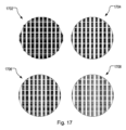
図7は、従来の方法と実施の形態について、デンスレイアウトの残差オーバレイ性能を比較する例の結果を示す。スパースレイアウトは200点を含み、デンスレイアウトは約1000点である。オーバレイ残差のウェハマップ702-710が示される。残差が大きいほど、ウェハ上の各点でより長いベクトルとして表される。したがって、ウェハマップの領域が暗いほど、残差オーバレイ性能が悪いことを表す。従来の方法(A)を使用して、補正なし702および補正あり704の結果が示される。図5を参照して説明した実施の形態にしたがった方法(B)を使用して、補正なし708および補正あり710の結果が示される。箱ひげ図712は、従来の方法(A)および実施の形態(B)について、x方向(OVX)およびy方向(OVY)の平均3シグマオーバレイ(オーバレイ残差)をnm単位で比較する。実施の形態(B)は、従来の方法(A)よりも低いオーバレイ残差を有する。これは、実施の形態の優位性を示す。
FIG. 7 shows example results comparing the residual overlay performance of dense layouts for conventional methods and embodiments. A sparse layout contains 200 points and a dense layout about 1000 points. Wafer maps 702-710 of overlay residuals are shown. Larger residuals are represented as longer vectors at each point on the wafer. Therefore, darker areas of the wafer map represent poorer residual overlay performance. Results without
図8は、分散サンプリングの場合の例の結果を示す。分散レイアウトは、12枚のウェハサイクルを使用し、異なる各スパースレイアウト内に200点以上あり、デンスレイアウト(約2000点)を提供する。 図7と同様、オーバレイ残差のウェハマップ802から812が示される。従来の方法(A)を使用して、補正なし802および補正あり804、806の結果が示される。図6を参照して説明した実施の形態にしたがった方法(B)を使用して、補正なし808および補正あり810、812の結果が示される。 モデリングは二つの工程、グローバルレベル804、810にて、および、グローバル残差から露光単位補正(CPE)モデル(露光単位モデリングレベル)806、812についてなされる。
FIG. 8 shows example results for distributed sampling. The distributed layout uses a 12-wafer cycle, with over 200 points in each different sparse layout, providing a dense layout (approximately 2000 points). Similar to FIG. 7, wafer maps 802-812 of overlay residuals are shown. Results without
箱ひげ図814は、グローバルレベル(工程1)での従来の方法(A)および実施の形態(B)について、x方向(OVX)およびy方向(OVY)の平均3シグマオーバレイ(オーバレイ残差)をnm単位で比較する。実施の形態(B)は、従来の方法(A)よりも低いオーバレイ残差を有する。
箱ひげ図816は、露光単位モデリングレベル(工程2)での従来の方法(A)および実施の形態(B)について、x方向(OVX)およびy方向(OVY)の平均3シグマオーバレイ(オーバレイ残差)をnm単位で比較する。実施の形態(B)は、従来の方法(A)よりも低いオーバレイ残差を有する。実施の形態(B)に伴うノイズ抑制は、すでにグローバルレベル814にて役立っているため、累積効果によって、露光単位モデリングレベル816における露光ごとモデリング補正のノイズがより少なくなる。
実施の形態は、本書に記載される実施の形態に係るプロセスに対する補正を決定する方法を備える半導体製造プロセスにて実施されてもよい。 Embodiments may be implemented in a semiconductor manufacturing process comprising methods for determining corrections for processes according to embodiments described herein.
実施の形態は、図1および図2を参照して説明したリソグラフィ装置またはリソグラフィセルにて実施されてもよい。 Embodiments may be implemented in a lithographic apparatus or lithographic cell as described with reference to FIGS.
実施の形態は、本書に記載される方法の工程を汎用データ処理装置(図2のLACUなど)に実行させるための機械可読指令を備えるコンピュータプログラム製品にて実施されてもよい。 Embodiments may be implemented in a computer program product comprising machine-readable instructions for causing a general-purpose data processing unit (such as the LACU of FIG. 2) to perform the method steps described herein.
実施の形態は、履歴データに関してオーバレイモデルを能動的に適応させることにより、ノイズを抑制する。履歴データセットから収集した情報は、計測データとモデル/サンプリングの相互作用についてより詳しく知るために使用される。分散サンプリングにおける2段階のノイズ抑制もまた、実施の形態によって提供される。 Embodiments suppress noise by actively adapting an overlay model on historical data. Information gleaned from historical data sets is used to learn more about the interaction of metrology data and models/sampling. Two stages of noise suppression in distributed sampling are also provided by embodiments.
トレーニング結果を観察し、どのパラメータがより重要になるかを決定し、どのパラメータが無関係になるかを決定すれば、どのプロセスツールが誤動作しているかを理解することができ、制御フローを能動的に改善できる(露光単位モデリングの頻度の増加など)。 By observing the training results and determining which parameters become more important and which become irrelevant, we can understand which process tools are malfunctioning, and actively change the control flow. (such as increasing the frequency of exposure unit modeling).
上述のように、典型的にフィールド単位モデルは、露光単位モデリングに使用され、設計されていないスパース対デンス不整合を部分的に捉える。実施の形態は、フィールド単位モデルのノイズの影響を低減し、その結果、より少ない測定点を用いて露光単位モデリングが更新されるかもしれない。 As noted above, field-by-field models are typically used for exposure-by-exposure modeling to partially capture undesigned sparse-to-dense mismatches. Embodiments may reduce the effects of noise in the per-field model, so that fewer measurement points may be used to update the per-exposure modeling.
全体として、実施の形態は、改善されたプロセス制御を提供し、その結果、プロセスの歩留まりの性能が向上する。 Overall, embodiments provide improved process control, resulting in improved process yield performance.
これまでに説明された本発明の態様に関連するさらなる実施の形態は、以下の番号が付された項のリストに開示される。
(項1)プロセスの補正を決定する方法であって、
前記プロセスを受ける一以上の基板にわたるパラメータの測定値を表し、スパースサンプリングレイアウトを用いて測定される第1スパースデータを取得することと、
前記プロセスを受ける一以上の基板にわたるパラメータの測定値を表し、前記スパースサンプリングレイアウトよりも空間的に密なデンスサンプリングレイアウトを用いて測定されるデンスデータを取得することと、
モデルを前記スパースデータおよび前記デンスデータにモデルを適用してスパース対デンス不整合を決定することと、
前記プロセスを受ける一以上の基板にわたるパラメータの測定値を表し、スパースサンプリングレイアウトを用いて測定される第2スパースデータを取得することと、
前記スパース対デンス不整合に基づいて前記モデルを適応させることと、
前記適応させたモデルを前記第2スパースデータに適用してスパースモデル結果を決定することと、
前記スパースモデル結果に基づいて前記プロセスに対する補正を決定することと、を備える方法。
(項2)前記スパース対デンス不整合に基づいて前記モデルを適応させる工程は、
前記スパース対デンス不整合に対する前記モデルの各部分の異なる寄与を評価することと、
前記スパース対デンス不整合が低減するように前記モデルの前記各部分を重み付けるための重み付け係数を決定することと、
前記重み付け係数を用いて前記モデルを適応させることと、を備える項1に記載の方法。
(項3)前記重み付け係数を決定する工程は、
前記スパース対デンス不整合が最小化するように前記モデルの前記各部分を重み付けるための重み付け係数を決定することを備える、項2に記載の方法。
(項4)前記スパース対デンス不整合を決定することは、行列を前記第1スパースデータおよび前記デンスデータでトレーニングすることを備え、前記スパース対デンス不整合に基づいて前記モデルを適応させる工程は、前記行列を用いて前記第2スパースデータを修正することを備える、先行する項のいずれかに記載の方法。
(項5)前記第2スパースデータを取得する工程は、前記プロセスを受ける複数の基板にわたるパラメータの測定値を表す第2デンスデータのダウンサンプリングによって第2スパースデータを取得することを備え、前記デンスデータは、前記複数の基板にわたって分散する異なるスパースサンプリングレイアウトを用いて測定され、
前記スパースモデル結果は、スパースモデル残差を備え、
前記方法は、デンスモデル結果を決定するために、前記スパースモデル残差に前記モデルを適用することをさらに備え、
前記プロセスに対する補正を決定する工程は、前記デンスモデル結果にさらに基づく、先行する項のいずれかに記載の方法。
(項6)先行する項のいずれかに記載の方法に係る前記プロセスに対する補正を決定する方法を備える半導体製造プロセス。
(項7)放射の投影ビームを提供するよう構成される照明システムと、
パターニングデバイスを支持するよう構成され、前記パターニングデバイスが所望のパターンにしたがって前記投影ビームをパターン化するよう構成されるサポート構造と、
基板を保持するよう構成される基板テーブルと、
前記パターン化されたビームを前記基板のターゲット部分に投影するよう構成される投影システムと、
項1から項5のいずれかに記載の方法に係る前記プロセスに対する補正を決定するよう構成される処理ユニットと、を備えるリソグラフィ装置。
(項8)項7に記載の前記リソグラフィ装置を備えるリソグラフィセル。
(項9)項1から項5のいずれかに記載の方法の工程を汎用データ処理装置に実行させるための機械可読指令を備えるコンピュータプログラム製品。
Further embodiments related to the aspects of the invention described above are disclosed in the list of numbered sections below.
(Section 1) A method of determining a process correction, comprising:
obtaining first sparse data representing parameter measurements across one or more substrates undergoing the process and measured using a sparse sampling layout;
obtaining dense data representing parameter measurements across one or more substrates undergoing the process and measured using a dense sampling layout that is spatially denser than the sparse sampling layout;
applying a model to the sparse data and the dense data to determine sparse versus dense inconsistencies;
obtaining second sparse data representing parameter measurements across one or more substrates undergoing the process and measured using a sparse sampling layout;
adapting the model based on the sparse versus dense mismatch;
applying the adapted model to the second sparse data to determine a sparse model result;
determining corrections to the process based on the sparse model results.
(Section 2) adapting the model based on the sparse vs. dense mismatch comprises:
evaluating different contributions of each part of the model to the sparse versus dense mismatch;
determining a weighting factor for weighting each portion of the model to reduce the sparse versus dense mismatch;
2. The method of
(Section 3) The step of determining the weighting factor includes:
3. The method of
(Section 4) Determining the sparse-to-dense mismatch comprises training a matrix with the first sparse data and the dense data, and adapting the model based on the sparse-to-dense mismatch , modifying the second sparse data using the matrix.
(Section 5) Obtaining the second sparse data comprises obtaining second sparse data by downsampling second dense data representing measurements of a parameter across a plurality of substrates undergoing the process; data is measured using different sparse sampling layouts distributed across the plurality of substrates;
the sparse model result comprises a sparse model residual;
The method further comprises applying the model to the sparse model residuals to determine a dense model result;
The method of any of the preceding clauses, wherein determining corrections to the process is further based on the dense model results.
(6) A semiconductor manufacturing process comprising a method of determining a correction for the process according to any of the preceding paragraphs.
(Section 7) an illumination system configured to provide a projection beam of radiation;
a support structure configured to support a patterning device, said patterning device configured to pattern said projection beam according to a desired pattern;
a substrate table configured to hold a substrate;
a projection system configured to project the patterned beam onto a target portion of the substrate;
A lithographic apparatus comprising a processing unit configured to determine a correction for the process according to the method of any of clauses 1-5.
(8) A lithographic cell comprising the lithographic apparatus of (7).
(9) A computer program product comprising machine-readable instructions for causing a general purpose data processing apparatus to perform the steps of the method of any one of (1) through (5).
(疎に測定されたパラメータデータの機械学習に基づく拡張)
本発明の別の態様では、モデルがデンス測定データに基づいてトレーニングされる。典型的なモデルは、モデル係数および基底関数を備え、モデル係数は基底関数に関連付けられる。基底関数は、注目する測定グリッド上の座標で評価することができ、その後、注目パラメータ(例えばオーバレイなど)を得るためにモデル係数と乗算される。
(machine learning-based extension of sparsely measured parameter data)
In another aspect of the invention, the model is trained based on dense measurement data. A typical model comprises model coefficients and basis functions, where the model coefficients are associated with the basis functions. The basis functions can be evaluated at coordinates on the measurement grid of interest and then multiplied with the model coefficients to obtain the parameters of interest (eg, overlay, etc.).
モデルの使用は、伝統的に、各座標1…Nにて各基底関数1…Mの値を決定することにより得られるM個の基底関数から各基底関数についてN個の値を備えるN×Mのサイズの行列DMを備える計画行列の構築によって実装される。座標は通常、パラメータ(オーバレイ、アレイメント、CD、または任意の他の性能またはプロセスパラメータ)の測定値が利用可能な座標に関連付けられる。計画行列DMにフィッティング係数f1…fMの列ベクトルFを乗算すると、注目パラメータの元の測定値に近い値の列ベクトルMVが得られる。これを図9に示す。数学的には、利用可能な測定データのベクトルに基づいてフィッティング係数を決定する作業は、DM×F=MVであり、これは、F=(DM)-1×MVに変換できる。さらなる参照は、国際特許出願WO2013092106A1、特に段落[0387]-[0394]になされ、これは、計画行列を定義し、サンプリング方式に関連するモデル不確実性を最小化するよう調整されたサンプリング方式を決定する方法を説明する。
The use of the model is traditionally N×M with N values for each basis function from M basis functions obtained by determining the value of each
利用される基底関数は、(例えば基板、基板上のフィールドまたはフィールド内の領域(サブフィールド)にわたる)注目パラメータの値の典型的な空間的な挙動を表さなければならない。例えば、基板にわたるオーバレイフィンガープリントが6次多項式の次数に典型的に制限されている場合、利用される基底関数を10次多項式に拡張してはならない。これは、オーバーフィッティングの挙動につながる可能性があるからである。しかしながら、その逆の可能性もあり、パラメータ値が高次の挙動を示すことが予想される場合、測定データを十分に高い精度でモデリングするために、基底関数を十分に高い次数に拡張する必要がある。後者の場合、測定データは、典型的に、モデリングされたパラメータ値の高振幅や高次変動などの非物理的なフィッティングの人工産物として観察されるアンダーフィッティングの発生を防ぐために十分に高い密度で利用可能でなければならない。したがって、最先端のモデリング方法の欠点は、選択されたモデル(例えば、選択された基底関数のセット)が、潜在的に長期間にわたって実際に発生する空間的な変動と互換性がある必要があるという要件である。モデルリングされた値が実際のパラメータフィンガープリントの挙動を表すことを保証するためには、パラメータ(値)を時間的に頻繁にかつ空間的に高密度で測定することを必要とするかもしれない。しかしながら、大量生産の環境では、製造プロセスのスループットに悪影響を与えるため、この要件を満たす機会はほとんどない。 The basis functions utilized should represent the typical spatial behavior of the values of the parameter of interest (eg, over the substrate, a field on the substrate, or a region (subfield) within the field). For example, if the overlay fingerprint across the substrate is typically limited to the order of a 6th order polynomial, then the basis functions utilized should not be extended to a 10th order polynomial. This is because it can lead to overfitting behavior. However, the converse is also possible, and if the parameter values are expected to exhibit high-order behavior, the basis functions need to be extended to sufficiently high orders in order to model the measured data with sufficiently high accuracy. There is In the latter case, the measured data are typically dense enough to prevent the occurrence of underfitting, which is observed as non-physical fitting artifacts such as high amplitude and high-order fluctuations in the modeled parameter values. Must be available. A drawback of state-of-the-art modeling methods is therefore that the selected model (e.g., the set of basis functions selected) must be compatible with spatial variations that occur in practice, potentially over long periods of time. is the requirement. To ensure that the modeled values represent the behavior of the actual parameter fingerprints, it may be necessary to measure the parameters (values) frequently in time and densely in space. . However, in a high volume manufacturing environment there is little opportunity to meet this requirement as it adversely impacts the throughput of the manufacturing process.
したがって、注目パラメータの測定データに含まれる実際に発生する空間的な成分の全てを高い精度でモデリングすることを保証し、デンス(高密度)測定データでのトレーニングを必要としながらも、頻繁に測定されるスパース測定データにも適用されるモデリング方法が必要とされる。 Therefore, it guarantees high-accuracy modeling of all of the actually occurring spatial components in the measured data of the parameter of interest, and requires training on dense measured data, but still requires frequent measurements. What is needed is a modeling method that also applies to sparse measurement data that is measured.
基底関数に関連付けられていないが、デンス測定データに基づく計画行列の評価に加えてトレーニングされる、いわゆる自由形状のパラメータによって最先端のモデリング方法を拡張することが提案される。本発明の方法は、図10に示され、自由形状パラメータは、N×Lの次元の自由形状行列FMとしてレイアウトされ、Lは自由形状行列FMに関連付けられた自由形状係数の数であり、自由形状行列の値は(動的に)適応可能な数である。ここで、フィッティング係数列ベクトルF’は、基底関数に関連付けられたフィッティング係数と、L個の自由形状フィッティング係数とを備える。基底関数に関連付けられたフィッティング係数は、以前に定義した行列式(F=(DM-1)×MV)に基づいて決定されうる一方、自由形状パラメータは、モデルリングされたパラメータ値の品質を向上させるために(例えば、測定値Mとの類似性に基づいて)調整されうる。自由形状パラメータおよび自由形状係数は、例えば、行列の式F’=(DM+FM)-1×MVに適用される勾配降下法を用いて決定されてもよい。主な結果は、自由形状パラメータおよび自由形状係数の最適化されたセットを得ることである。 It is proposed to extend state-of-the-art modeling methods with so-called free-form parameters, which are not associated with basis functions, but are trained in addition to the evaluation of design matrices based on dense measurement data. The method of the present invention is illustrated in FIG. 10, where the freeform parameters are laid out as a freeform matrix FM of dimension N×L, where L is the number of freeform coefficients associated with the freeform matrix FM, and the freeform The values of the shape matrix are (dynamically) adaptable numbers. Here, the fitting coefficient column vector F' comprises the fitting coefficients associated with the basis functions and L freeform fitting coefficients. The fitting coefficients associated with the basis functions can be determined based on the previously defined determinant (F=(DM −1 )×MV), while the freeform parameters improve the quality of the modeled parameter values. can be adjusted (eg, based on similarity to the measurement M) to allow The freeform parameters and freeform coefficients may be determined, for example, using gradient descent applied to the matrix formula F′=(DM+FM) −1 ×MV. The main result is to obtain an optimized set of freeform parameters and freeform coefficients.
自由形状パラメータは、密に測定されるパラメータ値のデータセットを用いて機械学習法によって得られてもよい。この場合、自由形状パラメータは、観測されたパラメータ値(測定)と相関のある特徴であると考えられる。トレーニングの態様は、モデル(特に、トレーニングされた自由形状フィッティング係数)が、測定データの高次の挙動を正確に表すことを保証する。低次の挙動は、典型的には、低次の基底関数と、これらの基底関数に関連付けられたフィッティング係数とを使用して、頻繁に測定されるスパースデータをモデリングすることによって正確に取得される。モデリングされた測定データの高次の内容は、主に、トレーニングされた自由形状パラメータと自由形状フィッティング係数によって提供される。本発明のモデリング方法を利用すると、データの特定の最小要求密度に依存することなく、モデル自体が高次の内容(予測)を提供するため、デンス測定データを頻繁に提供する必要がない。 The freeform parameters may be obtained by machine learning methods using a densely measured data set of parameter values. In this case, the freeform parameters are considered features that are correlated with the observed parameter values (measurements). The training aspect ensures that the model (especially the trained freeform fitting coefficients) accurately represents the high-order behavior of the measured data. Low-order behavior is typically accurately obtained by modeling frequently measured sparse data using low-order basis functions and fitting coefficients associated with these basis functions. be. The high-order content of the modeled measurement data is primarily provided by the trained freeform parameters and freeform fitting coefficients. Utilizing the modeling method of the present invention, dense measurement data need not be provided frequently because the model itself provides higher order content (predictions) without depending on a particular minimum required density of data.
本発明のある実施の形態において、パラメータデータをモデリングする方法が提供される。この方法は、基板上の複数の位置に関連するパラメータの値を取得することと、複数の位置での一以上の基底関数の評価に基づく第1行列の値と、以前の基板に関連するパラメータの以前に取得した値のセットに対して適応可能な数の行列のトレーニングに基づく第2行列の値とを取得することと、第1および第2の値のセットを集約することと、集約したセットおよび取得したパラメータの値を用いてモデルの係数を決定することと、係数と第2行列の値を用いてパラメータのモデリングされた値を提供することと、を備える。 In one embodiment of the invention, a method for modeling parametric data is provided. The method includes obtaining values of parameters associated with a plurality of locations on a substrate; values of a first matrix based on evaluation of one or more basis functions at the plurality of locations; obtaining values of a second matrix based on training an adaptable number of matrices for the previously obtained set of values of; aggregating the first and second sets of values; Determining coefficients of the model using the set and the obtained values of the parameters; and providing modeled values of the parameters using the values of the coefficients and the second matrix.
ある実施の形態において、パラメータはオーバレイである。 In one embodiment, the parameter is overlay.
ある実施の形態において、複数の位置は、一以上の基板にわたるスパース測定方式に関連付けられ、一以上の基板は、例えば、半導体製造プロセスにおいて処理されるウェハである。 In one embodiment, the multiple locations are associated with a sparse measurement scheme across one or more substrates, where the one or more substrates are, for example, wafers processed in a semiconductor manufacturing process.
ある実施の形態において、基底関数は多項式である。 In one embodiment, the basis functions are polynomials.
ある実施の形態において、基底関数は、互いに直交である。 In one embodiment, the basis functions are orthogonal to each other.
ある実施の形態において、基底関数は、基板にわたって最大で6次である。 In one embodiment, the basis functions are up to 6th order across the substrate.
ある実施の形態において、複数の位置は、ウェハ上の露光フィールドに関連する。 In one embodiment, the multiple positions are associated with an exposure field on the wafer.
ある実施の形態において、モデルパラメータは、自由形状モデルパラメータである。 In one embodiment, the model parameters are freeform model parameters.
ある実施の形態において、トレーニングされた関係性は、一以上の密にサンプリングされた以前の基板にわたるパラメータの初期値に基づいて得られる。 In one embodiment, the trained relationship is obtained based on initial values of parameters across one or more densely sampled previous substrates.
ある実施の形態において、トレーニングされた関係性は、ニューラルネットワークなどの機械学習方法を用いて、個々のモデルパラメータと一以上の基板にわたるパラメータのフィンガープリントとの間の関係を確立することに基づく。 In one embodiment, the trained relationship is based on establishing relationships between individual model parameters and parameter fingerprints across one or more substrates using machine learning methods such as neural networks.
ある実施の形態において、パラメータのフィンガープリントは、高次成分を備える。 In one embodiment, the parameter fingerprint comprises higher order components.
ある実施の形態において、高次成分は、パラメータのサンプル点の特定の値に関連する。 In one embodiment, the higher order components are associated with particular values of the parameter sample points.
代替的に、測定データのモデリングは、自由形状モデルパラメータおよび自由形状係数に完全に基づいてもよい。この場合、ある実施の形態に係るパラメータデータをモデルリングする方法は、基板上の複数の位置に関連付けられたパラメータの値のセットを取得することと、トレーニングされた機械学習モデルへの入力として値のセットを使用し、パラメータの一以上の値をパラメータの予測値にマッピングしてパラメータのモデリングされた値を取得することと、を備える。この場合、基板上のさまざまな位置に関連付けられたパラメータの値は、その位置でのパラメータの(モデリングされた)値にマッピングできる特徴であると考えられる。例えば、機械学習モデルは、取得した値をモデリングされた値にマッピングするように最適化された重み付けとバイアスを有するニューラルネットワークであってもよい。トレーニングは、機械学習モデルに関連付けられたN×M個の自由形状パラメータの行列およびM個の自由形状係数を定義することに基づいてもよく、N個の基板上の位置の数、および、機械学習モデルのM個の自由形状係数の決定は、パラメータのN個の予測値とパラメータの測定値との間の類似性の最適化に基づいてもよい。決定したM個の自由形状係数およびN×M個の自由形状パラメータを用いて、パラメータのN個のモデリングされた値が決定されてもよい。 Alternatively, the modeling of measured data may be based entirely on freeform model parameters and freeform coefficients. In this case, an embodiment method for modeling parametric data includes obtaining a set of parameter values associated with a plurality of locations on a substrate and using the values as input to a trained machine learning model. and mapping one or more values of the parameter to a predicted value of the parameter to obtain a modeled value of the parameter. In this case, the parameter values associated with various locations on the substrate are considered features that can be mapped to the (modeled) values of the parameter at that location. For example, the machine learning model may be a neural network with weights and biases optimized to map acquired values to modeled values. Training may be based on defining a matrix of N×M freeform parameters and M freeform coefficients associated with the machine learning model, the number of locations on the N substrate, and the machine Determining the M freeform coefficients of the learning model may be based on optimizing the similarity between the N predicted values of the parameter and the measured values of the parameter. Using the determined M freeform coefficients and the N×M freeform parameters, N modeled values of the parameters may be determined.
本発明のさらなる実施の形態は、以下の番号が付された項のリストに開示される。
(項10)パラメータデータをモデリングする方法であって、
基板上の複数の位置に関連付けられたパラメータの値のセットを取得することと、
前記複数の位置での一以上の基底関数の評価に基づく第1行列の値を取得することと、
以前の基板に関連付けられた前記パラメータの以前に取得した値のセットに対する適応可能な数の行列のトレーニングに基づく第2行列の値を取得することと、
前記第1および第2行列の値と前記取得した値のセットとを用いて前記モデルの係数を決定することと、
前記係数と第2行列の値を用いて前記パラメータのモデリングされた値を提供することと、を備える方法。
(項11)前記パラメータは、オーバレイである、項10に記載の方法。
(項12)前記複数の位置は、半導体製造プロセスを受ける一以上の基板にわたるスパース測定方式に関連する、項10または項11に記載の方法。
(項13)前記基底関数は、多項式である、項10から項12のいずれかに記載の方法。
(項14)前記基底関数は、互いに直交である、項10から項13のいずれかに記載の方法。
(項15)前記基底関数は、前記基板にわたって最大で6次である、項13に記載の方法。
(項16)前記複数の位置は、前記基板上の露光フィールドに関連する、項10から項15のいずれかに記載の方法。
(項17)前記適応可能な数は、自由形状モデルパラメータである、項10から項16のいずれかに記載の方法。
(項18)前記パラメータの前記以前に取得した値のセットは、密に測定された以前の基板に関連付けられる、項10から項17のいずれかに記載の方法。
(項19)前記トレーニングは、ニューラルネットワークなどの機械学習方法を用いて、前記以前の基板から、前記適応可能な数と、個々の各基板にわたる前記パラメータのフィンガープリントとの関係性を確立することに基づく、項10から項18のいずれかに記載の方法。
(項20)前記パラメータの前記フィンガープリントは、高次成分を備える、項19に記載の方法。
(項21)前記高次成分は、前記パラメータのサンプル点の特定の値に関連する、項20に記載の方法。
(項22)項10から項21のいずれかに記載の方法を汎用データ処理装置に実行させるための機械可読指令を備えるコンピュータプログラム製品。
Further embodiments of the invention are disclosed in the list of numbered sections below.
(Section 10) A method of modeling parametric data, comprising:
obtaining a set of parameter values associated with a plurality of locations on the substrate;
obtaining values of a first matrix based on evaluation of one or more basis functions at the plurality of locations;
obtaining values of a second matrix based on training the adaptive number matrix against a set of previously obtained values of said parameter associated with a previous substrate;
determining coefficients of the model using the values of the first and second matrices and the obtained set of values;
and using the coefficients and the values of a second matrix to provide a modeled value of the parameter.
11. The method of
12. The method of
Term 13. The method of any one of
14. The method of any one of 10 to 13, wherein the basis functions are orthogonal to each other.
15. The method of claim 13, wherein the basis functions are at most sixth order across the substrate.
16. The method of any of clauses 10-15, wherein the plurality of positions are associated with an exposure field on the substrate.
17. The method of any of paragraphs 10-16, wherein the adaptable numbers are freeform model parameters.
18. The method of any of clauses 10-17, wherein the set of previously obtained values for the parameter is associated with a closely measured previous substrate.
(Section 19) The training uses a machine learning method, such as a neural network, to establish from the previous substrates a relationship between the adaptable number and a fingerprint of the parameters across each individual substrate. 19. The method of any one of
20. The method of
21. The method of
22. A computer program product comprising machine-readable instructions for causing a general-purpose data processing apparatus to perform the method of any of paragraphs 10-21.
(高次フィンガープリントの予測に用いるリカレントニューラルネットワーク)
図11は、半導体製造プロセスのオーバレイサンプリングおよび制御の概要を概略的に示す。図11を参照すると、10個のウェハロット(またはバッチ、またはウェハ)での露光プロセス工程の10個の動作L1-L10の流れが示される。高次オーバレイパラメータHO1の値は、空間的に密なサンプリング方式を用いる第1ロットL1の測定1104に基づいて取得される。高次オーバレイパラメータHO1は、例えば、次の5個のロットの後続露光L2-L6の制御レシピ1106を決定することによって、半導体製造プロセスを構成するために使用される。次に、高次オーバレイパラメータの更新値HO6は、以前1102の高次オーバレイパラメータHO1に基づいて、および、空間的に密なサンプリング方式を用いる6番目のロットL6の測定1108に基づいて取得される。この例では、5番目のロットの露光ごとに高次パラメータの更新が繰り返される。
(Recurrent neural network used to predict high-order fingerprints)
FIG. 11 schematically illustrates an overview of overlay sampling and control of a semiconductor manufacturing process. Referring to FIG. 11, a flow of ten operations L1-L10 of exposure process steps on a ten wafer lot (or batch, or wafer) is shown. A value for the higher-order overlay parameter HO1 is obtained based on
一方、全ロットの露光について、スパース測定に基づくロットごとの低次補正が計算される。例えば、ロットL1の露光にて、低次オーバレイパラメータLO1は、空間的に密なサンプリング方式よりも空間的に密ではなく、より頻繁であるスパースサンプリング方式を用いた測定1110に基づいて取得される。低次パラメータLO1は、例えば露光工程の後続動作L2の制御レシピ1112を決定等することによって、半導体製造プロセスを構成するために用いられる。
On the other hand, lot-by-lot low-order corrections based on sparse measurements are calculated for the exposure of the whole lot. For example, in the exposure of lot L1, the low-order overlay parameter LO1 is obtained based on
このように、低次補正は、スパース測定に基づいてロットごとに計算され、高次補正は、複数ロットにおいて1回のデンス測定に基づいて取得される。 Thus, low-order corrections are calculated lot-by-lot based on sparse measurements, and high-order corrections are obtained based on single dense measurements in multiple lots.
図12は、半導体製造プロセスのアライメントサンプリングおよび制御の概要を概略的に示す。図12を参照すると、ウェハロットL1-L10は、オフラインアライメントマーク測定工程1202を有する。測定1204は、高空間サンプリング密度を有するオフライン測定に最適化されたオフライン測定ツール1206によって実行される。測定された高次アラインメントパラメータ値1208は、各ウェハロットL1-L10について格納HO1-HO10される。 次に、各高次アラインメントパラメータ値は、対応するウェハロットL1-L10での露光工程1214の動作の制御レシピ1212を決定するために使用される。
FIG. 12 schematically illustrates an overview of alignment sampling and control of a semiconductor manufacturing process. Referring to FIG. 12, wafer lots L1-L10 have an off-line alignment mark measurement process 1202. FIG.
一方、全ロットの露光について、スパース測定に基づくロットごとの低次補正が計算される。例えば、ロットL1の露光1214において、低次アラインメントパラメータ1216は、空間的に密なサンプリング方式よりも空間的に密ではないスパースサンプリング方式を使用する測定に基づいて取得される。これは、高次アラインメントパラメータのオフラインデンス測定1204と同じ頻度(ロットごと)を有する。低次パラメータ1216は、同じ露光工程の動作L1の制御レシピを決定するために使用される。
On the other hand, lot-by-lot low-order corrections based on sparse measurements are calculated for the exposure of the whole lot. For example, in
実施の形態は、長短期記憶(LSTM)予測アルゴリズムを使用して、デンス測定の合間にオーバレイ測定およびアライメント測定の双方を更新するための戦略を使用する。これは、スループットへの影響を最小限にしつつ、アライメントおよびオーバレイ制御の性能を改善する。完全に独立したLSTMネットワーク予測(トレーニング後のデンス測定が不要)も可能であるが、学習が不十分であると、しばらくした後に発散する可能性がある。 Embodiments employ strategies for updating both overlay and alignment measurements between dense measurements using long short-term memory (LSTM) prediction algorithms. This improves alignment and overlay control performance with minimal impact on throughput. Fully independent LSTM network prediction (no need for dense measures after training) is also possible, but poorly trained may diverge after some time.
図13は、本発明のある実施の形態にしたがった半導体製造プロセスのサンプリングおよび制御の方法の概要を概略的に示す。 FIG. 13 schematically illustrates a method overview for sampling and controlling a semiconductor manufacturing process according to one embodiment of the present invention.
図13を参照すると、高次パラメータの更新は、LSTMニューラルネットワークを使用した中間ロットまたは中間ウェハにおける予測を用いて実現される。これは、アライメントとオーバレイの双方について改善された高次補正を提供する。低次補正はウェハごとに測定される一方、高次補正は、中間ロットまたは中間ウェハにおけるLSTMによって予測される。ニューラルネットワークは、初期トレーニング(TRN)工程1302で構成される。
Referring to FIG. 13, updating higher order parameters is accomplished using predictions at intermediate lots or intermediate wafers using LSTM neural networks. This provides improved higher order corrections for both alignment and overlay. Low order corrections are measured wafer by wafer, while high order corrections are predicted by the LSTM at intermediate lots or intermediate wafers. A neural network is configured in an initial training (TRN)
図13は、半導体製造プロセスに関連付けられた高次パラメータの値を予測する方法を示す。この例では、半導体製造はリソグラフィ露光プロセスを処理する。パラメータは、y方向の3次のスキャナ露光拡大率パラメータD3yである。この方法は、空間的に密なサンプリング方式を使用する測定1306に基づいて高次パラメータの値1308を取得することを含む。リカレントニューラルネットワーク(NN)1304は、測定値1308に基づいて高次パラメータの予測値1312を決定するために使用される。高次パラメータの測定値1308は、測定したロットの処理の制御レシピを決定するために直接的に使用できる。
FIG. 13 illustrates a method of predicting values of higher order parameters associated with a semiconductor manufacturing process. In this example, semiconductor manufacturing processes lithographic exposure processes. The parameter is the third order scanner exposure magnification parameter D3y in the y direction. The method includes obtaining values 1308 of higher order parameters based on
高次パラメータの予測値1312は、半導体製造プロセスのプロセス工程の第1動作L1での測定1306から得られる高次パラメータの値1308に基づいて決定され、半導体製造プロセスのプロセス工程の後続動作L2の制御レシピ1314を決定する。予測値は、リカレントニューラルネットワーク(NNt=2)にフィードバックされる。ロットL3-L5の露光の場合、リカレントニューラルネットワーク(NNt=2…5)は自身を更新し、連続するロットの制御レシピを決定するために使用される予測値を生成する。高次パラメータの後続値626は、デンスサンプリング方式を使用する測定628に基づいて得られる。リカレントニューラルネットワークは、後続値626を使用して更新される(NNt=6)。
The predicted value 1312 of the high-order parameter is determined based on the high-order parameter value 1308 obtained from the
一方で、低次パラメータの値1318は、空間的にスパース(疎)なサンプリング方式を使用した測定(例えば、露光工程L2でのロットの測定に基づく値1320)に基づいて取得される。スパースサンプリング方式は、測定1306、1328に使用される高次サンプリング方式よりも空間的に密ではなく、より頻繁である。低次パラメータの値1320は、露光プロセス工程の後続動作L2の制御レシピ1322を決定するために使用される。
On the other hand, low-
低次パラメータの値1320は、プロセス工程の後続動作L2が実行されるのと同じ基板テーブル上に支持された同じ基板上で実行された測定に基づいて取得されてもよい。 制御レシピ1322は、低次パラメータの値1320を使用して決定される。
The low-
この例では、半導体製造プロセスは、基板をパターニングするバッチ式プロセスである。高次パラメータを取得するためのサンプリング方式は、5バッチごと(図13に示される)から10バッチごとの測定頻度を有する。第2サンプリング方式は、バッチごとに1回の測定頻度を有する。 In this example, the semiconductor manufacturing process is a batch process for patterning substrates. The sampling scheme for obtaining higher order parameters has a measurement frequency of every 5 batches (shown in FIG. 13) to every 10 batches. A second sampling scheme has a measurement frequency of once per batch.
この例において、半導体製造プロセスは、露光フィールドを用いて基板をパターニングするプロセスである。高次パラメータを取得するためのサンプリング方式は、露光フィールドごとに200から300の測定点となる空間密度を有し、低次パラメータを取得するためのサンプリング方式は、露光フィールドごとに2から3の測定点となる空間密度を有する。 In this example, the semiconductor manufacturing process is a process of patterning a substrate using an exposure field. The sampling scheme for obtaining high-order parameters has a spatial density of 200 to 300 measurement points per exposure field, and the sampling scheme for obtaining low-order parameters has a spatial density of 2 to 3 measurement points per exposure field. It has a spatial density that serves as a measurement point.
半導体製造プロセスに関連付けられたパラメータの値を予測する方法は、図6を参照して説明したように、半導体製造プロセス内で実施されてもよい。この方法は、図2のLACUなどの処理ユニットを有するリソグラフィ装置内で実施されてもよい。図2の監視制御システムSCSまたは図3のコンピュータシステムCL内のプロセッサで実施されてもよい。 A method of predicting values of parameters associated with a semiconductor manufacturing process may be implemented within the semiconductor manufacturing process, as described with reference to FIG. The method may be implemented in a lithographic apparatus having a processing unit such as the LACU of FIG. It may be implemented in a processor within the supervisory control system SCS of FIG. 2 or the computer system CL of FIG.
本発明は、図13を参照して説明した方法の工程を汎用データ処理装置に実行させるための機械可読指令を備えるコンピュータプログラム製品として実装されてもよい。 The invention may be implemented as a computer program product comprising machine-readable instructions for causing a general-purpose data processing apparatus to perform the steps of the method described with reference to FIG.
図13の方法の利点は、図11の方法と比較すると、オーバレイのための追加の測定が不要な点である。アライメントのために、空間的に密な測定が必要となるウェハは、ロットあたりにわずかである一方、全てのウェハは、異なる高次パラメータに基づいて決定される異なる制御レシピを受け取る。中間ロット(オーバレイの場合)または中間ウェハ(アライメントの場合)は、LSTMによって予測された高次パラメータを用いて決定される更新された制御レシピを受け取る。低次の測定および対応する制御レシピの更新は、オーバレイとアライメントのパラメータについて同じウェハテーブルで実行されるため、ウェハテーブル(チャック)のマッチングは必要とされない。 An advantage of the method of FIG. 13, compared to the method of FIG. 11, is that no additional measurements are required for overlay. Few wafers per lot require spatially dense measurements for alignment, while all wafers receive different control recipes that are determined based on different high-order parameters. Intermediate lots (for overlay) or intermediate wafers (for alignment) receive updated control recipes determined using the high-order parameters predicted by the LSTM. Wafer table (chuck) matching is not required because low-order measurements and corresponding control recipe updates are performed on the same wafer table for overlay and alignment parameters.
図14は、図11のサンプリングおよび制御方式に対応するオーバレイ高次パラメータ更新のグラフである。図14から16において、横軸はウェーハ番号WNである。縦軸は、y方向の3次のスキャナ露光拡大率パラメータD3yである。図14から16において、実線グラフ1402は、デンス測定サンプリングに基づく高次パラメータの元の値である。
FIG. 14 is a graph of overlay high-order parameter updates corresponding to the sampling and control scheme of FIG. 14 to 16, the horizontal axis is the wafer number WN. The vertical axis is the third-order scanner exposure magnification parameter D3y in the y direction. In FIGS. 14-16, the
図14を参照すると、垂直の一点鎖線の右側にある破線グラフ1404は、10点ごとにパラメータの更新を伴う高次パラメータ更新である(図11は、この更新を5点ごとにする場合を示すことに留意されたい)。
Referring to FIG. 14, the dashed
図15は、本発明のある実施の形態に係る更新を伴わない場合のオーバレイ高次パラメータ更新のグラフである。 FIG. 15 is a graph of overlay high-order parameter updates without updates according to one embodiment of the present invention.
図15を参照すると、垂直の一点鎖線の右側にある破線グラフ1504は、更新を伴わない予測パラメータ値である。これは、図13に対応するが、L6以降の更新を伴わない。このように、トレーニング後の更新を伴わない、フリーのLSTMを使用する。
Referring to FIG. 15, the dashed
図16は、本発明のある実施の形態に係る図13のサンプリングおよび制御方式に対応する更新を伴う場合のオーバレイ高次パラメータ更新のグラフである。 FIG. 16 is a graph of overlay high-order parameter updates with updates corresponding to the sampling and control scheme of FIG. 13 in accordance with one embodiment of the present invention.
図16を参照すると、垂直の一点鎖線の右側にある破線グラフ1604は、10点ごとの更新を伴う予測パラメータ値である(図13は、この更新を5点ごとにする場合を示すことに留意されたい)。LSTMネットワークは、垂直の一点鎖線の左側にあるデータの78%を用いてトレーニングされる。LSTMネットワークは、残りのデータ(22%、35枚のウェハ、破線904)に基づいて検証される。D3yの元の値と予測値の間の二乗平均平方根誤差(RMSE)は、図16(RMSE=2.12e-05)が最良である一方、図15(RMSE=2.83e-05)および図14(RMSE=2.82e-05)は同等である。 Referring to FIG. 16, the dashed line graph 1604 to the right of the vertical dash-dot line is the prediction parameter values with every 10 point update (note that FIG. 13 shows this every 5 point update). want to be). The LSTM network is trained with 78% of the data to the left of the vertical dash-dot line. The LSTM network is verified based on the remaining data (22%, 35 wafers, dashed line 904). The root-mean-square error (RMSE) between the original and predicted values of D3y is best in FIG. 16 (RMSE=2.12e-05), while FIG. 14 (RMSE=2.82e-05) are equivalent.
図17は、高次オーバレイパラメータ補正を伴わない場合、図14に対応するオーバレイ高次パラメータの更新を伴う場合、および、図15および図16に対応するオーバレイパラメータ予測を伴う場合の測定オーバレイのウェハマップを示す。 FIG. 17 shows a wafer of measured overlay without high-order overlay parameter correction, with overlay high-order parameter update corresponding to FIG. 14, and with overlay parameter prediction corresponding to FIGS. Show map.
ウェハプロットにおいて、実際の補正がデンスレイアウト(フィールドあたり13×19点)に適用され、それぞれの場合の補正能力が比較される。プロットは、平均プラス3シグマのオーバレイを示す。パターンが暗いほど、オーバレイ性能が悪い。ベースラインウェハマップ1702は、高次補正のない場合を示す。ウェハマップ1704は、図14のプロットに対応するオーバレイ高次パラメータ更新の結果であり、従来のオーバレイの場合である。ウェハマップ1706は、図15のプロットに対応するオーバレイ高次パラメータ更新の結果であり、更新を伴わないフリーのLSTMの場合である。ウェハマップ1708は、図16のプロットに対応するオーバレイ高次パラメータ更新の結果であり、更新を伴うLSTM予測の場合である。後者は、最良のオーバレイ補正性能を有し、より明るいパターンで示される。
In the wafer plot, the actual correction is applied to the dense layout (13x19 points per field) and the correction capability in each case is compared. The plot shows the
実施の形態は、各ウェハを測定することなく、高次パラメータをアライメント補正に含める方法を提供する。実施の形態は、オーバレイ測定を更新するための方法論も改善する。 Embodiments provide a way to include higher order parameters in alignment corrections without measuring each wafer. Embodiments also improve the methodology for updating overlay measurements.
本発明の方法は、(高次)パラメータの更新のために使用することに代えて、または加えて、前記パラメータの更新に使用されるモデルのパラメータの更新に使用されてもよい。例えば、半導体製造プロセスのRun-to-Run制御は、典型的に、周期的に測定されるプロセス(関連)パラメータを用いるプロセス補正の決定に基づく。プロセス補正の変動が大きくなりすぎるのを防ぐため、プロセスパラメータの最後に取得された測定のみではないものを含む、履歴プロセスパラメータ測定データのセットに指数加重移動平均(EWMA)方式がしばしば適用される。EWMA方式は、関連付けられた重み付けパラメータのセットを有してもよく、これらの一つは、いわゆる「平滑化定数」λである。平滑化定数は、測定したプロセスパラメータの値が将来のプロセス補正においてどの程度使用されるか、別の言い方をすれば、現在のプロセス補正を決定するために、測定したプロスパラメータの値をどれだけ過去に遡って使用するかを指令する。EWMA方式は、Zi=λ・Xi+(1-λ)・Zi-1によって表されてもよい。ここで、Zi-1は、例えば、実行(典型的には基板のロット)「i-1」の補正に最適となるように以前に決定されたプロセスパラメータ値を表し、Xiは、実行「i」について測定したプロセスパラメータであり、つづいて、Ziは、実行「i」(実行「i-1」に続く実行)に最適なプロセスパラメータの値を表すように予測される。 Alternatively or in addition to being used for updating (higher order) parameters, the method of the invention may be used for updating the parameters of the model used to update said parameters. For example, run-to-run control of semiconductor manufacturing processes is typically based on determination of process corrections using process (related) parameters that are periodically measured. Exponentially weighted moving average (EWMA) methods are often applied to sets of historical process parameter measurement data, including not only the most recently acquired measurement of the process parameter, to prevent the variability of the process correction from becoming too large. . The EWMA scheme may have a set of weighting parameters associated with it, one of these being the so-called "smoothing constant" λ. The smoothing constant determines how much the measured process parameter value will be used in future process corrections or, in other words, how much the measured process parameter value will be used to determine the current process correction. It instructs whether to go back and use it in the past. The EWMA scheme may be represented by Z i =λ·X i +(1−λ)·Z i −1. where Z i−1 represents, for example, the process parameter values previously determined to be optimal for the correction of run (typically lot of substrates) “i−1”, and X i represents run is the measured process parameter for 'i', then Z i is predicted to represent the optimal process parameter value for run 'i' (the run following run 'i−1').
プロセス制御におけるEWMAの使用のより詳細な情報は、例えば、「Automated Process Control optimization to control Low Volume Products based on High Volume Products data, Proceedings of SPIE 5755, 17 may 2005, doi: 10.1117/12.598409」に与えられており、その全体が参照により本書に含まれる。 More detailed information on the use of EWMA in process control is given, for example, in "Automated Process Control optimization to control Low Volume Products based on High Volume Products data, Proceedings of SPIE 5755, 17 may 2005, doi: 10.1117/12.598409". and is hereby incorporated by reference in its entirety.
平滑化定数に使用される値は、実行「i」についてのプロセス補正の決定に使用される予測された最良のプロセスパラメータに直接影響を与える。しかしながら、プロセス変動が発生する可能性があり、平滑化定数(または履歴プロセスパラメータデータの重み付けのためのモデルに関連付けられた任意の他のパラメータ)の最適値に影響を与える可能性がある。 The value used for the smoothing constant directly affects the predicted best process parameters used in determining the process correction for run "i". However, process variations can occur and can affect the optimal value of the smoothing constant (or any other parameter associated with the model for weighting historical process parameter data).
前述の実施の形態で説明したように、リカレントニューラルネットワークまたはLSTMを使用し、半導体製造プロセスに関連する第1パラメータの一以上の値を、第1パラメータの履歴測定値に基づいて予測することが提案される。半導体製造プロセスにおけるプロセス工程の後続動作の制御レシピを決定する代わりに、またはそれに加えて、第1パラメータの予測値に基づく重み付けモデルに関連付けられた一以上のパラメータを更新することが提案される。前記一以上のパラメータは、平滑化定数を含んでもよい。平滑化定数は、例えば、リカレントニューラルネットワーク(例えば典型的にはLSTM)を使用する第1パラメータの予測値と、重み付けモデル(例えば典型的にはEWMAに基づくモデル)を使用して予測した第1パラメータの値との間の一致レベルに基づいて決定されてもよい。最良の一致を与える重み付けパラメータ(例えば典型的には平滑化定数)が選択される。LSTMに基づく予測にベンチマークされた場合の平滑化定数の品質の周期的な再評価は、任意の時点でのEWMAモデルの最適な構成を保証する。 As described in previous embodiments, a recurrent neural network or LSTM can be used to predict one or more values of a first parameter associated with a semiconductor manufacturing process based on historical measurements of the first parameter. proposed. As an alternative, or in addition to determining a control recipe for subsequent operation of a process step in a semiconductor manufacturing process, it is proposed to update one or more parameters associated with a weighting model based on the predicted value of the first parameter. The one or more parameters may include a smoothing constant. The smoothing constant is, for example, the predicted value of the first parameter using a recurrent neural network (e.g., typically LSTM) and the first parameter predicted using a weighting model (e.g., typically an EWMA-based model). It may be determined based on the level of agreement between the values of the parameters. A weighting parameter (eg, typically a smoothing constant) that gives the best match is selected. A periodic re-evaluation of the quality of the smoothing constant when benchmarked against the LSTM-based prediction ensures optimal configuration of the EWMA model at any point in time.
ある実施の形態において、半導体製造プロセスに関連する第1パラメータの値を予測する方法が開示される。この方法は、第1サンプリング方式を用いる測定に基づく第1パラメータの第1の値を取得することと、リカレントニューラルネットワークを使用して第1の値に基づく第1パラメータの予測値を決定することと、第1パラメータの予測値および第1パラメータの取得した第1の値に基づいて、半導体製造プロセスの制御装置によって使用されるモデルに関連付けられたパラメータの値を決定することと、を備える。 In one embodiment, a method of predicting the value of a first parameter associated with a semiconductor manufacturing process is disclosed. The method includes obtaining a first value of a first parameter based on measurements using a first sampling scheme and determining a predicted value of the first parameter based on the first value using a recurrent neural network. and determining a value of a parameter associated with a model used by a controller of the semiconductor manufacturing process based on the predicted value of the first parameter and the obtained first value of the first parameter.
ある実施の形態において、前述の実施の形態の決定は、第1パラメータの予測値を、第1パラメータの取得した第1の値にモデルを適用することによって得られる第1パラメータの値と比較することに基づく。 In one embodiment, the determination of the preceding embodiment compares the predicted value of the first parameter to the value of the first parameter obtained by applying the model to the obtained first value of the first parameter. based on
ある実施の形態において、モデルは、指数加重移動平均モデルであり、パラメータは、前記指数加重移動平均モデルに関連付けられる平滑化定数である。 In one embodiment, the model is an exponentially weighted moving average model and the parameter is a smoothing constant associated with said exponentially weighted moving average model.
本発明の態様のさらなる実施の形態は、以下の番号が付された項のリストに開示される。
(項23)半導体製造プロセスに関連付けられた第1パラメータの値を予測する方法であって、
第1サンプリング方式を用いる測定に基づく第1パラメータの第1の値を取得することと、
リカレントニューラルネットワークを使用して前記第1の値に基づく前記第1パラメータの予測値を決定することと、を備える方法。
(項24)前記半導体製造プロセスにおけるプロセス工程の第1動作での測定から得られる前記第1の値に基づいて決定される前記第1パラメータの前記予測値を使用して、前記半導体製造プロセスにおける前記プロセス工程の後続動作の制御レシピを決定することをさらに備える、項23に記載の方法。
(項25)前記第1サンプリング方式よりも空間的に密ではなく、より頻繁な第2サンプリング方式を用いた測定に基づく第2パラメータの第2の値を取得することと、
前記第2パラメータの前記第2の値を使用して、前記プロセス工程の前記後続動作の前記制御レシピを決定することと、をさらに備える、項24に記載の方法。
(項26)前記第2の値は、前記プロセス工程の前記後続動作での測定に基づいて取得される、項25に記載の方法。
(項27)前記第2の値は、前記第2の値を用いて決定される前記制御レシピとともに実行される前記プロセス工程の前記後続動作と同じ基板テーブル上に支持される同じ基板上で実行される測定に基づいて取得される、項26に記載の方法。
(項28)前記半導体製造プロセスは、基板をパターニングするバッチ式プロセスであり、前記第1サンプリング方式は、5から10バッチごとの測定頻度を有し、前記第2サンプリング方式は、バッチごとに1回の測定頻度を有する、項25から項27のいずれかに記載の方法。
(項29)前記半導体製造プロセスは、露光フィールドを用いて基板をパターニングするプロセスであり、前記第1サンプリング方式は、フィールドごとに200から300の測定点となる空間密度を有し、前記第2サンプリング方式は、露光フィールドごとに2から3の測定点となる空間密度を有する、項25から項28のいずれかに記載の方法。
(項30)前記第1サンプリング方式を用いた測定に基づく前記第1パラメータの後続値を取得することと、前記後続値を用いて前記リカレントニューラルネットワークを更新することとをさらに備える、項23から項29のいずれかに記載の方法。
(項31)前記パラメータは、露光拡大率パラメータを備え、前記プロセス工程は、リソグラフィ露光を備える、項23から項30のいずれかに記載の方法。
(項32)前記リカレントニューラルネットワークは、長短期記憶ネットワークを備える、項23から項31のいずれかに記載の方法。
(項33)項23から項32のいずれかに記載の方法に係る前記半導体製造プロセスに関連付けられたパラメータの値を予測する方法を備える半導体製造プロセス。
(項34)放射の投影ビームを提供するよう構成される照明システムと、
パターニングデバイスを支持するよう構成され、前記パターニングデバイスが所望のパターンにしたがって前記投影ビームをパターン化するよう構成されるサポート構造と、
基板を保持するよう構成される基板テーブルと、
前記パターン化されたビームを前記基板のターゲット部分に投影するよう構成される投影システムと、
項23から項32のいずれかに記載の方法に係る前記半導体製造プロセスに関連付けられたパラメータの値を予測するよう構成される処理ユニットと、を備えるリソグラフィ装置。
(項35)項23から項32のいずれかに記載の方法の工程を汎用データ処理装置に実行させるための機械可読指令を備えるコンピュータプログラム製品。
(項36)前記第1パラメータの前記予測値と、前記第1サンプリング方式を用いる測定に基づく前記第1パラメータの前記取得した第1の値とに基づいて、半導体製造プロセスの制御装置によって用いられるモデルに関連付けられたパラメータの値を決定することをさらに備える、項23から項32のいずれかに記載の方法。
(項37)前記決定することは、前記第1パラメータの前記予測値を、前記第1パラメータの前記取得した第1の値を前記モデルに適用することによって得られる前記第1パラメータの値と比較することに基づく、項36に記載の方法。
(項38)前記モデルは、指数加重移動平均モデルであり、前記パラメータは、前記指数加重移動平均モデルに関連付けられる平滑化定数である、項36または項37に記載の方法。
(項39)半導体製造プロセスを構成する方法であって、
前記半導体製造プロセスにおけるプロセス工程の第1動作および第1サンプリング方式に関連付けられた測定に基づく第1パラメータの第1の値を取得することと、
リカレントニューラルネットワークを用いて、前記第1の値に基づく前記第1パラメータの予測値を決定することと、
前記半導体製造プロセスにおける前記プロセス工程の後続動作を構成する際に前記第1パラメータの前記予測値を用いることと、を備える方法。
(項40)前記第1サンプリング方式よりも空間的に密ではない第2サンプリング方式を用いる測定に基づく第2パラメータの第2の値を取得することと、
前記半導体製造プロセスにおける前記プロセス工程の前記後続動作を構成する際に前記第2パラメータの前記第2の値を用いることと、をさらに備える、項39に記載の方法。
(項41)前記第2の値は、前記プロセス工程の前記後続動作での測定に基づいて取得される、項40に記載の方法。
(項42)前記第2の値は、前記プロセス工程の前記後続動作が実行されるのと同じ基板テーブル上に支持される同じ基板上で実行される測定に基づいて取得され、前記プロセス工程の前記後続動作は、前記第2の値を用いて構成される、項41に記載の方法。
(項43)前記半導体製造プロセスは、基板をパターニングするバッチ式プロセスであり、前記第1サンプリング方式は、5から10バッチごとの測定頻度を有し、前記第2サンプリング方式は、バッチごとに1回の測定頻度を有する、項40に記載の方法。
(項44)前記半導体製造プロセスは、露光フィールドを用いて基板をパターニングするプロセスであり、前記第1サンプリング方式は、露光フィールドごとに200から300の測定点となる空間密度を有し、前記第2サンプリング方式は、露光フィールドごとに2から3の測定点となる空間密度を有する、項40に記載の方法。
Further embodiments of aspects of the present invention are disclosed in the list of numbered sections below.
(Section 23) A method of predicting a value of a first parameter associated with a semiconductor manufacturing process, comprising:
obtaining a first value of a first parameter based on measurements using a first sampling scheme;
determining a predicted value for the first parameter based on the first value using a recurrent neural network.
(Section 24) In the semiconductor manufacturing process, using the predicted value of the first parameter determined based on the first value obtained from a measurement at a first operation of a process step in the semiconductor manufacturing process 24. The method of Clause 23, further comprising determining a control recipe for subsequent operations of the process step.
(Term 25) obtaining a second value of a second parameter based on measurements using a second sampling scheme that is less spatially dense and more frequent than the first sampling scheme;
25. The method of clause 24, further comprising using the second value of the second parameter to determine the control recipe for the subsequent operation of the process step.
Clause 26. The method of clause 25, wherein the second value is obtained based on measurements at the subsequent operation of the process step.
(Section 27) The second value is performed on the same substrate supported on the same substrate table as the subsequent operation of the process step performed with the control recipe determined using the second value. 27. The method of clause 26, obtained based on measurements taken.
(Section 28) The semiconductor manufacturing process is a batch type process for patterning a substrate, the first sampling scheme has a measurement frequency of every 5 to 10 batches, and the second sampling scheme has a measurement frequency of 1 per batch. Clause 28. A method according to any one of clauses 25 to 27, having a frequency of measurement of .
(Section 29) The semiconductor manufacturing process is a process of patterning a substrate using an exposure field, the first sampling scheme has a spatial density of 200 to 300 measurement points per field, and the second 29. A method according to any of clauses 25-28, wherein the sampling scheme has a spatial density of 2 to 3 measurement points per exposure field.
(Section 30) From Section 23, further comprising obtaining subsequent values of the first parameter based on measurements using the first sampling scheme, and updating the recurrent neural network using the subsequent values. 30. The method of any of paragraphs 29.
Clause 31. The method of any of clauses 23-30, wherein the parameter comprises an exposure magnification parameter and the process step comprises lithographic exposure.
32. The method of any of paragraphs 23-31, wherein the recurrent neural network comprises a long short-term memory network.
(Item 33) A semiconductor manufacturing process comprising a method for predicting the value of a parameter associated with the semiconductor manufacturing process according to any one of items 23 to 32.
(Section 34) an illumination system configured to provide a projection beam of radiation;
a support structure configured to support a patterning device, said patterning device configured to pattern said projection beam according to a desired pattern;
a substrate table configured to hold a substrate;
a projection system configured to project the patterned beam onto a target portion of the substrate;
a processing unit configured to predict values of parameters associated with the semiconductor manufacturing process according to any of clauses 23-32.
(35) A computer program product comprising machine-readable instructions for causing a general-purpose data processing apparatus to perform the steps of the method of any one of Clauses 23-32.
(Section 36) Based on said predicted value of said first parameter and said obtained first value of said first parameter based on measurements using said first sampling scheme, used by a controller of a semiconductor manufacturing process. Clause 33. The method of any of clauses 23-32, further comprising determining values for parameters associated with the model.
(Section 37) The determining comprises comparing the predicted value of the first parameter to a value of the first parameter obtained by applying the obtained first value of the first parameter to the model. 37. The method of paragraph 36, based on doing.
38. The method of claim 36 or 37, wherein the model is an exponentially weighted moving average model and the parameter is a smoothing constant associated with the exponentially weighted moving average model.
(Section 39) A method of configuring a semiconductor manufacturing process, comprising:
obtaining a first value of a first parameter based on measurements associated with a first operation of a process step in the semiconductor manufacturing process and a first sampling scheme;
determining a predicted value of the first parameter based on the first value using a recurrent neural network;
and using the predicted value of the first parameter in configuring subsequent actions of the process step in the semiconductor manufacturing process.
(Term 40) obtaining a second value of a second parameter based on measurements using a second sampling scheme that is less spatially dense than the first sampling scheme;
40. The method of Clause 39, further comprising using said second value of said second parameter in configuring said subsequent operation of said process step in said semiconductor manufacturing process.
41. The method of
(Term 42) The second value is obtained based on measurements performed on the same substrate supported on the same substrate table on which the subsequent operation of the process step is performed, and 42. The method of clause 41, wherein the subsequent action is configured using the second value.
(Section 43) The semiconductor manufacturing process is a batch type process for patterning a substrate, the first sampling scheme has a measurement frequency of every 5 to 10 batches, and the second sampling scheme has a measurement frequency of 1 per batch. 41. The method of
(Section 44) The semiconductor manufacturing process is a process of patterning a substrate using an exposure field, the first sampling method has a spatial density of 200 to 300 measurement points per exposure field, and the 41. The method of
(一般的な定義)
本文では、ICの製造におけるリソグラフィ装置の使用への具体的な参照がなされたが、本書に記載されるリソグラフィ装置は、他の用途にも応用できることが理解されよう。取り得る他の応用には、集積光学システム、磁気ドメインメモリ、フラットパネルディスプレイ、液晶ディスプレイ(LCD)、薄膜磁気ヘッドなどのための案内および検出パターンの製造が含まれる。
(general definition)
Although specific reference has been made herein to the use of lithographic apparatus in the manufacture of ICs, it will be appreciated that the lithographic apparatus described herein can be applied to other applications as well. Other possible applications include the fabrication of guiding and sensing patterns for integrated optical systems, magnetic domain memories, flat panel displays, liquid crystal displays (LCDs), thin film magnetic heads, and the like.
本文では、検査または計測装置の文脈で本発明の実施の形態へ具体的な参照がなされたかもしれないが、本発明の実施の形態は他の装置で使用されてもよい。本発明の実施の形態は、マスク検査装置、リソグラフィ装置、またはウェハ(または他の基板)またはマスク(または他のパターニング装置)といった物体を測定または処理する任意の装置の一部を形成してもよい。計測装置または計測システムの用語は、検査装置または検査システムの用語を包含し、またはそれらと置換されてもよいことにも留意されたい。本書に開示されるような計測または検査装置は、基板上または基板内の欠陥および/または基板上の構造の欠陥を検出するために使用されてもよい。そのような実施の形態では、基板上の構造の特徴は、例えば、構造内の欠陥、構造の特定の部分の欠如、または基板上の望ましくない構造の存在に関係してもよい。 Although specific reference may be made herein to embodiments of the invention in the context of inspection or metrology devices, embodiments of the invention may be used in other devices. Embodiments of the invention may form part of a mask inspection apparatus, a lithographic apparatus, or any apparatus that measures or processes objects such as wafers (or other substrates) or masks (or other patterning devices). good. It should also be noted that the term metrology device or metrology system may encompass or replace the term inspection device or system. A metrology or inspection apparatus as disclosed herein may be used to detect defects on or in a substrate and/or defects in structures on the substrate. In such embodiments, features of structures on the substrate may relate to, for example, defects in the structures, absence of particular portions of structures, or presence of undesirable structures on the substrate.
具体的な参照が「計測装置/ツール/システム」または「検査装置/ツール/システム」へなされているが、これらの用語は、同じまたは類似の種類のツール、装置、またはシステムを指してもよい。例えば、本発明のある実施の形態を備える検査または計測装置は、基板上またはウェハ上の構造といった物理的システムの特性を決定するために使用されてもよい。例えば、本発明のある実施の形態を備える検査装置または計測装置は、基板の欠陥、または、基板上もしくはウェハ上の構造の欠陥を検出するために使用されてもよい。そのような実施の形態において、物理的構造の特徴は、構造内の欠陥、構造の特定部分の欠如、または、基板上もしくはウェハ上の望ましくない構造の存在に関係してもよい。 Although specific reference is made to "measurement equipment/tools/systems" or "inspection equipment/tools/systems," these terms may refer to the same or similar types of tools, equipment, or systems. . For example, an inspection or metrology apparatus comprising an embodiment of the invention may be used to determine characteristics of physical systems such as structures on substrates or wafers. For example, an inspection or metrology apparatus comprising an embodiment of the invention may be used to detect defects in a substrate or in structures on a substrate or wafer. In such embodiments, the physical structural features may relate to defects in the structure, the absence of certain portions of the structure, or the presence of undesirable structures on the substrate or wafer.
光学リソグラフィの文脈において本発明の実施の形態の使用への具体的な参照が上記でなされたが、文脈が許す限り、本発明は光学リソグラフィに限られず、他の用途、例えばインプリントリソグラフィで使用されてもよいことが理解されよう。 Although specific reference has been made above to the use of embodiments of the invention in the context of optical lithography, the invention is not limited to optical lithography, but may be used in other applications, such as imprint lithography, where the context permits. It will be appreciated that
上述のターゲットまたはターゲット構造(より一般的には基板上の構造)は、測定の目的で特別に設計および形成された計測ターゲット構造であるが、他の実施の形態では、注目する特性が基板上に形成されるデバイスの機能部分である一以上の構造で測定されてもよい。多くのデバイスは、規則的なグレーティング状の構造を有する。本書で使用される構造、ターゲットグレーティングおよびターゲット構造の用語は、実行される測定のために構造が特別に設けられていることを必要としない。マルチ感度ターゲットの実施の形態に関して、異なる製品フィーチャは、異なる感度(変化するピッチなど)を有する多くの領域を備えてもよい。さらに、計測ターゲットのピッチpは、スキャトロメータの光学システムの解像度限界に近いが、ターゲット部分Cにおけるリソグラフィプロセスによって作成された典型的な製品フィーチャの寸法よりもはるかに大きくてもよい。実際上は、ターゲット構造内のオーバレイグレーティングのラインおよび/またはスペースは、製品フィーチャと類似した寸法のより小さな構造を含むように作成されてもよい。 Although the targets or target structures (and more generally structures on the substrate) mentioned above are metrology target structures that are specifically designed and formed for the purpose of measurement, in other embodiments the property of interest is may be measured on one or more structures that are functional parts of a device formed in Many devices have a regular grating-like structure. The terms structure, target grating and target structure used herein do not require the structure to be specifically provided for the measurements to be performed. For multi-sensitivity target embodiments, different product features may have many regions with different sensitivities (such as varying pitches). Furthermore, the pitch p of the metrology target is close to the resolution limit of the optical system of the scatterometer, but may be much larger than the dimensions of typical product features created by the lithographic process in the target portion C. In practice, the overlay grating lines and/or spaces within the target structure may be made to include smaller structures of similar dimensions to the product features.
本発明の特定の実施の形態が上述されたが、本発明は、記載以外の方法で実施されてもよいことが理解されよう。上記の説明は、例示的であることを意図しており、限定的なものではない。したがって、以下に示す特許請求の範囲から逸脱しない限り、記載された本発明に改変がなされてもよいことは、当業者にとって明らかであろう。 While specific embodiments of the invention have been described above, it will be appreciated that the invention may be practiced otherwise than as described. The descriptions above are intended to be illustrative, not limiting. Thus, it will be apparent to those skilled in the art that modifications may be made to the invention as described without departing from the scope of the claims set forth below.
Claims (18)
前記半導体製造プロセスにおけるプロセス工程の第1動作に関連付けられた測定に基づく第1パラメータの第1の値を取得することと、
リカレントニューラルネットワークを用いて、前記第1の値を前記リカレントニューラルネットワークの入力として用いることに基づいて前記第1パラメータの予測値を決定することと、
前記半導体製造プロセスにおける前記プロセス工程の後続動作を構成する際に前記第1パラメータの前記予測値を用いることと、を備える方法。 A method of configuring a semiconductor manufacturing process, comprising:
obtaining a first value of a first parameter based on a measurement associated with a first operation of a process step in the semiconductor manufacturing process;
using a recurrent neural network to determine a predicted value for the first parameter based on using the first value as an input to the recurrent neural network ;
and using the predicted value of the first parameter in configuring subsequent actions of the process step in the semiconductor manufacturing process.
前記プロセス工程の前記後続動作に関連付けられた測定であって、前記第1サンプリング方式よりも空間的に密ではない第2サンプリング方式を用いる測定に基づく第2パラメータの第2の値を取得することと、
前記半導体製造プロセスにおける前記プロセス工程の前記後続動作を構成する際に前記第2パラメータの第2の値を用いることと、をさらに備える請求項1に記載の方法。 The measurement associated with the first operation of the process step is associated with a first sampling scheme, the method comprising:
Obtaining a second value of a second parameter based on measurements associated with the subsequent operation of the process step using a second sampling scheme that is less spatially dense than the first sampling scheme. and,
2. The method of claim 1, further comprising using a second value of said second parameter in configuring said subsequent operation of said process step in said semiconductor manufacturing process.
リカレントニューラルネットワークを用いて、前記第1の値を前記リカレントニューラルネットワークの入力として用いることに基づいて前記第1パラメータの予測値を決定する工程と、
前記半導体製造プロセスにおける前記プロセス工程の後続動作を構成する際に前記第1パラメータの前記予測値を用いる工程と、を汎用データ処理装置に実行させるための機械可読指令を備えるコンピュータプログラム製品。 obtaining a first value of a first parameter based on a measurement associated with a first operation of a process step in a semiconductor manufacturing process;
using a recurrent neural network to determine a predicted value for the first parameter based on using the first value as an input to the recurrent neural network ;
and using said predicted value of said first parameter in configuring subsequent actions of said process step in said semiconductor manufacturing process.
リカレントニューラルネットワークを用いて、前記第1の値を前記リカレントニューラルネットワークの入力として用いることに基づいて前記第1パラメータの予測値を決定する工程と、
前記半導体製造プロセスのRun-to-Run制御に用いられる制御装置を構成する際に前記第1パラメータの前記予測値を用いる工程と、を汎用データ処理装置に実行させるための機械可読指令を備えるコンピュータプログラム製品。 obtaining a first value of a first parameter based on a measurement associated with a process step in a semiconductor manufacturing process;
using a recurrent neural network to determine a predicted value for the first parameter based on using the first value as an input to the recurrent neural network ;
a computer comprising machine-readable instructions for causing a general-purpose data processing device to perform: program product.
前記半導体製造プロセスにおけるプロセス工程に関連付けられた測定に基づく第1パラメータの第1の値を取得することと、
リカレントニューラルネットワークを用いて、前記第1の値を前記リカレントニューラルネットワークの入力として用いることに基づいて前記第1パラメータの予測値を決定することと、
前記半導体製造プロセスのRun-to-Run制御に用いられる指数加重移動平均モデルを構成する際に前記第1パラメータの前記予測値を用いることと、を備える方法。 A method of configuring a semiconductor manufacturing process, comprising:
obtaining a first value of a first parameter based on a measurement associated with a process step in the semiconductor manufacturing process;
using a recurrent neural network to determine a predicted value for the first parameter based on using the first value as an input to the recurrent neural network ;
and using the predicted value of the first parameter in constructing an exponentially weighted moving average model for use in run-to-run control of the semiconductor manufacturing process.
Priority Applications (1)
| Application Number | Priority Date | Filing Date | Title |
|---|---|---|---|
| JP2023077714A JP7542110B2 (en) | 2018-11-07 | 2023-05-10 | Determining corrections to the process |
Applications Claiming Priority (9)
| Application Number | Priority Date | Filing Date | Title |
|---|---|---|---|
| EP18204882.7 | 2018-11-07 | ||
| EP18204882.7A EP3650939A1 (en) | 2018-11-07 | 2018-11-07 | Predicting a value of a semiconductor manufacturing process parameter |
| EP19150953 | 2019-01-09 | ||
| EP19150953.8 | 2019-01-09 | ||
| EP19173992 | 2019-05-13 | ||
| EP19173992.9 | 2019-05-13 | ||
| EP19199505 | 2019-09-25 | ||
| EP19199505.9 | 2019-09-25 | ||
| PCT/EP2019/077353 WO2020094325A1 (en) | 2018-11-07 | 2019-10-09 | Determining a correction to a process |
Related Child Applications (1)
| Application Number | Title | Priority Date | Filing Date |
|---|---|---|---|
| JP2023077714A Division JP7542110B2 (en) | 2018-11-07 | 2023-05-10 | Determining corrections to the process |
Publications (2)
| Publication Number | Publication Date |
|---|---|
| JP2022511681A JP2022511681A (en) | 2022-02-01 |
| JP7280356B2 true JP7280356B2 (en) | 2023-05-23 |
Family
ID=68210809
Family Applications (2)
| Application Number | Title | Priority Date | Filing Date |
|---|---|---|---|
| JP2021524168A Active JP7280356B2 (en) | 2018-11-07 | 2019-10-09 | Determination of corrections to the process |
| JP2023077714A Active JP7542110B2 (en) | 2018-11-07 | 2023-05-10 | Determining corrections to the process |
Family Applications After (1)
| Application Number | Title | Priority Date | Filing Date |
|---|---|---|---|
| JP2023077714A Active JP7542110B2 (en) | 2018-11-07 | 2023-05-10 | Determining corrections to the process |
Country Status (8)
| Country | Link |
|---|---|
| US (2) | US11086305B2 (en) |
| EP (2) | EP3974906A1 (en) |
| JP (2) | JP7280356B2 (en) |
| KR (2) | KR20210069104A (en) |
| CN (1) | CN112969967A (en) |
| IL (1) | IL282101B2 (en) |
| TW (4) | TWI729918B (en) |
| WO (1) | WO2020094325A1 (en) |
Families Citing this family (13)
| Publication number | Priority date | Publication date | Assignee | Title |
|---|---|---|---|---|
| WO2021254709A1 (en) * | 2020-06-16 | 2021-12-23 | Asml Netherlands B.V. | A method for modeling measurement data over a substrate area and associated apparatuses |
| USD977504S1 (en) | 2020-07-22 | 2023-02-07 | Applied Materials, Inc. | Portion of a display panel with a graphical user interface |
| US11688616B2 (en) | 2020-07-22 | 2023-06-27 | Applied Materials, Inc. | Integrated substrate measurement system to improve manufacturing process performance |
| US20220066411A1 (en) * | 2020-08-31 | 2022-03-03 | Applied Materials, Inc. | Detecting and correcting substrate process drift using machine learning |
| TW202226078A (en) * | 2020-11-10 | 2022-07-01 | 日商東京威力科創股份有限公司 | Model management system, model management method, and model management program |
| EP4040233A1 (en) * | 2021-02-03 | 2022-08-10 | ASML Netherlands B.V. | A method of determining a measurement recipe and associated metrology methods and appratuses |
| EP4050328A1 (en) * | 2021-02-25 | 2022-08-31 | ASML Netherlands B.V. | Method to predict metrology offset of a semiconductor manufacturing process |
| EP4105719A1 (en) * | 2021-06-15 | 2022-12-21 | ASML Netherlands B.V. | Causal convolution network for process control |
| KR20240004599A (en) * | 2021-05-06 | 2024-01-11 | 에이에스엠엘 네델란즈 비.브이. | Causal convolutional networks for process control |
| CN113758503B (en) * | 2021-08-12 | 2022-03-18 | 清华大学 | Process parameter estimation method and device, electronic equipment and storage medium |
| EP4216106A1 (en) * | 2022-01-19 | 2023-07-26 | ASML Netherlands B.V. | Method for controlling a production system and method for thermally controlling at least part of an environment |
| KR20240001593A (en) * | 2022-06-27 | 2024-01-03 | 주식회사 한화 | Method and apparatus for predicting chamber state using artificial neural network |
| US20240037442A1 (en) * | 2022-07-26 | 2024-02-01 | Applied Materials, Inc. | Generating indications of learning of models for semiconductor processing |
Citations (3)
| Publication number | Priority date | Publication date | Assignee | Title |
|---|---|---|---|---|
| JP2017536584A (en) | 2014-11-25 | 2017-12-07 | ストリーム モザイク,インコーポレイテッド | Improved process control technology for semiconductor manufacturing processes. |
| JP2019075555A (en) | 2017-10-13 | 2019-05-16 | ラム リサーチ コーポレーションLam Research Corporation | Method and apparatus for determining process parameters |
| JP2019102495A (en) | 2017-11-28 | 2019-06-24 | キヤノン株式会社 | Information processing apparatus, program, lithographic apparatus, lithographic system, and method of manufacturing article |
Family Cites Families (34)
| Publication number | Priority date | Publication date | Assignee | Title |
|---|---|---|---|---|
| JP2002134395A (en) | 2000-10-25 | 2002-05-10 | Sony Corp | Method for manufacturing semiconductor device and system for manufacturing semiconductor device |
| US7006205B2 (en) | 2002-05-30 | 2006-02-28 | Applied Materials Inc. | Method and system for event detection in plasma processes |
| JP3977324B2 (en) | 2002-11-12 | 2007-09-19 | エーエスエムエル ネザーランズ ビー.ブイ. | Lithographic apparatus |
| JP4480482B2 (en) | 2004-06-24 | 2010-06-16 | 株式会社日立ハイテクノロジーズ | Plasma etching processing apparatus control method and trimming amount control system |
| US8043797B2 (en) | 2004-10-12 | 2011-10-25 | Asml Netherlands B.V. | Lithographic apparatus and device manufacturing method |
| JP4580338B2 (en) | 2004-12-23 | 2010-11-10 | エーエスエムエル ネザーランズ ビー.ブイ. | Lithographic apparatus, excimer laser, and device manufacturing method |
| US8175831B2 (en) * | 2007-04-23 | 2012-05-08 | Kla-Tencor Corp. | Methods and systems for creating or performing a dynamic sampling scheme for a process during which measurements are performed on wafers |
| JP2009032183A (en) | 2007-07-30 | 2009-02-12 | Fujitsu Microelectronics Ltd | Prediction device, prediction method, and process control system |
| US7873585B2 (en) * | 2007-08-31 | 2011-01-18 | Kla-Tencor Technologies Corporation | Apparatus and methods for predicting a semiconductor parameter across an area of a wafer |
| TWI364061B (en) * | 2008-08-20 | 2012-05-11 | Inotera Memories Inc | The method for forecasting wafer overlay error and critical dimension |
| US8078995B2 (en) * | 2009-01-06 | 2011-12-13 | International Business Machines Corporation | Efficient isotropic modeling approach to incorporate electromagnetic effects into lithographic process simulations |
| US8136054B2 (en) * | 2009-01-29 | 2012-03-13 | Synopsys, Inc. | Compact abbe's kernel generation using principal component analysis |
| JP2011233744A (en) | 2010-04-28 | 2011-11-17 | Toshiba Corp | Exposure method and method of manufacturing semiconductor device |
| NL2009853A (en) | 2011-12-23 | 2013-06-26 | Asml Netherlands Bv | Methods and apparatus for measuring a property of a substrate. |
| WO2015049087A1 (en) | 2013-10-02 | 2015-04-09 | Asml Netherlands B.V. | Methods & apparatus for obtaining diagnostic information relating to an industrial process |
| US9087176B1 (en) * | 2014-03-06 | 2015-07-21 | Kla-Tencor Corporation | Statistical overlay error prediction for feed forward and feedback correction of overlay errors, root cause analysis and process control |
| CN109917622B (en) | 2015-04-10 | 2021-08-06 | Asml荷兰有限公司 | Method and apparatus for inspection and metrology |
| TWI737659B (en) | 2015-12-22 | 2021-09-01 | 以色列商應用材料以色列公司 | Method of deep learning - based examination of a semiconductor specimen and system thereof |
| US10648924B2 (en) * | 2016-01-04 | 2020-05-12 | Kla-Tencor Corp. | Generating high resolution images from low resolution images for semiconductor applications |
| US10043261B2 (en) * | 2016-01-11 | 2018-08-07 | Kla-Tencor Corp. | Generating simulated output for a specimen |
| US10181185B2 (en) * | 2016-01-11 | 2019-01-15 | Kla-Tencor Corp. | Image based specimen process control |
| US10360477B2 (en) * | 2016-01-11 | 2019-07-23 | Kla-Tencor Corp. | Accelerating semiconductor-related computations using learning based models |
| US10600026B2 (en) | 2016-07-08 | 2020-03-24 | Walmart Apollo, Llc | Stocking level indication system and method |
| KR101917006B1 (en) | 2016-11-30 | 2018-11-08 | 에스케이 주식회사 | Semiconductor Manufacturing Yield Prediction System and Method based on Machine Learning |
| US10496781B2 (en) * | 2016-12-19 | 2019-12-03 | Kla Tencor Corporation | Metrology recipe generation using predicted metrology images |
| EP3379356A1 (en) * | 2017-03-23 | 2018-09-26 | ASML Netherlands B.V. | Method of modelling lithographic systems for performing predictive maintenance |
| CN107369635B (en) * | 2017-06-06 | 2020-06-09 | 上海集成电路研发中心有限公司 | Intelligent semiconductor equipment system based on deep learning |
| JP2019007555A (en) * | 2017-06-26 | 2019-01-17 | プラトー株式会社 | Reduction gear and motor with reduction gear |
| WO2019155471A1 (en) | 2018-02-07 | 2019-08-15 | Applied Materials Israel Ltd. | Method of deep learning-based examination of a semiconductor specimen and system thereof |
| US11199506B2 (en) | 2018-02-21 | 2021-12-14 | Applied Materials Israel Ltd. | Generating a training set usable for examination of a semiconductor specimen |
| US11030557B2 (en) | 2018-06-22 | 2021-06-08 | Applied Materials, Inc. | Predicting arrival time of components based on historical receipt data |
| US11507824B2 (en) * | 2018-06-28 | 2022-11-22 | Applied Materials, Inc. | Training spectrum generation for machine learning system for spectrographic monitoring |
| US12067485B2 (en) * | 2018-09-28 | 2024-08-20 | Applied Materials, Inc | Long short-term memory anomaly detection for multi-sensor equipment monitoring |
| WO2020234863A1 (en) | 2019-05-22 | 2020-11-26 | Applied Materials Israel Ltd. | Machine learning-based classification of defects in a semiconductor specimen |
-
2019
- 2019-10-09 KR KR1020217013667A patent/KR20210069104A/en not_active Application Discontinuation
- 2019-10-09 EP EP21197330.0A patent/EP3974906A1/en active Pending
- 2019-10-09 JP JP2021524168A patent/JP7280356B2/en active Active
- 2019-10-09 EP EP19786562.9A patent/EP3807720B1/en active Active
- 2019-10-09 KR KR1020237029798A patent/KR20230130767A/en not_active Application Discontinuation
- 2019-10-09 CN CN201980073186.4A patent/CN112969967A/en active Pending
- 2019-10-09 WO PCT/EP2019/077353 patent/WO2020094325A1/en unknown
- 2019-10-31 TW TW109128463A patent/TWI729918B/en active
- 2019-10-31 TW TW108139392A patent/TWI703659B/en active
- 2019-10-31 TW TW111134065A patent/TWI824707B/en active
- 2019-10-31 TW TW110119354A patent/TWI777585B/en active
-
2021
- 2021-02-11 US US17/174,159 patent/US11086305B2/en active Active
- 2021-04-06 IL IL282101A patent/IL282101B2/en unknown
- 2021-07-06 US US17/367,901 patent/US11994845B2/en active Active
-
2023
- 2023-05-10 JP JP2023077714A patent/JP7542110B2/en active Active
Patent Citations (3)
| Publication number | Priority date | Publication date | Assignee | Title |
|---|---|---|---|---|
| JP2017536584A (en) | 2014-11-25 | 2017-12-07 | ストリーム モザイク,インコーポレイテッド | Improved process control technology for semiconductor manufacturing processes. |
| JP2019075555A (en) | 2017-10-13 | 2019-05-16 | ラム リサーチ コーポレーションLam Research Corporation | Method and apparatus for determining process parameters |
| JP2019102495A (en) | 2017-11-28 | 2019-06-24 | キヤノン株式会社 | Information processing apparatus, program, lithographic apparatus, lithographic system, and method of manufacturing article |
Also Published As
| Publication number | Publication date |
|---|---|
| TWI777585B (en) | 2022-09-11 |
| US11086305B2 (en) | 2021-08-10 |
| JP7542110B2 (en) | 2024-08-29 |
| US20210165399A1 (en) | 2021-06-03 |
| JP2023095988A (en) | 2023-07-06 |
| EP3807720B1 (en) | 2022-05-11 |
| EP3974906A1 (en) | 2022-03-30 |
| TW202135196A (en) | 2021-09-16 |
| TWI824707B (en) | 2023-12-01 |
| US11994845B2 (en) | 2024-05-28 |
| TW202301507A (en) | 2023-01-01 |
| KR20210069104A (en) | 2021-06-10 |
| US20210333785A1 (en) | 2021-10-28 |
| WO2020094325A1 (en) | 2020-05-14 |
| IL282101B (en) | 2022-10-01 |
| KR20230130767A (en) | 2023-09-12 |
| CN112969967A (en) | 2021-06-15 |
| TWI703659B (en) | 2020-09-01 |
| IL282101B2 (en) | 2023-02-01 |
| JP2022511681A (en) | 2022-02-01 |
| TWI729918B (en) | 2021-06-01 |
| IL282101A (en) | 2021-05-31 |
| EP3807720A1 (en) | 2021-04-21 |
| TW202101633A (en) | 2021-01-01 |
| TW202025329A (en) | 2020-07-01 |
Similar Documents
| Publication | Publication Date | Title |
|---|---|---|
| JP7280356B2 (en) | Determination of corrections to the process | |
| CN110622069B (en) | Method for predicting yield of device manufacturing process | |
| CN114207527B (en) | Method for controlling semiconductor manufacturing process | |
| EP3650939A1 (en) | Predicting a value of a semiconductor manufacturing process parameter | |
| US20230400778A1 (en) | Methods and computer programs for configuration of a sampling scheme generation model | |
| TWI804839B (en) | Method of configuring an imputer model and correlated computer program product | |
| TWI752612B (en) | Determining lithographic matching performance | |
| CN114270271B (en) | Method for controlling a lithographic apparatus | |
| TWI825417B (en) | Method of determining a distortion component of a substrate | |
| TWI814370B (en) | Causal convolution network for process control |
Legal Events
| Date | Code | Title | Description |
|---|---|---|---|
| A521 | Request for written amendment filed |
Free format text: JAPANESE INTERMEDIATE CODE: A523 Effective date: 20210705 |
|
| A621 | Written request for application examination |
Free format text: JAPANESE INTERMEDIATE CODE: A621 Effective date: 20210705 |
|
| A977 | Report on retrieval |
Free format text: JAPANESE INTERMEDIATE CODE: A971007 Effective date: 20220425 |
|
| A131 | Notification of reasons for refusal |
Free format text: JAPANESE INTERMEDIATE CODE: A131 Effective date: 20220517 |
|
| A521 | Request for written amendment filed |
Free format text: JAPANESE INTERMEDIATE CODE: A523 Effective date: 20220815 |
|
| A131 | Notification of reasons for refusal |
Free format text: JAPANESE INTERMEDIATE CODE: A131 Effective date: 20221025 |
|
| TRDD | Decision of grant or rejection written | ||
| A01 | Written decision to grant a patent or to grant a registration (utility model) |
Free format text: JAPANESE INTERMEDIATE CODE: A01 Effective date: 20230411 |
|
| A61 | First payment of annual fees (during grant procedure) |
Free format text: JAPANESE INTERMEDIATE CODE: A61 Effective date: 20230511 |
|
| R150 | Certificate of patent or registration of utility model |
Ref document number: 7280356 Country of ref document: JP Free format text: JAPANESE INTERMEDIATE CODE: R150 |