JP7278480B2 - Battery packs and devices containing them - Google Patents
Battery packs and devices containing them Download PDFInfo
- Publication number
- JP7278480B2 JP7278480B2 JP2022519316A JP2022519316A JP7278480B2 JP 7278480 B2 JP7278480 B2 JP 7278480B2 JP 2022519316 A JP2022519316 A JP 2022519316A JP 2022519316 A JP2022519316 A JP 2022519316A JP 7278480 B2 JP7278480 B2 JP 7278480B2
- Authority
- JP
- Japan
- Prior art keywords
- module
- battery
- pack
- tray
- lower cover
- Prior art date
- Legal status (The legal status is an assumption and is not a legal conclusion. Google has not performed a legal analysis and makes no representation as to the accuracy of the status listed.)
- Active
Links
Images


Classifications
-
- H—ELECTRICITY
- H01—ELECTRIC ELEMENTS
- H01M—PROCESSES OR MEANS, e.g. BATTERIES, FOR THE DIRECT CONVERSION OF CHEMICAL ENERGY INTO ELECTRICAL ENERGY
- H01M10/00—Secondary cells; Manufacture thereof
- H01M10/60—Heating or cooling; Temperature control
- H01M10/61—Types of temperature control
- H01M10/613—Cooling or keeping cold
-
- H—ELECTRICITY
- H01—ELECTRIC ELEMENTS
- H01M—PROCESSES OR MEANS, e.g. BATTERIES, FOR THE DIRECT CONVERSION OF CHEMICAL ENERGY INTO ELECTRICAL ENERGY
- H01M50/00—Constructional details or processes of manufacture of the non-active parts of electrochemical cells other than fuel cells, e.g. hybrid cells
- H01M50/20—Mountings; Secondary casings or frames; Racks, modules or packs; Suspension devices; Shock absorbers; Transport or carrying devices; Holders
- H01M50/204—Racks, modules or packs for multiple batteries or multiple cells
- H01M50/207—Racks, modules or packs for multiple batteries or multiple cells characterised by their shape
- H01M50/211—Racks, modules or packs for multiple batteries or multiple cells characterised by their shape adapted for pouch cells
-
- H—ELECTRICITY
- H01—ELECTRIC ELEMENTS
- H01M—PROCESSES OR MEANS, e.g. BATTERIES, FOR THE DIRECT CONVERSION OF CHEMICAL ENERGY INTO ELECTRICAL ENERGY
- H01M10/00—Secondary cells; Manufacture thereof
- H01M10/60—Heating or cooling; Temperature control
- H01M10/65—Means for temperature control structurally associated with the cells
- H01M10/653—Means for temperature control structurally associated with the cells characterised by electrically insulating or thermally conductive materials
-
- H—ELECTRICITY
- H01—ELECTRIC ELEMENTS
- H01M—PROCESSES OR MEANS, e.g. BATTERIES, FOR THE DIRECT CONVERSION OF CHEMICAL ENERGY INTO ELECTRICAL ENERGY
- H01M10/00—Secondary cells; Manufacture thereof
- H01M10/60—Heating or cooling; Temperature control
- H01M10/65—Means for temperature control structurally associated with the cells
- H01M10/655—Solid structures for heat exchange or heat conduction
- H01M10/6551—Surfaces specially adapted for heat dissipation or radiation, e.g. fins or coatings
-
- H—ELECTRICITY
- H01—ELECTRIC ELEMENTS
- H01M—PROCESSES OR MEANS, e.g. BATTERIES, FOR THE DIRECT CONVERSION OF CHEMICAL ENERGY INTO ELECTRICAL ENERGY
- H01M10/00—Secondary cells; Manufacture thereof
- H01M10/60—Heating or cooling; Temperature control
- H01M10/65—Means for temperature control structurally associated with the cells
- H01M10/655—Solid structures for heat exchange or heat conduction
- H01M10/6554—Rods or plates
-
- H—ELECTRICITY
- H01—ELECTRIC ELEMENTS
- H01M—PROCESSES OR MEANS, e.g. BATTERIES, FOR THE DIRECT CONVERSION OF CHEMICAL ENERGY INTO ELECTRICAL ENERGY
- H01M10/00—Secondary cells; Manufacture thereof
- H01M10/60—Heating or cooling; Temperature control
- H01M10/65—Means for temperature control structurally associated with the cells
- H01M10/655—Solid structures for heat exchange or heat conduction
- H01M10/6556—Solid parts with flow channel passages or pipes for heat exchange
-
- H—ELECTRICITY
- H01—ELECTRIC ELEMENTS
- H01M—PROCESSES OR MEANS, e.g. BATTERIES, FOR THE DIRECT CONVERSION OF CHEMICAL ENERGY INTO ELECTRICAL ENERGY
- H01M10/00—Secondary cells; Manufacture thereof
- H01M10/60—Heating or cooling; Temperature control
- H01M10/65—Means for temperature control structurally associated with the cells
- H01M10/656—Means for temperature control structurally associated with the cells characterised by the type of heat-exchange fluid
- H01M10/6567—Liquids
- H01M10/6568—Liquids characterised by flow circuits, e.g. loops, located externally to the cells or cell casings
-
- H—ELECTRICITY
- H01—ELECTRIC ELEMENTS
- H01M—PROCESSES OR MEANS, e.g. BATTERIES, FOR THE DIRECT CONVERSION OF CHEMICAL ENERGY INTO ELECTRICAL ENERGY
- H01M50/00—Constructional details or processes of manufacture of the non-active parts of electrochemical cells other than fuel cells, e.g. hybrid cells
- H01M50/20—Mountings; Secondary casings or frames; Racks, modules or packs; Suspension devices; Shock absorbers; Transport or carrying devices; Holders
- H01M50/204—Racks, modules or packs for multiple batteries or multiple cells
- H01M50/207—Racks, modules or packs for multiple batteries or multiple cells characterised by their shape
- H01M50/209—Racks, modules or packs for multiple batteries or multiple cells characterised by their shape adapted for prismatic or rectangular cells
-
- H—ELECTRICITY
- H01—ELECTRIC ELEMENTS
- H01M—PROCESSES OR MEANS, e.g. BATTERIES, FOR THE DIRECT CONVERSION OF CHEMICAL ENERGY INTO ELECTRICAL ENERGY
- H01M50/00—Constructional details or processes of manufacture of the non-active parts of electrochemical cells other than fuel cells, e.g. hybrid cells
- H01M50/20—Mountings; Secondary casings or frames; Racks, modules or packs; Suspension devices; Shock absorbers; Transport or carrying devices; Holders
- H01M50/233—Mountings; Secondary casings or frames; Racks, modules or packs; Suspension devices; Shock absorbers; Transport or carrying devices; Holders characterised by physical properties of casings or racks, e.g. dimensions
- H01M50/24—Mountings; Secondary casings or frames; Racks, modules or packs; Suspension devices; Shock absorbers; Transport or carrying devices; Holders characterised by physical properties of casings or racks, e.g. dimensions adapted for protecting batteries from their environment, e.g. from corrosion
-
- H—ELECTRICITY
- H01—ELECTRIC ELEMENTS
- H01M—PROCESSES OR MEANS, e.g. BATTERIES, FOR THE DIRECT CONVERSION OF CHEMICAL ENERGY INTO ELECTRICAL ENERGY
- H01M50/00—Constructional details or processes of manufacture of the non-active parts of electrochemical cells other than fuel cells, e.g. hybrid cells
- H01M50/20—Mountings; Secondary casings or frames; Racks, modules or packs; Suspension devices; Shock absorbers; Transport or carrying devices; Holders
- H01M50/271—Lids or covers for the racks or secondary casings
-
- H—ELECTRICITY
- H01—ELECTRIC ELEMENTS
- H01M—PROCESSES OR MEANS, e.g. BATTERIES, FOR THE DIRECT CONVERSION OF CHEMICAL ENERGY INTO ELECTRICAL ENERGY
- H01M2220/00—Batteries for particular applications
- H01M2220/20—Batteries in motive systems, e.g. vehicle, ship, plane
-
- H—ELECTRICITY
- H01—ELECTRIC ELEMENTS
- H01M—PROCESSES OR MEANS, e.g. BATTERIES, FOR THE DIRECT CONVERSION OF CHEMICAL ENERGY INTO ELECTRICAL ENERGY
- H01M2220/00—Batteries for particular applications
- H01M2220/30—Batteries in portable systems, e.g. mobile phone, laptop
-
- Y—GENERAL TAGGING OF NEW TECHNOLOGICAL DEVELOPMENTS; GENERAL TAGGING OF CROSS-SECTIONAL TECHNOLOGIES SPANNING OVER SEVERAL SECTIONS OF THE IPC; TECHNICAL SUBJECTS COVERED BY FORMER USPC CROSS-REFERENCE ART COLLECTIONS [XRACs] AND DIGESTS
- Y02—TECHNOLOGIES OR APPLICATIONS FOR MITIGATION OR ADAPTATION AGAINST CLIMATE CHANGE
- Y02E—REDUCTION OF GREENHOUSE GAS [GHG] EMISSIONS, RELATED TO ENERGY GENERATION, TRANSMISSION OR DISTRIBUTION
- Y02E60/00—Enabling technologies; Technologies with a potential or indirect contribution to GHG emissions mitigation
- Y02E60/10—Energy storage using batteries
-
- Y—GENERAL TAGGING OF NEW TECHNOLOGICAL DEVELOPMENTS; GENERAL TAGGING OF CROSS-SECTIONAL TECHNOLOGIES SPANNING OVER SEVERAL SECTIONS OF THE IPC; TECHNICAL SUBJECTS COVERED BY FORMER USPC CROSS-REFERENCE ART COLLECTIONS [XRACs] AND DIGESTS
- Y02—TECHNOLOGIES OR APPLICATIONS FOR MITIGATION OR ADAPTATION AGAINST CLIMATE CHANGE
- Y02T—CLIMATE CHANGE MITIGATION TECHNOLOGIES RELATED TO TRANSPORTATION
- Y02T10/00—Road transport of goods or passengers
- Y02T10/60—Other road transportation technologies with climate change mitigation effect
- Y02T10/70—Energy storage systems for electromobility, e.g. batteries
Description
関連出願との相互参照
本出願は、2020年4月28日付の韓国特許出願第10-2020-0051168号に基づく優先権の利益を主張し、当該韓国特許出願の文献に開示されたすべての内容は本明細書の一部として含まれる。
CROSS REFERENCE TO RELATED APPLICATIONS This application claims the benefit of priority based on Korean Patent Application No. 10-2020-0051168 dated Apr. 28, 2020 and contains all content disclosed in the documents of the Korean Patent Application are included as part of this specification.
本発明は、電池パックおよびこれを含むデバイスに関し、より具体的には、冷媒漏れが防止される電池パックおよびこれを含むデバイスに関する。 TECHNICAL FIELD The present invention relates to a battery pack and a device including the same, and more specifically to a battery pack and a device including the same that prevent coolant leakage.
現代社会では、携帯電話、ノートパソコン、ビデオカメラ、デジタルカメラなどの携帯型機器の使用が日常化するにつれ、このようなモバイル機器に関連する分野の技術に対する開発が活発になっている。また、充放電可能な二次電池は、化石燃料を使用する既存のガソリン車両などの大気汚染などを解決するための方策として、電気自動車(EV)、ハイブリッド電気自動車(HEV)、プラグ-インハイブリッド電気自動車(P-HEV)などの動力源として用いられていることから、二次電池に対する開発の必要性が高まっている。 2. Description of the Related Art In modern society, as the use of mobile devices such as mobile phones, laptop computers, video cameras, and digital cameras becomes commonplace, the development of technologies in fields related to such mobile devices is becoming more active. In addition, chargeable and dischargeable secondary batteries are used as measures to solve air pollution caused by existing gasoline vehicles that use fossil fuels, such as electric vehicles (EV), hybrid electric vehicles (HEV), and plug-in hybrids. Since secondary batteries are used as a power source for electric vehicles (P-HEV) and the like, there is an increasing need for development of secondary batteries.
現在商用化された二次電池には、ニッケルカドミウム電池、ニッケル水素電池、ニッケル亜鉛電池、リチウム二次電池などがあるが、なかでも、リチウム二次電池は、ニッケル系の二次電池に比べてメモリ効果がほとんど起こらず、充放電が自由であり、自己放電率が極めて低く、エネルギー密度が高いというメリットから注目されている。 Currently commercialized secondary batteries include nickel-cadmium batteries, nickel-metal hydride batteries, nickel-zinc batteries, and lithium secondary batteries. It is attracting attention because of its advantages such as almost no memory effect, free charging and discharging, extremely low self-discharge rate, and high energy density.
このようなリチウム二次電池は、主にリチウム系酸化物と炭素材をそれぞれ正極活物質と負極活物質として使用する。リチウム二次電池は、このような正極活物質と負極活物質がそれぞれ塗布された正極板と負極板とがセパレータを挟んで配置された電極組立体と、電極組立体を電解液と共に密封収納する電池ケースとを備える。 Such a lithium secondary battery mainly uses a lithium-based oxide and a carbon material as a positive active material and a negative active material, respectively. A lithium secondary battery includes an electrode assembly in which a positive electrode plate and a negative electrode plate coated with a positive electrode active material and a negative electrode plate are arranged with a separator sandwiched therebetween, and the electrode assembly is hermetically housed together with an electrolyte. A battery case is provided.
一般に、リチウム二次電池は、外装材の形状に応じて、電極組立体が金属缶に内蔵されている缶型二次電池と、電極組立体がアルミニウムラミネートシートのパウチに内蔵されているパウチ型二次電池とに分類される。 In general, lithium secondary batteries are divided into can-type secondary batteries in which an electrode assembly is built into a metal can and pouch-type batteries in which an electrode assembly is built into a pouch made of an aluminum laminate sheet, depending on the shape of the exterior material. It is classified as a secondary battery.
小型機器に用いられる二次電池の場合、2-3個の電池セルが配置されるが、自動車などのような中大型デバイスに用いられる二次電池の場合は、多数の電池セルを電気的に連結した電池モジュール(Battery module)が用いられる。このような電池モジュールは、多数の電池セルが互いに直列または並列に連結されて電池セル積層体を形成することによって、容量および出力が向上する。また、1つ以上の電池モジュールは、BMS(Battery Management System)、冷却システムなどの各種制御および保護システムと共に装着されて電池パックを形成することができる。 In the case of secondary batteries used in small devices, 2-3 battery cells are arranged, but in the case of secondary batteries used in medium-sized and large devices such as automobiles, many battery cells are electrically connected. A connected Battery module is used. Such a battery module improves capacity and output by connecting a plurality of battery cells in series or parallel to form a battery cell stack. Also, one or more battery modules can be mounted together with various control and protection systems such as a Battery Management System (BMS), a cooling system, etc. to form a battery pack.
二次電池は、適正温度より高くなる場合、二次電池の性能が低下することがあり、激しい場合、爆発や発火の危険もある。特に、多数の二次電池、つまり、電池セルを備えた電池モジュールや電池パックは、狭い空間で多数の電池セルから出る熱が合わされて温度がさらに迅速かつ激しく上昇することがある。言い換えれば、多数の電池セルが積層された電池モジュールとこのような電池モジュールが装着された電池パックの場合、高い出力を得ることができるが、充電および放電時、電池セルから発生する熱を除去することが容易でない。電池セルの放熱がうまく行われない場合、電池セルの劣化が速くなるにつれて寿命が短くなり、爆発や発火の可能性が大きくなる。 When the temperature of the secondary battery is higher than the appropriate temperature, the performance of the secondary battery may deteriorate, and in extreme cases, there is a risk of explosion or fire. In particular, the temperature of a battery module or battery pack having a large number of secondary batteries, that is, battery cells, may rise rapidly and violently due to the combined heat generated from the large number of battery cells in a narrow space. In other words, in the case of a battery module in which a large number of battery cells are stacked and a battery pack in which such a battery module is mounted, high output can be obtained, but heat generated from the battery cells during charging and discharging is removed. not easy to do. If the battery cells do not dissipate heat well, the life of the battery cells will be shortened as the deterioration of the battery cells accelerates, and the possibility of explosion or fire will increase.
さらに、車両用バッテリパックに含まれるバッテリモジュールの場合、直射光線に頻繁に露出し、夏季や砂漠地域といった高温の条件に置かれることがある。 Furthermore, battery modules contained in vehicle battery packs are frequently exposed to direct sunlight and may be subjected to high temperature conditions such as summer and desert regions.
したがって、電池モジュールや電池パックを構成する場合、安定的でありながらも効果的な冷却性能を確保することは非常に重要といえる。 Therefore, when constructing a battery module or a battery pack, it is very important to ensure stable and effective cooling performance.
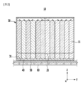
図1は、従来の電池モジュールに対する斜視図であり、図2は、図1の切断線A-A’に沿った断面図である。特に、図2は、電池モジュールの下に位置した熱伝達部材およびヒートシンクを追加的に示した。 FIG. 1 is a perspective view of a conventional battery module, and FIG. 2 is a cross-sectional view taken along line A-A' of FIG. In particular, FIG. 2 additionally showed a heat transfer member and a heat sink located below the battery module.
図1および図2を参照すれば、従来の電池モジュール10は、複数の電池セル11が積層されて電池セル積層体20を形成し、電池セル積層体20は、モジュールフレーム30に収納される。
1 and 2, in a
先に説明したように、複数の電池セル11を含むため、電池モジュール10は、充放電過程で多量の熱を発生させる。冷却手段として、電池モジュール10は、電池セル積層体20とモジュールフレーム30の底部31との間に位置した熱伝導性樹脂層40を含むことができる。また、電池モジュール10がパックフレームに装着されて電池パックを形成する時、電池モジュール10の下に熱伝達部材50およびヒートシンク60が順次に位置することができる。熱伝達部材50は、放熱パッドであってもよいし、ヒートシンク60は、内部に冷媒流路が形成される。
As described above, since the
電池セル11から発生した熱が、熱伝導性樹脂層40、モジュールフレーム30の底部31、熱伝達部材50およびヒートシンク60を順次に経て、電池モジュール10の外部に伝達される。
The heat generated from the
しかし、従来の電池モジュール10の場合、前記のように熱伝達経路が複雑で、電池セル11から発生した熱が効果的に伝達されにくい。モジュールフレーム30自体が熱伝導特性を低下させることがあり、モジュールフレーム30、熱伝達部材50およびヒートシンク60それぞれの間に形成されるエアギャップ(Air gap)などの微細な空気層も熱伝導特性を低下させる要因になりうる。
However, in the case of the
電池モジュールについては小型化や容量増大といった別の要求も求められ続けているので、冷却性能は高めながらもこのような多様な要求事項を併せて満足できる電池モジュールを開発することが実質的に必要といえる。 Since there are continuing demands for battery modules, such as miniaturization and increased capacity, it is practically necessary to develop a battery module that satisfies these various requirements while improving cooling performance. It can be said.
本発明が解決しようとする課題は、冷却性能が向上した電池パックおよびこれを含むデバイスを提供することである。 An object of the present invention is to provide a battery pack with improved cooling performance and a device including the same.
しかし、本発明の実施例が解決しようとする課題は上述した課題に限定されず、本発明に含まれている技術的な思想の範囲で多様に拡張可能である。 However, the problems to be solved by the embodiments of the present invention are not limited to the problems described above, and can be variously expanded within the scope of the technical ideas included in the present invention.
本発明の一実施例による電池パックは、複数の電池モジュールと、前記複数の電池モジュールのうち互いに対向する電池モジュールの間に配置されたパック冷媒管アセンブリと、前記パック冷媒管アセンブリの下部をカバーするパック冷媒管下部カバーと、前記パック冷媒管下部カバーの下側に位置したモジュールトレイと、前記モジュールトレイの下側に位置した下部ハウジングとを含み、前記パック冷媒管下部カバーには下部カバー開口部が形成され、前記下部カバー開口部は、前記モジュールトレイと前記下部ハウジングとの間に形成された空間と連結されている。 A battery pack according to an embodiment of the present invention includes a plurality of battery modules, a pack refrigerant pipe assembly disposed between battery modules facing each other among the plurality of battery modules, and a cover covering a lower portion of the pack refrigerant pipe assembly. a pack refrigerant pipe lower cover, a module tray positioned under the pack refrigerant pipe lower cover, and a lower housing positioned under the module tray, wherein the pack refrigerant pipe lower cover has a lower cover opening. A portion is formed, and the lower cover opening is connected with a space formed between the module tray and the lower housing.
前記複数の電池モジュールは、複数の電池セルが積層されている電池セル積層体と、前記電池セル積層体を収容するモジュールフレームと、前記モジュールフレームの底部に形成されたヒートシンクと、前記ヒートシンクに冷媒を供給および前記ヒートシンクから冷媒を排出する冷却ポートとをそれぞれ含み、前記冷却ポートは、前記下部カバー開口部上に位置することができる。 The plurality of battery modules includes a battery cell stack in which a plurality of battery cells are stacked, a module frame that accommodates the battery cell stack, a heat sink formed at the bottom of the module frame, and a coolant in the heat sink. and a cooling port for supplying and exhausting coolant from the heat sink, respectively, wherein the cooling port can be positioned over the lower cover opening.
前記モジュールフレームは、前記モジュールフレームの底部一部が突出して形成されたモジュールフレーム突出部を含み、前記冷却ポートは、前記モジュールフレーム突出部上において、前記下部カバー開口部の内部を下側から上側へ通過するように突出形成される。 The module frame includes a module frame protrusion formed by protruding a part of the bottom of the module frame, and the cooling port extends from the bottom to the top of the lower cover opening on the module frame protrusion. formed to protrude so as to pass through to the
前記互いに対向する電池モジュールのうち、1つの電池モジュールに形成された冷却ポートと他の1つの電池モジュールに形成された冷却ポートとは、互いに対向するように配置され、前記下部カバー開口部は、複数形成され、互いに対向するように配置された2つの冷却ポートは、複数の前記下部カバー開口部のうちの1つの前記下部カバー開口部上に共に位置することができる。 Among the mutually facing battery modules, a cooling port formed in one battery module and a cooling port formed in another battery module are arranged to face each other, and the lower cover opening is configured to: Two cooling ports formed in plurality and arranged to face each other may be co-located on one of the lower cover openings of the plurality of lower cover openings.
前記モジュールトレイは、モジュールトレイ開口部を含み、前記冷却ポートは、前記モジュールトレイ開口部上に位置することができる。 The module tray may include a module tray opening, and the cooling port may be positioned over the module tray opening.
前記下部カバー開口部は、前記モジュールトレイ開口部を介して前記モジュールトレイと前記下部ハウジングとの間に形成された空間と連結される。 The lower cover opening is connected to a space formed between the module tray and the lower housing through the module tray opening.
前記モジュールトレイと前記下部ハウジングとの間に形成されたモジュールトレイガスケットをさらに含み、前記モジュールトレイガスケットは、前記モジュールトレイと前記下部ハウジングとの間を密封することができる。 A module tray gasket formed between the module tray and the lower housing may be further included, wherein the module tray gasket may seal between the module tray and the lower housing.
前記モジュールトレイは、前記複数の電池モジュールそれぞれの外郭部分に沿って一体に形成され、前記モジュールトレイガスケットは、前記モジュールトレイの外郭部分に沿って形成される。 The module tray is integrally formed along an outer portion of each of the plurality of battery modules, and the module tray gasket is formed along an outer portion of the module tray.
前記パック冷媒管下部カバーと前記モジュールトレイとの間に形成された下部カバーガスケットをさらに含み、前記下部カバーガスケットは、前記パック冷媒管下部カバーと前記モジュールトレイとの間を密封することができる。 A lower cover gasket may be formed between the pack refrigerant tube lower cover and the module tray, and the lower cover gasket may seal between the pack refrigerant tube lower cover and the module tray.
前記下部カバーガスケットは、前記下部カバー開口部およびモジュールトレイ開口部の外側に形成される。 The bottom cover gasket is formed outside the bottom cover opening and the module tray opening.
前記パック冷媒管アセンブリの上部をカバーするパック冷媒管上部カバーをさらに含むことができる。 A pack refrigerant tube upper cover may be further included to cover an upper portion of the pack refrigerant tube assembly.
本発明の他の実施例によるデバイスは、前記電池パックを含む。 A device according to another embodiment of the present invention includes the battery pack.
本発明の実施例によれば、電池モジュールの内部に漏れ出た冷媒の侵入を防止して、短絡による火災発生の可能性を最小化することができる。 According to the embodiments of the present invention, it is possible to prevent leakage of coolant from entering the battery module, thereby minimizing the possibility of a fire due to a short circuit.
本発明の効果は上記の効果に制限されず、言及されていないさらに他の効果は特許請求の範囲の記載から当業者に明確に理解されるであろう。 The effects of the present invention are not limited to the effects described above, and other effects not mentioned will be clearly understood by those skilled in the art from the description of the claims.
以下、添付した図面を参照して、本発明の様々な実施例について、本発明の属する技術分野における通常の知識を有する者が容易に実施できるように詳細に説明する。本発明は種々の異なる形態で実現可能であり、ここで説明する実施例に限定されない。 Various embodiments of the present invention will now be described in detail with reference to the accompanying drawings so that those skilled in the art can easily carry them out. This invention may be embodied in many different forms and is not limited to the illustrative embodiments set forth herein.
本発明を明確に説明するために説明上不必要な部分は省略し、明細書全体にわたって同一または類似の構成要素については同一の参照符号を付す。 In order to clearly explain the present invention, parts that are not necessary for explanation are omitted, and the same or similar components are given the same reference numerals throughout the specification.
また、図面に示された各構成の大きさおよび厚さは説明の便宜のために任意に示したので、本発明が必ずしも図示のところに限定されない。図面において様々な層および領域を明確に表現するために厚さを拡大して示した。そして、図面において、説明の便宜のために、一部の層および領域の厚さを誇張して示した。 In addition, the size and thickness of each component shown in the drawings are arbitrarily shown for convenience of explanation, and the present invention is not necessarily limited to those shown in the drawings. Thicknesses have been exaggerated in the drawings for clarity of the various layers and regions. Also, in the drawings, the thickness of some layers and regions are exaggerated for convenience of explanation.
また、層、膜、領域、板などの部分が他の部分の「上に」あるとする時、これは、他の部分の「直上に」ある場合のみならず、その中間にさらに他の部分がある場合も含む。逆に、ある部分が他の部分の「直上に」あるとする時には、中間に他の部分がないことを意味する。さらに、基準となる部分の「上に」あるというのは、基準となる部分の上または下に位置することであり、必ずしも重力の反対方向に向かって「上に」位置することを意味するわけではない。 Also, when a part such as a layer, film, region, plate, etc., is "on" another part, it means not only that it is "directly on" the other part, but also that there is another part in between. including when there is Conversely, when a part is said to be "directly on" another part, it means that there is no other part in between. Furthermore, being "above" a reference part means being above or below the reference part, not necessarily "above" in the direction opposite to the direction of gravity. isn't it.
また、明細書全体において、ある部分がある構成要素を「含む」とする時、これは、特に反対になる記載がない限り、他の構成要素を除くのではなく、他の構成要素をさらに包含できることを意味する。 Also, throughout the specification, when a part "includes" a component, it does not exclude other components, but further includes other components, unless otherwise specified. means you can.
さらに、明細書全体において、「平面上」とする時、これは、対象部分を上から見た時を意味し、「断面上」とする時、これは、対象部分を垂直に切断した断面を横から見た時を意味する。 Furthermore, throughout the specification, when "on a plane" means when the target part is viewed from above, when "on a cross section" this means a cross section obtained by cutting the target part vertically It means when viewed from the side.
以下、図3~図5を参照して、本実施例による電池モジュールについて説明する。 Hereinafter, the battery module according to this embodiment will be described with reference to FIGS. 3 to 5. FIG.
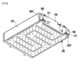
図3は、本発明の一実施例による電池モジュールを示す斜視図である。図4は、図3の電池モジュールの分解斜視図である。図5は、図3の電池モジュールをz軸方向に沿って電池モジュールの下から上へ眺めた斜視図である。 FIG. 3 is a perspective view showing a battery module according to one embodiment of the present invention. 4 is an exploded perspective view of the battery module of FIG. 3. FIG. FIG. 5 is a perspective view of the battery module in FIG. 3 as viewed from below along the z-axis direction.
図3および図4を参照すれば、本発明の一実施例による電池モジュール100は、複数の電池セル110が積層された電池セル積層体120と、電池セル積層体120を収納するモジュールフレーム200と、モジュールフレーム200の底部210aの下に位置するヒートシンク300とを含む。モジュールフレーム200の底部210aは、ヒートシンク300の上部プレートを構成し、ヒートシンク300の陥没部340とモジュールフレーム200の底部210aとが冷媒流路を形成する。
3 and 4, a
まず、電池セル110は、パウチ型電池セルであってもよい。このようなパウチ型電池セルは、樹脂層と金属層とを含むラミネートシートのパウチケースに電極組立体を収納した後、前記パウチケースのシーリング部を熱融着して形成される。この時、電池セル110は、長方形のシート状構造に形成される。
First, the
このような電池セル110は、複数から構成され、複数の電池セル110は、相互電気的に連結できるように積層されて電池セル積層体120を形成する。特に、図4に示されているように、x軸と平行な方向に沿って複数の電池セル110が積層される。
電池セル積層体120を収納するモジュールフレーム200は、上部カバー220と、U字状フレーム210とを含むことができる。
A
U字状フレーム210は、底部210aと、底部210aの両端部から上向延長された2つの側面部210bとを含むことができる。底部210aは、電池セル積層体120の下面をカバーすることができ、側面部210bは、電池セル積層体120の両側面をカバーすることができる。
The
上部カバー220は、U字状フレーム210によって囲まれる前記下面および前記両側面を除いた残りの上面(z軸方向)を囲む1つの板状型構造に形成される。上部カバー220とU字状フレーム210とは、互いに対応する角部位が接触した状態で、溶接などによって結合されることによって、電池セル積層体120を上下左右にカバーする構造を形成することができる。上部カバー220とU字状フレーム210により、電池セル積層体120を物理的に保護することができる。このために、上部カバー220とU字状フレーム210は、所定の強度を有する金属材質を含むことができる。
The
一方、具体的に示さないが、変形例によるモジュールフレーム200は、上面、下面および両側面が一体化された金属板材形態のモノフレームであってもよい。つまり、U字状フレーム210と上部カバー220とが相互結合される構造ではなく、押出成形で製造されて上面、下面および両側面が一体化された構造であってもよい。
Meanwhile, although not specifically shown, the
エンドプレート400は、モジュールフレーム200の開放された互いに対応する両側(y軸方向)に位置し、電池セル積層体120をカバーするように形成される。このようなエンドプレート400は、外部の衝撃から電池セル積層体120およびその他の電装品を物理的に保護することができる。
The
一方、具体的に示さないが、電池セル積層体120とエンドプレート400との間には、バスバーが装着されるバスバーフレームおよび電気的絶縁のための絶縁カバーなどが位置することができる。
Meanwhile, although not specifically shown, between the
本実施例によるモジュールフレーム200は、モジュールフレーム200の底部210aが延びてエンドプレート400を通るように形成されたモジュールフレーム突出部211を含む。この時、モジュールフレーム突出部211の上面部と連結される冷却ポート500によって流入および排出される冷媒が、モジュールフレーム突出部211を通してヒートシンク300に供給およびヒートシンク300から排出される。本実施例による冷却ポート500は、冷媒注入ポート500aと冷媒排出ポート500bとを含み、冷媒注入ポート500aと冷媒排出ポート500bは、後述するパック冷媒供給管およびパック冷媒排出管とそれぞれ連結される。モジュールフレーム突出部211は、モジュールフレーム200の一側において第1モジュールフレーム突出部と第2モジュールフレーム突出部とを含み、冷媒注入ポート500aは、前記第1モジュールフレーム突出部上に配置され、冷媒排出ポート500bは、前記第2モジュールフレーム突出部上に配置される。
The
本実施例によるヒートシンク300の下部プレート310には突出パターン340Dが形成される。本発明の一実施例による電池セル積層体120のように積層される電池セルの個数が従来に比べて多く増える大面積電池モジュールの場合、冷媒流路の幅がより広く形成されて温度偏差がより激しいことがある。大面積電池モジュールでは、かつて1つの電池モジュール内に約12個~24個の電池セルが積層されていた場合に比べて、約32個~48個の電池セルが1つの電池モジュール内に積層されている場合を含むことができる。この場合、本実施例による突出パターン340Dは、冷却流路の幅を実質的に縮小させる効果を発生させて圧力降下を最小化し、同時に冷媒流路の幅間の温度偏差を低減することができる。したがって、均一な冷却効果を実現することができる。
A
以下、図4および図5を参照して、本実施例によるヒートシンクについてより詳しく説明する。 Hereinafter, the heat sink according to this embodiment will be described in more detail with reference to FIGS. 4 and 5. FIG.
図4および図5を参照すれば、上述のとおり、モジュールフレーム200の底部210aは、ヒートシンク300の上部プレートを構成し、ヒートシンク300の陥没部340とモジュールフレーム200の底部210aとが冷媒の流路を形成する。
4 and 5, as described above, the
具体的には、ヒートシンク300は、モジュールフレーム200の下部に形成され、ヒートシンク300は、ヒートシンク300の骨格を形成し、モジュールフレーム200の底部210aと溶接などで直接結合する下部プレート310と、ヒートシンク300の一側に形成されて、外部からヒートシンク300の内部に冷媒を供給するインレット320と、ヒートシンク300の一側に形成されて、ヒートシンク300の内部で流動した冷媒がヒートシンク300の外部に排出されるようにするアウトレット330と、インレット320とアウトレット330とを連結して冷媒が流動する経路である陥没部340とを含むことができる。インレット320とアウトレット330は、モジュールフレーム突出部211の下面部と連結されるように、モジュールフレーム突出部211に対応する位置に形成される。このために、インレット320とアウトレット330は、ヒートシンク300の一辺からモジュールフレーム突出部211が位置した部分に突出したヒートシンク突出部300Pに形成される。ヒートシンク突出部300Pとモジュールフレーム突出部211とは、互いに溶接などの方法で直接結合可能である。
Specifically, the
ヒートシンク300の陥没部340は、下部プレート310が下側に陥没形成された部分に相当する。陥没部340は、冷媒流路が延びる方向を基準として垂直にxy平面で切断した断面がU字状管であってもよいし、前記U字状管の開放された上側に底部210aが位置することができる。ヒートシンク300が底部210aと接しつつ、陥没部340と底部210aとの間の空間が冷媒が流動する領域、つまり、冷媒の流路となる。これによって、モジュールフレーム200の底部210aが前記冷媒と直接接触できる。
The recessed
ヒートシンク300の陥没部340の製造方法に特別な制限はないが、板状型のヒートシンク300に対して陥没形成された構造を設けることによって、上側が開放されたU字状陥没部340を形成することができる。
Although there is no particular limitation on the method of manufacturing the recessed
一方、図示しないが、図4のモジュールフレーム200の底部210aと電池セル積層体120との間に熱伝導性樹脂(Thermal resin)を含む熱伝導性樹脂層が位置することができる。前記熱伝導性樹脂層は、熱伝導性樹脂(Thermal resin)を底部210aに塗布し、塗布された熱伝導性樹脂が硬化して形成される。
Meanwhile, although not shown, a thermally conductive resin layer including thermal resin may be positioned between the
前記熱伝導性樹脂は、熱伝導性接着物質を含むことができ、具体的には、シリコーン(Silicone)素材、ウレタン(Urethan)素材およびアクリル(Acrylic)素材のうちの少なくとも1つを含むことができる。前記熱伝導性樹脂は、塗布時には液状であるが、塗布後に硬化して電池セル積層体120を構成する1つ以上の電池セル110を固定する役割を果たすことができる。また、熱伝導特性に優れ、電池セル110から発生した熱を迅速に電池モジュールの下側に伝達することができる。
The thermally conductive resin may include a thermally conductive adhesive material, and specifically, may include at least one of a silicone material, a urethane material, and an acrylic material. can. The thermally conductive resin is in a liquid state when applied, but hardens after application to serve to fix one or
図2に示された従来の電池モジュール10は、電池セル11から発生した熱が、熱伝導性樹脂層40、モジュールフレーム30の底部31、熱伝達部材50およびヒートシンク60の冷媒を順次に経て、電池モジュール10の外部に伝達される。また、ヒートシンク60の冷媒の流路は、ヒートシンク60の内部に位置する。
In the
これに対し、本実施例による電池モジュール100は、モジュールフレーム200とヒートシンク300との冷却一体型構造を実現して、冷却性能をより向上させることができる。モジュールフレーム200の底部210aがヒートシンク300の上部プレートに対応する役割を果たすことによって、冷却一体型構造を実現することができる。直接冷却による冷却効率が上昇し、ヒートシンク300がモジュールフレーム200の底部210aと一体化された構造により、電池モジュールおよび電池モジュールが装着された電池パック上の空間活用率をより向上させることができる。
On the other hand, the
具体的には、電池セル110から発生した熱が、電池セル積層体120と底部210aとの間に位置する熱伝導性樹脂層(図示せず)、モジュールフレーム200の底部210a、冷媒を経て、電池モジュール100の外部に伝達される。従来の不要な冷却構造を除去することによって、熱伝達経路が単純化され、各層間のエアギャップを低減可能なため、冷却効率や性能が増大できる。特に、底部210aがヒートシンク300の上部プレートとして構成され、底部210aが直に冷媒と当接するため、冷媒を通したより直接的な冷却が可能というメリットがある。従来は、図2に示しているように、底部31と冷媒との間に熱伝達部材50およびヒートシンク60の上部構成が位置して冷却効率が低下するのと比較できる。
Specifically, the heat generated from the
また、不要な冷却構造の除去により、電池モジュール100の高さが減少して、コスト節減が可能であり、空間活用度を高めることができる。さらに、電池モジュール100がコンパクトに配置可能なため、電池モジュール100を多数含む電池パックの容量や出力を増大させることができる。
In addition, since the unnecessary cooling structure is removed, the height of the
一方、モジュールフレーム200の底部210aは、ヒートシンク300のうち陥没部340が形成されない下部プレート310部分と溶接により接合可能である。本実施例は、モジュールフレーム200の底部210aとヒートシンク300との冷却一体型構造により、上述した冷却性能の向上だけでなく、モジュールフレーム200に収容された電池セル積層体120の荷重を支持し、電池モジュール100の剛性を補強する効果を有することができる。それだけでなく、下部プレート310とモジュールフレーム200の底部210aとは、溶接結合などにより密封されることによって、下部プレート310の内側に形成された陥没部340において冷媒が漏れることなく流動できる。
Meanwhile, the
効果的な冷却のために、図5に示されているように、モジュールフレーム200の底部210aに対応する全領域にわたって陥没部340が形成されることが好ましい。このために、陥没部340は、少なくとも1回曲がって一側から他側につながることができる。特に、モジュールフレーム200の底部210aに対応する全領域にわたって陥没部340が形成されるために、陥没部340は数回曲がることが好ましい。
For effective cooling, a
後述するパック冷媒供給管からインレット320を通して冷媒が底部210aと陥没部340との間に流入し、流入した冷媒が冷媒流路に沿って移動した後、アウトレット330を通してパック冷媒排出管に排出される。モジュールフレーム200の底部210aに対応する全領域にわたって形成された冷媒流路の始点から終点まで冷媒が移動することによって、電池セル積層体120の全領域に対する効率的な冷却が行われる。
Refrigerant flows into between the
一方、前記冷媒は、冷却のための媒体として、特別な制限はないが、冷却水であってもよい。 On the other hand, the coolant may be cooling water, although there is no particular limitation as a medium for cooling.
以下、図6~図10を参照して、本発明の一実施例による電池パックの構造について説明する。 The structure of a battery pack according to an embodiment of the present invention will now be described with reference to FIGS. 6 to 10. FIG.
図6は、本発明の一実施例による電池パックを示す斜視図である。図7は、図6の電池パックにおいてPで表した領域を拡大して示す平面図である。図8は、図7においてパック冷媒管下部カバーおよびパック冷媒管上部カバーを除去した様子である。図9は、図7の切断線A-A’に沿った断面図である。図10は、図7の切断線B-B’に沿った断面図である。 FIG. 6 is a perspective view showing a battery pack according to one embodiment of the present invention. 7 is a plan view showing an enlarged region indicated by P in the battery pack of FIG. 6. FIG. FIG. 8 shows a state in which the pack refrigerant pipe lower cover and the pack refrigerant pipe upper cover are removed in FIG. 9 is a cross-sectional view taken along the section line A-A' in FIG. 7. FIG. FIG. 10 is a cross-sectional view along section line B-B' in FIG.
図6~図10を参照すれば、本発明の一実施例による電池パックは、複数の電池モジュール100と、複数の電池モジュール100のうち互いに対向する電池モジュールの間に配置されたパック冷媒管アセンブリ600と、パック冷媒管アセンブリ600の下部をカバーするパック冷媒管下部カバー700と、パック冷媒管下部カバー700の下側に位置したモジュールトレイ800と、モジュールトレイ800の下側に位置した下部ハウジング900とを含む。
6 to 10, a battery pack according to an embodiment of the present invention includes a plurality of
図6を参照すれば、本実施例による電池パックに含まれている複数の電池モジュール100は、電池セルが積層される方向に2列配置され、電池セルが積層される方向に垂直な方向に互いに対向する第1電池モジュールと第2電池モジュールとを含む。前記第1電池モジュールと前記第2電池モジュールは、図6において左右に互いに離隔している電池モジュール100を指すことができる。前記第1電池モジュールと前記第2電池モジュールとの間にパック冷媒管アセンブリ600、パック冷媒管下部カバー700およびパック冷媒管上部カバー740が配置される。
Referring to FIG. 6, a plurality of
本実施例において、パック冷媒管アセンブリ600は、互いに隣り合う電池モジュール100の間に配置される。パック冷媒管アセンブリ600が配置された互いに隣り合う電池モジュール100間の空間には、図8および図9に示されているように、互いに隣り合う電池モジュール100それぞれに形成された冷却ポート500がすべて配置される。この時、互いに隣り合う電池モジュール100のうち、1つの電池モジュールに形成された冷媒注入ポート510と他の1つの電池モジュール100に形成された冷媒排出ポート520とが、互いに対向しながら配置される。
In this embodiment, the pack
図8を参照すれば、パック冷媒供給管621とパック冷媒排出管622とは、互いに交差しながら延びることができる。このようなパック冷媒管620の配置構造を有することによって、電池パック内に複数の電池モジュール100と冷却構造との一体型構造を実現しつつ、空間活用率を高めながら同時に冷却効率も向上させることができる。このようなパック冷媒管620の配置構造を有することができるように、パック冷媒供給管621の高さとパック冷媒排出管622の高さとは互いに異なっていてもよい。パック冷媒供給管621の高さとパック冷媒排出管622の高さとが互いに異なる部分は一部であってよい。
Referring to FIG. 8, the pack
図8~図10を参照すれば、連結ポート610は、冷却ポート500とパック冷媒管620とを連結する。より詳しくは、冷却ポート500は、冷媒注入ポート510と冷媒排出ポート520とを含み、パック冷媒管620は、冷媒注入ポート510に連結されたパック冷媒供給管621と、冷媒排出ポート520に連結されたパック冷媒排出管622とを含み、連結ポート610は、冷媒注入ポート510とパック冷媒供給管621との間、および冷媒排出ポート520とパック冷媒排出管622との間をそれぞれ連結することができる。連結ポート610は、複数の電池モジュール100に冷媒を供給する各冷媒注入ポート510、および複数の電池モジュール100から冷媒を排出する各冷媒排出ポート520のそれぞれに連結されている。
8 to 10, the
パック冷媒管下部カバー700は、パック冷媒管アセンブリ600を収容し、パック冷媒管アセンブリ600から漏れ出た冷媒を周辺の電池モジュールに漏れ出ないようにカバーし、同時に後述する下部カバー開口部を通して漏れ出た冷媒を電池パックの下部空間に案内できる。
The pack refrigerant pipe
モジュールトレイ800は、複数の電池モジュール100の下側に位置し、複数の電池モジュール100が指定された位置に配置されて載置できる構造に形成される。また、モジュールトレイ800を介して複数の電池モジュール100が互いに離隔して配置され、離隔した空間にパック冷媒管アセンブリ600が位置できるように部品の配置空間を提供することができる。
The
図10に示しているように、モジュールトレイ800の下側には下部ハウジング900が位置する。下部ハウジング900とモジュールトレイ800との間には空間Sが形成される。本実施例によれば、パック冷媒管下部カバー700には下部カバー開口部710が形成され、下部カバー開口部710は、モジュールトレイ800と下部ハウジング900との間に形成された空間Sと連結されている。したがって、パック冷媒管アセンブリ600から漏れ出た冷媒は、下部カバー開口部710を介してモジュールトレイ800と下部ハウジング900との間に形成された空間Sに案内される。
As shown in FIG. 10, a
流体を用いた冷却構造において、不良品または製品運送中の事故などの原因で冷媒が漏れ出る状況が発生することがあり、漏れ出た冷媒は電装品の内部に侵入して短絡(short-circuit)を起こすことによって、電池パックに火災が発生する危険がある。したがって、冷媒が漏れ出た時、漏れ出た冷媒が電装品に侵入するのを未然に防止する必要性がある。 In the cooling structure using fluid, the refrigerant may leak due to defective products or accidents during product transportation. ) may cause a fire in the battery pack. Therefore, when the refrigerant leaks, it is necessary to prevent the leaked refrigerant from entering the electrical equipment.
そこで、本発明の一実施例によれば、冷却構造を形成する多様な部材およびそのような部材の連結部から冷媒漏れが発生する場合、これを一定の経路に誘導して、電池パック下部のモジュールトレイ800と下部ハウジング900との間の空間Sに貯留できるようにすることによって、漏れ出た冷媒が電装品の内部に侵入して短絡による火災発生の可能性を未然に防止することができる。
Therefore, according to an embodiment of the present invention, when coolant leaks from various members forming a cooling structure and a connection portion of such members, the leak is guided along a predetermined path, and is located at the bottom of the battery pack. By accumulating in the space S between the
以下、図9~図13を参照して、本発明の一実施例による冷媒誘導構造についてより詳しく説明する。 Hereinafter, a refrigerant induction structure according to an embodiment of the present invention will be described in more detail with reference to FIGS. 9 to 13. FIG.
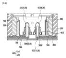
図11は、図7の切断線A-A’に沿った部分の構成を示す模式図である。図12は、図7の切断線B-B’に沿った部分の構成を示す模式図である。図13は、本発明の一実施例による電池パックの冷媒漏れ防止構造の分解斜視図である。 FIG. 11 is a schematic diagram showing the configuration of a portion along the section line A-A' in FIG. FIG. 12 is a schematic diagram showing the configuration of the portion along the section line B-B' in FIG. FIG. 13 is an exploded perspective view of a refrigerant leakage prevention structure for a battery pack according to an embodiment of the present invention.
図12を参照すれば、本実施例による冷却ポート500は、下部カバー開口部710上に位置することができる。より詳しくは、冷却ポート500は、モジュールフレーム突出部211上において、下部カバー開口部710の内部を下側から上側へ通過するように形成される。これによって、冷却ポート500およびこれと連結された連結ポート610、パック冷媒管620から漏れ出た冷媒が、下部カバー開口部710を通して下側空間Sに誘導できる。
Referring to FIG. 12 , the cooling
図9および図11を参照すれば、互いに対向する電池モジュール100のうち、1つの電池モジュールに形成された冷却ポート500と他の1つの電池モジュールに形成された冷却ポート500’とは、互いに対向するように配置され、下部カバー開口部710は、複数形成され、互いに対向するように配置された2つの冷却ポート500、500’は、複数の下部カバー開口部710のうちの1つの下部カバー開口部710上に共に位置することができる。これによって、互いに対向して隣接して位置する2つの冷却ポート500、500’から漏れ出た冷媒を一度に下側空間Sに誘導することができる。
9 and 11, among the
モジュールトレイ800は、モジュールトレイ開口部810を含み、冷却ポート500は、モジュールトレイ開口部810上に位置することができる。この時、下部カバー開口部710は、モジュールトレイ開口部810を介してモジュールトレイ800と下部ハウジング900との間に形成された空間Sと連結される。
The
本実施例によれば、モジュールトレイ800と下部ハウジング900との間に形成されたモジュールトレイガスケット820をさらに含むことができる。モジュールトレイ800は、複数の電池モジュール100それぞれの外郭部分に沿って一体に形成され、モジュールトレイガスケット820は、モジュールトレイ800の外郭部分に沿って形成される。モジュールトレイガスケット820は、モジュールトレイ800と下部ハウジング900との間を密封することができる。これによって、モジュールトレイ800と下部ハウジング900との間の空間Sに流れてきた冷媒が外部に流出しないようにすることができる。
According to this embodiment, a
パック冷媒管下部カバー700とモジュールトレイ800との間に形成された下部カバーガスケット720をさらに含むことができる。下部カバーガスケット720は、下部カバー開口部710およびモジュールトレイ開口部810の外側に形成される。下部カバーガスケット720は、パック冷媒管下部カバー700とモジュールトレイ800との間を密封することができる。下部カバー開口部710を通して流入した冷媒がモジュールトレイ800とパック冷媒管下部カバー700との間に漏れ出ないように、下部カバーガスケット720がモジュールトレイ800とパック冷媒管下部カバー700との間を密封して、下部カバー開口部710を通過した冷媒が、モジュールトレイ開口部810を通ってモジュールトレイ800と下部ハウジング900との間の空間Sに漏れることなく流入できる。
A
本実施例によれば、図13に示されているように、パック冷媒管アセンブリ600の上部をカバーするパック冷媒管上部カバー740をさらに含むことができる。パック冷媒管上部カバー740は、パック冷媒管下部カバー700と共に外部の衝撃からパック冷媒管アセンブリ600を物理的に保護することができる。
According to this embodiment, as shown in FIG. 13, a pack refrigerant
本実施例による電池パックは、本実施例による電池モジュールを1つ以上まとめて電池の温度や電圧などを管理する電池管理システム(Battery Management System;BMS)と冷却装置などを追加してパッキングした構造であってもよい。 The battery pack according to the present embodiment has a structure in which one or more battery modules according to the present embodiment are grouped together, and a battery management system (BMS) for managing battery temperature, voltage, etc., and a cooling device, etc. are added and packed. may be
上述した電池モジュールおよびこれを含む電池パックは、多様なデバイスに適用可能である。このようなデバイスには、電気自転車、電気自動車、ハイブリッド自動車などの運送手段に適用できるが、本発明はこれに限定されず、電池モジュールおよびこれを含む電池パックを使用できる多様なデバイスに適用可能であり、これも本発明の権利範囲に属する。 The battery module and the battery pack including the battery module described above can be applied to various devices. Such devices can be applied to transportation means such as electric bicycles, electric vehicles, and hybrid vehicles, but the present invention is not limited thereto, and can be applied to various devices that can use battery modules and battery packs including the same. , which also belongs to the scope of the present invention.
以上、本発明の好ましい実施例について詳細に説明したが、本発明の権利範囲はこれに限定されるものではなく、以下の特許請求の範囲で定義している本発明の基本概念を利用した当業者の様々な変形および改良形態も本発明の権利範囲に属する。 Although the preferred embodiments of the invention have been described in detail above, the scope of the invention is not limited thereto, but rather is based on the basic concepts of the invention defined in the following claims. Various variations and modifications of the traders are also within the scope of the present invention.
200:モジュールフレーム
211:モジュールフレーム突出部
300:ヒートシンク
500:冷却ポート
600:パック冷媒管アセンブリ
610:連結ポート
620:パック冷媒管
621:パック冷媒供給管
622:パック冷媒排出管
700:パック冷媒管下部カバー
710:下部カバー開口部
720:下部カバーガスケット
740:パック冷媒管上部カバー
800:モジュールトレイ
810:モジュールトレイ開口部
820:モジュールトレイガスケット
900:下部ハウジング
200: Module frame 211: Module frame protrusion 300: Heat sink 500: Cooling port 600: Pack refrigerant tube assembly 610: Connection port 620: Pack refrigerant tube 621: Pack refrigerant supply tube 622: Pack refrigerant discharge tube 700: Pack refrigerant tube bottom Cover 710: Lower cover opening 720: Lower cover gasket 740: Pack refrigerant tube upper cover 800: Module tray 810: Module tray opening 820: Module tray gasket 900: Lower housing
Claims (12)
前記複数の電池モジュールのうち互いに対向する電池モジュールの間に配置されたパック冷媒管アセンブリと、
前記パック冷媒管アセンブリの下部をカバーするパック冷媒管下部カバーと、
前記パック冷媒管下部カバーの下側に位置したモジュールトレイと、
前記モジュールトレイの下側に位置した下部ハウジングとを含み、
前記パック冷媒管下部カバーには下部カバー開口部が形成され、前記下部カバー開口部は、前記モジュールトレイと前記下部ハウジングとの間に形成された空間と連結されている電池パック。 a plurality of battery modules;
a pack refrigerant tube assembly disposed between battery modules facing each other among the plurality of battery modules;
a pack refrigerant tube lower cover covering a lower portion of the pack refrigerant tube assembly;
a module tray positioned under the pack refrigerant pipe lower cover;
a lower housing positioned below the module tray;
A lower cover opening is formed in the pack refrigerant pipe lower cover, and the lower cover opening is connected to a space formed between the module tray and the lower housing.
複数の電池セルが積層されている電池セル積層体と、
前記電池セル積層体を収容するモジュールフレームと、
前記モジュールフレームの底部に形成されたヒートシンクと、
前記ヒートシンクに冷媒を供給および前記ヒートシンクから冷媒を排出する冷却ポートとをそれぞれ含み、
前記冷却ポートは、前記下部カバー開口部上に位置する、請求項1に記載の電池パック。 The plurality of battery modules are
a battery cell stack in which a plurality of battery cells are stacked;
a module frame that houses the battery cell stack;
a heat sink formed on the bottom of the module frame;
cooling ports for supplying coolant to and discharging coolant from the heat sink, respectively;
The battery pack of claim 1, wherein the cooling port is located over the bottom cover opening.
前記冷却ポートは、前記モジュールフレーム突出部上において、前記下部カバー開口部の内部を下側から上側へ通過するように突出形成された、請求項2に記載の電池パック。 the module frame includes a module frame protruding part formed by protruding a part of the bottom of the module frame;
3. The battery pack according to claim 2, wherein the cooling port protrudes from the module frame protruding portion so as to pass through the interior of the lower cover opening from the lower side to the upper side.
前記下部カバー開口部は、複数形成され、
互いに対向するように配置された2つの冷却ポートは、複数の前記下部カバー開口部のうちの1つの前記下部カバー開口部上に共に位置する、請求項2又は3に記載の電池パック。 Among the battery modules facing each other, the cooling port formed in one battery module and the cooling port formed in the other one battery module are arranged to face each other,
A plurality of the lower cover openings are formed,
4. The battery pack according to claim 2 or 3, wherein two cooling ports arranged to face each other are co-located on one of the plurality of lower cover openings.
前記冷却ポートは、前記モジュールトレイ開口部上に位置する、請求項2に記載の電池パック。 the module tray includes a module tray opening;
3. The battery pack of claim 2, wherein said cooling port is located above said module tray opening.
前記モジュールトレイガスケットは、前記モジュールトレイと前記下部ハウジングとの間を密封する、請求項1に記載の電池パック。 further comprising a module tray gasket formed between the module tray and the lower housing;
The battery pack of claim 1, wherein said module tray gasket seals between said module tray and said lower housing.
前記モジュールトレイガスケットは、前記モジュールトレイの外郭部分に沿って形成される、請求項7に記載の電池パック。 the module tray is integrally formed along an outer shell portion of each of the plurality of battery modules;
8. The battery pack of claim 7, wherein the module tray gasket is formed along an outer shell portion of the module tray.
前記下部カバーガスケットは、前記パック冷媒管下部カバーと前記モジュールトレイとの間を密封する、請求項1に記載の電池パック。 further comprising a lower cover gasket formed between the pack refrigerant tube lower cover and the module tray;
The battery pack of claim 1, wherein the bottom cover gasket seals between the pack refrigerant tube bottom cover and the module tray.
Applications Claiming Priority (3)
| Application Number | Priority Date | Filing Date | Title |
|---|---|---|---|
| KR10-2020-0051168 | 2020-04-28 | ||
| KR1020200051168A KR20210132817A (en) | 2020-04-28 | 2020-04-28 | Battery pack and device including the same |
| PCT/KR2021/004054 WO2021221324A1 (en) | 2020-04-28 | 2021-04-01 | Battery pack and device including same |
Publications (2)
| Publication Number | Publication Date |
|---|---|
| JP2022549704A JP2022549704A (en) | 2022-11-28 |
| JP7278480B2 true JP7278480B2 (en) | 2023-05-19 |
Family
ID=78374182
Family Applications (1)
| Application Number | Title | Priority Date | Filing Date |
|---|---|---|---|
| JP2022519316A Active JP7278480B2 (en) | 2020-04-28 | 2021-04-01 | Battery packs and devices containing them |
Country Status (7)
| Country | Link |
|---|---|
| US (1) | US20220376325A1 (en) |
| EP (1) | EP4020672B1 (en) |
| JP (1) | JP7278480B2 (en) |
| KR (1) | KR20210132817A (en) |
| CN (1) | CN114514649B (en) |
| PL (1) | PL4020672T3 (en) |
| WO (1) | WO2021221324A1 (en) |
Citations (3)
| Publication number | Priority date | Publication date | Assignee | Title |
|---|---|---|---|---|
| JP2014192044A (en) | 2013-03-27 | 2014-10-06 | Sanyo Electric Co Ltd | Battery system for vehicle and electric vehicle with battery system |
| JP2018501603A (en) | 2014-12-04 | 2018-01-18 | エルジー・ケム・リミテッド | Battery pack |
| JP2019536214A (en) | 2017-04-04 | 2019-12-12 | エルジー・ケム・リミテッド | Battery pack having crash beam and drainage structure |
Family Cites Families (16)
| Publication number | Priority date | Publication date | Assignee | Title |
|---|---|---|---|---|
| KR101029838B1 (en) * | 2007-06-28 | 2011-04-15 | 주식회사 엘지화학 | Middle and Large-Sized Battery Pack Having Improved Cooling Efficiency |
| KR101218751B1 (en) * | 2010-01-06 | 2013-01-07 | 주식회사 엘지화학 | Middle or Large-sized Battery Pack of Improved Cooling Efficiency |
| JP5434662B2 (en) * | 2010-02-23 | 2014-03-05 | 三菱自動車工業株式会社 | Drainage structure for vehicle battery unit |
| JP2014026825A (en) * | 2012-07-26 | 2014-02-06 | Mitsubishi Motors Corp | Battery cooler |
| KR101579483B1 (en) * | 2014-02-25 | 2015-12-22 | 엘지전자 주식회사 | Battery Pack |
| JP6376378B2 (en) * | 2014-06-20 | 2018-08-22 | 株式会社Ihi | Storage battery unit |
| US10601088B2 (en) * | 2016-10-28 | 2020-03-24 | Tiveni Mergeco, Inc. | Battery module endplate with sealed hole for cooling tube connection |
| KR102196263B1 (en) * | 2016-11-30 | 2020-12-29 | 주식회사 엘지화학 | Battery Pack Having Cooling Structure with Improved Stability for Use of Liquid Coolant |
| KR102172517B1 (en) * | 2017-04-04 | 2020-10-30 | 주식회사 엘지화학 | Battery Pack having crash beam structure |
| KR102050025B1 (en) * | 2017-09-04 | 2020-01-08 | 주식회사 엘지화학 | Battery Pack of coolant direct contact cooling type |
| KR102273195B1 (en) * | 2017-12-27 | 2021-07-05 | 주식회사 엘지에너지솔루션 | Battery module with improved cooling structure |
| CN208127374U (en) * | 2018-04-02 | 2018-11-20 | 东莞市迈泰热传科技有限公司 | It is a kind of for protecting the support holder structure of battery |
| JP6729625B2 (en) * | 2018-04-06 | 2020-07-22 | トヨタ自動車株式会社 | Power storage device |
| CN208400902U (en) * | 2018-07-02 | 2019-01-18 | 深圳市欣旺达综合能源服务有限公司 | Novel energy storage cell packet and its case frame |
| KR20200020482A (en) * | 2018-08-17 | 2020-02-26 | 주식회사 동희산업 | Aluminum battery case for vehicle |
| KR102640329B1 (en) * | 2018-10-19 | 2024-02-22 | 삼성에스디아이 주식회사 | Battery module |
-
2020
- 2020-04-28 KR KR1020200051168A patent/KR20210132817A/en active Search and Examination
-
2021
- 2021-04-01 WO PCT/KR2021/004054 patent/WO2021221324A1/en unknown
- 2021-04-01 CN CN202180005486.6A patent/CN114514649B/en active Active
- 2021-04-01 US US17/767,156 patent/US20220376325A1/en active Pending
- 2021-04-01 EP EP21796245.5A patent/EP4020672B1/en active Active
- 2021-04-01 JP JP2022519316A patent/JP7278480B2/en active Active
- 2021-04-01 PL PL21796245.5T patent/PL4020672T3/en unknown
Patent Citations (3)
| Publication number | Priority date | Publication date | Assignee | Title |
|---|---|---|---|---|
| JP2014192044A (en) | 2013-03-27 | 2014-10-06 | Sanyo Electric Co Ltd | Battery system for vehicle and electric vehicle with battery system |
| JP2018501603A (en) | 2014-12-04 | 2018-01-18 | エルジー・ケム・リミテッド | Battery pack |
| JP2019536214A (en) | 2017-04-04 | 2019-12-12 | エルジー・ケム・リミテッド | Battery pack having crash beam and drainage structure |
Also Published As
| Publication number | Publication date |
|---|---|
| CN114514649A (en) | 2022-05-17 |
| JP2022549704A (en) | 2022-11-28 |
| EP4020672B1 (en) | 2024-01-31 |
| KR20210132817A (en) | 2021-11-05 |
| CN114514649B (en) | 2024-01-05 |
| PL4020672T3 (en) | 2024-04-15 |
| EP4020672A1 (en) | 2022-06-29 |
| EP4020672A4 (en) | 2022-12-28 |
| WO2021221324A1 (en) | 2021-11-04 |
| US20220376325A1 (en) | 2022-11-24 |
Similar Documents
| Publication | Publication Date | Title |
|---|---|---|
| JP7418558B2 (en) | Battery module and battery pack containing it | |
| JP7442920B2 (en) | Battery module and battery pack containing it | |
| JP7353503B2 (en) | Battery packs and devices containing them | |
| JP7199778B2 (en) | Battery modules and battery packs containing the same | |
| JP2022534482A (en) | Battery modules and battery packs containing the same | |
| JP2023513545A (en) | Battery packs and devices containing them | |
| JP2024045691A (en) | Battery packs and devices containing them | |
| JP7436125B2 (en) | Battery module and battery pack containing it | |
| JP7387204B2 (en) | Battery packs and devices containing them | |
| JP7395232B2 (en) | Battery packs and devices containing them | |
| JP7278480B2 (en) | Battery packs and devices containing them | |
| JP7297376B2 (en) | Battery module and battery pack containing same | |
| US20230073470A1 (en) | Battery module and battery pack including the same | |
| CN114586222B (en) | Battery module and battery pack including the same | |
| JP2023535460A (en) | Battery packs and devices containing them | |
| JP2023554656A (en) | Battery packs and devices containing them | |
| KR20210133530A (en) | Battery pack and device including the same | |
| JP2023548377A (en) | Battery packs and devices containing them | |
| JP2024504809A (en) | Battery module and battery pack containing it | |
| KR20210125938A (en) | Battery module and battery pack including the same | |
| JP2023554628A (en) | Battery module and battery pack containing it | |
| KR20230008531A (en) | Battery module, battery pack including the same and manufacturing method of secondary battery |
Legal Events
| Date | Code | Title | Description |
|---|---|---|---|
| A621 | Written request for application examination |
Free format text: JAPANESE INTERMEDIATE CODE: A621 Effective date: 20220325 |
|
| TRDD | Decision of grant or rejection written | ||
| A977 | Report on retrieval |
Free format text: JAPANESE INTERMEDIATE CODE: A971007 Effective date: 20230329 |
|
| A01 | Written decision to grant a patent or to grant a registration (utility model) |
Free format text: JAPANESE INTERMEDIATE CODE: A01 Effective date: 20230410 |
|
| A61 | First payment of annual fees (during grant procedure) |
Free format text: JAPANESE INTERMEDIATE CODE: A61 Effective date: 20230509 |
|
| R150 | Certificate of patent or registration of utility model |
Ref document number: 7278480 Country of ref document: JP Free format text: JAPANESE INTERMEDIATE CODE: R150 |