JP7278293B2 - Uplink and downlink preemption instructions - Google Patents
Uplink and downlink preemption instructions Download PDFInfo
- Publication number
- JP7278293B2 JP7278293B2 JP2020543100A JP2020543100A JP7278293B2 JP 7278293 B2 JP7278293 B2 JP 7278293B2 JP 2020543100 A JP2020543100 A JP 2020543100A JP 2020543100 A JP2020543100 A JP 2020543100A JP 7278293 B2 JP7278293 B2 JP 7278293B2
- Authority
- JP
- Japan
- Prior art keywords
- resources
- ulpi
- uplink
- rur
- bitmap
- Prior art date
- Legal status (The legal status is an assumption and is not a legal conclusion. Google has not performed a legal analysis and makes no representation as to the accuracy of the status listed.)
- Active
Links
Images


Classifications
-
- H—ELECTRICITY
- H04—ELECTRIC COMMUNICATION TECHNIQUE
- H04W—WIRELESS COMMUNICATION NETWORKS
- H04W74/00—Wireless channel access, e.g. scheduled or random access
- H04W74/08—Non-scheduled or contention based access, e.g. random access, ALOHA, CSMA [Carrier Sense Multiple Access]
- H04W74/0833—Non-scheduled or contention based access, e.g. random access, ALOHA, CSMA [Carrier Sense Multiple Access] using a random access procedure
- H04W74/0841—Non-scheduled or contention based access, e.g. random access, ALOHA, CSMA [Carrier Sense Multiple Access] using a random access procedure with collision treatment
-
- H—ELECTRICITY
- H04—ELECTRIC COMMUNICATION TECHNIQUE
- H04W—WIRELESS COMMUNICATION NETWORKS
- H04W72/00—Local resource management
- H04W72/50—Allocation or scheduling criteria for wireless resources
- H04W72/56—Allocation or scheduling criteria for wireless resources based on priority criteria
- H04W72/566—Allocation or scheduling criteria for wireless resources based on priority criteria of the information or information source or recipient
- H04W72/569—Allocation or scheduling criteria for wireless resources based on priority criteria of the information or information source or recipient of the traffic information
-
- H—ELECTRICITY
- H04—ELECTRIC COMMUNICATION TECHNIQUE
- H04L—TRANSMISSION OF DIGITAL INFORMATION, e.g. TELEGRAPHIC COMMUNICATION
- H04L1/00—Arrangements for detecting or preventing errors in the information received
- H04L1/0001—Systems modifying transmission characteristics according to link quality, e.g. power backoff
- H04L1/0009—Systems modifying transmission characteristics according to link quality, e.g. power backoff by adapting the channel coding
- H04L1/0013—Rate matching, e.g. puncturing or repetition of code symbols
-
- H—ELECTRICITY
- H04—ELECTRIC COMMUNICATION TECHNIQUE
- H04L—TRANSMISSION OF DIGITAL INFORMATION, e.g. TELEGRAPHIC COMMUNICATION
- H04L1/00—Arrangements for detecting or preventing errors in the information received
- H04L1/12—Arrangements for detecting or preventing errors in the information received by using return channel
- H04L1/16—Arrangements for detecting or preventing errors in the information received by using return channel in which the return channel carries supervisory signals, e.g. repetition request signals
- H04L1/1607—Details of the supervisory signal
-
- H—ELECTRICITY
- H04—ELECTRIC COMMUNICATION TECHNIQUE
- H04L—TRANSMISSION OF DIGITAL INFORMATION, e.g. TELEGRAPHIC COMMUNICATION
- H04L5/00—Arrangements affording multiple use of the transmission path
- H04L5/003—Arrangements for allocating sub-channels of the transmission path
- H04L5/0048—Allocation of pilot signals, i.e. of signals known to the receiver
- H04L5/005—Allocation of pilot signals, i.e. of signals known to the receiver of common pilots, i.e. pilots destined for multiple users or terminals
-
- H—ELECTRICITY
- H04—ELECTRIC COMMUNICATION TECHNIQUE
- H04L—TRANSMISSION OF DIGITAL INFORMATION, e.g. TELEGRAPHIC COMMUNICATION
- H04L5/00—Arrangements affording multiple use of the transmission path
- H04L5/003—Arrangements for allocating sub-channels of the transmission path
- H04L5/0048—Allocation of pilot signals, i.e. of signals known to the receiver
- H04L5/0051—Allocation of pilot signals, i.e. of signals known to the receiver of dedicated pilots, i.e. pilots destined for a single user or terminal
-
- H—ELECTRICITY
- H04—ELECTRIC COMMUNICATION TECHNIQUE
- H04L—TRANSMISSION OF DIGITAL INFORMATION, e.g. TELEGRAPHIC COMMUNICATION
- H04L5/00—Arrangements affording multiple use of the transmission path
- H04L5/003—Arrangements for allocating sub-channels of the transmission path
- H04L5/0053—Allocation of signaling, i.e. of overhead other than pilot signals
-
- H—ELECTRICITY
- H04—ELECTRIC COMMUNICATION TECHNIQUE
- H04L—TRANSMISSION OF DIGITAL INFORMATION, e.g. TELEGRAPHIC COMMUNICATION
- H04L5/00—Arrangements affording multiple use of the transmission path
- H04L5/14—Two-way operation using the same type of signal, i.e. duplex
-
- H—ELECTRICITY
- H04—ELECTRIC COMMUNICATION TECHNIQUE
- H04W—WIRELESS COMMUNICATION NETWORKS
- H04W52/00—Power management, e.g. TPC [Transmission Power Control], power saving or power classes
- H04W52/04—TPC
- H04W52/06—TPC algorithms
- H04W52/14—Separate analysis of uplink or downlink
- H04W52/146—Uplink power control
-
- H—ELECTRICITY
- H04—ELECTRIC COMMUNICATION TECHNIQUE
- H04W—WIRELESS COMMUNICATION NETWORKS
- H04W72/00—Local resource management
- H04W72/04—Wireless resource allocation
- H04W72/044—Wireless resource allocation based on the type of the allocated resource
- H04W72/0446—Resources in time domain, e.g. slots or frames
-
- H—ELECTRICITY
- H04—ELECTRIC COMMUNICATION TECHNIQUE
- H04W—WIRELESS COMMUNICATION NETWORKS
- H04W72/00—Local resource management
- H04W72/04—Wireless resource allocation
- H04W72/044—Wireless resource allocation based on the type of the allocated resource
- H04W72/0453—Resources in frequency domain, e.g. a carrier in FDMA
-
- H—ELECTRICITY
- H04—ELECTRIC COMMUNICATION TECHNIQUE
- H04W—WIRELESS COMMUNICATION NETWORKS
- H04W72/00—Local resource management
- H04W72/20—Control channels or signalling for resource management
- H04W72/21—Control channels or signalling for resource management in the uplink direction of a wireless link, i.e. towards the network
-
- H—ELECTRICITY
- H04—ELECTRIC COMMUNICATION TECHNIQUE
- H04W—WIRELESS COMMUNICATION NETWORKS
- H04W76/00—Connection management
- H04W76/10—Connection setup
- H04W76/11—Allocation or use of connection identifiers
Description
関連出願の相互参照および優先権主張
本出願は、2018年2月14日に出願された米国仮出願第62/630,546号の優先権を主張する、2019年2月12日に出願された米国出願第16/273,886号の優先権を主張するものであり、両出願は、本出願の譲受人に譲渡され、その全体が参照により本明細書に明確に組み込まれる。
CROSS-REFERENCE AND PRIORITY CLAIM TO RELATED APPLICATIONS This application is a U.S. application filed February 12, 2019 claiming priority to U.S. Provisional Application No. 62/630,546, filed February 14, 2018. No. 16/273,886, both of which are assigned to the assignee of the present application and are hereby expressly incorporated by reference in their entireties.
本開示の態様は、一般に、ワイヤレス通信システムに関し、より詳細には、第1のタイプのユーザ機器(UE)が、第2のタイプのUEに再割り振りされるリソース上で1つまたは複数のアクションを取る(たとえば、チャネル送信のための電力を中断または制御する)ことを可能にする、チャネルプリエンプション指示をシグナリングするための技法に関する。 Aspects of the present disclosure relate generally to wireless communication systems, and more particularly to allowing a first type of user equipment (UE) to perform one or more actions on resources reallocated to a second type of UE. (eg, suspending or controlling power for channel transmissions) for signaling channel preemption indications.
ワイヤレス通信システムは、電話、ビデオ、データ、メッセージング、およびブロードキャストなどの、様々な電気通信サービスを提供するために広く展開されている。一般のワイヤレス通信システムは、利用可能なシステムリソース(たとえば、帯域幅、送信電力)を共有することによって複数のユーザとの通信をサポートすることが可能な多元接続技術を採用し得る。そのような多元接続技術の例は、ロングタームエボリューション(LTE)システム、符号分割多元接続(CDMA)システム、時分割多元接続(TDMA)システム、周波数分割多元接続(FDMA)システム、直交周波数分割多元接続(OFDMA)システム、シングルキャリア周波数分割多元接続(SC-FDMA)システム、および時分割同期符号分割多元接続(TD-SCDMA)システムを含む。 Wireless communication systems are widely deployed to provide various telecommunication services such as telephone, video, data, messaging and broadcast. A typical wireless communication system may employ multiple-access techniques that can support communication with multiple users by sharing available system resources (eg, bandwidth, transmit power). Examples of such multiple access techniques are Long Term Evolution (LTE) systems, Code Division Multiple Access (CDMA) systems, Time Division Multiple Access (TDMA) systems, Frequency Division Multiple Access (FDMA) systems, Orthogonal Frequency Division Multiple Access. (OFDMA) systems, single carrier frequency division multiple access (SC-FDMA) systems, and time division synchronous code division multiple access (TD-SCDMA) systems.
いくつかの例では、ワイヤレス多元接続通信システムは、ユーザ機器(UE)としても知られている複数の通信デバイスのための通信を各々が同時にサポートする、いくつかの基地局を含み得る。LTEまたはLTE-Aネットワークでは、1つまたは複数の基地局のセットがeノードB(eNB)を定義してよい。他の例では(たとえば、次世代または5Gネットワークでは)、ワイヤレス多元接続通信システムは、いくつかの集約ユニット(CU)(たとえば、中央ノード(CN)、アクセスノードコントローラ(ANC)など)と通信するいくつかの分散ユニット(DU)(たとえば、エッジユニット(EU)、エッジノード(EN)、無線ヘッド(RH)、スマート無線ヘッド(SRH)、送信受信ポイント(TRP)など)を含んでよく、集約ユニットと通信する1つまたは複数の分散ユニットのセットがアクセスノード(たとえば、ニューラジオ基地局(NR BS:new radio base station)、ニューラジオノードB(NR NB:new radio node-B)、ネットワークノード、5G NB、gNBなど)を定義してよい。基地局またはDUは、(たとえば、基地局から、またはUEへの送信のための)ダウンリンクチャネルおよび(たとえば、UEから基地局または分散ユニットへの送信のための)アップリンクチャネル上でUEのセットと通信してよい。 In some examples, a wireless multiple-access communication system may include a number of base stations that each simultaneously support communication for multiple communication devices, also known as user equipments (UEs). In an LTE or LTE-A network, a set of one or more base stations may define an eNodeB (eNB). In other examples (e.g., in next-generation or 5G networks), a wireless multiple-access communication system communicates with several aggregation units (CUs) (e.g., central nodes (CN), access node controllers (ANC), etc.). It may contain several distributed units (DUs) (e.g. Edge Units (EU), Edge Nodes (EN), Radio Heads (RH), Smart Radio Heads (SRH), Transmit and Receive Points (TRP), etc.) and aggregate A set of one or more distributed units communicating with the unit is an access node (e.g., new radio base station (NR BS), new radio node-B (NR NB), network node). , 5G NB, gNB, etc.). A base station or DU monitors a UE on a downlink channel (eg, for transmission from the base station or to the UE) and an uplink channel (eg, for transmission from the UE to the base station or distribution unit). You may communicate with the set.
これらの多元接続技術は、異なるワイヤレスデバイスが都市、国家、地域、さらには地球規模で通信することを可能にする共通プロトコルを提供するために、様々な電気通信規格において採用されている。新生の電気通信規格の一例は、ニューラジオ(NR)、たとえば、5G無線アクセスである。NRは、第3世代パートナーシッププロジェクト(3GPP)によって公表されたLTEモバイル規格に対する拡張のセットである。それは、スペクトル効率を改善し、コストを削減し、サービスを改善し、新しいスペクトルを利用し、またダウンリンク(DL)およびアップリンク(UL)上でOFDMAをサイクリックプレフィックス(CP)とともに使用する他のオープン規格とよりうまく統合することによって、モバイルブロードバンドインターネットアクセスをよりうまくサポートし、ならびにビームフォーミング、多入力多出力(MIMO)アンテナ技術、およびキャリアアグリゲーションをサポートするように設計されている。 These multiple-access techniques have been adopted in various telecommunication standards to provide a common protocol that allows different wireless devices to communicate on a city, national, regional and even global scale. An example of an emerging telecommunications standard is New Radio (NR), eg 5G radio access. NR is a set of extensions to the LTE mobile standard promulgated by the 3rd Generation Partnership Project (3GPP). It improves spectral efficiency, reduces costs, improves services, takes advantage of new spectrum, and uses OFDMA with cyclic prefixes (CP) on the downlink (DL) and uplink (UL). It is designed to better support mobile broadband Internet access by better integrating with the open standards of , as well as support beamforming, multiple-input multiple-output (MIMO) antenna technology, and carrier aggregation.
しかしながら、モバイルブロードバンドアクセスに対する需要が増加し続けるにつれて、NR技術のさらなる改善に対する必要が存在する。好ましくは、これらの改善は、他の多元接続技術、およびこれらの技術を採用する電気通信規格に適用可能であるべきである。 However, as the demand for mobile broadband access continues to increase, there is a need for further improvements in NR technology. Preferably, these improvements should be applicable to other multiple access technologies and telecommunications standards that employ these technologies.
本開示のシステム、方法、およびデバイスはそれぞれ、いくつかの態様を有し、それらのうちの単一の態様だけが、その望ましい属性を担うわけではない。以下の特許請求の範囲によって表される本開示の範囲を限定することなく、いくつかの特徴についてここで簡潔に説明する。この説明を考慮した後、また特に「発明を実施するための形態」と題するセクションを読んだ後、本開示の特徴が、ワイヤレスネットワークにおけるアクセスポイントと局との間の改善された通信を含む利点をどのようにもたらすかが理解されよう。 The systems, methods, and devices of the disclosure each have several aspects, no single one of which is solely responsible for its desirable attributes. Without limiting the scope of the disclosure, which is represented by the following claims, some features are briefly described here. After considering this description, and particularly after reading the section entitled "Detailed Description," the features of the present disclosure have the advantage of including improved communication between access points and stations in wireless networks. It will be understood how to bring about
本開示のいくつかの態様は、たとえば、基地局(BS)によって実行され得るワイヤレス通信のための方法を提供する。方法は、一般に、第1のタイプの第1のユーザ機器(UE)によるスケジュールされた送信に対して割り振られたリソースが、第2のタイプの第2のUEに割り振られたアップリンクチャネルリソースと重複すると決定するステップを含む。方法は、決定に基づいて、重複するリソースのうちの少なくともいくつかを特定するアップリンクプリエンプション指示(ULPI)を第2のUEにシグナリングするステップも含む。 Certain aspects of the present disclosure provide a method for wireless communication, which may be performed by a base station (BS), for example. The method generally is such that resources allocated for scheduled transmissions by a first user equipment (UE) of a first type are equal to uplink channel resources allocated to a second UE of a second type. A step of determining duplicates is included. The method also includes signaling to the second UE an uplink preemption indication (ULPI) that identifies at least some of the overlapping resources based on the determination.
本開示のいくつかの態様は、たとえば、ユーザ機器(UE)によって実行され得るワイヤレス通信のための方法を提供する。方法は、一般に、第1のタイプの第1のUEに割り振られたアップリンクチャネルリソースを介して基地局(BS)にアップリンク信号をシグナリングするステップと、BSからアップリンクプリエンプション指示(ULPI)を受信するステップと、ULPIにおいて特定された1つまたは複数のリソースに基づいて1つまたは複数のアクションを取るステップとを含み、1つまたは複数のリソースは、第2のタイプの第2のUEによるスケジュールされた送信のために割り振られたリソースと重複する。 Certain aspects of the disclosure provide a method for wireless communication, which may be performed by, for example, a user equipment (UE). The method generally comprises the steps of signaling an uplink signal to a base station (BS) over uplink channel resources allocated to a first UE of a first type; receiving and taking one or more actions based on one or more resources identified in the ULPI, wherein the one or more resources are by the second UE of the second type Overlaps resources allocated for scheduled transmissions.
本開示のいくつかの態様は、たとえば、基地局(BS)によって実行され得るワイヤレス通信のための方法を提供する。方法は、一般に、第1のタイプの第1のユーザ機器(UE)への送信に対して割り振られたリソースが、第2のタイプの第2のUEに割り振られたダウンリンクチャネルリソースと重複すると決定するステップを含む。方法は、決定に基づいて、クロスキャリア情報を含むとともに、重複するリソースのうちの少なくともいくつかを特定する、ダウンリンクプリエンプション指示(DLPI)を第2のUEにシグナリングするステップも含む。 Certain aspects of the present disclosure provide a method for wireless communication, which may be performed by a base station (BS), for example. The method generally assumes that resources allocated for transmission to a first user equipment (UE) of a first type overlap with downlink channel resources allocated to a second UE of a second type. including the step of determining. The method also includes, based on the determination, signaling to the second UE a downlink preemption indication (DLPI) that includes cross-carrier information and identifies at least some of the overlapping resources.
本開示のいくつかの態様は、たとえば、ユーザ機器(UE)によって実行され得るワイヤレス通信のための方法を提供する。方法は、一般に、第1のタイプの第1のUEに割り振られた1つまたは複数のダウンリンクチャネルリソースを使用して基地局(BS)からダウンリンク信号を受信するステップと、BSからクロスキャリア情報を含むダウンリンクプリエンプション指示(DLPI)を受信するステップと、DLPIにおいて特定された1つまたは複数のリソースに基づいて1つまたは複数のアクションを取るステップとを含み、1つまたは複数のリソースは、第2のタイプの第2のUEへのスケジュールされた送信に対して割り振られたリソースと重複する。 Certain aspects of the disclosure provide a method for wireless communication, which may be performed by, for example, a user equipment (UE). The method generally comprises receiving downlink signals from a base station (BS) using one or more downlink channel resources allocated to a first UE of a first type; receiving a downlink preemption indication (DLPI) containing information; and taking one or more actions based on one or more resources identified in the DLPI, wherein the one or more resources are , overlap with the resources allocated for scheduled transmissions to the second UE of the second type.
態様は、一般に、添付の図面を参照しながら本明細書で十分に説明され、添付の図面によって示される、方法、装置、システム、コンピュータ可読媒体、および処理システムを含む。 Aspects generally include methods, apparatus, systems, computer-readable media, and processing systems, which are fully described herein with reference to and illustrated by the accompanying drawings.
上記の目的および関係する目的を達成するために、1つまたは複数の態様は、以下で十分に説明され、特に特許請求の範囲で指摘される特徴を含む。以下の説明および添付の図面は、1つまたは複数の態様のいくつかの例示的な特徴を詳細に記載する。しかしながら、これらの特徴は、様々な態様の原理が利用され得る様々な方法のほんのいくつかを示すものであり、この説明は、すべてのそのような態様およびそれらの均等物を含むものである。 To the accomplishment of the foregoing and related ends, the one or more embodiments comprise the features hereinafter fully described and particularly pointed out in the claims. The following description and the annexed drawings set forth in detail certain illustrative features of the one or more embodiments. These features are indicative, however, of but a few of the various ways in which the principles of various aspects may be employed and this description is intended to include all such aspects and their equivalents.
本開示の上記の特徴が詳細に理解され得るように、上記で簡単に要約したより具体的な説明が、態様を参照することによって行われることがあり、態様のうちのいくつかは添付の図面に示される。しかしながら、本説明は他の等しく効果的な態様に通じ得るので、添付の図面が、本開示のいくつかの典型的な態様のみを示し、したがって、本開示の範囲を限定するものと見なされるべきではないことに留意されたい。 So that the above features of the disclosure may be understood in detail, a more specific description briefly summarized above may be had by reference to the aspects, some of which are illustrated in the accompanying drawings shown in The accompanying drawings, however, should be considered to limit the scope of the disclosure, however, as the description may lead to other equally effective aspects, showing only certain typical aspects of the disclosure. Note that it is not
理解を容易にするために、可能な場合、図に共通する同一の要素を示すために、同一の参照番号が使用されている。特定の具陳なしに、一態様において開示する要素が他の態様において有利に利用され得ることが企図される。 For ease of understanding, identical reference numbers have been used, where possible, to designate identical elements that are common to the figures. It is contemplated that elements disclosed in one aspect may be advantageously utilized in other aspects without specific recitation.
本開示の態様は、ニューラジオ(NR)(ニューラジオアクセス技術または5G技術)のための装置、方法、処理システム、およびコンピュータ可読媒体を提供する。NRは、拡張モバイルブロードバンド(eMBB:Enhanced mobile broadband)ターゲットの広い帯域幅(たとえば、80MHzを越える)、ミリ波(mmW:millimeter wave)ターゲットの高いキャリア周波数(たとえば、60GHz)、マッシブMTC(mMTC:massive MTC)ターゲットの後方互換性のないMTC技法、および/またはミッションクリティカルターゲットの超高信頼低レイテンシ通信(URLLC:ultra reliable low latency communication)などの、様々なワイヤレス通信サービスをサポートし得る。これらのサービスは、レイテンシ要件および信頼性要件を含み得る。これらのサービスはまた、それぞれのサービス品質(QoS)要件を満たすための異なる送信時間間隔(TTI)を有し得る。加えて、これらのサービスは、同じサブフレームにおいて共存し得る。 Aspects of the present disclosure provide apparatus, methods, processing systems, and computer readable media for New Radio (NR) (New Radio Access Technology or 5G Technology). NR is defined as wide bandwidth (e.g., over 80 MHz) for Enhanced mobile broadband (eMBB) targets, high carrier frequencies (e.g., 60 GHz) for millimeter wave (mmW) targets, and massive MTC (mMTC: various wireless communication services, such as non-backwards compatible MTC techniques for massive MTC) targets, and/or ultra reliable low latency communication (URLLC) for mission-critical targets. These services may have latency and reliability requirements. These services may also have different transmission time intervals (TTI) to meet their respective quality of service (QoS) requirements. Additionally, these services can coexist in the same subframe.
本開示の態様は、非コードブックベースとコードブックベースのアップリンク送信方式の間の動的切替えのための技法および装置を提供する。 Aspects of this disclosure provide techniques and apparatus for dynamic switching between non-codebook-based and codebook-based uplink transmission schemes.
以下の説明は例を提供するものであり、特許請求の範囲に記載される範囲、適用可能性、または例を限定するものではない。本開示の範囲から逸脱することなく、説明する要素の機能および構成に変更が加えられてよい。様々な例は、様々な手順または構成要素を適宜に省略してよく、置換してよく、または追加してよい。たとえば、説明する方法は、説明する順序とは異なる順序で実行されてよく、様々なステップが追加されてよく、省略されてよく、または組み合わせられてよい。また、いくつかの例に関して説明する特徴が、いくつかの他の例では組み合わせられてよい。たとえば、本明細書に記載される任意の数の態様を使用して、装置が実装されてよく、または方法が実践されてよい。加えて、本開示の範囲は、本明細書に記載された本開示の様々な態様に加えて、またはそれらの態様以外に、他の構造、機能、または構造および機能を使用して実践されるそのような装置または方法を包含するものとする。本明細書で開示する本開示のいずれの態様も、請求項の1つまたは複数の要素によって具現化され得ることを理解されたい。「例示的」という語は、本明細書では「例、事例、または例示として機能すること」を意味するために使用される。本明細書で「例示的」であるものとして説明されるいずれの態様も、必ずしも他の態様よりも好ましいまたは有利であると解釈されるべきではない。 The following description provides examples and does not limit the scope, applicability, or examples set forth in the claims. Changes may be made in the function and arrangement of elements described without departing from the scope of the disclosure. Various examples may omit, substitute, or add various procedures or components as appropriate. For example, the methods described may be performed in a different order than that described, and various steps may be added, omitted, or combined. Also, features described with respect to some examples may be combined in some other examples. For example, an apparatus may be implemented or a method may be practiced using any number of the aspects set forth herein. Additionally, the scope of the present disclosure may be practiced using other structures, functions, or structures and functions in addition to or outside of the various aspects of the disclosure described herein. Any such apparatus or method is intended to be included. It should be understood that any aspect of the disclosure disclosed herein may be embodied by one or more elements of a claim. The word "exemplary" is used herein to mean "serving as an example, instance, or illustration." Any aspect described herein as being "exemplary" is not necessarily to be construed as preferred or advantageous over other aspects.
本明細書で説明する技法は、LTE、CDMA、TDMA、FDMA、OFDMA、SC-FDMA、および他のネットワークなどの、様々なワイヤレス通信ネットワークに使用され得る。「ネットワーク」および「システム」という用語は、しばしば、互換的に使用される。CDMAネットワークは、ユニバーサル地上無線アクセス(UTRA)、cdma2000などの無線技術を実装し得る。UTRAは、広帯域CDMA(WCDMA(登録商標))、およびCDMAの他の変形を含む。cdma2000は、IS-2000規格、IS-95規格、およびIS-856規格を対象とする。TDMAネットワークは、モバイル通信用グローバルシステム(GSM(登録商標))などの無線技術を実装し得る。OFDMAネットワークは、NR(たとえば、5G RA)、発展型UTRA(E-UTRA)、ウルトラモバイルブロードバンド(UMB)、IEEE 802.11(Wi-Fi)、IEEE 802.16(WiMAX)、IEEE 802.20、Flash-OFDMAなどの無線技術を実装し得る。UTRAおよびE-UTRAは、ユニバーサルモバイルテレコミュニケーションシステム(UMTS)の一部である。NRは、5G技術フォーラム(5GTF)とともに開発中の新しく出現したワイヤレス通信技術である。3GPPロングタームエボリューション(LTE)およびLTEアドバンスト(LTE-A)は、E-UTRAを使用するUMTSのリリースである。UTRA、E-UTRA、UMTS、LTE、LTE-AおよびGSM(登録商標)は、「第3世代パートナーシッププロジェクト」(3GPP)と称する団体による文書に記載されている。cdma2000およびUMBは、「第3世代パートナーシッププロジェクト2」(3GPP2)と称する団体の文書に記載されている。本明細書で説明する技法は、上述のワイヤレスネットワークおよび無線技術、ならびに他のワイヤレスネットワークおよび無線技術に使用され得る。明確にするために、本明細書では一般に3Gおよび/または4Gワイヤレス技術に関連する用語を使用して態様が説明されることがあるが、本開示の態様は、NR技術を含めて、5G以降のものなどの他の世代ベースの通信システムにおいて適用され得る。
The techniques described herein may be used for various wireless communication networks such as LTE, CDMA, TDMA, FDMA, OFDMA, SC-FDMA and other networks. The terms "network" and "system" are often used interchangeably. A CDMA network may implement a radio technology such as Universal Terrestrial Radio Access (UTRA), cdma2000, and so on. UTRA includes Wideband CDMA (WCDMA®) and other variants of CDMA. cdma2000 covers IS-2000, IS-95 and IS-856 standards. A TDMA network may implement a radio technology such as Global System for Mobile Communications (GSM). OFDMA networks include NR (e.g. 5G RA), Evolved UTRA (E-UTRA), Ultra Mobile Broadband (UMB), IEEE 802.11 (Wi-Fi), IEEE 802.16 (WiMAX), IEEE 802.20, Flash-OFDMA, etc. Wireless technology may be implemented. UTRA and E-UTRA are part of the Universal Mobile Telecommunications System (UMTS). NR is a newly emerging wireless communication technology under development with the 5G Technology Forum (5GTF). 3GPP Long Term Evolution (LTE) and LTE Advanced (LTE-A) are releases of UMTS that use E-UTRA. UTRA, E-UTRA, UMTS, LTE, LTE-A and GSM are described in documents by an organization named "3rd Generation Partnership Project" (3GPP). cdma2000 and UMB are described in documents from an organization named "3rd
例示的なワイヤレス通信システム
図1は、本開示の態様が実行され得る例示的なワイヤレスネットワーク100を示す。たとえば、ワイヤレスネットワーク100は、ニューラジオ(NR)または5Gネットワークであり得る。いくつかの態様では、BS110は、図8および図9に関連して本明細書でさらに説明するように、アップリンクチャネルリソースを第2のタイプのUE(たとえば、URLLC UE)に再割り振りするために、アップリンクプリエンプション指示(ULPI)を第1のタイプのUE(たとえば、eMBB UE)にシグナリングし得る。他の態様では、BS110は、図25および図26に関連して本明細書でさらに説明するように、ダウンリンクチャネルリソースを第2のタイプのUE(たとえば、URLLC UE)に再割り振りするために、ダウンリンクプリエンプション指示(DLPI)を第1のタイプのUE(たとえば、eMBB UE)にシグナリングし得る。
Exemplary Wireless Communication System FIG. 1 shows an
図1に示すように、ワイヤレスネットワーク100は、いくつかのBS110と他のネットワークエンティティとを含み得る。BSは、UEと通信する局であり得る。各BS110は、特定の地理的エリアに通信カバレージを提供し得る。3GPPでは、「セル」という用語は、この用語が使用される状況に応じて、このカバレージエリアにサービスしているノードBおよび/またはノードBサブシステムのカバレージエリアを指すことがある。NRシステムでは、「セル」およびgNB、ノードB、5G NB、AP、NR BS、またはTRPなどの用語は交換可能であり得る。いくつかの例では、セルは、必ずしも静止しているとは限らないことがあり、セルの地理的エリアは、モバイル基地局のロケーションに従って移動し得る。いくつかの例では、基地局は、任意の適切なトランスポートネットワークを使用して、直接物理接続、仮想ネットワークなど、様々なタイプのバックホールインターフェースを通じて、ワイヤレスネットワーク100内で互いに、および/または1つもしくは複数の他の基地局もしくはネットワークノード(図示せず)に相互接続され得る。
As shown in FIG. 1,
一般に、任意の数のワイヤレスネットワークが、所与の地理的エリアにおいて展開されてよい。各ワイヤレスネットワークは、特定の無線アクセス技術(RAT)をサポートしてよく、1つまたは複数の周波数で動作してよい。RATは、無線技術、エアインターフェースなどと呼ばれることもある。周波数は、キャリア、周波数チャネルなどと呼ばれることもある。各周波数は、異なるRATのワイヤレスネットワーク間の干渉を回避するために、所与の地理的エリアにおいて単一のRATをサポートしてよい。場合によっては、NR RATネットワークまたは5G RATネットワークが展開されてよい。 In general, any number of wireless networks may be deployed in a given geographic area. Each wireless network may support a particular radio access technology (RAT) and may operate on one or more frequencies. RAT is also called radio technology, air interface, etc. A frequency may also be referred to as a carrier, frequency channel, or the like. Each frequency may support a single RAT in a given geographical area to avoid interference between wireless networks of different RATs. In some cases, NR RAT networks or 5G RAT networks may be deployed.
BSは、マクロセル、ピコセル、フェムトセル、および/または他のタイプのセルのための通信カバレージを提供し得る。マクロセルは、比較的大きい地理的エリア(たとえば、半径数キロメートル)をカバーすることができ、サービスに加入しているUEによる無制限アクセスを可能にしてよい。ピコセルは、比較的小さい地理的エリアをカバーすることができ、サービスに加入しているUEによる無制限アクセスを可能にしてよい。フェムトセルは、比較的小さい地理的エリア(たとえば、自宅)をカバーすることができ、フェムトセルとの関連を有するUE(たとえば、限定加入者グループ(CSG)内のUE、自宅内のユーザのためのUEなど)による制限付きアクセスを可能にしてよい。マクロセルのためのBSは、マクロBSと呼ばれることがある。ピコセルのためのBSは、ピコBSと呼ばれることがある。フェムトセルのためのBSは、フェムトBSまたはホームBSと呼ばれることがある。図1に示す例では、BS110a、110bおよび110cは、それぞれ、マクロセル102a、102bおよび102cのためのマクロBSであり得る。BS110xは、ピコセル102xのためのピコBSであり得る。BS110yおよび110zは、それぞれ、フェムトセル102yおよび102zのためのフェムトBSであり得る。BSは1つまたは複数(たとえば、3つ)のセルをサポートしてよい。
A BS may provide communication coverage for macrocells, picocells, femtocells, and/or other types of cells. A macrocell may cover a relatively large geographic area (eg, several kilometers in radius) and may allow unrestricted access by UEs with service subscription. A picocell may cover a relatively small geographic area and may allow unrestricted access by UEs with service subscription. A femtocell can cover a relatively small geographical area (e.g., a home) and UEs that have an association with the femtocell (e.g., UEs in a closed subscriber group (CSG), for users within the home). UEs) may allow restricted access. A BS for a macro cell is sometimes called a macro BS. A BS for pico cells is sometimes called a pico BS. A BS for femtocells is sometimes called a femto BS or a home BS. In the example shown in FIG. 1,
ワイヤレスネットワーク100は、中継局も含んでもよい。中継局は、アップストリーム局(たとえばBSまたはUE)からデータおよび/または他の情報の送信を受信し、ダウンストリーム局(たとえば、UEまたBS)にデータおよび/または他の情報の送信を送る局である。また、中継局は、他のUEのための送信を中継するUEであってもよい。図1に示す例では、中継局110rは、BS110aとUE120rとの間の通信を容易にするために、BS110aおよびUE120rと通信することができる。中継局はまた、リレーBS、リレーなどと呼ばれることもある。
ワイヤレスネットワーク100は、異なるタイプのBS、たとえば、マクロBS、ピコBS、フェムトBS、リレーなどを含む異種ネットワークとすることができる。これらの異なるタイプのBSは、異なる送信電力レベル、異なるカバレージエリア、およびワイヤレスネットワーク100中の干渉に対する異なる影響を有してよい。たとえば、マクロBSは高い送信電力レベル(たとえば、20ワット)を有することがあり、一方で、ピコBS、フェムトBS、およびリレーはより低い送信電力レベル(たとえば、1ワット)を有することがある。
ワイヤレスネットワーク100は、同期動作または非同期動作をサポートしてよい。同期動作の場合、BSは、同様のフレームタイミングを有することができ、異なるBSからの送信は、時間的にほぼ整合し得る。非同期動作の場合、BSは、異なるフレームタイミングを有する場合があり、異なるBSからの送信は、時間的に整合していない場合がある。本明細書で説明する技法は、同期動作と非同期動作の両方に使用されてよい。
ネットワークコントローラ130は、BSのセットに結合し、これらのBSのための調整および制御を行い得る。ネットワークコントローラ130は、バックホールを介してBS110と通信し得る。BS110はまた、たとえば、直接、または間接的にワイヤレスバックホールもしくは有線バックホールを介して、互いに通信し得る。
A
UE120(たとえば、120x、120yなど)は、ワイヤレスネットワーク100の全体にわたって分散されてよく、各UEは静止であってよく、またはモバイルであってよい。UEは、移動局、端末、アクセス端末、加入者ユニット、局、顧客構内設備(CPE:Customer Premises Equipment)、セルラーフォン、スマートフォン、携帯情報端末(PDA)、ワイヤレスモデム、ワイヤレス通信デバイス、ハンドヘルドデバイス、ラップトップコンピュータ、コードレスフォン、ワイヤレスローカルループ(WLL)局、タブレット、カメラ、ゲームデバイス、ネットブック、スマートブック、ウルトラブック、医療デバイスもしくは医療機器、生体センサー/デバイス、スマートウォッチ、スマート衣料、スマートグラス、スマートリストバンド、スマートジュエリー(たとえば、スマートリング、スマートブレスレットなど)などのウェアラブルデバイス、娯楽デバイス(たとえば、音楽デバイス、ビデオデバイス、衛星無線など)、車両コンポーネントもしくは車両センサー、スマートメータ/センサー、工業生産機器、全地球測位システムデバイス、またはワイヤレス媒体もしくはワイヤード媒体を介して通信するように構成された任意の他の適切なデバイスと呼ばれる場合もある。いくつかのUEは、発展型もしくはマシンタイプ通信(MTC)デバイス、または発展型MTC(eMTC)デバイスと見なされる場合がある。MTC UEおよびeMTC UEは、BS、別のデバイス(たとえば、リモートデバイス)、または何らかの他のエンティティと通信することができる、たとえば、ロボット、ドローン、リモートデバイス、センサー、メータ、モニタ、ロケーションタグなどを含む。ワイヤレスノードは、たとえば、ワイヤード通信リンクまたはワイヤレス通信リンクを介して、ネットワーク(たとえば、インターネットもしくはセルラーネットワークなどのワイドエリアネットワーク)のための、またはネットワークへの接続性を提供し得る。いくつかのUEは、モノのインターネット(IoT)デバイスと見なされてよい。
UEs 120 (eg, 120x, 120y, etc.) may be dispersed throughout
図1において、両矢印を有する実線は、UEとサービングBSとの間の所望の送信を示し、サービングBSは、ダウンリンクおよび/またはアップリンク上でUEにサービスするように指定されたBSである。両矢印を有する細かい破線は、UEとBSとの間の干渉する送信を示す。 In FIG. 1, the solid line with double arrows indicates the desired transmission between the UE and the serving BS, which is the BS designated to serve the UE on the downlink and/or uplink. . A fine dashed line with double arrows indicates interfering transmissions between a UE and a BS.
特定のワイヤレスネットワーク(たとえば、LTE)は、ダウンリンク上で直交周波数分割多重化(OFDM)を利用し、かつアップリンク上でシングルキャリア周波数分割多重化(SC-FDM)を利用する。OFDMおよびSC-FDMは、システム帯域幅を、一般に、トーン、ビンなどとも呼ばれる、複数の(K個の)直交サブキャリアに区分する。各サブキャリアは、データで変調され得る。一般に、変調シンボルは、OFDMでは周波数領域において送られ、SC-FDMでは時間領域において送られる。隣接するサブキャリア間の間隔は固定される場合があり、サブキャリアの総数(K)は、システム帯域幅に依存する場合がある。たとえば、サブキャリアの間隔は15kHzであってよく、最小のリソース割振り(「リソースブロック」と呼ばれる)は12個のサブキャリア(または180kHz)であってよい。その結果、公称FFTサイズは、1.25、2.5、5、10または20メガヘルツ(MHz)のシステム帯域幅に対して、それぞれ、128、256、512、1024または2048に等しくなり得る。システム帯域幅はまた、サブバンドに区分され得る。たとえば、サブバンドは、1.8MHz(すなわち、6個のリソースブロック)をカバーすることができ、1.25、2.5、5、10または20MHzのシステム帯域幅に対して、それぞれ、1、2、4、8または16個のサブバンドが存在し得る。 Certain wireless networks (eg, LTE) utilize orthogonal frequency division multiplexing (OFDM) on the downlink and single-carrier frequency division multiplexing (SC-FDM) on the uplink. OFDM and SC-FDM partition the system bandwidth into multiple (K) orthogonal subcarriers, also commonly called tones, bins, and so on. Each subcarrier may be modulated with data. In general, modulation symbols are sent in the frequency domain with OFDM and in the time domain with SC-FDM. The spacing between adjacent subcarriers may be fixed, and the total number of subcarriers (K) may depend on the system bandwidth. For example, the subcarrier spacing may be 15kHz, and the minimum resource allocation (called a "resource block") may be 12 subcarriers (or 180kHz). As a result, the nominal FFT size can be equal to 128, 256, 512, 1024 or 2048 for system bandwidths of 1.25, 2.5, 5, 10 or 20 megahertz (MHz) respectively. The system bandwidth may also be partitioned into subbands. For example, a subband can cover 1.8 MHz (i.e., 6 resource blocks), with 1, 2, 4, 8 subbands, respectively, for system bandwidths of 1.25, 2.5, 5, 10 or 20 MHz. Or there can be 16 subbands.
本明細書で説明する例の態様はLTE技術に関連付けられ得るが、本開示の態様は、NRなど、他のワイヤレス通信システムに適用可能であり得る。 Although aspects of the examples described herein may relate to LTE technology, aspects of the disclosure may be applicable to other wireless communication systems, such as NR.
NRは、アップリンクおよびダウンリンク上でCPを用いてOFDMを利用し、TDDを使用する半二重動作に対するサポートを含み得る。100MHzの単一のコンポーネントキャリア帯域幅がサポートされ得る。NRリソースブロックは、0.1msの持続時間にわたって、サブキャリア帯域幅が75kHzの12個のサブキャリアにまたがり得る。各無線フレームは、10msの長さを有する50個のサブフレームで構成され得る。結果として、各サブフレームは0.2msの長さを有することができる。各サブフレームは、データ送信用のリンク方向(すなわち、DLまたはUL)を示してよく、サブフレームごとのリンク方向は、動的に切り替えられてよい。各サブフレームは、DL/ULデータならびにDL/UL制御データを含み得る。NRに関するULサブフレームおよびDLサブフレームは、図6および図7に関して以下でより詳細に説明されるようなものであり得る。eMBBおよび/またはURLLCなど、いくつかのNRネットワークに対して、各サブフレームは、最大で4つのスロットを含むサブキャリアを含み得る。スロットは、最大で14個のミニスロット、および最大で14個のOFDMシンボルを含み得る。ミニスロットは、1つまたは複数のOFDMシンボルを含み得る。1つのスロット内のOFDMシンボルは、ダウンリンク、フレキシブル(すなわち、ダウンリンクまたはアップリンク)、またはアップリンクとして分類され得る。ビームフォーミングがサポートされ得、ビーム方向が動的に構成され得る。プリコーディングを用いたMIMO送信もサポートされ得る。DLにおけるMIMO構成は、最大で8個のストリームおよびUEごとに最大で2個のストリームを用いたマルチレイヤDL送信で最大で8個の送信アンテナをサポートし得る。UEごとに最大で2個のストリームを用いたマルチレイヤ送信がサポートされ得る。最大で8個のサービングセルを用いて複数のセルのアグリゲーションがサポートされ得る。代替として、NRは、OFDMベース以外の異なるエアインターフェースをサポートし得る。NRネットワークは、CUおよび/またはDUなどのエンティティを含み得る。 NR utilizes OFDM with CP on the uplink and downlink and may include support for half-duplex operation using TDD. A single component carrier bandwidth of 100MHz may be supported. An NR resource block may span 12 subcarriers with a subcarrier bandwidth of 75 kHz for a duration of 0.1 ms. Each radio frame may consist of 50 subframes with a length of 10 ms. As a result, each subframe can have a length of 0.2ms. Each subframe may indicate a link direction (ie, DL or UL) for data transmission, and the link direction for each subframe may be dynamically switched. Each subframe may contain DL/UL data as well as DL/UL control data. The UL and DL subframes for NR may be as described in more detail below with respect to FIGS. For some NR networks, such as eMBB and/or URLLC, each subframe may contain subcarriers containing up to four slots. A slot may include up to 14 minislots and up to 14 OFDM symbols. A minislot may contain one or more OFDM symbols. OFDM symbols within one slot may be classified as downlink, flexible (ie, downlink or uplink), or uplink. Beamforming may be supported and beam directions may be dynamically configured. MIMO transmission with precoding may also be supported. A MIMO configuration in the DL may support up to 8 transmit antennas with multi-layer DL transmissions with up to 8 streams and up to 2 streams per UE. Multi-layer transmission with up to two streams per UE may be supported. Aggregation of multiple cells may be supported with up to 8 serving cells. Alternatively, NR may support different air interfaces other than OFDM-based. An NR network may include entities such as CUs and/or DUs.
いくつかの例では、エアインターフェースへのアクセスがスケジュールされてよく、スケジューリングエンティティ(たとえば、基地局)は、そのサービスエリアまたはセル内のいくつかのまたはすべてのデバイスおよび機器の間で通信のためのリソースを割り振る。本開示内では、以下でさらに説明するように、スケジューリングエンティティは、1つまたは複数の従属エンティティ用のリソースをスケジュールすること、割り当てること、再構成すること、および解放することを担当し得る。すなわち、スケジュールされた通信に対して、従属エンティティは、スケジューリングエンティティによって割り振られたリソースを利用する。基地局は、スケジューリングエンティティとして機能し得る唯一のエンティティではない。すなわち、いくつかの例では、UEが、1つまたは複数の従属エンティティ(たとえば、1つまたは複数の他のUE)のためのリソースをスケジュールする、スケジューリングエンティティとして機能し得る。この例では、UEは、スケジューリングエンティティとして機能しており、他のUEは、ワイヤレス通信のためにUEによってスケジュールされたリソースを利用する。UEは、ピアツーピア(P2P)ネットワーク中および/またはメッシュネットワーク中でスケジューリングエンティティとして機能し得る。メッシュネットワーク例では、UEは、スケジューリングエンティティと通信することに加えて、場合によっては互いに直接通信し得る。 In some examples, access to the air interface may be scheduled, and a scheduling entity (e.g., a base station) provides communication between some or all devices and equipment within its coverage area or cell. Allocate resources. Within this disclosure, a scheduling entity may be responsible for scheduling, allocating, reconfiguring, and releasing resources for one or more dependent entities, as described further below. That is, for scheduled communications, dependent entities utilize resources allocated by the scheduling entity. A base station is not the only entity that can act as a scheduling entity. That is, in some examples, a UE may act as a scheduling entity that schedules resources for one or more dependent entities (eg, one or more other UEs). In this example, the UE is acting as a scheduling entity and other UEs utilize resources scheduled by the UE for wireless communication. A UE may act as a scheduling entity in a peer-to-peer (P2P) network and/or in a mesh network. In a mesh network example, UEs may communicate directly with each other in some cases in addition to communicating with a scheduling entity.
したがって、時間-周波数リソースへのスケジュールされたアクセスを伴い、セルラー構成、P2P構成、およびメッシュ構成を有するワイヤレス通信ネットワークでは、スケジューリングエンティティおよび1つまたは複数の従属エンティティは、スケジュールされたリソースを利用して通信し得る。 Thus, in wireless communication networks with scheduled access to time-frequency resources and having cellular, P2P and mesh configurations, the scheduling entity and one or more subordinate entities utilize the scheduled resources. can communicate.
上述のように、RANは、CUおよびDUを含み得る。NR BS(たとえば、gNB、5G NB、NB、TRP、AP)が、1つまたは複数のBSに対応し得る。NRセルは、アクセスセル(ACell)またはデータオンリーセル(DCell)として構成され得る。たとえば、RAN(たとえば、集約ユニットまたは分散ユニット)は、セルを構成することができる。DCellは、キャリアアグリゲーションまたは二重接続性に使用されるが、初期アクセス、セル選択/再選択、またはハンドオーバに使用されないセルであり得る。場合によっては、DCellは同期信号を送信しないことがあり、場合によっては、DCellはSSを送信することがある。NR BSは、セルタイプを示すダウンリンク信号をUEに送信し得る。セルタイプ指示に基づいて、UEはNR BSと通信し得る。たとえば、UEは、示されたセルタイプに基づいて、セル選択用、アクセス用、ハンドオーバ用、および/または測定用と見なすべきNR BSを決定し得る。 As noted above, a RAN may include CUs and DUs. A NR BS (eg, gNB, 5G NB, NB, TRP, AP) may correspond to one or more BSs. An NR cell can be configured as an access cell (ACell) or a data only cell (DCell). For example, a RAN (eg, aggregation unit or distribution unit) may constitute a cell. A DCell may be a cell used for carrier aggregation or dual connectivity, but not used for initial access, cell selection/reselection, or handover. In some cases, the DCell may not transmit synchronization signals, and in other cases, the DCell may transmit SS. The NR BS may send a downlink signal to the UE indicating the cell type. Based on the cell type indication, the UE may communicate with the NR BS. For example, the UE may determine which NR BSs to consider for cell selection, access, handover, and/or measurement based on the indicated cell type.
図2は、図1に示したワイヤレス通信システム内で実装され得る分散型無線アクセスネットワーク(RAN)200の例示的な論理アーキテクチャを示す。5Gアクセスノード206は、アクセスノードコントローラ(ANC)202を含み得る。ANCは、分散型RAN200の集約ユニット(CU)であってよい。次世代コアネットワーク(NG-CN:next generation core network)204へのバックホールインターフェースは、ANCにおいて終端し得る。近隣次世代アクセスノード(NG-AN)へのバックホールインターフェースは、ANCにおいて終端し得る。ANCは、1つまたは複数のTRP208(BS、NR BS、ノードB、5G NB、AP、または何らかの他の用語で呼ばれることもある)を含み得る。上記で説明したように、TRPは「セル」と交換可能に使用され得る。
FIG. 2 shows an exemplary logical architecture of a distributed radio access network (RAN) 200 that may be implemented within the wireless communication system shown in FIG. A
TRP208は、DUであってよい。TRPは、1つのANC(ANC202)に接続されてよく、または2つ以上のANC(図示せず)に接続されてよい。たとえば、RAN共有、サービスとしての無線(RaaS:radio as a service)、およびサービス固有ANC配置に対して、TRPは2つ以上のANCに接続され得る。TRPは、1つまたは複数のアンテナポートを含み得る。TRPは、UEへのトラフィックを個別に(たとえば、動的選択)または一緒に(たとえば、共同送信)サービスするように構成され得る。
ローカルアーキテクチャ200は、フロントホール定義を示すために使用され得る。異なる展開タイプにわたるフロントホール(fronthauling)解決策をサポートするアーキテクチャが定義され得る。たとえば、アーキテクチャは、送信ネットワーク能力(たとえば、帯域幅、レイテンシ、および/またはジッタ)に基づき得る。
A
アーキテクチャは、特徴および/または構成要素をLTEと共有し得る。態様によれば、次世代AN(NG-AN)210は、NRとの二重接続性をサポートし得る。NG-ANは、LTEおよびNRに対して共通フロントホールを共有し得る。 The architecture may share features and/or components with LTE. According to an aspect, Next Generation AN (NG-AN) 210 may support dual connectivity with NR. NG-AN may share a common fronthaul for LTE and NR.
アーキテクチャは、TRP208間の協働を可能にし得る。たとえば、協働は、TRP内にプリセットされてよく、かつ/またはANC202を経由してTRPにわたってプリセットされてよい。態様によれば、TRP間インターフェースが必要とされない/存在しない場合がある。
The architecture may allow cooperation between
態様によれば、アーキテクチャ200内に、分割された論理機能の動的構成が存在する場合がある。図5を参照しながらより詳細に説明するように、無線リソース制御(RRC)レイヤ、パケットデータコンバージェンスプロトコル(PDCP)レイヤ、無線リンク制御(RLC)レイヤ、媒体アクセス制御(MAC)レイヤ、および物理(PHY)レイヤは、DUまたはCU(たとえば、それぞれTRPまたはANC)に適応可能に配置され得る。いくつかの態様によれば、BSは、集約ユニット(CU)(たとえば、ANC202)および/または1つもしくは複数の分散ユニット(たとえば、1つもしくは複数のTRP208)を含んでよい。
According to aspects, within
図3は、本開示のいくつかの態様による、分散型RAN300の例示的な物理アーキテクチャを示す。集中型コアネットワークユニット(C-CU)302が、コアネットワーク機能をホストし得る。C-CUは、中央に配置されてよい。C-CU機能は、ピーク容量に対処しようとして、(たとえば、アドバンストワイヤレスサービス(AWS)に)オフロードされ得る。
FIG. 3 illustrates an example physical architecture of distributed
集中型RANユニット(C-RU)304が、1つまたは複数のANC機能をホストし得る。場合によっては、C-RUは、コアネットワーク機能を局所的にホストし得る。C-RUは分散配置を有してよい。C-RUは、ネットワークエッジのより近くにあってよい。 A centralized RAN unit (C-RU) 304 may host one or more ANC functions. In some cases, the C-RU may host core network functions locally. C-RUs may have a distributed arrangement. C-RUs may be closer to the network edge.
DU306が、1つまたは複数のTRP(エッジノード(EN)、エッジユニット(EU)、無線ヘッド(RH)、スマート無線ヘッド(SRH)など)をホストし得る。DUは、無線周波数(RF)機能を備えたネットワークのエッジに位置し得る。
図4は、本開示の態様を実施するために使用され得る、図1に示すBS110およびUE120の例示的な構成要素を示す。BS110およびUE120の1つまたは複数の構成要素は、本開示の態様を実践するために使用され得る。たとえば、UE120のアンテナ452、Tx/Rx222、プロセッサ466、458、464、および/もしくはコントローラ/プロセッサ480、ならびに/またはBS110のアンテナ434、プロセッサ430、420、438、および/もしくはコントローラ/プロセッサ440は、本明細書で説明するとともに図8および図9を参照しながら示される動作を実行するために使用され得る。
FIG. 4 shows exemplary components of
図4は、図1におけるBSのうちの1つおよびUEのうちの1つであってよい、BS110およびUE120の設計のブロック図を示す。制限された接続シナリオの場合、基地局110は図1のマクロBS110cであってよく、UE120はUE120yであってよい。基地局110はまた、何らかの他のタイプの基地局であり得る。基地局110は、アンテナ434a~434tを備えることができ、UE120は、アンテナ452a~452rを備えることができる。
FIG. 4 shows a block diagram of a design of
基地局110において、送信プロセッサ420は、データソース412からデータを受信し、コントローラ/プロセッサ440から制御情報を受信し得る。制御情報は、物理ブロードキャストチャネル(PBCH)、物理制御フォーマットインジケータチャネル(PCFICH)、物理ハイブリッドARQインジケータチャネル(PHICH)、物理ダウンリンク制御チャネル(PDCCH)などに関するものであってよい。データは、物理ダウンリンク共有チャネル(PDSCH)などに関するものであってよい。プロセッサ420は、データおよび制御情報を処理(たとえば、符号化およびシンボルマッピング)して、それぞれデータシンボルおよび制御シンボルを取得することができる。プロセッサ420はまた、たとえば、PSS、SSS、およびセル固有基準信号に関する基準シンボルを生成することもできる。送信(TX)多入力多出力(MIMO)プロセッサ430は、適用可能な場合には、データシンボル、制御シンボル、および/または基準シンボルに対して空間処理(たとえば、プリコーディング)を実行することができ、出力シンボルストリームを変調器(MOD)432a~432tに提供することができる。各変調器432は、(たとえば、OFDMなどのための)それぞれの出力シンボルストリームを処理して、出力サンプルストリームを取得することができる。各変調器432は、出力サンプルストリームをさらに処理(たとえば、アナログに変換、増幅、フィルタリング、およびアップコンバート)して、ダウンリンク信号を取得することができる。変調器432a~432tからのダウンリンク信号を、それぞれアンテナ434a~434tを介して送信してよい。
At
UE120において、アンテナ452a~452rは、基地局110からダウンリンク信号を受信することができ、受信信号をそれぞれ復調器(DEMOD)454a~454rに提供することができる。各復調器454は、それぞれの受信信号を調整(たとえば、フィルタリング、増幅、ダウンコンバート、およびデジタル化)して、入力サンプルを取得することができる。各復調器454は、(たとえば、OFDMなどのための)入力サンプルをさらに処理して、受信シンボルを取得することができる。MIMO検出器456は、すべての復調器454a~454rから受信シンボルを取得し、適用可能な場合、受信シンボルに対してMIMO検出を実行し、検出されたシンボルを提供することができる。受信プロセッサ458は、検出されたシンボルを処理(たとえば、復調、デインターリーブ、および復号)し、UE120のための復号されたデータをデータシンク460に提供し、復号された制御情報をコントローラ/プロセッサ480に提供することができる。
At
アップリンクでは、UE120において、送信プロセッサ464が、データソース462からの(たとえば、物理アップリンク共有チャネル(PUSCH)についての)データ、およびコントローラ/プロセッサ480からの(たとえば、物理アップリンク制御チャネル(PUCCH)についての)制御情報を受信し、処理してよい。送信プロセッサ464はまた、基準信号のための基準シンボルを生成し得る。送信プロセッサ464からのシンボルは、適用可能な場合には、TX MIMOプロセッサ466によってプリコーディングされ、(たとえばSC-FDMなどのために)復調器454a~454rによってさらに処理され、基地局110に送信されてよい。BS110において、UE120からのアップリンク信号は、アンテナ434によって受信され、変調器432によって処理され、適用可能な場合には、MIMO検出器436によって検出され、受信プロセッサ438によってさらに処理されて、UE120によって送られた復号データおよび制御情報を取得し得る。受信プロセッサ438は、データシンク439に復号されたデータを提供し、コントローラ/プロセッサ440に復号された制御情報を提供してよい。
On the uplink, in
コントローラ/プロセッサ440および480は、それぞれ基地局110およびUE120における動作を指示し得る。BS110におけるプロセッサ440および/または他のプロセッサとモジュールとは、たとえば、図8および図27に示す機能ブロックおよび/または本明細書で説明する技法のための他のプロセスを実行、またはその実行を指示し得る。UE120におけるプロセッサ480および/または他のプロセッサとモジュールとはまた、たとえば、図9および図28に示す機能ブロックおよび/または本明細書で説明する技法のための他のプロセスを実行、またはその実行を指示し得る。メモリ442および482は、それぞれBS110およびUE120のためのデータおよびプログラムコードを記憶し得る。スケジューラ444は、ダウンリンクおよび/またはアップリンク上でのデータ送信のためにUEをスケジューリングし得る。
Controllers/
図5は、本開示の態様による、通信プロトコルスタックを実装するための例を示す図500を示す。示された通信プロトコルスタックは、5Gシステム(たとえば、アップリンクベースのモビリティをサポートするシステム)内で動作するデバイスによって実装され得る。図500は、無線リソース制御(RRC)レイヤ510、パケットデータコンバージェンスプロトコル(PDCP)レイヤ515、無線リンク制御(RLC)レイヤ520、媒体アクセス制御(MAC)レイヤ525、および物理(PHY)レイヤ530を含む通信プロトコルスタックを示す。様々な例では、プロトコルスタックのレイヤは、ソフトウェアの個別のモジュール、プロセッサもしくはASICの部分、通信リンクによって接続された非コロケートデバイスの部分、またはそれらの様々な組合せとして実装され得る。コロケート実装形態および非コロケート実装形態は、たとえば、ネットワークアクセスデバイス(たとえば、AN、CU、および/もしくはDU)またはUEのためのプロトコルスタックの中で使用されてよい。
FIG. 5 shows a diagram 500 illustrating an example for implementing communication protocol stacks, according to aspects of the present disclosure. The illustrated communication protocol stacks may be implemented by devices operating within 5G systems (eg, systems supporting uplink-based mobility). The diagram 500 includes a radio resource control (RRC)
第1のオプション505-aは、プロトコルスタックの実装が集中ネットワークアクセスデバイス(たとえば、図2のANC202)と分散ネットワークアクセスデバイス(たとえば、図2のDU208)との間で分割される、プロトコルスタックの分割実装形態を示す。第1のオプション505-aでは、RRCレイヤ510およびPDCPレイヤ515は、集約ユニットによって実装されてよく、RLCレイヤ520、MACレイヤ525、およびPHYレイヤ530は、DUによって実装されてよい。様々な例では、CUおよびDUは、コロケートされてよく、またはコロケートされなくてもよい。第1のオプション505-aは、マクロセル配置、マイクロセル配置、またはピコセル配置において有用であり得る。
A first option 505-a is protocol stack implementation split between a centralized network access device (eg,
第2のオプション505-bは、プロトコルスタックが単一のネットワークアクセスデバイス(たとえば、アクセスノード(AN)、ニューラジオ基地局(NB BS)、ニューラジオノードB(NR NB)、ネットワークノード(NN)など)の中で実装される、プロトコルスタックの統合実装形態を示す。第2のオプションでは、RRCレイヤ510、PDCPレイヤ515、RLCレイヤ520、MACレイヤ525、およびPHYレイヤ530は各々、ANによって実装され得る。第2のオプション505-bは、フェムトセル配置において有用であり得る。
A second option 505-b is for network access devices with a single protocol stack (e.g., Access Node (AN), New Radio Base Station (NB BS), New Radio Node B (NR NB), Network Node (NN) etc.) shows an integrated implementation of the protocol stack. In a second option,
ネットワークアクセスデバイスがプロトコルスタックの一部を実装するのか全部を実装するのかにかかわらず、UEは、全プロトコルスタック(たとえば、RRCレイヤ510、PDCPレイヤ515、RLCレイヤ520、MACレイヤ525、およびPHYレイヤ530)を実装してよい。
Regardless of whether the network access device implements part or all of the protocol stack, the UE has access to the entire protocol stack (e.g.,
図6は、DL中心のサブフレームの一例を示す図600である。DL中心のサブフレームは、制御部分602を含み得る。制御部分602は、DL中心のサブフレームの最初の部分または開始部分に存在し得る。制御部分602は、DL中心のサブフレームの様々な部分に対応する様々なスケジューリング情報および/または制御情報を含み得る。いくつかの構成では、制御部分602は、図6に示すように、物理DL制御チャネル(PDCCH)であってよい。DL中心のサブフレームは、DLデータ部分604も含み得る。DLデータ部分604は時々、DL中心のサブフレームのペイロードと呼ばれ得る。DLデータ部分604は、スケジューリングエンティティ(たとえば、UEまたはBS)から従属エンティティ(たとえば、UE)にDLデータを通信するために利用される通信リソースを含み得る。いくつかの構成では、DLデータ部分604は、物理DL共有チャネル(PDSCH)であってよい。
FIG. 6 is a diagram 600 showing an example of DL-centered subframes. A DL-centric subframe may include a
DL中心のサブフレームは、共通UL部分606も含み得る。共通UL部分606は時々、ULバースト、共通ULバースト、および/または様々な他の適切な用語で呼ばれ得る。共通UL部分606は、DL中心のサブフレームの様々な他の部分に対応するフィードバック情報を含み得る。たとえば、共通UL部分606は、制御部分602に対応するフィードバック情報を含み得る。フィードバック情報の非限定的な例は、ACK信号、NACK信号、HARQインジケータ、および/または様々な他の適切なタイプの情報を含み得る。共通UL部分606は、ランダムアクセスチャネル(RACH)手順、スケジューリング要求(SR)に関する情報、および様々な他の適切なタイプの情報などの、追加のまたは代替の情報を含み得る。図6に示すように、DLデータ部分604の終わりは、共通UL部分606の始まりから時間的に分離され得る。この時間の分離は時々、ギャップ、ガード期間、ガードインターバル、および/または様々な他の適切な用語で呼ばれ得る。この分離は、DL通信(たとえば、従属エンティティ(たとえば、UE)による受信動作)からUL通信(たとえば、従属エンティティ(たとえば、UE)による送信)への切替えのための時間を与える。上記はDL中心のサブフレームの一例にすぎず、同様の特徴を有する代替構造が、必ずしも本明細書で説明する態様から逸脱することなく存在し得ることを、当業者は理解されよう。
A DL-centric subframe may also include a
図7は、UL中心のサブフレームの一例を示す図700である。UL中心のサブフレームは、制御部分702を含み得る。制御部分702は、UL中心のサブフレームの最初の部分または開始部分に存在し得る。図7における制御部分702は、図6を参照しながら上記で説明した制御部分602と同様であってよい。UL中心のサブフレームは、ULデータ部分704も含み得る。ULデータ部分704は時々、UL中心のサブフレームのペイロードと呼ばれ得る。UL部分は、従属エンティティ(たとえば、UE)からスケジューリングエンティティ(たとえば、UEまたはBS)にULデータを通信するために利用される通信リソースを指すことがある。いくつかの構成では、制御部分702は、物理DL制御チャネル(PDCCH)であってよい。
FIG. 7 is a diagram 700 illustrating an example of a UL-centered subframe. A UL-centric subframe may include a control portion 702 . The control portion 702 may reside at the beginning or beginning of the UL-centered subframe. Control portion 702 in FIG. 7 may be similar to
図7に示すように、制御部分702の終わりは、ULデータ部分704の始まりから時間的に分離され得る。この時間の分離は時々、ギャップ、ガード期間、ガードインターバル、および/または様々な他の適切な用語で呼ばれ得る。この分離は、DL通信(たとえば、スケジューリングエンティティによる受信動作)からUL通信(たとえば、スケジューリングエンティティによる送信)への切替えのための時間を与える。UL中心のサブフレームは、共通UL部分706も含み得る。図7における共通UL部分706は、図6を参照しながら上記で説明した共通UL部分606と同様であってよい。共通UL部分706は、追加または代替として、チャネル品質インジケータ(CQI)、サウンディング基準信号(SRS)に関する情報、および様々な他の適切なタイプの情報を含み得る。上記はUL中心のサブフレームの一例にすぎず、同様の特徴を有する代替構造が、必ずしも本明細書で説明する態様から逸脱することなく存在し得ることを、当業者は理解されよう。一例では、フレームは、UL中心のサブフレームとDL中心のサブフレームの両方を含み得る。この例では、フレームにおけるDLサブフレームに対するUL中心のサブフレームの比率は、送信されるULデータの量およびDLデータの量に基づいて動的に調整され得る。たとえば、より多くのULデータがある場合、DLサブフレームに対するUL中心のサブフレームの比率は上昇し得る。逆に、より多くのDLデータがある場合、DLサブフレームに対するUL中心のサブフレームの比率は低下し得る。
As shown in FIG. 7, the end of the control portion 702 can be separated in time from the beginning of the
いくつかの状況では、2つ以上の従属エンティティ(たとえば、UE)はサイドリンク信号を使用して互いに通信することができる。そのようなサイドリンク通信の現実世界の適用例は、公共安全、近接サービス、UEからネットワークへの中継、車両間(V2V)通信、インターネットオブエブリシング(IoE:Internet-of-Everything)通信、IoT通信、ミッションクリティカルメッシュ、および/または様々な他の適切な適用例を含み得る。一般に、サイドリンク信号は、スケジューリングおよび/または制御のためにスケジューリングエンティティが利用され得るにもかかわらず、スケジューリングエンティティ(たとえば、UEまたはBS)を通じてその通信を中継せずに、ある従属エンティティ(たとえば、UE1)から別の従属エンティティ(たとえば、UE2)に通信される信号を指す場合がある。いくつかの例では、サイドリンク信号は、(通常は免許不要スペクトルを使用するワイヤレスローカルエリアネットワークとは異なり)免許必要スペクトルを使用して通信されてよい。 In some situations, two or more dependent entities (eg, UEs) may communicate with each other using sidelink signals. Real-world applications of such sidelink communication are public safety, proximity services, UE-to-network relay, vehicle-to-vehicle (V2V) communication, Internet-of-Everything (IoE) communication, IoT communication. , mission-critical meshes, and/or various other suitable applications. In general, sidelink signals are used by a dependent entity (e.g., It may refer to a signal communicated from UE1) to another dependent entity (eg, UE2). In some examples, sidelink signals may be communicated using a licensed spectrum (unlike wireless local area networks, which typically use unlicensed spectrum).
UEは、リソースの専用セットを使用してパイロットを送信することに関連する構成(たとえば、無線リソース制御(RRC)専用状態など)、またはリソースの共通セットを使用してパイロットを送信することに関連する構成(たとえば、RRC共通状態など)を含む、様々な無線リソース構成において動作し得る。RRC専用状態において動作するとき、UEは、パイロット信号をネットワークに送信するために、リソースの専用セットを選択し得る。RRC共通状態において動作するとき、UEは、パイロット信号をネットワークに送信するために、リソースの共通セットを選択し得る。いずれの場合も、UEによって送信されるパイロット信号は、ANもしくはDU、またはそれらの部分などの、1つまたは複数のネットワークアクセスデバイスによって受信され得る。各受信ネットワークアクセスデバイスは、リソースの共通セット上で送信されるパイロット信号を受信および測定するとともに、ネットワークアクセスデバイスがUEのためのネットワークアクセスデバイスの監視セットのメンバーであるUEに割り振られたリソースの専用セット上で送信されるパイロット信号も受信および測定するように構成され得る。受信ネットワークアクセスデバイスのうちの1つもしくは複数、または受信ネットワークアクセスデバイスがパイロット信号の測定値を送信する先のCUは、UE用のサービングセルを識別するために、またはUEのうちの1つもしくは複数のためのサービングセルの変更を開始するために、測定値を使用し得る。 The UE may be configured to transmit pilot using a dedicated set of resources (e.g., radio resource control (RRC) dedicated state, etc.) or to transmit pilot using a common set of resources. It may operate in a variety of radio resource configurations, including configurations that do (eg, RRC common state, etc.). When operating in RRC dedicated state, a UE may select a dedicated set of resources to transmit pilot signals to the network. When operating in RRC common state, a UE may select a common set of resources to transmit pilot signals to the network. In any case, pilot signals transmitted by the UE may be received by one or more network access devices, such as the AN or DU, or parts thereof. Each receiving network access device receives and measures a pilot signal transmitted on a common set of resources and of resources allocated to the UE for which the network access device is a member of a monitored set of network access devices for the UE. Pilot signals transmitted on the dedicated set may also be configured to receive and measure. One or more of the receiving network access devices, or the CUs to which the receiving network access devices transmit measurements of the pilot signal, to identify the serving cell for the UE, or one or more of the UEs. The measurements may be used to initiate a serving cell change for .
ワイヤレス通信において、チャネル状態情報(CSI)は、通信リンクの既知のチャネル特性を指すことがある。CSIは、たとえば、送信機と受信機との間の距離による散乱、フェージング、および電力減衰の結合された影響を表し得る。チャネルに対するこれらの影響を決定するために、チャネル推定が実行され得る。CSIは、特に、マルチアンテナシステムにおいて高データレートを用いた信頼できる通信を達成するために有用な現在のチャネル状態に基づいて送信を適応するために使用され得る。CSIは、通常は、受信機において推定され、量子化され、送信機にフィードバックされる。 In wireless communications, channel state information (CSI) may refer to the known channel characteristics of a communication link. CSI can represent, for example, the combined effects of scattering, fading, and power attenuation due to the distance between the transmitter and receiver. Channel estimation may be performed to determine these effects on the channel. CSI can be used to adapt transmissions based on current channel conditions, which is especially useful for achieving reliable communication with high data rates in multi-antenna systems. CSI is typically estimated and quantized at the receiver and fed back to the transmitter.
例示的なアップリンクプリエンプション指示
いくつかの通信システム(たとえば、NR)は、レイテンシおよび信頼性に対する要件を与える超高信頼低レイテンシ通信(URLLC)を維持する。たとえば、URLLCは、10ミリ秒のエンドツーエンドレイテンシおよび1ミリ秒内に10-5のブロック誤り率(BLER)を与え得る。URLLCサービスを改善するために、RANは、URLLC送信がスケジュールされるときに進行中の送信に対する電力制御を中断または実行するようにUEにシグナリングし得る。リソースのこのプリエンプションは、URLLC送信との干渉の低減を容易にし得る。本明細書でさらに説明するように、RANは、スケジュールされたURLLC送信との干渉を低減するために1つまたは複数のアクションを取るための指示をeMBB UEに送信し得る。
Exemplary Uplink Preemption Indication Some communication systems (eg, NR) maintain Ultra Reliable Low Latency Communication (URLLC) which imposes requirements on latency and reliability. For example, URLLC may give an end-to-end latency of 10 ms and a block error rate (BLER) of 10 −5 within 1 ms. To improve the URLLC service, the RAN may signal the UE to suspend or perform power control on ongoing transmissions when URLLC transmissions are scheduled. This preemption of resources may facilitate reducing interference with URLLC transmissions. As described further herein, the RAN may send an indication to the eMBB UE to take one or more actions to reduce interference with scheduled URLLC transmissions.
本明細書で提示した態様は、アップリンクチャネルリソースを第2のタイプのUE(たとえば、URLLC UE)に再割り振りするために、アップリンクプリエンプション指示(ULPI)を第1のタイプのUE(たとえば、eMBB UE)にシグナリングするための技法を提供する。 Aspects presented herein send an uplink preemption indication (ULPI) to a first type of UE (eg, URLLC UE) to reallocate uplink channel resources to a second type of UE (eg, URLLC UE). It provides techniques for signaling eMBB UEs).
図8は、たとえば、本開示のいくつかの態様による、アップリンクプリエンプション指示(ULPI)を実装するために、基地局および/または無線アクセスネットワーク(たとえば、図1のBS110)によって実行され得る例示的な動作800を示すフロー図である。動作800は、1つまたは複数のプロセッサ(たとえば、図4のプロセッサ440)上で実行され動作されるソフトウェア構成要素として実装され得る。さらに、動作800におけるBSによる信号の送信および受信は、たとえば、1つまたは複数のアンテナ(たとえば、図4のアンテナ434)によって可能にされ得る。いくつかの態様では、BSによる信号の送信および/または受信は、信号を取得および/もしくは出力する1つまたは複数のプロセッサ(たとえば、プロセッサ440)のバスインターフェースを介して実装され得る。
FIG. 8 illustrates exemplary operations that may be performed by a base station and/or radio access network (eg,
動作800は、802において、BSが、第1のタイプの第1のユーザ機器(UE)(たとえば、URLLC UE)によるスケジュールされた送信に対して割り振られたリソースが、第2のタイプの第2のUE(たとえば、eMBB UE)に割り振られたアップリンクチャネルリソースと重複すると決定することで開始し得る。804において、BSは、802における決定に基づいて、重複するリソースのうちの少なくともいくつかを特定するアップリンクプリエンプション指示(ULPI)を第2のUEにシグナリングする。
The
図9は、たとえば、本開示のいくつかの態様による、ULPIの受信および処理を実装するためにUE(たとえば、UE120)によって実行され得る例示的な動作900を示すフロー図である。動作900は、1つまたは複数のプロセッサ(たとえば、図4のプロセッサ480)上で実行され動作されるソフトウェア構成要素として実装され得る。さらに、動作900におけるUEによる信号の送信および受信は、たとえば、1つまたは複数のアンテナ(たとえば、図4のアンテナ452)によって可能にされ得る。いくつかの態様では、UEによる信号の送信および/または受信は、信号を取得および/もしくは出力する1つまたは複数のプロセッサ(たとえば、プロセッサ480)のバスインターフェースを介して実装され得る。
FIG. 9, for example, is a flow diagram illustrating
動作900は、902において、UEが、第1のタイプの第1のUE(たとえば、eMBB UE)に割り振られたアップリンクチャネルリソースを介してアップリンク信号を基地局(BS)にシグナリングすることで開始し得る。904において、第1のUEは、BSからアップリンクプリエンプション指示(ULPI)を受信する。906において、第1のUEは、本明細書でさらに説明するように、ULPIにおいて特定された1つまたは複数のリソースに基づいて1つまたは複数のアクションを取り、1つまたは複数のリソースは、第2のタイプの第2のUE(たとえば、URLLC UE)によるスケジュールされた送信に対して割り振られたリソースと重複する。
いくつかの態様では、1つまたは複数のアクションを取ることは、本明細書でさらに説明するように、UEによって取られる様々なアクションを含み得る。たとえば、1つまたは複数のアクションを取ることは、スケジュールされた送信の間の送信電力を低減することを含み得る。1つまたは複数のアクションを取ることは、スケジュールされた送信の間に第1のUEによる送信を中断することも含み得る。1つまたは複数のアクションを取ることは、スケジュールされた送信の後に第1のUEによる送信を再開することも含み得る。いくつかの態様では、本明細書でさらに説明するように、1つまたは複数のアクションを取ることは、特定されたリソースが、物理アップリンク制御チャネル(PUCCH)リソース、半永続的にスケジュールされた(SPS)リソース、サウンディング基準信号(SRS)リソース、物理ランダムアクセスチャネル(PRACH)リソース、物理ブロードキャストチャネル(PBCH)リソース、復調基準信号(DMRS)リソース、同期信号ブロック(SSB)リソース、位相トラッキング基準信号(PTRS)リソース、チャネル状態情報基準信号(CSIRS)リソース、などであることに依存する場合がある。 In some aspects, taking one or more actions may include various actions taken by the UE, as described further herein. For example, taking one or more actions may include reducing transmit power during a scheduled transmission. Taking one or more actions may also include suspending transmissions by the first UE during scheduled transmissions. Taking one or more actions may also include resuming transmission by the first UE after the scheduled transmission. In some aspects, as further described herein, taking one or more actions means that the identified resources are physical uplink control channel (PUCCH) resources, semi-persistently scheduled (SPS) resource, Sounding Reference Signal (SRS) resource, Physical Random Access Channel (PRACH) resource, Physical Broadcast Channel (PBCH) resource, Demodulation Reference Signal (DMRS) resource, Synchronization Signal Block (SSB) resource, Phase Tracking Reference Signal (PTRS) resources, channel state information reference signal (CSIRS) resources, and so on.
いくつかの態様では、eMBB UEは、ULPIをダウンリンクシグナリングを介して受信し、ULPIによって示されるように、URLLC送信の間にスケジュールされた任意の送信を中断し得る。たとえば、図10は、本開示の態様による、例示的なダウンリンクチャネル1002およびアップリンクチャネル1004の周波数-タイミング図を示す。示すように、ダウンリンクチャネル1002およびアップリンクチャネル1004は、スロット1006に及ぶ。BSは、DLチャネル1002を介してURLLC DCI1010およびULPI1020を送信し得る。eMBB UEが、ULチャネル1004を介してULデータ1012を送信しているとき、eMBB UEは、ULPIを受信し、その割り振られたリソースのうちのどれが、スケジュールされたURLLC送信と重複するかを決定する。DCI1010は、UL許可をURLLC UEに提供し、URLLC UEはULチャネル1004を介してULデータ1014を送信し得る。同時に、eMBB UEは、ULPIによって示されるように、URLLC UEに再割り振りされたリソースを使用してUL送信を中断し得る。これは、URLLCが、eMBB送信との干渉を回避し、URLLCに対して最適なワイヤレス環境を提供することを可能にする。いくつかの態様では、BSはまた、第2のULPI1020によって示すように、1つもしくは複数のOFDMシンボルまたはスロットごとにULPIをeMBB UEに周期的にシグナリングし得る。
In some aspects, an eMBB UE may receive a ULPI via downlink signaling and suspend any transmissions scheduled between URLLC transmissions, as indicated by the ULPI. For example, FIG. 10 shows a frequency-timing diagram of
いくつかの態様では、ULPIは、ダウンリンクプリエンプション指示(DLPI)と異なる、探索空間および/または制御リソース領域のロケーションを介してシグナリングされ得る。DLPIはまた、DLPIをシグナリングするために使用される無線ネットワーク一時識別子(RNTI)と異なるRNTIを使用してシグナリングされ得る。いくつかの態様では、ULPIは、DLPIと同じ探索空間および/または制御リソース領域のロケーションならびにDLPIと同じRNTIを使用してシグナリングされ得るが、シグナリングがアップリンクプリエンプションまたはダウンリンクプリエンプションのどちらに対するものかを決定するための追加の指示が存在する。 In some aspects, the ULPI may be signaled via a different search space and/or control resource region location than the downlink preemption indication (DLPI). DLPI may also be signaled using a Radio Network Temporary Identifier (RNTI) that is different from the RNTI used to signal the DLPI. In some aspects, ULPI may be signaled using the same search space and/or control resource region location as DLPI and the same RNTI as DLPI, but whether the signaling is for uplink preemption or downlink preemption. There are additional instructions for determining
いくつかの態様では、ULPIは、基準アップリンク領域(RUR)の時間オフセット、持続時間および1つまたは複数のリソースに対してeMBB UEに割り振られた1つまたは複数のリソースを特定し得る。たとえば、図11は、例示的なダウンリンクチャネル1102およびアップリンクチャネル1104の周波数-タイミング図を示す。示すように、ダウンリンクチャネル1102およびアップリンクチャネル1104は、3つのスロットに及ぶ。第2のスロットでは、ULPI1120は、ダウンリンクシグナリングを介して送信される。ULPIは、たとえば、図11に示すように、ULPIの送信時間に対するオフセット時間1122を示し得る。オフセット時間1122は、RUR(たとえば、RUR1140)がULチャネル1104内でいつ開始するかをeMBB UEに示し、1つまたは複数のミニスロットの長さであり得る。RURは、持続時間1124とURLLC UEに再割り振りされた1つまたは複数のリソース1126とを含むリソースマップであり、1つまたは複数のリソース1126は許可されたULリソース1114であるである。スケジュールされたURLLC送信に再割り振りされたリソース1126は、本明細書ではプリエンプションギャップと呼ばれることもある。
In some aspects, the ULPI may identify one or more resources allocated to the eMBB UE with respect to a reference uplink region (RUR) time offset, duration, and one or more resources. For example, FIG. 11 shows a frequency-timing diagram of
いくつかの態様では、BSは、レイテンシ能力など、様々な能力を有するUEをサービスし、これらの異なるタイプのUEを考慮に入れるためにULPI内に情報を提供し得る。たとえば、ULPI1120は、第1のRUR1140より長い長さのオフセット時間を有する第2のRUR1142を提供し得る。すなわち、ULPI1120は、ULPI1120に応答するのに十分な時間をそれらのUEに提供するオフセット時間を、より長いレイテンシを有するUEに示し得る。
In some aspects, a BS may serve UEs with different capabilities, such as latency capabilities, and provide information within the ULPI to take into account these different types of UEs. For example,
いくつかの態様では、ULPIは、特定のUEに固有のULPI(すなわち、UE固有のULPI)など、特定の能力を有する1つまたは複数のUEだけに限定され得る。すなわち、RANは、特定の能力、たとえばレイテンシを有するUEのグループに対するULPIを生成し得る。たとえば、図12は、本開示の態様による、例示的なULPIフォーマット1220AおよびBの図を示す。示すように、ULPIフォーマット1220Aは、特定の能力を有する1つまたは複数のUEだけに限定されるRUR情報1240を有する。同様に、ULPIフォーマット1220Bは、別の特定の能力を有する1つまたは複数のUEだけに限定されるRUR情報1242を有する。
In some aspects, a ULPI may be restricted to only one or more UEs with certain capabilities, such as a UE-specific ULPI (ie, UE-specific ULPI). That is, the RAN may generate a ULPI for a group of UEs with specific capabilities, eg latency. For example, FIG. 12 shows a diagram of exemplary ULPI formats 1220A and B, according to aspects of this disclosure. As shown,
いくつかの態様では、ULPIは、UEのグループの間で共通のULPI(すなわち、グループ共通ULPI)など、異なる能力(たとえば、レイテンシ)を有するUEに適用され得る。すなわち、RANは、異なる能力またはUEのグループの間で共通のULPI(すなわち、グループ共通ULPI)を有するUEに対するRUR情報を有するULPIを生成し得る。たとえば、図13は、本開示のいくつかの態様による、例示的なULPIフォーマット1320の図を示す。示すように、ULPIフォーマット1320は、特定の能力を有するUEに適用されるRUR情報1340と、異なる能力を有するUEに適用されるRUR情報1342とを含む。本明細書でさらに説明するように、RUR情報は、ULPI内のビットマップを介して伝達され得る。ULPIが異なる能力を有するUEに適用されるとき、1つの能力のUEは、ビットマップの一部を使用してよく、他の能力のUEによって使用されるビットマップ内の残りのRUR情報を無視する。
In some aspects, ULPI may be applied to UEs with different capabilities (eg, latency), such as a common ULPI among a group of UEs (ie, group-common ULPI). That is, the RAN may generate ULPIs with RUR information for UEs with different capabilities or common ULPIs among groups of UEs (ie, group-common ULPIs). For example, FIG. 13 shows a diagram of an
いくつかの態様では、ULPIフォーマットは、RRC情報を交換することなど、RANとUEとの間の情報の交換に基づいて決定され得る。いくつかの態様では、ULPIフォーマットは、RANが、そのUEと互換性のあるULPIフォーマットを決定するためにUEと情報を交換しないように、事前にプログラムされ得る。 In some aspects, the ULPI format may be determined based on information exchanges between the RAN and the UE, such as exchanging RRC information. In some aspects, the ULPI format may be pre-programmed such that the RAN does not exchange information with the UE to determine the ULPI format compatible with that UE.
いくつかの態様では、ULPIは、スケジュールされたURLLC送信の間に使用されるべき1つまたは複数のリソースを特定するビットマップを含み得る。ビットマップは、RURの持続時間およびRUR内に含まれるリソースを定義し得る。ビットマップの各ビットは、様々なリソースパラメータを表し得る。ビットマップのビットは、RURの広帯域リソース、サブバンドリソース、または1つもしくは複数のOFDMシンボルに対応し得る。広帯域リソースは、1つのコンポーネントキャリアのアクティブな帯域幅部分(BWP)内の、または帯域内隣接キャリアアグリゲーションにおけるコンポーネントキャリアのアクティブBWP内の、すべての周波数-領域リソースを指す場合がある。たとえば、図14は、本開示のいくつかの態様による、例示的なビットマップ1430の図を示す。示すように、ULPI1420は、14ビットを含むビットマップ1430を提供し、ここで各ビットは、広帯域アップリンクリソースを表す。ビットマップ1430は、URLLC送信に対して再割り振りされるアップリンクリソースを特定する。示すように、「0」の値を有するビット1432は、URLLC送信に対して再割り振りされないリソースを示し、「1」の値を有するビット1434は、URLLC送信に対して再割り振りされるとして特定されるリソースを示し得る。ULPI内のビットは、1つまたは複数のスロットであり得るRURの持続期間にわたって均等に分散され得る。その結果、ULPI内の各ビットは、1つまたは複数のOFDMシンボルを表す。
In some aspects, a ULPI may contain a bitmap that identifies one or more resources to be used during a scheduled URLLC transmission. The bitmap may define the duration of the RUR and the resources contained within the RUR. Each bit of the bitmap can represent different resource parameters. A bitmap bit may correspond to a RUR wideband resource, a subband resource, or one or more OFDM symbols. Wideband resources may refer to all frequency-domain resources within the active bandwidth portion (BWP) of one component carrier or within the active BWP of component carriers in an intra-band adjacent carrier aggregation. For example, FIG. 14 depicts a diagram of an
図15は、本開示の態様による、サブバンドによって分割された例示的なビットマップ1530の図を示す。示すように、ULPI1520は、14ビットを含むビットマップ1530を提供し、ここで各ビットは、RUR領域を14ビットによって均等に分割することによる、サブバンドアップリンクリソースを表す。図15では、ビット1534は、URLLC送信に対して再割り振りされるサブバンドアップリンクリソースを特定する。同じく、ビットマップ1530は、ビット1532を最上位ビット(MSB)にし、MSBから下がってビットマップ内に次のビットを作り、MSBに隣接するサブバンドに上がってビットマップ内に次のビットを作り、以下同様に矢印で示されるように進むことによって形成され得る。図14の各ビットは単一のOFDMシンボルに及ぶ一方で、図15の各ビットは2つのOFDMシンボルに及び、図14および図15に示すRURに対して14個のOFDMシンボルの持続時間をもたらす。
FIG. 15 shows a diagram of an
いくつかの態様では、ULPIは、時分割複信(TDD)構成におけるULリソースを表すビットマップを含み得る。たとえば、図16は、本開示のいくつかの態様による、TDD構成に対する例示的なビットマップ1630の図を示す。示すように、ULPI1620は、14ビットを含むビットマップ1630を提供し、ここで各ビットは、RUR領域を14ビットによってできるだけ均等に分割することによる、広帯域アップリンクリソースの1つまたは複数のOFDMシンボルを表す。ビットマップ1630によって表されるRURは、28個のOFDMシンボルを有する2つのスロットに及ぶ。サブフレーム内の最初の2つのダウンリンクシンボル1632は、ビットマップから除外されるものとして示され得る。すなわち、UEは、アップリンクまたはフレキシブルのリソースが、URLLC送信に対して再割り振りされるかどうかを示すために、ビットマップを解釈し得る。ビットマップの最上位ビットは、2つのフレキシブルOFDMシンボルを含むビット1634である。ビットマップの次のビットは、ビット1634の後の2つのアップリンクシンボルに対応する。ビット1636は、1つのアップリンクシンボル、2つのダウンリンクシンボル、および1つのフレキシブルシンボルを含む。UEは、ビットと関連付けられるかまたはビットに隣接する任意のダウンリンクリソースを無視し、それによって、UEは、ビットに隣接し得るかまたはビット内にあり得るダウンリンクリソースに関するアクションを取らない。同様に、ダウンリンクリソース1638は、ビットマップから無視されるかまたは除外される。ビット1640で開始する最終ビットの各ビットは、単一のアップリンクまたはフレキシブルのシンボルをカバーする。
In some aspects, the ULPI may include a bitmap representing UL resources in a time division duplex (TDD) configuration. For example, FIG. 16 depicts a diagram of an
図15と同様に、ULPIは、サブバンドリソースをカバーするTDDビットマップを含み得る。たとえば、図17は、本開示のいくつかの態様による、TDD構成に対する例示的なビットマップ1730の図を示す。示すように、ULPI1720は、14ビットを含むビットマップ1730を提供し、ここで各ビットは、RUR領域を14ビットによって時間領域および周波数領域内でできるだけ均等に分割することによる、サブバンドアップリンクリソースの1つまたは複数のOFDMシンボルを表す。サブフレーム内の最初の4つのダウンリンクシンボル1732は、ビットマップから除外されるものとして示され得る。示すように、最上位ビットは、サブバンド内で6つのシンボルを有するビット1734である。ビットマップは、図15内の矢印で示される進行と同様に、MSB1734から形成される。
Similar to FIG. 15, ULPI may contain TDD bitmaps covering subband resources. For example, FIG. 17 shows a diagram of an
いくつかの態様では、ULPIのRURは、物理アップリンク制御チャネル(PUCCH)内の1つまたは複数のリソースを含んでも、除外してもよい。たとえば、図18は、本開示のいくつかの態様による、アップリンクチャネル1800AおよびBの例示的な図を示す。示すように、RUR1840は、物理アップリンク共有チャネル(PUSCH)リソース1850およびPUCCHリソース1852を含み、それらはショートPUCCHリソースまたはロングPUCCHリソースであり得る。ロングPUCCHリソースは、図18に示す1つのスロット全体に及び得る。RURがPUCCHリソースを再割り振りされるとして特定する場合、UEは、PUCCHリソースを使用して制御シグナリングを送信すること、PUCCHリソースを使用して制御シグナリングの送信を中断すること、またはPUCCHリソースを使用して送信の電力を低減することを継続し得る。同様に、再割り振りされるべきPUCCHリソースを特定するULPIを送信した後、BSは、スケジュールされた送信の間にPUCCHリソースを介してeMBB UEからアップリンク信号を受信し、スケジュールされた送信に対する受信されたアップリンク信号の影響に少なくとも部分的に基づいて、スケジュールされたURLLC送信を復号し得る。たとえば、BSは、スケジュールされたURLLC送信を復号するために、受信されたアップリンク信号を相殺し得る。いくつかの態様では、スケジュールされたURLLC送信は、RUR内に含まれるeMBB UEのPUCCHリソースを使用しない場合がある。すなわち、RURがPUCCHリソースを含み得る場合でも、これらのリソースは、URLLC送信に再割り振りされない場合がある。
In some aspects, the ULPI RUR may include or exclude one or more resources in the physical uplink control channel (PUCCH). For example, FIG. 18 shows an exemplary diagram of
図19は、本開示のいくつかの態様による、PUCCHリソース1952が、RUR1940内に含まれるアップリンクチャネル1900AおよびBの例示的な図を示す。示すように、RUR1940は、ショートPUCCHリソースまたはロングPUCCHリソースであり得るPUCCHリソース1952を、再割り振りされるリソースとして特定されることから除外する。
FIG. 19 shows an example diagram of
いくつかの態様では、RURは、前に説明したPUCCHリソースと同様に、サウンディング基準信号(SRS)リソースを含んでも除外してもよい。たとえば、図19は、SRSリソース1954を含むRUR1940を示す。RURがSRSリソースを再割り振りされるとして特定する場合、UEは、SRSリソースを使用してSRSを送信すること、SRSの送信を中断すること、またはPUCCHリソースを使用して送信の電力を低減することを継続し得る。同様に、再割り振りされるべきSRSリソースを示すULPIを送信した後、BSは、eMBB UEからSRSを受信し、スケジュールされたURLLC送信に対する受信されたSRSの影響に少なくとも部分的に基づいてスケジュールされたURLLC送信を復号し得る。たとえば、BSは、スケジュールされたURLLC送信を復号するために、受信されたSRSを相殺し得る。いくつかの態様では、スケジュールされたURLLC送信は、RUR内に含まれるeMBB UEのSRSリソースを使用しない場合がある。すなわち、RURがSRSリソースを含み得る場合でも、これらのリソースは、URLLC送信に再割り振りされない場合がある。
In some aspects, the RUR may include or exclude Sounding Reference Signal (SRS) resources, similar to the PUCCH resources previously described. For example, FIG. 19 shows RUR 1940 including
いくつかの態様では、RURは、復調基準信号(DMRS)、チャネル状態情報基準信号(CSIRS)、および位相トラッキング基準信号(PTRS)など、他の基準信号リソースを含んでも除外してもよい。RURは、物理ランダムアクセスチャネル(PRACH)および物理ブロードキャストチャネル(PBCH)など、他の物理レイヤチャネルを含んでも除外してもよい。RURは、同期信号ブロック(SSB)を含んでも除外してもよい。いくつかの態様では、上記で例示されるeMBB UEの基準信号、物理チャネル、および同期信号によって使用されるリソースは、リソースがRUR内に含まれるときでも、URLLC送信に再割り振りされてもされなくてもよい。 In some aspects, the RUR may include or exclude other reference signal resources such as demodulation reference signals (DMRS), channel state information reference signals (CSIRS), and phase tracking reference signals (PTRS). The RUR may include or exclude other physical layer channels such as physical random access channel (PRACH) and physical broadcast channel (PBCH). A RUR may include or exclude a Synchronization Signal Block (SSB). In some aspects, the resources used by the eMBB UE's reference signal, physical channel, and synchronization signal illustrated above are not reallocated to URLLC transmissions, even when the resources are contained within the RUR. may
いくつかの態様では、RURは、図18および図19に関連して前に説明した基準信号、物理チャネル、および同期信号のリソースを含み得るが、これらのリソースは、いくつかのあらかじめ定義されたルールまたは無線リソース制御(RRC)構成に基づいてURLLC送信に再割り振りされない。この場合、URLLC送信のリソース割振りは、それらのリソースの周りでレートマッチングされ得る。いくつかの態様では、基準信号、物理チャネル、および同期信号のリソースは、いくつかのあらかじめ定義されたルールまたは無線リソース制御(RRC)構成に基づいてURLLC送信に再割り振りされることが可能であり得る。この場合、URLLC送信は、eMBB UEが、それらのリソース上の送信を継続、中断、または電力制御するかどうかにかかわらず、それらのリソースを再使用し得る。 In some aspects, the RUR may include the reference signal, physical channel, and synchronization signal resources described above with respect to FIGS. Not reallocated for URLLC transmissions based on rules or Radio Resource Control (RRC) configuration. In this case, the resource allocation for URLLC transmissions can be rate-matched around those resources. In some aspects, reference signal, physical channel, and synchronization signal resources may be reallocated for URLLC transmissions based on some predefined rules or Radio Resource Control (RRC) configuration. obtain. In this case, URLLC transmissions may reuse those resources regardless of whether the eMBB UE continues, suspends, or power controls transmissions on those resources.
いくつかの態様では、UEは、プリエンプションギャップが、RUR内の隣接するリソースに適用されると仮定してよい。すなわち、906において1つまたは複数のアクションを取ることは、ULPIにおいて特定された1つまたは複数のリソースに隣接するリソースに、本明細書で説明する1つまたは複数のアクションを適用することを含み得る。たとえば、図20は、本開示のいくつかの態様による、例示的なビットマップ2030の図を示す。示すように、ULPI2020は、再割り振りされたリソースによってプリエンプションされるとしてリソース2032を特定するビットマップ2030を提供する。UEは、特定されたリソース2032のうちの1つに隣接する下位のサブバンド2014もプリエンプションされると仮定してよく、本明細書で説明するように、この仮定に基づいて1つまたは複数のアクションを取ってもよい。
In some aspects, the UE may assume that preemption gaps apply to adjacent resources within the RUR. That is, taking one or more actions at 906 includes applying one or more actions described herein to resources adjacent to the one or more resources identified in the ULPI. obtain. For example, FIG. 20 depicts a diagram of an
場合によっては、たとえば、UEが、RURによって示される送信を中断することによって特定されたリソースに基づいて1つまたは複数のアクションを取るとき、ULPIは、UEのPUSCH送信内にプリエンプションギャップをトリガし得る。UEが、プリエンプションギャップにわたって位相連続性を保存することができる場合、BSは、プリエンプションギャップを間に有する受信されたアップリンク信号を復号し得る。すなわち、UEが、プリエンプションギャップにわたって位相連続性を保存することができる場合、BSは、受信された信号を復号する。 In some cases, the ULPI triggers a preemption gap in the UE's PUSCH transmission, for example when the UE takes one or more actions based on the identified resources by pausing the transmission indicated by the RUR. obtain. If the UE can preserve phase continuity across the preemption gap, the BS may decode the received uplink signal with the preemption gap in between. That is, the BS decodes the received signal if the UE is able to preserve phase continuity over the preemption gap.
UEが、位相連続性を維持することができない場合、UEは、プリエンプションギャップの前後に復調基準信号(DMRS)を送信し得る。たとえば、図21は、本開示のいくつかの態様による、例示的なPUSCH送信の図を示す。示すように、PUSCH送信2102は、送信を2つのデータブロックに分離するプリエンプションギャップを有する。UEは、URLLC再割振りにまだ気づかずに、BSが、受信されたDMRSに基づいてPUSCH送信を復号することを可能にするために、最初にDMRS2160を送信する場合がある。UEが送信しているとき、UEは、動作900に関して本明細書で説明するように、送信内でプリエンプションギャップ2132をトリガするULPIを受信する場合がある。UEは、位相連続性を維持することができないので、UEは、第2のDMRS2162がプリエンプションギャップの後で送信されるべきかどうかに部分的に基づいて、PUSCH送信を再開してもしなくてもよい。
If the UE is unable to maintain phase continuity, the UE may transmit demodulation reference signals (DMRS) before and after the preemption gap. For example, FIG. 21 shows a diagram of an exemplary PUSCH transmission, in accordance with certain aspects of the present disclosure. As shown,
いくつかの態様では、ULPIは、DMRSをパンクチャリングし得る。すなわち、ULPIは、UEのDMRSの送信と一致する、再割り振りされるべきリソースを特定し得る。そのような状況では、BSは、予想されるDMRSをプリエンプションギャップがパンクチャリングするとの決定に基づいて、受信された信号の少なくとも一部分を復号しないことを決定し得る。プリエンプションギャップが第1のDMRS(たとえば、DMRS2160)をパンクチャリングする場合、BSは、アップリンクデータの全スロットをドロップすることを決定し得る。プリエンプションギャップが第2のDMRS(たとえば、DMRS2162)をパンクチャリングする場合、BSは、予想されるDMRSの後の第2のデータブロックをドロップすることを決定し得る。DMRSは、DMRSの1つまたは複数のシンボルがパンクチャリングされる場合に、パンクチャリングされ得る。 In some aspects, ULPI may puncture DMRS. That is, the ULPI may identify resources to be reallocated consistent with the UE's DMRS transmission. In such situations, the BS may decide not to decode at least a portion of the received signal based on the decision that the preemption gap will puncture the expected DMRS. If the preemption gap punctures the first DMRS (eg, DMRS2160), the BS may decide to drop all slots of uplink data. If the preemption gap punctures the second DMRS (eg, DMRS2162), the BS may decide to drop the second data block after the expected DMRS. A DMRS may be punctured if one or more symbols of the DMRS are punctured.
いくつかの態様では、ULPIは、URLLCに対して再割り振りされるべき半永続的にスケジュールされた(SPS)リソースを特定し得る。SPSリソースは周期的であり、周波数領域内でホッピングされ得る。図22は、本開示のいくつかの態様による、SPSリソースを有する例示的なアップリンクチャネル2200の図を示す。示すように、アップリンクチャネル2200は、非アクティブ化されたSPSリソース2270と、アクティブ化されたSPSリソース2272とを含む。第1のスロットでは、UEは、非アクティブ化されたSPSリソースを使用するPUSCHリソース2274で動的にスケジュールされる。第2のスロットでは、PUSCHリソース2276は、プリエンプションギャップ2214をトリガするアクティブ化されたSPSリソース2272と重複する。BSは、アクティブ化されてURLLCに対して再割り振りされるべきSPSリソースを特定するULPIを送信し得る。次いで、UEは、アクティブ化されたSPSリソースの周りでレートマッチングし得る。いくつかの態様では、BSは、SPSリソース(たとえば、PUSCHリソース2278)を除外する、PUSCHリソースのアップリンク許可を、UEにシグナリングし得る。SPSリソースに対するULPIは、1つもしくは複数のアクティブ化されたSPSリソース、(たとえば、アクティブ化されたまたは非アクティブ化された)SPSリソースのステータス、または(たとえば、アクティブ化から非アクティブ化への、およびその逆の)SPSリソースのステータスの変化を特定するビットマップであり得る。
In some aspects, the ULPI may identify semi-persistently scheduled (SPS) resources to be reallocated to the URLLC. SPS resources are periodic and may be hopped in the frequency domain. FIG. 22 shows a diagram of an
いくつかの態様では、ULPIは、クロスキャリア情報を含み得る。すなわち、ULPIは、2つ以上のコンポーネントキャリアに対応するリソースを特定する。これは、RANが、ULPIのペイロードサイズを低減し、2つ以上のコンポーネントキャリアをサービスする、よりコンパクトなULPIフォーマットを有することを可能にする。たとえば、最大で16個のコンポーネントキャリアが、いくつかのシステム内でサポートされ、16個のコンポーネントキャリアの各々を表す各ULPI内で14ビットが与えられるならば、224ビットの最大ペイロードサイズがもたらされる。224ビットのULPIペイロードは、DCIメッセージの一部として含まれるには大きすぎる場合がある。クロスキャリアULPIは、2つ以上のコンポーネントキャリアにわたってアップリンクプリエンプションを示すために、ペイロードを低減することができる。 In some aspects, the ULPI may include cross-carrier information. That is, ULPI identifies resources corresponding to two or more component carriers. This allows the RAN to reduce the payload size of ULPI and have a more compact ULPI format serving more than one component carrier. For example, if up to 16 component carriers are supported in some systems, given 14 bits in each ULPI representing each of the 16 component carriers, this results in a maximum payload size of 224 bits. . A 224-bit ULPI payload may be too large to be included as part of a DCI message. Cross-carrier ULPI can reduce payload to indicate uplink preemption across two or more component carriers.
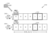
クロスキャリアULPIの一例として、図23は、本開示のいくつかの態様による、クロスキャリア情報を有するビットマップ2330の図を示す。示すように、ULPI2320は、2つ以上のコンポーネントキャリアに対応する14ビットを有するビットマップ2330を提供する。7つの最上位ビットはコンポーネントキャリア2302に対応し、7つの最下位ビットは他のコンポーネントキャリア2304に対応し得る。すなわち、ビットマップは、(M, N)表記に対して2つの(7、1)ビットマップを有し、ここでMは、RURの列、すなわちシンボルの数を与え、Nは、RURの行の数を与え、すなわち、Nは、ビットマップが広帯域かまたはサブバンドかを示す。各ビットは、1つまたは複数のOFDMシンボルおよび広帯域リソースに対応し得る。この例では、ビットマップ2330は、ビット2332および2334を、異なるコンポーネントキャリア2302および2304内で再割り振りされるとして特定する。
As an example of a cross-carrier ULPI, FIG. 23 shows a diagram of a
いくつかの態様では、クロスキャリアULPIの各ビットは、2つ以上のコンポーネントキャリアに対応し得る。たとえば、図24は、本開示のいくつかの態様による、クロスキャリア情報を有するビットマップ2430の図を示す。示すように、ULPI2420は、14ビット(M=14、N=1)を有するビットマップ2430を提供し、ここで各ビットは、2つ以上のコンポーネントキャリアに対応する。この例では、コンポーネントキャリア2404のリソースだけが、ビット2432に対して再割り振りされる予定である場合でも、UEは、コンポーネントキャリア2402および2404内のそれぞれのリソースの両方を、再割り振りされるとして特定するように、ビット2432を取り扱ってよい。すなわち、UEは、コンポーネントキャリア2402および2404内のリソースの両方が、リソースが実際に再割り振りされるかどうかにかかわらず、再割り振りされる予定であると仮定してよい。
In some aspects, each bit of the cross-carrier ULPI may correspond to two or more component carriers. For example, FIG. 24 shows a diagram of a
例示的なダウンリンクプリエンプション指示
いくつかの態様では、RANは、ダウンリンクリソースが、ダウンリンクプリエンプション指示(DLPI)を介してURLLC送信に再割り振りされたことをeMBB UEにシグナリングし得る。DLPIは、過去に再割り振りされたダウンリンクリソースを特定し得る。すなわち、DLPIは、基準ダウンリンク領域(RDR)において特定されたリソースを介して受信された信号を廃棄することをUEに示し得る。前述のULPIと同様に、DLPIも、クロスキャリア情報を含んでよく、クロスキャリア情報は、RANが、低減されたペイロードを用いてダウンリンクプリエンプションに対して複数のコンポーネントキャリアまたは帯域幅部分をサービスすることを可能にする。
Exemplary Downlink Preemption Indication In some aspects, the RAN may signal to the eMBB UE that downlink resources have been reallocated for URLLC transmission via a downlink preemption indication (DLPI). DLPI may identify downlink resources that have been reallocated in the past. That is, the DLPI may indicate to the UE to discard signals received over resources identified in the Reference Downlink Region (RDR). Similar to the ULPI described above, the DLPI may also contain cross-carrier information, where the RAN serves multiple component carriers or bandwidth portions for downlink preemption with reduced payload. make it possible.
本明細書で提示した態様は、ダウンリンクチャネルリソースを第2のタイプのUE(たとえば、URLLC UE)に再割り振りするために、ダウンリンクプリエンプション指示(DLPI)を第1のタイプのUE(たとえば、eMBB UE)にシグナリングするための技法を提供する。 Aspects presented herein send downlink preemption indications (DLPI) to UEs of a first type (eg, URLLC UEs) to reallocate downlink channel resources to UEs of a second type (eg, URLLC UEs). It provides techniques for signaling eMBB UEs).
図25は、たとえば、本開示のいくつかの態様による、ダウンリンクプリエンプション指示(DLPI)を実装するために、基地局および/または無線アクセスネットワーク(たとえば、図1のBS110)によって実行され得る例示的な動作2500を示すフロー図である。動作2500は、1つまたは複数のプロセッサ(たとえば、図4のプロセッサ440)上で実行され動作されるソフトウェア構成要素として実装され得る。さらに、動作2500におけるBSによる信号の送信および受信は、たとえば、1つまたは複数のアンテナ(たとえば、図4のアンテナ434)によって可能にされ得る。いくつかの態様では、BSによる信号の送信および/または受信は、信号を取得および/もしくは出力する1つまたは複数のプロセッサ(たとえば、プロセッサ440)のバスインターフェースを介して実装され得る。
FIG. 25, for example, illustrates exemplary diagrams that may be performed by a base station and/or radio access network (eg,
動作2500は、2502において、BSが、第1のタイプの第1のUE(たとえば、URLLC UE)への送信に対して割り振られたリソースが、第2のタイプの第2のUE(たとえば、eMBB UE)に割り振られたダウンリンクチャネルリソースと重複すると決定することで開始し得る。2504において、BSは、2502における決定に基づいて、クロスキャリア情報を含むとともに、重複するリソースのうちの少なくともいくつかを特定するダウンリンクプリエンプション指示(DLPI)を第2のUEにシグナリングする。
図26は、本開示のいくつかの態様による、ULPIの受信および処理を実装するために、たとえば、UE(たとえば、UE120)によって実行され得る例示的な動作2600を示すフロー図である。動作2600は、1つまたは複数のプロセッサ(たとえば、図4のプロセッサ480)上で実行され動作されるソフトウェア構成要素として実装され得る。さらに、動作2600におけるUEによる信号の送信および受信は、たとえば、1つまたは複数のアンテナ(たとえば、図4のアンテナ452)によって可能にされ得る。いくつかの態様では、UEによる信号の送信および/または受信は、信号を取得および/または出力する1つまたは複数のプロセッサ(たとえば、プロセッサ480)のバスインターフェースを介して実装され得る。
FIG. 26 is a flow diagram illustrating
動作2600は、2602において、UEが、第1のタイプのUE(たとえば、eMBB UE)に割り振られた1つまたは複数のダウンリンクチャネルリソースを使用してダウンリンク信号を基地局(BS)から受信することで開始し得る。2604において、第1のUEは、BSからクロスキャリア情報を含むダウンリンクプリエンプション指示(DLPI)を受信する。2606において、第1のUEは、DLPIにおいて特定された1つまたは複数のリソースに基づいて1つまたは複数のアクションを取り、1つまたは複数のリソースは、第2のタイプの第2のUE(たとえば、URLLC UE)へのスケジュールされた送信に対して割り振られたリソースと重複する。たとえば、スケジュールされた送信の間に特定されたリソースによって受信された信号を廃棄してもよい。なぜならば、それらの信号は、URLLC干渉で汚染されている場合があるからである。
いくつかの態様では、DLPIは、図23および図24のDLPIに対して前に説明したクロスキャリア情報と同様に形成され得るクロスキャリア情報を含み得る。たとえば、図27は、本開示のいくつかの態様による、クロスキャリア情報を有するビットマップ2730の図を示す。示すように、DLPI2720は、2つ以上のコンポーネントキャリアに対応する14ビットを有するビットマップ2730を提供する。7つの最上位ビットはコンポーネントキャリア2702に対応し、7つの最下位ビットは他のコンポーネントキャリア2704に対応し得る。すなわち、ビットマップは、図23に関連して本明細書で説明した2つの(M=7、N=1)ビットマップを含む。各ビットは、1つまたは複数のOFDMシンボルおよび広帯域リソースに対応し得る。この例では、ビットマップ2730は、ビット2732および2734を、異なるコンポーネントキャリア2702および2704内で再割り振りされるとして特定する。
In some aspects, the DLPI may include cross-carrier information that may be formed similar to the cross-carrier information previously described for the DLPI of FIGS. 23 and 24. FIG. For example, FIG. 27 shows a diagram of a
いくつかの態様では、クロスキャリアDLPIの各ビットは、図24のビットマップと同様に、2つ以上のコンポーネントキャリアに対応し得る。たとえば、図28は、本開示のいくつかの態様による、クロスキャリア情報を有するビットマップ2830の図を示す。示すように、DLPI2820は、14ビット(M=14、N=1)を有するビットマップ2830を提供し、ここで各ビットは、2つ以上のコンポーネントキャリアに対応する。この例では、リソースが実際に再割り振りされるかどうかにかかわらず、UEは、コンポーネントキャリア2802および2804内のそれぞれのリソースを、再割り振りされるとして特定するように、ビット2832を取り扱ってよい。
In some aspects, each bit of the cross-carrier DLPI may correspond to two or more component carriers, similar to the bitmap of FIG. For example, FIG. 28 shows a diagram of a
いくつかの態様では、DLPIは、同じキャリアインジケータフィールド(CIF)を有する2つ以上のUEにブロードキャストされ得る。すなわち、DLPIは、1つまたは複数のUEに割り当てられたCIFの特定の値だけに限定され得る。CIFは、DLPI内の基準ダウンリンク領域を特定するための基礎を提供し得る。すなわち、RDRは、UEに割り当てられたCIFに関連する場合がある。いくつかの態様では、DLPIは、CIFの特定の値を有するUEだけに限定され得る。すなわち、DLPIは、単一のUEおよびそのCIFに適用可能であり得る。 In some aspects, DLPI may be broadcast to two or more UEs with the same carrier indicator field (CIF). That is, DLPI may be limited to only certain values of CIF assigned to one or more UEs. The CIF may provide the basis for identifying reference downlink regions within the DLPI. That is, the RDR may relate to the CIF assigned to the UE. In some aspects, DLPI may be restricted to only UEs with a particular value of CIF. That is, DLPI may be applicable to a single UE and its CIF.
いくつかの態様では、クロスキャリアDLPIは、複数の別個のDLPIビットマップを含んでよく、それらのビットマップの各々は、同じCIF、すなわち同じクロスキャリア構成を有する1つまたは複数のUEに適用される。CIFの特定の値を有するUEは、UEが、クロスキャリアDLPI内でそのDLPIビットマップを特定することを可能にする指示によって、提供および/または事前構成され得る。 In some aspects, the cross-carrier DLPI may include multiple separate DLPI bitmaps, each of which applies to one or more UEs with the same CIF, i.e. the same cross-carrier configuration. be. A UE with a particular value of CIF may be provided and/or pre-configured with instructions that allow the UE to specify its DLPI bitmap within the cross-carrier DLPI.
DLPIビットマップの各ビットは、様々なリソースパラメータを表し得る。ビットマップのビットは、図14~図17に関連して本明細書で説明したように、RDRの広帯域リソース、サブバンドリソース、または1つもしくは複数のOFDMシンボルに対応し得る。DLPIはまた、図16および図17に関連して本明細書で説明したものと同じTDD技法を採用し得る。 Each bit in the DLPI bitmap can represent different resource parameters. Bitmap bits may correspond to RDR wideband resources, subband resources, or one or more OFDM symbols, as described herein with respect to FIGS. DLPI may also employ the same TDD techniques described herein with respect to FIGS.
図29は、図8、図9、図25および図26のうちの1つまたは複数で示される動作など、本明細書で開示する技法に対する動作を実行するように構成された、(たとえば、ミーンズプラスファンクション構成要素に対応する)様々な構成要素を含み得るワイヤレス通信デバイス2900を示す。通信デバイス2900は、トランシーバ2910に結合された処理システム2902を含む。トランシーバ2910は、本明細書で説明した様々な信号など、通信デバイス2900のための信号を、アンテナ2912を介して送受信するように構成される。処理システム2902は、通信デバイス2900によって受信された信号および/または送信されるべき信号を処理することを含む、通信デバイス2900のための処理機能を実行するように構成され得る。
29 is configured to perform operations for the techniques disclosed herein, such as those illustrated in one or more of FIGS. 8, 9, 25 and 26 (e.g., means 29 shows a
処理システム2902は、バス2908を介してコンピュータ可読媒体/メモリ2906に結合された1つまたは複数のプロセッサ2904を含む。いくつかの態様では、コンピュータ可読媒体/メモリ2906は、プロセッサ2904によって実行されるとき、図8、図9、図25および図26のうちの1つまたは複数で示す動作、または本明細書で説明する様々な技法を実行するための他の動作をプロセッサ2904に実行させるコンピュータ実行可能命令を記憶するように構成される。
いくつかの態様では、処理システム2902は、図8、図9、図25および図26のうちの1つまたは複数で示す受信動作を実行するための受信構成要素2914をさらに含む。加えて、処理システム2902は、図8、図9、図25および図26のうちの1つまたは複数で示す送信動作を実行するための送信構成要素2916を含む。さらに、処理システム2902は、図8、図9、図25および図26のうちの1つまたは複数で示す実行動作を実行するための実行構成要素2918を含む。同じく、処理システム2902は、図8、図9、図25および図26のうちの1つまたは複数で示す決定動作を実行するための決定構成要素2920を含む。受信構成要素2914、送信構成要素2916、実行構成要素2918、および決定構成要素2920は、バス2908を介してプロセッサ2904に結合され得る。プロセッサ2904は、図8、図9、図25および図26のうちの1つまたは複数で示す動作を実行するために、バス2908を介して信号を取得または出力し得る。いくつかの態様では、受信構成要素2914、送信構成要素2916、実行構成要素2918、および決定構成要素2920は、ハードウェア回路であり得る。いくつかの態様では、受信構成要素2914、送信構成要素2916、実行構成要素2918、および決定構成要素2920は、プロセッサ2904上で実行され動作されるソフトウェア構成要素であり得る。
In some aspects, the
本明細書で説明する技法は、URLLCシステムに利点を提供する。URLLCシステムのレイテンシおよび信頼性を改善するために、RANは、スケジュールされたURLLC送信の間に送信を中断するかまたは送信の送信電力を低減するために、ULPIを介して1つまたは複数のUEにシグナリングし得る。これは、BSにおいて遭遇する干渉を低減し、URLLC信号の信号対雑音比を向上させ得る。同じく、クロスキャリア情報は、RANが、2つ以上のキャリアコンポーネントをサービスすることを可能にし、本明細書で説明するように、リソースをプリエンプションするためのシグナリングオーバーヘッドを低減する。 The techniques described herein provide advantages for URLLC systems. In order to improve the latency and reliability of the URLLC system, the RAN may request one or more UEs via ULPI to suspend transmissions or reduce the transmission power of transmissions between scheduled URLLC transmissions. can be signaled to This may reduce the interference encountered at the BS and improve the signal-to-noise ratio of the URLLC signal. Similarly, cross-carrier information enables the RAN to serve more than one carrier component, reducing signaling overhead for preempting resources as described herein.
本明細書で開示する方法は、説明した方法を実現するための1つまたは複数のステップまたはアクションを含む。方法ステップおよび/またはアクションは、特許請求の範囲の範囲から逸脱することなく互いに入れ替えられ得る。言い換えれば、ステップまたはアクションの特定の順序が指定されない限り、特定のステップおよび/またはアクションの順序および/または使用は、特許請求の範囲の範囲から逸脱することなく修正され得る。 The methods disclosed herein comprise one or more steps or actions for achieving the described method. The method steps and/or actions may be interchanged with one another without departing from the scope of the claims. In other words, unless a specific order of steps or actions is specified, the order and/or use of specific steps and/or actions may be modified without departing from the scope of the claims.
本明細書で使用する場合、項目の列挙「のうちの少なくとも1つ」を指す句は、単一のメンバーを含むそれらの項目の任意の組合せを指す。一例として、「a、b、またはcのうちの少なくとも1つ」は、a、b、c、a-b、a-c、b-c、およびa-b-c、ならびに複数の同じ要素を有する任意の組合せ(たとえば、a-a、a-a-a、a-a-b、a-a-c、a-b-b、a-c-c、b-b、b-b-b、b-b-c、c-c、およびc-c-c、または任意の他の順序のa、b、およびc)を包含するものとする。 As used herein, a phrase referring to “at least one of” a list of items refers to any combination of those items, including single members. As an example, "at least one of a, b, or c" refers to a, b, c, a-b, a-c, b-c, and a-b-c, and any combination having more than one of the same elements (e.g., a-a, a-a-a , a-a-b, a-a-c, a-b-b, a-c-c, b-b, b-b-b, b-b-c, c-c, and c-c-c, or any other order of a, b, and c).
本明細書で使用する「決定すること」という用語は、幅広い様々なアクションを包含する。たとえば、「決定すること」は、算出すること、計算すること、処理すること、導出すること、調査すること、ルックアップすること(たとえば、テーブル、データベースまたは別のデータ構造においてルックアップすること)、確認することなどを含んでよい。また、「決定すること」は、受信すること(たとえば、情報を受信すること)、アクセスすること(たとえば、メモリ内のデータにアクセスすること)などを含み得る。また、「決定すること」は、解決すること、選択すること、選出すること、確立することなどを含み得る。 As used herein, the term "determining" encompasses a wide variety of actions. For example, "determining" means calculating, calculating, processing, deriving, examining, looking up (e.g., looking up in a table, database, or another data structure) , verifying, etc. Also, "determining" can include receiving (eg, receiving information), accessing (eg, accessing data in memory), and the like. Also, "determining" can include resolving, selecting, electing, establishing and the like.
前述の説明は、いかなる当業者も、本明細書で説明した様々な態様を実践することが可能になるように提供される。これらの態様の様々な変更が、当業者には容易に明らかになり、本明細書において規定される一般原理は、他の態様に適用される場合がある。したがって、特許請求の範囲は、本明細書に示した態様に限定されるものではなく、クレーム文言と一致するすべての範囲を与えられるべきであり、単数形での要素への言及は、そのように明記されていない限り、「唯一無二の」ではなく、「1つまたは複数の」を意味するものとする。別段に明記されていない限り、「いくつか」という用語は、1つまたは複数を指す。当業者に知られているか、または後で知られることになる、本開示全体にわたって説明した様々な態様の要素に対するすべての構造的および機能的均等物は、参照により本明細書に明確に組み込まれ、特許請求の範囲によって包含されることが意図される。その上、本明細書で開示したものは、そのような開示が特許請求の範囲に明示的に記載されているかどうかにかかわらず、公に供されるものではない。請求項の要素は、要素が「のための手段」という句を使用して明確に列挙されていない限り、または方法クレームの場合、要素が「のためのステップ」という句を使用して列挙されていない限り、米国特許法112条第6段落の規定に基づいて解釈されるべきではない。 The previous description is provided to enable any person skilled in the art to practice the various aspects described herein. Various modifications of these aspects will be readily apparent to those skilled in the art, and the general principles defined herein may apply to other aspects. Accordingly, the claims are not intended to be limited to the embodiments shown herein, but are to be accorded full scope consistent with the claim language, and references to elements in the singular shall not be construed as such. shall mean "one or more" rather than "one and only", unless expressly stated otherwise. Unless otherwise specified, the term "some" refers to one or more. All structural and functional equivalents to the elements of the various aspects described throughout this disclosure that are known or later become known to those skilled in the art are expressly incorporated herein by reference. , is intended to be encompassed by the claims. Moreover, nothing disclosed herein is being made available to the public, regardless of whether such disclosure is explicitly recited in the claims. An element of a claim is recited using the phrase "means for" unless the element is specifically recited using the phrase "means for" or, in the case of a method claim, the element is recited using the phrase "step for". should not be construed under the provisions of 35 U.S.C. 112, sixth paragraph unless
上記で説明した方法の様々な動作は、対応する機能を実行することが可能な任意の適切な手段によって実行され得る。手段は、限定はしないが、回路、特定用途向け集積回路(ASIC)、またはプロセッサを含む、様々なハードウェアおよび/またはソフトウェア構成要素および/またはモジュールを含み得る。一般に、図に示す動作が存在する場合、それらの動作は、同様の番号を付された対応する相当物であるミーンズプラスファンクション構成要素を有し得る。 The various acts of methods described above may be performed by any suitable means capable of performing the corresponding functions. The means may comprise various hardware and/or software components and/or modules including, but not limited to, circuits, application specific integrated circuits (ASICs), or processors. Generally, where there are operations shown in a figure, those operations may have means-plus-function components that are corresponding counterparts that are similarly numbered.
たとえば、送信するための手段(または送信のために出力するための手段)またはシグナリングするための手段は、図4に示す基地局110のアンテナ434またはユーザ機器120のアンテナ452を備え得る。受信するための手段(または取得するための手段)は、図4に示す基地局110のアンテナ434またはユーザ機器120のアンテナ452を備え得る。処理するための手段、取得するための手段、決定するための手段、1つもしくは複数のアクションを取るための手段、または特定するための手段は、図4に示す基地局110のMIMO検出器436、TX MIMOプロセッサ430、 TXプロセッサ420、および/もしくはコントローラ440、または、ユーザ機器120のMIMO検出器456、TX MIMOプロセッサ466、 TXプロセッサ464、および/もしくはコントローラ480などの1つまたは複数のプロセッサを含み得る、処理システムを備え得る。
For example, means for transmitting (or means for outputting for transmission) or means for signaling may comprise antenna 434 of
場合によっては、デバイスは、信号を実際に送信するのではなく、送信のために信号を出力するインターフェース(出力するための手段)を有してもよい。たとえば、プロセッサは、バスインターフェースを介して、送信のために無線周波数(RF)フロントエンドに信号を出力してもよい。同様に、デバイスは、信号を実際に受信するのではなく、別のデバイスから受信された信号を取得するためのインターフェース(取得するための手段)を有してもよい。たとえば、プロセッサは、バスインターフェースを介して、受信のためにRFフロントエンドから信号を取得(または受信)してもよい。場合によっては、送信のために信号を出力するためのインターフェースおよび信号を取得するためのインターフェースは、単一のインターフェースとして一体化されてもよい。 In some cases, the device may have an interface (means for outputting) that outputs the signal for transmission, rather than actually transmitting the signal. For example, the processor may output signals over the bus interface to a radio frequency (RF) front end for transmission. Similarly, a device may have an interface for obtaining a signal received from another device, rather than actually receiving the signal. For example, the processor may acquire (or receive) signals from the RF front end for reception via the bus interface. In some cases, the interface for outputting signals for transmission and the interface for acquiring signals may be integrated as a single interface.
本明細書で使用する「送信すること」または「受信すること」という用語は、多種多様なアクションを包含する。たとえば、「送信すること」は、出力すること(たとえば、送信されるべき信号を出力すること)、シグナリングすることなどを含み得る。同じく、「受信すること」は、取得すること(たとえば、信号を取得すること)、アクセスすること(たとえば、メモリ内のデータにアクセスすること)、サンプリングすること(たとえば、信号をサンプリングすること)などを含み得る。 As used herein, the terms "sending" or "receiving" encompass a wide variety of actions. For example, "transmitting" can include outputting (eg, outputting a signal to be transmitted), signaling, and the like. Similarly, "receiving" includes obtaining (e.g., obtaining a signal), accessing (e.g., accessing data in memory), sampling (e.g., sampling a signal) and so on.
本開示に関連して説明する様々な例示的な論理ブロック、モジュール、および回路は、汎用プロセッサ、デジタル信号プロセッサ(DSP)、特定用途向け集積回路(ASIC)、フィールドプログラマブルゲートアレイ(FPGA)もしくは他のプログラマブル論理デバイス(PLD)、ディスクリートゲートもしくはトランジスタ論理、ディスクリートハードウェア構成要素、または本明細書で説明する機能を実行するように設計されたそれらの任意の組合せを用いて実装または実行され得る。汎用プロセッサは、マイクロプロセッサであってよいが、代替として、プロセッサは、任意の市販のプロセッサ、コントローラ、マイクロコントローラ、または状態機械であってよい。プロセッサはまた、コンピューティングデバイスの組合せ、たとえば、DSPとマイクロプロセッサとの組合せ、複数のマイクロプロセッサ、DSPコアと連携した1つもしくは複数のマイクロプロセッサ、または任意の他のそのような構成として実装されてもよい。 Various exemplary logic blocks, modules, and circuits described in connection with this disclosure may be general purpose processors, digital signal processors (DSPs), application specific integrated circuits (ASICs), field programmable gate arrays (FPGAs), or others. can be implemented or performed using programmable logic devices (PLDs), discrete gate or transistor logic, discrete hardware components, or any combination thereof designed to perform the functions described herein. A general purpose processor may be a microprocessor, but in the alternative, the processor may be any commercially available processor, controller, microcontroller, or state machine. A processor may also be implemented as a combination of computing devices, such as a DSP and microprocessor combination, multiple microprocessors, one or more microprocessors in conjunction with a DSP core, or any other such configuration. may
ハードウェアにおいて実装される場合、例示的なハードウェア構成は、ワイヤレスノード内の処理システムを含み得る。処理システムは、バスアーキテクチャを用いて実装され得る。バスは、処理システムの特定の適用例および全体的な設計制約に応じて、任意の数の相互接続バスおよびブリッジを含んでよい。バスは、プロセッサ、機械可読媒体、およびバスインターフェースを含む様々な回路を互いにリンクさせ得る。バスインターフェースは、バスを介して、とりわけ、処理システムにネットワークアダプタを接続するために使用され得る。ネットワークアダプタは、PHYレイヤの信号処理機能を実装するために使用され得る。ユーザ機器120(図1参照)の場合、ユーザインターフェース(たとえば、キーパッド、ディスプレイ、マウス、ジョイスティックなど)がバスに接続されてもよい。バスは、タイミングソース、周辺装置、電圧調整器、電力管理回路などの様々な他の回路をリンクさせる場合があるが、これらの回路は当技術分野でよく知られており、したがって、これ以上は説明しない。プロセッサは、1つまたは複数の汎用プロセッサおよび/または専用プロセッサを用いて実装されてよい。例には、マイクロプロセッサ、マイクロコントローラ、DSPプロセッサ、およびソフトウェアを実行できる他の回路が含まれる。当業者は、特定の適用例とシステム全体に課せられた全体的な設計制約とに応じて処理システムに関する上述の機能を最も適切に実装するにはどうすべきかを認識するであろう。 When implemented in hardware, an exemplary hardware configuration may include the processing system within the wireless node. A processing system may be implemented using a bus architecture. A bus may include any number of interconnecting buses and bridges, depending on the particular application and overall design constraints of the processing system. A bus may link together various circuits including a processor, a machine-readable medium, and a bus interface. A bus interface can be used to connect, among other things, a network adapter to a processing system via a bus. A network adapter may be used to implement the signal processing functions of the PHY layer. For user equipment 120 (see FIG. 1), a user interface (eg, keypad, display, mouse, joystick, etc.) may be connected to the bus. The bus may link various other circuits such as timing sources, peripherals, voltage regulators, power management circuits, etc., but these circuits are well known in the art and therefore no further No explanation. A processor may be implemented with one or more general-purpose and/or special-purpose processors. Examples include microprocessors, microcontrollers, DSP processors, and other circuits capable of executing software. Those skilled in the art will recognize how to best implement the above-described functionality for a processing system depending on the particular application and the overall design constraints imposed on the overall system.
ソフトウェアにおいて実装される場合、機能は、1つまたは複数の命令またはコードとしてコンピュータ可読媒体上に記憶されるか、またはコンピュータ可読媒体を介して送信され得る。ソフトウェアは、ソフトウェア、ファームウェア、ミドルウェア、マイクロコード、ハードウェア記述言語と呼ばれるか、または他の名称で呼ばれるかどうかにかかわらず、命令、データ、またはそれらの任意の組合せを意味するように広く解釈されるべきである。コンピュータ可読媒体は、コンピュータ記憶媒体と、ある場所から別の場所へのコンピュータプログラムの伝達を容易にする任意の媒体を含む通信媒体の両方を含む。プロセッサは、機械可読記憶媒体に記憶されたソフトウェアモジュールの実行を含む、バスおよび一般的な処理を管理することを担い得る。コンピュータ可読記憶媒体は、プロセッサがその記憶媒体から情報を読み取ることができ、かつその記憶媒体に情報を書き込むことができるようにプロセッサに結合されてよい。代替として、記憶媒体は、プロセッサと一体であってよい。例として、機械可読媒体は、送信線路、データによって変調された搬送波、および/またはワイヤレスノードとは別個の命令が記憶されたコンピュータ可読記憶媒体を含んでよく、これらはすべて、バスインターフェースを介してプロセッサによってアクセスされる場合がある。代替としてまたは追加として、機械可読媒体またはその任意の部分は、キャッシュおよび/または汎用レジスタファイルと同様にプロセッサに統合されてよい。機械可読記憶媒体の例は、例として挙げると、RAM(ランダムアクセスメモリ)、フラッシュメモリ、ROM(読取り専用メモリ)、PROM(プログラマブル読取り専用メモリ)、EPROM(消去可能プログラマブル読取り専用メモリ)、EEPROM(電気的消去可能プログラマブル読取り専用メモリ)、レジスタ、磁気ディスク、光ディスク、ハードドライブ、もしくは任意の他の適切な記憶媒体、またはそれらの任意の組合せがあり得る。機械可読媒体はコンピュータプログラム製品内で具現化されてよい。 If implemented in software, the functions may be stored on or transmitted over a computer-readable medium as one or more instructions or code. Software shall be construed broadly to mean instructions, data, or any combination thereof, whether referred to as software, firmware, middleware, microcode, hardware description language, or otherwise. should. Computer-readable media includes both computer storage media and communication media including any medium that facilitates transfer of a computer program from one place to another. A processor may be responsible for managing the bus and general processing, including executing software modules stored on a machine-readable storage medium. A computer-readable storage medium may be coupled to the processor such that the processor can read information from, and write information to, the storage medium. Alternatively, the storage medium may be integral with the processor. By way of example, the machine-readable medium may include a transmission line, a carrier wave modulated with data, and/or a computer-readable storage medium having instructions separate from the wireless node, all via a bus interface. May be accessed by a processor. Alternatively or additionally, the machine-readable medium, or any portion thereof, may be integrated with the processor, as well as caches and/or general register files. Examples of machine-readable storage media include, by way of example, RAM (random access memory), flash memory, ROM (read-only memory), PROM (programmable read-only memory), EPROM (erasable programmable read-only memory), EEPROM ( electrically erasable programmable read-only memory), registers, magnetic disks, optical disks, hard drives, or any other suitable storage medium, or any combination thereof. A machine-readable medium may be embodied in a computer program product.
ソフトウェアモジュールは、単一の命令または多くの命令を含み得、いくつかの異なるコードセグメントにわたって、異なるプログラム間で、また複数の記憶媒体にわたって、分散され得る。コンピュータ可読媒体は、いくつかのソフトウェアモジュールを含んでよい。ソフトウェアモジュールは、プロセッサなどの装置によって実行されると、処理システムに様々な機能を実行させる命令を含む。ソフトウェアモジュールは、送信モジュールと受信モジュールとを含んでよい。各ソフトウェアモジュールは、単一の記憶デバイス内に存在しても、または複数の記憶デバイスにわたって分散されてよい。例として、トリガイベントが発生したときに、ソフトウェアモジュールは、ハードドライブからRAMにロードされてよい。ソフトウェアモジュールの実行中、プロセッサは、アクセス速度を高めるために、命令のうちのいくつかをキャッシュにロードしてよい。1つまたは複数のキャッシュラインが、次いで、プロセッサによって実行されるように汎用レジスタファイルにロードされてよい。以下でソフトウェアモジュールの機能に言及する場合、そのような機能は、そのソフトウェアモジュールからの命令を実行するときにプロセッサによって実装されることが理解されよう。 A software module may contain a single instruction, or many instructions, and may be distributed over several different code segments, among different programs, and across multiple storage media. A computer readable medium may include a number of software modules. The software modules contain instructions that, when executed by a device such as a processor, cause the processing system to perform various functions. Software modules may include a transmit module and a receive module. Each software module may reside in a single storage device or distributed across multiple storage devices. By way of example, a software module may be loaded from the hard drive into RAM when a trigger event occurs. During execution of the software module, the processor may load some of the instructions into cache to increase access speed. One or more cache lines may then be loaded into the general register file for execution by the processor. When referring to functionality of a software module below, it will be understood that such functionality is implemented by the processor when executing instructions from that software module.
また、任意の接続が、適切にコンピュータ可読媒体と呼ばれる。たとえば、ソフトウェアが、同軸ケーブル、光ファイバーケーブル、ツイストペア、デジタル加入者回線(DSL)、または赤外線(IR)、無線、およびマイクロ波などのワイヤレス技術を使用して、ウェブサイト、サーバ、または他のリモートソースから送信される場合、同軸ケーブル、光ファイバーケーブル、ツイストペア、DSL、または赤外線、無線、およびマイクロ波などのワイヤレス技術は、媒体の定義に含まれる。本明細書で使用するディスク(disk)およびディスク(disc)は、コンパクトディスク(disc)(CD)、レーザディスク(disc)、光ディスク(disc)、デジタル多用途ディスク(disc)(DVD)、フロッピーディスク(disk)、およびBlu-ray(登録商標)ディスク(disc)を含み、ディスク(disk)は、通常、データを磁気的に再生し、ディスク(disc)は、レーザを用いてデータを光学的に再生する。したがって、いくつかの態様では、コンピュータ可読媒体は、非一時的コンピュータ可読媒体(たとえば、有形媒体)を含んでよい。さらに、他の態様では、コンピュータ可読媒体は、一時的コンピュータ可読媒体(たとえば、信号)を備えることができる。上記の組合せもコンピュータ可読媒体の範囲に含まれるべきである。 Also, any connection is properly termed a computer-readable medium. For example, the software may link websites, servers, or other remote When transmitted from a source, coaxial cable, fiber optic cable, twisted pair, DSL, or wireless technologies such as infrared, radio, and microwave are included in the definition of medium. As used herein, disk and disc refer to compact disc (CD), laser disc (disc), optical disc, digital versatile disc (DVD), floppy disc. (disk), and Blu-ray (registered trademark) discs, where disks usually reproduce data magnetically, while discs reproduce data optically using lasers. Reproduce. Thus, in some aspects computer readable medium may comprise non-transitory computer readable medium (eg, tangible media). In addition, for other aspects computer-readable medium may comprise transitory computer-readable medium (eg, a signal). Combinations of the above should also be included within the scope of computer-readable media.
したがって、いくつかの態様は、本明細書で提示した動作を実行するためのコンピュータプログラム製品を含んでよい。たとえば、そのようなコンピュータプログラム製品は、本明細書で説明した動作を実行するように1つまたは複数のプロセッサによって実行可能である命令が記憶された(および/または符号化された)コンピュータ可読媒体を含んでよい。 Accordingly, some aspects may include a computer program product for performing the operations presented herein. For example, such a computer program product may be a computer-readable medium having stored (and/or encoded) instructions executable by one or more processors to perform the operations described herein. may contain
さらに、本明細書で説明する方法および技法を実行するためのモジュールおよび/または他の適切な手段は、適用可能な場合、ユーザ端末および/または基地局によってダウンロードおよび/または別の方法で取得されてよいことを理解されたい。たとえば、そのようなデバイスは、本明細書で説明する方法を実行するための手段の転送を容易にするためにサーバに結合されてよい。代替的に、本明細書で説明する様々な方法は、ユーザ端末および/または基地局が記憶手段(たとえば、RAM、ROM、コンパクトディスク(CD)またはフロッピーディスクなどの物理的記憶媒体など)をデバイスに結合または提供すると様々な方法を取得することができるように、記憶手段を介して提供されてよい。さらに、本明細書で説明する方法および技法をデバイスに提供するための任意の他の適切な技法が利用されてよい。 In addition, modules and/or other suitable means for performing the methods and techniques described herein may be downloaded and/or otherwise obtained by user terminals and/or base stations, where applicable. It should be understood that For example, such devices may be coupled to servers to facilitate transfer of means for performing the methods described herein. Alternatively, the various methods described herein allow the user terminal and/or base station to provide storage means (eg, RAM, ROM, physical storage media such as compact discs (CDs) or floppy disks, etc.) to the device. may be provided via storage means so that various methods can be obtained when combined with or provided to. In addition, any other suitable technique for providing a device with the methods and techniques described herein may be utilized.
特許請求の範囲が上記で示した厳密な構成および構成要素に限定されないことを理解されたい。特許請求の範囲の範囲から逸脱することなく、上記で説明した方法および装置の構成、動作、および詳細において、様々な修正、変更、および変形が加えられてよい。 It should be understood that the claims are not limited to the precise configuration and components shown above. Various modifications, changes and variations may be made in the arrangement, operation and details of the methods and apparatus described above without departing from the scope of the claims.
100 ワイヤレスネットワーク
102a マクロセル
102b マクロセル
102c マクロセル
102x ピコセル
102y フェムトセル
102z フェムトセル
110 基地局(BS)
110a BS
110b BS
110c BS、マクロBS
110r 中継局
110x BS
110y BS
110z BS
120 UE、ユーザ機器
120r UE
120x UE
120y UE
130 ネットワークコントローラ
200 分散型無線アクセスネットワーク(RAN)、ローカルアーキテクチャ、アーキテクチャ
202 アクセスノードコントローラ(ANC)
204 次世代コアネットワーク(NG-CN)
206 5Gアクセスノード
208 TRP、DU
210 次世代AN(NG-AN)
222 Tx/Rx
300 分散型RAN
302 集中型コアネットワークユニット(C-CU)
304 集中型RANユニット(C-RU)
306 DU
412 データソース
420 プロセッサ、送信プロセッサ、TXプロセッサ
430 TX MIMOプロセッサ
432 変調器、BS変調器/復調器
432a~432t 変調器(MOD)
434 アンテナ
434a~434t アンテナ
436 MIMO検出器
438 プロセッサ、受信プロセッサ
439 データシンク
440 コントローラ/プロセッサ、プロセッサ
442 メモリ
444 スケジューラ
452 アンテナ
452a~452r アンテナ
454 復調器
454a~454r 復調器(DEMOD)
456 MIMO検出器
458 プロセッサ、受信プロセッサ
462 データソース
464 プロセッサ、送信プロセッサ、TXプロセッサ
466 プロセッサ、TX MIMOプロセッサ
480 コントローラ/プロセッサ、プロセッサ
500 図
505-a 第1のオプション
505-b 第2のオプション
510 無線リソース制御(RRC)レイヤ
515 パケットデータコンバージェンスプロトコル(PDCP)レイヤ
520 無線リンク制御(RLC)レイヤ
525 媒体アクセス制御(MAC)レイヤ
530 物理(PHY)レイヤ
600 図
604 DLデータ部分
606 共通UL部分
700 図
702 制御部分
704 ULデータ部分
706 共通UL部分
800 動作
900 動作
1002 ダウンリンクチャネル、DLチャネル
1004 アップリンクチャネル、ULチャネル
1006 スロット
1010 URLLC DCI
1012 ULデータ
1014 ULデータ
1020 ULPI、第2のULPI
1102 ダウンリンクチャネル
1104 アップリンクチャネル
1114 ULリソース
1120 ULPI
1122 オフセット時間
1124 持続時間
1126 リソース
1140 RUR、第1のRUR
1142 第2のRUR
1220A ULPIフォーマット
1220B ULPIフォーマット
1240 RUR情報
1242 RUR情報
1320 ULPIフォーマット
1340 RUR情報
1342 RUR情報
1420 ULPI
1430 ビットマップ
1432 ビット
1434 ビット
1520 ULPI
1530 ビットマップ
1532 ビット
1534 ビット
1620 ULPI
1630 ビットマップ
1632 ダウンリンクシンボル
1634 ビット
1636 ビット
1638 ダウンリンクリソース
1640 ビット
1720 ULPI
1730 ビットマップ
1732 ダウンリンクシンボル
1734 ビット、MSB
1800A アップリンクチャネル
1800B アップリンクチャネル
1840 RUR
1850 物理アップリンク共有チャネル(PUSCH)リソース
1852 PUCCHリソース
1900A アップリンクチャネル
1900B アップリンクチャネル
1940 RUR
1952 PUCCHリソース
1954 SRSリソース
2014 下位のサブバンド
2020 ULPI
2030 ビットマップ
2032 リソース
2102 PUSCH送信
2132 プリエンプションギャップ
2160 DMRS、第1のDMRS
2162 第2のDMRS
2200 アップリンクチャネル
2214 プリエンプションギャップ
2270 SPSリソース
2272 SPSリソース
2274 PUSCHリソース
2276 PUSCHリソース
2278 PUSCHリソース
2302 コンポーネントキャリア
2304 コンポーネントキャリア
2320 ULPI
2330 ビットマップ
2332 ビット
2334 ビット
2402 コンポーネントキャリア
2404 コンポーネントキャリア
2420 ULPI
2430 ビットマップ
2432 ビット
2500 動作
2600 動作
2702 コンポーネントキャリア
2704 コンポーネントキャリア
2720 DLPI
2730 ビットマップ
2732 ビット
2734 ビット
2802 コンポーネントキャリア
2804 コンポーネントキャリア
2820 DLPI
2830 ビットマップ
2832 ビット
2900 通信デバイス、ワイヤレス通信デバイス
2902 処理システム
2904 プロセッサ
2906 コンピュータ可読媒体/メモリ
2908 バス
2910 トランシーバ
2912 アンテナ
2914 受信構成要素
2916 送信構成要素
2918 実行構成要素
2920 決定構成要素
100 wireless networks
102a Macrocell
102b Macrocell
102c Macrocell
102x picocell
102y Femtocell
102z Femtocell
110 base station (BS)
110a BS
110b BS
110c BS, Macro BS
110r relay station
110x BS
110y BS
110z BS
120 UE, user equipment
120r UE
120x UEs
120y UE
130 network controller
200 Distributed Radio Access Network (RAN), Local Architecture, Architecture
202 Access Node Controller (ANC)
204 Next Generation Core Network (NG-CN)
206 5G access nodes
208 TRP, DU
210 Next Generation AN (NG-AN)
222 Tx/Rx
300 Distributed RAN
302 Centralized Core Network Unit (C-CU)
304 Centralized RAN Unit (C-RU)
306 DU
412 data sources
420 Processor, Transmit Processor, TX Processor
430TX MIMO processor
432 Modulator, BS Modulator/Demodulator
432a-432t Modulator (MOD)
434 Antenna
434a-434t Antennas
436 MIMO detector
438 processor, receive processor
439 Data Sync
440 Controller/Processor, Processor
442 memory
444 Scheduler
452 Antenna
452a-452r Antennas
454 Demodulator
454a-454r Demodulator (DEMOD)
456 MIMO detector
458 processor, receive processor
462 data sources
464 processor, transmit processor, TX processor
466 processor, TX MIMO processor
480 Controller/Processor, Processor
500 figures
505-a first option
505-b second option
510 Radio Resource Control (RRC) Layer
515 Packet Data Convergence Protocol (PDCP) Layer
520 Radio Link Control (RLC) layer
525 Medium Access Control (MAC) Layer
530 Physical (PHY) Layer
600 figures
604 DL data part
606 Common UL Part
700 figures
702 control part
704 UL data part
706 Common UL Part
800 motion
900 movement
1002 downlink channels, DL channels
1004 uplink channels, UL channels
1006 slots
1010 URLLC DCI
1012 UL data
1014 UL data
1020 ULPI, 2nd ULPI
1102 downlink channels
1104 uplink channel
1114 UL Resources
1120 ULPI
1122 offset time
1124 Duration
1126 resources
1140 RUR, 1st RUR
1142 Second RUR
1220A ULPI format
1220B ULPI format
1240 RURInformation
1242 RUR information
1320 ULPI format
1340 RUR information
1342 RUR information
1420 ULPI
1430 bitmap
1432 bits
1434 bits
1520 ULPI
1530 bitmaps
1532 bits
1534 bits
1620 ULPI
1630 bitmap
1632 downlink symbol
1634 bits
1636 bits
1638 Downlink Resources
1640 bits
1720 ULPI
1730 bitmaps
1732 downlink symbol
1734 bits, MSB
1800A uplink channel
1800B uplink channel
1840 RUR
1850 physical uplink shared channel (PUSCH) resources
1852 PUCCH resource
1900A uplink channel
1900B uplink channel
1940 RUR
1952 PUCCH resource
1954 SRS Resource
2014 lower sub-band
2020 ULPI
2030 bitmap
2032 Resources
2102 Send PUSCH
2132 preemption gap
2160 DMRS, 1st DMRS
2162 Second DMRS
2200 uplink channels
2214 preemption gap
2270 SPS Resources
2272 SPS Resources
2274 PUSCH resources
2276 PUSCH resources
2278 PUSCH resources
2302 component carrier
2304 component carrier
2320 ULPI
2330 bitmap
2332 bits
2334 bits
2402 component carrier
2404 component carrier
2420 ULPI
2430 bitmap
2432 bits
2500 movements
2600 movement
2702 component carrier
2704 component carrier
2720 DLPI
2730 bitmaps
2732 bits
2734 bits
2802 component carrier
2804 component carrier
2820 DLPI
2830 bitmap
2832 bits
2900 communication device, wireless communication device
2902 processing system
2904 processor
2906 Computer Readable Medium/Memory
2908 Bus
2910 Transceiver
2912 Antenna
2914 Receiving Component
2916 transmission component
2918 Execution Components
2920 Decision component
Claims (15)
第1のタイプの前記第1のUEに割り振られたアップリンクチャネルリソースを介してアップリンク信号を基地局(BS)にシグナリングするステップと、
前記BSからアップリンクプリエンプション指示(ULPI)を受信するステップであって、
前記ULPIが、スケジュールされた送信の間に前記第1のUEによって使用されるべき1つまたは複数のリソースを特定するビットマップを含み、
前記ビットマップのビットが、基準アップリンク領域(RUR)の広帯域リソース、前記RURのサブバンドリソース、または前記RURの1つもしくは複数のシンボルのうちの少なくとも1つに対応し、
前記ULPIにおいて特定された前記1つまたは複数のリソースが、前記RURの:
時間オフセットと、
持続時間と、
1つまたは複数のリソースと
に関連する、ステップと、
前記ULPIにおいて特定された前記1つまたは複数のリソースに基づいて1つまたは複数のアクションを取るステップであって、前記1つまたは複数のリソースが、第2のタイプの第2のUEによるスケジュールされた送信に対して割り振られたリソースと重複する、ステップとを含む、方法。 A method for wireless communication by a first user equipment (UE), comprising:
signaling an uplink signal to a base station (BS) over uplink channel resources allocated to said first UE of a first type;
receiving an uplink preemption indication (ULPI) from the BS,
the ULPI includes a bitmap identifying one or more resources to be used by the first UE during a scheduled transmission;
bits of the bitmap corresponding to at least one of broadband resources of a reference uplink region (RUR), subband resources of the RUR, or one or more symbols of the RUR;
If the one or more resources identified in the ULPI are of the RUR :
a time offset and
duration and
one or more resources and
a step associated with
taking one or more actions based on the one or more resources identified in the ULPI, wherein the one or more resources are scheduled by a second UE of a second type; and overlapping the allocated resources for the transmission.
前記スケジュールされた送信の間に送信電力を低減するステップ、
前記スケジュールされた送信の間に前記第1のUEによる送信を中断するステップ、
前記ULPIにおいて特定された1つまたは複数のリソースに隣接するリソースに、前記1つまたは複数のアクションを適用するステップ、
前記ULPIの前記1つまたは複数のリソースのうちの物理アップリンク制御チャネル(PUCCH)リソースを特定し、前記スケジュールされた送信の間に前記PUCCHリソースを介してアップリンク制御情報をシグナリングするステップ、
前記ULPIの前記1つまたは複数のリソースのうちのサウンディング基準信号(SRS)リソースを特定し、前記スケジュールされた送信の間に前記SRSをシグナリングするステップ、
前記1つまたは複数のリソースのうちの前記SRSリソースを特定し、前記スケジュールされた送信の間に前記SRSの送信を中断するステップ、または
前記ULPI内の前記1つまたは複数のリソースのうちの、アクティブ化された半永続的にスケジュールされた(SPS)リソースを特定し、前記スケジュールされた送信の間に前記アクティブ化されたSPSリソースの周りで送信をレートマッチングするステップを含む、請求項1に記載の方法。 A step that takes one or more actions
reducing transmission power during the scheduled transmission;
suspending transmission by the first UE during the scheduled transmission;
applying said one or more actions to resources adjacent to one or more resources identified in said ULPI;
identifying a physical uplink control channel (PUCCH) resource among the one or more resources of the ULPI and signaling uplink control information over the PUCCH resource during the scheduled transmission;
identifying a Sounding Reference Signal (SRS) resource among the one or more resources of the ULPI and signaling the SRS during the scheduled transmission;
identifying the SRS resource among the one or more resources and suspending transmission of the SRS during the scheduled transmission; or among the one or more resources within the ULPI; 2. The method of claim 1, comprising identifying activated semi-persistently scheduled (SPS) resources and rate matching transmissions around the activated SPS resources during the scheduled transmission. described method.
前記信号が、少なくとも1つの復調基準信号(DMRS)を含み、または、
前記ギャップが、受信されると予想される復調基準信号(DMRS)をパンクチャリングする、請求項1に記載の方法。 further comprising signaling an uplink signal with gaps in the uplink signal as indicated by said ULPI and preserving phase continuity across said gaps, or
said signal comprises at least one demodulation reference signal (DMRS); or
2. The method of claim 1, wherein the gap punctures an expected received demodulation reference signal (DMRS).
第1のタイプの第1のユーザ機器(UE)によるスケジュールされた送信に対して割り振られたリソースが、第2のタイプの第2のUEに割り振られたアップリンクチャネルリソースと重複すると決定するステップと、
前記決定に基づいて、前記重複するリソースのうちの少なくともいくつかを特定するアップリンクプリエンプション指示(ULPI)を前記第2のUEにシグナリングするステップであって、
前記ULPIが、前記スケジュールされた送信の間に使用されるべき前記リソースを特定するビットマップを含み、
前記ビットマップのビットが、基準アップリンク領域(RUR)の広帯域リソース、前記RURのサブバンドリソース、または前記RURの1つもしくは複数のシンボルに対応し、
前記ULPIにおいて特定された前記リソースが、基準アップリンク領域の:
時間オフセットと、
持続時間と、
1つまたは複数のリソースと
に関連する、ステップと、
を含む、方法。 A method for wireless communication by a base station (BS), comprising:
determining that resources allocated for scheduled transmissions by a first user equipment (UE) of a first type overlap with uplink channel resources allocated to a second UE of a second type; and,
based on the determination, signaling to the second UE an uplink preemption indication (ULPI) identifying at least some of the overlapping resources;
the ULPI includes a bitmap identifying the resources to be used during the scheduled transmission;
bits of the bitmap corresponding to broadband resources of a reference uplink region (RUR), subband resources of the RUR, or one or more symbols of the RUR;
If the resource specified in the ULPI is of a reference uplink region :
a time offset and
duration and
one or more resources and
a step associated with
A method, including
前記ULPIが、UEのグループに適用される、
請求項1または6に記載の方法。 the ULPI is specific to one UE, or
the ULPI is applied to a group of UEs;
7. The method of claim 1 or 6.
前記第2のUEが前記ギャップにわたって位相連続性を保存することができる場合、前記受信された信号を復号するステップと、をさらに含む、請求項6に記載の方法。 receiving from the second UE the signal with gaps in the uplink signal as indicated by the ULPI;
7. The method of claim 6, further comprising decoding the received signal if the second UE is able to preserve phase continuity across the gap.
第1のタイプの第1のユーザ機器(UE)によるスケジュールされた送信に対して割り振られたリソースが、第2のタイプの第2のUEに割り振られたアップリンクチャネルリソースと重複すると決定するための手段と、
前記決定に基づいて、前記重複するリソースのうちの少なくともいくつかを特定するアップリンクプリエンプション指示(ULPI)を前記第2のUEにシグナリングするための手段であって、
前記ULPIが、前記スケジュールされた送信の間に使用されるべき前記リソースを特定するビットマップを含み、
前記ビットマップのビットが、基準アップリンク領域(RUR)の広帯域リソース、前記RURのサブバンドリソース、または前記RURの1つもしくは複数のシンボルに対応し、
前記ULPIにおいて特定された前記リソースが、基準アップリンク領域の:
時間オフセットと、
持続時間と、
1つまたは複数のリソースと
に関連する、手段と、
を備える、装置。 An apparatus for wireless communication, comprising:
to determine that resources allocated for a scheduled transmission by a first user equipment (UE) of a first type overlap with uplink channel resources allocated to a second UE of a second type; means of
means for signaling to the second UE an uplink preemption indication (ULPI) that identifies at least some of the overlapping resources based on the determination;
the ULPI includes a bitmap identifying the resources to be used during the scheduled transmission;
bits of the bitmap corresponding to broadband resources of a reference uplink region (RUR), subband resources of the RUR, or one or more symbols of the RUR;
If the resource specified in the ULPI is of a reference uplink region :
a time offset and
duration and
one or more resources and
means associated with
A device comprising:
第1のタイプの第1のユーザ機器(UE)に割り振られたアップリンクチャネルリソースを介してアップリンク信号を基地局(BS)にシグナリングするための手段と、
前記BSからアップリンクプリエンプション指示(ULPI)を受信するための手段であって、
前記ULPIが、スケジュールされた送信の間に前記第1のUEによって使用されるべき1つまたは複数のリソースを特定するビットマップを含み、
前記ビットマップのビットが、基準アップリンク領域(RUR)の広帯域リソース、前記RURのサブバンドリソース、または前記RURの1つもしくは複数のシンボルのうちの少なくとも1つに対応し、
前記ULPIにおいて特定された前記1つまたは複数のリソースが、前記RURの:
時間オフセットと、
持続時間と、
1つまたは複数のリソースと
に関連する、手段と、
前記ULPIにおいて特定された1つまたは複数のリソースに基づいて1つまたは複数のアクションを取るための手段であって、前記1つまたは複数のリソースが、第2のタイプの第2のUEによるスケジュールされた送信に対して割り振られたリソースと重複する、手段とを備える、装置。 An apparatus for wireless communication, comprising:
means for signaling an uplink signal to a base station (BS) over uplink channel resources allocated to a first user equipment (UE) of a first type;
means for receiving an uplink preemption indication (ULPI) from the BS, comprising:
the ULPI includes a bitmap identifying one or more resources to be used by the first UE during a scheduled transmission;
bits of the bitmap corresponding to at least one of broadband resources of a reference uplink region (RUR), subband resources of the RUR, or one or more symbols of the RUR;
If the one or more resources identified in the ULPI are of the RUR :
a time offset and
duration and
one or more resources and
means associated with
means for taking one or more actions based on one or more resources identified in said ULPI, wherein said one or more resources are scheduled by a second UE of a second type; overlapping with the allocated resources for the assigned transmissions.
Applications Claiming Priority (5)
| Application Number | Priority Date | Filing Date | Title |
|---|---|---|---|
| US201862630546P | 2018-02-14 | 2018-02-14 | |
| US62/630,546 | 2018-02-14 | ||
| US16/273,886 US11310838B2 (en) | 2018-02-14 | 2019-02-12 | Uplink and downlink preemption indications |
| US16/273,886 | 2019-02-12 | ||
| PCT/US2019/017869 WO2019160969A1 (en) | 2018-02-14 | 2019-02-13 | Uplink and downlink preemption indications |
Publications (3)
| Publication Number | Publication Date |
|---|---|
| JP2021513797A JP2021513797A (en) | 2021-05-27 |
| JPWO2019160969A5 JPWO2019160969A5 (en) | 2022-02-07 |
| JP7278293B2 true JP7278293B2 (en) | 2023-05-19 |
Family
ID=67540371
Family Applications (1)
| Application Number | Title | Priority Date | Filing Date |
|---|---|---|---|
| JP2020543100A Active JP7278293B2 (en) | 2018-02-14 | 2019-02-13 | Uplink and downlink preemption instructions |
Country Status (9)
| Country | Link |
|---|---|
| US (1) | US11310838B2 (en) |
| EP (1) | EP3753348A1 (en) |
| JP (1) | JP7278293B2 (en) |
| KR (1) | KR20200119259A (en) |
| CN (1) | CN111713161B (en) |
| AU (1) | AU2019221543B2 (en) |
| BR (1) | BR112020016250A2 (en) |
| TW (1) | TWI805689B (en) |
| WO (1) | WO2019160969A1 (en) |
Families Citing this family (28)
| Publication number | Priority date | Publication date | Assignee | Title |
|---|---|---|---|---|
| PL3641197T3 (en) | 2017-06-16 | 2024-04-15 | Wilus Institute Of Standards And Technology Inc. | Method, apparatus, and system for transmitting or receiving control channel and data channel in wireless communication system |
| US10728002B2 (en) | 2017-08-10 | 2020-07-28 | Huawei Technologies Co., Ltd. | System and method for enabling reliable and low latency communication |
| US10931430B2 (en) | 2018-02-25 | 2021-02-23 | Qualcomm Incorporated | Uplink preemption in carrier aggregation/multi-connectivity mode |
| EP3547780B1 (en) * | 2018-03-30 | 2022-02-16 | Comcast Cable Communications LLC | Wireless communications for uplink preemption and downlink preemption |
| JP7072080B2 (en) * | 2018-04-04 | 2022-05-19 | 中▲興▼通▲訊▼股▲ふぇん▼有限公司 | Methods, devices, and systems for preempting uplink transmission resources in wireless communications. |
| US10764833B2 (en) * | 2018-04-16 | 2020-09-01 | Qualcomm Incorporated | Uplink preemption or dynamic power control for mobile broadband and low latency communication multiplexing |
| WO2020002631A1 (en) | 2018-06-28 | 2020-01-02 | Sony Corporation | Ultra reliable and low latency communications multi-level pre-emption indication |
| CN109314988B (en) * | 2018-09-21 | 2022-04-08 | 北京小米移动软件有限公司 | Uplink data transmission method, device, equipment and system |
| WO2020056782A1 (en) * | 2018-09-22 | 2020-03-26 | Qualcomm Incorporated | Preemption indication for dl multiplexing of embb and urllc with non-coherent joint transmission |
| US20200314775A1 (en) * | 2019-03-29 | 2020-10-01 | Huawei Technologies Co., Ltd. | Systems and methods for ran slicing synchronization channel design |
| US11627585B2 (en) * | 2019-08-20 | 2023-04-11 | Qualcomm Incorporated | Preemption indication and power control for sidelink |
| WO2021035392A1 (en) * | 2019-08-23 | 2021-03-04 | Qualcomm Incorporated | Techniques for uplink control information (uci) based uplink preemption indication transmissions |
| US11558923B2 (en) | 2019-09-09 | 2023-01-17 | Qualcomm Incorporated | Uplink resource grant release in wireless communication systems |
| US11849430B2 (en) | 2019-09-09 | 2023-12-19 | Qualcomm Incorporated | Uplink resource allocation and activation |
| US11552734B2 (en) * | 2019-09-13 | 2023-01-10 | Qualcomm Incorporated | Techniques for bi-direction preemption indication transmissions |
| EP4039026A4 (en) * | 2019-09-30 | 2023-05-24 | ZTE Corporation | Time-frequency block cancellation |
| GB2587665A (en) | 2019-10-04 | 2021-04-07 | Nec Corp | Communication system |
| BR112022006563A2 (en) * | 2019-10-07 | 2022-06-28 | Ericsson Telefon Ab L M | WIRELESS DEVICE, METHODS ON A WIRELESS DEVICE CONFIGURED TO COMMUNICATE WITH A NETWORK NODE AND ON A NETWORK NODE CONFIGURED TO COMMUNICATE WITH A WIRELESS DEVICE, AND, NETWORK NODE |
| WO2021097590A1 (en) * | 2019-11-18 | 2021-05-27 | Zte Corporation | Systems and methods for determining information indicative of cancelation |
| WO2021093124A1 (en) * | 2019-12-31 | 2021-05-20 | Zte Corporation | Systems and methods for determining information indicative of cancelation |
| US11706770B2 (en) * | 2020-03-02 | 2023-07-18 | Qualcomm Incorporated | Physical (PHY) layer and media access control (MAC) layer operations following uplink cancellation indication (ULCI) |
| US11411779B2 (en) | 2020-03-31 | 2022-08-09 | XCOM Labs, Inc. | Reference signal channel estimation |
| KR20220162732A (en) * | 2020-04-02 | 2022-12-08 | 텔레폰악티에볼라겟엘엠에릭슨(펍) | Criteria Resources for Downlink Preemption in NR-U |
| CA3195885A1 (en) | 2020-10-19 | 2022-04-28 | XCOM Labs, Inc. | Reference signal for wireless communication systems |
| WO2022093988A1 (en) | 2020-10-30 | 2022-05-05 | XCOM Labs, Inc. | Clustering and/or rate selection in multiple-input multiple-output communication systems |
| US20220224475A1 (en) * | 2021-01-14 | 2022-07-14 | Qualcomm Incorporated | Demodulation reference signal bundling for physical uplink control channel repetitions |
| US11728945B2 (en) * | 2021-08-09 | 2023-08-15 | Qualcomm Incorporated | Uplink reference signal bundling techniques in wireless communications |
| US20230058614A1 (en) * | 2021-08-13 | 2023-02-23 | Qualcomm Incorporated | Conditional use of allocated periodic resources |
Family Cites Families (10)
| Publication number | Priority date | Publication date | Assignee | Title |
|---|---|---|---|---|
| US9350586B2 (en) * | 2014-03-24 | 2016-05-24 | Freescale Semiconductor, Inc. | Device for receiving interleaved communication signals |
| CN108463962B (en) * | 2016-01-13 | 2022-05-31 | 联想创新有限公司(香港) | Bidirectional subframe communication |
| EP3482595B1 (en) * | 2016-07-07 | 2021-09-01 | LG Electronics Inc. | Method and user equipment for receiving downlink signal |
| US20180027576A1 (en) * | 2016-07-21 | 2018-01-25 | Sharp Laboratories Of America, Inc. | User equipment and base stations that transceive ultra reliable low latency messages amidst delay tolerant transceptions |
| US20180035459A1 (en) * | 2016-07-29 | 2018-02-01 | Huawei Technologies Co., Ltd. | Coexistence of Grant-Based and Grant-Free Uplink Transmissions in a Channel |
| CN110249693B (en) * | 2017-02-06 | 2023-09-01 | 瑞典爱立信有限公司 | Uplink puncturing of minislots on slot transmission |
| PL3641197T3 (en) * | 2017-06-16 | 2024-04-15 | Wilus Institute Of Standards And Technology Inc. | Method, apparatus, and system for transmitting or receiving control channel and data channel in wireless communication system |
| US10631308B2 (en) * | 2017-08-18 | 2020-04-21 | FG Innovation Company Limited | Methods and devices for data transmission without grant during measurement gap |
| EP3568946A1 (en) * | 2017-10-26 | 2019-11-20 | Ofinno, LLC | Bandwidth part inactivity timer |
| JPWO2019098059A1 (en) * | 2017-11-15 | 2020-10-01 | 三菱電機株式会社 | Communication system, communication terminal equipment and communication node |
-
2019
- 2019-02-12 US US16/273,886 patent/US11310838B2/en active Active
- 2019-02-13 CN CN201980013010.XA patent/CN111713161B/en active Active
- 2019-02-13 EP EP19707990.8A patent/EP3753348A1/en active Pending
- 2019-02-13 WO PCT/US2019/017869 patent/WO2019160969A1/en active Application Filing
- 2019-02-13 JP JP2020543100A patent/JP7278293B2/en active Active
- 2019-02-13 BR BR112020016250-7A patent/BR112020016250A2/en unknown
- 2019-02-13 KR KR1020207023367A patent/KR20200119259A/en not_active Application Discontinuation
- 2019-02-13 AU AU2019221543A patent/AU2019221543B2/en active Active
- 2019-02-14 TW TW108104871A patent/TWI805689B/en active
Non-Patent Citations (6)
| Title |
|---|
| Intel Corporation,Indication of preemption of DL transmissions,3GPP TSG RAN WG1#89 R1-1707414,フランス,3GPP,2017年05月07日 |
| Intel Corporation,Multiplexing of different data channel durations,3GPP TSG RAN WG1 adhoc_NR_AH_1709 R1-1716325,フランス,3GPP,2017年09月12日 |
| Intel Corporation,Multiplexing of UL transmissions with different data durations and latency requirements,3GPP TSG RAN WG1#89 R1-1707415,フランス,3GPP,2017年05月07日 |
| InterDigital Inc.,On UL multiplexing of transmission with different reliability requirements,3GPP TSG RAN WG1 adhoc_NR_AH_1801 R1-1800633,フランス,3GPP,2018年01月13日 |
| Qualcomm Incorporated,Response to LS [1] on phase difference,3GPP TSG RAN WG4#82 R4-1701863,フランス,3GPP,2017年02月03日 |
| ZTE, Sanechips,Remaining details on DL DMRS and UL DMRS,3GPP TSG RAN WG1 adhoc_NR_AH_1709 R1-1715449,フランス,3GPP,2017年09月12日 |
Also Published As
| Publication number | Publication date |
|---|---|
| JP2021513797A (en) | 2021-05-27 |
| TWI805689B (en) | 2023-06-21 |
| WO2019160969A1 (en) | 2019-08-22 |
| CN111713161B (en) | 2023-11-21 |
| TW201939994A (en) | 2019-10-01 |
| CN111713161A (en) | 2020-09-25 |
| KR20200119259A (en) | 2020-10-19 |
| AU2019221543A1 (en) | 2020-08-06 |
| AU2019221543B2 (en) | 2023-06-01 |
| BR112020016250A2 (en) | 2020-12-15 |
| US11310838B2 (en) | 2022-04-19 |
| EP3753348A1 (en) | 2020-12-23 |
| US20190254081A1 (en) | 2019-08-15 |
Similar Documents
| Publication | Publication Date | Title |
|---|---|---|
| JP7278293B2 (en) | Uplink and downlink preemption instructions | |
| JP7296403B2 (en) | Pseudo-Collocation Assumption for Aperiodic Channel State Information Reference Signal Triggering | |
| KR102385277B1 (en) | Control resource set for single-carrier waveforms | |
| EP3602917B1 (en) | Coexistence of control resource sets with different waveforms | |
| JP7247180B2 (en) | Timing advance granularity for uplinks with different numerologies | |
| JP7164593B2 (en) | Method and Apparatus for SRS Antenna Switching in Carrier Aggregation | |
| EP3753368B1 (en) | Configuration, activation and deactivation of packet duplication | |
| JP2023078277A (en) | Reference signal (rs) configuration and transmission from serving and neighbor cell for mobility | |
| CN110089180B (en) | Transmitting sounding reference signals in a new radio | |
| JP2023111919A (en) | Resource Allocation for Physical Uplink Control Channel (PUCCH) | |
| CN110249656B (en) | Coupling aperiodic Channel State Information (CSI) Reference Symbol (RS) (CSI-RS) structure with feedback content and reporting timing | |
| JP7246389B2 (en) | Physical Uplink Control Channel (PUCCH) Resource Allocation | |
| JP7301755B2 (en) | Long uplink burst channel design | |
| JP7399089B2 (en) | Resource allocation for multiplexing of uplink control information (UCI) and data on the physical uplink shared channel (PUSCH) | |
| WO2018082010A1 (en) | Ue-assisted physical resource block group (prg) configuration and signaling | |
| JP7301003B2 (en) | Short burst channel design and multiplexing | |
| CN109792592B (en) | Larger bandwidth and higher data rates for EMTC | |
| CN110892665B (en) | Physical Uplink Control Channel (PUCCH) sequence configuration | |
| KR20210042903A (en) | Power control for shortened transmission time intervals |
Legal Events
| Date | Code | Title | Description |
|---|---|---|---|
| A521 | Request for written amendment filed |
Free format text: JAPANESE INTERMEDIATE CODE: A523 Effective date: 20220128 |
|
| A621 | Written request for application examination |
Free format text: JAPANESE INTERMEDIATE CODE: A621 Effective date: 20220128 |
|
| A131 | Notification of reasons for refusal |
Free format text: JAPANESE INTERMEDIATE CODE: A131 Effective date: 20221205 |
|
| A601 | Written request for extension of time |
Free format text: JAPANESE INTERMEDIATE CODE: A601 Effective date: 20230306 |
|
| A521 | Request for written amendment filed |
Free format text: JAPANESE INTERMEDIATE CODE: A523 Effective date: 20230317 |
|
| TRDD | Decision of grant or rejection written | ||
| A01 | Written decision to grant a patent or to grant a registration (utility model) |
Free format text: JAPANESE INTERMEDIATE CODE: A01 Effective date: 20230410 |
|
| A61 | First payment of annual fees (during grant procedure) |
Free format text: JAPANESE INTERMEDIATE CODE: A61 Effective date: 20230509 |
|
| R150 | Certificate of patent or registration of utility model |
Ref document number: 7278293 Country of ref document: JP Free format text: JAPANESE INTERMEDIATE CODE: R150 |