JP7278272B2 - Ultrasound imaging system and method - Google Patents
Ultrasound imaging system and method Download PDFInfo
- Publication number
- JP7278272B2 JP7278272B2 JP2020521428A JP2020521428A JP7278272B2 JP 7278272 B2 JP7278272 B2 JP 7278272B2 JP 2020521428 A JP2020521428 A JP 2020521428A JP 2020521428 A JP2020521428 A JP 2020521428A JP 7278272 B2 JP7278272 B2 JP 7278272B2
- Authority
- JP
- Japan
- Prior art keywords
- ultrasound
- heart
- controller
- procedure
- stroke volume
- Prior art date
- Legal status (The legal status is an assumption and is not a legal conclusion. Google has not performed a legal analysis and makes no representation as to the accuracy of the status listed.)
- Active
Links
Images


Classifications
-
- A—HUMAN NECESSITIES
- A61—MEDICAL OR VETERINARY SCIENCE; HYGIENE
- A61B—DIAGNOSIS; SURGERY; IDENTIFICATION
- A61B8/00—Diagnosis using ultrasonic, sonic or infrasonic waves
- A61B8/06—Measuring blood flow
- A61B8/065—Measuring blood flow to determine blood output from the heart
-
- A—HUMAN NECESSITIES
- A61—MEDICAL OR VETERINARY SCIENCE; HYGIENE
- A61B—DIAGNOSIS; SURGERY; IDENTIFICATION
- A61B5/00—Measuring for diagnostic purposes; Identification of persons
- A61B5/24—Detecting, measuring or recording bioelectric or biomagnetic signals of the body or parts thereof
- A61B5/316—Modalities, i.e. specific diagnostic methods
- A61B5/318—Heart-related electrical modalities, e.g. electrocardiography [ECG]
-
- A—HUMAN NECESSITIES
- A61—MEDICAL OR VETERINARY SCIENCE; HYGIENE
- A61B—DIAGNOSIS; SURGERY; IDENTIFICATION
- A61B8/00—Diagnosis using ultrasonic, sonic or infrasonic waves
- A61B8/06—Measuring blood flow
-
- A—HUMAN NECESSITIES
- A61—MEDICAL OR VETERINARY SCIENCE; HYGIENE
- A61B—DIAGNOSIS; SURGERY; IDENTIFICATION
- A61B8/00—Diagnosis using ultrasonic, sonic or infrasonic waves
- A61B8/08—Detecting organic movements or changes, e.g. tumours, cysts, swellings
- A61B8/0883—Detecting organic movements or changes, e.g. tumours, cysts, swellings for diagnosis of the heart
-
- A—HUMAN NECESSITIES
- A61—MEDICAL OR VETERINARY SCIENCE; HYGIENE
- A61B—DIAGNOSIS; SURGERY; IDENTIFICATION
- A61B8/00—Diagnosis using ultrasonic, sonic or infrasonic waves
- A61B8/12—Diagnosis using ultrasonic, sonic or infrasonic waves in body cavities or body tracts, e.g. by using catheters
-
- A—HUMAN NECESSITIES
- A61—MEDICAL OR VETERINARY SCIENCE; HYGIENE
- A61B—DIAGNOSIS; SURGERY; IDENTIFICATION
- A61B8/00—Diagnosis using ultrasonic, sonic or infrasonic waves
- A61B8/13—Tomography
- A61B8/14—Echo-tomography
-
- A—HUMAN NECESSITIES
- A61—MEDICAL OR VETERINARY SCIENCE; HYGIENE
- A61B—DIAGNOSIS; SURGERY; IDENTIFICATION
- A61B8/00—Diagnosis using ultrasonic, sonic or infrasonic waves
- A61B8/46—Ultrasonic, sonic or infrasonic diagnostic devices with special arrangements for interfacing with the operator or the patient
- A61B8/461—Displaying means of special interest
- A61B8/466—Displaying means of special interest adapted to display 3D data
-
- A—HUMAN NECESSITIES
- A61—MEDICAL OR VETERINARY SCIENCE; HYGIENE
- A61B—DIAGNOSIS; SURGERY; IDENTIFICATION
- A61B8/00—Diagnosis using ultrasonic, sonic or infrasonic waves
- A61B8/48—Diagnostic techniques
- A61B8/483—Diagnostic techniques involving the acquisition of a 3D volume of data
-
- A—HUMAN NECESSITIES
- A61—MEDICAL OR VETERINARY SCIENCE; HYGIENE
- A61B—DIAGNOSIS; SURGERY; IDENTIFICATION
- A61B8/00—Diagnosis using ultrasonic, sonic or infrasonic waves
- A61B8/48—Diagnostic techniques
- A61B8/488—Diagnostic techniques involving Doppler signals
-
- A—HUMAN NECESSITIES
- A61—MEDICAL OR VETERINARY SCIENCE; HYGIENE
- A61B—DIAGNOSIS; SURGERY; IDENTIFICATION
- A61B8/00—Diagnosis using ultrasonic, sonic or infrasonic waves
- A61B8/54—Control of the diagnostic device
- A61B8/543—Control of the diagnostic device involving acquisition triggered by a physiological signal
-
- G—PHYSICS
- G06—COMPUTING; CALCULATING OR COUNTING
- G06T—IMAGE DATA PROCESSING OR GENERATION, IN GENERAL
- G06T7/00—Image analysis
- G06T7/30—Determination of transform parameters for the alignment of images, i.e. image registration
- G06T7/33—Determination of transform parameters for the alignment of images, i.e. image registration using feature-based methods
- G06T7/344—Determination of transform parameters for the alignment of images, i.e. image registration using feature-based methods involving models
-
- A—HUMAN NECESSITIES
- A61—MEDICAL OR VETERINARY SCIENCE; HYGIENE
- A61B—DIAGNOSIS; SURGERY; IDENTIFICATION
- A61B8/00—Diagnosis using ultrasonic, sonic or infrasonic waves
- A61B8/44—Constructional features of the ultrasonic, sonic or infrasonic diagnostic device
- A61B8/4405—Device being mounted on a trolley
-
- A—HUMAN NECESSITIES
- A61—MEDICAL OR VETERINARY SCIENCE; HYGIENE
- A61B—DIAGNOSIS; SURGERY; IDENTIFICATION
- A61B8/00—Diagnosis using ultrasonic, sonic or infrasonic waves
- A61B8/44—Constructional features of the ultrasonic, sonic or infrasonic diagnostic device
- A61B8/4444—Constructional features of the ultrasonic, sonic or infrasonic diagnostic device related to the probe
- A61B8/4472—Wireless probes
-
- A—HUMAN NECESSITIES
- A61—MEDICAL OR VETERINARY SCIENCE; HYGIENE
- A61B—DIAGNOSIS; SURGERY; IDENTIFICATION
- A61B8/00—Diagnosis using ultrasonic, sonic or infrasonic waves
- A61B8/46—Ultrasonic, sonic or infrasonic diagnostic devices with special arrangements for interfacing with the operator or the patient
- A61B8/467—Ultrasonic, sonic or infrasonic diagnostic devices with special arrangements for interfacing with the operator or the patient characterised by special input means
- A61B8/469—Ultrasonic, sonic or infrasonic diagnostic devices with special arrangements for interfacing with the operator or the patient characterised by special input means for selection of a region of interest
-
- A—HUMAN NECESSITIES
- A61—MEDICAL OR VETERINARY SCIENCE; HYGIENE
- A61B—DIAGNOSIS; SURGERY; IDENTIFICATION
- A61B8/00—Diagnosis using ultrasonic, sonic or infrasonic waves
- A61B8/48—Diagnostic techniques
- A61B8/486—Diagnostic techniques involving arbitrary m-mode
-
- A—HUMAN NECESSITIES
- A61—MEDICAL OR VETERINARY SCIENCE; HYGIENE
- A61B—DIAGNOSIS; SURGERY; IDENTIFICATION
- A61B8/00—Diagnosis using ultrasonic, sonic or infrasonic waves
- A61B8/52—Devices using data or image processing specially adapted for diagnosis using ultrasonic, sonic or infrasonic waves
- A61B8/5269—Devices using data or image processing specially adapted for diagnosis using ultrasonic, sonic or infrasonic waves involving detection or reduction of artifacts
- A61B8/5276—Devices using data or image processing specially adapted for diagnosis using ultrasonic, sonic or infrasonic waves involving detection or reduction of artifacts due to motion
-
- G—PHYSICS
- G06—COMPUTING; CALCULATING OR COUNTING
- G06T—IMAGE DATA PROCESSING OR GENERATION, IN GENERAL
- G06T2207/00—Indexing scheme for image analysis or image enhancement
- G06T2207/10—Image acquisition modality
- G06T2207/10132—Ultrasound image
- G06T2207/10136—3D ultrasound image
-
- G—PHYSICS
- G06—COMPUTING; CALCULATING OR COUNTING
- G06T—IMAGE DATA PROCESSING OR GENERATION, IN GENERAL
- G06T2207/00—Indexing scheme for image analysis or image enhancement
- G06T2207/20—Special algorithmic details
- G06T2207/20112—Image segmentation details
- G06T2207/20121—Active appearance model [AAM]
-
- G—PHYSICS
- G06—COMPUTING; CALCULATING OR COUNTING
- G06T—IMAGE DATA PROCESSING OR GENERATION, IN GENERAL
- G06T2207/00—Indexing scheme for image analysis or image enhancement
- G06T2207/30—Subject of image; Context of image processing
- G06T2207/30004—Biomedical image processing
- G06T2207/30101—Blood vessel; Artery; Vein; Vascular
- G06T2207/30104—Vascular flow; Blood flow; Perfusion
Description
本発明は、特には一回拍出量を求めるための、超音波撮像システム及び方法に関する。 The present invention relates to ultrasound imaging systems and methods, particularly for determining stroke volume.
心臓の左心室又は右心室からの血液の流出量は、臨床医によって、診断及び治療用途の領域において使用されるパラメータである。一回の心臓周期(一回の心拍)中の血液の総流出量は(左心室)一回拍出量として知られ、一分間当たりの血液の流出量は心拍出量として知られる。これらの両方が、臨床的用途の領域において使用される重要なパラメータである。 The outflow of blood from the left or right ventricle of the heart is a parameter used by clinicians in the area of diagnostic and therapeutic applications. The total volume of blood output during one cardiac cycle (one heartbeat) is known as the (left ventricular) stroke volume, and the volume of blood output per minute is known as cardiac output. Both of these are important parameters used in the area of clinical applications.
一回拍出量の1つの重要な使用方法は、血行力学的流体介入(hemodynamic fluid intervention)中に静脈内流体応答性(intravenous fluid responsiveness)を評価する際のものである。 One important use of stroke volume is in assessing intravenous fluid responsiveness during hemodynamic fluid interventions.
呼吸するときに、肺は拡張及び収縮する。これらのボリューム変化は、胸腔内圧力の変化につながり、この圧力は、呼気の最中よりも吸気の最中のほうが低い。この圧力変化は、心臓の血行力学的機能に影響を与える。特には、胸腔内圧力によって左心室に及ぼされる有効力は、呼気の最中よりも吸気の最中のほうが低く、心拡張期ボリュームの低下をもたらす。 The lungs expand and contract when breathing. These volume changes lead to changes in intrathoracic pressure, which is lower during inspiration than during expiration. This pressure change affects the hemodynamic function of the heart. In particular, the effective force exerted on the left ventricle by intrathoracic pressure is lower during inspiration than during expiration, resulting in decreased diastolic volume.
この影響は、心収縮期の血圧における変化において間接的に測定され得る。大きな血圧偏位(>10mmHg、すなわち、>およそ1333.22パスカル)は、「奇脈(pulsus paradoxus)」と呼ばれ、心臓タンポナーデ、喘息などの症状と関連付けられ、急性の循環障害を持つ患者において最適な輸液療法を管理するために使用される。 This effect can be measured indirectly in changes in systolic blood pressure. Large blood pressure excursions (>10 mmHg, i.e., >approximately 1333.22 Pascals) are termed "pulsus paradoxus" and are associated with conditions such as cardiac tamponade, asthma, and in patients with acute circulatory disturbances. Used to administer optimal fluid therapy.
血行力学的に不安定な患者の呼吸支援の最中に、しばしば麻酔下で機械的換気が使用される。外部デバイスから陽圧が肺に及ぼされ、ボリューム拡張及び換気の吸気フェーズを誘発する。しかしながら、呼吸細気管支及び肺胞が受ける絶対空気圧は、通常呼吸中に受けるものとは異なり、隔膜の運動が、陽圧勾配の下で環境空気によって充填されるボリュームを生む。結果として、機械的換気中に血行力学的影響が逆転し、逆転した奇脈をもたらす。 Mechanical ventilation is often used under anesthesia during respiratory support in hemodynamically unstable patients. Positive pressure is exerted on the lungs from an external device to induce the inspiratory phase of volume expansion and ventilation. However, the absolute air pressure experienced by the respiratory bronchioles and alveoli is different from that experienced during normal respiration, and diaphragm movement creates a volume that is filled by ambient air under a positive pressure gradient. As a result, the hemodynamic effects are reversed during mechanical ventilation, resulting in reversed pulsus paradoxus.
左心室又は右心室の心収縮期及び心拡張期のボリュームを追跡するリアルタイムの方法がないので、心臓の機能に対する追加的な流体の潜在的な影響を評定するために、臨床医は呼吸周期の最中の血圧における変化の追跡を用いる。この間接的な方法は機能的であるが、心臓の近くでの血圧の時間追跡的記録を得るプロセスは、所定の箇所に侵襲的ラジアルカテーテル又は心臓内カテーテルを挿管された患者に限定される。更には、血圧記録は、左心室及び左心房への前負荷及び後負荷圧力を調査する間接的な方法である。 Because there is no real-time method to track systolic and diastolic volumes of the left or right ventricle, the clinician should examine the respiratory cycle to assess the potential impact of additional fluids on cardiac function. Tracking changes in blood pressure during the day is used. Although this indirect method is functional, the process of obtaining time-tracking recordings of blood pressure near the heart is limited to patients intubated with invasive radial or intracardiac catheters in place. Furthermore, blood pressure recording is an indirect method of investigating the preload and afterload pressures on the left ventricle and left atrium.
現在、血行力学的管理の最中に静脈内流体に対する反応を予測する方法は、リアルタイム血圧追跡分析に頼っている。「Optimizing fluid therapy in mechanically ventilated patients after cardiac surgery by on-line monitoring of left ventricular stroke volume variations.Comparison with aortic systolic pressure variations」、Br.J.Anaesth.、vol.88、no.1、124~126ページ、Jan.2002、において、Reuterらは、リアルタイムで一回拍出量を推定するために、(脈拍輪郭心拍出量(PiCCO)モニタを使用する)継続的動脈脈拍輪郭分析(continuous arterial pulse contour analysis)を使用した方法を解説している。この手法は、標準的な心収縮期圧力変動法(+/-8%)に比べると比較的うまくいくが、依然として侵襲的大腿カテーテルを必要とする。更には、脈拍輪郭分析には、一回拍出量の推定に関して、静脈静止軸(phlebostatic axis)に対する圧力トランスデューサの場所の変動性など、それ自体の限界がある。 Currently, methods for predicting response to intravenous fluid during hemodynamic management rely on real-time blood pressure tracking analysis. "Optimizing fluid therapy in mechanically ventilated patients after cardiovascular surgery by on-line monitoring of left ventricular stroke volume variations. Comparison with aortic systolic pressure variations," Br. J. Anaeth. , vol. 88, no. 1, pp. 124-126, Jan. 2002, Reuter et al. used continuous arterial pulse contour analysis (using a pulse contour cardiac output (PiCCO) monitor) to estimate stroke volume in real time. It explains the method used. This technique is relatively successful compared to standard systolic pressure fluctuations (+/-8%), but still requires an invasive femoral catheter. Furthermore, pulse contour analysis has its own limitations with respect to stroke volume estimation, such as the variability of the location of the pressure transducer relative to the phlebostatic axis.
心拍出量も、血行力学的症状の治療報告のために使用される重要な臨床的パラメータであり、心拍数を介して一回拍出量に関連し、すなわち、心拍出量=一回拍出量×心拍数である。 Cardiac output is also an important clinical parameter used for treatment reporting of hemodynamic conditions and is related to stroke volume via heart rate, i.e., cardiac output = stroke Stroke volume x heart rate.
一回拍出量(又は心拍出量)を直接的に測定する1つの手法は、超音波撮像方法を使用することである。 One approach to directly measure stroke volume (or cardiac output) is to use ultrasound imaging methods.
例えば、左心室流出路(LVOT)の2次元的ドップラ(経食道的(TEE))超音波は、心臓周期中に流出路を通る流れを監視することによって、推定された一回拍出量を継続的に提供し得ることが知られている。 For example, two-dimensional Doppler (transesophageal (TEE)) ultrasound of the left ventricular outflow tract (LVOT) provides an estimated stroke volume by monitoring flow through the outflow tract during the cardiac cycle. It is known to be continuously available.
この方法は、COを測定するために左心室流出路の2つの検査を行うために、訓練された音波検査者又は心臓病専門医を必要とする。第1に、LVOTの直径を測定するために、典型的にはmモードの超音波撮像が実施され、これにより円形仮定(circular assumption)から平均断面積が推定され得る。次に、心臓周期全体における最大血液速度を推定するためにスペクトルドップラ撮像が実施される。これらのパラメータはともに、COの比較的正確な推定値を提供するが、訓練されたユーザを必要とし、反復が難しい。 This method requires a trained sonographer or cardiologist to perform two tests of the left ventricular outflow tract to measure CO. First, m-mode ultrasound imaging is typically performed to measure the diameter of the LVOT, from which the average cross-sectional area can be estimated from a circular assumption. Spectral Doppler imaging is then performed to estimate the maximum blood velocity over the cardiac cycle. Both of these parameters provide relatively accurate estimates of CO, but require trained users and are difficult to replicate.
加えて、複数の心臓周期にわたってプローブ位置を変化させずに維持する必要、及びLVOT直径の推定を実施する必要性のために、相当の変動性に影響される。この方法は、訓練された音波検査者又は心臓病専門医なしには実施され得ない。 In addition, it is subject to considerable variability due to the need to keep the probe position unchanged over multiple cardiac cycles and the need to perform LVOT diameter estimation. This method cannot be performed without a trained sonographer or cardiologist.
加えて、この手法は、心臓周期の期間全体にわたってデータの継続的な収集を必要とする。 Additionally, this approach requires continuous collection of data over the duration of the cardiac cycle.
上記において明らかにされた欠点のうちの1つ又は複数を改善し得る、一回拍出量を求めることに対する向上された超音波ベースの手法が求められている。 There is a need for improved ultrasound-based approaches to stroke volume determination that may ameliorate one or more of the shortcomings identified above.
本発明は特許請求の範囲において定められる。 The invention is defined in the claims.
本発明の態様によると、心臓の一回拍出量を求めるための超音波撮像システムが提供され、超音波撮像システムは、超音波トランスデューサユニットによって取得された心臓の超音波データを受信するための入力部と、コントローラとを備え、コントローラは、
超音波トランスデューサユニットを使用して初期超音波データが取得され、初期超音波データにおいて撮影された心臓の心室から心房への逆流性の血流の有無を判定するために初期超音波データに対してドップラ処理技術が適用される初期評価プロシージャを実施し、
逆流性の流れが存在しないと判定したことに応じて、第1の撮像プロシージャを実行し、第1の撮像プロシージャにおいて、心臓の心臓周期の心収縮末期タイムポイント及び心拡張末期タイムポイントにおいてのみ3D超音波画像データを取得するように超音波トランスデューサユニットが制御され、前記タイムポイントの各々において心臓の前記心室のボリュームを求めるために3D超音波画像データに対して画像分割プロシージャが適用され、前記タイムポイント間の前記ボリュームにおける変化を計算することによって一回拍出量が求められ、
逆流性の流れが存在すると判定したことに応じて、第2の撮像プロシージャを実行し、第2の撮像プロシージャにおいて、1つ又は複数の心臓周期の総期間にわたって超音波データを取得するように超音波トランスデューサユニットを制御し、1つ又は複数の心臓周期の各々の最中の心臓の前記心室からの総血流量を特定するために前記超音波データに対して更なるドップラ処理技術を適用することによって一回拍出量が求められ、
求められた一回拍出量に基づいて出力情報を生成するように適合される。
According to an aspect of the present invention, an ultrasound imaging system for determining cardiac stroke volume is provided, the ultrasound imaging system for receiving ultrasound data of the heart acquired by an ultrasound transducer unit. An input unit and a controller, wherein the controller
Initial ultrasound data is acquired using an ultrasound transducer unit, and the initial ultrasound data is analyzed to determine the presence or absence of retrograde blood flow from the ventricles to the atria of the heart imaged in the initial ultrasound data. performing an initial assessment procedure in which Doppler processing techniques are applied;
In response to determining that no regurgitant flow is present, performing a first imaging procedure, wherein in the first imaging procedure the 3D imaging is performed only at end-systolic and end-diastolic time points of the cardiac cycle of the heart. an ultrasound transducer unit is controlled to acquire ultrasound image data, an image segmentation procedure is applied to the 3D ultrasound image data to determine the ventricular volume of the heart at each of the time points; Stroke volume is determined by calculating the change in said volume between points;
In response to determining that regurgitant flow is present, a second imaging procedure is performed, and in the second imaging procedure, the ultrasound is performed to acquire ultrasound data over the entire duration of one or more cardiac cycles. controlling an acoustic transducer unit to apply further Doppler processing techniques to the ultrasound data to determine total blood flow from the ventricles of the heart during each of one or more cardiac cycles; Stroke volume is obtained by
adapted to generate output information based on the determined stroke volume;
本発明は、左心室(LV)又は右心室(RV)のボリューム境界の寸法を、心収縮末期フェーズ及び心拡張末期フェーズの各々において、直接的に観察するために3D超音波画像データが使用され得るという発明者の認識に基づく。これらのボリューム間の差を計算することによって、一回拍出量の推定値が求められ得る。左心室又は右心室のいずれかが一回拍出量を推定するために使用され得る。 The present invention uses 3D ultrasound image data to directly observe the dimensions of left ventricular (LV) or right ventricular (RV) volume boundaries in each of the end-systolic and end-diastolic phases. Based on the inventor's recognition that By calculating the difference between these volumes, an estimate of stroke volume can be obtained. Either the left ventricle or the right ventricle can be used to estimate stroke volume.
分割技術は、2つのフェーズの各々におけるLV又はRVボリュームを特定及び測定する非常に正確な手段を提供する。加えて、ボリュームは直接的に観察されるので、継続的なデータ収集を必要とするドップラ流をベースとした方法とは対照的に、データは2つのタイムポイント、つまり、1つは心収縮末期、もう1つは心拡張末期においてのみ収集されればよい。このことは、リソース、時間を節約するとともに、フレームレートを増加させることができる。 Segmentation techniques provide a highly accurate means of identifying and measuring the LV or RV volume in each of the two phases. In addition, since the volume is observed directly, the data are collected at two time points, one at end-systole, in contrast to Doppler flow-based methods, which require continuous data collection. , the other need only be collected at end diastole. This can save resources, time and increase the frame rate.
しかしながら、発明者は、この方法は単純で、データ収集を減少させるものの、逆流性の流れ(心収縮期中の左心室又は右心室から左心房又は右心房への逆向きの血流)が存在すると、正確でないことも認識している。これらの場合においては、LV又はRVの単純なボリューム変化が、真の一回拍出量の正確な推定値をもたらすことはない。 However, the inventors believe that although this method is simple and reduces data collection, regurgitant flow (reverse blood flow from the left or right ventricle to the left or right atrium during systole) is present. , is also acknowledged to be inaccurate. In these cases, simple volume changes in the LV or RV do not yield accurate estimates of true stroke volume.
従って、本発明は、逆流性の流れが存在するか否かが判定される初期評価プロシージャを実施することを提案する。これは、初期超音波データに対して適用されるドップラ技術を使用して実施される。逆流性の流れが存在しないならば、一回拍出量は、論じられたように、心収縮末期及び心拡張末期の各々における3D超音波画像データの分割を使用して求められ、これらの間の差が一回拍出量の測定値をもたらす。しかしながら、逆流性の流れが存在するならば、代わりに、一回拍出量は、別の方法を使用して求められ、その方法においては、心臓周期全体にわたって継続的に収集された超音波データにドップラ技術が適用される。 Therefore, the present invention proposes to perform an initial assessment procedure in which it is determined whether or not regurgitant flow is present. This is done using Doppler techniques applied to the initial ultrasound data. If no regurgitant flow is present, stroke volume is determined using segmentation of the 3D ultrasound image data at each of end-systole and end-diastole, as discussed, and difference yields a measure of stroke volume. However, if regurgitant flow is present, stroke volume is instead determined using another method, in which ultrasound data is collected continuously throughout the cardiac cycle. Doppler technology is applied to
このように、一回拍出量判定の独自に最適化された手法が提供され、そこでは、逆流性の流れがないときは、最小限のデータ収集のみを必要とする直接的な3D超音波分割をベースとした方法が適用され、逆流性の流れがあるときは、全ての環境において正確性を保証するために、予備的なドップラ方法が適用される。 Thus, a uniquely optimized approach to stroke volume determination is provided, in which direct 3D ultrasound requires only minimal data acquisition in the absence of regurgitant flow. A segmentation-based method is applied, and when there is regurgitant flow, a preliminary Doppler method is applied to ensure accuracy in all circumstances.
逆流性の流れとは、特には血液が主に左心室から排出される心収縮期中の、左心室又は右心室から左心房又は右心房内への「逆向き」の流れを意味する。逆流性の心室流は、ボリューム変化によって流出したと考えられるいくらかの血液が、実際にはそれぞれの心房に戻り、その心臓周期中の心臓からの総ボリューム流出量を減少させるため、心室のボリュームにおける単純な差が正確でないことを意味する。 Regurgitant flow means "reverse" flow from the left or right ventricle into the left or right atrium, especially during systole when blood is primarily ejected from the left ventricle. Regurgitant ventricular flow is caused by the fact that some of the blood that is thought to have flowed out due to volume changes actually returns to each atrium, reducing the total volumetric outflow from the heart during its cardiac cycle. Means that the simple difference is not exact.
一回拍出量は、ボリューム変化又は左心室又は右心室(LV又はRV)のいずれかからの血液流出量を使用して推定され得る。実施例において、この方法は、LV又はRVのうちの一方に関してのみ実施される。代替的な実施例において、この方法は、LV及びRVの両方に関して実施される。いくつかの実施例において、LV及びRVの各々について求められた、推定された一回拍出量における差が比較されるが、これはいかなる相違も心臓病状の指標となり得るからである。 Stroke volume can be estimated using volume changes or blood output from either the left or right ventricle (LV or RV). In some embodiments, the method is performed only for one of the LV or RV. In an alternate embodiment, the method is performed for both the LV and RV. In some embodiments, differences in estimated stroke volumes determined for each of the LV and RV are compared, as any difference can be indicative of cardiac pathology.
いくつかの実施例において、逆流性の流れの有無を判定するために、LV及びRVの両方が評価される。この結果に基づいて、一回拍出量は、その一方又は両方に関して求められる。逆流性の流れの有無に応じて、各々について第1及び第2の撮像プロシージャのうちの異なるものが使用される。 In some embodiments, both LV and RV are evaluated to determine the presence or absence of reflux flow. Based on this result, stroke volume is determined for one or both. A different one of the first and second imaging procedures is used for each depending on the presence or absence of regurgitant flow.
逆流性の流れの有無は、僧帽弁領域(左心室の場合)及び/又は三尖弁領域(右心室の場合)で取得された超音波データに対して適用されるドップラ分析を通じて判定される。僧帽弁及び三尖弁は、左心房と左心室との間、及び右心房と右心室との間の血流をそれぞれ媒介する。 The presence or absence of regurgitant flow is determined through Doppler analysis applied to ultrasound data acquired in the mitral region (for the left ventricle) and/or the tricuspid region (for the right ventricle). . The mitral and tricuspid valves mediate blood flow between the left atrium and left ventricle and between the right atrium and right ventricle, respectively.
1つ又は複数の実施形態において、僧帽弁及び/又は三尖弁の場所が、準備的な超音波データセットを(例えば、Bモード撮像を使用して)取得し、それぞれの弁の場所を特定するためにデータセットを分割することによって、先ず特定される。 In one or more embodiments, mitral and/or tricuspid valve locations are obtained by acquiring a preliminary ultrasound data set (eg, using B-mode imaging) to determine the respective valve locations. It is first identified by partitioning the data set to identify.
心収縮末期及び心拡張末期タイムポイントとは、心臓の心収縮期(収縮)の終わり及び心臓の心拡張期(充填/拡張)の終わりの時間的ポイントを意味する。 End-systolic and end-diastolic time points refer to the time points at the end of systole (contraction) of the heart and the end of diastole (filling/expansion) of the heart.
実施形態のうちの1つにおいて、心臓の一回拍出量を求めるための超音波撮像システムは、心臓の超音波データを取得するように制御される超音波トランスデューサユニットを更に備える。 In one of the embodiments, the ultrasound imaging system for determining cardiac stroke volume further comprises an ultrasound transducer unit controlled to acquire ultrasound data of the heart.
初期超音波データは、心臓の心臓周期の全体にわたって又はその一部だけにおいて取得される。初期超音波データは、例えば、血液が左心室又は右心室から流出している心臓周期の心収縮フェーズの最中に取得される。 Initial ultrasound data is acquired over the entire cardiac cycle of the heart or only during a portion thereof. Early ultrasound data is acquired, for example, during the systolic phase of the cardiac cycle when blood is effluxing from the left or right ventricle.
「ボリュームを求める」とは、外側ボリュームを求めること、すなわち、左心室又は右心室の特定された外側境界によって画定されたボリュームを求めることを意味する。従って、心収縮末期フェーズ及び心拡張末期フェーズの各々において心室のボリュームを求めることは、心室の外側境界を特定し、特定された外側境界によって画定されるボリュームを推定することを意味する。 "Determining the volume" means determining the outer volume, ie the volume defined by the specified outer boundary of the left or right ventricle. Therefore, determining the volume of the ventricle in each of the end-systolic and end-diastolic phases means identifying the outer boundary of the ventricle and estimating the volume defined by the identified outer boundary.
総血流量とは、各心臓周期中に心室から流出する血液の総量を意味する。総血流量は、正味の血流量を意味する。典型的には、血液は、心収縮フェーズ中にのみ左心室又は右心室から流出する。従って、心室からの総血流量は、心収縮フェーズ中の心室からの総血流量である。 Total blood flow refers to the total amount of blood that leaves the ventricles during each cardiac cycle. Total blood flow means net blood flow. Typically, blood leaves the left or right ventricle only during the systolic phase. Total blood flow out of the ventricle is therefore the total blood flow out of the ventricle during the systolic phase.
所与の周期中の心臓からの特定された総血流量は、一回拍出量に等しい。 The specified total blood flow through the heart during a given cycle is equal to the stroke volume.
実施例において、出力情報は、心拍出量又は一回拍出量のいずれかを示し、前者は対象者の心拍数による単純な乗算を通じて求められ得る。心拍数は、例えば、対象者から収集されたECGデータから導き出された、コントローラへのECG入力を使用して取得され得る。 In an embodiment, the output information indicates either cardiac output or stroke volume, the former being determined through simple multiplication by the subject's heart rate. Heart rate may be obtained using an ECG input to the controller, eg, derived from ECG data collected from the subject.
更なるドップラ処理技術は、心臓の心室流出路を通る心臓の心室からの総血流量を求めることを有する。心室が左心室であるとき、流出路は左心室流出路(LVOT)である。心室が右心室であるとき、流出路は右心室流出路(RVOT)である。左心室流出路は、左心室の主な流出血液導管である。右心室流出路は、右心室の主な流出血液導管である。 A further Doppler processing technique involves determining the total blood flow from the heart's ventricles through the heart's ventricular outflow tract. When the ventricle is the left ventricle, the outflow tract is the left ventricular outflow tract (LVOT). When the ventricle is the right ventricle, the outflow tract is the right ventricular outflow tract (RVOT). The left ventricular outflow tract is the main outflow blood conduit of the left ventricle. The right ventricular outflow tract is the main outflow blood conduit of the right ventricle.
更なるドップラ処理技術は、周期全体にわたる心室からの血液速度の指標を求め、続いて、速度指標及びそれぞれの心室流出路の幾何学的寸法に基づいて心室からの総血流量を求めることを有する。幾何学的寸法は、例えば、システムによって求められ(以下において詳細に説明される)、又は、記憶され、又はユーザによって手動で入力される。 A further Doppler processing technique comprises determining an index of blood velocity from the ventricle over the cycle and subsequently determining the total blood flow from the ventricle based on the velocity index and the geometry of each ventricular outflow tract. . The geometric dimensions are, for example, determined by the system (described in detail below), or stored, or manually entered by the user.
実施形態の有利なセットにおいて、第2の撮像プロシージャは、データ収集方法における専門家の臨床的関与の必要性を低減又は除去する独自の手法に従って最適化される。 In an advantageous set of embodiments, the second imaging procedure is optimized according to a unique approach that reduces or eliminates the need for expert clinical involvement in the data collection method.
特には、1つ又は複数の実施形態によると、第2の撮像プロシージャは、心臓の心室流出路(LVOT又はRVOT)によって占められる超音波トランスデューサユニットの視野内の領域を特定することと、前記領域のみを表す又はそれに対応する超音波データを取得するようにトランスデューサユニットを制御することとを有する。 In particular, according to one or more embodiments, the second imaging procedure comprises identifying a region within the field of view of the ultrasound transducer unit occupied by the ventricular outflow tract (LVOT or RVOT) of the heart; and controlling the transducer unit to acquire ultrasound data representative of or corresponding to only the .
視野内における心室流出路の場所が分かると、コントローラは、超音波ビームを心室流出路へと操向又は方向付けするようにトランスデューサユニット(例えば、アレイトランスデューサを備える)に指示し、この解剖学的領域が検査のために効果的に隔離される。このことは、臨床医又は訓練されたオペレータが、心室流出路に向けられた超音波ビームを維持するようにトランスデューサユニットの位置決めを物理的に制御する必要性を除去する。 Once the location of the ventricular outflow tract within the field of view is known, the controller instructs the transducer unit (e.g., comprising an array transducer) to steer or direct the ultrasound beam into the ventricular outflow tract, thereby locating the anatomical An area is effectively isolated for inspection. This eliminates the need for a clinician or trained operator to physically control the positioning of the transducer unit to maintain the ultrasound beam directed into the ventricular outflow tract.
トランスデューサユニットは、LVOT又はRVOT(及び、より広くはLV及びRV)がその広視野内(すなわち、超音波ビームがトランスデューサユニットによって操向され得る視野内)にあるように、所定位置に手動で位置決めされることを一回だけ必要とする。この手法は、例えば集中治療室又は手術室などの環境において、継続的で自律的な一回拍出量又は心拍出量の監視を可能とする。 The transducer unit is manually positioned in position such that the LVOT or RVOT (and more broadly the LV and RV) is within its wide field of view (i.e., within the field of view in which the ultrasound beam may be steered by the transducer unit). only needs to be done once. This approach allows for continuous, autonomous monitoring of stroke volume or cardiac output, for example in environments such as intensive care units or operating rooms.
有利な実施例において、領域を特定することは、トランスデューサユニットの全体的な視野を表す第1の3D超音波画像データセットを撮影し、心室流出路によって占められる領域を特定するためにデータセットに対して画像分割技術を適用することを有する。 In an advantageous embodiment, identifying the region involves taking a first 3D ultrasound image data set representing the entire field of view of the transducer unit and scanning the data set to identify the region occupied by the ventricular outflow tract. to apply image segmentation techniques.
有利には、この手法は、臨床医が超音波トランスデューサユニットの位置を継続的に維持する必要性なしに、高いサンプリング頻度で心室流出量の正確な測定を可能とするために、3D超音波分割方法をドップラ超音波の方法と組み合わせる。加えて、本実施形態の分割手法を使用することによって、トランスデューサの位置決めは、実施例によると、3D画像データの撮影及び分割すること並びに心室流出路を特定することの較正プロセスを反復的に繰り返すことによって、迅速で簡単なやり方で繰り返しチェックされ得る。代替的に、トランスデューサユニットの運動検知は、組織運動部分を特定するようにドップラ超音波データをフィルタリングすることによって実施され得る。従って、超音波トランスデューサユニットの位置における任意のシフトは、心室流出路の位置を特定する3D画像データ収集及び分割を再び実施することによって素早く補正される。 Advantageously, this approach uses 3D ultrasound segmentation to allow accurate measurement of ventricular outflow at high sampling frequencies without the need for the clinician to continuously maintain the position of the ultrasound transducer unit. The method is combined with that of Doppler ultrasound. In addition, by using the segmentation approach of the present embodiment, transducer positioning iteratively repeats the calibration process of acquiring and segmenting 3D image data and identifying the ventricular outflow tract, according to an example. It can thus be checked repeatedly in a quick and easy way. Alternatively, motion sensing of the transducer unit may be performed by filtering the Doppler ultrasound data to identify portions of tissue motion. Any shift in the position of the ultrasound transducer unit is therefore quickly corrected by reperforming 3D image data acquisition and segmentation to locate the ventricular outflow tract.
有利な実施例において、画像分割技術は、モデルベースの分割(MBS)技術である。MBSは、典型的には、取得された、例えばBモードの、超音波画像データに心臓のフルモデルを適合する。このことは、左心室流出路(LVOT)又は右心室流出路(RVOT)などの解剖学的構造の場所を、例えば、隣接する決定可能な構造の場所及び一般的な心臓の解剖学的構造によって、決定し、誘導することを可能とする。 In a preferred embodiment, the image segmentation technique is a model-based segmentation (MBS) technique. MBS typically fits a full model of the heart to acquired, eg, B-mode, ultrasound image data. This allows the location of anatomical structures such as the left ventricular outflow tract (LVOT) or the right ventricular outflow tract (RVOT) to be determined, for example, by the location of adjacent determinable structures and general cardiac anatomy. , can be determined and guided.
第2の撮像プロシージャは、心室流出路のサイズを特定することを更に有する。これは、撮影された3D画像データの分割に基づいてなされる。分割は、解剖学的物体のサイズを推定するために使用され得る。好ましくは、サイズは、心室流出路の断面積であり、又は、心室流出路の直径又は幅であってもよい。サイズは、一回拍出量の推定値を計算するために、各単一の心臓周期中の直接的に測定された流速スペクトルと組み合わされて使用される。 The second imaging procedure further comprises determining the size of the ventricular outflow tract. This is done based on segmentation of the captured 3D image data. Segmentation can be used to estimate the size of an anatomical object. Preferably, the size is the cross-sectional area of the ventricular outflow tract or may be the diameter or width of the ventricular outflow tract. The size is used in combination with the directly measured flow velocity spectrum during each single cardiac cycle to compute an estimate of stroke volume.
特には、心室からの総血流量を求めるステップは、心室流出路を通る血流の速度を求め、前記速度と流出路の求められたサイズとに基づいて総血流量を推定することを有する。 In particular, determining the total blood flow from the ventricle comprises determining the velocity of blood flow through the ventricular outflow tract and estimating the total blood flow based on said velocity and the determined size of the outflow tract.
特定の実施例において、総血流量を導き出すために、平均流速が計算され、断面積によって乗算される。代替的に、更なる実施例において、心臓周期にわたる積分∫v(t)・Adtが計算される。ここで、v(t)は時間の関数としての測定された血流速度、Aは心室流出路の断面積である。故に、これは、一回の周期中の総ボリューム流出量、すなわち一回拍出量をもたらす。 In certain embodiments, the average flow velocity is calculated and multiplied by the cross-sectional area to derive total blood flow. Alternatively, in a further embodiment the integral ∫v(t)·Adt over the cardiac cycle is calculated. where v(t) is the measured blood flow velocity as a function of time and A is the cross-sectional area of the ventricular outflow tract. This therefore yields the total volumetric outflow during one cycle, ie stroke volume.
実施形態の1つのセットによると、一回拍出量は、左心室及び右心室の両方に関して推定され、又は求められる。 According to one set of embodiments, stroke volume is estimated or determined for both the left and right ventricles.
それ故、1つ又は複数の実施形態によると、コントローラは、心臓の左心室及び右心室の両方に関して初期評価プロシージャを実施し、
左心室及び/又は右心室からの逆流性の流れが存在しないと判定したことに応じて、左心室及び/又は右心室に関して第1の撮像プロシージャを実施し、
左心室又は右心室からの逆流性の流れが存在すると判定したことに応じて、左心室及び/又は右心室に関して第2の撮像プロシージャを実施するように適合される。
Therefore, according to one or more embodiments, the controller performs an initial assessment procedure on both the left and right ventricles of the heart,
performing a first imaging procedure on the left and/or right ventricle in response to determining that there is no retrograde flow from the left and/or right ventricle;
It is adapted to perform a second imaging procedure on the left ventricle and/or the right ventricle in response to determining that retrograde flow from the left or right ventricle is present.
この目的を達成するために、初期評価プロシージャ及び第1又は第2の撮像プロシージャを含む全体的プロシージャは、左心室及び右心室の両方に関して実施される。 To this end, a global procedure including an initial assessment procedure and a first or second imaging procedure is performed for both the left and right ventricles.
実施例において、左心室及び右心室について導き出された一回拍出量推定値が比較されるが、これはこの2つの間の相違が心臓病状の指標となるからである。 In an embodiment, stroke volume estimates derived for the left and right ventricles are compared, since the difference between the two is indicative of cardiac pathology.
代替的な実施例において、コントローラは、左心室又は右心室のうちの一方に関してのみ初期評価プロシージャを実施するように適合される。ここでは、一回拍出量は、左心室についてのみ、又は右心室についてのみ求められる。 In an alternative embodiment, the controller is adapted to perform the initial assessment procedure on only one of the left ventricle or the right ventricle. Here, stroke volume is determined only for the left ventricle or only for the right ventricle.
従って、初期評価プロシージャは、左心室から左心房への、又は右心室から右心房への逆流性の流れの有無を判定することを有する。 Accordingly, the initial assessment procedure comprises determining the presence or absence of regurgitant flow from the left ventricle to the left atrium or from the right ventricle to the right atrium.
上述されたように、一回拍出量における変動は、静脈内流体介入への血行力学的反応を評価する際の重要なパラメータである。 As mentioned above, variation in stroke volume is an important parameter in assessing hemodynamic response to intravenous fluid intervention.
それ故、1つ又は複数の実施形態によると、第1及び/又は第2の撮像プロシージャは、複数の心周期に対応する超音波画像データを取得することと、各心周期について一回拍出量を求めることと、心周期の間の一回拍出量における変動の指標を更に求めることとを有する。 Therefore, according to one or more embodiments, the first and/or second imaging procedure comprises acquiring ultrasound image data corresponding to a plurality of cardiac cycles; determining the volume; and further determining a measure of variation in stroke volume during a cardiac cycle.
実施例において、一回拍出量における変動の指標は、複数の異なる心臓周期の各々において求められた一回拍出量を列挙するデータセットである。実施例において、変動の指標は、時間経過に伴う一回拍出量における傾向の指標であり、例えば、時間の関数としての一回拍出量の傾きである。変動の指標は、最近2回の測定された心臓周期の間での一回拍出量における絶対的又は相対的変化の指標である。変動の任意の他の指標も使用されてよい。 In an embodiment, the measure of variability in stroke volume is a data set listing the stroke volume determined at each of a plurality of different cardiac cycles. In embodiments, the measure of variability is a measure of trends in stroke volume over time, eg, the slope of stroke volume as a function of time. A measure of variability is a measure of the absolute or relative change in stroke volume between the last two measured cardiac cycles. Any other measure of variability may also be used.
心拍出量における変化の指標が、追加的に又は代替的に求められる。 A measure of change in cardiac output is additionally or alternatively determined.
実施例において、コントローラは、第1の撮像プロシージャに従って、生成された出力情報及び/又は一回拍出量における求められた変動の指標を、コントローラと通信関係にある静脈内輸液デバイスに通信するように適合される。 In an embodiment, the controller is configured to communicate the output information generated in accordance with the first imaging procedure and/or the determined indication of variation in stroke volume to an intravenous infusion device in communication with the controller. is adapted to
輸液デバイスは、本発明の超音波撮像システムの外部にあり、又は、実施例において、撮像システムの一部である。輸液システムは、出力情報において示された一回拍出量又は心拍出量の値に基づいて、又は、これらの値のうちの一方又は両方における変動の指標に基づいて、輸液レジームを調節するように適合される。 The infusion device is external to the ultrasound imaging system of the invention or, in some embodiments, is part of the imaging system. The infusion system adjusts the infusion regime based on the stroke volume or cardiac output values indicated in the output information, or based on an indication of variation in one or both of these values. is adapted to
好ましい実施例において、超音波トランスデューサユニットは、超音波ビームを生成するように動作可能なトランスデューサアレイを備え、ビームは、操作可能な方向性を有する。この場合、好ましくは、ビームは操向可能である。異なる方向の間で操向可能な収束されたビームを形成するように超音波トランスデューサアレイの制御することは、当技術分野においてよく知られている。コントローラは、ビーム形成及びビーム操向を制御又は方向付けするマイクロビーム形成器機能を有する。代替的に、この機能を実施する別個のマイクロビーム形成器ユニットが設けられてよい。 In a preferred embodiment, the ultrasound transducer unit comprises a transducer array operable to generate an ultrasound beam, the beam having a steerable directionality. In this case the beam is preferably steerable. Controlling an ultrasound transducer array to form a focused beam steerable between different directions is well known in the art. The controller has microbeamformer functionality to control or direct beamforming and beam steering. Alternatively, a separate microbeamformer unit may be provided to perform this function.
このことは、例えば、第2の撮像プロシージャに従った、(左又は右)心室流出路だけへの超音波ビームの局所的な方向付けを可能とする。これは、2つの撮像プロシージャの間、及び超音波検査の異なる要求視野の間での簡単な切替を可能とする。 This allows local steering of the ultrasound beam only to the (left or right) ventricular outflow tract, for example, according to a second imaging procedure. This allows easy switching between the two imaging procedures and between the different required fields of view of the ultrasound examination.
実施例において、コントローラは、心臓周期を表す心電図(ECG)信号入力を受信し、この心電図信号入力を、超音波データ取得を心臓周期と同期させるために使用するように適合される。これは、ECGゲーティングとして知られている。ECG信号入力は、検査されている対象者に対して適用されたセンサから導き出される。 In an embodiment, the controller is adapted to receive an electrocardiogram (ECG) signal input representative of the cardiac cycle and use the ECG signal input to synchronize ultrasound data acquisition with the cardiac cycle. This is known as ECG gating. ECG signal inputs are derived from sensors applied to the subject being examined.
ECG信号は、心周期のフェーズの時間的な追跡を可能とし、データ収集は、例えば、各心周期の開始及び終了と一致するように時間調整され得る。第1の撮像プロシージャでは、ECG入力信号は、例えば、心収縮末期フェーズ及び心拡張末期フェーズの特定を可能とし、超音波データ収集はこれらのタイムポイントとのみ一致するように時間調整され得る。第2の撮像プロシージャでは、各心臓周期の開始及び終了が特定され得、データ収集は各所与の周期全体にわたって継続的に延長されるように時間調整され得る。 The ECG signal allows temporal tracking of the phases of the cardiac cycle, and data acquisition can be timed to coincide with the beginning and end of each cardiac cycle, for example. In a first imaging procedure, the ECG input signal may, for example, allow identification of end-systolic and end-diastolic phases, and ultrasound data acquisition may be timed to coincide only with these time points. In a second imaging procedure, the beginning and end of each cardiac cycle can be identified, and data acquisition can be timed to extend continuously throughout each given cycle.
超音波データのボリュームフレームレートが高い(例えば、25Hz)場合は、ECGゲーティングは必要ない。この場合、周期全体にわたる心室の最小の測定ボリュームが、実際にその周期中に心室が到達する最小ボリュームであるものと、合理的な信頼性で想定され得る。特には、左心室又は右心室のボリュームが、その周波数成分の2倍よりも大きな(又は等しい)ボリュームレートで測定されたならば、最小及び最大ボリュームポイントは、超音波データだけを使用して良好な信頼度で再構成され得る。 ECG gating is not necessary if the ultrasound data has a high volume frame rate (eg, 25 Hz). In this case, it can be assumed with reasonable confidence that the minimum measured volume of the ventricle over the cycle is actually the minimum volume reached by the ventricle during that cycle. In particular, if the left ventricular or right ventricular volume was measured at a volume rate greater than (or equal to) twice its frequency component, the minimum and maximum volume points are well established using only ultrasound data. can be reconstructed with high reliability.
しかしながら、ボリュームフレームレートが低い場合、従って、心収縮末期及び心拡張末期タイムポイントが特別なツールなしには求められ得ない場合、ECGゲーティングは特に有用である。 However, ECG gating is particularly useful when the volume frame rate is low, and thus the end-systolic and end-diastolic time points cannot be determined without special tools.
一回拍出量に関して求められた出力情報は、システムによって種々のやり方で処理又は使用される。出力情報は、ローカルなメモリに記憶され、又は、遠隔のメモリ又はデータ記憶装置に記憶されるために通信される。実施例において、出力情報は、ユーザに対して表示されるためにディスプレイデバイスへと通信される。 The determined output information regarding stroke volume may be processed or used by the system in a variety of ways. The output information may be stored in local memory or communicated for storage in a remote memory or data storage device. In embodiments, the output information is communicated to a display device for display to a user.
1つ又は複数の実施形態において、超音波撮像システムはディスプレイユニットを更に備え、コントローラは、出力情報の視覚的表現を表示するようにディスプレイユニットを制御するように適合される。 In one or more embodiments, the ultrasound imaging system further comprises a display unit, and the controller is adapted to control the display unit to display a visual representation of the output information.
出力情報は、対象者の看護又は治療を監視又は指示するときに使用するために、更なるシステム又はデバイスに通信される。実施例において、コントローラは、患者監視デバイスに通信可能に結合され、出力情報を患者監視デバイスへと通信するように適合される。 The output information is communicated to further systems or devices for use in monitoring or directing care or treatment of the subject. In embodiments, the controller is communicatively coupled to the patient monitoring device and adapted to communicate the output information to the patient monitoring device.
実施例において、通信可能な結合は、有線又は無線である。 In an embodiment, the communicative coupling is wired or wireless.
上述されたように、任意の実施形態によると、出力情報は心拍出量を示し、心拍出量は、求められた一回拍出量に基づいて、及び心臓の心拍数に基づいて、求められる。心拍数は、例えば、任意の適切な心臓若しくは脈拍数センサ又は関連するセンサ(例えば、PPGセンサ)から提供されるシステムへの信号入力から取得される。心拍数は、例えば、ECGセンサからの信号入力から取得される。 As described above, according to any embodiment, the output information is indicative of cardiac output, which is based on the determined stroke volume and based on heart rate: Desired. Heart rate is obtained, for example, from a signal input to the system provided from any suitable heart or pulse rate sensor or related sensor (eg, PPG sensor). Heart rate is obtained, for example, from a signal input from an ECG sensor.
出力情報はデータ出力の形態である。 The output information is in the form of data output.
1つ又は複数の実施形態において、超音波トランスデューサユニットは、例えば、経食道的心エコー検査(TEE)プローブ又は経胸腔的心エコー検査(TTE)プローブである。このようなプローブはどちらも、心臓の検査を可能とするトランスデューサ視野を提供するように、対象者の身体内又は身体上への設置が可能である。1つ又は複数の実施例において、コントローラは、超音波トランスデューサユニットに含まれる。例えば、コントローラは、トランスデューサユニット内に組み込まれ、又は、トランスデューサユニットに一体化される。 In one or more embodiments, the ultrasound transducer unit is, for example, a transesophageal echocardiography (TEE) probe or a transthoracic echocardiography (TTE) probe. Both such probes are capable of placement in or on a subject's body to provide a transducer field of view that permits examination of the heart. In one or more embodiments, the controller is included in the ultrasound transducer unit. For example, the controller is embedded within or integrated with the transducer unit.
実施例において、トランスデューサユニットは、超音波データを取得するためのトランスデューサアレイを備え、一体化されたコントローラを含むスマートプローブである。 In an embodiment, the transducer unit is a smart probe comprising a transducer array for acquiring ultrasound data and including an integrated controller.
代替的な実施例によると、コントローラはトランスデューサユニットとは別個のものである。例えば、超音波撮像システムは、カートをベースとしたシステム(すなわち、移動式システム)であり、カートのベースユニットはコントローラを備え、トランスデューサユニット(例えば、プローブ)は、コントローラへと通信可能に接続される。 According to an alternative embodiment, the controller is separate from the transducer unit. For example, an ultrasound imaging system is a cart-based system (i.e., a mobile system) in which the cart base unit includes a controller and a transducer unit (e.g., probe) is communicatively connected to the controller. be.
本発明の更なる態様による実施例は、患者監視デバイスと、患者監視デバイスと動作可能に結合された、心臓の超音波データを取得するための超音波トランスデューサユニットと、超音波トランスデューサユニットを制御し、前記心臓の一回拍出量を求めるためのコントローラとを備える、患者監視システムを提供し、コントローラは、
超音波トランスデューサユニットを使用して初期超音波データが取得され、初期超音波データにおいて撮影された心臓の心室から心房への逆流性の血流の有無を判定するために初期超音波データに対してドップラ処理技術が適用される初期評価プロシージャを実施し、
逆流性の流れが存在しないと判定したことに応じて、第1の撮像プロシージャを実行し、第1の撮像プロシージャにおいて、心臓の心臓周期の心収縮末期タイムポイント及び心拡張末期タイムポイントにおいてのみ3D超音波画像データを取得するように超音波トランスデューサユニットが制御され、前記タイムポイントの各々において心臓の前記心室のボリュームを求めるために3D超音波画像データに対して画像分割プロシージャが適用され、前記タイムポイント間の前記ボリュームにおける変化を計算することによって一回拍出量が求められ、
逆流性の流れが存在すると判定したことに応じて、第2の撮像プロシージャを実行し、第2の撮像プロシージャにおいて、1つ又は複数の心臓周期の総期間にわたって超音波データを取得するように超音波トランスデューサユニットを制御し、1つ又は複数の心臓周期の各々の最中の心臓の前記心室からの総血流量を特定するために前記超音波データに対して更なるドップラ処理技術を適用することによって一回拍出量が求められる。
An embodiment according to a further aspect of the invention controls a patient monitoring device, an ultrasound transducer unit operably coupled to the patient monitoring device for acquiring cardiac ultrasound data, and an ultrasound transducer unit. and a controller for determining the stroke volume of the heart, the controller comprising:
Initial ultrasound data is acquired using an ultrasound transducer unit, and the initial ultrasound data is analyzed to determine the presence or absence of retrograde blood flow from the ventricles to the atria of the heart imaged in the initial ultrasound data. performing an initial assessment procedure in which Doppler processing techniques are applied;
In response to determining that no regurgitant flow is present, performing a first imaging procedure, wherein in the first imaging procedure the 3D imaging is performed only at end-systolic and end-diastolic time points of the cardiac cycle of the heart. an ultrasound transducer unit is controlled to acquire ultrasound image data, an image segmentation procedure is applied to the 3D ultrasound image data to determine the ventricular volume of the heart at each of the time points; Stroke volume is determined by calculating the change in said volume between points;
In response to determining that regurgitant flow is present, a second imaging procedure is performed, and in the second imaging procedure, the ultrasound is performed to acquire ultrasound data over the entire duration of one or more cardiac cycles. controlling an acoustic transducer unit to apply further Doppler processing techniques to the ultrasound data to determine total blood flow from the ventricles of the heart during each of one or more cardiac cycles; Stroke volume is determined by
実施例において、トランスデューサユニットはコントローラを備える。トランスデューサユニットは、コントローラを備えるスマートプローブである。 In an embodiment the transducer unit comprises a controller. A transducer unit is a smart probe with a controller.
他の実施例において、患者監視デバイスはコントローラを備える。 In another embodiment, a patient monitoring device comprises a controller.
実施例において、通信可能な結合は、有線又は無線である。 In an embodiment, the communicative coupling is wired or wireless.
本発明の更なる態様による実施例は、心臓の超音波データを取得するために超音波トランスデューサユニットを使用する超音波撮像方法を提供し、超音波撮像方法は、
超音波トランスデューサユニットを使用して初期超音波データが取得され、初期超音波データにおいて撮影された心臓の心室から心房への逆流性の血流の有無を判定するために初期超音波データに対してドップラ処理技術が適用される初期評価プロシージャを実施するステップと、
逆流性の流れが存在しないと判定したことに応じて、第1の撮像プロシージャを実行するステップであって、心臓の心臓周期の心収縮末期タイムポイント及び心拡張末期タイムポイントにおいてのみ3D超音波画像データを取得するように超音波トランスデューサユニットが制御され、前記タイムポイントの各々において心臓の心室のボリュームを求めるために3D超音波画像データに対して画像分割プロシージャが適用され、前記タイムポイント間の前記ボリュームにおける変化を計算することによって一回拍出量が求められる、第1の撮像プロシージャを実行するステップと、
逆流性の流れが存在すると判定したことに応じて、第2の撮像プロシージャを実行するステップであって、1つ又は複数の心臓周期の総期間にわたって超音波データを取得するように超音波トランスデューサユニットを制御し、1つ又は複数の心臓周期の各々の最中の心臓の前記心室からの総血流量を特定するために前記超音波データに対して更なるドップラ処理技術を適用することによって一回拍出量が求められる、第2の撮像プロシージャを実行するステップと、
求められた一回拍出量に基づいて出力情報を生成するステップとを有する。
An embodiment according to a further aspect of the invention provides an ultrasound imaging method using an ultrasound transducer unit to acquire ultrasound data of the heart, the ultrasound imaging method comprising:
Initial ultrasound data is acquired using an ultrasound transducer unit, and the initial ultrasound data is analyzed to determine the presence or absence of retrograde blood flow from the ventricles to the atria of the heart imaged in the initial ultrasound data. performing an initial assessment procedure in which Doppler processing techniques are applied;
responsive to determining that no regurgitant flow is present, performing a first imaging procedure comprising 3D ultrasound images only at end-systolic and end-diastolic time points of the cardiac cycle of the heart; an ultrasound transducer unit is controlled to acquire data, an image segmentation procedure is applied to the 3D ultrasound image data to determine a volume of a ventricle of the heart at each of said time points, and said performing a first imaging procedure in which stroke volume is determined by calculating the change in volume;
responsive to determining that regurgitant flow is present, performing a second imaging procedure, the ultrasound transducer unit to acquire ultrasound data over the entire duration of one or more cardiac cycles; and apply further Doppler processing techniques to the ultrasound data to determine total blood flow from the ventricles of the heart during each of one or more cardiac cycles. performing a second imaging procedure in which stroke volume is determined;
and generating output information based on the determined stroke volume.
特定の実施形態によると、超音波撮像方法は、例えば身体の外部に位置する超音波トランスデューサユニットの使用に基づく、生体外撮像方法として(すなわち、非侵襲的に)実施される。従って、この場合、方法は、心臓の超音波データの生体外的取得のために超音波トランスデューサユニットを使用する撮像方法である。 According to certain embodiments, the ultrasound imaging method is implemented as an ex vivo imaging method (ie, non-invasively), for example based on the use of an ultrasound transducer unit located outside the body. Thus, in this case, the method is an imaging method using an ultrasound transducer unit for ex vivo acquisition of cardiac ultrasound data.
次に、本発明の実施例が、添付の図面を参照して詳細に説明される。 Embodiments of the invention will now be described in detail with reference to the accompanying drawings.
本発明は、一回拍出量及び/又は心拍出量を求めるための超音波撮像システムを提供する。撮像システムは、対象者の心臓の超音波データを取得するためのトランスデューサユニットと、コントローラとを含む。代替的に、撮像システムは、トランスデューサユニット自体を含むのではなく、トランスデューサユニットによって取得された超音波データを受信するための入力部を含む。コントローラは、2ステップのプロシージャを実行するように適合され、第1のステップは初期評価ステップであり、第2のステップは、評価の結果に応じた2つの可能なモードを有する撮像ステップである。初期評価プロシージャにおいて、逆流性の心室流が存在するか否かが判定される。これは、初期超音波データセットに対して適用されるドップラ処理技術を使用して実施される。逆流性の流れが存在しないならば、3D超音波画像データの分割を使用して心収縮末期及び心拡張末期の各々における心室のボリュームを特定及び測定することで一回拍出量が求められ、これらの間の差が一回拍出量の測定値をもたらす。逆流性の流れが存在するならば、一回拍出量は、心臓周期全体にわたって継続的に収集された超音波データに対して適用されるドップラ技術を使用して求められる。 The present invention provides an ultrasound imaging system for determining stroke volume and/or cardiac output. The imaging system includes a transducer unit for acquiring ultrasound data of the heart of a subject and a controller. Alternatively, the imaging system includes an input for receiving ultrasound data acquired by the transducer unit rather than including the transducer unit itself. The controller is adapted to carry out a two-step procedure, the first step being an initial evaluation step and the second step being an imaging step with two possible modes depending on the result of the evaluation. In the initial evaluation procedure, it is determined whether regurgitant ventricular flow is present. This is done using Doppler processing techniques applied to the initial ultrasound data set. Stroke volume is determined by identifying and measuring ventricular volume at each of end-systole and end-diastole using segmentation of the 3D ultrasound image data if no regurgitant flow is present; The difference between these yields a measure of stroke volume. If regurgitant flow is present, stroke volume is determined using Doppler techniques applied to ultrasound data collected continuously throughout the cardiac cycle.
一回拍出量を求めることは、臨床的用途領域において役立つ。一回拍出量における変動は、血行力学的静脈内流体介入への反応を評価するために使用され得る。 Determination of stroke volume is useful in the clinical application area. Variation in stroke volume can be used to assess response to hemodynamic intravenous fluid interventions.
心拍出量(一回拍出量及び心拍数の積に等しい)も重要な臨床的パラメータである。 Cardiac output (equal to the product of stroke volume and heart rate) is also an important clinical parameter.
超音波は、これらのパラメータを測定する好ましい手法の代表例である。血圧を使用した間接的な測定など超音波ベースでない様々な手法が存在するが、上に論じられたように、正確性及び信頼性に限界があるなど、これらには様々な欠点がある。一回拍出量における変化の測定値の相対測定とは対照的に、血圧測定を使用して一回拍出量の絶対測定を取得することは難しい。 Ultrasound represents a preferred technique for measuring these parameters. Various non-ultrasound-based techniques exist, such as indirect measurements using blood pressure, but they suffer from various drawbacks, such as limited accuracy and reliability, as discussed above. It is difficult to obtain an absolute measure of stroke volume using blood pressure measurements, as opposed to a relative measure of changes in stroke volume.
現在使用可能な方法の領域が、以下の表1において一覧として概要が示されているが、各々について欠点があることが分かる。 The areas of currently available methods are summarized in Table 1 below, and it can be seen that there are shortcomings with each.

超音波は、一回拍出量を直接的に測定する手段を提供する。しかしながら、現在実現されている超音波手法には、信頼性、正確性及び再現性に関して欠点がある。 Ultrasound provides a means of directly measuring stroke volume. However, currently implemented ultrasound techniques have drawbacks with respect to reliability, accuracy and reproducibility.
最も正確な手法は、心収縮期中の左心室流出路(LVOT)(左心室から出る全ての血液を運ぶ大導管)からの血流量を監視及び測定するためにドップラ超音波撮像を使用する。血流量は時間に伴って変動するので、超音波撮像によって提供される時間解像度が、これを魅力的な手法としている。この種類の超音波撮像に基づく心拍出量(及び/又は一回拍出量)推定技術は、広く使用されており、特には、心拍出量の迅速でスポット的なチェックのために使用される。 The most accurate technique uses Doppler ultrasound imaging to monitor and measure blood flow from the left ventricular outflow tract (LVOT) (the large duct that carries all blood out of the left ventricle) during systole. The temporal resolution offered by ultrasound imaging makes it an attractive approach, as blood flow varies with time. This type of ultrasound imaging-based cardiac output (and/or stroke volume) estimation technique is widely used, especially for rapid spot checks of cardiac output. be done.
しかしながら、上に論じられたように、この手法は、LVOTに向かって集束された超音波撮像プローブの位置を複数の心臓周期全体にわたって継続的に維持するために、訓練された心臓病専門医又は音波検査者を必要とする。万一、プローブが周期間で意図せずにシフト又は移動するなら、結果における正確性が影響を受ける。このプロシージャに熟練した者であっても、プローブの絶対的な静止状態を維持することは難しい。実践的な医療的制御についての要件も、この方法を継続的で連続的な監視、例えば、集中治療室又は手術室における監視に不適切なものとしている。 However, as discussed above, this approach requires a trained cardiologist or an acoustic wave to continuously maintain the position of the ultrasound imaging probe focused toward the LVOT throughout multiple cardiac cycles. Requires an inspector. Should the probe unintentionally shift or move in the cycle, the accuracy in the results will be affected. Even for those skilled in this procedure, it is difficult to maintain absolute stillness of the probe. The requirement for practical medical control also makes this method unsuitable for continuous continuous monitoring, for example in intensive care units or operating rooms.
ドップラ手法は、(血流量が継続的に監視及び測定され得るように)少なくとも各心臓周期の心収縮フェーズ全体にわたる継続的なデータ収集も必要とする。 The Doppler technique also requires continuous data collection at least throughout the systolic phase of each cardiac cycle (so that blood flow can be continuously monitored and measured).
本発明は、単純な3D分割をベースとした手法を提案し、この手法においては、3D超音波データは、心臓の心収縮期及び心拡張期の各々の末期において一回だけ収集され、データは分割されて各ポイントにおける左心室又は右心室のボリューム境界を特定及び数値化し、一回拍出量はこれらの間の差として求められる。 The present invention proposes a simple 3D segmentation-based approach, in which 3D ultrasound data are acquired only once at each end of systole and diastole of the heart, and the data are It is segmented to identify and quantify the volume boundaries of the left or right ventricle at each point, and the stroke volume is determined as the difference between them.
特には、心臓周期全体にわたって、左心室又は右心室の形状が、心臓組織のボリューム画像データから求められる。ボリュームは、心拡張末期フレーム及び心収縮末期フレームから計算され、脈拍ごとに一回拍出量をもたらす。この方法は、流体管理を予測及び誘導するために臨床医が使用することができる心室ボリュームの最小限に侵襲的で、直接的な評価をもたらす。 In particular, the shape of the left or right ventricle is determined from volume image data of heart tissue over the entire cardiac cycle. Volume is calculated from the end-diastolic and end-systolic frames to give the stroke volume per beat. This method provides a minimally invasive, direct assessment of ventricular volume that can be used by clinicians to predict and guide fluid management.
この手法は、信頼性及び再現性を向上させる。方法は、収集された各画像データセットに対して分割を適用するので、各データセット内において心室の位置(及びサイズ)が分割によって新たに特定され、従って、トランスデューサユニットの位置におけるシフトが、測定の正確性に与える影響は小さい。 This approach improves reliability and reproducibility. The method applies a segmentation to each acquired image data set so that within each data set the position (and size) of the ventricle is newly identified by the segmentation and thus the shift in the position of the transducer unit is measured have a small effect on the accuracy of
方法は、一回拍出量を求めるために、左心室又は右心室のいずれか、又はその両方に対して適用され得る。方法は、左心室及び右心室の両方に関して実施され得、それぞれについて個別の一回拍出量推定値が取得される。この2つの比較が特定の心臓病状の指標を提供し得る。 The method can be applied to either the left or right ventricle, or both, to determine stroke volume. The method can be performed on both the left and right ventricles, and separate stroke volume estimates are obtained for each. A comparison of the two may provide an indication of a particular cardiac condition.
しかしながら、この手法が完全に正確なのは、心拡張期中に心室(左心室又は右心室のそれぞれ)内への逆流性の血流がない場合だけである。この条件が満たされないと、心室の単純なボリューム変化は、真の一回拍出量を正確に反映しない。 However, this technique is completely accurate only when there is no retrograde blood flow into the ventricles (left or right ventricle, respectively) during diastole. If this condition is not met, simple ventricular volume changes do not accurately reflect the true stroke volume.
故に、全ての場合において正確性を保証するために、本発明のシステムは、逆流性の流れをチェックし、逆流がない場合にはボリューム変化をベースとした手法を実行し、逆流がある場合には継続的なドップラ流をベースとした手法を実行するように構成される。 Therefore, to ensure accuracy in all cases, the system of the present invention checks for regurgitant flow, implements a volume change-based approach if there is no regurgitation, and is configured to perform a continuous Doppler flow-based technique.
更には、好ましい実施例において、後者の場合には、心室流出路への超音波ビームの自動化された焦点合わせを提供する画像分析技術を有利に組み込んだ改善されたドップラ流をベースとした手法が適用され、それによって、専門の医療オペレータが不在であってもシステムの実行を可能とする。従って、これらの好ましい実施例は、一回拍出量及び心拍出量を測定するための知られたドップラ超音波方法の正確性及び信頼制を向上させる。 Furthermore, in a preferred embodiment, in the latter case, an improved Doppler flow-based approach that advantageously incorporates image analysis techniques to provide automated focusing of the ultrasound beam into the ventricular outflow tract is provided. applied, thereby allowing the system to operate in the absence of a professional medical operator. These preferred embodiments therefore improve the accuracy and reliability of known Doppler ultrasound methods for measuring stroke volume and cardiac output.
図1は、本発明のシステムの1つの実施例による基本的なハードウェア構成を概略的に示す。システムは、超音波トランスデューサユニット16を備え、この場合は経食道的心エコー検査(TEE)プローブの形態である。プローブは、方向性を制御可能なビームを有する超音波ビームを生成するように動作可能な超音波トランスデューサアレイ17を撮像端部に備える。
FIG. 1 schematically shows the basic hardware configuration according to one embodiment of the system of the invention. The system comprises an
使用時には、プローブは、臨床医によって、対象者22の心臓20がトランスデューサユニット16のトランスデューサアレイ17の広視野内にあるように、適切な位置に位置決めされる。ここでは、トランスデューサユニットはTEEプローブであり、TEEプローブは対象者22の食道内の適切な位置に設置される。
In use, the probe is properly positioned by the clinician such that the
プローブは、心臓20の一回拍出量及び/又は心拍出量を求めるためにトランスデューサユニット16を使用して超音波画像データの取得を制御するコントローラ18に動作可能に結合される。
The probe is operatively coupled to a
次に、例として、コントローラによって実行されるステップが、左心室だけが評価及び測定される実施例を参照して説明される。しかしながら、同じプロシージャのステップが代替的に又は追加的に右心室にも適用され得ることを理解されたい。また、全ての左心室への参照は、右心室を使用して一回拍出量を求めることにも適用可能であると理解されるべきである。 By way of example, the steps performed by the controller are now described with reference to an embodiment in which only the left ventricle is evaluated and measured. However, it should be understood that the same procedural steps may alternatively or additionally be applied to the right ventricle. Also, it should be understood that all references to the left ventricle are applicable to determining stroke volume using the right ventricle.
コントローラ18は、先ず初期評価プロシージャを実行するように適合され、初期評価プロシージャにおいては、少なくとも心臓周期の心収縮フェーズ中に心臓20の初期超音波データが取得される。次いで、逆流性の流れが存在するか否かが判定される。
これは、心収縮フェーズの開始時(A)及び終了時(B)(又は、同等には、心拡張末期(A)及び心収縮末期(B))における心臓を概略的に示す図2を参照して例示される。図示されるように、心収縮期中に、左心室24のボリュームは収縮し、左心室流出路(LVOT)を介して血液を心室から外に出す。左心室流出路(LVOT)は全体的に参照番号30で示され、流出路の直径は参照番号32で示される。
See FIG. 2 which schematically shows the heart at the beginning (A) and end (B) of the systolic phase (or equivalently, end diastole (A) and end systole (B)). is exemplified. As shown, during systole the volume of the
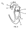
図3において矢印31によって図示されるように、逆流性の流れの場合、血液は、僧帽弁33を介して心室24から左心房25へと逆向きに流れる。この逆向きの流れは、心収縮フェーズ中に心臓(又は少なくとも僧帽弁33の領域)の超音波データを撮影し、逆転方向の流れを検知するためにドップラ分析を適用することによって検知され得る。
In the case of retrograde flow, as illustrated by
左心室に代わって右心室について一回拍出量が求められるべきである場合には、逆流性の流れは、三尖弁を介した右心室から右心房への逆向きの流れとして現れる。この逆向きの流れは、心収縮フェーズ中に心臓(又は少なくとも三尖弁の領域)の超音波データを撮影し、逆転方向の流れを検知するためにドップラ分析を適用することによって検知され得る。 If stroke volume is to be determined for the right ventricle instead of the left ventricle, regurgitant flow manifests as retrograde flow from the right ventricle to the right atrium via the tricuspid valve. This reverse flow can be detected by taking ultrasound data of the heart (or at least the region of the tricuspid valve) during the systolic phase and applying Doppler analysis to detect flow in the reverse direction.
単なる例として、以下の説明は、左心室のみについてのプロシージャを参照して説明される。 By way of example only, the following description will be described with reference to procedures for the left ventricle only.
有利には、初期評価プロシージャは、上に論じられた改善されたドップラ撮像技術を使用し、僧帽弁33によって占められるトランスデューサユニットの視野の領域を特定するために画像分割が使用される。
Advantageously, the initial assessment procedure uses the improved Doppler imaging technique discussed above, and image segmentation is used to identify the region of the transducer unit's field of view occupied by the
この手法によると、超音波トランスデューサプローブ16は、対象者の心臓20又は少なくとも僧帽弁領域33がトランスデューサプローブの広視野内にあるような、例えば、プローブのトランスデューサアレイ17の操向可能なビームの角度範囲内に位置するような対象者の食道内の位置に、臨床医によって最初に位置決めされる。
According to this approach, the
次いで、広視野の初期3D超音波画像データセットが取得される。 An initial wide-field 3D ultrasound image dataset is then acquired.
これによって取得されたグレースケールデータは、続いて、画像分割を適用するためにコントローラ18によって処理される。
The grayscale data thus acquired is subsequently processed by the
画像分割は、画像処理の分野においてよく知られたプロシージャであり、これによって、(デジタル)画像は、複数のセクタ又は領域に、例えば、これらの領域内にあるピクセルが共通して有する特性に従って区分又は分割される。例えば、画像分割は、典型的には、より広い画像内で物体を特定又はその場所を明らかにするために、及び、画像内の境界(例えば、線、曲線、輪郭)を特定するために適用される。 Image segmentation is a well-known procedure in the field of image processing, whereby a (digital) image is partitioned into sectors or regions, e.g. according to properties that pixels within these regions have in common. or divided. For example, image segmentation is typically applied to identify or locate objects within a larger image and to identify boundaries (e.g., lines, curves, contours) within an image. be done.
本適用例において、画像分割は、画像内の解剖学的物体又は領域を特定又はその場所を明らかにするため、及び前記物体又は領域の境界の場所を明らかにするに超音波画像が処理されることを可能とする。 In this application, image segmentation is the process by which an ultrasound image is processed to identify or reveal the location of an anatomical object or region within the image and to reveal the location of boundaries of said object or region. make it possible.
画像分割は、好ましくは、モデルベースの画像分割である。モデルベースの分割は、撮影された画像内の解剖学的物体をより正確に特定するために、特定の解剖学的領域又は物体の特徴を示す共通の構造的又は幾何学的パターンを使用する。特には、特定の解剖学的特徴についての似通った形状又は輪郭に関する確率的モデルが用いられる。次いで、このモデル内でエンコードされたパラメータが、関心対象となる特定の幾何学的特徴又は領域の境界をより正確及び明確に特定するために画像データを分割する際の条件として適用される。 Image segmentation is preferably model-based image segmentation. Model-based segmentation uses common structural or geometric patterns that characterize particular anatomical regions or objects to more accurately identify anatomical objects in captured images. In particular, probabilistic models of similar shapes or contours for particular anatomical features are used. The parameters encoded within this model are then applied as conditions in segmenting the image data to more accurately and clearly identify the boundaries of particular geometric features or regions of interest.
例えば、本適用例において、モデルベースの分割は、心臓領域に関連するモデルを使用し、又は、より具体的には、僧帽弁、三尖弁及び左心室流出路又は右心室流出路を含む左心室領域又は右心室領域のモデルを使用する。 For example, in this application, the model-based segmentation uses models that relate to the heart region, or more specifically includes the mitral valve, tricuspid valve and left ventricular outflow tract or right ventricular outflow tract. A model of the left or right ventricular region is used.
この目的のための適切なモデルベースの分割アルゴリズムは、当技術分野において知られている。例えば、本発明の超音波データ取得に適用され得るモデルベースの分割手法を説明するEcabertらの「Automatic Model-Based Segmentation of the Heart in CT Images」、IEEE TRANSACTIONS ON MEDICAL IMAGING、27(9)、2008を参照されたい。 Suitable model-based segmentation algorithms for this purpose are known in the art. For example, Ecabert et al., "Automatic Model-Based Segmentation of the Heart in CT Images," IEEE TRANSACTIONS ON MEDICAL IMAGING, 27(9), 2008, which describes a model-based segmentation approach that can be applied to the ultrasound data acquisition of the present invention. See
この場合の分割は、僧帽弁33、特には、僧帽弁によって占められる広視野の領域に対応する場所情報を生成するように適用される。例えば、僧帽弁の外形の座標、又はこの場所の任意の他の表現が求められる。
The segmentation in this case is applied to generate location information corresponding to the
次いで、求められた場所情報は、ドップラビーム形成ユニット(これは、例えば、コントローラ18に含まれる別個のユニットであってよく、又は、コントローラに機能的に一体化されてもよく、これは、コントローラがドップラビーム形成ユニットの機能を実行することを意味する)に送られる。
The determined location information is then used by a Doppler beam forming unit (which may be a separate unit, for example included in the
次いで、トランスデューサプローブ16のトランスデューサアレイ17は、他の領域を排除するために僧帽弁33の特定された領域へと超音波ビームを集束及び方向付け(すなわち、操向)するように制御される。超音波ビームは、少なくとも心臓周期の心収縮フェーズの期間全体にわたって送信される。このように、僧帽弁領域に対応する超音波データが収集され、戻ってくるエコー信号(例えば、パルス超音波の場合はエコーパルス)は、僧帽弁を通って流れる血液の血流速度関数を時間の関数として導き出すためにドップラ処理される。この関数は、負の速度、又は左心房25に向かう方向の速度(すなわち、逆流性の流れ)の発生を判定するために処理される。
The
逆流性の流れが特定されなかった場合、コントローラ18は、トランスデューサプローブ16のトランスデューサアレイ17が、心臓20を包含する、又は少なくとも心臓の左心室領域24を包含する広視野にわたって3D超音波画像データを取得するように制御される第1の撮像プロシージャを実行するように適合される。代替的な実施例において、広視野は少なくとも右心室領域を包含する。
If no regurgitant flow is identified,
特には、有利な実施例において、第1の撮像プロシージャについて、超音波トランスデューサユニット(本実施例においては超音波プローブ16)は、3次元的撮像データを10Hz又はそれより高いフレームレートで取得可能で、取得されたデータをコントローラ18へと送信可能である。プローブは、例えば機械的保持手段を使用して所定の箇所に物理的に保持される。プローブは、好ましくは、心臓20の十分な視野を可能にする位置の所定の箇所に保持される。経食道的使用(図1の実施例におけるものなど)では、プローブの安定性は、食道内での正確で安定した位置決めによって保証される。経胸腔的使用では、例えば、プローブホルダ又はパッチが使用される。
In particular, in an advantageous embodiment, for the first imaging procedure, the ultrasound transducer unit (in this example ultrasound probe 16) is capable of acquiring three-dimensional imaging data at a frame rate of 10 Hz or higher. , the acquired data can be sent to the
プローブ16は、対象者22の心臓周期の心拡張末期(図1;A)及び心収縮末期(図1;B)のポイントにおいてのみ3D超音波データを撮影するように制御される。コントローラ18は、好ましくは、対象者に結合されたECGセンサを有するECGユニット(不図示)に通信可能に結合される。コントローラにおいてECGユニットから受信された信号入力は、心拡張末期及び心収縮末期のタイミングを特定し、データ収集がこれらのフェーズと一致するように制御され得るようにするために使用される。このことは、データ収集を効率的に最小化する。
The
収集された各超音波画像データフレームは、画像分割アルゴリズムに従って、コントローラ18によって処理される。画像分割は、当技術分野においてよく知られたプロシージャであり、上に論じられたように、本発明の実施例における分割を実行するために適切なアルゴリズムが存在する。
Each acquired ultrasound image data frame is processed by the
画像分割は、(グレースケール)超音波3Dデータから、各画像フレーム(例えば、心拡張末期(A)及び心収縮末期(B))において左心室24のボリューム外側境界26の形状プロファイルを導き出す。実施例において、分割アルゴリズムは、例えば機械学習ツールなど、当技術分野において知られている任意の適切な画像処理ツールを使用する。アルゴリズムは、上に論じられたように、モデルベースの画像分割を使用する。
Image segmentation derives the shape profile of the volume
次いで、導き出された左心室境界26の形状情報は、コントローラ18によって処理され、心拡張末期及び心収縮末期の各々における左心室24のボリューム又は推定ボリュームが計算される。ボリュームにおける変化を導き出すために、計算された心収縮末期におけるボリュームは心拡張末期におけるものから減算される。ボリュームにおける変化は、一回拍出量、すなわち、心周期中の左心室24からの血液の総流出量に等しい。
The derived
この処理は、複数の心臓周期について一回拍出量の値を導き出すために、複数の心臓周期について繰り返される。 This process is repeated for multiple cardiac cycles to derive stroke volume values for multiple cardiac cycles.
更なる任意選択的なステップによると、コントローラ18は、導き出された一回拍出量の値を、一回拍出量変動情報を導き出すために複数の心臓周期について更に処理する。
According to a further optional step,
この情報は、ユーザに対して通信される前に、患者22のECG読み取り値、静脈内流体ボリューム投与情報及び臨床的ガイドラインなど、他の患者固有情報と有用に組み合わされる。このことは、関連する臨床的情報を一緒に都合よく提供することによってデバイスの使用効率を向上させる。 This information is usefully combined with other patient-specific information, such as the patient's 22 ECG readings, intravenous fluid volume administration information and clinical guidelines, before being communicated to the user. This improves the efficiency of using the device by conveniently providing relevant clinical information together.
実施例によると、システムは、導き出された一回拍出量及び/又は一回拍出量変動情報をユーザに対して表示するためのディスプレイユニット(不図示)を備える。この情報は、種々のフォーマットの範囲において表示される。例えば、一回拍出量のリアルタイム追跡、一回拍出量変動、静脈内流体投与履歴、及び流体投与への一回拍出量変動反応が表示される。 According to an embodiment, the system comprises a display unit (not shown) for displaying the derived stroke volume and/or stroke volume variability information to a user. This information is displayed in a range of different formats. For example, real-time tracking of stroke volume, stroke volume variation, intravenous fluid administration history, and stroke volume variation response to fluid administration are displayed.
図4は、関連するディスプレイユニットによってユーザに対して表示される例示的なリアルタイム追跡を示す。線42は、時間経過(x軸;秒)に伴う心室ボリュームの変動(y軸;mL)を示し、線44は、時間経過(x軸;秒)に伴う一回拍出量の変動(y軸;mL)を示す。 FIG. 4 shows exemplary real-time tracking displayed to the user by an associated display unit. Line 42 shows the variation of ventricular volume (y-axis; mL) over time (x-axis; seconds), and line 44 represents the variation of stroke volume (y-axis; s) over time (x-axis; seconds). Axis; mL).
図示されたデータは、機械的換気下の患者から収集されたものである。しかしながら、システムは、機械的換気下にない患者のためにも使用され得、患者が深く呼吸可能であるならば、TEEプローブが使用される場合にさえも使用され得る。 Data shown were collected from patients on mechanical ventilation. However, the system can also be used for patients not under mechanical ventilation, and even if a TEE probe is used, provided the patient is able to breathe deeply.
実施例によると、導き出された一回拍出量変動情報は、患者に対して適用されている静脈内輸液の制御又は調節、例えば、投与量又はタイミングの調節を直接的に報知する。これは、例えば、一回拍出量変動と静脈内流体投与反応との間のあらかじめ記憶された数学的関係性、又は、絶対一回拍出量と理想的な静脈内流体投与量との間の関係性に基づく。 According to embodiments, the derived stroke volume variability information directly informs control or adjustment of intravenous fluids being applied to the patient, eg, adjustment of dosage or timing. This can be, for example, a pre-stored mathematical relationship between stroke volume variation and intravenous fluid dose response, or between absolute stroke volume and ideal intravenous fluid dose. based on the relationship between
上記のことは、(上述の)初期評価プロシージャが、(少なくとも心収縮フェーズ中に)左心室24への逆流性の流れが存在していないことを示した場合にコントローラ18が実行する第1の撮像プロシージャを説明している。
The above is the
初期評価プロシージャにおいて逆流性の流れが特定された場合には、コントローラは、代わりに、ドップラベースの一回拍出量判定方法が実行される第2の撮像プロシージャを実行するように適合される。以下に説明される好ましい実施形態において、このドップラベースの方法は、有利には、左心室流出路についての場所情報を自動的に取得する超音波撮像方法を用い、このエリアへのビームの局所的な収束を可能とし、訓練されたユーザが継続的にプローブの位置決めを誘導する必要性を回避している。 If regurgitant flow is identified in the initial assessment procedure, the controller is instead adapted to perform a second imaging procedure in which a Doppler-based stroke volume determination method is performed. In the preferred embodiment described below, this Doppler-based method advantageously employs ultrasound imaging methods that automatically acquire location information about the left ventricular outflow tract, localizing the beam to this area. It allows for rapid convergence and avoids the need for a trained user to continually guide probe positioning.
代替的な実施例において、代替的に又は追加的に、右心室及び右心室流出路が検討される。説明を簡潔にするために、プロシージャは、単なる例として、左心室を参照して説明される。 In alternative embodiments, the right ventricle and right ventricular outflow tract are alternatively or additionally considered. For simplicity of explanation, the procedure will be described with reference to the left ventricle as an example only.
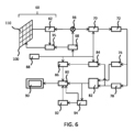
図5において、第2の撮像プロシージャのステップが、ブロック図の形態で概略的に示される。 In FIG. 5 the steps of the second imaging procedure are schematically illustrated in block diagram form.
第1の撮像プロシージャと同様に、プローブ16の超音波アレイ17は、左心室流出路がトランスデューサプローブの広視野内、すなわち、トランスデューサアレイの操向可能なビームの操向範囲内にあるように、オペレータによって前もって位置決めされるものと想定される。例示的な有利な位置決めは、例えば、中食道(ME)大動脈長軸、経胃的(TG)短軸、又は経胃的(TG)長軸と位置合わせされた広視野を提供する。
As in the first imaging procedure, the
(初期評価に応じた)第2の撮像プロシージャの開始時に、ステップ52において、コントローラ18は、3次元的(ボリューム)超音波画像データを取得するように、超音波トランスデューサユニット(プローブ)16を制御する。プローブは、対象者22の心臓20の画像を撮影するように前もって位置決めされる。3D超音波画像データを撮影するために、例えば、Bモードボリューム超音波撮像が用いられる。
At the start of the second imaging procedure (in response to the initial evaluation), at
ボリューム画像データが取得されると、ステップ54において、(グレースケール)データは、画像分割アルゴリズム(適切な画像分割アルゴリズム及び手段のより詳細な議論については上記を参照)に従って分割される。画像分割は、好ましくは、モデルベースの画像分割である。分割は、左心室流出路を含む撮像された心臓領域内の解剖学的な構造又は特徴の場所が特定されることを可能とする。分割は、解剖学的特徴に関するサイズ情報が特定されることも可能とする。特には、左心室流出路(LVOT)32の断面積が求められる。断面積は、図2及び図3において矢印32によって示されるように、少なくとも1つの特定の場所について求められ又は導き出されるが、LVOTの2つ以上の場所について求められてもよい。
Once the volumetric image data is acquired, in
プロシージャが右心室について実施される場合は、画像分割を使用して右心室流出路(RVOT)の位置及びサイズが代わりに導き出されることに留意されたい。 Note that if the procedure is performed on the right ventricle, image segmentation is used to derive the location and size of the right ventricular outflow tract (RVOT) instead.
導き出されるLVOTの座標は、例えば、超音波データの(例えば、モデルベースの)分割によって求められる。ステップ56において、これらはシステムのドップラビーム形成ユニットへと送られ、これは、座標に基づいて、LVOTへと超音波ビームを局所的に操向又は収束させるようにプローブ16のトランスデューサアレイ17を制御する。
The derived LVOT coordinates are determined, for example, by (eg, model-based) segmentation of the ultrasound data. At
ドップラビーム形成ユニットはコントローラ18に含まれ、又はコントローラに機能的に一体化され、すなわち、コントローラが超音波ビーム形成ユニットの機能を実施する。代替的に、ビーム形成ユニットはコントローラ18とは別個のものであり、例えば、より広範な診断用撮像システム又は患者監視システムの一部である。
The Doppler beamforming unit is included in the
トランスデューサアレイは、導き出されたLVOT断面積及び既知のビーム形状に基づいて、LVOT全体にわたる範囲に超音波ビームを向けるように制御される。この目的を達成するために、ドップラゲートの場所及び長さが、心臓周期にわたる画像座標の空間的範囲に基づいて設定される。これによって、LVOTに対応する超音波データが収集され、これから、LVOTを通って流れる血液に対応する速度情報が求められ得る。 The transducer array is controlled to direct the ultrasound beam over the LVOT based on the derived LVOT cross-sectional area and the known beam shape. To this end, the Doppler gate location and length are set based on the spatial extent of the image coordinates over the cardiac cycle. Thereby, ultrasound data corresponding to the LVOT is acquired, from which velocity information corresponding to blood flowing through the LVOT can be determined.
疑問を避けるために述べるが、「ドップラゲートの場所」とは、超音波データが収集されるべき、及び、ドップラ流測定値が取得されるべき関心領域を意味する当技術分野の用語である。ドップラゲートの長さとは、この関心領域のサイズを指す。 For the avoidance of doubt, "Doppler gate location" is a term of the art for the region of interest from which ultrasound data should be collected and Doppler flow measurements should be obtained. The length of the Doppler gate refers to the size of this region of interest.
現在の事例においては、ドップラゲートの場所及び長さは、LVOTの場所及びサイズに対応するように設定される。 In the current case, the Doppler gate location and length are set to correspond to the LVOT location and size.
好ましい本実施形態によると、ゲートの場所と長さとを求め、設定することは自動的に実施される。上に論じられたように、画像分割は、LVOTが存在する画像ボリューム内の場所を求めることを可能とする。LVOTの場所は、心臓周期における複数のフレームにわたって調べられ得、それによって、その心臓周期全体にわたってLVOTが存在した場所の総範囲(「座標の空間的範囲」)が求められ得る。 According to the presently preferred embodiment, determining and setting the location and length of the gate is performed automatically. As discussed above, image segmentation makes it possible to determine where within the image volume the LVOT resides. The location of the LVOT can be examined over multiple frames in the cardiac cycle, thereby determining the total extent of where the LVOT was located over the entire cardiac cycle (the "spatial extent of the coordinates").
例えば、いくつかの場合において、LVOTは、周期全体にわたって空間内で振動運動を行う。この場合、場所の総範囲は、LVOTの真のサイズよりも大きい。対照的に、LVOTが静止しているなら(静かな心臓運動)、場所の範囲は、周期全体にわたってLVOTの静的なサイズよりも拡がることはない。 For example, in some cases the LVOT undergoes oscillatory motion in space over a period. In this case, the total extent of locations is larger than the true size of the LVOT. In contrast, if the LVOT is stationary (quiet cardiac motion), the range of locations does not extend beyond the static size of the LVOT over the entire cycle.
LVOTの場所及びサイズが分かると、トランスデューサアレイは、心臓周期の期間に、求められたLVOT領域にわたって拡がるように超音波ビームをこの領域へと集束させ又は操向するように制御される。 Knowing the location and size of the LVOT, the transducer array is controlled to focus or steer the ultrasound beam to the determined LVOT region so that it spreads over the region during the cardiac cycle.
LVOT領域の横方向及び/又は高さ方向の全体的な範囲をカバーするのに十分な量の超音波の「ライン」がトランスデューサユニットから射出される。更には、軸方向寸法をカバーするために、データは、LVOTの深さの範囲に対応する時間遅延を伴って処理される。 A sufficient amount of "lines" of ultrasound waves are emitted from the transducer unit to cover the entire lateral and/or elevational extent of the LVOT region. Furthermore, in order to cover the axial dimension, the data are processed with time delays corresponding to the depth range of the LVOT.
代替的な実施例において、LVOTの総エリアにわたってビームの束を向けるのではなく、トランスデューサアレイ17は、LVOTによって描写される領域にわたって順次的にビームを「発射」するように制御される。ビームの目標の場所は、分割から導き出されたLVOTの幾何学的構造に基づいて決定され、必要とされるビームの数は、LVOTの既知の深さにおける既知の超音波ビームの幅に基づいて導き出される。これらの値は、典型的には、所与の超音波トランスデューサについての標準的な既知のパラメータである。
In an alternative embodiment, rather than directing a bundle of beams over the entire area of the LVOT, the
どちらの手法によっても、超音波データは、全体的な心臓周期にわたって、又は少なくとも心臓周期の心収縮フェーズにわたって収集される。データは、心臓周期にわたって、又は心収縮フェーズにわたって継続的に収集される。 With either approach, ultrasound data is acquired over the entire cardiac cycle, or at least over the systolic phase of the cardiac cycle. Data is collected continuously over the cardiac cycle or over the systolic phase.
LVOTに対応する超音波データの取得の際に、コントローラ18又はドップラ処理ユニットは、導き出されたデータをドップラ処理技術を使用して処理する。このような技術は、当技術分野において一般に知られており、一定期間にわたって所与の撮像領域について速度のスペクトルが導き出されること可能とする。現在の事例においては、速度のスペクトルは、左心室流出路(LVOT)を通って流れる血液について、心臓周期にわたって、又は少なくともその心収縮フェーズ(このとき、血液が左心室から流出する)にわたって導き出され得る。
Upon acquisition of ultrasound data corresponding to LVOT, the
この処理技術は、コントローラ18(又は、別個のドップラプロセッサ)が、時間(v(t))とともにLVOTを通る血液速度の関数を導き出すことを可能とする。 This processing technique allows controller 18 (or a separate Doppler processor) to derive a function of blood velocity through the LVOT with time (v(t)).
特定の実施例において、プローブの(小さな)意図しない運動によってもたらされる影響を除去するために、低周波数フィルタリングプロシージャが、導き出されたドップラ超音波データに対して適用され得る。この場合、コントローラは、より高い周波数の血液運動の、アーチファクトのない定量化を可能とするとともに、十分に低い周波数の組織運動成分を通過可能としてプローブ運動の検知も可能とするように、フィルタの最適化されたカットオフ周波数を設定する。 In certain embodiments, a low frequency filtering procedure may be applied to the derived Doppler ultrasound data to remove effects caused by (small) unintended movements of the probe. In this case, the controller configures the filters to allow artifact-free quantification of higher frequency blood motion, while allowing sufficiently low frequency tissue motion components to pass through to allow detection of probe motion as well. Sets the optimized cutoff frequency.
ステップ58において、分割中に導き出されたLVOTの断面積に基づいて、及び、送信された超音波ビームの特性(特には、生成されたビームの既知の操向方向)に基づいて、効果的なドップラ角度が計算される。送信されたビームの各々と、(超音波データから測定された)LVOTターゲットの平均的な流れベクトル方向との間の角度が計算される。次いで、効果的なドップラ角度を導き出すために、これらの角度の平均が計算される。次いで、効果的なドップラ角度は、心臓周期にわたるスペクトルドップラ追跡を補正するために、すなわち、角度補正されたドップラ追跡を導き出すために使用され、これによって、角度補正された速度-時間関数v(t)が導き出され得る。
In
画像分割に基づいてドップラ角度を導き出すことは、ドップラ角度が典型的にはオペレータ(すなわち、心臓病専門医又は音波検査者)によって手動で計算されていた以前の方法に対して著しい改善を示す。手動で実施されると、誤差が発生し得る。たとえドップラ角度計算における小さな誤差であったとしても、結果的な速度測定における重大な誤差に直接的につながり得、特に60°を超える角度のものはそうである。 Deriving the Doppler angle based on image segmentation represents a significant improvement over previous methods in which the Doppler angle was typically manually calculated by the operator (ie, cardiologist or sonographer). When performed manually, errors can occur. Even small errors in Doppler angle calculations can lead directly to significant errors in the resulting velocity measurements, especially for angles greater than 60°.
ドップラ角度補正された速度-時間関数v(t)と、(心臓周期にわたるLVOTを通る血流量の総ボリュームを導き出すために分割ステップ54において導き出された)LVOTの断面積との積に対して時間積分がとられる。LVOTは、左心室からの唯一の流出経路であるため、この総血流量は、一回拍出量(SV)の測定値を提供する。従って、これは、以下のように表現され得る。

最後に、ステップ60において、運動検知プロシージャが実施される。ここで、例えば低周波数フィルタを使用して、取得されたドップラ信号の低周波数部分が隔離される。この部分は、組織ドップラ部分、すなわち、血液の運動とは対照的な、組織の(比較的によりゆっくりとした)運動を表す部分を表す。この信号は、組織運動が前もって定められた閾値を超えるか否かを判定するように、すなわち、特定の閾値を超えるプローブの運動があったか否かを判定するように処理され得る。
Finally, at
閾値を超えるいかなる運動もなかった場合は、撮像プロシージャは、ドップラ超音波取得ステップ56へと直接的に戻るように(すなわち、LVOT位置情報を再び取得することなく)ループし得、LVOTについての新たな位置情報に基づいて、後続の心臓周期について一回拍出量が再び求められる。 If there has not been any motion above the threshold, the imaging procedure may loop directly back to the Doppler ultrasound acquisition step 56 (i.e., without acquiring LVOT position information again) and obtain new information about the LVOT. Stroke volume is re-determined for subsequent cardiac cycles based on the positional information.
閾値を超える運動があった場合は、プロシージャは、ステップ52へと戻り、広視野のボリューム超音波データがもう一度取得され、LVOTについて位置座標を再び取得するために分割54が再び実施される。次いで、プロシージャは、ステップ56に進み得、ドップラ超音波を取得及び処理し、更なる周期について一回拍出量を再び求める。
If there is motion above the threshold, the procedure returns to step 52, wide-field volumetric ultrasound data is once again acquired, and
従って、図5の第2の撮像プロシージャは、連続的な心周期について一回拍出量(及び/又は、任意選択的に、一回拍出量を対象者の心拍数で乗算することによる心拍出量)の測定値を取得するようにループして動作する。各周期の終わりに、プローブ運動検知60が実行される。
Accordingly, the second imaging procedure of FIG. 5 is a stroke volume (and/or, optionally, a heart rate by multiplying the stroke volume by the subject's heart rate) for successive cardiac cycles. operate in a loop to obtain measurements of stroke volume). At the end of each cycle,
上に概説された実施例においては、ステップ52及びステップ54において、LVOTについて場所情報を取得するためにボリュームBモード画像データが取得され、分割されるが、代替的な実施例において、場所情報を取得するための異なる手段が使用される。これは、異なる撮像手段である。異なる手段は、例えば、ボリューム(取得)フレームレートが低い(例えば、<約10Hz)場合に好ましく、又は必要である。特定の患者について高い視野又は解像度設定を適用した結果としてフレームレートは低くなり、達成可能なフレームレートがトレードオフされる。
In the embodiment outlined above, in
LVOTについてのサイズ情報の取得は、LVOTのMモード撮像を使用して実施され得、LVOTの断面積を求めることを可能とする。 Obtaining size information about the LVOT can be performed using M-mode imaging of the LVOT, allowing the cross-sectional area of the LVOT to be determined.
従来の2D超音波撮像において、Mモードは、継続的なエコーデータを1つの「ライン」に沿って集め、弁又は組織などの構造の振動が観察されることを可能とする。この情報から、構造の長さが求められ得る。この手法は3D撮像にも適用され得、構造、すなわち、この場合はLVOTの断面積を求めることを可能とする。 In conventional 2D ultrasound imaging, M-mode collects continuous echo data along one "line", allowing vibrations of structures such as valves or tissue to be observed. From this information, the length of the structure can be determined. This approach can also be applied to 3D imaging, allowing to determine the cross-sectional area of the structure, ie in this case the LVOT.
1つ又は複数の実施例によると、一貫した心臓活動(一貫したECG)は、複数周期にわたる心臓活動に関して仮定することを可能とし、より高い有効フレームレートが達成されることを可能とする。これらのパラメータは、患者によって異なる。 According to one or more embodiments, consistent cardiac activity (consistent ECG) allows assumptions about cardiac activity over multiple cycles, allowing higher effective frame rates to be achieved. These parameters vary from patient to patient.
1つ又は複数の実施例によると、ステップ54における分割に際して、コントローラ18が、LVOTがプローブ16の視野の周辺部に位置していること、又は完全に視野内にあるのではないことを判定又は検知した場合、オペレータは、ユーザインタフェースデバイス(例えば、ディスプレイ又は他の知覚的出力手段)を使用してその事実を警告され、LVOTが視野内、理想的には視野の中央に設置されることを保証するようにプローブの位置決めを調節することができる。
According to one or more embodiments, during segmentation at
上述の実施例において、超音波プローブ、特には、TEEプローブ又はTTEプローブが使用されるが、これは本発明の概念に不可欠ではない。心臓領域の3D超音波画像データ及びドップラ超音波データ(パルス波又は継続波)が取得可能な任意の超音波トランスデューサユニットが使用される。これは、実施例によると、外部トランスデューサユニット又は半侵襲的プローブであってよい。 In the above examples an ultrasound probe is used, in particular a TEE probe or a TTE probe, but this is not essential to the inventive concept. Any ultrasound transducer unit capable of acquiring 3D ultrasound image data and Doppler ultrasound data (pulse wave or continuous wave) of the cardiac region is used. This may be an external transducer unit or a semi-invasive probe, according to embodiments.
特定の実施形態によると、超音波データの取得は、生体外的やり方で(すなわち、非侵襲的に)実施され、例えば、身体外に位置する超音波トランスデューサユニットの使用に基づく。この場合、超音波トランスデューサユニットは、心臓の超音波データの生体外的取得のために使用される。 According to certain embodiments, acquisition of ultrasound data is performed in an ex vivo manner (ie, non-invasively), eg, based on the use of an ultrasound transducer unit located outside the body. In this case, the ultrasound transducer unit is used for ex vivo acquisition of cardiac ultrasound data.
実施例において、本発明の実施形態は、例えば、集中治療室、手術室又は救急車などにおける心臓監視のための経食道的超音波又は経胸腔的パッチプローブなど、超音波プローブが固定的な位置に設置され得る臨床的環境における使用を期待される。 In an embodiment, embodiments of the present invention can be used with ultrasound probes in fixed locations, such as transesophageal ultrasound or transthoracic patch probes for cardiac monitoring, e.g., in intensive care units, operating rooms, or ambulances. It is expected to be used in clinical settings where it can be set up.
実施形態の1つのセットによると、超音波撮像システムは、患者監視デバイスに通信可能に結合され、求められた一回拍出量に基づく出力情報を患者監視デバイスへと通信するように適合される。患者監視デバイスは、受信されたデータを記憶するためのメモリを含む。監視デバイスは、取得された情報をユーザ(例えば、臨床医)に対して表示するためのディスプレイを含む。患者監視システムは、所与の患者に関する更なる情報を含む患者データベースと接続され、この更なる情報は、取得された一回拍出量情報と連動して表示され得る。 According to one set of embodiments, the ultrasound imaging system is communicatively coupled to the patient monitoring device and adapted to communicate the determined stroke volume-based output information to the patient monitoring device. . The patient monitoring device includes memory for storing the received data. The monitoring device includes a display for displaying acquired information to a user (eg, a clinician). The patient monitoring system is connected to a patient database that contains additional information about a given patient, and this additional information can be displayed in conjunction with the acquired stroke volume information.
通信可能な結合は、有線又は無線である。無線結合は、例えば、Bluetooth、無線周波数通信、NFC、ZigBee、Wi-Fi又は任意の他の無線プロトコルなどの任意の無線通信媒体によって実現される。 Communicative couplings may be wired or wireless. Wireless coupling may be realized by any wireless communication medium such as Bluetooth, radio frequency communication, NFC, ZigBee, Wi-Fi or any other wireless protocol.
本発明の一態様によると、患者監視デバイスと、超音波トランスデューサユニットと、トランスデューサユニットを制御し、一回拍出量を求めるためのコントローラとを含む患者監視システムが提供される。 According to one aspect of the invention, a patient monitoring system is provided that includes a patient monitoring device, an ultrasound transducer unit, and a controller for controlling the transducer unit and determining stroke volume.
上述されたように、一回拍出量測定値は、静脈内流体管理における、特には、例えば、敗血症、脳手術、心臓及び肺動脈介入、又は集中治療によって引き起こされる循環補助及び継続した観察を必要とする換気された患者の場合における、特定の値である。 As mentioned above, stroke volume measurements are required for circulatory support and continued observation in intravenous fluid management, especially induced by, for example, sepsis, brain surgery, cardiac and pulmonary interventions, or intensive care. is a specific value in the case of a ventilated patient with .
本発明の実施形態による超音波撮像デバイスは、より広範な超音波診断用撮像システムの一部を形成し、又は、その一部として提供される。 An ultrasound imaging device according to embodiments of the present invention forms part of, or is provided as part of, a broader ultrasound diagnostic imaging system.
次に、例示的な超音波診断用撮像システムの全体的な動作が、図6を参照して説明される。 The overall operation of an exemplary ultrasonic diagnostic imaging system will now be described with reference to FIG.
例示的なシステムは、超音波を送信し、エコー情報を受信するためのCMUTトランスデューサアレイ100を有するアレイトランスデューサプローブ60の形態の超音波トランスデューサユニットを備える。トランスデューサアレイ100は、代替的に、PZT又はPVDFなどの材料で形成された圧電トランスデューサを備える。トランスデューサアレイ100は、2D平面において又は3D撮像のためには3次元的にスキャン可能なトランスデューサ110の2次元的なアレイである。別の実施例において、トランスデューサアレイは1Dアレイである。
The exemplary system comprises an ultrasound transducer unit in the form of an
トランスデューサアレイ100は、プローブにおけるマイクロビーム形成器62に結合され、これは、CMUTアレイセル又は圧電要素による信号の受信を制御する。マイクロビーム形成器は、米国特許第5,997,479号(Savordら)、米国特許第6,013,032号(Savord)及び米国特許第6,623,432号(Powersら)において説明されているように、トランスデューサのサブアレイ(又は「グループ」若しくは「パッチ」)によって受信された信号の少なくとも部分的なビーム形成が可能である。
The
マイクロビーム形成器は、全体的に任意選択的であることに留意されたい。以下の実施例は、アナログビーム形成を想定していない。 Note that the microbeamformer is entirely optional. The following examples do not assume analog beamforming.
マイクロビーム形成器62は、プローブケーブルによって、送信/受信(T/R)スイッチ66に結合され、これは送信と受信とを切り換えるとともに、マイクロビーム形成器が使用されず、主システムビーム形成器によってトランスデューサアレイが直接的に動作されるときに、主ビーム形成器70を高エネルギー送信信号から保護する。トランスデューサアレイ60からの超音波ビームの送信は、T/Rスイッチ66によってマイクロビーム形成器に結合されたトランスデューサコントローラ68及び主送信ビーム形成器(不図示)によって指示され、これは、ユーザインタフェース又は制御パネル88へのユーザの操作からの入力を受信する。
The
トランスデューサコントローラ68によって制御される機能のうちの1つは、ビームが操向及び収束される方向である。ビームは、トランスデューサアレイから真っ直ぐ前方に(垂直に)、又は、より広い視野のために異なる角度に操向される。トランスデューサコントローラ68は、CMUTアレイのためのDCバイアス制御装置95を制御するように結合され得る。DCバイアス制御装置95はCMUTセルに印加されるDCバイアス電圧を設定する。
One of the functions controlled by
受信チャンネルにおいて、部分的にビーム形成された信号がマイクロビーム形成器62によって生成され、主受信ビーム形成器70に結合され、ここで、トランスデューサの個々のパッチからの部分的にビーム形成された信号は、完全にビーム形成された信号へと合成される。例えば、主ビーム形成器70は、128のチャンネルを有し、その各々が、数ダースから数百のCMUTトランスデューサセル又は圧電要素のパッチから部分的にビーム形成された信号を受信する。このようにして、トランスデューサアレイの数千のトランスデューサによって受信された信号が、1つのビーム形成された信号に効率的に寄与し得る。
In the receive channel, the partially beamformed signals are generated by the microbeamformer 62 and coupled to the main receive
ビーム形成された受信信号は、信号プロセッサ72に結合される。信号プロセッサ72は、受信されたエコー信号を、帯域通過フィルタリング、デシメーション、I及びQコンポーネント分離、組織及び微小気泡から戻った非線形(基本周波数のより高い高調波)エコー信号の特定を可能とするように線形及び非線形の信号を分離するように働く高調波信号分離などの様々なやり方で処理し得る。信号プロセッサは、スペックル低減、信号合成、ノイズ除去などの追加的な信号増強も実施する。信号プロセッサにおける帯域通過フィルタはトラッキングフィルタであってよく、その通過帯域は、エコー信号が受信される深さが深くなるにつれて、より高い周波数帯域からより低い周波数帯域へとスライドし、それによって、これらの周波数が解剖学的情報を欠いているより深い深さからのより高い周波数におけるノイズを拒絶する。
The beamformed received signals are coupled to a
送信及び受信のためのビーム形成器は、種々のハードウェアにおいて実現され、種々の機能を有し得る。もちろん、受信器ビーム形成器は、送信ビーム形成器の特性を考慮して設計される。図6においては、簡潔さのために、受信器ビーム形成器62、70のみが図示されている。完全なシステムにおいては、送信マイクロビーム形成器、及び主送信ビーム形成器を具備する送信チェーンも存在するであろう。
Beamformers for transmit and receive may be implemented in different hardware and have different functions. Of course, the receiver beamformer is designed with the properties of the transmit beamformer in mind. In FIG. 6, only the
マイクロビーム形成器62の機能は、アナログ信号パスの数を減少させるために、信号の初期合成を提供することである。これは、典型的には、アナログドメインにおいて実施される。
The function of the
最終的なビーム形成は、主ビーム形成器70において、典型的には、デジタル化の後になされる。
Final beamforming is typically done after digitization in the
送信及び受信チャンネルは、固定的な周波数帯域を有する同一のトランスデューサアレイ60’を使用する。しかしながら、送信パルスが占める帯域幅は、使用された送信ビーム形成に応じて変わり得る。受信チャンネルは、全体的なトランスデューサ帯域幅を補足し得(これは古典的な手法である)、又は、帯域通過処理を使用して、有用な情報(例えば、主高調波の高調波)を含む帯域幅のみを抽出し得る。 The transmit and receive channels use the same transducer array 60' with fixed frequency bands. However, the bandwidth occupied by the transmit pulses may vary depending on the transmit beamforming used. The receive channel can either supplement the overall transducer bandwidth (which is the classical approach) or use bandpass processing to contain useful information (e.g. harmonics of the dominant harmonic). Only bandwidth can be extracted.
処理された信号は、Bモード(すなわち、明るさモード又は2D撮像モード)プロセッサ76及びドップラプロセッサ78に結合される。Bモードプロセッサ76は、身体内の臓器及び血管の組織などの身体内の構造の撮像のために、受信された超音波信号の振幅の検知を用いる。米国特許第6,283,919号(Roundhillら)及び米国特許第6,458,083号(Jagoら)において説明されているように、身体の構造のBモード画像は、高調波画像モード又は基本画像モードのいずれか、又はその両方の組合わせにおいて形成される。実施例において、Bモードプロセッサは、僧帽弁若しくは三尖弁及び/又は左心室流出路若しくは右心室流出路に関する場所又はサイズ情報を特定するために、上述のコントローラ18の画像分割機能を実施する。
The processed signals are coupled to a B-mode (ie brightness mode or 2D imaging mode)
ドップラプロセッサ78は、画像フィールドにおける血球の流れなどの物質の運動の検知のために、組織運動及び血流からの時間的に明らかな信号を処理する。ドップラプロセッサ78は、典型的には、選択されたタイプの身体内の材質から戻ったエコーを通過及び/又は拒絶するように設定されたパラメータを有するウォールフィルタを含む。ドップラプロセッサ78は、上述のコントローラ18のドップラ処理機能を実施する。特には、ドップラプロセッサ78は、僧帽弁又は三尖弁を通って逆方向に向かう血流の存在を判定(逆流性の流れの特定のため)するように、又は、左心室流出路又は右心室流出路を通る血流量を判定(総血液流出量を求めるため)するように構成される。
A
Bモードプロセッサ及びドップラプロセッサによって生成される構造及び運動信号は、スキャンコンバータ82及び多平面リフォーマッタ94に結合される。スキャンコンバータ82は、所望の画像フォーマットにおいて、エコー信号をそれらが受信された空間的関係に配置する。例えば、スキャンコンバータは、エコー信号を2次元的(2D)セクタ形状フォーマットに、又はピラミッド状の3次元的(3D)画像に配置する。スキャンコンバータは、ドップラ推定速度を有する画像フィールドにおけるポイントにおける運動に対応する色をBモード構造画像に重畳し、画像フィールドにおける組織及び血流の運動を示すカラードップラ画像を生成し得る。多平面リフォーマッタは、米国特許第6,443,896号(Detmer)において説明されているように、身体のボリューム領域における共通平面内のポイントから受信されたエコーを、その平面の超音波画像に変換する。ボリュームレンダラ92は、米国特許第6,530,885号(Entrekinら)において説明されているように、3Dデータセットのエコー信号を、所与の基準ポイントから見た投影3D画像に変換する。
The structural and motion signals produced by the B-mode processor and Doppler processor are coupled to scan
2D又は3D画像は、画像ディスプレイ90での表示のための更なる増強、バッファリング、一時記憶のために、スキャンコンバータ82、多平面リフォーマッタ94及びボリュームレンダラ92から画像プロセッサ80へと結合される。撮像のために使用されることに加えて、ドップラプロセッサ78によって生成される血流値及びBモードプロセッサ76によって生成される組織構造情報は、定量化プロセッサ84に結合される。定量化プロセッサは、血流のボリュームレートなどの種々の流動状態の測定値、並びに臓器のサイズ及び在胎齢などの構造的測定値を生成する。定量化プロセッサは、ユーザ制御パネル88から、測定が行われるべき画像の解剖学的構造におけるポイントなどの入力を受信する。定量化プロセッサからの出力データは、ディスプレイ90上の画像によって測定グラフィック及び値を再現するため、及び、ディスプレイデバイス90からの音響出力のために、グラフィックプロセッサ86に結合される。
2D or 3D images are coupled from
グラフィックプロセッサ86は、超音波画像とともに表示するためのグラフィック重畳も生成し得る。これらのグラフィック重畳は、患者名、画像の日付及び時間、撮像パラメータなどの標準的な識別情報を含み得る。これらの目的のために、グラフィックプロセッサは、ユーザインタフェース88から、患者名などの入力を受信する。
ユーザインタフェースは、トランスデューサアレイ60’からの超音波信号の生成、従って、トランスデューサアレイ及び超音波システムによって生成される画像を制御するために、送信コントローラ68にも結合され得る。コントローラ68の送信制御機能は、実施される機能のうちの1つに過ぎない。コントローラ68は、動作のモード(ユーザによって与えられる)、対応して必要な送信機構成、及び受信器のアナログ-デジタルコンバータにおける帯域通過構成も考慮する。コントローラ68は、固定的な状態の状態機械であってよい。
A user interface may also be coupled to the transmit
上に論じられたように、実施形態は、コントローラを使用する。コントローラは、必要とされる様々な機能を実施するためにソフトウェア及び/又はハードウェアによって多くのやり方で実現され得る。プロセッサは、必要とされる機能を実施するためにソフトウェア(例えば、マイクロコード)を使用してプログラムされた1つ又は複数のマイクロプロセッサを用いるコントローラの一例である。しかしながら、コントローラは、プロセッサを用いて実現されても用いずに実現されてもよく、いくつかの機能を実施する専用のハードウェアと他の機能を実施するプロセッサ(例えば、1つ又は複数のプログラムされたマイクロプロセッサ及び関連する回路)との組合わせとして実現されてもよい。 As discussed above, embodiments use controllers. The controller can be implemented in many ways in software and/or hardware to perform the various functions required. A processor is an example of a controller that employs one or more microprocessors programmed using software (eg, microcode) to perform the required functions. However, a controller may be implemented with or without a processor, including dedicated hardware to perform some functions and a processor (e.g., one or more programs) to perform other functions. integrated microprocessor and associated circuitry).
本開示の様々な実施形態において用いられるコントローラコンポーネントの例としては、従来のマイクロプロセッサ、特定用途向け集積回路(ASIC)、フィールドプログラマブルゲートアレイ(FPGA)などがあるが、これらに限られるものではない。 Examples of controller components used in various embodiments of the present disclosure include, but are not limited to, conventional microprocessors, application specific integrated circuits (ASICs), field programmable gate arrays (FPGAs), and the like. .
様々な実施態様において、プロセッサ又はコントローラは、RAM、PROM、EPROM及びEEPROM(登録商標)などの揮発性及び不揮発性コンピュータメモリなどの1つ又は複数の記憶媒体と関連付けられる。記憶媒体は、1つ又は複数のプロセッサ及び/又はコントローラ上で実行されたときに必要とされる機能を実施する1つ又は複数のプログラムによってエンコードされる。様々な記憶媒体が、プロセッサ又はコントローラ内に固定されてよく、又は、可搬性であって、記憶媒体上に記憶された1つ又は複数のプログラムがプロセッサ又はコントローラ内にロードされ得てもよい。 In various implementations, a processor or controller is associated with one or more storage media such as volatile and nonvolatile computer memory such as RAM, PROM, EPROM and EEPROM. The storage medium is encoded with one or more programs that perform the required functions when executed on one or more processors and/or controllers. Various storage media may be fixed within the processor or controller, or they may be portable such that one or more programs stored on the storage medium can be loaded into the processor or controller.
本発明の更なる態様による実施例は、心臓の一回拍出量を求めるための超音波撮像方法を提供し、超音波撮像方法は、心臓の超音波データを取得するために超音波トランスデューサユニットを使用し、超音波撮像方法は、
超音波トランスデューサユニットを使用して初期超音波データが取得され、初期超音波データにおいて撮影された心臓の心室から心房への逆流性の血流の有無を判定するために初期超音波データに対してドップラ処理技術が適用される初期評価プロシージャを実施するステップと、
逆流性の流れが存在しないと判定したことに応じて、第1の撮像プロシージャを実行するステップであって、心臓の心臓周期の心収縮末期タイムポイント及び心拡張末期タイムポイントにおいてのみ3D超音波画像データを取得するように超音波トランスデューサユニットが制御され、前記タイムポイントの各々において心臓の心室のボリュームを求めるために3D超音波画像データに対して画像分割プロシージャが適用され、前記タイムポイント間の前記ボリュームにおける変化を計算することによって一回拍出量が求められる、第1の撮像プロシージャを実行するステップと、
逆流性の流れが存在すると判定したことに応じて、第2の撮像プロシージャを実行するステップであって、1つ又は複数の心臓周期の総期間にわたって超音波データを取得するように超音波トランスデューサユニットを制御し、1つ又は複数の心臓周期の各々の最中の心臓の前記心室からの総血流量を特定するために前記超音波データに対して更なるドップラ処理技術を適用することによって一回拍出量が求められる、第2の撮像プロシージャを実行するステップと、
求められた一回拍出量に基づいて出力情報を生成するステップとを有する。
An embodiment according to a further aspect of the present invention provides an ultrasound imaging method for determining cardiac stroke volume, the ultrasound imaging method comprising an ultrasound transducer unit for acquiring ultrasound data of the heart. and the ultrasound imaging method is
Initial ultrasound data is acquired using an ultrasound transducer unit, and the initial ultrasound data is analyzed to determine the presence or absence of retrograde blood flow from the ventricles to the atria of the heart imaged in the initial ultrasound data. performing an initial assessment procedure in which Doppler processing techniques are applied;
responsive to determining that no regurgitant flow is present, performing a first imaging procedure comprising 3D ultrasound images only at end-systolic and end-diastolic time points of the cardiac cycle of the heart; an ultrasound transducer unit is controlled to acquire data, an image segmentation procedure is applied to the 3D ultrasound image data to determine a volume of a ventricle of the heart at each of said time points, and said performing a first imaging procedure in which stroke volume is determined by calculating the change in volume;
responsive to determining that regurgitant flow is present, performing a second imaging procedure, the ultrasound transducer unit to acquire ultrasound data over the entire duration of one or more cardiac cycles; and apply further Doppler processing techniques to the ultrasound data to determine total blood flow from the ventricles of the heart during each of one or more cardiac cycles. performing a second imaging procedure in which stroke volume is determined;
and generating output information based on the determined stroke volume.
特定の実施形態によると、超音波撮像方法は、例えば身体の外部に位置する超音波トランスデューサユニットの使用に基づく、生体外撮像方法として(すなわち、非侵襲的に)実施される。従って、この場合、方法は、心臓の超音波データの生体外的取得のために超音波トランスデューサユニットを使用する撮像方法である。 According to certain embodiments, the ultrasound imaging method is implemented as an ex vivo imaging method (ie, non-invasively), for example based on the use of an ultrasound transducer unit located outside the body. Thus, in this case, the method is an imaging method using an ultrasound transducer unit for ex vivo acquisition of cardiac ultrasound data.
特許請求された発明を実践するにあたって、図面、開示、及び添付の特許請求の範囲を検討することにより、開示された実施形態に対する他の変形例が、当業者によって理解及び実行され得る。特許請求の範囲において、「備える、含む、有する」という語は、他の要素又はステップを排除するものではなく、単数形は、複数性を排除するものではない。特定の手段が互いに異なる従属請求項において記載されているという単なる事実は、これらの手段の組合わせが有利に使用され得ないことを示すものではない。特許請求の範囲における任意の参照記号は、範囲を限定するものと解釈されるべきではない。 Other variations to the disclosed embodiments can be understood and effected by those skilled in the art, from a study of the drawings, the disclosure, and the appended claims, in practicing the claimed invention. In the claims, the word "comprising" does not exclude other elements or steps, and the singular does not exclude a plurality. The mere fact that certain measures are recited in mutually different dependent claims does not indicate that a combination of these measures cannot be used to advantage. Any reference signs in the claims shall not be construed as limiting the scope.
Claims (20)
超音波トランスデューサユニットによって取得された前記心臓の超音波データを受信するための入力部と、コントローラとを備え、
前記コントローラは、
前記超音波トランスデューサユニットを使用して初期超音波データが取得され、前記初期超音波データにおいて撮影された心臓の心室から心房への逆流性の血流の有無を判定するために前記初期超音波データに対してドップラ処理技術が適用される初期評価プロシージャを実施し、
逆流性の流れが存在しないと判定したことに応じて、第1の撮像プロシージャを実行し、前記第1の撮像プロシージャにおいて、前記心臓の心臓周期の心収縮末期タイムポイント及び心拡張末期タイムポイントにおいてのみ3D超音波画像データを取得するように前記超音波トランスデューサユニットが制御され、前記タイムポイントの各々において前記心臓の前記心室のボリュームを求めるために前記3D超音波画像データに対して画像分割プロシージャが適用され、前記タイムポイント間の前記ボリュームにおける変化を計算することによって一回拍出量が求められ、
逆流性の流れが存在すると判定したことに応じて、第2の撮像プロシージャを実行し、前記第2の撮像プロシージャにおいて、1つ又は複数の心臓周期の総期間にわたって超音波データを取得するように前記超音波トランスデューサユニットを制御し、前記1つ又は複数の心臓周期の各々の最中の前記心臓の前記心室からの総血流量を特定するために前記超音波データに対して更なるドップラ処理技術を適用することによって一回拍出量が求められ、
求められた前記一回拍出量に基づいて出力情報を生成する、超音波撮像システム。 An ultrasound imaging system for determining cardiac stroke volume, the ultrasound imaging system comprising:
an input for receiving the cardiac ultrasound data acquired by an ultrasound transducer unit; and a controller;
The controller is
Initial ultrasound data is acquired using the ultrasound transducer unit to determine the presence or absence of retrograde blood flow from the ventricles to the atria of the heart imaged in the initial ultrasound data. perform an initial assessment procedure in which Doppler processing techniques are applied to
responsive to determining that no regurgitant flow is present, performing a first imaging procedure, in the first imaging procedure, at an end-systolic time point and an end-diastolic time point of a cardiac cycle of the heart; wherein the ultrasound transducer unit is controlled to acquire only 3D ultrasound image data, and an image segmentation procedure is performed on the 3D ultrasound image data to determine the ventricular volume of the heart at each of the time points; applied and a stroke volume is determined by calculating the change in said volume between said time points;
responsive to determining that regurgitant flow is present, performing a second imaging procedure, wherein the second imaging procedure acquires ultrasound data over the entire duration of one or more cardiac cycles; further Doppler processing techniques on the ultrasound data to control the ultrasound transducer unit and determine total blood flow from the ventricles of the heart during each of the one or more cardiac cycles. Stroke volume is determined by applying
An ultrasound imaging system that generates output information based on the determined stroke volume.
任意選択的に、前記心室からの前記総血流量を求めることは、前記心室流出路を通る血流の速度を求めることと、前記速度及び前記心室流出路の求められた前記サイズに基づいて総血流量を推定することとを有する、請求項4又は5に記載の超音波撮像システム。 said second imaging procedure further comprising determining the size of said ventricular outflow tract;
Optionally, determining said total blood flow from said ventricle comprises: determining a velocity of blood flow through said ventricular outflow tract; and determining a total blood flow based on said velocity and said determined size of said ventricular outflow tract. 6. The ultrasound imaging system of claim 4 or 5, comprising estimating blood flow.
前記左心室及び/又は右心室からの逆流性の流れが存在しないと判定したことに応じて、前記左心室及び/又は右心室に関して前記第1の撮像プロシージャを実施し、
前記左心室又は右心室からの逆流性の流れが存在すると判定したことに応じて、前記左心室及び/又は右心室に関して前記第2の撮像プロシージャを実施する、請求項1から7のいずれか一項に記載の超音波撮像システム。 the controller performs the initial assessment procedure on both the left and right ventricles of the heart;
performing the first imaging procedure on the left and/or right ventricle in response to determining that there is no reflux flow from the left and/or right ventricle;
8. Performing the second imaging procedure on the left ventricle and/or the right ventricle in response to determining that retrograde flow from the left or right ventricle is present. 11. The ultrasound imaging system according to claim 1.
前記患者監視デバイスと動作可能に結合された超音波トランスデューサユニットから心臓の超音波データを受信するための入力部と、
前記超音波トランスデューサユニットを制御し、前記心臓の一回拍出量を求めるためのコントローラとを備える、患者監視システムであって、
前記コントローラは、
前記超音波トランスデューサユニットを使用して初期超音波データが取得され、前記初期超音波データにおいて撮影された心臓の心室から心房への逆流性の血流の有無を判定するために前記初期超音波データに対してドップラ処理技術が適用される初期評価プロシージャを実施し、
逆流性の流れが存在しないと判定したことに応じて、第1の撮像プロシージャを実行し、前記第1の撮像プロシージャにおいて、前記心臓の心臓周期の心収縮末期タイムポイント及び心拡張末期タイムポイントにおいてのみ3D超音波画像データを取得するように前記超音波トランスデューサユニットが制御され、前記タイムポイントの各々において前記心臓の前記心室のボリュームを求めるために前記3D超音波画像データに対して画像分割プロシージャが適用され、前記タイムポイント間の前記ボリュームにおける変化を計算することによって一回拍出量が求められ、
逆流性の流れが存在すると判定したことに応じて、第2の撮像プロシージャを実行し、前記第2の撮像プロシージャにおいて、1つ又は複数の心臓周期の総期間にわたって超音波データを取得するように前記超音波トランスデューサユニットを制御し、前記1つ又は複数の心臓周期の各々の最中の前記心臓の前記心室からの総血流量を特定するために前記超音波データに対して更なるドップラ処理技術を適用することによって一回拍出量が求められる、
患者監視システム。 a patient monitoring device;
an input for receiving cardiac ultrasound data from an ultrasound transducer unit operably coupled to the patient monitoring device;
a controller for controlling the ultrasound transducer unit and determining the stroke volume of the heart, comprising:
The controller is
Initial ultrasound data is acquired using the ultrasound transducer unit to determine the presence or absence of retrograde blood flow from the ventricles to the atria of the heart imaged in the initial ultrasound data. perform an initial assessment procedure in which Doppler processing techniques are applied to
responsive to determining that no regurgitant flow is present, performing a first imaging procedure, in the first imaging procedure, at an end-systolic time point and an end-diastolic time point of a cardiac cycle of the heart; wherein the ultrasound transducer unit is controlled to acquire only 3D ultrasound image data, and an image segmentation procedure is performed on the 3D ultrasound image data to determine the ventricular volume of the heart at each of the time points; applied and a stroke volume is determined by calculating the change in said volume between said time points;
responsive to determining that regurgitant flow is present, performing a second imaging procedure, wherein the second imaging procedure acquires ultrasound data over the entire duration of one or more cardiac cycles; further Doppler processing techniques on the ultrasound data to control the ultrasound transducer unit and determine total blood flow from the ventricles of the heart during each of the one or more cardiac cycles. Stroke volume is determined by applying
Patient monitoring system.
前記超音波撮像システムは、身体の外部に位置する超音波トランスデューサユニットによって取得される前記心臓の超音波データを受信するための入力部と、コントローラとを備え、
前記コントローラが、前記超音波トランスデューサユニットを使用して初期超音波データを取得し、前記初期超音波データにおいて撮影された心臓の心室から心房への逆流性の血流の有無を判定するために前記初期超音波データに対してドップラ処理技術が適用される初期評価プロシージャを実施するステップと、
前記コントローラが、逆流性の流れが存在しないと判定したことに応じて、第1の撮像プロシージャを実行するステップであって、前記心臓の心臓周期の心収縮末期タイムポイント及び心拡張末期タイムポイントにおいてのみ3D超音波画像データを取得するように前記超音波トランスデューサユニットが制御され、前記タイムポイントの各々において前記心臓の前記心室のボリュームを求めるために前記3D超音波画像データに対して画像分割プロシージャが適用され、前記タイムポイント間の前記ボリュームにおける変化を計算することによって一回拍出量が求められる、第1の撮像プロシージャを実行するステップと、
前記コントローラが、逆流性の流れが存在すると判定したことに応じて、第2の撮像プロシージャを実行するステップであって、1つ又は複数の心臓周期の総期間にわたって超音波データを取得するように前記超音波トランスデューサユニットを制御し、前記1つ又は複数の心臓周期の各々の最中の前記心臓の前記心室からの総血流量を特定するために前記超音波データに対して更なるドップラ処理技術を適用することによって一回拍出量が求められる、第2の撮像プロシージャを実行するステップと、
前記コントローラが、求められた前記一回拍出量に基づいて出力情報を生成するステップと
を有する、超音波撮像システムの作動方法。 A method of operating an ultrasound imaging system for determining cardiac stroke volume, comprising:
the ultrasound imaging system comprising an input for receiving ultrasound data of the heart acquired by an ultrasound transducer unit located outside the body; and a controller ,
The controller acquires initial ultrasound data using the ultrasound transducer unit and determines the presence or absence of retrograde blood flow from the ventricles to the atria of the heart imaged in the initial ultrasound data. performing an initial evaluation procedure in which Doppler processing techniques are applied to the initial ultrasound data;
responsive to the controller determining that no regurgitant flow is present, performing a first imaging procedure at end-systolic and end-diastolic time points of a cardiac cycle of the heart; wherein the ultrasound transducer unit is controlled to acquire only 3D ultrasound image data, and an image segmentation procedure is performed on the 3D ultrasound image data to determine the ventricular volume of the heart at each of the time points; performing a first imaging procedure that is applied and stroke volume is determined by calculating the change in the volume between the time points;
In response to the controller determining that regurgitant flow is present, executing a second imaging procedure to acquire ultrasound data over the entire duration of one or more cardiac cycles. further Doppler processing techniques on the ultrasound data to control the ultrasound transducer unit and determine total blood flow from the ventricles of the heart during each of the one or more cardiac cycles. performing a second imaging procedure in which the stroke volume is determined by applying
said controller generating output information based on said determined stroke volume.
Applications Claiming Priority (5)
| Application Number | Priority Date | Filing Date | Title |
|---|---|---|---|
| US201762574360P | 2017-10-19 | 2017-10-19 | |
| US62/574,360 | 2017-10-19 | ||
| EP17205318.3A EP3494893A1 (en) | 2017-12-05 | 2017-12-05 | Ultrasound imaging system and method |
| EP17205318.3 | 2017-12-05 | ||
| PCT/EP2018/078127 WO2019076839A1 (en) | 2017-10-19 | 2018-10-16 | Ultrasound imaging system and method |
Publications (3)
| Publication Number | Publication Date |
|---|---|
| JP2020537569A JP2020537569A (en) | 2020-12-24 |
| JP2020537569A5 JP2020537569A5 (en) | 2021-11-25 |
| JP7278272B2 true JP7278272B2 (en) | 2023-05-19 |
Family
ID=60574471
Family Applications (1)
| Application Number | Title | Priority Date | Filing Date |
|---|---|---|---|
| JP2020521428A Active JP7278272B2 (en) | 2017-10-19 | 2018-10-16 | Ultrasound imaging system and method |
Country Status (4)
| Country | Link |
|---|---|
| US (1) | US11617561B2 (en) |
| EP (2) | EP3494893A1 (en) |
| JP (1) | JP7278272B2 (en) |
| CN (1) | CN111225617B (en) |
Families Citing this family (7)
| Publication number | Priority date | Publication date | Assignee | Title |
|---|---|---|---|---|
| EP3804628A1 (en) * | 2019-10-07 | 2021-04-14 | Koninklijke Philips N.V. | Ultrasound interface unit and method |
| CN113117260B (en) * | 2019-12-30 | 2023-04-18 | 重庆融海超声医学工程研究中心有限公司 | Focused ultrasound device and focused ultrasound device control method |
| CN115151193A (en) * | 2020-02-20 | 2022-10-04 | 皇家飞利浦有限公司 | Method and system for fetal cardiac assessment |
| US11803967B2 (en) * | 2021-04-01 | 2023-10-31 | GE Precision Healthcare LLC | Methods and systems for bicuspid valve detection with generative modeling |
| EP4091550A1 (en) * | 2021-05-21 | 2022-11-23 | Koninklijke Philips N.V. | Cardiac image analysis |
| EP4094695A1 (en) * | 2021-05-28 | 2022-11-30 | Koninklijke Philips N.V. | Ultrasound imaging system |
| CN116458925B (en) * | 2023-06-15 | 2023-09-01 | 山东百多安医疗器械股份有限公司 | Portable non-blind area multi-mode ultrasonic electrocardio system |
Citations (2)
| Publication number | Priority date | Publication date | Assignee | Title |
|---|---|---|---|---|
| JP2013252423A (en) | 2012-05-08 | 2013-12-19 | Seiko Epson Corp | Cardiac output monitor device and cardiac output measurement method |
| JP2014534889A (en) | 2011-11-10 | 2014-12-25 | シーメンス・コーポレイション | Method and system for multiscale anatomical and functional modeling of coronary circulation |
Family Cites Families (23)
| Publication number | Priority date | Publication date | Assignee | Title |
|---|---|---|---|---|
| US4245647A (en) * | 1978-12-06 | 1981-01-20 | General Electric Company | Arrhythmia rejection circuit for gated cardiac image display systems |
| US6283919B1 (en) | 1996-11-26 | 2001-09-04 | Atl Ultrasound | Ultrasonic diagnostic imaging with blended tissue harmonic signals |
| US6458083B1 (en) | 1996-11-26 | 2002-10-01 | Koninklijke Philips Electronics N.V. | Ultrasonic harmonic imaging with adaptive image formation |
| US6013032A (en) | 1998-03-13 | 2000-01-11 | Hewlett-Packard Company | Beamforming methods and apparatus for three-dimensional ultrasound imaging using two-dimensional transducer array |
| US5997479A (en) | 1998-05-28 | 1999-12-07 | Hewlett-Packard Company | Phased array acoustic systems with intra-group processors |
| US6530885B1 (en) | 2000-03-17 | 2003-03-11 | Atl Ultrasound, Inc. | Spatially compounded three dimensional ultrasonic images |
| US6443896B1 (en) | 2000-08-17 | 2002-09-03 | Koninklijke Philips Electronics N.V. | Method for creating multiplanar ultrasonic images of a three dimensional object |
| US6468216B1 (en) | 2000-08-24 | 2002-10-22 | Kininklijke Philips Electronics N.V. | Ultrasonic diagnostic imaging of the coronary arteries |
| US7054679B2 (en) | 2001-10-31 | 2006-05-30 | Robert Hirsh | Non-invasive method and device to monitor cardiac parameters |
| US7450746B2 (en) * | 2002-06-07 | 2008-11-11 | Verathon Inc. | System and method for cardiac imaging |
| US20050245822A1 (en) * | 2002-07-22 | 2005-11-03 | Ep Medsystems, Inc. | Method and apparatus for imaging distant anatomical structures in intra-cardiac ultrasound imaging |
| US20070167809A1 (en) * | 2002-07-22 | 2007-07-19 | Ep Medsystems, Inc. | Method and System For Estimating Cardiac Ejection Volume And Placing Pacemaker Electrodes Using Speckle Tracking |
| US20080058656A1 (en) * | 2004-10-08 | 2008-03-06 | Costello Benedict J | Electric tomography |
| US20160206292A1 (en) * | 2008-08-05 | 2016-07-21 | Guardsman Scientific, Inc. | Systems and methods for managing a patient |
| JP5850861B2 (en) | 2010-01-29 | 2016-02-03 | エドワーズ ライフサイエンシーズ コーポレイションEdwards Lifesciences Corporation | Eliminating the effects of irregular cardiac cycles in determining cardiovascular parameters |
| US9320496B2 (en) * | 2010-02-25 | 2016-04-26 | Siemens Medical Solutions Usa, Inc. | Volumetric is quantification for ultrasound diagnostic imaging |
| US8696579B2 (en) * | 2010-06-04 | 2014-04-15 | Siemens Medical Solutions Usa, Inc. | Cardiac flow quantification with volumetric imaging data |
| US10078893B2 (en) * | 2010-12-29 | 2018-09-18 | Dia Imaging Analysis Ltd | Automatic left ventricular function evaluation |
| CN103429167A (en) * | 2011-01-28 | 2013-12-04 | 心脏技术有限公司 | System, method and device for automatic and autonomous determination of hemodynamic and cardiac parameters using ultrasound |
| MY177355A (en) * | 2012-03-23 | 2020-09-14 | Univ Putra Malaysia | A method for determining right ventricle stroke volume |
| CN104871161A (en) * | 2012-12-18 | 2015-08-26 | 皇家飞利浦有限公司 | Method and apparatus for simulating blood flow under patient-specific boundary conditions derived from an estimated cardiac ejection output |
| US10299862B2 (en) * | 2015-02-05 | 2019-05-28 | Siemens Healthcare Gmbh | Three-dimensional quantitative heart hemodynamics in medical imaging |
| CN113498542A (en) * | 2018-12-20 | 2021-10-12 | 皇家飞利浦有限公司 | Method and system for obtaining physiological measurements from a subject |
-
2017
- 2017-12-05 EP EP17205318.3A patent/EP3494893A1/en not_active Withdrawn
-
2018
- 2018-10-16 EP EP18783510.3A patent/EP3697311B1/en active Active
- 2018-10-16 JP JP2020521428A patent/JP7278272B2/en active Active
- 2018-10-16 CN CN201880067768.7A patent/CN111225617B/en active Active
- 2018-10-16 US US16/756,943 patent/US11617561B2/en active Active
Patent Citations (2)
| Publication number | Priority date | Publication date | Assignee | Title |
|---|---|---|---|---|
| JP2014534889A (en) | 2011-11-10 | 2014-12-25 | シーメンス・コーポレイション | Method and system for multiscale anatomical and functional modeling of coronary circulation |
| JP2013252423A (en) | 2012-05-08 | 2013-12-19 | Seiko Epson Corp | Cardiac output monitor device and cardiac output measurement method |
Non-Patent Citations (2)
| Title |
|---|
| GARCIA, Mario J. et al.,Echocardinographic assessment of left ventricular function,JOURNAL OF NUCLEAR CARDIOLOGY,Springer,2006年03月,Vol.13, No.2,pp.280-293 |
| THAVENDIRANATHAN, Paaladinesh et al.,Quantitative Assessment of Mitral Regurgitation,JACC:CARDIOVASCULAR IMAGING,2012年07月23日,Vol.5, No.11,pp.1161-1175 |
Also Published As
| Publication number | Publication date |
|---|---|
| EP3494893A1 (en) | 2019-06-12 |
| EP3697311B1 (en) | 2021-03-03 |
| EP3697311A1 (en) | 2020-08-26 |
| US20210196228A1 (en) | 2021-07-01 |
| CN111225617B (en) | 2023-09-08 |
| JP2020537569A (en) | 2020-12-24 |
| US11617561B2 (en) | 2023-04-04 |
| CN111225617A (en) | 2020-06-02 |
Similar Documents
| Publication | Publication Date | Title |
|---|---|---|
| JP7278272B2 (en) | Ultrasound imaging system and method | |
| US20130245441A1 (en) | Pressure-Volume with Medical Diagnostic Ultrasound Imaging | |
| EP3471624B1 (en) | System for determining hemodynamic parameters of a patient | |
| JP2015500083A (en) | Automatic imaging plane selection for echocardiography | |
| JP2011172933A (en) | Volumetric quantification method in medical diagnostic ultrasound and computer readable storage medium having stored therein data representing instructions executable by programmed processor for volumetric quantification in medical diagnostic ultrasound | |
| US20090227867A1 (en) | Ultrasonograph | |
| JP2013528458A (en) | Automatic heart rate detection for 3D ultrasound fetal imaging | |
| US20230210491A1 (en) | Method for estimating hemodynamic parameters | |
| WO2012169646A1 (en) | Ultrasonic diagnostic device, medical image processing device and medical image processing method | |
| JP7407821B2 (en) | Method and system for obtaining physiological measures from a subject | |
| CN111317508A (en) | Ultrasonic diagnostic apparatus, medical information processing apparatus, and computer program product | |
| EP3685756A1 (en) | Methods and systems for investigating blood vessel characteristics | |
| EP4125609B1 (en) | Medical sensing system and positioning method | |
| WO2019076839A1 (en) | Ultrasound imaging system and method | |
| EP3952731B1 (en) | Intracranial blood pressure estimation method and device | |
| EP3773231B1 (en) | Ultrasound imaging system and method | |
| RU2800255C2 (en) | Control unit for ultrasonic examinations | |
| US20220079550A1 (en) | Methods and systems for monitoring a function of a heart |
Legal Events
| Date | Code | Title | Description |
|---|---|---|---|
| A521 | Request for written amendment filed |
Free format text: JAPANESE INTERMEDIATE CODE: A523 Effective date: 20211014 |
|
| A621 | Written request for application examination |
Free format text: JAPANESE INTERMEDIATE CODE: A621 Effective date: 20211014 |
|
| A977 | Report on retrieval |
Free format text: JAPANESE INTERMEDIATE CODE: A971007 Effective date: 20220819 |
|
| A131 | Notification of reasons for refusal |
Free format text: JAPANESE INTERMEDIATE CODE: A131 Effective date: 20220830 |
|
| A131 | Notification of reasons for refusal |
Free format text: JAPANESE INTERMEDIATE CODE: A131 Effective date: 20221223 |
|
| A521 | Request for written amendment filed |
Free format text: JAPANESE INTERMEDIATE CODE: A523 Effective date: 20230316 |
|
| TRDD | Decision of grant or rejection written | ||
| A01 | Written decision to grant a patent or to grant a registration (utility model) |
Free format text: JAPANESE INTERMEDIATE CODE: A01 Effective date: 20230410 |
|
| A61 | First payment of annual fees (during grant procedure) |
Free format text: JAPANESE INTERMEDIATE CODE: A61 Effective date: 20230509 |
|
| R150 | Certificate of patent or registration of utility model |
Ref document number: 7278272 Country of ref document: JP Free format text: JAPANESE INTERMEDIATE CODE: R150 |