JP7274147B2 - Surgical system and method of use - Google Patents
Surgical system and method of use Download PDFInfo
- Publication number
- JP7274147B2 JP7274147B2 JP2019527457A JP2019527457A JP7274147B2 JP 7274147 B2 JP7274147 B2 JP 7274147B2 JP 2019527457 A JP2019527457 A JP 2019527457A JP 2019527457 A JP2019527457 A JP 2019527457A JP 7274147 B2 JP7274147 B2 JP 7274147B2
- Authority
- JP
- Japan
- Prior art keywords
- cannula
- valve assembly
- patient
- assembly
- plate
- Prior art date
- Legal status (The legal status is an assumption and is not a legal conclusion. Google has not performed a legal analysis and makes no representation as to the accuracy of the status listed.)
- Active
Links
Images


Classifications
-
- A—HUMAN NECESSITIES
- A61—MEDICAL OR VETERINARY SCIENCE; HYGIENE
- A61B—DIAGNOSIS; SURGERY; IDENTIFICATION
- A61B17/00—Surgical instruments, devices or methods, e.g. tourniquets
- A61B17/34—Trocars; Puncturing needles
- A61B17/3403—Needle locating or guiding means
-
- A—HUMAN NECESSITIES
- A61—MEDICAL OR VETERINARY SCIENCE; HYGIENE
- A61B—DIAGNOSIS; SURGERY; IDENTIFICATION
- A61B17/00—Surgical instruments, devices or methods, e.g. tourniquets
- A61B17/34—Trocars; Puncturing needles
- A61B17/3417—Details of tips or shafts, e.g. grooves, expandable, bendable; Multiple coaxial sliding cannulas, e.g. for dilating
- A61B17/3421—Cannulas
-
- A—HUMAN NECESSITIES
- A61—MEDICAL OR VETERINARY SCIENCE; HYGIENE
- A61B—DIAGNOSIS; SURGERY; IDENTIFICATION
- A61B17/00—Surgical instruments, devices or methods, e.g. tourniquets
- A61B17/34—Trocars; Puncturing needles
- A61B17/3474—Insufflating needles, e.g. Veress needles
-
- A—HUMAN NECESSITIES
- A61—MEDICAL OR VETERINARY SCIENCE; HYGIENE
- A61B—DIAGNOSIS; SURGERY; IDENTIFICATION
- A61B17/00—Surgical instruments, devices or methods, e.g. tourniquets
- A61B17/34—Trocars; Puncturing needles
- A61B17/3494—Trocars; Puncturing needles with safety means for protection against accidental cutting or pricking, e.g. limiting insertion depth, pressure sensors
- A61B17/3496—Protecting sleeves or inner probes; Retractable tips
-
- A—HUMAN NECESSITIES
- A61—MEDICAL OR VETERINARY SCIENCE; HYGIENE
- A61M—DEVICES FOR INTRODUCING MEDIA INTO, OR ONTO, THE BODY; DEVICES FOR TRANSDUCING BODY MEDIA OR FOR TAKING MEDIA FROM THE BODY; DEVICES FOR PRODUCING OR ENDING SLEEP OR STUPOR
- A61M1/00—Suction or pumping devices for medical purposes; Devices for carrying-off, for treatment of, or for carrying-over, body-liquids; Drainage systems
- A61M1/04—Artificial pneumothorax apparatus
-
- A—HUMAN NECESSITIES
- A61—MEDICAL OR VETERINARY SCIENCE; HYGIENE
- A61B—DIAGNOSIS; SURGERY; IDENTIFICATION
- A61B17/00—Surgical instruments, devices or methods, e.g. tourniquets
- A61B17/34—Trocars; Puncturing needles
- A61B17/3462—Trocars; Puncturing needles with means for changing the diameter or the orientation of the entrance port of the cannula, e.g. for use with different-sized instruments, reduction ports, adapter seals
-
- A—HUMAN NECESSITIES
- A61—MEDICAL OR VETERINARY SCIENCE; HYGIENE
- A61B—DIAGNOSIS; SURGERY; IDENTIFICATION
- A61B17/00—Surgical instruments, devices or methods, e.g. tourniquets
- A61B2017/0042—Surgical instruments, devices or methods, e.g. tourniquets with special provisions for gripping
- A61B2017/00455—Orientation indicators, e.g. recess on the handle
-
- A—HUMAN NECESSITIES
- A61—MEDICAL OR VETERINARY SCIENCE; HYGIENE
- A61B—DIAGNOSIS; SURGERY; IDENTIFICATION
- A61B17/00—Surgical instruments, devices or methods, e.g. tourniquets
- A61B17/34—Trocars; Puncturing needles
- A61B17/3403—Needle locating or guiding means
- A61B2017/3405—Needle locating or guiding means using mechanical guide means
- A61B2017/3407—Needle locating or guiding means using mechanical guide means including a base for support on the body
-
- A—HUMAN NECESSITIES
- A61—MEDICAL OR VETERINARY SCIENCE; HYGIENE
- A61B—DIAGNOSIS; SURGERY; IDENTIFICATION
- A61B17/00—Surgical instruments, devices or methods, e.g. tourniquets
- A61B17/34—Trocars; Puncturing needles
- A61B17/3417—Details of tips or shafts, e.g. grooves, expandable, bendable; Multiple coaxial sliding cannulas, e.g. for dilating
- A61B17/3421—Cannulas
- A61B17/3423—Access ports, e.g. toroid shape introducers for instruments or hands
- A61B2017/3427—Access ports, e.g. toroid shape introducers for instruments or hands for intercostal space
-
- A—HUMAN NECESSITIES
- A61—MEDICAL OR VETERINARY SCIENCE; HYGIENE
- A61B—DIAGNOSIS; SURGERY; IDENTIFICATION
- A61B17/00—Surgical instruments, devices or methods, e.g. tourniquets
- A61B17/34—Trocars; Puncturing needles
- A61B17/3417—Details of tips or shafts, e.g. grooves, expandable, bendable; Multiple coaxial sliding cannulas, e.g. for dilating
- A61B17/3421—Cannulas
- A61B2017/3443—Cannulas with means for adjusting the length of a cannula
-
- A—HUMAN NECESSITIES
- A61—MEDICAL OR VETERINARY SCIENCE; HYGIENE
- A61B—DIAGNOSIS; SURGERY; IDENTIFICATION
- A61B17/00—Surgical instruments, devices or methods, e.g. tourniquets
- A61B17/34—Trocars; Puncturing needles
- A61B2017/348—Means for supporting the trocar against the body or retaining the trocar inside the body
- A61B2017/3482—Means for supporting the trocar against the body or retaining the trocar inside the body inside
- A61B2017/3484—Anchoring means, e.g. spreading-out umbrella-like structure
- A61B2017/3488—Fixation to inner organ or inner body tissue
-
- A—HUMAN NECESSITIES
- A61—MEDICAL OR VETERINARY SCIENCE; HYGIENE
- A61B—DIAGNOSIS; SURGERY; IDENTIFICATION
- A61B17/00—Surgical instruments, devices or methods, e.g. tourniquets
- A61B17/34—Trocars; Puncturing needles
- A61B2017/348—Means for supporting the trocar against the body or retaining the trocar inside the body
- A61B2017/3482—Means for supporting the trocar against the body or retaining the trocar inside the body inside
- A61B2017/349—Trocar with thread on outside
Description
最初に出願したオーストラリア仮特許出願第2016904770号の全内容は、参照により本明細書に組み込まれる。
〔技術分野〕
The entire contents of originally filed Australian Provisional Patent Application No. 2016904770 are incorporated herein by reference.
〔Technical field〕
本発明は、体腔等の解剖学的腔内に経皮的挿入カニューレを設置および維持して、流体の移動の制御を可能にする手術システムおよび方法に関する。より詳細には、気胸および緊張性気胸の治療に使用する胸膜減圧システムおよび方法に関する。
〔背景技術〕
The present invention relates to surgical systems and methods for placing and maintaining a percutaneous insertion cannula within an anatomical cavity, such as a body cavity, to allow controlled movement of fluids. More particularly, it relates to pleural decompression systems and methods for use in treating pneumothorax and tension pneumothorax.
[Background technology]
緊張性気胸(TP)は、急性外傷を含む持続性の穿通性外傷または鈍的胸部外傷を有する主要な外傷患者の1~3%に生じる、生命を脅かす状態である。これは、自発呼吸外傷患者の50%が低酸素症であることと、当該患者の9.3%が呼吸停止状態であることと関連する。TPは致死的に傷ついた戦闘死傷者の3~4%における死因として特定されており、戦場における予防可能な死亡の33%の原因となっている。 Tension pneumothorax (TP) is a life-threatening condition that occurs in 1-3% of major trauma patients with persistent penetrating or blunt chest trauma, including acute trauma. This is associated with hypoxia in 50% of patients with spontaneous respiratory trauma and respiratory arrest in 9.3% of those patients. TP has been identified as the cause of death in 3-4% of fatal combat casualties and is responsible for 33% of preventable deaths on the battlefield.
胸腔を減圧し、空気または血液を排出することは、緊張性気胸に対する決定的な緊急治療である。緊張性気胸を減圧することができないことは、回避可能な早期外傷死における十分に認識された原因である。胸腔穿刺(NT)は、迅速な胸膜減圧を達成する緊急治療として、現在推奨されている技術である。従来のNT法は、患者の胸部を貫通して胸腔内に蓄積した流体にアクセスして摘出する減圧針の使用を含む(図1および図2参照)。 Decompression of the thoracic cavity to expel air or blood is the definitive emergency treatment for tension pneumothorax. Inability to decompress a tension pneumothorax is a well-recognized cause of preventable early traumatic death. Thoracentesis (NT) is the current preferred technique for emergency treatment to achieve rapid pleural decompression. Conventional NT procedures involve the use of a decompression needle that penetrates the patient's chest to access and extract fluid that has accumulated in the thoracic cavity (see FIGS. 1 and 2).
しかしながら、従来のNT法は、不適切な針の配置および不適切なカテーテルの長さを含むいくつかの要因に起因して、高い故障の危険性を有する。効果的な胸膜減圧に対する不十分な針の長さは、軍人の前胸壁厚さ(CWT)の増加に関連し得ることが理解される。これまでのところ、考えられる解決策は2つあった;長いカテーテルの使用と、他の部位へのアクセスを考慮することである。しかしながら、CWTにおける個体群差は「1つの長さのNTが全て適合する」アプローチに欠陥があり、長さが変動するアプローチは現場オペレータがストレス下で決定および配置するのに論理的に複雑であることを意味する。 However, conventional NT methods have a high risk of failure due to several factors including improper needle placement and improper catheter length. It is understood that insufficient needle length for effective pleural decompression may be associated with increased anterior chest wall thickness (CWT) in military personnel. So far, there have been two possible solutions; using longer catheters and considering access to other sites. However, population differences in CWT are flawed in the ``one length NT fits all'' approach, and the length-varying approach is logically complex for field operators to determine and place under stress. It means that there is
出願人は、CWTにおける個体群間の相違にもかかわらず、気胸および緊張性気胸の治療における利用に適した、利用し易い手術システムおよび方法への改善を提供することが有利であると判断した。本発明は、上述の問題を少なくとも部分的に軽減しようとするものである。
〔発明の概要〕
Applicants have determined that it would be advantageous to provide improvements to accessible surgical systems and methods suitable for use in the treatment of pneumothorax and tension pneumothorax despite population differences in CWT. . The present invention seeks to at least partially alleviate the problems discussed above.
[Outline of the invention]
本発明の一態様によれば、解剖学的体腔の開口を確立し維持する際に使用される手術システムであって、遠位端に切断部を有する閉塞具アセンブリ、およびカニューレと、カニューレを受容する通路、流体摘出装置に連結する第1の端部、および解剖学的体腔の外部に隣接して配置される第2の端部を含むバルブアセンブリと、患者の解剖学的体腔の外部に隣接して配置されるプレートを含むベースと、備え、カニューレは、ロック部と長手方向に伸長可能な本体とを含み、切断部に取り外し可能に連結し、患者の解剖学的体腔内に配置可能であり、プレートは、閉塞具アセンブリを受容するように構成されている開口と、開口の周りに配置され、バルブアセンブリを連結する連結手段と、を有し、カニューレのロック部は、使用時において、解剖学的体腔内に伸長される伸長可能な本体によってバルブアセンブリに保持され、流体摘出用通路を形成し易くするように構成され、カニューレは、当該カニューレが伸長状態を保持する手段を含む、システムを提供する。 According to one aspect of the present invention, a surgical system for use in establishing and maintaining an opening in an anatomical body cavity, comprising an obturator assembly having a cut at its distal end, and a cannula, and receiving the cannula. a valve assembly that includes a passageway for connecting to a fluid extraction device, a first end that connects to a fluid extraction device, and a second end that is positioned adjacent to the exterior of the patient's anatomical body cavity; a base including a plate positioned as a cannula including a locking portion and a longitudinally extendable body removably coupled to the cutting portion and positionable within the patient's anatomical body cavity; The plate has an aperture configured to receive the obturator assembly and coupling means disposed about the aperture and coupling the valve assembly, the locking portion of the cannula, in use: A system, wherein the cannula is retained in the valve assembly by an extendable body that extends within an anatomical body cavity and is configured to facilitate formation of a fluid extraction passageway, the cannula including means for retaining the cannula in an extended state. I will provide a.
本発明の別の態様によれば、気胸および/または緊張性気胸の治療に使用される胸膜減圧システムであって、遠位端に切断部を有する閉塞具アセンブリ、およびカニューレと、カニューレを受容する通路、流体摘出装置に連結する第1の端部、および肋間腔の上方に配置される第2の端部を含むバルブアセンブリと、患者の肋間腔の上方に配置されるプレートを含むベースと、備え、カニューレは、ロック部と長手方向に伸長可能な本体とを含み、切断部に取り外し可能に連結し、患者の胸腔内に配置可能であり、プレートは、閉塞具アセンブリを受容するように構成されている開口と、開口の周りに配置され、バルブアセンブリを連結する連結手段と、を有し、カニューレのロック部は、使用時において、患者の胸壁内に伸長する伸長可能な本体によってバルブアセンブリに保持され、胸水摘出用通路を形成し易くするように構成され、カニューレは、当該カニューレが伸長状態を保持する手段を含む、システムを提供する。 According to another aspect of the present invention, a pleural decompression system for use in treating pneumothorax and/or tension pneumothorax receives an obturator assembly having a cut at its distal end, and a cannula, and a cannula a valve assembly including a passageway, a first end coupled to a fluid extraction device, and a second end positioned over an intercostal space; a base including a plate positioned over the patient's intercostal space; a cannula including a locking portion and a longitudinally extendable body, removably coupled to the cutting portion and positionable within the patient's thoracic cavity, and a plate configured to receive the obturator assembly. and connecting means disposed about the opening and connecting the valve assembly, the locking portion of the cannula being secured in use by an extensible body that extends into the patient's chest wall. and configured to facilitate formation of the pleural effusion passageway, the cannula including means for retaining the cannula in an extended state.
本発明の別の態様によれば、手術システムは、気胸および/または緊張性気胸の治療に使用するために提供される。 According to another aspect of the invention, a surgical system is provided for use in treating pneumothorax and/or tension pneumothorax.
好ましくは、カニューレが、最小長さが約4cmであり、最大長さが約9cmであるように構成される。 Preferably, the cannula is configured to have a minimum length of about 4 cm and a maximum length of about 9 cm.
好ましくは、コイルばねが、カニューレ本体の周りに取り付けられて、伸長形態に向かって移動するように、本体の周りにバイアスを与える。 Preferably, a coil spring is mounted about the cannula body to bias it about to move toward the extended configuration.
好ましくは、カニューレが伸長状態を保持する手段が、カニューレの遠位端に配置される固定部を含む。好ましくは、固定部が螺旋フランジの形態である。好ましくは、螺旋フランジが、フランジが長手方向に折り畳まれる固定形態と、フランジが長手方向に伸長する摘出形態との間で動作可能である。 Preferably, the means for holding the cannula in the extended state includes a securing portion located at the distal end of the cannula. Preferably, the securing portion is in the form of a helical flange. Preferably, the helical flange is operable between a fixed configuration in which the flange is longitudinally collapsed and an extraction configuration in which the flange is longitudinally extended.
あるいは、カニューレが、カニューレ本体から伸長可能な伸縮部を2つ以上含む。好ましくは、カニューレが伸長状態を保持する手段が、カニューレが伸長状態であるときに、伸長状態において各伸縮部をロックするロック手段を含む。 Alternatively, the cannula includes two or more extensions extendable from the cannula body. Preferably, the means for holding the cannula in the extended state includes locking means for locking each extendable portion in the extended state when the cannula is in the extended state.
好ましくは、連結手段が、プレートの平面に垂直な軸に対して傾斜した角度において、バルブアセンブリを受容するように構成されている。 Preferably, the coupling means are arranged to receive the valve assembly at an oblique angle to an axis perpendicular to the plane of the plate.
好ましくは、プレートの下側にはプレートを患者に固定するための接着手段が設けられている。好ましくは、接着手段はフォームバック接着剤である。 Preferably, the underside of the plate is provided with adhesive means for securing the plate to the patient. Preferably, the adhesive means is a foamback adhesive.
好ましくは、システムが、肋間隙の上方にプレートを配置することをアシストする、プレートから伸長する指示体をさらに含む。 Preferably, the system further includes indicators extending from the plate to assist in positioning the plate over the intercostal space.
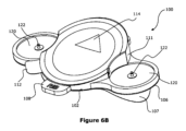
好ましくは、システムが、胴体に適用するときに、プレートが移動しないように安定させる、プレートから反対方向に伸長する側部をさらに含む。 Preferably, the system further includes side portions extending in opposite directions from the plate that stabilize the plate against movement when applied to the torso.
好ましくは、システムが、心臓空間データを外部監視装置に出力するように構成されているプレートに埋め込まれた電極をさらに含む。 Preferably, the system further includes electrodes embedded in the plate configured to output cardiac spatial data to an external monitoring device.
好ましくは、バルブアセンブリが一方向流出バルブを含む。 Preferably, the valve assembly includes a one-way outflow valve.
好ましくは、バルブの第1の端部が、流体摘出装置と連結するためのキャップを受容するように構成されている。 Preferably, the first end of the valve is configured to receive a cap for coupling with a fluid extraction device.
好ましくは、閉塞具アセンブリが、中空の軸と、軸の遠位端に配置される切断部とを含む。 Preferably, the obturator assembly includes a hollow shaft and a cutting portion located at the distal end of the shaft.
好ましくは、閉塞具アセンブリが、軸内に収容され、軸に対して移動可能なばね荷重内スタイレットをさらに含み、スタイレットが、近位端に配置されるハンドルと、軸の遠位端に配置される鈍頭部とを有し、閉塞具アセンブリは、スタイレットの鈍頭部が軸内に受容されて、切断部を露出させる格納された切断形態と、鈍頭部が切断部を越えて伸長する伸長形態との間で動作するように構成されている。 Preferably, the obturator assembly further includes a spring-loaded stylet housed within the shaft and movable relative to the shaft, the stylet having a handle disposed at the proximal end and a handle at the distal end of the shaft. The obturator assembly has a retracted cutting configuration in which the stylet bluff is received within the shaft to expose the stump, and the bluff extends beyond the stump. configured to operate between an extended configuration in which the
好ましくは、閉塞具アセンブリが、軸およびスタイレットを切断形態および伸長形態に保持するためのロック手段を備える。 Preferably, the obturator assembly comprises locking means for holding the shaft and stylet in the cut and extended configurations.
好ましくは、ロック手段が、軸およびスタイレット上に形成された相補的な突起および開口を1つ以上含む。 Preferably, the locking means includes one or more complementary projections and apertures formed on the shaft and stylet.
好ましくは、スタイレットのハンドルをユーザが押すことによって、閉塞具アセンブリが切断形態から伸長形態に変化し、鈍頭部が切断部を越えて伸長し、ロック手段が伸長形態においてスタイレットと係合する。 Preferably, user pressure on the handle of the stylet causes the obturator assembly to change from the cut configuration to the extended configuration, the blunt head extending beyond the cut, and the locking means engaging the stylet in the extended configuration. do.
好ましくは、切断部が、面取りされた先端を有する切断刃を含む。 Preferably, the cutting portion includes a cutting edge having a chamfered tip.
本発明の別の態様によれば、解剖学的体腔の開口を確立および維持する方法であって、患者の解剖学的体腔の外部に隣接して配置し、閉塞具アセンブリを受容するように構成されている開口と、開口の周りに配置され、バルブアセンブリを連結する連結手段とを有するプレートを含むベースを固定する工程と、ベースに、カニューレを受容する通路と、流体摘出装置に連結する開口端とを含むバルブアセンブリを連結する工程と、解剖学的体腔内で筋肉組織を切り開き、閉塞具アセンブリが切断圧力の低下を伴って切断部を越えて自動的に伸長し、切断部に対して鈍頭部をロックして内臓器官の損傷を予防するために、バルブアセンブリの通路およびプレートの開口に閉塞具アセンブリを挿入して、閉塞具アセンブリのハンドルを押すことによって、閉塞具アセンブリの切断部により、解剖学的体腔内で筋肉組織を切り開く工程と、カニューレのロック部をバルブアセンブリに固定し、閉塞具アセンブリを取り外すことによって、カニューレを閉塞具アセンブリから解剖学的体腔内に配置させる工程と、流体摘出装置をバルブアセンブリに連結することによって解剖学的体腔から流体を摘出する工程と、を含み、カニューレは、患者の解剖学的体腔内で伸長可能であり、バルブアセンブリ内への流体摘出用通路を形成し易くする長手方向に伸長可能な本体をさらに含み、カニューレは、使用時においてカニューレが伸長状態を保持する手段を含む、方法を提供する。 In accordance with another aspect of the invention, a method of establishing and maintaining an opening in an anatomical body cavity is configured for positioning outside and adjacent to an anatomical body cavity of a patient to receive an obturator assembly. securing a base including a plate having an opening in the base and connecting means disposed around the opening and connecting the valve assembly; a passageway in the base for receiving the cannula and an opening connecting to the fluid extraction device. and dissecting muscle tissue within the anatomical cavity such that the obturator assembly automatically extends beyond the cut with a reduction in cutting pressure and against the cut. The cut portion of the obturator assembly is cut by inserting the obturator assembly into the passageway of the valve assembly and the opening in the plate and depressing the handle of the obturator assembly to lock the blunt head and prevent damage to internal organs. dissecting the muscle tissue within the anatomical cavity; and deploying the cannula from the obturator assembly into the anatomical cavity by securing the locking portion of the cannula to the valve assembly and removing the obturator assembly. extracting fluid from the anatomical cavity by coupling a fluid extraction device to the valve assembly, the cannula being extendable within the patient's anatomical cavity to extract fluid into the valve assembly; The method further includes a longitudinally extendable body facilitating formation of the cannula passageway, and the cannula includes means for retaining the cannula in an extended state in use.
本発明の別の態様によれば、気胸および/または緊張性気胸の治療において胸膜減圧システムを使用して患者の胸腔から流体を摘出する方法であって、患者の胸腔の肋間隙の上方に、閉塞具アセンブリを受容するように構成されている開口と開口の周りに配置されバルブアセンブリを連結する連結手段とを含むプレートを含むベースを固定する工程と、ベースに、カニューレを受容する通路と流体摘出装置に連結する開口端とを含むバルブアセンブリを連結する工程と、筋肉組織を切り開き、閉塞具アセンブリが切断圧力の低下を伴って切断部を越えて自動的に伸長し、切断部に対して鈍頭部をロックして内臓器官の損傷を予防するために、バルブアセンブリの通路およびプレートの開口に閉塞具アセンブリを挿入して、閉塞具アセンブリのハンドルを押すことによって、閉塞具アセンブリの切断部により、胸腔内で筋肉組織を切り開く工程と、カニューレのロック部をバルブアセンブリに固定し、閉塞具アセンブリを取り外すことによって、カニューレを閉塞具アセンブリから胸腔内に配置させる工程と、流体摘出装置をバルブアセンブリに連結することによって胸腔から流体を摘出する工程と、を含み、カニューレは、患者の胸壁内で伸長可能であり、バルブアセンブリ内への胸水摘出用通路を形成し易くする長手方向に伸長可能な本体をさらに含み、カニューレは、使用時においてカニューレが伸長状態を保持する手段を含む、方法を提供する。 According to another aspect of the invention, a method of removing fluid from a patient's thoracic cavity using a pleural decompression system in the treatment of pneumothorax and/or tension pneumothorax comprises: securing a base including a plate including an aperture configured to receive an obturator assembly and coupling means disposed about the aperture and coupling the valve assembly; an open end that connects to the extractor; and cuts open the muscle tissue such that the obturator assembly automatically extends beyond the cut with a reduction in cutting pressure and against the cut. The cut portion of the obturator assembly is cut by inserting the obturator assembly into the passageway of the valve assembly and the opening in the plate and depressing the handle of the obturator assembly to lock the blunt head and prevent damage to internal organs. dissecting the muscle tissue within the thoracic cavity; securing the locking portion of the cannula to the valve assembly and removing the obturator assembly to deploy the cannula from the obturator assembly into the thoracic cavity; extracting fluid from the thoracic cavity by coupling to the assembly, the cannula being extendable within the patient's chest wall and longitudinally extendable to facilitate forming a pleural fluid extraction passageway into the valve assembly. body and the cannula includes means for retaining the cannula in an extended state in use.
好ましくは、カニューレが、最小長さが約4cmであり、最大長さが約9cmであるように構成されている。 Preferably, the cannula is configured to have a minimum length of about 4 cm and a maximum length of about 9 cm.
好ましくは、コイルばねが、カニューレ本体の周りに取り付けられ、本体の周りにバイアスを与えて、伸長形態に向かって移動する。 Preferably, a coil spring is mounted around the cannula body to bias it around the body to move toward the extended configuration.
好ましくは、カニューレが、カニューレ本体から伸長可能な伸縮部を2つ以上含む。 Preferably, the cannula includes two or more extensions extendable from the cannula body.
好ましくは、上記方法は、患者の肘が患者の中回内位である前腕に対して90度曲がっているとき、仰向けの患者の上腕の肘頭と肩峰との中間点を特定する工程と、上腕の中間点から患者の胴体に亘って、上腕に垂直である線を突出させる工程と、胸膜減圧を実施するために、前記突出した線と前記胴体間の接触領域を安全区域として標識する工程と、をさらに含む。 Preferably, the method comprises identifying the midpoint between the olecranon and the acromion of the patient's upper arm in supine position when the patient's elbow is flexed 90 degrees relative to the patient's mid-pronated forearm. protruding a line perpendicular to the upper arm from the midpoint of the upper arm across the patient's torso; and marking the contact area between the protruding line and the torso as a safe zone for performing pleural decompression. and a step.
本発明の別の態様によれば、使用時において、解剖学的体腔の開口を確立および維持する閉塞具アセンブリを受容し、患者の解剖学的体腔の外部に隣接して配置されるプレートを含み、プレートは、前記閉塞具アセンブリを受容するように構成されている開口を有する、ベースを提供する。 According to another aspect of the invention, the plate includes a plate that, in use, receives an obturator assembly that establishes and maintains an opening in the anatomical cavity and is positioned externally and adjacent to the patient's anatomical cavity. , the plate provides a base having an aperture configured to receive the obturator assembly.
本発明の別の態様によれば、使用時において、気胸および/または緊張性気胸の閉塞具アセンブリを受容し、患者の肋間腔の上方に配置されるプレートを含み、プレートは、閉塞具アセンブリを受容するように構成されている開口を有する、ベースを提供する。 In accordance with another aspect of the invention, the plate includes a plate that, in use, receives a pneumothorax and/or tension pneumothorax obturator assembly and is positioned above the patient's intercostal space, the plate accommodating the obturator assembly. A base is provided having an opening configured to receive it.
好ましくは、プレートの下側には、プレートを患者に固定する接着手段が設けられている。好ましくは、接着手段がフォームバッグ接着剤である。 Preferably, the underside of the plate is provided with adhesive means for securing the plate to the patient. Preferably, the adhesive means is a foam bag adhesive.
好ましくは、ベースが、ユーザが解剖学的体腔または肋間隙の、外部に隣接または上方にプレートを配置することをアシストする、プレートから伸長する指示体をさらに含む。 Preferably, the base further includes indicators extending from the plate to assist the user in positioning the plate externally adjacent to or above the anatomical cavity or intercostal space.
好ましくは、プレートが、使用時において、開口を密閉するように動作可能なバルブアセンブリを受容する、開口の周りに配置された連結手段をさらに含む。 Preferably, the plate further includes coupling means arranged around the opening for receiving a valve assembly operable to seal the opening in use.
好ましくは、連結手段が、プレートの平面に垂直な軸に対して傾斜した角度において、バルブアセンブリを受容するように構成されている。 Preferably, the coupling means are arranged to receive the valve assembly at an oblique angle to an axis perpendicular to the plane of the plate.
好ましくは、ベースが、胴体に適用するときに、プレートが移動しないように安定させる、プレートから反対方向に伸長する側部をさらに含む。 Preferably, the base further includes side portions extending in opposite directions from the plate that stabilize the plate against movement when applied to the torso.
好ましくは、ベースが、プレートに埋め込まれ、心臓空間データを外部監視装置に出力するように構成されている電極をさらに含む。 Preferably, the base further includes electrodes embedded in the plate and configured to output cardiac spatial data to an external monitoring device.
以下の本明細書および特許請求の範囲を通して、文脈上他の意味に解すべき場合を除き、用語「含む(comprise)」、ならびに「含む(comprises)」および「含む(comprising)」などの変形は、記載された整数もしくは工程または整数もしくは工程のグループを包含することを意味するが、任意の他の整数もしくは工程または整数もしくは工程のグループの除外を意味しないことが理解される。 Throughout the following specification and claims, unless the context dictates otherwise, the term "comprises" and variations such as "comprises" and "comprising" , is meant to include the recited integers or steps or groups of integers or steps, but not to exclude any other integers or steps or groups of integers or steps.
以下の本明細書および特許請求の範囲を通して、文脈上他の意味に解すべき場合を除き、用語「流体」は、空気等の気体の流体、ならびに血液および他の体液等の液体の流体を含むと理解される。
〔図面の簡単な説明〕
Throughout the following specification and claims, unless the context requires otherwise, the term "fluid" includes gaseous fluids such as air and liquid fluids such as blood and other bodily fluids. is understood.
[Brief description of the drawing]
本発明のさらなる態様、および前述の段落で説明した態様のさらなる実施形態は、以下の説明から明らかになるであろう。本発明は、添付の図面を参照し、例示することによってのみ説明される。 Further aspects of the invention, and further embodiments of the aspects described in the preceding paragraphs, will become apparent from the following description. The present invention will be described only by way of example with reference to the accompanying drawings.
図1は、従来の胸腔穿刺(NT)装置を示す写真である。
図2は、緊張性気胸を治療する、従来のNT装置の現場での使用を示す写真である。
図3A~3Dは、本発明の一実施形態による、胸腔の位置を特定するための患者の配置を示す写真である。
図4Aは、本発明の一実施形態である、組み立てた胸膜減圧手術システムを示す、拡大図である。
図4Bは、図4Aのシステムを示す、部分分解拡大図である。
図4Cは、図4Aのシステムを示す、拡大側面図である。
図4Dは、本発明の一実施形態である、組み立てた別の胸膜減圧手術システムを示す、拡大斜視図である。
図4Eは、本発明の一実施形態による、組み立てた別の胸膜減圧手術システムを示す、拡大斜視図である。
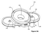
図5Aおよび5Bは、本発明の実施形態である、密閉キャップのないベースを示す拡大斜視図である。
図6Aおよび6Bは、本発明の実施形態である、密閉キャップを有するベースを示す拡大斜視図である。
図7Aは、図5Aのベースを示す拡大側面図である。
図7Bは、図5Bのベースを示す拡大底面斜視図である。
図8は、本発明の一実施形態であるバルブアセンブリを示す、拡大斜視図である。
図9Aおよび9Bは、本発明の実施形態によるバルブロックタブの異なる形態を示す、拡大上面斜視図である。
図10Aおよび10Bは、本発明の一実施形態である、ドッキングロックを有するバルブアセンブリを示す、部分拡大平面断面図である。
図11は、図8のバルブアセンブリを示す、側面断面図の部分拡大図である。
図12は、図8のバルブアセンブリの流出バルブを示す、部分拡大側面断面図である。
図13Aおよび13Bは、図8のバルブアセンブリの流出バルブを示す、拡大断面斜視図である。
図14は、本発明の別の実施形態であるバルブアセンブリを示す、拡大斜視断面図である。
図15は、本発明の別の実施形態にある、ベースが連結した、組み立てたバルブアセンブリを示す、拡大斜視断面図である。
図16は、本発明の別の実施形態である、バルブシールを有するバルブアセンブリを示す、拡大斜視断面図である。
図17は、本発明の別の実施形態である、ベースが連結した、バルブシールを有する組み立てたバルブアセンブリを示す、拡大斜視断面図である。
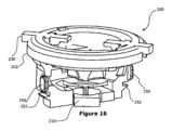
図18は、本発明の一実施形態である閉塞具アセンブリを示す、拡大斜視図である。
図19は、本発明の別の実施形態である閉塞具アセンブリを示す、拡大斜視図である。
図20は、本発明の一実施形態による、格納形態の内スタイレットを示す、図18の閉塞具アセンブリの拡大側面図である。
図21は、本発明の一実施形態による、格納形態と伸長形態との間の移行における内スタイレットを示す、図18の閉塞具アセンブリの拡大側面図である。
図22は、本発明の一実施形態による、完全伸長形態の内スタイレットを示す、図18の閉塞具アセンブリの拡大側面図である。
図23Aおよび23Bは、図19の閉塞具アセンブリのハンドルを示す拡大斜視図である。
図24は、本発明の実施形態によるカニューレ解放機構を示す、図19の閉塞具アセンブリの切断部の拡大斜視図である。
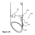
図25は、図24のカニューレ解放機構を示す拡大斜視図である。
図26は、本発明の一実施形態による、閉塞具アセンブリの切断部に近接して取り付けられたカニューレを示す、拡大側面図である。
図27は、本発明の一実施形態による、格納形態および完全伸長形態の内スタイレットを示す、一連の拡大側面断面図である。
図28は、本発明の一実施形態によるカニューレを示す、拡大斜視図である。
図29は、本発明の一実施形態による格納形態である図28のカニューレを示す、拡大正面図である。
図30は、本発明の一実施形態による伸長形態である図28のカニューレを示す、拡大正面図である。
図31は、本発明の別の実施形態によるカニューレを示す拡大斜視図である。
図32は、拡大螺旋フランジを示す、図31のカニューレの拡大正面図である。
図33は、本発明の別の実施形態による、螺旋フランジを示すカニューレの拡大正面図である。
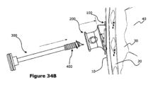
図34A~34Gは、本発明の実施形態による、胸膜減圧手術システムを配置する工程を示す概略図である。
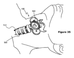
図35は、患者の気管の外部に隣接して配置する、本発明の一実施形態であるベースを示す模式図である。
図36は、図35のベースが連結した、本発明の別の実施形態のバルブアセンブリを示す模式図である。
図37は、患者の気管の外部に隣接して配置する、バルブアセンブリとベースが連結した、本発明の別の実施形態による換気ポートを示す模式図である。
図38A~38Eは、輪状甲状靭帯切開に使用される、本発明の別の実施形態である手術システムを配置する工程を示す概略図である。
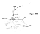
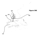
図39A~39Eは、輪状甲状靭帯切開に使用される、本発明の好ましい実施形態である手術システムを配置する工程を示す概略図である。
図40A~40Eは、尿道閉塞の治療に使用される、本発明の好ましい実施形態である手術システムを配置する工程を示す概略図である。
図41は、尿道閉塞の治療に使用される、本発明の一実施形態である手術システムを示す概略斜視図である。
図42は、本発明の別の実施形態であるバルブアセンブリを示す拡大斜視図である。
図43は、図42のバルブアセンブリの拡大側面図である。
図44は、閉状態のロック部材を示す、図42のバルブアセンブリの拡大上面断面図である。
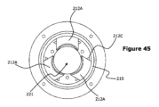
図45は、開状態のロック部材を示す、図42のバルブアセンブリの拡大上面断面図である。
図46は、図42のロック部材の拡大斜視図である。
図47は、本発明の一実施形態による伸縮カニューレの拡大斜視図であり、カニューレが格納状態にあることを示している。
図48は、図47の伸縮カニューレの拡大斜視図であり、部分的に伸長した状態のカニューレを示す。
図49は、図47の伸縮カニューレの拡大斜視図であり、カニューレが完全に伸長した状態を示す。
図50は、本発明の別の実施形態である閉塞具アセンブリを示す拡大斜視図である。
図51は、伸縮カニューレと共に使用される、図50の閉塞具アセンブリの一連の拡大側面図を示す。
図52A~52Gは、本発明の別の実施形態である胸膜減圧手術システムを配置する工程を示す概略図である。
〔発明を実施するための形態〕
FIG. 1 is a photograph showing a conventional thoracentesis (NT) device.
FIG. 2 is a photograph showing the on-site use of a conventional NT device to treat tension pneumothorax.
3A-3D are photographs showing positioning of a patient to locate the thoracic cavity, according to one embodiment of the present invention.
Figure 4A is an enlarged view showing an assembled pleural decompression surgical system in accordance with one embodiment of the present invention.
FIG. 4B is a partially exploded enlarged view showing the system of FIG. 4A.
Figure 4C is an enlarged side view showing the system of Figure 4A.
Figure 4D is an enlarged perspective view showing another assembled pleural decompression surgical system in accordance with one embodiment of the present invention.
FIG. 4E is an enlarged perspective view showing another assembled pleural decompression surgical system, according to one embodiment of the present invention.
Figures 5A and 5B are enlarged perspective views of a base without a sealing cap, in accordance with an embodiment of the present invention.
Figures 6A and 6B are enlarged perspective views of a base with a sealing cap that is an embodiment of the present invention.
7A is an enlarged side view of the base of FIG. 5A; FIG.
Figure 7B is an enlarged bottom perspective view of the base of Figure 5B.
Figure 8 is an enlarged perspective view showing a valve assembly that is one embodiment of the present invention;
9A and 9B are enlarged top perspective views showing different configurations of valve lock tabs according to embodiments of the present invention.
10A and 10B are partial enlarged plan cross-sectional views showing a valve assembly having a docking lock that is one embodiment of the present invention;
FIG. 11 is an enlarged fragmentary side cross-sectional view showing the valve assembly of FIG. 8;
12 is an enlarged partial side cross-sectional view showing the outflow valve of the valve assembly of FIG. 8; FIG.
13A and 13B are enlarged cross-sectional perspective views showing the outflow valve of the valve assembly of FIG. 8;
Figure 14 is an enlarged perspective cross-sectional view showing a valve assembly that is another embodiment of the present invention;
FIG. 15 is an enlarged perspective cross-sectional view showing an assembled valve assembly with connected bases in accordance with another embodiment of the present invention;
Figure 16 is an enlarged perspective cross-sectional view showing a valve assembly having a valve seal that is another embodiment of the present invention;
FIG. 17 is an enlarged perspective cross-sectional view showing another embodiment of the present invention, an assembled valve assembly having a base coupled valve seal.
Figure 18 is an enlarged perspective view showing an obturator assembly that is one embodiment of the present invention;
Figure 19 is an enlarged perspective view showing an obturator assembly that is another embodiment of the present invention;
20 is an enlarged side view of the obturator assembly of FIG. 18 showing the inner stylet in the stored configuration, according to one embodiment of the present invention; FIG.
21 is an enlarged side view of the obturator assembly of FIG. 18 showing the inner stylet in transition between a retracted configuration and an extended configuration, according to one embodiment of the present invention; FIG.
22 is an enlarged side view of the obturator assembly of FIG. 18 showing the inner stylet in a fully extended configuration, according to one embodiment of the present invention; FIG.
23A and 23B are enlarged perspective views of the handle of the obturator assembly of FIG. 19;
24 is an enlarged perspective view of a section of the obturator assembly of FIG. 19 showing a cannula release mechanism according to an embodiment of the present invention; FIG.
25 is an enlarged perspective view of the cannula release mechanism of FIG. 24; FIG.
FIG. 26 is an enlarged side view showing a cannula mounted proximate a cut of an obturator assembly, according to one embodiment of the invention;
FIG. 27 is a series of enlarged side cross-sectional views showing an inner stylet in retracted and fully extended configurations, according to one embodiment of the present invention;
Figure 28 is an enlarged perspective view showing a cannula according to one embodiment of the invention.
29 is an enlarged front view showing the cannula of FIG. 28 in a stored configuration according to one embodiment of the invention; FIG.
30 is an enlarged front view showing the cannula of FIG. 28 in an extended configuration according to one embodiment of the invention; FIG.
Figure 31 is an enlarged perspective view of a cannula according to another embodiment of the invention;
32 is an enlarged front view of the cannula of FIG. 31 showing an enlarged helical flange; FIG.
Figure 33 is an enlarged front view of a cannula showing a helical flange according to another embodiment of the invention;
34A-34G are schematic diagrams illustrating the steps of deploying a pleural decompression surgical system, in accordance with embodiments of the present invention.
FIG. 35 is a schematic diagram showing a base, an embodiment of the invention, positioned adjacent to the exterior of a patient's trachea.
36 is a schematic diagram showing another embodiment of the valve assembly of the present invention with the base of FIG. 35 coupled thereto; FIG.
FIG. 37 is a schematic diagram showing a ventilation port in accordance with another embodiment of the present invention with valve assembly and base coupled for placement adjacent the exterior of a patient's trachea.
Figures 38A-38E are schematic diagrams showing the steps of deploying a surgical system that is another embodiment of the present invention for use in a cricothyrotomy.
Figures 39A-39E are schematic diagrams showing the steps of deploying the surgical system of the preferred embodiment of the present invention for use in a cricothyrotomy.
Figures 40A-40E are schematic diagrams showing the steps of deploying the surgical system of the preferred embodiment of the present invention for use in treating urethral obstruction.
Figure 41 is a schematic perspective view of a surgical system that is an embodiment of the present invention for use in treating urethral obstruction.
Figure 42 is an enlarged perspective view of a valve assembly that is another embodiment of the present invention;
43 is an enlarged side view of the valve assembly of FIG. 42; FIG.
44 is an enlarged top cross-sectional view of the valve assembly of FIG. 42 showing the locking member in the closed state; FIG.
45 is an enlarged top cross-sectional view of the valve assembly of FIG. 42 showing the locking member in an open condition; FIG.
46 is an enlarged perspective view of the locking member of FIG. 42; FIG.
FIG. 47 is an enlarged perspective view of a telescoping cannula according to one embodiment of the invention, showing the cannula in a retracted state;
48 is an enlarged perspective view of the telescoping cannula of FIG. 47, showing the cannula in a partially extended state; FIG.
49 is an enlarged perspective view of the telescoping cannula of FIG. 47, showing the cannula fully extended; FIG.
Figure 50 is an enlarged perspective view of an obturator assembly that is another embodiment of the present invention;
Figure 51 shows a series of enlarged side views of the obturator assembly of Figure 50 in use with a telescoping cannula.
Figures 52A-52G are schematic diagrams illustrating the steps of deploying a pleural decompression surgical system that is another embodiment of the present invention.
[Mode for carrying out the invention]
図1および図2は、従来の胸腔穿刺(NT)装置および緊張性気胸を治療する分野におけるその使用を示す。従来のNT装置は、緊張性気胸を治療するために、肋間隙の上方で患者に直接施し、胸水を軽減する固定長の針およびカテーテルを含むことが知られている。 Figures 1 and 2 show a conventional thoracentesis (NT) device and its use in the field of treating tension pneumothorax. Conventional NT devices are known to include fixed length needles and catheters that are applied directly to the patient above the intercostal space to relieve pleural effusion to treat tension pneumothorax.
本発明の好ましい実施形態は、個体群における胸壁の厚みの違いにかかわらず、気胸および緊張性気胸の治療における、利用し易い手術システムおよび方法を提供することを目的とする。また、図3A~図3Dを参照して、患者の胸腔を効果的に特定する新しい方法が本明細書に記載される。胸腔を特定する従来の方法は、乳頭などのプロキシマーカーを配置することによって、第5肋間腔を特定することを含む。しかし、胸壁上の乳首の位置の固有の変動性は、これを信頼できないマーカーにする。患者の胴体上に適切な肋間腔を正確に特定することは、ストレスのない環境において40%の医師が成功しないという困難な作業であり得ることが理解される。この失敗率は、ストレス下で作業する戦闘医療従事者にとっては患者の防弾チョッキおよび衣料品等の妨害物品にも対処しなければならないので、さらに高いと推定される。 A preferred embodiment of the present invention aims to provide an easy-to-use surgical system and method for treating pneumothorax and tension pneumothorax, regardless of differences in chest wall thickness in the population. Also, with reference to FIGS. 3A-3D, a new method of effectively identifying a patient's thoracic cavity is described herein. Conventional methods of identifying the thoracic cavity include identifying the fifth intercostal space by placing a proxy marker such as the nipple. However, the inherent variability of nipple position on the chest wall makes this an unreliable marker. It is understood that accurately locating the appropriate intercostal space on a patient's torso can be a difficult task, with 40% of physicians failing in a stress-free environment. This failure rate is estimated to be even higher for combat medics working under stress because they also have to contend with obstructive items such as the patient's body armor and clothing.
図3A~3Dは、第4~第6肋間腔の間の胸腔の胸膜減圧を管理するための安全区域を特定する、中腕点法とみなされる新しい方法を示す。研究中、この方法を使用する研究者は、時間の100%の安全区域を特定することができたことが見出された。この方法は、以下のステップを含む。第一に、患者の腕を90度に曲げて患者を仰向けにし、前腕を中回内位(mid prone)にする。第二に、上腕の肘頭と肩峰との中間点を特定する。第三に、中間点から患者の胴体に亘って、テープ定規を用いて上腕に垂直である線を突出させる。最後に、胸膜減圧を行うために、突出させた線と胴体間の接触領域を安全区域として標識する。安全区域の位置を特定するこの新しい方法は、本発明の実施形態である胸膜減圧を行うのに適しているだけでなく、胸膜減圧を行う従来のNT装置と共に使用するのにも同様に適している。
Figures 3A-3D show a new method, referred to as the mid-arm point method, for identifying safe zones for managing pleural decompression of the thoracic cavity between the 4th and 6th intercostal spaces. During studies, it was found that researchers using this method were able to identify
ここで図4A~4Eを参照すると、胸膜減圧手術システム1の好ましい実施形態は、患者の肋間隙の外側に隣接または上方に取り付け可能なベース100と、ベース100に取り付け可能なバルブアセンブリ200とを備える。ベース100およびバルブアセンブリ200は、患者の胸壁組織を切り開くことによって胸腔に到達するように構成されている閉塞具アセンブリ300を受容するガイド通路を画定する。胸膜減圧手術システムの好ましい実施形態はさらに、閉塞具アセンブリ300が胸腔を切り開き、胸腔とバルブアセンブリ200との間の流体摘出用経路を生成するときに配置される、閉塞具アセンブリ300と取り外し可能に連結するカニューレ400を含む。ここで、各構成要素を詳細に説明し、システムを使用する方法も提供する。
4A-4E, a preferred embodiment of a pleural decompression
図5A~7Bは、患者の肋間腔の上方に取り付けるベース100の様々な実施形態および図を示す。ベース100は標識指示体108によって適切な肋間腔を特定する際にユーザをガイドし、患者にベース100を取り付けることにより、特定された肋間腔に効果的に印を付ける。ベース100はまた、胸膜減圧アセンブリ1に対して構造的な支持を提供し、閉塞具アセンブリ300の挿入のガイドをアシストする。図5A、図6Aおよび図7Aを参照すると、ベース100は、患者に取り付けるプレート102を備える。いくつかの構成において、プレートが患者の身体の輪郭に適合するように、弾性材料または可塑的に変形可能な材料であってもよい。プレート102は、閉塞具アセンブリ300およびカニューレ400を受容するようにサイズ決めされた開口104を有する。開口104はまた、NT法に従って、従来の閉塞具、カテーテル、および/または針を受容するようにサイズ決めされることが理解されるべきである。プレート102の下側には、使用前に保護層107除去後のプレート102を患者に固定する、発泡接着剤などの接着剤106が設けられる。プレート102を患者に取り付ける任意の適切な接着剤が使用され得ることが理解される。患者の肋骨間に閉塞具アセンブリ300を受容する、ベース100の開口104の特定を配置するために、ベース100は肋骨アライメントラベル108の形態である1つ以上の指示体を有する。肋骨アライメントラベル108は図に示すように、ベース100の反対方向に伸長し得る。
Figures 5A-7B show various embodiments and views of a base 100 that fits over the patient's intercostal space. The base 100 guides the user in identifying the appropriate intercostal space by means of a marking
ベース100には、バルブアセンブリ200を受容するために開口104の周りに配置された、ねじ込み縁部の形態のドッキング手段または連結手段110が設けられている。縁部は図に示すように、高さが変化する壁111の上方に支持され、縁部110の平面がプレート102の平面に垂直な軸に対して傾斜する。ねじ込み縁部がバルブアセンブリ200と連結すると記載しているが、任意の他の適切なドッキング手段または連結手段110が使用され得、非限定的な例として、「プッシュアンドクリック」連結のための締まりばめ連結クリップおよびインターロッククリップを挙げられることが理解されるべきである。一構成において、開口104も同様に傾斜させ、閉塞具アクセスが肋骨間隙間の適切な進入角度で生じる。縁部110および/または開口104の傾斜角度は肋間神経筋束への損傷の可能性を低減し、胸腔へのアクセスを容易にする。
The
側部120は、プレート102から反対方向に伸長し、患者の胴体に適用されたときにプレート102が移動しないように安定させるように設けてもよい。一構成において、ベース100が患者に取り付けられたときに横方向の変位を防止するように、側部120およびプレート102が接触表面積を増大させるダンベル形状を形成する。ベース100はまた、心臓空間データに関する情報などのデータを外部監視装置(図示せず)に出力する、プレート102および/または側部120に埋め込まれる1つ以上の電極122を備えてもよい。図5Aを参照すると、肋間腔を特定する中腕点法に従って、図示のように配置して患者に取り付けられる電極122は、3つの直交方向における空間的心臓モニタリングを有利に提供する。
ベース100には、図6Aに示すように、開口104、壁111、および縁部110の間の空間を密閉する開口キャップ112を設けてもよい。キャップ112を真空嵌めして、密閉空間下に無菌環境を作り出し、ベース100を患者に取り付けた後に無菌状態が維持されることを確実にするのに役立ててもよい。いくつかの実施形態において、キャップがスズ箔から作製される。開口キャップ112はまた、バルブアセンブリ200および閉塞具アセンブリ300へのアクセスのために、キャップ112が取り外されるかまたは貫通される必要があるので、オペレータによる無菌技術を促進するための認知補助として作用し得る。図5B、図6Bおよび図7Bは、ベース100の別の実施形態を示す。開口104はさらに、開口104を取り囲み、円滑な閉塞具のアクセスおよび引き抜きのための図5Bに示す通路117を確定するハウジング116を備える。ハウジング116には、バルブアセンブリ200を密閉するOリング118を設けてもよい。ハウジング116はまた、開口104、壁111および縁部110間の空間への環境汚染を防止することによって、無菌状態を増進する。開口キャップ112および/または開口バルブ116に、患者に取り付けるため、ベース100の正しい向きを示す、腹側矢印マーカー114を設けてもよい。
ベース100は胸膜減圧システム1と共に使用するように記載しているが、開口104が従来の閉塞具、カテーテル、針およびNTツールを受容するように構成され、サイズ決めされ得るので、ベース100は、患者の肋間位置を標識し、従来の胸膜減圧技術と共に使用するのに適した安定化構造を提供するスタンドアロンデバイスとして使用するのに等しく適していることが理解される。
Although the
図8~図17は、バルブアセンブリ200の様々な実施形態および図を示す。バルブアセンブリ200はバルブハウジング202を含む。バルブハウジングは、閉塞具アセンブリ300を受容し、カニューレ400がひとたび配置されると流体摘出デバイス(図示せず)に連結するアクセスポートとして使用されるよう構成された第1の端部203と、ベース100に連結し、肋間隙の外側および上方または隣接して配置するように構成された第2の端部204と、閉塞具アセンブリ300およびカニューレ400を受容するバルブ220を通る通路とを有する。一構成において、バルブアセンブリ200の内容物および胸腔からバルブアセンブリ200内に摘出される任意の流体をユーザが容易に検査し得るように、ハウジング202は透明な材料から作製される。バルブアセンブリ300の第2の端部204には、ベース100のドッキング縁部110に連結する1つ以上のドッキングタブ206が設けられている。一構成において、バルブアセンブリ200のドッキングがドッキング縁部110の相補的な凹部内でドッキングタブ206を押してクリックすることによって行われる。続いて、バルブアセンブリ200をベース100に対して回転させることによって、バルブアセンブリ200をベース100から取り外すことができ、ドッキングタブ206はねじ込み縁部110を通って移動し、連結が解除される。
8-17 illustrate various embodiments and views of
バルブアセンブリ200の第2の端部204またはその周囲には、ハウジング202の内部に、「プッシュアンドクリック」動作によってカニューレ400の対応するロック部412または溝をロックするばね荷重ロック機構210が設けられる。ロック機構210は、カニューレ400のロック部412の形状および寸法に対応する開口を形成する、中心方向を向いた3つの凹形状のロック部材を備える。図10Bおよび図15に示すように、ロック開口を形成するために、ロック部材212を中央に向かって押し付けるように、板ばね214によってロック部材212の各々を一端で偏らせる。例えば、閉塞具アセンブリ300の挿入中に、左側ばね214に抗する力でロック部材212は押し離されて、図10Aおよび15に示すように、直径が大きいカニューレ本体420の通過を一時的に可能にし得る。
At or about the
バルブハウジング202には、患者の胸腔からの流体の流れを制御する、中央通路221を有するバルブ220が設けられている。バルブ220は、バルブ220の遠位端における通路の開口を密閉するポートドア222と、胸腔からバルブ220内に摘出した気体または胸水などの任意の流体の存在を示す、バルブ220を取り囲むリングの形態であるフロー指示体224と、バルブ220の遠位端に向かう方向にフロー指示体224を偏らせるバルブばね226と、バルブ220とバルブハウジング202との間の接続を確実にするOリング228とを有する。いくつかの実施形態において、ポートドア222が図14に示すヒンジaによって保持されるコルクの形態であり、図15に示すように、閉塞具アセンブリ300およびカニューレ400を挿入することによって開くことができる。別の実施形態でおいて、図13Aおよび13Bから分かるように、バルブ220は、バルブ220の底部に可撓性バルブ223Aと、バルブ220の周囲の周りにあるバルブフラップ223Bとを備える。バルブフラップは、使用時に患者の身体からバルブハウジング202への流体の一方向移動を可能にするように構成されている。一構成において、バルブ220が一方向流出バルブである。流出バルブ形態の場合、バルブは必要に応じて流出を防止するために、オペレータが調節可能なバルブロックを備えて構成してもよい。
バルブの第1の端部203には、流体収集バッグなどの外部流体摘出装置(図示せず)に接続し得る密閉キャップ240と連結する、ロックリングの形態である連結器230が設けられている。図4Bに示す構成において、キャップ240をロッキングリング連結器230に押し込んでクリックすることによって、キャップ240がバルブアセンブリ200に連結される。図14は、表面積が大きいバルブアセンブリ200が密閉キャップ240によって覆われている、密閉キャップ240の別の実施形態を示している。
The
図16および図17は、バルブアセンブリ200の代替実施形態を示す。バルブアセンブリ200は、閉塞具アセンブリ300によって穿孔され得る、取り外し可能または貫通可能な密閉キャップ232を備えることができる。密閉キャップ232は、使用前にバルブアセンブリ200を無菌状態に保つ。密閉キャップ232はベース100および患者に対して使用するためのバルブアセンブリ200の方向を示す、アライメント指示体234をさらに備えてもよい。いくつかの構成において、図16および図17に示すように、バルブハウジング202がベース100のドッキング機構または連結機構110と連結する、1つ以上の連結器250、252を備える。
16 and 17 show an alternative embodiment of
図42~図46は、バルブアセンブリ200の別の実施形態を示す。バルブアセンブリ200は図44に示すように、ロック部材212Aを包囲し、ロック部材212Aに抗してばねバイアスを加え、閉状態で部材212Aを共に偏らせるように構成されている、Oリングまたは伸長可能/折り畳み可能なバンドの形態である弾性部材215をさらに備えてもよい。これは、複数のロック部材212Aは、ロック部材212Aが実質的に互いに向かって伸長する閉状態と、ロック部材212Aが弾性部材215に対して押し戻される開状態との間で移動することを可能にする効果を提供する。弾性部材215はロック部材212Aの各々に実質的に均一に広がった量の力を有利に加え、これにより、バルブアセンブリ200を通るカニューレ400のより円滑な通過が可能になる。さらに、ロック部材212Aは図46に示すように、面取り部212Bまたは先細部を備えて構成してもよい。面取り部または先細部はカニューレ400と連動して、カニューレ400がロック部材212Aの間でバルブアセンブリ200の開口またはバルブ通路221を通って摺動する際に、ロック部材212Aを押し離すことをアシストする。ロック部材212Aは、単一平面上でのロック部材212Aの移動を制限するために(すなわち、ロック部材212Aの上下移動を防止するために)、バルブアセンブリ200の対応するスロットまたはチャネル内に受容されるように構成されている、タブの形態である側面突起212Cをさらに備えて構成していてもよい。前述のように、ロック部材212Aが互いに離れるように強制されてカニューレ400の本体を通過させる開状態と、ロック部材212Aが互いに向かい合い、カニューレの対応する溝部412に対して固定を形成してカニューレを所定の位置にロックするバイアス閉状態との間で、ロック部材212Aは移動可能に構成され、ロック部材がバルブアセンブリ200から独立して取り外されるのを防止する。
42-46 illustrate another embodiment of
図18~27を参照すると、閉塞具アセンブリ300は、遠位端に切断部324を有する中空の軸330を備える。切断部324には、体組織を貫通して胸腔に到達する切断刃332が設けられている。切断刃332は図20~図22に示すように、面取りされたブレードとして形成され得る。面取りされた切断刃は、円錐形の先端を有すると言うことができる。閉塞具アセンブリ300は中空の軸330内に収容された内スタイレット320をさらに備え、スタイレット320は軸330に対して移動可能であるように構成されている。スタイレット320は近位端においてバネ荷重連結器によってハンドル310と接続し、作動時にハンドル310がスタイレット330に対して移動し得る。スタイレット320は、スタイレット320の遠位端に位置する鈍頭部323に接続し、鈍頭部323は鈍頭部材329を含む。中間部321A、321Bは、スタイレット320を鈍頭部323に接続する。鈍頭部323は、中間部のハウジングチューブ321B内に伸縮可能に収容された伸長可能なシャフトを備える。ばね322の形態のバイアス手段が、スタイレット320と鈍頭部323との間に配置され、その結果、鈍頭部323はスタイレット320から離れるようにバイアスをかけられ、図20~22および27に示すように、中空の軸330の切断部324を越えて外側に伸長する。
18-27,
中空の軸330の鈍頭部323および切断部324の相対位置は、相補的な突起および開口形成によってロックされ得る。図20~22に示す一構成において、鈍頭部323は1つ以上の突起326を備えて構成され、軸330の切断部324は軸330の長手方向軸に沿って間隔を置いて配置された開口334を備えて構成されている。ハンドル310を介して伝達される力によって鈍頭部323が下方に(軸330の遠位端に向かって)移動すると、鈍頭部323の突起326は相補的な形状の開口334と係合し、摩擦によって鈍頭部323を所定の位置にロックする。閉塞具アセンブリ300は、ハンドル310を押すことによって作動され得、その結果、閉塞具アセンブリ300は鈍頭部323が軸330内に完全に格納されてロックされる格納された切断形態から、鈍頭部323が軸330の切断部324を越えて伸長位置にロックされる伸長形態に変化することが理解されるべきである。
The relative positions of blunted
図23および図24に示すように、ハンドル310は、ばね328の接続によってスタイレット320に連結されている。力がもはやハンドル310に加えられなくなったときに、ばね328はハンドル310をその元の位置に向かって偏らせて戻す。さらに、ハンドル310を押すことは、図21に示すように、スタイレット320の鈍頭部323をその第1のロック位置から開放する効果を有する。挿入前のバルブアセンブリ200に対する閉塞具アセンブリ300のアライメントをアシストするために、アライメント指示体312はハンドル310に備えられ得る。いくつかの構成において、ハンドル310がオペレータによる取り扱いおよび把持を容易にするために、ゴム材料を備えている。
As shown in FIGS. 23 and 24, handle 310 is coupled to
カニューレ400は中空の軸330の切断部324に取り外し可能に連結され、切断部324が肋間腔で胸部組織を貫通するときに、患者の胸腔内に配置する。カニューレ400は患者の胸腔内への挿入前および挿入中のカニューレ400の不要な移動を低減し、以下に記載する閉塞具アセンブリ300との連結を容易にするために、平面取付けで切断部324に外部から受容されるようサイズ決めされおよび必要な大きさにする。図24~図26を参照すると、カニューレ400は切断部324に取り付けられ、切断部324の周囲の周りの突出縁部または隆起部336の形態である連結機構336、337と連結することによって所定の位置に保持される。カニューレ400に対して閉塞具アセンブリ300を引き抜くことによってカニューレが切断部324から取り外され得るように、突起337は構成されている。切断刃332に隣接しておよび/または垂直に位置する隆起部である形態の少なくとも1つの突起335は、閉塞具アセンブリ300が胸壁組織を切り開く際に長手方向の筋繊維の鈍い分離をアシストする鈍頭切開器の機能を果たすように提供され得、それによって、閉塞具アセンブリ300の清潔な通路が提供される。一構成において、2つの突起335が切断刃332に垂直に設けられる。
カニューレ400はいったん配置されると、患者の胸腔とバルブアセンブリ200との間の接続を確立し、閉塞具アセンブリ300の除去後に肋間カテーテルまたはビデオ内視鏡の挿入用アクセスポートとして使用され得、その結果、バルブを介した空気注入または通気を介して胸膜圧を制御し、直視下における胸腔の標的検査および排出、すなわち胸膜鏡検査/胸腔鏡検査を可能にする能力を有する。
Once positioned,
図28~図30を参照すると、カニューレは、使用時に胸水摘出する、胸腔とバルブアセンブリ200との間に経路を確立する、近位端410および遠位端430を有するチューブである。カニューレは、ロック部412と、固定部440と、それらの間に伸長する長手方向に伸長可能な本体420とを備える。カニューレ400の遠位端430は、カニューレ本体420の小さな直径から大きな直径に向かって先細になっている、先細の頭部を備えている。この特徴はカニューレがバルブアセンブリ200を通過するときに、カニューレがバルブアセンブリ200のロック機構210と係合して開くことを可能にする。ロック部412は図15に示すように、ロック部材212の上部に当接する、大きな直径を有する近位端410でロック機構210によって受容され、保持されるようなサイズ決めされ必要な大きさにする。固定部440は図34D~34Fに示すように、胸壁にカニューレ400を固定する螺旋または螺旋フランジ/スクリューの形態であるように構成され得る。固定部440はゴム/シリコーンのような弾性材料から作られ、バルブアセンブリ200のバルブ通路221およびロック機構210、ならびにベース100の開口104を通って嵌合することができるが、カニューレが胸腔にひとたび進入すると、胸壁に固定するためのフランジ形状を保持する。固定部440が螺旋フランジである実施形態において、フランジが長手方向に折り畳まれる固定形態と、フランジが長手方向に伸長する摘出形態との間で動作可能である。一構成において、固定部440が滅菌不活性ゴム材料から作製される。カニューレアセンブリの一部である固定部440(図31)は、反時計回りに回転させ(ねじを外し)、カニューレ(バルブアセンブリ200に取り付けられた)を胸壁内のその固定位置から引っ張ることによって取り外すことができる。図31~33は、細長い螺旋状フランジを有する固定部440と、円板状形態を有する固定部440とを含む、固定部440の異なる実施形態を示す。
28-30, the cannula is a tube having a
カニューレ本体420は図29および図30に示すように、その長手方向の長さに沿って長手方向に伸長可能である。一実施形態において、コイルばね422がカニューレ本体420の周りに取り付けられ、本体の周りにバイアスを与えて、伸長形態に向かって移動する。したがって、カニューレ400は、最小長さが約4cmであり、最大長さが約8.5cmであるように有利に構成されている。別の実施形態において、カニューレ400は、最小長さが約4cmであり、最大長さが約9cmであるように構成されている。この特徴により、胸膜減圧システム1は、個体群における胸壁の厚みの違いにかかわらず、胸水摘出のために胸腔とバルブアセンブリ200との間に経路を確立することができる。伸長可能な本体はコイルばね422で構成されるように記載しているが、他の適切な構成もまた使用され得、非限定的な例としては伸縮可能に壁付きカニューレ本体が挙げられる。カニューレ本体420の伸長可能な性質のために、カニューレ400は、本発明の精神から逸脱することなく、多数の異なる最小長さおよび最大長さを有するように構成され得ることが理解されるべきである。
別の実施形態において、カニューレ400が図47~49から分かるように、伸縮本体420Aと共に構成され得る。伸縮本体420Aは多くの区画または段部421を収容するように構成してもよい。この場合、全ての伸縮部421が本体420A内に格納する、図46に示す格納コンパクト状態と、1つ以上の区画421が本体420Aから長手方向に伸長する、図48に示す部分伸長状態と、全ての区画421が本体420Aから伸長する、図49に示す完全伸長状態との間で、本体420Aは構成可能である。カニューレ400の上部には同様に、バルブアセンブリ200のロック部材212と連結する溝部412が設けられてもよい。一実施形態において、カニューレは先細部413を備えて、カニューレ400とバルブアセンブリ200との間の滑らかなロック移行を可能にしてもよい。最下部のカニューレ区画421はまた、「マーフィーアイ(Murphy Eyes)」としても知られる、空気/流体が流れ出ることを可能にする側面流体口として機能する、開口を1つ以上の対を備えてもよい。最下部のカニューレ区画421はまた、使用時に、閉塞具アセンブリ300によって最初に伸長するように構成され、したがって、閉塞具アセンブリ300の突出隆起部336に捕捉される座部または段部421Bを備える。各カニューレ区画421はさらに、各区画421が、その完全な個々の区画長まで伸長すると、挿入後の自己折り畳みを防止するために所定の位置にロックされるように構成されている。一構成において、各区画421の上部には伸縮本体421Aの底壁にロックする溝部424が設けられている。オペレータが、カニューレ400が体腔内に挿入された程度を決定することを助けるために、放射線不透過性の標識が、カニューレ400の底部先端に設けられてもよい。
In another embodiment,
図50および図51を参照すると、伸縮本体420Aを有するカニューレ400が閉塞具アセンブリ300によって配置されるプロセスが示されている。最初に、カニューレは、閉塞具アセンブリ300の底端部に挿入され、バルブアセンブリ200およびベース100を通って挿入される。カニューレ400は閉塞具アセンブリ300と共に、バルブアセンブリ200を通過し、ロック部材212がカニューレ400の溝部412に連結すると、カニューレはバルブアセンブリ200にロックする。閉塞具アセンブリ300の突出隆起部336は、最下部のカニューレ区画421の座部421Bを押し、閉塞具アセンブリ300がバルブアセンブリ200およびベース100によってさらに挿入/押されたときにカニューレ区画421が外側に伸長する。閉塞具がバルブアセンブリ200によって押されるとき、伸縮本体420Aはこのようにして完全に伸長し得る。閉塞具アセンブリ300がその後にバルブアセンブリ200から取り外されるとき、伸縮本体420Aを有するカニューレ400は伸長したままである。3段の伸縮カニューレを図に示しているが、本発明の好ましい実施形態は任意の適切な数の伸縮部/段部を有してもよいことが理解される。
50 and 51, the process by which cannula 400 with
特に図24および図26を参照すると、切断部324の突出隆起部336および/またはカニューレ固定部440の縁部は使用中に閉塞具アセンブリ300およびカニューレ400をX線装置または同様の装置で相対位置に医師が配置するのをアシストするために、放射性帯またはマーカー(強調部分を参照されたい)を備えることができる。
24 and 26, the protruding
図34A~図34Gおよび図52A~図52Gを参照すると、緊張性気胸の治療に上述の胸膜減圧システム1を使用する方法も提供される。本方法は一般的に、臨床もしくは病院環境または現場での利用中において、医師によって患者に対して実施される以下の工程を含む。患者の胸膜減圧を実施するために、適切な肋間腔を前述の中腕点法を使用して特定し、安全区域を特定すべきである。保護膜107を除去し、接着剤106を患者に取り付けることによって、ベース100は患者の胸腔の肋間腔の上方または隣接して固定される。一方で、可能であれば、肋骨アライメント指示体108および方向指示体114を使用して位置アライメントを観察する。任意に、心臓監視装置を電極122に取り付けて、患者から物理的データを取り出してもよい。可能であれば、ベース100の開口キャップ112を取り外して、開口104を露出させる。バルブアセンブリ200を適所に押してクリックすることによって、バルブアセンブリ200をベース100に連結し、可能であればアライメント指示体を観察する。
34A-34G and 52A-52G, a method of using the
バルブアセンブリ200の通路221およびプレートの開口104を通じて挿入し(可能であれば任意のアライメント支持体を観察しながら)、閉塞具アセンブリ300のハンドル310を押すことによって、切断部324が組織20を切り開き、閉塞具アセンブリ300の切断部324を用いて胸腔内で胸部の筋肉組織を切り開く。閉塞具アセンブリ300の鈍頭部323は自動的に、切断部324を越えて胸腔を通じて伸長し、切断圧力の低下に伴って肺部に当接し、鈍頭部323を切断部324に対して伸長形態においてロックして、内臓器官の損傷を防止する。次いで、カニューレ400のロック部412をバルブアセンブリ200のロック機構210に固定することによって、カニューレ400は、閉塞具アセンブリ300から患者の胸腔30内に配置される。この工程は、カニューレ400がバルブアセンブリ200によって移動しているときに、バルブアセンブリ200によって閉塞具アセンブリ300を押すことによって自動的に行われることが理解される。カニューレ400の固定部430は図34Dに示すように、閉塞具アセンブリ300の切断部324と共に組織によって押され、胸壁20に固定される。伸縮本体420Aを有するカニューレ400では、異なる伸縮部421がカニューレ400から胸腔30まで伸長し、最下部421は最初に閉塞具アセンブリ300の挿入運動によって伸長する。各伸縮部421は伸長したままであり、閉塞具アセンブリ300が取り外されるときに、前の伸縮部421または伸縮本体420Aにロックされるので、圧縮され得ない。伸縮部421の自己ロック形態のために、固定フランジは、伸縮カニューレと共に使用する必要はないことが理解される。
Cutting
切開がひとたび完了すると、バルブアセンブリ200から閉塞具アセンブリ300を引き抜くことによって、閉塞具アセンブリ300は除去される。閉塞具アセンブリ300を引き抜くことにより、カニューレ400が切断部324から自動的に取り外され、長手方向に伸長可能なカニューレ本体420および遠位部430は図34Eに示すように胸部組織の内側に残る。このことによって、バルブアセンブリ200への胸水摘出用経路の形成を容易にする。次いで、外部流体摘出装置をバルブアセンブリ200に取り付けて、胸腔から流体を摘出してもよい。バルブアセンブリ200の透明ハウジング202によって、摘出される流体の特性を医者が容易に調べることができる。フロー指示体224は、バルブアセンブリ200内の摘出ガスの存在を医師が決定することを助けるのにも有用である。
Once the incision is complete,
上述のステップは特定の順序で提供されるが、この順序の任意の変形で実行することができ、上述のステップの間に追加のステップを実行してもよい。 Although the steps described above are provided in a particular order, they can be performed in any variation of that order, and additional steps may be performed between the steps described above.
手術システム1は気胸および緊張性気胸の治療において胸膜減圧のために肋間腔の上または隣接して配置して使用されるように記載している。実質的に同じ手術システム1を、ほとんどまたは全く改変する必要なく、他の手術用途において適切に使用し、解剖学的腔(例えば、体腔)に経皮的挿入カニューレを設置および維持して、解剖学的腔、バルブおよび外部環境との間の流体の移動の制御を可能にすることが理解される。非限定的な例として、以下が挙げられる。
輪状甲状腺膜または胸骨上端を介した気管へのアクセス(緊急輪状甲状靭帯切開の治療、すなわち、口または鼻腔を介して気管にアクセスできない場合に、患者の気管に緊急アクセスして肺を換気するため)。
急性尿閉患者の膀胱への恥骨からのアクセス(尿道閉塞の治療)。
腹壁を介した腹膜へのアクセス、および頭蓋を介した硬膜外腔へのアクセス。
Access to the trachea through the cricothyroid membrane or top of the sternum (to treat an emergency cricothyrotomy, i.e., for emergency access to the patient's trachea to ventilate the lungs when the trachea cannot be accessed through the mouth or nasal cavity) ).
Pubic access to the bladder in patients with acute urinary retention (treatment of urethral obstruction).
Access to the peritoneum through the abdominal wall and access to the epidural space through the skull.
図35~図39を参照すると、気管510にアクセスするために手術システム1を実質的に適用され得る。使用時には、ベース100が輪状軟骨512と甲状軟骨504との間に位置する輪状甲状膜500の上方またはそれに隣接して外部から配置され、実質的に前述のように配置される。適切なストラップ130がベース100に取り付け、患者の首の周りをループ状に囲み、ベースにさらにベースを固定する。一実施形態において、ストラップ130が側部120の開口を通じて供給され、適切なバックル装置で締め付けられる。次いで、バルブアセンブリ200を前述のように、ベース100に連結する。人工呼吸器のコネクタまたはポート260は人工呼吸器との接続のために、(例えば、連結器230を用いて)バルブアセンブリ200に固定されるように提供される。これにより、患者は、手術システム1が配置されている間、呼吸することが可能になる。別の実施形態において、バルブアセンブリ200は、人工呼吸器と接続するための側部アクセスコネクタまたはポート250を備える(図示せず)。コネクタまたはポートは、直径15mmであってもよい。次いで、閉塞具アセンブリ300およびカニューレ400は実質的には前述のように配置され、患者の気管510へのアクセスを提供し、カニューレ400の固定部440は、輪状甲状膜500の形態である解剖学的部分に固定される。閉塞具アセンブリ300は実質的に前述のように取り外され、カニューレ400を残し、気管510とバルブアセンブリ200との間に導管を提供し得る。続いて、バルブを反時計回りに回転させ、ユニットをベース100から引き出すことによって、バルブアセンブリ200およびカニューレ400を実質的に前述したように取り外すことができる。
With reference to FIGS. 35-39,
図40~41を参照すると、手術システム1は尿道閉塞の治療において、患者の膀胱600にアクセスするために実質的に適用され得る。使用に際して、医師は、患者の恥骨結合領域の上方またはそれに隣接して、ベース100を外部に配置する(図40A~40Eを参照されたい)。次いで、バルブアセンブリ200を連結し、閉塞具アセンブリ300およびカニューレ400を、実質的に前述のように配置し、カニューレ400の固定部440を、膀胱600の上壁の形態である解剖学的部分に固定し得る。次に、モジュールを通じてカテーテルを膀胱内に送り込むことができる。
40-41, the
予備実験の結果を以下に示す。 The results of preliminary experiments are shown below.
実験は、緊張性肺気胸(tPTX)が処置されないままである場合、重篤かつ生命を脅かす状態のままであるという背景で行われた。従来の技術を利用することによるtPTX治療および現在の課題に関連する懸念の調査は、代替方法を開発することの重要性を強調する。既存の慣習は実行するためのその単純さおよび時間において魅力的であり得るが、それらはそれらの失敗率および有効性を支持する限定された一連の反復可能なデータについて精査され続けた。したがって、装置の配置、カニューレの長さ、および閉塞具の長さに関する主な問題に同時に対処し、修正することができるエラーのない装置は、胸部外傷治療時の突破口の基礎を形成する。 The experiment was conducted in the context that tension pneumothorax (tPTX) remains a serious and life-threatening condition if left untreated. Investigation of concerns related to tPTX therapy and current challenges by utilizing conventional techniques underscores the importance of developing alternative methods. Although existing practices can be attractive in their simplicity and time to implement, they have been scrutinized for a limited set of repeatable data supporting their failure rates and effectiveness. Thus, an error-free device that can simultaneously address and correct the major issues of device placement, cannula length, and obturator length forms the basis for a breakthrough in treating thoracic trauma.
tPTXの実験豚モデルを開発することに関連して、SaPDパイロット試験および検証、胸膜減圧用の従来の胸腔穿刺に対するインビトロプロトタイプSaPD装置の試験を可能にし、挿入技術を標準化し、最後に、胸膜減圧に関連する合併症が結果の改善と共に減少し、インビボ配置前に必要とされる任意の改変を検証するための試験が行われている。 In connection with developing an experimental porcine model of tPTX, SaPD pilot testing and validation, enabling testing of an in vitro prototype SaPD device against conventional thoracentesis for pleural decompression, standardizing insertion techniques, and finally, pleural decompression. Complications associated with endocytosis decreased with improved outcomes, and trials are underway to validate any modifications required prior to in vivo placement.
結論として、SaPD装置は、tPTXのプレホスピタル治療および臨床治療のための価値のある有効な治療法を提示する。この概念は、胸膜減圧の失敗につながる複数の態様を対象とすることを目的とした。カニューレは高圧気体の放出に耐える能力を含むだけでなく、傷害を引き起こすことなくよじれを防止するのに十分な剛性も有し、現行の治療法では欠けていることが確認された態様である。さらに、鈍い先端部の配置を含む閉塞具の構成要素は、tPTX治療の盲目的な挿入に関連するリスクを低減するために作製された。毎年の外傷発生数の増加に伴い、全ての患者の身体タイプに適合し得る装置に対する評価は、tPTXの外傷管理に非常に有益である。 In conclusion, the SaPD device presents a valuable and effective therapy for pre-hospital and clinical treatment of tPTX. This concept was intended to cover multiple aspects that lead to failure of pleural decompression. Not only does the cannula include the ability to withstand the release of high-pressure gas, but it is also rigid enough to prevent kinking without causing injury, an aspect identified as lacking in current therapies. Additionally, an obturator component that includes a blunt tip placement was created to reduce the risks associated with blind insertion of tPTX therapy. With the number of injuries occurring each year increasing, evaluation of a device that can fit all patient body types would be of great benefit in the trauma management of tPTX.
本明細書で開示および定義する本発明が、本文または図面において言及され、またはそれらから明らかな個々の特徴のうちの2つ以上の代替的な組み合わせのすべてに及ぶことが理解されるのであろう。これらの異なる組み合わせの全ては、本発明の様々な代替態様を構成する。 It will be understood that the invention disclosed and defined herein extends to all alternative combinations of two or more of the individual features mentioned in or apparent from the text or drawings. . All of these different combinations constitute various alternative aspects of the invention.
本実施形態の説明および図面において、対応する特徴を示し参照するために、第1の実施形態に関して使用した参照番号と同じ参照番号を使用する。 In the description and drawings of this embodiment, the same reference numbers as those used with respect to the first embodiment are used to indicate and refer to corresponding features.
本発明の様々な実施形態を上記で説明したが、それらは単なる例として提示されたものであり、限定として提示されたものではないことが理解される。当業者には、本発明の精神および範囲から逸脱することなく、形態および詳細の様々な変更を行うことができることが明らかであろう。したがって、本発明は、上述の例示的な実施形態のいずれによっても限定されるべきではない。 While various embodiments of the invention have been described above, it is understood that they have been presented by way of example only and not limitation. It will be apparent to those skilled in the art that various changes in form and detail can be made without departing from the spirit and scope of the invention. Accordingly, the invention should not be limited by any of the above-described exemplary embodiments.
Claims (21)
遠位端の切断部、カニューレ、および配置可能な鈍頭部を有する閉塞具アセンブリと、
前記カニューレを受容する通路、流体摘出装置に連結する第1の端部、および前記解剖学的体腔の外部に隣接して配置される第2の端部を含むバルブアセンブリと、
患者の前記解剖学的体腔の外部に隣接して配置されるプレートを含むベースと、を備え、
前記カニューレは、ロック部と長手方向に伸長可能な本体とを含み、前記切断部に取り外し可能に連結し、患者の前記解剖学的体腔内に鈍頭部に沿って配置可能であり、
前記プレートは、閉塞具アセンブリを受容するように構成されている開口と、前記開口の周りに配置され、前記バルブアセンブリを連結する連結手段と、を有し、
前記カニューレの前記ロック部は、使用時において、前記解剖学的体腔内に伸長される前記伸長可能な本体によって前記バルブアセンブリに保持され、流体摘出用通路を形成し易くするように構成され、前記カニューレは、当該カニューレが伸長状態を保持する手段を含み、
前記閉塞具アセンブリが、中空の軸と、前記軸の遠位端に配置される前記切断部と、前記軸内に収容され、前記軸に対して移動可能なばね荷重内スタイレットを含み、
前記スタイレットが、遠位端に前記鈍頭部を有するとともに、近位端に配置され、前記鈍頭部と接続されているハンドルを有し、
前記閉塞具アセンブリが、前記スタイレットの鈍頭部が前記軸内に受容されて、前記切断部を露出させる格納された切断形態と、前記鈍頭部が前記切断部を越えて伸長する伸長形態との間で動作するように構成されている、システム。 A surgical system for use in establishing and maintaining an opening in an anatomical body cavity, comprising:
an obturator assembly having a distal cut, a cannula, and a deployable blunt;
a valve assembly including a passageway for receiving the cannula, a first end coupled to a fluid extraction device, and a second end positioned adjacent to the exterior of the anatomical cavity;
a base including a plate positioned externally adjacent to the patient's anatomical cavity;
said cannula includes a locking portion and a longitudinally extensible body removably coupled to said cutting portion and positionable within said anatomical body cavity of a patient along a blunt head;
said plate having an aperture configured to receive an obturator assembly and coupling means disposed about said aperture for coupling said valve assembly;
the locking portion of the cannula is configured to, in use, be retained on the valve assembly by the extendable body extending into the anatomical cavity to facilitate formation of a fluid extraction passageway; the cannula includes means for holding the cannula in an extended state;
said obturator assembly including a hollow shaft, said cutting portion disposed at a distal end of said shaft, and a spring-loaded inner stylet housed within said shaft and movable relative to said shaft;
said stylet having said blunt head at a distal end and a handle disposed at a proximal end and connected to said blunt head;
The obturator assembly has a retracted cutting configuration in which the stylet blunt is received within the shaft to expose the cutting, and an extended configuration in which the blunt extends beyond the cutting. A system that is configured to operate between
遠位端の切断部、カニューレ、および配置可能な鈍頭部を有する閉塞具アセンブリと、
前記カニューレを受容する通路、流体摘出装置に連結する第1の端部、および肋間腔の上方に配置される第2の端部を含むバルブアセンブリと、
患者の肋間腔の上方に配置されるプレートを含むベースと、を備え、
前記カニューレは、ロック部と長手方向に伸長可能な本体とを含み、前記切断部に取り外し可能に連結し、患者の胸腔内で鈍頭部に沿って配置可能であり、
前記プレートは、閉塞具アセンブリを受容するように構成されている開口と、前記開口の周りに配置され、前記バルブアセンブリを連結する連結手段と、を有し、
前記カニューレの前記ロック部は、使用時において、前記患者の胸壁内に伸長する前記伸長可能な本体によって前記バルブアセンブリに保持され、胸水摘出用通路を形成し易くするように構成され、前記カニューレは、当該カニューレが伸長状態を保持する手段を含み、
前記閉塞具アセンブリが、中空の軸と、前記軸の遠位端に配置される前記切断部と、前記軸内に収容され、前記軸に対して移動可能なばね荷重内スタイレットを含み、
前記スタイレットが、遠位端に前記鈍頭部を有するとともに、近位端に配置され、前記鈍頭部と接続されているハンドルを有し、
前記閉塞具アセンブリが、前記スタイレットの鈍頭部が前記軸内に受容されて、前記切断部を露出させる格納された切断形態と、前記鈍頭部が前記切断部を越えて伸長する伸長形態との間で動作するように構成されている、システム。 A pleural decompression system for use in treating pneumothorax and/or tension pneumothorax, comprising:
an obturator assembly having a distal cut, a cannula, and a deployable blunt;
a valve assembly that includes a passageway for receiving the cannula, a first end that connects to a fluid extraction device, and a second end that is positioned above the intercostal space;
a base including a plate positioned over the patient's intercostal space;
said cannula includes a locking portion and a longitudinally extensible body removably coupled to said cutting portion and positionable along a blunt head within a patient's thoracic cavity;
said plate having an aperture configured to receive an obturator assembly and coupling means disposed about said aperture for coupling said valve assembly;
The locking portion of the cannula is configured, in use, to be retained on the valve assembly by the extensible body that extends into the patient's chest wall to facilitate formation of a pleural fluid extraction passageway, the cannula comprising: , including means for holding the cannula in an extended state;
said obturator assembly including a hollow shaft, said cutting portion disposed at a distal end of said shaft, and a spring-loaded inner stylet housed within said shaft and movable relative to said shaft;
said stylet having said blunt head at a distal end and a handle disposed at a proximal end and connected to said blunt head;
The obturator assembly has a retracted cutting configuration in which the stylet blunt is received within the shaft to expose the cutting, and an extended configuration in which the blunt extends beyond the cutting. A system that is configured to operate between
Priority Applications (1)
| Application Number | Priority Date | Filing Date | Title |
|---|---|---|---|
| JP2023069185A JP2023089239A (en) | 2016-11-22 | 2023-04-20 | Surgical system and method of use |
Applications Claiming Priority (3)
| Application Number | Priority Date | Filing Date | Title |
|---|---|---|---|
| AU2016904770A AU2016904770A0 (en) | 2016-11-22 | Surgical system and method of use | |
| AU2016904770 | 2016-11-22 | ||
| PCT/AU2017/051286 WO2018094458A1 (en) | 2016-11-22 | 2017-11-22 | Surgical system and method of use |
Related Child Applications (1)
| Application Number | Title | Priority Date | Filing Date |
|---|---|---|---|
| JP2023069185A Division JP2023089239A (en) | 2016-11-22 | 2023-04-20 | Surgical system and method of use |
Publications (2)
| Publication Number | Publication Date |
|---|---|
| JP2020500078A JP2020500078A (en) | 2020-01-09 |
| JP7274147B2 true JP7274147B2 (en) | 2023-05-16 |
Family
ID=62194559
Family Applications (2)
| Application Number | Title | Priority Date | Filing Date |
|---|---|---|---|
| JP2019527457A Active JP7274147B2 (en) | 2016-11-22 | 2017-11-22 | Surgical system and method of use |
| JP2023069185A Pending JP2023089239A (en) | 2016-11-22 | 2023-04-20 | Surgical system and method of use |
Family Applications After (1)
| Application Number | Title | Priority Date | Filing Date |
|---|---|---|---|
| JP2023069185A Pending JP2023089239A (en) | 2016-11-22 | 2023-04-20 | Surgical system and method of use |
Country Status (6)
| Country | Link |
|---|---|
| US (2) | US11690938B2 (en) |
| EP (1) | EP3544648A4 (en) |
| JP (2) | JP7274147B2 (en) |
| CN (2) | CN110234367B (en) |
| AU (2) | AU2017363823B2 (en) |
| WO (1) | WO2018094458A1 (en) |
Families Citing this family (9)
| Publication number | Priority date | Publication date | Assignee | Title |
|---|---|---|---|---|
| US9883882B2 (en) | 2013-04-24 | 2018-02-06 | Medovex Corp. | Minimally invasive methods for spinal facet therapy to alleviate pain and associated surgical tools, kits and instructional media |
| US10398494B2 (en) | 2014-07-30 | 2019-09-03 | Medovex Corp. | Surgical tools for spinal facet therapy to alleviate pain and related methods |
| EP3148451B1 (en) | 2014-07-30 | 2018-06-06 | Medovex Corp. | Surgical tools for spinal facet therapy to alleviate pain |
| CN106999210B (en) * | 2014-12-12 | 2020-10-30 | 梅多维克斯公司 | Surgical tool with positioning member |
| WO2020140025A2 (en) * | 2018-12-27 | 2020-07-02 | Conmed Corporation | Soft-thread cannula and cannula seal assembly |
| US11065033B2 (en) * | 2019-07-02 | 2021-07-20 | Musc Foundation For Research Development | Minimally invasive subdural evacuating system |
| US11564708B2 (en) | 2020-06-15 | 2023-01-31 | Covidien Lp | Cannula assembly including an adjustable elongate shaft assembly |
| US11583315B2 (en) * | 2020-11-09 | 2023-02-21 | Covidien Lp | Surgical access device including variable length cannula |
| US20230355270A1 (en) * | 2021-08-11 | 2023-11-09 | Maruho Medical | Cannula and obturator system for minimally invasive surgery |
Citations (11)
| Publication number | Priority date | Publication date | Assignee | Title |
|---|---|---|---|---|
| US5997486A (en) | 1998-04-24 | 1999-12-07 | Denver Biomaterials, Inc. | Device for paracentisis and thoracentisis |
| WO2001008563A2 (en) | 1999-07-30 | 2001-02-08 | Gaya Limited | A surgical access device |
| US6517519B1 (en) | 1999-08-13 | 2003-02-11 | The Johns Hopkins University | Device and method for rapid chest tube insertion |
| WO2008029109A1 (en) | 2006-09-05 | 2008-03-13 | Smiths Group Plc | Pneumothorax treatment apparatus and methods |
| US20090131881A1 (en) | 2007-11-21 | 2009-05-21 | Frisella Jr William Anthony | Cannula |
| WO2009068661A1 (en) | 2007-11-29 | 2009-06-04 | Universiteit Maastricht | Device for thoracostomy |
| US20110144442A1 (en) | 2009-12-11 | 2011-06-16 | Ethicon Endo-Surgery, Inc. | Methods and Devices for Providing Access into a Body Cavity |
| WO2012077366A1 (en) | 2010-12-07 | 2012-06-14 | クリエートメディック株式会社 | Trocar |
| WO2012111201A1 (en) | 2011-02-18 | 2012-08-23 | テルモ株式会社 | Veress needle |
| US20130310750A1 (en) | 2012-05-16 | 2013-11-21 | The Seaberg Company, Inc. | Safety needle |
| US20160015423A1 (en) | 2014-07-15 | 2016-01-21 | Teleflex Medical Incorporated | Exchanger surgical access port and methods of use |
Family Cites Families (19)
| Publication number | Priority date | Publication date | Assignee | Title |
|---|---|---|---|---|
| CN2030072U (en) * | 1988-05-25 | 1989-01-04 | 泸州医学院 | Multifunctional thoracic cavity puncturing device |
| US5334164A (en) * | 1992-01-03 | 1994-08-02 | United States Surgical Corporation | Variable interior dimension cannula assembly |
| US5334159A (en) * | 1992-03-30 | 1994-08-02 | Symbiosis Corporation | Thoracentesis needle assembly utilizing check valve |
| US5385552A (en) | 1993-03-11 | 1995-01-31 | Habley Medical Technology Corporation | Trocar with overlapping seal elements |
| US5591191A (en) * | 1994-01-26 | 1997-01-07 | Kieturakis; Maciej J. | Surgical instrument and method for helically incising a pathway into the interior of the body |
| US5807338A (en) * | 1995-10-20 | 1998-09-15 | United States Surgical Corporation | Modular trocar system and methods of assembly |
| US7660621B2 (en) * | 2000-04-07 | 2010-02-09 | Medtronic, Inc. | Medical device introducer |
| US7736336B2 (en) * | 2001-09-13 | 2010-06-15 | Allegiance Corporation | Paracentesis device having multiple detachable components |
| CA2514857C (en) * | 2003-01-31 | 2012-03-13 | Flex Partners, Inc. | System and method for rapid placement of chest tubes |
| US7135010B2 (en) | 2003-09-30 | 2006-11-14 | Damage Control Surgical Technologies, Inc. | Method and apparatus for rapid deployment chest drainage |
| CN2694990Y (en) * | 2004-05-17 | 2005-04-27 | 李存科 | Closed pneumothorax reduced pressure emergency apparatus |
| US20060200185A1 (en) * | 2005-03-04 | 2006-09-07 | Marchek Connie P | Adjustable access device for surgical procedures |
| US20070005087A1 (en) | 2005-06-30 | 2007-01-04 | Smith Robert C | Thin bladed obturator with curved surfaces |
| WO2008045703A2 (en) * | 2006-10-09 | 2008-04-17 | Isik Frank F | Vascular access devices and methods of use |
| AU2008219731B2 (en) * | 2007-02-28 | 2013-09-12 | Covidien Lp | Trocar assembly with obturator and retractable stylet |
| US8409070B2 (en) * | 2007-10-26 | 2013-04-02 | Xoft, Inc. | Brachytherapy apparatus and method for use with minimally invasive surgeries of the lung |
| EP2242527A4 (en) * | 2008-02-19 | 2011-07-13 | Portaero Inc | Devices and methods for delivery of a therapeutic agent through a pneumostoma |
| US8562520B2 (en) * | 2010-10-01 | 2013-10-22 | Covidien Lp | Access port |
| EP2992914B1 (en) * | 2014-09-04 | 2023-11-01 | Safeguard Medical Technologies Limited | A transcutaneous device for removal of fluid from a body |
-
2017
- 2017-11-22 CN CN201780072377.XA patent/CN110234367B/en active Active
- 2017-11-22 WO PCT/AU2017/051286 patent/WO2018094458A1/en unknown
- 2017-11-22 JP JP2019527457A patent/JP7274147B2/en active Active
- 2017-11-22 EP EP17873201.2A patent/EP3544648A4/en active Pending
- 2017-11-22 CN CN202111170066.1A patent/CN113729889A/en active Pending
- 2017-11-22 US US16/462,910 patent/US11690938B2/en active Active
- 2017-11-22 AU AU2017363823A patent/AU2017363823B2/en active Active
-
2023
- 2023-04-20 JP JP2023069185A patent/JP2023089239A/en active Pending
- 2023-05-10 US US18/314,951 patent/US20230277736A1/en active Pending
- 2023-08-03 AU AU2023210628A patent/AU2023210628A1/en active Pending
Patent Citations (11)
| Publication number | Priority date | Publication date | Assignee | Title |
|---|---|---|---|---|
| US5997486A (en) | 1998-04-24 | 1999-12-07 | Denver Biomaterials, Inc. | Device for paracentisis and thoracentisis |
| WO2001008563A2 (en) | 1999-07-30 | 2001-02-08 | Gaya Limited | A surgical access device |
| US6517519B1 (en) | 1999-08-13 | 2003-02-11 | The Johns Hopkins University | Device and method for rapid chest tube insertion |
| WO2008029109A1 (en) | 2006-09-05 | 2008-03-13 | Smiths Group Plc | Pneumothorax treatment apparatus and methods |
| US20090131881A1 (en) | 2007-11-21 | 2009-05-21 | Frisella Jr William Anthony | Cannula |
| WO2009068661A1 (en) | 2007-11-29 | 2009-06-04 | Universiteit Maastricht | Device for thoracostomy |
| US20110144442A1 (en) | 2009-12-11 | 2011-06-16 | Ethicon Endo-Surgery, Inc. | Methods and Devices for Providing Access into a Body Cavity |
| WO2012077366A1 (en) | 2010-12-07 | 2012-06-14 | クリエートメディック株式会社 | Trocar |
| WO2012111201A1 (en) | 2011-02-18 | 2012-08-23 | テルモ株式会社 | Veress needle |
| US20130310750A1 (en) | 2012-05-16 | 2013-11-21 | The Seaberg Company, Inc. | Safety needle |
| US20160015423A1 (en) | 2014-07-15 | 2016-01-21 | Teleflex Medical Incorporated | Exchanger surgical access port and methods of use |
Also Published As
| Publication number | Publication date |
|---|---|
| AU2023210628A1 (en) | 2023-08-24 |
| WO2018094458A1 (en) | 2018-05-31 |
| US20190307937A1 (en) | 2019-10-10 |
| US11690938B2 (en) | 2023-07-04 |
| EP3544648A4 (en) | 2020-07-01 |
| CN110234367B (en) | 2022-04-19 |
| JP2020500078A (en) | 2020-01-09 |
| JP2023089239A (en) | 2023-06-27 |
| EP3544648A1 (en) | 2019-10-02 |
| CN110234367A (en) | 2019-09-13 |
| AU2017363823A1 (en) | 2019-05-16 |
| US20230277736A1 (en) | 2023-09-07 |
| AU2017363823B2 (en) | 2023-08-24 |
| CN113729889A (en) | 2021-12-03 |
Similar Documents
| Publication | Publication Date | Title |
|---|---|---|
| JP7274147B2 (en) | Surgical system and method of use | |
| US7947076B2 (en) | Nasal valve treatment method and apparatus | |
| EP0339945B1 (en) | Gas insufflation needle with instrument port | |
| US20110172767A1 (en) | Minimally invasive, direct delivery methods for implanting obesity treatment devices | |
| US11033703B2 (en) | System and method for emergency apneic oxygenation | |
| BR112019027318A2 (en) | trocar obturator with transverse needle ports | |
| US9694164B2 (en) | Medical instrument for inserting a chest drainage tube | |
| US20130090681A1 (en) | Dilating device | |
| JP6122546B2 (en) | Incontinence sling and delivery equipment | |
| US20240090921A1 (en) | Trocar positioning apparatus and methods for use | |
| US10806881B2 (en) | Cricotherotomy apparatus and method | |
| CN111479526B (en) | Thin cannula trocar and method | |
| US20230241340A1 (en) | Medical equipment | |
| US10485961B2 (en) | Medical procedure for inserting a chest drainage tube | |
| US11389609B2 (en) | Tracheotomy device and method | |
| US20170119430A1 (en) | Peritonial dialysis port apparatus | |
| US9980746B2 (en) | Locking member for a medical assembly delivery device | |
| DE10210215B4 (en) | Device for performing an emergency coniotomy (emergency coniotomy cutlery) | |
| AU2014249353B2 (en) | Medical device and method for injecting a fluid | |
| WO2010123040A1 (en) | Catheter, catheter securing device, catheter kit, and method of manufacturing catheter |
Legal Events
| Date | Code | Title | Description |
|---|---|---|---|
| A621 | Written request for application examination |
Free format text: JAPANESE INTERMEDIATE CODE: A621 Effective date: 20201120 |
|
| A977 | Report on retrieval |
Free format text: JAPANESE INTERMEDIATE CODE: A971007 Effective date: 20210917 |
|
| A131 | Notification of reasons for refusal |
Free format text: JAPANESE INTERMEDIATE CODE: A131 Effective date: 20211005 |
|
| A521 | Request for written amendment filed |
Free format text: JAPANESE INTERMEDIATE CODE: A523 Effective date: 20211227 |
|
| A131 | Notification of reasons for refusal |
Free format text: JAPANESE INTERMEDIATE CODE: A131 Effective date: 20220517 |
|
| A521 | Request for written amendment filed |
Free format text: JAPANESE INTERMEDIATE CODE: A523 Effective date: 20220817 |
|
| A131 | Notification of reasons for refusal |
Free format text: JAPANESE INTERMEDIATE CODE: A131 Effective date: 20220906 |
|
| A521 | Request for written amendment filed |
Free format text: JAPANESE INTERMEDIATE CODE: A523 Effective date: 20221206 |
|
| TRDD | Decision of grant or rejection written | ||
| A01 | Written decision to grant a patent or to grant a registration (utility model) |
Free format text: JAPANESE INTERMEDIATE CODE: A01 Effective date: 20230322 |
|
| A61 | First payment of annual fees (during grant procedure) |
Free format text: JAPANESE INTERMEDIATE CODE: A61 Effective date: 20230420 |
|
| R150 | Certificate of patent or registration of utility model |
Ref document number: 7274147 Country of ref document: JP Free format text: JAPANESE INTERMEDIATE CODE: R150 |