JP7271099B2 - File generator and file-based video generator - Google Patents
File generator and file-based video generator Download PDFInfo
- Publication number
- JP7271099B2 JP7271099B2 JP2018136204A JP2018136204A JP7271099B2 JP 7271099 B2 JP7271099 B2 JP 7271099B2 JP 2018136204 A JP2018136204 A JP 2018136204A JP 2018136204 A JP2018136204 A JP 2018136204A JP 7271099 B2 JP7271099 B2 JP 7271099B2
- Authority
- JP
- Japan
- Prior art keywords
- file
- foreground
- material data
- generating
- virtual viewpoint
- Prior art date
- Legal status (The legal status is an assumption and is not a legal conclusion. Google has not performed a legal analysis and makes no representation as to the accuracy of the status listed.)
- Active
Links
Images


Classifications
-
- G—PHYSICS
- G06—COMPUTING; CALCULATING OR COUNTING
- G06T—IMAGE DATA PROCESSING OR GENERATION, IN GENERAL
- G06T17/00—Three dimensional [3D] modelling, e.g. data description of 3D objects
- G06T17/20—Finite element generation, e.g. wire-frame surface description, tesselation
-
- H—ELECTRICITY
- H04—ELECTRIC COMMUNICATION TECHNIQUE
- H04N—PICTORIAL COMMUNICATION, e.g. TELEVISION
- H04N5/00—Details of television systems
- H04N5/76—Television signal recording
- H04N5/765—Interface circuits between an apparatus for recording and another apparatus
- H04N5/77—Interface circuits between an apparatus for recording and another apparatus between a recording apparatus and a television camera
-
- G—PHYSICS
- G06—COMPUTING; CALCULATING OR COUNTING
- G06T—IMAGE DATA PROCESSING OR GENERATION, IN GENERAL
- G06T19/00—Manipulating 3D models or images for computer graphics
-
- G—PHYSICS
- G06—COMPUTING; CALCULATING OR COUNTING
- G06T—IMAGE DATA PROCESSING OR GENERATION, IN GENERAL
- G06T7/00—Image analysis
- G06T7/10—Segmentation; Edge detection
- G06T7/194—Segmentation; Edge detection involving foreground-background segmentation
-
- H—ELECTRICITY
- H04—ELECTRIC COMMUNICATION TECHNIQUE
- H04N—PICTORIAL COMMUNICATION, e.g. TELEVISION
- H04N13/00—Stereoscopic video systems; Multi-view video systems; Details thereof
- H04N13/10—Processing, recording or transmission of stereoscopic or multi-view image signals
- H04N13/106—Processing image signals
- H04N13/111—Transformation of image signals corresponding to virtual viewpoints, e.g. spatial image interpolation
-
- H—ELECTRICITY
- H04—ELECTRIC COMMUNICATION TECHNIQUE
- H04N—PICTORIAL COMMUNICATION, e.g. TELEVISION
- H04N13/00—Stereoscopic video systems; Multi-view video systems; Details thereof
- H04N13/10—Processing, recording or transmission of stereoscopic or multi-view image signals
- H04N13/106—Processing image signals
- H04N13/172—Processing image signals image signals comprising non-image signal components, e.g. headers or format information
- H04N13/178—Metadata, e.g. disparity information
-
- H—ELECTRICITY
- H04—ELECTRIC COMMUNICATION TECHNIQUE
- H04N—PICTORIAL COMMUNICATION, e.g. TELEVISION
- H04N13/00—Stereoscopic video systems; Multi-view video systems; Details thereof
- H04N13/10—Processing, recording or transmission of stereoscopic or multi-view image signals
- H04N13/189—Recording image signals; Reproducing recorded image signals
-
- H—ELECTRICITY
- H04—ELECTRIC COMMUNICATION TECHNIQUE
- H04N—PICTORIAL COMMUNICATION, e.g. TELEVISION
- H04N13/00—Stereoscopic video systems; Multi-view video systems; Details thereof
- H04N13/10—Processing, recording or transmission of stereoscopic or multi-view image signals
- H04N13/194—Transmission of image signals
-
- H—ELECTRICITY
- H04—ELECTRIC COMMUNICATION TECHNIQUE
- H04N—PICTORIAL COMMUNICATION, e.g. TELEVISION
- H04N13/00—Stereoscopic video systems; Multi-view video systems; Details thereof
- H04N13/20—Image signal generators
- H04N13/282—Image signal generators for generating image signals corresponding to three or more geometrical viewpoints, e.g. multi-view systems
-
- H—ELECTRICITY
- H04—ELECTRIC COMMUNICATION TECHNIQUE
- H04N—PICTORIAL COMMUNICATION, e.g. TELEVISION
- H04N5/00—Details of television systems
- H04N5/76—Television signal recording
- H04N5/91—Television signal processing therefor
-
- H—ELECTRICITY
- H04—ELECTRIC COMMUNICATION TECHNIQUE
- H04N—PICTORIAL COMMUNICATION, e.g. TELEVISION
- H04N9/00—Details of colour television systems
- H04N9/79—Processing of colour television signals in connection with recording
- H04N9/80—Transformation of the television signal for recording, e.g. modulation, frequency changing; Inverse transformation for playback
- H04N9/82—Transformation of the television signal for recording, e.g. modulation, frequency changing; Inverse transformation for playback the individual colour picture signal components being recorded simultaneously only
- H04N9/8205—Transformation of the television signal for recording, e.g. modulation, frequency changing; Inverse transformation for playback the individual colour picture signal components being recorded simultaneously only involving the multiplexing of an additional signal and the colour video signal
-
- H—ELECTRICITY
- H04—ELECTRIC COMMUNICATION TECHNIQUE
- H04N—PICTORIAL COMMUNICATION, e.g. TELEVISION
- H04N13/00—Stereoscopic video systems; Multi-view video systems; Details thereof
- H04N13/20—Image signal generators
- H04N13/204—Image signal generators using stereoscopic image cameras
- H04N13/243—Image signal generators using stereoscopic image cameras using three or more 2D image sensors
-
- H—ELECTRICITY
- H04—ELECTRIC COMMUNICATION TECHNIQUE
- H04N—PICTORIAL COMMUNICATION, e.g. TELEVISION
- H04N13/00—Stereoscopic video systems; Multi-view video systems; Details thereof
- H04N13/20—Image signal generators
- H04N13/275—Image signal generators from 3D object models, e.g. computer-generated stereoscopic image signals
-
- H—ELECTRICITY
- H04—ELECTRIC COMMUNICATION TECHNIQUE
- H04N—PICTORIAL COMMUNICATION, e.g. TELEVISION
- H04N13/00—Stereoscopic video systems; Multi-view video systems; Details thereof
- H04N2013/0074—Stereoscopic image analysis
- H04N2013/0092—Image segmentation from stereoscopic image signals
Description
本発明は、仮想視点映像のファイルの生成及びその取扱いに関する。 The present invention relates to the generation and handling of virtual viewpoint video files.
複数のカメラを用いてオブジェクトを多方向から撮像して得られた複数視点映像から、ユーザが指定した任意の仮想視点から見た映像を再現する技術として、仮想視点映像生成技術がある。仮想視点映像の生成には、複数視点映像、前景画像、前景シルエット画像、前景3Dモデル、カメラパラメータ、背景画像、背景3Dモデルといった様々な映像素材が用いられる。これら映像素材は生成後にデータベースに蓄積され、ユーザが指定した仮想視点に基づいてデータベースから適切な素材データを取得して、仮想視点映像が生成される(特許文献1を参照)。
2. Description of the Related Art There is a virtual viewpoint video generation technology that reproduces a video viewed from an arbitrary virtual viewpoint specified by a user from multiple viewpoint videos obtained by imaging an object from multiple directions using a plurality of cameras. Various video materials such as multi-viewpoint videos, foreground images, foreground silhouette images,
しかしながら、データベースに格納される素材データのフォーマットを解釈できない装置は、当該素材データに基づく仮想視点映像を再生することが困難である。 However, it is difficult for a device that cannot interpret the format of the material data stored in the database to reproduce the virtual viewpoint video based on the material data.
例えば、データベースに格納される素材データのフォーマットが各素材を生成する装置毎にオリジナルのものが定義され、その取得方法も素材によって異なっていた場合、世の中に広く普及した端末(例えばスマートフォンなど)が仮想視点映像を生成することが困難であった。 For example, if the format of the material data stored in the database is original for each device that generates each material, and the acquisition method differs depending on the material, terminals that are widely used in the world (such as smartphones) It was difficult to generate a virtual viewpoint video.
本発明は、上記の課題に鑑みてなされたものであり、より多くの装置が仮想視点映像を生成できるようにすることを目的とする。 The present invention has been made in view of the above problems, and an object of the present invention is to enable more devices to generate virtual viewpoint videos.
本発明に係るファイル生成装置は、複数の視点で撮影された画像に基づく仮想視点映像の生成に用いる素材データを取得する取得手段と、前記取得手段により取得された素材データと前記素材データの種別を示す種別情報とを格納したファイルを生成するファイル生成手段と、前記ファイル生成手段により生成された前記ファイルを出力する出力手段とを備え、前記ファイル生成手段は、前記ファイルの生成において、前記ファイルに格納される各素材データのそれぞれに対しメタデータを付与して、前記ファイルに格納する、ことを特徴とする。 A file generation device according to the present invention comprises an acquisition means for acquiring material data used for generating a virtual viewpoint video based on images shot at a plurality of viewpoints; and output means for outputting the file generated by the file generation means , wherein the file generation means, in generating the file, the file metadata is added to each material data stored in the file, and the material data is stored in the file .
本発明によれば、より多くの装置が仮想視点映像を生成できるようになる。 According to the present invention, more devices can generate virtual viewpoint videos.
以下、本発明の実施形態について、図面を参照して説明する。なお、以下の実施形態は本発明を限定するものではなく、また、本実施形態で説明されている特徴の組み合わせの全てが本発明の解決手段に必須のものとは限らない。 BEST MODE FOR CARRYING OUT THE INVENTION Hereinafter, embodiments of the present invention will be described with reference to the drawings. It should be noted that the following embodiments do not limit the present invention, and not all combinations of features described in the embodiments are essential for the solution of the present invention.
本実施形態の仮想視点映像生成システムは、仮想視点映像の素材データを包含したファイルを生成するファイル生成装置と、当該ファイルを用いて仮想視点映像を生成する仮想視点映像生成装置とで構成される。本明細書においては、仮想視点映像(Virtual viewpoint video)の素材(material)データを包含するファイルを、「Vvvmファイル」と呼ぶこととする。なお、仮想視点映像とは、エンドユーザ及び/又は選任のオペレータ等が自由に仮想カメラの位置及び姿勢を操作することによって生成される映像であり、自由視点映像や任意視点映像などとも呼ばれる。また、仮想視点映像は、動画であっても、静止画であっても良い。以下では、仮想視点映像が動画である場合の例を中心に説明する。 The virtual viewpoint video generation system of this embodiment includes a file generation device that generates a file containing material data for a virtual viewpoint video, and a virtual viewpoint video generation device that generates a virtual viewpoint video using the file. . In this specification, a file containing material data of a virtual viewpoint video is called a "Vvvm file". A virtual viewpoint video is a video generated by freely manipulating the position and orientation of a virtual camera by an end user and/or a designated operator, and is also called a free viewpoint video or an arbitrary viewpoint video. Also, the virtual viewpoint video may be a moving image or a still image. An example in which the virtual viewpoint video is a moving image will be mainly described below.
ファイル生成装置は、複数視点映像やカメラパラメータといった仮想視点映像の生成に必要な素材データを格納したVvvmファイルを生成する。この際、Vvvmファイルには、格納されている素材データを特定する情報である格納データ情報が付加される。仮想視点映像生成装置は、Vvvmファイルに含まれる格納データ情報に基づき、自装置において仮想視点映像の生成が可能と分かれば、Vvvmファイル内の素材データを用いて仮想視点映像を生成する。 The file generation device generates a Vvvm file that stores material data necessary for generating virtual viewpoint video such as multi-view video and camera parameters. At this time, stored data information, which is information specifying the stored material data, is added to the Vvvm file. Based on the stored data information included in the Vvvm file, the virtual viewpoint video generation device generates the virtual viewpoint video using the material data in the Vvvm file when it is determined that the virtual viewpoint video can be generated by itself.
(ファイル生成装置)
図1は、本実施形態に係るファイル生成装置10の機能ブロック図である。ファイル生成装置10は、データ入力部11、カメラパラメータ生成部12、ファイル生成部13、ファイル出力部14で構成される。なお、ファイル生成装置10は、CPU、RAM、ROM、HDDといった、演算やデータ記憶のためのハードウェアを備えた情報処理装置であり、例えばPCなどである。図1に示す各部の機能は、CPUが、所定のプログラムをROM又はHDDから読み込んでRAMに展開し、これをCPUが実行するなどして実現される。以下、図1に示す各部の役割について説明する。
(File generation device)
FIG. 1 is a functional block diagram of a
データ入力部11は、Vvvmファイルに格納される各種の素材データ或いはその元になるデータの入力を、外部インタフェース(不図示)を介して受け付ける。本実施形態の場合、撮影シーンに設置された複数のカメラに関するカメラ情報、当該複数のカメラで撮影された複数視点映像、スタジアム等の施設(背景オブジェクト)の3次元形状を表す背景3Dモデルのデータが、外部装置から入力される。例えば、カメラ情報は各カメラのキャリブレーションを行うPCから、複数視点映像データは複数のカメラから、背景3Dモデルのデータはこれを生成するPCからそれぞれ入力される。カメラ情報には、各カメラの位置、姿勢(視線方向)、画角といった情報が含まれる。撮影途中でカメラの台数や各カメラの位置、姿勢、画角が変わった場合には、カメラ情報が再取得される。また、複数視点映像を構成するカメラ毎の撮影画像は、各カメラに付加されたカメラIDと関連づけられ、どのカメラで撮影した画像かを判別できるようになっている。入力されたカメラ情報はカメラパラメータ生成部12へ送られ、複数視点映像及び背景3Dモデルの各データは、ファイル生成部13に送られる。
The
カメラパラメータ生成部12は、データ入力部11から受け取ったカメラ情報に基づき、共通の注視点を向いた複数のカメラからなるカメラ群単位で、カメラパラメータを生成する。このカメラパラメータには、各カメラ群を構成するカメラの台数の情報、各カメラのID(カメラの識別番号等)と紐付けられた、各カメラの位置、姿勢、画角の情報が少なくとも含まれる。これらに加え、シャッタースピード、絞り値、ISO感度、色温度、レンズの焦点距離、撮影ターゲットまでの距離などの情報を含めてもよい。生成されたカメラパラメータは、ファイル生成部13に送られる。
Based on the camera information received from the
ファイル生成部13は、データ入力部11から受け取った複数視点映像と背景3Dモデルのデータ、カメラパラメータ生成部12から受け取ったカメラパラメータを、共通フォーマットで1つのファイルにまとめる。そして、素材データとして、カメラパラメータ、背景3Dモデル、複数視点映像が格納されていることを示す格納データ情報を生成し、当該ファイルに素材データと共に格納して、上述のVvvmファイルを生成する。なお、撮影途中で1又は複数のカメラの位置、姿勢、画角等が変更された場合には、変更後の内容が時刻情報と共にそのカメラパラメータに付加され、Vvvmファイル内に格納されることになる。こうすることで、格納されている複数視点映像を撮影しているカメラの位置、姿勢、画角等が途中で変わっていた場合においても、その事実と内容をVvvmファイル内のカメラパラメータから把握することが可能となる。また、上記ファイル生成の際には、例えばファイル転送時の容量制限等を考慮して、複数のVvvmファイルに分割してもよい。このような分割によるファイル生成を行った際には、本来は1つのファイルになるはずだった複数の分割ファイル同士を相互に関連付けるといった処理も併せてなされる。
The
ファイル出力部14は、ファイル生成部13で生成されたVvvmファイルを、仮想視点映像を生成可能な各種装置に出力する。出力態様としては、例えば、PCへの有線送信、スマートフォンやタブレットといった携帯端末への無線送信、ネットワークを介してのサーバへのアップロード、携帯可能な記憶媒体への格納などが考えられる。
The
以上が、ファイル生成装置10の主要機能を担う各部の説明である。
The above is the description of each unit that performs the main functions of the
(Vvvmファイルの生成)
続いて、ファイル生成装置10でVvvmファイルを生成する処理の流れを説明する。図2は、本実施形態に係る、Vvvmファイル生成処理の流れを示すフローチャートである。なお、各処理の冒頭における記号「S」はステップを意味する。
(Generation of Vvvm file)
Next, the flow of processing for generating a Vvvm file with the
S201では、データ入力部11が、背景3Dモデルのデータ及び撮影を行う各カメラの情報を、外部PC等から受信する。受信した背景3Dモデルのデータはファイル生成部13に送られ、カメラ情報はカメラパラメータ生成部12に送られる。続くS202では、カメラパラメータ生成部12が、データ入力部11から受け取ったカメラ情報に基づき、上述のカメラパラメータを生成する。生成したカメラパラメータは、ファイル生成部13に送られる。
In S201, the
S203では、ファイル生成部13が、データ入力部11から受け取った背景3Dモデルと、カメラパラメータ生成部12から受け取ったカメラパラメータを、Vvvmファイルに格納する。
In S203, the
S204では、データ入力部11が、複数視点映像の取得を開始する。例えば、デイジーチェーン方式等で接続された複数のカメラに対し撮影開始信号が送信され、これに応じて各カメラの撮影画像のデータがフレーム単位で順次受信される。撮影開始信号の発信元は、ファイル生成装置10でもよいし、別の装置でもよい。取得された複数視点映像のデータは、ファイル生成部13に順次送られる。
In S204, the
S205では、ファイル生成部13が、データ入力部11から受け取った複数視点映像のデータをVvvmファイル内に格納する。格納は例えばフレーム単位で実行され、複数視点映像を構成する各撮影画像がどのカメラで撮影されたのかが識別可能なように格納される。
In S205, the
S206では、データ入力部11が、複数視点映像の取得が完了したか否かを判定する。例えば、撮影を行っている複数のカメラに対し撮影停止信号が送信され、撮影された全フレーム分のデータの受信が完了していれば、複数視点映像の取得完了と判定してS207に進む。一方、撮影が継続中で未受信のフレームデータがあれば、S205に戻って複数視点映像の取得とそのVvvmファイルへの格納を続行する。
In S206, the
S207では、ファイル生成部13が、Vvvmファイルに格納された素材データの中身を示す格納データ情報を生成し、Vvvmファイルに付加する。完成したVvvmファイルは、ファイル出力部14に送られる。
In S207, the
そして、S208では、ファイル出力部14が、ユーザ等が指定する出力先としての仮想視点映像生成装置20に、Vvvmファイルを出力する。
Then, in S208, the
以上が、ファイル生成装置10における、Vvvmファイル生成処理の流れである。なお、図2のフローでは、ファイル生成部13が全フレームデータの取得処理が終了した後に1つのVvvmファイルにまとめているが、これに限定されない。例えば、フレーム単位で生成したファイルを順次出力し、出力先の外部装置で1つのファイルにまとめても構わない。
The above is the flow of the Vvvm file generation processing in the
(Vvvmファイルのデータ構造)
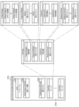
図3(a)は、本実施形態に係る、Vvvmファイルのデータ構造の一例を示す図である。図3(a)に示すVvvmファイル300は、データバージョン301、格納データ情報302、カメラパラメータ303、背景3Dモデル304、フレームデータ305から構成される。フレームデータ305は、第1フレームから第Nフレームまで存在し、1つのフレームデータにはM台のカメラによる撮影画像が含まれている。この場合において、N及びMは1以上の自然数である。
(Data structure of Vvvm file)
FIG. 3A is a diagram showing an example of the data structure of a Vvvm file according to this embodiment. A
Vvvmファイル300にどのような素材データが格納されているかは、格納データ情報302に示される。図3(b)は格納データ情報302のビットアサインの一例を示している。いま、格納データ情報302は32ビットの値を持ち、各ビットは、“1”であればその対象データが格納されていることを示し、“0”であればその対象データが格納されていないことを示す。図3(a)で示すVvvmファイル300には、各カメラの撮影画像(複数視点映像)、カメラパラメータ、背景3Dモデルの3種類の素材データが格納される。この場合、b0、b1、b5の各ビットが“1”、他のビットは“0”となる。b10~b13は独自に定義することができる。例えば、データ名称をデプスマップ或いは距離画像とした、前景画像と同じフォーマットで各画素値がカメラから被写体までの距離を表す画像を追加してもよい。また、仮想視点映像の生成を高速化するためのデータや高画質化するためのデータを追加してもよい。
The stored
また、格納される素材データそれぞれについても、それがどのようなデータであるかを示す付属情報(メタデータ)が付与される。図4(a)は各カメラの撮影画像のメタデータの一例を示している。図4(b)はカメラパラメータのメタデータの一例を示し、同(c)は格納カメラパラメータのビットアサインを示している。図4(d)は背景3Dモデルのメタデータの一例を示し、同(e)は格納背景3Dモデルのビットアサインを示している。なお、カメラパラメータ303の先頭(最初の4byte)には設置カメラの台数を示す情報が含まれ、この台数情報に続いてカメラパラメータに関するメタデータが、カメラの台数分だけ続くことになる。
Attached information (metadata) indicating what kind of data it is is attached to each of the stored material data. FIG. 4A shows an example of metadata of images captured by each camera. FIG. 4(b) shows an example of metadata of camera parameters, and FIG. 4(c) shows bit assignments of stored camera parameters. FIG. 4(d) shows an example of the metadata of the
以上のようにして、仮想視点映像の生成に必要な様々な素材データが共通のフォーマットで定義され、まとめてファイル化される。なお、カメラパラメータ303は、1つのVvvmファイルに対して1つでもよいが、フレーム単位でカメラパラメータを持つようにしてもよい。フレーム単位でカメラパラメータを持つことで、撮影途中でカメラの位置・姿勢が変化するケースや、一部のカメラが故障してカメラ群を構成するカメラ台数が変化するケースにも対応することができる。 As described above, various material data necessary for generating a virtual viewpoint video are defined in a common format and collectively filed. One camera parameter 303 may be provided for one Vvvm file, but the camera parameter may be provided for each frame. By having camera parameters for each frame, it is possible to handle cases where the camera position/posture changes during shooting, or cases where the number of cameras that make up a camera group changes due to a failure of some cameras. .
(Vvvmファイルの具体例)
続いて、ISO BMFF(ISO Base Media File Format ISO/IEC 14496-12 MPEG-4 Part 12)規格に準拠した、本実施形態のVvvmファイルの具体例を説明する。ISO BMFF規格では、「ボックス」という単位でファイルが構成される。図5(a)はボックスの構造を示す図であり、サイズ情報を格納する領域、タイプ情報を格納する領域、及びデータを格納する領域で構成される。また、図5(b)に示すように、ボックスの中にデータとしてさらにボックスを含む構造とすることも可能である。
(Concrete example of Vvvm file)
Next, a specific example of the Vvvm file of the present embodiment conforming to the ISO BMFF (ISO Base Media File Format ISO/IEC 14496-12 MPEG-4 Part 12) standard will be described. According to the ISO BMFF standard, files are configured in units called "boxes". FIG. 5(a) shows the structure of a box, which is composed of an area for storing size information, an area for storing type information, and an area for storing data. Also, as shown in FIG. 5B, it is possible to have a structure in which boxes are further included as data within boxes.
図6は、ISO BMFFに準拠したVvvmファイルの内部構造の一例を示している。ISO BMFFに準拠したVvvmファイル600は、ftyp601、moov602、cimg603、camp604、fimg605、bimg606、fmdl607、bmdl608及びmdat609の各ボックスで構成されている。以下、各ボックスについて説明する。
FIG. 6 shows an example of the internal structure of a Vvvm file conforming to ISO BMFF. A
ftypボックス(File Type Compatibility Box)601は、ファイル内の最初に配置されるボックスである。ftypボックス601には、ファイルフォーマットの情報、ボックスのバージョンを示す情報、他のファイルフォーマットとの互換性に関する情報、ファイルを作成したメーカ名称の情報などが記載される。Vvvmファイル内に格納される各素材データの種別を示す上述の格納データ情報302は、このftypボックス601に格納されても良い。また、moovボックス(Movie Box)602は、ファイル内にどんなデータがどのように格納されているかを明らかにするボックスであり、メディアデータを管理するための時間軸やアドレスなどの情報が入る。そして、mdatボックス(Media Data Box)609には、動画や音声といった、仮想視点映像を生成する際に使用するメディアデータ(素材データ)が入る。mdatボックス609にどのようにデータを格納したのかをmoovボックス602に記載しておくことで、これらメディアデータへのアクセスが可能になる。ftypボックス601、moovボックス602及びmdatボックス609は、ISO BMFF準拠のファイルにおいて共通で設けられるボックスである。これに対し、camp604、fimg605、bimg606、fmdl607及びbmdl608の各ボックスは、Vvvmファイルに特有のボックスである。以下、Vvvmファイルに特有のボックスについて具体例を交えて説明する。
An ftyp box (File Type Compatibility Box) 601 is a box placed first in a file. The
cimgボックス(Camera-captured Image Data Box)603は、カメラ毎に設定可能で、各カメラの撮影画像のフォーマット情報が入る。図7(a)はcimgボックス603の一例であり、同(b)はそのシンタックスである。
A cimg box (Camera-captured Image Data Box) 603 can be set for each camera, and contains format information of images captured by each camera. FIG. 7(a) is an example of the
campボックス(Camera Parameter Data Box)604は、カメラ毎に設定可能で、カメラパラメータとしてどのようなデータが格納されているかを示す情報とそれに対応するカメラパラメータの各値が入る。図8(a)はcampボックス604の一例であり、同(b)はそのシンタックスである。
A camp box (Camera Parameter Data Box) 604 can be set for each camera, and contains information indicating what kind of data is stored as a camera parameter and each value of the corresponding camera parameter. FIG. 8(a) is an example of the
fimgボックス(Foreground Image Data Box)605は、前景画像としてどのような画像データが格納されているかを示す情報と各前景画像のフォーマット情報が入る。図9(a)はfimgボックス605の一例であり、同(b)はそのシンタックスである。「前景フォーマット」901は、RAW、LOG、RGB、YUVといった前景画像の保存形式とビット深度を示す。「前景シルエットフォーマット」902は、前景シルエット画像のビット深度を示し、例えば、1ビット前景なのか背景なのかを示したり、8ビットで前景シルエットとしての確からしさを表現することができる。「切り出し前景フォーマット」903も「前景フォーマット」901と同様の情報を示す。
A fig box (Foreground Image Data Box) 605 contains information indicating what kind of image data is stored as a foreground image and format information of each foreground image. FIG. 9(a) is an example of the
bimgボックス(Background Image Data Box)606は、背景画像としてどのような画像データが格納されているかを示す情報と各背景画像のフォーマット情報が入る。図10(a)はbimgボックス606の一例であり、同(b)はそのシンタックスである。「背景フォーマット」1001は、上述の「前景フォーマット」901と同様、背景画像の保存形式とビット深度の情報を示す。「背景テクスチャフォーマット」1002は、その保存形式やビット深度の情報に加え、対応する背景3Dモデルの頂点座標の数を示す。「切り出し背景フォーマット」1003は「背景フォーマット」1001と同様の情報を示す。
A bimg box (Background Image Data Box) 606 contains information indicating what kind of image data is stored as a background image and format information of each background image. FIG. 10(a) is an example of the
fmdlボックス(Foreground Model Data Box)607は、前景3Dモデルとしてどのようなデータが格納されているかを示す情報と各前景3Dモデルのフォーマット情報が入る。図11(a)はfmdlボックス607の一例であり、同(b)はそのシンタックスである。「点群フォーマット」1101は、各点が何ミリのボクセルの座標を表現するかを示す。「メッシュモデルフォーマット」1102は、メッシュの頂点数などを示す。「ビルボードフォーマット」1103は、ビルボードを立てる座標の単位を示す。「バウンディングボックスフォーマット」1104は、バウンディングボックスが代表頂点2点で示されるのか、代表頂点1点と、幅、奥行き、高さで示されるのか、といった表現形式を示す。
An fmdl box (Foreground Model Data Box) 607 contains information indicating what kind of data is stored as the
bmdlボックス(Background Model Data Box)608は、背景3Dモデルとしてどのようなデータが格納されているかを示す情報と各背景3Dモデルのフォーマット情報が入る。図12(a)はbmdlボックス608の一例であり、同(b)はそのシンタックスである。「点群フォーマット」1201や「メッシュモデルフォーマット」1202は、上述の前景3Dモデルに関する、「点群フォーマット」1101や「メッシュモデルフォーマット」1102と同様の情報が示される。
A bmdl box (Background Model Data Box) 608 contains information indicating what kind of data is stored as the
本実施形態では、ISO BMFF規格を例に説明したが、Vvvmファイルのフォーマットはこれに限定されない。例えば、ISO BMFFと互換性のあるHEIF(High Efficiency Image File Format)やMiAF(Multi-Image Application Format)など他の規格であってもよい。或いは独自のフォーマットや今後新たに登場するフォーマットであっても構わない。また、それぞれのパラメータの値や表現も上述の例に限定されない。また、図6に示すcimg603、camp604、fimg605、bimg606、fmdl607、bmdl608の各ボックスのうち、少なくとも1つがmoovボックス602に格納されるようにしてもよい。
Although the ISO BMFF standard has been described as an example in this embodiment, the format of the Vvvm file is not limited to this. For example, other standards such as HEIF (High Efficiency Image File Format) compatible with ISO BMFF and MiAF (Multi-Image Application Format) may be used. Alternatively, it may be an original format or a format that will newly appear in the future. Also, the values and expressions of the respective parameters are not limited to the above examples. At least one of the boxes cimg 603,
(仮想視点映像生成装置)
続いて、図3(a)で示したデータ構造を持つVvvmファイル300を用いて、仮想視点から見た映像を生成する仮想視点映像生成装置について説明する。図13(a)は、本実施形態に係る、仮想視点映像生成装置20の内部構成を示す機能ブロック図である。仮想視点映像生成装置20は、ファイル入力部21、生成可否判定部22、前景背景分離部23、仮想視点パス入力部24、映像化部25、映像出力部26で構成される。なお、仮想視点映像生成装置20は、CPU、RAM、ROM、HDDといった、演算やデータ記憶のためのハードウェアを備えた情報処理装置であり、例えばPCなどである。図13(a)に示す各部の機能は、CPUが、所定のプログラムをROM又はHDDから読み込んでRAMに展開し、これをCPUが実行することで実現される。以下、図13(a)に示す各部の役割について説明する。
(Virtual viewpoint video generation device)
Next, a virtual viewpoint video generation device that generates video viewed from a virtual viewpoint using the
ファイル入力部21は、ファイル生成装置10で生成されたVvvmファイル300の入力を受け付け、各処理に必要なデータを読み出して、各処理に対応した機能ブロックに渡す。例えば、格納データ情報302を読み出して、生成可否判定部22に送る。また、各カメラのカメラパラメータ303を読み出して、前景背景分離部23と映像化部25に送る。また、背景3Dモデル304を読み出して、映像化部25に送る。また、仮想視点入力部24から受け取った仮想視点パスの情報に基づき、設定された仮想視点に対応する時刻のフレームデータ305を読み出し、前景・背景分離部23に送る。
The
生成可否判定部22は、ファイル入力部21から受け取った格納データ情報302を参照して、Vvvmファイル300内の素材データによって仮想視点映像を生成可能であるかを判定する。すなわち、格納データ情報で特定される素材データが、自装置が持つ機能に応じて要求される素材データを満たす場合、仮想視点映像が生成可能であると判定する。仮想視点映像を生成する手法にはいくつかあるが、仮想視点映像生成装置20は、例えば、前景画像、背景画像、前景3Dモデル、背景3Dモデルの4つの素材データを用いることによって、モデルベースレンダリングに基づく仮想視点映像を生成できる。ここで、本実施形態のVvvmファイル300に格納される素材データは、各カメラで撮影された画像(複数視点映像)、カメラパラメータ、背景3Dモデルの3種類であるとする。この例において、仮想視点映像生成装置20は、各カメラの撮影画像から前景と背景を分離する機能、さらに、前景3Dモデルを生成する機能を持っていれば、仮想視点映像を生成できる。生成可否判定部22は、自装置が採用する仮想視点映像の生成手法を前提として、自装置が有する仮想視点映像生成のための諸機能を踏まえた対応可否の判定基準(必要な素材データを示した判定用テーブル等)を予め作成し保持しておく。そして、当該判定基準に示された素材データがVvvmファイル300に含まれるか否かを、格納データ情報302を用いて確認することで、仮想視点映像が生成可能かどうかを判定する。以下に、対応可否の判定基準の一例として、バリエーションA~Cを示す。

格納データ情報302を用い上記判定基準に照らして得られた判定結果は、映像出力部26を介して、仮想視点映像生成装置20が備える不図示のモニタ等に表示するなどして、ユーザに通知される。
The judgment result obtained by using the stored
前景背景分離部23は、各カメラの撮影画像を前景と背景とに分離して前景シルエット画像を生成する。例えば、まず、カメラ毎に複数フレーム分の撮影画像を用いて背景画像を生成する。具体的には、同一カメラで撮影された複数フレーム間の画像比較により、動きのある領域と動きの無い領域とを検出し、動きのない領域を背景画像とする。背景画像を得ると、次に、各カメラの撮影画像と該生成した背景画像との間で対応する画素同士を比較し、画素値の差が所定の閾値以上である画素を前景画素とする。これにより、各カメラの撮影画像と同じ画像サイズであって、画素値が“1”を前景画素、画素値が“0”を背景画素とした前景シルエット画像が得られる。こうして得られた、背景画像と前景シルエット画像は、映像化部25に送られる。なお、撮影画像を前景と背景とに分離する手法は、上述の例に限定されない。例えば、撮影画像から前景3Dモデルを生成する処理の中で、機械学習技術等を用いて前景部分を分離することで、前景シルエット画像を生成してもよい。
A foreground/
仮想視点設定部24は、不図示のUI等を介したユーザ指定に基づいて、或いは予め決められた仮想視点の設定情報を読み込んで、仮想視点を設定する。動画による仮想視点映像を生成する場合に設定される仮想視点は、その生成対象時間(例えば10秒間、複数視点映像が60fpsで撮影されていれば600フレーム分)の間で移動するように設定されることが多い。そのようなユーザ指示等に基づき設定された仮想視点の移動経路(以下、「仮想視点パス」と呼ぶ。)の情報は、ファイル入力部21と映像化部25に送られる。仮想視点として設定されるパラメータは、例えば仮想カメラの位置、姿勢、画角等であり、さらに焦点位置や絞り値等を含んでもよい。
The virtual
映像化部25は、仮想視点設定部24から受け取った仮想視点パスの情報に基づいて仮想視点映像を生成する。映像化部25の詳細については後述する。映像化部25で生成した仮想視点映像のデータは、映像出力部26に送られる。
The
映像出力部26は、映像化部25から受け取った仮想視点映像のデータを、不図示のモニタに表示したり、或いは外部装置に送信するなどして出力する。
The
(映像化部の詳細)
図13(b)は、本実施形態に係る、映像化部25の詳細を示す機能ブロック図である。本実施形態の映像化部25は、前景3Dモデル生成部251、前景色づけ部252、背景色づけ部253、合成部254で構成される。以下、各部について説明する。
(Details of visualization section)
FIG. 13(b) is a functional block diagram showing details of the
前景3Dモデル生成部251は、前述の前景背景分離部23で生成された前景シルエット画像とファイル入力部21から受け取ったカメラパラメータとに基づき、前景3Dモデルを生成する。例えば、視体積交差法による前景3Dモデルの生成手順は、以下の1)~3)のとおりである。
The
1) 予め設定された前景3Dモデルの生成対象空間に一定の大きさをもった直方体(ボクセル)を敷き詰める。生成対象空間は、仮想視点パスに基づき、仮想カメラから見える範囲を算出して決定する。
1) Spread rectangular parallelepipeds (voxels) having a certain size in a
2) 各カメラのカメラパラメータを用いて、各直方体を三次元的にカメラの前景シルエット画像上に射影し、前景画素と重なるか確認する。前景画素と重ならない場合、該直方体は、前景3Dモデルを形成する直方体でないと判定する。全カメラのうち1台でも前景3Dモデルを形成する直方体でないと判定された場合、該直方体を削除する。
2) Using the camera parameters of each camera, project each rectangular parallelepiped three-dimensionally onto the foreground silhouette image of the camera and check whether it overlaps with the foreground pixels. If it does not overlap the foreground pixel, it is determined that the cuboid is not a cuboid forming the
3) 上記2)の処理をすべての直方体に対して行い、残った直方体の重心座標の点の集合を前景3Dモデルとする。
3) The processing of 2) above is performed for all the rectangular parallelepipeds, and the set of points of the barycentric coordinates of the remaining rectangular parallelepipeds is used as the
なお、ここでは視体積交差法を用いた前景3Dモデルの生成方法を説明したが、3Dモデルの生成方法はこれに限定されない。そして、上述のようにして生成した前景3Dモデルは、前景色づけ部252に送られる。
Although the method for generating the
前景色づけ部252は、前景3Dモデル生成部251で生成された前景3Dモデルに対し、仮想視点設定部24から受け取った仮想視点パスに基づき色づけ処理を行って、前景色付き画像を生成する。色づけ処理の具体的な手順は、以下の1)~3)のとおりである。
The
1) 前景3Dモデルの表面上の各点がどのカメラから見えるかの判定(可視性判定)を行う。この可視性判定では、まず、各点を全カメラの前景シルエット画像に射影する。この際、複数の点が、前景シルエット画像上の同じ画素に射影された場合は、カメラからみて最も距離が短い位置にある点が見える点、その他の点は見えない点と判定する。この処理を前景3Dモデルの表面上の全点に対して行って、各点に色づけするためのカメラを特定する。
1) Determine from which camera each point on the surface of the
2) 仮想視点パスに基づいて、前景3Dモデルを仮想視点映像となる画像に射影し、各画素に写る点を特定する。
2) Based on the virtual viewpoint path, the
3) 画素毎に、上記1)の可視性判定で射影された点が見えると判定されたカメラの撮影画像を用いて、当該点が射影された画素の色を決定する。この際、複数のカメラから見える点の場合は、仮想視点の向きと各カメラの向きを比較し、より角度の小さい2つのカメラの撮影画像を適宜重み付けるなどして、色を決定すればよい。 3) For each pixel, the color of the pixel onto which the point is projected is determined using the captured image of the camera for which the point is determined to be visible in the visibility determination in 1) above. At this time, in the case of a point that can be seen from multiple cameras, the direction of the virtual viewpoint and the direction of each camera can be compared, and the image captured by the two cameras with the smaller angle can be appropriately weighted to determine the color. .
上述のようにして生成した前景色付き画像のデータは、合成部254に送られる。
The data of the image with foreground color generated as described above is sent to the
背景色づけ部253は、各カメラの撮影画像から抽出された背景画像を用いて、背景3Dモデルに貼り付ける背景テクスチャを生成する。具体的には、以下の1)~5)の手順で、背景テクスチャが生成される。
The
1) 背景3Dモデルにおいて代表点となる頂点を設定する。
1) Set a vertex as a representative point in the
2) 上記1)で設定された頂点を、仮想視点に近い2台のカメラ(カメラ1、カメラ2とする)のカメラパラメータを用いて、仮想視点映像となる画像上に射影する。
2) The vertices set in 1) above are projected onto an image serving as a virtual viewpoint video using the camera parameters of two cameras (
3) 仮想視点とカメラ1の対応点、仮想視点とカメラ2の対応点を用いて、仮想視点とカメラ1間の射影行列1、及び、仮想視点とカメラ2間の射影行列2を算出する。
3) Using the corresponding points between the virtual viewpoint and the
4) 仮想視点映像となる画像における各画素の座標を、射影行列1と射影行列2を用いて、カメラ1の背景画像とカメラ2の背景画像にそれぞれ射影し、当該座標が射影された位置の画素値をそれぞれ取得する。
4) Project the coordinates of each pixel in the image to be the virtual viewpoint video onto the background image of
5) 得られた2つの画素値の平均値を、仮想視点映像となる画像における背景領域の画素値とする。 5) The average value of the obtained two pixel values is used as the pixel value of the background region in the image that is the virtual viewpoint video.
さらに、背景色づけ部253は、生成した背景テクスチャを、Vvvmファイル内に格納されていた背景3Dモデルに対し貼り付け、仮想視点から見たときの背景画像(仮想背景画像)を生成する。上述のようにして生成した仮想背景画像のデータは、合成部254に送られる。
Further, the
合成部254は、前景色づけ部252から受け取った前景色付き画像と、背景色づけ部253から受け取った仮想背景画像とを合成し、仮想視点からの見えを表す画像を生成する。具体的には、前景色付き画像の各画素に対し、仮想背景画像における対応する画素の画素値を上書きする処理を行なう。
The synthesizing
図14は、本実施形態に係るVvvmファイル300から、仮想視点映像生成装置20が仮想視点映像を生成し出力するまでの処理の流れを示すフローチャートである。なお、各処理の冒頭における記号「S」はステップを意味する。以下、図14のフローに沿って説明する。
FIG. 14 is a flow chart showing the flow of processing from the Vvvm file 300 according to the present embodiment until the virtual viewpoint
S1401では、ファイル入力部21が、Vvvmファイル300から格納データ情報302を読み出し、生成可否判定部22に出力する。続くS1402では、生成可否判定部22が、予め用意された生成可否判定基準の情報を読み出し、格納データ情報302を参照して、Vvvmファイル300内に格納された素材データを用いて仮想視点映像を生成可能であるかを判定する。判定の結果、仮想視点映像を生成可能な場合は、S1403に進む。この際、映像出力部26が、仮想視点映像を生成可能であることを示すメッセージを不図示のモニタに表示するなどの通知を行ってもよい。一方、仮想視点映像を生成不可能な場合は、S1409に進む。
In S<b>1401 , the
S1403では、ファイル入力部21が、Vvvmファイル300からカメラパラメータ303と背景3Dモデル304を読み出し、カメラパラメータ303を前景背景分離部23に、背景3Dモデル304を映像化部25にそれぞれ出力する。続くS1404では、仮想視点設定部24は、ユーザ指定等に基づき仮想視点パスを設定し、その情報をファイル入力部21と映像化部25に出力する。
In S1403, the
S1405では、ファイル入力部21が、入力された仮想視点パスに対応するフレームデータ305をVvvmファイル300から読み出し、前景背景分離部23に出力する。以降のS1406及びS1407は、フレーム単位で実行される。
In S<b>1405 , the
S1406では、前景背景分離部23が、各カメラの撮影画像に対して前景背景分離処理を行って、前景シルエット画像と背景画像を生成し、映像化部25に出力する。続くS1407では、映像化部25が、入力された仮想視点パス、前景シルエット画像及び背景画像に基づき仮想視点映像を生成する。
In S<b>1406 , the foreground/
S1408では、映像出力部26が、S1408で生成された仮想視点映像のデータを出力する。また、S1409では、映像出力部26が、仮想視点映像を出力できない旨のメッセージを不図示のモニタに表示するなどの通知を行う。
In S1408, the
以上が、Vvvmファイル300から仮想視点映像を生成し出力するまでの処理の流れである。
The above is the flow of processing for generating and outputting a virtual viewpoint video from the
<Vvvmファイルのバリエーション>
共通のフォーマットで素材データをファイル化したVvvmファイルのデータ構造は、前述の図3(a)に示す例に限定されない。以下に、Vvvmファイルのデータ構造のバリエーションを示す。
<Vvvm file variations>
The data structure of the Vvvm file in which material data is filed in a common format is not limited to the example shown in FIG. 3(a). Variations in the data structure of the Vvvm file are shown below.
図15に示すVvvmファイル1500は、データバージョン1501、格納データ情報1502、カメラパラメータ1503、背景3Dモデル1504、フレームデータ1505から構成される。そして、フレームデータ1505は、第1フレームから第Nフレームまで存在し、1つのフレームデータには、前景画像群、前景3Dモデル群、背景画像群が含まれている。そして、前景画像群には、M台のカメラに対応した前景画像と前景シルエット画像が含まれる。また、前景3Dモデル群には、O個の前景3Dモデルが含まれる。また、背景画像群には、P個の背景画像が含まれる。この場合において、N、M、O及びPは、いずれも1以上の自然数である。Vvvmファイル1500にどのような素材データが格納されているかは、格納データ情報1502によって示される。そして、図16(a)は前景画像に関するメタデータの一例を示し、同(b)はそのビットアサインを示している。ここで、前景切り出し画像は、カメラの撮影画像から前景領域を切り出した画像を意味し、前景画像をメインプロファイルとするときの拡張プロファイルに相当する。Vvvmファイルに格納されているのが前景切り出し画像のみで前景画像自体は格納されていない場合、仮想視点映像生成装置側が前景切り出し画像に対応していないと仮想視点映像を生成できないということになる。例えば、あるバージョンのメインプロファイルには対応可能であるが、拡張プロファイルには対応できないという装置の場合、前景画像に関するメタデータを確認することで、自装置では仮想視点映像の生成ができないと判断することができる。このように、素材データに付与されるメタデータによって、仮想視点映像の生成可否をさらに詳細に判断することが可能になる。また、図16(c)は背景画像に関するメタデータの一例を示し、同(d)は格納背景画像のビットアサインを示している。そして、図16(e)は前景3Dモデルのメタデータの一例を示し、同(f)は格納前景3Dモデルのビットアサインを示している。前景3Dモデルや背景3Dモデルには、点の集合で構成される点群モデルや、多角形の面を集めて構成されるメッシュモデルなど、いくつか種類がある。仮想視点映像を生成する装置は、Vvvmファイルに格納されている前景/背景の3Dモデルの種類が、自装置で対応可能な種類であるかを、これらメタデータを参照して判断することができる。図15に示すデータ構造を持つVvvmファイル1500を生成し、それを用いて仮想視点映像を生成する態様については、次の実施形態2おいて説明することとする。
A
図17に示すVvvmファイル1700は、データバージョン1701、格納データ情報1702、背景3Dモデル1703、フレームデータ1704から構成される。そして、フレームデータ1704は、第1フレームから第Nフレームまで存在し、1つのフレームデータには、前景画像群、前景3Dモデル群、可視性情報、背景テクスチャ群が含まれている。ここで、可視性情報は、前述の可視性判定の結果に相当する情報である。前景画像群には、M台のカメラに対応した前景画像が含まれる。また、前景3Dモデル群には、O個の前景3Dモデルが含まれる。また、可視性情報には、Q個の可視性情報が含まれる。また、背景テクスチャ群には、背景3Dモデルに貼り付けるR個の背景テクスチャが含まれる。ここでのQ及びRも1以上の自然数である。また、R個の背景テクスチャは背景画像を合成して生成するため、R≦Pとなる。そして、Vvvmファイル1700にどのような素材データが格納されているかは、格納データ情報1702によって示される。メタデータとビットアサインについては省略する。図17に示すVvvmファイル1700の場合、前景3Dモデルに加えて、可視性情報と背景テクスチャのデータも含まれている。したがって、前景色づけ部252における可視性判定や、背景色づけ部253における背景テクスチャの生成を省くことができ、仮想視点映像装置側の負荷を軽くすることができる。
A
図18に示すVvvmファイル1800は、データバージョン1801、格納データ情報1802、背景3Dモデル1803、フレームデータ1804から構成される。そして、フレームデータ1804は、第1フレームから第Nフレームまで存在し、1つのフレームデータには、テクスチャ付き前景3Dモデル群と背景テクスチャ群とが含まれている。ここで、テクスチャ付き前景3Dモデルは、前述の前景色づけ処理が施された前景3Dモデルを意味する。テクスチャ付き前景3Dモデル群には、O個のテクスチャ付き前景3Dモデルが含まれる。また、背景テクスチャ群には、R個の背景テクスチャが含まれる。そして、Vvvmファイル1800にどのような素材データが格納されているかは、格納データ情報1802によって示される。メタデータとビットアサインについては省略する。図18に示すVvvmファイル1800の場合、既に色づけ処理が済んだ前景3Dモデルが含まれていることから、図17のVvvmファイル1700よりも仮想視点映像装置側の負荷をさらに軽くすることができる。
A
なお、図3(a)、図15、図17におけるフレームデータを構成する画像データ(各カメラの撮影画像、前景画像、背景画像)は、カメラに付された通し番号順に格納されるのが通常であるが、これに限定されない。例えば各素材データのヘッダにカメラ番号を付与した上で、順不同で格納してもよい。また、本実施形態では、各カメラの撮影画像や前景画像などのデータを、フレーム単位で読み出し可能なように格納しているが、カメラ単位で読み出し可能なように格納してもよい。 It should be noted that the image data (the image captured by each camera, the foreground image, and the background image) that constitute the frame data in FIGS. Yes, but not limited to. For example, a camera number may be added to the header of each material data and stored in random order. In addition, in the present embodiment, the data such as the images captured by each camera and the foreground image are stored so as to be readable in units of frames, but they may be stored so as to be readable in units of cameras.
また、図3(a)、図15、図17、図18で例示したデータ構造においては、どのVvvmファイルにも背景3Dモデルが含まれているが必須ではない。例えば、○○スタジアムでのサッカーの試合といったように、撮影シーンが同一施設で行われる同種イベントである場合は、背景3Dモデルは、予め用意したものを共通で繰り返し使用可能である。受信したVvvmファイルに背景3Dモデルが含まれていなくても、仮想視点映像生成装置がその撮影シーンに対応する背景3Dモデルのデータを他の情報処理装置から取得するなどして、仮想視点映像を生成してもよい。この際、対応可否の判定基準がそれに応じたものになることは言うまでもない。
Also, in the data structures illustrated in FIGS. 3A, 15, 17, and 18, every Vvvm file includes a
以上のとおり本実施形態によれば、仮想視点映像を生成するために必要な素材データが共通のフォーマットでまとめてファイル化される。これにより、共通フォーマットのVvvmファイルに対応した端末やアプリケーションであれば容易に仮想視点映像を生成できるようになり、仮想視点映像の利用環境が拡がる。 As described above, according to the present embodiment, the material data necessary for generating the virtual viewpoint video are compiled into a file in a common format. As a result, any terminal or application compatible with the Vvvm file of the common format can easily generate a virtual viewpoint video, expanding the usage environment of the virtual viewpoint video.
次に、前述の図15に示すデータ構造を持つVvvmファイル1500を生成し、それを用いて仮想視点映像を生成する態様を、実施形態2として説明する。なお、実施形態1と共通する内容については説明を省略ないしは簡略化することとし、以下では差異点を中心に説明を行うものとする。
Next, a mode of generating a
前述のとおり、図15に示すVvvmファイル1500は、データバージョン1501、格納データ情報1502、カメラパラメータ1503、背景3Dモデル1504、フレームデータ1505から構成される。このため、本実施形態に係るファイル生成装置は、前景背景分離を実施し、前景3Dモデルの生成を行って、前景画像、前景シルエット画像、前景3Dモデル、背景画像の各データをフレーム単位で格納する。そして、Vvvmファイル1500には、これらの素材データが格納されていることを示す格納データ情報1502が付加される。また、本実施形態に係る仮想視点映像生成装置は、格納データ情報1502を参照して生成可否の判定を行って仮想視点映像の生成が可能であれば、当該ファイル内の前景画像、背景画像、前景3Dモデルの各素材データを用いて仮想視点映像を生成する。
As described above, the
(ファイル生成装置)
図19は、実施形態1の図1に対応する図であり、本実施形態に係るファイル生成装置10’の機能ブロック図である。ファイル生成装置10’は、データ入力部11’、カメラパラメータ生成部12’、ファイル生成部13’、ファイル出力部14に加え、前景背景分離部1901と前景3Dモデル生成部1902を有する。以下、図19に示す各部の役割について説明する。
(File generation device)
FIG. 19 is a diagram corresponding to FIG. 1 of
データ入力部11’は、その機能は、実施形態1のデータ入力部11と同じであるが、入力されたデータの出力先が異なる。すなわち、カメラ情報、複数視点映像、背景3Dモデルの入力を受け付けると、カメラ情報はカメラパラメータ生成部12’に、背景3Dモデルはファイル生成部13’に、複数視点映像のデータは前景背景分離部1901にそれぞれ送られる。
The data input unit 11' has the same function as the
カメラパラメータ生成部12’も、その機能は実施形態1のカメラパラメータ生成部12と同じであるが、生成したカメラパラメータの出力先が異なる。本実施形態の場合、生成されたカメラパラメータは、前景背景分離部1901、前景3Dモデル生成部1902及びファイル生成部13’に送られる。
The camera parameter generation unit 12' also has the same function as the camera
前景背景分離部1901は、実施形態1の仮想視点映像生成装置20における前景背景分離部23と同様、各カメラの撮影画像を前景と背景とに分離する処理を行い、前景画像、前景シルエット画像、背景画像を生成する。そして、得られた前景シルエット画像を前景3Dモデル生成部1902に、前景画像と背景画像をファイル生成部13’にそれぞれ送る。
Similar to the foreground/
前景3Dモデル生成部1902は、実施形態1の仮想視点映像生成装置20の映像化部25における前景3Dモデル生成部251と同様、前景シルエット画像と仮想視点パスとに基づき前景3Dモデルを生成する。そして、得られた前景3Dモデルを、ファイル生成部13’に送る。
A
ファイル生成部13’は、データ入力部11’から背景3Dモデル、前景背景分離部1901から前景画像、前景シルエット画像及び背景画像、前景3Dモデル生成部1902から前景3Dモデル、カメラパラメータ生成部12’からカメラパラメータを取得する。そして、取得したこれらデータを共通フォーマットでファイル化する。この際、前景画像、前景シルエット画像、前景3Dモデル及び背景画像は、フレーム単位で格納される。さらに、前景画像と前景シルエット画像はカメラ単位でも識別可能となるように、前景3Dモデルはモデル単位でも識別可能となるように、それぞれ格納される。さらに、素材データとしてこれらが格納されていることを示す格納データ情報1502を付加して、図15に示すVvvmファイル1500を生成する。
The file generation unit 13' generates a
(仮想視点映像生成装置)
図20(a)及び(b)は、実施形態1の図13(a)及び(b)に対応する図であり、本実施形態に係る仮想視点映像生成装置20’と映像化部25’の内部構成をそれぞれ示している。図20(a)には前景背景分離部23に対応する処理ブロックが存在せず、図20(b)には前景3Dモデル生成部251に対応する処理ブロックが存在しない。以下、図20(a)及び(b)に示す各部の機能について説明する。
(Virtual viewpoint video generation device)
FIGS. 20A and 20B are diagrams corresponding to FIGS. 13A and 13B of
ファイル入力部21’は、ファイル生成装置10’で生成されたVvvmファイルの入力を受け付け、各処理に必要なデータを読み出して、各処理に対応したブロックに渡す。図15に示すVvvmファイル1500が入力された場合は、格納データ情報1502を読み出して、それを生成可否判定部22’に送る。また、カメラパラメータ1503と背景3Dモデル1504を読み出して、映像化部25’に送る。また、仮想視点設定部24から受け取った仮想視点パスの情報に基づき、設定された仮想視点パスに対応するフレームデータ1505を読み出し、映像化部25’に送る。
The file input unit 21' accepts the input of the Vvvm file generated by the file generation device 10', reads data necessary for each process, and passes it to the block corresponding to each process. When the
生成可否判定部22’は、ファイル入力部21’から受け取った格納データ情報を用いて、入力されたVvvmファイルに基づき仮想視点映像を生成可能であるかを判定する。前述の通り、本実施形態の仮想視点映像装置20’は、前景背景分離機能と前景3Dモデル生成機能とを有しない。よって、入力されたVvvmファイルが、図15(a)に示すVvvmファイル1500であれば生成可能と判断されるが、例えば図3(a)に示すVvvmファイル300であれば生成不可能と判断されることになる。
Using the stored data information received from the file input unit 21', the generation availability determination unit 22' determines whether a virtual viewpoint video can be generated based on the input Vvvm file. As described above, the virtual viewpoint video device 20' of this embodiment does not have the foreground/background separation function and the
映像化部25’は、仮想視点設定部24から受け取った仮想視点パスの情報に基づいて仮想視点映像を生成する。映像化部25’の詳細については後述する。そして、映像出力部26が、映像化部25’にて生成された仮想視点映像のデータを、不図示のモニタに表示したり、或いは外部端末等に送信するなどして出力する。
The
(映像化部の詳細)
図20(b)に示す通り、本実施形態の映像化部25’は、前景色づけ部252’、背景色づけ部253、合成部254とで構成される。背景色づけ部253と合成部254は、実施形態1と異なるところはない。図20(c)は、本実施形態に係る前景色づけ部252’の内部構成を示すブロック図である。前景色づけ部252’は、使用モデル決定部2000と、複数種類の前景3Dモデルに対応した色づけ部、具体的には、メッシュモデル色づけ部2001、ビルボード色づけ部2002、点群モデル色づけ部2003とで構成される。使用モデル決定部2000によって決定された色づけ部において、前景オブジェクトの3Dモデルに色づけがなされ、仮想視点から見た前景色つき画像が生成される。例えば、入力された前景3Dモデルのタイプが、ビルボード形式であった場合は、ビルボード色づけ部2002が、当該前景3Dモデルに適用する色づけ部として決定される。ビルボードの場合はそれを立てる座標位置のみが示される(オブジェクトの三次元形状は持たない)ので、指定された座標位置に描画対象のオブジェクトがあるときの仮想視点から見える方向と大きさを計算し、仮想視点から見た前景を生成する。
(Details of visualization section)
As shown in FIG. 20(b), the imaging unit 25' of this embodiment is composed of a foreground coloring unit 252', a
モデル決定部2000は、前景3Dモデルに付与されたメタデータに基づいて、フレームデータ1505に含まれる前景3Dモデルの種類を特定し、3つの色づけ部2001~2003のうちどれを使用して色づけ処理を行うかを決定する。この際、フレームデータ1505内に複数種類の前景3Dモデルが格納されていれば、予め定めた優先順(例えば、点群モデル色づけ部2003、メッシュモデル色づけ部2001、ビルボード色づけ部2002の順)に使用する色づけ部を決定する。また、仮想視点の設定時にユーザが仮想視点映像生成モードを指定した場合には、当該指定に係る生成モードの内容に応じて決定するようにしてもよい。例えば、高画質モードが指定された場合は点群モデル色づけ部2003、通常画質モードが指定された場合はメッシュモデル色づけ部2001、高速モードが指定された場合はビルボード色づけ部2002、といった具合である。このように、予め定めた基準によって、前景3Dモデルに対する色づけ処理に用いる処理部を決定することにより、目的や用途に応じた適切な前景を生成することができる。
The
ここで、例えば、前景色づけ部252’が点群モデル色づけ部2003を有しておらず、仮想視点映像生成装置20’に入力されたVvvmファイル1500のフレームデータ1505に格納された前景3Dモデルが点群モデルのみであったと仮定する。この場合、生成可否判定部22’は、前景3Dモデルに関するメタデータを参照して、フレームデータ1505に含まれる前景3Dモデルが点群モデルだけであることを特定する。そして、自装置が点群モデルに対応した色づけ部を持たないことにより、仮想視点映像を生成することはできないと判定する。このように、格納データ情報1502だけでなく、それぞれの素材データに付与されたメタデータの内容を確認することにより、さらに詳細に仮想視点映像生成可否を判断することが可能となる。
Here, for example, the
<変形例>
なお、映像化部25’は、設定された仮想視点パスの下で実際に用いる素材データだけをVvvmファイル1500から取得することで、より効率的に仮想視点映像を生成するようにしてもよい。すなわち、ファイル入力部21’が、仮想視点設定部24から入力された仮想視点パスの情報に基づいて、仮想視点映像の生成に実際に使用する素材データのみを特定して、映像化部25’に渡すようにする。この特定の際には、対象となるフレームデータ1505に含まれる素材の種類(前景画像、前景3Dモデル、背景画像)を指定した上で、さらにカメラIDやモデルIDといったさらに細かな指定が含まれるようにする。以下に、設定された仮想視点に対応する素材データをどのように特定するのかについて説明する。
<Modification>
Note that the
まず、前景画像と背景画像については、設定された仮想視点位置と近い視点位置のカメラで撮影された前景画像或いは背景画像を、Vvvmファイル内のカメラパラメータに基づいて特定する。この際、選択する前景画像が少ないと、障害物に隠れるオクルージョンにより、色づけができない場合もある。また、選択する背景画像が少ないと、仮想視点に映る背景がすべて色づけできない可能性がある。そのため、複数台(例えば、視点位置が近いカメラから順に6台分)のカメラの撮影画像における前景画像や背景画像を選択するようにする。この際、台数を多くしたり、高さの異なるカメラを混ぜたりすることで、オクルージョンの影響を受けづらくしたり、背景が色づけできない可能性を低減したりすることができる。 First, with respect to the foreground image and the background image, the foreground image or background image captured by a camera at a viewpoint position close to the set virtual viewpoint position is specified based on the camera parameters in the Vvvm file. At this time, if the number of foreground images to be selected is small, coloring may not be possible due to occlusion hidden by obstacles. In addition, if the number of background images to be selected is small, there is a possibility that all the backgrounds reflected in the virtual viewpoint cannot be colored. Therefore, a foreground image and a background image are selected from images captured by a plurality of cameras (for example, six cameras in descending order of viewpoint positions). At this time, by increasing the number of cameras or mixing cameras with different heights, it is possible to reduce the influence of occlusion and reduce the possibility that the background cannot be colored.
次に、前景3Dモデルについては、Vvvmファイルに含まれる前景3Dモデルのバウンディングボックス情報に基づいて特定する。バウンディングボックス情報は、前景3Dモデルを直方体で囲ったときの、当該直方体の3次元座標を示す情報である。このバウンディングボックス情報を用いて、各前景3Dモデルが、設定された仮想視点から見えるか否かを判定する。具体的には、バウンディングボックスを表す直方体の各頂点を、仮想視点映像となる2次元画像に向けて射影したときに、各頂点に対応する点が当該画像上に存在するか否かを確認する。こうして、設定された仮想視点から見える前景3Dモデルが特定される。
Next, the
なお、設定された仮想視点パスの下で実際に使用する素材データだけを取得して効率的に仮想視点映像を生成する上述の内容は、図15に示すデータ構造のVvvmファイルに限定されるものではない。他のあらゆるデータ構造のVvvmファイルに対しても適用可能である。 Note that the above-described content of acquiring only the material data actually used under the set virtual viewpoint path and efficiently generating the virtual viewpoint video is limited to the Vvvm file having the data structure shown in FIG. isn't it. It is also applicable to Vvvm files of any other data structure.
以上のとおり本実施形態の場合、ファイル生成装置が、素材データとして、前景画像、背景画像及び前景3Dモデルが含まれるVvvmファイルを生成する。したがって、前景背景分離機能や前景3Dモデル生成機能を有していない仮想視点映像生成装置においても、Vvvmファイルに対応していれば容易に仮想視点映像を生成することができる。
As described above, in the case of this embodiment, the file generation device generates a Vvvm file that includes a foreground image, a background image, and a
(その他の実施例)
本発明は、上述の実施形態の1以上の機能を実現するプログラムを、ネットワーク又は記憶媒体を介してシステム又は装置に供給し、そのシステム又は装置のコンピュータにおける1つ以上のプロセッサーがプログラムを読出し実行する処理でも実現可能である。また、1以上の機能を実現する回路(例えば、ASIC)によっても実現可能である。
(Other examples)
The present invention supplies a program that implements one or more functions of the above-described embodiments to a system or device via a network or a storage medium, and one or more processors in the computer of the system or device reads and executes the program. It can also be realized by processing to It can also be implemented by a circuit (for example, ASIC) that implements one or more functions.
10 ファイル生成装置
13 ファイル化部
14 ファイル出力部
20 仮想視点映像生成装置
22 生成可否判定部
25 映像化部
26 映像出力部
REFERENCE SIGNS
Claims (26)
前記取得手段により取得された素材データと前記素材データの種別を示す種別情報とを格納したファイルを生成するファイル生成手段と、
前記ファイル生成手段により生成された前記ファイルを出力する出力手段と
を備え、
前記ファイル生成手段は、前記ファイルの生成において、前記ファイルに格納される各素材データのそれぞれに対しメタデータを付与して、前記ファイルに格納する、
ことを特徴とするファイル生成装置。 Acquisition means for acquiring material data used for generating a virtual viewpoint video based on images shot from a plurality of viewpoints;
file generating means for generating a file storing the material data acquired by the acquiring means and type information indicating the type of the material data;
and an output means for outputting the file generated by the file generation means ,
wherein, in generating the file, the file generating means adds metadata to each material data stored in the file and stores the metadata in the file;
A file generation device characterized by:
前記種別情報は、前記素材データが前記カメラパラメータを含むことを示す情報を含むことを特徴とする請求項1に記載のファイル生成装置。2. The file generation device according to claim 1, wherein said type information includes information indicating that said material data includes said camera parameters.
前記種別情報は、前記素材データが前景画像を含むことを示す情報を含むことを特徴とする請求項1又は2に記載のファイル生成装置。3. The file generation device according to claim 1, wherein the type information includes information indicating that the material data includes a foreground image.
前記種別情報は、前記素材データが前景3Dモデルを含むことを示す情報を含むことを特徴とする請求項1乃至3のいずれか1項に記載のファイル生成装置。4. The file generation device according to any one of claims 1 to 3, wherein the type information includes information indicating that the material data includes a foreground 3D model.
前記種別情報は、前記素材データが背景3Dモデルを含むことを示す情報を含むことを特徴とする請求項1乃至4のいずれか1項に記載のファイル生成装置。5. The file generation device according to any one of claims 1 to 4, wherein the type information includes information indicating that the material data includes a background 3D model.
前記取得手段により取得された素材データと前記素材データの種別を示す種別情報とを格納したファイルを生成するファイル生成手段と、
前記ファイル生成手段により生成された前記ファイルを出力する出力手段と、
を備え、
前記取得手段は、前記複数の視点で撮影を行うカメラの台数の情報、及び、各カメラのIDと紐付けられた各カメラの位置、姿勢、画角の情報を少なくとも含むカメラパラメータを生成して取得し、
前記ファイル生成手段は、前記ファイルの生成において、前記カメラパラメータを前記素材データとして前記ファイルに格納する
ことを特徴とするファイル生成装置。 Acquisition means for acquiring material data used for generating a virtual viewpoint video based on images shot from a plurality of viewpoints;
file generating means for generating a file storing the material data acquired by the acquiring means and type information indicating the type of the material data;
output means for outputting the file generated by the file generation means;
with
The acquisition means generates camera parameters including at least information on the number of cameras that shoot at the plurality of viewpoints , and information on the position, orientation, and angle of view of each camera linked to the ID of each camera. Acquired,
A file generating apparatus, wherein the file generating means stores the camera parameters as the material data in the file when generating the file.
前記取得手段により取得された素材データと前記素材データの種別を示す種別情報とを格納したファイルを生成するファイル生成手段と、
前記ファイル生成手段により生成された前記ファイルを出力する出力手段と、
を備え、
前記取得手段は、前記複数の視点で撮影を行う各カメラの撮影画像に対し前景背景分離を行い、
前記ファイル生成手段は、前記ファイルの生成において、前記前景背景分離の結果の少なくとも一部を、前記素材データとして前記ファイルに格納する
ことを特徴とするファイル生成装置。 Acquisition means for acquiring material data used for generating a virtual viewpoint video based on images shot from a plurality of viewpoints;
file generating means for generating a file storing the material data acquired by the acquiring means and type information indicating the type of the material data;
output means for outputting the file generated by the file generation means;
with
The acquisition means performs foreground/background separation on images captured by each camera that captures images from the plurality of viewpoints,
A file generating apparatus, wherein, in generating the file, the file generating means stores at least part of the result of the foreground/background separation in the file as the material data.
前記取得手段により取得された素材データと前記素材データの種別を示す種別情報とを格納したファイルを生成するファイル生成手段と、
前記ファイル生成手段により生成された前記ファイルを出力する出力手段と、
を備え、
前記取得手段は、前記複数の視点で撮影を行う各カメラの撮影画像における前景シルエット画像と、各カメラの位置及び姿勢を少なくとも含むカメラパラメータとに基づき、前景オブジェクトの3次元形状を表す前景3Dモデルを生成して取得し、
前記ファイル生成手段は、前記ファイルの生成において、前記前景3Dモデルを前記素材データとして前記ファイルに格納する
ことを特徴とするファイル生成装置。 Acquisition means for acquiring material data used for generating a virtual viewpoint video based on images shot from a plurality of viewpoints;
file generating means for generating a file storing the material data acquired by the acquiring means and type information indicating the type of the material data;
output means for outputting the file generated by the file generation means;
with
The acquisition means is a foreground 3D model representing a three-dimensional shape of a foreground object based on a foreground silhouette image in images captured by each camera that captures images from the plurality of viewpoints and camera parameters including at least the position and orientation of each camera. to generate and obtain
A file generating device, wherein the file generating means stores the foreground 3D model as the material data in the file when generating the file.
前記取得手段により取得された素材データと前記素材データの種別を示す種別情報とを格納したファイルを生成するファイル生成手段と、
前記ファイル生成手段により生成された前記ファイルを出力する出力手段と、
を備え、
前記ファイル生成手段は、前記ファイルの生成において、前記複数の視点で撮影された画像における背景オブジェクトの3次元形状を表す背景3Dモデルを、前記素材データとして前記ファイルに格納する
ことを特徴とするファイル生成装置。 Acquisition means for acquiring material data used for generating a virtual viewpoint video based on images shot from a plurality of viewpoints;
file generating means for generating a file storing the material data acquired by the acquiring means and type information indicating the type of the material data;
output means for outputting the file generated by the file generation means;
with
The file generating means is characterized in that, in generating the file, a background 3D model representing a three-dimensional shape of a background object in the images shot from the plurality of viewpoints is stored in the file as the material data. File generator.
前記ファイルに格納された素材データを用いた前記仮想視点映像の生成が可能かどうかを、前記種別情報に基づいて判定する判定手段と、
前記判定手段で生成可能と判定された場合に、前記入力手段により入力されたファイルに格納された素材データを用いて仮想視点映像を生成する生成手段と、
を備えたことを特徴とする映像生成装置。 input means for inputting a file storing material data used for generating a virtual viewpoint video based on images shot from a plurality of viewpoints and type information indicating the type of the material data;
determination means for determining whether or not the virtual viewpoint video can be generated using the material data stored in the file, based on the type information;
generation means for generating a virtual viewpoint video using the material data stored in the file input by the input means when the determination means determines that the generation is possible ;
A video generation device characterized by comprising:
前記入力手段により入力されたファイルに格納された素材データを用いて仮想視点映像を生成する生成手段と、
を備え、
前記生成手段は、前記複数の視点で撮影を行う各カメラの撮影画像における前景オブジェクトの3次元形状を表す前景3Dモデルに対し色づけする機能を少なくとも有する、
ことを特徴とする映像生成装置。 input means for inputting a file storing material data used for generating a virtual viewpoint video based on images shot from a plurality of viewpoints and type information indicating the type of the material data;
generating means for generating a virtual viewpoint video using the material data stored in the file input by the input means;
with
The generating means has at least a function of coloring a foreground 3D model representing a three-dimensional shape of a foreground object in images captured by each camera that captures images from the plurality of viewpoints .
A video generation device characterized by:
前記ファイルに複数種類の前景3Dモデルが含まれる場合、所定の基準に従って、使用する前景3Dモデルを決定し
決定した前記前景3Dモデルを用いて、前記仮想視点映像を生成する
ことを特徴とする請求項18に記載の映像生成装置。 The generating means is
If the file contains a plurality of types of foreground 3D models, a foreground 3D model to be used is determined according to a predetermined standard, and the determined foreground 3D model is used to generate the virtual viewpoint video. Item 19. The video generation device according to Item 18 .
前記ファイルに格納された素材データの中に含まれる、前記各カメラの撮影画像における前景シルエット画像と、前記各カメラの位置及び姿勢を少なくとも含むカメラパラメータとを用いて前景3Dモデルを生成し、
生成した前記前景3Dモデルに対して色づけを行なって、前記仮想視点映像を生成する
ことを特徴とする請求項17乃至21のいずれか1項に記載の映像生成装置。 The generating means is
generating a foreground 3D model using camera parameters including at least the position and orientation of each camera and a foreground silhouette image in the images captured by each camera, which are included in the material data stored in the file;
22. The video generation device according to any one of claims 17 to 21 , wherein the generated foreground 3D model is colored to generate the virtual viewpoint video.
前記ファイルに格納された素材データの中に含まれる前記各カメラの撮影画像に対し前景背景分離を行って前景シルエット画像を生成し、
前記ファイルに格納された素材データの中に含まれる、前記各カメラの位置及び姿勢を少なくとも含むカメラパラメータと、生成した前記前景シルエット画像とを用いて、前景3Dモデルを生成し、
生成した前記前景3Dモデルに対して色づけを行って、前記仮想視点映像を生成する
ことを特徴とする請求項17乃至21のいずれか1項に記載の映像生成装置。 The generating means is
generating a foreground silhouette image by performing foreground/background separation on the images captured by each of the cameras included in the material data stored in the file;
generating a foreground 3D model using the camera parameters including at least the position and orientation of each camera and the generated foreground silhouette image, which are included in the material data stored in the file;
22. The video generation device according to any one of claims 17 to 21 , wherein the generated foreground 3D model is colored to generate the virtual viewpoint video .
設定された仮想視点に基づいて、前記仮想視点映像の生成に必要な素材データを決定し、
決定した前記必要な素材データを前記ファイルの中から取得し、
取得した素材データを用いて、前記仮想視点映像を生成する
ことを特徴とする請求項14乃至23のいずれか1項に記載の映像生成装置。 The generating means is
determining material data necessary for generating the virtual viewpoint video based on the set virtual viewpoint;
Acquiring the determined necessary material data from the file,
24. The image generation device according to any one of claims 14 to 23 , wherein the obtained material data is used to generate the virtual viewpoint image .
前記取得ステップにより取得された素材データと前記素材データの種別を示す種別情報とを格納し、格納される各素材データのそれぞれに対しメタデータを付与したファイルを生成するファイル生成ステップと、
前記ファイル生成ステップにより生成された前記ファイルを出力する出力ステップと、
を含むことを特徴とするファイル生成方法。 an acquisition step of acquiring material data used for generating a virtual viewpoint video based on images shot from a plurality of viewpoints;
a file generation step of storing the material data acquired in the acquisition step and type information indicating the type of the material data , and generating a file in which metadata is added to each of the stored material data ;
an output step of outputting the file generated by the file generation step ;
A file generation method characterized by comprising :
Priority Applications (6)
| Application Number | Priority Date | Filing Date | Title |
|---|---|---|---|
| JP2018136204A JP7271099B2 (en) | 2018-07-19 | 2018-07-19 | File generator and file-based video generator |
| EP19837969.5A EP3826298A4 (en) | 2018-07-19 | 2019-05-15 | File generation device and device for generating image based on file |
| PCT/JP2019/019226 WO2020017134A1 (en) | 2018-07-19 | 2019-05-15 | File generation device and device for generating image based on file |
| US17/147,636 US11715263B2 (en) | 2018-07-19 | 2021-01-13 | File generation apparatus, image generation apparatus based on file, file generation method and storage medium |
| JP2023073248A JP2023090835A (en) | 2018-07-19 | 2023-04-27 | File generation device and video generation device on the basis of file |
| US18/208,341 US20230351693A1 (en) | 2018-07-19 | 2023-06-12 | File generation apparatus, image generation apparatus based on file, file generation method and storage medium |
Applications Claiming Priority (1)
| Application Number | Priority Date | Filing Date | Title |
|---|---|---|---|
| JP2018136204A JP7271099B2 (en) | 2018-07-19 | 2018-07-19 | File generator and file-based video generator |
Related Child Applications (1)
| Application Number | Title | Priority Date | Filing Date |
|---|---|---|---|
| JP2023073248A Division JP2023090835A (en) | 2018-07-19 | 2023-04-27 | File generation device and video generation device on the basis of file |
Publications (2)
| Publication Number | Publication Date |
|---|---|
| JP2020014159A JP2020014159A (en) | 2020-01-23 |
| JP7271099B2 true JP7271099B2 (en) | 2023-05-11 |
Family
ID=69163553
Family Applications (2)
| Application Number | Title | Priority Date | Filing Date |
|---|---|---|---|
| JP2018136204A Active JP7271099B2 (en) | 2018-07-19 | 2018-07-19 | File generator and file-based video generator |
| JP2023073248A Pending JP2023090835A (en) | 2018-07-19 | 2023-04-27 | File generation device and video generation device on the basis of file |
Family Applications After (1)
| Application Number | Title | Priority Date | Filing Date |
|---|---|---|---|
| JP2023073248A Pending JP2023090835A (en) | 2018-07-19 | 2023-04-27 | File generation device and video generation device on the basis of file |
Country Status (4)
| Country | Link |
|---|---|
| US (2) | US11715263B2 (en) |
| EP (1) | EP3826298A4 (en) |
| JP (2) | JP7271099B2 (en) |
| WO (1) | WO2020017134A1 (en) |
Families Citing this family (9)
| Publication number | Priority date | Publication date | Assignee | Title |
|---|---|---|---|---|
| JP7320352B2 (en) * | 2016-12-28 | 2023-08-03 | パナソニック インテレクチュアル プロパティ コーポレーション オブ アメリカ | 3D model transmission method, 3D model reception method, 3D model transmission device, and 3D model reception device |
| JP2020134973A (en) * | 2019-02-12 | 2020-08-31 | キヤノン株式会社 | Material generation apparatus, image generation apparatus and image processing apparatus |
| JP2021152724A (en) | 2020-03-24 | 2021-09-30 | キヤノン株式会社 | Information processing apparatus, information processing method, and program |
| JP2021163303A (en) | 2020-04-01 | 2021-10-11 | キヤノン株式会社 | Image processing apparatus, image processing method and program |
| CN115104127A (en) * | 2020-04-03 | 2022-09-23 | 索尼集团公司 | Information processing apparatus, generation method, and rendering method |
| JP2022126207A (en) * | 2021-02-18 | 2022-08-30 | キヤノン株式会社 | Information processor, information processing method, and program |
| JP2022126208A (en) * | 2021-02-18 | 2022-08-30 | キヤノン株式会社 | Information processor, information processing method, and program |
| WO2022191010A1 (en) * | 2021-03-12 | 2022-09-15 | ソニーグループ株式会社 | Information processing device and information processing method |
| US20230101991A1 (en) * | 2021-09-24 | 2023-03-30 | Sony Group Corporation | View-independent multi-camera volumetric capture system |
Citations (3)
| Publication number | Priority date | Publication date | Assignee | Title |
|---|---|---|---|---|
| JP2011015215A (en) | 2009-07-02 | 2011-01-20 | Canon Inc | Image display device, method for controlling image display device, and program |
| JP2012010344A (en) | 2011-07-13 | 2012-01-12 | Fujifilm Corp | Image processing apparatus, method and program |
| JP2014215828A (en) | 2013-04-25 | 2014-11-17 | シャープ株式会社 | Image data reproduction device, and viewpoint information generation device |
Family Cites Families (35)
| Publication number | Priority date | Publication date | Assignee | Title |
|---|---|---|---|---|
| US5812787A (en) * | 1995-06-30 | 1998-09-22 | Intel Corporation | Video coding scheme with foreground/background separation |
| EP1612697A1 (en) * | 2004-06-28 | 2006-01-04 | Dassault Systèmes | A graphical method for navigating in a database of modelled objects |
| US7221366B2 (en) * | 2004-08-03 | 2007-05-22 | Microsoft Corporation | Real-time rendering system and process for interactive viewpoint video |
| KR101334173B1 (en) * | 2006-01-11 | 2013-11-28 | 삼성전자주식회사 | Method and apparatus for encoding/decoding graphic data |
| JP2008177683A (en) * | 2007-01-16 | 2008-07-31 | Kyocera Mita Corp | Data providing system, data receiving system, data providing method, data providing program and data receiving program |
| JP2009080578A (en) * | 2007-09-25 | 2009-04-16 | Toshiba Corp | Multiview-data generating apparatus, method, and program |
| JP4902569B2 (en) * | 2008-02-19 | 2012-03-21 | キヤノン株式会社 | Image coding apparatus and control method thereof |
| US8878836B2 (en) * | 2008-02-29 | 2014-11-04 | Samsung Electronics Co., Ltd. | Method and apparatus for encoding datastream including additional information on multiview image and method and apparatus for decoding datastream by using the same |
| KR101490689B1 (en) * | 2008-05-27 | 2015-02-06 | 삼성전자주식회사 | Method and apparatus for generating a stereoscopic image datastream using a camera parameter, and method and apparatus for reconstructing a stereoscopic image using the same |
| AU2011221678B2 (en) * | 2010-03-05 | 2014-08-14 | Samsung Electronics Co., Ltd. | Method and apparatus for generating and reproducing adaptive stream based on file format, and recording medium thereof |
| KR101697184B1 (en) * | 2010-04-20 | 2017-01-17 | 삼성전자주식회사 | Apparatus and Method for generating mesh, and apparatus and method for processing image |
| RU2517299C2 (en) * | 2010-08-09 | 2014-05-27 | Панасоник Корпорэйшн | Method and device for coding/decoding of pictures |
| US20120229449A1 (en) * | 2010-11-08 | 2012-09-13 | Eyelead Sa | File structure and management in 3d authoring system |
| KR101249901B1 (en) * | 2011-06-22 | 2013-04-09 | 엘지전자 주식회사 | Mobile communication terminal and operation method thereof |
| US20130201187A1 (en) * | 2011-08-09 | 2013-08-08 | Xiaofeng Tong | Image-based multi-view 3d face generation |
| EP2852932A1 (en) * | 2012-05-22 | 2015-04-01 | Telefónica, S.A. | A method and a system for generating a realistic 3d reconstruction model for an object or being |
| US10163261B2 (en) * | 2014-03-19 | 2018-12-25 | Matterport, Inc. | Selecting two-dimensional imagery data for display within a three-dimensional model |
| JP2015136060A (en) * | 2014-01-17 | 2015-07-27 | ソニー株式会社 | Communication device, communication data generation method, and communication data processing method |
| US10013157B2 (en) * | 2015-07-22 | 2018-07-03 | Box, Inc. | Composing web-based interactive 3D scenes using high order visual editor commands |
| US20170064279A1 (en) * | 2015-09-01 | 2017-03-02 | National Taiwan University | Multi-view 3d video method and system |
| JP6548542B2 (en) * | 2015-09-29 | 2019-07-24 | 株式会社ホロン | SEM image acquisition apparatus and SEM image acquisition method |
| CN108476346B (en) * | 2016-01-13 | 2021-03-12 | 索尼公司 | Information processing apparatus, information processing method, and computer program |
| JP6604237B2 (en) * | 2016-03-01 | 2019-11-13 | 株式会社リコー | Information processing apparatus, information processing system, program, and control method |
| US20170286993A1 (en) * | 2016-03-31 | 2017-10-05 | Verizon Patent And Licensing Inc. | Methods and Systems for Inserting Promotional Content into an Immersive Virtual Reality World |
| JP6672075B2 (en) * | 2016-05-25 | 2020-03-25 | キヤノン株式会社 | CONTROL DEVICE, CONTROL METHOD, AND PROGRAM |
| JP6429829B2 (en) | 2016-05-25 | 2018-11-28 | キヤノン株式会社 | Image processing system, image processing apparatus, control method, and program |
| US10416836B2 (en) * | 2016-07-11 | 2019-09-17 | The Boeing Company | Viewpoint navigation control for three-dimensional visualization using two-dimensional layouts |
| US10389994B2 (en) * | 2016-11-28 | 2019-08-20 | Sony Corporation | Decoder-centric UV codec for free-viewpoint video streaming |
| US10306254B2 (en) * | 2017-01-17 | 2019-05-28 | Seiko Epson Corporation | Encoding free view point data in movie data container |
| JP6834577B2 (en) | 2017-02-22 | 2021-02-24 | 沖電気工業株式会社 | Signal information display, detection system and program |
| CN110832553A (en) * | 2017-06-29 | 2020-02-21 | 索尼公司 | Image processing apparatus, image processing method, and program |
| JP6409107B1 (en) | 2017-09-06 | 2018-10-17 | キヤノン株式会社 | Information processing apparatus, information processing method, and program |
| US20190131081A1 (en) * | 2017-10-30 | 2019-05-02 | Leedarson America Inc. | Retrofit switch |
| JP2019135617A (en) | 2018-02-05 | 2019-08-15 | キヤノン株式会社 | Information processing device, method for controlling the same, and image processing system |
| US10984541B2 (en) * | 2018-04-12 | 2021-04-20 | Samsung Electronics Co., Ltd. | 3D point cloud compression systems for delivery and access of a subset of a compressed 3D point cloud |
-
2018
- 2018-07-19 JP JP2018136204A patent/JP7271099B2/en active Active
-
2019
- 2019-05-15 WO PCT/JP2019/019226 patent/WO2020017134A1/en active Application Filing
- 2019-05-15 EP EP19837969.5A patent/EP3826298A4/en active Pending
-
2021
- 2021-01-13 US US17/147,636 patent/US11715263B2/en active Active
-
2023
- 2023-04-27 JP JP2023073248A patent/JP2023090835A/en active Pending
- 2023-06-12 US US18/208,341 patent/US20230351693A1/en active Pending
Patent Citations (3)
| Publication number | Priority date | Publication date | Assignee | Title |
|---|---|---|---|---|
| JP2011015215A (en) | 2009-07-02 | 2011-01-20 | Canon Inc | Image display device, method for controlling image display device, and program |
| JP2012010344A (en) | 2011-07-13 | 2012-01-12 | Fujifilm Corp | Image processing apparatus, method and program |
| JP2014215828A (en) | 2013-04-25 | 2014-11-17 | シャープ株式会社 | Image data reproduction device, and viewpoint information generation device |
Also Published As
| Publication number | Publication date |
|---|---|
| US11715263B2 (en) | 2023-08-01 |
| EP3826298A1 (en) | 2021-05-26 |
| JP2020014159A (en) | 2020-01-23 |
| US20210134058A1 (en) | 2021-05-06 |
| JP2023090835A (en) | 2023-06-29 |
| WO2020017134A1 (en) | 2020-01-23 |
| US20230351693A1 (en) | 2023-11-02 |
| EP3826298A4 (en) | 2022-05-04 |
Similar Documents
| Publication | Publication Date | Title |
|---|---|---|
| JP7271099B2 (en) | File generator and file-based video generator | |
| US10540818B2 (en) | Stereo image generation and interactive playback | |
| US10116922B2 (en) | Method and system for automatic 3-D image creation | |
| JP7002056B2 (en) | 3D model generator and 3D model generation method | |
| CN109064545B (en) | Method and device for data acquisition and model generation of house | |
| WO2021030002A1 (en) | Depth-aware photo editing | |
| US20110181591A1 (en) | System and method for compositing 3d images | |
| KR20140100656A (en) | Point video offer device using omnidirectional imaging and 3-dimensional data and method | |
| US10444931B2 (en) | Vantage generation and interactive playback | |
| JP2016537901A (en) | Light field processing method | |
| JP2010237804A (en) | System and method for searching image | |
| US20190266802A1 (en) | Display of Visual Data with a Virtual Reality Headset | |
| JP2019191989A (en) | System for, method of, and program for generating virtual viewpoint image | |
| WO2023207452A1 (en) | Virtual reality-based video generation method and apparatus, device, and medium | |
| US10163250B2 (en) | Arbitrary view generation | |
| US11557087B2 (en) | Image processing apparatus and image processing method for generating a strobe image using a three-dimensional model of an object | |
| CN107851333A (en) | Video generation device, image generation system and image generating method | |
| CN109978945B (en) | Augmented reality information processing method and device | |
| JP2017112526A (en) | Data recording device, imaging apparatus, data recording method, and program | |
| JP7378960B2 (en) | Image processing device, image processing system, image generation method, and program | |
| KR102151250B1 (en) | Device and method for deriving object coordinate | |
| JP2020134973A (en) | Material generation apparatus, image generation apparatus and image processing apparatus | |
| CN108876890A (en) | A method of for analyzing and operating image and video | |
| JP2014074999A (en) | Image processor |
Legal Events
| Date | Code | Title | Description |
|---|---|---|---|
| A621 | Written request for application examination |
Free format text: JAPANESE INTERMEDIATE CODE: A621 Effective date: 20210719 |
|
| A131 | Notification of reasons for refusal |
Free format text: JAPANESE INTERMEDIATE CODE: A131 Effective date: 20220927 |
|
| A521 | Request for written amendment filed |
Free format text: JAPANESE INTERMEDIATE CODE: A523 Effective date: 20221124 |
|
| TRDD | Decision of grant or rejection written | ||
| A01 | Written decision to grant a patent or to grant a registration (utility model) |
Free format text: JAPANESE INTERMEDIATE CODE: A01 Effective date: 20230328 |
|
| A61 | First payment of annual fees (during grant procedure) |
Free format text: JAPANESE INTERMEDIATE CODE: A61 Effective date: 20230426 |
|
| R151 | Written notification of patent or utility model registration |
Ref document number: 7271099 Country of ref document: JP Free format text: JAPANESE INTERMEDIATE CODE: R151 |