JP7268498B2 - Magnetic Markers and How to Use Magnetic Markers - Google Patents
Magnetic Markers and How to Use Magnetic Markers Download PDFInfo
- Publication number
- JP7268498B2 JP7268498B2 JP2019116765A JP2019116765A JP7268498B2 JP 7268498 B2 JP7268498 B2 JP 7268498B2 JP 2019116765 A JP2019116765 A JP 2019116765A JP 2019116765 A JP2019116765 A JP 2019116765A JP 7268498 B2 JP7268498 B2 JP 7268498B2
- Authority
- JP
- Japan
- Prior art keywords
- vehicle
- magnetic
- magnetic marker
- marker
- magnet
- Prior art date
- Legal status (The legal status is an assumption and is not a legal conclusion. Google has not performed a legal analysis and makes no representation as to the accuracy of the status listed.)
- Active
Links
- 239000003550 marker Substances 0.000 claims description 154
- 238000001514 detection method Methods 0.000 claims description 57
- 238000000034 method Methods 0.000 claims description 48
- 230000008569 process Effects 0.000 claims description 33
- 238000005259 measurement Methods 0.000 claims description 21
- 239000000463 material Substances 0.000 claims description 12
- 230000006872 improvement Effects 0.000 claims description 11
- 239000000843 powder Substances 0.000 claims description 9
- UQSXHKLRYXJYBZ-UHFFFAOYSA-N Iron oxide Chemical compound [Fe]=O UQSXHKLRYXJYBZ-UHFFFAOYSA-N 0.000 claims description 6
- 239000002245 particle Substances 0.000 claims description 5
- 239000000696 magnetic material Substances 0.000 claims description 3
- 230000002093 peripheral effect Effects 0.000 claims 3
- 239000002994 raw material Substances 0.000 claims 1
- 238000010586 diagram Methods 0.000 description 13
- 239000011324 bead Substances 0.000 description 12
- 239000011521 glass Substances 0.000 description 12
- 230000007935 neutral effect Effects 0.000 description 12
- 229920005989 resin Polymers 0.000 description 9
- 239000011347 resin Substances 0.000 description 9
- 230000005389 magnetism Effects 0.000 description 8
- 230000003287 optical effect Effects 0.000 description 8
- 238000006073 displacement reaction Methods 0.000 description 7
- 239000010410 layer Substances 0.000 description 7
- 239000011247 coating layer Substances 0.000 description 6
- 238000009826 distribution Methods 0.000 description 6
- 239000003973 paint Substances 0.000 description 6
- 230000001681 protective effect Effects 0.000 description 6
- 238000004080 punching Methods 0.000 description 6
- 230000000694 effects Effects 0.000 description 5
- 229910000859 α-Fe Inorganic materials 0.000 description 4
- 238000010030 laminating Methods 0.000 description 3
- 230000007246 mechanism Effects 0.000 description 3
- PNEYBMLMFCGWSK-UHFFFAOYSA-N aluminium oxide Inorganic materials [O-2].[O-2].[O-2].[Al+3].[Al+3] PNEYBMLMFCGWSK-UHFFFAOYSA-N 0.000 description 2
- 239000010426 asphalt Substances 0.000 description 2
- 230000008859 change Effects 0.000 description 2
- 230000000052 comparative effect Effects 0.000 description 2
- 230000001747 exhibiting effect Effects 0.000 description 2
- 238000009434 installation Methods 0.000 description 2
- 239000002184 metal Substances 0.000 description 2
- 229910052751 metal Inorganic materials 0.000 description 2
- 239000008188 pellet Substances 0.000 description 2
- 230000004044 response Effects 0.000 description 2
- 239000002002 slurry Substances 0.000 description 2
- 230000009471 action Effects 0.000 description 1
- 230000003044 adaptive effect Effects 0.000 description 1
- 239000000853 adhesive Substances 0.000 description 1
- 230000001070 adhesive effect Effects 0.000 description 1
- 230000005540 biological transmission Effects 0.000 description 1
- 238000004364 calculation method Methods 0.000 description 1
- 238000006243 chemical reaction Methods 0.000 description 1
- 239000011248 coating agent Substances 0.000 description 1
- 238000000576 coating method Methods 0.000 description 1
- 230000006866 deterioration Effects 0.000 description 1
- 238000005516 engineering process Methods 0.000 description 1
- 239000003822 epoxy resin Substances 0.000 description 1
- 239000006247 magnetic powder Substances 0.000 description 1
- 238000012423 maintenance Methods 0.000 description 1
- 238000004519 manufacturing process Methods 0.000 description 1
- 230000000116 mitigating effect Effects 0.000 description 1
- 230000003647 oxidation Effects 0.000 description 1
- 238000007254 oxidation reaction Methods 0.000 description 1
- 229920000647 polyepoxide Polymers 0.000 description 1
- 239000002861 polymer material Substances 0.000 description 1
- 239000011241 protective layer Substances 0.000 description 1
- 238000005096 rolling process Methods 0.000 description 1
- 230000035945 sensitivity Effects 0.000 description 1
- 239000002904 solvent Substances 0.000 description 1
- 230000002123 temporal effect Effects 0.000 description 1
Images


Classifications
-
- G—PHYSICS
- G01—MEASURING; TESTING
- G01S—RADIO DIRECTION-FINDING; RADIO NAVIGATION; DETERMINING DISTANCE OR VELOCITY BY USE OF RADIO WAVES; LOCATING OR PRESENCE-DETECTING BY USE OF THE REFLECTION OR RERADIATION OF RADIO WAVES; ANALOGOUS ARRANGEMENTS USING OTHER WAVES
- G01S13/00—Systems using the reflection or reradiation of radio waves, e.g. radar systems; Analogous systems using reflection or reradiation of waves whose nature or wavelength is irrelevant or unspecified
- G01S13/02—Systems using reflection of radio waves, e.g. primary radar systems; Analogous systems
- G01S13/06—Systems determining position data of a target
-
- E—FIXED CONSTRUCTIONS
- E01—CONSTRUCTION OF ROADS, RAILWAYS, OR BRIDGES
- E01F—ADDITIONAL WORK, SUCH AS EQUIPPING ROADS OR THE CONSTRUCTION OF PLATFORMS, HELICOPTER LANDING STAGES, SIGNS, SNOW FENCES, OR THE LIKE
- E01F9/00—Arrangement of road signs or traffic signals; Arrangements for enforcing caution
- E01F9/30—Arrangements interacting with transmitters or receivers otherwise than by visible means, e.g. using radar reflectors or radio transmitters
-
- E—FIXED CONSTRUCTIONS
- E01—CONSTRUCTION OF ROADS, RAILWAYS, OR BRIDGES
- E01F—ADDITIONAL WORK, SUCH AS EQUIPPING ROADS OR THE CONSTRUCTION OF PLATFORMS, HELICOPTER LANDING STAGES, SIGNS, SNOW FENCES, OR THE LIKE
- E01F9/00—Arrangement of road signs or traffic signals; Arrangements for enforcing caution
- E01F9/50—Road surface markings; Kerbs or road edgings, specially adapted for alerting road users
- E01F9/506—Road surface markings; Kerbs or road edgings, specially adapted for alerting road users characterised by the road surface marking material, e.g. comprising additives for improving friction or reflectivity; Methods of forming, installing or applying markings in, on or to road surfaces
- E01F9/524—Reflecting elements specially adapted for incorporation in or application to road surface markings
-
- E—FIXED CONSTRUCTIONS
- E01—CONSTRUCTION OF ROADS, RAILWAYS, OR BRIDGES
- E01F—ADDITIONAL WORK, SUCH AS EQUIPPING ROADS OR THE CONSTRUCTION OF PLATFORMS, HELICOPTER LANDING STAGES, SIGNS, SNOW FENCES, OR THE LIKE
- E01F9/00—Arrangement of road signs or traffic signals; Arrangements for enforcing caution
- E01F9/50—Road surface markings; Kerbs or road edgings, specially adapted for alerting road users
- E01F9/576—Traffic lines
- E01F9/578—Traffic lines consisting of preformed elements, e.g. tapes, block-type elements specially designed or arranged to make up a traffic line
-
- G—PHYSICS
- G01—MEASURING; TESTING
- G01B—MEASURING LENGTH, THICKNESS OR SIMILAR LINEAR DIMENSIONS; MEASURING ANGLES; MEASURING AREAS; MEASURING IRREGULARITIES OF SURFACES OR CONTOURS
- G01B7/00—Measuring arrangements characterised by the use of electric or magnetic techniques
- G01B7/02—Measuring arrangements characterised by the use of electric or magnetic techniques for measuring length, width or thickness
-
- G—PHYSICS
- G01—MEASURING; TESTING
- G01S—RADIO DIRECTION-FINDING; RADIO NAVIGATION; DETERMINING DISTANCE OR VELOCITY BY USE OF RADIO WAVES; LOCATING OR PRESENCE-DETECTING BY USE OF THE REFLECTION OR RERADIATION OF RADIO WAVES; ANALOGOUS ARRANGEMENTS USING OTHER WAVES
- G01S17/00—Systems using the reflection or reradiation of electromagnetic waves other than radio waves, e.g. lidar systems
- G01S17/02—Systems using the reflection of electromagnetic waves other than radio waves
- G01S17/06—Systems determining position data of a target
-
- G—PHYSICS
- G01—MEASURING; TESTING
- G01S—RADIO DIRECTION-FINDING; RADIO NAVIGATION; DETERMINING DISTANCE OR VELOCITY BY USE OF RADIO WAVES; LOCATING OR PRESENCE-DETECTING BY USE OF THE REFLECTION OR RERADIATION OF RADIO WAVES; ANALOGOUS ARRANGEMENTS USING OTHER WAVES
- G01S17/00—Systems using the reflection or reradiation of electromagnetic waves other than radio waves, e.g. lidar systems
- G01S17/88—Lidar systems specially adapted for specific applications
- G01S17/93—Lidar systems specially adapted for specific applications for anti-collision purposes
- G01S17/931—Lidar systems specially adapted for specific applications for anti-collision purposes of land vehicles
-
- G—PHYSICS
- G01—MEASURING; TESTING
- G01S—RADIO DIRECTION-FINDING; RADIO NAVIGATION; DETERMINING DISTANCE OR VELOCITY BY USE OF RADIO WAVES; LOCATING OR PRESENCE-DETECTING BY USE OF THE REFLECTION OR RERADIATION OF RADIO WAVES; ANALOGOUS ARRANGEMENTS USING OTHER WAVES
- G01S5/00—Position-fixing by co-ordinating two or more direction or position line determinations; Position-fixing by co-ordinating two or more distance determinations
- G01S5/02—Position-fixing by co-ordinating two or more direction or position line determinations; Position-fixing by co-ordinating two or more distance determinations using radio waves
- G01S5/0205—Details
-
- G—PHYSICS
- G05—CONTROLLING; REGULATING
- G05D—SYSTEMS FOR CONTROLLING OR REGULATING NON-ELECTRIC VARIABLES
- G05D1/00—Control of position, course or altitude of land, water, air, or space vehicles, e.g. automatic pilot
- G05D1/02—Control of position or course in two dimensions
- G05D1/021—Control of position or course in two dimensions specially adapted to land vehicles
- G05D1/0259—Control of position or course in two dimensions specially adapted to land vehicles using magnetic or electromagnetic means
- G05D1/0261—Control of position or course in two dimensions specially adapted to land vehicles using magnetic or electromagnetic means using magnetic plots
-
- G—PHYSICS
- G08—SIGNALLING
- G08G—TRAFFIC CONTROL SYSTEMS
- G08G1/00—Traffic control systems for road vehicles
- G08G1/01—Detecting movement of traffic to be counted or controlled
- G08G1/042—Detecting movement of traffic to be counted or controlled using inductive or magnetic detectors
-
- G—PHYSICS
- G08—SIGNALLING
- G08G—TRAFFIC CONTROL SYSTEMS
- G08G1/00—Traffic control systems for road vehicles
- G08G1/16—Anti-collision systems
- G08G1/167—Driving aids for lane monitoring, lane changing, e.g. blind spot detection
Description
本発明は、道路に敷設される磁気マーカ及び磁気マーカの利用方法に関する。 The present invention relates to a magnetic marker laid on a road and a method of using the magnetic marker.
従来、車両によって検出可能に道路に敷設される磁気マーカが知られている(例えば、特許文献1参照。)。磁気マーカは、例えば、車両に搭載された磁気センサを利用して検出可能である。例えば車線に沿って敷設された磁気マーカを利用すれば、自動操舵制御や車線逸脱警報などの各種の運転支援のほか、自動運転を実現できる。 2. Description of the Related Art Conventionally, a magnetic marker laid on a road so that it can be detected by a vehicle is known (see, for example, Patent Document 1). Magnetic markers can be detected, for example, using a magnetic sensor mounted on a vehicle. For example, by using magnetic markers laid along the lane, it is possible to realize autonomous driving in addition to various driving assistance such as automatic steering control and lane departure warning.
磁気マーカから生じる磁気の作用範囲は、さほど広くない。そのため、磁気マーカの敷設位置よりも手前に位置する車両が、磁気マーカを検出することは極めて困難である。車載可能な磁気センサの検出性能に鑑みると、車両が磁気マーカの敷設位置に到達したときに初めて磁気マーカの検出が可能になる。 The field of action of the magnetism emanating from the magnetic markers is not very wide. Therefore, it is extremely difficult for a vehicle located in front of the installation position of the magnetic marker to detect the magnetic marker. Considering the detection performance of the magnetic sensor that can be mounted on the vehicle, the detection of the magnetic marker becomes possible only when the vehicle reaches the position where the magnetic marker is laid.
車両が磁気マーカを通過する際に確実に磁気マーカを検出するため、車両側には高い検出性能が求められる。一般的に、確実な検出を実現しようとすると、外乱磁気を誤って検出する誤検出が多くなるおそれがある。 In order to reliably detect the magnetic markers when the vehicle passes the magnetic markers, the vehicle is required to have high detection performance. In general, when trying to achieve reliable detection, erroneous detection of stray magnetism may increase.
本発明は、前記従来の問題点に鑑みてなされたものであり、検出が容易な磁気マーカを提供しようとするものである。 SUMMARY OF THE INVENTION It is an object of the present invention to provide a magnetic marker that is easy to detect.
本発明の一態様は、車両が走行する走路に敷設される磁気マーカであって、
磁気発生源としての磁石と、入射した電磁波の少なくとも一部を再帰反射する反射部と、を含む磁気マーカにある。
One aspect of the present invention is a magnetic marker laid on a track on which a vehicle travels,
The magnetic marker includes a magnet as a magnetism generation source and a reflector that retroreflects at least part of incident electromagnetic waves.
本発明の一態様は、磁気発生源としての磁石と、入射した電磁波の少なくとも一部を再帰反射する反射部と、を含み、車両の走路に敷設された磁気マーカを、車両が走行しながら検出して利用する方法であって、
車両は、電磁波の発射方向及び電磁波の反射に要した時間に基づいて対象物の方位及び距離を取得する測距装置と、前記磁気マーカを検出して該磁気マーカに対する車両の横ずれ量を特定する磁気装置と、目標軌跡に沿って車両が走行するための目標操舵角を算出し、該目標軌跡に沿って走行するように車両を制御する処理回路と、を備えており、
車両の前方に向けて電磁波を発射して前記磁気マーカを検出し、当該磁気マーカの方位及び距離を計測する処理と、
電磁波を利用して検出された磁気マーカに車両が到達すると予測される予測到達時点、あるいは当該磁気マーカに対して予測される車両の車幅方向における偏差(横ずれ量)である予測横ずれ量を推定する処理と、
当該磁気マーカを実際に検出した時点である実際の検出時点、あるいは当該磁気マーカに対する車両の実際の偏差(横ずれ量)を特定する処理と、を含み、
前記実際の検出時点と前記予測到達時点との比較結果、及び前記実際の偏差(横ずれ量)と前記予測横ずれ量との比較結果のうち、少なくともいずれか一方の比較結果を利用し、前記測距装置による計測精度、前記磁気装置による前記磁気マーカの検出精度、前記処理回路が算出する目標操舵角の精度、及び前記目標軌跡に対する車両の追従精度のうちの少なくともいずれかの精度の向上を図る精度向上処理を実行する磁気マーカの利用方法にある。
One aspect of the present invention includes a magnet as a magnetism generating source and a reflector that retroreflects at least part of an incident electromagnetic wave, and detects a magnetic marker laid on a track of the vehicle while the vehicle is running. A method of using
The vehicle includes a distance measuring device that acquires the azimuth and distance of an object based on the emission direction of the electromagnetic wave and the time required for the electromagnetic wave to be reflected, and the magnetic marker that detects the magnetic marker to specify the amount of lateral deviation of the vehicle with respect to the magnetic marker. A magnetic device and a processing circuit that calculates a target steering angle for the vehicle to travel along the target trajectory and controls the vehicle to travel along the target trajectory,
a process of emitting electromagnetic waves toward the front of the vehicle to detect the magnetic markers and measuring the azimuth and distance of the magnetic markers;
Estimates the predicted arrival time at which the vehicle will reach a magnetic marker detected using electromagnetic waves, or the predicted amount of lateral deviation, which is the deviation (amount of lateral deviation) of the vehicle in the vehicle width direction predicted for the magnetic marker. and
a process of identifying the actual detection time, which is the time when the magnetic marker is actually detected, or the actual deviation (lateral deviation amount) of the vehicle from the magnetic marker,
using at least one of a comparison result between the actual detection time and the predicted arrival time and a comparison result between the actual deviation (amount of lateral deviation) and the predicted amount of lateral deviation; Accuracy for improving at least one of measurement accuracy by a device, detection accuracy of the magnetic marker by the magnetic device, accuracy of the target steering angle calculated by the processing circuit, and accuracy of vehicle tracking with respect to the target trajectory. A method of using a magnetic marker to perform an enhancement process.
本発明に係る磁気マーカは、入射した電磁波の少なくとも一部を再起反射する反射部を備えている。この磁気マーカは、磁気的な検出のみならず、電磁波を利用して検出可能である。例えば光や電波などの電磁波は、直進性が高く比較的遠方に到達できる。電磁波を利用すれば、磁気マーカの敷設位置に車両が到達するよりも前に磁気マーカを検出できる。 A magnetic marker according to the present invention includes a reflector that retro-reflects at least part of an incident electromagnetic wave. This magnetic marker can be detected using not only magnetic detection but also electromagnetic waves. For example, electromagnetic waves such as light and radio waves have high straightness and can reach relatively long distances. If electromagnetic waves are used, the magnetic markers can be detected before the vehicle reaches the location where the magnetic markers are laid.
磁気的な検出のみならず電磁波を利用して検出可能という本発明に係る磁気マーカについては、実際の検出時点と予測到達時点との比較結果、及び実際の偏差(横ずれ量)と予測横ずれ量との比較結果のうち、少なくともいずれか一方の比較結果を利用可能である。この比較結果は、測距装置による計測精度、磁気装置による磁気マーカの検出精度、処理回路が算出する目標操舵角の精度、及び目標軌跡に対する車両の追従精度のうちの少なくともいずれかの精度の向上を図る精度向上処理に利用可能である。 Regarding the magnetic marker according to the present invention, which can be detected not only by magnetic detection but also by using electromagnetic waves, the results of comparison between the actual detection time and the predicted arrival time, the actual deviation (lateral deviation) and the predicted lateral deviation are shown. At least one of the comparison results is available. The result of this comparison is an improvement in at least one of the accuracy of measurement by the distance measuring device, the accuracy of detection of the magnetic marker by the magnetic device, the accuracy of the target steering angle calculated by the processing circuit, and the accuracy of the vehicle following the target trajectory. It can be used for accuracy improvement processing to achieve
このように本発明に係る磁気マーカは、磁気的な検出のみならず電磁波を利用して検出可能であり、検出難易度が低減されている。また、本発明に係る磁気マーカによれば、磁気的な検出結果と、電磁波を利用した検出結果と、の比較結果を取得できる。この比較結果は、測距装置による計測精度、磁気装置による磁気マーカの検出精度、処理回路が算出する目標操舵角の精度、及び目標軌跡に対する車両の追従精度のうちの少なくともいずれかの精度を向上するために利用できる。 As described above, the magnetic marker according to the present invention can be detected not only by magnetic detection but also by using electromagnetic waves, thereby reducing the difficulty of detection. Further, according to the magnetic marker of the present invention, it is possible to obtain the result of comparison between the magnetic detection result and the detection result using electromagnetic waves. The result of this comparison improves the accuracy of at least one of the measurement accuracy of the distance measuring device, the detection accuracy of the magnetic marker by the magnetic device, the accuracy of the target steering angle calculated by the processing circuit, and the accuracy of the vehicle following the target trajectory. available for
本発明の実施の形態につき、以下の実施例を用いて具体的に説明する。
(実施例1)
本例は、車両の運転支援を実現するために道路(車両が走行する走路の一例)に敷設される磁気マーカに関する例である。この内容について、図1~図11を用いて説明する。
Embodiments of the present invention will be specifically described using the following examples.
(Example 1)
This example relates to a magnetic marker that is laid on a road (an example of a track on which a vehicle travels) in order to realize driving assistance of the vehicle. This content will be described with reference to FIGS. 1 to 11. FIG.
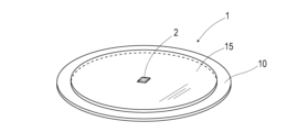
磁気マーカ1(図1)は、磁石シート10の表面に、反射シート15を積層して構成されている。反射シート15は、再帰反射特性を呈する反射部及び反射層の一例をなしている。磁気マーカ1は、直径100mm、厚さ2mmの扁平な円形状を呈している。この磁気マーカ1は、例えば、路面への接着接合が可能である。接着剤として、例えば、溶融状態のアスファルトを利用することも良い。
The magnetic marker 1 ( FIG. 1 ) is constructed by laminating a
磁石シート10は、磁気発生源としての磁石の一例である。本例の磁石シート10は、直径100mm、厚さ1.5mmの円形状の等方性フェライトラバーマグネットである。この磁石シート10の最大エネルギー積(BHmax)は、約6.4kJ/立方mである。
The
反射シート15は、直径100mm、厚さ0.5mmの円形状の樹脂製シートである。小片状のシート体の一例をなすこの反射シート15では、直径数10~100μmの高屈折率のガラスビーズ球が内部に分散配置されている。ガラスビーズ球を含む反射シート15は、入射した光の少なくとも一部を入射方向に向けて反射(再帰反射)する光学的な特性を備えている。特に、本例の反射シート15は、レーザ光を高効率で再帰反射するように光学的特性が調整されている。
The
磁気マーカ1は、例えば、大判シート状の等方性フェライトラバーマグネットの表面に、大判シート状の反射部材を積層して中間シート(図示略)を得た後、打ち抜き加工により円形状を打ち抜いて作成できる。磁気マーカ1の外周は、打ち抜きの際の切断面のままであっても良い。一般に、酸化鉄を主原料とするフェライトラバーマグネットは、酸化等による劣化のおそれが少なく、切断面に保護層やコーティング層を設ける必要性が少ないからである。
For example, the
なお、本例の反射シート15に代えて、高屈折率のガラスビーズ球を塗料の中に混入させた再帰反射塗料による塗膜層である反射層を、磁石シート10の表面に形成することも良い。例えば、大判シート状の等方性フェライトラバーマグネットの表面に塗膜層を設けた後、打ち抜き加工により円形状を打ち抜いて磁気マーカを作成しても良い。円形状の磁石シート10の表面に再帰反射塗料の塗膜層を形成することで、磁気マーカを作製しても良い。さらに塗料に代えて、高屈折率のガラスビーズ球を分散させた樹脂材料を採用し、この樹脂材料によるコーティング層を磁石シート10の表面に形成しても良い。樹脂材料は、例えば、エポキシ樹脂などの透明な樹脂材料であっても良い。磁石シート10の表面を覆う樹脂材料が硬化した後、樹脂材料の表面を溶かす処理を施すことで、ガラスビーズ球を外表面に露出させることも良い。粒子をなすガラスビーズ球に代えて、アルミナなどの金属粉(粉体)を採用することも良い。樹脂材料に代えて、アスファルトなどの高分子材料を採用することも良い。
Instead of the
以上のように構成された磁気マーカ1は、例えば、図2のように車線500の中央に沿って配置される。例えば2m間隔で配置される磁気マーカ1は、車線逸脱警報や車線維持機能や自動運転などの各種の運転支援に利用できる。
The
例えば車線維持機能を有する車両5は、図3のごとく、車線維持機能を実現するための制御ユニット61に加えて、磁気マーカ1を磁気的に検出するためのセンサアレイ51や、磁気マーカ1を光学的に検出するためのライダーユニット62等を備えている。さらに車両5は、半自動の走行を実現するための装備として、操舵角を調整する操舵ユニット65や、車速を調節するためのエンジンコントロールユニット66等を備えている。
For example, a
次に、磁気装置の一例であるセンサアレイ51、測距装置の一例であるライダーユニット62、処理回路の一例である制御ユニット61について概説する。
(センサアレイ)
センサアレイ51は、複数の磁気センサCn(nは1~15までの整数。)と、磁気センサCnの磁気計測値を処理する検出処理回路510と、を含めて構成されている。センサアレイ51は、磁気センサC1~15が一定の間隔を空けて一直線上に配列された棒状のユニットである。センサアレイ51は、棒状の長手方向が車幅方向に沿うように車両5に取り付けられる。
Next, the
(sensor array)
The
磁気センサCnとしては、例えば、MI(Magneto Impedance)センサを利用できる。MIセンサは、アモルファスワイヤなどの感磁体のインピーダンスが外部磁界に応じて敏感に変化するという公知のMI効果(Magneto Impedance Effect)を利用する高感度の磁気センサである。磁気センサCnは、アモルファスワイヤの長手方向に感度を有している。 For example, an MI (Magneto Impedance) sensor can be used as the magnetic sensor Cn. The MI sensor is a highly sensitive magnetic sensor that utilizes the well-known MI effect (Magneto Impedance Effect), in which the impedance of a magnetosensitive material such as an amorphous wire changes sensitively in response to an external magnetic field. The magnetic sensor Cn has sensitivity in the longitudinal direction of the amorphous wire.
本例の磁気センサCnは、直交する2方向に沿う2本のアモルファスワイヤを備えている。磁気センサCnは、センサアレイ51が上記のように車両5に取り付けられたとき、2本のアモルファスワイヤが進行方向及び車幅方向に沿うように構成されている。車両5に組み付けられたセンサアレイ51の磁気センサCnは、車両5の進行方向に作用する磁気成分、および車幅方向に作用する磁気成分を検出できる。
The magnetic sensor Cn of this example has two amorphous wires extending in two orthogonal directions. The magnetic sensor Cn is configured so that two amorphous wires extend along the traveling direction and the vehicle width direction when the
例えばいずれかの磁気センサCnが、進行方向に移動して磁気マーカ1の真上を通過するとき、進行方向の磁気計測値は、図4に例示する経時変化のグラフのように、磁気マーカ1の前後で正負が反転すると共に、磁気マーカ1の真上の位置でゼロを交差するように変化する。したがって、車両5の走行中では、いずれかの磁気センサCnが検出する進行方向の磁気について、その正負が反転するゼロクロスX1が生じたとき、センサアレイ51が磁気マーカ1の真上に位置すると判断できる。
For example, when one of the magnetic sensors Cn moves in the direction of travel and passes directly above the
また例えば、磁気センサCnと同じ仕様の磁気センサについて、磁気マーカ1の真上を通過する車幅方向の仮想線に沿う移動を想定してみる。この磁気センサによる車幅方向の磁気計測値は、磁気マーカ1を挟んだ両側で正負が反転すると共に、磁気マーカ1の真上の位置でゼロを交差するように変化する。15個の磁気センサCnを車幅方向に配列したセンサアレイ51の場合には、図5に例示する磁気分布のように、磁気マーカ1を介してどちらの側にあるかによって磁気センサCnが検出する車幅方向の磁気の正負が異なってくる。
Further, for example, let us assume that a magnetic sensor having the same specifications as the magnetic sensor Cn is moved along a virtual line passing directly above the
つまり、図5の磁気分布中のゼロクロスX2の位置が磁気マーカ1の真上の位置となる。例えば同図の場合、磁気センサC9とC10との中間辺りのC9.5のゼロクロスX2の位置が磁気マーカ1の真上の位置(以下、磁気マーカ1の位置という。)となる。ここで、センサアレイ51では、隣り合う磁気センサCnの間隔が10cmであると共に、磁気センサC8が車両5の車幅方向の中心となっている。したがって、図5の場合であれば、車両5の車幅方向の中心を基準として右側に(9.5-8)×10cm=15cmずれた位置が磁気マーカ1の位置となる。
That is, the position of the zero cross X2 in the magnetic distribution of FIG. For example, in the case of the figure, the position of the zero cross X2 of C9.5 in the middle between the magnetic sensors C9 and C10 is the position right above the magnetic marker 1 (hereinafter referred to as the position of the magnetic marker 1). Here, in the
例えば車幅方向において車両5が左側に寄って走行すると、センサアレイ51に相対して磁気マーカ1が右側にずれて、例えば図5のごとくゼロクロスX2の位置が磁気センサC8よりも右側の正値となる。車両5が右側に寄ったときの横ずれ量を正側とし左側に寄ったときの横ずれ量を負側とすると、例えば図5の場合には、磁気マーカ1の位置である上記の(9.5-8)×10cm=15cmの正負を反転した(-15)cmが車両5の横ずれ量となる。
For example, when the
ここで、磁気センサCnが磁気マーカ1を磁気的に検出する処理の内容を図6を参照して説明する。
検出処理回路510(図3)は、磁気センサCnの進行方向の磁気計測値を取得する(S101)。そして、検出処理回路510は、少なくともいずれかの磁気センサCnの進行方向の磁気計測値の経時変化につき、図4のX1に相当するゼロクロスの検出を試みる(S102)。検出処理回路510は、このゼロクロスを検出するまで(S102:NO)、磁気センサCnの進行方向の磁気計測値を繰り返し取得する(S101)。
Here, the contents of the process of magnetically detecting the
The detection processing circuit 510 (FIG. 3) acquires the magnetic measurement value of the traveling direction of the magnetic sensor Cn (S101). Then, the
検出処理回路510は、進行方向の磁気計測値の経時変化につき、図4の経時変化におけるX1に相当するゼロクロスを検出できたとき(S102:YES)、磁気マーカ1の真上にセンサアレイ51が位置していると判断する。なお、磁気マーカ1の検出判断については、図4のX1に相当するゼロクロスの検出に加えて、進行方向の磁気計測値の経時変化の割合、すなわち磁気計測値の微分値(差分値)の大きさが所定の閾値以上であるという条件を設定すると良い。
When the
検出処理回路510は、図4の磁気分布中のX1に相当するゼロクロスの検出に応じて磁気マーカ1を検出できたとき、磁気センサCnが同じタイミングで計測した車幅方向の磁気計測値の分布を表す図5の磁気分布を取得する(S103)。
When the
検出処理回路510は、磁気センサCnの車幅方向の磁気計測値の分布である図5の磁気分布について、X2に相当するゼロクロスの車幅方向の位置を特定する(S104)。そして、このゼロクロスの車幅方向の位置に基づいて、磁気マーカ1に対する車両5の車幅方向の横ずれ量を特定する(S105)。具体的には、検出処理回路510は、図5のX2に相当するゼロクロスの車幅方向の位置を示す値の正負を反転し、車幅方向の車両5の横ずれ量とする。
The
(ライダーユニット)
ライダーユニット62(図3)は、先行車両や前方の障害物を検知するためのユニットである。ライダーユニット62は、レーザ光の反射を利用して、前方150mまでの範囲の先行車両や障害物を光学的に検知する。例えば、ACC(Adaptive Cruise Control)機能や、衝突軽減ブレーキ機能などの実現のために、多くの車両5にライダーユニット62が搭載されている。このライダーユニット62は、反射シート15を備える磁気マーカ1(図1)の光学的な検出に活用できる。
(rider unit)
The rider unit 62 (Fig. 3) is a unit for detecting preceding vehicles and obstacles ahead. The
ライダーユニット62は、レーザ光をパルス発光する光源、対象物からの反射光を受光する受光部、発光から受光までの経過時間(反射時間)を計測する時間計測部、反射時間から距離を演算する距離演算部、を備えている。さらにライダーユニット62は、レーザ光を縦方向、横方向にビーム走査させる光学機構部を備えている。
The
光学機構部は、例えばレーザ光を反射して前方に投射するポリゴンミラー(多面鏡)と、ポリゴンミラーを高速回転させる駆動部と、を有している。光源から発射されたレーザ光は、ポリゴンミラーによって反射されて車両5の前方に向かう。光学機構部は、ポリゴンミラーによってレーザ光の方向を物理的に変更することで、測距エリア620(図8)となる前方の2次元領域をレーザ光によってビーム走査する。
The optical mechanism section has, for example, a polygon mirror (polygonal mirror) that reflects laser light and projects it forward, and a driving section that rotates the polygon mirror at high speed. A laser beam emitted from a light source is reflected by a polygon mirror and directed forward of the
ライダーユニット62は、図7の測距処理のフロー図で示すように、パルスレーザ光を発光した後(S201)、対象物からの反射光を受光するまでの経過時間を計時する(S202、S203:NO→S202)。ライダーユニット62は、反射光を受光すると(S203:YES)、発光から反射光の受光までに要した経過時間から対象物までの距離を演算する(S204)。
7, the
ライダーユニット62は、レーザ光を繰り返しパルス発光するように発光部を制御する。また、ライダーユニット62は、レーザ光のパルス発光と同期してポリゴンミラーを回転させ、レーザ光のビーム走査を実現する。ライダーユニット62は、テレビジョン等の画像伝送の際に利用される画像走査と同様、水平方向の各行を上から下に順番にビーム走査することで、図8のごとく、測距エリア620となる2次元領域の全域のビーム走査を実現する。
The
ライダーユニット62は、ビーム走査中の各点について測距処理(図7)を実行することで、前方の測距エリア620内の各点に距離データがひも付けられた距離画像を生成する。距離画像は、測距エリア620内の各点までの距離及び方位を表している。車両5の後端面に配設されたリフレクターや、磁気マーカ1の反射シート15は、再帰反射特性を有している。それ故、ライダーユニット62は、車両5や磁気マーカ1からの反射光を確実性高く受光でき、これらの対象物までの距離及び方位を確実性高く特定できる。
The
(制御ユニット)
制御ユニット61(図3)は、磁気マーカ1を検出するようにライダーユニット62及びセンサアレイ51を制御すると共に、車線維持走行を実現するための車両制御を実行する。制御ユニット61によるこの車両制御の内容について、図9のフロー図を参照しながら説明する。なお、このフロー図では、先行車両と適切な車間距離を空けて追従して走行するための車速調節制御の内容を省略している。
(Controller unit)
The control unit 61 (FIG. 3) controls the
図9のごとく、制御ユニット61は、まず、ライダーユニット62を利用して磁気マーカ1の光学的な検出処理を実行する(S301)。具体的には、制御ユニット61は、ライダーユニット62の測距処理(図7)による距離画像を取得し、この距離画像を処理することで前方に配置された磁気マーカ1を光学的に検出する。
As shown in FIG. 9, the
制御ユニット61は、ライダーユニット62による距離画像を参照し、検出された各磁気マーカ1までの距離及び方位を取得する(S302、図10参照。)。そして、制御ユニット61は、前方の車線500に配列された複数の磁気マーカ1の距離及び方位に基づいて、複数の磁気マーカ1を通過する3次元的な軌跡を演算し、目標軌跡1R(図10参照。)に設定する(S303)。
The
制御ユニット61は、目標軌跡1Rに沿って走行するための目標操舵角を演算すると共に(S304)、直近の磁気マーカ1に到達する時点を予測到達時点として推定する(S305)。例えば、現在時刻tr、直近の磁気マーカ1までの距離D、車両5の速度Vとしたとき、予測到達時点toは、tr+D/Vとなる。
The
制御ユニット61は、ステップS304で演算した目標操舵角を制御値として目標軌跡1Rに沿って車両5を走行させるための車両制御を実行する(S306)。そして制御ユニット61は、予測到達時点toに到達するまでの間(S307:NO)、ステップS304で演算した目標操舵角による車両制御を実行する(S306)。制御ユニット61は、このようにステップS306の車両制御を実行することで、目標軌跡1R(図10)に沿う車両走行を実現しようとする。
The
予測到達時点toに達したとき(S307:YES)、制御ユニット61は、センサアレイ51を利用して磁気マーカ1を磁気的に検出するための検出処理を試みる(S308)。制御ユニット61は、磁気マーカ1を検出できるまで(S309:NO)、磁気的な検出処理(S308)を繰り返し実行する。
When the predicted arrival time to is reached (S307: YES), the
磁気マーカ1を磁気的に検出できたとき(S309:YES)、制御ユニット61は、センサアレイ51が特定した車両5の横ずれ量を取得する(S310)。そして、制御ユニット61は、磁気マーカ1に対する車両5の横ずれ量を抑制できるように目標操舵角を補正する(S311)。そして制御ユニット61は、補正された目標操舵角を制御目標値とし、車両制御を実行する(S312)。
When the
なお、ステップS309の判断について、時間的な制限を組み合わせることも良い。例えば、予測到達時点toの経過後の所定時間が経過した場合、磁気マーカ1を検出できなかったと判断してそのままステップS312に移行しても良い。この場合には、横ずれ量による目標操舵角の補正が実施されないが、ステップS304で演算された目標操舵角による車両制御が可能である。
It should be noted that the judgment in step S309 may be combined with a time limit. For example, if a predetermined time has elapsed after the predicted arrival time to has passed, it may be determined that the
以上のように、再帰反射特性を有する反射シート15を備える磁気マーカ1は、磁気マーカ1に到達する手前の位置から光学的に検出可能である。ライダーユニット62を備える車両5であれば、車線500に沿うように配列された前方の複数の磁気マーカ1を同時に検出でき、これらの磁気マーカ1を通過する軌跡を目標軌跡1Rに設定できる。目標軌跡1Rを設定すれば、車線500に沿う滑らかな車線維持走行を実現できる。さらに、車両5が通過する際、磁気マーカ1を磁気的に検出すれば、磁気マーカ1に対する車両5の横ずれ量を高精度で特定できる。車両5の横ずれ量によって目標操舵角を補正すれば、車線500内での車幅方向の車両位置の調整が可能である。
As described above, the
ここで、磁気マーカ1を通過する際の横ずれ量によって車両の操舵輪を操舵する制御を比較例として説明する。この比較例の制御では、磁気マーカ1を通過する毎の小刻みな操舵制御に起因して車両のふらつきが生じるおそれがある。このような車両のふらつきは、例えば、近くを見て車線内の車両の位置(車幅方向の位置)を調整しようとする初心者の運転によって生じるふらつきに似ている。このような車両のふらつきを低減するには、制御ゲインを小さく設定すれば良いが、制御ゲインが小さいと、カーブ区間への進入時の制御遅れが問題になる可能性が高い。
Here, control for steering the steered wheels of the vehicle based on the amount of lateral deviation when passing the
例えば、十分に経験を積んだ運転者は、前方の道路形状を全体的に捉えてハンドルを操作するので、道路形状に追従する滑らかな運転を実現できる。目標軌跡1Rに基づいて目標操舵角を設定すると共に、車両5の横ずれ量によって目標操舵角を補正する本例の制御は、経験を積んだ運転者による運転に似ている。前方の磁気マーカ1を通過するラインを目標軌跡1Rに設定することは、前方の道路形状の全体的な把握に相当している。磁気マーカ1に対する横ずれ量によって操舵角を直接、制御するのではなく、横ずれ量によって目標操舵角を補正する本例の制御によれば、制御遅れを生じさせることなく車両5のふらつきを抑制できる。
For example, a well-experienced driver operates the steering wheel with an overall understanding of the shape of the road ahead, so smooth driving following the shape of the road can be realized. The control of this example, in which the target steering angle is set based on the
本例では、磁石シート10の表面の全部を覆う反射シート15を含む磁気マーカ1を例示している。反射シート15は、磁石シート10の表面の一部を覆うシートであっても良く、磁石シート10よりも大判のシートであっても良い。本例では、磁石シート10、及び反射シート15として円形状のものを例示している。磁石シート10及び反射シート15の形状は、円形状に限らず三角形や四角形などの多角形状であっても良く、磁石シート10及び反射シート15のうちの一方を円形状にし、他方を多角形状にしても良い。
In this example, the
磁石シート10の表面の一部に、再帰反射塗料による塗膜層を設けることも良い。また、本例では、厚さ1.5mmの磁石シート10を例示したが、より厚い磁石を採用する場合には、反射シートあるいは再帰反射塗料の塗膜層等による反射層を、磁石の外周側面に設けることも良い。
A part of the surface of the
タグリーダ(図示略)で読み取り可能なRFIDタグ2を含む図11の磁気マーカ1を採用することも良い。RFIDタグ2によれば、磁気マーカ1の敷設位置のデータや制限速度など運転支援に役立つ各種情報を車両に向けて出力できる。同図の磁気マーカ1では、磁石シート10の表面に、シート状のRFIDタグ2が配置されている。この磁気マーカ1では、RFIDタグ2が配置された磁石シート10の表面に、反射部をなす反射シート15が積層されている。この反射シート15は、磁石シート10の表面に配置されたRFIDタグ2を保護するための保護シートとしても機能する。
A
本例では、電磁波としてレーザ光などの光を例示し、磁気マーカ1の検出処理を実行する装置としてライダーユニット62を例示している。ミリ波等の電波(電磁波)を利用して磁気マーカ1を検出することもできる。ミリ波レーダによって磁気マーカ1を検出する場合には、車幅方向に延在する畝状のリブを設けた反射シートを採用することも良い。ミリ波などの電波は直進性が高いため、表面が平らな反射シートの場合、ミリ波を十分に再帰反射できないおそれがある。リブを設けた反射シートであれば、ミリ波の再帰反射率を高めることができる。なお、リブは、レーザ光の再帰反射率を高めるためにも有用に作用する。反射シートに代えて、再帰反射特性を呈するリブ(反射リブ)を磁石シートの表面側に設けることも良い。リブは、滑り止めとしても活用可能である。
In this example, light such as laser light is exemplified as the electromagnetic wave, and the
本例では、磁石シート10の表面に反射シート15を積層することにより磁石シート10の外表面側に形成された反射層を、磁気マーカ1の反射部として例示している。磁石シート10の表面に、保護シートと反射シートとを、該反射シートを外側にして積層することも良い。この場合、厳密には、磁石シート10の外表面に反射層が形成されているとは言えないが、磁石シート1の外表面側に反射層が形成されていると言える。
In this example, the reflection layer formed on the outer surface side of the
(実施例2)
本例は、実施例1の磁気マーカに基づいて、形態をテープ状に変更した例である。この内容について、図12及び図13を参照して説明する。
本例の磁気マーカ1(図12)は、幅150mmの連続シート状の反射テープ151の裏面(反射面の裏面)に、間隔を空けて複数の磁石シート10が配置された連続シート状(テープ状)の磁気マーカである。連続シート状の磁気マーカ1は、車線500の中央に沿って途切れなく敷設される(図13参照。)。磁気マーカ1は、反射テープ151の反射面が上面となるように路面に貼り付けられ、磁石シート10は、反射テープ151の裏側となる。磁気マーカ1は、実施例1と同じ仕様の車両によって光学的、磁気的に検出可能である。
(Example 2)
This example is based on the magnetic marker of Example 1, but modified to have a tape shape. This content will be described with reference to FIGS. 12 and 13. FIG.
The magnetic marker 1 (FIG. 12) of this example is a continuous sheet (tape) in which a plurality of
連続シート状の磁気マーカ1では、磁石シート10が例えば2m間隔で位置している。磁気的な検出処理によれば、実施例1と同様に、磁石シート10を検出可能である。
一方、本例の連続シート状の磁気マーカ1では、磁石シート10を保持するテープ(連続シート)として反射テープ151が採用されている。したがって、磁気マーカ1に対する光学的な検出処理の結果が、実施例1とは相違する。
In the continuous sheet-like
On the other hand, in the continuous sheet-like
本例の磁気マーカ1をライダーユニットが光学的に検出する場合、図13のハッチング領域のごとく、磁気マーカ1を連続的に検出可能である。ライダーユニットによる距離画像に基づけば、同図のハッチング領域の各位置までの距離及び方位を取得できる。車両側では、ハッチング領域を通る軌跡を目標軌跡1Rとして設定可能である。
When the lidar unit optically detects the
反射テープ151の幅は、本例のように磁石シート10の直径を超える幅であることは必須の構成ではない。磁石シート10の直径よりも幅狭の反射テープであっても良い。
なお、本例に代えて、車線500の中央に沿って間隔を空けて磁石シート10を敷設した後、磁石シート10を通過するように車線500の中央に沿って再帰反射塗料による塗装ラインを形成することも良い。このライン幅としては、磁石シート10の直径を超える幅であっても良く、磁石シート10の直径よりも狭い幅であっても良い。
It is not essential that the width of the
Instead of this example, after laying the
本例では、反射テープ151の裏面に磁石シート10を配置した磁気マーカの例である。磁石シート10を保護するための保護テープあるいは保護シートを、反射テープ151に貼り合わせることも良い。保護シートは、磁石シート10を被う小片状のシートであっても良い。保護テープは、反射テープと同様の連続テープであっても良い。反射テープ151の反射面に磁石シート10を配置することも良い。この場合には、レーザ光の電磁波を反射しない領域を磁石シート10の敷設位置と特定できる。
なお、その他の構成及び作用効果については、実施例1と同様である。
This example is an example of a magnetic marker in which the
Other configurations and effects are the same as those of the first embodiment.
(実施例3)
本例は、実施例1の磁気マーカに基づいて、反射部の態様を変更した例である。この内容について、図14及び図15を参照して説明する。
本例の磁気マーカ1は、磁石シート10そのものであって、実施例1で例示の反射シートを備えていない。本例の磁気マーカ1では、反射部をなす直径数10~100μmの高屈折率のガラスビーズ球108が磁石シート10の内部に分散配置され、磁気マーカ1の外表面に一部のガラスビーズ球108が露出している。
(Example 3)
This example is based on the magnetic marker of Example 1, and is an example in which the mode of the reflector is changed. This content will be described with reference to FIGS. 14 and 15. FIG.
The
次に、本例の磁気マーカ1の構成を明確にするために磁気マーカ1の作製方法を、図15を参照して説明する。
磁気マーカ1は、大判シート状の磁性シート104から打ち抜いて作成される。この磁性シート104を作製するに当たっては、まず、磁粉111(本例では磁性材料である酸化鉄の粉末、粉体)とガラスビーズ球108とを、基材となる溶融状態の樹脂材料中に混練したスラリー113を生成する。そして、このスラリー113を所定形状に成型して乾燥し、ペレット101を得る。磁性シート104は、圧延ローラ102によりペレット101をシート状に薄く引き延ばしたものである。ガラスビーズ球108が外表面に多く露出するよう、シンナー等の溶剤を利用して磁性シート104の表面を溶かす処理を実施することも良い。
Next, in order to clarify the configuration of the
The
本例におけるガラスビーズ球108は、反射部をなす粒子の一例である。ガラスビーズ球108に代えて、アルミナなどの金属粉(粉体)を反射部の一例として含む磁気マーカ(磁石シート)であっても良い。
なお、その他の構成及び作用効果については、実施例1と同様である。
The
Other configurations and effects are the same as those of the first embodiment.
(実施例4)
本例は、実施例1の磁気マーカを検出して利用する方法に関する例である。この内容について、図3、図9、図16及び図17を参照して説明する。
本例は、制御ユニット61による図9中のステップS307の判断内容を、予測到達時点toの所定時間(例えば1秒)前になったか否かの判断に変更した例である。さらに本例では、ステップS309の判断について、例えば予測到達時点toから所定時間(例えば1秒)経過後など時間的な制限を組み合わせている。なお、予測到達時点toの前後の所定時間の長さを等しく設定しても良く、異なる時間を設定しても良い。
(Example 4)
This example relates to a method of detecting and using the magnetic marker of the first embodiment. This content will be described with reference to FIGS. 3, 9, 16 and 17. FIG.
In this example, the
本例の場合、図16のごとく、予測到達時点toを基準として、磁気的な検出処理の実行期間を設定できる。予測到達時点toを基準とした時間的な期間を設定し、その時間的な期間内に磁気的な検出処理を実行すれば、車両5(センサアレイ51)が磁気マーカ1に到達したタイミングで、その磁気マーカ1を効率良く検出できる。磁気マーカ1に車両5が到達していないにも関わらず、無駄に磁気的な検出処理を繰り返す状況を回避でき、誤検出を抑制できる。
In this example, as shown in FIG. 16, the execution period of the magnetic detection process can be set with reference to the predicted arrival time to. If a time period is set with reference to the predicted arrival time to, and the magnetic detection process is executed within that time period, when the vehicle 5 (sensor array 51) reaches the
なお、所定時間としては、1秒間や0.5秒間などの所定の時間的な期間に代えて、所定の距離を車両が通過するのに要する時間を設定することも良い。例えば、所定の距離として0.5mを設定した場合、所定時間は、車速Vにより0.5mを除算して得られた時間となる。 As the predetermined time, instead of a predetermined time period such as 1 second or 0.5 seconds, it is also possible to set the time required for the vehicle to pass a predetermined distance. For example, when 0.5 m is set as the predetermined distance, the predetermined time is the time obtained by dividing the vehicle speed V by 0.5 m.
また、処理回路の一例である制御ユニット61は、図9のステップS305において予測到達時点toを推定する際、併せて、対応する磁気マーカ1に車両5が到達したときの横ずれ量である予測横ずれ量を推定する。具体的には、制御ユニット61は、ステップS304の目標操舵角によって車両5が制御された場合の走行軌跡1E(図17)を推定することで、磁気マーカ1に対する車両5の予測横ずれ量を推定する。制御ユニット61は、センサアレイ51がその磁気マーカ1を磁気的に検出したときに特定された実際の横ずれ量(実際の偏差)と、予測横ずれ量と、を比較する。そして、制御ユニット61は、実際の横ずれ量(実際の偏差)と、予測横ずれ量と、の間に閾値を超える差分(差分横ずれ量)が生じているときに誤検出と判定することで、磁気マーカの検出精度を向上させる(精度向上処理)。
When the
なお、図9中のステップS307の処理を省略することも良い。この場合、ステップS309において磁気マーカを検出できたと判断されたとき、実際の検出時点と、予測到達時点と、を比較すると良い。制御ユニット61は、実際の検出時点と、予測到達時点と、の時間差(差分)が閾値を超えるとき、誤検出と判定すると良い(精度向上処理)。このように誤検出を判定すれば、磁気マーカの検出精度を向上できる。
Note that the process of step S307 in FIG. 9 may be omitted. In this case, when it is determined that the magnetic marker has been detected in step S309, it is preferable to compare the actual detection time and the predicted arrival time. When the time difference (difference) between the actual detection time and the predicted arrival time exceeds a threshold value, the
また、磁気マーカ1に対する車両の実際の横ずれ量と、予測横ずれ量と、の差分横ずれ量の要因は、ライダーユニット62による磁気マーカ1の計測方位の誤差や、操舵制御に適用される目標操舵角の誤差等にある。
Further, the difference between the actual lateral deviation amount and the predicted lateral deviation amount of the vehicle with respect to the
ライダーユニット62では、レーザ光の発射方向を特定する際に基準となる軸が設定されている。ライダーユニット62は、車両の直進方向を示す進行軸と、ライダーユニット62の軸と、の方位的な関係を特定することで、対象物である磁気マーカの方位の計測を可能としている。車両の進行軸とライダーユニット62の軸との間で特定された方位的な関係に誤差があれば、磁気マーカの計測方位に誤差が生じ、制御ユニット61が設定する目標軌跡に誤差が発生する。制御目標である目標軌跡に誤差があれば、制御ユニット61による制御の結果、上記の差分横ずれ量が大きくなる。このように差分横ずれ量は、ライダーユニット62の軸の方位誤差に連動する量である。この差分横ずれ量を利用すれば、ライダーユニット62の軸の較正を実行可能である。ライダーユニット62の軸を較正すれば、測距装置の一例であるライダーユニット62による計測精度を向上でき、差分横ずれ量を抑制できる(精度向上処理)。
In the
例えば、ライダーユニット62の軸が正しい方向よりも右方に振れている誤差がある場合の精度向上処理の内容を説明する。なお、以下の説明では、車両の進行方向を基準として右側の角度を正、左側の角度を負、右側への横ずれを正、左側への横ずれを負とする。また、説明中の括弧内の左右の表示は、左右が入れ替わった場合を示している。
For example, the details of the accuracy improvement process when there is an error that the axis of the
ライダーユニット62の軸が正しい方向よりも右方(左方)に振れている場合、ライダーユニット62が対象物である磁気マーカについて計測する方位は実際の方位よりも左寄り(右寄り)となる。そうすると、目標軌跡が左寄り(右寄り)となって、操舵制御による実際の車両の走行軌跡が左寄り(右寄り)となり、実際の横ずれ量から予測横ずれ量を差し引いた差分横ずれ量が負値(正値)となる可能性が高くなる。この場合、負値(正値)の差分横ずれ量に対して変換係数を乗じて得られる負(正)の角度を、ライダーユニット62の軸の方位に加算することでライダーユニット62の軸を較正すると良い。このように負(正)の角度を加算すれば、右側(左側)に振れたライダーユニット62の軸を左側(右側)に戻す較正が可能である。なお、差分横ずれ量に乗ずる係数については、適宜、設定すると良い。
When the axis of the
また一般に、車両では、操舵輪を含めて車輪の取付に関する誤差が不可避である。車両の整備においては、キャンバー、トーイン、トーアウト、キャスターなどのホイールアライメントの値が許容誤差の範囲内に収まるように調整される。ホイールアライメントには誤差があるため、操舵輪の舵角(操舵角)がゼロ度のとき、車両が直進走行するとは限らない。すなわち、車両の直進走行に対応する操舵角の中立点はゼロ度とは限らない。 In general, in a vehicle, errors in mounting wheels, including steering wheels, are unavoidable. During vehicle maintenance, wheel alignment values such as camber, toe-in, toe-out and caster are adjusted to within tolerances. Since there is an error in the wheel alignment, the vehicle does not always run straight when the steering angle of the steered wheels is zero degrees. That is, the neutral point of the steering angle corresponding to the vehicle running straight is not necessarily zero degrees.
図9中のステップS304において、目標軌跡に対する目標操舵角を精度高く算出するためには、直進走行に対応する操舵角の中立点が精度高く特定されていることが重要である。操舵角の中立点に誤差があれば、目標軌跡に沿って車両を走行させるために制御ユニット61が算出する目標操舵角の精度が低下する。仮に目標操舵角が正しく算出されたとしても、操舵角の中立点に誤差があれば、制御ユニット61による制御により実際に車両が走行する軌跡が目標軌跡からずれてしまい、目標軌跡に対する追従精度が低下する。そして、目標操舵角の精度が十分でなかったり、目標軌跡に対する追従精度が十分でなければ、上記の差分横ずれ量が大きくなる。このように差分横ずれ量は、操舵角の中立点の誤差に連動する量である。この差分横ずれ量を利用すれば、操舵角の中立点の軸の較正を実行可能である。操舵角の中立点を較正すれば、制御ユニット61が算出する目標操舵角の精度、あるいは目標軌跡に対する車両の追従精度を向上でき、差分横ずれ量を抑制できる(精度向上処理)。
In step S304 in FIG. 9, in order to calculate the target steering angle with respect to the target trajectory with high accuracy, it is important that the neutral point of the steering angle corresponding to straight traveling is specified with high accuracy. If there is an error in the neutral point of the steering angle, the accuracy of the target steering angle calculated by the
例えば、操舵角の中立点が、正しい中立点よりも右側(左側)に振れている場合、操舵制御による車両の軌跡が右寄り(左寄り)となり、実際の横ずれ量から予測横ずれ量を差し引いた差分横ずれ量が正値(負値)となる可能性が高くなる。この場合、正値(負値)の差分横ずれ量に変換係数を乗じた正(負)の角度を、操舵角の中立点から減算することで中立点を較正すると良い。このように正(負)の角度を減算すれば、右側(左側)に振れた中立点を左寄り(右寄り)に戻す較正が可能である。
なお、その他の構成及び作用効果は、実施例1と同様である。
For example, when the neutral point of the steering angle deviates to the right (left) from the correct neutral point, the vehicle trajectory due to steering control becomes right (left), and the differential lateral deviation obtained by subtracting the predicted lateral deviation from the actual lateral deviation is calculated. It is more likely that the quantity will be positive (negative). In this case, the neutral point may be calibrated by subtracting the positive (negative) angle obtained by multiplying the positive (negative) differential lateral deviation amount by the conversion coefficient from the neutral point of the steering angle. By subtracting the positive (negative) angle in this way, it is possible to calibrate the neutral point shifted to the right (left) to return to the left (right).
Other configurations and effects are the same as those of the first embodiment.
以上、実施例のごとく本発明の具体例を詳細に説明したが、これらの具体例は、特許請求の範囲に包含される技術の一例を開示しているにすぎない。言うまでもなく、具体例の構成や数値等によって、特許請求の範囲が限定的に解釈されるべきではない。特許請求の範囲は、公知技術や当業者の知識等を利用して前記具体例を多様に変形、変更あるいは適宜組み合わせた技術を包含している。 Although the specific examples of the present invention have been described in detail above as examples, these specific examples merely disclose an example of the technology encompassed by the claims. Needless to say, the scope of claims should not be construed to be limited by the configurations and numerical values of specific examples. The scope of claims encompasses techniques in which the above-described specific examples are variously modified, changed, or appropriately combined using known techniques and knowledge of those skilled in the art.
1 磁気マーカ
10 磁石シート(磁石)
108 ガラスビーズ球(反射部)
15 反射シート(反射部、反射層)
151 反射テープ(反射部、反射層)
2 RFIDタグ
5 車両
500 車線
51 センサアレイ(磁気装置)
Cn 磁気センサ(nは1~15の自然数)
510 検出処理回路
61 制御ユニット(処理回路)
62 ライダーユニット(測距装置)
65 操舵ユニット
66 エンジンコントロールユニット
1
108 glass bead sphere (reflective part)
15 reflective sheet (reflective part, reflective layer)
151 reflective tape (reflective part, reflective layer)
2
Cn magnetic sensor (n is a natural number from 1 to 15)
510
62 lidar unit (ranging device)
65
Claims (13)
磁気発生源としての磁石と、入射した電磁波の少なくとも一部を再帰反射する反射部と、を含み、
外周側面のうちの少なくとも一部の側面が前記反射部によって形成されていると共に、当該反射部によって形成された前記少なくとも一部の側面が全周に亘っており、
前記走路に敷設された際、前記反射部によって形成された側面が、車両が前方に投射する電磁波の入射方向に面する磁気マーカ。 A magnetic marker laid at intervals on a track on which a vehicle travels,
including a magnet as a magnetic source and a reflector that retroreflects at least part of the incident electromagnetic wave,
At least a portion of the outer peripheral side surface is formed by the reflecting portion, and the at least a portion of the side surface formed by the reflecting portion extends over the entire circumference,
A magnetic marker in which a side surface formed by the reflecting portion faces an incident direction of an electromagnetic wave projected forward by a vehicle when installed on the track.
前記少なくとも一部の側面が該反射層によって形成されている磁気マーカ。 2. The reflective part according to claim 1, wherein the reflective part is a reflective layer formed on the outer surface side of the magnet,
A magnetic marker , wherein the at least one side surface is formed by the reflective layer .
前記反射部をなす粉体あるいは粒子の一部が前記少なくとも一部の側面に露出している磁気マーカ。 2. The magnetic marker according to claim 1 , wherein said magnetic marker comprises powder made of a magnetic material forming said magnet and powder or particles forming said reflecting portion dispersed in a base material,
A magnetic marker in which a portion of the powder or particles forming the reflecting portion is exposed on the side surface of at least the portion .
車両は、前記電磁波の発射方向及び前記電磁波の反射に要した時間に基づいて対象物の方位及び距離を取得する測距装置と、前記磁気マーカを磁気的に検出して該磁気マーカに対する車両の横ずれ量を特定する磁気装置と、目標軌跡に沿って車両が走行するための目標操舵角を算出し、該目標軌跡に沿って走行するように車両を制御する処理回路と、を備えており、
車両の前方に向けて前記電磁波を発射して前記磁気マーカを検出し、当該磁気マーカの方位及び距離を計測する処理と、
前記電磁波を利用して検出された磁気マーカに車両が到達すると予測される予測到達時点、あるいは当該磁気マーカに対して予測される車両の車幅方向における偏差(横ずれ量)である予測横ずれ量を推定する処理と、
当該磁気マーカを実際に検出した時点である実際の検出時点、あるいは当該磁気マーカに対する車両の実際の偏差(横ずれ量)を特定する処理と、を含み、
前記実際の検出時点と前記予測到達時点との比較結果、及び前記実際の偏差(横ずれ量)と前記予測横ずれ量との比較結果のうち、少なくともいずれか一方の比較結果を利用し、前記測距装置による計測精度、前記磁気装置による前記磁気マーカの検出精度、前記処理回路が算出する目標操舵角の精度、及び前記目標軌跡に対する車両の追従精度のうちの少なくともいずれかの精度の向上を図る精度向上処理を実行する磁気マーカの利用方法。 The method includes a magnet as a magnetic source and a reflector that retroreflects at least part of incident electromagnetic waves, and detects and utilizes a magnetic marker laid on the road of the vehicle while the vehicle is running. hand,
The vehicle includes a distance measuring device that obtains the direction and distance of an object based on the emission direction of the electromagnetic wave and the time required for the electromagnetic wave to reflect, a magnetic device for determining the amount of lateral deviation; and a processing circuit for calculating a target steering angle for the vehicle to travel along the target trajectory and controlling the vehicle to travel along the target trajectory,
A process of emitting the electromagnetic wave toward the front of the vehicle to detect the magnetic marker and measuring the azimuth and distance of the magnetic marker;
A predicted arrival time at which the vehicle is predicted to reach the magnetic marker detected using the electromagnetic waves, or a predicted lateral deviation amount, which is a deviation (amount of lateral deviation) of the vehicle in the vehicle width direction predicted with respect to the magnetic marker. a process of estimating;
a process of identifying the actual detection time, which is the time when the magnetic marker is actually detected, or the actual deviation (lateral deviation amount) of the vehicle from the magnetic marker,
using at least one of a comparison result between the actual detection time and the predicted arrival time and a comparison result between the actual deviation (amount of lateral deviation) and the predicted amount of lateral deviation; Accuracy for improving at least one of measurement accuracy by a device, detection accuracy of the magnetic marker by the magnetic device, accuracy of the target steering angle calculated by the processing circuit, and accuracy of vehicle tracking with respect to the target trajectory. A method of using magnetic markers to perform an enhancement process.
車両は、前記電磁波の発射方向及び前記電磁波の反射に要した時間に基づいて対象物の方位及び距離を取得する測距装置と、前記磁気マーカを磁気的に検出して該磁気マーカに対する車両の横ずれ量を特定する磁気装置と、目標軌跡に沿って車両が走行するための目標操舵角を算出し、該目標軌跡に沿って走行するように車両を制御する処理回路と、を備えており、
車両の前方に向けて前記電磁波を発射して前記磁気マーカを検出し、当該磁気マーカの方位及び距離を計測する処理と、
前記電磁波を利用して検出された磁気マーカに車両が到達すると予測される予測到達時点を推定する処理と、を含み、
前記磁気装置は、前記予測到達時点を基準とした時間的な区間において磁気マーカを磁気的に検出するための検出処理を実行し、
当該時間的な区間が経過したときには前記磁気マーカが未検出であっても前記検出処理を中断する磁気マーカの利用方法。 The method includes a magnet as a magnetic source and a reflector that retroreflects at least part of incident electromagnetic waves, and detects and utilizes a magnetic marker laid on the road of the vehicle while the vehicle is running. hand,
The vehicle includes a distance measuring device that obtains the direction and distance of an object based on the emission direction of the electromagnetic wave and the time required for the electromagnetic wave to reflect, a magnetic device for determining the amount of lateral deviation; and a processing circuit for calculating a target steering angle for the vehicle to travel along the target trajectory and controlling the vehicle to travel along the target trajectory,
A process of emitting the electromagnetic wave toward the front of the vehicle to detect the magnetic marker and measuring the azimuth and distance of the magnetic marker;
a process of estimating a predicted arrival time at which the vehicle is expected to reach the magnetic marker detected using the electromagnetic wave;
The magnetic device performs a detection process for magnetically detecting the magnetic marker in a time interval based on the predicted arrival time,
A method of using a magnetic marker that interrupts the detection process even if the magnetic marker has not been detected when the time interval has elapsed .
車両は、前記電磁波の発射方向及び前記電磁波の反射に要した時間に基づいて対象物の方位及び距離を取得する測距装置と、前記磁気マーカを磁気的に検出して該磁気マーカに対する車両の横ずれ量を特定する磁気装置と、目標軌跡に沿って車両が走行するための目標操舵角を算出し、該目標軌跡に沿って走行するように車両を制御する処理回路と、を備えており、
車両の前方に向けて前記電磁波を発射して前記磁気マーカを検出し、当該磁気マーカの方位及び距離を計測する処理と、
前記電磁波を利用して検出された車両の前方の複数の磁気マーカを通過する軌跡を、前記目標軌跡として設定して前記目標操舵角を算出する処理と、
前記磁気装置によって磁気的に検出された磁気マーカに対する車両の横ずれ量によって前記目標操舵角を補正する処理と、を含む磁気マーカの利用方法。 The method includes a magnet as a magnetic source and a reflector that retroreflects at least part of incident electromagnetic waves, and detects and utilizes a magnetic marker laid on the road of the vehicle while the vehicle is running. hand,
The vehicle includes a distance measuring device that obtains the direction and distance of an object based on the emission direction of the electromagnetic wave and the time required for the electromagnetic wave to reflect, a magnetic device for determining the amount of lateral deviation; and a processing circuit for calculating a target steering angle for the vehicle to travel along the target trajectory and controlling the vehicle to travel along the target trajectory,
A process of emitting the electromagnetic wave toward the front of the vehicle to detect the magnetic marker and measuring the azimuth and distance of the magnetic marker;
a process of calculating the target steering angle by setting a trajectory passing through a plurality of magnetic markers in front of the vehicle detected using the electromagnetic wave as the target trajectory;
and a process of correcting the target steering angle according to the amount of lateral deviation of the vehicle with respect to the magnetic marker magnetically detected by the magnetic device.
Priority Applications (5)
| Application Number | Priority Date | Filing Date | Title |
|---|---|---|---|
| JP2019116765A JP7268498B2 (en) | 2019-06-24 | 2019-06-24 | Magnetic Markers and How to Use Magnetic Markers |
| PCT/JP2020/024093 WO2020262220A1 (en) | 2019-06-24 | 2020-06-19 | Magnetic marker and method for using magnetic marker |
| CN202080044761.0A CN113994231A (en) | 2019-06-24 | 2020-06-19 | Magnetic marker and method for using magnetic marker |
| US17/621,243 US20220396922A1 (en) | 2019-06-24 | 2020-06-19 | Magnetic marker and magnetic marker using method |
| EP20831082.1A EP3989028A4 (en) | 2019-06-24 | 2020-06-19 | Magnetic marker and method for using magnetic marker |
Applications Claiming Priority (1)
| Application Number | Priority Date | Filing Date | Title |
|---|---|---|---|
| JP2019116765A JP7268498B2 (en) | 2019-06-24 | 2019-06-24 | Magnetic Markers and How to Use Magnetic Markers |
Publications (2)
| Publication Number | Publication Date |
|---|---|
| JP2021002299A JP2021002299A (en) | 2021-01-07 |
| JP7268498B2 true JP7268498B2 (en) | 2023-05-08 |
Family
ID=73995104
Family Applications (1)
| Application Number | Title | Priority Date | Filing Date |
|---|---|---|---|
| JP2019116765A Active JP7268498B2 (en) | 2019-06-24 | 2019-06-24 | Magnetic Markers and How to Use Magnetic Markers |
Country Status (5)
| Country | Link |
|---|---|
| US (1) | US20220396922A1 (en) |
| EP (1) | EP3989028A4 (en) |
| JP (1) | JP7268498B2 (en) |
| CN (1) | CN113994231A (en) |
| WO (1) | WO2020262220A1 (en) |
Families Citing this family (2)
| Publication number | Priority date | Publication date | Assignee | Title |
|---|---|---|---|---|
| JP6965815B2 (en) * | 2018-04-12 | 2021-11-10 | 愛知製鋼株式会社 | Marker detection system and operation method of marker detection system |
| CN116774213B (en) * | 2023-08-24 | 2023-10-13 | 成都艾视特信息技术有限公司 | Navigation method and device for trackless movement mechanism |
Citations (3)
| Publication number | Priority date | Publication date | Assignee | Title |
|---|---|---|---|---|
| JP2000355914A (en) | 1999-06-15 | 2000-12-26 | Kajima Corp | Construction method for lane marker for road coping with high-degree road traffic system |
| WO2017187879A1 (en) | 2016-04-28 | 2017-11-02 | 愛知製鋼株式会社 | Magnetic marker and driving assistance system |
| WO2018022834A1 (en) | 2016-07-29 | 2018-02-01 | 3M Innovative Properties Company | Radar radiation redirecting tape |
Family Cites Families (17)
| Publication number | Priority date | Publication date | Assignee | Title |
|---|---|---|---|---|
| JPS61251911A (en) * | 1985-04-30 | 1986-11-08 | Komatsu Ltd | Method for guiding unattended moving body |
| US4737049A (en) * | 1986-12-29 | 1988-04-12 | Callhan Edward J | Roadway reflector device |
| JPH05265543A (en) * | 1992-03-17 | 1993-10-15 | Hitachi Kiden Kogyo Ltd | Guide line for unmanned carrier and repairing method therefor |
| JPH06187032A (en) * | 1992-12-16 | 1994-07-08 | Yaskawa Electric Corp | Marker for mobile robot and information detector and traveling controller |
| JPH09506301A (en) * | 1993-11-17 | 1997-06-24 | リフレクティヴ テクノロジー インダストリーズ リミテッド | Retroreflective material |
| US6468678B1 (en) * | 1994-11-17 | 2002-10-22 | 3M Innovative Properties Company | Conformable magnetic articles for use with traffic bearing surfaces methods of making same systems including same and methods of use |
| US5684490A (en) * | 1995-03-01 | 1997-11-04 | The Ohio State University | Highway vehicle guidance system |
| WO1997014850A1 (en) * | 1995-10-18 | 1997-04-24 | Minnesota Mining And Manufacturing Company | Conformable magnetic articles underlaid beneath traffic-bearing surfaces |
| US5928761A (en) * | 1997-07-16 | 1999-07-27 | Minnesota Mining And Manufacturing Company | Retroreflective black pavement marking articles |
| US6365262B1 (en) * | 1998-10-20 | 2002-04-02 | 3M Innovative Properties Company | Pavement marking articles having enhanced retroreflectivity under dry or wet conditions and method for making same |
| US20030123930A1 (en) * | 2001-12-31 | 2003-07-03 | Jacobs Gregory F. | Matrix element magnetic pavement marker and method of making same |
| US20030123931A1 (en) * | 2001-12-31 | 2003-07-03 | Khieu Sithya S. | Matrix element pavement marker and method of making same |
| JP2005202478A (en) | 2004-01-13 | 2005-07-28 | Denso Corp | Automatic traveling system for vehicle |
| WO2015026581A2 (en) * | 2013-08-19 | 2015-02-26 | 3M Innovative Properties Company | Retroreflective sheeting including a low elastic modulus layer |
| US9959754B1 (en) * | 2014-01-13 | 2018-05-01 | Evolutionary Markings, Inc. | Pavement marker modules |
| US9892296B2 (en) * | 2014-11-12 | 2018-02-13 | Joseph E. Kovarik | Method and system for autonomous vehicles |
| CN112609605A (en) * | 2016-02-10 | 2021-04-06 | 爱知制钢株式会社 | Roller body |
-
2019
- 2019-06-24 JP JP2019116765A patent/JP7268498B2/en active Active
-
2020
- 2020-06-19 EP EP20831082.1A patent/EP3989028A4/en active Pending
- 2020-06-19 US US17/621,243 patent/US20220396922A1/en active Pending
- 2020-06-19 WO PCT/JP2020/024093 patent/WO2020262220A1/en active Search and Examination
- 2020-06-19 CN CN202080044761.0A patent/CN113994231A/en active Pending
Patent Citations (3)
| Publication number | Priority date | Publication date | Assignee | Title |
|---|---|---|---|---|
| JP2000355914A (en) | 1999-06-15 | 2000-12-26 | Kajima Corp | Construction method for lane marker for road coping with high-degree road traffic system |
| WO2017187879A1 (en) | 2016-04-28 | 2017-11-02 | 愛知製鋼株式会社 | Magnetic marker and driving assistance system |
| WO2018022834A1 (en) | 2016-07-29 | 2018-02-01 | 3M Innovative Properties Company | Radar radiation redirecting tape |
Also Published As
| Publication number | Publication date |
|---|---|
| JP2021002299A (en) | 2021-01-07 |
| US20220396922A1 (en) | 2022-12-15 |
| EP3989028A4 (en) | 2023-08-09 |
| EP3989028A1 (en) | 2022-04-27 |
| CN113994231A (en) | 2022-01-28 |
| WO2020262220A1 (en) | 2020-12-30 |
Similar Documents
| Publication | Publication Date | Title |
|---|---|---|
| CN109669451B (en) | Autonomous driving support apparatus and method | |
| US11042164B1 (en) | Light steering device with an array of oscillating reflective slats | |
| US8744741B2 (en) | Lidars | |
| CN109844562B (en) | Radar generated occupancy grid for autonomous vehicle awareness and planning | |
| KR102174193B1 (en) | Methods and systems for vehicle radar coordinaton and interference reduction | |
| US8970397B2 (en) | Roadside detection system, driver assistance system and roadside detecting method | |
| US11203335B2 (en) | Collision avoidance apparatus and collision avoidance method | |
| JP7268498B2 (en) | Magnetic Markers and How to Use Magnetic Markers | |
| JP6430777B2 (en) | Object detection device | |
| JPH04270402A (en) | Lateral vehicle guide system | |
| JPH09115093A (en) | Device and method for automatically guiding automobile | |
| US10907962B2 (en) | Driving assistance system mounted in vehicle | |
| US11435434B2 (en) | Multibounce target additional data | |
| US11435439B2 (en) | Multibounce target mitigation | |
| US20220128995A1 (en) | Velocity estimation and object tracking for autonomous vehicle applications | |
| JP7028982B2 (en) | Radar processing device | |
| US20210080539A1 (en) | Signal Processing for Near-Field Radar | |
| CN109144071A (en) | AGV traffic control method in a kind of narrow lane | |
| CN110316187A (en) | Automobile and its avoidance obstacle method | |
| US20230221444A1 (en) | Lidar device | |
| JP2020082879A (en) | Driving support system | |
| EP2113790A1 (en) | Improvements in LIDARs | |
| JPH10160486A (en) | Apparatus for detecting position of vehicle | |
| CN115552283A (en) | Method for detecting traffic congestion conditions in a motor vehicle | |
| JPH1062532A (en) | Radar for vehicle |
Legal Events
| Date | Code | Title | Description |
|---|---|---|---|
| A621 | Written request for application examination |
Free format text: JAPANESE INTERMEDIATE CODE: A621 Effective date: 20220204 |
|
| A131 | Notification of reasons for refusal |
Free format text: JAPANESE INTERMEDIATE CODE: A131 Effective date: 20221115 |
|
| A521 | Request for written amendment filed |
Free format text: JAPANESE INTERMEDIATE CODE: A523 Effective date: 20230113 |
|
| TRDD | Decision of grant or rejection written | ||
| A01 | Written decision to grant a patent or to grant a registration (utility model) |
Free format text: JAPANESE INTERMEDIATE CODE: A01 Effective date: 20230322 |
|
| A61 | First payment of annual fees (during grant procedure) |
Free format text: JAPANESE INTERMEDIATE CODE: A61 Effective date: 20230404 |
|
| R150 | Certificate of patent or registration of utility model |
Ref document number: 7268498 Country of ref document: JP Free format text: JAPANESE INTERMEDIATE CODE: R150 |