JP7267939B2 - Two-stage scrambling for transmission of Polar-encoded PDCCH - Google Patents
Two-stage scrambling for transmission of Polar-encoded PDCCH Download PDFInfo
- Publication number
- JP7267939B2 JP7267939B2 JP2019568401A JP2019568401A JP7267939B2 JP 7267939 B2 JP7267939 B2 JP 7267939B2 JP 2019568401 A JP2019568401 A JP 2019568401A JP 2019568401 A JP2019568401 A JP 2019568401A JP 7267939 B2 JP7267939 B2 JP 7267939B2
- Authority
- JP
- Japan
- Prior art keywords
- bits
- crc
- polar
- wtru
- bit
- Prior art date
- Legal status (The legal status is an assumption and is not a legal conclusion. Google has not performed a legal analysis and makes no representation as to the accuracy of the status listed.)
- Active
Links
- 230000005540 biological transmission Effects 0.000 title claims description 36
- 238000000034 method Methods 0.000 claims description 60
- PCHJSUWPFVWCPO-UHFFFAOYSA-N gold Chemical group [Au] PCHJSUWPFVWCPO-UHFFFAOYSA-N 0.000 claims description 12
- 125000004122 cyclic group Chemical group 0.000 claims description 6
- 238000013507 mapping Methods 0.000 description 53
- 230000011218 segmentation Effects 0.000 description 52
- 238000004891 communication Methods 0.000 description 44
- 238000010586 diagram Methods 0.000 description 35
- 238000010276 construction Methods 0.000 description 29
- 239000011159 matrix material Substances 0.000 description 28
- 238000013461 design Methods 0.000 description 24
- 238000005516 engineering process Methods 0.000 description 24
- 108700010388 MIBs Proteins 0.000 description 23
- 230000008569 process Effects 0.000 description 22
- 238000001514 detection method Methods 0.000 description 21
- 230000006870 function Effects 0.000 description 21
- 230000000875 corresponding effect Effects 0.000 description 20
- 241000169170 Boreogadus saida Species 0.000 description 17
- 230000002123 temporal effect Effects 0.000 description 14
- 238000004364 calculation method Methods 0.000 description 12
- 238000013138 pruning Methods 0.000 description 12
- 206010009944 Colon cancer Diseases 0.000 description 11
- 230000002829 reductive effect Effects 0.000 description 11
- 238000012360 testing method Methods 0.000 description 11
- 238000012545 processing Methods 0.000 description 8
- 230000003068 static effect Effects 0.000 description 8
- 238000013459 approach Methods 0.000 description 7
- 238000012937 correction Methods 0.000 description 7
- 238000007726 management method Methods 0.000 description 7
- 238000001228 spectrum Methods 0.000 description 7
- 230000011664 signaling Effects 0.000 description 6
- 230000001960 triggered effect Effects 0.000 description 6
- 101000651958 Crotalus durissus terrificus Snaclec crotocetin-1 Proteins 0.000 description 5
- 102100022887 GTP-binding nuclear protein Ran Human genes 0.000 description 5
- 101150084062 RAN gene Proteins 0.000 description 5
- 230000002596 correlated effect Effects 0.000 description 5
- 239000000969 carrier Substances 0.000 description 4
- 230000002093 peripheral effect Effects 0.000 description 4
- 230000001360 synchronised effect Effects 0.000 description 4
- 101000741965 Homo sapiens Inactive tyrosine-protein kinase PRAG1 Proteins 0.000 description 3
- 102100038659 Inactive tyrosine-protein kinase PRAG1 Human genes 0.000 description 3
- 230000001413 cellular effect Effects 0.000 description 3
- 239000006185 dispersion Substances 0.000 description 3
- 238000009826 distribution Methods 0.000 description 3
- 230000000694 effects Effects 0.000 description 3
- 238000005259 measurement Methods 0.000 description 3
- 238000010295 mobile communication Methods 0.000 description 3
- 206010011878 Deafness Diseases 0.000 description 2
- 101100172132 Mus musculus Eif3a gene Proteins 0.000 description 2
- 230000002776 aggregation Effects 0.000 description 2
- 238000004220 aggregation Methods 0.000 description 2
- 230000008901 benefit Effects 0.000 description 2
- 230000009977 dual effect Effects 0.000 description 2
- 229910001416 lithium ion Inorganic materials 0.000 description 2
- 230000007774 longterm Effects 0.000 description 2
- 238000012544 monitoring process Methods 0.000 description 2
- QELJHCBNGDEXLD-UHFFFAOYSA-N nickel zinc Chemical compound [Ni].[Zn] QELJHCBNGDEXLD-UHFFFAOYSA-N 0.000 description 2
- 230000003287 optical effect Effects 0.000 description 2
- 230000009467 reduction Effects 0.000 description 2
- 238000010187 selection method Methods 0.000 description 2
- 238000004904 shortening Methods 0.000 description 2
- 238000003860 storage Methods 0.000 description 2
- 230000005355 Hall effect Effects 0.000 description 1
- HBBGRARXTFLTSG-UHFFFAOYSA-N Lithium ion Chemical compound [Li+] HBBGRARXTFLTSG-UHFFFAOYSA-N 0.000 description 1
- 101100258328 Neurospora crassa (strain ATCC 24698 / 74-OR23-1A / CBS 708.71 / DSM 1257 / FGSC 987) crc-2 gene Proteins 0.000 description 1
- 102100032835 Oligoribonuclease, mitochondrial Human genes 0.000 description 1
- 101150069124 RAN1 gene Proteins 0.000 description 1
- 101100355633 Salmo salar ran gene Proteins 0.000 description 1
- 230000004913 activation Effects 0.000 description 1
- 230000001174 ascending effect Effects 0.000 description 1
- 230000003190 augmentative effect Effects 0.000 description 1
- 230000006399 behavior Effects 0.000 description 1
- 230000003139 buffering effect Effects 0.000 description 1
- OJIJEKBXJYRIBZ-UHFFFAOYSA-N cadmium nickel Chemical compound [Ni].[Cd] OJIJEKBXJYRIBZ-UHFFFAOYSA-N 0.000 description 1
- 238000004422 calculation algorithm Methods 0.000 description 1
- 230000000052 comparative effect Effects 0.000 description 1
- 238000004590 computer program Methods 0.000 description 1
- 230000001276 controlling effect Effects 0.000 description 1
- 238000005314 correlation function Methods 0.000 description 1
- 230000008878 coupling Effects 0.000 description 1
- 238000010168 coupling process Methods 0.000 description 1
- 238000005859 coupling reaction Methods 0.000 description 1
- 230000009849 deactivation Effects 0.000 description 1
- 230000000593 degrading effect Effects 0.000 description 1
- 230000005713 exacerbation Effects 0.000 description 1
- 239000000446 fuel Substances 0.000 description 1
- 230000002045 lasting effect Effects 0.000 description 1
- 230000000670 limiting effect Effects 0.000 description 1
- 239000004973 liquid crystal related substance Substances 0.000 description 1
- 230000000873 masking effect Effects 0.000 description 1
- 230000005055 memory storage Effects 0.000 description 1
- 229910052987 metal hydride Inorganic materials 0.000 description 1
- 229910052759 nickel Inorganic materials 0.000 description 1
- PXHVJJICTQNCMI-UHFFFAOYSA-N nickel Substances [Ni] PXHVJJICTQNCMI-UHFFFAOYSA-N 0.000 description 1
- -1 nickel metal hydride Chemical class 0.000 description 1
- 230000036961 partial effect Effects 0.000 description 1
- 230000000737 periodic effect Effects 0.000 description 1
- 239000004065 semiconductor Substances 0.000 description 1
- 238000000638 solvent extraction Methods 0.000 description 1
- 230000007704 transition Effects 0.000 description 1
- 238000000411 transmission spectrum Methods 0.000 description 1
Images


Classifications
-
- H—ELECTRICITY
- H04—ELECTRIC COMMUNICATION TECHNIQUE
- H04L—TRANSMISSION OF DIGITAL INFORMATION, e.g. TELEGRAPHIC COMMUNICATION
- H04L1/00—Arrangements for detecting or preventing errors in the information received
- H04L1/004—Arrangements for detecting or preventing errors in the information received by using forward error control
- H04L1/0072—Error control for data other than payload data, e.g. control data
-
- H—ELECTRICITY
- H04—ELECTRIC COMMUNICATION TECHNIQUE
- H04L—TRANSMISSION OF DIGITAL INFORMATION, e.g. TELEGRAPHIC COMMUNICATION
- H04L1/00—Arrangements for detecting or preventing errors in the information received
- H04L1/004—Arrangements for detecting or preventing errors in the information received by using forward error control
- H04L1/0041—Arrangements at the transmitter end
-
- H—ELECTRICITY
- H04—ELECTRIC COMMUNICATION TECHNIQUE
- H04L—TRANSMISSION OF DIGITAL INFORMATION, e.g. TELEGRAPHIC COMMUNICATION
- H04L1/00—Arrangements for detecting or preventing errors in the information received
- H04L1/004—Arrangements for detecting or preventing errors in the information received by using forward error control
- H04L1/0045—Arrangements at the receiver end
-
- H—ELECTRICITY
- H04—ELECTRIC COMMUNICATION TECHNIQUE
- H04L—TRANSMISSION OF DIGITAL INFORMATION, e.g. TELEGRAPHIC COMMUNICATION
- H04L1/00—Arrangements for detecting or preventing errors in the information received
- H04L1/004—Arrangements for detecting or preventing errors in the information received by using forward error control
- H04L1/0056—Systems characterized by the type of code used
- H04L1/0057—Block codes
-
- H—ELECTRICITY
- H04—ELECTRIC COMMUNICATION TECHNIQUE
- H04L—TRANSMISSION OF DIGITAL INFORMATION, e.g. TELEGRAPHIC COMMUNICATION
- H04L1/00—Arrangements for detecting or preventing errors in the information received
- H04L1/004—Arrangements for detecting or preventing errors in the information received by using forward error control
- H04L1/0056—Systems characterized by the type of code used
- H04L1/0061—Error detection codes
-
- H—ELECTRICITY
- H04—ELECTRIC COMMUNICATION TECHNIQUE
- H04L—TRANSMISSION OF DIGITAL INFORMATION, e.g. TELEGRAPHIC COMMUNICATION
- H04L1/00—Arrangements for detecting or preventing errors in the information received
- H04L1/004—Arrangements for detecting or preventing errors in the information received by using forward error control
- H04L1/0056—Systems characterized by the type of code used
- H04L1/0071—Use of interleaving
Description
相互参照
本出願は、2017年6月14日に出願された米国特許仮出願第62/519,396号明細書、2017年8月9日に出願された米国特許仮出願第62/543,117号明細書、2017年8月29日に出願された米国特許仮出願第62/551,722号明細書、2017年9月8日に出願された米国特許仮出願第62/556,292号明細書、2017年9月15日に出願された米国特許仮出願第62/559,394号明細書、2017年9月29日に出願された米国特許仮出願第62/566,256号明細書、2017年11月15日に出願された米国特許仮出願第62/586,429号明細書の優先権を主張するものであり、これらの米国特許仮出願は、それらの全体が参照により本明細書に組み込まれている。
CROSS-REFERENCES This application is based on U.S. Provisional Application No. 62/519,396, filed June 14, 2017; U.S. Provisional Application No. 62/551,722 filed Aug. 29, 2017; U.S. Provisional Application No. 62/556,292 filed Sep. 8, 2017; Sep. 15, 2017 U.S. Provisional Application No. 62/559,394 filed on September 29, 2017 U.S. Provisional Application No. 62/566,256 filed on November 15, 2017 No. 62/586,429, which claims priority to provisional application Ser.
モバイル通信が、発展を続けている。第5世代は、5Gと呼ばれることがある。モバイル通信の以前の(レガシー)世代は、例えば、第4の世代(4G)ロングタームエボリューション(LTE)である可能性がある。モバイル無線通信は、新無線(NR)などの様々な無線アクセス技術(RAT)を実装する。NRに関する使用事例は、例えば、エクストリームモバイルブロードバンド(eMBB:extreme Mobile Broadband)、超高信頼および低レイテンシ通信(URLLC:Ultra High Reliability and Low Latency Communications)、並びに大規模マシンタイプ通信(mMTC:massive Machine Type Communications)を含み得る。 Mobile communications continue to develop. The fifth generation is sometimes called 5G. A previous (legacy) generation of mobile communications may be, for example, the Fourth Generation (4G) Long Term Evolution (LTE). Mobile wireless communications implement various radio access technologies (RATs) such as new radios (NRs). Use cases for NR are, for example, extreme Mobile Broadband (eMBB), Ultra High Reliability and Low Latency Communications (URLLC), and Massive Machine Type Communications (mMTC). Communications).
無線送受信ユニット(WTRU)は、gNBから物理ダウンリンク制御チャネル(PDCCH)送信を受信し得る。PDCCH送信は、WTRUがPDCCH送信に対して早期終了(early termination)を実行し得るように符号化され(例えば、gNBによって符号化され)得る。WTRUが早期終了を実行し得るようにPDCCH送信が符号化される場合、WTRUを対象としない送信は、破棄され(例えば、復号の完了前に破棄され)得る。例えば、PDCCH送信を受信した後、WTRUは、第1のスクランブルシーケンスに基づいてPDCCH送信の第1の復号を実行し得る。第1のスクランブルシーケンスは、WTRU識別子(ID)によって初期化され得るゴールドシーケンス(Gold sequence)を使用して生成され得る。第1の復号が成功しない場合、WTRUは、PDCCH送信がWTRUを対象としない(例えば、WTRUによって破棄される)と決定し得る。第1の復号が成功する場合、WTRUは、第2のスクランブルシーケンスに基づいて受信されたPDCCH送信のアシスタンスビットを追加された(ABA:assistance bit added)Polar復号を実行し得る(例えば、そのときに実行し得る)。第2のスクランブルシーケンスは、WTRU ID(例えば、セル無線ネットワーク一時ID(C-RNTI))であることがある。ABA Polar復号が成功しない場合、WTRUは、PDCCH送信がWTRUを対象としないと決定し得る。Polar復号が成功する場合、WTRUは、CRCを実行してダウンリンク制御情報(DCI)を得てよい。 A wireless transmit/receive unit (WTRU) may receive a physical downlink control channel (PDCCH) transmission from a gNB. PDCCH transmissions may be coded (eg, coded by the gNB) such that the WTRU may perform early termination for PDCCH transmissions. If the PDCCH transmission is coded such that the WTRU may perform early termination, transmissions not intended for the WTRU may be discarded (eg, discarded before decoding is complete). For example, after receiving a PDCCH transmission, a WTRU may perform a first decoding of the PDCCH transmission based on a first scrambling sequence. A first scrambling sequence may be generated using a Gold sequence, which may be initialized by a WTRU identifier (ID). If the first decoding is not successful, the WTRU may determine that the PDCCH transmission is not intended for the WTRU (eg, discarded by the WTRU). If the first decoding is successful, the WTRU may perform assistance bit added (ABA) Polar decoding of the received PDCCH transmission based on the second scrambling sequence (e.g., then ). The second scrambling sequence may be the WTRU ID (eg, Cell Radio Network Temporary ID (C-RNTI)). If the ABA Polar decoding is not successful, the WTRU may decide that the PDCCH transmission is not intended for the WTRU. If the Polar decoding is successful, the WTRU may perform CRC to obtain downlink control information (DCI).
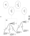
図1Aは、1つまたは複数の開示される実施形態が実装され得る例示的通信システム100を示す図である。通信システム100は、複数の無線ユーザに音声、データ、ビデオ、メッセージング、放送などのコンテンツを提供する多元接続システムであってよい。通信システム100は、複数の無線ユーザが無線帯域幅を含むシステムリソースの共有を通じてそのようなコンテンツにアクセスすることを可能にし得る。例えば、通信システム100は、符号分割多元接続(CDMA)、時分割多元接続(TDMA)、周波数分割多元接続(FDMA)、直交FDMA(OFDMA)、シングルキャリアFDMA(SC-FDMA)、ゼロテール(zero-tail)ユニークワード(unique-word)DFT拡散OFDM(ZT UW DTS-s OFDM)、ユニークワードOFDM(UW-OFDM)、リソースブロックフィルタリングされたOFDM、フィルタバンクマルチキャリア(FBMC)などの1つまたは複数のチャネルアクセス方法を使用し得る。
FIG. 1A is a diagram illustrating an
図1Aに示されるように、通信システム100は、無線送受信ユニット(WTRU)102a、102b、102c、102d、RAN104/113、CN106/115、公衆交換電話網(PSTN)108、インターネット110、および他のネットワーク112を含み得るが、開示される実施形態が任意の数のWTRU、基地局、ネットワーク、および/またはネットワーク要素を企図することは、理解されるであろう。WTRU102a、102b、102c、102dの各々は、無線環境内で動作するおよび/または通信するように構成された任意の種類のデバイスであってよい。例えば、いずれも「局」および/または「STA」と呼ばれる可能性があるWTRU102a、102b、102c、102dは、無線信号を送信するおよび/または受信するように構成されてよく、ユーザ機器(UE)、移動局、固定またはモバイル加入者ユニット、加入に基づくユニット、ページャ、セルラ電話、携帯情報端末(PDA)、スマートフォン、ラップトップ、ネットブック、パーソナルコンピュータ、無線センサー、ホットスポットまたはWi-Fiデバイス、モノのインターネット(IoT)デバイス、腕時計またはその他のウェアラブル、ヘッドマウントディスプレイ(HMD)、乗り物、ドローン、医療デバイスおよびアプリケーション(例えば、遠隔手術)、産業用デバイスおよびアプリケーション(例えば、産業用および/またはオートメーション化された処理チェーンの文脈の中で動作するロボットおよび/またはその他の無線デバイス)、コンシューマエレクトロニクスデバイス、商業用および/または産業用無線ネットワーク上で動作するデバイスなどを含み得る。WTRU102a、102b、102c、および102dのいずれも、交換可能なようにUEと呼ばれることがある。
As shown in FIG. 1A, a
通信システム100は、基地局114aおよび/または基地局114bも含み得る。基地局114a、114bの各々は、CN106/115、インターネット110、および/または他のネットワーク112などの1つまたは複数の通信ネットワークへのアクセスを容易にするためにWTRU102a、102b、102c、102dのうちの少なくとも1つと無線でインターフェースを取るように構成された任意の種類のデバイスであってよい。例えば、基地局114a、114bは、ベーストランシーバ基地局(BTS:base transceiver station)、Node-B、eNodeB、ホームNodeB、ホームeNodeB、gNB、NR NodeB、サイトコントローラ、アクセスポイント(AP)、無線ルータなどであってよい。基地局114a、114bはそれぞれ単一の要素として示されるが、基地局114a、114bが任意の数の相互接続された基地局および/またはネットワーク要素を含み得ることは、理解されるであろう。
基地局114aは、基地局コントローラ(BSC)、無線ネットワークコントローラ(RNC)、中継ノードなどのその他の基地局および/またはネットワーク要素(図示せず)も含み得るRAN104/113の一部であり得る。基地局114aおよび/または基地局114bは、セル(図示せず)と呼ばれることがある1つまたは複数のキャリア周波数において無線信号を送信するおよび/または受信するように構成され得る。これらの周波数は、免許が必要なスペクトル、免許が不要なスペクトル、または免許が必要なスペクトルと免許が不要なスペクトルとの組合せであってよい。セルは、比較的決まっていてよいまたは時間とともに変わってよい特定の地理的エリアに無線サービスのためのカバレッジを提供し得る。セルは、セルセクタにさらに分割され得る。例えば、基地局114aに関連するセルは、3つのセクタに分割され得る。従って、一実施形態において、基地局114aは、3つのトランシーバ、つまり、セルの各セクタについて1つのトランシーバを含み得る。実施形態において、基地局114aは、MIMO技術を採用してよく、セルの各セクタについて複数のトランシーバを利用してよい。例えば、ビームフォーミングが、所望の空間的な方向に信号を送信するおよび/または受信するために使用され得る。
基地局114a、114bは、任意の好適な無線通信リンク(例えば、無線周波数(RF)、マイクロ波、センチメートル波、マイクロメートル波、赤外線(IR)、紫外線(UV)、可視光など)であってよいエアインターフェース116を介してWTRU102a、102b、102c、102dのうちの1つまたは複数と通信し得る。エアインターフェース116は、任意の好適な無線アクセス技術(RAT)を使用して確立され得る。
The
より詳細には、上述のように、通信システム100は、多元接続システムであってよく、CDMA、TDMA、FDMA、OFDMA、SC-FDMAなどの1つまたは複数のチャネルアクセス方式を採用し得る。例えば、RAN104/113内の基地局114aおよびWTRU102a、102b、102cは、広帯域CDMA(WCDMA)を使用してエアインターフェース115/116/117を確立し得るユニバーサル移動体通信システム(UMTS)地上無線アクセス(UTRA)などの無線技術を実装してよい。WCDMAは、高速パケットアクセス(HSPA)および/または進化型HSPA(HSPA+)などの通信プロトコルを含み得る。HSPAは、高速ダウンリンク(DL)パケットアクセス(HSDPA)および/または高速ULパケットアクセス(HSUPA)を含み得る。
More particularly, as noted above,
実施形態において、基地局114aおよびWTRU102a、102b、102cは、ロングタームエボリューション(LTE)および/またはLTEアドバンスト(LTE-A)および/またはLTEアドバンストプロ(LTE-A Pro)を使用してエアインターフェース116を確立し得る進化型UMTS地上無線アクセス(E-UTRA)などの無線技術を実装してよい。
In an embodiment, the
実施形態において、基地局114aおよびWTRU102a、102b、102cは、新無線(NR)を使用してエアインターフェース116を確立し得るNR無線アクセスなどの無線技術を実装してよい。
In embodiments, the
実施形態において、基地局114aおよびWTRU102a、102b、102cは、複数の無線アクセス技術を実装してよい。例えば、基地局114aおよびWTRU102a、102b、102cは、例えば、デュアルコネクティビティ(DC:dual connectivity)原理を使用してLTE無線アクセスおよびNR無線アクセスを一緒に実装してよい。従って、WTRU102a、102b、102cによって利用されるエアインターフェースは、複数の種類の基地局(例えば、eNBおよびgNB)に/から送信される複数の種類の無線アクセス技術および/または送信によって特徴付けられることがある。
In embodiments, the
その他の実施形態において、基地局114aおよびWTRU102a、102b、102cは、IEEE802.11(すなわち、無線フィデリティ(WiFi))IEEE802.16(すなわち、WiMAX(Worldwide Interoperability for Microwave Access))、CDMA2000、CDMA2000 1X、CDMA2000 EV-DO、暫定標準(Interim Standard)2000(IS-2000)、暫定標準95(IS-95)、暫定標準856(IS-856)、GSM(Global System for Mobile communications)、EDGE(Enhanced Data rates for GSM Evolution)、GSM EDGE(GERAN)などの無線技術を実装してよい。
In other embodiments, the
図1Aの基地局114bは、例えば、無線ルータ、ホームNodeB、ホームeNodeB、またはアクセスポイントであってよく、事業所、家、乗り物、キャンパス、産業施設、(例えば、ドローによる使用のための)空中回廊(air corridor)、道路などの局所的なエリア内で無線コネクティビティを促進するために任意の好適なRATを利用し得る。一実施形態において、基地局114bおよびWTRU102c、102dは、無線ローカルエリアネットワーク(WLAN)を確立するためにIEEE802.11などの無線技術を実装してよい。実施形態において、基地局114bおよびWTRU102c、102dは、無線パーソナルエリアネットワーク(WPAN)を確立するためにIEEE802.15などの無線技術を実装してよい。さらに別の実施形態において、基地局114bおよびWTRU102c、102dは、ピコセルまたはフェムトセルを確立するためにセルラに基づくRAT(例えば、WCDMA、CDMA2000、GSM、LTE、LTE-A、LTE-A Pro、NRなど)を利用し得る。図1Aに示されるように、基地局114bは、インターネット110への直接接続を有することがある。従って、基地局114bは、CN106/115を介してインターネット110にアクセスするように求められないことがある。
The
RAN104/113は、WTRU102a、102b、102c、102dのうちの1つまたは複数に音声、データ、アプリケーション、および/またはVoIPサービスを提供するように構成された任意の種類のネットワークであってよいCN106/115と通信し得る。データは、異なるスループット要件、レイテンシ要件、誤り許容要件、信頼性要件、データスループット要件、モビリティ要件などの変化するサービス品質(QoS)要件を有することがある。CN106/115は、呼制御、課金(billing)サービス、モバイル位置情報サービス、プリペイド通話、インターネットコネクティビティ、ビデオ配信などを提供し、および/またはユーザ認証などの高レベルのセキュリティ機能を実行し得る。図1Aに図示されていないが、RAN104/113および/またはCN106/115がRAN104/113と同じRATまたは異なるRATを採用するその他のRANと直接的にまたは間接的に通信し得ることは、理解されるであろう。例えば、NR無線技術を利用していてよいRAN104/113に接続されることに加えて、CN106/115は、GSM、UMTS、CDMA2000、WiMAX、E-UTRA、またはWiFi無線技術を採用する別のRAN(図示せず)とも通信し得る。
CN106/115は、WTRU102a、102b、102c、102dがPSTN108、インターネット110、および/または他のネットワーク112にアクセスするためのゲートウェイとしても働き得る。PSTN108は、基本電話サービス(POTS)を提供する回線交換電話網を含み得る。インターネット110は、TCP/IPインターネットプロトコルスイートのTCP、UDP、および/またはIPなどの普通の通信プロトコルを使用する相互接続されたコンピュータネットワークおよびデバイスの世界的なシステムを含み得る。ネットワーク112は、その他のサービスプロバイダによって所有されおよび/または運用される有線および/または無線通信ネットワークを含み得る。例えば、ネットワーク112は、RAN104/113と同じRATまたは異なるRATを採用してよい1つまたは複数のRANに接続された別のCNを含み得る。
The
通信システム100内のWTRU102a、102b、102c、102dの一部または全ては、マルチモード能力を含み得る(例えば、WTRU102a、102b、102c、102dは、異なる無線リンクを介して異なる無線ネットワークと通信するための複数のトランシーバを含み得る)。例えば、図1Aに示されたWTRU102cは、セルラに基づく無線技術を採用し得る基地局114aおよびIEEE802無線技術を採用し得る基地局114bと通信するように構成され得る。
Some or all of the
図1Bは、例示的WTRU102を示すシステム図である。図1Bに示されるように、WTRU102は、とりわけ、プロセッサ118、トランシーバ120、送受信要素122、スピーカ/マイクロフォン124、キーパッド126、ディスプレイ/タッチパッド128、非リムーバブルメモリ130、リムーバブルメモリ132、電源134、GP)チップセット136、および/または他の周辺機器138を含み得る。WTRU102は、実施形態に合致したまま上述の要素の任意の部分的組合せを含み得ることは、理解されるだろう。
FIG. 1B is a system diagram illustrating an
プロセッサ118は、汎用プロセッサ、専用プロセッサ、通常のプロセッサ、デジタル信号プロセッサ(DSP)、複数のマイクロプロセッサ、DSPコアと関連する1つまたは複数のマイクロプロセッサ、コントローラ、マイクロコントローラ、特定用途向け集積回路(ASIC)、フィールドプログラマブルゲートアレイ(FPGA)回路、任意の他の種類の集積回路(IC)、ステートマシンなどであってよい。プロセッサ118は、信号符号化、データ処理、電力制御、入力/出力処理、および/またはWTRU102が無線環境内で動作することを可能にする任意のその他の機能を実行し得る。プロセッサ118は、送受信要素122に結合され得るトランシーバ120に結合され得る。図1Bはプロセッサ118およびトランシーバ120を別々の構成要素として示すが、プロセッサ118およびトランシーバ120が電子パッケージまたはチップに一緒に統合され得ることは、理解されるであろう。
送受信要素122は、エアインターフェース116を介して基地局(例えば、基地局114a)に信号を送信するかまたは基地局(例えば、基地局114a)から信号を受信するように構成され得る。例えば、一実施形態において、送受信要素122は、RF信号を送信するおよび/または受信するように構成されたアンテナであってよい。実施形態において、送受信要素122は、例えば、IR、UV、または可視光信号を送信するおよび/または受信するように構成されたエミッタ/ディテクタであってよい。さらに別の実施形態において、送受信要素122は、RF信号と光信号との両方を送信するおよび/または受信するように構成され得る。送受信要素122が無線信号の任意の組合せを送信するおよび/または受信するように構成され得ることは、理解されるであろう。
Transmit/receive
送受信要素122は図1Bに単一の要素として示されるが、WTRU102は、任意の数の送受信要素122を含み得る。より詳細には、WTRU102は、MIMO技術を採用し得る。従って、一実施形態において、WTRU102は、エアインターフェース116を介して無線信号を送信および受信するための2つ以上の送受信要素122(例えば、複数のアンテナ)を含み得る。
Although transmit/receive
トランシーバ120は、送受信要素122によって送信される信号を変調し、送受信要素122によって受信される信号を復調するように構成され得る。上述のように、WTRU102は、マルチモード能力を有し得る。従って、トランシーバ120は、例えば、NRおよびIEEE802.11などの複数のRATによってWTRU102が通信することを可能にするために複数のトランシーバを含み得る。
WTRU102のプロセッサ118は、スピーカ/マイクロフォン124、キーパッド126、および/またはディスプレイ/タッチパッド128(例えば、液晶ディスプレイ(LCD)ディスプレイユニットもしくは有機発光ダイオード(OLED)ディスプレイユニット)に結合されてよく、それらからユーザ入力データを受信し得る。プロセッサ118は、スピーカ/マイクロフォン124、キーパッド126、および/またはディスプレイ/タッチパッド128にユーザデータを出力することもある。加えて、プロセッサ118は、非リムーバブルメモリ130および/またはリムーバブルメモリ132などの任意の種類の好適なメモリの情報にアクセスし、そのメモリにデータを記憶し得る。非リムーバブルメモリ130は、RAM、ROM、ハードディスク、または任意のその他の種類のメモリストレージデバイスを含み得る。リムーバブルメモリ132は、SIMカード、メモリスティック、SDメモリカードなどを含み得る。他の実施形態において、プロセッサ118は、サーバ上またはホームコンピュータ(図示せず)上などの、WTRU102に物理的に置かれないメモリの情報にアクセスし、そのメモリにデータを記憶し得る。
The
プロセッサ118は、電源134から電力を受け取ることがあり、WTRU102のその他の構成要素に電力を分配し、および/またはその電力を制御するように構成され得る。電源134は、WTRU102に電力を供給するための任意の好適なデバイスであってよい。例えば、電源134は、1つまたは複数の乾電池(例えば、ニッケルカドミウム(NiCd)、ニッケル亜鉛(NiZn)、ニッケル水素(NiMH:nickel metal hydride)、リチウムイオン(Li-ion)など)、太陽電池、燃料電池などを含み得る。
プロセッサ118は、WTRU102の現在位置に関する位置情報(例えば、経度および緯度)を提供するように構成され得るGPSチップセット136にも結合され得る。GPSチップセット136からの情報に加えて、またはGPSチップセット136からの情報の代わりに、WTRU102は、基地局(例えば、基地局114a、114b)からエアインターフェース116を介して位置情報を受信し、および/または2つ以上の近くの基地局から信号が受信されるタイミングに基づいてその位置を決定し得る。WTRU102が実施形態に合致したまま任意の好適な位置決定方法によって位置情報を獲得し得ることは、理解されるであろう。
The
プロセッサ118は、追加的な特徴、機能および/または有線もしくは無線コネクティビティを提供する1つまたは複数のソフトウェアおよび/またはハードウェアモジュールを含み得るその他の周辺機器138にさらに結合されてよい。例えば、周辺機器138は、加速度計、電子コンパス、衛星トランシーバ、(写真および/またはビデオ用の)デジタルカメラ、USBポート、振動デバイス、テレビトランシーバ、ハンズフリーヘッドセット、Bluetooth(登録商標)モジュール、周波数変調(FM)ラジオユニット、デジタル音楽プレイヤー、メディアプレイヤー、ビデオゲームプレイヤーモジュール、インターネットブラウザ、仮想現実および/または拡張現実(VR/AR)デバイス、活動量計(activity tracker)などを含み得る。周辺機器138は、1つまたは複数のセンサーを含んでよく、センサーは、ジャイロスコープ、加速度計、ホール効果センサー、磁力計、方位センサー、近接センサー、温度センサー、時間センサー、ジオロケーションセンサー、高度計、光センサー、タッチセンサー、磁力計、気圧計、ジェスチャセンサー、バイオメトリックセンサー、および/または湿度センサーのうちの1つまたは複数であってよい。
WTRU102は、(例えば、(例えば、送信のための)ULと(例えば、受信のための)ダウンリンクとの両方に関して特定のサブフレームに関連する)信号の一部または全ての送信および受信が並列に発生し得るおよび/または同時に発生し得る全二重無線を含むことがある。全二重無線は、ハードウェア(例えば、チョーク(choke))かまたはプロセッサによる(例えば、別々のプロセッサ(図示せず)もしくはプロセッサ118による)信号処理かのどちらかによって自己干渉を削減するおよび/または実質的になくすための干渉管理ユニットを含み得る。実施形態において、WTRU102は、(例えば、(例えば、送信のための)ULかまたは(例えば、受信のための)ダウンリンクかのどちらかに関して特定のサブフレームに関連する)信号の一部または全ての送信および受信が並列に発生および/または同時に発生し得ない半二重無線を含み得る。
The
図1Cは、実施形態によるRAN104およびCN106を示すシステム図である。上述のように、RAN104は、エアインターフェース116を介してWTRU102a、102b、102cと通信するためにE-UTRA無線技術を採用し得る。RAN104は、CN106とも通信し得る。
FIG. 1C is a system
RAN104は、eNode-B160a、160b、160cを含む可能性があるが、RAN104が実施形態に合致したまま任意の数のeNode-Bを含み得ることは、理解されるであろう。eNode-B160a、160b、160cは、エアインターフェース116を介してWTRU102a、102b、102cと通信するための1つまたは複数のトランシーバをそれぞれ含み得る。一実施形態において、eNode-B160a、160b、160cは、MIMO技術を実装してよい。従って、eNode-B160aは、例えば、複数のアンテナを使用して、WTRU102aに無線信号を送信し、および/またはWTRU102aから無線信号を受信し得る。
eNode-B160a、160b、160cの各々は、特定のセル(図示せず)に関連付けられてよく、無線リソース管理判断、ハンドオーバ判断、ULおよび/またはDLにおけるユーザのスケジューリングなどを処理するように構成され得る。図1Cに示されるように、eNode-B160a、160b、160cは、X2インターフェースを介して互いに通信し得る。
Each of the eNode-
図1Cに示されるCN106は、モビリティ管理エンティティ(MME)162、サービングゲートウェイ(SGW)164、およびパケットデータネットワーク(PDN)ゲートウェイ(またはPGW)166を含み得る。上述の要素の各々はCN106の一部として示されるが、これらの要素のうちの任意の要素がCN運用者以外のエンティティによって所有および/または運用されることがあることは、理解されるであろう。
MME162は、S1インターフェースを介してRAN104内のeNode-B162a、162b、162cの各々に接続されてよく、制御ノードとして働き得る。例えば、MME162は、WTRU102a、102b、102cのユーザの認証、ベアラアクティブ化/非アクティブ化、WTRU102a、102b、102cの最初のアタッチ中の特定のサービングゲートウェイの選択などを担うことがある。MME162は、RAN104と、GSMおよび/またはWCDMAなどのその他の無線技術を採用するその他のRAN(図示せず)との間の切り替えのための制御プレーン機能を提供し得る。
SGW164は、S1インターフェースを介してRAN104内のeNodeB160a、160b、160cの各々に接続され得る。概して、SGW164は、WTRU102a、102b、102cに/からユーザデータパケットをルーティングおよび転送し得る。SGW164は、eNodeB間のハンドオーバ中にユーザプレーンのアンカーになること、DLデータがWTRU102a、102b、102cによって利用可能であるときにページングをトリガすること、WTRU102a、102b、102cのコンテキストを管理および記憶することなどのその他の機能を実行し得る。
SGW164は、PGW166に接続されてよく、PGW166は、WTRU102a、102b、102cとIP対応デバイスとの間の通信を容易にするために、WTRU102a、102b、102cにインターネット110などのパケット交換ネットワークへのアクセスを提供し得る。
The
CN106は、その他のネットワークとの通信を容易にし得る。例えば、CN106は、WTRU102a、102b、102cと従来の固定電話回線通信デバイスとの間の通信を容易にするために、WTRU102a、102b、102cにPSTN108などの回線交換ネットワークへのアクセスを提供し得る。例えば、CN106は、CN106とPSTN108との間のインターフェースとして働くIPゲートウェイ(例えば、IPマルチメディアサブシステム(IMS)サーバ)を含んでよく、またはそのようなIPゲートウェイと通信してよい。さらに、CN106は、WTRU102a、102b、102cに、その他のサービスプロバイダによって所有および/または運用されるその他の有線および/または無線ネットワークを含んでよい他のネットワーク112へのアクセスを提供し得る。
WTRUは図1A~図1Dに無線端末として示されるが、特定の代表的実施形態においては、そのような端末が通信ネットワークとの有線通信インターフェースを(例えば、一時的にまたは永続的に)使用してよいことが、企図される。 Although WTRUs are illustrated as wireless terminals in FIGS. 1A-1D, in certain representative embodiments such terminals use (e.g., temporarily or permanently) a wired communication interface with a communication network. It is contemplated that
代表的実施形態において、他のネットワーク112は、WLANであってよい。
In a representative embodiment,
インフラストラクチャ基本サービスセット(BSS)モードのWLANは、BSSのためのアクセスポイント(AP)およびAPに関連する1つまたは複数の局(STA)を有することがある。APは、配信システム(DS)、またはBSS内におよび/もしくはBSS外にトラフィックを運ぶ別の種類の有線/無線ネットワークにアクセスし得るかまたはそれらへのインターフェースを有し得る。BSSの外で生じるSTAへのトラフィックは、APを通じて到着することがあり、STAに届けられることがある。STAからBSSの外の送信先に向けて生じるトラフィックは、それぞれの送信先に届けられるためにAPに送信され得る。BSS内のSTA間のトラフィックは、例えば、APを通じて送信されることがあり、送信元STAが、APにトラフィックを送信することがあり、APが、送信先STAにトラフィックを届けることがある。BSS内のSTA間のトラフィックは、ピアツーピアトラフィックと考えられるおよび/または呼ばれることがある。ピアツーピアトラフィックは、ダイレクトリンクセットアップ(DLS)を用いて送信元STAと送信先STAとの間で(例えば、間で直接)送信され得る。特定の代表的な実施形態において、DLSは、802.11eのDLSまたは802.11zのトンネリングされたDLS(TDLS:tunneled DLS)を使用し得る。独立BSS(IBSS)モードを使用するWLANは、APを有していなくてよく、IBSS内のまたはIBSSを使用するSTA(例えば、STAの全て)は、互いに直接通信し得る。通信のIBSSモードは、本明細書においては、ときに通信の「アドホック」モードと呼ばれることがある。 A WLAN in infrastructure basic service set (BSS) mode may have an access point (AP) for the BSS and one or more stations (STAs) associated with the AP. An AP may access or have an interface to a distribution system (DS) or another type of wired/wireless network that carries traffic into and/or out of the BSS. Traffic to a STA that originates outside the BSS may arrive through the AP and be delivered to the STA. Traffic originating from STAs to destinations outside the BSS may be sent to the AP for delivery to the respective destinations. Traffic between STAs within a BSS may, for example, be sent through an AP, where a source STA may send traffic to the AP and the AP may deliver traffic to a destination STA. Traffic between STAs within a BSS may be considered and/or referred to as peer-to-peer traffic. Peer-to-peer traffic may be sent between (eg, directly between) a source STA and a destination STA using Direct Link Setup (DLS). In certain representative embodiments, the DLS may use 802.11e DLS or 802.11z tunneled DLS (TDLS). A WLAN using Independent BSS (IBSS) mode may not have an AP, and STAs in or using IBSS (eg, all of the STAs) may communicate directly with each other. The IBSS mode of communication is sometimes referred to herein as the "ad-hoc" mode of communication.
動作の802.11acのインフラストラクチャモードまたは動作の同様のモードを使用するとき、APは、プライマリチャネルなどの決まったチャネル上でビーコンを送信し得る。プライマリチャネルは、決まった幅(例えば、20MHzの幅の帯域幅)、またはシグナリングによって動的に設定される幅であることがある。プライマリチャネルは、BSSの動作チャネルであることがあり、APとの接続を確立するためにSTAによって使用されることがある。特定の代表的実施形態においては、キャリア検知多重アクセス/衝突回避(CSMA/CA)が、例えば、802.11システムに実装されることがある。CSMA/CAに関して、APを含むSTA(例えば、あらゆるSTA)は、プライマリチャネルを検知し得る。プライマリチャネルが特定のSTAによって検知される/検出されるおよび/またはビジーであると決定される場合、特定のSTAは、バックオフし得る。1つのSTA(例えば、1つの局のみ)が、任意の所与の時間に所与のBSSにおいて送信し得る。 When using the 802.11ac infrastructure mode of operation or a similar mode of operation, the AP may transmit beacons on a fixed channel, such as the primary channel. The primary channel may be of a fixed width (eg, a 20 MHz wide bandwidth) or a width dynamically set by signaling. A primary channel may be the operating channel of the BSS and may be used by STAs to establish connections with the AP. In certain representative embodiments, carrier sense multiple access/collision avoidance (CSMA/CA) may be implemented, for example, in 802.11 systems. For CSMA/CA, the STAs (eg, any STA) including the AP can detect the primary channel. If the primary channel is sensed/detected by a particular STA and/or determined to be busy, the particular STA may back off. One STA (eg, only one station) may transmit on a given BSS at any given time.
高スループット(HT)STAは、例えば、40MHzの幅のチャネルを形成するためにプライマリの20MHzのチャネルを隣接するまたは隣接しない20MHzのチャネルと組み合わせることによって通信のために40MHzの幅のチャネルを使用し得る。 A high throughput (HT) STA uses a 40 MHz wide channel for communication, e.g., by combining a primary 20 MHz channel with an adjacent or non-adjacent 20 MHz channel to form a 40 MHz wide channel. obtain.
超高スループット(VHT)STAは、20MHz、40MHz、80MHz、および/または160MHzの幅のチャネルをサポートし得る。40MHzおよび/または80MHzのチャネルは、連続する20MHzのチャネルを組み合わせることによって形成され得る。160MHzのチャネルは、8個の連続する20MHzのチャネルを組み合わせることによって、または80+80構成と呼ばれることがある、2つの連続しない80MHzのチャネルを組み合わせることによって形成されてよい。80+80構成に関しては、チャネル符号化の後、データが、そのデータを2つのストリームに分割し得るセグメントパーサに通されてよい。逆高速フーリエ変換(IFFT)処理および時間領域処理が、各ストリームに対して別々に行われ得る。ストリームは、2つの80MHzのチャネルにマッピングされてよくデータは、送信するSTAによって送信されてよい。受信するSTAの受信機においては、80+80構成のための上述の動作が、逆転されてよく、組み合わされたデータが、媒体アクセス制御(MAC)に送信されてよい。 A very high throughput (VHT) STA may support 20 MHz, 40 MHz, 80 MHz, and/or 160 MHz wide channels. 40 MHz and/or 80 MHz channels may be formed by combining consecutive 20 MHz channels. A 160 MHz channel may be formed by combining eight contiguous 20 MHz channels or by combining two non-contiguous 80 MHz channels, sometimes referred to as an 80+80 configuration. For the 80+80 configuration, after channel encoding, the data may be passed through a segment parser that may split the data into two streams. Inverse Fast Fourier Transform (IFFT) processing and time domain processing may be performed separately for each stream. The stream may be mapped to two 80 MHz channels and the data may be transmitted by the transmitting STA. At the receiving STA's receiver, the above operations for the 80+80 configuration may be reversed and the combined data may be sent to the medium access control (MAC).
動作のサブ1GHzモードが、802.11afおよび802.11ahによってサポートされる。802.11afおよび802.11ahにおいては、チャネル動作帯域幅およびキャリアが、802.11nおよび802.11acにおいて使用されるチャネル動作帯域幅およびキャリアに比して削減される。802.11afは、TVホワイトスペース(TVWS)スペクトル内の5MHz、10MHz、および20MHzの帯域幅をサポートし、802.11ahは、非TVWSスペクトルを使用して1MHz、2MHz、4MHz、8MHz、および16MHzの帯域幅をサポートする。代表的実施形態によれば、802.11ahは、マクロカバレッジエリア内のMTCデバイスなどのメータータイプ制御(Meter Type Control)/マシンタイプ通信(Machine-Type Communications)をサポートし得る。MTCデバイスは、特定の能力、例えば、特定のおよび/または制限された帯域幅のサポート(例えば、そのサポートのみ)を含む制限された能力を有することがある。MTCデバイスは、(例えば、非常に長いバッテリ寿命を維持するために)閾値を超えるバッテリ寿命を有するバッテリを含み得る。 A sub-1 GHz mode of operation is supported by 802.11af and 802.11ah. In 802.11af and 802.11ah, the channel operating bandwidth and carriers are reduced compared to those used in 802.11n and 802.11ac. 802.11af supports 5MHz, 10MHz and 20MHz bandwidths within the TV White Space (TVWS) spectrum and 802.11ah supports 1MHz, 2MHz, 4MHz, 8MHz and 16MHz bandwidths using the non-TVWS spectrum. Support bandwidth. According to representative embodiments, 802.11ah may support Meter Type Control/Machine-Type Communications such as MTC devices within a macro coverage area. An MTC device may have certain capabilities, eg, limited capabilities, including support for (eg, only support for) certain and/or limited bandwidths. An MTC device may include a battery that has a battery life above a threshold (eg, to maintain a very long battery life).
802.11n、802.11ac、802.11af、および802.11ahなどの複数のチャネルおよびチャネル帯域幅をサポートし得るWLANシステムは、プライマリチャネルとして指定され得るチャネルを含む。プライマリチャネルは、BSS内の全てのSTAによってサポートされる最大の共通動作帯域幅に等しい帯域幅を有することがある。プライマリチャネルの帯域幅は、BSS内で動作する際の全てのSTAのうちで、最も小さい帯域幅動作モードをサポートするSTAによって設定および/または制限されることがある。802.11ahの例では、プライマリチャネルは、たとえAPおよびBSS内のその他のSTAが2MHz、4MHz、8MHz、16MHz、および/またはその他のチャネル帯域幅動作モードをサポートするとしても、1MHzモードをサポートする(例えば、それのみをサポートする)STA(例えば、MTC型デバイス)のために1MHzの幅であることがある。キャリア検知および/またはネットワーク割り当てベクトル(NAV)設定は、プライマリチャネルのステータスに依存することがある。プライマリチャネルが、例えば、(1MHz動作モードのみをサポートする)STAがAPに送信しているためにビジーである場合、たとえ周波数帯域の大半がアイドルしたままであり、利用可能であり得るとしても、利用可能な周波数帯域全体がビジーであると考えられることがある。
WLAN systems that can support multiple channels and channel bandwidths, such as 802.11n, 802.11ac, 802.11af, and 802.11ah, include channels that can be designated as primary channels. A primary channel may have a bandwidth equal to the maximum common operating bandwidth supported by all STAs in the BSS. The bandwidth of the primary channel may be set and/or limited by the STA that supports the lowest bandwidth mode of operation among all STAs when operating within the BSS. In the 802.11ah example, the primary channel supports 1 MHz mode even if the AP and other STAs in the
米国では、802.11ahによって使用され得る利用可能な周波数帯域は、902MHzから928MHzまでである。韓国において、利用可能な周波数帯域は、917.5MHzから923.5MHzまでである。日本において、利用可能な周波数帯域は、916.5MHzから927.5MHzまでである。802.11ahのために利用可能な総帯域幅は、国コードに応じて6MHzから26MHzまでである。 In the United States, the available frequency band that can be used by 802.11ah is from 902 MHz to 928 MHz. In Korea, the available frequency band is from 917.5MHz to 923.5MHz. In Japan, the available frequency band is from 916.5MHz to 927.5MHz. The total bandwidth available for 802.11ah is from 6MHz to 26MHz depending on the country code.
図1Dは、実施形態によるRAN113およびCN115を示すシステム図である。上述のように、RAN113は、エアインターフェース116を介してWTRU102a、102b、102cと通信するためにNR無線技術を採用し得る。RAN113は、CN115とも通信し得る。
FIG. 1D is a system
RAN113はeNB180a、180b、180cを含み得るが、RAN113が実施形態に合致したまま任意の数のeNBを含み得ることは、理解されるであろう。gNB180a、180b、180cは、エアインターフェース116上でWTRU102a、102b、102cと通信するための1つまたは複数のトランシーバをそれぞれ含み得る。一実施形態において、gNB180a、180b、180cは、MIMO技術を実装し得る。例えば、gNB180a、180bは、gNB180a、180b、180cに信号を送信するおよび/またはgNB180a、180b、180cから信号を受信するためにビームフォーミングを利用し得る。従って、例えば、gNB180aは、複数のアンテナを使用して、WTRU102aに無線信号を送信し、および/またはWTRU102aから無線信号を受信し得る。実施形態において、gNB180a、180b、180cは、キャリアアグリゲーション技術を実装し得る。例えば、gNB180aは、WTRU102aに複数のコンポーネントキャリアを送信し得る(図示せず)。これらのコンポーネントキャリアのサブセットは、免許が不要なスペクトル上にあってよく、一方、残りのコンポーネントキャリアは、免許が必要なスペクトル上にあってよい。実施形態において、gNB180a、180b、180cは、協調マルチポイント(CoMP:Coordinated Multi-Point)技術を実装し得る。例えば、WTRU102aは、gNB180aおよびgNB180b(および/またはgNB180c)から協調した送信を受信し得る。
WTRU102a、102b、102cは、スケーラブルなニューメロロジー(numerology)に関連する送信を使用してgNB180a、180b、180cと通信し得る。例えば、OFDMシンボル間隔および/またはOFDMサブキャリア間隔は、異なる送信、異なるセル、および/または無線送信スペクトルの異なる部分に関して変わり得る。WTRU102a、102b、102cは、(例えば、変化する数のOFDMシンボルを含むおよび/または絶対時間(absolute time)の変化する長さ継続する)様々なまたはスケーラブルな長さのサブフレームまたは送信時間間隔(TTI)を使用してgNB180a、180b、180cと通信し得る。
gNB180a、180b、180cは、スタンドアロン構成および/または非スタンドアロン構成のWTRU102a、102b、102cと通信するように構成され得る。スタンドアロン構成において、WTRU102a、102b、102cは、(例えば、eNode-B160a、160b、160cなどの)その他のRANにさらにアクセスすることなくgNB180a、180b、180cと通信し得る。スタンドアロン構成において、WTRU102a、102b、102cは、gNB180a、180b、180cのうちの1つまたは複数をモビリティアンカーポイントとして利用し得る。スタンドアロン構成において、WTRU102a、102b、102cは、免許が不要な帯域の信号を使用してgNB180a、180b、180cと通信し得る。非スタンドアロン構成において、WTRU102a、102b、102cは、eNode-B160a、160b、160cなどの別のRANとも通信/接続しながらgNB180a、180b、180cと通信/接続し得る。例えば、WTRU102a、102b、102cは、1つまたは複数のgNB180a、180b、180cおよび1つまたは複数のeNode-B160a、160b、160cと実質的に同時に通信するためにDC原理を実装し得る。非スタンドアロン構成において、eNode-B160a、160b、160cは、WTRU102a、102b、102cのためのモビリティアンカーとして働くことがあり、gNB180a、180b、180cは、WTRU102a、102b、102cにサービスを提供するための追加的なカバレッジおよび/またはスループットを提供することがある。
The
gNB180a、180b、180cの各々は、特定のセル(図示せず)に関連付けられてよく、無線リソース管理判断、ハンドオーバ判断、ULおよび/またはDLにおけるユーザのスケジューリング、ネットワークスライシングのサポート、デュアルコネクティビティ、NRとE-UTRAとの間の網間接続(interworking)、ユーザプレーン機能(UPF)184a、184bへのユーザプレーンデータのルーティング、アクセスおよびモビリティ管理機能(AMF)182a、182bへの制御プレーン情報のルーティングなどを処理するように構成され得る。図1Dに示されるように、gNB180a、180b、180cは、Xnインターフェースを介して互いに通信し得る。
Each of the
図1Dに示されるCN115は、少なくとも1つのAMF182a、182b、少なくとも1つのUPF184a、184b、少なくとも1つのセッション管理機能(SMF)183a、183b、および恐らくはデータネットワーク(DN)185a、185bを含み得る。上述の要素の各々はCN115の一部として示されるが、これらの要素のうちの任意の要素がCN運用者以外のエンティティによって所有および/または運用されることがあることは、理解されるであろう。
The
AMF182a、182bは、N2インターフェースを介してRAN113内のgNB180a、180b、180cのうちの1つまたは複数に接続されてよく、制御ノードとして働き得る。例えば、AMF182a、182bは、WTRU102a、102b、102cのユーザの認証、ネットワークスライシング(例えば、異なる要件を有する異なるPDUセッションの処理)のサポート、特定のSMF183a、183bの選択、登録エリアの管理、NASシグナリングの終端、モビリティ管理などを担うことがある。ネットワークスライシングは、WTRU102a、102b、102cによって利用されるサービスの種類に基づいてWTRU102a、102b、102cのためのCNサポートをカスタマイズするためにAMF182a、182bによって使用され得る。例えば、異なるネットワークスライスが、超高信頼低レイテンシ(URLLC)アクセスに依拠するサービス、拡張された大規模モバイルブロードバンド(eMBB:enhanced massive mobile broadband)アクセスに依拠するサービス、マシンタイプ通信(MTC)アクセスのためのサービスなどの異なる使用事例のために確立され得る。AMF162は、RAN113と、LTE、LTE-A、LTE-A Pro、および/またはWiFiなどの非3GPPアクセス技術などのその他の無線技術を採用するその他のRAN(図示せず)との間の切り替えのための制御プレーン機能を提供し得る。
SMF183a、183bは、N11インターフェースを介してCN115のAMF182a、182bに接続され得る。SMF183a、183bは、N4インターフェースを介してCN115のUPF184a、184bにも接続され得る。SMF183a、183bは、UPF184a、184bを選択し、制御し、UPF184a、184bを通るトラフィックのルーティングを構成し得る。SMF183a、183bは、UEのIPアドレスの管理および割り当て、PDUセッションの管理、ポリシー施行およびQoSの制御、ダウンリンクデータ通知の提供などのその他の機能を実行し得る。PDUセッションの種類は、IPベース、非IPベース、イーサネットベースなどであることがある。
The
UPF184a、184bは、N3インターフェースを介してRAN113内のgNB180a、180b、180cのうちの1つまたは複数に接続されてよく、WTRU102a、102b、102cとIP対応デバイスとの間の通信を容易にするために、WTRU102a、102b、102cにインターネット110などのパケット交換ネットワークへのアクセスを提供し得る。UPF184a、184bは、パケットのルーティングおよび転送、ユーザプレーンポリシーの施行、マルチホームの(multi-homed)PDUセッションのサポート、ユーザプレーンQoSの処理、ダウンリンクパケットのバッファリング、モビリティアンカーの提供などのその他の機能を実行し得る。
The
CN115は、他のネットワークとの通信を容易にし得る。例えば、CN115は、CN115とPSTN108との間のインターフェースとして働くIPゲートウェイ(例えば、IPマルチメディアサブシステム(IMS)サーバ)を含んでよく、またはそのようなIPゲートウェイと通信してよい。さらに、CN115は、WTRU102a、102b、102cに、その他のサービスプロバイダによって所有および/または運用されるその他の有線および/または無線ネットワークを含んでよい他のネットワーク112へのアクセスを提供し得る。一実施形態において、WTRU102a、102b、102cは、UPF184a、184bへのN3インターフェースおよびUPF184a、184bとデータネットワーク(DN)185a、185bとの間のN6インターフェースを介してUPF184a、184bを通じてローカルのDN185a、185bに接続され得る。
図1A~図1Dおよび図1A~図1Dの対応する説明に鑑みて、WTRU102a~d、基地局114a~b、eNode-B160a~c、MME162、SGW164、PGW166、gNB180a~c、AMF182a~b、UPF184a~b、SMF183a~b、DN185a~b、および/または本明細書において説明される任意のその他のデバイスのうちの1つまたは複数に関連して本明細書において説明される機能のうちの1つまたは複数または全ては、1つまたは複数のエミュレーションデバイス(図示せず)によって実行され得る。エミュレーションデバイスは、本明細書において説明される機能のうちの1また複数または全てをエミュレーションするように構成された1つまたは複数のデバイスであってよい。例えば、エミュレーションデバイスは、その他のデバイスを試験するため並びに/またはネットワークおよび/もしくはWTRUの機能をシミュレーションするために使用され得る。
1A-1D and the corresponding description of FIGS. 1A-1D,
エミュレーションデバイスは、ラボ環境内でおよび/または運用者ネットワーク環境内で他のデバイスの1つまたは複数の試験を実施するように設計され得る。例えば、1つまたは複数のエミュレーションデバイスは、通信ネットワーク内の他のデバイスを試験するために有線および/または無線通信ネットワークの一部として完全にまたは部分的に実装および/または展開されている間に1つもしくは複数のまたは全ての機能を実行し得る。1つまたは複数のエミュレーションデバイスは、有線および/または無線通信ネットワークの一部として一時的に実装および/または展開されている間に1つもしくは複数のまたは全ての機能を実行し得る。エミュレーションデバイスは、無線通信を使用して試験するおよび/または試験を実行する目的で別のデバイスに直接結合され得る。 Emulation devices may be designed to conduct one or more tests of other devices within a lab environment and/or within an operator network environment. For example, one or more emulation devices while fully or partially implemented and/or deployed as part of a wired and/or wireless communication network to test other devices in the communication network. One or more or all functions may be performed. One or more emulation devices may perform one or more or all functions while temporarily implemented and/or deployed as part of a wired and/or wireless communication network. An emulation device may be directly coupled to another device for the purpose of testing and/or performing testing using wireless communication.
1つまたは複数のエミュレーションデバイスは、有線および/または無線通信ネットワークの一部として実装および/または展開されていない間に1つまたは全てを含む複数の機能を実行し得る。例えば、エミュレーションデバイスは、1つまたは複数の構成要素の試験を実施するために試験研究室(testing laboratory)および/または展開されていない(例えば、試験)有線および/または無線通信ネットワークにおける試験シナリオで利用され得る。1つまたは複数のエミュレーションデバイスは、試験機器であってよい。直接的なRF結合および/または(例えば、1つもしくは複数のアンテナを含み得る)RF回路を介した無線通信が、データを送信するおよび/または受信するためにエミュレーションデバイスによって使用され得る。 One or more emulation devices may perform multiple functions, including one or all while not being implemented and/or deployed as part of a wired and/or wireless communication network. For example, an emulation device may be used in a testing scenario in a testing laboratory and/or an undeployed (e.g., testing) wired and/or wireless communication network to perform testing of one or more components. can be utilized. One or more emulation devices may be test equipment. Direct RF coupling and/or wireless communication via RF circuitry (which may include, for example, one or more antennas) may be used by the emulation device to transmit and/or receive data.
以降、例示的実施形態の詳細な説明が、様々な図を参照して示される。この説明は可能な実装の詳細な例を提供するが、詳細は例示的であるように意図されており、本出願の範囲を限定するように全く意図されていないことに留意されたい。 A detailed description of exemplary embodiments is presented below with reference to the various figures. While this description provides detailed examples of possible implementations, it should be noted that the details are intended to be exemplary and are in no way intended to limit the scope of this application.
Polar符号は、(例えば、NRに関して)制御チャネル符号化のために使用され得る。Polar符号は、例えば、ターボ符号およびLDPC符号のように容量を達成する符号であり得る。Polar符号は、線形ブロック符号であり得る。Polar符号は、小さなエンコーディングおよび復号の複雑さを有し得る。Polar符号は、非常に低いエラーフロア(error floor)および明確な構築方式を有し得る。 Polar codes may be used for control channel coding (for NR, for example). Polar codes may be codes that achieve capacity, such as turbo codes and LDPC codes, for example. A Polar code can be a linear block code. Polar codes may have small encoding and decoding complexity. Polar codes can have very low error floors and well-defined construction schemes.
(N,K)Polar符号の例では、Kは、情報ブロック長であることがあり、Nは、符号化されたブロック長であることがある。値Nは、例えば、2の累乗、例えば、ある整数nに関してN=2nとして設定され得る。Polar符号は、線形ブロック符号であり得る。Polar符号の生成行列は、 In the example of a (N,K) Polar code, K may be the information block length and N may be the coded block length. The value N may, for example, be set as a power of 2, eg, N=2 n for some integer n. A Polar code can be a linear block code. The generator matrix of the polar code is
![]()
![]()
によって表されることがあり、BNは、ビット反転置換行列であることがあり、 and B N may be a bit-reversed permutation matrix,
![]()
![]()
は、クロネッカー積によるn乗を表すことがあり、 may represent the n-th power by the Kronecker product,

である。例では、Polar符号の実装において、BNは、(例えば、簡略化のために)エンコーダ側で無視されることがあり、ビット反転動作が、デコーダ側で実行されることがある。 is. As an example, in a Polar code implementation, the BN may be ignored at the encoder side (eg, for simplicity) and a bit-reversal operation may be performed at the decoder side.
図2は、N=8であるPolarエンコーダの例である。図2は、 FIG. 2 is an example of a Polar encoder with N=8. Figure 2 shows
![]()
![]()
の例示的実装を示す。Polar符号のコードワードは、例えば、x1 N=u1 NGNによって与えられることがある。 shows an exemplary implementation of A codeword for a Polar code may be given by, for example, x 1 N =u 1 N G N .
復号方式は、例えば、逐次除去(SC:Successive Cancellation)復号並びに/または(例えば、逐次除去リスト(SCL)復号およびCRCによって支援されたSCL復号などのSC復号に基づく)先進的な復号方式を含み得る。 Decoding schemes include, for example, Successive Cancellation (SC) decoding and/or advanced decoding schemes (eg, based on SC decoding, such as Successive Cancellation List (SCL) decoding and CRC-assisted SCL decoding). obtain.
CRCによって支援された(CA)Polar符号は、例えば、CA逐次除去リスト(SCL)デコーダを用いるPolar符号を含み得る。CA復号の例では、例えば、(例えば、復号の最後に)候補コードワードのリストから(例えば、最終的な)コードワードを選択するためにCRCビットが使用され得る。CRCビットは誤り検出機能をサポート(例えば、少なくとも部分的にサポート)し得るが、CRCビットは、例えば、誤り検出よりも誤り訂正の目的で設計され、使用され得る。 A CRC-assisted (CA) Polar code may include, for example, a Polar code using a CA Successive Cancellation List (SCL) decoder. In the CA decoding example, for example, CRC bits may be used to select a (eg, final) codeword from a list of candidate codewords (eg, at the end of decoding). Although CRC bits may support (eg, at least partially support) error detection functionality, CRC bits may, for example, be designed and used for error correction rather than error detection.
Polar符号は、例えば、エンコーディングおよび復号の観点でうまく構築され得る。うまくいくPolar符号は、例えば、PolarエンコーダのN個の入力ビットu1 NへのK個の情報ビットのマッピングに依存することがある。K個の情報ビットは、K個の最良のビットチャネルに載せられ得る。情報ビットからマッピングされない残りのN-K個の入力ビットは、凍結ビットと呼ばれることがある(例えば、凍結ビットは、0に設定されることがある)。凍結ビットのための位置のセットは、凍結セット(frozen set)Fと呼ばれることがある。 Polar codes, for example, can be well constructed in terms of encoding and decoding. A successful Polar code may, for example, depend on the mapping of K information bits onto the N input bits u 1 N of the Polar encoder. The K information bits may be put on the K best bit channels. The remaining NK input bits that are not mapped from the information bits are sometimes referred to as frozen bits (eg, frozen bits may be set to 0). The set of locations for frozen bits is sometimes referred to as the frozen set F.
最良のビットチャネルの判断は、変わることがあり、現実のチャネル状態に依存することがある。ビットチャネルは、例えば、凍結チャネル(frozen channel)のセットを決定するときに(例えば、それらの信頼性に基づいて)ランク付けされ得る。信頼できるビットチャネルは、良好なビットチャネルとしてランク付けされ得る。信頼性がより低いビットチャネルは、不良なビットチャネルとしてランク付けされ得る。 Determination of the best bit channel may vary and may depend on actual channel conditions. Bit channels may be ranked (eg, based on their reliability) when determining a set of frozen channels, for example. Reliable bit channels may be ranked as good bit channels. Less reliable bit channels may be ranked as bad bit channels.
ビットチャネルの信頼性を計算する複数のやり方が、存在し得る。ビットチャネルの信頼性は、例えば、バタチャリア限界(Bhattacharyya bound)、モンテカルロ推定、全遷移確率行列推定(full transition probability matrices estimation)、およびガウス近似を使用して決定され得る。様々な方式が、異なる計算複雑性を有することがあり、異なるチャネル状態に当てはまることがある。方式は、信頼性を計算する際に使用するために選択され得る設計SNRと呼ばれるパラメータを有し得る。 There may be multiple ways of calculating bit channel reliability. Bit channel reliability may be determined using, for example, Bhattacharyya bound, Monte Carlo estimation, full transition probability matrices estimation, and Gaussian approximation. Different schemes may have different computational complexity and may apply to different channel conditions. A scheme may have a parameter called design SNR that may be selected for use in calculating reliability.
ビットチャネルランクは、SNR設計に依存しないことがあるその他のやり方で計算され得る(例えば、ランクシーケンスが、式から生成されるかまたは小さなシーケンスから拡張され得る)。 The bit-channel rank may be calculated in other ways that may be independent of the SNR design (eg rank sequences may be generated from equations or extended from small sequences).
図3は、通常のPolar符号の例である。例では(例えば、図3に示されるように)、例えば、ビットチャネルの決定されたランクに基づいて、情報ビットは高信頼性ビットチャネルにおいて提供されることがあり、一方、低信頼性ビットチャネルは凍結ビットのために使用されることがある。 FIG. 3 is an example of a normal Polar code. In an example (eg, as shown in FIG. 3), information bits may be provided in a high-reliability bit channel, while information bits may be provided in a low-reliability bit channel, eg, based on the determined rank of the bit channel. is sometimes used for frozen bits.
パリティ検査(PC)Polar符号が、利用され得る。PC-Polar符号の例では、凍結サブチャネル(frozen sub-channel)セットのサブセットが、PC-凍結サブチャネルとして選択され得る。PC機能が、サブチャネル上の誤り訂正のために確立され得る。例では、(例えば、各パリティ検査サブチャネル位置の)PC-凍結サブチャネル上のPC機能に関わる1つまたは複数の復号されたビット(例えば、全ての復号されたビット)が、リスト復号ツリー(list decoding tree)を刈り込むために使用され得る。例えば、PC機能を満たす経路(例えば、PC機能を満たす経路のみ)が生き残り得る一方、残りの経路は削除され(例えば、オンザフライで削除され)得る。PC機能は、例えば、逐次除去に基づくデコーダに合致するように前方のみ(forward-only)として確立され得る(例えば、確立されなければならない)。 A parity check (PC) polar code may be utilized. In the PC-Polar code example, a subset of the frozen sub-channel set may be selected as the PC-frozen sub-channels. A PC function may be established for error correction on subchannels. In an example, one or more decoded bits (e.g., all decoded bits) associated with the PC function on the PC-Freeze subchannel (e.g., for each parity check subchannel location) are stored in a list decoding tree ( can be used to prune the list decoding tree). For example, paths that satisfy the PC functionality (eg, only those that satisfy the PC functionality) may survive, while the remaining paths may be deleted (eg, deleted on the fly). The PC function can be established (eg, must be established) as forward-only to match decoders based on successive cancellation, for example.
図4は、PC Polar符号の例である。図4は、情報ビットからPC Polar符号の入力へのビットマッピングの例を示す。 FIG. 4 is an example of a PC Polar code. FIG. 4 shows an example bit mapping from the information bits to the input of the PC Polar code.
PC Polar符号は、CA SCL復号における誤り訂正の目的で使用され得るCA Polar符号のCRCビットを除去するために使用されることがある。これは、Polar符号のオーバーヘッドを削減することがあり、それが、符号化利得をもたらすことがある。 A PC Polar code may be used to remove the CRC bits of the CA Polar code, which may be used for error correction purposes in CA SCL decoding. This may reduce the overhead of the Polar code, which may result in coding gain.
Polar符号は、(例えば、非常に小さなブロックサイズを除いて)UL/DL制御情報のためのチャネル符号として使用され得る。CRCビットが、例えば、誤警報率(FAR:false alarm rate)を下げるために制御メッセージのために使用され得る。 Polar codes may be used as channel codes for UL/DL control information (eg, except for very small block sizes). CRC bits can be used for control messages, for example, to reduce the false alarm rate (FAR).
DL制御チャネルのためのPolar符号は、例えば、以下、すなわち、(i)J’=3または6であること、(ii)J’’=0であること、および/または(iii)1つもしくは複数のJ+J’個のビットを付加することのうちの1つまたは複数をサポートし得る。J’=3または6の例では、1つまたは複数のJ+J’個のビットが、(例えば、符号構築の際の早期終了をサポートするために)分散され得る。ビット分散決定は、複雑性対利益を考慮し得る。 The Polar code for the DL control channel is, for example: (i) J′=3 or 6, (ii) J″=0, and/or (iii) one or One or more of appending multiple J+J' bits may be supported. In the example of J'=3 or 6, one or more J+J' bits may be scattered (eg, to support early termination during code construction). Bit spread decisions may consider complexity versus benefit.
CAおよびPC Polar符号は、例えば、巡回冗長検査(CRC)またはパリティ検査(PC)などのアシスタンスビットの連結のおかげでその他のPolar符号に比して優れた性能を提供し得る。アシスタンスビットは、例えば、誤り検出、誤り訂正、早期終了、および/またはリスト刈り込みなどのために使用され得る。アシスタンスビットによって支援されたPolar符号が、制御チャネルのために使用され得る。JビットCRCが、例えば、誤り検出のために提供され得る。J’またはJ’+J’’個のアシスタンスビットが、早期終了をサポートするために使用され得る。J’個のアシスタンスビットは、アシスタンスビットの信頼できるセットから選ばれ得る。J’’個のアシスタンスビットは、信頼性がより低い(例えば、信頼できない)セットから選ばれることがあり、J’’は、DL制御チャネルのためにゼロに設定されることがある。 CA and PC Polar codes may offer superior performance compared to other Polar codes due to the concatenation of assistance bits such as, for example, Cyclic Redundancy Checks (CRC) or Parity Checks (PC). Assistance bits may be used, for example, for error detection, error correction, early termination, and/or list pruning. Polar codes supported by assistance bits may be used for the control channel. A J-bit CRC may be provided, for example, for error detection. J' or J'+J'' assistance bits may be used to support early termination. The J' Assistance Bits may be chosen from the trusted set of Assistance Bits. J″ Assistance bits may be chosen from a less reliable (eg, unreliable) set, and J″ may be set to zero for the DL control channel.
Polar符号構築のための異なるアシスタンスビット(例えば、J、J’、およびJ’’)の数、長さ、および位置は、例えば、誤警報率(FAR)、レイテンシ、複雑性、および電力消費を最小化しながら必要とされる性能を維持するために慎重に決定され得る(例えば、されなければならない)。例えば、NRの異なるチャネルに関する様々な異なる設計目的を満たすために、アシスタンスビットによって支援された(ABA)Polar符号構築(PCC)を設計するために、通常の手順が使用され得る。 The number, length, and position of different assistance bits (e.g., J, J', and J'') for Polar code construction affect, for example, false alarm rate (FAR), latency, complexity, and power consumption. It can (eg, must) be carefully determined to maintain the required performance while minimizing it. For example, normal procedures can be used to design Assisted Bit Aided (ABA) Polar Code Construction (PCC) to meet a variety of different design objectives for different channels of NR.
eNodeBが、(例えば、LTEにおいて)例えば、WTRUに送信され得る物理ダウンリンク制御チャネル(PDCCH)フォーマットを決定し、適切なDCIを生成し、および/またはCRCを添付し得る。CRCは、例えば、PDCCHの所有者または用途に応じて無線ネットワーク一時識別子(RNTI)によってマスクされ得る。例では、CRCは、例えば、PDCCHが特定のWTRUのためのものであることがあるとき、WTRU一意識別子(例えば、セル-RNTI(C-RNTI)、ページングRNTI(P-RNTI)、一時C-RNTI(TC-RNTI)、ランダムアクセスRNTI(RA-RNTI)、準永続的スケジューリングC-RNTI(SPS C-RNTI)など)によってマスクされ得る。WTRU受信機は、例えば、(例えば、ブラインド復号を使用して)PDCCH候補のセットを監視することによってそのPDCCHを発見し得る。WTRUは、例えば、そのRNTIを使用して候補DCIのCRC(例えば、それぞれのブラインド復号されたDCIのCRC)のマスクを外し得る。WTRUは、例えば、CRCの誤りが検出されないとき、それを成功した復号の試みと見なすことがあり、成功した候補の中の制御情報を読むことがある。例えば、異なるRNTI、PDCCH候補、DCI、および/またはPDCCHフォーマットの可能性を考慮すると、PDCCHを成功裏に復号するために相当な数の試みが必要とされることがある。 The eNodeB may, for example, determine the physical downlink control channel (PDCCH) format that may be transmitted to the WTRU (eg, in LTE), generate the appropriate DCI, and/or attach a CRC. The CRC may be masked by a Radio Network Temporary Identifier (RNTI), eg, depending on the owner or usage of the PDCCH. In an example, the CRC may be a WTRU unique identifier (eg, Cell-RNTI (C-RNTI), Paging-RNTI (P-RNTI), Temporary C-RNTI, eg, when the PDCCH may be for a particular WTRU). RNTI (TC-RNTI), random access RNTI (RA-RNTI), semi-persistent scheduling C-RNTI (SPS C-RNTI), etc.). A WTRU receiver may, for example, discover its PDCCH by monitoring a set of PDCCH candidates (eg, using blind decoding). The WTRU may, for example, use its RNTI to unmask the CRC of the candidate DCI (eg, the CRC of each blind decoded DCI). The WTRU may, for example, consider it a successful decoding attempt when no CRC error is detected, and may read the control information in the successful candidate. For example, considering the possibility of different RNTI, PDCCH candidates, DCI, and/or PDCCH formats, a significant number of attempts may be required to successfully decode the PDCCH.
NRは、レイテンシ、複雑性、および電力消費を削減し得る。WTRUは、NR-PDCCHブラインド復号を適用し得る。NR-PDCCHのための効率的なPolar符号化が、BLER性能またはレイテンシを悪化させることなく(例えば、全ての情報ビットを復号する前に)早期終了を容易にし得るPolar符号構築を設計するために使用され得る。 NR can reduce latency, complexity, and power consumption. A WTRU may apply NR-PDCCH blind decoding. To design a Polar code construction in which efficient Polar coding for NR-PDCCH can facilitate early termination (e.g., before all information bits have been decoded) without degrading BLER performance or latency can be used.
同期信号(SS)ブロックインデックス(例えば、時間インデックス)が、NR-物理ブロードキャストチャネル(NR-PBCH)のコンテンツ内で送信され得る(例えば、明示的に送信され得る)。複数のSSブロックからのNR-PBCH信号を組み合わせることは、WTRUの復号性能を改善することがあり、例えば、不完全なビームフォーミングに対する堅牢性を提供し得る。MIBのペイロードに含まれることがあるSSブロックインデックスを明示的に変化させることは、異なるSSブロックに関して異なるNR-PBCHの符号化されたビットをもたらすことがある。複数のSSブロックからのNR-PBCH信号のソフト合成(soft combining)は、単純ではないことがある。NR-PBCHのためのPolar符号化は、これを実現するために慎重に設計されることがある。 A synchronization signal (SS) block index (eg, time index) may be transmitted (eg, explicitly transmitted) within the content of the NR-Physical Broadcast Channel (NR-PBCH). Combining the NR-PBCH signals from multiple SS blocks may improve the decoding performance of the WTRU, eg, may provide robustness against imperfect beamforming. Explicitly changing the SS block index that may be included in the MIB payload may result in different NR-PBCH coded bits for different SS blocks. Soft combining of NR-PBCH signals from multiple SS blocks may not be straightforward. Polar encoding for NR-PBCH may be carefully designed to achieve this.
アシスタンスビットによって支援された(ABA)Polar符号構築(PCC)が、異なる設計目的(例えば、誤り検出(ED)、誤り訂正(ED)、早期終了(ET)、および/またはリスト刈り込み)でNRチャネルのために使用され得る。ABA PCCは、例えば、(例えば、多くの実装に適用可能であるという観点で)汎用的、包括的、または再利用可能であり得る。 Assistance bit-assisted (ABA) Polar code construction (PCC) can be used for NR channels with different design objectives (e.g., error detection (ED), error correction (ED), early termination (ET), and/or list pruning). can be used for ABA PCCs can be, for example, generic, generic, or reusable (eg, in the sense that they are applicable to many implementations).
図5は、アシスタンスビットによって支援されたPolar符号構築の例である。図5は、NRチャネルに対するABA PCCの処理の例を示す。 FIG. 5 is an example of Polar code construction aided by assistance bits. FIG. 5 shows an example of ABA PCC processing for NR channels.
アシスタンスビット制御は、例えば、チャネルの種類、ペイロードサイズ、およびチャネル条件に基づいて、アシスタンスビットの種類および長さ、並びに関連付けられたABA PCCの種類を決定し得る。 The Assistance Bit Control may determine the type and length of the Assistance Bit and the type of associated ABA PCC based on, for example, channel type, payload size, and channel conditions.
ABA PCCは、例えば、eMBB制御チャネル、URLLC制御チャネル、および/またはURLLCデータチャネルに対して使用され得る。NRにおけるチャネルの種類は、例えば、制御チャネル(例えば、NR-PDCCH、NR強化型PDCCH(NR-ePDCCH))、NR-PBCH、NR物理アップリンク制御チャネル(NR-PUCCH)など)、またはデータチャネル(例えば、NR物理ダウンリンク共有チャネル(NR-PDSCH)、NR物理アップリンク共有チャネル(NR-PUSCH)など)とすることができる。 ABA PCC may be used for eMBB control channels, URLLC control channels, and/or URLLC data channels, for example. The types of channels in NR are, for example, control channels (eg, NR-PDCCH, NR enhanced PDCCH (NR-ePDCCH)), NR-PBCH, NR physical uplink control channel (NR-PUCCH), etc.), or data channels. (eg, NR physical downlink shared channel (NR-PDSCH), NR physical uplink shared channel (NR-PUSCH), etc.).
アシスタンスビットの種類、長さ、および位置は変化することができ、異なる設計目的(例えば、目標)または条件(例えば、変化するチャネルの種類、ペイロードなどに応じた)に対するPolar符号構築を支援するように選択され得る。ABA PCCの種類は、例えば、以下の1つまたは複数から選択され得る:CA Polar、PC Polar、分散型CRC Polar、PC-CA Polar、分散型単純パリティチェック(DSPC)Polar、ハッシュPolar、および/または規則または基準に基づく分散型アシスタンスビットまたはCRCを有する他のPolar符号(例えば、それらの任意の組合せ、またはCRC生成および/または分散の機能)。 The type, length, and position of the assistance bits can vary to support Polar code construction for different design objectives (e.g., goals) or conditions (e.g., depending on varying channel types, payloads, etc.). can be selected to ABA PCC types may be selected from, for example, one or more of the following: CA Polar, PC Polar, Distributed CRC Polar, PC-CA Polar, Distributed Simple Parity Check (DSPC) Polar, Hash Polar, and/or or other Polar codes with distributed assistance bits or CRC based on rules or criteria (eg, any combination thereof, or functions of CRC generation and/or distribution).
ABA PCCは、Polarエンコーディングへのビットチャネルマッピングのためのアシスタンスビットに対する位置を決定し得る。 The ABA PCC may determine positions for assistance bits for bit-channel mapping to Polar encoding.
アシスタンスビットの種類、長さ、および位置が決定され得る。以下の1つまたは複数が当てはまり得る。 The type, length, and position of the Assistance Bit can be determined. One or more of the following may apply.
アシスタンスビットは、早期終了(ET)のために使用され得る。ETアシスタンスビットの種類、長さ、および位置が決定され得る。 Assistance bits may be used for early termination (ET). The type, length, and position of the ET assistance bits can be determined.
ETアシスタンスビットは、例えば、CRC、PC、および/またはJ’として示され得るハッシュビットを含み得る。 ET assistance bits may include hash bits, which may be denoted as CRC, PC, and/or J', for example.
ETアシスタンスビットの位置は、例えば、本明細書で述べられるABA PCC組合せの1つまたは複数によって、一様にまたは一様でなく分散され得る。例(例えば、分散型CRC Polar符号を有する)において、アシスタンスビットの所与の長さはJ’として示され得る。2つのJ’ビットが、Jビットの次に付加されまたは挿入され得る。残りの(例えば、J’-2)ビットは、K個の情報ビットによって一様にまたは一様でなく分散され得る。例では、3つのJ’ビットが付加され、またはJビットの次に付加されることができ、残りの(例えば、J’-3)ビットは、K個の情報ビットによって一様にまたは一様でなく分散され得る。例では、(例えば、全ての)6つのJ’ビットは、K個の情報ビットによって一様にまたは一様でなく分散され得る。J’ビットの位置割り当ては、例えば、予め定義され、指定される、構成される(例えば、RRCメッセージによって)、および/または動的に要求されるおよび/またはシグナリングされることができる(例えば、DCIまたはMAC-CEなどのL1制御シグナリングによって)。 The positions of the ET assistance bits may be uniformly or unevenly distributed, eg, by one or more of the ABA PCC combinations described herein. In an example (eg, with a distributed CRC Polar code), a given length of assistance bits may be denoted as J'. Two J' bits may be appended or inserted next to the J bit. The remaining (eg, J'-2) bits may be uniformly or unevenly distributed over the K information bits. In an example, 3 J' bits may be appended, or may be appended next to J bits, and the remaining (eg, J'-3) bits are evenly or uniformly distributed over the K information bits. can be distributed rather than In an example, the (eg, all) 6 J' bits may be uniformly or unevenly distributed by the K information bits. The J′ bit position assignment can be, for example, predefined, specified, configured (eg, by an RRC message), and/or dynamically requested and/or signaled (eg, by L1 control signaling such as DCI or MAC-CE).
ETは、例えば、以下の条件の1つまたは複数に対してトリガされ、または使用され得る。 ET may be triggered or used, for example, for one or more of the following conditions.
ETは、例えば、低いSNRに対してトリガされ得る。情報ビットは、高いSNRにおいて成功裏に復号され得る(例えば、その可能性が非常に高くなり得る)。例では(例えば、CQIまたはSINRなどのチャネル条件に基づいて)、ETのためのアシスタンスビットJ’は、高いCQI/SINRに対して0に、および低いCQI/SINRに対してゼロでない値に設定され得る。 ET may be triggered for low SNRs, for example. Information bits can be successfully decoded at high SNRs (eg, the probability can be very high). In the example (eg, based on channel conditions such as CQI or SINR), the Assistance bit J′ for ET is set to 0 for high CQI/SINR and to a non-zero value for low CQI/SINR. can be
ETのための機会は、例えば、リストサイズLが増加するとき、(例えば、著しく)減少し得る。リストサイズは、例えば、チャネルの種類および/またはペイロードサイズに基づいて選択され得る。例では(例えば、データチャネルに対して)、リストサイズLは大きな数(例えば、8、16、32)になり得る。例では(例えば、制御チャネルに対して)、リストサイズLはより小さな数(例えば、4、8)になり得る。リストサイズは、例えば、ペイロードサイズに基づいて選択され得る。例では、Lは、例えば、予め定義されたまたは指定された規則に基づいて、ペイロードサイズが増加するのに従って増加し得る。アシスタンスビットJ’は、それに応じて設定され得る。 The chances for ET may decrease (eg, significantly) when, for example, the list size L increases. The list size may be selected based on channel type and/or payload size, for example. In an example (eg, for data channels), the list size L can be a large number (eg, 8, 16, 32). In examples (eg, for control channels), the list size L can be a smaller number (eg, 4, 8). List size may be selected based on payload size, for example. In an example, L may increase as the payload size increases, eg, based on predefined or specified rules. Assistance bit J' may be set accordingly.
ETは、例えば、大きなペイロードまたは情報ブロックサイズを有する制御チャネルおよび/またはデータチャネルに対して(例えば、超高信頼低レイテンシ通信(URLLC)において)使用され得る。例では、ETは、情報サイズK={32,48,64,80,120,200}を有するNR制御チャネルに対してトリガされ得る。ETは、例えば、小さな情報ブロックサイズ{1,2,4,8,16}に対してはトリガされないことがある。 ET may be used, for example, for control and/or data channels with large payload or information block sizes (eg, in ultra-reliable low-latency communications (URLLC)). In an example, ET may be triggered for NR control channels with information size K={32, 48, 64, 80, 120, 200}. ET may not be triggered for small information block sizes {1, 2, 4, 8, 16}, for example.
ETは、例えば、大きなアグリゲーションレベル(例えば、4、8、16)、および/または低い符号レート(例えば、1/3未満)を有するPDCCHに対してトリガされ得る。 ET may be triggered, for example, for PDCCHs with large aggregation levels (eg, 4, 8, 16) and/or low code rates (eg, less than 1/3).
アシスタンスビットは、エラー検出(ED)のために使用され得る。EDアシスタンスビットの種類、長さ、および/または位置が決定され得る。 Assistance bits may be used for error detection (ED). The type, length, and/or position of the ED assistance bits may be determined.
EDアシスタンスビットは、例えば、Jとして示され得るCRCビットを含み得る。Jの長さは、例えば、ペイロードサイズに依存し得る。例では、ペイロードサイズが大きいほど、数Jは大きくなる。Jは、異なるチャネルに対して指定されおよび/または選択され得る。例では、Jは、ダウンリンク制御情報(DCI)(例えば、16個のビット)と、UCI(例えば、CRCを有するULに対して8個のビットまたは16個のビット)とに対して異なり得る。Jは、例えば、ULにおけるペイロードサイズに依存し得る(例えば、0は除外されなくてもよい)。 ED assistance bits may include CRC bits, which may be denoted as J, for example. The length of J may depend, for example, on the payload size. In the example, the larger the payload size, the larger the number J. J may be specified and/or selected for different channels. In an example, J may be different for downlink control information (DCI) (eg, 16 bits) and UCI (eg, 8 bits or 16 bits for UL with CRC) . J may, for example, depend on the payload size in the UL (eg, 0 may not be excluded).
EDアシスタンスビットの位置は、例えば、UCIまたはDCIペイロードに付加され得る。 The location of the ED Assistance bit can be added to the UCI or DCI payload, for example.
アシスタンスビットは、エラー訂正(EC)のために使用され得る。ECアシスタンスビットの種類、長さ、および位置が決定され得る。 Assistance bits may be used for error correction (EC). The type, length, and position of the EC Assistance Bit may be determined.
ECアシスタンスビットは、例えば、J’またはJ”として示され得るCRCまたはPCを含み得る。 EC Assistance Bits may include, for example, a CRC or PC, which may be denoted as J' or J''.
ECアシスタンスビットの位置は、例えば、付加されおよび/または分散され得る。 The positions of the EC Assistance Bits may be appended and/or scattered, for example.
例では(例えば、図5に示されるような)、ABA PCCは、例えば、以下の1つまたは複数に基づいて実装され得る。 In an example (eg, as shown in FIG. 5), ABA PCC may be implemented based on, for example, one or more of the following.
ABA PCCは、例えば、アシスタンスビットの決定された種類および長さ、並びに関連付けられたABA PCCの種類(例えば、アシスタンスビット制御から)に基づいて実装されることができ、例えば、以下の1つまたは複数が当てはまり得る。 The ABA PCC can be implemented, for example, based on the determined type and length of the Assistance Bit and the associated ABA PCC type (e.g., from the Assistance Bit Control), e.g., one of or Multiple may apply.
例では、NRチャネルのソース情報のK個のビットが存在し得る(例えば、制御チャネルペイロードDCI、またはアップリンク制御情報(UCI))。これらのビットは、CRC添付を、通過(例えば、最初に通過)し得る(例えば、それによって処理され得る)。CRCビットの長さJは、K個の情報ビットに付加され得る異なる長さのCRCをサポートし得るアシスタンスビット制御によって決定され得る。CRCビットの長さJは、K個のソースビットに付加され得る。ソースビット(例えば、添付されたCRCを有する)は、アシスタンスビット生成およびビットチャネルマッピングに渡される(例えば、それによって処理される)ことができる。 In an example, there may be K bits of source information for NR channels (eg, control channel payload DCI, or uplink control information (UCI)). These bits may pass (eg, pass first) through (eg, be processed by) the CRC attachment. The length J of the CRC bits may be determined by an assistance bit control that may support different length CRCs that may be appended to the K information bits. A CRC bit length J may be appended to the K source bits. Source bits (eg, with CRC attached) can be passed to (eg, processed by) Assistance Bit Generation and Bit Channel Mapping.
例では、アシスタンスビット生成およびビットチャネルマッピングは、例えば、アシスタンスビットJ’を生成することができ、並びに情報および1つまたは複数のアシスタンスビット(例えば、全てのアシスタンスビット)(例えば、K+J+J’として示される)を、Polar符号のための適切なビットチャネルにマッピングし得る。この動作は、例えば、ABA PCCの種類に依存し得る(例えば、アシスタンスビット制御によって決定され得るのに従って)。ETのためのアシスタンスビットの長さJ’が決定され得る(例えば、決定されてもよい)(例えば、アシスタンスビット制御によって決定され得る)。ABA PCCは、Polarエンコーディングへのビットチャネルマッピングのためのアシスタンスビットのための位置を、例えば、以下のABA PCCの種類の1つまたは複数(例えば、それらの任意の組合せ)に対して決定し得る:CA Polar、PC Polar、分散型CRC Polar、PC-CA Polar、分散型単純パリティチェック(DSPC)Polar、およびハッシュPolar。 In an example, Assistance Bit Generation and Bit Channel Mapping can generate, for example, Assistance Bit J′, and information and one or more Assistance Bits (eg, all Assistance Bits) (eg, denoted as K+J+J′). ) can be mapped to the appropriate bit channel for the polar code. This behavior may depend, for example, on the type of ABA PCC (eg, as may be determined by the Assistance Bit Control). The length J' of the Assistance Bits for ET may (eg, be determined) determined (eg, determined by Assistance Bit Control). The ABA PCC may determine positions for assistance bits for bit-channel mapping to Polar encoding, for example, for one or more of the following ABA PCC types (eg, any combination thereof): : CA Polar, PC Polar, Distributed CRC Polar, PC-CA Polar, Distributed Simple Parity Check (DSPC) Polar, and Hash Polar.
Polarエンコーディングは、例えば、 Polar encoding is, for example,
![]()
![]()
または or
![]()
![]()
の行列を生成するなど、1つまたは複数のPolarエンコーディング動作を行い得る。 One or more Polar encoding operations may be performed, such as generating a matrix of .
Polarエンコードされたビットはレートマッチングに送られてよく、これは例えば、反復動作および/またはパンクチャリング動作を行い得る(例えば、使用され得るレートマッチング(RM)アルゴリズムから生成され得るパンクチャリングベクトルに基づいて)。 Polar-encoded bits may be sent to rate matching, which may, for example, perform a repeating operation and/or a puncturing operation (e.g., based on a puncturing vector that may be generated from a rate matching (RM) algorithm that may be used). hand).
Polar符号化は、制御チャネルに対してもたらされ得る。eNodeB(例えば、LTEにおける)は、WTRUに送信されることになるPDCCHフォーマットを決定、適切なDCIを作成、およびCRCを添付し得る。CRCは、例えば、PDCCHの所有者または使用に従って、RNTIを用いてマスクされ得る。CRCは、例えば、PDCCHが特定のWTRUのためのものであるとき、WTRU固有識別子(例えば、C-RNTI、P-RNTI、TC-RNTI、SPS C-RNTIなど)を用いてマスクされ得る。WTRU受信機は、例えば、PDCCH候補のセットを監視することによって(例えば、盲目的復号を用いて)、それのPDCCHを見出すことができる。WTRUは、例えば、それのRNTIを用いて、制御候補のCRC(例えば、各制御候補のCRC)をマスク解除し得る。WTRUはそれを、成功した復号の試行と見なすことができ、例えば、CRCエラーが検出されないとき、成功した候補内の制御情報を読み出し得る。例えば、異なるRNTI、PDCCH候補、DCIおよび/またはPDCCHフォーマットの可能性を考えると、PDCCHの復号に成功するためにはかなりの数の試行が必要になり得る。 Polar encoding may be provided for the control channel. The eNodeB (eg, in LTE) may determine the PDCCH format that will be transmitted to the WTRU, create the appropriate DCI, and attach the CRC. CRC may be masked with RNTI, eg, according to PDCCH owner or usage. The CRC may be masked with a WTRU-specific identifier (eg, C-RNTI, P-RNTI, TC-RNTI, SPS C-RNTI, etc.), for example, when the PDCCH is for a particular WTRU. A WTRU receiver may find its PDCCH, eg, by monitoring the set of PDCCH candidates (eg, using blind decoding). A WTRU may, for example, use its RNTI to unmask the CRC of control candidates (eg, the CRC of each control candidate). The WTRU may consider it a successful decoding attempt, and may read the control information in the candidate successfully, eg, when no CRC error is detected. For example, given the possibility of different RNTIs, PDCCH candidates, DCI and/or PDCCH formats, a significant number of attempts may be required to successfully decode the PDCCH.
WTRUは(例えば、NRにおける)、PDCCHの全セットを盲目的復号し得る。デコーダが1つまたは複数の仮定の試験を早く完了するほど、デコーダメモリは早く電力ダウンされ得る。早期終了(ET)は、レイテンシ(例えば、全体的なレイテンシ)、複雑さ、および/または電力消費を低減し得る。ETは、例えば、多段階(例えば、2段階)早期終了をベースとする、NR-PDCCHに対するPolar符号化によって実装され得る(例えば、図6での例によって示されるような)。 A WTRU (eg, in NR) may blindly decode the full set of PDCCHs. The sooner the decoder completes testing one or more hypotheses, the sooner the decoder memory can be powered down. Early termination (ET) may reduce latency (eg, overall latency), complexity, and/or power consumption. ET may be implemented, for example, by polar coding for NR-PDCCH based on multi-stage (eg, two-stage) early termination (eg, as shown by the example in FIG. 6).
図6は、2段階早期終了をサポートするためのNR-PDCCHに対するPolar符号化の例である。早期終了(例えば、全ての情報ビットを復号する前の)は、例えば、2段階ETをベースとするPolar符号化(例えば、NR-PDCCHに対する)によって容易にされ得る(例えば、BLER性能またはレイテンシを悪化せずに)。第1の段階は、例えば、ETのためのアシスタンスビットによって支援された(ABA)Polar符号構築(PCC)を備え得る。第2の段階は、例えば、UE-IDをベースとするUE固有のスクランブルを備えることができ、これは受信機/WTRU側における2段階ETをサポートし得る。このWTRU固有のスクランブル方式は、例えば、本明細書で述べられるように、CRCビットがWTRU-IDを用いてマスクされて適用(例えば、共同で適用)され得る。 FIG. 6 is an example of polar coding for NR-PDCCH to support two-stage early termination. Early termination (e.g., before decoding all information bits) may be facilitated, e.g., by two-stage ET-based Polar encoding (e.g., for NR-PDCCH) (e.g., reducing BLER performance or latency to without exacerbation). The first stage may comprise, for example, Assisted by Assistance Bits for ET (ABA) Polar Code Construction (PCC). The second stage may comprise, for example, UE-specific scrambling based on UE-ID, which may support two-stage ET at the receiver/WTRU side. This WTRU-specific scrambling scheme may be applied (eg, jointly applied) with the CRC bits masked with the WTRU-ID, for example, as described herein.
NR-PDCCHに対する2段階ET復号は、NR-PDCCHに対する2段階ETをベースとするPolar符号化によってサポートされることができ、これは送信器(例えば、gNB)において実装され得る。 Two-stage ET decoding for NR-PDCCH may be supported by two-stage ET-based polar encoding for NR-PDCCH, which may be implemented at the transmitter (eg, gNB).
第1の段階(例えば、段階1)の例では、NR-PDCCHに対するABA Polar符号化は、ET段階2 ABA Polar符号をベースとするETをサポートするために使用され得る。
In an example of the first stage (eg, stage 1), ABA polar coding for NR-PDCCH may be used to support ET based on
ETのためのアシスタンスビットJ’は、エラー検出が、1つまたは複数の示される手順(例えば、ABA PCCの種類によって、またはそれに対して示される手順)による部分復号の後に行われ得るように、コードワード内に分散され得る。 The assistance bit J' for ET is such that error detection can be performed after partial decoding by one or more indicated procedures (e.g., procedures indicated by or for ABA PCC types) can be distributed within the codeword.
例えば、アシスタンスビットJ’の位置およびサブチャネルマッピングを決定するために、選択されたABA PCC手順がNR-PDCCHのために使用され得る。ET対応型SCL-8デコーダは、例えば、段階1 ABA Polar符号化のデフォルトまたはベースラインとなり得る。
For example, a selected ABA PCC procedure may be used for NR-PDCCH to determine the location and subchannel mapping of the Assistance Bit J'. An ET-capable SCL-8 decoder, for example, can be the default or baseline for
例では、第1の段階(例えば、段階1)で、「アシスタンスビット制御」ブロックは、J’が0に等しく、ABA PCCの種類は分散型CRC Polarであることを決定し得る。「アシスタンスビット生成およびビットチャネルマッピング」ブロックは、(K+J+J’)として示される情報およびアシスタンスビット(例えば、情報および全てのアシスタンスビット)を、Polar符号のためのそれぞれのビットチャネルにマッピングし得る(例えば、「Polarエンコーディング」ブロックにおいて)。「Polarエンコーディング」サブブロックはPolarエンコーディング動作(例えば、通常のPolarエンコーディング動作)を行うことができ、Polarエンコードされたビットは例えば、上述のような「レートマッチング」ブロックに送られ得る。 In an example, in a first stage (eg, stage 1), the 'Assistance Bit Control' block may determine that J' is equal to 0 and the ABA PCC type is distributed CRC Polar. The 'Assistance Bit Generation and Bit Channel Mapping' block may map information and assistance bits (e.g. information and all assistance bits) denoted as (K+J+J') to respective bit channels for the Polar code (e.g. , in the “Polar Encoding” block). The 'Polar Encoding' sub-block can perform polar encoding operations (eg, normal polar encoding operations), and the Polar encoded bits can be sent to, for example, the 'Rate Matching' block as described above.
例では、第2の段階(例えば、段階2)で、符号化されたNR-PDCCHは(例えば、ABA Polarエンコーディングおよびレートマッチング(RM)の後)、WTRU-IDシーケンスによってスクランブルされることができ、これは受信機/WTRU側で段階1におけるETをサポートし得る(例えば、WTRU-IDをベースとするETを使用して)。
In an example, in a second stage (eg, stage 2), the encoded NR-PDCCH (eg, after ABA Polar encoding and rate matching (RM)) may be scrambled with the WTRU-ID sequence. , which may support ET in
WTRU-IDシーケンスは、以下の例示の手順の1つまたは複数を含む多様な手順によって生成され得る。 A WTRU-ID sequence may be generated by a variety of procedures, including one or more of the following example procedures.
例では、WTRU-IDシーケンスは1つまたは複数の擬似ランダムシーケンスとすることができる。WTRU-IDシーケンスの例は、ゴールドシーケンス(例えば、セル固有のスクランブルシーケンスと同様な)によって定義され得る。スクランブルシーケンス生成器は、WTRU-IDによって初期化され得る(例えば、セルIDのみの代わりに)。例では、WTRU-IDシーケンスは、WTRU-IDに対応する異なるサイクルシフトを有する1つまたは複数のZadoff-Chuシーケンスとすることができる。例では、WTRU-IDシーケンスは任意のシーケンスとすることができる(例えば、良好な自己および相互相関関数を有する任意のシーケンス)。 In an example, the WTRU-ID sequence may be one or more pseudo-random sequences. An example WTRU-ID sequence may be defined by a Gold sequence (eg, similar to a cell-specific scrambling sequence). The scrambling sequence generator may be initialized by the WTRU-ID (eg, instead of just the cell ID). In an example, the WTRU-ID sequence may be one or more Zadoff-Chu sequences with different cycle shifts corresponding to the WTRU-ID. In an example, the WTRU-ID sequence may be any sequence (eg, any sequence with good auto- and cross-correlation functions).
例では、WTRU-IDシーケンスはWTRU-IDシグニチャとして定義されることができ、これは直交シグニチャの1つまたは複数のセットによってマッピングされ、および示され得る。 In an example, a WTRU-ID sequence may be defined as a WTRU-ID signature, which may be mapped and indicated by one or more sets of orthogonal signatures.
例では、WTRU-IDは、マザーコード長によってPolarエンコードされることができ(例えば、DCIに対するABA Polar符号と同じマザーコード長)、および/または(例えば、次いで)スクランブルされ得る(例えば、XOR演算によって)。この手順は、例えば、PC Polar符号が段階1 ABA Polar符号化(例えば、PC-CA Polar符号)において使用され得るとき、使用されることができる。WTRU-IDは、凍結ビット内に(例えば、代替として)配置されることができ、およびABA Polarエンコーダ(例えば、PCビットなどのアシスタンスビットは、WTRU-IDと同じビットチャネル内に置かれることはできないという制限を有するPC-CA Polarエンコーダ)を通じて、DCIと共同符号化され得る。
In an example, the WTRU-ID may be Polar encoded by the mother code length (eg, same mother code length as the ABA Polar code for DCI) and/or (eg then) scrambled (eg, XOR operation by). This procedure can be used, for example, when a PC Polar code can be used in
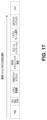
図7は、CRCを有するDCIに対するABA Polarエンコーディング、およびそれの、UE-ID(例えば、WTRU-ID)に対するPolarエンコーディングとの組合せの例である。Polar符号のマザーコード長は、例えば、N=2n個のビットとすることができる。CRCを有するDCIのPolarエンコーディングは、例えば、エンコーダの下部における最後の2D個のビットチャネルを手動でゼロに設定し得る。実際の情報は、ビットチャネルの上部部に分離され得る。これはビットチャネルの下部部を、UE-IDコードワードまたはUE-IDシーケンスとの(例えば、後の)組合せのために予約し得る。WTRU-IDのPolarエンコーディングは、マザーコード長2D個のビットを有するPolar符号を用い得る。CRCを有するDCIのエンコードされたビットは、UE-IDのエンコードされたビットと組み合わされ得る。前半部に対するエンコードされたビットは2n個のビットとすることができ、後半部に対するエンコードされたビットは2D個のビットとすることができる。組合せは、前半部の最後の2D個のビットと、後半部に対するエンコードされたビットとのXORを含み得る。 FIG. 7 is an example of ABA Polar encoding for DCI with CRC and its combination with Polar encoding for UE-ID (eg, WTRU-ID). The mother code length of a Polar code can be, for example, N=2 n bits. Polar encoding of DCI with CRC may, for example, manually set the last 2 D bit channels at the bottom of the encoder to zero. The actual information can be separated in the upper part of the bit channel. This may reserve the lower part of the bit channel for (eg, later) combination with the UE-ID codeword or UE-ID sequence. Polar encoding of the WTRU-ID may use a Polar code with a mother code length of 2 D bits. The DCI encoded bits with CRC may be combined with the UE-ID encoded bits. The encoded bits for the first half can be 2 n bits and the encoded bits for the second half can be 2 D bits. The combination may include XORing the last 2 D bits of the first half with the encoded bits for the second half.
図8は、NR-PDCCHに対する2段階マッピングおよびPolarエンコーディングの例である。例では、WTRU-IDは下部2D個のサブエンコーダにマッピングされることができ、一方、CRCを有するDCIは上部2n-2D個のサブエンコーダにマッピングされ得る。2つのサブエンコーダは、例えば、エンコーディングプロセスの最後の段階で結合され得る。サブエンコーダは、NR-PDCCH Polarエンコーディングのための2段階マッピングを示し得る。 FIG. 8 is an example of two-stage mapping and polar encoding for NR-PDCCH. In an example, the WTRU-ID may be mapped to the bottom 2 D sub-encoders, while the DCI with CRC may be mapped to the top 2 n −2 D sub-encoders. Two sub-encoders can be combined, for example, at the end of the encoding process. A sub-encoder may indicate a two-stage mapping for NR-PDCCH Polar encoding.
受信機側において、WTRUはNR-PDCCHに対する多段階(例えば、2段階)早期終了復号(例えば、図9の例に示されるような)を実行し得る。 At the receiver side, the WTRU may perform multi-stage (eg, two-stage) early termination decoding (eg, as shown in the example of FIG. 9) for the NR-PDCCH.
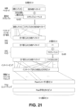
図9は、NR-PDCCHに対する2段階早期終了(ET)復号の例である。例では、早期終了を容易にするために(例えば、WTRUにおけるレイテンシ、電力および/または複雑さを低減するように)、NR-PDCCHに対する復号の2つの段階があり得る。 FIG. 9 is an example of two stage early termination (ET) decoding for NR-PDCCH. In an example, there may be two stages of decoding for NR-PDCCH to facilitate early termination (eg, to reduce latency, power and/or complexity at the WTRU).
WTRUは、(例えば、NR-PDCCHを受信することを条件として)盲目的復号の実行を開始し得る。WTRUは、(例えば、全ての情報ビットを復号する前の早期終了を容易にするために)NR-PDCCH送信がWTRUを対象としたものかどうかを決定するために、ET段階1 WTRU-IDベースの検出またはデスクランブルを使用し得る。WTRUは、例えば、受信されたNR-PDCCHがWTRUを対象としたものでない(例えば、WTRUがNR-PDCCHはWTRUを対象としたものでないと決定した)とき、NR-PDCCHの復号を停止し、段階2においてETをトリガし得る。図9に示されるように、ET段階1 WTRU-IDベースのデスクランブルは、ET段階2のET機能を補助し得る(例えば、対象としたものではないまたは望ましくないWTRUのPDCCH Polar復号をさらに早期に終了するように)。WTRUは、本明細書で述べられる技法を使用して(デ)スクランブルシーケンスを生成し得る。例では、Polar復号における早期終了は、PDCCH送信およびアシスタンスビット(例えば、CRCビット)の最初のデスクランブルの共同動作によって達成され得る。WTRUは、例えば、受信されたNR-PDCCHがWTRUを対象としたものであるとき、NR-PDCCHの復号を開始し得る(例えば、ABA Polar復号によって)。WTRUはET段階2を実行して、例えば、制御チャネルを復号しながら、(例えば、全ての)ABA Polar復号が合格したかどうかを決定し得る(例えば、ETのための分散型CRCを含み得るアシスタンスビットに基づいて)。WTRUは、例えば、ABA復号が合格しなかったとき、NR-PDCCH復号を停止し、ETをトリガし得る。WTRUは、例えば、ABA Polar復号が合格したとき、CRCチェックを実行し、成功裏に復号されたNR-PDCCHからDCIを取得し得る。
The WTRU may start performing blind decoding (eg, conditional on receiving NR-PDCCH). The WTRU uses an
NR-PBCHに対して、Polar符号化がもたらされ得る。例えば、NR-PBCHに対するPolar符号化は、SSブロックを組み合わせ得る(例えば、CRC添付の後)。 Polar coding may be provided for NR-PBCH. For example, Polar encoding for NR-PBCH may combine SS blocks (eg, after CRC attachment).
SSブロックインデックス(例えば、時間インデックス)は、NR-PBCHのコンテンツの中で送信され得る(例えば、明示的に送信され得る)。 The SS block index (eg, time index) may be transmitted (eg, explicitly transmitted) in the content of the NR-PBCH.
複数のSSブロックからのNR-PBCH信号のソフト組合せは、復号性能を改善し得る。MIBのペイロード内の明示的SSブロックインデックスは、結果として異なるSSブロックに対して異なるNR-PBCH符号化ビットとなり得る。従って、複数のSSブロックからのNR-PBCH信号のソフト組合せは単純にはなり得ない。 Soft combining of NR-PBCH signals from multiple SS blocks can improve decoding performance. An explicit SS block index in the MIB payload can result in different NR-PBCH coded bits for different SS blocks. Therefore, soft combining of NR-PBCH signals from multiple SS blocks cannot be straightforward.
複数のSSブロックからのNR-PBCH信号のソフト組合せは、例えば、Polar符号構築を慎重に設計することによって容易にされ得る。例では、SSブロック時間インデックスは、それが、非時間インデックスペイロードから分離され得るように、エンコードされ得る。異なるSSブロックからの複数のNR-PBCH信号を有する受信機は、例えば、SSブロックに対応する符号化されたビットの区間をパンクチャリングした後、NR-PBCH信号を組み合わせ得る。 Soft combining of NR-PBCH signals from multiple SS blocks can be facilitated, for example, by carefully designing the Polar code construction. In an example, the SS block temporal index can be encoded such that it can be separated from the non-temporal index payload. A receiver with multiple NR-PBCH signals from different SS blocks may, for example, combine the NR-PBCH signals after puncturing intervals of coded bits corresponding to the SS blocks.
図12は、共同エンコーディングによるNR-PBCH符号化手順の例である。例では、MIBのペイロードは、部に分けられることができ、例えば:(1)時間インデックスペイロード(例えば、SSブロックインデックスおよび/または半無線フレームタイミング)、および(2)非時間インデックスペイロード(例えば、SFN、帯域幅など)である。 FIG. 12 is an example of an NR-PBCH encoding procedure with joint encoding. In an example, the payload of a MIB can be divided into parts such as: (1) a time index payload (e.g. SS block index and/or half-radio frame timing), and (2) a non-time index payload (e.g. SFN, bandwidth, etc.).
MIBペイロードの一部(例えば、各部)には、別個のCRCが添付され得る。非時間インデックスMIBのためのCRC長は、時間インデックスMIBのためのCRC長とは異なり得る。非時間インデックスMIBのために、時間インデックスMIBのためのCRC長より大きなCRC長が使用され得る。複数の(例えば、2つの)CRC長の和が与えられることが想定され得る。例えば、合計で24個のCRCビットが割り振られる場合、非時間インデックスMIBのためのCRCは19個のビットとすることができ、時間インデックスMIBのためのCRCは5つのビットとすることができる。 Part (eg, each part) of the MIB payload may be accompanied by a separate CRC. The CRC length for non-time-indexed MIBs may differ from the CRC length for time-indexed MIBs. For non-time-indexed MIBs, a larger CRC length than for time-indexed MIBs may be used. It may be assumed that multiple (eg, two) sums of CRC lengths are provided. For example, if a total of 24 CRC bits are allocated, the CRC for non-time-indexed MIBs may be 19 bits and the CRC for time-indexed MIBs may be 5 bits.
例では、Polar符号のマザーコード長は、N=2n個のビットとすることができる。CRCを有する時間インデックスMIBは、エンコーダの上部における最初の2t個のビットチャネル(例えば、何らかの整数tに対して)にマッピングされ得る。CRCを有する非時間インデックスMIBは、エンコーダの下部における残りのビットチャネルにマッピングされ得る(例えば、図13に見られるように)。非時間インデックスMIB部は、例えば、ペイロードコンテンツおよびそれらの重要度レベルに応じて、エンコーダの下部のビットチャネルへの優先順位付けされたマッピング(例えば、さらに優先順位付けされたマッピング)を受信し得る。非時間インデックスMIB部のマッピング、および時間インデックスMIB部のマッピングは、使用されることになるレートマッチングまたはパンクチャリング方式に依存し得る。例では(例えば、自然パンクチャリング方式を用いた)、一定量のビットが上からパンクチャリングされ得る。対応する入力ビットチャネルは、ゼロに設定され得る(例えば、されてもよい)。これらのビットは、例えば、時間インデックスMIB部と一緒に、ビットチャネルの上にあってよい。 In an example, the mother code length of a Polar code can be N=2 n bits. A time index MIB with CRC may be mapped to the first 2 t bit channels (eg, for some integer t) at the top of the encoder. A non-time-indexed MIB with CRC may be mapped to the remaining bit channels at the bottom of the encoder (eg, as seen in FIG. 13). The non-time-indexed MIB part may receive a prioritized mapping (eg, a more prioritized mapping) to the lower bit channels of the encoder, eg, according to the payload contents and their level of importance. . The mapping of non-time-indexed MIB parts and the mapping of time-indexed MIB parts may depend on the rate matching or puncturing scheme to be used. In an example (eg, using a natural puncturing scheme), a fixed amount of bits may be punctured from above. The corresponding input bit channel may (eg, may) be set to zero. These bits may be on the bit channel, for example together with the time index MIB part.
ソースビットは、生成器行列 The source bits are the generator matrix
![]()
![]()
を有するPolarエンコーダに(例えば、次いで)渡されることができ、 can be passed (e.g. then) to a Polar encoder with
![]()
![]()
はn次のクロネッカー累乗を示すことができ、 can denote the n-th Kronecker exponentiation,

である。 is.
レートマッチング動作のパンクチャリングの種類は、例えば、NR-PBCHのための所与のリソースブロックに適合するように、Polarコードワードのために使用され得る。 A puncturing type of rate matching operation may be used for Polar codewords, eg, to fit a given resource block for NR-PBCH.
例では、CRCを有する時間インデックスMIBは、エンコーダの下における最後の2tビットチャネルにマッピングされ得る(例えば、何らかの整数tに対して)。CRCを有する非時間インデックスMIBは、エンコーダの上における残りのビットチャネルにマッピングされ得る(例えば、図14に見られるように)。 In an example, a time index MIB with CRC may be mapped to the last 2 t -bit channel under the encoder (eg, for some integer t). A non-time-indexed MIB with CRC may be mapped to the remaining bit channels on the encoder (eg, as seen in FIG. 14).
非時間インデックスMIB部に対して、方式はいくつかの情報をビットチャネルにマッピングし得る(例えば、情報の重要度レベルに応じて)。 For non-time-indexed MIB parts, the scheme may map some information into bit channels (eg, depending on the importance level of the information).
より重要な情報は、より信頼性のあるビットチャネルに割り振られ得る。図10は、非時間インデックスMIB部に対するビットチャネルマッピングの例を示す。例では、CRCビットは、より信頼性のあるビットチャネル(例えば、最も信頼性のあるビットチャネル)に割り振られ得る。重要度が低い情報は、信頼性の低いビットチャネルに割り振られ得る。情報の重要度は、ビットチャネルの信頼度のレベルに正に相関し得る。例えば、セル禁止フラグおよび/またはシステム帯域幅情報は、CRCビットより重要度が低くてよく、CRCビットに関連付けられた信頼度のレベルの次の信頼度のレベルのビットチャネルに割り振られ得る。 More important information can be allocated to more reliable bit channels. FIG. 10 shows an example of bit-channel mapping for non-time-indexed MIB parts. In an example, CRC bits may be allocated to more reliable bit channels (eg, the most reliable bit channel). Less important information may be allocated to less reliable bit channels. The importance of information can be positively correlated with the level of reliability of the bit channel. For example, the cell barring flag and/or system bandwidth information may be less important than the CRC bits and may be allocated to the next reliability level bit channel after the reliability level associated with the CRC bits.
システムフレーム番号(SFN)および/または半フレームインジケーション(HFI)は、CRCビット、セル禁止フラグ、およびシステム帯域幅情報より重要度が低くてよく、その信頼度のレベルより低い信頼度のレベルのビットチャネルに割り振られ得る。予約フィールドは、より信頼性の低い(例えば、最も信頼性の低い)ビットチャネルに割り振られ得る。 The system frame number (SFN) and/or half frame indication (HFI) may be of lesser importance than the CRC bits, cell barring flags, and system bandwidth information and have a level of reliability lower than that level of reliability. It can be allocated to bit channels. Reserved fields may be allocated to less reliable (eg, least reliable) bit channels.
例では、いくつかの情報は、ビットチャネルにマッピングされ得る(例えば、情報安定度レベルに応じて)。 In an example, some information may be mapped to a bit channel (eg, depending on information stability level).
より静的なシステム情報は、前端ビットチャネルに割り振られ得る。より静的でないシステム情報は、後端ビットチャネルに割り振られ得る。図11は、MIBの非時間インデックス部に対するビットチャネルマッピングの例を示す。情報ビットセット内で、CRCビットは、例えば、自然な順序で、後端ビットチャネルに(例えば、常に)置かれ得る。半静的情報(例えば、システムフレーム番号および/または半フレームインジケーション)は、CRCビットの次に置かれ得る。他のシステム情報は、前端ビットチャネルに置かれ得る。本明細書で述べられる特徴は、WTRU側における復号を容易にし得る。WTRUは、例えば、何らかの前のMIB復号から、静的なシステム情報を知り得て、またはすでに知り得る。WTRUは、例えば、WTRUの現在のPBCH復号のために、異なる(例えば、新たな)システムフレーム番号および/または半フレームインジケーションを取得し得る(例えば、取得することが必要になり得る)。WTRUは、他の静的なシステム情報を前に取得されたビットと見なすことができ、および/または半静的なシステム情報を直接復号し得る。 More static system information may be allocated to the leading edge bit channel. Less static system information may be allocated to the trailing bit channel. FIG. 11 shows an example bit-channel mapping for the non-time index part of the MIB. Within the information bit set, the CRC bits may be placed (eg, always) in the trailing bit channel, eg, in natural order. Semi-static information (eg, system frame number and/or half-frame indication) may be placed next to the CRC bits. Other system information may be placed in the leading edge bit channel. Features described herein may facilitate decoding at the WTRU side. The WTRU may know or already know static system information, eg, from some previous MIB decoding. A WTRU may, for example, obtain (eg, need to obtain) a different (eg, new) system frame number and/or half-frame indication for the WTRU's current PBCH decoding. The WTRU may regard other static system information as previously obtained bits and/or may directly decode the semi-static system information.
例では、より静的なシステム情報は後端ビットチャネルに割り振られてよく、および/またはより静的でないシステム情報は前端ビットチャネルに割り振られ得る。より静的でないシステム情報の復号が、容易にされ得る。より静的でないシステム情報は、最初に復号され得る。 In examples, more static system information may be allocated to the trailing edge bit channel and/or less static system information may be allocated to the leading edge bit channel. Decoding of less static system information may be facilitated. Less static system information may be decoded first.
非時間インデックスMIB部のマッピング、および/または時間インデックスMIB部のマッピングは、使用されることになるレートマッチングまたはパンクチャリング方式に依存し得る。例では、自然パンクチャリング方式を用いて、ある量(例えば、一定の量)のビットが、上からパンクチャリングされ得る。対応する入力ビットチャネルは、ゼロとなるように設定される。対応する入力ビットチャネルは、例えば、時間インデックスMIB部と一緒に、ビットチャネルの上にあってよい。 The mapping of non-time-indexed MIB parts and/or the mapping of time-indexed MIB parts may depend on the rate matching or puncturing scheme to be used. In an example, using a natural puncturing scheme, a certain amount (eg, a fixed amount) of bits may be punctured from above. The corresponding input bit channel is set to zero. A corresponding input bit channel may be on top of the bit channel, for example together with the time index MIB part.
図13は、NR-PBCHに対する分離型マッピングおよびPolarエンコーディング動作の例である。例では、CRCを有するSSブロック時間インデックスは、時間インデックスサブエンコーダの上2t個の入力にマッピングされ得る。CRCを有する非時間インデックスペイロードは、下2n-2t個のサブエンコーダにマッピングされ得る。複数の(例えば、2つの)サブエンコーダは、エンコーディングプロセスの最後の段階で接続され得る。サブエンコーダは、NR-PBCH Polarエンコーディングのための分離型マッピングを示すために使用され得る。 FIG. 13 is an example of separate mapping and polar encoding operation for NR-PBCH. In an example, the SS block time index with CRC may be mapped to the top 2 t inputs of the time index sub-encoder. A non-time index payload with CRC may be mapped to the bottom 2 n −2 t sub-encoders. Multiple (eg, two) sub-encoders may be connected at the end of the encoding process. A sub-encoder may be used to represent the separable mapping for NR-PBCH Polar encoding.
レートマッチングが考慮され得る。パンクチャリング方式は、例えば、NR-PBCHに対する低い符号化レートにより、レートマッチング方式として選択され得る。例では、パンクチャリングは、出力ビットの上から適用され得る。対応する入力チャネルは0に設定され得る。SSブロック時間インデックスは(例えば、次いで)、サブエンコーダの残りのビットチャネルに置かれ得る。 Rate matching may be considered. A puncturing scheme may be selected as the rate matching scheme, eg, due to the low coding rate for NR-PBCH. In an example, puncturing may be applied over the output bits. The corresponding input channel may be set to 0. The SS block time index may (eg, then) be placed in the remaining bit channels of the sub-encoder.
図14は、SSブロック時間インデックスがエンコーダの後端に置かれる、分離型マッピングおよび/またはPolarエンコーディング動作の例を示す。CRCを有するSSブロック時間インデックスは、下2t個のサブエンコーダにマッピングされ得る。CRCを有する非時間インデックスペイロードは、上2n-2t個のサブエンコーダにマッピングされ得る。2つのサブエンコーダは、エンコーディングプロセスのいくつかの(例えば、最後の)段階において接続され得る。サブエンコーダは、例えば、NR-PBCH Polarエンコーディングのための分離型マッピングを示すために使用され得る。例では、分離型マッピングは、CRCを有するSSブロック時間インデックスがn/t個のビットチャネル(例えば、n/t個のビットチャネルごと)に置かれるものとなり得る。 FIG. 14 shows an example of separable mapping and/or polar encoding operations where the SS block time index is placed at the end of the encoder. The SS block time index with CRC may be mapped to the bottom 2 t sub-encoders. A non-time index payload with CRC may be mapped to the upper 2 n −2 t sub-encoders. Two sub-encoders may be connected at some (eg, last) stage of the encoding process. A sub-encoder can be used, for example, to indicate a separable mapping for NR-PBCH Polar encoding. In an example, a separable mapping may be such that the SS block time index with CRC is placed in n/t bit-channels (eg, every n/t bit-channels).
図15は、別個のエンコーディングを有するNR-PBCH符号化手順の例である。SSブロックインデックスおよび他の非時間インデックスMIB情報は、共同でエンコードされ得る(例えば、図12の例で示されるように)。このエンコーディングプロセスは、各SSブロックインデックス値に対して使用されることがあり、これは非効率的である。(例えば、代替の)例では、SSブロックインデックスは、非時間インデックスMIBとは別にエンコードされ得る。 FIG. 15 is an example of an NR-PBCH encoding procedure with separate encoding. The SS block index and other non-temporal index MIB information may be jointly encoded (eg, as shown in the example of FIG. 12). This encoding process may be used for each SS block index value, which is inefficient. In an (eg, alternative) example, the SS block index may be encoded separately from the non-temporal index MIB.
例では、MIBのペイロードは2つの部に分けられ得る:(1)時間インデックスペイロード(例えば、SSブロックインデックスおよび半無線フレームタイミング)、および(2)非時間インデックスペイロード(例えば、SFN、帯域幅など)である。 In an example, the payload of a MIB can be divided into two parts: (1) time index payload (e.g. SS block index and half-radio frame timing), and (2) non-time index payload (e.g. SFN, bandwidth, etc.). ).
MIBペイロードの(例えば、各)部には、別個のCRCが添付され得る。非時間インデックスMIBに対するCRC長は、時間インデックスMIBに対するCRC長とは異なり得る。非時間インデックスMIBに対しては、時間インデックスMIBに対するCRC長より大きなCRC長が使用され得る。 A separate CRC may be attached to (eg, each) part of the MIB payload. The CRC length for non-time-indexed MIBs can be different than the CRC length for time-indexed MIBs. For non-time-indexed MIBs, a CRC length larger than the CRC length for time-indexed MIBs may be used.
例では、Polar符号のマザーコード長は、N=2n個のビットとすることができる。非時間インデックスMIBは、エンコーダの上における最初の2t個のビットチャネル(例えば、何らかの整数tに対して)をゼロに(例えば、手動で)設定することによって、Polarエンコードされ得る。実際の情報は、ビットチャネルの下部から分離され得る。これは、時間インデックスMIBとの後の組合せのために、ビットチャネルの上部を予約することができる。この動作は、SFNの一定の値に対する1つまたは複数の(例えば、全ての)可能なSSブロックに対して、1回行われ得る(例えば、1回だけ行われ得る)。 In an example, the mother code length of a Polar code can be N=2 n bits. A non-time-indexed MIB can be Polar-encoded by setting (eg, manually) the first 2 t bit channels on the encoder (eg, for some integer t) to zero. The actual information can be separated from the bottom of the bit channel. This can reserve the upper part of the bit channel for later combination with the time index MIB. This operation may be performed once (eg, only once) for one or more (eg, all) possible SS blocks for a fixed value of SFN.
SSブロックインデックスMIBは、例えば、2t個のビットのマザーコード長を有するPolar符号を使用することによって、Polarエンコードされ得る。この動作は、(例えば、各)可能なSSブロックに対して、(例えば、1回)行われ得る。 The SS block index MIB can be Polar encoded, for example, by using a Polar code with a mother code length of 2 t bits. This operation may be performed (eg, once) for (eg, each) possible SS block.
非時間インデックスMIBのエンコードされたビットは、SSブロックインデックスMIBのエンコードされたビットと組み合わされ得る。前半部に対するエンコードされたビットは、例えば、2n個のビットとすることができ、後半部に対するエンコードされたビットは、例えば、2t個のビットとすることができる。組合せは、前半部の最初の2t個のビットと、後半部に対するエンコードされたビットとのXORを含み得る。 The encoded bits of the non-temporal index MIB can be combined with the encoded bits of the SS block index MIB. The encoded bits for the first half can be, for example, 2 n bits and the encoded bits for the second half can be, for example, 2 t bits. The combination may involve XORing the first 2 t bits of the first half with the encoded bits for the second half.
図16は、非時間インデックスMIBに対する分離型マッピングおよびPolarエンコーディング、並びにSSブロックインデックスMIBに対するPolarエンコーディングとのそれの組合せの例である。図16は、(i)非時間インデックスMIBに対する分離型マッピングおよびPolarエンコーディング、(ii)SSブロックインデックスMIBに対するPolarエンコーディング、並びに(iii)SSブロックインデックスMIBおよび非時間インデックスMIBからのPolarエンコードされたビットの組合せ動作の、詳細な動作の例を示す。 FIG. 16 is an example of separate mapping and Polar encoding for non-temporally indexed MIBs and its combination with Polar encoding for SS block indexed MIBs. FIG. 16 shows (i) separable mapping and polar encoding for non-temporal index MIBs, (ii) polar encoding for SS block index MIBs, and (iii) polar encoded bits from SS block index MIBs and non-temporal index MIBs. shows an example of detailed operation of the combination operation of .
SSブロックインデックスMIBは予めエンコードされることができ、符号化されたビットは保存され得る(例えば、容易なアクセスのために)。例では、合計のサポートされるSSブロックは、例えば、64までとなり得る(例えば、NRにおいて)。64個のPolarコードワードを保存することは、例えば、コードワードの長さが2t個のビットに制限され得ることを考えると、かなりのメモリを使用しなくてよい。保存されたコードワードは、非時間インデックスMIBの符号化されたビットと、(例えば、直接)組み合わされ得る。 The SS Block Index MIB can be pre-encoded and the coded bits can be saved (eg, for easy access). In an example, the total supported SS blocks can be, for example, up to 64 (eg, in NR). Storing 64 Polar codewords does not use significant memory, eg, given that the codeword length can be limited to 2 t bits. The stored codewords can be combined (eg, directly) with the encoded bits of the non-time-indexed MIB.
NR-PBCH信号は、様々なシナリオまたは事例では、WTRU側で受信され得る。WTRUによる処理は、様々な事例に対して異なり得る。 The NR-PBCH signal may be received at the WTRU side in various scenarios or instances. Processing by the WTRU may differ for different cases.
例では、WTRUは、複数のSSブロックから複数のNR-PBCH信号を受信し得る。WTRUは、それらのそれぞれに対するSSブロックインデックスを知り得ない。以下の1つまたは複数が当てはまり得る。WTRUは(例えば、最初に)、受信されたNR-PBCH信号から最初の2t個のビットをパンクチャリングし得る。WTRUは(例えば、次いで)、NR-PBCH信号をソフト組み合わせし、非時間インデックスMIBを復号し得る。復号された非時間インデックスMIBは、再エンコードされることができ、最初の2t個のビットチャネルに対するそれの影響は、受信されたNR-PBCH信号において相殺され得る。WTRUは(例えば、次いで)、各受信されたNR-PBCH信号に対してSSブロックインデックスを復号し得る。 In an example, a WTRU may receive multiple NR-PBCH signals from multiple SS blocks. The WTRU may not know the SS block index for each of them. One or more of the following may apply. A WTRU may (eg, initially) puncture the first 2 t bits from the received NR-PBCH signal. The WTRU may (eg, then) soft-combine the NR-PBCH signals and decode the non-time-indexed MIB. The decoded non-time-indexed MIB can be re-encoded and its effect on the first 2 t bit channels can be canceled in the received NR-PBCH signal. The WTRU may (eg, then) decode the SS block index for each received NR-PBCH signal.
例では、WTRUは、前に取得されたSSブロックインデックスを用いて、単一のNR-PBCH信号を受信し得る。以下の1つまたは複数が当てはまり得る。WTRUは、SSブロックインデックスをエンコードし、NR-PBCH信号に対するそれの寄与を相殺し得る。WTRUは、非時間インデックスMIBを復号し得る。 In an example, a WTRU may receive a single NR-PBCH signal using a previously obtained SS block index. One or more of the following may apply. A WTRU may encode the SS block index to offset its contribution to the NR-PBCH signal. A WTRU may decode non-time-indexed MIBs.
例では、WTRUは、前に取得されたSSブロックインデックスを用いて複数のNR-PBCH信号を受信し得る。以下の1つまたは複数が当てはまり得る。WTRUは、SSブロックインデックスをエンコードし、対応するNR-PBCH信号に対するそれの寄与を相殺し得る。WTRUは、NR-PBCH信号を組み合わせ、組み合わされたNR-PBCH信号から非時間インデックスMIBを復号し得る。 In an example, a WTRU may receive multiple NR-PBCH signals with previously obtained SS block indices. One or more of the following may apply. A WTRU may encode the SS block index and offset its contribution to the corresponding NR-PBCH signal. A WTRU may combine the NR-PBCH signals and decode the non-time-indexed MIB from the combined NR-PBCH signals.
本明細書で述べられる様々な事例では、想定は、SSブロック時間インデックスが分離されてエンコードされることを含み得る。いくつかの信頼性のあるビットチャネルが、利用されないことがある。何らかのBLER性能損失が結果として生じ得る。SSブロック時間インデックスおよび/または他の非時間インデックスMIBは、共同でエンコードされ得る。優先度マッピングが適用され得る。SSブロック時間インデックスは、後のビットチャネル(例えば、図17)、またはより信頼性のあるビットチャネル(例えば、図18)に割り振られ得る。SSブロック時間インデックスは頻繁に復号されることができ、一方、他の非時間インデックスMIBは低い頻度でまたはまれに復号され得る。SSブロック時間インデックスを後端ビットチャネルに割り振ることによって、より頻繁なシステム情報の信頼性のある復号が、例えば、何らかの情報復号(例えば、前に取得された情報復号)を通じて強化され得る。 In various cases discussed herein, assumptions may include that the SS block time index is encoded separately. Some reliable bit channels may not be utilized. Some BLER performance loss may result. The SS block time index and/or other non-time index MIBs may be jointly encoded. Priority mapping may be applied. The SS block time index may be allocated to later bit channels (eg, FIG. 17) or more reliable bit channels (eg, FIG. 18). The SS block time index can be decoded frequently, while other non-time index MIBs can be decoded infrequently or infrequently. By allocating the SS block time index to the trailing bit channel, more frequent reliable decoding of system information may be enhanced, for example, through some information decoding (eg, previously obtained information decoding).
例えば、本明細書で述べられる手法、技法、または基準を使用して、NR PBCHチャネル符号化設計がもたらされ得る。 For example, the methodology, techniques, or criteria described herein may be used to yield an NR PBCH channel coding design.
図19は、10個のシステムフレーム番号(SFN)ビット、1つの半フレームインジケーションビット、および6つのSSブロックインデックス(SSBI)ビットを含んだ、NR時間関連情報の例を示す。SFNの7つのMSBは、BCH TTI分解能をもたらし得る。SFNの3つのLSB、および半フレームインジケーションビットは、BCH TTI内のバーストセットインデックスでよい。SSBIの6個のビットは、バーストセット内とすることができる。6GHzより上の帯域に関して、10個のSFNビット、半フレームインジケーションビット、およびSSBIの3つのMSBは、NR-PBCHペイロード内にあってよく、および/またはSSBIの3つのLSBは、8つの異なるPBCH-DMRSシーケンスによって示され得る。6GHzより下の帯域に関して、SSBIの3つのMSBは、NR-PBCHペイロード内になくてよい。その後に、6GHzより下の帯域に対する予約ビットは、6GHzより上の帯域に対するものより3つのビット長くなり得る。 FIG. 19 shows an example of NR time-related information, including ten system frame number (SFN) bits, one half frame indication bit, and six SS block index (SSBI) bits. The 7 MSBs of SFN can provide BCH TTI resolution. The 3 LSBs of the SFN and the half-frame indication bit may be the burst set index within the BCH TTI. Six bits of SSBI can be in the burst set. For bands above 6 GHz, the 10 SFN bits, the half-frame indication bit, and the 3 MSBs of SSBI may be in the NR-PBCH payload, and/or the 3 LSBs of SSBI may be 8 different It can be indicated by the PBCH-DMRS sequence. For bands below 6 GHz, the 3 MSBs of SSBI may not be in the NR-PBCH payload. After that, the reserved bits for the bands below 6 GHz can be three bits longer than those for the bands above 6 GHz.
例では、セルIDおよびSFNの一部に基づくことができる第1のスクランブル初期化が、SSブロックインデックス、半無線フレーム(例えば、存在する場合)、並びにCRC添付およびエンコーディングプロセスの前のSFNの一部を除く、PBCHペイロードに適用され得る。SFNの一部は、以下の1つまたは複数とすることができる(例えば、NR AH3によって選択されることになる):SFNの3つのLSBビット、並びにSFNの2番目および3番目のLSBビット。 In an example, the first scrambling initialization, which can be based on the cell ID and part of the SFN, is the SS block index, the half-radio frame (e.g., if any), and the part of the SFN prior to the CRC attachment and encoding process. It can be applied to the PBCH payload, excluding the part. A portion of the SFN may be one or more of the following (eg, to be selected by NR AH3): the 3 LSB bits of the SFN and the 2nd and 3rd LSB bits of the SFN.
例では、第1のPBCHスクランブルは、セルIDによって初期化されるゴールドシーケンスを含み得る。SFNの2番目および3番目のLSBは、シーケンスの連続した非重複部分を決定するために使用され得る。長さ4Mのゴールドシーケンスが生成されることができ、ここでMはスクランブルされることになるビットの数である。生成されたシーケンスは、4つの非重複部分に分割され得る。2番目および3番目のLSBは、シーケンスの非重複部分のうちの1つまたは複数(例えば、それぞれ)のインデックスを、(例えば、一意に)識別し得る。これは図20に示される。
In an example, the first PBCH scrambling may include a Gold sequence initialized by cell ID. The 2nd and 3rd LSBs of the SFN can be used to determine consecutive non-overlapping portions of the sequence. A Gold sequence of
動作想定は、NR-PBCHが56個のビットのペイロードサイズ(例えば、CRCを含めて)を有することを含み得る。10個のビットSFNは、NR-PBCHによって運ばれ得る。動作想定は、4個のビットPRBグリッドオフセットはNR-PBCHによって運ばれることを含み得る。残りのシステム情報(RMSI)、初期アクセスのためのMsg.2/4、およびブロードキャストされる他のシステム情報(OSI)に対する、ニューメロロジーを示すために、単一のビットがNR-PBCHにおいて使用され得る。以下の例の1つまたは複数が、gNBによって(例えば、RMSIに対するニューメロロジーとして)使用され得る。サブ6GHzに関して、0:15KHzおよび1:30KHzが使用され得る。6GHz超に関して、0:60KHzおよび1:120KHzが使用され得る。 Operational assumptions may include that the NR-PBCH has a payload size of 56 bits (eg, including CRC). A 10-bit SFN may be carried by the NR-PBCH. A working assumption may include that the 4-bit PRB grid offset is carried by the NR-PBCH. Residual System Information (RMSI), Msg. for initial access. A single bit may be used in the NR-PBCH to indicate the numerology for 2/4, and other system information (OSI) that is broadcast. One or more of the following examples may be used by a gNB (eg, as a neumerology for RMSI). For sub-6 GHz, 0:15 KHz and 1:30 KHz may be used. For above 6 GHz, 0:60 KHz and 1:120 KHz may be used.
1個のビット半フレームインジケーションはPBCHペイロードの一部とすることができ、測定のためのCSI-RSが20ms以上の周期性を有するとき、WTRUは、測定の目的に対してネットワークが「同期的」であると想定し得る。例えば、3GHz以下に対して、半フレームインジケーションは、さらに(例えば、暗黙的に)シグナリングされ得る(例えば、最大L=4に対してPBCH DMRSの一部としてシグナリングされ得る)。 The 1-bit half-frame indication may be part of the PBCH payload, and when the CSI-RS for measurement has a periodicity of 20 ms or more, the WTRU may indicate that the network is "synchronized" for measurement purposes. It can be assumed that For example, for 3 GHz and below, a half-frame indication may also be (eg, implicitly) signaled (eg, as part of the PBCH DMRS for up to L=4).
PDCCHのPolar符号設計(例えば、関連付けられたインターリーバを有する24個のビットD-CRC)は、再使用され得る。動作想定は(例えば、RAN1#89から、および確認されたものとして)、NR-PBCHによって運ばれる場合は時間インデックスを含む、データは明示的に送信され得ることを含み得る。 The PDCCH polar code design (eg, 24-bit D-CRC with associated interleaver) can be reused. Operational assumptions (eg, from RAN1#89 and as confirmed) may include that data may be sent explicitly, including the time index if carried by NR-PBCH.
図21は、例えば、本明細書での手法および技法に基づいた、チャネル(例えば、PBCH)エンコーディングプロセスの例を示す。本明細書ではPBCHフィールドの順序が提案されることができ、例えば、前に取得された(例えば、前に導出されたまたは復号された)ビットを、前に取得されていないおよび/またはPolarエンコーディングの前のビットの、前に置くことによって、使用され得る。順序は、PBCHデコーダ性能および/またはレイテンシを改善するために使用され得る。いくつかの前に取得された情報ビットは、以下、すなわち、SSBI、予約ビット、SFN(その一部または全て)、または半無線フレームインジケーションのうちの、1つまたは複数とすることができる。 FIG. 21 illustrates an example channel (eg, PBCH) encoding process, eg, based on the techniques and techniques herein. An order of PBCH fields may be suggested herein, e.g. can be used by prefixing the bit before the . The order may be used to improve PBCH decoder performance and/or latency. Some previously obtained information bits may be one or more of the following: SSBI, reserved bits, SFN (part or all thereof), or half-radio frame indication.
情報ビットは、時間インデックスフィールド内に置かれ得る。情報ビットの一部または全ては、時間インデックスフィールド内に置かれ得る。例えば、情報(例えば、前に取得された情報)は、何らかのシステム情報を含み得る。システム情報は、SSBI、SFN(その一部または全て)、および/または同様のものを含み得る。例では、情報は、何らかのシステム情報および/または予約ビットを含み得る。何らかの情報(例えば、前に取得された情報)は、何らかのシステム情報および/または予約ビットの一部を含み得る。 Information bits may be placed in the time index field. Some or all of the information bits may be placed within the time index field. For example, the information (eg, previously obtained information) may include some system information. System information may include SSBI, SFN (some or all thereof), and/or the like. In examples, the information may include some system information and/or reserved bits. Some information (eg, previously obtained information) may include some system information and/or reserved bits.
MIBペイロード(例えば、32個のビット)は、例えば、(例えば、スクランブルされていない)時間インデックスおよび他のMIBペイロードを含む、複数の(例えば、2つの)部に分割され得る。(例えば、スクランブルされていない)時間インデックスは、以下の1つまたは複数を含み得る:SFNの2番目および3番目のLSB;SSブロックインデックスの3つのMSB;または半無線フレーム。いくつかの(例えば、他の)MIBペイロードは、SFNの1つのLSBおよび7つのMSB、4個のビットPRBグリッドオフセット、RMSIに対する1個のビットニューメロロジー、予約ビット、または他のビットのうちの1つまたは複数を含み得る。 A MIB payload (eg, 32 bits) may be split into multiple (eg, two) parts, including, for example, a (eg, unscrambled) time index and another MIB payload. The (eg, unscrambled) time index may include one or more of the following: the 2nd and 3rd LSBs of the SFN; the 3 MSBs of the SS block index; or a half-radio frame. Some (e.g., other) MIB payloads are 1 LSB and 7 MSBs of SFN, 4-bit PRB grid offset, 1-bit numerology for RMSI, reserved bits, or among other bits may include one or more of
MIBペイロード(例えば、他のMIBペイロード)をスクランブルするために、例えば、時間インデックス情報および/またはセルIDに基づいて、スクランブルシーケンスが生成されおよび/または使用され得る。スクランブルされていない時間インデックス、およびスクランブルされた他のMIBペイロードは、いくつかのパターンにおいて並べ替えられ得る。MIBペイロード並べ替えパターンは、例えば、PBCH復号複雑さを低減するため、および/またはPBCH復号性能を改善するために使用され得る。例えば、いくつかのMIBコンテンツは、Polarエンコーダの1つまたは複数のビットチャネルの一定の領域に配置され得る。NR-PBCHフィールド順序付けは、例えば、Polarエンコーディングの前の分散型CRCに対するインターリーバの影響(例えば、*)を補償し得る。 A scrambling sequence may be generated and/or used to scramble MIB payloads (eg, other MIB payloads), eg, based on time index information and/or cell ID. Unscrambled time indices and other scrambled MIB payloads may be permuted in several patterns. MIB payload reordering patterns may be used, for example, to reduce PBCH decoding complexity and/or improve PBCH decoding performance. For example, some MIB content may be placed in certain regions of one or more bit channels of the Polar encoder. The NR-PBCH field ordering may, for example, compensate for interleaver effects (eg, *) on distributed CRC prior to Polar encoding.
並べ替えられたMIBペイロードは、例えば、固定のCRC多項式に基づいて、CRCビット(例えば、24個のビット)を生成するために使用され得る。CRCビットは、セルIDから生成されたいくつかのビットを用いてマスクされ得る。 The permuted MIB payload can be used to generate CRC bits (eg, 24 bits), eg, based on a fixed CRC polynomial. The CRC bits can be masked with some bits generated from the cell ID.
MIBペイロードおよびマスクされたCRCビットは、例えば、所与のインターリーバパターンに基づいて分散され得る。以下のインターリーバパターンは、いくつかの(例えば、合意された)インターリーバパターンから導出され得る。 The MIB payload and masked CRC bits may be distributed based on a given interleaver pattern, for example. The following interleaver patterns can be derived from several (eg, agreed upon) interleaver patterns.

例えば、本明細書で述べられるように、1番目のインターリービング出力ビットは1番目のインターリービング入力ビットとすることができ、2番目のインターリービング出力ビットは3番目のインターリービング入力ビットとすることができ、3番目のインターリービング出力ビットは4番目のインターリービング入力ビットとすることができ、および/または4番目のインターリービング出力ビットは6番目のインターリービング入力ビットとすることができる、などとなる。 For example, the first interleaving output bit can be the first interleaving input bit, and the second interleaving output bit can be the third interleaving input bit, as described herein. , the third interleaving output bit can be the fourth interleaving input bit, and/or the fourth interleaving output bit can be the sixth interleaving input bit, and so on. Become.
インターリーブされたMIBおよびCRCビットは、例えば、所与のPolar符号シーケンスによって、Polar符号の情報ビットセットにマッピングされ得る。例えば、512個のビットマザーコード長が使用され得る。Polarエンコーディングが適用され得る。 The interleaved MIB and CRC bits may be mapped, for example, by a given Polar code sequence to the information bit set of the Polar code. For example, a 512 bit mother code length may be used. Polar encoding can be applied.
CRCマスク動作がもたらされ得る。CRCビットの一部または全ては、例えば、1つまたは複数のビット(例えば、セルIDから生成された)を用いてマスクされ得る。 A CRC mask operation may be provided. Some or all of the CRC bits can be masked, for example, with one or more bits (eg, generated from the cell ID).
例では、セルIDは16個のビットのものとすることができ、CRC長は24個のビットのものとすることができる。CRCビットをマスクする異なるやり方が使用されることができ、例えば、以下の1つまたは複数が使用され得る。セルIDは(例えば、最初に)、擬似ランダムシーケンス生成を通過することができ、またはセルIDは、CRCビットの一部または全てとXORされ得る(例えば、直接XORされ得る)。 In an example, the cell ID may be of 16 bits and the CRC length may be of 24 bits. Different ways of masking the CRC bits can be used, for example one or more of the following. The cell ID may (eg, first) go through a pseudo-random sequence generation, or the cell ID may be XORed (eg, directly XORed) with some or all of the CRC bits.
セルIDは、例えば、初期シーケンスとして、擬似ランダムシーケンス生成を通過することができ(例えば、最初に通過することができ)、これはゴールドシーケンスまたは他のシーケンスに基づき得る。24個のCRCビットとのXOR演算を有するように、24個の生成された擬似ランダムシーケンスビット(例えば、最初の24個、または特定のオフセット後の24個)が使用され得る。いくつかの例では、最初のA個(例えば、A<24)の生成されたシーケンスビットは、24個のCRCビットの一部とのXOR演算を有するように使用され得る。例えば、A=21であり、最後の(または最初の)21個のCRCビットだけが、生成されたシーケンスとXORされ得る。最後の21個のCRCビットは分散されなくてよく、および/または最後の21個のCRCビットはCRC分散の後に付加され得る。 The cell ID may, for example, go through a pseudo-random sequence generation as an initial sequence (eg, may go first), which may be based on the Gold sequence or other sequences. 24 generated pseudo-random sequence bits (eg, the first 24, or 24 after a particular offset) may be used to have an XOR operation with the 24 CRC bits. In some examples, the first A (eg, A<24) generated sequence bits may be used to have an XOR operation with some of the 24 CRC bits. For example, if A=21, only the last (or first) 21 CRC bits can be XORed with the generated sequence. The last 21 CRC bits may not be scattered and/or the last 21 CRC bits may be appended after CRC dispersion.
セルIDは、CRCビットの一部または全てとXORされ得る(例えば、直接XORされ得る)。例えば、セルIDが16個のビットである場合、XOR演算は最初または最後の16個のCRCビットに向かうものとすることができる。例では、XOR演算は、セルIDによって最後の16個のCRCビットに適用され得る(例えば、なぜなら最後の16個のCRCビットは分散され得ないからである)。 The cell ID may be XORed (eg, directly XORed) with some or all of the CRC bits. For example, if the cell ID is 16 bits, the XOR operation may be for the first or last 16 CRC bits. In an example, an XOR operation may be applied to the last 16 CRC bits by cell ID (eg, because the last 16 CRC bits cannot be distributed).
セルIDは16個のビットから24個のビットまで循環され、次いで24個のCRCビット(例えば、24個のCRCビットの全て)とXORされ得る。 The Cell ID may be cycled from 16 bits to 24 bits and then XORed with 24 CRC bits (eg, all 24 CRC bits).
セルIDは16個のビットからA個の(16<A<24)ビットまで循環され、次いで最後のA個のCRCビットとXORされ得る。16個のビットセルIDがCRCビットの一部とXORされる場合、セルIDから生成されたビットとXORされるCRCビットの一部は、分散型CRCビットを含まなくてよい。例えば、本明細書で述べられるインターリーバパターンにおいて、(*)、最後の21個のビットは分散されなくてよい。セルIDは、16個のビットから21個のビットに(例えば、循環拡張によって)、拡張され得る(例えば、最初に拡張され得る)。21個の拡張されたビットは最後の21個のCRCビットとXORするために使用されることができ、これは分散されなくてよい。 The Cell ID may be cycled from 16 bits to A (16<A<24) bits and then XORed with the last A CRC bits. If the 16-bit cell ID is XORed with a portion of the CRC bits, the portion of the CRC bits that is XORed with the bits generated from the cell ID may not contain distributed CRC bits. For example, in the interleaver patterns described herein, (*), the last 21 bits may not be distributed. The Cell ID may be extended (eg, extended first) from 16 bits to 21 bits (eg, by cyclic extension). The 21 extended bits can be used to XOR with the last 21 CRC bits, which need not be distributed.
例えば、CRC生成の前に、MIBペイロードに対する1つまたは複数の並べ替えパターンが使用され得る(例えば、図21の「並べ替えペイロードビット」)。 For example, one or more reordering patterns for the MIB payload may be used prior to CRC generation (eg, "Reorder Payload Bits" in FIG. 21).
情報(例えば、いくつかの情報)は、例えば、本明細書で述べられるように、情報安定度レベルに応じて、ビットチャネルにマッピングされ得る。 Information (eg, some information) can be mapped to bit channels according to information stability levels, eg, as described herein.
設計基準は、システム情報(例えば、図21の他のMIBペイロードなど、前に取得されていないシステム情報)を後端ビットチャネルに割り振ること、および/またはシステム情報(例えば、図21の時間インデックスなど、前に取得されたシステム情報)を前端ビットチャネルに割り振ることを含み得る。例えば、本明細書で述べられる、情報をベースとする復号を用いて、BLER性能利得が達成され得る。 The design criteria are to allocate system information (e.g., system information not previously obtained, such as other MIB payloads of FIG. 21) to the trailing bit channel, and/or assign system information (e.g., time index of FIG. 21, etc.) , previously obtained system information) to the leading edge bit channel. For example, using information-based decoding as described herein, BLER performance gains may be achieved.
例えば、6個のビットSSブロックインデックス(SSBI)はb5、b4、b3、b2、b1、b0によって示されることができ、ここでb5は最上位ビット(MSB)であり、b0は最下位ビット(LSB)である。例では、b5、b4、およびb3(例えば、b5、b4、およびb3のみ)が、PBCHペイロードに含まれ得る。SSBIのb3、b4、b5が、本明細書で述べられ得る。半フレームインジケーションビットは、c0によって示され得る。10個のビットSFNはs9、・・・、s0によって示されることができ、ここでs9はMSBであり、s0はLSBである。s2およびs1(例えば、s2およびs1のみ)が、図21の時間インデックスコンテンツに含まれ得る。予約ビットはr0、r1、・・・によって示され得る。サブ6GHzチャネルのための予約ビットの数は、6GHzより上のチャネルのための予約ビットの数より3個のビット多くなり得る。 For example, a 6-bit SS Block Index (SSBI) can be denoted by b5, b4, b3, b2, b1, b0, where b5 is the most significant bit (MSB) and b0 is the least significant bit ( LSB). In an example, b5, b4, and b3 (eg, only b5, b4, and b3) may be included in the PBCH payload. SSBI b3, b4, b5 may be mentioned herein. A half-frame indication bit may be indicated by c0. The 10-bit SFN can be denoted by s9,...,s0, where s9 is the MSB and s0 is the LSB. s2 and s1 (eg, only s2 and s1) may be included in the time index content of FIG. Reserved bits may be indicated by r0, r1, . The number of reserved bits for sub-6 GHz channels can be 3 bits more than the number of reserved bits for channels above 6 GHz.
MIBペイロード並べ替えパターンに対する以下の方式のうちの1つまたは複数がもたらされ、および/または使用され得る。MIBペイロードは、SSBIが、例えば、情報ビットセット内で自然な順序での前端(front)になり得るように、Polar符号ビットチャネルに割り振られ得る。MIBペイロードは、(s1,s2)が情報ビットセット内で自然な順序での前端にあるように、Polar符号ビットチャネルに割り振られ得る。MIBペイロードは、c0が情報ビットセット内で自然な順序での前端にあるように、Polar符号ビットチャネルに割り振られ得る。MIBペイロードは、予約ビット(r0、r1、・・・)が情報ビットセット内で自然な順序での前端になり得るように、Polar符号ビットチャネルに割り振られ得る。 One or more of the following schemes for MIB payload reordering patterns may be provided and/or used. The MIB payload may be allocated to the Polar code bit channel such that the SSBI may, for example, be front in natural order within the information bit set. The MIB payload may be allocated to the Polar code bit channel such that (s1, s2) is first in natural order within the information bit set. The MIB payload may be allocated to the Polar code bit channel such that c0 is first in natural order within the information bit set. The MIB payload may be allocated to the Polar code bit channel such that the reserved bits (r0, r1, . . . ) may be the leading edge in natural order within the information bit set.
MIBペイロードは、Polar符号ビットチャネルに割り振られ得る。SSBIは、例えば、情報ビットセット内で自然な順序での前端になり得る。 The MIB payload can be allocated to the Polar codebit channel. The SSBI may, for example, be the front end in natural order within the information bit set.
(b3、b4、b5)は、情報ビットセットの前端に割り振られ得る。例えば、インターリーバパターン(*)、(b3、b4、b5)または(b5、b4、b3)は、MIBペイロード並べ替えプロセスにおいて(0、2、3)の位置に置かれ得る。以下の特徴のうちの1つまたは複数が使用されることができ、例えば、c0は自然な順序で前端から2番目に割り振られてよく、(s1,s2)は自然な順序で前端から2番目に割り振られてよく、または予約ビットは自然な順序で前端から2番目に割り振られてよい。 (b3, b4, b5) may be allocated at the front end of the information bit set. For example, the interleaver pattern (*), (b3, b4, b5) or (b5, b4, b3) may be placed at position (0, 2, 3) in the MIB payload reordering process. One or more of the following features may be used, e.g., c0 may be assigned second from front in natural order, (s1, s2) second from front in natural order or the reserved bits may be allocated second from the front in natural order.
c0は、自然な順序で前端から2番目に割り当てられ得る。半フレームインジケーションは、Polarエンコーダの前に、シーケンスによってスクランブルされなくてよい。c0は自然な順序での2番目の前端内に置かれ得る。このビットの復号は、SSBI復号の後に(例えば、SSBI復号の直後に)生じ得る。例えば、c0は、MIBペイロード並べ替えプロセス(例えば、インターリーバパターンを使用して(*))において、5番目の位置に並べ替えられ得る。 c0 can be assigned second from the front in natural order. Half-frame indications do not have to be scrambled with a sequence before the Polar encoder. c0 can be placed in the second front end in natural order. Decoding of this bit may occur after SSBI decoding (eg, immediately after SSBI decoding). For example, c0 may be reordered to the fifth position in the MIB payload reordering process (eg, using the interleaver pattern (*)).
SFNビットは、例えば、前端から2番目へのc0の割り振りに続いて、自然な順序で前端から3番目に割り振られ得る。2つのビット(例えば、(s1,s2))が、他のSFNビットの前端に置かれ得る。この2つのビットは、スクランブルシーケンスを生成するために使用され得る。いくつかのビット(例えば、他のビット)は、スクランブルシーケンスによってスクランブルされ得る。(s1,s2)または(s2,s1)は、MIBペイロード並べ替えプロセス/方式において、(7、10)の位置に並べ替えられ得る。(s0、s3、s4、・・・、s9)または(s9、s8、・・・、s3、s0)は、(例えば、その後に)(11、12、14、15、18、19、21、24)の位置に割り振られ得る。図22は、[SSBI、半フレームインジケーション、SFN]の自然な順序でのペイロードビット並べ替えパターンの例を示す。 The SFN bits may be allocated, for example, third from the front in natural order, following the allocation of c0 from the second from the front. Two bits (eg, (s1, s2)) may be placed at the front of the other SFN bits. These two bits can be used to generate the scrambling sequence. Some bits (eg, other bits) may be scrambled with a scrambling sequence. (s1,s2) or (s2,s1) can be reordered to position (7,10) in the MIB payload reordering process/scheme. (s0, s3, s4, . . . , s9) or (s9, s8, . 24). FIG. 22 shows an example payload bit permutation pattern in the natural order of [SSBI, Half Frame Indication, SFN].
10個のSFNビットは、全体として割り振られ得る。(s1,s2)は異なって扱われなくてよい。例えば、(s0、s1、・・・、s9)または(s9、s8、・・・、s0)は、(7、10、11、12、14、15、18、19、21、24)の位置に並べ替えられ得る。図23は、[SSBI、半フレームインジケーション、SFN]の自然な順序でのペイロードビット並べ替えパターンの例を示す。 Ten SFN bits may be allocated as a whole. (s1, s2) may not be treated differently. For example, (s0, s1, ..., s9) or (s9, s8, ..., s0) is the position can be sorted into FIG. 23 shows an example payload bit reordering pattern in the natural order of [SSBI, Half Frame Indication, SFN].
(s1,s2)は、自然な順序で前端から2番目に割り振られ得る。(s1,s2)は、スクランブルシーケンスを生成するために使用され得る。(s1,s2)は、自然な順序で前端から2番目に置かれ得る。(s1,s2)を自然な順序での2番目の前端に置くことは、(s1,s2)の早期の復号、および/またはWTRU側におけるスクランブルシーケンスの迅速な生成を容易にし得る。(s1,s2)または(s2,s1)は、例えば、インターリーバパターンを用いて(*)、MIBペイロード並べ替えプロセス/方式において(5、7)の位置に置かれ得る。 (s1, s2) can be allocated second from the front in the natural order. (s1, s2) can be used to generate the scrambling sequence. (s1, s2) can be placed second from the front in the natural order. Placing (s1, s2) at the second front end in the natural order may facilitate early decoding of (s1, s2) and/or rapid generation of the scrambling sequence on the WTRU side. (s1,s2) or (s2,s1) can be placed at position (5,7) in the MIB payload reordering process/scheme, for example, using an interleaver pattern (*).
残りのSFNビットは、例えば、自然な順序での2番目の前端への(s1,s2)の割り振りに続いて、自然な順序での3番目の前端に割り振られ得る。例えば、(s0、s3、s4、・・・、s9)または(s9、s8、・・・、s3、s0)は、MIBペイロード並べ替えプロセス/方式において、(10、11、12、14、15、18、19、21)の位置に置かれ得る。半フレームインジケーション(例えば、c0)は、24の位置に置かれ得る。図24は、[SSBI、SFN、半フレームインジケーション]の自然な順序でのPBCHペイロードビット並べ替えパターンの例を示し得る。 The remaining SFN bits may be allocated, for example, to the 3rd leading edge in natural order, following the allocation of (s1, s2) to the 2nd leading edge in natural order. For example, (s0, s3, s4, ..., s9) or (s9, s8, ..., s3, s0) are (10, 11, 12, 14, 15 , 18, 19, 21). Half-frame indications (eg, c0) can be placed at 24 positions. FIG. 24 may show an example of a PBCH payload bit reordering pattern in the natural order of [SSBI, SFN, half-frame indication].
c0は、自然な順序で前端から3番目に割り振られ得る。残りのSFNビットは、例えば、c0が自然な順序での3番目の前端に割り振られ得た後に、割り振られ得る。例えば、半フレームインジケーション(例えば、c0)は、10の位置に割り当てられ得る。他のSFNビット(例えば、(s1,s2)を除く)は、位置(11、12、14、15、18、19、21、24)に割り振られ得る。図25は、[SSBI、(s1,s2)、半フレームインジケーション、他のSFN]の自然な順序でのPBCHペイロードビット並べ替えパターンの例を示し得る。 c0 may be assigned third from the front in natural order. The remaining SFN bits may be allocated, for example, after c0 may be allocated to the third front end in natural order. For example, a half-frame indication (eg, c0) may be assigned to the 10th position. Other SFN bits (eg, except (s1, s2)) may be allocated at positions (11, 12, 14, 15, 18, 19, 21, 24). FIG. 25 may show an example of a PBCH payload bit permutation pattern in the natural order of [SSBI, (s1, s2), half-frame indication, other SFN].
予約ビットは、自然な順序で前端から2番目に割り振られ得る。例えば、サブ6GHzチャネルに対しては、3個のビットSSBIのいくつか(例えば、全て)はゼロでよく、および/または3個のビットSSBIのいくつか(例えば、全て)は予約ビットの一部と見なされ得る。6GHzより上のチャネルに対して、3個のビットSSBIは有効とすることができ、および/または予約ビットの数はサブ6GHzチャネルでの予約ビットの数より3個のビット少なくてよい。SSBIのコンテンツは、予約ビットに結び付けられ得る。SSBIおよび/または予約ビットは、自然な順序での前端内に置かれ得る。自然な順序での前端内の予約ビットの割り振りは、復号性能損失には繋がり得ない。前端チャネルは、(例えば、一般に)後端チャネルより信頼性が低い。重要度が低い(例えば、「ドントケア」または「前に取得されたビット」)ビットを、信頼性の低いビットチャネルに割り振ることは、復号性能損失を低減し得る。図26は、[SSBI、予約ビット]の自然な順序でのPBCHペイロードビット並べ替えパターンの例を示すことができ、ここで予約ビットの数は10と想定される。 Reserved bits may be allocated second from the front in natural order. For example, for sub-6 GHz channels, some (eg, all) of the 3-bit SSBI may be zero and/or some (eg, all) of the 3-bit SSBI are part of reserved bits. can be regarded as For channels above 6 GHz, 3-bit SSBI may be enabled and/or the number of reserved bits may be 3 bits less than the number of reserved bits in sub-6 GHz channels. The contents of the SSBI can be tied to reserved bits. SSBI and/or reserved bits may be placed in the front end in natural order. Allocation of reserved bits in the front end in natural order cannot lead to decoding performance loss. The leading end channel is (eg, generally) less reliable than the trailing end channel. Allocating less important (eg, "don't care" or "previously obtained bits") bits to less reliable bit channels may reduce decoding performance loss. FIG. 26 can show an example of a PBCH payload bit reordering pattern in the natural order of [SSBI, reserved bits], where the number of reserved bits is assumed to be ten.
残りの割り当ては、例えば、自然な順序での2番目の前端への予約ビットのこの割り振りに続いて、本明細書での例に示される手法を使用して適用され得る。c0は3番目の前端に割り振られてよく、および/またはSFNは4番目の前端に割り振られ得る。SFNは3番目の前端に割り振られてよく、および/またはc0は4番目の前端に割り振られ得る。(s1,s2)および予約ビットの位置は、交換され得る。 The remaining allocations may be applied, for example, following this allocation of reserved bits to the second front end in natural order, using the techniques shown in the examples herein. c0 may be allocated to the 3rd front edge and/or SFN may be allocated to the 4th front edge. SFN may be allocated to the 3rd front edge and/or c0 may be allocated to the 4th front edge. The positions of (s1, s2) and reserved bits can be swapped.
MIBペイロードは、(s1,s2)が情報ビットセット内で自然な順序での前端にあるように、Polar符号ビットチャネルに割り振られ得る。 The MIB payload may be allocated to the Polar code bit channel such that (s1, s2) is first in natural order within the information bit set.
(s1,s2)は、情報ビットセットの前端に割り振られ得る。(s1,s2)または(s2,s1)は、例えば、インターリーバパターンを使用して(*)、MIBペイロード並べ替えプロセス/方式において(0、2)の位置に置かれ得る。例えば、以下のうちの1つまたは複数が使用され得る:(b3、b4、b5)は自然な順序での前端から2番目に割り振られることができ、またはc0が自然な順序での前端から2番目に割り振られ得る。 (s1, s2) may be allocated at the front end of the information bit set. (s1, s2) or (s2, s1) can be placed at position (0, 2) in the MIB payload reordering process/scheme, eg, using an interleaver pattern (*). For example, one or more of the following may be used: (b3, b4, b5) may be assigned second from the front in natural order, or c0 may be assigned second from the front in natural order. th can be allocated.
(b3、b4、b5)は、自然な順序での前端から2番目に割り振られ得る。 (b3, b4, b5) may be allocated second from the front in the natural order.
隣接セル測定事例では、隣接セルのSSBI(例えば、SSBIのみ)は、PBCH復号から使用され(例えば、必要とされ)得る。SSBIは、自然な順序での2番目の前端に置かれ得る。例えば、(b3、b4、b5)または(b5、b4、b3)は、(3、5、7)の位置に割り振られ得る(例えば、インターリーバパターンを用いて(*))。 In the neighbor cell measurement case, the neighbor cell's SSBI (eg, SSBI only) may be used (eg, required) from PBCH decoding. The SSBI can be placed second in the natural order at the front end. For example, (b3, b4, b5) or (b5, b4, b3) can be allocated to position (3, 5, 7) (eg, using an interleaver pattern (*)).
例えば、(b3、b4、b5)の自然な順序での2番目の前端への割り振りに続いて、予約ビット、半フレームインジケーション、または他のSFNビット(例えば、s0、s3、・・・、s9)のうちの1つまたは複数は、自然な順序でのSSBIの後に置かれ得る。予約ビット、半フレームインジケーション、および/または他のSFNビットの間での異なる順序が使用され得る。 For example, allocation of (b3, b4, b5) to the second leading edge in natural order, followed by reserved bits, half-frame indications, or other SFN bits (e.g., s0, s3, . s9) may be placed after SSBI in natural order. Different orders among reserved bits, half-frame indications, and/or other SFN bits may be used.
c0は、自然な順序での前端から2番目に割り振られ得る。 c0 may be allocated second from the front end in natural order.
c0は、例えば、インターリーバパターンを使用して(*)、位置3に割り振られ得る。1つまたは複数のSSBI、残りのSFNビット(すなわち、s0、s3、・・・、s9)、または予約ビットは、例えば、c0の位置3への割り振りに続いて、自然な順序でc0の後に置かれ得る。SSBI、残りのSFNビット、および/または予約ビットの間での異なる順序が使用され得る。
c0 may be allocated to
MIBペイロードは、c0が情報ビットセット内で自然な順序での前端にあるように、Polar符号ビットチャネルに割り振られ得る。 The MIB payload may be allocated to the Polar code bit channel such that c0 is first in natural order within the information bit set.
残りのビット割り振りは、例えば、c0なしで、本明細書で述べられるビットフィールド順序を再使用し得る。例では、SSBIおよび/またはSFNは、自然な順序での2番目および/または3番目の前端に割り振られ得る。例では、予約ビットは、自然な順序での2番目の前端に割り振られてよく、および/またはSSBIおよびSFNは自然な順序での3番目および4番目の前端に割り振られ得る。 Remaining bit allocations may reuse the bit-field order described herein, eg, without c0. In an example, the SSBI and/or SFN may be allocated to the second and/or third leading edge in the natural order. In an example, reserved bits may be allocated second leading in natural order, and/or SSBI and SFN may be allocated third and fourth leading in natural order.
例では、インターリーバパターン(*)は、c0が情報ビットセット内で自然な順序での前端にあるように、MIBペイロードがPolar符号ビットチャネルに割り振られるとき、SSBIおよび/またはSFNを、自然な順序での2番目および/または3番目の前端に割り振り得る。以下のうちの1つまたは複数が当てはまり得る。半フレームインジケーションc0は最初の位置に割り振られてよく、3つのSSBIビット(b3、b4、b5)は(2、3、5)の位置に割り振られ得る。図27Aは、例示的ペイロードビット並べ替えパターンを示す。図27Aでわかるように、PBCHペイロードビットは、自然な順序で並べ替えられ得る(例えば、半フレームインジケーションビットは、SSBIビットの前に配置され得る)。 In the example, the interleaver pattern (*) causes the SSBI and/or SFN to be placed in the natural It may be assigned to the front end of the second and/or third in order. One or more of the following may apply. Half-frame indication c0 may be allocated in the first position, and the three SSBI bits (b3, b4, b5) may be allocated in positions (2, 3, 5). FIG. 27A shows an exemplary payload bit permutation pattern. As can be seen in FIG. 27A, the PBCH payload bits may be permuted in their natural order (eg, half-frame indication bits may be placed before the SSBI bits).
MIBペイロードは、予約ビット(r0、r1、・・・)が情報ビットセット内で自然な順序での前端になり得るように、Polar符号ビットチャネルに割り振られ得る。 The MIB payload may be allocated to the Polar code bit channel such that the reserved bits (r0, r1, . . . ) may be the leading edge in natural order within the information bit set.
残りのビット割り振りは、例えば、予約ビットなしで、本明細書で述べられるビットフィールド順序を再使用し得る。以下のうちの1つまたは複数が使用されることができ、例えば、SSBIビット(b3、b4、b5)は自然な順序での2番目の前端に割り当てられてよく、または半無線フレームインジケーションc0は自然な順序での2番目の前端に置かれ得る。 Remaining bit allocations may reuse the bit field order described herein, eg, without reserved bits. One or more of the following may be used, for example, the SSBI bits (b3, b4, b5) may be assigned to the second front end in natural order, or the half-radio frame indication c0 can be placed in the second front end in the natural order.
SSBIビット(b3、b4、b5)は、自然な順序での前端から2番目に割り振られ得る。SSBIビット(b3、b4、b5)を自然な順序での2番目の前端に割り振る理由は、SSBIビットが予約ビットに関連し得ることを含み得る。例えば、6GHzより上の帯域に対する予約ビットの数は6GHzより下の帯域に対するものより3つのビット少なくてよく、および/またはSSBIビットは、6GHzより上の帯域に対して(例えば、それのみに)生じ得る。SSBIビットと予約ビットの和の数は、6GHzより上の帯域および6GHzより下の帯域に対して同様または同一とし得る。例えば、SSBIおよび予約ビットは、自然な順序で隣接するものとして割り振られ得る。SSBIおよび予約ビットを、自然な順序で隣接するものとして割り振ることは、6GHzより上の帯域および6GHzより下の帯域に対する、PBCHの統一された設計を可能にし得る。半無線フレームインジケーションおよびSFNビットは、例えば、SSBIおよび予約ビットの自然な順序で隣接するものとしての割り振りに続いて、自然な順序での3番目および4番目の前端内に置かれ得る。 The SSBI bits (b3, b4, b5) may be allocated second from the front in their natural order. Reasons for allocating the SSBI bits (b3, b4, b5) second most in natural order may include that the SSBI bits may relate to reserved bits. For example, the number of reserved bits for the band above 6 GHz may be three bits less than for the band below 6 GHz, and/or the SSBI bits are reserved for the band above 6 GHz (e.g., only for it). can occur. The number of SSBI bits plus reserved bits may be similar or identical for the band above 6 GHz and the band below 6 GHz. For example, SSBI and reserved bits may be allocated as adjacent in natural order. Allocating the SSBI and reserved bits as contiguous in their natural order may enable a unified design of the PBCH for the bands above 6 GHz and below 6 GHz. The half-radio frame indication and the SFN bit may be placed, for example, in the 3rd and 4th leading edge in natural order, following the allocation of the SSBI and reserved bits as adjacent in natural order.
例えば、6GHzより上の帯域に対して、10個の予約ビットおよび3つのSSBIビットが使用され得る。図27Bに例示的並べ替え技法が示される。図27Bは、6GHzより上の帯域に対する自然な順序(例えば、予約ビット、SSBIの自然な順序)でのPBCHペイロードビット並べ替えパターンの例である。 For example, 10 reserved bits and 3 SSBI bits may be used for bands above 6 GHz. An exemplary reordering technique is shown in FIG. 27B. FIG. 27B is an example of a PBCH payload bit permutation pattern in natural order (eg, reserved bits, SSBI natural order) for bands above 6 GHz.
6GHzを下回る帯域のために13個の予約ビットが使用され、SSBIビットは使用されないことがある。図28に、例示的な並べ替え技法を示す。図28は、6GHzを下回る帯域のための自然な順序(例えば、予約ビットの自然な順序)でのPBCHペイロードビット並べ替えパターンの一例である。 13 reserved bits are used for the band below 6 GHz and the SSBI bits may not be used. FIG. 28 shows an exemplary reordering technique. FIG. 28 is an example of a PBCH payload bit reordering pattern in natural order (eg, natural order of reserved bits) for bands below 6 GHz.
半無線フレームインジケーションc0は、自然な順序で前端から2番目に置かれ得る。SFNとSSBIとは、それぞれ、自然な順序で前端から第3番目と第4番目とに割り振られ得る。SFNとSSBIとの順序は逆転され得る。 The half-radio frame indication c0 may be placed second from the front in natural order. The SFN and SSBI can be assigned to the third and fourth from the front end in natural order, respectively. The order of SFN and SSBI can be reversed.
予約ビットは、方式のうちの1つまたは複数中でビット割り振り中で全体として想定されることができる。例えば、1つまたは複数の予約ビット(例えば、全ての予約ビット)が、ビット割り振り中で同じに扱われ/処理され得る。(例えば、狭帯域IoT(NB-IoT)では)いくつかの予約ビットが他の目的のために使用され得る。予約ビットの一部は前に取得されたビットと想定され得、予約ビットの一部(例えば、他の予約ビット)は、将来の使用のためのものであり得、前に取得されたビットと見なされないことがある。本明細書で説明される方式は、将来使用されないことがある予約ビットの一部に適用され得る(例えば、それにのみ適用され得る)。 Reserved bits can be assumed as a whole in bit allocation in one or more of the schemes. For example, one or more reserved bits (eg, all reserved bits) may be treated/processed the same during bit allocation. Some reserved bits may be used for other purposes (eg, in Narrowband IoT (NB-IoT)). Some of the reserved bits may be assumed to be previously acquired bits, some of the reserved bits (e.g., other reserved bits) may be for future use, and may be assumed to be previously acquired bits. may not be considered. The schemes described herein may be applied to (eg, only applied to) some of the reserved bits that may not be used in the future.
予約ビットの一部または全部は、事例によっては、凍結ビットとして設定され得る。予約ビットの一部または全部を凍結ビットとして設定することは、MIBのペイロードが56個のビットよりも小さいことがあり得ることを暗示し得る。56個の情報ビットセットを満たすために、MIBのいくつかの他のペイロードが繰り返され得、それは、それの復号信頼性を増加させ得る。繰り返されるペイロードは、SSBI、SFN、セル禁止フラグ、RMSIスケジューリング情報、半フレームインジケーションなどのうちの1つまたは複数を含み得る。 Some or all of the reserved bits may be set as frozen bits in some instances. Setting some or all of the reserved bits as frozen bits may imply that the payload of the MIB can be smaller than 56 bits. Some other payloads of the MIB may be repeated to fill the 56 information bit sets, which may increase its decoding reliability. The repeated payload may include one or more of SSBI, SFN, cell barring flags, RMSI scheduling information, half-frame indications, and the like.
本明細書で説明されるように、PBCHペイロードの割り振りは、自然な順序に関するもの、および/または信頼性の順序に関するものであり得る。以下のうちの1つまたは複数は、PBCHペイロード並べ替えに適用し得る。Ziは、並べ替えられ得る情報ビット入力を示し得る。Wiは、Ziに対応し得る並べ替えられたMIBペイロードのビットインデックスを示し得る。Aは、(例えば、(*)として本明細書で説明される)インターリーバパターンを示し得る。 As described herein, allocation of PBCH payloads may be in terms of natural order and/or in terms of reliability order. One or more of the following may apply to PBCH payload reordering. Z i may denote information bit inputs that may be permuted. W i may denote the bit index of the reordered MIB payload that may correspond to Z i . A may denote an interleaver pattern (eg, described herein as (*)).
例では、Polarシーケンスは、56個のビットチャネル(例えば、最も信頼できる56個のビットチャネル)を取得するために使用され得る。本明細書で説明されるPolarシーケンスを想定すれば、56個の最も信頼できるビットチャネルは、セットXによって示され得る信頼性の昇順で取得され得る。 In an example, a Polar sequence may be used to obtain 56 bit channels (eg, the most reliable 56 bit channels). Given the Polar sequences described herein, the 56 most reliable bit channels may be obtained in ascending order of reliability, which may be indicated by set X.

セットXは、ソートされ(例えば、自然な順序でソートされ)得、これは、セットYを生じ得る。 Set X may be sorted (eg, sorted in natural order), which may yield set Y.

Ziが、(例えば、自然な順序に関して)i番目の第1のビットチャネルに配置されるべきである場合、WiはA(i)(例えば、Wi=A(i))に設定され得る。Ziがi番目の最も信頼できないビットチャネルに配置されるべきである場合、インデックスjは、Y(j)=X(i)であるように発見され得る。Wiは、A(j)(例えば、Wi=A(j))に設定され得る。 If Z i is to be placed in the ith first bit channel (e.g., with respect to natural order), then W i is set to A(i) (e.g., W i =A(i)). obtain. If Z i is to be placed in the i-th least reliable bit channel, the index j can be found such that Y(j)=X(i). W i may be set to A(j) (eg, W i =A(j)).
例では、第1のスクランブルは、ペイロードビット並べ替えの前に実行され得る。例では、(例えば、単に、XOR演算であるので)第1のスクランブルは、PBCHペイロードビットの順序に影響を及ぼさないことがある。本明細書で説明されるように、MIBペイロード並べ替えは、スクランブルされていないビットに適用され得る(例えば、それにも適用され得る)。本明細書で説明されるように、スクランブルは、実行され得る(例えば、ペイロード並べ替え動作の後に実行され得る)。 In an example, the first scrambling may be performed before payload bit reordering. In an example, the first scrambling may not affect the order of the PBCH payload bits (eg, because it is simply an XOR operation). As described herein, MIB payload reordering may be applied to (eg, applied to) unscrambled bits. As described herein, scrambling may be performed (eg, after payload reordering operations).
SFNを介した合成のためにNR-PBCHのためにPolar符号化方式が与えられ得る。異なるSSブロックからのNR-PBCH信号は、より良い復号性能を達成するために(例えば、前に説明したように)組み合わされ得るが、これは、例えば、NR-PBCH信号がシステムフレーム番号(SFN)とは異なるときに有用でないことがある。異なるSFNおよび異なるSSブロックをもつNR-PBCH信号は、例えば、SFNおよびSSブロックインデックスを分離するために、例えば、例示的な方式を拡張することによって組み合わされ得る。 Polar coding scheme may be provided for NR-PBCH for combining over SFN. The NR-PBCH signals from different SS blocks can be combined (eg, as previously explained) to achieve better decoding performance, because, for example, the NR-PBCH signals are aligned with the system frame number (SFN ) may not be useful when different. NR-PBCH signals with different SFNs and different SS blocks may be combined, eg, by extending the exemplary scheme, eg, to separate the SFN and SS block indices.
図29は、SSブロックインデックスおよびSFNの共同エンコーディングを用いるNR-PBCH符号化手順の一例である。図29に、図12に基づく拡張を示す。 FIG. 29 is an example of the NR-PBCH encoding procedure with joint encoding of SS block index and SFN. FIG. 29 shows an extension based on FIG.
例では、MIBのペイロードは、(i)時間インデックスペイロード(例えば、SSブロックインデックスおよび半無線フレームタイミング)、(ii)SFNペイロード、および(iii)非時間インデックス/SFNペイロード(例えば、帯域幅など)の3部に分けられ得る。 In the example, the payloads of the MIB are (i) time index payloads (e.g. SS block index and half-radio frame timing), (ii) SFN payloads, and (iii) non-time index/SFN payloads (e.g. bandwidth, etc.). can be divided into three parts.
MIBペイロードの一部(例えば、各部)は、別々のCRCに添付され得る。3部のためのCRC長は互いに異なり得る。例では、非時間インデックスMIBのためのCRC長は、時間インデックスMIBのためのCRC長よりも大きくなり得る。 A portion (eg, each portion) of the MIB payload may be attached with a separate CRC. The CRC lengths for the three copies can be different from each other. In an example, the CRC length for non-time-indexed MIBs can be larger than the CRC length for time-indexed MIBs.
例では、Polar符号のマザーコード長は、N=2n個のビットになり得る。CRCをもつ時間インデックスMIBは、例えば、何らかの整数tについて、エンコーダの上の第1の2t個のビットチャネルにマッピングされ得る。CRCをもつSFNは。エンコーダの上の第2の2t個のビットチャネルにマッピングされ得る。CRCをもつ非時間インデックス/SFN MIBは、エンコーダの下の残りのビットチャネルにマッピングされ得る。 In an example, the mother code length of a Polar code can be N=2 n bits. A time-indexed MIB with CRC may, for example, be mapped to the first 2 t bit channels on the encoder for some integer t. SFN with CRC. It can be mapped to a second 2 t -bit channel on the encoder. A non-time index/SFN MIB with CRC may be mapped to the remaining bit channels below the encoder.
非時間インデックス/SFN MIB部は、例えば、ペイロードコンテンツおよびそれらの重要度レベルに応じてエンコーダの下のビットチャネルへの優先順位付けされたマッピング(例えば、さらなる優先順位付けされたマッピング)を受信し得る。 The non-time index/SFN MIB part receives a prioritized mapping (e.g., a further prioritized mapping) to bit channels under the encoder, e.g., according to payload contents and their level of importance. obtain.
非時間インデックス/SFN MIB部、SFN MIB部、および時間インデックスMIB部のマッピングは、例えば、使用されるレートマッチングまたはパンクチャリング方式に依存し得る。例では、(例えば、自然パンクチャリング方式では)ある量のビットは上からパンクチャリングされ得る。対応する入力ビットチャネルは(例えば、また)、0になるように設定され得る。これらのビットは、例えば、時間インデックスMIB部と一緒にビットチャネルの上にあり得る。 The mapping of non-time-indexed/SFN MIB parts, SFN MIB parts, and time-indexed MIB parts may depend, for example, on the rate matching or puncturing scheme used. In an example, some amount of bits may be punctured from above (eg, in a natural puncturing scheme). The corresponding input bit channel may (eg, also) be set to zero. These bits can be on the bit channel together with the time index MIB part, for example.
ソースビットは、(例えば、次いで)、生成器行列 The source bits are (e.g., then) the generator matrix
![]()
![]()
と一緒にPolarエンコーダに渡され得、ここで、 can be passed to the Polar encoder together with
![]()
![]()
は、n次のクロネッカー累乗を示し、 denotes the n-th Kronecker exponentiation,

である。 is.
パンクチャリングの種類のレートマッチング演算は、例えば、NR-PBCHのための所与のリソースブロックを適合するためにPolarコードワードに使用され得る。 A rate matching operation of the puncturing type may be used for Polar codewords, eg, to adapt a given resource block for the NR-PBCH.
図30は、NR-PBCHのための分離型マッピングおよびPolarエンコーディングの一例である。図30に、分離型マッピングおよびPolarエンコーディング演算の一例を示す。CRCをもつSSブロック時間インデックスは、上の2t個のサブエンコーダにマッピングされ得る。CRCをもつSFNブロックは、次の2t個のサブエンコーダにマッピングされ得る。CRCをもつ非時間インデックス/SFNペイロードは、下の2n-2(t+1)個のサブエンコーダにマッピングされ得る。3つのサブエンコーダは、例えば、エンコーディングプロセスの最終段階において接続され得る。 FIG. 30 is an example of separate mapping and polar encoding for NR-PBCH. FIG. 30 shows an example of separable mapping and polar encoding operations. The SS block time index with CRC may be mapped to the 2 t sub-encoders above. An SFN block with CRC may be mapped to the next 2 t sub-encoders. A non-time index/SFN payload with CRC may be mapped to the bottom 2 n −2 (t+1) sub-encoders. The three sub-encoders can be connected, for example, at the final stage of the encoding process.
図31は、SSブロックインデックスおよびSFNの別々のエンコーディングを用いるNR-PBCH符号化手順の一例である。図31に、図15の例示的な拡張を示す。 FIG. 31 is an example of the NR-PBCH encoding procedure with separate encoding of SS block index and SFN. FIG. 31 shows an exemplary extension of FIG.
MIBのペイロードは、(i)時間インデックスペイロード(例えば、SSブロックインデックスおよび半無線フレームタイミング)、(ii)SFNペイロード、および(iii)非時間インデックス/SFNペイロード(例えば、帯域幅など)の3部に分けられ得る。 The payload of the MIB is in three parts: (i) time index payload (e.g. SS block index and half-radio frame timing), (ii) SFN payload, and (iii) non-time index/SFN payload (e.g. bandwidth, etc.) can be divided into
MIBペイロードの(例えば、各)一部は、別々のCRCに添付され得る。3部のためのCRC長は互いに異なり得る。 The (eg, each) portion of the MIB payload may be attached with a separate CRC. The CRC lengths for the three copies can be different from each other.
Polar符号のマザーコード長は、N=2n個のビットになり得る。非時間インデックス/SFN MIBは、Polarエンコードされ得る。エンコーダの上の第1の2(t+1)個のビットチャネルは、0として(例えば、手動で)設定され得る。実際の情報は、ビットチャネルの下部に分離され得る。これは、時間インデックスMIBおよびSFN MIBとの(例えば、後の)組合せのためにビットチャネルの上部を予約し得る。非時間インデックスに対するPolarエンコーディングは、SFNの(例えば、全ての)可能な値のための(例えば、全ての)可能なSSブロックのために(例えば、1回だけ)実行され得る。 The mother code length of a Polar code can be N=2 n bits. The non-temporal index/SFN MIB may be Polar encoded. The first 2 (t+1) bit channels on the encoder can be set as 0 (eg, manually). The actual information can be separated at the bottom of the bit channel. This may reserve the upper portion of the bit channel for (eg, later) combination with the Time Index MIB and SFN MIB. Polar encoding for non-temporal indices may be performed (eg, only once) for (eg, all) possible SS blocks for (eg, all) possible values of SFN.
SSブロックインデックスMIBは、Polarエンコードされ得る。マザーコード長2t個のビットをもつPolar符号が使用され得る。この演算は、(例えば、それぞれの)可能なSSブロックのために実行され得る(例えば、1回実行され得る)。 The SS Block Index MIB may be Polar encoded. Polar codes with a mother code length of 2 t bits can be used. This operation may be performed (eg, performed once) for (eg, each) possible SS block.
SFN MIBは、Polarエンコードされ得る。マザーコード長2t個のビットをもつPolar符号が使用され得る。この演算は、(例えば、それぞれの)可能なSFN値のために(例えば、1回)実行され得る。 The SFN MIB may be Polar encoded. Polar codes with a mother code length of 2 t bits can be used. This operation may be performed (eg, once) for (eg, each) possible SFN value.
非時間インデックスMIBのエンコードされたビットは、SSブロックインデックスMIBのエンコードされたビットおよびSFN MIBのエンコードされたビットと組み合わされ得る。前半部のためのエンコードされたビットは、2n個のビットであり得、一方、後半の2部のためのエンコードされたビットは、2t個のビットであり得る。組合せは、例えば、SSブロックインデックス部のためのエンコードされたビットをもつ非時間インデックスMIB部の第1の2t個のビットのXORとSFN MIB部のためのエンコードされたビットをもつ非時間インデックスMIB部の第2の2t個のビットのXORとを備え得る。 The encoded bits of the non-time index MIB may be combined with the encoded bits of the SS Block Index MIB and the encoded bits of the SFN MIB. The encoded bits for the first half may be 2 n bits, while the encoded bits for the second half may be 2 t bits. The combination is, for example, the XOR of the first 2 t bits of the non-temporal index MIB part with the encoded bits for the SS block index part and the non-temporal index with the encoded bits for the SFN MIB part. XOR the second 2 t bits of the MIB part.
図32は、非時間インデックス/SFN MIBのための分離型マッピングおよびPolarエンコーディング並びにSSブロックインデックスMIBのためのPolarエンコーディングおよびSFN MIBのためのPolarエンコーディングとのそれの組合せの一例である。図32に、(i)非時間インデックスMIBのための分離型マッピングおよびPolarエンコーディング、(ii)SSブロックインデックスMIBのためのPolarエンコーディングおよびSFN MIBのためのPolarエンコーディング、(iii)SSブロックインデックスMIB、SFN MIBおよび非時間インデックスMIBからのPolarエンコードされたビットの組合せ演算の詳細な演算の一例を示す。 FIG. 32 is an example of separate mapping and Polar encoding for the non-temporal index/SFN MIB and its combination with Polar encoding for the SS Block Index MIB and Polar encoding for the SFN MIB. FIG. 32 shows (i) separate mapping and polar encoding for non-temporal index MIB, (ii) polar encoding for SS block index MIB and polar encoding for SFN MIB, (iii) SS block index MIB, FIG. 2 shows an example of detailed operations for Polar encoded bit combination operations from the SFN MIB and the non-time-indexed MIB.
早期終了のためのPolar符号構成について本明細書で説明され得る。インターリーバ設計およびCRC多項式、リスト刈り込み設計および/もしくは構成、WTRU固有のスクランブル、または早期終了のためのセグメント分けのうちの1つまたは複数を適用し得る。 A Polar code configuration for early termination may be described herein. One or more of interleaver design and CRC polynomial, list pruning design and/or construction, WTRU-specific scrambling, or segmentation for early termination may be applied.
インターリーバ設計およびCRC多項式について本明細書で説明され得る。 Interleaver design and CRC polynomials may be described herein.
ダウンリンク制御チャネル符号化のためにCRC多項式(例えば、単一のCRC多項式)が使用され得る。CRC多項式の後に、例えば、(例えば、許容できる複雑性および/またはレイテンシをもつ)FARおよび/またはBLERターゲットを達成しながら早期終了の利益を与えるためにインターリーバ実装が続き得る。分散CRC方式を用いる例示的なPolar符号構成フローを図33に示し得る。図33に示すように、1つまたは複数の(例えば、19個の)CRCビットを取得するために、1つまたは複数のK個のソースビットがCRC生成ブロックに(例えば、最初に)渡され得る。1つまたは複数の(例えば、19個の)CRCビットがソース情報に付加され得る。K+19個のビットが、インターリービングブロックを通して渡され得、ここで、19個のCRCビットのうちの3つがK個のソースビットの間で分散され得る。K個のソースビットが、分散されたCRCビットに合致するようにインターリーブされ得る。 A CRC polynomial (eg, a single CRC polynomial) may be used for downlink control channel encoding. The CRC polynomial may be followed by an interleaver implementation, eg, to provide early termination benefits while achieving FAR and/or BLER targets (eg, with acceptable complexity and/or latency). An exemplary Polar code construction flow using a distributed CRC scheme may be shown in FIG. As shown in FIG. 33, one or more K source bits are passed (eg, first) to a CRC generation block to obtain one or more (eg, 19) CRC bits. obtain. One or more (eg, 19) CRC bits may be appended to the source information. K+19 bits may be passed through the interleaving block, where 3 of the 19 CRC bits may be distributed among the K source bits. K source bits may be interleaved to match the distributed CRC bits.
図33は、例示的なPolar符号構成フローを与え得る。CRC生成ブロックおよびインターリービングブロックについて本明細書で説明され得る。CRC多項式が与えられ得、ここで、CRC多項式は、CRC生成ブロック中で使用され得る。本明細書で説明される例示的なCRC多項式は、良好なBLER性能、良好なFAR性能、および/または良好な早期終了性能を与え得る。19個のビットのCRC多項式の一例は、以下のうちの1つまたは複数を含み得る。 FIG. 33 may provide an exemplary Polar code configuration flow. CRC generation blocks and interleaving blocks may be described herein. A CRC polynomial may be provided, where the CRC polynomial may be used in the CRC generation block. The example CRC polynomials described herein may provide good BLER performance, good FAR performance, and/or good early termination performance. An example 19-bit CRC polynomial may include one or more of the following.

11個のビットのCRC多項式の一例は、以下のうちの1つまたは複数を含み得る。 An example 11-bit CRC polynomial may include one or more of the following.

インターリービングパターン計算は、以下のうちの1つまたは複数を含み得る。サポートされるべき最大情報ブロック長Kmaxが定義され得る。パリティ行列は、(例えば、CRC多項式に基づいて)生成され得る。例えば、パリティ行列は、次元Kmax×Cを含み得、ここで、Cは、CRC多項式深度であり得る。パリティ行列からの列が選択され得、分散されるべき対応するパリティビットが選択され得る。選択された列の総数が分散されるべきCRCビットの数よりも少ない場合、値1をもつ選択された列の1つまたは複数の(例えば、全ての)行が除去され得、パリティ行列のための列が選択され得る。順番に選択された列について、その列中で1に対応する1つまたは複数の(例えば、全ての)情報ビットは、対応するパリティビットの前に配置され得る。(例えば、パリティ生成器行列から)列を選択することについて本明細書で説明され得る。例では、(例えば、CRCでない)情報ビットの索引付け順序は逆転され得る。例えば、情報ビットの索引付け順序は、列の終了部分から開始し得る。例えば、情報ビットの索引付け順序は、列の開始部分から開始し得る。最大の重みを有する列が選択され得ること、最小の重みを有する列が選択され得ること、および/またはパリティ生成行列中で最小最高の1を有する列が選択され得ることの選択肢のうちの1つまたは複数を適用し得る。例えば、情報ビットの索引付け順序が列の開始部分から開始し得るとき選択肢のうちの1つまたは複数を適用し得る。
Interleaving pattern calculations may include one or more of the following. A maximum information block length K max to be supported may be defined. A parity matrix may be generated (eg, based on a CRC polynomial). For example, the parity matrix may have dimensions K max ×C, where C may be the CRC polynomial depth. A column from the parity matrix may be selected and the corresponding parity bits to be distributed may be selected. If the total number of selected columns is less than the number of CRC bits to be distributed, one or more (e.g., all) rows of the selected columns with
最小最高の1をもつ列を選択することは、パリティ行列中の列の各々中の要素1の最大位置のセットのうち、最低位置に対応する列が選択され得ることであり得る。本明細書で、例示的な行列を与え得る。
0 0 0
0 1 1
1 0 1
1 0 0
Selecting the column with the lowest highest 1 may be that the column corresponding to the lowest position of the set of highest positions of
0 0 0
0 1 1
1 0 1
1 0 0
第1列中の「1」の最高位置は2であり得る。第2列中の「1」の最高位置は3であり得る。最後の列中の「1」の最高位置は3であり得る。この例示的な行列から、列1が全ての列のうち最高要素「1」の最小位置(例えば2)を有するので列1が選択され得る。
The highest position of "1" in the first column can be two. The highest position of "1" in the second column can be three. The highest position of '1' in the last column can be 3. From this exemplary matrix,
最大の重みを有する列が選択され得る。例では、2つ以上の列が同じ最大重みを有する場合、同じ最大重みを有する候補列のうち最左の列が選ばれ得ること、同じ最大重みを有する候補列のうちパリティ行列中で最小最高の1をもつ列が選ばれ得ること、または同じ最大重みを有する候補列のうちパリティ行列中で最大最低の1をもつ列が選ばれ得ることのうちの1つが使用され得る。パリティ行列中で最小最高の1をもつ列が選択される場合、それは、選択される列のうち最高1の最小の行インデックスを有する列であり得る。パリティ行列中で同じ最小最高の1を有する依然として2つ以上の列が残っている場合、残りの列の最左の列が選ばれ得るか、またはパリティ行列中で最小の2番目に最高の1をもつ残りの列が選ばれ得る。 The column with the highest weight can be selected. In the example, if two or more columns have the same maximum weight, then the leftmost candidate column with the same maximum weight can be chosen, the smallest highest candidate column in the parity matrix with the same maximum weight or the column with the highest and lowest 1 in the parity matrix among the candidate columns with the same maximum weight. If the column with the lowest highest 1 in the parity matrix is selected, it may be the column with the lowest row index with the highest 1 among the selected columns. If there are still more than two columns left with the same lowest-highest 1 in the parity matrix, the leftmost of the remaining columns may be chosen, or the lowest second-highest 1 in the parity matrix. can be selected.
最小の重みを有する列が選択され得る。2つ以上の列が同じ最小の重みを有する場合、本明細書で説明される1つまたは複数の例が使用され得る。例えば、候補のうち最左の列が選ばれ得るか、パリティ行列中で最小最高の1をもつ候補列が選ばれ得るか、またはパリティ行列中で最大最高の1をもつ候補列が選ばれ得る。 The column with the lowest weight can be selected. If two or more columns have the same minimum weight, one or more of the examples described herein may be used. For example, the leftmost column of the candidates may be chosen, the candidate column with the lowest highest 1 in the parity matrix may be chosen, or the candidate column with the highest highest 1 in the parity matrix may be chosen. .
以下の例について考慮し得る。CRC多項式がx4+x3+1(例えば、0×19=0b11001)であるとき、パリティ生成器行列は、本明細書で与えるように、12個の情報ビットのためのものであり得る。 The following example may be considered. When the CRC polynomial is x4+x3+1 (eg, 0x19=0b11001), the parity generator matrix may be for 12 information bits as given herein.

各列中の1の数は、それぞれ、7、7、7、および8であり得る。最小の重みは、7であり得、3列が重み7を有し得る。第1の列について、上から開始して最初の「1」は、第2の行になり得る。第2の列について、上から開始して最初の「1」は、第2の行になり得る。第3の列について、上から開始して最初の「1」は、第3の行になり得る。「最小最高の1」規則によって、本明細書で説明されるように、第3の列が、この例示的な行列から選択され得る。 The number of 1's in each column can be 7, 7, 7, and 8, respectively. The minimum weight may be 7, and 3 columns may have a weight of 7. For the first column, the first "1" starting from the top can be the second row. For the second column, the first "1" starting from the top can be the second row. For the third column, the first "1" starting from the top can be the third row. A third column may be selected from this exemplary matrix, as described herein, by the "min-max-1" rule.
パリティ行列中で最小最高の1を有する列が選択され得る。2つ以上の列がパリティ行列中で同じ最小最高の1を有する場合、選択のために、候補列のうち最左の列が選ばれ得ること、パリティ行列中で最小の2番目に最高の1をもつ候補列が選ばれ得ること、または最高(または最低の)重みをもつ候補列が選ばれ得ることのうちの1つまたは複数が使用され得る。 The column with the lowest highest 1 in the parity matrix may be selected. If two or more columns have the same lowest-highest 1 in the parity matrix, then the leftmost column of the candidate columns may be chosen for selection, the second lowest 1 in the parity matrix. or the candidate column with the highest (or lowest) weight may be chosen.
候補列のうち最左の列が選択され、Kmax=200個のビットである場合、以下のインターリーバパターンが与えられ得る。本明細書におけるインターリーバパターン中の下線付きの値は、CRCビットを示し得る。 If the leftmost candidate column is selected and K max =200 bits, the following interleaver pattern may be given. Underlined values in the interleaver patterns herein may indicate CRC bits.

本明細書における例示的な行列を与え得る。
0 0 0
1 1 1
1 0 0
1 0 1
0 1 0
第1の列中の「1」の最高の位置は4であり得、第2の列中の「1」の最高の位置は4であり得、最後の列中の「1」の最高の位置は4であり得る。第1の列中の「1」の2番目に最高の位置は3であり得、第2の列中の「1」の2番目に最高の位置は1であり得、最後の列中の「1」の2番目に最高の位置は2であり得る。列1が例示的な行列からの全ての列のうち2番目に最高の要素「1」の最小位置(例えば3)を有するので列1が選択され得る。
Exemplary matrices herein may be given.
0 0 0
1 1 1
1 0 0
1 0 1
0 1 0
The highest position of a '1' in the first column may be 4, the highest position of a '1' in the second column may be 4, and the highest position of a '1' in the last column may be 4. can be four. The second highest position of a '1' in the first column may be 3, the second highest position of a '1' in the second column may be 1, and the last column may be ' The second highest position of 1' can be 2.
1つまたは複数の例示的なリスト刈り込み設計および/または構成について本明細書で説明され得る。 One or more example list pruning designs and/or configurations may be described herein.
1つまたは複数のCRCビットは、Polar符号構成中に分散され得る。例では、3個のCRCビットは、Polar符号構成中に分散され得る。Polarデコーダにおいて、3個の分散されたCRCビットは、早期終了のために使用され得る。3個の分散されたCRCビットは、リスト(または経路)刈り込みのために使用され得る。リスト刈り込みのための分散されたCRCビットの使用は、BLER性能を改善し得る。分散されたCRCビットの使用は、誤警報性能および/または早期終了の利得を低下させ得る。分散されたCRCビットの使用は、Polarデコーダに含まれることも含まれないこともある(例えば、構成されることも構成されないこともある)。対応する判断は、送信機に同期され得る。そのような選択は、予め決定され得るか、または構成され得る。構成は、RRCメッセージを介するものであり得る。例えば、表1に示す1つまたは複数のアイテムは、RRCConnectionReconfigurationメッセージに追加され得る。 One or more CRC bits may be distributed throughout the Polar code construction. In an example, three CRC bits may be distributed throughout the Polar code construction. In the Polar decoder, 3 distributed CRC bits can be used for early termination. The three distributed CRC bits can be used for list (or path) pruning. Using distributed CRC bits for list pruning may improve BLER performance. The use of distributed CRC bits may degrade false alarm performance and/or early termination gains. The use of distributed CRC bits may or may not be included (eg, configured or not) in the Polar decoder. Corresponding decisions may be synchronized to the transmitter. Such selection may be predetermined or configured. Configuration may be via RRC messages. For example, one or more items shown in Table 1 may be added to the RRCConnectionReconfiguration message.

2段階DCIが採用されるとき、第1のDCIを含んでいる第1の制御チャネルは、受信機側において受信されるべき第2のDCIについて経路刈り込みが適用されるのかどうかを示し得る。経路刈り込みを示すフラグは、第1のDCI中に含まれ得る。 When two-stage DCI is employed, the first control channel containing the first DCI may indicate whether path pruning is applied for the second DCI to be received at the receiver side. A flag indicating path pruning may be included in the first DCI.
1つまたは複数の規則は、分散されたCRCを扱うために確立され得る。例えば、経路刈り込みのためにPBCH、共通制御チャネル、またはアップリンク制御チャネル中の分散されたCRCが使用され得る。PDCCHまたはWTRU固有の制御チャネル中の分散されたCRCは、(例えば、経路刈り込みでなく)早期終了のために使用されないことがある。 One or more rules may be established to handle distributed CRCs. For example, distributed CRCs in the PBCH, common control channel, or uplink control channel may be used for path pruning. A distributed CRC in the PDCCH or WTRU-specific control channel may not be used for early termination (eg, not path pruning).
WTRU固有のスクランブルについて本明細書で説明され得る。例では、WTRU固有のスクランブルが除外されないことがある。WTRU固有のスクランブルを用いる1つまたは複数の例示的なPolar符号構成について本明細書で説明され得る。WTRU固有のスクランブルは、誤り検出性能を向上させ得る。例えば、WTRU固有のスクランブルは、WTRU IDの差により意図されていないデータを復号しないことがある。WTRU固有のスクランブルは、誤警報率を低減し得る。復号は、例えば、CRCビット不一致により、より早く停止され得、早期終了を可能にし得る。 WTRU-specific scrambling may be described herein. In an example, WTRU-specific scrambling may not be excluded. One or more exemplary Polar code configurations with WTRU-specific scrambling may be described herein. WTRU-specific scrambling may improve error detection performance. For example, WTRU-specific scrambling may not decode unintended data due to WTRU ID differences. WTRU-specific scrambling may reduce the false alarm rate. Decoding may be stopped earlier due to, for example, a CRC bit mismatch, allowing early termination.
図34に、DL制御チャネルのために分散されたCRCおよびWTRU固有のスクランブルを用いる例示的なPolar符号構成フローを示す。CRCスクランブルブロックは、(例えば、図33と比較して)図34に示すように挿入され得る。CRCスクランブルブロックへの入力は、WTRU-IDまたはC-RNTIであり得る。一時C-RNTI、SPS C-RNTI、P-RNTI、RA-RNTI、TPC-PUSCH-RNTI、TPC-PUCCH-RNTIなどのRNTIのうちの1つまたは複数が含まれ得る(例えば、それも含まれ得る)。 FIG. 34 shows an exemplary Polar code configuration flow with distributed CRC and WTRU-specific scrambling for the DL control channel. A CRC scrambling block may be inserted as shown in FIG. 34 (eg, compared to FIG. 33). The input to the CRC scrambling block may be the WTRU-ID or C-RNTI. One or more of the RNTIs such as Temporary C-RNTI, SPS C-RNTI, P-RNTI, RA-RNTI, TPC-PUSCH-RNTI, TPC-PUCCH-RNTI may be included (eg, also included). obtain).
例では、スクランブル演算は、以下のうちの1つまたは複数を含み得る。WTRU-IDは、(例えば、最初に)、ゴールドシーケンスまたは他のシーケンスに基づき得る(例えば、初期シーケンスとして)擬似ランダムシーケンス生成を渡し得る。19(または11)個のCRCビットとのXOR演算を有するために生成された擬似ランダムシーケンスビット(例えば、最初の19または11個の生成された擬似ランダムシーケンスビット)が使用され得る。 In examples, the scrambling operation may include one or more of the following. The WTRU-ID may (eg, initially) pass a pseudo-random sequence generation (eg, as an initial sequence), which may be based on a Gold sequence or other sequence. A generated pseudorandom sequence bit (eg, the first 19 or 11 generated pseudorandom sequence bits) to have an XOR operation with 19 (or 11) CRC bits may be used.
例では、スクランブル演算は、(例えば、直接)CRCビットのうちの1つまたは複数(例えば、全て)とWTRU-IDをXORし得る。WTRU-IDが16個のビットである場合、XOR演算は、最初のまたは最後の16個のCRCビットに向けたものであり得る。例では、WTRU-IDは、16個のビットから19個のビットに循環もしくは繰り返され得、並びに/または19個のCRCビットとXORし得る。CRCスクランブル演算は、凍結ビットセット内に追加的に置かれたWTRU-IDを用いて、または1つもしくは複数の(例えば、全ての)エンコードされたビットが本明細書で説明されるようにWTRU-IDによってスクランブルされる方式を用いて展開され得る(例えば、共同で展開され得る)。 In an example, the scrambling operation may XOR the WTRU-ID with one or more (eg, all) of the (eg, directly) CRC bits. If the WTRU-ID is 16 bits, the XOR operation may be for the first or last 16 CRC bits. In an example, the WTRU-ID may be cycled or repeated from 16 bits to 19 bits and/or XORed with 19 CRC bits. The CRC scrambling operation may be performed with the WTRU-ID additionally placed in the frozen bit set, or the WTRU where one or more (eg, all) encoded bits are described herein. - Can be deployed using a scheme that is scrambled by ID (eg, can be deployed jointly).
図35に、DL制御チャネルのために分散されたCRCおよびWTRU固有のスクランブルを用いる例示的なPolar符号構成フローを示す。16個のビットのWTRU-IDがCRCビットの一部とXORする場合、XORされたCRCビットの一部は分散されたCRCビットを含み得る。誤警報率(FAR)性能が改善され得る。XORされたCRCビットが分散されたCRCビットを含む場合、CRCスクランブル演算は、図35に示したように、(例えば、インターリービングブロック後に)例示的なPolar符号構成フローに追加され得る。CRCスクランブル演算は、凍結ビットセット内に追加的に置かれたWTRU-IDを用いて、または1つもしくは複数の(例えば、全ての)エンコードされたビットが本明細書で説明されるようにWTRU-IDによってスクランブルされる方式を用いて展開され得る(例えば、共同で展開され得る)。 FIG. 35 shows an exemplary Polar code configuration flow with distributed CRC and WTRU-specific scrambling for the DL control channel. If the 16-bit WTRU-ID is XORed with part of the CRC bits, then part of the XORed CRC bits may contain scattered CRC bits. False alarm rate (FAR) performance may be improved. If the XORed CRC bits include scattered CRC bits, a CRC scrambling operation may be added to the exemplary Polar code construction flow (eg, after the interleaving block) as shown in FIG. The CRC scrambling operation may be performed with the WTRU-ID additionally placed in the frozen bit set, or the WTRU where one or more (eg, all) encoded bits are described herein. - Can be deployed using a scheme that is scrambled by ID (eg, can be deployed jointly).
早期終了のためのセグメント分けについて本明細書で説明され得る。 Segmentation for early termination may be described herein.
NR Polar符号実装では、符号ブロックサイズは、最大のデコーダの複雑性および/またはレイテンシに基づいて限定され得る。必要な符号ブロックサイズが限定を超えるとき、繰り返しが適用され得る。繰り返し(例えば、厳しい繰り返し)が適用される必要があるとき、セグメント分けが(例えば、繰り返しよりも良好な性能を有するために)採用され得る。送信機における例示的なセグメント分け手順を図36に示し得る。セグメント分けされたPolar符号化ブロックのPolar復号の例示的な手順を図37に示し得る。 In an NR Polar code implementation, the code block size may be limited based on maximum decoder complexity and/or latency. Repetition may be applied when the required code block size exceeds the limit. Segmentation can be employed (eg, to have better performance than repetition) when repetition (eg, strict repetition) needs to be applied. An exemplary segmentation procedure at the transmitter may be shown in FIG. An exemplary procedure for Polar decoding of segmented Polar encoded blocks may be shown in FIG.
セグメント分けブロックでは、CRCビットをもつ情報ビットは、複数のセグメントに分割され得る。例では、2つのセグメントが想定され得る。例示的な2つのセグメントが分割され得(例えば、等しく分割され得)、各セグメントにそれぞれ In the segmentation block, information bits with CRC bits may be divided into multiple segments. In the example, two segments can be assumed. Two exemplary segments may be divided (e.g., equally divided) such that each segment has a respective

個のビットが割り当てられ得る。1つまたは複数のCRCビットが入力ブロックに(例えば、入力ブロック全体に)分散され得、セグメント(例えば、第1のセグメント)中に存在し得る。 bits can be allocated. One or more CRC bits may be distributed in the input block (eg, throughout the input block) and may be present in a segment (eg, the first segment).
復号のレイテンシは(例えば、URLLCのようないくつかのアプリケーションに対する)ファクタであり得、並列実装が開示され得る。セグメント分けされたPolar符号の並列復号が構成され得る。分散されたCRCビットが第2のセグメント中にあるとき、並列復号中の分散されたCRCビットは早期終了性能に寄与しないことがある。 Decoding latency may be a factor (eg, for some applications such as URLLC), and parallel implementations may be disclosed. Parallel decoding of segmented Polar codes can be constructed. When the scattered CRC bits are in the second segment, the scattered CRC bits during parallel decoding may not contribute to early termination performance.
分散されたCRCビットは、第1のセグメント(例えば、第1のセグメントだけ)内に配置され得る。分散されたCRCビットは、セグメント分けの下で扱われ得る。例では、xは、例えば、情報ビットの領域中の最後の分散されたCRCビットのインデックスであり得る。xが第1のセグメントの最後のインデックスよりも大きい場合、1つもしくは複数の(例えば、全ての)分散されたCRCビットが第1のセグメント中に含まれるまで分散されたCRCビットの数を低減し得ること、および/または1つもしくは複数の(例えば、全ての)分散されたCRCビットが第1のセグメント中に含まれるまで第1のセグメント中の情報ビットの数を増加し得ることの選択肢を適用し得る。 The scattered CRC bits may be placed within the first segment (eg, only the first segment). The scattered CRC bits may be treated under segmentation. In an example, x may be, for example, the index of the last distributed CRC bit in the field of information bits. If x is greater than the last index of the first segment, reduce the number of distributed CRC bits until one or more (e.g., all) distributed CRC bits are included in the first segment. and/or the option of increasing the number of information bits in the first segment until one or more (e.g., all) distributed CRC bits are included in the first segment. can be applied.
例では、xが第1のセグメントの最後のインデックスよりも大きい場合、1つまたは複数の(例えば、全ての)分散されたCRCビットが第1のセグメント中に含まれるまで分散されたCRCビットの数が低減され得る。インターリーバ構成は、分散されたCRCビットの変化に従って変更され得る。 In the example, if x is greater than the last index of the first segment, then one or more (e.g., all) scattered CRC bits are included in the first segment. number can be reduced. The interleaver configuration can be changed according to changes in the distributed CRC bits.
分散されたCRCビットの低減は、送信機と受信機との間で同期され得る。受信機が情報ブロック長に基づいて送信機と同じ計算を実行し得ること、計算がオフラインで行われ得ること、または受信機に対する分散されたCRCビットの低減があるのかどうかおよび/もしくはそれがどのくらいであるのかを送信機がシグナリングし得ることの選択肢を適用し得る。例えば、送信機は、分散されたCRCビットの数が低減されるのか否か、並びに/または分散されたCRCビットがどのくらい低減されるのかを計算し得る。計算は、例えば、セグメント分けサイズに基づいて前もって行われ得る。計算結果は、例えば、リアルタイム計算を回避するために事前記憶され得る。受信機が情報ブロック長に基づいて送信機と同じ計算を実行する場合、受信機はどのCRCビットを低減すべきかを知り得る。計算がオフラインで行われ得る場合、情報ビットの長さに関する低減されたCRCビットの表が提供および/または指定され得る。送信機が受信機にこの情報をシグナリングする場合、シグナリング(例えば、2個のビットのシグナリング)が構成され得る。例では、2個のビットのシグナリングは、3個のビットの分散されたCRCビットのうちの何個が低減されるのかを示し得る。例では、「00」は、分散されたCRCビットが低減されないことを示し得る。「01」は、1個の分散されたCRCビットが低減されることを示し得る。「10」は、2個の分散されたCRCビットが低減されることを示し得る。「11」は、3個の分散されたCRCビットが低減されることを示し得る。 The distributed CRC bit reduction can be synchronized between the transmitter and the receiver. whether and/or how much the receiver can perform the same calculations as the transmitter based on the information block length, the calculations can be done offline, or there is a distributed CRC bit reduction for the receiver. The option that the transmitter may signal whether the For example, the transmitter may calculate whether the number of distributed CRC bits is reduced and/or how much the distributed CRC bits are reduced. The calculation can be done in advance based on segmentation size, for example. Calculation results may be pre-stored, for example, to avoid real-time calculations. If the receiver performs the same calculation as the transmitter based on the information block length, the receiver will know which CRC bits to reduce. If the calculation can be done offline, a reduced CRC bit table for the length of the information bits can be provided and/or specified. If the transmitter signals this information to the receiver, the signaling (eg, 2-bit signaling) may be configured. In an example, the 2-bit signaling may indicate how many of the 3-bit distributed CRC bits are reduced. In an example, '00' may indicate that the distributed CRC bits are not reduced. '01' may indicate that 1 distributed CRC bit is reduced. A '10' may indicate that 2 distributed CRC bits are reduced. "11" may indicate that 3 distributed CRC bits are reduced.
例では、xが第1のセグメントの最後のインデックスよりも大きい場合、1つまたは複数の(例えば、全ての)分散されたCRCビットが第1のセグメント中に含まれるまで第1のセグメント中の情報ビットの数が増加され得る。xに限定され得る1つまたは複数の(例えば、全ての)情報ビットは、第1のセグメント中に含まれ得、残りの情報ビットは、第2のセグメントに割り当てられ得る。 In the example, if x is greater than the last index of the first segment, then one or more (e.g., all) distributed CRC bits in the first segment are included in the first segment. The number of information bits can be increased. One or more (eg, all) information bits, which may be limited to x, may be included in the first segment and the remaining information bits may be assigned to the second segment.
セグメントサイズは、フレキシブルであり得る。例えば、セグメントサイズは、情報ブロック長に依存し得る。セグメント分けのサイズは、送信機と受信機との間で同期され得る。受信機が情報ブロック長に基づいて送信機と同じ計算を実行し得ること、計算がオフラインで行われ得ること、または送信機が受信機にこの情報をシグナリングし得ることの選択肢を適用し得る。受信機が情報ブロック長に基づいて送信機と同じ計算を実行する場合、受信機は各セグメント分けのサイズを知り得る。計算がオフラインで行われ得る場合、情報ビットの長さに関する第1のセグメント長の表が提供および/または指定および/またはシグナリングされ得る。 Segment sizes can be flexible. For example, the segment size may depend on the information block length. The segmentation size can be synchronized between the transmitter and receiver. The option may apply that the receiver may perform the same calculation as the transmitter based on the information block length, the calculation may be done offline, or the transmitter may signal this information to the receiver. If the receiver performs the same calculation as the transmitter based on the information block length, the receiver will know the size of each segmentation. If the calculation can be done offline, a table of first segment lengths in terms of information bit lengths can be provided and/or specified and/or signaled.
(例えば、新無線(NR)のための)インターリーバ設計およびCRC多項式について本明細書で説明され得る。 Interleaver designs (eg, for New Radio (NR)) and CRC polynomials may be described herein.
DLのためのCRCビットの数は、(例えば、LTEの場合のように)16から24に増加され得る。図38に、DL制御チャネルのために分散されたCRCをもつ例示的なNR Polar符号構成フローを示す。 The number of CRC bits for DL may be increased from 16 to 24 (eg, as in LTE). FIG. 38 shows an exemplary NR Polar code construction flow with distributed CRC for the DL control channel.
使用されるべきCRC多項式は、次のように与えられ得る。
D24+D23+D21+D20+D17+D15+D13+D12+D8+D4+D2+D+1
Kmaxが200と推定された状態で、対応するインターリーバパターンは、以下の通りであり得る。
The CRC polynomial to be used can be given as follows.
D24 + D23 + D21 + D20 + D17 + D15 + D13 + D12 + D8 + D4 + D2 +D+1
With K max estimated to be 200, the corresponding interleaver pattern may be:

本明細書におけるインターリーバパターン中の下線付きの値は、CRCビットを示し得る。 Underlined values in the interleaver patterns herein may indicate CRC bits.
本明細書で説明される多項式および/またはインターリーバパターンに対する1つまたは複数の変更は、(例えば、変更をできるだけ最小に保ちながら)変更され得る。 One or more changes to the polynomials and/or interleaver patterns described herein may be changed (eg, while keeping the changes as minimal as possible).
意図されたコードワードを用いるFARがターゲット2(-21)を上回り得るので、(例えば、上記に示した)インターリーバパターンのFAR性能は十分でないことがある。FAR性能は、1.5*2(-21)の高さに達し得る。FAR性能は、付加されるCRCビットの数を増加させることによって改善され得る。付加されるCRCビットの数が増加される場合、早期終了利得が低減され得る。早期終了利得は、トレラントであり得る(例えば、FAR性能がより問題であり得る)。インターリーバパターンの1つまたは複数の例示的な変更が与えられ得る(例えば、変更は太字で示され得る)。 The FAR performance of the interleaver pattern (eg, shown above) may not be sufficient, as the FAR with the intended codeword may exceed the target of 2 (-21) . The FAR performance can reach as high as 1.5*2 (-21) . FAR performance can be improved by increasing the number of added CRC bits. If the number of added CRC bits is increased, the early termination gain can be reduced. Early termination gains may be tolerant (eg, FAR performance may be more of an issue). One or more exemplary changes to the interleaver pattern may be provided (eg, changes may be shown in bold).

例示的な変更パターンでは、付加されるCRCビットの数は18個のビットに増加され得る(例えば、一方、未変更パターンでは、付加されるCRCビットの数は17個のビットであり得る)。 In an exemplary modified pattern, the number of added CRC bits may be increased to 18 bits (eg, while in an unmodified pattern, the number of added CRC bits may be 17 bits).
付加されるCRC数は、例えば、早期終了利得を犠牲にして、FARを低減する(例えば、さらに低減する)ために増加され得る(例えば、さらに増加され得る)。例では、インターリーバパターンの変更が与えられ得る(例えば、変更は太字で示され得る)。 The number of added CRCs may be increased (eg, further increased) to reduce (eg, further reduce) FAR, eg, at the expense of early termination gain. In examples, changes in interleaver patterns may be given (eg, changes may be shown in bold).

例では、インターリーバパターンの変更が与えられ得る(例えば、変更は太字で示され得る)。 In examples, changes in interleaver patterns may be given (eg, changes may be shown in bold).

例では、インターリーバパターンの変更が与えられ得る(例えば、変更は太字で示され得る)。 In examples, changes in interleaver patterns may be given (eg, changes may be shown in bold).

例示的な変更されたインターリーバパターンのうちの1つまたは複数(例えば、全て)では、変更されていないパターンとの差は太字のテキストで示され得、CRCビットは、下線付きのテキストで示され得る。 For one or more (e.g., all) of the exemplary modified interleaver patterns, differences from the unmodified pattern may be indicated in bold text, and CRC bits may be indicated in underlined text. can be
パラメータKmaxは、Kmax=max(140,Rel-15+20における最大DCIペイロードサイズ)のように与えられ得る。本明細書で説明される変更されたパターンのうちの1つまたは複数(例えば、全て)は、Kmax=200に基づき得る。以下の例示的なインターリーバパターンのうちの1つまたは複数は、Kmax=140に基づき得る。 The parameter K max can be given as K max =max(maximum DCI payload size in 140, Rel-15+20). One or more (eg, all) of the modified patterns described herein may be based on K max =200. One or more of the following exemplary interleaver patterns may be based on K max =140.

または、 or,

または、 or,

または、 or,

または、 or,

(例えば、Kmax=140に基づく)上記の変更されたインターリーバパターンでは、FAR性能は、例えば、良好な早期終了利得を保ちながら、2(-21)のターゲットレベルを達成し得る。 With the above modified interleaver pattern (eg, based on K max =140), the FAR performance can, for example, achieve the target level of 2 (−21) while keeping good early termination gain.
インターリーバパターンは、例えば、同じ最小最高の1を有し得る候補列のうち最左の列を選ぶ優先度でパリティ行列中の最小最高の1を選ぶことによって生成され得、ここで、以下の通りである。 The interleaver pattern may be generated, for example, by choosing the lowest-highest 1 in the parity matrix with a priority of choosing the leftmost candidate column that may have the same lowest-highest 1, where: Street.

または、 or,

または、 or,

または、 or,

または、 or,

インターリーバパターンは、同じ最小最高の1を有し得る候補列のうち最左の列を選ぶ優先度で、例えば、パリティ行列中の最小最高の1を選ぶことに基づいて、最初の列選択の後のその他の選択手順よって生成され得る。例えば、(例えば、最小の重みをもつ列を選択する代わりに)残りの分散されたCRCビットについて最大の重みをもつ列が選択され得る。本明細書で説明される選択手順では、以前に選択された列中で「1」の値をもつ行が考慮(例えば、削除)されないことがある。
The interleaver pattern is based on the priority of choosing the leftmost candidate column among the candidate columns that may have the same min-
以下のパターンは、本明細書で説明される手順(例えば、最小の重みの代わりに最大の重みを選択すること)によって生成されるインターリーバパターンの例を示し得る。 The following patterns may show examples of interleaver patterns generated by the procedures described herein (eg, selecting maximum weights instead of minimum weights).

または、 or,
本明細書で説明される1つまたは複数のインターリーバパターン(例えば、最大の重みを選択すること)は、所与のCRC多項式に基づき得る。1つまたは複数の他のCRC多項式が実装され得る。例えば、LTEにおける24個のビットのCRCのためのCRC多項式のうちの1つまたは複数が再利用され得る。
D24+D23+D18+D17+D14+D11+D10+D7+D6+D5+D4+D3+D+1
または、
D24+D23+D6+D5+D+1
One or more of the interleaver patterns described herein (eg, selecting maximum weights) may be based on a given CRC polynomial. One or more other CRC polynomials may be implemented. For example, one or more of the CRC polynomials for a 24-bit CRC in LTE may be reused.
D24 + D23 + D18 + D17 + D14 + D11 + D10 + D7 + D6 + D5 + D4 + D3 +D+1
or,
D24 + D23 + D6 + D5 +D+1
本明細書で提供される例示的なCRC多項式は、良好な誤り検出性能を示し得、NRにおいて(例えば、特に、Polar符号化における分散されたCRC方式のために)再利用され得る。 The exemplary CRC polynomials provided herein can exhibit good error detection performance and can be reused in NR (e.g., especially for distributed CRC schemes in Polar coding).
インターリーバのためのネストされた設計が与えられ得る。例えば、ネストされた演算を実行する際に、情報ビットは、K≦Kmaxであり得る。x0,..,x(K+23)は、単一のCRC生成器からの出力ビットであり得、ここで、最後の24個のビットは、CRCビットを付加され得る。K+24個のビットは、Kmax+24個のビットに拡張され得る。例えば、以下の通りであり得る。 A nested design for the interleaver can be given. For example, when performing nested operations, the information bits may be K≦K max . x 0 , . . , x (K+23) may be the output bits from a single CRC generator, where the last 24 bits may be appended with CRC bits. K+24 bits can be expanded to K max +24 bits. For example, it can be as follows.

拡張されたy個のビットは、本明細書で説明されるパターンでインターリーバに渡され得る。インターリーバからの出力ビットは、 The extended y bits may be passed to the interleaver in the patterns described herein. The output bits from the interleaver are
![]()
![]()
によって示され得る。1つまたは複数の(例えば、全ての)ヌルビットが can be indicated by One or more (e.g. all) null bits
![]()
![]()
から除去され得る。 can be removed from
例示的なネストされた構造に基づいて、Kmax=200の場合、インターリーバパターンは、次の通りであり得る。 Based on an exemplary nested structure, for K max =200, the interleaver pattern can be:

または、 or,

または、 or,

または、 or,

または、 or,

Kmax=140の場合、インターリーバパターンは、次の通りであり得る。 For K max =140, the interleaver pattern may be:

または、 or,

または、 or,

または、 or,

または、 or,

例では、ネストされた演算を実行するやり方は、実際の情報ビットがK≦Kmax個であると仮定することを含み得る。x0,..,x(K+23)は、単一のCRC生成器からの出力ビットであり得、ここで、最後の24個のビットは、CRCビットを付加され得る。インターリーバに供給されるビットは、次のように示され得る。 In an example, a way to perform nested operations may include assuming that the actual number of information bits is K≦K max . x 0 , . . , x (K+23) may be the output bits from a single CRC generator, where the last 24 bits may be appended with CRC bits. The bits fed to the interleaver can be denoted as follows.

拡張されたy個のビットは、本明細書で示されるパターンでインターリーバに渡され得る。インターリーバからの出力ビットは、 The extended y bits may be passed to the interleaver in the pattern shown herein. The output bits from the interleaver are
![]()
![]()
によって示され得る。1つまたは複数の(例えば、全ての)ヌルビットが can be indicated by One or more (e.g. all) null bits
![]()
![]()
から除去され得る。 can be removed from
ネストされた構造に基づいて、Kmax=200の場合、インターリーバパターンは、次の通りであり得る。 Based on the nested structure, for K max =200, the interleaver pattern can be:

または、 or,

または、 or,

または、 or,

または、 or,

Kmax=140の場合、インターリーバパターンは、次の通りであり得る。 For K max =140, the interleaver pattern may be:

または、 or,

または、 or,

または、 or,

または、 or,

インターリーバ設計および実装(例えば、追加のおよび/または代替のインターリーバ設計および実装)は、例えば、NRのために与えられ得る。例では、(例えば、前に提示され得るように)情報ビットおよびCRCビットは、共同でインターリーブされ得る。インターリーブされたビットシーケンスは、例えば、情報ビットセットの自然な順序でPolarエンコーダに渡され得る。情報ビットセットは、凍結しないビットチャネルを示し得る。情報ビットセットは、情報ビットとCRCビットとを運ぶために使用され得る。情報ビットセットは、例えば、レートマッチング方式による、所与のPolar符号シーケンスについて、例えば、情報長K、CRC長、および/またはレートマッチング出力シーケンス長Mに依存し得る。 Interleaver designs and implementations (eg, additional and/or alternative interleaver designs and implementations) may be provided for NR, for example. In an example, information bits and CRC bits may be jointly interleaved (eg, as may be presented previously). The interleaved bit sequence may, for example, be passed to the Polar encoder in the natural order of the information bit set. The information bit set may indicate bit channels that are not frozen. An information bit set may be used to carry information bits and CRC bits. The information bit set may depend, for example, on the information length K, the CRC length, and/or the rate matching output sequence length M for a given Polar code sequence, eg, according to a rate matching scheme.
インターリーバのFAR性能は、例えば、Polar符号シーケンスおよび/またはPolar符号レートマッチング方式によって影響を及ぼされ得る。これは、例えば、(例えば、分散され、付加される)CRCビットが情報ビットセット内の比較的あまり信頼できないビットチャネルに割り当てられ得るので発生し得る。これは、FAR性能に影響を及ぼし得るCRCビットの信頼できない復号を生じ得る。例では、インターリーバパターンは、情報ビットブロックサイズKと送信のための符号化ビットの数Mとのペア(例えば1つのペア)について良好なFAR性能を達成し得、(K,M)の別のペアについて悪いFAR性能を達成し得る。(例えば、従って)FAR性能は安定していないことがある。 The interleaver's FAR performance can be affected by, for example, the Polar code sequence and/or the Polar code rate matching scheme. This may occur, for example, because CRC bits (eg, scattered and appended) may be assigned to relatively unreliable bit channels within the information bit set. This can result in unreliable decoding of CRC bits that can affect FAR performance. In an example, an interleaver pattern may achieve good FAR performance for a pair (eg, one pair) of information bit block size K and number of coded bits for transmission M, and another of (K,M) A bad FAR performance can be achieved for the pair of . (eg, therefore) FAR performance may not be stable.
FAR性能は、例えば、(例えば、図39の例に示すように)本明細書で説明される1つまたは複数の実装を使用して安定し得るか、信頼でき得るか、または保証され得る。 FAR performance may, for example, be stable, reliable, or guaranteed using one or more implementations described herein (eg, as shown in the example of FIG. 39).
図39に、分散されたCRCビットおよびインターリーブされたCRCビットをもつNR Polar符号構成フローの一例を示す。 FIG. 39 shows an example of NR Polar code construction flow with distributed and interleaved CRC bits.
例では、(例えば、図39に示すように)K個の情報ビットは、「CRC生成およびインターリービング」を通して渡され得る。CRC多項式は、24の長さなどの任意の長さを有し得る。CRCビットの数(例えば、24)が(例えば、CRC多項式長に基づいて)生成され得る。CRCビットは、例えば、1つまたは複数の規則に基づいてインターリーブされ得る。CRC長は、例えば、24個のビットまたは任意の他の数のビットであり得る。(例えば、本明細書で提供する例を含む)方式が他のCRC長に適用され得る。 In an example, K information bits may be passed through "CRC generation and interleaving" (eg, as shown in FIG. 39). The CRC polynomial may have any length, such as 24 lengths. A number of CRC bits (eg, 24) may be generated (eg, based on the CRC polynomial length). CRC bits may be interleaved based on one or more rules, for example. The CRC length can be, for example, 24 bits or any other number of bits. Schemes (eg, including the examples provided herein) may be applied to other CRC lengths.
(例えば、24個のビットなどの)CRCビットが、(例えば、図40の例によって示すように)(例えば、代替として)生成され、CRCインターリービングなしに(例えば、直接)使用され得る。 CRC bits (eg, 24 bits) may be generated (eg, alternatively) and used (eg, directly) without CRC interleaving (eg, as shown by the example in FIG. 40).
図40に、インターリーブされたCRCビットをもたず、分散されたCRCビットをもつNR Polar符号構成フローの一例を示す。 FIG. 40 shows an example of NR Polar code construction flow without interleaved CRC bits but with scattered CRC bits.
例では、(例えば、図40に示すように)K個の情報ビットは、複数の(例えば、2つの)部(例えば、ネストされた構造およびインターリーバパターン)を有し得る「情報ビットインターリービング」を通して渡され得る。ネストされた構造は、例えば、インターリーバパターンの長さKmaxに合致するように、例えば、Kの数を拡大し得る。例では、K個のビットの情報ビットは、x0,..,x(K-1)を備え得る。 In an example, K information bits (eg, as shown in FIG. 40) may have multiple (eg, two) parts (eg, nested structures and interleaver patterns) "information bit interleaving can be passed through The nested structure may, for example, expand the number K to match the length K max of the interleaver pattern. In the example, the K bits of information bits are x 0 , . . , x (K-1) .
ネストされた構造の例では、K個のビットは、例えば、式(1)に従ってKmax個のビットに拡張され得る。
yi=xK-i-1,i=0,...,K-1 (1)
yi=NULL,i=K,...,Kmax-1
In the nested structure example, K bits may be expanded to K max bits according to equation (1), for example.
y i =x Ki-1 , i=0, . . . , K−1 (1)
y i =NULL, i=K, . . . , K max −1
ネストされた構造の例では、K個のビットは、例えば、式(2)に従ってKmax個のビットに拡張され得る。
yi=xi,i=0,...,K-1 (2)
yi=NULL,i=K,...,Kmax-1
In the nested structure example, K bits may be expanded to K max bits according to equation (2), for example.
y i =x i , i=0, . . . , K−1 (2)
y i =NULL, i=K, . . . , K max −1
ネストされた構造の例では、K個のビットは、例えば、式(3)に従ってKmax個のビットに拡張され得る。 In the nested structure example, K bits may be expanded to K max bits according to equation (3), for example.

ネストされた構造の例では、K個のビットは、例えば、式(4)に従ってKmax個のビットに拡張され得る。 In the nested structure example, K bits may be expanded to K max bits according to equation (4), for example.

インターリーバパターン(例えば、設計または実装)は、例えば、CRC多項式に依存し得る。インターリーバパターンは、CRCビットのためのインターリービング方式に依存し得る(例えば、図39)か、またはCRCビットのためのインターリービング方式に依存しないことがある(例えば、図40)。例では(例えば、24個のビットのCRCの場合)、C0,...,C23は、(例えば、図39の)「CRC生成およびインターリービング」によって生成された24個のインターリーブされたCRCビット、または(例えば、図40の)「CRC生成」によって生成された24個のCRCビットを表し得る。 The interleaver pattern (eg, design or implementation) can depend, for example, on the CRC polynomial. The interleaver pattern may depend on the interleaving scheme for the CRC bits (eg, FIG. 39) or may be independent of the interleaving scheme for the CRC bits (eg, FIG. 40). In the example (eg, for a 24-bit CRC), C 0 , . . . , C 23 are 24 interleaved CRC bits generated by "CRC generation and interleaving" (eg, in FIG. 39) or 24 bits generated by "CRC generation" (eg, in FIG. 40). can represent the CRC bits of
C0に対応する(例えば、またはそれを生成もしくはサポートする)情報ビットは、第1の部にインターリーブされ得、C1に対応する(例えば、またはそれを生成もしくはサポートする)情報ビットは、(例えば、それらが第1の部中にないとき)第2の部にインターリーブされ得、以下同様に行われる。(例えば、式(1)に従って)K個のビットがKmax=200に拡張されるネストされた構造の例では、CRC多項式は、例えば、gCRC24(D)=[D24+D23+D21+D20+D17+D15+D13+D12+D8+D4+D2+D+1]であり得る。 Information bits corresponding to (eg, or generating or supporting) C 0 may be interleaved in the first part, and information bits corresponding to (eg, generating or supporting) C 1 may be ( For example, when they are not in the first part, they may be interleaved in the second part, and so on. In an example of a nested structure with K bits expanded to K = 200 (e.g., according to equation (1)), the CRC polynomial may be, for example, gCRC24(D)=[D24+D23+D21+D20+D17+D15+D13+D12+D8+D4+D2+D+1].
CRCビットは、(例えば、インターリーブされたCRCビットをもたない)自然な順序で順序付けられ得る。情報ビットのためのインターリーブパターンは、例えば、以下の通りであり得る。 The CRC bits may be ordered in their natural order (eg, without interleaved CRC bits). An interleaving pattern for the information bits may, for example, be as follows.

(例えば、式(3)に従って)K個のビットがKmax=200に拡張されるネストされた構造の例では、CRC多項式は、例えば、gCRC24(D)=[D24+D23+D21+D20+D17+D15+D13+D12+D8+D4+D2+D+1]であり得る。 In an example of a nested structure where K bits are expanded to K = 200 (e.g., according to equation (3)), the CRC polynomial may be, for example, gCRC24(D)=[D24+D23+D21+D20+D17+D15+D13+D12+D8+D4+D2+D+1].
CRCビットは、(例えば、インターリーブされたCRCビットをもたない)自然な順序で順序付けられ得る。情報ビットのためのインターリーブパターンは、例えば、以下の通りであり得る。 The CRC bits may be ordered in their natural order (eg, without interleaved CRC bits). An interleaving pattern for the information bits may, for example, be as follows.

(例えば、式(1)に従って)K個のビットがKmax=140に拡張されるネストされた構造の例では、CRC多項式は、例えば、gCRC24(D)=[D24+D23+D21+D20+D17+D15+D13+D12+D8+D4+D2+D+1]であり得る。 In an example of a nested structure with K bits expanded to K=140 (e.g., according to equation (1)), the CRC polynomial may be, for example, gCRC24(D)=[D24+D23+D21+D20+D17+D15+D13+D12+D8+D4+D2+D+1].
CRCビットは、(例えば、インターリーブされたCRCビットをもたない)自然な順序で順序付けられ得る。情報ビットのためのインターリーブパターンは、例えば、以下の通りであり得る。 The CRC bits may be ordered in their natural order (eg, without interleaved CRC bits). An interleaving pattern for the information bits may, for example, be as follows.

(例えば、式(3)に従って)K個のビットがKmax=140に拡張され得るネストされた構造の例では、CRC多項式は、例えば、gCRC24(D)=[D24+D23+D21+D20+D17+D15+D13+D12+D8+D4+D2+D+1]であり得る。 In an example of a nested structure where K bits can be expanded to K=140 (e.g., according to equation (3)), the CRC polynomial can be, for example, gCRC24(D)=[D24+D23+D21+D20+D17+D15+D13+D12+D8+D4+D2+D+1].
CRCビットは、(例えば、インターリーブされたCRCビットをもたない)自然な順序で順序付けられ得る。情報ビットのためのインターリーブパターンは、例えば、以下の通りであり得る。 The CRC bits may be ordered in their natural order (eg, without interleaved CRC bits). An interleaving pattern for the information bits may, for example, be as follows.

「CRCビットマッピング」は、(例えば、図39の場合のようにインターリーブされた、または図40の場合のようにインターリーブされていない)(例えば、24個の)CRCビットを、例えば、自然な順序で情報ビットセットの(例えば、24個の)最も信頼できるビットチャネルにマッピングし得る。例では、24個の最も信頼できるビットチャネルが、選択され、自然な順序でソートされ得る。CRCビットは、自然な順序でビットチャネルに(例えば、1対1で)マッピングされ得る。例では、(例えば、長さが256個のビットのPolar符号の場合)Polarシーケンスおよびレートマッチング方式から生じる24個の最も信頼できるビットチャネルは、(例えば、低から高の信頼性の順序で)例えば、以下の通りであり得る。 "CRC bit mapping" maps (e.g., 24) CRC bits (e.g., interleaved as in FIG. 39 or non-interleaved as in FIG. 40) into e.g. to the (eg, 24) most reliable bit channels of the information bit set. In an example, the 24 most reliable bit channels may be selected and sorted in natural order. The CRC bits may be mapped (eg, one-to-one) to the bit channel in their natural order. In the example (e.g., for a Polar code of length 256 bits), the 24 most reliable bit channels resulting from the Polar sequence and rate matching scheme are (e.g., in order of low to high reliability) For example, it can be as follows.

例えば、自然な順序で順序付けられたビットチャネルは、以下の通りであり得る。 For example, an ordered bit channel in natural order could be:

例では、C0,...,C23は、例えば、「CRC生成およびインターリービング」によって生成される24個のインターリーブされたCRCビットであり得る。例えば、C0は、ビットチャネル63に割り振られ得、C1は、ビットチャネル95に割り振られ得、C2は、ビットチャネル111に割り振られ得るなどである。 In the example, C 0 , . . . , C 23 can be, for example, 24 interleaved CRC bits generated by “CRC generation and interleaving”. For example, C 0 may be allocated to bit channel 63, C 1 may be allocated to bit channel 95, C 2 may be allocated to bit channel 111, and so on.
「情報ビットマッピング」は、例えば、Kmax個のインターリーブされた情報ビットを自然な順序で情報ビットセット中にKmax個の最も信頼できないビットチャネルにマッピングし得る。例えば、残りの情報ビットセットは、自然な順序でソートされ得る。インターリーブされた情報ビットは、例えば、自然な順序でビットチャネルに(例えば、1対1で)マッピングされ得る。例では、(例えば、長さが256個のビットのPolar符号の場合)Polarシーケンスおよびレートマッチング方式から生じるKmax=26個の最も信頼できないビットチャネルは、(例えば低から高の信頼性の順序で)例えば、以下の通りであり得る。 "Information bit mapping" may, for example, map the K max interleaved information bits into the K max least reliable bit channels in the information bit set in natural order. For example, the remaining information bit sets can be sorted in natural order. The interleaved information bits may, for example, be mapped (eg, one-to-one) to the bit channel in their natural order. In the example, (e.g., for a Polar code of length 256 bits), the K max =26 least reliable bit channels resulting from the Polar sequence and rate matching scheme are (e.g., in the order of low to high reliability at) can be, for example:

例えば、自然な順序で順序付けられたビットチャネルは、以下の通りであり得る。 For example, an ordered bit channel in natural order could be:

例では、 For example,
![]()
![]()
は、例えば、「情報ビットインターリービング」によって生成されるインターリーブされたKmax個の情報ビットであり得る。S0は、ビットチャネル61に割り振られ得、S1は、ビットチャネル62に割り振られ得、S2は、ビットチャネル91に割り振られ得るなどである。 may be, for example, K max interleaved information bits generated by "information bit interleaving". S 0 may be allocated to bit channel 61, S 1 may be allocated to bit channel 62, S 2 may be allocated to bit channel 91, and so on.
CRCビット(例えば、全てのCRCビット)は、最も信頼性できるビットチャネルにマッピングされ得る。分散されたCRCビットの数は、例えば、CRC長と同じ大きさであり得る。CRCビットは、(例えば、代替として)(例えば、通常通り)付加された残りのCRCビットを保ちながら、部分的に分散され得る。例では、最大X個のCRCビットが分散され得、一方、残りのY個のCRCビットが付加され得る。例えば、Y個の付加されたCRCビットが、(例えば、最初に)情報ビットセット中で最も大きいインデックスをもつビットチャネルに割り当てられ得る。X個の最も信頼できるビットチャネルが、残りの情報ビットセットから決定され得る。X個の分散されたCRCビットは、X個の最も信頼できるビットチャネルに割り当てられ得る。 CRC bits (eg, all CRC bits) may be mapped to the most reliable bit channel. The number of distributed CRC bits can be, for example, as large as the CRC length. The CRC bits may (eg, alternatively) be partially distributed while keeping the remaining CRC bits appended (eg, as usual). In an example, up to X CRC bits may be distributed, while the remaining Y CRC bits may be appended. For example, Y additional CRC bits may be assigned (eg, first) to the bit channel with the highest index in the information bit set. The X most reliable bit channels can be determined from the remaining information bit set. The X distributed CRC bits may be assigned to the X most reliable bit channels.
例では、最大X=5個のCRCビットが分散され得、一方、残りのY=19個のCRCビットが付加され得る。情報ビットセットは、(例えば、低から高の信頼性の順序で)例えば、以下の50個のビットチャネルから構成され得る。 In the example, a maximum of X=5 CRC bits may be distributed, while the remaining Y=19 CRC bits may be added. The information bit set may consist of, for example, the following 50 bit channels (eg, in order of reliability from low to high).

それは、または、自然な順序で、例えば、以下のように構成され得る。 It may alternatively, in its natural order, be constructed as follows, for example:

17個の付加されたCRCビットは、例えば、以下のビットチャネルを占有し得る。 The 17 additional CRC bits may occupy, for example, the following bit channels.
![]()
![]()
5個の分散されたCRCビットは、例えば、残りの情報ビットセットからの5つの最も信頼できるビットチャネルを占有し得る。
[119 123 125 126 127]。
The 5 distributed CRC bits may, for example, occupy the 5 most reliable bit channels from the remaining information bit set.
[119 123 125 126 127].
CRCビットは、(例えば、別の方式では)信頼できるビットチャネルを一様に占有し得る。例では、凍結されていないビットの信頼性の順序での2つのCRCビット間の間隔は、例えば、50/24=2(例えば、または1および3などの他の値)であり得る。CRCビットの一部分が付加され得、一方、残りのCRCビットは、残りの凍結されてないビットを一様に占有し得る。例では、間隔は、26/5=5(例えば、または4および6などの他の値)であり得る。オフセットは、例えば、均一な占有では間隔よりも小さくなり得る。 The CRC bits may (eg, otherwise) uniformly occupy the reliable bit channel. In an example, the spacing between two CRC bits in order of unfrozen bit reliability may be, for example, 50/24=2 (or other values such as 1 and 3, for example). A portion of the CRC bits may be appended, while the remaining CRC bits may uniformly occupy the remaining unfrozen bits. In an example, the spacing may be 26/5=5 (eg, or other values such as 4 and 6). The offset can be smaller than the spacing for uniform occupancy, for example.
FAR性能は、最も信頼できるビットチャネルに(例えば、1つまたは複数のまたは全ての)CRCビットを割り当てることによって改善され得る。早期終了利得は、例えば、CRCビット分散に関連付けられ得る情報ビットを分散することによって達成され得る。(例えば、デコーダ側での)早期終了チェックは、例えば、(例えば、全ての)サポートする情報ビットがすでに復号されているとき、分散されたCRCビットが復号されるときに実装され得る。早期終了チェックは、例えば、分散されたCRCビットのためのいくつかのサポートする情報ビットが、利用可能でないか、または分散CRCビットが復号されるときに復号されないことがあるとき、(例えば、最後のサポートする情報ビットが復号される時間に)遅延され得る。(例えば、1個の)情報ビットの復号は、複数の分散されたCRCビットからの複数の早期終了チェックをトリガし得る。早期終了利得は、例えば、付加されたCRCビットが最後の付加されるCRCビットでないことがあるときに付加されたCRCビットによって達成され得る。 FAR performance may be improved by assigning (eg, one or more or all) CRC bits to the most reliable bit channel. Early termination gain may be achieved by scattering information bits, which may be associated with CRC bit dispersion, for example. An early termination check (eg, at the decoder side) may be implemented, for example, when the distributed CRC bits are decoded when (eg, all) the supporting information bits have already been decoded. An early termination check may occur, e.g., when some supporting information bits for the distributed CRC bits are not available or may not be decoded when the distributed CRC bits are decoded (e.g., the last (to the time the supporting information bits are decoded). Decoding an information bit (eg, one) may trigger multiple early termination checks from multiple distributed CRC bits. An early termination gain can be achieved, for example, with the appended CRC bits when the appended CRC bits may not be the last appended CRC bits.
(例えば、図39および図40の)「情報ビットインターリービング」および「CRC生成およびインターリービング」は、「CRC生成およびインターリーバ」と呼ばれることがある。「情報ビットマッピング」および「CRCビットマッピング」は、「ビットチャネルマッピング」と呼ばれることがある。 "Information bit interleaving" and "CRC generation and interleaving" (eg, in FIGS. 39 and 40) are sometimes referred to as "CRC generation and interleaver." "Information bit mapping" and "CRC bit mapping" are sometimes referred to as "bit channel mapping".
「ビットチャネルマッピング」が実装され得る。CRCビットは、情報ビットセットのより信頼できるビットチャネルにマッピングされ得る。 A "bit-channel mapping" may be implemented. CRC bits may be mapped to a more reliable bit channel of the information bit set.
図41に、分散されたCRCビットをもつNR Polar符号構成図の一例を示す。「ビットチャネルマッピング」が、例えば、インターリービングとPolarエンコーディングと(例えば、図38および図41に示す比較例)の間に導入され得る。 FIG. 41 shows an example of an NR Polar code diagram with distributed CRC bits. A "bit-channel mapping" can be introduced, for example, between interleaving and polar encoding (eg, comparative examples shown in FIGS. 38 and 41).
(例えば、インターリーバパターンおよび/またはネストされた構造を含む)本明細書における分散されたCRC方式は、URLLCデータチャネルに適用され得る。 The distributed CRC schemes herein (eg, including interleaver patterns and/or nested structures) may be applied to URLLC data channels.
UL制御チャネルの場合、CRCビットの数は、(nFAR+3)個のビットであり得る。1つまたは複数の(例えば、全ての)ビットが情報ビットの最後に付加され得る。早期終了利得は、CRCビットを考慮しないことがある。nFAR=8である場合、1つまたは複数の11個のビットのCRC多項式が(例えば、それらの良好な誤り検出能力に基づいて)与えられ得る。 For the UL control channel, the number of CRC bits may be (nFAR+3) bits. One or more (eg, all) bits may be appended to the end of the information bits. Early termination gain may not consider CRC bits. If nFAR=8, one or more 11-bit CRC polynomials may be provided (eg, based on their good error detection capabilities).

nFAR=4である場合、1つまたは複数の7個のビットのCRC多項式が(例えば、それらの良好な誤り検出能力に基づいて)与えられ得る。 If nFAR=4, one or more 7-bit CRC polynomials may be provided (eg, based on their good error detection capabilities).

nFAR=5である場合、1つまたは複数の8個のビットのCRC多項式が(例えば、それらの良好な誤り検出能力に基づいて)与えられ得る。 If nFAR=5, one or more 8-bit CRC polynomials may be provided (eg, based on their good error detection capabilities).

nFAR=24である場合、1つまたは複数の27個のビットのCRC多項式が(例えば、それらの良好な誤り検出能力に基づいて)与えられ得る。 If nFAR=24, one or more 27-bit CRC polynomials may be provided (eg, based on their good error detection capabilities).

nFAR=29である場合、1つまたは複数の32個のビットのCRC多項式が(例えば、それらの良好な誤り検出能力に基づいて)与えられ得る。 If nFAR=29, then one or more 32-bit CRC polynomials may be provided (eg, based on their good error detection capabilities).

nFAR=0である場合、1つまたは複数の3個のビットのCRC多項式が(例えば、それらの良好な誤り検出能力に基づいて)与えられ得る。
D3+D+1(0×B)、または
D3+1(0×9)
If nFAR=0, one or more 3-bit CRC polynomials may be provided (eg, based on their good error detection capabilities).
D 3 +D+1 (0×B), or D 3 +1 (0×9)
制御チャネルのための(例えば、nFARに対応する)FAR性能などのためのCRC長は、ペイロードサイズに依存し得るか、またはペイロードサイズと相関していることがある。例えば、ペイロードサイズが大きいとき、WTRUはCRC長L1を選択し得、ペイロードサイズが中程度であるとき、WTRUはCRC長L2を選択し得、および/またはペイロードサイズが小さいとき、WTRUはCRC長L3を選択し得る。例えば、L1は、L2よりも大きいことがあり、L2は、L3よりも大きいことがある。ペイロードサイズと関連するCRC長とを決定するために1つまたは複数の閾値が使用され得る。例えば、FAR性能(例えば、nFAR)に対応するCRC長が、0、4、8、16、24、32などのうちの1つから選択され得る。他の値が選択され得る。 The CRC length for FAR performance (eg, corresponding to n FAR ) for the control channel, etc. may depend on or be correlated with the payload size. For example, when the payload size is large, the WTRU may select CRC length L1, when the payload size is medium, the WTRU may select CRC length L2, and/or when the payload size is small, the WTRU may select CRC length L2. L3 may be selected. For example, L1 may be greater than L2, and L2 may be greater than L3. One or more thresholds may be used to determine the payload size and associated CRC length. For example, a CRC length corresponding to FAR performance (eg, nFAR ) may be selected from one of 0, 4, 8, 16, 24, 32, and so on. Other values can be chosen.
制御チャネル(例えば、ULおよび/またはDL制御チャネル)のための復号(例えば、Polar符号のためのリスト復号)を支援するために使用されるCRC長は、ペイロードサイズに依存し得るか、またはペイロードサイズと相関していることがある。例えば、ペイロードサイズが大きいとき、WTRUはCRC長M1を選択し得、ペイロードサイズが中程度であるとき、WTRUはCRC長M2を選択し得、および/またはペイロードサイズが小さいとき、WTRUはCRC長M3を選択し得る。例えば、M1は、M2よりも大きいことがあり、M2は、M3よりも大きいことがある。ペイロードサイズおよび/または関連するCRC長を決定するために1つまたは複数の閾値が使用され得る。例えば、復号(例えば、Polar符号のリスト符号化)を支援するためのCRC長が、0、2、3、4、5および6などのうちの1つから選択され得る。他の値が選択され得る。 The CRC length used to aid decoding (eg, list decoding for Polar codes) for control channels (eg, UL and/or DL control channels) may depend on the payload size, or may be May be correlated with size. For example, when the payload size is large, the WTRU may select CRC length M1, when the payload size is medium, the WTRU may select CRC length M2, and/or when the payload size is small, the WTRU may select CRC length M2. M3 may be selected. For example, M1 may be greater than M2, and M2 may be greater than M3. One or more thresholds may be used to determine payload size and/or associated CRC length. For example, a CRC length to aid decoding (eg, list encoding of Polar codes) may be selected from one of 0, 2, 3, 4, 5 and 6, and so on. Other values can be chosen.
総CRC長は、ペイロードサイズに依存し得るか、またはペイロードサイズと相関していることがある。FARなどの異なる目的および/もしくは機能として働く並びに/または制御チャネル(例えば、ULおよび/もしくはDLチャネル)のための復号を支援する複数のCRCのために使用される総CRCは、ペイロードサイズに依存し得るか、またはペイロードサイズと相関していることがある。例えば、ペイロードサイズが大きいとき、WTRUは総CRC長N1を選択し得、ペイロードサイズが中程度であるとき、WTRUは総CRC長N2を選択し得、および/またはペイロードサイズが小さいとき、WTRUは総CRC長N3を選択し得る。例えば、N1は、N2よりも大きいことがあり、N2は、N3よりも大きいことがある。ペイロードサイズおよび/または関連する総CRC長を決定するために1つまたは複数の閾値が使用され得る。総CRC長は、複数のCRC長の和であり得る。例えば、総CRC長は、FARのために選択されたCRC長および/または復号を支援するためのCRC長の和であり得る。例えば、FAR性能(例えば、nFAR)に対応し、復号を支援する総CRC長(例えば、Polar復号のためのリストサイズは8として選択され得、Polar復号を支援するためのCRC長が3個のビットであることに対応する)は、3、7、11、19、24、27、32、35のうちの1つから選択され得る。他の値が可能であり得る。 The total CRC length may depend on or be correlated with payload size. Total CRC used for multiple CRCs serving different purposes and/or functions such as FAR and/or assisting decoding for control channels (e.g. UL and/or DL channels) depends on payload size or may be correlated with payload size. For example, when the payload size is large, the WTRU may select a total CRC length of N1, when the payload size is medium, the WTRU may select a total CRC length of N2, and/or when the payload size is small, the WTRU may select A total CRC length of N3 may be chosen. For example, N1 may be greater than N2, and N2 may be greater than N3. One or more thresholds may be used to determine payload size and/or associated total CRC length. The total CRC length may be the sum of multiple CRC lengths. For example, the total CRC length may be the sum of the CRC lengths selected for the FAR and/or the CRC lengths to aid decoding. For example, a total CRC length that supports decoding (eg, n FAR ) and supports decoding (eg, the list size for polar decoding may be selected as 8, and a CRC length of 3 to support polar decoding. ) may be selected from one of 3, 7, 11, 19, 24, 27, 32, 35. Other values may be possible.
例では、ペイロードサイズ(または情報ブロックサイズ)に基づくUL CRC長選択が以下のように構成され得る。
8≦K≦18である場合、nFAR=4であり、これは、以下を与える。
In an example, UL CRC length selection based on payload size (or information block size) may be configured as follows.
If 8≦K≦18, then n FAR =4, which gives:
12≦K+nFAR≦22
19≦K≦248である場合、nFAR=8であり、これは、以下を与える。
12≤K+ nFAR≤22
For 19≦K≦248, n FAR =8, which gives:
27≦K+nFAR≦256
249≦K≦496である場合、nFAR=16であり、これは、以下を与える。
27≤K+ nFAR≤256
For 249≦K≦496, n FAR =16, which gives:
265≦K+nFAR≦512
K>496である場合、nFAR=24であり、これは、以下を与える。
265≤K+ nFAR≤512
For K>496, n FAR =24, which gives:
K+nFAR>520 K+ nFAR >520
例では、ペイロードサイズ(または情報ブロックサイズ)に基づくUL CRC長選択が以下のように構成され得る。 In an example, UL CRC length selection based on payload size (or information block size) may be configured as follows.
12≦K≦22である場合、nFAR=0であり、これは、以下を与える。 If 12≦K≦22, then n FAR =0, which gives:
12≦K+nFAR≦22
23≦K≦248である場合、nFAR=8であり、これは、以下を与える。
12≤K+ nFAR≤22
If 23≦K≦248, then n FAR =8, which gives:
31≦K+nFAR≦256
249≦K≦496である場合、nFAR=16であり、これは、以下を与える。
31≤K+ nFAR≤256
For 249≦K≦496, n FAR =16, which gives:
265≦K+nFAR≦512
K>496である場合、nFAR=24であり、これは、以下を与える。
265≤K+ nFAR≤512
For K>496, n FAR =24, which gives:
K+nFAR>520 K+ nFAR >520
単一の総CRC長は、簡単のためにおよび/または最大ペイロードサイズの場合のために選択され得る。例えば、DL制御チャネルは、例えば、FAR性能のための21個のCRCビットとPolar符号のためのリスト復号のための3個のビットとを考慮して総CRC長を24個のビットとして選択し得る。より高い解像度をもつ(例えば、本明細書で説明される)ペイロードサイズに基づいてUL CRC長を決定するサブセットが実装され得る。 A single total CRC length may be chosen for simplicity and/or for the case of maximum payload size. For example, the DL control channel selects the total CRC length as 24 bits, eg, considering 21 CRC bits for FAR performance and 3 bits for list decoding for Polar codes. obtain. A subset that determines the UL CRC length based on the payload size (eg, described herein) with higher resolution may be implemented.
例えば、ペイロードサイズ(または情報ブロックサイズ)に基づくUL CRC長選択が以下のように構成され得る。
12≦K≦22である場合、nFAR=0であり、これは、以下を与える。
For example, UL CRC length selection based on payload size (or information block size) can be configured as follows.
If 12≦K≦22, then n FAR =0, which gives:
12≦K+nFAR≦22
23≦K≦248である場合、nFAR=8であり、これは、以下を与える。
12≤K+ nFAR≤22
If 23≦K≦248, then n FAR =8, which gives:
31≦K+nFAR≦256
249≦Kである場合、nFAR=16であり、これは、以下を与える。
31≤K+ nFAR≤256
For 249≦K, n FAR =16, which gives:
265≦K+nFAR
例えば、ペイロードサイズ(または情報ブロックサイズ)に基づくUL CRC長選択が以下のように構成され得る。
12≦K≦14である場合、nFAR=0であり、これは、以下を与える。
265≦K+n FAR
For example, UL CRC length selection based on payload size (or information block size) can be configured as follows.
If 12≦K≦14, then n FAR =0, which gives:
12≦K+nFAR≦14
15≦K≦248である場合、nFAR=8であり、これは、以下を与える。
12≤K+ nFAR≤14
For 15≦K≦248, n FAR =8, which gives:
23≦K+nFAR≦256
249≦Kである場合、nFAR=16であり、これは、以下を与える。
23≤K+ nFAR≤256
For 249≦K, n FAR =16, which gives:
265≦K+nFAR 265≦K+n FAR
(例えば、所与の範囲の情報ブロックサイズのための)本明細書におけるnFAR値は、ペイロードコンテンツに応じて異なり得る。例えば、15≦K≦248の場合、ペイロードコンテンツが比較的より重要な制御情報(例えば、PMI、RIおよび/またはCBG関連情報)を含む場合、nFARは8に等しくなり得る。ペイロードコンテンツが比較的あまり重要でない制御情報を含む場合、nFARは、5に等しくなり得る。 The nFAR values herein (eg, for a given range of information block sizes) may vary depending on payload content. For example, for 15≦K≦248, nFAR may equal 8 if the payload content includes relatively more important control information (eg, PMI, RI and/or CBG related information). nFAR may be equal to 5 if the payload content contains relatively unimportant control information.
CRC長と関連する多項式とを選択するための解決策は、(例えば、ULおよび/またはDLのWTRU固有の制御チャネルおよび/または共通制御チャネルおよび/またはデータチャネルに限定されないことがある)以下のチャネルに適用され得る。 A solution for selecting the CRC length and associated polynomials (eg, which may not be limited to UL and/or DL WTRU-specific control channels and/or common control channels and/or data channels) is as follows: It can be applied to channels.
NR-PUCCHおよび/またはNR-PUSCHのためのCRC選択が与えられ得る。 CRC selection for NR-PUCCH and/or NR-PUSCH may be provided.
NR-PUCCHとNR-PUSCHとは異なるFAR性能要件を有し得る。同じまたは異なるnFAR値がPUCCHおよび/またはPUSCH上のUCIに適用されるように提案され得る。周期的なCSI、半周期的なCSI、非周期的なCSI、またはサブ帯域CSIのうちの1つまたは複数を含む種類IのCSIフィードバックは、PUCCHまたはPUSCH上で送信され得る。種類IIのCSIフィードバックは、(例えば、主に、)PUSCH上で送信され得る。 NR-PUCCH and NR-PUSCH may have different FAR performance requirements. The same or different nFAR values may be proposed to apply to UCI on PUCCH and/or PUSCH. Type I CSI feedback including one or more of periodic CSI, semi-periodic CSI, aperiodic CSI, or sub-band CSI may be sent on the PUCCH or PUSCH. Type II CSI feedback may be sent (eg, primarily) on PUSCH.
例では、同じnFAR値がPUCCHおよびPUSCH上のUCIに適用されるように提案され得る。nFARの値は、ペイロードサイズおよび/またはUCIコンテンツに依存し得る(例えば、それのみに依存し得る)。符号化は簡略化され得る。 In an example, the same n FAR value may be proposed to apply to UCI on PUCCH and PUSCH. The value of nFAR may depend on the payload size and/or the UCI content (eg, it may depend only on it). Encoding can be simplified.
例では、異なるnFAR値がPUCCHおよびPUSCH上のUCIに適用されるように提案され得る。以下の手法のうちの1つまたは複数が使用され得る。 In an example, different n FAR values may be proposed to apply to UCI on PUCCH and PUSCH. One or more of the following techniques may be used.
例では、PUSCHは、UCIを運ぶためにPUCCHよりも多くのリソースを有し得る。UCIがPUSCH上で運ばれる場合、nFAR値および/またはCRC長がより大きくなり得る。例えば、同じペイロードサイズを仮定すれば、UCIがPUSCH上で送信されるべきである場合、より多くのCRCビットがUCIに追加され得る。 In an example, PUSCH may have more resources than PUCCH to carry UCI. If UCI is carried on PUSCH, the nFAR value and/or CRC length may be larger. For example, assuming the same payload size, more CRC bits may be added to the UCI if it should be sent on PUSCH.
例では、PUCCHは、nFAR上に対して高い要件を有し得る。UCIがPUCCH上で運ばれる場合、より大きいnFAR値および/またはCRC長を有することが望ましいことがある。例えば、同じペイロードサイズを仮定すれば、UCIがPUCCH上で送信されるべきである場合、より多くのCRCビットがUCIに追加され得る。 In an example, PUCCH may have high requirements on nFAR. If UCI is carried on PUCCH, it may be desirable to have a larger nFAR value and/or CRC length. For example, assuming the same payload size, more CRC bits may be added to UCI if UCI is to be transmitted on PUCCH.
例では、1つまたは複数のCRC長が、組み合わされた制御およびデータチャネルに添付され得る。NR-PUCCHがNR-PUSCH上で運ばれるNR-PUSCHで多重化される場合、より長い長さをもつ単一のCRCが組み合わされた制御およびデータチャネルに添付され得る。同じであることも異なることもある複数の(例えば、2つの)CRC長が、NR-PUCCHとNR-PUSCHとに別々に添付され得る。単一のCRCの長さは、NR-PUCCHとNR-PUSCHとに別々に添付され得る複数のCRC(例えば、より短いCRC)の長さよりも大きくなり得る。 In an example, one or more CRC lengths may be attached to the combined control and data channels. A single CRC with a longer length may be attached to the combined control and data channels if the NR-PUCCH is multiplexed with the NR-PUSCH carried on the NR-PUSCH. Multiple (eg, two) CRC lengths, which may be the same or different, may be separately attached to NR-PUCCH and NR-PUSCH. The length of a single CRC may be greater than the length of multiple CRCs (eg, shorter CRCs) that may be separately attached to NR-PUCCH and NR-PUSCH.
CRC長は、ペイロードサイズ、UCIコンテンツ、またはキャリアの物理チャネルのうちの1つまたは複数に基づいて計算され得る。 The CRC length may be calculated based on one or more of payload size, UCI content, or the carrier's physical channel.
2つ以上のチャネルの種類(例えば、PUCCHまたはPUSCH)のための単一のCRCが適用され得る。CRC生成は、複数のチャネル上で送信されるべきである組み合わされたコンテンツまたはペイロードに基づき得る。 A single CRC for more than one channel type (eg, PUCCH or PUSCH) may be applied. CRC generation may be based on the combined content or payload to be transmitted over multiple channels.
例では、PUCCHとPUSCHとは、同時に送信され得、および/またはPUCCH UCIは、PUSCH上でピギーバックし得る。例では、PUCCHとPUSCHとは、異なる時間に送信され得る。 In examples, PUCCH and PUSCH may be transmitted simultaneously and/or PUCCH UCI may be piggybacked on PUSCH. In an example, PUCCH and PUSCH may be transmitted at different times.
単一のCRCは、例えば、ペイロードを用いてPUCCH上で送信され得る。単一のCRCは、例えば、ペイロードを用いてPUSCH上で送信され得る。単一のCRCがペイロードを用いてPUCCHおよび/またはPUSCH上で送信されるとき、スロットが同じスロット中にPUSCHとPUCCHとを含み得るスロットベースの構造が使用され得る。単一のCRCがペイロードを用いてPUCCHおよび/またはPUSCH上で送信されるとき、1つの非スロット(例えば、ミニスロット)がPUSCHを含み得、一方、他の非スロットがPUCCHを含み得る非スロットベースの構造が使用され得る。単一のCRCが、PUSCHとPUCCHとの両方をもつ単一のスロットに適用され得る。単一のCRCは、複数の非スロットと、PUSCHを用いる非スロットの一部と、PUCCHを用いる非スロットの一部とに適用され得る。 A single CRC may be sent on the PUCCH with the payload, for example. A single CRC may be sent on PUSCH with the payload, for example. When a single CRC is transmitted on PUCCH and/or PUSCH with a payload, a slot-based structure may be used where a slot may contain PUSCH and PUCCH in the same slot. When a single CRC is sent on PUCCH and/or PUSCH with payload, one non-slot (e.g., minislot) may contain PUSCH, while another non-slot may contain PUCCH A base structure may be used. A single CRC may be applied to a single slot with both PUSCH and PUCCH. A single CRC may be applied to multiple non-slots, a portion of non-slots using PUSCH, and a portion of non-slots using PUCCH.
本明細書で説明される手法および例(例えば、チャネルに基づく手法および例)は、例えば、ペイロードコンテンツおよび/またはペイロード長および/またはペイロード送信チャネルに基づいてCRC生成と組み合わされ得る。 Techniques and examples described herein (eg, channel-based techniques and examples) can be combined with CRC generation, eg, based on payload content and/or payload length and/or payload transmission channel.
図42に、所与のUCIのためのCRC長/多項式を選択するプロセスの一例を示し得る。プロセスは、所与のUCIが運ばれる物理チャネル、ペイロードサイズ、またはペイロードコンテンツのうちの1つまたは複数に依存し得る。ULチャネルを選択するために使用される基準は、ペイロードサイズ、ペイロードコンテンツ、またはUCIの周期性などのうちの1つまたは複数を含み得る。選択されたチャネルがPUSCHである場合、UCIは、データ上でピギーバックすることも、ピギーバックしないこともある。選択されたチャネルがPUSCHである場合、より長いCRC長のためのペイロードサイズ閾値(例えば、図42のX1)は、概して、PUCCHのためのペイロードサイズ閾値(例えば、図42のX2)よりも大きくなり得る。 An example process for selecting a CRC length/polynomial for a given UCI may be illustrated in FIG. The process may depend on one or more of the physical channel, payload size, or payload content on which a given UCI is carried. The criteria used to select the UL channel may include one or more of payload size, payload content, UCI periodicity, or the like. If the selected channel is PUSCH, the UCI may or may not piggyback on the data. If the selected channel is PUSCH, the payload size threshold for longer CRC lengths (eg, X1 in FIG. 42) is generally larger than the payload size threshold for PUCCH (eg, X2 in FIG. 42). can be.
UCIがPUSCH上でデータとピギーバックする場合、PolarエンコードされたUCIビットのリソースマッピングは、(例えば、前にロードされたDMRSを含む)UL DMRSおよび/または場合によっては追加の構成されたDMRSの近くに割り振られ得る。例えば、UCIマッピングは、最高の優先度をもつ前にロードされたまたは予め定義されたDMRSに隣接するリソース要素またはOFDMシンボルにマッピングされ得、および/または2番目に最高の優先度をもつ追加的に構成されたDMRSに隣接するリソース要素またはOFDMシンボルにマッピングされ得る。(例えば、もしあれば)残りのUCIは、DMRSの近くに前に割り当てられたUCIビットに隣接するリソース要素またはOFDMシンボルにマッピングされ得る。マッピング規則は、ある順序(例えば、最初に周波数、次に時間の順序で)あり得る。 If UCI is piggybacked with data on PUSCH, the resource mapping of the Polar encoded UCI bits can be divided between UL DMRS (eg, including previously loaded DMRS) and/or possibly additional configured DMRS. Can be allocated nearby. For example, the UCI mapping may be mapped to resource elements or OFDM symbols adjacent to a previously loaded or predefined DMRS with the highest priority and/or an additional may be mapped to resource elements or OFDM symbols adjacent to the configured DMRS. The remaining UCI (eg, if any) may be mapped to resource elements or OFDM symbols adjacent to the previously allocated UCI bits near the DMRS. The mapping rules may be in some order (eg, frequency first, then time).
UL制御チャネルのためのセグメント分けを与え得る。 A segmentation for the UL control channel may be provided.
分散されたCRC方式は、(例えば、本明細書で説明される)早期終了利得を達成するために適用され得る。いくつかの環境では、分散されたCRC方式は、例えば、UL制御チャネルのために適用されないことがある。その環境では、セグメント分けが使用され得る。UL制御チャネルについて一例として説明されるが、分散されたCRC方式が使用されない任意の他のチャネルに同じ方式が適用され得る。 A distributed CRC scheme may be applied to achieve early termination gains (eg, as described herein). In some environments, distributed CRC schemes may not be applied, eg, for the UL control channel. In that environment, segmentation may be used. Although the UL control channel is described as an example, the same scheme can be applied to any other channel where the distributed CRC scheme is not used.
図43に、UCIのセグメント分けおよび/またはCRC添付の例示的な実装を示す。UCIサイズKおよび/または送信のための符号化ビットの数Mが与えられれば、WTRUは、セグメント分けが使用される(例えば、必要とされる)のか否かを決定し得る(例えば、最初に決定し得る)。UCIのセグメント分けは、大きいKおよびMのために使用され得る(例えば、大きいKおよびMのためにのみ必要とされ得る)。例えば、UL制御チャネルのための最大マザー符号長は、1024個のビットを超えないことがある。繰り返しは、1024個のビットよりも大きいMのための良好なBLER性能を達成しないことがある。小さいKおよびMの場合、セグメント分けは、使用されないことがある(例えば、必要とされないことがある)。(K,M)と同様のまたはそれと等価の2つのパラメータ(K,R)が、セグメント分けが必要とされるかどうかを決定する際に使用され得、ここで、Rは、符号レートである。例では、セグメント分けは、K>KthrおよびR<Rthrである場合に使用され得る。閾値KthrおよびRthrは、使用される変調次数に依存し得る。例えば、QPSKのための閾値KthrおよびRthrは、16QAMのための閾値KthrおよびRthrとは異なり得る。 FIG. 43 illustrates an exemplary implementation of UCI segmentation and/or CRC attachment. Given the UCI size K and/or the number of coded bits for transmission M, the WTRU may determine whether segmentation is used (eg required) (eg, first can be determined). UCI segmentation may be used for large K and M (eg, may be required only for large K and M). For example, the maximum mother code length for the UL control channel may not exceed 1024 bits. Iteration may not achieve good BLER performance for M larger than 1024 bits. For small K and M, segmentation may not be used (eg, may not be required). Two parameters (K, R) similar or equivalent to (K, M) may be used in determining whether segmentation is required, where R is the code rate. . In an example, segmentation can be used if K>K thr and R<R thr . The thresholds K thr and R thr may depend on the modulation order used. For example, the thresholds K thr and R thr for QPSK may be different than the thresholds K thr and R thr for 16QAM.
セグメント分けが使用されない(例えば、必要とされない)場合、CRCビットがUCIペイロードに付加され得る。CRC長は、UCIコンテンツおよび/またはUCIペイロードサイズおよび/またはUCIを運ぶ物理チャネルに依存し得る。 If segmentation is not used (eg, not required), CRC bits may be added to the UCI payload. The CRC length may depend on the UCI content and/or the UCI payload size and/or the physical channel carrying the UCI.
セグメント分けが使用される(例えば、必要とされる)場合、第1のレベルのCRCビットが付加され得る(例えば、最初に付加され得る)。CRC(例えば、図43中のCRC1)は、例えば、受信機側でセグメントを組み合わせるときに誤り検出のために使用され得る。CRCは、長さ0のものであり得る。
If segmentation is used (eg, required), a first level of CRC bits may be added (eg, added first). A CRC (eg, CRC1 in FIG. 43) can be used, for example, for error detection when combining segments at the receiver side. The CRC may be of
セグメント分けは、(例えば、付加された第1のレベルCRCビットをもつUCIペイロードに)適用され得る。セグメント分けは、異なる基準、例えば、等しい長さのセグメント分けおよび/またはUCIコンテンツベースのセグメント分けに基づき得る。セグメント分けは、様々なやり方で実行され得る。 Segmentation may be applied (eg, to UCI payloads with first level CRC bits appended). Segmentation may be based on different criteria, eg, equal length segmentation and/or UCI content-based segmentation. Segmentation can be performed in various ways.
例では、セグメント分けは、各セグメントに付加された後続のCRCビットを考慮することなしに各セグメントが同じまたは同様の長さのものであることを確実にする。 In an example, segmentation ensures that each segment is of the same or similar length without considering subsequent CRC bits appended to each segment.
例では、セグメント分けは、各セグメントに付加された後続のCRCビットを考慮することによって各セグメントが同じまたは同様の長さのものであることを確実にする。 In an example, segmentation ensures that each segment is of the same or similar length by considering the trailing CRC bits appended to each segment.
例では、セグメント分けは、セグメントの各々が同じまたは同様の長さのものであることを保証しないことがある(例えば、そうする必要がないことがある)。セグメント分けは、各セグメントがいくつかのUCIを含んでいることができることを保証し得る。この例では、セグメント分けは、各セグメントが様々な手法を通していくつかのUCIを含んでいることができることを保証し得る。手法では、重要なUCI情報(例えば、ACK/NACK、RI、PMI)がセグメントに割り振られ得る。あまり重要でないUCI情報は、別のセグメントに割り振られ得る。手法では、重要なUCI情報は、複数の(例えば、両方の)セグメントに一様に割り振られ得る。あまり重要でないUCI情報は、複数の(例えば、両方の)セグメントに一様に割り振られ得る。 In an example, segmentation may not (eg, may not need to) ensure that each of the segments is of the same or similar length. Segmentation may ensure that each segment can contain several UCIs. In this example, segmentation may ensure that each segment can contain several UCIs through various techniques. In the approach, important UCI information (eg, ACK/NACK, RI, PMI) may be allocated to segments. Less important UCI information may be allocated to another segment. In the approach, important UCI information may be uniformly allocated to multiple (eg, both) segments. Less important UCI information may be uniformly allocated to multiple (eg, both) segments.
(例えば、各)セグメントは、それ自体の長さおよび/またはコンテンツを有し得る。UCIコンテンツと長さとに基づいて、いくつかの(例えば、適切な)CRCビットが(例えば、各)セグメントに追加され得る。各セグメントに適用されるCRC長は、同じであることも異なることもある。これは、異なるCRC多項式が各セグメントのために使用され得ることを暗示し得る。CRCのうちの1つまたは両方またはいくつかは、長さ0のものであり得る。
A segment (eg, each) may have its own length and/or content. A number (eg, appropriate) CRC bits may be added to (eg, each) segment based on the UCI content and length. The CRC length applied to each segment may be the same or different. This may imply that different CRC polynomials may be used for each segment. One or both or some of the CRCs may be of
セグメント分けが適用される場合、各セグメントは異なる符号レートに対応し得る。例えば、セグメントは、より重要なUCIコンテンツを含んでいる場合、より低い符号レートでエンコードされ得る。セグメントは、あまり重要でないUCIコンテンツを含んでいる場合、より高い符号レートでエンコードされ得る。 If segmentation is applied, each segment may correspond to a different code rate. For example, a segment may be encoded with a lower code rate if it contains more important UCI content. A segment may be encoded at a higher code rate if it contains less important UCI content.
図44に、大きいUCIをセグメント分けするコンテンツの一例を示す。ソース情報は、大きいUCIおよび/または多重のUCIであり得る。CRC1は、大きいUCIの最後に添付され得る(例えば、最初に添付され得る)。このCRC1は、誤り検出のために使用され得る。CRC1をもつ大きいUCIがセグメント分けされ得る。想定は、セグメント1とセグメント2との2つのセグメントが適用されることを含み得る。セグメント分けは、等しい長さに基づき得、および/またはUCIコンテンツに基づき得る。例えば、セグメント1は、例えば、CBGレベルACK/NACK、RI、またはPMIのうちの1つまたは複数を含むより重要な情報を含み得る。セグメント2は、あまり重要でない情報、例えば、CQIを含み得る。
FIG. 44 shows an example of content for segmenting a large UCI. The source information can be a large UCI and/or multiple UCIs. CRC1 may be appended at the end (eg, at the beginning) of the large UCI. This CRC1 can be used for error detection. A large UCI with CRC1 can be segmented. An assumption may include that two segments,
複数の(例えば、2つの別々の)CRC(例えば、CRC2およびCRC3)が(例えば、各)セグメントに付加され得る。CRC長/CRC多項式は、異なるUCIコンテンツおよび/またはペイロードサイズに対して異なり得る。 Multiple (eg, two separate) CRCs (eg, CRC2 and CRC3) may be attached to (eg, each) segment. The CRC length/CRC polynomial may be different for different UCI content and/or payload size.
付加されたCRCをもつセグメントがエンコードされ得る。例えば、各セグメントのコンテンツに応じて異なる符号化レート(例えば、セグメントごとに異なる符号化レート)が、セグメントに適用され得る。 A segment with an attached CRC may be encoded. For example, different coding rates may be applied to segments depending on the content of each segment (eg, different coding rates for different segments).
本明細書におけるSCI Polarエンコーディングプロセスが提供または使用され得る。 The SCI Polar encoding process herein may be provided or used.
サイドリンクは、例えば、LTEにおいてデバイスツーデバイス(D2D)通信および/またはビークルツーエブリシング(V2X)通信のために使用され得る。サイドリンク制御チャネルのためのチャネル符号化プロセスは、例えば、PSCCHチャネルのためのデータを生成するために使用され得る。 Sidelinks may be used for device-to-device (D2D) and/or vehicle-to-everything (V2X) communications in LTE, for example. A channel coding process for the sidelink control channel may be used, for example, to generate data for the PSCCH channel.
図45に、SCIのセグメント分けおよび/またはチャネルエンコーディングのプロセスの一例を示す。SCIサイズKおよび送信のための符号化ビットの数M(例えば、または、同等にまたは同様に、符号化レートR)が与えられれば、WTRUは、最初に、セグメント分けが使用されるべきである(例えば、必要とされるべきである)か否かを決定し得る。例えば、SCIセグメント分けは、大きいKおよびMのために使用され得る(例えば、それにのみ必要とされ得る)。SCIセグメント分けが、概して、大きいKおよびMのために(例えばそれらのためにのみ)使用される理由は、UL制御チャネルのための最大マザーコード長が1024個のビットよりも長くないことがあることを含み得、繰り返しは、1024個のビットよりも大きいMのために十分なBLER性能を達成しないことがある。小さいKおよび/または小さいMの場合(例えば、大きいRの場合)、セグメント分けが必要とされないことがある。例では、セグメント分けは、K>KthrおよびR<Rthrである場合に使用され得る。閾値KthrおよびRthrは、使用される変調次数に依存し得る。例えば、QPSKのための閾値KthrおよびRthrは、16QAMのための閾値KthrおよびRthrとは異なり得る。 FIG. 45 illustrates an example process for segmenting and/or channel encoding SCI. Given the SCI size K and the number of coded bits M for transmission (eg, or, equally or similarly, the coding rate R), the WTRU should first use segmentation. (eg, should be required). For example, SCI segmentation may be used (eg, may only be required for) large K and M. The reason SCI segmentation is generally used for (e.g., only for) large K and M is that the maximum mother code length for the UL control channel is not longer than 1024 bits. and the iteration may not achieve sufficient BLER performance for M larger than 1024 bits. For small K and/or small M (eg, large R), segmentation may not be required. In an example, segmentation can be used if K>K thr and R<R thr . The thresholds K thr and R thr may depend on the modulation order used. For example, the thresholds K thr and R thr for QPSK may be different than the thresholds K thr and R thr for 16QAM.
セグメント分けが使用されない(例えば、必要とされない)場合、CRCビットがSCIペイロードに付加され得る。CRC長は、SCIコンテンツおよび/またはSCIペイロードサイズに依存し得る。 If segmentation is not used (eg, not required), CRC bits may be added to the SCI payload. The CRC length may depend on the SCI content and/or SCI payload size.
セグメント分けが使用される(例えば、必要とされる)場合、第1のレベルのCRCビットが付加され得る(例えば、最初に付加され得る)。第1のレベルCRC(例えば、図45中のCRC1)は、例えば、受信機側でセグメントを組み合わせるときに誤り検出のために使用され得る。第1のレベルCRCは、長さ0のものであり得る。 If segmentation is used (eg, required), a first level of CRC bits may be added (eg, added first). A first level CRC (eg, CRC1 in FIG. 45) can be used, for example, for error detection when combining segments at the receiver side. The first level CRC may be of length zero.
セグメント分けが適用され得る。セグメント分けは、異なる基準、例えば、等しい長さのセグメント分けまたはSCIコンテンツベースのセグメント分けに基づき得る。セグメント分けは、例えば、以下の1つもしくは複数のやり方で適用され得る、セグメント分けは、同じもしくは同様の長さであるセグメントを与え得る(例えば、それらの各々を保証し得る)か、またはセグメント分けは、いくつかのSCIを含んでいる(例えば、セグメントの各々がいくつかのSCIを含んでいることを保証する)セグメントを与え得る。 Segmentation may be applied. Segmentation may be based on different criteria, eg, equal length segmentation or SCI content-based segmentation. Segmentation may be applied, for example, in one or more of the following ways: segmentation may provide segments that are the same or similar length (eg, may ensure each of them) or segment Partitioning may provide segments containing several SCIs (eg, ensuring that each segment contains several SCIs).
セグメント分けは、例えば、各セグメントに付加された後続のCRCビットを考慮してまたはそれを考慮しないで、同じまたは同様の長さのセグメントを与え得る(例えば、それらの各々を保証し得る)。誤りパディングが(例えば、必要な場合)適用され得る。 Segmentation may, for example, provide segments of the same or similar length (eg, may guarantee each of them) with or without consideration of subsequent CRC bits appended to each segment. Error padding may be applied (eg, if required).
セグメント分けは、セグメントの各々が同じまたは同様の長さのものであることを保証する必要がないことがある。例では、セグメント分けは、いくつかのSCIを含んでいる(例えば、セグメントの各々がいくつかのSCIを含んでいることを保証する)セグメントを与え得る。例えば、重要なSCI情報(例えば、ACK/NACK、RI、PMI)がセグメントに割り振られ得、および/またはあまり重要でないSCI情報が別のセグメントに割り振られ得る。例えば、いくつかのSCI情報(例えば、重要なSCI情報)が複数(例えば、両方のセグメント)に割り振られ得(例えば、一様に割り振られ得)、他のSCI情報(例えば、あまり重要でないSCI情報)が、複数(例えば、両方のセグメント)に割り振られ得る(例えば、一様に割り振られ得る)。 Segmentation may not need to ensure that each of the segments is of the same or similar length. In an example, segmentation may provide segments containing several SCIs (eg, ensuring that each segment contains several SCIs). For example, critical SCI information (eg, ACK/NACK, RI, PMI) may be allocated to a segment and/or less critical SCI information may be allocated to another segment. For example, some SCI information (eg, critical SCI information) may be allocated multiple (eg, both segments) (eg, uniformly allocated) and other SCI information (eg, less critical SCI information) information) may be allocated (eg, uniformly allocated) in multiple (eg, both segments).
セグメント(例えば、各セグメント)は、それ自体の長さおよび/またはコンテンツを有し得る。例えば、適切なCRCビットが、例えば、SCIコンテンツおよび長さに基づいて各セグメントに追加され得る。各セグメントに適用されるCRC長は、同じであることも異なることもある。異なるCRC多項式が各セグメントのために使用され得ることが暗示され得る。CRCのうちの1つ、両方、または複数は、長さ0のものであり得る。サイドリンクは、アップリンクまたはダウンリンクから異なるCRC多項式を使用し得る。(例えば、各)セグメントのためのCRC長は、SCIペイロードコンテンツ、ペイロードサイズ、または搬送チャネル(例えば、PSCCHまたはPSDCH)のうちの1つまたは複数に依存し得る。 A segment (eg, each segment) may have its own length and/or content. For example, appropriate CRC bits may be added to each segment, eg, based on SCI content and length. The CRC length applied to each segment may be the same or different. It can be implied that a different CRC polynomial may be used for each segment. One, both, or more of the CRCs may be of length zero. The sidelink may use different CRC polynomials from the uplink or downlink. The CRC length for (eg, each) segment may depend on one or more of the SCI payload content, payload size, or transport channel (eg, PSCCH or PSDCH).
セグメント分けが適用される場合、各セグメントは異なる符号レートに対応し得る。例えば、セグメントがより重要なSCIコンテンツを含んでいる場合、セグメントは、より低い符号レートでエンコードされ得る。セグメントが、あまり重要でないSCIコンテンツを含んでいる場合、セグメントは、より高い符号レートでエンコードされ得る。 If segmentation is applied, each segment may correspond to a different code rate. For example, a segment may be encoded at a lower code rate if it contains more significant SCI content. If the segment contains less important SCI content, the segment may be encoded at a higher code rate.
セグメント(例えば、各セグメント)は、Polarエンコードされ得る。Polarエンコーダのマザーコード長は、CRC長をもつペイロードサイズおよび/または送信のための符号化ビットの数M(例えば、同様にまたは同等に、符号レートR)に依存し得る。符号化ビットは、レートマッチングのためにサーキュラバッファ中に保存され得る。サブブロックインターリービングは、符号化ビットがサーキュラバッファに保存される前に適用され得る。サブブロックの数は、8、16、32または他の数であり得る。 A segment (eg, each segment) may be Polar encoded. The mother code length of the Polar encoder may depend on the payload size with CRC length and/or the number M of coded bits for transmission (eg, likewise or equivalently, the code rate R). The coded bits may be stored in a circular buffer for rate matching. Sub-block interleaving may be applied before the coded bits are stored in a circular buffer. The number of sub-blocks can be 8, 16, 32 or some other number.
レートマッチング方式は、例えば、CRCをもつペイロードサイズおよび/または送信のための符号化ビットの数に応じてパンクチャリング、繰り返し、または短縮のうちの1つまたは複数のうちで選択され得る。パンクチャリングの場合、送信のためのビットは、例えば、サーキュラバッファの途中から開始して、サーキュラバッファの最後に終了して連続的に選択され得る。短縮の場合、送信のためのビットは、例えば、サーキュラバッファの最初から開始して、サーキュラバッファの途中で終了して連続的に選択され得る。繰り返しの場合、送信のためのビットは、サーキュラバッファの最初から開始して連続的に選択され得る。パンクチャリングの場合、パンクチャリングされたビットに対応する何らかの凍結ビット拡張が適用され得る。 A rate matching scheme may be selected among one or more of puncturing, repeating, or shortening, eg, depending on the payload size with CRC and/or the number of coded bits for transmission. For puncturing, bits for transmission may be selected sequentially, eg, starting in the middle of a circular buffer and ending at the end of the circular buffer. For shortening, the bits for transmission may be selected sequentially, eg, starting at the beginning of the circular buffer and ending in the middle of the circular buffer. For repetition, the bits for transmission may be selected sequentially starting from the beginning of the circular buffer. For puncturing, some frozen bit extension corresponding to punctured bits may be applied.
レートマッチングされたビットは、サーキュラバッファから選ばれ得る。レートマッチングされたビットは、チャネルインターリーバを渡すことも渡さないこともある。例えば、三角チャネルインターリーバは、レートマッチングされたビットに適用され得る。 Rate-matched bits may be selected from a circular buffer. The rate-matched bits may or may not pass the channel interleaver. For example, a triangular channel interleaver may be applied to the rate-matched bits.
新無線WTRU固有のスクランブルについて本明細書で説明され得る。 New wireless WTRU-specific scrambling may be described herein.
16個のビットから24個のビットにDL制御チャネルのためのCRCビットを増加すると、本明細書で説明されるWTRU固有のスクランブルが相応して調整され得る。 When increasing the CRC bits for the DL control channel from 16 bits to 24 bits, the WTRU-specific scrambling described herein may be adjusted accordingly.
WTRU固有のスクランブルを用いる新無線Polar符号構成について本明細書で説明され得る。WTRU固有のスクランブルは、誤り検出性能を向上させ得る。例えば、意図されないデータは、例えば、WTRU IDの差により復号されないことがある。これは、誤警報率を低減し得る。復号は、例えば、CRCビットの不一致により、より早く停止され得る。これにより、(例えば、WTRUによる)早期終了が可能になり得る。 A new wireless Polar code configuration with WTRU-specific scrambling may be described herein. WTRU-specific scrambling may improve error detection performance. For example, unintended data may not be decoded due to, for example, WTRU ID differences. This can reduce the false alarm rate. Decoding may be stopped earlier due to, for example, CRC bit mismatch. This may allow early termination (eg, by the WTRU).
図46に、DL制御チャネルのために分散されたCRCおよびWTRU固有のスクランブルを用いる例示的なPolar符号構成フローを示す。図46でわかるように、CRCスクランブルブロックは、(例えば、図38と比較して)例えば、CRC生成ブロックとインターリービングブロックとの間に挿入され得る。CRCスクランブルブロックへの1つの入力は、WTRU-IDまたはC-RNTIであり得る。一時C-RNTI、準永続的スケジューリング(SPS)C-RNTI、ページングRNTI(P-RNTI)、無線ネットワークRNTI(RA-RNTI)、送信電力制御(TPC)物理アップリンク共有チャネル(PUSCH)-RNTI、TPC-物理アップリンク制御チャネル(PUCCH)-RNTIなどの他のRNTIが入力と見なされ得る。 FIG. 46 shows an exemplary Polar code configuration flow with distributed CRC and WTRU-specific scrambling for the DL control channel. As can be seen in FIG. 46, the CRC scrambling block can be inserted between, for example, the CRC generation block and the interleaving block (eg, compared to FIG. 38). One input to the CRC scrambling block may be the WTRU-ID or C-RNTI. Temporary C-RNTI, Semi-Persistent Scheduling (SPS) C-RNTI, Paging RNTI (P-RNTI), Radio Network RNTI (RA-RNTI), Transmission Power Control (TPC) Physical Uplink Shared Channel (PUSCH)-RNTI, Other RNTIs such as TPC-Physical Uplink Control Channel (PUCCH)-RNTI may be considered as inputs.
例では、スクランブル演算は、次の通りであり得る。WTRU-IDは、例えば、初期シーケンスとして擬似ランダムシーケンス生成を渡し得る(例えば、最初に渡し得る)。擬似ランダムシーケンス生成は、ゴールドシーケンスまたは他のシーケンスに基づき得る。24個のCRCビットとのXOR演算を有するために最初の(例えば、特定のオフセットの後の)24個の生成された擬似ランダムシーケンスビットが使用され得る。 In an example, the scrambling operation may be as follows. The WTRU-ID may, for example, pass a pseudo-random sequence generation as the initial sequence (eg, pass first). Pseudo-random sequence generation can be based on Gold sequences or other sequences. The first 24 generated pseudo-random sequence bits (eg, after a particular offset) may be used to have an XOR operation with the 24 CRC bits.
例では、スクランブル演算は、CRCビットの一部または全てとWTRU-IDを直接XORし得る。WTRU-IDが16個のビット(16個のビットのみ)である場合、XOR演算は、最初のまたは最後の16個のCRCビットに向けて実行され得る。WTRU-IDは、16個のビットから24個のビットに循環され得、24個のCRCビットとXORし得る。 In an example, the scrambling operation may directly XOR some or all of the CRC bits with the WTRU-ID. If the WTRU-ID is 16 bits (only 16 bits), the XOR operation may be performed towards the first or last 16 CRC bits. The WTRU-ID may be rotated from 16 bits to 24 bits and XORed with 24 CRC bits.
16個のビットのWTRU-IDがCRCビットの一部とXORする場合、XORされたCRCビットの一部は、例えば、FAR性能を改善するためにそれらの分散されたCRCビットを含み得る(例えば、含むのを好み得る)。付加されたCRCビット(例えば、付加されたCRCビットのみ)がWTRU-IDとXORされ得る。16個のビットのWTRU-IDが本明細書で説明されるようにCRCビットの一部とXORする場合、CRCスクランブル演算が、図47に示すようにインターリービングブロックの後に追加され得る。K個の情報ビットは、CRCスクランブルブロックをバイパスし得る。 If the 16-bit WTRU-ID is XORed with part of the CRC bits, then part of the XORed CRC bits may, for example, include those distributed CRC bits to improve FAR performance (e.g. , you may like to include). The appended CRC bits (eg, appended CRC bits only) may be XORed with the WTRU-ID. If the 16-bit WTRU-ID is XORed with some of the CRC bits as described herein, a CRC scrambling operation may be added after the interleaving block as shown in FIG. The K information bits may bypass the CRC scrambling block.
スクランブルは、Polarエンコーディングの前に凍結ビットと、パリティビットと、凍結されてないビットとを含む1つまたは複数の(例えば、全ての)ビットに対して行われ得る。WTRU-IDは、例えば、初期シーケンスとして擬似ランダムシーケンス生成を渡し得る(例えば、最初に渡し得る)。擬似ランダムシーケンス生成は、ゴールドシーケンスまたは他のシーケンスに基づき得る。Polarエンコーディングの前にN個のビットとのXOR演算を有するために最初の(例えば、特定のオフセットの後の)N個の生成された擬似ランダムシーケンスビットが使用され得る。1つまたは複数の(例えば、全ての)N個のビット中に、短縮されたビットが除外され得るか、または含められ得る。 Scrambling may be performed on one or more (eg, all) bits including frozen bits, parity bits, and unfrozen bits prior to Polar encoding. The WTRU-ID may, for example, pass a pseudo-random sequence generation as the initial sequence (eg, pass first). Pseudo-random sequence generation can be based on Gold sequences or other sequences. The first N generated pseudo-random sequence bits (eg, after a particular offset) may be used to have an XOR operation with the N bits prior to Polar encoding. Shortened bits may be excluded or included in one or more (eg, all) N bits.
例では、スクランブルは、例えば、Polarエンコーディングの前に凍結ビットと、パリティビットと、凍結されてないビットとを含む1つまたは複数の(例えば、全ての)ビットに対して行われ得る。この手法は、他の手法(例えば、本明細書で説明される例)とは異なり得る。他の手法は(例えば、CRCビットのみの上の)WTRU-IDをスクランブルすることに焦点を当て得る。この手法は、凍結ビット、パリティビットおよび/または情報ビット上のWTRU-IDをスクランブルすることに焦点を当て得る。例(例えば、本明細書で説明される例)では、(例えば、ただ1つの)復号取り組みが使用され(例えば、必要とされ)、ここで、WTRU-IDのデスクランブルが復号された(例えば、唯一復号された)CRCビット上に追加され得る。この手法では、例えば、候補のWTRU-ID、例えば、TPC-RNTI、SPS-RNTI、P-RNTI、RA-RNTIなど毎に1つずつの複数の復号試行が使用され得る(例えば、必要とされ得る)。 In an example, scrambling may be performed on one or more (eg, all) bits, including frozen bits, parity bits, and unfrozen bits, eg, prior to Polar encoding. This approach may differ from other approaches (eg, examples described herein). Other approaches may focus on scrambling the WTRU-ID (eg, on CRC bits only). This approach may focus on scrambling the WTRU-ID on frozen bits, parity bits and/or information bits. In examples (eg, examples described herein), (eg, only one) decoding effort was used (eg, required), where the descrambling of the WTRU-ID was decoded (eg, , uniquely decoded) CRC bits. In this approach, multiple decoding attempts may be used, eg, one for each candidate WTRU-ID, eg, TPC-RNTI, SPS-RNTI, P-RNTI, RA-RNTI, etc. (eg, the required obtain).
例えば、複数のWTRU-IDに基づく複数の仮説復号を回避するために、凍結ビット、パリティビットおよび凍結されてないビット上の適切なWTRU-IDをスクランブルするときに適切なWTRU-IDが適用され得る。図48に、WTRU-ID(例えば、適切なWTRU-ID)を決定する実装を示す。例えば、DCIメッセージがWTRU固有の探索空間に(例えば、そこにのみ)置かれるべきであるのかどうかが決定され得る。DCIメッセージがWTRU固有の探索空間に置かれるべき(例えば、そこにのみ置かれるべき)である場合、スクランブルのためにC-RNTIが使用され得る。C-RNTIのみがデスクランブルのためにWTRUによって使用される場合、仮説復号は必要とされないことがある。DCIメッセージがWTRU固有の探索空間にのみ置かれるべきでない場合、DCIメッセージをグループ共通探索空間に置かれるべきであるのかどうかが決定され得る。例えば、DCIメッセージが共通探索空間に置かれるべきである場合、WTRUは、これがグループ共通DCIであるのかどうかをさらにチェックし得、WTRUは、グループ共通探索空間に(例えば、そこにのみ)DCIを置き得る。これがグループ共通DCIである場合、グループ共通RNTIがスクランブル演算のために使用され得る。これがグループ共通DCIでない場合、gNBは、可能なRNTIのうちのいくつか(例えば、全て)を組み合わせ得る。組合せは、可能なRNTIのうちのいくつか(例えば、全て)をXORし、および/または可能なRNTIのうちのいくつか(例えば、全て)を多重化し得る。組み合わされたRNTIは、スクランブル演算のために使用され得る。WTRU-ID(例えば、C-RNTI、グループ共通RNTI、または他のRNTIの組合せ)は、例えば、擬似ランダムシーケンスを生成するための初期段階として使用され得る。適切なWTRU-IDのスクランブルはまた、符号化ビットに適用され得る。 For example, to avoid multiple hypothetical decoding based on multiple WTRU-IDs, the proper WTRU-ID is applied when scrambling the proper WTRU-ID on frozen bits, parity bits and unfrozen bits. obtain. FIG. 48 shows an implementation of determining a WTRU-ID (eg, a suitable WTRU-ID). For example, it may be determined whether the DCI message should be placed in (eg, only in) a WTRU-specific search space. A C-RNTI may be used for scrambling if the DCI message is to be placed in (eg, only placed in) a WTRU-specific search space. Hypothetical decoding may not be required if only the C-RNTI is used by the WTRU for descrambling. If the DCI message should not be placed only in the WTRU-specific search space, it may be determined whether the DCI message should be placed in the group common search space. For example, if the DCI message is to be placed in the common search space, the WTRU may further check if this is a group common DCI, and the WTRU may place the DCI in (eg, only in) the group common search space. can be placed If this is a group-common DCI, a group-common RNTI may be used for scrambling operations. If this is not a group common DCI, the gNB may combine some (eg, all) of the possible RNTIs. The combination may XOR some (eg, all) of the possible RNTIs and/or multiplex some (eg, all) of the possible RNTIs. The combined RNTI may be used for scrambling operations. A WTRU-ID (eg, a C-RNTI, a group common RNTI, or a combination of other RNTIs) may be used, for example, as an initial step to generate a pseudo-random sequence. Appropriate WTRU-ID scrambling may also be applied to the coded bits.
新無線のためのPolar符号化のためのシステム、方法および手段を開示した。アシスタンスビットによって支援された(ABA:Assistance Bit Aided)Polar符号構成(PCC)が、例えば、異なる設計目的(例えば、誤り検出(ED)、誤り補正(EC)、早期終了(ET)、およびリスト刈り込み)をもつNRチャネルのために使用され得る。制御チャネル(例えば、NR-PDCCH)のためのPolar符号化は、例えば、早期終了(ET)ベースのPolar符号化を備え得る。Polar符号化は、SSブロック上で組み合わせることおよび/またはSFN上で組み合わせることを含み得るNR-PBCHのために与えられ得る。早期終了のためのPolar符号化構成は、例えば、インターリーバ設計およびCRC多項式、リスト刈り込み設計および構成、WTRU固有のスクランブル、早期期終了のためのセグメント分け、NRインターリーバ設計およびCRC多項式、並びに/またはNR WTRU固有のスクランブルを備え得る。PCCは、例えば、CRCビットをインターリーブすることを用いてまたは用いずにCRCを分散し得る。誤警報率(FAR)性能は、例えば、最も信頼できるビットチャネルにCRCビットを割り当てることによって改善され得る。早期終了利得は、例えば、CRCビット分散に関連付けられた情報ビットを分散することによって達成され得る。 A system, method and instrumentalities for Polar encoding for new radios have been disclosed. Assistance Bit Aided (ABA) Polar Code Construction (PCC) has different design objectives (e.g., error detection (ED), error correction (EC), early termination (ET), and list pruning). ) can be used for NR channels. Polar encoding for control channels (eg, NR-PDCCH) may comprise, eg, early termination (ET)-based polar encoding. Polar coding may be provided for NR-PBCH, which may include combining on the SS block and/or combining on the SFN. Polar coding configurations for early termination include, for example, interleaver design and CRC polynomials, list pruning design and configuration, WTRU-specific scrambling, segmentation for early termination, NR interleaver design and CRC polynomials, and/or or with NR WTRU-specific scrambling. PCC may, for example, distribute the CRC with or without interleaving the CRC bits. False alarm rate (FAR) performance can be improved, for example, by allocating CRC bits to the most reliable bit channels. Early termination gain may be achieved, for example, by scattering information bits associated with the CRC bit dispersion.
特徴、要素および行為(例えば、プロセスおよび手段)について、非限定的な例として説明される。例が、LTE、LTE-A、新無線(NR)または5Gプロトコルを対象とするものであり得るが、本明細書における主題は、他の無線通信、システム、サービスおよびプロトコルに適用可能である。説明される主題の各特徴、要素、行為または他の態様は、図または説明に提示されているのかどうかにかかわらず、本明細書で提示する例にかかわらず、任意の順序で、以前に取得されているのかどうかにかかわらず、他の主題を含め、単独でまたは任意の組合せで実装され得る。 The features, elements and acts (eg, processes and means) are described as non-limiting examples. Examples may be for LTE, LTE-A, New Radio (NR) or 5G protocols, but the subject matter herein is applicable to other wireless communications, systems, services and protocols. Each feature, element, act or other aspect of the described subject matter, whether presented in the drawings or the description, in any order, notwithstanding the examples presented herein, has been previously acquired. may be implemented singly or in any combination, including other subject matter, whether or not
WTRUは、物理デバイスの識別情報、または加入関連の識別情報、例えば、MSISDN、SIP URIなどのユーザの識別情報を指すことがある。WTRUは、アプリケーションベースの識別情報、例えば、アプリケーションごとに使用され得るユーザ名を指すことがある。 A WTRU may refer to the identity of a physical device or the identity of a user such as subscription-related identities, eg, MSISDN, SIP URI. A WTRU may refer to an application-based identity, eg, a username that may be used for each application.
gNBは、WTRUに送信され得るMIBを受信し得る。MIBは、時間インデックスおよびペイロードに対応し得る1つまたは複数のビットを含み得る。時間インデックスは、SSブロックインデックスと半フレームインジケータビットとを含み得る。gNBは、自然な順序および/または信頼性の順序を達成する(例えば、適用されたインターリーバ機能を考慮しながら自然な順序および/または信頼性の順序を達成する)ためにMIBビットを並べ替え得る。gNBは、並べ替えられたMIBのためのCRCを生成し得る。CRCは、24個のビットを備え得る。CRCの最後の16個のビットは、WTRUベースの識別子(例えば、C-RNTI、一時C-RNTI、P-RNTI、RA-RNTI、TPC-PUSCH-RNTI、TPC-PUCCH-RNTIなど)を用いてスクランブルされ得る。gNBは、並べ替えられたMIBとスクランブルされたCRCとに対してインターリービング演算を実行し得る。gNBは、インターリーブされたビットにPolarエンコーディングを適用し得る。 A gNB may receive a MIB that may be transmitted to the WTRU. A MIB may contain one or more bits that may correspond to a time index and a payload. A time index may include an SS block index and a half-frame indicator bit. The gNB reorders the MIB bits to achieve natural and/or reliable ordering (e.g., achieve natural and/or reliable ordering while considering the applied interleaver function) obtain. The gNB may generate a CRC for the reordered MIB. A CRC may comprise 24 bits. The last 16 bits of the CRC with a WTRU-based identifier (e.g., C-RNTI, Temporary C-RNTI, P-RNTI, RA-RNTI, TPC-PUSCH-RNTI, TPC-PUCCH-RNTI, etc.) can be scrambled. The gNB may perform interleaving operations on the reordered MIB and the scrambled CRC. The gNB may apply Polar encoding to the interleaved bits.
上記で説明したプロセスは、コンピュータおよび/またはプロセッサが実行するためのコンピュータ可読媒体に組み込まれたコンピュータプログラム、ソフトウェア、および/またはファームウェアで実装され得る。コンピュータ可読媒体の例は、限定はしないが、(有線および/または無線接続を介して送信される)電子信号および/またはコンピュータ可読記憶媒体を含む。コンピュータ可読記憶媒体の例は、限定はしないが、読取り専用メモリ(ROM)、ランダムアクセスメモリ(RAM)、レジスタ、キャッシュメモリ、半導体メモリデバイス、限定はしないが、内蔵ハードディスクおよびリムーバブルディスクなどの磁気メディア、光磁気メディア、並びにCD-ROMディスクおよび/またはデジタル多用途ディスク(DVD)などの光メディアを含む。ソフトウェアに関連するプロセッサは、WTRU、端末、基地局、RNC、および/または任意のホストコンピュータにおいて使用するための無線周波数トランシーバを実装するために使用され得る。 The processes described above may be implemented in computer programs, software, and/or firmware embodied in a computer-readable medium for execution by a computer and/or processor. Examples of computer-readable media include, but are not limited to, electronic signals (transmitted over wired and/or wireless connections) and/or computer-readable storage media. Examples of computer-readable storage media include, but are not limited to, read-only memory (ROM), random-access memory (RAM), registers, cache memory, semiconductor memory devices, and magnetic media such as, but not limited to, internal hard disks and removable disks. , magneto-optical media, and optical media such as CD-ROM discs and/or Digital Versatile Discs (DVDs). A software-related processor may be used to implement a radio frequency transceiver for use in a WTRU, terminal, base station, RNC, and/or any host computer.
Claims (16)
メモリと、
プロセッサであって、
物理ダウンリンク制御チャネル(PDCCH)送信を受信し、
第1のスクランブルシーケンスを使用してPDCCH送信をデスクランブルしてPolar符号化されたビットを生成し、
前記Polar符号化されたビットを復号してPolar復号されたビットを生成し、前記Polar符号化されたビットを復号することは、前記Polar復号されたビット内の少なくとも1つのアシスタンスビットの位置を決定することを含み、
第2のスクランブルシーケンスを使用して前記Polar復号されたビットの一部をデスクランブルし、前記Polar復号されたビットの一部は、24個の巡回冗長検査(CRC)ビットの最後の16ビットであり、
前記Polar復号されたビットの一部をデスクランブルすることが成功したという条件で、前記Polar復号されたビットからダウンリンク制御情報(DCI)を得る
ように少なくとも構成されたプロセッサと
を備えたWTRU。 A wireless transmit/receive unit (WTRU),
memory;
a processor,
receive a physical downlink control channel (PDCCH) transmission;
descrambling the PDCCH transmission using the first scrambling sequence to generate polar encoded bits;
Decoding the polar-encoded bits to produce polar-decoded bits, and decoding the polar-encoded bits determines the position of at least one assistance bit within the polar-decoded bits. including
descrambling some of the Polar decoded bits using a second scrambling sequence, some of the Polar decoded bits being the last 16 of 24 cyclic redundancy check (CRC) bits; can be,
a WTRU, comprising : a processor configured at least to obtain downlink control information (DCI) from the Polar decoded bits, provided that some of the Polar decoded bits are successfully descrambled.
プロセッサであって、
ダウンリンク制御情報(DCI)ビットに24個の巡回冗長検査(CRC)ビットを添付し、前記24個のCRCビットの最後の16ビットは、第2のスクランブルシーケンスを使用してスクランブルされ、
前記24個のCRCビットおよびDCIビットをインターリーブして、インターリーブされたCRCおよびDCIビットを生成し、前記24個のCRCビットをインターリーブすることは、前記24個のCRCビットの一部を分散することを含み、前記24個のCRCビットの一部は、DCIに関連付けられるアシスタンスビットであり、
前記インターリーブされた24個のCRCおよびDCIビットのPolar符号化を実行してPolar符号化されたビットを生成し、
前記Polar符号化されたビットを第1のスクランブルシーケンスでスクランブルし、
前記スクランブルされたPolar符号化されたビットを含む物理ダウンリンク制御チャネル(PDCCH)送信を送信する
ように構成されたプロセッサと
を備えた基地局。 memory;
a processor,
appending 24 cyclic redundancy check (CRC) bits to the downlink control information (DCI) bits, the last 16 bits of said 24 CRC bits being scrambled using a second scrambling sequence;
interleaving the 24 CRC bits and DCI bits to generate interleaved CRC and DCI bits, and interleaving the 24 CRC bits dispersing a portion of the 24 CRC bits. and some of the 24 CRC bits are assistance bits associated with DCI;
performing polar encoding of the interleaved 24 CRC and DCI bits to produce polar encoded bits;
scrambling the Polar encoded bits with a first scrambling sequence;
A base station comprising : a processor configured to transmit a physical downlink control channel (PDCCH) transmission including the scrambled Polar encoded bits.
物理ダウンリンク制御チャネル(PDCCH)送信を受信することと、
第1のスクランブルシーケンスを使用してPDCCH送信をデスクランブルしてPolar符号化されたビットを生成することと、
前記Polar符号化されたビットを復号してPolar復号されたビットを生成することであって、前記Polar符号化されたビットを復号することは、前記Polar復号されたビット内の少なくとも1つのアシスタンスビットの位置を決定することを含む、ことと、
第2のスクランブルシーケンスを使用して前記Polar復号されたビットの一部をデスクランブルすることであって、前記Polar復号されたビットの一部は、24個の巡回冗長検査(CRC)ビットの最後の16ビットであり、
前記Polar復号されたビットの一部をデスクランブルすることが成功したという条件で、前記Polar復号されたビットからダウンリンク制御情報(DCI)を得ることと
を備える方法。 A method performed by a wireless transmit/receive unit (WTRU), comprising:
receiving a physical downlink control channel (PDCCH) transmission;
descrambling the PDCCH transmission using the first scrambling sequence to generate polar encoded bits;
decoding the polar-encoded bits to produce polar-decoded bits, wherein decoding the polar-encoded bits comprises at least one assistance bit in the polar-decoded bits; including determining the position of
descrambling a portion of the Polar-decoded bits using a second scrambling sequence, the portion of the Polar-decoded bits being the last of 24 Cyclic Redundancy Check (CRC) bits; is 16 bits of
obtaining downlink control information (DCI) from the Polar decoded bits, provided that some of the Polar decoded bits are successfully descrambled.
前記24個のCRCビットおよびDCIビットをインターリーブして、インターリーブされたCRCおよびDCIビットを生成することであって、前記24個のCRCビットをインターリーブすることは、前記24個のCRCビットの一部を分散することを含み、前記24個のCRCビットの一部は、DCIに関連付けられるアシスタンスビットである、ことと、
前記インターリーブされた24個のCRCおよびDCIビットのPolar符号化を実行してPolar符号化されたビットを生成することと、
前記Polar符号化されたビットを第1のスクランブルシーケンスでスクランブルすることと、
前記スクランブルされたPolar符号化されたビットを物理ダウンリンク制御チャネル(PDCCH)を介して送信することと
を備える方法。 Appending 24 cyclic redundancy check (CRC) bits to the downlink control information (DCI) bits, the last 16 bits of said 24 CRC bits being scrambled using a second scrambling sequence. be done and
interleaving the 24 CRC bits and DCI bits to generate interleaved CRC and DCI bits, wherein interleaving the 24 CRC bits is part of the 24 CRC bits; wherein some of the 24 CRC bits are assistance bits associated with DCI;
performing polar encoding of the interleaved 24 CRC and DCI bits to generate polar encoded bits;
scrambling the Polar encoded bits with a first scrambling sequence;
and transmitting the scrambled Polar encoded bits over a physical downlink control channel (PDCCH).
Applications Claiming Priority (15)
| Application Number | Priority Date | Filing Date | Title |
|---|---|---|---|
| US201762519396P | 2017-06-14 | 2017-06-14 | |
| US62/519,396 | 2017-06-14 | ||
| US201762543117P | 2017-08-09 | 2017-08-09 | |
| US62/543,117 | 2017-08-09 | ||
| US201762551722P | 2017-08-29 | 2017-08-29 | |
| US62/551,722 | 2017-08-29 | ||
| US201762556292P | 2017-09-08 | 2017-09-08 | |
| US62/556,292 | 2017-09-08 | ||
| US201762559394P | 2017-09-15 | 2017-09-15 | |
| US62/559,394 | 2017-09-15 | ||
| US201762566256P | 2017-09-29 | 2017-09-29 | |
| US62/566,256 | 2017-09-29 | ||
| US201762586429P | 2017-11-15 | 2017-11-15 | |
| US62/586,429 | 2017-11-15 | ||
| PCT/US2018/037243 WO2018231924A1 (en) | 2017-06-14 | 2018-06-13 | Two-stage scrambling for polar coded pdcch transmission |
Publications (3)
| Publication Number | Publication Date |
|---|---|
| JP2020523858A JP2020523858A (en) | 2020-08-06 |
| JP2020523858A5 JP2020523858A5 (en) | 2021-07-29 |
| JP7267939B2 true JP7267939B2 (en) | 2023-05-02 |
Family
ID=62817084
Family Applications (1)
| Application Number | Title | Priority Date | Filing Date |
|---|---|---|---|
| JP2019568401A Active JP7267939B2 (en) | 2017-06-14 | 2018-06-13 | Two-stage scrambling for transmission of Polar-encoded PDCCH |
Country Status (8)
| Country | Link |
|---|---|
| US (1) | US11005597B2 (en) |
| EP (1) | EP3639423A1 (en) |
| JP (1) | JP7267939B2 (en) |
| KR (1) | KR102605328B1 (en) |
| CN (1) | CN110785952B (en) |
| IL (1) | IL271321B2 (en) |
| TW (1) | TWI771431B (en) |
| WO (1) | WO2018231924A1 (en) |
Families Citing this family (22)
| Publication number | Priority date | Publication date | Assignee | Title |
|---|---|---|---|---|
| US11070237B2 (en) * | 2017-03-23 | 2021-07-20 | Qualcomm Incorporated | Parity bit channel assignment for polar coding |
| CN109150199A (en) | 2017-06-17 | 2019-01-04 | 华为技术有限公司 | A kind of interleaving treatment method and device for the Polar code that polarizes |
| EP3637653A4 (en) * | 2017-06-16 | 2020-05-06 | Huawei Technologies Co., Ltd. | Data processing method and data processing device |
| CN109150376B (en) * | 2017-06-16 | 2022-02-15 | 大唐移动通信设备有限公司 | Channel coding method and equipment |
| CN109150383B (en) * | 2017-06-27 | 2021-08-27 | 华为技术有限公司 | Polar code encoding method and device |
| CA3070072C (en) * | 2017-07-28 | 2022-10-25 | Lg Electronics Inc. | Method for transmitting and receiving synchronization signal block and device therefor |
| CN111030707B (en) * | 2017-07-28 | 2020-10-27 | 华为技术有限公司 | Polar code encoding method and device |
| WO2019053618A1 (en) * | 2017-09-12 | 2019-03-21 | Telefonaktiebolaget Lm Ericsson (Publ) | Crc interleaving pattern for polar codes |
| CN109525362A (en) * | 2017-09-18 | 2019-03-26 | 华为技术有限公司 | A kind of coding method of polar code and code device |
| CN109587729B (en) * | 2017-09-29 | 2021-05-07 | 华为技术有限公司 | Method for processing physical downlink control channel and related equipment |
| WO2019095190A1 (en) * | 2017-11-16 | 2019-05-23 | Qualcomm Incorporated | Reduced overhead error detection code design for decoding a codeword |
| WO2019153301A1 (en) * | 2018-02-11 | 2019-08-15 | Qualcomm Incorporated | Retransmission of physical uplink control channel (pucch) for ultra reliable low latency communications (urllc) |
| US20220141877A1 (en) * | 2019-02-15 | 2022-05-05 | Lg Electronics Inc. | Method by which terminal performs random access procedure in wireless communication system, and device therefor |
| CN109873686B (en) * | 2019-03-11 | 2020-06-05 | 北京理工大学 | 5G broadcast channel merging and receiving method based on polarization code |
| US11552732B2 (en) * | 2019-06-28 | 2023-01-10 | Viettel Group | Polar coding system and parallel computation method for polar coding system |
| KR20210006807A (en) | 2019-07-09 | 2021-01-19 | 삼성전자주식회사 | Apparatus and method to transmit and receive signal in communication system |
| KR20210081952A (en) * | 2019-12-24 | 2021-07-02 | 삼성전자주식회사 | Appartus and method for polar code decoding in communication system |
| US11374686B2 (en) * | 2020-02-04 | 2022-06-28 | Qualcomm Incorporated | Parity check bits for non-coherent communication |
| CN111444154B (en) * | 2020-03-26 | 2020-11-27 | 涵涡智航科技(玉溪)有限公司 | Method for efficiently storing log files in single chip microcomputer system |
| CN112636873B (en) * | 2020-12-18 | 2023-03-24 | 浙江三维利普维网络有限公司 | Data transmission method, data transmission device, storage medium and electronic device |
| WO2023030639A1 (en) * | 2021-09-03 | 2023-03-09 | Nokia Technologies Oy | Facilitating improved decoding of punctured synchronization signal block data |
| US20230217441A1 (en) * | 2022-01-04 | 2023-07-06 | Qualcomm Incorporated | Sidelink mode 1 mini-slot |
Family Cites Families (13)
| Publication number | Priority date | Publication date | Assignee | Title |
|---|---|---|---|---|
| AU2008318792B2 (en) * | 2007-10-29 | 2012-09-06 | Interdigital Patent Holdings, Inc. | Handling random access channel responses |
| US8300587B2 (en) * | 2009-08-17 | 2012-10-30 | Nokia Corporation | Initialization of reference signal scrambling |
| WO2013015558A2 (en) * | 2011-07-24 | 2013-01-31 | 엘지전자 주식회사 | Method and apparatus for bit mapping for downlink control channel in wireless communication system |
| US9635658B2 (en) * | 2012-02-27 | 2017-04-25 | Samsung Electronics Co., Ltd. | Adaptation of control signaling transmissions to variations in respective resources |
| EP3509240B1 (en) * | 2013-04-03 | 2022-03-23 | InterDigital Patent Holdings, Inc. | Epdcch common search space design for one or more carrier types |
| USRE49547E1 (en) * | 2013-08-20 | 2023-06-06 | Lg Electronics Inc. | Method for transmitting data by using polar coding in wireless access system |
| RU2685034C2 (en) * | 2014-12-22 | 2019-04-16 | Хуавэй Текнолоджиз Ко., Лтд. | Encoding device and encoding method with polar code |
| US10285168B2 (en) * | 2015-09-16 | 2019-05-07 | Intel Corporation | Systems and methods for elimination of PDCCH in resource allocation signaling for MTC devices |
| JP6663987B2 (en) * | 2015-11-04 | 2020-03-13 | インターデイジタル パテント ホールディングス インコーポレイテッド | Method of paging procedure for reduced bandwidth WTRU |
| EP3273602B1 (en) * | 2016-07-19 | 2022-01-26 | MediaTek Inc. | Low complexity rate matching design for polar codes |
| US10440703B2 (en) * | 2017-01-10 | 2019-10-08 | Mediatek Inc. | Physical downlink control channel design for 5G new radio |
| CN108462554B (en) * | 2017-02-17 | 2021-06-15 | 华为技术有限公司 | Polar code transmission method and device |
| US10278168B2 (en) * | 2017-05-04 | 2019-04-30 | At&T Intellectual Property I, L.P. | Multi-stage segmented downlink control information with reduced overhead |
-
2018
- 2018-06-13 CN CN201880038778.8A patent/CN110785952B/en active Active
- 2018-06-13 WO PCT/US2018/037243 patent/WO2018231924A1/en active Search and Examination
- 2018-06-13 KR KR1020197036516A patent/KR102605328B1/en active IP Right Grant
- 2018-06-13 EP EP18737468.1A patent/EP3639423A1/en active Pending
- 2018-06-13 JP JP2019568401A patent/JP7267939B2/en active Active
- 2018-06-13 US US16/620,354 patent/US11005597B2/en active Active
- 2018-06-14 TW TW107120518A patent/TWI771431B/en active
-
2019
- 2019-12-10 IL IL271321A patent/IL271321B2/en unknown
Non-Patent Citations (3)
| Title |
|---|
| Coherent Logix Inc.,UE_ID Frozen Bit Insertion for DCI Early Block Discrimination[online],3GPP TSG RAN WG1 #90,3GPP,2017年08月17日,R1-1714067,検索日[2022.06.28],Internet<URL:http://www.3gpp.org/ftp/tsg_ran/WG1_RL1/TSGR1_90/Docs/R1-1714067.zip> |
| Huawei,Summary of [89-27] Polar code proposal for NR[online],3GPP TSG RAN WG1 adhoc_NR_AH_1706,3GPP,2017年06月20日,R1-1711442,検索日[2022.06.28],Internet<URL:http://www.3gpp.org/ftp/tsg_ran/WG1_RL1/TSGR1_AH/NR_AH_1706/Docs/R1-1711442.zip> |
| Qualcomm Incorporated,View on DCI contents[online],3GPP TSG RAN WG1 #89,3GPP,2017年05月19日,R1-1708613,検索日[2022.06.28],Internet<URL:http://www.3gpp.org/ftp/tsg_ran/WG1_RL1/TSGR1_89/Docs/R1-1708613.zip> |
Also Published As
| Publication number | Publication date |
|---|---|
| TWI771431B (en) | 2022-07-21 |
| KR20200064954A (en) | 2020-06-08 |
| US11005597B2 (en) | 2021-05-11 |
| IL271321B (en) | 2022-10-01 |
| US20200228236A1 (en) | 2020-07-16 |
| IL271321B2 (en) | 2023-02-01 |
| CN110785952B (en) | 2022-10-25 |
| EP3639423A1 (en) | 2020-04-22 |
| TW201907667A (en) | 2019-02-16 |
| CN110785952A (en) | 2020-02-11 |
| KR102605328B1 (en) | 2023-11-24 |
| IL271321A (en) | 2020-01-30 |
| WO2018231924A1 (en) | 2018-12-20 |
| JP2020523858A (en) | 2020-08-06 |
Similar Documents
| Publication | Publication Date | Title |
|---|---|---|
| JP7267939B2 (en) | Two-stage scrambling for transmission of Polar-encoded PDCCH | |
| CN111357219B (en) | Polarity encoding system | |
| CN110249563B (en) | Method and apparatus for two-stage downlink control information for polar decoding | |
| TWI744508B (en) | Polar coding systems, procedures, and signaling | |
| KR102539912B1 (en) | Code block segmentation according to LDPC base matrix selection | |
| EP3619978B1 (en) | Efficient utilization of ssbs in new radio systems | |
| WO2018231621A1 (en) | Group-common physical downlink control channels for wireless communication |
Legal Events
| Date | Code | Title | Description |
|---|---|---|---|
| A521 | Request for written amendment filed |
Free format text: JAPANESE INTERMEDIATE CODE: A523 Effective date: 20200213 |
|
| RD02 | Notification of acceptance of power of attorney |
Free format text: JAPANESE INTERMEDIATE CODE: A7422 Effective date: 20200110 |
|
| RD04 | Notification of resignation of power of attorney |
Free format text: JAPANESE INTERMEDIATE CODE: A7424 Effective date: 20191226 |
|
| A521 | Request for written amendment filed |
Free format text: JAPANESE INTERMEDIATE CODE: A523 Effective date: 20210614 |
|
| A621 | Written request for application examination |
Free format text: JAPANESE INTERMEDIATE CODE: A621 Effective date: 20210614 |
|
| A977 | Report on retrieval |
Free format text: JAPANESE INTERMEDIATE CODE: A971007 Effective date: 20220629 |
|
| A131 | Notification of reasons for refusal |
Free format text: JAPANESE INTERMEDIATE CODE: A131 Effective date: 20220705 |
|
| A601 | Written request for extension of time |
Free format text: JAPANESE INTERMEDIATE CODE: A601 Effective date: 20221005 |
|
| A601 | Written request for extension of time |
Free format text: JAPANESE INTERMEDIATE CODE: A601 Effective date: 20221205 |
|
| A521 | Request for written amendment filed |
Free format text: JAPANESE INTERMEDIATE CODE: A523 Effective date: 20221216 |
|
| TRDD | Decision of grant or rejection written | ||
| A01 | Written decision to grant a patent or to grant a registration (utility model) |
Free format text: JAPANESE INTERMEDIATE CODE: A01 Effective date: 20230328 |
|
| A61 | First payment of annual fees (during grant procedure) |
Free format text: JAPANESE INTERMEDIATE CODE: A61 Effective date: 20230420 |
|
| R150 | Certificate of patent or registration of utility model |
Ref document number: 7267939 Country of ref document: JP Free format text: JAPANESE INTERMEDIATE CODE: R150 |
|
| S111 | Request for change of ownership or part of ownership |
Free format text: JAPANESE INTERMEDIATE CODE: R313113 |
|
| R350 | Written notification of registration of transfer |
Free format text: JAPANESE INTERMEDIATE CODE: R350 |