JP7267911B2 - Beamforming Reconfigurable Correlator (Pulse Compression Receiver) Based on Multi-Gigabit Serial Transceiver (SERDES) - Google Patents
Beamforming Reconfigurable Correlator (Pulse Compression Receiver) Based on Multi-Gigabit Serial Transceiver (SERDES) Download PDFInfo
- Publication number
- JP7267911B2 JP7267911B2 JP2019503643A JP2019503643A JP7267911B2 JP 7267911 B2 JP7267911 B2 JP 7267911B2 JP 2019503643 A JP2019503643 A JP 2019503643A JP 2019503643 A JP2019503643 A JP 2019503643A JP 7267911 B2 JP7267911 B2 JP 7267911B2
- Authority
- JP
- Japan
- Prior art keywords
- bit
- logic
- pattern
- signal
- serializer
- Prior art date
- Legal status (The legal status is an assumption and is not a legal conclusion. Google has not performed a legal analysis and makes no representation as to the accuracy of the status listed.)
- Active
Links
Images


Classifications
-
- G—PHYSICS
- G01—MEASURING; TESTING
- G01S—RADIO DIRECTION-FINDING; RADIO NAVIGATION; DETERMINING DISTANCE OR VELOCITY BY USE OF RADIO WAVES; LOCATING OR PRESENCE-DETECTING BY USE OF THE REFLECTION OR RERADIATION OF RADIO WAVES; ANALOGOUS ARRANGEMENTS USING OTHER WAVES
- G01S7/00—Details of systems according to groups G01S13/00, G01S15/00, G01S17/00
- G01S7/02—Details of systems according to groups G01S13/00, G01S15/00, G01S17/00 of systems according to group G01S13/00
- G01S7/28—Details of pulse systems
- G01S7/285—Receivers
- G01S7/32—Shaping echo pulse signals; Deriving non-pulse signals from echo pulse signals
-
- G—PHYSICS
- G01—MEASURING; TESTING
- G01S—RADIO DIRECTION-FINDING; RADIO NAVIGATION; DETERMINING DISTANCE OR VELOCITY BY USE OF RADIO WAVES; LOCATING OR PRESENCE-DETECTING BY USE OF THE REFLECTION OR RERADIATION OF RADIO WAVES; ANALOGOUS ARRANGEMENTS USING OTHER WAVES
- G01S13/00—Systems using the reflection or reradiation of radio waves, e.g. radar systems; Analogous systems using reflection or reradiation of waves whose nature or wavelength is irrelevant or unspecified
- G01S13/02—Systems using reflection of radio waves, e.g. primary radar systems; Analogous systems
- G01S13/06—Systems determining position data of a target
- G01S13/08—Systems for measuring distance only
- G01S13/10—Systems for measuring distance only using transmission of interrupted, pulse modulated waves
- G01S13/26—Systems for measuring distance only using transmission of interrupted, pulse modulated waves wherein the transmitted pulses use a frequency- or phase-modulated carrier wave
- G01S13/28—Systems for measuring distance only using transmission of interrupted, pulse modulated waves wherein the transmitted pulses use a frequency- or phase-modulated carrier wave with time compression of received pulses
- G01S13/284—Systems for measuring distance only using transmission of interrupted, pulse modulated waves wherein the transmitted pulses use a frequency- or phase-modulated carrier wave with time compression of received pulses using coded pulses
- G01S13/288—Systems for measuring distance only using transmission of interrupted, pulse modulated waves wherein the transmitted pulses use a frequency- or phase-modulated carrier wave with time compression of received pulses using coded pulses phase modulated
-
- G—PHYSICS
- G01—MEASURING; TESTING
- G01S—RADIO DIRECTION-FINDING; RADIO NAVIGATION; DETERMINING DISTANCE OR VELOCITY BY USE OF RADIO WAVES; LOCATING OR PRESENCE-DETECTING BY USE OF THE REFLECTION OR RERADIATION OF RADIO WAVES; ANALOGOUS ARRANGEMENTS USING OTHER WAVES
- G01S17/00—Systems using the reflection or reradiation of electromagnetic waves other than radio waves, e.g. lidar systems
- G01S17/02—Systems using the reflection of electromagnetic waves other than radio waves
- G01S17/06—Systems determining position data of a target
- G01S17/08—Systems determining position data of a target for measuring distance only
- G01S17/10—Systems determining position data of a target for measuring distance only using transmission of interrupted, pulse-modulated waves
- G01S17/26—Systems determining position data of a target for measuring distance only using transmission of interrupted, pulse-modulated waves wherein the transmitted pulses use a frequency-modulated or phase-modulated carrier wave, e.g. for pulse compression of received signals
-
- G—PHYSICS
- G01—MEASURING; TESTING
- G01S—RADIO DIRECTION-FINDING; RADIO NAVIGATION; DETERMINING DISTANCE OR VELOCITY BY USE OF RADIO WAVES; LOCATING OR PRESENCE-DETECTING BY USE OF THE REFLECTION OR RERADIATION OF RADIO WAVES; ANALOGOUS ARRANGEMENTS USING OTHER WAVES
- G01S7/00—Details of systems according to groups G01S13/00, G01S15/00, G01S17/00
- G01S7/02—Details of systems according to groups G01S13/00, G01S15/00, G01S17/00 of systems according to group G01S13/00
- G01S7/28—Details of pulse systems
- G01S7/285—Receivers
-
- G—PHYSICS
- G01—MEASURING; TESTING
- G01S—RADIO DIRECTION-FINDING; RADIO NAVIGATION; DETERMINING DISTANCE OR VELOCITY BY USE OF RADIO WAVES; LOCATING OR PRESENCE-DETECTING BY USE OF THE REFLECTION OR RERADIATION OF RADIO WAVES; ANALOGOUS ARRANGEMENTS USING OTHER WAVES
- G01S7/00—Details of systems according to groups G01S13/00, G01S15/00, G01S17/00
- G01S7/48—Details of systems according to groups G01S13/00, G01S15/00, G01S17/00 of systems according to group G01S17/00
- G01S7/483—Details of pulse systems
- G01S7/486—Receivers
- G01S7/487—Extracting wanted echo signals, e.g. pulse detection
Description
本願は、2017年1月13日に出願した米国特許出願第15/406113号の一部継続出願の利益を主張するものであり、その内容が参照により本明細書に組み込まれている。本願はまた、2016年4月8日に出願した、「A Reconfigurable Correlator(Pulse Compression Receiver) and Beam Former Based on Multi-Gigabit Serial Transceivers(SERDES)」という名称の米国仮特許出願第62/320159号の出願の利益を主張するものであり、やはりその内容が参照により本明細書に組み込まれている。 This application claims the benefit of a continuation-in-part of US patent application Ser. No. 15/406,113, filed Jan. 13, 2017, the contents of which are incorporated herein by reference. This application is also a U.S. provisional patent application entitled "A Reconfigurable Correlator (Pulse Compression Receiver) and Beam Former Based on Multi-Gigabit Serial Transceivers (SERDES)" filed on April 8, 2016. of No. 62/320159 This application claims the benefit of the application, the contents of which are also incorporated herein by reference.
本発明は信号処理に関し、より詳細には、パルス圧縮受信機及び相関器に関する。すべて非限定的な例として、本発明は、非限定的な例として、自走車などの自律走行車両で利用されるタイプのRADAR、LIDAR、及び他の測距システム、並びに非限定的な例として、5Gワイヤレス電気通信などのMassive-MIMO(multiple-in-multiple-out)ネットワークで利用されるタイプのワイヤレス通信モデムでの応用例を有する。 The present invention relates to signal processing, and more particularly to pulse compression receivers and correlators. All by way of non-limiting example, the present invention may be applied to RADAR, LIDAR, and other ranging systems of the type utilized in autonomous vehicles, such as self-driving cars, as well as non-limiting examples. has application in wireless communication modems of the type utilized in massive-MIMO (multiple-in-multiple-out) networks such as 5G wireless telecommunications.
測距システムは、反射波を使用して、例えば、物体の存在、距離、及び/又は速度を識別する。音ベースの測距(ranging)が事実上数百万年にわたって使用されてきたが、19世紀末及び20世紀初頭まで、人類は、それと無線周波数ベースの測距(RADAR)をどのように利用するかを発見しなかった。1960年代に、レーザ自体の出現の後に、レーザベースの測距(LIDAR)が続いた。 Ranging systems use reflected waves to identify the presence, distance, and/or velocity of objects, for example. Although sound-based ranging has been in use for millions of years in nature, until the late 19th and early 20th centuries mankind had no idea how it and radio-frequency-based ranging (RADAR) were used. did not find In the 1960s, the advent of lasers themselves was followed by laser-based ranging (LIDAR).
自動測距システムの基本は、パルスを環境内にブロードキャストして、それを到来信号と突き合わせ、それらが、潜在的な注目の物体からのパルスの反射を含むかどうかを決定することである。簡単に述べたが、この実施は決して簡単ではない。1つには、これは、反射の距離分解能が、送信されるパルスの帯域幅に反比例するからである。帯域幅が高くなるほど、距離分解能は小さくなる(即ち、精細になる)。このことは(高帯域幅となる傾向がある)短いパルスを支持するが、それらは通常、非常に複雑な受信機及び送信機アーキテクチャとなり、信号対雑音比が限定される。(当業者が理解するように、信号対雑音比(SNR)は、SNR=パルスエネルギー/ノイズエネルギーという関係によって表現され得る。ノイズエネルギーは受信機の帯域幅に比例する(k×T×BW)。これが、より高い帯域設計ではSNRがより弱い理由である。)(より低い帯域幅となる傾向がある)より長いパルスは計器設計及び実装を簡略化し、同一の出力レベルに対して信号対雑音比を改善するが、分解能が低下する。 The basis of an automatic ranging system is to broadcast a pulse into the environment and match it with incoming signals to determine if they contain a pulse reflection from a potential object of interest. Although briefly stated, this implementation is by no means trivial. In part, this is because the range resolution of reflections is inversely proportional to the bandwidth of the transmitted pulse. The higher the bandwidth, the smaller (ie finer) the range resolution. While this favors short pulses (which tend to be high bandwidth), they typically result in very complex receiver and transmitter architectures with limited signal-to-noise ratios. (As those skilled in the art understand, the signal-to-noise ratio (SNR) can be expressed by the relationship SNR = pulse energy/noise energy. Noise energy is proportional to the receiver bandwidth (k x T x BW) This is why the SNR is weaker for higher bandwidth designs.) Longer pulses (which tend to be lower bandwidth) simplify instrument design and implementation, and reduce signal-to-noise for the same output level. Improves ratio but reduces resolution.
パルス圧縮は、両方の世界の最良を得る技法である。送信される信号を変調すること、例えば、各パルス内の周波数を変更することによって、又は連続波信号の位相を符号化することによって、この技法は、より短いパルスの改善された分解能と共に、より長く、より低出力のパルスの改善された信号強度を実現し得る。例えば、先験的に知られるパターンを各パルスに組み込むことにより、その反射の到着時刻、したがって反射が行われた物体の距離が、パルスパターンと到来反射信号との間の最高の相関点を見つけることによって、より高い精度で決定され得る。言い換えれば、この時、長いパルス持続時間で非常に精細な分解能が達成され得る。 Pulse compression is a technique that gets the best of both worlds. By modulating the transmitted signal, e.g., by changing the frequency within each pulse, or by encoding the phase of a continuous wave signal, this technique provides greater resolution with improved resolution of shorter pulses. Improved signal strength of longer, lower power pulses may be achieved. For example, by incorporating a pattern known a priori into each pulse, the time of arrival of that reflection, and hence the distance of the object from which the reflection occurred, finds the point of highest correlation between the pulse pattern and the incoming reflected signal. can be determined with higher accuracy. In other words, very fine resolution can then be achieved with long pulse durations.
それは当技術分野にとって恩恵であることが分かったが、パルス圧縮は、特に例えば、市販の自律走行車両動作についての測距をサポートするのに必要な速度で実装するのに、コストがかかるということが分かることがある。 While it has proven to be a boon to the art, pulse compression is costly to implement, especially at the speeds required to support ranging for commercial autonomous vehicle operation, for example. can be understood.
上記に鑑みて、本発明の目的は、信号処理のための改善された方法及び装置を提供することである。 SUMMARY OF THE INVENTION In view of the above, it is an object of the present invention to provide an improved method and apparatus for signal processing.
関連する目的は、信号相関及びパルス圧縮のための改善された方法及び装置を提供することである。 A related object is to provide an improved method and apparatus for signal correlation and pulse compression.
本発明の別の関連する目的は、測距、ワイヤレス通信、及び他の応用例で適用され得るような改善された方法及び装置を提供することである。 Another related object of the present invention is to provide an improved method and apparatus such as may be applied in ranging, wireless communications, and other applications.
本発明の別の目的は、RADAR、LIDAR、及び他の測距技術と共に使用するのに適するような改善された方法及び装置を提供することである。 Another object of the present invention is to provide an improved method and apparatus suitable for use with RADAR, LIDAR and other ranging techniques.
本発明のさらに別の目的は、そのような測距システムでパルス及びその反射を送信及び受信するための改善された方法及び装置を提供することである。 Yet another object of the present invention is to provide improved methods and apparatus for transmitting and receiving pulses and their reflections in such ranging systems.
本発明のさらに別の目的は、そのような測距システム及び他のシステムと共に使用するための、改善された相関器及びその動作方法を提供することである。 It is a further object of the present invention to provide an improved correlator and method of operation for use with such ranging systems and other systems.
本発明のさらに別の目的は、再構成可能であるような改善された相関器及び方法を提供することである。 It is yet another object of the present invention to provide such improved correlators and methods that are reconfigurable.
上記は、いくつかの態様で、信号パターンを、印加された信号と相関させる論理(logic)を有するタイプの信号相関器の改善を実現する、本発明の目的のうちにあるものである。改善は、「アナログ」信号が印加される入力を有する受信側(「デシリアライザ」とも呼ばれる)を有するシリアライザ/デシリアライザ(「SERDES」)によって特徴付けられる。SERDESは、アナログ信号のデジタルサンプルを生成し、相関器内の相関論理に印加する。 The foregoing is among the objects of the present invention which, in some aspects, provide improvements in signal correlators of the type having logic that correlates signal patterns with applied signals. The improvement is characterized by a serializer/deserializer (“SERDES”) having a receiver (also called a “deserializer”) with an input to which an “analog” signal is applied. The SERDES produces digital samples of the analog signal and applies them to the correlation logic within the correlator.
本発明のこれらの態様によれば、SERDESのデシリアライザは、ADC、即ちアナログ-デジタル変換器として動作する。それは、印加された「アナログ」信号をサンプリングし、アナログ信号のそれぞれの連続するサンプルの振幅を表す、例えば、それぞれ1ビット長の値のデジタルストリームを生成する。 According to these aspects of the invention, the SERDES deserializer operates as an ADC, analog-to-digital converter. It samples an applied "analog" signal and produces a digital stream of, for example, each one bit long value representing the amplitude of each successive sample of the analog signal.
本発明の関連する態様は、SERDESが印加されたアナログ信号を少なくとも3ギガサンプル/秒(GSPS)のレートで、好ましくは少なくとも28GSPSのレートでサンプリングする、例えば、前述のような改善された信号相関器を提供する。本発明の他の関連する態様では、印加されるアナログ信号は、少なくとも10mVpp、好ましくは少なくとも250mVppの差動振幅を達成するように調整される。 A related aspect of the invention is to sample the SERDES-impressed analog signal at a rate of at least 3 gigasamples per second (GSPS), preferably at a rate of at least 28 GSPS, e.g. provide utensils. In another related aspect of the invention, the applied analog signal is adjusted to achieve a differential amplitude of at least 10 mVpp, preferably at least 250 mVpp.
本発明の他の態様は、SERDESがASIC及びFPGAのいずれかで実装される、例えば、前述のような改善された信号相関器を提供する。本発明の関連する態様は、再構成可能であるそのような相関器を提供する。本発明のさらに別の関連する態様は、SERDES(及び/又はそれが実施されるASIC若しくはFPGA)に固有のクロック追跡及び補正機能が使用不能にされる、例えば、前述のような改善された信号相関器を提供する。 Another aspect of the invention provides an improved signal correlator, eg, as described above, in which the SERDES is implemented in either ASICs and FPGAs. A related aspect of the invention provides such a correlator that is reconfigurable. Yet another related aspect of the present invention is that the clock tracking and correction functions inherent in the SERDES (and/or the ASIC or FPGA in which it is implemented) are disabled, e.g. Provide a correlator.
本発明のこれらの態様によれば、送信されるべき信号パターンが、フィールドリプログラマブルであるメモリ内に格納され得る。 According to these aspects of the invention, the signal pattern to be transmitted can be stored in a memory that is field reprogrammable.
本発明の別の態様は、デシリアライザから直接的又は間接的に(例えば、MACユニットに関連するレジスタを介して)デジタルストリームのそれぞれの部分、即ち「アナログ」信号の連続する(又はほぼ連続する)サンプルのそれぞれのセットを受信するようにそれぞれ結合された複数の積和(MAC)ユニットから相関論理が構成される、例えば、前述のような信号相関器を提供する。それぞれの部分は、他の部分にはない少なくとも1つのサンプルを含み、連続する部分は、重複するが、1つ又は複数の連続するサンプル(又はほぼ連続するサンプル)によって互いにオフセットされる。 Another aspect of the invention is that each portion of the digital stream, i.e., a continuous (or nearly continuous) "analog" signal, directly or indirectly (e.g., via registers associated with the MAC unit) from the deserializer Provide, for example, a signal correlator as described above, in which the correlation logic consists of a plurality of sum-of-products (MAC) units each coupled to receive a respective set of samples. Each portion contains at least one sample that is not in the other portion, and consecutive portions overlap but are offset from each other by one or more consecutive samples (or nearly consecutive samples).
本発明の関連する態様によれば、MACユニットはそれぞれ、信号パターンとデジタルストリームのそれぞれの部分をサンプルごとに(例えば、ビットごとに)乗算し、それらの乗算の結果を合計する。本発明のこれらの態様に従って動作するシステム及び方法では、より高い相関が、より大きい和に対応する。例えば、サンプルが1ビット値である本発明の代替の態様では、好ましくは、各MACユニットは、乗算の代わりにブール排他的論理和(XOR)演算を実施し、それらのXOR演算の結果を合計(又は累積)する。本発明の態様に従って動作するシステム及び方法では、より高い相関がより小さい和に対応する(XOR演算は、比較されるビットが合致するとき0を生成し、比較されるビットが合致しないとき1を生成するため)。 According to a related aspect of the invention, each MAC unit multiplies the signal pattern and the respective portion of the digital stream sample-by-sample (eg, bit-wise) and sums the results of those multiplications. In systems and methods operating according to these aspects of the invention, higher correlations correspond to higher sums. For example, in alternative aspects of the invention where the samples are 1-bit values, each MAC unit preferably performs a Boolean exclusive OR (XOR) operation instead of multiplication and sums the results of those XOR operations. (or accumulate). In systems and methods operating in accordance with aspects of the present invention, a higher correlation corresponds to a smaller sum (the XOR operation produces a 0 when the compared bits match and a 1 when the compared bits do not match). to generate).
本発明の関連する態様は、少なくとも3GSPSのレートで、好ましくは、少なくとも28ギガサンプル/秒(GSPS)のレートで(例えば、SERDESからの)サンプルを処理する、例えば、前述のような信号相関器を提供する。 A related aspect of the invention processes samples (e.g., from a SERDES) at a rate of at least 3 GSPS, preferably at least 28 gigasamples per second (GSPS), e.g., a signal correlator as described above. I will provide a.
本発明の別の態様は、印加されたアナログ信号に基づいてパルスを送信する送信論理を有するタイプの、電磁波又は他の波ベースの測距システム(又は、本明細書で同義に用いられる用語である測距システム)、例えば、RADAR又はLIDARシステムに対する改善を実現する。改善は、送信論理に結合されるシリアライザ(「送信側」とも呼ばれる)を有するSERDESによって特徴付けられる。シリアライザは、(i)パルスのベースとなるパターンが印加される入力と、(ii)パターンのシリアライズ(serialization)されたものが送信論理に印加されるようにする出力とを有する。 Another aspect of the invention is an electromagnetic wave or other wave-based ranging system (or, as the terms are used interchangeably herein certain ranging systems), for example RADAR or LIDAR systems. The improvement is characterized by a SERDES having a serializer (also called "transmitter") coupled to the transmit logic. The serializer has (i) an input to which the pattern on which the pulses are based is applied, and (ii) an output which causes a serialized version of the pattern to be applied to the transmit logic.
本発明のこれらの態様では、SERDESのシリアライザは、DACとして、即ちデジタル-アナログ変換器として動作する。それは、シリアライザの出力で、パターンを(それぞれのビットの値に応じて)立上り及び立下り電圧パルスとして表されるビットのストリームに変換する。 In these aspects of the invention, the SERDES serializer operates as a DAC, ie, as a digital-to-analog converter. It converts the pattern into a stream of bits represented as rising and falling voltage pulses (depending on the value of each bit) at the output of the serializer.
本発明の関連する態様は、SERDESが少なくとも3GSPSのレートで、好ましくは、少なくとも28ギガサンプル/秒(GSPS)のレートで前述の変換を実施する、改善されたそのような測距システムを提供する。 A related aspect of the invention provides such an improved ranging system in which the SERDES performs the aforementioned conversion at a rate of at least 3 GSPS, preferably at a rate of at least 28 gigasamples per second (GSPS). .
他の関連する態様では、本発明は、送信論理によって送信されるパルスが選択された自己相関特性を有するようにパターンが選択される、例えば、前述のような改善された測距システムを提供する。それらは、本発明の別の関連する態様によれば、0以外の任意のラグでの最小の自己相関振幅でよい。本発明の別の関連する態様によれば、送信論理によって送信されるパルスが擬似無秩序雑音シーケンス(PRN)であるようにパターンが選択され得る。 In other related aspects, the invention provides an improved ranging system, e.g., as described above, in which the pattern is selected such that the pulses transmitted by the transmit logic have selected autocorrelation properties. . They may be the minimum autocorrelation amplitudes at any lag other than 0, according to another related aspect of the invention. According to another related aspect of the invention, the pattern may be selected such that the pulses transmitted by the transmit logic are pseudo-random noise sequences (PRNs).
本発明の他の態様は、SERDESがASIC及びFPGAのいずれかで実装される、例えば、前述のような改善された測距システムを提供する。本発明の関連する態様では、信号パターンが、例えば、線形フィードバックシフトレジスタ(LFSR)で、フィールド再プログラム可能であるメモリ内に格納され、及び/又はオンザフライで生成され得る。 Another aspect of the invention provides an improved ranging system, eg, as described above, in which the SERDES is implemented in either ASICs and FPGAs. In related aspects of the invention, the signal patterns may be stored in a field reprogrammable memory, for example, in a linear feedback shift register (LFSR), and/or generated on-the-fly.
本発明のさらに別の態様は、(i)パルスの可能な反射であるアナログ信号を受信する受信論理と、(ii)受信された信号と、送信されたパルスのベースとなるパターン(又は「シーケンス」)とを相関させる相関論理とを含む、例えば、前述のタイプの電磁測距システムに対する改善を実現する。 Yet another aspect of the present invention is to (i) receive logic that receives an analog signal that is a possible reflection of a pulse; ) and correlation logic that correlates the .
改善は、SERDESが上記で論じたようなデシリアライザの方式で動作し得、(i)(パルスの可能な反射である)アナログ信号が印加される入力と、(ii)例えば、受信された信号の1ビットデジタルサンプルとして、そのアナログ信号のデシリアライズ(deserialization)されたものが相関論理に印加されるようにする出力とを有するデシリアライザ論理(「受信側」とも呼ばれる)を有することで特徴付けられる。 An improvement is that the SERDES may operate in the manner of a deserializer as discussed above, with (i) an input to which an analog signal (which is a possible reflection of the pulse) is applied and (ii) a A deserializer logic (also called a "receiver") having an output that causes a deserialized version of the analog signal to be applied to the correlation logic as 1-bit digital samples.
本発明の別の態様は、印加された信号に基づいて環境内にパルスを送信する送信論理を含む、改善された測距システムを提供する。(i)パターンが印加される入力と、(ii)送信論理に結合される出力であって、パターンのシリアライズされたものが印加信号として生成される出力とを有するシリアライザを有するSERDESが設けられる。送信論理(及びその関連する回路)は、ブートレースレンズ(例えば、Tomar, ”An overview of Design and Analysis techniques of Bootlace Lens for Multiple beamforming,” IACSIT Int’l Journal of Engineering and Technology, v. 1 , n. 5, Dec. 2009, pp. 397以降,及び文献内の他の箇所参照。)、より具体的には、本発明のいくつかの態様によれば、ロットマンレンズを含む。
Another aspect of the invention provides an improved ranging system that includes transmit logic that transmits pulses into the environment based on the applied signal. A SERDES is provided having a serializer having (i) an input to which the pattern is applied, and (ii) an output coupled to transmit logic where a serialized version of the pattern is produced as the applied signal. The transmit logic (and its associated circuitry) is based on a bootlace lens (see, e.g., Tomar, "An overview of Design and Analysis techniques of Bootlace Lens for Multiple beamforming," IACSIT Int'l Journal of E Engineering and Technology, v. 1,
本発明の関連する態様は、例えば、前述のような改善された測距システムを提供し、ロットマンレンズが、例えば、増幅及び調整に続いて、レンズの対応するビームポートにそれぞれ結合される複数の選択可能な出力を有するスイッチによって、シリアライズされたものを受信するように結合される。スイッチは、(増幅及び調整のいずれかに続いて)シリアライザによって出力されたパターンのシリアライズされたものから生成された無線周波数(RF)信号を、ロットマンレンズのビームポートのうちの1つ又は複数に選択的に送り得る。 A related aspect of the invention provides an improved ranging system, eg, as described above, in which a Rotman lens comprises a plurality of laser beams each coupled to a corresponding beam port of the lens, eg, following amplification and adjustment. A switch having a selectable output is coupled to receive the serialized version. The switch directs the radio frequency (RF) signal generated from the serialized version of the pattern output by the serializer (followed either by amplification and conditioning) to one or more of the beam ports of the Rotman lens. can be sent selectively.
本発明の関連する態様によれば、ロットマンレンズは複数のエレメントポートを有し、それぞれが送信アンテナに結合される。複数の送信アンテナを備えるアレイは、RF信号が印加されるロットマンレンズのビームポートによって決定される方向にRF信号を放射する。 According to a related aspect of the invention, the Rotman lens has multiple element ports, each coupled to a transmit antenna. An array with multiple transmit antennas radiates RF signals in a direction determined by the beam port of the Rotman lens to which the RF signals are applied.
本発明の関連する態様では、スイッチは、ロットマンレンズの2つのビームポートに無線周波数(RF)信号を選択的に送る。スイッチの各出力と、ロットマンレンズのそれぞれに対応するビームポートとの間に置かれる回路が、それらの間で転送される信号の位相を変更し得る。 In a related aspect of the invention, a switch selectively directs radio frequency (RF) signals to two beam ports of the Rotman lens. Circuitry interposed between each output of the switch and the beam port corresponding to each of the Rotman lenses can change the phase of signals transferred between them.
他の態様では、本発明は、物体からのパルスの可能な反射であるアナログ信号を環境から受信する受信論理をそれぞれ有する複数の受信セクションを有する、例えば、前述のタイプの測距システムを提供する。そのような各セクション内のSERDESは、それぞれのセクションの受信論理に結合され、それによって受信されたアナログ信号のデジタルサンプルのストリームを生成するデシリアライザを有する。各セクション内の相関器が、送信されたパルスがそれに基づくパターンに対して、そのストリームを相関させる。 In another aspect, the invention provides a ranging system, e.g. of the type described above, having a plurality of receive sections each having receive logic for receiving analog signals from the environment that are possible reflections of pulses from objects. . The SERDES within each such section has a deserializer coupled to the respective section's receive logic, thereby producing a stream of digital samples of the received analog signal. A correlator in each section correlates the stream against the pattern on which the transmitted pulses are based.
本発明の関連する態様は、複数の受信セクションの相関器に結合される測距論理を備える、例えば、前述のタイプの測距システムを提供する。測距論理は、送信論理によって送信され、受信セクションによって受信されたパルスが反射される物体の距離、速度、方位、ドップラー、及び/又は絶対位置若しくは相対位置のいずれかを決定し得る。 A related aspect of the invention provides a ranging system, eg, of the type described above, comprising ranging logic coupled to correlators of multiple receive sections. The ranging logic may determine the range, velocity, heading, Doppler, and/or either absolute or relative position of the object from which the pulses transmitted by the transmit logic and received by the receive section are reflected.
デシリアライザは、本発明の先述した態様に従ったレートで、例えば、少なくとも3ギガサンプル/秒(GSPS)から、少なくとも28ギガサンプル/秒(GSPS)の間のレートで、印加されたアナログ信号をサンプリングし得る。本発明の先述した態様に従って論じたように、SERDESは、ASIC又はFPGAで実装され得る。 The deserializer samples the applied analog signal at a rate according to the previously described aspect of the invention, e.g., at a rate between at least 3 gigasamples per second (GSPS) and at least 28 gigasamples per second (GSPS). can. As discussed according to previous aspects of the invention, the SERDES can be implemented in ASICs or FPGAs.
本発明のさらに他の態様は、相関器が例えば前述のような積和ユニットを備える、例えば、前述のような測距システムを提供する。 Yet another aspect of the invention provides a ranging system, eg, as described above, wherein the correlator comprises a sum-of-products unit, eg, as described above.
本発明の他の態様は、環境内にパルスを送信する複数の送信アンテナを含む測距システムを提供する。パターンが印加される入力を有するシリアライザをそれぞれ有する1つ又は複数のSERDESは、パターンのシリアライズされたものが生成される出力であって、送信アンテナのうちの1つ又は複数に結合される出力をそれぞれ有する。送信論理は、1つ又は複数のSERDESと、複数の送信アンテナとの間に結合され、それによって送信されたパルスを指向的に操る。 Another aspect of the invention provides a ranging system that includes multiple transmit antennas that transmit pulses into an environment. One or more SERDES, each having a serializer with an input to which the pattern is applied, an output from which a serialized version of the pattern is produced, the output being coupled to one or more of the transmit antennas. Each has. Transmit logic is coupled between one or more SERDES and multiple transmit antennas to directionally steer the transmitted pulses.
本発明のさらに他の態様は、パルスの可能な反射を環境から受信する複数の受信アンテナを含む、例えば、前述のような測距システムを備える。受信アンテナのうちの1つ又は複数に結合される入力を有するデシリアライザをそれぞれ有する1つ又は複数のSERDESは、可能なパルス反射を表すアナログ信号のデジタルサンプルのストリームがその上で生成される出力をそれぞれ有する。1つ又は複数の相関器は、デシリアライザの1つ又は複数の出力に結合され、それによって生成されたストリームを、送信されたパルスのベースとなるパターンに対して相関させる。 Yet another aspect of the invention comprises a ranging system, eg, as described above, that includes multiple receive antennas for receiving possible reflections of pulses from the environment. One or more SERDES, each having a deserializer with an input coupled to one or more of the receive antennas, produces an output on which a stream of digital samples of an analog signal representing possible pulse reflections is generated. Each has. One or more correlators are coupled to one or more outputs of the deserializer to correlate the stream produced thereby against the underlying pattern of transmitted pulses.
本発明のさらに他の態様は、複数のトランシーバセクションを含む測距システムを提供し、トランシーバセクションのそれぞれが、印加されたアナログ信号に基づいてパルスを送信する送信論理と、パルスの可能な反射であるアナログ信号を受信する受信論理とを有する。そのような各セクション内に設けられるSERDESは、それぞれのトランシーバセクションの送信論理に結合されるシリアライザと、それぞれのトランシーバセクションの受信論理に結合されるデシリアライザ論理とを有する。各シリアライザは、パターンが印加される入力と、パターンのシリアライズされたものがそれぞれのトランシーバセクションの送信論理に印加されるようにする出力とを有する。各デシリアライザは、パルスの可能な反射であるアナログ信号が印加される入力を有し、それぞれのトランシーバセクションの受信論理によって受信されたアナログ信号のデジタルサンプルを生成する。(a)それぞれのトランシーバセクションの送信論理による環境へのパルスの送信、及び(b)それぞれのトランシーバセクションの受信論理によって受信されたアナログ信号のデジタルサンプルのうちの少なくとも1つを遅延するために、遅延論理が設けられる。加算要素は、トランシーバセクションに結合され、それから受信されたデジタルサンプルを合計する。相関器は、加算要素に結合され、加算要素によって生成された和を、送信されたパルスのベースとなるパターンに対して相関させる。 Yet another aspect of the present invention provides a ranging system that includes a plurality of transceiver sections, each transceiver section having transmit logic to transmit pulses based on an applied analog signal and possible reflections of the pulses. receiving logic for receiving an analog signal. The SERDES provided within each such section has a serializer coupled to the transmit logic of the respective transceiver section and a deserializer logic coupled to the receive logic of the respective transceiver section. Each serializer has an input to which the pattern is applied and an output that causes the serialized version of the pattern to be applied to the transmit logic of the respective transceiver section. Each deserializer has an input to which an analog signal, a possible reflection of a pulse, is applied and produces digital samples of the analog signal received by the receive logic of the respective transceiver section. to delay at least one of (a) transmission of pulses to the environment by the transmit logic of each transceiver section, and (b) digital samples of analog signals received by the receive logic of each transceiver section; Delay logic is provided. A summing element is coupled to the transceiver section and sums the digital samples received therefrom. A correlator is coupled to the summing element and correlates the sum produced by the summing element against the underlying pattern of transmitted pulses.
本発明の関連する態様は、加算前に相関が実施される、例えば、すぐ上で説明したような測距システムを提供する。これらの態様では、送信されるパルスのベースとなるパターンに対して、デジタルサンプルを突き合わせるために、相関器が、デシリアライザの下流側(かつ、遅延要素が存在する場合はその上流側)の各トランシーバセクション内に設けられる。これらの態様によれば、加算要素が、(対応する)相関器出力を合計するためにトランシーバセクションに結合される。 A related aspect of the invention provides a ranging system, eg, as described immediately above, in which correlation is performed prior to summation. In these aspects, a correlator is provided for each of the signals downstream of the deserializer (and upstream of the delay element, if present) to match the digital samples against the underlying pattern of transmitted pulses. Located within the transceiver section. According to these aspects, summing elements are coupled to the transceiver sections for summing the (corresponding) correlator outputs.
本発明の別の態様は、印加されたアナログ信号に基づいてパルスをそれぞれ送信する複数の送信論理サブセクションと、それぞれの送信論理サブセクションに結合されるシリアライザをそれぞれ有する複数のSERDESとを有する、改善された測距システムを提供する。各シリアライザは、パターンが印加される入力と、パターンのシリアライズされたものがそれぞれの送信論理サブセクションに印加されるようにする出力とを有する。遅延論理は、それぞれの送信論理サブセクションによる環境へのパルスの送信を遅延する。 Another aspect of the invention has multiple transmit logic subsections each transmitting a pulse based on an applied analog signal, and multiple SERDES, each having a serializer coupled to each transmit logic subsection. To provide an improved ranging system. Each serializer has an input to which the pattern is applied and an output that causes a serialized version of the pattern to be applied to the respective transmit logic subsection. Delay logic delays transmission of pulses to the environment by respective transmit logic subsections.
本発明の関連する態様は、それぞれの送信論理サブセクションによるパルスの送信に対して課される遅延間隔を変更する遅延論理に結合される制御論理を含む、例えば、前述のような改善された測距システムを提供する。制御論理は、ビットパターンが環境内に送信される有効な方向を操るために遅延間隔を変更し得る。 A related aspect of the invention includes control logic coupled to the delay logic that alters the delay intervals imposed on the transmission of pulses by respective transmit logic subsections, e.g. Provide a distance system. Control logic may change the delay interval to steer the effective direction in which bit patterns are transmitted into the environment.
本発明の他の態様は、物体からのパルスの可能な反射であるアナログ信号を環境からそれぞれ受信する複数の受信論理サブセクションと、それぞれの受信論理サブセクションに結合されるデシリアライザをそれぞれ有する複数のSERDESとを有する、改善された測距システムを提供する。各デシリアライザは、パルスの可能な反射であるアナログ信号が印加される入力を有し、それぞれのトランシーバセクションの受信論理によって受信されたアナログ信号のデジタルサンプルを生成する。受信論理サブセクションに、受信されたデジタルサンプルを合計する加算要素が結合される。遅延論理は、それぞれの送信論理サブセクションから加算要素へのデジタルサンプルの転送を遅延する。本発明の関連する態様は、例えば、先述したような加算前に相関が実施されるような測距システムを提供する。 Another aspect of the invention is a plurality of receive logic subsections, each having a deserializer coupled to each receive logic subsection, each receiving an analog signal from the environment that is a possible reflection of a pulse from an object. SERDES and an improved ranging system. Each deserializer has an input to which an analog signal, a possible reflection of a pulse, is applied and produces digital samples of the analog signal received by the receive logic of the respective transceiver section. A summing element is coupled to the receive logic subsection for summing the received digital samples. Delay logic delays the transfer of digital samples from the respective transmit logic subsections to the summing element. A related aspect of the invention provides, for example, a ranging system in which correlation is performed before summation as previously described.
本発明の関連する態様は、加算要素に結合され、送信されるパルスのベースとなるパターンに対して、加算要素によって生成された和を相関させる相関器を含む、例えば、前述のような改善された測距システムを提供する。遅延論理に結合される制御論理は、物体からのパルスの可能な反射である、受信論理サブセクションによって環境から受信されるアナログ信号に対する指向性感度を操るために、それぞれの送信論理サブセクションから加算要素へのデジタルサンプルの転送の遅延に課される遅延間隔を変更し得る。 A related aspect of the invention includes a correlator coupled to the summing element for correlating the sum produced by the summing element against the underlying pattern of transmitted pulses, e.g. provide a ranging system. Control logic coupled to the delay logic adds from each transmit logic subsection to manipulate directional sensitivity to analog signals received from the environment by the receive logic subsection, which are possible reflections of pulses from objects. The delay interval imposed on delaying the transfer of digital samples to the element may be changed.
本発明のさらに他の目的は、前述のような相関器と、電磁波及び他の波ベースの測距システムとを操作するための方法を提供する。 Yet another object of the present invention is to provide a method for operating a correlator as described above and electromagnetic and other wave based ranging systems.
図面を参照することによって本発明のより完全な理解を得ることができる。 A more complete understanding of the invention can be obtained by referring to the drawings.
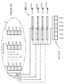
図1は、本発明の一実施による測距(又は「レンジング」)システム10を示す。図示されるシステムは、無線周波数パルス、即ちRADARを使用して、物体の存在、距離、速度、及び/又は他の特性を決定するが、本明細書の教示により、光ベースのパルス(LIDAR)を使用するシステム、及び/又は音などの他の波の形態を使用するシステム(ソナー)に等しく適用可能であることが理解されよう。図示されるシステム10の応用例は、とりわけ自律及び半自律走行車両誘導(例えば、「自走」車)を含む。
FIG. 1 shows a ranging (or "ranging")
図示される実施形態のパラメータは、以下の議論でのそのような応用例を中心とする。これは例によるものであり、そのような誘導をサポートする際の使用が意図されるか、それとも他の応用例かの如何に関わらず、及びRFを利用するか、それとも他のパルス形態を利用するかの如何に関わらず、同一又は他の動作及び設計パラメータを他の実施形態が利用し得ることを理解されよう。 The parameters of the illustrated embodiment are central to such applications in the discussion below. This is by way of example, whether intended for use in supporting such induction or other applications, and whether RF or other pulse forms are utilized. It is understood that other embodiments may utilize the same or other operating and design parameters, regardless of whether.
図示されるシステム10は、図面に示されるように相互接続され、以下でさらに説明される送信論理12、受信論理14、及び相関論理16を含む。
The illustrated
(送信論理)
送信論理12は、印加されたアナログ信号に基づくパルスを環境又はその他の中に送信するためにRADARシステムと共に(具体的には、例えば、パルス圧縮RADARシステムにおいて)使用するための、当技術分野で周知のタイプの構成要素を備える。図示される実施形態では、これが、図示されるように、又は当技術分野で周知のその他の形で接続された、電力増幅器18、バンドパスフィルタ20、及び送信アンテナ22を含むものとして示されている。
(Transmission logic)
Transmit
図示される要素18~22は、RFパルス送信の技術分野、例えば、RADAR応用例で周知のタイプであり、所望の応用例に従って(本明細書の教示に従って適合されるが)、印加される信号を調整し、それに基づいてパルスを送信するための、当技術分野で周知の従来の方式で選択され、構成される。 The illustrated elements 18-22 are of a type well known in the art of RF pulse transmission, e.g. is selected and configured in a conventional manner known in the art for adjusting , and transmitting pulses based thereon.
ここで示される送信論理12の構成要素は例によるものである。無線周波数パルスの送信に適した、当業者の理解の範囲内の他の構成要素が、その代わりに、又は追加で使用され得ることを理解されよう。さらに、やはり当業者の理解の範囲内の代替構成要素が、LIDAR、ソナー、又は他の波ベースの測距に基づく実施形態のために使用され得ることを理解されよう。
The components of transmit
(受信論理)
受信論理14は、送信されたパルスの可能な反射を表す到来アナログ信号を環境(又はその他)から受信するためにRADARシステムと共に(具体的には、例えば、パルス圧縮RADARシステムにおいて)使用するための、当技術分野で周知のタイプの構成要素を備える。事実として、それらの信号はしばしば雑音を含み(又はもっぱら雑音を構成し)得る。図示される実施形態では、受信論理は、図示されるように、又は当技術分野で周知のその他の形で接続された、受信アンテナ24、バンドパスフィルタ26、低雑音増幅器28、制限増幅器30を含む。
(Receive logic)
Receive
図示される要素24~30は、RADAR受信の技術分野で周知のタイプであり、(すべて、本明細書の教示に従って適合されるように)可能なパルス反射、並びに通常はノイズを含む到来信号を調整するための、当技術分野で周知の従来の方式で選択され、構成される。 The illustrated elements 24-30 are of a type well known in the art of RADAR reception, and (all as adapted in accordance with the teachings herein) detect possible pulse reflections, as well as the normally noisy incoming signal. selected and configured in a conventional manner known in the art for conditioning.
ここで示される受信論理14の構成要素は例によるものである。反射された無線周波数パルスの受信に適した、当業者の理解の範囲内の他の構成要素が、その代わりに、又は追加で使用され得ることを理解されよう。さらに、やはり当業者の理解の範囲内の代替構成要素が、LIDAR、ソナー、又は他の波ベースの測距に基づく実施形態のために使用され得ることを理解されよう。
The components of receive
(相関論理)
相関論理16は、多少でもそれらの間に高い相関があるときを見つけるために、受信論理14によって受信され、調整された到来信号を、送信論理12によって送信されたパルス(又は、より適切には、図示される実施形態では、パルスがそれに基づくパターン)と相関させる。図示される相関論理は、図示されるように(例えば、FPGAの論理ゲート又はその他によって)、或いは本明細書の教示に鑑みて明らかなように結合された、シリアライザ/デシリアライザ(SERDES)32、相関器34、及び波形生成器36を備える。
(correlation logic)
要素32~36のそれぞれはスタンドアロン回路要素でよく、或いは、それらのうちの1つ又は複数は、共通FPGA、ASIC、又はその他で実施され得る。さらに、要素32~36、又はそれらのうちの1つ若しくは複数は、上記で論じた他の要素のうちの1つ又は複数、例えば、要素12~30と共に、共通FPGA、ASIC、又は他の論理要素上に組み込まれ得る。FPGA、ASICなどの内に組み込まれるとき、要素32~36は、少なくとも3ギガサンプル/秒(GSPS)のレート、好ましくは、少なくとも28GSPSのレートで到来信号をサンプリングし、処理することを実現する。 Each of elements 32-36 may be stand-alone circuitry, or one or more of them may be implemented in a common FPGA, ASIC, or otherwise. Additionally, elements 32-36, or one or more thereof, may be implemented in a common FPGA, ASIC, or other logic together with one or more of the other elements discussed above, such as elements 12-30. can be embedded on an element. When incorporated within an FPGA, ASIC, etc., elements 32-36 provide for sampling and processing incoming signals at a rate of at least 3 gigasamples per second (GSPS), preferably at least 28 GSPS.
(波形生成器)
波形生成器36は、送信論理12によって送信されるパルスがそれに基づく(基づくことになる)パターンを実施する、長さmのマルチビットデジタル値(例えば、バイト、ワード、ロングワードなどでよい)を生成する。いくつかの実装では、これは静的な値である。他では、それは、周期的に、又はその他の形で変化するという点で動的である。
(waveform generator)
発生器36によって生成されるマルチビット値、又は「ビットパターン」の一例は、「111000110010」などのデジタル値であり、ただし1は、パルスが「オン」であるときを示し、0は、パルスが「オフ」であるときを示す。デジタル値で実施されるパターンは、「チャープ」パルス、即ち、短くなる時間枠にわたって「オン」及び「オフ」となるパルス、ここでは、例示のために過ぎないが、3刻み(tick)にわたってオン、3刻みにわたってオフ、2刻みにわたってオン、2刻みにわたってオフ、1刻みにわたってオン、1刻みにわたってオフとなるパルス(すべては例によるものである)を定義し、「刻み」は一般的な長さの瞬間(例えば、マイクロ秒、ミリ秒など)を指す。
An example of a multi-bit value, or "bit pattern", generated by
動的な値の一例は、擬似無秩序雑音シーケンス(PRN)からの値であるが、その代わりに、又はそれに加えて、例えば、適切な自己相関特性を有する他の動的な値が使用され得ることを当業者は理解されよう。 An example of a dynamic value is a value from a pseudo-random noise sequence (PRN), but other dynamic values can be used instead or in addition, e.g. with suitable autocorrelation properties. Those skilled in the art will appreciate that.
波形生成器36は、以下で論じるように、前述のマルチビットデジタル値を保持し、それをシリアライザ32bの入力に印加するのに適したレジスタ(図示せず)又は他の論理を備え得る。レジスタは、例えば、「工場で」、「店で」、又は他のオペレータ操作時にプログラムされ得る、例えば、ROM、EEPROMなどを備え得る。或いは、それは、ユーザ要求時又はその他で、例えば、PRN又は他の動的マルチビットデジタル値のケースのように、オンザフライで値を変更する線形フィードバックシフトレジスタ(LFSR)などの汎用又は専用論理(図示せず)でよい。そのような汎用又は専用論理は、本明細書の教示に鑑みて、当業者の理解の範囲内の技術を利用して、FPGA、ASIC、又はその他で実装され得る。
(シリアライザ/デシリアライザ(SERDES))
図示される論理16は、本明細書の教示に従って適合される、当技術分野で周知のタイプのシリアライザ/デシリアライザ32(SERDES)を含む。SERDES32は、スタンドアロン電子回路要素でよく、又は汎用若しくは専用回路要素、例えば、フィールドプログラマブルゲートアレイ(FPGA)、特定用途向け集積回路(ASIC)などの中に、例えば、インターフェースユニットとして組み込まれるものでよい。図示される実施形態では、SERDES32は、例えば、パルス圧縮器34及び波形生成器36と共に、相関ユニット16の形成部分として示されており、実際に、いくつかの実施形態では、それらのユニットは共通FPGA(又はASIC)上にある。他の実施形態では、SERDES32は、それらのユニット34、36の一方又は両方から別々にパッケージ化され得る。
(Serializer/Deserializer (SERDES))
The illustrated
慣習により、SERDES32は、入力及び出力をそれぞれ含む、デシリアライザ32a(「受信側」とも呼ばれる)及びシリアライザ32b(「送信側」とも呼ばれる)を含む。それらの入力及び出力は、当技術分野で一般的であるように、(例えば、スタンドアロンSERDESのケースでは)リード、(FPGA内に組み込まれるSERDESのケースでは)論理経路などでよい。
By convention, the
(デシリアライザ)
デシリアライザ32aは、その入力でデジタル信号を受け入れ、その出力で、例えば、「並列化」(「デシリアライズ」とも呼ばれる)し、又は入力信号を構成するビットをグループ化する(例えば、ビットのストリームをバイト、ワード、又はロングワードに変換する)ことによって、それを別のフォーマットのデジタル信号に変換するための、当技術分野で一般的に知られているタイプのものである。
(deserializer)
The
デシリアライザ32aは、測距システム10のレンジ及び経路内の物体からのパルスの可能な反射を表す入力信号38を受け入れるために、例えば、図1及び2に示されるように受信論理14に結合される。それらの信号38は、それらが環境から受信され、特に、例えば、その中の要素18~22がRADARの技術分野で周知のタイプであるシステム10内の、受信論理14の要素によって処理される方式を考慮すると、通常は「アナログ」信号と見なされ得る(図2にそのように示されている)。
しかしながら、デシリアライザ32aは、その入力でそれらの「アナログ」信号を、デジタルであるかのように、具体的には、図示される実施形態では、ビットのストリームであるかのように受け入れ、それは、その出力で、それらのビットを、例えば、ロングワードとしてグループ化する。本明細書では、「ロングワード」という用語は、32ビットワードだけではなく、データの任意のマルチビットユニットを指す。好ましい実施形態では、128ビットワード(「オクタワード」又は「ダブルクァッドワード」とも呼ばれる)があるが、他の実施形態では、それらは、ニブル(4ビット)、バイト(8ビット)、半ワード(16ビット)、ワード(32ビット)、又は任意の他のマルチビットサイズでよい。
However, the
したがって、図示される実施形態のデシリアライザ32aは、実質的には、パルスの可能な反射を表す(その入力で受信された)到来「アナログ」信号をサンプリングし、(その出力で生成される)ロングワードのストリームに変換する1ビットADC(即ちアナログ-デジタル変換器)として動作し、サンプリングは、高(振幅1)及び低(振幅0)の2つの振幅についてだけである。したがって、そのストリーム中のロングワードは、それらの可能な反射を表すビットパターンを実施する。
Thus, the
図2に示される実施形態では、デシリアライザ32aは、図示されるように、入力信号38をサンプリングし、4ビット「ロングワード」(より適切には、「ニブル」)のデジタルストリーム40に変換(グループ化)する。それらのロングワードのサイズに、典型的に、合致するサイズである幅n(ここではn=4)を有する回路経路42が、それらのロングワードを相関器34内のレジスタに搬送する。(図5以降に示されるようないくつかの好ましい実施形態では、非限定的な例として、ロングワードは128ビット長であり、経路42は128ビット幅である。)理解されるであろうが、ロングワード内に格納されたそれぞれの連続するビットは、異なるそれぞれの時間での入力信号38の振幅を表す。
In the embodiment shown in FIG. 2,
(シリアライザ)
デシリアライザ32aと同様に、シリアライザ32bは、その入力でデジタル信号を受け入れ、例えば、入力信号を構成するビットをシリアライズ又は非グループ化する(例えば、バイト、ワード、又はロングワードを、その構成ビットのストリームに変換する)ことによって、その出力でそれを別のフォーマットのデジタル信号に変換するための当技術分野で周知のタイプである。
(serializer)
Similar to
シリアライザ32bの入力は波形生成器36に結合され、波形生成器36は、送信論理12によって送信されるパルスのベースとなるパターンを実装するワード、ロングワード、又は他のマルチビットデジタル値をその入力に印加する。シリアライザ32bは、その入力でマルチビット値をシリアライズ又は非グループ化し、パルスとして環境又はその他に送信するために、それを送信論理12、より具体的には、図示される実施形態では電力増幅器18に、例えば個々のビットのストリームとして印加する。
The input of
この目的で、アナログ信号が通常は送信論理12に印加されることを当業者は理解されよう。しかしながら、シリアライザ32bは、アナログであるかのように扱われ、パルスとして環境又はその他に送信されるように、そのデジタル出力を論理12(ここでは、具体的には増幅器18)に印加する。
Those skilled in the art will appreciate that an analog signal is typically applied to transmit
したがって、図示される実施形態のシリアライザ32bは、実質的には、波形生成器36によって印加されたデジタル信号を個々のビットのストリームに変換し、送信アンテナ22によるパルスとしての増幅及びブロードキャストのために、アナログ信号であるかのように送信論理12に印加される1ビットDAC(デジタル-アナログ変換器)として動作する。
Thus,
(相関器)
相関器34は、送信論理12によって送信されるパルスのベースとなるパターンを実装する波形生成器36からのマルチビットデジタル値で実現されるビットパターンを、入力信号38からデシリアライザ32aによって生成されるロングワードのデジタルストリームで実装されるパルスの可能な反射を表すビットパターンと相関させる。この目的で、相関器34は、(発生器36からの)パルスビットパターンと、相関器(又はその他)の部分を形成するレジスタ内に記憶された(デシリアライザ32aからの)デジタルストリームの連続する部分で実装されるビットパターンとの最良の合致がある場合にそれを探索する。
(correlator)
図2を参照すると、図示される実施形態では、相関器34は、(例えば、FPGA又はその他の論理ゲートによって)図示され、又は本明細書の議論に鑑みてその他の形で明らかとなるように結合された、サンプルレジスタ44、積和(MAC)ユニット46、及び(発生器36からの)パルスビットパターンについてのストア48を備える。要素44~48のそれぞれは、スタンドアロン回路要素でよく、或いは、それらのうちの1つ又は複数は、共通FPGA、ASIC、又はその他で実施され得る。さらに、要素44~48、又はそれらのうちの任意の1つ又は複数は、SERDES32、及び/又は上記で論じた他の要素、例えば要素12~30のうちの1つ又は複数と共に、共通FPGA、ASIC、又は他の論理要素上に組み込まれ得る。
Referring to FIG. 2, in the illustrated embodiment,
(サンプルレジスタ)
サンプルレジスタ44は、それらが含むビットパターン(論理14によって受信されたパルスの可能な反射を表す)が(発生器36からの)パルスビットパターンに対して比較され得るのに十分な長さの、デシリアライザ32aによって生成されたデジタルストリーム40からのロングワードを格納する(又は「バッファリング」する)。図示される実施形態では、複数のp個のレジスタが設けられる(ここでは、A、B、及びCと符号が付けられる)。効率のために、それぞれが、デシリアライザ32aによって出力された単一のロングワードのビットを個々の1ビット記憶要素(ここでは、A[0]...A[3]、B[0]...B[3]、及びC[0]...C[3]と符号が付けられる)内に収容するようなサイズに作られる。したがって、例えば、回路経路42が幅n(例えば、4ビット、128ビットなど)である場合、レジスタ44A~44Cはそれぞれ同一の長さnである。他の実施形態では、レジスタは、例えば、それらのうちの複数がデシリアライザ32aによって出力された単一のロングワードのビットを収容することが必要とされるように、又は逆に、複数のそのようなロングワードが単一のレジスタを埋めることが必要とされるように、異なるサイズに作られ得る。
(sample register)
Sample registers 44 are of sufficient length so that the bit patterns they contain (representing possible reflections of the pulses received by logic 14) can be compared against the pulse bit patterns (from generator 36). Store (or "buffer") longwords from the
(前述のように)スタンドアロン回路要素又は共通回路要素で実施され得るレジスタ44は、各クロック又は処理サイクル(又はその他)と共に、デシリアライザ32aから経路42を介して受信された各ロングワードがレジスタAから、レジスタB、次いでレジスタに進むように、シフトレジスタ(又はその他)として実装され得る。
図示される実施形態では、pは、p≧1+roundup((m-1)/n)によって定義され、ただしm及びnは、上記で論じたように定義される。このようにしてpを選択することは、MACユニット46が(発生器36からの)パルスビットパターンと、(デシリアライザ32aからの)デジタル化された可能な反射内のビットパターンとの最良の合致を、もしあれば、それらの反射がロングワード境界上に来ない場合であっても見つけることを可能にするように、十分な数のロングワードがレジスタ44内にバッファリングされることを保証する。
In the illustrated embodiment, p is defined by p≧1+roundup((m−1)/n), where m and n are defined as discussed above. Selecting p in this manner allows
(積和ユニット)
積和(MAC)ユニット46は、デジタルストリーム40の連続するそれぞれの部分を受信するように、レジスタ44を構成する要素のそれぞれのセットに結合され、その中に格納されたビットパターンを受信するようにパターンストア48に結合される。デジタルストリーム40のそれぞれのそのような部分は、入力信号38の連続するサンプルを備え、他の部分にない少なくとも1つのサンプルを含む。連続する部分は重複しているが、1つ又は複数の連続するサンプルだけ互いにオフセットされる。
(product sum unit)
A multiply-accumulate (MAC)
上記が図3Aに示されており、FPGAの論理ゲートを介して、ハードワイヤリングを介して、又はその他でレジスタ44の要素A[0]、A[1]、A[2]、A[3]、B[0]、及びB[1]に結合されたMAC[0]と、同様に要素A[1]、A[2]、A[3]、B[0]、B[1]、及びB[2]に結合されたMAC[1]と、A[2]、A[3]、B[0]、B[1]、B[2]、及びB[3]に結合されたMAC[2]と、A[3]、B[0]、B[1]、B[2]、B[3]、及びC[0]に結合されたMAC[3]とを示す(それらのMACユニット46はまた、図示されるように、FPGAの論理ゲートを介して、ハードワイヤリングを介して、又はその他でパターンストア48にやはり結合される)。
The above is illustrated in FIG. 3A, where the elements A[0], A[1], A[2], A[3] of
図2を参照すると、それぞれの図示されたMACユニットは、(i)MACユニットが結合されるレジスタ44の要素内にバッファリングされたデジタルストリーム44のそれぞれの部分の値を、波形生成器36からのマルチビットデジタル値で実施されるビットパターンとビットごとに乗算し、(ii)それらの乗算の結果を合計する。以下で論じられるように、本発明のいくつかの実施形態では、波形生成器からのビットパターンは乗算のために使用される。MACユニット46の構成が図3Bにより詳細に示されており、乗算演算の代わりにXOR演算が利用される実施形態を示す。
Referring to FIG. 2, each illustrated MAC unit receives (i) the value of the respective portion of the
その和に基づいて各MACによって生成された出力は、デジタルストリームのそれぞれの部分、及びそれによって、受信論理14によって受信されたパルスの可能な反射のそれぞれのサンプリングと、論理12によって送信されるパルスがそれに基づいたビットパターンとの相関度を示す。それらの出力は、図面ではCORR[0]...CORR[3]と符号で示されている。
The output produced by each MAC based on its sum is the respective portion of the digital stream and thereby each sampling of the possible reflections of the pulse received by receive
図示される実施形態では、複数のk個のMACユニットが設けられる。それらは、ここではMAC[0]...MAC[3]と符号が付けられ、それぞれは、波形生成器36からのマルチビットデジタル値のmビットを、デジタルストリームのそれぞれの部分のmビットと乗算する(又は、代替的に、以下で論じるように、それに関するXOR演算を実施する)ためのm個の論理要素を収容するようなサイズに作られる。
In the illustrated embodiment, a plurality of k MAC units are provided. They are here MAC[0]. . . MAC[3], each multiplying m bits of the multi-bit digital value from
(前述のように)スタンドアロン回路要素又は共通回路要素で実施され得るMACユニットは、それぞれの入力を乗算及び合計する当技術分野で一般的に知られているタイプのものでよい。そのような実施形態では、より大きい出力はより高い相関度を示す。相関がビットパターン間である場合に使用するための図3Bに示されるような実施形態では、MACユニットは、ブール排他的論理和演算(XOR)として実装される。比較されるビットが合致する場合、XOR演算が値0を有するので、より小さい出力はより高い相関度を示す。以下で論じるように、本発明のいくつかの実施形態では、波形生成器からのビットパターンがXOR演算のために使用される。 MAC units, which may be implemented in stand-alone circuitry or in common circuitry (as described above), may be of the type commonly known in the art that multiply and sum their respective inputs. In such embodiments, a higher output indicates a higher degree of correlation. In an embodiment such as that shown in FIG. 3B for use where the correlation is between bit patterns, the MAC unit is implemented as a Boolean exclusive OR operation (XOR). A smaller output indicates a higher degree of correlation because the XOR operation has a value of 0 if the compared bits match. As discussed below, in some embodiments of the present invention, bit patterns from waveform generators are used for XOR operations.
図示される実施形態では、値kが以下の式によって定義される。m≦nである場合はk=n、それ以外の場合はk=rounddown(n/m)。このようにしてkを選択することは、十分な数のMACユニットが(発生器36からの)パルスビットパターンと、(デシリアライザ32aからの)デジタル化された可能な反射内のビットパターンの連続する部分との最良の合致がある場合にそれを、それらがロングワード境界上に来ない場合であっても見つけることを保証する。 In the illustrated embodiment, the value k is defined by the following equation. k=n if m≦n, otherwise k=rounddown(n/m). Selecting k in this manner ensures that a sufficient number of MAC units is a continuous Guarantees to find the best matches to the parts, if any, even if they do not lie on longword boundaries.
上記の構成を通じて、MACユニット46は、(発生器36からの)パルスビットパターンを、(デシリアライザ32aからの)(デジタル化された)可能な反射のデジタルストリーム中のビットパターンで表されるパルスと、それらのパルスがロングワード境界上に来ない場合であっても相関させることができる。レジスタ44内に格納される(かつMACユニットによって利用される)それぞれの連続するサンプルは、異なるそれぞれの時間での入力信号38の振幅を表す。非常に高程度の相関が見つけられると、入力信号38のそれぞれの部分の受信の時間が、計算的に(デシリアライザ32a及び相関論理34を実装する回路のクロックタイミングに基づいて)又はその他の形で決定され得る。
Through the above configuration,
図示される実施形態では、それぞれのMACユニット46がそれに対して演算する(レジスタ44内に格納された)デジタルストリームの部分は、ストリーム40中のロングワードからの直に隣接するサンプルのセットを備える。他の実施形態では、本明細書の趣旨から逸脱することなく、それらは、ほぼ隣接するサンプル、例えば、デジタルストリームからの1つおきのサンプル、3つのサンプルごとに2つなどを備え得る。同様に、図示される実施形態では、デジタルストリームの連続する部分は、ただ1つのサンプルだけ互いにオフセットされるが、他の実施形態では、やはり本明細書の趣旨から逸脱することなく、それらは、2つ以上のサンプルだけオフセットされ得る。
In the illustrated embodiment, the portion of the digital stream (stored in register 44) on which each
(ビットパターンストア)
MACユニット46は、それからマルチビット値を受信するように、発生器36に直接的に結合され得る。しかしながら、図示される実施形態では、MACユニットはストア48からその値を受信し、ストア48は発生器36から値を受信する。図示されるように発生器36に結合され得る、図示される実施形態のストア48は長さmであり、発生器36によって生成されたデジタル値のそれと合致する。その要素は、ここではそれぞれCode[0]...Code[5]と符号が付けられる。ストア48は、前述のようにスタンドアロン回路要素又は共通回路要素で実施され得る。いくつかの実施形態では、ストア48は、MACユニットによる乗算演算又はXOR演算で使用するために、発生器36からのマルチビット値の時間反転値を保持する。
(bit pattern store)
(演算(Operation))
相関論理34の演算が図4A~4Eに示されており、以下で説明される。
(Operation)
The operation of
図4Aに示されるように、デシリアライザ32aは、可能なパルス反射を含む、論理12によって受信される入力信号38のそれぞれのサンプルの振幅をそれぞれ表す1及び0からなるロングワード、ここではニブルを含むデジタルストリーム40を生成する。(ここでは、及び他の図面では、例示に関して「無関係(don't care)」であることを示すためにXが示されており、実際には、これらも1又は0となる。)図4Aではレジスタ44が空として示されているが、実際には、それらは、先に取得されたサンプルで埋められる可能性が高い。図面に示されるように、ストア48は、波形生成器36から受信された(時間反転)パルスビットパターン値でプリロードされ得る。MACユニット46はまた、デフォルトでデフォルト値LOWを出力し得、それらのユニット46のそれぞれに関連するレジスタ44の要素と、ストア48内のビットパターンとの間に相関がないことを示す。
As shown in FIG. 4A,
図4Bは、論理34の動作の次のクロック又は他の処理サイクルを示す。ここでは、デジタルストリーム40中のロングワードのうちの最初に生成されたものが、シフトレジスタのうちの最初(レジスタA)にロードされる。MACユニット46は、上記のようにLOW値出力を引き続き放射する。それらのユニット46のそれぞれに関連するレジスタ44の要素と、ストア48内のビットパターンとの間に相関が残っていないからである。
FIG. 4B shows the next clock or other processing cycle of
図4C~4Eは、論理34の動作の次のいくつかのクロック又は処理サイクルを示す。各サイクルでは、シフトレジスタ44の内容があるレジスタから次のレジスタに、即ちレジスタAからレジスタBに、次いでレジスタCにシフトされ、デジタルストリーム40からの新しいロングワードが、第1のシフトレジスタA内にロードされる。内容がシフトされるとき、各MACユニット46は、そのユニット46に関連するレジスタ44の要素と、ストア48内の(時間反転)ビットパターンとの間の相関を再計算する。
4C-4E illustrate the next few clock or processing cycles of
MACユニット46は、図4Dに関連するサイクルの間を除いて、LOW値を引き続き出力する。そこでは、MAC[3]がHIGH値を出力するものとして示されており、ストア48内のビットパターン「110010」と、そのMACユニットに関連するレジスタ要素A[3]、B[0]、B[1]、B[2]、B[3]、及びC[0]内に格納されたパターン「110010」との間の相関を示す(その関連は上記で論じられ、図3A及び3Bに示される)。
相関論理がその部分である測距システム10の部分を形成する論理が、相関がその結果として生じるパルス反射を含む入力信号38のその部分の受信時間を(例えば、上記で論じたように)決定し、それから、それらの反射を引き起こした物体の存在、距離、及び/又は速度を決定することによって、HIGH値に応答し得る。そのような決定を行うために必要とされる論理は、本明細書の教示に鑑みて当業者の理解の範囲内にある。
The logic forming the portion of the ranging
(例)
図5及び6は、直接無線周波数(図5)及びヘテロダインBPSK変調(図6)RADAR応用例での本発明の実施形態を示す。図7は、LIDAR応用例での本発明の実施形態を示す。図5~7では、同様の機能の要素を示すのに図1と同様の名称が使用される。それらの要素の構成及び動作は、上記及び以下の教示に鑑みて当業者には明らかであろう。
(example)
5 and 6 show embodiments of the invention in direct radio frequency (FIG. 5) and heterodyne BPSK modulation (FIG. 6) RADAR applications. FIG. 7 shows an embodiment of the invention in a LIDAR application. 5-7, like nomenclature is used as in FIG. 1 to denote like-functional elements. The structure and operation of these elements will be apparent to those skilled in the art in view of the above and following teachings.
図5~7の実施形態の特徴は以下を含む。 Features of the embodiments of FIGS. 5-7 include the following.
1.28ギガサンプル/秒(GSPS)で、14GHzアナログ帯域幅と共に動作する1ビットデジタル-アナログ変換器としての、シリアライザ32b、即ちSERDES32の「送信側」の使用
2.28ギガサンプル/秒(GSPS)で、14GHzアナログ帯域幅と共に動作する1ビットアナログ-デジタル変換器としての、デシリアライザ32a、即ちSERDES32の「受信側」の使用
3.28ギガサンプル/秒(GSPS)で動作する信号処理を実装して、上記で論じた要素の中でもとりわけ、本明細書でSERDES、相関器34、及び波形生成器36に属すると考えられる機能を実施するための、FPGA又はASICの高入出力スループット(数テラビット/秒)及び論理容量(1Mフリップフロップ超)の使用
Using the
A.SERDES32の送信側の詳細な動作
SERDESの送信機(TX)部分32bは、28GSPSで動作する1ビットDACとして働く。
A. Detailed Operation of the
それぞれの生成されたサンプルは、送信セクション12を形成する100オーム差動伝送線路内に送達される振幅1.1Vppの立上り又は立下りパルスのどちらかである。立上り/立下り時間は~12ピコ秒(ps)であり、RMS時間ジッタは~8psである。
Each generated sample is either a rising or falling pulse of amplitude 1.1 Vpp delivered into the 100 ohm differential transmission line forming transmit
RADAR応用例では、システムは、望ましい自己相関特性(0以外の任意のラグで最小の自己相関振幅)を有する波形を生成する。そのような波形の1つの実際の例は、擬似無秩序雑音シーケンス(PRN)である。具体的には、複数のRADARが、近接して、同一の搬送周波数で動作しているとき(例えば、自動車RADAR)、システムは、各RADARに、他のすべてと直交するそれ自体のPRNシーケンス(ビタビシーケンス)を割り当てる。シーケンスは、メモリ内に格納され、又は例えば波形生成器36の部分を形成する、線形フィードバックシフトレジスタ(LFSR)と共に「オンザフライ」で生成され得る。
In a RADAR application, the system produces a waveform with the desired autocorrelation properties (minimum autocorrelation amplitude at any lag other than 0). One practical example of such a waveform is a pseudorandom noise sequence (PRN). Specifically, when multiple RADARs are operating in close proximity and on the same carrier frequency (e.g., automotive RADARs), the system provides each RADAR with its own PRN sequence ( Viterbi sequence). The sequence may be stored in memory or generated "on the fly" with a linear feedback shift register (LFSR), which forms part of the
別の実際の波形例はチャープのデジタル近似である。例として、図1及び5に示されるタイプの送信回路を通じてデジタルシーケンス11110000111000111001100110101010の送信の結果として得られる、図1に関連して上記で論じた波形50を示す図8を参照されたい。 Another practical waveform example is a digital approximation of a chirp. As an example, see FIG. 8 which shows waveform 50 discussed above in connection with FIG.
B.SERDES32の受信側32aの詳細な動作
トランシーバ(SERDES32)の受信側32aは、28GSPSで動作する1ビットADC(比較器)として働き、立上り/立下り時間は~12psであり、RMS時間ジッタは~8psである。受信機(RX)32a入力は、100オーム差動入力インピーダンスを有し得る。一実施形態では、1×10e-12ビット誤り率を保証するために、入力信号の差動振幅は少なくとも250mVである。一実施形態では、RX入力の前方のドライバ増幅器28、30が、所望のサンプリング済み信号を少なくとも250mVまで引き上げる。
B. Detailed Operation of the Receive
SERDES32aは、218MHzのレートの128ビット幅の並列データストリーム40を出力する。
The
決定性待ち時間を保証するために、SERDESのすべてのクロック追跡及び補正機能(クロック&データ回復(CDR))が使用不能にされている。 To guarantee deterministic latency, all SERDES clock tracking and correction functions (Clock & Data Recovery (CDR)) are disabled.
C.相関器34による受信デジタル信号処理
相関器34は、28GSPSのレートで動作し、真の28GHzアナログ解析帯域幅を特徴とする。比較のために、2011年のMIT Lincoln Labsの最新のRADARは、わずか4GSPSで動作する相関器の主要な性能指数を誇った。
C. Receive Digital Signal Processing by
相関器34の部分を形成し、かつ/又は相関器34に結合されるEEPROM又は他のメモリ(図示せず)内に格納され得る相関器係数は、適用された更新によって再構成され得る。比較のために、従来技術の表面弾性波相関器は、同程度の28GHzアナログ帯域幅で動作することができるが、その係数が「その幾何形状内にエッチング」される。
Correlator coefficients, which form part of
D.動作
SERDES受信機32aは、218MHzのレートで128ビット幅ワードのストリームを出力する。各ビットは単一のサンプルに対応する。最下位ビット(LSB)は、SERDES32のRXサンプラ32aにたどり着く最初のサンプルであり、最上位ビット(MSB)は最後のサンプルである。時間領域相関を実装するために、システムは、到来RXシーケンスに対して送信されたシーケンスの時間反転バージョンとの積和演算(Multiply-and-Accumulate operation)を実施する。
D.
E.リアルタイム演算
図示される実施形態では、128個の可能なタイムシフトのうちの1つにそれぞれ割り当てられる、並列に動作する128個の積和ユニット44が設けられる。積和ユニット44演算はパイプライン式に実装される。
E. Real Time Arithmetic In the illustrated embodiment, 128 multiply-accumulate
・第1のパイプラインステージは、サンプルごとの乗算をビット単位XORとして実行する。各サンプルの振幅はわずか1ビットであるので、これは適法である。
・後続のパイプラインステージは、すべての個々のXORの結果を累積する(折り重ねる)。
・タイミングを近づけるために、実施形態は、218MHzスループットを達成するのに十分なパイプラインステージを実装する。
- The first pipeline stage performs the sample-wise multiplication as a bit-wise XOR. This is legal because the amplitude of each sample is only 1 bit.
• Subsequent pipeline stages accumulate (fold) the results of all individual XORs.
• To bring the timing closer, the embodiment implements enough pipeline stages to achieve 218 MHz throughput.
前述の実施形態についてのリソース利用は以下の通りである。 The resource utilization for the above embodiment is as follows.
・Xilinx UltraScale技術では256サンプル幅リアルタイム相関器が8782個の論理セルを消費した。これは、Xilinx Virtex UltraScale VU095の0.7%の利用に相当する。
・これに基づいて、推定が、このデバイスでは最大10^4~10^5サンプル幅リアルタイム相関器に適合している。
• A 256-sample wide real-time correlator consumed 8782 logic cells in the Xilinx UltraScale technology. This corresponds to 0.7% utilization of the Xilinx Virtex UltraScale VU095.
• Based on this, the estimation is suitable for real-time correlators up to 10^4-10^5 samples wide in this device.
F.非リアルタイム演算
より長い相関器34を実装するために、実施形態はまず、サンプルをローカルメモリ内に格納する。
F. Non-Real-Time Computation To implement a
4位相偏移キーイング(QPSK)全28GHzアナログ帯域幅設計では、実施形態は、DDR4などの少なくとも7GB/秒のメモリ帯域幅を使用する。128GB DDR4メモリモジュールは、後のオフラインの相関のために1×10e12個のサンプルを格納することができることになる。 For a Quadrature Phase Shift Keying (QPSK) full 28 GHz analog bandwidth design, embodiments use at least 7 GB/sec memory bandwidth such as DDR4. A 128GB DDR4 memory module will be able to store 1×10e12 samples for later off-line correlation.
(ビームフォーミング)
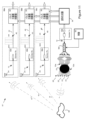
ビームフォーミング又はビーム操舵(本明細書では同義に用いられる用語)を利用して、物体の方位、並びに、例えば、存在、距離、速度、ドップラー、及び/又は他の特性を決定する測距システムが以下で説明され、図9~11に示される。システムは、これを、(i)システムによって環境内に送信されるパルスの実際の(又は有効な)向きを変更すること、及び/又は(ii)それによって反射され、例えば、複数のアンテナによって受信されたパルスから物体方位を推論することによって実施する。本明細書では、「方位」とは、測距システム、又はより典型的には、例えば、そのようなシステムが配置される車両に向かい合う物体の角度若しくは方向を指す。図9~10は、並列トランシーバセクション及び共通相関器を利用する測距システム51を示す。図11は、ロットマンレンズ及び並列受信機セクションを備える別のシステムを示す。これらのシステムは、図9~11に示されるように構成されるが、(同様の参照番号の使用によって示されるように)図1~4に関連して上記で論じたタイプの構成要素を利用し、それらの図面に従って修正され、以下で論じられるように、それと同様に動作する。
(beam forming)
Ranging systems that utilize beamforming or beam steering (terms used interchangeably herein) to determine object orientation and, for example, presence, range, velocity, Doppler, and/or other properties It is described below and illustrated in FIGS. 9-11. The system does this by (i) changing the actual (or effective) direction of the pulses transmitted by the system into the environment, and/or (ii) reflected thereby and received by, for example, multiple antennas. This is done by inferring the object orientation from the received pulses. As used herein, "azimuth" refers to the angle or direction of an object facing a ranging system, or more typically, for example, a vehicle in which such a system is located. 9-10 show a ranging
(並列トランシーバセクション及び共通相関器)
図9~10を参照すると、測距システム51は、並列トランシーバセクション52a、52b、52cを含み、そのうちの3つが図面に示され、以下で論じられる(しかし、他の実施形態がより多数又は少数のそのようなセクションを利用し得ることを理解されよう)。図示されるように、各セクション52a~52cは、送信アンテナ22を含む送信論理12と、受信アンテナ24を含む受信論理14とを備える。セクション52a~52cのそれぞれの送信論理12は、システム51がそれに基づくRADAR又は他の波ベースの測距プロトコルのために、例えば、「送信論理」という見出しの下で、図1~4に関連して上記で論じられたように選択され、構成され、動作する構成要素(必ずしも図9には示されていない)を備える。同様に、セクション52a~52cのそれぞれの受信論理14は、システム51がそれに基づくRADAR又は他の波ベースの測距プロトコルのために、例えば、「受信論理」という見出しの下で、図1~4に関連して上記で論じられたように選択され、構成され、動作する構成要素(必ずしも図9には示されていない)を備える。
(parallel transceiver section and common correlator)
9-10, ranging
各トランシーバセクション、例えば、52aの送信論理12及び受信論理14は、(i)そのセクション、例えば、52aに共通であるが、(ii)他のセクション、例えば、52b、52cによって使用されるものとは(少なくとも、それぞれのセクションの構成要素によってそのように区別可能に)異なる、パルスの送信及び受信のための搬送波及び/又は他のプロトコルを利用する。したがって、例として、トランシーバセクション52aは、周波数F1の搬送波を利用してパルスを送信及び受信し得、トランシーバセクション52bは周波数F2を利用し得、トランシーバセクション52cは周波数F3を利用し得る。或いは、別の例として、トランシーバセクション52a、52b、52cは、同一の周波数を利用するが、それぞれ異なる符号化パルスシーケンスP1、P2、及びP3を送信し得る。したがって、トランシーバセクション52a~52cによって送信及び受信されるパルスは同一でよいが(しかし、異なるそれぞれの搬送波で符号化される)、それらのセクションは、大きな漏話又は他のチャネル干渉なしに、同時にそれぞれのパルスを送信及び/又は受信し得る。
The transmit
さらに、各トランシーバセクション52a~52cは、以下の教示に従って適合される、図1~4に示され、それに関連して、例えば、「シリアライザ/デシリアライザ(SERDES)」という見出しの下で、上記で説明したSERDESの方式で動作するSERDES32を含む。システム51の各SERDESは、(i)図1~4に示され、それに関連して上記で説明した、対応する要素のそれと同様に、そのそれぞれのセクションの受信機論理14に結合され、それと共に動作するデシリアライザ32aと、(ii)図1~4に示され、それに関連して上記で説明した、対応する要素のそれとやはり同様に、それぞれのセクション52a~52cの送信論理12に結合され、それと共に動作するシリアライザ32bとを有する。図9~10のシステム51では、各SERDES32のシリアライザ32bの入力が、時間遅延論理54bを介して波形生成器36に結合される。さらに、システム51では、各SERDES32のデシリアライザ32aの出力で生成されたロングワード(例えば、ニブル)を搬送する回路経路が、遅延論理54aと、図示されるように相関器34’に直列に結合された加算論理58とを含む。
Further, each
(遅延論理)
本明細書の教示に従って適合される、当技術分野で周知のタイプのデジタル遅延線を備える遅延論理要素54a、54bが、それらがその上にある回路経路の幅に合致するようなサイズに作られる。要素54a、54bは、それらを通過するそれぞれのストリーム又は信号内の異なる遅延(又は休止)を実施するために、動的に、互いに独立に設定され得る。図示される実施形態では、制御論理60が、本明細書の教示に従ってそれらの遅延間隔を設定するために、要素54a、54bに結合される。
(delayed logic)
Delay
具体的には、各トランシーバセクション52a~52cの遅延論理54aは、それぞれのデシリアライザ32aから受信したnビットロングワードのそれぞれのデジタルストリーム40a~40cを、加算論理58にそのストリームを渡す前に、指定の時間間隔Δ1だけ遅延するためのデジタル遅延線を備える。各トランシーバセクション52a~52cの遅延論理54bは、波形生成器36によって生成されたマルチビットデジタル値のそれぞれのシリアライザ32bへの印加を時間間隔Δ2だけ遅延し、したがってそのそれぞれのトランシーバセクションがその値に基づいてパルスを環境内に送信することを時間間隔Δ2だけ遅延するデジタル遅延線を備える。
Specifically, the
本明細書の教示に従って動作する状態機械、マイクロプロセッサ、又は他の論理を備え得る制御論理60は、それらの反射を引き起こした物体の存在、距離、及び/又は速度を決定する前述の論理、即ち以下で「測距論理」と呼ばれるものに結合され得る(実際には、その部分を形成し得る)。
(送信パルスの操舵)
(それらの構成要素の中でも)それらのそれぞれのシリアライザ32b及びアンテナ22を含む、それぞれのトランシーバセクション52a~52cの送信論理12は、図1~4の実施形態の同名の要素に関連して上記で説明したのと同様に波形生成器36と共に動作する。したがって、上記の「シリアライザ」という見出しの下での議論に適合して、各セクション52a~52cのシリアライザ32bは、その入力でマルチビット値をシリアライズ又は非グループ化し、それを、例えば、個々のビットのストリームとして、パルスとして環境又はその他に送信されるべきそれぞれのセクション52a~52cの送信論理12に印加する。上記と同様に、そのようなシリアライザ32bは、実質的には、それに印加されたデジタル信号を、送信アンテナ22によるパルスとしての増幅及びブロードキャストのためにそのストリームがアナログ信号であるかのように、それが送信論理12に印加する個々のビットのストリームに変換する1ビットDACとして動作する。
(Steering of transmitted pulse)
The transmit
前述のように、トランシーバセクション52a~52cのシリアライザ32bのそれぞれの入力は、環境内に送信されたパルスのベースとなるであろうパターンを実装するマルチビットデジタル値を受信する。図9~10の実施形態では、同一のそのような値が、発生器36によって、それらのそれぞれの遅延論理要素54bを介して、シリアライザ32bのすべてに印加される。
As previously mentioned, the input of each of the
異なる時間遅延値Δ2をそれらの要素54bのうちの1つ又は複数に印加することによって、システム51、より具体的には、例えば、制御論理60は、それらのビットパターンが環境内に送信される有効な方向に「向け」得、その結果、それらは、システム51(より典型的には、例えば、システムがその上に配設される車両)のレンジ内に配設された物体に、よりほぼ同時に到着する。さらに、Δ2の値を経時的に変更することによって、システム51、より具体的には、例えば論理60は、システム51(より典型的には、例えば、システムがその上に配設される車両)の運動のレンジ及び/又は経路内の角度のレンジにわたって、ビットパターンが環境内に送信される有効な方向に「操舵」し得る。
By applying different time delay values Δ 2 to one or more of those
例えば、セクション52aの遅延論理要素54bについてΔ2を0マイクロ秒に、セクション52bの要素54bについてΔ2を0.05マイクロ秒に、セクション52cの要素54bについてΔ2を0.10マイクロ秒に設定することによって、制御論理60は、それらのトランシーバセクション52a~52cのそれぞれのアンテナ22によって送信されるパルスが、例えば、図9に示されるように、セクション52cのアンテナ22のより近くに配設され、セクション52bの対応するアンテナからはより遠くに配設され、セクション52aのそのアンテナからはさらにより遠くに配設される物体62に、よりほぼ同時に到着することを保証する。物体62がシステム51に対して移動している場合、これは、それらのパルスの反射からシステム51によって識別可能な距離情報が、物体62の位置のより正確な三角測量のために使用され得るという利点を有する。
For example, set Δ2 to 0 microseconds for
さらに、Δ2の値を経時的に変更することによって、例えば、上記の例を続けると、セクション52aの遅延論理要素54bについてのΔ2を0マイクロ秒から0.10マイクロ秒に、セクション52cの要素54bについてのΔ2を0.05マイクロ秒から0マイクロ秒に、再び最大0.05マイクロ秒に、セクション52bの要素54bについてのΔ2を0.10マイクロ秒から0マイクロ秒に増分式に変更することによって、制御論理60は、それぞれのアンテナによって送信されるパルスを操舵し得、その結果、それらは、図面に示されるように、システム51の送信アンテナ22のアレイの「正面」で、セクション52aのアンテナ22により近くに配設され、セクション52bの対応するアンテナからはより遠くに配設され、セクション52cのそのアンテナからはさらにより遠くに配設される物体64(図9)の位置に対して走査する。遅延論理要素54bの値Δ2の設定及び変更、したがって送信されるパルスの操舵を実施するための制御要素60の動作は、本明細書の教示に鑑みて当業者の知識の範囲内にある。
Further, by changing the value of Δ 2 over time, for example, continuing the example above, Δ 2 for
(受信パルスの操舵)
(それらの構成要素の中でも)それらのそれぞれのデシリアライザ及びアンテナ24を含む、それぞれのトランシーバセクション52a~52cの受信論理14は、図1~4の実施形態の同名の要素に関連して上記で説明したのと同様に動作する。したがって、図10を参照すると、上記の「デシリアライザ」という見出しの下での議論に適合して、各セクション52a~52cのデシリアライザ32aは、実質的には、環境から受信されたパルスの可能な反射を表す(その入力で受信された)到来「アナログ」信号をサンプリングし、(その出力で生成された)ロングワード40a~40cのそれぞれのストリームに変換する1ビットADCとして動作する。
(Steering of received pulses)
The receive
図1~4に関連して上記で説明した実施形態とは異なり、システム51のトランシーバセクション52a~52cのデシリアライザ32aのそれぞれの出力は、相関器34’に直接的には結合されない。むしろ、図10に示されるように、回路経路42は、それぞれの遅延論理要素54a、及び加算要素58を介して、対応するロングワードストリーム40a~40cをその相関器に送る。
Unlike the embodiments described above in connection with FIGS. 1-4, the outputs of each of
それと共に、要素54a及び58は、ストリーム40a~40cを互いに対して時間遅延又は時間オフセットし、それらの時間遅延されたストリームからのサンプルを合計するために使用される。(例えば、発生器36からのビットパターンとは高く相関しないビットの連続を挿入することによって、各ストリーム40a~40c内のロングワード間、又はロングワード内に遅延が挿入され得ることを当業者は理解されよう。)合計され、時間遅延されたサンプルを(発生器36からの)パルスビットパターンに対して相関器34’で相関させることによって、システム51は、セクション52a~52cによって受信されたそのビットパターンの反射のサンプルを最良に位置合せさせる遅延Δ1の組合せを識別する。この目的で、制御論理60は、遅延要素54aにΔ1の異なる値を印加し、それらの値を増分式又はその他の形で変更し、それによって、反射されたパルスに対するシステムの指向性感度を「操舵」する。
Together,
前述の「最良の」組合せを構成するΔ1の値から、反射されたパルスの通過時間が決定され、各セクションのアンテナから反射を引き起こした物体までの距離が決定される。その位置はそれらの距離から三角測量される。その実装が当業者の理解の範囲内であるこれらの計算は、前述の測距論理によって実施され得る。 From the values of Δ 1 that make up the aforementioned "best" combination, the transit time of the reflected pulse is determined, and the distance from each section's antenna to the object that caused the reflection. Its position is triangulated from those distances. These calculations, the implementation of which is within the understanding of those skilled in the art, may be performed by the ranging logic described above.
これは、図10に示される例によってより良く理解され得る。そこには、ここでは波面66a、66b、66cによって表される、システム51のレンジ内の物体62から(例えばほぼ同時に)反射するパルスが示されている。物体62はトランシーバセクション52cのアンテナ24により近い(ここでは、距離d3)ので、その反射されたパルスは、最初に、例えば、例として、時刻t1に到着する。反射されたパルスは、物体から少し離れている(ここでは、距離d2)セクション52bのアンテナ24に、わずかな時間オフセットの後に、例えば例として、t1+0.05マイクロ秒に到着し、さらに離れている(ここでは、距離d3)セクション52aのアンテナ24に、さらにオフセットした後に、例えば、t1+0.10マイクロ秒に到着する。
This can be better understood by the example shown in FIG. There, the pulses are shown reflecting (eg, nearly simultaneously) from an
図示される実施形態では、セクション52a~52cを通る回路経路はほぼ同一であるので、それらのセクションのそれぞれのデシリアライザ32aは、図示されるように、対応する時間オフセット0、0.05、及び0.10マイクロ秒と共にストリーム40a~40cを生成する。図10を参照し、上記の例を続けると、しかしながら、遅延論理要素のそれぞれのΔ1を変更することによって、この例では、セクション52aの遅延論理要素54aのΔ1を0.0マイクロ秒に、セクション52bの遅延論理要素54aのΔ1を0.05マイクロ秒に、セクション52cの遅延論理要素54aのΔ1を0.1マイクロ秒に設定することによって、パルスは位置合せされ得る。図面のストリーム40a’~40c’を参照されたい。
In the illustrated embodiment, since the circuit paths through
(受信パルスの操舵をサポートする加算及び相関器)
共通加算要素58は、トランシーバセクション52a~52cの遅延要素54aから受信したストリームに関する算術和をサンプルごとに実施する。図10に示される実施形態では、要素58は、ストリーム40a’~40c’を入力として受け入れ、得られるストリーム40”を出力として生成する。動作の際に、例えば、ストリーム40a’がサンプル値「1001001」を含み、ストリーム40b’がサンプル値「1100100」を含み、ストリーム40c’がサンプル値「1010010」を含む場合、加算要素58は、対応するサンプルを合計して、値「3111111」を有する、得られるストリーム40”を生成する。要素58は、当業者の理解の範囲内のそのような目的に適した多入力加算器又は他のデジタル論理要素又は回路として実装され得る。加算要素58は、得られるストリーム40”を、回路経路42’を介して相関器38に送る。
(summer and correlator to support steering of received pulses)
Common summing
それらの出力40a’~40c’が干渉を強め合うように整列されるような、ストリーム40a~40cに対して要素54aによって課される時間遅延がどこかは、要素58によるそれらのストリームの合計が、以下の例に示されるように、どこで、各サンプルが単一の値(ストリーム40a’~40c’のケースでは0又は1、ストリーム40”のケースでは0~3)のように見えることを強調するようになるかである。
Where is the time delay imposed by
例1-完全に位置合せされたストリーム
ストリーム40a’:1001001
ストリーム40b’:1001001
ストリーム40c’:1001001
-------
ストリーム40” :3003003
Example 1 - Fully Aligned
-------
例2-部分的に位置合せされたストリーム
ストリーム40a’:1001001
ストリーム40b’:1001001
ストリーム40c’:0100100
-------
ストリーム40” :2102100
Example 2 - Partially Aligned
-------
例3-位置合せされていないストリーム
ストリーム40a’:1001001
ストリーム40b’:0100100
ストリーム40c’:0010010
-------
ストリーム40” :1111111
Example 3 -
-------
例1から明らかなように、ストリーム40a’~40c’が完全に位置合せされるとき、得られるストリーム40”は、その位置合せを強調する「ピーク」(ここでは、値「3」で表される)及びトラフ(ここでは、値「0」で表される)を有する。そのような得られるストリーム40”は、例えば、「1001001」の(発生器36からの)パルスビットパターンと高い相関を有する。例2の部分的に位置合せされたストリーム(その得られるストリームは、そのビットパターンと中程度の相関を有するだけである)及び例3(その得られるストリームは、そのビットパターンとほとんど相関を示さない)ではそうではない。
As can be seen from Example 1, when
回路経路42は、デシリアライザ32aによって生成されるロングワードのサイズに通常は合致する幅n(例えば、4ビット、128ビットなど)を有するのに対して、回路経路42’は、ストリーム40”中のより大きい合計サンプル値のストリーム、例えば図9~10に示される実施形態について、回路経路42によって搬送されるn個の1ビット値ではなく、(上記の例で最大3つの合計値を収容するのに適した)n個の2ビット値のストリームを収容するようなサイズに作られる。もちろん、追加のトランシーバセクション52a~52cを有する実施形態、及び/又はデシリアライザ32aによって生成される各サンプルがそれ自体マルチビット値である実施形態などについて、さらに広い回路経路42’が必要とされ得る。
図9~10の相関器34’は、図1~4の実施形態での要素34に関連して、例えば、「相関器」、「サンプルレジスタ」、「積和ユニット」、及び「ビットパターンストア」という見出しの下で、上記で説明したのと同様に構築され、動作する。しかしながら、図9~10の相関器34’は、波形生成器36からのマルチビットデジタル値内に組み込まれるビットパターンを、(図1~4に関連して上記で説明したように)単一のデシリアライザ32aによって生成されるロングワードのデジタルストリームに対してではなく、複数のデシリアライザ32aから遅延要素54aによって供給される時間オフセットストリームのサンプルごとの和を含む、加算要素58によって出力される、得られるストリーム40”に対して相関させる。さらに、図9~10の相関器34’のサンプルレジスタ44(図示せず)は、図1~4に関連して上記で論じた実施形態のケースのようなn個の1ビット値ではなく、ストリーム40”(例えば、上記の例の2ビット値のストリーム)中のより大きい合計サンプル値のストリームを収容するようなサイズに作られる。さらに、ストリーム40”中の合計サンプル値はマルチビット値(例えば、上記で論じた例での2ビット)であるので、相関器34’のMACユニット(図示せず)は、図1~4に関連して論じたようなブールXOR演算ではなく、従来の乗算(及び累積)演算を使用する。
Correlators 34' of FIGS. 9-10 are associated with
図1~4の相関器34のMACユニットと場合と同じく、図9~10の相関器34’のMACユニットは、(発生器36からの)パルスビットパターンを、対応するレジスタ44内に格納されたストリーム40”中の、差分時間オフセットされた合計サンプル値に対して相関させる。十分に高程度の相関が見つかったとき、前述の測距論理は、例えば(パルスが環境内に送信された遅延Δ2と、得られるパルス反射サンプルがそれと位置合せされた遅延Δ1とを含む)格納された信号タイミング情報、及び/又はシステム51内の回路経路長に基づいて、各トランシーバセクション52a~52cによって生成及び受信された反射パルスの送信時間を決定する。測距論理は、各セクション52a~52cのアンテナから、反射を引き起こした物体62までの距離を決定する。やはり当業者の理解の範囲内である、その後者の計算は、(例えば、システム51がその上に配設される車両上の)絶対的又は相対的アンテナ配置に基づき得る。次いで、本明細書の教示に鑑みてやはり当業者の理解の範囲内であるように、三角測量を使用して、測距論理は、表示、衝突検出、又はその他のために、物体62の距離、速度、方位、ドップラー、及び/又は絶対位置若しくは相対位置を決定し得る。
As with the MAC unit of
本発明の代替実施形態では、受信されたパルスの操舵が、前述と同様であるが、合計の前に相関を実施することによって達成される。これらの実施形態では、送信されるパルスがそれに基づくパターンに対して、デジタルサンプルを突き合わせるために、相関器が、デシリアライザの下流側(かつ遅延要素の上流側)の各トランシーバセクション内に設けられる。加算要素が、対応する相関器出力を合計するためにトランシーバセクションに結合され、それによって、最大の相関和となる遅延Δ1、即ちパルス反射サンプルストリームが最良に位置合せされるときの遅延Δ1を見つけることを容易にする。 In an alternative embodiment of the invention, steering of the received pulses is accomplished as before, but by performing correlation before summation. In these embodiments, a correlator is provided in each transceiver section downstream of the deserializer (and upstream of the delay element) to match the digital samples against the pattern on which the transmitted pulse is based. . A summation element is coupled to the transceiver section for summing the corresponding correlator outputs so that the delay Δ 1 for the maximum correlation sum, ie the delay Δ 1 when the pulse reflected sample streams are best aligned make it easier to find
(並列受信機セクション及びロットマンレンズ)
図11は、送信されたパルスを操るためのロットマンレンズを含み、それらのパルスの反射から物体方位の決定を容易にするための、それ自体の相関器をそれぞれ備える並列受信機セクションを含む測距システム51’を示す。3つの受信機セクション66a~66cが図面に示され、以下で論じられるが、他の実施形態がより多数又は少数のそのようなセクションを利用し得ることを理解されよう。
(parallel receiver section and Rotman lens)
FIG. 11 includes a Rotman lens to steer the transmitted pulses and includes parallel receiver sections each with its own correlator to facilitate determination of object orientation from reflections of those pulses. System 51' is shown. Three
(ロットマンレンズを使用する、送信されたパルスの操舵)
システム51’は、パルスを環境内に送信するパルス発生回路(ここでは、SERDESベースのシリアライザ32b、波形生成器36、送信論理12、スイッチ68、ロットマンレンズ70、及び送信アンテナ22を備える)を含む。シリアライザ32b、波形生成器36、送信論理12、及び送信アンテナ22は、ビームフォーミングについての以下の議論に従って適合されるように、図1~4に示され、例えば「送信論理」、「波形生成器」、「シリアライザ/デシリアライザ(SERDES)」、及び「シリアライザ」という見出しの下で、上記で論じた同名の要素と同様に選択され、構成され、動作する。
(Steering of transmitted pulses using a Rotman lens)
System 51' includes a pulse generator circuit (here comprising SERDES-based
図11のシステム51’では、スイッチ68及びロットマンレンズ70が、送信論理と、複数の送信アンテナ22のアレイとの間に置かれる。当業者によって理解されるであろうが、印加された無線周波数信号を操るのに適した当技術分野で周知のブートレースレンズのタイプ(例えば、Rudge, The Handbook of Antenna Design - Volume 1 (1982), 例えばp.310以降参照。)であるレンズ70は、システム51がそれに基づくRADAR又は他の波ベースの測距プロトコルでの使用のためのサイズに作られ、或いは適合される。慣習により、レンズ70は、複数のエレメントポート70bからメインボディに結合された複数のビームポート70aを含む。アンテナ22は、エレメントポート70bに1対1で結合され、それらのポート70bの互いに対する配置に合致するパターンで互いに対して配設される。図示される実施形態ではロットマンレンズが利用されるが、他の実施形態は、図示されるロットマンレンズの代わりに、他のタイプのブートレースレンズを利用し得る。
In the system 51' of FIG. 11, a switch 68 and a
システム51’がそれに基づくRADAR又は他の波ベースの測距プロトコルでRF信号を選択的に送るための、当技術分野で周知のタイプでよいスイッチ68は、(i)シリアライザ32bによって出力された、シリアライズされたストリームの増幅(より一般には、調整)に続いてそれによって生成されたRF信号を受信するための、図示されるように送信論理12に結合される入力(即ち、アンテナ22の上流側)と、(ii)ビームポート70aのうちの対応する1つにそれぞれ結合される複数の選択可能な出力とを有する。出力選択は、図示されるようにスイッチ68に結合される制御論理60によって実現される。
A switch 68, which may be of a type known in the art, for selectively transmitting RF signals in a RADAR or other wave-based ranging protocol based on which system 51' is: (i) output by
スイッチ68は、論理60’の制御下で、シリアライザ32aによって出力されたストリームから送信論理12によって生成されたRF信号をビームポート70aのうちの単一のものに送り、印加するために使用される。それに対応して、ロットマンレンズは、アンテナアレイから、アンテナが結合されるポート70bによって決定される方向にそのRF信号を放射させる。スイッチ出力選択を変更することによって、論理60’は、アンテナのアレイによって送信されたパルスを、それらがアレイの「正面」で走査するように、例えば、「送信されたパルスの操舵」という見出しの下で上記で論じたのと類似の方式で操舵し得る。
Switch 68 is used to direct and apply the RF signal generated by transmit
システム51’のいくつかの実施形態では、アンテナアレイによって出力されたパルスビームのより細かい操舵が、送信論理12によって生成されたRF信号を2つのビームポート70aに同時に印加するために、論理60の制御下で、スイッチ68の使用によって達成される。これは、RF信号が印加される個々のビームポートのそれぞれに関連するそれの中間の方向へのアンテナアレイからのRF信号の放射を実施する。他の実施形態では、それらのビームポートのどちらかに印加されるRF信号の「位相」を変更することによって、例えば、そのRF信号で表されるビットを部分クロックサイクルだけシフトするために、より細かい細分性が達成される。そのような位相変動は、Xilinxから市販されているタイプの送信クロック位相補間回路、又は同様の回路を使用して、論理60’の制御下で実装され得る。そのような回路(図示せず)は、スイッチ68の各出力と、レンズ70のそれぞれの対応するビームポート70aとの間に直列接続で配置され得る。
In some embodiments of system 51', the finer steering of the pulsed beams output by the antenna array causes
本明細書の教示に従って動作する状態機械、マイクロプロセッサ、又は他の論理を備え得る制御論理60’が、前述の測距論理に結合され得る(実際には、その部分を形成し得る)。スイッチ68の制御を実施するための制御論理60のプログラミング又は他の構成は、本明細書の教示に鑑みて当業者の理解の範囲内にある。
Control logic 60', which may comprise a state machine, microprocessor, or other logic operating in accordance with the teachings herein, may be coupled to (indeed, may form part of) the aforementioned ranging logic. Programming or otherwise configuring
(並列受信機セクションを使用する、受信されたパルスの操舵)
各受信機セクション66a~66cは、図示されるように、パルス反射を受信及び処理する、受信アンテナ24、SERDESベースのデシリアライザ32a、及び相関器34を含む受信論理14を備える。セクション66a~66cのそれぞれの受信論理14は、システム51’がそれに基づくRADAR又は他の波ベースの測距プロトコルのために、例えば「受信論理」という見出しの下で、図1~4に関連して上記で論じられたように選択され、構成され、動作する構成要素(必ずしも図11には示されていない)を備える。
(steering of received pulses using parallel receiver sections)
Each
各セクション66aのデシリアライザ32aは、図1~4に示され、それに関連して上記で説明した、対応する要素のそれと同様に、SERDESで実装され、そのそれぞれのセクションの受信機論理14に結合され、それと共に動作する。さらに、各セクション66a~66cは、図1~4の実施形態での要素34に関連して、例えば「相関器」、「サンプルレジスタ」、「積和ユニット」、及び「ビットパターンストア」という見出しの下で、上記で説明したのと同様に構築され、動作する相関器34を含む。
The
波形生成器36と共に、各受信機セクション66a~66bの受信論理14、デシリアライザ32a、及び相関器34は、図1~4に示され、例えば「動作」という見出しの下で、上記で論じた同名の要素と同様に動作する。上記で論じた実施形態と同様に、各受信機セクション66a~66cのデシリアライザ32aは、可能なパルス反射を含む論理14によって受信される入力信号のそれぞれのサンプルの振幅を表す1及び0を含むロングワードを含むそれぞれのデジタルストリーム40を生成する。
The receive
各クロック又は他の処理サイクルと共に、それぞれのデジタルストリーム40のロングワードが、それぞれの相関器のシフトレジスタ内にロードされる。それらの相関器のそれぞれのMACユニットは、例えば、「積和ユニット」という見出しの下で上記で説明したように、そのMACユニットが結合されるレジスタ内にバッファリングされたそれぞれのデジタルストリームのそれぞれの部分の値を、波形生成器36からのマルチビットデジタル値内に組み込まれるビットパターンとビットごとに乗算し、それらの乗算の結果を合計する。
With each clock or other processing cycle, a longword of each
上記の、図11のシステム51’に等しく適用可能である、その同じ見出しの下でさらに説明されるように、累積された和に基づいてセクション66a~66cのそれぞれの相関器34の各MACによって生成される出力は、それぞれのデジタルストリームのそれぞれの部分、それによって、それぞれの受信論理14によって受信されるパルスの可能な反射のそれぞれのサンプリングと、論理12によって送信されるパルスのベースとなるビットパターンとの相関度を示す。それらの出力は、前述の測距論理に送られ、十分に高程度の相関が見つかると、測距論理は、それぞれの論理14によって受信された入力信号のそれぞれの部分の受信時間を決定する。
By each MAC of each
測距論理は、各セクション66a~66cについて決定された受信時間を使用して、各セクション66a~66cのアンテナから、反射を引き起こした物体62までの距離を決定する。やはり当業者の理解の範囲内である、その後者の計算は、(例えば、システム51がその上に配設される車両上の)絶対的又は相対的アンテナ配置に基づき得る。次いで、三角測量を使用して、測距論理は、表示、衝突検出、又はその他のために、物体62の距離、速度、方位、ドップラー、及び/又は絶対位置若しくは相対位置を決定し得る。これも、本明細書の教示に鑑みて当業者の理解の範囲内にある。
The ranging logic uses the reception times determined for each
図面に共に示されているが、システム51’のロットマンレンズベースの送信側を並列受信機セクション66a~66cと共に使用する必要はなく、その代わりに、図1~4又は図9~10又はその他の実施形態に関連して与えられた種類のパルス反射処理論理と共に使用され得ることを理解されよう。同様に、システム51’の受信機セクションは、その代わりに、それらの同じ実施形態又はその他で与えられた種類のパルス送信論理と共に使用され得る。
Although shown together in the figures, it is not necessary to use the Rotman lens-based transmit side of system 51' with
前述の目的を達成するシステム及び方法が上記で説明されたが、本明細書で説明される実施形態は本発明の例に過ぎないこと、及びここで図示され、説明されるものを修正する他の実施形態が本発明の範囲内に包含されることを理解されよう。上記に鑑みて、特許請求の範囲がある。 While systems and methods have been described above that accomplish the foregoing objectives, the embodiments described herein are merely examples of the invention and other modifications than those shown and described herein may be made. It will be appreciated that embodiments of are encompassed within the scope of the present invention. In view of the above, we have the following claims.
Claims (44)
アナログ信号が印加される入力を有するデシリアライザを含むシリアライザ/デシリアライザ(「SERDES」)を備え、
前記デシリアライザは、
(i)前記印加されたアナログ信号を、それがビットのデジタルストリームかのように受け入れ、
(ii)それぞれが前記アナログ信号の1ビットのデジタルサンプルを含む、それらのビットを、ロングワードとしてグループ化し、
(iii)前記相関論理への印加に対して、前記ロングワードを含むデジタルストリームを生成し、
前記ロングワードは、4ビット、8ビット、16ビット、32ビット、128ビット、又は任意の他のマルチビット単位のデータを含み、
前記相関論理は、複数の積和(MAC)ユニットを備え、それぞれが前記デシリアライザからのデジタルストリームのそれぞれの部分を受信するように結合され、
前記相関論理は複数p個のレジスタを備え、各レジスタはそれぞれ同一の長さnであり、
前記複数p個のレジスタは、パルスビットパターンと、デジタル化された可能な反射内のビットパターンとの最良の合致を見つけるように、前記レジスタ内に十分な数のロングワードがバッファリングされる、
信号相関器。 In a signal correlator of the type having correlation logic that correlates the applied signal and the signal pattern,
a serializer/deserializer (“SERDES”) including a deserializer having an input to which an analog signal is applied;
The deserializer is
(i) accepting the applied analog signal as if it were a digital stream of bits;
(ii) grouping those bits into longwords, each containing one bit of a digital sample of said analog signal;
(iii) generating a digital stream containing said longword for application to said correlation logic;
the longword includes 4-bit, 8-bit, 16-bit, 32-bit, 128-bit, or any other multi-bit units of data;
the correlation logic comprising a plurality of multiply-accumulate (MAC) units, each coupled to receive a respective portion of the digital stream from the deserializer ;
the correlation logic comprises a plurality of p registers, each register having the same length n;
the plurality of p registers are buffered with a sufficient number of longwords in the registers to find the best match between the pulse bit pattern and the bit pattern in the possible digitized reflections;
signal correlator.
A.印加される信号に基づいてパルスを環境内に送信する送信論理と、
B.(i)パターンが印加される入力と、(ii)前記送信論理に結合される出力であって、前記パターンのシリアライズされたものが前記印加される信号として生成される出力とを有するシリアライザを含むシリアライザ/デシリアライザ(「SERDES」)と
を備え、
C.前記送信論理は前記環境内へ送信されたパルスを操るブートレースレンズを含み、
前記デシリアライザは、アナログ信号をビットのストリームであるかのように受け入れ、それらのビットを、4ビット、8ビット、16ビット、32ビット、128ビット、又は任意の他のマルチビット単位のデータを含むロングワードとしてグループ化し、
D.前記電磁測距システムは、前記ロングワードを格納するための相関器を含み、前記相関器は複数p個のレジスタを備え、各レジスタはそれぞれ同一の長さnであり、
前記複数p個のレジスタは、パルスビットパターンと、デジタル化された可能な反射内のビットパターンとの最良の合致を見つけるように、前記レジスタ内に十分な数のロングワードがバッファリングされる、
電磁測距システム。 In electromagnetic ranging systems of the type that transmit pulses into the environment,
A. transmit logic for transmitting pulses into the environment based on the applied signal;
B. (i) an input to which a pattern is applied; and (ii) an output coupled to said transmit logic, wherein a serialized version of said pattern is produced as said applied signal. a serializer/deserializer (“SERDES”);
C. the transmission logic includes a bootlace lens that manipulates pulses transmitted into the environment;
The deserializer accepts an analog signal as if it were a stream of bits, and those bits comprise 4-bits, 8-bits, 16-bits, 32-bits, 128-bits, or any other multi-bit units of data. group as longwords ,
D. said electromagnetic ranging system comprising a correlator for storing said longword, said correlator comprising a plurality of p registers, each register having the same length n;
the plurality of p registers are buffered with a sufficient number of longwords in the registers to find the best match between the pulse bit pattern and the bit pattern in the possible digitized reflections;
electromagnetic ranging system.
請求項2に記載のシステム。 3. The system of claim 2, wherein the bootrace lens is a Rotman lens.
請求項3に記載のシステム。 4. The system of claim 3, wherein said Rotman lens has an input coupled to receive a serialized version of said pattern output by a serializer by a switch.
請求項3に記載のシステム。 4. The system of claim 3, wherein an input of a switch receives a serialized version of said pattern output by a serializer following one of amplification and conditioning.
請求項4に記載のシステム。 5. The system of claim 4, wherein the switch has multiple selectable outputs each coupled to a corresponding beam port of the Rotman lens.
請求項4に記載のシステム。 5. The system of claim 4, wherein the Rotman lens has multiple element ports each coupled to a transmit antenna.
請求項7に記載のシステム。 The switch selects a radio frequency ( RF) signal selectively transmitted.
請求項8に記載のシステム。 9. The system of claim 8, wherein an array comprising multiple transmit antennas radiates the RF signals in directions determined by one or more beam ports of a Rotman lens to which the RF signals are applied.
請求項7に記載のシステム。 The switch applies a radio frequency (RF) signal generated from a serialized version of the pattern output by a serializer, either amplified and conditioned, to be applied to the two beam ports of the Rotman lens. 8. The system of claim 7, selectively sending the .
請求項10に記載のシステム。 11. A circuit according to claim 10, comprising a circuit interposed between each output of said switch and each corresponding beam port of said Rotman lens, said circuit changing the phase of said signal transferred between them. system.
A.印加される信号に基づいてパルスを環境内に送信する送信論理と、
B.前記パルスの可能な反射であるアナログ信号を環境から受信する受信論理をそれぞれ有する複数の受信セクションであって、各受信セクションが、
(i)前記受信セクションの前記受信論理に結合され、前記受信論理によって受信された前記アナログ信号のデジタルサンプルのストリームを生成するデシリアライザを有するシリアライザ/デシリアライザ(「SERDES」)と、
(ii)送信されたパルスのベースとなるパターンに対して前記ストリームを相関させる相関器と、を含む受信セクションと
を備え、
前記デシリアライザは、前記アナログ信号をビットのストリームであるかのように受け入れ、それらのビットを、4ビット、8ビット、16ビット、32ビット、128ビット、又は任意の他のマルチビット単位のデータを含むロングワードとしてグループ化し、
前記相関器は複数p個のレジスタを備え、各レジスタはそれぞれ同一の長さnであり、
前記複数p個のレジスタは、パルスビットパターンと、デジタル化された可能な反射内のビットパターンとの最良の合致を見つけるように、前記レジスタ内に十分な数のロングワードがバッファリングされる、
測距システム。 In ranging systems of the type that transmit pulses into the environment,
A. transmit logic for transmitting pulses into the environment based on the applied signal;
B. a plurality of receiving sections each having receiving logic for receiving from the environment an analog signal that is a possible reflection of said pulse, each receiving section comprising:
(i) a serializer/deserializer (“SERDES”) coupled to the receive logic of the receive section and having a deserializer that produces a stream of digital samples of the analog signal received by the receive logic;
(ii) a correlator for correlating said stream against an underlying pattern of transmitted pulses ;
The deserializer accepts the analog signal as if it were a stream of bits and converts those bits into 4-bit, 8-bit, 16-bit, 32-bit, 128-bit, or any other multi-bit units of data. grouped as longwords containing
the correlator comprises a plurality of p registers, each register having the same length n;
the plurality of p registers are buffered with a sufficient number of longwords in the registers to find the best match between the pulse bit pattern and the bit pattern in the possible digitized reflections;
ranging system.
請求項12に記載の測距システム。 13. The ranging system of claim 12, comprising ranging logic coupled to the correlators of the plurality of receive sections.
請求項13に記載の測距システム。 The ranging logic determines the range, velocity, heading, Doppler, and/or either absolute or relative position of an object from which pulses transmitted by the transmit logic and received by the receive section are reflected. 14. A ranging system according to Item 13.
請求項12に記載の測距システム。 13. The ranging system of claim 12, wherein each deserializer samples the applied analog signal at a rate of at least 3 gigasamples per second (GSPS).
請求項12に記載の測距システム。 13. The ranging system of claim 12, wherein each deserializer samples the applied analog signal at a rate of at least 28 gigasamples per second (GSPS).
請求項12に記載の測距システム。 13. The ranging system of Claim 12, wherein the SERDES is implemented in one of an ASIC and an FPGA.
前記デジタルストリームの各部分は、前記受信セクションによって受信された前記アナログ信号の複数の連続する又はほぼ連続するサンプルを含み、
前記デジタルストリームの各部分は、他の部分にない少なくとも1つのサンプルを含む
請求項12に記載の測距システム。 each correlator comprising a plurality of multiply-accumulate (MAC) units respectively coupled to receive respective portions of a digital stream from the deserializers of respective receive sections;
each portion of the digital stream includes a plurality of consecutive or nearly consecutive samples of the analog signal received by the receiving section;
13. The ranging system of Claim 12, wherein each portion of the digital stream includes at least one sample not found in other portions.
請求項18に記載の測距システム。 19. The MAC of claim 18, wherein each MAC (i) bitwise multiplies each portion of the digital stream with a signal pattern and (ii) sums the results of those multiplications over the plurality of bits that make up each portion. ranging system.
A.(i)パターンが印加される入力と、(ii)前記送信論理に結合され、前記パターンのシリアライズされたものが前記印加される信号として生成される出力とを有するシリアライザを含むSERDESと、
B.ブートレースレンズと、を備える
請求項12に記載の測距システム。 The transmit logic includes:
A. a SERDES comprising a serializer having (i) an input to which a pattern is applied, and (ii) an output coupled to said transmit logic for generating a serialized version of said pattern as said applied signal;
B. 13. The ranging system of claim 12, comprising a bootlace lens.
請求項20に記載の測距システム。 21. The ranging system of claim 20, wherein the bootrace lens is a Rotman lens.
請求項21に記載の測距システム。 22. The ranging system of claim 21, wherein said Rotman lens is coupled to receive a serialized version of said pattern output by a serializer via a switch.
請求項21に記載の測距システム。 22. The ranging system of claim 21, wherein a switch input receives a serialized version of said pattern output by a serializer following one of amplification and conditioning.
請求項22に記載の測距システム。 23. The ranging system of claim 22, wherein said switch has a plurality of selectable outputs each coupled to a corresponding beam port of said Rotman lens.
請求項22に記載の測距システム。 23. The ranging system of Claim 22, wherein the Rotman lens has a plurality of element ports each coupled to a transmit antenna.
請求項25に記載の測距システム。 The switch selects a radio frequency ( RF) signal selectively transmitted.
請求項26に記載の測距システム。 27. The ranging system of claim 26, wherein an array comprising multiple transmit antennas radiates the RF signals in directions determined by the one or more beam ports of a Rotman lens to which the RF signals are applied.
請求項25に記載の測距システム。 The switch selectively selects radio frequency (RF) signals generated from serialization of the pattern output by a serializer, followed by either amplification and conditioning, for application to two beam ports of the Rotman lens. 26. A ranging system according to claim 25.
請求項28に記載の測距システム。 29. The claim of claim 28, comprising circuitry interposed between each output of said switch and each corresponding beam port of said Rotman lens, said circuitry changing the phase of said signal transferred therebetween. ranging system.
A.印加される信号に基づいて環境内にパルスを送信するステップと、
B.前記印加されたアナログ信号を、それがビットのデジタルストリームかのように受け入れるステップと、
C.それらのビットを、それぞれが前記アナログ信号の1ビットのデジタルサンプルを含み、ロングワードとしてグループ化するステップと、
前記ロングワードは、4ビット、8ビット、16ビット、32ビット、128ビット、又は任意の他のマルチビット単位のデータを含み、
D.(i)パターンが印加される入力と、(ii)送信論理に結合される出力とを有するシリアライザを含むシリアライザ/デシリアライザ(「SERDES」)で、前記パターンのシリアライズされたものを、前記印加される信号として生成するステップと
を含み、
E.前記送信するステップは、ブートレースレンズを使用して前記パルスを送信するステップを含み、
F.前記電磁測距システムを操作する方法は、前記ロングワードを複数p個のレジスタ内に格納するステップを含み、前記複数p個のレジスタは、パルスビットパターンと、デジタル化された可能な反射内のビットパターンとの最良の合致を見つけるように、前記レジスタ内に十分な数のロングワードがバッファリングされる、方法。 In a method of operating an electromagnetic ranging system of the type that transmits pulses into an environment comprising:
A. transmitting a pulse into the environment based on the applied signal;
B. accepting the applied analog signal as if it were a digital stream of bits;
C. grouping the bits into longwords, each containing one bit of a digital sample of the analog signal;
the longword includes 4-bit, 8-bit, 16-bit, 32-bit, 128-bit, or any other multi-bit units of data;
D. A serializer/deserializer ("SERDES") that includes a serializer having (i) an input to which a pattern is applied, and (ii) an output that is coupled to transmit logic to transmit a serialized version of the pattern to the applied generating as a signal and
E. the transmitting step includes transmitting the pulse using a bootlace lens;
F. A method of operating the electromagnetic ranging system includes storing the longword in a plurality of p registers, the plurality of p registers comprising a pulse bit pattern and a A method wherein a sufficient number of longwords are buffered in said register to find the best match to a bit pattern .
請求項30に記載の方法。 31. The method of claim 30, wherein the bootrace lens is a Rotman lens.
請求項31に記載の方法。 32. The method of claim 31, wherein said Rotman lens is coupled to receive a serialized version of said pattern output by a serializer via a switch.
請求項31に記載の方法。 Following either amplification and conditioning, selectively directing to one or more beam ports of the Rotman lens a radio frequency (RF) signal generated from a serialized version of the pattern output by a serializer. 32. The method of claim 31, comprising steps.
請求項33に記載の方法。 34. The method of claim 33, comprising emitting the RF signal in a direction determined by the one or more beam ports of a Rotman lens to which the RF signal is applied.
請求項31に記載の方法。 selectively directing to two beam ports of said Rotman lens, following any of amplification and conditioning, radio frequency (RF) signals generated from a serialized version of said pattern output by a serializer. 32. The method of claim 31.
請求項35に記載の方法。 36. The method of claim 35, comprising changing the phase of at least one RF signal applied to at least one beam port of the Rotman lens.
A.印加される信号に基づいてパルスを環境内に送信するステップと、
B.複数の受信セクションのそれぞれで、前記パルスの可能な反射であるアナログ信号を環境からビットのストリームであるかのように受け入れ、それらのビットを、4ビット、8ビット、16ビット、32ビット、128ビット、又は任意の他のマルチビット単位のデータを含むロングワードとしてグループ化するステップと、
C.各受信セクションで、
(i)受信セクションによって受信された前記アナログ信号のデジタルサンプルのストリームを生成するステップと、
(ii)送信されたパルスのベースとなるパターンに対して前記ストリームを相関させるステップと
を実施するステップと
を含み、
D.前記測距システムを操作する方法は、前記ロングワードを複数p個のレジスタ内に格納するステップを含み、前記複数p個のレジスタは、パルスビットパターンと、デジタル化された可能な反射内のビットパターンとの最良の合致を見つけるように、前記レジスタ内に十分な数のロングワードがバッファリングされる、方法。 In a method of operating a ranging system comprising:
A. transmitting a pulse into the environment based on the applied signal;
B. Each of the plurality of receive sections accepts an analog signal, a possible reflection of said pulse, from the environment as if it were a stream of bits and converts those bits into 4-bit, 8-bit, 16-bit, 32-bit, 128-bit grouping as longwords containing bits, or any other multi-bit units of data;
C. In each receiving section,
(i) generating a stream of digital samples of said analog signal received by a receiving section;
(ii) correlating the stream against an underlying pattern of transmitted pulses ;
D. A method of operating the ranging system includes storing the longword in a plurality of p registers, the plurality of p registers comprising a pulse bit pattern and a bit within a digitized possible reflection. A method wherein a sufficient number of longwords are buffered in said register to find the best match to a pattern .
請求項37に記載の方法。 determining from pulses transmitted by transmit logic and received by said receive section either range, velocity, heading, Doppler, and/or absolute or relative position of a reflected object. described method.
A.(i)パターンが印加される入力と、(ii)前記パターンのシリアライズされたものが前記印加される信号として生成される出力と、を有するシリアライザを含むSERDESと、
B.ブートレースレンズと
を使用して、前記パルスを送信するステップを含む
請求項37に記載の方法。 Step (A) is
A. a SERDES comprising a serializer having (i) an input to which a pattern is applied, and (ii) an output to produce a serialized version of said pattern as said applied signal;
B. 38. The method of claim 37, comprising transmitting the pulse using a bootlace lens.
請求項39に記載の方法。 40. The method of claim 39, wherein the bootrace lens is a Rotman lens.
請求項40に記載の方法。 41. The method of claim 40, comprising switchably transmitting to the Rotman lens a radio frequency (RF) signal generated from a serialized version of the pattern output by a serializer following any of amplification and conditioning. the method of.
請求項41に記載の方法。 42. The method of claim 41, comprising radiating the RF signal into the environment in a direction determined by one or more beam ports of a Rotman lens to which the RF signal is applied.
請求項40に記載の方法。 following either amplification and conditioning, switchably directing to two beam ports of said Rotman lens radio frequency (RF) signals generated from a serialized version of said pattern output by a serializer; 41. The method of claim 40.
請求項35に記載の方法。 36. The method of Claim 35, comprising changing the phase of the RF signal directed to at least one of the two beam ports of the Rotman lens.
Priority Applications (1)
| Application Number | Priority Date | Filing Date | Title |
|---|---|---|---|
| JP2022083439A JP2022116118A (en) | 2016-04-08 | 2022-05-20 | Beam forming reconfigurable correlator (pulse compression receiver) based on multi-gigabit serial transceiver (serdes) |
Applications Claiming Priority (5)
| Application Number | Priority Date | Filing Date | Title |
|---|---|---|---|
| US201662320159P | 2016-04-08 | 2016-04-08 | |
| US62/320,159 | 2016-04-08 | ||
| US15/406,113 | 2017-01-13 | ||
| US15/406,113 US10656244B2 (en) | 2016-04-08 | 2017-01-13 | Reconfigurable correlator (pulse compression receiver) and beam former based on multi-gigabit serial transceivers (SERDES) |
| PCT/US2017/026715 WO2017177201A1 (en) | 2016-04-08 | 2017-04-07 | Beam-forming reconfigurable correlator (pulse compression receiver) based on multi-gigabit serial transceivers (serdes) |
Related Child Applications (1)
| Application Number | Title | Priority Date | Filing Date |
|---|---|---|---|
| JP2022083439A Division JP2022116118A (en) | 2016-04-08 | 2022-05-20 | Beam forming reconfigurable correlator (pulse compression receiver) based on multi-gigabit serial transceiver (serdes) |
Publications (3)
| Publication Number | Publication Date |
|---|---|
| JP2019521365A JP2019521365A (en) | 2019-07-25 |
| JP2019521365A5 JP2019521365A5 (en) | 2021-06-10 |
| JP7267911B2 true JP7267911B2 (en) | 2023-05-02 |
Family
ID=59999439
Family Applications (2)
| Application Number | Title | Priority Date | Filing Date |
|---|---|---|---|
| JP2019503643A Active JP7267911B2 (en) | 2016-04-08 | 2017-04-07 | Beamforming Reconfigurable Correlator (Pulse Compression Receiver) Based on Multi-Gigabit Serial Transceiver (SERDES) |
| JP2022083439A Pending JP2022116118A (en) | 2016-04-08 | 2022-05-20 | Beam forming reconfigurable correlator (pulse compression receiver) based on multi-gigabit serial transceiver (serdes) |
Family Applications After (1)
| Application Number | Title | Priority Date | Filing Date |
|---|---|---|---|
| JP2022083439A Pending JP2022116118A (en) | 2016-04-08 | 2022-05-20 | Beam forming reconfigurable correlator (pulse compression receiver) based on multi-gigabit serial transceiver (serdes) |
Country Status (4)
| Country | Link |
|---|---|
| US (1) | US10656244B2 (en) |
| EP (1) | EP3440479A4 (en) |
| JP (2) | JP7267911B2 (en) |
| WO (2) | WO2017177103A1 (en) |
Families Citing this family (5)
| Publication number | Priority date | Publication date | Assignee | Title |
|---|---|---|---|---|
| US10698083B2 (en) * | 2017-08-25 | 2020-06-30 | Raytheon Company | Method and apparatus of digital beamforming for a radar system |
| KR102611985B1 (en) | 2018-01-24 | 2023-12-08 | 삼성전자주식회사 | optical integrated circuit device array having bi-directional characteristics and optical system using the same |
| WO2019237115A1 (en) | 2018-06-08 | 2019-12-12 | Cohen Seth D | Clockless time-to-digital converter |
| US11265178B1 (en) | 2018-06-08 | 2022-03-01 | Southern Research Institute | Physically unclonable functions using pulse width chaotic maps |
| US11733364B2 (en) * | 2020-05-21 | 2023-08-22 | Kratos Sre, Inc. | Target ranging with subsampled noise correlation |
Citations (11)
| Publication number | Priority date | Publication date | Assignee | Title |
|---|---|---|---|---|
| US20020122503A1 (en) | 2001-03-01 | 2002-09-05 | Agazzi Oscar E. | Digital signal processing based de-serializer |
| US20040164891A1 (en) | 2002-12-20 | 2004-08-26 | Thomas Schoeberl | Angle-scanning radar system |
| US20050180491A1 (en) | 2004-02-17 | 2005-08-18 | Fujitsu Ten Limited | Radar apparatus |
| JP2005351862A (en) | 2004-06-14 | 2005-12-22 | Fujitsu Ltd | Radar installation |
| US20050285773A1 (en) | 2002-06-06 | 2005-12-29 | Roadeye Flr General Partnership | Forward-looking radar system |
| JP2010517459A (en) | 2007-01-31 | 2010-05-20 | キネテイツク・リミテツド | Antenna system and radar system incorporating antenna system |
| JP2010127641A (en) | 2008-11-25 | 2010-06-10 | Denso Corp | Antenna device and azimuth detecting device |
| JP2010169530A (en) | 2009-01-22 | 2010-08-05 | Mitsui Eng & Shipbuild Co Ltd | Position information detecting device and position information detection method |
| JP2010217128A (en) | 2009-03-19 | 2010-09-30 | Furukawa Electric Co Ltd:The | Impulse generator |
| US20120157852A1 (en) | 2009-06-02 | 2012-06-21 | Samplify Systems, Inc. | Ultrasound signal compression |
| US20130027240A1 (en) | 2010-03-05 | 2013-01-31 | Sazzadur Chowdhury | Radar system and method of manufacturing same |
Family Cites Families (63)
| Publication number | Priority date | Publication date | Assignee | Title |
|---|---|---|---|---|
| US3170158A (en) | 1963-05-08 | 1965-02-16 | Rotman Walter | Multiple beam radar antenna system |
| US3680137A (en) | 1970-12-03 | 1972-07-25 | Us Navy | Circular symmetric bootlace lens system |
| US3887918A (en) | 1973-05-09 | 1975-06-03 | Itt | Multi-level digital coincidence detection |
| US4237461A (en) | 1979-02-15 | 1980-12-02 | The United States Of America As Represented By The Secretary Of The Navy | High-speed digital pulse compressor |
| US4359736A (en) | 1980-11-24 | 1982-11-16 | The United States Of America As Represented By The Secretary Of The Navy | Frequency-phase coding device |
| US4400790A (en) | 1981-01-06 | 1983-08-23 | E-Systems, Inc. | Transversal correlator |
| US4373190A (en) | 1981-01-22 | 1983-02-08 | The United States Of America As Represented By The Secretary Of The Navy | Efficient, precompression, bandwidth-tolerant, digital pulse expander-compressor |
| US4408205A (en) | 1981-06-25 | 1983-10-04 | International Telephone And Telegraph Corporation | Multiple beam antenna feed arrangement for generating an arbitrary number of independent steerable nulls |
| US4513288A (en) | 1982-03-29 | 1985-04-23 | The United States Of America As Represented By The Secretary Of The Army | Group-complementary code sets for implementing pulse-compression processing with optimum aperiodic autocorrelation and optimum cross-correlation properties |
| US4513289A (en) | 1982-05-11 | 1985-04-23 | The United States Of America As Represented By The Secretary Of The Navy | P1 Polyphase code expander-compressor |
| US4509051A (en) | 1982-09-20 | 1985-04-02 | The United States Of America As Represented By The Secretary Of The Navy | Phase-coded pulse expander-compressor |
| US6208285B1 (en) * | 1983-02-10 | 2001-03-27 | Northrop Grumman Corporation | Pulse compressor for doppler tolerant radar |
| US4661819A (en) | 1983-05-12 | 1987-04-28 | The United States Of America As Represented By The Secretary Of The Navy | Doppler tolerant binary phase coded pulse compression system |
| US4566011A (en) | 1983-07-08 | 1986-01-21 | The United States Of America As Represented By The Secretary Of The Navy | Palindromic polyphase code expander-compressor |
| US4559607A (en) * | 1983-07-11 | 1985-12-17 | International Telephone And Telegraph Corporation | Arrangement to provide an accurate time-of-arrival indication for a plurality of received signals |
| US4707839A (en) * | 1983-09-26 | 1987-11-17 | Harris Corporation | Spread spectrum correlator for recovering CCSK data from a PN spread MSK waveform |
| US4813006A (en) * | 1987-06-29 | 1989-03-14 | Hughes Aircraft Company | Analog-digital correlator |
| US4833479A (en) * | 1988-03-21 | 1989-05-23 | Motorola, Inc. | Digital poly-phase pulse compressor |
| DE68908149T2 (en) | 1989-01-10 | 1994-03-17 | Ibm | Modem with software-adjusted keying speed. |
| CH679718A5 (en) * | 1989-10-19 | 1992-03-31 | Ascom Zelcom Ag | |
| US5321409A (en) * | 1993-06-28 | 1994-06-14 | Hughes Missile Systems Company | Radar system utilizing chaotic coding |
| US5768306A (en) * | 1993-09-06 | 1998-06-16 | Ntt Mobile Communications Network, Inc. | Sliding correlator used in CDMA systems to establish initial synchronization |
| US5568150A (en) * | 1995-07-31 | 1996-10-22 | Northrop Grumman Corporation | Method and apparatus for hybrid analog-digital pulse compression |
| CN1063548C (en) * | 1996-01-13 | 2001-03-21 | 大连海事大学 | Method and system for radar signal recording, transmitting and treatment with zone controllable function |
| US5677697A (en) | 1996-02-28 | 1997-10-14 | Hughes Electronics | Millimeter wave arrays using Rotman lens and optical heterodyne |
| US5959571A (en) * | 1996-04-22 | 1999-09-28 | The Furukawa Electric Co., Ltd. | Radar device |
| US6581086B1 (en) | 1999-10-25 | 2003-06-17 | Motorola, Inc. | Multiply and accumulate unit (MAC) and method therefor |
| US6867693B1 (en) | 2001-07-25 | 2005-03-15 | Lon B. Radin | Spatial position determination system |
| US7023374B2 (en) | 2001-10-16 | 2006-04-04 | Abraham Jossef | Method and apparatus for signal detection and jamming |
| US7039134B1 (en) * | 2002-01-22 | 2006-05-02 | Comsys Communication & Signal Processing Ltd. | Reduced complexity correlator for use in a code division multiple access spread spectrum receiver |
| US6693580B1 (en) | 2002-09-04 | 2004-02-17 | Northrop Grumman Corporation | Multifunction millimeter-wave system for radar, communications, IFF and surveillance |
| US6653957B1 (en) | 2002-10-08 | 2003-11-25 | Agilent Technologies, Inc. | SERDES cooperates with the boundary scan test technique |
| US7286572B2 (en) | 2003-01-10 | 2007-10-23 | Sierra Monolithics, Inc. | Highly integrated, high-speed, low-power serdes and systems |
| US20050135468A1 (en) * | 2003-12-19 | 2005-06-23 | Bhushan Asuri | Feed forward filter |
| US7561619B2 (en) * | 2003-12-19 | 2009-07-14 | Intel Corporation | Feedback filter |
| KR100818774B1 (en) * | 2004-01-29 | 2008-04-03 | 포스데이타 주식회사 | Method and apparatus for overlaying multi-carrier and direct sequence spread spectrum signals in a broadband wireless communication system |
| EP1849235B1 (en) * | 2005-02-09 | 2016-07-27 | Bryan Anthony Reeves | Radar system |
| US7778320B2 (en) | 2005-10-03 | 2010-08-17 | Clariphy Communications, Inc. | Multi-channel equalization to compensate for impairments introduced by interleaved devices |
| US7793013B1 (en) | 2005-12-29 | 2010-09-07 | Altera Corporation | High-speed FIR filters in FPGAs |
| US7952516B2 (en) | 2006-09-26 | 2011-05-31 | Lockheed Martin Corporation | System and method for coherent frequency switching in DDS architectures |
| WO2008082917A2 (en) | 2006-12-27 | 2008-07-10 | Lockheed Martin Corporation | Directive spatial interference beam control |
| US7787533B2 (en) | 2007-01-03 | 2010-08-31 | Lockheed Martin Corporation | Alternative method for equalizing DDS generated waveforms |
| US8095085B2 (en) | 2007-06-08 | 2012-01-10 | Arizona Board Of Regents For And On Behalf Of Arizona State University | Automatic antenna tuning unit for software-defined and cognitive radio |
| DE102008010882A1 (en) | 2008-02-25 | 2009-09-03 | IAD Gesellschaft für Informatik, Automatisierung und Datenverarbeitung mbH | Device and method for direction estimation and / or decoding of secondary radar signals |
| US7656325B1 (en) * | 2008-07-09 | 2010-02-02 | Lsi Corporation | Serializer-deserializer (SerDes) having a predominantly digital architecture and method of deserializing data |
| DE102009029051A1 (en) | 2009-09-01 | 2011-03-03 | Robert Bosch Gmbh | Method and device for providing a reflection signal |
| KR101137088B1 (en) | 2010-01-06 | 2012-04-19 | 주식회사 만도 | Integrated Radar Apparatus and Integrated Antenna Apparatus |
| WO2011128882A1 (en) | 2010-04-15 | 2011-10-20 | Smiths Detection Ireland Limited | An imaging system |
| US8730084B2 (en) | 2010-11-29 | 2014-05-20 | King Abdulaziz City For Science And Technology | Dual mode ground penetrating radar (GPR) |
| KR20120065652A (en) | 2010-12-13 | 2012-06-21 | 한국전자통신연구원 | Homodyne rf transceiver for radar sensor |
| US8533518B2 (en) * | 2011-01-07 | 2013-09-10 | Anue Systems, Inc. | Systems and methods for precise timing measurements using high-speed deserializers |
| US8683254B2 (en) | 2011-01-07 | 2014-03-25 | Anue Systems, Inc. | Systems and methods for precise event timing measurements |
| US8850259B2 (en) * | 2011-01-07 | 2014-09-30 | Anue Systems, Inc. | Systems and methods for precise generation of phase variation in digital signals |
| US20120313820A1 (en) | 2011-06-07 | 2012-12-13 | Raytheon Company | System technique for conical geo-location of radio frequency sources |
| US9743357B2 (en) | 2011-12-16 | 2017-08-22 | Joseph Akwo Tabe | Energy harvesting computer device in association with a communication device configured with apparatus for boosting signal reception |
| DE102011056963C5 (en) * | 2011-12-23 | 2018-03-01 | Sick Ag | Measurement of distances according to the signal transit time principle |
| EP2820554B1 (en) | 2012-03-02 | 2016-08-24 | Keyssa, Inc. | Systems and methods for duplex communication |
| JP6116126B2 (en) * | 2012-03-29 | 2017-04-19 | パナソニック株式会社 | Radar equipment |
| CN102780490B (en) | 2012-08-14 | 2014-12-10 | 武汉滨湖电子有限责任公司 | DDS (direct digital synthesis) type ultra-wide band frequency-modulated signal generating circuit and method |
| US9252809B2 (en) | 2012-10-11 | 2016-02-02 | Broadcom Corporation | Using FEC statistics to tune serdes |
| US9913587B2 (en) | 2013-11-01 | 2018-03-13 | Cardiio, Inc. | Method and system for screening of atrial fibrillation |
| US10746849B2 (en) | 2016-04-08 | 2020-08-18 | General Radar Corp. | Beam-forming reconfigurable correlator (pulse compression receiver) based on multi-gigabit serial transceivers (SERDES) |
| WO2017187243A1 (en) | 2016-04-25 | 2017-11-02 | Uhnder, Inc. | Vehicular radar sensing system utilizing high rate true random number generator |
-
2017
- 2017-01-13 US US15/406,113 patent/US10656244B2/en active Active
- 2017-04-07 JP JP2019503643A patent/JP7267911B2/en active Active
- 2017-04-07 WO PCT/US2017/026545 patent/WO2017177103A1/en active Application Filing
- 2017-04-07 WO PCT/US2017/026715 patent/WO2017177201A1/en active Application Filing
- 2017-04-07 EP EP17779955.8A patent/EP3440479A4/en active Pending
-
2022
- 2022-05-20 JP JP2022083439A patent/JP2022116118A/en active Pending
Patent Citations (11)
| Publication number | Priority date | Publication date | Assignee | Title |
|---|---|---|---|---|
| US20020122503A1 (en) | 2001-03-01 | 2002-09-05 | Agazzi Oscar E. | Digital signal processing based de-serializer |
| US20050285773A1 (en) | 2002-06-06 | 2005-12-29 | Roadeye Flr General Partnership | Forward-looking radar system |
| US20040164891A1 (en) | 2002-12-20 | 2004-08-26 | Thomas Schoeberl | Angle-scanning radar system |
| US20050180491A1 (en) | 2004-02-17 | 2005-08-18 | Fujitsu Ten Limited | Radar apparatus |
| JP2005351862A (en) | 2004-06-14 | 2005-12-22 | Fujitsu Ltd | Radar installation |
| JP2010517459A (en) | 2007-01-31 | 2010-05-20 | キネテイツク・リミテツド | Antenna system and radar system incorporating antenna system |
| JP2010127641A (en) | 2008-11-25 | 2010-06-10 | Denso Corp | Antenna device and azimuth detecting device |
| JP2010169530A (en) | 2009-01-22 | 2010-08-05 | Mitsui Eng & Shipbuild Co Ltd | Position information detecting device and position information detection method |
| JP2010217128A (en) | 2009-03-19 | 2010-09-30 | Furukawa Electric Co Ltd:The | Impulse generator |
| US20120157852A1 (en) | 2009-06-02 | 2012-06-21 | Samplify Systems, Inc. | Ultrasound signal compression |
| US20130027240A1 (en) | 2010-03-05 | 2013-01-31 | Sazzadur Chowdhury | Radar system and method of manufacturing same |
Also Published As
| Publication number | Publication date |
|---|---|
| EP3440479A4 (en) | 2020-07-29 |
| JP2022116118A (en) | 2022-08-09 |
| EP3440479A1 (en) | 2019-02-13 |
| US10656244B2 (en) | 2020-05-19 |
| US20170293018A1 (en) | 2017-10-12 |
| JP2019521365A (en) | 2019-07-25 |
| WO2017177201A1 (en) | 2017-10-12 |
| WO2017177103A1 (en) | 2017-10-12 |
Similar Documents
| Publication | Publication Date | Title |
|---|---|---|
| US10746849B2 (en) | Beam-forming reconfigurable correlator (pulse compression receiver) based on multi-gigabit serial transceivers (SERDES) | |
| JP7267911B2 (en) | Beamforming Reconfigurable Correlator (Pulse Compression Receiver) Based on Multi-Gigabit Serial Transceiver (SERDES) | |
| US11726172B2 (en) | Programmable code generation for radar sensing systems | |
| JP4392409B2 (en) | Radar equipment | |
| US7564400B2 (en) | Spread spectrum radar apparatus | |
| JP6818541B2 (en) | Radar device and positioning method | |
| JP2009522575A5 (en) | ||
| US11846696B2 (en) | Reduced complexity FFT-based correlation for automotive radar | |
| JP2005510169A (en) | Ultra wide band antenna array | |
| JP4567292B2 (en) | Pulse radar that does not interfere with communication signal and method for generating the pulse | |
| JP2006194802A (en) | Distance measuring apparatus | |
| JP2019521365A5 (en) | ||
| US20200363523A1 (en) | Randomized phase and amplitude radar codes for space object tracking | |
| KR20180025131A (en) | Pulse radar device and operating method thereof | |
| KR101982895B1 (en) | Method for operating a uwb device | |
| JP6375250B2 (en) | Radar equipment | |
| US5140330A (en) | Continuous emission radar device for determining, at short range, the relative positions of a missile and a vehicle to which the device is fitted | |
| JP4755822B2 (en) | PULSE COMPRESSION DEVICE, DETECTION DEVICE, AND PULSE COMPRESSION METHOD | |
| RU2089924C1 (en) | Method of space scanning | |
| JPH1090393A (en) | Signal detector pulse-width continuously variable correlation | |
| JP2011007560A (en) | Receiving device and method | |
| WO2023106957A1 (en) | Global navigation system/radar common signal processing | |
| JPS6360348B2 (en) | ||
| DESIGN | Applied RAdio electRonicS |
Legal Events
| Date | Code | Title | Description |
|---|---|---|---|
| A521 | Request for written amendment filed |
Free format text: JAPANESE INTERMEDIATE CODE: A523 Effective date: 20181211 |
|
| RD02 | Notification of acceptance of power of attorney |
Free format text: JAPANESE INTERMEDIATE CODE: A7422 Effective date: 20201210 |
|
| A521 | Request for written amendment filed |
Free format text: JAPANESE INTERMEDIATE CODE: A523 Effective date: 20201211 |
|
| A621 | Written request for application examination |
Free format text: JAPANESE INTERMEDIATE CODE: A621 Effective date: 20201211 |
|
| A917 | Reason for reinstatement of right to file examination request |
Free format text: JAPANESE INTERMEDIATE CODE: A917 Effective date: 20201211 |
|
| A521 | Request for written amendment filed |
Free format text: JAPANESE INTERMEDIATE CODE: A821 Effective date: 20201210 |
|
| A521 | Request for written amendment filed |
Free format text: JAPANESE INTERMEDIATE CODE: A523 Effective date: 20210625 |
|
| A131 | Notification of reasons for refusal |
Free format text: JAPANESE INTERMEDIATE CODE: A131 Effective date: 20220104 |
|
| A601 | Written request for extension of time |
Free format text: JAPANESE INTERMEDIATE CODE: A601 Effective date: 20220330 |
|
| A521 | Request for written amendment filed |
Free format text: JAPANESE INTERMEDIATE CODE: A523 Effective date: 20220520 |
|
| A131 | Notification of reasons for refusal |
Free format text: JAPANESE INTERMEDIATE CODE: A131 Effective date: 20220726 |
|
| A601 | Written request for extension of time |
Free format text: JAPANESE INTERMEDIATE CODE: A601 Effective date: 20221019 |
|
| A601 | Written request for extension of time |
Free format text: JAPANESE INTERMEDIATE CODE: A601 Effective date: 20221205 |
|
| A521 | Request for written amendment filed |
Free format text: JAPANESE INTERMEDIATE CODE: A523 Effective date: 20230124 |
|
| TRDD | Decision of grant or rejection written | ||
| A01 | Written decision to grant a patent or to grant a registration (utility model) |
Free format text: JAPANESE INTERMEDIATE CODE: A01 Effective date: 20230328 |
|
| A61 | First payment of annual fees (during grant procedure) |
Free format text: JAPANESE INTERMEDIATE CODE: A61 Effective date: 20230420 |
|
| R150 | Certificate of patent or registration of utility model |
Ref document number: 7267911 Country of ref document: JP Free format text: JAPANESE INTERMEDIATE CODE: R150 |