JP7259751B2 - power supply system - Google Patents
power supply system Download PDFInfo
- Publication number
- JP7259751B2 JP7259751B2 JP2019536374A JP2019536374A JP7259751B2 JP 7259751 B2 JP7259751 B2 JP 7259751B2 JP 2019536374 A JP2019536374 A JP 2019536374A JP 2019536374 A JP2019536374 A JP 2019536374A JP 7259751 B2 JP7259751 B2 JP 7259751B2
- Authority
- JP
- Japan
- Prior art keywords
- battery
- power supply
- fuel cell
- power
- voltage
- Prior art date
- Legal status (The legal status is an assumption and is not a legal conclusion. Google has not performed a legal analysis and makes no representation as to the accuracy of the status listed.)
- Active
Links
Images


Classifications
-
- B—PERFORMING OPERATIONS; TRANSPORTING
- B60—VEHICLES IN GENERAL
- B60L—PROPULSION OF ELECTRICALLY-PROPELLED VEHICLES; SUPPLYING ELECTRIC POWER FOR AUXILIARY EQUIPMENT OF ELECTRICALLY-PROPELLED VEHICLES; ELECTRODYNAMIC BRAKE SYSTEMS FOR VEHICLES IN GENERAL; MAGNETIC SUSPENSION OR LEVITATION FOR VEHICLES; MONITORING OPERATING VARIABLES OF ELECTRICALLY-PROPELLED VEHICLES; ELECTRIC SAFETY DEVICES FOR ELECTRICALLY-PROPELLED VEHICLES
- B60L58/00—Methods or circuit arrangements for monitoring or controlling batteries or fuel cells, specially adapted for electric vehicles
- B60L58/10—Methods or circuit arrangements for monitoring or controlling batteries or fuel cells, specially adapted for electric vehicles for monitoring or controlling batteries
- B60L58/18—Methods or circuit arrangements for monitoring or controlling batteries or fuel cells, specially adapted for electric vehicles for monitoring or controlling batteries of two or more battery modules
- B60L58/20—Methods or circuit arrangements for monitoring or controlling batteries or fuel cells, specially adapted for electric vehicles for monitoring or controlling batteries of two or more battery modules having different nominal voltages
-
- B—PERFORMING OPERATIONS; TRANSPORTING
- B60—VEHICLES IN GENERAL
- B60L—PROPULSION OF ELECTRICALLY-PROPELLED VEHICLES; SUPPLYING ELECTRIC POWER FOR AUXILIARY EQUIPMENT OF ELECTRICALLY-PROPELLED VEHICLES; ELECTRODYNAMIC BRAKE SYSTEMS FOR VEHICLES IN GENERAL; MAGNETIC SUSPENSION OR LEVITATION FOR VEHICLES; MONITORING OPERATING VARIABLES OF ELECTRICALLY-PROPELLED VEHICLES; ELECTRIC SAFETY DEVICES FOR ELECTRICALLY-PROPELLED VEHICLES
- B60L1/00—Supplying electric power to auxiliary equipment of vehicles
- B60L1/003—Supplying electric power to auxiliary equipment of vehicles to auxiliary motors, e.g. for pumps, compressors
-
- B—PERFORMING OPERATIONS; TRANSPORTING
- B60—VEHICLES IN GENERAL
- B60L—PROPULSION OF ELECTRICALLY-PROPELLED VEHICLES; SUPPLYING ELECTRIC POWER FOR AUXILIARY EQUIPMENT OF ELECTRICALLY-PROPELLED VEHICLES; ELECTRODYNAMIC BRAKE SYSTEMS FOR VEHICLES IN GENERAL; MAGNETIC SUSPENSION OR LEVITATION FOR VEHICLES; MONITORING OPERATING VARIABLES OF ELECTRICALLY-PROPELLED VEHICLES; ELECTRIC SAFETY DEVICES FOR ELECTRICALLY-PROPELLED VEHICLES
- B60L3/00—Electric devices on electrically-propelled vehicles for safety purposes; Monitoring operating variables, e.g. speed, deceleration or energy consumption
- B60L3/0023—Detecting, eliminating, remedying or compensating for drive train abnormalities, e.g. failures within the drive train
- B60L3/0046—Detecting, eliminating, remedying or compensating for drive train abnormalities, e.g. failures within the drive train relating to electric energy storage systems, e.g. batteries or capacitors
-
- B—PERFORMING OPERATIONS; TRANSPORTING
- B60—VEHICLES IN GENERAL
- B60L—PROPULSION OF ELECTRICALLY-PROPELLED VEHICLES; SUPPLYING ELECTRIC POWER FOR AUXILIARY EQUIPMENT OF ELECTRICALLY-PROPELLED VEHICLES; ELECTRODYNAMIC BRAKE SYSTEMS FOR VEHICLES IN GENERAL; MAGNETIC SUSPENSION OR LEVITATION FOR VEHICLES; MONITORING OPERATING VARIABLES OF ELECTRICALLY-PROPELLED VEHICLES; ELECTRIC SAFETY DEVICES FOR ELECTRICALLY-PROPELLED VEHICLES
- B60L58/00—Methods or circuit arrangements for monitoring or controlling batteries or fuel cells, specially adapted for electric vehicles
- B60L58/40—Methods or circuit arrangements for monitoring or controlling batteries or fuel cells, specially adapted for electric vehicles for controlling a combination of batteries and fuel cells
-
- H—ELECTRICITY
- H01—ELECTRIC ELEMENTS
- H01M—PROCESSES OR MEANS, e.g. BATTERIES, FOR THE DIRECT CONVERSION OF CHEMICAL ENERGY INTO ELECTRICAL ENERGY
- H01M8/00—Fuel cells; Manufacture thereof
- H01M8/04—Auxiliary arrangements, e.g. for control of pressure or for circulation of fluids
-
- B—PERFORMING OPERATIONS; TRANSPORTING
- B60—VEHICLES IN GENERAL
- B60L—PROPULSION OF ELECTRICALLY-PROPELLED VEHICLES; SUPPLYING ELECTRIC POWER FOR AUXILIARY EQUIPMENT OF ELECTRICALLY-PROPELLED VEHICLES; ELECTRODYNAMIC BRAKE SYSTEMS FOR VEHICLES IN GENERAL; MAGNETIC SUSPENSION OR LEVITATION FOR VEHICLES; MONITORING OPERATING VARIABLES OF ELECTRICALLY-PROPELLED VEHICLES; ELECTRIC SAFETY DEVICES FOR ELECTRICALLY-PROPELLED VEHICLES
- B60L2210/00—Converter types
- B60L2210/10—DC to DC converters
-
- Y—GENERAL TAGGING OF NEW TECHNOLOGICAL DEVELOPMENTS; GENERAL TAGGING OF CROSS-SECTIONAL TECHNOLOGIES SPANNING OVER SEVERAL SECTIONS OF THE IPC; TECHNICAL SUBJECTS COVERED BY FORMER USPC CROSS-REFERENCE ART COLLECTIONS [XRACs] AND DIGESTS
- Y02—TECHNOLOGIES OR APPLICATIONS FOR MITIGATION OR ADAPTATION AGAINST CLIMATE CHANGE
- Y02E—REDUCTION OF GREENHOUSE GAS [GHG] EMISSIONS, RELATED TO ENERGY GENERATION, TRANSMISSION OR DISTRIBUTION
- Y02E60/00—Enabling technologies; Technologies with a potential or indirect contribution to GHG emissions mitigation
- Y02E60/30—Hydrogen technology
- Y02E60/50—Fuel cells
-
- Y—GENERAL TAGGING OF NEW TECHNOLOGICAL DEVELOPMENTS; GENERAL TAGGING OF CROSS-SECTIONAL TECHNOLOGIES SPANNING OVER SEVERAL SECTIONS OF THE IPC; TECHNICAL SUBJECTS COVERED BY FORMER USPC CROSS-REFERENCE ART COLLECTIONS [XRACs] AND DIGESTS
- Y02—TECHNOLOGIES OR APPLICATIONS FOR MITIGATION OR ADAPTATION AGAINST CLIMATE CHANGE
- Y02T—CLIMATE CHANGE MITIGATION TECHNOLOGIES RELATED TO TRANSPORTATION
- Y02T10/00—Road transport of goods or passengers
- Y02T10/60—Other road transportation technologies with climate change mitigation effect
- Y02T10/70—Energy storage systems for electromobility, e.g. batteries
-
- Y—GENERAL TAGGING OF NEW TECHNOLOGICAL DEVELOPMENTS; GENERAL TAGGING OF CROSS-SECTIONAL TECHNOLOGIES SPANNING OVER SEVERAL SECTIONS OF THE IPC; TECHNICAL SUBJECTS COVERED BY FORMER USPC CROSS-REFERENCE ART COLLECTIONS [XRACs] AND DIGESTS
- Y02—TECHNOLOGIES OR APPLICATIONS FOR MITIGATION OR ADAPTATION AGAINST CLIMATE CHANGE
- Y02T—CLIMATE CHANGE MITIGATION TECHNOLOGIES RELATED TO TRANSPORTATION
- Y02T90/00—Enabling technologies or technologies with a potential or indirect contribution to GHG emissions mitigation
- Y02T90/40—Application of hydrogen technology to transportation, e.g. using fuel cells
Description
本発明は、電力の供給源としてバッテリと燃料電池とを備える電力供給システムおよびその運転方法に関する。 The present invention relates to a power supply system including a battery and a fuel cell as power supply sources, and a method of operating the system.
JP2007-228753には、走行モータを給電対象とする高圧バッテリと、太陽電池と、を電力源として備え、太陽電池の発電電力により高圧バッテリを充電可能に構成された電動車両が開示されている。このシステムは、高圧バッテリの状態を監視する監視ユニットを備え、監視ユニットは、電源端子にダイオードが接続され、太陽電池か低圧バッテリかの2つの電源系統のいずれかから電力の供給を受けて作動する。具体的には、監視ユニットは、太陽電池の発電電力により高圧バッテリを充電する場合に、低圧電源用DC/DCコンバータを介して太陽電池の発電電力の供給を受ける一方、低圧電源用DC/DCコンバータが停止している場合は、低圧バッテリから電源電圧の供給を受ける(段落0032、0033)。 JP2007-228753 discloses an electric vehicle that includes a high-voltage battery for supplying power to a traction motor and a solar cell as power sources, and is configured to be able to charge the high-voltage battery with electric power generated by the solar cell. This system includes a monitoring unit that monitors the state of the high-voltage battery. The monitoring unit has a diode connected to the power supply terminal and operates by receiving power from either of two power supply systems, a solar cell or a low-voltage battery. do. Specifically, when the high-voltage battery is charged by the power generated by the solar cell, the monitoring unit receives the power generated by the solar cell via the DC/DC converter for low-voltage power supply. When the converter is stopped, the power supply voltage is supplied from the low-voltage battery (paragraphs 0032 and 0033).
JP2007-228753では、一対のダイオードにより電源系統の切替器が構成される。しかし、この切替器は、監視ユニットを給電対象とした電源系統を切り替えるものに過ぎない。電力源として燃料電池を備える場合は、燃料電池の補機に対する電源の確保を検討する必要がある。燃料電池を起動させ、自律給電が可能となるまでは、燃料電池の補機に対し、(燃料電池自体の発電電力ではなく)外部から電力を供給しなければならないからである。 In JP2007-228753, a pair of diodes constitutes a power system switch. However, this switching device merely switches the power supply system to which the monitoring unit is the object of power supply. When a fuel cell is provided as a power source, it is necessary to consider securing a power source for auxiliary devices of the fuel cell. This is because the auxiliary devices of the fuel cell must be supplied with power from outside (not the power generated by the fuel cell itself) until the fuel cell is activated and autonomous power supply becomes possible.
本発明は、以上の問題を考慮した電力供給システムを提供することを目的とする。 An object of the present invention is to provide a power supply system that takes into account the above problems.
本発明は、一形態において、燃料電池と、燃料電池に接続されたバッテリユニットと、を備える電力供給システムを提供する。本形態において、バッテリユニットは、燃料電池に対し、燃料電池の補機に電力を供給するとともに、燃料電池の発電電力を充電可能に接続された第1バッテリと、燃料電池の補機に対し、第1バッテリとは異なる経路を介して電力を供給可能に接続された第2バッテリと、を備える。燃料電池の補機の動作電圧は第2バッテリの出力電圧に対応し、第2バッテリは、第1バッテリに対し、第1バッテリの放電電力を充電な電力経路を介して接続される。電力供給システムは、第1バッテリおよび第2バッテリとで、燃料電池の補機に対する電力の供給源を切り替える切替部と、第1バッテリの充電中または第1バッテリのフェール発生時に、燃料電池の補機に対する電力の供給源を第1バッテリから第2バッテリに切り替えるよう切替部を制御する制御部と、電力経路を遮断可能な遮断部と、をさらに備える。 SUMMARY OF THE INVENTION In one aspect, the present invention provides a power supply system that includes a fuel cell and a battery unit connected to the fuel cell. In this embodiment, the battery unit supplies electric power to the auxiliary equipment of the fuel cell and is connected to the first battery so as to be charged with the electric power generated by the fuel cell, and to the auxiliary equipment of the fuel cell, a second battery connected so as to be able to supply electric power via a path different from that of the first battery. The operating voltage of the auxiliary equipment of the fuel cell corresponds to the output voltage of the second battery, and the second battery is connected to the first battery via a power path for charging the discharged power of the first battery. The power supply system includes a switching unit for switching a power supply source for an auxiliary device of the fuel cell between the first battery and the second battery, and a power supply source for the fuel cell during charging of the first battery or when a failure occurs in the first battery. A control unit that controls the switching unit to switch the power supply source for the machine from the first battery to the second battery, and a blocking unit that can block the power path.
本発明は、他の形態において、電力供給システムの運転方法を提供する。 In another aspect, the present invention provides a method of operating a power supply system.
以下、図面を参照して、本発明の実施形態について説明する。 Hereinafter, embodiments of the present invention will be described with reference to the drawings.
(第1実施形態)
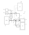
図1は、本発明の第1実施形態に係る電力供給システムPを備える電動車両(以下、単に「車両」という)の駆動系(以下「車両駆動系」という)Vの概略的な構成を示している。(First embodiment)
FIG. 1 shows a schematic configuration of a drive system (hereinafter referred to as "vehicle drive system") V of an electric vehicle (hereinafter simply referred to as "vehicle") equipped with a power supply system P according to a first embodiment of the present invention. ing.
車両駆動系Vは、大別すると、電力供給システムP、パワーコントロールユニット3および走行モータ4を備え、電力供給システムPの出力により、パワーコントロールユニット3を介して走行モータ4を駆動する。パワーコントロールユニット3は、インバータを内蔵し、バッテリユニット2から出力される直流電流を三相の交流電流に変換して、走行モータ4に供給する。走行モータ4は、図示しない差動装置を介して車両の駆動輪と接続されており、駆動輪を回転させて、車両を推進する。走行モータ4は、原動機としても発電機としても動作可能なモータジェネレータであり、車両の制動走行時に発電機として動作し、電力を回生することが可能である。
The vehicle drive system V roughly includes an electric power supply system P, a power control unit 3 and a
本実施形態において、電力供給システムPは、燃料電池1と、バッテリユニット2と、を電力源として備える。ここで、バッテリユニット2でいう「ユニット」との用語は、単に概念的な纏まりをいうに過ぎず、物理的な一体性までをも意味するものではない。換言すれば、バッテリユニット2は、構成要素同士が近くに纏まって配置されている必要はなく、1つの構成要素(例えば、2つのバッテリ21、22のうち一方)が車両のボンネット内部に配置される一方、異なる構成要素(例えば、他方のバッテリ)が車両後部のトランクルームに隣接して配置されてもよい。
In this embodiment, the power supply system P includes a
燃料電池1は、例えば、固体酸化物型の燃料電池(SOFC)である。燃料電池1は、他の種類の燃料電池であってもよい。本実施形態において、燃料電池1は、複数の燃料電池単位セルを積層して構成され、含酸素燃料(例えば、エタノール)を原燃料として作動する。エタノールの水蒸気改質反応により生じる水素が燃料として燃料電池1のアノード極に供給される一方、大気中の空気(具体的には、酸素)が酸化剤ガスとしてカソード極に供給される。燃料電池1が固体酸化物型のものである場合に、アノード極およびカソード極での発電に係る反応は、夫々次式により表すことができる。
The
アノード極: 2H2+4O2- → 2H2O+4e- …(1.1)
カソード極: O2+4e- → 2O2- …(1.2)
バッテリユニット2は、先に述べたように、その出力を、パワーコントロールユニット3を介して走行モータ4に供給する一方、燃料電池1が発電した電力の供給を受け、これをバッテリに蓄電する。本実施形態では、燃料電池1とバッテリユニット2とを接続する充電用の電力経路上に、一方向性のDC/DCコンバータ51が介装されている。コンバータ51は、昇圧コンバータであり、バッテリユニット2は、充電電力として、燃料電池1からコンバータ51により昇圧された後の電力の供給を受ける。本実施形態において、コンバータ51は、絶縁型である。Anode electrode: 2H 2 +4O 2− →2H 2 O+4e − (1.1)
Cathode: O 2 +4e − →2O 2− (1.2)
As described above, the
さらに、バッテリユニット2は、後に述べるように、燃料電池1に対して給電用の電力経路を介して接続され、燃料電池1の運転に必要な各種補機に対し、この経路を介して電力を供給する。燃料電池1の補機は、例えば、センサ、アクチュエータ、ヒータ、ポンプおよびブロアであり、センサとして、原燃料または酸化剤ガスの流量を検出する流量センサ、燃料電池1の温度を検出する温度センサ、燃料タンクに残存する原燃料の量を検出する液位センサ等を例示することができる。ブロアないしエアコンプレッサは、酸化剤ガスの供給通路(カソードガス通路)の開放端近傍に取り付けられ、大気中の空気をカソードガス通路に吸入するものである。
Furthermore, as will be described later, the
燃料電池1、バッテリユニット2およびパワーコントロールユニット3等の動作は、コントローラ101により制御される。
A
図2は、電力供給システムPの概略的な構成を示している。 FIG. 2 shows a schematic configuration of the power supply system P. As shown in FIG.
本実施形態において、電力供給システムPは、燃料電池1と、バッテリユニット2と、を備える。
In this embodiment, the power supply system P includes a
図2は、燃料電池1全体を二点鎖線により概念的に示しており、燃料電池1は、大別すると、燃料電池単位セルの積層体である発電部11と、燃料電池1の運転に必要な補機(以下、単に「補機」と表記することで、車両補機23と区別する)12と、により構成される。
FIG. 2 conceptually shows the
バッテリユニット2は、複数のバッテリを備え、本実施形態では、2つのバッテリ21、22を備える。1つは、比較的電圧の高い高圧バッテリ21であり、本実施形態では、400Vの端子電圧を有することから、これを特に「強電バッテリ」と呼ぶ。別の1つは、高圧バッテリ21よりも電圧の低い低圧バッテリ22であり、本実施形態では、14Vの端子電圧を有し、強電バッテリ21との対比から、これを特に「弱電バッテリ」と呼ぶ。
The
強電バッテリ21は、走行モータ4に供給される電力を蓄え、弱電バッテリ22は、走行モータ4以外の車両補機23に供給される電力を蓄えるためのものである。車両補機23は、例えば、オーディオ等の車内電装機器である。強電バッテリ21は、後に述べるように、急速充電器に接続されることで充電可能であるとともに、車両の制動走行時に、走行モータ4により回生された電力を充電することも可能である。
The heavy
強電バッテリ21は、第1給電経路p1を介して燃料電池1の補機12に接続され、補機12に対し、第1給電経路p1を通じて電力を供給することが可能である。第1給電経路p1には、DC/DCコンバータ24が介装され、強電バッテリ21からコンバータ24により降圧された後の電圧(本実施形態では、14V)が補機12に印加される。
The high-
他方で、強電バッテリ21は、燃料電池1に対して燃料電池1の発電電力を充電可能に接続され、具体的には、燃料電池1の発電部11と第1給電経路p1とが、コンバータ51が介装された電力経路p2を介して接続されている。これにより、燃料電池1からコンバータ51による昇圧後の電圧(本実施形態では、400V)が第1給電経路p1に印加され、さらに、第1給電経路p1を介して強電バッテリ21に印加される。ここで、第1給電経路p1に印加された電圧は、コンバータ24により降圧され、補機12に印加される。これにより、補機12に対する燃料電池1の自律給電が可能となる。
On the other hand, the
弱電バッテリ22は、車両補機23に電力経路p3を介して接続される一方、第2給電経路p4を介して燃料電池1の補機12に接続されている。本実施形態において、第2給電経路p2は、第1給電経路p1に対し、コンバータ24と燃料電池1の補機12との間で接続され、これにより、弱電バッテリ22は、補機12に対し、第1給電経路p1とは異なる第2給電経路p4を通じて電力を供給することが可能である。さらに、第1給電経路p1と第2給電経路p2とが電力経路p5を介して接続されており、弱電バッテリ22は、強電バッテリ21の放電電力を、この経路p5を介して充電可能な状態にある。第1給電経路p1と第2給電経路p2とをつなぐ電力経路p5には、強電バッテリ21の電圧(例えば、400V)を弱電バッテリ22の充電電圧(例えば、14V)に変換するDC/DCコンバータ25が介装されている。コンバータ25は、電力供給システムPの停止時(例えば、車両の運転停止時)に、弱電バッテリ22および車両補機23を、システムの他の構成要素、つまり、高圧系から電気的に隔離するアイソレータとして機能するものである。
The weak
電力供給システムPは、以上に加え、燃料電池1の補機12に対する電力の供給源を、強電バッテリ21と弱電バッテリ22とで切り替える切替部R1、R2を備える。
In addition to the above, the power supply system P includes switching units R1 and R2 that switch the power supply source for the
本実施形態において、切替部R1、R2は、第1給電経路p1に介装された第1リレーR1と、第2給電経路p4に介装された第2リレーR2と、により構成される。本実施形態では、第1および第2リレーR1、R2を異なるユニットとして構成するが、これに限らず、一体のユニットとして構成することも可能である。 In this embodiment, the switching units R1 and R2 are configured by a first relay R1 interposed in the first power supply path p1 and a second relay R2 interposed in the second power supply path p4. Although the first and second relays R1 and R2 are configured as different units in this embodiment, they may be configured as an integrated unit.
第1給電経路p1に備わる第1リレーR1は、強電バッテリ21とコンバータ24との間、換言すれば、強電バッテリ21を電力源とする電流の方向に関してコンバータ24の上流側に配置されている。さらに、第1リレーR1は、強電バッテリ21を電力源とする電流の方向に関して第1給電経路p1と電力経路p2との接続点j1よりも上流側に配置され、第2リレーR2は、弱電バッテリ22を電力源とする電流の方向に関して第2給電経路p4と電力経路p5との接続点j2よりも下流側に配置されている。
The first relay R1 provided in the first power supply path p1 is arranged between the high-
コントローラ101は、電子制御ユニットとして構成され、中央演算装置(CPU)、ROMおよびRAM等の各種記憶装置、入出力インターフェース等を備えるマイクロコンピュータからなる。コントローラ101は、DC/DCコンバータ24、25、51のほか、第1および第2リレーR1、R2に制御指令を出力し、それらの動作を制御する。
The
本実施形態では、強電バッテリ21により「第1バッテリ」が構成され、弱電バッテリ22により「第2バッテリ」が、DC/DCコンバータ25により「第1圧力変換部」が、DC/DCコンバータ24により「第2圧力変換部」が夫々構成される。第1および第2リレーR1、R2により「切替部」が構成され、コントローラ101により「制御部」が構成される。そして、強電バッテリ21、弱電バッテリ22、コンバータ24、25、第1および第2リレーR1、R2により、本実施形態に係る「バッテリユニット」が構成される。
In the present embodiment, the strong
図3は、本実施形態に係る電力源切替制御の基本的な流れをフローチャートにより示している。コントローラ101は、電力供給システムPの作動中(例えば、車両の運転中)に、同図に示す制御を所定時間毎に繰り返し実行するようにプログラムされている。これに限らず、本制御のプログラムは、燃料電池1の起動要求があった場合に、割込処理として実行されるものであってもよい。
FIG. 3 is a flowchart showing the basic flow of power source switching control according to this embodiment. The
本実施形態において、コントローラ101は、強電バッテリ21から燃料電池1の補機12に対する電力の供給が可能であるか否かを判定し、電力の供給が可能である場合は、電力の供給源として強電バッテリ21を選択し、電力の供給が可能でない場合は、電力の供給源として弱電バッテリ22を選択する。そして、強電バッテリ21を電力源とする場合に、コントローラ101は、第1リレーR1にオン信号を出力し、第2リレーR2にオフ信号を出力する。他方で、弱電バッテリ22を電力源とする場合に、コントローラ101は、第1リレーR1にオフ信号を出力し、第2リレーR2にオン信号を出力する。
In this embodiment, the
フローチャートの説明に移り、S101では、燃料電池1の起動時であるか否かを判定する。燃料電池1の起動時であるか否かの判定は、例えば、強電バッテリ21の充電量を検出し、検出された充電量が所定量未満であるか否かを判定することによる。強電バッテリ21の充電量が所定量未満であり、不足している場合は、燃料電池1の発電電力により強電バッテリ21を充電するため、燃料電池1を起動するのである。燃料電池1は、その起動時において、自律給電が可能な状態にない。燃料電池1の起動時である場合は、S102へ進み、そうでない場合は、S106へ進む。
Moving on to the description of the flowchart, in S101, it is determined whether or not the
S102では、強電バッテリ21の急速充電中であるか否かを判定する。この判定は、例えば、強電バッテリ21の急速充電用のコネクタ(例えば、車両の後部または側面に備わる)に急速充電器のプラグが差し込まれているか否かを判定することによる。強電バッテリ21の急速充電中である場合は、S103へ進み、そうでない場合は、S106へ進む。
In S102, it is determined whether or not the high-
S103では、強電バッテリ21ないし高圧系のフェール発生時であるか否かを判定する。この判定は、強電バッテリ21を電力源とする電力の供給に何らかの異常ないし支障が生じたか否かを判定することにより具現され、強電バッテリ21自体のほか、例えば、第1給電経路p1に断線が生じたり、コンバータ24に異常ないし故障が生じたりしたか否かを判定することによる。強電バッテリ21のフェール発生時である場合は、S104へ進み、そうでない場合は、S106へ進む。
In S103, it is determined whether or not the
S104では、第1リレーR1をオフ状態とする。 In S104, the first relay R1 is turned off.
S105では、第2リレーR2をオン状態とする。 In S105, the second relay R2 is turned on.
S106では、第1リレーR1をオン状態とする。 In S106, the first relay R1 is turned on.
S107では、第2リレーR2をオフ状態とする。 In S107, the second relay R2 is turned off.
このように、コントローラ101は、燃料電池1の起動時に、第1および第2リレーR1、R2の動作を制御し、S104および105の処理により、燃料電池1の補機12に対する電力源を弱電バッテリ22とする一方、S106および107の処理により、燃料電池1の補機12に対する電力源を強電バッテリ21とする。
In this way, the
本実施形態に係る電力供給システムPは、以上のように構成され、本実施形態により得られる作用及び効果について、以下に述べる。 The power supply system P according to this embodiment is configured as described above, and the actions and effects obtained by this embodiment will be described below.
(作用および効果の説明)
第1に、燃料電池1の補機12に対する電力の供給源を、強電バッテリ21と弱電バッテリ22とで切替可能としたことで、強電バッテリ21から電力を供給することができない状況、例えば、強電バッテリ21の充電中または強電バッテリ21のフェール発生時にあっても弱電バッテリ22から電力を供給することが可能となる。よって、強電バッテリ21の状態によらず、燃料電池1の補機12に対する電力源を確保することができる。(Description of actions and effects)
First, the power supply source for the
ここで、本実施形態では、強電バッテリ21ないし高圧系の状態を判定し、強電バッテリ21から燃料電池1の補機12に対する電力の供給が可能でない場合に、電力源を弱電バッテリ22に切り替えることで、強電バッテリ21の状態に応じて的確に電力源を切り替えることができる。そして、このような判定を燃料電池1の起動時に行い、電力源の切替えを行う必要がある場合に、電力源を弱電バッテリ22とすることで、燃料電池1の自律給電が可能となるまでの電力源を確保することが可能となる。よって、燃料電池1を任意のタイミングで停止し、起動および暖機を実行することができる。
Here, in this embodiment, the state of the high-
さらに、本実施形態によれば、高圧バッテリないし強電バッテリ21と、低圧バッテリないし弱電バッテリ22と、を既に備える電動車両に対し、補機12に対する電力源の確保を目的とした特別な低圧バッテリによらず、既存の蓄電設備により燃料電池1の起動性を確保することができる。よって、システム全体でのコストの上昇を抑えるとともに、サイズの増大を抑制することができる。
Furthermore, according to the present embodiment, a special low-voltage battery for the purpose of securing a power source for the
第2に、強電バッテリ21に対し、弱電バッテリ22を強電バッテリ21により充電可能に接続したことで、車両補機23を安定して作動させることができる。ここで、第1および第2バッテリ21、22を互いに接続する電力経路p5上にコンバータ25を設置したことで、強電バッテリ21から弱電バッテリ22への電力の供給を実現するとともに、弱電バッテリ22を高圧系から隔離可能とし、例えば、車両の運転停止中における弱電バッテリ22の過度な放電が高圧系に及ぼす影響を抑制することができる。
Secondly, by connecting the
本実施形態では、電力源切替制御(図3)を燃料電池1の起動時に実行することとしたが、これに限らず、電力供給システムPの作動中、強電バッテリ21ないし高圧系の状態を常に監視し、強電バッテリ21から燃料電池1の補機12に対する電力の供給が可能でないと判定した場合に、補機12に対する電力源を強電バッテリ21から弱電バッテリ22に切り替えるように構成してもよい。これにより、例えば、燃料電池1の発電電力が補機12の駆動に必要な電力を満たさない場合にあっても燃料電池1の運転を安定して継続させることが可能となる。
In the present embodiment, the power source switching control (FIG. 3) is executed when the
さらに、本実施形態では、コントローラ101により、強電バッテリ21から燃料電池1の補機12に対する電力の供給が可能であるか否かを判定し、可能でないと判定した場合に、補機12に対する電力源を弱電バッテリ22に切り替えることとしたが、判定という特別な工程によらず、例えば、強電バッテリ21の急速充電用のコネクタに急速充電器のプラグが差し込まれた場合に、強電バッテリ21による電力の供給が可能でないとして、自動的に電力源が切り替わるように構成することも可能である。強電バッテリ21は、急速充電時において、それ自体に備わるリレー(図示せず)により、第1給電経路p1に対する接続が遮断される。
Further, in the present embodiment, the
以下、本発明の他の実施形態について説明する。 Other embodiments of the present invention will be described below.
(第2実施形態)
図4は、本発明の第2実施形態に係る電力供給システムP2の構成を示す概略図である。ここで、第1実施形態におけると同様の機能を奏する部品または部分は、図2に示すのと同一の符号を付し、重複回避のため、その詳細な説明を省略する(第3実施形態についても同様である)。(Second embodiment)
FIG. 4 is a schematic diagram showing the configuration of a power supply system P2 according to the second embodiment of the invention. Here, parts or portions that perform the same functions as in the first embodiment are denoted by the same reference numerals as those shown in FIG. is also the same).
電力供給システムP2は、燃料電池1の補機12として、異なる電圧で動作する複数の補機12aおよび12bを備える。補機12aは、比較的低い電圧(例えば、14V)で動作する補機であり、例えば、燃料電池1の運転に必要なセンサおよびアクチュエータ等である。他方で、補機12bは、補機12aよりも高い電圧(例えば、48V)で動作する補機であり、センサおよびアクチュエータ以外の補機として、ブロアを例示することができる。補機12bは、第2給電経路p4に対し、電力経路p6を介して接続され、強電バッテリ21および弱電バッテリ22のどちらからも電力の供給を受けることが可能である。
The power supply system P2 includes, as the
電力供給システムP2は、さらに、電力経路p6に、バッテリユニット2の出力電圧、具体的には、コンバータ24による降圧後の電圧または弱電バッテリ22の電圧を補機12bの動作電圧に変換するDC/DCコンバータ31を備える。コンバータ31は、昇圧コンバータとして構成され、補機12bは、切替器(第1リレーR1、第2リレーR2)の状態に応じ、強電バッテリ21からコンバータ24により降圧され、さらに、コンバータ31により昇圧された後の電圧か、弱電バッテリ22からコンバータ31により昇圧された後の電圧か、の供給を受ける。
The power supply system P2 further includes a DC/DC converter that converts the output voltage of the
本実施形態では、補機12aにより「第1補機」が構成され、補機12bにより「第2補機」が構成される。さらに、DC/DCコンバータ31により「第3電圧変換部」が構成される。
In this embodiment, the
コントローラ101は、第1実施形態におけると同様に構成されてよく、図3に示すのと同様の手順に従って電力源切替制御を実行し、強電バッテリ21および弱電バッテリ22の間で、補機12a、12bに対する電力の供給源を切り替える。
The
このように、バッテリユニット2と補機12bとの間にコンバータ31を介装し、コンバータ24による降圧後の電圧または弱電バッテリ22の電圧を、コンバータ31により昇圧して補機12bに印加可能とすることで、比較的電圧の高い補機12bとして、例えば、ブロアの運転を可能とするとともに、強電バッテリ21による電力の供給が可能でない場合にあってもブロアに対する電力源を確保することができる。
In this manner, the
(第3実施形態)
図5は、本発明の第3実施形態に係る電力供給システムP3の構成を示す概略図である。(Third Embodiment)
FIG. 5 is a schematic diagram showing the configuration of a power supply system P3 according to the third embodiment of the invention.
電力供給システムP3は、第2実施形態におけると同様に、異なる電圧で動作する複数の補機12aおよび12b、例えば、比較的低い電圧(例えば、14V)で動作する補機12aと、補機12aよりも高い電圧(例えば、48V)で動作する補機12b(例えば、ブロア)と、を備える。補機12aに対するバッテリユニット2の電力接続は、第1実施形態におけると同様であり、補機12aは、第1給電経路p1を介して強電バッテリ21に接続されるとともに、第2給電経路p4を介して弱電バッテリ22に接続された状態にある。これに対し、補機12bは、第2給電経路p4とは接続されておらず、電力経路p7を介して第1給電経路p1に接続され、第1給電経路p1を介して強電バッテリ21に接続されている。
As in the second embodiment, the power supply system P3 includes a plurality of
電力供給システムP2は、さらに、電力経路p7に、強電バッテリ21の電圧またはコンバータ51による昇圧後の電圧(例えば、400V)を補機12bの動作電圧に変換するDC/DCコンバータ32を備える。コンバータ32は、降圧コンバータとして構成され、補機12bは、燃料電池1の補機12に対する電力源として強電バッテリ21が選択されている場合(換言すれば、第1リレーR1がオン状態にある場合)に、強電バッテリ21からコンバータ32より降圧された後の電圧の供給を受ける。
The power supply system P2 further includes a DC/
本実施形態では、補機12aにより「第1補機」が構成され、補機12bにより「第2補機」が構成される。さらに、DC/DCコンバータ32により「第4電圧変換部」が構成される。
In this embodiment, the
コントローラ101は、第1実施形態におけると同様に構成されてよく、図3に示すのと同様の手順に従って電力源切替制御を実行し、強電バッテリ21および弱電バッテリ22の間で、補機12a、12bに対する電力の供給源を切り替える。
The
このように、強電バッテリ21と補機12bとを、コンバータ24を介さずに、コンバータ32を介装した電力経路p7により接続し、補機12bに対し、強電バッテリ21の電圧をコンバータ32により降圧させて印加可能とすることで、強電バッテリ21の電圧を、コンバータ24による降圧を介さずにコンバータ32により直接、補機12bの動作電圧に変換することができる。よって、コンバータ24による降圧を介する場合と比較して、降圧に要する分のエネルギの損失を回避することが可能となるので、コンバータ24を小型化し、システム全体にかかるコストを低減するとともに、サイズのコンパクト化を図ることができる。
In this way, the
以上の説明では、「第2補機」として第1補機(補機12a)よりも高い電圧で動作する補機12bを採用したが、「第2補機」は、第1補機よりも低い電圧で動作するものであってもよい。
In the above description, the
さらに、以上の説明では、コントローラ101を、燃料電池1、バッテリユニット2およびパワーコントロールユニット3等の動作を統合的に制御するシステムコントローラとして構成したが、これに限らず、コントローラ101が有する機能、例えば、燃料電池1およびバッテリユニット2の動作に関してコントローラ101が有する機能を複数のコントローラに分散させ、燃料電池1の動作を制御する燃料電池コントローラと、バッテリユニット2の動作を制御するバッテリコントローラと、の組み合わせとして構成することも可能である。この場合に、燃料電池1の補機12または動作電圧の低い補機12aに、燃料電池コントローラを含めることができる。
Furthermore, in the above description, the
以上、本発明の実施形態について説明したが、上記実施形態は、本発明の適用例の一部を示したに過ぎず、本発明の技術的範囲を、上記実施形態の具体的構成に限定する趣旨ではない。上記実施形態に対し、特許請求の範囲に記載した事項の範囲内で様々な変更および修正が可能である。 Although the embodiments of the present invention have been described above, the above embodiments merely show a part of the application examples of the present invention, and the technical scope of the present invention is limited to the specific configurations of the above embodiments. not on purpose. Various changes and modifications can be made to the above-described embodiment within the scope of matters described in the claims.
Claims (11)
前記燃料電池に接続されたバッテリユニットと、
を備える、車両の電力供給システムであって、
前記バッテリユニットは、
前記燃料電池に対し、前記燃料電池の補機に電力を供給するとともに、前記燃料電池の発電電力を充電可能に接続された第1バッテリと、
前記燃料電池の補機に対し、前記第1バッテリとは異なる経路を介して電力を供給可能に接続された第2バッテリと、を備え、
前記燃料電池の補機の動作電圧は前記第2バッテリの出力電圧に対応し、
前記第2バッテリは、前記第1バッテリに対し、前記第1バッテリの放電電力を充電可能な電力経路を介して接続され、
前記電力供給システムは、
前記第1バッテリと前記第2バッテリとで、前記燃料電池の補機に対する電力の供給源を切り替える切替部と、
前記第1バッテリの充電中または前記第1バッテリのフェール発生時に、前記燃料電池の補機に対する電力の供給源を前記第1バッテリから前記第2バッテリに切り替えるように前記切替部を制御する制御部と、
前記電力経路を遮断可能な遮断部と、をさらに備える、
電力供給システム。 a fuel cell;
a battery unit connected to the fuel cell;
A power supply system for a vehicle, comprising:
The battery unit is
a first battery connected to the fuel cell so as to supply electric power to an auxiliary device of the fuel cell and to be charged with electric power generated by the fuel cell;
a second battery connected to the auxiliary equipment of the fuel cell so as to be able to supply electric power via a path different from that of the first battery;
the operating voltage of the auxiliary equipment of the fuel cell corresponds to the output voltage of the second battery;
The second battery is connected to the first battery via a power path capable of charging the discharged power of the first battery,
The power supply system is
a switching unit that switches between the first battery and the second battery to supply power to an auxiliary device of the fuel cell;
A control unit that controls the switching unit to switch a power supply source for an auxiliary device of the fuel cell from the first battery to the second battery during charging of the first battery or when a failure occurs in the first battery. and,
further comprising a blocking unit capable of blocking the power path,
power supply system.
前記第1バッテリは、前記車両の走行モータに供給される電力を蓄え、
前記第2バッテリは、前記走行モータ以外の車両補機に供給される電力を蓄える、
電力供給システム。 The power supply system according to claim 1,
The first battery stores electric power supplied to a travel motor of the vehicle,
The second battery stores electric power to be supplied to vehicle accessories other than the traction motor.
power supply system.
前記第1バッテリは、前記第2バッテリよりも電圧が高く、
前記バッテリユニットは、前記遮断部として、前記第1バッテリの電圧を前記第2バッテリの充電電圧に変換する第1電圧変換部を備える、
電力供給システム。 The power supply system according to claim 1 or 2,
the first battery has a higher voltage than the second battery,
The battery unit includes, as the cutoff unit, a first voltage conversion unit that converts the voltage of the first battery into the charging voltage of the second battery.
power supply system.
前記バッテリユニットは、前記第1バッテリと前記燃料電池の補機とを接続する電力経路上に、前記第1バッテリの電圧を前記燃料電池の補機の動作電圧に変換する第2電圧変換部を備える、
電力供給システム。 The power supply system according to claim 3,
The battery unit includes a second voltage conversion section that converts the voltage of the first battery into an operating voltage of the auxiliary equipment of the fuel cell, on a power path connecting the first battery and the auxiliary equipment of the fuel cell. prepare
power supply system.
前記燃料電池の補機として、第1補機と、前記第1補機とは異なる電圧で動作する第2補機と、を備え、
前記バッテリユニットと前記第2補機との間に、前記バッテリユニットの出力電圧を前記第2補機の動作電圧に変換する第3電圧変換部を備える、
電力供給システム。 The power supply system according to claim 4,
a first auxiliary machine and a second auxiliary machine operating at a voltage different from that of the first auxiliary machine as auxiliary machines of the fuel cell;
A third voltage converter is provided between the battery unit and the second auxiliary machine, and converts the output voltage of the battery unit into the operating voltage of the second auxiliary machine,
power supply system.
前記燃料電池の補機として、第1補機と、前記第1補機とは異なる電圧で動作する第2補機と、を備え、
前記バッテリユニットは、前記燃料電池に対し、その出力電圧を前記第1補機に対して印加可能に接続され、
前記第1バッテリは、前記第2補機に対し、前記第2電圧変換部を介さずに電力を供給可能に接続され、
前記第1バッテリと前記第2補機とを接続する電力経路上に、前記第1バッテリの電圧を前記第2補機の動作電圧に変換する第4電圧変換部を備える、
電力供給システム。 The power supply system according to claim 4,
a first auxiliary machine and a second auxiliary machine operating at a voltage different from that of the first auxiliary machine as auxiliary machines of the fuel cell;
the battery unit is connected to the fuel cell so that its output voltage can be applied to the first auxiliary machine;
The first battery is connected to the second auxiliary machine so as to be able to supply electric power without passing through the second voltage conversion unit,
a fourth voltage conversion unit that converts the voltage of the first battery to the operating voltage of the second auxiliary machine on the power path that connects the first battery and the second auxiliary machine;
power supply system.
前記第2補機は、前記第1補機よりも高い電圧で動作する、
電力供給システム。 The power supply system according to claim 5 or 6,
The second accessory operates at a higher voltage than the first accessory,
power supply system.
前記制御部は、
前記第1バッテリから前記燃料電池の補機に対する電力の供給が可能であるか否かを判定し、
前記電力の供給が可能である場合は、前記電力の供給源を前記第1バッテリとし、
前記電力の供給が可能でない場合は、前記電力の供給源を前記第2バッテリとする、
電力供給システム。 The power supply system according to any one of claims 1 to 7,
The control unit
determining whether power can be supplied from the first battery to the auxiliary equipment of the fuel cell;
when the power can be supplied, the power supply source is the first battery;
If the power supply is not possible, the power supply source is the second battery.
power supply system.
前記制御部は、前記燃料電池の起動時に、前記切替部の動作を制御して、前記燃料電池の補機に対する電力の供給源を切り替える、
電力供給システム。 The power supply system according to claim 8,
When the fuel cell is activated, the control unit controls the operation of the switching unit to switch the power supply source for the auxiliary equipment of the fuel cell.
power supply system.
前記制御部は、前記第1バッテリの充電中または前記第1バッテリのフェール発生時に、前記第1バッテリからの電力の供給が可能でないと判定し、前記電力の供給源を前記第2バッテリとする、
電力供給システム。 The power supply system according to claim 8 or 9,
The control unit determines that power supply from the first battery is not possible during charging of the first battery or when a failure occurs in the first battery, and selects the second battery as a power supply source. ,
power supply system.
車両の走行モータに供給される電力を蓄える第1バッテリと、
前記走行モータ以外の車両補機に供給される電力を蓄える第2バッテリと、
前記第1バッテリの電圧を前記燃料電池の補機に印加可能に配設された第1給電経路と、
前記第2バッテリの電圧を前記燃料電池の補機に印加可能に配設された第2給電経路と、を備え、
前記燃料電池の補機の動作電圧は前記第2バッテリの出力電圧に対応し、
前記第2バッテリは、前記第1バッテリに対し、前記第1バッテリの放電電力を充電可能な電力経路を介して接続されるとともに、
前記第1および第2給電経路の間で、前記燃料電池の補機に対する給電経路を切り替える切替部と、
前記第1バッテリの充電中または前記第1バッテリのフェール発生時に、前記燃料電池の補機に対する前記給電経路を前記第1給電経路から前記第2給電経路に切り替えるように前記切替部を制御する制御部と、
前記電力経路を遮断可能な遮断部と、をさらに備える
電力供給システム。 a fuel cell;
a first battery that stores electric power to be supplied to a travel motor of the vehicle;
a second battery that stores electric power to be supplied to vehicle accessories other than the travel motor;
a first power supply path disposed so as to be able to apply the voltage of the first battery to an auxiliary device of the fuel cell;
a second power supply path disposed so as to be able to apply the voltage of the second battery to an auxiliary device of the fuel cell;
the operating voltage of the auxiliary equipment of the fuel cell corresponds to the output voltage of the second battery;
The second battery is connected to the first battery via a power path capable of charging the discharged power of the first battery,
a switching unit for switching between the first and second power supply paths, a power supply path for an auxiliary device of the fuel cell;
Control for controlling the switching unit to switch the power supply path for the auxiliary machine of the fuel cell from the first power supply path to the second power supply path during charging of the first battery or when a failure occurs in the first battery. Department and
A power supply system further comprising: a breaker capable of breaking the power path.
Applications Claiming Priority (1)
| Application Number | Priority Date | Filing Date | Title |
|---|---|---|---|
| PCT/JP2017/029320 WO2019035173A1 (en) | 2017-08-14 | 2017-08-14 | Power supply system and operation method thereof |
Publications (2)
| Publication Number | Publication Date |
|---|---|
| JPWO2019035173A1 JPWO2019035173A1 (en) | 2020-11-19 |
| JP7259751B2 true JP7259751B2 (en) | 2023-04-18 |
Family
ID=65361907
Family Applications (1)
| Application Number | Title | Priority Date | Filing Date |
|---|---|---|---|
| JP2019536374A Active JP7259751B2 (en) | 2017-08-14 | 2017-08-14 | power supply system |
Country Status (5)
| Country | Link |
|---|---|
| US (1) | US11214170B2 (en) |
| EP (1) | EP3670238B1 (en) |
| JP (1) | JP7259751B2 (en) |
| CN (1) | CN111032418A (en) |
| WO (1) | WO2019035173A1 (en) |
Families Citing this family (4)
| Publication number | Priority date | Publication date | Assignee | Title |
|---|---|---|---|---|
| JP6881224B2 (en) * | 2017-10-20 | 2021-06-02 | トヨタ自動車株式会社 | Fuel cell vehicle |
| JP6965830B2 (en) * | 2018-05-24 | 2021-11-10 | トヨタ自動車株式会社 | Vehicle power supply |
| US11021073B1 (en) * | 2020-02-26 | 2021-06-01 | Atieva, Inc. | Electric vehicle power supply system to minimize loss during vehicle rest |
| US20220340048A1 (en) * | 2021-04-14 | 2022-10-27 | Toyota Motor Engineering & Manufacturing North America, Inc. | Dual battery fuel cell system |
Citations (3)
| Publication number | Priority date | Publication date | Assignee | Title |
|---|---|---|---|---|
| JP2004194438A (en) | 2002-12-12 | 2004-07-08 | Toyota Motor Corp | Operation device with power supply and control method for operation device with power supply |
| JP2007306778A (en) | 2006-05-15 | 2007-11-22 | Toyota Industries Corp | Dc/dc converter, and power supply switching method of dc/dc converter |
| JP2013198294A (en) | 2012-03-19 | 2013-09-30 | Honda Motor Co Ltd | Moving body |
Family Cites Families (14)
| Publication number | Priority date | Publication date | Assignee | Title |
|---|---|---|---|---|
| JPH06124720A (en) * | 1992-10-10 | 1994-05-06 | Aqueous Res:Kk | Hybrid power supply device |
| US6492056B1 (en) * | 2000-03-13 | 2002-12-10 | Energy Conversion Devices, Inc. | Catalytic hydrogen storage composite material and fuel cell employing same |
| JP5140894B2 (en) * | 2000-05-15 | 2013-02-13 | トヨタ自動車株式会社 | Power supply using fuel cell and chargeable / dischargeable power storage unit |
| US6559621B2 (en) * | 2001-05-21 | 2003-05-06 | Cellex Power Products, Inc. | Hybrid energy storage device charge equalization system and method |
| JP2007228753A (en) | 2006-02-24 | 2007-09-06 | Toyota Motor Corp | Electric vehicle |
| JP2008004482A (en) * | 2006-06-26 | 2008-01-10 | Nissan Motor Co Ltd | Fuel cell system |
| JP4873365B2 (en) * | 2006-07-04 | 2012-02-08 | スズキ株式会社 | Vehicle control device |
| JP5011021B2 (en) * | 2007-08-01 | 2012-08-29 | 本田技研工業株式会社 | Fuel cell system |
| KR20120020686A (en) * | 2010-08-31 | 2012-03-08 | 현대자동차주식회사 | System and method for emergency startup of fuel cell vehicle |
| JP5622693B2 (en) | 2011-09-09 | 2014-11-12 | 本田技研工業株式会社 | Fuel cell vehicle |
| JP6089552B2 (en) * | 2012-10-09 | 2017-03-08 | 三菱自動車工業株式会社 | Power control device |
| KR101459900B1 (en) * | 2013-05-07 | 2014-11-10 | 현대자동차주식회사 | Method for controlling stop and start for fuelcell car |
| DE102014201440A1 (en) * | 2014-01-27 | 2015-07-30 | Volkswagen Aktiengesellschaft | Motor vehicle electrical system with optimized switching function |
| CN107591546A (en) * | 2017-08-25 | 2018-01-16 | 北京工业大学 | A kind of fuel cell lithium battery hybrid power heat management system and the method for operation |
-
2017
- 2017-08-14 EP EP17921825.0A patent/EP3670238B1/en active Active
- 2017-08-14 JP JP2019536374A patent/JP7259751B2/en active Active
- 2017-08-14 US US16/637,821 patent/US11214170B2/en active Active
- 2017-08-14 CN CN201780093951.XA patent/CN111032418A/en active Pending
- 2017-08-14 WO PCT/JP2017/029320 patent/WO2019035173A1/en unknown
Patent Citations (3)
| Publication number | Priority date | Publication date | Assignee | Title |
|---|---|---|---|---|
| JP2004194438A (en) | 2002-12-12 | 2004-07-08 | Toyota Motor Corp | Operation device with power supply and control method for operation device with power supply |
| JP2007306778A (en) | 2006-05-15 | 2007-11-22 | Toyota Industries Corp | Dc/dc converter, and power supply switching method of dc/dc converter |
| JP2013198294A (en) | 2012-03-19 | 2013-09-30 | Honda Motor Co Ltd | Moving body |
Also Published As
| Publication number | Publication date |
|---|---|
| CN111032418A (en) | 2020-04-17 |
| JPWO2019035173A1 (en) | 2020-11-19 |
| US11214170B2 (en) | 2022-01-04 |
| US20200164766A1 (en) | 2020-05-28 |
| EP3670238B1 (en) | 2022-01-19 |
| EP3670238A1 (en) | 2020-06-24 |
| EP3670238A4 (en) | 2020-09-30 |
| WO2019035173A1 (en) | 2019-02-21 |
Similar Documents
| Publication | Publication Date | Title |
|---|---|---|
| KR102478086B1 (en) | Fuel cell vehicle system and control method of the same | |
| KR101230900B1 (en) | Control method of fuel cell hybrid system | |
| JP7259751B2 (en) | power supply system | |
| KR101033900B1 (en) | Power transmission device and method for fuel cell-super capacitor hybrid vehicle | |
| WO2007113990A1 (en) | Vehicle assistance system | |
| KR101592377B1 (en) | Apparatus and method for startup of fuel cell vehicle | |
| KR20080054281A (en) | Power down control method of fuel cell hybrid electric vehicle | |
| EP2800183A1 (en) | Fuel cell system | |
| US10122177B2 (en) | Power supply method and power supply system | |
| JP6891963B2 (en) | Power supply system and its control method | |
| JPWO2019035172A1 (en) | Vehicle power supply system | |
| JP2007073325A (en) | Fuel cell system and method of controlling discharge power therein | |
| US9849805B2 (en) | Fuel cell vehicle | |
| WO2008114758A1 (en) | Fuel cell system | |
| CN107492919A (en) | Power system and its control method | |
| US9545910B2 (en) | Control apparatus for electric vehicle | |
| KR100872647B1 (en) | Power down control method of fuel cell hybrid electric vehicle | |
| JP2014060838A (en) | Power supply system | |
| JP5873365B2 (en) | Power supply system | |
| JP7155622B2 (en) | power supply system | |
| JP2014057389A (en) | Power supply system | |
| JP2018121397A (en) | Electric vehicle | |
| JP6766655B2 (en) | Dual power supply drive system | |
| JP2013198289A (en) | Power supply system | |
| JP6575873B2 (en) | Fuel cell system |
Legal Events
| Date | Code | Title | Description |
|---|---|---|---|
| A521 | Request for written amendment filed |
Free format text: JAPANESE INTERMEDIATE CODE: A523 Effective date: 20200205 |
|
| A529 | Written submission of copy of amendment under article 34 pct |
Free format text: JAPANESE INTERMEDIATE CODE: A5211 Effective date: 20200205 |
|
| A621 | Written request for application examination |
Free format text: JAPANESE INTERMEDIATE CODE: A621 Effective date: 20200205 |
|
| A131 | Notification of reasons for refusal |
Free format text: JAPANESE INTERMEDIATE CODE: A131 Effective date: 20210427 |
|
| A521 | Request for written amendment filed |
Free format text: JAPANESE INTERMEDIATE CODE: A523 Effective date: 20210622 |
|
| A131 | Notification of reasons for refusal |
Free format text: JAPANESE INTERMEDIATE CODE: A131 Effective date: 20211130 |
|
| A521 | Request for written amendment filed |
Free format text: JAPANESE INTERMEDIATE CODE: A523 Effective date: 20220119 |
|
| A131 | Notification of reasons for refusal |
Free format text: JAPANESE INTERMEDIATE CODE: A131 Effective date: 20220621 |
|
| A521 | Request for written amendment filed |
Free format text: JAPANESE INTERMEDIATE CODE: A523 Effective date: 20220822 |
|
| A131 | Notification of reasons for refusal |
Free format text: JAPANESE INTERMEDIATE CODE: A131 Effective date: 20230110 |
|
| A521 | Request for written amendment filed |
Free format text: JAPANESE INTERMEDIATE CODE: A523 Effective date: 20230131 |
|
| A521 | Request for written amendment filed |
Free format text: JAPANESE INTERMEDIATE CODE: A523 Effective date: 20230213 |
|
| TRDD | Decision of grant or rejection written | ||
| A01 | Written decision to grant a patent or to grant a registration (utility model) |
Free format text: JAPANESE INTERMEDIATE CODE: A01 Effective date: 20230307 |
|
| A61 | First payment of annual fees (during grant procedure) |
Free format text: JAPANESE INTERMEDIATE CODE: A61 Effective date: 20230320 |
|
| R151 | Written notification of patent or utility model registration |
Ref document number: 7259751 Country of ref document: JP Free format text: JAPANESE INTERMEDIATE CODE: R151 |