JP7258907B2 - Multi-modal imaging registration - Google Patents
Multi-modal imaging registration Download PDFInfo
- Publication number
- JP7258907B2 JP7258907B2 JP2020550600A JP2020550600A JP7258907B2 JP 7258907 B2 JP7258907 B2 JP 7258907B2 JP 2020550600 A JP2020550600 A JP 2020550600A JP 2020550600 A JP2020550600 A JP 2020550600A JP 7258907 B2 JP7258907 B2 JP 7258907B2
- Authority
- JP
- Japan
- Prior art keywords
- ultrasound imaging
- imaging probe
- image
- ray
- motion
- Prior art date
- Legal status (The legal status is an assumption and is not a legal conclusion. Google has not performed a legal analysis and makes no representation as to the accuracy of the status listed.)
- Active
Links
- 238000003384 imaging method Methods 0.000 title claims description 56
- 239000000523 sample Substances 0.000 claims description 174
- 238000012285 ultrasound imaging Methods 0.000 claims description 147
- 238000000034 method Methods 0.000 claims description 52
- 238000002604 ultrasonography Methods 0.000 claims description 44
- 230000000241 respiratory effect Effects 0.000 claims description 26
- 230000015654 memory Effects 0.000 claims description 25
- 230000008569 process Effects 0.000 claims description 23
- 230000000747 cardiac effect Effects 0.000 claims description 21
- 238000012545 processing Methods 0.000 claims description 20
- 238000001514 detection method Methods 0.000 claims description 9
- 238000004458 analytical method Methods 0.000 claims description 6
- 238000002560 therapeutic procedure Methods 0.000 claims 3
- 230000008859 change Effects 0.000 description 9
- 230000029058 respiratory gaseous exchange Effects 0.000 description 7
- 230000007246 mechanism Effects 0.000 description 6
- 238000002594 fluoroscopy Methods 0.000 description 5
- 230000006870 function Effects 0.000 description 5
- 230000008901 benefit Effects 0.000 description 3
- 238000004519 manufacturing process Methods 0.000 description 3
- 239000000463 material Substances 0.000 description 3
- 230000011218 segmentation Effects 0.000 description 3
- 230000000007 visual effect Effects 0.000 description 3
- 238000012800 visualization Methods 0.000 description 3
- 210000003484 anatomy Anatomy 0.000 description 2
- 238000006073 displacement reaction Methods 0.000 description 2
- 230000009977 dual effect Effects 0.000 description 2
- 230000004927 fusion Effects 0.000 description 2
- 238000007499 fusion processing Methods 0.000 description 2
- 239000011159 matrix material Substances 0.000 description 2
- 230000003068 static effect Effects 0.000 description 2
- 238000003860 storage Methods 0.000 description 2
- 230000001052 transient effect Effects 0.000 description 2
- 238000013519 translation Methods 0.000 description 2
- 206010073306 Exposure to radiation Diseases 0.000 description 1
- 230000009471 action Effects 0.000 description 1
- 230000006978 adaptation Effects 0.000 description 1
- 238000003491 array Methods 0.000 description 1
- 230000004888 barrier function Effects 0.000 description 1
- 239000003086 colorant Substances 0.000 description 1
- 238000009500 colour coating Methods 0.000 description 1
- 238000012790 confirmation Methods 0.000 description 1
- 238000010219 correlation analysis Methods 0.000 description 1
- 230000003247 decreasing effect Effects 0.000 description 1
- 230000000694 effects Effects 0.000 description 1
- 238000001914 filtration Methods 0.000 description 1
- 238000002695 general anesthesia Methods 0.000 description 1
- 238000011065 in-situ storage Methods 0.000 description 1
- 238000013152 interventional procedure Methods 0.000 description 1
- 239000004973 liquid crystal related substance Substances 0.000 description 1
- 210000004115 mitral valve Anatomy 0.000 description 1
- 238000012986 modification Methods 0.000 description 1
- 230000004048 modification Effects 0.000 description 1
- 230000000737 periodic effect Effects 0.000 description 1
- 230000002093 peripheral effect Effects 0.000 description 1
- 230000000644 propagated effect Effects 0.000 description 1
- 230000008439 repair process Effects 0.000 description 1
- 230000004044 response Effects 0.000 description 1
- 210000004872 soft tissue Anatomy 0.000 description 1
- 239000007787 solid Substances 0.000 description 1
- 238000006467 substitution reaction Methods 0.000 description 1
- 238000001356 surgical procedure Methods 0.000 description 1
- 230000002123 temporal effect Effects 0.000 description 1
- 238000013175 transesophageal echocardiography Methods 0.000 description 1
- 230000009466 transformation Effects 0.000 description 1
- 238000000844 transformation Methods 0.000 description 1
- 210000000591 tricuspid valve Anatomy 0.000 description 1
Images


Classifications
-
- A—HUMAN NECESSITIES
- A61—MEDICAL OR VETERINARY SCIENCE; HYGIENE
- A61B—DIAGNOSIS; SURGERY; IDENTIFICATION
- A61B6/00—Apparatus or devices for radiation diagnosis; Apparatus or devices for radiation diagnosis combined with radiation therapy equipment
- A61B6/12—Arrangements for detecting or locating foreign bodies
-
- A—HUMAN NECESSITIES
- A61—MEDICAL OR VETERINARY SCIENCE; HYGIENE
- A61B—DIAGNOSIS; SURGERY; IDENTIFICATION
- A61B6/00—Apparatus or devices for radiation diagnosis; Apparatus or devices for radiation diagnosis combined with radiation therapy equipment
- A61B6/44—Constructional features of apparatus for radiation diagnosis
- A61B6/4417—Constructional features of apparatus for radiation diagnosis related to combined acquisition of different diagnostic modalities
-
- A—HUMAN NECESSITIES
- A61—MEDICAL OR VETERINARY SCIENCE; HYGIENE
- A61B—DIAGNOSIS; SURGERY; IDENTIFICATION
- A61B6/00—Apparatus or devices for radiation diagnosis; Apparatus or devices for radiation diagnosis combined with radiation therapy equipment
- A61B6/52—Devices using data or image processing specially adapted for radiation diagnosis
- A61B6/5211—Devices using data or image processing specially adapted for radiation diagnosis involving processing of medical diagnostic data
- A61B6/5229—Devices using data or image processing specially adapted for radiation diagnosis involving processing of medical diagnostic data combining image data of a patient, e.g. combining a functional image with an anatomical image
- A61B6/5247—Devices using data or image processing specially adapted for radiation diagnosis involving processing of medical diagnostic data combining image data of a patient, e.g. combining a functional image with an anatomical image combining images from an ionising-radiation diagnostic technique and a non-ionising radiation diagnostic technique, e.g. X-ray and ultrasound
-
- A—HUMAN NECESSITIES
- A61—MEDICAL OR VETERINARY SCIENCE; HYGIENE
- A61B—DIAGNOSIS; SURGERY; IDENTIFICATION
- A61B8/00—Diagnosis using ultrasonic, sonic or infrasonic waves
- A61B8/08—Detecting organic movements or changes, e.g. tumours, cysts, swellings
- A61B8/0833—Detecting organic movements or changes, e.g. tumours, cysts, swellings involving detecting or locating foreign bodies or organic structures
- A61B8/0841—Detecting organic movements or changes, e.g. tumours, cysts, swellings involving detecting or locating foreign bodies or organic structures for locating instruments
-
- A—HUMAN NECESSITIES
- A61—MEDICAL OR VETERINARY SCIENCE; HYGIENE
- A61B—DIAGNOSIS; SURGERY; IDENTIFICATION
- A61B8/00—Diagnosis using ultrasonic, sonic or infrasonic waves
- A61B8/08—Detecting organic movements or changes, e.g. tumours, cysts, swellings
- A61B8/0883—Detecting organic movements or changes, e.g. tumours, cysts, swellings for diagnosis of the heart
-
- A—HUMAN NECESSITIES
- A61—MEDICAL OR VETERINARY SCIENCE; HYGIENE
- A61B—DIAGNOSIS; SURGERY; IDENTIFICATION
- A61B8/00—Diagnosis using ultrasonic, sonic or infrasonic waves
- A61B8/12—Diagnosis using ultrasonic, sonic or infrasonic waves in body cavities or body tracts, e.g. by using catheters
-
- A—HUMAN NECESSITIES
- A61—MEDICAL OR VETERINARY SCIENCE; HYGIENE
- A61B—DIAGNOSIS; SURGERY; IDENTIFICATION
- A61B8/00—Diagnosis using ultrasonic, sonic or infrasonic waves
- A61B8/42—Details of probe positioning or probe attachment to the patient
- A61B8/4245—Details of probe positioning or probe attachment to the patient involving determining the position of the probe, e.g. with respect to an external reference frame or to the patient
-
- A—HUMAN NECESSITIES
- A61—MEDICAL OR VETERINARY SCIENCE; HYGIENE
- A61B—DIAGNOSIS; SURGERY; IDENTIFICATION
- A61B8/00—Diagnosis using ultrasonic, sonic or infrasonic waves
- A61B8/44—Constructional features of the ultrasonic, sonic or infrasonic diagnostic device
- A61B8/4416—Constructional features of the ultrasonic, sonic or infrasonic diagnostic device related to combined acquisition of different diagnostic modalities, e.g. combination of ultrasound and X-ray acquisitions
-
- A—HUMAN NECESSITIES
- A61—MEDICAL OR VETERINARY SCIENCE; HYGIENE
- A61B—DIAGNOSIS; SURGERY; IDENTIFICATION
- A61B8/00—Diagnosis using ultrasonic, sonic or infrasonic waves
- A61B8/52—Devices using data or image processing specially adapted for diagnosis using ultrasonic, sonic or infrasonic waves
- A61B8/5215—Devices using data or image processing specially adapted for diagnosis using ultrasonic, sonic or infrasonic waves involving processing of medical diagnostic data
- A61B8/5238—Devices using data or image processing specially adapted for diagnosis using ultrasonic, sonic or infrasonic waves involving processing of medical diagnostic data for combining image data of patient, e.g. merging several images from different acquisition modes into one image
- A61B8/5261—Devices using data or image processing specially adapted for diagnosis using ultrasonic, sonic or infrasonic waves involving processing of medical diagnostic data for combining image data of patient, e.g. merging several images from different acquisition modes into one image combining images from different diagnostic modalities, e.g. ultrasound and X-ray
-
- A—HUMAN NECESSITIES
- A61—MEDICAL OR VETERINARY SCIENCE; HYGIENE
- A61B—DIAGNOSIS; SURGERY; IDENTIFICATION
- A61B8/00—Diagnosis using ultrasonic, sonic or infrasonic waves
- A61B8/52—Devices using data or image processing specially adapted for diagnosis using ultrasonic, sonic or infrasonic waves
- A61B8/5269—Devices using data or image processing specially adapted for diagnosis using ultrasonic, sonic or infrasonic waves involving detection or reduction of artifacts
- A61B8/5276—Devices using data or image processing specially adapted for diagnosis using ultrasonic, sonic or infrasonic waves involving detection or reduction of artifacts due to motion
Landscapes
- Health & Medical Sciences (AREA)
- Life Sciences & Earth Sciences (AREA)
- Engineering & Computer Science (AREA)
- Medical Informatics (AREA)
- Pathology (AREA)
- General Health & Medical Sciences (AREA)
- Veterinary Medicine (AREA)
- Physics & Mathematics (AREA)
- Nuclear Medicine, Radiotherapy & Molecular Imaging (AREA)
- Public Health (AREA)
- Biophysics (AREA)
- Radiology & Medical Imaging (AREA)
- Biomedical Technology (AREA)
- Heart & Thoracic Surgery (AREA)
- Molecular Biology (AREA)
- Surgery (AREA)
- Animal Behavior & Ethology (AREA)
- Optics & Photonics (AREA)
- High Energy & Nuclear Physics (AREA)
- Computer Vision & Pattern Recognition (AREA)
- Cardiology (AREA)
- Ultra Sonic Daignosis Equipment (AREA)
- Apparatus For Radiation Diagnosis (AREA)
Description
本発明は、X線画像及び超音波画像の位置合わせを維持するためのコントローラ、方法及びシステムに関する。 The present invention relates to controllers, methods and systems for maintaining registration of X-ray and ultrasound images.
[001] エコーナビゲータ(EchoNav)は、術中のX線透視画像と術中の経食道心エコー(TEE)画像との融合を可能にするカテーテルラボ(cathlab)ソフトウェアスイートにおけるツールである。TEEプローブは、患者を過度のX線に曝すことへの懸念のため連続的にではないが、X線透視上で断続的に追跡される。高精度の場合、三次元(3D)空間でのTEEプローブの位置及び方向を決定するために、2以上のX線透視投影が最初に使用される。もっとも、典型的には、X線透視のTEEに対する初期位置合わせの後では、1つの面のみが使用される。TEEプローブは、X線透視画像からセグメント化され、X線透視上での位置と向きが決定される。これに基づいて、TEE画像がX線透視画像上の正しい位置にオーバーレイされる。TEEプローブの位置は、続いて、新たなX線透視画像(単一のX線透視投影)が取得されるたびに更新される。 [001] Echo Navigator (EchoNav) is a tool in the cathlab software suite that allows the fusion of intraoperative fluoroscopic images with intraoperative transesophageal echocardiographic (TEE) images. The TEE probe is tracked on fluoroscopy intermittently, but not continuously due to concerns about exposing the patient to excessive X-rays. For high accuracy, two or more X-ray perspective projections are first used to determine the position and orientation of the TEE probe in three-dimensional (3D) space. However, typically only one plane is used after initial registration to the fluoroscopic TEE. The TEE probe is segmented from the fluoroscopic image and its fluoroscopic position and orientation determined. Based on this, the TEE image is overlaid in the correct position on the fluoroscopic image. The position of the TEE probe is subsequently updated each time a new fluoroscopic image (single fluoroscopic projection) is acquired.
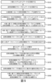
[002] 図1は、上述した既知の融合処理を示す。図1におけるS101Aにおいて、X線透視投影#1はTEEプローブ100を含む。S101Bにおいて、X線透視投影#2もTEEプローブ100を含む。S102において、TEEプローブ100は上記2つのX線透視投影からセグメント化される。この場合、これはTEEプローブ100の分離された位置及び向きを反映するからである。S103において、TEEプローブ100の位置及び向きが、2つのX線透視投影からのTEEプローブ100の上記セグメント化に基づいて決定される。S104において、TEEプローブ100の画像がX線透視画像上に該TEEプローブ100の位置及び向きの上記決定に基づいてオーバーレイされる。
[002] Figure 1 illustrates the known fusion process described above. At S101A in FIG. 1,
[003] TEEプローブ100はX線透視を使用してのみ追跡されるので、X線透視撮像が実行されない場合、現在の視覚化が有効であるかどうかをユーザに伝えるために利用可能な情報は存在しない。現在のところ、この情報は、電子ディスプレイ上のモデル内のTEEプローブ100のカラーコーティングを介して伝達され得るものであり、最後のX線透視画像から一定量の時間後、該TEEプローブ100のモデルの色は、例えば、緑から白へ変化し、当該位置合わせが古くなっていることを示す。加えて、後続の蛍光透視取得において生のX線透視画像は単一の面からのX線透視投影となるため、精度は現在のところ制限されている。
[003] Since the
[004] 時折の(X線透視法が使用されていない場合等)超音波撮像プローブの位置を認識しないことは、重要なワークフローの障壁になる可能性がる。超音波画像のX線透視画像に対する位置合わせは、生の超音波画像をX線透視画像に関連付ける(例えば融合)ためだけでなく、超音波画像内/上から戻ってX線蛍光透視画像内/上に位置合わせされる注釈を表示するためにも使用される。 [004] Occasional ignorance of the position of the ultrasound imaging probe (such as when fluoroscopy is not being used) can be a significant workflow barrier. Registration of the ultrasound image to the fluoroscopic image is not only for associating (e.g., fusing) the raw ultrasound image with the fluoroscopic image, but also within the ultrasound image/backwards within the fluoroscopic image/ Also used to display annotations that are aligned above.
位置合わせが不明な場合、注釈は超音波画像に誤って表示され得、この結果、混乱又は信頼性の低下につながる可能性がある(状態が技術的に正しい場合でも)。従って、位置合わせが最早有効でないということの知識は、タイムアウトからの結果である現在の解決策よりもワークフローの利益をもたらす。超音波撮像プローブの動きを補償することは、更に大きな利益をもたらし得る。 If the registration is unknown, the annotations may appear incorrectly on the ultrasound image, which can lead to confusion or unreliability (even if the condition is technically correct). Therefore, the knowledge that alignment is no longer valid provides workflow benefits over current solutions that result from timeouts. Compensating for ultrasound imaging probe motion can provide even greater benefits.
[005] 本開示の一態様によれば、X線画像及び超音波画像の位置合わせを維持するためのコントローラは、命令を記憶するメモリと、前記命令を実行するプロセッサとを有する。前記プロセッサにより実行された場合、前記命令は前記コントローラに、X線撮像を実行するために使用されるX線システムからデータを受信するステップ、及び超音波撮像を実行するために使用される超音波撮像プローブからデータを受信するステップを含む処理を実行させる。該コントローラにより実行される処理は、X線に基づく画像を前記超音波撮像プローブからの画像に対して前記X線に基づく画像のうちの前記超音波撮像プローブのX線画像に基づいて位置合わせするステップ、及び前記超音波撮像プローブからのデータから、該超音波撮像プローブの動きを検出するステップも含む。 [005] According to one aspect of the present disclosure, a controller for maintaining registration of an X-ray image and an ultrasound image has a memory that stores instructions and a processor that executes the instructions. When executed by the processor, the instructions instruct the controller to receive data from an x-ray system used to perform x-ray imaging; A process is performed that includes receiving data from an imaging probe. Processing performed by the controller aligns an x-ray-based image to an image from the ultrasound imaging probe based on x-ray images of the ultrasound imaging probe in the x-ray-based images. and detecting motion of the ultrasound imaging probe from data from the ultrasound imaging probe.
[006] 本開示の他の態様によれば、X線画像及び超音波画像の位置合わせを維持するための方法は、命令を記憶するメモリ及び前記命令を実行するプロセッサを含むコンピュータにより、X線撮像を実行するために使用されるX線システムからデータを受信するステップを含む。該方法は、前記コンピュータにより、超音波撮像を実行するために使用される超音波撮像プローブからデータを受信するステップも含む。該方法は、更に、X線に基づく画像を前記超音波撮像プローブからの画像に対して、前記X線に基づく画像のうちの前記超音波撮像プローブのX線画像に基づいて位置合わせするステップと、前記コンピュータにより且つ前記超音波撮像プローブからのデータから、該超音波撮像プローブの動きを検出するステップと、を含む。 [006] According to another aspect of the present disclosure, a method for maintaining registration of an X-ray image and an ultrasound image comprises: an X-ray image by a computer including a memory storing instructions and a processor executing the instructions; It includes receiving data from an X-ray system used to perform the imaging. The method also includes receiving, by the computer, data from an ultrasound imaging probe used to perform ultrasound imaging. The method further comprises registering an x-ray based image to an image from the ultrasound imaging probe based on an x-ray image of the ultrasound imaging probe in the x-ray based images. , detecting motion of the ultrasound imaging probe by the computer and from data from the ultrasound imaging probe.
[007] 本開示の更に他の態様によれば、X線画像及び超音波画像の位置合わせを維持するためのシステムは、X線システム、超音波撮像プローブ及びコントローラを含む。前記X線システムは、X線に基づいて画像を発生する。前記超音波撮像プローブは、超音波画像を発生する。前記コントローラは、命令を記憶するメモリ及び前記命令を実行するプロセッサを含む。前記プロセッサにより実行された場合、前記命令は前記コントローラに、前記X線システムからデータを受信するステップ及び記超音波撮像プローブからデータを受信するステップを含む処理を実行させる。該プロセッサにより実行される処理は、X線に基づく画像を前記超音波撮像プローブからの画像に対して前記X線に基づく画像のうちの前記超音波撮像プローブのX線画像に基づいて位置合わせするステップ、及び前記超音波撮像プローブからのデータから該超音波撮像プローブの動きを検出するステップも含む。 [007] According to yet another aspect of the present disclosure, a system for maintaining registration of an X-ray image and an ultrasound image includes an X-ray system, an ultrasound imaging probe and a controller. The x-ray system generates images based on x-rays. The ultrasound imaging probe generates ultrasound images. The controller includes a memory that stores instructions and a processor that executes the instructions. When executed by the processor, the instructions cause the controller to perform processes including receiving data from the x-ray system and receiving data from the ultrasound imaging probe. Processing performed by the processor aligns an x-ray-based image to an image from the ultrasound imaging probe based on x-ray images of the ultrasound imaging probe in the x-ray-based images. and detecting motion of the ultrasound imaging probe from data from the ultrasound imaging probe.
[008] 例示的な実施態様は、添付図と共に精読すれば、以下の詳細な説明から最もよく理解される。種々のフィーチャは必ずしも実寸で描かれているわけではないことを強調しておく。実際に、説明を明確にするために、寸法は任意に増減することができる。適用可能で実用的な場合、同様の参照番号は同様の要素を指す。 [008] The illustrative embodiments are best understood from the following detailed description when read in conjunction with the accompanying drawings. It is emphasized that the various features are not necessarily drawn to scale. In fact, the dimensions can be arbitrarily increased or decreased for clarity of explanation. Like reference numbers refer to like elements where applicable and practicable.
[018] 以下の詳細な説明においては、限定ではなく説明の目的で、本教示による実施態様の完全な理解を提供するために、特定の詳細を開示する代表的な実施態様が記載される。既知のシステム、装置、材料、操作方法及び製造方法の説明は、代表的な実施態様の説明を曖昧にしないようにするために省略され得る。それにもかかわらず、当業者の範囲内にあるシステム、装置、材料及び方法は、本教示の範囲内であり、代表的な実施態様に従って使用することができる。本明細書で使用される用語は、特定の実施態様を説明することのみを目的としており、限定することを意図するものではないことを理解されたい。定義された用語は、本教示の技術分野で一般的に理解され受け入れられている該定義された用語の技術的及び科学的意味に追加されるものである。 [018] In the following detailed description, for purposes of illustration and not limitation, representative implementations disclosing specific details are set forth in order to provide a thorough understanding of implementations in accordance with the present teachings. Descriptions of known systems, devices, materials, methods of operation, and methods of manufacture may be omitted so as not to obscure the description of the representative embodiments. Nevertheless, systems, devices, materials and methods within the purview of those skilled in the art are within the scope of the present teachings and can be used in accordance with the exemplary embodiments. It is to be understood that the terminology used herein is for the purpose of describing particular embodiments only and is not intended to be limiting. Defined terms are in addition to their technical and scientific meanings as commonly understood and accepted in the technical field of the present teachings.
[019] 本明細書では、第1、第2、第3等の用語が様々な要素又は構成要素を説明するために使用され得るが、これらの要素又は構成要素はこれらの用語によって限定されるべきではないことが理解されよう。これらの用語は、ある要素又は部品を別の要素又は構成要素から区別するためにのみ使用される。従って、以下で論じる第1の要素又は構成要素は、本発明の概念の教示から逸脱することなく、第2の要素又は構成要素と呼ぶことができる。 [019] Although the terms first, second, third, etc. may be used herein to describe various elements or components, these elements or components are limited by these terms. It should be understood that it should not. These terms are only used to distinguish one element or component from another. Accordingly, a first element or component discussed below could be termed a second element or component without departing from the teachings of the inventive concept.
[020] 本明細書で使用される用語は、特定の実施態様を説明することのみを目的としており、限定することを意図するものではない。明細書及び添付請求項で使用される場合、単数形の用語は、文脈が明確に別段の指示をしない限り、単数形及び複数形の両方を含むことを意図している。更に、「有する」、「有した」及び/又は同様の用語は、本明細書で使用される場合、記載されたフィーチャ、要素及び/又は構成要素の存在を指定するが、1以上の他のフィーチャ、要素、構成要素及び/又はこれらのグループの存在若しくは追加を排除するものではない。本明細書で使用される場合、「及び/又は」という用語は、関連するリストされた項目の1以上の如何なる及び全ての組み合わせを含む。 [020] The terminology used herein is for the purpose of describing particular embodiments only and is not intended to be limiting. As used in the specification and appended claims, singular terms are intended to include both singular and plural forms unless the context clearly dictates otherwise. Additionally, the terms “comprise,” “has,” and/or like terms as used herein specify the presence of the stated features, elements and/or components but not one or more other It does not exclude the presence or addition of features, elements, components and/or groups thereof. As used herein, the term "and/or" includes any and all combinations of one or more of the associated listed items.
[021] 特に断りのない限り、要素又は構成要素が他の要素又は構成要素に「接続され」、「結合され」又は「隣接する」と言われる場合、該要素又は構成要素は前記他の要素又は構成要素に直接接続若しくは結合することがことでき、又は介在する要素又は構成要素が存在することができる。すなわち、これら及び類似の用語は、1以上の中間要素又は構成要素を使用して2つの要素又は構成要素を接続することができる場合を包含する。しかしながら、要素又は構成要素が別の要素又は構成要素に「直接接続される」と言われる場合、これは、2つの要素又は構成要素が中間の若しくは介在する要素又は構成要素なしで互いに接続される場合のみを含む。 [021] Unless otherwise specified, when an element or component is said to be "connected to," "coupled with," or "adjacent to" another element or component, the element or component refers to the other element or component. or directly connected or coupled to a component, or there may be intervening elements or components. That is, these and similar terms encompass where one or more intermediate elements or components can be used to connect two elements or components. However, when an element or component is said to be "directly connected" to another element or component, this means that the two elements or components are connected to each other without intermediate or intervening elements or components. Contains only the case.
[022] 上記の観点から、本開示は、その様々な態様、実施態様及び/又は特定のフィーチャ若しくは部分構成要素の1以上により、以下に具体的に記載されるような利点の1以上を引き出すことを意図している。限定ではなく説明の目的で、本教示による実施態様の完全な理解を提供するために、特定の詳細を開示する例示的な実施態様が示される。しかしながら、本明細書に開示された特定の詳細から逸脱する本開示と一致する他の実施態様は、添付請求項の範囲内に留まるものである。更に、例示的な実施態様の説明を曖昧にしないように、良く知られた装置及び方法の説明は省略され得る。このような方法及び装置は、本開示の範囲内にある。 [022] In view of the foregoing, the present disclosure, through one or more of its various aspects, implementations and/or specific features or subcomponents, derives one or more of the advantages as specifically described below. intended to be For purposes of explanation and not limitation, example implementations disclosing specific details are presented in order to provide a thorough understanding of implementations in accordance with the present teachings. However, other implementations consistent with the present disclosure that depart from the specific details disclosed herein are within the scope of the appended claims. Moreover, descriptions of well-known devices and methods may be omitted so as not to obscure the description of the example embodiments. Such methods and apparatus are within the scope of this disclosure.
[023] 以下においては、X線透視はX線と称し、TEEを含む如何なるタイプの超音波も超音波と称する。 [023] In the following, fluoroscopy is referred to as x-rays and any type of ultrasound including TEEs is referred to as ultrasound.
[024] 図2A、図2B及び図2Cは、EchoNavソフトウェアスイートのビューを融合ビューで示している。 [024] Figures 2A, 2B and 2C show views of the EchoNav software suite in a fused view.
[025] 図2Aは、代表的実施態様による複数方式画像化位置合わせを初期ビューで示している。 [025] Figure 2A illustrates in an initial view multi-modal imaging registration according to a representative embodiment.
[026] 図2Aにおいて、X線画像及び超音波画像の融合の後、X線ビュー及び超音波ビューが位置合わせされる。図2Aにおいて、X線ビュー及び超音波ビューは心臓の画像及び該心臓内/上の介入医療デバイスの画像である。 [026] In FIG. 2A, after fusion of the X-ray and ultrasound images, the X-ray and ultrasound views are registered. In FIG. 2A, the X-ray and ultrasound views are images of the heart and interventional medical devices in/on the heart.
[027] 図2Bは、図2Aの代表的実施態様による、超音波撮像プローブの移動の後の複数方式画像化位置合わせを示す。 [027] FIG. 2B illustrates multi-modal imaging registration after movement of the ultrasound imaging probe, according to the representative embodiment of FIG. 2A.
[028] 図2Bにおいて、超音波撮像プローブの移動の後、リアルタイムの心臓(X線)ビューは、動きが発生する前の以前の心臓(X線)ビューに対してずれて見える。即ち、図2Bにおいて、当該デバイスの高い方の表示は超音波に基づくものであり、該デバイスの低い方の表示は運動が起きる前の以前のX線ビューである。該デバイスの高い方の表示と低い方の表示との間の差は、次いで、当該複数方式画像化位置合わせにより解決される。 [028] In FIG. 2B, after movement of the ultrasound imaging probe, the real-time cardiac (X-ray) view appears shifted relative to the previous cardiac (X-ray) view before motion occurred. That is, in FIG. 2B, the upper display of the device is based on ultrasound and the lower display of the device is the previous X-ray view before motion occurred. Differences between the upper and lower views of the device are then resolved by the multi-modal imaging registration.
[029] 図2Cは、図2A及び図2Bの代表的実施態様による、超音波撮像プローブの動きの補償後の複数方式画像化位置合わせを示す。 [029] Figure 2C illustrates multi-modal imaging registration after compensation for ultrasound imaging probe motion, according to the exemplary embodiment of Figures 2A and 2B.
[030] 図2Cにおいて、動き補償は、超音波ビューを前の心臓(X線)ビューと一致するように戻す。言い換えると、図2Cに示され且つここで及び本明細書の何処かで説明される補償は、X線に基づく画像と超音波撮像プローブからの画像との間の位置合わせ不整合を補正する。 [030] In FIG. 2C, motion compensation brings the ultrasound view back into line with the previous cardiac (x-ray) view. In other words, the compensation shown in FIG. 2C and described here and elsewhere herein corrects misalignment between the x-ray-based image and the image from the ultrasound imaging probe.
[031] 図2Bに示されるように、超音波撮像プローブの動きは、結果として超音波撮像プローブからの画像とX線からの画像との間の変位、不整合又は他の不均衡をもたらし得る。言い換えると、超音波撮像プローブが2つのX線収集の間で移動すると、超音波画像とX線画像との間の空間的関係が失われる。X線は、患者及び要員の放射線被曝のために常に使用することはできないが、X線を常に使用することが、前もって動きを認識する唯一の方法であろう。更に、幾つかの構造的心臓介入処置等の幾つかの介入処置の場合、X線撮像が主要な撮像方式ではない場合がある。特に僧帽弁又は三尖弁の手術の場合、治療のために視覚化する必要のある生きた軟組織構造はX線により画像化することができないため、エコーが主にデバイスのナビゲーションのために使用される。 [031] As shown in FIG. 2B, movement of the ultrasound imaging probe can result in a displacement, misalignment or other imbalance between the image from the ultrasound imaging probe and the image from the x-ray. . In other words, as the ultrasound imaging probe moves between two x-ray acquisitions, the spatial relationship between the ultrasound and x-ray images is lost. X-rays cannot always be used for radiation exposure of patients and personnel, but the constant use of X-rays may be the only way to recognize motion in advance. Additionally, for some interventional procedures, such as some structural cardiac interventions, X-ray imaging may not be the primary imaging modality. Especially for mitral or tricuspid valve surgery, echo is primarily used for device navigation as the live soft tissue structures that need to be visualized for treatment cannot be imaged by x-rays. be done.
[032] 本明細書で説明されるように、超音波画像を分析して動きを検出し、プローブが移動したこと及び位置合わせがもはや正確ではないことをユーザに示すことができる。更に、図2Cに示すように、動きは、X線と超音波との間の正確な位置合わせを可能にするために補償することができる。動きの補償は、X線なしで実行され、その代わりに検出された超音波の動きに基づくものとなる。 [032] As described herein, ultrasound images can be analyzed to detect motion and indicate to the user that the probe has moved and that the alignment is no longer correct. Furthermore, as shown in FIG. 2C, motion can be compensated to allow accurate alignment between X-rays and ultrasound. Motion compensation is performed without x-rays and is instead based on detected ultrasound motion.
[033] 図3は、代表的実施態様による複数方式画像化位置合わせのためのシステムを示す。 [033] FIG. 3 illustrates a system for multi-modal imaging registration according to a representative embodiment.
[034] 図3において、超音波システム350は、プロセッサ361及びメモリ362を備えた中央ステーション360、タッチパネル363、モニタ359、データ接続部358(例えば、有線又は無線データ接続部)によって中央ステーション360に接続された超音波撮像プローブ356、及びデータ接続部357(例えば、有線又は無線データ接続部)を介して中央ステーション360に接続された介入医療デバイス355を含む。図3における介入医療デバイス(機器)355は、シースS及びワイヤWを含む。
[034] In FIG. 3, an ultrasound system 350 includes a
[035] X線放出器372はX線をX線スクリーン371に向かって放出する。更に、人工呼吸器380がX線放出器372の近傍に配置されている。
[036] 位置合わせシステム390は、プロセッサ391及びメモリ392を含む。位置合わせシステム390は、X線放出器372、呼吸器380及び中央ステーション360からデータを受信する。位置合わせシステム390は、例えば、プロセッサ391がメモリ392内の命令を実行することにより、本明細書に記載の処理を実行する。しかしながら、位置合わせシステム390は、中央ステーション360において若しくは中央ステーション360によって、又は何らかの他のメカニズムで実施化することもできる。プロセッサ391及びメモリ392の組み合わせは、位置合わせシステム390内であるか又は別の構成内であるかに拘わらず、本明細書において該用語が使用されるように、「コントローラ」と見なすことができる。
[037] 介入医療デバイス355は、図示されるようにツールTを含み得る。介入医療デバイス355は、図2A、図2B及び図2Cの様々なビューで示されるデバイスに対応し、X線放出器372によって生成される画像及び超音波撮像プローブ356によって作成される画像から位置合わせされる対象である。この場合、異なる画像の位置合わせは、超音波撮像プローブ356からの(のものというより)ビューがX線放出器372からのビューに適切にオーバーレイされて示されることを可能にする。
[037] The interventional
[038] 説明として、介入医療デバイス355は、医療処置中に患者の内部に配置される。介入医療デバイス355の位置は、X線放出器372によって生成される画像及び超音波撮像プローブ356によって生成される画像の両方で見ることができる。異なる撮像モードにおける介入医療デバイス355の位置の位置合わせは、可能な範囲で維持される。本明細書に記載されるように、超音波撮像プローブ356からのデータを、該超音波撮像プローブ356の動きを検出するために使用することができ、これは、様々な方法において使用され且つ有用である。
[038] By way of explanation, interventional
[039] 例えば、超音波撮像プローブ356の動きを検出したら、該超音波撮像プローブ356の動きを、所定の閾値と比較することができる。超音波撮像プローブ356の動きが所定の閾値を超えると判定された場合、該動きを検出すること及び該動きが所定の閾値を超えると判定することに基づいて通知を生成することができる。通知は、動きが検出されたことを視覚的にオペレータに警告する警告灯又はインジケータ等の二進メカニズムとすることができる。該通知は、所定の閾値が、各々が異なる輝度設定又は異なるカラーの警告灯に対応する多数の異なる所定の閾値の1つであり得るようにして、超音波撮像プローブ356の動きが大きくなるにつれて次第に明るくなる警告灯等の可変メカニズムとすることもできる。このように、通知は、超音波撮像プローブ356の動きの量に基づいて変化することができ、二進メカニズムに限定されるものではない。
[039] For example, upon detecting motion of the
[040] 当該通知は、動きが特定のしきい値を超えていることを示すことができ、このことは、画面に表示されている超音波画像の空間位置が、最早、信頼することができないことを意味する。例えば、インターフェース上に示される超音波撮像プローブは、白又は赤に着色することができる。この場合、ユーザは、もし必要なら、当該位置合わせを再固定するために新たなX線画像を取得するための選択を有する。前述したように、ユーザには、二進閾値、又は異なる意味の通知を表示することができる信頼性フィードバックのいずれかを供給することができる。例えば、通知は、超音波撮像プローブが検出されて安定していることを意味する緑から、超音波撮像プローブが移動して新たな入力が必要であることを意味する赤まで等のように、異なる陰影又は輝度レベルのカラーを示すバーとすることができる。 [040] The notification may indicate that the motion exceeds a certain threshold, which means that the spatial position of the ultrasound image being displayed on the screen can no longer be relied upon. means that For example, the ultrasound imaging probe shown on the interface can be colored white or red. In this case, the user has the option to acquire a new X-ray image to re-fix the alignment, if necessary. As previously mentioned, the user can be provided with either binary thresholds or confidence feedback that can display notifications with different meanings. For example, the notification may be green, meaning that the ultrasound imaging probe is detected and stable, to red, meaning that the ultrasound imaging probe has moved and new input is required, and so on. It can be a bar showing colors of different shades or brightness levels.
[041] 呼吸器380は、位置合わせシステム390に入力を供給するために使用することができる。呼吸運動は、生きている患者に常に存在し、このような呼吸運動は周期的であり得る。従って、呼吸サイクルの呼吸による周期性は、自然の補助によらない呼吸によるものであれ、呼吸器380によって補助される呼吸によるものであれ、識別及び除去することができる。呼吸運動が常に存在する限り、そのような呼吸運動は、閾値を超え且つ新たなX線画像取得を起動する超音波撮像プローブ356の動きの原因としての考慮から除外されるべきである。時間の経過に伴う三次元(3D)呼吸運動の四次元(4D)データセットを使用して、呼吸運動を除外することができる。4Dデータセットは、心周期とは別の呼吸周期(呼吸サイクル)を反映する。他の例として、個々の呼吸サイクルよりも長い時間(10秒等)を使用して、呼吸運動による変化とプローブの運動による変化を区別するために画像の変化のパターン分析を実行することができる。呼吸運動は、呼吸器380等の外部呼吸装置から、又は呼吸は監視するが呼吸を補助することはない外部センサから受信される入力に基づいて補償することができる。
[041]
[042] オプションとして、患者が全身麻酔下にある場合等において、呼吸器380からの入力を直接使用することができる。代わりに、ベルトを呼吸運動推定に使用することもできる。呼吸器380又は代替ベルトのいずれかからの入力を位置合わせシステム390に供給して、呼吸運動と超音波撮像プローブ356の運動とを区別することができる。運動パターンを超音波エコー画像で測定することができ、相互相関分析(例えば、正規化された相互相関)を測定された運動に対し実行することができる。超音波エコー画像から推定された時間的運動パターンと呼吸器380又は代替ベルト/ベルトの入力との間の相互相関が高い場合、推定された運動は殆ど呼吸である可能性が高い。
[042] Optionally, input from the
[043] 超音波撮像プローブ356の動きの量は、どの程度該動きが補償されるべきかを決定するために測定することもできる。例えば、動きの検出は、超音波シネループにおける変化検出によって実現することができる。シネループは、ある期間の関連する一連の画像であり、個々のフレームのシーケンスとしてデジタルで保存される。従って、超音波撮像プローブからのシネループの分析に基づいて、該超音波撮像プローブの動きを検出することができる。
[043] The amount of motion of the
[044] ロバストさのために、動きの量を決定するための上記分析は、心周期ごとに実行することができる。心臓は三次元で撮像することができ、これは時間の経過とともに心周期を明らかにすることができる。時間の経過とともに三次元で撮像された各心周期は四次元(4D)データセットである。すなわち、経時的に識別された三次元心周期は四次元心周期であり、超音波撮像プローブの動きは、このような四次元心周期の間で検出することができる。連続する心周期の4Dデータセットを比較して、動きの量を含む動きを検出することができる。 [044] For robustness, the above analysis to determine the amount of motion can be performed every cardiac cycle. The heart can be imaged in three dimensions, which can reveal the cardiac cycle over time. Each cardiac cycle imaged in three dimensions over time is a four-dimensional (4D) dataset. That is, the three-dimensional cardiac cycles identified over time are four-dimensional cardiac cycles, and the motion of the ultrasound imaging probe can be detected during such four-dimensional cardiac cycles. Motion, including the amount of motion, can be detected by comparing 4D data sets of successive cardiac cycles.
[045] 例えば、異なるサイクルからの超音波画像は、時空間ローパスフィルタ処理の後、二乗差の合計又は他の同様の尺度を使用して比較することができる。他の例として、位置合わせマトリックスにおける変化量が、解剖学的構造の回転及び/又は並進等の特性を反映し得る。動きの量は、解剖学的目印に対して測定することができる。変化の量は、解剖学的構造のセグメンテーションから測定することもできる。更に、変化量は、解剖学的構造の回転及び/又は並進等の特性を反映するが、心臓モデルの3D超音波データセットへの適合も反映する位置合わせマトリックスから測定することができる。 [045] For example, ultrasound images from different cycles can be compared using sum of squared differences or other similar measures after spatio-temporal low-pass filtering. As another example, the amount of change in the registration matrix may reflect properties such as rotation and/or translation of the anatomy. The amount of motion can be measured relative to anatomical landmarks. The amount of change can also be measured from anatomical segmentation. Additionally, the amount of variation can be measured from a registration matrix that reflects properties such as rotation and/or translation of the anatomy, but also the fit of the heart model to the 3D ultrasound dataset.
[046] 6-DOF(六次の自由度)の動き推定を、四次元超音波心臓シネループ(又はX平面+時間)に基づいて実行することができる。6次の自由度は、3つの平行移動軸及び3つの回転軸を含む。ここで、心臓は固定ビーコンとして使用することができ、視野内の心臓の見かけの動きは、心臓の周りの視野の動きに対応する。即ち、視野内の心臓の見かけの動きは、心臓の周りの視野に影響を与えるプローブの動きに対応するので、これを、超音波撮像プローブの動きが発生したことを判断すること及び後の補償の基礎として使用することができる。既知の運動推定及び補償技術を使用して、X線オーバーレイ上で心臓の位置を一定に保つことができ、かくして、X線画像上の超音波セクターの位置は調整され、X線上で見られる超音波撮像プローブの位置からオフセットすることができる。後者は古いX線画像に対応するからである。該オフセットは図2B及び図2Cに示されている。超音波撮像プローブが移動したこと、及び位置合わせを更新することができるように新しいX線画像が再度取得されるべきであることを示すために指示表示を提供することができる。 [046] 6-DOF (sixth degree of freedom) motion estimation can be performed based on a 4D ultrasound cardiac cineloop (or X-plane + time). The sixth degree of freedom includes three translational axes and three rotational axes. Here, the heart can be used as a stationary beacon, and the apparent motion of the heart within the field of view corresponds to the motion of the field of view around the heart. That is, the apparent motion of the heart within the field of view corresponds to the motion of the probe affecting the field of view around the heart, and thus can be used to determine that motion of the ultrasound imaging probe has occurred and subsequent compensation. can be used as a basis for Known motion estimation and compensation techniques can be used to keep the position of the heart constant on the X-ray overlay, thus adjusting the position of the ultrasound sector on the X-ray image and adjusting the position of the ultrasound sector seen on the X-ray. It can be offset from the position of the acoustic imaging probe. This is because the latter corresponds to older X-ray images. The offset is shown in Figures 2B and 2C. An indication may be provided to indicate that the ultrasound imaging probe has moved and that new x-ray images should be acquired again so that the alignment can be updated.
[047] 別の例では、超音波撮像プローブ356の動きを検出したら、該超音波撮像プローブ356の動きを補償して、X線放出器からのX線に基づく画像と超音波撮像プローブからの画像との間の位置合わせを維持することができる。
[047] In another example, upon detection of motion of the
[048] 更に、介入医療デバイス355の動きを、複雑化を回避するために動き分析から除外することができる。例えば、超音波ボリューム内での介入医療デバイス355の動きは、超音波撮像プローブ356が移動したという誤った肯定指示情報を生成し得る。このような理由で、一層のロバストさを提供するためにX面又は4Dデータセットを使用することができる。代わりに、モデルベースの位置合わせ手法を使用してロバストさ強化することもできる。画像ベースのセグメンテーション又はナビゲーションを含む多くの方法のうちの1つを使用して介入医療デバイス355が追跡される場合、超音波ボリューム内の該介入医療デバイス355の位置は既知となる。機器追跡システムの例として、電磁(EM)追跡システムはフィールド発生器及び追跡されるセンサコイルを使用する。原位置追跡システムは、超音波を検出し、場所を識別するために使用することができる検出された超音波信号に基づく信号を送信する受動型超音波センサを使用する。結果として、当該デバイスを取り巻く超音波画像の部分は、動き検出アルゴリズムから除外することができる。例えば、バレル缶又はボックス等の一般的な三次元形状を、除外される領域を最小化するために、超音波画像内の介入医療デバイス355に密に重ね合わせることができる。
[048] Additionally, movement of the interventional
[049] 図4は、代表的実施態様による、複数方式画像化位置合わせの方法を実施化することができる汎用コンピュータシステムを示す。 [049] FIG. 4 illustrates a general-purpose computer system capable of implementing a method of multi-modal imaging registration, according to a representative embodiment.
[050] コンピュータシステム400は、該コンピュータシステム400に、本明細書に開示される方法又はコンピュータベースの機能のうちの何れか1以上を実行させるために実行することができる一群の命令を含むことができる。コンピュータシステム400は、自立型装置として動作することができ、又は、例えば、ネットワーク401を使用して、他のコンピュータシステム又は周辺装置に接続することができる。図4のコンピュータシステム400の要素及び特性の何れか又は全ては、中央ステーション360、位置合わせシステム390、超音波撮像プローブ356、超音波システム350、又はコントローラを含むと共に本明細書に記載の処理を実行することができる他の同様の装置及びシステムの要素及び特性を表すことができる。
[050]
[051] ネットワーク構成では、コンピュータシステム400は、サーバクライアントユーザネットワーク環境においてクライアントの能力で動作することができる。コンピュータシステム400は、制御ステーション、撮像プローブ、受動型超音波センサ、静止型コンピュータ、モバイルコンピュータ、パーソナルコンピュータ(PC)又は当該マシンによりなされるべき動作を指定する一群の命令(順次又はその他)を実行することができる何らかの他のマシン等の種々の装置として完全に若しくは部分的に実施化する又は斯かる種々の装置に組み込むことができる。コンピュータシステム400は、追加のデバイスを含む統合システム内にある装置して、又は斯かる装置内に組み込むことができる。一実施態様では、コンピュータシステム400は、ビデオ又はデータ通信を提供する電子装置を使用して実施化することができる。更に、コンピュータシステム400が示されているが、「システム」という用語は、1以上のコンピュータ機能を実行するための命令のセット又は複数のセットを個別に若しくは共同で実行するシステム又はサブシステムの如何なる集合も含むと解釈されるべきである。
[051] In a network configuration,
[052] 図4に示されるように、コンピュータシステム400は、プロセッサ410を含む。コンピュータシステム400のためのプロセッサ410は、有形で非一時的である。本明細書で使用される場合、「非一時的」という用語は、状態の永久的特徴としてではなく、ある期間続く状態の特徴として解釈されるべきである。「非一時的」という用語は、特に、搬送波若しくは信号の特徴又は如何なる場所及び時点でも一時的にのみ存在する他の形態等のつかの間の特徴を否定するものである。本明細書に記載の如何なるプロセッサも、製造品及び/又はマシン部品である。コンピュータシステム400のプロセッサは、本明細書の様々な実施態様に記載される機能を果たすためのソフトウェア命令を実行するように構成される。コンピュータシステム400のプロセッサは、汎用プロセッサであってもよく、特定用途向け集積回路(ASIC)の一部であってもよい。コンピュータシステム400のプロセッサは、マイクロプロセッサ、マイクロコンピュータ、プロセッサチップ、コントローラ、マイクロコントローラ、デジタル信号プロセッサ(DSP)、状態マシン又はプログラマブルロジックデバイスでもあり得る。コンピュータシステム400のプロセッサは、フィールドプログラマブルゲートアレイ(FPGA)等のプログラマブルゲートアレイ(PGA)を含む論理回路、又は個別ゲート及び/又はトランジスタロジックを含む別のタイプの回路でもあり得る。コンピュータシステム400のプロセッサは、中央処理装置(CPU)、グラフィックス処理ユニット(GPU)又はその両方であり得る。更に、本明細書に記載の如何なるプロセッサも、複数のプロセッサ、並列プロセッサ又はその両方を含み得る。複数のプロセッサは、単一のデバイス又は複数のデバイスに含まれるか、又はこれらに結合され得る。
[052] As shown in FIG.
[053] 更に、コンピュータシステム400は、バス408を介して相互に通信することができるメインメモリ420及びスタチックメモリ430を含む。本明細書に記載のメモリは、データ及び実行可能命令を格納することができる有形の記憶媒体であり、内部に命令が記憶される間において非一時的である。本明細書で使用される場合、「非一時的」という用語は、状態の永久的特徴としてではなく、ある期間続く状態の特徴として解釈されるべきである。「非一時的」という用語は、特に、搬送波若しくは信号の特徴、又は如何なる場所及び如何なる時点でも一時的にのみ存在する他の形態等のつかの間の特徴を否定するものである。本明細書に記載のメモリは、製品及び/又はマシン部品である。本明細書に記載のメモリは、コンピュータによりデータ及び実行可能な命令を読み取ることができるコンピュータ読取可能な媒体である。本明細書に記載のメモリは、ランダムアクセスメモリ(RAM)、読み取り専用メモリ(ROM)、フラッシュメモリ、電気的にプログラム可能な読み取り専用メモリ(EPROM)、電気的に消去可能なプログラム可能な読み取り専用メモリ(EEPROM)、レジスタ、ハードディスク、リムーバブルディスク、テープ、コンパクトディスク読み取り専用メモリ(CD-ROM)、デジタル多用途ディスク(DVD)、フロッピーディスク、ブルーレイディスク又は当技術分野で知られている他の形式の記憶媒体とすることができる。メモリは、揮発性又は不揮発性、安全な及び/又は暗号化された、安全でない及び/又は暗号化されていないものとすることができる。
[053]
[054] 図示されるように、コンピュータシステム400は、液晶ディスプレイ(LDC)、有機発光ダイオード(OLED)ディスプレイ、フラットパネルディスプレイ、ソリッドステートディスプレイ又はブラウン管(CRT)等のビデオディスプレイユニット450を更に含むことができる。更に、コンピュータシステム400は、キーボード/仮想キーボード、タッチ感知入力スクリーン又は音声認識を備えた音声入力部等の入力装置460、及びマウス又はタッチ感知入力スクリーン若しくはパッド等のカーソル制御装置470を含み得る。コンピュータシステム400は、ディスクドライブユニット480、スピーカー又はリモートコントロール等の信号発生装置490及びネットワークインターフェース装置440も含むことができる。
[054] As shown, the
[055] 一実施態様では、図4に示されるように、ディスクドライブユニット480はコンピュータ読取可能な媒体482を含むことができ、該媒体内に1以上の組の命令484、例えば ソフトウェアを埋め込むことができる。命令484の組は、コンピュータ読取可能な媒体482から読み取ることができる。更に、命令484は、プロセッサによって実行された場合、本明細書に記載される方法及び処理の1以上を実行するために使用することができる。一実施態様において、命令484は、完全に又は少なくとも部分的に、メインメモリ420、スタチックメモリ430内に、及び/又はコンピュータシステム400による実行中にプロセッサ410内に存在し得る。
[055] In one embodiment, as shown in Figure 4, the
[056] 代替の実施態様において、特定用途向け集積回路(ASIC)、プログラマブルロジックアレイ及び他のハードウェア部品等の専用ハードウェア実施化例は、本明細書で説明される方法の1以上を実施するよう構成することができる。本明細書に記載される1以上の実施態様は、2以上の特定の相互接続されたハードウェアモジュール又は装置を、斯かるモジュールの間で及びを介して通信され得る関連する制御及びデータ信号と共に使用して、機能を実施することができる。従って、本開示は、ソフトウェア、ファームウェア及びハードウェア構成を包含する。本出願における如何なるものも、有形の非一時的プロセッサ及び/又はメモリ等のハードウェアではなく、ソフトウェアのみで実施化され又は実施化可能であると解釈されるべきではない。 [056] In alternative embodiments, dedicated hardware implementations such as application specific integrated circuits (ASICs), programmable logic arrays and other hardware components perform one or more of the methods described herein. can be configured to One or more of the embodiments described herein employ two or more specific interconnected hardware modules or devices, along with associated control and data signals that can be communicated between and via such modules. can be used to perform functions. Accordingly, this disclosure encompasses software, firmware and hardware configurations. Nothing in this application should be construed to be or can be implemented solely in software rather than in hardware such as a tangible non-transitory processor and/or memory.
[057] 本開示の様々な実施態様によれば、本明細書に記載される方法は、ソフトウェアプログラムを実行するハードウェアコンピュータシステムを使用して実施することができる。更に、例示的な非限定的な実施態様において、実施化例は、分散処理、コンポーネント/オブジェクト分散処理及び並列処理を含むことができる。仮想コンピュータシステム処理を、本明細書に記載の方法又は機能の1以上を実施するために構築することができ、本明細書に記載のプロセッサを使用して、仮想処理環境をサポートすることができる。 [057] According to various embodiments of the present disclosure, the methods described herein can be implemented using a hardware computer system executing a software program. Further, in exemplary non-limiting embodiments, implementations can include distributed processing, component/object distributed processing, and parallel processing. Virtual computer system processing can be constructed to perform one or more of the methods or functions described herein, and the processors described herein can be used to support virtual processing environments. .
[058] 本開示は、命令484を含むコンピュータ読取可能な媒体482を想定するか、又は伝播される信号に応答して命令484を受信及び実行する。かくして、ネットワーク401に接続された装置は、該ネットワーク401を介してビデオ又はデータを通信することができる。更に、命令484は、ネットワークインターフェース装置440によりネットワーク401を介して送信又は受信することができる。
[058] This disclosure contemplates a computer-
[059] 図5は、代表的実施態様による複数方式画像化位置合わせのための処理を示す。 [059] FIG. 5 illustrates a process for multi-modal imaging registration according to a representative embodiment.
[060] S510においては、データが、X線放出器372等のX線システムから受信される。該データは、位置合わせシステム390によって受信され得る。該データは、X線画像、X線画像を作成するために使用され得る生データ、又はその両方であり得る。 該X線画像は、患者の画像であり、完全に又は部分的に患者内の介入医療デバイス355の視覚化を含むと共に、超音波撮像プローブ356の画像も含み得る。しかしながら、最初から述べたように、X線システムによるX線撮像は、複数方式画像化位置合わせにおける超音波撮像プローブ356の動きを決定する基礎ではない。
[060] At S510, data is received from an x-ray system, such as
[061] むしろ、S520において超音波撮像プローブ356から受信されるデータが、該超音波撮像プローブ356の動きを検出する基礎である。S520において超音波撮像プローブ356から受信されるデータは、超音波画像、超音波画像を作成するために使用することができる生データ、又はその両方であり得る。該超音波画像も、患者の画像であり、完全に又は部分的に患者内の介入医療デバイス355の視覚化を含み得る。
[061] Rather, the data received from the
[062] S525において、X線画像において超音波撮像プローブが識別される。 [062] At S525, the ultrasound imaging probe is identified in the x-ray image.
[063] S530において、心周期及び/又は呼吸周期が、X線システムから受信されたデータから及び/又は超音波撮像プローブ356から受信されたデータから識別される。
[063] At S530, cardiac and/or respiratory cycles are identified from data received from the X-ray system and/or from data received from the
[064] S540において、X線に基づく画像は、超音波撮像プローブ356からの画像に位置合わせされる。位置合わせは、異なる撮像方式における同じ目的物を整列させることを含み、ある座標系を別の座標系に合致させること、ある撮像モードにおける目印を他の撮像モードにおける同じ目印に一致させること、ある撮像モードを他の撮像モードのサイズに一致するようにサイズ変更すること、又は同じシーンの2つの別々の画像間の位置合わせを確立する他の既知の形態を含み得る。一方のモードからの画像は、基準画像又は固定画像として指定することができ、幾何学的変換又は局所的変位を他方のモードからの他の画像に適用して、2つの画像モードからの画像を整列させることができる。前述したように、複数方式画像化位置合わせは、超音波撮像プローブ356の動きが検出された場合のように、S540での位置合わせが古くなった場合等の状況に対処する。
[064] At S540, the x-ray-based image is registered with the image from the
[065] S550において、図5の処理は、介入治療デバイス355を含む領域を識別して除外するステップを含む。介入医療デバイス355を含む領域は、X線に基づく画像及び超音波撮像プローブ356からの画像の何れか又は両方において識別することができる。
[065] At S550, the process of FIG. A region containing an interventional
[066] S555では、新たなデータセットが超音波撮像プローブ356から受信される。S550までの処理(S550を含む)は、古くなり得るS540における最初の位置合わせが、本明細書に記載される複数方式画像化位置合わせによって対処される中心的関心事(又はその1つ)であるという意味で、S550以降の処理に対する一形態の背景と見なすことができる。S555における超音波撮像プローブからの新たなデータセットは、該超音波撮像プローブの動きが検出されるデータセットである。
[066] At S555, a new data set is received from the
[067] S556においては、超音波撮像プローブ356の位置が、新たな各データセットから決定される。S557では、当該超音波撮像プローブの位置の変化が、上記新たなデータセットのうちの2つの間で決定される。例えば、新たなデータセットがS555で取得されるたびに、該新たなデータセットからS556において決定された超音波撮像プローブ356の位置を、直前のデータセット、又は該新たなデータセットの前の所定の期間から若しくは該新たなデータセットの前の所定の数のデータセットからのもの等の他の以前のデータセットにおける位置と比較することができる。
[067] At S556, the position of the
[068] S560においては、超音波撮像プローブ356の位置の変化が、1以上の所定の閾値と比較される。例えば、超音波撮像プローブ356の位置は、目印の回転若しくはオフセット又は前述した他のメカニズム等により、超音波撮像プローブ356からのデータに基づいて異なる画像フレームから識別することができる。上記異なる画像フレームは、連続していてもよく、又は特定の時間量又は介在する画像フレームの数によってオフセットされていてもよい。前記閾値は、二進の閾値とすることができ、又は各々が結果的通知のレベル等の異なる意味若しくは結果を持つ異なる閾値を含むスライディングスケールとすることもできる。移動量が決定されたなら、S560での比較は、決定された移動量を1以上の閾値と比較することを含む比較的単純な問題となり得る。
[068] At S560, the change in position of the
[069] S570では、超音波撮像プローブ356の動きが、該超音波撮像プローブ356からのデータから正式に検出される。S570での検出は、S560での位置の変化が僅少なもの以上であることに基づくと共に、S530からの心周期及び/又は呼吸周期も考慮に入れる。このように、S570における超音波撮像プローブからのデータからの該超音波撮像プローブの動きの検出は、例えば、X線に基づく画像が古く、S540での画像の位置合わせが古い可能性があることを反映する動きの正式な確認を含む。
[069] At S570, motion of the
[070] S580において、超音波撮像プローブ356の検出された動きを通知するための通知が発生される。
[070] At S580, a notification is generated to notify of the detected motion of the
[071] S590において、図5の処理は、超音波撮像プローブの動きを補償して、該超音波撮像プローブからの画像に対するX線に基づく画像の位置合わせを維持する。補償は、1若しくは2以上のデカルト軸上での画像情報のシフト、又は1つの軸若しくは2以上の軸の回りでの画像情報の回転を含むことができる。図5には示されていないが、S540における位置合わせは、S590での補償に基づいて再度実行することができる。 [071] At S590, the process of Figure 5 compensates for the motion of the ultrasound imaging probe to maintain alignment of the x-ray-based image with the image from the ultrasound imaging probe. Compensation can include shifting the image information on one or more Cartesian axes or rotating the image information about one or more axes. Although not shown in FIG. 5, the alignment at S540 can be performed again based on the compensation at S590.
[072] 図6は、代表的実施態様による、複数方式画像化位置合わせのための他の処理を示す。 [072] Figure 6 illustrates another process for multi-modal imaging registration, according to a representative embodiment.
[073] 図6の処理はS601において開始する。S610において、当該X線システムからデータが受信され、S620において、超音波撮像プローブ356からデータが受信される。S610及びS620におけるデータの受信は、図示されたように同時であるか、順次であるか、又は受信が部分的に同時であり且つ部分的に順次となるように重なり合うこともできる。
[073] The process of FIG. 6 starts at S601. Data is received from the x-ray system at S610 and data is received from the
[074] S625において、超音波撮像プローブ356がX線画像において識別される。S630において、心周期及び/又は呼吸周期がX線システムからのデータ及び超音波撮像プローブ356からのデータから識別される。
[074] At S625, the
[075] S640において、X線に基づく画像が超音波撮像プローブ356からの画像に対し、識別された超音波撮像プローブ356を含むX線画像に基づいて位置合わせされる。
[075] At S640, the x-ray-based image is registered to the image from the
[076] S650において、X線に基づく画像及び超音波撮像プローブ356からの画像において介入医療デバイス355の(の周辺の)領域が識別されて除外される。
[076] At S650, regions (around) the interventional
[077] S655において、新たなデータセット(又は複数のデータセット)が超音波撮像プローブ356から受信され、該超音波撮像プローブ356の位置が新たな各データセットから決定され、該超音波撮像プローブ356の位置の変化が新たなデータセットの2つから決定される。
[077] At S655, a new data set (or multiple data sets) is received from the
[078] S660において、当該超音波撮像プローブの位置の変化が、予め定められた閾値と比較される。該変化は、どんなに小さくても、順次の画像フレームの間の如何なる観察される動きでもあり得る。 [078] At S660, the change in position of the ultrasound imaging probe is compared to a predetermined threshold. The change can be any observed motion between successive image frames, however small.
[079] S655において、動きが検出されたかについて判定がなされる。動きは、S660における位置の変化が閾値を超える場合に検出される。動きが検出されない場合(S665=ノー)、当該処理はS655に戻り、X線システム及び超音波撮像プローブ356からのデータを再び受信する。
[079] At S655, a determination is made as to whether motion has been detected. Motion is detected if the change in position at S660 exceeds a threshold. If motion is not detected (S665=NO), the process returns to S655 to again receive data from the X-ray system and
[080] 動きが検出された場合(S665=イエス)、S670において、当該超音波撮像プローブの動きが心周期及び/又は呼吸周期を考慮に入れて検出される。即ち、自然の心運動及び/又は自然の若しくは補助された呼吸運動に基づく該プローブの動きは、除外され、オフセットされ又はそれ以外で取り除かれ得る。 [080] If motion is detected (S665=yes), then at S670 motion of the ultrasound imaging probe is detected taking into account the cardiac and/or respiratory cycles. That is, movement of the probe due to natural cardiac motion and/or natural or assisted respiratory motion may be excluded, offset or otherwise removed.
[081] S680では、超音波撮像プローブ356の検出された動きの通知が生成される。S690では、超音波撮像プローブの動きが、該超音波撮像プローブ356からの画像へのX線に基づく画像の位置合わせを維持するために補償される。S680での通知及びS690での補償は、図示されるように同時とすることができ、順次とすることができ、又は通知及び補償が部分的に同時且つ部分的に順次となるように重なり合うようにすることができる。
[081] At S680, a notification of the detected motion of the
[082] 図7は、代表的な実施態様による、複数方式画像化位置合わせのための別の処理を示す。図7において、要素番号は、他の実施態様における要素番号との相関関係を明確に描くために番号順から外れる場合がある。それにもかかわらず、図7に示される流れは、図7に示される実施態様における複数方式画像化位置合わせの処理の態様を表すものである。 [082] FIG. 7 illustrates another process for multi-modal imaging registration, according to a representative embodiment. In FIG. 7, the element numbers may be out of numerical order to clearly delineate the correlation with element numbers in other embodiments. Nevertheless, the flow shown in FIG. 7 represents aspects of the process of multi-modal imaging registration in the embodiment shown in FIG.
[083] 図7の処理は、S701で開始する。S710では、二重投影X線撮像が取得される。二重投影X線撮像は2つの面から投影されたX線撮像であり、これは初期的に実行することができる一方、後続のX線撮像は単一の面からであり得る。S720では、TEE撮像がTEEプローブから取得される。S710での二重投影X線撮像及びS720でのTEE撮像の受信は、図示されたように同時であり得るか、順次であり得るか、又は受信が部分的に同時且つ部分的に順次となるように重なり得る。 [083] The process of FIG. 7 starts at S701. At S710, a double projection X-ray image is acquired. Double projection X-ray imaging is X-ray imaging projected from two planes, which can be performed initially while subsequent X-ray imaging can be from a single plane. At S720, TEE imaging is acquired from the TEE probe. The reception of the dual projection X-ray imaging at S710 and the TEE imaging at S720 can be simultaneous as shown, can be sequential, or reception can be partially simultaneous and partially sequential. can overlap.
[084] S725において、TEEプローブの姿勢がX線撮像において識別される。該TEEプローブの姿勢は、該TEEプローブの位置及び向きを含む。 [084] At S725, the pose of the TEE probe is identified in the X-ray imaging. The pose of the TEE probe includes the position and orientation of the TEE probe.
[085] S740において、TEE撮像が最新のX線画像上に重ねられる。S799における判定は新たなX線画像が利用可能であるかについてなされ、そうでないなら(S799=ノー)、当該処理はS720に戻って新たなTEE撮像を取得する。新たなX線画像が利用可能なら(S799=イエス)、当該処理はS725に戻って該新たなX線画像におけるTEEプローブの姿勢を再び識別する。 [085] At S740, the TEE imaging is overlaid on the current X-ray image. A determination at S799 is made as to whether a new X-ray image is available, and if not (S799=No), the process returns to S720 to acquire a new TEE image. If a new x-ray image is available (S799=yes), the process returns to S725 to again identify the pose of the TEE probe in the new x-ray image.
[086] S750では、機器領域が識別され、S720で取得されたTEE画像から削除される。S730では、心運動及び呼吸運動がTEE撮像から削除される。S770において動きが検出され、S790において、検出された動きが補償される。S790後の補償された動きの出力は、S740での最新のX線画像上のオーバーレイのため、並びにS790で補償された測定された動きの量及び補償の品質を反映するためにユーザに提供される視覚的指示子を更新するための両方のために供給される。S780において視覚的指示子を更新した後、当該処理はS720に戻り、TEE撮像を再度取得する。 [086] At S750, equipment regions are identified and removed from the TEE image acquired at S720. At S730, cardiac motion and respiratory motion are removed from the TEE imaging. Motion is detected at S770 and the detected motion is compensated at S790. The compensated motion output after S790 is provided to the user for overlay on the latest X-ray image at S740 and to reflect the measured amount of motion compensated at S790 and the quality of compensation. provided for both to update the visual indicator. After updating the visual indicators at S780, the process returns to S720 to acquire TEE imaging again.
[087] 図7に示され、上記で説明したように、2つの並列処理を、複数のループを用いて再帰的パターンで実行することができる。したがって、S710において二重投影X線画像として取得される最初のX線画像には、単一投影X線画像(図示せず)が後続され得、かくして、S725でのTEEプローブの識別は新たなX線画像が利用可能となる(S799=イエス)毎に実行される。S720からS780までのTEE処理もループで実行することができ、補償された動きが、S740において最新のX線画像上に新しいTEE撮像をオーバーレイすると共に、S720において新しいTEE撮像を再度取得する前にS780において視覚的指示子を更新するために繰り返し使用されるようにする。 [087] As shown in Figure 7 and described above, two parallel processes can be performed in a recursive pattern using multiple loops. Thus, the initial X-ray image acquired as a dual projection X-ray image at S710 may be followed by a single projection X-ray image (not shown), thus identifying the TEE probe at S725 is a new process. Executed each time an X-ray image becomes available (S799=yes). The TEE processing from S720 to S780 can also be performed in a loop, with the motion compensated overlaying the new TEE image on top of the latest X-ray image at S740 and before reacquiring the new TEE image at S720. It will be used repeatedly to update the visual indicator at S780.
[088] 前述したように、図7における要素番号は番号順から外れて見え得るが、これは、他の実施態様において同様の要素番号との相関関係を明確に描くために行われたものである。斯かるステップの異なる順序は、種々の実施態様に示されるステップを、まったくではなくて異なる順序で、又は追加の介在するステップ及び処理(図示せず)が間に実行されるようにして実行することができる点で、複数方式画像化位置合わせのための処理ステップの変動性を反映している。したがって、複数方式画像化位置合わせは、超音波プローブの動きを識別して対処するためのメカニズムを提供する。測定された動きは、閾値と比較することができ、呼吸周期及び/又は心周期からの影響を除去し若しくはそれ以外で考慮するための補正を施すことができる。測定された動きが修復を正当化するのに十分なほど重要である場合、オペレータに動きの程度を反映する可変通知を含む通知を提供することができ、及び/又は当該動きを、超音波からの画像をX線からの画像のジオメトリと再び一致するように調整するために補償することができる。 [088] As noted above, the element numbers in FIG. 7 may appear out of numerical order, but this was done to clearly delineate the correlation with similar element numbers in other embodiments. be. Different orders of such steps may cause the steps shown in various embodiments to be performed in different orders rather than none, or with additional intervening steps and processes (not shown) performed in between. It reflects the variability of the processing steps for multi-modal imaging registration in that it can. Thus, multimodal imaging registration provides a mechanism for identifying and addressing ultrasound probe motion. The measured motion can be compared to a threshold and corrected to remove or otherwise account for effects from respiratory and/or cardiac cycles. If the measured motion is significant enough to justify repair, the operator can be provided with a notification that includes a variable notification reflecting the degree of motion and/or the motion can be detected from ultrasound. can be compensated to adjust the image back to match the geometry of the image from the x-ray.
[089] 複数方式画像化位置合わせを幾つかの例示的な実施態様を参照して説明したが、使用された文言は、限定の文言ではなく、説明及び例示の文言であることが理解される。各態様における複数方式画像化位置合わせの範囲及び趣旨から逸脱することなく、現在述べられ及び補正される添付請求項の範囲内で変更を行うことができる。複数方式画像化位置合わせは、特定の手段、材料及び実施態様を参照して説明されているが、複数方式画像化位置合わせは、開示された詳細に限定されることを意図していない。むしろ、複数方式画像化位置合わせは、添付請求項の範囲内にあるような、すべての機能的に等価な構造、方法及び使用にまで及ぶものである。 [089] While multimodal imaging registration has been described with reference to several exemplary embodiments, it is understood that the words that have been used are words of description and illustration, rather than words of limitation. . Changes may be made within the scope and spirit of the appended claims as presently stated and amended without departing from the scope and spirit of multi-modal imaging registration in each aspect. Although multimodal imaging registration has been described with reference to particular means, materials and implementations, multimodal imaging registration is not intended to be limited to the details disclosed. Rather, multi-modal imaging registration extends to all functionally equivalent structures, methods and uses as falling within the scope of the appended claims.
[090] 例えば、図3は中央ステーション360及びX線放出器372とは別個の位置合わせシステム390を示している。しかしながら、位置合わせは中央ステーション360若しくは均等物又はX線放出器若しくは均等物の一方又は他方により実行することもできる。
[090] For example, FIG. However, alignment can also be performed by one or the other of the
[091] 本明細書に記載の実施態様の図示は、様々な実施態様の構造の一般的な理解を提供することを意図している。これらの図示は、本明細書に記載されている本開示の全ての要素及びフィーチャの完全な説明として働くことを意図するものではない。本開示を検討すれば、他の多くの実施態様が当業者には明らかとなり得る。本開示の範囲から逸脱することなく構造的及び論理的置換及び変更を行うことができるように、本開示から他の実施態様を利用し、導き出すことができる。更に、各図は単なる表現であり、縮尺どおりに描かれていない場合がある。図示内の特定の比率は誇張されている場合があり、他の比率は最小化されている場合がある。したがって、本開示及び図面は、限定的ではなく例示的であると見なされるべきである。 [091] The illustrations of the embodiments described herein are intended to provide a general understanding of the structure of the various embodiments. These illustrations are not intended to serve as a complete description of all the elements and features of the disclosure described herein. Many other implementations may be apparent to those of skill in the art upon reviewing the disclosure. Other implementations may be utilized and derived from the present disclosure such that structural and logical substitutions and changes may be made without departing from the scope of the present disclosure. Further, each figure is a representation only and may not be drawn to scale. Certain proportions within the illustrations may be exaggerated and other proportions may be minimized. Accordingly, the present disclosure and drawings are to be regarded in an illustrative rather than a restrictive sense.
[092] 本開示の1以上の実施態様は、ここでは、本出願の範囲を如何なる特定の発明又は発明的概念に自発的に限定することを意図することなく、単に便宜のために「発明」という用語によって、個別に及び/又は集合的に参照され得る。更に、本明細書では特定の実施態様が図示及び説明されているが、同一又は同様の目的を達成するように設計された如何なる後の構成も、上記特定の実施態様と置換することができると理解されたい。本開示は、様々な実施態様の如何なる及び全ての後の適応又は変形をカバーすることを意図している。上記実施態様の組み合わせ及び本明細書に具体的に記載されていない他の実施態様は、本記載を検討すれば当業者には明らかであろう。 [092] One or more embodiments of the present disclosure may be referred to herein as the "invention" merely for convenience, without intending to voluntarily limit the scope of the present application to any particular invention or inventive concept. may be referred to individually and/or collectively by the terms. Further, while specific embodiments are illustrated and described herein, any later arrangement designed to accomplish the same or similar purpose may be substituted for the specific embodiments. be understood. This disclosure is intended to cover any and all later adaptations or variations of various embodiments. Combinations of the above embodiments, and other embodiments not specifically described herein, will be apparent to those of skill in the art upon reviewing the description.
[093] 本開示の要約は、37C.F.R§1.72(b)に準拠するために提供されたものであり、請求項の範囲又は意味を解釈又は制限するために使用されるものではないとの理解で提示されるものである。更に、前述の詳細な説明では、開示を合理化する目的で、様々なフィーチャを一緒にグループ化するか、又は単一の実施態様で説明することができる。本開示は、請求項に記載された実施態様が各請求項に明示的に記載されているよりも多くのフィーチャを必要とするという意図を反映していると解釈されるべきではない。むしろ、以下の請求項が反映するように、本発明の主題は、開示された実施態様の何れかのフィーチャの全てよりも少ないものに向けられ得る。したがって、以下の請求項は、各請求項が自身で請求項に記載された主題を別途定義するものとして、詳細な説明に組み込まれる。 [093] This Abstract of the Disclosure is provided for compliance with 37 C.F.R § 1.72(b) and shall not be used to interpret or limit the scope or meaning of the claims. It is presented with understanding. Additionally, in the foregoing Detailed Description, various features may be grouped together or described in a single implementation for the purpose of streamlining the disclosure. This disclosure is not to be interpreted as reflecting an intention that the claimed implementations require more features than are expressly recited in each claim. Rather, as the following claims reflect, inventive subject matter may be directed to less than all features of any disclosed embodiment. Thus, the following claims are hereby incorporated into the Detailed Description, with each claim separately defining claimed subject matter on its own.
[094] 開示された実施態様の前述の説明は、当業者が本開示に記載された概念を実施することを可能にするために提供されている。したがって、上記の開示された主題は、例示的であり、限定的ではないと見なされるべきであり、添付の請求項は、本開示の真の趣旨及び範囲内にあるそのような全ての修正、強化及び他の実施態様をカバーすることを意図する。したがって、法律で認められる最大限の範囲で、本開示の範囲は、以下の請求項及びそれらの均等物の最も広い許容可能な解釈によって決定されるべきであり、前述の詳細な説明によって制限又は限定されるべきではない。 [094] The previous description of the disclosed embodiments is provided to enable any person skilled in the art to implement the concepts described in the present disclosure. Accordingly, the above disclosed subject matter is to be considered illustrative and not limiting, and the appended claims cover all such modifications that come within the true spirit and scope of this disclosure. It is intended to cover enhancements and other implementations. Accordingly, to the fullest extent permitted by law, the scope of the disclosure is to be determined by the broadest allowable interpretation of the following claims and their equivalents, limited or not by the preceding detailed description. should not be limited.
Claims (19)
命令を記憶するメモリと、
前記命令を実行するプロセッサと、
を有し、
前記プロセッサにより実行された場合に前記命令が前記コントローラに、
X線撮像を実行するために使用されるX線システムからデータを受信するステップ、
超音波撮像を実行するために使用される超音波撮像プローブからデータを受信するステップ、
X線に基づく画像を前記超音波撮像プローブからの画像に対して前記X線に基づく画像のうちの前記超音波撮像プローブのX線画像に基づいて位置合わせするステップ、及び
前記超音波撮像プローブからのデータから、該超音波撮像プローブの動きを検出するステップ、
を有する処理を実行させる、コントローラにおいて、
前記コントローラにより実行される前記処理は、
介入治療デバイスが前記超音波撮像プローブからのシネループにおいて移動された領域を識別するステップ、及び
前記超音波撮像プローブの動きの検出から、前記領域内の動きを除外するステップ、
を更に有する、コントローラ。 A controller for maintaining registration of an X-ray image and an ultrasound image, comprising:
a memory for storing instructions;
a processor that executes the instructions;
has
the instructions to the controller when executed by the processor;
receiving data from an X-ray system used to perform X-ray imaging;
receiving data from an ultrasound imaging probe used to perform ultrasound imaging;
registering an x-ray-based image to an image from the ultrasound imaging probe based on an x-ray image of the ultrasound imaging probe among the x-ray-based images; and from the ultrasound imaging probe. detecting motion of the ultrasound imaging probe from the data of
In a controller that executes a process having
The processing performed by the controller includes:
identifying a region where an interventional therapy device has moved in a cine loop from the ultrasound imaging probe; and
excluding motion within the region from detection of motion of the ultrasound imaging probe;
A controller .
前記超音波撮像プローブの動きが所定の閾値を超えるかを判定するステップ、及び
前記超音波撮像プローブの動きを検出することに基づいて通知を発生するステップ、
を更に有する、請求項1に記載のコントローラ。 The processing performed by the controller includes:
determining whether motion of the ultrasound imaging probe exceeds a predetermined threshold; and generating a notification based on detecting motion of the ultrasound imaging probe;
2. The controller of claim 1, further comprising:
前記X線に基づく画像と前記超音波撮像プローブからの画像との間の位置合わせを維持するために前記超音波撮像プローブの動きを補償するステップ、
を更に有する、請求項1に記載のコントローラ。 The processing performed by the controller includes:
compensating for motion of the ultrasound imaging probe to maintain registration between the x-ray-based image and an image from the ultrasound imaging probe;
2. The controller of claim 1, further comprising:
前記通知が前記超音波撮像プローブの動きの量に基づいて変化する、
請求項2に記載のコントローラ。 the predetermined threshold varies between a plurality of predetermined thresholds;
the notification varies based on the amount of movement of the ultrasound imaging probe;
3. The controller of claim 2.
前記超音波撮像プローブの動きの量を測定するステップ、及び
前記X線に基づく画像と前記超音波撮像プローブからの画像との間の位置合わせを維持するために前記超音波撮像プローブの動きを補償するステップ、
を更に有し、
前記補償するステップが、前記X線に基づく画像と前記超音波撮像プローブからの画像との間の位置合わせ不整合を補正するためのものである、
請求項4に記載のコントローラ。 The processing performed by the controller includes:
measuring an amount of motion of the ultrasound imaging probe; and compensating for motion of the ultrasound imaging probe to maintain registration between the x-ray-based image and an image from the ultrasound imaging probe. step to
further having
wherein the compensating step is to correct misalignment between the x-ray-based image and an image from the ultrasound imaging probe;
5. A controller as claimed in claim 4.
三次元で撮像された心臓のデータについて、前記超音波撮像プローブに影響を与える時間にわたる四次元のデータセットとして識別するステップ、及び
前記四次元のデータセットを使用して心周期の間で前記超音波撮像プローブの動きを検出するステップ、
を更に有する、請求項6に記載のコントローラ。 The processing performed by the controller includes:
identifying cardiac data imaged in three dimensions as a four -dimensional data set over time to impinge on said ultrasound imaging probe; detecting movement of the ultrasound imaging probe between
7. The controller of claim 6, further comprising:
前記超音波撮像プローブに影響を与える呼吸周期を識別するステップ、及び
前記呼吸周期における呼吸による周期性を識別して除去するステップ、
を更に有する、請求項6に記載のコントローラ。 The processing performed by the controller includes:
identifying respiratory cycles affecting the ultrasound imaging probe; and identifying and removing respiratory periodicity in the respiratory cycles;
7. The controller of claim 6, further comprising:
前記X線に基づく画像及び前記超音波撮像プローブからの画像を、前記超音波撮像プローブの動きを補償することに基づいて位置合わせするステップ、
を更に有する、請求項1に記載のコントローラ。 The processing performed by the controller includes:
registering the x-ray-based image and the image from the ultrasound imaging probe based on compensating for motion of the ultrasound imaging probe;
2. The controller of claim 1, further comprising:
命令を記憶するメモリ及び前記命令を実行するプロセッサを含み、
前記プロセッサが、X線撮像を実行するために使用されるX線システムからデータを受信するステップと、
超音波撮像を実行するために使用される超音波撮像プローブからデータを受信するステップと、
前記プロセッサが、X線に基づく画像を前記超音波撮像プローブからの画像に対して、前記X線に基づく画像のうちの前記超音波撮像プローブのX線画像に基づいて位置合わせするステップと、
前記プロセッサが、前記超音波撮像プローブからのデータから、該超音波撮像プローブの動きを検出するステップと、
を有する、方法において、
前記プロセッサが、介入治療デバイスが前記超音波撮像プローブからのシネループにおいて移動された領域を識別するステップ、及び
前記プロセッサが、前記超音波撮像プローブの動きの検出から、前記領域内の動きを除外するステップ、
を更に有する、方法。 A method of operating a controller that controls to maintain registration of an X-ray image and an ultrasound image, the controller comprising:
comprising a memory storing instructions and a processor executing the instructions;
said processor receiving data from an x-ray system used to perform x-ray imaging;
receiving data from an ultrasound imaging probe used to perform ultrasound imaging;
the processor registering an x-ray-based image to an image from the ultrasound imaging probe based on an x-ray image of the ultrasound imaging probe in the x-ray-based image;
the processor detecting motion of the ultrasound imaging probe from data from the ultrasound imaging probe;
a method comprising :
said processor identifying a region where an interventional therapy device has moved in a cine loop from said ultrasound imaging probe; and
the processor excluding motion within the region from detection of motion of the ultrasound imaging probe;
The method further comprising :
を更に有する、請求項12に記載の方法。 the processor compensating for motion of the ultrasound imaging probe to maintain registration between the x-ray-based image and an image from the ultrasound imaging probe;
13. The method of claim 12 , further comprising:
前記プロセッサが、前記超音波撮像プローブの動きを検出することに基づいて通知を発生するステップ、
を更に有する、請求項12に記載の方法。 the processor determining whether motion of the ultrasound imaging probe exceeds a predetermined threshold; and
the processor generating a notification based on detecting motion of the ultrasound imaging probe;
13. The method of claim 12 , further comprising:
前記通知が前記超音波撮像プローブの動きの量に基づいて変化する、
請求項14に記載の方法。 the predetermined threshold varies between a plurality of predetermined thresholds;
the notification varies based on the amount of movement of the ultrasound imaging probe;
15. The method of claim 14 .
前記超音波撮像プローブからの画像はTEE画像を有し、
前記超音波撮像プローブからのデータが前記TEE画像を有する、
請求項12に記載の方法。 the ultrasound imaging probe comprises a transesophageal echocardiographic (TEE) probe;
the image from the ultrasound imaging probe comprises a TEE image;
data from the ultrasound imaging probe comprises the TEE image;
13. The method of claim 12 .
を更に有する、請求項13に記載の方法。 the processor fusing the x-ray-based image and the image from the ultrasound imaging probe based on compensating for motion of the ultrasound imaging probe;
14. The method of claim 13 , further comprising:
請求項12に記載の方法。 motion of the ultrasound imaging probe is detected based on analysis of a cineloop from the ultrasound imaging probe;
13. The method of claim 12 .
X線に基づいて画像を発生するX線システムと、
超音波画像を発生する超音波撮像プローブと、
命令を記憶するメモリ及び前記命令を実行するプロセッサを含むコントローラと、
を有し、
前記プロセッサにより実行された場合に前記命令が前記コントローラに、
前記X線システムからデータを受信すること、
前記超音波撮像プローブからデータを受信すること、
X線に基づく画像を前記超音波撮像プローブからの画像に対して前記X線に基づく画像のうちの前記超音波撮像プローブのX線画像に基づいて位置合わせすること、及び
前記超音波撮像プローブからのデータから、該超音波撮像プローブの動きを検出すること、
を有する処理を実行させる、システムにおいて、
前記コントローラにより実行される前記処理は、
介入治療デバイスが前記超音波撮像プローブからのシネループにおいて移動された領域を識別するステップ、及び
前記超音波撮像プローブの動きの検出から、前記領域内の動きを除外するステップ、
を更に有する、システム。 A system for maintaining registration of an X-ray image and an ultrasound image, comprising:
an x-ray system for generating images based on x-rays;
an ultrasound imaging probe for generating an ultrasound image;
a controller that includes a memory that stores instructions and a processor that executes the instructions;
has
the instructions to the controller when executed by the processor;
receiving data from the x-ray system;
receiving data from the ultrasound imaging probe;
aligning an x-ray-based image to an image from the ultrasound imaging probe based on an x-ray image of the ultrasound imaging probe among the x-ray-based images; and from the ultrasound imaging probe. detecting motion of the ultrasound imaging probe from the data of
In a system that executes a process having
The processing performed by the controller includes:
identifying a region where an interventional therapy device has moved in a cine loop from the ultrasound imaging probe; and
excluding motion within the region from detection of motion of the ultrasound imaging probe;
A system further comprising :
Applications Claiming Priority (3)
| Application Number | Priority Date | Filing Date | Title |
|---|---|---|---|
| US201862644644P | 2018-03-19 | 2018-03-19 | |
| US62/644,644 | 2018-03-19 | ||
| PCT/EP2019/056847 WO2019180023A1 (en) | 2018-03-19 | 2019-03-19 | Multi-modal imaging alignment |
Publications (2)
| Publication Number | Publication Date |
|---|---|
| JP2021518204A JP2021518204A (en) | 2021-08-02 |
| JP7258907B2 true JP7258907B2 (en) | 2023-04-17 |
Family
ID=65911138
Family Applications (1)
| Application Number | Title | Priority Date | Filing Date |
|---|---|---|---|
| JP2020550600A Active JP7258907B2 (en) | 2018-03-19 | 2019-03-19 | Multi-modal imaging registration |
Country Status (5)
| Country | Link |
|---|---|
| US (2) | US11771392B2 (en) |
| EP (1) | EP3768168B1 (en) |
| JP (1) | JP7258907B2 (en) |
| CN (1) | CN111989045A (en) |
| WO (1) | WO2019180023A1 (en) |
Citations (1)
| Publication number | Priority date | Publication date | Assignee | Title |
|---|---|---|---|---|
| WO2017089509A1 (en) | 2015-11-25 | 2017-06-01 | Koninklijke Philips N.V. | System for tracking an ultrasonic probe in a body part |
Family Cites Families (12)
| Publication number | Priority date | Publication date | Assignee | Title |
|---|---|---|---|---|
| CN102651999B (en) * | 2009-12-09 | 2015-07-22 | 皇家飞利浦电子股份有限公司 | Combination of ultrasound and x-ray systems |
| WO2011070492A1 (en) * | 2009-12-09 | 2011-06-16 | Koninklijke Philips Electronics N.V. | Visualization of ultrasound in x-ray images |
| US9135707B2 (en) | 2010-06-28 | 2015-09-15 | Koninklijke Philips N.V. | Real-time quality control of EM calibration |
| US20120259237A1 (en) * | 2011-04-05 | 2012-10-11 | Carticept Medical, Inc. | Fluid injection system comprising a motion transfer cable |
| US9687204B2 (en) * | 2011-05-20 | 2017-06-27 | Siemens Healthcare Gmbh | Method and system for registration of ultrasound and physiological models to X-ray fluoroscopic images |
| DE102011079561B4 (en) | 2011-07-21 | 2018-10-18 | Siemens Healthcare Gmbh | Method and X-ray device for timely presentation of a moving section of a body, computer program and data carrier |
| US9155470B2 (en) * | 2012-01-24 | 2015-10-13 | Siemens Aktiengesellschaft | Method and system for model based fusion on pre-operative computed tomography and intra-operative fluoroscopy using transesophageal echocardiography |
| US20140142419A1 (en) | 2012-11-19 | 2014-05-22 | Biosense Webster (Israel), Ltd. | Patient movement compensation in intra-body probe |
| KR102205898B1 (en) * | 2013-09-04 | 2021-01-21 | 삼성전자주식회사 | Method and Apparatus for registering medical images |
| US20160030008A1 (en) | 2014-07-30 | 2016-02-04 | General Electric Company | System and method for registering ultrasound information to an x-ray image |
| CA2913744C (en) * | 2014-12-05 | 2019-11-26 | University Of Windsor | Ultrasonic device for dental implant navigation |
| EP3434192A1 (en) * | 2017-07-26 | 2019-01-30 | Koninklijke Philips N.V. | Registration of x-ray and ultrasound images |
-
2019
- 2019-03-19 JP JP2020550600A patent/JP7258907B2/en active Active
- 2019-03-19 CN CN201980026688.1A patent/CN111989045A/en active Pending
- 2019-03-19 WO PCT/EP2019/056847 patent/WO2019180023A1/en unknown
- 2019-03-19 US US16/981,636 patent/US11771392B2/en active Active
- 2019-03-19 EP EP19713399.4A patent/EP3768168B1/en active Active
-
2023
- 2023-09-01 US US18/241,428 patent/US20230404513A1/en active Pending
Patent Citations (1)
| Publication number | Priority date | Publication date | Assignee | Title |
|---|---|---|---|---|
| WO2017089509A1 (en) | 2015-11-25 | 2017-06-01 | Koninklijke Philips N.V. | System for tracking an ultrasonic probe in a body part |
Also Published As
| Publication number | Publication date |
|---|---|
| EP3768168A1 (en) | 2021-01-27 |
| US20230404513A1 (en) | 2023-12-21 |
| WO2019180023A1 (en) | 2019-09-26 |
| JP2021518204A (en) | 2021-08-02 |
| CN111989045A (en) | 2020-11-24 |
| US11771392B2 (en) | 2023-10-03 |
| US20210022698A1 (en) | 2021-01-28 |
| EP3768168B1 (en) | 2024-05-15 |
Similar Documents
| Publication | Publication Date | Title |
|---|---|---|
| US8582856B2 (en) | Image processing apparatus, image processing method, and program | |
| JP6334821B2 (en) | Guide system for positioning a patient for medical imaging | |
| US10426414B2 (en) | System for tracking an ultrasonic probe in a body part | |
| JP7116944B2 (en) | MEDICAL DEVICE, METHOD OF CONTROLLING MEDICAL DEVICE, AND PROGRAM | |
| JP2019107397A (en) | Medical apparatus, control method and program of medical apparatus | |
| WO2015051622A1 (en) | Ultrasound fusion imaging method and ultrasound fusion imaging navigation system | |
| US20130245428A1 (en) | Patient-probe-operator tracking method and apparatus for ultrasound imaging systems | |
| US10586338B2 (en) | Apparatus for determining positions of an interventional instrument in a projection image | |
| US10515449B2 (en) | Detection of 3D pose of a TEE probe in x-ray medical imaging | |
| US11488313B2 (en) | Generating a motion-compensated image or video | |
| KR101993384B1 (en) | Method, Apparatus and system for correcting medical image by patient's pose variation | |
| JP2016034486A (en) | Medical imaging system, surgery guide system, and medical imaging method | |
| CN114287955A (en) | CT three-dimensional image generation method and device and CT scanning system | |
| CN108430376B (en) | Providing a projection data set | |
| JP2022517246A (en) | Real-time tracking to fuse ultrasound and X-ray images | |
| JP2020501865A (en) | Navigation platform for medical devices, especially cardiac catheters | |
| JP7258907B2 (en) | Multi-modal imaging registration | |
| JP2021058530A (en) | Medical information processing device, medical information processing system, medical information processing program and medical image pickup device | |
| JP2014212904A (en) | Medical projection system | |
| EP4144298A1 (en) | Object visualisation in x-ray imaging | |
| JP2012179300A (en) | X-ray diagnostic apparatus, image display device, and method | |
| WO2019048286A1 (en) | Ultrasound probe localization with drift correction | |
| JP2019107392A (en) | Medical apparatus, and control method and program of medical apparatus |
Legal Events
| Date | Code | Title | Description |
|---|---|---|---|
| A621 | Written request for application examination |
Free format text: JAPANESE INTERMEDIATE CODE: A621 Effective date: 20220317 |
|
| A131 | Notification of reasons for refusal |
Free format text: JAPANESE INTERMEDIATE CODE: A131 Effective date: 20221121 |
|
| A521 | Request for written amendment filed |
Free format text: JAPANESE INTERMEDIATE CODE: A523 Effective date: 20230216 |
|
| TRDD | Decision of grant or rejection written | ||
| A01 | Written decision to grant a patent or to grant a registration (utility model) |
Free format text: JAPANESE INTERMEDIATE CODE: A01 Effective date: 20230307 |
|
| A61 | First payment of annual fees (during grant procedure) |
Free format text: JAPANESE INTERMEDIATE CODE: A61 Effective date: 20230405 |
|
| R150 | Certificate of patent or registration of utility model |
Ref document number: 7258907 Country of ref document: JP Free format text: JAPANESE INTERMEDIATE CODE: R150 |