JP7257546B2 - Glenoid baseplate and implant assembly - Google Patents
Glenoid baseplate and implant assembly Download PDFInfo
- Publication number
- JP7257546B2 JP7257546B2 JP2021557101A JP2021557101A JP7257546B2 JP 7257546 B2 JP7257546 B2 JP 7257546B2 JP 2021557101 A JP2021557101 A JP 2021557101A JP 2021557101 A JP2021557101 A JP 2021557101A JP 7257546 B2 JP7257546 B2 JP 7257546B2
- Authority
- JP
- Japan
- Prior art keywords
- glenoid
- baseplate
- scapula
- transverse
- glenoid baseplate
- Prior art date
- Legal status (The legal status is an assumption and is not a legal conclusion. Google has not performed a legal analysis and makes no representation as to the accuracy of the status listed.)
- Active
Links
Images


Classifications
-
- A—HUMAN NECESSITIES
- A61—MEDICAL OR VETERINARY SCIENCE; HYGIENE
- A61F—FILTERS IMPLANTABLE INTO BLOOD VESSELS; PROSTHESES; DEVICES PROVIDING PATENCY TO, OR PREVENTING COLLAPSING OF, TUBULAR STRUCTURES OF THE BODY, e.g. STENTS; ORTHOPAEDIC, NURSING OR CONTRACEPTIVE DEVICES; FOMENTATION; TREATMENT OR PROTECTION OF EYES OR EARS; BANDAGES, DRESSINGS OR ABSORBENT PADS; FIRST-AID KITS
- A61F2/00—Filters implantable into blood vessels; Prostheses, i.e. artificial substitutes or replacements for parts of the body; Appliances for connecting them with the body; Devices providing patency to, or preventing collapsing of, tubular structures of the body, e.g. stents
- A61F2/02—Prostheses implantable into the body
- A61F2/30—Joints
- A61F2/40—Joints for shoulders
- A61F2/4081—Glenoid components, e.g. cups
-
- A—HUMAN NECESSITIES
- A61—MEDICAL OR VETERINARY SCIENCE; HYGIENE
- A61F—FILTERS IMPLANTABLE INTO BLOOD VESSELS; PROSTHESES; DEVICES PROVIDING PATENCY TO, OR PREVENTING COLLAPSING OF, TUBULAR STRUCTURES OF THE BODY, e.g. STENTS; ORTHOPAEDIC, NURSING OR CONTRACEPTIVE DEVICES; FOMENTATION; TREATMENT OR PROTECTION OF EYES OR EARS; BANDAGES, DRESSINGS OR ABSORBENT PADS; FIRST-AID KITS
- A61F2/00—Filters implantable into blood vessels; Prostheses, i.e. artificial substitutes or replacements for parts of the body; Appliances for connecting them with the body; Devices providing patency to, or preventing collapsing of, tubular structures of the body, e.g. stents
- A61F2/02—Prostheses implantable into the body
- A61F2/30—Joints
- A61F2/30721—Accessories
- A61F2/30749—Fixation appliances for connecting prostheses to the body
-
- A—HUMAN NECESSITIES
- A61—MEDICAL OR VETERINARY SCIENCE; HYGIENE
- A61F—FILTERS IMPLANTABLE INTO BLOOD VESSELS; PROSTHESES; DEVICES PROVIDING PATENCY TO, OR PREVENTING COLLAPSING OF, TUBULAR STRUCTURES OF THE BODY, e.g. STENTS; ORTHOPAEDIC, NURSING OR CONTRACEPTIVE DEVICES; FOMENTATION; TREATMENT OR PROTECTION OF EYES OR EARS; BANDAGES, DRESSINGS OR ABSORBENT PADS; FIRST-AID KITS
- A61F2/00—Filters implantable into blood vessels; Prostheses, i.e. artificial substitutes or replacements for parts of the body; Appliances for connecting them with the body; Devices providing patency to, or preventing collapsing of, tubular structures of the body, e.g. stents
- A61F2/02—Prostheses implantable into the body
- A61F2/30—Joints
- A61F2/40—Joints for shoulders
-
- A—HUMAN NECESSITIES
- A61—MEDICAL OR VETERINARY SCIENCE; HYGIENE
- A61F—FILTERS IMPLANTABLE INTO BLOOD VESSELS; PROSTHESES; DEVICES PROVIDING PATENCY TO, OR PREVENTING COLLAPSING OF, TUBULAR STRUCTURES OF THE BODY, e.g. STENTS; ORTHOPAEDIC, NURSING OR CONTRACEPTIVE DEVICES; FOMENTATION; TREATMENT OR PROTECTION OF EYES OR EARS; BANDAGES, DRESSINGS OR ABSORBENT PADS; FIRST-AID KITS
- A61F2/00—Filters implantable into blood vessels; Prostheses, i.e. artificial substitutes or replacements for parts of the body; Appliances for connecting them with the body; Devices providing patency to, or preventing collapsing of, tubular structures of the body, e.g. stents
- A61F2/02—Prostheses implantable into the body
- A61F2/30—Joints
- A61F2002/30001—Additional features of subject-matter classified in A61F2/28, A61F2/30 and subgroups thereof
- A61F2002/30316—The prosthesis having different structural features at different locations within the same prosthesis; Connections between prosthetic parts; Special structural features of bone or joint prostheses not otherwise provided for
- A61F2002/30329—Connections or couplings between prosthetic parts, e.g. between modular parts; Connecting elements
- A61F2002/30433—Connections or couplings between prosthetic parts, e.g. between modular parts; Connecting elements using additional screws, bolts, dowels, rivets or washers e.g. connecting screws
-
- A—HUMAN NECESSITIES
- A61—MEDICAL OR VETERINARY SCIENCE; HYGIENE
- A61F—FILTERS IMPLANTABLE INTO BLOOD VESSELS; PROSTHESES; DEVICES PROVIDING PATENCY TO, OR PREVENTING COLLAPSING OF, TUBULAR STRUCTURES OF THE BODY, e.g. STENTS; ORTHOPAEDIC, NURSING OR CONTRACEPTIVE DEVICES; FOMENTATION; TREATMENT OR PROTECTION OF EYES OR EARS; BANDAGES, DRESSINGS OR ABSORBENT PADS; FIRST-AID KITS
- A61F2/00—Filters implantable into blood vessels; Prostheses, i.e. artificial substitutes or replacements for parts of the body; Appliances for connecting them with the body; Devices providing patency to, or preventing collapsing of, tubular structures of the body, e.g. stents
- A61F2/02—Prostheses implantable into the body
- A61F2/30—Joints
- A61F2/30767—Special external or bone-contacting surface, e.g. coating for improving bone ingrowth
- A61F2/30771—Special external or bone-contacting surface, e.g. coating for improving bone ingrowth applied in original prostheses, e.g. holes or grooves
- A61F2002/30772—Apertures or holes, e.g. of circular cross section
- A61F2002/30774—Apertures or holes, e.g. of circular cross section internally-threaded
-
- A—HUMAN NECESSITIES
- A61—MEDICAL OR VETERINARY SCIENCE; HYGIENE
- A61F—FILTERS IMPLANTABLE INTO BLOOD VESSELS; PROSTHESES; DEVICES PROVIDING PATENCY TO, OR PREVENTING COLLAPSING OF, TUBULAR STRUCTURES OF THE BODY, e.g. STENTS; ORTHOPAEDIC, NURSING OR CONTRACEPTIVE DEVICES; FOMENTATION; TREATMENT OR PROTECTION OF EYES OR EARS; BANDAGES, DRESSINGS OR ABSORBENT PADS; FIRST-AID KITS
- A61F2/00—Filters implantable into blood vessels; Prostheses, i.e. artificial substitutes or replacements for parts of the body; Appliances for connecting them with the body; Devices providing patency to, or preventing collapsing of, tubular structures of the body, e.g. stents
- A61F2/02—Prostheses implantable into the body
- A61F2/30—Joints
- A61F2/30767—Special external or bone-contacting surface, e.g. coating for improving bone ingrowth
- A61F2/30771—Special external or bone-contacting surface, e.g. coating for improving bone ingrowth applied in original prostheses, e.g. holes or grooves
- A61F2002/30772—Apertures or holes, e.g. of circular cross section
- A61F2002/3079—Stepped or enlarged apertures, e.g. having discrete diameter changes
-
- A—HUMAN NECESSITIES
- A61—MEDICAL OR VETERINARY SCIENCE; HYGIENE
- A61F—FILTERS IMPLANTABLE INTO BLOOD VESSELS; PROSTHESES; DEVICES PROVIDING PATENCY TO, OR PREVENTING COLLAPSING OF, TUBULAR STRUCTURES OF THE BODY, e.g. STENTS; ORTHOPAEDIC, NURSING OR CONTRACEPTIVE DEVICES; FOMENTATION; TREATMENT OR PROTECTION OF EYES OR EARS; BANDAGES, DRESSINGS OR ABSORBENT PADS; FIRST-AID KITS
- A61F2/00—Filters implantable into blood vessels; Prostheses, i.e. artificial substitutes or replacements for parts of the body; Appliances for connecting them with the body; Devices providing patency to, or preventing collapsing of, tubular structures of the body, e.g. stents
- A61F2/02—Prostheses implantable into the body
- A61F2/30—Joints
- A61F2/30767—Special external or bone-contacting surface, e.g. coating for improving bone ingrowth
- A61F2/30771—Special external or bone-contacting surface, e.g. coating for improving bone ingrowth applied in original prostheses, e.g. holes or grooves
- A61F2002/30795—Blind bores, e.g. of circular cross-section
- A61F2002/30797—Blind bores, e.g. of circular cross-section internally-threaded
-
- A—HUMAN NECESSITIES
- A61—MEDICAL OR VETERINARY SCIENCE; HYGIENE
- A61F—FILTERS IMPLANTABLE INTO BLOOD VESSELS; PROSTHESES; DEVICES PROVIDING PATENCY TO, OR PREVENTING COLLAPSING OF, TUBULAR STRUCTURES OF THE BODY, e.g. STENTS; ORTHOPAEDIC, NURSING OR CONTRACEPTIVE DEVICES; FOMENTATION; TREATMENT OR PROTECTION OF EYES OR EARS; BANDAGES, DRESSINGS OR ABSORBENT PADS; FIRST-AID KITS
- A61F2/00—Filters implantable into blood vessels; Prostheses, i.e. artificial substitutes or replacements for parts of the body; Appliances for connecting them with the body; Devices providing patency to, or preventing collapsing of, tubular structures of the body, e.g. stents
- A61F2/02—Prostheses implantable into the body
- A61F2/30—Joints
- A61F2/30767—Special external or bone-contacting surface, e.g. coating for improving bone ingrowth
- A61F2/30771—Special external or bone-contacting surface, e.g. coating for improving bone ingrowth applied in original prostheses, e.g. holes or grooves
- A61F2002/30795—Blind bores, e.g. of circular cross-section
- A61F2002/30813—Stepped or enlarged blind bores, e.g. having discrete diameter changes
-
- A—HUMAN NECESSITIES
- A61—MEDICAL OR VETERINARY SCIENCE; HYGIENE
- A61F—FILTERS IMPLANTABLE INTO BLOOD VESSELS; PROSTHESES; DEVICES PROVIDING PATENCY TO, OR PREVENTING COLLAPSING OF, TUBULAR STRUCTURES OF THE BODY, e.g. STENTS; ORTHOPAEDIC, NURSING OR CONTRACEPTIVE DEVICES; FOMENTATION; TREATMENT OR PROTECTION OF EYES OR EARS; BANDAGES, DRESSINGS OR ABSORBENT PADS; FIRST-AID KITS
- A61F2/00—Filters implantable into blood vessels; Prostheses, i.e. artificial substitutes or replacements for parts of the body; Appliances for connecting them with the body; Devices providing patency to, or preventing collapsing of, tubular structures of the body, e.g. stents
- A61F2/02—Prostheses implantable into the body
- A61F2/30—Joints
- A61F2/40—Joints for shoulders
- A61F2/4014—Humeral heads or necks; Connections of endoprosthetic heads or necks to endoprosthetic humeral shafts
- A61F2002/4018—Heads or epiphyseal parts of humerus
- A61F2002/4022—Heads or epiphyseal parts of humerus having a concave shape, e.g. hemispherical cups
-
- A—HUMAN NECESSITIES
- A61—MEDICAL OR VETERINARY SCIENCE; HYGIENE
- A61F—FILTERS IMPLANTABLE INTO BLOOD VESSELS; PROSTHESES; DEVICES PROVIDING PATENCY TO, OR PREVENTING COLLAPSING OF, TUBULAR STRUCTURES OF THE BODY, e.g. STENTS; ORTHOPAEDIC, NURSING OR CONTRACEPTIVE DEVICES; FOMENTATION; TREATMENT OR PROTECTION OF EYES OR EARS; BANDAGES, DRESSINGS OR ABSORBENT PADS; FIRST-AID KITS
- A61F2/00—Filters implantable into blood vessels; Prostheses, i.e. artificial substitutes or replacements for parts of the body; Appliances for connecting them with the body; Devices providing patency to, or preventing collapsing of, tubular structures of the body, e.g. stents
- A61F2/02—Prostheses implantable into the body
- A61F2/30—Joints
- A61F2/40—Joints for shoulders
- A61F2/4081—Glenoid components, e.g. cups
- A61F2002/4085—Glenoid components, e.g. cups having a convex shape, e.g. hemispherical heads
-
- A—HUMAN NECESSITIES
- A61—MEDICAL OR VETERINARY SCIENCE; HYGIENE
- A61F—FILTERS IMPLANTABLE INTO BLOOD VESSELS; PROSTHESES; DEVICES PROVIDING PATENCY TO, OR PREVENTING COLLAPSING OF, TUBULAR STRUCTURES OF THE BODY, e.g. STENTS; ORTHOPAEDIC, NURSING OR CONTRACEPTIVE DEVICES; FOMENTATION; TREATMENT OR PROTECTION OF EYES OR EARS; BANDAGES, DRESSINGS OR ABSORBENT PADS; FIRST-AID KITS
- A61F2/00—Filters implantable into blood vessels; Prostheses, i.e. artificial substitutes or replacements for parts of the body; Appliances for connecting them with the body; Devices providing patency to, or preventing collapsing of, tubular structures of the body, e.g. stents
- A61F2/02—Prostheses implantable into the body
- A61F2/30—Joints
- A61F2/46—Special tools or methods for implanting or extracting artificial joints, accessories, bone grafts or substitutes, or particular adaptations therefor
- A61F2/4603—Special tools or methods for implanting or extracting artificial joints, accessories, bone grafts or substitutes, or particular adaptations therefor for insertion or extraction of endoprosthetic joints or of accessories thereof
- A61F2002/4629—Special tools or methods for implanting or extracting artificial joints, accessories, bone grafts or substitutes, or particular adaptations therefor for insertion or extraction of endoprosthetic joints or of accessories thereof connected to the endoprosthesis or implant via a threaded connection
Description
いずれかの優先権出願への参照による組み込み
本出願により出願されたアプリケーションデータシートにおいて外国または国内の優先権主張が識別されるいずれかの出願及び全ての出願が、米国特許法施行規則第1.57条の下で参照により以下に組み込まれる。
INCORPORATION BY REFERENCE TO ANY PRIORITY APPLICATION Any and all applications identified with a foreign or domestic priority claim in an Application Data Sheet filed by this application shall comply with 37 CFR §1. Incorporated below by reference under section 57.
本出願は、関節窩面において肩甲骨に結合されることが可能であり、関節窩面の内側に、及び肩甲骨の前表面と後表面との間に配置されたアンカーペグを有することができる、改善された関節窩ベースプレート設計に向けられる。 The present application can be coupled to the scapula at the glenoid surface and can have anchor pegs positioned medial to the glenoid surface and between the anterior and posterior surfaces of the scapula. , directed to an improved glenoid baseplate design.
肩関節の状態は、肩関節形成術により解決されることが時にある。そのような治療から利益を受ける患者に対して全肩関節形成術を利用可能にすることに更なる努力が集められている。全肩関節形成術では、関節窩は典型的には、リーマで穴を開けられ、リーマで穴を開けることに続き、関節窩関節部品が肩甲骨に取り付けられる。関節部品は、人間の頭または上腕骨関節部品の移動のための平坦な面をもたらす。 Shoulder conditions are sometimes resolved with shoulder arthroplasty. Further efforts are being focused on making total shoulder arthroplasty available to patients who would benefit from such treatment. In total shoulder arthroplasty, the glenoid is typically reamed and following reaming, the glenoid joint component is attached to the scapula. The joint component provides a flat surface for movement of the human head or humeral joint component.
肩甲骨上で関節窩関節部品を支持するために関節窩ベースプレートが使用されることがある。関節窩ベースプレートは、肩甲骨に関節窩ベースプレートを固定する部分として肩甲骨の中に挿入されるように構成されたアンカーペグをその内側側部に含むことがある。 A glenoid baseplate is sometimes used to support the glenoid joint component on the scapula. The glenoid baseplate may include an anchor peg on its medial side configured to be inserted into the scapula as part of securing the glenoid baseplate to the scapula.
関節窩ベースプレートが既知であるが、そのようなベースプレートを埋め込む際に直面する1つの課題は、ベースプレートのアンカーペグ(または、他の内側突起)が肩甲骨内に常に組み込まれ、例えば、肩甲骨内に完全に閉鎖され、肩甲骨の後壁または前壁を通じて延在しないことを保証することである。 Although glenoid baseplates are known, one challenge faced in implanting such baseplates is that the baseplate's anchor pegs (or other medial protrusions) are always incorporated into the scapula, e.g. is completely closed and does not extend through the posterior or anterior wall of the scapula.
いくつかの実施例では、関節窩面の真下の肩甲骨の深部または更に最深部の中に延在する位置にベースプレートの横行体上に位置付けることができる細長体、例えば、アンカーペグを含むことができる、関節窩ベースプレートを生成する方法が提供される。アンカーペグ位置は、アンカーに対して選択された円蓋の部分に適合する長いアンカーペグまたは更に最長のアンカーペグをもたらすよう、関節窩の真下のジオメトリ(円蓋ジオメータと称されることがある)に合致することができる。いくつかのケースでは、位置は、アンカーペグが肩甲骨の壁に穴を開けないように選択される。 Some embodiments may include an elongated body, e.g., an anchor peg, that can be positioned on the transverse body of the baseplate in a position that extends into the deep or even deepest part of the scapula just below the glenoid surface. A method of producing a glenoid baseplate is provided. Anchor peg location is the geometry just below the glenoid (sometimes referred to as the vault geometer) to provide a long or even longest anchor peg that fits the portion of the vault selected for the anchor. can match. In some cases, the position is chosen so that the anchor peg does not puncture the wall of the scapula.
1つの実施形態では、横行体及び細長体を有する関節窩ベースプレートが提供される。横行体は、患者の肩甲骨を係合するように構成された第1の側部、第1の側部から離れて面するように構成された第2の側部、及び複数のアンカーアパーチャを有する。アンカーアパーチャは、第1の側部と第2の側部との間に形成される。横行体はまた、第1の側部と第2の側部との間で延在する円形周囲を有してもよい。円形周囲は、肩甲骨の前方側部に向かって方位付けられるように構成された前方部分及び肩甲骨の後方側部に向かって方位付けられるように構成された後方部分を有する。円形周囲は、中心を有してもよい。細長体は、第1の端と第2の端との間で縦軸に沿って配置される。第2の端は、横行体の第1の側部と結合される。第1の端は、第2の端から離れて配置される。細長体の縦軸は、その前方部分に向かって円形周囲の中心からオフセットされる。 In one embodiment, a glenoid baseplate is provided having a transverse body and an elongated body. The transverse body has a first side configured to engage the patient's scapula, a second side configured to face away from the first side, and a plurality of anchor apertures. have. An anchor aperture is formed between the first side and the second side. The transverse body may also have a circular perimeter extending between the first side and the second side. The circular perimeter has an anterior portion configured to be oriented toward the anterior side of the scapula and a posterior portion configured to be oriented toward the posterior side of the scapula. A circular perimeter may have a center. The elongated body is disposed along the longitudinal axis between the first end and the second end. The second end is coupled with the first side of the transverse body. The first end is spaced apart from the second end. The longitudinal axis of the elongated body is offset from the center of the circular circumference towards its forward portion.
ベースプレートを通じたアンカーアパーチャは、外科手術の時の間にアンカー部材の角度または方位を判定することなく、外科医が各アンカーアパーチャを通じて骨アンカーを進行させることができるように、ベースプレートに対して固定されてもよく、角度または方位を判定するステップを取り除く。 Anchor apertures through the baseplate may be fixed relative to the baseplate such that the surgeon can advance a bone anchor through each anchor aperture without determining the angle or orientation of the anchor members during the surgical procedure. , the step of determining the angle or orientation is eliminated.
アンカーアパーチャは、外科手術の時に、ベースプレートに対し、またはアンカーアパーチャを通じてアンカー部材の角度を外科医が選択することを可能にするように構成されてもよい。セグメント化されたネジは、アンカーアパーチャを通じたアンカー部材の角度が外科手術の時に選択されることを可能にすることができる。傾転、回転、または旋回するように構成された内部部材を角度付けることは、外科手術の時のベースプレートに対するアンカー部材の方位の選択を可能にすることができる。 The anchor aperture may be configured to allow the surgeon to select the angle of the anchor member relative to the baseplate or through the anchor aperture during surgery. A segmented screw can allow the angle of the anchor member through the anchor aperture to be selected at the time of surgery. Angling an inner member configured to tilt, rotate, or pivot can allow selection of the orientation of the anchor member relative to the baseplate during surgery.
別の実施形態では、横行板及びアンカーペグを含む関節窩ベースプレートが提供される。横行板は、患者の肩甲骨を係合するように構成された内側側部、内側側部から離れて面するように構成された外側側部、内側側部と外側側部との間に形成された複数の骨ネジ孔、及び円形周囲を有する。円形周囲は、内側側部と外側側部との間で延在する。円形周囲は、肩甲骨の前方側部に向かって方位付けられるように構成された前方部分、肩甲骨の後方側部に向かって方位付けられるように構成された後方部分、及び中心を有する。アンカーペグは、横行板の内側側部と結合された外側端と外側端から離れて配置された内側端との間で縦軸に沿って配置される。アンカーペグの縦軸は、その前方部分に向かって円形周囲の中心からオフセットされる。 In another embodiment, a glenoid baseplate is provided that includes a transverse plate and an anchor peg. The transverse plate has a medial side configured to engage the patient's scapula, a lateral side configured to face away from the medial side, and a transverse plate formed between the medial side and the lateral side. a plurality of drilled bone screw holes and a circular perimeter. A circular perimeter extends between the medial side and the lateral side. The circular perimeter has an anterior portion configured to be oriented toward the anterior side of the scapula, a posterior portion configured to be oriented toward the posterior side of the scapula, and a center. An anchor peg is disposed along the longitudinal axis between an outer end coupled to the inner side of the transverse plate and an inner end spaced apart from the outer end. The longitudinal axis of the anchor peg is offset from the center of the circular circumference towards its forward portion.
別の実施形態では、関節窩アンカーが設けられる方法が実行または命令される。関節窩アンカーは、横行部材及び突起部を有する。横行部材は、内側側部、外側側部、前方周囲、及び後方周囲を有する。突起部は、内側側部から延在する。突起部は、後方周囲よりも前方周囲に近くに位置する。方法では、止り穴は、肩甲骨の外側部分において形成される。止り穴は、関節窩の下方部分の中心からオフセットされた軌跡に沿って形成される。止り穴は、関節窩における開口部及び開口部とは反対の閉鎖端(enclosed end)を有する。閉鎖端は、肩甲骨の前方面から間隔を空けられる。閉鎖端は、肩甲骨の後方面から間隔を空けられる。関節窩アンカーの突起部は、突起部が開口部と閉鎖端との間で止り穴に沿って肩甲骨内に閉鎖されるように、止り穴の中に進行する。 In another embodiment, a method is performed or directed in which a glenoid anchor is provided. The glenoid anchor has a transverse member and a protrusion. The transverse member has a medial side, a lateral side, a front perimeter, and a rear perimeter. A projection extends from the medial side. The protrusions are located closer to the anterior perimeter than to the posterior perimeter. In the method, a blind hole is formed in the lateral portion of the scapula. A blind hole is formed along a trajectory that is offset from the center of the inferior portion of the glenoid. The blind hole has an opening in the glenoid and an enclosed end opposite the opening. The closed end is spaced from the anterior aspect of the scapula. The closed end is spaced from the posterior aspect of the scapula. The projection of the glenoid anchor is advanced into the blind hole such that the projection is closed into the scapula along the blind hole between the opening and the closed end.
別の実施形態では、患者の肩甲骨のスキャンに応答して、画像データが受信される方法が実行される。肩甲骨の外側面から内側に延在するアンカー軌跡は、画像データから識別される。アンカー軌跡は、肩甲骨の前方面に対して、例えば、肩甲骨の前方面から間隔を空けて選択された位置にある。アンカー軌跡は、肩甲骨の後方面に対して、例えば、肩甲骨の後方面から間隔を空けて選択された位置にあってもよい。前方面からのアンカー軌跡または後方面からのアンカー軌跡のうちの少なくとも1つの間隔を空けることは、撮像情報に基づいている。横行部材及び突起部を有する関節窩アンカーが形成される。関節窩アンカーは、内側側部、内側側部を境界付ける周囲、外側側部、前方部分、及び後方部分を有する。突起部は、内側側部から延在する。突起部は、周囲が関節窩縁の下方部分の湾曲と位置合わせされるときに、識別されたアンカー軌跡と位置合わせされた位置において周囲内に配置される。 In another embodiment, a method is performed in which image data is received in response to scanning a patient's scapula. An anchor trajectory extending medially from the lateral aspect of the scapula is identified from the image data. The anchor trajectory is at a selected location relative to the anterior aspect of the scapula, eg, spaced from the anterior aspect of the scapula. The anchor trajectory may be at a selected location relative to the posterior aspect of the scapula, eg, spaced from the posterior aspect of the scapula. The spacing of at least one of the anchor trajectory from the anterior plane or the anchor trajectory from the posterior plane is based on the imaging information. A glenoid anchor is formed having a transverse member and a projection. The glenoid anchor has a medial side, a perimeter bounding the medial side, a lateral side, an anterior portion, and a posterior portion. A projection extends from the medial side. The protrusions are positioned within the perimeter at positions aligned with the identified anchor trajectory when the perimeter is aligned with the curvature of the inferior portion of the glenoid rim.
いくつかのケースでは、内側側部を境界付ける周囲は、患者の関節窩縁の部分の湾曲に対応する。例えば、周囲は、患者の関節窩縁の下方部分に対応してもよい。周囲は、関節窩縁の下方部分が変形の影響を受ける場合、関節窩の別の部分の湾曲に対応してもよい。周囲は、いくつかのケースでは、患者の縁の形状または湾曲とは独立してもよい。 In some cases, the perimeter bounding the medial side corresponds to the curvature of the glenoid portion of the patient. For example, the perimeter may correspond to the inferior portion of the patient's glenoid rim. The perimeter may correspond to the curvature of another portion of the glenoid if the inferior portion of the glenoid rim is affected by deformation. The perimeter may be independent of the shape or curvature of the patient's edge in some cases.
いくつかの実施例では、例えば、アンカーペグまたは他の細長部材の両皮質固定をもたらすために、関節窩面の真下の肩甲骨の何らかの壁の穿孔が望ましいアプローチが使用される。このアプローチは、関節窩の下の領域(例えば、円蓋)の相対的に深い部分の中に延在するアンカーペグまたは他の細長アンカー部材についての位置を選択するアプローチと組み合わされてもよい。 In some embodiments, an approach is used where perforation of some wall of the scapula just below the glenoid surface is desirable, for example, to provide bicortical fixation of anchor pegs or other elongated members. This approach may be combined with a position selection approach for anchor pegs or other elongated anchor members that extend into the relatively deep portion of the area below the glenoid (eg, the vault).
様々な実施形態は、例示を目的に添付図面において表され、実施形態の範囲を限定するとして解釈されるべきではない。更に、異なる開示される実施形態の様々な特徴が、本開示の一部である追加の実施形態を形成するよう組み合わされてもよい。 Various embodiments are depicted in the accompanying drawings for purposes of illustration and should not be construed as limiting the scope of the embodiments. Moreover, various features of different disclosed embodiments may be combined to form additional embodiments that are part of the present disclosure.
本出願は、関節窩アセンブリと人間の肩甲骨との間の健全な接合をもたらす際の成功を改善することに向けられる。それらの改善は、肩関節形成術外科手術におけるより大きな成功を可能にすることを意図している。図1及び2は、何らかの肩の処置において生じることがある懸念を示す。図1は、上腕骨50、及び肩に配置された逆肩インプラントを有する肩の肩甲骨55の概略図を示す。上腕骨50は、上腕骨切除部52を有する。上腕骨インプラントアセンブリ53は、上腕骨アンカー(上腕骨切除部52の真下に示される)及び逆関節体54を含む。逆関節体54は、いくつかのケースでは、上腕骨切除部52の上、または少なくとも部分的に上腕骨切除部52の下に配置されてもよい。肩甲骨55は、関節窩58(図1Aを参照)を含む外側面56を有する。関節窩58は、上腕骨50の先端が通常は関節でつなぐ肩甲骨55の一部分である。全肩関節形成術に続き、肩甲骨55に結合された関節体66によってこの機能がもたらされる。例えば、関節体66を支持するための関節窩ベースプレート62を含む関節窩アセンブリ60が設けられてもよい。関節窩ベースプレート62は、肩甲骨55と結合されてもよい。関節窩ベースプレート62は、肩甲骨55の中に進行するように構成されたアンカーペグ64を有してもよい。関節窩ベースプレート62は、関節窩58がリーマで穴を開けられる場合に関節窩58の真下で骨の上に配置された端を有してもよい。以下で説明されるいくつかの実施形態では、関節窩ベースプレート62は、リーマで穴を開けることなく、またはリーマで穴を開けることを最小にして、関節窩58上に置かれてもよい。
The present application is directed to improving success in creating a healthy coaptation between the glenoid assembly and the human scapula. These improvements are intended to enable greater success in shoulder arthroplasty surgery. Figures 1 and 2 illustrate concerns that may arise in any shoulder procedure. FIG. 1 shows a schematic view of the
準最適なケースでは、関節窩ベースプレート62は、肩甲骨55上に適切に置かれない。図1及び2は、アンカーペグ64の内側端が肩甲骨55の後方面78を貫通する準最適な方式において関節窩ベースプレート62のアンカーペグ64が肩甲骨55の中に置かれてもよいことを示す。アンカーペグ64は、そのケースでは肩甲骨55の外部で露出されてもよい。図2は、アンカーペグ64の内側端が肩甲骨55の前方面76または後方面78を貫通することができることを示す。それらの結果は、いくつかの理由で準最適である。アンカーペグ64と肩甲骨55の骨との間の接合の安全性は、それらの構造の間の直接接触がある長さに応じたものである。直接接触は、骨内殖についての機会をもたらし、安全性をもたらす。そのような内殖は、完全に露出された長さに沿って発生しない。更に、露出された端は、肩甲骨55の周りの軟組織への刺激を生じさせることがある。更に、アンカーペグ64が望ましくない位置において骨を穿孔するとした場合、穿孔は、肩甲骨を弱くし、骨折のリスクを増大させる。
In suboptimal cases, the
図1Aは、肩甲骨55の外側側部の概略を示す。関節窩58は、関節窩縁68によって関節窩58の残りから分離した関節面を含む。健康な肩関節は一般的に、略円形の下方部分70を有する細長関節面を関節窩縁68内に有する。より詳細に、下方部分70は、関節窩縁68の円形セグメントによって囲まれることがある。関節窩縁68の円形部分は、中心72の周りに配置されることがある。より一般的に、中心72は、下方部分70の中心部分、例えば、幾何中心であることがある。中心72は、関節窩縁68の最上方部分(図1Aにおけるグラフィックの最上部に位置する)から関節窩縁68の最下方部分(図1Aの底部に位置する)に延在する、関節窩縁68の上方-下方軸上に、または上下軸に沿って配置されることがある。中心72は、関節窩58の全体または関節窩縁68の幾何中心の下方に配置された上方-下方部分において関節窩縁68にわたって延在する翼弦の中心部分、例えば、中間点に位置することがある。例えば、中心72は、関節窩縁68の最下方点から関節窩58の全体または関節窩縁68の幾何中心までの距離の約2分の1~3分の2に位置することがある。
FIG. 1A shows a schematic of the lateral side of the
以下で更に詳細に議論されるように、肩甲骨55をスキャンして、撮像情報を収集するために撮像装置80が使用されてもよい。その情報は、画像処理システム82において処理されてもよい。画像処理システム82は、撮像装置80からのスキャンされたデータに対応する撮像情報を記憶することができるメモリを含んでもよい。画像処理システム82はまた、命令を実行することができる1つ以上のハードウェアプロセッサを含んでもよい。画像処理システム82は、肩甲骨55の全ての先述した構造を識別するよう撮像情報を処理してもよい。撮像情報も、アンカーペグを置くために肩甲骨55の中への方向においてアンカー軌跡84を特定するよう処理されてもよい。アンカー軌跡84は、肩甲骨55の外側面56における止り穴220(図7Aと関連して以下で議論される)からの方向であってもよい。止り穴220は、アンカー軌跡84に沿って開口部224(開口部86として図1Aにおいて概略的に示される)から延在してもよい。アンカー軌跡84は、関節窩58の下方部分74の中心72からオフセットされてもよい。図1Aに示されるように、オフセットは、前方面76の方向にあってもよい。開口部86は、中心72と前方面76との間に位置してもよい。開口部86は、中心72から肩甲骨55の前方面76に隣接した関節窩縁68の前方側部までの距離の10%に位置してもよい。開口部86は、中心72から肩甲骨55の前方面76に隣接した関節窩縁68の前方側部までの距離の20%に位置してもよい。開口部86は、中心72から肩甲骨55の前方面76に隣接した関節窩縁68の前方側部までの距離の30%に位置してもよい。開口部86は、中心72から肩甲骨55の前方面76に隣接した関節窩縁68の前方側部までの距離の40%に位置してもよい。開口部86は、中心72から肩甲骨55の前方面76に隣接した関節窩縁68の前方側部までの距離の50%に位置してもよい。開口部86は、中心72から肩甲骨55の前方面76に隣接した関節窩縁68の前方側部までの距離の60%に位置してもよい。いくつかのケースでは、開口部86は、例えば、それらの割合または他の割合のいずれかだけ肩甲骨55の後方面78により近く、前方面76に向かう以外の方向に位置する。開口部86は、他の方向にあってもよいと共に、患者の必要性に応じて、例えば、前方、後方、下方、または上方のいずれかの間の下方向、上方向、または何らかの方向にあってもよい。
An
画像処理システム82は、いずれかの適切な方式において撮像情報を処理するように構成されてもよい。図1Bは、少なくとも部分的に画像処理システム82によって実行することができる1つの方法を示す。ステップ88では、処理は、撮像情報を受信してもよい。例えば、撮像装置80は、ネットワークによって、撮像情報を受信するように構成されたプロセッサを有するコンピュータに接続されてもよい。ネットワークは、インターネット接続、無線接続、または撮像装置80が位置する同一の設備内の有線接続を含んでもよい。いくつかの用途では、撮像情報を含むデータファイルは、画像処理コンピュータに物理的に搬送されてもよい。いくつかの用途では、撮像装置80は、撮像情報を処理するように構成されたプロセッサを有するコンピュータに直接接続される。
その後、ステップ90では、肩甲骨55の外側部分または外側面56が特徴付けられてもよい。外側部分の特徴付けは、肩甲骨55の全てまたは一部分の仮想モデルを生成するためのセグメント化を含んでもよい。ステップ90は、上腕骨50の全てまたは一部分の仮想モデルを形成することを含んでもよい。ステップ90は、関節窩58の全てまたは一部分の仮想モデルを形成することを含んでもよい。ステップ90において形成される仮想モデルは、関節窩縁68のモデルを含んでもよい。ステップ90において形成される仮想モデルは、関節窩縁68の下方部分70のモデルを含んでもよい。ステップ90では、下方部分70の中心72は、仮想モードにおいて識別されてもよい。関節窩58は、例えば、下方部分70の湾曲の半径を取得することによって、中心72を特定するよう特徴付けられてもよい。中心72は、下方部分70の湾曲の半径についての中心として識別されてもよい。
Thereafter, at
ステップ90は、肩甲骨55の外側面56を特徴付けることを含んでもよい。肩甲骨55は、例えば、関節窩58の周りに配置された骨に外側に面して、関節窩58のすぐ近くに配置されてもよい。いくつかのケースでは、肩甲骨55は、例えば、肩甲骨55の前方面76に沿って、及び/または肩甲骨55の後方面78に沿って、外側面56の内側で更に特徴付けられてもよい。ステップ90は、関節窩58の1つ以上の位置において前方面76と後方面78との間の肩甲骨55の厚みを判定することを含んでもよい。例えば、厚みは、図1A及び1Cに示されるように、線91に沿って判定されてもよい。図1Cは、直線としての線91の簡易化された例示を提供する。関節窩58のほとんどの例では、線91は、例えば、外側に面する凹面を有する関節窩58の湾曲を辿る。線91は、関節窩縁68の前方側部から関節窩縁68の後方側部に延在してもよい。厚みt1は、中心72から内側に延在する距離として判定されてもよい。距離は、中心72において関節窩58の接線に垂直に測定されてもよい。
ステップ90はまた、厚みt1が関節窩ベースプレート62のアンカーペグ64を完全に包含するために十分でない場合に、中心72から間隔を空けられた位置において厚みt2を判定することを含んでもよい。開口部86の位置は、厚みt2及び厚みt3の合計が閾値を上回る位置として判定されてもよい。1つの方法では、アンカーペグ64を保持するよう形成することができる止り穴220の端から後方面78の外壁までの厚みt2を設けることが好ましい。例えば、厚みt3は、少なくとも、後方面78における皮質壁をそのままの状態にするのに十分に大きくてもよい。1つの技術では、厚みt3は、肩甲骨55の最近の壁に最も近い止り穴220の一部分から測定される。例えば、肩甲骨55の後壁が止り穴220の端の近傍で前方に傾斜する場合、t3についての測定は、止り穴220の後方側部から(止り穴の中心からでなく)後壁までである。
図1Cは、いくつかのケースでは、肩甲骨55が、開口部86がある位置の範囲にわたって置かれることを可能にする形状を有してもよいことを示す。測定厚みt2及び厚みt3の位置から肩甲骨55の前方面76からの厚みt4の測定の位置までの距離は、開口部86についてのとり得る位置の範囲をもたらす。開口部86について位置の範囲が識別されると、開口部86の位置の選択は、図1Cに示される位置の範囲に沿った関節窩58の下の骨質などの他の因子に基づいてもよい。いくつかの方法では、いずれかの変形の存在及び位置が考慮されてもよい。例えば、変形の存在及び位置は、骨に固定されることになる周囲ネジの能力に影響を与えることがある。よって、開口部86の位置は、周囲ネジによってもたらされるものを含む最良の全体的なアンカー固定をもたらすよう調節または選択されてもよい。
FIG. 1C shows that in some cases,
画像処理システム82は、開口部86の位置及びアンカー軌跡84が判定されるステップ92を実行してもよい。画像処理システム82は、開口部86の位置及びアンカー軌跡84を判定する一部として、寸法t2及びt3を判定してもよい。例えば、画像処理システム82におけるハードウェアプロセッサは、中心72からの所与の位置オフセットについての厚みt2及びt3を判定する方法を実装するコードを実行してもよい。中心72から前方に距離が増加して配置された位置において、画像処理システム82は、寸法t3を判定してもよい。厚みt3は、関節窩の真下の肩甲骨の前壁または後壁に隣接した皮質壁の厚みなど、解剖学的参照距離をもたらすことができる(図1Cを参照)。厚みt2は、関節窩面及び厚みt3から画像処理システム82によって判定されてもよい(図1Cを参照)。厚みt2及びt3が所与の患者に対して十分である場合、アンカー軌跡84と共に開口部86についての位置が確立されてもよい。厚みt2またはt3のいずれかが十分でない場合、中心72からの更なる増分が画像処理システム82によって評価されてもよい。この更なる増分、例えば、厚みt2及びt3に対応する骨における状態は、厚みt2及びt3が十分であるかどうかを判定するよう、画像処理システム82によって評価されてもよい。いくつかの実施形態では、画像処理システム82は、例えば、関節窩ベースプレート62についての構成を生成するよう、図1Bの方法の追加のステップを実行する。関節窩ベースプレート62の構成は、関節窩ベースプレート62の近位もしくは遠位(または、横行もしくは内側)部分の中心とアンカーペグ64の中心の位置との間のオフセットの量を含んでもよい。それに沿ってアンカーペグ64が延在する方向は全体的に、いくつかの実施形態では、関節窩ベースプレート62の外側面または内側面に垂直であってもよい。いくつかの方法では、画像処理システム82は、開口部86の位置及びアンカーペグ64の対応する位置と共に、肩甲骨55内のアンカー軌跡84及びアンカーペグ64の対応する構成(例えば、方位及び長さ)を判定すると、ステップ92を終了する。開口部86は有利なことに、ステップ90における分析に基づいて必要に応じて、中心72の前方に、中心72の後方に、中心72の下方に、中心72の上方に、または中心72の前方、後方、下方、及び上方のいずれかの組み合わせで位置すると判定されてもよい。
図1及び1Cは、中心72に対する開口部86の方向が前方面76に向かうことを示す。開口部86は、図2に示されるように、中心72と後方面78との間に位置してもよい。後方面78がより全体的に内側-外側に延在し、前方面76が後方面に向かってより湾曲する(図2の下図にあるように)場合、中心72と後方面78との間の開口部86についての位置の範囲ももたらされてもよい。
1 and 1C show the orientation of the
ステップ94では、関節窩ベースプレート62についての仕様または構成が出力されてもよい。出力は、線画の形式にあってもよい。出力は、急速な製造設備によって使用されることになるコンピュータコードであってもよい。ステップ94における出力は、レビュー受領者、製造受領者、医師の顧客、及び/または患者の顧客を含む複数の受領者に直接または間接的に送信されてもよい。
At
ステップ96では、ステップ94の構成または仕様の出力は、製造設備によって受信されてもよい。構成または仕様は、ステップ96において他の当事者によって受信されてもよい。ステップ96は、いずれかの種類の3Dプリンタがステップ94において出力された命令を受信することを伴ってもよい。命令は、ステップ98において関節窩ベースプレート62を形成する3Dプリンタによって受信及び実装されてもよい。ステップ98は、関節窩ベースプレート62を形成し、その後、適切な仕上げ工程に関節窩ベースプレート62を通すことによって、関節窩ベースプレート62を生成する。ステップ98は、図1Bの方法が終了するとすぐに、またはその後、外科医に関節窩ベースプレート62を移送することを含んでもよい。
At
図1D~1Eは、本明細書における方法及び装置の更なる変形例を示す。図1Dに示される方法は、アンカー長として説明することができる、細長体、例えば、アンカーペグの長さが確認される追加のステップ93が存在することを除き、図1Bの方法と同様である。アンカー長は、関節窩面の間の厚みt4に対応してもよい。1つの技術では、厚みt4の判定は、皮質境界79、例えば、全体的に海綿骨が全体的に皮質骨へと遷移する位置を識別するために、画像処理システム82を使用することを含んでもよい。厚みt4は、少なくとも、関節窩面から皮質境界79までの距離になることが必要とされることがある。結果が、図1Dの方法によって定義された細長体により形成された関節窩ベースプレートが肩甲骨壁に到達し、いくつかのケースでは肩甲骨壁を通じて延在して、両皮質固定をもたらすことであるように、厚みt4は、この距離よりも大きいことが必要とされることがある。図1Dの方法の残りは、図1Bの方法と同一であってもよい。
1D-1E illustrate further variations of the methods and apparatus herein. The method shown in FIG. 1D is similar to the method of FIG. 1B, except that there is an
発明者Pierric Deransart及びVincent Simoesを記入し、Patient-Matched Orthopedic Implantというタイトルを保持する、2019年5月13日に代理人整理番号126-033USP1の下で出願された特許出願は、患者特有の方式または患者に合致した方式において関節窩ベースプレート及び他の整形外科インプラントの様々な実施形態を構成及び作成することに関連する様々な方法の更なる開示のため、並びにそのような関節窩ベースプレート及び整形外科インプラントと共に全ての他の目的のための更なる開示のために、その全体を参照することによって以下に組み込まれる。 A patent application filed on May 13, 2019 under Attorney Docket No. 126-033USP1, bearing the title Patient-Matched Orthopedic Implant, with inventors Pierric Deransart and Vincent Simoes, is a patient-specific formula. Or for further disclosure of various methods related to constructing and fabricating various embodiments of glenoid baseplates and other orthopedic implants in a patient-matched manner, and such glenoid baseplates and orthopedic implants. For further disclosure for all other purposes as well as implants, it is incorporated below by reference in its entirety.
図3~3Bは、1つの実施形態に従った、例示的な関節窩ベースプレート100を示す。以下で議論されるように、関節窩に関節窩関節部材を固定するために、関節窩ベースプレート100が使用されてもよい。関節窩ベースプレート100は、以下で議論される関節窩ベースプレート62の実施態様の例である。
3-3B show an exemplary
関節窩ベースプレート100は、横行体104及び細長体108を含む。細長体108は、例えば、アンカーペグ64と同様のアンカーペグとして構成されてもよい。関節窩ベースプレート100は、第1の側部120を含む。第1の側部120は、患者の肩甲骨を係合するように構成された内側側部であってもよい。関節窩ベースプレート100は、第2の側部124を含む。第2の側部124は、内側側部120から離れて面するように構成された外側側部であってもよい。第2の側部124は、第1の側部120が肩甲骨55に反して固定されるとき、肩甲骨55から離れて面してもよい。
The
図3Aは、関節窩ベースプレート100が、複数のアンカーアパーチャ132を含んでもよく、複数のアンカーアパーチャ132が、内側側部120と外側側部124との間に形成された複数の骨ネジ孔であってもよいことを示す。アンカーアパーチャ132は、いくつかの実施形態では、横行体の周りで均等に分散されてもよい。いくつかの実施形態では、第2の側部124の周りでアンカーアパーチャ132の不均等な分散が存在する。アンカーアパーチャ132は、ベースプレート100を通じた固定された孔または固定された通路であってもよい。アンカーアパーチャは、ベースプレート100における陥凹内に配置された内部部材によってまたは内部部材を通じて部分的に画定された孔または通路として形成されてもよい。いくつかの実施形態では、ベースプレート100における陥凹及び/またはアパーチャ132は、非ネジ状面及び/またはネジ状面を含んでもよい。様々な実施例では、2つ以上のアパーチャ132のうちの1つ以上は、ネジ状であってもよく、2つ以上のアパーチャ132のうちの別の1つ以上は、非ネジ状であってもよい。実施例では、2つのネジ状アパーチャ132は、第1の側部または内側側部120の拡張部分、例えば、その角度付けられた面を通じて配置されてもよく、1つ以上の、例えば、2つの非ネジ状孔は、ネジ状孔に隣接して配置されてもよい。拡張部分は、患者に適切な予め定義された拡張であってもよく、または患者の肩甲骨及び/または関節窩領域の撮像に基づいて患者に対して特別に設計された患者特有の拡張部分であってもよい。いくつかの実施形態では、内部部材(複数可)は、半球形外面を含んでもよく、ベースプレート100に対する内部部材の移動、例えば、回転、傾転、及び/または旋回を許容するために、半球形である陥凹に配置されてもよい。内部部材(複数可)は、ベースプレート100に対する骨アンカーの方位が外科手術の時に選択されることを可能にする。回転、傾転、または旋回することができる内部部材の更なる詳細は、参照によって本明細書で以下に組み込まれる、US9629725B2において説明される。
FIG. 3A illustrates that
関節窩ベースプレート100は、内側側部120と外側側部124との間で延在することができる円形周囲136を有してもよい。円形周囲136は、例えば、第2の側部124に向かうよりも第1の側部120に向かって大きく先細ってもよい。円形周囲136は、肩甲骨55の関節窩縁68の下方部分74の湾曲に対応してもよい。細長体108は、周囲が関節窩縁68の下方部分74の湾曲と位置合わせされるとき、アンカー軌跡84と位置合わせされることになる位置において円形周囲136内に配置されてもよい。細長体108は、関節窩ベースプレート100を回転して方位付けることによって、例えば、方向付けられるような方向性の印を方位付けることによって、開口部86と位置合わせされてもよい。「SUP」などの表記は、上方向と位置合わせされることになる横行体104に対してマーク付けされてもよい。他の実施形態では、方向性の他の印が設けられてもよい。
The
図3Aは、関節窩ベースプレート100の円形周囲136が、以下で更に議論されるように、関節窩ベースプレート100に関節体を固定するための機構を有する中心148を有してもよいことを示す。円形周囲136は、円形周囲136の一部分を含む前方周囲137を有してもよい。円形周囲136は、後方周囲138を有してもよい。後方周囲138は、円形周囲136の後方部分を含む。細長体108は、内側側部120から延在する突起部として構成されてもよい。突起部108は、後方周囲138よりも前方周囲137に近くに位置してもよい。
FIG. 3A shows that the
関節窩ベースプレート100は、肩甲骨55の前方側部に向かって方位付けられるように構成された前方部分140を含んでもよい。関節窩ベースプレート100は、肩甲骨55の後方側部に向かって方位付けられるように構成された後方部分144を含んでもよい。前方部分140及び後方部分144は、中心148の周りに配置されてもよく、例えば、中心148を囲んでもよい。
The
図3は、横行体104及び細長体108が、相互にどのように固定または結合することができるかを示す。細長体108は、縦軸160に沿って延在してもよい。細長体108は、第1の端164及び第2の端168を有してもよい。第2の端168は、横行体104の第1の側部120と(例えば、内側側部と)結合されてもよい。第1の端164は、第2の端168から離れて(例えば、外側端から離れて)配置されてもよい。第1の端164は、関節窩ベースプレート100の内側端164であってもよい。アンカーペグ108の縦軸160は、前方部分140に向かって円形周囲136の中心148からオフセットされる。中心148は、図3において破線によって示される。図3A及び3Bは、陥凹が中心148において形成されることを示す。陥凹は、関節窩ベースプレート100に関節体(関節体66など)を固定するために接合機構(例えば、ネジ)が使用されることを可能にする。関節窩ベースプレート100の構成は、関節体66と関節窩ベースプレート100との間の接合が中心148に沿うことを可能にすると共に、例えば、図1Bの方法に従って、細長体108の位置が中心148から間隔を空けられることを可能にする。
FIG. 3 shows how
図3A及び3Bは、関節窩ベースプレート100が、関節窩ベースプレート100への関節体(例えば、関節体66)の接合を促進するためのネジ状孔180を有してもよいことを示す。ネジ状孔180は好ましくは、開口端184を有する止り穴として構成される。止り穴構成は、閉鎖端188を含んでもよい。閉鎖端188は、ネジ状孔180が構造の内側側部上で開く場所と比較して、関節窩ベースプレート100の強度を大幅に増大させる。ネジ状孔180は、ファスナ体192内で形成されてもよい。ファスナ体192は、図3において最も顕著に見られるように、細長体108の横行の拡張として構成されてもよい。ファスナ体192は、その第1の端164において細長体108の直径よりも短い幅を有してもよい。ファスナ体192は、横行体104の内側-外側厚みよりも短い距離だけ延在してもよい。ファスナ体192は、第1の端194及び第2の端196を含んでもよい。第2の端196は、横行体104の第1の側部120と結合されてもよい。第1の端194は、横行体104から離れて配置されてもよい。ファスナ体192は、横行体104を上回る少なくとも短い距離だけファスナが延在することを可能にする。この構成は、横行体104が第2の側部124上で相対的にまたは完全に平坦であることを可能にする。
FIGS. 3A and 3B show that
横行体104の円形周囲136は、関節体66の先細った陥凹と一致するように構成された先細った輪郭201を含む。関節窩ベースプレート100の第2の側部124は、アンカーアパーチャ132が横行体104の外側表面の周りで均等に分散されたアパーチャ周204を有してもよい。図4Aは、アンカーアパーチャ132の全てが横行体104の外側表面の周りで均等に間隔が空けられた実施形態を示す。図3Aは、細長体とは反対のアパーチャ周204の前方部分がアパーチャなしに形成され、例えば、連続領域205をもたらすことを示す。連続領域205は、隣接したアンカーアパーチャ132からの規則的な間隔における固体面を含んでもよい。連続領域205の存在は、アンカーアパーチャ132の領域の中に細長体108の位置をシフトさせることに起因して生じることがある。細長体108がそこで固体であることを理由に、その領域を通じて骨ネジを方向付ける機会が存在しない。したがって、連続領域205が設けられてもよい。連続領域205は、固体領域または穴が開けられていない領域であってもよい。
いくつかの実施形態では、内側接合部208は、細長体108の第1の端164に設けられる。内側接合部208は、細長体108の遠位表面上で中心に置かれた止り穴を含んでもよい。内側接合部208は、患者の骨物質または接木物質を固定するために使用されてもよい。止り穴は、関節窩ベースプレート100を操作または処理する間、ピンまたはペグが細長体108の中に挿入されることを可能にする。そのような保持の間、関節窩ベースプレート100は、適切な平滑にされた面をもたらすよう更に処理されてもよい。操作接合部208は任意選択であり、細長体108の第2の端168において固体面と置き換えられてもよい。
In some embodiments, inner joint 208 is provided at
関節窩ベースプレート100の操作は、横行体104上、例えば、その第2の側部124上で工具接合部150を設けることによって促進されてもよい。上記議論されたように、第2の側部124は、関節窩ベースプレート100の外側側部であってもよい。第2の側部124は、関節窩に向かって皮膚に関節窩ベースプレート100を通すためにツールが使用されていたとき、皮膚を通じて使用中の外科医に延在することができるツールによってアクセス可能であってもよい。工具接合部150は、横行体104の第2の側部124において、2つ以上の対向したスロット、開口部、または止り穴を含んでもよい。スロット、開口部、または止り穴は、それらの端が第2の側部124の面においてスロット、開口部、または止り穴の端よりも互いに近いように互いに向かって角度付けられてもよい。示されるように、工具接合部150は、2つの周囲で隣接したアンカーアパーチャ132の間でアパーチャ周204のすぐ外部に配置されてもよい。
Manipulation of the
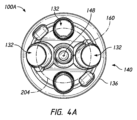
図4及び4Aは、以下で異なって説明されるものを除き、関節窩ベースプレート100と同様の関節窩ベースプレート100Aを示す。関節窩ベースプレート100の説明は、関節窩ベースプレート100Aの説明を補完する。関節窩ベースプレート100と比較可能な関節窩ベースプレート100Aのいずれかの機構も、関節窩ベースプレート100への補完になる。関節窩ベースプレート100Aは、上記議論されたような横行体104及び細長体108を含む。細長体108は、縦軸160に沿って延在する。横行体104は、中心148を有する円形周囲136を有してもよい。中心148と細長体108との間のオフセットが設けられてもよい。オフセットは、図4に示されるように、前方向にあってもよい。関節窩ベースプレート100Aが適用されることになる肩甲骨の性質に応じて、細長体108と中心148との間のオフセットは、別の方向、例えば、後方向にあってもよい。細長体108と中心148との間のオフセットは、他の方向、例えば、患者の必要性に応じた下方向、上方向、または前方向、後方向、下方向、もしくは上方向のいずれかの間の何らかの方向にあってもよい。
4 and 4A show a
関節窩ベースプレート100は、細長体108に平行して配置されたファスナ体192Aを有してもよい。ファスナ体192Aは、ファスナ体192と同様であってもよい。例えば、ファスナ体192Aは、閉鎖端188及び開口端184を有してもよい。ファスナ体192は、開口端184から閉鎖端188に延在するネジ状孔180を有してもよい。ファスナ体192Aは、関節窩ベースプレート100Aに結合されたファスナの少なくとも一部が、第1の側部120が付加される骨の表面の下に配置されることを可能にするように設けられてもよい。ファスナ体192Aに結合されたファスナは、関節窩ベースプレート100Aに逆関節体66を更に固定するよう、開口端184から外に及び関節体の中に延在してもよい。したがって、ファスナの一部分は、逆関節体66、横行体104の厚みにおける一部分、及びファスナ体192Aにおける一部分に配置されてもよい。
The
ファスナ体192Aは、関節窩ベースプレート100におけるファスナ体192が行うよりも少ない程度に、細長体108の側面から離れて延在する。関節窩ベースプレート100Aを置くことは、ファスナ体192と比較して、ファスナ体192Aのより少ない容積を収容するために、関節窩58の骨の調製をあまり必要としない。また、ファスナ体192Aにより近い細長体108の位置は、細長体108の周囲が横行体104においてアンカーアパーチャ132の内方向に配置されることを可能にする。図4Aは、構成が、横行体104の周りで全体的に均等に分散されたアンカーアパーチャ132をアパーチャ周204が含むことを可能にすることを示す。例えば、横行体104は、例えば、縦軸160の細長体108の位置と円形周囲136の前方部分140との間に位置するアンカーアパーチャ132を有してもよい。関節窩ベースプレート100Aは有利なことに、細長体108が横行体104の第1の側部120の内側の骨に完全に詰め込まれることを可能にし、また、肩甲骨への更なる固定をもたらす、均等な分散においてアンカーアパーチャ132を通じてアンカーが配置されることを可能にする。
図5~5Bは、以下で異なって説明されるものを除き、関節窩ベースプレート100及び関節窩ベースプレート100Aと同様の関節窩ベースプレート100Bを示す。関節窩ベースプレート100及び関節窩ベースプレート100Aの説明は、関節窩ベースプレート100Bの説明を補完する。関節窩ベースプレート100または関節窩ベースプレート100Aと比較可能な関節窩ベースプレート100Bの機構のいずれかの説明も、関節窩ベースプレート100及び/または関節窩ベースプレート100Aの説明を補完する。
5-5B show a
関節窩ベースプレート100Bは、細長体108B及び横行体104Bを含む。細長体108Bは、縦軸160に沿って配置される。横行体104Bは、中心軸148として示される、中心148の周りで対称である。関節窩ベースプレート100Bは、細長体108Bとは反対の横行体104Bの側部に配置された結合突起部210を含む。結合突起部210は、中心148の周りで対称であってもよい。結合突起部210は、先細った外周囲を有してもよい。結合突起部210は、横行体104Bから結合突起部210の自由端までその長さに沿って直径において減少する外周囲を有してもよい。結合突起部210は、関節体66と係合するようそこに形成されたネジ状孔180Bを含んでもよい。ネジ状孔180Bは、結合突起部210内で開口端184Bと閉鎖端188Bとの間に配置されてもよい。閉鎖端188Bは、横行体104Bの厚み内で配置されてもよい。閉鎖端188Bは、細長体108Bと結合突起部210との間に配置されてもよい。工具接合部212は、ネジ状孔180Bに配置されてもよい。工具接合部212は、開口端184Bから閉鎖端188Bに向かって延在してもよい。
工具接合部212は、肩甲骨に対する関節窩ベースプレート100Bの正確な方位付けを視覚化し、またはもたらすことに貢献するよう、回転非対称であってもよい。例えば、凹面の配列が工具接合部212の周りに設けられてもよい。拡大した凹面が工具接合部212の上方部分に設けられてもよい。例えば、横行体104Bの外側側部の上側に対して「SUP」とラベル付けされ、及び/または横行体104Bの外側側部の下側に対して「INF」とラベル付けされた、方位の視覚的印が関節窩ベースプレート100Bにも設けられてもよい。他の実施形態では、横行体104Bは、前方に対して「ANT」とラベル付けされてもよく、または後方に対して「POS」とラベル付けされてもよい。それらの方位のうちの1つ以上を示すために他の印が使用されてもよい。
The tool joint 212 may be rotationally asymmetric to help visualize or provide correct orientation of the
横行体104Bは、アンカーアパーチャ132と同様のアンカーアパーチャ132Bを含んでもよく、また、それを通じて進行することができる、骨アンカー、例えば、ネジに横行体104Bを接合するためのネジを含んでもよい。ネジは、外科手術の時に方位を選択することができる、固定された方位においてネジが骨アンカーに固定されることを可能にするようセグメント化されてもよい。
The
関節窩ベースプレート100Bの構成の1つの利点は、細長体108Bが、横行体104Bの第1の骨が面する側部または内側側部に位置する第1の端から細長体108Bの第2の(内側)端までの円形輪郭を有する円筒形状を有してもよいことである。細長体108Bの外面は、ネジ状孔180Bの中に進行するファスナが横行体104Bの第1の骨が面する側部または内側側部を超えて延在しないことを理由に、ファスナ体192またはファスナ体192Aと同様の構造から自由である。関節窩ベースプレート100Bが骨の中により容易に挿入されることを可能にする陥凹において円形孔を形成することができる点で、これは、患者の肩甲骨の調製がより簡易になることを可能にする。ファスナ体192またはファスナ体192Aの存在は、関節窩上に置かれるように構成された患者特有の内側面なしにベースプレートが調整される場合、関節窩ベースプレート100または関節窩ベースプレート100Aの嵌入の間に骨の補完的な調製または骨の圧縮のいずれかを必要とすることがある。内側面が患者特有に作成されるケースでは、ファスナ体192またはファスナ体192Aは、ベースプレートの内側側部上で患者に対して拡張されるベースプレートの広がりに位置してもよく、付加されるときに関節窩面の外側に位置してもよい。よって、ファスナ体192またはファスナ体192Aに対して追加の骨調製が必要でない。
One advantage of the configuration of
結合突起部210は、関節窩ベースプレート100または関節窩ベースプレート100Aの先細った輪郭201によってもたらされる接合と同様の接合を関節体66にもたらすことができる。結合突起部210は、結合突起部210の自由端に隣接した横行体104Bに向かってより大きな寸法を有する先細った輪郭を有する。結合突起部210の最大寸法は、結合突起部210が結合された横行体104Bの側部の寸法よりも小さい。よって、結合突起部210は、横行体104Bよりも小さくてもよい。結合突起部210は、1:5よりも大きいアスペクト比(突起部210の直径に対する高さ)を有してもよい。様々な実施例では、結合突起部210は、1:4よりも大きい、1:3よりも大きい、1:2よりも大きい、例えば、約1:1のアスペクト比を有する。対照的に、その周囲が関節体66に一致するための先細った輪郭201をもたらす、横行体104は、1:1よりも小さいアスペクト比(本体104の高さに対する直径)を有してもよい。横行体104は、1:2よりも小さい、1:3よりも小さい、1:4よりも小さいアスペクト比を有してもよい。いくつかの実施例では、横行体104は、1:2~1:7の間、例えば、約1:5のアスペクト比を有する。より小さい結合突起部210との関節体66の挿入及び位置合わせは、全体的により大きい先細った輪郭201に対する関節体66の挿入及び位置合わせよりも容易であることができる。より小さい直径の突起部210への本体66の位置合わせは、部分的にこの機構のより高いアスペクト比(長さ対幅)を理由により容易である。すなわち、突起部210はより狭く且つより長く、よって、より短く且つより広い、先細った輪郭201よりもはるかに高いアスペクト比を有する。より高いアスペクト比は、関節体66が結合突起部210の自由端上に置かれることを可能にし、それが横行体104Bに進行するにつれて、突起部210は、完全な接合の前に適切な位置合わせの中に本体66をガイドする。先細った輪郭201のケースでは、より小さいアスペクト比は、部品が完全に接合されることになる前に、それらの機構の構造によって位置合わせ確認をあまり生じさせない。軟組織の存在及び制限された視認性により、位置合わせはまさにより困難である。しかしながら、両方の接合部は、関節体66と対応する関節窩ベースプレートとの間の卓越した接合をもたらす。
図5Cは、以下で異なって説明されるものを除き、関節窩ベースプレート100Bと同様の関節窩ベースプレート100Cを示す。関節窩ベースプレート100Cは、関節窩ベースプレート100及び関節窩ベースプレート100Aのいくつかの機構との類似性をも有する。関節窩ベースプレート100、100A、100Bの説明は、関節窩ベースプレート100Cの説明を補完する。関節窩ベースプレート100、100A、100Bと比較可能な関節窩ベースプレート100Cの機構のいずれかの説明も、関節窩ベースプレート100、100A、及び/または関節窩ベースプレート100Bの説明を補完する。
FIG. 5C shows a
図5Cは、関節窩ベースプレート100Cが、横行体104Bの内側側部上に配置された細長体108Cを有することを示す。横行体104Bは、関節窩ベースプレート100Bにあるように中心148上に配置される。細長体108Cは、縦軸160に沿って配置される。縦軸160は、横行体104Bの中心148と位置合わせされ、例えば、横行体104Bの中心148と交差し、または横行体104Bの中心148と共線にある。したがって、関節窩ベースプレート100Cは、結合突起部210及び細長体108Cの両方が共通軸の周りで対称である構成をもたらす。関節窩ベースプレート100Cは、より対称的な前方面76及び後方面78を有する患者、並びに/またはより厚みのある肩甲骨を有する患者に対して適切である。それらの患者は、アンカー軌跡84が関節窩58の中心72と位置合わせされるとき、横行体104Bの第1の側部120から離れて延在する横行体104Bの平面に垂直な方向に沿って細長体108Cの全長を受けることができる。
FIG. 5C shows
図5Cの構成は、結合突起部210及び工具接合部212を有してもよい。関節窩ベースプレート100は、関節窩ベースプレート100Cと同様の対称構成により形成されてもよい。
The configuration of FIG. 5C may have
図6は、以下で異なって説明されるものを除き、関節窩ベースプレート100、100Bと同様の関節窩ベースプレート100Dを示す。関節窩ベースプレート100Dは、関節窩ベースプレート100A、100Cのいくつかの機構との類似性をも有する。関節窩ベースプレート100、100A、100B、100Cの説明は、関節窩ベースプレート100Dの説明を補完する。関節窩ベースプレート100、100A、100B、100Cと比較可能な関節窩ベースプレート100Dの機構のいずれかの説明も、関節窩ベースプレート100及び/または関節窩ベースプレート100、100A、100B、100Cの説明を補完する。
FIG. 6 shows a
関節窩ベースプレート100Dは、横行体104B及び細長体108Dを有する。細長体108Dは、細長体108Bと同様である。細長体108Dは、横行体104Bの第1の側部120から、第1の側部120から離れて配置された自由端に延在する。細長体108Dは、縦軸160に沿って延在する。縦軸160は、細長体108Dとは反対の横行体104Bの側部上に配置された結合突起部210の中心148からオフセットされてもよい。中心148と縦軸160との間のオフセットは、前方向にあってもよい。そのようなオフセットは、肩甲骨55の後方面78に向かうよりも前方面76に向かってより多くの骨の貯蔵量(bone stock)が利用可能である患者に適合する。
The
関節窩ベースプレート100Dまたは関節窩ベースプレート100の縦軸160と中心148との間のオフセットは、1つの実施形態では、約6mmであってもよい。関節窩ベースプレート100Dまたは関節窩ベースプレート100の縦軸160と中心148との間のオフセットは、1つの実施形態では、約5mmであってもよい。関節窩ベースプレート100Dまたは関節窩ベースプレート100の縦軸160と中心148との間のオフセットは、1つの実施形態では、約4mmであってもよい。関節窩ベースプレート100Bまたは関節窩ベースプレート100Aの縦軸160と中心148との間のオフセットは、1つの実施形態では、約3mmであってもよい。関節窩ベースプレート100Bまたは関節窩ベースプレート100Aの縦軸160と中心148との間のオフセットは、1つの実施形態では、約2mmであってもよい。関節窩ベースプレート100Bまたは関節窩ベースプレート100Aの縦軸160と中心148との間のオフセットは、1つの実施形態では、約1mmであってもよい。関節窩ベースプレート100Bまたは関節窩ベースプレート100Aの縦軸160と中心148との間のオフセットは、1つの実施形態では、約0.5mmであってもよい。
The offset between the
図6Aは、いくつかの量のオフセットについて、関節窩ベースプレート100Dが1つ以上のアンカーアパーチャ132を省略することを示す。関節窩ベースプレート100にあるように、アパーチャ周204は、アンカーアパーチャ132Bが横行体104Bの第2の側部124の周りで均等に分散されることをもたらす。アンカーアパーチャ132Bは、均等な増分によって間隔を空けられてもよい。増分位置のうちの1つ以上では、横行体104Bは、そこに形成されたアンカーアパーチャ132Bなしに固体にされる。省略されたアンカーアパーチャ132Bの領域内に少なくとも部分的に配置された細長体108Dを関節窩ベースプレート100Dが有すること理由に、アンカーアパーチャ132Bが省略される。細長体108Dがこの位置に位置付けられることを理由に、骨ネジなどの骨アンカーは、この領域を通じて置かれ得ない。
FIG. 6A shows that
外科的計画から構成された肩インプラント
上記議論された、図1A~1Cを参照して様々な関節窩ベースプレートをより良好に理解することができる。関節窩ベースプレート100は有利なことに、肩甲骨55の撮像情報が撮像装置80から取得されるステップ88に続いて形成されてもよい。撮像装置80は、CTスキャナ、X線、MRI、もしくは他の同様の撮像モダリティであってもよく、または骨もしくは骨の上の組織との直接接触によって骨形状を取得することができるトレーサからであってもよい。肩甲骨55は、ステップ90において特徴付けられてもよい。これは、例えば、メモリに記憶することができ、及び/またはグラフィカルユーザインタフェースにおいて表示することができる3Dモデルを提供するよう撮像情報をセグメント化することによって、肩甲骨55の仮想モデルを生成するための画像処理システム82によって採用されたいずれかの適切な技術を伴ってもよい。この情報は、関節窩58の下方部分70の中心72を識別することを含んでもよい。中心72は、肩甲骨55の関節窩縁68の下方部分74の翼弦の中間点として識別されてもよい。翼弦は、関節窩縁68の下方部分74の最後方点からの半径に等しい距離に位置してもよい。翼弦は、肩甲骨55の前方面76に隣接したその前方部分と肩甲骨55の後方面78に隣接したその後方部分との間で関節窩縁68に沿って上方-下方位置に位置してもよい。上方-下方位置は、関節窩58にわたる距離が関節窩縁68の下方部分74の湾曲の半径の2倍に等しい位置であってもよい。関節窩ベースプレート100は、横行体104が関節窩縁68の下方部分74の湾曲の半径に等しい半径を有する円周囲を有するように構成されてもよい。横行体104の中心148は、ステップ90において判定されるような中心72に位置してもよい。
Shoulder Implant Constructed from Surgical Planning The various glenoid baseplates can be better appreciated with reference to FIGS. 1A-1C, discussed above. The
細長体108の位置は、ステップ92において判定されてもよい。ステップは、細長体108を受けるための関節窩58の表面において開口部86を調製する適切な位置を発見することを伴う。上述したように、位置は、中心72に隣接して位置付けられてもよい。開口部86は有利なことに、ステップ90における分析に基づいた必要性に応じて、中心72の前方、中心72の後方、中心72の上方、中心72の下方、または中心72への前方、後方、上方、及び下方のいずれかの組み合わせで形成されてもよい。開口部86の位置は、深度、強度、厚み、骨密度、及び骨強度のいずれかの組み合わせが細長体108の最小長に適合するよう十分である、線91に沿った位置を発見することによって選択されてもよい。開口部86の位置は、開口部86から閉鎖端に延在する肩甲骨55において骨が止り穴の形成を支持する1つであってもよく、そこでは、止り穴において細長体108の全体長に適合することができる。図1Cを参照して、細長体108は、厚みt2に等しい長さを有してもよい。位置は、参照符号86を境界付ける2つの水平線の間のいずれかの位置であってもよい。
The position of
ステップ94は、横行体104の直径及び細長体108の位置を指定することを含んでもよい。ステップ94はまた、細長体108の長さを指定することを含んでもよい。肩甲骨55においてより大きな骨の容積を有する患者に対し、追加の長さが臨床的利点、例えば、より良好なインプラントの安全性をもたらすと見なされる場合、細長体108が最小長よりも長く作成されてもよい。ステップ94はまた、骨面の下に延在し(図3~4Aにあるように)、または患者に付加されるときに骨の外側に位置する(図5~6Aにあるように)ネジ状孔を有するベースプレートを出力してもよい。
ステップ98は、接着製造工程、例えば、三次元プリンティングなどの適切な工程を通じてベースプレートを形成することを含んでもよい。三次元プリンティングの例は、直接金属レーザ焼結法(DMLS)、熱溶解積層法(FDM)、熱溶解フィラメント製造法(FFF)、及び電子ビーム融解(EBM)を含む。それらの接着製造工程または他の接着製造工程のいずれかの1つまたは組み合わせは、ステップ98において使用されてもよい。それらの工程では、前に形成された個々の層の最上部に物体の個々の層を連続して形成することによって三次元物体が形成される。それらの工程は、物体の総寸法を厳密に制御することができ、また、曲線などの複雑な特徴及び形状を形成することができる。特定の実施形態では、図1の破線-点線99において示すように、例えば、関節窩58の凹曲面と一致する凸曲面を有する、特定の患者の特定の生体構造と一致することができる相補面として本明細書で開示される関節窩ベースプレートのいずれかの第1の側部120を形成するために、ステップ98が使用されてもよい。
上記で更に議論されたように、肩甲骨55は、前方面76と後方面78との間の厚みを有し、肩甲骨は、小さいことがあり、関節窩58の真下で急速及び/または予測不能に減少することがある。関節窩58の真下での厚みの変化は、肩甲骨の前方面及び後方面が患者ごとに不規則または一貫しないことを含む多くの因子に起因することがある。先述の方法及び装置は、肩甲骨の壁内でのベースプレートの内側側部上への関節窩ベースプレートの細長体の突起部の一貫して健全なアンカー固定をもたらす。本出願の出願人は、多くの患者に対し、これは、ポストがベースプレートの前方区域にオフセットされるオフセットされた内側ポストを結果としてもたらすことを発見した。それらの構成は、臨床的な成功のより高い尤度につながることがある。
As discussed further above, the
患者の肩甲骨生体構造に基づいて構成されたベースプレートについての外科的方法
先述した開示は、様々な有利な外科的方法を提供する。図7~7Cは、それらの方法のいくつかを示す。図7は、例えば、関節窩58の表面内で、肩甲骨55の外側面56に止り穴220が形成され得ることを示す。止り穴は、図1A~1Cの方法において識別された開口部86の位置に形成されてもよい。止り穴は、開口部86に対応する開口部224から開口部224とは反対の閉鎖端228に延在してもよい。閉鎖端228は、肩甲骨55の前方面76及び後方面78から間隔を空けられた深度及び前方-後方位置にあってもよい。止り穴は、図1A~1Cの方法において判定されたアンカー軌跡84に対応する軸に沿って延在してもよい。図7及び7Aは、止り穴220が関節窩58の下方部分70の中心72からオフセットされることを示す。
Surgical Methods for Baseplates Configured Based on Patient's Scapular Anatomy The foregoing disclosure provides various advantageous surgical methods. Figures 7-7C illustrate some of those methods. FIG. 7 shows that a
図7は、ベースプレート構成のいくつかに対し、止り穴220が拡大されてもよく、例えば、拡張した開口部226を設けることを示す。拡張した開口部226は、中心72に向かって止り穴220から延在する部分であってもよい。例えば、関節窩ベースプレート100Aは、中心148と位置合わせされたファスナ体192Aを含む。中心148は、関節窩ベースプレート100Aが付加されるときに中心72と位置合わせされることになる。したがって、関節窩58の表面は、拡張した開口部226を含む止り穴220を拡大して、ファスナ体192Aを収容するよう調製されてもよい。拡張した開口部226は、関節窩ベースプレート100Aに関節体66を接合するためのネジを横行体104上で中心に置くことができるように、中心72に、中心72の上に、または中心72の周りに配置される。拡張した開口部226を形成することは、外科的ドリルによって、小型リーマによって、タンプによって、または関節窩58に試用インプラントを置く工程において達成されてもよい。代わりに、関節窩ベースプレート100Aは、止り穴220の中に進行してもよく、拡張した開口部226は、関節窩ベースプレート100Aが骨の中に嵌入されるにつれて、骨の圧縮によって形成されてもよい。
FIG. 7 shows that for some of the baseplate configurations the
図7Cは、関節窩58への関節窩ベースプレート100Dの付加を示す。細長体108Dは、細長体108Dが止り穴220への開口部224にあるように、関節窩58に向かう矢印240によって示されるように進行してもよい。細長体108Dは、細長体108Dが閉鎖端228に隣接または接触するまで、止り穴220の中に進行してもよい。細長体108Dは、細長体横行体104Bが関節窩58に隣接または接触するまで、止り穴220の中に進行してもよい。細長体108Dは、図1における破線-点線99によって示されるような関節窩ベースプレート100Dの患者に合致した内側側部が関節窩58の自然の凹面または既存の凹面と接触しまたは入れ子になるまで、止り穴220の中に進行してもよい。細長体108Dは、閉鎖端228に隣接して位置し、または閉鎖端228に接触する。
FIG. 7C shows the addition of the
開口部224の中に細長体108Dを進行させる前に、関節窩ベースプレート100Dは、関節窩58に対して矢印241によって示されるように回転して方位付けられてもよい。例えば、回転位置付けの印または機構が存在する場合、それらの機構は、外科医によって適切に方位付けられてもよい。上述したように、横行体104Bの第2の側部124は、上方に方位付けられるべきである横行体104Bの部分を示すよう、「SUP」によりマーク付けされてもよい。いくつかの実施形態では、上方に対して「SUP」、下方に対して「INF」、前方に対して「ANT」、後方に対して「POS」などをマーク付けすることに依存することの代わりにまたはそれに加えて、関節窩ベースプレート100Dを進行させまたは保持する器具の一部分が適切に方位付けられることを視覚的に容易に確認することができるように、横行体104Bの結合突起部210上に配置された工具接合部212は、回転非対称であってもよい。
Prior to advancing
図7Cは、止り穴220の中への関節窩ベースプレート100Dの回転位置付け(必要である場合)及び進行に続いて、関節窩ベースプレート100Dが肩甲骨55に固定されてもよいことを示す。1つ以上の骨アンカー244は、横行体104Bを通じて、及び骨の中に進行してもよい。骨アンカー244は、横行体104Bを通じて肩甲骨55の皮質骨に向かって及び/または皮質骨の中に方向付けられてもよい。いくつかの技術では、骨アンカー244の方向またはその長さは、特定の結果を保証するよう、外科手術の前または間に計画または選択されてもよい。例えば、方位または長さは、横行体104Bに結合された端とは反対の骨アンカー244の端が、肩甲骨55の前方面76または後方面78を通じてではないが皮質骨に配置されることを保証するよう計画または選択されてもよい。方位または長さは、横行体104Bに結合された端とは反対の骨アンカー244の端が、皮質骨に配置され、また、肩甲骨55の前方面76または後方面78を通じて延在することを保証するよう計画または選択されてもよい。図7Cは、横行体104Bを通じて肩甲骨55の中に置かれた1つのみのネジを示す。例えば、結合突起部210に対して上方及び/または下方に示される断平面から外に追加のネジが置かれてもよい。上記議論されたように、関節窩ベースプレート100Dは、2つのアンカーアパーチャ132Bが上方位置及び下方位置に設けられ、1つのアンカーアパーチャ132Bが後方位置に設けられるように構成される。アンカーアパーチャ132Bが省略される、横行体104Bの前方の拡張が設けられる。図7Cは、細長体108Dの位置と横行体104Bの前方周囲との間でいずれの骨アンカー244なしに関節窩ベースプレート100Dが固定されることを示す。
FIG. 7C shows that following rotational positioning (if necessary) and advancement of
図7Cは、肩甲骨55に関節窩ベースプレート100Dを固定することに続いて、関節体66が関節窩ベースプレート100Dと結合されてもよいことを示す。関節体66は、結合突起部210に向かう矢印252によって示されるように進行してもよい。結合突起部210は、関節体66の内側側部において形成された対応する先細った陥凹において受けられてもよい。先細った陥凹及び結合突起部210は、モールステーパ接合を形成するように構成されてもよい。モールステーパ接合は、関節窩ベースプレート100Dに関節体66を固定するために十分である。いくつかの実施形態では、関節体66を通じて結合突起部210のネジ状孔180Bの中に進行したネジによって追加の固定が設けられてもよい。ネジは、それが閉鎖端188Bに向かって開口端184Bから進行するにつれて、ネジをネジ状孔180Bに係合してもよい。いくつかの実施形態では、ネジは、結合突起部210のネジ状孔180Bの中に進行することによって、関節体66と関節窩ベースプレート100Dとの間の唯一の接合をもたらすことができ、それが閉鎖端188Bに向かって開口端184Bから進行するにつれて、ネジをネジ状孔180Bに係合する。
FIG. 7C shows that following securing the
用語
本明細書で使用されるように、相対用語「外側(lateral)」及び「内側(medial)」は、生体構造に対して定義されることとする。よって、内側は、正中線に向かう方向を指し、外側は、正中線から離れた方向を指す。
Terminology As used herein, the relative terms "lateral" and "medial" shall be defined with respect to anatomy. Thus, medial refers to the direction toward the midline and lateral refers to the direction away from the midline.
特定の実施形態及び実施例が本明細書で説明されてきたが、本開示において示され及び説明された配送システムの多くの態様が更なる実施形態または許容可能な実施例を形成するよう異なって組み合わされてもよく、及び/または修正されてもよいことが当業者によって理解されよう。全てのそのような修正及び変形は、本明細書で本開示の範囲内に含まれることが意図される。広範囲の様々な設計及びアプローチが可能である。本明細書で開示される機構、構造、またはステップは必須ではなく、または不可欠ではない。 Although specific embodiments and examples have been described herein, many aspects of the delivery system shown and described in this disclosure may vary to form further embodiments or acceptable examples. It will be appreciated by those skilled in the art that they may be combined and/or modified. All such modifications and variations are intended to be included herein within the scope of this disclosure. A wide variety of different designs and approaches are possible. No mechanism, structure, or step disclosed herein is essential or essential.
本開示の目的のため、特定の態様、利点、及び新規の特徴が本明細書で説明される。いずれかの特定の実施形態に従って全てのそのような利点が必ずしも達成されるわけではないことがあることが理解されよう。よって、例えば、当業者は、本明細書で教示または示唆することができるような他の利点を必ずしも達成することなく、本明細書で教示されるような1つの利点または利点のグループを達成する方式において、開示が具体化または実施されてもよいことを認識するであろう。 For purposes of the disclosure, certain aspects, advantages and novel features are described herein. It is understood that not all such advantages may necessarily be achieved in accordance with any particular embodiment. Thus, for example, one skilled in the art may achieve one advantage or group of advantages as taught herein without necessarily attaining other advantages as may be taught or suggested herein. It will be appreciated that the disclosure may be embodied or embodied in any manner.
その上、例示的な実施形態が本明細書で説明されてきたが、本開示に基づいて当業者によって認識されるように、いずれかの実施形態及び全ての実施形態の範囲は、同等の要素、修正、省略、組み合わせ(例えば、様々な実施形態にわたる態様の)、適合、及び/または変更を有する。特許請求の範囲における限定は、特許請求の範囲において採用される言語に基づいて広義に解釈されることになり、実施例が非排他的であるとして解釈されることになる、本明細書において説明される実施例、または出願の審査の間に説明される実施例に限定されない。更に、開示される処理及び方法のアクションは、アクションを再順序付けること、及び/または追加のアクションを挿入すること、及び/またはアクションを削除することによってを含む、いずれかの方式において修正されてもよい。したがって、明細書及び実施例は例示のみであるとして解釈され、特許請求の範囲及びその同等物のそれらの全ての範囲によって真の範囲及び趣旨が示されることが意図される。 Moreover, while exemplary embodiments have been described herein, the scope of any and all , modifications, omissions, combinations (eg, aspects across various embodiments), adaptations, and/or alterations. Limitations in the claims are to be interpreted broadly based on the language employed in the claims, and the examples set forth herein are to be interpreted as non-exclusive. It is not limited to the examples given or described during prosecution of an application. Additionally, the actions of the disclosed processes and methods may be modified in any manner, including by reordering actions and/or inserting additional actions and/or deleting actions. good too. It is therefore intended that the specification and examples be considered as exemplary only, with a true scope and spirit being indicated by the following claims and their full scope of equivalents.
とりわけ、「~できる(can)」、「~し得る(might)」、「する場合がある(may)」、及び「例えば(e.g.)」など、本明細書で使用される条件付き言語は、特に明記されていない限り、または使用されるようにコンテキスト内で他に理解されるように、特定の特徴、要素、及び/または状態をいくつかの実施形態は含むが、他の実施形態は含まないことを伝えることが全体的に意図される。よって、そのような条件付き言語は全体的に、特徴、要素、ブロック、及び/または状態が1つ以上の実施形態に対して多少なりとも必要とされていること、あるいは著者が入力もしくは促すことにより、または著者が入力もしくは促すことなく、それらの特徴、要素、及び/または状態がいずれかの特定の実施形態に含まれるかどうか、またはいずれかの特定の実施形態において実行されるかどうかを決定するためのロジックを1つ以上の実施形態が必然的に含む、ことを示唆することを意図していない。 Conditional terms used herein such as “can,” “might,” “may,” and “eg,” among others. The language includes certain features, elements, and/or states in some embodiments, but not in other implementations, unless otherwise specified or otherwise understood in the context as it is used. It is generally intended to convey that morphology is not included. Thus, such conditional language generally means that the feature, element, block, and/or state is more or less required for one or more embodiments or entered or prompted by the author. whether such features, elements, and/or states are included in or performed in any particular embodiment, by or without input or prompting by the author. It is not intended to imply that one or more embodiments necessarily include logic to make the determination.
本明細書で開示される範囲は、いずれかの及び全ての重複、下位の範囲、及びそれらの組み合わせをも包含する。「~まで(up to)」、「少なくとも(at least)」、「~よりも大きい(greater than)」、「~よりも少ない(less than)」、及び「~の間(between)」などの言語は、記載された数を含む。「約(about)」または「おおよそ(approximately)」などの用語によって先行される数は、記載された数を含み、状況に基づいて解釈されるべきである(例えば、状況下でできるだけ合理的に、例えば、±1%、±5%、±10%、±15%など)。例えば、「約0.01インチ」は、「0.01インチ」を含む。「実質的に(substantially)」などの用語によって先行されるフレーズは、記載されたフレーズを含み、状況に基づいて解釈されるべきである(例えば、状況下でできるだけ合理的に)。例えば、「実質的に線形である」は、「線形である」を含む。
The ranges disclosed herein also include any and all overlaps, subranges, and combinations thereof. such as "up to", "at least", "greater than", "less than", and "between" The language includes the numbers listed. Numbers preceded by terms such as “about” or “approximately” are inclusive of the number stated and should be interpreted based on the circumstances (e.g., as reasonably possible under the circumstances). , e.g., ±1%, ±5%, ±10%, ±15%, etc.). For example, "about 0.01 inch" includes "0.01 inch." Phrases preceded by terms such as "substantially" include the phrase being described and should be interpreted based on the circumstances (eg, as reasonably possible under the circumstances). For example, "substantially linear" includes "linear."
Claims (13)
第1の端と第2の端との間で縦軸に沿って配置された細長体であって、前記第2の端は、前記横行体の前記第1の側部と結合され、前記第1の端は、前記第2の端から離れて配置される、前記細長体と、
前記細長体の側面から延在し、かつ第1端と第2端とを有するファスナ体であって、前記ファスナ体は前記第1端と前記第2端との間で延在しており、前記ファスナ体の前記第2端は前記横行体の前記第1の側部と結合され、前記ファスナ体の前記第1端は前記横行体から離れて配置され、前記ファスナ体は前記横行体においてネジ状孔と位置合わせされる、前記ファスナ体と、を備え、
前記細長体の前記縦軸は、その前記前方部分に向かって前記円形周囲の前記中心からオフセットされる、
関節窩ベースプレート。 a first side configured to engage a patient's scapula; a second side configured to face away from said first side; a transverse body including a plurality of anchor apertures formed between two sides and a circular perimeter extending between the first side and the second side, wherein the circular perimeter has an anterior portion configured to be oriented toward the anterior side of the scapula, a posterior portion configured to be oriented toward the posterior side of the scapula, and a center; body and
an elongated body disposed along a longitudinal axis between a first end and a second end, the second end being coupled to the first side of the transverse body; said elongated body, one end of which is spaced apart from said second end;
a fastener body extending from a side of said elongated body and having a first end and a second end, said fastener body extending between said first end and said second end; The second end of the fastener body is coupled to the first side of the transverse body, the first end of the fastener body is spaced apart from the transverse body, and the fastener body threads into the transverse body. the fastener body aligned with the shaped hole ;
said longitudinal axis of said elongated body is offset from said center of said circular perimeter towards said forward portion thereof;
glenoid baseplate.
前記横行板の前記内側側部と結合された外側端と前記外側端から離れて配置された内側端との間で縦軸に沿って配置されたアンカーペグと、を備え、
前記アンカーペグの前記縦軸は、その前記前方部分に向かって前記円形周囲の前記中心からオフセットされる、
関節窩ベースプレートであって、
前記関節窩ベースプレートは、
前記アンカーペグの側面から延在し、かつ第1端と第2端とを有するファスナ体であって、前記ファスナ体は前記第1端と前記第2端との間で延在しており、前記ファスナ体の前記第2端は前記横行板の前記内側側部と結合され、前記ファスナ体の前記第1端は前記横行板から離れて配置され、前記ファスナ体は前記横行板においてネジ状孔と位置合わせされる、前記ファスナ体を備える、関節窩ベースプレート。 a medial side configured to engage a patient's scapula; a lateral side configured to face away from the medial side; and a lateral side formed between the medial side and the lateral side. a transverse plate having a plurality of bone screw holes therein and a circular perimeter extending between the medial side and the lateral side, the circular perimeter oriented toward the anterior side of the scapula; the transverse plate having an anterior portion configured to align with the scapula, a posterior portion configured to be oriented toward the posterior side of the scapula, and a center;
an anchor peg positioned along a longitudinal axis between an outer end coupled to the inner side of the transverse plate and an inner end spaced apart from the outer end;
the longitudinal axis of the anchor peg is offset from the center of the circular circumference toward the forward portion thereof;
a glenoid baseplate ,
The glenoid baseplate comprises:
a fastener body extending from a side of said anchor peg and having a first end and a second end, said fastener body extending between said first end and said second end; The second end of the fastener body is coupled to the inner side of the transverse plate, the first end of the fastener body is spaced from the transverse plate, and the fastener body has a threaded hole in the transverse plate. a glenoid baseplate comprising said fastener body aligned with a glenoid baseplate ;
Applications Claiming Priority (3)
| Application Number | Priority Date | Filing Date | Title |
|---|---|---|---|
| US201962847077P | 2019-05-13 | 2019-05-13 | |
| US62/847,077 | 2019-05-13 | ||
| PCT/US2020/031134 WO2020231657A1 (en) | 2019-05-13 | 2020-05-01 | Glenoid baseplate and implant assemblies |
Publications (2)
| Publication Number | Publication Date |
|---|---|
| JP2022525978A JP2022525978A (en) | 2022-05-20 |
| JP7257546B2 true JP7257546B2 (en) | 2023-04-13 |
Family
ID=70918983
Family Applications (1)
| Application Number | Title | Priority Date | Filing Date |
|---|---|---|---|
| JP2021557101A Active JP7257546B2 (en) | 2019-05-13 | 2020-05-01 | Glenoid baseplate and implant assembly |
Country Status (6)
| Country | Link |
|---|---|
| US (1) | US20220183851A1 (en) |
| EP (1) | EP3968905A1 (en) |
| JP (1) | JP7257546B2 (en) |
| AU (1) | AU2020276186C1 (en) |
| CA (1) | CA3134015C (en) |
| WO (1) | WO2020231657A1 (en) |
Families Citing this family (3)
| Publication number | Priority date | Publication date | Assignee | Title |
|---|---|---|---|---|
| FR2971144A1 (en) | 2011-02-08 | 2012-08-10 | Tornier Sa | GLENOIDAL IMPLANT FOR SHOULDER PROSTHESIS AND SURGICAL KIT |
| AU2020328486B2 (en) | 2019-08-09 | 2024-01-25 | Howmedica Osteonics Corp. | Apparatuses and methods for implanting glenoid prostheses |
| US11819415B2 (en) * | 2021-04-02 | 2023-11-21 | Arthrex, Inc. | Orthopaedic implant systems including internal networks and methods of repair |
Citations (4)
| Publication number | Priority date | Publication date | Assignee | Title |
|---|---|---|---|---|
| US20090149961A1 (en) | 2006-05-22 | 2009-06-11 | Mathys Ag Bettlach | Shoulder Prosthesis having a Protrusion on the Base Plate |
| JP2014504161A (en) | 2010-09-01 | 2014-02-20 | メイヨ フォンデーシヨン フォー メディカル エジュケーション アンド リサーチ | Method for optimizing arthroplasty component design |
| WO2015103090A1 (en) | 2014-01-03 | 2015-07-09 | Tornier, Inc. | Reverse shoulder systems |
| WO2019079104A2 (en) | 2017-10-16 | 2019-04-25 | Imascap Sas | Shoulder implants and methods of use and assembly |
Family Cites Families (3)
| Publication number | Priority date | Publication date | Assignee | Title |
|---|---|---|---|---|
| FR2773469B1 (en) * | 1998-01-09 | 2000-03-03 | Alain Leonard | SURGICAL EQUIPMENT FOR THE IMPLANTATION OF A TOTAL SHOULDER PROSTHESIS, AND TOTAL SHOULDER PROSTHESIS |
| DE50103671D1 (en) * | 2000-11-16 | 2004-10-21 | Willi Horber | JOINT PROSTHESIS |
| DE10123517C1 (en) * | 2001-05-15 | 2002-11-28 | Keramed Medizintechnik Gmbh | Shoulder endoprosthesis has a joint connection formed by a protrusion on a middle part clamped by a clamping element from the proximal end of the middle part in a recess in the proximal end of a shaft |
-
2020
- 2020-05-01 WO PCT/US2020/031134 patent/WO2020231657A1/en unknown
- 2020-05-01 US US17/432,228 patent/US20220183851A1/en active Pending
- 2020-05-01 CA CA3134015A patent/CA3134015C/en active Active
- 2020-05-01 EP EP20729288.9A patent/EP3968905A1/en active Pending
- 2020-05-01 AU AU2020276186A patent/AU2020276186C1/en active Active
- 2020-05-01 JP JP2021557101A patent/JP7257546B2/en active Active
Patent Citations (4)
| Publication number | Priority date | Publication date | Assignee | Title |
|---|---|---|---|---|
| US20090149961A1 (en) | 2006-05-22 | 2009-06-11 | Mathys Ag Bettlach | Shoulder Prosthesis having a Protrusion on the Base Plate |
| JP2014504161A (en) | 2010-09-01 | 2014-02-20 | メイヨ フォンデーシヨン フォー メディカル エジュケーション アンド リサーチ | Method for optimizing arthroplasty component design |
| WO2015103090A1 (en) | 2014-01-03 | 2015-07-09 | Tornier, Inc. | Reverse shoulder systems |
| WO2019079104A2 (en) | 2017-10-16 | 2019-04-25 | Imascap Sas | Shoulder implants and methods of use and assembly |
Also Published As
| Publication number | Publication date |
|---|---|
| CA3134015C (en) | 2024-01-02 |
| AU2020276186A1 (en) | 2021-09-16 |
| EP3968905A1 (en) | 2022-03-23 |
| US20220183851A1 (en) | 2022-06-16 |
| AU2020276186C1 (en) | 2022-07-21 |
| WO2020231657A1 (en) | 2020-11-19 |
| AU2020276186B2 (en) | 2022-05-19 |
| JP2022525978A (en) | 2022-05-20 |
| CA3134015A1 (en) | 2020-11-19 |
Similar Documents
| Publication | Publication Date | Title |
|---|---|---|
| JP7257546B2 (en) | Glenoid baseplate and implant assembly | |
| US11229524B2 (en) | Method for modeling humeral anatomy and optimization of component design | |
| EP2231072B1 (en) | A prosthetic device and system for preparing a bone to receive a prosthetic device | |
| US9186154B2 (en) | Patient-specific instruments for total ankle arthroplasty | |
| US9895231B2 (en) | Neck sparing total hip implant system | |
| CN103702627A (en) | Device and method for retroversion correction for shoulder arthroplasty | |
| JP2014521395A (en) | Prosthetic guide with patient-specific features | |
| US20240000579A1 (en) | Calcaneal prosthesis | |
| US8398719B2 (en) | Neck sparing total hip implant methods | |
| AU2020328486B2 (en) | Apparatuses and methods for implanting glenoid prostheses | |
| US10624755B2 (en) | Prosthetic glenoid component | |
| US8900303B2 (en) | Porous bone reinforcements | |
| US20220338998A1 (en) | Method for Modeling Glenoid Anatomy and Optimization of Asymmetric Component Design |
Legal Events
| Date | Code | Title | Description |
|---|---|---|---|
| A621 | Written request for application examination |
Free format text: JAPANESE INTERMEDIATE CODE: A621 Effective date: 20210922 |
|
| A977 | Report on retrieval |
Free format text: JAPANESE INTERMEDIATE CODE: A971007 Effective date: 20221014 |
|
| A131 | Notification of reasons for refusal |
Free format text: JAPANESE INTERMEDIATE CODE: A131 Effective date: 20221206 |
|
| A521 | Request for written amendment filed |
Free format text: JAPANESE INTERMEDIATE CODE: A523 Effective date: 20230207 |
|
| TRDD | Decision of grant or rejection written | ||
| A01 | Written decision to grant a patent or to grant a registration (utility model) |
Free format text: JAPANESE INTERMEDIATE CODE: A01 Effective date: 20230307 |
|
| A61 | First payment of annual fees (during grant procedure) |
Free format text: JAPANESE INTERMEDIATE CODE: A61 Effective date: 20230403 |
|
| R150 | Certificate of patent or registration of utility model |
Ref document number: 7257546 Country of ref document: JP Free format text: JAPANESE INTERMEDIATE CODE: R150 |