JP7256661B2 - IMAGING DEVICE, CONTROL METHOD OF IMAGING MEANS, PROGRAM AND STORAGE MEDIUM - Google Patents
IMAGING DEVICE, CONTROL METHOD OF IMAGING MEANS, PROGRAM AND STORAGE MEDIUM Download PDFInfo
- Publication number
- JP7256661B2 JP7256661B2 JP2019051507A JP2019051507A JP7256661B2 JP 7256661 B2 JP7256661 B2 JP 7256661B2 JP 2019051507 A JP2019051507 A JP 2019051507A JP 2019051507 A JP2019051507 A JP 2019051507A JP 7256661 B2 JP7256661 B2 JP 7256661B2
- Authority
- JP
- Japan
- Prior art keywords
- counting
- pixels
- exposure
- imaging device
- imaging
- Prior art date
- Legal status (The legal status is an assumption and is not a legal conclusion. Google has not performed a legal analysis and makes no representation as to the accuracy of the status listed.)
- Active
Links
- 238000003384 imaging method Methods 0.000 title claims description 73
- 238000000034 method Methods 0.000 title claims description 45
- PWPJGUXAGUPAHP-UHFFFAOYSA-N lufenuron Chemical compound C1=C(Cl)C(OC(F)(F)C(C(F)(F)F)F)=CC(Cl)=C1NC(=O)NC(=O)C1=C(F)C=CC=C1F PWPJGUXAGUPAHP-UHFFFAOYSA-N 0.000 title 1
- 230000004044 response Effects 0.000 claims description 3
- 238000012545 processing Methods 0.000 description 49
- 230000008569 process Effects 0.000 description 36
- 230000010365 information processing Effects 0.000 description 23
- 230000035945 sensitivity Effects 0.000 description 8
- 239000000758 substrate Substances 0.000 description 8
- 238000012937 correction Methods 0.000 description 7
- 238000010586 diagram Methods 0.000 description 6
- 230000003287 optical effect Effects 0.000 description 6
- 238000010791 quenching Methods 0.000 description 6
- 238000003705 background correction Methods 0.000 description 4
- 230000000694 effects Effects 0.000 description 3
- 230000006870 function Effects 0.000 description 3
- 230000010354 integration Effects 0.000 description 3
- 230000008859 change Effects 0.000 description 2
- 238000004891 communication Methods 0.000 description 2
- 238000011161 development Methods 0.000 description 2
- 238000005375 photometry Methods 0.000 description 2
- 230000009471 action Effects 0.000 description 1
- 238000003491 array Methods 0.000 description 1
- 230000015556 catabolic process Effects 0.000 description 1
- 239000003086 colorant Substances 0.000 description 1
- 230000006835 compression Effects 0.000 description 1
- 238000007906 compression Methods 0.000 description 1
- 230000006872 improvement Effects 0.000 description 1
- 238000012986 modification Methods 0.000 description 1
- 230000004048 modification Effects 0.000 description 1
- 238000012544 monitoring process Methods 0.000 description 1
- 239000004065 semiconductor Substances 0.000 description 1
- 230000007704 transition Effects 0.000 description 1
Images


Classifications
-
- H—ELECTRICITY
- H04—ELECTRIC COMMUNICATION TECHNIQUE
- H04N—PICTORIAL COMMUNICATION, e.g. TELEVISION
- H04N25/00—Circuitry of solid-state image sensors [SSIS]; Control thereof
- H04N25/70—SSIS architectures; Circuits associated therewith
- H04N25/71—Charge-coupled device [CCD] sensors; Charge-transfer registers specially adapted for CCD sensors
- H04N25/75—Circuitry for providing, modifying or processing image signals from the pixel array
-
- H—ELECTRICITY
- H04—ELECTRIC COMMUNICATION TECHNIQUE
- H04N—PICTORIAL COMMUNICATION, e.g. TELEVISION
- H04N25/00—Circuitry of solid-state image sensors [SSIS]; Control thereof
- H04N25/50—Control of the SSIS exposure
- H04N25/53—Control of the integration time
-
- H—ELECTRICITY
- H01—ELECTRIC ELEMENTS
- H01L—SEMICONDUCTOR DEVICES NOT COVERED BY CLASS H10
- H01L27/00—Devices consisting of a plurality of semiconductor or other solid-state components formed in or on a common substrate
- H01L27/14—Devices consisting of a plurality of semiconductor or other solid-state components formed in or on a common substrate including semiconductor components sensitive to infrared radiation, light, electromagnetic radiation of shorter wavelength or corpuscular radiation and specially adapted either for the conversion of the energy of such radiation into electrical energy or for the control of electrical energy by such radiation
- H01L27/144—Devices controlled by radiation
- H01L27/146—Imager structures
- H01L27/14643—Photodiode arrays; MOS imagers
- H01L27/14645—Colour imagers
-
- H—ELECTRICITY
- H04—ELECTRIC COMMUNICATION TECHNIQUE
- H04N—PICTORIAL COMMUNICATION, e.g. TELEVISION
- H04N25/00—Circuitry of solid-state image sensors [SSIS]; Control thereof
- H04N25/40—Extracting pixel data from image sensors by controlling scanning circuits, e.g. by modifying the number of pixels sampled or to be sampled
-
- H—ELECTRICITY
- H04—ELECTRIC COMMUNICATION TECHNIQUE
- H04N—PICTORIAL COMMUNICATION, e.g. TELEVISION
- H04N25/00—Circuitry of solid-state image sensors [SSIS]; Control thereof
- H04N25/70—SSIS architectures; Circuits associated therewith
- H04N25/76—Addressed sensors, e.g. MOS or CMOS sensors
- H04N25/77—Pixel circuitry, e.g. memories, A/D converters, pixel amplifiers, shared circuits or shared components
- H04N25/772—Pixel circuitry, e.g. memories, A/D converters, pixel amplifiers, shared circuits or shared components comprising A/D, V/T, V/F, I/T or I/F converters
Description
本発明は、アバランシェフォトダイオードを用いた撮像デバイス、撮像手段の制御方法、プログラム及び記憶媒体に関し、特に画像撮影処理における露光時間の制御に関するものである。 The present invention relates to an imaging device using an avalanche photodiode, an imaging means control method, a program, and a storage medium, and more particularly to exposure time control in image capturing processing.
近年、デジタルカメラ等に用いられる撮像素子として、画像信号を非破壊で読み出すことが可能なフォトンカウンティング型の撮像素子の検討がなされている。これは、アバランシェフォトダイオード(APD)をガイガーモードで動作させた際に発生するアバランシェ現象を利用して、入射したフォトンの数そのものを計測してデジタル信号として出力する撮像素子である。このような撮像素子は、SPAD(Single Photon Avalanche Diode)と呼ばれている。 2. Description of the Related Art In recent years, photon-counting imaging devices capable of non-destructively reading out image signals have been studied as imaging devices used in digital cameras and the like. This is an imaging device that uses the avalanche phenomenon that occurs when an avalanche photodiode (APD) is operated in a Geiger mode to measure the number of incident photons themselves and outputs it as a digital signal. Such an image sensor is called a SPAD (Single Photon Avalanche Diode).
APDをガイガーモードで動作させる時、例えばAPDに1つのフォトンが入射するとアバランシェ現象によって観測可能なレベルの電流が発生する。この電流をパルス信号に変換し、そのパルス信号の数をカウントすることで、入射するフォトンの個数を直接計測することが可能となる。そのため、RTSノイズが発生せず、S/N比の向上が期待されている。SPADを用いたセンシングデバイスの一例として、特許文献1では複数画素のSPADから成る測距用センサが開示されている。 When an APD is operated in Geiger mode, for example, a single photon incident on the APD produces an observable level of current due to the avalanche phenomenon. By converting this current into a pulse signal and counting the number of pulse signals, it is possible to directly measure the number of incident photons. Therefore, no RTS noise is generated, and an improvement in the S/N ratio is expected. As an example of a sensing device using SPADs, Patent Literature 1 discloses a distance measuring sensor composed of SPADs with a plurality of pixels.
ここでAPDを用いた従来のフォトンカウンティング型の撮像素子の動作概要について図9を用いて説明する。図9(a)は、APDをガイガーモードで動作させる撮像素子の単位画素(以下、「画素」と呼ぶ。)の等価回路を示している。画素は、APD91、クエンチ抵抗92、コンパレータ93、抵抗R1,R2より構成される。
Here, an overview of the operation of a conventional photon-counting imaging device using an APD will be described with reference to FIG. FIG. 9A shows an equivalent circuit of a unit pixel (hereinafter referred to as "pixel") of an image sensor that operates the APD in Geiger mode. A pixel consists of an
APD91のアノード端はGNDに接続されており、カソード端はクエンチ抵抗92に接続されている。そして、クエンチ抵抗92を介して、電圧VDDから逆バイアス電圧が印加される。このとき電圧VDDとGNDの電圧差はAPD91をガイガーモードにする為に降伏電圧以上となるように設定する。
APD 91 has an anode end connected to GND and a cathode end connected to
図9(b)はフォトン入射待機状態からアバランシェ現象が発生し、また元のフォトン入射待機状態に戻るまでのAPD91のカソード端の電圧VAPDの推移を示している。時刻t90からt91の期間はフォトン入射待機状態であり、時刻t91でAPD91にフォトンが入射するとアバランシェ現象が発生する。アバランシェ現象が発生すると電流が流れて電圧VAPDが低下してアバランシェ現象が止まり(時刻t93)、また元のフォトン入射待機状態に戻る(時刻t95)。
FIG. 9(b) shows the transition of the voltage VAPD at the cathode end of the
図9(a)に示すようにコンパレータ93の一方の入力端子にはAPD91のカソード端の電圧VAPDが、もう一方の入力端子には基準電圧Vrefを抵抗R1と抵抗R2とで分圧した参照電圧Vthが入力されている。参照電圧Vthは、上記で説明したフォトンが入射した際の電圧VAPDの変化が検出できるように、V0とVminの間の電位に設定する。
As shown in FIG. 9(a), one input terminal of the
コンパレータ93は、電圧VAPDがVthより小さくなり、再び電圧VAPDがVthより大きくなるまでの期間(電圧VAPDがVthレベルを往復した期間)にパルス信号を1つ出力する。
The
図9(c)は、図9(b)に示すようにAPD91のカソード端の電圧VAPDが推移した場合のコンパレータ93の出力Voutを示している。時刻t92に電圧VAPDがVthより小さくなり、時刻t94に再びVAPDがVthより大きくなるため、t92~t94の期間にパルス信号が一つ出力される。
FIG. 9(c) shows the output V out of the
このコンパレータ93にカウンタ94を接続しておけば、入射したフォトンの数をカウントすることができる。従って、フォトン入射待機状態からアバランシェ現象の発生、アバランシェ現象の停止、また元のフォトン入射待機状態へ戻るサイクルを繰り返すことで、APD91に入射したフォトンの数を計測することが可能となる。
By connecting a
特許文献1に開示されたAPDを用いた撮像素子では、露光中に一部分の画素の信号を読み出し、露光終了後に1フレーム分の画素の信号と加算したとしてもS/N比は悪化しないため、画質は低下しない。しかしながら、画素の読み出し情報が多いため、画素の読み出し間隔が空いてしまい、露光時間制御の精度が低くなってしまう。 In the image pickup device using the APD disclosed in Patent Document 1, the S/N ratio does not deteriorate even if the signals of some pixels are read out during exposure and added to the signals of the pixels for one frame after the exposure is finished. Image quality is not reduced. However, since there is a large amount of pixel readout information, the pixel readout interval is long, and the accuracy of exposure time control is lowered.
本発明は上記問題点を鑑みてなされたものであり、フォトカウンティングタイプの撮像素子の露光時間を精度良く制御することを目的とする。 SUMMARY OF THE INVENTION An object of the present invention is to control the exposure time of a photo-counting type imaging device with high accuracy.
上記目的を達成するために、本発明の撮像デバイスは、複数の画素を有し、前記複数の画素がそれぞれ、光子の入射に応じてパルス信号を出力するセンサ手段と、前記パルス信号の数をカウントするカウント手段と、を有する撮像手段と、前記カウント手段からカウント情報を読み出す読み出し手段と、前記画素の露光中に、予め決められたタイミングで、前記複数の画素の少なくとも一部の画素のカウント手段から、カウント情報を読み出すように前記読み出し手段を制御する制御手段と、を有し、前記制御手段は、前記画素の露光に先立って、前記カウント手段からカウント情報を読み出すように前記読み出し手段を制御し、前記読み出されたカウント情報から求めたカウント値の増加速度に応じて、前記予め決められたタイミングを制御する。
In order to achieve the above object, an imaging device of the present invention has a plurality of pixels, each of which has sensor means for outputting a pulse signal in response to incidence of photons, and counting means for counting; reading means for reading count information from the counting means; and counting of at least some of the plurality of pixels at a predetermined timing during exposure of the pixels. and control means for controlling the reading means to read count information from the means , wherein the control means controls the reading means to read the count information from the counting means prior to exposing the pixels. The predetermined timing is controlled according to the increasing speed of the count value obtained from the read count information .
本発明によれば、フォトカウンティングタイプの撮像素子の露光時間を精度良く制御することができる。 According to the present invention, it is possible to accurately control the exposure time of a photo-counting type imaging device.
以下、添付図面を参照して実施形態を詳しく説明する。尚、以下の実施形態は特許請求の範囲に係る発明を限定するものでするものでなく、また実施形態で説明されている特徴の組み合わせの全てが発明に必須のものとは限らない。実施形態で説明されている複数の特徴うち二つ以上の特徴が任意に組み合わされてもよい。また、同一若しくは同様の構成には同一の参照番号を付し、重複した説明は省略する。 Hereinafter, embodiments will be described in detail with reference to the accompanying drawings. It should be noted that the following embodiments are not intended to limit the invention according to the claims, and not all combinations of features described in the embodiments are essential to the invention. Two or more of the features described in the embodiments may be combined arbitrarily. Also, the same or similar configurations are denoted by the same reference numerals, and redundant explanations are omitted.
<第1の実施形態>
以下、図1を参照して、本発明の第1の実施形態における撮像デバイスの一例として、撮像装置の構成について説明する。図1は、第1の実施形態に係る撮像装置の構成を示すブロック図である。
<First Embodiment>
Hereinafter, the configuration of an imaging apparatus will be described as an example of an imaging device according to the first embodiment of the present invention with reference to FIG. FIG. 1 is a block diagram showing the configuration of an imaging device according to the first embodiment.
図1において、撮影光学系は、第1レンズ群116、絞り117、第2レンズ群118を含む。第1レンズ群116は撮影光学系の先端に配置され、光軸方向に進退し、変倍作用(ズーム機能)を実現する。絞り117は、その開口径が、絞り駆動回路113により絞りアクチュエータ115を介して制御されて、撮影時の光量が調節される。第2レンズ群118はフォーカスレンズを含み、フォーカス駆動回路112がフォーカスアクチュエータ114を介して第2レンズ群118を光軸方向に進退駆動することにより、撮影光学系の焦点調節を行う。
In FIG. 1, the imaging optical system includes a
シャッタ111は、静止画撮影時に露光秒時を調節するフォーカルプレーンシャッタである。なお、本実施形態では、シャッタ111により撮像素子100の露光秒時を調節する構成とするが、本発明はこれに限られるものではなく、撮像素子100が電子シャッタ機能を有し、制御パルスで露光秒時を調節する構成であってもよい。
A
撮像素子100は、各画素がAPD(Avalanche Photodiode)を有する撮像素子であり、撮影光学系を介して入射するフォトン(光子)数をカウントして、カウント数(画素値)を出力する。なお、撮像素子100の詳細構成に関しては、図2及び図3を参照して後述する。
The
撮像信号処理回路101では、撮像素子100から入力される画素値に対して、ノイズを軽減するローパスフィルタ処理やシェーディング補正処理、WB補正処理などの各種の画像信号処理、さらにキズ補正やダークシェーディング補正、黒引き処理等の各種の補正、圧縮等を行って画像データを生成する。
The imaging
全体制御演算部102は、撮像装置全体の制御と各種演算を行う。露光終了判定部103は、撮像素子100から出力された画素値に基づいて、露光終了タイミングの判定を行う。読み出し制御回路104は、全体制御演算部102からの制御信号および露光終了判定部103の判定結果に基づき、撮像素子100を駆動するための駆動パルスを発生させる。
An overall
メモリ部105は、撮像信号処理回路101により生成された画像データを一時的に記憶する。記録媒体制御インターフェース(I/F)部106は、記録媒体108に画像データの記録または読み出しを行う。表示部107は、画像データの表示を行う。記録媒体108は、半導体メモリ等の着脱可能な記憶媒体であり、画像データの記録または読み出しを行う。外部インターフェース(I/F)部109は、外部コンピュータ等と通信を行う為のインターフェースである。
The
操作部110にて、ユーザが設定した撮像装置の駆動条件に関する情報は、全体制御演算部102に送られ、これらの情報に基づいて撮像装置全体の制御が行われる。また、操作部110は、不図示の電源ボタンや静止画記録ボタンを含む。電源ボタンをON/OFFすることにより、撮像装置をON/OFFすることができる。また、撮像装置がONの状態で静止画記録ボタンをONすることで、静止画の記録開始を指示することができる。
Information about driving conditions of the image pickup apparatus set by the user in the
なお、上述する構成を有する撮像装置では、静止画及び/または動画を撮影することができる。 Note that still images and/or moving images can be captured with the imaging device having the above configuration.
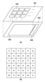
図2は、撮像素子100の概略構造を示しており、本実施形態では、一例として、センサ基板301と回路基板302とが電気的に接続されるように互いに積層された、積層構造を有する。
FIG. 2 shows a schematic structure of the
図2(a)において、センサ基板301には、複数の画素303が2次元状に配置された画素アレイが形成される。なお、画素303の詳細な構成については後述する。回路基板302には、画素演算部304及び信号処理回路305が形成される。
In FIG. 2A, a
画素演算部304は、センサ基板301上の画素毎にバンプ等で電気的に接続され、各画素303を駆動するための制御信号を出力すると共に、画素303からのコンパレータ出力を受け、各種処理を行う。
A
また、画素演算部304は、後述するように、対応する画素毎に入射したフォトンに応じて出力されるコンパレータからのパルス信号の数を計測するカウンタを有する。画素演算部304で計測されたカウント値は、信号処理回路305によって撮像素子100の外部へと出力される。
In addition, as will be described later, the
図2(b)は、撮像素子100で使用されるカラーフィルタアレイの一例を示しており、図2(a)の画素アレイに含まれる。このカラーフィルタの配列は、ベイヤー配列と呼ばれ、第1の色フィルタを赤(R)、第2の色フィルタを緑(Gr)、第3の色フィルタを緑(Gb)、第4の色フィルタを青(B)として繰り返し配列されている。原色の色フィルタ配列の中でも、高い解像度と優れた色再現性を備えた色フィルタ配列である。
FIG. 2(b) shows an example of a color filter array used in the
次に、図3を参照して、画素303と画素演算部304の一部の構成について説明する。図3は、センサ基板301上の画素303及び画素303に対応する回路基板302上の画素演算部304の一部の等価回路を示している。
Next, the configuration of part of the
画素303は、クエンチ抵抗401、受光素子であるAPD402、コンパレータ403、参照電圧Vthを生成するための抵抗R1、R2を含み、センサ基板301上に配置される。なお、画素アレイに含まれる他の画素も同様の構成を有する。画素演算部304は、各画素303に対応したカウンタ404及び、各カウンタ404に接続された機能情報処理部405を含み、回路基板302上に配置される。
The
APD402のアノード端は接地(GND)されており、カソード端はクエンチ抵抗401に接続されている。そしてAPD402には、クエンチ抵抗401を介して、電圧HVDDによる逆バイアス電圧が印加される。このとき電圧HVDDとGNDの電圧差は、APD402をガイガーモードにする為にブレーク電圧以上となるように設定される。
The
APD402のカソード端の電圧VAPD(出力電圧)はコンパレータ403の一方の入力端に入力される。また、コンパレータ403のもう一方の入力端には、基準電圧Vrefを、抵抗R1とR2により分圧した参照電圧Vthが入力される。
A voltage V APD (output voltage) at the cathode terminal of
コンパレータ403は、電圧VAPDが参照電圧Vthレベルを往復した場合にパルス信号を出力する。コンパレータ403から出力されたパルス信号は、各画素に対応するカウンタ404に入力され、その数が計測される。カウンタ404にはバイナリカウンタ等の回路が用いられ、ビット数に応じてカウンタ404によりカウントすることのできる最大値が決まる。
A
各カウンタ404からの出力(カウント値)は、信号処理回路305及び機能情報処理部405の少なくともいずれか一方に送られる。信号処理回路305に直接送られたカウント値は、そのまま撮像信号処理回路101へ送られる。
An output (count value) from each
一方、機能情報処理部405へ送られた場合、機能情報処理部405は入力したカウント値に基づいてカウント情報を生成し、信号処理回路305を介して、露光終了判定部103へと出力される。なお、後述する露光終了判定条件によって、カウント情報は様々な形態を取ることが可能であり、その詳細については、後述する。
On the other hand, when it is sent to the functional
露光終了判定部103は、機能情報処理部405から得られた情報を元に、露光を終了するか否かの判定を行い、読み出し制御回路104へと情報を出力する。露光終了判定部103が露光を終了しない(露光を継続する)と判定した場合、読み出し制御回路104は再びカウント情報を取得する処理に戻り、同様の処理を繰り返す。露光終了判定部103が露光を終了すると判定した場合、読み出し制御回路104は、カウンタ404の動作を終了し、全画素情報を読み出すように、撮像素子100を制御する。
Based on the information obtained from the functional
次に、本実施形態における撮像装置の動作について、図4のタイミングチャートを参照しながら、図5のフローチャートに沿って説明する。 Next, the operation of the imaging apparatus according to the present embodiment will be described along the flowchart of FIG. 5 while referring to the timing chart of FIG.
時刻t0において、ユーザにより、操作部110に含まれる電源ボタンがONされ、更に操作部110に含まれる静止画記録ボタンがONされると処理が開始され、S502において、全体制御演算部102は、各種初期設定を行う。この初期設定は、撮像素子100に対するISO感度(撮影感度)の設定や、フォーカス駆動回路112に対する第2レンズ群118の位置の設定、絞り駆動回路113に対する絞り値の設定等を含む。また、露光終了判定の基準を定める。
At time t0, when the user turns on the power button included in the
次に、S504において、全体制御演算部102は、機能情報処理部405を制御すべく、読み出し制御回路104に露光終了判定に用いるカウント情報を得るための条件設定を行う。
Next, in S<b>504 , the overall control
まず、カウンタ404から機能情報処理部405に入力する情報としては、読み出す画素と、カウンタ404から読み出すビットが挙げられる。全画素の情報を監視したい場合には、全画素のカウンタ404からカウント値を読み出すように設定する。また、主被写体枠や中央測光エリア等、一部の画素情報を監視したい場合には、対象となる画素のカウンタ404からカウント値を読み出すように設定する。
First, information input from the
さらに、各画素のカウンタ404の全ビット情報を用いて露光終了判定を行う場合には全ビット情報を読み出すように設定し、各画素のカウンタ404の一部のビット情報を用いて露光終了判定を行う場合には一部のビット情報のみを読み出すように設定する。
Furthermore, when all the bit information of the
一部のビット情報のみを露光終了判定に用いるときの処理の一例として、S502の初期設定時に定めた露光終了判定の基準値から、読み出すビットを決定する方法がある。例えば、カウンタ404の上位2ビットを監視することで、カウンタ404が最大値に達する前に、露光を終了させるように、全体制御演算部102が読み出し制御回路104を制御することができる。
As an example of processing when only part of the bit information is used for exposure end determination, there is a method of determining bits to be read from the exposure end determination reference value determined at the time of initialization in S502. For example, by monitoring the upper 2 bits of the
また、全ビット情報を露光終了判定に用いることで、例えば、カウンタ404の最大値の4分の3で露光を終了させるなど、任意のカウント値に達したことに応じて、露光を終了させることができる。
Further, by using all bit information for exposure end determination, exposure can be ended when an arbitrary count value is reached, such as by ending exposure at three-fourths of the maximum value of the
S505において、撮像素子100のカウンタ404をリセットした後(時刻t1)、S506において、全体制御演算部102によって決められた露出条件(露光時間/絞り/感度)に従って、読み出し制御回路104は撮像素子100の露光を開始する(時刻t2)。これにより、APD402は動作を開始し、カウンタ404はコンパレータ403から出力されたパルス信号のカウントを開始する。
After resetting the
予め決められた時間が経過すると、S507において、S504で設定された条件に基づいて、機能情報処理部405はカウンタ404からカウント値を読み出して処理し(時刻t3)、露光終了判定部103が必要とするカウント情報を出力する。例えば、全画素の情報を用いて露光終了判定を行う場合、機能情報処理部405は、全画素のカウンタ404からカウント値を読み出す。また、一部の画素の情報を用いて露光終了判定を行う場合には、機能情報処理部405は、設定された一部の画素のカウンタ404からカウント値を読み出す。
After a predetermined time has passed, in S507, the functional
また、カウンタ404の全ビット情報を用いて露光終了判定を行う場合には、機能情報処理部405は、カウンタ404の全ビット情報を読み出し、一部のビット情報を用いて露光終了判定を行う場合には、必要なビット情報のみを読み出す。
Further, when the exposure end is determined using all the bit information of the
機能情報処理部405は、このようにして読み出した必要な情報をそのままカウント情報として出力しても良い。また、いずれかのカウンタ404のビット情報が予め決められた条件を満たした場合に、その旨を示す情報(例えば、「1」)をカウント情報として出力するようにしても良い。
The functional
また、露光終了判定部103が指定の領域の画素値の積分結果に基づいて判定を行う場合には、S504で設定された条件に基づいて得られた情報を加算した情報をカウント情報として出力しても良い。また、露光終了判定部103が最も大きいカウント値の情報を用いて判定を行う場合には、入力したカウント値の内、最大のカウント値をカウント情報として出力しても良い。他にも、条件に応じて様々なカウント情報を出力することが考えられる。
When the exposure
S508では、露光終了判定部103が、機能情報処理部405から出力されたカウント情報に基づいて、露光終了判定処理を行う(時刻t4)。ここでの判定は、機能情報処理部405から出力されたカウント情報が、S502で初期設定時に定めた露光終了判定の条件を満たしているか否かで判定する。
In S508, the exposure
例えば、上位2ビットの値に基づく指定領域の積分結果で判定する場合、S507において機能情報処理部405が各画素のカウンタ404の上位2ビットの値を読み出し、指定領域内の画素のカウント値を積分し、積分値をカウント情報として出力するような構成が考えられる。この際、露光終了判定部103では得られる積分値を所定の閾値と比較し、積分値が閾値に達するか否かで露光終了判定を行うことができる。上述の通り、機能情報処理部405の処理内容と、露光終了判定部103の判定方法には、他にも様々なものが考えられる。
For example, when the determination is made based on the integration result of the specified area based on the upper 2-bit value, the functional
そして、露光を終了する場合はS509へ進んで露光を終了し、カウンタ404のカウントを停止する(時刻t9)。露光を終了しない場合はS507に戻り、露光を継続して、露光終了判定処理を繰り返す(時刻t5、t6、t7、t8)。
Then, when the exposure is finished, the process advances to S509, the exposure is finished, and the counting of the
S509で露光を終了すると、S510において、全画素300のカウンタ404から、全ビット情報の読み出しを行い、静止画情報を取得する。なお、ここで読み出された情報(カウント値)は、カウンタ404から直接信号処理回路305を介して撮像信号処理回路101へと送られ、処理されて画像データに変換される。
When the exposure ends in S509, all bit information is read from the
続くS511では、画像データに対し、全体制御演算部102は静止画の現像処理として、ノイズを軽減するローパスフィルタ処理やシェーディング補正処理、WB補正処理など各種の画像データ処理や補正処理を行う。
In subsequent S511, the overall
S512では、S511で処理された画像データを、静止画データとして記録媒体108へ記録、または、表示部107へのライブビュー表示などを行い、処理を終了する。
In S512, the image data processed in S511 is recorded as still image data on the
上記の通り第1の実施形態によれば、露光終了判定に必要な情報のみをカウンタから読み出すことで、撮像素子100とのデータ通信量を減らすことが可能となる。これにより、露光終了判定処理を行う間隔を短くすることが可能となり、露光終了判定の基準から大きく離れることなく、露光を終了することができる。
As described above, according to the first embodiment, it is possible to reduce the amount of data communication with the
なお、本実施形態では撮像素子100を積層センサであること前提とし、機能情報処理部405を撮像素子100内に持つ構成としたが、本発明はこれに限られるものではない。
In this embodiment, it is assumed that the
また、本実施形態では露光終了判定部103及び読み出し制御回路104を独立して持つ構成としたが、本発明はこれに限られるものではなく、撮像素子100内に含まれる構成としてもよい。その場合、撮像素子100単体で撮像デバイスを構成する。
Further, although the exposure
<第2の実施形態>
次に、本発明の第2の実施形態について説明する。なお、本実施形態における撮像装置の構成は、図1乃至図3を参照して説明したものと同様であるため、ここでは説明を省略する。
<Second embodiment>
Next, a second embodiment of the invention will be described. Note that the configuration of the imaging apparatus according to the present embodiment is the same as that described with reference to FIGS. 1 to 3, so description thereof will be omitted here.
第2の実施形態は、露光終了判定処理が第1の実施形態と異なる。第1の実施形態では、初期設定時(S502)に露光終了判定の基準を定めておき、機能情報処理部405から出力されたカウント情報が基準を超えているか否かを判断して露光終了タイミングの制御を行う。
The second embodiment differs from the first embodiment in exposure end determination processing. In the first embodiment, at the time of initial setting (S502), a standard for determining the end of exposure is determined, and it is determined whether or not the count information output from the functional
それに対し、第2の実施形態では、機能情報処理部405から出力されたカウント情報を表示部107に表示し、ユーザの操作により露光終了タイミングの制御を行う。以下、第2の実施形態における撮像装置の動作について、図6のフローチャートを用いて説明する。なお、図5に示す第1の実施形態で説明した処理と同様の処理には同じ参照番号を付し、適宜説明を省略する。
In contrast, in the second embodiment, the count information output from the functional
ユーザにより、操作部110に含まれる電源ボタンがONされ、更に操作部110に含まれる静止画記録ボタンがONされると処理が開始され、全体制御演算部102は、各種初期設定を行う(S602)。ここでの初期設定は、撮像素子100に対するISO感度(撮影感度)の設定や、フォーカス駆動回路112に対する第2レンズ群118の位置の設定、絞り駆動回路113に対する絞り値の設定等を含む。なお、上述した第1の実施形態では、この初期設定を行うタイミングで露光終了判定の基準を定める処理を行うが、本実施形態では行わない。
When the user turns on the power button included in the
次に、S603において、撮像信号処理回路101に入力する条件を設定し、機能情報処理部405の制御を行う。撮像信号処理回路101に入力するカウント情報は、第1の実施形態と同様に、読み出す画素と、カウンタ404から読み出すビットが挙げられる。このとき、本実施形態では、ユーザが表示部107にてカウンタ404のカウント値を確認し、操作部110より露光終了操作を行うため、機能情報処理部405は、積分等の処理は行わずに、S603で設定された条件に基づいたカウント情報をそのまま出力する。ただし、表示部107の画素数が少ない場合等、全画素の情報が必要ない場合には、画素の加算処理や間引き処理を行うよう、読み出す画素の条件を設定する。
Next, in S603, conditions for inputting to the imaging
続いて、S505で撮像素子100のカウンタ404をリセットした後、S506で撮像素子100の露光を開始する。
Subsequently, after resetting the
S604において、S603で設定された条件に基づいて、機能情報処理部405はカウンタ404からカウント値を読み出して、撮像信号処理回路101にカウント情報を出力する。S605では、全体制御演算部102は表示用画像の現像処理として、ノイズを軽減するローパスフィルタ処理やシェーディング補正処理、WB補正処理など各種の画像データ処理や補正処理を行い、S606で表示部107へのライブビュー表示を行う。
In S<b>604 , the functional
S607で、ユーザにより操作部110に含まれる静止画記録ボタンがOFFされた否かを判定する。静止画記録ボタンがOFFされた場合はS509へ進んで露光を終了し、カウンタ404のカウントを停止する。静止画記録ボタンがOFFされていない場合はS604に戻って露光を継続し、露光終了判定処理を繰り返す。
In S607, it is determined whether or not the still image recording button included in the
そして、第1の実施形態と同様に、S509~S512の処理を行って、処理を終了する。 Then, as in the first embodiment, the processing of S509 to S512 is performed and the processing ends.
上記の通り第2の実施形態によれば、露光終了判定として必要な情報のみを読み出すことで、撮像素子100とのデータ通信量を減らすことが可能となることに加え、ユーザの所望のタイミングで露光を終了することが行うことができる。
As described above, according to the second embodiment, it is possible to reduce the amount of data communication with the
<第3の実施形態>
以下、本発明の第3の実施形態について説明する。なお、本実施形態における撮像装置の構成は、図1乃至図3を参照して説明したものと同様であるため、ここでは説明を省略する。
<Third Embodiment>
A third embodiment of the present invention will be described below. Note that the configuration of the imaging apparatus according to the present embodiment is the same as that described with reference to FIGS. 1 to 3, so description thereof will be omitted here.
第3の実施形態は、露光終了判定処理の開始タイミング、即ち、最初の露光終了判定を行うタイミングが第1の実施形態と異なる。第1の実施形態では、撮像素子100の露光開始後(S506)、すぐに露光終了判定用の情報(カウント値)を読み出し(S507)、露光終了判定(S508)を行う。これに対し、第3の実施形態では、静止画の記録動作開始に先立って得られたAE(Automatic Exposure)演算用画像情報に基づいて、露光終了判定用の情報の読み出しを開始するタイミングを変更する。以下に、第3の実施形態における撮像装置の動作について、図7のフローチャートを用いて説明する。なお、図5に示す第1の実施形態で説明した処理と同様の処理には同じ参照番号を付し、適宜説明を省略する。 The third embodiment differs from the first embodiment in the start timing of the exposure end determination process, that is, the timing of performing the first exposure end determination. In the first embodiment, immediately after the start of exposure of the image sensor 100 (S506), information (count value) for exposure end determination is read out (S507), and exposure end determination is performed (S508). On the other hand, in the third embodiment, the timing of starting to read out information for exposure end determination is changed based on image information for AE (Automatic Exposure) calculation obtained prior to the start of the still image recording operation. do. The operation of the imaging apparatus according to the third embodiment will be described below using the flowchart of FIG. The same reference numerals are given to the same processes as those described in the first embodiment shown in FIG. 5, and the description thereof will be omitted as appropriate.
ユーザにより、操作部110に含まれる電源ボタンがONされ、更に操作部110に含まれる静止画記録ボタンがONされると処理が開始され、全体制御演算部102は、各種AE演算用画像の初期設定を行う(S702)。ここでの初期設定とは、撮像素子100に対するISO感度(撮影感度)の設定や、フォーカス駆動回路112に対する第2レンズ群118の位置の設定、絞り駆動回路113に対する絞り値の設定等を含む。このとき、AE演算用画像の取得領域は、全体制御演算部102により撮像装置の測光条件に応じて決定される。そして、AE演算用画像の撮影を行う(S703)。ここで取得された画像を、静止画撮影前の待機画像として表示部107へライブビュー表示を行っても良い。
When the user turns on the power button included in the
続くS704では、S703で取得したAE演算用画像から露光終了判定処理の開始タイミングを設定する。まず、全体制御演算部102は、S702で設定したAE演算用画像の初期設定と、S703で取得したAE演算用画像の画素積分値より、各画素303に対応するカウント値の増加速度を求める。このカウント値の増加速度と、静止画撮影時の撮影条件(ISO感度、TV(シャッタ速度)、露出等)において、露光終了の判定が為されるであろう露光時間から、露光終了判定処理の開始タイミングを決定する。ここでは、撮像素子100の露光を開始してからの時間を決定する。
In subsequent S704, the start timing of the exposure end determination process is set from the AE calculation image acquired in S703. First, the overall
その後、第1の実施形態と同様にS502、S504、S505、S506の処理を行って、S705に進む。 After that, the processes of S502, S504, S505, and S506 are performed in the same manner as in the first embodiment, and the process proceeds to S705.
S705では、S506で撮像素子100の露光が開始されてから、S704で決定した露光終了判定処理の開始時間が経過しているか否かを判定する。経過している場合には、第1の実施形態と同様に、S507~S512の処理を行って、図7に示す処理を終了する。経過していない場合には、S705を繰り返し、露光終了判定処理の開始時間が経過するまで待機する。
In S705, it is determined whether or not the start time of the exposure end determination process determined in S704 has elapsed since the exposure of the
上記の通り第3の実施形態によれば、撮像動作開始前にAE演算用画像を取得し、露光終了判定開始タイミングを設定する。これにより、第1の実施形態と同様の効果に加えて、露光終了判定処理を行う回数を減らすことが可能となり、撮像装置の省電力化につなげることができる。 As described above, according to the third embodiment, an image for AE calculation is obtained before the imaging operation is started, and the timing for starting the exposure end determination is set. As a result, in addition to the same effect as in the first embodiment, it is possible to reduce the number of times exposure end determination processing is performed, which can lead to power saving of the imaging apparatus.
なお、第3の実施形態では露光終了判定処理のタイミングに関し、開始タイミングのみを設定し、その後は定期的に露光終了判定処理を行うとしたが、この限りではない。露光終了判定処理開始後、S507で読み出した露光終了判定用情報より、再度、各画素303に対応するカウント値の増加速度を求め、このカウント値の増加速度から、露光終了判定タイミングの頻度を変更するようにしても良い。
In addition, in the third embodiment, only the start timing is set for the timing of the exposure end determination process, and then the exposure end determination process is periodically performed, but this is not the only option. After starting the exposure end determination process, the increase speed of the count value corresponding to each
<第4の実施形態>
次に、本発明の第4の実施形態について説明する。なお、本実施形態における撮像装置の構成は、図1乃至図3を参照して説明したものと同様であるため、ここでは説明を省略する。
<Fourth Embodiment>
Next, a fourth embodiment of the invention will be described. Note that the configuration of the imaging apparatus according to the present embodiment is the same as that described with reference to FIGS. 1 to 3, so description thereof will be omitted here.
露光終了判定部103において露光を終了すると判定してから、実際に読み出し制御回路104がカウンタ404でのカウントを止め、撮像素子100の露光を終了するよう制御するまでには、多少の時間を要する。以下、ここでかかる時間を「露光終了時タイムラグ」と呼ぶ。
It takes some time for the
つまり、露光終了判定部103が露光を終了すると判定してからも、撮像素子100は露光終了時タイムラグの分、露光が続いてしまう。そのため露光終了判定部103は、実際に狙う明るさに達する前に露光終了と判定する必要がある。ただし、露光終了時タイムラグの期間の露光量(カウンタ404の進み具合)は、被写体の輝度により異なる。
That is, even after the exposure
そこで、第4の実施形態では、本画像露光中に取得するカウント値を用い、露光終了判定の基準値を変更する処理を行う。
Therefore, in the fourth embodiment, the count value obtained during the exposure of the main image is used to change the reference value for determining the end of exposure.
第4の実施形態は、露光終了判定処理での基準値の設定の手法が第1の実施形態と異なる。第1の実施形態では、初期設定時(S502)に露光終了判定処理の基準値を決定する。それに対し、第4の実施形態では、静止画記録動作中に得られる露光終了判定用の情報より求められるカウント値の増加速度から、S502で設定した露光終了判定処理の基準値を変更していく。 The fourth embodiment differs from the first embodiment in the method of setting the reference value in the exposure end determination process. In the first embodiment, the reference value for the exposure end determination process is determined at the time of initialization (S502). On the other hand, in the fourth embodiment, the reference value for the exposure end determination process set in S502 is changed from the increasing speed of the count value obtained from the exposure end determination information obtained during the still image recording operation. .
以下に本実施形態における撮像装置の動作について、図8のフローチャートを用いて説明する。なお、図5に示す第1の実施形態で説明した処理と同様の処理には同じ参照番号を付し、適宜説明を省略する。 The operation of the imaging apparatus according to this embodiment will be described below with reference to the flowchart of FIG. The same reference numerals are given to the same processes as those described in the first embodiment shown in FIG. 5, and the description thereof will be omitted as appropriate.
まず、ユーザにより、操作部110に含まれる電源ボタン(不図示)がONされた後に行われるS502~S507の処理は、第1の実施形態における処理と同様である。
First, the processing of S502 to S507 performed after the user turns on the power button (not shown) included in the
S507で露光終了判定用にカウンタ404からカウント値を読み出すと、次のS802において、S507で読み出したカウント値より、カウント値の増加速度を算出する。続いてS803では、S802で求めたカウント値の増加速度より、露光終了判定時に用いる基準値の更新を行う。
After the count value is read from the
ここでは、露光終了時タイムラグにカウント値の増加速度をかけた分、基準値から前倒しすることで、露光終了処理時(カウント停止時)に合わせたいカウント値となるように基準値を変更する。この処理により、露光終了時タイムラグによるカウント値の誤差を防ぐことが可能となる。 Here, the reference value is advanced from the reference value by the time lag at the end of exposure multiplied by the increasing speed of the count value, so that the reference value is changed to the count value desired at the time of the end processing of exposure (when the count is stopped). This processing makes it possible to prevent an error in the count value due to the time lag at the end of exposure.
続いて、S508~S512の処理を行って、図8の処理を終了する。 Subsequently, the processing of S508 to S512 is performed, and the processing of FIG. 8 ends.
上記の通り第4の実施形態によれば、第1の実施形態と同様の効果に加え、露光終了用に取得した情報をカウント値の増加速度の算出にも用いることで、露光終了時タイムラグによる誤差を吸収し、所望の露光量により近い画像を取得することが可能となる。 As described above, according to the fourth embodiment, in addition to the same effect as the first embodiment, by using the information acquired for the end of the exposure to calculate the increase speed of the count value, the time lag at the end of the exposure It is possible to absorb the error and obtain an image closer to the desired exposure amount.
<他の実施形態>
なお、本発明は、複数の機器から構成されるシステムに適用しても、一つの機器からなる装置に適用してもよい。
<Other embodiments>
The present invention may be applied to a system composed of a plurality of devices or to an apparatus composed of a single device.
また、本発明は、上述の実施形態の1以上の機能を実現するプログラムを、ネットワーク又は記憶媒体を介してシステム又は装置に供給し、そのシステム又は装置のコンピュータにおける1つ以上のプロセッサーがプログラムを読出し実行する処理でも実現可能である。また、1以上の機能を実現する回路(例えば、ASIC)によっても実現可能である。 Further, the present invention supplies a program that implements one or more functions of the above-described embodiments to a system or device via a network or a storage medium, and one or more processors in the computer of the system or device executes the program. It can also be realized by a process of reading and executing. It can also be implemented by a circuit (for example, ASIC) that implements one or more functions.
発明は上記実施形態に制限されるものではなく、発明の精神及び範囲から離脱することなく、様々な変更及び変形が可能である。従って、発明の範囲を公にするために請求項を添付する。 The invention is not limited to the embodiments described above, and various modifications and variations are possible without departing from the spirit and scope of the invention. Accordingly, the claims are appended to make public the scope of the invention.
100:撮像素子、101:撮像信号処理回路、102:全体制御演算部、103:露光終了判定部、104:読み出し制御回路、105:メモリ部、107:表示部、110:操作部、301:センサ基板、302:回路基板、303:画素、304:画素演算部、305:信号処理回路、402:APD、403:コンパレータ、404:カウンタ、405:機能情報処理部 100: image pickup device, 101: image pickup signal processing circuit, 102: overall control calculation unit, 103: exposure end determination unit, 104: readout control circuit, 105: memory unit, 107: display unit, 110: operation unit, 301: sensor Substrate 302: Circuit board 303: Pixel 304: Pixel calculation unit 305: Signal processing circuit 402: APD 403: Comparator 404: Counter 405: Functional information processing unit
Claims (16)
前記カウント手段からカウント情報を読み出す読み出し手段と、
前記画素の露光中に、予め決められたタイミングで、前記複数の画素の少なくとも一部の画素のカウント手段から、カウント情報を読み出すように前記読み出し手段を制御する制御手段と、を有し、
前記制御手段は、前記画素の露光に先立って、前記カウント手段からカウント情報を読み出すように前記読み出し手段を制御し、前記読み出されたカウント情報から求めたカウント値の増加速度に応じて、前記予め決められたタイミングを制御することを特徴とする撮像デバイス。 imaging means having a plurality of pixels, each of said plurality of pixels having sensor means for outputting a pulse signal in response to incidence of photons; and counting means for counting the number of said pulse signals;
reading means for reading count information from the counting means;
a control means for controlling the reading means to read count information from the counting means of at least some of the plurality of pixels at a predetermined timing during exposure of the pixels ;
The control means controls the reading means to read the count information from the counting means prior to the exposure of the pixels, and according to the speed of increase of the count value obtained from the read count information, the An imaging device characterized by controlling predetermined timing .
前記予め決められた条件を満たしている場合に、前記カウント手段のカウントを停止することを特徴とする請求項1に記載の撮像デバイス。 further comprising determination means for determining whether the count information satisfies a predetermined condition;
2. The imaging device according to claim 1 , wherein counting by said counting means is stopped when said predetermined condition is satisfied .
前記カウント値の増加速度と、前記判定手段により前記予め決められた条件を満たしていると判定されてから前記カウント手段のカウントを停止するまでにかかる時間とに基づいて、前記予め決められたタイミングを変更することを特徴とする請求項2に記載の撮像デバイス。 The predetermined condition is that the count value of the counting means reaches a predetermined value,
The predetermined timing based on the rate of increase of the count value and the time required from when the determining means determines that the predetermined condition is satisfied until when the counting by the counting means is stopped. 3. The imaging device according to claim 2 , wherein is changed.
前記カウント手段のカウントを停止する指示を入力する操作手段と、を更に有し、
前記操作手段により前記指示が入力された場合に、前記カウント手段のカウントを停止することを特徴とする請求項1乃至6のいずれか1項に記載の撮像デバイス。 display means for displaying the count information read by the reading means under the control of the control means;
an operation means for inputting an instruction to stop counting by the counting means;
7. The imaging device according to any one of claims 1 to 6, wherein the counting of the counting means is stopped when the instruction is input by the operating means.
読み出し手段が、前記画素の露光に先立って、前記カウント手段からカウント情報を読み出す工程と、
制御手段が、前記読み出されたカウント情報から求めたカウント値の増加速度に応じて、予め決められたタイミングを制御する工程と、
前記読み出し手段が、前記画素の露光中に、前記予め決められたタイミングで、前記複数の画素の少なくとも一部の画素のカウント手段から、カウント情報を読み出す読み出し工程と
を有することを特徴とする制御方法。 A control method for imaging means having a plurality of pixels, each of said plurality of pixels having sensor means for outputting a pulse signal in response to incidence of photons, and counting means for counting the number of said pulse signals. hand,
a reading means reading count information from the counting means prior to exposing the pixels;
a step in which the control means controls a predetermined timing according to the speed of increase of the count value obtained from the read count information;
a reading step in which the reading means reads count information from the counting means of at least some of the plurality of pixels at the predetermined timing during exposure of the pixels ;
A control method characterized by having
操作手段から、前記カウント手段のカウントを停止する指示を入力する入力工程と、
前記制御手段が、前記操作手段から前記指示が入力された場合に、前記カウント手段のカウントを停止する停止工程と
を更に有することを特徴とする請求項13に記載の制御方法。 a display step of displaying the count information read in the read step on a display means;
an input step of inputting an instruction to stop counting by the counting means from the operating means;
14. The control method according to claim 13, further comprising a stopping step of stopping counting by said counting means when said instruction is input from said operating means.
Priority Applications (2)
| Application Number | Priority Date | Filing Date | Title |
|---|---|---|---|
| JP2019051507A JP7256661B2 (en) | 2019-03-19 | 2019-03-19 | IMAGING DEVICE, CONTROL METHOD OF IMAGING MEANS, PROGRAM AND STORAGE MEDIUM |
| US16/821,391 US11336858B2 (en) | 2019-03-19 | 2020-03-17 | Image capturing device and method that control an exposure period of a photon-counting type of an image sensor |
Applications Claiming Priority (1)
| Application Number | Priority Date | Filing Date | Title |
|---|---|---|---|
| JP2019051507A JP7256661B2 (en) | 2019-03-19 | 2019-03-19 | IMAGING DEVICE, CONTROL METHOD OF IMAGING MEANS, PROGRAM AND STORAGE MEDIUM |
Publications (3)
| Publication Number | Publication Date |
|---|---|
| JP2020155886A JP2020155886A (en) | 2020-09-24 |
| JP2020155886A5 JP2020155886A5 (en) | 2022-03-30 |
| JP7256661B2 true JP7256661B2 (en) | 2023-04-12 |
Family
ID=72514911
Family Applications (1)
| Application Number | Title | Priority Date | Filing Date |
|---|---|---|---|
| JP2019051507A Active JP7256661B2 (en) | 2019-03-19 | 2019-03-19 | IMAGING DEVICE, CONTROL METHOD OF IMAGING MEANS, PROGRAM AND STORAGE MEDIUM |
Country Status (2)
| Country | Link |
|---|---|
| US (1) | US11336858B2 (en) |
| JP (1) | JP7256661B2 (en) |
Families Citing this family (1)
| Publication number | Priority date | Publication date | Assignee | Title |
|---|---|---|---|---|
| JP2022034409A (en) * | 2020-08-18 | 2022-03-03 | キヤノン株式会社 | Image encoding device, control method of the same, and program |
Citations (4)
| Publication number | Priority date | Publication date | Assignee | Title |
|---|---|---|---|---|
| JP2003101870A (en) | 2001-09-21 | 2003-04-04 | Konica Corp | Image pickup device |
| JP2015092660A (en) | 2013-10-01 | 2015-05-14 | 株式会社ニコン | Imaging apparatus, imaging apparatus control method, electronic apparatus, electronic apparatus control method, and control program |
| JP2015159518A (en) | 2014-02-25 | 2015-09-03 | キヤノン株式会社 | Imaging apparatus, control method thereof and program |
| JP2018198388A (en) | 2017-05-24 | 2018-12-13 | キヤノン株式会社 | Solid-state image sensor, imaging apparatus, and imaging method |
Family Cites Families (5)
| Publication number | Priority date | Publication date | Assignee | Title |
|---|---|---|---|---|
| JPH09210778A (en) * | 1996-02-07 | 1997-08-15 | Kyocera Corp | Photometric/light control circuit |
| JP5432657B2 (en) | 2009-10-02 | 2014-03-05 | キヤノン株式会社 | Imaging device, storage device, and control method |
| US10359375B2 (en) * | 2013-10-23 | 2019-07-23 | Nanovision Technology (Beijing) Co., Ltd. | Photon count-based radiation imaging system, method and device thereof |
| EP3389259B1 (en) * | 2015-12-07 | 2020-09-02 | Panasonic Intellectual Property Management Co., Ltd. | Solid-state image-capturing device and method for driving solid-state image-capturing device |
| US10785423B2 (en) * | 2017-12-07 | 2020-09-22 | Canon Kabushiki Kaisha | Image sensor, image capturing apparatus, and image capturing method |
-
2019
- 2019-03-19 JP JP2019051507A patent/JP7256661B2/en active Active
-
2020
- 2020-03-17 US US16/821,391 patent/US11336858B2/en active Active
Patent Citations (4)
| Publication number | Priority date | Publication date | Assignee | Title |
|---|---|---|---|---|
| JP2003101870A (en) | 2001-09-21 | 2003-04-04 | Konica Corp | Image pickup device |
| JP2015092660A (en) | 2013-10-01 | 2015-05-14 | 株式会社ニコン | Imaging apparatus, imaging apparatus control method, electronic apparatus, electronic apparatus control method, and control program |
| JP2015159518A (en) | 2014-02-25 | 2015-09-03 | キヤノン株式会社 | Imaging apparatus, control method thereof and program |
| JP2018198388A (en) | 2017-05-24 | 2018-12-13 | キヤノン株式会社 | Solid-state image sensor, imaging apparatus, and imaging method |
Also Published As
| Publication number | Publication date |
|---|---|
| US11336858B2 (en) | 2022-05-17 |
| US20200304745A1 (en) | 2020-09-24 |
| JP2020155886A (en) | 2020-09-24 |
Similar Documents
| Publication | Publication Date | Title |
|---|---|---|
| US9917998B2 (en) | Systems and methods for measuring scene information while capturing images using array cameras | |
| JP4972724B2 (en) | Method and apparatus for capturing interleaved images | |
| US9154685B2 (en) | Driving technology of an image sensor in an image capture apparatus | |
| US9854178B2 (en) | Image pickup apparatus with flicker detection and having plurality of unit pixel areas, control method therefor, and storage medium | |
| US10785423B2 (en) | Image sensor, image capturing apparatus, and image capturing method | |
| US20160316158A1 (en) | Imaging apparatus and signal processing method | |
| US11363219B2 (en) | Information processing apparatus, image sensor, image capturing apparatus, and information processing method | |
| US11290648B2 (en) | Image capture apparatus and control method thereof | |
| CN110392183B (en) | Image pickup apparatus and control method thereof | |
| JP6808333B2 (en) | Display control device and method, and imaging device | |
| JP5597243B2 (en) | Imaging device | |
| US11272112B2 (en) | Image capturing apparatus | |
| US10056421B2 (en) | Imaging device and imaging method | |
| JP7256661B2 (en) | IMAGING DEVICE, CONTROL METHOD OF IMAGING MEANS, PROGRAM AND STORAGE MEDIUM | |
| EP2782332B1 (en) | Digital camera with focus-detection pixels used for light metering | |
| JP5791765B2 (en) | Imaging apparatus and control method thereof | |
| JP4637029B2 (en) | Imaging apparatus and control method thereof | |
| JP2020115604A (en) | Imaging apparatus and control method of the same | |
| JPWO2019065554A1 (en) | Imaging device, information acquisition method and information acquisition program | |
| JP2020036073A (en) | Imaging device and control method thereof | |
| JP7361514B2 (en) | Image sensor and imaging device | |
| JP5961058B2 (en) | Imaging apparatus and control method thereof, image processing apparatus and control method thereof | |
| KR20100027943A (en) | Imaging apparatus and imaging method | |
| JP2020028115A (en) | Imaging apparatus | |
| JP7094767B2 (en) | Imaging device and its control method and program |
Legal Events
| Date | Code | Title | Description |
|---|---|---|---|
| RD01 | Notification of change of attorney |
Free format text: JAPANESE INTERMEDIATE CODE: A7421 Effective date: 20210103 |
|
| A521 | Request for written amendment filed |
Free format text: JAPANESE INTERMEDIATE CODE: A523 Effective date: 20210113 |
|
| A521 | Request for written amendment filed |
Free format text: JAPANESE INTERMEDIATE CODE: A523 Effective date: 20220318 |
|
| A621 | Written request for application examination |
Free format text: JAPANESE INTERMEDIATE CODE: A621 Effective date: 20220318 |
|
| A977 | Report on retrieval |
Free format text: JAPANESE INTERMEDIATE CODE: A971007 Effective date: 20230209 |
|
| TRDD | Decision of grant or rejection written | ||
| A01 | Written decision to grant a patent or to grant a registration (utility model) |
Free format text: JAPANESE INTERMEDIATE CODE: A01 Effective date: 20230303 |
|
| A61 | First payment of annual fees (during grant procedure) |
Free format text: JAPANESE INTERMEDIATE CODE: A61 Effective date: 20230331 |
|
| R151 | Written notification of patent or utility model registration |
Ref document number: 7256661 Country of ref document: JP Free format text: JAPANESE INTERMEDIATE CODE: R151 |