JP7256596B2 - Facsimile machine, its control method, and program - Google Patents
Facsimile machine, its control method, and program Download PDFInfo
- Publication number
- JP7256596B2 JP7256596B2 JP2017168834A JP2017168834A JP7256596B2 JP 7256596 B2 JP7256596 B2 JP 7256596B2 JP 2017168834 A JP2017168834 A JP 2017168834A JP 2017168834 A JP2017168834 A JP 2017168834A JP 7256596 B2 JP7256596 B2 JP 7256596B2
- Authority
- JP
- Japan
- Prior art keywords
- telephone
- power supply
- hook
- handset
- setting
- Prior art date
- Legal status (The legal status is an assumption and is not a legal conclusion. Google has not performed a legal analysis and makes no representation as to the accuracy of the status listed.)
- Active
Links
Images


Classifications
-
- H—ELECTRICITY
- H04—ELECTRIC COMMUNICATION TECHNIQUE
- H04N—PICTORIAL COMMUNICATION, e.g. TELEVISION
- H04N1/00—Scanning, transmission or reproduction of documents or the like, e.g. facsimile transmission; Details thereof
- H04N1/32—Circuits or arrangements for control or supervision between transmitter and receiver or between image input and image output device, e.g. between a still-image camera and its memory or between a still-image camera and a printer device
- H04N1/327—Initiating, continuing or ending a single-mode communication; Handshaking therefor
- H04N1/32704—Establishing a communication with one of a facsimile and another telecommunication apparatus sharing a single line
- H04N1/32763—Supplying power to the apparatus
-
- H—ELECTRICITY
- H04—ELECTRIC COMMUNICATION TECHNIQUE
- H04M—TELEPHONIC COMMUNICATION
- H04M11/00—Telephonic communication systems specially adapted for combination with other electrical systems
- H04M11/06—Simultaneous speech and data transmission, e.g. telegraphic transmission over the same conductors
- H04M11/066—Telephone sets adapted for data transmision
-
- H—ELECTRICITY
- H04—ELECTRIC COMMUNICATION TECHNIQUE
- H04N—PICTORIAL COMMUNICATION, e.g. TELEVISION
- H04N1/00—Scanning, transmission or reproduction of documents or the like, e.g. facsimile transmission; Details thereof
- H04N1/00127—Connection or combination of a still picture apparatus with another apparatus, e.g. for storage, processing or transmission of still picture signals or of information associated with a still picture
- H04N1/00281—Connection or combination of a still picture apparatus with another apparatus, e.g. for storage, processing or transmission of still picture signals or of information associated with a still picture with a telecommunication apparatus, e.g. a switched network of teleprinters for the distribution of text-based information, a selective call terminal
- H04N1/00302—Connection or combination of a still picture apparatus with another apparatus, e.g. for storage, processing or transmission of still picture signals or of information associated with a still picture with a telecommunication apparatus, e.g. a switched network of teleprinters for the distribution of text-based information, a selective call terminal with a telephonic apparatus, e.g. telephone answering machine or videotex terminal
-
- H—ELECTRICITY
- H04—ELECTRIC COMMUNICATION TECHNIQUE
- H04N—PICTORIAL COMMUNICATION, e.g. TELEVISION
- H04N1/00—Scanning, transmission or reproduction of documents or the like, e.g. facsimile transmission; Details thereof
- H04N1/32—Circuits or arrangements for control or supervision between transmitter and receiver or between image input and image output device, e.g. between a still-image camera and its memory or between a still-image camera and a printer device
- H04N1/327—Initiating, continuing or ending a single-mode communication; Handshaking therefor
- H04N1/32704—Establishing a communication with one of a facsimile and another telecommunication apparatus sharing a single line
- H04N1/32706—Type of the other apparatus
- H04N1/32708—Telephone
-
- H—ELECTRICITY
- H04—ELECTRIC COMMUNICATION TECHNIQUE
- H04N—PICTORIAL COMMUNICATION, e.g. TELEVISION
- H04N1/00—Scanning, transmission or reproduction of documents or the like, e.g. facsimile transmission; Details thereof
- H04N1/32—Circuits or arrangements for control or supervision between transmitter and receiver or between image input and image output device, e.g. between a still-image camera and its memory or between a still-image camera and a printer device
- H04N1/327—Initiating, continuing or ending a single-mode communication; Handshaking therefor
- H04N1/32704—Establishing a communication with one of a facsimile and another telecommunication apparatus sharing a single line
- H04N1/32715—Detecting
- H04N1/32726—Detecting signals other than facsimile protocol signals, e.g. DTMF signals
-
- H—ELECTRICITY
- H04—ELECTRIC COMMUNICATION TECHNIQUE
- H04N—PICTORIAL COMMUNICATION, e.g. TELEVISION
- H04N1/00—Scanning, transmission or reproduction of documents or the like, e.g. facsimile transmission; Details thereof
- H04N1/32—Circuits or arrangements for control or supervision between transmitter and receiver or between image input and image output device, e.g. between a still-image camera and its memory or between a still-image camera and a printer device
- H04N1/327—Initiating, continuing or ending a single-mode communication; Handshaking therefor
- H04N1/32704—Establishing a communication with one of a facsimile and another telecommunication apparatus sharing a single line
- H04N1/32715—Detecting
- H04N1/32728—Detecting an off-hook condition
-
- H—ELECTRICITY
- H04—ELECTRIC COMMUNICATION TECHNIQUE
- H04N—PICTORIAL COMMUNICATION, e.g. TELEVISION
- H04N1/00—Scanning, transmission or reproduction of documents or the like, e.g. facsimile transmission; Details thereof
- H04N1/32—Circuits or arrangements for control or supervision between transmitter and receiver or between image input and image output device, e.g. between a still-image camera and its memory or between a still-image camera and a printer device
- H04N1/327—Initiating, continuing or ending a single-mode communication; Handshaking therefor
- H04N1/32704—Establishing a communication with one of a facsimile and another telecommunication apparatus sharing a single line
- H04N1/32739—Generating signals
- H04N1/32745—Generating messages, indications or warnings locally
-
- Y—GENERAL TAGGING OF NEW TECHNOLOGICAL DEVELOPMENTS; GENERAL TAGGING OF CROSS-SECTIONAL TECHNOLOGIES SPANNING OVER SEVERAL SECTIONS OF THE IPC; TECHNICAL SUBJECTS COVERED BY FORMER USPC CROSS-REFERENCE ART COLLECTIONS [XRACs] AND DIGESTS
- Y02—TECHNOLOGIES OR APPLICATIONS FOR MITIGATION OR ADAPTATION AGAINST CLIMATE CHANGE
- Y02D—CLIMATE CHANGE MITIGATION TECHNOLOGIES IN INFORMATION AND COMMUNICATION TECHNOLOGIES [ICT], I.E. INFORMATION AND COMMUNICATION TECHNOLOGIES AIMING AT THE REDUCTION OF THEIR OWN ENERGY USE
- Y02D30/00—Reducing energy consumption in communication networks
- Y02D30/70—Reducing energy consumption in communication networks in wireless communication networks
Description
本発明は、ファクシミリ装置とその制御方法、及びプログラムに関するものである。 The present invention relates to a facsimile machine, its control method, and program.
近年、プリント、コピー等の機能に加えて、ファクシミリ通信機能、ハンドセット(テンキーの無い外付け電話機)による通話機能を備えた複合機が広く普及している。ファクシミリ通信を行うために複合機をPSTN(Public Switched Telephone Network:公衆電話網)に接続し、送信側から着信側へ発呼すると電話会社の交換機から着信側へ呼出信号が送出される。いま着信側が複合機で、その複合機にハンドセットを接続した場合、着信時にハンドセットが鳴動する設定を鳴動設定、鳴動しない設定を無鳴動設定と呼ぶ。無鳴動設定では、リレーを用い、そのリレーをオンすることにより、ハンドセットを電話回線から切り離す制御が行われる。ハンドセットが電話回線から切り離されると電話回線から直流電圧が給電されないので、代わりに複合機の内部から直流を給電して、ハンドセットのオフフックを検出する。一方、鳴動設定では、リレーをオフすることにより、ハンドセットを電話回線に接続する制御が行われる。この場合は、電話回線からハンドセットに直流電圧が給電されるので、リレーをオフしていてもハンドセットのオフフックを検出できる。このようにユーザの用途に合わせて無鳴動設定と鳴動設定を変更して利用する。 2. Description of the Related Art In recent years, in addition to functions such as printing and copying, multi-function machines having a facsimile communication function and a call function using a handset (an external telephone with no numeric keypad) have become widespread. In order to perform facsimile communication, a multi-function device is connected to a PSTN (Public Switched Telephone Network), and when a call is made from the sender to the called party, a calling signal is sent from the exchange of the telephone company to the called party. If the receiving side is a multifunction device and a handset is connected to the multifunction device, the setting for ringing the handset when receiving a call is called ringing setting, and the setting for not ringing is called non-ringing setting. In the no-ring setting, a relay is used, and by turning on the relay, control is performed to disconnect the handset from the telephone line. When the handset is disconnected from the telephone line, no DC voltage is supplied from the telephone line. On the other hand, in the ring setting, control is performed to connect the handset to the telephone line by turning off the relay. In this case, since a DC voltage is supplied to the handset from the telephone line, off-hooking of the handset can be detected even if the relay is turned off. In this way, the non-ringing setting and the ringing setting are changed according to the user's purpose.
着信時にハンドセットが鳴動し、ユーザがハンドセットをオフフックして着信音を聞きファクシミリの着信か通話かを判断したい場合は、鳴動設定で利用することが多い。一方、着信時にハンドセットは鳴動せず、ファクシミリを自動受信したい場合やファクシミリ通信か相手との通話かを自動判定し、通話の場合にハンドセットを鳴動させるFAXTEL切り替えの場合は、無鳴動設定で利用することが多い。 When the handset rings when an incoming call is received and the user wants to off-hook the handset and listen to the ringtone to determine whether it is a facsimile call or a call, the ring setting is often used. On the other hand, if you want to automatically receive faxes without ringing the handset when receiving an incoming call, or if you want to automatically determine whether it is a fax communication or a call with the other party, and use FAXTEL switching that rings the handset when talking, use the non-ringing setting. There are many things.
また消費電力を抑える省電力の要望の広まりを受けて、複合機を操作可能なスタンバイ時でも、その複合機をできるだけ低消費電力で待機させておく必要性が高まってきている。例えば特許文献1には、鳴動設定が指示されると、内部給電をオフし、かつリレーをオフ(電話機を回線に接続)にして消費電力を削減する制御方法が記載されている。
In addition, in response to the growing demand for power saving to reduce power consumption, there is an increasing need to keep the multifunction machine on standby with as low power consumption as possible even when the multifunction machine is in a standby state in which it can be operated. For example,
しかしながら上記引用文献1では、鳴動設定が指示されると、鳴動設定時にハンドセットを持ち上げてテンキーダイヤルで発呼する際、以下の課題が発生する。ユーザがファクシミリ装置で電話番号を入力すると、モデムやSDAA(シリコンDAA)を制御してダイヤル信号を送出するが、その前に行う制御が存在する。まずモデムやSDAAで直流捕捉を行う。ハンドセットが電話回線に接続されたままでDTMF信号を送出すると送出レベルに影響するため、上記リレーをオンしてハンドセットを電話回線から切り離す制御が、ダイヤル信号を送出する前に行われる。パルスダイヤルでも波形に影響するため、同様である。リレーをオンすると、ハンドセットは電話回線から切り離されるため、ハンドセットへの給電はオフされて、ハンドセットのオフフック検出部の電流が遮断される。この点が上記引用文献1では考慮されていない。
However, in
次世代のファクシミリ装置では、省電力のために、スタンバイ時のデフォルト設定を、テンキーダイヤルを有していないハンドセットを鳴動設定とし、内部給電をオフにすることが検討されている。この状態でユーザがハンドセットを持ちあげると、ファクシミリ装置本体の操作部にテンキーダイヤル画面を表示して、相手先の電話番号の入力を可能にする。このテンキーを使用してダイヤルを入力するとモデムがダイヤル信号を送出するが、その最中にハンドセットの影響を受けないようリレーをオンにしてハンドセットと回線とを切り離す。このとき内部給電がオフされているため、オフフック検出部はハンドセットがオンフックされたと誤認識してしまう。この誤認識により、途中でダイヤル入力がキャンセルされてしまい、ユーザは、所望の相手と通話ができなくなる。 For the next-generation facsimile apparatus, in order to save power, it is being considered to set the default setting during standby to a ringing setting for a handset that does not have a ten-key dial and to turn off the internal power supply. When the user picks up the handset in this state, a ten-key dial screen is displayed on the operation unit of the facsimile apparatus main body, enabling the input of the telephone number of the other party. When a dial is entered using this numeric keypad, the modem sends a dial signal, but during that time the relay is turned on to disconnect the handset from the line so as not to be affected by the handset. Since the internal power supply is turned off at this time, the off-hook detection section erroneously recognizes that the handset has been on-hooked. Due to this erroneous recognition, the dial input is canceled in the middle, and the user cannot talk with the desired party.
本発明の目的は、上記従来技術の課題を解決することにある。 SUMMARY OF THE INVENTION An object of the present invention is to solve the above problems of the prior art.
本発明の目的は、鳴動モードが選択され、電話機と電話回線とが接続され、給電手段が停止している状態で、ユーザが電話機をオフフックしてダイヤル入力できるようにする技術を提供することにある。 SUMMARY OF THE INVENTION An object of the present invention is to provide a technique that allows a user to off-hook a telephone and perform dialing in a state where the ringing mode is selected, the telephone is connected to the telephone line, and the power feeding means is stopped. It is in.
上記目的を達成するために本発明の一態様に係るファクシミリ装置は以下のような構成を備える。即ち、
接続された電話機のオフフック及びオンフックを検出する検出手段と、
前記電話機と電話回線との接続を、接続と遮断との間で切り替える切替手段と、
前記切替手段を介して前記電話機に給電する給電手段と、
前記電話機を鳴動させる鳴動モードまたは前記電話機を鳴動させない無鳴動モードを選択する選択手段と、
前記選択手段によって前記鳴動モードが選択され、前記切替手段により前記電話機と前記電話回線とが接続され、且つ、前記給電手段が停止している状態で、前記検出手段により前記電話機のオフフックが検出されると、前記給電手段による前記電話機への給電を開始するようにユーザに設定するよう促す画面を表示し、当該画面を介したユーザの設定に従って前記給電手段を動作させ、且つ前記給電手段から前記電話機への給電を開始するよう制御する制御手段と、を有することを特徴とする。
In order to achieve the above object, a facsimile apparatus according to one aspect of the present invention has the following configuration. Namely
detection means for detecting off-hook and on-hook of a connected telephone;
a switching means for switching between connection and disconnection of the connection between the telephone and the telephone line;
power feeding means for feeding power to the telephone through the switching means;
selection means for selecting a ringing mode in which the telephone is ringed or a no-ring mode in which the telephone is not ringed;
The ringing mode is selected by the selection means, the telephone and the telephone line are connected by the switching means, and the off-hook of the telephone is detected by the detection means in a state in which the power feeding means is stopped. Then, a screen prompting the user to set to start power supply to the telephone by the power supply means is displayed, the power supply means is operated according to the user's setting via the screen, and the and control means for controlling to start supplying power to the telephone.
本発明によれば、鳴動モードが選択され、電話機と電話回線とが接続され、給電手段が停止している状態で、ユーザが電話機をオフフックしてダイヤル入力できる効果がある。 According to the present invention, in a state where the ringing mode is selected, the telephone is connected to the telephone line, and the power feeding means is stopped, the user can dial the telephone by off-hooking the telephone.
本発明のその他の特徴及び利点は、添付図面を参照とした以下の説明により明らかになるであろう。なお、添付図面においては、同じ若しくは同様の構成には、同じ参照番号を付す。 Other features and advantages of the invention will become apparent from the following description with reference to the accompanying drawings. In the accompanying drawings, the same or similar configurations are given the same reference numerals.
添付図面は明細書に含まれ、その一部を構成し、本発明の実施形態を示し、その記述と共に本発明の原理を説明するために用いられる。
以下、添付図面を参照して本発明の実施形態を詳しく説明する。尚、以下の実施形態は特許請求の範囲に係る本発明を限定するものでなく、また本実施形態で説明されている特徴の組み合わせの全てが本発明の解決手段に必須のものとは限らない。 BEST MODE FOR CARRYING OUT THE INVENTION Hereinafter, embodiments of the present invention will be described in detail with reference to the accompanying drawings. In addition, the following embodiments do not limit the present invention according to the claims, and not all combinations of features described in the embodiments are essential for the solution of the present invention. .
図1は、本発明の実施形態1に係るファクシミリ通信機能を含む複合機101の構成を説明するブロック図である。
FIG. 1 is a block diagram illustrating the configuration of a
この複合機101は、ファクシミリ通信機能を含み、コピー機能、LAN(Loacl Area Network)等のネットワークを介してPC等からの印刷ジョブを受信して印刷するプリント機能等を有する。コントローラ部(制御部)102は、この複合機101の各部を制御しており、複合機101の画像処理動作、データの送受信、データの変換、データの保存、電力制御等を行う。操作部103は、ユーザが各種の操作を行うための操作パネル、及び操作情報を表示するための表示器を備え、この複合機101のUI(ユーザインターフェース)を提供している。スキャナ部104は、原稿の画像をスキャンし、その画像データをコントローラ部102に入力する。プリンタ部105は、コントローラ部102で処理された様々な種類の画像データに基づいて画像を印刷して出力する。ネットワークケーブル106はLANに接続されている。ファクシミリユニット107は、電話回線108経由でPSTN内に存在する交換機(図示せず)に接続されている。また交換機に直接接続せず、構内交換機や光ルータのアナログポートに接続されても良い。複合機101のファクシミリユニット107に設けられたハンドセット接続端子にハンドセット109を接続し、通話相手とハンドセット109で通話する事や通話後にファクシミリ通信に切り換えて所望の処理を行う。ハンドセット109は、電話回線108に直接接続可能で、オフフックされると回線を捕捉し、オンフックされると回線切断を行う機能を持つが、ここでは電話番号を入力するテンキーを有しない外部電話機としている。ハンドセット109をユーザが持ち上げると、複合機101の操作部103の表示がテンキーダイヤル画面に遷移する。ユーザが操作部103で電話番号を指示すると、ファクシリミリユニット107のモデム211(図2)によりDTMF送出などの制御を行い交換機へ電話番号を送出する。そして交換機より相手電話機を呼出し、相手が応答すると通話できる。
The MFP 101 includes a facsimile communication function, a copy function, and a print function of receiving and printing a print job from a PC or the like via a network such as a LAN (Local Area Network). A controller unit (control unit) 102 controls each unit of the
第一の電源110、第二の電源111は、電源プラグ112から供給される交流の商用電源を、複合機101の各部で使用する直流電圧に変換する。ここで、通常動作モード(スタンバイとも呼ぶ)では、第一の電源110、第二の電源111からの電源は各部に供給されている。一方、省電力モードに移行した際には、第二の電源111は、コントローラ部102から出力される電源制御信号113によって、その電源出力はオフされる。
A
省電力モードで、外部装置からコントローラ部102に対してジョブの受信があった場合、コントローラ部102は、省電力モードからスタンバイに移行するために電源制御信号113を切替えることで第二の電源111の電源出力をオンにする。
In the power saving mode, when a job is received from an external device to the
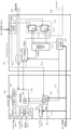
図2は、実施形態1に係る複合機101のコントローラ部102とファクシミリユニット107の構成を、より詳しく説明するブロック図である。ここでは特に、複合機101の設定を、スタンバイ時無鳴動(Hリレー214オン)、内部給電をオン(電話電源供給部215から直流24Vを給電)に設定した状態を示す。
FIG. 2 is a block diagram illustrating in more detail the configuration of the
コントローラ部102の画像処理部201は、その内部に制御用のCPU220、ROM221、RAM222、画像処理回路、各種I/F回路を有する。CPU220はROM221或いはHDD202に格納されているプログラムをRAM2222に展開して実行することにより後述する各種制御を行う。例えばCPU220は、コピー、プリント、ファクシミリ、スキャン等の各種処理モードに従って、それぞれ対象となるユニットに応じたデータのやり取り、制御を行い、所望の画像処理や制御を実行して、この複合機101の動作を制御している。
The
HDD(ハードディスクドライブ)202は、複合機101の制御プログラムや画像データの保存領域や作業領域として利用される。ファクシミリ受信時に、受信画像データはHDD202に保存される。また複合機101の各種設定もHDD202に保存される。複合機101のスタンバイ時の鳴動設定、内部給電の設定を操作部103の指示により設定し、HDD202に保存することができる。
An HDD (Hard Disk Drive) 202 is used as a storage area and a work area for control programs and image data of the
図12は、実施形態1に係る複合機101の操作部103の表示器に表示されるファクシミリの設定画面の一例を示す図である。
FIG. 12 is a diagram showing an example of a facsimile setting screen displayed on the display of the
この設定画面例のように、ユーザ或いはサービスマンは、鳴動設定を「無鳴動」或いは「鳴動」、内部給電の設定を「する」或いは「しない」に設定してHDD202に保存することができる。また受信モードを「自動受信」或いは「FAXTEL切り替え」或いは「手動受信」のいずれかに設定してHDD202に保存することができる。
As shown in this setting screen example, the user or serviceman can set the ring setting to "no ring" or "ring" and the internal power supply setting to "on" or "off" and save them in the
図10は、実施形態1に係る複合機101のHDD102における受信モード、鳴動設定、及び内部給電の設定値を登録しているテーブルの一例を示す図である。
FIG. 10 is a diagram showing an example of a table in which reception modes, ring settings, and setting values for internal power supply are registered in the
鳴動設定を無鳴動にすると鳴動設定値は「1」に、鳴動にすると鳴動設定値は「0」で保存され、CPU220は、その保存された値を読みだして制御を変更することができる。また内部給電設定を「する」に設定すると、内部給電設定値は「1」に、内部給電設定を「しない」に設定すると内部給電設定値は「0」で保存される。また受信モードが自動受信に設定されると受信モード設定値は「0」、FAXTEL切替えに設定されると受信モード設定値は「1」、手動受信に設定されると受信モード設定値は「2」となる。尚、HDD202の代わりに画像処理部201内部の不揮発メモリ(不図示)に保存する構成としても良い。
When the ringing setting is set to non-ringing, the ringing set value is stored as "1", and when set to ringing, the ringing set value is stored as "0", and the
スキャナI/F203、プリンタI/F204、操作部I/F205は、それぞれスキャナ部104、プリンタ部105、操作部103に接続するためのI/F(インターフェース)を示している。LANコントローラ206は、ネットワークケーブル106経由でLANに接続され外部装置と通信するためのLANコントローラである。
A scanner I/
呼出信号検出部210は、電話回線108を介して到来する交流75V、16Hz程度の電話の呼出信号を絶縁して通常のデジタル回路で受信できるよう変換する。呼出信号検出部210には、フォトカプラなどの電気部品を利用することができ、一定電圧以上の交流信号が印加されると呼出信号検出部210からコントローラ部102の割り込み判定部207へ、その呼出信号を整形した信号が入力される。交換機は通常の呼出信号を送出する前に直流48Vの極性を反転した後、呼出信号を1秒オン、2秒オフを1セットとする周期で呼び出しを行う。そして交換機は、そのオン時間の間、75V、16Hzの交流信号を直流48Vに重畳して送出する。また交換機は、オフ時間の間、直流48Vを維持する。そして、ファクシミリが回線を捕捉すると、交換機は呼び出し信号を停止し、送信側と着信側は回線接続されて通信できるようになる。
A
モデム211は、電話回線108を介して相手機とファクシミリ通信を行い、CPU220により制御される。モデム211と画像処理部201はI/Fを介して接続され、画像処理部201とモデム211との間のI/Fは、シリアルバス或いはパラレルバスを用いる。またモデム211は、ファクシミリ信号の変調、復調を行うとともに、画像データの送信、受信、トーン検出、DTMF検出を行う。また電話回線の1次と2次をトランスで絶縁して音声帯域の信号を伝達し、電話回線の直流捕捉をCML(Connect Modem to Line)リレー制御で行う回路構成をとることも可能である。また電話回線108の1次側には、SDAA(Silicon Data Access Arrangement)と呼ばれるA/D、D/Aを行う半導体を配置し、かつトランジスタを制御することにより直流捕捉を行う方式でも良い。A/Dはアナログデジタル変換、D/Aはデジタルアナログ変換の略である。回線1次側に配置するSDAAと2次側に配置するIC(図示せず)をまとめてモデム211として実施形態では扱う。回線の1次側に配置するSDAAと2次側に配置するIC(図示せず)との間にインダクタ或いはコンデンサで形成される絶縁回路を配置して、絶縁及び信号伝達を行う。
信号212は、交換機から送出される呼出信号を呼出信号検出部210で整形して出力される信号であり、これを以後、CI信号212と呼ぶ。割り込み判定部207に入力されたCI信号212をCPU220がリードして呼び出し信号の周波数やオン、オフ時間を判定して呼び出し信号が到来したかを判定することができる。またCI信号212をポート制御部213に並列に入力して、CPU220はポート制御部213をリードすることで、呼び出し信号の周波数やオン、オフ時間を判定して呼び出し信号が到来したかを判定しても良い。
A
ポート制御部213は、GPIO(General Purpose Input Output)機能を持つICやLSIを利用することができる。またCPU220は、ポート制御部213の出力ポートを制御して、Hリレー214や電話電源供給部215を制御する。Hリレー214をポート制御部213が直接駆動できない場合は、それらの間にトランジスタを挿入しても良い。
The
Hリレー214は、複合機101を無鳴動設定とした時、スタンバイ時にリレーをオンすることでハンドセット109を電話回線108から切り離す制御が行われる。リレーをオン状態に保つと、その間、約0.2Wの電力を消費する。複合機101を鳴動設定とした時、リレーをオフすることで、ハンドセット109を電話回線108に接続する制御が行われる。Hリレー214をオフすると、FAX受信であってもハンドセット109が鳴動してしまうが、約0.2W消費電力を削減できる。
The
オフフック検出部216は、ハンドセット109のオフフックを検出する。電話回線108の電圧を絶縁し、通常のデジタル回路で受信できるよう変換した信号を出力する。オフフック検出部216にはフォトカプラなどを利用することができる。Hリレー214をオフしていると交換機から約48Vの直流電圧が給電されており、オフフック時にハンドセット109が日本では50~300Ωの抵抗値となり、フォトカプラに約20mA以上電流が流れることで持ち上げを検知する。オンフック時にハンドセット109が1MΩ以上の抵抗値となり、フォトカプラの電流が遮断されることで、ハンドセット109が置き台に置かれたことを検知する。
Off-
信号217は、オフフック検出部216で整形した出力信号であり、これを以後、フック信号217と呼ぶ。オフフック検出部216からコントローラ部102の割り込み判定部207へ信号217が入力されて、オフフックが発生したことを検知できる。フック信号217をポート制御部213に並列に入力して、CPU220はポート制御部213をリードすることで、ハンドセット109が持ち上げ状態(オフフック)か、置き台に置かれた状態(オンフック)かを判定しても良い。
A
オフフック検出部216は、Hリレー214をオンしたときは電話回線108から電力が給電されないので、代わりに電話電源供給部215から電力を供給することができる。電話電源供給部215は、絶縁されたDCDCコンバータなどを用いて、ポート制御により+24V出力、停止、-150V出力を制御するよう構成することができる。スタンバイ時は、複合機101の電話電源供給部215から直流24Vが給電され、ハンドセット109のオフフック(持ち上げ)を検出できる。またFAXTEL切替えモードに設定すると、電話電源供給部215から直流24Vを給電するが、着信処理の際にCPU220がファクシミリ通信か相手との通話かを自動判定する。通話と判定された場合、ハンドセット109を鳴動させる疑似的な呼び出し信号(例えば+24Vと-150Vを一定周期で変化させる)を電話電源供給部215から発生させる構成にしても良い。電話電源供給部215をオンして+24Vを出力すると、その間、約1Wの電力を消費する。電話電源供給部215を停止すると、ハンドセット109のオフフックを検出できなくなるが、約1Wの消費電力を削減できる。消費電力の削減値は回路構成によって異なる。
Off-
割り込み判定部207は、画像処理部201を含むコントローラ部102を省電力モードから起動させる起動要因を検出する回路である。割り込み判定部207は、呼出信号検出部210と接続されており、呼び出し信号に変化があるとCI信号212が変化する。割り込み判定部207は、オフフック検出部216と接続されており、ハンドセット109をオフフックするとフック信号217が変化する。省電力モードの場合、電源制御信号113を制御して第二の電源111をオンさせる。一旦、第二の電源111をオンさせると、その後CI信号212が変化を繰り返しても割り込み判定部207は無視して電源制御信号113の状態を維持する。その後、CPU220が再度、省電力モードへ移行するまで、呼出し信号を割込み起動要因としては扱わない。CPU220は、割り込み判定部207の信号状態をリードすることで電話回線からの呼び出しがあるかを判定することもできる。
The interrupt
スタンバイ時に供給される電源は、第一の電源110及び第二の電源111から複合機101の全てに供給され、全ての機能が使用できる。省電力モードでは、第一の電源110から図1、図2で図示された一部に供給され、起動要因を検出可能なごく一部のみの通電状態となる。スタンバイ時から省電力モードへの移行は、一定時間ジョブが無い等、規定の条件を満たしたときに、CPU220により実施される。コントローラ部102から出力される電源制御信号113で第二の電源111をオフすることで省電力モードに移行する。
Power supplied during standby is supplied from the
図3は、実施形態1に係る複合機101のコントローラ部102とファクシミリユニット107の構成を、より詳しく説明するブロック図である。ここでは特に、複合機101の設定を、スタンバイ時、鳴動(Hリレー214オフ)、内部給電をオフ(電話電源供給部215からの給電をオフ)に設定した状態を示す。尚、図3において、図2と同じ部分は同じ参照番号で示し、その説明を省略する。
FIG. 3 is a block diagram illustrating in more detail the configuration of the
図4は、実施形態1に係る複合機101がスタンバイ時、内部給電がオフの設定で、かつ鳴動設定のときの処理を説明するフローチャートである。尚、このフローチャートで示す処理は、CPU220がROM221或いはHDD202に格納されているプログラムをRAM222に展開して実行することにより達成される。
FIG. 4 is a flowchart illustrating processing when the
この処理は、複合機101が電源オンされて、起動時の初期化が行われた状態で開始される。まずS401でCPU220は、HDD202に保存されたファクシミリの受信モード設定値、鳴動設定値、内部給電の設定値を読み出し、その設定値に応じてファクシミリの初期設定を行ってスタンバイ動作に移行する。尚、HDD202ではなく画像処理部201の内部フラッシュメモリに保存されている場合、そちらから読み出しを行う。
This process is started when the
実施形態1では、受信モードを自動受信、鳴動設定を鳴動、内部給電設定をしない設定で動作を説明する。鳴動設定が「鳴動」であればCPU220は、Hリレー214をオフする。また内部給電の設定が「しない」であるため、CPU220は電話電源供給部215の電源出力を停止する。Hリレー214をオフすると、図3に示すように、ハンドセット109は電話回線108に接続され、交換機からの直流給電(通常48V)によりハンドセット109の持ち上げをオフフック検出部216で検知することができる。
In the first embodiment, the operation will be described with the reception mode set to automatic reception, the ringing setting set to ring, and the internal power supply set to not set. If the ringing setting is “ringing”,
次にS402に進みCPU220は、内部給電の設定値をリードして内部給電を「する」設定かを判定する。ここで内部給電を「する」と判定すると、特徴となる処理は不要であるためS403へ処理を進る。S403でCPU220は、従来のスタンバイ時に実施しているジョブ待ち受け処理を継続する。内部給電設定値が変更されるまで、処理に変更は無い。もし内部給電設定値が変更されると、CPU220の処理はS418に進んで一度終了した後、S401へ移行して再度、処理を開始する。
Next, proceeding to S402, the
一方、S402でCPU2220は、内部給電をしないと判定した場合はS404へ処理を進める。S404でCPU220は、呼出信号の変化を検出したかを判定する。ここで呼出信号の変化があったと判定するとS405へ処理を進め、そうでないときはS406へ処理を進める。S405でCPU220は、着信処理を行う。ここでの従来の着信処理と同じであり、FAX受信などの着信処理が終了後、CPU220はS418に進んで一連の処理を終了させた後、S401へ移行して、再度スタンバイ状態を開始する。
On the other hand, if the CPU 2220 determines in S402 not to internally supply power, the process proceeds to S404. In S404,
S406でCPU220は、ハンドセット109のオフフック(持ち上げ)検知があったかを判定する。オフフック検知があったと判定するとS407へ処理を進め、オフフック検知が無いと判定するとS404へ処理を進める。S407は実施形態1の特徴となる処理であり、CPU220は、内部給電の設定とは関係なく内部給電をオンする制御を行う。このときCPU220は、ポート制御部213を制御し、電話電源供給部215から直流24Vの給電を開始させる。そして直流電圧が安定した後に、Hリレー214がオンされている時のハンドセットのオフフック(持ち上げ)を検出できる。交換機は直流48Vを給電することが多いが、電話電源供給部215から直流24Vを給電しても、持ち上げ時にオフフック検出部216に閾値以上の電流が流れるため問題ない。そして操作部103に「電話番号を入力して下さい」とテンキーダイヤル画面を表示して、ユーザに電話番号の入力を促す。これによりユーザは、操作部103のテンキーやタッチパネルを用いて、電話番号を入力して指示することができる。そしてCPU220の処理はS408に移行する。
In S406, the
S408でCPU220は、ハンドセット109のオンフック(置いた事の)検知があったか、或いは送受信指示があったか、或いはダイヤル終了指示があったかを判定する。ユーザがハンドセット109を置くか、操作部103から送受信指示を行う、ダイヤル終了キーを押下する等、これ以上、モデム211からダイヤル送出をしないとユーザが指示したかを判定する。ダイヤルキャンセルの指示を早期に反映させるために、S408の判定は、S411~S417の間、バックグラウンドで常に並列に行うように構成しても良い。ハンドセット109のオンフック検知或いは送受信指示、或いはダイヤル終了指示があったと判定すると、CPU220の処理はS409に移行し、そうでなければS411に移行する。S409の処理は、実施形態1の特徴となる処理であり、CPU220は、内部給電の設定とは関係なく内部給電をオフする制御を行う。ハンドセット109を置く、或いはFAX送信、或いは受信指示を行う、或いはダイヤル終了指示を行う等、これ以上モデム211からダイヤル送出をしないとユーザが指示した時に、このステップに移行してくる。CPU220は、ポート制御部213を制御し、電話電源供給部215をオフして内部給電を停止する。これによりHリレー214がオンされている時のハンドセットのオフフック(持ち上げ)を検出できなくなるが、当初S401で設定されていた状態に戻るので消費電力を低減できる。そして直流電圧が一定電圧まで下がり安定した後に、CPU220の処理はS410へ移行する。S410でCPU220は、終了処理を行う。ハンドセット109を置く、或いはダイヤル終了指示を行って、ダイヤルをキャンセルした場合、操作部103をスタンバイ状態に戻す。或いはFAX送信を指示された場合、FAX送信処理を実施する。或いはFAX受信を指示された場合、FAX受信処理を実施する。S410の処理は従来行っているダイヤルキャンセルの画面遷移或いはFAX送信或いはFAX受信と同様となる。FAX送信であれば、CPU220はモデム305による回線捕捉後、ハンドセット109により送出レベルが影響を受けるため、Hリレー214をオンし、ハンドセット109を電話回線108から切り離す。そしてCPU220はモデム305を制御してFAX送信処理を行う。FAX受信でも同様である。指示された処理が終了するとスタンバイ状態に戻るためにCPU220の処理はS418に進んで終了する。
In S408, the
S411でCPU220は、操作部103からダイヤル入力があったかを判定する。ユーザが操作部103のテンキーやタッチパネルを用いて、電話番号を入力したと判定するとS412に処理を進め、電話番号が入力されていないと判定するとS408に処理を進める。S412でCPU220は、モデム211による回線捕捉処理を行う。ユーザが電話番号を入力した時、モデム211からダイヤル信号を送出するために、このステップに移行してくる。そしてS413に進みCPU220は、Hリレー214をオンする処理を行う。これは、ハンドセット109が電話回線108に接続されたままでモデム211からDTMF信号を送出すると送出レベルに影響するため、Hリレー214をオンしてハンドセット109を電話回線108から切り離すためである。パルスダイヤルの場合でも波形に影響するため同様の処理を行う。そしてS414に進みCPU220は、ハンドセット109のオンフック(置いた事の)を検知したかを判定する。ここでハンドセット109のオンフックを検知するとS409に進み、そうでなければS415に処理を進める。
In S<b>411 , the
ここで、もし実施形態1の特徴となるS407の制御を行なわないと、S414に移行した時点で以下の課題が発生する。この課題について図11を参照して説明する。 Here, if the control of S407, which is the characteristic feature of the first embodiment, is not performed, the following problem will occur at the time of shifting to S414. This problem will be described with reference to FIG.
図11は、従来例における内部給電とリレーの状態を示すタイムチャートで、課題が発生する例を説明する図である。 FIG. 11 is a time chart showing internal power supply and relay states in a conventional example, and is a diagram for explaining an example in which a problem occurs.
内部給電をオンするS407の制御を行なわないと、電話電源供給部215からの給電が停止しているので、Hリレー214をオンした時はハンドセットに直流電圧が印加されない状態となり、オフフック検出部216の電流は遮断される。そして図11の1100で示すように、ユーザはハンドセットを置いていないのに、CPUはユーザがハンドセットを置いたと誤認する。ハンドセットのオンフックの判定はこの間でも行われているため、オンフックしたと見なされて、CPUはダイヤルキャンセルを行い、モデムによる回線捕捉を終了して、ハンドセットを電話回線に接続するためにHリレー214をオフに戻さない。そして一旦、スタンバイ状態に戻った後でもユーザはハンドセットを置いていないので、ハンドセットは電話回線を捕捉するが、ダイヤルキャンセルされているため所望の相手とは通話できないという課題が発生する。
If the control of S407 for turning on the internal power supply is not performed, the power supply from the telephone
これに対して実施形態1では、S407の制御を実施することで上記課題を解決することができる。実施形態1ではS407で内部給電がオンされているので、S413でHリレー214がオンされてハンドセット109が回線から遮断されても、ハンドセット109に直流電圧が印加され続けるため、オフフック検出部216の電流は遮断されない。これにより上述したようなオンフックの誤認は起こらないため、ユーザは所望の相手と通話できる。
On the other hand, in
再び図4に戻り、S415でCPU220は、モデム211によるダイヤル信号送出処理を行う。CPU220は、モデム211を制御し、指示された電話番号に対応するDTMF信号を所定の送出レベルで送出する。尚、トーンでなくパルス設定の場合、CPU220は、モデム211を制御し、指示された電話番号に対応するダイヤルパルス信号を所定のタイミングで送出する。ダイヤルパルス信号は直流捕捉と直流解放を所定のタイミングで実施することで送出する。次にS416に進みCPU220は、Hリレー214をオフする処理を行う。これは、ユーザが持ち上げたハンドセット109を電話回線108に再度接続して、ユーザが通話できるようにするためである。そしてS417へ進みCPU220は、モデム211による回線捕捉を終了させる。これはユーザが持ち上げたハンドセット109が回線捕捉をしているので、モデム211による回線捕捉は必要ないためである。そしてCPU220の処理はS408に戻る。S418でCPU220は、一連の処理を終了させる。そして再度スタンバイ状態へ移行するため、CPU220はS401に移行する。
Returning to FIG. 4 again, in S415, the
以上の図4に示すフローチャートに従って処理すると、内部給電やリレーなどの状態は図7に示すタイムチャートのように遷移し、課題は発生しない。 If the processing is performed according to the flowchart shown in FIG. 4, the state of the internal power supply, the relay, etc. changes as shown in the time chart shown in FIG. 7, and no problem occurs.
図7は、実施形態1に係る複合機101における、内部給電とリレーの状態を説明するタイムチャートである。
FIG. 7 is a time chart for explaining internal power feeding and relay states in the
実施形態1の処理を行うことにより、スタンバイ時、内部給電がオフの設定で、かつ鳴動設定のときに、オフフックを検出するとS407で内部給電設定がオフであっても、内部給電をオンにする。これによりハンドセット109を持ち上げて操作部103からダイヤル操作する場合でも、内部給電の設定を変更せずに、相手と通話可能なファクシミリ機能を提供できる。
By performing the processing of the first embodiment, when off-hook is detected when internal power supply is set to off during standby and ringing is set, internal power supply is turned on in S407 even if the internal power supply setting is off. . As a result, even when the
[実施形態2]
実施形態2では図3に示すスタンバイ時、内部給電がオフの設定で、かつ鳴動設定の場合、つまりHリレー214をオフ、電話電源供給部215をオフしているときのCPU220の制御について説明する。尚、実施形態2に係る複合機101のハードウェア構成等は前述の実施形態1と同様であるため、その説明を省略する。
[Embodiment 2]
In the second embodiment, the control of the
スタンバイ時、内部給電がオフの設定で、かつ鳴動設定で、ユーザがハンドセット109持ち上げて発呼した場合、CPU220が行う実施形態2の制御手順を図5のフローチャートで説明する。
The control procedure of the second embodiment performed by the
図5は、実施形態2に係る複合機101がスタンバイ時、内部給電がオフの設定で、かつ鳴動設定のときの処理を説明するフローチャートである。尚、このフローチャートで示す処理は、CPU220がROM221或いはHDD202に格納されているプログラムをRAM222に展開して実行することにより達成される。
FIG. 5 is a flowchart illustrating processing when the
まず、複合機101は電源オンされて、起動時の初期化が行われた状態とする。CPU220の処理はS501に移行し処理を開始する。S501~S506の処理は、前述の図4のS401~S406の処理と同じなので、その説明を省略する。
First, the
S507は、実施形態2の特徴となる処理であり、CPU220は、内部給電設定を変更するように促す画面を表示する。S507は、実施形態1のS407を実施しない複合機101で代わりに行う代替処理である。
S507 is processing that characterizes the second embodiment, and the
実施形態1で説明したように、内部給電設定がオフの場合、ハンドセット109を接続して、オフフックした後に操作部103からダイヤル操作すると、途中で回線電流が一旦切断されてしまい、相手と通話できなくなる。そこでS507でCPU220は、スタンバイ時に、ハードセット109がオフフックされたと検知すると、操作部103の画面に注意を喚起する画面を表示する。この画面では、「テンキーダイヤルを行う場合、内部給電設定を「しない」(オフ)→「する」(オン)へ変更してください」と表示してユーザに内部給電の設定変更を促す。
As described in the first embodiment, when the internal power supply setting is off, when the
またその後、操作部103の画面を自動的に図12に示す設定画面に遷移させ、ユーザに内部給電設定を「する」に設定して保存するよう促す構成としても良い。また或いは操作部103の画面に「テンキーダイヤルを行う場合、内部給電設定を「しない」→「する」へ変更する必要があります。変更しますか?」と表示して、ユーザに「はい」「いいえ」のいずれかを選択させる構成としても良い。ここでユーザが「はい」を選択するとCPU220は、内部給電設定を「する」に設定して保存する。一方、ユーザが「いいえ」を選択すると、内部給電設定を変更しない。そしてCPU220の処理はS508に進み、CPU220は終了処理を行う。いまユーザが、ハンドセット109を置いて(オンフックして)ダイヤルをキャンセルした場合、操作部103の表示をスタンバイ状態に戻す。処理が終了するとスタンバイ状態に戻るためにCPU220の処理はS509へ移行する。S509でCPU220は、一連の処理を終了させる。そして再度スタンバイ状態へ移行するため、CPU220はS501に処理を進める。S507でユーザが内部給電設定を「しない」から「する」に設定して保存すると、次のS502では内部給電が「する」設定されているため、課題は発生しない。
After that, the screen of the
図8は、実施形態2に係る複合機101において、S507で表示される注意画面例を説明する図である。
FIG. 8 is a diagram illustrating an example of a caution screen displayed in S507 on the
800は、テンキーを使用してダイヤルする場合、内部給電設定を「しない」→「する」へ変更する必要があるため、その変更を促す画面例を示す。801は、別の注意画面例を示し、ここではFAX設定で、内部給電設定を「しない」か、「する」かラジオボタンで選択して確定ボタンを押下することで選択できる。802は、テンキーを使用してダイヤルする場合、内部給電設定を「しない」→「する」へ変更する必要があるため、その変更するか否を「はい」か「いいえ」で選択できる画面例を示す。
800 shows an example of a screen prompting the change because it is necessary to change the internal power supply setting from "no" to "on" when dialing using the numeric keypad.
以上説明したように実施形態2によれば、内部給電設定をオフ、Hリレーをオフにして消費電力を削減する鳴動待機の際、ユーザがハンドセットを持ち上げた時に操作部103に内部給電設定を変更するように促す表示を行うことができる。これによりユーザに対して、内部給電の設定を変更しないと、ユーザの意図通り動作しないことを警告できる。
As described above, according to the second embodiment, when the user lifts the handset during ringing standby in which the internal power supply setting is turned off and the H relay is turned off to reduce power consumption, the
また自動的に、内部給電の設定画面例に遷移することで、わかりやすいユーザインタフェースを提供する。 In addition, an easy-to-understand user interface is provided by automatically transitioning to an example of an internal power supply setting screen.
またユーザに対して内部給電の設定を変更するか否かを問い合わせ、ユーザの指示に応じて、その設定を変更できることで、ユーザにとって分かり易いユーザインタフェースを提供できる。 Further, by asking the user whether or not to change the setting of the internal power supply and changing the setting according to the user's instruction, it is possible to provide a user interface that is easy for the user to understand.
こうして消費電力を削減する鳴動待機の際でも、内部給電を「しない」から「する」に変更して保存することで、ユーザがハンドセットを持ち上げた後にダイヤルを操作した場合でも、相手と通話可能な複合機を提供できる。 Even during ring standby, which reduces power consumption in this way, by changing the internal power supply from "off" to "on" and saving it, even if the user lifts the handset and operates the dial, it is possible to talk to the other party. We can provide multi-function devices.
[実施形態3]
実施形態3では、図3に示すスタンバイ時、内部給電をしない設定で、かつ鳴動設定、つまりHリレー214をオフ、電話電源供給部215をオフしている時のCPU220の制御について説明する。スタンバイ時、内部給電をしない設定で、かつ鳴動設定でハンドセットを持ち上げて発呼した場合、CPU220が行う実施形態3の制御手順を図6のフローチャートで説明する。尚、実施形態3に係る複合機101のハードウェア構成等は、前述の実施形態1と同様であるため、その説明を省略する。
[Embodiment 3]
In the third embodiment, the control of the
図6は、実施形態3に係る複合機101がスタンバイ時、内部給電がオフの設定で、かつ鳴動設定のときの処理を説明するフローチャートである。尚、このフローチャートで示す処理は、CPU220がROM221或いはHDD202に格納されているプログラムをRAM222に展開して実行することにより達成される。図6のS601~606の処理は、前述の図4のS401~406の処理と同じなので、その説明を省略する。
FIG. 6 is a flowchart illustrating processing when the
S607は、実施形態3で特徴となる処理であり、CPU220は、内部給電設定値を自動的に「する」へ変更してHDD202或いは画像処理部201の内部フラッシュメモリへ保存する。実施形態1で説明したように内部給電設定がオフの場合、ハンドセットを接続して、持ち上げ後に操作部からダイヤル操作すると途中で回線電流が一旦切断されてしまい、相手と通話できなくなる。従ってS607でCPU220は、操作部103の画面に「内部給電設定を「する」に変更しました」と表示してユーザに設定値を自動的に変更したことを通知する。そしてCPU220はS608へ処理を進める。
S<b>607 is processing that is characteristic of the third embodiment. When the internal power supply setting is off as described in the first embodiment, when the handset is connected and the dial operation is performed from the operation unit after the handset is lifted, the line current is cut off midway, making it impossible to talk to the other party. Accordingly, in step S607, the
S608でCPU220は、内部給電設定値の変更に応じて内部給電をオンする制御を行い、テンキーダイヤル画面を表示する。具体的には、CPU220はポート制御部213を制御し、電話電源供給部215から直流24Vの給電を開始する。そして直流電圧が安定した後、ハンドセットのオフフック(持ち上げ)を検出できる。そして操作部103に「電話番号を入力して下さい」とテンキーダイヤル画面を表示しユーザに電話番号の入力を促す。これによりユーザは、操作部103のテンキーやタッチパネルを用いて、電話番号を入力することができる。そしてCPU220の処理はS609へ移行する。S609ではS408と同じ処理が行われるため説明を省略する。またS610~S617の処理は、前述の図4のS410~S417と同じ処理であるため、その説明を省略する。
In S608, the
図9は、実施形態3に係る複合機における、内部給電とリレーの状態を説明するタイムチャートである。図9に示すように、ハンドセット109のオフフックが検出されると900で、内部給電設定を自動的に「する」に変更して保存するため、後続の処理で内部給電がオンに変更される。これにより、ハンドセットのオフフック(持ち上げ)を検出でき、かつ操作部103に「電話番号を入力して下さい」とテンキーダイヤル画面を表示してユーザのダイヤル入力が可能になる。
FIG. 9 is a time chart for explaining the state of internal power feeding and relays in the MFP according to the third embodiment. As shown in FIG. 9, when the
以上説明したように実施形態3によれば、内部給電をオフ、Hリレーをオフ、として消費電力を削減する鳴動待機の場合に、ユーザがハンドセットを持ち上げると、自動的に内部給電設定をオンに変更して、操作部に通知を表示する。このように、自動的に内部給電の設定を「しない」から「する」へ変更することにより、消費電力を削減する鳴動待機でハンドセットを持ち上げてダイヤル操作した場合でも、相手と通話可能な複合機を提供できる。 As described above, according to the third embodiment, when the user picks up the handset in ringing standby mode in which power consumption is reduced by turning off the internal power supply and turning off the H relay, the internal power supply setting is automatically turned on. Change to display notifications in the control panel. In this way, by automatically changing the internal power supply setting from "off" to "on," power consumption is reduced. Even if you pick up the handset and dial while in ring standby mode, you can talk to the other party. can provide
(その他の実施形態)
本発明は、上述の実施形態の1以上の機能を実現するプログラムを、ネットワーク又は記憶媒体を介してシステム又は装置に供給し、そのシステム又は装置のコンピュータにおける1つ以上のプロセッサーがプログラムを読出し実行する処理でも実現可能である。また、1以上の機能を実現する回路(例えば、ASIC)によっても実現可能である。
(Other embodiments)
The present invention supplies a program that implements one or more functions of the above-described embodiments to a system or device via a network or a storage medium, and one or more processors in the computer of the system or device reads and executes the program. It can also be realized by processing to It can also be implemented by a circuit (for example, ASIC) that implements one or more functions.
本発明は上記実施形態に制限されるものではなく、本発明の精神及び範囲から離脱することなく、様々な変更及び変形が可能である。従って、本発明の範囲を公にするために、以下の請求項を添付する。 The present invention is not limited to the embodiments described above, and various modifications and variations are possible without departing from the spirit and scope of the present invention. Accordingly, to publicize the scope of the invention, the following claims are included.
101…複合機、102…コントローラ部、103…操作部、107…ファクシミリユニット、108…電話回線、109…ハンドセット、201…画像処理部、211…モデム、214…Hリレー、215…電話電源供給部、216…オフフック検出部、220…CPU
DESCRIPTION OF
Claims (5)
前記電話機と電話回線との接続を、接続と遮断との間で切り替える切替手段と、
前記切替手段を介して前記電話機に給電する給電手段と、
前記電話機を鳴動させる鳴動モードまたは前記電話機を鳴動させない無鳴動モードを選択する選択手段と、
前記選択手段によって前記鳴動モードが選択され、前記切替手段により前記電話機と前記電話回線とが接続され、且つ、前記給電手段が停止している状態で、前記検出手段により前記電話機のオフフックが検出されると、前記給電手段による前記電話機への給電を開始するようにユーザに設定するよう促す画面を表示し、当該画面を介したユーザの設定に従って前記給電手段を動作させ、且つ前記給電手段から前記電話機への給電を開始するよう制御する制御手段と、
を有することを特徴とするファクシミリ装置。 detection means for detecting off-hook and on-hook of a connected telephone;
a switching means for switching between connection and disconnection of the connection between the telephone and the telephone line;
power feeding means for feeding power to the telephone through the switching means;
selection means for selecting a ringing mode in which the telephone is ringed or a no-ring mode in which the telephone is not ringed;
The ringing mode is selected by the selection means, the telephone and the telephone line are connected by the switching means, and the off-hook of the telephone is detected by the detection means in a state in which the power feeding means is stopped. Then, a screen prompting the user to set to start power supply to the telephone by the power supply means is displayed, the power supply means is operated according to the user's setting via the screen, and the control means for controlling the initiation of power supply to the telephone;
A facsimile machine characterized by having:
前記制御手段は、前記検出手段により前記電話機のオフフックが検出されてダイヤル入力があると前記モデムにより前記電話回線を捕捉させて前記切替手段により前記電話機と前記電話回線との接続を遮断し、前記モデムによりダイヤル信号を送出させた後、前記切替手段により前記電話機と前記電話回線とを接続することを特徴とする請求項1に記載のファクシミリ装置。 further comprising a modem for performing facsimile communication with the other party via the telephone line;
The control means causes the modem to seize the telephone line and disconnects the telephone line from the telephone line by the switching means when the off-hook of the telephone is detected by the detection means and a dial input is received. 2. A facsimile apparatus according to claim 1, wherein said telephone and said telephone line are connected by said switching means after a dial signal is transmitted by a modem.
接続された電話機のオフフック及びオンフックを検出する検出工程と、
前記電話機と電話回線との接続を、接続と遮断との間で切り替える切替工程と、
給電手段から前記電話機に給電する給電工程と、
前記電話機を鳴動させる鳴動モードまたは前記電話機を鳴動させない無鳴動モードを選択する選択工程と、
前記選択工程によって前記鳴動モードが選択され、前記切替工程で前記電話機と前記電話回線とが接続され、且つ、前記給電手段が停止している状態で、前記検出工程で前記電話機のオフフックが検出されると、前記給電工程による前記電話機への給電を開始するようにユーザに設定するよう促す画面を表示し、当該画面を介したユーザの設定に従って前記給電工程を実行させ、且つ前記給電工程による前記電話機への給電を開始するよう制御する制御工程と、
を有することを特徴とする制御方法。 A control method for controlling a facsimile machine, comprising:
a detection step for detecting off-hook and on-hook of the connected telephone;
a switching step of switching the connection between the telephone and the telephone line between connection and disconnection;
a power supply step of powering the phone from power supply means;
selecting a ringing mode to ring the phone or a non-ringing mode to not ring the phone;
The ringing mode is selected by the selection step, the telephone and the telephone line are connected in the switching step, and the off-hook of the telephone is detected in the detection step in a state in which the power feeding means is stopped. Then, a screen prompting the user to set to start power supply to the phone by the power supply process is displayed, the power supply process is executed according to the user's setting via the screen, and the power supply process is performed by the power supply process. a control step for controlling the initiation of power supply to the phone;
A control method characterized by having
Priority Applications (3)
| Application Number | Priority Date | Filing Date | Title |
|---|---|---|---|
| JP2017168834A JP7256596B2 (en) | 2017-09-01 | 2017-09-01 | Facsimile machine, its control method, and program |
| US16/100,907 US10498923B2 (en) | 2017-09-01 | 2018-08-10 | Facsimile apparatus, method of controlling the same, and storage medium |
| JP2023004699A JP7415055B2 (en) | 2017-09-01 | 2023-01-16 | Facsimile device, its control method, and program |
Applications Claiming Priority (1)
| Application Number | Priority Date | Filing Date | Title |
|---|---|---|---|
| JP2017168834A JP7256596B2 (en) | 2017-09-01 | 2017-09-01 | Facsimile machine, its control method, and program |
Related Child Applications (1)
| Application Number | Title | Priority Date | Filing Date |
|---|---|---|---|
| JP2023004699A Division JP7415055B2 (en) | 2017-09-01 | 2023-01-16 | Facsimile device, its control method, and program |
Publications (3)
| Publication Number | Publication Date |
|---|---|
| JP2019047347A JP2019047347A (en) | 2019-03-22 |
| JP2019047347A5 JP2019047347A5 (en) | 2020-09-17 |
| JP7256596B2 true JP7256596B2 (en) | 2023-04-12 |
Family
ID=65518414
Family Applications (2)
| Application Number | Title | Priority Date | Filing Date |
|---|---|---|---|
| JP2017168834A Active JP7256596B2 (en) | 2017-09-01 | 2017-09-01 | Facsimile machine, its control method, and program |
| JP2023004699A Active JP7415055B2 (en) | 2017-09-01 | 2023-01-16 | Facsimile device, its control method, and program |
Family Applications After (1)
| Application Number | Title | Priority Date | Filing Date |
|---|---|---|---|
| JP2023004699A Active JP7415055B2 (en) | 2017-09-01 | 2023-01-16 | Facsimile device, its control method, and program |
Country Status (2)
| Country | Link |
|---|---|
| US (1) | US10498923B2 (en) |
| JP (2) | JP7256596B2 (en) |
Citations (3)
| Publication number | Priority date | Publication date | Assignee | Title |
|---|---|---|---|---|
| JP2007235505A (en) | 2006-03-01 | 2007-09-13 | Konica Minolta Business Technologies Inc | External telephone set separation controller and facsimile machine |
| JP2016225936A (en) | 2015-06-03 | 2016-12-28 | キヤノン株式会社 | Facsimile machine, facsimile machine control method, and program |
| JP7212493B2 (en) | 2018-10-16 | 2023-01-25 | 花王株式会社 | Container sheet |
Family Cites Families (5)
| Publication number | Priority date | Publication date | Assignee | Title |
|---|---|---|---|---|
| JPH07212493A (en) * | 1994-01-24 | 1995-08-11 | Murata Mach Ltd | Facsimile equipment |
| JPH07336456A (en) * | 1994-06-08 | 1995-12-22 | Canon Inc | Facsimile terminal |
| KR100742346B1 (en) * | 2005-05-03 | 2007-07-25 | 삼성전자주식회사 | DC Feeding switching apparatus |
| JP5480720B2 (en) * | 2009-07-27 | 2014-04-23 | キヤノン株式会社 | COMMUNICATION DEVICE, ITS CONTROL METHOD, AND PROGRAM |
| JP2012019280A (en) * | 2010-07-06 | 2012-01-26 | Ricoh Co Ltd | Facsimile device and power supply control method for facsimile device |
-
2017
- 2017-09-01 JP JP2017168834A patent/JP7256596B2/en active Active
-
2018
- 2018-08-10 US US16/100,907 patent/US10498923B2/en active Active
-
2023
- 2023-01-16 JP JP2023004699A patent/JP7415055B2/en active Active
Patent Citations (3)
| Publication number | Priority date | Publication date | Assignee | Title |
|---|---|---|---|---|
| JP2007235505A (en) | 2006-03-01 | 2007-09-13 | Konica Minolta Business Technologies Inc | External telephone set separation controller and facsimile machine |
| JP2016225936A (en) | 2015-06-03 | 2016-12-28 | キヤノン株式会社 | Facsimile machine, facsimile machine control method, and program |
| JP7212493B2 (en) | 2018-10-16 | 2023-01-25 | 花王株式会社 | Container sheet |
Also Published As
| Publication number | Publication date |
|---|---|
| JP2019047347A (en) | 2019-03-22 |
| US20190075216A1 (en) | 2019-03-07 |
| US10498923B2 (en) | 2019-12-03 |
| JP7415055B2 (en) | 2024-01-16 |
| JP2023052424A (en) | 2023-04-11 |
Similar Documents
| Publication | Publication Date | Title |
|---|---|---|
| JP5790183B2 (en) | Facsimile machine | |
| JP6730789B2 (en) | Communication device, control method thereof, and program | |
| JP7256596B2 (en) | Facsimile machine, its control method, and program | |
| US8879694B2 (en) | Communication apparatus and communication system | |
| US9219814B2 (en) | Communication apparatus and control method therefor | |
| US7092499B2 (en) | Communication apparatus | |
| JP2017183965A (en) | Information processing device, control method of information processing device, and program | |
| JP5790182B2 (en) | Facsimile machine | |
| JP2016225936A (en) | Facsimile machine, facsimile machine control method, and program | |
| JP5510365B2 (en) | Communication device | |
| EP0848538A2 (en) | Communication terminal device | |
| JP2012104924A (en) | Facsimile device | |
| JP2007215058A (en) | Data communication method | |
| JP2911472B2 (en) | Communication device | |
| KR100202408B1 (en) | Data transmitting apparatus using inner telephone circuit and method thereof | |
| KR100260220B1 (en) | Facsimile apparatus | |
| JP2019201354A (en) | Image communication apparatus, control method thereof, and program | |
| JP3060565B2 (en) | Facsimile machine | |
| JP2017092573A (en) | Image communication device, control method thereof, and program | |
| JPS61176241A (en) | Communication equipment | |
| JP2011103516A (en) | Facsimile apparatus | |
| JP2019047347A5 (en) | ||
| JPH07177330A (en) | Facsimile equipment | |
| JP2016116005A (en) | Facsimile device and sender number acquisition method | |
| JP2006279562A (en) | Composite machine |
Legal Events
| Date | Code | Title | Description |
|---|---|---|---|
| A521 | Request for written amendment filed |
Free format text: JAPANESE INTERMEDIATE CODE: A523 Effective date: 20200806 |
|
| A621 | Written request for application examination |
Free format text: JAPANESE INTERMEDIATE CODE: A621 Effective date: 20200806 |
|
| RD01 | Notification of change of attorney |
Free format text: JAPANESE INTERMEDIATE CODE: A7421 Effective date: 20210103 |
|
| A521 | Request for written amendment filed |
Free format text: JAPANESE INTERMEDIATE CODE: A523 Effective date: 20210113 |
|
| A977 | Report on retrieval |
Free format text: JAPANESE INTERMEDIATE CODE: A971007 Effective date: 20210517 |
|
| A131 | Notification of reasons for refusal |
Free format text: JAPANESE INTERMEDIATE CODE: A131 Effective date: 20210521 |
|
| A521 | Request for written amendment filed |
Free format text: JAPANESE INTERMEDIATE CODE: A523 Effective date: 20210712 |
|
| A131 | Notification of reasons for refusal |
Free format text: JAPANESE INTERMEDIATE CODE: A131 Effective date: 20210802 |
|
| A521 | Request for written amendment filed |
Free format text: JAPANESE INTERMEDIATE CODE: A523 Effective date: 20210930 |
|
| A02 | Decision of refusal |
Free format text: JAPANESE INTERMEDIATE CODE: A02 Effective date: 20211025 |
|
| A521 | Request for written amendment filed |
Free format text: JAPANESE INTERMEDIATE CODE: A523 Effective date: 20220125 |
|
| C60 | Trial request (containing other claim documents, opposition documents) |
Free format text: JAPANESE INTERMEDIATE CODE: C60 Effective date: 20220125 |
|
| A911 | Transfer to examiner for re-examination before appeal (zenchi) |
Free format text: JAPANESE INTERMEDIATE CODE: A911 Effective date: 20220202 |
|
| C21 | Notice of transfer of a case for reconsideration by examiners before appeal proceedings |
Free format text: JAPANESE INTERMEDIATE CODE: C21 Effective date: 20220207 |
|
| A912 | Re-examination (zenchi) completed and case transferred to appeal board |
Free format text: JAPANESE INTERMEDIATE CODE: A912 Effective date: 20220311 |
|
| C211 | Notice of termination of reconsideration by examiners before appeal proceedings |
Free format text: JAPANESE INTERMEDIATE CODE: C211 Effective date: 20220318 |
|
| C22 | Notice of designation (change) of administrative judge |
Free format text: JAPANESE INTERMEDIATE CODE: C22 Effective date: 20220708 |
|
| C13 | Notice of reasons for refusal |
Free format text: JAPANESE INTERMEDIATE CODE: C13 Effective date: 20220822 |
|
| A521 | Request for written amendment filed |
Free format text: JAPANESE INTERMEDIATE CODE: A523 Effective date: 20220927 |
|
| C13 | Notice of reasons for refusal |
Free format text: JAPANESE INTERMEDIATE CODE: C13 Effective date: 20221118 |
|
| A521 | Request for written amendment filed |
Free format text: JAPANESE INTERMEDIATE CODE: A523 Effective date: 20230116 |
|
| C23 | Notice of termination of proceedings |
Free format text: JAPANESE INTERMEDIATE CODE: C23 Effective date: 20230203 |
|
| C03 | Trial/appeal decision taken |
Free format text: JAPANESE INTERMEDIATE CODE: C03 Effective date: 20230303 |
|
| C30A | Notification sent |
Free format text: JAPANESE INTERMEDIATE CODE: C3012 Effective date: 20230303 |
|
| A61 | First payment of annual fees (during grant procedure) |
Free format text: JAPANESE INTERMEDIATE CODE: A61 Effective date: 20230331 |
|
| R151 | Written notification of patent or utility model registration |
Ref document number: 7256596 Country of ref document: JP Free format text: JAPANESE INTERMEDIATE CODE: R151 |